LX8x10x Manual English Ver0626
User Manual: Pdf Manuals • LXNAV Gliding
Open the PDF directly: View PDF ![]() .
.
Page Count: 108 [warning: Documents this large are best viewed by clicking the View PDF Link!]
- 1 Important Notices
- 2 Packing Lists
- 3 Basics
- 4 System Description
- 5 Operating Modes
- 5.1 Quick Access Menus
- 5.1.1 MC/BAL
- 5.1.2 Reset G
- 5.1.3 Navboxes Option
- 5.1.4 Select / Select Near (Only in WPT mode)
- 5.1.5 Edit Target
- 5.1.6 Flarm Traffic
- 5.1.7 Event
- 5.1.8 Night
- 5.1.9 Edit Task (Only in Task Mode)
- 5.1.10 Start Task (only in Task Mode)
- 5.1.11 Restart Task (only in Task Mode)
- 5.1.12 Next Waypoint (only in Task Mode)
- 5.1.13 Send WPT
- 5.1.14 Sidebar
- 5.1.15 Options
- 5.1.16 Load/Save
- 5.1.17 Wind
- 5.2 Info Mode
- 5.3 Flarm Mode
- 5.4 Thermal Assistant Mode
- 5.5 Waypoint Mode
- 5.6 Task Mode
- 5.7 Setup Mode
- 5.7.1 QNH & RES
- 5.7.2 Flight Recorder
- 5.7.3 Vario Parameters
- 5.7.3.1 Vario Needle Filter
- 5.7.3.2 Vario Sound Filter
- 5.7.3.3 Netto Filter
- 5.7.3.4 Relative Filter
- 5.7.3.5 SC Filter
- 5.7.3.6 Smart Filter
- 5.7.3.7 Needle Range
- 5.7.3.8 Auto SC
- 5.7.3.9 TE Compensation
- 5.7.3.10 Vario Average Time
- 5.7.3.11 Integrator Reset
- 5.7.3.12 Temperature Offset
- 5.7.3.13 Airspeed Offset
- 5.7.3.14 Inertial Assisted Vario
- 5.7.4 Thermal Assistant
- 5.7.5 Display
- 5.7.6 Graphics
- 5.7.7 Sounds
- 5.7.8 Warnings
- 5.7.9 Obs. Zones
- 5.7.10 Units
- 5.7.11 Hardware
- 5.7.12 Profiles
- 5.7.13 Files
- 5.7.14 Polar and Glider
- 5.7.15 Logbook
- 5.7.16 Admin mode
- 5.7.17 Password
- 5.7.18 About
- 5.1 Quick Access Menus
- 6 Variometer and Altimeter
- 7 Flying with the LXNAV S8x/S10x
- 8 Installation
- 8.1 Installing the LXNAV S8x/S10x
- 8.2 Connecting the LXNAV S8x/S10x
- 8.3 Cut-outs
- 8.4 Available Cables for GPS/Flarm and PDA Ports
- 8.5 Installation of Options
- 8.6 Ports and Wiring
- 8.7 S8x/S10x Configurations
- 8.7.1 Symbols
- 8.7.2 Nano/Nano3 – Sxxx - MiniMap
- 8.7.3 Nano3 - Sxxx - Oudie
- 8.7.4 Colibri II – Sxxx - Oudie
- 8.7.5 Colibri/Volkslogger - Sxxx - Oudie
- 8.7.6 Flarm – Sxxx - FlarmViewX - Oudie
- 8.7.7 FlarmMouse - ADSB – Sxxx - FlarmView - Oudie
- 8.7.8 FlarmMouse – Sxxx - Oudie
- 8.7.9 FlarmMouse - Nano3 - Sxxx - Oudie
- 8.7.10 PowerMouse + (Nano3) - Sxxx - Oudie
- 8.7.11 S8x/S10x– S8xD
- 8.8 Data Transfer
- 9 Firmware Update
- 10 FAQ
- 11 Revision History

June 2018
Page 2 of 108
1 Important Notices 7
1.1 Limited Warranty 7
2 Packing Lists 8
2.1 S80 (80mm) Variometer Unit 9
2.2 S8 (57mm) Variometer Unit 10
2.3 S10 (57mm) Variometer Unit 11
2.4 S100 (80mm) Variometer Unit 12
2.5 S8D Repeater Unit 13
2.6 S80D Repeater Unit 14
3 Basics 15
3.1 LXNAV S8x/S10x at a Glance 15
3.2 LXNAV S8x/S10x Features 16
3.2.1 Interfaces 16
3.2.2 Options 16
3.2.3 S8/S80 Club 16
3.2.4 Technical Data 17
Power Consumption 17
Size and Weight 17
4 System Description 18
4.1 Push Button – Rotary Switches 18
4.1.1 Power Button 18
4.2 Rotary Switches 18
4.3 Buttons (Three) 19
4.4 Switching on the Unit 19
4.5 User Input 20
4.5.1 Text Edit Control 20
4.5.2 “Spin” Control 21
4.5.3 Selection Control 21
4.5.4 Checkbox and Checkbox List 21
4.5.5 Slider Selector 22
4.6 Switching Off 22
5 Operating Modes 23
5.1 Quick Access Menus 23
5.1.1 MC/BAL 24
5.1.2 Reset G 24
5.1.3 Navboxes Option 24
Editing navboxes 25
Navboxes with description 25
5.1.4 Select / Select Near (Only in WPT mode) 26
5.1.5 Edit Target 27
5.1.6 Flarm Traffic 27
5.1.7 Event 27
5.1.8 Night 27
5.1.9 Edit Task (Only in Task Mode) 27
5.1.10 Start Task (only in Task Mode) 28
5.1.11 Restart Task (only in Task Mode) 28
5.1.12 Next Waypoint (only in Task Mode) 28
5.1.13 Send WPT 28
5.1.14 Sidebar 29
5.1.15 Options 29
5.1.16 Load/Save 29
5.1.17 Wind 29
June 2018
Page 3 of 108
5.2 Info Mode 30
5.2.1 Quick Access Menu 30
5.3 Flarm Mode 31
5.3.1 Quick Access Menu 31
Edit Target 31
Flarm Traffic 32
5.3.2 Flarm Warnings 32
5.4 Thermal Assistant Mode 33
5.4.1 Quick Access Menu 33
5.5 Waypoint Mode 34
5.5.1 Quick Access Menu 34
5.5.2 Second Page Within Waypoint Mode (Numerical Data) 35
5.5.3 Third Page at Waypoint Mode (AHRS page) 36
5.5.4 Quick Access Menu 37
5.6 Task Mode 38
5.6.1 Second Page Within Task Mode (Numerical Data) 38
5.6.2 Third Page Within Task Mode (AHRS Page) 39
5.6.3 Quick Access Menu 39
Editing navboxes 40
Reset G 40
5.7 Setup Mode 41
5.7.1 QNH & RES 42
QNH 42
Safety Altitude 42
5.7.2 Flight Recorder 43
Recording Interval 43
Auto Finish 43
Finish Before OFF 43
Logger Always ON 43
Pilot 43
Co-pilot 43
Competition number 43
Registration number 43
5.7.3 Vario Parameters 44
Vario Needle Filter 44
Vario Sound Filter 44
Netto Filter 44
Relative Filter 44
SC Filter 44
Smart Filter 45
Needle Range 45
Auto SC 45
TE Compensation 46
Vario Average Time 47
Integrator Reset 47
Temperature Offset 47
Airspeed Offset 48
Inertial Assisted Vario 48
5.7.4 Thermal Assistant 48
Colour Circles By 48
Use active navigation data 48
For Manual switching 49
June 2018
Page 4 of 108
Switch to Thermal Assistant Mode 49
Thermal Assistant Ping Method 49
5.7.5 Display 49
Automatic Brightness 50
Minimum Brightness 50
Maximum Brightness 50
Get Brighter In 50
Get Darker In 50
Brightness 50
Night Mode Darkness 50
5.7.6 Graphics 51
Map 51
Airspace 51
Waypoints 52
Glider and Track 53
Task 53
Flarm 54
Theme Setup 55
Modes 56
5.7.7 Sounds 56
Equalizer Option 56
Vario Sounds 57
Flarm Sounds 59
5.7.8 Warnings 60
Enable Flarm Warnings 60
Flarm Warnings 60
Visual Messages/Warnings 61
Voice Warnings 62
5.7.9 Obs. Zones 62
5.7.10 Units 63
5.7.11 Hardware 64
Digital inputs 64
Indicator Setup 66
Communication Setup 67
Battery Setup 68
Remote Stick (NEW) 71
Compass Module 71
CAN Bridge 71
Flaps 73
AHRS 74
5.7.12 Profiles 74
5.7.13 Files 76
Waypoints File 76
Airspace File 77
Flarmnet file 78
5.7.14 Polar and Glider 78
Polar 78
Speeds 79
Flaps 80
5.7.15 Logbook 80
5.7.16 Admin mode 81
5.7.17 Password 81
June 2018
Page 5 of 108
List of Password Functions 81
5.7.18 About 82
6 Variometer and Altimeter 83
6.1 Altimeter 83
6.2 Speed Command 83
7 Flying with the LXNAV S8x/S10x 84
7.1 On the Ground 84
7.1.1 Power on Procedure 84
7.1.2 Set Elevation and QNH 84
7.1.3 Pre-flight Check 85
7.2 Airborne 86
7.2.1 Final Glide Calculation 86
8 Installation 87
8.1 Installing the LXNAV S8x/S10x 88
8.2 Connecting the LXNAV S8x/S10x 88
8.3 Cut-outs 89
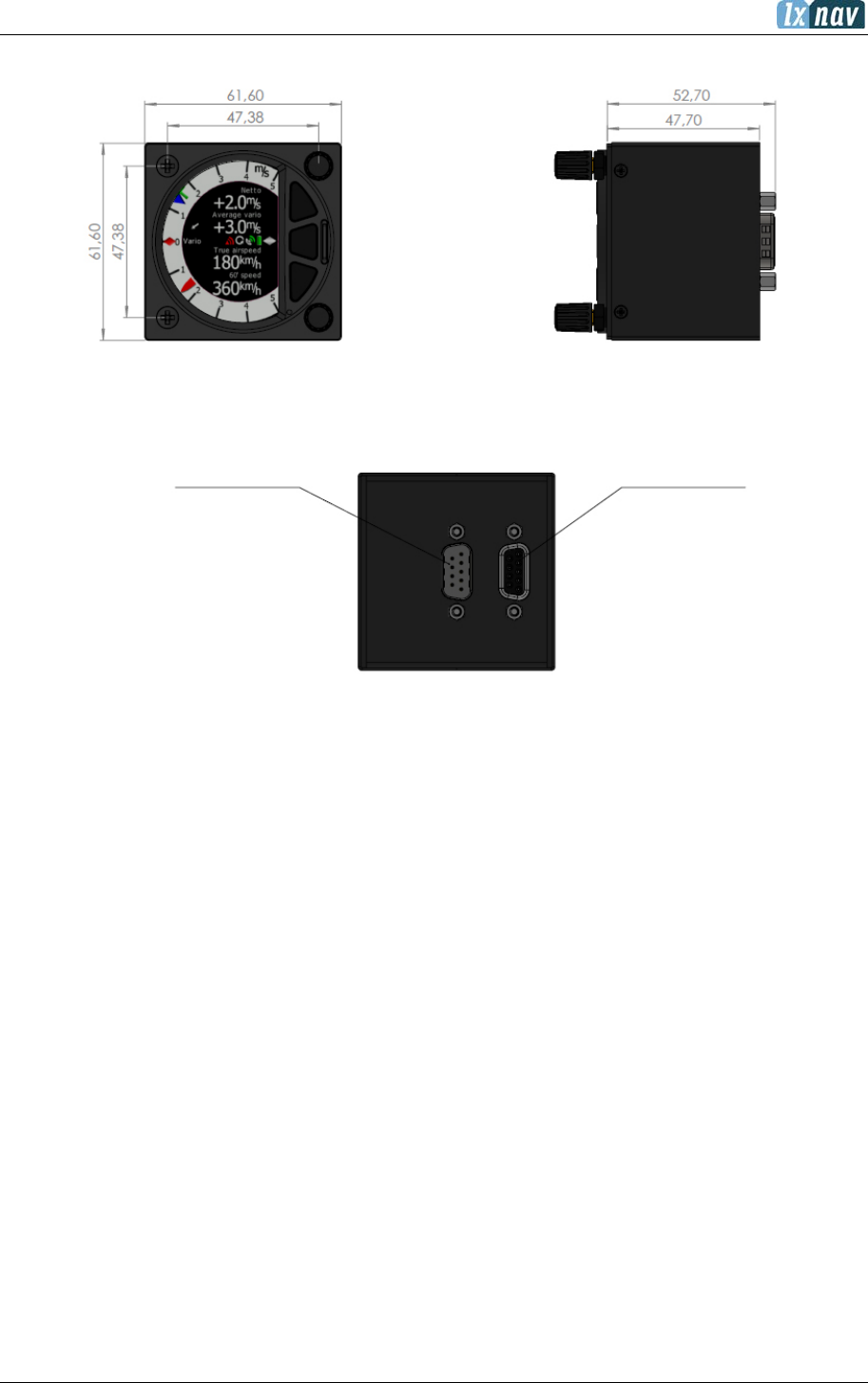
8.3.1 Cut-out for S8 and S10 89
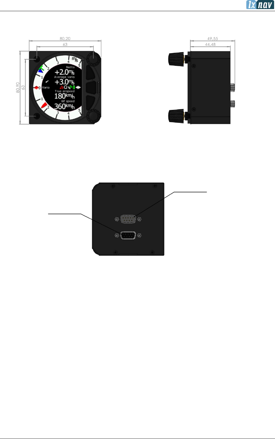
8.3.2 Cut-out for S80 and S100 89
8.4 Available Cables for GPS/Flarm and PDA Ports 90
8.5 Installation of Options 91
91
8.5.1 S8xD Option (Repeater) 91
Data Exchange 92
8.5.2 Magnetic Compass (Compass – CAN) 93
8.5.3 Flap sensor (Flap – CAN) 93
8.5.4 Remote Stick (Remote-CAN) 93
8.5.5 AHRS Option 94
8.6 Ports and Wiring 95
8.6.1 LXNAV S8x Ports 95
PDA Port (RJ45) 95
GPS Port (RJ12) 96
Main Port 96
Audio Port 96
8.6.2 Wirings 97
LXNAV S8X Wiring 97
LXNAV S10x Wiring 97
LXNAV S8xD Wiring 98
8.7 S8x/S10x Configurations 99
8.7.1 Symbols 99
8.7.2 Nano/Nano3 – Sxxx - MiniMap 99
8.7.3 Nano3 - Sxxx - Oudie 99
8.7.4 Colibri II – Sxxx - Oudie 100
8.7.5 Colibri/Volkslogger - Sxxx - Oudie 100
8.7.6 Flarm – Sxxx - FlarmViewX - Oudie 101
8.7.7 FlarmMouse - ADSB – Sxxx - FlarmView - Oudie 101
8.7.8 FlarmMouse – Sxxx - Oudie 102
8.7.9 FlarmMouse - Nano3 - Sxxx - Oudie 102
8.7.10 PowerMouse + (Nano3) - Sxxx - Oudie 103
8.7.11 S8x/S10x– S8xD 103
8.8 Data Transfer 104
8.8.1 S8x/S10x 104
8.8.2 Other Data Transfers 104

June 2018
Page 6 of 108
9 Firmware Update 105
9.1 Updating LXNAV S10x and S8x Firmware Using a Micro SD Card 105
9.2 Updating LXNAV S8x Firmware Using a Micro SD Card (up to fw. 5.43) 105
9.3 Updating LXNAV S8x Firmware Using a Micro SD Card (OLD Method) 105
9.4 Incomplete update message (OLD version) 106
10 FAQ 107
11 Revision History 108
June 2018
Page 7 of 108
1 Important Notices
The LXNAV S8x/S10x system is designed for VFR use only as an aid to prudent navigation. All
information is presented for reference only. Terrain, airports and airspace data are provided
only as an aid to situation awareness.
Information in this document is subject to change without notice. LXNAV reserves the right
to change or improve their products and to make changes in the content of this material
without obligation to notify any person or organization of such changes or improvements.
A Yellow triangle is shown for parts of the manual which should be read carefully
and are important for operating the LXNAV S8x/S10xsystem.
Notes with a red triangle describe procedures that are critical and may result in
loss of data or any other critical situation.
A bulb icon is shown when a useful hint is provided to the reader.
A cloud icon is shown when this functionality is supported only on S10x-systems.
1.1 Limited Warranty
This LXNAV S8x/S10x product is warranted to be free from defects in materials or workmanship
for two years from the date of purchase. Within this period, LXNAV will, at its sole discretion,
repair or replace any components that fail in normal use. Such repairs or replacement will be
made at no charge to the customer for parts and labour, the customer shall be responsible for
any transportation cost. This warranty does not cover failures due to abuse, misuse, accident,
or unauthorized alterations or repairs.
THE WARRANTIES AND REMEDIES CONTAINED HEREIN ARE EXCLUSIVE AND IN LIEU OF ALL
OTHER WARRANTIES EXPRESSED OR IMPLIED OR STATUTORY, INCLUDING ANY LIABILITY
ARISING UNDER ANY WARRANTY OF MERCHANTABILITY OR FITNESS FOR A PARTICULAR
PURPOSE, STATUTORY OR OTHERWISE. THIS WARRANTY GIVES YOU SPECIFIC LEGAL
RIGHTS, WHICH MAY VARY FROM STATE TO STATE.
IN NO EVENT SHALL LXNAV BE LIABLE FOR ANY INCIDENTAL, SPECIAL, INDIRECT OR
CONSEQUENTIAL DAMAGES, WHETHER RESULTING FROM THE USE, MISUSE, OR INABILITY
TO USE THIS PRODUCT OR FROM DEFECTS IN THE PRODUCT. Some states do not allow the
exclusion of incidental or consequential damages, so the above limitations may not apply to
you. LXNAV retains the exclusive right to repair or replace the unit or software, or to offer a
full refund of the purchase price, at its sole discretion. SUCH REMEDY SHALL BE YOUR SOLE
AND EXCLUSIVE REMEDY FOR ANY BREACH OF WARRANTY.
To obtain warranty service, contact your local LXNAV dealer or contact LXNAV directly.
March 2018 © 2018 LXNAV. All rights reserved.

June 2018
Page 8 of 108
2 Packing Lists
• LXNAV S8x or S10x main unit
• Main power cable for S8x/S10x + CAN terminator
• Speaker
• GPS cable (S7-GPS-IGC included, other types optional, this cable is included only with the
S8x device)
• PDA cable (optional)
• 2x6 mm screw
• Bluetooth antenna
• GPS antenna
• Barogram calibration chart
Second Seat:
• Main S8xD unit
• Y cable splitter (optional, only with compass or remote stick)
• Main 3m CAN cable

June 2018
Page 9 of 108
2.1 S80 (80mm) Variometer Unit
TE
P Total
P Static
Audio jack
GPS/Flarm port
Main power
June 2018
Page 10 of 108
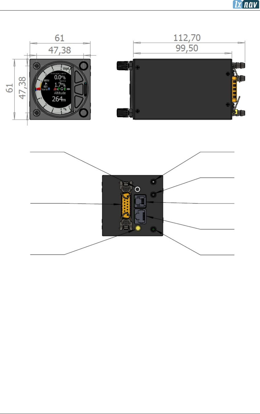
2.2 S8 (57mm) Variometer Unit
TE
PDA port
GPS/Flarm port
P Total
P Static
Audio jack
Main power
NOT IN USE
June 2018
Page 11 of 108
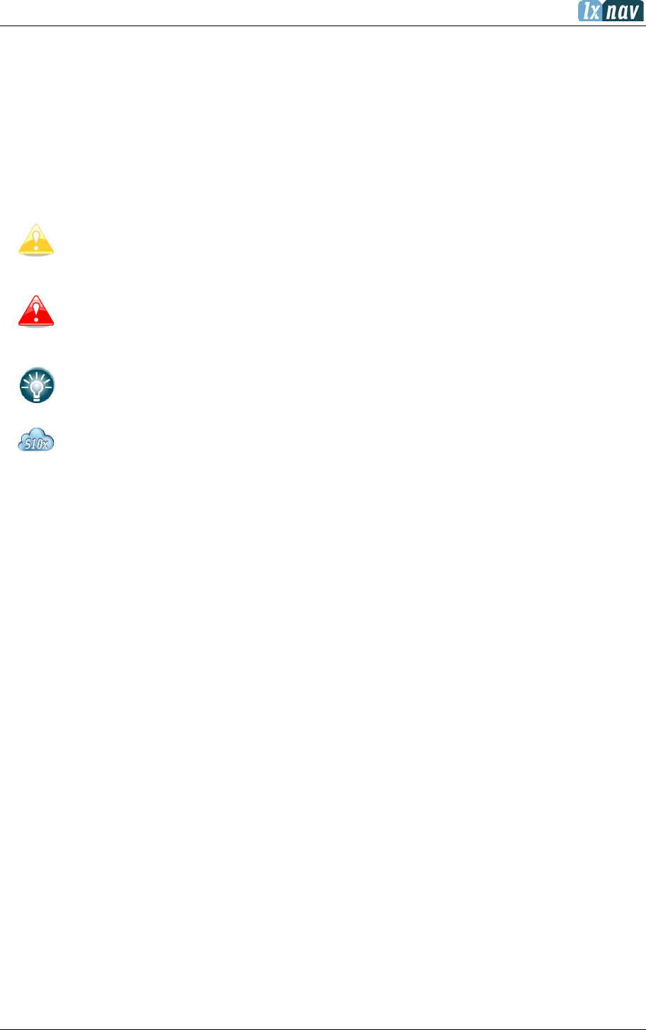
2.3 S10 (57mm) Variometer Unit
P Total
P Static
TE
GPS Antenna
Audio jack
Bluetooth antenna
GPS/Flarm port
Main power
PDA port
NOT IN USE
June 2018
Page 12 of 108
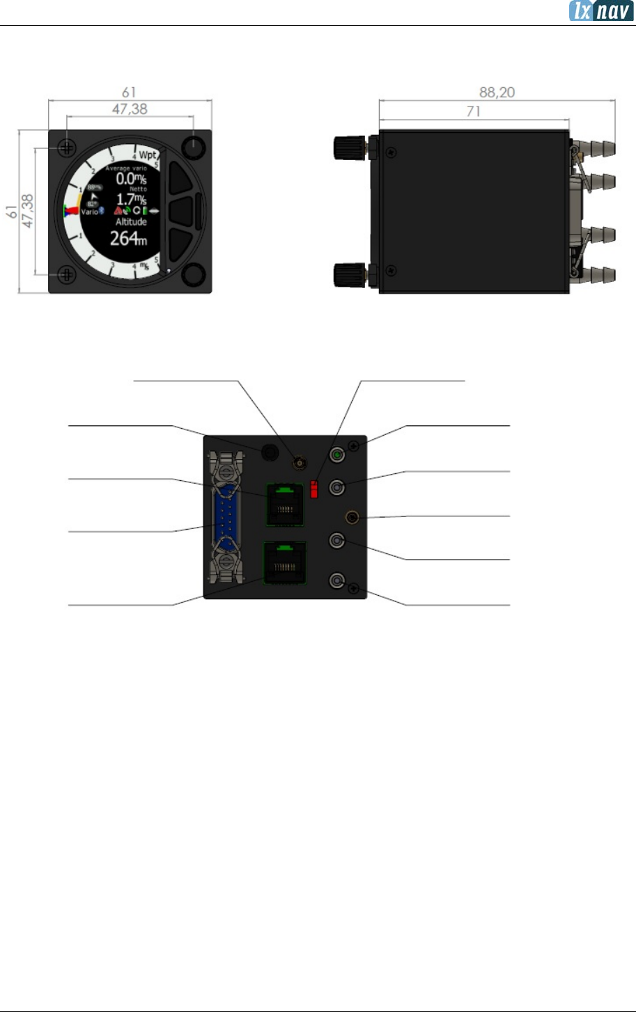
2.4 S100 (80mm) Variometer Unit
P Static
Main power
GPS antenna
Audio jack
GPS/Flarm port
PDA Port
P Total
TE
Bluetooth antenna
NOT IN USE
June 2018
Page 13 of 108
2.5 S8D Repeater Unit
CAN
CAN
June 2018
Page 14 of 108
2.6 S80D Repeater Unit
CAN
CAN
June 2018
Page 15 of 108
3 Basics
3.1 LXNAV S8x/S10x at a Glance
The LXNAV S8x/S10X is a standalone digital variometer, final glide calculator and navigation
system with a simple moving map. The LXNAV S8x/S10x has both GPS/Flarm and PDA/PNA
input/output. The unit has standard dimensions that will fit into a glider panel with an opening
of 80 mm diameter (3.15”) or 57 mm diameter. It is also able to supply a PDA/PNA with power
(5VDC/1A). The unit has an integrated high precision digital pressure sensor and inertial
system. The sensors are sampled more than 100 times per second. Real Time Data is
displayed via a vario needle, an airspace map and up to 4 variable number fields displayed on
a QVGA 320x240 pixel, 3.5-inch (S80/S100) or 2.5-inch (S8/S10), high brightness (1200 nits)
colour display. To adjust values and settings the LXNAV S8x/S10x has two rotary push button
knobs and three additional push buttons.
The LXNAV S8x/S10x can be expanded with one or more repeaters (LXNAV S8x/S10x) via the
CAN bus. This allows both pilots in a two-seat glider to have independent control of all
functions of each unit in the front or the rear seat.
The S10x unit includes a built-in IGC-approved flight recorder, a Bluetooth module
and its own backup battery which provides from 3 to 4.5 hours of independent
operation.
June 2018
Page 16 of 108
3.2 LXNAV S8x/S10x Features
• An extremely bright 3.5’’ (S80/S100) or 2.5” (S8/S10) QVGA colour display readable in
all sunlight conditions with the ability to adjust the backlight.
• Two rotary switches (knobs) with push button function and three push buttons are
used for input.
• Pre-loaded polar database for nearly all gliders.
• GPS/Flarm and PDA/PNA input/output.
• Flarm Indication if a Flarm is connected to the GPS/Flarm port.
• Programmable “needles” for selectable data such as netto vertical speed, relative
(super netto) and vertical speed (vario).
• 320x240 pixels colour screen for additional information such as average, thermal vario,
time, speed etc…
• Many custom audio settings.
• 100Hz sampling rate for very fast response.
• Speed to fly indication.
• TE compensation can be selected to be either pneumatic TE probe or electronic TE.
• Audio equalizer, for custom vario sound performance.
• Audio thermal assistant.
• Built-in high level, IGC-approved flight recorder.
• Built-in Bluetooth module.
• Backup battery.
• Engine noise level sensor (ENL).
• Built-in GPS module.
3.2.1 Interfaces
• GPS/Flarm port input/output on RS232 level (RJ12 connector, none-Standard IGC)
(12V/2A)
• PDA port input/output on RS232 or TTL level for PDA/PNA devices with 5V power supply
(8 pin RJ 45, 5V / 1A).
• Audio port (Standard 3mm phone jack).
• 1Mbit CAN bus for extension to S8xD repeater or Remote stick (CAN remote).
3.2.2 Options
By using a CAN bus system, a second seat device can be connected. The unit installed in the
rear seat of the glider is independently powered and receives all the necessary data from the
main unit. The communication between both units is exclusively via the CAN bus system
(Remote stick, Compass module, Second seat device).
3.2.3 S8/S80 Club
S8 Club and S80 Club are special price performance editions of basic S8 and S80 units.
Following features are optional on this device: Task mode (see chapter 5.6), Digital inputs
(see chapter 5.7.11.1), Pilot profiles (see chapter 5.7.12) and Airspaces (see chapter
5.7.6.2). Every option can be upgraded separately at any time. For purchasing additional
options please contact LXNAV.
Device:
S8
S8 Club
S80
S80 Club
TASK mode
Yes
Optional
Yes
Optional
Airspace
Yes
Optional
Yes
Optional
Digital inputs
Yes
Optional
Yes
Optional
Pilot profiles
yes
Optional
Yes
Optional
June 2018
Page 17 of 108
3.2.4 Technical Data
Power input 10-16 V DC.
Power Consumption
Device
Min. Brightness (mA)
Max. Brightness (mA)
S8
140
190
S8D
90
140
S80
140
190
S80D
90
140
S10
170
200
S100
190
250
Size and Weight
Device
Size
Weight (g)
S8
57 mm cut-out
61x61x95mm
339
S8D
57 mm cut-out
61x61x48
210
S80
80 mm (3.15") standard aircraft cut-out
81x81x132mm
460
S80D
80 mm (3.15") standard aircraft cut-out
81x81x45mm
290
S10
57 mm cut-out
61x61x70mm
348
S100
80 mm (3.15") standard aircraft cut-out
81x81x64mm
515
June 2018
Page 18 of 108
4 System Description
4.1 Push Button – Rotary Switches
The two Rotary switches also have a push button function. The LXNAV S8x/S10x detects short
or long presses of the push button. A short press means just a click, a long press means
pushing the button for more than one second.
4.1.1 Power Button
The system is powered up by pressing any of the push buttons or a press of either of the
rotary knobs. A long press of the upper rotary knob will turn the S8x/S10x off. Use this
instead of the avionics master switch.
4.2 Rotary Switches
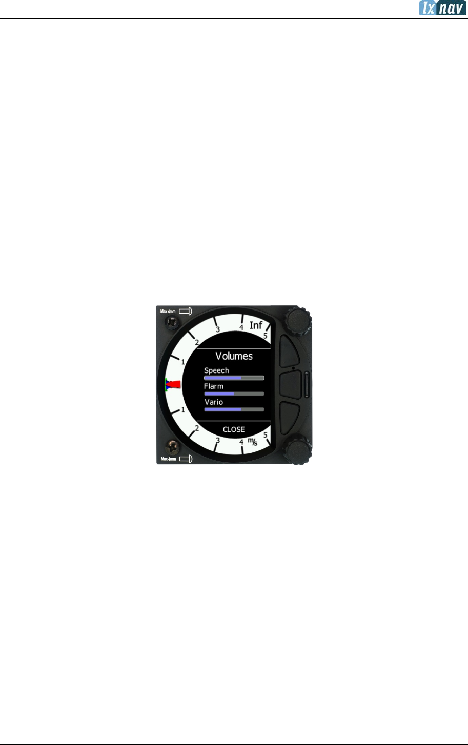
The upper rotary knob is designed for direct volume control. A short-press on the upper rotary
knob will produce an option to select between options and adjust volumes for the Vario, Speech
and Flarm beep.
A long-press on the upper rotary knob will shut down the system cleanly.
The lower rotary knob is used to adjust settings within the current mode or within menus.
With the lower rotary push button, it is possible to toggle between the MC and the Ballast and
Bugs settings. In all other menus this knob is used for setting values and editing texts.
June 2018
Page 19 of 108
4.3 Buttons (Three)
The three buttons between the two rotary knobs have fixed functions. The top button is ESC
(CANCEL), the middle is to switch between modes and the lower button is the ENTER (OK)
button. The upper and lower buttons are also to rotate between subpages in the WPT and
TSK modes.
4.4 Switching on the Unit
Pressing any of the buttons or rotary knobs will turn on the S8x/S10x. The first LXNAV
welcome screen will appear with the system information (Device name, Version, Serial
number...)
The S8xD rear seat unit cannot be powered up before the S8x/S10x has been
powered up.
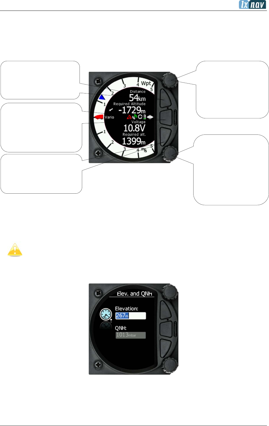
When the boot procedure is completed the setup elevation dialogue will be displayed.
The user must set either the Elevation or the QNH with the lower rotary button. After pressing
the lower rotary button, the user can switch between the Elevation and QNH dialogues. As
soon as the settings are set the middle button must be pressed to proceed.
Rotary switch with
push button
Enter and operate
only in the volume
menu
Rotary switch with
push button used
for:
Adjusting the level of
the zoom
Enter/confirm the
selection/function
Push button used for:
• Mode selection
•
Confirm option
in some menus
Push button used for:
•
Switch between
modes
•
Exit from the
menu
Push button used for:
• Mode selection
• Confirm option in
some menus
June 2018
Page 20 of 108
The upper push button also has the power OFF function.
4.5 User Input
The LXNAV S8x/S10x user interface consists of dialogues which have various input controls.
They are designed to make the input of names, parameters, etc., as easy as possible. Input
controls can be summarized as:
• Text editor
• Spin controls (Selection control)
• Checkboxes
• Slider control
To move the function from one control to another, rotate the lower rotary knob as follows:
• Clockwise rotation will select the next control.
• Counter clockwise rotation will select the previous control. The lower PUSH button enters
the selected feature.
• Faster rotation of the rotary knob will increase the rate at which the value changes i.e.
bigger steps in value.
4.5.1 Text Edit Control
The Text Editor is used to input an alphanumeric string; the picture below shows typical options
when editing text/numbers. Use the lower rotary knob to change the value at the current
cursor position.
Once the required value is selected, press the lower push button to move to the next character
selection. To move back to the previous character, press the upper push button. When you
have finished editing, press the Enter key – the lower rotary button. A short press of the
middle push button exits from the edited field (“control”).
Rotate the rotary
knob to change the
value
Press the push
button to move to
the next character

June 2018
Page 21 of 108
4.5.2 “Spin” Control
“Spin” controls are designed for numeric parameters. Rotate the knob to increase/decrease
the selected value. To increase a value in larger steps, spin the lower rotary knob faster.
4.5.3 Selection Control
Selection boxes, also known as combo boxes, are used to select a value from a list of
predefined values. Use the lower rotary knob to scroll through the list.
4.5.4 Checkbox and Checkbox List
A checkbox enables or disables a parameter. Press the lower rotary knob to toggle the value.
If an option is enabled a check mark will be displayed, otherwise an empty rectangle will be
displayed.
June 2018
Page 22 of 108
4.5.5 Slider Selector
Some values, such as volume and brightness, are displayed as a slider icon.
With a push of the lower rotary button you can activate the slide control and then by rotating
the knob you can select the preferred value and confirm it via the push button.
4.6 Switching Off
You will lose your settings if you power down the S8x via the panel master-power switch.
S10x will shut down properly, when switching down master – power switch.
To archive your settings, shut down with a long-press of the volume (top) knob.
All settings are saved during the power off procedure. We strongly recommend
switching off the unit by using a long-press of the (top) knob.
If the system is powered off via the master switch, changed data will not be saved.
Flight parameters at take-off such as target altitude and position will remain in the
stored memory so that your final glide calculations are not affected.
June 2018
Page 23 of 108
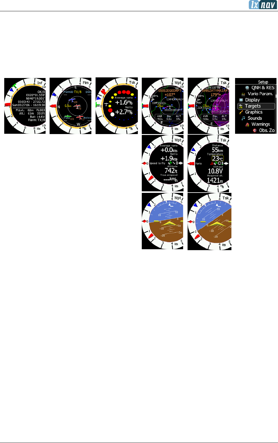
5 Operating Modes
The LXNAV S8x/S10x has five operating modes. The middle (Menu) push button toggles
through the 5 display modes in a circular way. The diagram below shows the mode structure
of the LXNAV S8x. With the upper and lower buttons, it is also possible to shift between
subpages.
Info Mode
Flarm Mode
Thermal Mode
Waypoint Mode
Task Mode
Setup Mode
• Info Mode: Contains the GPS data, Altitude, Battery and Sunset time, OAT.
• Flarm Mode: Showing Flarm targets in range (if a Flarm device is connected to the GPS
port).
• Thermal Mode: Showing a thermal assistant during circling (S8x only if a GPS source is
present).
• Waypoint Mode: Simple navigation screen to a waypoint plus subpages (S8x only if a
GPS source is present).
• Task Mode: Task screen showing the task and airspace plus subpages (S8x only if a GPS
source is present).
• Setup Mode: For all aspects of the setup of the S8x/S10x.
5.1 Quick Access Menus
For each mode a quick access menu is available, which varies from mode to mode. Items
available in quick access menus are:
• MC/BAL (In all modes)
• Reset G (In all modes)
• Edit target (only Flarm page)
• Flarm traffic (only Flarm page)
• Navboxes (Only in THM, TASK and WPT mode)
• SideBar

June 2018
Page 24 of 108
• Select (Only in WPT mode)
• Select Near (Only in WPT mode)
• Send WPT
• Event
• Night
• Edit Task (only in task mode)
• Start (only in task mode)
• Next (only in task mode, visible only after pressing start)
• Restart (only in task mode, visible only after pressing start)
• Options (only in TSK mode)
• Load (only in TSK mode)
• Save (only in TSK mode)
• Wind (only in WPT and TSK mode)
5.1.1 MC/BAL
To change the McCready value press the bottom rotary knob and press on MC/BAL. A short
press of the lower rotary knob moves from McCready to the Ballast box and pressing the lower
rotary knob again will open the Bugs box. If no action is performed within 3 seconds, the box
will close, or you can also press CLOSE anytime (lower push button).
5.1.2 Reset G
“Reset G” is a method of re-setting the “G” meter if configured as the yellow bar on the vario
scale.
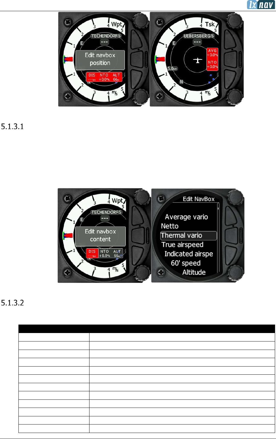
5.1.3 Navboxes Option
Open the Quick Access menu by pressing the lower rotary knob and select Navboxes. Then
press the same knob to select number of navboxes visible on the screen. Pressing the enter
button will produce another option to select the position of navboxes (only in Wpt and Tsk
modes), which can be located vertically or horizontally. The final step is a selection of the
navbox to be displayed in the selected navbox.
June 2018
Page 25 of 108
Editing navboxes
Selecting the navboxes option and then pressing the lower rotary knob will allow you to select
one of the three boxes by rotating the same knob followed by a short press. You can then
select the required data for the highlighted navbox. A short press of the lower rotary knob
selects the desired setting and returns you to the navbox selection.
Pressing the EXIT (middle) button at any time saves the setting and moves to the main mode.
Navboxes with description
List of available navboxes:
Type
Description
60’ speed
Average speed for last hour
Altitude
Altitude in user defined units
Altitude (ft)
Altitude in Feet
Altitude (IGC)
IGC altitude (not available in S8/S80 units)
Arrival altitude
Arrival altitude on target
ArrMc0
Arrival altitude on target with Mc=0
Average Netto
Average vertical movement of air mass
Average vario
Average vario (average vario time can be set)
Bearing
Bearing to the target if GPS is present
Distance
Distance to the target
Emc
Calculated glide ratio at selected McCready value
Flap Current
Current flap position

June 2018
Page 26 of 108
Flap Requested
Requested flap position
Flight level
Flight level
Flight time
Airborne time
Ground speed
Speed over ground, taken from GPS
Heading
Heading (from compass)
Height
Height is the vertical distance above take off position
Indicated airspeed
IAS
Inverse alt
Altitude in opposite unit
Inverse distance
Distance to the target in opposite unit
MacCready
McCready setting
Netto
Vertical speed of air mass
RDL
On radial of selected target
reqE
Required glide ratio to the target
Required alt.
Required altitude to real target elevation (without safety
altitude taken in account)
Speed2Fly
Calculated speed to fly from MC setting
Steering course
Steering course to the target
tArrMc0
Arrival altitude on task finish with Mc=0
Task distance
Flown distance on task
Task E
Required glide ratio to task finish
Task remain
Remaining distance of task
Temperature
OAT – Outside air temperature
Thermal vario
Average vario from beginning of circling (Green T)
Time
Local time Offset can be adjusted under Setup-Units
Total Alt.
Altitude which considers also the kinetic energy
Track
Track over ground taken from GPS
True airspeed
TAS
Voltage
Voltage of power supply
Wind
Wind direction and speed
Wind comp.
Wind component
xTrk
Off distance from the task leg
Safety altitude has no influence to required alt calculation!
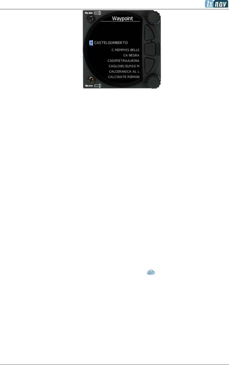
5.1.4 Select / Select Near (Only in WPT mode)
To Select a waypoint, rotate the lower rotary knob to highlight the select option and then
press once. This will open the Waypoint list.
June 2018
Page 27 of 108
The waypoint can be selected from the alphabetical list of waypoints (see uploading files
section 5.7.13.1). Rotating the lower rotary knob moves you through the waypoint list in
alphabetical order, clockwise increases the value, counter-clockwise decreases the value. To
select the first letter of the desired waypoint, rotate the lower rotary knob, then press the
lower push button to move to the next selection of the letter. Rotate the lower rotary knob
until the second letter of the required waypoint is highlighted and then repeat the process until
the required waypoint is the only selection available. Press enter (lower rotary button) to
select the waypoint. The screen will then change back to the navigation mode and show a
line to the waypoint, waypoint name and the relative bearing.
Select Near is to select a WPT from the list which is sorted by distance from the current
location. Selection of a WPT is the same as described above.
5.1.5 Edit Target
The user can edit the Flarm target details.
5.1.6 Flarm Traffic
This mode shows all available Flarm traffic around the glider with their FLARM ID codes; the
user can also edit all Flarm object data.
5.1.7 Event
Event is used to log an event. The recording rate will be increased to 1 second for one minute.
A message
“Event marked”
will be displayed on the screen.
5.1.8 Night
Selecting night will cause the unit’s brightness to be decreased to its minimum. Pressing again
on “night” will reset the brightness to the value defined under settings.
5.1.9 Edit Task (Only in Task Mode)
Selecting edit task via a short press of the lower rotary knob will enter the task editing screen.
The first time you edit a task it will be blank. A short press of the lower rotary knob will open
another menu with the option to:
• Insert,
June 2018
Page 28 of 108
• Edit,
• Delete,
• Zone.
Selecting Insert will allow you to enter a waypoint from the list as a start point. Rotating the
lower rotary knob moves you through the waypoint list in alphabetical order, clockwise
increases the value, counter-clockwise decreases the value. To select the first letter of the
desired waypoint, rotate the lower rotary knob, then press the lower push button to move to
the selection of the next letter. Rotate the lower rotary knob until the second letter of the
required Waypoint is highlighted and then repeat the process until the required waypoint is
the only selection available. Press enter (lower rotary button) to select the Waypoint. Once
the start point is selected, rotate the lower rotary knob clockwise and click to select the second
turn point. Edit the second turn point as above. Repeat for all the points in the task. When
you have completed editing the task, press the (middle) button to save the task and return to
the Task navigation mode.
You can also change the Observation zone from the defaults for each Waypoint. To do this
select EDIT TASK->select waypoint in the task and then press the lower rotary knob. The
quick access menu allows you to insert, edit, delete or change the zone for the Waypoint. If
you select Zone you can modify the zone for that specific waypoint only.
5.1.10 Start Task (only in Task Mode)
Selecting start followed by a short press of the lower rotary knob will start a task.
5.1.11 Restart Task (only in Task Mode)
Selecting restart followed by a short press of the lower rotary knob will restart the task.
5.1.12 Next Waypoint (only in Task Mode)
Selecting next followed by a short press of the lower rotary knob will advance the task to the
next waypoint in the task.
5.1.13 Send WPT
With pressing that option, selected waypoint will be sent to SxxxD unit.

June 2018
Page 29 of 108
5.1.14 Sidebar
In the Sidebar menu, a user can select between the different sidebars options that can be
displayed on the page. (Classic Speed to Fly-push/pull bar, Flaps tape, Speed tape and
combined Speed & Flap tape).
5.1.15 Options
In this menu you can enable/disable navigation to the nearest point. Only in task mode.
5.1.16 Load/Save
In the Load menu you can create files to load on the instrument or you can upload them to
the instrument via the SD card. To save currently active task select Save in the quick access
menu.
5.1.17 Wind
Here you can switch between automatic wind calculation by instrument or setting wind
parameters yourself. When Wind calculation is disabled you can manually set wind speed and
direction.

June 2018
Page 30 of 108
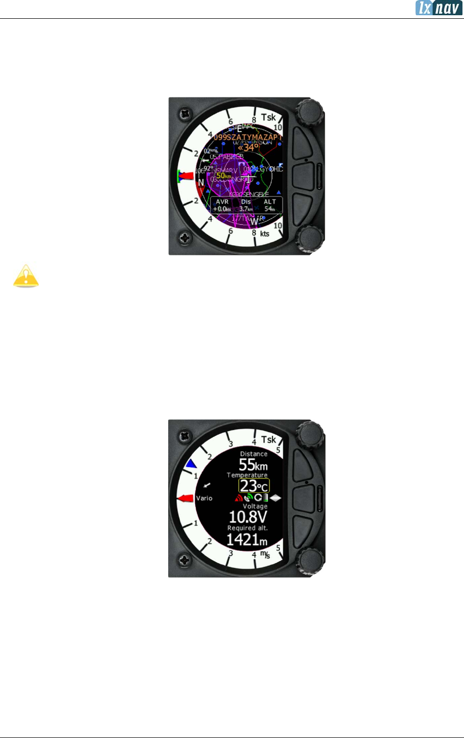
5.2 Info Mode
The Info Mode gives you a snapshot of the GPS position, date and time along with Flight level,
altitude, Battery and Flarm status. The Flight Level equivalent is also available in meters or
feet as is the Altitude navbox.
Description:
• Logger status is display as Stop or Run. You can also set logger to be always turned
on (see chapter 5.7.2.4)
• The GPS status is displayed as OK, BAD, NODATA together with the number of
satellites.
• Latitude and longitude
• Local time and date
• Sunrise and sunset time.
• Flight level also in meters
• Altitude in meters and ft
• Battery status
• Flarm status (TX – transmits data / and a number of received Flarms)
• OAT – outside air temperature
• GFL – G-force levels. Minimum and maximum recorded G-force level
5.2.1 Quick Access Menu
A short press of the (lower) rotary button activates the Quick Access menu. Refer to Section
5.1 for details of the Quick Access menu.
June 2018
Page 31 of 108
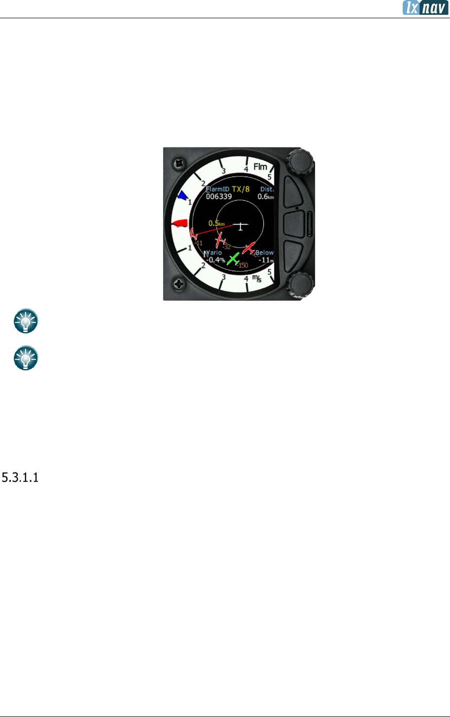
5.3 Flarm Mode
If the S8x/S10x is connected to a Flarm source via the GPS port (in the S10x called the Flarm
port) then the Flarm Mode will display a map of the relative positions of Flarm targets that are
within range. By rotating the lower rotary knob, you can change the range of the display from
0.5 km to 150 km. Switching between Flarm targets is possible via the up/down button. Data
from a selected Flarm object can be seen in 4 corners, such as: Flarm Id, Distance, Vario and
Relative altitude (Above / Below). There is also an indication of how many Flarm objects are
present displayed as: TX/number.
This mode can be disabled via Setup->graphics->modes->Flarm mode.
Distance, relative altitude and vario indications are related to the selected target.
5.3.1 Quick Access Menu
A short press of the lower rotary button activates the Quick Access menu. Refer to Section
5.1 for details of the Quick Access menu.
Edit Target
The user can edit the following Flarm objects data:
• Flarm ID
• Competition sign
• Pilot
• Aircraft type
• Registration
• Airfield
• Communication frequency (object’s communication frequency)
These settings can be accessed by pressing the lower rotary button, selecting EDIT target and
then modifying the data of interest.

June 2018
Page 32 of 108
Flarm Traffic
All Flarm objects in range are displayed in this mode. The following details are shown:
• Flarm target ID
• Relative distance
• Vertical speed (vario data from the object)
• Relative altitude
If you press on the selected Flarm target you can enter the edit target menu where you can
insert a target’s data.
5.3.2 Flarm Warnings
Regardless of which Mode you are in, if a Flarm target triggers an urgent (third warning level)
or important (second warning level) warning then the screen will change to the Flarm warning
mode automatically.
Extract from the Flarm manual:
Warnings are given in order of the time remaining before a potential collision, not the geometrical
distance. The first warning level for another aircraft or an obstacle is delivered at less than 19 - 25
seconds before the possible collision; the second warning level is delivered at less than 14 - 18 seconds
before; the third level at less than 6 - 8 seconds before.
The central number and chevrons indicate if the Flarm target is below or above and by how many
meters/feet. The number in the bottom right indicates the range in meters/feet.
The numbers are related only to the closest or the most dangerous target.
June 2018
Page 33 of 108
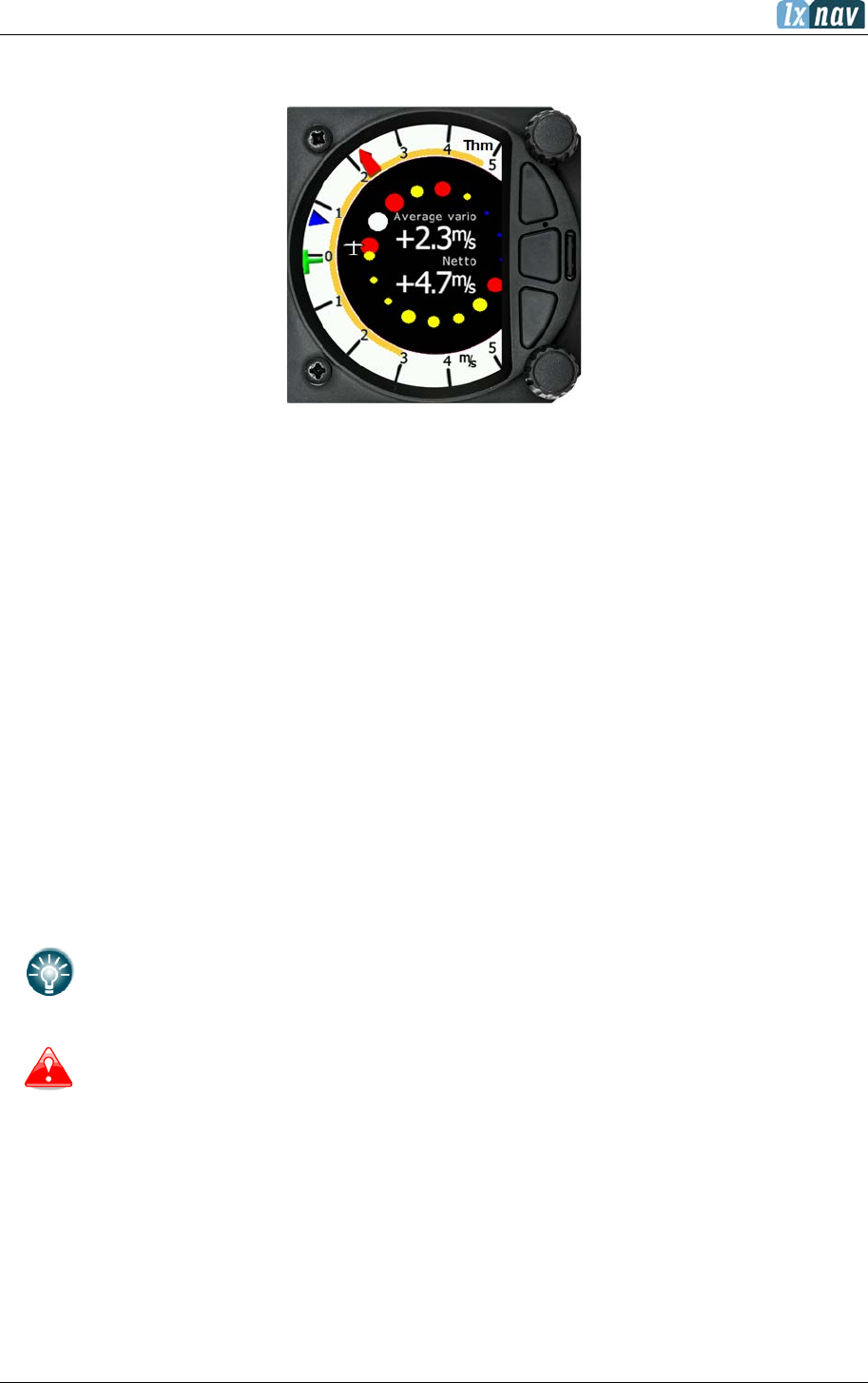
5.4 Thermal Assistant Mode
The Thermal Assistant mode displays a graphical representation of your location within the
thermal. If you are thermaling to the left, there will be an aircraft symbol on the right of the
ring of bubbles and the bubbles will appear to rotate clockwise (towards the symbol of the
glider). If you are in a right-hand thermal there will be an aircraft symbol on the left and the
ring of bubbles will appear to rotate anticlockwise (towards the symbol of the glider). Large
red bubbles indicate the strongest lift within the thermal and small blue dots indicate the
weakest lift or sink within the thermal. Yellow bubbles indicate lift equal to your MacCready
setting, average thermal or average climb rate depending on your preferred setting (refer to
Section 5.7.4.1). The point of strongest lift is indicated by a white large bubble.
You can use the thermal assistant, to visually determine which part of the thermal has the
strongest lift and adjust your turn accordingly to manoeuvre the glider in the direction of the
strongest lift and away from the weakest lift or sink.
The thermaling assistant can be set to automatically change to the Thermal assistant mode or
it can be manually selected. See Section 5.7.4.2 for settings.
The two navboxes within the Thermal Assistant Mode can be configured using the quick access
menu.
This page can be configured via: Setup->graphics->modes->thermal mode.
Look out of the cockpit!
Looking into thermal assistant might be life threating for you and other pilots in
the thermal.
5.4.1 Quick Access Menu
A short press of the (lower) rotary button activates the Quick Access menu. Refer to Section
5.1 for details of the Quick Access menu.

June 2018
Page 34 of 108
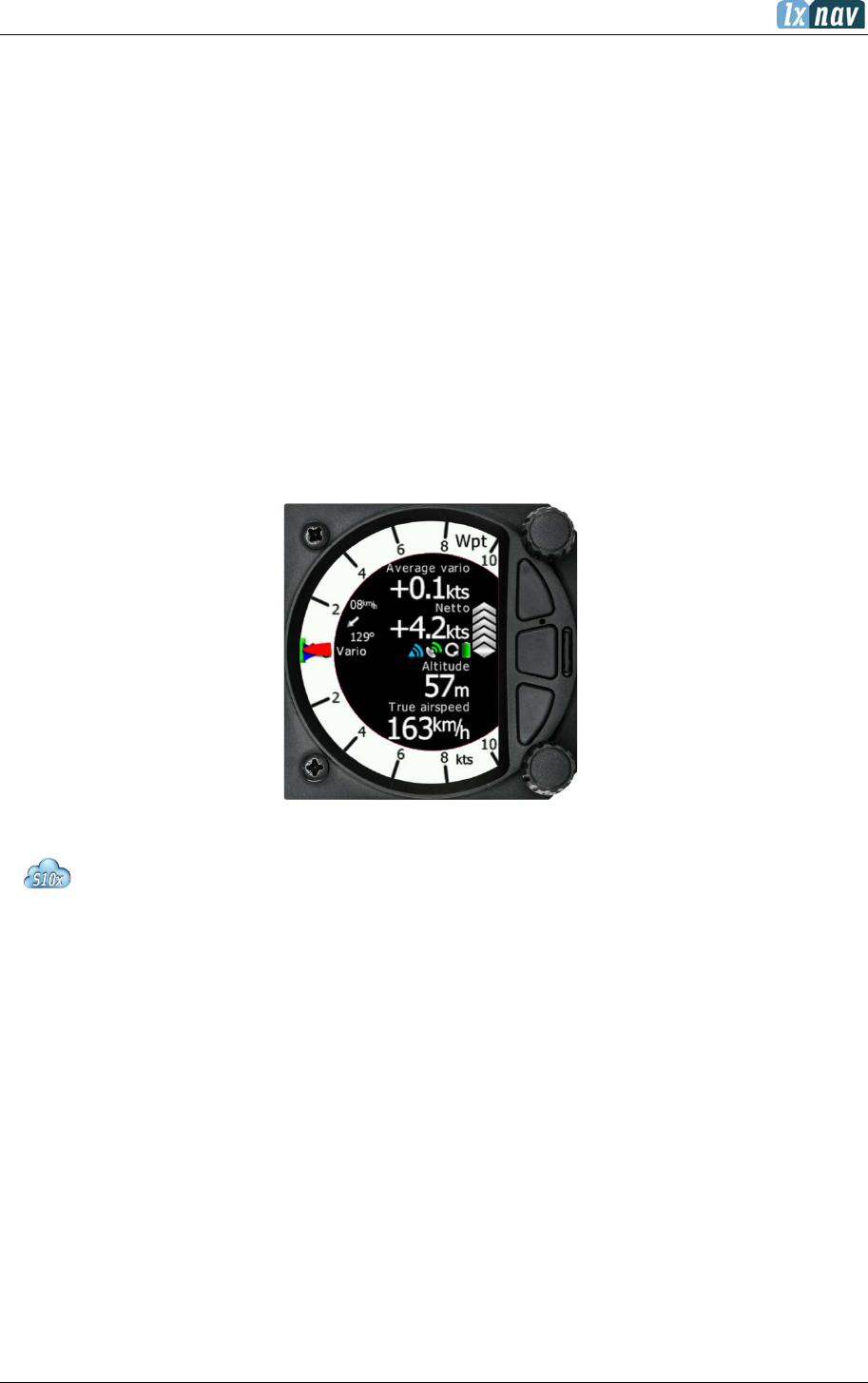
5.5 Waypoint Mode
The Waypoint mode is a quick access screen to provide simple navigation to a Waypoint or
Airport. By rotating the bottom rotary knob, you can vary the range of the display from 0.5 km
to 200 km.
The first page shows a line to a selected waypoint, the name of the selected waypoint at the
top of the screen and the relative bearing and chevrons indicating the direction to turn towards
the selected waypoint.
5.5.1 Quick Access Menu
A short press of the (lower) rotary button activates the Quick Access menu. Refer to Section
5.1 for details of the Quick Access menu.

June 2018
Page 35 of 108
5.5.2 Second Page Within Waypoint Mode (Numerical Data)
The Waypoint mode has a second page which contains numerical data. Defaults are 4
navboxes: Average Vario, Netto, Altitude and True Airspeed. In addition, the central line shows
the status of the Flarm, GPS, Cruise/Climb and battery status. This second page can be
selected by pressing the lower push button once. You can return to the Waypoint navigation
mode by pressing the upper push button (top button of the three).
• The Vario Needle can display: the Vario, Netto, Relative or Speed to fly value
(Setup->Hardware->Indicator). The scale can be chosen in the range of +/-5
+/-10 or +/-20 (in SETUP-> Vario Parameters). Within the software the range
can be set to m/s, kts, km/h, mph or fpm (in Setup, Units, Vertical speed)
• SideBar can be configured to display Speed to fly bar, Speed tape or flap tape.
o The Speed to fly bar symbol indicates which speed you must fly
relative to the current MacCready setting, sink rate and speed. One
arrow means 10 units of speed faster or slower. Up red arrows mean
fly slower and down blue arrows mean fly faster.
o Speed Tape represents the Indicated Air Speed (IAS) in speed tape
form. Depending on the speed setting’s (see Polar & Glider - Speeds).
The speed tape will change colour from green, yellow to red depending
on the settings and the IAS
o Flap Tape can display recommended flap position. If a Flap sensor is
present on the CAN bus, the flap tape will also display the actual flap
position.
• The Red diamond symbol can show Netto, Average Netto, Average vertical
speed or G-force.
• The Blue arrow symbol shows the current MacCready value.
• The Green T symbol represents last thermal average value.
• The Yellow Bar can show Max and Min values of vario over defined time
(average vario) or G meter (over whole flight).
Vario indicator needle
McCready setting
Last thermal average
Red diamond
Needle type
Wind vector
GPS status
Battery
Lower numbers
Range/units
Upper numbers
Climb/cruise simbol
Speed to fly simbol
Flarm status
Side bar
Yellow Bar (Min/Max
vario or Min/Max g-
force
June 2018
Page 36 of 108
• The Flarm Status symbol indicates the presence of a Flarm unit (grey), if the
Flarm receives any data from other Flarm units, the symbol becomes red.
• The GPS symbol is green when GPS status id is OK, and red when GPS status
is bad. If GPS data is not detected, the symbol will disappear.
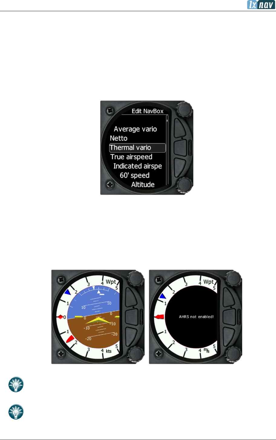
The numerical navboxes can be changed using the Quick Access menu with a short press of
the lower rotary knob followed by selecting navbox from the menu and a further short press
of the lower rotary knob. With the first navbox highlighted with a yellow border you can scroll
through the four navboxes using the lower rotary knob. Select the navbox you wish to change
with a short press of the lower rotary knob. This will open a list of available navboxes.
Select the required navbox and then save this with a short press of the lower rotary knob.
Repeat the process for any other navbox that needs to be changed.
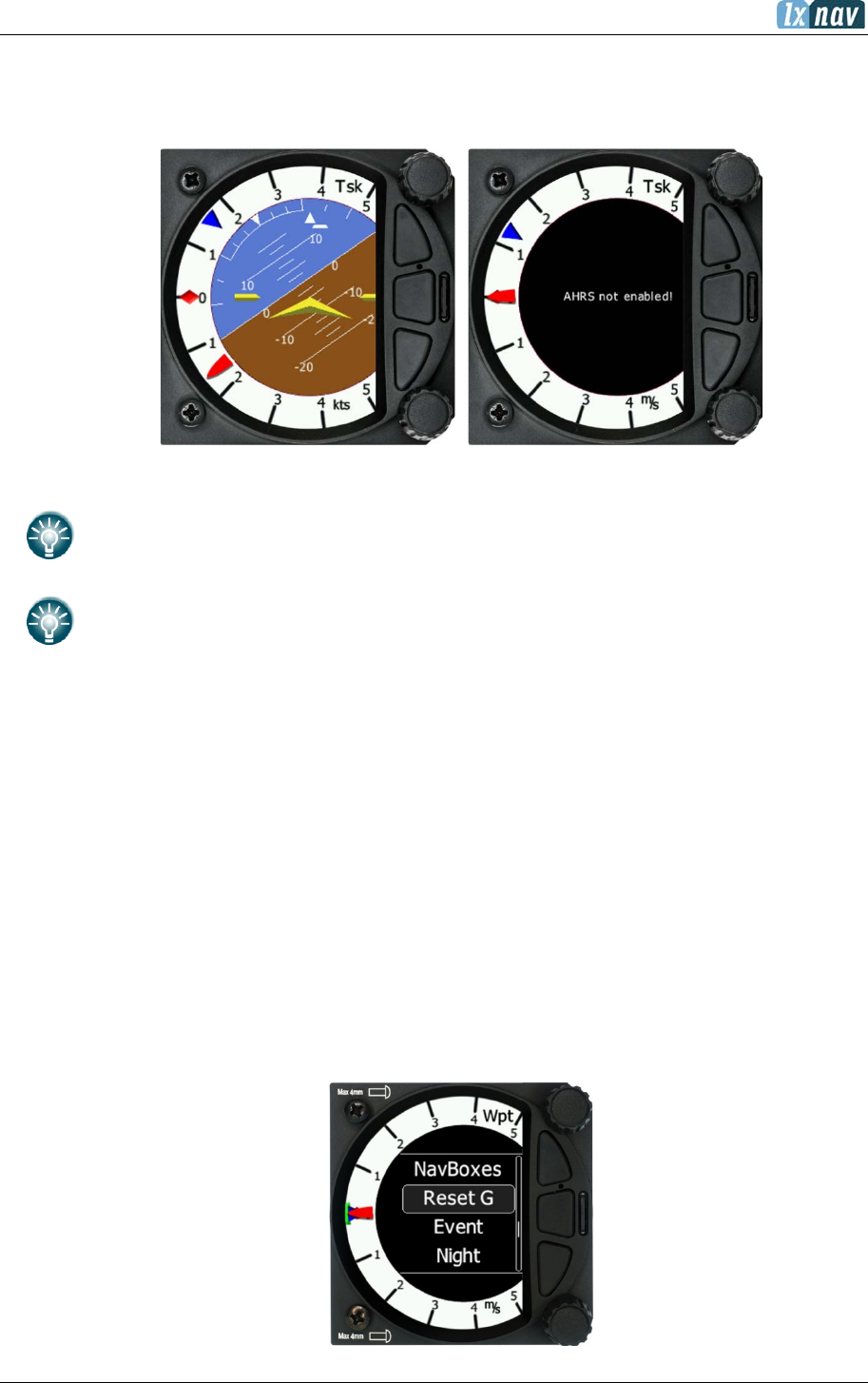
5.5.3 Third Page at Waypoint Mode (AHRS page)
The Waypoint mode has a third page which displays the AHRS (if this feature has been enabled
– refer to Section 8.5.5).
The Pitch offset can be adjusted via the lower rotary knob.
For competitions the artificial horizon can be disabled via the
Setup>Graphics>Modes menu. See Section (5.7.6) for more details. When the
artificial horizon page is active a
BFION event is written to recorded flight for
verification purposes.

June 2018
Page 38 of 108
5.6 Task Mode
The task mode can display a navigation page including airspace and a task. By rotating the
lower rotary knob, you can change the range of the display from 0.5 km to 200 km.
Task mode is not enabled on S8/S80 Club version. To purchase this option please
refer to chapter 3.2.3
5.6.1 Second Page Within Task Mode (Numerical Data)
The Task mode has a second page which contains numerical data. Defaults are Average Vario,
Netto, Altitude and True Airspeed. The central line also displays the status of the Flarm, GPS,
Cruise/Climb and battery. This second page can be selected by pressing the lower push button
once. You can return to the task navigation page by pressing the upper push button.
The navigation boxes in this second task page can be changed using the Quick Access menu
and selecting navbox. You can make changes to the navboxes as described in Section 5.1.3.
June 2018
Page 39 of 108
5.6.2 Third Page Within Task Mode (AHRS Page)
The Task mode has a third page which displays the AHRS (if this feature has been enabled,
refer to Section 8.5.5 for details).
The pitch offset can be adjusted with the lower rotary knob.
For competitions the artificial horizon can be disabled in the
Setup>Graphics>Modes menu. See Section 5.7.6 for more details. When the
artificial horizon page is active a BFION event is written to the recorded flight for
verification purposes.
5.6.3 Quick Access Menu
A short press of the lower rotary knob activates the Quick Access menu. Refer to Section 5.1
for details about the Quick Access menu. The following menus are available:
• MC/BAL
• Edit task
• Options
• Load
• Save
• Wind
• Navboxes
• Sidebar
• Reset G
• Event
• Night
June 2018
Page 40 of 108
Changing the Start, Edit task, MC/BAL is the same as Page 1 of the Task mode.
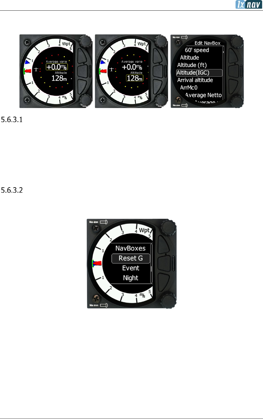
Editing navboxes
Selecting the navboxes option and then pressing the bottom rotary knob will allow you to
select one of the three boxes by rotating the lower rotary knob followed by a short press. You
can then select the required data for the highlighted navbox. A short press of the lower rotary
knob selects the desired setting and returns you to the navbox selection.
Pressing the EXIT (middle) button at any time saves the setting and moves to the main page.
Reset G
“Reset G” is a method of re-setting the “G” meter if configured as the yellow bar on the vario
scale.
June 2018
Page 41 of 108
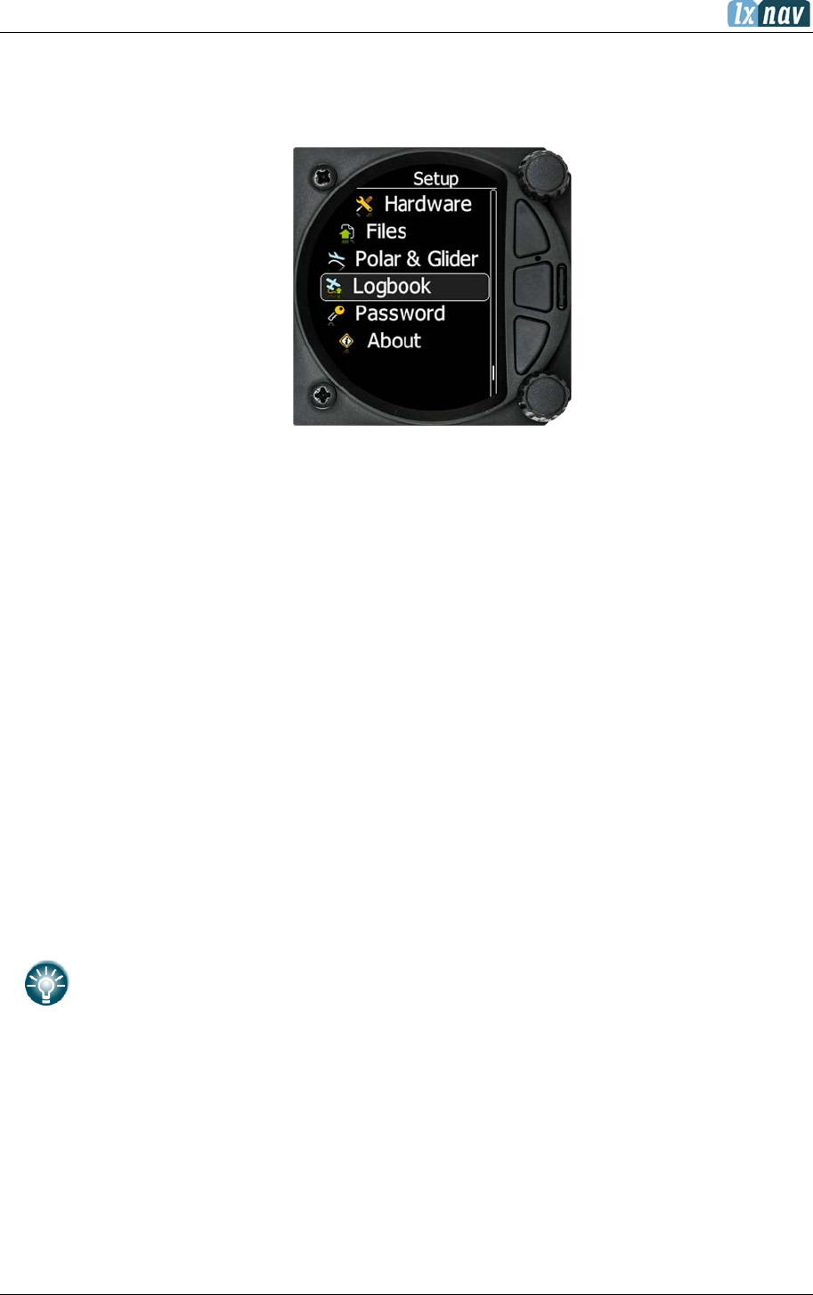
5.7 Setup Mode
The setup mode allows you to change the configuration and base settings for the S8x/S10x
vario.
Following items are listed in the setup menu:
• QNH &RES
• Flight recorder
• Vario parameters
• Thermal assistant
• Display
• Graphics
• Sounds
• Warnings
• Observatory Zones
• Units
• Hardware
• Files
• Polar & Glider
• Logbook
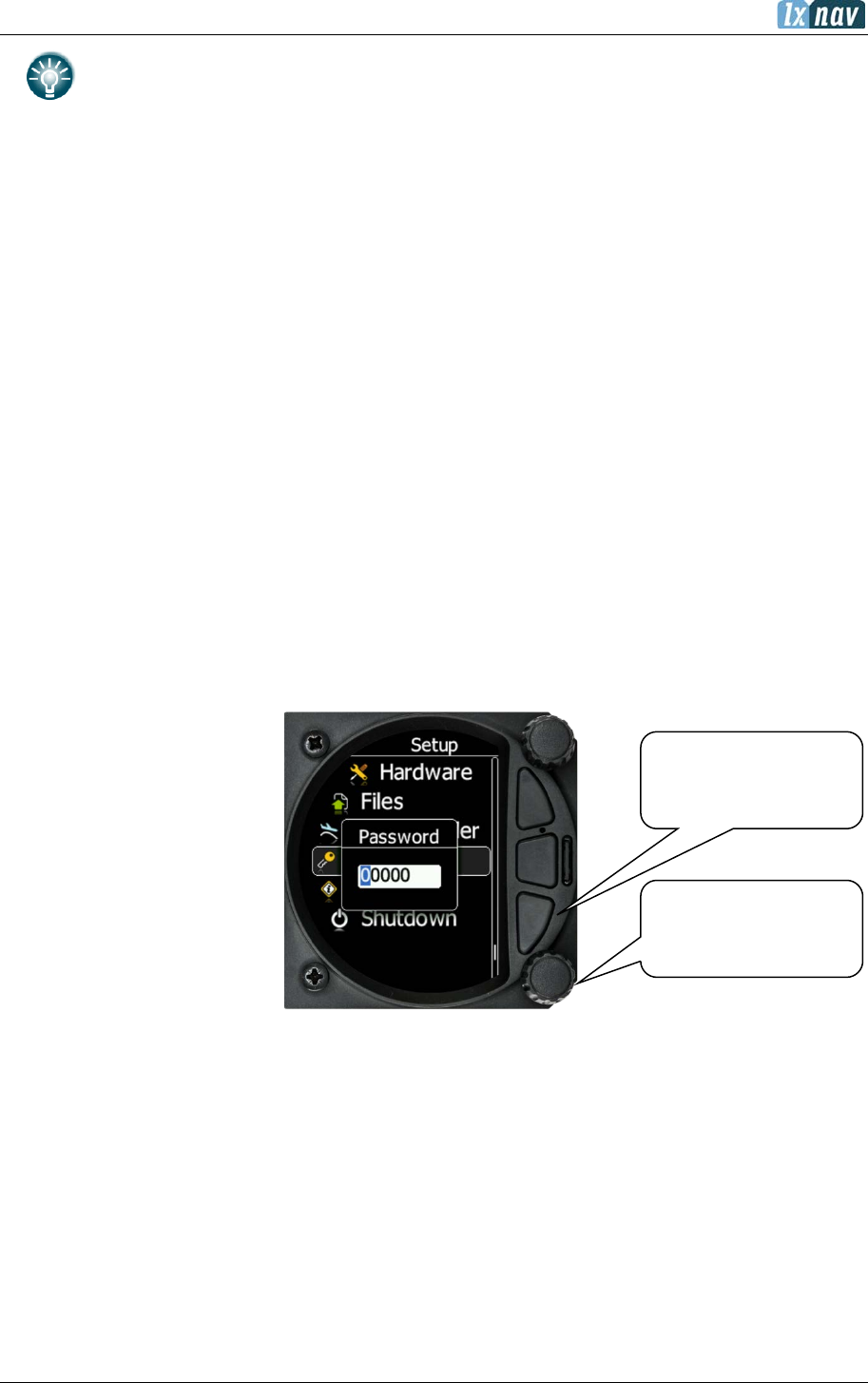
• Password
• About
You can scroll up and down the list of settings by rotating the lower rotary knob and selecting
a setting to change with a short press of the lower rotary knob.
All menus have the EXIT button which will exit to the previous menu. You can also
exit from the menu if you press the middle push button.
Some of the options have sub menus and these are selected in the same way.
June 2018
Page 42 of 108
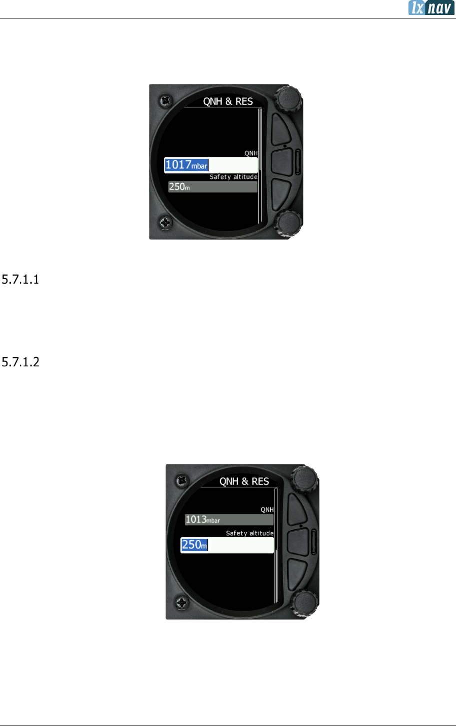
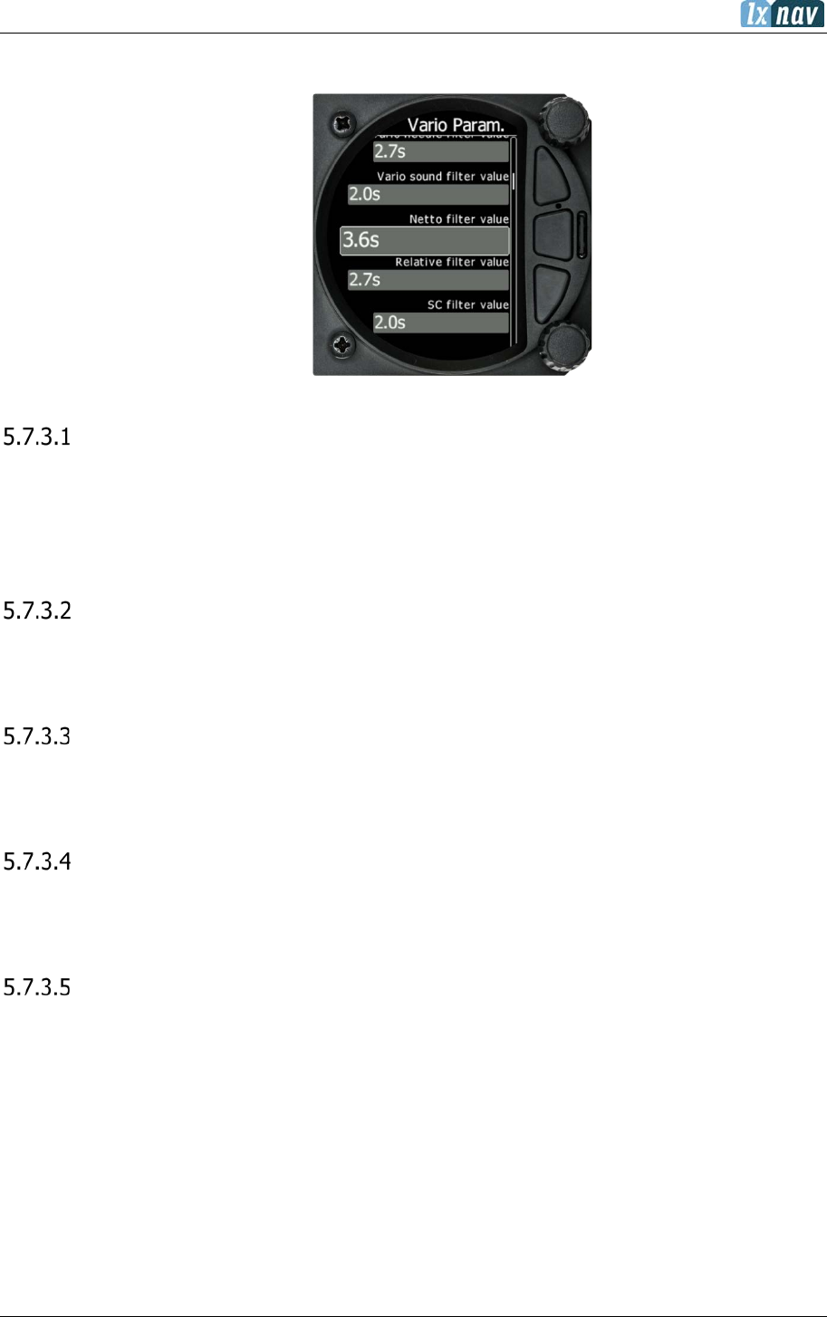
5.7.1 QNH & RES
Turn the lower rotary knob to select the required entry field. Press the lower rotary knob to
select it and start editing the value. A further short press will enter the value.
QNH
This feature may be used to offset the altitude datum as the result of pressure changes during
the flight. Since changing the QNH influences the indicated altitude, care should be taken
when changing the value as an incorrect setting could upset the final glide calculation.
Safety Altitude
This setting is the altitude reserve or safety altitude and is the height that the instrument adds
to the final glide altitude required so the glider arrives over the final glide destination at the
selected safety altitude. Once the safety altitude has been specified, the pilot must keep the
final glide indicator on 0 to arrive at the safety altitude (setup one of the navboxes in the
primary or secondary pages of waypoint or task modes to be Arrival Altitude).

June 2018
Page 43 of 108
5.7.2 Flight Recorder
The S10x vario system has a built-in IGC-approved flight recorder. In this menu the user can
set flight recorder parameters and pilot’s data.
S8x version 6 or higher also has a flight recorder which does not have a digital
signature and therefore is not approved for badge flights according IGC standards.
Recording Interval
Set the recording interval from 1 – 20 seconds.
Auto Finish
If this functionality is enabled, the flight recorder will automatically finish the flight under the
following conditions:
- GPS status OK
- Groundspeed lower than 20 km/h
- True airspeed lower than 40km/h
- Absolute vario lower than 1m/s for 300 seconds
Finish Before OFF
If this setting is enabled the flight will be finished if the user powers down the unit.
Logger Always ON
This setting will enable logging of flight immediately after power on and will log the fight until
the unit is powered down. The only condition to start logging is the presence of a valid time
(GPS status BAD or OK). Logging will not start if GPS status is Very Bad (no valid time present).
Pilot
Insert the pilot’s name which will be stored in the declaration.
Co-pilot
If the system is used in a two-seater the name of the co-pilot may also be entered.
Competition number
Insert the competition number of the glider which is also stored in the flight file.
Registration number
Insert the registration number of the glider which is also stored in the flight file.
June 2018
Page 44 of 108
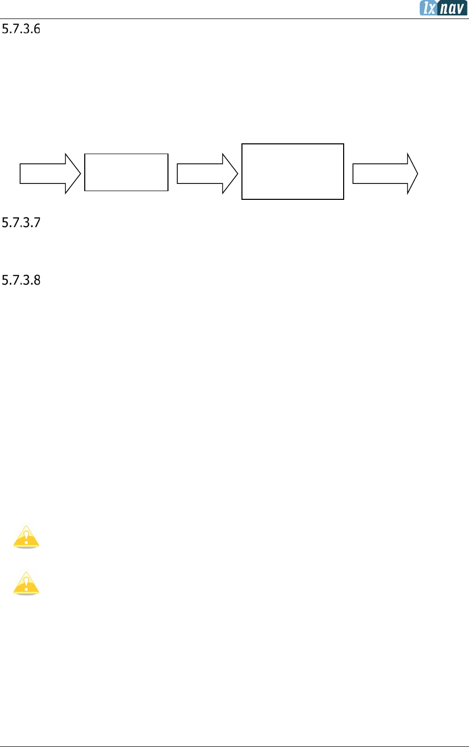
5.7.3 Vario Parameters
Vario Needle Filter
Sets a time constant of the Vario needle. The value can be adjusted between 0.1 and 5 s
with step 1.0s or 0.1s. Default value is 2.0 s.
A lower number (0.1s compared to 5.0 s) means very sensitive (fast vario).
Vario Sound Filter
Sets a time constant of the Vario sound. The value can be adjusted between 0.1 and 5 s with
step 1.0 s or 0.1 s. Default value is 2.0 s.
Netto Filter
Sets a time constant of the Vario Netto needle. The value can be adjusted between 0.1 and
5 s with step 1.0 s or 0.1 s. Default value is 4.0 s.
Relative Filter
Sets a time constant of the Vario Relative needle. The value can be adjusted between 0.1
and 5 s with step 1.0 s or 0.1 s. Default value is 4.0 s.
SC Filter
Sets a time constant of the Speed-To-Fly needle. The value can be adjusted between 0.1
and 5 s with step 1.0 s or 0.1 s. Default value is 4.0 s.
June 2018
Page 45 of 108
Smart Filter
Using the Smart vario filter the vertical speed can be further filtered. Smart vario filter
defines maximum speed of the vario needle. “1” is the highest damping, “8” the lowest. Off
means no additional filtering.
Needle Range
Sets the full-scale range of the vario (2.5 m/s, 5 m/s or 10 m/s). Default value is 5 m/s
(10 kts).
Auto SC
Defines the conditions when the instrument will switch automatically between vario and speed
to fly mode.
• OFF: Switching exclusively by means of an external switch connected to the S8x/S10x.
With new versions of Remote sticks there is no longer a “physical” switch connection
between the Remote stick and the Vario unit – it is a switch on the Remote stick which is
connected through the RS485 bus.
• GPS: When the GPS detects that the glider is circling an automatic change over to vario
will happen after approximately 10 seconds. Detection of straight flight will cause a
changeover to speed command.
• IAS: When the IAS exceeds a pre-set value. The IAS at which switching occurs can be
selected in 5 km/h steps from 100 up to 160 km/h (or the equivalent in knots or mph).
• G-meter – for switching between cruise and climb mode based on the G measured by
the inertial system. When glider starts circling the S8x/S10x will automatically switch from
cruise to climb mode.
The external switch wired to the LXNAV S8x/S10x has absolute priority and will
override all other switching methods. VP (Vario priority) input can also override a
hard-wired SC switch.
To configure navboxes in SC mode on the ground you must first turn Auto SC off,
configure your navboxes and then set Auto SC back to your preferred setting.
FILTER
0.5 to 5
Smart Vario
FILTER
1 to 8 or OFF
RAW
VARIO
FILTERED
VARIO
VARIO
INDICATOR

June 2018
Page 46 of 108
TE Compensation
The LXNAV S8x/S10x offers two methods of vario Total Energy Compensation:
• Pneumatic TE Pitot tube
• Electronic TE compensation
It is important to note that the method of TE compensation is defined when the
instrument is installed by virtue of the pneumatic connections made to the TE and
static ports. Changing the compensation type in the setup mode below WILL NOT
change the method of compensation – the pneumatic plumbing must be changed
first.
If the TE pitot tube has been connected, TE compensation should be set to 0%.
No further adjustment of the TE compensation is possible. Quality of the TE tube
is the one and only factor.
For
electronic
TE compensation, connect the TE port to
static
. Set the Vario Param
TE compensation
initially
to 100% and then adjust this with flight testing as
described below.

June 2018
Page 47 of 108
5.7.3.9.1 TE-Fine Tuning
The electronic TE compensation can be fine-tuned during flight using the following procedure:
It is essential that this is only done in smooth air; it is not possible to tune the TE accurately
in turbulent air.
• Set TE compensation to 100%.
• Accelerate up to approximately 160 km/h (75 kts) and keep the speed stable for a few
seconds.
• Gently reduce the speed to 80 km/h (45 kts).
• Observe the vario indicator during the manoeuvre. At 160 km/h the vario will indicate
about -2 m/s (-4 kts). During the speed reduction the vario should move towards zero
and should never exceed zero.
• If the vario shows a climb the compensation is too low; increase the TE% and vice
versa.
• Try another “zoom” to assess the change and make further adjustments if necessary.
Electronic TE compensation is only effective when the Pitot tube and static sources are co-
located and the pneumatic lines to the instrument are approximately the same length. The
best sensor to use is the combined pitot/static Prandtl tube. If problems are experienced with
the electronic TE compensation the most likely cause is the glider’s static source.
The static source can be checked by plumbing the pneumatic tubes for electronic
compensation and then setting the TE: to 0%. In still air accelerate to approximately 160 km/h
(75kts) and slowly reduce the speed to 80km/h (45kts). Observe the vario indicator. If the
static source is good the vario should immediately start to move to show a climb. If the needle
initially shows increased sink and then moves to a climb, the static source of the glider is
unsuitable and there is no way to provide successful TE compensation electronically. The use
of a dedicated and accurate fin-mounted pitot/static source such as a Prandtl tube might help.
Vario Average Time
Defines the integration period for the average netto vario in seconds. The default is 20
seconds.
Integrator Reset
If this item is enabled the average vario (integrator) will be reset to 0 when switching from SC
to Vario mode.
Temperature Offset
The LXNAV S8x/S10x is supplied with an external outside air temperature (OAT) sensor. With
the offset setting it will correct static errors of temperature measurement.
June 2018
Page 48 of 108
Airspeed Offset
The user has the possibility to make an airspeed offset if the measurement is not correct.
Inertial Assisted Vario
With the LXNAV S8x/S10x, it is possible to adjust the influence of g-force on the vario. This
influence is very small and can be set to OFF or between 0 and 4.
0 means no inertial assistance.
4 is the highest influence of the inertial platform to vario.
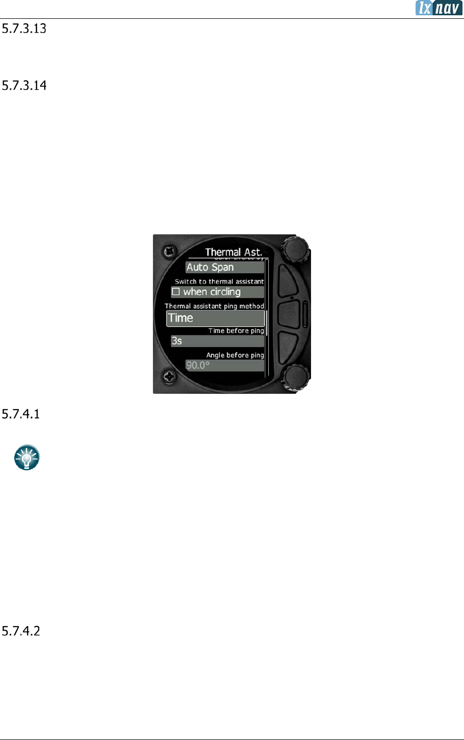
5.7.4 Thermal Assistant
Colour Circles By
There are three options for the thermal assistant, Auto Span, MacCready and Average Vario.
The colours in the thermal assistant indicate below average (blue), average
(yellow), above average (red) and the strongest point of thermal (white).
• If Auto Span is selected then the Thermal Assistant will use the average performance
of the last circle to calculate below, average and above average climb and indicate
accordingly i.e. red bubbles for strongest lift and blue dots for weakest lift or sink.
• If MacCready is selected then the Thermal Assistant will use the current MacCready
setting to show rate of climb below, MacCready and above the MacCready setting
• If Average Vario is selected then the Thermal Assistant will use the average vario for
the flight to show the rate of climb below average vario, average vario and above
average vario.
Use active navigation data
If this item is checked, all the data relating to navigation will be calculated to either Wpt or
Task, depending on which page the thermal mode was switched from.
June 2018
Page 49 of 108
For Manual switching
In you manually switch to thermal mode, all navigation data will be related to the setting you
have selected.
Switch to Thermal Assistant Mode
With this box ticked the S8x/S10x will change to the Thermal Assistant mode when the glider
starts turning in a climb. If the box is left un-ticked, then the thermal assistant mode can be
accessed manually.
The S8x will only detect turning if a GPS or Flarm device is attached. The S8x uses
a combination of change of speed, angle of bank and direction change to indicate
circling.
The S10x has an internal GPS module.
Thermal Assistant Ping Method
If the Thermal assistant ping method is enabled the user will hear a PING during circling.
When the PING is heard the pilot must expand the circle to centre the thermal. In the settings
there are two methods available to trigger the PING: time before thermal maximum and angle
before thermal maximum.
5.7.4.5.1 Time Before Ping
Using this method, user will hear PING (different audible signal) the selected number of
seconds before maximum of thermal.
5.7.4.5.2 Angle Before Ping
Using this method, user will hear PING (different audible signal) the selected number of
degrees before maximum of thermal.
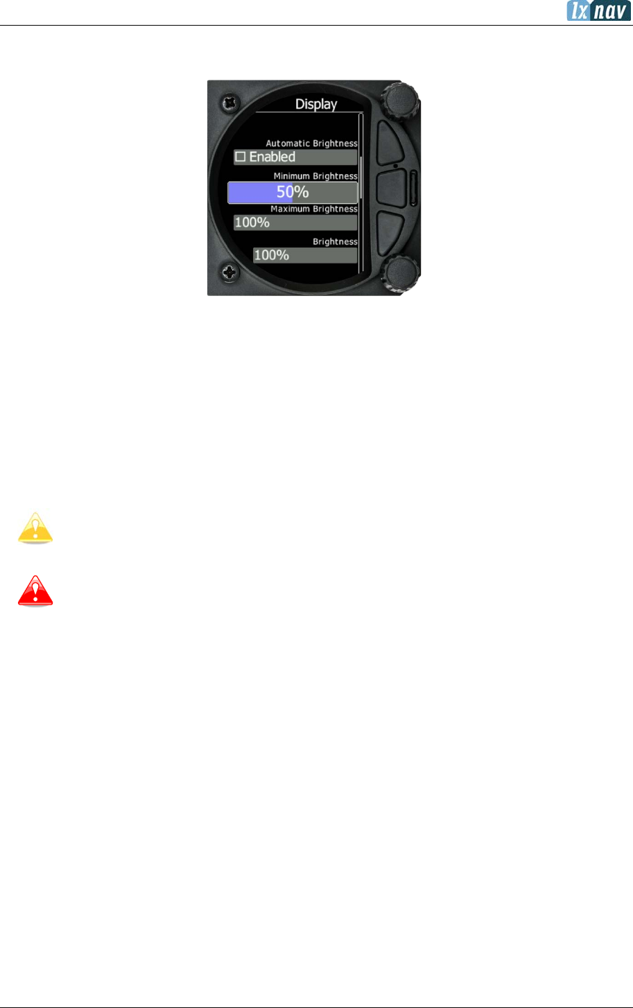
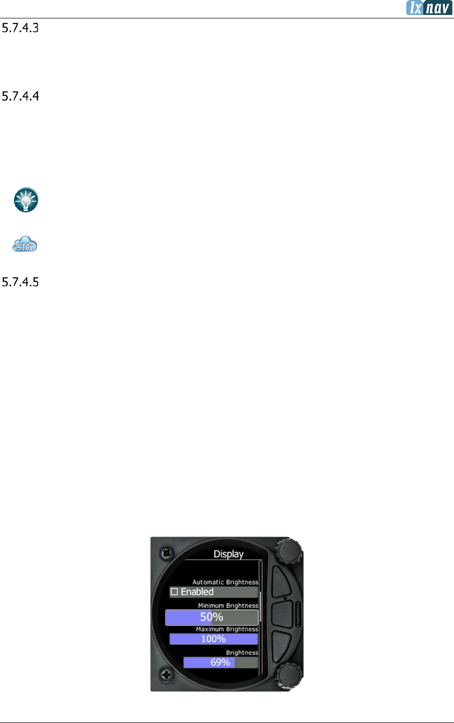
5.7.5 Display

June 2018
Page 50 of 108
Automatic Brightness
If the Automatic Brightness is checked, then the brightness will be automatically adjusted
between the minimum and maximum parameters set. If the Automatic Brightness is
unchecked, then the brightness is controlled by the brightness setting.
Minimum Brightness
Use this slider to adjust the minimum brightness for the Automatic Brightness option.
Maximum Brightness
Use this slider to adjust the maximum brightness for the Automatic Brightness option.
Get Brighter In
The user can specify in which time period the brightness can reach the required brightness.
Get Darker In
The user can specify in which time period the brightness can reach the required brightness.
Brightness
With the Automatic Brightness unchecked you can set the brightness manually with this slider.
Night Mode Darkness
Set the percentage of the brightness to be used after a press on the NIGHT mode button.
June 2018
Page 51 of 108
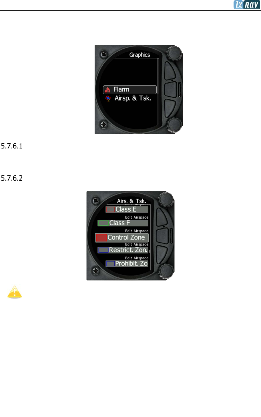
5.7.6 Graphics
The Graphics option has a sub menu for Map, Airspace, Waypoints, Glider and Track, Tasks,
Flarm, Theme setup and Modes.
Map
Option to set Track Up or North Up.
Airspace
Airspaces are not enabled on S8/S80 Club version. To purchase this option please
refer to chapter 3.2.3
In this dialogue you can define the airspace map presentation. Check the Show airspace
item to enable airspace displays in navigational modes. If this item is unchecked no airspace
will be displayed.
Use Show only airspace below to eliminate airspace which is going to be too high for the
day. For example, if the forecasted cloud base is to be 1500 m, set this value to 1600 m and
your screen will be much more readable.
In the airspace type list, you can specify how each airspace type is displayed. You should
define each type of airspace zone separately. First choose an airspace type from the list. You
can modify the Transparency of the selected type. The Zoom value defines to which zoom
June 2018
Page 52 of 108
level this type is going to be visible. The Colour and Width items specify how the selected
airspace zone will be drawn.
All settings listed above can be changed for airspace classes A, B, C, D, E, F and for the
following types of airspace:
• Control zone
• Restricted zone
• Prohibited zone
• Danger zone
• Glider sector
• Airway sector
• Transponder Mandatory Zone (TMZ)
• Military zone
• Other zone
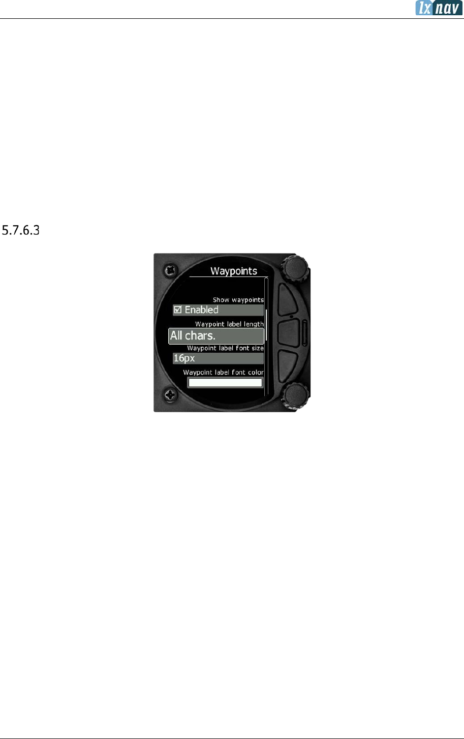
Waypoints
In this dialogue you can define whether waypoints are displayed or not, how many characters
are displayed and the size and colour of the label.
Show waypoint
Check the dialogue box to enable waypoint labels for the Waypoint and Task Modes.
Label Length
You can choose to display all the characters in the waypoint name or a maximum of 8, 7, 6,
5, 4, 3, 2, 1 or none.
Label Font size
You can choose between 24, 18 or 16 points.
Label Font Colour
You can choose a font colour from the pallet of 12 colours.
June 2018
Page 53 of 108
Glider and Track
In this dialogue you can choose to show a line to the target and your track line together with
the colour from the pallet of 15 colours.
Show line to target
Check the dialogue box to display a line to the target.
Line to target
You can choose the colour of the target line from the pallet of 15 colours.
Show track line
Check the dialogue box to enable a line to the target.
Track line
You can choose the colour of the track line from the pallet of 15 colours.
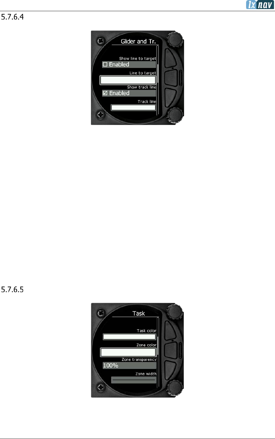
Task
With this dialogue you can change the colour of the task line and turn point zone and modify
the zone transparency and Zone line width.
June 2018
Page 54 of 108
Task colour
You can choose the colour of the task line from the pallet of 15 colours.
Zone colour
You can choose the colour of the task line from the pallet of 15 colours.
Zone transparency
With this dialogue you can choose the level of the zone transparency from 0 to 100%.
Zone width
This dialogue defines the line width of the zone with a choice of 10-line widths.
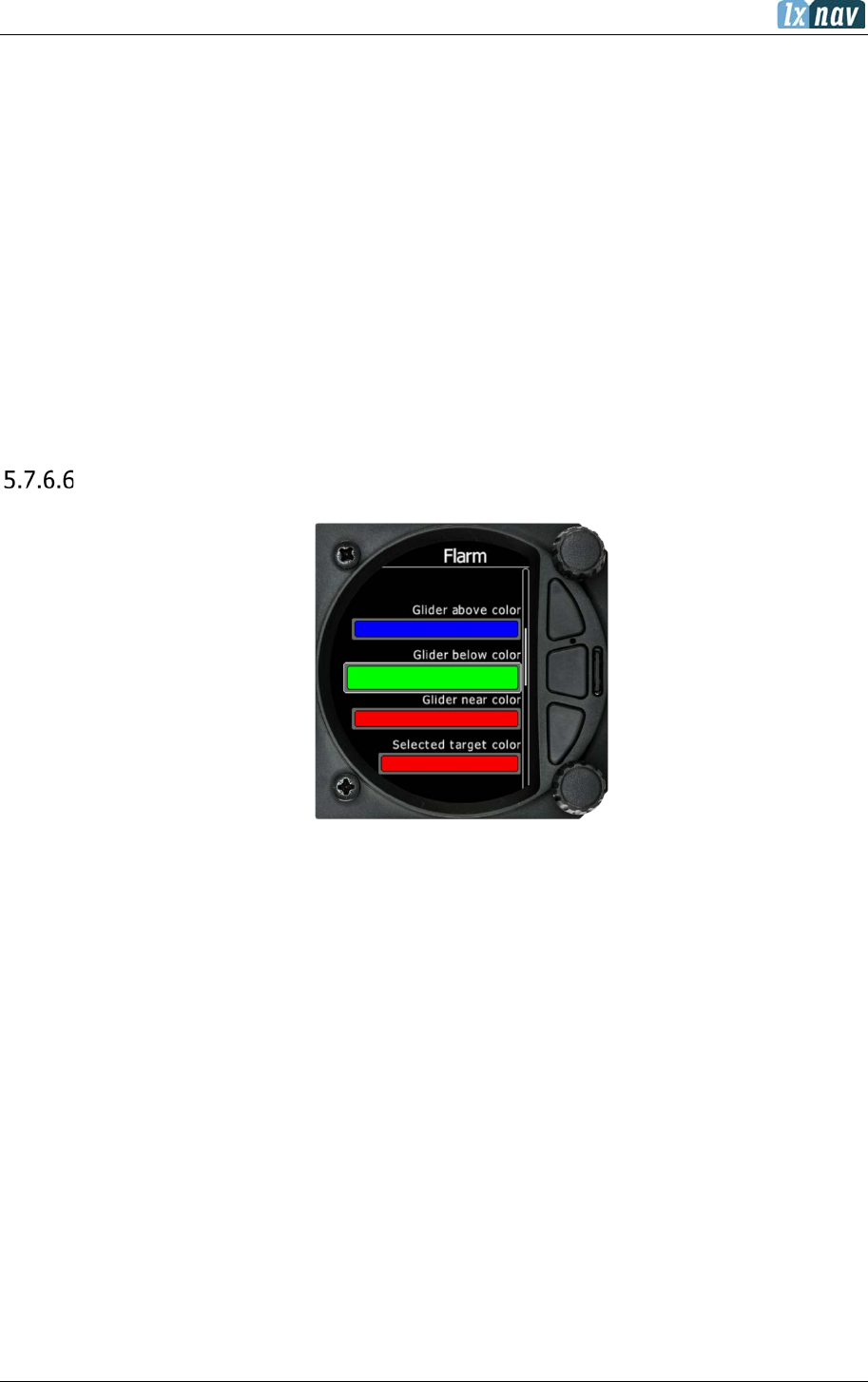
Flarm
In this menu you can choose to show Flarm traffic on the map, select target on map only,
change glider colours and adjust the Flarm object timeout and graphical settings.
5.7.6.6.1 Traffic on Map
Check the dialogue box to display Flarm objects on the screen.
5.7.6.6.2 Select Target on Map Only
There will be only the selected target on the map.
5.7.6.6.3 Colours
Colours can be set for the following:
• Glider Above Colour
• Glider Below Colour
• Glider Near Colour
• Selected target Colour
June 2018
Page 55 of 108
5.7.6.6.4 Label Text
On the map it is possible to show additional, related text next to the Flarm object.
This option can be set to None, Competition sign, Climb rate and Relative vertical.
5.7.6.6.5 Active Timeout
Adjusts the time a glider symbol remains on the map after it has last been seen by the Flarm.
5.7.6.6.6 Inactive Timeout
Adjusts the time for inactive gliders on the Flarm target list. Inactive gliders are gliders where
the Flarm signal has been lost for a period longer than the Active timeout. The targets become
inactive and remain only in the Flarm target list for this time.
5.7.6.6.7 Draw Line to Selected Target
Check this option to enable or disable a line drawn to a selected Flarm target.
5.7.6.6.8 Draw History
Select if a trail is to be drawn behind Flarm targets to show where the targets have been.
5.7.6.6.9 Plane Icon size
To adjust the pixel size of Flarm targets.
Theme Setup
With this dialogue you can change the background colour of the vario gauge and the inner
information circle, the user message transparency and navbox transparency.
5.7.6.7.1 Colour style – Gauge: Inner
With this dialogue you can change the background colour for the vario gauge (Outer ring) and
the background of the information circle within the gauge. You have the choice of the
following:
Gauge
Inner
White
Black (default)
White
White
Black
White
Black
Black
5.7.6.7.2 User msg. Transp.
With this dialogue you can change the transparency of the user messages when they are
displayed overlaid on each screen from 0 to 100%. Default is 50%.
June 2018
Page 56 of 108
5.7.6.7.3 Navbox transparency
With this dialogue you can change the transparency of the navboxes which are overlaid on
each screen from 0 to 100%. Default is 44%.
5.7.6.7.4 Wind Symbol Size
Here you change the size of the wind symbol from Small to Large.
Modes
Task, Thermal and Flarm modes can be disabled via this menu. Also, the AHRS page can be
disabled here.
For competitions the artificial horizon can be disabled in this menu. When the
artificial horizon page is active a BFION event is written to the recorded flight for
verification purposes.
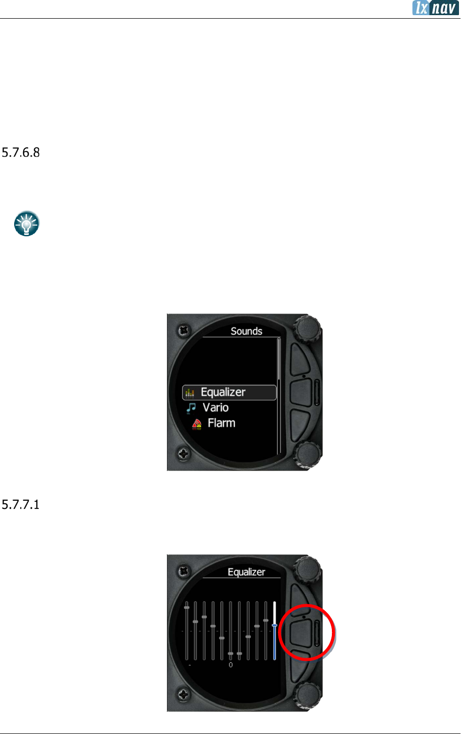
5.7.7 Sounds
The sounds option has a sub menu for Equalizer, Vario and Flarm.
Equalizer Option
With the lower rotary knob, you can adjust the volume for each frequency. The settings are
stored when you exit the screen (via the middle button).

June 2018
Page 57 of 108
Vario Sounds
In this menu the user can change all the parameters for vario sounds.
The volume for Vario, Flarm and Speech can also be adjusted directly via the upper
rotary knob whilst in the Flarm, Waypoint and Task Modes.
5.7.7.2.1 Vario Volume
The user can set the default vario volume.
Sound shape
In this menu, you can choose between following shapes: Sinus, Triangular and Harmonic.
Vario audio mode:
• Linear positive: the sound is interrupted with silence every few milliseconds when the
needle is positive; on negative side sound is linear (not interrupted).
• Linear negative: inverse function to Linear positive.
• Linear: the sound is linear and non-interrupted in full scale range.
• Digital positive: similar to Linear positive, except the frequency is not changing
linearly but with larger steps.
• Digital negative: inverse function to Digital positive.
• Linear positive only: the sound is present only at positive values, for negative values
there is silence.
• Digital positive only: similar function to Linear positive only, except the sound is
similar to the digital tone.
• Digital: similar function to Linear, except the sound is similar to the digital tone. The
frequency is not changing linearly, but by steps. Sounds like playing a flute.
5.7.7.2.1.1
SC Audio mode
SC audio mode has five modes:
• SC positive: the sound is interrupted with silence every few milliseconds when the needle
is positive; on negative side sound is linear (not interrupted).
• SC negative: inverse function to SC positive.
• SC: the sound is linear and non-interrupted in full scale range.

June 2018
Page 58 of 108
• SC Mixed: for positive relative values the sound represents relative; for negative relative
values the sound represents SC (for that setting it is recommended to set SC needle to
relative).
• Netto speed: the variometer will produce the same sound as defined in Vario audio,
except it will follow netto vertical speed.
Dead band
Defines the width of the audio dead band in speed to fly mode. Default value is ±1 m/s.
5.7.7.2.1.2
Audio frequencies
• Freq at 0% defines the tone frequency at 0 m/s.
• Freq at +100% defines the tone frequency at full + deflection.
• Freq at -100% defines the tone frequency at full – deflection.
5.7.7.2.1.3
Equalization pre-sets
We have three options: default LXNAV speaker, flat setting or user defined.
The volume for Vario, Flarm and Speech can also be adjusted directly via the upper
rotary knob whilst in the Flarm, Waypoint and Task Modes.
June 2018
Page 59 of 108
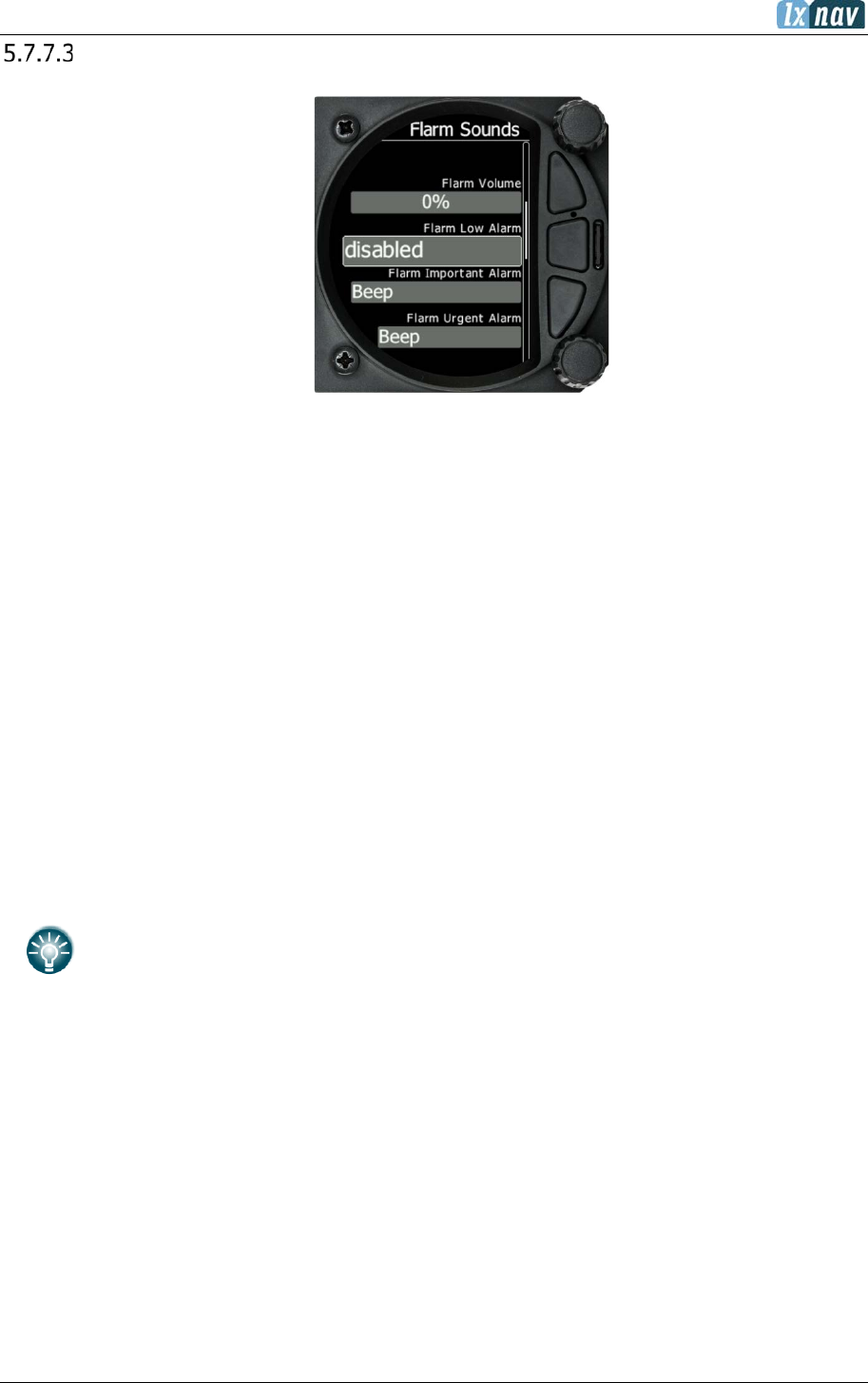
Flarm Sounds
5.7.7.3.1 Flarm Volume
Adjust the default Flarm volume with the slider.
5.7.7.3.2 Flarm Low Alarm
For distant Flarm targets the S8x/S10xgive a short or long message, just a beep or be turned
off (19-25 seconds before possible collision).
5.7.7.3.3 Flarm Important Alarm
For close Flarm targets the S8Xcan give a short or long message, just a beep or be turned
off (14-18 seconds before possible collision).
5.7.7.3.4 Flarm Urgent Alarm:
For very close Flarm targets the S8x/S10xgive a short or long message, just a beep or be
turned off (6-8 seconds before possible collision).
The volume for Vario, Flarm and Speech can also be adjusted directly via the upper
rotary knob whilst in the Flarm, Waypoint and Task Modes.
For the alarm sound the user has the possibility to select between beep, short message and
long message sounds.
Short message sounds: “Traffic two o’clock”
Long message sounds like: “Traffic two o’clock, two kilometres, two hundred meters above”.

June 2018
Page 60 of 108
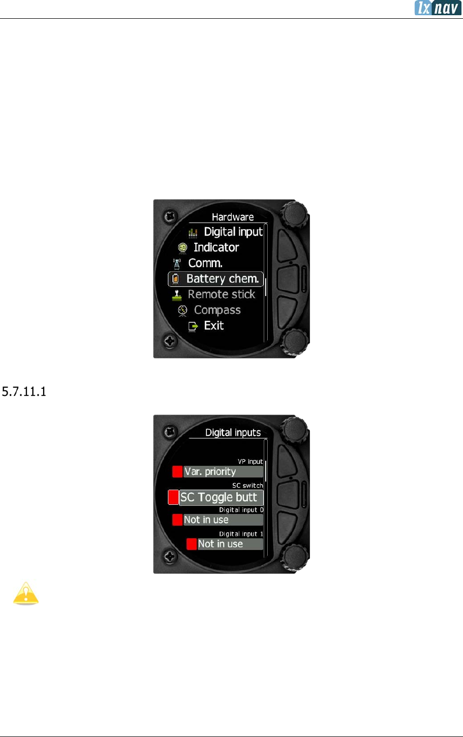
5.7.8 Warnings
Enable Flarm Warnings
Warnings can be enabled or disabled in this section.
The warning dismiss time can be set from 0 to 120 seconds.
Flarm Warnings
Display urgent alarms: Third level approximately 8 seconds before predicted collision.
Display important alarms: Second level approximately 13 seconds before predicted
collision.
Display low alarms: First level approximately 18 seconds before predicted collision.
Dismiss while circling: This dismisses Flarm alarms for Flarm targets in the same thermal.
Flarm warnings for urgent alerts override this.
Altitude Alarm: It can be set in meters or feet. The S8x/S10x will display a warning before
reaching the selected altitude.
Warn me before: Is related to Altitude alarm; it can be set from 10 to 500 seconds. The
predicted time to reach alarm altitude is calculated from the average vario.
Dismiss time: If a Flarm warning is dismissed, there will be no Flarm warnings for the
number of seconds set in that menu. Once certain Flarm alarm is set of you can dismiss it for
that set amount of second by pressing lower knob.

June 2018
Page 61 of 108
Visual Messages/Warnings
The S8x/S10x will provide the following visual messages/warnings:
• Digital signature failed (it will appear immediately after initial setup)
• Freezing temperature (it is related to the OAT measurement)
• Task started
• Inside zone
• Next zone
• Outside zone
• Airbrakes not locked
• Check landing gear
• Low external battery
• Running on internal battery (if flight recorder is running)
• Shutting down (if flight recorder is not running and there is no external power)
• Freezing temperature (if the outside temperature is 1 degrees)
• Altitude warning
June 2018
Page 62 of 108
Voice Warnings
The S8x/S10x will trigger the following voice warnings:
1. Gear warnings
CHECK GEAR: this warning is triggered 5 minutes after take-off if the landing gear is
not wired to any of the inputs of the S8x/S10x.
CHECK LANDING GEAR: during the flight, gear up*, airbrakes opened*.
2. Airbrakes warnings
CHECK AIRBRAKES: if you are on the ground, speed 0, gear down*, airbrakes opened*.
This warning is repeated every 30 seconds.
WARNING AIRBRAKES, WARNING AIRBRAKES…: during the acceleration, gear down*,
airbrakes opened*.
CHECK AIRBRAKES: speed, airbrakes opened*.
3. Low battery (if the battery is low – see battery chemistry setting).
4. Stall speed (warning is related to the stall speed set in the menu).
5. Flarm voice message long: Traffic at: position, distance, vertical distance.
6. Flarm voice message short: Traffic at: position.
*airbrakes or landing gear should be wired to digital inputs!
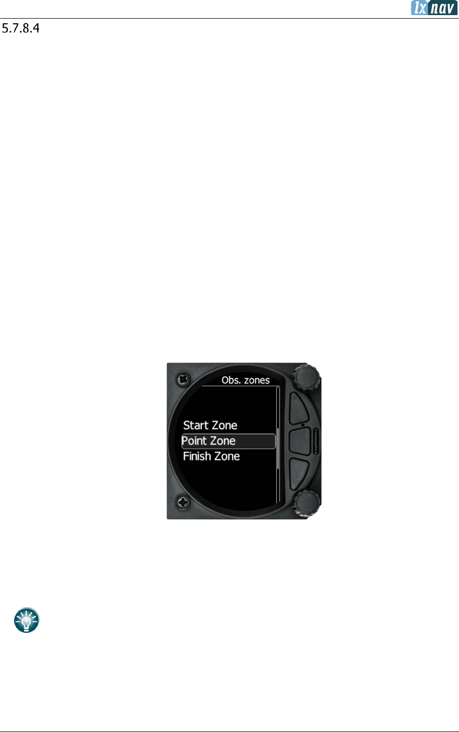
5.7.9 Obs. Zones
The default Observation Zones can be configured in this section for all tasks.
The Start, Waypoint and Finish zone can be configured separately although the setup is very
similar.
The Start and Finish zone do not have the option of the AAT check box or Auto
next.
June 2018
Page 63 of 108
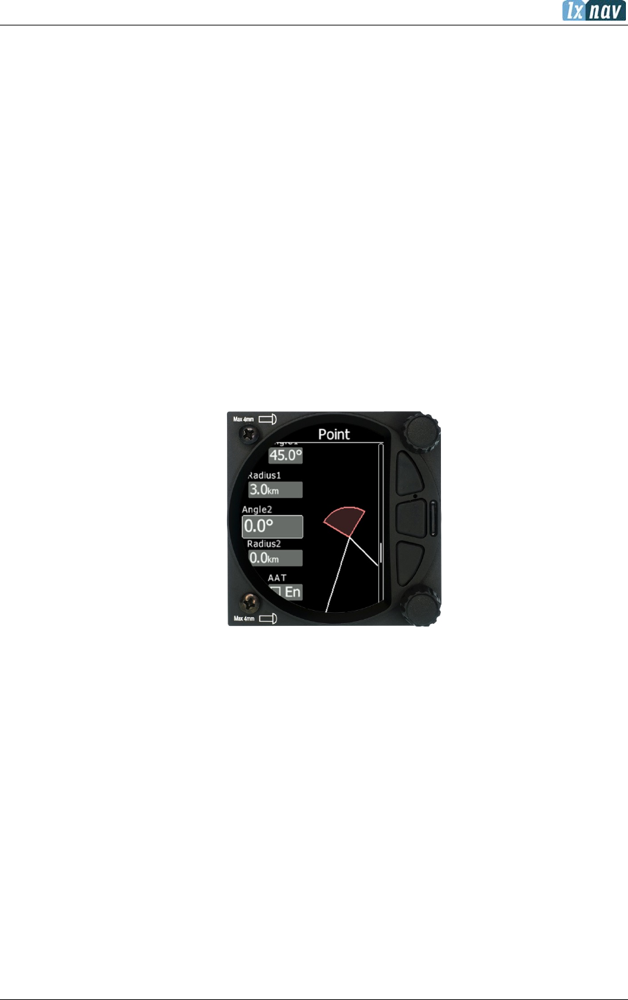
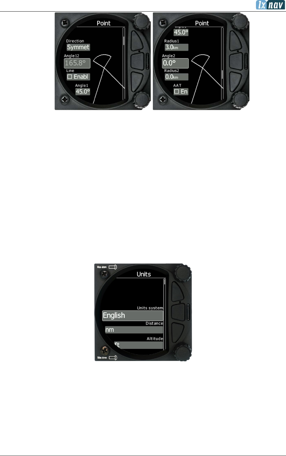
• Direction: Options include Start, Previous, Next, Symmetrical or Fixed angle.
• Angle 12: is greyed out unless fixed angle is specified in Direction.
• Line Check Box; typically used for Start and Finish. If line is checked then
Angle 1, Angle 2 and Radius 2 are greyed out.
• Angle 1: Sets the angle of the Turn Point Zone.
• Radius 1: Sets the radius of the Turn Point Zone.
• Angle 2: Sets angle 2 for complex Turn Points and Assigned Area Tasks.
• Radius 2: Sets the radius for complex Turn Points and Assigned Area Tasks.
• AAT Check Box: when checked the S8x/S10x considers the area created within
the zone as an Assigned area.
• Auto Next: Typically used in racing tasks, this will change the navigation of the
S8x/S10x to the next turn point when a single fix is made within the Turn Point
Zone.
5.7.10 Units
Use this menu to specify units, UTC time offset and type of ballast input.
• Units system: Metric, English, US.
• Distance: Units available; statute miles, nautical miles, kilometres.
• Altitude: Units available feet, meters.
• Temperature: Units available; degrees centigrade or degrees Fahrenheit.
• Pressure: Units available; inches of mercury (inHg), mm of mercury (mmHg),
mbar.
• Speed: Units available; fpm, m/s, mph, kts, km/h.
• XC Speed: Units available; fpm, m/s, mph, kts, km/h.
• Vertical Speed: Units available; fpm, m/s, mph, kts, km/h.
June 2018
Page 64 of 108
• Wind: Units available; fpm, m/s, mph, kts, km/h.
• Weight: lbs or kg
• Load: lb/ft2 or kg/m2
• Longitude/Latitude: DD.ddddd, DDMM.mmmmm’, DDMM’SS.ss”, DD.dddd,
DDMM.mmm’, DDMM’SS”
• UTC Offset: in half or whole hours plus or minus Zulu.
• Ballast: weight (insert ballast in kg), load (ballast kg/m2), overload (factor of
overload).
5.7.11 Hardware
The hardware setup has a sub menu for Digital inputs, Indicator, Communications, Battery,
Remote Stick, Flaps, Bridge and Compass module.
Digital inputs
Digital inputs are not enabled on S8/S80 Club version. To purchase this option
please refer to chapter 3.2.3
VP Input (Vario Priority)
When this input is activated by grounding the appropriate wire, the unit will change over to
Vario immediately. This input wire is set open (not grounded) as a factory default on delivery.
This switch has priority over all SC switching methods. This means it will override all other
signals for SC and switch unit to vario mode. This input is not wired in standard wiring - it
must be wired by the customer.

June 2018
Page 65 of 108
5.7.11.1.1 SC Switch
The LXNAV S8x/S10x has an input for an external speed command switch. Using the
external switch, it is possible to manually switch between SC and Vario. Setting the SC switch
to ON means that closing the switch will cause the instrument to enter SC mode. Setting the
SC switch to OFF means that closing the switch will select Vario mode. There is a third option
by setting SC INPUT to TASTER and connecting a push button to the input; each key press
will toggle between SC and Vario (mandatory setting for LX Remote, which provides a push
button for SC).
5.7.11.1.2 Digital Inputs 1,2,3,4
The LXNAV S8x/S10x has 4 external digital inputs which can be set to indicate the state of the
landing gear, airbrakes and water open or closed. The wiring is described in Section 8.6.2.
5.7.11.1.3 Example of Warnings Triggered by the Input:
1. Gear warnings
CHECK GEAR: this warning is triggered 5 minutes after take-off if the landing gear is
not wired to any of the inputs on the S8x/S10x.
CHECK LANDING GEAR: during the flight, gear up, airbrakes opened.
2. Airbrakes warnings
CHECK AIRBRAKES: if you are on the ground, speed 0, gear down, airbrakes opened.
This warning is repeated every 30 seconds.
WARNING AIRBRAKES, WARNING AIRBRAKES…: during the acceleration, gear down*,
airbrakes opened.
CHECK AIRBRAKES: speed, airbrakes opened.
Input pins are available on the rear DB15 connector, but they are not wired.
Input is active when it is shortened to ground.
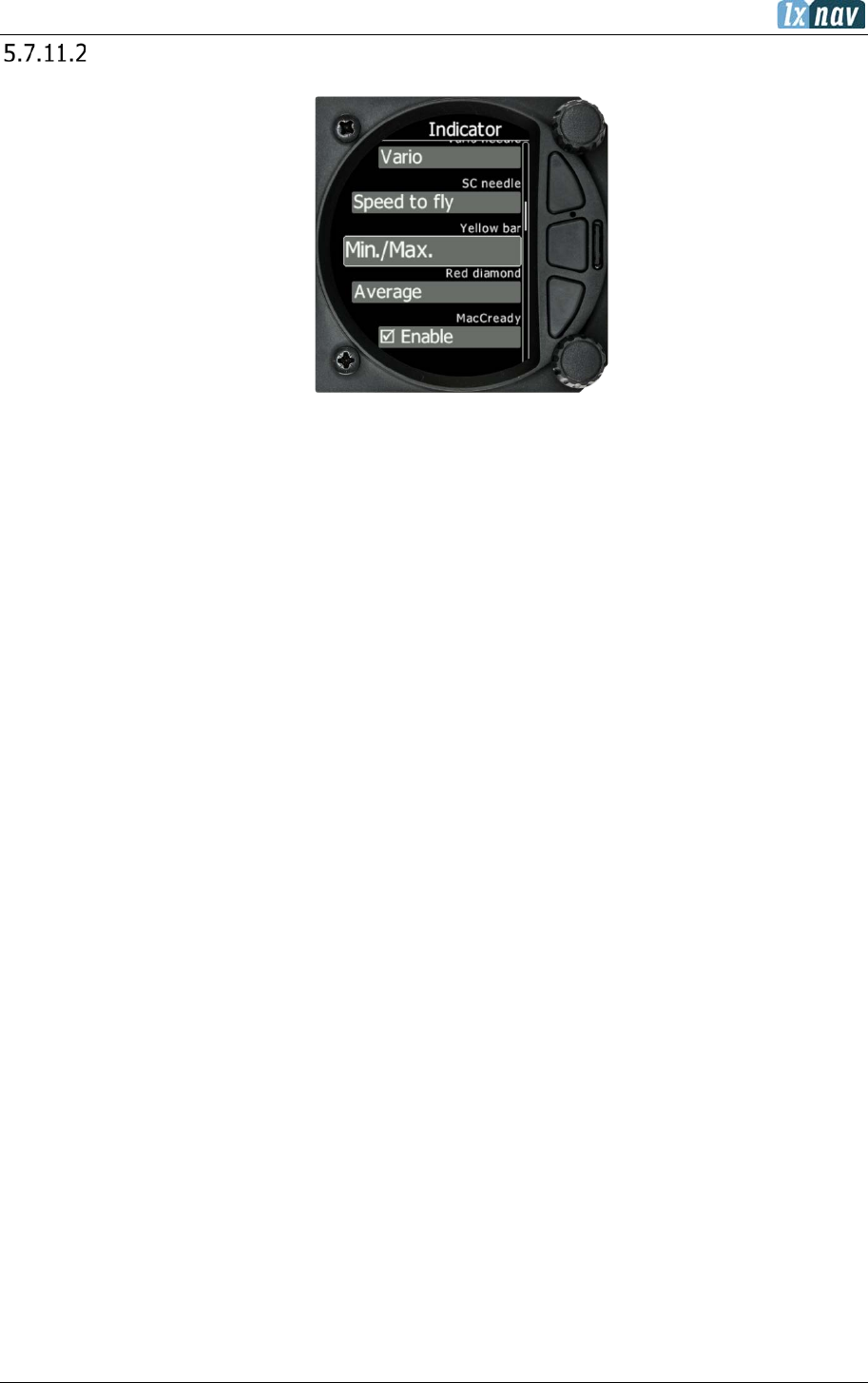
June 2018
Page 66 of 108
Indicator Setup
Vario Needle: Can be set to Vario, SC, Netto or Relative.
SC needle: Can be set to Vario, SC, Netto or Relative.
Yellow Bar: Can be set to G-meter, Min/Max vario or no bar.
Red Diamond: Can be set to No diamond, Average, Netto, Average Netto or G-meter.
MacCready: The blue triangle can be enabled or disabled.
Thermal: The green T can be enabled or disabled.
STF or Speed to Fly: The push - pull bar can be enabled or disabled.
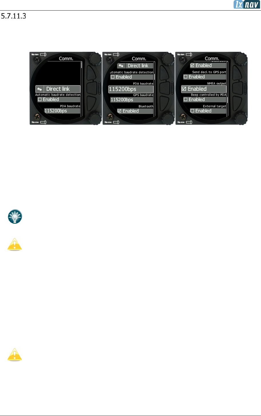
June 2018
Page 67 of 108
Communication Setup
This is used to configure the two ports on the back of the S8x/S10x for connecting to a
GPS/Flarm source and to a PDA. Each port can be configured separately.
5.7.11.3.1 Direct link: PDA-GPS link
If your PDA device does not support automatic switch to DIRECT LINK between GPS and PDA
port, there is a manual DIRECT LINK menu. The user can select between PDA-GPS or BT-
GPS.
When automatic baud rate is enabled, the LXNAV S8x/S10x will automatically search on all
speeds to receive valid data on the GPS(FLARM) port. When the S8x/S10x receives a valid
NMEA sentence it will lock on that baud rate and stop searching.
PDA-GPS link is normally automatic, but some PDA's software requires manual
settings.
Connecting S8x/S10x to Flarm extension port can lead to data being send over
being insufficient. Please connect S8x/S10x to the main Flarm port.
5.7.11.3.2 BT-GPS Link
Allows a PNA device connected via Bluetooth to directly communication with a device which is
connected to the GPS/Flarm port (Flarm/Nano).
5.7.11.3.3 PDA Baud rate
Set the baud rate of the PDA port.
The baud rate on the PDA port must be set to same as it is on the PDA device otherwise
S8x/S10x and PDA will not hear each other.
The baud rate on PDA must not be lower than the setting on GPS port.
5.7.11.3.4 GPS (S10x-Flarm port) Baud Rate
Set the baud rate of the GPS/Flarm port.

June 2018
Page 68 of 108
To obtain best performance from the LXNAV S8x/S10x it is recommended that both
baud rates are set as high as possible.
5.7.11.3.5 Bluetooth
ON/OFF for the internal Bluetooth module. If the BT module is turned off the power
consumption will be lower, and the operating time of the internal battery will increase.
NMEA output on PDA port and on BT can be enabled or disabled. If you are not using a PDA
port this setting should be disabled to obtain better performance.
The Bluetooth password is 1234
5.7.11.3.6 Beeps Controlled by PDA
If a PDA is connected to the S8x/10x, the PDA can send a beep command to the S8x. If this
feature is enabled the S8x/10x will beep on request from the PDA.
5.7.11.3.7 External Target
If this item is checked unit will accept target information received by PDA, BT or GPS port.
User will get information to the screen, that new target is received. User can accept or ignore
the target.
Battery Setup
S10x units have 2 options listed:
• External battery
• Internal battery
5.7.11.4.1 External Battery chemistry
The user must select the battery from the battery list to obtain the proper voltage
measurement.
Batteries used in gliders today are not just the old-style lead acid battery but also Lithium
Ion (LiIon) and Lithium Iron Phosphate (LiFePo) are available.

June 2018
Page 69 of 108
Each battery type has a different power delivery curve and it is now possible to configure the
Low and High Battery warnings.
Select battery from list gives you a drop-down list with the suggested battery settings for Full
Voltage, Low Battery Voltage and Empty Voltage as pre-sets. Selecting one of these will set
the values in the following boxes.
Alternatively, you can manually change the Full Voltage, Low Battery Voltage and Empty
Voltage if your battery type is not listed. Those settings will influence the battery level icon
and low battery warning.
5.7.11.4.2 Internal Battery
S10x units have also a built-in internal battery where you can check the health and settings of
this battery.
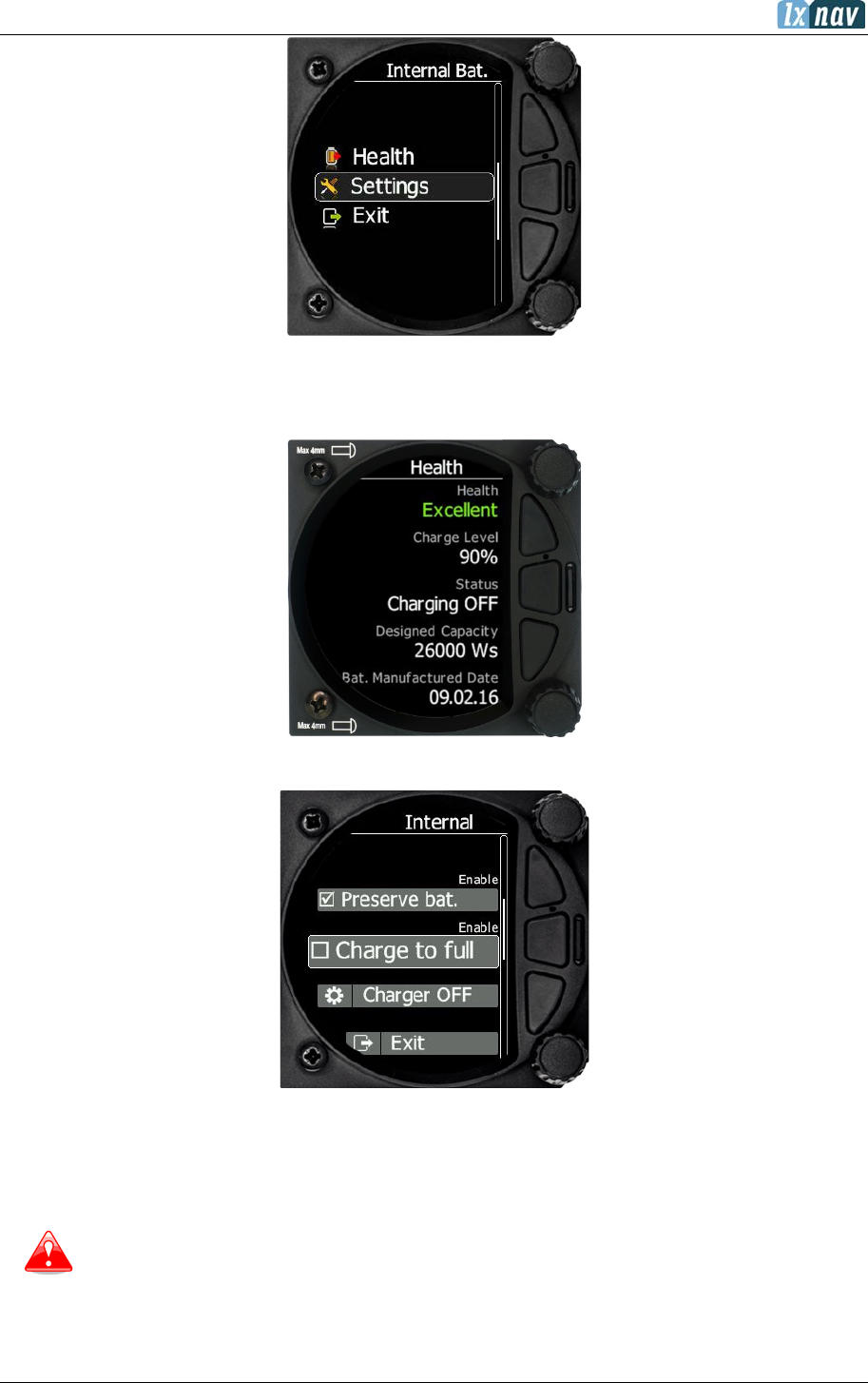
June 2018
Page 70 of 108
5.7.11.4.2.1 Health of the Battery
This shows the health of the internal battery and its charge level.
5.7.11.4.2.2 Settings of the Internal Battery
The following values can be set:
• Preserve battery = charger will not be activated until the battery drains below 75%.
• Charge to full = if it is not checked, the battery will be charged up to 90%.
• Charger mode = manual manipulation of charging.
The internal battery will not supply power to
any peripheral devices, such as
compass module, remote stick, Flarm, PDA…
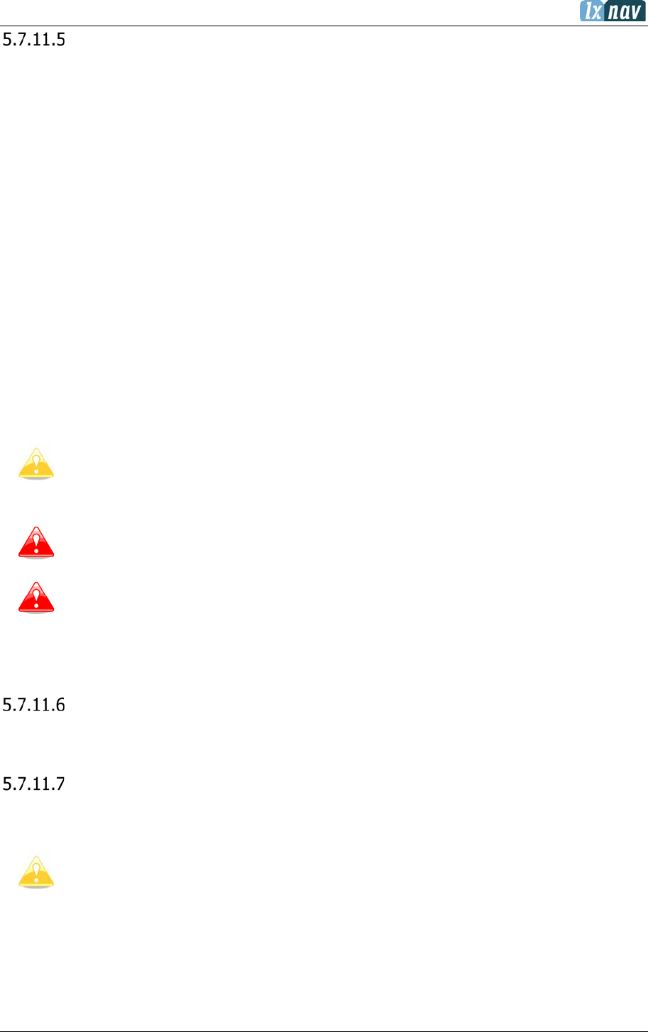
June 2018
Page 71 of 108
Remote Stick (NEW)
The remote stick is also connected to the CAN bus which is the main wiring of the S8x/S10x.
The device must be registered in case of a two-seat device as it is possible to have two remote
sticks; one registered to the main device and the other one to the second seat device.
Registering the remote stick can be done in the following way:
press any button on the remote stick – the S8x/S10Xwill detect the presence of the remote
stick on the CAN BUS.
Go to Setup->Hardware->Remote stick.
To confirm the remote stick, you must press the OK button on the remote stick.
The process is similar for the second remote for the S8xD repeater unit. Be sure that at the
time of registering repeater unit, front unit is not in Register mode, otherwise both units will
listen to the same remote stick.
While remote stick is on different type of communication than Sxxx, user must
specify for what purpose remote stick will be used when ordering one. In case of
Sxxx instruments, there will be included adapter named Remote CAN. On one side
is connected to CAN bus over DB9 connector and on the other side to appropriate
wires of remote stick. Follow colour marks on spring contacts.
The Can bus is always under power, consequently the remote stick is also under
power. After the flight disconnect the batteries or turn off the master switch to
prevent discharging the batteries.
The remote stick is only recognized if the system is under external 12V power. It
will not work if the S10/S100 is running on the internal battery only.
Compass Module
TO BE DONE – the compass module is not supported yet.
CAN Bridge
CAN Bridge is an external device which is sold separately and is used to output NMEA data or
to connect a radio or transponder to the system.
See installation manual for details on the wiring of CAN Bridge.
Once CAN bridge is plugged in to the CAN BUS, Bridge Sxxxxxx will appear in the Hardware
menu.

June 2018
Page 72 of 108
First, you must define functionality. The dialogue will change based on what you selected and
will display related items.
5.7.11.7.1 NMEA output
NMEA output is used to transmit NMEA sentences. You can select desired NMEA sentences
and define baud rate at which they will be transmitted.
5.7.11.7.2 Radio bridge
Radio bridge is used to operate a radio through the main display unit. First the type of
connected radio must be selected. For the list of supported devices please refer to CAN Bridge
installation manual found on www.lxnav.com.
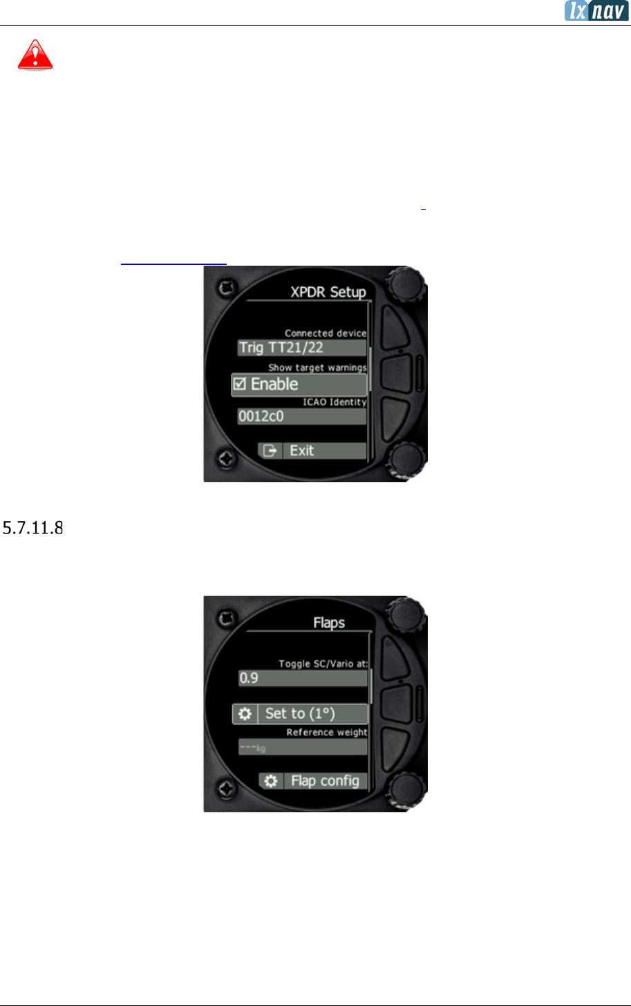
June 2018
Page 73 of 108
Due to Becker AR6201 not supporting RS-232 connections it is not supported yet
Selecting Config radio will open the radio setup menu. In this menu you can select Show
target warnings. This will trigger warnings generated from the device (example: radio is too
hot). Here you can also setup active and standby frequency, volume, squelch volume
and VOX volume.
5.7.11.7.3 XPDR Bridge
XPDR bridge can operate the transponder with the main unit. You can set ICAO Identity in
XPDR Setup menu which is opened by clicking Config XPDR. It can also show target warnings
from the transponder. For the list of supported devices please refer to CAN Bridge installation
manual found on www.lxnav.com
Flaps
When a flap sensor is installed, use this menu to set flaps position. Use the page selector to
select the desired flap position. Press SET to set the position. Repeat this procedure for all flap
positions.
When all flap positions are set, a green dot will be displayed with current flap position. If flap
labels are not set yet, press EDIT to name label. Flap labels must be entered with increasing
speed range. It is recommended that flaps labels are set together with speed range in Polar
and Glider setup. It is also possible to toggle between cruise and climb mode using the flap
sensor.
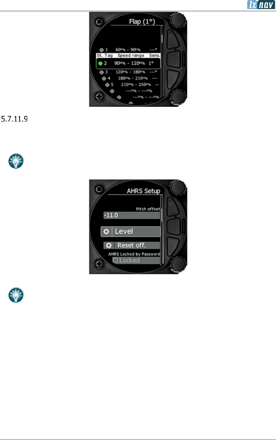
June 2018
Page 74 of 108
AHRS
Once AHRS is activated as described in chapter 8.5.5, this menu is used to calibrate AHRS for
installation error.
Place your glider in levelled position and select Level. You can also modify Pitch offset.
While inflight pitch offset can be adjusted via the lower rotary knob.
In this menu AHRS can also be Locked by Password.
AHRS locked option serves for a judge at the competition. Judge can lock or
unlock an AHRS with his own password. If he can’t unlock it with his password, it
means that pilot has changed the password and used the AHRS.
5.7.12 Profiles
In this menu, the pilot can save his own settings in a profile. Different profiles are useful if
more than one pilot is flying the same glider, or, if the glider has a different wing configuration
(15m, 18m). All of the S8x/S10x settings are save in every individual profile (glider information,
pilot information, user interface...).
With the lower rotary knob, a pilot can scroll between different profiles, the profiles are stored
within the internal storage of the S vario. Please note, the profiles are not stored on the SD
card.
When you select the profile, by pressing the lower rotary button, a sub menu will appear with
the following options:

June 2018
Page 75 of 108
• Edit (edit name of the profile)
• Active (make that profile active)
• Lock (lock that profile. All later changes on the S vario will not be stored to profile,
useful to protect a profile from changes in a club or syndicate environment)
• New (create new profile. You have the option to copy an existing selected profile or
create a new factory default profile)
• Save to SD (copy the profile from the internal storage to the SD card)
• Cancel (do nothing and exit from that menu)
• Delete (delete selected profile) At power on, the profile selection menu will appear. A
user can select between all the available profiles stored on the S vario.
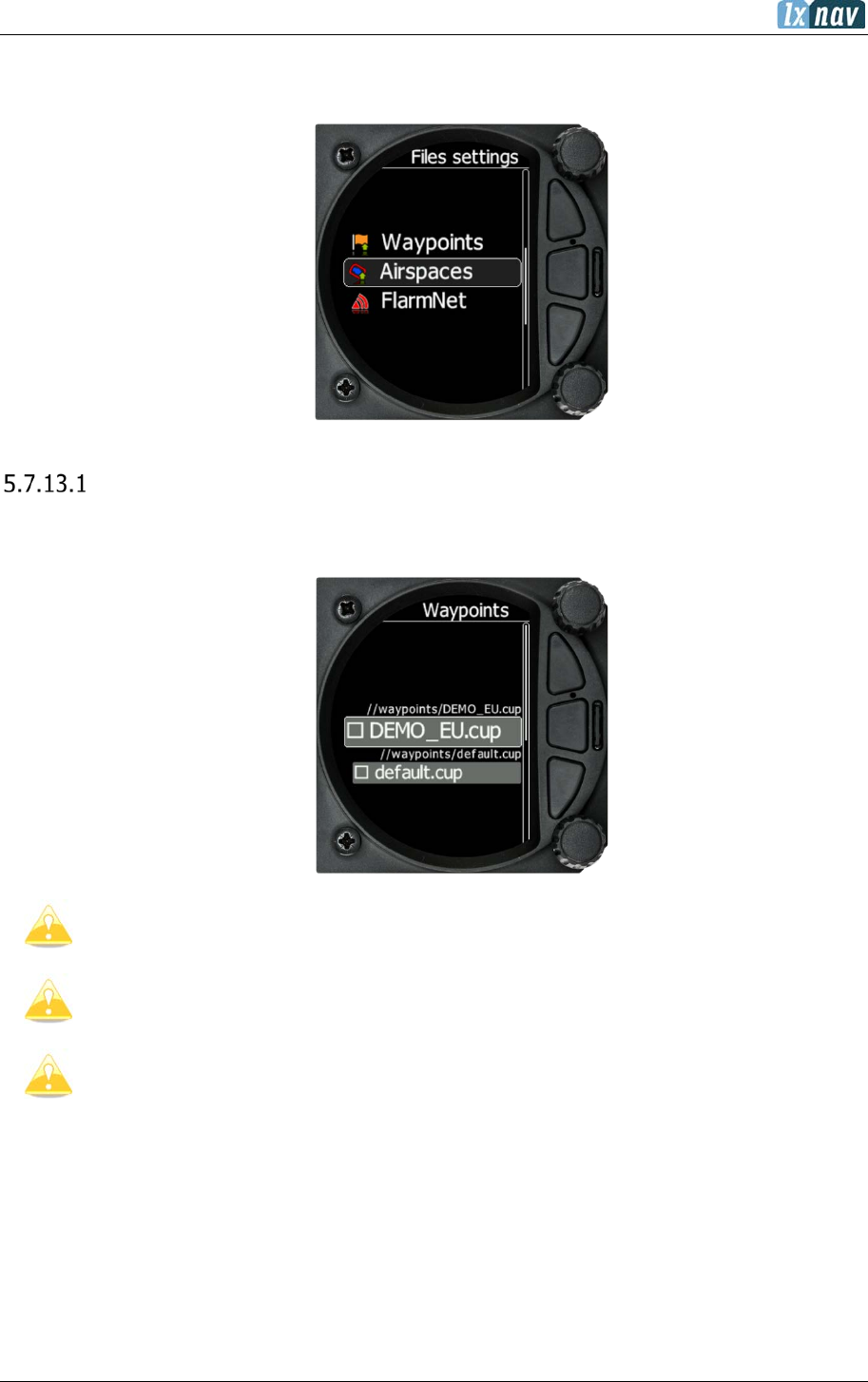
June 2018
Page 76 of 108
5.7.13 Files
The Files menu allows you to upload or select Waypoint, Airspace and Flarm Net files.
Waypoints File
Selecting the Waypoints option opens a list of .cup files available on the SD card. Selecting a
file loads this file into the internal memory.
Please note that only one Waypoint file can be loaded at any one time.
The file size of a waypoint file is limited to 1MB. The supported format is CUP as
generated with the SeeYou
program. Some versions of CUP may not be
compatible if they are not created according to CUP
standard, which is a
proprietary format from the Naviter company.
The number of CUP files that can be viewed/selected is 20.

June 2018
Page 77 of 108
Airspace File
Selecting the Airspace option opens a list of .cub and .lxa (files from ASAPT database) files
available on the SD card. Selecting a file loads this file into internal memory.
Selecting a file loads this file for use.
Please note that only one Airspace file can be loaded at once.
The LXNAV ASAPT database file format is also supported and can be loaded into
the system.
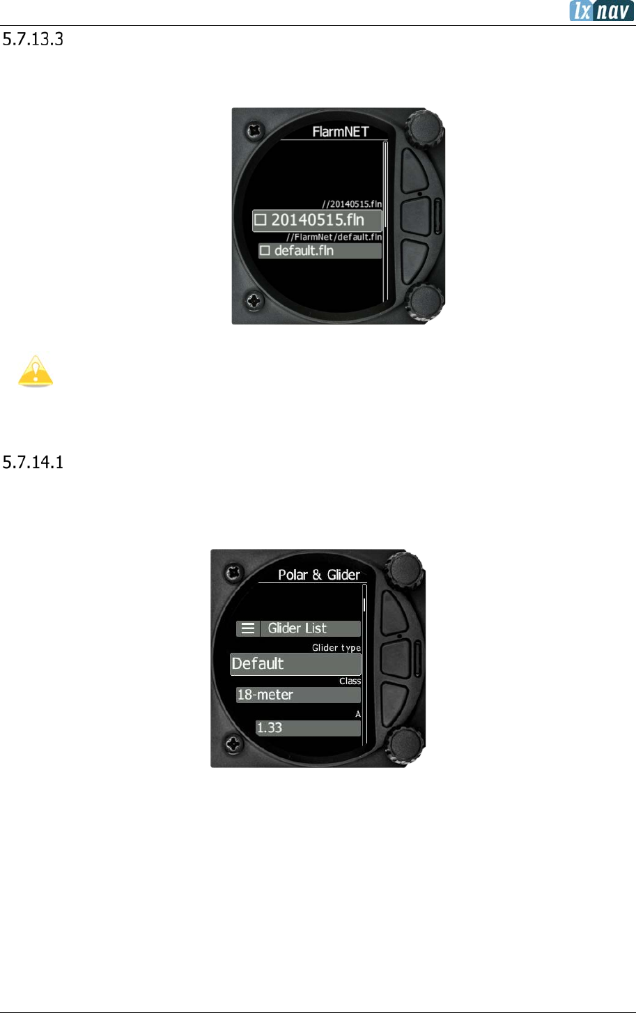
June 2018
Page 78 of 108
Flarmnet file
Selecting the Flarmnet option opens a list of .fln files available on the SD card or in the internal
memory. Selecting a file loads it.
Please note that only one Flarmnet file can be loaded at any one time.
5.7.14 Polar and Glider
Polar
The Polar and Glider section allows you to load and edit a set of parameters for your glider’s
polar. You can select from a pre-defined list of nearly every common glider or make your own
polar.
Select Glider from List: presents you with an alphabetical list of all the common gliders and
associated polar data. All glider data will be copied from the chosen polar. Verify that the
best glide ratio and minimum sink rate displayed. To see whether the polar data matches your
glider’s performance review the MacCready Setting Menu where you can verify the values.
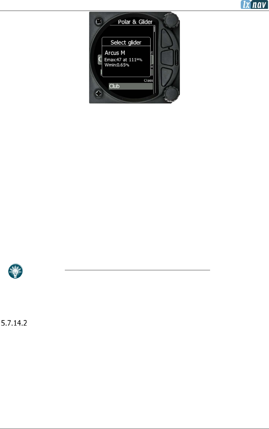
June 2018
Page 79 of 108
You can modify the polar by changing coefficients a, b and c. A polar is defined as a quadratic
equation with the parameters a, b, and c.
Use the SeeYou program (Tools->Polar) to calculate coefficients a, b and c for a given glider’s
polar. The program requires three sink points entered at selected speeds (e.g.: 100 km/h,
130 km/h, and 150 km/h). The program will calculate the values of a, b and c, which should
be noted and entered into the LXNAV S8x/S10x.
• Class: Options for Touring, Ultralight, World, Twin-seater, Club, 18-meter, 15-meter,
Open, Standard and Unknown are available.
• A, b, c: Options can be adjusted or entered for a non-listed glider.
• Reference load (wing loading) value represents the value at which the polar was
measured.
• Reference weight corresponds to the weight value at which the polar was measured.
• Maximum take-off weight is the maximum take-off weight allowed for the glider.
It is not used in the calculation; it is just a reminder to the pilot of the maximum take-
off weight. Empty weight is weight of the glider without the pilot and ballast.
• Pilot weight is the weight of the pilot with parachute and baggage.
• Co Pilot Weight is the weight of the co-pilot with parachute and baggage.
weightgliderMinimum
ballastWaterweightPilotweightgliderEmpty
overload ..
.... ++
=
In case of a two-seater configuration both users have possibilities to change
parameters. The last change performed is synchronized into both instruments.
Speeds
The user can set the following speeds:
• Stall speed (VS0)
• Stall speed (VS1)
• Approach speed (Vapp)
• Best climb (Vec)
• Max flaps (Vfe)
• Manoeuvre speed (Va)
• Max speed (Vne)
These speeds will be used as warnings such as:
• Stall speed
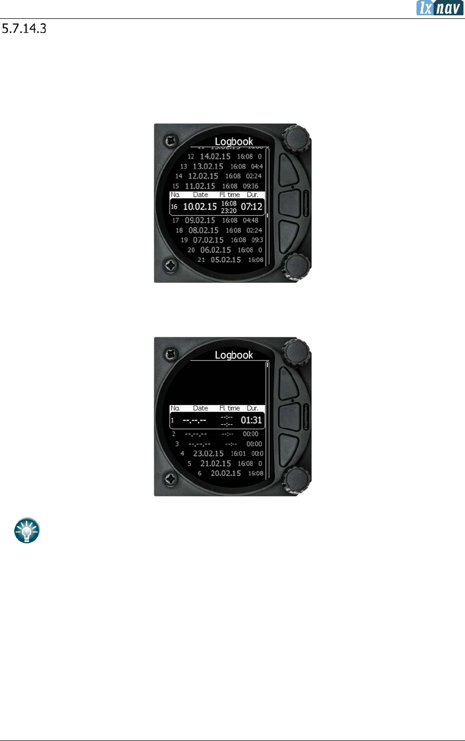
June 2018
Page 80 of 108
Flaps
For setting up flaps please refer to Section Napaka! Vira sklicevanja ni bilo mogoče najti.
for more details
5.7.15 Logbook
The logbook page lists all the flights sorted by date.
If GPS data is present the logbook will show the date and time of departure. Manual navigation
(without GPS) will show duration and will be marked with “—“ marks.
The user can download a flight by a short press on the lower rotary button.
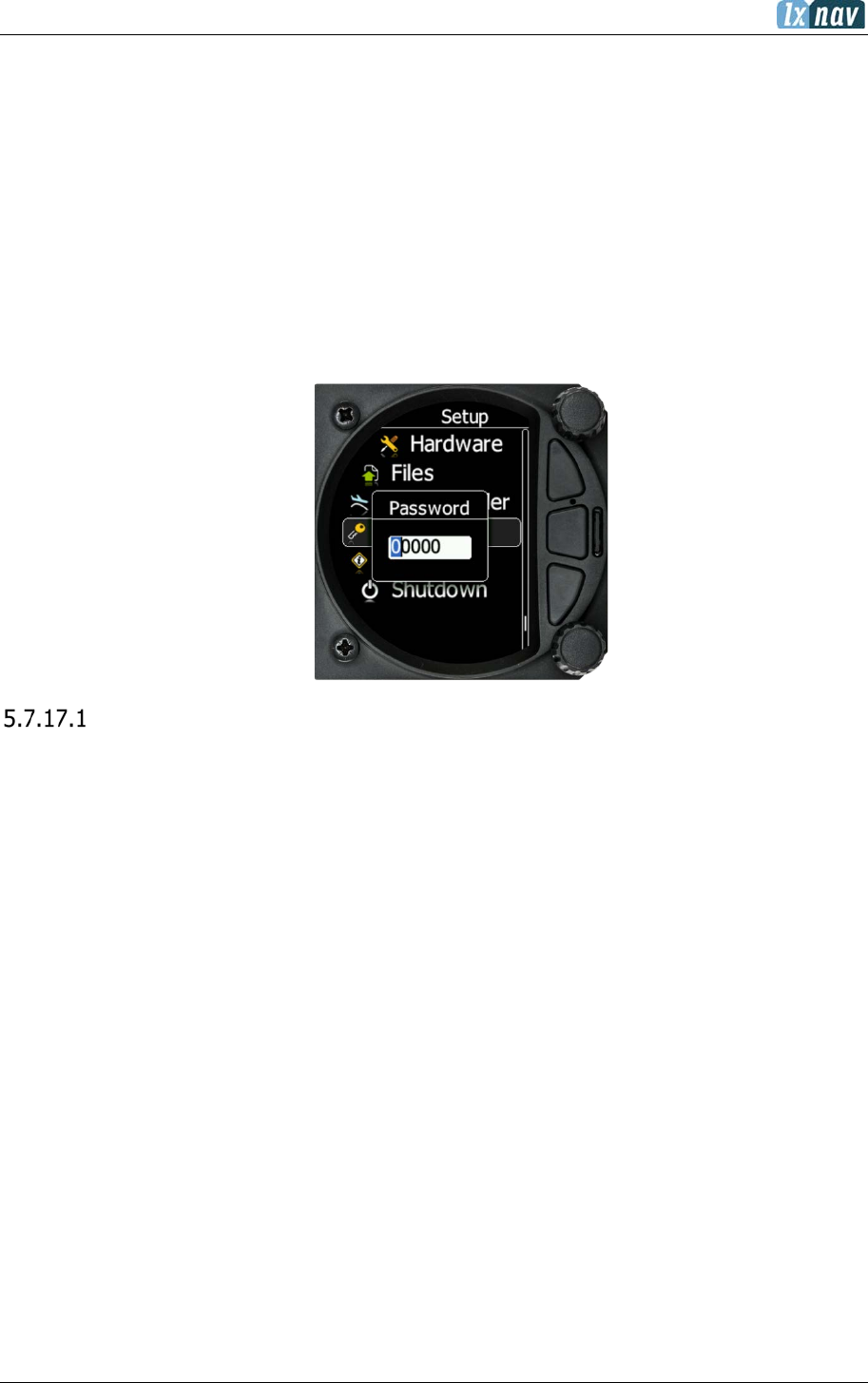
June 2018
Page 81 of 108
5.7.16 Admin mode
In this menu a pilot can lock the unit and protect the settings with a password. If admin mode
is selected and a password applied, the settings on the unit will be locked and are not able to
be changed. This function is very useful in a club glider, where not all the pilots are experienced
enough to setup the unit. In this case, the CFI will lock the unit with a password. The unit
can be unlocked anytime with the same password. Do not forget set admin password. If
forgotten the only way to recover is to type in password 00666 which resets the whole
instrument to factory default and all settings will be lost.
5.7.17 Password
There are several system passwords which run specific procedures as listed below:
List of Password Functions
DELETE WHOLE LOGBOOK 99999
RESET TO FACTORY DEFAULT 00666
AHRS LICENSE ACTIVATION / DEACTIVATION 30000
AUTO ZERO 01043
REPORT TO SD CARD 00111
UPDATE FIRMWARE 89891
FORMAT INTERNAL MEMORY (all data will be lost) 32233
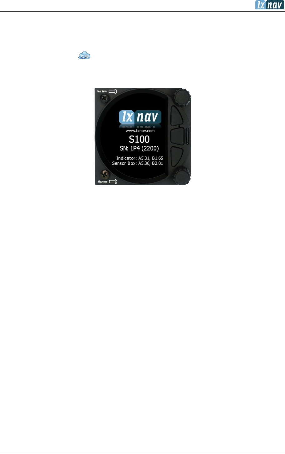
June 2018
Page 82 of 108
5.7.18 About
In the about page, information about the display platform and the sensor box can be viewed.
The user can view the following details:
• IGC serial number
• Indicator version A and B,
• Sensor box version A and B.
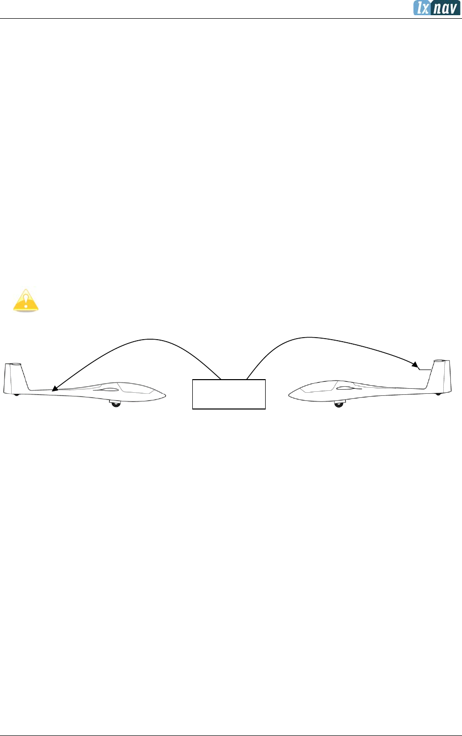
June 2018
Page 83 of 108
6 Variometer and Altimeter
All signals from the pneumatic sensors (altitude, speed) are derived from high quality pressure
sensors, which mean that no flask is necessary. The vario signal is derived from the altitude
signal. All signals are temperature and altitude compensated. The colour display shows the
vario information as well as many other parameters.
The display is user configurable. The Variometer can be configured to show:
• Range 5, 10 and 2.5 m/s or 10, 20 and 5 kts.
• Time constants 0.1 s to 5 s, in addition there are 4 settings for electronic processing for
the vario signal.
• Netto shows the air mass lift and sink.
• Relative shows the lift or sink that would be achieved if the glider was circling at
thermaling speed.
There are two ways by which the vario indications can be corrected for total energy. Electronic
TE compensation is based on speed changes with time and pneumatic compensation with a
TE probe. The quality of the TE compensation depends entirely on the location, size and
dimension of the TE tube. The installation must be leak-proof.
If an electronic TE compensation is selected the TE (P
st
) port should be connected
to a good static pressure source. If pneumatic compensation is selected the TE
(Pst) port should be connected to the TE probe.
6.1 Altimeter
The altimeter of the LXNAV S8x/S10X is temperature compensated from -20ºC up to + 60ºC.
The altimeter is calibrated up to 20000 m.
6.2 Speed Command
Speed command flying based on the MacCready theory is a very useful tool to optimize cross-
country speed. When the instrument changes to speed command mode the audio will change
and become a director informing the pilot whether he is flying too fast or too slow. To reduce
confusion between vario and speed command audio some special features are incorporated:
• Continuous audio signal and other kinds of signals can be chosen. For details see
setup.
• No audio at correct speed (dead band).
TE (Pst)
LXNAV S8(0)
Electronic TE Compensation
Compensation with TE probe
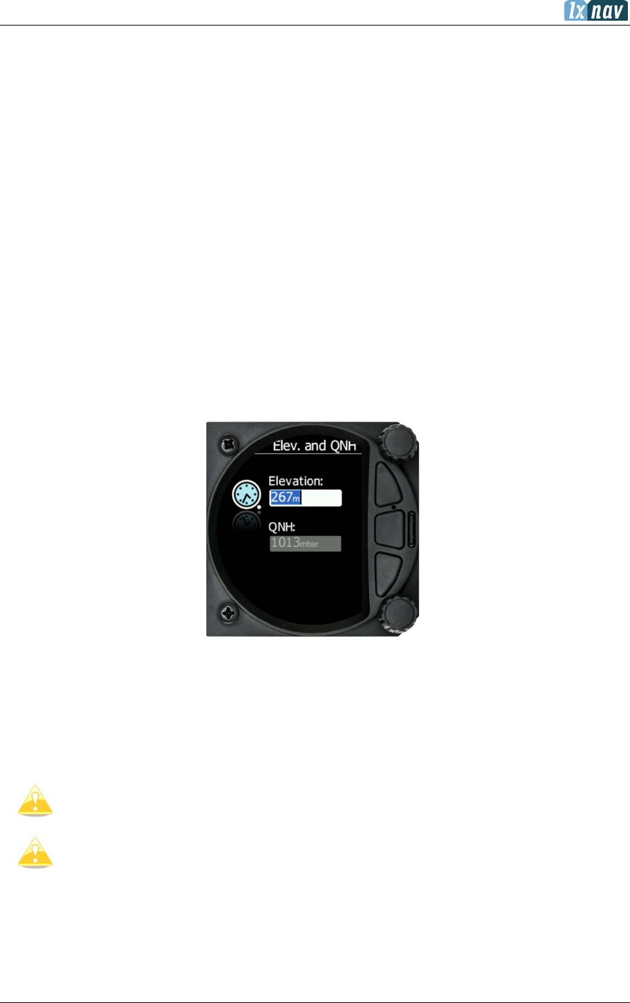
June 2018
Page 84 of 108
7 Flying with the LXNAV S8x/S10x
To get the best out of the LXNAV S8x/S10x it is important that some preparation is made prior
to take-off. Trying to configure the instrument or set a task while flying is very hazardous
especially in a competition. Pre-flight preparation will help ensure that the flight will be both
safe and enjoyable.
7.1 On the Ground
7.1.1 Power on Procedure
Press any of the rotary or push buttons to start the LXNAV S8x/S10x. The LXNAV S8x/S10x
welcome screen will appear. The first screen shows the version of the boot loader, firmware,
hardware and serial number. The boot procedure normally takes a few seconds. When
completed the Set Elevation dialogue is displayed.
7.1.2 Set Elevation and QNH
This setting is crucial for final glide calculation: therefore, please pay careful attention to it.
The instrument will offer elevation over standard pressure level QNE. Use the knob to fine-
tune the elevation.
The QNH should be changed only when airfield elevation and QNH pressure are given. This
might happen in some competitions.
In all other cases the elevation should always match QNH pressure.
The Set Elevation dialogues are not shown if the LXNAV S8x/S10x is switched off
and on during flight.
QNH can be also corrected during flight under Setup-QNH and RES menu.

June 2018
Page 85 of 108
7.1.3 Pre-flight Check
After elevation setup the LXNAV S8x/S10x will switch to the Info screen for normal operation
mode.
Use the middle (Menu) button to scroll to Flarm, Waypoint or Task Screen to verify that the
MacCready, Ballast, and Bugs settings are set to the expected values for the current flight.
In any of these screens press the lower rotary button to raise the dialogue box to check or
set MacCready, Ballast and Bugs values.
Rotate the bottom knob to modify any setting. Next check the safety altitude (height above
destination, arrival altitude) setting.
Refer to Section 5.7.1.2 to find how to define the safety altitude.

June 2018
Page 86 of 108
7.2 Airborne
7.2.1 Final Glide Calculation
Final glide is a function calculated from the target distance, target elevation, altitude, wind
component, MC setting and Bug setting. The S8x/S10x will have sufficient information to
calculate this automatically if a GPS source is attached and the target to navigate to is set in
Waypoint or Task screen. To display the Arrival Altitude (above Safety Altitude) make sure
you have configured at least one of the navboxes on the primary or secondary screens to
Arrival Altitude.
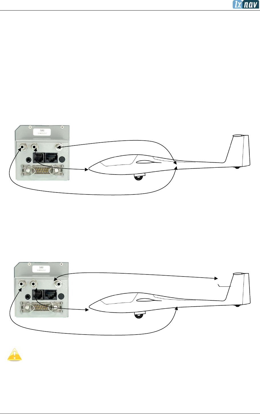
June 2018
Page 87 of 108
8 Installation
The LXNAV S8x/10x requires a standard 57 or 80 mm cut-out.
Three pressure connectors are fitted to the back of the S8x/S10x. A label shows their
functions:
• Pstatic means static pressure connector.
• Ptotal means pitot or total pressure connector.
• TE means total energy TE pressure connector.
If the unit is to be configured for electronic TE compensation the connections are as follows:
• Pstatic Static
• Ptotal Pitot or Total pressure
• TE/Pstatic Static
If the unit is to be configured for pneumatic TE compensation using a TE tube, then the
connections are:
• TE/Pstatic TE tube
• Pstatic Static
• Ptotal Pitot or Total pressure
If the Ptotal and Static are connected the wrong way around
there will be no
integrator (average climb) and speed to fly indication during the flight.
The LXNAV S8x/S10x is connected to 12 Volt power supply via the 15-pin SUB-D connector.
Optionally the LXNAV S8xD can be connected via the CAN bus and the connectors are labelled
with “CAN” at each end.
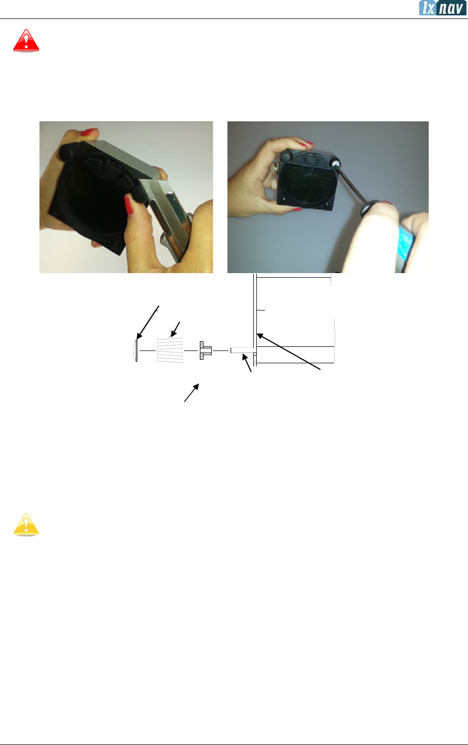
June 2018
Page 88 of 108
hollow-core screw M6
instrument panel
selector axis
press-in cover
special type screw
rotary knob
LX5000
S8(0), view close
to one rotary
Panel
rotary knob
Cap
axis
rotary button
Instrument has no internal fuse. 3A external fuse is required! Power supply
cables should use a minimum of 0.5 mm² wires.
8.1 Installing the LXNAV S8x/S10x
The LXNAV S8x/S10x vario should be mounted in a standard 80 mm hole.
Remove the two rotary knob caps with a knife or flat screw driver, then hold each knob and
unscrew it. Remove the remaining two screws and the two M6 threaded nuts. Install the
S8x/S10x into the panel and screw back all screws, nuts and knobs. Ensure that between the
knobs and the panel there is sufficient space so that the button can be pushed.
Ensure that the LXNAV S8x/S10x is located far enough from the compass.
8.2 Connecting the LXNAV S8x/S10x
The LXNAV S8x/S10x is connected to the 12V DC power supply. The red wire goes to +
positive and blue wire goes to – ground. If you don’t use the S8xD (second seat unit) the Can
connector should be left terminated with a CAN terminator. The SC cable is used for the
external switch intended for switching between climb and cruise mode.
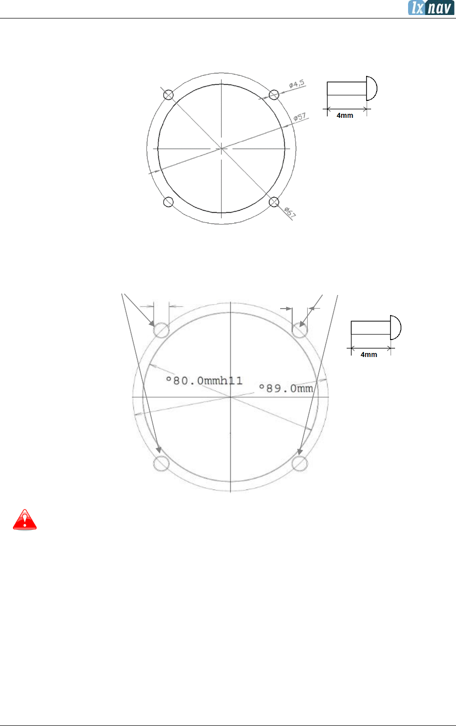
June 2018
Page 89 of 108
8.3 Cut-outs
8.3.1 Cut-out for S8 and S10
8.3.2 Cut-out for S80 and S100
Length of the screw is limited to max 4mm!
4,5mm
6,3mm
June 2018
Page 90 of 108
8.4 Available Cables for GPS/Flarm and PDA Ports
GPS / Flarm port (on S10x)
Device
Cable Code
Nano power
CC-NP-LX
(RX/TX are crossed)
Generic RS232 with female DB9
V7-GPS-232
Flight recorders, FLARMs with standard 6p IGC
connector RJ12 type, Red Box, Colibri, Colibri2, VL
V7-GPS-IGC
Power Flarm (RJ45), K6 mux
V7-GPS-PF
Power Flarm Core
V7-GPS-PFCORE
PDA Port
Device
Cable Code
OUDIE
CC-NP-OUDIE1
Generic RS232 with female DB9
CC-NP-232
IPAQ 310/314
CC-NP-IPAQ310
IPAQ 38/39xx/47xx
CC-NP-38
MiniMap
CC-NP-LX
Butterfly Connect
CC-NP-BFC
The PDA and GPS are not designed in accordance with IGC standard. It can be
used only with a dedicated cable. Do not plug an unknown cable to it as it may
damage the LXNAV S8x/S10x unit.

June 2018
Page 91 of 108
Flarm
Splitter
Flarm
splitter
Flarmview2
Flarm
FlarmView cable
S8xD
S8x/S10x
CAN cable
Remote
stick
CAN Y cable
CAN Y
cable
PDA CAN
Remote
stick D
Compass
Remote CAN
Remote CAN
CAN Y cable
Flaps
CAN Y cable
Terminator
8.5 Installation of Options
The LXNAV S8x can be connected to a 2nd seat repeater unit LXNAV S8xD, remote stick,
magnetic compass and AHRS options.
8.5.1 S8xD Option (Repeater)
In two-seat gliders it is possible to install the LXNAV S8xD rear seat device. The S8xD looks
almost identical to the S8x; in fact, it runs the same software as the first seat device.
The basic idea of the two-seat configuration is that both devices work independently from
each other with the possibility of automatically exchanging various items of data (volume, Mc,
polar…).
GND
12V
Oudie
Oudie

June 2018
Page 92 of 108
Data Exchange
All data is exchanged between the front and rear units. The LXNAV S8x/S10x also exchanges
data with GPS and PDA. Change of MC, Bal, Bugs, Volume, polar settings… on a PDA will also
influence the LXNAV S8x/S10x. The same will happen also in the opposite direction.

June 2018
Page 93 of 108
8.5.2 Magnetic Compass (Compass – CAN)
UNDER DEVELOPMENT
When simply connected to CAN bus the main unit will recognize it. This option is not released
yet but is planned for a future software release.
The Can bus is always under power; hence the compass module is also under
power. After flight, disconnect batteries or turn off master switch
to prevent
discharging batteries.
8.5.3 Flap sensor (Flap – CAN)
Flap sensor must be connected to CAN bus, through CAN bus (Y) splitter. Remaining port on
Y CAN splitter must be terminated with CAN terminator.
8.5.4 Remote Stick (Remote-CAN)
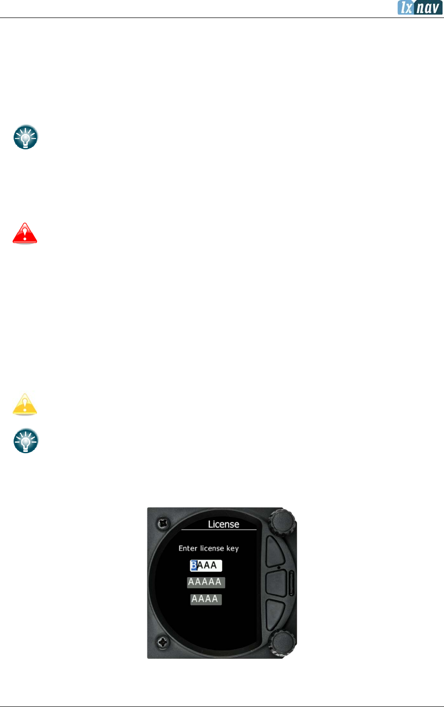
June 2018
Page 94 of 108
The remote stick is also connected to the CAN bus. On the S8x/S10x a special menu is provided
to register the remote stick. The device must be registered in case of two-seat device; it is
possible to have two remote sticks, one registered on the front and another on the rear device.
Registering a remote stick can be done on following way. Press any button on the
remote stick – in this way the S8x/S10x will detect the presence of the remote stick
on the CAN BUS, after that go under setup-hardware-remote and register remote
stick.
To confirm a remote stick, you must press the OK button on the remote
stick.
The same is done with a second remote for S8xD repeater unit. Ensure that when
registering the repeater unit that the front unit is not in Register mode, otherwise
both units will listen to the same remote stick.
The Can bus is always under power, consequently the remote stick is also under
power. After flight, please disconnect batteries or turn off master switch to prevent
discharging batteries.
8.5.5 AHRS Option
To activate AHRS an activation code must be purchased.
The AHRS option can be activated by the following procedure:
- Enter password 30000
- Enter the 13-digit license key and confirm.
If the code is correct you will see an AHRS on the AHRS page.
Activating AHRS on main unit will also activate it on all the repeaters (second seat
devices).
If you want to deactivate AHRS use same password (30000) again.
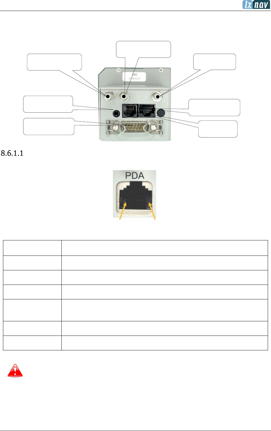
June 2018
Page 95 of 108
8.6 Ports and Wiring
8.6.1 LXNAV S8x Ports
PDA Port (RJ45)
1 2 3 4 5 6 7 8
Pin numbers
Pin Number Description
1,2 Ground
3 (output) Transmit from LXNAV S8XRS232 (e.g. Computer, IPAQ38/39xx)
4 (input) Receive to LXNAV S8XRS232 (e.g. Computer, IPAQ38/39xx)
5 (output) Transmit from LXNAV S8XLV-TTL (3.3V) (e.g. Oudie, HP302,
HP31x)
6 (input) Receive to LXNAV S8XLV-TTL (3.3V) (e.g. Oudie, HP302, HP31x)
7,8 5V OUTPUT (maximum 1A)
The RJ45 plug is NOT designed in accordance with the IGC standard. It can be
used only with dedicated cable. Do not plug an unknown cable to it as it may
damage the LXNAV S8Xunit.
Static probe
Total pressure probe
(Pitot)
TE probe or
Static
Audio output
PDA port RJ45 type
GPS port RJ12
type
Main power supply
(V7 wiring)
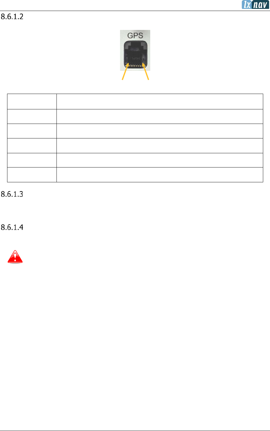
June 2018
Page 96 of 108
GPS Port (RJ12)
1 2 3 4 5 6
Pin numbers
Pin Number Description
1 (output) 12V DC, to supply GPS (Maximum 2A)
2,3 N.C.
4 (input) Receive to LXNAV S8XRS232 (e.g. NANO power 232)
5 (output) Transmit from LXNAV S8XRS232 (e.g. NANO power 232)
6 Ground
Main Port
The main port is used to connect the S8X to the main wiring loom.
Audio Port
The supplied speaker is connected with a standard 3mm phono jack.
This port is designed to be connected with an 8-ohm speaker supplied with the S8x.
Please consult with your dealer if you want to make a different connection.
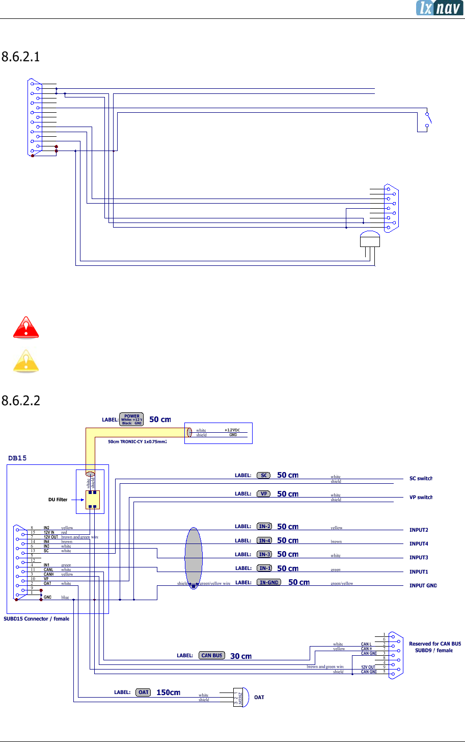
June 2018
Page 97 of 108
8.6.2 Wirings
LXNAV S8X Wiring
Newer versions of wirings can have the power supply cable shielded with black and
white colour. White is +12V DC (positive pole) and black is GND (negative pole)
If a CAN BUS cable is not connected to an LXNAV S8xD, the CAN connector must be
terminated with a CAN TERMINATOR!
LXNAV S10x Wiring
SUBD15 Connector / female
S80
1
9
2
10
3
11
4
12
5
13
6
14
7
15
8
SC switch
30 cm
50 cm
OAT
1.5m LABEL:OAT
LABEL:SC
shield
CAN BUS
SUBD9 / female
CAN H
1
6
2
7
3
8
4
9
5
J3
CAN L
CAN GND
CAN GND
12V
LABEL: CAN BUS
123
GND
LM335Z
50 cm
SC
B
A
VP
OAT
CANH
CANL
12V IN
IN1
IN3
IN2
IN0
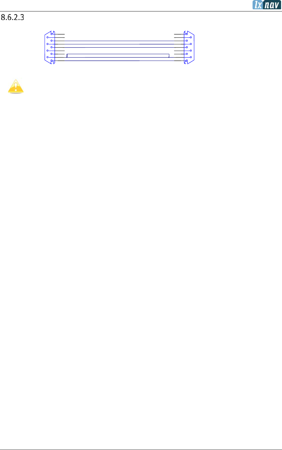
June 2018
Page 98 of 108
LXNAV S8xD Wiring
The rear seat device is powered from the first seat device.
350 cm
Reserved for CAN BUS
SUBD9 / female
CAN H
1
6
2
7
3
8
4
9
5
J3
CAN L
CAN GND (SHIELD)
CAN GND (SHIELD)
12V
LABEL: CAN BUS
1
6
2
7
3
8
4
9
5
J3
Reserved for CAN BUS
SUBD9 / male
LABEL: CAN BUS
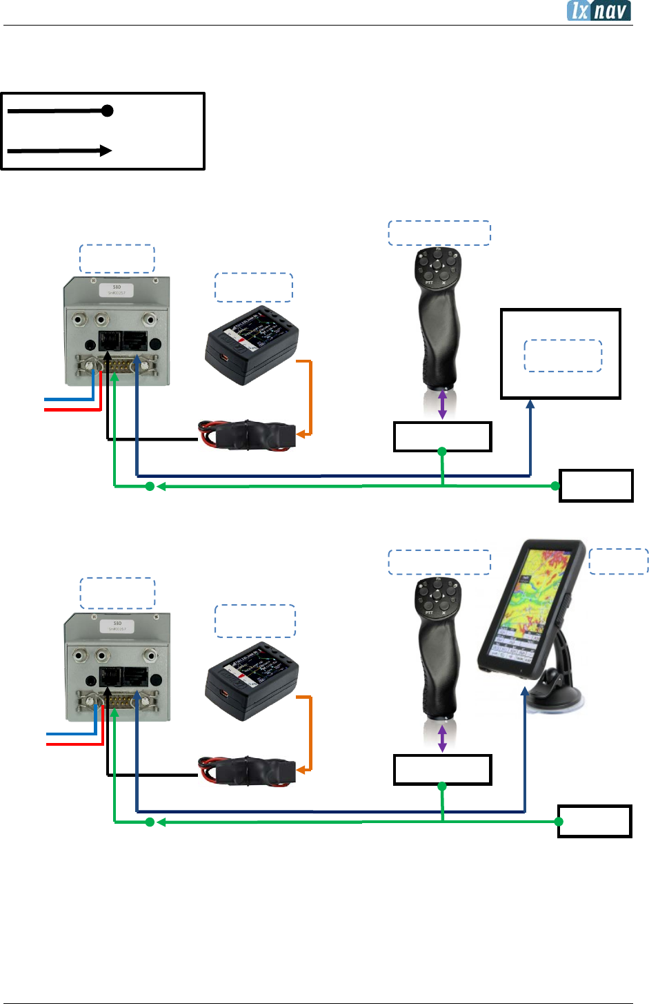
June 2018
Page 99 of 108
S8x/S10x
GND
12V
Oudie
CAN
cable
CC-NP-LX
USB cable
Terminator
Remote stick
CAN Y cable
Nano1/3/4
CAN
cable
CC-NP-LX
USB cable
Terminator
S8x/S10x
Remote stick
CAN Y cable
Nano1/3/4
MiniMap
Remote CAN
Remote CAN
8.7 S8x/S10x Configurations
8.7.1 Symbols
8.7.2 Nano/Nano3 – Sxxx - MiniMap
8.7.3 Nano3 - Sxxx - Oudie
CC-NP-LX
GND
12V
CC-NP-OUDIE
Female
Male
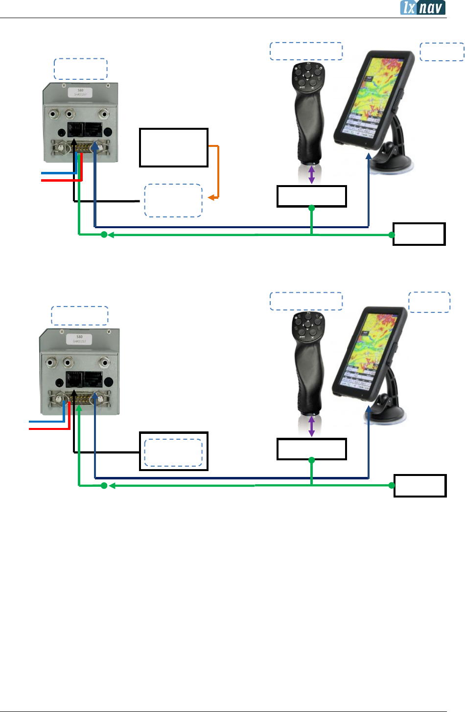
June 2018
Page 100 of 108
Oudie
CAN
cable
V7-GPS-IGC
USB cable
Colibri II
Colibri 2
Power and
data
Terminator
S8x/S10x
Remote stick
CAN Y cable
Oudie
CAN
cable
Colibri
Volkslogger
Terminator
S8x/S10x
Remote stick
CAN Y cable
V7-GPS-IGC
Remote CAN
Remote CAN
8.7.4 Colibri II – Sxxx - Oudie
8.7.5 Colibri/Volkslogger - Sxxx - Oudie
GND
12V
GND
12V
CC-NP-OUDIE
CC-NP-OUDIE
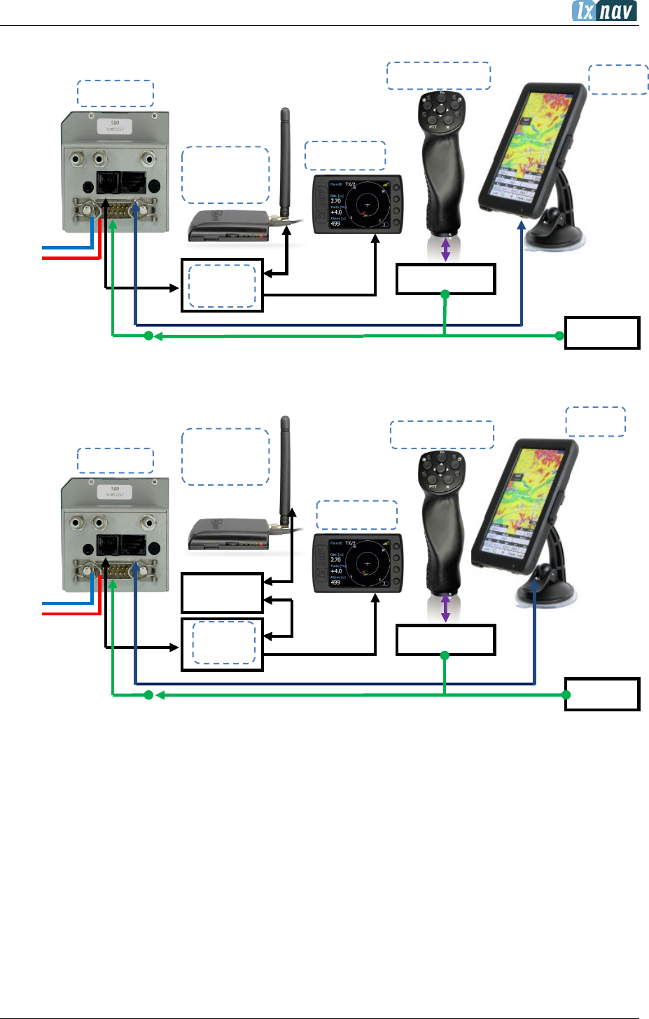
June 2018
Page 101 of 108
CAN
cable
Terminator
S8x/S10x
CAN Y cable
FlarmView
FlarmView cable
Flarm
Red box
FlarmMouse
Flarm
Splitter
Oudie
CAN
cable
Terminator
S8x/S10x
CAN Y cable
FlarmView
FlarmView cable
Flarm
Red box
FlarmMouse
Flarm
Splitter
Oudie
ADSB
Remote stick
Remote stick
Remote CAN
Remote CAN
8.7.6 Flarm – Sxxx - FlarmViewX - Oudie
8.7.7 FlarmMouse - ADSB – Sxxx - FlarmView - Oudie
GND
12V
GND
12V
CC-NP-OUDIE
CC-NP-OUDIE
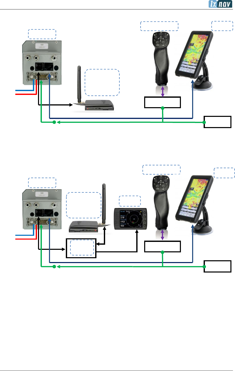
June 2018
Page 102 of 108
Oudie
CAN
cable
Terminator
S8x/S10x
Remote stick
CAN Y cable
Flarm
Red box
FlarmMouse
PowerMouse
CAN
cable
Terminator
S8x/S10x
Remote stick
CAN Y cable
Nano3
Nano Power PF
*gets 12V from S8x/S10x
Flarm
Red box
FlarmMouse
PowerMouse
Flarm
Splitter
Oudie
Remote CAN
Remote CAN
8.7.8 FlarmMouse – Sxxx - Oudie
8.7.9 FlarmMouse - Nano3 - Sxxx - Oudie
CC-NP-OUDIE
GND
12V
GND
12V
CC-NP-OUDIE
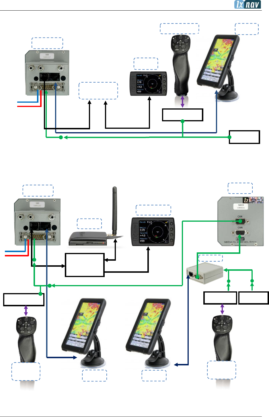
June 2018
Page 103 of 108
Flarm
Splitter
Flarm
Splitter
Flarmview2
Flarm
FlarmView cable
S8xD
S8x/S10x
CAN cable
Remote
stick
Oudie
CAN Y
cable
CAN Y cable
Terminator
Remote CAN
CAN
cable
Terminator
S8x/S10x
Remote stick
CAN Y cable
Nano3
Nano Power PF*
gets power from
S8x/S10x
PowerMouse
Port1 Port2
Oudie
Remote CAN
Remote
stick
Remote CAN
PDA CAN
8.7.10 PowerMouse + (Nano3) - Sxxx - Oudie
8.7.11 S8x/S10x– S8xD
GND
12V
Oudie
CC-NP-OUDIE
GND
12V

June 2018
Page 104 of 108
8.8 Data Transfer
8.8.1 S8x/S10x
Data Transfer/Action
Remark
S8x/S10x
↔
Oudie / Oudie BT
MC/Ballast/Bugs; ALT; TSK
declaration; Pilot declaration
S8x/S10x
→
Flarm
Task declaration
S8x/S10x
→
Nano / Nano3
TSK declaration
S8x/S10x,
also BT
↔
XC soar
MC/Ballast/Bugs; ALT; TSK
declaration; Pilot declaration
8.8.2 Other Data Transfers
Data Transfer/Action
Remark
Flarm
→
XC soar / Oudie
Flight transfer
Via direct link
XC
Soar/Oudie
→
Flarm
Task declaration
Via direct link
Nano/Nano3
→
XC soar / Oudie
Task declaration, flight
download?
Via direct link
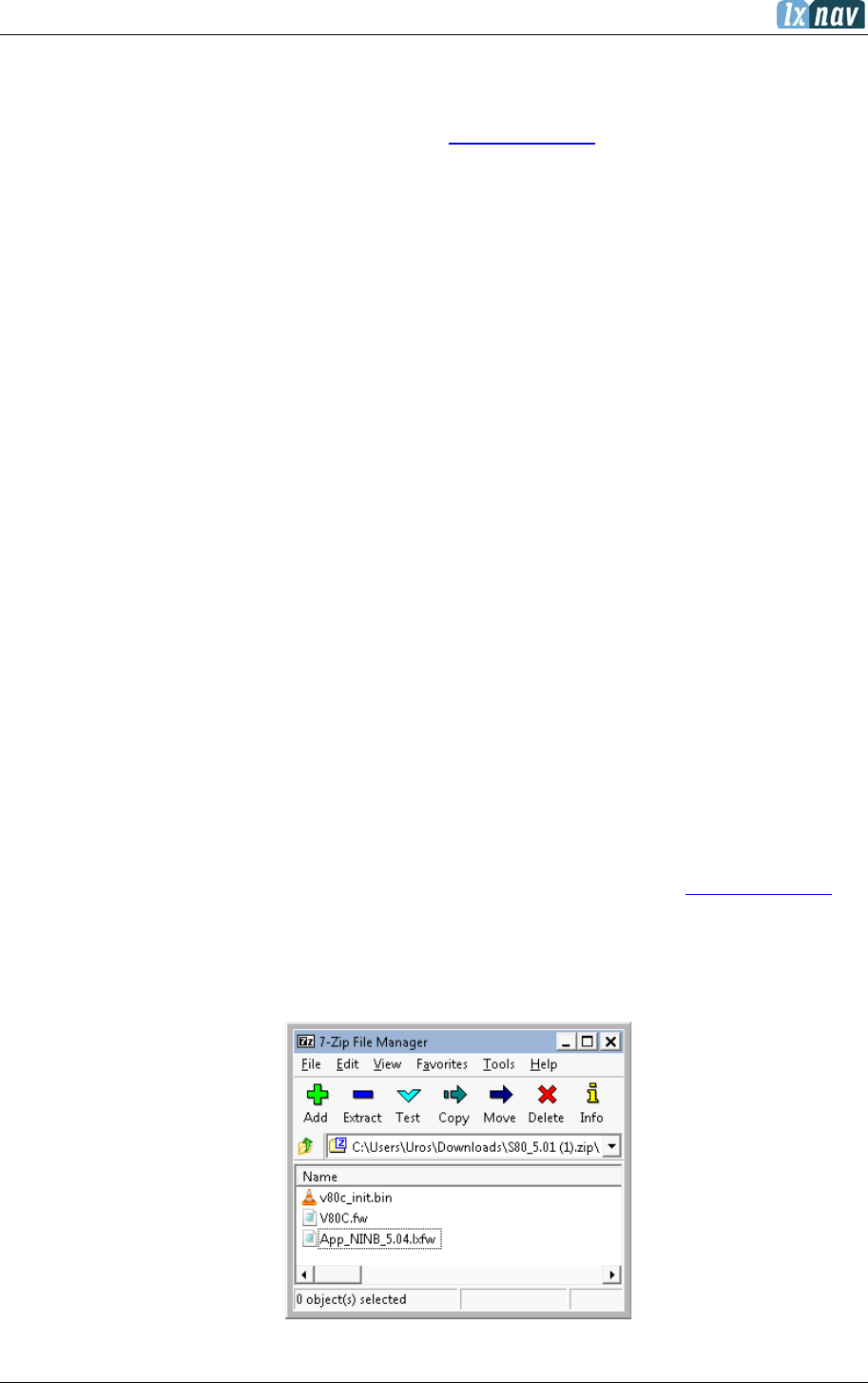
June 2018
Page 105 of 108
9 Firmware Update
Firmware updates for the main display indicator and vario unit can be easily carried out using
the micro SD Card. Please visit our webpage www.lxnav.com and download the firmware
update.
You can also subscribe to a newsletter to automatically receive news about the system.
9.1 Updating LXNAV S10x and S8x Firmware Using a Micro SD
Card
Copy the firmware ZFW file type to the SD card. The S10x will ask you to update.
After confirmation the firmware update will be performed automatically.
9.2 Updating LXNAV S8x Firmware Using a Micro SD Card (up to
fw. 5.43)
Unzip the file from the website and put all three files to the SD card:
• App_NINC_X.YY.lxfw
• V80C.fw
• V80c_init.bin
If some of these files are missing or are corrupt, the firmware update will not be successful.
Transfer the firmware update files to the micro SD card and insert it into the S8x. The unit
will ask you UPDATE? Confirm and reboot the S8x unit. The update will be performed
automatically.
9.3 Updating LXNAV S8x Firmware Using a Micro SD Card (OLD
Method)
The firmware consists of two parts, vario and display.
The firmware can be downloaded from the download-firmware section on www.lxnav.com. It
is a compressed ZIP file which must be firstly uncompressed. Inside are three files:
- App_NINB_X.YY.lxfw (this is firmware for vario part),
- V80C.fw (first part of firmware for display part),
- V80c_init.bin (second part of firmware for display part).
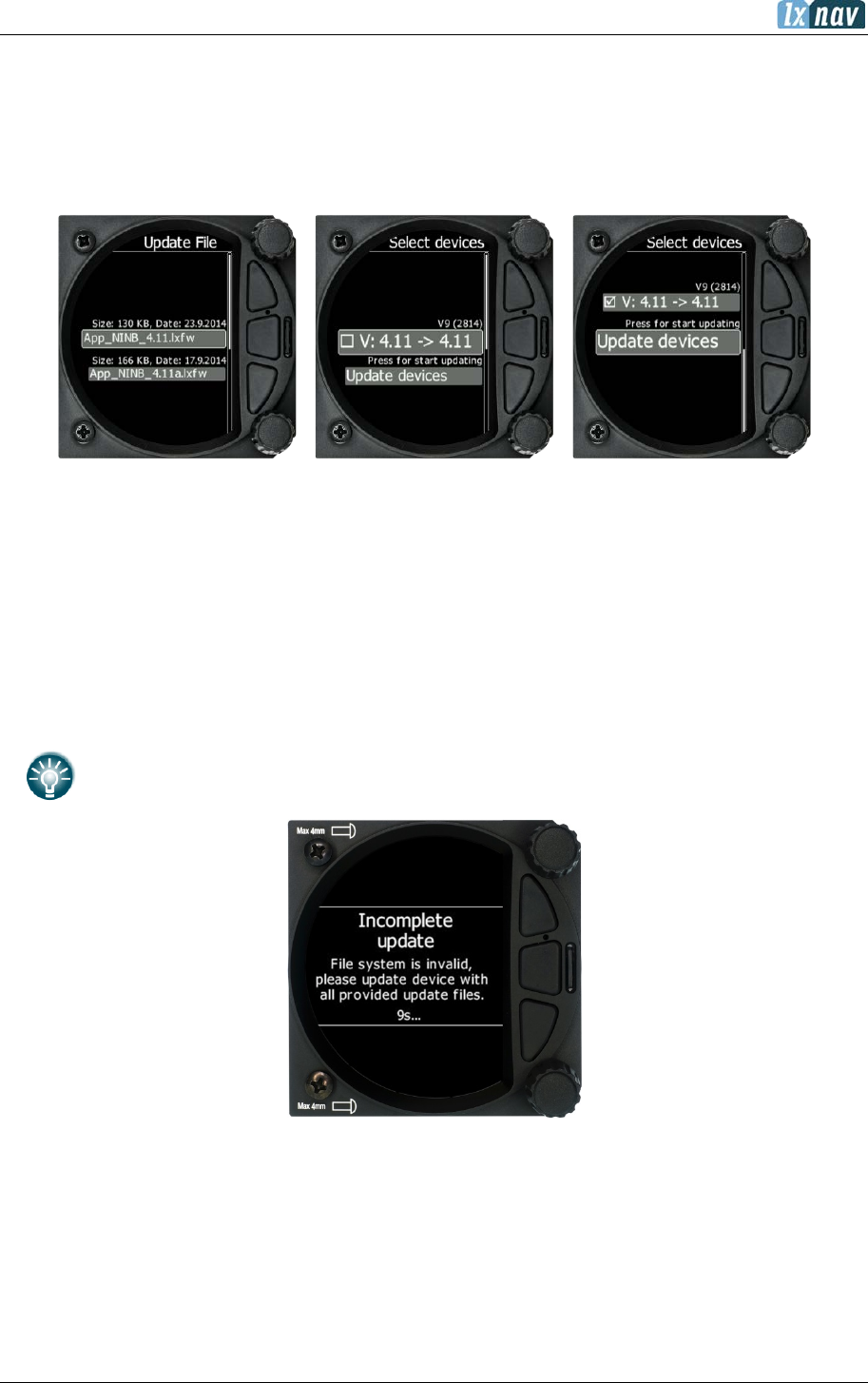
June 2018
Page 106 of 108
If some of these files are missing or are corrupt, the firmware update will not be successful.
Transfer the firmware update files to the micro SD card and insert it into the S8x. Reboot the
S8x and the update of the display part will be performed automatically.
• Go to the Setup screen and select the password option.
• Enter the password 89891 - this will bring you to the firmware update menu.
• Choose the correct firmware for the vario part and press update.
9.4 Incomplete update message (OLD version)
Update file contains 3 files:
• V8xc.fw
• V8xc_init.bin
• App_NINC_XX.lxfw
If V8xc_init.bin is missing, the following message will appear “Incomplete update …”
All updates after version 5.45 contains all 3 files zipped in one file

June 2018
Page 107 of 108
10 FAQ
1. How can I save the IGC file?
Go to the logbook page, select the flight of interest, short press on the lower rotary
button and download the flight to the micro SD card.
2. Is it possible to interface with an iPad/iPhone/other iOS devices?
That is not possible.
3. I don't see how you charge the actual unit whilst it is bolted into the plane?
Via the main power cable which is supplied with the device.
4. Do I have to put the fuse between the master switch and battery?
Yes, use a 3A fuse.
5. Can pin 3 of the (now free) PDA port be configured to provide ADSb data at 4800 baud
and a NMEA filter (GPRMC only) to a transponder?
No, the PDA port is our standard and will never be changed. For a transponder we can
provide a NMEA bridge.
6. Does the Bluetooth connection with the Oudie have all functions of the PDA port?
Yes.
7. Can the original old flat FLARM box be connected to the Flarm port?
Yes
8. Does the delivery include an external GPS aerial on S10x?
Yes, but only on the S10x.

June 2018
Page 108 of 108
11 Revision History
October 2014
Initial release version 4.9
November 2014
Updated chapters 8.5.2,8.5.3
December 2014
Updated chapters 5.3.2, 5.5.1.2, 7.2.1
January 2015
Updated chapter 5.7.11.3
January 2015
Typos, release 4.97a
January 2015
New cables for PDA and GPS port ch.8.4
March 2015
New sections for thermal assistant and logbook
May 2015
Typos, release 501e
June 2015
Release 501f, updated ch.8.5.3, updated ch.5.7.13.1
June 2015
New chapter Quick access menus 5.1
March 2016
Complete review of the manual, added S10x
June 2016
Units chapter, Warnings, Added OAT to Info page, Update procedure for
S8x, Voice warnings completely described
August 2016
Review of English language content (Thanks to Howard Mills)
August 2016
Added Flap navboxes
August 2017
Updated chapter 5.7.11.5, Updated connection schemes 8.7
September 2017
New Chapters 5.7.12, 5.1.14, Updated Ch. 5.5.2
October 2017
New chapter 5.7.16
December 2017
Updated chapter 8.5
January 2018
Minor change in chapters 5.2, 8.7.10
March 2018
New chapter S8/S80 Club 3.2.3, CAN Bridge 5.7.11.7, AHRS 5.7.11.9
and Flaps 5.7.11.8 Updated chapters: 5.7.2, 5.7.3, 5.7.12, 8.5.5
June 2018
New chapters: 5.1.15, 5.1.16, 5.1.17 Updated chapters: 5.2, 5.7.8,
5.7.12, 5.7.16
