LXFlarm View2Manual English Ver0260
User Manual: Pdf Manuals • LXNAV Gliding
Open the PDF directly: View PDF ![]() .
.
Page Count: 31
- 1 Important Notices
- Packing Lists
- 2 Basics
- 3 Operation
- 4 Working with the FlarmView2
- 5 Using FlarmView2
- 6 Editing of a task
- 7 Installation
- 8 Flarmnet Update
- 9 Firmware Update
- 10 Revision History

FlarmView² Version 2.60 April 2018
Page 2 of 31
1 Important Notices 4
1.1 Limited Warranty 4
Packing Lists 5
2 Basics 6
2.1 LXNAV FlarmView2 at a Glance 6
2.2 Technical data 7
2.3 Rocker button 7
2.4 Four push buttons 8
3 Operation 9
3.1 User Input 9
3.1.1 Buttons on FlarmView2 9
3.1.2 Text Edit Control 10
3.1.3 Selection Control 10
3.1.4 Line width selection 11
3.1.5 Colour selection 11
3.1.6 Checkbox and Checkbox List 11
3.1.7 Slider selector 11
3.2 Normal operation 12
4 Working with the FlarmView2 13
4.1 Tree structure 13
4.2 Main screen description 13
4.2.1 Flarm symbols 14
4.3 Info screen 14
4.4 Flarm screen 15
4.5 Waypoint screen 15
4.6 Task screen 15
4.7 Setup Menu 16
4.7.1 Display 16
4.7.2 Graphics 16
4.7.2.1 Map orientation 16
4.7.2.2 Airspace 16
4.7.2.3 Waypoints 16
4.7.2.4 Glider and Track 17
4.7.2.5 Task 17
4.7.2.6 Flarm 17
4.7.2.7 Theme Setup 17
4.7.3 Warnings 17
4.7.4 Observation Zones 18
4.7.5 Hardware 19
4.7.5.1 Communication 20
4.7.5.2 Sounds 20
4.7.5.3 NMEA test 20
4.7.6 Flarm 20
4.7.7 Files 21
4.7.7.1 Download flight data 21
4.7.7.2 IGC to KML 21
4.7.7.3 Waypoints 22
4.7.7.4 Airspaces 22
4.7.7.5 FlarmNet 22
4.7.8 Units 22
4.7.9 Password 23
4.7.10 About 23

FlarmView² Version 2.60 April 2018
Page 3 of 31
5 Using FlarmView2 24
5.1.1 Selecting and switching between targets 24
5.2 Flarm Warning 24
6 Editing of a task 26
7 Installation 27
7.1 Installing the LXNAV FlarmView2 27
7.2 Connecting LXNAV FlarmView2 27
7.2.1 Ports and Wiring 27
7.2.1.1 LXNAV FlarmView2 port (RJ11) 27
7.2.1.2 LXNAV FlarmView2 wiring 28
8 Flarmnet Update 29
9 Firmware Update 30
9.1 Updating LXNAV FlarmView²Flash integrity failed” 30
10 Revision History 31

FlarmView² Version 2.60 April 2018
Page 4 of 31
1 Important Notices
Information in this document is subject to change without notice. LXNAV reserves the right
to change or improve their products and to make changes in the content of this material
without obligation to notify any person or organization of such changes or improvements.
A Yellow triangle is shown for parts of the manual which should be read very
carefully and are important for operating the FlarmView2.
Notes with a red triangle describe procedures which are critical and may result in
loss of data or any other critical situation.
A bulb icon is shown when a useful hint is provided to the reader.
1.1 Limited Warranty
This FlarmView2 product is warranted to be free from defects in materials or workmanship
for two years from the date of purchase. Within this period, LXNAV will, at its sole option,
repair or replace any components that fail in normal use. Such repairs or replacement will
be made at no charge to the customer for parts and labour, provided that the customer pays
for shipping costs. This warranty does not cover failures due to abuse, misuse, accident, or
unauthorized alterations or repairs.
THE WARRANTIES AND REMEDIES CONTAINED HEREIN ARE EXCLUSIVE AND IN LIEU OF
ALL OTHER WARRANTIES EXPRESSED OR IMPLIED OR STATUTORY, INCLUDING ANY
LIABILITY ARISING UNDER ANY WARRANTY OF MERCHANTABILITY OR FITNESS FOR A
PARTICULAR PURPOSE, STATUTORY OR OTHERWISE. THIS WARRANTY GIVES YOU
SPECIFIC LEGAL RIGHTS, WHICH MAY VARY FROM STATE TO STATE.
IN NO EVENT SHALL LXNAV BE LIABLE FOR ANY INCIDENTAL, SPECIAL, INDIRECT OR
CONSEQUENTIAL DAMAGES, WHETHER RESULTING FROM THE USE, MISUSE, OR
INABILITY TO USE THIS PRODUCT OR FROM DEFECTS IN THE PRODUCT.
Some states do not allow the exclusion of incidental or consequential damages, so the above
limitations may not apply to you. LXNAV retains the exclusive right to repair or replace the
unit or software, or to offer a full refund of the purchase price, at its sole discretion. SUCH
REMEDY SHALL BE YOUR SOLE AND EXCLUSIVE REMEDY FOR ANY BREACH OF WARRANTY.
To obtain warranty service, contacts your local LXNAV dealer or contact LXNAV directly.
April 2018 © 2018 LXNAV. All rights reserved.

FlarmView² Version 2.60 April 2018
Page 5 of 31
Packing Lists
• LXNAV FlarmView2
• FlarmView2 cable
• SD card
FlarmView² Version 2.60 April 2018
Page 6 of 31
2 Basics
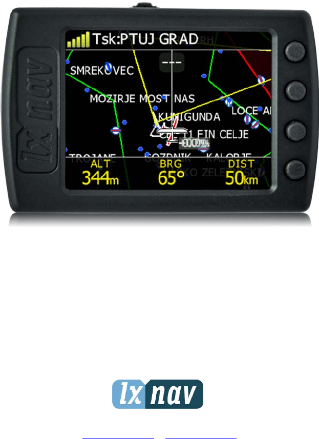
2.1 LXNAV FlarmView2 at a Glance
LXNAV FlarmView2 is a Flarm and ADS-B traffic and collision warning display with preloaded
FlarmNet database. The 2’’ QVGA sunlight readable display has a resolution of 320*240 RGB
pixels. For simple and quick manipulation, four push buttons on the FlarmView2. FlarmView2
monitors the vertical speed and altitude of each object on the screen.
The housing is made of robust ABS plastic. On the left side of the unit there is a rocker
button, on the right side there are 4 rubber push buttons.
A 4 GB solid state disk is used for data storage.
Data downloadable through a USB connection which is compatible with all operating systems
(MS Win, Linux and Mac OS).
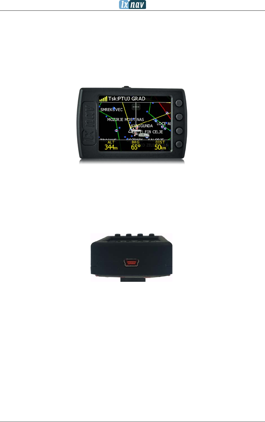
At the left side of the unit there is a mini USB connector, this is used for charging and data
transfer.
FlarmView² Version 2.60 April 2018
Page 7 of 31
2.2 Technical data
Hardware
• ARM M4 core processor
• 4GBytes memory solid state disc
• QVGA 320*240 colour pixel TFT sunlight readable trans reflective LCD
• Three direction rocker button and four push buttons
Input and output
• USB interface (mass storage device)
• SD card for data exchange
• Serial RS232 interface for PDA connection
Size and weight
• Outline dimension: 65 x 42 x 18 mm
• Weight: ~36g
Power
• Power input 9V-16V DC input.
• Consumption (0.84W) ~70mA@12V
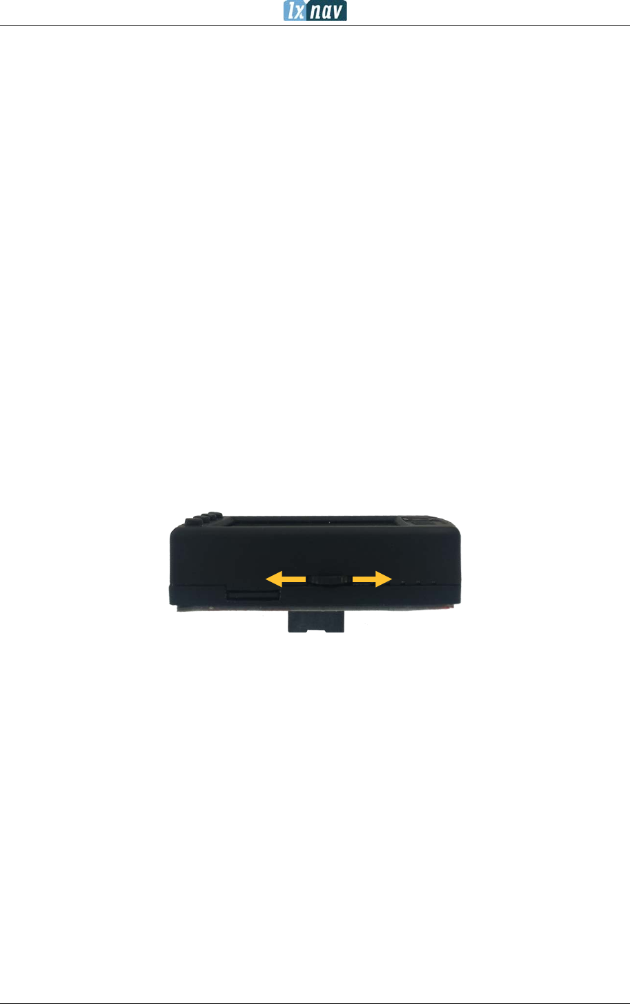
2.3 Rocker button
The rocker button has several actions; you can press it or move it left or right.
Moving the rocker button will increase or decrease the sound volume when on an info page.
On pages with the map, the rocker button has a zoom function.
In the setup page, you can move through each menu and make changes.
FlarmView² Version 2.60 April 2018
Page 8 of 31
2.4 Four push buttons
FlarmView2 has four push buttons, which have a dynamic function.
The function of each push button is described on the blue label adjacent to the button. A
label can have two options with the second option coloured red on the label. This indicates
that the button has two functions. The blue option is operated with a short press and the red
option with a long press. For labels with two options, the second option is typically the
opposite function of the first option. e.g. Next/Previous, Insert/Delete, Ok/Cancel,
forward/backward.
The functions of buttons are mostly related to the current page (waypoint, task, flarm, info
and setup). If there is no label next to the button, this button has no function.
FlarmView² Version 2.60 April 2018
Page 9 of 31
3 Operation
There are two modes of operation: Data transfer mode and Normal operation mode.
When in the data transfer (USB mode) mode, data can be exchanged. Normal operation
mode is when FlarmView2 is not in USB mode.
In data transfer mode, the last two or three green LEDs will be permanently lit, on the
screen, there will be a message “USB connected”, whereas in the normal operation mode,
up to four LEDs will be blinking, or the screen will display data only.
3.1 User Input
The FlarmView2 user interface consists of many dialogues, which have different input
controls. They are designed to make input of names, parameters, etc., as easy as possible.
Input controls can be summarised as:
• Text editor
• Spin controls (Selection control)
• Checkboxes
• Slider control
• Line width control
• Colour selection
To move the function from one control to another, use up or down buttons. By pressing the
EDIT button access to the control that is displayed is possible.
3.1.1 Buttons on FlarmView2
Each of the four buttons have dynamically set functions. When you press a button, beside
the button will appear a blue label with the action assigned to that button in that context.
On the main screen, the top button always performs the function of switching between
pages. Short press will cycle in one direction between pages, a long press will cycle in the
opposite direction between pages. A number of the pages look similar initially as the cycling
between them simply change’s the zoom level. The screen will momentarily be updated to
reflect the new zoom level. The number in a zoom level icon shows us the outer circle
radius (2km – depends on distance units setting etc.). The inner circle is half of that
distance.
The Middle buttons help with target selection by cycling through available targets. The
lower button has an EDIT function, where we can edit/view the currently selected target.
FlarmView² Version 2.60 April 2018
Page 10 of 31
3.1.2 Text Edit Control
The Text Editor is used to input an alphanumeric string; the picture below shows typical
options when editing text. Use the up/down button’s to change the value at the current
cursor position.
Push button next = “>>B” will move cursor right. A long press on the NEXT button, will
move the cursor left. At the last character position, a push of the button will confirm the
edited value, long press Ok C) will cancel editing and exit that control. If a Long press is
available, part of the button label will be a Gray colour. For the example above, a long press
of the top button “>> B” has a “back” function. A long press of the bottom button has a
“Cancel” function. The Flarm ID field is not editable; this is because the flarm identification
number is unique.
3.1.3 Selection Control
Selection boxes, also known as combo boxes, are used to select a value from a list of
predefined values. Use the up/down buttons to select the appropriate value.
FlarmView² Version 2.60 April 2018
Page 11 of 31
3.1.4 Line width selection
Line width boxes, are used to select a line width from a list of predefined widths. Use the
up/down buttons to select the appropriate width.
3.1.5 Colour selection
Colour selection boxes, are used to select a colour from a list of predefined colours. Use the
up/down buttons to select the appropriate colour.
3.1.6 Checkbox and Checkbox List
A checkbox enables or disables a particular parameter. Press the EDIT button to toggle the
value. If an option is enabled a check mark will be shown, otherwise an empty rectangle will
be displayed.
3.1.7 Slider selector
Some values like volume and brightness are displayed as a slider

FlarmView² Version 2.60 April 2018
Page 12 of 31
With EDIT you can activate the slider control and then with the up/down buttons you can
select the preferred value and confirm it with the OK push button.
3.2 Normal operation
During normal operation mode, the user can use the FlarmView2 as simple navigation,
airspace indicator and Flarm radar display. There are five pages (information page, Flarm
radar, waypoint page, task page and setup page).
FlarmView² Version 2.60 April 2018
Page 13 of 31
4 Working with the FlarmView2
4.1 Tree structure
The FlarmView2 has four modes, info, Waypoint, Task and Setup mode.
Info
Flarm
Waypoint
Task
Setup
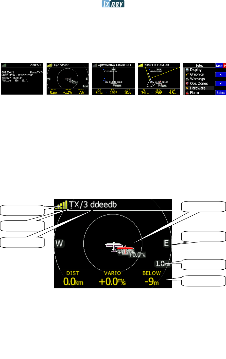
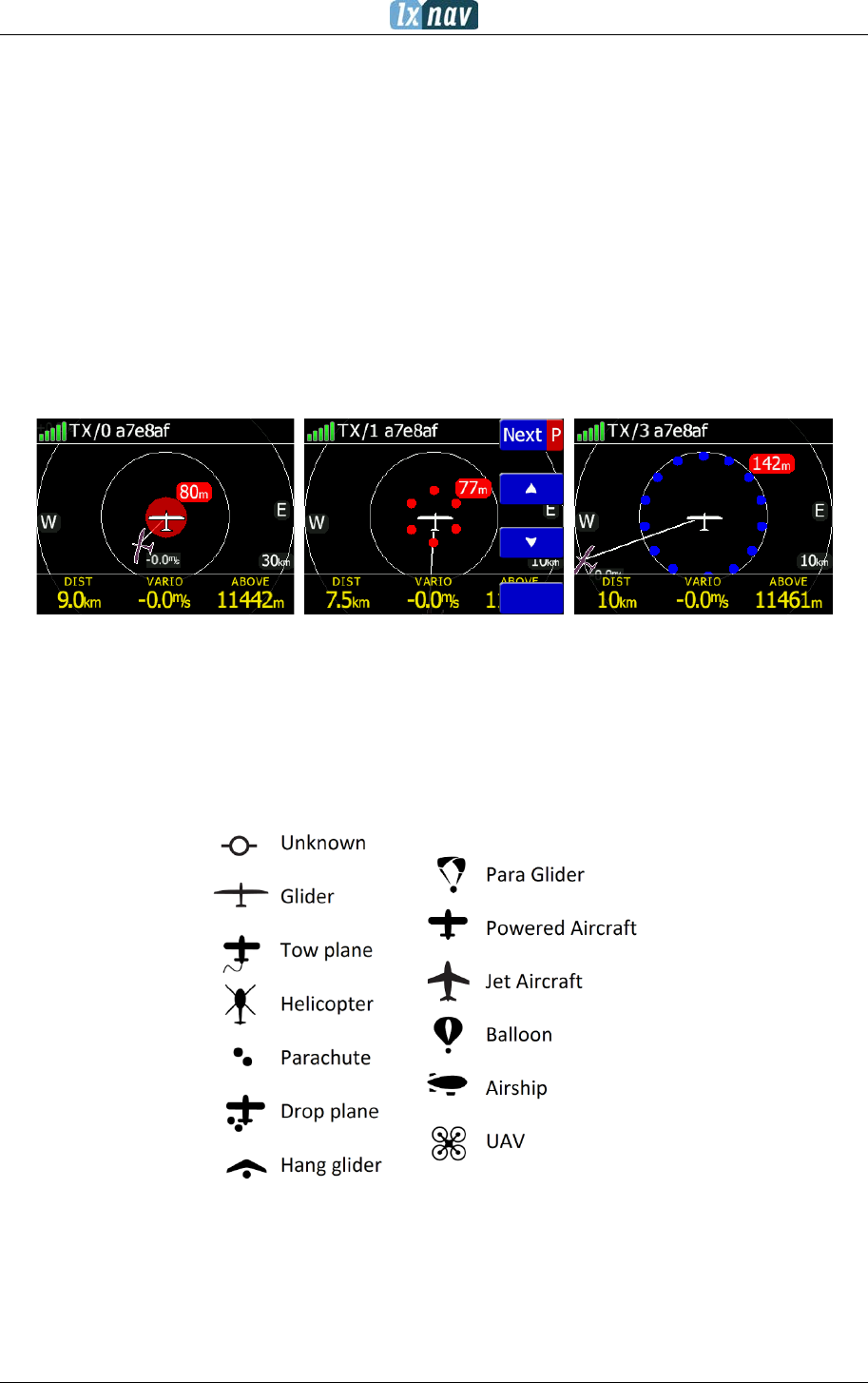
4.2 Main screen description
The main navigation screen consists of a map with coloured airspace, waypoints with names
or task (depends on which page you are looking at). The status line indicates the status of
the GPS, indicates the chosen waypoint that you are navigating to. Menu buttons appears,
when you press any one of the buttons. Each button has its own function which is described
on the button label. The functions of buttons are mostly related to the page where you are
(waypoint, task, flarm, info, setup). If there is no label on the button, this button has no
function.
In the centre top of the map is the “off course” indicator, which helps the pilot fly in the right
direction. At the bottom of the map screen there are three navboxes, showing bearing,
distance to the target and the pressure altitude.
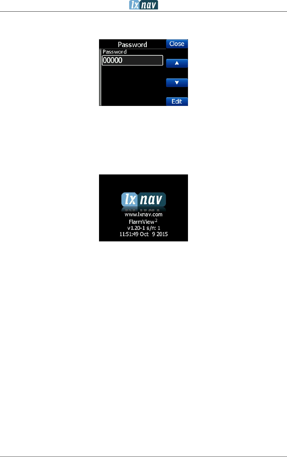
Status of Flarm
TX/3, (TX) means, that flarm device transmits data, (3) means, that Flarm receives data
from three Flarm devices.
Flarm identification is a 6 digit hexadecimal number, which can be used to identify each
target.
Flarm Targets
GPS status
Flarm status
Flarm ID
Navboxes
Zoom level
East side
FlarmView² Version 2.60 April 2018
Page 14 of 31
GPS status indicates the status of the Flarm's GPS receiver, the number of painted bars
counts the number of satellites that Flarm gps receiver receives.
• green bars indicate the GPS 3D status
• yellow means GPS 2D
• red GPS BAD
• N.C. means that FlarmView2 is not receive data from Flarm.
Zoom level tells us what the current zoom setting on the radar is
In the case of an undirected warning (such as a PCAS warning) being so close that we can’t
display as described above, a warning looks like the following picture:
All targets are displayed as a glider symbols. It's also possible to change the object’s colour,
depending on the relative altitude to our position. All received targets (Flarm or PCAS) are
marked with the same type of symbol except undirected targets, for which we don't know
from which direction they are coming from. Flarm targets can be separated only by their ID.
4.2.1 Flarm symbols
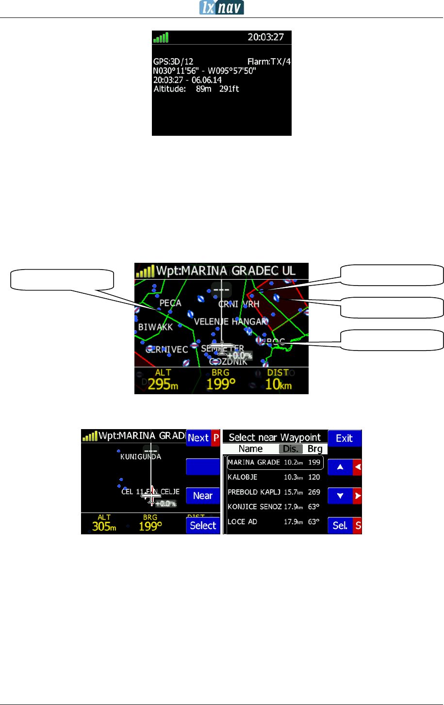
4.3 Info screen
On the info screen, data about GPS and Flarm status are available.
FlarmView² Version 2.60 April 2018
Page 15 of 31
4.4 Flarm screen
Selection of flarm targets and zoom in/out is available. If the FlarmView2 is connected to a
PowerFlarm, it is also possible to show PCAS traffic.
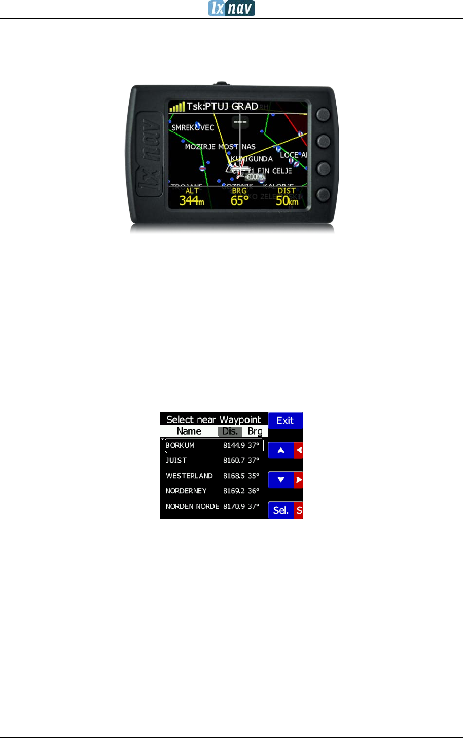
4.5 Waypoint screen
In this screen, the pilot can navigate to a selected waypoint, Select waypoint from opened
CUP file, or select landable waypoint from near list - Near button
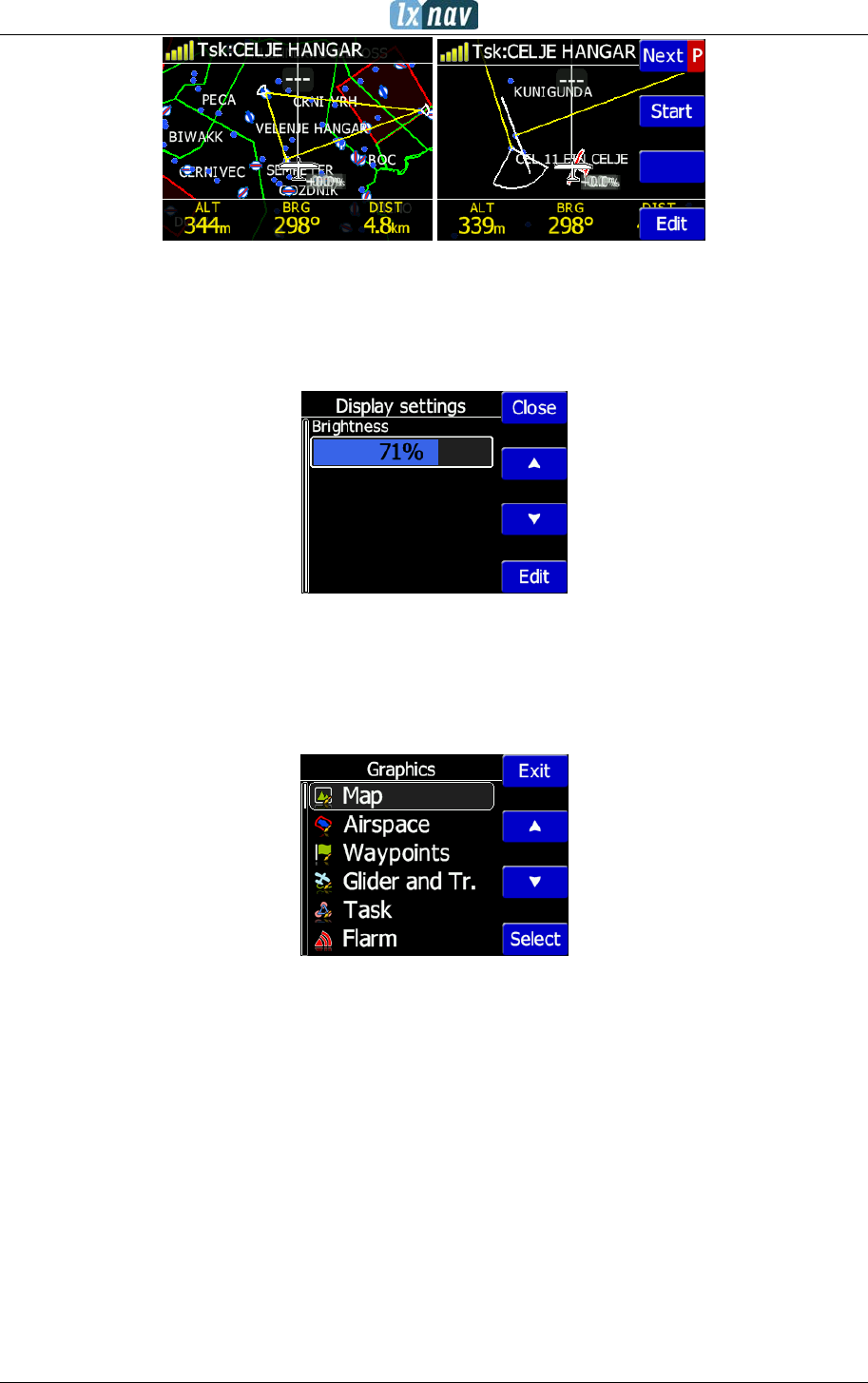
4.6 Task screen
In this screen user can navigate to waypoints from a task, switching between them, edit task
points and their zones. Read more in chapter 6.
CTR airspace
APT asphalt RWY
APT grass RWY
WPT symbol
FlarmView² Version 2.60 April 2018
Page 16 of 31
4.7 Setup Menu
4.7.1 Display
Under this menu the Brightness of display can be set after press on the EDIT button.
4.7.2 Graphics
Graphics has many sub items which are related to Map, Airspace, Waypoints, Glider and
Track, Task, Flarm and Theme Setup settings.
4.7.2.1 Map orientation
Map orientation can be set to:
• track up
• north up
4.7.2.2 Airspace
User can define indication, level of indication and colour of airspaces.
4.7.2.3 Waypoints
User can define the following settings:
• Enable waypoints indication
• Label length (from none to all characters)
• Label font size (16px, 18px and 24px)
• Label font colour
FlarmView² Version 2.60 April 2018
Page 17 of 31
4.7.2.4 Glider and Track
Here it is possible to modify track and target settings (line to target, track line...)
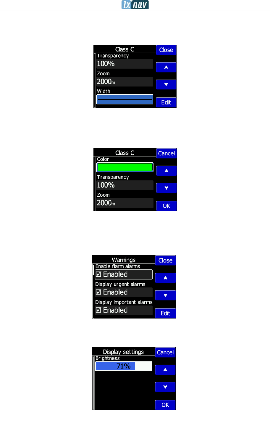
4.7.2.5 Task
Graphics of task/zone settings (colour, width, transparency) can be adjusted under this
menu.
4.7.2.6 Flarm
Flarm objects (traffic) indication can be adjusted by:
• Target above colour (default is blue)
• Target below colour (green)
• Target near colour (red)
• Selected target colour (pink)
• Label text
• Active timeout (15s) – adjusts, remaining time of glider on map after last seen
• Inactive timeout – adjusts remaining time of inactive gliders on the list. Inactive
gliders are those, where their signal was lost, after active timeout, they become
inactive and remains only on the list
• Draw line to target
• Draw history – tail behind the Flarm object
• Plane icon size
• Compass labels (in inner circle) – If enabled then “N”,”E”,”W”,”S” are in the inner
circle of Flarm radar screen
4.7.2.7 Theme Setup
User can change graphic settings on FlarmView2.
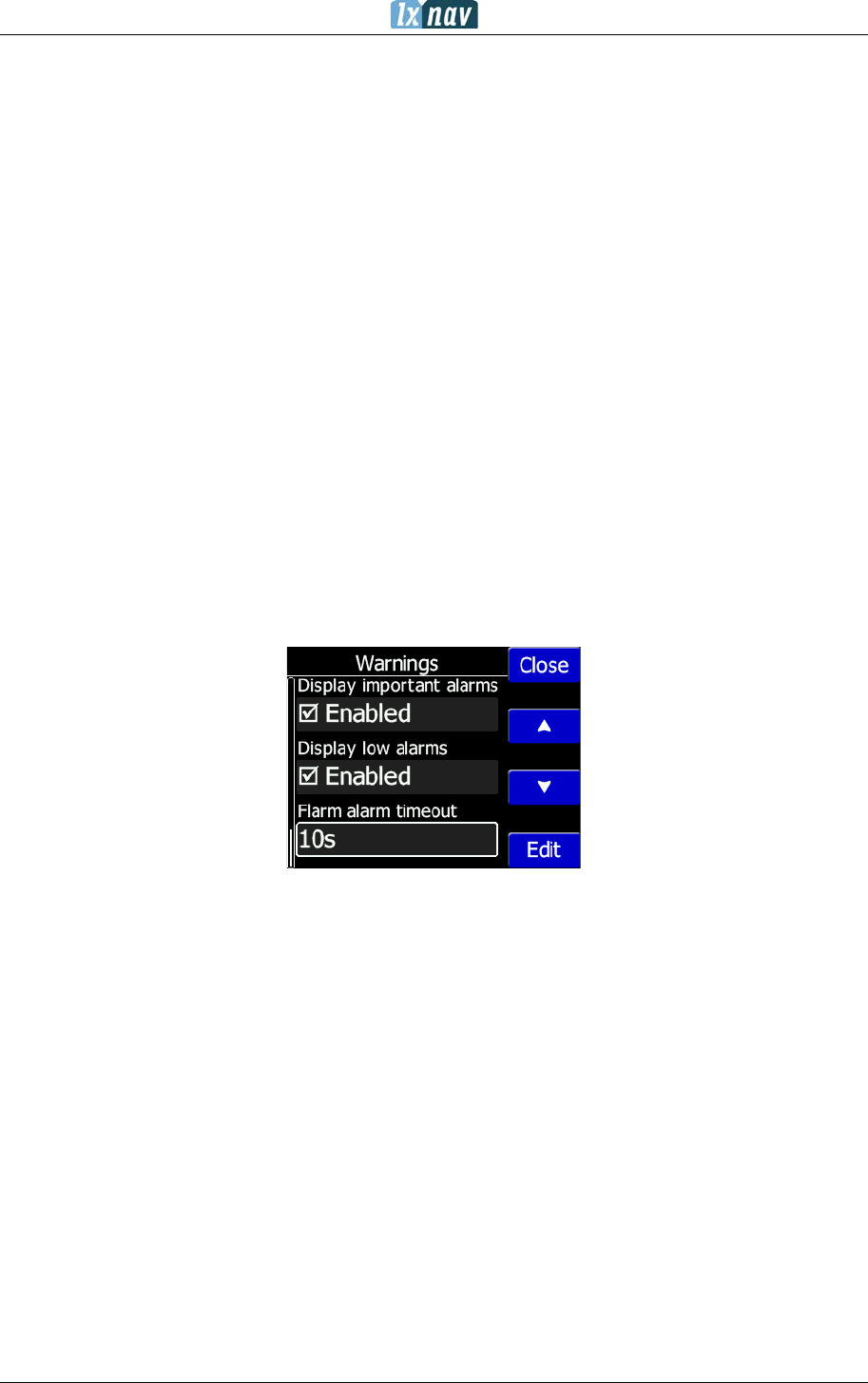
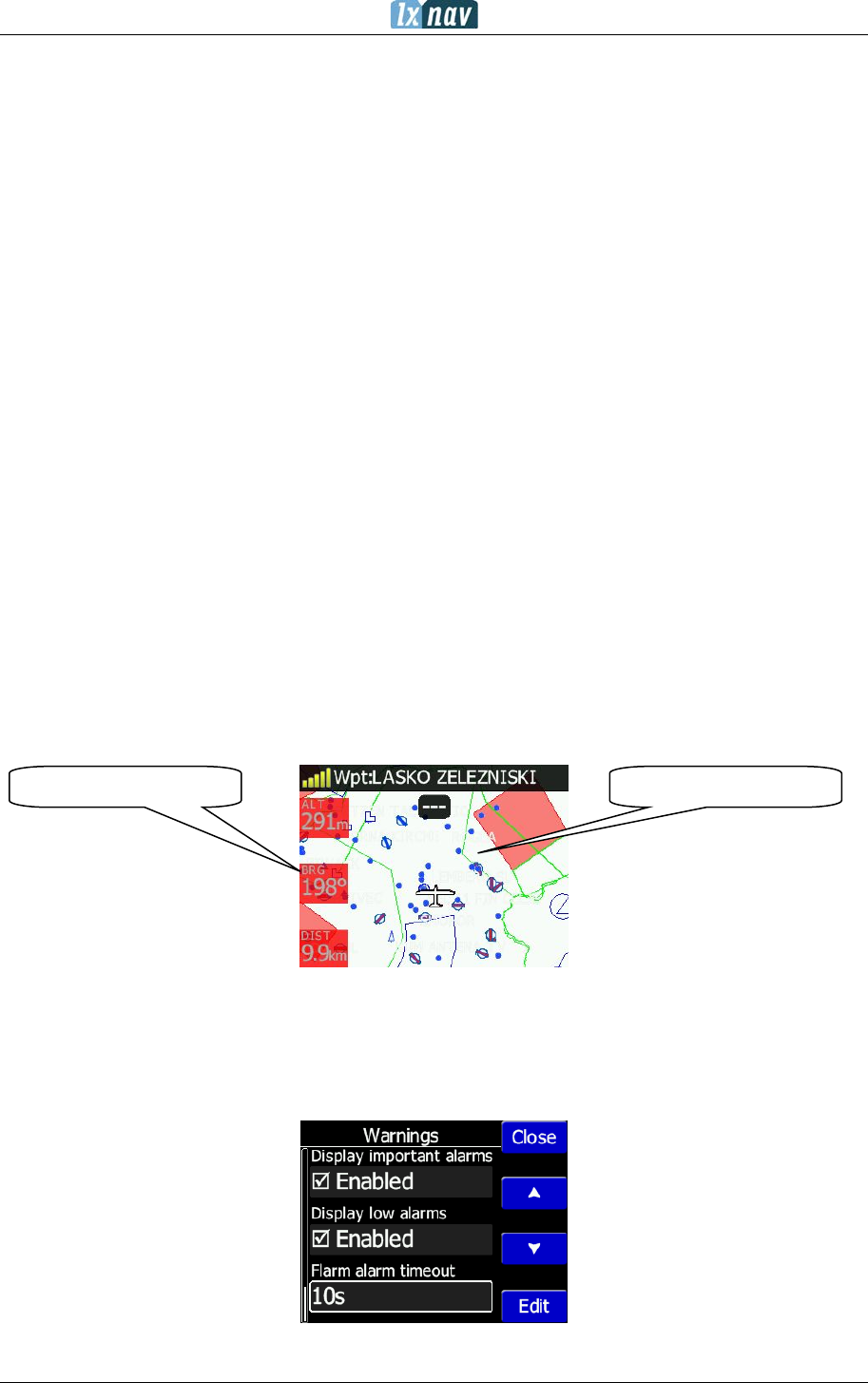
4.7.3 Warnings
Warnings can be enabled for three different levels (low, important and urgent), separately
A/C (undirected warnings can be enabled), also a distance of A/C warning, where will be
displayed flarm watch. If Alert on A/C mode is disabled, A/C mode distance is not applicable.
Theme: white-black
Navbox colour: Red
FlarmView² Version 2.60 April 2018
Page 18 of 31
The warnings are classified into three levels (See Flarm manual for details on
www.flarm.com)
• First level (Low) approximately 18 seconds before predicted collision
• Second level (Important) approximately 13 seconds before predicted collision
• Third level (Urgent) approximately 8 seconds before predicted collision.
First 3 minutes there won’t be any warnings.
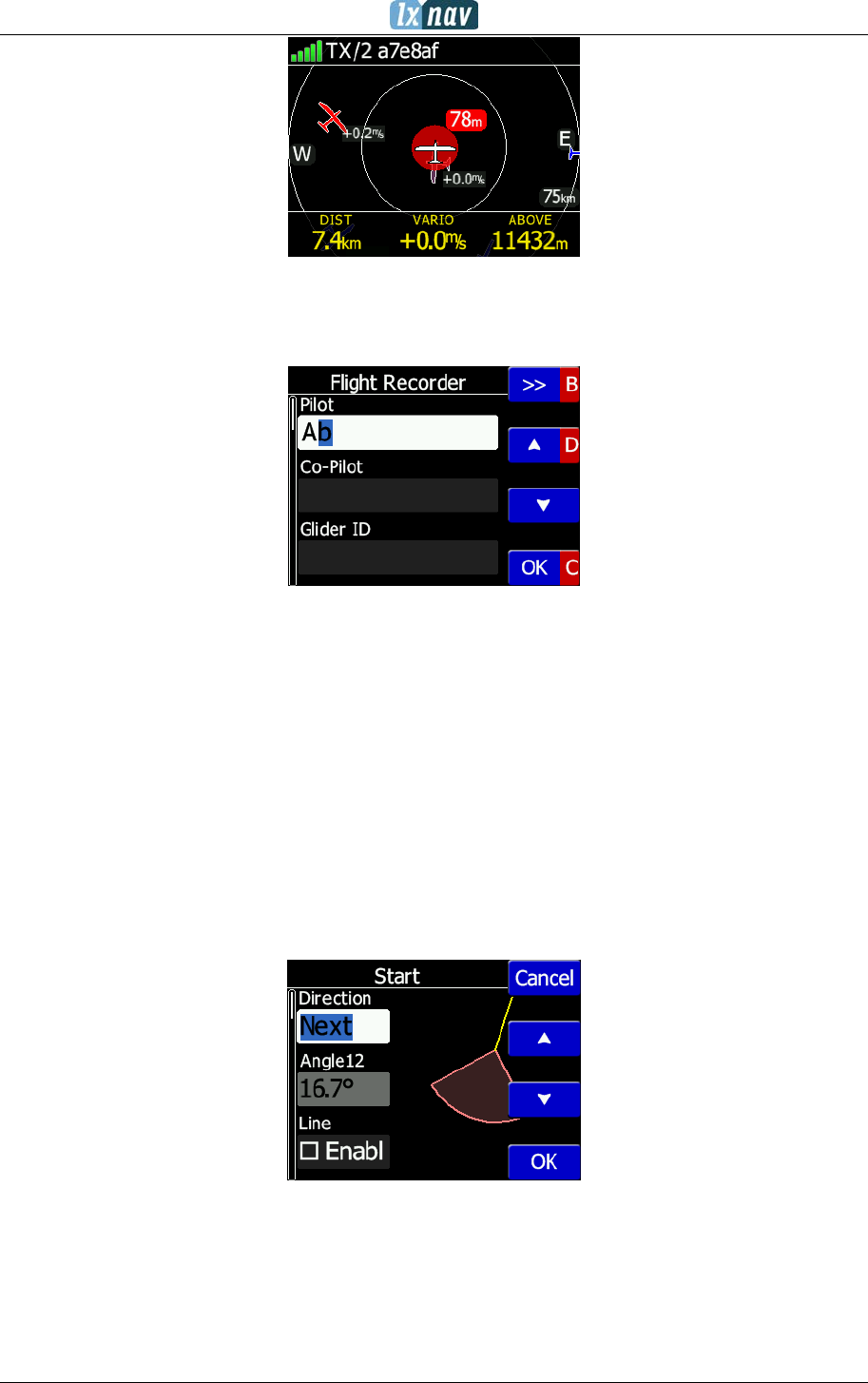
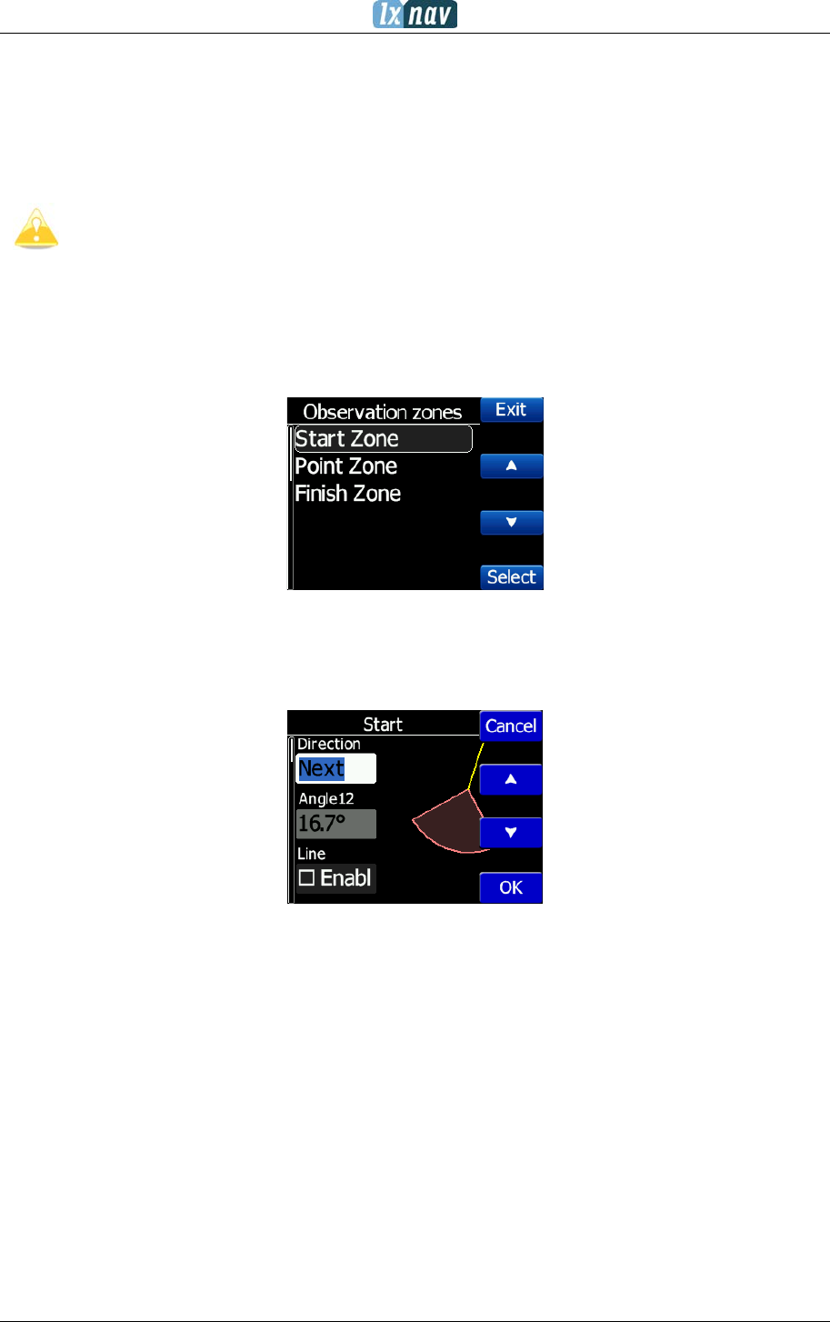
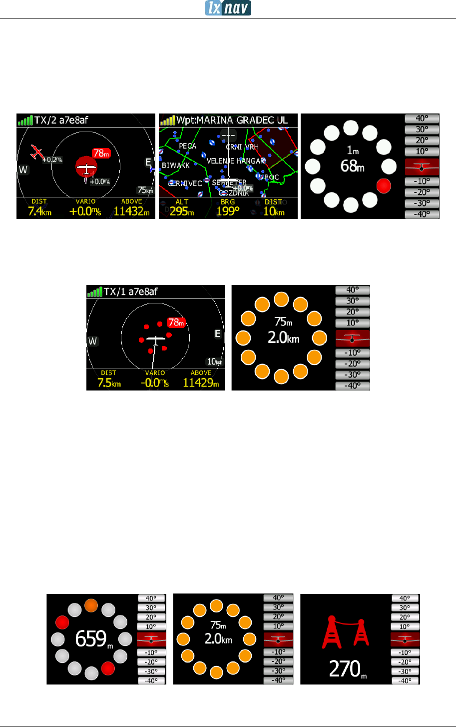
4.7.4 Observation Zones
This menu defines the default observation zone geometry. The following items can be
chosen: start zone, waypoint zone and finish zone.
Each type of observation zone is defined with two angles, two radius and mean bearing
(Angle12). These parameters enable the creation of any known zone geometry separately
for start, turn point and finish.
Using parameters in the zone dialogue it is possible to describe all types of observation
zones.
Angle12 defines the orientation of the observation zone.
Available values for Direction are:
• Symmetric: This is the most common selection for turn point.
• Fixed: This is mostly used for assigned areas.
• Next: will orient the observation zone in direction of the outgoing leg. This is usually
used for start.
• Previous: will orient the zone in direction of the incoming leg and is usually used for the
finish.
• Start: orientates the sector always towards the start.
If the Line checkbox is checked the sector will become a line type of observation zone. The
Radius 1 parameter describes half of width of line length. Use the UP/DOWN arrow buttons
to increase or decrease radius for step 0.1. Long press will increase/decrease for 5.0.
FlarmView² Version 2.60 April 2018
Page 19 of 31
If Line is not checked the Angle1 parameter will define the basic shape of the observation
zone. A value of 180° means that the zone is a cylinder and 45° is the classical FAI sector.
Use Up/Down buttons to select right angle.
Angle2 and Radius2 are used for more complex observation zone setups.
When changing observation zone parameters the screen is automatically updated to display
the new zone.
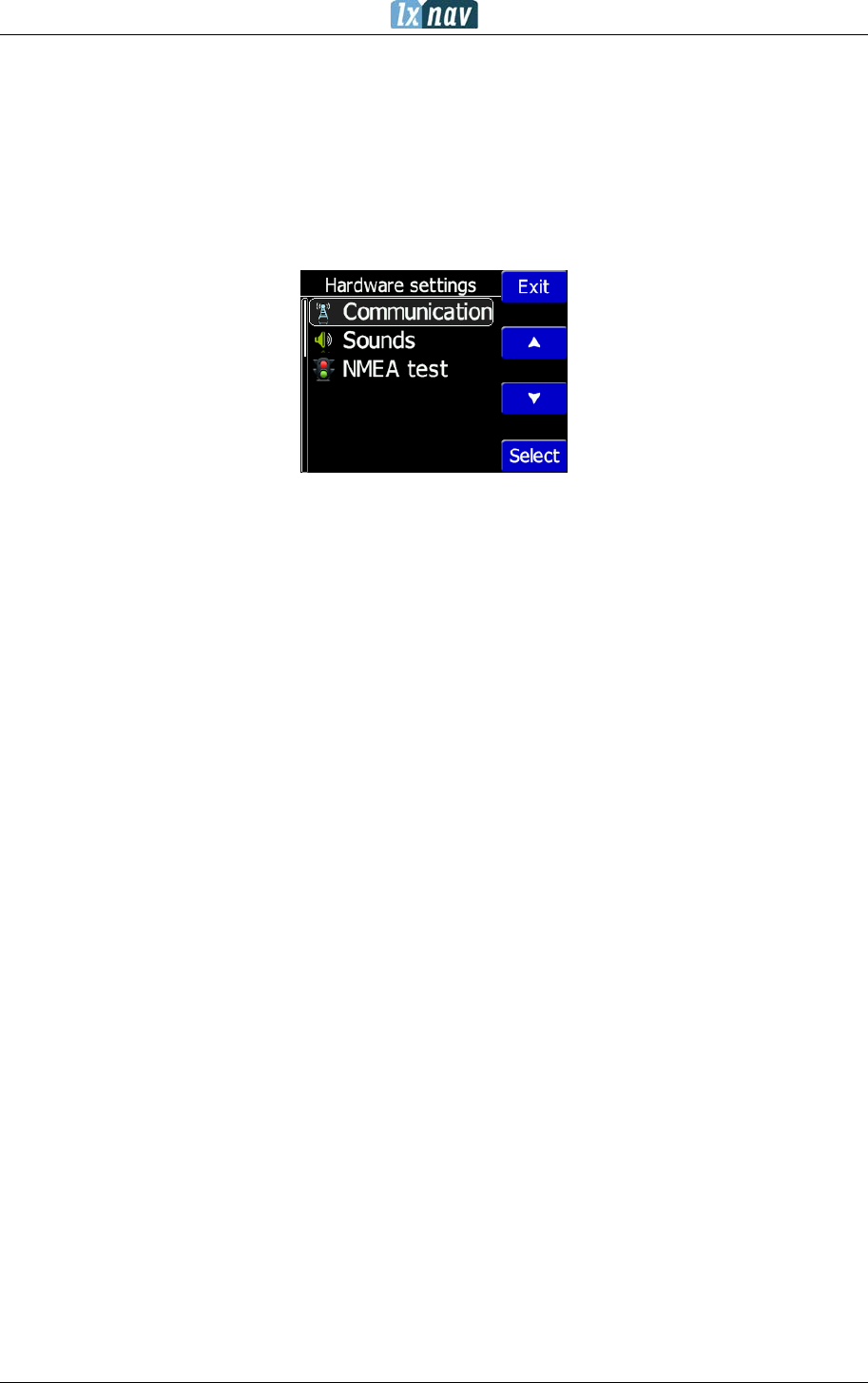
4.7.5 Hardware
In the Hardware menu there are three sub items:
• Communication
• Sounds
• NMEA test
FlarmView² Version 2.60 April 2018
Page 20 of 31
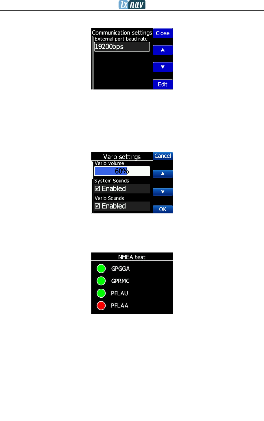
4.7.5.1 Communication
In the communication menu, you can set external port baud rate. Flarm devices typically run
at 19200 bps.
4.7.5.2 Sounds
In this menu various setting for sounds can be adjusted Volume, enabling of system
sounds and Flarm warnings.
4.7.5.3 NMEA test
In this menu user can see which data is coming from the Flarm. This page is very useful for
trouble shooting.
Explanation of Flarm sentences:
• GPGGA: Global Positioning System Fix Data
• GPRMC: Recommended minimum specific GPS/Transit data
• PFLAU: Operating status and priority intruder and obstacle data
• PFLAA: Data on other moving objects around (PCAS etc)
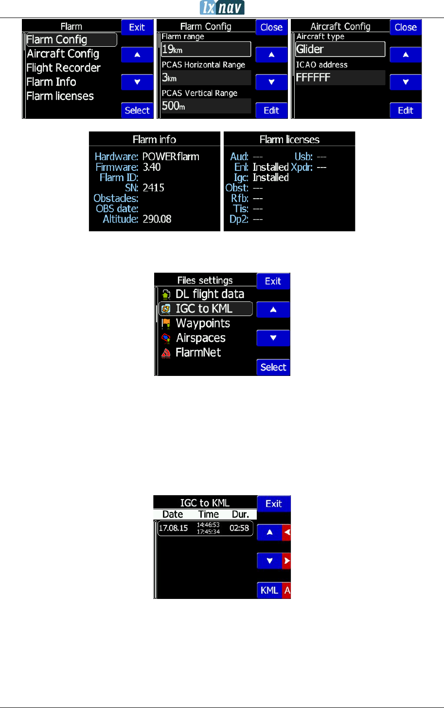
4.7.6 Flarm
If a Flarm is detected, the user can make some configuration setting changes on the Flarm
and get some Flarm status information.
FlarmView² Version 2.60 April 2018
Page 21 of 31
4.7.7 Files
Under this menu, user can download and upload files.
4.7.7.1 Download flight data
With FlarmView2 a user can download flights from Flarm through FlarmView2 on to the SD
card in the FlarmView2
4.7.7.2 IGC to KML
FlarmView2 can convert the IGC file to a KML, which can be used for Google Earth software.
FlarmView² Version 2.60 April 2018
Page 22 of 31
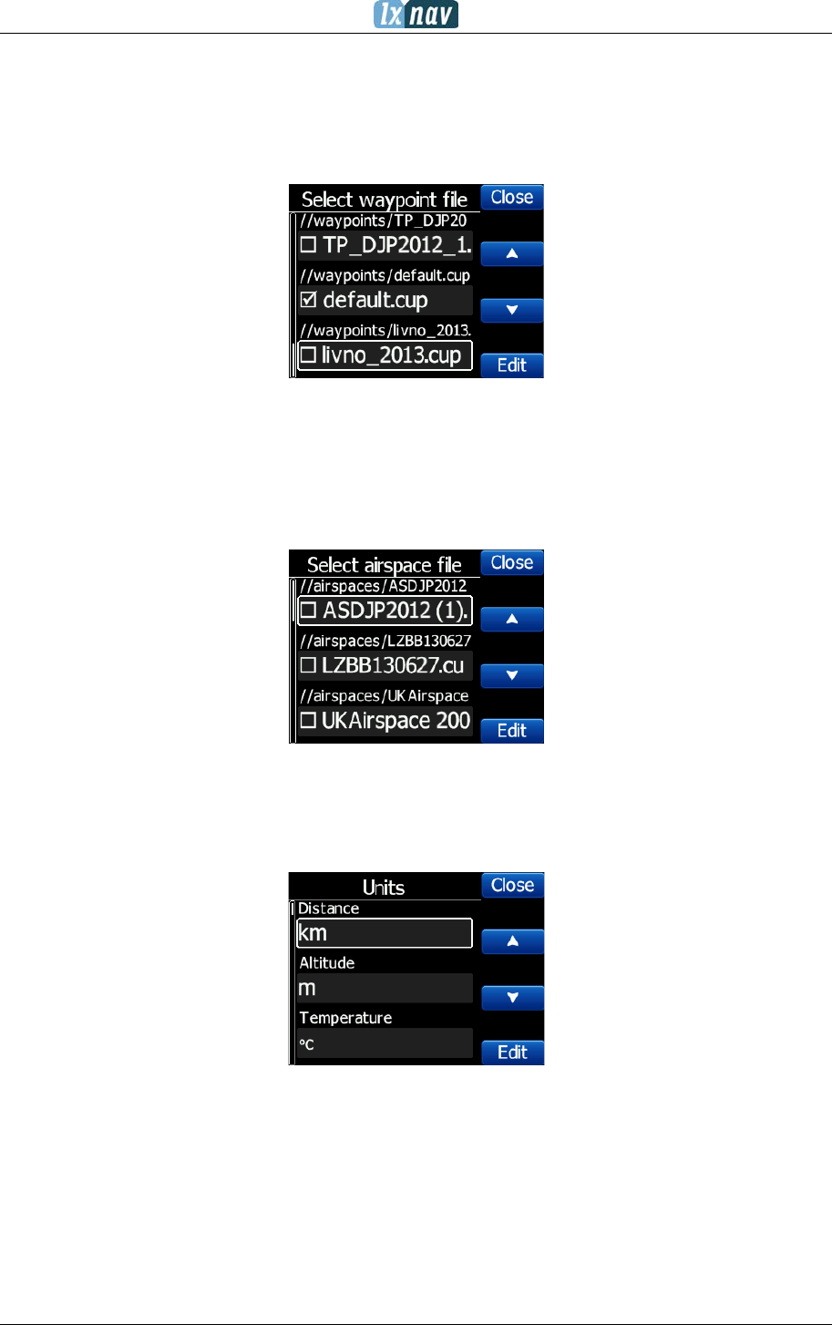
4.7.7.3 Waypoints
The FlarmView2 supports CUP file format for waypoints. There is no limitation in file size or
number of waypoints. However, the smaller the waypoint, the faster the FlarmView2 display
will operate.
4.7.7.4 Airspaces
CUB file format for airspace is supported. There is no limitation in file size however, the
smaller the airspace file, the faster the FlarmView2 display will operate.
4.7.7.5 FlarmNet
FlarmNet data can be loaded also in this section.
4.7.8 Units
All units are user configurable.
FlarmView² Version 2.60 April 2018
Page 23 of 31
4.7.9 Password
There are several passwords which run specific procedures as listed below:
• 00666 Resets all settings on FlarmView2 to factory default
• 99999 Will erase all data on Flarm device
• 30000 Will delete Flarmnet user file on FlarmView2
4.7.10 About
Under the about menu, a user can see the version and serial number of the FlarmView2
FlarmView² Version 2.60 April 2018
Page 24 of 31
5 Using FlarmView2
FlarmView2 is able to display Flarm and PCAS traffic on the map or on the radar screen. The
Radar screen is visible only when Flarm is detected by FlarmView2. In case of collision
warning, another screen will immediately appear with the direction of the threat.
PCAS alerts on the map are represented as a dotted circle with relative altitude. The PCAS
warning is represented as lights on the clock as red or orange (PCAS target information has
only a range and no direction).
A warning can be dismissed with a short press of any button. Dismiss time can be configured
in setup.
5.1.1 Selecting and switching between targets
The target can be selected using Up/Down (middle two) buttons. If the target disappears
when it is selected, the FlarmView2 will still indicate information about the last selected
target. Information about distance, altitude and vario will disappear. If the target appears
back, the trace will continue.
5.2 Flarm Warning
Below are warnings which will appear for Flarm, PCAS and Obstacle warnings.
Flarm PCAS Obstacle

FlarmView² Version 2.60 April 2018
Page 25 of 31
The screen indicates the relative position of the threat. In the first image two gliders are
approaching from the left side at the same altitude and one from back right, the second
screen is an example of undirected warning (AC mode). Middle number shows horizontal
distance to the target. The last picture indicates an obstacle warning.
FlarmView² Version 2.60 April 2018
Page 26 of 31
6 Editing of a task
In the Task page, the user can enter or edit the task. Waypoints can be loaded into a task
from the active waypoint file.
In the task page you can press the edit button. Using the up or down button you can
highlight an existing waypoint or empty space and then set a new waypoint. By pressing the
Ins. (insert) button you can start browsing through all of the waypoints in the selected CUP
file.
Selecting from a list of waypoints is very intuitive. The FlarmView2 will only offer you a
choice of characters that are available from the list of waypoint names available. Using the
button “>>” you can move to the next character (right), the red part of the label B
indicates one space back or one character to the left using a longer press of the button. A
similar function for the “OK” button, where you can confirm a selected waypoint or with the
C, you can cancel the selection of a waypoint. The previous waypoint will then be selected.
When you are back in the Task menu, you can Insert or delete D the waypoint.
To
insert
a waypoint you make a quick press on the Ins. and to
delete
a
waypoint you press and hold down D for about (not more than) a second
Each waypoint can have a custom zone or area applied.
These areas can be modified by pressing to Zone button.
FlarmView² Version 2.60 April 2018
Page 27 of 31
7 Installation
7.1 Installing the LXNAV FlarmView2
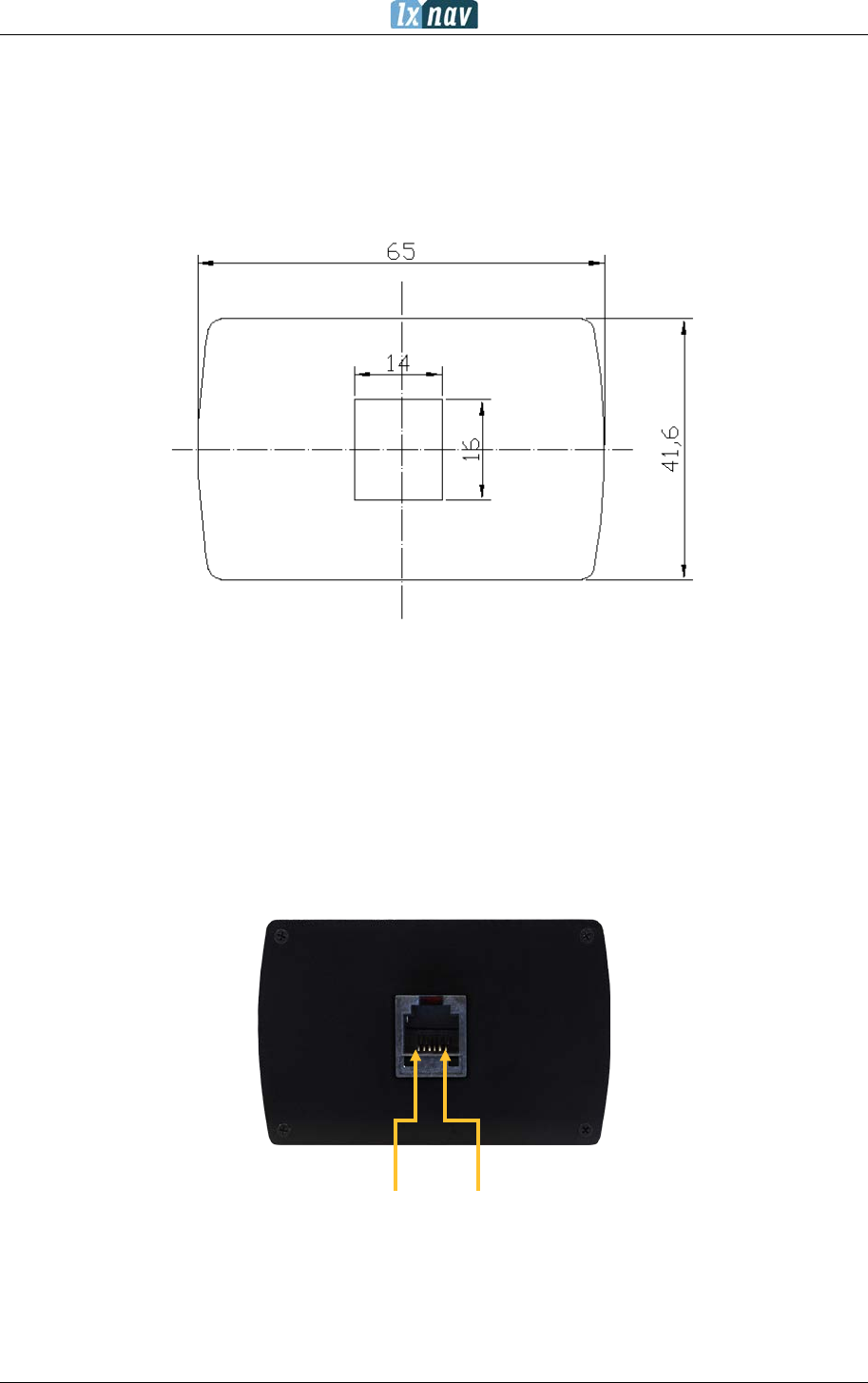
The LXNAV FlarmView2 cut-out is very simple. A square hole with dimensions 14mm x
15mm, need to be cut.
Peel off protection film and stick the FlarmView2 to the instrument panel.
7.2 Connecting LXNAV FlarmView2
FlarmView2 can be connected to any Flarm or ADS-B device with the FlarmView2 cable.
7.2.1 Ports and Wiring
7.2.1.1 LXNAV FlarmView2 port (RJ11)
1 2 3 4 5
Pin numbers

FlarmView² Version 2.60 April 2018
Page 28 of 31
Pin number Description
1 (Power input) 12VDC (On version 2)
2 (Power input) 3.3VDC (On version 1)
3 GND
4 (input) Data in RS232 – receive line
5 (output) Data out RS232 – transmit line
6 Ground
7.2.1.2 LXNAV FlarmView2 wiring

FlarmView² Version 2.60 April 2018
Page 29 of 31
8 Flarmnet Update
Flarm net database can be updated very easily.
• Please visit http://www.flarmnet.org
• Download file for LXNAV (LX8000, LX8080, LX9000) or click on following link:
http://www.flarmnet.org/files/lxfile.php
• FLN type file will be downloaded.
• Copy flarm.fln file to SD card of FlarmView2.

FlarmView² Version 2.60 April 2018
Page 30 of 31
9 Firmware Update
Firmware updates of the LXNAV FlarmView2 can be easily carried out using the SD card.
Please visit our webpage www.lxnav.com and check for the updates.
You can also subscribe to a newsletter to receive news about the LXNAV FlarmView
automatically.
9.1 Updating LXNAV FlarmView²Flash integrity failed”
• Download the latest firmware from our web site, section downloads/firmware
http://www.lxnav.com/download/firmware.html.
• Copy fv2.fw file to FlarmView’s2 SD card.
• Turn on FlarmView².
• Firmware update will take a few seconds.
If the update procedure is interrupted, LXNAV FlarmView will not start. It will
cycle in bootloader application with red message “Flash integrity failed”.
Bootloader application is waiting to read the right firmware from SD card. After
successful firmware update LXNAV FlarmView will start again.
If FlarmView gives you message “Flash integrity failed”, this means that firmware
update was not successful and it will need to be repeated.

FlarmView² Version 2.60 April 2018
Page 31 of 31
10 Revision History
June 2015
Initial release version 1.02
August 2015
Chapter 5.7.5.3 – explanation of NMEA sentences
October 2015
Added more detailed descriptions
Added chapters from 4.7.2.1-4.7.2.7
Added chapters 4.7.7.1-4.7.7.5
Added chapter 9 and 9.1
November 2016
Updated ch.4.7.3
July 2017
Added chapter 4.2.1
April 2018
Updated chapter 4.7.3
