LG Dishwasher LDS5811 Service Manual
Lg - Dw - Lds5811 Service Manual LG - DW - LDS5811 Service Manual LG - DW - LDS5811 Service Manual LG applianceservicesecretsmembership.com_manuals
Lg 3828Ed3001X LG 3828ED3001X LG 3828ED3001X LG applianceservicesecretsmembership.com_manuals
2013-04-09
: Pdf Lg - Dishwasher - Lds5811 Service Manual LG - Dishwasher - LDS5811_Service_Manual LG
Open the PDF directly: View PDF ![]() .
.
Page Count: 55

DISHWASHER
SERVICE MANUAL
BEFORE SERVICING THE UNIT, PLEASE READ THIS MANUAL CAREFULLY
FOR SAFETY AND CORRECT SERVICES.
NOTE
MODEL : LDF 7810WW / LDF 7810BB / LDF 7810ST
MODEL : LDF 7811WW / LDF 7811BB / LDF 7811ST
LDS 5811WW / LDS 5811BB / LDS 5811ST
3828ED3001X 2005.3.10 5:18 PM 페이지2 001 HP LaserJet 5000 Series

- 3 -
1. CAUTION......................................................................................................................... 4
2. SPECIFICATIONS ........................................................................................................... 5
3. WIRING DIAGRAM........................................................................................................ 6
4. FEATURES & TECHNICAL EXPLANATION ................................................................... 7
5. PARTS NAME................................................................................................................ 13
6. PROGRAM CHART ..................................................................................................... 15
7. HOW TO DISASSEMBLE ............................................................................................ 16
8. TROUBLE SHOOTING METHODS.............................................................................. 25
A. TROUBLE SHOOTING ACCORDING TO DISPLAYED ERROR MESSAGE.......... 25
B. TROUBLE DIAGNOSES AND REPAIR BY SYMPTOM........................................... 27
9. INSTALLATION INSTRUCTION ................................................................................... 31
10. EXPLODED VIEW .......................................................................................................37
11. REPLACEMENT PART LIST ........................................................................................45
CONTENTS
3828ED3001X 2005.3.10 5:18 PM 페이지3 001 HP LaserJet 5000 Series

- 4 -
DISCONNECT POWER CORD BEFORE SERVICING
RECONNECT ALL GROUNDING DEVICES
IMPORTANT SAFETY NOTICE !
This service information is intended for individuals
possessing adequate backgrounds of electrical,
electronic and mechanical experience.
Any attempt to repair this appliance may result in
personal injury and property damage.
The manufacturer or seller can not be responsible
for the interpretation of this information, nor can it
assume any liability in connection with its use.
CAUTION !
3828ED3001X 2005.3.10 5:18 PM 페이지4 001 HP LaserJet 5000 Series
- 5 -
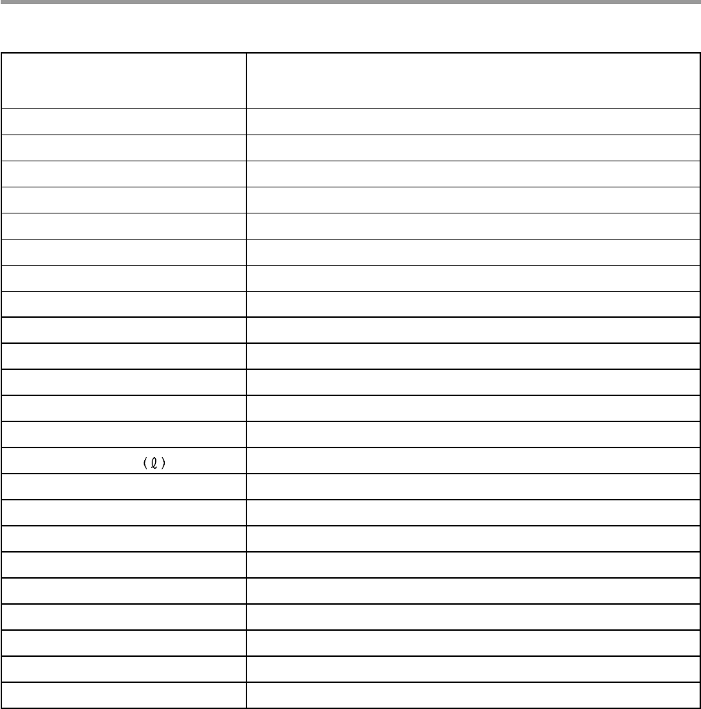
2. SPECIFICATION
Rated Voltage / Frequency AC 120V/60Hz
Installation Built-In
Place Settings 16
Product Dimension(in) 23 7/8
〃x 25
〃x 33 7/8
〃
Product Weight(lbs) 7811/7810 series : 115lbs, 5811 series : 110lbs
Door Color White, Black, Stainless
Tub Material Stainless Steel
Control Electronic
Rated Power(Watt) 1,350
Heater Power(Watt) 1,200
Programs 6
Upper Rack Position Adjustable
Lower Rack 50% Fold down
Water Consumption 21-30 (Normal)
Power Consumption(kWh/year) 370
Operating Time (min) 101-135 (Normal)
Fan Dry System Yes
Delay Start Function Yes
Auto-Off Power Switch Yes
Process Monitor Yes
Wash Level 5
Racks Nylon Coating
Operating Water Pressure (Bar) 20-120 (140-830kPa)
ITEM SPECIFICATION
3828ED3001X 2005.3.10 5:18 PM 페이지5 001 HP LaserJet 5000 Series
- 6 -
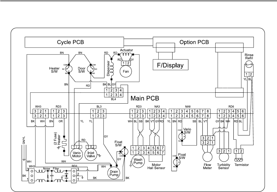
3. WIRING DIAGRAM
3828ED3001X 2005.3.10 5:18 PM 페이지6 001 HP LaserJet 5000 Series
- 7 -
4. FEATURES & TECHNICAL EXPLANATION
4-1. Product Features
If you raise the Upper Rack, you can load large dishes in the Lower Rack.
(Max. 14 in.)
The tall tub provides large dishes loading as well as large capacity.
LG dishwashers let you load oversized items in the Lower and Upper Rack.
Newly introduced Slim Direct Inverter motor is inverter-controlled. Speed is
controlled based on program selection. It also offers high energy efficiency to
minimize energy loss.
This is one of the best performance solutions for drying dishes because it
minimizes venting humid air to the outside of the dishwasher. In addition, this
system ensures better drying results compared to the condensing drying
system.
Because of alternating water spray between the Upper and Lower
Rack, the water pressure allows superior performance and reduced
consumption of water and electricity.
For best wash results, the self-cleaning filter system continuously cleans the
water as it circulates. Your LG dishwasher has a self-cleaning filter that grinds
food into small particles before it goes down the drain.
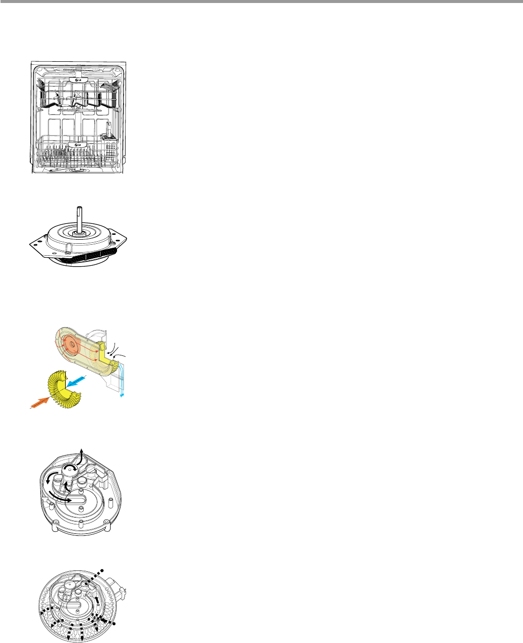
■■Ultra Big Capacity
■■Slim Direct Inverter Motor
■■Hybrid Drying System
■■Vario Spray System
■■Self Cleaning Filter
Moist
Air
Dry
Air
Mixed
Air
to
Upper
Arm
to
Lower
Arm
Soil Sensor
Fine Mesh
to Drain
3828ED3001X 2005.3.10 5:18 PM 페이지7 001 HP LaserJet 5000 Series
- 8 -
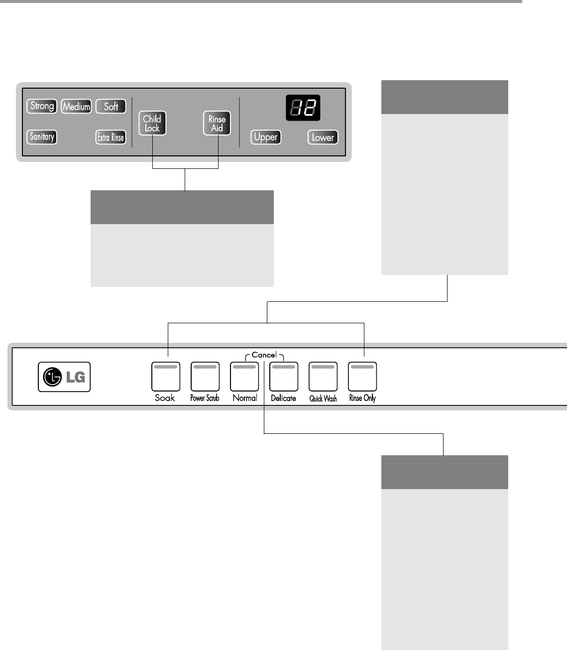
4-2. Display Panel
4-2-1. LDF 7811/7810 Series
PROGRAM
• Press the program that
corresponds to your
desired wash cycle.
CANCEL
• To cancel a running
program, open the door,
then press and hold the
Normal and Delicate
buttons for 3 seconds.
INDICATOR
• Child lock: Lamp will turn on
when Child Lock setting is on.
• Rinse Aid: Refill with Rinse aid
when Lamp turns on.
This program is for very heavily soiled loads including pots,
pans and casserole dishes which may have dry food residue.
This program is for very heavily soiled loads
This program is for normally soiled everyday loads.
This program is for washing delicate items like glasses.
This program is for that quick wash of lightly soiled recently
used dishes and cutlery.
This program is for very lightly soiled loads.
Soak
Normal
Quick Wash
Rinse Only
Delicate
Power Scrub
Control panel may vary on some models.
3828ED3001X 2005.3.10 5:18 PM 페이지8 001 HP LaserJet 5000 Series
- 9 -
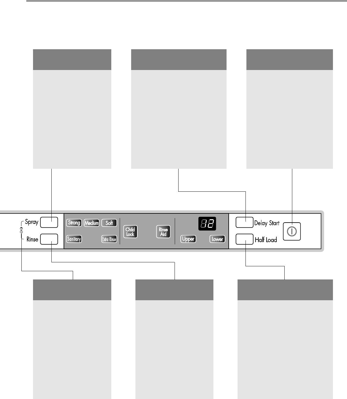
SPRAY
(INTENSITY)
• Repeated pressing of the
Spray button will select
Strong, Medium or
Soft.
DELAY START
• If you want to delay the start of
a selected program, press the
Delay Start button.
• Each press of Delay Start will
delay the start of the cycle by
one hour.
• The delay start time can be
adjusted from 1 to 24 hours in
one-hour increment.
HALF LOAD
• In case of a small load, use the
upper or lower rack only to save
energy.
• Each press of the Half Load
button cycles between upper
rack only and lower rack only.
• If you don't press Half Load,
the dishwasher runs normally,
i.e, operation of upper and
lower spray arm alternating
periodically.
POWER
• For operating, press this
button first for power on.
• After operating, the power
automatically switches off
for safety and economy.
• In case of an unusual Power
surge or disturbance, the
power may be automatically
turned off for safety.
CHILD LOCK
• Lock the control buttons
to prevent the settings
from being changed.
• To lock/unlock, press
Spray and Rinse
buttons simultaneously
for 3 seconds with door
open.
SANITARY/
EXTRA RINSE
• Repeated pressing of the
Rinse button will select
Sanitary, Extra Rinse
or both.
• If you select the Sanitary
function, the temperature
of Heating Rinse can
reach 161。F (72℃).
• When you select Extra
Rinse, an additional
rinse cycle is added.
3828ED3001X 2005.3.10 5:18 PM 페이지9 001 HP LaserJet 5000 Series
- 10 -
Strong
Medium
Soft
Spray Rinse
Half Load
Soak
Sanitary
Extra
Rinse
Upper
Lower
SPRAY
(INTENSITY)
• Repeated pressing of the
Spray button will select
Strong, Medium or
Soft.
CHILD LOCK
• Lock the control buttons
to prevent the settings
from being changed.
• To lock/unlock, press
Spray and Rinse buttons
simultaneously for 3
seconds.
SANITARY/
EXTRA RINSE
• Repeated pressing of the
Rinse button will select
Sanitary, Extra Rinse
or both.
• If you select the Sanitary
function, the temperature
of Heating Rinse can
reach 161。F (72℃).
• When you select Extra
Rinse, an additional
rinse cycle is added.
HALF LOAD
• In case of a small load, use the
upper or lower rack only to save
energy.
• Each press of the Half Load
button cycles between upper
rack only and lower rack only.
• If you don't press Half Load,
the dishwasher runs normally,
i.e, operation of upper and
lower spray arm alternating
periodically.
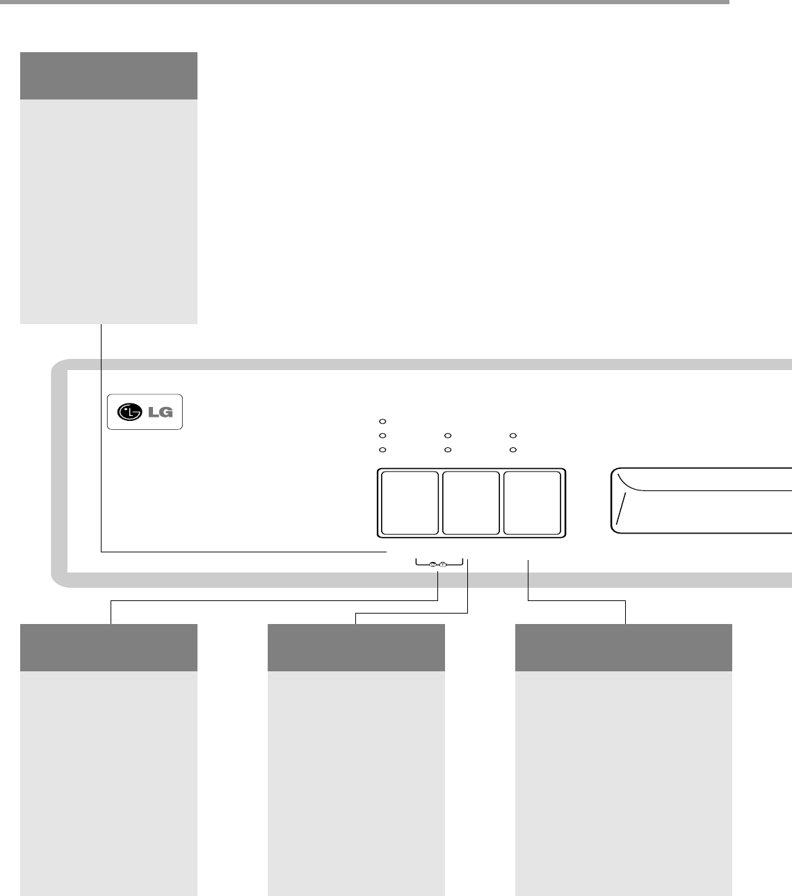
4-2-2. LDF 5811 Series
3828ED3001X 2005.3.10 5:19 PM 페이지10 001 HP LaserJet 5000 Series
- 11 -
Soak
Power
Scrub
Quick
Wash
Rinse
Only
Normal
Cancel
Delicate Power
Delay Start
INDICATOR
• Child lock: Lamp will turn
on when Child Lock
setting is on.
• Rinse Aid: Refill with
Rinse aid when Lamp turns
on.
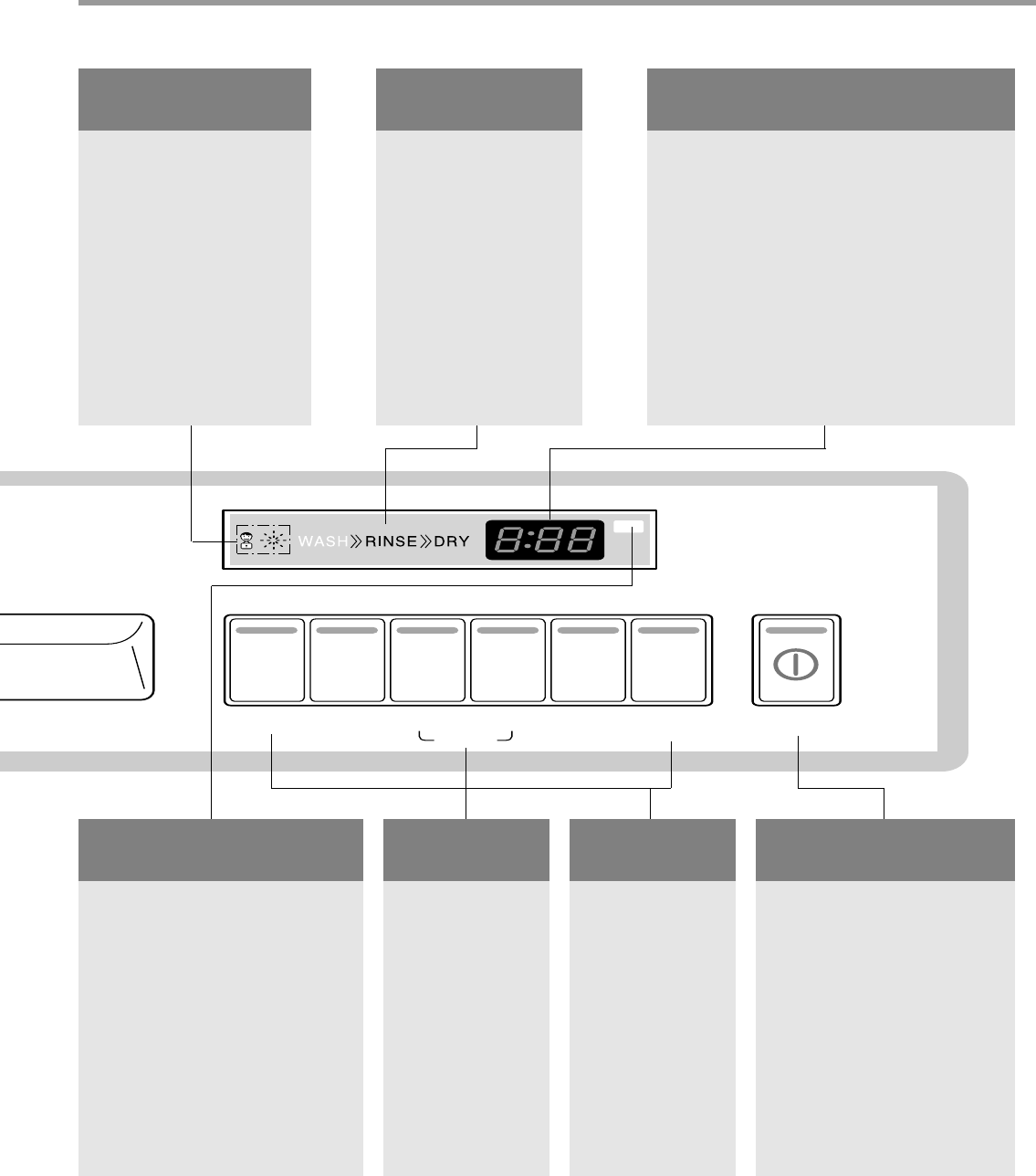
PROCESSING
INDICATOR
• Current program
phase is indicated.
TIME LEFT
• Before starting, the display window shows
the running time of the selected program.
• After starting, the display window shows
the remaining time.
• If the dishwasher has a trouble, the trouble
type is displayed.
PROGRAM
• Press the
program that
corresponds to
your desired
wash cycle.
CANCEL
• To cancel a
running program,
press and hold
the Normal and
Delicate buttons
for 3 seconds.
DELAY START
• If you want to delay the start of
a selected program, press the
Delay Start button.
• Each press of Delay Start will
delay the start of the cycle by
one hour.
• The delay start time can be
adjusted from 1 to 12 hours in
one-hour increment.
POWER
• For operating, press this
button first for power on.
• After operating, the power
automatically switches off
for safety and economy.
• In case of an unusual Power
surge or disturbance, the
power may be automatically
turned off for safety.
3828ED3001X 2005.3.10 5:19 PM 페이지11 001 HP LaserJet 5000 Series

4.3 TEST MODE
CHECK PROGRAM
BUTTON The number of
pushing button Front Display
Top
Display Load and Checking points Door open/
closed
Rinse + Time Delay +
POWER S/W
Soak
Power Scrub
Normal
Delicate
Quick Wash
Rinse Only
Supply
Rinse
Half Load
Time Delay
Normal Water Level : 315
Pure Water : more than 229
1 TIME
1 TIME
1 TIME
1 TIME
1 TIME
1 TIME
1 TIME
1 TIME
1 TIME
1 TIME
1 TIME
2 TIME
3 TIME
4 TIME
5 TIME
6 TIME
7 TIME
8 TIME
9 TIME
10 TIME
11 TIME
12 TIME
13 TIME
31
32
33
34
35
36
37
38
39
3A
3b
3c
n : 3H/U:023H/U2
11
22
33
44
55
66
77
88
99
1 : 11
2 : 22
3 : 33
4 : 44
5 : 55
6 : 66
7 : 77
8 : 88
9 : 99
Soil Level
n : 02
n : 03
Frequency
n : 05
n : 06
n : 07
n : 08
Temp. ()
n : 0A
n : 0b
n : 0c
Soil Sensor
Wash Pump
Drain Pump
Inlet Valve
Dispenser
Heater
(for 10 sec)
Fan
Thermistor
Lower Nozzle
(VARIO)
Upper Nozzle
(VARIO)
Wash-Drain-
Water Supply
Auto-Off
Delay Start
Child Lock + Rinse
Aid
Wash
Rinse
Dry
Wash-Rinse-Dry
Strong-Soft
Sanitary-Extra
Upper-Lower
Soak-Normal
Delicate-Rinse
Only
Rinse Aid
All LEDs are lighting Both
All LEDs are lighting
All LEDs are lighting
All LEDs are lighting
All LEDs are lighting
All LEDs are lighting
All LEDs are lighting
Strong/Medium/Soft
Sanitary-Extra Rinse
Upper-Lower
Both
Both
Both
Both
Both
Both
Both
Both
Both
Both
Closed
Closed
Both
Closed
Closed
Closed
Both
Closed
Closed
Closed
Closed
Supply water before operating the Test Mode.
- 12 -
3828ED3001X 2005.3.10 5:19 PM 페이지12 001 HP LaserJet 5000 Series
- 13 -
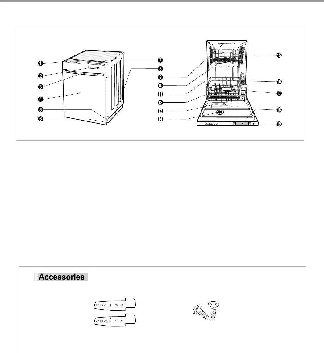
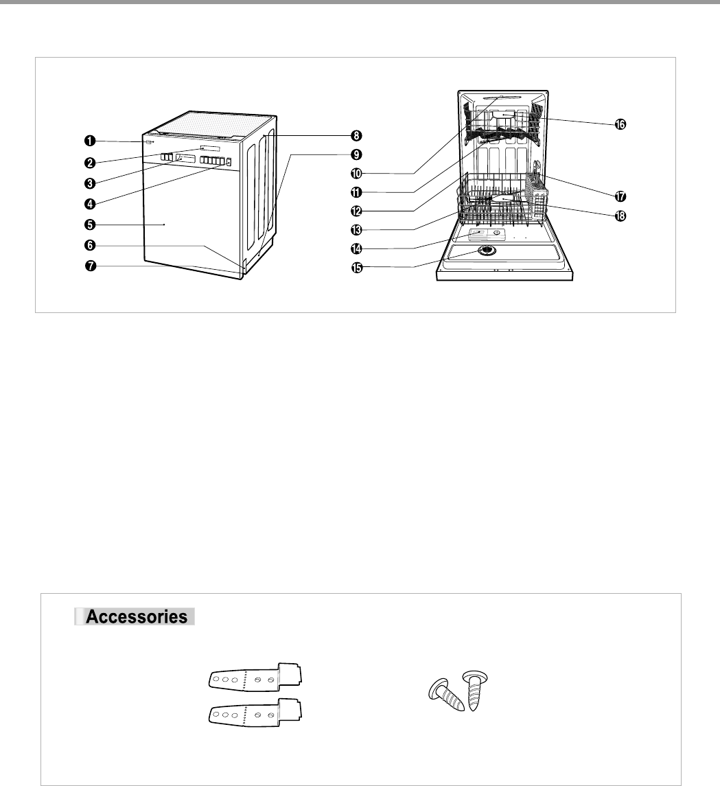
5. PARTS NAME
Control Panel
Front Display
Door Handle
Front Cover
Lower Cover
Leveling Foot
Side Cabinet
Base
Top Spray Arm
Upper Spray Arm
Removable Tines
Lower Spray Arm
Detergent & Rinse Aid Dispenser
Vapor Vent Cover
Upper Rack
Cutlery Basket
Lower Rack
Top Display
Power Button
The appearance and specifications may be varied without notice according to localities.
INSTALL BRACKET WOOD SCREW
5-1. LDF 7811/7810 Series
3828ED3001X 2005.3.10 5:19 PM 페이지13 001 HP LaserJet 5000 Series
- 14 -
Control Panel
Front Display
Door Handle
Power Button
Front Cover
Lower Cover
Leveling Foot
Side Cabinet
Base
Top Spray Arm
Upper Spray Arm
Removable Tines
Lower Spray Arm
Detergent & Rinse Aid Dispenser
Vapor Vent Cover
Upper Rack
Cutlery Basket
Lower Rack
The appearance and specifications may be varied without notice according to localities.
INSTALL BRACKET WOOD SCREW
4-2. LDF 5811 Series
3828ED3001X 2005.3.10 5:19 PM 페이지14 001 HP LaserJet 5000 Series
- 15 -
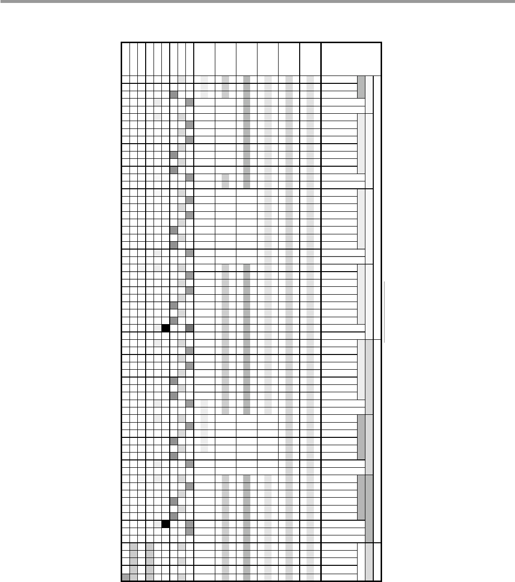
6. PROGRAM CHART(SCHEMATIC DIAGRAM)
Drain A
26 10 10 46 10 10 30 30
49 65 72
18 10 10 38 10 10 26 30
63 68
10 10 10 30 10 20 30
60 65
10 10
61
22 10 26 30
49 68
86 20
20
46 60
10
30 8 30 3 30
W/Motor
Drain Pump
Inlet Valve
Heater
Vario Motor
Fan Motor
Dispenser
Thermal Act
Auto Off S/W
Program chart
Rinse Dry
Main Wash
Wash
Rinse 1 Rinse 2 Heating Rinse Dry
Program
Wash
Wash
Wash
Rinse
Stop
Stop
Stop
Wash
Wash
Wash
Wash
Wash
Water Supply
Water Supply
Water Supply
Water Supply
Water Supply
Water Supply
Water Supply
Water Supply
Wash
Drain
Drain
Drain
Drain
Drain
Heating A
Heating B
Dry
Drain D
Drain
Drain
Drain
Stop
Stop
Drain
Drain
Water Supply
Water Supply
Stop
Drain C
Drain
Water Supply
Water Supply
Rinse
Drain
Drain
Drain
Drain
Drain
Drain
Drain
Drain
Drain
Drain B Drain B Drain C
Drain
Drain
Drain
Stop
Drain
Drain
Stop
Pre Wash 1 Pre Wash 2 Pre Wash 3
Drain B Drain B
Wash
Wash
Wash
Wash
Drain
Stop
Water Supply
Wash
Power Scrub
Soak
Rinse Only
Quick
Fine China
NORMAL
3828ED3001X 2005.3.10 5:19 PM 페이지15 001 HP LaserJet 5000 Series
- 16 -
BEFORE DISASSEMBLING THE DISHWASHER ;
1) Remove the cord from electric outlet to avoid electric shock.
2) Close the Water Tap (faucet).
3) Remove all dishes and items in the dishwasher.
4) Remove the Lower Rack and the Upper Rack.
5) Remove the inlet hose and drain hose connetion to avoid the hose damages.
6) Prepare some towels to avoid floor wet by the water left in the dishwasher.
7. HOW TO DISASSEMBLE
7-1. FULL DISASSEMBLE
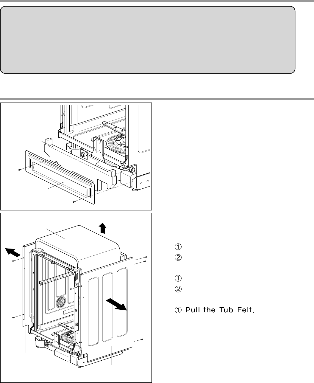
1. Lower Cover and Lower Felt
1) Remove the front 2 screws.
2) Pull the Felt.
3) Remove the Inlet Hose and Power Supply
Cable.
2. Cabinet and Tub Felt
1) Cabinet-R
Remove front 2 screws.
Remove rear 3 screws.
2) Cabinet-L
Remove front 2 screws.
Remove rear 3 screws.
3) Tub Felt
Lower Felt
Lower Cover
Tub Felt
Cabinet-L
Cabinet-R
3828ED3001X 2005.3.10 5:19 PM 페이지16 001 HP LaserJet 5000 Series
- 17 -
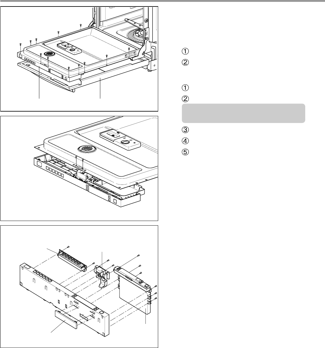
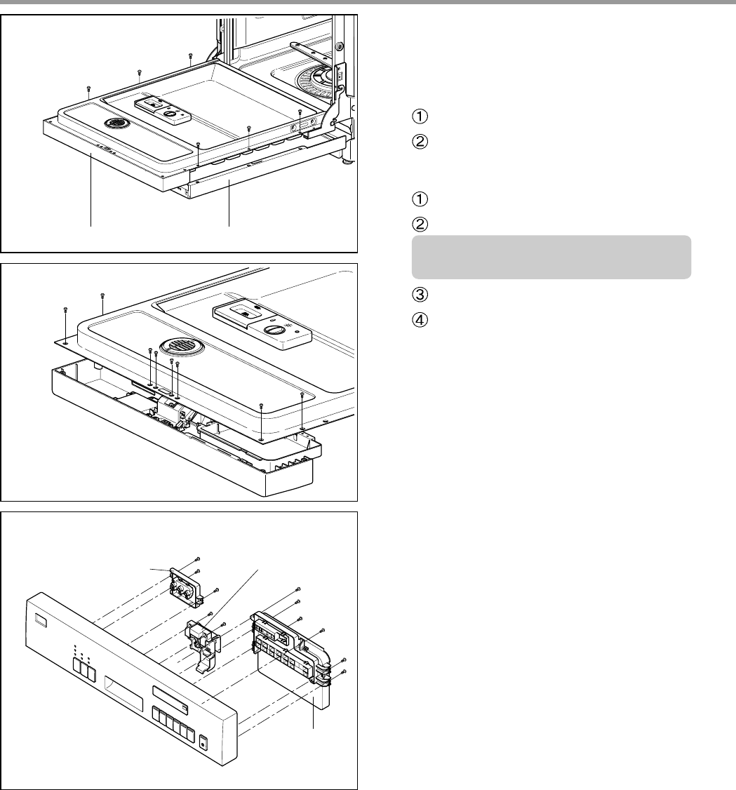
Control Panel Front Cover
Controller
Controller
Latch Assembly
F
ront Display
3-1. Door Assembly
(LDF7811/7810 Series)
1) Front Cover
Open the door.
Remove 12 screws(stainless).
2) Control Panel Assembly
Remove 2 screws(Stainless).
Remove the wire connections.
Be sure the wiring should not be
changed in reassembling
Remove the Latch assembly.
Remove the Front Display.
Remove 8 screws for Controller.
3828ED3001X 2005.3.10 5:19 PM 페이지17 001 HP LaserJet 5000 Series
- 18 -
Control Panel Front Cover
Controller
Controller
Latch Assembly
3-2. Door Assembly
(LDF 5811 Series)
1) Front Cover
Open the door.
Remove 6 screws(Stainless).
2) Control Panel Assembly
Remove 8 screws(Stainless).
Remove the wire connections.
Be sure the wiring should not be
changed in reassembling
Remove the Latch assembly.
Remove 8 screws for Controller.
3828ED3001X 2005.3.10 5:19 PM 페이지18 001 HP LaserJet 5000 Series
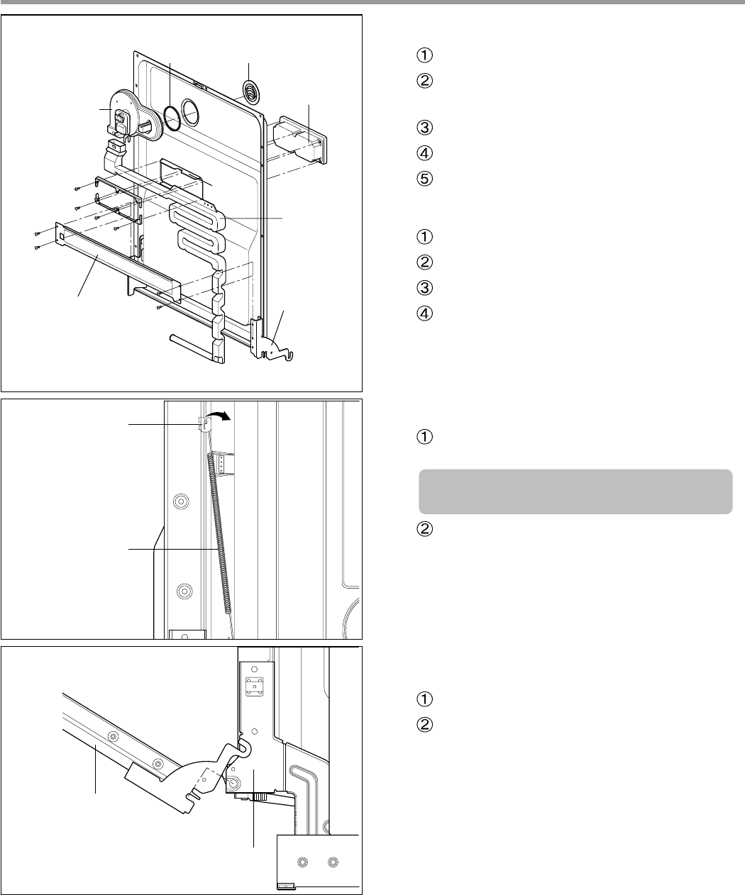
- 19 -
F
an Assembly
Inner CoverGasket
Flange
Detergent
Dispenser
Door Hinge
Air Duct
Door Bracket
H
inge Bracket
H
inge Spring
3) Fan Assembly
Open the door.
Remove 4 screws and a earth screw for
Door Bracket.
Remove the wire connetions.
Remove the Air Duct.
Turn the Inner Cover counterclockwise.
4) Detergent Dispenser
Close the door
Remove the wire connections.
Remove 6 screws with brackets.
Push the Detergent slowly pulling up the
the Flange by Standard Screwdriver.
5) Door Spring (Right & Left)
Push the Spring upwards and take it off
from the Hinge Bracket.
Be careful not to be injured by the
sharpedge of Tub.
Take off the Hinge Link from the Hinge.
6) Door Liner
Open the door.
Pull the Door Liner and take it off from
the Hinge Supporter.
D
oor Liner Assembly
Hinge Supporter
3828ED3001X 2005.3.10 5:19 PM 페이지19 001 HP LaserJet 5000 Series
- 20 -
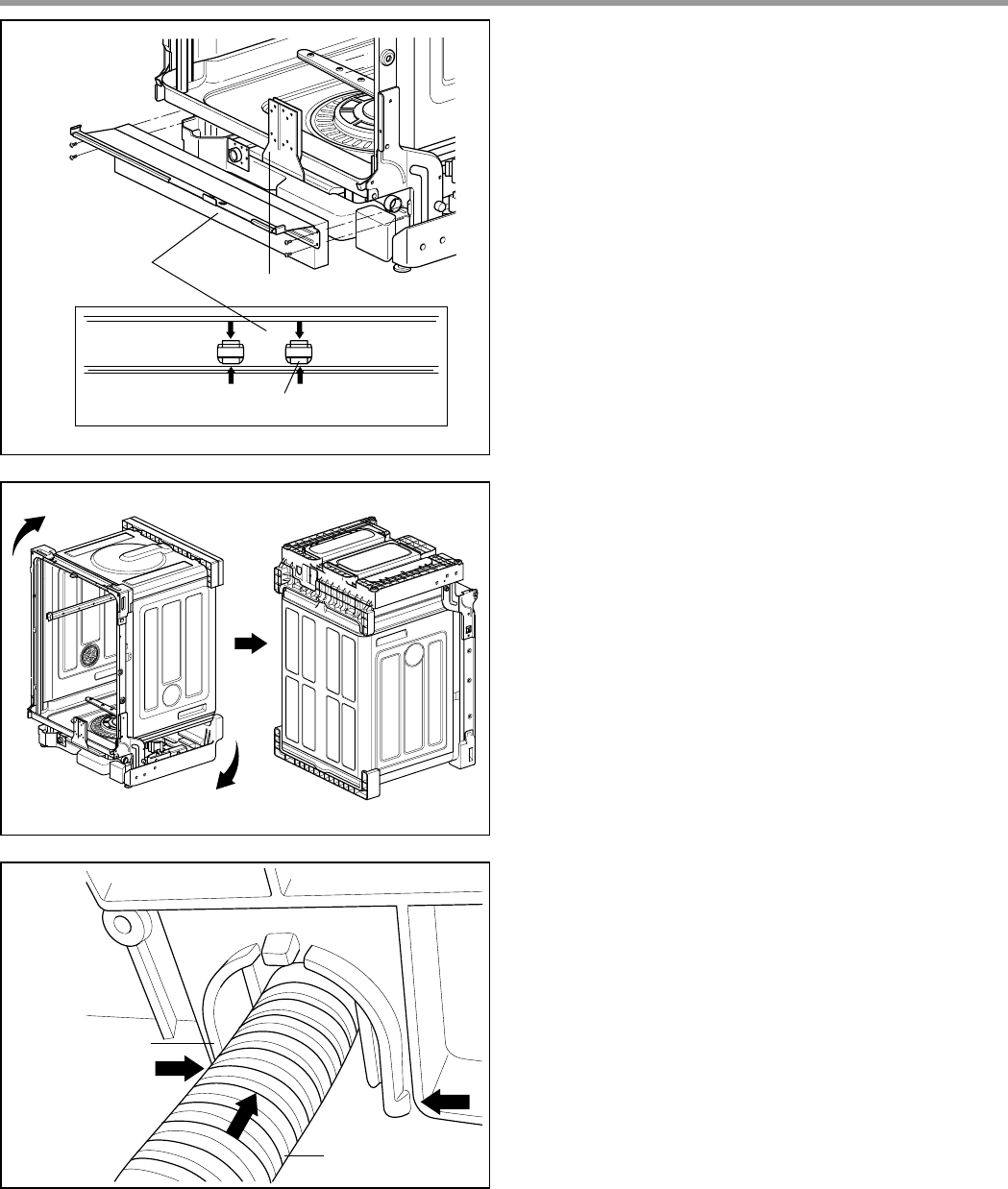
Lead Wire Holer Hook
Lead Wire Holer
Lower Frame
Drain Hose
D
rain Hose
H
older
4. Lower Frame
1) Press the holder hook as shown in figure.
2) Remove 4 screws.
6. Drain Hose Holder
1) Press the holder hook as shown in figure.
2) Pull the Drain Hose and remove the Drain
Hose Holder.
5. Put the Dishwasher upside down.
3828ED3001X 2005.3.10 5:19 PM 페이지20 001 HP LaserJet 5000 Series
- 21 -
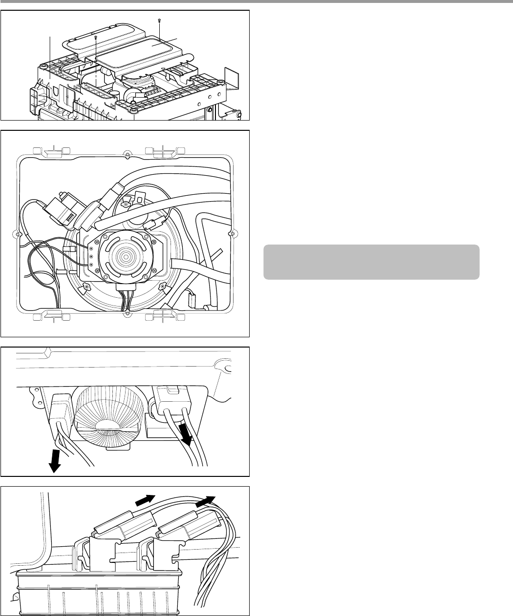
Base Cover
Cabinet Base
7. Base Cover
1) Remove 2 screws.
2) Pull the Base Cover out.
8. Harness & Hose Assembly
1) Remove the wiring connections.
2) Remove the Hose connections from
Sump Assembly.
You can see the information of Wiring
Diagram at the back of Lower Cover.
3828ED3001X 2005.3.10 5:19 PM 페이지21 001 HP LaserJet 5000 Series
- 22 -
Cabinet Base
Inlet Valve
Cabinet Base
Air Braker
Nut
Gasket
Air Braker
Assembly
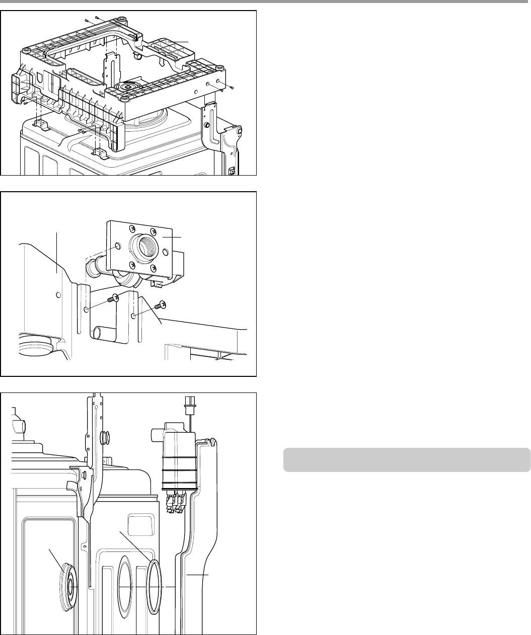
9. Cabinet Base
1) Remove 8 screws.
2) Lift it upward.
10. Inlet Valve
1) You can disassemble the lnlet Valve by
removing the 2 screws.
11. Air Braker Assembly
1) Disconnect the 3 hoses assembly.
2) Turn the Air Braker Nut counterclockwise.
Be careful the o-ring should not be lost.
3828ED3001X 2005.3.10 5:19 PM 페이지22 001 HP LaserJet 5000 Series
- 23 -
Sump Holder
Hook
Sump
Assembly
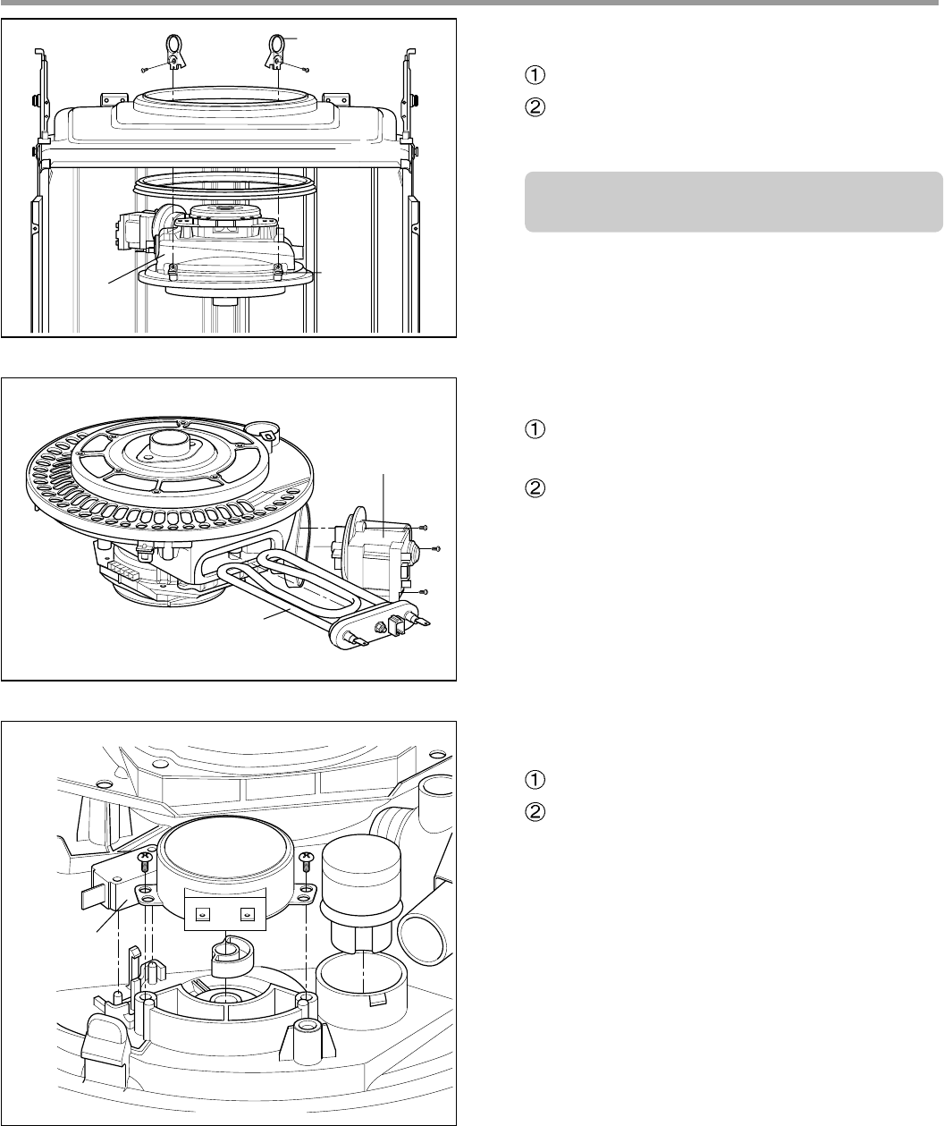
1) Heater & Drain Motor
Pull the Heater out of the Sump after
releasing the nut.
Remove 3 screws.
2) Vario Motor & Soil Sensor
Remove 2 screws for Vario Motor.
Pull the Vario Motor, Soil Sensor and
Micro S/W.
Drain Pump
Heater
Vario Motor Soil
Sensor
Micro S/W
12. Sump Assembly
Remove 2 screws.
Remove the Sump Holder and push the
Sump Assembly down with pulling aside
Hook.
Be careful not to drop the Sump
Assembly to the bottom.
3828ED3001X 2005.3.10 5:19 PM 페이지23 001 HP LaserJet 5000 Series
- 24 -
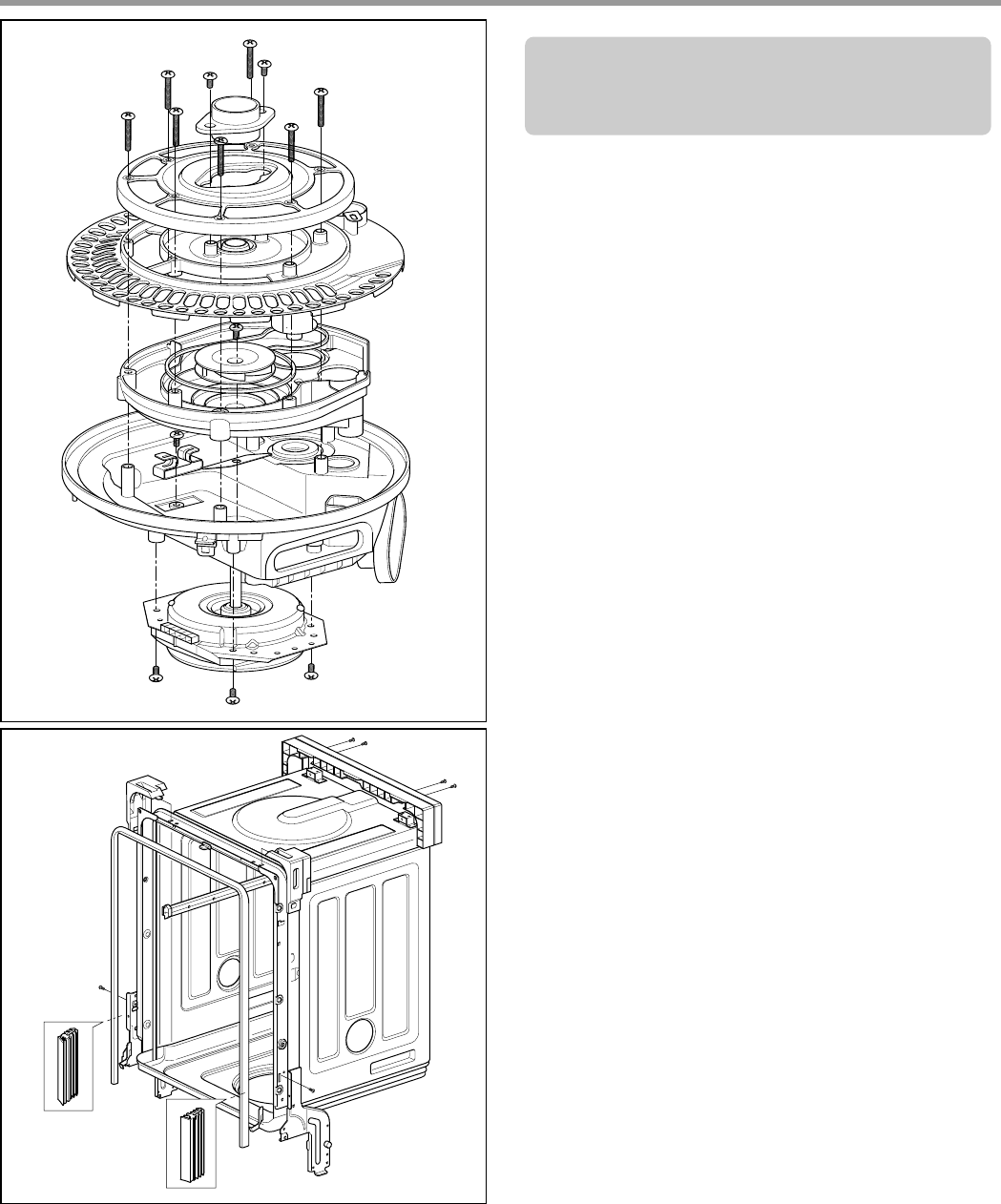
13. Holder Supporter, Tub Packing
and Hinge Supporter Assembly.
When you reassemble the Sump Assembly,
be careful not to kink, tear and take off the
seals.
3828ED3001X 2005.3.10 5:19 PM 페이지24 001 HP LaserJet 5000 Series
- 25 -
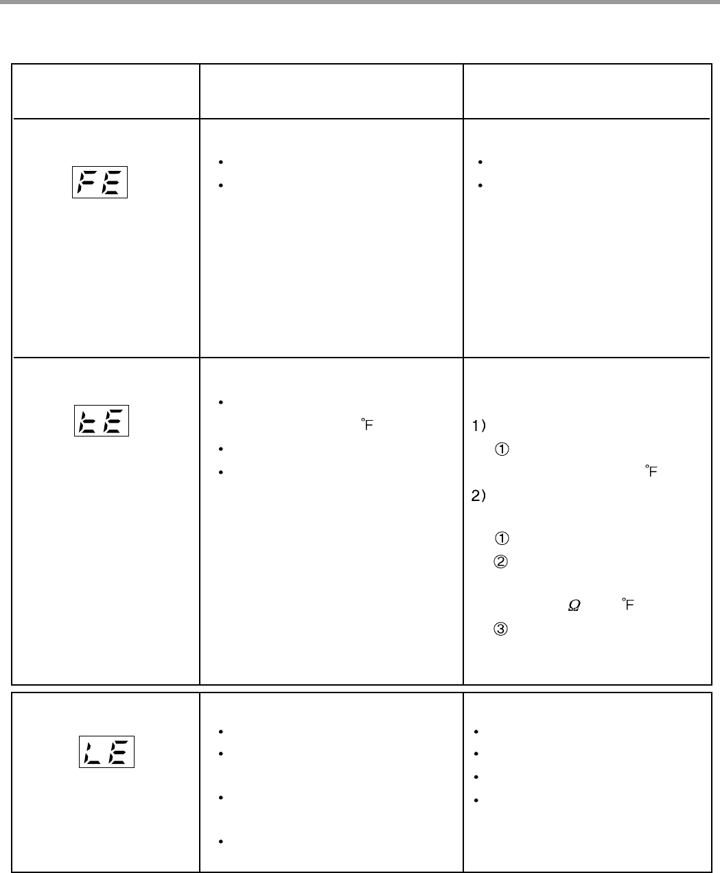
A. TROUBLE SHOOTING ACCORDING TO DISPLAYED ERROR MESSAGE
ERROR MESSAGE POSSIBLE CAUSE REMEDY
FOR ERROR OCCURRENCE
The Water Supply Tap is closed.
The Water Supply is shut off.
The Inlet Hose is kinked.
The Water Pressure is very low.
(below 10 psi)
Inlet Valve is OK?
The filter of Inlet Valve is clogged
by impure water.
The Hall sensor is OK?
The Impeller of Air Guide is bound.
The Drain Hose kinked or blocked.
Wiring connection is OK?
The drain outlet of sump is
blocked.
The Drain Pump/Motor or circuit is
troubled.
Water leakage in Hose connections.
Water is leaked by damages.
The Motor Water Seal leakage of
Sump assembly.
The height of Drain Hose connection
(sink-Drain Hose) is not over 20″
.
Impeller of the Washing Pump is
worn away.
Remove the cause of kink or block.
Check the wiring connection.
Measure the electric resistance of
Drain Motor. (20-40 )
Replace the Drain Motor or repair
the Circuit.
Replace the connections of Hose.
Check the point of damages and
repair or replace the related parts.
Read the Installation Instructions
(page 9) and fix it to the
recommended Height.
Replace the Impeller of the
Washing Pump.
Take action on Water Supply
device.
Measure the electric resistance of
Inlet Valve. (950-1300 )
Clean the filter of Inlet Valve.
Check the frequency of Inlet Water
by the Test Mode.
Replace the Air Braker.
Not reached to the nor-
mal water level in spite
of 10 min. water supply
INLET ERROR
displayed
Condition
Not fully drained out in
spite of 5 min. drain
operation
The excessive RPM of
Washing Motor
happened during Wash
cycle due to water
leakage.
DRAIN ERROR
displayed
Condition
LEAKAGE ERROR
displayed
Condition
8.TROUBLE SHOOTING METHODS
3828ED3001X 2005.3.10 5:19 PM 페이지25 001 HP LaserJet 5000 Series
- 26 -
ERROR MESSAGE POSSIBLE CAUSE REMEDY
FOR ERROR OCCURRENCE
The Inlet Valve is troubled.
The Controller is troubled.
The Inlet Water Temperature is
very high. (over 194 )
Wiring connection is OK?
The Thermistor is OK?
Wiring connection is OK?
The Impeller of Washing Pump is
locked.
The rotor of Washing Motor is
locked.
The Blade is locked.
Check the temperature. (Test Mode)
If the temperature is displayed,
adjust the Inlet Water
Temperature to 120 .
If the temperature is not
displayed,
check the wiring connection.
check the electric resistance
of Thermistor.
(11~14k at 77 )
Replace the PCB.
Replace the Inlet Valve.
Repair or replace the Controller.
Excessive water is sup-
plied than normal water
level.(Automatically drain
Pump operated.)
EXCESS ERROR
displayed
Condition
The resistance of ther-
mistor not normally out put.
THERMAL ERROR
displayed
Condition
Check the wiring connection.
Replace the cause of restriction.
Replace the Washing Motor.
Replace the PCB.
The Motor is working
abnormally.
MOTOR ERROR
displayed
Condition
3828ED3001X 2005.3.10 5:19 PM 페이지26 001 HP LaserJet 5000 Series
- 27 -
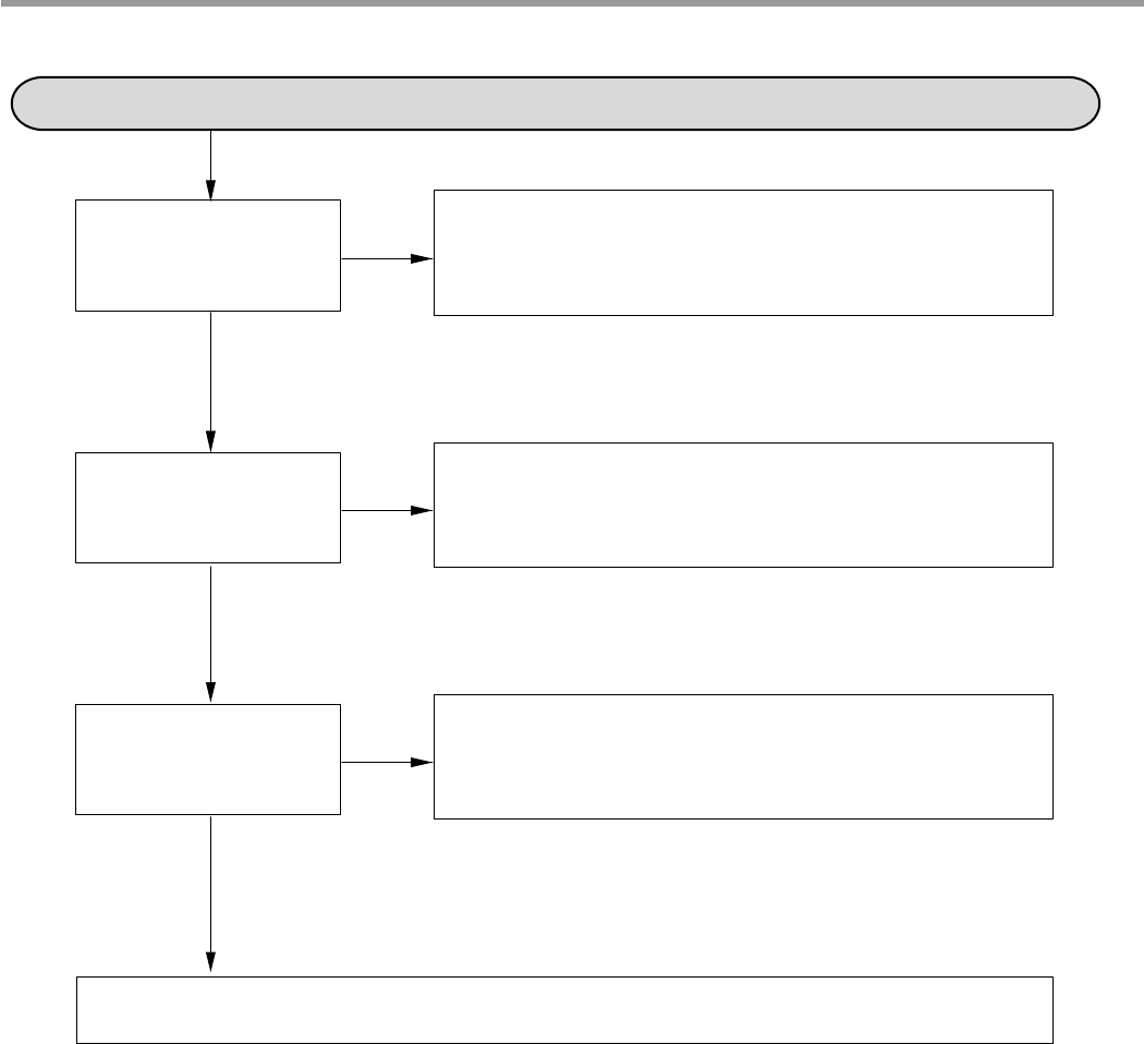
No Power on when the power button pressed.
The Power connection
is correctly connected.
The Fuse or
Circuit Breaker
of house is O.K?
The Power Switch or
the Circuit is O.K?
• Re-connect the Powr connection.
• Check the electricity is failed or not.
• Replace the Fuse or Circuit Breaker of house.
• Check the Power Switch or the circuit and repair it.
Check the Controller.(Power Circuit)
B. TROUBLE DIAGNOSES AND REPAIR BY SYMPTOM
NO
NO
YES
YES
YES
NO
3828ED3001X 2005.3.10 5:19 PM 페이지27 001 HP LaserJet 5000 Series
- 28 -
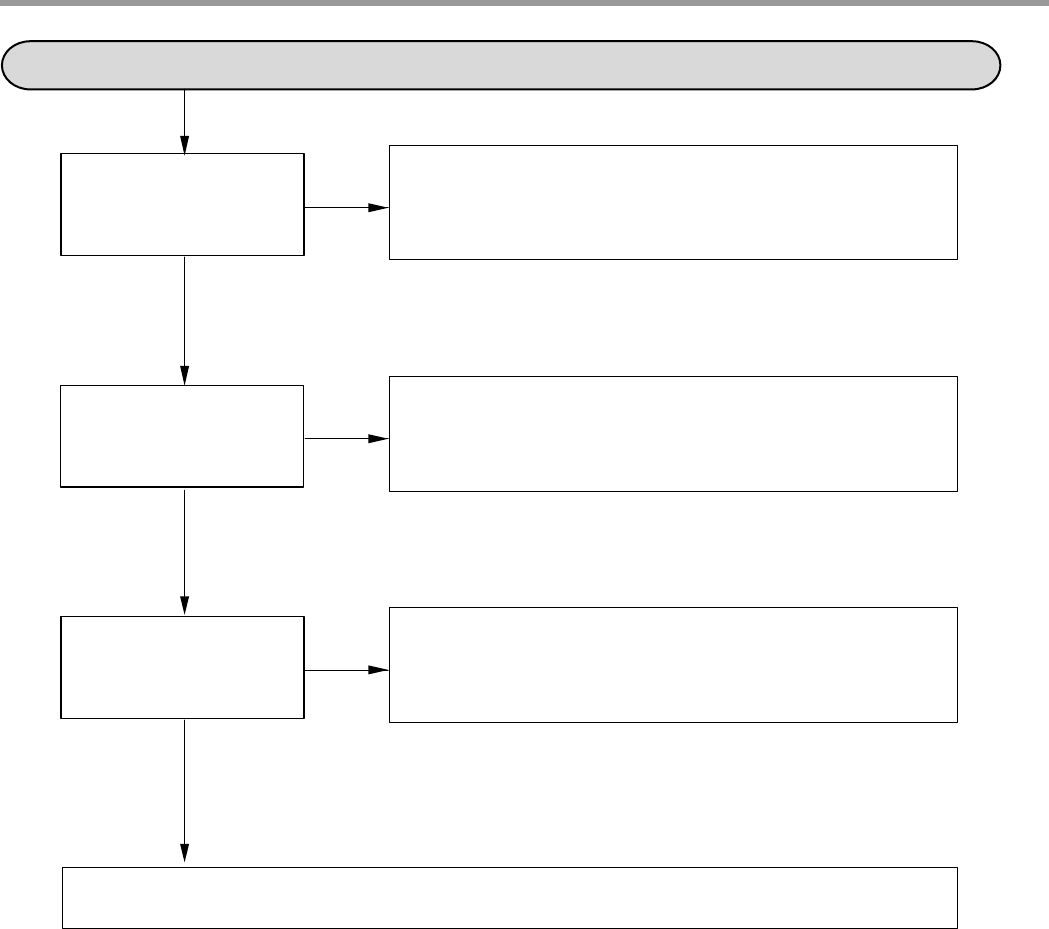
The Wash Pump/Motor does not run.
The Door is tightly
closed?
The Wiring connections
is OK?
The Blade is not locked
by a small and sharp
object?
• close the Door tightly.
• Check the Door Switch in Latch Handle.
• Re-connect the wiring connections related to the
Washing Motor.
• Remove the cause of lock or replace the Blade.
Replace the Wahing Pump/Motor
NO
NO
NO
YES
YES
YES
3828ED3001X 2005.3.10 5:19 PM 페이지28 001 HP LaserJet 5000 Series
- 29 -
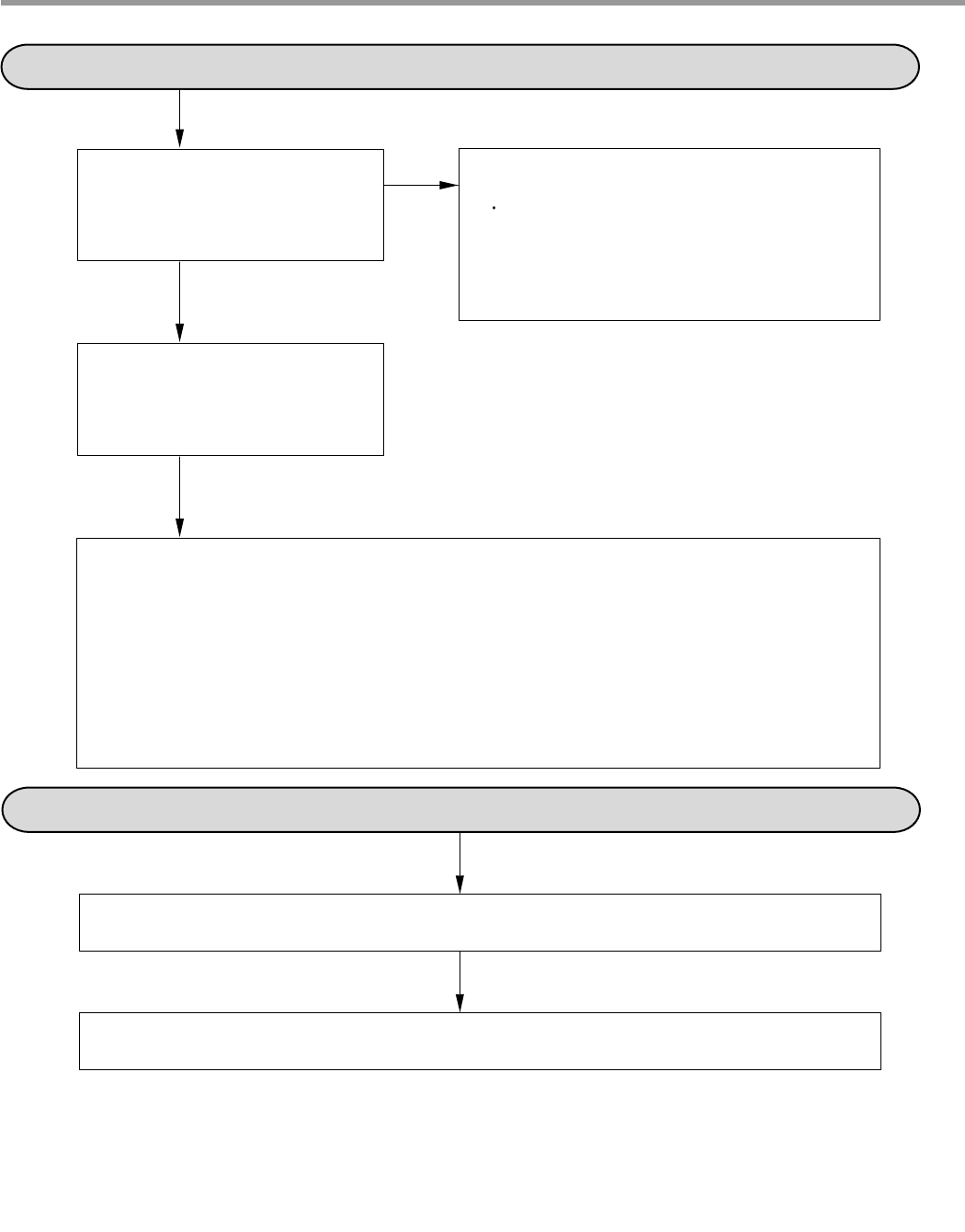
Washing Results are not Satisfactory
After washing, are there still
White deposits or streaks on
the dishes?
NO
After washing, are there still
food soils on the dishes?
YES
Check that : - the amount of detergent Correctly used or not
- Filters clogged or not.
- the holes of spray arms blocked or not.
- Utensils are correctly arranged or not.
- Utensils are overloaded or not.
- the spray arm rotating is obstructed or not.
- the program is correctly selected or not.
Reduce the amount of Rinse-Aid
(for Streak)
YES
Dry Results are not satisfactory
Increase the amount of Rinse-Aid.(Set the number higher)
Select the Program that the Rinse temperature is higher.
3828ED3001X 2005.3.10 5:19 PM 페이지29 001 HP LaserJet 5000 Series
- 30 -
Power Button not automatically off after operation.
Check the button is blocked by foreign materials.
Check the Power Switch.(Replace it, if necessary.)
Check the Controller.(Replace it, if necessary.)
3828ED3001X 2005.3.10 5:19 PM 페이지30 001 HP LaserJet 5000 Series
- 31 -
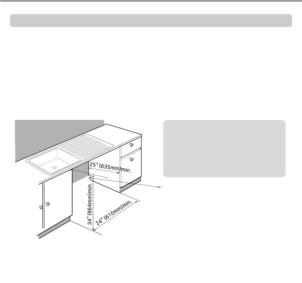
9. INSTALLATION INSTRUCTION
Step 1: PREPARE CUPBOARD OPENING
1. This dishwasher is designed to fit a standard dishwasher opening as shown below.
2. Select a location as close to sink as possible for easy connections to water and drain lines.
3. The dishwasher should not be installed more than 10 ft. (3m) from the sink for proper
drainage.
4. If dishwasher is to be installed in a corner, a minimum of 2 in. (50mm) is required between
the dishwasher and an adjacent a wall.
■Ensure the floor under the dishwasher is at the same level as the rest of the room to
allow for any service requirements.
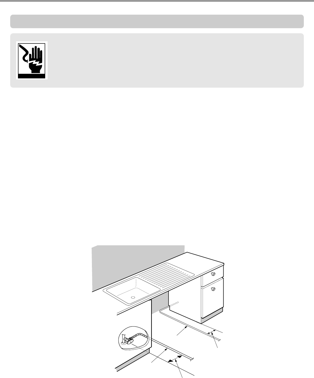
If dishwasher will sit directly on
subflooring, subfloor should be
sealed with a waterproof paint or
sealer to prevent damage from
steam.
Drill a 1-1/2″″
(38mm) dia hole or cut
out for drain hose, inlet hose and
electrical cables on either side.
approx. 4″″
(100mm, W) X 4″″
(100mm, H)
These openings must be within 4″″
(100mm) from the floor and 1-5/8″
(40mm) from the back wall. If there is
a floor in the cabinet under the sink,
it will also be necessary to drill or cut
through the floor to connect the
water and drain under the sink.
3828ED3001X 2005.3.10 5:19 PM 페이지31 001 HP LaserJet 5000 Series
- 32 -
Electrical Cable
Water Supply
Tube
5 1/2 - 6 1/4(140 - 160mm)
8 1/4 - 9 1/4(208 - 233mm)
WARNING!
For personal safety, remove house fuse or open circuit breaker before
installation. Do not use an extension cord or adapter plug with this dishwasher.
Electrical and grounding connections must comply with the national electrical
code/provincial and municipal code and/or other local codes.
Figure A
Step 2: PREPARE THE ELECTRICAL WIRING
1. This appliance must be operated with correct voltage as shown in this manual and on the
rating plate, and connected to an individual, properly grounded branch circuit, protected
by time delay fuse. Wiring must be 3 wires including ground.
2. The wiring or cord should be in an accessible location adjacent to, and not behind the
dishwasher and within 4 ft. (1.2m) of the dishwasher side.
3. The wiring or cord must be grounded properly, if in doubt, have it checked by a qualified
electrician. No other appliance shall be connected to the same outlet by a double adapter
or similar plug.
4. The wiring or cord must be oriented as shown in Figure A below.
5. Check the dishwasher for any damage before trying to install it.
6. Make sure water line and Electrical line are oriented in the bottom channels as shown in
the figure below.
If you find any damage to the dishwasher, Please contact your dealer or builder
immediately.
3828ED3001X 2005.3.10 5:19 PM 페이지32 001 HP LaserJet 5000 Series
- 33 -
Step 3: PREPARE THE WATER SUPPLY CONNECTION
1. This dishwasher may be connected to either hot or cold water. If the water can not be
maintained below 149(65), the dishwasher must be connected to cold water.
2. When connecting the dishwasher water line, sealing tape or compound should be used to
avoid leaks.
3. When connecting the dishwasher water line, the house supply should be shut off.
4. The Water Supply Tube must be oriented as shown in Figure A on page 6.
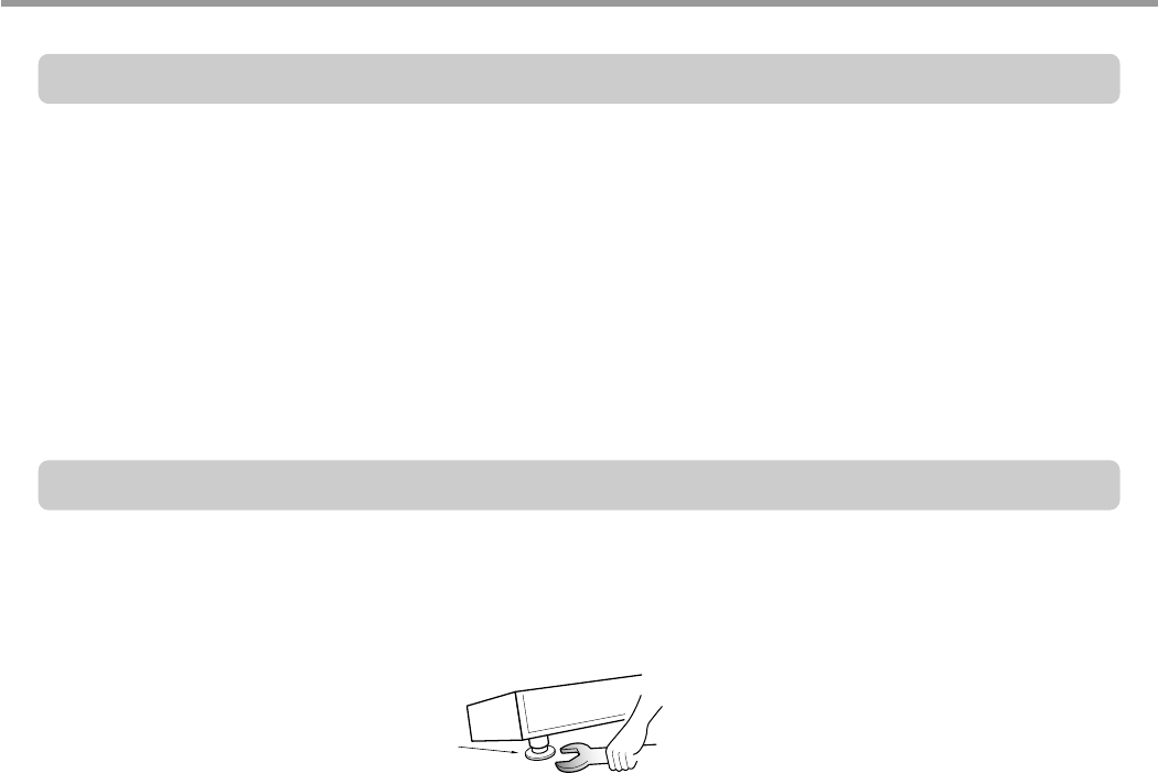
Step 4: PREPARE DISHWASHER FOR INSTALLATION
1. Adjust the legs to the required height to fit properly under the countertop as shown below.
2. Check the level of dishwasher by using level.
L
eveling foot
3828ED3001X 2005.3.10 5:19 PM 페이지33 001 HP LaserJet 5000 Series
- 34 -
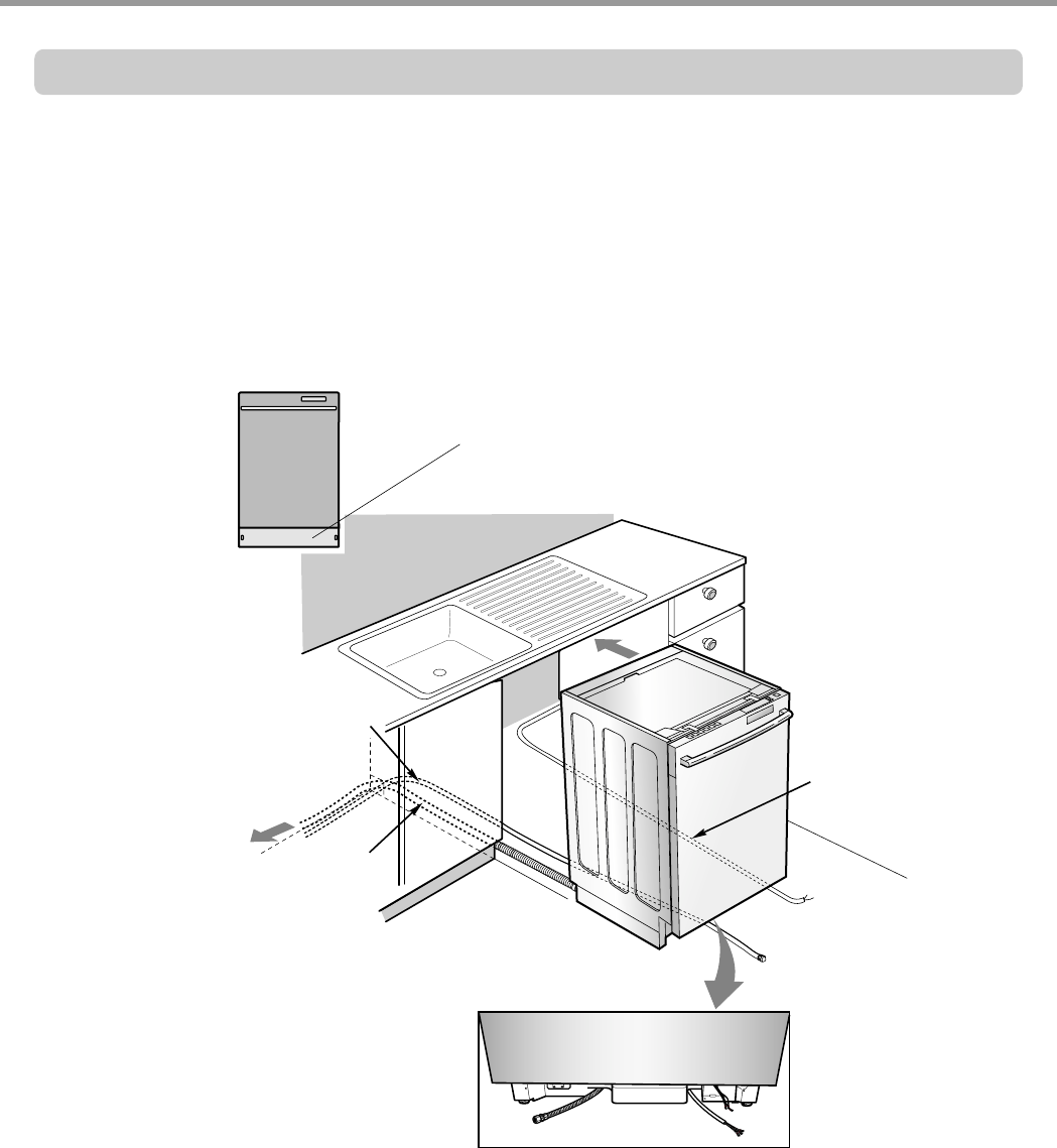
1. Remove the Lower Cover and orient dishwasher as shown below.
2. Before sliding the dishwasher into the cupboard opening, make all necessary height
adjustments using the legs.
3. Slide the dishwasher into the cabinet opening carefully. Make sure that the drain hose
inside the cabinet is not kinked.
4. Follow the instruction as in Figure B.
Step 5: INSTALL THE DISHWASHER IN CUPBOARD
Lower Cover
Drain Hose
Water Supply Tube
Electrical Cable
3828ED3001X 2005.3.10 5:19 PM 페이지34 001 HP LaserJet 5000 Series
- 35 -
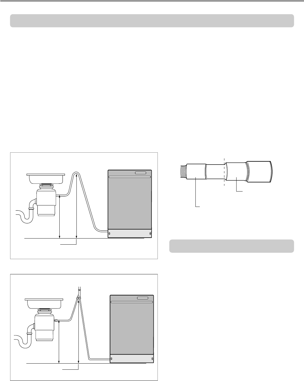
Step 6: DRAIN LINE CONNECTION
1. If the end of the drain hose does not fit to the drain line, use an adapter (not supplied) that
must be resistant to heat and detergent and may be obtained from a plumbing shop.
2. There are 2 typical connections as shown in Figures C & D.
There may be other options than shown here for connection the drain hose. The drain
connection must meet local plumbing regulations.
The S trap spigot must be drilled out cleanly and free of obstruction to its maximum
internal diameter, if used for drainage.
To prevent syphoning, one of the following instruction methods must be followed:
�Follow local codes and ordinances.
�Do not exceed 10 ft. (3m) distance
to drain.
�Do not connect drain lines from
other devices to the dishwasher
drain hose.
Drain Requirements
Figure C:
Connection to Disposer or waste Tee.
Dishwasher
Drain Hose
Sink
Min. 20(508mm)
Min. 30(770mm)
Max. 40(1000mm)
1/2
(13mm) 3/4
(19mm) 1
(25mm)
In case Figure C
In case Figure D,Cut off the
Drain Hose in a dotted line
Figure D:
Connection to Air Gap.
Dishwasher
Drain Hose
Rubber
Connector
Sink
Min. 20(508mm)
Min. 30(770mm)
Max. 40(1000mm)
Air Gap
3828ED3001X 2005.3.10 5:19 PM 페이지35 001 HP LaserJet 5000 Series
- 36 -
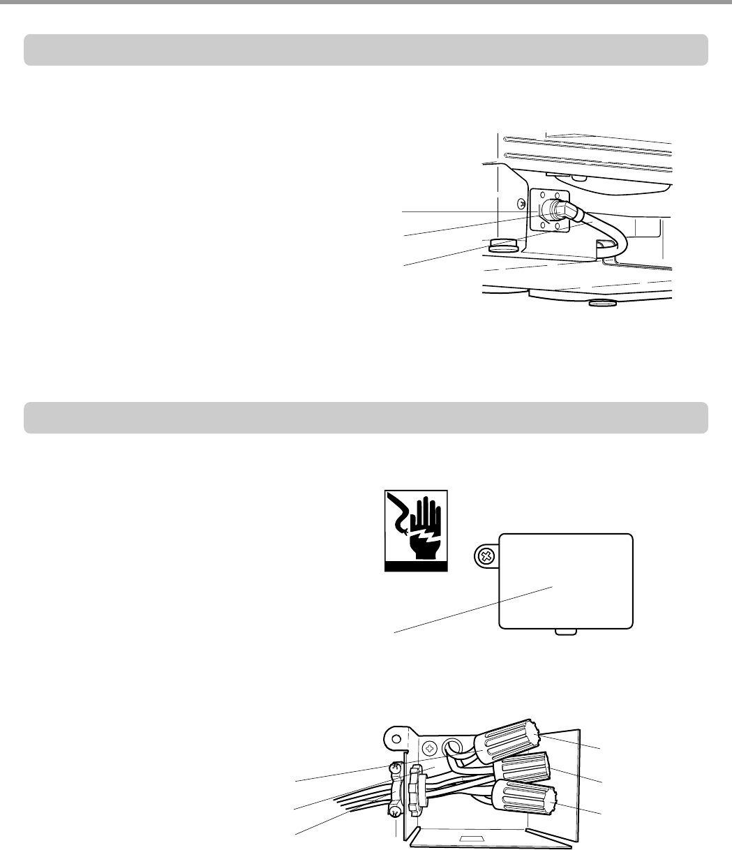
Step 7: WATER SUPPLY CONNECTION
1. When connecting, sealing tape or
sealing compound should be
used to avoid water leaks.
2. Before connecting, turn off the water
supply.
3. After fitting the Elbow into the
Inlet Valve, slide the Flexible
Stainless Tube or Copper Tube
into the Elbow.
4. Tighten the nut and make sure
that the line is not kinked or
sharply bent.
Inlet Valve
Water Supply Tube
Elbow
1. Before beginning, turn off electrical
power to the unit at the circuit breaker.
2. Remove the Junction Cover and then
Install the Strain Relief.
3. Twist Wire Connectors tightly on the
wires. Wrap each connection with
Electrical tape.
4. Check again and make sure that all
wires are connected correctly, black to
black, white to white, green to green
(ground to ground).
5. Replace the Junction Cover.
Junction Cover
Wire Connector
Junction Case
Strain Relief
black to black
(ground to ground)
green to green
white to white
Step 8: ELECTRICAL POWER CONNECTION
3828ED3001X 2005.3.10 5:19 PM 페이지36 001 HP LaserJet 5000 Series

- 37 -
Step 9: FINAL CHECKS
1. Turn electrical power back on at the circuit breaker.
2. Turn house water supply back on.
3. Operate the dishwasher through one cycle (Quick cycle is recommended) to check for
water leaks and operating conditions.
4. Replace the Lower Cover.
3828ED3001X 2005.3.10 5:19 PM 페이지37 001 HP LaserJet 5000 Series
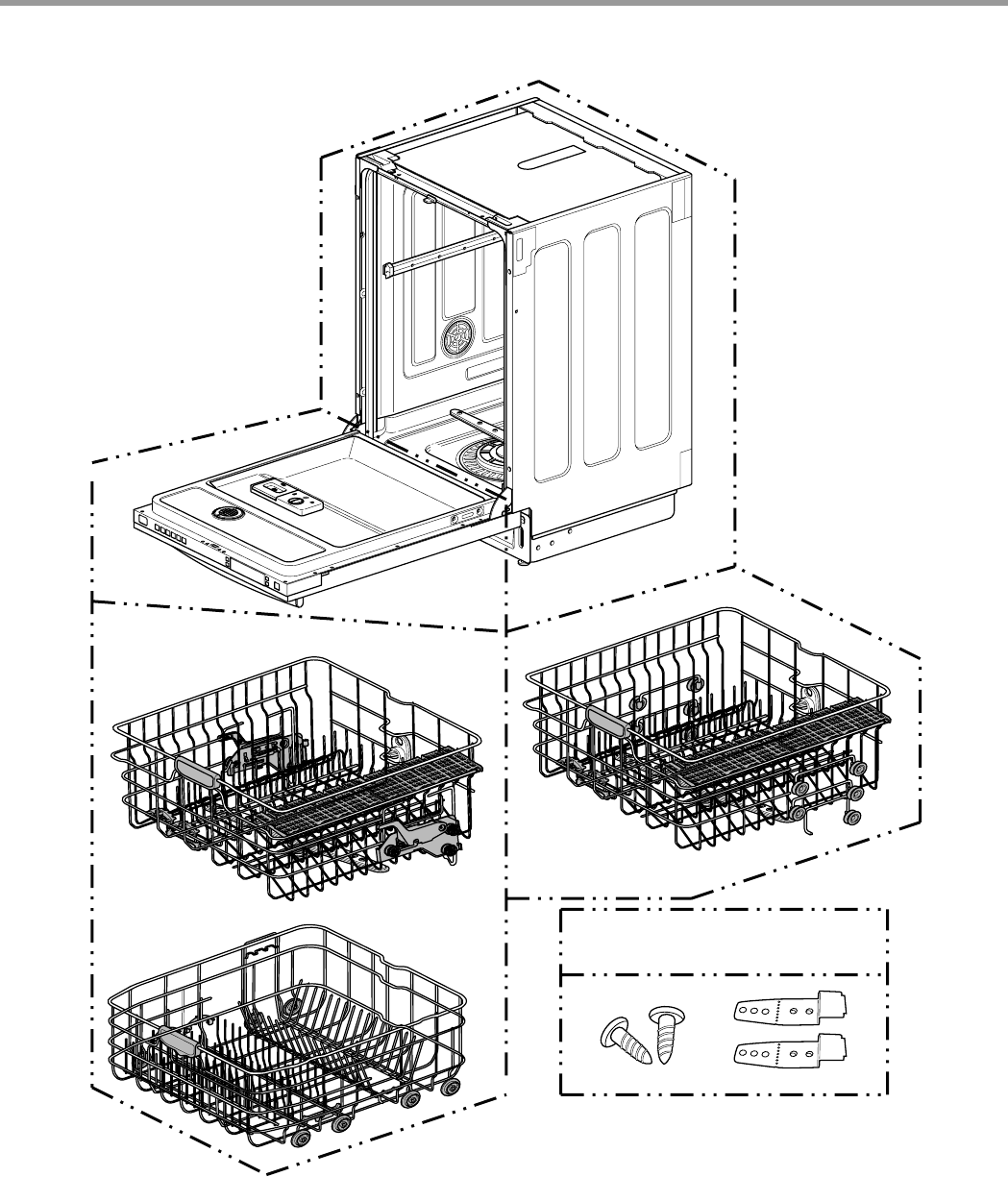
- 38 -
LDF 7810 Series
LDF 7811 Series
LDF 5811 Series
ACCESSORIES
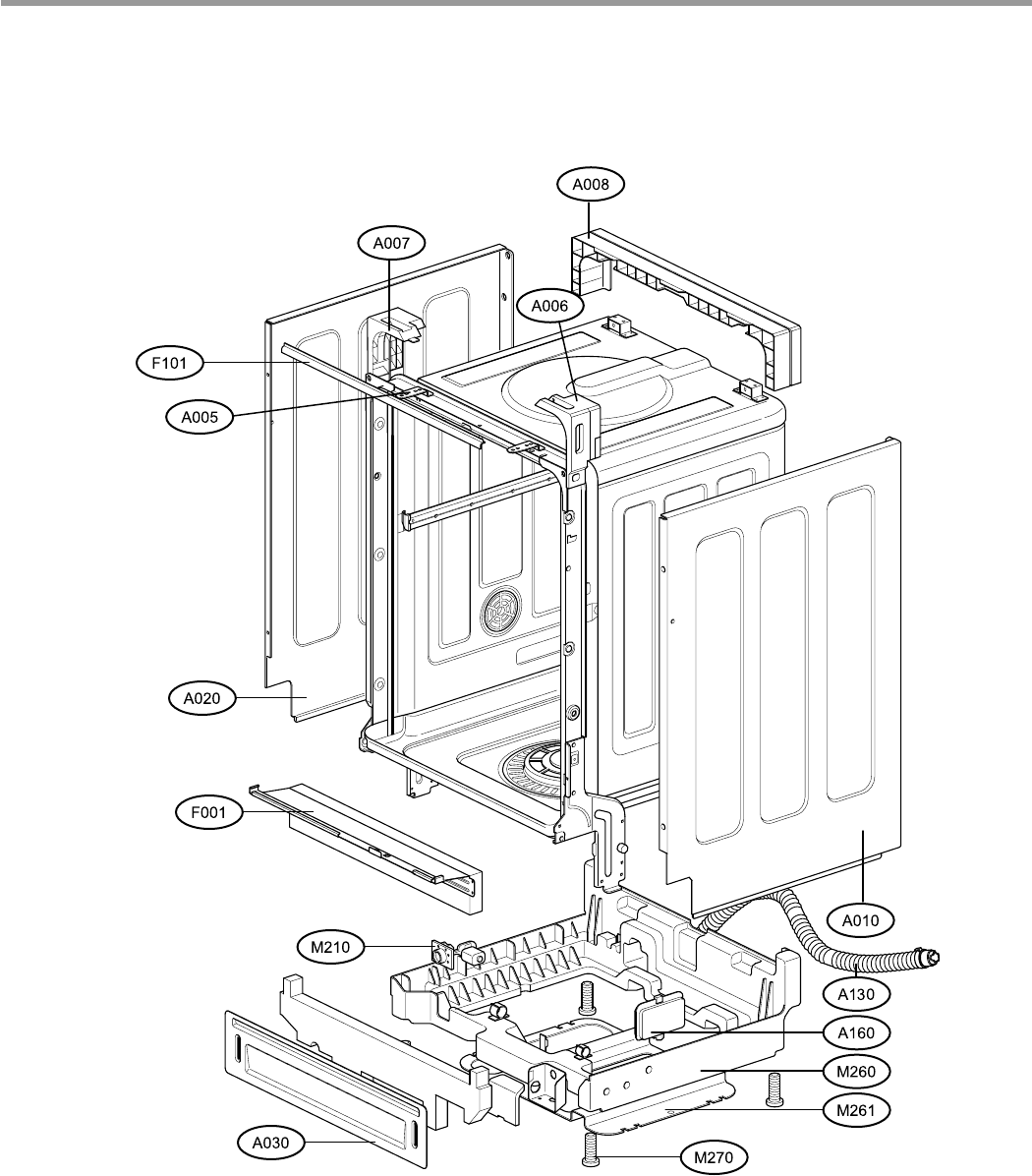
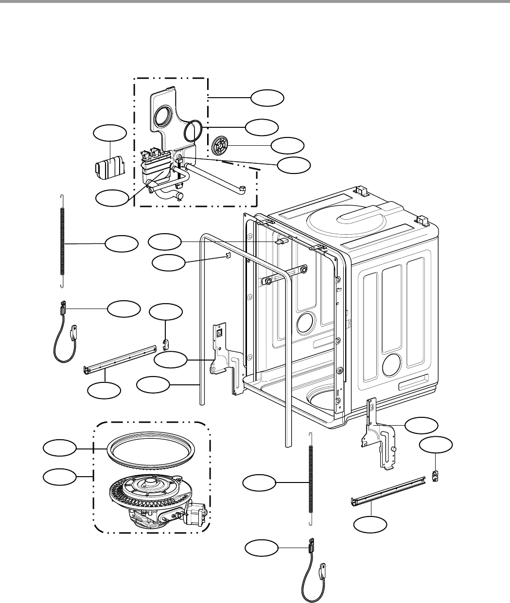
10. EXPLODED VIEW
3828ED3001X 2005.3.10 5:19 PM 페이지38 001 HP LaserJet 5000 Series
- 39 -
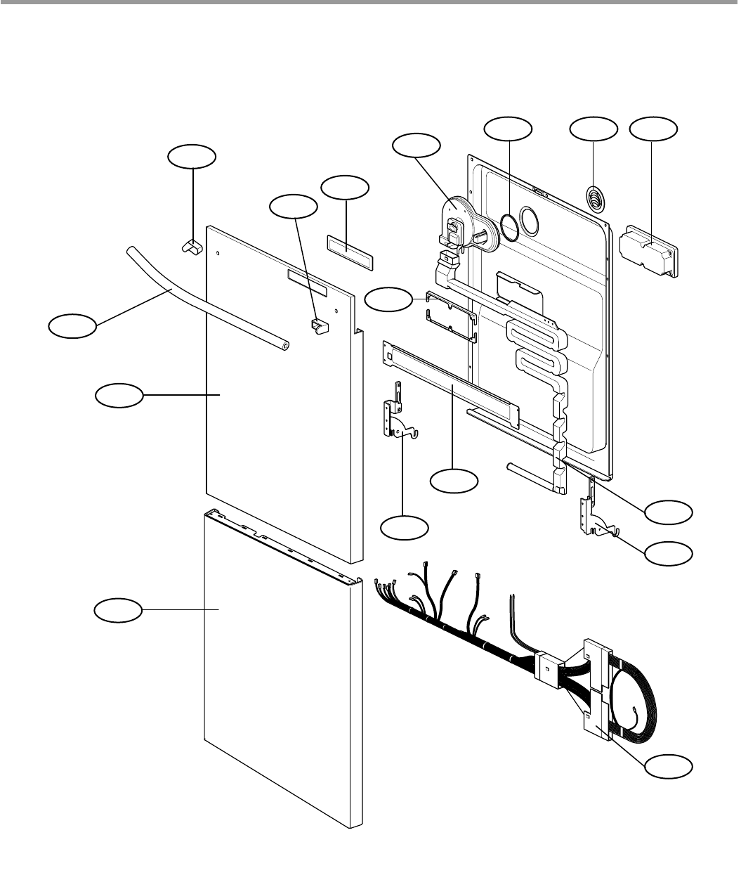
EXPLODED VIEW
3828ED3001X 2005.3.10 5:19 PM 페이지39 001 HP LaserJet 5000 Series
- 40 -
M006
F040
F050
F060
F022
F045
F011
F013 F117
F110
F117
F210
F011
F013
F143
F144
F171
F132
M005
M090
F014
EXPLODED VIEW - TUB ASSEMBLY
3828ED3001X 2005.3.10 5:19 PM 페이지40 001 HP LaserJet 5000 Series
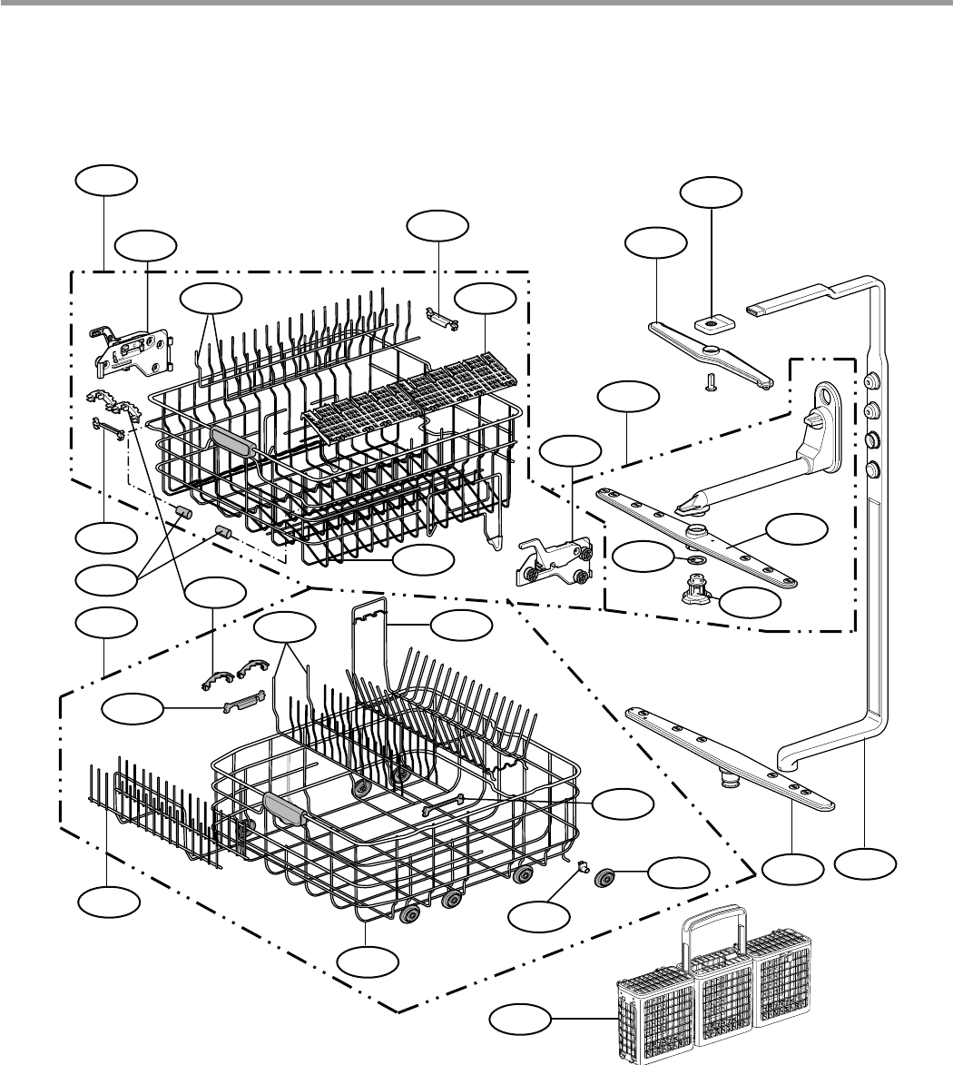
- 41 -
A110
A143
A142
A150
A158
A156
A155
A070
A060
A140
A073
A147
A050 F191
F004
F192
A141
A147
A157
A158
A170
A148
A149
A144
A159
A151
A080
A074
EXPLODED VIEW - PANEL ASSEMBLY
3828ED3001X 2005.3.10 5:19 PM 페이지41 001 HP LaserJet 5000 Series
- 42 -
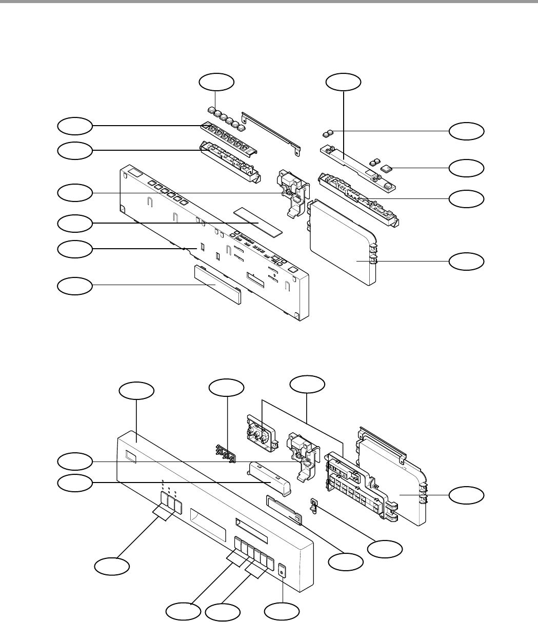
K260
K203
K208
K254
K209
K216
K201
K207
K215
K251
K253
K252
K260
K262
K203
K208
K209
K251
K212
K252
K230
K201
K217
K216
EXPLODED VIEW - DOOR ASSEMBLY
3828ED3001X 2005.3.10 5:19 PM 페이지42 001 HP LaserJet 5000 Series
- 43 -
K002
K001K122
K110
K124
K141
A120
K010
K010
K005
K006
K230
K121
K006
F174
F142
EXPLODED VIEW - BASE ASSEMBLY
3828ED3001X 2005.3.10 5:19 PM 페이지43 001 HP LaserJet 5000 Series
- 44 -
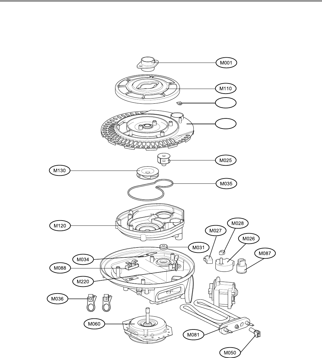
M038
M037
EXPLODED VIEW - SUMP ASSEMBLY
3828ED3001X 2005.3.10 5:19 PM 페이지44 001 HP LaserJet 5000 Series
- 45 -- 45 -
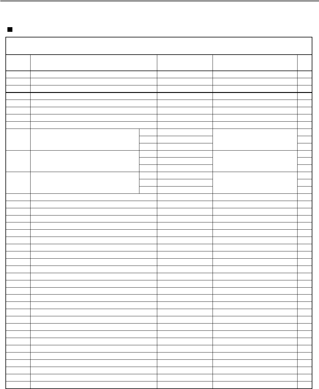
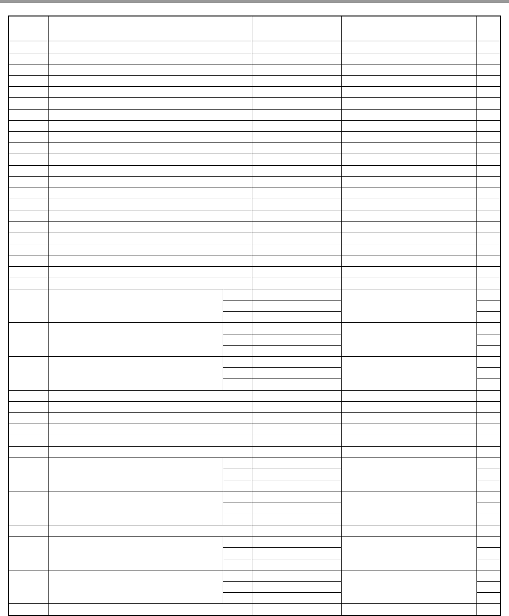
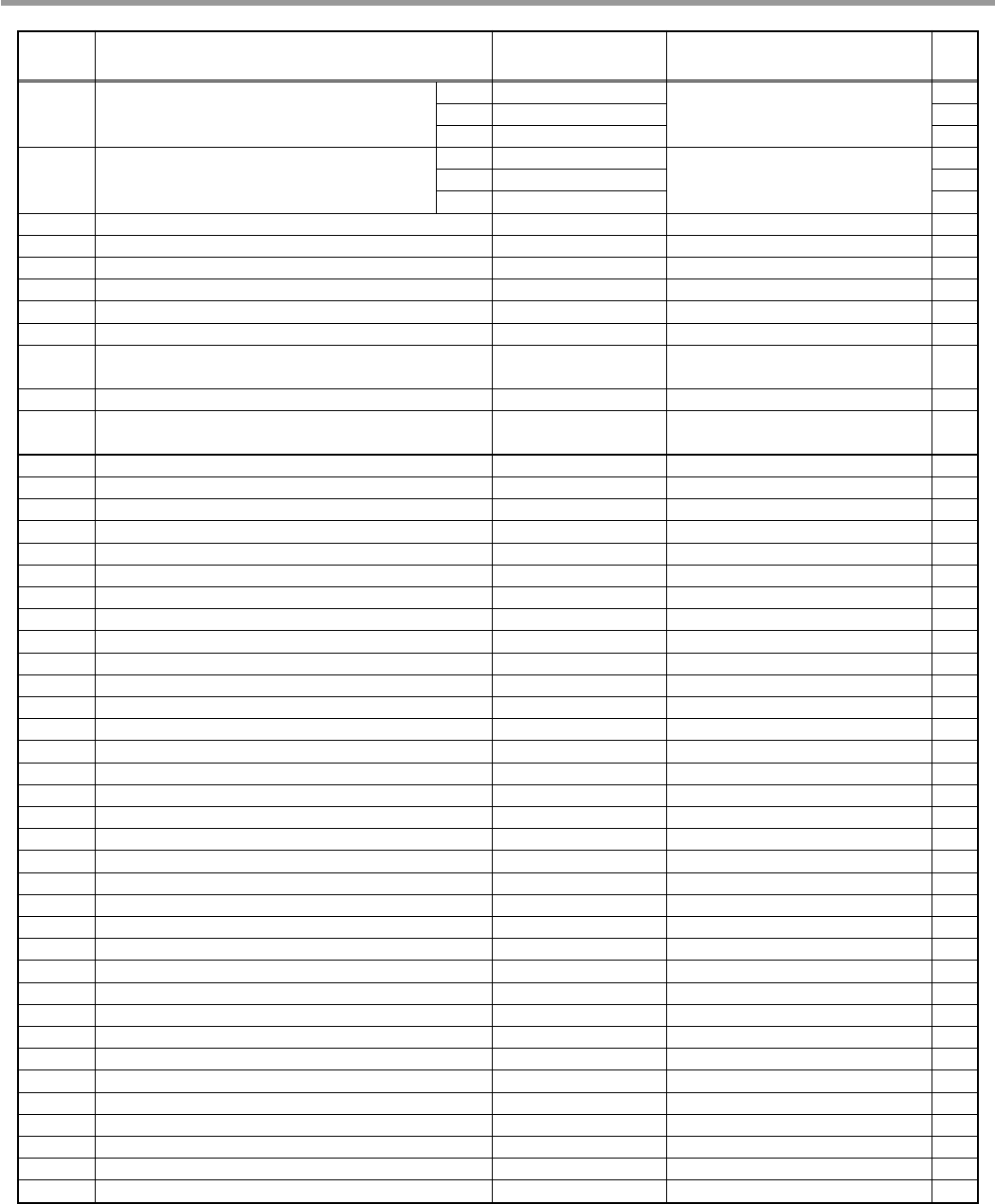
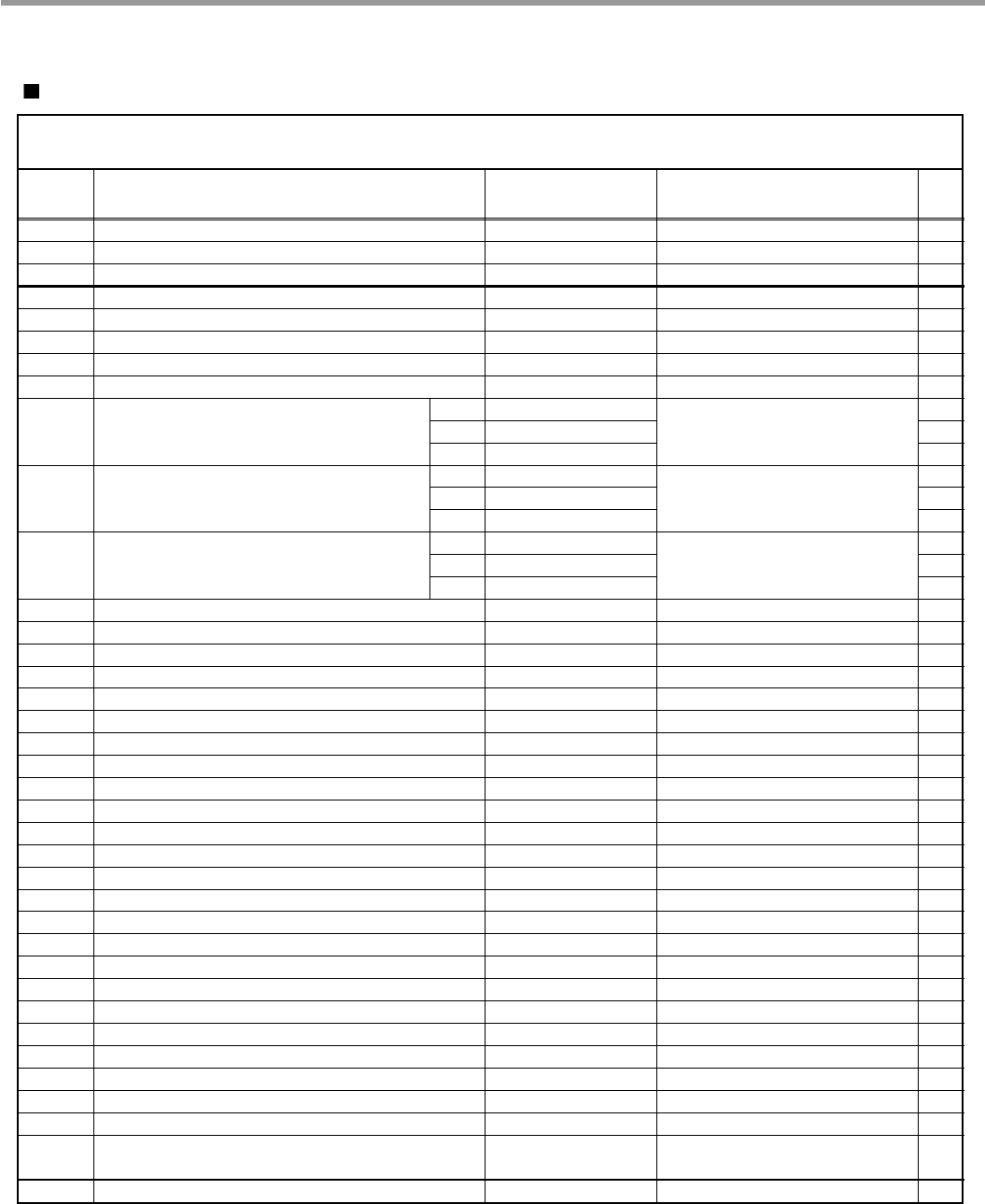
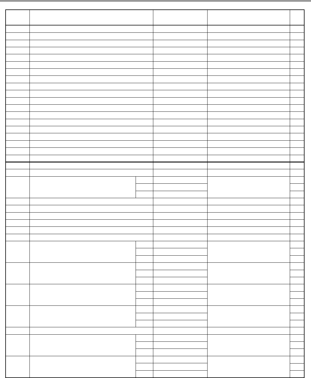
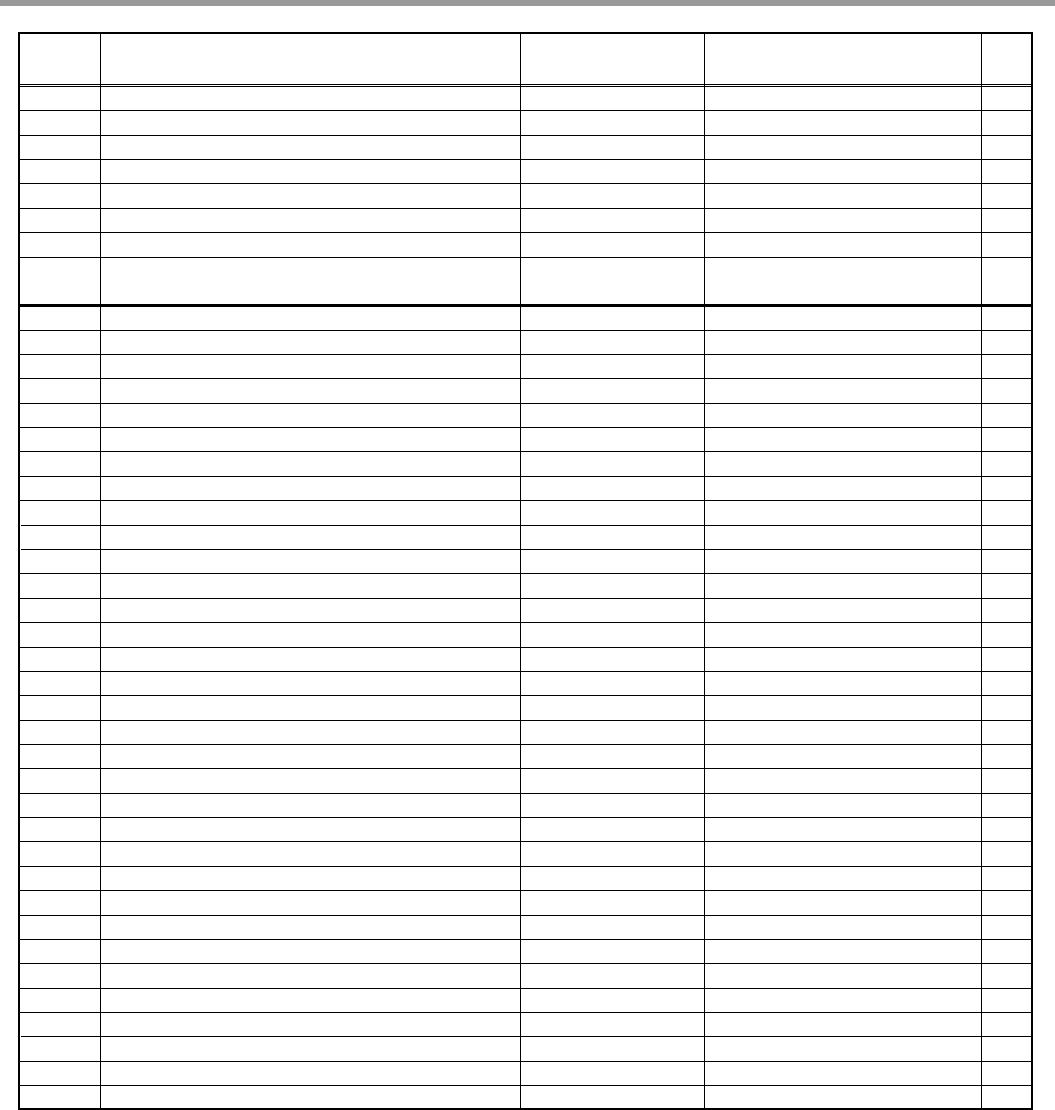
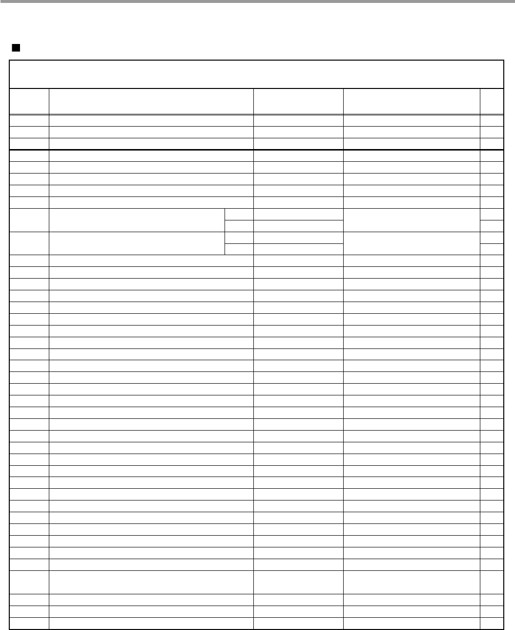
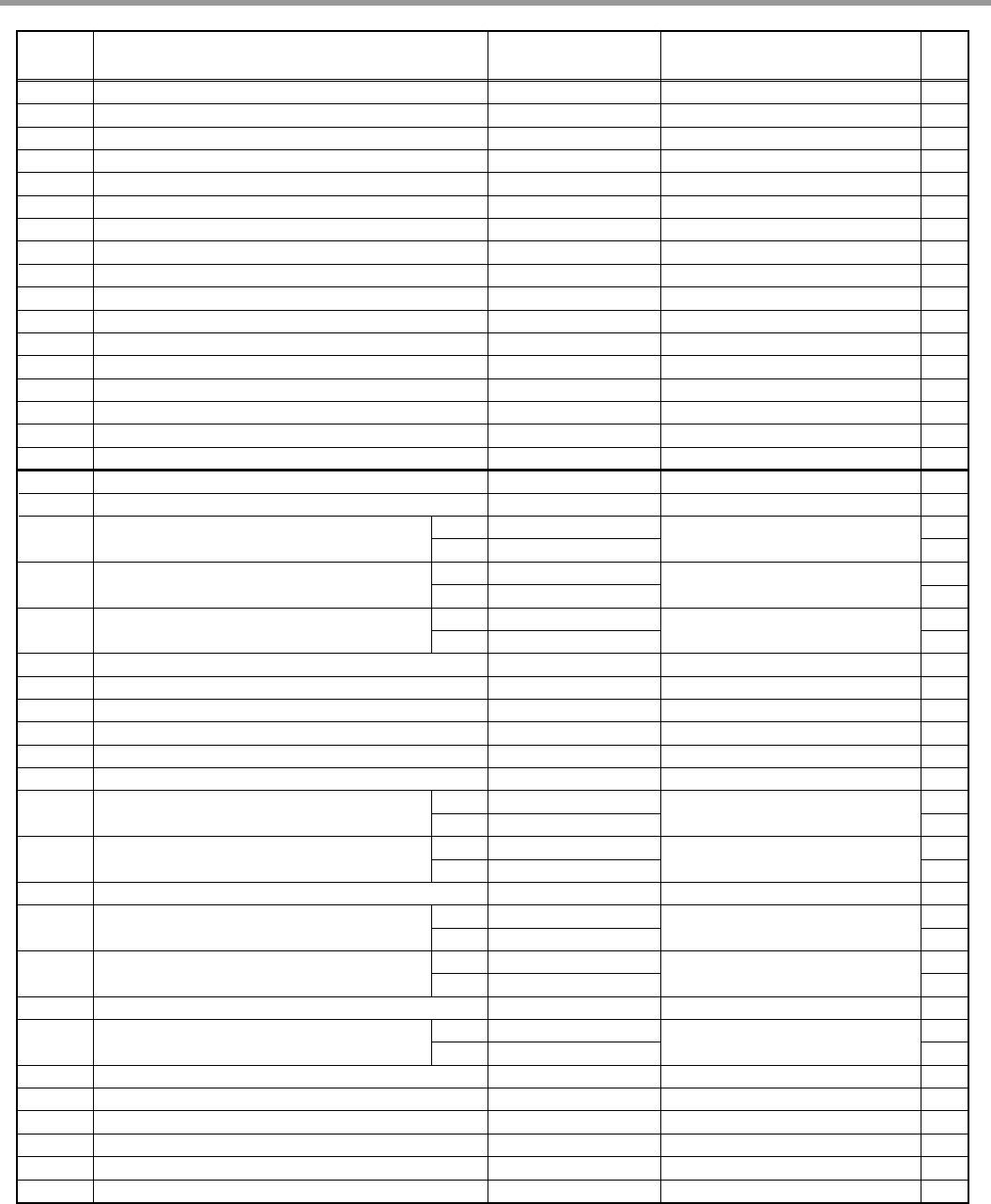
11. REPLACEMENT PART LIST
*001 MANUAL ASSEMBLY, OWNER’S 3829DD3002B 1
*002 BOX, CARTON 3890DZ3015A 1
*003 MANUAL, SERVICE 3828ED3001X 1
A003 FELT 4766DD2004A LOWER FELT 1
A005 BRACKET, TOP 4810DD4002B 4
A006 SUPPORTER, HOLDER 498ED2015A 1
A007 SUPPORTER, HOLDER 498ED2014A 1
A008 SUPPORTER, HOLDER 498ED2018A 1
3090ED1001A 1
A010 CABINET 3090ED1001B 1
3090ED1001C 1
3090ED1002A 1
A020 CABINET 3090ED1002B 1
3090ED1002C 1
3551DD2001A 1
A030 COVER ASSEMBLY, LOWER 3551DD2001B 1
3551DD2001B 1
A050 NOZZLE ASSEMBLY 5249DD1002A LOWER NOZZLE 1
A060 NOZZLE ASSEMBLY 5249DD1001A UPPER NOZZLE 1
A070 GUIDE ASSEMBLY 4975ED1006A 1
A073 WASHER, DRAWING 1WZZDD3001A 1
A074 SHAFT, NOZZLE 4370ED3007A 1
A080 RACK 3750DD2001A CUP RACK 2
A110 BASKET ASSEMBLY, SPOON 5005DD1001A 1
A120 HARNESS, PWB 6877DD1002A 1
A130 HOSE ASSEMBLY, DRAIN 5215ED3001E 1
A140 RACK ASSEMBLY 3751DD1001A LOWER RACK 1
A141 RACK 3750ED1004A 1
A142 ROLLER 4580DD4001A 8
A143 SHAFT, ROLLER 4370FD3706C 8
A144 RACK 3750DD2003A 2
A147 HOLDER 4930DD3006A 3
A148 RACK 3750DD1001A 1
A149 RACK 3750DD1002A 1
A150 RACK ASSEMBLY 3751DD1002A UPPER RACK 1
A151 RACK 3750ED1005A 1
A155 GUIDE ASSEMBLY 4975ED2004A 1
A156 GUIDE ASSEMBLY 4975ED2005A 1
A157 HOLDER 4930DD3003A 4
A158 HOLDER 4930DD3005A 3
A159 RACK 3750DD2002A 2
A160 FILTER ASSEMBLY (CIRC) 6201EC1006A 1
A170 PACKING 3920DD3004A 2
A301 SCREW TAB TITE(B) 1SBF0402618
LATCH LOCK, HINGE SUPORTER ~ BODY FRAME
3
DESC PART No. COMMENTS
QTYLOC
LG MODEL: LD-6100WB/BB/TB
YOUR MODEL: LDF7811WW/BB/ST Run_Date : 2005-01-30
SPECIFICATION: 120V 60Hz
CAUTION : BEFORE REPLACING ANY OFTHESE COMPONENTS.
READ CAREFULLY THE SAFETY PRECAUTIONS IN THIS MANUAL
NOTE : S(SAFETY PARTS), AL(ALTERNATIVE PARTS)
WB
BB
ST
WB
BB
ST
WB
BB
ST
3828ED3001X 2005.3.10 5:19 PM 페이지45 001 HP LaserJet 5000 Series
- 46 -- 46 -
F001 FRAME ASSEMBLY 3211DD1001A 1
F004 NOZZLE ASSEMBLY 5249DD2001A TOP NOZZLE 1
F011 SPRING, HINGE 4970ED4004A 2
F014 HINGE, BRACKET 4810ED4004A 2
F022 SENSOR ASSEMBLY 6501DD2001A 1
F040 GUIDE ASSEMBLY 4975DD1001A 1
F045 COVER, PROTECT 3550DD2001A 1
F050 NUT, DRAWING 4020FD3641C 1
F060 GASKET 4986DD3001A 1
F101 PACKING 3920DD3002A 1
F110 RAIL ASSEMBLY 5219DD2002A 1
F117 STOPPER, ROLLER 4620ED3001A 2
F132 PACKING 3920DD3003A TUB PACKING 1
F143 HINGE ASSEMBLY 4775ED3004A 1
F144 HINGE ASSEMBLY 4775ED3003A 1
F171 LATCH, LOCK 4026DD3001A 1
F174 BRACKET, HINGE 4810DD1001A DOOR FRAME 1
F191 GUIDE, WATER 4974DD2003A 1
F192 GUIDE, NOZZLE 4974DD3001A 1
F210 RAIL ASSEMBLY 5219DD2001A 1
K001 DISPENSER 4924FD2123E 1
K002 BRACKET ASSEMBLY 4810FD3805A 2
3650ED2006A 1
K005 HANDLE 3650ED2006B 1
3650ED2006C 1
3806ED3008A 2
K006 DECO, HANDLE 3806ED3008B 2
3806ED3008C 2
3551DD1003A 1
K010 COVER ASSEMBLY, FRONT 3551DD1003B 1
3551DD1003D 1
K110 BLOWER ASSEMBLY 5835ED2002A 1
K121 GASKET 4986DD3003A BLOWER GASKET 1
K122 COVER, BLOWER 3550ED3011A 1
K124 VENT 5232ED2001A 1
K141 DOOR HINGE ASSEMBLY 4775DD2001A 1
K142 DOOR HINGE ASSEMBLY 4775DD2002A 1
5020ED3008C 6
K201 BUTTON, CONTROL 5020ED3008D PROGRAM BUTTON 6
5020ED3008E 6
3790ED3007A 1
K203 WINDOW 3790ED3007D TOP WINDOW 1
3790ED3007E 1
K207 COVER, GUIDE 3550ED3012A 1
3720ED1005A 1
K208 PANEL, CONTROL 3720ED1005B 1
3720ED1005C 1
5020ED3011A 1
K209 BUTTON, POWER SWITCH 5020ED3011B 1
5020ED3011A 1
K215 COVER, GUIDE 3550ED1009A 1
PART NAME PART No. SPEC&COLOR
Q'tyNo.
WB
BB
ST
WB
BB
ST
WB
BB
ST
WB
BB
ST
WB
BB
ST
WB
BB
ST
WB
BB
ST
3828ED3001X 2005.3.10 5:19 PM 페이지46 001 HP LaserJet 5000 Series
- 47 -- 47 -
5020ED3012C 4
K216 BUTTON, CONTROL 5020ED3012D OPTION BUTTON 4
3791DD3001E 1
3791DD3001A 1
K230 WINDOW 3791DD3001B FRONT WINDOW 1
3791DD3001B 1
K251 PWB(PCB) ASSEMBLY, MAIN 6871DD1006A 1
K252 PWB(PCB) ASSEMBLY, DISPLAY 6871DD2001A 1
K253 PWB(PCB) ASSEMBLY, DISPLAY 6871DD2002A 1
K254 DISPLAY LED ASSEMBLY 6327DC3001A 1
K260 LATCH, ASSEMBLY 4027ED3002A 1
K301 SCREW, DRAWING 4000FD4268A DOOR LINER~DOOR HINGE 4
K302 SCREW, DRAWING 1SZZED3001A
DOOR LINER~CONTROL PANEL
~
FRONT COVER
6
K303 SCREW, DRAWING 1SZZED3002A
DOOR LINER~CONTROL PANEL
2
K304 SCREW, DRAWING 1SZZED3003A
DOOR LINER~CONTROL PANEL
10
CABINET~BODY FRAME
M001 HOLDER 4930DD3002A 1
M005 GASKET 4986DD3002A SUMP GASKET 1
M006 SUMP, ASSEMBLY 3485ED1002A 1
M025 VALVE, CHECK 5220DD3001A 1
M026 MOTOR ASSEMBLY, WM 4681ED3001B VARIO MOTOR 1
M027 SWITCH, MICRO 3W40025C 1
M028 CAM, SWITCH 4430ED3001A 1
M031 PACKING 3920ED4009B VARIO PACKING 1
M034 BLADE 5832DD4001A 1
M035 SEAL 4036DD3001A 1
M036 HOLDER 4930DD3008A 1
M037 FILTER ASSEMBLY, MESH 5231DD1001A 1
M038 HOLDER 4930DD3012A 1
M050 MOTOR ASSEMBLY, PUMP 4681EA2002D DRAIN MOTOR 1
M060 MOTOR ASSEMBLY, WM 4681ED1004A 1
M081 HEATER ASSEMBLY 5301DD1001A 1
M083 THERMISTOR ASSEMBLY 6323DD3001A 1
M087 SENSOR ASSEMBLY 6501ED2002B SOIL SENSOR 1
M088 PROTECTOR (MECH) 3740ED3003A 1
M090 FLOAT ASSEMBLY 4769DD2001A 1
M110 FILTER ASSEMBLY, MESH 5231ED1001A 1
M120 CASE ASSEMBLY 3111DD1001A 1
M130 IMPELLER ASSEMBLY 5911ED3003A 1
M210 VALVE ASSEMBLY, INLET 5221DD1001A 1
M220 VALVE, CHECK 5220ED4004A 1
M260 BASE, CABINET 3040ED1003A 1
M261 COVER ASSEMBLY, BASE 3551DD1002A 1
M270 LEG 4778ED3001A 1
M301 SCREW, DRAWING 4W51229F BASE~HINGE SUPPORTER 4
M302 SCREW, DRAWING 1SZZED3005A 7
M303 SCREW, DRAWING 1SZZED3006A IMPELLER~MOTOR 1
M304 SCREW, DRAWING 1SZZFA4305A SUMP~DRAIN PUMP 3
M305 SCREW, DRAWING 4W51194D SUMP~MOTOR 4
PART NAME PART No. SPEC&COLOR
Q'tyNo.
WB
BB
ST
WB
BB
ST
3828ED3001X 2005.3.10 5:19 PM 페이지47 001 HP LaserJet 5000 Series
- 48 -- 48 -
*001 MANUAL ASSEMBLY, OWNER’S 3829DD3002C 1
*002 BOX, CARTON 3890DZ3015A 1
*003 MANUAL, SERVICE 3828ED3001X 1
A003 FELT 4766DD2004A LOWER FELT 1
A005 BRACKET, TOP 4810DD4002B 4
A006 SUPPORTER, HOLDER 498ED2015A 1
A007 SUPPORTER, HOLDER 498ED2014A 1
A008 SUPPORTER, HOLDER 498ED2018A 1
3090ED1001A 1
A010 CABINET 3090ED1001B 1
3090ED1001C 1
3090ED1002A 1
A020 CABINET 3090ED1002B 1
3090ED1002C 1
3551DD2001A 1
A030 COVER ASSEMBLY, LOWER 3551DD2001B 1
3551DD2001B 1
A050 NOZZLE ASSEMBLY 5249DD1002A LOWER NOZZLE 1
A060 NOZZLE ASSEMBLY 5249DD1001A UPPER NOZZLE 1
A070 GUIDE ASSEMBLY 4975ED1006A 1
A073 WASHER, DRAWING 1WZZDD3001A 1
A074 SHAFT, NOZZLE 4370ED3007A 1
A080 RACK 3750DD2001A CUP RACK 2
A110 BASKET ASSEMBLY, SPOON 5005DD1001A 1
A120 HARNESS, PWB 6877DD1002A 1
A130 HOSE ASSEMBLY, DRAIN 5215ED3001E 1
A140 RACK ASSEMBLY 3751DD1001A LOWER RACK 1
A141 RACK 3750ED1004A 1
A142 ROLLER 4580DD4001A 8
A143 SHAFT, ROLLER 4370FD3706C 8
A144 RACK 3750DD2003A 2
A147 HOLDER 4930DD3006A 3
A148 RACK 3750DD1001A 1
A149 RACK 3750DD1002A 1
A150 RACK ASSEMBLY 3751DD1002B UPPER RACK 1
A151 RACK 3750ED1005B 1
A157 HOLDER 4930DD3003A 4
A158 HOLDER 4930DD3005A 3
A159 RACK 3750DD2002A 2
A160 FILTER ASSEMBLY (CIRC) 6201EC1006A 1
A170 PACKING 3920DD3004A 2
A301 SCREW TAB TITE(B) 1SBF0402618
LATCH LOCK, HINGE SUPPORTER
3
~ BODY FRAME
F001 FRAME ASSEMBLY 3211DD1001A 1
DESC PART No. COMMENTS
QTYLOC
LG MODEL: LD-6090WB/BB/TB
YOUR MODEL: LDS5811WW/BB/ST Run_Date : 2005-01-30
SPECIFICATION: 120V 60Hz
CAUTION : BEFORE REPLACING ANY OFTHESE COMPONENTS.
READ CAREFULLY THE SAFETY PRECAUTIONS IN THIS MANUAL
NOTE : S(SAFETY PARTS), AL(ALTERNATIVE PARTS)
WB
BB
ST
WB
BB
ST
WB
BB
ST
3828ED3001X 2005.3.10 5:19 PM 페이지48 001 HP LaserJet 5000 Series
- 49 -- 49 -
F004 NOZZLE ASSEMBLY 5249DD2001A TOP NOZZLE 1
F011 SPRING, HINGE 4970ED4004A 2
F014 HINGE, BRACKET 4810ED4004A 2
F022 SENSOR ASSEMBLY 6510DD2001A 1
F040 GUIDE ASSEMBLY 4975DD1001A 1
F045 COVER, PROTECT 3550DD2001A 1
F050 NUT, DRAWING 4020FD3641C 1
F060 GASKET 4986DD3001A 1
F101 PACKING 3920DD3002A 1
F110 RAIL ASSEMBLY 5219DD2002A 1
F117 STOPPER, ROLLER 4620ED3001A 2
F132 PACKING 3920DD3003A TUB PACKING 1
F143 HINGE ASSEMBLY 4775ED3004A 1
F144 HINGE ASSEMBLY 4775ED3003A 1
F171 LATCH, LOCK 4026DD3001A 1
F174 BRACKET, HINGE 4810DD1001A DOOR FRAME 1
F191 GUIDE, WATER 4974DD2003A 1
F192 GUIDE, NOZZLE 4974DD3001A 1
F210 RAIL ASSEMBLY 5219DD2001A 1
K001 DISPENSER 4924FD2123E 1
K002 BRACKET ASSEMBLY 4810FD3805A 2
3551DD1004A 1
K010 COVER ASSEMBLY, FRONT 3551DD1004B 1
3551DD1004D 1
K110 BLOWER ASSEMBLY 5835ED2002A 1
K121 GASKET 4986DD3003A BLOWER GASKET 1
K122 COVER, BLOWER 3550ED3011A 1
K124 VENT 5232ED2001A 1
K141 DOOR HINGE ASSEMBLY 4775DD2001A 1
K142 DOOR HINGE ASSEMBLY 4775DD2002A 1
5020DD2001A 1
K201 BUTTON, CONTROL 5020DD2001B PROGRAM BUTTON 1
5020DD2001C 1
3790DD3001A 1
K203 WINDOW 3790DD3001B PROGRESS WINDOW 1
3790DD3001B 1
3720DD1001A 1
K208 PANEL, CONTROL 3720DD1001B 1
3720DD1001C 1
5020DD2004A 1
K209 BUTTON, POWER SWITCH 5020DD2004B 1
5020DD2004C 1
K212 BUTTON, CONTROL 5020DD3001A DELAY START 1
5020DD2003A 1
K216 BUTTON, CONTROL 5020DD2003B OPTION BUTTON 1
5020DD2003C 1
5020DD2002A 1
K217 BUTTON, CONTROL 5020DD2002B PROGRAM BUTTON 1
5020DD2002C 1
PART NAME PART No. SPEC&COLOR
Q'tyNo.
WB
BB
ST
BB
WB
ST
WB
BB
ST
WB
BB
ST
WB
BB
ST
WB
BB
ST
WB
BB
ST
3828ED3001X 2005.3.10 5:19 PM 페이지49 001 HP LaserJet 5000 Series
- 50 -- 50 -
K230 WINDOW 3790DD3002A OPTION WINDOW 1
K251 PWB(PCB) ASSEMBLY, MAIN 6871DD1006B 1
K252 PWB(PCB) ASSEMBLY, DISPLAY 6871DD2003A 1
K254 DISPLAY LED ASSEMBLY 6327DC3001A 1
K260 LATCH, ASSEMBLY 4027ED3002A 1
K301 SCREW, DRAWING 4000FD4268A DOOR LINER~DOOR HINGE 4
K301 SCREW, DRAWING 1SZZED3002A
DOOR LINER~CONTROL PANEL
8
K304 SCREW, DRAWING 1SZZED3003A
DOOR LINER~CONTROL PANEL
10
CABINET~BODY FRAME
M001 HOLDER 4930DD3002A 1
M005 GASKET 4986DD3002A SUMP GASKET 1
M006 SUMP, ASSEMBLY 3485ED1002A 1
M025 VALVE, CHECK 5220DD3001A 1
M026 MOTOR ASSEMBLY, WM 4681ED3001B VARIO MOTOR 1
M027 SWITCH, MICRO 3W40025C 1
M028 CAM, SWITCH 4430ED3001A 1
M031 PACKING 3920ED4009B VARIO PACKING 1
M034 BLADE 5832DD4001A 1
M035 SEAL 4036DD3001A 1
M036 HOLDER 4930DD3008A 1
M037 FILTER ASSEMBLY, MESH 5231DD1001A 1
M038 HOLDER 4930DD3012A 1
M050 MOTOR ASSEMBLY, PUMP 4681EA2002D DRAIN MOTOR 1
M060 MOTOR ASSEMBLY, WM 4681ED1004A 1
M081 HEATER ASSEMBLY 5301DD1001A 1
M083 THERMISTOR ASSEMBLY 6323DD3001A 1
M087 SENSOR ASSEMBLY 6501ED2002B SOIL SENSOR 1
M088 PROTECTOR (MECH) 3740ED3003A 1
M090 FLOAT ASSEMBLY 4769DD2001A 1
M110 FILTER ASSEMBLY, MESH 5231ED1001A 1
M120 CASE ASSEMBLY 3111DD1001A 1
M130 IMPELLER ASSEMBLY 5911ED3003A 1
M210 VALVE ASSEMBLY, INLET 5221DD1001A 1
M220 VALVE, CHECK 5220ED4004A 1
M260 BASE, CABINET 3040ED1003A 1
M261 COVER ASSEMBLY, BASE 3551DD1002A 1
M270 LEG 4778ED3001A 1
M301 SCREW, DRAWING 4W51229F BASE~HINGE SUPPORTER 4
M302 SCREW, DRAWING 1SZZED3005A 7
M303 SCREW, DRAWING 1SZZED3006A IMPELLER~MOTOR 1
M304 SCREW, DRAWING 1SZZFA4305A SUMP~DRAIN PUMP 3
M305 SCREW, DRAWING 4W51194D SUMP~MOTOR 4
PART NAME PART No. SPEC&COLOR
Q'tyNo.
3828ED3001X 2005.3.10 5:19 PM 페이지50 001 HP LaserJet 5000 Series
- 51 -- 51 -
*001 MANUAL ASSEMBLY, OWNER’S 3829DD3002B 1
*002 BOX, CARTON 3890DZ3015A 1
*003 MANUAL, SERVICE 3828ED3001X 1
A003 FELT 4766DD2004A LOWER FELT 1
A005 BRACKET, TOP 4810DD4002B 4
A006 SUPPORTER, HOLDER 498ED2015A 1
A007 SUPPORTER, HOLDER 498ED2014A 1
A008 SUPPORTER, HOLDER 498ED2018A 1
A010 CABINET 3090ED1001B 1
3090ED1001C 1
A020 CABINET 3090ED1002B 1
3090ED1002C 1
A030 COVER ASSEMBLY, LOWER 3551DD2001B 1
A050 NOZZLE ASSEMBLY 5249DD1002A LOWER NOZZLE 1
A060 NOZZLE ASSEMBLY 5249DD1001A UPPER NOZZLE 1
A070 GUIDE ASSEMBLY 4975ED1006A 1
A073 WASHER, DRAWING 1WZZDD3001A 1
A074 SHAFT, NOZZLE 4370ED3007A 1
A080 RACK 3750DD2001A CUP RACK 2
A110 BASKET ASSEMBLY, SPOON 5005DD1001A 1
A120 HARNESS, PWB 6877DD1002A 1
A130 HOSE ASSEMBLY, DRAIN 5215ED3001E 1
A140 RACK ASSEMBLY 3751DD1001A LOWER RACK 1
A141 RACK 3750ED1004A 1
A142 ROLLER 4580DD4001A 8
A143 SHAFT, ROLLER 4370FD3706C 8
A144 RACK 3750DD2003A 2
A147 HOLDER 4930DD3006A 3
A148 RACK 3750DD1001A 1
A149 RACK 3750DD1002A 1
A150 RACK ASSEMBLY 3751DD1002A UPPER RACK 1
A151 RACK 3750ED1005A 1
A155 GUIDE ASSEMBLY 4975ED2004A 1
A156 GUIDE ASSEMBLY 4975ED2005A 1
A157 HOLDER 4930DD3003A 4
A158 HOLDER 4930DD3005A 3
A159 RACK 3750DD2002A 2
A160 FILTER ASSEMBLY (CIRC) 6201EC1006A 1
A170 PACKING 3920DD3004A 2
A301 SCREW TAB TITE(B) 1SBF0402618
LATCH LOCK, HINGE SUPPORTER
3
~ BODY FRAME
F001 FRAME ASSEMBLY 3211DD1001A 1
F004 NOZZLE ASSEMBLY 5249DD2001A TOP NOZZLE 1
F011 SPRING, HINGE 4970ED4004A 2
DESC PART No. COMMENTS
QTYLOC
LG MODEL: LD-6105WB/BB/TB
YOUR MODEL: LDF7810WW/BB/ST Run_Date : 2005-01-30
SPECIFICATION: 120V 60Hz
CAUTION : BEFORE REPLACING ANY OFTHESE COMPONENTS.
READ CAREFULLY THE SAFETY PRECAUTIONS IN THIS MANUAL
NOTE : S(SAFETY PARTS), AL(ALTERNATIVE PARTS)
BB
ST
BB
ST
3828ED3001X 2005.3.10 5:19 PM 페이지51 001 HP LaserJet 5000 Series
- 52 -- 52 -
F014 HINGE, BRACKET 4810ED4004A 2
F022 SENSOR ASSEMBLY 6501DD2001A 1
F040 GUIDE ASSEMBLY 4975DD1001A 1
F045 COVER, PROTECT 3550DD2001A 1
F050 NUT, DRAWING 4020FD3641C 1
F060 GASKET 4986DD3001A 1
F101 PACKING 3920DD3002A 1
F110 RAIL ASSEMBLY 5219DD2002A 1
F117 STOPPER, ROLLER 4620ED3001A 2
F132 PACKING 3920DD3003A TUB PACKING 1
F143 HINGE ASSEMBLY 4775ED3004A 1
F144 HINGE ASSEMBLY 4775ED3003A 1
F171 LATCH, LOCK 4026DD3001A 1
F174 BRACKET, HINGE 4810DD1001A DOOR FRAME 1
F191 GUIDE, WATER 4974DD2003A 1
F192 GUIDE, NOZZLE 4974DD3001A 1
F210 RAIL ASSEMBLY 5219DD2001A 1
K001 DISPENSER 4924FD2123E 1
K002 BRACKET ASSEMBLY 4810FD3805A 2
K005 HANDLE 3650ED2006B 1
3650ED2006C 1
K006 DECO, HANDLE 3806ED3008B 2
3806ED3008C 2
K010 COVER ASSEMBLY, FRONT 3551DD1003F 1
3551DD1003G 1
K110 BLOWER ASSEMBLY 5835ED2002A 1
K121 GASKET 4986DD3003A BLOWER GASKET 1
K122 COVER, BLOWER 3550ED3011A 1
K124 VENT 5232ED2001A 1
K141 DOOR HINGE ASSEMBLY 4775DD2001A 1
K142 DOOR HINGE ASSEMBLY 4775DD2002A 1
K201 BUTTON, CONTROL 5020ED3008D 6
5020ED3008E PROGRAM BUTTON 6
K203 WINDOW 3790ED3007D 1
3790ED3007E TOP WINDOW 1
K207 COVER, GUIDE 3550ED3012A 1
K208 PANEL, CONTROL 3720ED1005B 1
3720ED1005C 1
K209 BUTTON, POWER SWITCH 5020ED3011B 1
5020ED3011A 1
K215 COVER, GUIDE 3550ED1009A 1
K216 BUTTON, CONTROL 5020ED3012D OPTION BUTTON 4
5020ED3012E 4
K251 PWB(PCB) ASSEMBLY, MAIN 6871DD1006A 1
K252 PWB(PCB) ASSEMBLY, DISPLAY 6871DD2001A 1
K253 PWB(PCB) ASSEMBLY, DISPLAY 6871DD2002A 1
K254 DISPLAY LED ASSEMBLY 6327DC3001A 1
K260 LATCH, ASSEMBLY 4027ED3002A 1
K301 SCREW, DRAWING 4000FD4268A DOOR LINER~DOOR HINGE 4
PART NAME PART No. SPEC&COLOR
Q'tyNo.
BB
ST
BB
ST
BB
ST
BB
ST
BB
ST
BB
ST
BB
ST
BB
ST
3828ED3001X 2005.3.10 5:19 PM 페이지52 001 HP LaserJet 5000 Series

- 53 -- 53 -
K302 SCREW, DRAWING 1SZZED3001A
DOOR LINER~CONTROL PANEL
6
~ FRONT COVER
K303 SCREW, DRAWING 1SZZED3002A
DOOR LINER~CONTROL PANEL
2
K304 SCREW, DRAWING 1SZZED3003A
DOOR LINER~CONTROL PANEL
10
CABINET~BODY FRAME
M001 HOLDER 4930DD3002A 1
M005 GASKET 4986DD3002A SUMP GASKET 1
M006 SUMP, ASSEMBLY 3485ED1002A 1
M025 VALVE, CHECK 5220DD3001A 1
M026 MOTOR ASSEMBLY, WM 4681ED3001B VARIO MOTOR 1
M027 SWITCH, MICRO 3W40025C 1
M028 CAM, SWITCH 4430ED3001A 1
M031 PACKING 3920ED4009B VARIO PACKING 1
M034 BLADE 5832DD4001A 1
M035 SEAL 4036DD3001A 1
M036 HOLDER 4930DD3008A 1
M037 FILTER ASSEMBLY, MESH 5231DD1001A 1
M038 HOLDER 4930DD3012A 1
M050 MOTOR ASSEMBLY, PUMP 4681EA2002D DRAIN MOTOR 1
M060 MOTOR ASSEMBLY, WM 4681ED1004A 1
M081 HEATER ASSEMBLY 5301DD1001A 1
M083 THERMISTOR ASSEMBLY 6323DD3001A 1
M087 SENSOR ASSEMBLY 6501ED2002B SOIL SENSOR 1
M088 PROTECTOR (MECH) 3740ED3003A 1
M090 FLOAT ASSEMBLY 4769DD2001A 1
M110 FILTER ASSEMBLY, MESH 5231ED1001A 1
M120 CASE ASSEMBLY 3111DD1001A 1
M130 IMPELLER ASSEMBLY 5911ED3003A 1
M210 VALVE ASSEMBLY, INLET 5221DD1001A 1
M220 VALVE, CHECK 5220ED4004A 1
M260 BASE, CABINET 3040ED1003A 1
M261 COVER ASSEMBLY, BASE 3551DD1002A 1
M270 LEG 4778ED3001A 1
M301 SCREW, DRAWING 4W51229F BASE~HINGE SUPPORTER 4
M302 SCREW, DRAWING 1SZZED3005A 7
M303 SCREW, DRAWING 1SZZED3006A IMPELLER~MOTOR 1
M304 SCREW, DRAWING 1SZZFA4305A SUMP~DRAIN PUMP 3
M305 SCREW, DRAWING 4W51194D SUMP~MOTOR 4
PART NAME PART No. SPEC&COLOR
Q'tyNo.
3828ED3001X 2005.3.10 5:19 PM 페이지53 001 HP LaserJet 5000 Series

- 54 -
3828ED3001X 2005.3.10 5:19 PM 페이지54 001 HP LaserJet 5000 Series

- 55 -
3828ED3001X 2005.3.10 5:19 PM 페이지55 001 HP LaserJet 5000 Series

P/No. : 3828ED3001X
3828ED3001X 2005.3.10 5:18 PM 페이지1 001 HP LaserJet 5000 Series
