3828ER3035Q LG Frnt Load Washer 3431 3434
2013-04-09
: Pdf Lg Frnt Load Washer 3431 - 3434 LG Frnt Load Washer 3431 - 3434 LG
Open the PDF directly: View PDF ![]() .
.
Page Count: 44

WASHING MACHINE
SERVICE MANUAL
READ THIS MANUAL CAREFULLY TO DIAGNOSE
PROBLEMS CORRECTLY BEFORE SERVICING THE UNIT.
MODEL: WM3431H*/WM3434H*
CAUTION
Website: http://www.LGEservice.com [For U.S.A]
www.lg.ca [For CANADA]
E-mail: http://www.LGEservice.com/techsup.html
!

JAN. 2005 PRINTED IN KOREA
P/No.:3828ER3035Q

CONTENTS
1. SPECIFICATIONS .........................................................................................................................3
2. FEATURES & TECHNICAL EXPLANATION ................................................................................ 4
3. PARTS IDENTIFICATION ............................................................................................................ 6
4. INSTALLATION & TEST ............................................................................................................... 7
5. OPERATION ................................................................................................................................10
6. WIRING DIAGRAM/PROGRAM CHART.....................................................................................12
7. TROUBLESHOOTING.................................................................................................................13
7-1. BEFORE PERFORMING SERVICE ...................................................................................13
7-2. QC TEST MODE.................................................................................................................13
7-3. HOW TO CHECK THE WATER LEVEL FREQUENCY ......................................................13
7-4. ERROR DISPLAY ...............................................................................................................14
8. ERROR DIAGNOSIS AND CHECKLIST .....................................................................................16
8-1. DIAGNOSIS AND SOLUTION FOR ABNORMAL OPERATION ........................................16
8-2. FAULT DIAGNOSIS AND TROUBLE SHOOTING .............................................................19
9. DISASSEMBLY INSTRUCTIONS ...............................................................................................29
10. EXPLODED VIEW .....................................................................................................................38
10-1. CABINET & CABINET COVER ASSEMBLY.....................................................................38
10-2. CONTROL PANEL & DISPENSER ASSEMBLY...............................................................39
10-3. DRUM & TUB ASSEMBLY................................................................................................40
10-4. DRYER .............................................................................................................................41
2
3
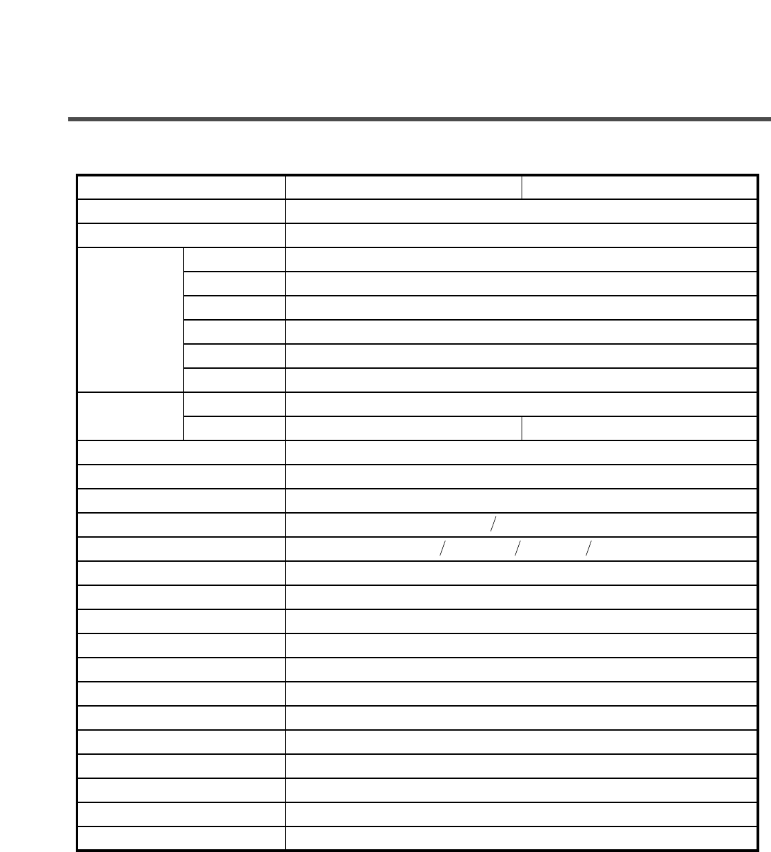
1. SPECIFICATION
WM3431H* WM3434H*
WASHING
SPIN
FAN MOTOR
DRAIN MOTOR
WASH HEATER
DRY HEATER
WASH
SPIN 0-1400 rpm 0-1200 rpm
ELECTRIC
POWER
CONSUMPTION
ITEM
POWER SUPPLY
PRODUCT W EIGHT
REVOLUTION
SPEED
OPERATIONAL WATER PRESSURE
CONTROL TYPE
WASH CAPACITY
DRY CAPACITY
DIMENSIONS
CYCLES
WASH/RINSE TEMPERATURES
SPIN SPEEDS
OPTIONS
DELAY WASH
DOOR SW ITCH TY P E
WATER LEVEL
LAUNDRY LOAD SENSING
ERROR DIAGNOSIS
POWER AUTO OFF
CHILD LOCK
AUTO RESTART
AC 120 V, 60 Hz
147 lbs. (68 kg)
140 W
410 W
25 W
80 W
1000 W
1200 W
50 rpm
4.5-145 psi (30-1000 kPa)
Electronic
2.11 cu. ft
8
1316 lbs. (4 kg )
23 " (W) X 25 " " (D) X 33 (H)
9
5
5
Soak, Extra Wash, Rinse+Spin, Spin Only, Dry Only, Delay W ash, Extra Rinse
up to 19 hours
Bi-Metal
Incorporated
Incorporated
10 steps (by sensor)
Incorporated
Incorporated
Incorporated
38 14
38
2. FEATURES & TECHNICAL EXPLANATION
4
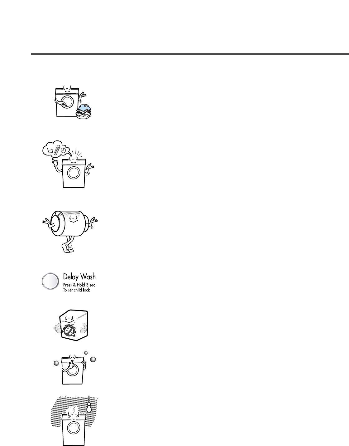
2-1.FEATURES
n Automatic Process From Washing To Drying
Automatic process from washing to drying can be
selected easily.
n More economical by using Intelligent Wash
System
Intelligent Wash System detects the amount of load and
water temperature, and then determines the optimum
water level and washing time to minimize energy and
water consumption.
n Direct Drive System
The advanced Brushless DC motor directly drives the
drum without belt and pulley.
n Child-Lock
The Child-Lock prevents children from pressing any
button to change the settings during operation.
n Built-in Heater
Internal heater automatically heats the water to the
optimal temperature on selected cycles.
n Low noise speed control system
By sensing the amount of load and balance, it evenly
distributes load to minimize the spinning noise level.
n Auto Restart
If the washing machine is turned off by a power failure, it
will restart automatically from the position it stopped.
5
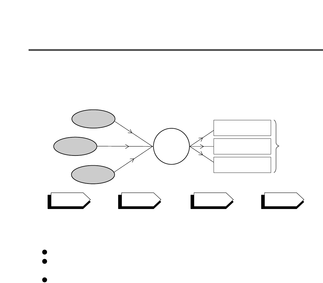
2-2. NEURO FUZZY WASHING TIME OPTIMIZATION
To get the best washing performance, optimal time is determined by the water temperature,
the selected washing temperature, and the size of the load.
2-3. WATER LEVEL CONTROL
This model incorporates a pressure sensor which can sense the water level in the tub.
The water supply is stopped when the water level reaches the preset level, the washing
program then proceeds.
Spinning does not proceed until the water in the tub drains to a certain level.
NEURO-
FUZZY
load
size
selected
washing
temperature
water
temperature
washing time
rinsing time
spin rhythm, time
the best
washing
performance
SENSING
PROCESSING
DETERMINATION
EFFECT
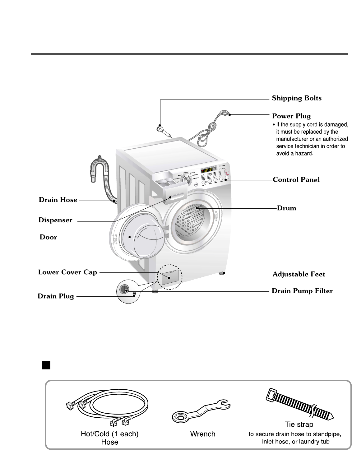
3. PARTS IDENTIFICATION
6
ACCESSORIES
울
란제리
란제리
4. INSTALLATION & TEST
7
Before servicing, ask the customer what the trouble is.
Check the setup (power supply is 120 V AC, remove the transit bolts....).
Check with the troubleshooting guide.
Plan your service method by referring to the disassembly instructions.
Service the unit.
After servicing, operate the appliance to see whether it functions correctly.
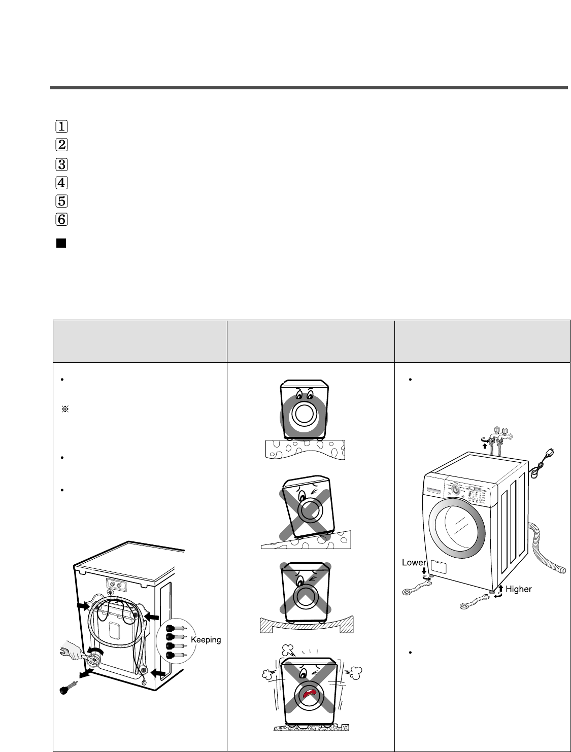
STANDARD INSTALLATION
The appliance should be installed as follows:
REMOVE THE SHIPPING INSTALL THE APPLIANCE ADJUST THE
BOLTS
ON A FLAT AND FIRM SURFACE
LEVELING
Remove the 4 shipping bolts Turn the leveling feet to adjust
with the supplied wrench. the appliance.
Do lower bolts first remove
easily.
Keep the shipping bolts and
wrench for future use.
Insert the 4 caps
(provided) into the hole.
Turn clockwise to raise;
counterclockwise to lower.
8
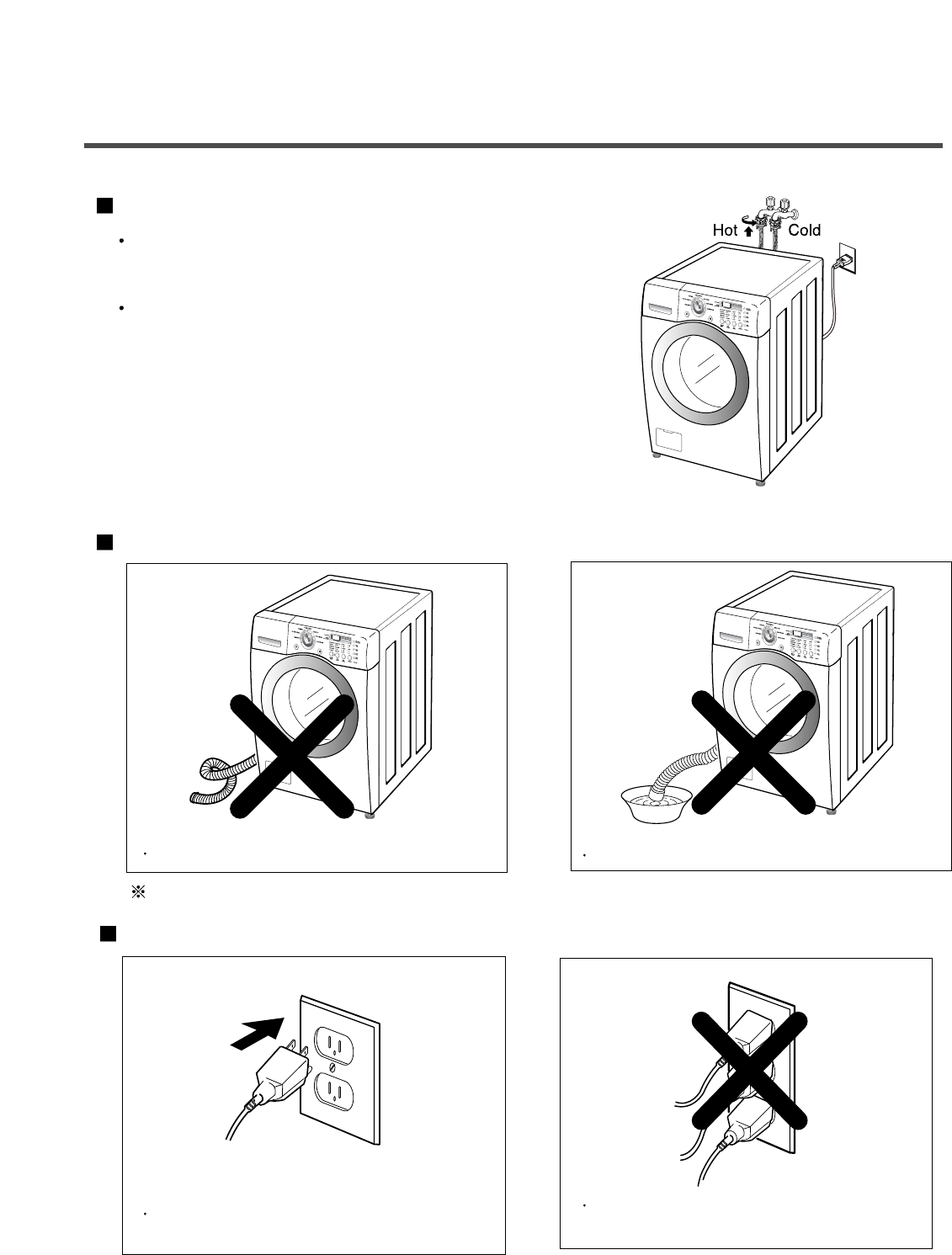
HOW TO CONNECT THE INLET HOSE
Verify that the rubber washer is inside of the
valve connector.
Tighten the inlet hose securely to prevent leaks.
CONNECT THE DRAIN HOSE
CONNECT POWER PLUG
The end of the drain hose should be placed less than 96
”
from the floor.
Connect the power plug to the wall outlet. Washer should be connected to dedicated
circuit.
Make sure that the hose is not twisted. Avoid submerging the end of the hose.
9
MAX
max
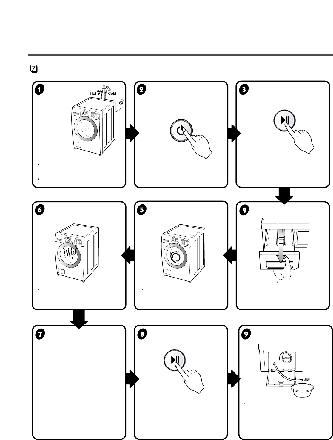
Connect the power plug to
the outlet.
Connect the inlet hose.
Preparation Press the POWER button. Press
the
Start/Pause
for washing. button.
Press the Wash/Rinse button Check if the drum rotates Check if water is supplied
and the present temperature will
clockwise and counterclockwise.
through the detergent dispenser.
be displayed.
Power off.
Check if the door can be
opened after 3 minutes.
• Power off and power on.
• Press the Spin Speed button.
• Press the Start/Pause button.
• Check the spin and drain
functions.
If SVC is needed, remove the
remaining water by pulling out
the hose and removing the
cap.
Check the water heating Check automatic reverse Check the water supply.
function. rotation.
Check drain and spin
Power off and open the
Water removal
functions. door
TEST OPERATION
10
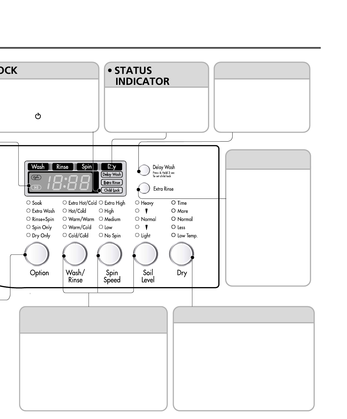
5. OPERATION
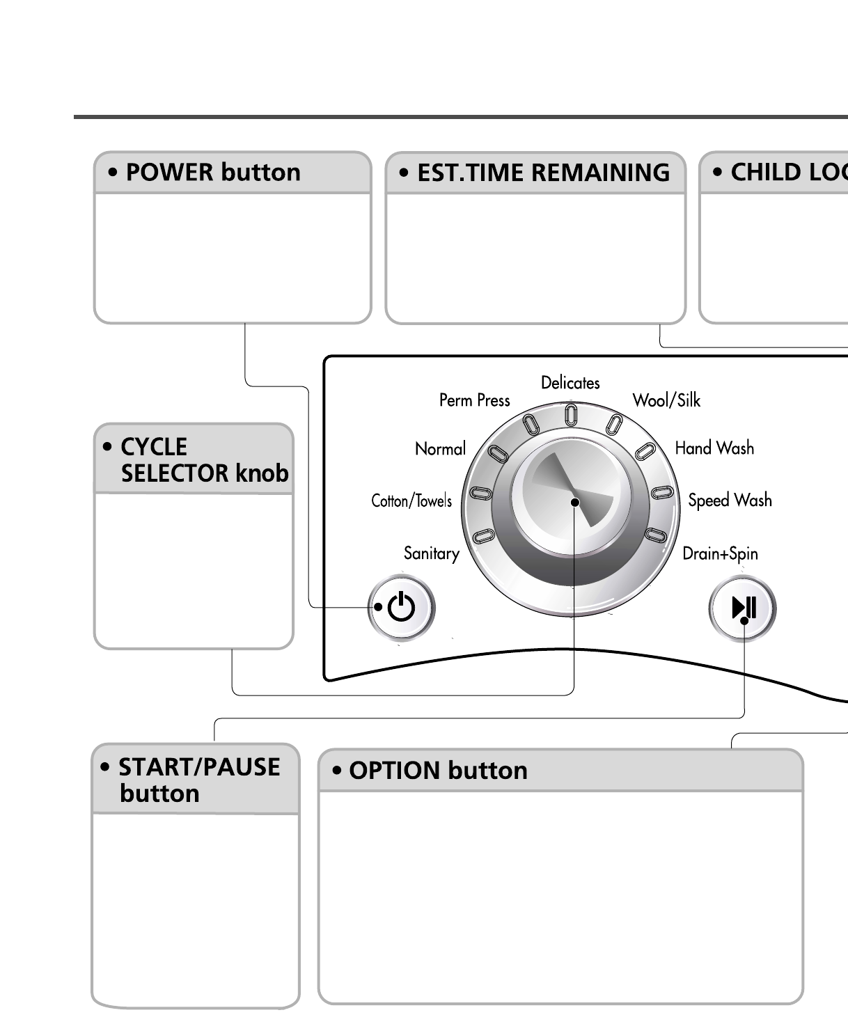
• Use this button to turn the power
On/Off.
• Rotate the Cycle selector
knob to select the cycle
designed for different
types of fabric and soil
levels.
• Use this option to pre
Press and hold Dela
lock/unlock control.
• When Child lock is s
are disabled except t
the washer while it is
•Soak: Use this option to wash normal clothes or thick and heavy
clothes which are excessively dirty.
• Extra Wash: If the laundry is heavily soiled, this option is effective.
• Rinse+Spin: Use this option to rinse and then spin.
• Spin Only: Use this option to select spin cycle only.
• Dry Only: When you want Dry only, select this option.
• Use this button to Start/
Stop the washer.
• This display shows:
a) the estimated time remaining in the
cycle when operating.
b) an error code when an error has been
detected.
11
• Extra Rinse
• DRY Button• Wash/Rinse, Spin Speed,
Soil Level Button
• Delay Wash
o prevent unwanted use of the washer.
elay Wash button for 3 seconds to
ol.
s set, Child Lock lights and all buttons
ept the Power button. You can lock
it is operating.
• This option provides an
additional rinse cycle.
• Use this option to ensure
the removal of detergent
or bleach residue from
garments.
• Allows the start of any cycle to
be delayed for 1~19 hours.
• Select a water temperature based on the type of
load you are washing.
• To change the spin speed, press the Spin Speed
button repeatedly to cycle through available
options.
• To change the soil level, press the Soil Level
button repeatedly until the desired setting is on.
• These lights show which portion
of the cycle the washer is
operating.
• Dry programs selected by pressing the Dry button.
• By pressing the button [Normal – More – Time –
Off – Low Temp. – Less] can be selected.
12
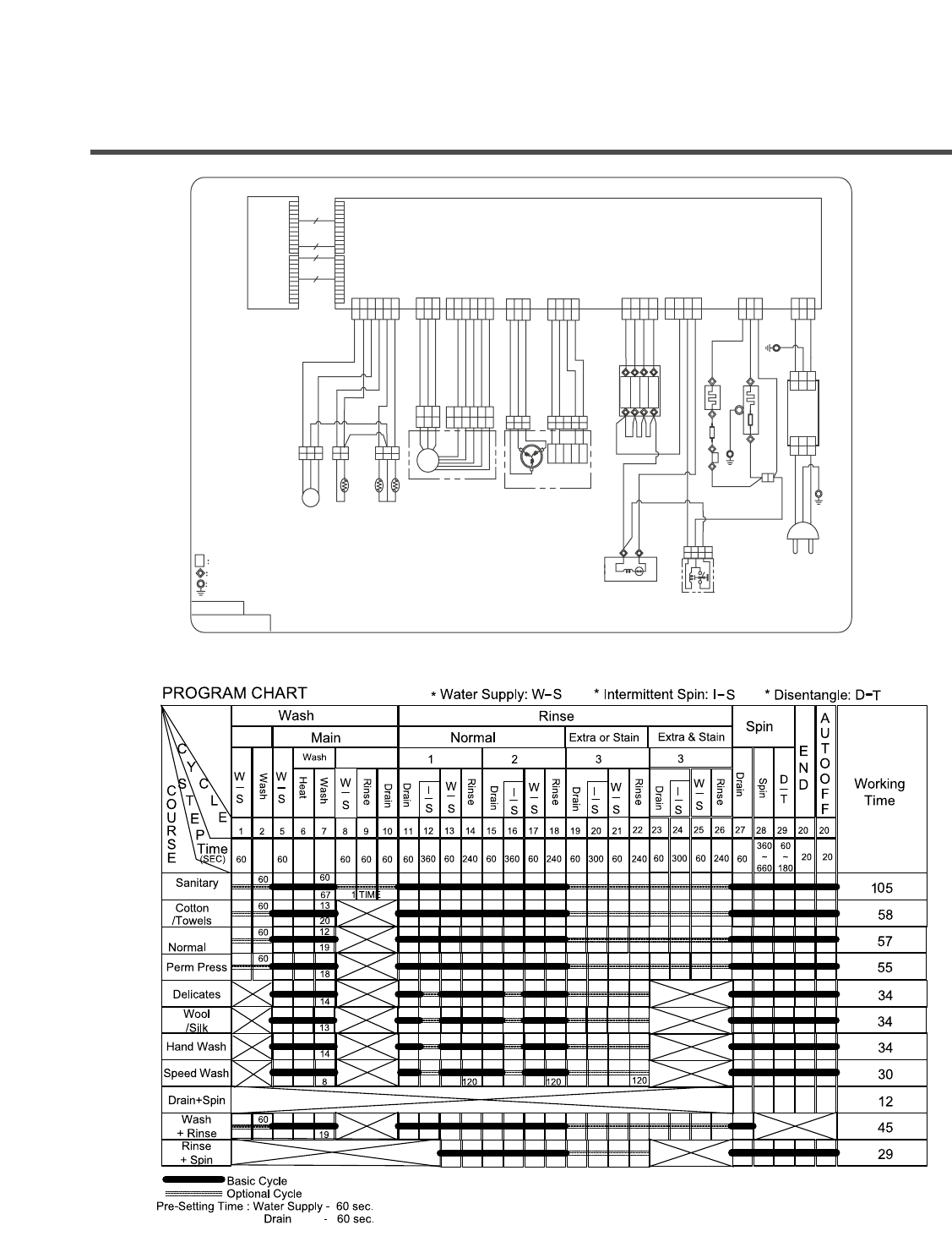
6. WIRING DIAGRAM/PROGRAM CHART
MAIN PWB
NA
VT BL BL WH GY YL YL YL
BL
YL
BL RD
RD
RD
FUSE
FUSE
DOOR LOCK S/W
DRAIN PUMP
YL
BK
BK BK BK BK BK
UVW
BL BN
BK
WH
GN/YL
GN
/
YL
GN
RD
BK
BKRD
CP
WASH
HEATER
POWER
CORD
DRY
HEATER
INLET
VALVE
Ha
Hb
Voo
GND
MOTOR
FAN MOTOR
PRESSURE
SENSOR
n
"n" PIN CONNECTOR
#250 TERMINAL+HOUSING
RING TERMINAL GROUND
Base/Line
3854ER3001S
WH
TH1
(TUB)
(S) (S)
(G)
TH2
(DRY DUCT) TH3
(CONDENSING DUCT)
BNBKGY PIWH SB WH BK YL OR BL BL RD YL BL RD
GY
WH
BN GY PI
123456
123456
123456
123
123
123
321
321
324
3
1
124
123
123
123
1234
14
1
23
23 4
14
1
23
234
13
1
42
42356
65432
12345
12345
1
654
123
123
123
123
12 12
123123
123
123 321
DISPLAY
PWB
WH GYRD RD YL BL RD WH
NA
WHWH
WH
WH
WH
WHWHNA
WH
WH
RD
NOISE
FILTER
123
123
123
123
D
R
Y
H
O
T
M
A
I
N
B
L
E
A
C
H
**
Cool-down **Approx.
(Minutes)
* Wash time is in minutes.
** The total working time will vary with the load size,
water temperature and ambient temperature.
Soak
13
7. TROUBLE SHOOTING
7-1. BEFORE PERFORMING SERVICE
Be careful of electric shock when disconnecting parts while troubleshooting.
The voltage of each terminal is 110/120 V AC and DC when the unit is plugged in.
7-2. QC TEST MODE.
The washer must be empty and the controls must be in the off state.
1. Press the Wash/Rinse and Spin Speed buttons simultaneously.
2. Press the Power button, while the above condition. Then buzzer will sound twice.
3. Press the Start/Pause button repeatedly to cycle through the test modes.
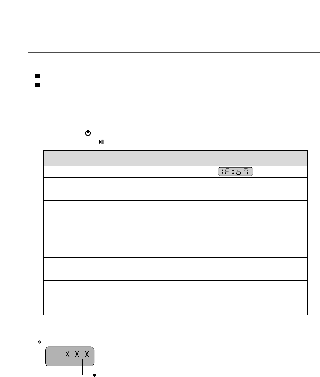
7-3. HOW TO CHECK THE WATER LEVEL FREQUENCY
Press the
Wash/Rinse and Spin Speed button simultaneously.
So, for example a display indicating 241: a Water level frequency of 241 x.1 kHz
= 24.1 kHz
The digits indicate the water level frequency ( x.1 kHz ).
Check Point Display Status
None Turns on all lamps and locks the door.
1 time Tumble clockwise. rpm (40~50)
2 times Low speed Spin. rpm
3 times High speed Spin. rpm
4 times Inlet valve for bleach turns on. Water level frequency (25~65)
5 times Inlet valve for main wash turns on. Water level frequency (25~65)
6 times Inlet valve for hot water turns on. Water level frequency (25~65)
7 times Inlet valve for dry turns on. Water level frequency (25~65)
8 times Tumble counterclockwise. rpm (40~50)
9 times
Heater turns on for 3 sec. Water temperature
10 times
Drain pump turns on.
Water level frequency (25~65)
11 times
Dry operation for 6 minutes.
Temperature in Dry duct.
12 times
Power off and unlock the door.
Turn off all lamps.
Number of times the
Start/Pause button is pressed
14
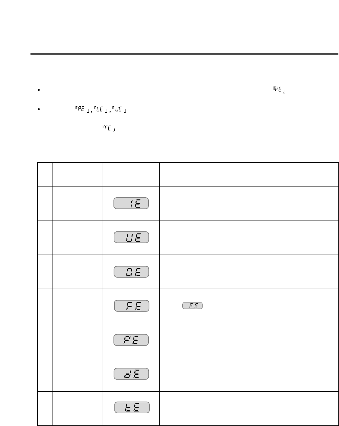
7-4. ERROR DISPLAY
If you press the Start/Pause button when an error is displayed, any error except will disappear
and the machine will go into the pause status.
In case of if the error is not resolved within 20 sec., or in the case of other errors,
if the error is not resolved within 4 min., power will be turned off automatically and the error code will
blink. In the case of , power will not be turned off.
ERROR SYMPTOM CAUSE
WATER INLET
ERROR
• Correct water level (246) is not reached within 8 minutes
after water is supplied or it does not reach the preset water
level within 25 minutes.
• The load is too small.
• The appliance is tilted.
• Laundry is gathered to one side.
• Non distributable items are put into the drum.
1
2
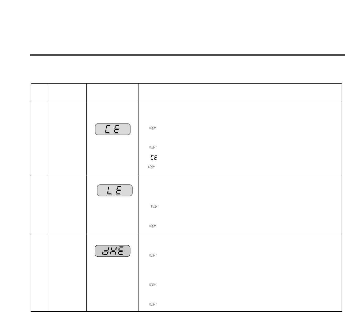
IMBALANCE
ERROR
• Not fully drained within 10 minutes.
3
DRAIN
ERROR
• Water is overflowing (water level frequency is over 213).
※If is displayed, the drain pump will operate to
drain the water automatically.
4
OVER FLOW
ERROR
• The SENSOR SWITCH ASSEMBLY is out of order.
5
PRESSURE
SENSOR
ERROR
• Door not all the way closed.
• Loose electrical connections at Door switch and
PWB Assembly.
• The DOOR SWITCH ASSEMBLY is out of order.
6
DOOR OPEN
ERROR
• The THERMISTOR is out order.
7
HEATING
ERROR
ERROR SYMPTOM CAUSE
8
9
10
• MAIN PWB ASSEMBLY is out of order
Replace the MAIN PWB ASSEMBLY
• Winding in the STATOR ASSEMBLY is short-circuited.
Replace the STATOR ASSEMBLY
• “ ” is dispplayed during a high spin
Replace the LEAD WIRE ASSEMBLY (MOTOR)
• The connector in the LEAD WIRE ASSEMBLY is not connected to
the connnector of STATOR ASSEMBLY
Reconnect or repair the connector
• The hall sensor is out of order/defective.
Replace the STATOR ASSEMBLY
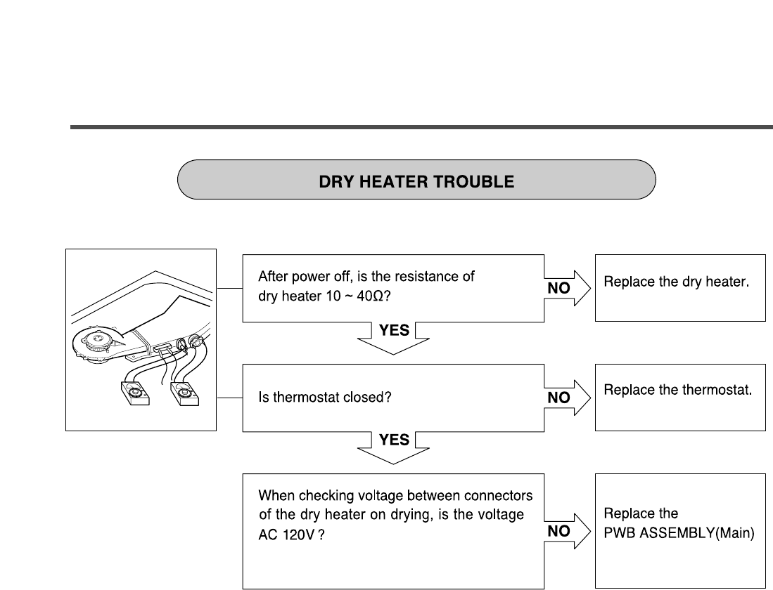
• The Dry Heater is out of order
Replace the Dry Heater
• The Connector of the Dry Heater is not connected properly to the
connector in the Main PWB ASSEMBLY
Reconnect or repair the connector
• The Dry fan motor is out of order
Replace the fan Motor.
CURRENT
ERROR
MOTOR
ERROR
DRY
HEATOR
ERROR
15
16
8-1. DIAGNOSIS AND SOLUTION FOR ABNORMAL OPERATION
8. ERROR DIAGNOSIS AND CHECKLIST
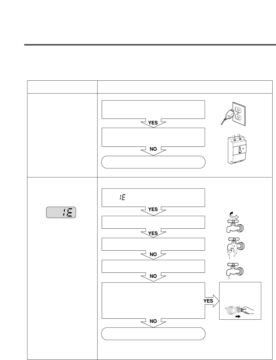
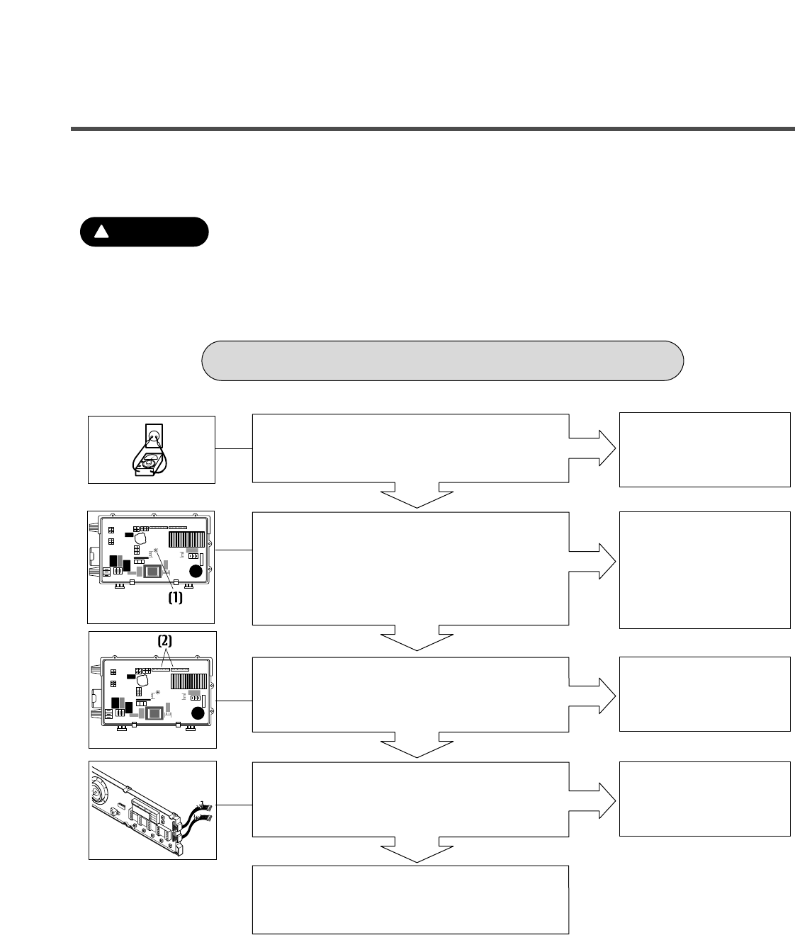
SYMPTOM GUIDE FOR SERVICE CALL
NO POWER
Water inlet trouble
Is the power plug connected firmly to
120V~ outlet?
Power failure? or Breaker opened?
Visit to check
Is " " displayed?
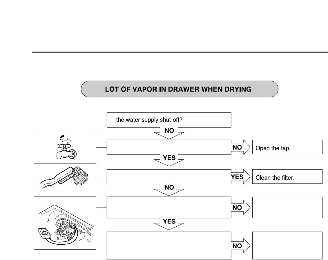
Is the tap opened?
Is the tap frozen?
Is the water supply shut-off?
Is filter in the inlet valve clogged with
foreign material?
Visit to check
Clean the filter of
inlet valve
17
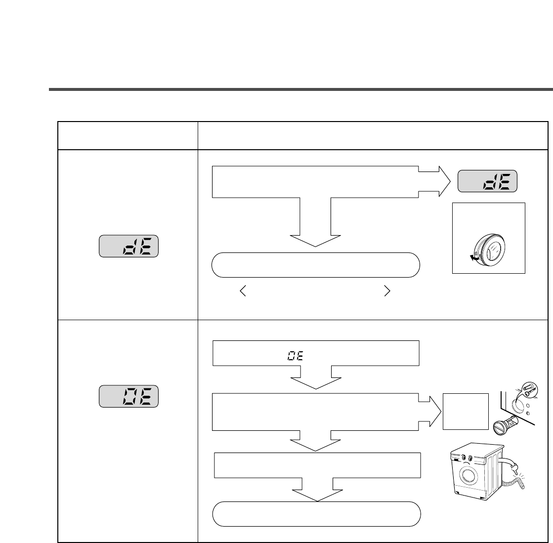
SYMPTOM
¥ Door does not open
¥ Error displayed on
the program
¥ DRAIN TROUBLE
GUIDE FOR SERVICE CALL
NO
YES
NO
YES
Started with door opened?
NO
YES
Is the drain pump filter clogged with foreign
material such as pin, coin and etc.?
Is the drain hose frozen with water,
kinked or crushed?
Visit to check
Close the door
Visit to check
Check if the door switch is O K.
Is " " displayed?
Clean up
the filter.
.
18
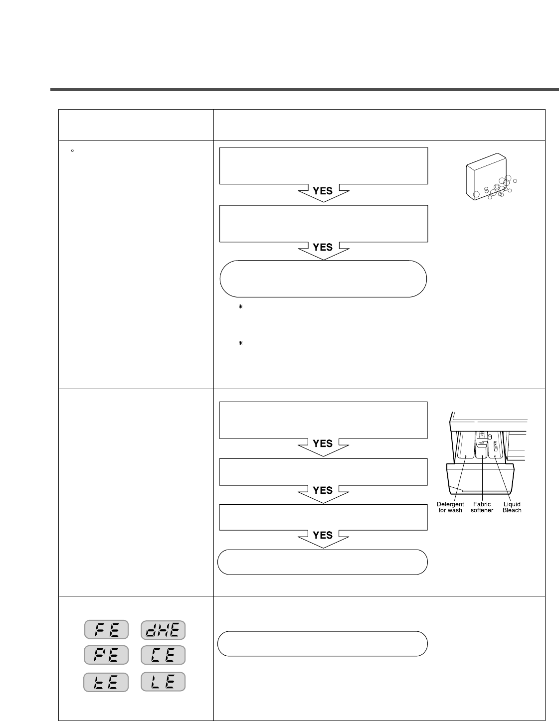
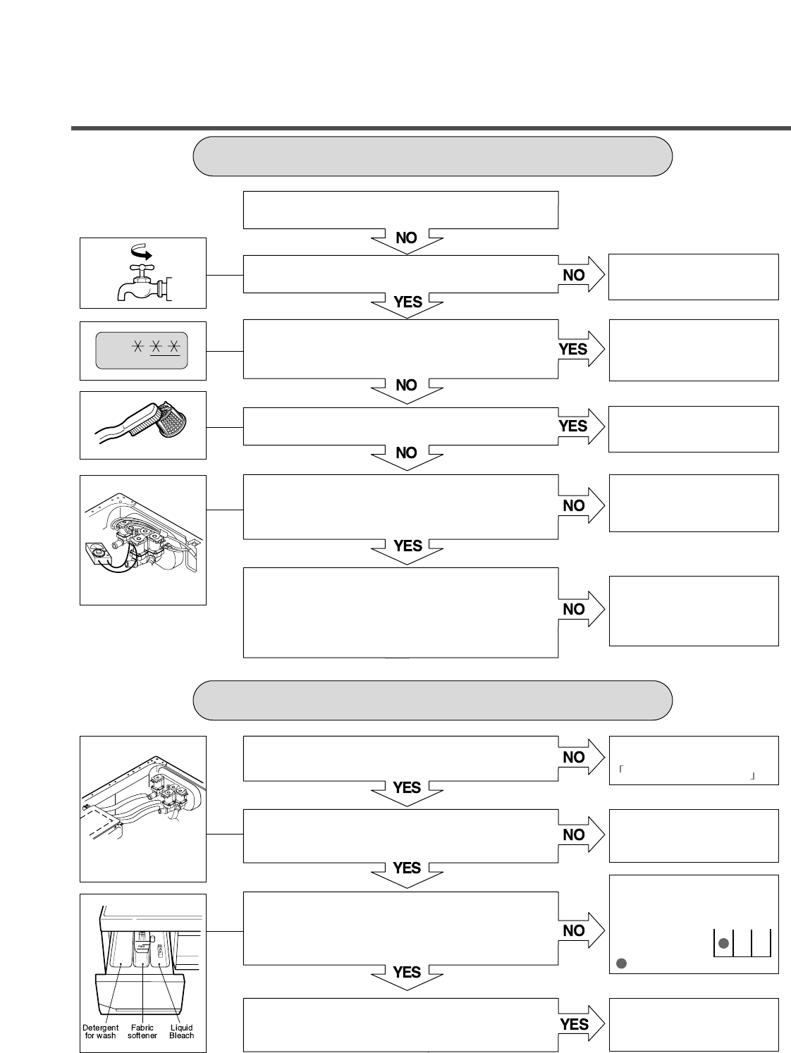
SYMPTOM GUIDE FOR SERVICE CALL
Suds overflow from the
appliance.
(In this condition, wash and
spin do not operate
normally)
Is low-sudsing detergent for the drum
washing machine used?
Is the proper amount of detergent used
as recommended?
Reduce the amount of detergent.
Is softener put in the correct compartment of
the drawer?
Is the drawer closed during wash?
Is the cap clogged?
Explain proper use of liquid laundry products.
< Clean the compartment for softener >
Visit to check
LOW-SUDSING
This appliance has the automatic suds sensing function which
operates during high-sudsing for good rinse and preventing
overflow.
When high suds are sensed, suds removing function such as
drain, water input and pause will operate without rotating the
drum.
¥ Liquid laundry products
do not flow in.
19
8-2. FAULT DIAGNOSIS AND TROUBLESHOOTING
1. Be careful of electric shock or disconnecting the parts while trouble shooting.
2. First of all, check the connection of each part terminal with wiring diagram.
3. If you replace the MAIN PWB ASSEMBLY, put in the connectors correctly.
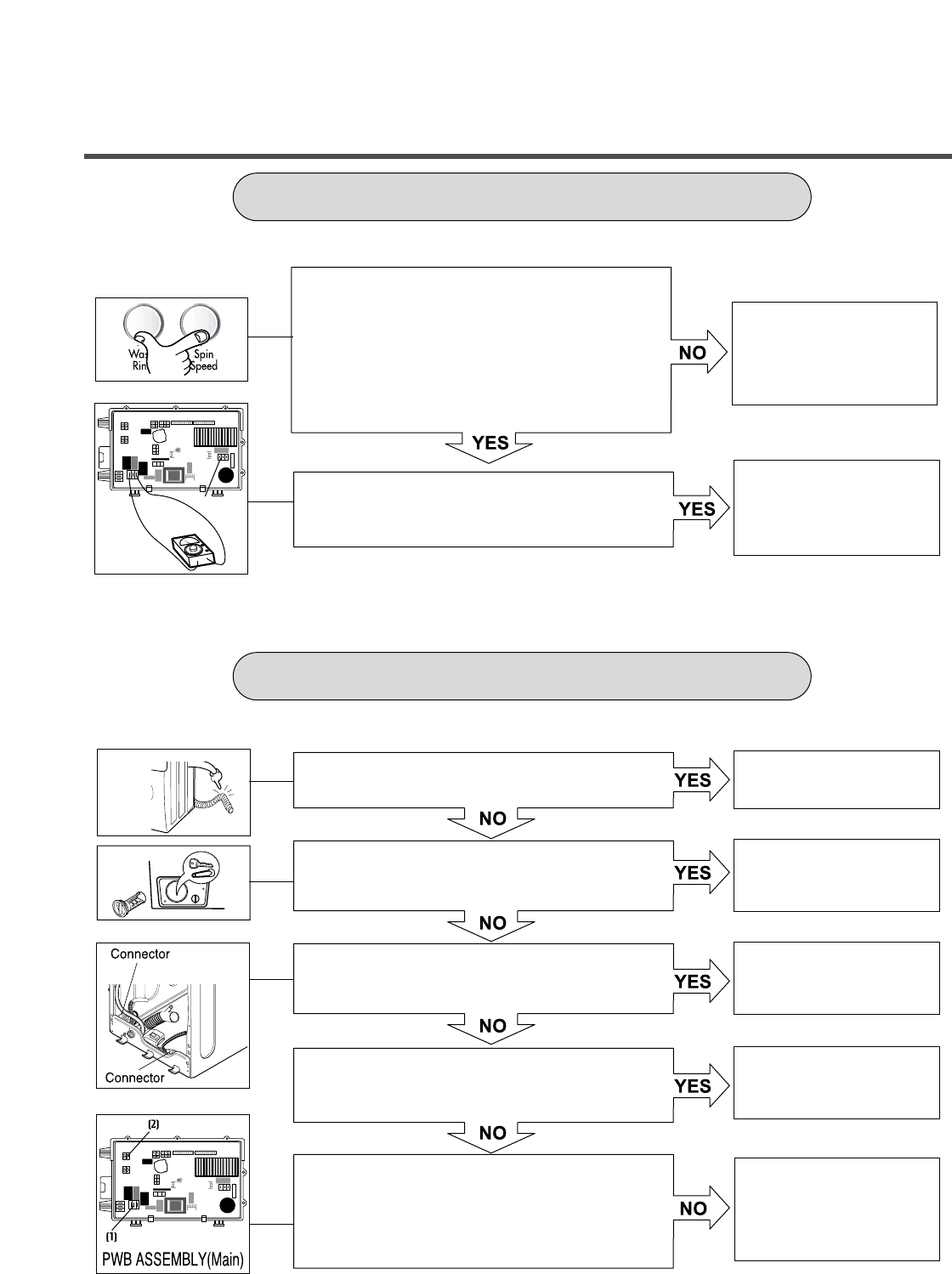
NO
NO
YES
YES
YES
NO
NO
YES
<PWB ASSEMBLY (MAIN)>
<PWB ASSEMBLY (MAIN)>
Check the fuse or reset
the circuit breaker.
Replace MAIN PWB
ASSEMBLY
Reconnect.
Reconnect.
Is the supplied voltage 120 V AC?
Is the led(1) on?
Are the connectors (2) on the PWB loose?
Is wire of the PWB ASSEMBLY disconnected?
Replace PWB ASSEMBLY
NO POWER
CAUTION
!
20
Is water supply shut-off?
Is the tap opened?
When you press both Wash/Rinse button and
Spin Speed button simultaneously, is the water
level frequency below 240?
Is the inlet valve filter clogged?
Is resistance between each terminal of INLET
VALVE ASSEMBLY is 0.8~1.2
kΩ
?
Verify the voltage of the inlet valve connector is
120 V AC.
(Refer to 7-2 QC TEST MODE)
Is water supplied?
Are replaceptacles correctly connected to the
terminals of the INLET VALVE ASSEMBLY?
Is detergent put in the correct compartment of
the dispenser?
Is the detergent caked or hardened?
Open the tap.
Check the AIR CHAMBER
and the tube (clogged).
Clean the filter.
Replace the INLET VALVE
ASSEMBLY.
Check electrical connection.
Replace the MAIN PWB
ASSEMBLY.
Refer to
NO WATER SUPPLY
Check the wiring.
Put the detergent in the
correct position
MAIN WASH
: Detergent
Clean the dispenser.
NO WATER SUPPLY
DETERGENT DOES NOT FLOW IN
21
ABNORMAL SOUND
SOFTENER/BLEACH DOES NOT FLOW IN
Secure the bolt.
Replace the STATOR
ASSEMBLY or ROTOR
ASSEMBLY.
Refer to
NO WATER SUPPLY
Check the wiring.
Put it in the correct
compartment.
Clean the cap and
container.
Is the motor bolt loosened?
Is there friction noise coming from the motor?
Is water supplied?
Are receptacles correctly connected to the terminals
of the INLET VALVE ASSEMBLY?
Is softener/bleach put in the correct compartment of
the dispenser?
Is the softener/bleach cap clogged?
22
AC120V
Replace the
SENSOR SWITCH
ASSEMBLY.
Replace the MAIN PWB
ASSEMBLY
Repair the
DRAIN HOSE
ASSEMBLY.
Remove foreign material.
Reconnect or repair the
connector
Repair the
DRAIN PUMP
ASSEMBLY.
Repair the MAIN PWB
ASSEMBLY.
When pressing Wash/Rinse and Spin Speed at
the same time after draining, is the water level
frequency 255?
When pressing and Spin Speed buttons
at the same time while washing, is the water level
frequency between 230 - 243 ?
Check the voltage between two pins while
pressing the POWER button. Is the voltage
120 V AC?
Is the drain hose twisted or frozen?
Is the impeller of the drain pump clogged?
Is the connector disconnected or disassembled.
Is the resistance of the drain pump coil too high or
low? (resistance of the coil is 10-20 Ω)
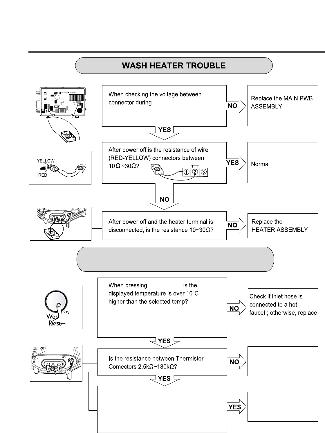
When checking voltage between connectors
during spin, is the voltage 120 V AC as in the
figure?
HEATING WITHOUT WATER
DRAIN MALFUNCTIONING
23
AC 120V
washing, is the voltage
120 V AC?
Wash/Rinse,
MAIN PWB ASSEMBLY.
Check electrical connection.
Replace THERMISTOR.
Push the THERMISTOR
tightly to the rubber.
When checking THERMISTOR on the tub, is the
THERMISTOR loosened?
Extra Hot : 70°C
Hot : 50°C
Warm : 40°C
Cold : 25°C
HEATING CONTINUOUSLY ABOVE
THE SETTING WATER TEMPERATURE
24
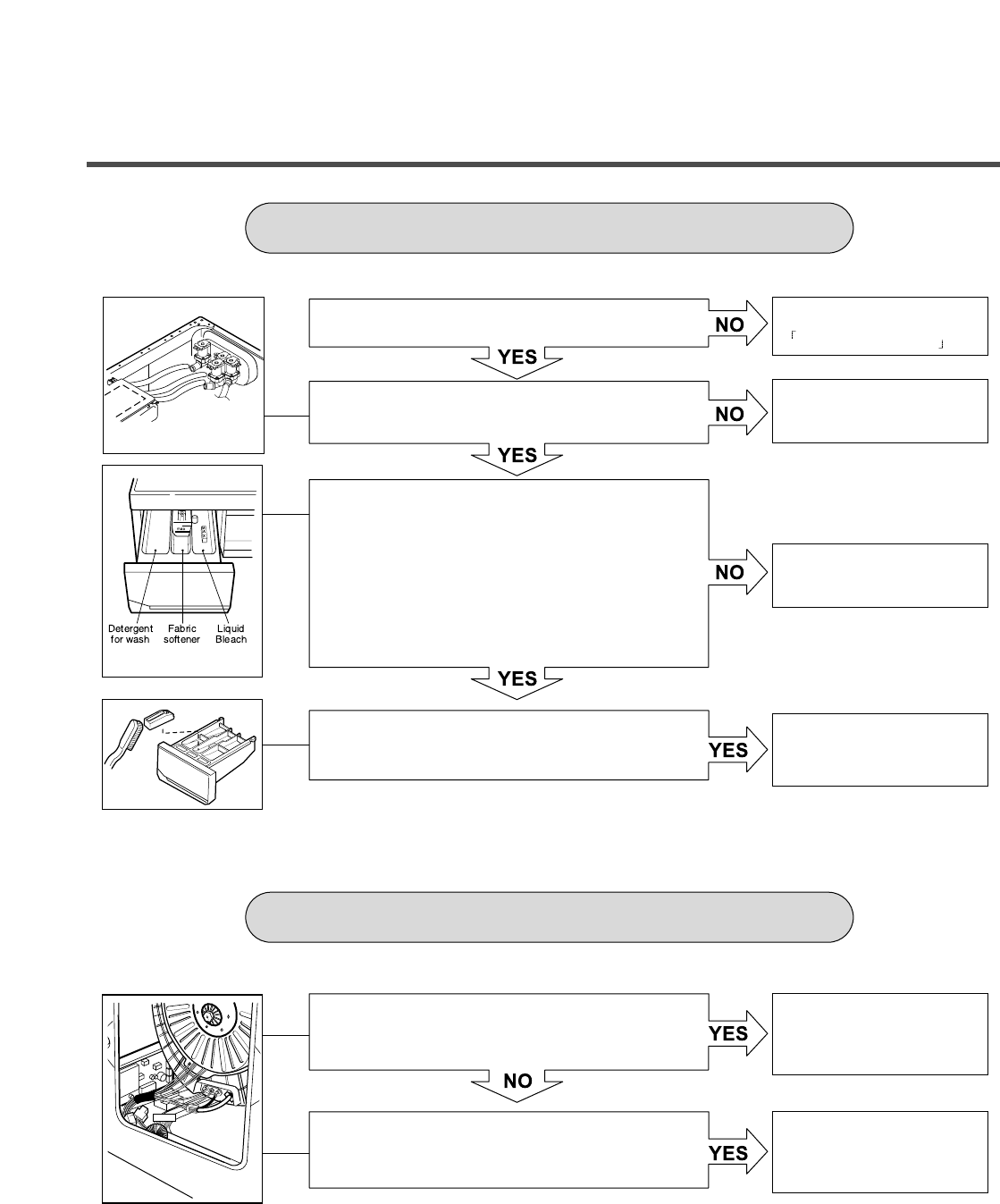
SPIN TROUBLE
Check the SENSOR SWITCH
ASSEMBLY or HOSE (Pressure).
If the problem is on the SENSOR
SWITCH ASSEMBLY or the
HOSE, replace the SENSOR
SWITCH ASSEMBLY or the
HOSE.
Normal
Reconnect or repair
connector
Replace the STATOR
ASSEMBLY
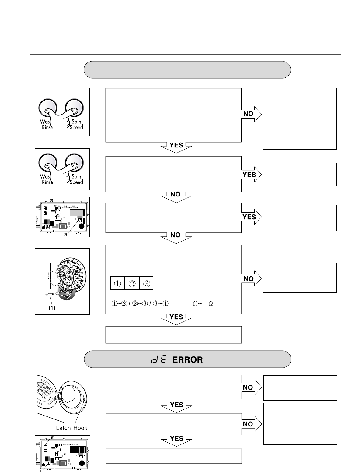
Check during spin if the frequency of the water
level is 248 or more.
Press the Start/Pause button 2 times in QC
Test mode, is the drum spinning at low speed?
Is it disconnected, or disassembled?
[Red:3pin(1), GY:4pin(2)]
Check the motor connector, is the resistance of
the terminal same as the figure?
MOTOR TERMINAL (1)
Resistance of terminal:
About 5 15
Replace the MAIN PWB ASSEMBLY
Does the spring of Latch Hook actuate?
Is DOOR SWITCH ASSEMBLY broken?
Replace the DOOR SWITCH ASSEMBLY.
Replace Door Assembly.
Check the DOOR SWITCH
ASSEMBLY Connector and
MAIN PWB ASSEMBLY
[Red 3 pin and blue 4 pin
white 3 pin connector (1)
connector (1)].
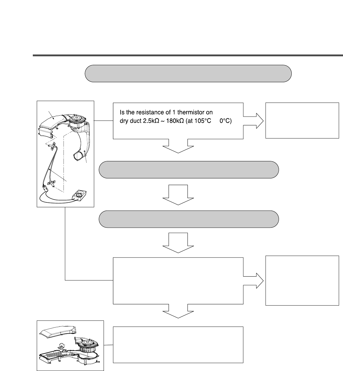
Dry duct
Condensing
duct
Thermistor
Disassemble the cabinet cover and
condensing bellows.
Is there any foreign object in condensing
bellows.
Clean the bellows
[dHE] ERROR DISPLAY
CHECK FOR DRY HEATER TROUBLE
CHECK FOR DRY FAN MOTOR TROUBLE
NO
YES
Replace the thermistor.
YES
NO
Disassemble the dry fan assy and dry duct
upper, and clean foreign object in duct and
fan.
~
25
26
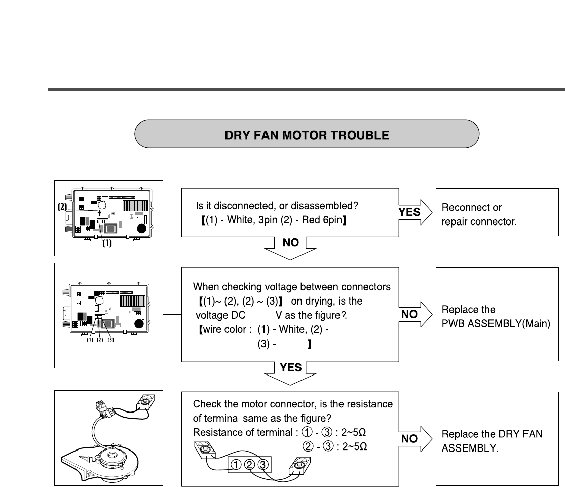
Black
Yellow
20~30
27
Is
Is the tap opened?
Is the inlet valve filter clogged?
Is resistance between each terminal of
INLET VALVE ASSEMBLY 0.8-1.2 k‰?
Replace the INLET
VALVE ASSEMBLY.
Check electrical connection.
Replace the MAIN PWB
ASSEMBLY
Verify the voltage of the inlet valve connector
is 120 V AC.
(Refer to 7-2 QC TEST MODE)
28
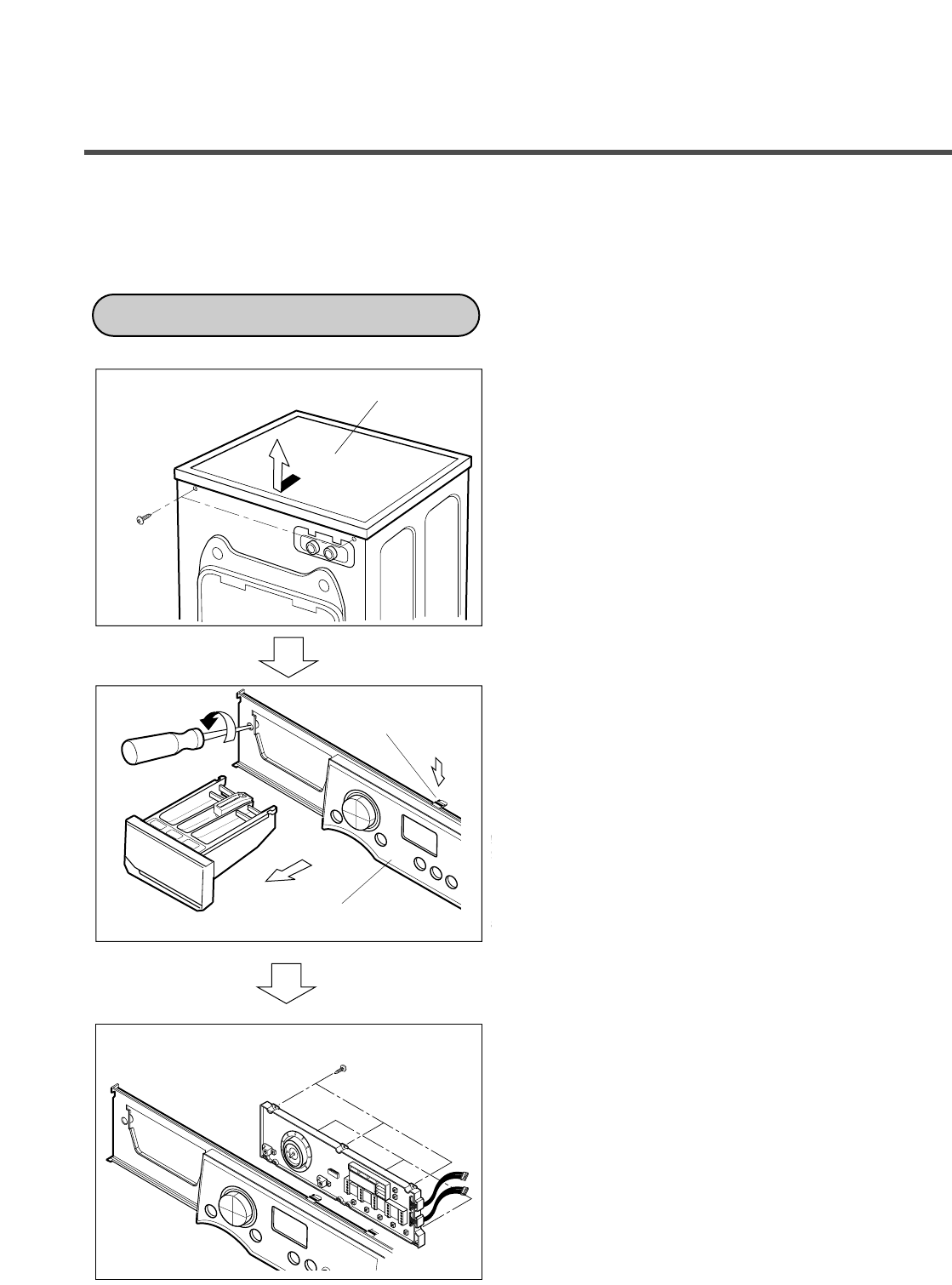
9. DISASSEMBLY INSTRUCTIONS
Be sure to unplug the machine from the outlet before disassembling and repairing the parts.
①Unscrew 2 screws on the back of the top plate.
②Pull the top plate backward and upward as
shown.
③Disconnect the Display PWB Assembly
connector from Flat cable.
④Pull out the drawer and unscrew 2 screws.
⑤Push 2 upper hooks and pull the Control Panel
Assembly forward.
⑥Unscrew the 6 screws from the Control Panel
Assembly.
⑦Disassemble the Display PWB Assembly.
PANEL ASSEMBLY(CONTROL)
Hook
CONTROL PANEL
PLATE ASSEMBLY(TOP)
PWB ASSEMBLY(DISPLAY)
29
30
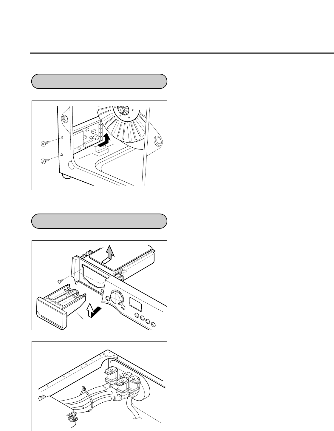
①Unscrew the 4 screws from the back cover.
②Unscrew the 2 screws from the lower-left
side of the cabinet.
③Disconnect the connectors.
④Disassemble the Main PWB Assembly in
arrow direction.
①Disassemble the Top plate assembly.
②Pull out the drawer.
③Unscrew the 2 screws and push out the
dispenser assembly.
④Disassemble the clamps and hoses.
⑤Disassemble the bellows at the lower side of
the dispenser.
PWB ASSEMBLY(MAIN)
DISPENSER ASSEMBLY
DISPENSER ASSEMBLY
DRAWER
31
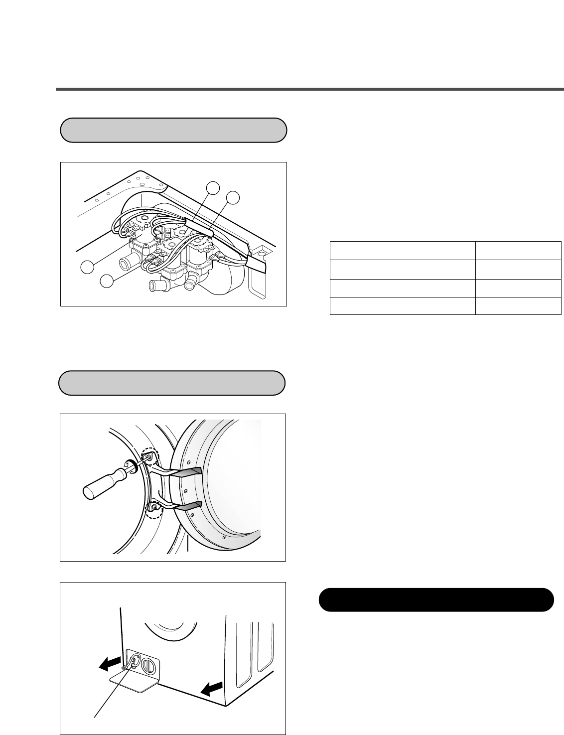
①Disassemble the 4 connectors from the valves.
②Unscrew the 2 screws from the back of the
cabinet.
Wire color
21
3
4
INLET VALVE
VALVE
(DRY) YL - BK
VALVE
(BLEACH) GY - BK
VALVE
(MAIN WASH)
WH/ - BK
VALVE
(HOT)
BL - BK
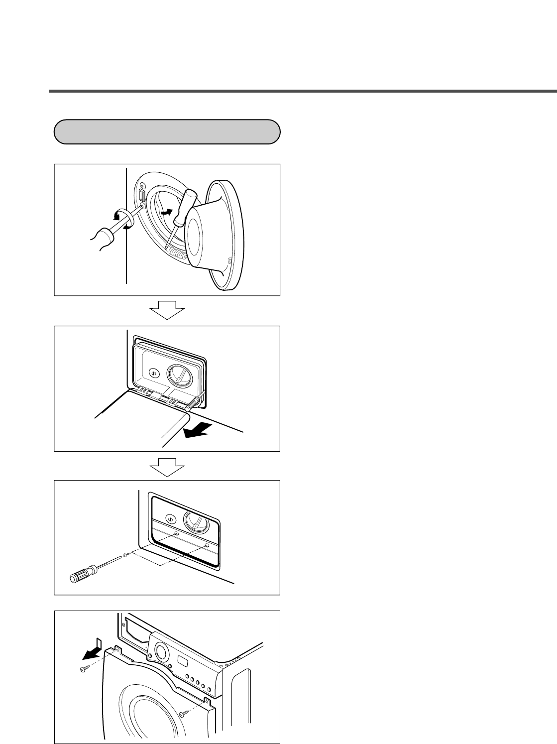
①Open the door.
②Unscrew the 2 screws from the Cabinet Cover.
③Disassemble the door upward.
※When removing the Door Assembly, it is
necessary to hold the Bracket that is inside of
the Cabinet Cover.
Drain in to bucket by pulling out hose and
removing cap.
CAP (REMAINING HOSE)
DOOR
Method of removing remaining water
32
①Disassemble the clamp assembly.
②Unscrew the 2 screws from cabinet cover.
③Unscrew the screw from filter cover.
④Put a flat ( - ) screwdriver or putty knife into
the both sides of the filter cover, and pull it
out.
⑤Unscrew the 2 screws from the lower side of
the cabinet cover.
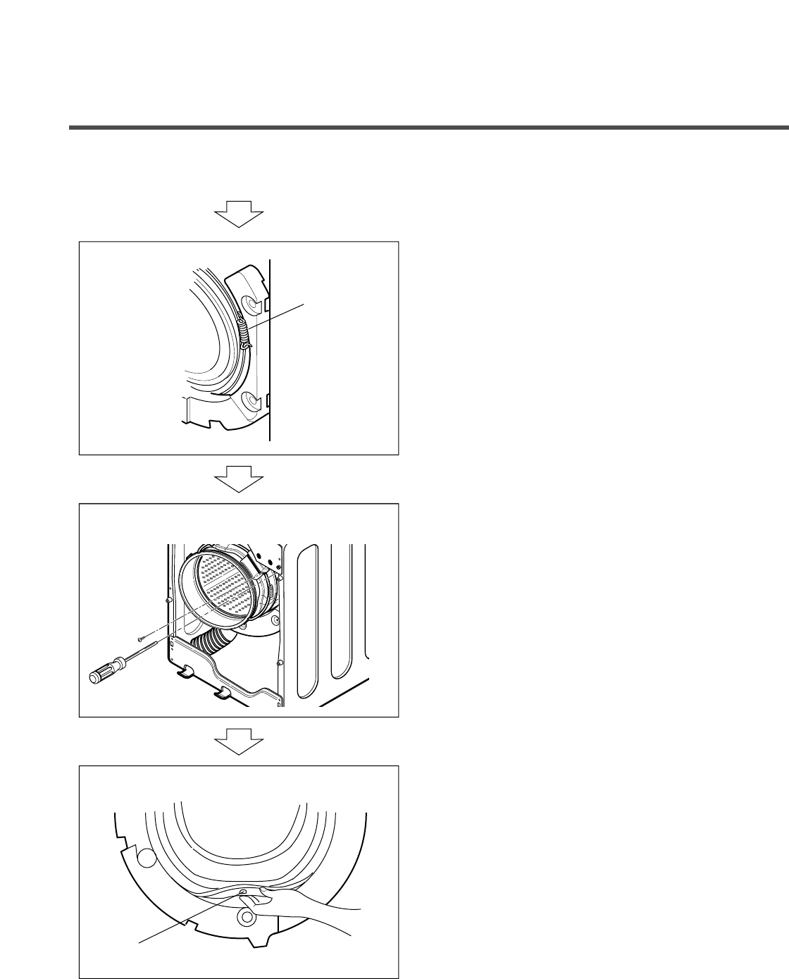
⑥Unscrew the 2 screws from upper part of the
cabinet cover.
GASKET ASSEMBLY
33
⑦Disassemble the clamp assembly.
⑧Remove dry gasket clamp by loosening the
screw.
⑨When reassembling the gasket, put the drain
hole of the gasket downward.
Drain Hole
Tub Gasket
Clamp
34
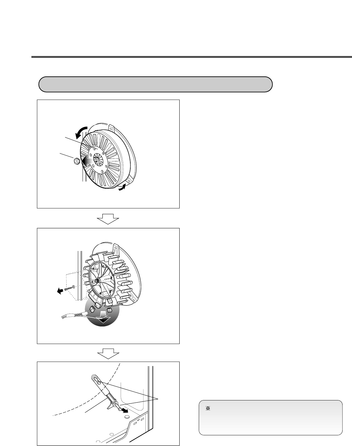
①Disassemble the back cover.
②Remove the bolt.
③Pull out the Rotor.
③Unscrew the 2 screws from the tub bracket.
④Remove the 6 bolts on the stator.
⑤Unplug the 2 connectors from the stator.
⑥Disassemble the damper hinges from the tub
and base.
⑦Separate the dampers.
ROTOR ASSEMBLY, STATOR ASSEMBLY, FRICTION DAMPER
Rotor
Bolt
Friction
Damper
Hinge
(Damper)
(ROTOR ASSEMBLY)
(STATOR ASSEMBLY)
(FRICTION DAMPER)
HOW TO ASSEMBLE THE MOTOR
NOTE
Once removed, replace the damper pin with new
one.
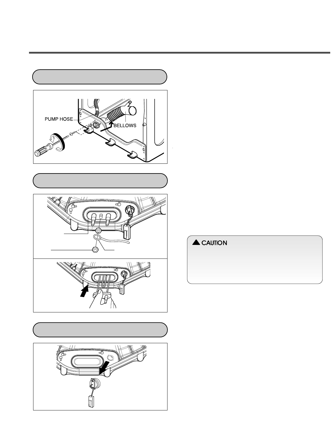
①Disassemble the cabinet cover.
②Separate the pump hose and the bellows from
the pump assembly.
③Disassemble the pump assembly in arrow
direction.
①Disassemble the back cover.
②Separate 2 connectors from the heater.
③Loosen the nut and pull out the heater.
①Disassemble the back cover.
②Unplug the white connector from the
thermistor.
③Pull it out by holding the bracket of the
thermistor.
Washing
Heater
Nut Ring Terminal
PUMP
HEATER
THERMISTOR
35
• When assembling the heater, insert the heater
into the heater clip on the bottom of the tub.
• Tighten the fastening nut so the heater is
secure.
!
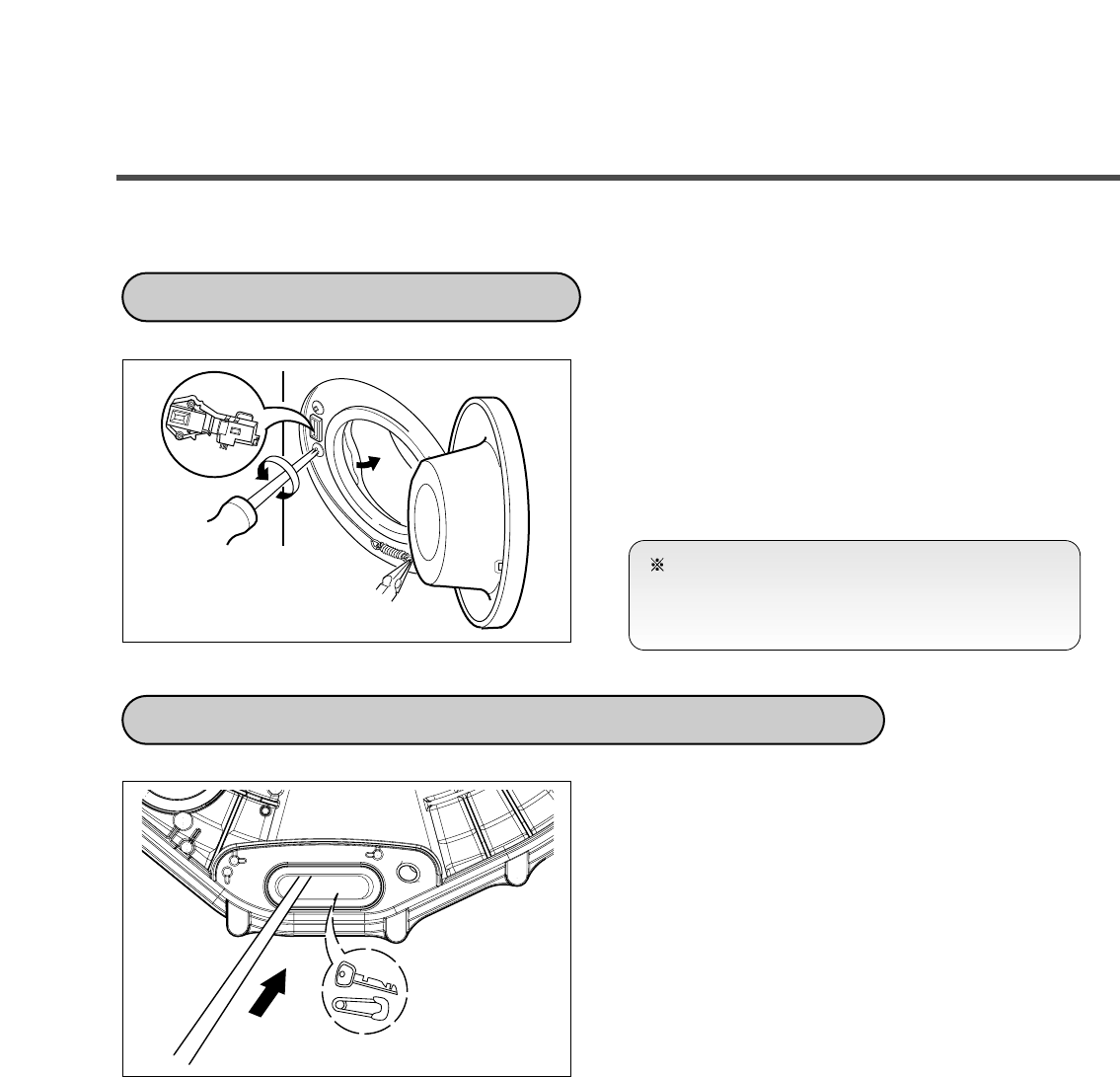
①Open the door and disassemble the Clamp
assembly.
②Unscrew the 2 screws.
③Disconnect the connector from the Door
switch assembly.
①Disassemble the back cover.
②Separate the heater from the tub.
③Remove any foreign objects (wire, coin, etc.)
by inserting a long bar in the opening.
SWITCH ASSEMBLY, DOOR LOCK
WHEN A FOREIGN OBJECT IS STUCK BETWEEN DRUM AND TUB
36
NOTE
Reconnect the connector after replacing the
DOOR SWITCH ASSEMBLY.
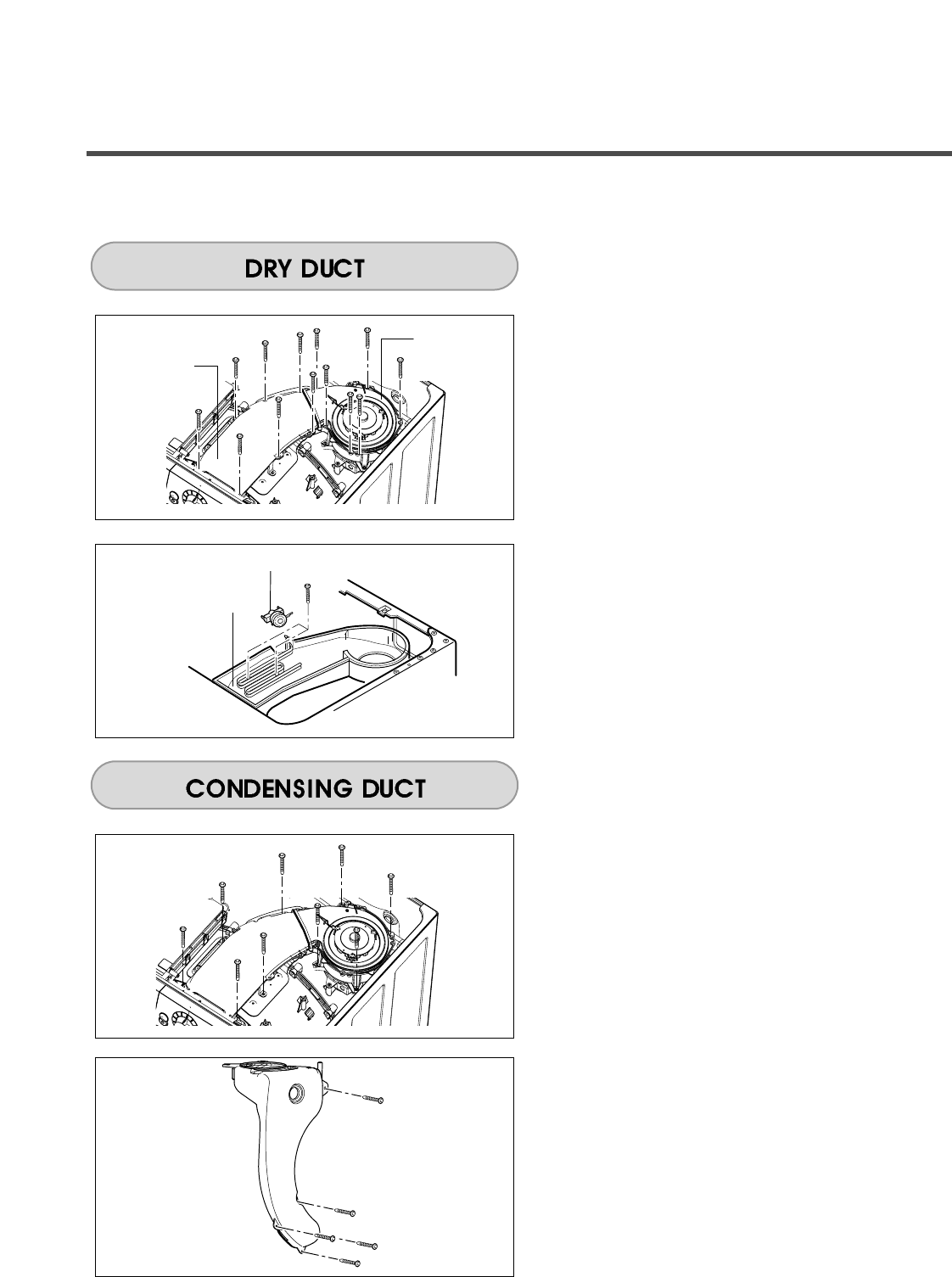
①Remove 6 screws and dry fan assembly.
②Remove 7 screws and dry duct upper.
①Remove 2 screws and dry heater.
②Remove thermostat.
①Remove 17 screws from Dry duct upper and
Dry fan Assembly.
①Remove 5 screws and condensing duct.
37
Dry fan
Ass’y
Dry Duct
Upper
Dry Heater
Thermostat
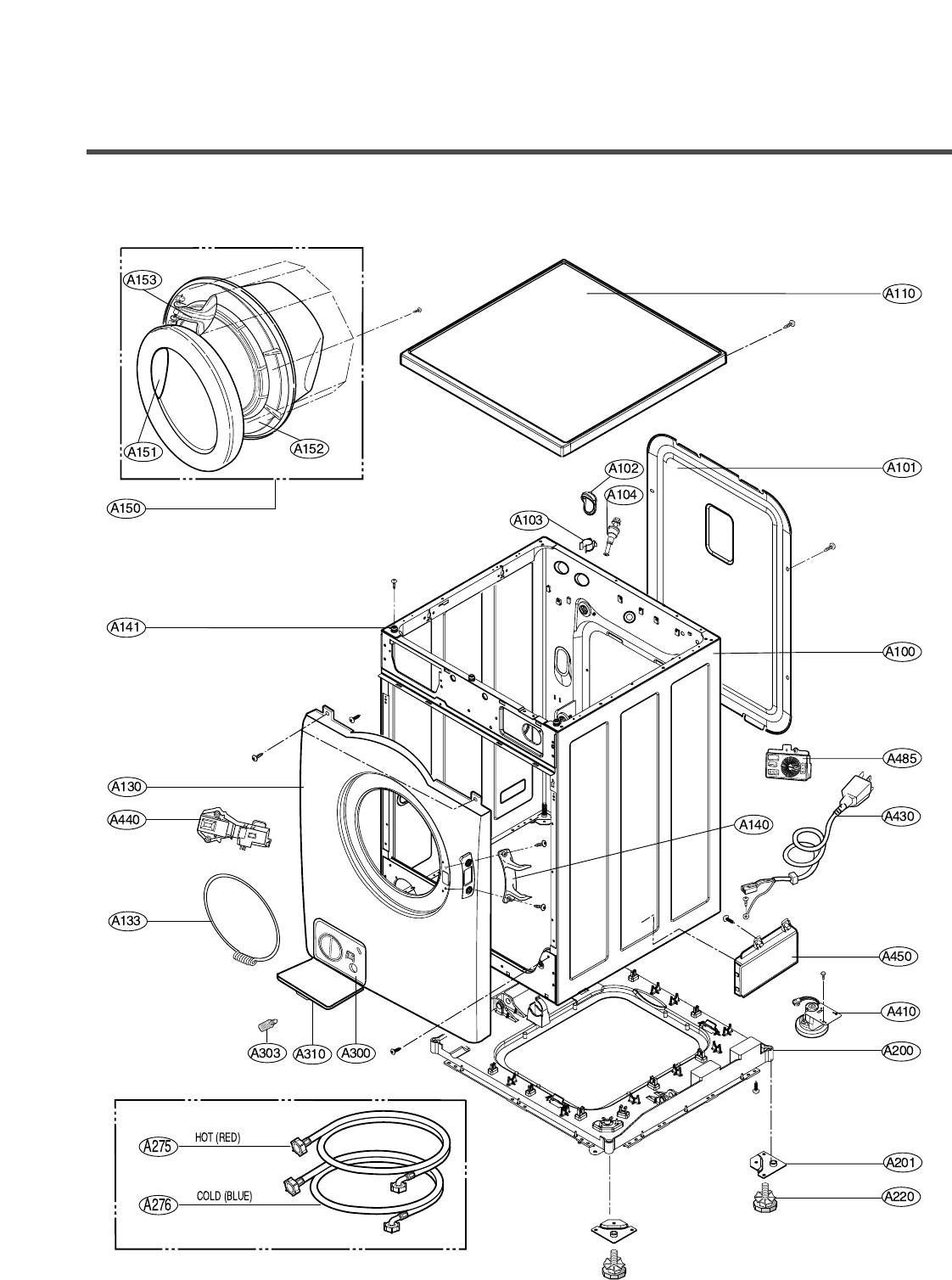
10-1. CABINET & CABINET COVER ASSEMBLY
10. EXPLODED VIEW AND PART LIST
38
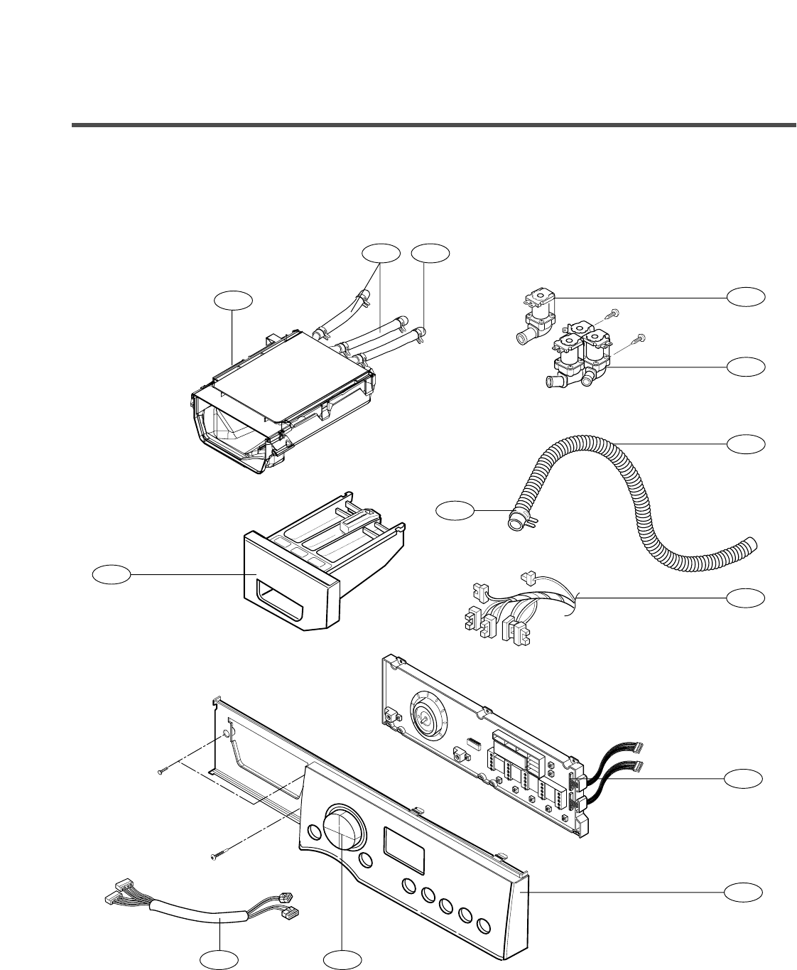
10-2. CONTROL PANEL & DISPENSER ASSEMBLY
39
F130 F215
F440
F210
F160
F170
F110
F220
F441
F120
F300
F321F322
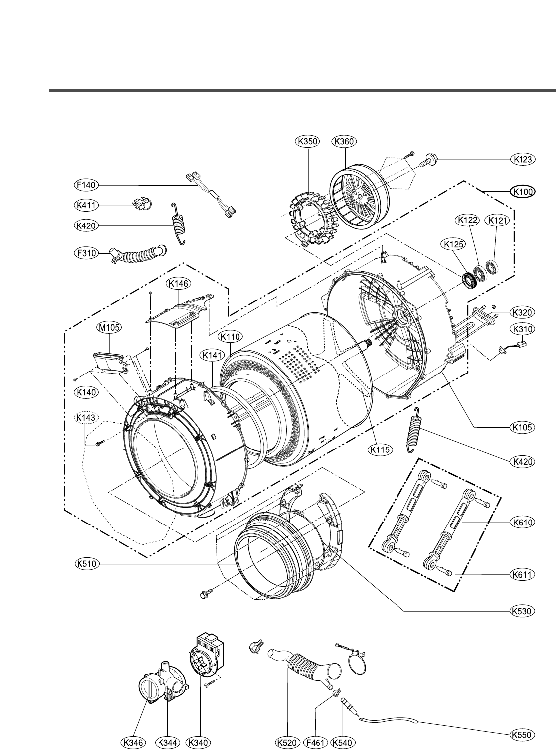
10-3.
DRUM & TUB ASSEMBLY
40
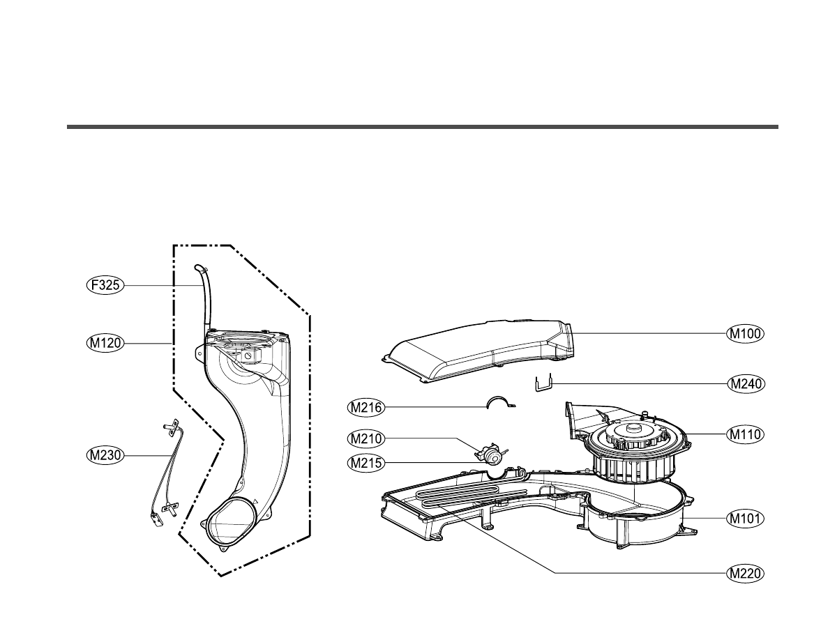
10-4.
DRYER
41
42
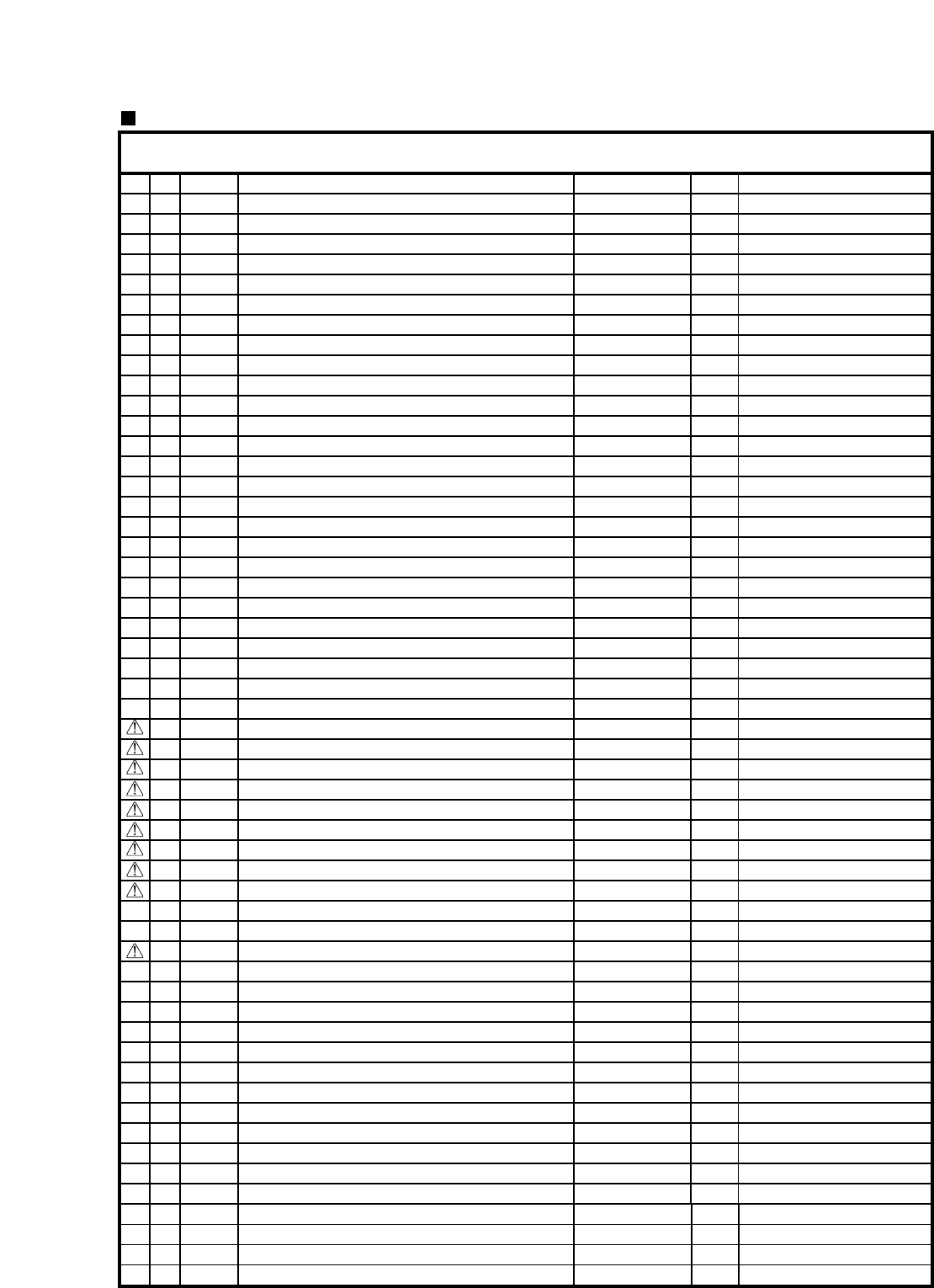
REPLACEMENT PARTS LIST
CAUTION : Before replacing any part of these components
Read carefully the safety precautions in this manual
NOTE : S(Safety Parts), AL(Alternative parts)
LG MODEL: WD-14311RD.AOWEEUS Run_Date : 2005-01-24
Y
OUR MODEL: WM3431HW SPECIFICATION: 120V 60Hz
S AL LOC DESCRIPTION PARTS No. Q'TY REMARKS
*001
*002
*003
*004
A100
A101
A102
A103
A104
A110
A130
A133
A140
A141
A150
A151
A152
A153
A200
A201
A220
A275
A276
A300
A303
A310
A410
A430
A440
A450
A485
F110
F120
F130
F140
F160
F170
F210
F215
F220
F300
F310
F321
F322
F325
F440
F441
F461
K100
K105
K110
K115
K121
K122
3829ER3031H
3890EZ3446K
3W20018B
3828ER3035Q
3091ER0006P
3808FR1202A
4830FR3107A
4930FR3151A
4011FR3159G
3457ER1005A
3550ER1018A
2W20017C
4774ER2006A
4930ER4001A
3581ER1007B
3212ER1015A
3212ER1014A
3650ER2003A
3040FR0049A
4810ER3016A
4779ER3002A
5215FD3715G
5215FD3715H
3110ER3002A
5006ER3009A
5006ER3012A
6600FA1704S
6411ER1006E
6601ER1005B
6871EC1126F
6201EC1006A
6871EC2034A
6877ER1030L
6877EC2001C
6877ER1007F
5220FR2075C
5220FR2006H
3721ER1080N
4940ER3015B
3721ER1066W
4925ER1017B
4738ER2004A
5214FR4125D
5214FR4125L
5214ER4003A
5214FR3188G
4861FR3068C
4861FR3068C
3045ER0029D
3045ER0030A
3045ER1010C
4434ER1005A
4280FR4048M
4280FR4048G
1
1
1
0
1
1
1
1
4
1
1
1
1
3
1
1
1
1
1
4
4
1
1
1
1
1
1
1
1
1
1
1
1
1
1
1
1
1
1
1
1
1
1
2
1
1
1
1
1
1
1
1
1
1
MANUAL ASSEMBLY,OWNERS
BOX,CARTON
SPANNER
MANUAL,SERVICE
CABINET ASSEMBLY
COVER,BACK
BUSHING
HOLDER
BOLT ASSEMBLY
TOP PLATE ASSEMBLY
COVER,CABINET
CLAMP ASSEMBLY
HINGE
HOLDER
DOOR ASSEMBLY
DOOR FRAME,OUTER
DOOR FRAME,INNER
HANDLE
BASE,CABINET
BRACKET,BASE
LEG ASSEMBLY
HOSE,INLET
HOSE,INLET
CASE
CAP,DRAIN HOSE
CAP,COVER
SWITCH ASSEMBLY,SENSOR SWITCH
POWER CORD ASSEMBLY
SWITCH ASSEMBLY,DOOR
PWB(PCB) ASSEMBLY,MAIN
FILTER ASSEMBLY(CIRC)
PWB(PCB) ASSEMBLY,DISPLAY
HARNESS,PWB
CABLE,FLAT
HARNESS,MOTOR
VALVE ASSEMBLY,INLET
VALVE ASSEMBLY,INLET
PANEL ASSEMBLY,CONTROL
KNOB,ROTARY
PANEL ASSEMBLY,DRAWER
DISPENSER ASSEMBLY
BELLOWS
HOSE,INLET
HOSE,INLET
HOSE,INLET
HOSE,PUMP
CLAMP
CLAMP
TUB ASSEMBLY,DRUM
TUB ASSEMBLY,OUTER[SUB5]
TUB ASSEMBLY,INNER[DRUM]
SPIDER
BEARING,BALL
BEARING,BALL
43
LG MODEL: WD-14311RD.AOWEEUS Run_Date : 2005-01-24
Y
OUR MODEL: WM3431HW SPECIFICATION: 120V 60Hz
S AL LOC DESCRIPTION PARTS No. Q'TY REMARKS
K123
K125
K140
K141
K143
K146
K310
K320
K340
K344
K346
K350
K360
K411
K420
K510
K520
K530
K540
K550
K610
K611
M100
M101
M105
M110
M120
M210
M215
M216
M220
M230
M240
BOLT ASSEMBLY
SEAL
COVER,TUB
SEAL
SCREW,DRAWING
COVER,PROTECT
THERMISTOR ASSEMBLY
HEATER ASSEMBLY
MOTOR ASSEMBLY,PUMP
CASING ASSEMBLY,PUMP
FILTER(MECH)
STATOR ASSEMBLY
ROTOR ASSEMBLY
HOLDER
SPRING,HINGE
GASKET
BELLOWS
CLAMP ASSEMBLY
CHAMBER,AIR
HOSE,INLET
DAMPER ASSEMBLY,FRICTION
HINGE
DUCT,OUTLET
DUCT,OUTLET
DUCT,INLET
MOTOR ASSEMBLY,FAN
DUCT ASSEMBLY
THERMOSTAT ASSEMBLY
SEAL
CLAMP
HEATER ASSEMBLY
THERMISTOR ASSEMBLY
FUSE ASSEMBLY
4040FR4051C
4036ER2003A
3550ER0028A
4036ER4001A
1SZZFA4362C
3550ER3011A
6322FR2046C
5301FR1158K
4681EA2001D
3661FR2093E
5230ER3001A
4417FA1994E
4413ER1001B
4930FR3040A
4970FR2084T
4986ER1003A
4738FR1145A
4861ER2001B
3504FR3134A
5214FR4125M
4900FR2030F
4774FR3118B
5208ER1006A
5208ER1005A
5208ER2003A
4680ER1001G
5209ER0004B
6931FR3108A
4036FR4045A
4860ER3004A
5301FR2076G
6322FR2046K
6901ER4001A
1
1
1
1
13
1
1
1
1
1
1
1
1
2
2
1
1
1
1
1
2
4
1
1
1
1
1
1
1
1
1
1
1
