LoRa Mote User's Guide Lo Ra Users 1107499
User Manual: Pdf
Open the PDF directly: View PDF ![]() .
.
Page Count: 34
- Trademarks
- EU Declaration of Conformity
- Table of Contents
- Preface
- Conventions Used in This Guide
- Recommended Reading
- Customer Support
- Chapter 1. Introduction
- Chapter 2. Getting Started
- Appendix A. Board of Schematics and Bill of Materials
- Appendix B. Legacy Board Schematics and Bill of Materials
- Worldwide Sales
2015-2016 Microchip Technology Inc. DS40001808B
LoRa® Mote User’s Guide

DS40001808B-page 2 2015-2016 Microchip Technology Inc.
Information contained in this publication regarding device
applications and the like is provided only for your convenience
and may be superseded by updates. It is your responsibility to
ensure that your application meets with your specifications.
MICROCHIP MAKES NO REPRESENTATIONS OR
WARRANTIES OF ANY KIND WHETHER EXPRESS OR
IMPLIED, WRITTEN OR ORAL, STATUTORY OR
OTHERWISE, RELATED TO THE INFORMATION,
INCLUDING BUT NOT LIMITED TO ITS CONDITION,
QUALITY, PERFORMANCE, MERCHANTABILITY OR
FITNESS FOR PURPOSE. Microchip disclaims all liability
arising from this information and its use. Use of Microchip
devices in life support and/or safety applications is entirely at
the buyer’s risk, and the buyer agrees to defend, indemnify and
hold harmless Microchip from any and all damages, claims,
suits, or expenses resulting from such use. No licenses are
conveyed, implicitly or otherwise, under any Microchip
intellectual property rights unless otherwise stated.
Note the following details of the code protection feature on Microchip devices:
• Microchip products meet the specification contained in their particular Microchip Data Sheet.
• Microchip believes that its family of products is one of the most secure families of its kind on the market today, when used in the
intended manner and under normal conditions.
• There are dishonest and possibly illegal methods used to breach the code protection feature. All of these methods, to our
knowledge, require using the Microchip products in a manner outside the operating specifications contained in Microchip’s Data
Sheets. Most likely, the person doing so is engaged in theft of intellectual property.
• Microchip is willing to work with the customer who is concerned about the integrity of their code.
• Neither Microchip nor any other semiconductor manufacturer can guarantee the security of their code. Code protection does not
mean that we are guaranteeing the product as “unbreakable.”
Code protection is constantly evolving. We at Microchip are committed to continuously improving the code protection features of our
products. Attempts to break Microchip’s code protection feature may be a violation of the Digital Millennium Copyright Act. If such acts
allow unauthorized access to your software or other copyrighted work, you may have a right to sue for relief under that Act.
Microchip received ISO/TS-16949:2009 certification for its worldwide
headquarters, design and wafer fabrication facilities in Chandler and
Tempe, Arizona; Gresham, Oregon and design centers in California
and India. The Company’s quality system processes and procedures
are for its PIC® MCUs and dsPIC® DSCs, KEELOQ® code hopping
devices, Serial EEPROMs, microperipherals, nonvolatile memory and
analog products. In addition, Microchip’s quality system for the design
and manufacture of development systems is ISO 9001:2000 certified.
QUALITY MANAGEMENT S
YSTEM
CERTIFIED BY DNV
== ISO/TS 16949 ==
Trademarks
The Microchip name and logo, the Microchip logo, AnyRate,
dsPIC, FlashFlex, flexPWR, Heldo, JukeBlox, KeeLoq,
KeeLoq logo, Kleer, LANCheck, LINK MD, MediaLB, MOST,
MOST logo, MPLAB, OptoLyzer, PIC, PICSTART, PIC32 logo,
RightTouch, SpyNIC, SST, SST Logo, SuperFlash and UNI/O
are registered trademarks of Microchip Technology
Incorporated in the U.S.A. and other countries.
ClockWorks, The Embedded Control Solutions Company,
ETHERSYNCH, Hyper Speed Control, HyperLight Load,
IntelliMOS, mTouch, Precision Edge, and QUIET-WIRE are
registered trademarks of Microchip Technology Incorporated
in the U.S.A.
Analog-for-the-Digital Age, Any Capacitor, AnyIn, AnyOut,
BodyCom, chipKIT, chipKIT logo, CodeGuard, dsPICDEM,
dsPICDEM.net, Dynamic Average Matching, DAM, ECAN,
EtherGREEN, In-Circuit Serial Programming, ICSP, Inter-Chip
Connectivity, JitterBlocker, KleerNet, KleerNet logo, MiWi,
motorBench, MPASM, MPF, MPLAB Certified logo, MPLIB,
MPLINK, MultiTRAK, NetDetach, Omniscient Code
Generation, PICDEM, PICDEM.net, PICkit, PICtail,
PureSilicon, RightTouch logo, REAL ICE, Ripple Blocker,
Serial Quad I/O, SQI, SuperSwitcher, SuperSwitcher II, Total
Endurance, TSHARC, USBCheck, VariSense, ViewSpan,
WiperLock, Wireless DNA, and ZENA are trademarks of
Microchip Technology Incorporated in the U.S.A. and other
countries.
SQTP is a service mark of Microchip Technology Incorporated
in the U.S.A.
Silicon Storage Technology is a registered trademark of
Microchip Technology Inc. in other countries.
GestIC is a registered trademarks of Microchip Technology
Germany II GmbH & Co. KG, a subsidiary of Microchip
Technology Inc., in other countries.
All other trademarks mentioned herein are property of their
respective companies.
© 2015-2016, Microchip Technology Incorporated, Printed in
the U.S.A., All Rights Reserved.
ISBN: 978-1-5224-0550-4
2015-2016 Microchip Technology Inc. DS40001808B-page 3
Object of Declaration: LoRa® Mote

LoRa® Mote User’s Guide
DS40001808B-page 4 2015-2016 Microchip Technology Inc.
NOTES:
LoRa® MOTE USER’S GUIDE
2015-2016 Microchip Technology Inc. DS40001808B-page 5
Table of Contents
Preface ........................................................................................................................... 7
Chapter 1. Introduction
1.1 Overview ...................................................................................................... 11
1.2 Features ....................................................................................................... 11
1.3 Contents ....................................................................................................... 12
Chapter 2. Getting Started
2.1 Introduction ................................................................................................... 13
2.2 Methods of Operation ................................................................................... 13
2.2.1 USB ........................................................................................................... 13
2.2.2 Battery ....................................................................................................... 13
2.3 Hardware Description ................................................................................... 14
2.4 Mote Application Description ........................................................................ 17
2.4.1 USB CDC-Serial ........................................................................................ 17
2.4.2 Mobile Mote Sensor Emulation ................................................................. 17
2.4.3 Bootloader Behavior .................................................................................. 18
2.4.4 Application Updates .................................................................................. 19
Appendix A. Board of Schematics and Bill of Materials
A.1 Introduction .................................................................................................. 21
A.2 Board Schematics ........................................................................................ 21
A.3 Bill of Materials ............................................................................................. 24
Appendix B. Legacy Board Schematics and Bill of Materials
B.1 Introduction .................................................................................................. 25
B.2 Differences ................................................................................................... 25
B.3 Board Schematics ........................................................................................ 29
B.4 Bill of Materials ............................................................................................. 31
Worldwide Sales and Service .................................................................................... 33

LoRa® Mote User’s Guide
DS40001808B-page 6 2015-2016 Microchip Technology Inc.
NOTES:
2015-2016 Microchip Technology Inc. DS40001808B-page 7
LoRa® MOTE USER’S GUIDE
Preface
INTRODUCTION
This chapter contains general information that will be useful to know before using the
LoRa® Mote and attached LoRa® Technology Module. Topics discussed in this chapter
include:
•Document Layout
•Conventions Used in this Guide
•Recommended Reading
•The Microchip Website
•Development Systems Customer Change Notification Service
•Customer Support
•Revision History
DOCUMENT LAYOUT
This document describes how to use the LoRa® Mote as a demonstration to show how
LoRa technology communication works. The document is organized as follows:
•Chapter 1. “Introduction” – This chapter describes the LoRa® Mote and
presents various modes of operation.
•Chapter 2. “Getting Started” – This chapter describes the two main
communication methods, and the hardware requirements for getting started with
the LoRa® Mote.
•Appendix A. “Board of Schematics and Bill of Materials” – This appendix
provides the LoRa® Mote schematics and the Bill of Materials (BOM).
•Appendix B. “Legacy Board Schematics and Bill of Materials” – This
appendix provides the LoRa® Mote schematics and the Bill of Materials (BOM) for
the Legacy Mote Design; along with brief descriptions of changes between
designs.
NOTICE TO CUSTOMERS
All documentation becomes dated, and this manual is no exception. Microchip tools and
documentation are constantly evolving to meet customer needs, so some actual dialogs and/
or tool descriptions may differ from those in this document. Please refer to our website
(www.microchip.com) to obtain the latest documentation available.
Documents are identified with a “DS” number. This number is located on the bottom of each
page, in front of the page number. The numbering convention for the DS number is
“DSXXXXXXXXA”, where “XXXXXXXX” is the document number and “A” is the revision level
of the document.
For the most up-to-date information on development tools, see the MPLAB® IDE online help.
Select the Help menu, and then Topics to open a list of available online help files.
LoRa® Mote User’s Guide
DS40001808B-page 8 2015-2016 Microchip Technology Inc.
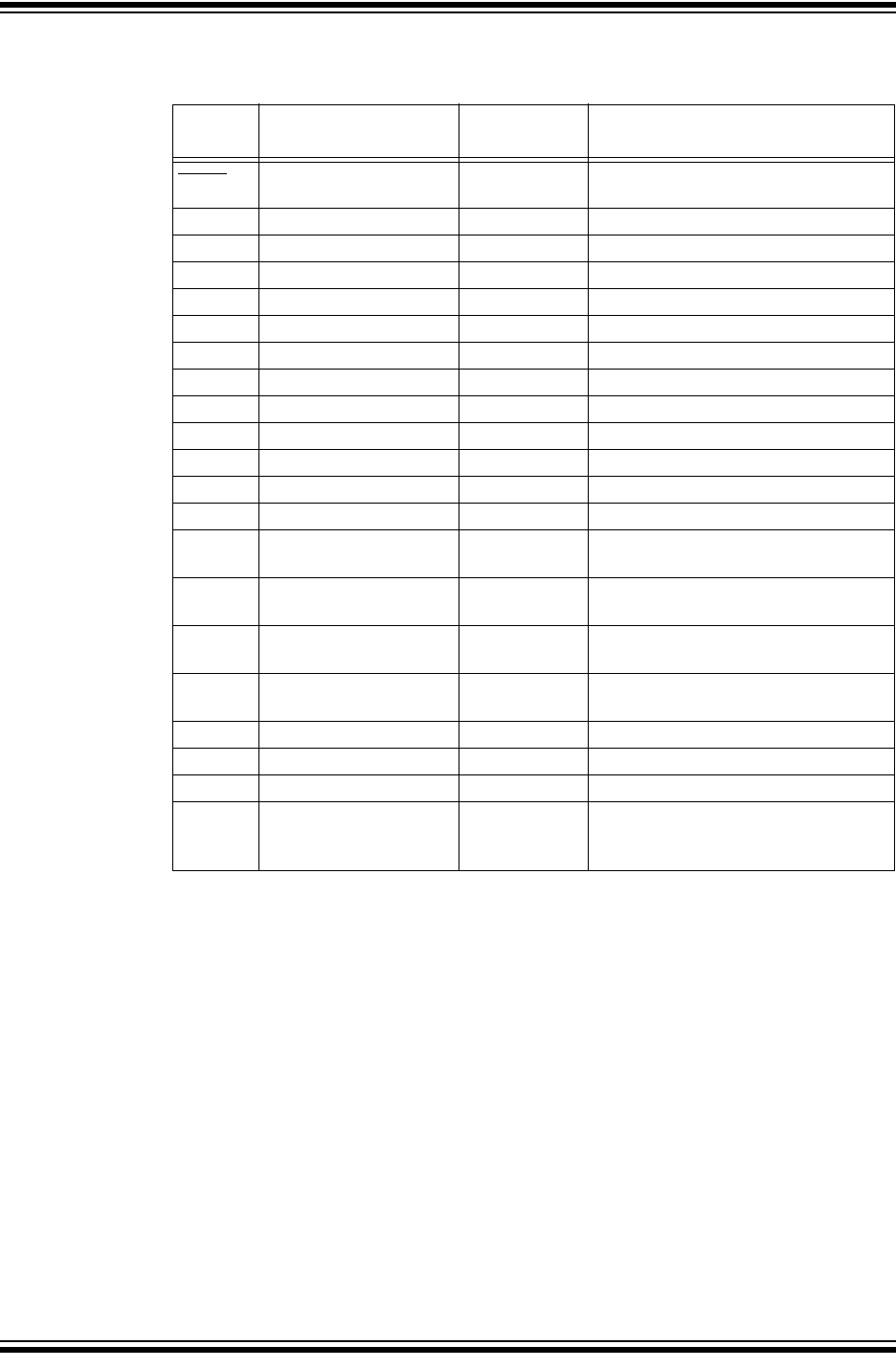
CONVENTIONS USED IN THIS GUIDE
This manual uses the following documentation conventions:
DOCUMENTATION CONVENTIONS
Description Represents Examples
Arial font:
Italic characters Referenced books MPLAB® IDE User’s Guide
Emphasized text ...is the only compiler...
Initial caps A window the Output window
A dialog the Settings dialog
A menu selection select Enable Programmer
Quotes A field name in a window or
dialog
“Save project before build”
Underlined, italic text with
right angle bracket
A menu path File>Save
Bold characters A dialog button Click OK
A tab Click the Power tab
N‘Rnnnn A number in verilog format,
where N is the total number of
digits, R is the radix and n is a
digit.
4‘b0010, 2‘hF1
Text in angle brackets < > A key on the keyboard Press <Enter>, <F1>
Courier New font:
Plain Courier New Sample source code #define START
Filenames autoexec.bat
File paths c:\mcc18\h
Keywords _asm, _endasm, static
Command-line options -Opa+, -Opa-
Bit values 0, 1
Constants 0xFF, ‘A’
Italic Courier New A variable argument file.o, where file can be
any valid filename
Square brackets [ ] Optional arguments mcc18 [options] file
[options]
Curly brackets and pipe
character: { | }
Choice of mutually exclusive
arguments; an OR selection
errorlevel {0|1}
Ellipses... Replaces repeated text var_name [,
var_name...]
Represents code supplied by
user
void main (void)
{ ...
}

Preface
2015-2016 Microchip Technology Inc. DS40001808B-page 9
RECOMMENDED READING
This user’s guide describes how to use the LoRa® Mote. Other useful documents are
listed below. The following Microchip documents are available and recommended as
supplemental reference resources:
RN2483 Low-Power Long-Range LoRa® Technology Transceiver Module
Data Sheet (DS50002346)
This data sheet provides detailed specifications for the RN2483 module.
RN2483 LoRa® Technology Module Command Reference User’s Guide
(DS40001784)
This user’s guide provides specifications about the commands to be used with the
LoRa® module.
RN2483 LoRa® Technology PICtail™/PICtail Plus Daughter Board User’s Guide
(DS50002366)
This user’s guide describes how to configure and use the LoRa® Daughter Board.
RN2903 Low-Power Long-Range LoRa® Technology Transceiver Module Data
Sheet (DS50002390)
This data sheet provides detailed specifications for the RN2903 module.
RN2903 LoRa® Technology Module Command Reference User’s Guide
(DS40001811)
This user’s guide provides specifications about the commands to be used with the
LoRa® module.
RN2903 LoRa® Technology PICtail™/PICtail Plus Daughter Board User’s Guide
(DS50002424)
This user’s guide describes how to configure and use the LoRa® Daughter Board.
LoRa® Technology Evaluation Suite User’s Guide (DS40001847)
This user’s guide describes how to use the LoRa® Technology Evaluation Kit along
with the LoRa Development Utility Application Graphic User Interface (GUI) as a
demonstration platform to show how to create and manage a LoRa Technology
Network.
To obtain any of Microchip’s documents, visit the Microchip website at
www.microchip.com.
THE MICROCHIP WEBSITE
Microchip provides online support via our website at www.microchip.com. This website
is used as a means to make files and information easily available to customers. Acces-
sible by using your favorite Internet browser, the website contains the following infor-
mation:
•Product Support – Data sheets and errata, application notes and sample
programs, design resources, user’s guides and hardware support documents,
latest software releases and archived software
•General Technical Support – Frequently Asked Questions (FAQs), technical
support requests, online discussion groups, Microchip consultant program
member listing
•Business of Microchip – Product selector and ordering guides, latest Microchip
press releases, listing of seminars and events, listings of Microchip sales offices,
distributors and factory representatives

LoRa® Mote User’s Guide
DS40001808B-page 10 2015-2016 Microchip Technology Inc.
DEVELOPMENT SYSTEMS CUSTOMER CHANGE NOTIFICATION SERVICE
Microchip’s customer notification service helps keep customers current on Microchip
products. Subscribers will receive e-mail notification whenever there are changes,
updates, revisions or errata related to a specified product family or development tool of
interest.
To register, access the Microchip website at www.microchip.com, click on Customer
Change Notification and follow the registration instructions.
The Development Systems product group categories are:
•Compilers – The latest information on Microchip C compilers, assemblers, linkers
and other language tools. These include all MPLAB C compilers; all MPLAB
assemblers (including MPASM™ assembler); all MPLAB linkers (including
MPLINK™ object linker); and all MPLAB librarians (including MPLIB™ object
librarian).
•Emulators – The latest information on Microchip in-circuit emulators.This
includes the MPLAB REAL ICE™ and MPLAB ICE 2000 in-circuit emulators.
•In-Circuit Debuggers – The latest information on the Microchip in-circuit
debuggers. This includes MPLAB ICD 3 in-circuit debuggers and PICkit™ 3
debug express.
•MPLAB® X IDE – The latest information on Microchip MPLAB IDE, the Windows®
Integrated Development Environment for development systems tools. This list is
focused on the MPLAB IDE, MPLAB IDE Project Manager, MPLAB Editor and
MPLAB SIM simulator, as well as general editing and debugging features.
•Programmers – The latest information on Microchip programmers. These include
production programmers such as MPLAB REAL ICE in-circuit emulator, MPLAB
ICD 3 in-circuit debugger and MPLAB PM3 device programmers. Also included
are nonproduction development programmers such as PICSTART® Plus and
PICkit 2 and 3.
CUSTOMER SUPPORT
Users of Microchip products can receive assistance through several channels:
• Distributor or Representative
• Local Sales Office
• Field Application Engineer (FAE)
• Technical Support
Customers should contact their distributor, representative or field application engineer
(FAE) for support. Local sales offices are also available to help customers. A listing of
sales offices and locations is included in the back of this document.
Technical support is available through the website at:
http://www.microchip.com/support.
REVISION HISTORY
Revision A (August 2015)
Initial release of the document.
Revision B (May 2016)
Updated documentation to reflect Revision B of the Mote. Moved Legacy Mote material
to Appendix Section; along with notes on the difference between devices.

2015-2016 Microchip Technology Inc. DS40001808B-page 11
LoRa
®
MOTE USER’S GUIDE
Chapter 1. Introduction
1.1 OVERVIEW
The LoRa® Mote is a demonstration board that showcases the Microchip Low-Power
Long Range LoRa® Technology Transceiver Module.
The LoRa® Mote provides access to the module through a convenient USB-to-UART
bridge chip and supports connection points to all GPIO-controlled module pins.
This chapter discusses the following topics:
• Features
• Contents
1.2 FEATURES
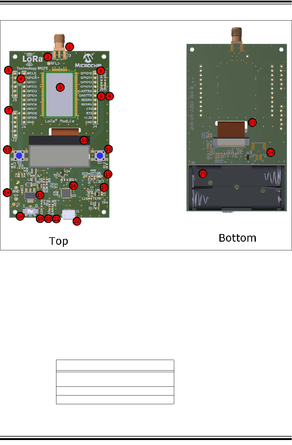
The LoRa® Mote has the following features, as represented in Figure 1-1:
1. 868/915 MHz High-Frequency SMA Connector
2. 433 MHz Low-Frequency Antenna Point
3. RN Module ICSP™ Programming Through Holes
4. Module Breakout Header 1
5. Module Breakout Header 2
6. Microchip LoRa® Module
7. Mote ICSP Programming Through Holes
8. Green LED controlled by RN Module GPIO10
9. Orange LED controlled by RN Module GPIO11
10. Backlight LCD Display; 1.2 Inch 128 X 32 Dot Matrix
11. S1 Switch (Navigation)
12. S2 Switch (Selection)
13. Everlight (ALS-PT19-315C) Ambient Light Sensor
14. Alternative Power Supply Through Hole Connectors
15. MCP1825S – LDO Regulator
16. PIC18LF45K50 8-bit USB XLP Flash 32Kb MCU
17. MCP9700 – Linear Active Thermistor
18. Battery Power Switch
19. Mote Power Indicator Red LED
20. Red LED controlled by MCU pin RA7 (28)
21. Green LED controlled by MCU pin RA6 (29)
22. USB Micro-B Connector
23. LCD Ribbon Connector
24. LCD Backlight Power Connector
25. (2) AAA Battery Pack
LoRa® Mote User’s Guide
DS40001808B-page 12 2015-2016 Microchip Technology Inc.
FIGURE 1-1: LoRa® MOTE
The high-speed UART interface and the GPIO ports are available on the module to
configure, control and transfer data. The Mote board has an on-board PIC18
supporting USB-to-UART serial bridge, enabling easy serial connection.
Demonstration of the module can be performed by plugging the Mote into a USB port
of a PC. The USB port powers the Mote board and enables the user to communicate
using the module’s ASCII commands.
Development using the module with Microchip’s PIC® MCU line is possible via the
24-pin card edge connectors on the Mote board.
1.3 CONTENTS
The Mote contains the following tools, as listed in Table 1-1.
TABLE 1-1: LoRa® MOTE
Description
LoRa® Mote populated with the LoRa®
Module
USB Cable (Male-A to Male Mini-B)
Antenna – 868/915 MHz

2015-2016 Microchip Technology Inc. DS40001808B-page 13
LoRa
®
MOTE USER’S GUIDE
Chapter 2. Getting Started
2.1 INTRODUCTION
This LoRa® Mote User’s Guide is designed to be used in conjunction with the LoRa
Technology Command Reference User’s Guide for the on-board LoRa module. This
chapter describes the hardware requirements for the LoRa Mote board, and also
provides descriptions of the different communication modes.
The module accepts commands via UART interface. Communication with the module
is achieved through two methods of operation, USB and Battery.
This chapter discusses the following topics:
• Operation Methods
• Communication to the Module
• Hardware Description
2.2 METHODS OF OPERATION
2.2.1 USB
When the Mote board is connected to the host via USB, the device will operate
automatically in USB mode. The on-board PIC18LF45K50 MCU will become a
USB-to-UART bridge device. The host can run a simple terminal emulator application
to issue commands directly to the module.
When in CDC Command mode, it is possible to operate in Battery mode by pressing
either push button. The Mote will only forward Serial commands to the RN module
when in CDC Command mode. If running in Battery mode with the USB cable
connected; disconnecting and reconnecting the USB cable is required to return to
normal USB mode for CDC serial command parsing emulation.
Supply voltage is provided via USB, and is regulated from 5V to the nominal 3.3V using
the on-board LDO (U1).
2.2.2 Battery
When no USB cable is attached, and the board is powered by (2) AAA batteries (B1),
the Mote is operating in Battery mode.
In Battery Operation mode, the Microchip PIC18LF45K50 PIC® MCU on the Mote unit
can run custom functions and directly issue ASCII commands to the attached LoRa
module via the UART interface.
The on-board MCU influences UART communications specific to operation states.
Additional resources exist on the MCU, allowing further custom development by the
user.
LoRa® Mote User’s Guide
DS40001808B-page 14 2015-2016 Microchip Technology Inc.
2.3 HARDWARE DESCRIPTION
The RF signal paths are connected to the SMA edge connector and the designated via
through-hole point. The high-frequency (868/915 MHz band) RF signal is transmitted
through the RFH (J3) SMA connector. The low-frequency (433 MHz) RF signal is
transmitted via the through-hole point (RFL), this allows connection of a user-supplied
wire antenna.
The on-board PIC18LF45K50 MCU is programmable via ICSP™ through connector J2.
In addition, the PIC18LF45K50 MCU application program is capable of being updated
via the bootloader utility.
The Mote board will power-on automatically when a USB cable is connected. When
powered by AAA batteries, power-on/off is controlled using the (S3) switch
.
Mote environment data is measured by a light sensor (U4) and by a temperature sensor
(U5). There are two on-board push buttons (S2, S3) used for menu navigation and
selection. In addition, there are four LEDs. Two LEDs (D3-Orange, D4-Green) are
connected to the module’s GPIO10 and GPIO11 I/O’s. Two LEDs (D5-Red, D6-Green)
are connected to and controlled by the PIC18LF45K50 device.
Table 2-2 shows the LoRa® Mote PIC18LF45K50 connections:
Note: The North-American (915 MHz) module does not support the ability to
transmit a (433 MHz) low-frequency signal.
TABLE 2-2: MOTE PIC18LF45K50 USAGE
PIN Pin Name Description Mote Usage
General Purpose Pins
PORT A
17 RA0 USB_DET USB Power Detection (Digital, Input)
18 RA1 VBAT Battery Voltage (Analog, ADC)
19 RA2 TEMP_SENSE MCP9700 Thermistor Sensor (Analog, ADC) [NOT
USED; Requires {R7} population]
20 RA3 LIGHT_SENSE ALS-PT19-315C Ambient Light Sensor (Analog
,ADC) [NOT USED; Requires {R15} population]
21 RA4 TP3 Test Point 3 [NOT USED]
22 RA5 SLEEP_PWR MOSFET {Q2} Enable/Disable; Used for Sleep
Power Current Reduction
29 RA6 GREEN_LED Application Behavior Descriptor (Digital, Output)
28 RA7 RED_LED Application Behavior Descriptor (Digital, Output)
PORT B
8 RB0 S3 Push Button Application Navigation Controller (Digital, Input)
9 RB1 S2 Push Button Application Navigation Controller (Digital, Input)
10 RB2 DISPRST LCD Display Dedicated Reset Enable/Disable Pin
11 RB3 RD_E LCD Read Enable/Disable Pin
12 RB4 CS LCD Chip Select Pin
13 RB5 MODRST Dedicated RN Module Reset Enable/Disable Pin
14 RB6 PGC ICSP™ Programmer
15 RB7 PGD ICSP™ Programmer
PORT C
30 RC0 A0 LCD Command/Data Select Pin
31 RC1 R/W LCD Read/Write Select Pin
Getting Started
2015-2016 Microchip Technology Inc. DS40001808B-page 15
The populated module (U7) is re-programmable via the ICSP™ press pin pad
programming connector point (J5). In addition, the populated LoRa module is capable
of being updated via the LoRa® bootloader GUI, as described in the RN2483 LoRa®
Technology Module Command Reference User’s Guide (DS40001784),
RN2903 LoRa® Technology Module Command Reference User’s Guide
(DS40001811), or LoRa® Technology Evaluation Suite User’s Guide (DS40001847).
All the pins of the module can be accessed via surface-mount pads located on both
sides of the (U7) connection point. The user can mount two 1.27 mm pitched socket
headers if desired. Sockets can connect the module pins to a custom board, whereas
the Mote board is capable of providing power. The sockets are broken into two header
breakout groupings used in supplying connection points to the module’s power, ground
and additional GPIO/UART pins.
Table 2-3 shows the LoRa module jumper breakout connections.
32 RC2 MODEM_WAKE Wake from Sleep Via RN Module output [NOT
USED]
40 RC6 TX PIC® MCU to Module Communication
1 RC7 RX PIC® MCU to Module Communication
PORT D
34 RD0 D0
8-bit bidirectional data bus connect to an 8-bit or
16-bit standard MPU data bus
35 RD1 D1
36 RD2 D2
37 RD3 D3
2 RD4 D4
3 RD5 D5
4 RD6 D6
5 RD7 D7
PORT E
23 RE0 TP1 Test Point 1 [NOT USED]
24 RE1 TP2 Test Point 2 [NOT USED]
25 RE2 BACKLIGHT LCD Backlight Power Control (Pulse-Width
Modulation, Output)
16 RE3 MCLR ICSP™ Programmer
Dedicated Pin
6,27, 41 VSS Ground Reference Ground Reference
7,26 VDD +3.3 V Power Source
38 D- DN USB Communications
39 D+ DP USB Communications
33 VUSB3V3 +3.3 V Power Reference
TABLE 2-2: MOTE PIC18LF45K50 USAGE (CONTINUED)
PIN Pin Name Description Mote Usage
General Purpose Pins
LoRa® Mote User’s Guide
DS40001808B-page 16 2015-2016 Microchip Technology Inc.
TABLE 2-3: MODULE JUMPER CONNECTIONS
Signal
Name Description Module Pin
Connection Mote Function
MCLR Reset 32 ICSP™ Programmer; Connected to
MODRST (RB5, 13)
GPIO0 General Purpose I/O 35 Unused
GPIO1 General Purpose I/O 36 Unused
GPIO2 General Purpose I/O 37 Unused
GPIO3 General Purpose I/O 38 Unused
GPIO4 General Purpose I/O 39 Unused
GPIO5 General Purpose I/O 40 Unused
GPIO6 General Purpose I/O 43 Unused
GPIO7 General Purpose I/O 44 Unused
GPIO8 General Purpose I/O 45 Unused
GPIO9 General Purpose I/O 46 MODEM_WAKE (RC2, 32)
GPIO10 General Purpose I/O 14 D5 – Orange LED
GPIO11 General Purpose I/O 13 D6 – Green LED
GPIO12 General Purpose I/O 10 Connected to Temperature Sensor;
MODTMPSENS (Analog, ADC)
GPIO13 General Purpose I/O 9 Connected to Ambient Light Sensor;
MODLITESENS (Analog, ADC)
UARTRX Module Communication 7 PIC® MCU TX
(RC6, Pin 40)
UARTTX Module Communication 6 PIC® MCU RX
(RC7, Pin 1)
CTS Module Communication 3 Unused
RTS Module Communication 2 Unused
+3.3V Power Source 34, 12 +3.3V Rail
GND Ground Reference 1,8,11,20,21,22
,24,26,27,
28,33,41,47
Ground
Getting Started
2015-2016 Microchip Technology Inc. DS40001808B-page 17
2.4 MOTE APPLICATION DESCRIPTION
This section describes the basic operation of the LoRa Mote application program.
The default LoRa Mote application comes with three methods of operation:
• USB CDC-Serial Communication
• Mobile Mote Sensor Emulation
• Application Update via Bootloader
2.4.1 USB CDC-Serial
When a USB Mini-B is connected to the LoRa Mote, it will power-on, regardless of the
power switch S3. If the LoRa Mote is already in operation, the USB connection will take
pre-emptive control and act only as a serial emulation device. After being connected to
a host PC, the LoRa Mote will enumerate. In this operation mode, the user can enter
the required LoRaWAN™ credentials for joining an existing LoRaWAN network.
There is a wide range of third-party serial communication programs which can be used
to communicate with the module populated on the LoRa Mote. Refer to the RN2483
LoRa® Technology Module Command Reference User’s Guide (DS40001784) for
additional information on parsing commands directly into the RN module for LoRa
communications.
2.4.2 Mobile Mote Sensor Emulation
When powered using (2) AAA batteries, the LoRa Mote will act in Mobile Mote mode.
This application is best used to demonstrate a real working Internet of Things (IoT)
sensor design.
After power-on, the LoRa Mote will attempt a LoRaWAN network first through either
Activation-By-Personalization (ABP) [S2], or Over-The-Air-Activation (OTAA) [S3];
depending upon the type requested. If the proper keys necessary to join the requested
process (ABP, OTAA), the LoRa Mote will display the message “Valid Keys Required”.
The user will then have to enter the required keys of the module through USB
CDC-Serial mode, and store them using the ‘mac save’ command. The minimal
required credentials for each join process are indicated below:
•OTAA
-DevEUI
-AppEUI
-AppKey
•ABP
- DevAddr
- NwkSKey
-AppSKey
If the proper credentials are entered, the LoRa Mote will automatically join the system.
After joining, the LoRa Mote will enter Running mode.
When running, the LoRa Mote acts as a demonstration device. It is capable of key
LoRa communication events, such as manual uplink packets, automatic periodic uplink
packets, and displaying last received downlink data.
Menu navigation is handled by using S2 for navigation and S3 for selection.
Note: MPCOMMS is required to be installed for USB enumeration. This is
installed automatically together with MPLAB® X.

LoRa® Mote User’s Guide
DS40001808B-page 18 2015-2016 Microchip Technology Inc.
Table 2-4 shows the menus with operation descriptions:
2.4.3 Bootloader Behavior
The PIC18LF45K50 is pre-programmed with a bootloader application. Bootloader
mode is initiated by holding either S2/S3 or both push buttons upon power-up.
The bootloader applications are based off the HID bootloader – PIC18 Non-J; the
project is supplied with the Microchip Libraries for Applications (MLA) that can be found
at www.microchip.com/mla.
In addition, the utility supplied with the MLA is used to handle all Mote PIC® MCU
application bootloading behaviors.
TABLE 2-4: DESCRIPTION OF MENU OPERATION
Menu Description
Sensor Display Displays Light and Temperature Sensor Data
Issue uplink (S2) issues a confirmed uplink message with sensor data
payload.
(S3) issues an unconfirmed uplink message with sensor data
payload.(1)
View downlink When the red LED (D5) is lit, a downlink message is ready for
viewing.
This menu will display the received downlink payload.
Menu Timeout Configures/Disables the Sleep time-out features of the Mote.
Disabling this feature will prevent the Mote to automatically enter
sleeping if inactive. If not disabled, the Menu time out contains
varying options in length. Menu time-out length is represented in
seconds.
Perform Periodic
Sleep Uplinks Configures/Disables the ability for the Mote to issue Uplink
Transmissions when asleep. Configures the rate at which the
Mote is periodically woken from Sleep through use of the
Watchdog Timer. Periodic Uplink Transmission lengths are
represented in minutes.
Select Data Rate Configures the working Data Rate for the RN module. Available
Data Rate options are dependent upon the populated RN module
type. Selection of Adaptive Data Rate (ADR) is also available.
Upon exiting the menu will issue configuration commands to the
RN module where parameter value is “saved”.
Sleep Control The LoRa® Mote will automatically enter Sleep if no buttons are
pressed for 30 seconds. The LoRa Mote can be placed into Sleep
manually by selecting the Sleep option in the menus.
Wake-Up events include:
• Pressing either S2 or S3 push buttons
• A USB plug-in
• Periodic WDT (Watchdog Timer) ticks
• Module message reception
Note 1: The port number used for Mote uplink messages is randomly selected
between 1-223.
Note: Additionally, the module contains its own bootloader application which can
be accessed/updated as discussed in the RN2483 LoRa® Technology
Module Command Reference User’s Guide (DS40001784)

Getting Started
2015-2016 Microchip Technology Inc. DS40001808B-page 19
2.4.4 Application Updates
• If powered by USB cable, the red LED (D3) and the green LED (D4) will begin to
alternate ON/OFF.
• If the device is in Battery Operation mode and the Bootloader mode is entered,
the red LED (D3) will stay ON, the green LED (D4) will remain OFF. Once the USB
cable is plugged-in, the green/red LED will alternate.
The application firmware can be updated by launching the HID bootloader GUI application
included with the Microchip Libraries for Applications (MLA) at www.microchip.com/mla.
DIR:
\\mla\v2014_07_22\apps\usb\device\bootloaders\utilities\bin\win\HIDBootloader.exe
Note: If Bootloader mode is entered unintentionally, power cycling the board will
re-enter the LoRa® Mote default application.

LoRa® Mote User’s Guide
DS40001808B-page 20 2015-2016 Microchip Technology Inc.
NOTES:

2015-2016 Microchip Technology Inc. DS40001808B-page 21
LoRa® MOTE USER’S GUIDE
Appendix A. Board of Schematics and Bill of Materials
A.1 INTRODUCTION
This appendix provides the LoRa® Mote schematics and Bill of Materials (BOM).
•Board Schematics
•Bill of Materials
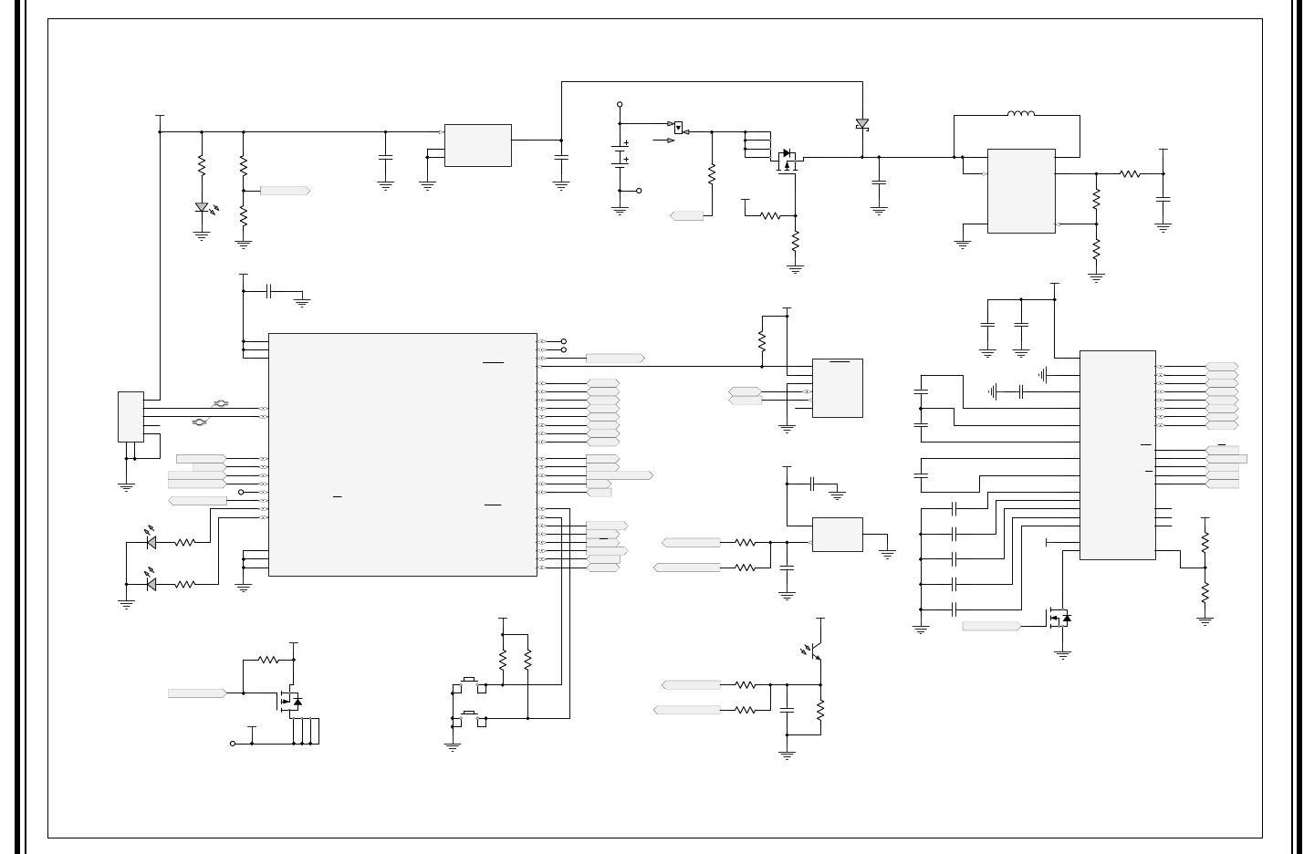
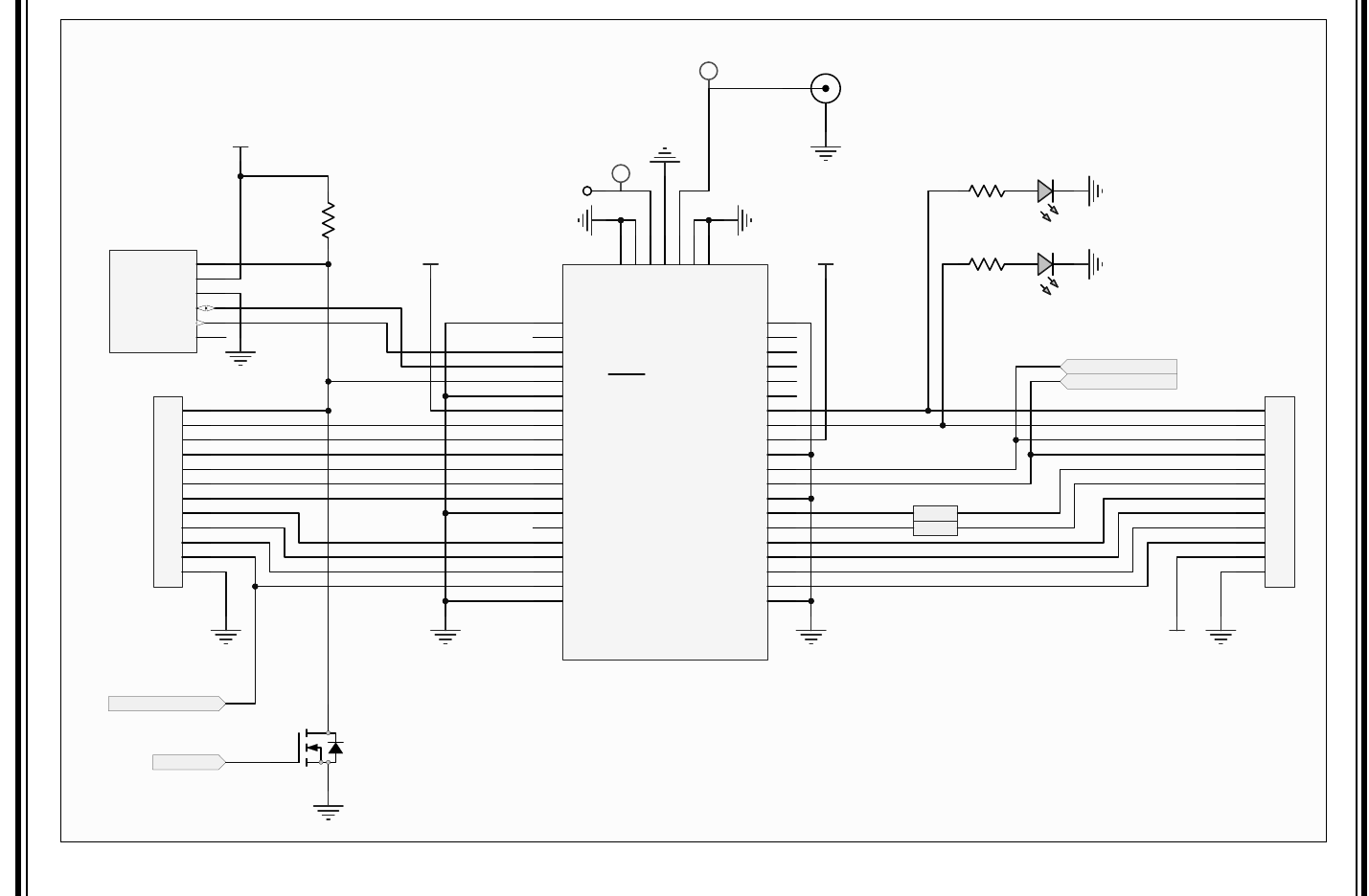
A.2 BOARD SCHEMATICS
Figure A-1 and Figure A-2 show the board schematics.
LoRa® Mote User’s Guide
DS40001808B-page 22 2015-2016 Microchip Technology Inc.
FIGURE A-1: LoRa® MOTE BOARD SCHEMATIC 1
9
,1
(1
*1'
6:
9
)%
9
287
0&37,&+
8
9
)
&
9
)
&
*1'
)
&
9
9
.
5
63
)
&
9
.
5
9
5;
7;
0%5/7*
'
5HG
'
5
5
/,*+7B6(16(
6,('+7*(
4
.
5
9
63
+
/
/,*+7B6(16(
63
0
5
6,('+7*(
4
.
5
.
5
9
86%
0
5
5
5
6/((3B3:5
6/((3B3:5
9
)
&
9
)
&
'B3
'B1
.
5
.
5
86%B'(7
86%B'(7
*1'
9
287
9
''
8
0&3
)
&
',63567
&6
',63567
&6
X)
&
9
33
0&/5
9
''
*1'
,&63'$7
,&63&/.
1&
'13
3,&NLW
70
-
&/6%%7
6
3*&
3*'
3*'
3*&
7(03B6(16(
7(03B6(16(
*UHHQ
'
5HG
'
5
5
5
5
.
5
9
%$7
9
%$7
9
86%
02'(0B:$.(
9
.
5
$$$
%
9
66
5$&,1$1
5$&,1$1&7&03
5$&,1$1'$&2879
5()
5$&,1$19
5()
5$&2876547&.,
5$&287651466+/9',1$1
5$&/.226&
5$&/.,26&
626&7&.,7*7&.,,2&&5&
626&,&&3,2&&5&
$1,2&&&&33$&73/65&
9
86%
9
',2&&
',2&&
$1&.7;,2&&5&
$1'75;,2&&6'25&
9
66
9
''
$16'$6',65,)/7,175%
$1&,16&/6&.3&,175%
$13%&7(',175%
$1&,16'2&&3&7('5%
$13',2&%5%
$17*7&.,,2&%5%
3*&,2&%5%
3*',2&%5%
0&/59335(
(3
$15'
$15'
$15'
$15'
$15'
3%$15'
3&$15'
3'$15'
9
''
$15(
$15(
$15(
3,&/).,09
8 )
&
'13
&
'
'
'
'
'
'
'
'
'
'
'
'
'
'
'
'
$
$
5:
5:
5'B(
5'B(
63
9
X)
&
9
X)
&
9
X)
&
9
& X)
9
& X)
9
& X)
9
& X)
9
& X)
5
5
'13
5
63
9
,1
*1'
9
287
7$%*1'
0&36('%
8
6
6
%$&./,*+7
86%PLFUR%
9
%86
'
'
,'
*1'
-
02'567
5
5
5
5
'13
5
'13
5
02'7036(16
02'/,7(6(16
1
4
(5&
9
66
9
''
'%
'%
'%
'%
'%
'%
'%
'%
9
287
&$3
&$3
&$3
&$3
&$3
9
9
9
9
9
&
1&
&6
5(6
$
:5B5:
5'B(
1&
1&
.
$
/&'
9
%$&./,*+7
73
73
73
73
)
& .
5
$/637&/75
4
Board of Schematics and Bill of Materials
2015-2016 Microchip Technology Inc. DS40001808B-page 23
FIGURE A-2: LoRa® MOTE BOARD SCHEMATIC 2
7;
5;
9
.
5
9 9
L
2KP
L
2KP
-
'13
-
'13
-
9
2UDQJH
'
*UHHQ
'
5
5
5
5
*1'
5(6(59('
5(6(59('
*3,2
*3,2
*1'
9
*3,2
*1'
1&
1&
1&
1&
1&
*1'
*1'
*1'
5)+
*1'
5)/
*1'
*1'
*1'
3*0
3*&
3*'
*3,2
*1'
9
*3,2
*3,2
*3,2
*3,2
*3,2
5(6(70&/5
*1'
*3,2
8$57576
8$57&76
8$575;
8$577;
*1'
1&
*3,2
*3,2
*3,2
*3,2
51,500+]510+]
8
02'(0B:$.(
5)/
9
33
0&/5
9
''
*1'
,&63'$7
,&63&/.
1&
3,&NLW
70
'13
-
02'/,7(6(16
02'7036(16
1
4
02'567
LoRa® Mote User’s Guide
DS40001808B-page 24 2015-2016 Microchip Technology Inc.
A.3 BILL OF MATERIALS
TABLE A-1: LoRa® MOTE BOARD BILL OF MATERIALS (BOM)
Quantity Designator Description Manufacturer 1 Manufacturer Part Number 1
1B1 Plastic battery holder, two AAA, series
connection Keystone Electronics 2468
2 C1, C3 Cap, Ceramic, 4.7 uF, 10V 10% X5R Kemet C0603C475K8PACTU
2 C2, C18 Cap, Ceramic, 1 uF, 10V X5R Kemet C0603C105M8PACTU
1 C4 Cap, Ceramic, 10 uF, 10V X5R 10% TDK Corporation C1608X5R1A106M
4 C5, C7, C11, C15 Cap, Ceramic, 0.1uF, 50V X5R TDK Corporation C1608X7R1H104M080AA
1 C8 Cap, Ceramic, 2.2 uF, 16V X5R TDK Corporation C1608X5R1C225K080AB
8C9, C10, C12, C13,
C14, C16, C17, C19 Cap, Ceramic, 1 uF, 16V X5R TDK Corporation C1608X5R1C105K080AA
1D1 Diode, Schottky, 20V, 500 mA,
SOD123 ON Semiconductor MBR0520LT1G
2 D2, D3 LED, SMD, RED, 0603 package Kingbright APT1608EC
2 D4, D6 LED, SMD, GRN, 0603 package Kingbright APT1608SGC
1 D5 LED, SMD, AMBER, 0603 package Lite-On Inc LTST-C190AKT
1J1 Receptacle, Micro USB, Type B, with
Solder Tabs, Round Holes FCI 10118194-0001LF
1 J3 SMA Jack, 50 Ohm, Edge Mount Samtec SMA-J-P-H-ST-EM1
1L1 Inductor, 4.7 uH, Wirewound, 20%
SMD 2518 Taiyo Yuden CBC2518T4R7M
1 LCD1 LCD Display, 1.2 Inch 128 X 32 Dot
Matrix, Backlight EastRising ERC12832-1
2 Q1, Q2 P-CHAN MOSFET, 20V 2A, Built-In
ESD, SOT-363 Vishay Siliconix SI1427EDH-T1-GE3
2 Q3, Q4 N-CHAN MOSFET, 60V 115 mA Fairchild Semiconductor 2N7002
1 Q5 Sensor, Ambient Light, 630 nM, SMD Everlight Electronics Co Ltd ALS-PT19-315C/L177/TR8
1 R1 Res, 1K 1/10W 1% Panasonic Electronic Components ERJ-3EKF1001V
1 R2 Res, 470 Ohm, 1/10W 1% Stackpole Electronics Inc. RMCF0603FT470R
7R3, R5, R12, R13,
R14, R19, R20 Res, 10K, 1/10W 1% Panasonic Electronic Components ERJ-3EKF1002V
4 R4, R10, R24, R25 Res, 0 Ohm, 1/10W Stackpole Electronics Inc. RMCF0603ZT0R00
1 R6 Res, 1.69M 1/10W 1% Vishay Dale CRCW06031M69FKEA
1 R8 Res, 20K 1/10W 1% Stackpole Electronics Inc. RMCF0603FT20K0
2 R9, R17 Res, 100K, 1/10W 1% Stackpole Electronics Inc. RMCF0603FT100K
1 R11 Res, 1M 1/10W 1% Stackpole Electronics Inc. RMCF0603FT1M00
4 R16, R18, R21, R22 Res, 330 Ohm, 1/10W 1% Stackpole Electronics Inc. RMCF0603FT330R
1 S1 Switch, Slide, SPDT, 0.2A, 12V Copal Electronics Inc CL-SB-12B-01T
2S2, S3 Switch, Tact, PB MOM SPST-NO,
0.5A, 12V C&K Components PTS645SM43SMTR92 LFS
1 TAPE1 3M Foam Tape, Double-Coated, 1.00
X 0.031 X 5yds 3M (TC) 1-5-4032W
1 TAPE2 Tape, Double-Coated, 1.00 X 0.008 X
5yds 3M (TC) 1-5-9088
1U1 Regulator, LDO, 3.0V, 500 mA,
SOT223 Microchip Technology MCP1825S-3002E/DB
1U2 Synchronous Boost Regulator with I/O
Bypass Microchip Technology MCP16252T-I/CH
1U3 USB 8-Bit Flash XLP Microcontroller,
32Kb, UQFN-40 Microchip Technology PIC18LF45K50-I/MV
1 U5 LP Linear Active Thermistor, SC70-5 Microchip Technology MCP9700T-E/LT
1U6 LoRa
® Module, 868 MHz (915 MHz) Microchip Technology Inc RN2483-I/RM (RN2903)
2015-2016 Microchip Technology Inc. DS40001808B-page 25
LoRa® MOTE USER’S GUIDE
Appendix B. Legacy Board Schematics and Bill of Materials
B.1 INTRODUCTION
This appendix section provides short descriptions of the Differences between the LoRa® Mote Revisions B
design discussed in this user’s guide, and that of the initial Legacy Mote Design, and the Legacy LoRa®
Mote board schematics and Bill of Materials (BOM).
•Differences
•Board Schematics
•Bill of Materials
B.2 DIFFERENCES
General:
(New Mote) (Legacy Mote)
A)
S2 Push Button S1 Push Button
S3 Push Button S2 Push Button
B)
Push Button Layout Change
C)
Temperature Sensor Measured by GPIO12 Measured by PIC via RA2
Light Sensor Measured by GPIO13 Measured by PIC via RA3
D)
MODRST N/A; RN Module RESET pin tied to MCLR & Pull Up (R19) to +3.3 V
(It is RECOMMENDED to have a DEDICATED pin for toggle control of the RN Module RESET pin to prevent
power cycle issues which were observed with the Legacy Mote design)
E)
PIC18LF45K50 MCU PIC18LF25K50
F)
J5 ICSP™ RN Module Programming Through-Holes J5 ICSP™ RN Module Programming Pads
G)
Green/Orange LEDs controlled by GPIO10/GPIO11 Layout Change
H)
PWM driven Backlight LCD (ERC12832-1) OLED LCD (ER-OLED0.91-3B-3801)
I)
Sharp Ambient Light Sensor (GA1A1S202WP) Everlight Ambient Light Sensor (ALS-PT19-315C)
Note: On legacy design the light values are inverted. No/less light results in higher
values; while increased/more light will result in lower value.

LoRa® Mote User’s Guide
DS40001808B-page 26 2015-2016 Microchip Technology Inc.
Hardware Description:
The Legacy LoRa® Mote design has the following features, as represented in Figure B-1:
1. 868/915 MHz High-Frequency SMA Connector
2. 433 MHz Low-Frequency Antenna Point
3. Module Breakout Header 1
4. Module Breakout Header 2
5. Module Connector
6. SSD1306 (128 x 64) Dot Matrix OLED
7. Module ICSP™ Programming Pads
8. Mote ICSP Programming Through Hole
9. S1 Switch (Navigation)
10. S2 Switch (Selection)
11. Sharp (GA1A1S202WP) Ambient Light Sensor
12. MCP9700T – Linear Active Thermistor
13. MCP1825S – LDO Regulator
14. PIC18LF25K50 8-bit MCU
15. Alternative Power Supply Through Hole Connectors
16. Descriptive LEDs, (2) Controlled by PIC18, (2) Controlled by Module
17. USB Mini-B Connector
18. Battery Power Switch
19. Website QR Code
20. (2) AAA Battery Pack
21. OLED SSD1306 Ribbon Connector
Legacy Board Schematics and Bill of Materials
2015-2016 Microchip Technology Inc. DS40001808B-page 27
FIGURE B-1: LoRa® MOTE LEGACY
Top Bottom
LoRa® Mote User’s Guide
DS40001808B-page 28 2015-2016 Microchip Technology Inc.
TABLE B-1: MOTE PIC18LF25K50 USAGE
Pin Name Description Mote Usage
General Purpose Pins
RA0 USB_DET USB Power Detection (Digital, Input)
RA1 VBAT Battery Voltage (Analog, ADC)
RA2 TEMP_SENSE MCP9700 Thermistor Sensor (Analog, ADC)
RA3 LIGHT_SENSE GA1A1S202WP Ambient Light Sensor (Analog, ADC)
RA4 VOUT_EN Boost Regulator Enable (Digital, Output)
RA5 SENSE_PWR Power Reference Point
RA6 Red LED (D5) Application Behavior Descriptor (Digital, Output)
RA7 Green LED (D6) Application Behavior Descriptor (Digital, Output)
RB0 Unused Unused
RB1 SCK OLED SPI Clock Reference
RB2 RESET OLED Manual Reset Control
RB3 SDO OLED SPI Communication
RB4 CS OLED Chip-Select
RB5 D/C OLED Data/Command Select
RB6 PGC ICSP™ Programmer
RB7 PGD ICSP Programmer
RC0 S1 Push Button Application Navigation Controller (Digital, Input)
RC1 S2 Push Button Application Navigation Controller (Digital, Input)
RC2 MODEM_WAKE Module Wake Application from Sleep (Digital, Input) [Module GPIO9]
RC6 TX PIC® MCU to Module Communication
RC7 RX PIC® MCU to Module Communication
RE3 MCLR ICSP™ Programmer
Dedicated Pin
VUSB3V3 +3.3V Power Reference
D- DN USB Communications
D+ DP USB Communications
VDD +3.3V Power Source
VSS Ground Reference Ground Reference

Legacy Board Schematics and Bill of Materials
2015-2016 Microchip Technology Inc. DS40001808B-page 29
B.3 BOARD SCHEMATICS
Figure B-2 and Figure B-3 show the legacy board schematics.
FIGURE B-2: LoRa® MOTE LEGACY BOARD SCHEMATIC 1
9
,1
(1
*1'
6:
9
)%
9
287
0&37,&+
8
9
)
&
9
)
&
9
287
B(1
*1'
9
%86
'
'
,'
*1'
-
9
)
&
9
9
.
5
6&.
63
)
&
9
9
287
B(1
.
5
6
9
5;
7;
0%5/7*
'
5HG
'
5
5
/,*+7B6(16(
6,('+7*(
4
.
5
9
63
+
/
*$$6:3
*1'
*1'
,R
9
&&
8
/,*+7B6(16(
63
)
&
0
5
5
5
'135
5
6,('+7*(
4
.
5
.
5
9
86%
0
5
5
5
9
)
&
9
)
&
9
)
&
9
)
&
63
63
6(16(B3:5
6(16(B3:5
.
5
0&36('%
9
,1
*1'
9
287
7$%*1'
8
9
)
&
9
)
&
'B3
'B1
.
5
.
5
86%B'(7
86%B'(7
*1'
9
287
9
''
8
0&3
.
5
)
&
5(6(7
6'2
&6
'&
'&
6&.
6'2
5(6(7
&6
X)
&
)
& .
5
(52/('%
&3
&1
&3
&1
9
%$7
9
''
,
5()
6&/.
6',1
'&
5(6(7
&6
9
66
9
&20+
9
&&
2/('
9
33
0&/5
9
''
*1'
,&63'$7
,&63&/.
1&
'13
3,&NLW
70
-
&/6%%7
6
3*&
3*'
3*'
3*&
7(03B6(16(
7(03B6(16(
*UHHQ
'
5HG
'
5
5
5
5
73
.
5
9
%$7
9
%$7
9
86%
02'(0B:$.(
9
6
.
5
9
66
5$&,1$1
5$&,1$1
5$&,1$1'$&2879
5()
5$&,1$19
5()
5$&2876547&.,
5$&287651466+/9',1$1
5$&/.226&
5$&/.,26&
626&7&.,7*7&.,,2&&5&
626&,&&3,2&&5&
$1,2&&&&33$&73/65&
9
86%
9
',2&&
',2&&
$1&.7;,2&&5&
$1'75;,2&&6'25&
9
66
9
''
$16'$6',65,)/7,175%
$1&,16&/6&.3&,175%
$13%&7(',175%
$1&,16'2&&3&7('5%
$13',2&%5%
$17*7&.,,2&%5%
3*&,2&%5%
3*',2&%5%
0&/59
33
5(
(3
3,&/).,0/
8
$$$
%
LoRa® Mote User’s Guide
DS40001808B-page 30 2015-2016 Microchip Technology Inc.
FIGURE B-3: LoRa® MOTE LEGACY BOARD SCHEMATIC 2
7;
5;
9
.
5
9 9
L
2KP
9
33
0&/5
9
''
*1'
,&63'$7
,&63&/.
'133,&NLW
70
-
L
2KP
-
'13
-
'13
-
9
2UDQJH
'
*UHHQ
'
5
5
5
5
*1'
5(6(59('
5(6(59('
*3,2
*3,2
*1'
9
*3,2
*1'
1&
1&
1&
1&
1&
*1'
*1'
*1'
5)+
*1'
5)/
*1'
*1'
*1'
3*0
3*&
3*'
*3,2
*1'
9
*3,2
*3,2
*3,2
*3,2
*3,2
5(6(70&/5
*1'
*3,2
8$57576
8$57&76
8$575;
8$577;
*1'
1&
*3,2
*3,2
*3,2
*3,2
51,500+]510+]
8
02'(0B:$.(
5)/

Legacy Board Schematics and Bill of Materials
2015-2016 Microchip Technology Inc. DS40001808B-page 31
B.4 BILL OF MATERIALS
TABLE B-2: BILL OF MATERIALS (BOM)
Quantity Designator Description Manufacturer 1 Manufacturer Part Number 1
1B1 Plastic battery holder, two AAA, series conn, 063 Elev, Tape
Mount Keystone Electronics 2468
2 C1, C3 Cap, Ceramic, 4.7 uF, 10V 10% X5R Kemet C0603C475K8PACTU
5 C2, C8, C9, C10, C12 Cap, Ceramic, 1 uF, 10V X5R Kemet C0603C105M8PACTU
1 C4 Cap, Ceramic, 10 uF, 10V X5R 10% TDK Corporation C1608X5R1A106M
4 C5, C11, C13, C14 Cap, Ceramic, 0.1 uF, 50V X5R TDK Corporation C1608X7R1H104M080AA
1 C6 Cap, Ceramic, 2.2 uF, 16V X5R TDK Corporation C1608X5R1C225K080AB
1 C7 Cap, Ceramic, 4.7 uF, 16V 10% X5R Taiyo Yuden EMK107ABJ475KA-T
1 D1 Diode, Schottky, 20V, 500 mA, SOD123 ON Semiconductor MBR0520LT1G
2 D2, D5 LED, SMD, RED, 0603 package Kingbright APT1608EC
1 D3 LED, SMD, AMBER, 0603 package Lite-On Inc LTST-C190AKT
2 D4, D6 LED, SMD, GRN, 0603 package Kingbright APT1608SGC
1 J1 Receptacle, Mini USB, UX60-MB-5ST, Type B Hirose Electric Co Ltd UX60-MB-5ST
1 J3 SMA Jack, 50 Ohm, Edge Mount Samtec SMA-J-P-H-ST-EM1
1 L1 Inductor, 4.7 uH, Wirewound, 20% SMD 2518 Taiyo Yuden CBC2518T4R7M
1OLED1 OLED Display Module, SPI, 128 X 32, Blue, with FPC
Connector East Rising ER-OLED0.91-3B-3801
2 Q1, Q2 P-CHAN MOSFET, 20V 2A, Built-In ESD, SOT-363 Vishay Siliconix SI1427EDH-T1-GE3
1 R1 Res, 470 Ohm, 1/10W 1% Stackpole Electronics Inc RMCF0603FT470R
4 R2, R7, R21, R26 Res, 0 Ohm, 1/10W Stackpole Electronics Inc RMCF0603ZT0R00
6R3, R10, R11, R12, R19,
R24 Res, 10K, 1/10W 1% Panasonic Electronic
Components ERJ-3EKF1002V
1 R4 Res, 1.69M 1/10W 1% Vishay Dale CRCW06031M69FKEA
3 R6, R15, R18 Res, 100K, 1/10W 1% Stackpole Electronics Inc RMCF0603FT100K
1 R8 Res, 1M 1/10W 1% Stackpole Electronics Inc RMCF0603FT1M00
4 R9, R14, R16, R17 Res, 330 Ohm, 1/10W 1% Stackpole Electronics Inc RMCF0603FT330R
1 R13 Res, 390K, 1/10W 1% Stackpole Electronics Inc RMCF0603FT390K
1 R25 Res, 20K 1/10W 1% Stackpole Electronics Inc RMCF0603FT20K0
1 S1 Switch, Tact, PB MOM SMT, Series TL3302 E-Switch TL3302AF180QJ
1 S2 Switch, Slide, SPDT, 0.2A, 12V Copal Electronics Inc CL-SB-12B-01T
0.9 inches TAPE1 3M Foam Tape, Double-Coated, 1.00 X 0.031 X 5 yds 3M (TC) 1-5-4032W
0.4 inches TAPE2 Tape, Double-Coated, 1.00 X 0.008 X 5 yds 3M (TC) 1-5-9088
1 U1 Regulator, LDO, 3.3V, 500 mA, SOT223 Microchip Technology MCP1825S-3302E/DB
1 U2 Synchronous Boost Regulator with I/O Bypass Microchip Technology MCP16252T-I/CH
1 U3 USB 8-Bit Flash Microcontroller, 32Kb, QFN-28 Microchip Technology PIC18F25K50-I/ML
LoRa® Mote User’s Guide
DS40001808B-page 32 2015-2016 Microchip Technology Inc.
1 U4 Sensor, Ambient Light, 555 nM, SMD Sharp Microelectronics GA1A1S202WP
1 U5 LP Linear Active Thermistor, SC70-5 Microchip Technology MCP9700T-E/LT
1U7 LoRa
® Module, 868 MHz (915 MHz) Microchip Technology Inc RN2483-I/RM (RN2903)
TABLE B-2: BILL OF MATERIALS (BOM) (CONTINUED)
Quantity Designator Description Manufacturer 1 Manufacturer Part Number 1
2015-2016 Microchip Technology Inc. DS40001808B-page 33
AMERICAS
Corporate Office
2355 West Chandler Blvd.
Chandler, AZ 85224-6199
Tel: 480-792-7200
Fax: 480-792-7277
Technical Support:
http://www.microchip.com/
support
Web Address:
www.microchip.com
Atlanta
Duluth, GA
Tel: 678-957-9614
Fax: 678-957-1455
Austin, TX
Tel: 512-257-3370
Boston
Westborough, MA
Tel: 774-760-0087
Fax: 774-760-0088
Chicago
Itasca, IL
Tel: 630-285-0071
Fax: 630-285-0075
Cleveland
Independence, OH
Tel: 216-447-0464
Fax: 216-447-0643
Dallas
Addison, TX
Tel: 972-818-7423
Fax: 972-818-2924
Detroit
Novi, MI
Tel: 248-848-4000
Houston, TX
Tel: 281-894-5983
Indianapolis
Noblesville, IN
Tel: 317-773-8323
Fax: 317-773-5453
Los Angeles
Mission Viejo, CA
Tel: 949-462-9523
Fax: 949-462-9608
New York, NY
Tel: 631-435-6000
San Jose, CA
Tel: 408-735-9110
Canada - Toronto
Tel: 905-673-0699
Fax: 905-673-6509
ASIA/PACIFIC
Asia Pacific Office
Suites 3707-14, 37th Floor
Tower 6, The Gateway
Harbour City, Kowloon
Hong Kong
Tel: 852-2943-5100
Fax: 852-2401-3431
Australia - Sydney
Tel: 61-2-9868-6733
Fax: 61-2-9868-6755
China - Beijing
Tel: 86-10-8569-7000
Fax: 86-10-8528-2104
China - Chengdu
Tel: 86-28-8665-5511
Fax: 86-28-8665-7889
China - Chongqing
Tel: 86-23-8980-9588
Fax: 86-23-8980-9500
China - Dongguan
Tel: 86-769-8702-9880
China - Hangzhou
Tel: 86-571-8792-8115
Fax: 86-571-8792-8116
China - Hong Kong SAR
Tel: 852-2943-5100
Fax: 852-2401-3431
China - Nanjing
Tel: 86-25-8473-2460
Fax: 86-25-8473-2470
China - Qingdao
Tel: 86-532-8502-7355
Fax: 86-532-8502-7205
China - Shanghai
Tel: 86-21-5407-5533
Fax: 86-21-5407-5066
China - Shenyang
Tel: 86-24-2334-2829
Fax: 86-24-2334-2393
China - Shenzhen
Tel: 86-755-8864-2200
Fax: 86-755-8203-1760
China - Wuhan
Tel: 86-27-5980-5300
Fax: 86-27-5980-5118
China - Xian
Tel: 86-29-8833-7252
Fax: 86-29-8833-7256
ASIA/PACIFIC
China - Xiamen
Tel: 86-592-2388138
Fax: 86-592-2388130
China - Zhuhai
Tel: 86-756-3210040
Fax: 86-756-3210049
India - Bangalore
Tel: 91-80-3090-4444
Fax: 91-80-3090-4123
India - New Delhi
Tel: 91-11-4160-8631
Fax: 91-11-4160-8632
India - Pune
Tel: 91-20-3019-1500
Japan - Osaka
Tel: 81-6-6152-7160
Fax: 81-6-6152-9310
Japan - Tokyo
Tel: 81-3-6880- 3770
Fax: 81-3-6880-3771
Korea - Daegu
Tel: 82-53-744-4301
Fax: 82-53-744-4302
Korea - Seoul
Tel: 82-2-554-7200
Fax: 82-2-558-5932 or
82-2-558-5934
Malaysia - Kuala Lumpur
Tel: 60-3-6201-9857
Fax: 60-3-6201-9859
Malaysia - Penang
Tel: 60-4-227-8870
Fax: 60-4-227-4068
Philippines - Manila
Tel: 63-2-634-9065
Fax: 63-2-634-9069
Singapore
Tel: 65-6334-8870
Fax: 65-6334-8850
Taiwan - Hsin Chu
Tel: 886-3-5778-366
Fax: 886-3-5770-955
Taiwan - Kaohsiung
Tel: 886-7-213-7828
Taiwan - Taipei
Tel: 886-2-2508-8600
Fax: 886-2-2508-0102
Thailand - Bangkok
Tel: 66-2-694-1351
Fax: 66-2-694-1350
EUROPE
Austria - Wels
Tel: 43-7242-2244-39
Fax: 43-7242-2244-393
Denmark - Copenhagen
Tel: 45-4450-2828
Fax: 45-4485-2829
France - Paris
Tel: 33-1-69-53-63-20
Fax: 33-1-69-30-90-79
Germany - Dusseldorf
Tel: 49-2129-3766400
Germany - Karlsruhe
Tel: 49-721-625370
Germany - Munich
Tel: 49-89-627-144-0
Fax: 49-89-627-144-44
Italy - Milan
Tel: 39-0331-742611
Fax: 39-0331-466781
Italy - Venice
Tel: 39-049-7625286
Netherlands - Drunen
Tel: 31-416-690399
Fax: 31-416-690340
Poland - Warsaw
Tel: 48-22-3325737
Spain - Madrid
Tel: 34-91-708-08-90
Fax: 34-91-708-08-91
Sweden - Stockholm
Tel: 46-8-5090-4654
UK - Wokingham
Tel: 44-118-921-5800
Fax: 44-118-921-5820
Worldwide Sales and Service
07/14/15