Lora Design Guide STD
LoraDesignGuide_STD
LoraDesignGuide_STD
User Manual: Pdf
Open the PDF directly: View PDF ![]() .
.
Page Count: 9

WIRELESS & SENSING
Revision 1 July 2013 © 2013 Semtech Corporation
1
SX1272/3/6/7/8
LoRa Modem Design Guide
SX1272/3/6/7/8: LoRa Modem
Designer’s Guide
AN1200.13
TCo

WIRELESS & SENSING
Revision 1 July 2013 © 2013 Semtech Corporation
2
SX1272/3/6/7/8
LoRa Modem Design Guide
Table of Contents
1. Overview ........................................................................................................................................................ 3
2 Principles of LoRa Design ............................................................................................................................ 3
2.1 LoRa Modulation ............................................................................................................................................. 3
2.2 Receiver Sensitivity ......................................................................................................................................... 3
2.3 SNR and Spreading Factor ............................................................................................................................. 3
2.4 BW and Chip Rate........................................................................................................................................... 4
3 Advanced LoRa Design Parameters ........................................................................................................... 5
3.1 Forward Error Correction ................................................................................................................................ 5
3.2 Hardware Implementation ............................................................................................................................... 6
3.3 Low Data Rate Optimisation Mode & Header Mode ....................................................................................... 6
4 The LoRa Packet Format & Time On Air ..................................................................................................... 7
5 LoRa Calculator ............................................................................................................................................. 8
Table of Figures
Figure 1. The LoRa Bandwidth Corresponds to the Double Sided Transmit Spectrum Bandwidth .............................. 4
Figure 2. Influence of Coding Rate on Sensitivity (SF = 7, BW = 125 kHz, 13 Byte Payload) ...................................... 5
Figure 3. Individual RF transmit and receive paths (left) provides better sensitivity than the single shared TRx path
(right). ...................................................................................................................................................................... 6
Figure 4. LoRa Modem Packet formatting. .................................................................................................................... 7
Figure 5. The LoRa Calculator Interface. ....................................................................................................................... 8
DISCLAIMER
The performance figures are for indication only. For definitive product performance data please refer to the
datasheet.
WIRELESS & SENSING
Revision 1 July 2013 © 2013 Semtech Corporation
3
SX1272/3/6/7/8
LoRa Modem Design Guide
1. Overview
This guide provides the basic information necessary for the designer to evaluate the suitability of the LoRa modem
for their radio application. The design is split into two sections covering basic and advanced design topics.
2 Principles of LoRa Design
2.1 LoRa Modulation
LoRa is a spread spectrum modulation scheme that that uses wideband linear frequency modulated pulses
whose frequency increases or decreases over a certain amount of time to encode information. The main
advantages of this approach are twofold: a substantial increase in receiver sensitivity due to the processing gain of
the spread spectrum technique and a high tolerance to frequency misalignment between receiver and transmitter.
To better understand how to implement a radio design using the LoRa modulation format it is necessary to briefly
examine the factors influencing radio receiver sensitivity.
2.2 Receiver Sensitivity
The sensitivity of a radio receiver at room temperature is given by:
Eqn. 1
The first term is due to thermal noise in 1 Hz of bandwidth and can only be influenced by changing the
temperature of the receiver. The second term, BW, is the receiver bandwidth. NF Is the receiver noise figure
and is fixed for a given hardware implementation. Finally, SNR represents the signal to noise ratio required by
the underling modulation scheme. It is the signal to noise ratio and bandwidth that are available as design
variables to the LoRa designer.
2.3 SNR and Spreading Factor
The basic premise of spread spectrum is that each bit of information is encoded as multiple chips. The
relationship between the bit and chip rate for LoRa modulation, and respectively, is given by:
Eqn. 2
where SF is the spreading factor.
SNR Is the minimum ratio of wanted signal power to noise that can be demodulated. The performance of the
LoRa modulation itself, forward error correction (FEC) techniques and the spread spectrum processing gain
combine to allow significant SNR improvements. Some example SNRs for both conventional and LoRa
modulation formats are shown in the table below. The lower this number the more sensitive the receiver will
be. Negative numbers indicate the ability to receive signal powers below the receiver noise floor:
Table 1. SNR for Various Modulation Configurations
Modulation
Typical SNR
LoRa SF12
-20 dB
LoRa SF10
-15 dB
GMSK
9 dB
WIRELESS & SENSING
Revision 1 July 2013 © 2013 Semtech Corporation
4
SX1272/3/6/7/8
LoRa Modem Design Guide
The substitution of one bit for multiple chips of information means that the spreading factor has a direct
influence on the duration of the LoRa packet. The influence of the spreading factor on the sensitivity and the time
on air are shown below for a fixed bandwidth of 250 kHz.
Table 2. Influence of SF on Time on Air and Sensitivity (CR=2, BW=250)
SF
Time on air [ms]
Sensitivity [dBm]
12
528.4
-134
10
132.1
-129
8
39.2
-124
2.4 BW and Chip Rate
One of the principle design compromises that the designer must manage in the selection of spreading factor is
that of time on air (packet duration) versus occupied bandwidth. The representation of a single bit by many
chips, implies that the chips must either be sent faster than the original bitrate – increasing the occupied
bandwidth of the signal, or in the same bandwidth – increasing the time taken to transmit the information.
LoRa modulation sends the spread data stream at a chip rate equal to the programmed bandwidth in chips-
per-second-per-Hertz. So a LoRa bandwidth of 125 kHz corresponds to a chip rate of 125 kcps.
Equation 1 shows us that an increase in bandwidth (BW) due to the integration of additional noise power in the
channel, will desensitize the receiver. Meaning that for a given spreading factor the designer can either elect to
use a narrow bandwidth, maximizing sensitivity but increasing time on air or increasing the bandwidth for faster
transmission but reducing sensitivity.
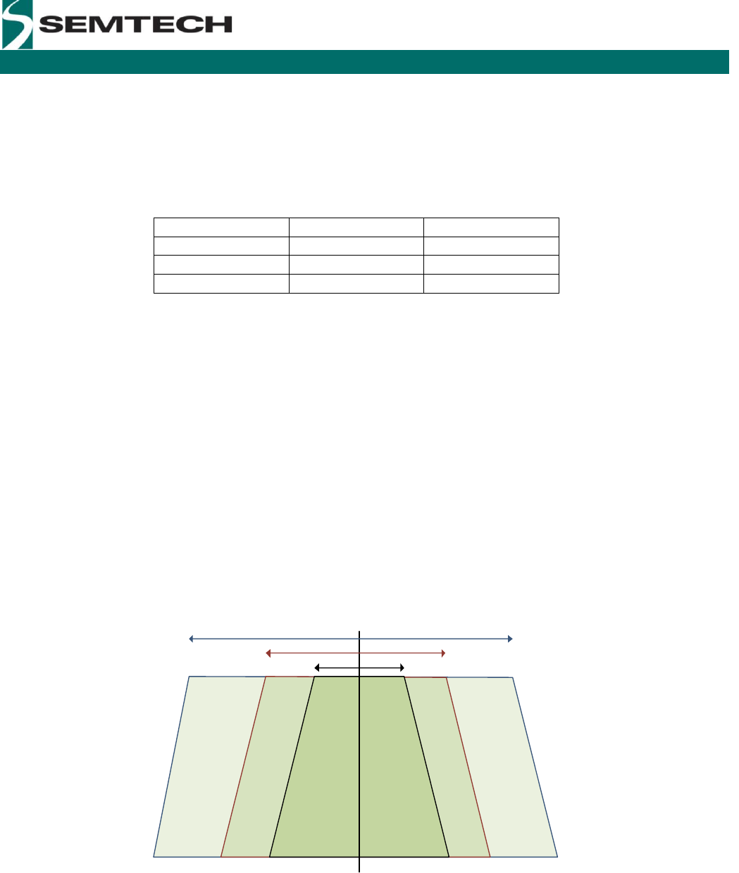
Here we take the example of the SX1272, which has three programmable bandwidth settings 500 kHz, 250 kHz and
125 kHz (as shown below). (The SX1276 has bandwidths from 500 kHz to as low as 7.8 kHz).
fc
500 kHz
250 kHz
125 kHz
Figure 1. The LoRa Bandwidth Corresponds to the Double Sided Transmit Spectrum Bandwidth
WIRELESS & SENSING
Revision 1 July 2013 © 2013 Semtech Corporation
5
SX1272/3/6/7/8
LoRa Modem Design Guide
For a fixed spreading factor the influence of bandwidth on the resulting time on air and sensitivity are shown in the
table below for a 10 byte payload packet:
Table 3. Influence of BW on Time on Air and Sensitivity (CR=2, SF=10)
BW
Time on air [ms]
Sensitivity [dBm]
125
264.2
-132
250
132.1
-129
500
66
-126
Examination of the basic design criterion of bandwidth and spreading factor allow quick evaluation of the suitability
of LoRa for a given application. However, to optimize design performance there are other design criteria that must
also be considered.
3 Advanced LoRa Design Parameters
In addition to the use of spreading factor and bandwidth there are other design variables that the designer must
consider when implementing a LoRa radio link. These are of particular importance when optimizing the robustness
to interference and time on air of the LoRa transmission.
3.1 Forward Error Correction
The LoRa modem also employs a form of Forward Error Correction (FEC) that permits the recovery of bits of
information due to corruption by interference. This requires a small overhead of additional encoding of the data in
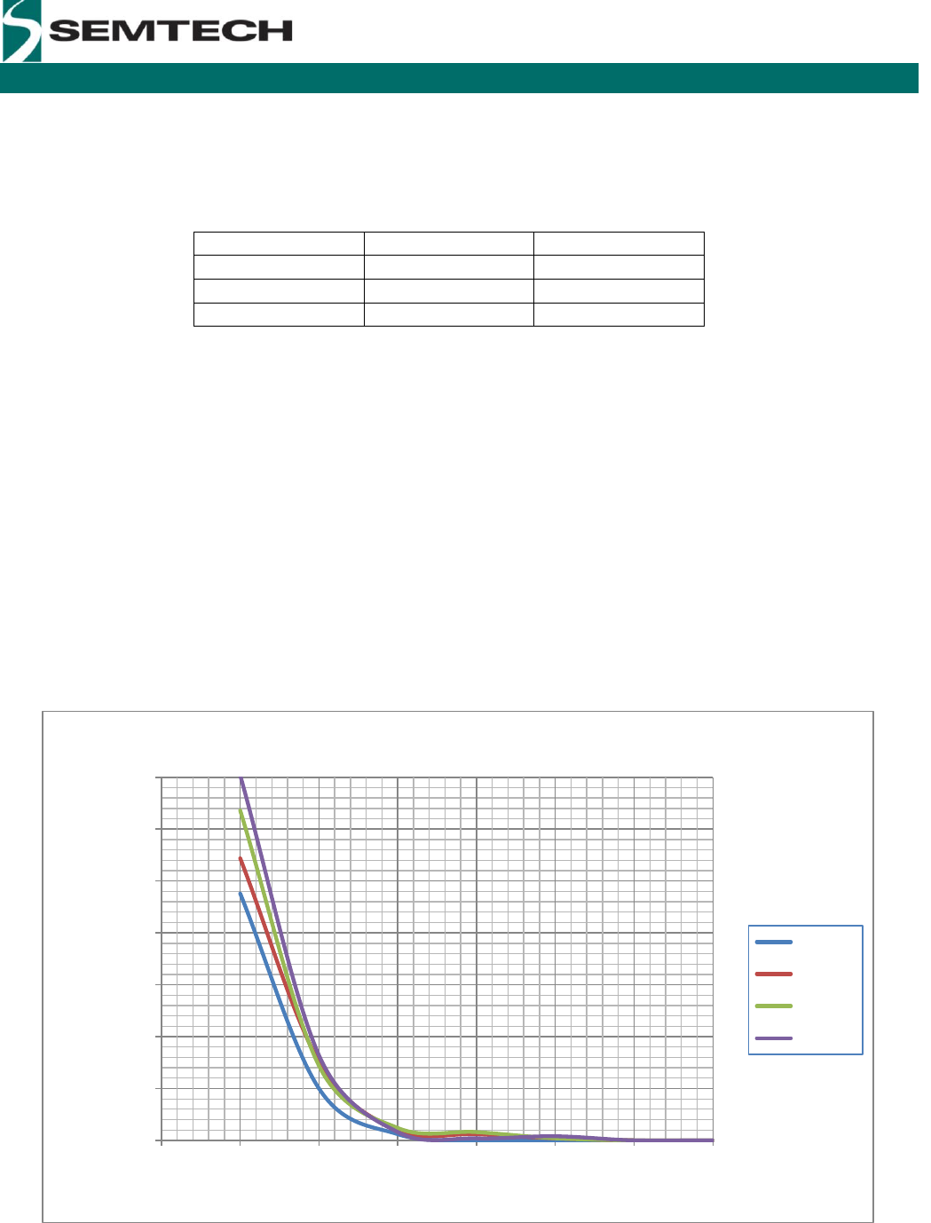
the transmitted packet. Depending upon the coding rate selected, the additional robustness attained in the presence
of thermal noise alone is shown in the family of curves below.
Figure 2. Influence of Coding Rate on Sensitivity (SF = 7, BW = 125 kHz, 13 Byte Payload)
0.00%
5.00%
10.00%
15.00%
20.00%
25.00%
30.00%
35.00%
-127 -126 -125 -124 -123 -122 -121 -120
PER (%)
Indicated Input Power (dBm)
Sensitivity as a Function of Code Rate
CR = 4/5
CR = 4/6
CR = 4/7
CR = 4/8
WIRELESS & SENSING
Revision 1 July 2013 © 2013 Semtech Corporation
6
SX1272/3/6/7/8
LoRa Modem Design Guide
The real performance gain of FEC, however, is in the presence of bursts of interference. If the radio link is likely to
be subject to such interference, the use of FEC should be evaluated.
The table below then shows how the increase in coding rate influences time on air for a fixed bandwidth of 250 kHz
at SF = 10.
Table 4. Influence of CR on Time on Air (SF=10, BW=250 kHz)
CR
Time on air [ms]
1
123.9
2
132.1
4
148.5
3.2 Hardware Implementation
The receiver RF connection method will further influence the receiver sensitivity and the header mode has an impact
on the time on air. The effect of the header mode is discussed in Section 4.
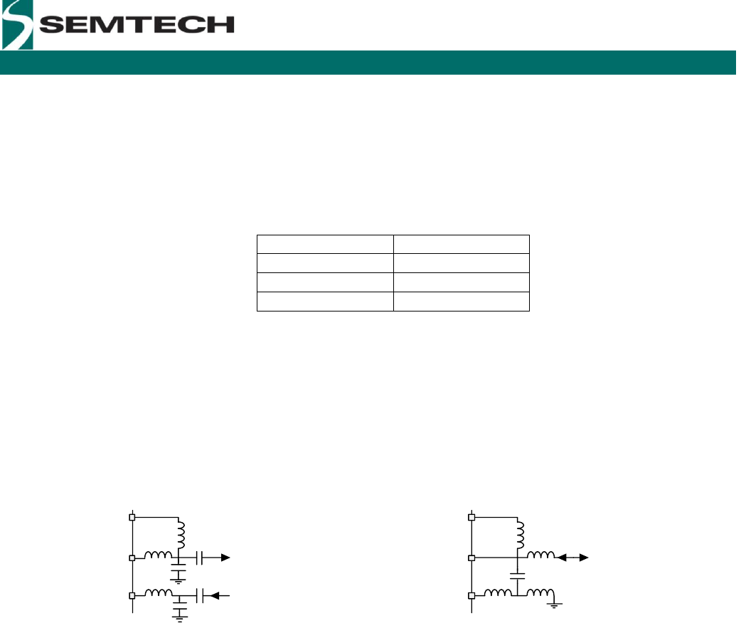
Two receiver input connection, RFI, configurations are possible with the SX1272/3/3/6/7/8. The image below shows
both configurations. Optimal sensitivity performance (by reduction of noise figure, NF, of Equation 2) is possible by
employing individual RF and Tx paths, using separate antennas or an RF switch for single antenna operation.
VR_PA
RFO
RFI
VR_PA
RFO
RFI
Tx
Rx
TRx
Figure 3. Individual RF transmit and receive paths (left) provides better sensitivity than the single shared
TRx path (right).
3.3 Low Data Rate Optimisation Mode & Header Mode
The final two factors that influence the time on air of the packet are two operational modes connected to the modem
and packet settings of the modem. To understand their influence it is necessary to examine the format of the LoRa
packet.
WIRELESS & SENSING
Revision 1 July 2013 © 2013 Semtech Corporation
7
SX1272/3/6/7/8
LoRa Modem Design Guide
4 The LoRa Packet Format & Time On Air
To effectively manage the regulatory and system level design constraints of time on air and receiver sensitivity, it is
hence necessary to be able to calculate the time on air of a given modem configuration. The precise formulae are
given below.
For calculation of the time on air it is convenient to define symbol duration, . This is the time taken to send
chips at the chip rate so, recalling that the bandwidth defines the chip rate, it is given by:
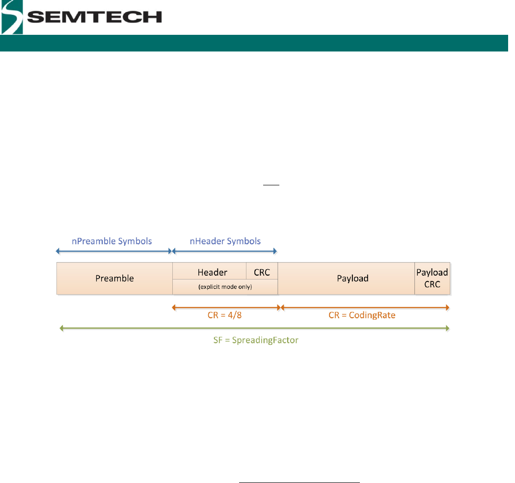
The packet comprises several elements, as shown in the following image.
Figure 4. LoRa Modem Packet formatting.
Common to all modem configurations is a sequence of preamble, whose duration is given by:
Where is the number of programmed preamble symbols. The number of symbols that make up the packet
payload and header is given by:
With the following dependencies:
PL Is the number of payload bytes.
SF The spreading factor
H = 0 when the header is enabled and H = 1 when no header is present.
DE = 1 when the low data rate optimization is enabled , DE = 0 for disabled.
Is the coding rate from 1 to 4
It follows that if the time on air requires reduction, and the packet length is known in advance, then the header
information can be removed. The payload duration is then the symbol period multiplied by the number of payload
symbols.
The time on air, or packet duration, is simply then the sum of the preamble and payload duration:
WIRELESS & SENSING
Revision 1 July 2013 © 2013 Semtech Corporation
8
SX1272/3/6/7/8
LoRa Modem Design Guide
Here we can see that, in the narrow band regime, the LoRa packet can have a significant duration. To avoid issues
surrounding drift of the crystal reference oscillator due to either temperature change or motion, the low data rate
optimization bit is used. Specifically for 125 kHz bandwidth and SF = 11 and 12, this adds a small overhead to
increase robustness to reference frequency variations over the timescale of the LoRa packet.
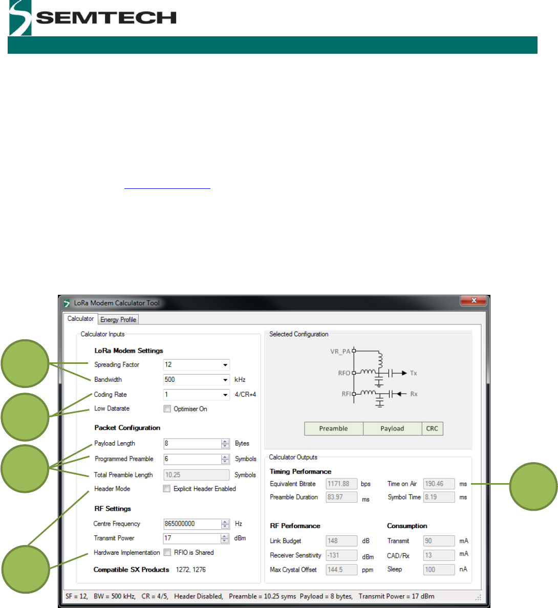
5 LoRa Calculator
Note that in order to simplify design decisions using the LoRa modem there is a software planning tool that allows
the quick evaluation of the LoRa modem configuration and the resulting time on air and sensitivity performance. This
can be downloaded from www.semtech.com.
The image below shows the main display of the LoRa calculator. Here we see that all of the design variables of this
guide can be modified and the resultant RF and time on air performances are calculated without the need to
manually calculate the quantities of the design equations of both this guide and the datasheet.
For convenience the image is indexed with the Section number of this guide that discusses that feature. For
information on other parameters, please consult the product datasheet.
Figure 5. The LoRa Calculator Interface.
2
3
4
4
3

WIRELESS & SENSING
Revision 1 July 2013 © 2013 Semtech Corporation
9
SX1272/3/6/7/8
LoRa Modem Design Guide
Contact Information
© Semtech 2013
All rights reserved. Reproduction in whole or in part is prohibited without the prior written consent of the
copyright owner. The information presented in this document does not form part of any quotation or contract, is
believed to be accurate and reliable and may be changed without notice. No liability will be accepted by the
publisher for any consequence of its use. Publication thereof does not convey nor imply any license under
patent or other industrial or intellectual property rights. Semtech assumes no responsibility or liability
whatsoever for any failure or unexpected operation resulting from misuse, neglect improper installation, repair
or improper handling or unusual physical or electrical stress including, but not limited to, exposure to
parameters beyond the specified maximum ratings or operation outside the specified range.
SEMTECH PRODUCTS ARE NOT DESIGNED, INTENDED, AUTHORIZED OR WARRANTED TO BE
SUITABLE FOR USE IN LIFE-SUPPORT APPLICATIONS, DEVICES OR SYSTEMS OR OTHER CRITICAL
APPLICATIONS. INCLUSION OF SEMTECH PRODUCTS IN SUCH APPLICATIONS IS UNDERSTOOD TO
BE UNDERTAKEN SOLELY AT THE CUSTOMER’S OWN RISK. Should a customer purchase or use Semtech
products for any such unauthorized application, the customer shall indemnify and hold Semtech and its officers,
employees, subsidiaries, affiliates, and distributors harmless against all claims, costs damages and attorney
fees which could arise.
Semtech Corporation
Advanced Communications and Sensing Products Division
200 Flynn Road, Camarillo, CA 93012
Phone: (805) 498-2111 Fax: (805) 498-3804
