Low Profile Deep Well Installation Manual
Low-Profile-Deep-Wel.. Low-Profile-Deep-Well-Installation-Manual
User Manual: Pdf Low-Profile-Deep-Well-Installation-Manual
Open the PDF directly: View PDF ![]() .
.
Page Count: 7
BISON DEEP WELL LOW PROFILE HAND PUMP
INSTALLATION INSTRUCTIONS
Inspect the contents of the box to be sure everything you ordered
has been received. Be sure to check the serial number on the pump
head assembly to verify it matches the serial number on your
invoice/packing list.
Read All Instructions Before Beginning the Actual Pump
Installation
DO'S & DON'TS FOR PUMP INSTALLATION
DO NOT begin the installation without first reading the entire
instruction booklet, studying and understanding the diagrams.
DO NOT begin the installation of the pump without first
checking the water level in your well to be sure you have enough
pipe and rod to install the pump cylinder at least 20’ below the
static water level.
DO NOT over tighten the 1 ¼” pvc piping into the pvc female
pipe thread bell end of the sch. 120 plastic pipe. The pipe can be
threaded with a pair of pliers or a 12” pipe wrench.
DO NOT use large pipe wrenches for the assembly of the pvc
piping.
DO NOT install the pump during a thunder and lightning storm.
Be aware of any overhead power lines.
DO NOT hurry the installation of your pump. Think before you
act.
DO NOT screw multiple lengths of pipe and rod together, laid
out on the ground, and then try to lift all the pipe and rod to a
vertical position to lower it into the well.
DO NOT lower the pump and pipe sections into the well by the
safety rope. Grab the pipe securely with both hands and lower
the pipe, cylinder and safety rope into the well 8’ at a time, using
WARNING: All pumps are shipped with a
stainless steel male pipe thread hose adapter.
You may want to check local codes to see if a
hose Bibb backflow preventer should be used
when connecting a hose to the hose adapter on
the pump. CONSULT YOUR LOCAL PLUMBING
CODE!!
BISON PUMPS
PO BOX 977
HOULTON, ME 04730
INFO@BISONPUMPS.COM
WWW.BISONPUMPS.COM
1-800-339-2601
the paddle as a stop. The safety rope should be tied off to a
secure object, i.e. the well casing so that it can be lowered slowly
and safely.
If you are going down more than 14 lengths of
pipe and rod, mechanical means of lowering
them into the well is recommended along with
the Bison lifting tool and adjustable rod. Gloves
are recommended when handling rope.
DO read the installation instructions and study all diagrams.
Begin the installation when you are confident you understand the
instructions completely.
DO have another person help you with the installation. If you are
not comfortable with the mechanics of the installation, we
suggest you hire the services of a licensed plumber, pump
installer or well driller.
DO make sure one end of the safety rope is securely tied to the
cylinder and the other end to a secure object such as the well
casing.
DO turn the electricity off to the electric submersible pump
before beginning the installation if you are installing the hand
pump in the same well as the electric submersible.
DO use the paddle provided to aid in the installation of your
pump.
DO thread the ends of the rods together so they butt up against
each other then tighten the lock nuts with ½” & 9/16” open end
wrenches.
DO use Teflon tape on any male pipe threads which are not
already taped before you screw them together.
Note: Bison Pumps and any of its affiliates will not be held
responsible for defects or damage to this product due to
inexperienced or negligent workmanship during installation of
the pump and associated parts.
INSTALLATION INSTRUCTIONS
(Bison Pumps recommend two people be involved for ease of
installation.)
REQUIRED TOOLS: ½” and 9/16” open end wrenches, pliers,
vice grips
STEP #1 - Make sure you have read and understand the
installation instructions.
STEP #2 - If you are installing the pump in a well casing
specifically dedicated to a hand pump, go to STEP #6.
STEP #3 - If you are installing your Bison Deep Well Hand Pump
in the same casing as an electric submersible pump or piping
which connects to a jet pump, see note at the end of instructions:
STEP #4 - Remove the existing well cover or well seal, whichever
you may have and set it aside. *If you have a submersible pump,
be sure to shut the electricity off to the pump before beginning
the installation of the Bison Hand Pump*
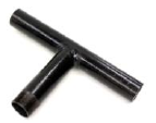
If you are installing in the
same casing as an electric
submersible pump, in most
cases the electrical wires exit
the top of the casing then run
back down to the ground with
a piece of conduit.
Side-Mount Conduit Ell
Using a bi-metal hole saw, drill a hole through
the side of the well casing 3-4” below the top
of the casing then install the electrical conduit ell (BPN-375C – offered as an
accessory by Bison Pumps).
This will allow you to pass the wire from outside the casing through the conduit
ell to the inside of the casing where you can re-connect the wires to the
submersible pump.
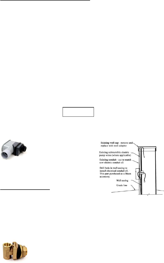
STEP #5 - You may need to lift your submersible
pump or deep well jet assembly and foot valve in
order to pass the Bison Pump Cylinder by the
Pitless adapter (pictured) in your well casing. To
BPN-375C
BPN-375C
avoid this step, you may want to select a smaller Bison Pump
cylinder.
STEP #6 - Remove the Bison Pump Cylinder from the box.
Remove the red plastic plug from the pump cylinder and discard.
STEP #7 - Start the assembly of your Bison Pump. If you have
purchased a complete kit, you will notice the safety rope has been
securely tied to the pump cylinder when you received your pump.
Tie the other end of the rope to a secure object, i.e. the well casing,
temporarily. The safety rope will be tied to the 1/4" eye bolt on the
underside of the well adapter in step #13. (See Detail "A").
STEP #8 – Note: when you receive your rod, one of the lock nuts
will already be tightened securely. Assemble your first piece of
3/8" stainless steel rod to the rod protruding from the cylinder.
Pull the rod in the Bison Pump Cylinder all the way to the top to
connect the first rod. As you assemble the stainless steel rod, screw
the rod into the coupling until the two rod ends butt up against
each other. Use pliers to lock the rods together. Be sure to tighten
the 3/8" stainless steel jam nuts on both sides of the rod coupling.
We recommend as you connect each rod thereafter, thread on the
Rod Retrieval Tool to pull the rod up as far as you can and connect
a pair of vice grips to hold the rod in place while you secure the
coupling and tighten the lock nuts. This should be done each time.
STEP #9 - Screw the PVC male end of the first 8' section of pipe
into the female thread in the head of the pump cylinder. Use
Teflon tape or pipe dope compound on all pipe threads.
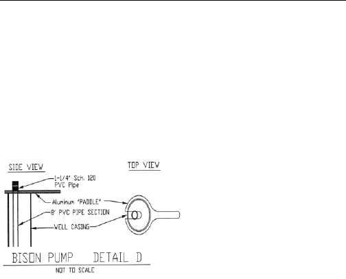
STEP #10 - Lower the cylinder and
the first 8' section of piping into the
well. Using the slotted aluminum
paddle you received with your
pump, slide it under the PVC bell
end of the pipe and rest the paddle
on top of the well casing. This will
hold the pipe in place while you assemble the rod and pipe.
Continue to connect the 3/8" rod sections and PVC pipe until you
have lowered all of the pipe into the well.
STEP #11 – Attach the rod retrieval tool to the last section of rod
and pull all the way up. Attach vice grips to hold the rod up from
the pipe.
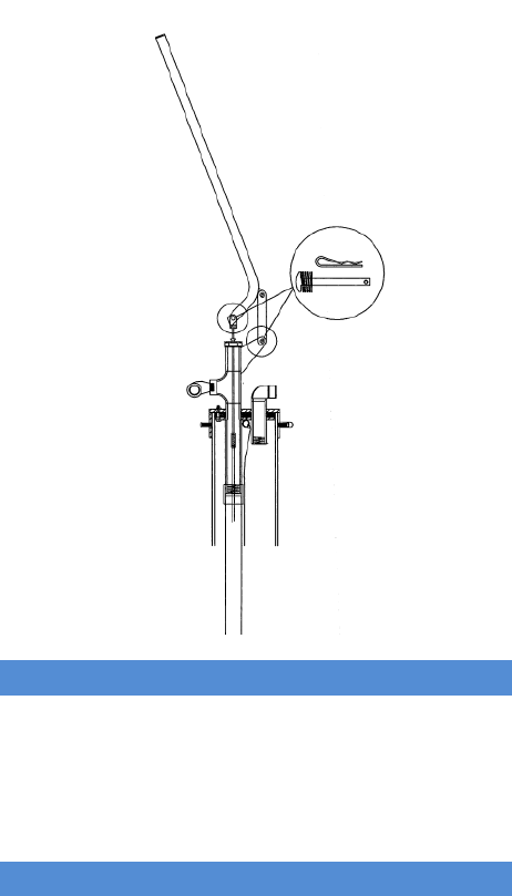
STEP #12 - Remove the 3/8" Allen head shoulder bolt at the top of
the handle connection to the lift rod (See Detail "A").
STEP #13 - Screw the 3/8" rod that is protruding from the bottom
of the well head into the last rod sticking out of the PVC pipe.
Tighten these rods together using plier or vice grips and a 9/16”
wrench. Thread the jam nut up against the lift rod and tighten.
Screw the Well Head into the PVC bell end of the pipe. (This step
is performed more easily with two people.)
STEP #14 - Tie the end of the safety rope to the 1/4" eye bolt on
the underside of the well adapter (See Detail "A"). Set the well
adapter and pump head onto the casing, squarely and straight; then
evenly tighten the (4) stainless steel nuts on top of the well adapter.
Tighten the (4) allen head set screws on the well adapter to secure
it to the casing. Check to make sure the pump head is square and
straight on the well casing; making sure all the bolts are tight.
Place the (4) rubber boots on the allen head set screws of the well
adapter. Reconnect the pump handle to the lift rod with the 3/8"
Allen head shoulder bolt. Do not over tighten the shoulder bolt
as this will cause the pump handle to pump hard.
STEP #15 – Attach the handle using the fasteners which are
shipped on the handle (See photo for correct placement).
STEP #16 - Pump the handle on your Bison Deep Well Hand
Pump and enjoy a cold glass of water directly from your well.
If you are currently treating the water in your home, remember
that the water you pump directly from your well is untreated
water. Bison Pumps recommends that you have your water tested
to be sure that it is good quality potable drinking water.

NOTE: FOR LOW PROFILE PUMPS WITH
SUBMERSIBLE PUMP CONNECTIONS: The well adapter
includes the following connections:
3/4” FIPS hole for electrical wires
1 ¼” male nipple under adapter for piping to
submersible
1” FIPS adapter to facilitate piping to the house supply.
Consult a licensed plumber or well professional for further
assistance.
Additional Installation Tips:
1. If you live in an area that experiences freezing
temperatures, be sure to drill an 1/8" hole in the 1 1/4" PVC
pipe approximately 6' to 7' below the well adapter. If you
experience freezing temperatures that could have a frost
penetration deeper than 7', drill the hole lower on the 1 1/4"
PVC pipe.
2. On the top of the pump body is a gland nut which the lift
rod slides through when pumping your hand pump. This nut
should be hand tight. If there is leaking through this nut
when pressurizing a vessel, then tighten this gland nut a
quarter turn. Do not overtighten as this may cause
difficulty in pumping your hand pump or damage to your
lift rod.
3. If you experience any deficiencies or malfunction of your
Bison Deep Well Hand Pump, please call 1-800-339-2601
for assistance and answers to your specific questions or
concerns.
4. Be sure to check local plumbing codes in your area to be
verify that your installation meets all code
requirements.
5. You will notice a brass hose bibb cap is shipped with the
hose bibb adapter. This cap can be tightened to the hose
bibb to keep insects out when the pump is not in use.
Caution: In the winter months, be sure to let the pump
drain back completely before securing the brass cap.
You may not want to use the cap during the winter.
6. Thank you for investing in a Bison Deep Well Hand Pump.
BPN-RPK
Repair Kit DW Hand Pump
BPN-006
Wash Flat Nylon 3/8" x1-1/16
BP-GN
Gland Nut
BPN-069
Nut Ny-locknut 316 3/8"-16
BPN-702
Roll Pin
Part Numbers
Options DW Hand Pump
BPN-330C
Check Valve and Pressure Gauge
BP-PK
Pressurizing Kit for spout
