Report For ACSS1407139 01 August 11, 2015 LVD Of 561044
2016-04-12
: Pdf Lvd Of 561044 LVD_of_561044 CertsReports 561044 ProductFiles
Open the PDF directly: View PDF ![]() .
.
Page Count: 93
Report No.: ACSS1407139-01
Page 2 of 71
TRF NO. SRENIT-01V1.3
AUDIX TECHNOLOGY (SHENZHEN) CO., LTD
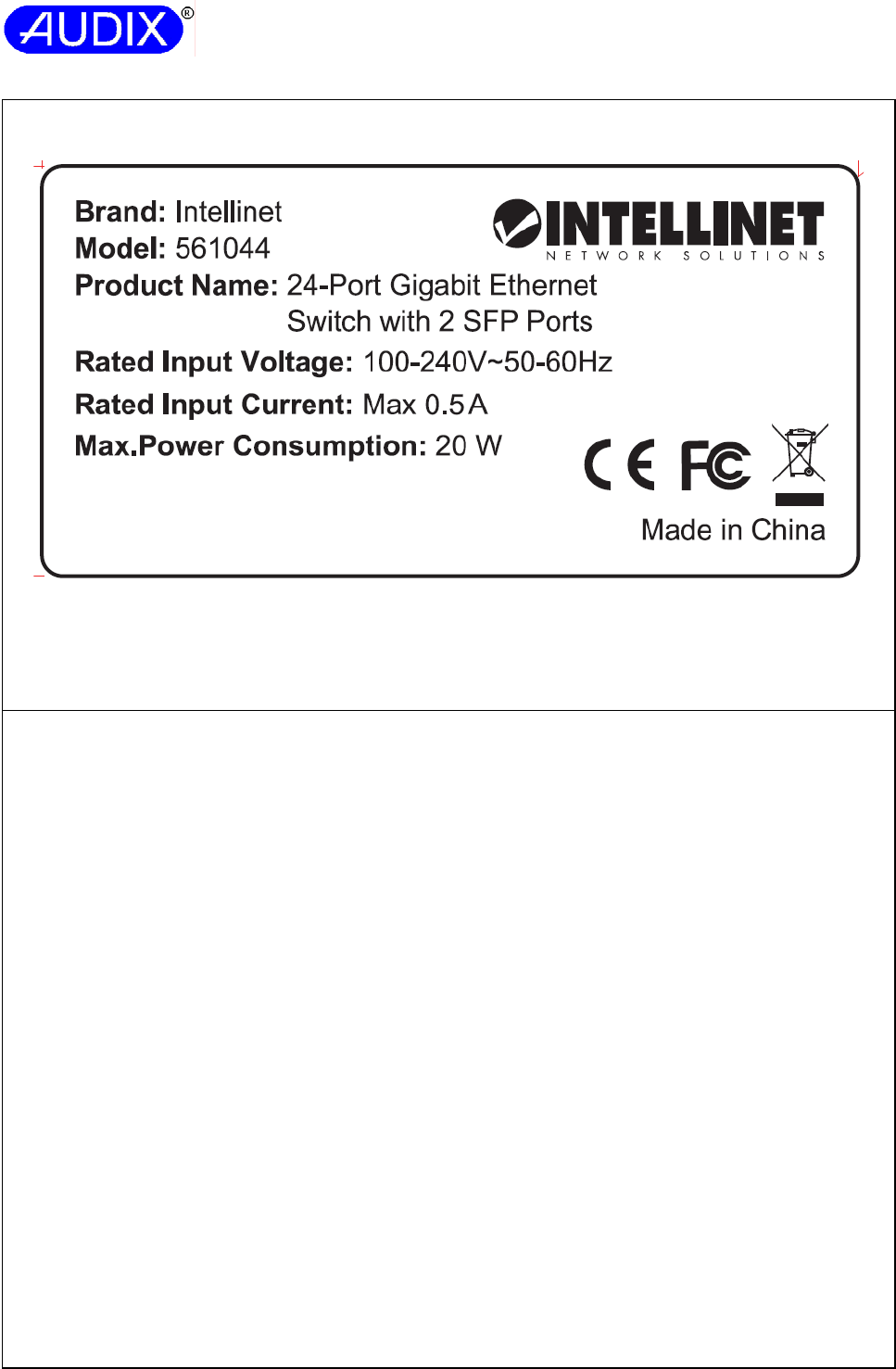
Copy of marking plate
1. Artwork of Marking Label.
Note(s):
- The marking plate(s) artwork appended to this report may be only a draft. The use of certification marks
on a product must be authorized by the respective NCBs that own these marks.
- The height of CE symbol should be 5.0 mm Min., the height of WEEE symbol should be 7.0mm Min..
Summary of testing:
Following symbols and abbreviations may be used in this test report.
F= Function Insulation
B= Basic Insulation
S= Supplementary Insulation
D/R= Double or Reinforced Insulation
S/C= Short-Circuit
O/C= Open-Circuit
O/L= Over-Load
B/L= Block
IP= Internal protection operated (list component)
CT= Constant temperatures were obtained
CD= Components damaged (list damaged components)
NCD= No components damaged (list damaged components)
NB= No indication of dielectric breakdown
NC= Cheesecloth remained intact
NT= Tissue paper remained intact
NH= No hazard occured
Pri.= Primary
Sec.= Secondary
PCB= Printed Circuit Board
PSU= Power Supply Unit
EUT= Equipment Under Test
EPS= External Power Supply

Report No.: ACSS1407139-01
Page 3 of 71
TRF NO. SRENIT-01V1.3
AUDIX TECHNOLOGY (SHENZHEN) CO., LTD
Test item particulars:
Equipment mobility………........................................ …: [x] movable [] hand-held [] transportable
[] stationary [] for building-in [] direct plug-in
[] rack-mounted
Connection to the mains ………………………..………: [x] pluggable equipment: [x] type A [] type B
[] permanent connection
[x] detachable power supply cord
[] non-detachable power supply cord
[] not directly connected to the mains
Operation condition …………………………………..…: [x] continuous
[] rated operating / resting time:
Access location ......................................................... : [x] operator accessible
[] restricted access location
Over voltage category (OVC) ................................... : [] OVC I [x] OVC II [] OVC III [] OVC IV
[ ] other:
Mains supply tolerance (%) or absolute mains supply
values ........................................................................ :
+6%, -10%
Tested for IT power systems .................................... : [] Yes [x] No
IT testing, phase-phase voltage (V) .......................... : N/A
Class of equipment ................................................... : [x] Class I [] Class II [] Class III
[] Not classified
Pollution degree (PD) ............................................... : [] PD 1 [x] PD 2 [] PD 3
IP protection class .................................................... : IP20
Altitude during operation (m) .................................... : Up to 2000m
Altitude of test laboratory (m) ................................... : Up to 2000m
Mass of equipment (kg) ……………………………….: Approx. 2.42kg
Maximum operation ambient …………………...………: 40°C
Possible test case verdicts:
- Test case does not apply to the test object ………….: N (Not Applicable)
- Test object does meet the requirement………………: P (Pass)
- Test object does not meet the requirement………….: F (Fail)
Testing:
Date of receipt of test item……………………………...: N/A
Date(s) of performance of tests ………………………..: N/A
General remarks:
The test results presented in this report relate only to the object tested.
This report shall not be reproduced, except in full, without the written approval of the Issuing testing
laboratory.
"(See Attachment #)" refers to additional information appended to the report.
"(See appended table)" refers to a table appended to the report.
Throughout this report, a point is used as the decimal separator.
List of test equipment must be kept on file and available for review.

Report No.: ACSS1407139-01
Page 4 of 71
TRF NO. SRENIT-01V1.3
AUDIX TECHNOLOGY (SHENZHEN) CO., LTD
GENERAL PRODUCT INFORMATION:
Report summary
1. The EUT is a 24-Port 10/100/1000Mbps + 2 SFP Green Ethernet Switch, this model used two power
boards (Power board models: G0682 or TPT18S12A), electronic components mounted on Min. V-1 PCB
and enclosed in metal enclosure..
2. The original test report (ACSS1407139) was amended on August 11, 2015 with the following
modifications:
1) Revise product name and model name;
2) Revise applicant’s name and address;
3) Revise Manufacturer’s name and address;
4) Revise trademark;
5) Change the current of rating from 0.31A max. to Max. 0.5A.
3. Since above reasons, no test is necessary. All the test data were fully reproduced from original report
(ACSS1407139).
4. This amendment report shall be read in conjunction with original test report (ACSS1407139).
Report modify history
No. Report No. /
issued date
Model No. Modification to the appliances:
1. ACSS1407139/
August 27, 2014
FR-S1026GF-C Original test report.
Additional information
N/A
Attached enclosure(s)
Attachment A: 11 pages of Photo-Documentation.
Attachment B: 4 pages of Circuit Diagram and PCB Layout.
Attachment C: 6 pages of Transformer Specification.
Report No.: ACSS1407139-01
Page 5 of 71
EN 60950-1
Clause Requirement + Test Result - Remark Verdict
TRF NO. SRENIT-01V1.3
AUDIX TECHNOLOGY (SHENZHEN) CO., LTD
1 GENERAL P
1.5 Components P
1.5.1 General P
Comply with IEC 60950-1 or relevant component
standard
(See appended table 1.5.1) P
1.5.2 Evaluation and testing of components Certified components are
used in accordance with their
ratings, certifications and they
comply with applicable parts
of this standard.
Components not certified are
used in accordance with their
ratings and they comply with
applicable parts of IEC
60950-1 and the relevant
component standard.
Components, for which no
relevant IEC-standard exists,
have been tested under the
conditions occurring in the
equipment, using applicable
parts of IEC 60950-1.
P
1.5.3 Thermal controls No thermal controls. N
1.5.4 Transformers Transformers are used
suitable for their intended
application and comply with
the relevant requirements of
the standard and particularly
with these of Annex C.
P
1.5.5 Interconnecting cables Interconnection cables do not
present a hazard.
P
1.5.6 Capacitors bridging insulation Power board (model G0682):
X2 capacitors and Y1
capacitors are used to be
according to IEC 60384-14.
Power board (model
TPT18S12A): X2 capacitors
and Y1 capacitors and Y2
capacitors are used to be
according to IEC 60384-14.
P
1.5.7 Resistors bridging insulation Refer to below: P
1.5.7.1 Resistors bridging functional, basic or supplementary
insulation
Power board (model G0682):
Bleeder resistors are bridging
function insulation.
Power board (model
TPT18S12A): Bleeder
resistors are bridging function
insulation.
P
Report No.: ACSS1407139-01
Page 6 of 71
EN 60950-1
Clause Requirement + Test Result - Remark Verdict
TRF NO. SRENIT-01V1.3
AUDIX TECHNOLOGY (SHENZHEN) CO., LTD
1.5.7.2 Resistors bridging double or reinforced insulation
between a.c. mains and other circuits
N
1.5.7.3 Resistors bridging double or reinforced insulation
between a.c. mains and antenna or coaxial cable
N
1.5.8 Components in equipment for IT power systems N
1.5.9 Surge suppressors P
1.5.9.1 General For Power board (model
G0682): approved Varistor
(MOV1) comply with Annex Q
used in primary circuit.
For Power board (model
TPT18S12A): approved
Varistor (MOV1) comply with
Annex Q used in primary
circuit.
P
1.5.9.2 Protection of VDRs A fuse is connected in series
with VDR.
P
1.5.9.3 Bridging of functional insulation by a VDR Approved Varistor located
between mains lines.
P
1.5.9.4 Bridging of basic insulation by a VDR N
1.5.9.5 Bridging of supplementary, double or reinforced
insulation by a VDR
N
1.6 Power interface P
1.6.1 AC power distribution systems TN Power System P
1.6.2 Input current The steady state input current
of the equipment did not
exceed the RATED
CURRENT by more than 10%
under NORMAL LOAD.
(see appended table 1.6.2)
P
1.6.3 Voltage limit of hand-held equipment This appliance is not hand-
held equipment.
N
1.6.4 Neutral conductor Components connected
between phases and earth
are rated certified for a
working voltage: 250V.
P
1.7 Marking and instructions P
1.7.1 Power rating Rating marking readily visible
to operator.
P
Rated voltage(s) or voltage range(s) (V) ................. : Refer to page 2 P
Symbol for nature of supply, for d.c. only .............. : N
Rated frequency or rated frequency range (Hz) ... : Refer to page 2 P
Rated current (mA or A) ........................................ : Refer to page 2 P
Report No.: ACSS1407139-01
Page 7 of 71
EN 60950-1
Clause Requirement + Test Result - Remark Verdict
TRF NO. SRENIT-01V1.3
AUDIX TECHNOLOGY (SHENZHEN) CO., LTD
Manufacturer’s name or trade-mark or identification
mark ...................................................................... :
Refer to page 2 P
Model identification or type reference ................... : Refer to page 2 P
Symbol for Class II equipment only ......................... : Class I equipment. N
Other markings and symbols ................................... : Other symbols do not affect
safety.
P
1.7.2 Safety instructions and marking Refer to below: P
1.7.2.1 General P
1.7.2.2 Disconnect devices Appliance coupler as
disconnect devices.
N
1.7.2.3 Overcurrent protective device Pluggable equipment type A N
1.7.2.4 IT power distribution systems Shall be provided when
submitted for national
approval (for Norway).
N
1.7.2.5 Operator access with a tool All areas containing hazards
are inaccessible to the
operator.
N
1.7.2.6 Ozone N
1.7.3 Short duty cycles The equipment is intended for
continuous operation.
N
1.7.4 Supply voltage adjustment ................................... : No voltage selector. N
Methods and means of adjustment; reference to
installation instructions ......................................... :
N
1.7.5 Power outlets on the equipment .......................... : No standard power outlet. N
1.7.6 Fuse identification (marking, special fusing
characteristics, cross-reference) ......................... :
Power board (model G0682):
“F1 T3.15A, 250V~” is
marked adjacent to fuse on
PCB.
Power board (model
TPT18S12A): “F1 T2A
250VAC” is marked adjacent
to fuse on PCB.
P
1.7.7 Wiring terminals Refer to below: P
1.7.7.1 Protective earthing and bonding terminals .......... : Appliance inlet is provided.
The symbol (IEC 60417-5019)
was marked on the appliance
inlet.
P
1.7.7.2 Terminals for a.c. mains supply conductors N
1.7.7.3 Terminals for d.c. mains supply conductors N
1.7.8 Controls and indicators Refer to below: P
1.7.8.1 Identification, location and marking ..................... : The function of indicators
affecting safety is obvious
without knowledge of
language.
P
Report No.: ACSS1407139-01
Page 8 of 71
EN 60950-1
Clause Requirement + Test Result - Remark Verdict
TRF NO. SRENIT-01V1.3
AUDIX TECHNOLOGY (SHENZHEN) CO., LTD
1.7.8.2 Colours ................................................................ : Colours are used for
functional indications, not
involved safety.
P
1.7.8.3 Symbols according to IEC 60417 ........................ : No such controls. N
1.7.8.4 Markings using figures ....................................... : No controls use figures. N
1.7.9 Isolation of multiple power sources .................... : Only one connection
supplying hazardous voltages
and energy levels to the
equipment.
N
1.7.10 Thermostats and other regulating devices ......... : No thermostats or other
regulating devices.
N
1.7.11 Durability The marking was subjected to
the permanence of marking
test. After the test, there was
no damage to the marking.
The marking did not fade.
P
1.7.12 Removable parts No removable parts. N
1.7.13 Replaceable batteries ......................................... : No battery in the equipment. N
Language(s) ......................................................... : —
1.7.14 Equipment for restricted access locations ........... : Equipment not intended for
installation in RAL.
N
2 PROTECTION FROM HAZARDS P
2.1 Protection from electric shock and energy hazards P
2.1.1 Protection in operator access areas P
2.1.1.1 Access to energized parts All accessible circuits are
SELV circuits.
P
Test by inspection .................................................... : Complies. P
Test with test finger (Figure 2A) ........................... : The test finger was unable to
contact bare hazardous parts.
P
Test with test pin (Figure 2B) ................................ : The test pin was unable to
contact bare hazardous parts.
P
Test with test probe (Figure 2C) ........................... : No TNV circuit in the
equipment.
N
2.1.1.2 Battery compartments No battery compartments. N
2.1.1.3 Access to ELV wiring No internal wiring at ELV
accessible to the operator.
N
Working voltage (Vpeak or Vrms); minimum
distance through insulation (mm)
—
2.1.1.4 Access to hazardous voltage circuit wiring No hazardous voltage wiring
in operator accessible area.
N
2.1.1.5 Energy hazards ........................................................ : No energy hazard in operator
access area. Checked by
means of test finger.
P
Report No.: ACSS1407139-01
Page 9 of 71
EN 60950-1
Clause Requirement + Test Result - Remark Verdict
TRF NO. SRENIT-01V1.3
AUDIX TECHNOLOGY (SHENZHEN) CO., LTD
2.1.1.6 Manual controls No shafts of knobs etc. N
2.1.1.7 Discharge of capacitors in equipment The capacitance of the input
circuit exceed 0.1 μF, the
measurement was performed
in the fuse-in condition.
P
Measured voltage (V); time-constant (s) .................. : Power board (model G0682):
Time constant is measured,
Max. 220ms, 358.3Vpk (37%
of Vpk is 132.6V), C4=0.22μF
and resistor
R1=R2=R8=R31=1MΩ, no
load (Vin=254.4V).
Power board (model
TPT18S12A): Time constant
is measured, Max. 160ms,
358.3Vpk (37% of Vpk is
132.6V), C2=0.22μF and
resistor
R1=R2=R4=R5=750KΩ, no
load (Vin=254.4V).
—
2.1.1.8 Energy hazards – d.c. mains supply N
a) Capacitor connected to the d.c. mains supply .... : N
b) Internal battery connected to the d.c. mains supply
................................................................................... :
N
2.1.1.9 Audio amplifiers ........................................................ : N
2.1.2 Protection in service access areas No unexpected hazards inside
the unit and no unintentional
contact to hazardous areas
likely during service
operations as considering the
equipment disconnected from
mains when servicing.
P
2.1.3 Protection in restricted access locations Equipment not instored for
installation in RAL.
N
2.2 SELV circuits P
2.2.1 General requirements SELV limits are not exceeded
under normal condition and
after a single fault.
P
2.2.2 Voltages under normal conditions (V) .................. : Between any SELV circuit,
42.4V peak or 60Vdc were not
exceeded.
(See appended table 2.2.2)
P
Report No.: ACSS1407139-01
Page 10 of 71
EN 60950-1
Clause Requirement + Test Result - Remark Verdict
TRF NO. SRENIT-01V1.3
AUDIX TECHNOLOGY (SHENZHEN) CO., LTD
2.2.3 Voltages under fault conditions (V) ....................... : Limits of 71V peak or 120Vdc
were not exceeded within 0.2
seconds and limits of 42.4V
peak or 60Vdc were not
exceeded for longer than 0.2
seconds.
(See appended table 2.2.3)
P
2.2.4 Connection of SELV circuits to other circuits ..... : SELV circuits are only
connected to other SELV
circuits.
P
2.3 TNV circuits
No TNV circuit.
N
2.3.1 Limits N
Type of TNV circuits .................................................. : —
2.3.2 Separation from other circuits and from accessible
parts
N
2.3.2.1 General requirements N
2.3.2.2 Protection by basic insulation N
2.3.2.3 Protection by earthing N
2.3.2.4 Protection by other constructions ......................... : N
2.3.3 Separation from hazardous voltages N
Insulation employed ............................................... : —
2.3.4 Connection of TNV circuits to other circuits N
Insulation employed ............................................... : —
2.3.5 Test for operating voltages generated externally N
2.4 Limited current circuits P
2.4.1 General requirements Limits are not exceeded. P
2.4.2 Limit values (See appended table 2.4.2) P
Frequency (Hz) .......................................................... : —
Measured current (mA) ............................................. : —
Measured voltage (V) ................................................ : —
Measured circuit capacitance (nF or µF) ............... : —
2.4.3 Connection of limited current circuits to other
circuits
Connected to SELV P
Report No.: ACSS1407139-01
Page 11 of 71
EN 60950-1
Clause Requirement + Test Result - Remark Verdict
TRF NO. SRENIT-01V1.3
AUDIX TECHNOLOGY (SHENZHEN) CO., LTD
2.5 Limited power sources N
a) Inherently limited output N
b) Impedance limited output N
c) Regulating network limited output under normal
operating and single fault condition
N
d) Overcurrent protective device limited output N
Max. output voltage (V), max. output current (A),
max. apparent power (VA) ..................................... :
—
Current rating of overcurrent protective device (A) .: —
2.6 Provisions for earthing and bonding P
2.6.1 Protective earthing Accessible conductive parts
are reliably connected to
protective earth.
P
2.6.2 Functional earthing Secondary functional earthing
is separated to primary by
reinforced or double
insulation.
P
2.6.3 Protective earthing and protective bonding
conductors
Refer to below: P
2.6.3.1 General P
2.6.3.2 Size of protective earthing conductors No power supply cord
provided.
N
Rated current (A), cross-sectional area (mm2),
AWG ...................................................................... :
—
2.6.3.3 Size of protective bonding conductors Protective bonding conductor
which connect to ground pin
of AC inlet. See cl. 2.6.3.4 for
ground continue test.
P
Rated current (A), cross-sectional area (mm2),
AWG ...................................................................... :
—
Protective current rating (A), cross-sectional area
(mm2), AWG ........................................................... :
—
2.6.3.4 Resistance of earthing conductors and their
terminations; resistance (Ω), voltage drop (V), test
current (A), duration (min) ......................................... :
(See appended table 2.6.3.4) P
2.6.3.5 Colour of insulation .................................................... : No green-and-yellow wire
used.
N
2.6.4 Terminals Refer to below: P
2.6.4.1 General P
Report No.: ACSS1407139-01
Page 12 of 71
EN 60950-1
Clause Requirement + Test Result - Remark Verdict
TRF NO. SRENIT-01V1.3
AUDIX TECHNOLOGY (SHENZHEN) CO., LTD
2.6.4.2 Protective earthing and bonding terminals The earthing terminal in the
appliance inlet is regarded as
the main protective earthing
terminal. The test of sub-
clause 2.6.3.4 was performed
for protective bonding
conductor and their terminals.
P
Rated current (A), type, nominal thread diameter
(mm) .......................................................................... :
The test of cl. 2.6.3.4 is
complied.
⎯
2.6.4.3 Separation of the protective earthing conductor from
protective bonding conductors
The equipment is provided
with an appliance inlet.
P
2.6.5 Integrity of protective earthing Refer to below: P
2.6.5.1 Interconnection of equipment No interconnection of
equipment.
N
2.6.5.2 Components in protective earthing conductors and
protective bonding conductors
There are no switches or
overcurrent protective devices
in the protective earthing /
bonding conductor.
P
2.6.5.3 Disconnection of protective earth It is not possible to disconnect
protective earth without
disconnecting mains; an
appliance coupler will be used
as disconnect device.
P
2.6.5.4 Parts that can be removed by an operator Appliance coupler provided
for the protective earthing
connection is made before
and broken after the
hazardous voltage. No other
operator removable parts.
P
2.6.5.5 Parts removed during servicing Protective earthed parts
cannot be removed in a way
which impair safety.
P
2.6.5.6 Corrosion resistance No risk of corrosion P
2.6.5.7 Screws for protective bonding Adequate connection of
protective bonding.
P
2.6.5.8 Reliance on telecommunication network or cable
distribution system
Neither TNV circuits nor
cable distribution system in
the equipment.
N
2.7 Overcurrent and earth fault protection in primary circuits P
2.7.1 Basic requirements Protective device of building
installation used as against
earth faults, protective device
of integral parts in equipment
used as against excessive
current and short-circuits.
P
Instructions when protection relies on building
installation
N
Report No.: ACSS1407139-01
Page 13 of 71
EN 60950-1
Clause Requirement + Test Result - Remark Verdict
TRF NO. SRENIT-01V1.3
AUDIX TECHNOLOGY (SHENZHEN) CO., LTD
2.7.2 Faults not simulated in 5.3.7 Considered P
2.7.3 Short-circuit backup protection The building installation is
considered as providing
short-circuit backup
protection.
P
2.7.4 Number and location of protective devices ............. : One protective device (fuse)
used in line.
P
2.7.5 Protection by several devices N
2.7.6 Warning to service personnel ................................... : ⎯
2.8 Safety interlocks
No safety interlocks provided.
N
2.8.1 General principles N
2.8.2 Protection requirements N
2.8.3 Inadvertent reactivation N
2.8.4 Fail-safe operation N
2.8.5 Moving parts N
2.8.6 Overriding N
2.8.7 Switches, relays and their related circuits N
2.8.7.1 Separation distances for contact gaps and their
related circuits (mm) ........................................... :
⎯
2.8.7.2 Overload test N
2.8.7.3 Endurance test N
2.8.7.4 Electric strength test N
2.8.8 Mechanical actuators N
2.9 Electrical insulation P
2.9.1 Properties of insulating materials Neither natural rubber,
materials containing asbestos
nor hygroscopic materials are
used as insulation. No driving
belts or couplings used.
P
2.9.2 Humidity conditioning 48Hours. P
Relative humidity (%), temperature (°C) ............... : 95% RH, 30°C. —
2.9.3 Grade of insulation Refer to cl. 2.10 and
appended table 5.2
P
2.9.4 Separation from hazardous voltages For earthed metal enclosure,
basic insulation used; For
output terminals, double or
reinforced insulation used.
P
Method(s) used ..................................................... : Method 1 and method 2. —
Report No.: ACSS1407139-01
Page 14 of 71
EN 60950-1
Clause Requirement + Test Result - Remark Verdict
TRF NO. SRENIT-01V1.3
AUDIX TECHNOLOGY (SHENZHEN) CO., LTD
2.10 Clearances, creepage distances and distances through insulation P
2.10.1 General Refer to below: P
2.10.1.1 Frequency ............................................................. : Considered. P
2.10.1.2 Pollution degrees .................................................. : 2 P
2.10.1.3 Reduced values for functional insualtion The function insulation
complied with clause 5.3.4.
P
2.10.1.4 Intervening unconnected conductive parts N
2.10.1.5 Insulation with varying dimensions N
2.10.1.6 Special separation requirements N
2.10.1.7 Insulation in circuits generating starting pulses N
2.10.2 Determination of working voltage (See appended table 2.10.2) P
2.10.2.1 General P
2.10.2.2 RMS working voltage (See appended table 2.10.2) P
2.10.2.3 Peak working voltage (See appended table 2.10.2) P
2.10.3 Clearances P
2.10.3.1 General Refer to below: P
2.10.3.2 Mains transient voltages Normal transient voltage
considered.
P
a) AC mains supply ............................................... : Overvoltage category II for
primary circuit and transient
voltage 2500Vpeak.
P
b) Earthed d.c. mains supplies ............................. : N
c) Unearthed d.c. mains supplies ......................... : N
d) Battery operation .............................................. : N
2.10.3.3 Clearances in primary circuits (See appended table 2.10.3
and 2.10.4)
P
2.10.3.4 Clearances in secondary circuits Functional insulation, comply
with 5.3.4 c).
P
2.10.3.5 Clearances in circuits having starting pulses The circuit will not generate
starting pulse.
N
2.10.3.6 Transients from a.c. mains supply ........................ : N
2.10.3.7 Transients from d.c. mains supply ........................ : N
2.10.3.8 Transients from telecommunication networks and
cable distribution systems .................................... :
N
2.10.3.9 Measurement of transient voltage levels N
a) Transients from a mains suplply N
For an a.c. mains supply ....................................... : N
For a d.c. mains supply ......................................... : N
b) Transients from a telecommunication network : N
Report No.: ACSS1407139-01
Page 15 of 71
EN 60950-1
Clause Requirement + Test Result - Remark Verdict
TRF NO. SRENIT-01V1.3
AUDIX TECHNOLOGY (SHENZHEN) CO., LTD
2.10.4 Creepage distances P
2.10.4.1 General Refer to below: P
2.10.4.2 Material group and comparative tracking index Material group IIIb is
assumed.
P
CTI tests .................................................................... : —
2.10.4.3 Minimum creepage distances (See appended table 2.10.3
and 2.10.4).
P
2.10.5 Solid insulation P
2.10.5.1 General P
2.10.5.2 Distances through insulation (See appended table 2.10.5). P
2.10.5.3 Insulating compound as solid insulation Approved optocouplers
(see appended table 1.5.1).
P
2.10.5.4 Semiconductor devices Approved optocouplers
(see appended table 1.5.1).
P
2.10.5.5. Cemented joints N
2.10.5.6 Thin sheet material – General P
2.10.5.7 Separable thin sheet material Insulation tape used wrapped
on the transformer.
P
Number of layers (pcs) .......................................... : 2 layers as reinforced
insulation.
—
2.10.5.8 Non-separable thin sheet material N
2.10.5.9 Thin sheet material – standard test procedure N
Electric strength test —
2.10.5.10 Thin sheet material – alternative test procedure P
Electric strength test (See appended table 5.2) P
2.10.5.11 Insulation in wound components N
2.10.5.12 Wire in wound components For power board (model:
G0682): secondary winding
on transformer T1 used triple
insulated wire.
P
Working voltage .................................................... : P
a) Basic insulation not under stress ...................... : N
b) Basic, supplemetary, reinforced insulation ....... : Wire complies to Annex U,
three layers as reinforced
insulation.
P
c) Compliance with Annex U ................................ : P
Two wires in contact inside wound component;
angle between 45° and 90° .................................. :
Protection against mechanical
stress is provided by tube and
insulation tape.
P
2.10.5.13 Wire with solvent-based enamel in wound
components
N
Report No.: ACSS1407139-01
Page 16 of 71
EN 60950-1
Clause Requirement + Test Result - Remark Verdict
TRF NO. SRENIT-01V1.3
AUDIX TECHNOLOGY (SHENZHEN) CO., LTD
Electric strength test —
Routine test N
2.10.5.14 Additional insulation in wound components N
Working voltage .................................................... : N
- Basic insulation not under stress ........................ : N
- Supplemetary, reinforced insulation ................... : N
2.10.6 Construction of printed boards Refer to below: P
2.10.6.1 Uncoated printed boards (See appended table 2.10.3
and 2.10.4)
P
2.10.6.2 Coated printed boards N
2.10.6.3 Insulation between conductors on the same inner
surface of a printed board
N
2.10.6.4 Insulation between conductors on different layers of
a printed board
N
Distance through insulation N
Number of insulation layers (pcs) ............................. : N
2.10.7 Component external terminations (See appended table 2.10.3
and 2.10.4)
P
2.10.8 Tests on coated printed boards and coated
components
N
2.10.8.1 Sample preparation and preliminary inspection N
2.10.8.2 Thermal conditioning N
2.10.8.3 Electric strength test N
2.10.8.4 Abrasion resistance test N
2.10.9 Thermal cycling N
2.10.10 Test for Pollution Degree 1 environment and
insulating compound
N
2.10.11 Tests for semiconductor devices and cemented joints N
2.10.12 Enclosed and sealed parts N
3 WIRING, CONNECTIONS AND SUPPLY P
3.1 General P
3.1.1 Current rating and overcurrent protection All wires/conductors possess
adequate cross-sectional
areas for their intended
application and internal wiring
are adequately insulated.
P
3.1.2 Protection against mechanical damage The wires are routed away
from sharp edges and parts
which could damage
insulation.
P
Report No.: ACSS1407139-01
Page 17 of 71
EN 60950-1
Clause Requirement + Test Result - Remark Verdict
TRF NO. SRENIT-01V1.3
AUDIX TECHNOLOGY (SHENZHEN) CO., LTD
3.1.3 Securing of internal wiring The wires are positioned in
such a manner that prevents
excessive strain, loosening of
terminal connections and
damage of conductor
insulation.
P
3.1.4 Insulation of conductors Insulation on internal
conductors is considered to
be of adequate quality and
suitable for the application
and the working voltages
involved.
P
3.1.5 Beads and ceramic insulators Not provided. N
3.1.6 Screws for electrical contact pressure At least two complete threads
into the metal plate.
P
3.1.7 Insulating materials in electrical connections All connections are metal to
metal, or where contact
pressure is transmitted
through PCB material for
earthing purposes a
combination of screw, washer
and spring-washer is
provided.
N
3.1.8 Self-tapping and spaced thread screws N
3.1.9 Termination of conductors Terminations cannot become
displaced so that clearances
and creepage distances can
be reduced
P
10 N pull test Considered P
3.1.10 Sleeving on wiring No sleeving used. N
3.2 Connection to a mains supply P
3.2.1 Means of connection Appliance inlet. P
3.2.1.1 Connection to an a.c. mains supply P
3.2.1.2 Connection to a d.c. mains supply The equipment is not for
connection to a d.c. mains
supply.
N
3.2.2 Multiple supply connections Single phase supply. N
3.2.3 Permanently connected equipment Not permanently connected
equipment.
N
Number of conductors, diameter of cable and
conduits (mm) ....................................................... :
—
3.2.4 Appliance inlets The appliance inlet complies
with IEC 60320-1 and is
properly placed to avoid
hazards after insertion of the
appliance coupler.
P
Report No.: ACSS1407139-01
Page 18 of 71
EN 60950-1
Clause Requirement + Test Result - Remark Verdict
TRF NO. SRENIT-01V1.3
AUDIX TECHNOLOGY (SHENZHEN) CO., LTD
3.2.5 Power supply cords No power cord provided. N
3.2.5.1 AC power supply cords N
Type ...................................................................... : —
Rated current (A), cross-sectional area (mm2),
AWG ..................................................................... :
—
3.2.5.2 DC power supply cords AC supply, not connected to
DC supply.
N
3.2.6 Cord anchorages and strain relief Equipment provided with an
appliance inlet.
N
Mass of equipment (kg), pull (N) ......................... : —
Longitudinal displacement (mm) ........................... : —
3.2.7 Protection against mechanical damage No sharp points of cutting
edges on the equipment
surfaces.
P
3.2.8 Cord guards N
Diameter or minor dimension D (mm); test mass (g)
............................................................................... :
—
Radius of curvature of cord (mm) .......................... : —
3.2.9 Supply wiring space N
3.3 Wiring terminals for connection of external conductors
Appliance inlet used
N
3.3.1 Wiring terminals No wiring terminals. N
3.3.2 Connection of non-detachable power supply cords N
3.3.3 Screw terminals N
3.3.4 Conductor sizes to be connected N
Rated current (A), cord/cable type, cross-sectional
area (mm2) ............................................................. :
—
3.3.5 Wiring terminal sizes N
Rated current (A), type, nominal thread diameter
(mm) ...................................................................... :
—
3.3.6 Wiring terminal design N
3.3.7 Grouping of wiring terminals N
3.3.8 Stranded wire N
3.4 Disconnection from the mains supply P
3.4.1 General requirement P
3.4.2 Disconnect devices Appliance coupler. P
3.4.3 Permanently connected equipment N
3.4.4 Parts which remain energized N
3.4.5 Switches in flexible cords No such switches used. N
Report No.: ACSS1407139-01
Page 19 of 71
EN 60950-1
Clause Requirement + Test Result - Remark Verdict
TRF NO. SRENIT-01V1.3
AUDIX TECHNOLOGY (SHENZHEN) CO., LTD
3.4.6 Number of poles - single-phase and d.c. equipment Disconnect device
disconnects all poles
simultaneously.
P
3.4.7 Number of poles - three-phase equipment Single phase equipment. N
3.4.8 Switches as disconnect devices No such switches used. N
3.4.9 Plugs as disconnect devices The appliance coupler will be
regarded as disconnect
device, no warning is
required.
N
3.4.10 Interconnected equipment No interconnection of
hazardous voltages or energy
levels.
N
3.4.11 Multiple power sources One power source only. N
3.5 Interconnection of equipment P
3.5.1 General requirements Considered. P
3.5.2 Types of interconnection circuits ............................. : SELV circuits. P
3.5.3 ELV circuits as interconnection circuits No ELV interconnection. N
3.5.4 Data ports for additional equipment N
4 PHYSICAL REQUIREMENTS P
4.1 Stability N
Angle of 10° The unit is not floor-standing. N
Test force (N) ........................................................ : —
4.2 Mechanical strength P
4.2.1 General P
4.2.2 Steady force test, 10 N No hazard as a result of the
10N test.
P
4.2.3 Steady force test, 30 N N
4.2.4 Steady force test, 250 N No hazard. The test is
performed at top, bottom and
sides of metal enclosure.
P
4.2.5 Impact test Carried out to top side,
lateral-sides and bottom side
of enclosure.
P
Fall test No hazard as result of the
impact test.
P
Swing test P
4.2.6 Drop test; height (mm) .......................................... : N
4.2.7 Stress relief test Metal enclosure. N
Report No.: ACSS1407139-01
Page 20 of 71
EN 60950-1
Clause Requirement + Test Result - Remark Verdict
TRF NO. SRENIT-01V1.3
AUDIX TECHNOLOGY (SHENZHEN) CO., LTD
4.2.8 Cathode ray tubes No CRT provided. N
Picture tube separately certified ........................... : N
4.2.9 High pressure lamps No high pressure lamp
provided.
N
4.2.10 Wall or ceiling mounted equipment; force (N) ...... : N
4.2.11 Rotating solid media N
Test to cover on the door………………………….: —
4.3 Design and construction P
4.3.1 Edges and corners All edges and corners are
judged to be sufficiently well
rounded so as not to
constitute a hazard.
P
4.3.2 Handles and manual controls; force (N) ............. : No knobs, grips, handles,
lever etc.
N
4.3.3 Adjustable controls No hazardous adjustable
controls.
N
4.3.4 Securing of parts All hazardous parts are fixed
to retain position in event of
termination failure.
P
4.3.5 Connection by plugs and sockets SELV connector does not
comply with IEC 60320 or IEC
60083.
P
4.3.6 Direct plug-in equipment Not direct plug-in equipment. N
Torque .................................................................. : —
Compliance with the relevant mains plug standard
.............................................................................. :
N
4.3.7 Heating elements in earthed equipment No heating elements
provided.
N
4.3.8 Batteries No batteries in the equipment. N
- Overcharging of a rechargeable battery N
- Unintentional charging of a non-rechargeable
battery
N
- Reverse charging of a rechargeable battery N
- Excessive discharging rate for any battery N
4.3.9 Oil and grease Insulation is not exposed to
oil, grease etc.
N
4.3.10 Dust, powders, liquids and gases The equipment does not
contain flammable liquids or
gases.
N
4.3.11 Containers for liquids or gases No containers for liquids or
gases in the equipment.
N
Report No.: ACSS1407139-01
Page 21 of 71
EN 60950-1
Clause Requirement + Test Result - Remark Verdict
TRF NO. SRENIT-01V1.3
AUDIX TECHNOLOGY (SHENZHEN) CO., LTD
4.3.12 Flammable liquids ................................................ : The equipment does not
contain flammable liquid.
N
Quantity of liquid (l) .............................................. : N
Flash point (°C) .................................................... : N
4.3.13 Radiation Refer to below: P
4.3.13.1 General P
4.3.13.2 Ionizing radiation The equipment does not
generate ionizing radiation.
N
Measured radiation (pA/kg) ................................. : —
Measured high-voltage (kV) ................................ : —
Measured focus voltage (kV) ............................... : —
CRT markings ...................................................... : —
4.3.13.3 Effect of ultraviolet (UV) radiation on materials The equipment does not
produce significant UV
radiation.
N
Part, property, retention after test, flammability
classification ........................................................ :
N
4.3.13.4 Human exposure to ultraviolet (UV) radiation ..... : The equipment does not
produce significant UV
radiation.
N
4.3.13.5 Lasers (including laser diodes) and LEDs P
4.3.13.5.1 Lasers (including laser laser diodes) N
Laser class ........................................................... : ⎯
4.3.13.5.2 Light emitting diodes (LEDs) Diffusive LED only, the
energy of the indicator LED is
far below the limit for class I
LED products.
P
4.3.13.6 Other types .......................................................... : The equipment does not
generate other types of
radiation.
N
4.4 Protection against hazardous moving parts N
4.4.1 General N
4.4.2 Protection in operator access areas .................... : N
4.4.3 Protection in restricted access locations ............. : Not intended for installation in
RAL.
N
4.4.4 Protection in service access areas N
4.4.5 Protection against moving fan blades N
4.4.5.1 General N
Not considered to cause pain or injury. a)………….: ⎯
Is considered to cause pain, not injury. b) …………: ⎯
Report No.: ACSS1407139-01
Page 22 of 71
EN 60950-1
Clause Requirement + Test Result - Remark Verdict
TRF NO. SRENIT-01V1.3
AUDIX TECHNOLOGY (SHENZHEN) CO., LTD
Considered to cause injury. c) …………: ⎯
4.4.5.2 Protection for users N
Use of symbol or warning ……………………...……: ⎯
4.4.5.3 Protection for service persons N
Use of symbol or warning ………………...…………: ⎯
4.5 Thermal requirements P
4.5.1 General P
4.5.2 Temperature tests (See appended table 4.5.2) P
Normal load condition per Annex L ........................ : —
4.5.3 Temperature limits for materials Not exceed the values. P
4.5.4 Touch temperature limits Not exceed the values. P
4.5.5 Resistance to abnormal heat ............................... : N
4.6 Openings in enclosures P
4.6.1 Top and side openings Refer to below: P
Dimensions (mm) ................................................. : Top and front sides: no
openings.
Reae side: Numerous circular
holes, diameter is maximum
1.8 mm, each cover an area
145 mm x 26 mm.
Left side: Numerous circular
holes, diameter is maximum
1.8 mm, each cover an area
145 mm x 26 mm.
Right side: Numerous
trapezoid holes, maximum
27.8 mm x 6.9 mm, cover two
circular areas, diameter is
maximum 37.7 mm.
Hazardous parts are not
located within 5° vertical
projection of openings.
—
4.6.2 Bottoms of fire enclosures No openings. P
Construction of the bottomm, dimensions (mm) .. : —
4.6.3 Doors or covers in fire enclosures No doors or covers in fire
enclosure.
N
4.6.4 Openings in transportable equipment Not transportable equipment. N
4.6.4.1 Constructional design measures N
Dimensions (mm) ................................................. : —
4.6.4.2 Evaluation measures for larger openings N
4.6.4.3 Use of metallized parts N
Report No.: ACSS1407139-01
Page 23 of 71
EN 60950-1
Clause Requirement + Test Result - Remark Verdict
TRF NO. SRENIT-01V1.3
AUDIX TECHNOLOGY (SHENZHEN) CO., LTD
4.6.5 Adhesives for constructional purposes Adhesives not used. N
Conditioning temperature (°C), time (weeks) ....... : —
4.7 Resistance to fire P
4.7.1 Reducing the risk of ignition and spread of flame In accordance with method 1. P
Method 1, selection and application of components
wiring and materials
Materials with the required
flammability classes are used.
P
Method 2, application of all of simulated fault
condition tests
Method 1 used. N
4.7.2 Conditions for a fire enclosure Refer to below: P
4.7.2.1 Parts requiring a fire enclosure The fire enclosure is required
to cover all parts.
P
4.7.2.2 Parts not requiring a fire enclosure The fire enclosure is required
to cover all parts.
N
4.7.3 Materials Refer to below: P
4.7.3.1 General Components and material
have adequate flammability
classification.
(See appended table 1.5.1)
P
4.7.3.2 Materials for fire enclosures Metallic P
4.7.3.3 Materials for components and other parts outside
fire enclosures
Fire enclosure cover all parts. N
4.7.3.4 Materials for components and other parts inside fire
enclosures
Internal components and
other parts inside fire
enclosure are rated min. V-1.
P
4.7.3.5 Materials for air filter assemblies No air filters in the equipment. N
4.7.3.6 Materials used in high-voltage components No high-voltage components. N
5 ELECTRICAL REQUIREMENTS AND SIMULATED ABNORMAL CONDITIONS P
5.1 Touch current and protective conductor current P
5.1.1 General Test conducted in
accordance with cl. 5.1.2 to
cl. 5.1.7.
P
5.1.2 Configuration of equipment under test (EUT) No interconnected equipment
or multiple power sources.
N
5.1.2.1 Single connection to an a.c. mains supply N
5.1.2.2 Redundant multiple connections to an a.c. mains
supply
N
5.1.2.3 Simultaneous multiple connections to an a.c. mains
supply
N
5.1.3 Test circuit Figure 5A used. P
5.1.4 Application of measuring instrument Measuring circuit in Annex
D.1 used
P
Report No.: ACSS1407139-01
Page 24 of 71
EN 60950-1
Clause Requirement + Test Result - Remark Verdict
TRF NO. SRENIT-01V1.3
AUDIX TECHNOLOGY (SHENZHEN) CO., LTD
5.1.5 Test procedure P
5.1.6 Test measurements Refer to below: P
Supply voltage (V) ............................................... : 254.4Vac, 60Hz —
Measured touch current (mA) .............................. : (See appended table 5.1.6) —
Max. allowed touch current (mA) ......................... : Unearthed accessible parts:
0.25mA;
Earthed accessible parts:
3.5mA.
—
Measured protective conductor current (mA) ...... : —
Max. allowed protective conductor current (mA) .. : —
5.1.7 Equipment with touch current exceeding 3,5 mA The touch current does not
exceed 3.5mA.
N
5.1.7.1 General ................................................................ : N
5.1.7.2 Simultaneous multiple connections to the supply N
5.1.8 Touch currents to telecommunication networks and
cable distribution systems and from
telecommunication networks
Not connected to a
telecommunication network or
cable distribution systems.
N
5.1.8.1 Limitation of the touch current to a
telecommunication network or to a cable distribution
system
N
Supply voltage (V) ............................................... : —
Measured touch current (mA) .............................. : —
Max. allowed touch current (mA) ......................... : —
5.1.8.2 Summation of touch currents from
telecommunication networks
N
a) EUT with earthed telecommunication ports .... : N
b) EUT whose telecommunication ports have no
reference to protective earth
N
5.2 Electric strength P
5.2.1 General (See appended table 5.2) P
5.2.2 Test procedure (See appended table 5.2) P
5.3 Abnormal operating and fault conditions P
5.3.1 Protection against overload and abnormal operation (See appended table 5.3) P
5.3.2 Motors Approved system fans used. N
5.3.3 Transformers See Annex C P
5.3.4 Functional insulation ............................................. : Complies with method a), c),
and see appended table
2.10.3 & 2.10.4 and
appended table 5.3.
P
Report No.: ACSS1407139-01
Page 25 of 71
EN 60950-1
Clause Requirement + Test Result - Remark Verdict
TRF NO. SRENIT-01V1.3
AUDIX TECHNOLOGY (SHENZHEN) CO., LTD
5.3.5 Electromechanical components No electromechanical
components.
N
5.3.6 Audio amplifiers in ITE ......................................... : The equipment does not
contain audio amplifies.
N
5.3.7 Simulation of faults (See appended table 5.3) P
5.3.8 Unattended equipment N
5.3.9 Compliance criteria for abnormal operating and fault
conditions
Refer to below: P
5.3.9.1 During the tests No fire propagated beyond
the equipment. No molten
metal was emitted. No any
hazard.
P
5.3.9.2 After the tests Not reduction of clearance
and creepage distances.
Electric Strength tests
performed after abnormal and
fault tests.
P
6 CONNECTION TO TELECOMMUNICATION NETWORKS
The equipment is not connected to a TELECOMMUNICATION NETWORKS
N
6.1 Protection of telecommunication network service persons, and users of other
equipment connected to the network, from hazards in the equipment
N
6.1.1 Protection from hazardous voltages N
6.1.2 Separation of the telecommunication network from earth N
6.1.2.1 Requirements N
Supply voltage (V) ............................................... : —
Current in the test circuit (mA) ........................... : —
6.1.2.2 Exclusions ............................................................ : N
6.2 Protection of equipment users from overvoltages on telecommunication networks N
6.2.1 Separation requirements N
6.2.2 Electric strength test procedure N
6.2.2.1 Impulse test N
6.2.2.2 Steady-state test N
6.2.2.3 Compliance criteria N
6.3 Protection of the telecommunication wiring system from overheating N
Max. Output current (A) ....................................... : —
Current limiting method ........................................ : —
Report No.: ACSS1407139-01
Page 26 of 71
EN 60950-1
Clause Requirement + Test Result - Remark Verdict
TRF NO. SRENIT-01V1.3
AUDIX TECHNOLOGY (SHENZHEN) CO., LTD
7 CONNECTION TO CABLE DISTRIBUTION SYSTEMS
The equipment is not connected to a CABLE DISTRIBUTION SYSTEMS.
N
7.1 General N
7.2 Protection of cable distribution system service
persons, and users of other equipment connected
to the system, from hazardous voltages in the
equipment
N
7.3 Protection of equipment users from overvoltages on
the cable distribution system
N
7.4 Insulation between primary circuits and cable
distribution systems
N
7.4.1 General N
7.4.2 Voltage surge test N
7.4.3 Impulse test N
A ANNEX A, TESTS FOR RESISTANCE TO HEAT AND FIRE N
A.1 Flammability test for fire enclosures of movable
equipment having a total mass exceeding 18 kg,
and of stationary equipment (see 4.7.3.2)
N
A.1.1 Samples ................................................................ : —
Wall thickness (mm) ............................................. : —
A.1.2 Conditioning of samples; temperature (°C) ......... : N
A.1.3 Mounting of samples ............................................ : N
A.1.4 Test flame (see IEC 60695-11-3) N
Flame A, B, C or D ............................................... : —
A.1.5 Test procedure N
A.1.6 Compliance criteria N
Sample 1 burning time (s) .................................... : —
Sample 2 burning time (s) .................................... : —
Sample 3 burning time (s) .................................... : —
A.2 Flammability test for fire enclosures of movable equipment having a total mass not
exceeding 18 kg, and for material and components located inside fire enclosures
(see 4.7.3.2 and 4.7.3.4)
N
A.2.1 Samples, material ................................................. : —
Wall thickness (mm) ............................................. : —
A.2.2 Conditioning of samples; temperature (°C) ......... : N
A.2.3 Mounting of samples ............................................ : N
A.2.4 Test flame (see IEC 60695-11-4) N
Flame A, B or C ................................................... : —
A.2.5 Test procedure N
A.2.6 Compliance criteria N
Report No.: ACSS1407139-01
Page 27 of 71
EN 60950-1
Clause Requirement + Test Result - Remark Verdict
TRF NO. SRENIT-01V1.3
AUDIX TECHNOLOGY (SHENZHEN) CO., LTD
Sample 1 burning time (s) .................................... : —
Sample 2 burning time (s) .................................... : —
Sample 3 burning time (s) .................................... : —
A.2.7 Alternative test acc. to IEC 60695-11-5, cl. 5 and 9 N
Sample 1 burning time (s) .................................... : —
Sample 2 burning time (s) .................................... : —
Sample 3 burning time (s) .................................... : —
A.3 Hot flaming oil test (see 4.6.2) N
A.3.1 Mounting of samples N
A.3.2 Test procedure N
A.3.3 Compliance criterion N
B ANNEX B, MOTOR TESTS UNDER ABNORMAL CONDITIONS (see 4.7.2.2 and
5.3.2) N
B.1 General requirements N
Position ................................................................ : —
Manufacturer ........................................................ : —
Type ..................................................................... : —
Rated values ....................................................... : —
B.2 Test conditions N
B.3 Maximum temperatures N
B.4 Running overload test N
B.5 Locked-rotor overload test N
Test duration (days) ............................................. : —
Electric strength test: test voltage (V) .................. : —
B.6 Running overload test for d.c. motors in secondary
circuits
N
B.6.1 General N
B.6.2 Test procedure N
B.6.3 Alternative test procedure N
B.6.4 Electric strength test; test voltage (V) .................. : N
B.7 Locked-rotor overload test for d.c. motors in
secondary circuits
N
B.7.1 General N
B.7.2 Test procedure N
B.7.3 Alternative test procedure N
B.7.4 Electric strength test; test voltage (V) ..................: N
B.8 Test for motors with capacitors N
Report No.: ACSS1407139-01
Page 28 of 71
EN 60950-1
Clause Requirement + Test Result - Remark Verdict
TRF NO. SRENIT-01V1.3
AUDIX TECHNOLOGY (SHENZHEN) CO., LTD
B.9 Test for three-phase motors N
B.10 Test for series motors N
Operating voltage (V) ........................................... : —
C ANNEX C, TRANSFORMERS (see 1.5.4 and 5.3.3) P
Position ................................................................ : Primary to Secondary. —
Manufacturer ........................................................ : (See appended table 1.5.1) —
Type ..................................................................... : (See appended table 1.5.1) —
Rated values ....................................................... : (See appended table 1.5.1) —
Method of protection ............................................. : Inherent impedance. —
C.1 Overload test (See appended table 5.3) P
C.2 Insulation (See appended table 2.10.3
and 2.10.4)
P
Protection from displacement of windings ............ : Secured by insulation tape. P
D ANNEX D, MEASURING INSTRUMENTS FOR TOUCH-CURRENT TESTS
(see 5.1.4) P
D.1 Measuring instrument Figure D.1 used. P
D.2 Alternative measuring instrument N
E ANNEX E, TEMPERATURE RISE OF A WINDING (see 1.4.13) N
F ANNEX F, MEASUREMENT OF CLEARANCES AND CREEPAGE DISTANCES
(see 2.10 and Annex G) P
G ANNEX G, ALTERNATIVE METHOD FOR DETERMINING MINIMUM
CLEARANCES N
G.1 Clearances N
G.1.1 General N
G.1.2 Summary of the procedure for determining
minimum clearances
N
G.2 Determination of mains transient voltage (V) N
G.2.1 AC mains supply .................................................. : N
G.2.2 Earthed d.c. mains supplies ................................ : N
G.2.3 Unearthed d.c. mains supplies ............................ : N
G.2.4 Battery operation ................................................. : N
G.3 Determination of telecommunication network
transient voltage (V) ............................................. :
N
G.4 Determination of required withstand voltage (V) N
G.4.1 Mains transients and internal repetitive peaks .... : N
Report No.: ACSS1407139-01
Page 29 of 71
EN 60950-1
Clause Requirement + Test Result - Remark Verdict
TRF NO. SRENIT-01V1.3
AUDIX TECHNOLOGY (SHENZHEN) CO., LTD
G.4.2 Transients from telecommunication networks ..... : N
G.4.3 Combination of transients N
G.4.4 Transients from cable distribution systems N
G.5 Measurement of transient voltages (V) N
a) Transients from a mains supply N
For an a.c. mains supply N
For a d.c. mains supply N
b) Transients from a telecommunication network N
G.6 Determination of minimum clearances ................ : N
H ANNEX H, IONIZING RADIATION (see 4.3.13) N
J ANNEX J, TABLE OF ELECTROCHEMICAL POTENTIALS (see 2.6.5.6) P
Metal(s) used ....................................................... : —
K ANNEX K, THERMAL CONTROLS (see 1.5.3 and 5.3.8) N
K.1 Making and breaking capacity N
K.2 Thermostat reliability; operating voltage (V) ........ : ⎯
K.3 Thermostat endurance test; operating voltage (V)
.............................................................................. :
⎯
K.4 Temperature limiter endurance; operating voltage
(V) ........................................................................ :
⎯
K.5 Thermal cut-out reliability N
K.6 Stability of operation N
L ANNEX L, NORMAL LOAD CONDITIONS FOR SOME TYPES OF ELECTRICAL
BUSINESS EQUIPMENT (see 1.2.2.1 and 4.5.2) P
L.1 Typewriters N
L.2 Adding machines and cash registers N
L.3 Erasers N
L.4 Pencil sharpeners N
L.5 Duplicators and copy machines N
L.6 Motor-operated files N
L.7 Other business equipment P
M ANNEX M, CRITERIA FOR TELEPHONE RINGING SIGNALS (see 2.3.1) N
M.1 Introduction N
M.2 Method A N
Report No.: ACSS1407139-01
Page 30 of 71
EN 60950-1
Clause Requirement + Test Result - Remark Verdict
TRF NO. SRENIT-01V1.3
AUDIX TECHNOLOGY (SHENZHEN) CO., LTD
M.3 Method B N
M.3.1 Ringing signal N
M.3.1.1 Frequency (Hz) .................................................... : —
M.3.1.2 Voltage (V) ........................................................... : —
M.3.1.3 Cadence; time (s), voltage (V) ............................. : —
M.3.1.4 Single fault current (mA) ...................................... : —
M.3.2 Tripping device and monitoring voltage ............... : N
M.3.2.1 Conditions for use of a tripping device or a
monitoring voltage
N
M.3.2.2 Tripping device N
M.3.2.3 Monitoring voltage (V) .......................................... : —
N ANNEX N, IMPULSE TEST GENERATORS (see 1.5.7.2, 1.5.7.3, 2.10.3.9, 6.2.2.1,
7.3.2, 7.4.3 and Clause G.5) N
N.1 ITU-T impulse test generators N
N.2 IEC 60065 impulse test generator N
P ANNEX P, NORMATIVE REFERENCES —
Q ANNEX Q, Voltage dependent resistors (VDRs) (see 1.5.9.1) P
a) Preferred climatic categories ........................... : —
b) Maximum continuous voltage .......................... : —
c) Pulse current .................................................... : —
R ANNEX R, EXAMPLES OF REQUIREMENTS FOR QUALITY CONTROL
PROGRAMMES N
R.1 Minimum separation distances for unpopulated
coated printed boards (see 2.10.6.2)
N
R.2 Reduced clearances (see 2.10.3) N
S ANNEX S, PROCEDURE FOR IMPULSE TESTING (see 6.2.2.3) N
S.1 Test equipment N
S.2 Test procedure N
S.3 Examples of waveforms during impulse testing N
T ANNEX T, GUIDANCE ON PROTECTION AGAINST INGRESS OF WATER
(see 1.1.2) N
Not protected against ingress of water. —
Report No.: ACSS1407139-01
Page 31 of 71
EN 60950-1
Clause Requirement + Test Result - Remark Verdict
TRF NO. SRENIT-01V1.3
AUDIX TECHNOLOGY (SHENZHEN) CO., LTD
U ANNEX U, INSULATED WINDING WIRES FOR USE WITHOUT INTERLEAVED
INSULATION (see 2.10.5.4) N
No such insulated winding wires for use without interleave. —
V ANNEX V, AC POWER DISTRIBUTION SYSTEMS (see 1.6.1) P
V.1 Introduction Refer to below: P
V.2 TN power distribution systems Single-phase. TN power
system considered and used
for testing.
P
V.3 TT power distribution systems N
V.4 IT power distribution systems N
W ANNEX W, SUMMATION OF TOUCH CURRENTS N
W.1 Touch current from electronic circuits N
W.1.1 Floating circuits N
W.1.2 Earthed circuits N
W.2 Interconnection of several equipments N
W.2.1 Isolation N
W.2.2 Common return, isolated from earth N
W.2.3 Common return, connected to protective earth N
X ANNEX X, MAXIMUM HEATING EFFECT IN TRANSFORMER TESTS
(see clause C.1) P
X.1 Determination of maximum input current See Annex C.1 P
X.2 Overload test procedure Electronic protection mode is
used.
P
Y ANNEX Y, ULTRAVIOLET LIGHT CONDITIONING TEST (see 4.3.13.3) N
Y.1 Test apparatus ..................................................... : N
Y.2 Mounting of test samples ..................................... : N
Y.3 Carbon-arc light-exposure apparatus .................. : N
Y.4 Xenon-arc light exposure apparatus .................... : N
Z ANNEX Z, OVERVOLTAGE CATEGORIES (see 2.10.3.2 and Clause G.2) N
AA ANNEX AA, MANDREL TEST (see 2.10.5.8) N
BB ANNEX BB, CHANGES IN THE SECOND EDITION —
Report No.: ACSS1407139-01
Page 32 of 71
EN 60950-1
Clause Requirement + Test Result - Remark Verdict
TRF NO. SRENIT-01V1.3
AUDIX TECHNOLOGY (SHENZHEN) CO., LTD
CC ANNEX CC, Evaluation of integrated circuit (IC) current limiters N
CC.1 General N
CC.2 Test program 1…………………………………….: —
CC.3 Test program 2…………………………………….: —
DD ANNEX DD, Requirements for the mounting means of rack-mounted
equipment N
DD.1 General N
DD.2 Mechanical strength test, variable N…………..: —
DD.3 Mechanical strength test, 250N, including end
stops…………………………………………………:
—
DD.4 Compliance…………………………………………: —
EE ANNEX EE, Household and home/office document/media shredders N
EE.1 General N
EE.2 Markings and instructions N
Use of markings or symbols………….…………: —
Information of user instructions, maintenance
and/or servicing instructions……………………:
—
EE.3 Inadvertent reactivation test………………….…: —
EE.4 Disconnection of power to hazardous moving
parts:
N
Use of markings or symbols……………………: —
EE.5 Protection against hazardous moving parts N
Test with test finger (Figure 2A) ………...……: —
Test with wedge probe (Figure EE1 and EE2) : —
Report No.: ACSS1407139-01
Page 33 of 71
EN 60950-1
Clause Requirement + Test Result - Remark Verdict
TRF NO. SRENIT-01V1.3
AUDIX TECHNOLOGY (SHENZHEN) CO., LTD
EN 60950-1:2006/A11:2009/A1:2010/A12:2011/A2:2013 – CENELEC COMMON MODIFICATIONS
Clause Requirement + Test Result - Remark Verdict
Clauses, subclauses, notes, tables and figures which are additional to those in
IEC60950-1 and it´s amendmets are prefixed “Z”
—
Contents
(A2:2013)
Add the following annexes:
Annex ZA (normative) Normative references to international
publications with their corresponding
European publications
Annex ZB (normative) Special national conditions
Annex ZD (informative) IEC and CENELEC code designations for
flexible cords
—
General Delete all the “country” notes in the reference document (IEC 60950-1:2005)
according to the following list:
1.4.8 Note 2 1.5.1 Note 2 & 3 1.5.7.1 Note
1.5.8 Note 2 1.5.9.4 Note 1.7.2.1 Note 4, 5 & 6
2.2.3 Note 2.2.4 Note 2.3.2 Note
2.3.2.1 Note 2 2.3.4 Note 2 2.6.3.3 Note 2 & 3
2.7.1 Note 2.10.3.2 Note 2 2.10.5.13 Note 3
3.2.1.1 Note 3.2.4 Note 3. 2.5.1 Note 2
4.3.6 Note 1 & 2 4.7 Note 4 4.7.2.2 Note
4.7.3.1Note 2 5.1.7.1 Note 3 & 4 5.3.7 Note 1
6 Note 2 & 5 6.1.2.1 Note 2 6.1.2.2 Note
6.2.2 Note 6.2.2.1 Note 2 6.2.2.2 Note
7.1 Note 3 7.2 Note 7.3 Note 1 & 2
G.2.1 Note 2 Annex H Note 2
—
General
(A1:2010) Delete all the “country” notes in the reference document (IEC 60950-
1:2005/A1:2010) according to the following list:
1.5.7.1 Note 6.1.2.1 Note 2
6.2.2.1 Note 2 EE.3 Note
—
General
(A2:2013) Delete all the “country” notes in the reference document (IEC 60950-
1:2005/A2:2013) according to the following list:
2.7.1 Note * 2.10.3.1 Note 2
6.2.2. Note
* Note of secretary: Text of Common Modification remains unchanged.
—
1.1.1
(A1:2010) Replace the text of NOTE 3 by the following.
NOTE 3 The requirements of EN 60065 may also be used to meet safety requirements for multimedia
equipment. See IEC Guide 112, Guide on the safety of multimedia equipment. For television sets EN
60065 applies.
N
Report No.: ACSS1407139-01
Page 34 of 71
EN 60950-1
Clause Requirement + Test Result - Remark Verdict
TRF NO. SRENIT-01V1.3
AUDIX TECHNOLOGY (SHENZHEN) CO., LTD
1.3.Z1 Add the following subclause:
1.3.Z1 Exposure to excessive sound pressure
The apparatus shall be so designed and constructed
as to present no danger when used for its intended
purpose, either in normal operating conditions or
under fault conditions, particularly providing
protection against exposure to excessive sound
pressures from headphones or earphones.
NOTE Z1 A new method of measurement is described in
EN 50332-1, Sound system equipment:
Headphones and earphones associated with portable
audio equipment - Maximum sound pressure level
measurement methodology and limit considerations - Part
1: General method for “one package equipment”, and in
EN 50332-2, Sound system equipment: Headphones and
earphones associated with portable audio equipment -
Maximum sound pressure level measurement
methodology and limit considerations - Part 2: Guidelines
to associate sets with headphones coming from different
manufacturers.
N
(A12:2011) In EN 60950-1:2006/A12:2011
Delete the addition of 1.3.Z1 / EN 60950-1:2006
Delete the definition 1.2.3.Z1 / EN 60950-1:2006
/A1:2010
N
1.5.1
(Added
info*)
Add the following NOTE:
NOTE Z1 The use of certain substances in electrical and
electronic equipment is restricted within the EU: see
Directive 2002/95/EC.
New Directive 2011/65/11 *
N
1.7.2.1
(A1:2010)
In addition, for a PORTABLE SOUND SYSTEM, the
instructions shall include a warning that excessive
sound pressure from earphones and headphones can
cause hearing loss.
N
1.7.2.1
(A12.2011) In EN 60950-1:2006/A12:2011
Delete NOTE Z1 and the addition for Portable Sound
System.
Add the following clause and annex to the existing
standard and amendments.
N
Zx Protection against excessive sound pressure from personal music
players
N

Report No.: ACSS1407139-01
Page 35 of 71
EN 60950-1
Clause Requirement + Test Result - Remark Verdict
TRF NO. SRENIT-01V1.3
AUDIX TECHNOLOGY (SHENZHEN) CO., LTD
Zx.1 General
This sub-clause specifies requirements for protection
against excessive sound pressure from personal
music players that are closely coupled to the ear. It
also specifies requirements for earphones and
headphones intended for use with personal music
players.
A personal music player is a portable equipment
for personal use, that:
is designed to allow the user to listen to recorded
or broadcast sound or video; and
primarily uses headphones or earphones that can
be worn in or on or around the ears; and
allows the user to walk around while in use.
NOTE 1 Examples are hand-held or body-worn portable CD
players, MP3 audio players, mobile phones with MP3 type
features, PDA’s or similar equipment.
A personal music player and earphones or
headphones intended to be used with personal
music players shall comply with the requirements of
this sub-clause.
The requirements in this sub-clause are valid for
music or video mode only.
The requirements do not apply:
while the personal music player is connected to an
external amplifier; or
while the headphones or earphones are not used.
NOTE 2 An external amplifier is an amplifier which is not part of
the personal music player or the listening device, but which is
intended to play the music as a standalone music player.
The requirements do not apply to:
hearing aid equipment and professional
equipment;
NOTE 3 Professional equipment is equipment sold through
special sales channels. All products sold through normal
electronics stores are considered not to be professional
equipment.
Not personal music player N
analogue personal music players (personal music
players without any kind of digital processing of the
sound signal) that are brought to the market before
the end of 2015.
NOTE 4 This exemption has been allowed because this
technology is falling out of use and it is expected that within a few
years it will no longer exist. This exemption will not be extended to
other technologies.
For equipment which is clearly designed or intended
for use by young children, the limits of EN 71-1
apply.
N

Report No.: ACSS1407139-01
Page 36 of 71
EN 60950-1
Clause Requirement + Test Result - Remark Verdict
TRF NO. SRENIT-01V1.3
AUDIX TECHNOLOGY (SHENZHEN) CO., LTD
Zx.2 Equipment requirements
No safety provision is required for equipment that
complies with the following:
equipment provided as a package (personal music
player with its listening device), where
the acoustic output LAeq,T is ≤ 85 dBA measured
while playing the fixed “programme simulation noise”
as described in EN 50332-1; and
a personal music player provided with an
analogue electrical output socket for a listening
device, where the electrical output is ≤ 27 mV
measured as described in EN 50332-2, while playing
the fixed “programme simulation noise” as described
in EN 50332-1.
NOTE 1 Wherever the term acoustic output is used in this clause,
the 30 s A-weighted equivalent sound pressure level LAeq,T is
meant. See also Zx.5 and Annex Zx.
All other equipment shall:
a) protect the user from unintentional acoustic
outputs exceeding those mentioned above; and
b) have a standard acoustic output level not
exceeding those mentioned above, and
automatically return to an output level not
exceeding those mentioned above when the
power is switched off; and
c) provide a means to actively inform the user of the
increased sound pressure when the equipment is
operated with an acoustic output exceeding
those mentioned above. Any means used shall
be acknowledged by the user before activating a
mode of operation which allows for an acoustic
output exceeding those mentioned above. The
acknowledgement does not need to be repeated
more than once every 20 h of cumulative listening
time; and
NOTE 2 Examples of means include visual or audible signals.
Action from the user is always required.
NOTE 3 The 20 h listening time is the accumulative listening time,
independent how often and how long the personal music player
has been switched off.
d) have a warning as specified in Zx.3; and
e) not exceed the following:
1) equipment provided as a package (player with
Its listening device), the acoustic output
shall be ≤ 100 dBA measured while playing the
fixed “programme simulation noise” described
in EN 50332-1; and
2) a personal music player provided with an
analogue electrical output socket for a listening
device, the electrical output shall be ≤ 150 mV
measured as described in EN 50332-2, while
playing the fixed “programme simulation noise”
described in EN 50332-1.
N
Report No.: ACSS1407139-01
Page 37 of 71
EN 60950-1
Clause Requirement + Test Result - Remark Verdict
TRF NO. SRENIT-01V1.3
AUDIX TECHNOLOGY (SHENZHEN) CO., LTD
For music where the average sound pressure (long
term LAeq,T) measured over the duration of the song
is lower than the average produced by the
programme simulation noise, the warning does not
need to be given as long as the average sound
pressure of the song is below the basic limit of 85
dBA. In this case T becomes the duration of the
song.
NOTE 4 Classical music typically has an average sound pressure
(long term LAeq,T) which is much lower than the average
programme simulation noise. Therefore, if the player is capable to
analyse the song and compare it with the programme simulation
noise, the warning does not need to be given as long as the
average sound pressure of the song is below the basic limit of 85
dBA.
For example, if the player is set with the programme simulation
noise to 85 dBA, but the average music level of the song is only
65 dBA, there is no need to give a warning or ask an
acknowledgement as long as the average sound level of the song
is not above the basic limit of 85 dBA.
N
Zx.3 Warning
The warning shall be placed on the equipment, or on
the packaging, or in the instruction manual and shall
consist of the following:
the symbol of Figure 1 with a minimum height of 5
mm; and
the following wording, or similar:
“To prevent possible hearing damage, do not listen
at high volume levels for long periods.”
Figure 1 – Warning label (IEC 60417-6044)
Alternatively, the entire warning may be given
through the equipment display during use, when the
user is asked to acknowledge activation of the
higher level.
N
Zx.4 Requirements for listening devices (headphones and earphones) N
Report No.: ACSS1407139-01
Page 38 of 71
EN 60950-1
Clause Requirement + Test Result - Remark Verdict
TRF NO. SRENIT-01V1.3
AUDIX TECHNOLOGY (SHENZHEN) CO., LTD
Zx.4.1 Wired listening devices with analogue
input
With 94 dBA sound pressure output LAeq,T, the input
voltage of the fixed “programme simulation noise”
described in EN 50332-2 shall be ≥ 75 mV.
This requirement is applicable in any mode where
the headphones can operate (active or
passive), including any available setting (for example
built-in volume level control).
NOTE The values of 94 dBA – 75 mV correspond with 85dBA –
27 mV and 100 dBA – 150 mV.
N
Zx.4.2 Wired listening devices with digital input
With any playing device playing the fixed
“programme simulation noise” described in EN
50332-1 (and respecting the digital interface
standards, where a digital interface standard exists
that specifies the equivalent acoustic level), the
acoustic output LAeq,T of the listening device shall be
≤ 100 dBA.
This requirement is applicable in any mode where
the headphones can operate, including any available
setting (for example built-in volume level control,
additional sound feature like equalization, etc.).
NOTE An example of a wired listening device with digital input is a
USB headphone.
N
Zx.4.3 Wireless listening devices
In wireless mode:
with any playing and transmitting device playing
the fixed programme simulation noise described in
EN 50332-1; and
respecting the wireless transmission standards,
where an air interface standard exists that specifies
the equivalent acoustic level; and
with volume and sound settings in the listening
device (for example built-in volume level control,
additional sound feature like equalization, etc.) set to
the combination of positions that maximize the
measured acoustic output for the abovementioned
programme simulation noise, the acoustic output
LAeq,T of the listening device shall be ≤ 100 dBA.
NOTE An example of a wireless listening device is a Bluetooth
headphone.
N
Zx.5 Measurement methods
Measurements shall be made in accordance with EN
50332-1 or EN 50332-2 as applicable. Unless stated
otherwise, the time interval T shall be 30 s.
NOTE Test method for wireless equipment provided without
listening device should be defined.
N
Report No.: ACSS1407139-01
Page 39 of 71
EN 60950-1
Clause Requirement + Test Result - Remark Verdict
TRF NO. SRENIT-01V1.3
AUDIX TECHNOLOGY (SHENZHEN) CO., LTD
2.7.1 Replace the subclause as follows:
Basic requirements
To protect against excessive current, short-circuits
and earth faults in PRIMARY CIRCUITS, protective
devices shall be included either as integral parts of
the equipment or as parts of the building installation,
subject to the following, a), b) and c):
a) except as detailed in b) and c), protective devices
necessary to comply with the requirements of 5.3
shall be included as parts of the equipment;
b) for components in series with the mains input to
the equipment such as the supply cord, appliance
coupler, r.f.i. filter and switch, short-circuit and
earth fault protection may be provided by
protective devices in the building installation;
P
c) it is permitted for PLUGGABLE EQUIPMENT
TYPE B or PERMANENTLY CONNECTED
EQUIPMENT, to rely on dedicated overcurrent
and short-circuit protection in the building
installation, provided that the means of protection,
e.g. fuses or circuit breakers, is fully specified in
the installation instructions.
If reliance is placed on protection in the building
installation, the installation instructions shall so state,
except that for PLUGGABLE EQUIPMENT TYPE A
the building installation shall be regarded as
providing protection in accordance with the rating of
the wall socket outlet.
N
2.7.2 This subclause has been declared ‘void’. N
3.2.3 Delete the NOTE in Table 3A, and delete also in this
table the conduit sizes in parentheses.
N
3.2.5.1 Replace “60245 IEC 53” by “H05 RR-F”;
“60227 IEC 52” by “H03 VV-F or
H03 VVH2-F”;
“60227 IEC 53” by “H05 VV-F or
H05 VVH2-F2”.
In Table 3B, replace the first four lines by the
following:
Up to and including 6 | 0,75 a) |
Over 6 up to and including 10| (0,75) b) 1,0 |
Over 10 up to and including 16| (1,0) c) 1,5 |
In the conditions applicable to Table 3B delete the
words “in some countries” in condition a).
In NOTE 1, applicable to Table 3B, delete the
second sentence.
N
3.2.5.1
(A2:2013)
NOTE Z1 The harmonised code designations corresponding to
the IEC cord types are given in Annex ZD N
Report No.: ACSS1407139-01
Page 40 of 71
EN 60950-1
Clause Requirement + Test Result - Remark Verdict
TRF NO. SRENIT-01V1.3
AUDIX TECHNOLOGY (SHENZHEN) CO., LTD
3.3.4 In Table 3D, delete the fourth line: conductor sizes
for 10 to 13 A, and replace with the following:
Over 10 up to and including 16 | 1,5 to 2,5 | 1,5 to 4
|
Delete the fifth line: conductor sizes for 13 to 16 A
N
4.3.13.6
(A1:2010) Replace the existing NOTE by the following:
NOTE Z1 Attention is drawn to:
1999/519/EC: Council Recommendation on the limitation
of exposure of the general public to electromagnetic fields
0 Hz to 300 GHz, and
2006/25/EC: Directive on the minimum health and safety
requirements regarding the exposure of workers to risks
arising from physical agents (artifical optical radiation).
N
Standards taking into account mentioned
Recommendation and Directive which demonstrate
compliance with the applicable EU Directive are indicated
in the OJEC.
N
Annex H Replace the last paragraph of this annex by:
At any point 10 cm from the surface of the
OPERATOR ACCESS AREA, the dose rate shall not
exceed 1 μSv/h (0,1 mR/h) (see NOTE). Account is
taken of the background level.
Replace the notes as follows:
NOTE These values appear in Directive 96/29/Euratom.
Delete NOTE 2.
N
Bibliograp
hy
Additional EN standards. ⎯
ZA NORMATIVE REFERENCES TO INTERNATIONAL PUBLICATIONS WITH THEIR
CORRESPONDING EUROPEAN PUBLICATIONS
⎯
ZB ANNEX (normative)
SPECIAL NATIONAL CONDITIONS (EN)
Clause Requirement + Test Result - Remark Verdict
1.2.4.1 In Denmark, certain types of Class I appliances (see
3.2.1.1) may be provided with a plug not establishing
earthing conditions when inserted into Danish
socket-outlets.
N
1.2.13.14
(A11:2009)
In Norway and Sweden, for requirements see
1.7.2.1 and 7.3 of this annex.
N
1.5.7.1
(A11:2009)
In Finland, Norway and Sweden, resistors bridging
BASIC INSULATION in CLASS I PLUGGABLE EQUIPMENT
TYPE A must comply with the requirements in 1.5.7.1.
In addition when a single resistor is used, the
resistor must withstand the resistor test in 1.5.7.2.
N
1.5.8 In Norway, due to the IT power system used (see
annex V, Figure V.7), capacitors are required to be
rated for the applicable line-to-line voltage (230 V).
P
Report No.: ACSS1407139-01
Page 41 of 71
EN 60950-1
Clause Requirement + Test Result - Remark Verdict
TRF NO. SRENIT-01V1.3
AUDIX TECHNOLOGY (SHENZHEN) CO., LTD
1.5.9.4 In Finland, Norway and Sweden, the third dashed
sentence is applicable only to equipment as defined
in 6.1.2.2 of this annex.
No such construction. N
1.7.2.1 In Finland, Norway and Sweden, CLASS I
PLUGGABLE EQUIPMENT TYPE A intended for
connection to other equipment or a network shall, if
safety relies on connection to protective earth or if
surge suppressors are connected between the
network terminals and accessible parts, have a
marking stating that the equipment must be
connected to an earthed mains socket-outlet.
The marking text in the applicable countries shall be
as follows:
In Finland: "Laite on liitettävä suojakoskettimilla
varustettuun pistorasiaan"
In Norway: “Apparatet må tilkoples jordet
stikkontakt”
In Sweden: “Apparaten skall anslutas till jordat
uttag”
N
1.7.2.1
(A11:2009) In Norway and Sweden, the screen of the cable
distribution system is normally not earthed at the
entrance of the building and there is normally no
equipotential bonding system within the building.
Therefore the protective earthing of the building
installation need to be isolated from the screen of a
cable distribution system.
It is however accepted to provide the insulation
external to the equipment by an adapter or an
interconnection cable with galvanic isolator, which
may be provided by e.g. a retailer.
The user manual shall then have the following or
similar information in Norwegian and Swedish
language respectively, depending on in what country
the equipment is intended to be used in:
“Equipment connected to the protective earthing of
the building installation through the mains
connection or through other equipment with a
connection to protective earthing – and to a cable
distribution system using coaxial cable, may in some
circumstances create a fire hazard. Connection to a
cable distribution system has therefore to be
provided through a device providing electrical
isolation below a certain frequency range (galvanic
isolator, see EN 60728-11).”
N
Report No.: ACSS1407139-01
Page 42 of 71
EN 60950-1
Clause Requirement + Test Result - Remark Verdict
TRF NO. SRENIT-01V1.3
AUDIX TECHNOLOGY (SHENZHEN) CO., LTD
NOTE In Norway, due to regulation for installations of cable
distribution systems, and in Sweden, a galvanic isolator shall
provide electrical insulation below 5 MHz. The insulation shall
withstand a dielectric strength of 1,5 kV r.m.s., 50 Hz or 60 Hz, for
1 min.
Translation to Norwegian (the Swedish text will also
be accepted in Norway):
“Utstyr som er koplet til beskyttelsesjord via
nettplugg og/eller via annet jordtilkoplet
utstyr – og er tilkoplet et kabel-TV nett, kan forårsake
brannfare. For å unngå dette skal det ved tilkopling
av utstyret til kabel-TV nettet installeres en galvanisk
isolator mellom utstyret og kabel- TV nettet.”
Translation to Swedish:
”Utrustning som är kopplad till skyddsjord via jordat
vägguttag och/eller via annan
utrustning och samtidigt är kopplad till kabel-TV nät
kan i vissa fall medfőra risk főr
brand. Főr att undvika detta skall vid anslutning av
utrustningen till kabel-TV nät
galvanisk isolator finnas mellan utrustningen och
kabel-TV nätet.”
N
1.7.2.1
(A2:2013) In Denmark, CLASS I PLUGGABLE EQUIPMENT
TYPE A intended for connection to other equipment
or a network shall, if safety relies on connection to
protective earth or if surge suppressors are
connected between the network terminals and
accessible parts, have a marking stating that the
equipment must be connected to an earthed mains
socket-outlet.
The marking text in Denmark shall be as follows:
In Denmark: “Apparatets stikprop skal tilsluttes en
stikkontakt med jord, som giver forbindelse til
stikproppens jord.”
N
1.7.5 In Denmark, socket-outlets for providing power to
other equipment shall be in accordance with the
Heavy Current Regulations, Section 107-2-D1,
Standard Sheet DK 1-3a, DK 1-5a or DK 1-7a, when
used on Class I equipment. For STATIONARY
EQUIPMENT the socket-outlet shall be in
accordance with Standard Sheet DK 1-1b or DK 1-
5a.
N
1.7.5
(A11:2009) For CLASS II EQUIPMENT the socket outlet shall be in
accordance with Standard Sheet DKA 1-4a.
N
Report No.: ACSS1407139-01
Page 43 of 71
EN 60950-1
Clause Requirement + Test Result - Remark Verdict
TRF NO. SRENIT-01V1.3
AUDIX TECHNOLOGY (SHENZHEN) CO., LTD
1.7.5
(A2:2013)
In Denmark, socket-outlets for providing power to
other equipment shall be in accordance with the DS
60884-2-D1:2011.
For class I equipment the following Standard Sheets
are applicable: DK 1-3a, DK 1-1c,
DK 1-1d, DK 1-5a or DK 1-7a, with the exception for
STATIONARY EQUIPMENT where the socket-
outlets shall be in accordance with Standard Sheet
DK 1-1b, DK 1-1c, DK 1-1d or DK 1-5a.
Socket outlets intended for providing power to Class
II apparatus with a rated current of 2,5 A shall be in
accordance with DS 60884-2-D1 standard sheet
DKA 1-4a. Other current rating socket outlets shall
be in compliance with by DS 60884-2-D1
Standard Sheet DKA 1-3a or DKA 1-3b.
Justification
the Heavy Current Regulations, 6c
N
2.2.4 In Norway, for requirements see 1.7.2.1, 6.1.2.1 and
6.1.2.2 of this annex.
N
2.3.2 In Finland, Norway and Sweden there are
additional requirements for the insulation. See
6.1.2.1 and 6.1.2.2 of this annex.
N
2.3.4 In Norway, for requirements see 1.7.2.1, 6.1.2.1 and
6.1.2.2 of this annex.
N
2.6.3.3 In the United Kingdom, the current rating of the
circuit shall be taken as 13 A, not 16 A.
P
2.7.1 In the United Kingdom, to protect against excessive
currents and short-circuits in the PRIMARY CIRCUIT
of DIRECT PLUG-IN EQUIPMENT, tests according
to 5.3 shall be conducted, using an external
protective device rated 30 A or 32 A. If these tests
fail, suitable protective devices shall be included as
integral parts of the DIRECT PLUG-IN EQUIPMENT,
so that the requirements of 5.3 are met.
N
2.10.5.13 In Finland, Norway and Sweden, there are
additional requirements for the insulation, see
6.1.2.1 and 6.1.2.2 of this annex.
N
Report No.: ACSS1407139-01
Page 44 of 71
EN 60950-1
Clause Requirement + Test Result - Remark Verdict
TRF NO. SRENIT-01V1.3
AUDIX TECHNOLOGY (SHENZHEN) CO., LTD
3.2.1.1 In Switzerland, supply cords of equipment having a
RATED CURRENT not exceeding 10 A shall be
provided with a plug complying with SEV 1011 or
IEC 60884-1 and one of the following dimension
sheets:
SEV 6532-2.1991 Plug Type 15 3P+N+PE
250/400 V, 10 A
SEV 6533-2.1991 Plug Type 11 L+N
250 V, 10 A
SEV 6534-2.1991 Plug Type 12 L+N+PE
250 V, 10 A
In general, EN 60309 applies for plugs for currents
exceeding 10 A. However, a 16 A plug and socket-
outlet system is being introduced in Switzerland, the
plugs of which are according to the following
dimension sheets, published in February 1998:
SEV 5932-2.1998: Plug Type 25 , 3L+N+PE 230/400
V, 16 A
SEV 5933-2.1998:Plug Type 21, L+N, 250 V, 16A
SEV 5934-2.1998: Plug Type 23, L+N+PE 250 V, 16
A
N
3.2.1.1 In Denmark, supply cords of single-phase
equipment having a rated current not exceeding13 A
shall be provided with a plug according to the Heavy
Current Regulations, Section 107-2-D1.
CLASS I EQUIPMENT provided with socket-outlets
with earth contacts or which are intended to be used
in locations where protection against indirect contact
is required according to the wiring rules shall be
provided with a plug in accordance with standard
sheet DK 2-1a or DK 2-5a.
If poly-phase equipment and single-phase
equipment having a RATED CURRENT exceeding
13 A is provided with a supply cord with a plug, this
plug shall be in accordance with the Heavy Current
Regulations, Section 107-2-D1 or EN 60309-2.
N
Report No.: ACSS1407139-01
Page 45 of 71
EN 60950-1
Clause Requirement + Test Result - Remark Verdict
TRF NO. SRENIT-01V1.3
AUDIX TECHNOLOGY (SHENZHEN) CO., LTD
3.2.1.1
(A2:2013)
In Denmark, supply cords of single-phase
equipment having a rated current not exceeding 13
A shall be provided with a plug according to DS
60884-2-D1.
CLASS I EQUIPMENT provided with socket-outlets
with earth contacts or which are intended to be used
in locations where protection against indirect contact
is required according to the wiring rules shall be
provided with a plug in accordance with standard
sheet DK 2-1a or DK 2-5a.
If a single-phase equipment having a RATED
CURRENT exceeding 13 A or if a poly-phase
equipment is provided with a supply cord with a plug,
this plug shall be in accordance with the standard
sheets DK 6-1a in DS 60884-2-D1 or EN 60309-2.
Justification
the Heavy Current Regulations, 6c
N
3.2.1.1 In Spain, supply cords of single-phase equipment
having a rated current not exceeding 10 A shall be
provided with a plug according to UNE 20315:1994.
Supply cords of single-phase equipment having a
rated current not exceeding 2,5 A shall be provided
with a plug according to UNE-EN 50075:1993.
CLASS I EQUIPMENT provided with socket-outlets
with earth contacts or which are intended to be used
in locations where protection against indirect contact
is required according to the wiring rules, shall be
provided with a plug in accordance with standard
UNE 20315:1994.
If poly-phase equipment is provided with a supply
cord with a plug, this plug shall be in accordance
with UNE-EN 60309-2.
N
3.2.1.1 In the United Kingdom, apparatus which is fitted
with a flexible cable or cord and is designed to be
connected to a mains socket conforming to BS 1363
by means of that flexible cable or cord and plug,
shall be fitted with a ‘standard plug’ in accordance
with Statutory Instrument 1768:1994 - The Plugs and
Sockets etc. (Safety) Regulations 1994, unless
exempted by those regulations.
NOTE ‘Standard plug’ is defined in SI 1768:1994 and
essentially means an approved plug conforming to BS
1363 or an approved conversion plug.
N
3.2.1.1 In Ireland, apparatus which is fitted with a flexible
cable or cord and is designed to be connected to a
mains socket conforming to I.S. 411 by means of
that flexible cable or cord and plug, shall be fitted
with a 13 A plug in accordance with Statutory
Instrument 525:1997 - National Standards Authority
of Ireland (section 28) (13 A Plugs and Conversion
Adaptors for Domestic Use) Regulations 1997.
N
3.2.4 In Switzerland, for requirements see 3.2.1.1 of this
annex.
N

Report No.: ACSS1407139-01
Page 46 of 71
EN 60950-1
Clause Requirement + Test Result - Remark Verdict
TRF NO. SRENIT-01V1.3
AUDIX TECHNOLOGY (SHENZHEN) CO., LTD
3.2.5.1 In the United Kingdom, a power supply cord with
conductor of 1,25 mm2 is allowed for equipment with
a rated current over 10 A and up to and including 13
A.
N
3.3.4 In the United Kingdom, the range of conductor
sizes of flexible cords to be accepted by terminals for
equipment with a RATED CURRENT of over 10 A up
to and including 13 A is:
• 1,25 mm2 to 1,5 mm2 nominal cross-sectional area.
N
4.3.6 In the United Kingdom, the torque test is performed
using a socket outlet complying with BS 1363 part
1:1995, including Amendment 1:1997 and
Amendment 2:2003 and the plug part of DIRECT
PLUG-IN EQUIPMENT shall be assessed to BS
1363: Part 1, 12.1, 12.2, 12.3, 12.9, 12.11, 12.12,
12.13, 12.16 and 12.17, except that the test of 12.17
is performed at not less than 125 °C. Where the
metal earth pin is replaced by an Insulated Shutter
Opening Device (ISOD), the requirements of clauses
22.2 and 23 also apply.
N
4.3.6 In Ireland, DIRECT PLUG-IN EQUIPMENT is known
as plug similar devices. Such devices shall comply
with Statutory Instrument 526:1997 - National
Standards Authority of Ireland (Section 28)
(Electrical plugs, plug similar devices and sockets for
domestic use) Regulations, 1997.
N
5.1.7.1 In Finland, Norway and Sweden TOUCH
CURRENT measurement results exceeding 3,5 mA
r.m.s. are permitted only for the following equipment:
• STATIONARY PLUGGABLE EQUIPMENT TYPE A
that
is intended to be used in a RESTRICTED
ACCESS LOCATION where equipotential bonding
has been applied, for example, in a
telecommunication centre; and
has provision for a permanently connected
PROTECTIVE EARTHING CONDUCTOR; and
is provided with instructions for the installation of
that conductor by a SERVICE PERSON;
• STATIONARY PLUGGABLE EQUIPMENT TYPE
B;
• STATIONARY PERMANENTLY CONNECTED
EQUIPMENT.
N

Report No.: ACSS1407139-01
Page 47 of 71
EN 60950-1
Clause Requirement + Test Result - Remark Verdict
TRF NO. SRENIT-01V1.3
AUDIX TECHNOLOGY (SHENZHEN) CO., LTD
6.1.2.1
(A1:2010) In Finland, Norway and Sweden, add the following
text between the first and second paragraph of the
compliance clause:
If this insulation is solid, including insulation forming
part of a component, it shall at least consist of either
- two layers of thin sheet material, each of which
shall pass the electric strength test below, or
- one layer having a distance through insulation of at
least 0,4 mm, which shall pass the electric strength
test below.
Alternatively for components, there is no distance
through insulation requirements for the insulation
consisting of an insulating compound completely
filling the casing, so that CLEARANCES and
CREEPAGE DISTANCES do not exist, if the
component passes the electric strength test in
accordance with the compliance clause below and in
addition
- passes the tests and inspection criteria of 2.10.11
with an electric strength test of 1,5 kV multiplied by
1,6 (the electric strength test of
2.10.10 shall be performed using 1,5 kV), and
- is subject to ROUTINE TESTING for electric
strength during manufacturing, using a test voltage
of 1,5 kV.
N
It is permitted to bridge this insulation with an
optocoupler complying with 2.10.5.4 b).
It is permitted to bridge this insulation with a
capacitor complying with EN 60384-14:2005,
subclass Y2.
A capacitor classified Y3 according to EN 60384-
14:2005, may bridge this insulation under the
following conditions:
- the insulation requirements are satisfied by having
a capacitor classified Y3 as defined by EN 60384-
14, which in addition to the Y3 testing, is tested with
an impulse test of 2,5 kV defined in EN 60950-
1:2006, 6.2.2.1;
- the additional testing shall be performed on all the
test specimens as described in EN 60384-14:
- the impulse test of 2,5 kV is to be performed before
the endurance test in EN 60384-14, in the
sequence of tests as described in EN 60384-14.
N
Report No.: ACSS1407139-01
Page 48 of 71
EN 60950-1
Clause Requirement + Test Result - Remark Verdict
TRF NO. SRENIT-01V1.3
AUDIX TECHNOLOGY (SHENZHEN) CO., LTD
6.1.2.2 In Finland, Norway and Sweden, the exclusions
are applicable for PERMANENTLY CONNECTED
EQUIPMENT, PLUGGABLE EQUIPMENT TYPE B
and equipment intended to be used in a
RESTRICTED ACCESS LOCATION where
equipotential bonding has been applied, e.g. in a
telecommunication centre, and which has provision
for a permanently connected PROTECTIVE
EARTHING CONDUCTOR and is provided with
instructions for the installation of that conductor by a
SERVICE PERSON.
N
7.2 In Finland, Norway and Sweden, for requirements
see 6.1.2.1 and 6.1.2.2 of this annex.
The term TELECOMMUNICATION NETWORK in
6.1.2 being replaced by the term CABLE
DISTRIBUTION SYSTEM.
N
7.3
(A11:2009) In Norway and Sweden, for requirements see
1.2.13.14 and 1.7.2.1 of this annex.
N

Report No.: ACSS1407139-01
Page 49 of 71
EN 60950-1
Clause Requirement + Test Result - Remark Verdict
TRF NO. SRENIT-01V1.3
AUDIX TECHNOLOGY (SHENZHEN) CO., LTD
Annex ZD
(informative)
IEC and CENELEC code designations for flexible cords
Type of flexible cord Code designations
IEC CENELEC
PVC insulated cords
Flat twin tinsel cord 60227 IEC 41 H03VH-Y
Light polyvinyl chloride sheathed flexible cord 60227 IEC 52 H03VV-F
H03VVH2-F
Ordinary polyvinyl chloride sheathed flexible cord 60277 IEC 53 H05VV-F
H05VVH2-F
Rubber insulated cords
Braided cord 60245 IEC 51 H03RT-F
Ordinary tough rubber sheathed flexible cord 60245 IEC 53 H05RR-F
Ordinary polychloroprene sheathed flexible cord 60245 IEC 57 H05RN-F
Heavy polychloroprene sheathed flexible cord 60245 IEC 66 H07RN-F
Cords having high flexibility
Rubber insulated and sheathed cord 60245 IEC 86 H03RR-H
Rubber insulated, crosslinked PVC sheathed cord 60245 IEC 87 H03RV4-H
Crosslinked PVC insulated and sheathed cord 60245 IEC 88 H03V4V4-H
Report No.: ACSS1407139-01
Page 50 of 71
TRF NO. SRENIT-01V1.3
AUDIX TECHNOLOGY (SHENZHEN) CO., LTD
1.5.1 TABLE: list of critical components P
object/part No. manufacturer/
trademark
type/model technical data standard mark(s) of
conformity1)
PCB
(on main board)
Various Various V-1, Min. 130°C UL UL
The following components located on power board (model: G0682)
AC Inlet Zhejiang LECI
Electronics
Co.,LTD
DB-14 250Vac, 10A EN 60320-1 VDE
40032137
PCB Various Various
Min. V-1, 130°C UL UL
Mylar sheet
(under the
power board)
SABIC
INNOVATIVE
PLASTICS
US L L C
FR60 (GG) Min. V-0, 125°C UL UL E121562
(Alternative) SUZHOU
OMAY
OPTICAL
MATERIALS
CO LTD
SE11 Min. V-0, 80°C UL UL E249605
(Alternative) MIANYANG
LONGHUA
FILM CO LTD
PC-860-60B Min. V-0, 80°C UL UL E254551
Fuse (F1) Conquer
Electronics
Co., Ltd.
MST series T3.15A, 250Vac, EN 60127-1
EN 60127-3
VDE
40017118
(Alternative) Honghu
Bluelight
Electronic
Co.,Ltd.
6ET T3.15A, 250Vac EN 60127-1
EN 60127-3
VDE
40034107
(Alternative) XC
Electronics
(Shenzhen)
Co., Ltd.
5TE T3.15A, 250Vac EN 60127-1
EN 60127-3
VDE
40029550
Electrolytic
capacitor
(C38)
-- -- 400V, 47uF, 105°CEN 60950-1 Test with
appliance
Internal output
wire
SHENZHEN
JILI DIANYE
CO LTD
1007 80°C, VM-1,
20AWG
UL UL E317675
(Alternative) SHENZHEN
LINKOL
WIRE&CABL
E CO LTD
1007 80°C, VM-1,
20AWG
UL UL E320450
(Alternative) Linoya
Electronic
Technology
Co., Ltd
1007 80°C, VM-1,
20AWG
UL UL E315619
Report No.: ACSS1407139-01
Page 51 of 71
TRF NO. SRENIT-01V1.3
AUDIX TECHNOLOGY (SHENZHEN) CO., LTD
object/part No. manufacturer/
trademark
type/model technical data standard mark(s) of
conformity1)
Varistor (MOV1) Thinking
Electronic
Industrial Co.,
Ltd
TVR10561-D Min. 300Vac, 85°C IEC 61051-2 VDE
40021243
(Alternative) Cerglass
MFG Inc
10D561K Min. 300Vac, 85°C IEC 61051-2 VDE
40028836
(Alternative) Shantou
High-New
Technology
Dev. Zone
Songtian
Enterprise
Co., Ltd.
STE-10D561K Min. 300Vac, 85°C IEC 61051-2 VDE
40023049
(Alternative) Joyin
Company Ltd.
10S561K Min. 300Vac, 85°C IEC 61051-2 VDE
40004658
(Alternative) Brightking
(Shenzhen)
Co., Ltd.
10D561K Min. 300Vac, 85°C IEC 61051-2 VDE
40027827
Discharge
resistor (R1, R2,
R8, R31)
-- -- Rated of each
resistor: 1Mohm,
0.25W
EN 60950-1 Test with
appliance
X2 capacitor
(C4)
Shenzhen Su
Rong
Capacitors
Co., Ltd.
MPX 0.22uF, 275Vac EN 60384-14 VDE
40008924
(Alternative) Shantou
High-new
Technology
Developmen
Zone
Songtian
MPX 0.22uF, 275Vac EN 60384-14 TUV R
50136379
(Alternative) Dain
Electronic
Co., Ltd.
MPX 0.22uF, 275Vac EN 60384-14 VDE
40018798
(Alternative) Shenzhen
Yimanfeng
Science And
Technology
Co., Ltd
MPX/MKP 0.22uF, 280Vac EN 60384-14 VDE
40028516
(Alternative) Xiangtai
Electronic
(Shenzhen)
Co.,Ltd.
MPX, MKP 0.22uF, 275Vac EN 60384-14 VDE
40036065
(Alternative) HSUAN TAI
ELECTRONI
C CO LTD
MCY 0.22uF, 275Vac EN 60384-14 VDE 125205
Inductor
(L3)
SHENZHEN
WZY
TECHNOLOG
Y CO., LTD
LL00118V00 -- EN 60950-1 Test with
appliance
Report No.: ACSS1407139-01
Page 52 of 71
TRF NO. SRENIT-01V1.3
AUDIX TECHNOLOGY (SHENZHEN) CO., LTD
object/part No. manufacturer/
trademark
type/model technical data standard mark(s) of
conformity1)
- Winding TONGLING
NONFERRO
US COPPER
CROWN
ELECTRICAL
CO., LTD
UEW 130°C UL UL E217937
- Bobbin Changchun
Co Ltd
T375J
Y1 capacitor
(C3, C9, C10)
Shantou
High-New
Technology
CD-series Max. 1000pF, Min.
250Vac, 125°C
IEC 60384-14 VDE
40025754
(Alternative) JYH CHUNG
ELECTRONI
CS CO LTD
JD Max. 1000pF, Min.
250Vac, 85°C
IEC 60384-14 VDE 137027
(Alternative) XIAMEN
WANMING
ELECTRONI
CS CO LTD
HJ Max. 1000pF, Min.
250Vac, 85°C
IEC 60384-14 VDE
40000353
(Alternative) Shaanxi
Huaxing
Electronic
Development
Co., Ltd
CT7Y1 Max. 1000pF, Min.
250Vac, 125°C
IEC 60384-14 VDE
40015542
(Alternative) DONGGUAN
EASY-
GATHER
ELECTRONI
C CO LTD
DCF Max. 1000pF, Min.
250Vac, 125°C
IEC 60384-14 VDE
40015758
(Alternative) SHENZHEN
TERUIXIANG
ELECTRONI
C CO, LTD.
TY Max. 1000pF, Min.
250Vac, 125°C
IEC 60384-14 VDE
40023136
Optocouplers
(OT1)
BRIGHT LED
ELECTRONI
CS CORP
BPC-817C Reinforced
Insulation
EN 60747-5-2 VDE
40007240
(Alternative) Cosmo
Electronic
Corp
K1010 Reinforced
Insulation
EN 60747-5-2 VDE 101347
(Alternative) COSMO KPC 817 Reinforced
Insulation
EN 60747-5-2 VDE 101347
(Alternative) Everlight
Electronics
Co., Ltd.
EL817 Reinforced
Insulation
EN 60747-5-2 VDE 132249
(Alternative) LITE-ON
Technology
Corporation
LTV-817 Reinforced
Insulation
EN 60747-5-2 VDE
40015248
(Alternative) Fairchild
Semiconducto
r Corp
H11A817(A; B;
C; D; X)
Reinforced
Insulation
EN 60747-5-2 VDE 104801
Report No.: ACSS1407139-01
Page 53 of 71
TRF NO. SRENIT-01V1.3
AUDIX TECHNOLOGY (SHENZHEN) CO., LTD
object/part No. manufacturer/
trademark
type/model technical data standard mark(s) of
conformity1)
Transformer
(T1)
SHENZHEN
HENGSIDA
INDUSTRY
CO LTD
LT00672V01 -- EN60950-1 Test with the
appliance
- Winding
(primary
winding)
TA YA
ELECTRIC
WIRE &
CABLE CO
LTD
MW75-C 130°C UL UL E201757
- Triple wire
(secondary (N2)
winding)
Furukawa
Electric Co.,
Ltd.
TEX-E 130°C UL UL E206440
- Bobbin SUMITOMO
BAKELITE
CO LTD
PM-9820 Phenolic. UL UL E41429
- Insulation tape 3M
COMPANY
ELECTRICAL
MARKETS
DIV (EMD)
1350-1(b) 130°C UL UL E17385
- Tube GREAT
HOLDING
INDUSTRIAL
CO., LTD
TFL 200°C UL UL E156256
Transformer
(T1)
(Alternative)
SHENZHEN
XINDAHUI
ELECTRONI
CS CO., LTD
LT00672V01 -- EN60950-1 Test with the
appliance
- Winding
(primary
winding)
PACIFIC
ELECTRIC
WIRE &
CABLE
(SHENZHEN)
CO., LTD
MW75-C 155°C UL UL E84201
- Triple wire
(secondary
winding)
Totoku
Electronic
TIW-E 130°C UL UL E166483
- Bobbin CHANG
CHUN
PLASTIC CO
LTD
T200NA Phenolic. UL UL E59481
- Insulation tape 3M
COMPANY
ELECTRICAL
MARKETS
DIV (EMD)
1350-1(b) 130°C UL UL E17385
- Tube GREAT
HOLDING
INDUSTRIAL
CO., LTD
TFL 200℃ UL UL E156256
Report No.: ACSS1407139-01
Page 54 of 71
TRF NO. SRENIT-01V1.3
AUDIX TECHNOLOGY (SHENZHEN) CO., LTD
object/part No. manufacturer/
trademark
type/model technical data standard mark(s) of
conformity1)
The following components located on power board (model: TPT18S12A)
AC Inlet TECX-
UNIONS
Technology
Corporation
TU-301-S 15A/250Vac
Max. 70°C
EN 60320-1 VDE
40014528
(Alternative) Zhe Jiang Bei
Er Jia
Electronic
Co., Ltd.
ST-A01-003JTA 10A/250Vac
Max. 70°C
EN 60320-1 VDE
40027359
PCB Various Various
Min. V-1, 130°C UL UL
Fuse (F1) Shenzhen
Lanson
Electronics
Co. Ltd.
3K T2AL, 250Vac EN 60127-1
EN 60127-3
VDE
40010682
(Alternative) Dongguan
Better
Electronic
Technology
Co., Ltd.
332 T2AL, 250Vac EN 60127-1
EN 60127-3
TUV
J50158950
(Alternative) Dongguan
Hongda
Electronic
Technology
Co., Ltd.
31TD T2AL, 250Vac EN 60127-1
EN 60127-3
VDE
40030816
Electrolytic
capacitor
(C3)
-- -- 400V, 47uF, 105°CEN 60950-1 Test with
appliance
Bleeder
resistors (R1,
R2, R4, R5)
-- -- 750KΩ, 1/4W EN 60950-1 Test with
appliance
Varistor (MOV1) Thinking
Electronic
Industrial Co.,
Ltd.
TVR10471-V
TVR10471
470V IEC 61051-1
IEC 61051-2
VDE 005944
(Alternative) Thinking
Electronic
Industrial Co.,
Ltd.
TVR14471 470V IEC 61051-1
IEC 61051-2
VDE
40031391
(Alternative) Brightking
(Shenzhen)
Co., Ltd
471KD14 470V IEC 61051-1
IEC 61051-2
VDE
40027827
(Alternative) Lien Shun
Electronics
Co., Ltd
10D471K 470V IEC 61051-1
IEC 61051-2
VDE
40005858
(Alternative) Centra
Science Corp.
CNR-10D471K 470V IEC 61051-1
IEC 61051-2
VDE
40008220
X2 capacitor
(C2)
Tenta Electric
Industrial Co.
Ltd.
MEX 0.22uF, 275Vac EN 60384-14 VDE 119119

Report No.: ACSS1407139-01
Page 55 of 71
TRF NO. SRENIT-01V1.3
AUDIX TECHNOLOGY (SHENZHEN) CO., LTD
object/part No. manufacturer/
trademark
type/model technical data standard mark(s) of
conformity1)
(Alternative) Dain
Electronics
Co., Ltd.
MPX/ NPX/ MEX 0.22uF, 275Vac EN 60384-14 VDE
40018798
(Alternative) Shantou
High-new
Technology
Development
Zone
Songtian
MPX 0.22uF, 275Vac EN 60384-14 TUV
R50136379
(Alternative) Dongguan
Easy-gather
Electronic
Co., Ltd.
MKP-X2 0.47uF, 300Vac EN 60384-14 VDE
40022258
(Alternative) Shenzhen Su
Rong
Capacitors
Co., Ltd.
MPX/ MKP 0.47uF, 280Vac EN 60384-14 VDE
40008924
Inductor
(L1)
SHENZHEN
TOPOW
ELECTRRON
ICS CO. ,
LTD
UU10.5 -- EN 60950-1 Test with
appliance
- Winding PACIFIC
ELECTRIC
WIRE &
CABLE
(SHENZHEN)
CO LTD
UEW/U 130°C UL1446 UL E201757
Y1 capacitor
(CY3)
Guangdong
South
Hongming
Electronic
Science and
Technology
Co., Ltd.
F 2200pF, 250Vac,
Min. 125°C
IEC 60384-14 VDE
40036393
(Alternative) Shantou
High-new
Technology
Dev. Zone
Songtian
Enterprise
Co., Ltd.
CE-Series 2200pF, 250Vac,
Min. 125°C
IEC 60384-14 VDE
40025754
(Alternative) Shaanxi
Huaxing
Electronic
Development
Co., Ltd
CT7Y1 2200pF, 400Vac,
Min. 125°C
IEC 60384-14 VDE
40015542
(Alternative) Jya-nay Co.,
Ltd.
JN 2200pF, 250Vac,
Min. 125°C
IEC 60384-14 TUV
R50232059
Report No.: ACSS1407139-01
Page 56 of 71
TRF NO. SRENIT-01V1.3
AUDIX TECHNOLOGY (SHENZHEN) CO., LTD
object/part No. manufacturer/
trademark
type/model technical data standard mark(s) of
conformity1)
(Alternative) Shenzhen
Teruixiang
Electronic
Co,Ltd
TY-Series
(TYB,TYE,TYF)
2200pF, 400Vac,
Min. 125°C
IEC 60384-14 VDE
40023136
(Alternative) Dongguan
Easy-gather
Electronic
Co., Ltd.
DCF 2200pF, 400Vac,
Min. 125°C
IEC 60384-14 VDE
40022942
Y2 capacitor
(CY1, CY2,
CY4, CY5)
Guangdong
South
Hongming
Electronic
Science and
Technology
Co., Ltd.
F 1000pF, 250Vac,
Min. 125°C
IEC 60384-14 VDE
40036246
(Alternative) Shantou
High-new
Technology
Dev. Zone
Songtian
Enterprise
Co., Ltd.
CE-Series 1000pF, 250Vac,
Min. 125°C
IEC 60384-14 VDE
40025748
(Alternative) Shaanxi
Huaxing
Electronic
Development
Co., Ltd
CT7Y2 1000pF, 400Vac,
Min. 125°C
IEC 60384-14 VDE
40032125
(Alternative) Dongguan
Easy-gather
Electronic
Co., Ltd.
DCF 2200pF, 250Vac,
Min. 125°C
IEC 60384-14 VDE
40015758
Optocouplers
(U2)
Everlihgt
Electronics
Co., LTD
EL817(blank;V) Reinforced
Insulation
EN 60747-5-2 VDE 132249
(Alternative) Bright Led
Electronics
Corp.
BPC-817 Series Reinforced
Insulation
EN 60747-5-2 VDE 40007240
Transformer
(T1)
SHENZHEN
TOPOW
ELECTRRON
ICS CO. ,
LTD
EF2525 -- EN 60950-1 Tested with
appliance
- Winding Pacific
Electric Wire
& Cable
(Shenzhen)
Co., Ltd.
UEW/U 130°C UL UL E201757
- Bobbin Chang Chun
Plastics Co.,
Ltd.
T375J 150°C, Phenolic UL UL E59481
Report No.: ACSS1407139-01
Page 57 of 71
TRF NO. SRENIT-01V1.3
AUDIX TECHNOLOGY (SHENZHEN) CO., LTD
object/part No. manufacturer/
trademark
type/model technical data standard mark(s) of
conformity1)
- Insulation tape Jingjiang
Yahua
Pressure
Sensitive
Glue Co., Ltd
WF 130°C UL UL E165111
- Varnish John C Dolph
Co
BC-346A 200°C UL UL E317427
Mylar sheet
(uunder power
supply)
Various Various Min. V-2,
Min. 105°C
UL UL
Secondary lead
wire
Various Various VM-1, 18AWG,
Max. 80°C
UL UL
supplementary information:--
Report No.: ACSS1407139-01
Page 58 of 71
TRF NO. SRENIT-01V1.3
AUDIX TECHNOLOGY (SHENZHEN) CO., LTD
1.6.2 TABLE: Input test P
Fuse # U (V) F (Hz) Irated (A) I (A) P (W) Ifuse (A) Condition/status
Tested with power board (model: G0682)
F1 90 50 -- 0.290 16.31 0.290 Maximum Normal Load
F1 100 50 0.31 0.262 16.33 0.262 Maximum Normal Load
F1 240 50 0.31 0.150 16.38 0.150 Maximum Normal Load
F1 254.4 50 -- 0.146 16.52 0.146 Maximum Normal Load
F1 90 60 -- 0.290 16.14 0.290 Maximum Normal Load
F1 100 60 0.31
0.262 16.29 0.262 Maximum Normal Load
F1 240 60 0.31
0.149 16.30 0.149 Maximum Normal Load
F1 254.4 60 -- 0.144 16.32 0.144 Maximum Normal Load
Tested with power board (model: TPT18S12A)
F1 90 50 -- 0.278 16.04 0.278 Maximum Normal Load
F1 100 50 0.31 0.253 15.98 0.253 Maximum Normal Load
F1 240 50 0.31 0.151 16.97 0.151 Maximum Normal Load
F1 254.4 50 -- 0.147 17.14 0.147 Maximum Normal Load
F1 90 60 -- 0.278 15.93 0.278 Maximum Normal Load
F1 100 60 0.31
0.253 15.88 0.253 Maximum Normal Load
F1 240 60 0.31
0.149 16.80 0.149 Maximum Normal Load
F1 254.4 60 -- 0.144 17.09 0.144 Maximum Normal Load
Note(s):
The measured steady input current at rated supply voltage shall not exceed the rated current by more than
10% under normal load.
Max. normal load: All the output ports transfer data continuously.
2.2.2 TABLE: Hazardous voltage measurement P
Component Location Max. voltage (V)
(normal operation)
Voltage Limiting Components
V peak V dc
Tested with power board (model: G0682)
T1
Pin8 – Pin9 64.5 -- --
After C20 to GND 55.0 -- C20
After R30/R21/D4 to
GND
-- 12.3 R21, R30, C20, D4
Tested with power board (model: TPT18S12A)
T2
Pin7, 8to pin9, 10 65.0 -- --
After R31 to GND 56.3 -- R31, R33, R38
After D6 to GND -- 12.2 R31, R33, R38, D6
Note(s): --
Report No.: ACSS1407139-01
Page 59 of 71
TRF NO. SRENIT-01V1.3
AUDIX TECHNOLOGY (SHENZHEN) CO., LTD
2.2.3 TABLE: SELV reliability test P
Accessible Part
From - To
Component Fault Max. voltage (V)
(fault condition)
Comment
V peak V d.c.
Tested with power board (model: G0682)
After D4 to GND R30 S/C -- 12.3 --
After D4 to GND C20 S/C -- 12.3 --
After D4 to GND D4 S/C -- 0 Unit shutdown
Tested with power board (model: TPT18S12A)
After D6 to GND R31 S/C -- 0 Unit shutdown
After D6 to GND D6 S/C -- 0 Unit shutdown
Note(s):--
2.4.2 TABLE: Limited current circuits test P
Location Voltage
(V)
Current
(mA)
Freq.
(kHz)
Limit
(mA)
Tested with power board (model: G0682)
C10 secondary pin to “GND” 4.5 2.3 109.5 70
Tested with power board (model: TPT18S12A)
CY3 secondary Pin to “GND” 27.0 13.5 65.0 45.5
Note(s): --
2.5 TABLE: Limited power sources test N
Output
tested
Location Single fault Measured Maximum Limited
From To Uoc (V) Isc (A) VA Isc (A) VA
-- -- -- -- -- -- -- -- --
-- -- -- -- -- -- -- -- --
Note(s): --
2.6.3.4 TABLE: Earthing test P
Test point Current (A) Duration
(min)
Measured resistance or
voltage drops (ohms or
V)
Limited
resistance or
voltage drops
(ohms or V)
Tested with power board (model: G0682)
Between earth pin of AC inlet
and metal enclosure 32 2 0.012 0.1 ohms
Between polarity of N and earth
pin of metal enclosure 32 2 0.007 0.1 ohms
Tested with power board (model: TPT18S12A)
Between earth pin of AC inlet
and metal enclosure 32 2 0.007 0.1 ohms
Note(s): --
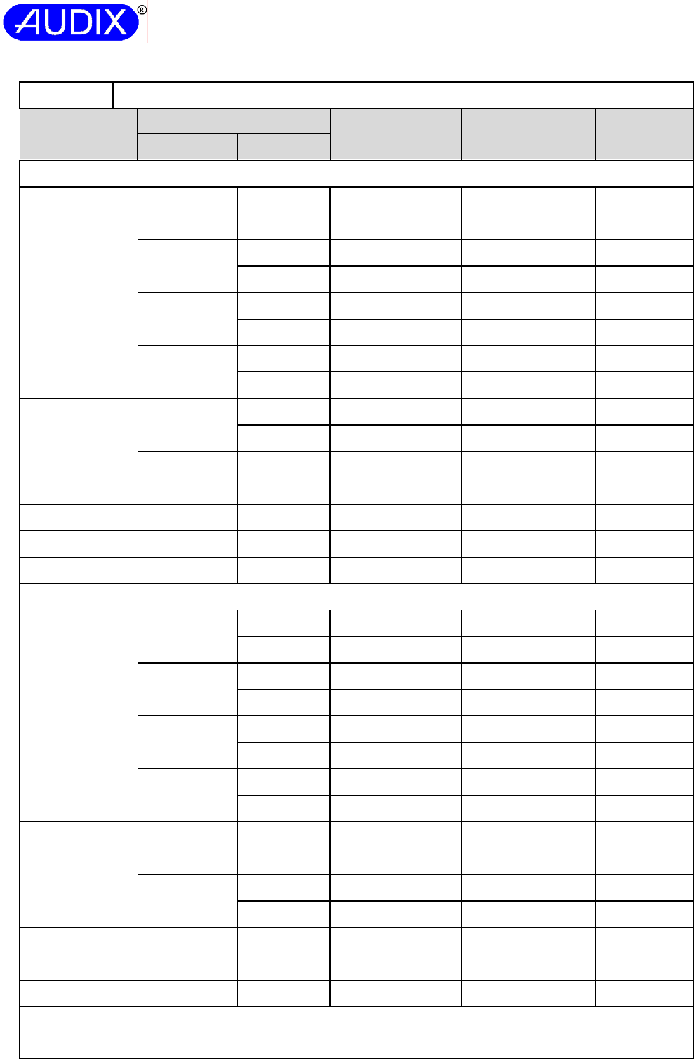
Report No.: ACSS1407139-01
Page 60 of 71
TRF NO. SRENIT-01V1.3
AUDIX TECHNOLOGY (SHENZHEN) CO., LTD
2.10.2 TABLE: Working voltage measurement
Component Location Peak Voltage (Vac) RMS Voltage (Vac) Comments
From To
Tested with power board (model: G0682)
T1
Pin 1 Pin8 166 128 --
Pin 9 217 129 --
Pin 3 Pin8 475 165 *
Pin 9 433 155 --
Pin 4 Pin8 275 133 --
Pin 9 245 129 --
Pin 5 Pin8 175 129 *
Pin 9 204 130 --
OT1
Pin 3 Pin 1 175 129 --
Pin 2 175 129 --
Pin 4 Pin 1 175 129 --
Pin 2 175 129 --
C3 Pri. Sec. 0 0 --
C9 Pri. Sec. 350 243 --
C10 Pri. Sec. 165 128 --
Tested with power board (model: TPT18S12A)
T1
Pin 1 Pin 7, 8 175 120 --
Pin 9, 10 226 123 --
Pin 2 Pin 7, 8 458 178 *
Pin 9, 10 417 162 --
Pin 4 Pin 7, 8 241 126 --
Pin 9, 10 204 123 --
Pin 5 Pin 7, 8 175 124 --
Pin 9, 10 195 124 --
U2
Pin 3 Pin 1 179 124 --
Pin 2 179 125 --
Pin 4 Pin 1 179 125 --
Pin 2 179 125 --
CY1 Pri. Sec. 350 243 --
CY2 Pri. Sec. 350 243 --
CY3 Pri. Sec. 175 122 --
Note(s): Test condition: 240V/50Hz.
The * indicate the maximum peak voltage and RMS voltage.
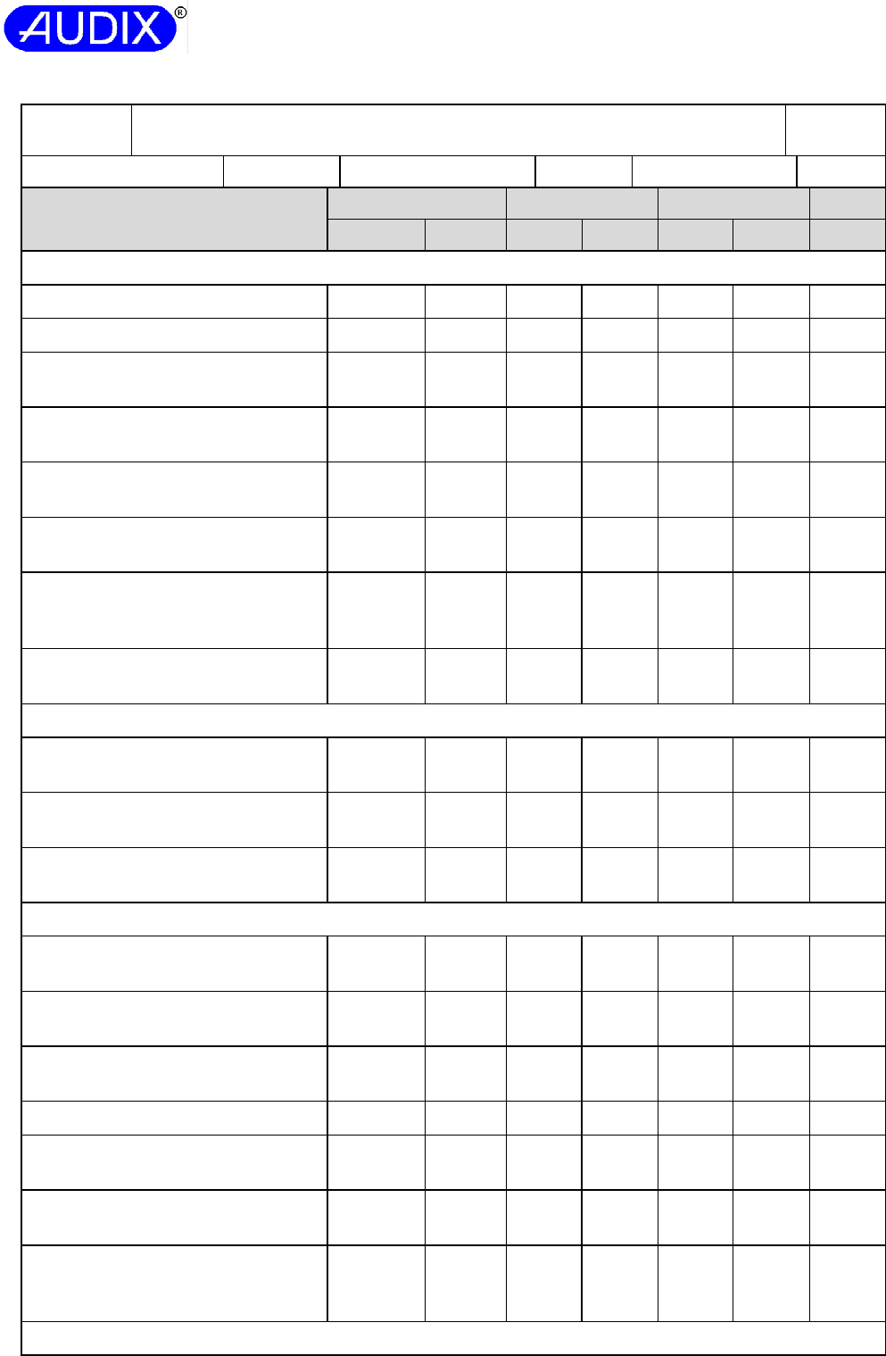
Report No.: ACSS1407139-01
Page 61 of 71
TRF NO. SRENIT-01V1.3
AUDIX TECHNOLOGY (SHENZHEN) CO., LTD
2.10.3 and
2.10.4 TABLE: Clearances and creepage distances measurement P
Rated supply voltage: 100-240V Pollution degree: 2 Material Group: IIIb
Location Operating Voltage Clearance (mm) Creepage (mm) CTI
V peak V rms Min Actual Min Actual --
Tested with power board (model: G0682)
Different polarity of L and GND (B) 339 240 2.0 7.4 2.4 7.4 <175
Different polarity of N and GND (B) 339 240 2.0 4.5 2.4 6.4 <175
Different polarity of L and N before
fuse (B) 339 240 2.0 4.5 2.4 5.5 <175
Different polarity of fuse (F1) on
PCB (F) 339 240 1.5 3.2 2.4 3.2 <175
Different polarity of Y2 capacitor
(C9) on PCB (B) 339 240 2.0 6.5 2.4 6.5 <175
Different component D8 and polarity
of GND on PCB (B) 339 240 2.0 7.4 2.4 7.4 <175
Pattern traces, between Primary and
Secondary traces (OT1) on PCB
(D/R)
<420
(175)
<240
(129) 4.0 7.4 4.8 7.4 <175
Different polarity of Y1 capacitor
(C10) on PCB (D/R)
<420
(165)
<240
(128) 4.0 7.7 4.8 7.7 <175
Mains transformer T1, core as primary
Secondary pin to Core of
transformer T1 (D/R) 475 <240
(165) 4.2 6.4 4.8 6.4 <175
Primary winding to secondary pin of
transformer T2 (D/R) 475 <240
(165) 4.2 6.0 4.8 6.0 <175
Primary to secondary of transformer
T1 on PCB trace (D/R) 475 <240
(165) 4.2 7.8 4.8 7.8 <175
Tested with power board (model: TPT18S12A)
Different polarity of L and N before
fuse (B) 339 240 2.0 4.3 2.4 4.3 <175
Different polarity of fuse (F1) on
PCB (F) 339 240 1.5 4.4 2.4 4.4 <175
Primary PCB traces to protective
earth on PCB (B) 339 240 2.0 5.2 2.4 5.2 <175
Metallic enclosure top to T1 core (B) 339 240 2.0 12.4 2.4 >12.4 <175
Different polarity of Y2 capacitor
(CY2) on PCB (B) 339 240 2.0 4.6 2.4 4.6 <175
Different polarity of Y1 capacitor
(CY3) on PCB (D/R)
<420
(175)
<240
(122) 4.0 7.2 4.8 7.2 <175
Pattern traces, between Primary and
Secondary traces (U2) on PCB
(D/R)
<420
(346)
<240
(170) 4.0 7.3 4.8 7.3 <175
Mains transformer T1, core as floating
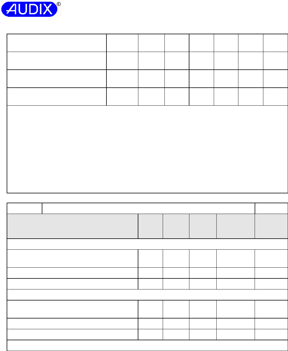
Report No.: ACSS1407139-01
Page 62 of 71
TRF NO. SRENIT-01V1.3
AUDIX TECHNOLOGY (SHENZHEN) CO., LTD
Pri. coil to Core (B) 458 <240
(178) 2.1 3.0 2.4 3.0 <175
Sec. coil to Core (B) 458 <240
(178) 2.1 3.0 2.4 3.0 <175
Primary coil to secondary coil (D/R) 458 <240
(178) 4.2 6.0 4.8 6.0 <175
Primary to secondary of transformer
T1 on PCB trace (D/R) 458 <240
(178) 4.2 6.8 4.8 6.8 <175
Note(s):
B=Basic insulation, D/R= double insulation or reinforce insulation.
- No components reduce distance after 10N steady force applied.
- One mylar sheet is under power board and fixed on metal enclosure.
On Power board (model: G0682):
- With 8.1mm length 1.4mm width gap on PCB below between different polarity of L and GND;
- With 7.6mm length 1.4mm width gap on PCB below between different polarity of N and GND;
- Transformer (Model: T1) secondary winding is triple insulated wire, transformer core is regarded as
integral with transformer primary.
On Power board (model: TPT18S12A):
- Transformer (Model: T1) secondary winding is triple insulated wire, transformer core is regarded as
floating.
2.10.5 TABLE: Distance through insulation measurement P
Distance through insulation (DTI) at/of: U peak
(V)
U rms
(V)
Test
voltage
(V)
Required dti
(mm or
layers)
dti
(mm or
layers)
Tested with power board (model: G0682)
1. Insulation tape wrapped on transformer T1,
Reinforced, 2 layers (each layer tested) 475 165
3000Vac At least
2 layers 2 layers
2. Bobbin of transformer T1 475 165
1699Vac -- 0.80mm
3. Mylar sheet (under power board) 475 165
1699Vac -- 0.28mm
Tested with power board (model: TPT18S12A)
1. Insulation tape wrapped on transformer T1,
Reinforced, 2 layers (each layer tested) 458 178
3000Vac At least
2 layers 2 layers
2. Bobbin of transformer T1 458 178
1671Vac -- 0.90mm
3. Mylar sheet (under power board) 458 178
1671Vac -- 0.28mm
Note(s): --
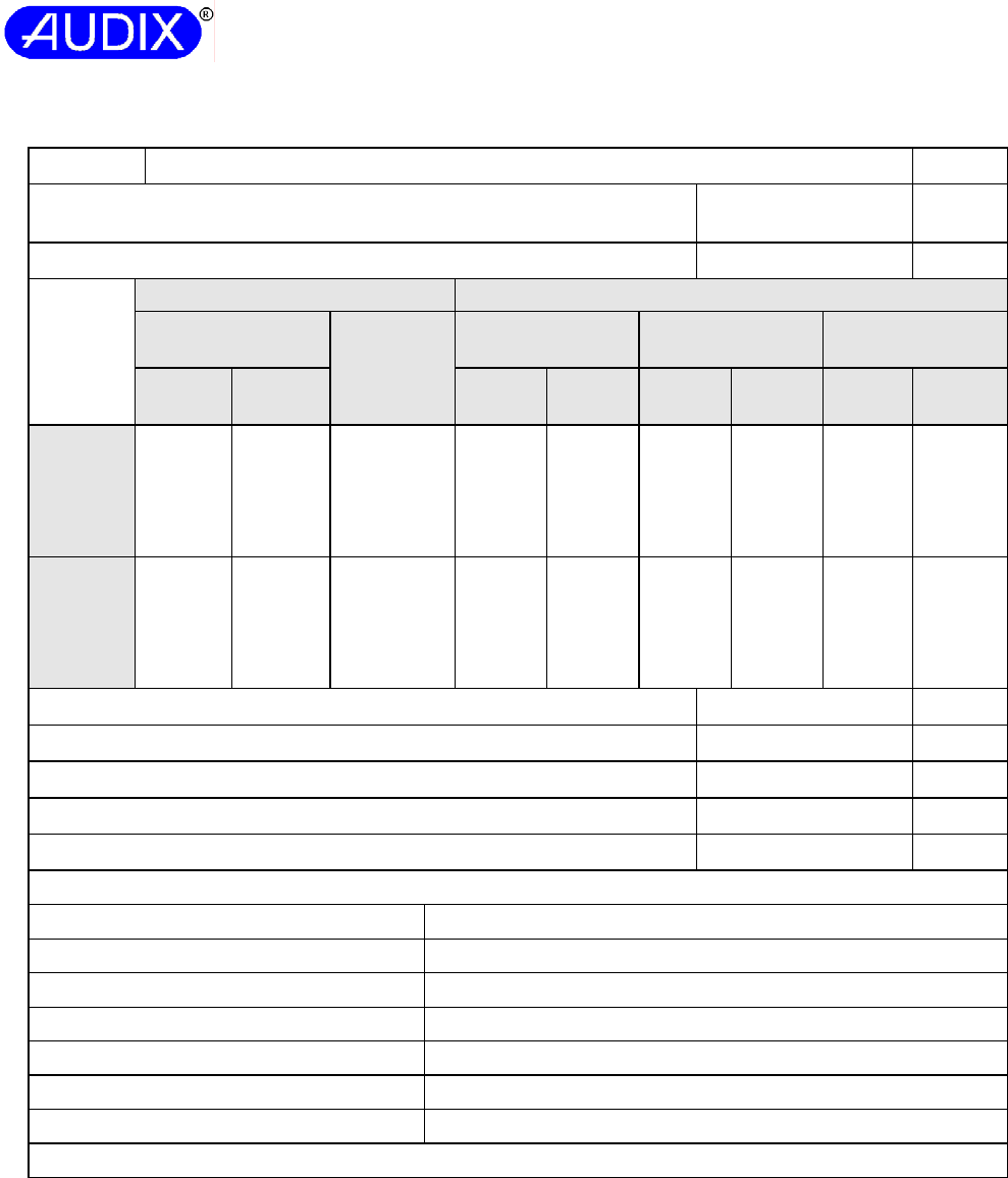
Report No.: ACSS1407139-01
Page 63 of 71
TRF NO. SRENIT-01V1.3
AUDIX TECHNOLOGY (SHENZHEN) CO., LTD
4.3.8 TABLE: Batteries N
The tests of 4.3.8 are applicable only when appropriate battery data is not
available
-- --
Is it possible to install the battery in a reverse polarity position? -- --
Non-rechargeable batteries Rechargeable batteries
Discharging Un-
intentional
charging
Charging Discharging Reversed
charging
Meas.
current
Manuf.
Specs.
Meas.
current
Manuf.
Specs.
Meas.
current
Manuf.
Specs.
Meas.
current
Manuf.
Specs.
Max.
current
during
normal
condition
-- -- -- -- -- -- --
-- --
Max.
current
during
fault
condition
-- -- -- -- -- -- -- -- --
Test results: Verdict
- Chemical leaks -- --
- Explosion of the battery -- --
- Emission of flame or expulsion of molten metal -- --
- Electric strength tests of equipment after completion of tests -- --
Supplementary information:
Battery category ............................................ (Lithium, NiMh, NiCad, Lithium Ion …)
Manufacturer ............................................... --
Type / model ............................................... --
Voltage ........................................................ --
Capacity ...................................................... mAh
Tested and Certified by (incl. Ref. No.) ....... --
Circuit protection diagram: --
Note(s):
Report No.: ACSS1407139-01
Page 64 of 71
TRF NO. SRENIT-01V1.3
AUDIX TECHNOLOGY (SHENZHEN) CO., LTD
4.5.2 TABLE: Heating test under normal operation
Tested with power board (model: G0682)
P
Test voltage (V) : 90V/50Hz 254.4V/50Hz ⎯
Test times …………………………. : 3hours16minutes 1hour 37minutes ⎯
Tam a1 (°C) ……………………...… : 27.1 27.1
⎯
Tam a2 (°C) …………………………: 27.1 26.9
⎯
maximum temperature T of part/at: Measured
T
Calculated
T (40°C)
Measured
T
Calculated
T (40°C)
allowed
Tmax
1. AC inlet, inside 37.8 50.7 37.4 50.5 70
2. J1 body 40.3 53.2 39.7 52.8 --
3. C4 body 47.9 60.8 45.2 58.3 100
4. L3 winding 57.0 69.9 47.9 61.0 130
5. PCB near D5 59.7 72.6 50.3 63.4 130
6. C38 body 56.2 69.1 51.7 64.8 105
7. PCB near Q1 61.3 74.2 59.4 72.5 130
8. C10 body 57.9 70.8 58.2 71.3 85
9. T1 winding 69.5 82.4 71.1 84.2 110
10. T1 core 67.6 80.5 69.1 82.2 110
11. PCB under T1 54.9 67.8 56.1 69.2 130
12. OT1 body 45.7 58.6 46.5 59.6 100
13. C8 body 62.7 75.6 65.0 78.1 130
14. Output wire 49.2 62.1 50.3 63.4 130
15. Mylar sheet under T1 42.2 55.1 42.6 55.7 130
16. L5 winding 80.9 93.8 81.0 94.1 105
17. C25 body 74.5 87.4 74.6 87.7 105
18. Heatsink of U4 81.1 94.0 81.0 94.1 105
19. X4 body 58.7 71.6 58.8 71.9 105
20. Metal enclosure top of T1, inside 39.7 52.6 40.2 53.3 105
21. Metal enclosure top of T1, outside 36.3 49.2 36.3 49.4 105
22. Ambient 27.1 40.0 26.9 40.0 105
Report No.: ACSS1407139-01
Page 65 of 71
TRF NO. SRENIT-01V1.3
AUDIX TECHNOLOGY (SHENZHEN) CO., LTD
4.5.2 TABLE: Heating test under normal operation (cont.)
Tested with power board (model: TPT18S12A)
P
Test voltage (V) : 90V/50Hz 254.4V/50Hz ⎯
Test times …………………………. : 3hours 21minutes 1hour 14minutes ⎯
Tam a1 (°C) ……………………...… : 25.3 26.4
⎯
Tam a2 (°C) …………………………: 26.4 26.3
⎯
maximum temperature T of part/at: Measured
T
Calculated
T (40°C)
Measured
T
Calculated
T (40°C)
allowed
Tmax
1. AC inlet, inside 37.8 50.7 37.4 50.5 70
2. CON1 body 40.3 53.2 39.7 52.8 --
3. C3 body 47.9 60.8 45.2 58.3 105
4. PCB near D4 57.0 69.9 47.9 61.0 130
5. L1 winding 59.7 72.6 50.3 63.4 130
6. C2 body 56.2 69.1 51.7 64.8 100
7. PCB near Q1 61.3 74.2 59.4 72.5 130
8. CY3 body 57.9 70.8 58.2 71.3 125
9. T1 winding 69.5 82.4 71.1 84.2 110
10. T1 core 67.6 80.5 69.1 82.2 110
11. PCB near T1 54.9 67.8 56.1 69.2 130
12. OT1 body 45.7 58.6 46.5 59.6 100
13. C8 body 62.7 75.6 65.0 78.1 130
14. Output wire 49.2 62.1 50.3 63.4 130
15. Mylar sheet under T1 42.2 55.1 42.6 55.7 130
16. L5 winding 80.9 93.8 81.0 94.1 105
17. C25 body 74.5 87.4 74.6 87.7 105
18. Heatsink against U4 81.1 94.0 81.0 94.1 105
19. X4 body 58.7 71.6 58.8 71.9 105
20. Metal enclosure top of T1, inside 39.7 52.6 40.2 53.3 105
21. Metal enclosure top of T1, outside 36.3 49.2 36.3 49.4 --
22. Ambient 27.1 40.0 26.9 40.0 --
Note(s):
1. The temperatures were measured under worst case normal mode defined in 1.2.2.1 and as described in
sub-clause 1.6.2 and at voltages as described in sub-clause 1.4.5.
2. Thermocouple method used for measuring the temperatures
3. Unit specified with maximum of 40°C ambient temperature and all temperatures were calculated for a
maximum ambient temperature of 40°C.
Report No.: ACSS1407139-01
Page 66 of 71
TRF NO. SRENIT-01V1.3
AUDIX TECHNOLOGY (SHENZHEN) CO., LTD
4.5.5 TABLE: Ball pressure test of thermoplastic parts N
Allowed impression diameter (mm): ≤ 2 mm ⎯
Part Test temperature (°C) Impression diameter
(mm)
-- -- --
Note(s): --
5.1.6 TABLE: Touch current measurement P
Measured between: Measured
(mA)
Limit
(mA)
Comments/conditions
Tested with power board (model: G0682)
Output terminal and Line & neutral 0.005 0.25 Fuse in, “e” closed
Metal enclosure and Line & neutral 0.13 3.5 Fuse in, “e” opened
Tested with power board (model: TPT18S12A)
L&N and Output terminal 0.005 0.25 Fuse in, “e” closed
L&N and Metal enclosure 0.21 3.5 Fuse in, “e” opened
Note(s): --
5.2 TABLE: Electric strength tests, impulse tests and voltage surge tests P
Test voltage applied between: Voltage shape
(AC, DC,
impulse, surge)
Test voltage
(Vrms)
Breakdown
Yes / No
Tested with power board (model: G0682)
Line & neutral and output terminal (D/R) AC 3000V No
Line & neutral and metal enclosure (B) AC 1699V No
Mains transformer T1
Primary and secondary of transformer (D/R) AC 3000V No
Secondary and core of transformer (D/R) AC 3000V No
One layer of Mylar sheet (under power board) (B) AC 1699V No
Tested with power board (model: TPT18S12A)
Line & neutral and output terminal (D/R) AC 3000V No
Line & neutral and metal enclosure (B) AC 1671V No
Mains transformer T1
Primary and secondary of transformer (D/R) AC 3000V No
Primary and core of transformer (B) AC 1671V No
Secondary and core of transformer (B) AC 1671V No
One layer of Mylar sheet (under power board) (B) AC 1671V No
Note(s): --
Report No.: ACSS1407139-01
Page 67 of 71
TRF NO. SRENIT-01V1.3
AUDIX TECHNOLOGY (SHENZHEN) CO., LTD
5.3 TABLE: Fault condition test P
Ambient temperature (°C) .................................... :25°C, if not specify. —
Power source for EUT: Manufacturer, model/type,
output rating ......................................................... :
-- —
No. Component Fault Test
voltage
(V)
Test
time
Fuse # Fuse
(mA)
Result
Tested with power board (model: G0682)
1 D6 S/C 240V/
50Hz
1sec. F1 0 Unit shutdown immediately,
Fuse(F1) opened, CD (D5),
NT, NC, NB, NH.
2 C38 S/C 240V/
50Hz
1sec. F1 0 Unit shutdown immediately,
Fuse(F1) opened, CD (D5,
D8), NT, NC, NB, NH.
3 Q1
(pinG to pinS)
S/C 240V/
50Hz
10mins F1 20 Unit shutdown immediately,
recoverable when fault
removed, NCD, NC, NT, NB,
NH.
4 Q1
(pinG to pinD)
S/C 240V/
50Hz
1sec. F1 0 Unit shutdown immediately,
Fuse(F1) opened, CD (R22,
R27, U4, D6, D7, Q1), NT,
NC, NB, NH.
5 Q1
(pinD to pinS)
S/C 240V/
50Hz
1sec. F1 0 Fuse(F1) opened, CD (R22,
R27, U4, D6, D7, Q1), NT,
NC, NB, NH.
6 Q1
(pinD to pinS)
S/C 240V/
60Hz
1sec. F1 0 Unit shutdown immediately,
Fuse(F1) opened, CD(R22,
R27, R16, R26, U4, D6, D7,
D5, D6, Q1), NT, NC, NB,
NH.
7 U4
(pin1 to pin5)
S/C 240V/
50Hz
10mins F1 19 Unit shutdown immediately,
recoverable when fault
removed, NCD, NC, NT, NB,
NH.
8 U4
(pin2 to pin5)
S/C 240V/
50Hz
10mins F1 19 Unit shutdown immediately,
CD(U4, C1, C26), NC, NT,
NB, NH.
9 U4
(pin2 to pin4)
S/C 240V/
50Hz
10mins F1 18 Unit shutdown immediately,
recoverable when fault
removed, NCD, NC, NT, NB,
NH.
10 U4
(pin3 to pin5)
S/C 240V/
50Hz
10mins F1 19 Unit shutdown immediately,
CD(U4, C1, C26), NC, NT,
NB, NH.
11 D4 S/C 240V/
50Hz
10mins F1 150 Unit similar normal operation,
NCD, NC, NT, NB, NH.
12 T1
(pin1 to pin3)
S/C 240V/
50Hz
10mins F1 154↔19 Unit shutdown and cycled,
recoverable when fault
removed, NCD, NC, NT, NB,
NH.
Report No.: ACSS1407139-01
Page 68 of 71
TRF NO. SRENIT-01V1.3
AUDIX TECHNOLOGY (SHENZHEN) CO., LTD
13 T1
(pin4 to pin5)
S/C 240V/
50Hz
10mins F1 89↔19 Unit shutdown and cycled,
recoverable when fault
removed, NCD, NC, NT, NB,
NH.
14 T1
(pin8 to pin9)
S/C 240V/
50Hz
10mins F1 65↔19 Unit shutdown and cycled,
recoverable when fault
removed, NCD, NC, NT, NB,
NH.
15 OT1
(pin1 to pin2)
S/C 240V/
50Hz
10mins F1 105↔20 Unit shutdown and cycled,
recoverable when fault
removed, NCD, NC, NT, NB,
NH.
16 OT1
(pin3 to pin4)
S/C 240V/
50Hz
10mins F1 19 Unit shutdown and cycled,
recoverable when fault
removed, NCD, NC, NT, NB,
NH.
17 OT1 (pin1) O/C 240V/
50Hz
10mins F1 99 Unit shutdown and cycled,
recoverable when fault
removed, NCD, NC, NT, NB,
NH.
18 OT1 (pin3) O/C 240V/
50Hz
10mins F1 104 Unit shutdown immediately,
recoverable when fault
removed, NCD, NC, NT, NB,
NH.
19 D4 S/C 240V/
50Hz
10mins F1 70↔20 Unit shutdown and cycled,
recoverable when fault
removed, NCD, NC, NT, NB,
NH.
20 R30 S/C 240V/
50Hz
10mins F1 150 Unit similar normal operation,
NCD, NC, NT, NB, NH.
21 C20 S/C 240V/
50Hz
2hrs
11mins
F1 165 Unit power increased to
18.73W, CD(R21,R30),
Measured maximum
temperature:
T1 winding: 64.8Ⅲ;
T1 core: 62.9Ⅲ;
Ambient: 27.2Ⅲ. NT, NC,
NB, NH.
22 J2
(+12V to GND)
S/C 240V/
50Hz
10mins F1 84↔20 Unit shutdown and cycled,
recoverable when fault
removed, NCD, NC, NT, NB,
NH.
23 Ventilation
openings
Blocked 240V/
50Hz
1hr
8mins
F1 150 Unit similar normal operation,
measured maximum
temperature:
T1 winding: 71.3℃;
T1 core: 69.3℃;
Ambient: 27.1℃. NT, NC,
NB, NH.
Report No.: ACSS1407139-01
Page 69 of 71
TRF NO. SRENIT-01V1.3
AUDIX TECHNOLOGY (SHENZHEN) CO., LTD
24 T1 output O/L 240V/
50Hz
7hrs
15mins
F1 226⇗
285⇗
362⇗
18
Unit shut down when loaded
additional 1.7A, recoverable
when fault removed,
measured maximum
temperature:
T1 winding:105.3Ⅲ;
T1 core:102.8Ⅲ;
Ambient: 27.7Ⅲ. NT, NC,
NB, NH.
Tested with power board (model: TPT18S12A)
1 D1 S/C 240V/
50Hz
1sec. F1 0 Unit shutdown immediately,
Fuse(F1) opened, CD(D4),
NT, NC, NB, NH.
2 C3 S/C 240V/
50Hz
1sec. F1 0 Unit shutdown immediately,
Fuse(F1) opened, CD(D1,
D3), NT, NC, NB, NH.
3 Q1
(pinG to pinS)
S/C 240V/
50Hz
10mins F1 18 Unit shutdown immediately,
recoverable when fault
removed, NCD, NC, NT, NB,
NH.
4 Q1
(pinG to pinD)
S/C 240V/
50Hz
1sec. F1 0 Unit shutdown immediately,
Fuse(F1) opened, CD(R7,
R8, R9, R10, D2, D4, U1),
NT, NC, NB, NH.
5 Q1
(pinD to pinS)
S/C 240V/
50Hz
1sec. F1 0 Unit shutdown immediately,
Fuse(F1) opened, CD(R7,
R8, R9, R10, D1, D3, U1),
NT, NC, NB, NH.
6 U1
(pin1 to pin5)
S/C 240V/
50Hz
10mins F1 17 Unit shutdown immediately,
recoverable when fault
removed, NCD, NC, NT, NB,
NH.
7 U1
(pin2 to pin5)
S/C 240V/
50Hz
10mins F1 17 Unit shutdown immediately,
CD(C4), NC, NT, NB, NH.
8 U1
(pin1 to pin4)
S/C 240V/
50Hz
1sec. F1 0 Unit shutdown immediately,
Fuse(F1) opened, CD(R7,
R8, R9, R10, Q1, D1, D3,
U1), NT, NC, NB, NH.
9 U1
(pin5 to pin6)
S/C 240V/
50Hz
1sec. F1 0 Unit shutdown immediately,
Fuse(F1) opened, CD(R7,
R8, R9, R10, Q1, D1, D3,
U1), NT, NC, NB, NH.
10 D5 S/C 240V/
50Hz
1hr
55mins
F1 170 Unit power increased to
20.22W, Measured maximum
temperature:
T1 winding: 71.3Ⅲ;
T1 core: 67.3Ⅲ;
Ambient: 26.7Ⅲ. NT, NC,
NB, NH.
11 T1
(Pin1 to Pin2)
S/C 240V/
50Hz
10mins F1 140↔17 Unit shutdown and cycled,
recoverable when fault
removed, NCD, NC, NT, NB,
NH.
Report No.: ACSS1407139-01
Page 70 of 71
TRF NO. SRENIT-01V1.3
AUDIX TECHNOLOGY (SHENZHEN) CO., LTD
12 T1
(Pin4 to Pin5)
S/C 240V/
50Hz
10mins F1 76↔17 Unit shutdown and cycled,
recoverable when fault
removed, NCD, NC, NT, NB,
NH.
13 T1
(Pin7,8 to
Pin9,10)
S/C 240V/
50Hz
10mins F1 89↔17 Unit shutdown and cycled,
recoverable when fault
removed, NCD, NC, NT, NB,
NH.
14 D6 S/C 240V/
50Hz
10mins F1 125↔17 Unit shutdown and cycled,
recoverable when fault
removed, NCD, NC, NT, NB,
NH.
15 C8 S/C 240V/
50Hz
10mins F1 88↔17 Unit shutdown and cycled,
recoverable when fault
removed, NCD, NC, NT, NB,
NH.
16 R31 S/C 240V/
50Hz
10mins F1 146 Unit shutdown immediately,
recoverable when fault
removed, NCD, NC, NT, NB,
NH.
17 U2
(pin1 to pin2)
S/C 240V/
50Hz
10mins F1 89↔17 Unit shut down immediately,
recoverable when fault
removed, NCD, NT, NC, NB,
NH.
18 U2
(pin3 to pin4)
S/C 240V/
50Hz
10mins F1 17 Unit shutdown immediately,
recoverable when fault
removed, NCD, NC, NT, NB,
NH.
19 U2
(pin1)
O/C 240V/
50Hz
10mins F1 75↔18 Unit shut down immediately,
recoverable when fault
removed, NCD, NT, NC, NB,
NH.
20 U2
(pin3)
O/C 240V/
50Hz
10mins F1 78↔17 Unit shut down immediately,
recoverable when fault
removed, NCD, NT, NC, NB,
NH.
21 CON2
(+12V to GND)
S/C 240V/
50Hz
10mins F1 75↔17 Unit shut down immediately,
recoverable when fault
removed, NCD, NT, NC, NB,
NH.
22 Ventilation
openings
Blocked 240V/
50Hz
2hrs
39mins
F1 151 Unit similar normal operation,
NCD, NC, NT, NB, NH.
Measured max. temperature
on:
T2 winding: 72.8Ⅲ;
T3 winding: 69.0Ⅲ;
Ambient: 27.1Ⅲ.
Report No.: ACSS1407139-01
Page 71 of 71
TRF NO. SRENIT-01V1.3
AUDIX TECHNOLOGY (SHENZHEN) CO., LTD
23 T1 output O/L 240V/
50Hz
7hrs
12mins
F1 228⇗
274⇗
323⇗
81
Unit shut down and cycled
when loaded additional
1.60A, recoverable when
fault removed, measured
maximum temperature:
T1 winding:101.7Ⅲ;
T1 core: 92.8Ⅲ;
Ambient: 28.0Ⅲ. NT, NC,
NB, NH.
Note(s): --
6.2.2.2 TABLE:Electric strength tests (Steady-state) N
Test voltage applied between: Test voltage (V) Breakdown
-- -- --
-- -- --
Note(s): --
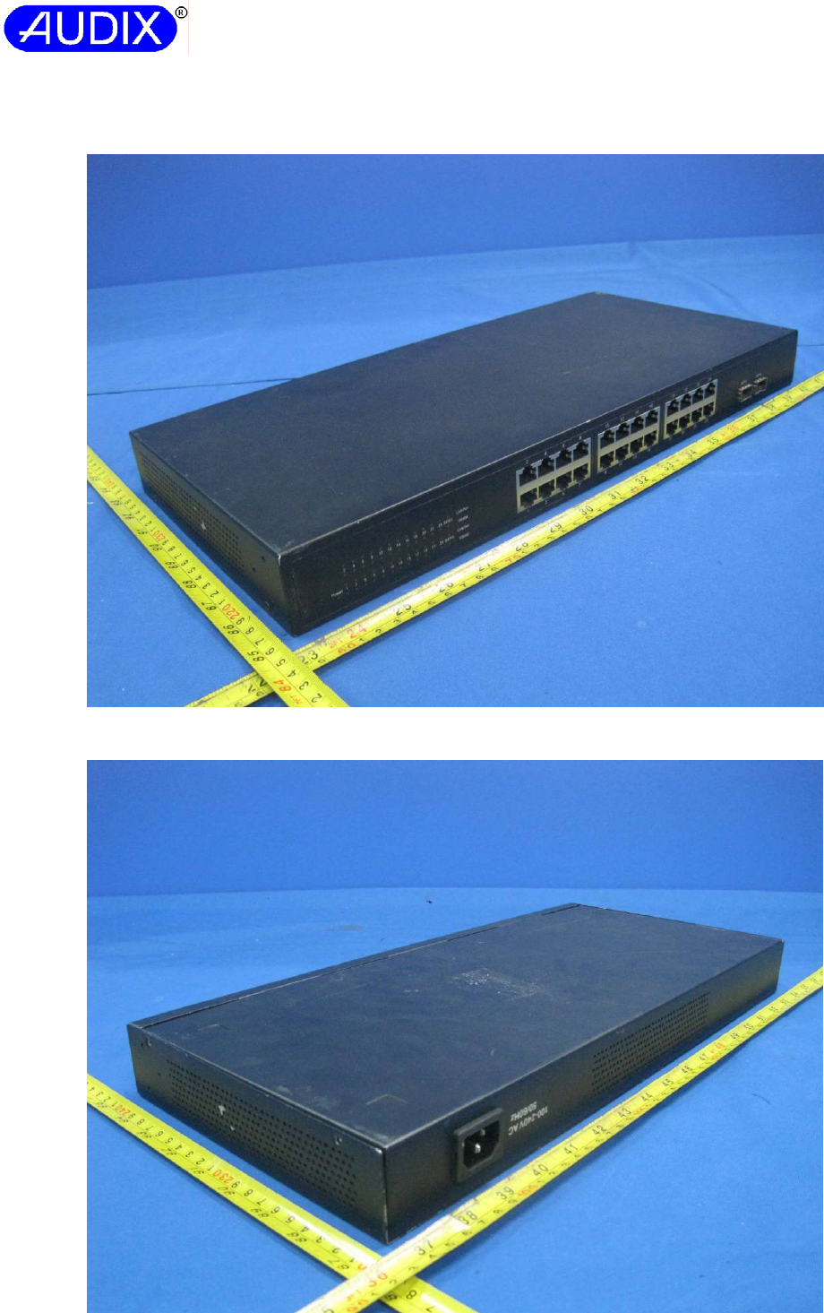
Report No.: ACSS1407139-01
AUDIX TECHNOLOGY (SHENZHEN) CO., LTD
Attachment A: Photo-documentation Page 1 of 11
Fig. 1 - Overview (1)
(Dimensions: Approx. 440 mm x 205 mm x 43 mm)
Fig. 2 – Overview (2)
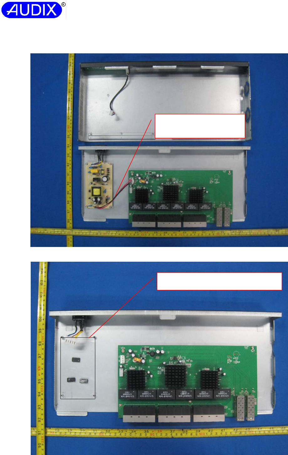
Report No.: ACSS1407139-01
AUDIX TECHNOLOGY (SHENZHEN) CO., LTD
Attachment A: Photo-documentation Page 2 of 11
Fig. 3 - Internal view with Power board (model: G0682)
Fig. 4 - Mylar sheet below the power supply board overview
The secondary lead wires
can’t touch primary live parts
by cable ties.
Mylar sheet below the Power board.
(Dimensions: Approx. 121 mm x 73 mm)
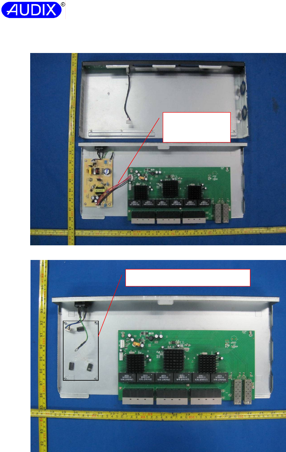
Report No.: ACSS1407139-01
AUDIX TECHNOLOGY (SHENZHEN) CO., LTD
Attachment A: Photo-documentation Page 3 of 11
Fig. 5 - Internal view with power board (model: TPT18S12A)
Fig. 6 - Mylar sheet below the power supply board overview
Mylar sheet below the Power board.
(Dimensions: Approx. 121 mm x 73 mm)
The secondary lead
wires can’t touch
primary live parts by
cab
l
e
t
i
es
.
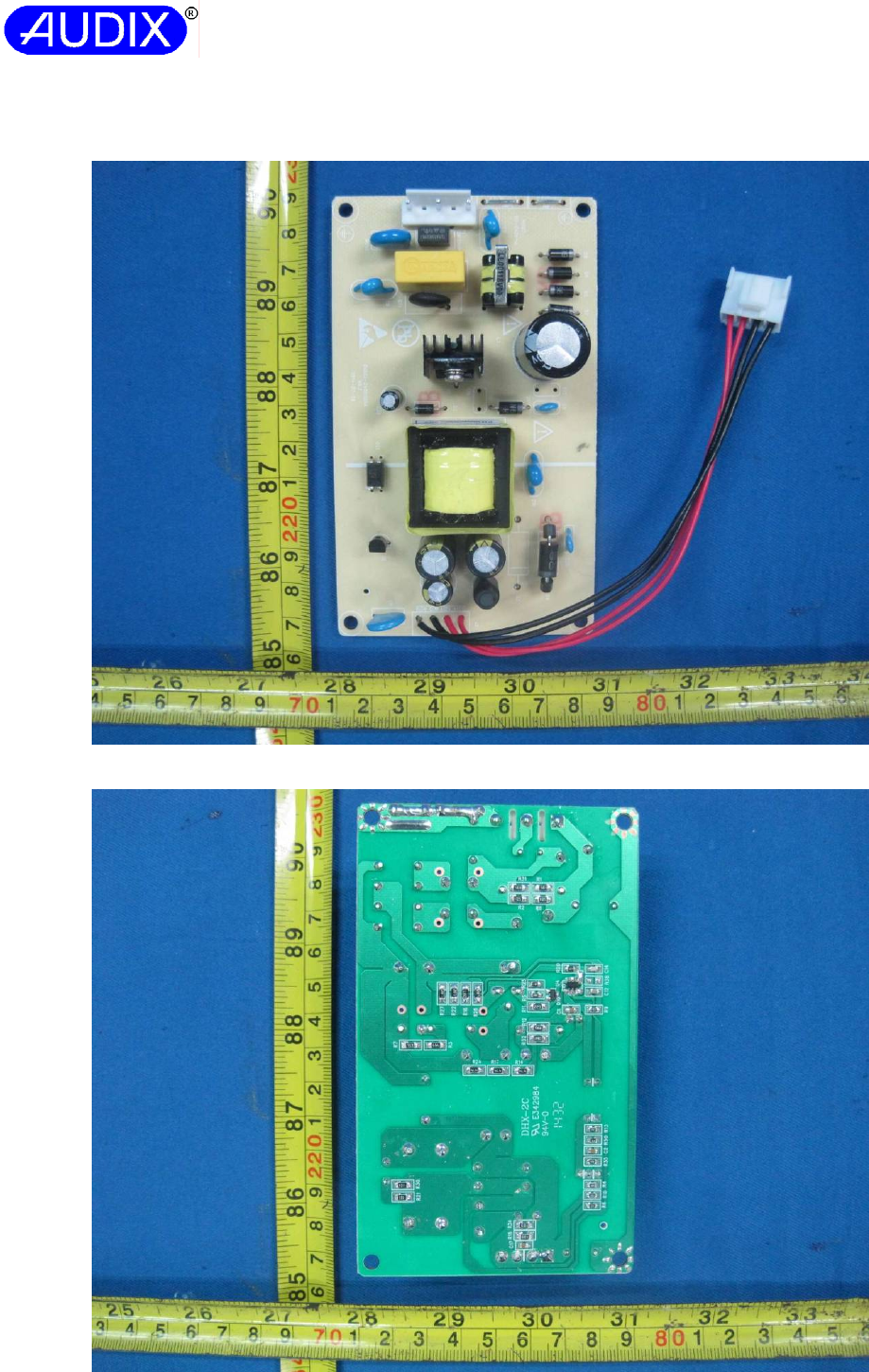
Report No.: ACSS1407139-01
AUDIX TECHNOLOGY (SHENZHEN) CO., LTD
Attachment A: Photo-documentation Page 4 of 11
Fig. 7 – Top view of the power board (model: G0682)
Fig. 8 – Bottom view of the power board (model: G0682)
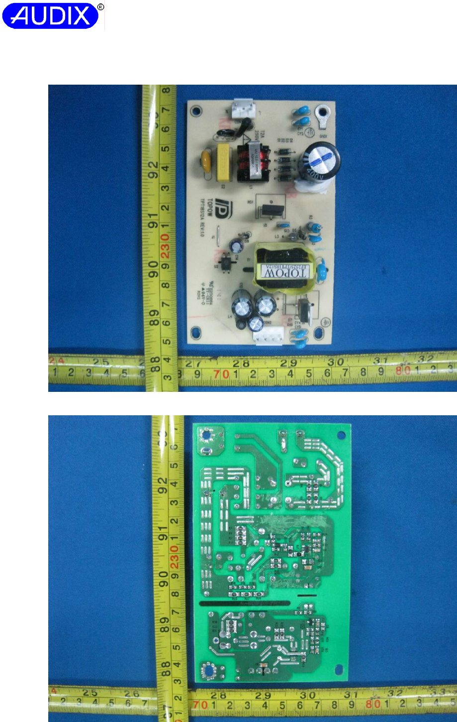
Report No.: ACSS1407139-01
AUDIX TECHNOLOGY (SHENZHEN) CO., LTD
Attachment A: Photo-documentation Page 5 of 11
Fig. 9 – Top view of power board (model: TPT18S12A)
Fig. 10 – Bottom view of the power board (model: TPT18S12A)
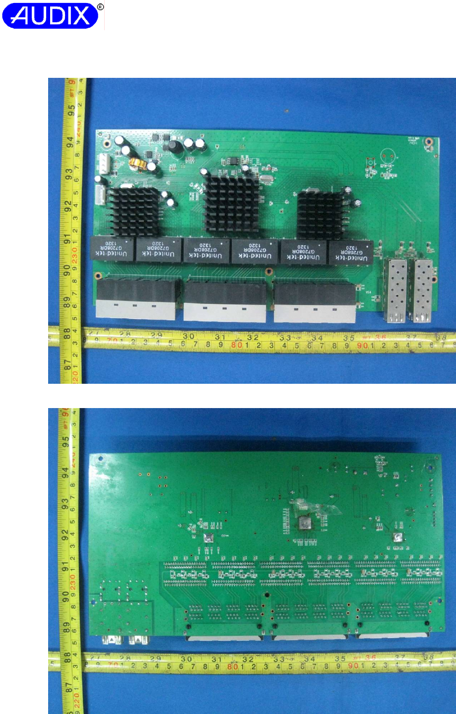
Report No.: ACSS1407139-01
AUDIX TECHNOLOGY (SHENZHEN) CO., LTD
Attachment A: Photo-documentation Page 6 of 11
Fig. 11 – Top view of main board
Fig. 12 – Bottom view of the main board
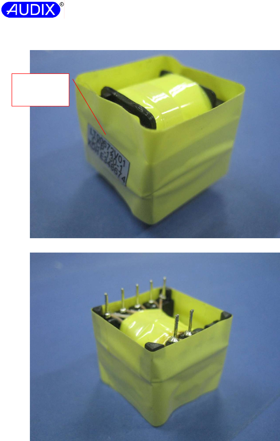
Report No.: ACSS1407139-01
AUDIX TECHNOLOGY (SHENZHEN) CO., LTD
Attachment A: Photo-documentation Page 7 of 11
Fig. 13 – Transformer T1 on power board (model: G0682) overview(1)
Fig. 14 – Transformer T1 on power board (model: G0682) overview (2)
Two layers of
insulation tape
wrapped on
transformer.
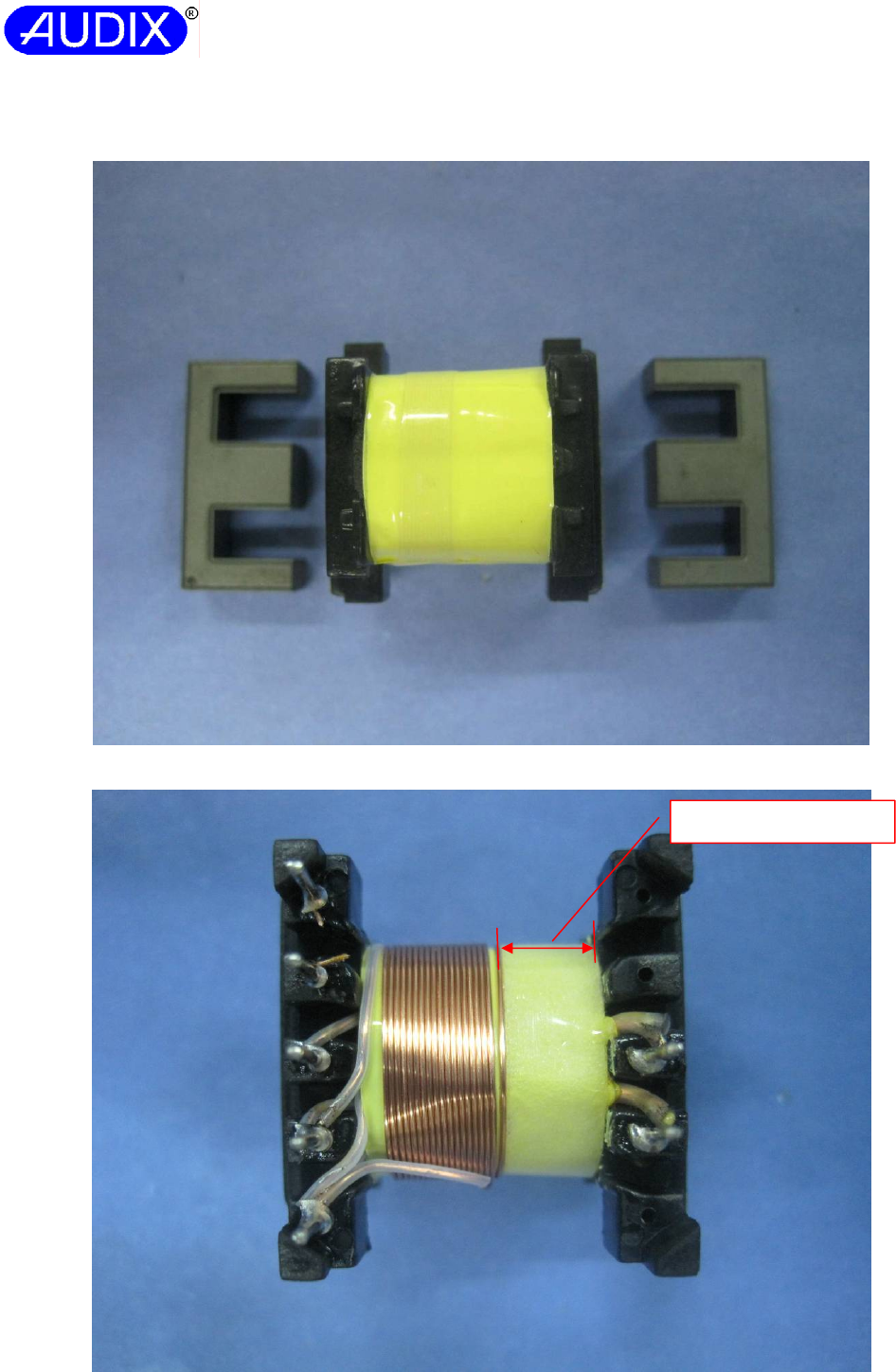
Report No.: ACSS1407139-01
AUDIX TECHNOLOGY (SHENZHEN) CO., LTD
Attachment A: Photo-documentation Page 8 of 11
Fig. 15 – Transformer T1 on power board (model: G0682) overview (3)
Fig. 16 – Transformer T1 on power board (model: G0682) overview (4)
Margin tape: 6.0mm
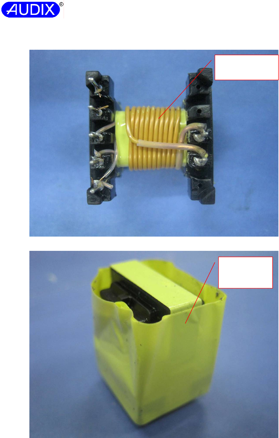
Report No.: ACSS1407139-01
AUDIX TECHNOLOGY (SHENZHEN) CO., LTD
Attachment A: Photo-documentation Page 9 of 11
Fig. 17 – Transformer T1 on power board (model: G0682) overview (5)
Fig. 18 – Transformer T1 on power board (model: TPT18S12A) overview(6)
Triple insulated wire
is used in secondary
wire.
Two layers of
insulation tape
wrapped on
transformer.
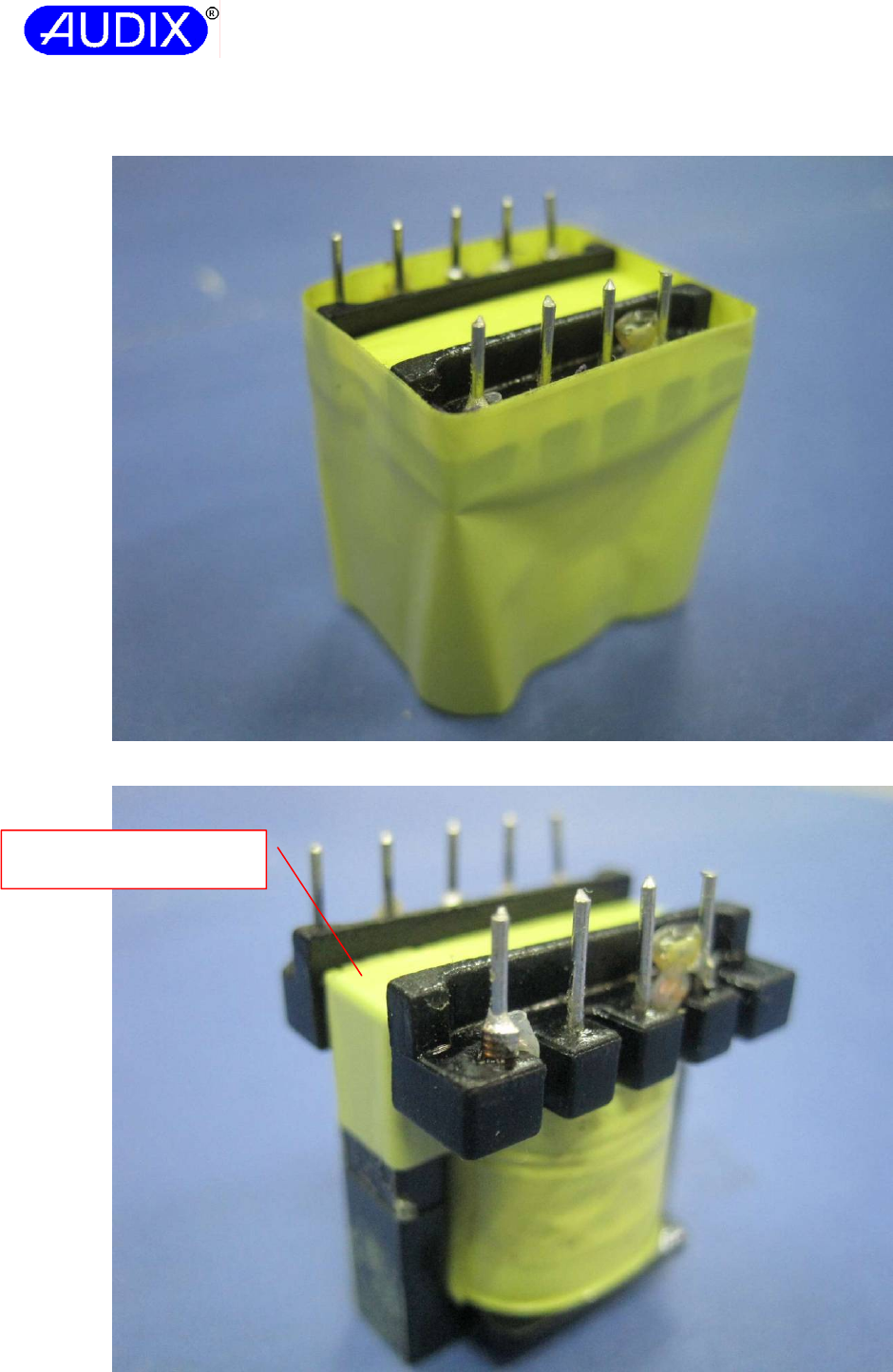
Report No.: ACSS1407139-01
AUDIX TECHNOLOGY (SHENZHEN) CO., LTD
Attachment A: Photo-documentation Page 10 of 11
Fig. 19 – Transformer T1 on power board (model: TPT18S12A) overview(7)
Fig. 20 – Transformer T1 on power board (model: TPT18S12A) overview(8)
Lenght: approx. 45.0mm,
Width: approx. 13.0mm
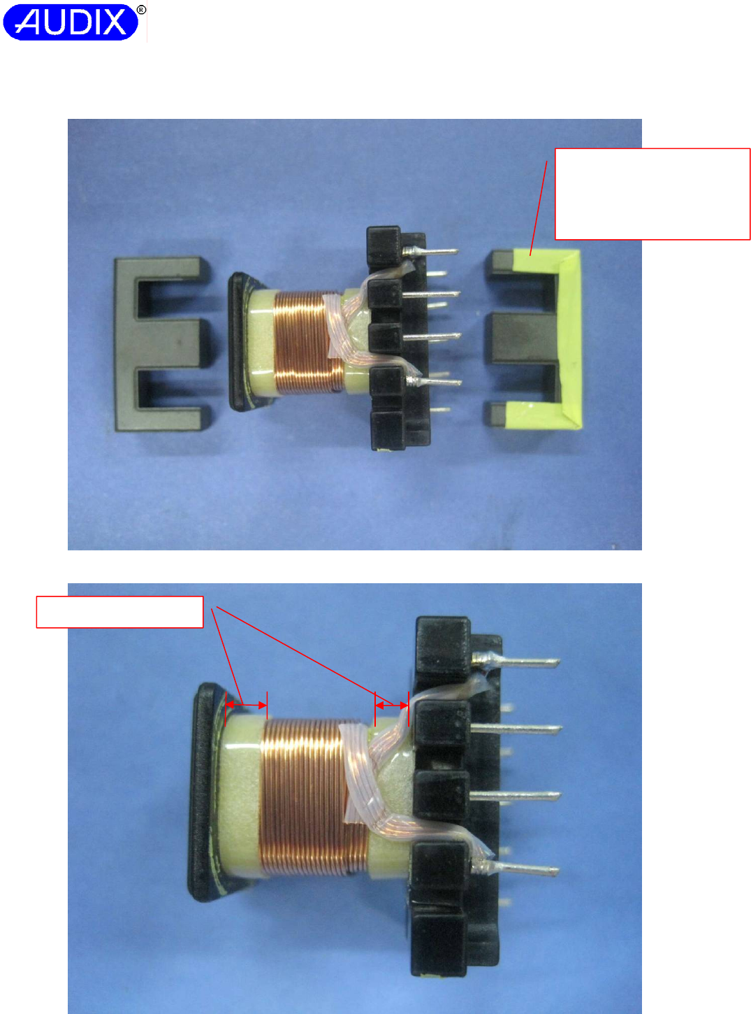
Report No.: ACSS1407139-01
AUDIX TECHNOLOGY (SHENZHEN) CO., LTD
Attachment A: Photo-documentation Page 11 of 11
Fig. 21 – Transformer T1 on power board (model: TPT18S12A) overview(9)
Fig. 22 – Transformer T1 on power board (model: TPT18S12A) overview(10)
Two layers of insulation tape
wrapped on bottom
transformer core.(Lenght:
approx. 13.0mm, Width:
approx. 3.0mm)
Margin tape: 3.0mm
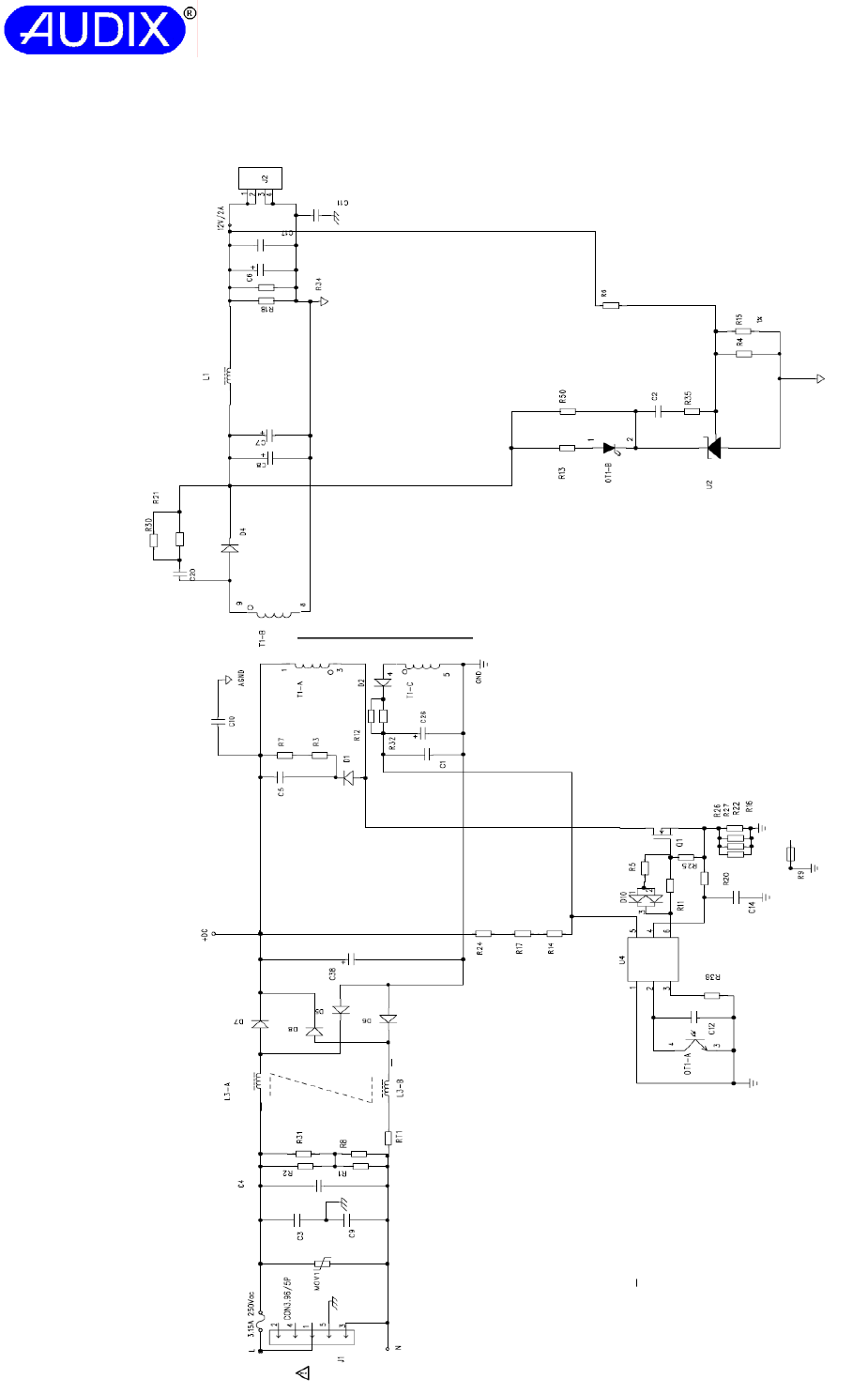
Report No.: ACSS1407139-01
AUDIX TECHNOLOGY (SHENZHEN) CO., LTD
Attachment B: Circuit Diagram and PCB Layout for power boaed (model: G0682) Page 1 of 4
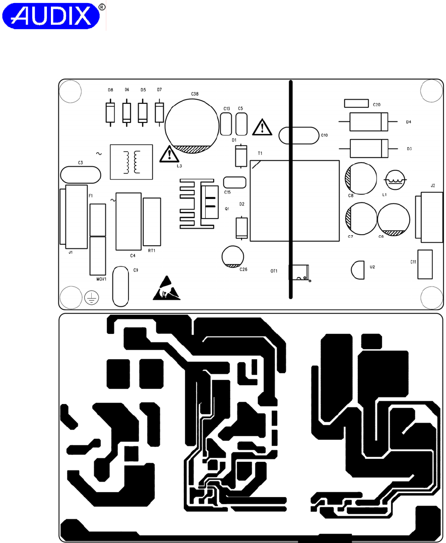
Report No.: ACSS1407139-01
AUDIX TECHNOLOGY (SHENZHEN) CO., LTD
Attachment B: Circuit Diagram and PCB Layout for power board (model: G0682) Page 2 of 4
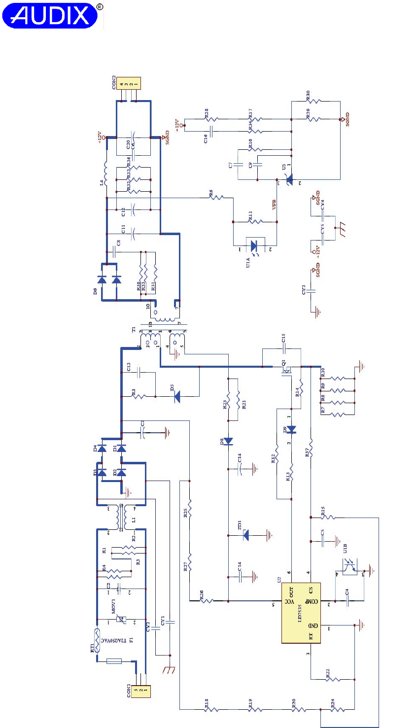
Report No.: ACSS1407139-01
AUDIX TECHNOLOGY (SHENZHEN) CO., LTD
Attachment B: Circuit Diagram and PCB Layout for power boaed (model: TPT18S12A) Page 3 of 4
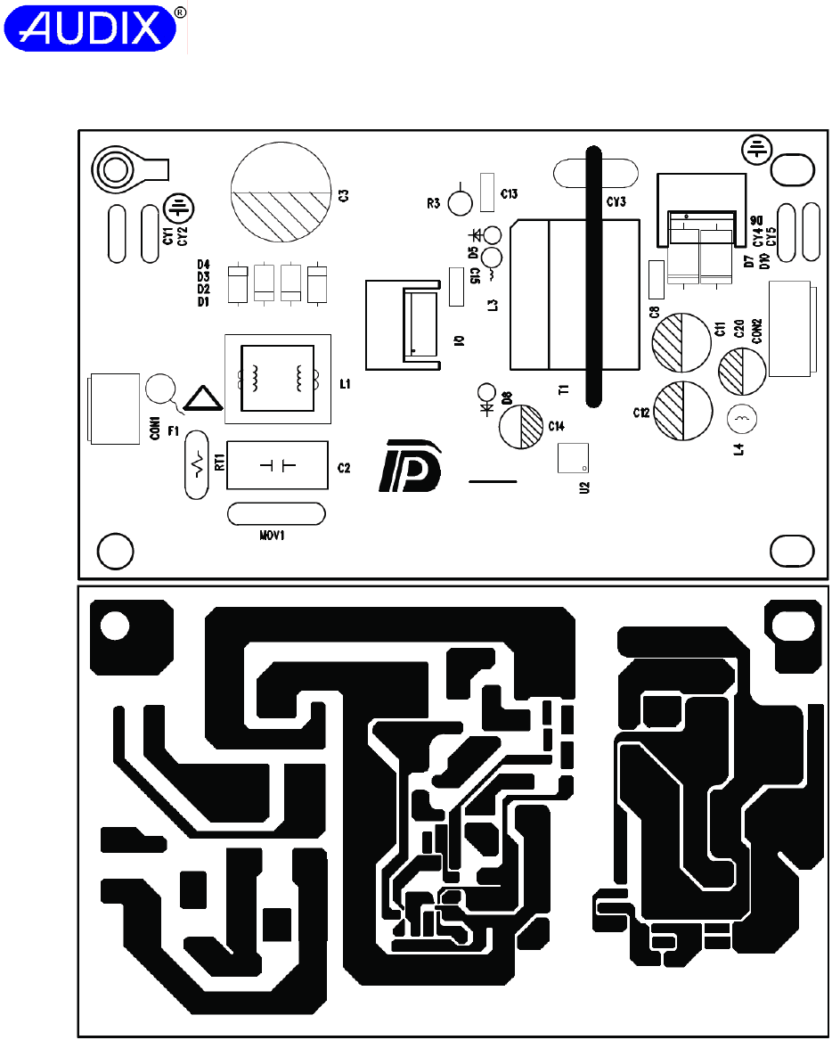
Report No.: ACSS1407139-01
AUDIX TECHNOLOGY (SHENZHEN) CO., LTD
Attachment B: Circuit Diagram and PCB Layout for power boaed (model: TPT18S12A) Page 4 of 4
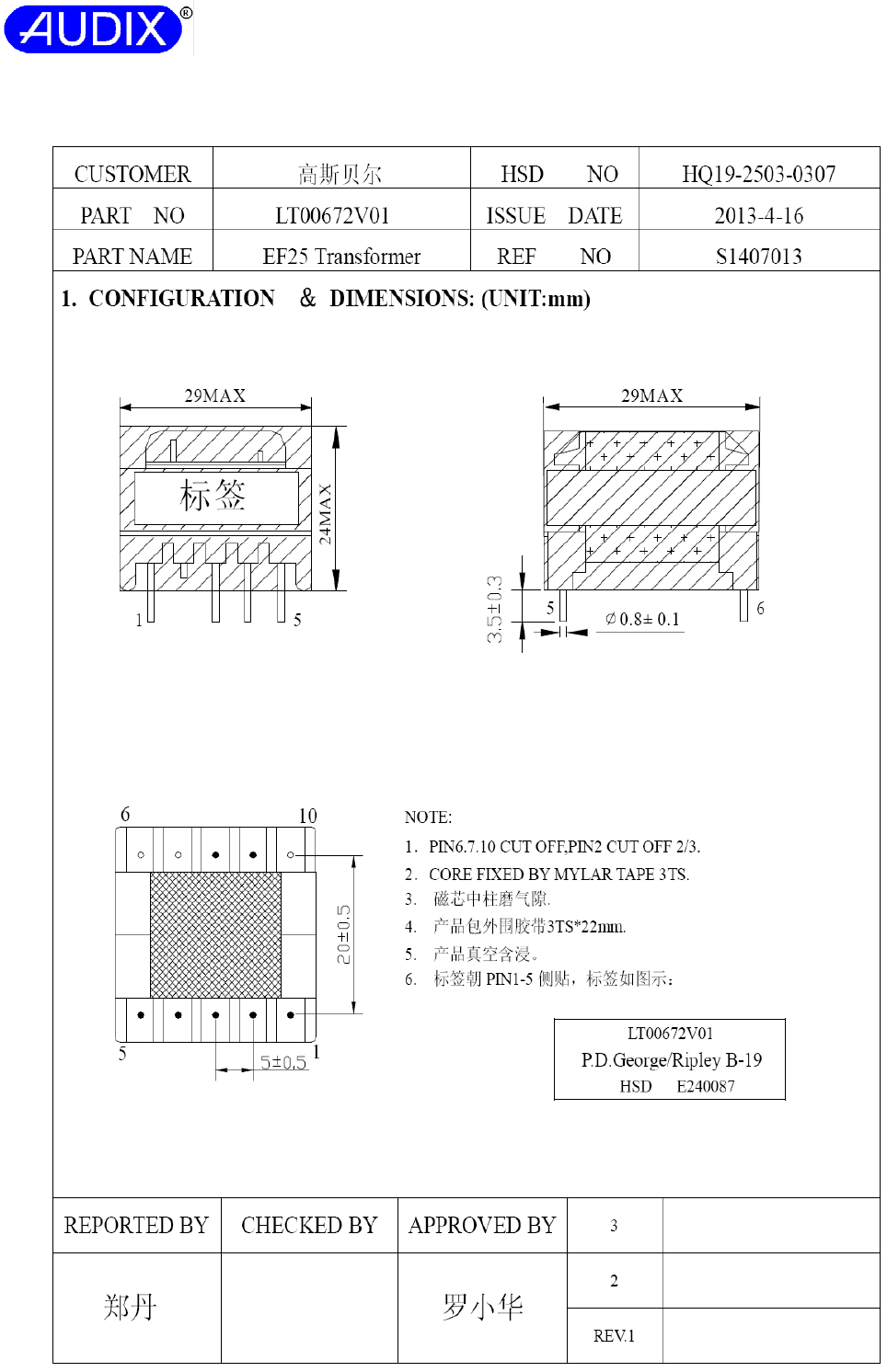
Report No.: ACSS1407139-01
AUDIX TECHNOLOGY (SHENZHEN) CO., LTD
Attachment C: Transformer T1 Specification for G0682 (model:LT00672V01) Page 1 of 6
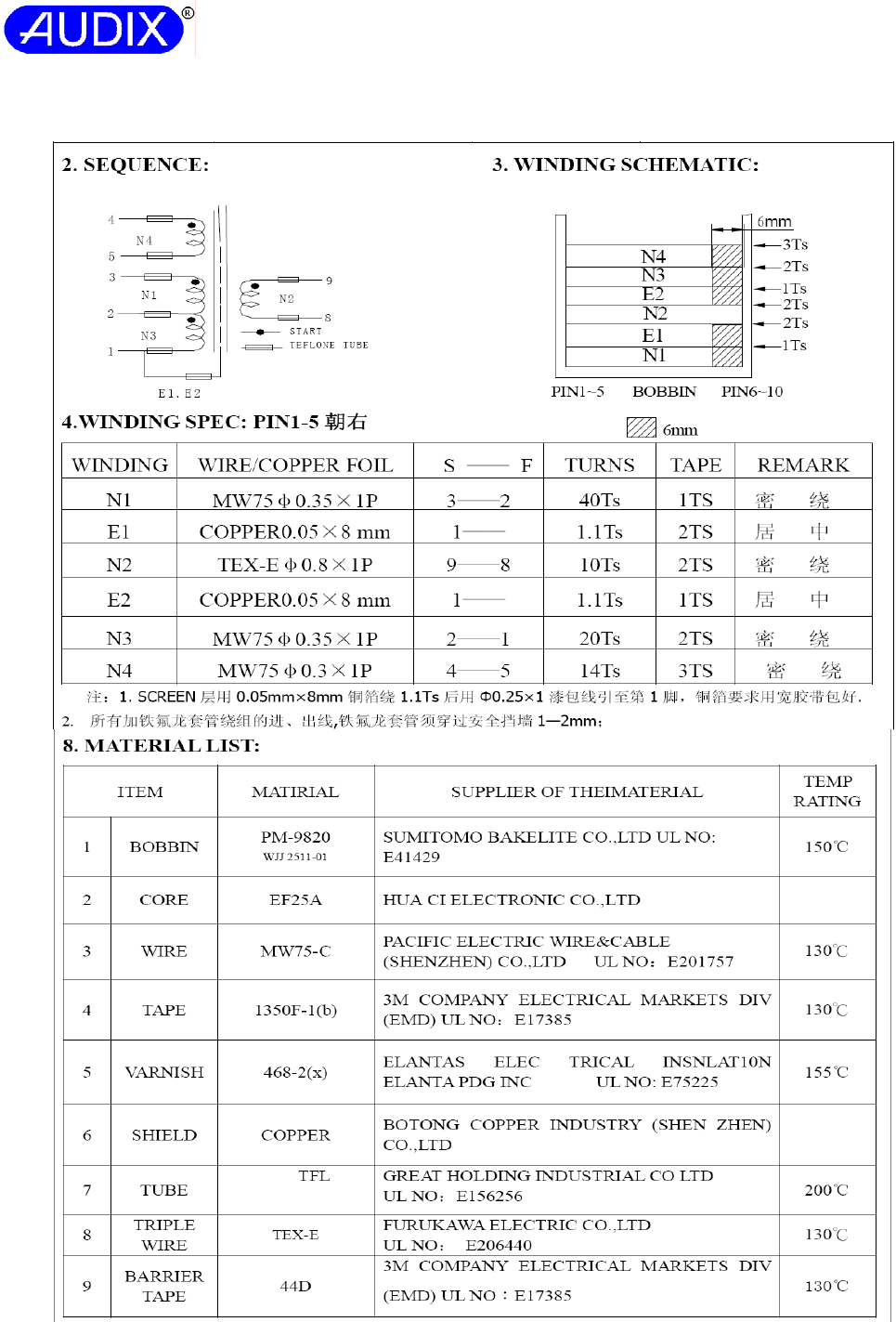
Report No.: ACSS1407139-01
AUDIX TECHNOLOGY (SHENZHEN) CO., LTD
Attachment C: Transformer T1 Specification for G0682 (model:LT00672V01) Page 2 of 6
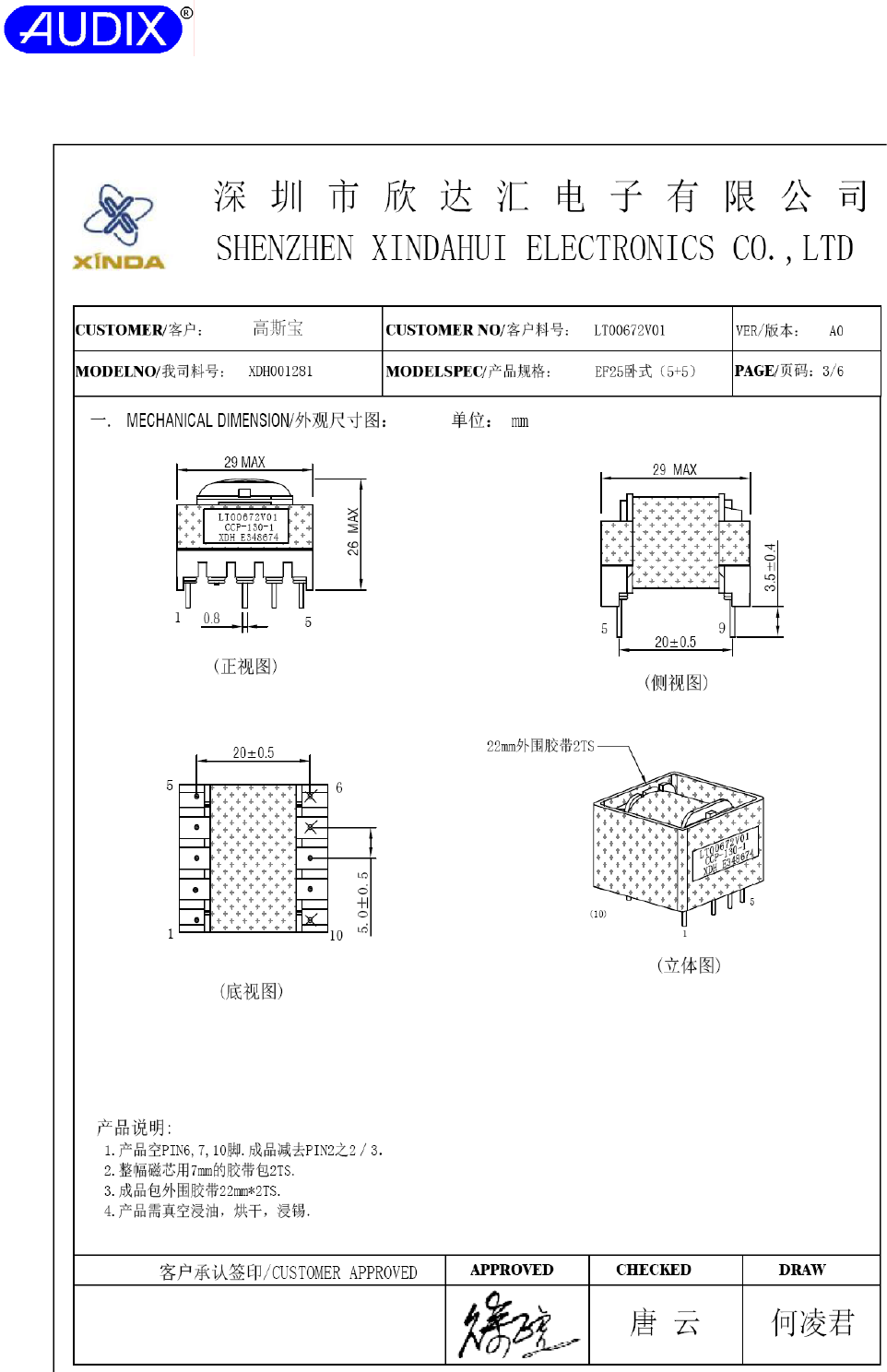
Report No.: ACSS1407139-01
AUDIX TECHNOLOGY (SHENZHEN) CO., LTD
Attachment C: Transformer T1 Specification for G0682 (model: LT00672V01) Page 3 of 6
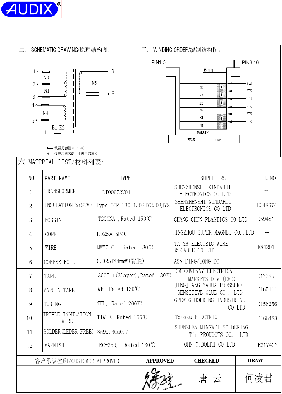
Report No.: ACSS1407139-01
AUDIX TECHNOLOGY (SHENZHEN) CO., LTD
Attachment C: Transformer T1 Specification for G0682 (model: LT00672V01) Page 4 of 6
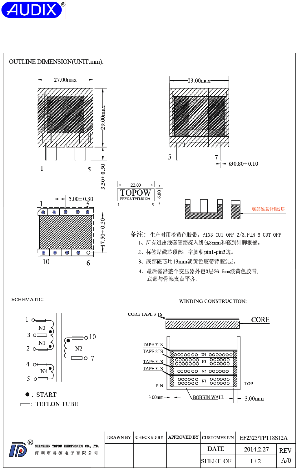
Report No.: ACSS1407139-01
AUDIX TECHNOLOGY (SHENZHEN) CO., LTD
Attachment C: Transformer T1 Specification for TPT18S12A (model: EF2525) Page 5 of 6
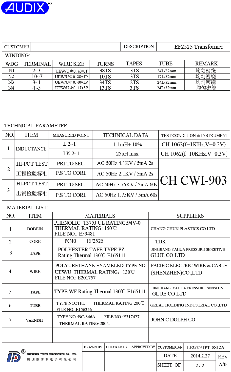
Report No.: ACSS1407139-01
AUDIX TECHNOLOGY (SHENZHEN) CO., LTD
Attachment C: Transformer T1 Specification for TPT18S12A (model: EF2525) Page 6 of 6
