FCTM M2K 006 FLIGHT CREW TECHNIQUES MANUAL A320 A319 2K
User Manual: Pdf
Open the PDF directly: View PDF ![]() .
.
Page Count: 454 [warning: Documents this large are best viewed by clicking the View PDF Link!]
- FCTM - 05 SEP 17 - GLG - A318/A319/A320/A321
- Front Matter
- Preliminary Pages
- General Information
- Airbus Operational Philosophy
- Aircraft Systems
- Procedures
- Preliminary Pages
- Normal Procedures
- General
- Standard Operating Procedures
- Supplementary Procedures
- Abnormal and Emergency Procedures
- General
- AUTO FLIGHT
- BRAKES
- ELEC
- ENG
- Introduction
- All Engines Failure
- Engine Failure - General
- Engine Failure at Low Speed (on ground)
- Engine Failure after V1
- Engine Failure During Initial Climb
- Engine Failure During Cruise
- Engine Stall
- Engine Tailpipe Fire
- Engine Vibrations
- One Engine Inoperative - Circling
- One Engine Inoperative - Go-Around
- One Engine Inoperative - Landing
- Thrust Levers Management in the Case of Inoperative Reverser(s)
- F/CTL
- FUEL
- HYD
- L/G
- MISC
- NAV
- SMOKE
- Preventing Identified Risks

REFERENCE: GLG A318/A319/A320/A321 FLEET FCTM ISSUE DATE: 05 SEP 17
A318/A319/A320/A321
FLIGHT CREW
TECHNIQUES MANUAL
The content of this document is the property of Airbus. It is supplied in confidence and commercial
security on its contents must be maintained. It must not be used for any purpose other than that for
which it is supplied, nor may information contained in it be disclosed to unauthorized persons. It must
not be reproduced in whole or in part without permission in writing from the owners of the copyright.
© AIRBUS 2005. All rights reserved.
Intentionally left blank

A318/A319/A320/A321
FLIGHT CREW
TECHNIQUES MANUAL
TRANSMITTAL LETTER
GLG A318/A319/A320/A321 FLEET TRL P 1/2
FCTM 05 SEP 17
Issue date: 05 SEP 17
This is the FLIGHT CREW TECHNIQUES MANUAL at issue date 05 SEP 17 for the
A318/A319/A320/A321 and replacing last issue dated 19 JUN 17

A318/A319/A320/A321
FLIGHT CREW
TECHNIQUES MANUAL
TRANSMITTAL LETTER
Intentionally left blank
GLG A318/A319/A320/A321 FLEET TRL P 2/2
FCTM 05 SEP 17

A318/A319/A320/A321
FLIGHT CREW
TECHNIQUES MANUAL
FILING INSTRUCTIONS
GLG A318/A319/A320/A321 FLEET FI P 1/2
FCTM 05 SEP 17
Please incorporate this revision as follow:
InsertLocalization
Subsection Title Remove Rev. Date
PLP-LESS
LIST OF EFFECTIVE SECTIONS/SUBSECTIONS ALL 05 SEP 17
PLP-LEDU
LIST OF EFFECTIVE DOCUMENTARY UNITS ALL 05 SEP 17
PLP-LOM
LIST OF MODIFICATIONS ALL 05 SEP 17
AOP-PLP-TOC
TABLE OF CONTENTS ALL 05 SEP 17
AOP-PLP-SOH
SUMMARY OF HIGHLIGHTS ALL 05 SEP 17
AOP-10-20-20
Design Principles ALL 05 SEP 17
AOP-10-20-30
Utilization Principles ALL 05 SEP 17
AS-PLP-TOC
TABLE OF CONTENTS ALL 05 SEP 17
AS-PLP-SOH
SUMMARY OF HIGHLIGHTS ALL 05 SEP 17
AS-FG-10-2
Autothrust ALL 05 SEP 17
AS-FM-10
Use of FMS ALL 05 SEP 17
AS-RUD
Rudder ALL 05 SEP 17
AS-WXR
Weather Radar ALL 05 SEP 17
PR-PLP-TOC
TABLE OF CONTENTS ALL 05 SEP 17
PR-PLP-SOH
SUMMARY OF HIGHLIGHTS ALL 05 SEP 17
PR-NP-GEN
General ALL 05 SEP 17
PR-NP-SOP-60
Cockpit Preparation ALL 05 SEP 17
PR-NP-SOP-100
Taxi ALL 05 SEP 17
PR-NP-SOP-150
Cruise ALL 05 SEP 17
Continued on the following page

A318/A319/A320/A321
FLIGHT CREW
TECHNIQUES MANUAL
FILING INSTRUCTIONS
GLG A318/A319/A320/A321 FLEET FI P 2/2
FCTM 05 SEP 17
Continued from the previous page
InsertLocalization
Subsection Title Remove Rev. Date
PR-NP-SOP-160
Descent Preparation ALL 05 SEP 17
PR-NP-SOP-170
Descent ALL 05 SEP 17
PR-NP-SOP-180
Holding ALL 05 SEP 17
PR-NP-SOP-190-CONF
Configuration Management ALL 05 SEP 17
PR-NP-SOP-190-GUI
Guidance Management ALL 05 SEP 17
PR-NP-SOP-260
Go-Around ALL 05 SEP 17
PR-NP-SP-10-10-1
Cold Weather Operations and Icing Conditions ALL 05 SEP 17
PR-NP-SP-10-10-3
Windshear ALL 05 SEP 17
PR-AEP-BRK
BRAKES ALL 05 SEP 17
PR-AEP-ELEC
ELEC ALL 05 SEP 17
PR-AEP-ENG
ENG ALL 05 SEP 17
PR-AEP-HYD
HYD ALL 05 SEP 17
PR-AEP-MISC
MISC ALL 05 SEP 17
PR-AEP-NAV
NAV ALL 05 SEP 17
PRELIMINARY PAGES
Intentionally left blank

A318/A319/A320/A321
FLIGHT CREW
TECHNIQUES MANUAL
PRELIMINARY PAGES
TABLE OF CONTENTS
GLG A318/A319/A320/A321 FLEET PLP-TOC P 1/2
FCTM 19 JUN 17
GI General Information
AOP Airbus Operational Philosophy
AS Aircraft Systems
PR Procedures
PIR Preventing Identified Risks

A318/A319/A320/A321
FLIGHT CREW
TECHNIQUES MANUAL
PRELIMINARY PAGES
TABLE OF CONTENTS
Intentionally left blank
GLG A318/A319/A320/A321 FLEET PLP-TOC P 2/2
FCTM 19 JUN 17

A318/A319/A320/A321
FLIGHT CREW
TECHNIQUES MANUAL
PRELIMINARY PAGES
LIST OF EFFECTIVE SECTIONS/SUBSECTIONS
GLG A318/A319/A320/A321 FLEET PLP-LESS P 1/2
FCTM 05 SEP 17
M(1) Localization Subsection Title Rev. Date
R PLP-LESS LIST OF EFFECTIVE SECTIONS/SUBSECTIONS 05 SEP 17
PLP-LETDU LIST OF EFFECTIVE TEMPORARY DOCUMENTARY UNITS 22 MAR 17
GI General Information 22 MAR 17
AOP-10-10 Introduction 22 MAR 17
AOP-10-20-10 Objective 22 MAR 17
R AOP-10-20-20 Design Principles 05 SEP 17
R AOP-10-20-30 Utilization Principles 05 SEP 17
AOP-10-30-10 Design Principles 22 MAR 17
AOP-10-30-20 Utilization Principles 22 MAR 17
AOP-10-40 Procedures Design 22 MAR 17
AOP-20 Tasksharing Rules and Communication 22 MAR 17
AOP-30-10 General 22 MAR 17
AOP-30-20 Handling of Cockpit Controls 22 MAR 17
AOP-30-30 Handling of ECAM/QRH/OEB 22 MAR 17
AOP-30-40 Handling of Advisory 22 MAR 17
AOP-30-50 Spurious Caution 22 MAR 17
AOP-30-60 Use of Summaries 22 MAR 17
AOP-40 Golden Rules for Pilots 19 JUN 17
AS-BIRD Bird 22 MAR 17
AS-FG-10-1 Auto Flight 22 MAR 17
R AS-FG-10-2 Autothrust 05 SEP 17
R AS-FM-10 Use of FMS 05 SEP 17
AS-ROWROP ROW/ROP 19 JUN 17
E AS-RUD Rudder 05 SEP 17
AS-TCAS TCAS 22 MAR 17
R AS-WXR Weather Radar 05 SEP 17
R PR-NP-GEN General 05 SEP 17
PR-NP-SOP-40 Preliminary Cockpit Preparation 22 MAR 17
PR-NP-SOP-50 Exterior Walkaround 22 MAR 17
R PR-NP-SOP-60 Cockpit Preparation 05 SEP 17
PR-NP-SOP-70 Before Pushback or Start 22 MAR 17
R PR-NP-SOP-100 Taxi 05 SEP 17
PR-NP-SOP-110 Before Takeoff 22 MAR 17
PR-NP-SOP-120 Takeoff 22 MAR 17
PR-NP-SOP-140 Climb 19 JUN 17
R PR-NP-SOP-150 Cruise 05 SEP 17
R PR-NP-SOP-160 Descent Preparation 05 SEP 17
R PR-NP-SOP-170 Descent 05 SEP 17
R PR-NP-SOP-180 Holding 05 SEP 17
PR-NP-SOP-190-GEN General 22 MAR 17
Continued on the following page

A318/A319/A320/A321
FLIGHT CREW
TECHNIQUES MANUAL
PRELIMINARY PAGES
LIST OF EFFECTIVE SECTIONS/SUBSECTIONS
GLG A318/A319/A320/A321 FLEET PLP-LESS P 2/2
FCTM 05 SEP 17
Continued from the previous page
M(1) Localization Subsection Title Rev. Date
R PR-NP-SOP-190-CONF Configuration Management 05 SEP 17
R PR-NP-SOP-190-GUI Guidance Management 05 SEP 17
PR-NP-SOP-250 Landing 19 JUN 17
R PR-NP-SOP-260 Go-Around 05 SEP 17
PR-NP-SOP-270 After Landing 22 MAR 17
R PR-NP-SP-10-10-1 Cold Weather Operations and Icing Conditions 05 SEP 17
PR-NP-SP-10-10-2 Turbulence 22 MAR 17
R PR-NP-SP-10-10-3 Windshear 05 SEP 17
PR-NP-SP-20 Green Operating Procedures 22 MAR 17
PR-NP-SP-30 Radius to Fix (RF) Legs 22 MAR 17
PR-NP-SP-40 Touch and Go 22 MAR 17
PR-NP-SP-50 Stop and Go 22 MAR 17
PR-AEP-GEN General 22 MAR 17
PR-AEP-AUTOFLT AUTO FLIGHT 22 MAR 17
R PR-AEP-BRK BRAKES 05 SEP 17
R PR-AEP-ELEC ELEC 05 SEP 17
R PR-AEP-ENG ENG 05 SEP 17
PR-AEP-F_CTL F/CTL 22 MAR 17
PR-AEP-FUEL FUEL 22 MAR 17
R PR-AEP-HYD HYD 05 SEP 17
PR-AEP-LG L/G 05 SEP 17
R PR-AEP-MISC MISC 05 SEP 17
R PR-AEP-NAV NAV 05 SEP 17
PR-AEP-SMOKE SMOKE 22 MAR 17
PIR Preventing Identified Risks 19 JUN 17
(1) Evolution code : N=New, R=Revised, E=Effectivity, M=Moved

A318/A319/A320/A321
FLIGHT CREW
TECHNIQUES MANUAL
PRELIMINARY PAGES
LIST OF EFFECTIVE TEMPORARY DOCUMENTARY UNITS
GLG A318/A319/A320/A321 FLEET PLP-LETDU P 1/2
FCTM 22 MAR 17
M Localization DU Title DU identification DU date
No Temporary Documentary Unit

A318/A319/A320/A321
FLIGHT CREW
TECHNIQUES MANUAL
PRELIMINARY PAGES
LIST OF EFFECTIVE TEMPORARY DOCUMENTARY UNITS
Intentionally left blank
GLG A318/A319/A320/A321 FLEET PLP-LETDU P 2/2
FCTM 22 MAR 17

A318/A319/A320/A321
FLIGHT CREW
TECHNIQUES MANUAL
PRELIMINARY PAGES
AIRCRAFT ALLOCATION TABLE
GLG A318/A319/A320/A321 FLEET PLP-AAT P 1/2
FCTM 19 JUN 17
This table gives, for each delivered aircraft, the cross reference between:
- The Manufacturing Serial Number (MSN).
- The Fleet Serial Number (FSN) of the aircraft as known by AIRBUS S.A.S.
- The registration number of the aircraft as known by AIRBUS S.A.S.
- The aircraft model.
M(1) MSN FSN Registration Number Model
1882 HC-CKN 319-112
2078 HC-CLF 319-112
3408 HC-CRU 320-214
3467 HC-CSB 319-115
3518 HC-CSA 319-115
4100 HC-CSF 320-214
4379 HC-CJM 320-214
4487 HC-CJW 320-214
4547 HC-CJV 320-214
(1) Evolution code : N=New, R=Revised

A318/A319/A320/A321
FLIGHT CREW
TECHNIQUES MANUAL
PRELIMINARY PAGES
AIRCRAFT ALLOCATION TABLE
Intentionally left blank
GLG A318/A319/A320/A321 FLEET PLP-AAT P 2/2
FCTM 19 JUN 17

A318/A319/A320/A321
FLIGHT CREW
TECHNIQUES MANUAL
PRELIMINARY PAGES
LIST OF MODIFICATIONS
GLG A318/A319/A320/A321 FLEET PLP-LOM P 1/2
FCTM 05 SEP 17
M(1) MODIFICATION Linked SB Incorp. Date Title
J0071 22 MAR 17 WING STRUCTURE-INTRODUCTION OF A WING TIP
INCORPORATING A TIP FENCE FOR 72T MTOW A/C
Applicable to: ALL
K3154 22 MAR 17 FUSELAGE - REAR FUSELAGE - ADAPT STRUCTURE
OF SECTION 17 TO 19 TO A319 DEFINITION
Applicable to: HC-CKN, HC-CLF, HC-CSA, HC-CSB
P10383 31-1334 04
31-1414 03
22 MAR 17 INDICATING/RECORDING SYSTEMS FLIGHT
WARNING COMPUTER (FWC) INSTALL FWC
STANDARD H2-F5
Applicable to: ALL
P10694 22-1296 06 22 MAR 17 AUTO-FLIGHT - FMGC ACTIVATE "MOD NAV IN GO
AROUND" ON FMGC
Applicable to: HC-CJM, HC-CJV, HC-CJW, HC-CSB
P11856 22-1315 05 22 MAR 17 AUTO - FLIGHT FMGC: ACTIVATE NO AP
DISCONNECTION BELOW MDA/MDH UNTIL MISSED
APPROACH POINT
Applicable to: ALL
P3379 22 MAR 17 INDICATING/RECORDING SYSTEMS - GENERAL -
DEFINE PIN PROGRAMMING FOR STD VERSIONS
Applicable to: ALL
P3560 22 MAR 17 AUTO FLIGHT - FMGC - PROVIDE TIME CONSTRAINT
AND TEN CHARACTERS RTE IDENT FUNCTIONS
Applicable to: ALL
P4319 22 MAR 17 AUTO FLIGHT/FCU DEFINE FD ENGAGEMENT IN
CROSSED BARS AT GO AROUND
Applicable to: ALL
P4320 22 MAR 17 AUTO FLIGHT - ACTIVATE GLOBAL SPEED
PROTECTION AND FD DISENGAGEMENT UPON
SPEED CONDITIONS
Applicable to: ALL
P4576 22 MAR 17 LANDING GEAR-GENERAL WHEELS AND BRAKES
EQUIPMENT COST REDUCTION ELECTRICAL
ALTERNATE BRAKING
Applicable to: HC-CJM, HC-CJV, HC-CJW, HC-CRU, HC-CSA, HC-CSB, HC-CSF
P4808 22 MAR 17 LANDING GEAR - GENERAL - WHEELS AND BRAKES
- EQUIPMENT COST REDUCTION BSCU REDESIGN
Applicable to: HC-CJM, HC-CJV, HC-CJW, HC-CRU, HC-CSA, HC-CSB, HC-CSF
P5518 22 MAR 17 LANDING GEAR - GENERAL - NORMAL BRAKING -
INTRODUCE STD 8 BSCU TWIN VERSION
Applicable to: ALL
Continued on the following page
A318/A319/A320/A321
FLIGHT CREW
TECHNIQUES MANUAL
PRELIMINARY PAGES
LIST OF MODIFICATIONS
GLG A318/A319/A320/A321 FLEET PLP-LOM P 2/2
FCTM 05 SEP 17
Continued from the previous page
M(1) MODIFICATION Linked SB Incorp. Date Title
P5768 22 MAR 17 ELECTRICAL POWER - AC EMERGENCY
GENERATION - ACTIVATE ON A320 SAME
ELECTRICAL EMERG. CONFIGURATION THAN A321
Applicable to: HC-CJM, HC-CJV, HC-CJW, HC-CRU, HC-CSF
P6375 22 MAR 17 LANDING GEAR-PARKING/ULTIMATE EMERGENCY
BRAKING -INSTALL A PRESSURE SWITCH (PARKING
BRAKE SYSTEM IMPROVEMENT
Applicable to: ALL
P7218 22 MAR 17 AUTOFLIGHT - FLIGHT MANAGEMENT AND
GUIDANCE COMPUTER (FMGC) DEVELOP FMS 2ND
GENERATION HONEYWELL STEP1
Applicable to: ALL
P7519 22 MAR 17 AUTOFLIGHT - FMGC - INSTALL FMGC CFM
C13042AA01 (EQUIPPED WITH FMS2 HONEYWELL)
Applicable to: ALL
P7721 32-1247 02 22 MAR 17 LANDING GEAR - WHEELS AND BRAKES REMOVE
THE TEMPORARY REVISIONS 5.02.00/23 AND
5.03.00/23 ON FLIGHT MANAL
Applicable to: ALL
P7790 22 MAR 17 AUTO FLIGHT FLIGHT MANAGEMENT AND
GUIDANCE SYSTEM ACTIVATE FMA ENHANCEMENT
FUNCTION
Applicable to: HC-CJM, HC-CJV, HC-CJW, HC-CLF, HC-CRU, HC-CSA, HC-CSB, HC-CSF
P8440 32-1291 01 22 MAR 17 LANDING GEAR - WHEELS AND BRAKES
INTRODUCE GOODRICH DURACARB CARBON
BRAKES WITH ANTI - OXYDAN "M1"
Applicable to: ALL
P9171 22 MAR 17 NAVIGATION - ADIRS INTRODUCE AIR DATA
MONITORING FUNCTION
Applicable to: HC-CJV, HC-CJW
22-1359 05 22 MAR 17 AUTO-FLIGHT-FLIGHT MANAGEMENT AND
GUIDANCE COMPUTER (FMGC)-INSTALL FMGC
HONEYWELL H2C13 ON CFM A/C
Applicable to: HC-CJM, HC-CJV, HC-CJW, HC-CKN, HC-CLF, HC-CSB
E 22-1480 03 12 APR 17 AUTO FLIGHT-FLIGHT AUGMENTATION (FAC)
DEFINE STOP RUDDER INPUT WARNING FUNCTION
ON AIRCRAFT
Applicable to: HC-CLF, HC-CSA, HC-CSB, HC-CSF
22-1559 02 19 JUN 17 AUTO FLIGHT - GENERAL - ACTIVATE ROPS
FUNCTION
Applicable to: HC-CSB
(1) Evolution code : N=New, R=Revised, E=Effectivity
GENERAL INFORMATION
Intentionally left blank

A318/A319/A320/A321
FLIGHT CREW
TECHNIQUES MANUAL
GENERAL INFORMATION
PRELIMINARY PAGES
TABLE OF CONTENTS
GLG A318/A319/A320/A321 FLEET GI-PLP-TOC P 1/2
FCTM 22 MAR 17
FCTM Purpose.........................................................................................................................................................A
FCTM Content......................................................................................................................................................... B
Introduction to the Preventing Identified Risks....................................................................................................... C
Questions and Suggestions.................................................................................................................................... D
Abbreviations............................................................................................................................................................E

A318/A319/A320/A321
FLIGHT CREW
TECHNIQUES MANUAL
GENERAL INFORMATION
PRELIMINARY PAGES
TABLE OF CONTENTS
Intentionally left blank
GLG A318/A319/A320/A321 FLEET GI-PLP-TOC P 2/2
FCTM 22 MAR 17

A318/A319/A320/A321
FLIGHT CREW
TECHNIQUES MANUAL
GENERAL INFORMATION
GLG A318/A319/A320/A321 FLEET GI P 1/22
FCTM A to B → 22 MAR 17
FCTM PURPOSE
Ident.: GI-00016234.0001001 / 20 MAR 17
Applicable to: ALL
The Flight Crew Techniques Manual (FCTM ) provides complementary information to the Flight Crew
Operating Manual (FCOM).
The FCTM provides the flight crew with:
‐ The general Airbus operational philosophy (e.g. design and utilization principles, golden rules for
pilots)
‐ Additional information to the FCOM procedures (the “why" to do and the “how" to do)
‐ Best practices, operating techniques on maneuvers, and handling
‐ Information on situation awareness.
If the FCTM data differs from the FCOM data, the FCOM remains the reference.
FCTM CONTENT
Ident.: GI-00018007.0001001 / 20 MAR 17
Applicable to: ALL
The FCTM has 5 sections:
GENERAL INFORMATION
This section provides information on:
‐ The FCTM purpose
‐ The FCTM content
‐ The introduction to the Preventing Identified Risks
‐ The abbreviations.
AIRBUS OPERATIONAL PHILOSOPHY
This section is divided into four sub-sections:
1. Design Philosophy:
This sub-section describes the Airbus design and utilization principles of:
‐ The cockpit
‐ The fly-by-wire
‐ The procedures.
2. Tasksharing rules and communication:
This sub-section describes the general tasksharing and communication rules in normal and
abnormal operations.
3. Management of Abnormal Operations:

A318/A319/A320/A321
FLIGHT CREW
TECHNIQUES MANUAL
GENERAL INFORMATION
GLG A318/A319/A320/A321 FLEET GI P 2/22
FCTM ← B to D 22 MAR 17
This sub-section describes how the flight crew should manage abnormal operations (e.g.
Handling of ECAM alerts, QRH, ADVISORY)
4. Golden Rules for Pilots:
This sub-section describes the Airbus "GOLDEN RULES FOR PILOTS".
AIRCRAFT SYSTEMS
This section provides supplementary information and operating techniques on the use of specific
systems (e.g. BIRD, TCAS)
PROCEDURES
This section provides in normal and abnormal operations:
‐ Best practices (why to, how to, what if not done)
‐ Maneuvers and handling techniques
This section is divided into two sub-sections:
1. Normal Procedures (including Supplementary Procedures)
2. Abnormal and Emergency Procedures.
PREVENTING IDENTIFIED RISKS
This section provides the glossary of the identified risks and potential consequences that the flight
crew may encounter.
INTRODUCTION TO THE PREVENTING IDENTIFIED RISKS
Ident.: GI-00016235.0001001 / 20 MAR 17
Applicable to: ALL
The aim of this chapter is to highlight some of the risks and potential consequences that the flight
crew may encounter, in order to improve:
‐ The awareness of the flight crew with regards to these risks
‐ The risk management.
Refer to PIR Introduction.
QUESTIONS AND SUGGESTIONS
Ident.: GI-00018644.0001001 / 20 MAR 17
Applicable to: ALL
For any questions or comments related to this manual, the Operator’s Flight Operations Management
may contact the Airbus Flight Operations Support & Training Standards department.

A318/A319/A320/A321
FLIGHT CREW
TECHNIQUES MANUAL
GENERAL INFORMATION
GLG A318/A319/A320/A321 FLEET GI P 3/22
FCTM E → 22 MAR 17
ABBREVIATIONS
Ident.: GI-00018009.0001001 / 20 MAR 17
Applicable to: ALL
A
Abbreviation Term
A>B A is greater than B
A≥B A is greater than or equal to B
A<B A is less than B
A≤B A is less than or equal to B
A/BRK Autobrake
A/C Aircraft
A/P Autopilot
AP Autopilot
A/S Airspeed
A/SKID Anti-skid
A/THR Auto Thrust
AA Airworthiness Authorities
AB Abort
ABCU Alternate Braking Control Unit
ABN Abnormal
ABV Above
AC Alternating Current
ACARS ARINC Communication Addressing and Reporting System
ACAS Airbrone Collision Avoidance System
ACCEL Acceleration
ACC Active Clearance Control
ACCU Accumulator
ACP Audio Control Panel
ACSC Air Conditioning System Controller
ACT Additional Center Tank
ADF Automatic Direction Finder
ADIRS Air Data Inertial Reference System
ADIRU Air Data Inertial Reference Unit
ADM Air Data Module
ADR Air Data Reference
ADS-B Automatic Dependent Surveillance-Broadcast
ADV Advisory
AEVC Avionic Equipment Ventilation Controller
AFM Airplane Flight Manual
AFS Auto Flight System
AGL Above Ground Level
Continued on the following page

A318/A319/A320/A321
FLIGHT CREW
TECHNIQUES MANUAL
GENERAL INFORMATION
GLG A318/A319/A320/A321 FLEET GI P 4/22
FCTM ← E → 22 MAR 17
Continued from the previous page
Abbreviation Term
AIDS Aircraft Integrated Data System
AIL Aileron
AIME Autonomous Integrity Monitoring Extrapolation
AIU Audio Interface Unit
ALT Altitude
ALTN Alternate
AMI Airline Modifiable Information
AMU Audio Management Unit
ANT Antenna
AOA Angle of Attack
AOC Airline Operational Control
APP Approach
APPR Approach
APPU Assymetry Position Pick-off Unit
APU Auxiliary Power Unit
AR Authorization Required
ARINC Aeronautical Radio Incorporated
ARN Aircraft Registration Number
ARP Aerospace Recommended Practice
ARPT Airport
ASAP As Soon As Possible
ASI Air Speed Indicator
ASP Audio Selector Panel
ATC Air Traffic Control
ATM Air Traffic Management
ATN Aeronautical Telecommunications Network
ATE Automatic Test Equipment
ATIS Automatic Terminal Information Service
ATS Air Traffic Service
ATSAW Airbrone Traffic Situational Awareness
ATSU Air Traffic Service Unit
ATT Attitude
AUTO Automatic
AVNCS Avionics
AWY Airway
B
Abbreviation Term
B/C Back Course
BARO Barometric
Continued on the following page

A318/A319/A320/A321
FLIGHT CREW
TECHNIQUES MANUAL
GENERAL INFORMATION
GLG A318/A319/A320/A321 FLEET GI P 5/22
FCTM ← E → 22 MAR 17
Continued from the previous page
Abbreviation Term
BAT Battery
BCL Battery Charge Limiter
BCDS Bite Centralized Data System
BCU Backup Control Unit
BDDV Brake Dual Distribution Valve
BITE Built-In Test Equipment
BIU BITE Interface Unit
BFE Buyer Furnished Equipment
BFO Beat Frequency Oscillator
BMC Bleed Monitoring Computer
BNR Binary
BRG Bearing
BRK Brake
BRT Bright
BSCU Braking Steering Control Unit
BTC Bus Tie Contactor
BTL Bottle
BUS Busbar
C
Abbreviation Term
C/B Circuit Breaker
CB Circuit Breaker
C/L Checklist
CL Checklist
CAB Cabin
CAPT Captain, Capture
CAS Calibrated Airspeed
CAT Category
CBMS Circuit Breaker Monitoring System
CCD Cursor Control Device
CDL Configuration Deviation List
CDLS Cockpit Door Locking System
CDSS Cockpit Door Surveillance System
CDU Control Display Unit
CF Cost of Fuel
CFDIU Centralized Fault Display Interface Unit
CFDS Centralized Fault Display System
CG Center of Gravity
CHAN Channel
Continued on the following page

A318/A319/A320/A321
FLIGHT CREW
TECHNIQUES MANUAL
GENERAL INFORMATION
GLG A318/A319/A320/A321 FLEET GI P 6/22
FCTM ← E → 22 MAR 17
Continued from the previous page
Abbreviation Term
CHG Change
CHK Check
CI Cost Index
CIDS Cabin Intercommunication Data System
CKPT Cockpit
CLB Climb
CLR Clear
CLSD Closed
CM1(2) Crewmember 1 (left seat) or 2 (right seat)
CM1 Crewmember 1 (left seat)
CM2 Crewmember 2 (right seat)
CMPTR Computer
CMS Constant Mach Segment
CMS Centralized Maintenance System
CNSU Cabin Network Server Unit
CO Company
CO RTE Company Route
COND Conditioning
CONF Configuration
CONT Continuous
CPC Cabin Pressure Controller
CPCU Cabin Pressure Controller Unit
CPDLC Controller-Pilot Data Link Communication
CRC Continuous Repetitive Chime
CRG Cargo
CRS Course
CRT Cathode Ray Tube
CRZ Cruise
CSAS Conditioned Service Air System
CSCU Cargo Smoke Control Unit
CSD Constant Speed Drive
CSM/G Constant Speed Motor/Generator
CSTR Constraint
CT Cost of Time
CTL Control
CTL PNL Control Panel
CTR Center
CVR Cockpit Voice Recorder

A318/A319/A320/A321
FLIGHT CREW
TECHNIQUES MANUAL
GENERAL INFORMATION
GLG A318/A319/A320/A321 FLEET GI P 7/22
FCTM ← E → 22 MAR 17
D
Abbreviation Term
DA Drift Angle
DAC Digital to Analog Converter
DAR Digital AIDS Recorder
DC Direct Current
DCDU Datalink Control and Display Unit
DCL Digital Cabin Logbook
DDRMI Digital Distance and Radio Magnetic Indicator
DECEL Deceleration
DES Descent
DEST Destination
DET Detection, Detector
DFA Delayed Flap Approach
DFDR Digital Flight Data Recorder
DH Decision Height
DIR Direction
DIR TO Direct To
DISC Disconnect
DISCH Discharge
DIST Distance
DITS Digital Information Transfer System
DIV Diverter
DMC Display Management Computer
DME Distance Measuring Equipment
DMU Data Management Unit (Aids)
DN Down
DSDL Dedicated Serial Data Link
DTG Distance To Go
DTO Derated Takeoff
DU Display Unit
DU Documentary Unit
E
Abbreviation Term
EWD Engine/Warning Display
ECAM Electronic Centralized Aircraft Monitoring
ECAS Emergency Cockpit Alerting System
ECB Electronic Control Box (APU)
ECM Engine Condition Monitoring
ECON Economic
Continued on the following page

A318/A319/A320/A321
FLIGHT CREW
TECHNIQUES MANUAL
GENERAL INFORMATION
GLG A318/A319/A320/A321 FLEET GI P 8/22
FCTM ← E → 22 MAR 17
Continued from the previous page
Abbreviation Term
ECP ECAM Control Panel
ECS Environmental Control System
ECU Engine Control Unit
EDP Engine-Driven Pump
EEC Electronic Engine Computer
EFB Electronic Flight Bag
EFCS Electronic Flight Control System
EFIS Electronic Flight Instruments System
EFOB Estimated Fuel On Board
EGPWS Enhanced Ground Proximity Warning System
EGT Exhaust Gas Temperature
EIS Electronic Instruments System
EIU Engine Interface Unit
ELAC Elevator Aileron Computer
ELEC Electrics
ELT Emergency Locator Transmitter
ELEV Elevator
ELV Elevation
EMER Emergency
EMER GEN Emergency Generator
ENG Engine
EO Engine-Out
EOSID Engine-Out Standard Instrument Departure
EPE Estimated Position Error (equal to EPU)
EPR Engine Pressure Ratio
EPU Emergency Power Unit
EPU Estimated Position Uncertainty (equal to EPE)
EROPS Extended Range Operation
ESS Essential
EST Estimated
ETA Estimated Time of Arrival
ETE Estimated Time Enroute
ETOPS Extended Twin Operations
ETP Equal Time Point
EVMU Engine Vibration Monitoring Unit
E/WD Engine/Warning Display
EXP Expedite
EXT PWR External Power
EXTN Extension

A318/A319/A320/A321
FLIGHT CREW
TECHNIQUES MANUAL
GENERAL INFORMATION
GLG A318/A319/A320/A321 FLEET GI P 9/22
FCTM ← E → 22 MAR 17
F
Abbreviation Term
F Fuel
FAA Federal Aviation Administration
FAP Forward Attendant Panel
F/C Flight Crew
F/O First Officer
FO First Officer
FAC Flight Augmentation Computer
FADEC Full Authority Digital Engine Control System
FAF Final Approach Fix
FAP Forward Attendant Panel
FAR Federal Aviation Regulations
FAV Fan Air Valve
FCDC Flight Control Data Concentrator
FCMS Fuel Control and Monitoring System
FCOM Flight Crew Operating Manual
FCU Flight Control Unit
FD Flight Director
FDIMU Flight Data Interface and Management Unit
FDIU Flight Data Interface Unit
FDU Fire Detection Unit
FEP Final End Point
FF Fuel Flow
FG Flight Guidance
FGC Flight Guidance Computer
F-G/S FLS Glide Slope
FIDS Fault Isolation and Detection System
FL Flight Level
FLHV Fuel Lower Heating Value
F-LOC FLS Localizer
FLP Flap
FLS FMS Landing System
FLT Flight
F/CTL Flight Control
FLT CTL Flight Control
FLXTO Flexible Takeoff
FM Flight Management
FMA Flight Mode Annunciator
FMGC Flight Management and Guidance Computer
FMGS Flight Management and Guidance System
Continued on the following page

A318/A319/A320/A321
FLIGHT CREW
TECHNIQUES MANUAL
GENERAL INFORMATION
GLG A318/A319/A320/A321 FLEET GI P 10/22
FCTM ← E → 22 MAR 17
Continued from the previous page
Abbreviation Term
FMS Flight Management System
FNL Final
FOB Fuel On Board
FOM Figure Of Merit
FPA Flight Path Angle
F-PLN Flight Plan
FPD Flight Path Director
FPPU Feedback Position Pick-off Unit
FPV Flight Path Vector
FQI Fuel Quantity Indication
FQU Fuel Quantity Unit
FREQ Frequency
FRT Front
FRV Fuel Return Valve
FU Fuel Used
FWC Flight Warning Computer
FWD Forward
FWS Flight Warning System
G
Abbreviation Term
G/S Glideslope
GA Go-Around
GAPCU Ground and Auxiliary Power Control Unit
GBAS Ground Based Augmentation System
GCU Generator Control Unit
GDU Group of Documentary Unit
GEN Generator
GES Ground Earth Station
GLC Generator Line Contactor
GLS GBAS Landing System
GLS GNSS Landing System
GMT Greenwich Mean Time
GND Ground
GND TEMP Ground Temperature
GPCU Ground Power Control Unit
GPIRS Global Positioning and Inertial Reference System
GPS Global Positioning System
GPWS Ground Proximity Warning System
GRND Ground
Continued on the following page

A318/A319/A320/A321
FLIGHT CREW
TECHNIQUES MANUAL
GENERAL INFORMATION
GLG A318/A319/A320/A321 FLEET GI P 11/22
FCTM ← E → 22 MAR 17
Continued from the previous page
Abbreviation Term
GRP Geographic Reference Point
GRVTY Gravity
GS Ground Speed
GW Gross Weight
H
Abbreviation Term
HC Harness Connector
HCU Hydraulic Control Unit
HDG Heading
HDG/S Heading Selected
HDL Handle
HF High Frequency
HI High
HLD Hold
HM Holding Pattern with a Manual Termination
HMU Hydrau-Mechanical Unit
HMS Heat Management System
HP High Pressure
HPA Hectopascal
HPV High Pressure Valve
HUD Head Up Display
HYD Hydraulic
I
Abbreviation Term
I/O Inputs/Outputs
I/P Input or Intercept Profile
IAF Initial Approach Fix
IAS Indicated Airspeed
IATA International Air Transport Association
ICAO International Air Transport Organization
IDENT Identification
IDG Integrated Drive Generator
IFE In Flight Entertainment
IFR Instrument Flight Rules
IGGS Inert Gas Generation System
IGN Ignition
ILS Instrument Landing System
IM Inner Marker
Continued on the following page

A318/A319/A320/A321
FLIGHT CREW
TECHNIQUES MANUAL
GENERAL INFORMATION
GLG A318/A319/A320/A321 FLEET GI P 12/22
FCTM ← E → 22 MAR 17
Continued from the previous page
Abbreviation Term
IMM Immediate
INB Inbound
INBO Inboard
INCREM Increment
INIT Initialization
INOP Inoperative
INR Inner
INST Instrument
INTCP Intercept
INV Inverter
IP Intermediate Pressure
IPC Intermediate Pressure Check valve
IPPU Instrumentation Position Pick-off Unit
IR Inertial Reference
IRS Inertial Reference System
ISA International Standard Atmosphere
ISDU Initial System Display Unit
ISIS Integrated Standby Instrument System
ISOL Isolation
ISPSS In Seat Power Supply System
J
Abbreviation Term
K
Abbreviation Term
L
Abbreviation Term
L/G Landing Gear
LAF Load Alleviation Function
LAT Latitude
LAT REV Lateral Revision
LAV Lavatory
LCD Liquid Crystal Display
LCN Load Classification Number
Landing Distance Available
LDA Localizer Directional Aid
LDG Landing
LDS Laptop Docking Station
Continued on the following page

A318/A319/A320/A321
FLIGHT CREW
TECHNIQUES MANUAL
GENERAL INFORMATION
GLG A318/A319/A320/A321 FLEET GI P 13/22
FCTM ← E → 22 MAR 17
Continued from the previous page
Abbreviation Term
LED Light Emiting Diode
LEDU List of Effective Documentary Units
LEOEB List of Effective Operations Engineering Bulletins
LESS List of Effective Section/Subsections
LF Low Frequency
LGCIU Landing Gear Control Interface Unit
LGPIU Landing Gear Position Indicator Unit
LH Left-Hand
LIM Limitation
LIS Localizer Inertial Smoothing
LK Lock
LL Latitude/Longitude
LLS Left-Line Select key
LO Low
LOC Localizer
LONG Longitude
LP Low Pressure
LRRA Low Range Radio Altimeter
LRU Line Replaceable Unit
LS Loudspeaker
LSK Line Select Key
LT Light
LTS Load and Trim Sheet
LVL Level
LVL/CH Level Change
LVR Lever
LW Landing Weight
M
Abbreviation Term
MABH Minimum Approach Break-off Height
MAC Mean Aerodynamic Chord
MAG Magnetic
MAG DEC Magnetic Declination
MAG VAR Magnetic Variation
MAINT Maintenance
MAN Manual
MAP Missed Approach Point
MAX Maximum
MAX CLB Maximum Climb
Continued on the following page

A318/A319/A320/A321
FLIGHT CREW
TECHNIQUES MANUAL
GENERAL INFORMATION
GLG A318/A319/A320/A321 FLEET GI P 14/22
FCTM ← E → 22 MAR 17
Continued from the previous page
Abbreviation Term
MAX DES Maximum Descent
MAX END Maximum Endurance
MC Master Caution
MCDU Multipurpose Control and Display Unit
MCT Maximum Continuous Thrust
MCU Modular Concept Unit
MDA Minimum Descent Altitude
MDDU Multifunction Disk Drive Unit
MDH Minimum Descent Height
MECH Mechanic
MEA Minimum En Route Altitude
MED Medium
MEL Minimum Equipment List
MFA Memorized Fault Annunciator
MIN Minimum
MKR Marker
MLA Maneuver Load Alleviation
MLS Microwave Landing System
MLW Maximum Landing Weight
MM Middle Marker
MMEL Master Minimum Equipment List
MMO Maximum Operating Mach
MMR Multi Mode Receiver
MN Mach number
MORA Minimum Off Route Altitude
MRIU Maintenance and Recording Interface Unit
MSA Minimum Safe Altitude
MSG Message
MSL Mean Sea Level
MSU Mode Selector Unit
MTBF Mean Time Between Failure
MTOW Maximum Takeoff Weight
MZFW Maximum Zero Fuel Weight
N
Abbreviation Term
N/A Not Applicable
NA Not Applicable
N1 Low Pressure Rotor Speed (in %)
N2 High Pressure Rotor Speed (in %)
Continued on the following page

A318/A319/A320/A321
FLIGHT CREW
TECHNIQUES MANUAL
GENERAL INFORMATION
GLG A318/A319/A320/A321 FLEET GI P 15/22
FCTM ← E → 22 MAR 17
Continued from the previous page
Abbreviation Term
NACA National Advisory Committee for Aeronautics
NAI Engine Nacelle Anti-Ice
NAV Navigation
NAVAID Navigation Aid
NCD Non Computed Data
ND Navigation Display
NDB Non Directional Beacon
NLG Nose Landing Gear
NORM Normal
NW Nosewheel
NWS Nosewheel Steering
O
Abbreviation Term
O/P Output
OANS On-board Airport Navigation System
OAT Outside Air Temperature
OBRM On Board Replaceable Module
OEB Operations Engineering Bulletin
OFF/R Off Reset
OFST Offset
OIS Onboard Information System
OIT Onboard Information Terminal
OM Outer Marker
OP Open
OPP Opposite
OPS Operations
OPT Optimum
OUTB Outbound
OUTR Outer
OVBD Overboard
OVHD Overhead
OVHT Overheat
OVRD Override
OVSPD Overspeed
OXY Oxygen

A318/A319/A320/A321
FLIGHT CREW
TECHNIQUES MANUAL
GENERAL INFORMATION
GLG A318/A319/A320/A321 FLEET GI P 16/22
FCTM ← E → 22 MAR 17
P
Abbreviation Term
P/N Part Number
PN Part Number
PA Passenger Address
P-ALT Profile Altitude
PAX Passenger
PBE Protective Breathing Equipment
P-CLB Profile Climb
PCU Power Control Unit
P-DES Profile Descent
PDB Performance Data Base
PDU Pilot Display Unit
PERF Performance
PES Passenger Entertainment System
PF Pilot Flying
PFC Porous Friction Course
PFD Primary Flight Display
PHC Probes Heat Computer
P-MACH Profile Mach
PM Pilot Monitoring
PNL Panel
POB Pressure Off Brake
POS Position
PPOS Present Position
PPU Position Pick-off Unit
PR Pressure
PRED Prediction
PRESS Pressure, Pressurization
PROC Procedure
PROC T Procedure Turn
PROF Profile
PROG Progress
PROTEC Protection
P-SPEED Profile Speed
PSL Product Structure Level
PSU Passenger Service Unit
PT Point
PTR Printer
PTT Push To Talk
PTU Power Transfer Unit (Hydraulic)
Continued on the following page

A318/A319/A320/A321
FLIGHT CREW
TECHNIQUES MANUAL
GENERAL INFORMATION
GLG A318/A319/A320/A321 FLEET GI P 17/22
FCTM ← E → 22 MAR 17
Continued from the previous page
Abbreviation Term
PVI Paravisual Indicator
PWR Power
PWS Predictive Windshear System
Q
Abbreviation Term
QAR Quick Access Recorder
QFE Field Elevation Atmosphere Pressure
QFU Runway Heading
QNE Sea Level Standard Atmosphere Pressure (1013 hPa)
QNH Sea Level Atmosphere Pressure
QRH Quick Reference Handbook
QT Quart (US)
QTY Quantity
R
Abbreviation Term
R/I Radio/Inertial
RA Radio Altimeter
RA Resolution Advisory
RACC Rotor Active Clearance Control
RAD Radio
RAIM Receiver Autonomous Integrity Monitoring
RAT Ram Air Turbine
RATC Remote ATC Box
RCDR Recorder
RCL Recall
RCVR Receiver
REAC Reactive
REC Recommended
RED Reduction
REG Regulation
REL Release
REV Reverse
RH Right-Hand
RLSK Right Line Select Key
RMI Radio Magnetic Indicator
RMP Radio Management Panel
RNAV Area Navigation
RNG Range
Continued on the following page

A318/A319/A320/A321
FLIGHT CREW
TECHNIQUES MANUAL
GENERAL INFORMATION
GLG A318/A319/A320/A321 FLEET GI P 18/22
FCTM ← E → 22 MAR 17
Continued from the previous page
Abbreviation Term
RNP Required Navigation Performance
ROP Runway Overrun Protection
ROPS Runway Overrun Prevention System
ROW Runway Overrun Warning
RPCU Residual Pressure Control Unit
RPM Revolution Per Minute
RPTG Repeating
RQRD Required
RSV Reserves
RTE Route
RTL Rudder Travel Limit
RTO Rejected Takeoff
RTOW Regulatory Takeoff Weight
RUD Rudder
RVSM Reduced Vertical Separation Minimum
RWY Runway
S
Abbreviation Term
S South
S/C Step Climb
S/D Step Descent
S/D Shut Down
S/F Slats/Flaps
S/N Serial Number
SN Serial Number
SAAAR Special Aircrew and Aircraft Authorization Required
SAT Static Air Temperature
SATCOM Satellite Communication
SC Single Chime
SCP Software Control Panel
SD System Display
SDAC System Data Acquisition Concentrator
SDCU Smoke Detection Control Unit
SDF Simplified Directional Facility
SEC Spoiler Elevator Computer
SEL Selector
SFCC Slat/Flap Control Computer
SFE Seller-Furnished Equipment
SID Standard Instrument Departure
Continued on the following page

A318/A319/A320/A321
FLIGHT CREW
TECHNIQUES MANUAL
GENERAL INFORMATION
GLG A318/A319/A320/A321 FLEET GI P 19/22
FCTM ← E → 22 MAR 17
Continued from the previous page
Abbreviation Term
SIM Simulation
SLT Slat
SPD Speed
SPD LIM Speed Limit
SPLR Spoiler
SRS Speed Reference System
STAR Standard Terminal Arrival Route
STAT Static
STAT INV Static Inverter
STBY Standby
STD Standard
STEER Steering
STRG Steering
STS Status
SWTG Switching
SYNC Synchronize
SYS System
T
Abbreviation Term
T.O Takeoff
T/O Takeoff
TO Takeoff
T/C Top of Climb
T/D Top of Descent
TA Traffic Advisory
TAC Taxiing Aid Camera
TACAN Tactical Air Navigation
TACT Tactical
TAS True Air Speed
TAT Total Air Temperature
TAU Time to intercept
TAWS Terrain Awareness and Warning System
TBC To Be Confirmed
TBD To Be Determined
TCAS Traffic Alert and Collision Avoidance System
TDU Temporary Documentary Unit
TEMP Temperature
TFTS Terrestrial Flight Telephon System
TGT Target
Continued on the following page

A318/A319/A320/A321
FLIGHT CREW
TECHNIQUES MANUAL
GENERAL INFORMATION
GLG A318/A319/A320/A321 FLEET GI P 20/22
FCTM ← E → 22 MAR 17
Continued from the previous page
Abbreviation Term
THR Thrust
THS Trimmable Horizontal Stabilizer
TK Tank
TK Track angle
TKE Track Angle Error
TLA Throttle Lever Angle
TLU Travel Limitation Unit
TMR Timer
TOGA Takeoff - Go-Around
TOGW Takeoff Gross Weight
TOW Takeoff Weight
T-P Turn Point
TPIS Tire Pressure Indicating System
TR Transformer Rectifier
T-R Transmitter-Receiver
TRANS Transition
TRK Track
TROPO Tropopause
TRU Transformer Rectifier Unit
TRV Travel
TSM Trouble Shooting Manual
TTG Time to Go
TVMC Minimum Control Speed Temperature
TWY Taxiway
U
Abbreviation Term
UFD Unit Fault Data
ULB Underwater Locator Beacon
UNLK Unlock
UP Up, Upper
UTC Universal Coordinated Time
V
Abbreviation Term
V/S Vertical Speed
V1 Decision Speed
V2 Takeoff Safety Speed
VAPP Approach Speed
VBV Variable Bypass Valve
Continued on the following page

A318/A319/A320/A321
FLIGHT CREW
TECHNIQUES MANUAL
GENERAL INFORMATION
GLG A318/A319/A320/A321 FLEET GI P 21/22
FCTM ← E → 22 MAR 17
Continued from the previous page
Abbreviation Term
VC Calibrated airspeed
VDEV Vertical Deviation
VEL Velocity
VERT Vertical
VERT REV Vertical Revisor
VFE Maximum Speed for each Flap configuration
VFEN VFE Next
VFTO Final Takeoff Speed
VHF Very High Frequency
VHV Very High Voltage
VIB Vibration
VIP Vertical Intersection Point
VLE Maximum Landing Gear Extended Speed
VLS Lowest Selectable Speed
VLV Valve
VM Maneuvering Speed
VMAX Maximum Allowable Speed
VMC Visual Meteorological Conditions
VMCA Minimum Control Speed in the Air
VMCG Minimum Control Speed on Ground
VMCL Minimum Control Speed at Landing
VMIN Minimum Operating Speed
VMO Maximum Operating Speed
VMU Minimum Unstick Speed
VOR VHF Omnidirectional Range
VOR-D VOR-DME
VR Rotation Speed
VREF Landing Reference Speed
VSI Vertical Speed Indicator
VSV Variable Stator Vane
VU Visual Unit
W
Abbreviation Term
WAI Wing Anti-Ice
WARN Warning
WBC Weight and Balance Computer
WBS Weight and Balance System
WGD Windshield Guidance Display
WHC Window Heat Computer
Continued on the following page

A318/A319/A320/A321
FLIGHT CREW
TECHNIQUES MANUAL
GENERAL INFORMATION
GLG A318/A319/A320/A321 FLEET GI P 22/22
FCTM ← E 22 MAR 17
Continued from the previous page
Abbreviation Term
WNDW Window
WPT Waypoint
WSHLD Windshield
WT Weight
WTB Wing Tip Brake
WXR Weather Radar
X
Abbreviation Term
XBLD Crossbleed
XCVR Transceiver
XFR Transfer
XMTR Transmitter
XPDR Transponder
XTK Crosstrack Error
Y
Abbreviation Term
Z
Abbreviation Term
ZFCG Zero Fuel Center of Gravity
ZFW Zero Fuel Weight
ZFWCG Zero Fuel Weight Center of Gravity field
AIRBUS OPERATIONAL
PHILOSOPHY
Intentionally left blank

A318/A319/A320/A321
FLIGHT CREW
TECHNIQUES MANUAL
AIRBUS OPERATIONAL PHILOSOPHY
PRELIMINARY PAGES
TABLE OF CONTENTS
GLG A318/A319/A320/A321 FLEET AOP-PLP-TOC P 1/2
FCTM 05 SEP 17
AOP-10 Design Philosophy
AOP-10-10 Introduction
Introduction...............................................................................................................................................................A
AOP-10-20 Cockpit Philosophy
AOP-10-20-10 Objective
Objective.................................................................................................................................................................. A
AOP-10-20-20 Design Principles
Arrangement of Panels............................................................................................................................................A
Alerts........................................................................................................................................................................ B
AOP-10-20-30 Utilization Principles
Dark Cockpit Concept for Overhead Panel.............................................................................................................A
Color Coding............................................................................................................................................................B
Need to See Concept..............................................................................................................................................C
Less Paper Cockpit................................................................................................................................................. D
AOP-10-30 Fly-By-Wire
AOP-10-30-10 Design Principles
Fly-By-Wire...............................................................................................................................................................A
Flight Control Protections........................................................................................................................................ B
Sidestick...................................................................................................................................................................C
Thrust/Autothrust......................................................................................................................................................D
AOP-10-30-20 Utilization Principles
Use of Sidestick.......................................................................................................................................................A
Flying in Reconfiguration Laws............................................................................................................................... B
AOP-10-40 Procedures Design
What For?................................................................................................................................................................ A
General Design and Utilization Principles............................................................................................................... B
Normal Procedures - Standard Operating Procedures (SOP)................................................................................C
Normal Procedures - Supplementary Procedures.................................................................................................. D
Abnormal and Emergency Procedures................................................................................................................... E
AOP-20 Tasksharing Rules and Communication
General.....................................................................................................................................................................A
FCU/AFS and EFIS Control Panels........................................................................................................................ B
FMS Entries via MCDU...........................................................................................................................................C
Continued on the following page

A318/A319/A320/A321
FLIGHT CREW
TECHNIQUES MANUAL
AIRBUS OPERATIONAL PHILOSOPHY
PRELIMINARY PAGES
TABLE OF CONTENTS
GLG A318/A319/A320/A321 FLEET AOP-PLP-TOC P 2/2
FCTM 05 SEP 17
Continued from the previous page
AOP-30 Management of Abnormal Operations
AOP-30-10 General
Introduction...............................................................................................................................................................A
Sequence of Procedure...........................................................................................................................................B
One Procedure at a Time....................................................................................................................................... C
Use of Autopilot....................................................................................................................................................... D
LAND ASAP Definition............................................................................................................................................ E
AOP-30-20 Handling of Cockpit Controls
General.....................................................................................................................................................................A
Tasksharing Rules for Cockpit Controls and Reset Buttons Operation.................................................................. B
Tasksharing Rules for Thrust Levers Operation.....................................................................................................C
Handling Overhead Panel Control.......................................................................................................................... D
AOP-30-30 Handling of ECAM/QRH/OEB
General.....................................................................................................................................................................A
Tasksharing Rules................................................................................................................................................... B
Handling of ECAM...................................................................................................................................................C
Handling of QRH..................................................................................................................................................... D
ECAM/QRH/OEB Actions Completed......................................................................................................................E
AOP-30-40 Handling of Advisory
General.....................................................................................................................................................................A
Tasksharing Rules................................................................................................................................................... B
AOP-30-50 Spurious Caution
Spurious Caution..................................................................................................................................................... A
AOP-30-60 Use of Summaries
Use of Summaries................................................................................................................................................... A
AOP-40 Golden Rules for Pilots
Golden Rules for Pilots........................................................................................................................................... A

A318/A319/A320/A321
FLIGHT CREW
TECHNIQUES MANUAL
AIRBUS OPERATIONAL PHILOSOPHY
PRELIMINARY PAGES
SUMMARY OF HIGHLIGHTS
GLG A318/A319/A320/A321 FLEET AOP-PLP-SOH P 1/2
FCTM 05 SEP 17
Localization
Title
Toc
Index
ID Reason
AOP-10-20-20
Arrangement of Panels
A1Minor update of the abbreviation tag.
AOP-10-20-30
Dark Cockpit Concept for Overhead
Panel
A1Minor update of the abbreviation tag.

A318/A319/A320/A321
FLIGHT CREW
TECHNIQUES MANUAL
AIRBUS OPERATIONAL PHILOSOPHY
PRELIMINARY PAGES
SUMMARY OF HIGHLIGHTS
Intentionally left blank
GLG A318/A319/A320/A321 FLEET AOP-PLP-SOH P 2/2
FCTM 05 SEP 17

A318/A319/A320/A321
FLIGHT CREW
TECHNIQUES MANUAL
AIRBUS OPERATIONAL PHILOSOPHY
DESIGN PHILOSOPHY
INTRODUCTION
GLG A318/A319/A320/A321 FLEET AOP-10-10 P 1/2
FCTM A 22 MAR 17
INTRODUCTION
Ident.: AOP-10-10-00018048.0001001 / 20 MAR 17
Applicable to: ALL
A safe and efficient flight results from an effective interaction between:
‐ The Airbus cockpit philosophy
‐ The procedures
‐ The pilots (human mechanisms and behaviors).

A318/A319/A320/A321
FLIGHT CREW
TECHNIQUES MANUAL
AIRBUS OPERATIONAL PHILOSOPHY
DESIGN PHILOSOPHY
INTRODUCTION
Intentionally left blank
GLG A318/A319/A320/A321 FLEET AOP-10-10 P 2/2
FCTM 22 MAR 17

A318/A319/A320/A321
FLIGHT CREW
TECHNIQUES MANUAL
AIRBUS OPERATIONAL PHILOSOPHY
DESIGN PHILOSOPHY
COCKPIT PHILOSOPHY - OBJECTIVE
GLG A318/A319/A320/A321 FLEET AOP-10-20-10 P 1/2
FCTM A 22 MAR 17
OBJECTIVE
Ident.: AOP-10-20-10-00016236.0001001 / 20 MAR 17
Applicable to: ALL
The Airbus cockpit is designed to achieve the operational needs of the flight crew throughout the
aircraft operating environment, while ensuring the maximum of commonality within the Fly-By-Wire
family.
The design of the cockpit is built according to 10 high level design requirements:
1. The flight crew is ultimately responsible for the safe operation of the aircraft
2. If required, the flight crew can exercise their full authority by performing intuitive actions, while
aiming at eliminating the risks of overstress or overcontrol
3. Accommodate for a wide range of pilot skill levels and experience acquired on previous aircraft
4. Ensure safety, passenger comfort, and efficiency, in that order of priority
5. Simplify the tasks of the flight crew, by enhancing situation and aircraft status awareness
6. The automation is considered as an additional feature available to the flight crew, who can decide
when to delegate and what level of assistance they need in accordance with the situation
7. The design of the Human Machine Interfaces (HMI) takes into account system features together
with the strengths and weaknesses of the flight crew
8. The state of the art of the human factors considerations are applied in the system design
process, in order to manage the potential errors of the flight crew
9. The overall cockpit design contributes to facilitate and to enhance the flight crew communication
(e.g. tasksharing, teamworking)
10. The use of new technologies and implementation of new functionalities are imposed by:
‐ Significant safety benefits
‐ Obvious operational advantages
‐ A clear response to the needs of the flight crew.

A318/A319/A320/A321
FLIGHT CREW
TECHNIQUES MANUAL
AIRBUS OPERATIONAL PHILOSOPHY
DESIGN PHILOSOPHY
COCKPIT PHILOSOPHY - OBJECTIVE
Intentionally left blank
GLG A318/A319/A320/A321 FLEET AOP-10-20-10 P 2/2
FCTM 22 MAR 17

A318/A319/A320/A321
FLIGHT CREW
TECHNIQUES MANUAL
AIRBUS OPERATIONAL PHILOSOPHY
DESIGN PHILOSOPHY
COCKPIT PHILOSOPHY - DESIGN PRINCIPLES
GLG A318/A319/A320/A321 FLEET AOP-10-20-20 P 1/2
FCTM A → 05 SEP 17
ARRANGEMENT OF PANELS
Ident.: AOP-10-20-20-00016237.0001001 / 25 JUL 17
Applicable to: ALL
GENERAL
The purpose of the layout of the forward facing cockpit is to take into account the operational
requirements for a two pilot-cockpit.
This layout enables:
‐ To significantly reduce the flight crew workload
‐ To optimize the tasksharing
‐ To minimize “Head down" time.
The location of the main controls takes into account:
‐ The relative importance of each system
‐ The frequency of operation by the pilots
‐ The ease with which controls can be reached
‐ The shape of the control (designed to prevent confusion)
‐ The duplication of control, if required.
OVERHEAD PANEL
The system control panels linked to an engine are vertically organized, in order to permit the
accomplishment of Normal/Abnormal procedures in a straight forward and intuitive manner. In
addition, this arrangement aims at minimizing the errors of the flight crew.
GLARESHIELD
The glareshield supports the short term tactical controls for the Auto Flight System (AFS).
The operation of the controls can be achieved “Head Up" and within easy access for both pilots.
1MAIN INSTRUMENT PANEL
The main instrument panel mainly supports the display units which are necessary to:
‐ FLY (PFD/HUD )
‐ NAVIGATE (ND)
‐ COMMUNICATE (DCDU )
‐ MONITOR the various aircraft systems (ECAM).
The display units are located in the full and non-obstructed view of both pilots.
PEDESTAL
The pedestal mainly supports the controls for:
‐ Engine and thrust (engine master levers, thrust levers)
‐ Aircraft configuration (speed brake lever, flaps lever, rudder trim)

A318/A319/A320/A321
FLIGHT CREW
TECHNIQUES MANUAL
AIRBUS OPERATIONAL PHILOSOPHY
DESIGN PHILOSOPHY
COCKPIT PHILOSOPHY - DESIGN PRINCIPLES
GLG A318/A319/A320/A321 FLEET AOP-10-20-20 P 2/2
FCTM ← A to B 05 SEP 17
‐ Navigation (MCDU , FMS)
‐ Communication (RMP).
ALERTS
Ident.: AOP-10-20-20-00016239.0001001 / 20 MAR 17
Applicable to: ALL
ALERT TRIGGERING
As a general rule, an alert is required when:
‐ A system failure occurs
‐ The aircraft violates the normal flight envelope
‐ An unexpected event related to safety occurs (e.g. TCAS , TAWS)
‐ An outside message is coming up (e.g. cabin, ATC)
‐ A system automatically changes its mode of operation (e.g. AP auto-disconnection, mode
reversion).
The alerts:
‐ Trigger visual and/or aural indications
‐ Are ranked by severity and priority
‐ Are inhibited when not relevant in some specific flight phases.
ALERT INDICATION
The alerts indications are presented to the flight crew as follows:
‐ Initial indication (visual or aural) via the MASTER CAUTION or MASTER WARNING
‐ The Engine Warning Display (EWD) displays the title of the alert related to the failure
‐ The System Display (SD) automatically displays the affected system
‐ On the overhead panel, the pushbutton/pushbutton-switch light of the affected system comes on
in amber or red.

A318/A319/A320/A321
FLIGHT CREW
TECHNIQUES MANUAL
AIRBUS OPERATIONAL PHILOSOPHY
DESIGN PHILOSOPHY
COCKPIT PHILOSOPHY - UTILIZATION PRINCIPLES
GLG A318/A319/A320/A321 FLEET AOP-10-20-30 P 1/2
FCTM A to B 05 SEP 17
DARK COCKPIT CONCEPT FOR OVERHEAD PANEL
Ident.: AOP-10-20-30-00016240.0001001 / 25 JUL 17
Applicable to: ALL
1Most of the systems are controlled from the overhead panel via:
‐ Pushbutton
‐ Pushbutton switch
‐ Switch
‐ Knob, knob-selector.
Each pushbutton/pushbutton switch has one or two lights:
‐ The upper one is dedicated to alert or system status (e.g. FAULT light, OPEN light).
If no alert or system status is required, two grey dots replace the light
‐ The lower one corresponds:
• On pushbutton switch, to the control selection of the system (e.g. ON, OFF, OVRD), or
• On pushbutton, to the system status (e.g. ENG ANTI ICE).
If no control system selection is required, two grey dots replace the light.
The general operational rule is: Light out philosophy. The systems are ready and fit to fly.
COLOR CODING
Ident.: AOP-10-20-30-00016241.0001001 / 20 MAR 17
Applicable to: ALL
DISPLAY UNITS
The information provided on the display units is color coded to indicate:
‐ The status of the system (ECAM or FMA)
‐ The status of the mode (FMA)
‐ The nature of the information (e.g. title of an alert, action to be performed, information).
PUSHBUTTON/PUSHBUTTON SWITCH LIGHT
The information provided on the pushbutton/pushbutton switch is also color coded to indicate the
status of the system:
‐ Amber: Indicates that a system is failed
‐ Red: Indicates a failure that may require an immediate corrective action
‐ Green: Indicates that a system operates normally
‐ Blue: Indicates the normal operation of a temporarily selected system
‐ White: Indicates the abnormal position of a pushbutton switch or maintenance/test result
indication
‐ Blank: The system is fit to fly.

A318/A319/A320/A321
FLIGHT CREW
TECHNIQUES MANUAL
AIRBUS OPERATIONAL PHILOSOPHY
DESIGN PHILOSOPHY
COCKPIT PHILOSOPHY - UTILIZATION PRINCIPLES
GLG A318/A319/A320/A321 FLEET AOP-10-20-30 P 2/2
FCTM C to D 05 SEP 17
NEED TO SEE CONCEPT
Ident.: AOP-10-20-30-00016242.0001001 / 20 MAR 17
Applicable to: ALL
The DUs may display information that can potentially overload the flight crew.
In order to prevent this situation, some principles have been established to provide the flight crew
with the right information, at the right time:
‐ The right information in a given flight phase
‐ Uncluttered, and non-overloaded “need to show" data
‐ Redundant, or consolidated data for safety related parameters
‐ Predictive information on essential parameters.
LESS PAPER COCKPIT
Ident.: AOP-10-20-30-00016243.0001001 / 20 MAR 17
Applicable to: ALL
The less paper cockpit concept:
‐ Improves the access to pilots' operational information and simplifies some of their tasks
‐ Reduces the number of paper documents in the cockpit and replaces them by electronic ones:
• Improving information access and search
• Enabling quicker and easier updates.

A318/A319/A320/A321
FLIGHT CREW
TECHNIQUES MANUAL
AIRBUS OPERATIONAL PHILOSOPHY
DESIGN PHILOSOPHY
FLY-BY-WIRE - DESIGN PRINCIPLES
GLG A318/A319/A320/A321 FLEET AOP-10-30-10 P 1/2
FCTM A to C 22 MAR 17
FLY-BY-WIRE
Ident.: AOP-10-30-10-00016244.0001001 / 20 MAR 17
Applicable to: ALL
GENERAL
The relationship between the pilot input on the sidestick, and the aircraft response, is called the
control law.
The control law determines the handling characteristics of the aircraft.
FLIGHT CONTROL PROTECTIONS
Ident.: AOP-10-30-10-00016246.0001001 / 20 MAR 17
Applicable to: ALL
The purpose of the flight control protections is to:
‐ Give full authority to the flight crew, in order to enable them to obtain the best aircraft performance
with an instinctive, immediate action on the related control
‐ Minimize the possibility of over-controlling, overstressing, or damaging the aircraft.
One of the PF's primary tasks is to maintain the aircraft within the limits of the normal flight envelope.
However, some circumstances, due to extreme situations or aircraft mishandling, may provoke the
violation of these limits.
Despite system protections, the PF must not deliberately exceed the normal flight envelope. In
addition, these protections are not designed to be structural limit protections (e.g. opposite rudder
pedal inputs). Rather, they are designed to assist the PF in emergency and stressful situations,
where only instinctive and rapid reactions will be effective.
SIDESTICK
Ident.: AOP-10-30-10-00016247.0001001 / 20 MAR 17
Applicable to: ALL
OPERATIONAL BENEFITS
The main operational benefits of the side-mounted stick:
‐ It enables a non-obstructed view of the main instrument panel
‐ It is adapted for emergency situations (e.g. incapacitation, stick jamming, control failures)
‐ It fits comfortably into the hand with a correct adjustment of the armrest
‐ It makes the sliding table installation possible (e.g. for maps, documents, meals).
When the autopilot is engaged:
‐ The sidesticks are locked in neutral position (immediate tactile feedback)
‐ There is no possibility of simultaneous input from the flight crew and the autopilot
‐ The autopilot can be disconnected instinctively, at any time, by a firm pressure on the sidestick.

A318/A319/A320/A321
FLIGHT CREW
TECHNIQUES MANUAL
AIRBUS OPERATIONAL PHILOSOPHY
DESIGN PHILOSOPHY
FLY-BY-WIRE - DESIGN PRINCIPLES
GLG A318/A319/A320/A321 FLEET AOP-10-30-10 P 2/2
FCTM D 22 MAR 17
THRUST/AUTOTHRUST
Ident.: AOP-10-30-10-00016248.0001001 / 20 MAR 17
Applicable to: ALL
NON BACK-DRIVEN THRUST LEVER CONCEPT
Airbus has selected the non-back-driven thrust lever concept:
‐ The flight crew can easily and intuitively monitor the energy of the aircraft via current energy
cues (speed, speed trend, HUD chevrons , engine parameters), and not via ambiguous
thrust levers movement
‐ When the autothrust is engaged, the Thrust Lever Position determines the maximum authorized
thrust that may be commanded by the autothrust
‐ When the flight crew uses manual thrust, the Thrust Lever Position determines the current thrust
(as on any aircraft not equipped with autothrust).

A318/A319/A320/A321
FLIGHT CREW
TECHNIQUES MANUAL
AIRBUS OPERATIONAL PHILOSOPHY
DESIGN PHILOSOPHY
FLY-BY-WIRE - UTILIZATION PRINCIPLES
GLG A318/A319/A320/A321 FLEET AOP-10-30-20 P 1/2
FCTM A to B → 22 MAR 17
USE OF SIDESTICK
Ident.: AOP-10-30-20-00016249.0001001 / 20 MAR 17
Applicable to: ALL
Only one pilot flies at a time.
If the PM wants to act on the sidestick, he/she must:
‐ Clearly announce “I have control"
‐ Press and maintain his/her sidestick pushbutton, in order to get full control of the Fly-By-Wire
system.
The flight crew should keep in mind that sidestick inputs are algebraically added. Therefore dual
inputs must be avoided, and will trigger aural and visual alerts.
Either pilot can make an input on their sidestick at any time.
Either pilot can deactivate the other pilot’s sidestick by pressing on their sidestick pb.
FLYING IN RECONFIGURATION LAWS
Ident.: AOP-10-30-20-00018052.0001001 / 20 MAR 17
Applicable to: ALL
When the aircraft is in reconfiguration law at high altitude, the flight crew should consider descending
to a lower altitude to increase the margin to buffet. Descending by approximately 4 000 ft below REC
MAX ALT reduces significantly the occurrence of stall warning in turbulence.
ALTERNATE LAW
The handling characteristics within the normal flight envelope, are identical in pitch with normal
law.
Outside the normal flight envelope, the PF must take appropriate preventive actions to avoid losing
control, and/or avoid high speed excursions. These actions are the same as those that would be
applied in any case of non protected aircraft.
DIRECT LAW
The PF must avoid performing large thrust changes, or sudden speedbrake movements,
particularly if the center of gravity is aft. If the speedbrakes are out, and the aircraft has been
re-trimmed, the PF must gently retract the speedbrakes, to give time to retrim, and thereby avoid a
large, nose-down trim change.
MECHANICAL BACKUP
In such cases, the objective is not to fly the aircraft accurately, but to maintain the aircraft attitude
safe and stabilized, in order to allow the restoration of lost systems.
The pitch trim wheel is used to control pitch. Any action on the pitch trim wheel should be applied
smoothly, because the THS effect is significant due to its large size.

A318/A319/A320/A321
FLIGHT CREW
TECHNIQUES MANUAL
AIRBUS OPERATIONAL PHILOSOPHY
DESIGN PHILOSOPHY
FLY-BY-WIRE - UTILIZATION PRINCIPLES
GLG A318/A319/A320/A321 FLEET AOP-10-30-20 P 2/2
FCTM ← B 22 MAR 17
The rudder provides lateral control, and induces a significant roll with a slight delay. The PF should
apply some rudder to turn, and wait for the aircraft reaction. To stabilize and level the wings,
anticipate by releasing the rudder pedals.
A318/A319/A320/A321
FLIGHT CREW
TECHNIQUES MANUAL
AIRBUS OPERATIONAL PHILOSOPHY
DESIGN PHILOSOPHY
PROCEDURES DESIGN
GLG A318/A319/A320/A321 FLEET AOP-10-40 P 1/4
FCTM A to B 22 MAR 17
WHAT FOR?
Ident.: AOP-10-40-00016250.0001001 / 20 MAR 17
Applicable to: ALL
The objectives of the procedures are to:
‐ Share a common practice, in order to ensure a safe and efficient flight
‐ Organize tasksharing and teamworking
‐ Guide pilots actions (interface between the flight crew and the aircraft).
GENERAL DESIGN AND UTILIZATION PRINCIPLES
Ident.: AOP-10-40-00016251.0001001 / 20 MAR 17
Applicable to: ALL
The procedures are consistent with the Airbus aircraft design philosophy.
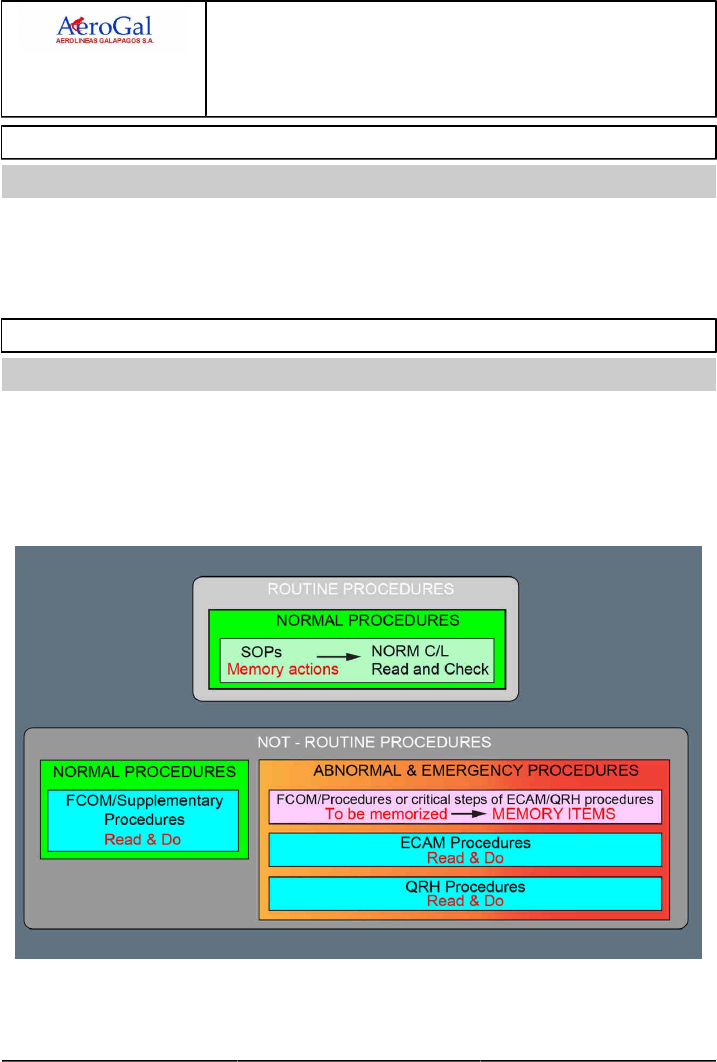
The procedures are divided into routine, and not-routine procedures.
They are easy to identify and to understand.
The pilots are trained to use and strictly apply the procedures.
The tasksharing and a standard communication process are clearly defined, in order to ensure a safe
and efficient use of the procedures.

A318/A319/A320/A321
FLIGHT CREW
TECHNIQUES MANUAL
AIRBUS OPERATIONAL PHILOSOPHY
DESIGN PHILOSOPHY
PROCEDURES DESIGN
GLG A318/A319/A320/A321 FLEET AOP-10-40 P 2/4
FCTM C to D → 22 MAR 17
NORMAL PROCEDURES - STANDARD OPERATING PROCEDURES (SOP)
Ident.: AOP-10-40-00016252.0001001 / 20 MAR 17
Applicable to: ALL
GENERAL
During the daily normal operations of the aircraft, the flight crew performs actions frequently.
These actions are identified as routine tasks. The routine tasks are supported by the Standard
Operating Procedures (SOPs).
SOP DESIGN PRINCIPLES
SOP are designed according to the following principles:
‐ One SOP per flight phase
‐ Actions are described in a chronological order
‐ Actions are easy to memorize and to apply (cockpit scan, actions flow).
SOP design is effective provided that:
‐ All systems operate normally
‐ All automatic functions are used normally.
Some SOP actions are checked against checklists.
SOP UTILIZATION PRINCIPLES
The flight crew should perform SOP actions by memory. The flight crew can also decide to refer
to the QRH, in order to perform both the Preliminary Cockpit Preparation and Securing the Aircraft
procedures.
NORMAL PROCEDURES - SUPPLEMENTARY PROCEDURES
Ident.: AOP-10-40-00016253.0001001 / 20 MAR 17
Applicable to: ALL
GENERAL
During the daily normal operations of the aircraft, the flight crew may have to perform actions
which are not part of the SOP , i.e. not frequently done. These actions are identified as not-routine
tasks dedicated to not-routine situation (e.g. airframe deicing/anti-icing procedures on ground,
manual engine start). The not-routine tasks are supported by the Supplementary Procedures.
The flight crew must perform not-routine actions, using the READ & DO principle.

A318/A319/A320/A321
FLIGHT CREW
TECHNIQUES MANUAL
AIRBUS OPERATIONAL PHILOSOPHY
DESIGN PHILOSOPHY
PROCEDURES DESIGN
GLG A318/A319/A320/A321 FLEET AOP-10-40 P 3/4
FCTM ← D to E 22 MAR 17
SUPPLEMENTARY PROCEDURES DESIGN PRINCIPLES
The Supplementary Procedures are designed according to the following principles:
‐ Easy to identify and to understand
‐ One Supplementary Procedure for a given situation
‐ Actions are described in a chronological order.
SUPPLEMENTARY PROCEDURES UTILIZATION PRINCIPLES
Supplementary Procedures utilization is effective provided that the flight crew performs the
Supplementary Procedures using the READ & DO principle (generally done by the PM).
ABNORMAL AND EMERGENCY PROCEDURES
Ident.: AOP-10-40-00016254.0001001 / 20 MAR 17
Applicable to: ALL
ABNORMAL AND EMERGENCY PROCEDURES DESIGN PRINCIPLES
These procedures are not-routine, classified in abnormal or emergency, and prioritized in
accordance with the criticality of the situation.
An abnormal or emergency procedure is initiated following:
‐ A system failure, or
‐ An operational context.
The design of an abnormal or emergency procedure is defined as:
‐ A MEMORY ITEM, when the flight crew has no time to refer to the ECAM /QRH /FCOM to
ensure a safe flight path, or
‐ A READ & DO procedure that is handled via the ECAM , QRH , FCOM , or OEB.
The type of procedure is easy to identify:
[MEM] MEMORY ITEMS ECAM Procedures [QRH] Procedures
MEMORY READ & DO
ABNORMAL AND EMERGENCY PROCEDURES UTILIZATION PRINCIPLES
The utilization of abnormal and emergency procedures follows the here below principle:
WHEN? HOW?
Memory Items Immediately Memory
Abnormal/Emergency
Procedures ECAM /QRH /FCOM
When appropriate READ & DO

A318/A319/A320/A321
FLIGHT CREW
TECHNIQUES MANUAL
AIRBUS OPERATIONAL PHILOSOPHY
DESIGN PHILOSOPHY
PROCEDURES DESIGN
Intentionally left blank
GLG A318/A319/A320/A321 FLEET AOP-10-40 P 4/4
FCTM 22 MAR 17

A318/A319/A320/A321
FLIGHT CREW
TECHNIQUES MANUAL
AIRBUS OPERATIONAL PHILOSOPHY
TASKSHARING RULES AND COMMUNICATION
GLG A318/A319/A320/A321 FLEET AOP-20 P 1/4
FCTM A → 22 MAR 17
GENERAL
Ident.: AOP-20-00016255.0001001 / 20 MAR 17
Applicable to: ALL
A correct application of tasksharing and communication rules ensures a safe and effective operation
of the aircraft.
NORMAL OPERATIONS
GENERAL
It is the responsibility of the PF to:
‐ FLY
‐ NAVIGATE.
It is the responsibility of the PM to:
‐ MONITOR the flight path, the navigation and the aircraft systems
‐ COMMUNICATE.
However, when necessary, the flight crew may re-allocate the tasks, as required.
SUPPLEMENTARY PROCEDURES
For Supplementary Procedures, the flight crew should use the following tasksharing:
If the procedure is related to engine start, it is recommended to read the entire
procedure first, and then:
‐ The PM reads the actions, and
‐ The PF acts on the controls.
For all other supplementary procedures:
The procedures should be applied in accordance with the READ & DO principle, i.e. the PM
reads the procedure and the PF or the PM acts on the controls, depending on the context.
ABNORMAL OPERATIONS
It is the responsibility of the PF to:
‐ FLY,
‐ NAVIGATE
‐ COMMUNICATE after the initiation of:
• The ECAM actions, or
• A QRH procedure.
It is the responsibility of the PM to:
‐ MONITOR the flight path and the navigation
‐ Perform ECAM actions or apply QRH /OEB procedure.

A318/A319/A320/A321
FLIGHT CREW
TECHNIQUES MANUAL
AIRBUS OPERATIONAL PHILOSOPHY
TASKSHARING RULES AND COMMUNICATION
GLG A318/A319/A320/A321 FLEET AOP-20 P 2/4
FCTM ← A to B 22 MAR 17
Note: During the ECAM management process or the application of a QRH /OEB procedure,
the “COM" task is transferred to the PF , as the cognitive skills of the PM are mostly
dedicated to the understanding and the application of the ECAM /QRH /OEB actions.
Therefore, their situation awareness of the environment and the navigation is less
effective than the PF’s one.
FCU/AFS AND EFIS CONTROL PANELS
Ident.: AOP-20-00016256.0001001 / 20 MAR 17
Applicable to: ALL
GENERAL
The FCU (AFS CP and EFIS CP ) and MCDU must be used in accordance with specific rules, in
order to ensure:
‐ Safe operation (correct entries made)
‐ Effective inter-pilot communication (knowing each other’s intentions).
AFS CP SELECTIONS
AFS CP entries (selection or target adjustment) are performed by:
‐ The PF , with AP ON, or by the PM (upon PF request)
‐ The PM (upon PF request), with AP OFF (except AP / A/THR that may be selected on by the
PF).
Engagement by
Selection of PF PM
AP /
A/THR
DISCONNECTION: YES
(via instinctive disconnect pb)
ENGAGEMENT: YES
DISCONNECTION: NO
ENGAGEMENT: upon PF request
FD NO Upon PF request
AFS CP
knobs
(AP OFF)
NO Upon PF request
AFS CP
knobs
(AP ON)
YES Upon PF request
EFIS CP SELECTIONS
Whatever the status of the AP , the PF and the PM must perform their onside EFIS CP selections.

A318/A319/A320/A321
FLIGHT CREW
TECHNIQUES MANUAL
AIRBUS OPERATIONAL PHILOSOPHY
TASKSHARING RULES AND COMMUNICATION
GLG A318/A319/A320/A321 FLEET AOP-20 P 3/4
FCTM C 22 MAR 17
FMS ENTRIES VIA MCDU
Ident.: AOP-20-00016257.0001001 / 20 MAR 17
Applicable to: ALL
Below 10 000 ft, entries should be restricted to those that have an operational effect:
‐ PERF APPR
‐ DIR TO
‐ NAVAIDS
‐ Late change of runway
‐ Activate SEC F-PLN
‐ ENABLE ALTN.
Time consuming entries must be performed at all times:
‐ By the PM upon PF request, or
‐ By the PF after a temporary transfer of controls to the PM.

A318/A319/A320/A321
FLIGHT CREW
TECHNIQUES MANUAL
AIRBUS OPERATIONAL PHILOSOPHY
TASKSHARING RULES AND COMMUNICATION
Intentionally left blank
GLG A318/A319/A320/A321 FLEET AOP-20 P 4/4
FCTM 22 MAR 17

A318/A319/A320/A321
FLIGHT CREW
TECHNIQUES MANUAL
AIRBUS OPERATIONAL PHILOSOPHY
MANAGEMENT OF ABNORMAL OPERATIONS
GENERAL
GLG A318/A319/A320/A321 FLEET AOP-30-10 P 1/2
FCTM A to D → 22 MAR 17
INTRODUCTION
Ident.: AOP-30-10-00021471.0001001 / 20 MAR 17
Applicable to: ALL
Below-listed procedures are performed using the "READ & DO" principle (except MEMORY items or
OEB immediate actions):
‐ ECAM procedures, are triggered automatically in response to an abnormal behavior of the
systems monitored by the Flight Warning System (FWS)
‐ QRH procedures, are applied by the flight crew in response to an abnormal event detected by any
flight crewmember
‐ OEB procedures, are triggered in some situations.
SEQUENCE OF PROCEDURE
Ident.: AOP-30-10-00021472.0001001 / 20 MAR 17
Applicable to: ALL
In most situations, the following sequence is the basic one that should be applied by the flight crew.
However, this sequence may not cover all operational situations. Therefore, in all cases, the flight
crew should exercise their judgment and adapt the sequence of actions to the real conditions.
In the case of abnormal or emergency situations, the flight crew should apply the procedures in the
following sequence, as appropriate:
‐ MEMORY ITEMS or OEB immediate actions
‐ OEB
‐ ECAM
‐ QRH
ONE PROCEDURE AT A TIME
Ident.: AOP-30-10-00021473.0001001 / 20 MAR 17
Applicable to: ALL
When the flight crew applies a procedure, they must complete the procedure, unless:
‐ An action requests to apply/consider another procedure,
‐ The flight crew needs to update their situation assessment due to an unexpected abnormal or
emergency situation (e.g. Smoke detected by the cabin crew or volcanic ash encounter).
USE OF AUTOPILOT
Ident.: AOP-30-10-00021474.0001001 / 20 MAR 17
Applicable to: ALL
The AP has not been certified in all configurations, and its performance cannot be guaranteed. If the
pilot chooses to use the AP in such circumstances, extra vigilance is required, and the AP must be

A318/A319/A320/A321
FLIGHT CREW
TECHNIQUES MANUAL
AIRBUS OPERATIONAL PHILOSOPHY
MANAGEMENT OF ABNORMAL OPERATIONS
GENERAL
GLG A318/A319/A320/A321 FLEET AOP-30-10 P 2/2
FCTM ← D to E 22 MAR 17
disconnected, if the aircraft deviates from desired or safe flight path. For additional information, Refer
to FCOM/LIM-AFS-10 Autopilot Function.
LAND ASAP DEFINITION
Ident.: AOP-30-10-00021475.0001001 / 20 MAR 17
Applicable to: ALL
If red LAND ASAP is part of the procedure, land as soon as possible at the nearest airport at which a
safe landing can be made.
Note: Red LAND ASAP information is applicable to a time-critical situation.
If amber LAND ASAP is part of the procedure, consider landing at the nearest suitable airport.
Note: The suitability criteria should be defined in accordance with the Operator's policy.

A318/A319/A320/A321
FLIGHT CREW
TECHNIQUES MANUAL
AIRBUS OPERATIONAL PHILOSOPHY
MANAGEMENT OF ABNORMAL OPERATIONS
HANDLING OF COCKPIT CONTROLS
GLG A318/A319/A320/A321 FLEET AOP-30-20 P 1/2
FCTM A to C 22 MAR 17
GENERAL
Ident.: AOP-30-20-00021493.0001001 / 20 MAR 17
Applicable to: ALL
In flight, the PF and PM must crosscheck before any action on the following controls:
‐ ENG MASTER lever
‐ IR selector
‐ All guarded controls
‐ System reset.
The flight crew must crosscheck the above-listed controls, in order to prevent any inadvertent action
by the flight crew with irreversible effects (i.e. when the flight crew operates red guarded controls).
If the flight crew inadvertently operates a black guarded control, the subsequent effect is reversible.
The flight crew must restrict the reset of systems to those listed in the FCOM /QRH.
TASKSHARING RULES FOR COCKPIT CONTROLS AND RESET BUTTONS OPERATION
Ident.: AOP-30-20-00021490.0001001 / 20 MAR 17
Applicable to: ALL
To confirm the operation of the above-listed controls, the flight crew should use the following
tasksharing method:
‐ The PM indicates the related control and requests confirmation from the PF
‐ The PF verifies the control designated by the PM and gives confirmation to the PM
‐ The PM operates the related control, as required.
TASKSHARING RULES FOR THRUST LEVERS OPERATION
Ident.: AOP-30-20-00021491.0001001 / 20 MAR 17
Applicable to: ALL
The thrust levers are part of the controls that the PF operates, in order to ensure their “FLY" task.
Therefore, the PM should not operate the thrust levers. If requested by any ECAM /QRH /OEB
procedure, the PM should ask to the PF to operate the corresponding lever. The flight crew should
use the following tasksharing method:
‐ The PF indicates the related thrust lever and requests confirmation from the PM
‐ The PM verifies the thrust lever indicated by the PF and gives confirmation to the PF
‐ The PF operates the related thrust lever, as required.

A318/A319/A320/A321
FLIGHT CREW
TECHNIQUES MANUAL
AIRBUS OPERATIONAL PHILOSOPHY
MANAGEMENT OF ABNORMAL OPERATIONS
HANDLING OF COCKPIT CONTROLS
GLG A318/A319/A320/A321 FLEET AOP-30-20 P 2/2
FCTM D 22 MAR 17
HANDLING OVERHEAD PANEL CONTROL
Ident.: AOP-30-20-00021492.0001001 / 20 MAR 17
Applicable to: ALL
The cockpit overhead panels are clearly labeled, in order to help the flight crew to correctly identify all
applicable systems and controls.
When the ECAM /QRH /OEB procedure requires the flight crew to perform an action on the overhead
panel or when the flight crew performs a system reset, the flight crew is able to rapidly identify and
find the correct system panel via the white label (uppercase) that is on the side or on top of each
panel.
To perform any action requested by a procedure, the PM should indicate the related panel and
control and announce in sequence:
‐ The name of the system
‐ The name of the control, or system reset
‐ The action.
E.g. “AIR, XBLEED, CLOSE".
The use of this type of approach enables the PM to keep the PF informed of the progress of the
procedure and reduces the risk of the PM operating the wrong control.
It is important for the flight crew to remember that, most of the time, in the case of a system failure,
the FAULT light of the applicable control comes on in amber. This enables the flight crew to correctly
identify the applicable system control on the overhead panel.
After the selection of a control, the PM should check the SD page, in order to verify that the selected
action was performed (e.g. The closure of the crossbleed valve should change the indications that
appear on the SD page).

A318/A319/A320/A321
FLIGHT CREW
TECHNIQUES MANUAL
AIRBUS OPERATIONAL PHILOSOPHY
MANAGEMENT OF ABNORMAL OPERATIONS
HANDLING OF ECAM/QRH/OEB
GLG A318/A319/A320/A321 FLEET AOP-30-30 P 1/6
FCTM A to B 22 MAR 17
GENERAL
Ident.: AOP-30-30-00021494.0001001 / 20 MAR 17
Applicable to: ALL
When an abnormal situation is detected by the flight crew, the first priority of the flight crew is to
maintain a safe flight path before the flight crew performs any READ & DO actions. For takeoff or
go around, the flight crew should delay READ & DO actions until the aircraft reaches a minimum of
400 ft AGL . This is an appropriate compromise between stabilization of the aircraft and a delay in
the actions. However, the flight crew may initiate READ & DO actions below 400 ft AGL, provided
that the flight path is safe.
When the flight crew performs a “READ & DO" ECAM /QRH /OEB procedure, they must:
‐ Correctly read and apply the ECAM /QRH /OEB actions
‐ Appropriately share tasks
‐ Carefully monitor and crosscheck.
However, in some time critical situations, the flight crew has no time to refer to the ECAM /QRH
/OEB procedure. Therefore, the flight crew must know, and strictly apply by memory, items referred
to as MEMORY ITEMS or OEB immediate actions.
TASKSHARING RULES
Ident.: AOP-30-30-00021495.0001001 / 20 MAR 17
Applicable to: ALL
The PF usually remains the PF for the entire flight, unless the Captain decides to re-allocate tasks
differently, or in case of failure that impacts the "FLY" task of the PF.
In addition to the routine tasks "FLY" and "NAVIGATE" performed by the PF , it is the responsibility of
the PF to perform all the following actions:
‐ Initiate ECAM /QRH /OEB actions that the PM must perform,
‐ Communicate after ECAM /QRH /OEB actions are initiated and until the PM announces:
• "ECAM actions completed", or
• “XXX procedure completed", in the case of QRH or OEB procedure.
In addition to the routine task “MONITOR" performed by the PM, it is the responsibility of the PM to
manage the ECAM /QRH /OEB actions after the PF announces “ECAM ACTIONS" or launch a QRH
procedure, as follow:
‐ Read & Do the ECAM /QRH /OEB actions in a spoken voice
‐ Obtain PF confirmation before clearing any ECAM.

A318/A319/A320/A321
FLIGHT CREW
TECHNIQUES MANUAL
AIRBUS OPERATIONAL PHILOSOPHY
MANAGEMENT OF ABNORMAL OPERATIONS
HANDLING OF ECAM/QRH/OEB
GLG A318/A319/A320/A321 FLEET AOP-30-30 P 2/6
FCTM C → 22 MAR 17
HANDLING OF ECAM
Applicable to: ALL
Ident.: AOP-30-30-A-00021499.0001001 / 20 MAR 17
GENERAL
The ECAM actions are actions that the PM must perform on ground or in flight following an ECAM
alert, once the aircraft trajectory is stabilized and the PF announced “ECAM actions". The ECAM
actions are divided into several steps, which are clearly identified on the EWD and SD pages.
The PM must:
‐ “READ & DO" the ECAM procedures, identified as procedure action lines on the EWD
‐ Analyse the operational impact on the affected system via the SD page
‐ Read the STATUS page, including associated procedures.
If an ECAM procedure requests the flight crew to apply a QRH procedure, the flight crew should:
‐ Keep the procedure displayed on the ECAM
‐ Apply the requested QRH procedure.
The objective is to avoid the flight crew to be disturbed with subsequent ECAM alerts that may
trigger with less priority.
Ident.: AOP-30-30-A-00021500.0001001 / 20 MAR 17
ECAM TASKSHARING
The flight crew should apply any OEB that affects an ECAM alert. To apply the ECAM procedure,
the flight crew should use the following tasksharing method:
Ident.: AOP-30-30-A-00021501.0001001 / 20 MAR 17
L12
PF PM
First pilot who notices
MASTER WARNING /CAUTION .............................. RESET
For each ECAM procedure:
"Title of failure"................................................... ANNOUNCE
ECAM .................................................................... CONFIRM
The PM should check/inspect the overhead panel and/or
associated SD , in order to analyze and confirm the failure,
before they take any action. The flight crew should keep in
mind that the sensors on the overhead panel and/or SD may
be different from the sensors that trigger the failure.
OEB ....................................................................CONSIDER
"ECAM ACTIONS"....................................................ORDER
Continued on the following page

A318/A319/A320/A321
FLIGHT CREW
TECHNIQUES MANUAL
AIRBUS OPERATIONAL PHILOSOPHY
MANAGEMENT OF ABNORMAL OPERATIONS
HANDLING OF ECAM/QRH/OEB
GLG A318/A319/A320/A321 FLEET AOP-30-30 P 3/6
FCTM ← C → 22 MAR 17
Continued from the previous page
PF PM
Apply the Tasksharing Rules and Communication for Abnormal Operations
Refer to AOP-20 General
ECAM /OEB ACTIONS......................................... PERFORM
"CLEAR (name of the system)?"........................... REQUEST
ECAM ACTIONS PERFORMED...............................CHECK
"CLEAR (name of the system)"............................ CONFIRM
CLR pb .......................................................................PRESS
Before the PM presses the CLR pb, the flight crew should
carefully check that all actions have been performed.
For each System Display (SD) page:
SD page................................................................. ANALYZE
"CLEAR (name of the system)?"........................... REQUEST
"CLEAR (name of the system)"............................ CONFIRM
CLR pb .......................................................................PRESS
When STATUS page appears:
"STATUS"........................................................... ANNOUNCE
"STOP ECAM"..........................................................ORDER
ECAM ACTIONS........................................................... STOP
Consider any normal C/L, system reset, or any
additional procedure, as applicable
"CONTINUE ECAM".................................................ORDER
STATUS.........................................................................READ
The procedures associated with the STATUS should be
previewed to evaluate the associated workload. They should
be performed at the appropriate flight phase.
"REMOVE STATUS?"............................................REQUEST
"REMOVE STATUS"............................................ CONFIRM
STS pb .......................................................................PRESS
"ECAM ACTIONS COMPLETED".......................ANNOUNCE
Ident.: AOP-30-30-A-00021502.0001001 / 20 MAR 17
STOP ECAM
When necessary, the flight crew should stop the ECAM actions when they need to perform
actions which require acknowledgement, check or crosscheck from both flight crewmembers (e.g.
communication to ATC , request of configuration change, baro setting). Then, they should continue
with ECAM actions.

A318/A319/A320/A321
FLIGHT CREW
TECHNIQUES MANUAL
AIRBUS OPERATIONAL PHILOSOPHY
MANAGEMENT OF ABNORMAL OPERATIONS
HANDLING OF ECAM/QRH/OEB
GLG A318/A319/A320/A321 FLEET AOP-30-30 P 4/6
FCTM ← C to D → 22 MAR 17
In all cases, the flight crew must stop the ECAM actions before reading the STATUS page, in order
to:
‐ Perform the After Takeoff/Climb C/L or any normal C/L, if applicable.
The flight crew must perform the pending normal C/L at this stage as it is a good compromise
between the necessary application of ECAM procedures and system analysis and the delay in the
check of systems status (e.g. in the case of failure after takeoff, flaps and landing gear retracted)
‐ Consider any system reset.
The ECAM procedure may consider reset of the system by switching OFF then ON the associated
system via the usual cockpit control. However reset action may not be requested by the ECAM
procedure. In this case, it is the flight crew responsibility to consider any system reset to recover
the operation of the affected system, provided that the system reset is permitted in the system
reset table. If the reset is successful, the STATUS page will disappear. The flight crew must not
apply the system reset procedure from memory. They must refer to the QRH.
‐ Consider application of the ENG RELIGHT procedure after an engine failure with no damage.
The flight crew should consider performing the ENG RELIGHT procedure at this stage as if the
relight is successful the STATUS page will disappear.
STATUS PAGE
The purpose of the STATUS page is to provide an overview of the technical status of the aircraft
in all flight phases. Therefore, it is important that the flight crew checks the whole STATUS page
information, in order to correctly assess the situation and subsequently make appropriate decision.
The STATUS page may contain some actions, that should be performed by the flight crew at a more
appropriate time. The flight crew should read the procedures associated with the STATUS page
during the STATUS page review to evaluate and anticipate the workload for each flight phase.
Ident.: AOP-30-30-A-00021503.0001001 / 20 MAR 17
IF THE ECAM WARNING (OR CAUTION) DISAPPEARS
If an ECAM warning disappears while a procedure is being applied, the warning can be considered
no longer applicable. Application of the procedure can be stopped. For example, during the
application of an engine fire procedure, if the fire is successfully extinguished with the first fire
extinguisher bottle, the ENG 1(2) FIRE warning disappears and the procedure no longer applies.
Any remaining ECAM procedures should be performed as usual.
HANDLING OF QRH
Ident.: AOP-30-30-00021497.0001001 / 20 MAR 17
Applicable to: ALL
GENERAL
When the flight crew needs to apply a QRH procedure, the PM should use the QRH/Abnormal and
Emergency Procedures table of contents in order to search and select the applicable procedure.

A318/A319/A320/A321
FLIGHT CREW
TECHNIQUES MANUAL
AIRBUS OPERATIONAL PHILOSOPHY
MANAGEMENT OF ABNORMAL OPERATIONS
HANDLING OF ECAM/QRH/OEB
GLG A318/A319/A320/A321 FLEET AOP-30-30 P 5/6
FCTM ← D to E 22 MAR 17
IF THE CONDITIONS OF THE APPLICATION OF A QRH PROCEDURE DISAPPEAR
The flight crew can stop any abnormal QRH procedure if the conditions for its application
disappear.
ECAM/QRH/OEB ACTIONS COMPLETED
Ident.: AOP-30-30-00021498.0001001 / 20 MAR 17
Applicable to: ALL
When the ECAM /QRH /OEB actions are completed, the flight crew should:
‐ Resume the Normal Operations Task sharing rules
‐ If time permits, review the FCOM for additional information on the applicable procedure(s).
However, the flight crew should not prolong the flight to refer to the FCOM.
‐ Assess the situation
When convenient, recall the STATUS page, in order to assess the situation:
• Check any fuel penalty factor, and check the remaining fuel at destination or diversion airport
• Check any landing distance penalty, and compute the landing distance at destination or
diversion airport
• Consider all the operational, maintenance and commercial aspects.
‐ Make the decision
‐ Inform the ATC, the cabin crew, the passengers, and airline operations as required.

A318/A319/A320/A321
FLIGHT CREW
TECHNIQUES MANUAL
AIRBUS OPERATIONAL PHILOSOPHY
MANAGEMENT OF ABNORMAL OPERATIONS
HANDLING OF ECAM/QRH/OEB
Intentionally left blank
GLG A318/A319/A320/A321 FLEET AOP-30-30 P 6/6
FCTM 22 MAR 17

A318/A319/A320/A321
FLIGHT CREW
TECHNIQUES MANUAL
AIRBUS OPERATIONAL PHILOSOPHY
MANAGEMENT OF ABNORMAL OPERATIONS
HANDLING OF ADVISORY
GLG A318/A319/A320/A321 FLEET AOP-30-40 P 1/2
FCTM A to B 22 MAR 17
GENERAL
Ident.: AOP-30-40-00021478.0001001 / 20 MAR 17
Applicable to: ALL
The ADVISORY enables the flight crew to monitor the drifting parameter. The sensors used to trigger
an advisory may be different from those used by the FWS to trigger an ECAM alert.
TASKSHARING RULES
Ident.: AOP-30-40-00021480.0001001 / 20 MAR 17
Applicable to: ALL
The flight crew should use the following tasksharing method:
‐ The flight crewmember that first notices an advisory announces “ADVISORY on XYZ system",
‐ Then, the PF requests the PM to monitor the drifting parameter. If time permits, the PM may refer
to the QRH, in order to:
• Check the advisory triggering conditions in various advisory situations
• Find the associated recommended actions.

A318/A319/A320/A321
FLIGHT CREW
TECHNIQUES MANUAL
AIRBUS OPERATIONAL PHILOSOPHY
MANAGEMENT OF ABNORMAL OPERATIONS
HANDLING OF ADVISORY
Intentionally left blank
GLG A318/A319/A320/A321 FLEET AOP-30-40 P 2/2
FCTM 22 MAR 17

A318/A319/A320/A321
FLIGHT CREW
TECHNIQUES MANUAL
AIRBUS OPERATIONAL PHILOSOPHY
MANAGEMENT OF ABNORMAL OPERATIONS
SPURIOUS CAUTION
GLG A318/A319/A320/A321 FLEET AOP-30-50 P 1/2
FCTM A 22 MAR 17
SPURIOUS CAUTION
Ident.: AOP-30-50-00020719.0001001 / 20 MAR 17
Applicable to: ALL
Any spurious caution can be deleted with the EMER CANC pb . When pressed, the EMER CANC pb
deletes both the aural alert, and the caution for the remainder of the flight. This is indicated on the
STATUS page, by the "CANCELLED CAUTION" title.
The EMER CANCEL inhibits any aural warning that is associated with a red warning, but does not
affect the warning itself.

A318/A319/A320/A321
FLIGHT CREW
TECHNIQUES MANUAL
AIRBUS OPERATIONAL PHILOSOPHY
MANAGEMENT OF ABNORMAL OPERATIONS
SPURIOUS CAUTION
Intentionally left blank
GLG A318/A319/A320/A321 FLEET AOP-30-50 P 2/2
FCTM 22 MAR 17
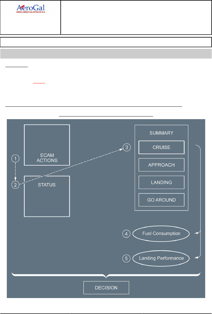
A318/A319/A320/A321
FLIGHT CREW
TECHNIQUES MANUAL
AIRBUS OPERATIONAL PHILOSOPHY
MANAGEMENT OF ABNORMAL OPERATIONS
USE OF SUMMARIES
GLG A318/A319/A320/A321 FLEET AOP-30-60 P 1/4
FCTM A → 22 MAR 17
USE OF SUMMARIES
Ident.: AOP-30-60-00018295.0001001 / 20 MAR 17
Applicable to: ALL
GENERAL
The QRH summaries are QRH procedures created to help the flight crew to perform actions in the
case of an ELEC EMER CONFIG or a dual hydraulic failure.
The QRH summaries are divided into four sections: CRUISE, APPROACH, LANDING, and
GO-AROUND.
SITUATION ASSESSMENT WITH THE CRUISE SECTION OF THE QRH SUMMARY
Situation Assessment with the QRH Summary
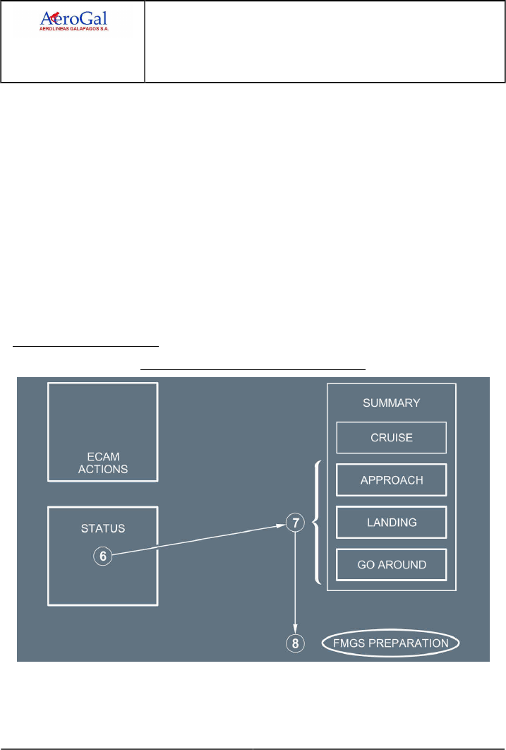
A318/A319/A320/A321
FLIGHT CREW
TECHNIQUES MANUAL
AIRBUS OPERATIONAL PHILOSOPHY
MANAGEMENT OF ABNORMAL OPERATIONS
USE OF SUMMARIES
GLG A318/A319/A320/A321 FLEET AOP-30-60 P 2/4
FCTM ← A → 22 MAR 17
‐Steps 1 and 2: The flight crew should apply the ECAM first. This includes both the
procedure and the STATUS page. When ECAM actions are completed, the PM announces
"ECAM ACTIONS COMPLETED". Then, the PM should refer to the corresponding QRH
summaries.
‐Step 3: After the check of the STATUS page, the PM should refer to the CRUISE section of
the QRH summaries. The CRUISE section highlights the remaining systems (in ELEC EMER
configuration only), the main limitations, and the flight capability of the aircraft.
The CRUISE section helps the flight crew to assess the situation and to select an appropriate
runway for landing.
As indicated in the CRUISE section, the flight crew should refer to the performance application or
the corresponding chapters of the QRH for:
‐ The evaluation of increased fuel consumption (step 4)
‐ The landing performance computation at the selected airport (step 5).
APPROACH PREPARATION
Approach Preparation with the QRH Summary
While the flight crew checks the STATUS page (step 6 ), they should use the APPROACH,
LANDING, and GO-AROUND sections to support the approach preparation (steps 7 and 8).
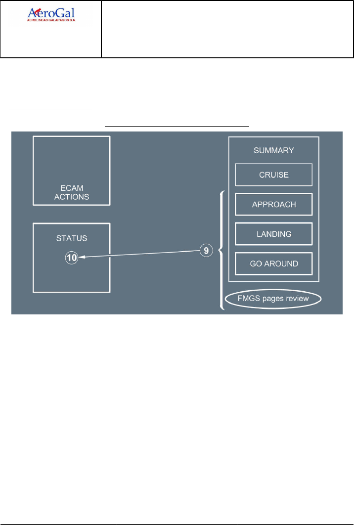
A318/A319/A320/A321
FLIGHT CREW
TECHNIQUES MANUAL
AIRBUS OPERATIONAL PHILOSOPHY
MANAGEMENT OF ABNORMAL OPERATIONS
USE OF SUMMARIES
GLG A318/A319/A320/A321 FLEET AOP-30-60 P 3/4
FCTM ← A → 22 MAR 17
When appropriate, the APPROACH, LANDING, and GO-AROUND sections include the LANDING
WITH SLATS or FLAPS JAMMED procedure and the L/G GRAVITY EXTENSION procedure that
the flight crew must apply during the approach, landing, and go-around phases.
APPROACH BRIEFING
Approach Briefing with the QRH Summary
The flight crew should use the APPROACH, LANDING, and GO-AROUND sections of the QRH
summary to perform the approach briefing, while they crosscheck the associated FMS pages and
the STATUS page (steps 9 and 10).
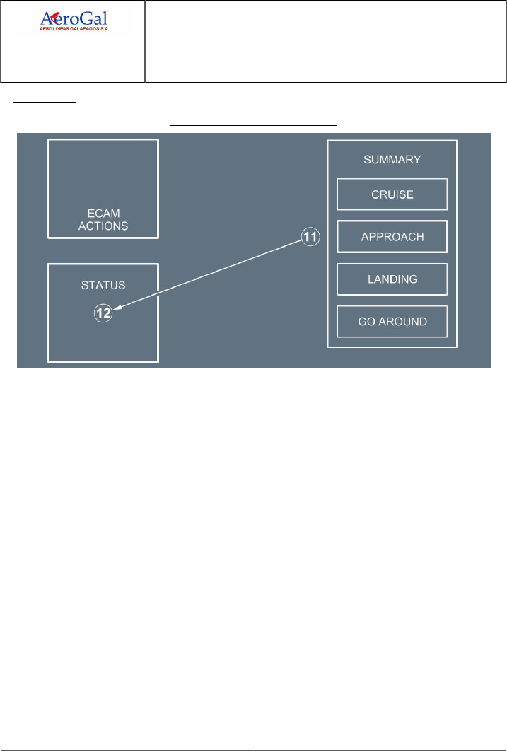
A318/A319/A320/A321
FLIGHT CREW
TECHNIQUES MANUAL
AIRBUS OPERATIONAL PHILOSOPHY
MANAGEMENT OF ABNORMAL OPERATIONS
USE OF SUMMARIES
GLG A318/A319/A320/A321 FLEET AOP-30-60 P 4/4
FCTM ← A 22 MAR 17
APPROACH
Approach with the QRH Summary
To perform the approach, the flight crew should refer to the APPROACH section (step 11).
When the aircraft is in final configuration, the flight crew can rapidly review the LANDING and
GO-AROUND sections, as a reminder (braking, NWS , reversers, and L/G retraction in the case of
a go-around).
Finally, the PM should check the STATUS page (step 12 ) and check that all the APPR PROC
actions are completed.

A318/A319/A320/A321
FLIGHT CREW
TECHNIQUES MANUAL
AIRBUS OPERATIONAL PHILOSOPHY
GOLDEN RULES FOR PILOTS
GLG A318/A319/A320/A321 FLEET AOP-40 P 1/4
FCTM A → 19 JUN 17
GOLDEN RULES FOR PILOTS
Ident.: AOP-40-00018441.0001001 / 19 APR 17
Applicable to: ALL
INTRODUCTION
The Airbus "Golden Rules for Pilots" are operational guidelines, based on all of the following:
• Basic flying principles
• The adaptation of these basic flying principles to modern-technology aircraft
• The provision of information about required crew coordination for the operation of Airbus
aircraft.
The objective of these Golden Rules is to also take into account the principles of flight crew
interaction with automated systems, and the principles of Crew Resource Management (CRM), in
order to help prevent the causes of many accidents or incidents and to ensure flight efficiency.
GENERAL GOLDEN RULES
The following four Golden Rules for Pilots are applicable to all normal operations, and to all
unexpected or abnormal/emergency situations:
1. Fly. Navigate. Communicate: In this order and with appropriate tasksharing.
Fly! Navigate! Communicate! The flight crew must perform these three actions in sequence and
must use appropriate tasksharing in normal and abnormal operations, in manual flight or in flight
with the AP engaged.

A318/A319/A320/A321
FLIGHT CREW
TECHNIQUES MANUAL
AIRBUS OPERATIONAL PHILOSOPHY
GOLDEN RULES FOR PILOTS
GLG A318/A319/A320/A321 FLEET AOP-40 P 2/4
FCTM ← A → 19 JUN 17
The following explains each of the three actions, and the steps associated with the performance
of these actions:
•Fly
"Fly" indicates that:
‐The Pilot Flying (PF ) must concentrate on "flying the aircraft" to monitor and control the
pitch attitude, bank angle, airspeed, thrust, sideslip, heading, etc., in order to achieve and
maintain the desired targets, vertical flight path, and lateral flight path.
‐The Pilot Monitoring (PM ) must assist the PF and must actively monitor flight
parameters, and call out any excessive deviation. The PM's role of "actively monitoring" is
very important.
Therefore, both flight crewmembers must:
• Focus and concentrate on their tasks to ensure appropriate tasksharing
• Maintain situational awareness and immediately resolve any uncertainty as a crew.
•Navigate
"Navigate" refers to and includes the following four "Know where ..." statements, in order to
ensure situational awareness:
• Know where you are…
• Know where you should be…
• Know where you should go…
• Know where the weather, terrain, and obstacles are.
•Communicate
"Communicate" involves effective and appropriate crew communication between the:
• PF and the PM
• Flight crew and Air Traffic Control (ATC)
• Flight crew and the cabin crew
• Flight crew and the ground crew.
Communication enables the flight crew to safely and appropriately perform the flight, and
enhance situational awareness. To ensure good communication, the flight crew should use
standard phraseology and the applicable callouts.
In abnormal and emergency situations, the PF must recover a steady flight path, and the flight
crew must identify the flight situation. The PF must then inform ATC and the cabin crew of:
▪ The flight situation
▪ The flight crew’s intentions.
The flight crew must therefore always keep in mind the key message:
Fly the Aircraft, Fly the Aircraft, Fly the Aircraft...

A318/A319/A320/A321
FLIGHT CREW
TECHNIQUES MANUAL
AIRBUS OPERATIONAL PHILOSOPHY
GOLDEN RULES FOR PILOTS
GLG A318/A319/A320/A321 FLEET AOP-40 P 3/4
FCTM ← A → 19 JUN 17
To safely and appropriately perform a flight, both flight crewmembers must have basic flying
skills, and must be able to fly with appropriate tasksharing in all situations.
2. Use the appropriate level of automation at all times.
Aircraft are equipped with several levels of automation, used to perform specific tasks.
The appropriate use of automated systems significantly helps the flight crew with, for example:
• Workload management
• Situation awareness (traffic, ATC communication, etc.).
The flight crew must, at all times, perform both of the following:
•Determine and select the appropriate level of automation that can include manual flight
Note: The decision to use manual flight must be agreed between both pilots and must be
based on an individual assessment of the pilot. This assessment should include
aircraft status (malfunctions), pilot fatigue, weather conditions, traffic situation, and if
the PF is familiar with the area.
•Understand the operational effect of the selected level of automation.
3. Understand the FMA at all times.
The flight crew must confirm the operational effect of all actions on the FCU , or on the MCDU ,
via a crosscheck of the corresponding annunciation or data on the PFD and on the ND.
At all times, the flight crew should be aware of the following:
• Guidance modes (armed or engaged)
• Guidance targets
• Aircraft response in terms of attitude, speed, and trajectory
• Transition or reversion modes.
Therefore, to ensure correct situational awareness, at all times, the flight crew must:
•Monitor the FMA
•Announce the FMA
•Confirm the FMA
•Understand the FMA.
4. Take action if things do not go as expected.
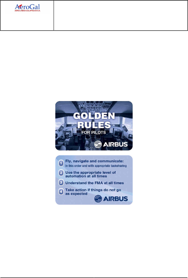
A318/A319/A320/A321
FLIGHT CREW
TECHNIQUES MANUAL
AIRBUS OPERATIONAL PHILOSOPHY
GOLDEN RULES FOR PILOTS
GLG A318/A319/A320/A321 FLEET AOP-40 P 4/4
FCTM ← A 19 JUN 17
If the aircraft does not follow the desired vertical or lateral flight path, or the selected
targets , and if the flight crew does not have sufficient time to analyze and solve the situation,
the flight crew must immediately take appropriate or required actions, as follows:
The PF should change the level of automation:
‐ From managed guidance to selected guidance, or
‐ From selected guidance to manual flying.
The PM should perform the following actions in sequence:
‐ Communicate with the PF
‐ Challenge the actions of the PF, when necessary
‐ Take over, when necessary.
AIRCRAFT SYSTEMS
Intentionally left blank

A318/A319/A320/A321
FLIGHT CREW
TECHNIQUES MANUAL
AIRCRAFT SYSTEMS
PRELIMINARY PAGES
TABLE OF CONTENTS
GLG A318/A319/A320/A321 FLEET AS-PLP-TOC P 1/2
FCTM 05 SEP 17
AS-BIRD Bird
Introduction...............................................................................................................................................................A
Practical Use of the Bird......................................................................................................................................... B
AS-FG Flight Guidance
AS-FG-10-1 Auto Flight
Objective.................................................................................................................................................................. A
Managed and Selected Modes................................................................................................................................B
Main Interfaces with the AP/FD.............................................................................................................................. C
AP/FD Monitoring.................................................................................................................................................... D
Recommended Practice for Autopilot (AP) Engagement........................................................................................ E
Use of the FD without the AP ................................................................................................................................F
AS-FG-10-2 Autothrust
Normal Operations...................................................................................................................................................A
Operations with One Engine Inoperative................................................................................................................ B
To Set Autothrust To Off.........................................................................................................................................C
Alpha Floor.............................................................................................................................................................. D
Autothrust Use - Summary......................................................................................................................................E
AS-FM Flight Management
AS-FM-10 Use of FMS
Navigation Accuracy................................................................................................................................................ A
ZFW - ZFWCG Entry Errors....................................................................................................................................B
AS-ROWROP ROW/ROP
ROW/ROP................................................................................................................................................................A
AS-RUD Rudder
General.....................................................................................................................................................................A
Operational Recommendations............................................................................................................................... B
AS-TCAS TCAS
Intruder Classification.............................................................................................................................................. A
Operating Techniques..............................................................................................................................................B
Continued on the following page

A318/A319/A320/A321
FLIGHT CREW
TECHNIQUES MANUAL
AIRCRAFT SYSTEMS
PRELIMINARY PAGES
TABLE OF CONTENTS
GLG A318/A319/A320/A321 FLEET AS-PLP-TOC P 2/2
FCTM 05 SEP 17
Continued from the previous page
AS-WXR Weather Radar
General.....................................................................................................................................................................A
Weather Detection................................................................................................................................................... B
Analysis of Weather Radar Data............................................................................................................................ C
Operations in Convective Weather......................................................................................................................... D
Ice Crystals.............................................................................................................................................................. E

A318/A319/A320/A321
FLIGHT CREW
TECHNIQUES MANUAL
AIRCRAFT SYSTEMS
PRELIMINARY PAGES
SUMMARY OF HIGHLIGHTS
GLG A318/A319/A320/A321 FLEET AS-PLP-SOH P 1/2
FCTM 05 SEP 17
Localization
Title
Toc
Index
ID Reason
AS-FG-10-2
Normal Operations
A1Minor update of the abbreviation tag.
AS-FG-10-2
Alpha Floor
D2Minor update of the abbreviation tag.
AS-FM-10
Navigation Accuracy
A1Minor update of the abbreviation tag.
Documentation update: Deletion of information.AS-FM-10
Technical Background
B2
illustration updated with correct architecture
AS-WXR
Ice Crystals
E1Correction of a typo.
AS-RUD
Operational Recommendations
B1Effectivity update: The information now also applies to HC-CLF.
AS-RUD
Operational Recommendations
B2Effectivity update: The information no longer applies to HC-CLF.

A318/A319/A320/A321
FLIGHT CREW
TECHNIQUES MANUAL
AIRCRAFT SYSTEMS
PRELIMINARY PAGES
SUMMARY OF HIGHLIGHTS
Intentionally left blank
GLG A318/A319/A320/A321 FLEET AS-PLP-SOH P 2/2
FCTM 05 SEP 17

A318/A319/A320/A321
FLIGHT CREW
TECHNIQUES MANUAL
AIRCRAFT SYSTEMS
BIRD
GLG A318/A319/A320/A321 FLEET AS-BIRD P 1/4
FCTM A to B → 22 MAR 17
INTRODUCTION
Ident.: AS-BIRD-00016266.0001001 / 20 MAR 17
Applicable to: ALL
Two flying references may be used on the PFD:
‐ The attitude
‐ The Flight Path Vector (FPV), called the "bird".
When TRK /FPA is selected on the FCU , the "bird" is the flight reference with the TRK and FPA as
basic guidance parameters.
When HDG /VS is selected on the FCU , "bird" is off, and the attitude is the flight reference with HDG
and VS as basic guidance parameters.
The attitude flight reference should be used for dynamic manoeuvres, for example, take-off or
go-around. An action on the sidestick has an immediate effect on the aircraft attitude. The flight crew
can monitor this flight reference directly and accurately during these manoeuvres.
RELIABILITY
The FPV is computed from IRS data, therefore, it is affected by ADIRS errors. An error may be
indicated by a small track error, usually of up to ± 2 °. This can be easily determined during the
approach.
The FPV is also computed from static pressure information. Therefore, the bird must be
considered as not reliable, if altitude information is not reliable.
PRACTICAL USE OF THE BIRD
Applicable to: ALL
Ident.: AS-BIRD-A-00018465.0001001 / 20 MAR 17
GENERAL RULE
When using the "bird", the flight crew should first change attitude, and then check the result with
reference to the "bird".
Ident.: AS-BIRD-A-00018467.0001001 / 20 MAR 17
APPROACH USING FPA GUIDANCE
The FPV is particularly useful for this type of approach. The flight crew can select values for the
inbound track and final descent path angle on the FCU. Once established inbound, only minor
corrections should be required to maintain an accurate approach path. The flight crew can monitor
the tracking and descent flight path, with reference to the track indicator and the "bird".
However, the flight crew should understand that the "bird" only indicates a flight path angle and
track, and does not provide guidance to a ground-based radio facility. Therefore, even if the

A318/A319/A320/A321
FLIGHT CREW
TECHNIQUES MANUAL
AIRCRAFT SYSTEMS
BIRD
GLG A318/A319/A320/A321 FLEET AS-BIRD P 2/4
FCTM ← B → 22 MAR 17
"bird" indicates that the aircraft is flying with the correct flight path angle and track, this does not
necessarily mean that the aircraft is on the correct final approach path.
The TRK -FPA Flight Director (FD ) is particularly useful for guiding the aircraft during
non-precision approaches, although, it can also be used at other times. When using this mode
of the FD , the pilot places the FPV symbol in the center of the flight path director (FPD ) symbol.
This is similar to using the FD in HDG -V/S , when the pilot puts the center of the fixed aircraft
symbol at the center of the crossed bars of the FD . If the FCU is set on the correct track and
flight path angle, and if the FPV and the FPD are aligned, they will guide the aircraft along a
trajectory that is stabilized with respect to the ground, whereas when the pilot is using HDG -V/S
, the trajectory is stabilized with respect to the air. However, if the aircraft is disturbed from this
ideal trajectory, merely following the FPD will result in its following a trajectory that is parallel to the
intended trajectory. Thus, when the aircraft is disturbed from the original trajectory, the pilot must
adjust either its track or its flight path angle or both in order to obtain guidance back to the original
trajectory.
Ident.: AS-BIRD-A-00018477.0001001 / 20 MAR 17
VISUAL CIRCUITS
The FPV can be used as a cross-reference, when flying visual circuits. On the downwind leg, the
flight crew should position the wings of the "bird" on the horizon, in order to maintain level flight.
The downwind track should be set on the FCU . The flight crew should position the tail of the "bird"
on the blue track index on the PFD , in order to maintain the desired track downwind.
On the final inbound approach, the track index should be set to the final approach course of the
runway. A standard 3 ° approach path is indicated, when the top of the bird's tail is immediately
below the horizon, and the bottom of the "bird" is immediately above the 5 ° nose down marker.
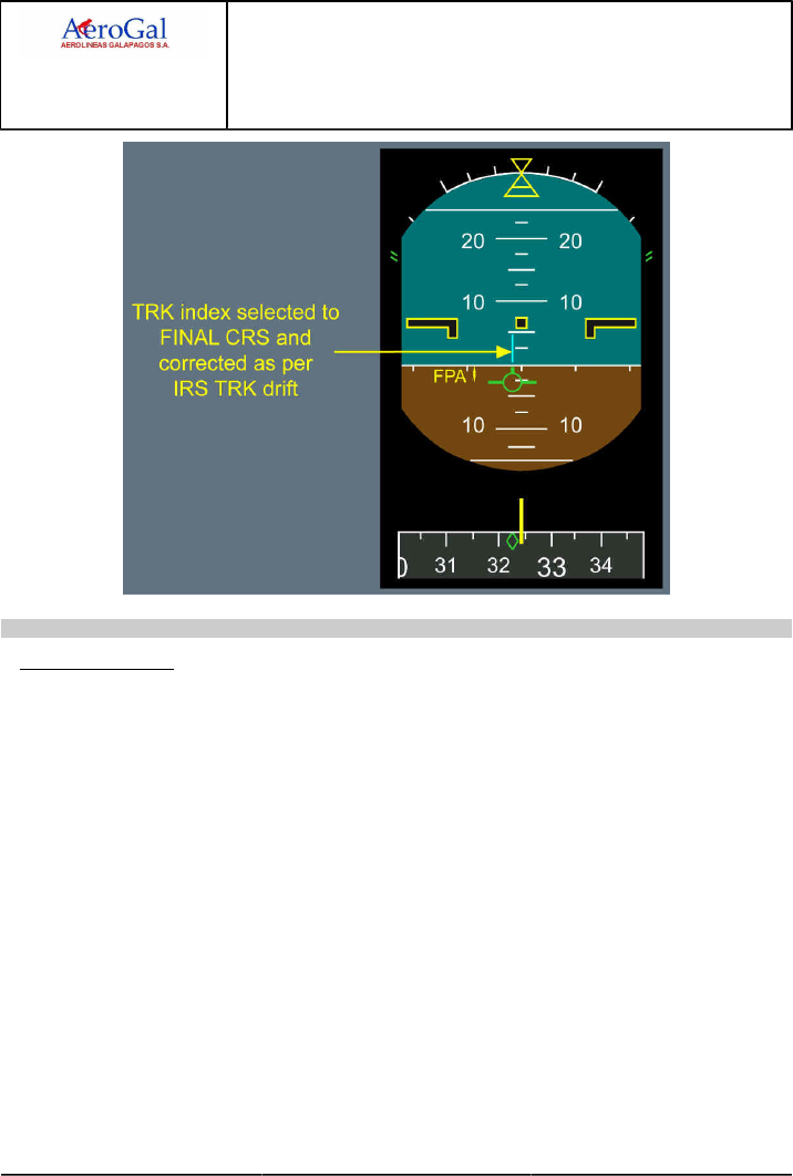
A318/A319/A320/A321
FLIGHT CREW
TECHNIQUES MANUAL
AIRCRAFT SYSTEMS
BIRD
GLG A318/A319/A320/A321 FLEET AS-BIRD P 3/4
FCTM ← B → 22 MAR 17
Ident.: AS-BIRD-A-00018478.0001001 / 20 MAR 17
FINAL APPROACH
The "bird" is a very useful flight reference, because it provides the trajectory parameters, and
quickly warns the pilot of downburst. In addition, together with the GS MINI protection, it is
an excellent indicator of shears or wind variations. The position of the "bird" in relation to the
fixed aircraft symbol provides an immediate indication of the wind direction. Therefore, when
approaching the minimum, the flight crew knows in which direction to search for the runway.
If the target approach speed symbol moves upward, this indicates that there is headwind gust. If
the "bird" drifts to the right, this indicates that there is wind from the left.
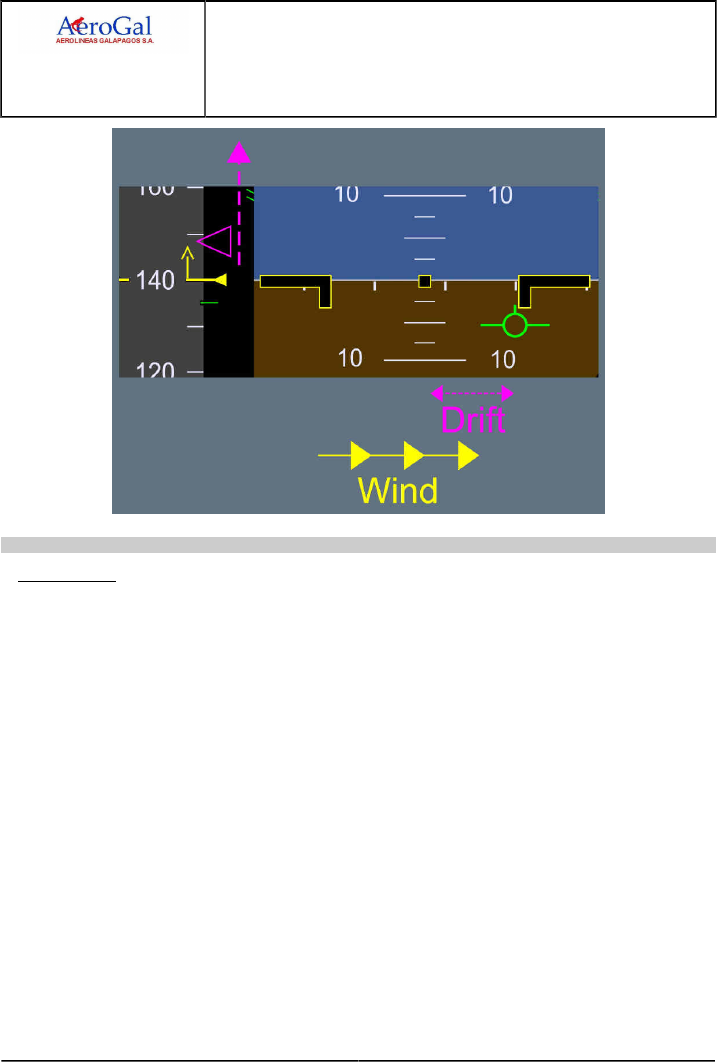
A318/A319/A320/A321
FLIGHT CREW
TECHNIQUES MANUAL
AIRCRAFT SYSTEMS
BIRD
GLG A318/A319/A320/A321 FLEET AS-BIRD P 4/4
FCTM ← B 22 MAR 17
Ident.: AS-BIRD-A-00018479.0002001 / 20 MAR 17
GO-AROUND
The pilot must take care when making a go-around with the FPV selected. There is inevitably
some lag between the pilot’s raising the nose to commence the go-around and the aircraft’s
responding by changing its trajectory.
For the go-around, the appropriate flight reference is the attitude, because go-around is a dynamic
maneuver. Therefore, when performing a go-around, regardless of the previously-selected flight
reference, upon selection of TOGA , the FD bars are automatically restored in SRS /GA TRACK
modes, and the "bird" is automatically removed.
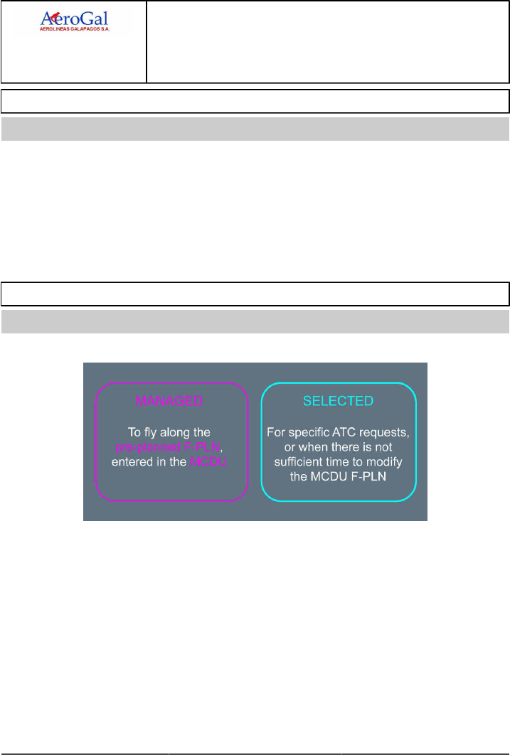
A318/A319/A320/A321
FLIGHT CREW
TECHNIQUES MANUAL
AIRCRAFT SYSTEMS
FLIGHT GUIDANCE
AUTO FLIGHT
GLG A318/A319/A320/A321 FLEET AS-FG-10-1 P 1/4
FCTM A to B 22 MAR 17
OBJECTIVE
Ident.: AS-FG-10-1-00018207.0001001 / 20 MAR 17
Applicable to: ALL
The Flight Director (FD ) and the Auto Pilot (AP) assist the flight crew to fly the aircraft within the
normal flight.
To achieve this objective:
‐ The FD provides adequate attitude or flight path orders and enables the Pilot Flying (PF) to
accurately fly the aircraft manually
‐ The AP takes over routine tasks. This give the PF the necessary time and resources to assess the
overall operational situation.
MANAGED AND SELECTED MODES
Ident.: AS-FG-10-1-00016271.0001001 / 20 MAR 17
Applicable to: ALL
The choice of mode is a strategic decision that is taken by the PF.
Managed modes require:
‐ Good FMS navigation accuracy (or GPS PRIMARY)
‐ An appropriate ACTIVE F-PLN (i.e. the intended lateral and vertical trajectory is entered, and the
sequencing of the F-PLN is monitored).
If these two conditions are not fulfilled, revert to selected mode.
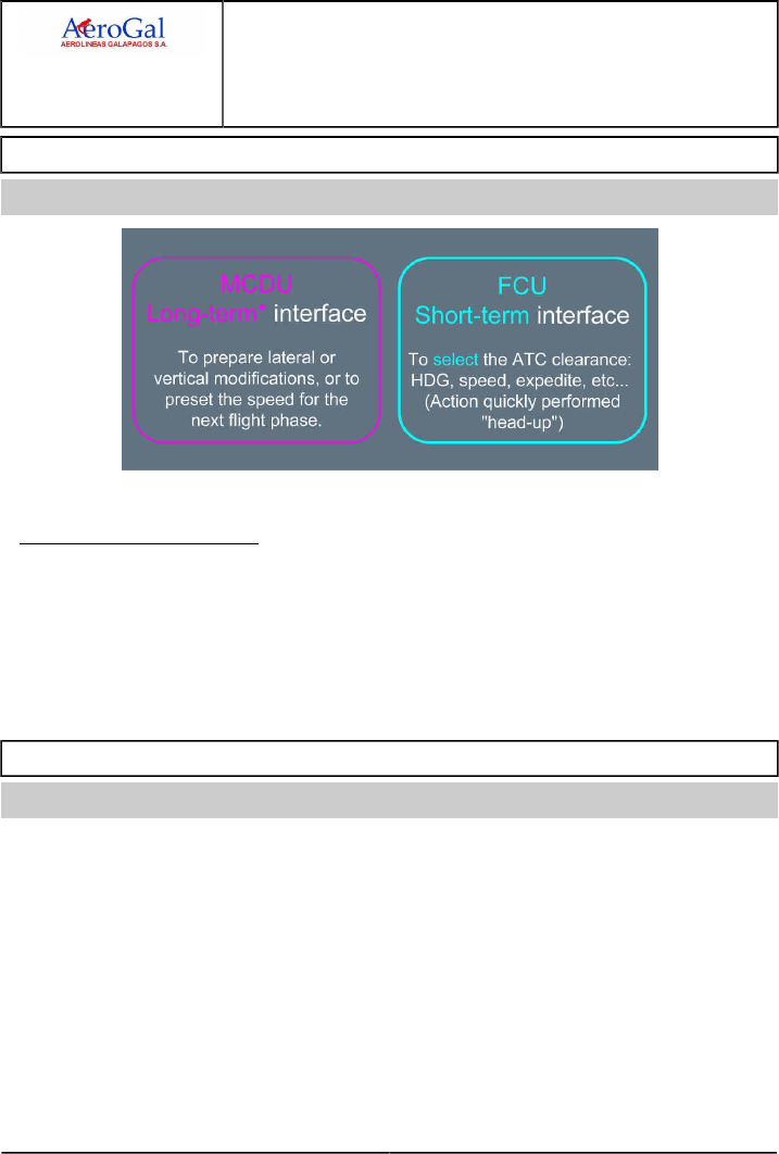
A318/A319/A320/A321
FLIGHT CREW
TECHNIQUES MANUAL
AIRCRAFT SYSTEMS
FLIGHT GUIDANCE
AUTO FLIGHT
GLG A318/A319/A320/A321 FLEET AS-FG-10-1 P 2/4
FCTM C to D 22 MAR 17
MAIN INTERFACES WITH THE AP/FD
Ident.: AS-FG-10-1-00016272.0001001 / 20 MAR 17
Applicable to: ALL
*The DIR TO function is an exception to this rule.
OPERATIONAL TECHNIQUES
With the FMS, anticipate flight plan updates by preparing:
‐ EN ROUTE DIVERSIONS
‐ DIVERSION TO ALTN
‐ CIRCLING
‐ LATE CHANGE OF RWY
This enables the MCDU to be used for short-term actions.
AP/FD MONITORING
Ident.: AS-FG-10-1-00016273.0001001 / 20 MAR 17
Applicable to: ALL
The FMA indicates the status of the AP , FD and A/THR and their corresponding operating modes.
The PF must monitor the FMA and announce any FMA change. The flight crew uses the FCU or
MCDU to give orders to the AP /FD. The aircraft is expected to fly in accordance with these orders.
The main concern for the flight crew should be:
‐WHAT IS THE AIRCRAFT EXPECTED TO FLY NOW?
‐WHAT IS THE AIRCRAFT EXPECTED TO FLY NEXT?
If the aircraft does not fly as expected:
‐ If in managed mode, select the desired target, or
‐ Disengage the autopilot, and fly the aircraft manually.

A318/A319/A320/A321
FLIGHT CREW
TECHNIQUES MANUAL
AIRCRAFT SYSTEMS
FLIGHT GUIDANCE
AUTO FLIGHT
GLG A318/A319/A320/A321 FLEET AS-FG-10-1 P 3/4
FCTM E to F 22 MAR 17
RECOMMENDED PRACTICE FOR AUTOPILOT (AP) ENGAGEMENT
Ident.: AS-FG-10-1-00016274.0001001 / 20 MAR 17
Applicable to: ALL
Before engaging the AP, the flight crew should:
‐ Fly the aircraft on the intended path
‐ Check on the FMA that the Flight Director (FD ) is engaged with the appropriate guidance modes
for the intended flight path. If not, set the FD on, and the appropriate guidance mode(s) as
required
‐ Center the FD bars with the aircraft symbol on the PFD.
Note: Engaging the AP while large orders are required to achieve the intended flight path may
result in an AP overshoot of the intended vertical or lateral target. This situation can
surprise the flight crew, due to the resulting large pitch/roll changes and thrust variations.
USE OF THE FD WITHOUT THE AP
Ident.: AS-FG-10-1-00016275.0001001 / 20 MAR 17
Applicable to: ALL
When manually flying the aircraft with the FD s ON, the FD bars or the FPD symbol provide lateral
and vertical orders in accordance with the active modes that the flight crew selects.
Therefore:
‐ Fly with a centered FD or FPD
‐ If not using FD orders, turn off the FD . It is strongly recommended to turn off the FD s to ensure
that the A/THR is in SPEED mode if the A/THR is active.

A318/A319/A320/A321
FLIGHT CREW
TECHNIQUES MANUAL
AIRCRAFT SYSTEMS
FLIGHT GUIDANCE
AUTO FLIGHT
Intentionally left blank
GLG A318/A319/A320/A321 FLEET AS-FG-10-1 P 4/4
FCTM 22 MAR 17
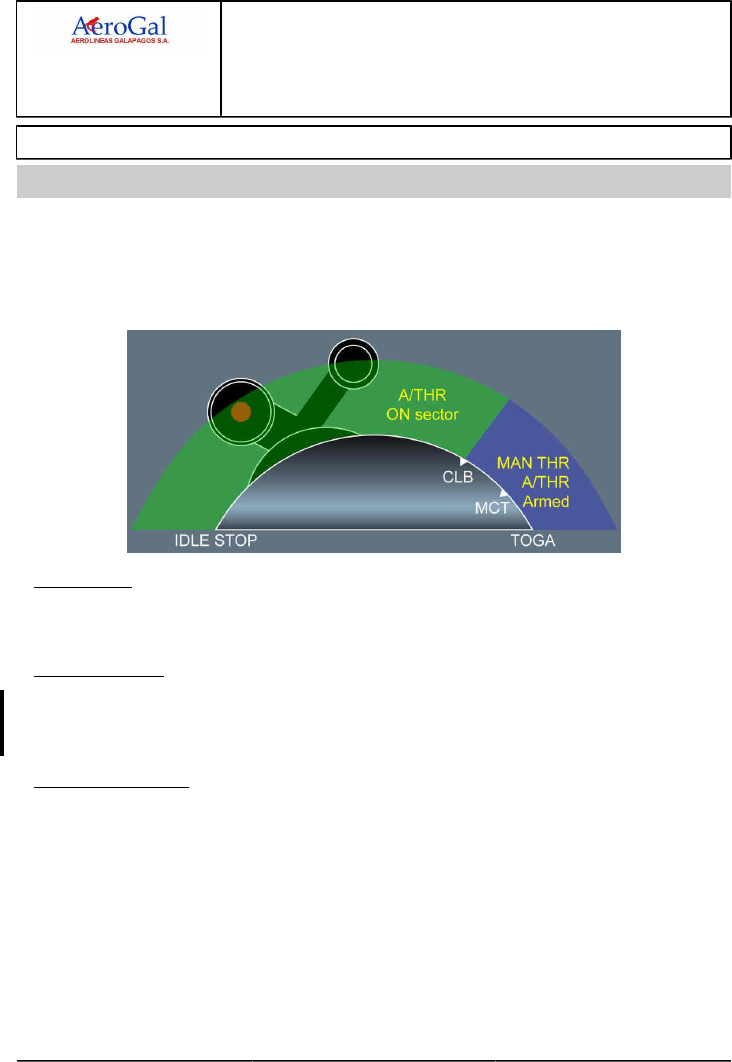
A318/A319/A320/A321
FLIGHT CREW
TECHNIQUES MANUAL
AIRCRAFT SYSTEMS
FLIGHT GUIDANCE
AUTOTHRUST
GLG A318/A319/A320/A321 FLEET AS-FG-10-2 P 1/8
FCTM A → 05 SEP 17
NORMAL OPERATIONS
Ident.: AS-FG-10-2-00018246.0001001 / 25 JUL 17
Applicable to: ALL
The A/THR can only be active, when the thrust levers are between IDLE and the CLB detent.
When the thrust levers are beyond the CLB detent, thrust is controlled manually to the thrust lever
Angle, and the A/THR is armed (A/THR appears in blue on the FMA ). This means that the A/THR
is ready to be re-activated, when the flight crew sets the thrust levers back to the CLB detent (or
below).
AT TAKEOFF
The thrust levers are set either full forward to TOGA , or to the FLX detent. Thrust is manually
controlled to the TLA , and A/THR is armed. The FMA indicates this in blue.
1AFTER TAKEOFF
When the aircraft reaches THR RED ALT , the flight crew sets the thrust levers back to the CLB
detent. This activates A/THR . MAX CLB will, therefore, be the maximum normal thrust setting that
will be commanded by the A/THR in CLB , CRZ , DES , or APPR, as required.
DURING APPROACH
The pilot should use autothrust for approaches. On final approach, it usually gives more accurate
speed control, although in turbulent conditions the actual airspeed may vary from the target speed,
by as much as five knots. Although the changeover between auto and manual thrust is easy to
make with a little practice, the pilot should, when using autothrust for the final approach, keep it
engaged until he retards the thrust levers to idle for touchdown. If the pilot is going to make the
landing using manual thrust, he should disconnect the A/THR by the time he has reached 1 000 ft
on the final approach.
If he makes a shallow flare, with A/THR engaged, it will increase thrust to maintain the approach
speed until he pulls the thrust levers back to idle. Therefore he should avoid making a shallow
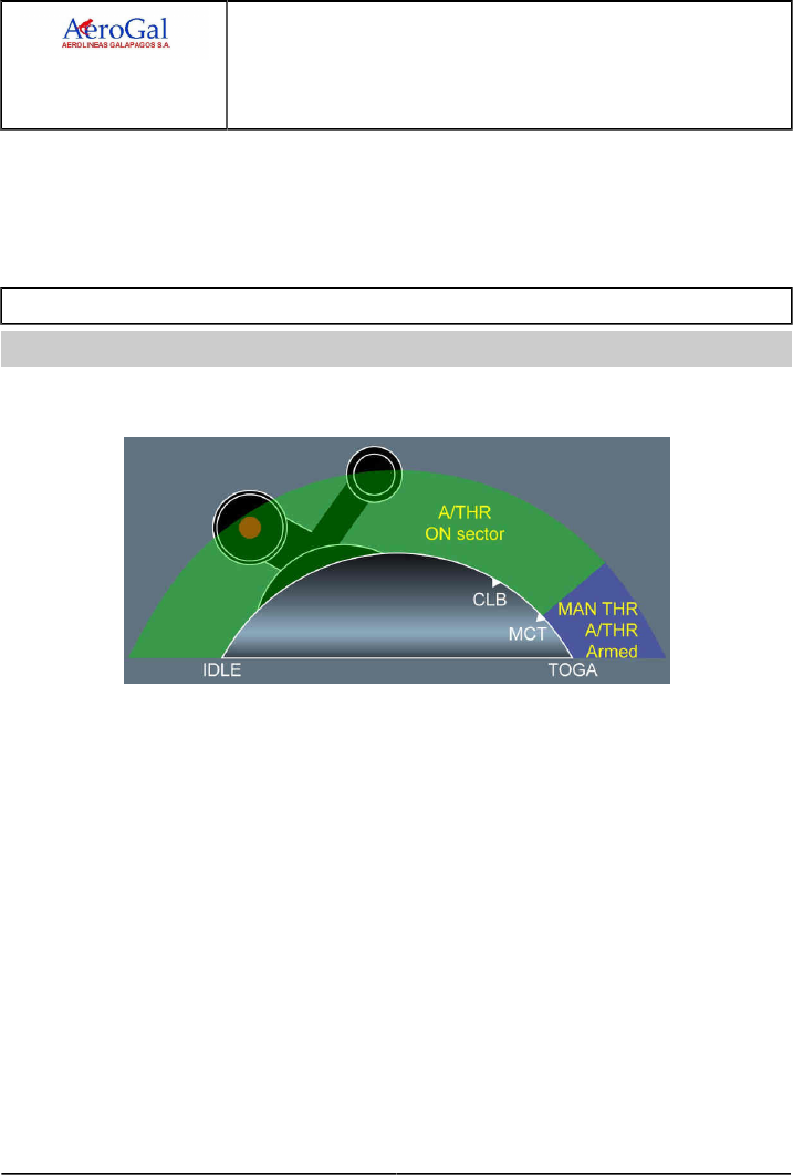
A318/A319/A320/A321
FLIGHT CREW
TECHNIQUES MANUAL
AIRCRAFT SYSTEMS
FLIGHT GUIDANCE
AUTOTHRUST
GLG A318/A319/A320/A321 FLEET AS-FG-10-2 P 2/8
FCTM ← A to B 05 SEP 17
flare, or should retard the thrust levers as soon as it is no longer necessary to carry thrust, and if
necessary before he receives the “retard” reminder.
Although use of the autothrust is recommended for the entire approach, this does not absolve the
pilot from his responsibility to monitor its performance, and to disconnect it if it fails to maintain
speed at the selected value.
OPERATIONS WITH ONE ENGINE INOPERATIVE
Ident.: AS-FG-10-2-00018247.0001001 / 20 MAR 17
Applicable to: ALL
The above-noted principles also apply to an one-engine inoperative situation, except that A/THR can
only be active, when thrust levers are set between IDLE and MCT.
In case of engine failure, the thrust levers will be in MCT detent for remainder of the flight. This is
because MCT is the maximum thrust that can usually be commanded by the A/THR for climb or
acceleration, in all flight phases (e.g. CLB , CRZ , DES or APPR ).
With AP OFF, pilots may feel that the directional control is more difficult because the A/THR changes
the thrust setting. The choice between using, or not using A/THR after engine failure is a personal
one. As far as the speed control is concerned, the A/THR is usually more accurate than a pilot.
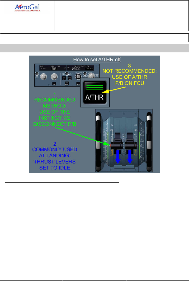
A318/A319/A320/A321
FLIGHT CREW
TECHNIQUES MANUAL
AIRCRAFT SYSTEMS
FLIGHT GUIDANCE
AUTOTHRUST
GLG A318/A319/A320/A321 FLEET AS-FG-10-2 P 3/8
FCTM C → 05 SEP 17
TO SET AUTOTHRUST TO OFF
Ident.: AS-FG-10-2-00018251.0002001 / 20 MAR 17
Applicable to: ALL
1) USE OF INSTINCTIVE DISCONNECT (I/D) PUSHBUTTON
If the I/D pushbutton is pressed when the thrust levers are in CL detent, thrust will increase to MAX
CL. This will cause an unwanted thrust increase and may destabilize the approach.
Therefore, the recommended technique for setting A/THR to off is:
‐ Return the thrust levers to approximately the current thrust setting, by observing the TLA symbol
on the thrust gauge
‐ Press the I/D pb.
This technique minimizes thrust discontinuity, when setting A/THR to off.
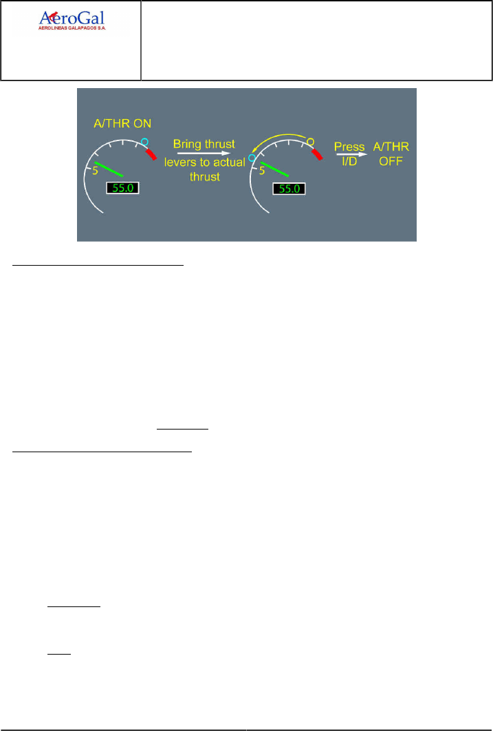
A318/A319/A320/A321
FLIGHT CREW
TECHNIQUES MANUAL
AIRCRAFT SYSTEMS
FLIGHT GUIDANCE
AUTOTHRUST
GLG A318/A319/A320/A321 FLEET AS-FG-10-2 P 4/8
FCTM ← C → 05 SEP 17
2) THRUST LEVERS SET TO IDLE
If thrust levers are set to IDLE, A/THR is set to off. This technique is usually used in descent, when
the A/THR is in THR IDLE, or at landing. During flare, with the A/THR active, the thrust levers
are set to the CLB detent. Then, when thrust reduction is required for landing, the thrust levers
should be moved rapidly and set to the IDLE stop. This will retard thrust, and set A/THR to off. As
a reminder, the "RETARD" aural alert will sound. In flare, this aural alert will occur at 20 ft, except
in the case of autoland, where it occurs at 10 ft.
It should be noted that, when the thrust levers are set back to IDLE and A/THR set to off: The
A/THR can be reactivated by pressing the pushbutton on the FCU , and returning the thrust levers
to the applicable detent. The thrust levers should be immediately returned to the applicable detent,
in order to avoid an ECAM "AUTO FLT A/THR LIMITED" alert.
3) USE OF THE FCU PUSHBUTTON
Use of the FCU pushbutton is considered to be an involuntary A/THR off command (e.g. in the
case of a failure). When pressed, thrust is frozen and remains locked at the value it had when the
flight crew pressed the A/THR pushbutton, as long as the thrust levers remain in the CLB or MCT
detent.
If thrust levers are out of detent, thrust is manually controlled and, therefore, unlocked.
An ECAM caution and an FMA message trigger during thrust lock:
‐ THR LK appears in amber on the FMA
‐ The ECAM caution is:
AUTO FLT A/THR OFF
THR LEVERS ......... MOVE
and then, if the thrust levers are not moved within 5 s:
ENG THRUST LOCKED
THR LEVERS ......... MOVE
In this case, when the flight crew moves the thrust levers out of detent, full manual control is
recovered, and the THR LK message disappears from the FMA.

A318/A319/A320/A321
FLIGHT CREW
TECHNIQUES MANUAL
AIRCRAFT SYSTEMS
FLIGHT GUIDANCE
AUTOTHRUST
GLG A318/A319/A320/A321 FLEET AS-FG-10-2 P 5/8
FCTM ← C to D → 05 SEP 17
This feature should not be used, unless the instinctive disconnect pushbuttons are inoperative.
ALPHA FLOOR
Ident.: AS-FG-10-2-00018248.0001001 / 25 JUL 17
Applicable to: ALL
2When the aircraft's angle-of-attack goes beyond the ALPHA FLOOR threshold, this means that the
aircraft has decelerated significantly (below ALPHA PROT speed): A/THR activates automatically
and orders TOGA thrust, regardless of the thrust lever position.
The example below illustrates that:
• The aircraft is in descent with the thrust levers manually set to IDLE.
• The aircraft decelerates, during manual flight with the FD off, as indicated on the FMA.
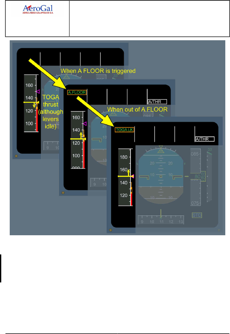
A318/A319/A320/A321
FLIGHT CREW
TECHNIQUES MANUAL
AIRCRAFT SYSTEMS
FLIGHT GUIDANCE
AUTOTHRUST
GLG A318/A319/A320/A321 FLEET AS-FG-10-2 P 6/8
FCTM ← D 05 SEP 17
When the speed decreases, so that the angle-of-attack reaches the ALPHA FLOOR threshold,
A/THR activates and orders TOGA thrust, despite the fact that the thrust levers are at IDLE.
When the aircraft accelerates again, the angle-of-attack drops below the ALPHA FLOOR threshold.
TOGA thrust is maintained or locked. This enables the flight crew to reduce thrust, as necessary.
TOGA LK appears on the FMA to indicate that TOGA thrust is locked. The desired thrust can only be
recovered by setting A/THR to off, with the instinctive disconnect pushbutton.
ALPHA floor is available, when the flight controls are in NORMAL LAW, from liftoff to 100 ft RA at
landing. It is inhibited in some cases of engine failure.
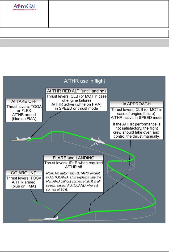
A318/A319/A320/A321
FLIGHT CREW
TECHNIQUES MANUAL
AIRCRAFT SYSTEMS
FLIGHT GUIDANCE
AUTOTHRUST
GLG A318/A319/A320/A321 FLEET AS-FG-10-2 P 7/8
FCTM E → 05 SEP 17
AUTOTHRUST USE - SUMMARY
Ident.: AS-FG-10-2-00018253.0001001 / 20 MAR 17
Applicable to: ALL
Use of A/THR is recommended during the entire flight.
It may be used in most failures cases, including:
‐ Engine failure, even during autoland
‐ Abnormal configurations.

A318/A319/A320/A321
FLIGHT CREW
TECHNIQUES MANUAL
AIRCRAFT SYSTEMS
FLIGHT GUIDANCE
AUTOTHRUST
GLG A318/A319/A320/A321 FLEET AS-FG-10-2 P 8/8
FCTM ← E 05 SEP 17
A/THR should be monitored via the:
‐ FMA – SPEED / SPEED TREND on the PFD
‐ N1 /N1 command (EPR ) on the ECAM E/WD.
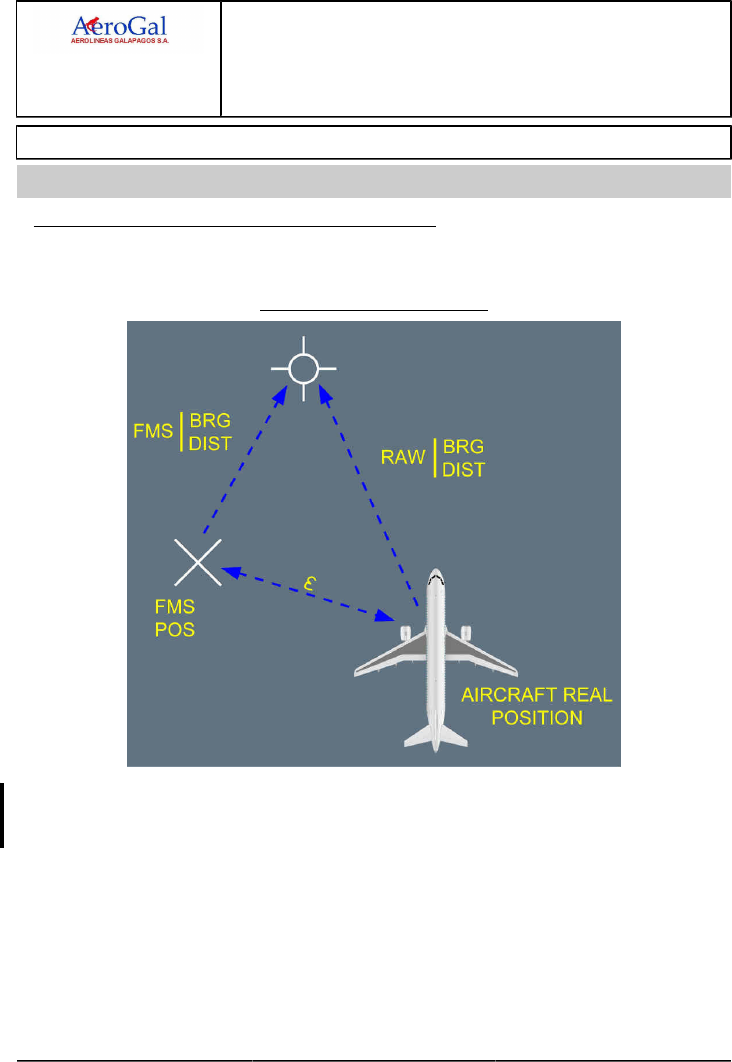
A318/A319/A320/A321
FLIGHT CREW
TECHNIQUES MANUAL
AIRCRAFT SYSTEMS
FLIGHT MANAGEMENT
USE OF FMS
GLG A318/A319/A320/A321 FLEET AS-FM-10 P 1/8
FCTM A → 05 SEP 17
NAVIGATION ACCURACY
Ident.: AS-FM-10-00019557.0001001 / 25 JUL 17
Applicable to: ALL
NAVIGATION ACCURACY CROSSCHECK TECHNIQUE
The principle consists in comparing the FMS position with the RADIO position (aircraft real
position).
Navigation Accuracy Crosscheck
The flight crew inserts a radio ident in MCDU PROG page (which provides a bearing/distance
relative to FMS position). Then, the flight crew compares these values with raw data received from
the NAVAID that indicates the real position of the aircraft . This enables to quantify the error ε.
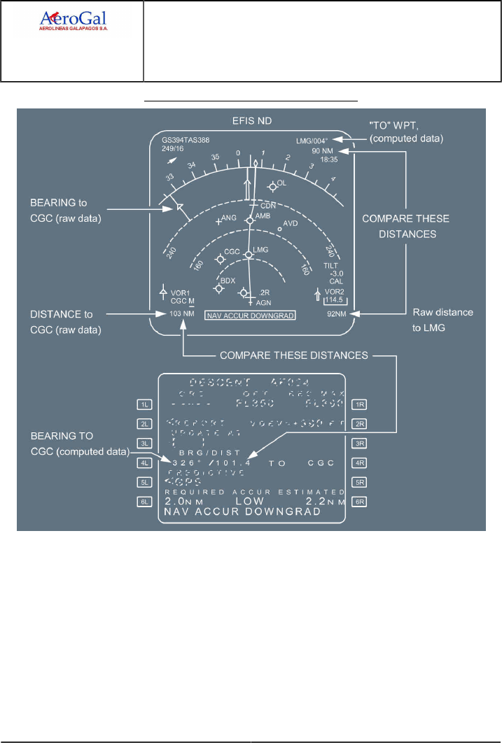
A318/A319/A320/A321
FLIGHT CREW
TECHNIQUES MANUAL
AIRCRAFT SYSTEMS
FLIGHT MANAGEMENT
USE OF FMS
GLG A318/A319/A320/A321 FLEET AS-FM-10 P 2/8
FCTM ← A → 05 SEP 17
Navigation Accuracy Crosscheck Technique
On the ND , the flight crew compares the position of the needle and its associated DME distance
(the real position of the aircraft) with the position of the NAVAID symbol and its associated
distance, indicated by the range markers (these markers provide a bearing/distance, in relation to
the FMS position).
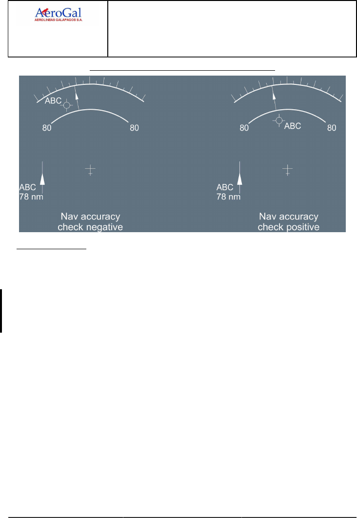
A318/A319/A320/A321
FLIGHT CREW
TECHNIQUES MANUAL
AIRCRAFT SYSTEMS
FLIGHT MANAGEMENT
USE OF FMS
GLG A318/A319/A320/A321 FLEET AS-FM-10 P 3/8
FCTM ← A → 05 SEP 17
Navigation Accuracy Crosscheck Technique on the ND
1POSITION UPDATE
In case of an obvious and major map shift noticed by specific messages such as "CHECK A/C
POSITION, FM 1/FM2 POS MISMATCH", the aircraft position may be updated on the MCDU
PROG page. Two techniques are available:
The recommended technique is to carry out a FMS update over a beacon by pressing the
UPDATE prompt once estimating that the aircraft overflies the beacon using the associated
needle. The potential error induced is approximately 4 to 5 NM. When the position update is
achieved, the EPE is automatically set to a higher value and the navigation accuracy is low.
The second technique consists in updating the FM position when flying over a
Point/Bearing/Distance (P/B/D) with reference to beacon raw data (Needle + Distance) rather than
the beacon itself. The potential for error is far less when the distance is greater than 60 NM. The
flight crew will keep in mind the potential 180 ° error on bearing.
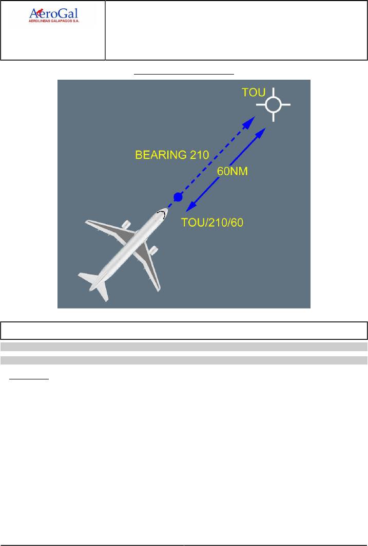
A318/A319/A320/A321
FLIGHT CREW
TECHNIQUES MANUAL
AIRCRAFT SYSTEMS
FLIGHT MANAGEMENT
USE OF FMS
GLG A318/A319/A320/A321 FLEET AS-FM-10 P 4/8
FCTM ← A to B → 05 SEP 17
FM Position Update in Flight
ZFW - ZFWCG ENTRY ERRORS
Applicable to: ALL
Ident.: AS-FM-10-A-00019558.0001001 / 20 MAR 17
GENERAL
The aircraft Gross Weight (GW ) and Centre of Gravity (CG ) are computed independently by the
FM and FAC:
‐ GW and CG values FM computed are used for:
• FM predictions and speeds
• ECAM (GW)
• MCDU (GW and CG).
‐ GW and CG values FAC computed are used for:
• Flight control laws
• Computation of characteristic speeds (VLS , F, S, GD ) for display on PFD.
A ZFW or ZFWCG entry error in MCDU INIT B page induces calculation errors that are to be
highlighted.

A318/A319/A320/A321
FLIGHT CREW
TECHNIQUES MANUAL
AIRCRAFT SYSTEMS
FLIGHT MANAGEMENT
USE OF FMS
GLG A318/A319/A320/A321 FLEET AS-FM-10 P 5/8
FCTM ← B → 05 SEP 17
Ident.: AS-FM-10-A-00019559.0001001 / 03 AUG 17
2TECHNICAL BACKGROUND
The GW and CG computation is as follows:
1. The pilot enters the ZFW and ZFWCG in the MCDU INIT B page
2. The FMGC computes the GW and CG from:
‐ The ZFW , ZFWCG inserted in the MCDU INIT B page
‐ The fuel quantities from the Fuel Quantity Indicator (FQI)
‐ The Fuel Flow from the FADEC.
3. This current GW and/or CG is used for:
‐ FM predictions and speeds
‐ ECAM (GW only)
‐ MCDU (GW and CG).
4. The FAC computes its own GW and CG from aerodynamic data.
5. GW and CG FAC computed are used for:
‐ Minor adjustments on the flight control laws
‐ Characteristic speeds (VLS , F, S, Green dot) display on PFD.
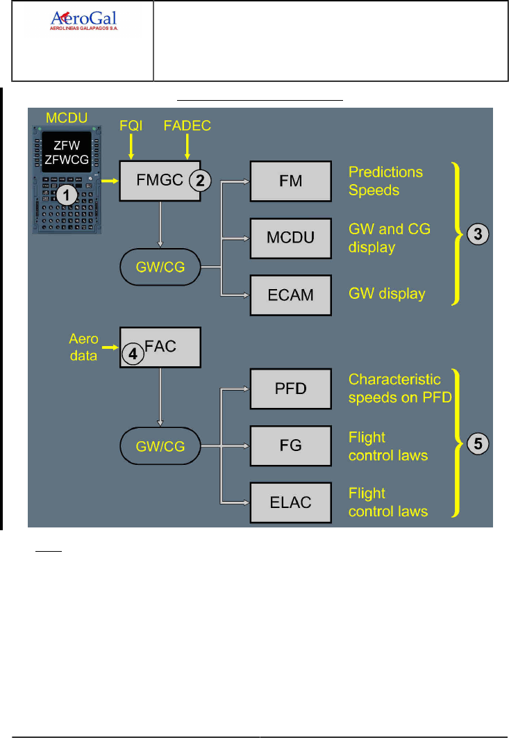
A318/A319/A320/A321
FLIGHT CREW
TECHNIQUES MANUAL
AIRCRAFT SYSTEMS
FLIGHT MANAGEMENT
USE OF FMS
GLG A318/A319/A320/A321 FLEET AS-FM-10 P 6/8
FCTM ← B → 05 SEP 17
GW and CG Computation and Use
Note: ‐ On ground, FAC uses the GW FM computed.
‐ In flight, at low altitude (below 15 000 ft), low speed (below 250 kt) and flight
parameters stabilized, GW FAC computed comes from aerodynamic data. If these
conditions are not met, GW FAC computed equates to the last memorized GW - fuel
used.
‐ If the GW FM computed and FAC computed differs from a given threshold, a "CHECK
GW " message appears on the MCDU scratchpad.

A318/A319/A320/A321
FLIGHT CREW
TECHNIQUES MANUAL
AIRCRAFT SYSTEMS
FLIGHT MANAGEMENT
USE OF FMS
GLG A318/A319/A320/A321 FLEET AS-FM-10 P 7/8
FCTM ← B 05 SEP 17
Ident.: AS-FM-10-A-00019560.0001001 / 20 MAR 17
ZFW ENTRY ERROR AND OPERATIONAL CONSEQUENCES
If the pilot enters erroneous ZFW on MCDU INIT B page, this will affect as follows:
‐ GW and, to a lesser degree, CG , computed by FM are erroneous. This induces the following
consequences:
• The FM predictions and speeds are erroneous
• Incorrect GW and CG on MCDU FUEL PRED page
• Incorrect GW displayed on ECAM
‐ FAC GW , which is based on FM GW on ground, will be updated only once airborne through a
specific slow calculation using AOA information. Consequently,
• Characteristic speeds on PFD at take-off are erroneous, but they are correct in flight
• SRS mode guidance is affected if computed VLS is above V2 as inserted in the MCDU PERF
TAKE-OFF page.
Note: 1. In flight, if the FM and FAC GW differ from a given threshold, a "CHECK GW"
message is triggered on the MCDU.
2. Valpha prot, Valpha max, Vsw are not affected since based on aerodynamic data.
ERRONEOUS FUEL ON BOARD ENTRY
As long as the engines are not started, the FM GW is erroneous and above-mentioned
consequences apply. Once the engines are started, the fuel figures are updated and
downstream data update accordingly.
It should be noted however, that the FOB on ECAM is correct since it is provided from FQI data.
Ident.: AS-FM-10-A-00019561.0001001 / 20 MAR 17
OPERATIONAL RECOMMENDATIONS
ZFW entries should be cross-checked by both crewmembers to avoid entry error.
If the "CHECK GW " amber warning is displayed on the MCDU , a significant discrepancy exists
between the FM computed GW and the FAC computed GW.
The crew will compare the Load and Trim Sheet (LTS) figures with the FM GW and fuel used:
‐ If an obvious entry error is detected, FM GW will be updated on the MCDU FUEL PRED page.
‐ If FM and LTS GW are in accordance and appear to be correct, the FAC computed GW
should be suspected (AOA sensor problem). Consequently, characteristic speeds on PFD are
erroneous and should be disregarded. Characteristic speeds should be extracted from QRH.
‐ If FM and LTS GW are in accordance but LTS GW is suspected, FAC and QRH characteristic
speeds should be compared (to validate FAC outputs) and the most appropriate applied.

A318/A319/A320/A321
FLIGHT CREW
TECHNIQUES MANUAL
AIRCRAFT SYSTEMS
FLIGHT MANAGEMENT
USE OF FMS
Intentionally left blank
GLG A318/A319/A320/A321 FLEET AS-FM-10 P 8/8
FCTM 05 SEP 17

A318/A319/A320/A321
FLIGHT CREW
TECHNIQUES MANUAL
AIRCRAFT SYSTEMS
ROW/ROP
GLG A318/A319/A320/A321 FLEET AS-ROWROP P 1/4
FCTM A → 19 JUN 17
ROW/ROP
Applicable to: HC-CSB
Ident.: AS-ROWROP-10-00020809.0001001 / 20 MAR 17
GENERAL
The Runway Overrun Prevention System (ROPS ) is designed to alert the flight crew in the case
of potential runway overrun situation for dry and wet runway. The ROPS is composed of two
functions:
‐ The Runway Overrun Warning (ROW ) function. It automatically arms at 500 ft AGL and works
until start of braking,
‐ The Runway Overrun Protection (ROP) function. It works from start of braking until the aircraft
stops.
The absence of ROW alert during approach should not prevent the flight crew from closely
monitoring the stabilized approach criteria and from performing a go around if necessary.
In the case of a failure that affects landing performance and/or thrust reversers availability, ROPS
does not prevent runway excursion. Nevertheless, in the case of ROPS alert, the flight crew
immediately shall apply ROPS procedures.
Ident.: AS-ROWROP-10-00018596.0001001 / 20 MAR 17
ROW ALERTS DURING FINAL APPROACH
If during final approach, the IF WET: RWY TOO SHORT message is displayed on the PFD, the
flight crew must perform a go-around when the runway condition is either not dry or contaminated.
If the runway condition is dry, the flight crew can disregard the message and continue the
approach.
If during final approach, the RWY TOO SHORT message is displayed on the PFD , the flight
crew must perform a go-around. In addition to the message displayed on the PFD , the aural alert
"RUNWAY TOO SHORT" triggers below 200 ft AGL to remind the flight crew of the necessity to
perform a go-around.
ROP ALERTS ON GROUND
During the landing roll, if the "BRAKE, MAX BRAKING, MAX BRAKING" aural alert triggers, the
PF must immediately:
‐ Apply and keep maximum manual pedal braking, and
‐ Apply and keep maximum reverse thrust.
If the "SET MAX REVERSE" aural alert triggers, the flight crew must immediately apply and keep
maximum reverse thrust.
If the "KEEP MAX REVERSE" aural alert triggers, the flight crew must keep maximum reverse
thrust as long as necessary.

A318/A319/A320/A321
FLIGHT CREW
TECHNIQUES MANUAL
AIRCRAFT SYSTEMS
ROW/ROP
GLG A318/A319/A320/A321 FLEET AS-ROWROP P 2/4
FCTM ← A → 19 JUN 17
Below 70 kt, when the flight crew considers that the aircraft can stop on the runway and the PFD
message MAX REVERSE is no longer displayed, the flight crew sets idle reverse thrust. Unless
required due to an emergency, it is recommended to avoid the use of high level of reverse thrust at
low speed in order to avoid engine stall and excessive EGT.
Note: In the case of lateral directional control difficulties at low speed in adverse conditions
(crosswind on the critical side, low runway friction) with a failure leading to asymmetrical
reverse thrust (thrust reverse failure or dispatch with one thrust reverse inoperative), the
flight crew should recover directional control and then, follow the "SET MAX REVERSE"
and "KEEP MAX REVERSE" aural alerts.
APPROACHING THE RUNWAY END
The ROP function takes into account the "Landing Distance Available" of the TAWS database and
its associated end of runway, in order to compute the ROP alert with adequate margins. The ROP
function does not take into account the airport layout (e.g. taxiway at the far end of the runway)
and expects that the aircraft will decelerate before it vacates at the runway end. Therefore, the
flight crew should anticipate a deceleration below 20 kt when the aircraft approaches the end of
the runway.
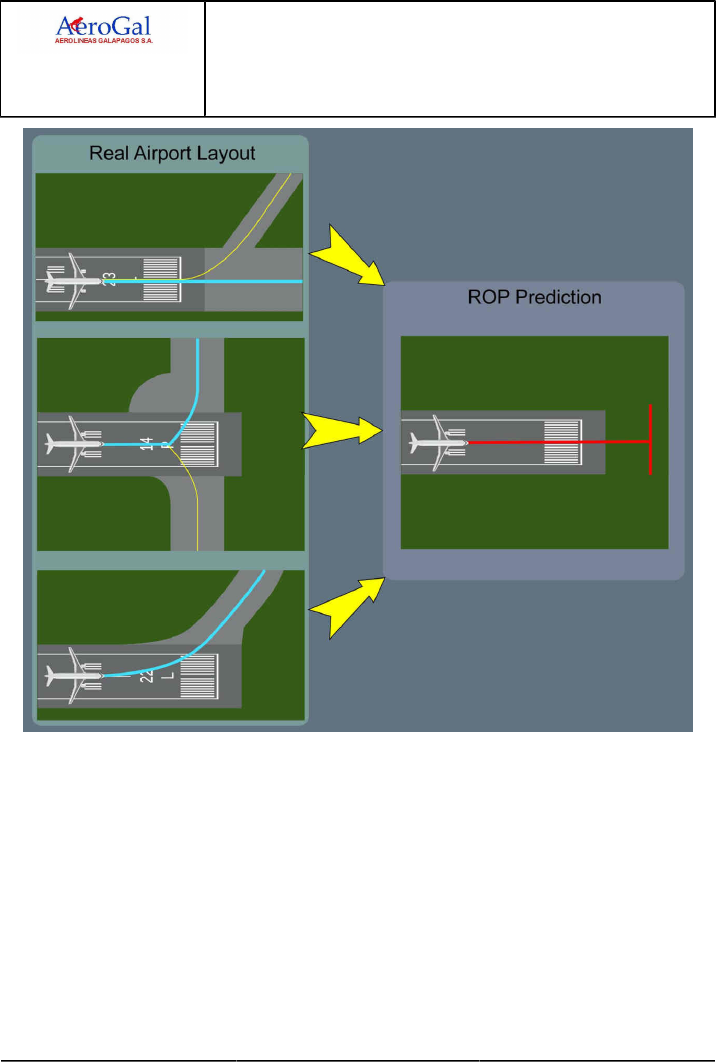
A318/A319/A320/A321
FLIGHT CREW
TECHNIQUES MANUAL
AIRCRAFT SYSTEMS
ROW/ROP
GLG A318/A319/A320/A321 FLEET AS-ROWROP P 3/4
FCTM ← A 19 JUN 17

A318/A319/A320/A321
FLIGHT CREW
TECHNIQUES MANUAL
AIRCRAFT SYSTEMS
ROW/ROP
Intentionally left blank
GLG A318/A319/A320/A321 FLEET AS-ROWROP P 4/4
FCTM 19 JUN 17

A318/A319/A320/A321
FLIGHT CREW
TECHNIQUES MANUAL
AIRCRAFT SYSTEMS
RUDDER
GLG A318/A319/A320/A321 FLEET AS-RUD P 1/4
FCTM A to B → 05 SEP 17
GENERAL
Ident.: AS-RUD-00018204.0001001 / 20 MAR 17
Applicable to: ALL
In flight, the rudder controls the yaw, and the vertical stabilizer ensures directional stability. The
rudder and the vertical stabilizer are designed to :
‐ Provide sufficient lateral/directional control of the aircraft during crosswind takeoffs and landings,
within the certified crosswind limits
‐ Provide aircraft control in the case of an engine failure, and maximum asymmetric thrust at any
speed above the minimum control speed on ground (VMCG).
Flight crew controls the rudder via a conventional mechanical rudder control. FACs computers
provide:
‐ Yaw damping
‐ Rudder travel limitation.
Refer to FCOM/DSC-27-10-20 Yaw Control - General for more information about yaw control.
OPERATIONAL RECOMMENDATIONS
Ident.: AS-RUD-00018205.0002001 / 20 MAR 17
Criteria: 22-1480, SA
1Applicable to: HC-CLF, HC-CSA, HC-CSB, HC-CSF
In order to avoid exceeding structural loads on the rudder and vertical stabilizer, the following
recommendations must be observed.
THE RUDDER IS DESIGNED TO CONTROL THE AIRCRAFT, IN THE FOLLOWING SITUATIONS
A. IN NORMAL OPERATIONS, FOR LATERAL CONTROL
‐ During takeoff roll, when on ground, particularly in crosswind conditions
‐ During landing flare with crosswind, for decrab purposes
‐ During the landing roll, when on the ground.
In the above situations, large and even rapid rudder inputs may be necessary in order to
maintain control of the aircraft.
The flight crew should always apply the rudder corrections as necessary, in order to obtain the
appropriate aircraft response.
On Airbus aircraft, the rudder control system includes a turn coordination function to achieve
acceptable turn coordination.
B. TO COUNTERACT THRUST ASYMMETRY
Up to full rudder deflection can be used to compensate for the yawing moments that are due to
asymmetric thrust.

A318/A319/A320/A321
FLIGHT CREW
TECHNIQUES MANUAL
AIRCRAFT SYSTEMS
RUDDER
GLG A318/A319/A320/A321 FLEET AS-RUD P 2/4
FCTM ← B → 05 SEP 17
Note: At high speed (i.e. slats retracted), thrust asymmetry (eg. due to an engine failure)
does not have a significant effect on the yaw control of the aircraft. The rudder
deflection required to counter an engine failure and center the sideslip is small.
C. IN SOME OTHER ABNORMAL SITUATIONS
The flight crew may also use the rudder pedals in some abnormal situations. For example:
‐ Loss of both yaw damper systems. The flight crew uses the rudder pedals as deemed
necessary, for turn coordination to prevent excessive sideslip.
‐ Rudder trim runaway. The flight crew uses the rudder pedals in order to return the rudder to
neutral
‐ Landing with an abnormal landing gear position: The flight crew uses the rudder pedals for
directional control on the ground.
In all of the normal or abnormal situations that are described above, correct rudder pedals use
does not affect the structural integrity of the aircraft.
Note: In the event of a rudder travel limit system failure, refer to the relevant RUDDER
TRAVEL LIMIT FAULT procedure.
THE RUDDER SHOULD NOT BE USED
‐ To induce roll
‐ To counter roll, induced by any type of turbulence.
Regardless of the airborne flight condition, aggressive, full or nearly full, opposite rudder pedal
inputs must not be applied. Such inputs can lead to loads higher than the limit, and can result in
structural damage or failure. The rudder travel limiter system is not designed to prevent structural
damage or failure in the event of such rudder system inputs.
For dutch roll, the flight control laws combined with the neutral aircraft damping are sufficient to
correctly damp the dutch roll oscillations. Therefore, the flight crew should not use the rudder
pedals in order to complement the flight control laws.
STOP RUDDER INPUT AURAL ALERT
The "STOP RUDDER INPUT" aural alert and red PFD message associated with MASTER
WARNING light is triggered when inappropriate rudder inputs are detected. These alerts advise
the flight crew to avoid excessive rudder load. The flight crew should react and immediately
release the rudder pedals.
CAUTION Avoid large and rapid rudder inputs.

A318/A319/A320/A321
FLIGHT CREW
TECHNIQUES MANUAL
AIRCRAFT SYSTEMS
RUDDER
GLG A318/A319/A320/A321 FLEET AS-RUD P 3/4
FCTM ← B → 05 SEP 17
OPERATIONAL RECOMMENDATIONS
Ident.: AS-RUD-00018205.0001001 / 20 MAR 17
Criteria: SA
2Applicable to: HC-CJM, HC-CJV, HC-CJW, HC-CKN, HC-CRU
In order to avoid exceeding structural loads on the rudder and vertical stabilizer, the following
recommendations must be observed.
THE RUDDER IS DESIGNED TO CONTROL THE AIRCRAFT, IN THE FOLLOWING SITUATIONS
A. IN NORMAL OPERATIONS, FOR LATERAL CONTROL
‐ During takeoff roll, when on ground, particularly in crosswind conditions
‐ During landing flare with crosswind, for decrab purposes
‐ During the landing roll, when on the ground.
In the above situations, large and even rapid rudder inputs may be necessary in order to
maintain control of the aircraft.
The flight crew should always apply the rudder corrections as necessary, in order to obtain the
appropriate aircraft response.
On Airbus aircraft, the rudder control system includes a turn coordination function to achieve
acceptable turn coordination,.
B. TO COUNTERACT THRUST ASYMMETRY
Up to full rudder deflection can be used to compensate for the yawing moments that are due to
asymmetric thrust.
Note: At high speed (i.e. slats retracted), thrust asymmetry (eg. due to an engine failure)
does not have a significant effect on the yaw control of the aircraft. The rudder
deflection required to counter an engine failure and center the sideslip is small.
C. IN SOME OTHER ABNORMAL SITUATIONS
The flight crew may also use the rudder pedals in some abnormal situations. For example:
‐ Loss of both yaw damper systems. The flight crew uses the rudder pedals as deemed
necessary, for turn coordination to prevent excessive sideslip.
‐ Rudder trim runaway. The flight crew uses the rudder pedals in order to return the rudder to
neutral
‐ Landing with an abnormal landing gear position: The flight crew uses the rudder pedals for
directional control on the ground.
In all of the normal or abnormal situations that are described above, correct rudder pedals use
does not affect the structural integrity of the aircraft.

A318/A319/A320/A321
FLIGHT CREW
TECHNIQUES MANUAL
AIRCRAFT SYSTEMS
RUDDER
GLG A318/A319/A320/A321 FLEET AS-RUD P 4/4
FCTM ← B 05 SEP 17
Note: In the event of a rudder travel limit system failure, refer to the relevant RUDDER
TRAVEL LIMIT FAULT procedure.
THE RUDDER SHOULD NOT BE USED
‐ To induce roll
‐ To counter roll, induced by any type of turbulence.
Regardless of the airborne flight condition, aggressive, full or nearly full, opposite rudder pedal
inputs must not be applied. Such inputs can lead to loads higher than the limit, and can result in
structural damage or failure. The rudder travel limiter system is not designed to prevent structural
damage or failure in the event of such rudder system inputs.
For dutch roll, the flight control laws combined with the neutral aircraft damping are sufficient to
correctly damp the dutch roll oscillations. Therefore, the flight crew should not use the rudder
pedals in order to complement the flight control laws.

A318/A319/A320/A321
FLIGHT CREW
TECHNIQUES MANUAL
AIRCRAFT SYSTEMS
TCAS
GLG A318/A319/A320/A321 FLEET AS-TCAS P 1/4
FCTM A 22 MAR 17
INTRUDER CLASSIFICATION
Ident.: AS-TCAS-00016287.0001001 / 20 MAR 17
Applicable to: ALL
Intruder Display Type of
collision threat Aural warning Crew action
No threat traffic or
others
No threat - -
Proximate Consider as No threat - -
Traffic Advisory (TA) Potential threat "TRAFFIC TRAFFIC" No evasive maneuver
Preventive, e.g.
"MONITOR V/S"
Do not alter your flight
path and keep VS out
of red sector
Corrective, e.g.
"CLIMB"
Smoothly and firmly
(0.25 g) follow VSI
green sector within 5 s
Resolution Advisory
(RA)
Collision threat
Corrective, e.g.
"CLIMB NOW" or
"INCREASE CLIMB"
Smoothly and firmly
(0.35 g) follow VSI
green sector within
2.5 s

A318/A319/A320/A321
FLIGHT CREW
TECHNIQUES MANUAL
AIRCRAFT SYSTEMS
TCAS
GLG A318/A319/A320/A321 FLEET AS-TCAS P 2/4
FCTM B → 22 MAR 17
OPERATING TECHNIQUES
Applicable to: ALL
Ident.: AS-TCAS-10-00018674.0001001 / 20 MAR 17
The flight crew should select
‐ ABV in climb (+9 900 ft/-2 700 ft or +7 000 ft/-2 700 ft, depending on the type of TCAS control
panel)
‐ ALL in cruise (+2 700 ft/-2 700 ft)
‐ BELOW , if the cruise altitude is within 2 000 ft of FL 410, or in descent (+2 700 ft/-9 900 ft or
+2 700 ft/-7 000 ft, depending on the type of TCAS control panel)
‐ THRT in heavy traffic terminal area
‐ TA, in the case of:
• Engine failure
• Flight with landing gear down (if applicable)
• In case of known nearby traffic, which is in visual contact
• Operations at specific airports, and during specific procedures that an operator identifies as
having a significant potential for not wanted and not appropriate RAs, e.g. closely spaced
parallel runways, converging runways.
The flight crew should comply with the vertical speed limitations during the last 2 000 ft of a climb
or descent. In particular, the flight crew should limit vertical speeds to 1 500 ft/min during the last
2 000 ft of a climb or descent, especially when they are aware of traffic that is converging in altitude
and intending to level off 1 000 ft above or below the flight crew's assigned altitude.
If a TA is generated:
‐ The PF announces: "TCAS, I have controls".
‐ No evasive maneuver should be initiated, only on the basis of a TA.

A318/A319/A320/A321
FLIGHT CREW
TECHNIQUES MANUAL
AIRCRAFT SYSTEMS
TCAS
GLG A318/A319/A320/A321 FLEET AS-TCAS P 3/4
FCTM ← B 22 MAR 17
If a RA is generated:
‐ The flight crew must always follow the TCAS RA orders in the correct direction, even:
• If the TCAS RA orders are in contradiction with the ATC instructions
• At the maximum ceiling altitude with CLIMB, CLIMB or INCREASE CLIMB, INCREASE CLIMB
TCAS RA orders
• If it results in crossing the altitude of the intruder.
CAUTION If a pilot does not follow a RA , he should be aware that the intruder may be
TCAS equipped and may be maneuvering toward his aircraft in response to a
coordinated RA. This could compromize safe separation.
‐ The PF disconnects the AP , and smoothly and firmly follows the Vertical Speed Indicator (VSI )
green sector within 5 s, and requests that both FDs be disconnected.
Note: Both FD s must be disconnected once APs are disconnected:
‐ To ensure autothrust speed mode
‐ To avoid possible confusion between FD bar orders and, TCAS aural and VSI orders
‐ The PM disconnects both FDs, but will not try to see intruders.
‐ The PF will avoid excessive maneuvers, and keep the Vertical Speed outside the red area of the
VSI and within the green area. If necessary, the PF must use the full speed range between Valpha
max and Vmax.
‐ The PM must notify ATC.
‐ The flight crew should never maneuver in the opposite direction of the RA , because TCAS
maneuvers are coordinated.
‐ In final approach, i.e. "CLIMB", "CLIMB NOW", "INCREASE CLIMB", the flight crew will initiate a
go-around.
When clear of conflict:
‐ The flight crew must resume normal navigation, in accordance with ATC clearance, and using the
AP, as required.

A318/A319/A320/A321
FLIGHT CREW
TECHNIQUES MANUAL
AIRCRAFT SYSTEMS
TCAS
Intentionally left blank
GLG A318/A319/A320/A321 FLEET AS-TCAS P 4/4
FCTM 22 MAR 17
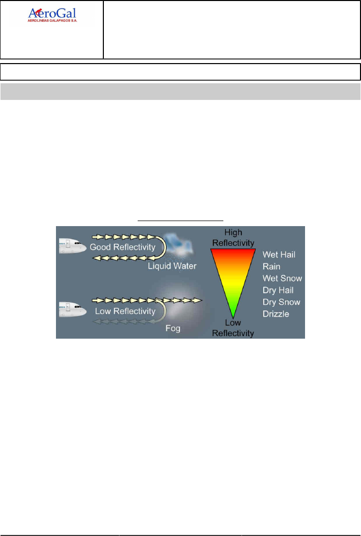
A318/A319/A320/A321
FLIGHT CREW
TECHNIQUES MANUAL
AIRCRAFT SYSTEMS
WEATHER RADAR
GLG A318/A319/A320/A321 FLEET AS-WXR P 1/16
FCTM A → 05 SEP 17
GENERAL
Ident.: AS-WXR-00019761.0001001 / 20 MAR 17
Applicable to: ALL
This FCTM chapter provides basic knowledge on the use of onboard weather radars. To get all the
information on the characteristics, limitations and operational recommendations of each radar, refer
to the user guide of the radar manufacturer.
Weather detection is based on the reflectivity of water droplets. The weather echo appears on the
ND with a color scale that goes from red (high reflectivity) to green (low reflectivity).
The intensity of the weather echo is associated with the droplet size, composition and quantity (e.g.
the reflectivity of a water particle is five times more than an ice particle of the same size). The flight
crew must be aware that the weather radar does not detect weather that has small droplets (e.g.
clouds or fog), or that does not have droplets (e.g. clear air turbulence).
Weather Radar Principle
The purpose of the weather radar is to help the flight crew detect and avoid storm cells (e.g.
cumulonimbus). Due to its large vertical expansion, a storm cell does not have the same reflectivity
depending on the altitude. The quantity of liquid water in the atmosphere decreases with the altitude.
Therefore the reflectivity of a storm cell decreases with the altitude.
The upper detection limit of the weather radar is called the radar top.
The flight crew must be aware of both of the following:
‐ The radar top is not the visible top of the storm cell
‐ The storm cell and associated turbulence extend significantly above the radar top.
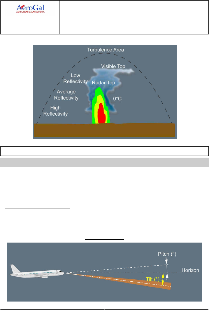
A318/A319/A320/A321
FLIGHT CREW
TECHNIQUES MANUAL
AIRCRAFT SYSTEMS
WEATHER RADAR
GLG A318/A319/A320/A321 FLEET AS-WXR P 2/16
FCTM ← A to B → 05 SEP 17
Reflective Image of a Cumulonimbus
WEATHER DETECTION
Ident.: AS-WXR-00019763.0001001 / 20 MAR 17
Applicable to: ALL
The flight crew uses the following controls and functions to operate the weather radar:
‐ TILT
‐ GAIN
‐ RANGE.
MANUAL TILT MANAGEMENT
The tilt refers to the angle between the antenna beam centerline and the horizon.
The radar uses data from the IRS to stabilize its antenna. Therefore, the antenna tilt is
independent of the aircraft pitch and bank angle.
Tilt Angle Definition
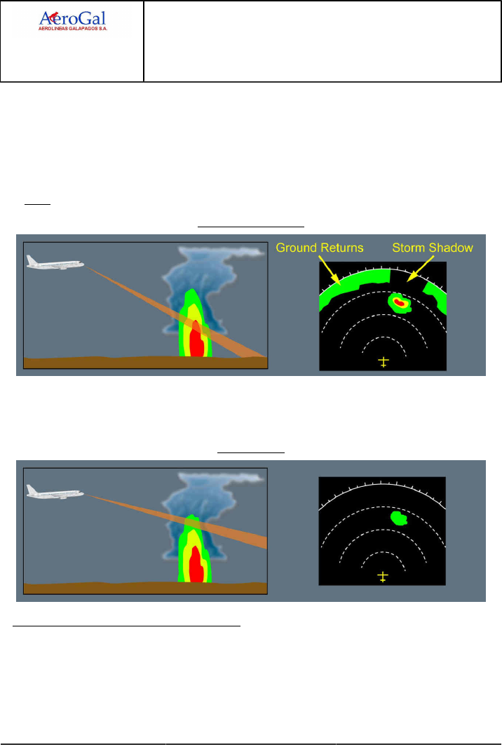
A318/A319/A320/A321
FLIGHT CREW
TECHNIQUES MANUAL
AIRCRAFT SYSTEMS
WEATHER RADAR
GLG A318/A319/A320/A321 FLEET AS-WXR P 3/16
FCTM ← B → 05 SEP 17
The flight crew should regularly scan the area ahead of the aircraft, at several ND ranges. In order
to identify the strongest weather returns, the flight crew should tilt the weather radar antenna up
and down.
To obtain a correct display of a storm cell, the flight crew must use the tilt knob to point the
weather radar beam to the most reflective part of the storm cell. A correct tilt setting prevents the
overscanning of the storm cell.
Note: Common practice is to ensure that the ground return is at the top of the ND screen.
Correct Storm Display
At high altitude, a storm cell may contain ice particles that have low reflectivity. If the tilt setting is
not correct, the ND may display only the upper (less reflective) part of a storm cell (overscanning).
As a result, the flight crew may underestimate or not detect a storm cell.
Overscanning
GAIN SETTING FOR WEATHER DETECTION
The flight crew should use the calibrated gain (CAL or AUTO) for weather detection as a default
mode for the weather radar. The use of the calibrated gain ensures a standard display of the
colors on the ND. The flight crew can manually tune the gain to analyze storm cells.Refer to
AS-WXR Analysis of weather radar data
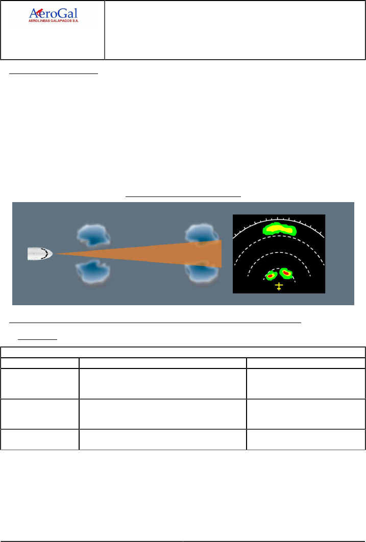
A318/A319/A320/A321
FLIGHT CREW
TECHNIQUES MANUAL
AIRCRAFT SYSTEMS
WEATHER RADAR
GLG A318/A319/A320/A321 FLEET AS-WXR P 4/16
FCTM ← B → 05 SEP 17
RANGE MANAGEMENT
The flight crew should monitor both the long-distance and short-distance weather, in order to be
able to efficiently plan appropriate course changes, and to avoid the “blind alley effect.Refer to
AS-WXR Analysis of weather radar data
At long distance ahead of the aircraft, the accuracy of the weather displayed is low, due to both of
the following:
‐ The increase in the width of the weather radar beam
‐ Signal attenuation.
Therefore, the accuracy of the weather displayed is better for short-distance weather.
Accuracy of the Weather Display
USE OF THE WEATHER RADAR IN ACCORDANCE WITH THE FLIGHT PHASE
Manual Tilt
Manual Weather Radars (or Automatic Weather Radars in Manual Tilt Mode)
Flight Phase Tilt Control Comments
TAXI
Away from ground personnel, set the ND to
the lowest range. Tilt down then up. Check
appearance/disappearance of ground returns.
Radar check.
TAKEOFF
In the case of suspected adverse weather conditions,
manually and gradually tilt up to scan weather (maximum
15 ° up). In all other cases, set the tilt to 4 ° up.
When lined up, check of the departure
path.
CLIMB Adjust the ND range as required and decrease the tilt
angle as the aircraft climbs.
Compensation of the altitude increase
to avoid overscanning.
Continued on the following page

A318/A319/A320/A321
FLIGHT CREW
TECHNIQUES MANUAL
AIRCRAFT SYSTEMS
WEATHER RADAR
GLG A318/A319/A320/A321 FLEET AS-WXR P 5/16
FCTM ← B → 05 SEP 17
Continued from the previous page
Manual Weather Radars (or Automatic Weather Radars in Manual Tilt Mode)
Flight Phase Tilt Control Comments
LEVEL
FLIGHT/CRUISE
1. Adjust ND range as required
2. Regularly modify the tilt to scan the weather ahead
of the aircraft
3. When the weather scan is completed, adjust the tilt
so that the ground returns appear on the top of the
ND (2) (3).
In cruise, the combination of the
following ND ranges provides good
weather awareness (1):
‐ 160 NM on the PM ND
‐ 80 NM on the PF ND.
Use shorter ND ranges to track/avoid
short-distance weather.
DESCENT During descent, adjust the tilt to maintain the ground
returns on the top of the ND. -
APPROACH Set the tilt to 4 ° up. This tilt setting (4 ° up) prevents the
display of too many ground returns.
(1) For aircraft equipped with a manual weather radar that has only one tilt control knob, use an
average tilt value to suit both ND ranges.
(2) It is difficult to identify the difference between weather returns and ground returns: A change in the
tilt setting causes the shape and color of ground returns to rapidly change. These ground returns
eventually disappear. This is not the case for weather returns.
(3) For flights above the water, there are no ground returns. Therefore, the flight crew can use any of
the following tilt settings at cruise altitude as an initial value before adjustment:
‐approximately -6 ° for an ND range of 40 NM, or
‐approximately -2 ° for an ND range of 80 NM, or
‐approximately -1 ° for an ND range of 160 NM, or
‐approximately -1 ° for an ND range of 320 NM.
Automatic Tilt Control
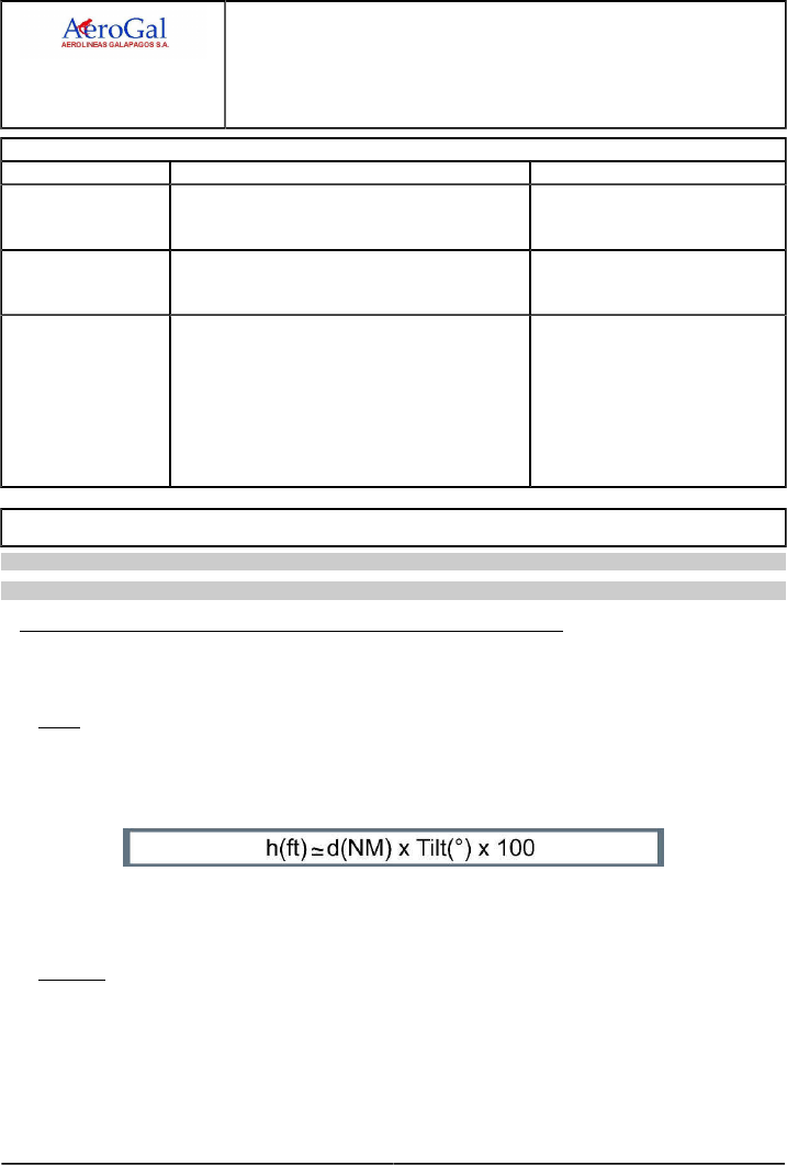
A318/A319/A320/A321
FLIGHT CREW
TECHNIQUES MANUAL
AIRCRAFT SYSTEMS
WEATHER RADAR
GLG A318/A319/A320/A321 FLEET AS-WXR P 6/16
FCTM ← B to C → 05 SEP 17
Automatic Weather Radars
Flight Phase Tilt Control Comments
TAXI
Away from ground personnel, set the ND to
the lowest range. Tilt down then up. Check
appearance/disappearance of ground returns.
Set manual tilt mode for radar check.
TAKEOFF
In the case of suspected adverse weather conditions,
manually and gradually tilt up to scan weather (maximum
15 ° up). Then set tilt to AUTO.
When lined up, check of the departure
path. Then, use the automatic tilt mode
for takeoff.
IN FLIGHT
Adjust ND range as required.
Set tilt to AUTO.
Use manual tilt for storm cell analysis, then set tilt back
to AUTO.
Regularly perform manual scans to enhance weather
awareness, then set tilt back to AUTO.
In cruise, the combination of the
following ND ranges provides good
weather awareness:
‐ 160 NM on the PM ND
‐ 80 NM on the PF ND.
Use shorter ND ranges to track/avoid
short-distance weather.
ANALYSIS OF WEATHER RADAR DATA
Applicable to: ALL
Ident.: AS-WXR-A-00019767.0001001 / 20 MAR 17
ASSESSMENT OF THE VERTICAL EXPANSION OF A STORM CELL
The assessment of the vertical expansion of a detected storm cell enables the flight crew to
assess the convective energy of the storm cell and therefore to identify its potential threat.
Note: The flight crew can increase the gain in order to obtain a more visible display of the top of
the storm cell (that contains less reflective ice particles).
When flying towards a cell, the flight crew can estimate the vertical expansion of the cloud
above/below the aircraft altitude with the following formula:
h(ft) is the difference between the radar top altitude and the aircraft altitude.
d(NM) is the distance between the aircraft and the storm cell.
Tilt(°) is the tilt setting for which the storm cell image disappears from the ND.
Example: A weather return that disappears from the ND at 40 NM with a tilt setting of 1 ° down,
indicates that the top of the storm cell is 4 000 ft below the aircraft altitude.
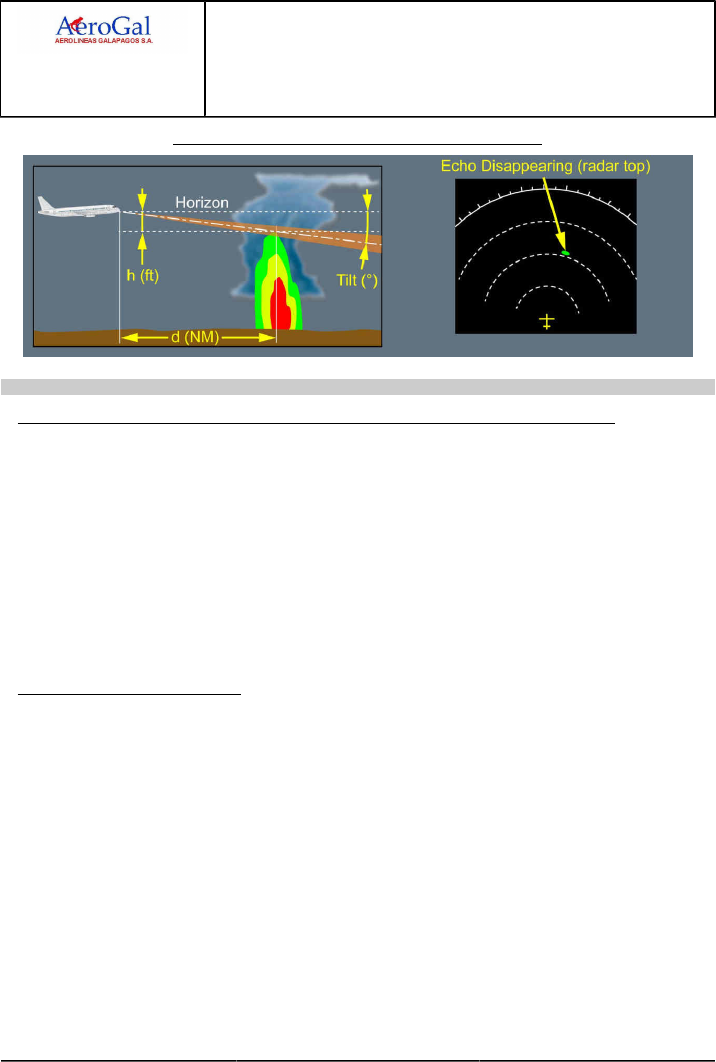
A318/A319/A320/A321
FLIGHT CREW
TECHNIQUES MANUAL
AIRCRAFT SYSTEMS
WEATHER RADAR
GLG A318/A319/A320/A321 FLEET AS-WXR P 7/16
FCTM ← C → 05 SEP 17
Assessment of the Vertical Expansion of a Storm Cell
Ident.: AS-WXR-A-00019766.0001001 / 20 MAR 17
INTERPRETATION OF THE COLORS OF THE WEATHER DISPLAYED ON THE ND
Particle reflectivity of a storm cell is independent of the potential weather hazard in the storm cell.
There can be a high percentage of humidity in the atmosphere, when near the sea. In this case,
thermal convection will produce clouds that are full of water. These clouds will have a high
reflectivity, but may not necessarily be a high threat.
On the other hand, in equatorial overland regions where specific converging winds produce
large-scale uplifts of dry air. As a result, these storm cells have lower reflectivity than mid-latitude
storm cells, and therefore can be difficult to detect. However turbulence in, or above these clouds
may have a higher intensity than indicated by the image on the weather radar display.
The flight crew must not underestimate a storm cell with a high vertical expansion, even if the
weather return is low.
SPECIFIC WEATHER SHAPES
The flight crew should carefully observe shapes, more than colors, in order to detect adverse
weather conditions.
Areas of different colors that are near to one another usually indicate zones of severe turbulence.
Some shapes are good indicators of severe hail and signify strong vertical drafts. Shapes that
change quickly, whatever form they take, also indicate high weather activity.
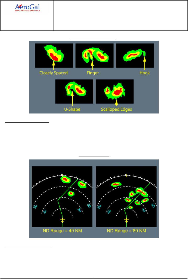
A318/A319/A320/A321
FLIGHT CREW
TECHNIQUES MANUAL
AIRCRAFT SYSTEMS
WEATHER RADAR
GLG A318/A319/A320/A321 FLEET AS-WXR P 8/16
FCTM ← C → 05 SEP 17
Specific Weather Shapes
BLIND ALLEY EFFECT
The flight crew should determine appropriate course changes to avoid adverse weather conditions,
with the use of both high and short ND ranges. This technique avoids the “blind alley effect",
defined by the following: A course change that may appear safe with a short ND range, may be
blocked when observed with a higher ND range.
Blind Alley Effect
ATTENUATION EFFECT
In areas of heavy precipitation, an important part of the weather radar signal is reflected by
the frontal part of the precipitation due to its strong reflectivity. Therefore, the area behind the
precipitation returns low signals, that appears as green or black areas (storm shadows).
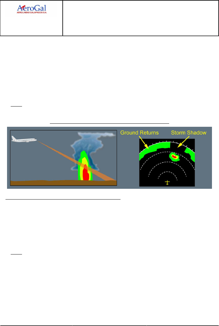
A318/A319/A320/A321
FLIGHT CREW
TECHNIQUES MANUAL
AIRCRAFT SYSTEMS
WEATHER RADAR
GLG A318/A319/A320/A321 FLEET AS-WXR P 9/16
FCTM ← C → 05 SEP 17
Attenuation of long-distance weather or attenuation of ground returns can help the flight crew to
identify an area of heavy precipitation that may be a very active storm cell.
Some radars provide an indication on the ND to highlight areas that may be affected by
attenuation:
‐ PAC alert on Collins radars Refer to FCOM/DSC-34-SURV-30-30 Weather Radar indication
on ND
‐ REACT function on Honeywell radars .Refer to FCOM/DSC-34-SURV-30-30 Weather
Hazard Prediction Function Indication on ND
Note: On a weather radar display, the flight crew should always consider a black hole behind a
red area as a potentially very active zone.
Use of Attenuation Effect to Identify an Active Storm Cell
USE OF MANUAL GAIN FOR WEATHER ANALYSIS
To assess the general weather conditions, the flight crew can use manual gain.
Manual gain adjusts the color calibration of the radar. Therefore, the weather will appear either
stronger (gain increased) or weaker (gain reduced).
When operating in heavy rain, the weather radar picture can be saturated. In this case, manually
reduce the gain will help the flight crew to identify the areas of heaviest rainfall, that are usually
associated with active storm cells.
Note: After a storm cell analysis, the flight crew must set the GAIN knob back to AUTO/CAL.
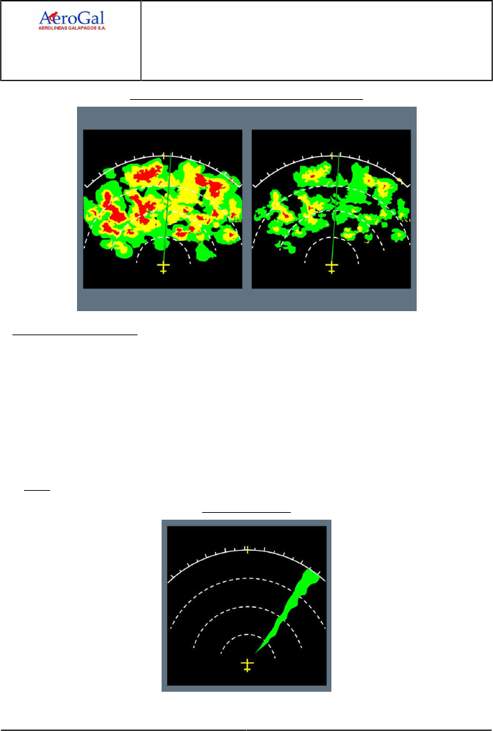
A318/A319/A320/A321
FLIGHT CREW
TECHNIQUES MANUAL
AIRCRAFT SYSTEMS
WEATHER RADAR
GLG A318/A319/A320/A321 FLEET AS-WXR P 10/16
FCTM ← C 05 SEP 17
Use of Reduced gain to Identify Heaviest Rainfall
RADAR INTERFERENCE
High power external radio frequency sources that operate at a frequency next to the frequency of
the weather radar may create interferences. These interferences may result in a not usual return
display on the ND . The radar return will appear as a single wedge that extends out along the ND
toward the source of interference.
The width and color of the interference may differ on the ND, depending on the distance to the
source and its strength.
This interference does not damage the radar system, and will disappear as soon as the source of
interference is outside the limit of the radar scan zone.
Note: Radar interference may also be known as ‘spoking’ or ‘alien radar’.
Radar Interference

A318/A319/A320/A321
FLIGHT CREW
TECHNIQUES MANUAL
AIRCRAFT SYSTEMS
WEATHER RADAR
GLG A318/A319/A320/A321 FLEET AS-WXR P 11/16
FCTM D → 05 SEP 17
OPERATIONS IN CONVECTIVE WEATHER
Ident.: AS-WXR-00019768.0001001 / 20 MAR 17
Applicable to: ALL
The flight should apply the following operational recommendations in convective weather conditions.
These recommendations are applicable in addition to basic knowledge of meteorology and of
operation in adverse weather conditions.
Weather detection:
‐ Always consider that a convective cloud may be dangerous, even if the weather echo is weak.
Remember that the weather radar detects only water droplets
‐ Frequent lightning may indicate an area with high probability of severe turbulence
‐ Remember that the TURB function detects areas of wet turbulence only
Avoidance decision:
‐ Establish an "area of greatest threat" based on the locations and shape of the strongest weather
radar echoes, and on the meteorological knowledge of the flight crew. This "area of greatest
threat" corresponds to the zone where the flight crew estimates that the weather conditions are
too dangerous to fly in
‐ Initiate your avoidance maneuver as early as possible. As the aircraft gets nearer to the
convective weather zone, the information from the weather radar often becomes partial.
Consider a minimum distance of 40 NM from the convective cloud to make the decision for
avoidance maneuver.
Avoidance technique:
‐ If possible, perform lateral avoidance instead of vertical avoidance. Vertical avoidance is
in general not recommended, particularly at high altitude, due to the reduction of buffet
and performance margins. In addition, some convective clouds may have a significant and
unpredictable build-up speed.
‐ Lateral avoidance:
• If possible, deviate upwind instead of downwind. Usually, there is less turbulence and hail
upwind of a convective cloud
• If possible, avoid the identified “area of greatest threat” by at least 20 NM
• Apply an additional margin if the convective clouds are very dynamic
‐ Vertical avoidance:
• Avoid flying below a convective cloud, even in visual conditions, due to possible severe
turbulence, windshear, microbursts, lightning strikes and hail. If an aircraft must fly below a
convective cloud, the flight crew should take into account all indications (visual judgement,
weather radar, weather report, pilot’s report, etc.) before they take the final decision
• For flight above a convective cloud, apply a vertical margin of 5 000 ft from the identified
“area of greatest threat”.
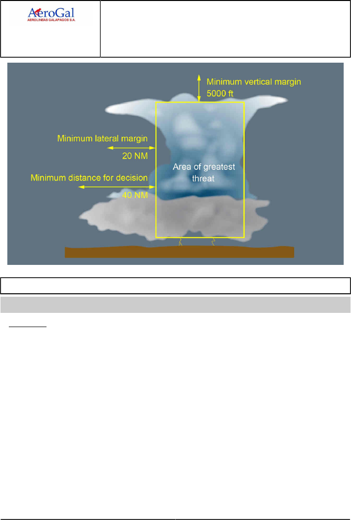
A318/A319/A320/A321
FLIGHT CREW
TECHNIQUES MANUAL
AIRCRAFT SYSTEMS
WEATHER RADAR
GLG A318/A319/A320/A321 FLEET AS-WXR P 12/16
FCTM ← D to E → 05 SEP 17
ICE CRYSTALS
Ident.: AS-WXR-00021072.0001001 / 06 JUL 17
Applicable to: ALL
GENERAL
Clouds are made of particles of water that can be either liquid or solid. Ice crystals are very small
solid water particles. In some areas, there may be a very high concentration of ice crystals that
may have adverse effect on the aircraft.
Areas of ice crystals are usually next to, or above the core of convective clouds that have
high-intensity precipitation. However, areas of ice crystals may sometimes even be several
nautical miles away from the core of the associated convective cloud.
When ice crystals get in contact with a hot surface, they melt. Depending on the type of surface,
a water film may appear. On the windshield, this water film creates not-expected appearance of
“rain” at temperatures too low for liquid water to exist.
If there is a specific airflow towards a zone of the aircraft where water can build up, accretion may
occur and create a block of ice. This is why flight in areas of ice crystals may result in various
effects, for example engine vibrations, engine power loss, engine damage, or icing of air data
probes.
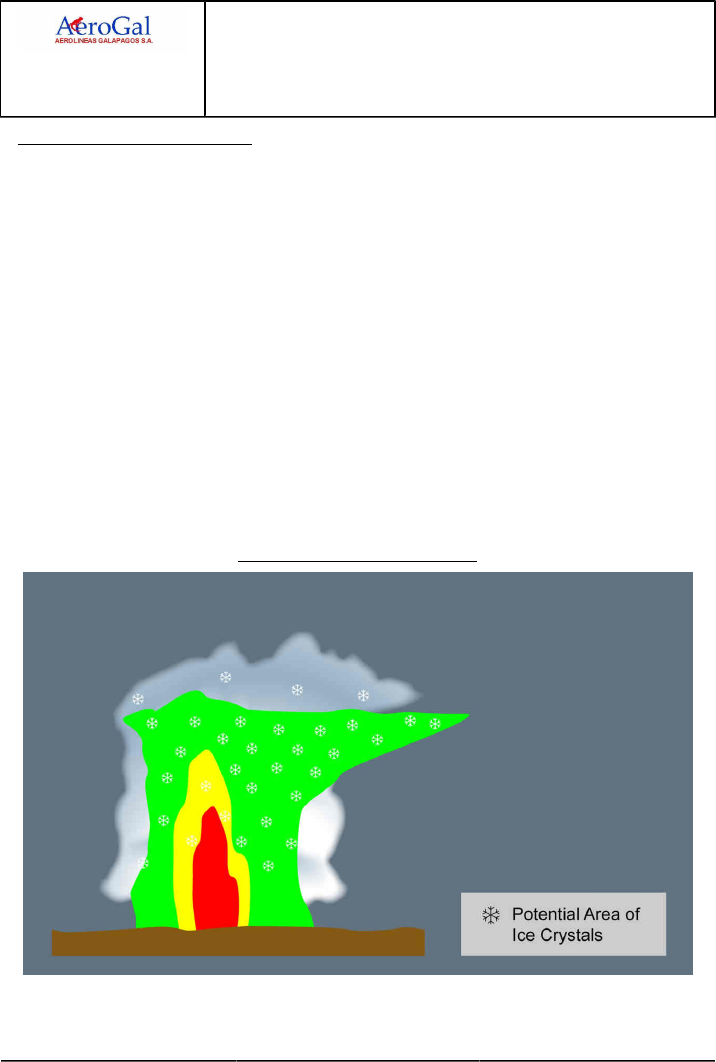
A318/A319/A320/A321
FLIGHT CREW
TECHNIQUES MANUAL
AIRCRAFT SYSTEMS
WEATHER RADAR
GLG A318/A319/A320/A321 FLEET AS-WXR P 13/16
FCTM ← E → 05 SEP 17
DETECTION OF ICE CRYSTALS
Ice crystals are difficult to detect with the weather radar, because their reflectivity is very low due
to both their small size and solid state. In addition, in areas of ice crystals, the flight crew should
not expect significant icing of the airframe. This is because ice crystals bounce off cold aircraft
surfaces. This is why even the ice detection system does not detect ice crystals, because ice
crystals do not build up on ice detectors and visual ice indicators.
However, areas of ice crystals are usually associated with visible moisture. Ice crystals can be
indicated by one or more of the following:
‐ Appearance of rain on the windshield at temperatures too low for rain to exist. This “rain” is
usually associated with a “Shhhh” noise
‐ Small accumulation of ice particles on wipers
‐ Smell of ozone or Saint Elmo’s fire
‐ Aircraft TAT indication that remains near 0 °C (due to freezing of the TAT probe)
‐ Light to moderate turbulence in IMC at high altitude
‐ No significant radar echo at high aircraft altitude, combined with:
• High-intensity precipitation that appears below the aircraft, or
• Aircraft position downwind of a very active convective cloud.
Isolated Continental Thunderstorm
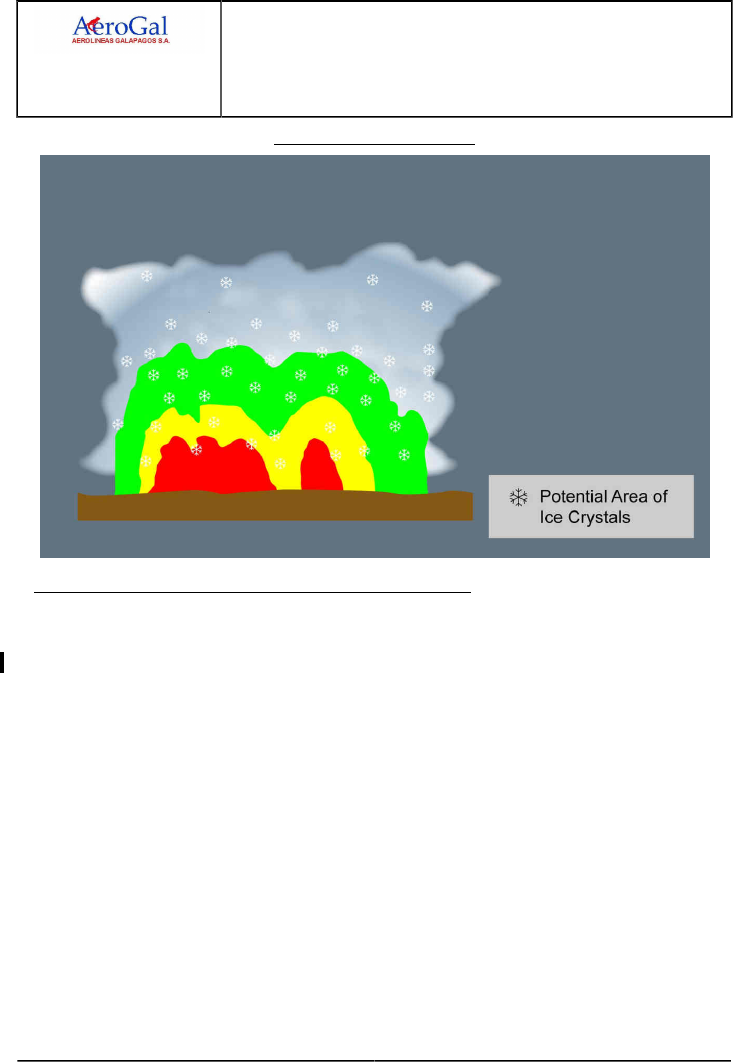
A318/A319/A320/A321
FLIGHT CREW
TECHNIQUES MANUAL
AIRCRAFT SYSTEMS
WEATHER RADAR
GLG A318/A319/A320/A321 FLEET AS-WXR P 14/16
FCTM ← E → 05 SEP 17
Mesoscale Convective Cloud
1OPERATIONAL RECOMMENDATIONS FOR ICE CRYSTALS
If possible, the flight crew should avoid flight into areas that have a high concentration of ice
crystals. The following recommendations apply:
‐ Use the weather radar:
• Identify areas that have a strong echo, and perform a detailed analysis of the structure of the
convective clouds
• If necessary, use the weather radar manual modes for a more precise analysis
• Pay particular attention to strong echoes below the aircraft and to downwind areas.
‐ To avoid convective clouds, comply with operational recommendations (Refer to AS-WXR
Operations in Convective Weather), particularly:
• Prefer lateral to vertical avoidance
• Comply with the avoidance margins
• Deviate upwind instead of downwind.

A318/A319/A320/A321
FLIGHT CREW
TECHNIQUES MANUAL
AIRCRAFT SYSTEMS
WEATHER RADAR
GLG A318/A319/A320/A321 FLEET AS-WXR P 15/16
FCTM ← E 05 SEP 17
If the aircraft encounters ice crystals precipitation despite avoidance action, and if this results in
engines or probes misbehaviors, the published procedures and recommendations apply, and in
particular:
‐ ECAM alerts related to engine failure or engine stall
‐ ECAM alerts related to probe failure
‐ QRH procedures such as the ones linked to unreliable airspeed indication, engine vibrations,
engine relight in flight…

A318/A319/A320/A321
FLIGHT CREW
TECHNIQUES MANUAL
AIRCRAFT SYSTEMS
WEATHER RADAR
Intentionally left blank
GLG A318/A319/A320/A321 FLEET AS-WXR P 16/16
FCTM 05 SEP 17
PROCEDURES
Intentionally left blank

A318/A319/A320/A321
FLIGHT CREW
TECHNIQUES MANUAL
PROCEDURES
PRELIMINARY PAGES
TABLE OF CONTENTS
GLG A318/A319/A320/A321 FLEET PR-PLP-TOC P 1/8
FCTM 05 SEP 17
PR-NP Normal Procedures
PR-NP-GEN General
General.....................................................................................................................................................................A
Communication........................................................................................................................................................ B
Clean Cockpit.......................................................................................................................................................... C
Secured and Transit Stop....................................................................................................................................... D
Use of Normal Check List....................................................................................................................................... E
PR-NP-SOP Standard Operating Procedures
PR-NP-SOP-40 Preliminary Cockpit Preparation
Objectives.................................................................................................................................................................A
Oxygen.....................................................................................................................................................................B
PR-NP-SOP-50 Exterior Walkaround
Exterior Walkaround................................................................................................................................................ A
PR-NP-SOP-60 Cockpit Preparation
ADIRS Operations................................................................................................................................................... A
FMGS Preparation................................................................................................................................................... B
Takeoff Briefing........................................................................................................................................................C
PR-NP-SOP-70 Before Pushback or Start
Takeoff Data............................................................................................................................................................ A
Seating Position and Adjustment of Rudder Pedals............................................................................................... B
PR-NP-SOP-100 Taxi
Brakes...................................................................................................................................................................... A
Flight Controls..........................................................................................................................................................B
Taxi Roll and Steering.............................................................................................................................................C
180 degrees Turn on Runway................................................................................................................................ D
Takeoff Briefing Confirmation.................................................................................................................................. E
ADIRS Alignment..................................................................................................................................................... F
PR-NP-SOP-110 Before Takeoff
Packs........................................................................................................................................................................A
Continued on the following page

A318/A319/A320/A321
FLIGHT CREW
TECHNIQUES MANUAL
PROCEDURES
PRELIMINARY PAGES
TABLE OF CONTENTS
GLG A318/A319/A320/A321 FLEET PR-PLP-TOC P 2/8
FCTM 05 SEP 17
Continued from the previous page
PR-NP-SOP-120 Takeoff
Thrust Setting...........................................................................................................................................................A
Takeoff Roll..............................................................................................................................................................B
Rotation....................................................................................................................................................................C
Tail Strike Avoidance...............................................................................................................................................D
Acceleration Altitude ...............................................................................................................................................E
Slats/Flaps Retraction at Heavy Weight..................................................................................................................F
Overspeed Warning During Slats/Flaps Transition.................................................................................................G
Low Altitude Level Off............................................................................................................................................. H
Noise Abatement Takeoff......................................................................................................................................... I
PR-NP-SOP-140 Climb
Climb Modes............................................................................................................................................................A
Small Altitude Changes........................................................................................................................................... B
Speed Considerations............................................................................................................................................. C
Vertical Performance Predictions............................................................................................................................ D
Lateral Navigation.................................................................................................................................................... E
PR-NP-SOP-150 Cruise
FMS Use..................................................................................................................................................................A
Cost Index................................................................................................................................................................B
Speed Considerations............................................................................................................................................. C
Speed Decay During Cruise....................................................................................................................................D
Altitude Considerations............................................................................................................................................ E
Step Climb................................................................................................................................................................F
Fuel Temperature.................................................................................................................................................... G
PR-NP-SOP-160 Descent Preparation
Landing Performance - General..............................................................................................................................A
Landing Performance - Normal Operations............................................................................................................ B
Landing Performance - Abnormal Operations........................................................................................................ C
Approach Preparation..............................................................................................................................................D
Brakes Oxidation......................................................................................................................................................E
Approach Briefing.....................................................................................................................................................F
PR-NP-SOP-170 Descent
Computation Principles............................................................................................................................................ A
Guidance and Monitoring........................................................................................................................................ B
PR-NP-SOP-180 Holding
Holding Speed and Configuration........................................................................................................................... A
In the Holding Pattern............................................................................................................................................. B
Continued on the following page

A318/A319/A320/A321
FLIGHT CREW
TECHNIQUES MANUAL
PROCEDURES
PRELIMINARY PAGES
TABLE OF CONTENTS
GLG A318/A319/A320/A321 FLEET PR-PLP-TOC P 3/8
FCTM 05 SEP 17
Continued from the previous page
PR-NP-SOP-190 Approach
PR-NP-SOP-190-GEN General
Introduction...............................................................................................................................................................A
Discontinued Approach............................................................................................................................................B
PR-NP-SOP-190-CONF Configuration Management
Initial Approach........................................................................................................................................................ A
Intermediate Approach.............................................................................................................................................B
Final Approach.........................................................................................................................................................C
PR-NP-SOP-190-GUI Guidance Management
Approach using LOC G/S Guidance....................................................................................................................... A
Approach using LOC G/S for CATII CATIII............................................................................................................ B
Approach using FINAL APP Guidance................................................................................................................... C
Approach using FPA Guidance...............................................................................................................................D
Circling Approach.....................................................................................................................................................E
Visual Approach....................................................................................................................................................... F
ILS RAW DATA.......................................................................................................................................................G
PR-NP-SOP-250 Landing
Approach and landing techniques...........................................................................................................................A
Transition to Visual References.............................................................................................................................. B
Flare and Touchdown..............................................................................................................................................C
Rollout......................................................................................................................................................................D
Deceleration............................................................................................................................................................. E
Tail Strike Avoidance............................................................................................................................................... F
PR-NP-SOP-260 Go-Around
General.....................................................................................................................................................................A
Considerations about Go-Around............................................................................................................................ B
AP/FD Go-Around Phase Activation....................................................................................................................... C
Go-Around Phase.................................................................................................................................................... D
Engines Acceleration............................................................................................................................................... E
Leaving the Go-Around Phase................................................................................................................................ F
PR-NP-SOP-270 After Landing
Use of Brake Fans.................................................................................................................................................. A
Continued on the following page

A318/A319/A320/A321
FLIGHT CREW
TECHNIQUES MANUAL
PROCEDURES
PRELIMINARY PAGES
TABLE OF CONTENTS
GLG A318/A319/A320/A321 FLEET PR-PLP-TOC P 4/8
FCTM 05 SEP 17
Continued from the previous page
PR-NP-SP Supplementary Procedures
PR-NP-SP-10 Adverse Weather
PR-NP-SP-10-10-1 Cold Weather Operations and Icing Conditions
General.....................................................................................................................................................................A
Exterior Inspection................................................................................................................................................... B
Cockpit Preparation................................................................................................................................................. C
Aircraft Deicing/Anti-Icing on Ground......................................................................................................................D
After Start.................................................................................................................................................................E
Taxi-Out....................................................................................................................................................................F
Takeoff.....................................................................................................................................................................G
In Flight....................................................................................................................................................................H
Landing......................................................................................................................................................................I
Taxi-in....................................................................................................................................................................... J
PR-NP-SP-10-10-2 Turbulence
Introduction...............................................................................................................................................................A
TAKEOFF.................................................................................................................................................................B
IN FLIGHT............................................................................................................................................................... C
Landing.................................................................................................................................................................... D
PR-NP-SP-10-10-3 Windshear
General.....................................................................................................................................................................A
Operational Recommendations............................................................................................................................... B
PR-NP-SP-20 Green Operating Procedures
General.....................................................................................................................................................................A
Dispatch................................................................................................................................................................... B
Preliminary Cockpit Preparation.............................................................................................................................. C
External Walkaround............................................................................................................................................... D
Cockpit Preparation................................................................................................................................................. E
Before Pushback or Start........................................................................................................................................ F
After Start................................................................................................................................................................ G
Taxi.......................................................................................................................................................................... H
Before Takeoff...........................................................................................................................................................I
Climb.........................................................................................................................................................................J
Cruise.......................................................................................................................................................................K
Descent Preparation.................................................................................................................................................L
Descent....................................................................................................................................................................M
Holding.....................................................................................................................................................................N
Approach..................................................................................................................................................................O
After Landing............................................................................................................................................................P
Continued on the following page

A318/A319/A320/A321
FLIGHT CREW
TECHNIQUES MANUAL
PROCEDURES
PRELIMINARY PAGES
TABLE OF CONTENTS
GLG A318/A319/A320/A321 FLEET PR-PLP-TOC P 5/8
FCTM 05 SEP 17
Continued from the previous page
PR-NP-SP-30 Radius to Fix (RF) Legs
Radius to Fix (RF) Legs..........................................................................................................................................A
PR-NP-SP-40 Touch and Go
Touch and Go..........................................................................................................................................................A
PR-NP-SP-50 Stop and Go
Stop and Go............................................................................................................................................................ A
PR-AEP Abnormal and Emergency Procedures
PR-AEP-GEN General
Introduction...............................................................................................................................................................A
PR-AEP-AUTOFLT AUTO FLIGHT
FMGS Failure...........................................................................................................................................................A
PR-AEP-BRK BRAKES
Loss of Braking........................................................................................................................................................A
PR-AEP-ELEC ELEC
Introduction to Emergency Electrical Configuration................................................................................................ A
Technical Background............................................................................................................................................. B
General Guidelines.................................................................................................................................................. C
Remaining Systems.................................................................................................................................................D
PR-AEP-ENG ENG
Introduction...............................................................................................................................................................A
All Engines Failure...................................................................................................................................................B
Engine Failure - General.........................................................................................................................................C
Engine Failure at Low Speed (on ground)..............................................................................................................D
Engine Failure after V1........................................................................................................................................... E
Engine Failure During Initial Climb..........................................................................................................................F
Engine Failure During Cruise..................................................................................................................................G
Engine Stall..............................................................................................................................................................H
Engine Tailpipe Fire.................................................................................................................................................. I
Engine Vibrations..................................................................................................................................................... J
One Engine Inoperative - Circling........................................................................................................................... K
One Engine Inoperative - Go-Around......................................................................................................................L
One Engine Inoperative - Landing..........................................................................................................................M
Thrust Levers Management in the Case of Inoperative Reverser(s)...................................................................... N
Continued on the following page

A318/A319/A320/A321
FLIGHT CREW
TECHNIQUES MANUAL
PROCEDURES
PRELIMINARY PAGES
TABLE OF CONTENTS
GLG A318/A319/A320/A321 FLEET PR-PLP-TOC P 6/8
FCTM 05 SEP 17
Continued from the previous page
PR-AEP-F_CTL F/CTL
Abnormal Flaps/Slats Configuration........................................................................................................................ A
PR-AEP-FUEL FUEL
Fuel Leak................................................................................................................................................................. A
PR-AEP-HYD HYD
Hydraulic Generation Particularities........................................................................................................................ A
Dual Hydraulic Failures........................................................................................................................................... B
Remaining Systems.................................................................................................................................................C
PR-AEP-LG L/G
Landing with Abnormal L/G.....................................................................................................................................A
Nose Wheel Steering Fault..................................................................................................................................... B
Taxi with Deflated or Damaged Tires..................................................................................................................... C
WHEEL Tire Damaged Suspected..........................................................................................................................D
PR-AEP-MISC MISC
Cockpit Windshield/Window Cracked...................................................................................................................... A
EMER DESCENT.................................................................................................................................................... B
EMER EVAC............................................................................................................................................................C
EMER LANDING..................................................................................................................................................... D
Flight Crew Incapacitation....................................................................................................................................... E
Handling the Aircraft in the Case of Severe Damage.............................................................................................F
Low Energy..............................................................................................................................................................G
Overspeed................................................................................................................................................................H
OVERWEIGHT LANDING.........................................................................................................................................I
Rejected Takeoff...................................................................................................................................................... J
Stall Recovery..........................................................................................................................................................K
Volcanic Ash Encounter...........................................................................................................................................L
Upset Prevention and Recovery.............................................................................................................................M
PR-AEP-NAV NAV
ADR/IRS FAULT...................................................................................................................................................... A
Unreliable Airspeed Indications............................................................................................................................... B
"Unreliable Speed Indication" QRH Procedure.......................................................................................................C
Dual Radio Altimeter Failure................................................................................................................................... D
Continued on the following page

A318/A319/A320/A321
FLIGHT CREW
TECHNIQUES MANUAL
PROCEDURES
PRELIMINARY PAGES
TABLE OF CONTENTS
GLG A318/A319/A320/A321 FLEET PR-PLP-TOC P 7/8
FCTM 05 SEP 17
Continued from the previous page
PR-AEP-SMOKE SMOKE
Preface.....................................................................................................................................................................A
Smoke Detection and Procedure Application..........................................................................................................B
Coordination with Cabin Crew ............................................................................................................................... C
Smoke/Fumes/AVNCS Smoke QRH Procedure.....................................................................................................D
Lithium Battery Fire in the Cockpit..........................................................................................................................E
Cargo Smoke........................................................................................................................................................... F

A318/A319/A320/A321
FLIGHT CREW
TECHNIQUES MANUAL
PROCEDURES
PRELIMINARY PAGES
TABLE OF CONTENTS
Intentionally left blank
GLG A318/A319/A320/A321 FLEET PR-PLP-TOC P 8/8
FCTM 05 SEP 17

A318/A319/A320/A321
FLIGHT CREW
TECHNIQUES MANUAL
PROCEDURES
PRELIMINARY PAGES
SUMMARY OF HIGHLIGHTS
GLG A318/A319/A320/A321 FLEET PR-PLP-SOH P 1/2
FCTM 05 SEP 17
Localization
Title
Toc
Index
ID Reason
PR-NP-GEN
Use of Normal Check List
E1Minor update of the abbreviation tag.
PR-NP-SOP-60
Takeoff Briefing
C1Minor update of the abbreviation tag.
PR-NP-SOP-100
Brake Check
A1Minor update of the abbreviation tag.
PR-NP-SOP-100
Braking Anomalies
A2Minor update of the abbreviation tag.
PR-NP-SOP-150
Speed Decay During Cruise
D1Minor update of the abbreviation tag.
PR-NP-SOP-160
In-Flight Landing Distance without
failure
B1Minor update of the abbreviation tag.
PR-NP-SOP-160
Principle
C2Minor update of the abbreviation tag.
PR-NP-SOP-160
VAPP Determination with Failure
C3Minor update of the abbreviation tag.
PR-NP-SOP-160
In-Flight Landing Distance with
Failure
C4Minor update of the abbreviation tag.
PR-NP-SOP-160
Method to Determine Aircraft
Performance at Landing with Several
Failures
C5Minor update of the abbreviation tag.
PR-NP-SOP-160
Approach Briefing
F6Minor update of the abbreviation tag.
PR-NP-SOP-170
Guidance and Monitoring
B1Minor update of the abbreviation tag.
PR-NP-SOP-170
Guidance and Monitoring
B2Minor update of the abbreviation tag.
PR-NP-SOP-180
In the Holding Pattern
B1Minor update of the abbreviation tag.
Update of the illustration.PR-NP-SOP-190-CONF
F-PLN Sequencing
A1
Addition of information.
Enhancement of the wording in order to better describe the
recommended procedure.
PR-NP-SOP-190-GUI
Approach Procedure
B1
Update of the PM monitoring in DUAL HUD configuration.
Minor update of the abbreviation tag.PR-NP-SOP-190-GUI
Interception of the Final Approach
Course
C2
Update of the illustration.
PR-NP-SOP-190-GUI
Back Course Localizer Approach
D3Minor update of the abbreviation tag.
Continued on the following page

A318/A319/A320/A321
FLIGHT CREW
TECHNIQUES MANUAL
PROCEDURES
PRELIMINARY PAGES
SUMMARY OF HIGHLIGHTS
GLG A318/A319/A320/A321 FLEET PR-PLP-SOH P 2/2
FCTM 05 SEP 17
Continued from the previous page
Localization
Title
Toc
Index
ID Reason
PR-NP-SOP-190-GUI
Circling Approach Pattern
E4Corrections of typing error related to TRK-FPA in the illustration.
PR-NP-SOP-260
Diversion
F1Minor update of the abbreviation tag.
PR-NP-SP-10-10-1
Landing
I1Minor update of the abbreviation tag.
No technical change. Correction of a typographical error.PR-NP-SP-10-10-3
General
A1
Documentation update: Deletion of text.
Minor update of the abbreviation tag.
Correction of the link that refers to the FCOM description.
PR-NP-SP-10-10-3
General
A2
No technical change. Correction of a typographical error.
PR-AEP-BRK
Loss of Braking
A1Minor update of the abbreviation tag.
PR-AEP-ELEC
Technical Background
B1Minor update of the abbreviation tag.
PR-AEP-ENG
Engine Failure after V1
E1Minor update of the abbreviation tag.
Minor update of the abbreviation tag.
Update of the illustration to reflect the correct procedure for green
dot.
PR-AEP-ENG
Engine Failure after V1
E2
Documentation update: Deletion of information.
PR-AEP-HYD
Hydraulic Generation Particularities
A1Minor update of the abbreviation tag.
PR-AEP-HYD
Remaining Systems
C2Minor update of the abbreviation tag.
PR-AEP-HYD
Remaining Systems
C3Minor update of the abbreviation tag.
PR-AEP-MISC
Evacuation Procedure
C1Minor update of the abbreviation tag.
PR-AEP-MISC
RTO Technique
J2Minor update of the abbreviation tag.
PR-AEP-NAV
Unreliable Airspeed Indications
B1Minor update of the abbreviation tag.

A318/A319/A320/A321
FLIGHT CREW
TECHNIQUES MANUAL
PROCEDURES
NORMAL PROCEDURES
GENERAL
GLG A318/A319/A320/A321 FLEET PR-NP-GEN P 1/4
FCTM A to B → 05 SEP 17
GENERAL
Ident.: PR-NP-GEN-00018667.0001001 / 20 MAR 17
Applicable to: ALL
The Normal Procedures chapter outlines the techniques that the flight crew should apply during
each flight phase, in order to optimize the use of the aircraft. The flight crew should read the Normal
Procedures chapter in conjunction with the FCOM, which provides the normal procedures and their
associated tasksharing, callouts, and checklists.
All of these flying techniques are applicable to normal conditions.
COMMUNICATION
Ident.: PR-NP-GEN-00018668.0001001 / 20 MAR 17
Applicable to: ALL
CROSS-COCKPIT COMMUNICATION
The term "cross-cockpit communication" refers to communication between the PF and the PM.
This communication is important for any flight crew. Each time one flight crewmember adjusts or
changes information and/or equipment on the flight deck, the other flight crewmember must be
informed, and an acknowledgement must be obtained.
Such adjustments and changes include:
‐ FMGS alterations
‐ Changes in speed or Mach
‐ Tuning navigation aids
‐ Flight path modifications
‐ System selections (e.g. anti-ice system).
When using cross-cockpit communication, standard phraseology is essential to ensure
effective flight crew communication. This phraseology should be concise and exact. Refer to
FCOM/PRO-NOR-SOP-90 Communications and Standard Terms
In addition to the standard callout, the flight crew should communicate to enhance situation
awareness. As per PM role and in accordance with the Airbus golden rules, the PM should monitor
and announce any situation that requires PF reaction or should takeover, when necessary.
This is the case for any deviation from the intended flight path, or any case that requires a new
assessment of the flight situation and of the flight crew's intention.
STERILE COCKPIT RULE
When the aircraft is below 10 000 ft, any conversation that is not essential should be avoided: This
includes conversations that take place in the cockpit, or between the flight crew and cabin crew.
It is important to adhere to this policy, in order to facilitate communication between both of the

A318/A319/A320/A321
FLIGHT CREW
TECHNIQUES MANUAL
PROCEDURES
NORMAL PROCEDURES
GENERAL
GLG A318/A319/A320/A321 FLEET PR-NP-GEN P 2/4
FCTM ← B to E → 05 SEP 17
flight crew, and to ensure the effective communication of emergency or safety-related information,
between flight and cabin crew members.
CLEAN COCKPIT
Ident.: PR-NP-GEN-00018669.0001001 / 20 MAR 17
Applicable to: ALL
Objects not stored in their dedicated area in the cockpit may fall and cause hazards such as damage
the equipment or accidentally operate controls or pushbuttons. Airbus highly recommends that the
flight crews put and store all objects in their dedicated area in the cockpit:
‐ Cups in the cup holders
‐ Books and paper, if any, in the lateral stowage
‐ Trash in the waste bin in the lateral console
‐ Meal trays on the floor behind the flight crew. The flight attendants should collect the meal trays as
soon as possible
‐ Personal equipment properly secured in the various stowage area.
SECURED AND TRANSIT STOP
Ident.: PR-NP-GEN-00018700.0001001 / 20 MAR 17
Applicable to: ALL
The aircraft is:
‐ in TRANSIT STOP when the last check list performed by the flight crew is the PARKING C/L
‐ in SECURED STOP when the last check list performed by the flight crew is the SECURING THE
AIRCRAFT C/L
The flight crew performs only the items indicated by an asterisk (*) in the Standard Operating
Procedures (SOP's) when there is no flight crew change and after a TRANSIT STOP.
Otherwise, the flight crew performs all the items of the SOP's.
USE OF NORMAL CHECK LIST
Ident.: PR-NP-GEN-00018701.0001001 / 25 JUL 17
Applicable to: ALL
1Airbus' NORMAL CHECKLIST takes into account ECAM information, and includes only those items
that can directly impact flight safety and efficiency, if actions are not correctly performed. These
checklists are of a "non-action" type (i.e. all actions should be completed from memory before the
flight crew performs the checklist).
The NORMAL CHECKLIST includes 9 flight phases. The BEFORE START, BEFORE TAKEOFF,
and AFTER TAKEOFF checklists are divided in two sections: The "Down to the Line" section, and
the "Below the Line" section. This format is designed to help flight crews to manage the workload.

A318/A319/A320/A321
FLIGHT CREW
TECHNIQUES MANUAL
PROCEDURES
NORMAL PROCEDURES
GENERAL
GLG A318/A319/A320/A321 FLEET PR-NP-GEN P 3/4
FCTM ← E 05 SEP 17
For example, the "BEFORE START - Down to the Line" checklist may be called out, as soon as the
Load and Trim Sheet is available and takeoff data is set. On the other hand, the "BEFORE START -
Below the Line" checklist may be called out after obtaining start-up clearance.
The Pilot Flying (PF ) requests the NORMAL CHECKLIST, and the Pilot Monitoring (PM ) reads it.
The checklist actions are referred to as "challenge/response"-type actions. The PF "responds" to the
"challenge" only after checking the current status of the aircraft. When both pilots have to respond,
"BOTH" is indicated.
If the configuration does not correspond to the checklist response, the PF must take corrective action
before "responding" to the "challenge". The PF may request that this action is performed by the PM
depending on the situation. If corrective action is not possible, then the PF must modify the response
to reflect the real situation (with a specific answer). When necessary, the other flight crewmember
must crosscheck the validity of the response. The challenger (PM ) waits for a response before
proceeding with the checklist. For the checklist items that are identified as "AS RQRD", the response
should correspond to the real condition or configuration of the system.
The PM must announce "LANDING CHECKLIST COMPLETE", after reading and completing the
checklist.

A318/A319/A320/A321
FLIGHT CREW
TECHNIQUES MANUAL
PROCEDURES
NORMAL PROCEDURES
GENERAL
Intentionally left blank
GLG A318/A319/A320/A321 FLEET PR-NP-GEN P 4/4
FCTM 05 SEP 17

A318/A319/A320/A321
FLIGHT CREW
TECHNIQUES MANUAL
PROCEDURES
NORMAL PROCEDURES
STANDARD OPERATING PROCEDURES
- PRELIMINARY COCKPIT PREPARATION
GLG A318/A319/A320/A321 FLEET PR-NP-SOP-40 P 1/2
FCTM A to B 22 MAR 17
OBJECTIVES
Ident.: PR-NP-SOP-40-00018703.0001001 / 20 MAR 17
Applicable to: ALL
The objectives of the preliminary cockpit preparation are:
‐ To ensure that all safety checks are performed before applying electrical power:
• The RCL pb is pressed for at least 3 s to display the cautions and warnings from the previous
flight.
• The technical logbook and MEL are checked at this stage.
‐ To check the liquid levels i.e. oil, hydraulic and oxygen pressure using
• The HYD pb is pressed to check the hydraulic level
• The ENG pb is pressed to check engine oil level (Refer to FCOM/PRO-NOR-SOP-04 ECAM)
• The DOOR pb is pressed, to check the oxygen pressure level
‐ To check the position of surface control levers e.g. slats/flaps, parking brake.
During the Preliminary Cockpit Preparation, the flight crew must also review all OEB s applicable to
the aircraft. The flight crew must pay a particular attention to the red OEB s, and more particularly to
the red OEB s that must be applied before the ECAM procedure.
OXYGEN
Ident.: PR-NP-SOP-40-00018704.0001001 / 20 MAR 17
Applicable to: ALL
The ECAM DOOR/OXY SD page displays the oxygen pressure. When the oxygen pressure is below
a defined threshold, an amber half box highlights the value. This advises the flight crew that the
bottle should be refilled. The flight crew should refer to the minimum flight crew oxygen pressure
(Refer to FCOM/LIM-OXY Minimum Flight Crew Oxygen Pressure). The prolonged dispatch of the
aircraft in such condition is not recommended.

A318/A319/A320/A321
FLIGHT CREW
TECHNIQUES MANUAL
PROCEDURES
NORMAL PROCEDURES
STANDARD OPERATING PROCEDURES
- PRELIMINARY COCKPIT PREPARATION
Intentionally left blank
GLG A318/A319/A320/A321 FLEET PR-NP-SOP-40 P 2/2
FCTM 22 MAR 17

A318/A319/A320/A321
FLIGHT CREW
TECHNIQUES MANUAL
PROCEDURES
NORMAL PROCEDURES
STANDARD OPERATING PROCEDURES - EXTERIOR WALKAROUND
GLG A318/A319/A320/A321 FLEET PR-NP-SOP-50 P 1/2
FCTM A 22 MAR 17
EXTERIOR WALKAROUND
Ident.: PR-NP-SOP-50-00018705.0001001 / 20 MAR 17
Applicable to: ALL
Standard Operating Procedures (SOP) outline the various elements that the flight crew must review
in greater detail. The objectives of the exterior inspection are:
‐ To obtain a global assessment of the aircraft status. Any missing parts or panels will be checked
against the Configuration Deviation List (CDL) for possible dispatch and any potential operational
consequences.
‐ To ensure that main aircraft surfaces are in adequate position relative to surface control levers.
‐ To check that there are no leaks e.g. engine drain mast, hydraulic lines.
‐ To check the status of the essential visible sensors i.e. AOA, pitot and static probes.
‐ To observe any possible abnormalities on the landing gear status:
• Wheels and tires status (cut, wear, cracks)
• Safety pins are removed
• Brakes status (Brake wear pin length with parking brake ON)
• Length of oleo. Any difference between the two main landing gears shall be reported.
‐ To observe any possible abnormality on the engines:
• Fan blades, turbine exhaust, engine cowl and pylon status
• Access door closed
• Correct closure/latching condition of the fan cowl doors.
• Safety pins are removed .

A318/A319/A320/A321
FLIGHT CREW
TECHNIQUES MANUAL
PROCEDURES
NORMAL PROCEDURES
STANDARD OPERATING PROCEDURES - EXTERIOR WALKAROUND
Intentionally left blank
GLG A318/A319/A320/A321 FLEET PR-NP-SOP-50 P 2/2
FCTM 22 MAR 17

A318/A319/A320/A321
FLIGHT CREW
TECHNIQUES MANUAL
PROCEDURES
NORMAL PROCEDURES
STANDARD OPERATING PROCEDURES - COCKPIT PREPARATION
GLG A318/A319/A320/A321 FLEET PR-NP-SOP-60 P 1/6
FCTM A 05 SEP 17
ADIRS OPERATIONS
Ident.: PR-NP-SOP-60-00020405.0001001 / 20 MAR 17
Applicable to: ALL
The flight crew performs the alignment or realignment of the IRS during the cockpit preparation. This
action enables the IRS to operate in the NAV mode and to provide continuously the aircraft position.
The flight crew can perform:
‐ An alignment or a realignment of the IRS with a complete IRS alignment procedure
‐ A realignment of the IRS with a fast IRS alignment procedure.
The IRS alignment or realignment includes following two steps:
‐ Alignment:
Gyro and accelerometers prepare for the NAV computation.
‐ Position Initialization:
Navigation starting point is set.
ALIGNMENT STEP
COMPLETE IRS ALIGNMENT:
During a complete alignment, IRS s use the gravity and earth rotation to determinate the aircraft
attitude and true heading, and IRSs estimate a current aircraft latitude.
The IR mode selectors must be OFF for more than 5 s. Then, the flight crew sets the IR mode
selectors to the NAV mode.
Note: The ON BAT light comes on during 5 s.
FAST IRS ALIGNMENT:
During a fast alignment, IRS s reset the ground speed and some internal filters to 0, but IRSs do
not estimate the aircraft position.
The flight crew sets the IR mode selectors to OFF then, back to the NAV mode within 5 s.
POSITION INITIALIZATION STEP
Refer to PR-NP-SOP-60 FMGS Preparation
CHECK OF ADIRS MODE
During the BEFORE START checklist, the flight crew checks that IRS s are in the NAV mode on
the MCDU.
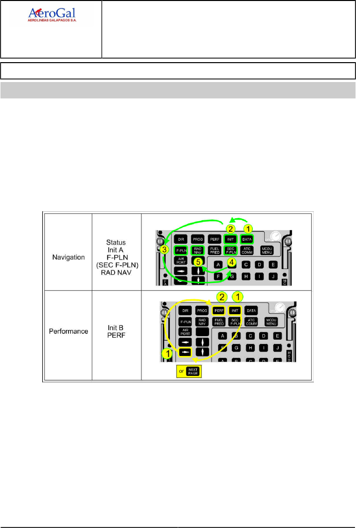
A318/A319/A320/A321
FLIGHT CREW
TECHNIQUES MANUAL
PROCEDURES
NORMAL PROCEDURES
STANDARD OPERATING PROCEDURES - COCKPIT PREPARATION
GLG A318/A319/A320/A321 FLEET PR-NP-SOP-60 P 2/6
FCTM B → 05 SEP 17
FMGS PREPARATION
Ident.: PR-NP-SOP-60-00018725.0002001 / 20 MAR 17
Applicable to: ALL
FMGS programming involves inserting navigation data, then performance data. It is to be noted that:
‐ Boxed fields must be filled
‐ Blue fields inform the crew that entry is permitted
‐ Green fields are used for FMS generated data, and cannot be changed
‐ Magenta characters identify limits (altitude, speed or time), that FMS will attempt to meet
‐ Yellow characters indicate a temporary flight plan display
‐ Amber characters signify that the item being displayed is important and requires immediate action
‐ Small font signifies that data is FMS computed
‐ Large font signifies manually entered data.
This sequence of entry is the most practical. INIT B should not be filled immediately after INIT A,
because the FMGS would begin to compute F-PLN predictions. These computations would slow
down the entry procedure.

A318/A319/A320/A321
FLIGHT CREW
TECHNIQUES MANUAL
PROCEDURES
NORMAL PROCEDURES
STANDARD OPERATING PROCEDURES - COCKPIT PREPARATION
GLG A318/A319/A320/A321 FLEET PR-NP-SOP-60 P 3/6
FCTM ← B → 05 SEP 17
To obtain correct predictions, the fields of the various pages must be completed correctly, with
available planned data for the flight:
‐ DATA
The database validity, NAVAID s and waypoints (possibly stored in previous flight), and PERF
FACTOR must be checked on the STATUS page.
‐ INIT A
The INIT A page provides access to aircraft present position. The flight crew will check that it
corresponds to the real aircraft position (Refer to PR-NP-SOP-60 ADIRS Operations).
Manual Position Initialization of the IRS:
The flight crew will check or modify the MCDU coordinates for the IRS position initialization. The
most appropriate coordinates for the position initialization are gate coordinates.
Then, the flight crew will press the ALIGN IRS prompt.
Note: When the flight crew enters or modifies the origin airport (FROM) or the CO RTE , the
MCDU INIT coordinates are reset to the Airport Reference Point (ARP). The pilot may
manually modify these coordinates.
The history wind is the vertical wind profile, that has been encountered during the previous
descent and should be entered at this stage if it is representative of the vertical wind profile for the
next flight.
‐ F-PLN
The F-PLN A page is to be completed thoroughly including:
• The take-off runway
• SID
• Altitude and speed constraints
• Correct transition to the cruise waypoint
• Intended step climb/descents, according to the Computerized Flight Plan (CFP).
If time permits, the wind profile along the flight plan may be inserted using vertical revision through
wind prompt.
The flight crew should also check the overall route distance (6th line of the F-PLN page), versus
CFP distance.
‐ SEC F-PLN
The SEC F-PLN should be used to consider an alternate runway for take-off, a return to departure
airfield or a routing to a take-off alternate.
‐ RAD NAV
The RAD NAV page is checked, and any required NAVAID should be manually entered using
ident. If a NAVAID is reported on NOTAM as unreliable, it must be deselected on the MCDU
DATA/POSITION MONITOR/SEL NAVAID page.

A318/A319/A320/A321
FLIGHT CREW
TECHNIQUES MANUAL
PROCEDURES
NORMAL PROCEDURES
STANDARD OPERATING PROCEDURES - COCKPIT PREPARATION
GLG A318/A319/A320/A321 FLEET PR-NP-SOP-60 P 4/6
FCTM ← B 05 SEP 17
‐ INIT B
The flight crew:
• Inserts the expected ZFWCG /ZFW , and block fuel to initialize a F-PLN computation.
• Checks fuel figures consistent with flight preparation fuel figures.
The flight crew will update weight and CG on receipt of the load sheet.
The FMS uses the trip wind for the entire flight from origin to destination. The trip wind is an
average wind component that may be extracted from the CFP. The trip wind facility is available if
the wind profile has not already been entered.
After Engine start, the INIT B page is no longer available. The flight crew should use the FUEL
PRED page for weight and fuel data insertion, if required.
The INIT B page should not be completed immediately after INIT A, because the FMGS would
begin to compute F-PLN predictions. This would slow down the entry procedure.
‐ PERF
The thrust reduction altitude/acceleration altitude (THR RED /ACC) are set to default at 1 500 ft, or
at a value defined by airline policy. The THR RED/ACC may be changed in the PERF TAKE-OFF
page, if required. The flight crew should consider the applicable noise abatement procedure.
The one-engine-out acceleration altitude must:
• Be at least 400 ft above airport altitude
• Ensure that the net flight path is 35 ft above obstacles
• Ensure that the maximum time for takeoff thrust is not exceeded.
Therefore, there are generally a minimum and a maximum one engine out acceleration altitude
values. The minimum value satisfies the first two criteria. The maximum value satisfies the last
one. Any value between those two may be retained.
The one engine out acceleration altitude is usually defaulted to 1 500 ft AGL and will be updated
as required.
The flight crew uses the PERF CLB page to pre-select a speed. For example, "Green Dot" speed
for a sharp turn after take-off.
The crew may also check on the PROG page the CRZ FL, MAX REC FL and OPT FL.
Once the FMGS has been programmed, the PM should then cross check the information prior to the
take-off briefing.
When the predictions are available, the crew may print the PREFLIGHT DATA . This listing
provides all the predictions which may be used during the initial part of the flight.
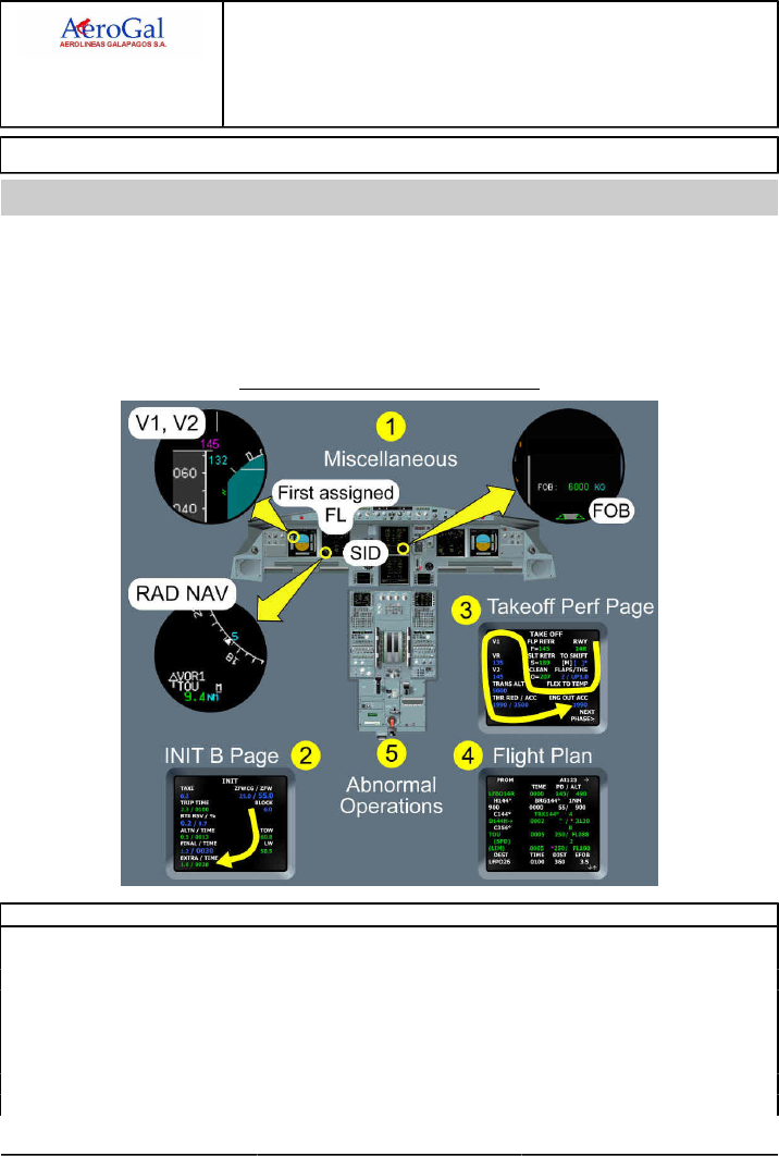
A318/A319/A320/A321
FLIGHT CREW
TECHNIQUES MANUAL
PROCEDURES
NORMAL PROCEDURES
STANDARD OPERATING PROCEDURES - COCKPIT PREPARATION
GLG A318/A319/A320/A321 FLEET PR-NP-SOP-60 P 5/6
FCTM C → 05 SEP 17
TAKEOFF BRIEFING
Ident.: PR-NP-SOP-60-00016298.0001001 / 25 JUL 17
Applicable to: ALL
1The PF should perform the takeoff briefing at the gate , when the flight crew workload permits,
Cockpit preparation has been completed and, before engine start.
The takeoff briefing should be relevant, concise and chronological. When a main parameter is
referred to by the PF, both flight crewmembers must crosscheck that the parameter has been set or
programmed correctly. The takeoff briefing covers the following:
Take off briefing with associated checks
1- Miscellaneous
Aircraft type and model (Tail strike awareness)
Aircraft technical status (MEL and CDL considerations, relevant OEB)
NOTAMS
Weather
RWY conditions
Use of ENG/Wing Anti Ice
ENG Start Procedure
Push Back
Expected Taxi Clearance
Continued on the following page

A318/A319/A320/A321
FLIGHT CREW
TECHNIQUES MANUAL
PROCEDURES
NORMAL PROCEDURES
STANDARD OPERATING PROCEDURES - COCKPIT PREPARATION
GLG A318/A319/A320/A321 FLEET PR-NP-SOP-60 P 6/6
FCTM ← C 05 SEP 17
Continued from the previous page
1- Miscellaneous
Use of Radar
Use of Packs for Takeoff
2- INIT B Page
Block Fuel (1) (FOB on EW/D)
Estimated TOW
Extra time at destination
3- Takeoff Perf Page
TO RWY
TO CONF
FLEX / TOGA (1) (FLEX TOGA on MCDU)
V1 , VR , V2 (1) (V1 , V2 on PFD)
TRANS ALT
THR RED / ACC Altitude
4- Flight Plan
Minimum Safe Altitude
First assigned FL (1) (altitude target in blue on PFD)
Flight Plan description (1) (SID on MCDU FPLN page)
RAD NAV (1) (RAD NAV on ND)
5- Abnormal Operations
For any failure before V1:
CAPT will call "STOP" or "GO"
In case of failure after V1:
continue TO , no actions before 400 ft AGL except gear up
reaching 400 ft AGL , ECAM actions
reaching EO ACC altitude
‐ If the engine is secured, level off, accelerate and clean up
‐ Otherwise continue climbing until the engine is secured (but not above EO maximum acceleration altitude)
at green dot: OP CLB, MCT , resume ECAM , after TO C/L, status
ENG OUT routing: EOSID , SID, radar vector, immediate return ...
(1) Items that must be cross-checked on the associated display.

A318/A319/A320/A321
FLIGHT CREW
TECHNIQUES MANUAL
PROCEDURES
NORMAL PROCEDURES
STANDARD OPERATING PROCEDURES
- BEFORE PUSHBACK OR START
GLG A318/A319/A320/A321 FLEET PR-NP-SOP-70 P 1/2
FCTM A to B 22 MAR 17
TAKEOFF DATA
Ident.: PR-NP-SOP-70-00016299.0001001 / 20 MAR 17
Applicable to: ALL
If the takeoff conditions change before the engine start, both flight crewmembers should compute
again the takeoff performance with the updated parameter(s), and crosscheck the results.
The experience shows that a simple visual check by one flight crewmember of the entries made by
the other flight crewmember does not prevent significant errors. Therefore, both flight crewmembers
should compute the data independently, then:
‐ The PF enters the revised takeoff data in the INIT B and PERF pages of the MCDU.
‐ The PM crosschecks the PF entries with his/her own results
The two independent computations of the takeoff performance and the crosscheck of the results
validate the entries made by both flight crewmembers.
SEATING POSITION AND ADJUSTMENT OF RUDDER PEDALS
Ident.: PR-NP-SOP-70-00018710.0001001 / 20 MAR 17
Applicable to: ALL
To achieve a correct seating position, the aircraft is fitted with an eye-position indicator on the centre
windscreen post. The eye-position indicator has two balls on it. When the balls are superimposed on
each other, they indicate that the pilot's eyes are in the correct position.
The flight crew should not sit too low, to avoid increasing the cockpit cut-off angle, therefore reducing
the visual segment. During Low Visibility Procedures (LVP), it is important that the pilot's eyes
are positioned correctly, in order to maximize the visual segment, and consequently, increase the
possibility of achieving the appropriate visual reference for landing as early as possible.
After adjusting the seat, each pilot should adjust the outboard armrest, so that the forearm rests
comfortably on it, when holding the sidestick. There should be no gaps between the pilot's forearm
and the armrest. The pilot's wrist should not be bent when holding the sidestick. This ensures that
the pilot can accomplish flight maneuvers by moving the wrist instead of lifting the forearm from the
armrest.
Symptoms of incorrect armrest adjustment include over-controlling, and not being able to make
small, precise inputs.
The flight crew must have their feet in a position so that full rudder deflection combined with full
braking, even differential, can be applied instinctively and without delay.
The armrest and the rudder pedals have position indicators. These positions should be noted and set
accordingly for each flight.

A318/A319/A320/A321
FLIGHT CREW
TECHNIQUES MANUAL
PROCEDURES
NORMAL PROCEDURES
STANDARD OPERATING PROCEDURES
- BEFORE PUSHBACK OR START
Intentionally left blank
GLG A318/A319/A320/A321 FLEET PR-NP-SOP-70 P 2/2
FCTM 22 MAR 17

A318/A319/A320/A321
FLIGHT CREW
TECHNIQUES MANUAL
PROCEDURES
NORMAL PROCEDURES
STANDARD OPERATING PROCEDURES - TAXI
GLG A318/A319/A320/A321 FLEET PR-NP-SOP-100 P 1/10
FCTM A → 05 SEP 17
BRAKES
Ident.: PR-NP-SOP-100-A-00018728.0002001 / 20 MAR 17
Criteria: P4576, SA
Applicable to: HC-CJM, HC-CJV, HC-CJW, HC-CRU, HC-CSA, HC-CSB, HC-CSF
BRAKE CHECK
When the aircraft starts to move, the PF should check the efficiency of the normal braking system
by gently pressing the brake pedals, to ensure that the aircraft slows down.
Ident.: PR-NP-SOP-100-A-00018728.0001001 / 25 JUL 17
Criteria: SA
Applicable to: HC-CKN, HC-CLF
1BRAKE CHECK
When the aircraft starts to move, the PF should check the efficiency of the normal braking system
by gently pressing the brake pedals, to ensure that the aircraft slows down. The PM should also
check the triple brake indicator to ensure that brake pressure drops to zero. This indicates a
successful changeover to the normal braking system (green pressure has taken over yellow
pressure). Although green hydraulic power supplies the braking system, each time pedals are
quickly pressed, a brief brake pressure indication may appear on the BRAKE PRESS indicator.
No maintenance action is required if the pressure peak is less than 2 000 PSI. If a “spongy” pedal
is felt during taxi, this indicates a degraded performance of the alternate braking system. Spongy
pedals can change the feeling of braking.
Ident.: PR-NP-SOP-100-A-00018729.0001001 / 20 MAR 17
Applicable to: ALL
CARBON BRAKE WEAR
Carbon brake wear depends on the number of brake applications and on brake temperature. It
does not depend on the applied pressure, or the duration of the braking. The temperature at which
maximum brake wear occurs depends on the brake manufacturer. Therefore, the only way the
pilot can minimize brake wear is to reduce the number of brake applications.
Ident.: PR-NP-SOP-100-A-00018730.0001001 / 20 MAR 17
Applicable to: ALL
TAXI SPEED AND BRAKING
On long, straight taxiways, and with no ATC or other ground traffic constraints, the PF should allow
the aircraft to accelerate to 30 kt, and should then use one smooth brake application to decelerate
to 10 kt. The PF should avoid continuous brake applications. The GS indication on the ND should
be used to assess taxi speed.

A318/A319/A320/A321
FLIGHT CREW
TECHNIQUES MANUAL
PROCEDURES
NORMAL PROCEDURES
STANDARD OPERATING PROCEDURES - TAXI
GLG A318/A319/A320/A321 FLEET PR-NP-SOP-100 P 2/10
FCTM ← A 05 SEP 17
Ident.: PR-NP-SOP-100-A-00018731.0001001 / 20 MAR 17
Applicable to: ALL
BRAKE TEMPERATURE
The maximum brake temperature limitation for takeoff ensures that, in the case of a hydraulic leak,
any hydraulic fluid that touches the brake units does not ignite in the wheel well after the landing
gear retraction.
Ident.: PR-NP-SOP-100-A-00018732.0002001 / 25 JUL 17
Applicable to: ALL
2BRAKING ANOMALIES
If the ACCU PRESS drops below 1 500 PSI, the flight crew should be aware that the Parking
Brake can, quite suddenly, become less efficient. This explains the amber range on the hydraulic
pressure gauge of the ACCU PRESS.
If the flight crew encounters any braking problems during taxi, they should set the A/SKID &
N/W STRG sw to OFF. They should not apply pressure to the pedals while setting the A/SKID &
N/W STRG sw to OFF. Then, the PF should refer to the triple brake indicator and modulate the
pressure as necessary.
Ident.: PR-NP-SOP-100-A-00018733.0001001 / 20 MAR 17
Applicable to: ALL
BRAKE FANS
Brake fans cool the brakes, and the brake temperature sensor. Therefore, when the brake fans
are running, the indicated brake temperature will be significantly lower than the indicated brake
temperature when the brake fans are off.
Therefore, as soon as the brake fans are switched on, the indicated brake temperature decreases
almost instantaneously. On the other hand, when the brake fans are switched off, it will take
several minutes for the indicated brake temperature to increase and match the real brake
temperature.
When the fans are running, the difference between the indicated and the actual brake temperature
can range from 50 °C (when the actual brake temperature is 100 °C) to 150 °C (when the actual
brake temperature is 300 °C). Therefore, before takeoff, if the fans are running, the flight crew
should refer to the indicated brake temperature. When the indicated brake temperature is above
150 °C, takeoff must be delayed.
Brake fans should not be used during takeoff, in order to avoid Foreign Object Damage to fans
and brakes.

A318/A319/A320/A321
FLIGHT CREW
TECHNIQUES MANUAL
PROCEDURES
NORMAL PROCEDURES
STANDARD OPERATING PROCEDURES - TAXI
GLG A318/A319/A320/A321 FLEET PR-NP-SOP-100 P 3/10
FCTM B to C → 05 SEP 17
FLIGHT CONTROLS
Ident.: PR-NP-SOP-100-00018788.0001001 / 20 MAR 17
Applicable to: ALL
At a convenient stage, before or during taxi, and before arming the autobrake, the PF silently applies
full longitudinal and lateral sidestick deflection. On the F/CTL page, the PM checks and calls out
full travel of elevators and ailerons, and correct deflection and retraction of spoilers. As each full
travel/neutral position is reached, the PM calls out:
‐ "Full up, full down, neutral"
‐ "Full left, full right, neutral"
The PF silently checks that the PM calls are in accordance with the sidestick order. The PF then
presses the PEDAL DISC pb on the nose wheel tiller and silently applies full left and full right rudder
and then returns the rudder to neutral. The PM follows on the rudder pedals and, when each full
travel/neutral position is reached, calls out:
‐ "Full left, full right, neutral"
Full control input must be held for sufficient time for full travel to be reached and indicated on F/CTL
page.
The PM then applies full longitudinal and lateral sidestick deflection, and on the F/CTL page, silently
checks full travel and correct sense of all elevators and ailerons, and correct deflection and retraction
of all spoilers.
If this check is carried out during taxiing, it is essential that the PF remains head-up throughout the
procedure.
TAXI ROLL AND STEERING
Ident.: PR-NP-SOP-100-00016302.0001001 / 01 JUN 17
Applicable to: ALL
Before taxi, check that the amber "NWS DISC" ECAM message is off, to ensure that steering is fully
available.
THRUST USE
The flight crew will need a little power above idle thrust to move the aircraft.
Excessive thrust application can result in exhaust-blast damage or Foreign Object Damage (FOD).
Thrust should normally be used symmetrically.
TILLER AND RUDDER PEDALS USE
Pedals control nosewheel steering at low speed (± 6 ° with full pedal deflection). Therefore, on
straight taxiways and on shallow turns, the pilot can use the pedals to steer the aircraft, keeping a
hand on the tiller. In sharper turns, the pilot must use the tiller.
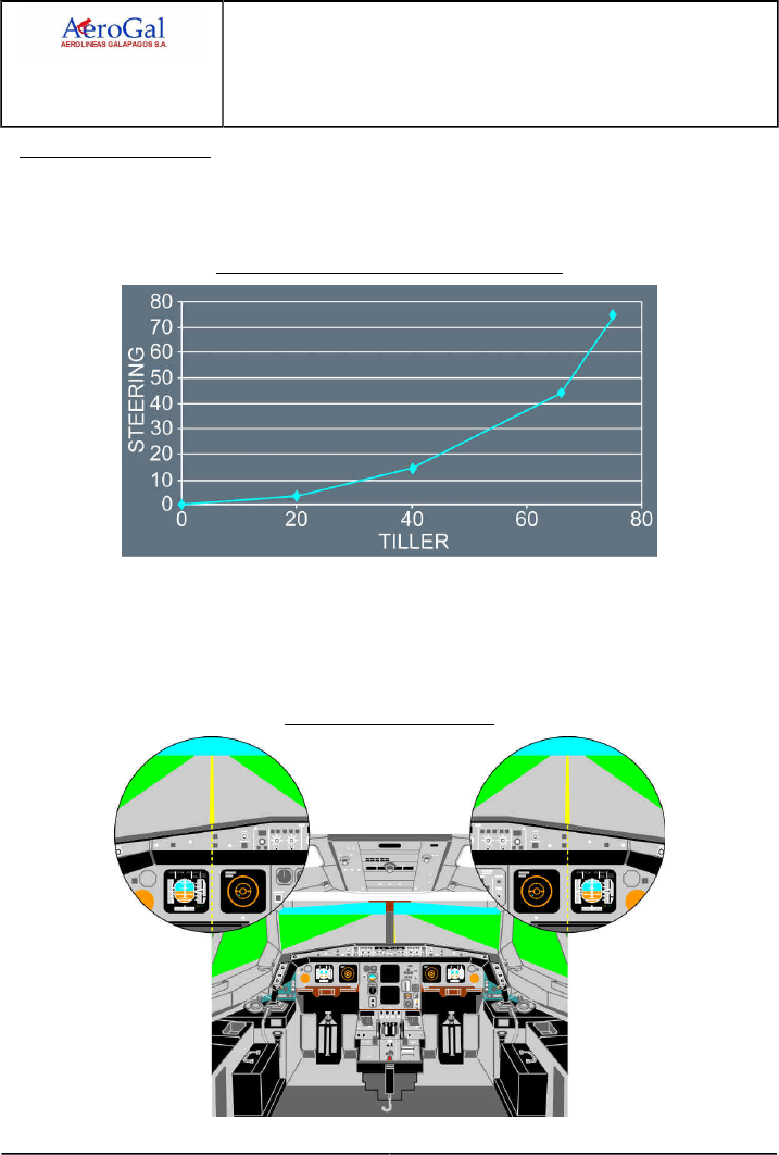
A318/A319/A320/A321
FLIGHT CREW
TECHNIQUES MANUAL
PROCEDURES
NORMAL PROCEDURES
STANDARD OPERATING PROCEDURES - TAXI
GLG A318/A319/A320/A321 FLEET PR-NP-SOP-100 P 4/10
FCTM ← C → 05 SEP 17
STEERING TECHNIQUE
The Nosewheel steering is "by-wire" with no mechanical connection between the tiller and the
nosewheel. The relationship between tiller deflection and nosewheel angle is not linear and the
tiller forces are light.
Tiller Deflection vs. Nosewheel Steering Angle
Therefore, the PF should move the tiller smoothly and maintain the tiller's position. Any correction
should be small and smooth, and maintained for enough time to enable the pilot to assess the
outcome. Being over-active on the tiller will cause uncomfortable oscillations.
On straight taxiways, the aircraft is correctly aligned on the centerline, when the centerline is
lined-up between the PFD and ND.
Proper Centerline Following
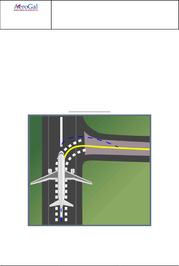
A318/A319/A320/A321
FLIGHT CREW
TECHNIQUES MANUAL
PROCEDURES
NORMAL PROCEDURES
STANDARD OPERATING PROCEDURES - TAXI
GLG A318/A319/A320/A321 FLEET PR-NP-SOP-100 P 5/10
FCTM ← C → 05 SEP 17
If both pilots act on the tiller or pedals, their inputs are added until the maximum value of the
steering angle (programmed within the BSCU) is reached.
When the seating position is correct, the cut-off angle is 20 °, and the visual ground geometry
provides an obscured segment of 42 ft (12.5 m). During taxi, a turn must be initiated before an
obstacle approaches the obscured segment. This provides both wing and tail clearance, with
symmetric thrust and no differential braking.
Asymmetric thrust can be used to initiate a tight turn and to keep the aircraft moving during the
turn. If nosewheel lateral skidding occurs while turning, reduce taxi speed or increase turn radius.
Avoid stopping the aircraft in a turn, because excessive thrust will be required to start the aircraft
moving again.
The flight crew should be aware that the main gear on the inside of a turn will always cut the
corner and track inside of the nosewheel track. For this reason, the oversteering technique may be
considered especially for A321 where main gear is 20 m behind the pilot.
Oversteering Technique
When exiting a tight turn, the pilot should anticipate the steer out. Additionally, the pilot should
allow the aircraft to roll forward for a short distance to minimize the stress on the main gears.
In the event that one or more tires is/are deflated on the main landing gear, the maximum
permitted steering angle will be limited by the aircraft speed. Therefore, with one tire deflated, the

A318/A319/A320/A321
FLIGHT CREW
TECHNIQUES MANUAL
PROCEDURES
NORMAL PROCEDURES
STANDARD OPERATING PROCEDURES - TAXI
GLG A318/A319/A320/A321 FLEET PR-NP-SOP-100 P 6/10
FCTM ← C to D → 05 SEP 17
aircraft speed is limited to 7 kt and nosewheel steering can be used. With two tires deflated, the
aircraft speed is limited to 3 kt and nosewheel steering angle should be limited to 30 °.
For turns of 90 ° or more, the aircraft speed should be less than 10 kt.
180 DEGREES TURN ON RUNWAY
Ident.: PR-NP-SOP-100-00021675.0001001 / 06 JUN 17
Applicable to: ALL
For more information on the minimum runway width that is necessary to perform a 180 ° turn with the
following technique, Refer to FCOM/DSC-20-30 180 degrees Turn on Runway.
Note: If the runway is wet or contaminated, the aircraft may skid, particularly on painted parts of
the runway. The flight crew should consider additional margin when the runway is wet or
contaminated.
IF THE PF IS THE CREWMEMBER IN THE LEFT HAND SEAT (CM1)
Taxi on the right hand side of the runway.
Maintain a ground speed between 5 kt and 8 kt during the entire maneuver.
Note: On wet or contaminated runway, it is recommended to maintain a speed of 5 kt during
the entire maneuver.
Turn left, maintaining a 25 ° divergence from the runway axis.
Monitor the approaching runway edge.
When the CM1 is physically over the runway edge:
‐ Turn right, up to full tiller deflection
‐ If necessary, use asymmetric thrust (IDLE on ENG 2) and/or differential braking (more brake
pressure on the right side) to maintain a constant speed.
When the 180 ° turn is complete, align with runway centerline and release the tiller to neutral
position before stopping.
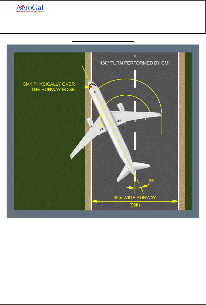
A318/A319/A320/A321
FLIGHT CREW
TECHNIQUES MANUAL
PROCEDURES
NORMAL PROCEDURES
STANDARD OPERATING PROCEDURES - TAXI
GLG A318/A319/A320/A321 FLEET PR-NP-SOP-100 P 7/10
FCTM ← D → 05 SEP 17
For A318/A319/A320/A320Neo
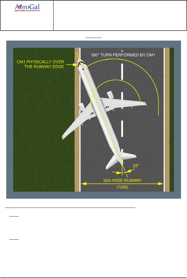
A318/A319/A320/A321
FLIGHT CREW
TECHNIQUES MANUAL
PROCEDURES
NORMAL PROCEDURES
STANDARD OPERATING PROCEDURES - TAXI
GLG A318/A319/A320/A321 FLEET PR-NP-SOP-100 P 8/10
FCTM ← D → 05 SEP 17
For A321
IF THE PF IS THE CREWMEMBER IN THE RIGHT HAND SEAT (CM2)
Note: the technique is symmetrical
Taxi on the left hand side of the runway.
Maintain a ground speed between 5 kt and 8 kt during the entire maneuver.
Note: On wet or contaminated runway, it is recommended to maintain a speed of 5 kt during
the entire maneuver.
Turn right, maintaining a 25 ° divergence from the runway axis.
Monitor the approaching runway edge.

A318/A319/A320/A321
FLIGHT CREW
TECHNIQUES MANUAL
PROCEDURES
NORMAL PROCEDURES
STANDARD OPERATING PROCEDURES - TAXI
GLG A318/A319/A320/A321 FLEET PR-NP-SOP-100 P 9/10
FCTM ← D to F 05 SEP 17
When the CM2 is physically over the runway edge:
‐ Turn left, up to full tiller deflection
‐ If necessary, use asymmetric thrust (IDLE on ENG 1) and/or differential braking (more brake
pressure on the left side) to maintain a constant speed.
When the 180 ° turn is complete, align with runway centerline and release the tiller to neutral
position before stopping.
TAKEOFF BRIEFING CONFIRMATION
Ident.: PR-NP-SOP-100-00018789.0001001 / 20 MAR 17
Applicable to: ALL
The TAKEOFF BRIEFING CONFIRMATION should only review any changes that may have
occurred since the full TAKEOFF BRIEFING done at the parking bay (e.g. change of SID, change in
runway conditions, etc.).
ADIRS ALIGNMENT
Ident.: PR-NP-SOP-100-00020404.0001001 / 20 MAR 17
Applicable to: ALL
During taxi, a good way to check a global consistency of FMGC entries (position and flight plan) is
to check the runway and the SID on the ND in comparison to the aircraft symbol, that indicates the
current aircraft position. To do so, set the ND in ARC or NAV mode with a range 10 NM.

A318/A319/A320/A321
FLIGHT CREW
TECHNIQUES MANUAL
PROCEDURES
NORMAL PROCEDURES
STANDARD OPERATING PROCEDURES - TAXI
Intentionally left blank
GLG A318/A319/A320/A321 FLEET PR-NP-SOP-100 P 10/10
FCTM 05 SEP 17

A318/A319/A320/A321
FLIGHT CREW
TECHNIQUES MANUAL
PROCEDURES
NORMAL PROCEDURES
STANDARD OPERATING PROCEDURES - BEFORE TAKEOFF
GLG A318/A319/A320/A321 FLEET PR-NP-SOP-110 P 1/2
FCTM A 22 MAR 17
PACKS
Ident.: PR-NP-SOP-110-00016303.0001001 / 20 MAR 17
Applicable to: ALL
If the takeoff has to be achieved without air bleed fed from the engines for performance reasons,
but air conditioning desired, the APU bleed may be used with packs ON, thus maintaining engine
performance level and passenger comfort. In case of APU auto shut down during takeoff, the engine
thrust is frozen till the thrust is manually reduced. The packs revert to engine bleed which causes an
increase of EGT to keep N1/EPR.
If the takeoff is performed with one pack unserviceable, the procedure states to set the failed pack
to OFF. The takeoff may be performed with the other pack ON (if performances permit) with TOGA
or FLEX thrust, the pack being supplied by the onside bleed. In this asymmetric bleed configuration,
the N1 takeoff value is limited to the value corresponding to the bleed ON configuration and takeoff
performance must be computed accordingly.

A318/A319/A320/A321
FLIGHT CREW
TECHNIQUES MANUAL
PROCEDURES
NORMAL PROCEDURES
STANDARD OPERATING PROCEDURES - BEFORE TAKEOFF
Intentionally left blank
GLG A318/A319/A320/A321 FLEET PR-NP-SOP-110 P 2/2
FCTM 22 MAR 17

A318/A319/A320/A321
FLIGHT CREW
TECHNIQUES MANUAL
PROCEDURES
NORMAL PROCEDURES
STANDARD OPERATING PROCEDURES - TAKEOFF
GLG A318/A319/A320/A321 FLEET PR-NP-SOP-120 P 1/8
FCTM A to B → 22 MAR 17
THRUST SETTING
Ident.: PR-NP-SOP-120-00018791.0001001 / 20 MAR 17
Applicable to: ALL
The Thrust Setting procedure ensures that all engines will accelerate similarly. If not properly applied,
this may lead to asymmetrical thrust increase, and, consequently, to severe directional control
problem.
If the thrust levers are not set to the proper take-off detent, e.g. FLX instead of TOGA , an alert
triggers on the ECAM.
TAKEOFF ROLL
Ident.: PR-NP-SOP-120-00018792.0001001 / 20 MAR 17
Applicable to: ALL
Once the thrust is set, the PF announces the indications on the FMA . The PM must check that the
thrust is set by 80 kt and must announce "Thrust Set".
The Captain must keep his hand on the thrust levers when the thrust levers are set to TOGA /FLX
notch and until V1.
On a normal takeoff, to counteract the pitch up moment during thrust application, the PF should apply
half forward (full forward in cross wind case) sidestick at the start of the takeoff roll until reaching
80 kt. At this point, the input should be gradually reduced to be zero by 100 kt.
The PF should use pedals to keep the aircraft straight. The nosewheel steering authority decreases
at a pre-determined rate as the groundspeed increases (no more efficiency at 130 kt) and the rudder
becomes more effective. The use the tiller is not recommended during takeoff roll, because of its high
efficiency, which might lead to aircraft overreaction.
For crosswind takeoffs, routine use of into wind aileron is not necessary. In strong crosswind
conditions, small lateral stick input may be used to maintain wings level, if deemed necessary due to
into wind wing reaction, but avoid using large deflections, resulting in excessive spoiler deployment
which increase the aircraft tendency to turn into the wind (due to high weight on wheels on the spoiler
extended side), reduces lift and increases drag. Spoiler deflection becomes significant with more
than a third sidestick deflection.
In the event of unexpected lateral disturbance during takeoff roll, the flight crew should use the
rudder as for counteracting any lateral disturbance. Indeed, excessive rudder input may increase
the magnitude of the lateral disturbance. The flight crew may be surprised during takeoff roll by
unexpected lateral disturbance in conditions such as:
‐ The presence of thermals or thermal vortices that often develop in hot and dry countries.
Sometimes, these thermal streams get stronger, and create small whirlwinds referred to as "dust
devils", or
‐ The jet blast of another aircraft close to the active runway, or
‐ The wind that accelerates between two buildings by "venturi" effect.

A318/A319/A320/A321
FLIGHT CREW
TECHNIQUES MANUAL
PROCEDURES
NORMAL PROCEDURES
STANDARD OPERATING PROCEDURES - TAKEOFF
GLG A318/A319/A320/A321 FLEET PR-NP-SOP-120 P 2/8
FCTM ← B to D → 22 MAR 17
As the aircraft lifts off, any lateral stick input applied will result in a roll rate demand, making aircraft
lateral control more difficult. Wings must be level.
In case of low visibility takeoff, visual cues are primary means to track the runway centerline. The
PFD yaw bar provides an assistance in case of expected fog patches if ILS available.
ROTATION
Ident.: PR-NP-SOP-120-00018793.0001001 / 20 MAR 17
Applicable to: ALL
Rotation is conventional. During the takeoff roll and the rotation, the pilot flying scans rapidly the
outside references and the PFD . Until airborne, or at least until visual cues are lost, this scanning
depends on visibility conditions (the better the visibility, the higher the priority given to outside
references). Once airborne, the PF must then controls the pitch attitude on the PFD using FD bars in
SRS mode which is then valid.
Initiate the rotation with a smooth positive backward sidestick input (typically 1/3 to 1/2 backstick).
Avoid aggressive and sharp inputs.
The initial rotation rate is about 3 °/s. Avoid low rotation rates as this will have an impact on takeoff
performance by increasing the takeoff ground run. Rotation rates between 2 °/s and 3 °/s will have a
minimal impact on takeoff run but rates significantly below 2 °/s should be avoided.
If the established pitch rate is not satisfactory, the pilot must make smooth corrections on the stick.
He must avoid rapid and large corrections, which cause sharp reaction in pitch from the aircraft. If, to
increase the rotation rate, a further and late aft sidestick input is made around the time of lift-off, the
possibility of tailstrike increases significantly on A321.
During rotation, the crew must not chase the FD pitch bar, since it does not give any pitch rate order,
and might lead to overreaction.
Once airborne only, the crew must refine the aircraft pitch attitude using the FD , which is then
representative of the SRS orders. The fly-by-wire control laws change into flight normal law, with
automatic pitch trim active.
TAIL STRIKE AVOIDANCE
Ident.: PR-NP-SOP-120-00018798.0001001 / 20 MAR 17
Applicable to: ALL
INTRODUCTION
If tailstrike is not a concern for the A318, the importance of this subject increases as fuselage
length increases. Therefore, it is particularly important for A321 operators.
Tail strikes can cause extensive structural damage, which can jeopardize the flight and lead
to heavy maintenance action. They most often occur in such adverse conditions as crosswind,
turbulence, windshear, etc.

A318/A319/A320/A321
FLIGHT CREW
TECHNIQUES MANUAL
PROCEDURES
NORMAL PROCEDURES
STANDARD OPERATING PROCEDURES - TAKEOFF
GLG A318/A319/A320/A321 FLEET PR-NP-SOP-120 P 3/8
FCTM ← D → 22 MAR 17
MAIN FACTORS
EARLY ROTATION
Early rotation occurs when rotation is initiated below the scheduled VR. The potential reasons
for this are:
• The calculated VR is incorrect for the aircraft weight or flap configuration.
• The PF commands rotation below VR due to gusts, windshear or an obstacle on the runway.
Whatever the cause of the early rotation, the result will be an increased pitch attitude at lift-off,
and consequently a reduced tail clearance.
ROTATION TECHNIQUE
The recommendation given in the ROTATION TECHNIQUE paragraph should be applied.
A fast rotation rate increases the risk of tailstrike, but a slow rate increases take-off distance.
The recommended rate is about 3 °/s, which reflects the average rates achieved during flight
test, and is also the reference rate for performance calculations.
CONFIGURATION (NOT APPLICABLE TO A318)
When performance is limiting the takeoff weight, the flight crew uses TOGA thrust and selects
the configuration that provides the highest takeoff weight.
When the actual takeoff weight is lower than the permissible one, the flight crew uses FLEX TO
thrust. For a given aircraft weight, a variety of flap configurations are possible. Usually, the flight
crew selects the configuration that provides the maximum FLEX temperature. This is done to
prolong engine life. The first degrees of flexible thrust have an impact on maintenance costs
about 5 times higher than the last one.
The configuration that provides the maximum FLEX temperature varies with the runway length.
On short runways, CONF 3 usually provides the highest FLEX temperature, and the tail
clearance at lift off does not depends on the configuration.
On medium or long runways, the second segment limitation becomes the limiting factor, and
CONF 2 or CONF 1+F becomes the optimum configuration, in term of FLEX temperature.
In these cases, the tail clearance at lift off depends on the configuration. The highest flap
configuration gives the highest tailstrike margin.
TAKEOFF TRIM SETTING
The main purpose of the pitch trim setting for take-off is to provide consistent rotation
characteristics. Take-off pitch trim is set manually via the pitch trim wheel.
The aircraft performs a safe takeoff, provided the pitch trim setting is within the green band on
the pitch trim wheel.

A318/A319/A320/A321
FLIGHT CREW
TECHNIQUES MANUAL
PROCEDURES
NORMAL PROCEDURES
STANDARD OPERATING PROCEDURES - TAKEOFF
GLG A318/A319/A320/A321 FLEET PR-NP-SOP-120 P 4/8
FCTM ← D to E → 22 MAR 17
However, the pitch trim setting significantly affects the aircraft behaviour during rotation:
‐ With a forward CG and the pitch trim set to the nose-down limit the pilots will feel an aircraft
"heavy to rotate" and aircraft rotation will be very slow in response to the normal take off stick
displacement.
‐ With an aft CG and the pitch trim set to the nose-up limit the pilots will most probably have to
counteract an early autorotation until VR is reached.
In either case the pilot may have to modify his normal control input in order to achieve the
desired rotation rate, but should be cautious not to overreact.
CROSSWIND TAKEOFF
It is said in the TAKEOFF ROLL paragraph that care should be taken to avoid using large
deflection, resulting in excessive spoiler deployment. A direct effect of the reduction in lift due to
the extension of the spoilers on one wing will be a reduction in tail clearance and an increased
risk of tailstrike.
OLEO INFLATION
The correct extension of the main landing gear shock absorber (and thus the nominal increase
in tail clearance during the rotation) relies on the correct inflation of the oleos.
ACTION IN CASE OF TAILSTRIKE
If a tailstrike occurs at take-off, flight at altitude requiring a pressurized cabin must be avoided and
a return to the originating airport should be performed for damage assessment.
ACCELERATION ALTITUDE
Ident.: PR-NP-SOP-120-00019320.0001001 / 20 MAR 17
Applicable to: ALL
At the acceleration altitude, the FD pitch mode changes from SRS to CLB or OP CLB mode. The
speed target jumps:
• Either to the managed target speed e.g. speed constraint, speed limit or ECON climb speed
• Or to the preselected climb speed (entered by the pilot on the MCDU PERF CLB page before
takeoff).
If green dot speed is higher than the managed target speed (e.g. speed constraint 220 kt) displayed
by the magenta triangle on the PFD speed scale, the AP /FD will guide the aircraft to green dot (as
per the general managed speed guidance rule). If required by ATC , the crew will select the adequate
target speed (below green dot) on the FCU.

A318/A319/A320/A321
FLIGHT CREW
TECHNIQUES MANUAL
PROCEDURES
NORMAL PROCEDURES
STANDARD OPERATING PROCEDURES - TAKEOFF
GLG A318/A319/A320/A321 FLEET PR-NP-SOP-120 P 5/8
FCTM ← E to G 22 MAR 17
During takeoff phase, F and S speeds are the minimum speeds for retracting the surfaces:
• At F speed, the aircraft accelerating (positive speed trend): retract to 1.
• At S speed, the aircraft accelerating (positive speed trend): retract to 0.
If the ENG MODE selector had been selected to IGN START for take-off, the PM should confirm with
the PF when it may be deselected.
SLATS/FLAPS RETRACTION AT HEAVY WEIGHT
Ident.: PR-NP-SOP-120-00018799.0001001 / 20 MAR 17
Applicable to: ALL
If take-off is carried out at heavy weight, two protections may intervene:
‐ The Automatic Retraction System (ARS)
‐ The Alpha Lock function
THE AUTOMATIC RETRACTION SYSTEM
While in CONF 1+F and IAS reaches 210 kt (VFE CONF1+F is 215 kt or 225 kt on some A321,
Refer to FCOM/LIM-AG-SPD Maximum Flaps/Slats Speeds), the ARS is activated. The ARS
automatically retracts flaps to 0 °. The VFE displayed on the PFD change from VFE CONF1+F to
VFE CONF 1. As the aircraft accelerates above S speed, the flap lever can be selected to 0. If IAS
decreases below VFE CONF1+F, the flaps will not extend back to 1+F.
THE ALPHA LOCK FUNCTION
The slats alpha/speed lock function will prevent slat retraction at high AOA or low speed at the
moment the flap lever is moved from Flaps 1 to Flaps 0. "A. LOCK" pulses above the E/WD Slat
indication. The inhibition is removed and the slats retract when both alpha and speed fall within
normal values. This is a normal situation for take-off at heavy weight. If Alpha lock function is
triggered, the crew will continue the scheduled acceleration, allowing further slats retraction.
OVERSPEED WARNING DURING SLATS/FLAPS TRANSITION
Ident.: PR-NP-SOP-120-00018801.0001001 / 20 MAR 17
Applicable to: ALL
During the Slats/Flaps transition, the flight crew must respect the VMAX displayed on the PFD. The
VMAX value displayed on the PFD speed scale is based on the Slats/Flaps control lever position.
The OVERSPEED WARNING is based on the actual Slats/Flaps surface position. Therefore,
during Slats/Flaps transition, the dynamic acceleration of the airplane may lead to a temporary
OVERSPEED WARNING even if the current speed is out of the red and black strip displayed on the
PFD. In this situation, there are no operational consequences. The flight crew must report any type of
overspeed event.

A318/A319/A320/A321
FLIGHT CREW
TECHNIQUES MANUAL
PROCEDURES
NORMAL PROCEDURES
STANDARD OPERATING PROCEDURES - TAKEOFF
GLG A318/A319/A320/A321 FLEET PR-NP-SOP-120 P 6/8
FCTM H to I → 22 MAR 17
LOW ALTITUDE LEVEL OFF
Ident.: PR-NP-SOP-120-00018803.0001001 / 20 MAR 17
Applicable to: ALL
If the aircraft is required to level off below the acceleration altitude, ALT* engages and target speed
goes to initial climb speed. The "LVR CLB" message flashes on the FMA. In this case, the crew
should expect a faster than normal acceleration, and be prepared to retract the flaps and slats
promptly.
NOISE ABATEMENT TAKEOFF
Ident.: PR-NP-SOP-120-00018804.0001001 / 20 MAR 17
Applicable to: ALL
Noise Abatement Procedures will not be conducted in conditions of significant turbulence or
windshear.
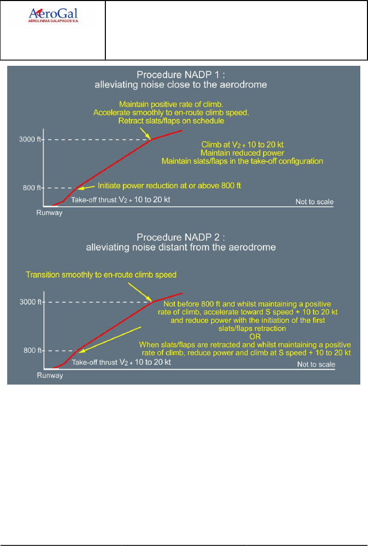
A318/A319/A320/A321
FLIGHT CREW
TECHNIQUES MANUAL
PROCEDURES
NORMAL PROCEDURES
STANDARD OPERATING PROCEDURES - TAKEOFF
GLG A318/A319/A320/A321 FLEET PR-NP-SOP-120 P 7/8
FCTM ← I 22 MAR 17

A318/A319/A320/A321
FLIGHT CREW
TECHNIQUES MANUAL
PROCEDURES
NORMAL PROCEDURES
STANDARD OPERATING PROCEDURES - TAKEOFF
Intentionally left blank
GLG A318/A319/A320/A321 FLEET PR-NP-SOP-120 P 8/8
FCTM 22 MAR 17

A318/A319/A320/A321
FLIGHT CREW
TECHNIQUES MANUAL
PROCEDURES
NORMAL PROCEDURES
STANDARD OPERATING PROCEDURES - CLIMB
GLG A318/A319/A320/A321 FLEET PR-NP-SOP-140 P 1/4
FCTM A → 19 JUN 17
CLIMB MODES
Ident.: PR-NP-SOP-140-00018856.0004001 / 20 MAR 17
Criteria: P4320, P7790, SA
Applicable to: HC-CJM, HC-CJV, HC-CJW, HC-CLF, HC-CRU, HC-CSA, HC-CSB, HC-CSF
The AP /FD climb modes may be either:
‐ Managed, or
‐ Selected.
MANAGED
The managed AP /FD mode in climb is CLB . Its use is recommended as long as the aircraft is
cleared along the F-PLN.
SELECTED
The selected AP /FD modes in climb are OP CLB , V/S and EXPED .
OP CLB is to be used if ATC gives radar vector or clears the aircraft direct to a given FL without
any climb constraints.
In areas of high traffic density, low values of vertical speed will reduce the possibility of nuisance
TCAS warnings.
If the crew selects a high V/S , it may happen that the aircraft is unable to climb with this high V/S
and to maintain the target speed with Max Climb thrust, for performance reasons. In that case,
the AP /FD will guide to the target V/S , and the A/THR will command up to Max Climb thrust, in
order to try to keep the target speed; but the aircraft will decelerate and its speed might reach
VLS . When VLS is reached the AP will pitch the aircraft down so as to fly a V/S , which allows
maintaining VLS. A triple click is generated.
Whenever V/S is used, pilots should pay particular attention to the speed trend as V/S takes
precedence over speed requirements.
The EXPED mode is used to climb with maximum vertical gradient i.e. the target speed
becomes green dot. Its use should be avoided above FL 250.
The crew should be aware that altitude constraints in the MCDU F-PLN page are observed only
when the climb is managed, i.e. when CLB is displayed on the FMA. Any other vertical mode will
disregard any altitude constraints.
A likely scenario would be, when the FCU altitude is set above an altitude constraint and the pilot
selects V/S when below that constraint to avoid a potential TCAS TA. In this case, the aircraft will
disregard the altitude constraint.

A318/A319/A320/A321
FLIGHT CREW
TECHNIQUES MANUAL
PROCEDURES
NORMAL PROCEDURES
STANDARD OPERATING PROCEDURES - CLIMB
GLG A318/A319/A320/A321 FLEET PR-NP-SOP-140 P 2/4
FCTM ← A 19 JUN 17
CLIMB MODES
Ident.: PR-NP-SOP-140-00018856.0002001 / 20 MAR 17
Criteria: P4320, SA
Applicable to: HC-CKN
The AP /FD climb modes may be either:
‐ Managed, or
‐ Selected.
MANAGED
The managed AP /FD mode in climb is CLB . Its use is recommended as long as the aircraft is
cleared along the F-PLN.
SELECTED
The selected AP /FD modes in climb are OP CLB , V/S and EXPED .
OP CLB is to be used if ATC gives radar vector or clears the aircraft direct to a given FL without
any climb constraints.
In areas of high traffic density, low values of vertical speed will reduce the possibility of nuisance
TCAS warnings.
If the crew selects a high V/S , it may happen that the aircraft is unable to climb with this high V/S
and to maintain the target speed with Max Climb thrust, for performance reasons. In that case,
the AP /FD will guide to the target V/S , and the A/THR will command up to Max Climb thrust, in
order to try to keep the target speed; but the aircraft will decelerate and its speed might reach
VLS . When VLS is reached the AP will pitch the aircraft down so as to fly a V/S , which allows
maintaining VLS.
Whenever V/S is used, pilots should pay particular attention to the speed trend as V/S takes
precedence over speed requirements.
The EXPED mode is used to climb with maximum vertical gradient i.e. the target speed
becomes green dot. Its use should be avoided above FL 250.
The crew should be aware that altitude constraints in the MCDU F-PLN page are observed only
when the climb is managed, i.e. when CLB is displayed on the FMA. Any other vertical mode will
disregard any altitude constraints.
A likely scenario would be, when the FCU altitude is set above an altitude constraint and the pilot
selects V/S when below that constraint to avoid a potential TCAS TA. In this case, the aircraft will
disregard the altitude constraint.

A318/A319/A320/A321
FLIGHT CREW
TECHNIQUES MANUAL
PROCEDURES
NORMAL PROCEDURES
STANDARD OPERATING PROCEDURES - CLIMB
GLG A318/A319/A320/A321 FLEET PR-NP-SOP-140 P 3/4
FCTM B to C → 19 JUN 17
SMALL ALTITUDE CHANGES
Ident.: PR-NP-SOP-140-00016306.0001001 / 20 MAR 17
Applicable to: ALL
The use of low values of V/S, e.g. less than 1 000 ft/min, may be appropriate for small altitude
changes as it makes the guidance smoother and needs less thrust variation.
SPEED CONSIDERATIONS
Ident.: PR-NP-SOP-140-00018857.0001001 / 20 MAR 17
Applicable to: ALL
The climb speed may be either:
‐ Managed, or
‐ Selected.
MANAGED
The managed climb speed, computed by the FMGS, provides the most economical climb profile
as it takes into account weight, actual and predicted winds, ISA deviation and Cost Index (CI). The
managed climb speed also takes into account any speed constraints, e.g. the default speed limit
which is 250 kt up to 10 000 ft.
SELECTED
If necessary, the climb speed can be either pre-selected on ground prior to take-off on the MCDU
PERF CLIMB page or selected on the FCU as required.
On ground, prior take-off, speed target at acceleration altitude can be pre-selected on the MCDU
PERF CLIMB page. It is to be used when the F-PLN has a sharp turn after take-off, when high
angle of climb is required or for ATC clearance compliance.
Once airborne, the speed can be selected on FCU to achieve the maximum rate of climb or the
maximum gradient of climb.
The speed to achieve the maximum rate of climb, i.e. to reach a given altitude in the shortest time,
lies between ECON climb speed and green dot. As there is no indication of this speed on the PFD,
a good rule of thumb is to use turbulence speed to achieve maximum rate.
The speed to achieve the maximum gradient of climb, i.e. to reach a given altitude in a shortest
distance, is green dot. The MCDU PERF CLB page displays the time and distance required to
achieve the selected altitude by climbing at green dot speed. Avoid reducing to green dot at high
altitude, particularly at heavy weight, as it can take a long time to accelerate to ECON mach.
Pilots should be aware that it is possible to select and fly a speed below green dot but there would
be no operational benefit in doing this.
When selected speed is used, the predictions on the F-PLN page assume the selected speed
is kept till the next planned speed modification, e.g. 250 kt /10 000 ft, where managed speed is
supposed to be resumed. Consequently, the FM predictions remain meaningful.

A318/A319/A320/A321
FLIGHT CREW
TECHNIQUES MANUAL
PROCEDURES
NORMAL PROCEDURES
STANDARD OPERATING PROCEDURES - CLIMB
GLG A318/A319/A320/A321 FLEET PR-NP-SOP-140 P 4/4
FCTM ← C to E 19 JUN 17
When IAS is selected in lower altitude, there is an automatic change to Mach at a specific
crossover altitude.
Finally, as selected speed does not provide the optimum climb profile, it should only be used when
operationally required, e.g. ATC constraint or weather.
VERTICAL PERFORMANCE PREDICTIONS
Ident.: PR-NP-SOP-140-00018858.0001001 / 20 MAR 17
Applicable to: ALL
The MCDU PROG page provides the crew with the MAX REC ALT and with the OPT ALT
information (See cruise section). This information is to be used to rapidly answer to ATC : "CAN YOU
CLIMB TO FL XXX?"
The MCDU PERF CLB page provides predictions to a given FL in terms of time and distance
assuming CLB mode. This FL is defaulted to the FCU target altitude or it may be manually inserted.
The level arrow on the ND assumes the current AP engaged mode. This information is to be used
to rapidly answer to ATC : "CAN YOU MAKE FL XXX by ZZZ waypoint?". The crew will use a PD
(Place/Distance), i.e. ZZZ,-10 waypoint if the question is "CAN YOU MAKE FL XXX , 10 NM before
ZZZ point?"
LATERAL NAVIGATION
Ident.: PR-NP-SOP-140-00018859.0001001 / 20 MAR 17
Applicable to: ALL
If the aircraft is following the programmed SID , the AP /FD should be in NAV . If ATC vectors the
aircraft, HDG will be used until a time when clearance is given to either resume the SID or track
direct to a specific waypoint. In either case, the crew must ensure that the waypoints are properly
sequenced.
The crew should keep in mind that the use of HDG mode e.g. following ATC radar vectors, will revert
CLB to OP CLB and any altitude constraints in the MCDU F-PLN page will not be observed unless
they are selected on the FCU.

A318/A319/A320/A321
FLIGHT CREW
TECHNIQUES MANUAL
PROCEDURES
NORMAL PROCEDURES
STANDARD OPERATING PROCEDURES - CRUISE
GLG A318/A319/A320/A321 FLEET PR-NP-SOP-150 P 1/10
FCTM A → 05 SEP 17
FMS USE
Applicable to: ALL
Ident.: PR-NP-SOP-150-10-00020458.0001001 / 20 MAR 17
CRUISE FL
If the aircraft is cleared to a lower cruise flight level than the pre-planned cruise flight level
displayed on MCDU PROG page, the cruise Mach number will not be targeted. The crew will
update the MCDU PROG page accordingly.
When at cruise FL , the AP altitude control is soft. This means that the AP will allow small altitude
variation around the cruise altitude (typically ± 50 ft) to keep cruise Mach before a readjustment of
thrust occurs. This optimizes the fuel consumption in cruise.
Ident.: PR-NP-SOP-150-10-00020457.0001001 / 20 MAR 17
WIND AND TEMPERATURE
When reaching cruise FL , the crew will ensure that the wind and temperatures are correctly
entered and the lateral and vertical F-PLN reflect the CFP . Wind entries should be made
at waypoints when there is a difference of either 30 ° or 30 kt for the wind data and 5 °C for
temperature deviation. This will ensure that the FMS fuel and time predictions are as accurate as
possible.
Ident.: PR-NP-SOP-150-10-00018860.0002001 / 20 MAR 17
STEP CLIMB
If there is a STEP in the F-PLN , the crew will ensure that the wind is properly set at the first
waypoint beyond the step (D on the following example) at both initial FL and step FL.
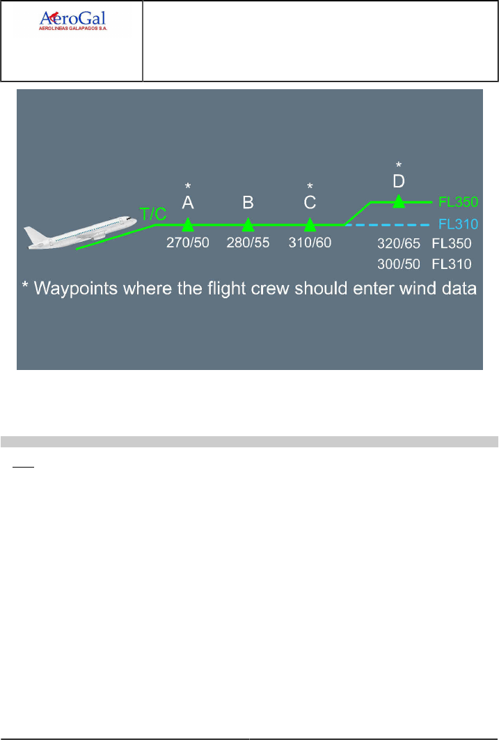
A318/A319/A320/A321
FLIGHT CREW
TECHNIQUES MANUAL
PROCEDURES
NORMAL PROCEDURES
STANDARD OPERATING PROCEDURES - CRUISE
GLG A318/A319/A320/A321 FLEET PR-NP-SOP-150 P 2/10
FCTM ← A → 05 SEP 17
If at D waypoint, the CFP provides the wind at FL 350 but not at FL 310, it is recommended to
insert the same wind at FL 310 as the one at FL 350. This is due to wind propagation rules, which
might affect the optimum FL computation.
Ident.: PR-NP-SOP-150-10-00020455.0002001 / 20 MAR 17
ETP
ETP function should be used to assist the crew in making a decision should an en-route diversion
be required. Suitable airport pairs should be entered on the ETP page and the FMS will then
calculate the ETP . Each time an ETP is sequenced, the crew should insert the next suitable
diversion airfield.
The SEC F-PLN is a useful tool and should be used practically. The ETP should be inserted in the
SEC F-PLN as a PD (Place/Distance) and the route to diversion airfield should be finalized. By
programming a potential en-route diversion, the crew would reduce their workload should a failure
occur. This is particularly true when terrain considerations apply to the intended diversion route.
When an ETP is sequenced, the crew will:
‐ Access the ETP page
‐ Insert the next applicable diversion airfield with associated wind
‐ Read new ETP
‐ Insert new ETP as a PD
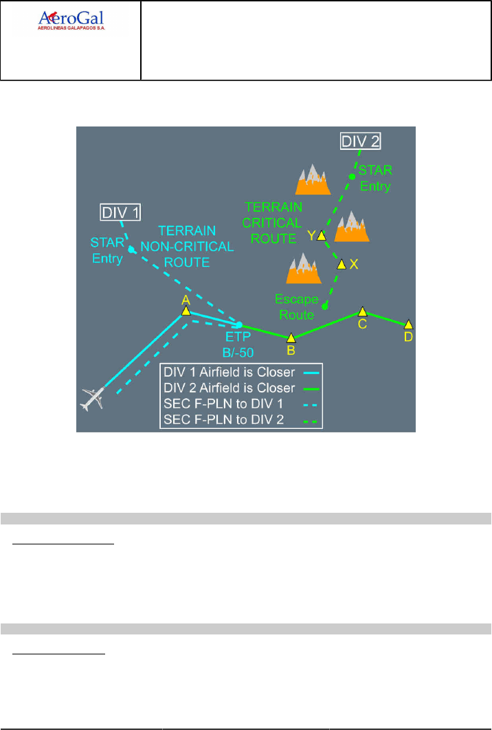
A318/A319/A320/A321
FLIGHT CREW
TECHNIQUES MANUAL
PROCEDURES
NORMAL PROCEDURES
STANDARD OPERATING PROCEDURES - CRUISE
GLG A318/A319/A320/A321 FLEET PR-NP-SOP-150 P 3/10
FCTM ← A → 05 SEP 17
‐ Copy active on the SEC F-PLN
‐ Insert the new diversion as New Dest in the SEC F-PLN from new ETP.
The DATA/Stored Routes function in the MCDU can be used to store up to five possible diversion
routes. These routes can be entered into the SEC F-PLN using the SEC INIT prompt. This prompt
will only be available if the SEC F-PLN is deleted. Refer to FCOM/DSC-22_20-60-30 Using the
Secondary Flight Plan Function for further information.
Ident.: PR-NP-SOP-150-10-00020454.0002001 / 20 MAR 17
CLOSEST AIRPORT
For diversion purpose, the crew can also use the CLOSEST AIRPORT page which provides
valuable fuel/time estimates to the four closest airports from the aircraft position, as well as to
an airport the crew may define. The fuel and time predictions are a function of the average wind
between the aircraft and the airport.
Ident.: PR-NP-SOP-150-10-00020456.0002001 / 20 MAR 17
MISCELLANEOUS
If ATC requires a position report, the crew will use the REPORT page which can be accessed from
PROG page.

A318/A319/A320/A321
FLIGHT CREW
TECHNIQUES MANUAL
PROCEDURES
NORMAL PROCEDURES
STANDARD OPERATING PROCEDURES - CRUISE
GLG A318/A319/A320/A321 FLEET PR-NP-SOP-150 P 4/10
FCTM ← A to C → 05 SEP 17
If ATC requires a report on a given radial, the crew will use the FIX INFO page or RADIAL FIX
INFO page which can be accessed from a lateral revision on F-PLN page at PPOS.
If ATC requires a report at a given time, the crew will insert a time marker pseudo waypoint.
If ATC gives a DIR TO clearance to a waypoint far from present position, the crew will use the
ABEAM facility. This facility allows both a better crew orientation and the previously entered winds
to be still considered.
COST INDEX
Ident.: PR-NP-SOP-150-00018861.0001001 / 20 MAR 17
Applicable to: ALL
The Cost Index (CI ) is used to take into account the relationship between fuel and time related
costs in order to minimize the trip cost. The CI is calculated by the airline for each sector. From an
operational point of view, the CI affects the speeds (ECON SPEED/MACH) and cruise altitude (OPT
ALT). CI=0 corresponds to maximum range whereas the CI=999 corresponds to minimum time.
The CI is a strategic parameter which applies to the whole flight. However, the CI can be modified
by the crew in flight for valid strategic operational reasons. For example, if the crew needs to reduce
the speed for the entire flight to comply with curfew requirements or fuel management requirements
(XTRA gets close to 0), then it is appropriate to reduce the CI.
The SEC F-PLN can be used to check the predictions associated with new CI . If they are
satisfactory, the crew will then modify the CI in the primary F-PLN . However, the crew should be
aware that any modification of the CI would affect trip cost.
SPEED CONSIDERATIONS
Ident.: PR-NP-SOP-150-00018862.0002001 / 20 MAR 17
Applicable to: ALL
The cruise speed may be either:
‐ Managed, or
‐ Selected.
MANAGED
When the cruise altitude is reached, the A/THR operates in SPEED/MACH mode. The optimum
cruise Mach number is automatically targeted. Its value depends on:
‐ CI
‐ Cruise flight level
‐ Temperature deviation
‐ Weight
‐ Headwind component.

A318/A319/A320/A321
FLIGHT CREW
TECHNIQUES MANUAL
PROCEDURES
NORMAL PROCEDURES
STANDARD OPERATING PROCEDURES - CRUISE
GLG A318/A319/A320/A321 FLEET PR-NP-SOP-150 P 5/10
FCTM ← C to D → 05 SEP 17
The crew should be aware that the optimum Mach number will vary according to the above
mentioned parameters, e.g. it will increase with an increasing headwind, e.g. +50 kt head wind
equates to M +0.01.
Should ATC require a specific time over a waypoint, the crew can perform a vertical revision
on that waypoint and enter a time constraint. The managed Mach number would be modified
accordingly to achieve this constraint. If the constraint can be met within a tolerance, a magenta
asterix will be displayed on the MCDU ; if the constraint cannot be met, an amber asterix will be
displayed. Once the constrained waypoint is sequenced, the ECON Mach is resumed.
SELECTED
Should ATC require a specific cruise speed or turbulence penetration is required, the pilot must
select the cruise speed on the FCU . FMS predictions are updated accordingly until reaching
either the next step climb or top of descent, where the programmed speeds apply again. The FMS
predictions are therefore realistic.
At high altitude, the speed should not be reduced below GREEN DOT as this may create a
situation where it is impossible to maintain speed and/or altitude as the increased drag may
exceed the available thrust.
SPEED DECAY DURING CRUISE
Ident.: PR-NP-SOP-150-00018863.0001001 / 25 JUL 17
Applicable to: ALL
1FACTORS THAT CAUSE A SPEED DECAY DURING CRUISE
On aircraft with no failure, and the A/THR engaged or the MAX CLB Thrust applied in manual
mode, a continuous speed decay during cruise phase may be due to:
‐ A large and continuous increase in tailwind or decrease in headwind, in addition to an increase
in the Outside Air Temperature (OAT ), that results in a decrease of the REC MAX FL (Refer to
PR-NP-SOP-150 Altitude Considerations), or
‐ A large downdraft, when the flight crew flies (parallel and) downwind in a mountainous area,
due to orographic waves. The downdraft may have a negative vertical speed of more than
500 ft/min. Therefore, if the aircraft is in a downdraft, the flight crew must climb in order to
maintain altitude, and the pitch angle and the thrust value increase. Without sufficient thrust
margin, the flight crew may notice that aircraft speed decays, but the REC MAX FL is not
modified.
THRUST MARGIN AND EXTERNAL PARAMETERS
The flight crew must be aware that at high altitude, the thrust margin (difference between the thrust
in use and the maximum available thrust) is limited. The maximum available thrust decreases
when there is an increase in altitude and/or outside temperature. In some conditions, MCT may be

A318/A319/A320/A321
FLIGHT CREW
TECHNIQUES MANUAL
PROCEDURES
NORMAL PROCEDURES
STANDARD OPERATING PROCEDURES - CRUISE
GLG A318/A319/A320/A321 FLEET PR-NP-SOP-150 P 6/10
FCTM ← D to E → 05 SEP 17
the maximum available thrust. In such a situation, it is useless to put the thrust levers in the TOGA
detent to try to increase the thrust.
The REC MAX FL indicated in the PROG page of the MCDU decreases when the OAT increases.
The nearer the aircraft is to the REC MAX FL, the smaller the thrust margin.
GREEN DOT (GD) SPEED AS A REFERENCE
The optimum lift/drag speed is the GD speed. The GD speed uses the lowest quantity of thrust
necessary to maintain the required/desired altitude. When the aircraft speed is below GD speed,
any decrease in speed requires an increase in thrust in order to maintain the required/desired
altitude. Therefore, if aircraft speed is below GD speed and continues to decrease, even with the
maximum available thrust in use, if the flight crew maintains the current altitude, the angle of attack
will further increase.
OPERATIONAL RECOMMENDATION
The nearer the aircraft is to the REC MAX FL, the smaller the thrust margin the flight crew has to
manage a speed decay during cruise.
If aircraft speed goes below GD speed, with the maximum available thrust in use, the only way for
the flight crew to avoid a dangerous increase in the angle of attack is to descend.
As a result, the flight crew can recover normal aircraft speed and the normal thrust margin.
ALTITUDE CONSIDERATIONS
Ident.: PR-NP-SOP-150-00018864.0001001 / 20 MAR 17
Applicable to: ALL
The MCDU PROG page displays:
‐ REC MAX FL
‐ OPT FL.
REC MAX FL
REC MAX FL reflects the present engine and wing performance and does not take into account
the cost aspect. It provides a 0.3 gbuffet margin. If the crew inserts a FL higher than REC MAX
into the MCDU , it will be accepted only if it provides a buffet margin greater than 0.2 g. Otherwise,
it will be rejected and the message "CRZ ABOVE MAX FL" will appear on the MCDU scratchpad.
This message may also be triggered in case of temperature increase leading the aircraft to fly
above the REC MAX FL. Unless there are overriding operational considerations, e.g. either to
accept a cruise FL higher than REC MAX or to be held significantly lower for a long period, REC
MAX should be considered as the upper cruise limit.
OPT FL
OPT FL displayed on the MCDU is the cruise altitude for minimum cost when ECON MACH is
flown and should be followed whenever possible. It is important to note that the OPT FL displayed

A318/A319/A320/A321
FLIGHT CREW
TECHNIQUES MANUAL
PROCEDURES
NORMAL PROCEDURES
STANDARD OPERATING PROCEDURES - CRUISE
GLG A318/A319/A320/A321 FLEET PR-NP-SOP-150 P 7/10
FCTM ← E to F → 05 SEP 17
on the PROG page is meaningful only if the wind and temperature profile has been accurately
entered. The flight crew should be aware that flying at a FL different from the OPT FL can have an
adverse effect on the trip cost.
For each Mach number, there will be a different OPT FL. Should an FMGS failure occur, the crew
should refer to the FCOM or QRH to determine the OPT FL. FCOM and QRH charts are only
provided for two different Mach numbers.
STEP CLIMB
Ident.: PR-NP-SOP-150-00018865.0001001 / 20 MAR 17
Applicable to: ALL
Since the optimum altitude increases as fuel is consumed during the flight, from a cost point of view,
it is preferable to climb to a higher cruise altitude when the aircraft weight permits. This technique,
referred to as a Step Climb, is typically accomplished by initially climbing approximately 2 000 ft
above the optimum altitude and then cruising at that flight level until approximately 4 000 ft below
optimum.
The MCDU STEP ALT page may be called a vertical revision from the MCDU F-PLN page or from
the MCDU PERF CRZ page. Step climb can either be planned at waypoint (STEP AT) or be optimum
step point calculated by the FMGS (ALT ). If predictions are satisfactory in term of time and fuel
saving, the crew will insert it in F-PLN provided it is compatible with ATC.
The optimum step computation will be accurate if a vertical wind profile has been properly entered.
Refer to the FMS USE of this section. Refer to FCOM/PER-CRZ-ALT-20 WIND ALTITUDE TRADE
FOR CONSTANT SPECIFIC RANGE to provide valuable tables to assess the effect of the vertical
wind profile on the optimum cruise flight level.
It may be advantageous to request an initial cruise altitude above optimum if altitude changes are
difficult to obtain on specific routes. This minimizes the possibility of being held at a low altitude and
high fuel consumption condition for long periods of time. The requested/cleared cruise altitude should
be compared to the REC MAX altitude. Before accepting an altitude above optimum, the crew should
determine that it will continue to be acceptable considering the projected flight conditions such as
turbulence, standing waves or temperature change.
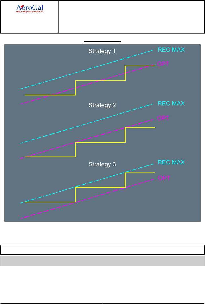
A318/A319/A320/A321
FLIGHT CREW
TECHNIQUES MANUAL
PROCEDURES
NORMAL PROCEDURES
STANDARD OPERATING PROCEDURES - CRUISE
GLG A318/A319/A320/A321 FLEET PR-NP-SOP-150 P 8/10
FCTM ← F to G → 05 SEP 17
OPT FL Follow Up
The diagram above shows three step climb strategies with respect to OPT and REC MAX FL.
Strategy 1 provides the best trip cost, followed by 2 then 3.
FUEL TEMPERATURE
Ident.: PR-NP-SOP-150-00018866.0001001 / 22 MAR 17
Applicable to: ALL
Fuel freeze refers to the formation of wax crystals suspended in the fuel, which can accumulate when
fuel temperature is below the freeze point (-47 °C for jet A1) and can prevent proper fuel feed to the
engines.

A318/A319/A320/A321
FLIGHT CREW
TECHNIQUES MANUAL
PROCEDURES
NORMAL PROCEDURES
STANDARD OPERATING PROCEDURES - CRUISE
GLG A318/A319/A320/A321 FLEET PR-NP-SOP-150 P 9/10
FCTM ← G 05 SEP 17
During normal operations, fuel temperature rarely decreases to the point that it becomes limiting.
However, extended cruise operations increase the potential for fuel temperatures to reach the freeze
point. Fuel temperature will slowly reduce towards TAT. The rate of cooling of fuel can be expected
to be in the order of 3 °C per hour with a maximum of 12 °C per hour in the most extreme conditions.
If fuel temperature approaches the minimum allowed, the ECAM outputs a caution. Consideration
should be given to achieving a higher TAT:
• Descending or diverting to a warmer air mass may be considered. Below the tropopause, a
4 000 ft descent gives a 7 °C increase in TAT. In severe cases, a descent to as low as 25 000 ft
may be required.
• Increasing Mach number will also increase TAT . An increase of M 0.01 produces approximately
0.7 °C increase in TAT.
In either case, up to 1 h may be required for fuel temperature to stabilise. The crew should consider
the fuel penalty associated with either of these actions.

A318/A319/A320/A321
FLIGHT CREW
TECHNIQUES MANUAL
PROCEDURES
NORMAL PROCEDURES
STANDARD OPERATING PROCEDURES - CRUISE
Intentionally left blank
GLG A318/A319/A320/A321 FLEET PR-NP-SOP-150 P 10/10
FCTM 05 SEP 17

A318/A319/A320/A321
FLIGHT CREW
TECHNIQUES MANUAL
PROCEDURES
NORMAL PROCEDURES
STANDARD OPERATING PROCEDURES - DESCENT PREPARATION
GLG A318/A319/A320/A321 FLEET PR-NP-SOP-160 P 1/30
FCTM A → 05 SEP 17
LANDING PERFORMANCE - GENERAL
Applicable to: ALL
Ident.: PR-NP-SOP-160-A-00018874.0001001 / 20 MAR 17
GENERAL
As per EU-OPS 1.400: “Before commencing an approach to land, the commander shall satisfy
himself/herself that, according to the information available to him/her, the weather at the
aerodrome and the condition of the runway intended to be used should not prevent a safe
approach, landing or missed approach, having regard to the performance information contained in
the Operations Manual”.
The flight crew should always consider a landing performance assessment in the reported
conditions as part of their approach preparation.
There are some specific triggers for doing in-flight performance assessment:
‐Wet runways: on smooth runways, in hot and high conditions or for runways with descending
slope, the flight crew should check the landing performance.
‐Contaminated runways:
‐ Under FAA regulation, the dispatch assumes wet runway at arrival, therefore the flight crew
should systematically re-assess the landing performance in flight,
‐ Under EASA regulation, the flight crew should re-assess the landing performance in flight,
especially for runways with descending slope.
‐Deterioration of the runway condition since dispatch.
‐ Under degrading or rapidly changing conditions the flight crew should determine the worst
acceptable conditions under which the landing can be continued, in case information to that end
is received late during the approach
‐ The flight crew decides to land with autoland and/or autobrake,
‐Runway change versus assumptions made at dispatch. If it is not known which runway was
planned to be used at time of dispatch, assume that it was based on the longest runway and
no wind. If the runway to be actually used has more unfavorable characteristics, a specific
computation should be made.
‐In-flight system failure impacting landing performance (change of configuration, increase of
approach speed, loss of deceleration devices).
‐Preparation of alternative runways if the flight crew anticipate late changes.
The flight crew should use all available information to make a realistic assessment of the runway
conditions. They should also check how much these conditions may degrade before it becomes
impossible to stop the aircraft within the declared available distance. When any doubt exists,
requesting to change the runway for a more favorable one, or even deciding a diversion, may be
the better solution.
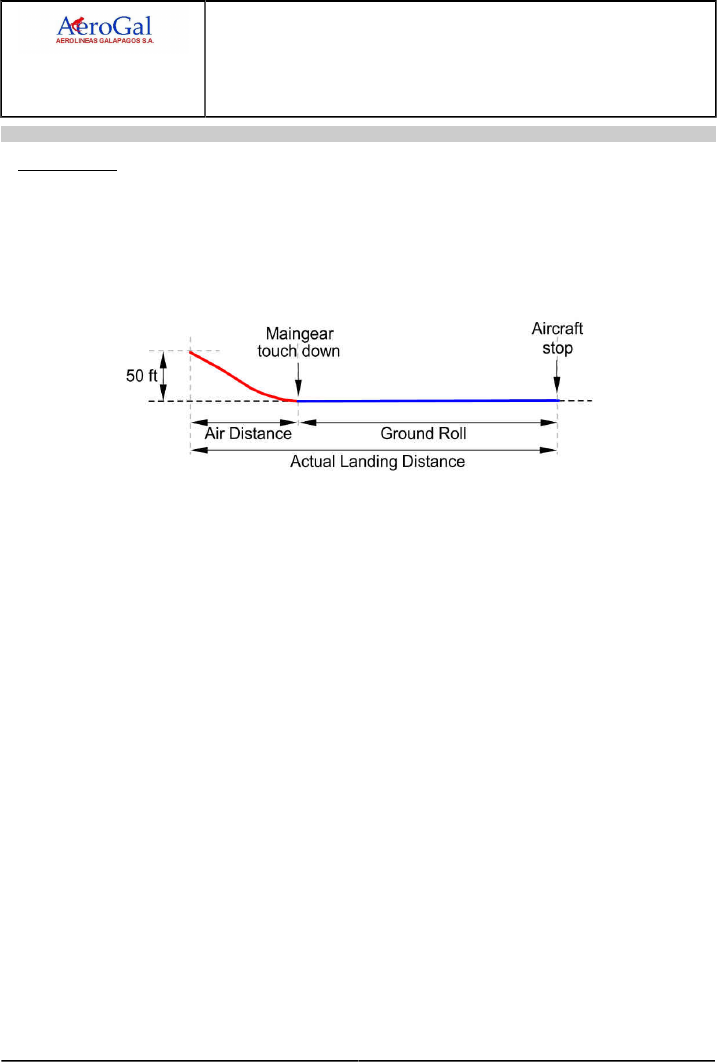
A318/A319/A320/A321
FLIGHT CREW
TECHNIQUES MANUAL
PROCEDURES
NORMAL PROCEDURES
STANDARD OPERATING PROCEDURES - DESCENT PREPARATION
GLG A318/A319/A320/A321 FLEET PR-NP-SOP-160 P 2/30
FCTM ← A → 05 SEP 17
Ident.: PR-NP-SOP-160-A-00019851.0001001 / 20 MAR 17
DEFINITIONS
ACTUAL LANDING DISTANCE (ALD)
The ALD is the distance to come to a complete stop from a point 50 ft above the landing
surface. The ALD is a regulatory landing distance established during flight tests in
non-operational conditions (rate of descent, piloting skills…), not representative of daily
operations.
REQUIRED LANDING DISTANCE (RLD)
The RLD is a regulatory landing distance based on the Actual Landing Distance multiplied by a
regulatory coefficient. It is used for dispatch only.
RLD (Dry) = ALD / 0.6
RLD (Wet) = 1.15 x RLD (Dry)
RLD (Contaminated) = greatest of [1.15 x ALD (Contaminated) OR RLD (Wet)]
LANDING DISTANCE (LD)
The LD is the landing distance calculated in-flight (also called in-flight landing distance). It is
based on the landing performance model elaborated by the Takeoff and Landing Performance
Assessment / Aviation Rulemaking Committee (the TALPA /ARC committee was mandated
to find an industry consensus and produce recommendations for new regulation on landing
performance assessment). LD wants to be more representative of the landing technique
followed by line pilot and so more representative of daily operations.
FACTORED LANDING DISTANCE
The LD calculated in flight does not include margins. It assumes a stabilized approach in
outside conditions consistent with the computation assumptions. In order to cover the variability
in flying techniques and unexpected conditions at landing, the flight crew should apply an
appropriate margin to the in-flight landing distance (either determined with or without failure).
It is the airline responsibility to define the margins that the flight crew should apply on top of the
in-flight landing distance.
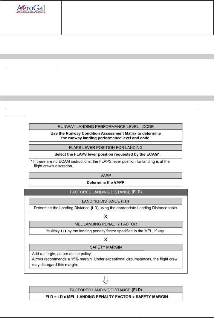
A318/A319/A320/A321
FLIGHT CREW
TECHNIQUES MANUAL
PROCEDURES
NORMAL PROCEDURES
STANDARD OPERATING PROCEDURES - DESCENT PREPARATION
GLG A318/A319/A320/A321 FLEET PR-NP-SOP-160 P 3/30
FCTM ← A → 05 SEP 17
The Airbus recommendation is to add a margin of 15 % to the in-flight landing distance. Under
exceptional circumstances, the flight crew may disregard this margin.
Ident.: PR-NP-SOP-160-A-00019852.0001001 / 20 MAR 17
MEL CONSIDERATIONS
Some MEL items affect the landing distance. For these items, the MEL provides a coefficient that
the flight crew must apply on top of the in-flight landing distance (either determined with or without
failure).
Ident.: PR-NP-SOP-160-A-00019853.0001001 / 20 MAR 17
METHOD TO DETERMINE AIRCRAFT PERFORMANCE AT LANDING WITHOUT OR WITH
FAILURE

A318/A319/A320/A321
FLIGHT CREW
TECHNIQUES MANUAL
PROCEDURES
NORMAL PROCEDURES
STANDARD OPERATING PROCEDURES - DESCENT PREPARATION
GLG A318/A319/A320/A321 FLEET PR-NP-SOP-160 P 4/30
FCTM ← A → 05 SEP 17
Ident.: PR-NP-SOP-160-A-00019854.0001001 / 20 MAR 17
THE RUNWAY CONDITION ASSESSMENT MATRIX (RCAM)
INFORMATION PROVIDED BY THE RCAM
The RCAM provides the flight crew with a combination of all available information (Runway
Surface Conditions: State or / and Contaminant, Pilot Report of Braking Action (PIREP ) or
Estimated Surface Friction (ESF)) in order to assess the Related Landing Performance Code -
Level.
The RCAM provides six Landing Performance Codes - Levels:
‐ 6 - Dry
‐ 5 - Good
‐ 4 - Good to Medium
‐ 3 - Medium
‐ 2 - Medium to Poor
‐ 1 - Poor
The RCAM also provides the maximum demonstrated crosswind value (gust included) for each
landing performance.
Note: The RCAM does not show the friction coefficient (Mu) since there is no correlation
between the coefficient measured by a vehicle and the actual aircraft braking
capability / landing performance.
HOW TO USE THE RCAM
In order to assess the landing distance, the flight crew should determine a Landing Performance
Code - Level using the RCAM.
The flight crew makes a primary assessment based on runway state or / and runway
contaminant type and depth and the OAT. Then, the flight crew may downgrade this primary
assessment if:
‐ A report (PIREP or ESF) is available and this report corresponds to a lower Landing
Performance Code - Level,
‐ Complementary information is available and is related to a possible degradation of the
runway surface conditions.
If the primary means of assessment (runway state or/and runway contaminant type and depth)
is not available, the flight crew should request it to the ATC.
The flight crew should not use a report or any other complementary information in order to
upgrade a primary assessment (runway covered by treated ice may be an exception, for more
information, refer to the example below).

A318/A319/A320/A321
FLIGHT CREW
TECHNIQUES MANUAL
PROCEDURES
NORMAL PROCEDURES
STANDARD OPERATING PROCEDURES - DESCENT PREPARATION
GLG A318/A319/A320/A321 FLEET PR-NP-SOP-160 P 5/30
FCTM ← A → 05 SEP 17
CASE OF LOOSE CONTAMINANT
When a loose contaminant (standing water, slush, dry snow or wet snow) is present on the
runway, ICAO Annex 14 recommendations state that no estimated surface friction should
be reported as the measurement is not reliable. Therefore, Estimated Surface Friction
measurement done on winter contaminated runways should be treated with caution.
MAXIMUM CROSSWIND CONSIDERATION
The maximum crosswind value that the flight crew should retain is the one corresponding to
the worse Landing Performance. This means that if the flight crew downgrades the Landing
Performance Code - Level after considering additional information, they should also downgrade
the maximum demonstrated crosswind value.
Note: When assessing the maximum demonstrated crosswind value, the flight crew must
take into account any available complementary information which is related to a
possible degradation of the directional control of the aircraft.
EXAMPLES OF LANDING PERFORMANCE CODE — LEVEL ASSESSMENT
RUNWAY CONTAMINATED BY COMPACTED SNOW, OAT -10 °C AND PIREP OR ESF
MEDIUM
Compacted Snow at or below -15 °C is in the category GOOD TO MEDIUM, above -15 °C it
becomes MEDIUM. The report Medium could originate from a PIREP or a friction measurement.
This information indicates that the computation should be done with the Landing Performance 3
- MEDIUM and corresponding maximum crosswind condition must be retained.
RUNWAY COVERED BY LESS THAN 3 MM (1/8 INCH) OF WATER BUT HEAVY RAIN WITH
STORM CELLS IN THE VICINITY ARE REPORTED
According to the matrix, the expected landing performance on a runway covered by less than
3 mm (1/8 inch) of water (runway is wet) is 5 - GOOD. However heavy rain can saturate the
draining capabilities of the runway and lead to standing water. Standing water (more than 3 mm
– 1/8 inch of water) is in the category 2 - MEDIUM TO POOR.
This information indicates that it may be appropriate to consider 2 - MEDIUM TO POOR
Landing Performance and corresponding maximum crosswind condition must be considered.
RUNWAY COVERED BY TREATED ICE (COLD AND DRY) WITH AN ESTIMATED SURFACE
FRICTION GOOD OR RUNWAY CONDITION CODE 3
Icy runways are basically classified is in the category 1 - POOR or 0 - LESS THAN
POOR. The RCAM does not give credit for runway treatment, such as with sand, gravel or
chemicals unconditionally. The success of the surface treatment must be validated by friction
measurements and supported by all other observations of trained airport personnel. The
airport may report the measured friction and/or a runway Condition Code. When the observed
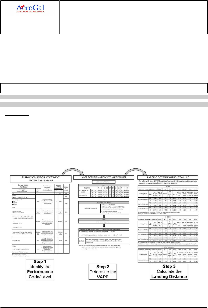
A318/A319/A320/A321
FLIGHT CREW
TECHNIQUES MANUAL
PROCEDURES
NORMAL PROCEDURES
STANDARD OPERATING PROCEDURES - DESCENT PREPARATION
GLG A318/A319/A320/A321 FLEET PR-NP-SOP-160 P 6/30
FCTM ← A to B → 05 SEP 17
braking action on an icy runway is at least 5 - GOOD, it is permitted to apply 3 - MEDIUM for the
performance assessment. When Runway Condition Codes are reported, this margin is already
taken into account in the report.
The upgrade of the landing performance may only be performed by airport: if on treated cold
and dry ice a surface friction GOOD or better is measured on all three thirds of the runway, an
upgrade to 3 - MEDIUM is allowed.
LANDING PERFORMANCE - NORMAL OPERATIONS
Applicable to: ALL
Ident.: PR-NP-SOP-160-B-00019855.0001001 / 20 MAR 17
PRINCIPLE
In order to assess the landing performance without failure (or in the case of a failure that does not
affect landing performance), the flight crew should follow the three main steps described below:
1. Determine the Landing Performance Code - Level using the RCAM,
2. Determine the VAPP by referring to the VAPP computation table without failure of the QRH,
3. Calculate the In-Flight Landing Distance with the In-Flight Landing Distance tables without
failure of the QRH.

A318/A319/A320/A321
FLIGHT CREW
TECHNIQUES MANUAL
PROCEDURES
NORMAL PROCEDURES
STANDARD OPERATING PROCEDURES - DESCENT PREPARATION
GLG A318/A319/A320/A321 FLEET PR-NP-SOP-160 P 7/30
FCTM ← B → 05 SEP 17
Ident.: PR-NP-SOP-160-B-00019856.0001001 / 20 MAR 17
VAPP DETERMINATION WITHOUT FAILURE
When the flight crew has determined the Landing Performance Code - Level using the RCAM
(Refer to PR-NP-SOP-160 The Runway Condition Assessment Matrix (RCAM)), they should
determine the Approach Speed (VAPP).
GENERAL CONSIDERATIONS
The VAPP is defined by the flight crew to perform the safest approach. It is function of the
aircraft landing weight, slats/flaps configuration, wind conditions, use of A/THR, icing conditions.
In most cases, the FMGC provides a correct VAPP value on the MCDU PERF APPR, when
tower wind and FLAPS 3 or FLAPS FULL landing configuration have been inserted.
The flight crew can insert a lower VAPP in the MCDU PERF APPR, down to VLS , if landing
is performed without A/THR , without wind and no ice accretion. In case of strong or gusty
crosswind greater than 20 kt, VAPP should be at least VLS +5 kt; the 5 kt increment above VLS
may be increased up to 15 kt at the flight crew's discretion.
The flight crew should keep in mind that the wind entered in the MCDU PERF APPR considers
the wind direction to be in the same reference as the runway direction e. g. if airport is magnetic
referenced, the crew will insert magnetic wind. The wind direction provided by ATIS and ATC is
given in the same reference as the runway direction whereas the wind provided by VOLMET ,
METAR or TAF is always true referenced.
VAPP is computed at estimated landing weight while the aircraft is in CRZ or DES phase,
provided that the F-PLN is correctly sequenced and inserted in the MCDU . When the approach
phase is activated, VAPP is computed using current gross weight. Managed speed should be
used for final approach as it provides Ground Speed mini guidance, even when the VAPP has
been manually inserted.
In a general manner, the VAPP value is the sum of the VLS and the APPRroach CORrection
(APPR COR):
USE OF THE QRH TABLE TO DETERMINE THE VAPP WITHOUT FAILURE
VAPP Determination
The QRH provides the table for determining the VAPP without failure in the In-Flight
Performance chapter.
The flight crew should first determine the VLS as a function of the estimated aircraft weight at
landing and of the landing configuration.
Then they should add the APPRoach CORrection which depends on the A/THR, ice accretion
condition or headwind component value.
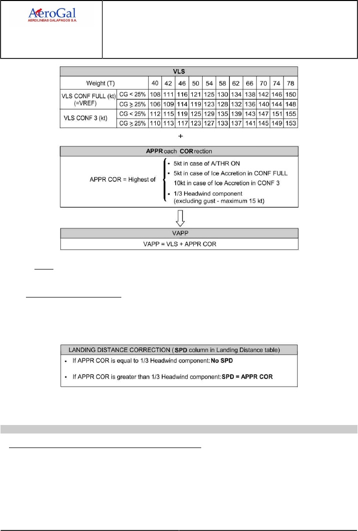
A318/A319/A320/A321
FLIGHT CREW
TECHNIQUES MANUAL
PROCEDURES
NORMAL PROCEDURES
STANDARD OPERATING PROCEDURES - DESCENT PREPARATION
GLG A318/A319/A320/A321 FLEET PR-NP-SOP-160 P 8/30
FCTM ← B → 05 SEP 17
Note: This example illustrates the method to determine the VAPP. It is not customized to
all aircraft configuration.
Landing distance correction
If the APPRroach CORrection is greater than 1/3 of the headwind component, the flight crew
must take into account the increase of the ground speed at touchdown in the in-flight landing
distance computation by applying the SPD correction.
Any extra approach speed increment must be taken into account in the in-flight landing
distance computation by applying the SPD correction.
Ident.: PR-NP-SOP-160-B-00019857.0001001 / 25 JUL 17
1IN-FLIGHT LANDING DISTANCE WITHOUT FAILURE
In order to determine the in-flight landing distance, the flight crew should refer to the in-flight
landing distance tables of the QRH for the Performance Code - Level that they determined with the
RCAM (6 - DRY, 5 - GOOD, 4 - GOOD TO MEDIUM, etc…).

A318/A319/A320/A321
FLIGHT CREW
TECHNIQUES MANUAL
PROCEDURES
NORMAL PROCEDURES
STANDARD OPERATING PROCEDURES - DESCENT PREPARATION
GLG A318/A319/A320/A321 FLEET PR-NP-SOP-160 P 9/30
FCTM ← B → 05 SEP 17
REFERENCE DISTANCE (REF DIST)
The flight crew should determine the REF DIST depending on the landing configuration (CONF
3 or CONF FULL) and the braking mode (Maximum manual braking, Autobrake LOW or MED).
The QRH provides REF DIST for a given aircraft landing weight (the Maximum Landing Weight
(MLW ) of the aircraft family), at sea level, in ISA conditions, no wind, on runway with no slope,
without reverse thrust, in manual landing and at a VAPP equal to the VLS of the corresponding
configuration.
CORRECTIONS TO BE APPLIED TO THE REF DIST
When the REF DIST is determined, flight crew applies, when relevant, the corrections for each
parameter having an effect on the in-flight landing distance:
‐WGT : Weight correction to cover the difference between the actual landing weight and the
reference weight used to provide REF DIST . This correction covers the impact on the VLS
linked to the actual aircraft landing weight. The correction for a weight below the reference
weight is provided at the bottom of the table
‐SPD : Speed correction calculated during the VAPP determination,
‐ALT: Airport Pressure Altitude correction,
‐WIND: Tailwind component correction,
‐TEMP : Temperature correction for temperatures above ISA condition,
‐SLOPE: Downward slope correction of the runway,
‐REV: Reverse thrust correction to take into account the benefit of each available thrust
reverser (this correction considers maximum reverser thrust).
‐OVW: Correction to be applied in the case of an overweight landing using the Overweight
Landing Procedure. This correction takes into account the fact that the Overweight Landing
procedure requests the pilot flying to “touchdown as smoothly as possible” and to apply
brakes “after the nosewheel touchdown”.
Note: In the case of an overweight landing, both the WGT and the OVW corrections should
be applied:
‐ WGT correction to reflect the actual aircraft landing weight
‐ OVW correction to reflect the use of the Overweight Landing Procedure
The QRH also provides the Automatic Landing Correction that should be applied when an
automatic landing is performed.
Note: Environment effects that reduce the in-flight landing distance (temperature below ISA ,
“uphill” slope) are not considered in the QRH tables.

A318/A319/A320/A321
FLIGHT CREW
TECHNIQUES MANUAL
PROCEDURES
NORMAL PROCEDURES
STANDARD OPERATING PROCEDURES - DESCENT PREPARATION
GLG A318/A319/A320/A321 FLEET PR-NP-SOP-160 P 10/30
FCTM ← B → 05 SEP 17
Ident.: PR-NP-SOP-160-B-00019858.0001001 / 20 MAR 17
EXAMPLE OF LANDING PERFORMANCE ASSESSMENT WITHOUT FAILURE
The aim of this example is to illustrate the method to assess the landing performance. It is not
customized to all aircraft configuration (landing weight, ...).
LANDING DATA
•Aircraft: A320
•Runway Condition: 2 mm of slush
•Report: Good to Medium
•Runway Slope: 1 % UP
•Wind / OAT: 12 kt headwind / -5 °C
•Airport Pressure Altitude: Sea Level
•Estimated Landing Weight: 62 t
•Landing Configuration: CONF FULL
•Landing Technique: Manual landing, A/THR ON
•A/BRK: MED
•Thrust Reversers: Use of all thrust reversers
•Ice accretion: No
•CG: 29 %
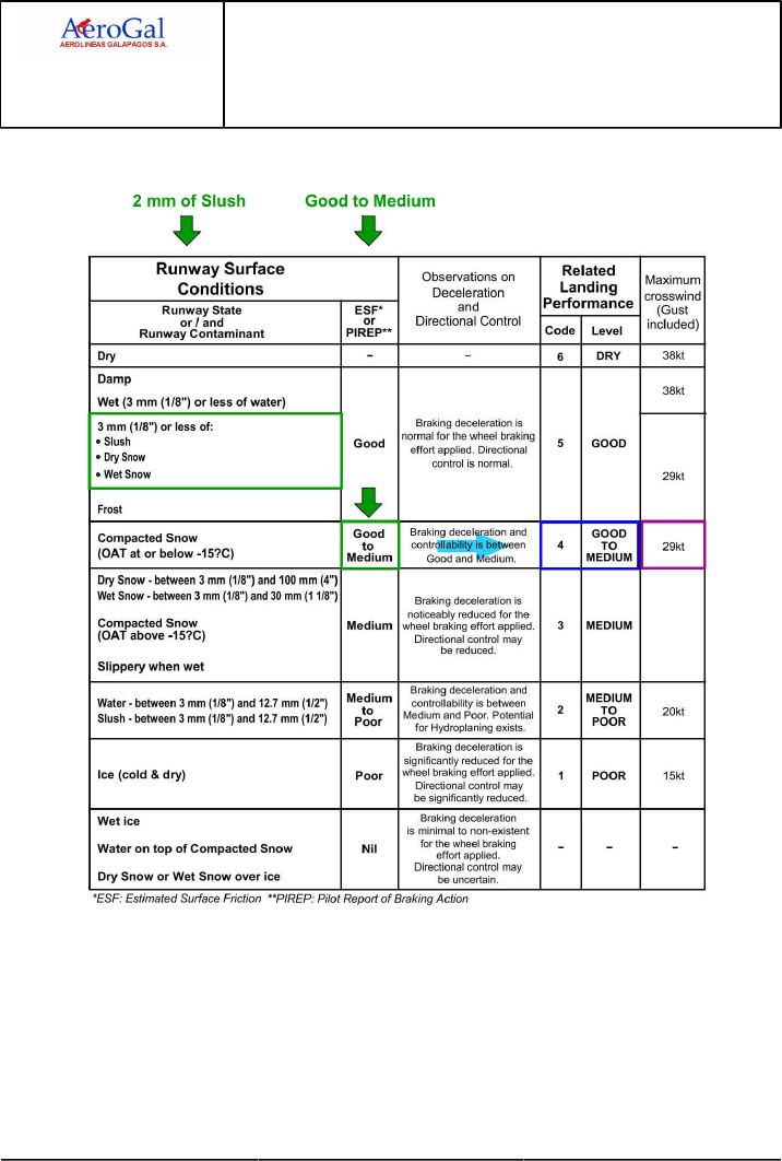
A318/A319/A320/A321
FLIGHT CREW
TECHNIQUES MANUAL
PROCEDURES
NORMAL PROCEDURES
STANDARD OPERATING PROCEDURES - DESCENT PREPARATION
GLG A318/A319/A320/A321 FLEET PR-NP-SOP-160 P 11/30
FCTM ← B → 05 SEP 17
STEP 1: IDENTIFY THE LANDING PERFORMANCE CODE – LEVEL
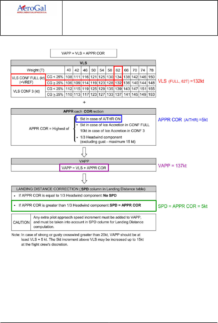
A318/A319/A320/A321
FLIGHT CREW
TECHNIQUES MANUAL
PROCEDURES
NORMAL PROCEDURES
STANDARD OPERATING PROCEDURES - DESCENT PREPARATION
GLG A318/A319/A320/A321 FLEET PR-NP-SOP-160 P 12/30
FCTM ← B → 05 SEP 17
STEP 2: DETERMINE THE VAPP
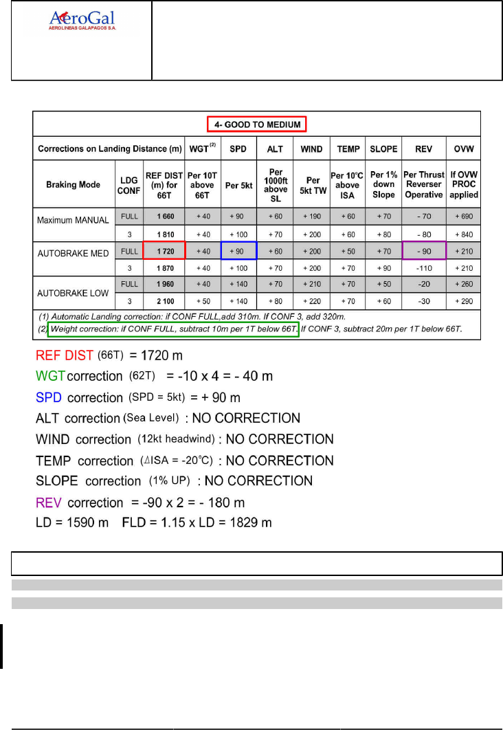
A318/A319/A320/A321
FLIGHT CREW
TECHNIQUES MANUAL
PROCEDURES
NORMAL PROCEDURES
STANDARD OPERATING PROCEDURES - DESCENT PREPARATION
GLG A318/A319/A320/A321 FLEET PR-NP-SOP-160 P 13/30
FCTM ← B to C → 05 SEP 17
STEP 3: CALCULATE THE IN-FLIGHT LANDING DISTANCE
LANDING PERFORMANCE - ABNORMAL OPERATIONS
Applicable to: ALL
Ident.: PR-NP-SOP-160-C-00019981.0001001 / 25 JUL 17
2In order to assess the landing performance in the case of a failure that affects landing performance
(LDG DIST … PROC APPLY displayed on ECAM), the flight crew should follow the three main steps
described below:
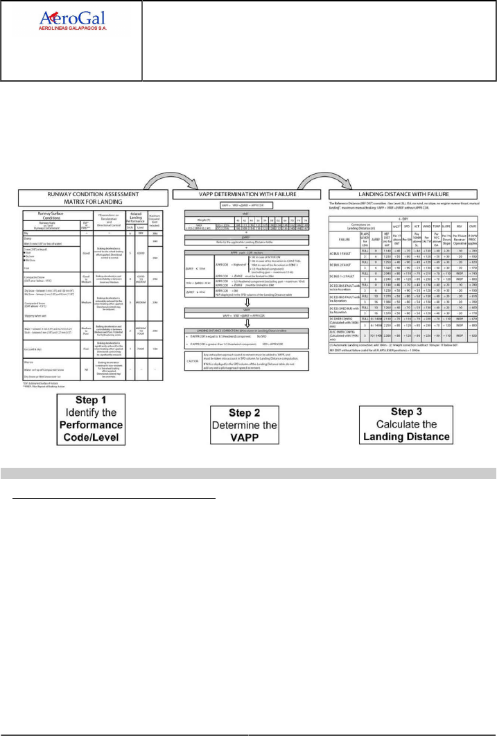
A318/A319/A320/A321
FLIGHT CREW
TECHNIQUES MANUAL
PROCEDURES
NORMAL PROCEDURES
STANDARD OPERATING PROCEDURES - DESCENT PREPARATION
GLG A318/A319/A320/A321 FLEET PR-NP-SOP-160 P 14/30
FCTM ← C → 05 SEP 17
1. Determine the Landing Performance Code - Level using the RCAM,
2. Determine the VAPP by referring to the VAPP computation table with failure of the QRH,
3. Calculate the In-Flight Landing Distance with the In-Flight Landing Distance tables with failure of
the QRH.
Ident.: PR-NP-SOP-160-C-00019982.0001001 / 25 JUL 17
3VAPP DETERMINATION WITH FAILURE
When the flight crew has determined the Landing Performance Code - Level using the RCAM
(Refer to PR-NP-SOP-160 The Runway Condition Assessment Matrix (RCAM)), they should
determine the Approach Speed (VAPP).
GENERAL CONSIDERATIONS
Some failures affect the approach speed:
‐ Some failures (typically slats or flaps failure) increase the VLS . In this case, the VLS
displayed on the PFD (if available) takes into account the actual configuration,
‐ In some others failures, it is required to fly at speed higher than VLS to improve the handling
characteristics of the aircraft. This speed increment is to be added to the VLS displayed on
the PFD when the landing configuration is reached.
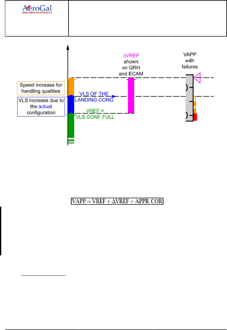
A318/A319/A320/A321
FLIGHT CREW
TECHNIQUES MANUAL
PROCEDURES
NORMAL PROCEDURES
STANDARD OPERATING PROCEDURES - DESCENT PREPARATION
GLG A318/A319/A320/A321 FLEET PR-NP-SOP-160 P 15/30
FCTM ← C → 05 SEP 17
In order to prepare the approach and landing, the flight crew needs to calculate the VAPP in
advance. Because the landing configuration is not yet established, the appropriate VLS is not
necessarily available at that time on the PFD.
VAPP is therefore determined from the reference speed (VREF) defined as the VLS in CONF
FULL. As a general manner, the VAPP is the sum of VREF and of the effect of the failure on the
reference speed (ΔVREF ) and of the approach correction (APPR COR):
The Airbus recommendation is to limit the sum (ΔVREF + APPR COR ) to 20 kt in order not
to increase indefinitely the approach speed as it has a direct impact on the landing distance.
As a result, for a failure which increases the reference speed by more than 20 kt, there is no
approach correction. This also results in the display of N/A (Not Applicable) in the in-flight
landing distance tables in the column for the speed correction (SPD), since the reference
landing distance already takes into account the effect of the failure in the increased approach
speed.
USE OF THE TABLE FOR COMPUTING VAPP WITH FAILURE
VAPP Determination
The QRH provides the table for determining the VAPP without failure in the In-Flight
Performance chapter.
The flight crew should first determine the VREF as a function of the estimated aircraft weight
at landing and of the landing configuration.
Then they should take into account the effect of the failure by referring to the applicable
in-flight landing distance table which provides the ΔVREF for each failure.
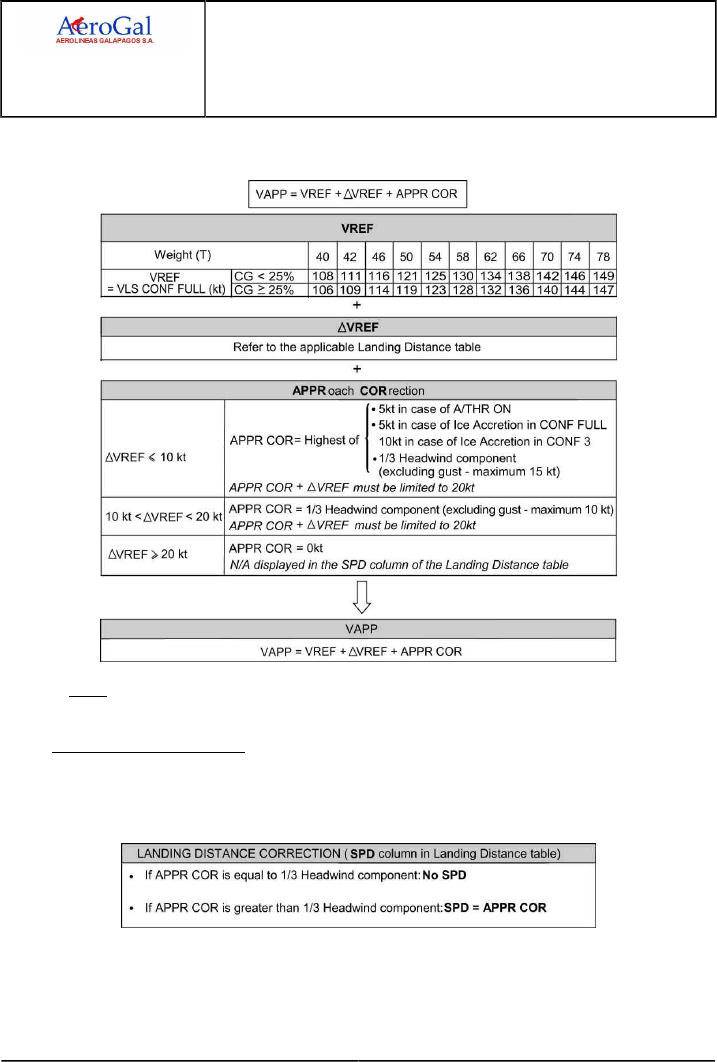
A318/A319/A320/A321
FLIGHT CREW
TECHNIQUES MANUAL
PROCEDURES
NORMAL PROCEDURES
STANDARD OPERATING PROCEDURES - DESCENT PREPARATION
GLG A318/A319/A320/A321 FLEET PR-NP-SOP-160 P 16/30
FCTM ← C → 05 SEP 17
Finally they should add the APPRoach CORrection which depends on ΔVREF , the A/THR,
ice accretion condition or headwind component value.
Note: This example illustrates the method to determine the VAPP. It is not customized to
all aircraft configuration.
Landing Distance correction
If the APPRroach CORrection is greater than 1/3 of the headwind component, the flight crew
must take into account the increase of the ground speed at touchdown in the in-flight landing
distance computation by applying the SPD correction.
Any extra approach speed increment must be taken into account in the in-flight landing
distance computation by applying the SPD correction.

A318/A319/A320/A321
FLIGHT CREW
TECHNIQUES MANUAL
PROCEDURES
NORMAL PROCEDURES
STANDARD OPERATING PROCEDURES - DESCENT PREPARATION
GLG A318/A319/A320/A321 FLEET PR-NP-SOP-160 P 17/30
FCTM ← C → 05 SEP 17
Ident.: PR-NP-SOP-160-C-00019983.0001001 / 25 JUL 17
4IN-FLIGHT LANDING DISTANCE WITH FAILURE
In order to determine the in-flight landing distance with failure, the flight crew should refer to the
in-flight landing distance tables of the QRH for the aircraft system affected by the failure.
For each aircraft system, the QRH provides tables for the Performance Code - Level determined
with the RCAM (6 - DRY, 5 - GOOD, 4 - GOOD TO MEDIUM, etc…).
REFERENCE DISTANCE (REF DIST)
For each recommended flaps lever position for landing, the tables provide, when relevant, the
associated effect of the failure on the reference speed (ΔVREF ), which must be taken into
account in the VAPP determination.
The QRH provides REF DIST for a given aircraft landing weight (the Maximum Landing Weight
(MLW ) of the aircraft family), at sea level, in ISA conditions, no wind, on runway with no slope,
without reverse thrust, in manual landing, maximum manual braking and at a VAPP equal to the
sum (VREF + ΔVREF).
CORRECTIONS TO BE APPLIED TO THE REF DIST
When the REF DIST is determined, flight crew applies, when relevant, the corrections for each
parameter having an effect on the landing distance:
‐WGT : Weight correction to cover the difference between the actual landing weight and the
reference weight used to provide REF DIST . This correction covers the impact on the VLS
linked to the actual aircraft landing weight. The correction for a weight below the reference
weight is provided at the bottom of the table,
‐SPD : Speed correction calculated during the VAPP determination,
‐ALT: Airport Pressure Altitude correction,
‐WIND: Tailwind component correction,
‐TEMP : Temperature correction for temperatures above ISA conditions,
‐SLOPE: Downward slope correction of the runway,
‐REV: Reverse thrust correction to take into account the benefit of each available thrust
reverser (considers maximum reverser thrust).
‐OVW: Correction to be applied in the case of an overweight landing using the Overweight
Landing Procedure. This correction takes into account the fact that the Overweight Landing
procedure request the pilot flying to “touchdown as smoothly as possible” and to apply brakes
“after the nosewheel touchdown”.
Note: In the case of an overweight landing both the WGT and the OVW should be applied:
‐ WGT correction to reflect the actual aircraft landing weight.
‐ OVW correction to reflect the use of the Overweight Landing Procedure

A318/A319/A320/A321
FLIGHT CREW
TECHNIQUES MANUAL
PROCEDURES
NORMAL PROCEDURES
STANDARD OPERATING PROCEDURES - DESCENT PREPARATION
GLG A318/A319/A320/A321 FLEET PR-NP-SOP-160 P 18/30
FCTM ← C → 05 SEP 17
The QRH also provides the Automatic Landing Correction that should be applied when an
automatic landing is performed.
Note: 1. Environment effects that reduce the in-flight landing distance (temperature below
ISA , “uphill” slope) are not considered in the QRH tables.
2. The REF DIST without failure is also provided at bottom of each table. It
corresponds to the reference distance without failure configuration FULL. It enables
flight crew to evaluate the impact on in-flight landing distance of a system failure
(for more information, Refer to PR-NP-SOP-160 Method to Determine Aircraft
Performance at Landing with Several Failures)
Ident.: PR-NP-SOP-160-C-00019984.0001001 / 20 MAR 17
EXAMPLE OF LANDING PERFORMANCE ASSESSMENT WITH FAILURE
The aim of this example is to illustrate the method to assess the landing performance. It is not
customized to all aircraft configuration (landing weight, A/BRK modes...).
LANDING DATA
•Aircraft: A320
•Runway Condition: Compacted Snow
•Report: Good
•Runway Slope: No Slope
•Wind / OAT: 12 kt headwind / -15 °C
•Airport Pressure Altitude: 1 000 ft
•Estimated Landing Weight: 66 t
•In-Flight failure: ENG 1 SHUTDOWN with ENG FIRE pb pushed
•Landing Technique: Manual landing, A/THR ON
•Landing Configuration: CONF FULL
•Thrust Reversers: Use of all available thrust reversers
•Ice accretion: Yes
•CG: 29 %
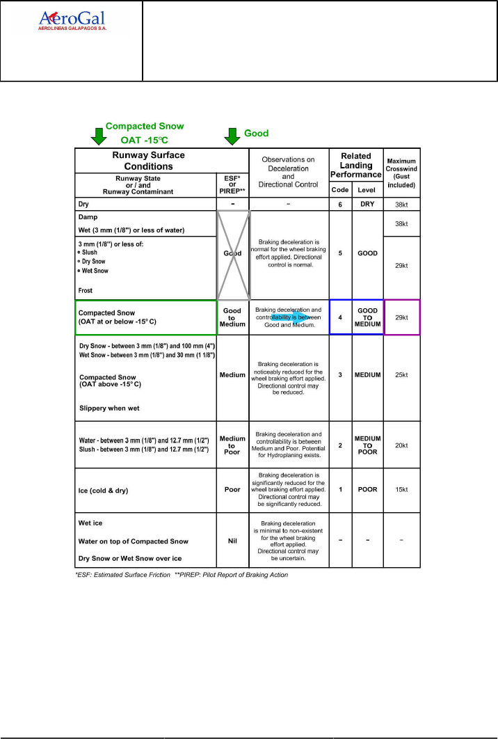
A318/A319/A320/A321
FLIGHT CREW
TECHNIQUES MANUAL
PROCEDURES
NORMAL PROCEDURES
STANDARD OPERATING PROCEDURES - DESCENT PREPARATION
GLG A318/A319/A320/A321 FLEET PR-NP-SOP-160 P 19/30
FCTM ← C → 05 SEP 17
STEP 1: IDENTIFY THE LANDING PERFORMANCE CODE - LEVEL
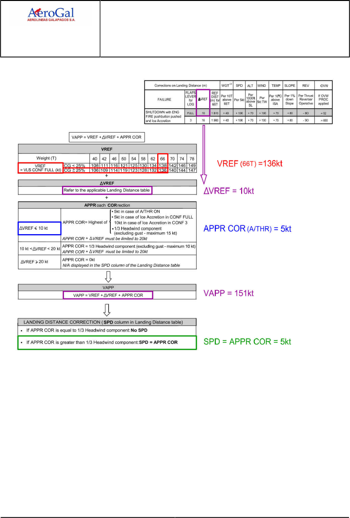
A318/A319/A320/A321
FLIGHT CREW
TECHNIQUES MANUAL
PROCEDURES
NORMAL PROCEDURES
STANDARD OPERATING PROCEDURES - DESCENT PREPARATION
GLG A318/A319/A320/A321 FLEET PR-NP-SOP-160 P 20/30
FCTM ← C → 05 SEP 17
STEP 2: DETERMINE THE VAPP
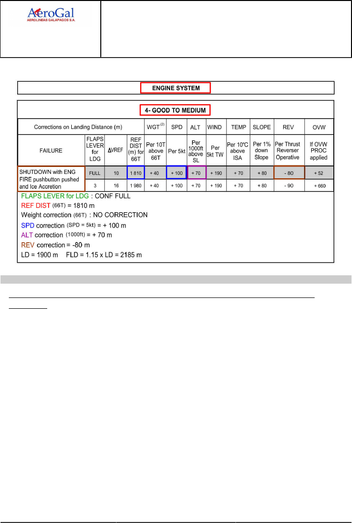
A318/A319/A320/A321
FLIGHT CREW
TECHNIQUES MANUAL
PROCEDURES
NORMAL PROCEDURES
STANDARD OPERATING PROCEDURES - DESCENT PREPARATION
GLG A318/A319/A320/A321 FLEET PR-NP-SOP-160 P 21/30
FCTM ← C → 05 SEP 17
STEP 3: CALCULATE THE IN-FLIGHT LANDING DISTANCE
Ident.: PR-NP-SOP-160-C-00019985.0001001 / 25 JUL 17
5METHOD TO DETERMINE AIRCRAFT PERFORMANCE AT LANDING WITH SEVERAL
FAILURES
Due to the low probability of having several in-flight failures leading to an increase of the landing
distance, the Airbus Operational Documentation does not address the combination of in-flight
failures of different systems (however, dual hydraulic, dual electrical... are covered).
Whereas the probability of having several in-flight failures leading to an increase of the in-flight
landing distance is low, the combinations of MEL item(s) that lead(s) to a landing performance
impact only when combined to specific single in-flight failure is probable. The method described
below provides a method to assess landing distance, in case of multiple failures.
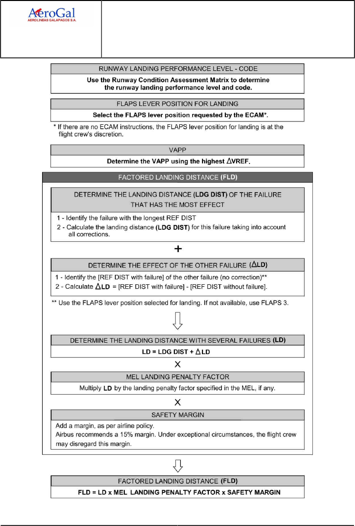
A318/A319/A320/A321
FLIGHT CREW
TECHNIQUES MANUAL
PROCEDURES
NORMAL PROCEDURES
STANDARD OPERATING PROCEDURES - DESCENT PREPARATION
GLG A318/A319/A320/A321 FLEET PR-NP-SOP-160 P 22/30
FCTM ← C → 05 SEP 17
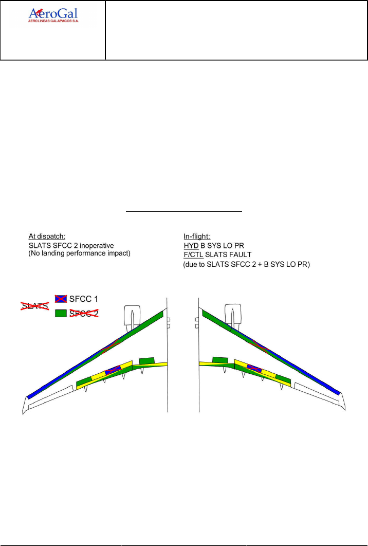
A318/A319/A320/A321
FLIGHT CREW
TECHNIQUES MANUAL
PROCEDURES
NORMAL PROCEDURES
STANDARD OPERATING PROCEDURES - DESCENT PREPARATION
GLG A318/A319/A320/A321 FLEET PR-NP-SOP-160 P 23/30
FCTM ← C → 05 SEP 17
EXAMPLE
The aim of this example is to illustrate the method to assess the landing performance in
the case of several failures due to dispatch under MEL. It is not customized to all aircraft
configuration (flight control and hydraulic systems architecture, landing weight...).
In this example we consider an A320 dispatched under MEL with the slats channel of the SFCC
2 inoperative (the redundancy of the slats control is lost but no landing performance impact).
In-flight (cruise), the HYD B SYS LO PR triggers (B RSVR LO LVL). Landing performance is
impacted as SPLR 3 is inoperative. In addition, due to the fact that the aircraft was dispatched
under MEL with the slats channel of the SFCC 2 inoperative, F/CTL SLATS FAULT (S<1) also
triggers which has a supplementary landing performance impact (in addition to the loss of SPLR
3).
A320 example of several failures
LANDING DATA
•Aircraft: A320
•Landing Performance level: DRY
•Conditions: ISA Conditions, No wind, No slope
•Estimated Landing Weight: 62 t
•Landing Technique: Manual landing, A/THR ON
•Thrust Reversers: Use of all available thrust reversers
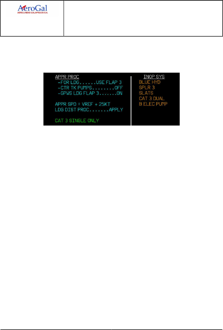
A318/A319/A320/A321
FLIGHT CREW
TECHNIQUES MANUAL
PROCEDURES
NORMAL PROCEDURES
STANDARD OPERATING PROCEDURES - DESCENT PREPARATION
GLG A318/A319/A320/A321 FLEET PR-NP-SOP-160 P 24/30
FCTM ← C → 05 SEP 17
FLAPS LEVER POSITION FOR LANDING
The ECAM status page indicates the required flaps lever position for landing if the failure
requests it.
If there are no ECAM instructions, the flaps lever position for landing is at flight crew’s
discretion.
VAPP
Determine the VAPP using the highest ΔVREF
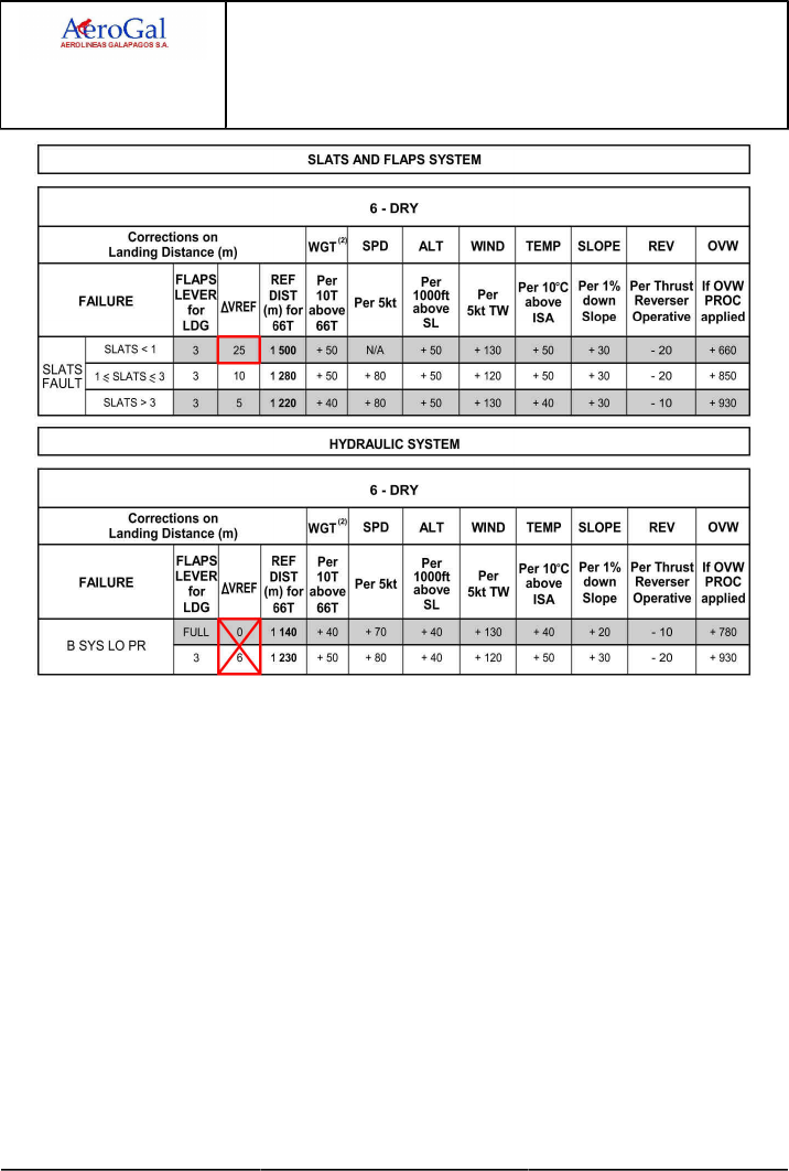
A318/A319/A320/A321
FLIGHT CREW
TECHNIQUES MANUAL
PROCEDURES
NORMAL PROCEDURES
STANDARD OPERATING PROCEDURES - DESCENT PREPARATION
GLG A318/A319/A320/A321 FLEET PR-NP-SOP-160 P 25/30
FCTM ← C → 05 SEP 17
In this example, ΔVREF = 25 kt must be used to determine VAPP.
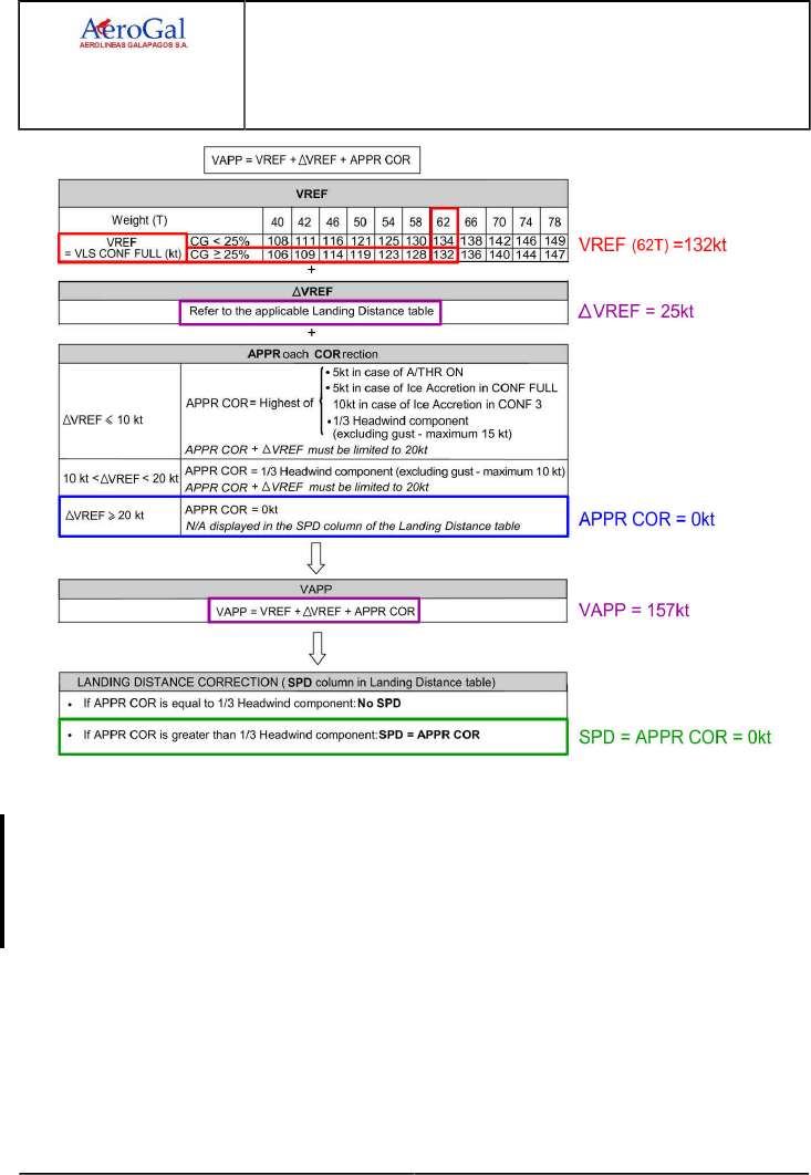
A318/A319/A320/A321
FLIGHT CREW
TECHNIQUES MANUAL
PROCEDURES
NORMAL PROCEDURES
STANDARD OPERATING PROCEDURES - DESCENT PREPARATION
GLG A318/A319/A320/A321 FLEET PR-NP-SOP-160 P 26/30
FCTM ← C → 05 SEP 17
In this example, VAPP = 157 kt and SPD = 0 kt.
DETERMINE THE LANDING DISTANCE (LDG DIST) OF THE FAILURE THAT HAS THE MOST
EFFECT
To determine LDG DIST , identify the failure having the longest REF DIST, then calculate the
landing distance for this failure taking into account all corrections as necessary. The method to
calculate the landing distance is unchanged.
In this example, the failure that has the most effect is the F/CTL SLATS FAULT (S<1)
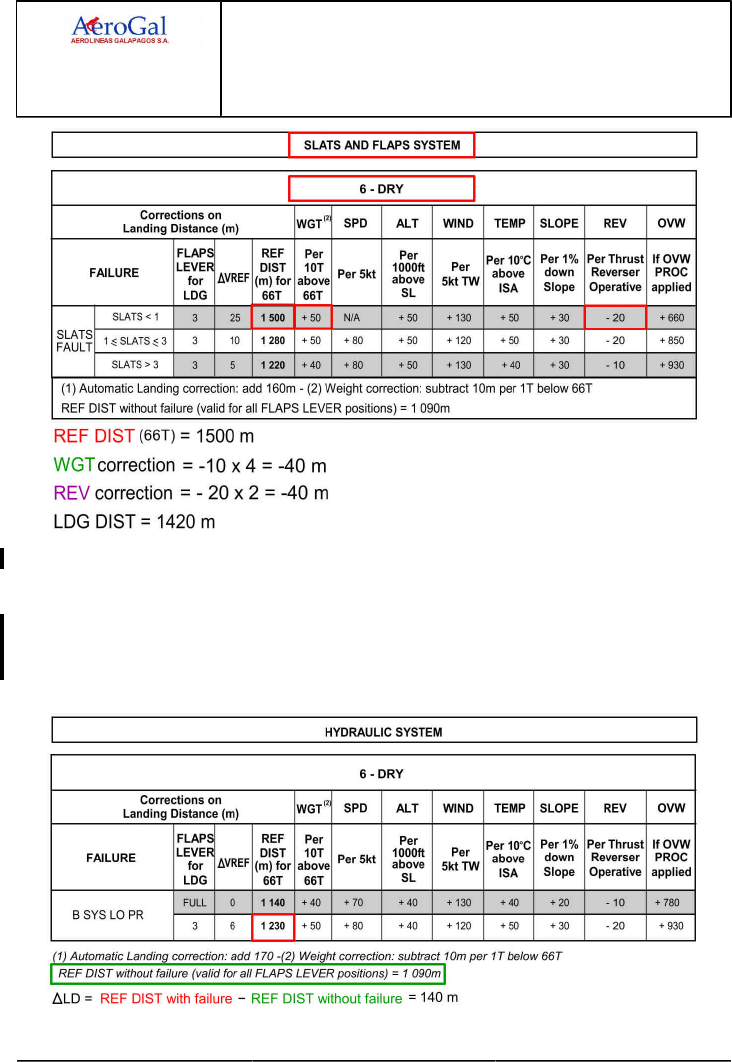
A318/A319/A320/A321
FLIGHT CREW
TECHNIQUES MANUAL
PROCEDURES
NORMAL PROCEDURES
STANDARD OPERATING PROCEDURES - DESCENT PREPARATION
GLG A318/A319/A320/A321 FLEET PR-NP-SOP-160 P 27/30
FCTM ← C → 05 SEP 17
In this example, LDG DIST = 1 420 m
DETERMINE THE EFFECT OF THE OTHER FAILURE (ΔLD)
To determine the effect of the other failure ΔLD , compare the REF DIST of the other failure
(Use the FLAPS lever position selected for landing. If not available, use FLAPS 3) to the REF
DIST with no failure that is provided at bottom of the landing distance tables.
In this example, the other failure is the HYD B SYS LO PR
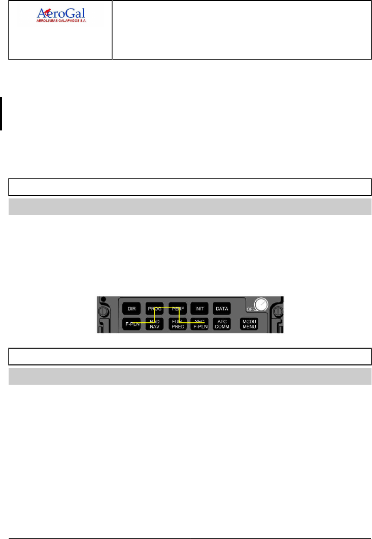
A318/A319/A320/A321
FLIGHT CREW
TECHNIQUES MANUAL
PROCEDURES
NORMAL PROCEDURES
STANDARD OPERATING PROCEDURES - DESCENT PREPARATION
GLG A318/A319/A320/A321 FLEET PR-NP-SOP-160 P 28/30
FCTM ← C to E 05 SEP 17
In this example, ΔLD = 1230 - 1090 = 140 m.
DETERMINE THE LANDING DISTANCE WITH SEVERAL FAILURES (LD)
To determine the landing distance with several failures LD , add the landing distance calculated
from the failure with the greatest impact LDG DIST to the effect of the other failure ΔLD.
In this example, LD = LDG DIST + ΔLD = 1420 + 140 = 1 560 m.
In this example, FLD = 1.15 x 1560 = 1 794 m.
The flight crew must also multiply the FLD by the landing penalty factor specified in the MEL, if
any.
APPROACH PREPARATION
Ident.: PR-NP-SOP-160-00018872.0001001 / 20 MAR 17
Applicable to: ALL
The flight crew should obtain the latest information for landing (weather, runway state, braking action,
etc, ...) at the latest 15 min prior to descent. The flight crew should check the landing performance
(VAPP , Landing distance) and the PF should program the FMGS for the descent and arrival. The
fuel predictions are accurate if the F-PLN is correctly entered in terms of arrival, go-around and
alternate routing.
The PF should program the FMGS applying the following sequence:
BRAKES OXIDATION
Ident.: PR-NP-SOP-160-00020780.0001001 / 20 MAR 17
Applicable to: ALL
Two different factors affect the life of carbon brakes:
‐ The wear of the disks
‐ The oxidation of the disks.
The oxidation may degrade rapidly the carbon brakes and may cause the rupture of a brake disk.
The main cause of oxidation is the repetitive high temperature of the brakes (particularly above
400 °C). Therefore, the flight crew should preferably use autobrake LO when performance permits.

A318/A319/A320/A321
FLIGHT CREW
TECHNIQUES MANUAL
PROCEDURES
NORMAL PROCEDURES
STANDARD OPERATING PROCEDURES - DESCENT PREPARATION
GLG A318/A319/A320/A321 FLEET PR-NP-SOP-160 P 29/30
FCTM F → 05 SEP 17
APPROACH BRIEFING
Ident.: PR-NP-SOP-160-00018873.0001001 / 25 JUL 17
Applicable to: ALL
6The main objective of the approach briefing is for the PF to inform the PM of his intended course
of action for the approach. The briefing should be practical and relevant to the actual weather
conditions expected. It should be concise and conducted in a logical manner. It should be given at a
time of low workload if possible, to enable the crew to concentrate on the content. It is very important
that any misunderstandings are resolved at this time.
Before starting an approach, the flight crew must brief again any change to the procedure initially
planned during descent preparation (in particular changes to lateral, vertical and go around
trajectory).
PF briefing Associated cross check
Aircraft type and technical status
NOTAM
Weather
‐ Accessibility
‐ Runway in use
Fuel
‐ Extra fuel FUEL PRED page
Descent
‐ TOD (time, position)
‐ MORA , STAR , MSA
‐ Altitude and speed constraints
F-PLN page
F-PLN page
Holding
(if expected)
‐ Entry in holding pattern
‐ MHA and MAX speed
Approach
‐ Approach type
‐ Altitude and final descent point identification
‐ Glide path
‐ Minima
‐ Missed approach procedure
‐ Alternate considerations
‐ Management of degraded navigation
‐ PERF APPR and ND
‐ F-PLN
‐ PFD /FMA
‐ PERF APPR
‐ F-PLN
‐ F-PLN
Continued on the following page
A318/A319/A320/A321
FLIGHT CREW
TECHNIQUES MANUAL
PROCEDURES
NORMAL PROCEDURES
STANDARD OPERATING PROCEDURES - DESCENT PREPARATION
GLG A318/A319/A320/A321 FLEET PR-NP-SOP-160 P 30/30
FCTM ← F 05 SEP 17
Continued from the previous page
PF briefing Associated cross check
Landing
‐ Runway data: length, surface (smooth, grooved or
porous), runway condition (contaminant type and depth),
Braking action if available, expected wind
‐ Landing Performance consideration versus runway data
‐ Tail strike awareness
‐ Use of autobrake (mode, manual take over)
‐ Use of reverses (IDLE, Max)
‐ Expected taxi route
Radio aids
RAD NAV
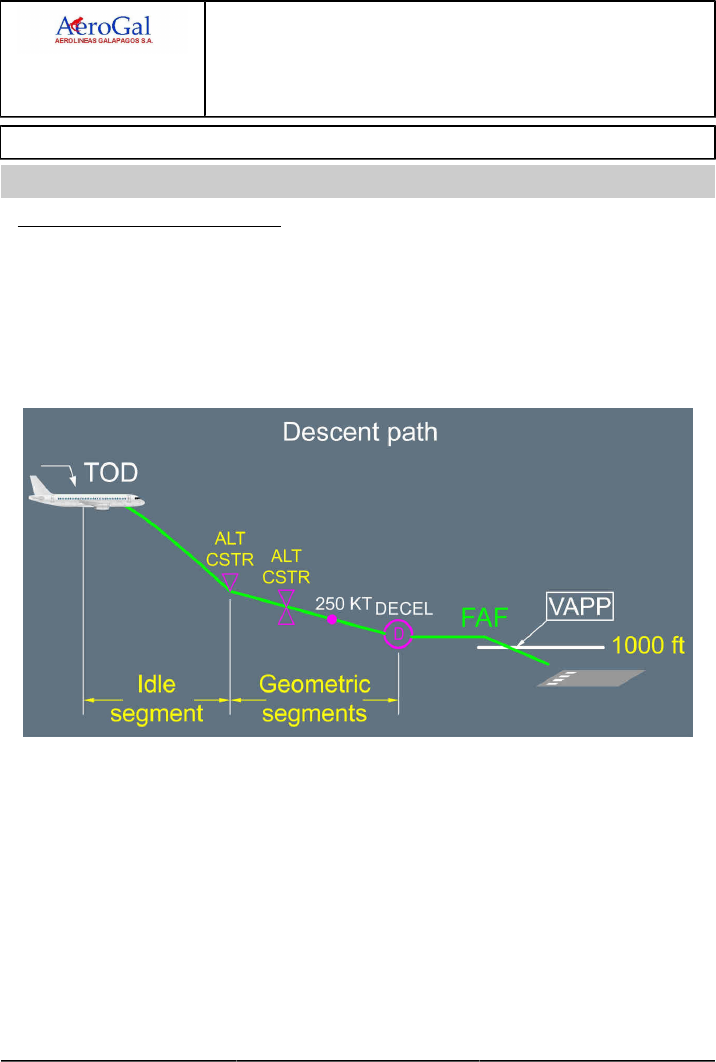
A318/A319/A320/A321
FLIGHT CREW
TECHNIQUES MANUAL
PROCEDURES
NORMAL PROCEDURES
STANDARD OPERATING PROCEDURES - DESCENT
GLG A318/A319/A320/A321 FLEET PR-NP-SOP-170 P 1/6
FCTM A → 05 SEP 17
COMPUTATION PRINCIPLES
Ident.: PR-NP-SOP-170-00018923.0001001 / 20 MAR 17
Applicable to: ALL
TOD AND PROFILE COMPUTATION
The FMGS calculates the Top Of Descent point (TOD ) backwards from a position 1 000 ft on
the final approach with speed at VAPP . It takes into account any descent speed and altitude
constraints and assumes managed speed is used. The first segment of the descent will always be
idle segment until the first altitude constraint is reached. Subsequent segments will be "geometric",
i.e. the descent will be flown at a specific angle, taking into account any subsequent constraints. If
the STAR includes a holding pattern, it is not considered for TOD or fuel computation. The TOD is
displayed on the ND track as a white symbol:
The idle segment assumes a given managed speed flown with idle thrust plus a small amount of
thrust. This gives some flexibility to keep the aircraft on the descent path if engine anti-ice is used
or if winds vary.
With Descent Profile Optimization option (DPO ), the idle segment assumes a given managed
speed flown at idle thrust. This gives less flexibility to keep the aircraft on the descent path if
engine anti-ice is used or if winds vary. In case of use of engine anti-ice or increased tailwind, the
use of speed brakes may be required to go back on the descent path.
The TOD computed by the FMS is quite reliable provided the flight plan is properly documented
down to the approach.
A318/A319/A320/A321
FLIGHT CREW
TECHNIQUES MANUAL
PROCEDURES
NORMAL PROCEDURES
STANDARD OPERATING PROCEDURES - DESCENT
GLG A318/A319/A320/A321 FLEET PR-NP-SOP-170 P 2/6
FCTM ← A to B → 05 SEP 17
MANAGED DESCENT SPEED PROFILE
The managed speed is equal to:
‐ The ECON speed (which may have been modified by the crew on the PERF DES page, before
entering DESCENT phase), or
‐ The speed constraint or limit when applicable.
GUIDANCE AND MONITORING
Ident.: PR-NP-SOP-170-00018924.0001001 / 25 JUL 17
Applicable to: ALL
1INTRODUCTION
To carry out the descent, the crew can use either the managed descent mode (DES ) or the
selected descent modes (OP DES or V/S). Both descent modes can be flown either with selected
speed or managed speed.
The modes and monitoring means are actually linked.
The managed DES mode guides the aircraft along the FMS pre-computed descent profile, as
long as it flies along the lateral F-PLN : i.e. DES mode is available if NAV is engaged. As a general
rule when DES mode is used, the descent is monitored using VDEV called "yoyo" on PFD , or its
digital value on the PROG page, as well as the level arrow on the ND.
The selected OP DES or V/S modes are used when HDG is selected or when ALT CSTR may
be disregarded or for various tactical purposes. As a general rule when OP DES or V/S modes
are used, the descent is monitored using the Energy Circle, (displayed if HDG or TRK modes and
indicating the required distance to descend, decelerate and land from present position) and the
level arrow on the ND . When the aircraft is not far away from the lateral F-PLN (small XTK ), the
yoyo on PFD is also a good indicator.
2MANAGED DESCENT MODE
The managed descent profile from high altitude is approximately 2.5 °.
As an estimation of the distance to touchdown is required to enable descent profile monitoring, it
is important to ensure that the MCDU F-PLN plan page reflects the expected approach routing.
Any gross errors noted in the descent profile are usually a result of incorrect routing entered in the
MCDU or non-sequencing of F-PLN waypoints, giving a false distance to touchdown.
DESCENT INITIATION
To initiate a managed descent, the pilot will set the ATC cleared altitude on the FCU and push
the ALT selector. DES mode engages and is annunciated on the FMA . If an early descent
were required by ATC , DES mode would give 1 000 ft/min rate of descent, until regaining the
computed profile.
To avoid overshooting the computed descent path, it is preferable to push the FCU ALT selector
a few miles prior to the calculated TOD. This method will ensure a controlled entry into the

A318/A319/A320/A321
FLIGHT CREW
TECHNIQUES MANUAL
PROCEDURES
NORMAL PROCEDURES
STANDARD OPERATING PROCEDURES - DESCENT
GLG A318/A319/A320/A321 FLEET PR-NP-SOP-170 P 3/6
FCTM ← B → 05 SEP 17
descent and is particularly useful in situations of high cruise Mach number or strong upper
winds.
If the descent is delayed, a "DECELERATE" or "T/D REACHED" message appears in white
on the PFD and in amber on the MCDU . Speed should be reduced towards green dot, and
when cleared for descent, the pilot will push for DES and push for managed speed. The speed
reduction prior to descent will enable the aircraft to recover the computed profile more quickly as
it accelerates to the managed descent speed.
DESCENT PROFILE
When DES with managed speed is engaged, the AP /FD guides the aircraft along the
pre-computed descent path determined by a number of factors such as altitude constraints,
wind and descent speed. However, as the actual conditions may differ from those planned, the
DES mode operates within a 20 kt speed range around the managed target speed to maintain
the descent path.
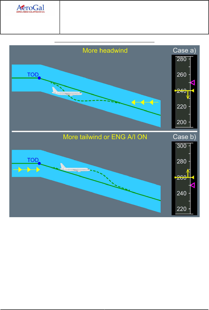
A318/A319/A320/A321
FLIGHT CREW
TECHNIQUES MANUAL
PROCEDURES
NORMAL PROCEDURES
STANDARD OPERATING PROCEDURES - DESCENT
GLG A318/A319/A320/A321 FLEET PR-NP-SOP-170 P 4/6
FCTM ← B → 05 SEP 17
Managed Descent: Speed Target Range Principle
If the aircraft gets high on the computed descent path:
‐ The speed will increase towards the upper limit of the speed range, to keep the aircraft on
the path with IDLE thrust.
‐ If the speed reaches the upper limit, THR IDLE is maintained, but the autopilot does not
allow the speed to increase any more, thus the VDEV will slowly increase.
‐ A path intercept point, which assumes half speedbrake extension, will be displayed on
the ND descent track.
‐ If speed brakes are not extended, the intercept point will move forward. If it gets close
to an altitude-constrained waypoint, then a message "AIR BRAKES" or "MORE DRAG",
depending of the FMGS standard, will be displayed on the PFD and MCDU.
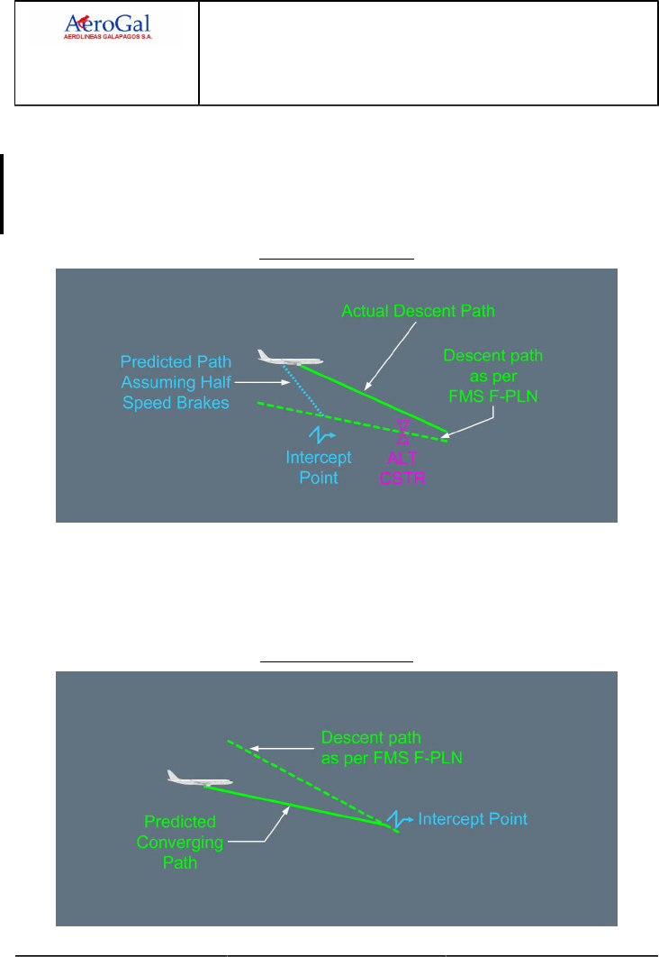
A318/A319/A320/A321
FLIGHT CREW
TECHNIQUES MANUAL
PROCEDURES
NORMAL PROCEDURES
STANDARD OPERATING PROCEDURES - DESCENT
GLG A318/A319/A320/A321 FLEET PR-NP-SOP-170 P 5/6
FCTM ← B → 05 SEP 17
This technique allows an altitude constraint to be matched with minimum use of
speedbrakes.
When regaining the descent profile, the speedbrakes should be retracted to prevent the
A/THR applying thrust against speedbrakes. If the speedbrakes are not retracted, the "SPD
BRK " message on the ECAM memo becomes amber and "RETRACT SPEEDBRAKES" is
displayed in white on the PFD.
A/C Above Descent Path
If the aircraft gets low on the computed descent path:
The speed will decrease towards the lower limit of the speed range with idle thrust. When
the lower speed limit is reached the A/THR will revert to SPEED/MACH mode and apply
thrust to maintain the descent path at this lower speed. The path intercept point will be
displayed on the ND, to indicate where the descent profile will be regained.
A/C Below Descent Path

A318/A319/A320/A321
FLIGHT CREW
TECHNIQUES MANUAL
PROCEDURES
NORMAL PROCEDURES
STANDARD OPERATING PROCEDURES - DESCENT
GLG A318/A319/A320/A321 FLEET PR-NP-SOP-170 P 6/6
FCTM ← B 05 SEP 17
If selected speed is used:
The descent profile remains unchanged. As the selected speed may differ from the speed
taken into account for pre-computed descent profile and speed deviation range does not
apply, the aircraft may deviate from the descent profile e.g. if the pilot selects 275 kt with a
pre-computed descent profile assuming managed speed 300 kt, VDEV will increase.
SELECTED DESCENT
There are 2 modes for flying a selected descent, namely OP DES and V/S. These modes will be
used for pilot tactical interventions.
V/S mode is automatically selected when HDG or TRK mode is selected by the pilot, while in DES
mode. Furthermore, in HDG or TRK mode, only V/S or OP DES modes are available for descent.
To initiate a selected descent, the pilot should set the ATC cleared altitude on the FCU and pull
the ALT selector. OP DES mode engages and is annunciated on the FMA . In OP DES mode, the
A/THR commands THR IDLE and the speed is controlled by the THS.
Speed may be either managed or selected. In managed speed, the descent speed is displayed
only as a magenta target but there is no longer a speed target range since the pre-computed flight
profile does not apply.
The AP /FD will not consider any MCDU descent altitude constraints and will fly an unrestricted
descent down to the FCU selected altitude.
If the crew wishes to increase the rate of descent, OP DES mode can be used, selecting a higher
speed. Speedbrake is very effective in increasing descent rate but should be used with caution at
high altitude due to the associated increase in VLS.
If the pilot wishes to shallow the descent path, V/S can be used. A/THR reverts to SPEED mode.
In this configuration, the use of speedbrakes is not recommended to reduce speed, since this
would lead to thrust increase and the speed would be maintained.

A318/A319/A320/A321
FLIGHT CREW
TECHNIQUES MANUAL
PROCEDURES
NORMAL PROCEDURES
STANDARD OPERATING PROCEDURES - HOLDING
GLG A318/A319/A320/A321 FLEET PR-NP-SOP-180 P 1/2
FCTM A to B → 05 SEP 17
HOLDING SPEED AND CONFIGURATION
Ident.: PR-NP-SOP-180-00018934.0001001 / 20 MAR 17
Applicable to: ALL
Whenever holding is anticipated, it is preferable to maintain cruise level and reduce speed to green
dot, with ATC clearance, to minimize the holding requirement. As a rule of thumb, a M 0.05 decrease
during 1 h equates to 4 min hold. However, other operational constraints might make this option
inappropriate.
A holding pattern can be inserted at any point in the flight plan or may be included as part of the
STAR. In either case, the holding pattern can be modified by the crew.
If a hold is to be flown, provided NAV mode is engaged and the speed is managed, an automatic
speed reduction will occur to achieve the hold speed when entering the holding pattern.
The default hold speed is the lowest of the following:
‐ Maximum Endurance speed
‐ ICAO limit holding speed
‐ Speed constraint (if any).
When no specific speed limit applies, the default hold speed is the Maximum Endurance speed,
which is approximately equal to Green Dot and provides the lowest hourly fuel consumption.
If the Maximum Endurance speed is greater than the ICAO or state maximum holding speed, the
crew should select flap 1 below 20 000 ft and fly S speed. Fuel consumption will be increased when
holding in anything other than clean configuration and Maximum Endurance speed.
IN THE HOLDING PATTERN
Ident.: PR-NP-SOP-180-00018935.0001001 / 25 JUL 17
Applicable to: ALL
1The holding pattern is not included in the descent path computation since the FMGS does not know
how many patterns will be flown. When the holding fix is sequenced, the FMGS assumes that only
one holding pattern will be flown and updates predictions accordingly. Once in the holding pattern,
the VDEV indicates the vertical deviation between current aircraft altitude and the altitude at which
the aircraft should cross the exit fix in order to be on the descent profile.
The DES mode guides the aircraft down at -1 000 ft/min whilst in the holding pattern until reaching
the cleared altitude or altitude constraint.
When in the holding pattern, LAST EXIT UTC /FUEL information is displayed on the MCDU HOLD
page. These predictions are based upon the fuel policy requirements specified on the MCDU FUEL

A318/A319/A320/A321
FLIGHT CREW
TECHNIQUES MANUAL
PROCEDURES
NORMAL PROCEDURES
STANDARD OPERATING PROCEDURES - HOLDING
GLG A318/A319/A320/A321 FLEET PR-NP-SOP-180 P 2/2
FCTM ← B 05 SEP 17
PRED page with no extra fuel, assuming the aircraft will divert. The crew should be aware that this
information is computed with defined assumptions e.g.:
‐ Aircraft weight being equal to landing weight at primary destination
‐ Flight at FL 220 if distance to ALTN is less than 200 NM, otherwise FL 310 performed at maximum
range speed.
‐ Constant wind (as entered in alternate field of the DES WIND page).
‐ Constant delta ISA (equal to delta ISA at primary destination)
‐ Airway distance for a company route, otherwise direct distance.
Alternate airport may be modified using the MCDU ALTN airport page which can be accessed by a
lateral revision at destination.
To exit the holding pattern, the crew should select either:
‐ IMM EXIT (The aircraft will return immediately to the hold fix, exit the holding pattern and resume
its navigation), or
‐ HDG if radar vectors, or
‐ DIR TO if radar vectors.
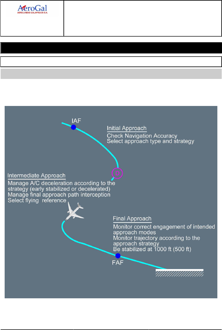
A318/A319/A320/A321
FLIGHT CREW
TECHNIQUES MANUAL
PROCEDURES
NORMAL PROCEDURES
STANDARD OPERATING PROCEDURES - APPROACH
GLG A318/A319/A320/A321 FLEET PR-NP-SOP-190-GEN P 1/2
FCTM A 22 MAR 17
General
INTRODUCTION
Ident.: PR-NP-SOP-190-GEN-00016386.0001001 / 20 MAR 17
Applicable to: ALL
All approaches are divided into three parts (i.e initial, intermediate and final) where the flight crew
should perform associated configuration management and guidance management.
Techniques, which apply to specific approach types are covered in the appropriate chapters.

A318/A319/A320/A321
FLIGHT CREW
TECHNIQUES MANUAL
PROCEDURES
NORMAL PROCEDURES
STANDARD OPERATING PROCEDURES - APPROACH
GLG A318/A319/A320/A321 FLEET PR-NP-SOP-190-GEN P 2/2
FCTM B 22 MAR 17
DISCONTINUED APPROACH
Ident.: PR-NP-SOP-190-GEN-00016390.0001001 / 20 MAR 17
Applicable to: ALL
The discontinued approach is an alternative technique to the GO AROUND procedure to interrupt an
approach when the aircraft is at or above the selected FCU altitude.
Contrary to the GO AROUND procedure, the discontinued approach technique does not require the
flight crew to set the thrust levers to TOGA detent.
The flight crew should initiate the discontinued approach technique with the callout: “CANCEL
APPROACH”.
The first action of the flight crew is to disengage and disarm any AP /FD approach mode, by pressing
on the APPR pb or LOC pb.

A318/A319/A320/A321
FLIGHT CREW
TECHNIQUES MANUAL
PROCEDURES
NORMAL PROCEDURES
STANDARD OPERATING PROCEDURES - APPROACH
GLG A318/A319/A320/A321 FLEET PR-NP-SOP-190-CONF P 1/6
FCTM A → 05 SEP 17
Configuration Management
INITIAL APPROACH
Applicable to: ALL
Ident.: PR-NP-SOP-190-CONF-A-00018950.0004001 / 25 JUL 17
1F-PLN SEQUENCING
When in NAV mode, the F-PLN will sequence automatically. In HDG /TRK mode, the F-PLN
waypoints will sequence automatically only if the aircraft flies close to the planned route. Correct
F-PLN sequencing is important to ensure that the planned missed approach route is available
in case of go-around and to ensure correct predictions. A good cue to monitor the proper F-PLN
sequencing is the TO waypoint on the upper right side of the ND, which should remain meaningful.
If ATC provides radar vectors and automatic waypoint sequencing does not occur, the flight crew
should use the DIR TO RADIAL IN function, or delete the FROM waypoint on the F-PLN page until
the next likely waypoint to be overflown is displayed as the TO waypoint on the ND. This ensures:
‐ A proper F-PLN sequencing
‐ A comprehensive ND display
‐ An assistance for lateral interception
‐ The VDEV to be computed on reasonable distance assumptions.
However, considerations should be given the following:
‐ A radial is to be inserted in the MCDU. In the following example, the final approach course is
90 ° corresponding to radial 270 °.
‐ DIR TO RADIAL IN must not be used beyond the Final Descent Point, in order to ensure that
the vertical profile in final is unchanged.
‐ Using DIR TO or DIR TO RADIAL IN function arms the NAV mode. If NAV mode is not
appropriate, the flight crew will pull the HDG knob to disarm it.
‐ Deceleration will not occur automatically as long as lateral mode is HDG.
The flight crew should sequence the F-PLN first, and then press the APPR pb. When the LOC
mode (or F-LOC mode for aircraft fitted with FLS ) is armed or engaged, the flight crew should not
perform a DIR TO , in order to sequence the F-PLN as this will result in the FMGS to revert to the
NAV mode. In this case, the LOC mode (or F-LOC mode for aircraft fitted with FLS) will have to be
re-armed and re-engaged, increasing workload unduly.
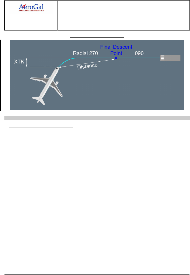
A318/A319/A320/A321
FLIGHT CREW
TECHNIQUES MANUAL
PROCEDURES
NORMAL PROCEDURES
STANDARD OPERATING PROCEDURES - APPROACH
GLG A318/A319/A320/A321 FLEET PR-NP-SOP-190-CONF P 2/6
FCTM ← A → 05 SEP 17
Use of DIR TO radial in facility
Ident.: PR-NP-SOP-190-CONF-A-00018951.0001001 / 20 MAR 17
APPROACH PHASE ACTIVATION
Activation of the approach phase will initiate a deceleration towards VAPP or the speed constraint
inserted at the Final Descent Point (FDP).
When in NAV mode with managed speed, the approach phase activates automatically when
sequencing the deceleration pseudo-waypoint. If an early deceleration is required, the approach
phase can be activated on the MCDU PERF APPR page. When the approach phase is activated,
the magenta target speed becomes VAPP.
When in HDG mode, e.g. for radar vectoring, the crew will activate the approach phase manually.
APPROACH SPEED TECHNIQUE
There are two approach techniques:
‐ Decelerated approach
‐ Early stabilized approach.
DECELERATED APPROACH
This technique refers to an approach where the aircraft reaches 1 000 ft in the landing
configuration at VAPP . In most cases, this equates to the aircraft being in CONF 1 and at S
speed at the FDP. This is the preferred technique for an approach using vertical managed
guidance. The deceleration pseudo waypoint assumes a decelerated approach technique.
EARLY STABILIZED APPROACH
This technique refers to an approach where the aircraft reaches the FDP in the landing
configuration at VAPP . This technique is recommended for non-precision approaches
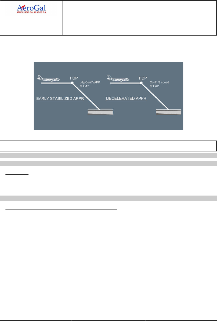
A318/A319/A320/A321
FLIGHT CREW
TECHNIQUES MANUAL
PROCEDURES
NORMAL PROCEDURES
STANDARD OPERATING PROCEDURES - APPROACH
GLG A318/A319/A320/A321 FLEET PR-NP-SOP-190-CONF P 3/6
FCTM ← A to B → 05 SEP 17
(LOC FPA , NAV FPA and TRK FPA ). To get a valuable deceleration pseudo waypoint and to
ensure a timely deceleration, the pilot should enter VAPP as a speed constraint at the FDP.
Early Stabilized versus Decelerated Approach
INTERMEDIATE APPROACH
Applicable to: ALL
Ident.: PR-NP-SOP-190-CONF-B-00018952.0001001 / 20 MAR 17
GENERAL
The purpose of the intermediate approach is to bring the aircraft at the proper speed, altitude and
configuration at FDP.
Ident.: PR-NP-SOP-190-CONF-B-00018953.0001001 / 20 MAR 17
DECELERATION AND CONFIGURATION CHANGE
Managed speed is recommended for the approach. Once the approach phase has been activated,
the A/THR will guide aircraft speed towards the maneuvering speed of the current configuration,
whenever higher than VAPP , e.g. green dot for CONF 0, S speed for CONF 1 etc.
To achieve a constant deceleration and to minimize thrust variation, the crew should extend the
next configuration when reaching the current configuration maneuvering speed +10 kt (IAS must
be lower than VFE next), e.g. when the speed reaches green dot +10 kt, the crew should select
CONF 1. Using this technique, the mean deceleration rate will be approximately 10 kt/NM in level
flight. This deceleration rate will be twice i.e. 20 kt/NM, with the use of the speedbrakes.
If selected speed is to be used to comply with ATC , the requested speed should be selected on
the FCU . A speed below the manoeuvring speed of the present configuration may be selected
provided it is above VLS . When the ATC speed constraint no longer applies, the pilot should push
the FCU speed selector to resume managed speed.

A318/A319/A320/A321
FLIGHT CREW
TECHNIQUES MANUAL
PROCEDURES
NORMAL PROCEDURES
STANDARD OPERATING PROCEDURES - APPROACH
GLG A318/A319/A320/A321 FLEET PR-NP-SOP-190-CONF P 4/6
FCTM ← B to C → 05 SEP 17
When flying the intermediate approach in selected speed, the crew will activate the approach
phase. This will ensure further proper speed deceleration when resuming managed speed;
otherwise the aircraft will accelerate to the previous applicable descent phase speed.
In certain circumstances, e.g. tail wind or high weight, the deceleration rate may be insufficient.
In this case, the landing gear may be lowered, preferably below 220 kt (to avoid gear doors
overstress), and before selection of Flap 2. Speedbrakes can also be used to increase the
deceleration rate but the crew should be aware of:
‐ The increase in VLS with the use of speedbrakes
‐ The limited effect at low speeds
‐ The speed brake auto-retraction when selecting CONF FULL (A319, A320) or CONF 3 (A321
only) There is no speed brake auto-retraction on A318.
FINAL APPROACH
Applicable to: ALL
Ident.: PR-NP-SOP-190-CONF-C-00018957.0001001 / 20 MAR 17
USE OF A/THR
The flight crew should use the A/THR for approaches as it provides accurate speed control. The
PF should keep the hand on the thrust levers so as to be prepared to react if needed.
During final approach, the managed target speed moves along the speed scale as a function of
wind variation. If ATC gives a new wind for landing, the flight crew will update it on MCDU PERF
APPR page.
The flight crew should ideally check the reasonableness of the target speed by referring to GS on
the top left on ND . If the A/THR performance is unsatisfactory, the PF should disconnect it and
control the thrust manually.
If the PF uses manual thrust for landing, he/she should disconnect the A/THR at 1 000 ft AAL at
the latest.
Ident.: PR-NP-SOP-190-CONF-C-00018958.0001001 / 20 MAR 17
TRAJECTORY STABILIZATION
The first prerequisite for safe final approach and landing is to stabilize the aircraft as per criteria
given in the FCOM (Refer to FCOM/PRO-NOR-SOP-18-A Stabilization Criteria).
If, for any reason, one flight parameter deviates from stabilized conditions, the PM will make a
callout.

A318/A319/A320/A321
FLIGHT CREW
TECHNIQUES MANUAL
PROCEDURES
NORMAL PROCEDURES
STANDARD OPERATING PROCEDURES - APPROACH
GLG A318/A319/A320/A321 FLEET PR-NP-SOP-190-CONF P 5/6
FCTM ← C 05 SEP 17
Following a PM flight parameter exceedance call out, the suitable PF response will be:
‐ Acknowledge the PM callout, for proper crew coordination purposes
‐ Take immediate corrective action to control the exceeded parameter back into the defined
stabilized conditions
‐ Assess whether stabilized conditions will be recovered early enough prior to landing, otherwise
initiate a go-around.
Ident.: PR-NP-SOP-190-CONF-C-00019361.0001001 / 20 MAR 17
AP DISCONNECTION
During the final approach with the AP engaged, the aircraft will be stabilized. Therefore, when
disconnecting the AP for a manual landing, the pilot should avoid the temptation to make large
inputs on the sidestick.
The pilot should disconnect the autopilot early enough to resume manual control of the aircraft and
to evaluate the drift before flare. During crosswind conditions, the pilot should avoid any tendency
to drift downwind.
Some common errors include:
‐ Descending below the final path, and/or
‐ reducing the drift too early.

A318/A319/A320/A321
FLIGHT CREW
TECHNIQUES MANUAL
PROCEDURES
NORMAL PROCEDURES
STANDARD OPERATING PROCEDURES - APPROACH
Intentionally left blank
GLG A318/A319/A320/A321 FLEET PR-NP-SOP-190-CONF P 6/6
FCTM 05 SEP 17
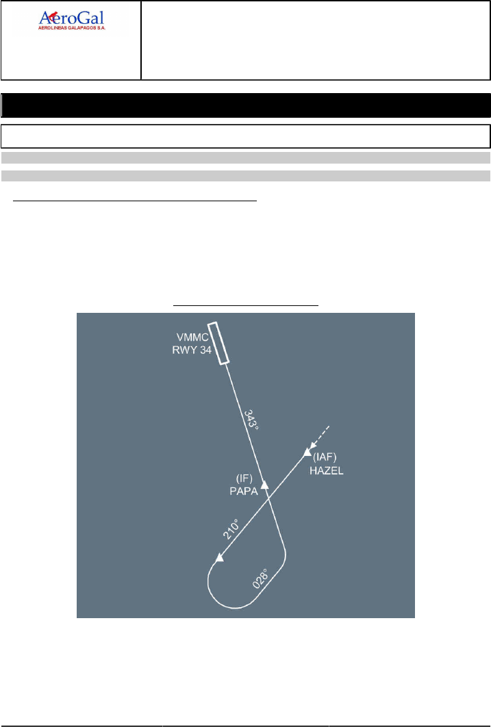
A318/A319/A320/A321
FLIGHT CREW
TECHNIQUES MANUAL
PROCEDURES
NORMAL PROCEDURES
STANDARD OPERATING PROCEDURES - APPROACH
GLG A318/A319/A320/A321 FLEET PR-NP-SOP-190-GUI P 1/24
FCTM A → 05 SEP 17
Guidance Management
APPROACH USING LOC G/S GUIDANCE
Applicable to: ALL
Ident.: PR-NP-SOP-190-GUI-A-00019357.0001001 / 20 MAR 17
INTERCEPTION OF FINAL APPROACH COURSE
When cleared for the ILS and when on the intercept trajectory for the LOC , the flight crew should
press the APPR pb. This arms the approach modes, and LOC and GS are displayed in blue on the
FMA . At this stage, the second AP, if available, should be selected.
In the example below, if the ATC clears the aircraft for the procedure at HAZEL, the flight crew
must delay the push on the APPR pb, as the aircraft is not on the intercept trajectory for the LOC:
VMMC ILS RWY34 via HAZEL
If the ATC clears for a LOC capture only, the flight crew will press the LOC pb-sw on the FCU.
If the ATC clears for approach at a significant distance, e.g. 30 NM, the flight crew should be
aware that the G/S may be perturbed and CAT 1 will be displayed on FMA till a valid Radio
Altimeter signal is received.

A318/A319/A320/A321
FLIGHT CREW
TECHNIQUES MANUAL
PROCEDURES
NORMAL PROCEDURES
STANDARD OPERATING PROCEDURES - APPROACH
GLG A318/A319/A320/A321 FLEET PR-NP-SOP-190-GUI P 2/24
FCTM ← A to B → 05 SEP 17
Ident.: PR-NP-SOP-190-GUI-A-00019358.0001001 / 20 MAR 17
GLIDE SLOPE INTERCEPTION FROM ABOVE
The following procedure should only be applied when established on the localizer. There are a
number of factors which might lead to a glide slope interception from above. In such a case, the
flight crew must react without delay to meet the stabilization criteria.
In order to get the best rate of descent when cleared by ATC and below the limiting speeds, the
flight crew should lower the landing gear and select flaps as required (at least CONF 2 should
be selected to ensure that the aircraft speed will not increase). Speedbrakes may also be used,
noting the considerations detailed in the subsection "Deceleration and configuration change"
earlier in this chapter.
When cleared to intercept the glide slope, the flight crew should:
‐ Press the APPR pb on FCU and confirm G/S is armed,
‐ Select the FCU altitude above aircraft altitude to avoid unwanted ALT*,
‐ Select V/S 1 500 ft/min initially. V/S in excess of 2 000 ft/min will result in the speed increasing
towards VFE.
Use V/S rather than OP DES to ensure that the A/THR is in SPEED mode rather than IDLE mode.
The flight crew should carefully monitor the rate of descent to avoid exceeding VFE . When
approaching the G/S path, G/S* will engage. The flight crew should monitor the G/S capture with
raw data (pitch and G/S deviation). The go-around altitude should be set on the FCU at G/S*.
APPROACH USING LOC G/S FOR CATII CATIII
Applicable to: ALL
Ident.: PR-NP-SOP-190-GUI-B-00019399.0001001 / 20 MAR 17
CAT II and CAT III approaches are flown to very low DH (or without DH ) with very low RVR . The
guidance of the aircraft on the ILS beam and the guidance of the aircraft speed must be consistently
of high performance and accurate so that an automatic landing and roll out can be performed in good
conditions and, the acquisition of visual cues is achieved and the aircraft properly stabilized. Hence,
‐ The automatic landing is required in CAT III operations including roll out in CAT IIIB.
‐ The automatic landing is the preferred landing technique in CAT II conditions
‐ Any failures of the automated systems shall not significantly affect the aircraft automatic landing
system performance
‐ The crew procedures and task sharing allow to rapidly detect any anomaly and thus lead to the
right decision

A318/A319/A320/A321
FLIGHT CREW
TECHNIQUES MANUAL
PROCEDURES
NORMAL PROCEDURES
STANDARD OPERATING PROCEDURES - APPROACH
GLG A318/A319/A320/A321 FLEET PR-NP-SOP-190-GUI P 3/24
FCTM ← B → 05 SEP 17
Ident.: PR-NP-SOP-190-GUI-B-00019400.0001001 / 20 MAR 17
DEFINITION
DECISION HEIGHT
The Decision Height (DH ) is the wheel height above the runway elevation by which a go around
must be initiated unless appropriate visual reference has been established and the aircraft
position and the approach path have been assessed as satisfactory to continue the automatic
approach and landing safely. The DH is based on RA.
ALERT HEIGHT
The Alert Height (AH) is the height above the runway, based on the characteristics of the
aeroplane and its fail-operational automatic landing system, above which a CATIII approach
would be discontinued and a missed approach initiated if a failure occurred in one of the
redundant parts of the automatic landing system, or in the relevant ground equipment.
In others AH definition, it is generally stated that if a failure affecting the fail-operational criteria
occurs below the AH, it would be ignored and the approach continued (except if AUTOLAND
warning is triggered). The AH concept is relevant when CAT 3 DUAL is displayed on FMA.
On single aisle Airbus family, the AH =100 ft.
CAT 3 SINGLE
CAT 3 SINGLE is announced when the airborne systems are fail passive which means that a
single failure will lead to the AP disconnection without any significant out of trim condition or
deviation of the flight path or attitude. Manual flight is then required. This minimum DH is 50 ft.
CAT 3 DUAL
CAT 3 DUAL is announced when the airborne systems are fail-operational. In case of a
single failure, the AP will continue to guide the aircraft on the flight path and the automatic
landing system will operate as a fail-passive system. In the event of a failure below the AH, the
approach, flare and landing can be completed by the remaining part of the automatic system. In
that case, no capability degradation is indicated. Such a redundancy allows CAT III operations
with or without DH.
Ident.: PR-NP-SOP-190-GUI-B-00019401.0001001 / 20 MAR 17
FLIGHT PREPARATION
In addition to the normal flight preparation, the following preparation must be performed when CAT
II or CAT III approach is planned:
‐ Ensure that destination airport meets CAT II or CAT III requirements
‐ Check aircraft required equipment for CAT 2 or CAT 3 in QRH
‐ Check that crew qualification is current

A318/A319/A320/A321
FLIGHT CREW
TECHNIQUES MANUAL
PROCEDURES
NORMAL PROCEDURES
STANDARD OPERATING PROCEDURES - APPROACH
GLG A318/A319/A320/A321 FLEET PR-NP-SOP-190-GUI P 4/24
FCTM ← B → 05 SEP 17
‐ Consider extra fuel for possible approach delay
‐ Consider weather at alternate
Ident.: PR-NP-SOP-190-GUI-B-00019402.0001001 / 20 MAR 17
APPROACH PREPARATION
LIMITATIONS
‐ The crew will check that tower wind remains within the limit for CAT II or CAT III approaches
(Refer to FCOM/LIM-AFS-20 Maximum Wind Conditions for ILS/MLS (If Installed) CAT II or
CAT III and for GLS (If Installed) CAT I)
‐ The autoland maximum altitude must be observed.
AIRCRAFT CAPABILITY
The failures that may affect the aircraft's CAT 2 or CAT 3 capability are listed in the QRH . Most
of these failures are monitored by the FMGS and the landing capability will be displayed on the
FMA once the APPR pb is pressed, i.e. CAT 2, CAT 3 SINGLE, CAT 3 DUAL. However, there
are a number of failures which affect the aircraft's landing capability which are not monitored
by the FMGS and, consequently, not reflected on the FMA. It is very important, therefore, that
the crew refer to the QRH to establish the actual landing capability if some equipment are listed
inoperative.
AIRPORT FACILITIES
The airport authorities are responsible for establishing and maintaining the equipment required
for CAT II/III approach and landing. The airport authorities will activate the LVP procedures as
the need arises based on RVR . Prior to planning a CAT II/III approach, the crew must ensure
that LVP are in force.
CREW QUALIFICATION
The captain must ensure that both crew members are qualified and that their qualification is
current for the planned approach.
SEATING POSITION
The crew must realise the importance of eye position during low visibility approaches and
landing. A too low seat position may greatly reduce the visual segment. When the eye reference
position is lower than intended, the visual segment is further reduced by the cut-off angle of the
glareshield or nose. As a rule of thumb, an incorrect seating position which reduces the cut-off
angle by 1 ° reduces the visual segment by approximately 10 m (30 ft).
A318/A319/A320/A321
FLIGHT CREW
TECHNIQUES MANUAL
PROCEDURES
NORMAL PROCEDURES
STANDARD OPERATING PROCEDURES - APPROACH
GLG A318/A319/A320/A321 FLEET PR-NP-SOP-190-GUI P 5/24
FCTM ← B → 05 SEP 17
USE OF LANDING LIGHTS
The use of landing lights at night in low visibility can be detrimental to the acquisition of visual
reference. Reflected lights from water droplets or snow may actually reduce visibility. The
landing lights would, therefore, not normally be used in CAT II/III weather conditions.
APPROACH STRATEGY
Regardless of the actual weather conditions, the crew should plan the approach using the
best approach capability. This would normally be CAT 3 DUAL with autoland, depending upon
aircraft status. The crew should then assess the weather with respect to possible downgrade
capability.
CAT IIIConditions CAT I CAT II
WITH DH NO DH
Flying technique Manual flying or
AP /FD , A/THR
AP /FD , A/THR
down to DH
AP /FD/ATHR and Autoland
Minima & weather DA (DH) Baro ref Visibility DH with RA
RVR
Autoland Possible with precautions Recommended Mandatory
GO AROUND STRATEGY
The crew must be ready mentally for go-around at any stage of the approach. Should a
failure occur above 1 000 ft RA , all ECAM actions (and DH amendment if required) should be
completed before reaching 1 000 ft RA, otherwise a go-around should be initiated. This ensures
proper task sharing for the remainder of the approach.
APPROACH BRIEFING
Before commencing a CAT II/III approach a number of factors must be considered by the crew.
In addition to the standard approach briefing, the following points should be emphasised during
an approach briefing for a low visibility approach:
‐ Aircraft capability
‐ Airport facilities
‐ Crew qualification
‐ Weather minima
‐ Task sharing
‐ Call-outs
‐ Go-around strategy

A318/A319/A320/A321
FLIGHT CREW
TECHNIQUES MANUAL
PROCEDURES
NORMAL PROCEDURES
STANDARD OPERATING PROCEDURES - APPROACH
GLG A318/A319/A320/A321 FLEET PR-NP-SOP-190-GUI P 6/24
FCTM ← B → 05 SEP 17
Ident.: PR-NP-SOP-190-GUI-B-00019403.0001001 / 31 AUG 17
1APPROACH PROCEDURE
TASK SHARING
The workload is distributed in such a way that the PF primary tasks are supervising and
decision making and the PM primary task is monitoring the operation of the automatic system.
PF Tasks
The PF supervises the approach (trajectory, attitude, speed) and takes appropriate decision
at DH or in case of failure.
Since the approach is flown with AP /FD /A-THR, the PF must be continuously ready to
take-over:
‐ If any AP hard over is experienced
‐ If a major failure occurs
‐ If any doubt arises.
The PF announces "LAND ", when displayed on FMA.
PM Tasks
For aircraft without HUD or with single HUD , the PM is head down throughout the automatic
approach and automatic landing.
For aircraft with DUAL HUD , the PM may be head up or head down.
The PM monitors:
‐ The FMA and calls all mode changes below 350 ft as required (i.e. after PF calls "LAND")
‐ The Auto call out
‐ The aircraft trajectory or attitude exceedance
‐ Any failures.
The PM should be go-around minded.
SOME SYSTEM PARTICULARS
‐ Below 700 ft RA , data coming from the FMS is frozen e.g.: ILS tune inhibit.
‐ Below 400 ft RA , the FCU is frozen.
‐ At 350 ft, LAND must be displayed on FMA. This ensures correct final approach guidance.
‐ Below 200 ft, the AUTOLAND red light illuminates if:
• Both APs trip off
• Excessive beam deviation is sensed
• Localizer or glide slope transmitter or receiver fails
• A RA discrepancy of at least 15 ft is sensed.

A318/A319/A320/A321
FLIGHT CREW
TECHNIQUES MANUAL
PROCEDURES
NORMAL PROCEDURES
STANDARD OPERATING PROCEDURES - APPROACH
GLG A318/A319/A320/A321 FLEET PR-NP-SOP-190-GUI P 7/24
FCTM ← B → 05 SEP 17
‐ Flare comes at or below 40 ft
‐ THR IDLE comes at or below 30 ft
‐ RETARD auto call out comes at 10 ft for autoland as an order (Instead of 20 ft for manual
landing as a reminder).
VISUAL REFERENCE
Approaching the DH , the PF starts to look for visual references, progressively increasing
external scanning. It should be stressed that the DH is the lower limit of the decision zone.
The captain should come to this zone prepared for a go-around but with no pre-established
judgement.
Required conditions to continue:
‐ With DH:
In CAT II operations, the conditions required at DH to continue the approach are that the
visual references should be appropriate to monitor the continued approach and landing
and that the flight path should be acceptable. If both these conditions are not satisfied, it is
mandatory to initiate a go-around.
In CAT III operations, the condition required at DH is that there should be visual references
which confirm that the aircraft is over the touch down zone. Go-around is mandatory if the
visual references do not confirm this.
‐ Without DH:
The decision to continue does not depend on visual references, even though a minimum
RVR is specified. The decision depends only on the operational status of the aircraft and
ground equipment. If a failure occurs prior to reaching the AH, a go-around will be initiated.
A go-around must nevertheless be performed if AUTOLAND warning is triggered below AH.
However, it is good airmanship for the PF to acquire visual cues during flare and to monitor
the roll out.
Loss of visual reference
‐ With DH before touch down:
If decision to continue has been made by DH and the visual references subsequently become
inappropriate a go-around must be initiated.
A late go-around may result in ground contact. If touch down occurs after TOGA is engaged,
the AP remains engaged in that mode and A/THR remains in TOGA. The ground spoilers and
auto-brake are inhibited.
‐ With DH or without DH after touch down:
If visual references are lost after touch down, a go-around should not be attempted. The
roll-out should be continued with AP in ROLL OUT mode down to taxi speed.

A318/A319/A320/A321
FLIGHT CREW
TECHNIQUES MANUAL
PROCEDURES
NORMAL PROCEDURES
STANDARD OPERATING PROCEDURES - APPROACH
GLG A318/A319/A320/A321 FLEET PR-NP-SOP-190-GUI P 8/24
FCTM ← B to C → 05 SEP 17
FLARE/LANDING/ROLL OUT
During the flare, decrab and roll-out, the PF will look outside to assess that the autoland is
properly carried out, considering the appropriate visual references.
For CAT II approaches, autoland is recommended. If manual landing is preferred, the PF will
take-over at 80 ft at the latest. This ensures a smooth transition for the manual landing.
Pull to REV MAX (or REV IDLE if conditions permits) at main landing gear touchdown (not
before).
The use of auto-brake is recommended as it ensures a symmetrical brake pressure application.
However, the crew should be aware of possible dissymmetry in case of crosswind and wet
runways.
The PM should make the standard callouts and advise ATC when the landing roll is completed.
Ident.: PR-NP-SOP-190-GUI-B-00019405.0001001 / 20 MAR 17
AUTOLAND IN CAT I OR BETTER WEATHER CONDITIONS
The flight crew may wish to practice automatic landings in CAT I or better weather conditions for
training purposes. This type of approach should be carried out only with the airline authorization.
The flight crew should be aware that fluctuations of the LOC and/or GS might occur due to the fact
that protection of ILS sensitive areas, which applies during LVP , will not necessarily be in force. It
is essential, therefore, that the PF is prepared to take over manually at any time during a practice
approach and rollout, should the performance of the AP become unsatisfactory.
APPROACH USING FINAL APP GUIDANCE
Ident.: PR-NP-SOP-190-GUI-D-00019391.0003001 / 25 JUL 17
Applicable to: ALL
2INTERCEPTION OF THE FINAL APPROACH COURSE
It is essential to have a correct F-PLN in order to ensure proper final approach guidance. Indeed
the NAV and APP NAV modes are always guiding the aircraft along the F-PLN active leg and the
managed vertical mode ensures VDEV =0, VDEV , being computed along the remaining F-PLN to
destination. Hence, the crew will monitor the proper sequencing of the F-PLN , more specifically
if HDG mode is selected, by checking that the TO WPT , on upper right hand corner of ND, is the
most probable one and meaningful.
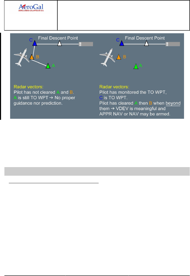
A318/A319/A320/A321
FLIGHT CREW
TECHNIQUES MANUAL
PROCEDURES
NORMAL PROCEDURES
STANDARD OPERATING PROCEDURES - APPROACH
GLG A318/A319/A320/A321 FLEET PR-NP-SOP-190-GUI P 9/24
FCTM ← C → 05 SEP 17
The flight crew can use the DIR TO RADIAL IN function to sequence the F-PLN.
When cleared for final approach course interception, the pilot should press the APPR p/b on
FCU . On the FMA , APP NAV mode becomes armed or engaged and FINAL mode becomes
armed. The VDEV or "brick" scale becomes active and represents the vertical deviation, which
may include a level segment. The VDEV /brick scale will only be displayed if ILS or LS pb is not
pressed. If the ILS or LS pb is pressed by mistake, the V/DEV will flash in amber on the PFD.
The final approach course interception will be monitored through applicable raw data.
Ident.: PR-NP-SOP-190-GUI-D-00019077.0001001 / 20 MAR 17
Applicable to: ALL
INTERCEPTION OF THE FINAL VERTICAL LEG
For a managed approach, FINAL APP becomes active and the FMS manages both lateral and
vertical guidance. The crew will monitor the final approach using:
‐ Start of descent blue symbol on ND
‐ FMA on PFD
‐ VDEV , XTK , F-PLN on ND with GPS PRIMARY
‐ VDEV , XTK , F-PLN confirmed by needles, distance/altitude.
If FINAL does not engage at the beginning of the final descent, the flight crew should consider
to interrupt the instrument approach procedure unless they can maintain visual references
throughout the approach.
In some NPA s, the final approach flies an "idle descent" segment from one altitude constraint to
another, followed by a level segment. This is materialized by a magenta level off symbol on ND
followed by a blue start of descent.
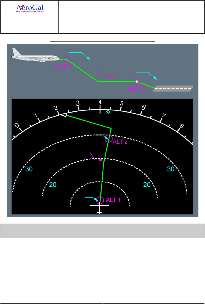
A318/A319/A320/A321
FLIGHT CREW
TECHNIQUES MANUAL
PROCEDURES
NORMAL PROCEDURES
STANDARD OPERATING PROCEDURES - APPROACH
GLG A318/A319/A320/A321 FLEET PR-NP-SOP-190-GUI P 10/24
FCTM ← C → 05 SEP 17
Final Approach Trajectory with Idle Descent Segment
Ident.: PR-NP-SOP-190-GUI-D-00020820.0006001 / 20 MAR 17
Criteria: 22-1315, 22-1359, P11856, SA
Applicable to: HC-CJM, HC-CJV, HC-CJW, HC-CKN, HC-CLF, HC-CSB
REACHING MINIMA
The applicable minima are those associated with the approach chart.
When the aircraft reaches the minima, the PM either monitors or announces “MINIMUM”.
The current altitude value becomes amber.
If the appropriate visual conditions are met at minima:
The flight crew can visually continue the approach.

A318/A319/A320/A321
FLIGHT CREW
TECHNIQUES MANUAL
PROCEDURES
NORMAL PROCEDURES
STANDARD OPERATING PROCEDURES - APPROACH
GLG A318/A319/A320/A321 FLEET PR-NP-SOP-190-GUI P 11/24
FCTM ← C → 05 SEP 17
Below minima:
When the FINAL APP mode is used for approach, the FDs provide lateral and vertical
managed guidance down to the MAP. The flight crew can keep the AP/FD engaged below
minima.
Keeping the AP/FD below minima when visual references are acquired is highly valuable
in the following conditions:
‐ High minima above ground level
‐ Marginal weather conditions.
However, the guidance may not be relevant especially in the following cases:
‐ MAP not at the RWY threshold and final segment not aligned with the runway track
(final segment does not cross the RWY threshold)
‐ Strong offset between final segment and runway track.
In such cases the AP/FD should be switched off and TRK FPA (bird) flying reference may
be used.
At the MAP or Minimum Use Height of the AP:
The FMS invalidates the vertical profile at the MAP. The FDs revert from FINAL APP to
HDG V/S mode.
Thus, the flight crew must disconnect the AP no later than the MAP or the Minimum Use
Height of AP , whichever occurs first (Refer to FCOM/LIM-AFS-10 Autopilot Function for
the Minimum Use Height of AP).
Switching OFF FDs and use of Bird after the MAP is at pilot discretion.
CAUTION ‐ Below minima, the visual references must be the primary references until
landing.
‐ From minima down to the MAP the FD provides an additional guidance.
The FD must be switched off if the guidance is not relevant or not followed.
‐ After the MAP , disregard the FD as it reverts to HDG V/S.
If the appropriate visual conditions are not met at minima:
The flight crew must initiate a missed approach.
Ident.: PR-NP-SOP-190-GUI-D-00020820.0003001 / 20 MAR 17
Criteria: 22-1315, SA
Applicable to: HC-CRU, HC-CSA, HC-CSF
REACHING MINIMA
The applicable minima are those associated with the approach chart.
When the aircraft reaches the minima, the PM either monitors or announces “MINIMUM”.
The current altitude value becomes amber.
If the appropriate visual conditions are met at minima:
The flight crew can visually continue the approach.

A318/A319/A320/A321
FLIGHT CREW
TECHNIQUES MANUAL
PROCEDURES
NORMAL PROCEDURES
STANDARD OPERATING PROCEDURES - APPROACH
GLG A318/A319/A320/A321 FLEET PR-NP-SOP-190-GUI P 12/24
FCTM ← C → 05 SEP 17
Below minima:
When the FINAL APP mode is used for approach, the FDs provide lateral and vertical
managed guidance down to the MAP. The flight crew can keep the AP/FD engaged below
minima.
Keeping the AP/FD below minima when visual references are acquired is highly valuable
in the following conditions:
‐ High minima above ground level
‐ Marginal weather conditions.
However, the guidance may not be relevant especially in the following cases:
‐ MAP not at the RWY threshold and final segment not aligned with the runway track
(final segment does not cross the RWY threshold)
‐ Strong offset between final segment and runway track.
In such cases the AP/FD should be switched off and TRK FPA (bird) flying reference may
be used.
At the MAP or Minimum Use Height of the AP:
The FMS invalidates the vertical profile at the MAP . The FDs revert from FINAL APP to
HDG V/S mode and the AP automatically disconnects.
Thus, the flight crew must disconnect the AP no later than the MAP or the Minimum Use
Height of AP , whichever occurs first (Refer to FCOM/LIM-AFS-10 Autopilot Function for
the Minimum Use Height of AP).
Switching OFF FDs and use of Bird after the MAP is at pilot discretion.
CAUTION ‐ Below minima, the visual references must be the primary references until
landing.
‐ From minima down to the MAP the FD provides an additional guidance.
The FD must be switched off if the guidance is not relevant or not followed.
‐ After the MAP , disregard the FD as it reverts to HDG V/S.
If the appropriate visual conditions are not met at minima:
The flight crew must initiate a missed approach.
Ident.: PR-NP-SOP-190-GUI-D-00019392.0001001 / 20 MAR 17
Applicable to: ALL
COLD WEATHER OPERATIONS
For all Non Precision Approaches, there is a minimum OAT . Below this temperature, the error on
the barometric altitude is no longer acceptable, and altitude should be corrected in temperature.
As it is not authorized to make these altitude corrections to the final approach segment of the FM
Flight Plan (F-PLN ) through the MCDU , it is not possible to use FINAL APP when OAT is below
this minimum OAT . The flight crew must then use selected vertical guidance. This minimum OAT

A318/A319/A320/A321
FLIGHT CREW
TECHNIQUES MANUAL
PROCEDURES
NORMAL PROCEDURES
STANDARD OPERATING PROCEDURES - APPROACH
GLG A318/A319/A320/A321 FLEET PR-NP-SOP-190-GUI P 13/24
FCTM ← C to D → 05 SEP 17
is indicated on the approach chart or must be defined by the operator based on the terrain profile
(plus adequate margin).
APPROACH USING FPA GUIDANCE
Applicable to: ALL
Ident.: PR-NP-SOP-190-GUI-E-00020344.0001001 / 20 MAR 17
GENERAL
This section deals with flying an approach with the FPA guidance.
The lateral guidance may be either managed or selected and the vertical guidance is FPA.
The use of AP is recommended for all approaches using FPA guidance as it reduces crew
workload and facilitates monitoring the procedure and flight path.
The following sections list some particularities of these approaches.
Ident.: PR-NP-SOP-190-GUI-E-00020352.0001001 / 20 MAR 17
INTERCEPTION OF THE FINAL APPROACH COURSE
When cleared for final approach course interception:
If NAV ACCURACY HIGH:
NAV mode can be used. Under radar vectoring, the crew should use the DIR TO FDP with
RADIAL INBD facility.
If NAV ACCURACY LOW:
Select appropriate TRK on FCU, in order to establish final course tracking with reference to
navaid raw data. When established on the final course, the selected track compensates for
drift.
The final approach course interception should be monitored through applicable raw data (ADF ,
VOR , LOC).
Ident.: PR-NP-SOP-190-GUI-E-00020343.0001001 / 20 MAR 17
INTERCEPTION OF THE FINAL VERTICAL LEG
As for intermediate approach, NAV mode can be used if NAV ACCURACY is HIGH, TRK mode
must be used if NAV ACCURACY is LOW.
The Final Path Angle (FPA ) should be preset on the FCU 1 NM prior to the FDP at the latest. A
smooth interception of the final approach path can be achieved by pulling the FPA selector 0.3 NM
prior to the FDP.
The vertical trajectory should be monitored with altitude/distance raw data.

A318/A319/A320/A321
FLIGHT CREW
TECHNIQUES MANUAL
PROCEDURES
NORMAL PROCEDURES
STANDARD OPERATING PROCEDURES - APPROACH
GLG A318/A319/A320/A321 FLEET PR-NP-SOP-190-GUI P 14/24
FCTM ← D → 05 SEP 17
Ident.: PR-NP-SOP-190-GUI-E-00020821.0001001 / 20 MAR 17
REACHING MINIMA
When approaching minima, the pilot flying should expand the instrument scan to include outside
visual cues.
If the required visual conditions are not met at minima, or are lost below minima, a missed
approach must be initiated.
Ident.: PR-NP-SOP-190-GUI-E-00019394.0001001 / 20 MAR 17
LOC ONLY, ILS G/S OUT
LOC ONLY approaches may be flown using the LOC signal for lateral navigation and FPA for
vertical guidance.
DESCENT (CROSSING FL100)
The flight crew will select LS p/b on the EFIS control panel.
INITIAL/INTERMEDIATE APPROACH
The flight crew will press LOC pb-sw on the FCU when cleared for approach and on the
intercept trajectory for the final approach course. The flight crew will monitor the LOC armed
mode and then LOC capture.
FINAL APPROACH
Approaching the point where the final descent starts, the flight crew will initiate the descent as
for approach using vertical selected guidance.
Ident.: PR-NP-SOP-190-GUI-E-00020342.0001001 / 25 JUL 17
3BACK COURSE LOCALIZER APPROACH
Back course localizer (LOC B/C ) approach consists in using the LOC signal of the opposite
runway for lateral approach management.
LOC B/C approach should be flown using the TRK mode for lateral guidance and the FPA mode
for vertical guidance. The approach is flown using the ND in ROSE LS/ILS mode as it shows the
correct LEFT/RIGHT information for the beam deviation.
The preferred technique is the early stabilized approach technique, using the AP /FD and A/THR.
APPROACH PREPARATION
The flight crew should manually enter the ILS in the MCDU RAD NAV page using:
‐ Either the IDENT (ILS stored in the FMS database). If RWY /ILS MISMATCH message is
triggered the flight crew can disregard it.
‐ Or the frequency (ILS not stored in the FMS database).
In both cases, the front course will be entered in the CRS field.
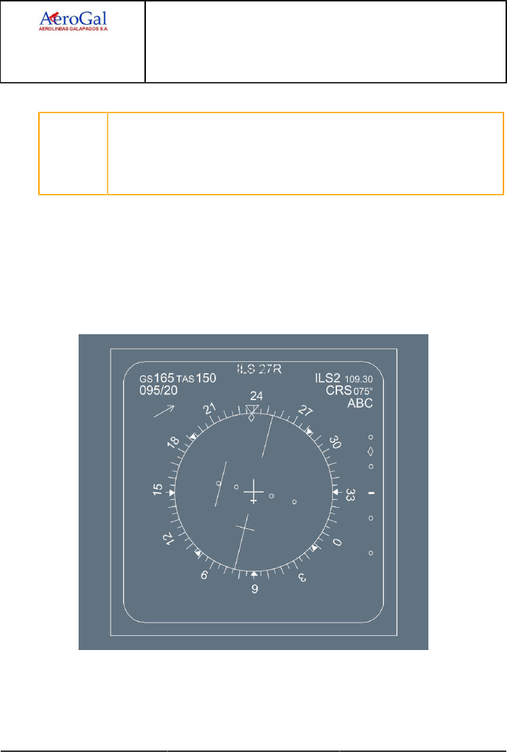
A318/A319/A320/A321
FLIGHT CREW
TECHNIQUES MANUAL
PROCEDURES
NORMAL PROCEDURES
STANDARD OPERATING PROCEDURES - APPROACH
GLG A318/A319/A320/A321 FLEET PR-NP-SOP-190-GUI P 15/24
FCTM ← D 05 SEP 17
DESCENT (CROSSING FL100)
CAUTION The flight crew must not select ILS via the ILS/LS pb: doing so makes the PFD
show reverse deviations.
The flight crew must not arm the LOC or APPR modes.
The flight crew must not select the LS pb on ISIS , since it displays the LOC
deviations in the wrong sense.
INITIAL / INTERMEDIATE APPROACH
The flight crew should:
‐ select the ND in ROSE ILS/LS mode on the EFIS control panel. The display shows the
correct LEFT/RIGHT information for the beam deviation.
‐ select the TRK /FPA flying reference (bird).
When clear for approach, the crew should intercept manually LOC B/C using the blue TRK
index with reference with LOC B/C lateral deviation on ND.
FINAL APPROACH
Approaching the Final Descent Point, the flight crew will select the FPA corresponding to the
final approach path.

A318/A319/A320/A321
FLIGHT CREW
TECHNIQUES MANUAL
PROCEDURES
NORMAL PROCEDURES
STANDARD OPERATING PROCEDURES - APPROACH
GLG A318/A319/A320/A321 FLEET PR-NP-SOP-190-GUI P 16/24
FCTM E → 05 SEP 17
CIRCLING APPROACH
Applicable to: ALL
Ident.: PR-NP-SOP-190-GUI-F-00019395.0001001 / 20 MAR 17
The circling approach is the visual phase of an instrument approach to bring an aircraft into position
for landing on a runway which is not suitably located for a straight-in approach (e.g. due to wind
conditions).
APPROACH PREPARATION
The flight crew performs the approach preparation before starting the descent, including
tuning of the reference navaids. They should include the following additional items in the FMS
programming:
F-PLN
Lateral: Enter STAR, instrument approach procedure, including the missed approach procedure
for instrument approach.
Vertical: Insert F speed as constraint at FAF since the circling approach will be flown in
configuration 3, landing gear down and F speed. Check altitude constraints.
SEC F-PLN
When planning for a circling approach, the landing runway will be inserted into the SEC F-PLN.
The crew will update the SEC F-PLN as follows:
‐ SEC F-PLN then COPY ACTIVE
‐ Lateral revision on destination and insert landing runway
‐ Keep the F-PLN discontinuity
APPROACH BRIEFING
The flight crew should perform the Approach Briefing with additional items specific to the circling
procedure:
‐ Circling minima as published on the Approach chart or as per Company Operations Manual
‐ Direction of circling, if restricted according to the Approach chart, e.g. due to terrain. It is
preferable that PF should be on the same side as the direction of circling, e.g. for circling to the
left, PF should be CM1
‐ Significant obstacles in airport vicinity
‐ Technique to be used (e.g. AP and A/THR , FPV) and configuration
‐ Action in the case of loss of visual references.
FINAL INSTRUMENT APPROACH
The flight crew flies a stabilized approach at F speed, configuration 3 and landing gear down.

A318/A319/A320/A321
FLIGHT CREW
TECHNIQUES MANUAL
PROCEDURES
NORMAL PROCEDURES
STANDARD OPERATING PROCEDURES - APPROACH
GLG A318/A319/A320/A321 FLEET PR-NP-SOP-190-GUI P 17/24
FCTM ← E → 05 SEP 17
The flight crew can perform the LANDING C/L except the FLAPS for landing. They will check the
configuration for landing during the final turn.
CIRCLING APPROACH
CAUTION The flight crew must conduct the flight within the circling area, while maintaining
required visual references at all times.
The following can be used to assist the flight crew in the circling approach pattern:
‐ Selected modes with AP are recommended. Waypoints can be entered before the approach
to assist the flight crew in the circling approach pattern. However, they must not fly this pattern
with AP engaged in NAV mode
‐ The ND in ROSE mode with a low range can be used for situational awareness
‐ In support to the timing technique, the flight crew should initiate the base turn when the aircraft
is approximately on the 45 ° angle of the runway threshold.
Note: The circling area which ensures obstacle clearance is based on a maximum speed of
180 kt for Category C aircraft. Maintaining F speed during the circling procedure ensures
that the aircraft remains within the safe circling area. In regions where FAA TERPS
criteria apply, the circling areas and limit speeds are more restrictive. Therefore, in these
regions, refer to the Company SOPs.
At the Circling MDA(H) at the latest:
‐ Perform a level off
At MAP, if the flight crew finds no visual reference:
‐ Initiate a go-around
When required conditions for circling are satisfied:
‐ Select TRK -FPA
‐ Preselect a track of 45 ° away from the final approach course (or as required by the published
procedure)
‐ When wings level, start the chrono
‐ After approximately 30 s select the downwind track parallel to the landing runway
‐ At any time in the downwind leg, activate the SEC F-PLN to display the landing runway and to
take credit of the ground speed mini function in final approach when managed speed is used.
Nevertheless, the flight crew should avoid a too early activation of the SEC F-PLN in order to
keep the missed approach procedure of the instrument approach within the FMS if a go-around
is necessary.
‐ When the aircraft is abeam the runway threshold, start the CHRONO. The time from abeam
threshold to the beginning of the base turn depends on the height above touchdown:
Approximately 3 s /100 ft.
‐ Disconnect the AP and remove the FD s at the latest before starting the descent toward the
runway. Keep the A/THR.

A318/A319/A320/A321
FLIGHT CREW
TECHNIQUES MANUAL
PROCEDURES
NORMAL PROCEDURES
STANDARD OPERATING PROCEDURES - APPROACH
GLG A318/A319/A320/A321 FLEET PR-NP-SOP-190-GUI P 18/24
FCTM ← E → 05 SEP 17
‐ To perform the final turn, initially maintain 25 ° bank angle and maintain the altitude until the
visual references for the intended runway are distinctly visible and identifiable
‐ Set the landing configuration when appropriate, but ensure early stabilization in final
‐ When the aircraft is fully configured for landing, complete LANDING checklist.
If, at any time during the circling procedure, the required visual references are lost, the main
objective is to climb and to leave the circling area into the missed approach of the initial instrument
approach, while remaining within the obstacle-free area, unless otherwise specified.
When the SEC F-PLN is activated, the go-around procedure in the FMS is associated with the
landing runway, and not with the instrument approach. Therefore, if visual references are lost
during the circling approach, the flight crew should fly the go-around using selected guidance,
following the pre-briefed missed approach procedure, unless otherwise specified.
For circling approach with one engine inoperative, Refer to PR-AEP-ENG One Engine Inoperative
- Circling.
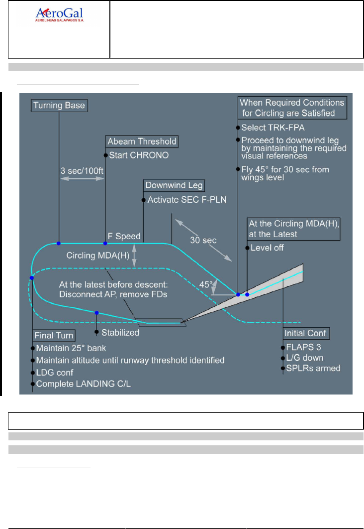
A318/A319/A320/A321
FLIGHT CREW
TECHNIQUES MANUAL
PROCEDURES
NORMAL PROCEDURES
STANDARD OPERATING PROCEDURES - APPROACH
GLG A318/A319/A320/A321 FLEET PR-NP-SOP-190-GUI P 19/24
FCTM ← E to F → 05 SEP 17
Ident.: PR-NP-SOP-190-GUI-F-00019396.0001001 / 11 JUL 17
4CIRCLING APPROACH PATTERN
VISUAL APPROACH
Applicable to: ALL
Ident.: PR-NP-SOP-190-GUI-G-00019397.0002001 / 20 MAR 17
INITIAL APPROACH
The flight crew must keep in mind that the pattern is flown visually. However, the cross track error
on ND is a good cue of the aircraft lateral position versus the runway centerline. This indication

A318/A319/A320/A321
FLIGHT CREW
TECHNIQUES MANUAL
PROCEDURES
NORMAL PROCEDURES
STANDARD OPERATING PROCEDURES - APPROACH
GLG A318/A319/A320/A321 FLEET PR-NP-SOP-190-GUI P 20/24
FCTM ← F → 05 SEP 17
can be obtained when performing a DIR TO radial inbound on the last available waypoint,
positionned on the extended runway centerline.
The flight crew will aim to get the following configuration at beginning of the downwind leg:
‐ Both AP and FDs will be selected off
‐ BIRD ON
‐ A/THR confirmed active in speed mode, i.e. SPEED on the FMA
‐ Managed speed will be used to enable the "GS mini" function
‐ The downwind track will be selected on the FCU to assist in downwind tracking
‐ The downwind track altitude will be set on FCU.
Ident.: PR-NP-SOP-190-GUI-G-00019398.0001001 / 20 MAR 17
INTERMEDIATE / FINAL APPROACH
Assuming a 1 500 ft AAL circuit, the base turn should be commenced 45 s after passing abeam
the downwind threshold (3 s/100 ft +/- 1 s/1 kt of head/downwind).
The final turn onto the runway centreline will be commenced with 20 ° angle of bank. Initially the
rate of descent should be 400 ft/min, increasing to 700 ft/min when established on the correct
descent path
The pilot will aim to be configured for landing at VAPP by 500 ft AAL, at the latest. If not stabilised,
a go-around must be carried out.
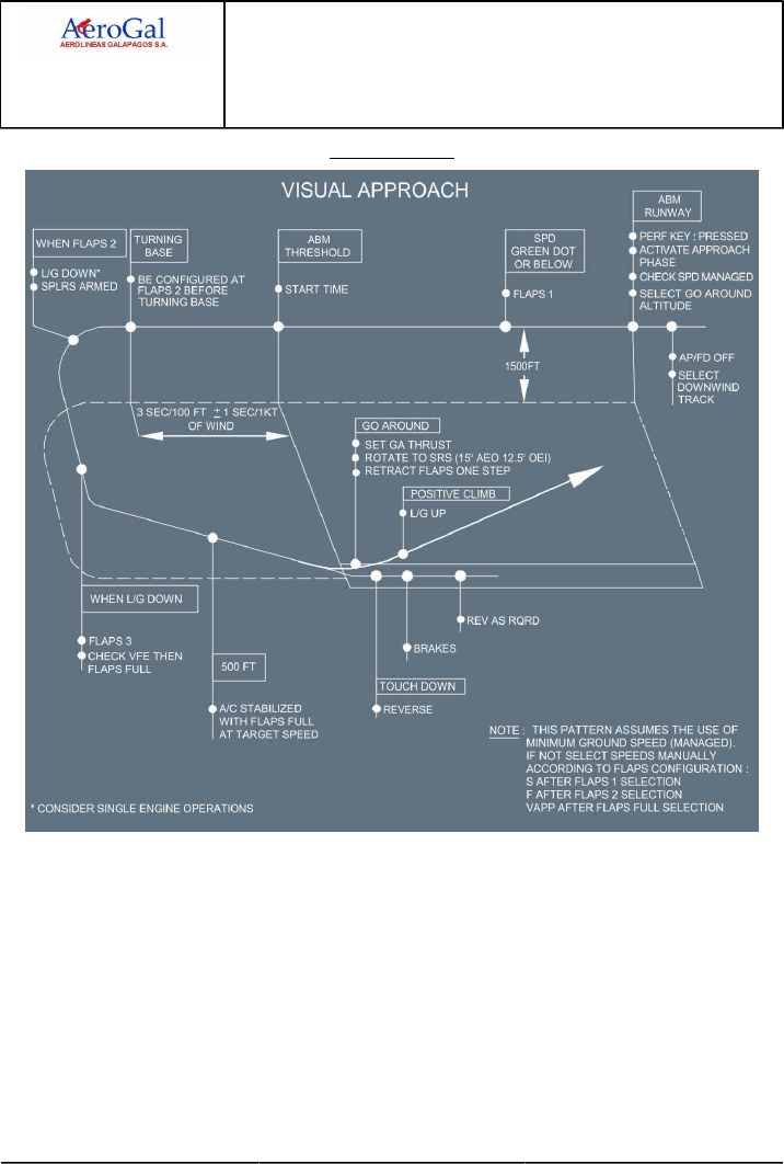
A318/A319/A320/A321
FLIGHT CREW
TECHNIQUES MANUAL
PROCEDURES
NORMAL PROCEDURES
STANDARD OPERATING PROCEDURES - APPROACH
GLG A318/A319/A320/A321 FLEET PR-NP-SOP-190-GUI P 21/24
FCTM ← F → 05 SEP 17
Visual Approach
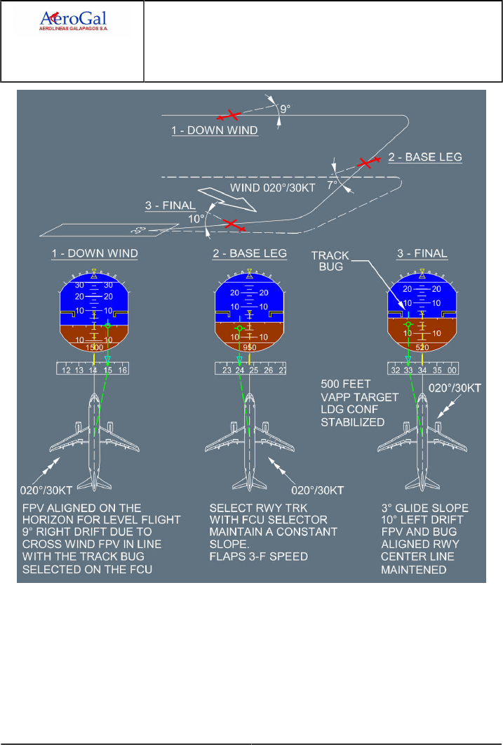
A318/A319/A320/A321
FLIGHT CREW
TECHNIQUES MANUAL
PROCEDURES
NORMAL PROCEDURES
STANDARD OPERATING PROCEDURES - APPROACH
GLG A318/A319/A320/A321 FLEET PR-NP-SOP-190-GUI P 22/24
FCTM ← F → 05 SEP 17
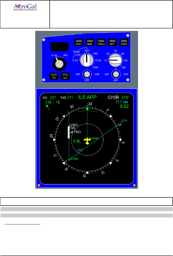
A318/A319/A320/A321
FLIGHT CREW
TECHNIQUES MANUAL
PROCEDURES
NORMAL PROCEDURES
STANDARD OPERATING PROCEDURES - APPROACH
GLG A318/A319/A320/A321 FLEET PR-NP-SOP-190-GUI P 23/24
FCTM ← F to G → 05 SEP 17
ILS RAW DATA
Applicable to: ALL
Ident.: PR-NP-SOP-190-GUI-H-00019380.0001001 / 20 MAR 17
INITIAL APPROACH
FLYING REFERENCE
The "bird" is to be used as the flying reference.
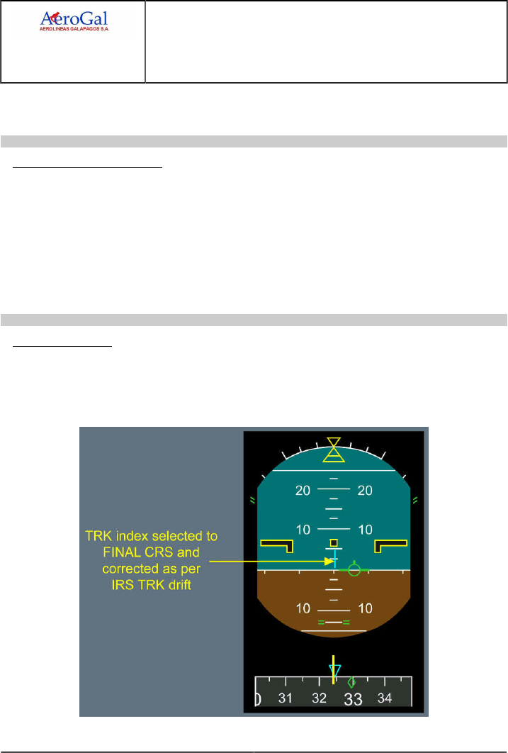
A318/A319/A320/A321
FLIGHT CREW
TECHNIQUES MANUAL
PROCEDURES
NORMAL PROCEDURES
STANDARD OPERATING PROCEDURES - APPROACH
GLG A318/A319/A320/A321 FLEET PR-NP-SOP-190-GUI P 24/24
FCTM ← G 05 SEP 17
APPROACH PHASE ACTIVATION
The approach technique is the early stabilized approach.
Ident.: PR-NP-SOP-190-GUI-H-00019381.0001001 / 20 MAR 17
INTERMEDIATE APPROACH
The TRK index will be set to the ILS course and, once established on the LOC , the tail of the bird
should be coincident with the TRK index. This method allows accurate LOC tracking taking into
account the drift.
Should the LOC deviate, the pilot will fly the bird in the direction of the LOC index, and when
re-established on the LOC , set the tail of the bird on the TRK index again. If there is further LOC
deviation, check unwanted residual bank angle. Also a slight IRS drift should be suspected as the
bird is computed out of IRS data.
The ILS course pointer and the TRK diamond are also displayed on PFD compass.
Ident.: PR-NP-SOP-190-GUI-H-00019382.0001001 / 20 MAR 17
FINAL APPROACH
When ½ dot below the G/S , the pilot should initiate the interception of the G/S by smoothly flying
the FPV down to the glide path angle. Should the G/S deviate, the pilot will make small corrections
in the direction of the deviation and when re-established on the G/S , reset the bird to the G/S
angle.

A318/A319/A320/A321
FLIGHT CREW
TECHNIQUES MANUAL
PROCEDURES
NORMAL PROCEDURES
STANDARD OPERATING PROCEDURES - LANDING
GLG A318/A319/A320/A321 FLEET PR-NP-SOP-250 P 1/16
FCTM A to C → 19 JUN 17
APPROACH AND LANDING TECHNIQUES
Ident.: PR-NP-SOP-250-00020010.0001001 / 20 MAR 17
Applicable to: ALL
A stabilized approach is essential for achieving successful landings. It is imperative that the flare
height be reached at the appropriate airspeed and flight path angle. The A/THR and FPV are
effective aids to the pilot.
VAPP should be determined with the wind corrections by using the FMGS functions. As a reminder,
when the aircraft is close to the ground, the wind intensity tends to decrease and the wind direction
to turn (direction in degrees decreasing in the northern latitudes). Both effects may reduce the head
wind component close to the ground and the wind correction to VAPP is there to compensate for this
effect.
When the aircraft is close to the ground, high sink rate should be avoided, even in an attempt to
maintain a close tracking of the glideslope. Priority should be given to the attitude and sink rate. If a
normal touchdown distance is not possible, a go-around should be performed.
If the aircraft has reached the flare height at VAPP , with a stabilized flight path angle, the normal
SOP landing technique will lead to the right touchdown attitude and airspeed.
During the flare, the pilot should not concentrate on the airspeed, but only on the attitude with
external cues.
Specific PM call outs have been reinforced for excessive pitch attitude at landing.
TRANSITION TO VISUAL REFERENCES
Ident.: PR-NP-SOP-250-00020016.0001001 / 20 MAR 17
Applicable to: ALL
When Transitioning from IMC to VMC , the crew will watch the bird versus the aircraft attitude symbol
in the center of the PFD. This provides a good assessment of the drift, thus in which direction to look
for the runway.
But, then:
‐ Do not turn towards the runway
‐ Do not duck under.
FLARE AND TOUCHDOWN
Ident.: PR-NP-SOP-250-00020012.0001001 / 20 MAR 17
Applicable to: ALL
PITCH CONTROL
When reaching 50 ft, auto-trim ceases and the pitch law is modified to flare law. Indeed, the
normal pitch law, which provides trajectory stability, is not the best adapted to the flare manoeuvre.
The system memorizes the attitude at 50 ft, and that attitude becomes the initial reference for

A318/A319/A320/A321
FLIGHT CREW
TECHNIQUES MANUAL
PROCEDURES
NORMAL PROCEDURES
STANDARD OPERATING PROCEDURES - LANDING
GLG A318/A319/A320/A321 FLEET PR-NP-SOP-250 P 2/16
FCTM ← C → 19 JUN 17
pitch attitude control. As the aircraft descends through 30 ft, the system begins to reduce the
pitch attitude to -2 °nose down over a period of 8 s. Consequently, the pilot will have to move the
stick rearwards, so as to reproduce conventional aircraft aerodynamic characteristics. The flare
technique is thus very conventional.
Prior to flare, avoid destabilization of the approach and steepening the slope at low heights in
attempts to target a shorter touchdown. If a normal touchdown point cannot be achieved or if
destabilization occurs just prior to flare, a go-around (or rejected landing) should be performed.
The PM monitors the rate of descent and should call "SINK RATE" if the vertical speed is
excessive prior to the flare.
From stabilized conditions, the flare height is about 30 ft.
This height varies due to the range of typical operational conditions that can directly influence the
rate of descent.
Compared to typical sea level flare heights for flat and adequate runway lengths, pilot need to be
aware of factors that will require an earlier flare, in particular:
‐ High airport elevation.
Increased altitude will result in higher ground speeds during approach with associated increase
in descent rates to maintain the approach slope.
‐ Steeper approach slope (compared to nominal 3 °).
‐ Tailwind.
Increased tailwind will result in higher ground speed during approach with associated increase
in descent rates to maintain the approach slope.
‐ Increasing runway slope.
Increasing runway slope and/or rising terrain in front of the runway will affect the radio height
callouts down to over flying the threshold used by the flight crew to assess the height for the
start of flare possibly causing flare inputs to be late. The visual misperception of being high is
also likely.
Note that the cumulative effect of any of the above factors combined for one approach will require
even more anticipation to perform an earlier flare.
If the flare is initiated too late then the pitch changes will not have sufficient time to allow the
necessary change to aircraft trajectory. Late, weak or released flare inputs increase the risk of a
hard landing.
Avoid under flaring.
‐ The rate of descent must be controlled prior to the initiation of the flare (rate not increasing)
‐ Start the flare with positive ( or "prompt") backpressure on the sidestick and holding as
necessary
‐ Avoid forward stick movement once Flare initiated (releasing back-pressure is acceptable)
At 20 ft, the "RETARD" auto call-out reminds the pilot to retard thrust levers. It is a reminder rather
than an order. When best adapted, the pilot will rapidly retard all thrust levers: depending on the

A318/A319/A320/A321
FLIGHT CREW
TECHNIQUES MANUAL
PROCEDURES
NORMAL PROCEDURES
STANDARD OPERATING PROCEDURES - LANDING
GLG A318/A319/A320/A321 FLEET PR-NP-SOP-250 P 3/16
FCTM ← C 19 JUN 17
conditions, the pilot will retard earlier or later. However, the pilot must ensure that all thrust levers
are at IDLE detent at the latest at touchdown, to ensure ground spoilers extension at touchdown.
In order to assess the rate of descent in the flare, and the aircraft position relative to the ground,
look well ahead of the aircraft. The typical pitch increment in the flare is approximately 4 °, which
leads to -1 ° flight path angle associated with a 10 kt speed decay in the manoeuvre. Do not allow
the aircraft to float or do not attempt to extend the flare by increasing pitch attitude in an attempt
to achieve a perfectly smooth touchdown. A prolonged float will increase both the landing distance
and the risk of tail strike.
After touch down, the pilot must "fly" the nosewheel smoothly, but without delay, on to the runway,
and must be ready to counteract any residual pitch up effect of the ground spoilers. However, the
main part of the spoiler pitch up effect is compensated by the flight control law itself.
It is not recommended to keep the nose high in order to increase aircraft drag during the initial part
of the roll-out, as this technique is inefficient and increases the risk of tail strike. Furthermore, if
auto brake MED is used, it may lead to a hard nose gear touch down.
LATERAL AND DIRECTIONAL CONTROL
FINAL APPROACH
In crosswind conditions, a crabbed-approach wings-level should be flown with the aircraft
(cockpit) positioned on the extended runway centerline until the flare.
FLARE
The objectives of the lateral and directional control of the aircraft during the flare are:
‐ To land on the centerline, and
‐ to minimize the lateral loads on the main landing gear.
The recommended de-crab technique is to use all of the following:
‐ The rudder to align the aircraft with the runway heading during the flare
‐ The roll control, if needed, to maintain the aircraft on the runway centerline. Any tendency to
drift downwind should be counteracted by an appropriate lateral (roll) input on the sidestick.
In the case of strong crosswind, in the de-crab phase, the PF should be prepared to add
small bank angle into the wind in order to maintain the aircraft on the runway centerline. The
aircraft may be landed with a partial de-crab (residual crab angle up to about 5 °) to prevent an
excessive bank. This technique prevents wingtip/sharklet (or engine nacelle) strike caused by
an excessive bank angle.
As a consequence, this may result in touching down with some bank angle into the wind (hence
with the upwind landing gear first).

A318/A319/A320/A321
FLIGHT CREW
TECHNIQUES MANUAL
PROCEDURES
NORMAL PROCEDURES
STANDARD OPERATING PROCEDURES - LANDING
GLG A318/A319/A320/A321 FLEET PR-NP-SOP-250 P 4/16
FCTM D to E → 19 JUN 17
ROLLOUT
Ident.: PR-NP-SOP-250-00020015.0001001 / 20 MAR 17
Applicable to: ALL
NORMAL CONDITIONS
During the roll out, the rudder pedals will be used to steer the aircraft on the runway centreline.
At high speed, directional control is achieved with rudder. As the speed reduces, the Nose Wheel
Steering (NWS ) becomes active. However, the NWS tiller will not be used until taxi speed is
reached.
CROSSWIND CONDITIONS
The above-mentioned technique applies. Additionally, the pilot will avoid setting stick into the wind
as it increases the weathercock effect. Indeed, it creates a differential down force on the wheels
into the wind side.
The reversers have a destabilizing effect on the airflow around the rudder and thus decrease
the efficiency of the rudder. Furthermore they create a side force, in case of a remaining crab
angle, which increases the lateral skidding tendency of the aircraft. This adverse effect is quite
noticeable on contaminated runways with crosswind. In case a lateral control problem occurs in
high crosswind landing, the pilot will consider to set reversers back to Idle.
At lower speeds, the directional control of the aircraft is more problematic, more specifically
on wet and contaminated runways. Differential braking is to be used if necessary. On wet and
contaminated runways, the same braking effect may be reached with full or half deflection of the
pedals; additionally the anti skid system releases the brake pressure on both sides very early
when the pilot presses on the pedals. Thus if differential braking is to be used, the crew will totally
release the pedal on the opposite side to the expected turn direction.
For more information about rudder pedals recommendations, Refer to PR-NP-SOP-70 Seating
Position and Adjustment of Rudder Pedals
DECELERATION
Ident.: PR-NP-SOP-250-00020013.0002001 / 20 MAR 17
Criteria: 22-1559, SA
Applicable to: HC-CSB
Once on the ground, the importance of the timely use of all means of stopping the aircraft cannot be
overemphasised. Three systems are involved in braking once the aircraft is on the ground:
‐ The ground spoilers
‐ The thrust reversers
‐ The wheel brakes.
In the case of ROP alert, the flight crew must immediately apply the associated operating techniques
(Refer to AS-ROWROP Operating Techniques).

A318/A319/A320/A321
FLIGHT CREW
TECHNIQUES MANUAL
PROCEDURES
NORMAL PROCEDURES
STANDARD OPERATING PROCEDURES - LANDING
GLG A318/A319/A320/A321 FLEET PR-NP-SOP-250 P 5/16
FCTM ← E → 19 JUN 17
THE GROUND SPOILERS
When the aircraft touches down with at least one main landing gear and when at least one thrust
lever is in the reverse sector, the ground spoilers partially automatically deploy to ensure that the
aircraft is properly sit down on ground. Then, the ground spoilers automatically fully deploy. This is
the partial lift dumping function.
The ground spoilers contribute to aircraft deceleration by increasing aerodynamic drag at high
speed. Wheel braking efficiency is improved due to the increased load on the wheels. Additionally,
the ground spoiler extension signal is used for auto-brake activation.
REVERSE THRUST EFFICIENCY
Thrust reversers are more efficient at high speeds: The flight crew must select reverse thrust
immediately after main landing gear touchdown.
Below 70 kt, thrust reversers efficiency rapidly decreases. Below 60 kt with REV MAX selected,
engine stall may occur. Therefore, it is recommended to reduce the reverse thrust to REV IDLE at
70 kt, and keep REV IDLE until taxi speed. However in an emergency case, the flight crew must
keep REV MAX until full-stop of the aircraft.
At taxi speed, and not above, stow the thrust reversers before leaving the runway, in order to avoid
foreign object ingestion.
REVERSE THRUST SELECTION
The selection of REV MAX is the standard practice for landing.
LANDING ON DRY RUNWAYS
On DRY runways, the flight crew may select REV IDLE.
LANDING ON WET RUNWAYS
On WET runways, the flight crew may select REV IDLE, if all the conditions described in the
SOP DESCENT PREPARATION (Refer to FCOM/PRO-NOR-SOP-16 Descent Preparation -
General) are satisfied.
LANDING ON CONTAMINATED RUNWAYS
On contaminated runways, the flight crew must select REV MAX.

A318/A319/A320/A321
FLIGHT CREW
TECHNIQUES MANUAL
PROCEDURES
NORMAL PROCEDURES
STANDARD OPERATING PROCEDURES - LANDING
GLG A318/A319/A320/A321 FLEET PR-NP-SOP-250 P 6/16
FCTM ← E → 19 JUN 17
REMINDER ON LANDING DISTANCE COMPUTATION AT DISPATCH FOR DRY AND WET
RUNWAYS
DEFINITIONS
ALD : The Actual Landing Distance is the distance used on a dry runway from
the crossing of the runway threshold at 50 ft until full-stop of the aircraft,
using maximum manual braking. No reverse thrust is considered for
the calculation of the ALD. The ALD is demonstrated during flight test
campaign for certification purpose.
RLD dry : The Required Landing Distance on a dry runway is a factored ALD. The
factor is 1.67. (RLD dry = ALD x 1.67)
RLD wet : The Required Landing Distance on a wet runway is a factored ALD. The
factor is 1.92 (RLD wet = RLD dry x 1.15)
DISPATCH CONDITIONS
For landing distance computation at dispatch, the airline uses the RLD.
Landing distances computed at dispatch for wet runways provide only reduced margins in
comparison with landing distances achievable in operations with the use of REV IDLE. Sufficient
margins are restored when the flight crew uses REV MAX.
The runway slope is not considered for the landing distance computation at dispatch.
On a destination airport with multiple runways, the landing distance computation at dispatch
may be performed on the longest landing runway with no wind.
The expected landing runway may be used for the landing distance computation at dispatch
with forecast wind at landing. If the wind condition changes at landing, the flight crew must
perform a new landing distance computation.
LANDING WITH REV IDLE ON WET RUNWAYS
The landing distance computation at dispatch (RLD ) does not consider REV IDLE operation.
Therefore, it is necessary to perform a computation to consider REV IDLE operation, as
described in the SOP DESCENT PREPARATION (Refer to FCOM/PRO-NOR-SOP-16 Descent
Preparation - General). This may be done before the flight.
At descent preparation, if the flight crew considers the use of REV IDLE on a wet runway, they
should be able to confirm a MEDIUM TO POOR landing distance computation with no reverse
credit on the predicted landing runway.
A MEDIUM TO POOR computation enables the flight crew to consider extreme situations where
a runway reported wet is worse than wet. If a runway reported wet is water contaminated, the
braking action is a function of the water depth. During active precipitation or shortly afterwards,
the water depth is variable, and therefore difficult to evaluate and to report accurately.

A318/A319/A320/A321
FLIGHT CREW
TECHNIQUES MANUAL
PROCEDURES
NORMAL PROCEDURES
STANDARD OPERATING PROCEDURES - LANDING
GLG A318/A319/A320/A321 FLEET PR-NP-SOP-250 P 7/16
FCTM ← E → 19 JUN 17
Therefore on runways reported wet, the real friction coefficient may be significantly less than
expected and/or aquaplaning may occur. When REV IDLE is used, the maximum possible
deceleration of the aircraft mainly depends on the runway friction coefficient.
WHEEL BRAKES
Wheel brakes contribute the most to aircraft deceleration on the ground. Many factors may affect
efficient braking such as load on the wheels, tire pressure, runway pavement characteristics and
runway contamination and braking technique. The only factor over which the pilot has any control
is the use of the correct braking technique, as discussed below.
ANTI-SKID
The anti-skid system adapts pilot applied brake pressure to runway conditions by sensing an
impending skid condition and adjusting the brake pressure to each individual wheel as required.
The anti-skid system maintains the skidding factor (slip ratio) close to the maximum friction
force point. This will provide the optimum deceleration with respect to the pilot input. Full pedal
braking with anti-skid provides a deceleration rate of 10 kt/sec.
BRAKES
The use of auto brake versus pedal braking should observe the following guidelines:
‐ The use of A/BRAKE is usually preferable because it minimizes the number of brake
applications and thus reduces brake wear. Additionally, the A/BRAKE provides a symmetrical
brake pressure application which ensures an equal braking effect on both main landing
gear wheels on wet or evenly contaminated runway. More particularly, the A/BRAKE is
recommended on short, wet, contaminated runway, in poor visibility conditions and in Auto
land.
‐ The use of LO auto brake should be preferred on long and dry runways whereas the use of
MED auto brake should be preferred for short or contaminated runways. The use of MAX
auto brake is not recommended.
‐ On very short runways, the use of pedal braking is to be envisaged since the pilot may apply
full pedal braking with no delay after touch down.
‐ On very long runways, the use of pedal braking may be envisaged if the pilot anticipates that
braking will not be needed. To reduce brake wear, the number of brake application should be
limited.
‐ In case of pedal braking, do not ride the brakes but apply pedal braking when required and
modulate the pressure without releasing. This minimizes brake wear.
The green DECEL light comes on when the actual deceleration is 80 % of the selected rate. For
example the DECEL light might not appear when the autobrake is selected on a contaminated
runway, because the deceleration rate is not reached with the autobrake properly functioning.
Whereas the DECEL light might appear with LO selected on a dry runway while only the
reversers achieve the selected deceleration rate without autobrake being actually activated. In
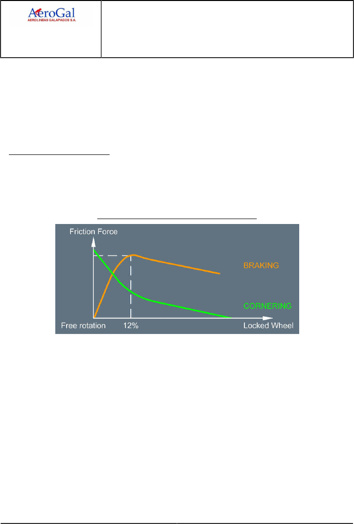
A318/A319/A320/A321
FLIGHT CREW
TECHNIQUES MANUAL
PROCEDURES
NORMAL PROCEDURES
STANDARD OPERATING PROCEDURES - LANDING
GLG A318/A319/A320/A321 FLEET PR-NP-SOP-250 P 8/16
FCTM ← E → 19 JUN 17
other words, the DECEL light is not an indicator of the autobrake operation as such, but that the
deceleration rate is reached.
Since the auto brake system senses deceleration and modulates brake pressure accordingly,
the timely application of MAX reverse thrust will reduce the actual operation of the brakes
themselves, thus the brake wear and temperature.
Auto-brake does not relieve the pilot of the responsibility of achieving a safe stop within the
available runway length.
CROSS WIND CONDITIONS
The reverse thrust side force and crosswind component can combine to cause the aircraft to drift
to the downwind side of the runway if the aircraft is allowed to weathercock into wind after landing.
Additionally, as the anti-skid system will be operating at maximum braking effectiveness, the main
gear tire cornering forces available to counteract this drift will be reduced.
Braking Force and Cornering Force vs Antiskid
To correct back to the centreline, the pilot must reduce reverse thrust to reverse idle and release
the brakes. This will minimise the reverse thrust side force component, without the requirement
to go through a full reverser actuating cycle, and provide the total tire cornering forces for
realignment with the runway centreline. Rudder and differential braking should be used, as
required, to correct back to the runway centreline. When re-established on the runway centreline,
the pilot should re-apply braking and reverse thrust as required.
For more information about rudder pedals recommendations, Refer to PR-NP-SOP-70 Seating
Position and Adjustment of Rudder Pedals
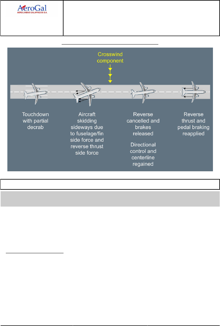
A318/A319/A320/A321
FLIGHT CREW
TECHNIQUES MANUAL
PROCEDURES
NORMAL PROCEDURES
STANDARD OPERATING PROCEDURES - LANDING
GLG A318/A319/A320/A321 FLEET PR-NP-SOP-250 P 9/16
FCTM ← E → 19 JUN 17
Directional Control During Crosswind Landing
DECELERATION
Ident.: PR-NP-SOP-250-00020013.0001001 / 20 MAR 17
Criteria: SA
Applicable to: HC-CJM, HC-CJV, HC-CJW, HC-CKN, HC-CLF, HC-CRU, HC-CSA, HC-CSF
Once on the ground, the importance of the timely use of all means of stopping the aircraft cannot be
overemphasised. Three systems are involved in braking once the aircraft is on the ground:
‐ The ground spoilers
‐ The thrust reversers
‐ The wheel brakes.
THE GROUND SPOILERS
When the aircraft touches down with at least one main landing gear and when at least one thrust
lever is in the reverse sector, the ground spoilers partially automatically deploy to ensure that the
aircraft is properly sit down on ground. Then, the ground spoilers automatically fully deploy. This is
the partial lift dumping function.
The ground spoilers contribute to aircraft deceleration by increasing aerodynamic drag at high
speed. Wheel braking efficiency is improved due to the increased load on the wheels. Additionally,
the ground spoiler extension signal is used for auto-brake activation.

A318/A319/A320/A321
FLIGHT CREW
TECHNIQUES MANUAL
PROCEDURES
NORMAL PROCEDURES
STANDARD OPERATING PROCEDURES - LANDING
GLG A318/A319/A320/A321 FLEET PR-NP-SOP-250 P 10/16
FCTM ← E → 19 JUN 17
REVERSE THRUST EFFICIENCY
Thrust reversers are more efficient at high speeds: The flight crew must select reverse thrust
immediately after main landing gear touchdown.
Below 70 kt, thrust reversers efficiency rapidly decreases. Below 60 kt with REV MAX selected,
engine stall may occur. Therefore, it is recommended to reduce the reverse thrust to REV IDLE at
70 kt, and keep REV IDLE until taxi speed. However in an emergency case, the flight crew must
keep REV MAX until full-stop of the aircraft.
At taxi speed, and not above, stow the thrust reversers before leaving the runway, in order to avoid
foreign object ingestion.
REVERSE THRUST SELECTION
The selection of REV MAX is the standard practice for landing.
LANDING ON DRY RUNWAYS
On DRY runways, the flight crew may select REV IDLE.
LANDING ON WET RUNWAYS
On WET runways, the flight crew may select REV IDLE, if all the conditions described in the
SOP DESCENT PREPARATION (Refer to FCOM/PRO-NOR-SOP-16 Descent Preparation -
General) are satisfied.
LANDING ON CONTAMINATED RUNWAYS
On contaminated runways, the flight crew must select REV MAX.
REMINDER ON LANDING DISTANCE COMPUTATION AT DISPATCH FOR DRY AND WET
RUNWAYS
DEFINITIONS
ALD : The Actual Landing Distance is the distance used on a dry runway from
the crossing of the runway threshold at 50 ft until full-stop of the aircraft,
using maximum manual braking. No reverse thrust is considered for
the calculation of the ALD. The ALD is demonstrated during flight test
campaign for certification purpose.
RLD dry : The Required Landing Distance on a dry runway is a factored ALD. The
factor is 1.67. (RLD dry = ALD x 1.67)
RLD wet : The Required Landing Distance on a wet runway is a factored ALD. The
factor is 1.92 (RLD wet = RLD dry x 1.15)
DISPATCH CONDITIONS
For landing distance computation at dispatch, the airline uses the RLD.

A318/A319/A320/A321
FLIGHT CREW
TECHNIQUES MANUAL
PROCEDURES
NORMAL PROCEDURES
STANDARD OPERATING PROCEDURES - LANDING
GLG A318/A319/A320/A321 FLEET PR-NP-SOP-250 P 11/16
FCTM ← E → 19 JUN 17
Landing distances computed at dispatch for wet runways provide only reduced margins in
comparison with landing distances achievable in operations with the use of REV IDLE. Sufficient
margins are restored when the flight crew uses REV MAX.
The runway slope is not considered for the landing distance computation at dispatch.
On a destination airport with multiple runways, the landing distance computation at dispatch
may be performed on the longest landing runway with no wind.
The expected landing runway may be used for the landing distance computation at dispatch
with forecast wind at landing. If the wind condition changes at landing, the flight crew must
perform a new landing distance computation.
LANDING WITH REV IDLE ON WET RUNWAYS
The landing distance computation at dispatch (RLD ) does not consider REV IDLE operation.
Therefore, it is necessary to perform a computation to consider REV IDLE operation, as
described in the SOP DESCENT PREPARATION (Refer to FCOM/PRO-NOR-SOP-16 Descent
Preparation - General). This may be done before the flight.
At descent preparation, if the flight crew considers the use of REV IDLE on a wet runway, they
should be able to confirm a MEDIUM TO POOR landing distance computation with no reverse
credit on the predicted landing runway.
A MEDIUM TO POOR computation enables the flight crew to consider extreme situations where
a runway reported wet is worse than wet. If a runway reported wet is water contaminated, the
braking action is a function of the water depth. During active precipitation or shortly afterwards,
the water depth is variable, and therefore difficult to evaluate and to report accurately.
Therefore on runways reported wet, the real friction coefficient may be significantly less than
expected and/or aquaplaning may occur. When REV IDLE is used, the maximum possible
deceleration of the aircraft mainly depends on the runway friction coefficient.
WHEEL BRAKES
Wheel brakes contribute the most to aircraft deceleration on the ground. Many factors may affect
efficient braking such as load on the wheels, tire pressure, runway pavement characteristics and
runway contamination and braking technique. The only factor over which the pilot has any control
is the use of the correct braking technique, as discussed below.
ANTI-SKID
The anti-skid system adapts pilot applied brake pressure to runway conditions by sensing an
impending skid condition and adjusting the brake pressure to each individual wheel as required.
The anti-skid system maintains the skidding factor (slip ratio) close to the maximum friction
force point. This will provide the optimum deceleration with respect to the pilot input. Full pedal
braking with anti-skid provides a deceleration rate of 10 kt/sec.

A318/A319/A320/A321
FLIGHT CREW
TECHNIQUES MANUAL
PROCEDURES
NORMAL PROCEDURES
STANDARD OPERATING PROCEDURES - LANDING
GLG A318/A319/A320/A321 FLEET PR-NP-SOP-250 P 12/16
FCTM ← E → 19 JUN 17
BRAKES
The use of auto brake versus pedal braking should observe the following guidelines:
‐ The use of A/BRAKE is usually preferable because it minimizes the number of brake
applications and thus reduces brake wear. Additionally, the A/BRAKE provides a symmetrical
brake pressure application which ensures an equal braking effect on both main landing
gear wheels on wet or evenly contaminated runway. More particularly, the A/BRAKE is
recommended on short, wet, contaminated runway, in poor visibility conditions and in Auto
land.
‐ The use of LO auto brake should be preferred on long and dry runways whereas the use of
MED auto brake should be preferred for short or contaminated runways. The use of MAX
auto brake is not recommended.
‐ On very short runways, the use of pedal braking is to be envisaged since the pilot may apply
full pedal braking with no delay after touch down.
‐ On very long runways, the use of pedal braking may be envisaged if the pilot anticipates that
braking will not be needed. To reduce brake wear, the number of brake application should be
limited.
‐ In case of pedal braking, do not ride the brakes but apply pedal braking when required and
modulate the pressure without releasing. This minimizes brake wear.
The green DECEL light comes on when the actual deceleration is 80 % of the selected rate. For
example the DECEL light might not appear when the autobrake is selected on a contaminated
runway, because the deceleration rate is not reached with the autobrake properly functioning.
Whereas the DECEL light might appear with LO selected on a dry runway while only the
reversers achieve the selected deceleration rate without autobrake being actually activated. In
other words, the DECEL light is not an indicator of the autobrake operation as such, but that the
deceleration rate is reached.
Since the auto brake system senses deceleration and modulates brake pressure accordingly,
the timely application of MAX reverse thrust will reduce the actual operation of the brakes
themselves, thus the brake wear and temperature.
Auto-brake does not relieve the pilot of the responsibility of achieving a safe stop within the
available runway length.
CROSS WIND CONDITIONS
The reverse thrust side force and crosswind component can combine to cause the aircraft to drift
to the downwind side of the runway if the aircraft is allowed to weathercock into wind after landing.
Additionally, as the anti-skid system will be operating at maximum braking effectiveness, the main
gear tire cornering forces available to counteract this drift will be reduced.
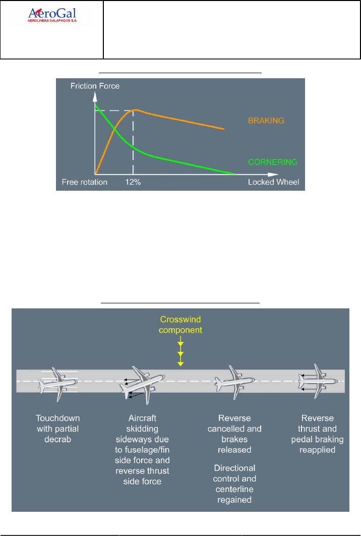
A318/A319/A320/A321
FLIGHT CREW
TECHNIQUES MANUAL
PROCEDURES
NORMAL PROCEDURES
STANDARD OPERATING PROCEDURES - LANDING
GLG A318/A319/A320/A321 FLEET PR-NP-SOP-250 P 13/16
FCTM ← E 19 JUN 17
Braking Force and Cornering Force vs Antiskid
To correct back to the centreline, the pilot must reduce reverse thrust to reverse idle and release
the brakes. This will minimise the reverse thrust side force component, without the requirement
to go through a full reverser actuating cycle, and provide the total tire cornering forces for
realignment with the runway centreline. Rudder and differential braking should be used, as
required, to correct back to the runway centreline. When re-established on the runway centreline,
the pilot should re-apply braking and reverse thrust as required.
For more information about rudder pedals recommendations, Refer to PR-NP-SOP-70 Seating
Position and Adjustment of Rudder Pedals
Directional Control During Crosswind Landing

A318/A319/A320/A321
FLIGHT CREW
TECHNIQUES MANUAL
PROCEDURES
NORMAL PROCEDURES
STANDARD OPERATING PROCEDURES - LANDING
GLG A318/A319/A320/A321 FLEET PR-NP-SOP-250 P 14/16
FCTM F → 19 JUN 17
TAIL STRIKE AVOIDANCE
Ident.: PR-NP-SOP-250-00020014.0001001 / 20 MAR 17
Applicable to: ALL
Although most of tail strikes are due to deviations from normal landing techniques, some are
associated with external conditions such as turbulence and wind gradient.
DEVIATION FROM NORMAL TECHNIQUES
Deviations from normal landing techniques are the most common causes of tail strikes. The main
reasons for this are due to:
‐ Allowing the speed to decrease well below VAPP before flare
Flying at too low speed means high angle of attack and high pitch attitude, thus reducing ground
clearance. When reaching the flare height, the pilot will have to significantly increase the pitch
attitude to reduce the sink rate. This may cause the pitch to go beyond the critical angle.
‐ Prolonged hold off for a smooth touch down
As the pitch increases, the pilot needs to focus further ahead to assess the aircraft's position
in relation to the ground. The attitude and distance relationship can lead to a pitch attitude
increase beyond the critical angle.
‐ Too high flare
A high flare can result in a combined decrease in airspeed and a long float. Since both lead to
an increase in pitch attitude, the result is reduced tail clearance.
‐ Too high sink rate, just prior reaching the flare height
In case of too high sink rate close to the ground, the pilot may attempt to avoid a firm touch
down by commanding a high pitch rate. This action will significantly increase the pitch attitude
and, as the resulting lift increase may be insufficient to significantly reduce the sink rate, the
high pitch rate may be difficult to control after touch down, particularly in case of bounce.
‐ Bouncing at touch down
In case of bouncing at touch down, the pilot may be tempted to increase the pitch attitude to
ensure a smooth second touch down. If the bounce results from a firm touch down, associated
with high pitch rate, it is important to control the pitch so that it does not further increase beyond
the critical angle.
AIRCRAFT SYSTEM FOR TAIL STRIKE PREVENTION
The following aircraft systems help to prevent tail strike occurrence:
‐ A "PITCH-PITCH" synthetic voice sounds when the pitch attitude becomes excessive,
‐ A tail strike pitch limit indicator appears on the PFD to indicate the maximum pitch attitude to
avoid a tail strike.
This design is installed as an option on A320 and A321.

A318/A319/A320/A321
FLIGHT CREW
TECHNIQUES MANUAL
PROCEDURES
NORMAL PROCEDURES
STANDARD OPERATING PROCEDURES - LANDING
GLG A318/A319/A320/A321 FLEET PR-NP-SOP-250 P 15/16
FCTM ← F 19 JUN 17
BOUNCING AT TOUCH DOWN
In case of light bounce, maintain the pitch attitude and complete the landing, while keeping the
thrust at idle. Do not allow the pitch attitude to increase, particularly following a firm touch down
with a high pitch rate.
In case of high bounce, maintain the pitch attitude and initiate a go-around. Do not try to avoid a
second touch down during the go-around. Should it happen, it would be soft enough to prevent
damage to the aircraft, if pitch attitude is maintained.
Only when safely established in the go-around, retract flaps one step and the landing gear. A
landing should not be attempted immediately after high bounce, as thrust may be required to
soften the second touch down and the remaining runway length may be insufficient to stop the
aircraft.
CUMULATIVE EFFECTS
No single factor should result in a tail strike, but accumulation of several can significantly reduce
the margin.

A318/A319/A320/A321
FLIGHT CREW
TECHNIQUES MANUAL
PROCEDURES
NORMAL PROCEDURES
STANDARD OPERATING PROCEDURES - LANDING
Intentionally left blank
GLG A318/A319/A320/A321 FLEET PR-NP-SOP-250 P 16/16
FCTM 19 JUN 17

A318/A319/A320/A321
FLIGHT CREW
TECHNIQUES MANUAL
PROCEDURES
NORMAL PROCEDURES
STANDARD OPERATING PROCEDURES - GO-AROUND
GLG A318/A319/A320/A321 FLEET PR-NP-SOP-260 P 1/6
FCTM A to B → 05 SEP 17
GENERAL
Ident.: PR-NP-SOP-260-00019222.0001001 / 20 MAR 17
Applicable to: ALL
Failure to recognize the need for and to execute a go-around, when required, is a major cause of
approach and landing accidents. Because a go-around is an infrequent occurrence, it is important to
be "go-around minded". The decision to go-around should not be delayed, as an early go-around is
safer than a last minute one at lower altitude.
CONSIDERATIONS ABOUT GO-AROUND
Applicable to: ALL
Ident.: PR-NP-SOP-260-A-00019214.0001001 / 20 MAR 17
DECISION MAKING
The flight crew must consider to perform a go-around if:
‐ There is a loss or a doubt about situation awareness, or
‐ There is a malfunction which jeopardizes the safe completion of the approach e.g. major
navigation problem, or
‐ ATC changes the final approach clearance resulting in rushed action from the crew or
potentially unstable approach, or
‐ The approach is unstable in speed, altitude, or flight path in such a way that stability is not
obtained by 1 000 ft AAL in IMC or (500 ft AAL in VMC), or is not maintained until landing, or
‐ Any of the following alerts occur:
• GPWS, or
• TCAS, or
• Windshear, or
• ROW alerts for the relevant runway condition. Refer to AS-ROWROP Operating
Techniques.
‐ Adequate visual references are not obtained at minima or lost below minima.
Ident.: PR-NP-SOP-260-A-00019215.0001001 / 20 MAR 17
GO-AROUND NEAR THE GROUND
The PF must not initiate a go-around after the selection of the thrust reversers. If the PF initiates a
go-around, the flight crew must complete the go-around maneuver.

A318/A319/A320/A321
FLIGHT CREW
TECHNIQUES MANUAL
PROCEDURES
NORMAL PROCEDURES
STANDARD OPERATING PROCEDURES - GO-AROUND
GLG A318/A319/A320/A321 FLEET PR-NP-SOP-260 P 2/6
FCTM ← B to C → 05 SEP 17
If the flight crew performs a go-around near the ground, they should take into account the
following:
‐ The PF should avoid excessive rotation rate, in order to prevent a tailstrike. For more
information Refer to PR-NP-SOP-250 Tail Strike Avoidance
‐ A temporary landing gear contact with the runway is acceptable.
Only when the aircraft is safely established in the go-around, the flight crew retracts flaps one step
and the landing gear.
Note: If the aircraft is on the runway and in FULL configuration when the PF applies TOGA
thrust, a CONFIG FLAPS NOT IN T.O CONFIG ECAM alert is triggered. The flight crew
should disregard this alert.
AP/FD GO-AROUND PHASE ACTIVATION
Ident.: PR-NP-SOP-260-00019216.0003001 / 20 MAR 17
Criteria: 22-1296, P10694, P4319, SA
Applicable to: HC-CJM, HC-CJV, HC-CJW, HC-CSB
When the thrust levers are set to the TOGA detent, and provided the real slats/flaps configuration is
different from clean configuration, all of the following occur:
‐ If the autopilot or the flight director is in use, SRS and GA TRK (NAV) modes engage.
‐ If the autopilot and both flight directors are off, the PF will maintain 15 ° of pitch.
‐ The GA phase activates on the FMS:
• The missed approach becomes the active F-PLN
• At the end of the missed approach procedure, the FMS strings the previous flown approach in
the active F-PLN.
‐ If not previously engaged, the FD automatically engages with the HDG /VS reference on the FCU.
For the go-around, the appropriate flight reference is the attitude, because go-around is a dynamic
maneuver
‐ If extended, the speed brakes automatically retract.
If TOGA thrust is not desired during go-around for any reason, e.g. an early go-around ordered by
ATC , it is essential that the thrust levers are set momentarily but without delay, to the TOGA detent
(i.e. the full forward thrust levers position), in order to ensure proper activation of the SRS GA and
the Go-Around phase (i.e. guidance modes and FMS flight phase). Then, the flight crew should set
the thrust lever to CL detent to take advantage of the A/THR (the A/THR follows a speed target).

A318/A319/A320/A321
FLIGHT CREW
TECHNIQUES MANUAL
PROCEDURES
NORMAL PROCEDURES
STANDARD OPERATING PROCEDURES - GO-AROUND
GLG A318/A319/A320/A321 FLEET PR-NP-SOP-260 P 3/6
FCTM ← C 05 SEP 17
If the thrust levers are not correctly set to the TOGA detent, the following occur:
‐ The AP /FD remain engaged in approach or landing mode (e.g. G/S , LOC , LAND , FLARE on
FMA)
‐ The FMS does not engage the GA phase, and remains in APPR phase.
AP/FD GO-AROUND PHASE ACTIVATION
Ident.: PR-NP-SOP-260-00019216.0002001 / 20 MAR 17
Criteria: P4319, SA
Applicable to: HC-CKN, HC-CLF, HC-CRU, HC-CSA, HC-CSF
When the thrust levers are set to the TOGA detent, and provided the real slats/flaps configuration is
different from clean configuration, all of the following occur:
‐ If the autopilot or the flight director is in use, SRS and GA TRK modes engage.
‐ If the autopilot and both flight directors are off, the PF will maintain 15 ° of pitch.
‐ The GA phase activates on the FMS:
• The missed approach becomes the active F-PLN
• At the end of the missed approach procedure, the FMS strings the previous flown approach in
the active F-PLN.
‐ If not previously engaged, the FD automatically engages with the HDG /VS reference on the FCU.
For the go-around, the appropriate flight reference is the attitude, because go-around is a dynamic
maneuver
‐ If extended, the speed brakes automatically retract.
If TOGA thrust is not desired during go-around for any reason, e.g. an early go-around ordered by
ATC , it is essential that the thrust levers are set momentarily but without delay, to the TOGA detent
(i.e. the full forward thrust levers position), in order to ensure proper activation of the SRS GA and
the Go-Around phase (i.e. guidance modes and FMS flight phase). Then, the flight crew should set
the thrust lever to CL detent to take advantage of the A/THR (the A/THR follows a speed target).
If the thrust levers are not correctly set to the TOGA detent, the following occur:
‐ The AP /FD remain engaged in approach or landing mode (e.g. G/S , LOC , LAND , FLARE on
FMA)
‐ The FMS does not engage the GA phase, and remains in APPR phase.

A318/A319/A320/A321
FLIGHT CREW
TECHNIQUES MANUAL
PROCEDURES
NORMAL PROCEDURES
STANDARD OPERATING PROCEDURES - GO-AROUND
GLG A318/A319/A320/A321 FLEET PR-NP-SOP-260 P 4/6
FCTM D 05 SEP 17
GO-AROUND PHASE
Ident.: PR-NP-SOP-260-00019217.0004001 / 20 MAR 17
Criteria: 22-1296, P10694, P4319, SA
Applicable to: HC-CJM, HC-CJV, HC-CJW, HC-CSB
GO-AROUND WITH FD ON
The SRS mode guides the aircraft with the highest speed of VAPP or IAS at time of TOGA
selection (limited to maximum of VLS +25 with all engines operative or VLS +15 with one engine
inoperative with FMS 2) until the acceleration altitude where the target speed increases to green
dot.
Some FMS misbehavior may prevent this automatic target speed increase. Should this occur,
pulling the FCU ALT knob for OP CLB manually disengages SRS mode and allows the target
speed to increase to green dot. It should be noted however, that the target speed increases to
green dot speed as soon as ALT* mode engages when approaching the FCU clearance altitude.
The missed approach route becomes the ACTIVE F-PLN provided the waypoints have been
correctly sequenced on the approach.
At TOGA selection, the missed approach F-PLN is immediately followed in NAV mode, or will be
followed after a transition in GA TRK mode with NAV armed.
The GA TRK mode guides the aircraft on the track memorized at the time of TOGA selection. NAV
mode engages as soon as the aircraft is aligned on the F-PLN.
Above the go-around acceleration altitude, or when the flight crew engages another vertical mode
(CLB , OP CLB), the target speed is green dot.
GO-AROUND PHASE
Ident.: PR-NP-SOP-260-00019217.0002001 / 20 MAR 17
Criteria: P4319, SA
Applicable to: HC-CKN, HC-CLF, HC-CRU, HC-CSA, HC-CSF
The SRS mode guides the aircraft with the highest speed of VAPP or IAS at time of TOGA selection
(limited to maximum of VLS +25 with all engines operative or VLS +15 with one engine inoperative
with FMS 2) until the acceleration altitude where the target speed increases to green dot.
Some FMS misbehaviour may prevent this automatic target speed increase. Should this occur,
pulling the FCU ALT knob for OP CLB manually disengages SRS mode and allows the target speed
to increase to green dot. It should be noted however, that the target speed increases to green dot
speed as soon as ALT* mode engages when approaching the FCU clearance altitude.
The GA TRK mode guides the aircraft on the track memorised at the time of TOGA selection. The
missed approach route becomes the ACTIVE F-PLN provided the waypoints have been correctly
sequenced on the approach. Pushing for NAV enables the missed approach F-PLN to be followed.
Above the go-around acceleration altitude, or when the flight crew engages another vertical mode
(CLB , OP CLB), the target speed is green dot.
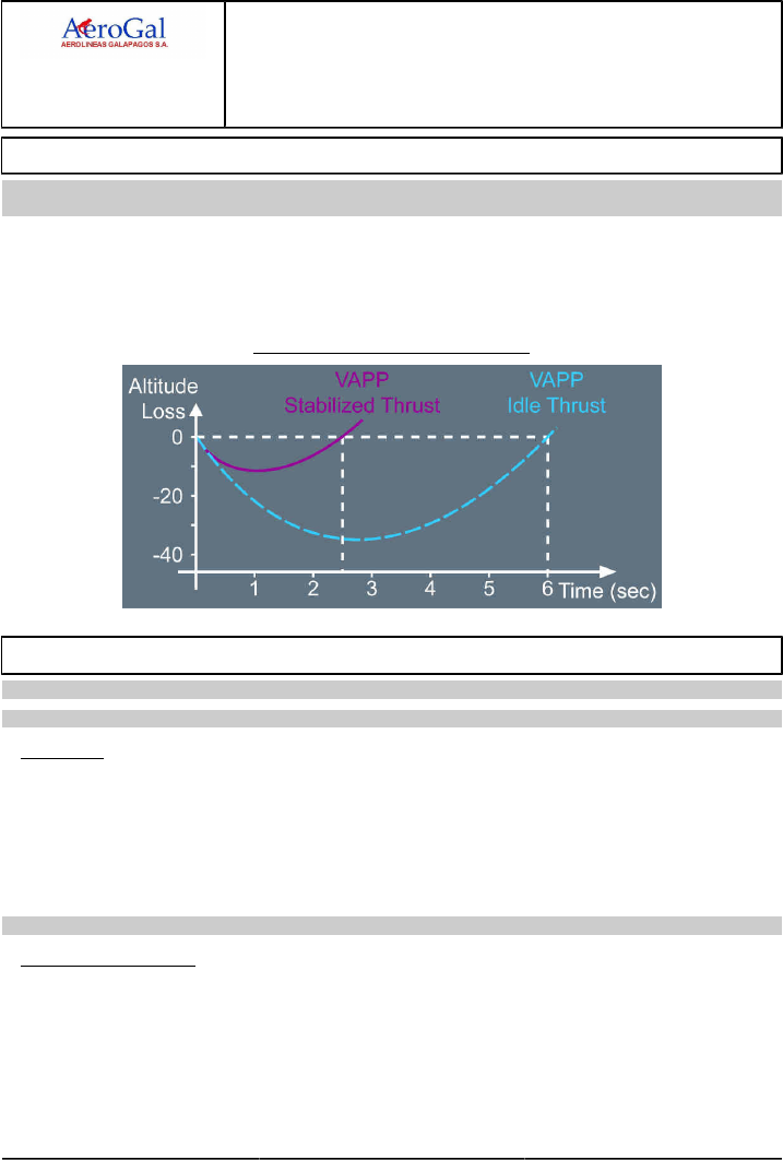
A318/A319/A320/A321
FLIGHT CREW
TECHNIQUES MANUAL
PROCEDURES
NORMAL PROCEDURES
STANDARD OPERATING PROCEDURES - GO-AROUND
GLG A318/A319/A320/A321 FLEET PR-NP-SOP-260 P 5/6
FCTM E to F → 05 SEP 17
ENGINES ACCELERATION
Ident.: PR-NP-SOP-260-00019218.0001001 / 20 MAR 17
Applicable to: ALL
When the pilot sets TOGA thrust for go-around, it takes some time for the engines to spool up due to
the acceleration capability of the high by pass ratio engines. Therefore, the pilot must be aware that
the aircraft will initially lose some altitude. This altitude loss will be greater if initial thrust is close to
idle and/or the aircraft speed is lower than VAPP.
Altitude Loss Following a Go-Around
LEAVING THE GO-AROUND PHASE
Applicable to: ALL
Ident.: PR-NP-SOP-260-B-00019219.0001001 / 20 MAR 17
GENERAL
The purpose of leaving the go-around phase is to obtain the proper target speed and proper
predictions depending upon the strategy chosen by the crew. During the missed approach, the
crew will elect either of the following strategies:
‐ Fly a second approach
‐ Carry out a diversion.
Ident.: PR-NP-SOP-260-B-00019220.0001001 / 20 MAR 17
SECOND APPROACH
If a second approach is to be flown, the crew will activate the approach phase in the MCDU PERF
GO-AROUND page. The FMS switches to Approach phase and the target speed moves according
to the flaps lever setting, e.g. green dot for Flaps 0.
The crew will ensure proper waypoint sequencing during the second approach in order to have the
missed approach route available, should a further go-around be required.

A318/A319/A320/A321
FLIGHT CREW
TECHNIQUES MANUAL
PROCEDURES
NORMAL PROCEDURES
STANDARD OPERATING PROCEDURES - GO-AROUND
GLG A318/A319/A320/A321 FLEET PR-NP-SOP-260 P 6/6
FCTM ← F 05 SEP 17
Ident.: PR-NP-SOP-260-B-00019221.0001001 / 25 JUL 17
1DIVERSION
Once the aircraft path is established and clearance has been obtained, the crew will modify the
FMGS to allow the FMGS switching from go-around phase to climb phase:
‐ If the crew has prepared the ALTN FPLN in the active F-PLN , a lateral revision at the TO WPT
is required to access the ENABLE ALTN prompt. On selecting the ENABLE ALTN prompt, the
lateral mode reverts to HDG if previously in NAV . The aircraft will be flown towards the next
waypoint using HDG or NAV via a DIR TO entry.
‐ If the crew has prepared the ALTN FPLN in the SEC F-PLN, the SEC F-PLN will be activated,
and a DIR TO performed as required. AP /FD must be in HDG mode for the ACTIVATE SEC
F-PLN prompt to be displayed.
‐ If the crew has not prepared the ALTN FPLN, a selected climb will be initiated. Once
established in climb and clear of terrain, the crew will make a lateral revision at any waypoint to
insert a NEW DEST . The route and a CRZ FL (on PROG page) can be updated as required.

A318/A319/A320/A321
FLIGHT CREW
TECHNIQUES MANUAL
PROCEDURES
NORMAL PROCEDURES
STANDARD OPERATING PROCEDURES - AFTER LANDING
GLG A318/A319/A320/A321 FLEET PR-NP-SOP-270 P 1/2
FCTM A 22 MAR 17
USE OF BRAKE FANS
Ident.: PR-NP-SOP-270-00019849.0001001 / 20 MAR 17
Applicable to: ALL
Delaying brake fans selection limits the oxidation of any possible transient hot spots of the brake
disk surface. The selection of the brake fans, before the aircraft reaches the gate, prevents to blow
carbon brake dust on the ground personnel. The brake fans blow dust during the first seconds of
operation only.

A318/A319/A320/A321
FLIGHT CREW
TECHNIQUES MANUAL
PROCEDURES
NORMAL PROCEDURES
STANDARD OPERATING PROCEDURES - AFTER LANDING
Intentionally left blank
GLG A318/A319/A320/A321 FLEET PR-NP-SOP-270 P 2/2
FCTM 22 MAR 17

A318/A319/A320/A321
FLIGHT CREW
TECHNIQUES MANUAL
PROCEDURES
NORMAL PROCEDURES
SUPPLEMENTARY PROCEDURES - ADVERSE WEATHER
GLG A318/A319/A320/A321 FLEET PR-NP-SP-10-10-1 P 1/10
FCTM A to C 05 SEP 17
Cold Weather Operations and Icing Conditions
GENERAL
Ident.: PR-NP-SP-10-10-1-00019322.0001001 / 20 MAR 17
Applicable to: ALL
Aircraft performance is certified on the basis of a clean wing. Ice accretion affects wing performance.
When the wing is clean, the airflow smoothly follows the shape of the wing. When the wing is
covered with ice, the airflow separates from the wing when the Angle-Of-Attack (AOA ) increases.
Therefore, the maximum lift-coefficient is reduced. As a result, the aircraft may stall at a lower AOA,
and the drag may increase.
The flight crew must keep in mind that the wing temperature of the aircraft may be significantly lower
than 0 °C, after a flight at high altitude and low temperature, even if the Outside Air Temperature
(OAT) is higher than 0 °C. In such cases, humidity or rain will cause ice accretion on the upper
wing, and light frost under the wing (only 3 mm of frost on the under side of the wing tank area is
acceptable).
EXTERIOR INSPECTION
Ident.: PR-NP-SP-10-10-1-00016317.0002001 / 20 MAR 17
Applicable to: ALL
When icing conditions on ground are encountered, and/or when ice accretion is suspected, the
Captain should determine, on the basis of the exterior inspection, if the aircraft requires ground
deicing/anti-icing treatment. This visual inspection must take into account all vital parts of the aircraft,
and must be performed from locations that offer a clear view of these parts.
COCKPIT PREPARATION
Ident.: PR-NP-SP-10-10-1-00019323.0001001 / 20 MAR 17
Applicable to: ALL
The following systems may be affected in very cold weather:
‐ The EFIS /ECAM (when the cockpit temperature is very low)
‐ The IRS alignment (may take longer than usual, up to 15 min).
The probe and window heating may be used on ground.

A318/A319/A320/A321
FLIGHT CREW
TECHNIQUES MANUAL
PROCEDURES
NORMAL PROCEDURES
SUPPLEMENTARY PROCEDURES - ADVERSE WEATHER
GLG A318/A319/A320/A321 FLEET PR-NP-SP-10-10-1 P 2/10
FCTM D 05 SEP 17
AIRCRAFT DEICING/ANTI-ICING ON GROUND
Ident.: PR-NP-SP-10-10-1-00016318.0002001 / 20 MAR 17
Applicable to: ALL
DE-ICING/ANTI-ICING FLUID
Deicing/anti-icing fluids must be able to remove ice and to prevent its accumulation on aircraft
surfaces until the beginning of the takeoff. In addition, the fluids must flow off the surfaces of the
aircraft during takeoff, in order not to degrade takeoff performance.
Several types of fluids can be used. These fluids have different characteristics:
type 1 type 2, 3, 4
Low viscosity High viscosity
Limited hold-over time Longer hold-over time
Used mainly for de-icing Used for de-icing and anti-icing
The holdover time starts from the beginning of the application of the fluid, and depends on the type
of fluid, and on the nature and severity of precipitation. The flight crew should refer to applicable
tables as guidelines. These tables must be used in conjunction with the pre-takeoff check.
Depending upon the severity of the weather, de-icing/anti-icing procedure must be applied either:
‐ In one step, via the single application of heated and diluted deicing/anti-icing fluid: This
procedure provides a short holdover time, and should be used in low moisture conditions only.
The holdover time starts from the beginning of the application of the fluid.
‐ In two steps, by first applying the heated deicing fluid, then by applying a protective anti-icing
fluid: These two sprays must be applied consecutively. The holdover time starts from the
beginning of the application of the second fluid.
PROCEDURES
The following outlines the various procedures to be applied before and after spraying:
‐ All ENG and APU BLEED pushbuttons must be set to OFF and the DITCHING pushbutton must
be set to ON, to prevent any engine ingestion of deicing/anti-icing fluid.
‐ The aircraft can be deiced/anti-iced, with the engine and/or the APU running or off. However,
the APU or the engine should not be started during spraying.
‐ The aircraft must be deiced/anti-iced symmetrically on both sides.
‐ After spraying, keep bleeds off for a few minutes, and perform a visual inspection of the aircraft
surfaces.
‐ A deicing/anti-icing report must be filled out to indicate the type of fluid and when the spraying
began.

A318/A319/A320/A321
FLIGHT CREW
TECHNIQUES MANUAL
PROCEDURES
NORMAL PROCEDURES
SUPPLEMENTARY PROCEDURES - ADVERSE WEATHER
GLG A318/A319/A320/A321 FLEET PR-NP-SP-10-10-1 P 3/10
FCTM E to G → 05 SEP 17
AFTER START
Ident.: PR-NP-SP-10-10-1-00016319.0002001 / 20 MAR 17
Applicable to: ALL
‐ Keep the engine bleeds off, with the engines running at higher N1.
‐ Keep the APU running with the bleed off for a few minutes after spraying.
‐ The slats/flaps and flight controls can be moved, because they no longer have ice.
TAXI-OUT
Ident.: PR-NP-SP-10-10-1-00016320.0002001 / 20 MAR 17
Applicable to: ALL
On contaminated runways, the taxi speed should be limited to 10 kt, and any action that could
distract the flight crew during taxiing should be delayed until the aircraft is stopped.
The following factors should be taken into account:
‐ At speeds below 20 kt: Antiskid deactivates.
‐ Engine anti-ice increases ground idle thrust.
‐ To minimize the risk of skidding during turns: Avoid large tiller inputs.
‐ On slippery taxiways: It may be more effective to use differential braking and/or thrust, instead of
nosewheel steering.
‐ On slush-covered, or snow-covered, taxiways: Flap selection should be delayed until reaching the
holding point, in order to avoid contaminating the flap/slat actuation mechanism.
‐ When reaching the holding point: The "Before Takeoff down to the line" checklist must be
performed.
‐ The flight crew must maintain the aircraft at an appropriate distance from the aircraft in front.
‐ In icing conditions: When holding on ground for extended periods of time, or if engine vibration
occurs, thrust should be increased periodically, and immediately before takeoff, to shed any ice
from the fan blades.
For more details about this procedure, Refer to FCOM/PRO-NOR-SOP-09 After Start - ENG Anti-Ice
TAKEOFF
Ident.: PR-NP-SP-10-10-1-00016321.0002001 / 20 MAR 17
Applicable to: ALL
TAKEOFF PERFORMANCES
The use of FLEX thrust for takeoff on contaminated runways is prohibited. However, derated
thrust may be used, as required, in order to optimize aircraft performance. When available, a
derated takeoff thrust results in lower minimum control speeds and, therefore, in a lower V1. A
reduction in the minimum control speeds can sometimes enhance takeoff performance.
If anti-ice is used, the flight crew must apply the applicable performance penalty.

A318/A319/A320/A321
FLIGHT CREW
TECHNIQUES MANUAL
PROCEDURES
NORMAL PROCEDURES
SUPPLEMENTARY PROCEDURES - ADVERSE WEATHER
GLG A318/A319/A320/A321 FLEET PR-NP-SP-10-10-1 P 4/10
FCTM ← G to H → 05 SEP 17
Slush, standing water, or deep snow reduces the aircraft takeoff performance because of
increased rolling resistance and the reduction in tire-to-ground friction. A higher flap setting
increases the runway limited takeoff weight, but reduces second the segment limited takeoff
weight.
TAKEOFF ROLL
Before the aircraft lines up on the runway for takeoff, the flight crew must ensure that the airframe
has no ice or snow.
Then, before applying thrust, the Captain should ensure that the nosewheel is straight. If there is a
tendency to deviate from the runway centerline, this tendency must be neutralized immediately, via
rudder pedal steering, not via the tiller.
On contaminated runways, the flight crew should ensure that engine thrust advances
symmetrically to help minimize potential problems with directional control.
The flight crew should keep in mind that a RTO is a potentially hazardous manoeuvre on
contaminated runways.
If a RTO must be performed, the flight crew should maintain directional control with the rudder and
small inputs to the nose wheel. If necessary, the flight crew should use differential braking in order
to realign with the runway centerline, when stopping distance permits.
IN FLIGHT
Ident.: PR-NP-SP-10-10-1-00016322.0002001 / 20 MAR 17
Applicable to: ALL
CLIMB/DESCENT
Whenever icing conditions are encountered or expected, the engine anti-ice should be turned on.
Although the TAT before entering clouds may not require engine anti-ice, flight crews should be
aware that the TAT often decreases significantly, when entering clouds.
If the recommended anti-ice procedures are not performed, engine stall, over-temperature, or
engine damage may occur,
Wing anti-ice should be turned on, if either severe ice accretion is expected, or if there is any
indication of icing on the airframe.
HOLDING
If holding is performed in icing conditions, the flight crew should maintain clean configuration. This
is because prolonged flight in icing conditions with the slats extended should be avoided.
APPROACH
ICE ACCRETION
If significant ice accretion develops on parts of the wing, the aircraft speed must be increased
(Refer to FCOM/PRO-NOR-SUP-ADVWXR Minimum Speed with Ice Accretion).
A318/A319/A320/A321
FLIGHT CREW
TECHNIQUES MANUAL
PROCEDURES
NORMAL PROCEDURES
SUPPLEMENTARY PROCEDURES - ADVERSE WEATHER
GLG A318/A319/A320/A321 FLEET PR-NP-SP-10-10-1 P 5/10
FCTM ← H → 05 SEP 17
BAROMETER INDICATIONS
In cold weather, the atmosphere differs from the International Standard Atmosphere (ISA )
conditions. The parameters that the ADIRS computes are barometric and ISA -referenced.
When the atmosphere differs from the ISA conditions, the altitude and FPA computed by the
ADIRS , and the associated indications on PFD (altitude, VDEV, ...) are not accurate.
Note: The ADIRS computes the FPA from inertial data and barometric altitude.
When the temperature is lower than ISA:
‐ The true altitude of the aircraft is lower than the altitude that the ADIRS computes.
‐ The FPA that the aircraft actually flies, is less steep than the FPA that the ADIRS computes.
If appropriate, the flight crew should therefore apply corrections on the altitudes and on the
FPA (in vertical selected FPA mode), and they should be vigilant on the parameters that are
displayed.
Altitude Correction
The flight crew should consider to correct the target altitudes, by adding the values that are
indicated in the table below:
Corrections to be Added (ft)
Airport Temperature (°C)
Height (ft) -10 -20 -30
500 50 70 100
1 000 100 140 190
2 000 200 280 380
3 000 290 420 570
4 000 390 570 760
5 000 490 710 950
These values are calculated for an aerodrome at sea level, and are therefore conservative
when applied at a higher altitude aerodrome. For aerodromes at sea level, these corrections
corresponds approximately to 4 x Delta ISA x Height (ft)/1000.
The correction depends on the airport temperature, and on the height above the airport. This
correction has to be added to the indicated altitude.
Along the Approach and Missed Approach, the flight crew should consider to apply the
altitude corrections on the relevant minimum altitudes (all including FAF, Step-down altitudes,
minima), and on the altitude for the altitude/distance check.
For Non Precision Approach in vertical managed mode, refer to the Approach guidance
management section.
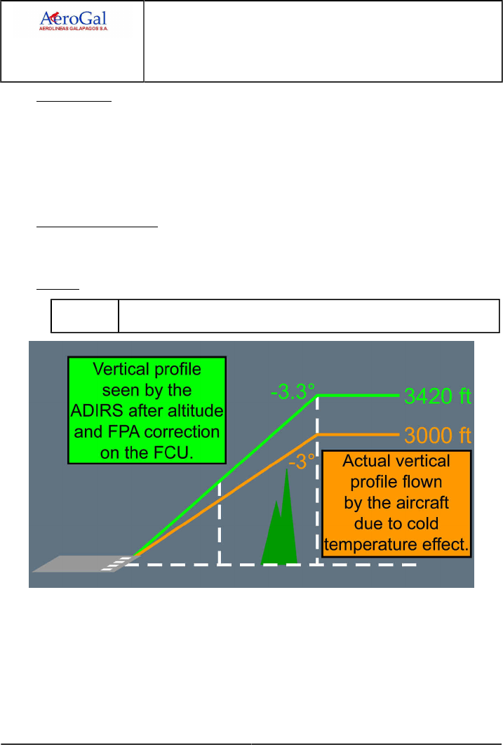
A318/A319/A320/A321
FLIGHT CREW
TECHNIQUES MANUAL
PROCEDURES
NORMAL PROCEDURES
SUPPLEMENTARY PROCEDURES - ADVERSE WEATHER
GLG A318/A319/A320/A321 FLEET PR-NP-SP-10-10-1 P 6/10
FCTM ← H 05 SEP 17
FPA Correction
When the temperature is lower than ISA , the FPA that the aircraft actually flies is less steep
than the FPA that the ADIRS (ISA referenced) computes.
In vertical selected mode FPA , to correct the FPA for this ISA deviation effect, the flight crew
should select on the FCU a FPA slightly different from the FPA that the aircraft needs to fly.
In any case, the check "altitude (corrected in temperature) versus distance" remains the
reference.
Impact on the indications
The barometric indications on PFD , namely the altitude and the VDEV are not corrected in
temperature and are therefore not accurate.
Example
EXAMPLE Airport outside temperature -20 °C ; Delta ISA = -35 °C.
Approach: FAF at 3 000 ft ; Final descent slope 3 °.

A318/A319/A320/A321
FLIGHT CREW
TECHNIQUES MANUAL
PROCEDURES
NORMAL PROCEDURES
SUPPLEMENTARY PROCEDURES - ADVERSE WEATHER
GLG A318/A319/A320/A321 FLEET PR-NP-SP-10-10-1 P 7/10
FCTM I → 05 SEP 17
LANDING
Ident.: PR-NP-SP-10-10-1-00016323.0002001 / 25 JUL 17
Applicable to: ALL
The flight crew should avoid landing on slippery runways, particularly if the antiskid is inoperative.
However, if it is not possible to avoid such landings, the following factors (linked to operations on
contaminated runways) should be considered:
‐ Braking action
‐ Directional control.
1BRAKING ACTION
The presence of fluid contaminants on the runway has an adverse effect on braking performance,
because it reduces the friction between the tires and the surface of the runway. It also creates
a layer of fluid between the tires and the runway surface, and reduces the contact area. The
landing distances provide a good assessment of the real landing distances for specific levels of
contamination.
After a brief flare a firm touchdown should be made, and REV MAX should be selected as soon
as the main landing gear is on ground. Using reversers on a runway that is contaminated with
dry snow may reduce visibility, particularly at low speeds. In such cases, reverse thrust should be
reduced to idle, if applicable.
If necessary, REV MAX can be used until the aircraft is fully stopped.
The use of MED autobrake mode is recommended, when landing on an evenly contaminated
runway. It is possible that the DECEL light on the AUTO BRK panel will not come on, as the
predetermined deceleration may not be achieved. This does not mean that the autobrake is not
working.
In the case of uneven contamination on a wet or contaminated runway, the autobrake may laterally
destabilize the aircraft. If this occurs, consider deselecting the autobrake.
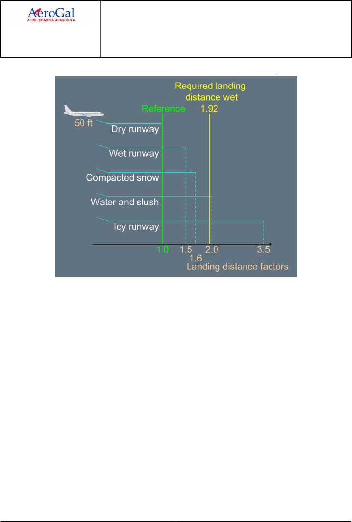
A318/A319/A320/A321
FLIGHT CREW
TECHNIQUES MANUAL
PROCEDURES
NORMAL PROCEDURES
SUPPLEMENTARY PROCEDURES - ADVERSE WEATHER
GLG A318/A319/A320/A321 FLEET PR-NP-SP-10-10-1 P 8/10
FCTM ← I → 05 SEP 17
Typical Landing Distance Factors Versus Runway Condition
DIRECTIONAL CONTROL
During rollout, the sidestick must be centered. This prevents asymmetric wheel loading, that
results in asymmetric braking and increases the weathercock tendency of the aircraft.
The flight crew should maintain directional control with the rudder as long as possible.
When required, differential braking must be applied by completely releasing the pedal on the
side that is opposite to the expected direction of the turn. This is because, on a slippery runway,
the same braking effect may be produced by a full or half-deflection of the pedal.
Landing on a contaminated runway in crosswind requires careful consideration. In such a case,
directional control problems are caused by two different factors:
‐ If the aircraft touches down with some crab and the reverse thrust is selected, the side force
component of reverse adds to the crosswind component and causes the aircraft to drift to the
downwind side of the runway.
‐ As the braking efficiency increases, the cornering force of the main wheels decreases. This
adds to any problems there may be with directional control.

A318/A319/A320/A321
FLIGHT CREW
TECHNIQUES MANUAL
PROCEDURES
NORMAL PROCEDURES
SUPPLEMENTARY PROCEDURES - ADVERSE WEATHER
GLG A318/A319/A320/A321 FLEET PR-NP-SP-10-10-1 P 9/10
FCTM ← I to J 05 SEP 17
If there is a problem with directional control:
‐ Reverse thrust should be set to idle, in order to reduce the reverse thrust side-force
component.
‐ The brakes should be released, in order to increase the cornering force.
‐ The pilot should return to the runway centerline, reselect reverse thrust, and resume braking
(Refer to PR-NP-SOP-250 Rollout).
TAXI-IN
Ident.: PR-NP-SP-10-10-1-00016324.0002001 / 20 MAR 17
Applicable to: ALL
During taxi-in, after landing, the flaps/slats should not be retracted. This is because retraction could
cause damage, by crushing any ice that is in the slots of the slats. When the aircraft arrives at
the gate, and the engines are stopped, a visual inspection should be performed to check that the
slats/flaps areas are free of contamination. They may then be retracted, with the electric pumps.
At the end of the flight at parking, in extreme cold conditions, cold soak protection is requested when
a longer stop over is expected.

A318/A319/A320/A321
FLIGHT CREW
TECHNIQUES MANUAL
PROCEDURES
NORMAL PROCEDURES
SUPPLEMENTARY PROCEDURES - ADVERSE WEATHER
Intentionally left blank
GLG A318/A319/A320/A321 FLEET PR-NP-SP-10-10-1 P 10/10
FCTM 05 SEP 17

A318/A319/A320/A321
FLIGHT CREW
TECHNIQUES MANUAL
PROCEDURES
NORMAL PROCEDURES
SUPPLEMENTARY PROCEDURES - ADVERSE WEATHER
GLG A318/A319/A320/A321 FLEET PR-NP-SP-10-10-2 P 1/4
FCTM A to C → 22 MAR 17
Turbulence
INTRODUCTION
Ident.: PR-NP-SP-10-10-2-00019325.0001001 / 20 MAR 17
Applicable to: ALL
Severe turbulence is defined as turbulence that causes large, abrupt changes in altitude and/or
attitude. It usually causes large variations in airspeed.
The flight crew must use weather reports and charts to determine the location and altitude of possible
CB s, storms, and Clear Air Turbulence (CAT).
If turbulence is expected:
‐ The flight crew must set the SEAT BELTS sw to ON, in order to prepare passengers and prevent
injuries
‐ All loose equipment must be secured in the cockpit and in the cabin.
If severe turbulence occurs during a flight, the flight crew must make a logbook entry in order to
initiate maintenance action.
TAKEOFF
Ident.: PR-NP-SP-10-10-2-00016326.0001001 / 20 MAR 17
Applicable to: ALL
For takeoff in high turbulence, the flight crew must wait for the target speed +20 kt (limited to VFE -5)
before retracting the slats/flaps (e.g. the flight crew must wait for F+20 kt before setting Flaps 1).
IN FLIGHT
Ident.: PR-NP-SP-10-10-2-00016327.0001001 / 20 MAR 17
Applicable to: ALL
USE OF RADAR
Areas of known turbulence, associated with CBs, must be avoided. Good management of the
radar tilt is essential, in order to accurately assess and evaluate the vertical development of CBs.
Usually, the gain should be left in AUTO . However, selective use of manual gain may help to
assess the general weather conditions. Manual gain is particularly useful, when operating in heavy
rain, if the radar picture is saturated. In this case, reduced gain will help the flight crew to identify
the areas of heaviest rainfall, that are usually associated with active CB cells. After using manual
gain, it should be reset to AUTO, in order to recover optimum radar sensitivity. A weak echo
should not be a reason for the flight crew to underestimate a CB, because only the wet parts of
the CB are detected. The decision to avoid a CB must be taken as early as possible, and lateral
avoidance should, ideally, be at 20 NM upwind.

A318/A319/A320/A321
FLIGHT CREW
TECHNIQUES MANUAL
PROCEDURES
NORMAL PROCEDURES
SUPPLEMENTARY PROCEDURES - ADVERSE WEATHER
GLG A318/A319/A320/A321 FLEET PR-NP-SP-10-10-2 P 2/4
FCTM ← C to D → 22 MAR 17
USE OF AP AND A/THR
If moderate turbulence is encountered, the flight crew should set the AP and A/THR to ON with
managed speed.
If severe turbulence is encountered, the flight crew should keep the AP engaged. Thrust levers
should be set to turbulence N1 (Refer to QRH), and the A/THR should then be disconnected. Use
of the A/THR is, however, recommended during approach, in order to benefit from the GS mini.
If the aircraft is flown manually, the flight crew should be aware of the fact that flight control
laws are designed to cope with turbulence. Therefore, they should avoid the temptation to fight
turbulence, and should not over-control the sidestick.
THRUST AND AIR SPEED
Set the thrust to give the recommended speed. This thrust setting aims to obtain, in stabilized
conditions, the speed for turbulence penetration.
Only change thrust in case of an extreme variation in airspeed, and do not chase your Mach or
airspeed.
A transient increase is preferable to a loss of speed, that decreases buffet margins and is difficult
to recover.
ALTITUDE
If the flight crew flies the aircraft manually:
‐ The flight crew may expect large variations in altitude, but should not chase altitude
‐ The flight crew should consider descending to or below OPT FL, in order to increase the margin
to buffet.
CONSIDERATIONS ON CLEAR AIR TURBULENCE (CAT)
CAT can be expected by referring to weather charts and pilot reports. However, the radar cannot
detect CAT, because it is "dry turbulence".
If CAT is encountered, the flight crew may consider avoiding it vertically, keeping in mind that the
buffet margin reduces as the altitude increases.
MISCELLANEOUS
‐ The flight crew must set the harness to on, check that the seat belts signs are on and use all
white lights in thunderstorms.
‐ Turbulence speeds are indicated in the QRH.
LANDING
Ident.: PR-NP-SP-10-10-2-00020711.0001001 / 22 MAR 17
Applicable to: ALL
Configuration FULL, or 3, can be used.

A318/A319/A320/A321
FLIGHT CREW
TECHNIQUES MANUAL
PROCEDURES
NORMAL PROCEDURES
SUPPLEMENTARY PROCEDURES - ADVERSE WEATHER
GLG A318/A319/A320/A321 FLEET PR-NP-SP-10-10-2 P 3/4
FCTM ← D 22 MAR 17
CONF FULL provides better handling capability in turbulent conditions, however, CONF 3 provides
more energy and less drag.

A318/A319/A320/A321
FLIGHT CREW
TECHNIQUES MANUAL
PROCEDURES
NORMAL PROCEDURES
SUPPLEMENTARY PROCEDURES - ADVERSE WEATHER
Intentionally left blank
GLG A318/A319/A320/A321 FLEET PR-NP-SP-10-10-2 P 4/4
FCTM 22 MAR 17
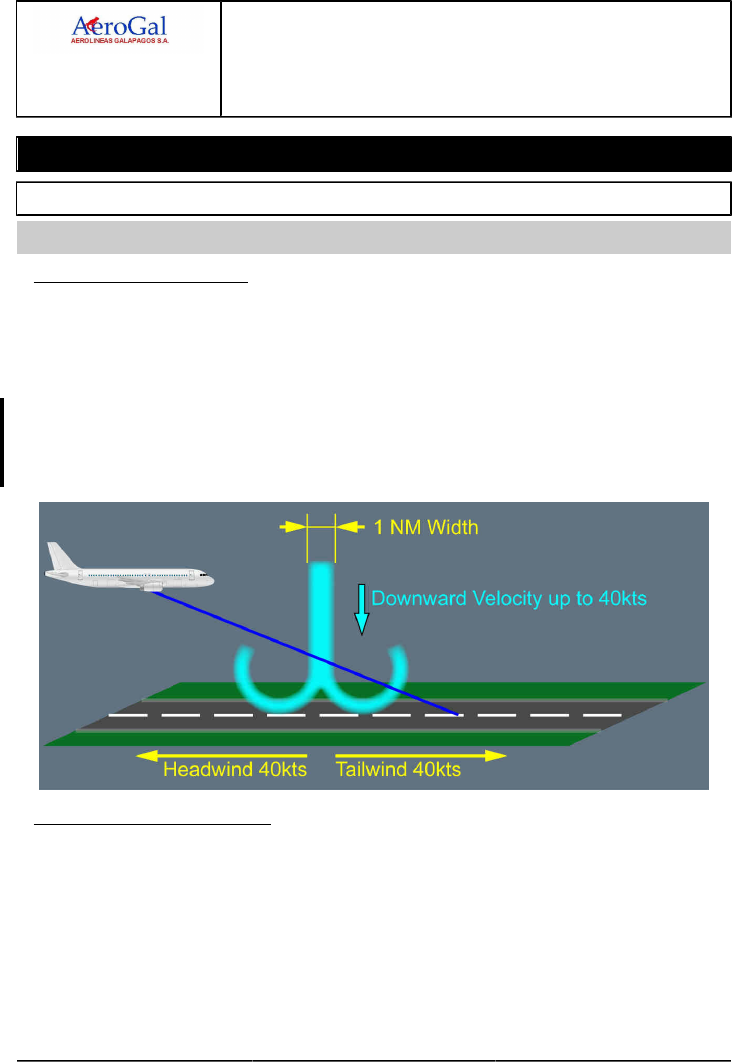
A318/A319/A320/A321
FLIGHT CREW
TECHNIQUES MANUAL
PROCEDURES
NORMAL PROCEDURES
SUPPLEMENTARY PROCEDURES - ADVERSE WEATHER
GLG A318/A319/A320/A321 FLEET PR-NP-SP-10-10-3 P 1/6
FCTM A → 05 SEP 17
Windshear
GENERAL
Ident.: PR-NP-SP-10-10-3-00019324.0001001 / 31 AUG 17
Applicable to: ALL
1WINDSHEAR PHENOMENON
The windshear is mostly due to cool shaft of air, like a cylinder between 0.5 NM and 1.5 NM width
that is moving downward. When the air encounters the ground:
‐ Mushrooms horizontally, causing horizontal wind gradient
‐ Curls inward at the edges, causing vertical air mass movement.
Flight safety is affected, because:
‐ Horizontal wind gradient significantly affects lift, causing the aircraft to descend or to reach very
high AOA
‐ Vertical air mass movement severely affect the aircraft flight path.
AWARENESS AND AVOIDANCE
Awareness of the weather conditions that cause windshear will reduce the risk of an encounter.
Studying meteorological reports and listening to tower reports will help the flight crew to assess the
weather conditions that are to be expected during takeoff or landing.
If a windshear encounter is likely, the takeoff or landing should be delayed until the conditions
improve, e.g. until a thunderstorm has moved away from the airport.

A318/A319/A320/A321
FLIGHT CREW
TECHNIQUES MANUAL
PROCEDURES
NORMAL PROCEDURES
SUPPLEMENTARY PROCEDURES - ADVERSE WEATHER
GLG A318/A319/A320/A321 FLEET PR-NP-SP-10-10-3 P 2/6
FCTM ← A → 05 SEP 17
2STRATEGY TO COPE WITH WINDSHEAR
The windshear and microburst are hazardous phenomena for an aircraft at takeoff or landing. The
strategy to cope with windshear is:
‐Increasing flight crew awareness through the Predictive Windshear System (if available)
‐Informing the flight crew of unexpected air mass variations through FPV and approach speed
variations
‐Warning the flight crew of significant loss of energy through "SPEED, SPEED, SPEED" and
"WINDSHEAR" aural warnings (if available)
‐Providing effective tools to escape the shear through ALPHA FLOOR protection, SRS pitch
order, high AOA protection and Ground Speed mini protection.
INCREASING FLIGHT CREW AWARENESS (IF AVAILABLE)
When the airshaft of a microburst reaches the ground, it mushrooms outward carrying with it a
large number of falling rain droplets. The radar can measure speed variations of the droplets,
and as a result, assess wind variations. This predictive capability to assess wind variations is
performed by the Predictive Windshear System (PWS ). The PWS automatically operates below
a given altitude (Refer to FCOM/DSC-34-SURV-30-20 General), if the radar is ON or OFF,
provided that the PWS sw is in the AUTO position.
INFORMING FLIGHT CREW
The FPV associated with the approach speed variations (GS mini protection) is an effective
means for informing the flight crew of unexpected air mass variations:
Approach speed variations and lateral FPV displacement reflect horizontal wind gradient.
Vertical FPV displacement reflects the vertical air mass movement.
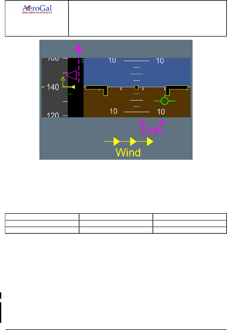
A318/A319/A320/A321
FLIGHT CREW
TECHNIQUES MANUAL
PROCEDURES
NORMAL PROCEDURES
SUPPLEMENTARY PROCEDURES - ADVERSE WEATHER
GLG A318/A319/A320/A321 FLEET PR-NP-SP-10-10-3 P 3/6
FCTM ← A → 05 SEP 17
WARNING THE FLIGHT CREW
The "SPEED, SPEED, SPEED" low energy warning (if available) is based on the aircraft speed,
acceleration and flight path angle. This warning attracts the PF eyes to the speed scale, and
request rapid thrust adjustment. In windshear conditions, it is the first warning to appear, before
the activation of the alpha floor. The following table provides some typical values of the speed at
which the warning could occur in two different circumstances.
Deceleration Rate Flight Path Angle Warning
-1 kt/second -3 ° VLS -7 kt
-1 kt/second -4 ° VLS -1 kt
In addition, the aircraft has a reactive windshear warning system. This system triggers if
the aircraft encounters windshear. In such a case, there is a "WINDSHEAR WINDSHEAR
WINDSHEAR" aural warning.
PROVIDING EFFECTIVE TOOLS
There are three efficient tools to assist the flight crew to escape:
‐ The alpha floor protection
‐ the SRS AP/FD pitch law
‐ The high angle of attack protection.
When the alpha floor protection is triggered, the A/THR triggers TOGA on all engines. The
FMA displays A FLOOR , that changes to TOGA LK , when the aircraft angle-of-attack has
decreased. TOGA /LK can only be deselected by turning the A/THR off.

A318/A319/A320/A321
FLIGHT CREW
TECHNIQUES MANUAL
PROCEDURES
NORMAL PROCEDURES
SUPPLEMENTARY PROCEDURES - ADVERSE WEATHER
GLG A318/A319/A320/A321 FLEET PR-NP-SP-10-10-3 P 4/6
FCTM ← A to B → 05 SEP 17
The SRS pitch mode ensures the best aircraft climb performance. Therefore, the procedure
requests following the SRS pitch bar and possibly full aft stick, in order to follow the SRS orders
and minimize the loss of height.
The high angle-of-attack protection enables the PF to safely pull full aft stick, if needed, in
order to follow the SRS pitch order, or to rapidly counteract a down movement. This provides
maximum lift and minimum drag, by automatically retracting the speed brakes, if they are
extended.
OPERATIONAL RECOMMENDATIONS
Ident.: PR-NP-SP-10-10-3-00016325.0001001 / 20 MAR 17
Applicable to: ALL
GENERAL GUIDELINE
‐ Predictive windshear warning (“WINDSHEAR AHEAD" and "GO AROUND WINDSHEAR
AHEAD" aural alerts), reactive windshear warning ("WINDHEAR WINDSHEAR WINDSHEAR"
aural alert) and windshear detected by the flight crew, request immediate actions that are given
in memory item procedures.
The following recommendations apply:
• If the memory item request to set TOGA thrust for takeoff or go-around, the flight crew should
follow SRS orders and if necessary pull the sidestick fully back.
If the FD bars are not displayed, the flight crew should move toward an initial pitch attitude of
17.5 °. Then, if necessary, to prevent a loss in altitude, increase the pitch attitude.
• If the AP is engaged, the flight should keep it engaged. Autopilot disengages if the angle of
attack value goes above α prot
• The flight crew should monitor the flight path, the speed and the speed trend.
‐ Suspected windshear (upon ATC or traffic notification) and predictive windshear caution
(“MONITOR RADAR DISPLAY" aural alert) request anticipation of the flight crew to be prepared
for a possible windshear.
BEFORE TAKEOFF
SUSPECTED WINDSHEAR OR PREDICTIVE WINDSHEAR (ADVISORY, CAUTION OR
WARNING)
The takeoff should be delayed until conditions improve.
The flight crew should evaluate takeoff conditions by using observations and experience and by
checking the weather conditions.
The most favorable runway should be selected considering location of the likely windshear.
The flight crew should use the weather radar or the predictive windshear system before
commencing takeoff to ensure that the flight path clears any potential problem areas.

A318/A319/A320/A321
FLIGHT CREW
TECHNIQUES MANUAL
PROCEDURES
NORMAL PROCEDURES
SUPPLEMENTARY PROCEDURES - ADVERSE WEATHER
GLG A318/A319/A320/A321 FLEET PR-NP-SP-10-10-3 P 5/6
FCTM ← B → 05 SEP 17
DURING TAKEOFF AND INITIAL CLIMB OUT
SUSPECTED WINDSHEAR OR PREDICTIVE WINDSHEAR CAUTION
In the case of suspected windshear or if the predictive windshear aural alert “MONITOR RADAR
DISPLAY" is triggered (alert is inhibited when the speed is greater than 100 kt and altitude is
below 50 kt), the flight crew:
‐ Must set TOGA
‐ Can change the aircraft configuration, provided that the aircraft does not enter windshear.
PREDICTIVE WINDSHEAR WARNING
If the predictive windshear aural alert “WINDSHEAR AHEAD" is triggered during the takeoff roll
up to 100 kt, the captain must reject the takeoff (the aural alert is inhibited when the speed is
greater than 100 kt and altitude is below 50 ft).
If the predictive windshear aural alert “WINDSHEAR AHEAD" is triggered above 50 ft, the flight
crew must set TOGA. The flight crew can change the aircraft configuration, provided that the
aircraft does not enter windshear.
REACTIVE WINDSHEAR WARNING OR WINDSHEAR DETECTED BY THE FLIGHT CREW
‐ If windshear occurs before V1 with significant speed and speed trend variations and the
captain decides that there is sufficient runway to stop the airplane, the captain must initiate a
rejected take-off.
‐ If windshear occurs after V1, the flight crew must set TOGA. The following points should be
stressed:
• Rotate normally
• The PF must fly SRS pitch orders rapidly and smoothly, but not aggressively
• The configuration should not be changed until definitely out of the shear, because
operating the landing gear doors causes additional drag
• The PM should call wind variations from the ND and V/S
• When out of the shear, the PF should recover smoothly to a normal climb and the PM
should report the encounter to ATC.
DURING APPROACH
SUSPECTED WINDSHEAR OR PREDICTIVE WINDSHEAR ADVISORY/CAUTION
In the case of suspected windshear, predictive windshear aural alert “MONITOR RADAR
DISPLAY", or predictive windshear ADVISORY ICON displayed on the ND, the flight crew
should either delay the approach or divert to another airport.
However, if the approach is continued, the flight crew should consider the following:

A318/A319/A320/A321
FLIGHT CREW
TECHNIQUES MANUAL
PROCEDURES
NORMAL PROCEDURES
SUPPLEMENTARY PROCEDURES - ADVERSE WEATHER
GLG A318/A319/A320/A321 FLEET PR-NP-SP-10-10-3 P 6/6
FCTM ← B 05 SEP 17
‐ Evaluate conditions for safe landing by using the observations and experience, and by
checking the weather conditions
‐ The weather severity must be assessed with the weather radar display
‐ A most favorable runway must be considered (considering also the one which has the most
appropriate approach aid)
‐ A Conf 3 landing should be considered
‐ The use of managed speed in the approach phase is recommended to take advantage of the
G/S mini function (The G/S mini-function, associated with managed speed, carry extra speed
in strong wind conditions)
‐ The flight crew may increase VAPP displayed on MCDU PERF APP page up to a maximum
VLS +15 kt. In case of strong or gusty crosswind greater than 20 kt, Refer to QRH/PER-A
VAPP Determination without Failure (Paper Only), or use the LDG PERF application of
FlySmart with Airbus for VAPP determination.
‐ In very difficult weather conditions, the A/THR response time may not be sufficient to manage
the instantaneous loss of airspeed. Refer to PR-NP-SOP-190-CONF Use of A/THR for the
applicable technique description.
PREDICTIVE WINDSHEAR WARNING
If the predictive windshear aural alert “GO AROUND WINDSHEAR AHEAD" is triggered during
approach, the flight crew must set TOGA for go-around. The flight crew can change the aircraft
configuration, provided that the aircraft does not enter windshear:
REACTIVE WINDSHEAR WARNING OR WINDSHEAR DETECTED BY THE FLIGHT CREW
If windshear occurs during approach the PF must set TOGA and apply the associated memory
items. The following points should be stressed:
‐ The PF must fly SRS pitch orders rapidly and smoothly, but not aggressively.
‐ The configuration should not be changed until definitely out of the shear, because operating
the landing gear doors causes additional drag.
‐ The PM should call wind variation from the ND and V/S and,
‐ When out of the shear, the PF should recover smoothly to a normal climb. and the PM should
report the encounter to ATC.

A318/A319/A320/A321
FLIGHT CREW
TECHNIQUES MANUAL
PROCEDURES
NORMAL PROCEDURES
SUPPLEMENTARY PROCEDURES - GREEN OPERATING PROCEDURES
GLG A318/A319/A320/A321 FLEET PR-NP-SP-20 P 1/8
FCTM A to B → 22 MAR 17
GENERAL
Ident.: PR-NP-SP-20-00019335.0001001 / 20 MAR 17
Applicable to: ALL
This section describes the available cost-reduction guidelines for the different flight phases.
Operators can use these procedures in order to define their own cost-reduction policy.
Each Operator is responsible for the decision of what costs/parameters to reduce, for example
(non-exhaustive list):
‐ Maintenance costs
‐ Fuel consumption
‐ Operating costs
‐ Passenger comfort.
For example, the purpose of both Cost Index (CI) and Flexible Takeoff is to reduce general costs, not
the fuel consumption.
The information in this chapter is not applicable to all Operators to the same extent, and depends on
their specific operations (e.g. geographical location, airport conditions, local regulations, etc.).
The flight crew should decide which procedures to apply, in accordance with the Operator guidelines
and the flight conditions of the day.
DISPATCH
Ident.: PR-NP-SP-20-00019336.0001001 / 20 MAR 17
Applicable to: ALL
FUEL QUANTITY
The flight crew must determine and monitor the necessary fuel quantity at departure, from
accurate and consistent data (i.e. weather, performance factor, optimum flight level, average wind
speed, etc.).
The weight of any extra fuel will increase fuel consumption.
TAKEOFF CONFIGURATION
Fuel reduction is not a factor for the selection of a takeoff configuration.
The takeoff performance and best takeoff configuration depend on several operational and
environmental factors. The flight crew should select the takeoff configuration that:
‐ Optimizes takeoff performance (takeoff weight, etc.)
‐ If possible, increases flexible temperature
‐ Reduces takeoff speed (higher configuration for a dedicated flexible temperature).
A higher slats and flaps configuration (i.e. slats and flaps more extended) slightly increases fuel
consumption. But, with a higher flexible temperature, such a higher configuration results in a cost
reduction.
A318/A319/A320/A321
FLIGHT CREW
TECHNIQUES MANUAL
PROCEDURES
NORMAL PROCEDURES
SUPPLEMENTARY PROCEDURES - GREEN OPERATING PROCEDURES
GLG A318/A319/A320/A321 FLEET PR-NP-SP-20 P 2/8
FCTM ← B to D 22 MAR 17
TAKEOFF THRUST
When performance permits, use the highest flexible temperature for takeoff.
Takeoff with flexible thrust increases fuel consumption compared with takeoff with TOGA thrust,
due to the longer takeoff phase. But the use of flexible thrust reduces engine wear and reduces
general costs.
PRELIMINARY COCKPIT PREPARATION
Ident.: PR-NP-SP-20-00020592.0001001 / 20 MAR 17
Applicable to: ALL
APU
The flight crew may delay, for as long as possible, the APU start, and use the ground electrical unit
and ground pneumatic unit when available.
AIR CONDITIONING
If one pack is sufficient to supply air when on ground, the flight crew can set one PACK to OFF.
In such a case, the flight crew should switch between the packs on each flight, in order to prevent
excessive wear of one pack.
EXTERNAL WALKAROUND
Ident.: PR-NP-SP-20-00019337.0001001 / 20 MAR 17
Applicable to: ALL
During the external inspection, the flight crew should pay attention to defects that may increase
aerodynamic drag, for example:
‐ Mismatch of aircraft fuselage panels
‐ Flight control surfaces that are not correctly aligned
‐ Worn seals on the airframe
‐ Peeling paint
‐ Dirt on the aircraft.

A318/A319/A320/A321
FLIGHT CREW
TECHNIQUES MANUAL
PROCEDURES
NORMAL PROCEDURES
SUPPLEMENTARY PROCEDURES - GREEN OPERATING PROCEDURES
GLG A318/A319/A320/A321 FLEET PR-NP-SP-20 P 3/8
FCTM E to F 22 MAR 17
COCKPIT PREPARATION
Ident.: PR-NP-SP-20-00019338.0001001 / 20 MAR 17
Applicable to: ALL
FMGS INITIALIZATION
INIT PAGE
The flight crew should respectively check that:
‐ The Cost Index (CI ) is consistent with the Computerized Flight Plan (CFP). The CI is the ratio
of time costs versus fuel costs. The purpose of the CI is not to reduce fuel consumption
‐ The tropopause value is correct, in order to ensure the accuracy of FMS predictions.
TAKEOFF PERF PAGE
If conditions and regulations permit, the flight crew should reduce the altitude for both the thrust
reduction altitude (THR RED ALT ) and the acceleration altitude (ACCEL ALT).
Depending on the regulations, the lowest authorized altitude may be 400 ft.
TAKEOFF RUNWAY OPTIMIZATION
The takeoff performance is the first factor to consider in the selection of the takeoff runway.
When possible, the flight crew should request takeoff on the runway that minimizes the taxi time
and optimizes the departure trajectory, in order to minimize the flight time.
BEFORE PUSHBACK OR START
Ident.: PR-NP-SP-20-00019339.0001001 / 20 MAR 17
Applicable to: ALL
PUSHBACK/START CLEARANCE
When conditions and ATC permit, the flight crew should delay the engine start for as long as
possible. This is to reduce time spent with the engines running before takeoff.
Before takeoff, the flight crew must ensure engine warm-up, in order to prevent engine wear, and
to maintain engine performance.
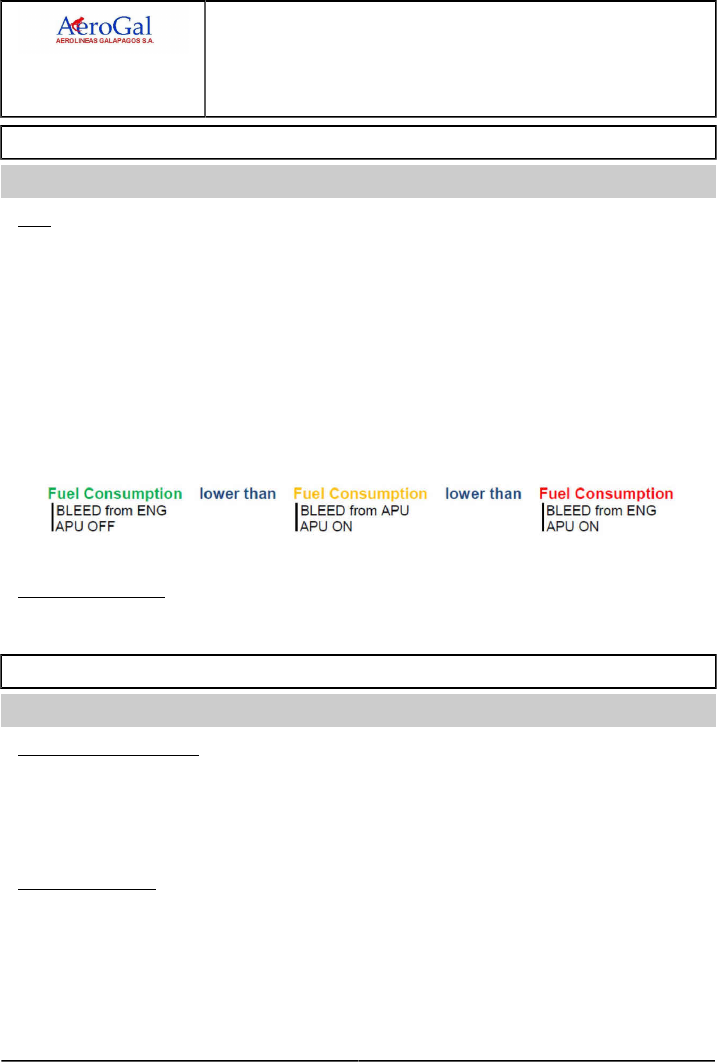
A318/A319/A320/A321
FLIGHT CREW
TECHNIQUES MANUAL
PROCEDURES
NORMAL PROCEDURES
SUPPLEMENTARY PROCEDURES - GREEN OPERATING PROCEDURES
GLG A318/A319/A320/A321 FLEET PR-NP-SP-20 P 4/8
FCTM G to H 22 MAR 17
AFTER START
Ident.: PR-NP-SP-20-00019340.0001001 / 20 MAR 17
Applicable to: ALL
APU
‐ If the APU is not necessary during or after taxi, the flight crew should set the APU bleed to off
and shut down the APU . Fuel consumption is reduced when the APU is not running, even if
bleed air is supplied by the engines.
‐ If the APU is necessary during or after taxi (e.g. when takeoff performance requires APU bleed),
the flight crew may set the APU bleed to ON, in order to reduce fuel consumption. This opens
the crossbleed valve and automatically closes the engine bleed. As the bleed air is not supplied
by the engines, the fuel consumption is reduced.
However, the use of APU bleed can lead to exhaust gases ingestion into the air conditioning
system.
AIR CONDITIONING
Consider LO (ECON) mode. Refer to FCOM/PRO-NOR-SOP-06 Overhead Panel - Air Cond
TAXI
Ident.: PR-NP-SP-20-00019341.0001001 / 20 MAR 17
Applicable to: ALL
THRUST MANAGEMENT
Idle thrust is sufficient to move a light aircraft during taxi. If necessary, the flight crew should apply
a small thrust increase.
Excessive thrust burns more fuel, requires more brake application, and results in an increase in
brake wear.
ONE ENGINE TAXI
Refer to FCOM/Refer to FCOM/PRO-SUP - One Engine Taxi - Departure

A318/A319/A320/A321
FLIGHT CREW
TECHNIQUES MANUAL
PROCEDURES
NORMAL PROCEDURES
SUPPLEMENTARY PROCEDURES - GREEN OPERATING PROCEDURES
GLG A318/A319/A320/A321 FLEET PR-NP-SP-20 P 5/8
FCTM I to K → 22 MAR 17
BEFORE TAKEOFF
Ident.: PR-NP-SP-20-00019342.0001001 / 20 MAR 17
Applicable to: ALL
AIR CONDITIONING
Before takeoff, the flight crew can set both packs to OFF. Refer to FCOM/PRO-NOR-SOP-11
Before Takeoff - Packs.
CLIMB
Ident.: PR-NP-SP-20-00020597.0001001 / 20 MAR 17
Applicable to: ALL
ECON SPEED
Unless restricted by the ATC , the flight crew should use managed speed during climb, in order to
fly at the optimum ECON speed.
ACCELERATION BELOW 10 000 FT
By default, the FMS flight plan takes into account the 250 kt speed limitation below 10 000 ft. If the
ATC permits, the flight crew can remove this limitation, in order to accelerate and save fuel.
CRUISE
Ident.: PR-NP-SP-20-00020598.0001001 / 20 MAR 17
Applicable to: ALL
OPTIMUM FLIGHT LEVEL (OPT FL)
During cruise, the OPT FL increases while the aircraft weight decreases.
The flight crew should monitor the OPT FL, and fly at the most appropriate flight level for optimum
aircraft performance and fuel consumption.
For additional information, Refer to PR-NP-SOP-150 Step Climb.
WIND UPDATE
The flight crew should insert accurate and up-to-date wind information in the FMS, in order to
optimize respectively:
‐ Fuel predictions
‐ Determination of OPT FL.
The flight crew should update wind information when the change is more than:
‐ 30 ° in direction, or
‐ 30 kt in speed.
For additional information, Refer to PR-NP-SOP-150 Wind and Temperature.

A318/A319/A320/A321
FLIGHT CREW
TECHNIQUES MANUAL
PROCEDURES
NORMAL PROCEDURES
SUPPLEMENTARY PROCEDURES - GREEN OPERATING PROCEDURES
GLG A318/A319/A320/A321 FLEET PR-NP-SP-20 P 6/8
FCTM ← K to L 22 MAR 17
MANAGED SPEED
The flight crew should use managed speed mode, in order to:
‐ Fly at ECON speed
‐ Optimize speed in accordance with the CI and flight conditions of the day.
The flight crew should not modify the CI in flight.
For additional information, Refer to PR-NP-SOP-150 Cost Index.
DESCENT PREPARATION
Ident.: PR-NP-SP-20-00019343.0001001 / 20 MAR 17
Applicable to: ALL
LANDING RUNWAY OPTIMIZATION
When landing performance permits, the flight crew should ask the ATC to land on the runway that
minimizes approach and/or taxi time.
LANDING PREPARATION
When landing performance permits, the best combination to reduce fuel costs and brakes
oxidation is: CONF 3 + REV IDLE + Autobrake LO.
If the flight crew needs to reduce the landing distance, they should consider to use the
deceleration devices in the following order:
1. FLAPS FULL
2. REV MAX
3. Autobrake MED.
The flight crew should avoid the use of Autobrake MED in combination with CONF 3 and REV
IDLE. This is because this configuration highly increases brake temperature and, as a result,
brakes oxidation, which may be severe.
L2 For more information about brakes oxidation, Refer to PR-NP-SOP-160 Brakes Oxidation.
L1 When the flight crew rides the brakes (and overrides the Autobrake) at landing, brakes oxidation
may occur.

A318/A319/A320/A321
FLIGHT CREW
TECHNIQUES MANUAL
PROCEDURES
NORMAL PROCEDURES
SUPPLEMENTARY PROCEDURES - GREEN OPERATING PROCEDURES
GLG A318/A319/A320/A321 FLEET PR-NP-SP-20 P 7/8
FCTM M to O 22 MAR 17
DESCENT
Ident.: PR-NP-SP-20-00020599.0001001 / 20 MAR 17
Applicable to: ALL
MANAGED SPEED
The flight crew should use managed speed mode, in order to:
‐ Fly at ECON speed
‐ Optimize speed in accordance with the CI and flight conditions of the day.
HOLDING
Ident.: PR-NP-SP-20-00020600.0001001 / 20 MAR 17
Applicable to: ALL
FLAPS CONFIGURATION
Clean configuration is the optimum configuration for a holding circuit.
When required (holding pattern or speed limitation), the flight crew may consider the selection of
CONF 1.
OPTIMUM SPEED
In clean configuration, the flight crew should fly at Green Dot speed, in order to optimize the
Lift-to-Drag ratio.
APPROACH
Ident.: PR-NP-SP-20-00020601.0001001 / 20 MAR 17
Applicable to: ALL
DECELERATION
When conditions and ATC permit, a decelerated approach reduces fuel consumption.
When the approach type does not enable to fly a decelerated approach, the flight crew should fly
an early-stabilized approach.
FLAPS CONFIGURATION
When landing performance permits, the selection of CONF 3 reduces both the approach time and
fuel consumption.

A318/A319/A320/A321
FLIGHT CREW
TECHNIQUES MANUAL
PROCEDURES
NORMAL PROCEDURES
SUPPLEMENTARY PROCEDURES - GREEN OPERATING PROCEDURES
GLG A318/A319/A320/A321 FLEET PR-NP-SP-20 P 8/8
FCTM P 22 MAR 17
AFTER LANDING
Ident.: PR-NP-SP-20-00019344.0001001 / 20 MAR 17
Applicable to: ALL
APU
After landing, the flight crew should delay, for as long as possible, the start of the APU.
If only the ground pneumatic unit is available at the gate, the flight crew may keep the APU bleed
off during transit.
AIR CONDITIONING
If one pack is sufficient to supply air when on ground, the flight crew can set one PACK to OFF.
In such a case, the flight crew should switch between the packs on each flight, in order to prevent
excessive wear of one pack.
ONE ENGINE TAXI
Refer to FCOM/Refer to FCOM/PRO-SUP - One Engine Taxi - Arrival

A318/A319/A320/A321
FLIGHT CREW
TECHNIQUES MANUAL
PROCEDURES
NORMAL PROCEDURES
SUPPLEMENTARY PROCEDURES - RADIUS TO FIX (RF) LEGS
GLG A318/A319/A320/A321 FLEET PR-NP-SP-30 P 1/4
FCTM A → 22 MAR 17
RADIUS TO FIX (RF) LEGS
Applicable to: ALL
Ident.: PR-NP-SP-30-A-00019329.0001001 / 20 MAR 17
GENERAL
A Radius-to-Fix (RF ) leg is an arc of circle with a fixed radius coded in the FMS Navigation Data
Base. The rounded value of the radius is displayed on the MCDU FLIGHT PLAN page and is
called ARC value.
Ident.: PR-NP-SP-30-A-00019330.0001001 / 20 MAR 17
USE OF AP/FD
Depending on the RNP operations, use of the FD s or the AP /FD may be mandatory.
Ident.: PR-NP-SP-30-A-00019331.0001001 / 20 MAR 17
SPEED MANAGEMENT ALONG RF LEGS
When flying an RF leg, the FMS adapts the bank angle to fly the arc. The bank angle is a function
of the ground speed.
If the ground speed is excessive, the requested bank angle to follow the trajectory can be higher
than the maximum bank angle permitted by the Flight Guidance (FG) system (30 ° in normal
conditions). In this case the aircraft will overshoot the trajectory.
Therefore, to fly RF legs, the flight crew should be aware of the following operational
recommendations:
‐ Respect speed constraints on RF legs. Use managed speed.
‐ Pay attention to strong winds, particularly to high tailwinds that increase the ground speed
‐ Monitor the bank angle, particularly when near 30 ° (i.e. the maximum bank angle with the AP
/FD engaged).
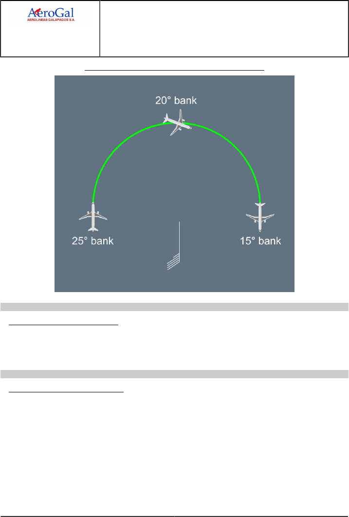
A318/A319/A320/A321
FLIGHT CREW
TECHNIQUES MANUAL
PROCEDURES
NORMAL PROCEDURES
SUPPLEMENTARY PROCEDURES - RADIUS TO FIX (RF) LEGS
GLG A318/A319/A320/A321 FLEET PR-NP-SP-30 P 2/4
FCTM ← A → 22 MAR 17
Variation of the bank angle due to the wind in RF legs
Ident.: PR-NP-SP-30-A-00019332.0001001 / 22 MAR 17
GO-AROUND DURING RF LEG
When the flight crew selects TOGA thrust, particularly in a turn, they must check that the NAV
mode immediately engages in order to stay on the desired track.
If the NAV mode does not automatically engage, the flight crew must engage it manually.
Ident.: PR-NP-SP-30-A-00019333.0001001 / 20 MAR 17
USE OF THE DIR TO FUNCTION
In flight, the flight crew must use the DIR TO function only above the MSA.
The flight crew must use the RADIAL IN function when performing a DIR TO towards a waypoint
followed by a RF leg. This enables the alignment of the aircraft with the subsequent RNP F-PLN
track.
The flight crew must not descend below the MSA until the aircraft is established on the F-PLN leg.

A318/A319/A320/A321
FLIGHT CREW
TECHNIQUES MANUAL
PROCEDURES
NORMAL PROCEDURES
SUPPLEMENTARY PROCEDURES - RADIUS TO FIX (RF) LEGS
GLG A318/A319/A320/A321 FLEET PR-NP-SP-30 P 3/4
FCTM ← A → 22 MAR 17
Ident.: PR-NP-SP-30-A-00019334.0001001 / 20 MAR 17
ENGINE-OUT CONSIDERATIONS
The bank angle limit of the FG is 30 ° with one engine inoperative, when NAV , APP NAV , or
FINAL APP modes are engaged.
With one engine inoperative, the bank angle limit of the FG may be lower than 30 ° when the IAS
is lower than maneuvering speeds VMAN. The VMAN is the F speed, S speed, or Green Dot
speed, depending on the flap configuration. The bank angle limit of the FG depends on the IAS as
illustrated on the following graph:
During go-around or departure with one engine inoperative, the IAS may be lower than the current
maneuvering speed, which will limit the bank angle.

A318/A319/A320/A321
FLIGHT CREW
TECHNIQUES MANUAL
PROCEDURES
NORMAL PROCEDURES
SUPPLEMENTARY PROCEDURES - RADIUS TO FIX (RF) LEGS
GLG A318/A319/A320/A321 FLEET PR-NP-SP-30 P 4/4
FCTM ← A 22 MAR 17
The flight crew must be aware that during acceleration, flaps retraction at the usual speeds (F
speed, then S speed) may affect the turn radius capability and be incompatible with the procedure
being flown.

A318/A319/A320/A321
FLIGHT CREW
TECHNIQUES MANUAL
PROCEDURES
NORMAL PROCEDURES
SUPPLEMENTARY PROCEDURES - TOUCH AND GO
GLG A318/A319/A320/A321 FLEET PR-NP-SP-40 P 1/4
FCTM A → 22 MAR 17
TOUCH AND GO
Applicable to: ALL
Ident.: PR-NP-SP-40-A-00020989.0001001 / 20 MAR 17
GENERAL
The primary objective of a touch and go is to practice approach and landing. Touch and go are not
intended for neither landing roll nor takeoff procedure training.
Except for the items detailed hereafter, the flight crew must apply the SOPs and standard
tasksharing when they perform a touch and go. On repetitive patterns without significant change,
the instructor can decide to adapt the After Takeoff and Approach checklists.
The flight crew should pay attention to the following remarks when they perform a touch and go:
‐ The decision speed (V1 ) does not apply to touch and go. The PFD does not display V1 during
the roll phase of a touch and go. Therefore, the flight crew should be go-minded.
‐ If the instructor wants to abandon the touch and go, the instructor calls “STOP – I HAVE
CONTROL". Simultaneously the instructor takes control and stops the aircraft, with the use of
maximum braking and reverse. When the aircraft stops, the instructor calls for any applicable
ECAM actions. The decision to discontinue a touch and go after the application of TOGA must
only be taken if the instructor is sure that the aircraft cannot safely fly.
‐ If the trainee selects reverse thrust, the flight crew must perform a full-stop landing.
Ident.: PR-NP-SP-40-A-00020990.0001001 / 20 MAR 17
DURING FINAL APPROACH
Before each touch and go, the instructor confirms with the trainee that both of the following apply:
‐ Reverse thrust will not be selected
‐ Brakes (auto or manual) will not be used.
Ident.: PR-NP-SP-40-A-00020991.0001001 / 20 MAR 17
DURING TOUCH AND GO
Trainee Instructor
‐ Perform usual flare and landing technique
‐ Maintain the runway centerline.
‐Disarm the ground spoilers (1)
‐ Order “STAND UP".
Move forward the thrust levers approximately 5 cm (2 in), in
order to prevent the reduction of engines to ground idle.
Continued on the following page

A318/A319/A320/A321
FLIGHT CREW
TECHNIQUES MANUAL
PROCEDURES
NORMAL PROCEDURES
SUPPLEMENTARY PROCEDURES - TOUCH AND GO
GLG A318/A319/A320/A321 FLEET PR-NP-SP-40 P 2/4
FCTM ← A → 22 MAR 17
Continued from the previous page
Trainee Instructor
‐Set flaps configuration for takeoff (2)
‐ If necessary, reset the rudder trim
‐ Monitor/adjust the pitch trim movement towards the
green band
‐ Place one hand behind the thrust levers to ensure that
they are advanced to approximately 5 cm (2 in)
‐ Order “GO" when the aircraft is in the correct
configuration (pitch trim, rudder trim and flaps).
Set TOGA thrust.
Remove the hand from the thrust levers.
‐ Check engine parameters and announce “THRUST SET"
‐ Order “ROTATE" at VAPP
‐ Maintain the hand behind the thrust levers to ensure that
the trainee does not perform an inadvertent reduction of
thrust or unwanted stop.
Rotate the aircraft and target takeoff pitch attitude, then
follow SRS.
(1) At nosewheel touchdown, the instructor pushes on the SPEED BRAKE lever to disarm the ground
spoilers. The objective is to initiate the immediate retraction of the ground spoilers, and not to wait
for their automatic retraction while the thrust levers are advanced.
Carefully disarm the ground spoilers, so that the SPEED BRAKE lever is not moved. If the SPEED
BRAKE lever is not in the fully-retracted position, the CONFIG SPEED BRAKES NOT RETRACTED alert
will appear and the SPEED BRAKE lever will possibly command speed brakes extension. As per
aircraft design, ground spoilers automatically retract when thrust levers are set above CLB detent.
(2) Flap settings are as follows:
‐Landing configuration: CONF FULL
‐Takeoff configuration: CONF 2.
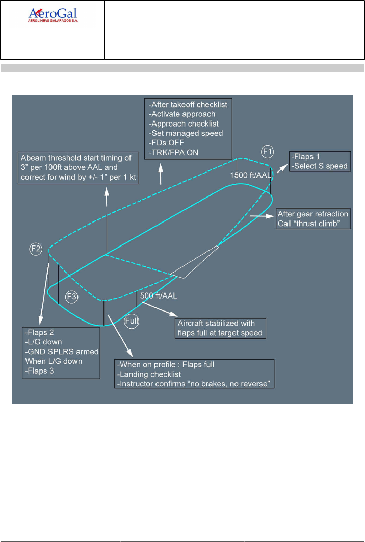
A318/A319/A320/A321
FLIGHT CREW
TECHNIQUES MANUAL
PROCEDURES
NORMAL PROCEDURES
SUPPLEMENTARY PROCEDURES - TOUCH AND GO
GLG A318/A319/A320/A321 FLEET PR-NP-SP-40 P 3/4
FCTM ← A 22 MAR 17
Ident.: PR-NP-SP-40-A-00020992.0001001 / 20 MAR 17
VISUAL PATTERN

A318/A319/A320/A321
FLIGHT CREW
TECHNIQUES MANUAL
PROCEDURES
NORMAL PROCEDURES
SUPPLEMENTARY PROCEDURES - TOUCH AND GO
Intentionally left blank
GLG A318/A319/A320/A321 FLEET PR-NP-SP-40 P 4/4
FCTM 22 MAR 17

A318/A319/A320/A321
FLIGHT CREW
TECHNIQUES MANUAL
PROCEDURES
NORMAL PROCEDURES
SUPPLEMENTARY PROCEDURES - STOP AND GO
GLG A318/A319/A320/A321 FLEET PR-NP-SP-50 P 1/2
FCTM A → 22 MAR 17
STOP AND GO
Applicable to: ALL
Ident.: PR-NP-SP-50-A-00020993.0001001 / 20 MAR 17
GENERAL
The primary objective of a stop and go is to practice:
‐ Approach and landing
‐ Roll out and runway vacation
‐ Taxi and takeoff.
Except for the items detailed hereafter, the flight crew must apply the SOPs and standard
tasksharing when they perform a stop and go.
The flight crew should taxi the aircraft to the runway threshold for the next takeoff.
Ident.: PR-NP-SP-50-A-00020994.0001001 / 20 MAR 17
WHEN THE RUNWAY IS VACATED
PF PM
Disarm ground spoilers. Set the FLAPS lever to 0.
Ident.: PR-NP-SP-50-A-00020995.0001001 / 20 MAR 17
BEFORE NEXT TAKEOFF
Before the next takeoff, the flight crew should perform all of the following actions:
‐ Set FMS:
• Set INIT data
• Set ZFW & ZFW CG data
• Set F-PLN data
• Set TAKEOFF data.
‐ Set FCU and reset FDs
‐ Set Takeoff configuration:
• Arm Ground Spoilers
• Set Flaps
• Set / check Rudder and Pitch Trims
• Set MAX Autobrake mode.
‐ Perform T.O CONFIG test
‐ Perform After Start checklist
‐ Request ATC clearance

A318/A319/A320/A321
FLIGHT CREW
TECHNIQUES MANUAL
PROCEDURES
NORMAL PROCEDURES
SUPPLEMENTARY PROCEDURES - STOP AND GO
GLG A318/A319/A320/A321 FLEET PR-NP-SP-50 P 2/2
FCTM ← A 22 MAR 17
‐ Perform Takeoff briefing
‐ Perform Before Takeoff checklist.
Ident.: PR-NP-SP-50-A-00020996.0001001 / 20 MAR 17
BEFORE LINE UP
PF PM
Check brake temperature. Check brake temperature (1).
(1) In order to limit the brake temperature, the flight crew should select the appropriate exit after
landing. If performance permits, the instructor can decide to keep the landing gear down after
takeoff for brake cooling.

A318/A319/A320/A321
FLIGHT CREW
TECHNIQUES MANUAL
PROCEDURES
ABNORMAL AND EMERGENCY PROCEDURES
GENERAL
GLG A318/A319/A320/A321 FLEET PR-AEP-GEN P 1/2
FCTM A 22 MAR 17
INTRODUCTION
Ident.: PR-AEP-GEN-00016331.0001001 / 20 MAR 17
Applicable to: ALL
The Abnormal and Emergency Procedures chapter highlights techniques that will be used in
some abnormal and emergency operations. Some of the procedures discussed in this chapter
are the result of double or triple failures. Whilst it is very unlikely that any of these failures will be
encountered, it is useful to have a background understanding of the effect that they have on the
handling and management of the aircraft. In all cases, the ECAM /QRH should be handled as
described in FCTM (Refer to AOP-30-30 General).

A318/A319/A320/A321
FLIGHT CREW
TECHNIQUES MANUAL
PROCEDURES
ABNORMAL AND EMERGENCY PROCEDURES
GENERAL
Intentionally left blank
GLG A318/A319/A320/A321 FLEET PR-AEP-GEN P 2/2
FCTM 22 MAR 17

A318/A319/A320/A321
FLIGHT CREW
TECHNIQUES MANUAL
PROCEDURES
ABNORMAL AND EMERGENCY PROCEDURES
AUTO FLIGHT
GLG A318/A319/A320/A321 FLEET PR-AEP-AUTOFLT P 1/2
FCTM A 22 MAR 17
FMGS FAILURE
Ident.: PR-AEP-AUTOFLT-00019223.0001001 / 20 MAR 17
Applicable to: ALL
SINGLE FMGC FAILURE
Should a single FMGC failure occurs, the AP , if engaged on affected side, will disconnect. The
AP will be restored using the other FMGC . The A/THR remains operative. Furthermore, flight plan
information on the affected ND may be recovered by using same range as the opposite ND . The
crew should consider a FMGC reset as detailed in QRH.
DUAL FMGC FAILURE
Should a dual FMGC failure occurs, the AP /FD and A/THR will disconnect. The crew will try to
recover both AP and A/THR by selecting them back ON (The AP and A/THR can be recovered if
the FG parts of the FMGS are still available).
If both AP and A/THR cannot be recovered, the thrust levers will be moved to recover manual
thrust. The pilot will switch off the FD s and select TRK / FPA to allow the blue track index and the
bird to be displayed. The RMP s will be used to tune the NAVAIDs.
The crew will refer to the QRH for system reset considerations and then will Refer to
FCOM/DSC-22_20-90-10 Automatic FMGC Reset and Resynchronization - FM Reset to reload
both FMGC as required.

A318/A319/A320/A321
FLIGHT CREW
TECHNIQUES MANUAL
PROCEDURES
ABNORMAL AND EMERGENCY PROCEDURES
AUTO FLIGHT
Intentionally left blank
GLG A318/A319/A320/A321 FLEET PR-AEP-AUTOFLT P 2/2
FCTM 22 MAR 17

A318/A319/A320/A321
FLIGHT CREW
TECHNIQUES MANUAL
PROCEDURES
ABNORMAL AND EMERGENCY PROCEDURES
BRAKES
GLG A318/A319/A320/A321 FLEET PR-AEP-BRK P 1/2
FCTM A 05 SEP 17
LOSS OF BRAKING
Ident.: PR-AEP-BRK-00019299.0001001 / 25 JUL 17
Applicable to: ALL
GENERAL
If the flight crew does not perceive deceleration when required, the flight crew will apply the LOSS
OF BRAKING procedure from memory because of the urgency of the situation.
1PROCEDURE
USE OF REVERSE THRUST
‐ If needed, full reverse thrust may be used until coming to a complete stop. Below 70 kt, when
the flight crew considers that the aircraft can stop on the runway, the flight crew should set
idle reverse thrust
‐ Unless required due to an emergency, it is recommended to avoid the use of high level of
reverse thrust at low speed, in order to avoid engine stall and excessive EGT.
A/SKID & N/W STRG OFF
In order to successfully revert to alternate braking, it is important to sequence the actions in
three steps. The PF should:
1. Release the brake pedals
2. Request the PM to set the A/SKID & N/W STRG sw to OFF
3. Press the brake pedals, only after the PM has set the A/SKID & N/W STRG sw to OFF.
Modulate brake pedal pressure to maximum 1 000 PSI. At low ground speed, adjust brake
pressure as required. Monitor the brake pressure on the BRAKES PRESS indicator.
PARKING BRAKE
‐ Use short successive parking brake applications to stop the aircraft
‐ Brake onset asymmetry may be felt at each parking brake application
‐ If possible, delay the use of parking brake until low speed, to reduce the risk of tire burst and
lateral control difficulties.

A318/A319/A320/A321
FLIGHT CREW
TECHNIQUES MANUAL
PROCEDURES
ABNORMAL AND EMERGENCY PROCEDURES
BRAKES
Intentionally left blank
GLG A318/A319/A320/A321 FLEET PR-AEP-BRK P 2/2
FCTM 05 SEP 17

A318/A319/A320/A321
FLIGHT CREW
TECHNIQUES MANUAL
PROCEDURES
ABNORMAL AND EMERGENCY PROCEDURES
ELEC
GLG A318/A319/A320/A321 FLEET PR-AEP-ELEC P 1/2
FCTM A to C → 05 SEP 17
INTRODUCTION TO EMERGENCY ELECTRICAL CONFIGURATION
Ident.: PR-AEP-ELEC-00019224.0001001 / 20 MAR 17
Applicable to: ALL
The procedure discussed in this section is the EMERGENCY ELECTRICAL CONFIGURATION.
Whilst it is very unlikely that this failure will be encountered, it is useful:
‐ To refresh on the technical background
‐ To recall the general guidelines that must be followed in such a case
‐ To outline the main available systems according to the electrical power source.
TECHNICAL BACKGROUND
Ident.: PR-AEP-ELEC-00019225.0002001 / 25 JUL 17
Applicable to: ALL
1The emergency electrical configuration is due to the loss of AC BUS 1 and 2. The RAT extends
automatically. This powers the blue hydraulic circuit which drives the emergency generator. The
emergency generator supplies both AC and DC ESS BUS.
Below 125 kt, the RAT stalls and the emergency generator is no longer powered. The emergency
generation network is automatically transferred to the batteries and AC SHED ESS and DC SHED
ESS BUS are shed.
Below 100 kt, the DC BAT BUS is automatically connected and below 50 kt, the AC ESS BUS is
shed.
GENERAL GUIDELINES
Ident.: PR-AEP-ELEC-00019226.0004001 / 20 MAR 17
Applicable to: ALL
As only PFD 1 is available, the left hand seat pilot becomes PF . Once a safe flight path is
established, and the aircraft is under control, ECAM actions will be carried out.
This is a serious emergency and ATC should be notified using appropriate phraseology ("MAYDAY").
Although the ECAM displays LAND ASAP in red, it would be unwise to attempt an approach at a
poorly equipped airfield in marginal weather. However, prolonged flight in this configuration is not
recommended.
AP /FD and ATHR are lost. The flight is to be completed manually in alternate and then, when gear
down, in direct law. Crews should be aware that workload is immediately greatly increased.
As only the EWD is available, disciplined use of the ECAM Control Panel (ECP) is essential.
Consideration should be given to starting the APU as indicated by the ECAM and taking into account
the probability to restore using APU generator.
A clear reading of STATUS is essential to assess the aircraft status and properly sequence actions
during the approach.

A318/A319/A320/A321
FLIGHT CREW
TECHNIQUES MANUAL
PROCEDURES
ABNORMAL AND EMERGENCY PROCEDURES
ELEC
GLG A318/A319/A320/A321 FLEET PR-AEP-ELEC P 2/2
FCTM ← C to D 05 SEP 17
The handling of this failure is referred to as a "complex procedure". A summary for handling the
procedure is included in the QRH, which will be referred to upon completion of the ECAM procedure.
The ELEC EMER CONFIG SYS REMAINING list is available in QRH.
When landing gear is down, flight control law reverts to direct law.
The approach speed must be at least min RAT speed (140 kt) to keep the emergency generator
supplying the electrical network.
The BSCU are lost. Consequently, the NWS and anti skid are lost. Alternate braking with yellow
hydraulic pressure modulation up to 1 000 PSI will be used. Additionally, reversers are not available.
RA 1+2 are lost with their associated call out. Call out will be made by PM.
Approaching 50 kt during the landing roll, all CRTs will be lost.
REMAINING SYSTEMS
Ident.: PR-AEP-ELEC-00019227.0001001 / 20 MAR 17
Applicable to: ALL
The electrical distribution has been designed to fly, navigate, communicate and ensure passengers
comfort. The ELEC EMER CONFIG SYS REMAINING list is available in QRH. The significant
remaining systems are:
Significant remaining systems in ELEC EMER CONFIG
FLY PFD1, alternate law
NAVIGATE ND 1, FMGC 1, RMP 1, VOR 1/ILS 1, DME1
COMMUNICATE VHF 1, HF 1, ATC1
On BAT , some additional loads are lost such as FAC 1 and FMGC1.

A318/A319/A320/A321
FLIGHT CREW
TECHNIQUES MANUAL
PROCEDURES
ABNORMAL AND EMERGENCY PROCEDURES
ENG
GLG A318/A319/A320/A321 FLEET PR-AEP-ENG P 1/20
FCTM A to B → 05 SEP 17
INTRODUCTION
Ident.: PR-AEP-ENG-00018094.0001001 / 20 MAR 17
Applicable to: ALL
Most engine malfunctions are taken into account by one or several ECAM alerts that warn the flight
crew and provide the flight crew with the actions to perform. However, some engine malfunctions
require some knowledge and the analysis of the flight crew, so that the flight crew can recognize,
understand, and manage these engine malfunctions.
When the flight crew identifies an abnormal parameter, the flight crew should use all the information
available to analyze the engine malfunction. The flight crew should not consider only this abnormal
parameter to perform their analysis.
If possible, the flight crew should keep the engine running in flight. Except if a procedure requires an
engine shutdown, it is usually preferable to keep the engine running. Even at idle, the engine powers
the hydraulic, electric, and bleed systems.
In addition, if the flight crew is not sure which engine has a malfunction, the flight crew should keep
the engines running. If really damaged, the affected engine will eventually fail.
ALL ENGINES FAILURE
Applicable to: ALL
Ident.: PR-AEP-ENG-A-00020207.0001001 / 20 MAR 17
INTRODUCTION
The all engines failure is the situation where the aircraft entirely or partially loses engine thrust,
and is no longer able to maintain level flight.
The all engines failure can be identified by the Flight Warning Computer (FWC) or by the flight
crew:
1. In most cases, the FWC detects an all engines failure condition and displays the ENG DUAL
FAILURE ECAM alert
2. In some cases, the FWC does not detect the all engines failure condition. In the case of partial
loss of thrust (no engine flame out) on one or more engines, the residual N2 may remain slightly
above the ENG 1(2) FAIL alert threshold.
Even if the ENG DUAL FAILURE alert is not triggered, the flight crew must rapidly decide to
apply either the ENG DUAL FAILURE QRH procedure, or the EMER LANDING QRH procedure,
depending on their assessment of the situation. If the flight crew considers there is sufficient time
to attempt an engine relight, they must apply the ENG DUAL FAILURE QRH procedure. However,
if the flight crew considers there is not sufficient time to attempt an engine relight, they must apply
the EMER LANDING QRH procedure. For more information, Refer to PR-AEP-MISC EMER
LANDING.

A318/A319/A320/A321
FLIGHT CREW
TECHNIQUES MANUAL
PROCEDURES
ABNORMAL AND EMERGENCY PROCEDURES
ENG
GLG A318/A319/A320/A321 FLEET PR-AEP-ENG P 2/20
FCTM ← B → 05 SEP 17
Ident.: PR-AEP-ENG-A-00020797.0001001 / 20 MAR 17
TECHNICAL BACKGROUND
An all engines failure situation mainly results in an emergency electrical configuration (Refer to
PR-AEP-ELEC Introduction to Emergency Electrical Configuration), and in the loss of the green
and yellow hydraulic systems.
ELECTRICAL CONFIGURATION
In the case of an all engines failure:
‐ All the AC busbars are lost
‐ The RAT automatically deploys to supply the emergency generator (EMER GEN or CSM/G ).
The EMER GEN supplies both the AC ESS and the DC ESS bus bars.
The AC ESS SHED bus bar and DC ESS SHED bus bar are:
‐ Supplied by the CSM/G
‐ Shed, when the aircraft is supplied only by batteries.
The emergency generator can supply all the electrical loads that are necessary for the
remainder of the flight. The EMER GEN , that is connected to the network, remains connected
even if all the main generators are recovered (following engines relight), or if the APU generator
is connected.
Below FL 250, if the flight crew can start the APU, the normal electrical configuration partly
recovers.
HYDRAULIC GENERATION
The green and yellow hydraulic systems are lost. The RAT automatically deploys to pressurize
the blue hydraulic system.
When the hydraulic power is lost, the right aileron is lost and goes to its zero hinge moment
position. There is enough authority to balance this roll, but instead of flying with permanent stick
deflection in roll, the PF may use the rudder trim to generate sideslip and therefore compensate
for this upfloating aileron. When the APU generator is connected, the control of the right aileron
is restored due to the recovery of ELAC 2.
As hydraulic power is only available from the RAT , the PF should avoid large and rapid rudder
deflections.
If engine windmilling is sufficient, additional hydraulic power may be recovered.
Ident.: PR-AEP-ENG-A-00020798.0002001 / 20 MAR 17
GENERAL PHILOSOPHY
The ECAM provides the first immediate actions to be performed, then refers to two different
QRH procedures: ENG DUAL FAILURE with FUEL REMAINING or ENG DUAL FAILURE
with NO FUEL REMAINING procedures. Consequently, the flight crew must first apply the
steps displayed on the ECAM , then apply the appropriate QRH procedure depending whether

A318/A319/A320/A321
FLIGHT CREW
TECHNIQUES MANUAL
PROCEDURES
ABNORMAL AND EMERGENCY PROCEDURES
ENG
GLG A318/A319/A320/A321 FLEET PR-AEP-ENG P 3/20
FCTM ← B → 05 SEP 17
fuel is remaining or not. These QRH procedures are optimized to cope with each situation by
providing corresponding OPERATING SPEEDS and required procedures until landing, including
APPROACH PREPARATION, FORCED LANDING and DITCHING.
In the fuel remaining case,
• The actions should be commenced, with attention to the optimum relight speed without starter
assist (with wind milling). If there is no relight within 30 s, the ENG DUAL FAILURE with FUEL
REMAINING QRH procedure orders engine masters off for 30 s. This is to permit ventilation of
the combustion chamber. Then, the engine masters may be set ON again. Without starter assist
(wind milling), this can be done at the same time.
• If the crew wants to take credit of the APU bleed air, the APU should be started below FL 250.
Below FL 200, an engine relight should be attempted with starter assist (using the APU bleed).
• Green dot, which corresponds to the optimum relight speed with starter assist, is displayed on
the left PFD . With starter assist (APU bleed), only one engine must be started at a time.
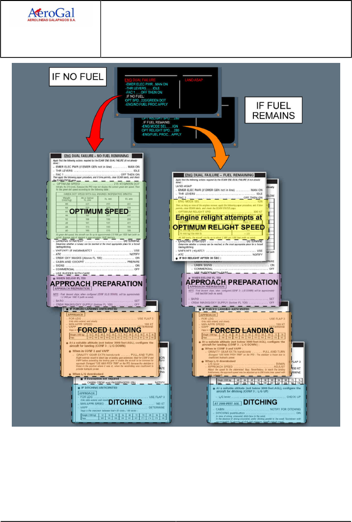
A318/A319/A320/A321
FLIGHT CREW
TECHNIQUES MANUAL
PROCEDURES
ABNORMAL AND EMERGENCY PROCEDURES
ENG
GLG A318/A319/A320/A321 FLEET PR-AEP-ENG P 4/20
FCTM ← B 05 SEP 17

A318/A319/A320/A321
FLIGHT CREW
TECHNIQUES MANUAL
PROCEDURES
ABNORMAL AND EMERGENCY PROCEDURES
ENG
GLG A318/A319/A320/A321 FLEET PR-AEP-ENG P 5/20
FCTM C to D 05 SEP 17
ENGINE FAILURE - GENERAL
Ident.: PR-AEP-ENG-00016338.0001001 / 20 MAR 17
Applicable to: ALL
An engine flameout can be due to many reasons, for example:
‐ Fuel starvation
‐ Encounter with volcanic ash, sand or dust clouds
‐ Heavy rain, hail, or icing
‐ Bird strike
‐ Engine stall
‐ Engine control system malfunction.
An engine flameout may trigger an ECAM alert.
The flight crew can detect an engine flameout without damage by a rapid decrease of EPR /N1 , N2 ,
N3 , EGT and FF.
The flight crew can suspect engine damage, if the flight crew observes two or more of the following
symptoms:
‐ Rapid increase of the EGT above the red line
‐ Important mismatch of the rotor speeds, or absence of rotation
‐ Significant increase of aircraft vibrations, or buffeting, or both vibrations and buffeting
‐ Hydraulic system loss
‐ Repeated, or not controllable engine stalls.
ENGINE FAILURE AT LOW SPEED (ON GROUND)
Ident.: PR-AEP-ENG-00018095.0001001 / 20 MAR 17
Applicable to: ALL
If an engine failure occurs at low speed, the resultant yaw may be significant, leading to rapid
displacement from the runway centreline.
To regain or maintain directional control on the runway, it is necessary:
‐ To immediately reduce both thrust levers to IDLE, which will reduce the thrust asymmetry caused
by the failed engine
‐ To select both reversers irrespective of which engine has failed
‐ To use rudder pedal for directional control, supplemented by symmetrical or differential braking if
needed.
The steering hand-wheels may be used when taxi is reached.
Note: 1. If rudder pedal input and differential braking are needed, apply both on the same side
2. Below 72 kts, the ground spoilers will not deploy and the auto brake will not activate.

A318/A319/A320/A321
FLIGHT CREW
TECHNIQUES MANUAL
PROCEDURES
ABNORMAL AND EMERGENCY PROCEDURES
ENG
GLG A318/A319/A320/A321 FLEET PR-AEP-ENG P 6/20
FCTM E → 05 SEP 17
ENGINE FAILURE AFTER V1
Ident.: PR-AEP-ENG-00018096.0001001 / 04 SEP 17
Applicable to: ALL
AIRCRAFT HANDLING
If an engine fails after V1 the takeoff must be continued. The essential and primary tasks are
linked to aircraft handling. The aircraft must be stabilized at the correct pitch and airspeed, and
established on the correct track prior to the initiation of the ECAM procedure.
ON THE GROUND:
Rudder is used conventionally to maintain the aircraft on the runway centreline.
At VR , rotate the aircraft smoothly, at a slower rate than with all engines operation, using
a continuous pitch rate to an initial pitch attitude of 12.5 °. The combination of high FLEX
temperature and low V speeds requires precise handling during the rotation and lift off. The
12.5 ° pitch target will ensure the aircraft becomes airborne.
WHEN SAFELY AIRBORNE:
The SRS orders should then be followed which may demand a lower pitch attitude to acquire or
maintain V2.
With a positive rate of climb and when the radio height has increased, the PM will call "positive
climb". This will suggest to the PF for landing gear retraction.
Shortly after lift off, the lateral normal law commands some rudder surface deflection to
minimize the sideslip (there is no feedback of this command to the pedals). Thus, the lateral
behavior of the aircraft is safe and the pilot should not be in a hurry to react on the rudder
pedals and to chase the beta target.
The blue beta target will replace the normal sideslip indication on the PFD. Since the lateral
normal law does not command the full needed rudder surface deflection, the pilot will have to
adjust conventionally the rudder pedals to center the beta target.
When the beta target is centred, total drag is minimized even though there is a small amount
of sideslip. The calculation of the beta target is a compromise between drag produced by
deflection of control surfaces and airframe drag produced by a slight sideslip. Centering the beta
target produces less total drag than centering a conventional ball, as rudder deflection, aileron
deflection, spoiler deployment and aircraft body angle are all taken into account.
The crew will keep in mind that the yaw damper reacts to a detected side slip. This means
that, with hands off the stick and no rudder input, the aircraft will bank at about 5 ° maximum
and then, will remain stabilized. Thus, laterally, the aircraft is a stable platform and no rush is
required to laterally trim the aircraft. Control heading conventionally with bank, keeping the beta
target at zero with rudder. Accelerate if the beta target cannot be zeroed with full rudder. Trim
the rudder conventionally.

A318/A319/A320/A321
FLIGHT CREW
TECHNIQUES MANUAL
PROCEDURES
ABNORMAL AND EMERGENCY PROCEDURES
ENG
GLG A318/A319/A320/A321 FLEET PR-AEP-ENG P 7/20
FCTM ← E → 05 SEP 17
The use of the autopilot is STRONGLY recommended. Following an engine failure, the rudder
should be trimmed out prior to autopilot engagement.
Once AP is engaged, the rudder trim is managed through the AP and, hence, manual rudder
trim command, including reset, is inhibited.
1THRUST CONSIDERATIONS
Consider the use of TOGA thrust, keeping in mind the following:
‐ For a FLEX takeoff, selecting the operating engine to TOGA provides additional performance
margin but is not a requirement of the reduced thrust takeoff certification. The application of
TOGA will very quickly supply a large thrust increase but this comes with a significant increase
in yawing moment and an increased pitch rate. The selection of TOGA restores thrust margins
but it may be at the expense of increased workload in aircraft handling.
‐ For a derated takeoff , the flight crew cannot apply asymmetric TOGA thrust if the speed is
below F , due to VMCA considerations.
WARNING If the takeoff is performed at derated takeoff thrust, selecting TOGA at a speed
below F can lead to loss of control of the aircraft.
‐ Takeoff thrust is limited to 10 minutes.
2PROCEDURE
INITIATION OF THE PROCEDURE
The PM will closely monitor the aircraft's flight path. He will cancel any Master Warning/Caution
and read the ECAM title displayed on the top line of the E/WD.
Procedures are initiated on PF command.
No action is taken (apart from cancelling audio warnings through the MASTER WARNING light)
until:
‐ The appropriate flight path is established and,
‐ The aircraft is at least 400 ft above the runway.
A height of 400 ft is recommended because it is a good compromise between the necessary
time for stabilization and the excessive delay in procedure initiation.
Priority must be given to the control of aircraft trajectory. Once the PF has stabilized the flight
path, the PM confirms the failure and the PF orders ECAM actions.
The flight crew should delay the acceleration for securing the engine. An engine is considered
as secured when the ECAM actions of the procedures are performed until:
‐ "ENG MASTER OFF" for an engine failure without damage
‐ "AGENT 1 DISCH" for an engine failure with damage
‐ Fire extinguished or "AGENT 2 DISCH" for an engine fire.

A318/A319/A320/A321
FLIGHT CREW
TECHNIQUES MANUAL
PROCEDURES
ABNORMAL AND EMERGENCY PROCEDURES
ENG
GLG A318/A319/A320/A321 FLEET PR-AEP-ENG P 8/20
FCTM ← E → 05 SEP 17
Note: If the decision has been taken to delay the acceleration, the flight crew must not
exceed the engine out maximum acceleration altitude. (The engine out maximum
acceleration altitude corresponds to the maximum altitude that can be achieved with
one engine out and the other engine(s) operating at takeoff thrust for a maximum of 10
min.)
ACCELERATION SEGMENT
At the engine-out acceleration altitude, push ALT pb or push the V/S knob to level off the
aircraft and to allow the speed to increase. If the aircraft is being flown manually, the PF should
remember that, as airspeed increases, the rudder input needed to keep the beta target centred
will reduce. Retract the flaps as normal. When the flap lever is at zero, the beta target reverts to
the normal sideslip indication.
FINAL TAKEOFF SEGMENT
As the speed trend arrow reaches Green Dot speed, pull for OPEN CLIMB, set THR MCT when
the LVR MCT message flashes on the FMA (triggered as the speed index reaches green dot)
and resume climb using MCT . If the thrust lever are already in the FLX /MCT detent, move
lever to CL and then back to MCT.
When an engine failure occurs after takeoff, noise abatement procedures are no longer a
requirement. Additionally, the acceleration altitude provides a compromise between obstacle
clearance and engine thrust limiting time. It allows the aircraft to be configured to Flap 0 and
green dot speed, which provides the best climb gradient.
Once established on the final takeoff flight path, continue the ECAM (consider OEB, if
applicable). When the STATUS is displayed, the AFTER TAKEOFF/CLIMB checklist should be
completed and both the computer reset and engine relight (if no damage) considered. STATUS
should then be reviewed.
ONE ENGINE OUT FLIGHT PATH
The one engine out flight path will be flown according to the takeoff briefing made at the gate:
‐ The EOSID (with attention to the decision point location)
‐ The SID
‐ Radar vectors...
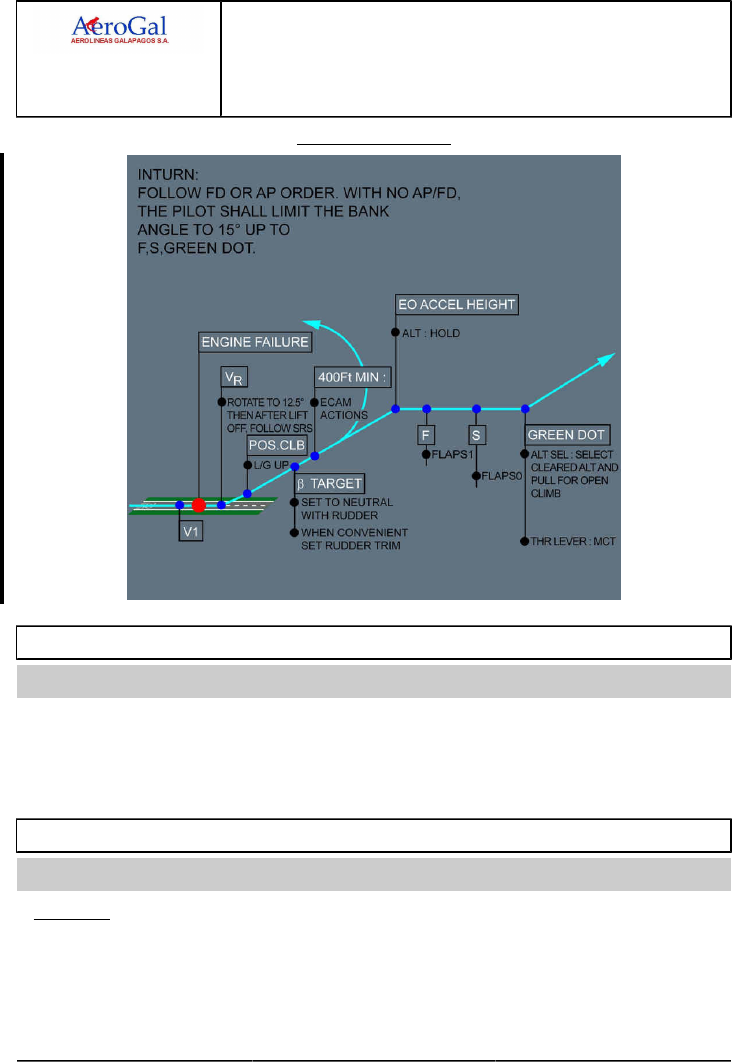
A318/A319/A320/A321
FLIGHT CREW
TECHNIQUES MANUAL
PROCEDURES
ABNORMAL AND EMERGENCY PROCEDURES
ENG
GLG A318/A319/A320/A321 FLEET PR-AEP-ENG P 9/20
FCTM ← E to G → 05 SEP 17
Engine failure after V1
ENGINE FAILURE DURING INITIAL CLIMB
Ident.: PR-AEP-ENG-00018097.0001001 / 20 MAR 17
Applicable to: ALL
This procedure is similar to the "Engine Failure after V1" procedure. If the failure occurs above V2
however, maintain the SRS commanded attitude. In any case, the minimum speed must be V2.
When an engine failure is detected, the FMGS produces predictions based on the engine-out
configuration and any pre-selected speeds entered in the MCDU are deleted.
ENGINE FAILURE DURING CRUISE
Ident.: PR-AEP-ENG-00018098.0001001 / 20 MAR 17
Applicable to: ALL
GENERAL
When an engine failure occurs during cruise, three possible strategies apply:
‐ The standard strategy
‐ The obstacle strategy
‐ The fixed speed strategy.

A318/A319/A320/A321
FLIGHT CREW
TECHNIQUES MANUAL
PROCEDURES
ABNORMAL AND EMERGENCY PROCEDURES
ENG
GLG A318/A319/A320/A321 FLEET PR-AEP-ENG P 10/20
FCTM ← G → 05 SEP 17
Unless a specific procedure has been established before dispatch (considering ETOPS or
mountainous areas), the standard strategy is used.
Note: Pressing the EO CLR key on the MCDU restores the all engine operative predictions and
performance. Reverting to one engine-out performance again is not possible.
PROCEDURE
As soon as the engine failure is recognized, the PF simultaneously:
‐ Sets all thrust levers to MCT
‐ Disconnects A/THR.
In cruise, the PF:
‐ Sets a HDG as appropriate and pulls
‐ Determines the engine out recovery altitude.
When ready for descent, the PF:
‐ Sets the SPEED and pulls
‐ Sets the engine out recovery altitude and pulls to engage for OPEN DES.
When appropriate, the PF requires the ECAM /OEB actions.
At high flight levels, close to the weight limits, the aircraft speed quickly reduces. Thus, the flight
crew should not delay to descent. The crew must not decelerate below green dot.
The A/THR is disconnected to avoid any engine thrust reduction when selecting speed according
to strategy or when pulling for OPEN DES to initiate the descent. With the A/THR disconnected,
the target speed is controlled by the elevator when in OPEN DES.
Carrying out the ECAM actions should not be hurried, as it is important to complete the drill
correctly.
STANDARD STRATEGY
Set speed target M 0.78/300 kt. The speed of 0.78/300 kt is chosen to ensure the aircraft is within
the stabilized windmill engine relight in-flight envelope.
The REC MAX EO Cruise altitude, which equates to LRC Engine-Out maximum FL with anti-icing
off, is displayed on the MCDU PROG page (One engine out gross ceiling at long-range speed is
also available in the QRH in case of double FM failure).
When the V/S becomes less than 500 ft/min, select V/S -500 ft/min and A/THR on. Once
established at level off altitude, long-range cruise performance with one engine out may be
extracted from QRH.
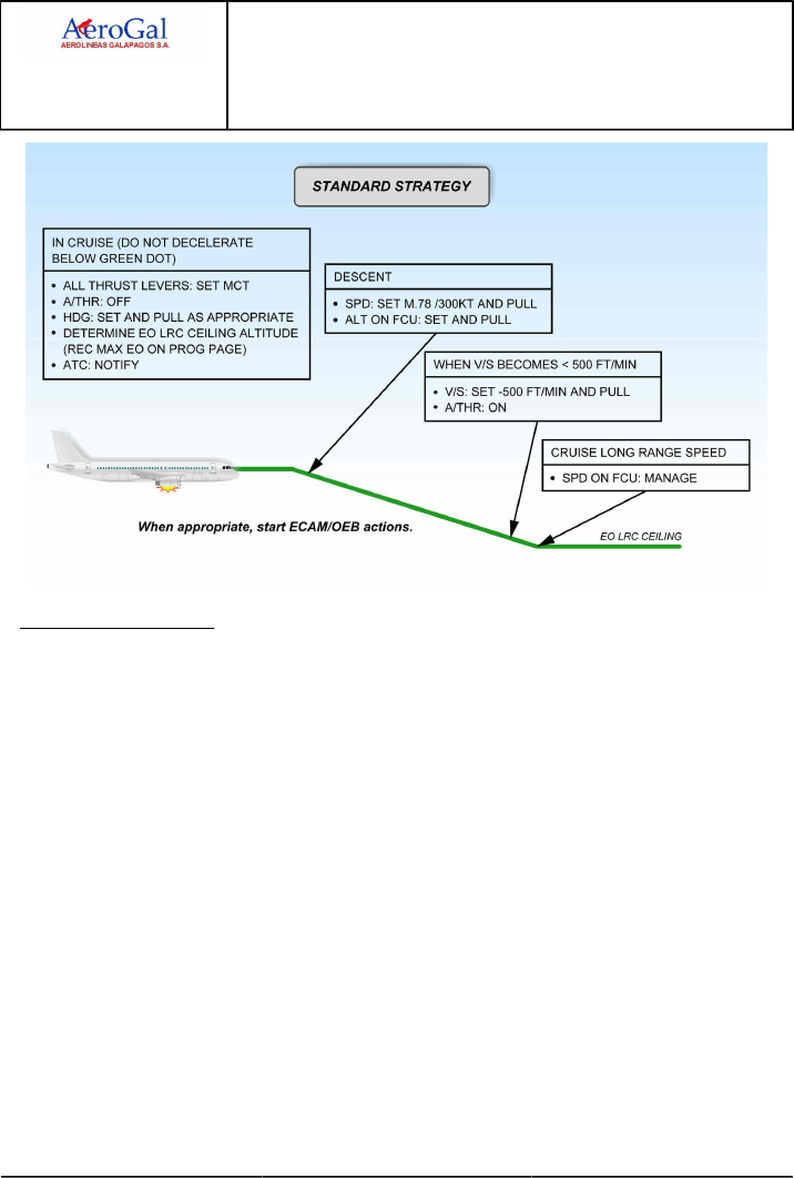
A318/A319/A320/A321
FLIGHT CREW
TECHNIQUES MANUAL
PROCEDURES
ABNORMAL AND EMERGENCY PROCEDURES
ENG
GLG A318/A319/A320/A321 FLEET PR-AEP-ENG P 11/20
FCTM ← G → 05 SEP 17
OBSTACLE STRATEGY
To maintain the highest possible level due to terrain, the drift down procedure must be adopted.
The speed target in this case is green dot. The procedure is similar to the standard strategy, but as
the speed target is now green dot, the rate and angle of descent are reduced.
The MCDU PERF CRZ page in EO condition displays the drift down ceiling (One engine out gross
ceiling at green dot speed is also available in the QRH and FCOM).
When clear of obstacles, revert to Standard Strategy.
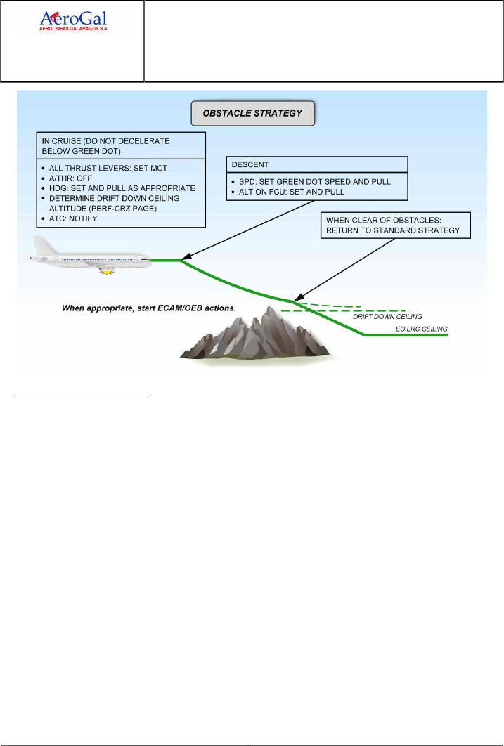
A318/A319/A320/A321
FLIGHT CREW
TECHNIQUES MANUAL
PROCEDURES
ABNORMAL AND EMERGENCY PROCEDURES
ENG
GLG A318/A319/A320/A321 FLEET PR-AEP-ENG P 12/20
FCTM ← G → 05 SEP 17
FIXED SPEED STRATEGY
This section provides the fixed speed strategy recommended for ETOPS operation. Refer to
FCOM/PRO-SPO-40-40 Diversion Performance Data.
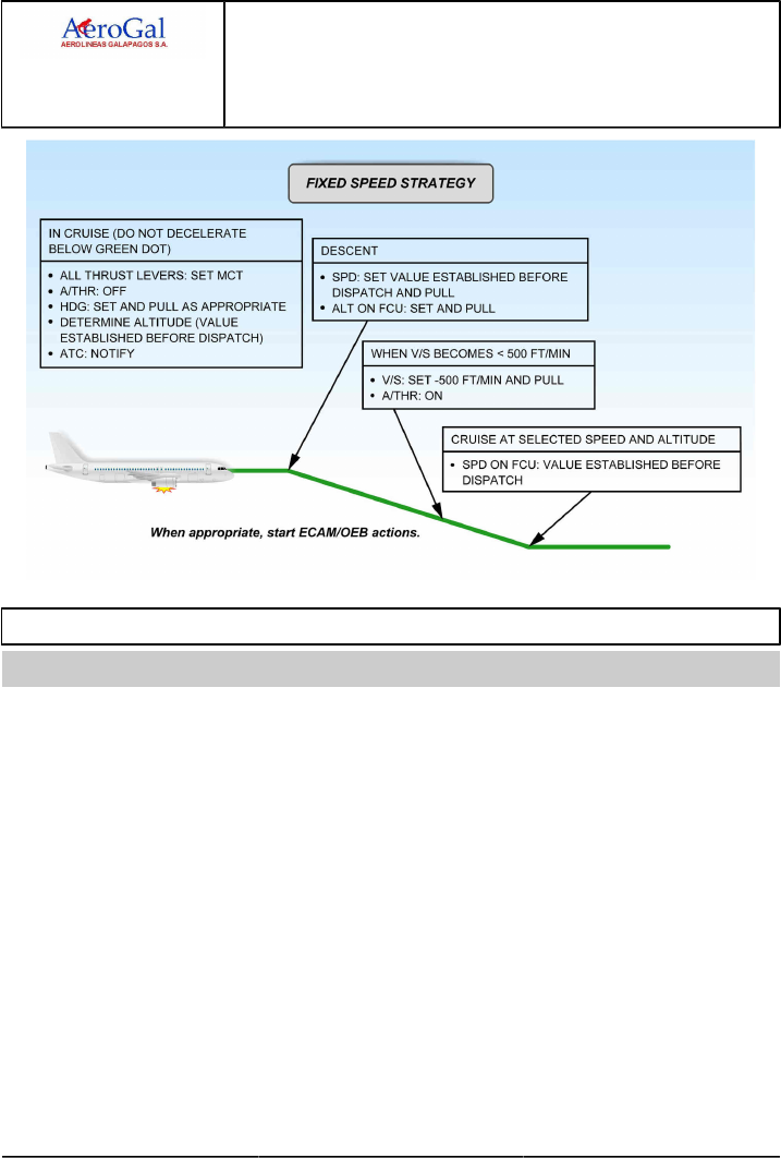
A318/A319/A320/A321
FLIGHT CREW
TECHNIQUES MANUAL
PROCEDURES
ABNORMAL AND EMERGENCY PROCEDURES
ENG
GLG A318/A319/A320/A321 FLEET PR-AEP-ENG P 13/20
FCTM ← G to H → 05 SEP 17
ENGINE STALL
Ident.: PR-AEP-ENG-00018099.0001001 / 20 MAR 17
Applicable to: ALL
An engine stall is the disruption of the airflow in a turbine engine. When the blades of the engine
compressors stall, they are no longer able to compress the air from the front to the rear of the engine.
In some cases, there may be a breakdown of the airflow, with the high pressure air at the end of the
compressor reversing flow, and exiting from the front of the engine. If this occurs, it may result in an
immediate and significant loss of thrust.
From the flight crew perspective, the engine stall is one of the most startling events at takeoff or
during flight. The engine stall should not take the flight crew away from their primary task that is to fly
the aircraft.
An engine stall can be due to any of the following reasons:
‐ An engine degradation (e.g. compressor blade rupture, or high wear)
‐ Ingestion of foreign objects (e.g. birds), or ice
‐ A malfunction of the bleed system
‐ A malfunction of the engine controls (e.g. fuel scheduling, or stall protection devices)
During takeoff, and at high power settings, the symptoms of an engine stall are the following:
‐ One or more very loud bangs, usually compared to a shotgun being fired a few meters away
‐ An instant loss of thrust, or even a reverse thrust, that causes a yaw movement

A318/A319/A320/A321
FLIGHT CREW
TECHNIQUES MANUAL
PROCEDURES
ABNORMAL AND EMERGENCY PROCEDURES
ENG
GLG A318/A319/A320/A321 FLEET PR-AEP-ENG P 14/20
FCTM ← H → 05 SEP 17
‐ Fluctuations of the engine parameters (EPR /N1 , N2, or N3 ). The engine may give the
impression to pump
‐ An increase of the EGT
‐ Engine vibrations
‐ Flames may be visible from both ends of the engine (inlet / tail pipe)
‐ Acrid smell in the cockpit
During cruise, and at low power settings (e.g. at thrust reduction at the T/D), the symptoms of an
engine stall are the following:
‐ One or more muffled bangs
‐ Slow or no thrust lever response
‐ Fluctuations of the engine parameters (EPR /N1 , N2, or N3 ). The engine may give the
impression to pump
‐ An increase of the EGT
‐ Engine vibrations
‐ Acrid smell in the cockpit
Most of the FADECs have functions that:
‐ Regulate the airflow through the compressor, to prevent engine stalls
‐ Are able to detect engine stalls
‐ Try to recover from an engine stall, without flight crew action, by modifying the airflow
When the FADEC detects an engine stall, the FADEC requests that the ENG 1(2) STALL ECAM alert
is triggered.
The FADEC is not able to detect an engine stall in all cases. Therefore, if the flight crew detects one
or a combination of the engine stall symptoms, the flight crew should suspect an engine stall, and
apply the QRH Engine Stall procedure.
The Engine Stall procedure is not a memory item. Therefore, if a stall occurs during the cruise phase,
the flight crew shall take the time to assess the situation before applying the procedure, as most of
the times the FADEC will self-recover from the stall before any flight crew action. The Engine Stall
procedure (ECAM or QRH) is as follows:
‐ When the flight crew has stabilized the aircraft trajectory, the flight crew first reduces thrust to idle
on the affected engine.
This action reduces the differential pressure across the compressor. This helps the engine airflow
to become more stable.
‐ When at idle thrust, the flight crew checks the stability of the engine parameters on the EWD , and
particularly the EPR /N1 , EGT , N2 , and N3 . The flight crew should also check the engine
vibrations on the ENG SD page.

A318/A319/A320/A321
FLIGHT CREW
TECHNIQUES MANUAL
PROCEDURES
ABNORMAL AND EMERGENCY PROCEDURES
ENG
GLG A318/A319/A320/A321 FLEET PR-AEP-ENG P 15/20
FCTM ← H to I → 05 SEP 17
‐ The flight crew shuts down the engine if:
• The fluctuations of the engine parameters, or the high EGT, or the engine vibrations persist, or
• The symptoms of the engine stall persist at idle thrust.
‐ If the engine parameters are normal:
• The flight crew selects the anti-ice on, in order to increase the bleed demand.
This reduces the pressure at the exit of the compressor, and helps the airflow to circulate in the
engine turbine from front to rear.
• Then, the flight crew slowly advances the thrust levers, as long as the engine stall does not
occur again. The engine response may be slow at high altitude.
▪ If the engine stall reoccurs, the flight crew keeps the engine thrust below the stall threshold.
The flight crew should not shut down the engine if the engine stall can be avoided. The flight
crew should manually control the thrust on the affected engine between idle and the identified
stall threshold for the remainder of the flight.
▪ If the engine stall does not reoccur, the flight crew can resume normal operation of the
engine.
The flight crew must report any engine stall for maintenance action.
ENGINE TAILPIPE FIRE
Ident.: PR-AEP-ENG-00018100.0001001 / 20 MAR 17
Applicable to: ALL
An engine tailpipe fire can only occur at engine start or at engine shutdown. It is the result of an
excess of fuel in the combustion chamber, in the turbine or in the exhaust nozzle, that ignites. A
tailpipe fire is an internal fire in the engine, compared with an engine fire that occurs outside the
engine core and gas path. No critical areas are affected in the engine in the case of a tailpipe fire.
However, it can have an effect on the aircraft (e.g. damage the flaps). The correct method to manage
an engine tailpipe fire is to stop the fuel flow, and to ventilate the engine.
In the case of a tailpipe fire, there is no cockpit alert. The only indication can be an increasing EGT
due to the fire in the turbine. Therefore, most of the time, the ground crew, cabin crew, or ATC
visually detect the tailpipe fire.
In the case of a tailpipe fire, the flight crew must apply the QRH ENG TAILPIPE FIRE procedure,
which requires the flight crew to:
‐ Shut down the engine, in order to stop the fuel flow
‐ Dry crank the engine, to remove the remaining fuel.
The flight crew should not use the ENG FIRE pb. This cuts off the electrical supply of the FADEC ,
and stops the dry crank sequence performed by the FADEC.
The flight crew should not use the fire extinguisher, as it does not extinguish an internal engine fire.
As a first priority, the fuel flow must be stopped, and the engine must be ventilated.

A318/A319/A320/A321
FLIGHT CREW
TECHNIQUES MANUAL
PROCEDURES
ABNORMAL AND EMERGENCY PROCEDURES
ENG
GLG A318/A319/A320/A321 FLEET PR-AEP-ENG P 16/20
FCTM ← I to J → 05 SEP 17
If the tailpipe fire procedure does not stop the fire, or if bleed air is not easily available, the ground
crew can use a ground fire extinguisher as a last option. Ground fire extinguishing agent can cause
serious corrosive damage to the engine and requires a maintenance action on the engine.
ENGINE VIBRATIONS
Ident.: PR-AEP-ENG-00018101.0001001 / 20 MAR 17
Applicable to: ALL
Engine vibrations are usually caused by an imbalance of the engine that can be due to many reasons
such as:
‐ A deformation of one or several blades due to Foreign Object Damage (FOD), or a bird strike
‐ A rupture or a loss of one or several blades
‐ An internal engine failure (e.g. engine stall)
‐ A fan icing
High engine vibration alone does not require an engine in-flight shutdown. If the engine needs to be
shutdown, other symptoms and certainly an ECAM alert will warn the flight crew, and request them to
shut down the engine.
A high N1 vibration level may be accompanied by perceivable airframe vibrations.
When the vibration level exceeds a certain threshold, the ECAM advisory function automatically
highlights the affected parameter. When the flight crew identifies high engine vibrations, the flight
crew must refer to the ECAM ADVISORY CONDITIONS section of the QRH . This section guides the
flight crew to the QRH HIGH ENGINE VIBRATION procedure.
On the A320neo, the ECAM advisory is replaced by an ECAM alert that guides the flight crew toward
the QRH HIGH ENGINE VIBRATION procedure.
In the case of high engine vibrations, the flight crew first checks the engine parameters, and
crosschecks them with the other engine. The flight crew identifies if there are engine vibrations only,
or if there is another problem on the engine for which the flight crew may expect an ECAM alert.
Then the flight crew determines if icing is suspected or not. The flight crew should suspect icing if N1
vibrations occur without variation on other engine parameters. If the flight crew notices unexpected
behavior on other engine parameters, the flight crew should consider that icing is not suspected.
These checks take into account the cases of engine problems in icing conditions, and also the cases
of vibrations due to icing, out of standard icing conditions.
If the flight crew suspects icing, and if flight conditions permit, the flight crew should shed the ice with
the following procedure:
‐ The flight crew disconnects the A/THR
‐ The flight crew performs several large thrust variations from idle to a thrust compatible with the
flight phase.
It may be necessary to perform several engine run-ups (decrease and then increase of thrust) to
fully shed the ice.

A318/A319/A320/A321
FLIGHT CREW
TECHNIQUES MANUAL
PROCEDURES
ABNORMAL AND EMERGENCY PROCEDURES
ENG
GLG A318/A319/A320/A321 FLEET PR-AEP-ENG P 17/20
FCTM ← J to L 05 SEP 17
If the flight crew does not suspect icing, and if flight conditions permit, the flight crew reduces thrust
to make the vibrations decrease, and stay below the advisory threshold.
If the vibrations do not decrease, there may be another problem with the engine. The flight crew
should expect an ECAM alert that will provide guidance on the actions to perform.
Finally, during the taxi-in phase, the flight crew may consider to shut down the engine if the flight
crew experienced vibrations in flight, or if the flight crew experiences vibrations during taxi. On
ground, the flight crew should consider engine shutdown in order to avoid increased damage to the
engine.
ONE ENGINE INOPERATIVE - CIRCLING
Ident.: PR-AEP-ENG-00018102.0001001 / 20 MAR 17
Applicable to: ALL
In normal conditions, circling with one engine inoperative requires the down wind leg to be flown in
CONF 3, with landing gear extended.
In hot and high conditions and at high landing weight, the aircraft may not be able to maintain level
flight in CONF 3 with landing gear down. The flight crew should check the maximum weight showed
in the QRH CIRCLING APPROACH WITH ONE ENGINE INOPERATIVE procedure table. If the
landing weight is above this maximum value, the landing gear extension should be delayed until
established on final approach.
If the approach is flown at less than 750 ft RA , the warning "L/G NOT DOWN" will be triggered.
"TOO LOW GEAR" warning is to be expected, if the landing gear is not downlocked at 500 ft RA.
Therefore, if weather conditions permit, it is recommended to fly a higher circling pattern.
ONE ENGINE INOPERATIVE - GO-AROUND
Ident.: PR-AEP-ENG-00018103.0001001 / 20 MAR 17
Applicable to: ALL
A one engine inoperative go-around is similar to a go-around flown with all engines.
On the application of TOGA, the flight crew must apply rudder promptly to compensate for the
increase in thrust and consequently to keep the beta target centred.
Provided the flap lever is selected to Flap 1 or greater, SRS will engage and will be followed. If SRS
is not available, the initial target pitch attitude will be 12.5 °.
The lateral FD mode will be GA TRK (or NAV if option installed) and this must be considered with
respect to terrain clearance.
At the engine-out acceleration altitude, apply the same technique as described earlier. Refer to
PR-AEP-ENG Engine Failure after V1.

A318/A319/A320/A321
FLIGHT CREW
TECHNIQUES MANUAL
PROCEDURES
ABNORMAL AND EMERGENCY PROCEDURES
ENG
GLG A318/A319/A320/A321 FLEET PR-AEP-ENG P 18/20
FCTM M to N → 05 SEP 17
ONE ENGINE INOPERATIVE - LANDING
Ident.: PR-AEP-ENG-00018104.0001001 / 19 APR 17
Applicable to: ALL
Autoland is available with one engine inoperative, and maximum use of the AP should be made to
minimise crew workload. If required, a manual approach and landing with one engine inoperative is
conventional. The flight crew should trim to keep the slip indication centred. It remains yellow as long
as the thrust on the remaining engine(s) is below a certain value.
With flap selected and above this threshold value, the indicator becomes the blue beta target. This is
a visual cue that the aircraft is approaching its maximum thrust capability.
The flight crew should not select the gear down too early, as large amounts of power will be required
to maintain level flight at high weights and/or high altitude airports.
The flight crew can reset the rudder trim in the later phase of the approach, before engine thrust
reduction. On pressing the rudder trim reset button, the trim is removed and the flight crew should
anticipate the increased rudder force required. With rudder trim at zero, the neutral rudder pedal
position corresponds to zero rudder and zero nose wheel deflection.
THRUST LEVERS MANAGEMENT IN THE CASE OF INOPERATIVE REVERSER(S)
Ident.: PR-AEP-ENG-00018106.0001001 / 20 MAR 17
Applicable to: ALL
PREFACE
This section provides recommendations on thrust levers management in case of inoperative
reverser(s). These recommendations are applicable in case of in-flight failure (including engine
failure) and/or in case of MEL dispatch with reverser(s) deactivated.
AT LEAST ONE REVERSER OPERATIVE
If at least one reverser is operative, the general recommendation is to select the reverser thrust on
both engines during rejected takeoff (RTO) and at landing, as per normal procedures.
Note: The ENG 1(2) REVERSER FAULT ECAM caution may be triggered after the reverser
thrust is selected. This is to remind the flight crew that one reverser is inoperative.
NO REVERSERS OPERATIVE
If no reversers are operative, the general recommendation is to not select the reverser thrust
during RTO and at landing.
However, the PF still sets both thrust levers to the IDLE detent, as per normal procedures.

A318/A319/A320/A321
FLIGHT CREW
TECHNIQUES MANUAL
PROCEDURES
ABNORMAL AND EMERGENCY PROCEDURES
ENG
GLG A318/A319/A320/A321 FLEET PR-AEP-ENG P 19/20
FCTM ← N 05 SEP 17
BRIEFING
IMPORTANCE OF THE FLIGHT CREW BRIEFING
Among others, the aircraft status must be reviewed during the flight crew briefing. Any
particularities (operational consequences, procedures, associated task sharing and callout)
must be reviewed at that time. The flight crew must notably review:
‐ The status of the thrust reversers and if reverser thrust can be used
‐ Operational effect (aircraft handling during roll-out).

A318/A319/A320/A321
FLIGHT CREW
TECHNIQUES MANUAL
PROCEDURES
ABNORMAL AND EMERGENCY PROCEDURES
ENG
Intentionally left blank
GLG A318/A319/A320/A321 FLEET PR-AEP-ENG P 20/20
FCTM 05 SEP 17

A318/A319/A320/A321
FLIGHT CREW
TECHNIQUES MANUAL
PROCEDURES
ABNORMAL AND EMERGENCY PROCEDURES
F/CTL
GLG A318/A319/A320/A321 FLEET PR-AEP-F_CTL P 1/2
FCTM A → 22 MAR 17
ABNORMAL FLAPS/SLATS CONFIGURATION
Ident.: PR-AEP-F_CTL-00019291.0001001 / 20 MAR 17
Applicable to: ALL
CAUSES
Abnormal operation of the flaps and/or slats may be due to one of the following problems:
‐ Double SFCC failure
‐ Double hydraulic failure (B+G or Y+G)
‐ Flaps/Slats jammed (operation of the WTB)
CONSEQUENCES
Abnormal operation of the flaps and slats has significant consequences since:
‐ The control laws may change
‐ The selected speed must be used
‐ A stabilized approach should be preferred
‐ The approach attitudes change
‐ Approach speeds and landing distances increase
‐ The go-around procedure may have to be modified.
Note: The FMS predictions do not take into account the slat or flap failures. Since fuel
consumption is increased, these predictions are not valid.
FAILURE AT TAKEOFF
Should a flap/slat retraction problem occur at takeoff, the crew will PULL the speed knob for
selected speed to stop the acceleration and avoid exceeding VFE. The overspeed warning is
computed according to the actual slats/flaps position.
The landing distance available at the departure airport and the aircraft gross weight will determine
the crew's next course of action.
FAILURE DURING THE APPROACH
The detection of a slat or flap failure occurs with the selection of flap lever during the approach.
With A/THR operative, the managed speed target will become the next manoeuvring characteristic
speed e.g. S speed when selecting flap lever to 1. At this stage, if a slat or flap failure occurs, the
crew will:
‐ Pull the speed knob for selected speed to avoid further deceleration
‐ Delay the approach to complete the ECAM procedure
‐ Refer to LANDING WITH FLAPS OR SLATS JAMMED QRH procedure.
‐ Update the approach briefing.
In the QRH , the line, "SPD SEL............VFE NEXT -5 kt" is designed to allow the crew to configure
the aircraft for landing whilst controlling the speed in a safe manner. This procedure may involve

A318/A319/A320/A321
FLIGHT CREW
TECHNIQUES MANUAL
PROCEDURES
ABNORMAL AND EMERGENCY PROCEDURES
F/CTL
GLG A318/A319/A320/A321 FLEET PR-AEP-F_CTL P 2/2
FCTM ← A 22 MAR 17
reducing speed below the manoeuvring speed for the current configuration which is acceptable
provided the speed is kept above VLS. The speed reduction and configuration changes should
preferably be carried out wings level.
Assuming VLS is displayed on the PFD , VAPP should be close to VLS + wind correction, since
this speed is computed on the actual slat/flap position.
The AP may be used down to 500 ft AGL . As the AP is not tuned for the abnormal configurations,
its behavior can be less than optimum and must be monitored.
During the approach briefing, emphasis should be made of:
‐ Tail strike awareness
‐ The go-around configuration
‐ Any deviation from standard call out
‐ The speeds to be flown, following a missed approach
‐ At the acceleration altitude, selected speed must be used to control the acceleration to the
required speed for the configuration.
Consider the fuel available and the increased consumption associated with a diversion when
flying with flaps and/or slats jammed. Additionally, when diverting with flaps/slats extended, cruise
altitude is limited to 20 000 ft.

A318/A319/A320/A321
FLIGHT CREW
TECHNIQUES MANUAL
PROCEDURES
ABNORMAL AND EMERGENCY PROCEDURES
FUEL
GLG A318/A319/A320/A321 FLEET PR-AEP-FUEL P 1/2
FCTM A → 22 MAR 17
FUEL LEAK
Ident.: PR-AEP-FUEL-00019292.0001001 / 20 MAR 17
Applicable to: ALL
Significant fuel leaks, although rare, are sometimes difficult to detect.
Fuel check will be carried out by:
‐ Checking that the remaining fuel added to the burnt fuel corresponds to the fuel on board at the
gate.
‐ Maintaining the fuel log and comparing fuel on board to expected flight plan fuel would alert the
crew to any discrepancy.
Fuel checks should be carried out when overflying a waypoint or at least every 30 min. Any
discrepancy should alert the crew and investigation should be carried out without delay.
In addition, the flight crew can also suspect a fuel leak if:
‐ The sum of FOB and FU is significantly less than FOB at engine start, or is decreasing,
L2 If the sum of FOB and FU is significantly more than FOB at engine start, an erroneous or
over-read fuel quantity indication can be suspected.
‐
L1 There is a discrepancy between the fuel on board and the expected flight plan fuel,
‐ A passenger or cabin crew observes a fuel spray from an engine/pylon or a wing,
‐ The total fuel quantity abnormally decreases,
‐ A fuel imbalance develops,
‐ The fuel quantity of one wing tank decreases abnormally fast (leak from engine/pylon, or hole in a
tank),
‐ A tank overflows (due to pipe rupture in a tank),
‐ The fuel flow is excessive (leak from engine),
‐ Fuel is smelt in the cabin
‐ The destination EFOB is decreasing or is displayed amber on the FMS F-PLN page.
Any time an unexpected fuel quantity indication, ECAM fuel message or imbalance is noted, a fuel
leak should be considered as a possible cause. Initial indications should be carefully cross-checked
by reference to other means, including if possible, a visual inspection.
If a fuel leak is suspected, the flight crew should perform the "FUEL LEAK" abnormal procedure in
the QRH.
The main steps of the FUEL LEAK procedure are:
If the fuel leak is confirmed coming from the engine/pylon:
The affected engine is shut down to isolate the fuel leak and fuel cross-feed valve may be used
as required.

A318/A319/A320/A321
FLIGHT CREW
TECHNIQUES MANUAL
PROCEDURES
ABNORMAL AND EMERGENCY PROCEDURES
FUEL
GLG A318/A319/A320/A321 FLEET PR-AEP-FUEL P 2/2
FCTM ← A 22 MAR 17
If the fuel leak is not confirmed coming from the engine/pylon or the leak is not located:
‐ Isolate each tank : maintain the cross-feed valve closed and switch off the center pumps. Each
wing tank feeds the associated engine
‐ If the fuel quantity decrease faster in one wing than in the other wing tank, the fuel leak is
identified as coming from one wing tank. In this case, the associated engine is shut down in
order to confirm if the leak comes from the wing tank or from the engine
‐ If the fuel quantity symmetrically decrease in both wing tanks and the fuel quantity in the
center tank decrease, the fuel leak comes from the center tank or the APU feed line.
A318/A319/A320/A321
FLIGHT CREW
TECHNIQUES MANUAL
PROCEDURES
ABNORMAL AND EMERGENCY PROCEDURES
HYD
GLG A318/A319/A320/A321 FLEET PR-AEP-HYD P 1/6
FCTM A to B → 05 SEP 17
HYDRAULIC GENERATION PARTICULARITIES
Ident.: PR-AEP-HYD-00019294.0001001 / 25 JUL 17
Applicable to: ALL
PREFACE
The aircraft has three continuously operating hydraulic systems: green, blue and yellow. A
bidirectional Power Transfer Unit (PTU) enables the yellow system to pressurize the green system
and vice versa. Hydraulic fluid cannot be transferred from one system to another.
PTU PRINCIPLE
In flight, the PTU operates automatically if differential pressure between green and yellow systems
exceeds 500 PSI. This allows to cover the loss of one engine or one engine driven pump cases.
USE OF PTU IN CASE OF FAILURE
In case of reservoir low level, reservoir overheat, reservoir low air pressure, the PTU must be
switched OFF as required by ECAM to avoid a PTU overheat which may occur two minutes later.
Indeed, a PTU overheat may lead to the loss of the second hydraulic circuit.
1RECOMMENDATIONS
When required by the ECAM, the PTU should be switched off without delay in case of:
‐ HYD G(Y) RSVR LO LVL
‐ HYD G(Y) RSVR LO AIR PR (Only if pressure fluctuates)
‐ HYD G(Y) RSVR OVHT
DUAL HYDRAULIC FAILURES
Ident.: PR-AEP-HYD-00019295.0001001 / 20 MAR 17
Applicable to: ALL
PREFACE
Single hydraulic failures have very little effect on the handling of the aircraft but will cause a
degradation of the landing capability to CAT 3 SINGLE.
Dual hydraulic failures however, although unlikely, are significant due to the following
consequences depending on the affected hydraulic circuits (Refer to PR-AEP-HYD Remaining
Systems):
‐ Loss of AP
‐ Flight control law degradation
‐ Landing in abnormal configuration
‐ Extensive ECAM procedures with associated workload and task-sharing considerations
‐ Significant considerations for approach and landing.

A318/A319/A320/A321
FLIGHT CREW
TECHNIQUES MANUAL
PROCEDURES
ABNORMAL AND EMERGENCY PROCEDURES
HYD
GLG A318/A319/A320/A321 FLEET PR-AEP-HYD P 2/6
FCTM ← B 05 SEP 17
GENERAL GUIDELINES
It is important to note that the AP will not be available to the crew but both FD and A/THR still
remain. Additionally, depending on the affected hydraulic circuits, aircraft handling characteristics
may be different due to the loss of some control surfaces. The PF will maneuver with care to avoid
high hydraulic demand on the remaining systems.
The PF will be very busy flying the aircraft and handling the communications with the flight controls
in Alternate Law (HYD G+B SYS LO PR or G+Y SYS LO PR).
A double hydraulic failure is an emergency situation, with red LAND ASAP displayed, and a
MAYDAY should be declared to ATC . A landing must be carried out as soon as possible bearing
in mind, however, that the ECAM actions should be completed prior the approach.
PF will then require the ECAM actions. A clear reading of STATUS is essential to assess the
aircraft status and properly sequence actions during the approach.
This failure is called a "complex procedure" and the QRH summary should be referred to upon
completion of the ECAM procedure (Refer to AOP-30-60 Use of Summaries).
While there is no need to remember the following details, an understanding of the structure of
the hydraulic and flight control systems would be an advantage. The F/CTL SD page and the
OPS DATA section of the QRH provide an overview of the flight controls affected by the loss of
hydraulic systems.
The briefing will concentrate on safety issues since this will be a hand-flown approach with certain
handling restrictions:
‐ Use of the selected speeds on the FCU.
‐ Landing gear gravity extension
‐ Approach configuration and flap lever position
‐ Approach speed VAPP
‐ Tail strike awareness
‐ Braking and steering considerations
‐ Go around call out, aircraft configuration and speed.
The STATUS page requires, in each case, a landing gear gravity extension. The LANDING GEAR
GRAVITY EXTENSION procedure will be completed with reference to the QRH.
A stabilized approach will be preferred.

A318/A319/A320/A321
FLIGHT CREW
TECHNIQUES MANUAL
PROCEDURES
ABNORMAL AND EMERGENCY PROCEDURES
HYD
GLG A318/A319/A320/A321 FLEET PR-AEP-HYD P 3/6
FCTM C → 05 SEP 17
REMAINING SYSTEMS
Ident.: PR-AEP-HYD-00019296.0001001 / 25 JUL 17
Criteria: SA
Applicable to: HC-CKN, HC-CLF
2Remaining systems
Flight phase Systems HYD G+B SYS LO PR HYD G+Y SYS LO PR HYD B+Y SYS LO PR
Auto pilot Inop Inop Inop
Yaw damper YD2 only Inop YD1 only
Control law ALTN LAW and DIRECT
LAW when L/G DN
ALTN LAW and DIRECT
LAW when L/G DN
NORM LAW
Stabilizer Avail Inop (1) Avail
Spoilers 2 SPLRS/wing 1 SPLR/wing 2 SPLRS/wing
Elevator R ELEV only Avail L ELEV only
Cruise
Aileron Inop Avail Avail
(1) The stabilizer is lost. In alternate law, the auto trim function is provided through the elevators. At
landing gear extension, switching to direct law, the auto trim function is lost. However, the mean
elevator position at that time is memorized, and becomes the reference for centered sidestick
position. This is why, in order to ensure proper centered sidestick position for approach and
landing, the procedure requires to wait for stabilization at VAPP, before landing gear extension.
If this procedure is missed, the flare and pitch control in case of go-around may be difficult.
The PFD message USE MAN PITCH TRIM after landing gear extension should thus be
disregarded.
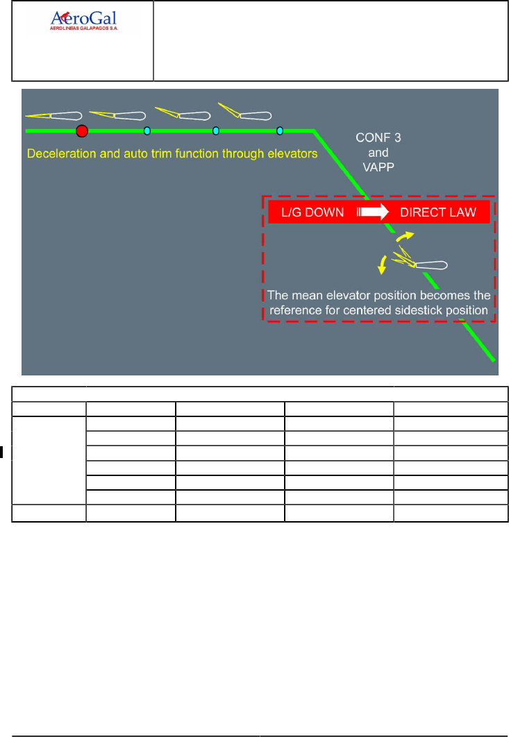
A318/A319/A320/A321
FLIGHT CREW
TECHNIQUES MANUAL
PROCEDURES
ABNORMAL AND EMERGENCY PROCEDURES
HYD
GLG A318/A319/A320/A321 FLEET PR-AEP-HYD P 4/6
FCTM ← C → 05 SEP 17
Remaining systems
Flight phase Systems HYD G+B SYS LO PR HYD G+Y SYS LO PR HYD B+Y SYS LO PR
Slats/Flaps FLAPS slow only SLATS slow only (1) SLATS/FLAPS slow
L/G extension Gravity Gravity Gravity
Braking ALTN BRK only Y ACCU PRESS only NORM BRK only
Anti skid Avail Inop Avail
Nose wheel steering Inop Inop Inop
Landing
Reverse REV 2 only Inop REV 1 only
Go/around L/G retraction Inop Inop Inop
(1) High pitch during approach should be expected. Approach briefing should outline it for tail strike
awareness and pitch attitude will be monitored during flare.
A318/A319/A320/A321
FLIGHT CREW
TECHNIQUES MANUAL
PROCEDURES
ABNORMAL AND EMERGENCY PROCEDURES
HYD
GLG A318/A319/A320/A321 FLEET PR-AEP-HYD P 5/6
FCTM ← C → 05 SEP 17
REMAINING SYSTEMS
Ident.: PR-AEP-HYD-00019296.0002001 / 25 JUL 17
Criteria: P4576, SA
Applicable to: HC-CJM, HC-CJV, HC-CJW, HC-CRU, HC-CSA, HC-CSB, HC-CSF
3Remaining systems
Flight phase Systems HYD G+B SYS LO PR HYD G+Y SYS LO PR HYD B+Y SYS LO PR
Auto pilot Inop Inop Inop
Yaw damper YD2 only Inop YD1 only
Control law ALTN LAW and DIRECT
LAW when L/G DN
ALTN LAW and DIRECT
LAW when L/G DN
NORM LAW
Stabilizer Avail Inop (1) Avail
Spoilers 2 SPLRS/wing 1 SPLR/wing 2 SPLRS/wing
Elevator R ELEV only Avail L ELEV only
Cruise
Aileron Inop Avail Avail
(1) The stabilizer is lost. In alternate law, the auto trim function is provided through the elevators. At
landing gear extension, switching to direct law, the auto trim function is lost. However, the mean
elevator position at that time is memorized, and becomes the reference for centered sidestick
position. This is why, in order to ensure proper centered sidestick position for approach and
landing, the procedure requires to wait for stabilization at VAPP, before landing gear extension.
If this procedure is missed, the flare and pitch control in case of go-around may be difficult.
The PFD message USE MAN PITCH TRIM after landing gear extension should thus be
disregarded.

A318/A319/A320/A321
FLIGHT CREW
TECHNIQUES MANUAL
PROCEDURES
ABNORMAL AND EMERGENCY PROCEDURES
HYD
GLG A318/A319/A320/A321 FLEET PR-AEP-HYD P 6/6
FCTM ← C 05 SEP 17
Remaining systems
Flight phase Systems HYD G+B SYS LO PR HYD G+Y SYS LO PR HYD B+Y SYS LO PR
Slats/Flaps FLAPS slow only SLATS slow only (1) SLATS/FLAPS slow
L/G extension Gravity Gravity Gravity
Braking ALTN BRK only Y ACCU PRESS only NORM BRK only
Anti skid Avail Inop Avail
Nose wheel steering Avail Inop Inop
Landing
Reverse REV 2 only Inop REV 1 only
Go/around L/G retraction Inop Inop Inop
(1) High pitch during approach should be expected. Approach briefing should outline it for tail strike
awareness and pitch attitude will be monitored during flare.

A318/A319/A320/A321
FLIGHT CREW
TECHNIQUES MANUAL
PROCEDURES
ABNORMAL AND EMERGENCY PROCEDURES
L/G
GLG A318/A319/A320/A321 FLEET PR-AEP-LG P 1/4
FCTM A → 05 SEP 17
LANDING WITH ABNORMAL L/G
Ident.: PR-AEP-LG-00019297.0001001 / 20 MAR 17
Applicable to: ALL
To avoid unnecessary application of the L/G GRAVITY EXTENSION and the LDG WITH
ABNORMAL L/G QRH procedures, the flight crew must check for the three landing gear green
indications on the ECAM WHEEL SD page: at least one green triangle on each landing gear is
sufficient to indicate that the landing gear is down and locked. The flight crew must also rely also on
the “LDG GEAR DN” green MEMO. This is sufficient to confirm that the landing gear is downlocked.
If one landing gear is not downlocked, the flight crew must perform the LDG WITH ABNORMAL L/G
QRH procedure. In this case, it is always better to land with any available gear rather than carry out a
landing without any gear.
In all cases, weight should be reduced as much as possible to provide the slowest possible
touchdown speed.
A fuel imbalance may be considered by the flight crew. Landing with a lighter wing on the affected
side allows to keep it up longer and delay the moment of nacelle contact. If the imbalance advisory
triggers, the flight crew can disregard it, as the aircraft handling qualities are not significantly affected.
Although foaming of the runway is not a requirement, full advantage should be taken of any ATC
offer to do so.
The passengers and cabin crew should be informed of the situation in good time. This will allow the
cabin crew to prepare the cabin and perform their emergency landing and evacuation procedures.
If one or both main landing gears in abnormal position, the ground spoilers will not be armed to keep
as much roll authority as possible for maintaining the wings level. Ground spoiler extension would
prevent spoilers from acting as roll surfaces.
The flight crew will not arm the autobrake as manual braking will enable better pitch and roll control.
Furthermore, with at least one main landing gear in the abnormal position, the autobrake cannot be
activated (ground spoilers not armed).
With one main landing gear not extended, the reference speed used by the anti-skid system is not
correctly initialized. Consequently, the anti-skid must be switched off to prevent permanent brake
release.
In all cases, a normal approach should be flown and control surfaces used as required to maintain
the aircraft in a normal attitude for as long as possible after touchdown. The engines should be shut
down early enough to ensure that fuel is cut off prior to nacelle touchdown, but late enough to keep
sufficient authority on control surfaces in order to:
‐ Maintain runway axis
‐ Prevent nacelle contact on first touch down
‐ Maintain wing level and pitch attitude as long as possible.

A318/A319/A320/A321
FLIGHT CREW
TECHNIQUES MANUAL
PROCEDURES
ABNORMAL AND EMERGENCY PROCEDURES
L/G
GLG A318/A319/A320/A321 FLEET PR-AEP-LG P 2/4
FCTM ← A to C → 05 SEP 17
Considering a realistic hydraulic demand, the hydraulic power remains available up to approximately
30 s after the shut down of the related engine. It is the reason why the recommendations to switch
the ENG masters OFF are as follow:
‐ If NOSE L/G abnormal
Before nose impact
‐ If one MAIN L/G abnormal
At touch down
‐ If both MAIN L/G abnormal
In the flare, before touch down
The reversers will not be used to prevent the ground spoilers extension and because the engine will
touch the ground during roll out.
The engines and APU fire pbs are pushed when the use of flight controls is no longer required i.e.
when aircraft has stopped.
NOSE WHEEL STEERING FAULT
Ident.: PR-AEP-LG-00019298.0001001 / 20 MAR 17
Applicable to: ALL
If the Nose Wheel Steering (NWS) is lost for taxiing, the flight crew can steer the aircraft with
differential braking technique. If the flight crew does not have experience with this technique, he
should preferably request a towing to return to the gate. The flight crew can request the towing early
in approach, if the failure has been triggered in flight.
TAXI WITH DEFLATED OR DAMAGED TIRES
Ident.: PR-AEP-LG-00021646.0001001 / 01 JUN 17
Applicable to: ALL
In some abnormal situations, after a rejected takeoff or after landing, the flight crew may need to
vacate the runway and taxi the aircraft with deflated or damaged tires.
The flight crew must ensure that the number and position of deflated or damaged tires are in
accordance with the limitations provided in the FCOM. Refer to FCOM/LIM-LG Taxi with Deflated or
Damaged Tires.
In order to identify the number and position of the affected tires, the flight crew can use the tire
pressure indication available on the WHEEL SD page.
If the number or position of the affected tires is not in accordance with the limitations provided in the
FCOM , the ground crew must change a sufficient number of wheels before taxi, in order to ensure
compliance with the FCOM limitations.
As indicated in the FCOM limitations, the nosewheel steering angle must be limited to a maximum of
30 °. In order to ensure that this limitation is not exceeded, the flight crew should use the graduations
available on the steering handwheel.

A318/A319/A320/A321
FLIGHT CREW
TECHNIQUES MANUAL
PROCEDURES
ABNORMAL AND EMERGENCY PROCEDURES
L/G
GLG A318/A319/A320/A321 FLEET PR-AEP-LG P 3/4
FCTM ← C to D → 05 SEP 17
The 30 ° limitation for the nosewheel steering angle corresponds to either of the following:
‐A steering handwheel position on the 3rd graduation, or
‐A steering handwheel position in the middle of the 2nd and 3rd graduation with pedals fully deflected
in the same direction.
WHEEL TIRE DAMAGED SUSPECTED
Ident.: PR-AEP-LG-00019300.0001001 / 01 JUN 17
Applicable to: ALL
GENERAL
The flight crew must apply the WHEEL TIRE DAMAGED SUSPECTED procedure in the case of
suspicion of damage on one or several tires.
The crew may suspect tire damaged based on several indications. This include, but are not limited
to:
‐ Information from the ATC of the presence of tire debris on the runway,
‐ A bang noise during the takeoff roll or just after takeoff,
Note: A bang noise may not necessarily indicate tire damages. A bang noise may also have
others origins (e.g. engine, nose landing gear retraction).
‐ A non-commanded sudden yaw noticed during the takeoff roll,
Note: Directional deviation may also come from lateral gusts during the takeoff run.
‐ The WHEEL TIRE LO PR alert triggered after takeoff,
Note: The WHEEL TIRE LO PR alert may not trigger in all cases as the tire debris may
have also damaged the tire pressure sensor.
‐ The WHEEL SD page showing amber XX for the tire pressure indication on one or several
wheels,
Note: The tire debris may have affected other tire pressure sensors (or associated wiring) so
amber XX may be displayed for other wheels than the damaged ones.
‐ The aircraft has other damages (brakes, slats/flaps, etc.).
Depending on the situation, one or several of the above factors may help the flight crew in the
decision to apply the procedure.

A318/A319/A320/A321
FLIGHT CREW
TECHNIQUES MANUAL
PROCEDURES
ABNORMAL AND EMERGENCY PROCEDURES
L/G
GLG A318/A319/A320/A321 FLEET PR-AEP-LG P 4/4
FCTM ← D 05 SEP 17
PROCEDURE
FOR LANDING
Damage on one or more tires has an impact on the landing distance. The performance impact
of a burst tire is equivalent to a brake released. The flight crew must assess the number of
damaged tires and compute the impact on landing distance using the Airbus EFB LDG PERF
application or the QRH.
If the Airbus EFB LDG PERF application is used, the flight crew must select the appropriate
failure case:
‐ WHEEL TIRE DAMAGED SUSPECTED (ONE)
‐ WHEEL TIRE DAMAGED SUSPECTED (MORE THAN ONE).
If the QRH is used, the flight crew must select the appropriate failure case:
‐ ONE BRK RELEASE failure case if one tire is damaged
‐ TWO BRK RELEASE failure case if more than one tire is damaged.
FOR RUNWAY VACATION AND TAXI
After landing, before the taxi in, it is necessary to assess the exact condition of the wheels and
landing gear.
To do so, the flight crew must ask for an inspection of the landing gear before the taxi is initiated
and make sure the condition of the affected wheels is in accordance with FCOM limitations.
For more information, Refer to FCOM/LIM-LG Taxi with Deflated or Damaged Tires, and Refer
to PR-AEP-LG Taxi with Deflated or Damaged Tires.

A318/A319/A320/A321
FLIGHT CREW
TECHNIQUES MANUAL
PROCEDURES
ABNORMAL AND EMERGENCY PROCEDURES
MISC
GLG A318/A319/A320/A321 FLEET PR-AEP-MISC P 1/30
FCTM A → 05 SEP 17
COCKPIT WINDSHIELD/WINDOW CRACKED
Ident.: PR-AEP-MISC-00019241.0001001 / 20 MAR 17
Applicable to: ALL
COCKPIT WINDOWS DESCRIPTION
Refer to FCOM/DSC-56-40 Description
COCKPIT WINDSHIELD/WINDOWS DAMAGE DESCRIPTION
During flight, cockpit windows may be damaged due to:
‐ Impact with foreign objects
‐ Electrical arcing of the windows heating system
‐ Natural ageing of the heating film
‐ Moisture ingress
‐ Delamination
‐ Manufacturing quality defect
‐ Damage done at installation.
As per design, each structural ply (Inner ply or Middle ply) can sustain twice the maximum
differential pressure of a standard flight.
Therefore, depending on the part of the windshield/window that is damaged, the structural integrity
of the windshield/window may not be impacted.
COCKPIT WINDOWS DAMAGE EVALUATION
In the case of a cockpit windshield/window cracking, the flight crew should evaluate the damage.
STRUCTURAL INTEGRITY EVALUATION
WARNING The flight crew must be careful when touching the damaged window. Broken
glass chips can cause cuts.
The COCKPIT WINDSHIELD/WINDOW CRACKED procedure (Refer to
FCOM/PRO-ABN-MISC [QRH] COCKPIT WINDSHIELD / WINDOW CRACKED procedure)
requires the flight crew to check if the Inner ply is affected. To do so, the flight crew should
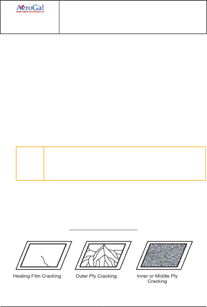
A318/A319/A320/A321
FLIGHT CREW
TECHNIQUES MANUAL
PROCEDURES
ABNORMAL AND EMERGENCY PROCEDURES
MISC
GLG A318/A319/A320/A321 FLEET PR-AEP-MISC P 2/30
FCTM ← A 05 SEP 17
touch the affected glass with a pen or a finger nail to check if the crack(s) is(are) on the cockpit
side (Inner ply):
‐ If there is no crack on the cockpit side:
The Inner ply is not damaged. Therefore, the structural integrity is not affected: the
windshield/window is still able to sustain the differential pressure up to the maximum flight
level.
‐ If there are cracks on the cockpit side:
The Inner ply is damaged. The structural integrity of the window may be altered. As the
flight crew cannot easily identify if the Middle ply is also affected or not, the flight crew must
descend to FL 230/MEA in order to reduce the ΔP to 5 PSI.
Refer to FCOM/PRO-ABN-MISC [QRH] COCKPIT WINDSHIELD / WINDOW CRACKED
procedure to get the full procedure.
ADDITIONAL VISUAL CLUES:
In addition, visual clues can help the flight crew to assess which part of the window is affected
by the crack.
CAUTION The visual clues given below are not sufficient to assess the structural integrity
of the window. The flight crew must do a physical check of the Inner ply of the
windshield as required by the COCKPIT WINDSHIELD/WINDOW CRACKED
procedure (Refer to FCOM/PRO-ABN-MISC [QRH] COCKPIT WINDSHIELD /
WINDOW CRACKED procedure) and apply the procedure accordingly.
A heating film cracking looks like roughly a straight line across the window starting from a
window edge. In most of the cases the line stops in the middle of the window.
An outer ply cracking usually shows a few broken lines that start from one edge of the
windshield or from a foreign object impact, and go through the window to another edge.
A structural ply cracking (Inner ply or Middle ply) has a break pattern that covers the entire
surface of the windshield. The small pieces of broken glass impair the visibility.
Typical Cockpit Window Damages

A318/A319/A320/A321
FLIGHT CREW
TECHNIQUES MANUAL
PROCEDURES
ABNORMAL AND EMERGENCY PROCEDURES
MISC
GLG A318/A319/A320/A321 FLEET PR-AEP-MISC P 3/30
FCTM B → 05 SEP 17
EMER DESCENT
Ident.: PR-AEP-MISC-00019302.0001001 / 20 MAR 17
Applicable to: ALL
The emergency descent should only be initiated on positive confirmation that cabin altitude and
rate of climb are excessive and uncontrollable. However, the flight crew must rely on the CAB PR
EXCESS CAB ALT warning, even if not confirmed on the CAB PRESS SD page. The CAB PR
EXCESS CAB ALT warning can be triggered by a cabin pressure sensor, different from the one used
to control the pressure and display the cabin altitude on the SD.
The flight crew should perform the actions of the EMER DESCENT in two steps:
‐ First step: Apply the memory items.
‐ Second step: Perform the read-&-do procedure (ECAM or QRH).
During the first step, the PM should focus on monitoring the FMA to ensure that the PF had correctly
established the aircraft in descent.
During the second step, the PF should refine the settings.
To initiate the emergency descent, the use of autopilot (AP) and autothrust is highly recommended.
At high flight levels, the flight crew should extend the speed brakes while monitoring the VLS . This is
in order to avoid the activation of the angle of attack protection which may result in the retraction of
the speed brakes and in AP disconnection.
Note: When in IDLE thrust, high speed and with speed brake extended, the rate of descent is
approximately 7 000 ft/min. To descend from FL 390 to FL 100, it takes approximately
4 min and 40 NM.
The flight crew should be aware that the MORA displayed on ND is the highest MORA value
within a radius of 40 NM around the aircraft.
The flight crew should suspect structural damage in case of a loud bang, or high cabin vertical
speed. If the flight crew suspects structural damage, apply both of the following:
‐ Set the SPEED/MACH pb to SPEED, to prevent an increase in the IAS, or to reduce the speed.
This action minimizes the stress on aircraft structure
‐ Carefully use the speed brakes, to avoid additional stress on aircraft structure.
If the cabin altitude goes above 14 000 ft, the flight crew must press the MASK MAN ON pb. When it
is obvious that the cabin altitude will exceed 14 000 ft, the flight crew could press the MASK MAN ON
pb, before the cabin altitude reaches 14 000 ft.
Finally, subsequent to an emergency descent, once the oxygen masks are removed, the flight crew
should perform all of the following:
‐ Close the oxygen stowage mask compartment.
‐ Press the PRESS TO RESET oxygen control slide, to deactivate the mask microphone, and to cut
off the oxygen.
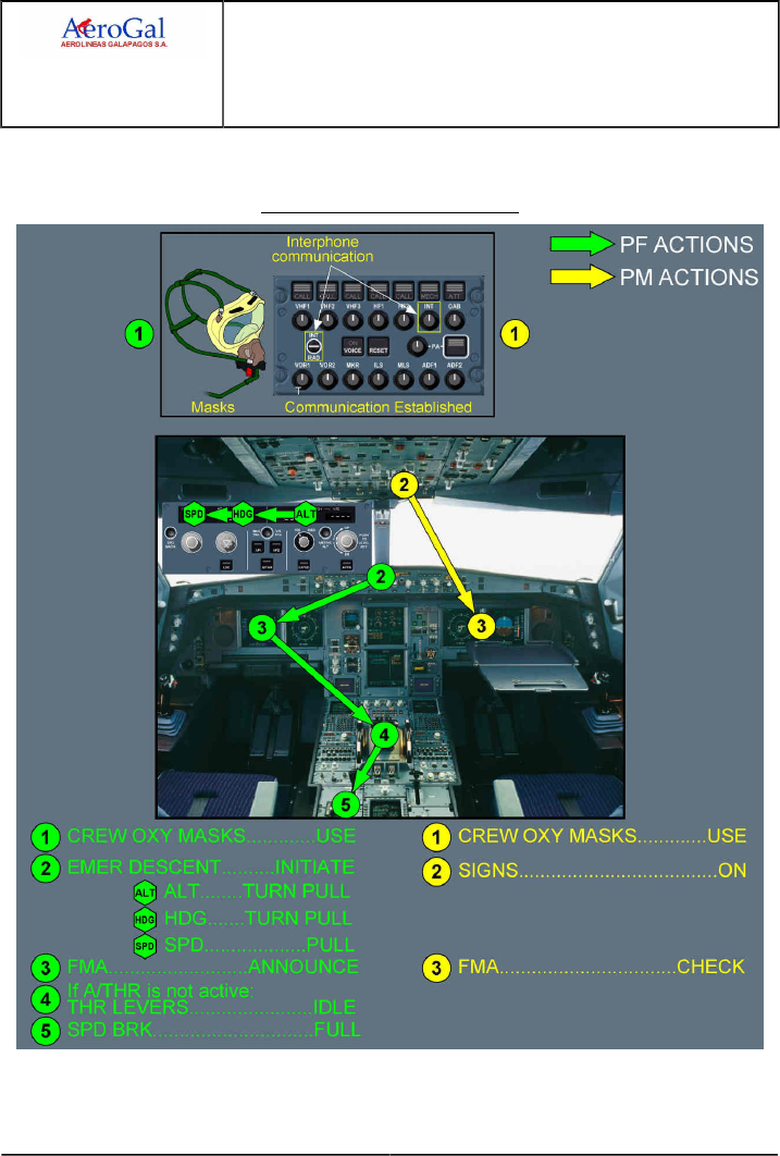
A318/A319/A320/A321
FLIGHT CREW
TECHNIQUES MANUAL
PROCEDURES
ABNORMAL AND EMERGENCY PROCEDURES
MISC
GLG A318/A319/A320/A321 FLEET PR-AEP-MISC P 4/30
FCTM ← B 05 SEP 17
Below FL 100, the flight crew should limit the rate of descent to approximately 1 000 ft/min, except
during the approach phase.
EMER DESCENT - Memory Items

A318/A319/A320/A321
FLIGHT CREW
TECHNIQUES MANUAL
PROCEDURES
ABNORMAL AND EMERGENCY PROCEDURES
MISC
GLG A318/A319/A320/A321 FLEET PR-AEP-MISC P 5/30
FCTM C → 05 SEP 17
EMER EVAC
Applicable to: ALL
Ident.: PR-AEP-MISC-A-00019303.0001001 / 20 MAR 17
GENERAL
The typical case, which may require an emergency evacuation, is an uncontrollable on ground
engine fire. This situation, which may occur following a rejected takeoff or after landing, requires
good crew coordination to cope with a high workload situation:
‐ In the rejected takeoff case, the Captain calls "STOP". This confirms that the Captain has
controls
‐ In all other cases, the Captain calls "I HAVE CONTROL" if required, to state the control hand
over.
Note: If possible, position the aircraft to keep the fire away from the fuselage, taking into
account the wind direction.
Ident.: PR-AEP-MISC-A-00016352.0002001 / 20 MAR 17
DECISION MAKING
As soon as aircraft is stopped, and the parking brake is set, the captain notifies the cabin crew and
calls for ECAM ACTIONS. At this stage, the task sharing is defined as follow:
‐ The first officer carries out the ECAM actions
‐ The captain builds up his decision to evacuate depending on the circumstances. Considerations
should be given to:
• Fire remaining out of control after having discharged the agents
• Possible passenger evacuation of the aircraft on the runway
• Communicating intentions or requests to ATC.
If fire remains out of control after having discharged the fire agents, the captain calls for the EMER
EVAC procedure.

A318/A319/A320/A321
FLIGHT CREW
TECHNIQUES MANUAL
PROCEDURES
ABNORMAL AND EMERGENCY PROCEDURES
MISC
GLG A318/A319/A320/A321 FLEET PR-AEP-MISC P 6/30
FCTM ← C → 05 SEP 17
Ident.: PR-AEP-MISC-A-00019304.0001001 / 25 JUL 17
1EVACUATION PROCEDURE
Some items need to be highlighted:
‐ It is essential that the differential pressure be zeroed.
In automatic pressurization mode, the crew can rely on the CPC, and the Delta P check is
therefore not applicable.
If MAN CAB PRESS is used in flight, the CAB PR SYS (1+2) FAULT procedure requires
selecting MAN V/S CTL to FULL UP position during final approach to cancel any residual cabin
pressure.
However, since the residual pressure sensor indicator, installed in the cabin door, is inhibited
with slides armed, an additional Delta P check is required by the EMER EVAC procedure.
Since MAN CAB PRESS is never used for takeoff as at least one automatic cabin pressure
control must be operative for departure, the Delta P check does not apply to the case of
emergency evacuation following a rejected takeoff.
‐ CABIN CREW (PA )…ALERT reminds the captain for the "CABIN CREW AT STATION" call
out. (In case of RTO , this is done during the RTO flow pattern). Cabin crew must be aware
that the flight crew is still in control of the situation. In certain circumstances, this will avoid any
unwanted or unnecessary evacuation initiated by the cabin crew
‐ EVACUATION…INITIATE requires the captain confirmation that the emergency evacuation is
still required. If still required, the captain:
• Notifies the cabin crew to start the evacuation,
• Activates the EVAC command,
• Advises ATC,
This will be done preferably in this order for a clear understanding by cabin crew.
Note: In the case of an emergency evacuation subsequent to a rejected takeoff, the F/O
(instead of the captain) advises the ATC.
On ground with engines stopped, only the right dome light is operational and the three positions
(BRT , DIM, OFF) of the DOME light sw remain available, allowing the EMER EVAC procedure
completion.
The crew will keep in mind that as long as the evacuation order is not triggered, the crew may
differ or cancel the passengers' evacuation. As soon as the evacuation order is triggered, this
decision is irreversible.
When aircraft is on batteries power, the crew seats can only be operated mechanically.
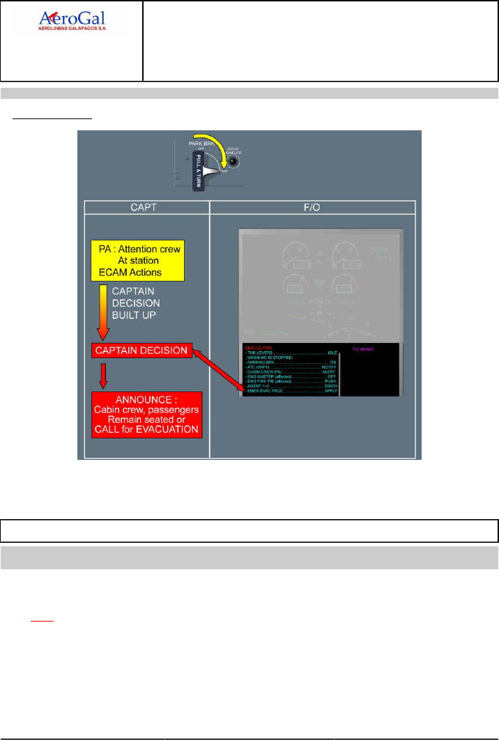
A318/A319/A320/A321
FLIGHT CREW
TECHNIQUES MANUAL
PROCEDURES
ABNORMAL AND EMERGENCY PROCEDURES
MISC
GLG A318/A319/A320/A321 FLEET PR-AEP-MISC P 7/30
FCTM ← C to D → 05 SEP 17
Ident.: PR-AEP-MISC-A-00019305.0001001 / 20 MAR 17
TASKSHARING
When applying the EMER EVAC procedure, the F/O can select the engine masters OFF and push
the FIRE pb, without any confirmation from the Captain.
EMER LANDING
Ident.: PR-AEP-MISC-00019308.0001001 / 20 MAR 17
Applicable to: ALL
In some rare cases, the loss of all engines occurs at a very low height above ground level, and there
is not sufficient time to attempt an engine relight. Therefore, the flight crew may not be able to apply
the ENG DUAL FAILURE procedure. The flight crew must use the remaining time to fly the aircraft to
an appropriate landing spot, and to prepare the aircraft for touchdown (ditching or forced landing).
The EMER LANDING procedure is provided in the QRH close to the EMER EVAC procedure.
The EMER LANDING procedure provides the flight crew with the following items and actions to
perform, for the best possible touchdown:
‐ The landing gear position
‐ The slats/flaps configuration

A318/A319/A320/A321
FLIGHT CREW
TECHNIQUES MANUAL
PROCEDURES
ABNORMAL AND EMERGENCY PROCEDURES
MISC
GLG A318/A319/A320/A321 FLEET PR-AEP-MISC P 8/30
FCTM ← D to E → 05 SEP 17
‐ The speed
‐ The pitch attitude, in the case of ditching.
Flight crew actions that are considered as basic airmanship (notify the ATC, notify the cabin crew,
etc.) are not included in the EMER LANDING procedure.
WHEN TO APPLY THE EMER LANDING PROCEDURE
The flight crew must rapidly decide to apply either the ENG DUAL FAILURE procedure, or the
EMER LANDING procedure, depending on their assessment of the situation.
To make their decision, the flight crew should take all the following parameters into account:
‐ The aircraft altitude
‐ The remaining time before touchdown
‐ The rate of descent
‐ The flight crew workload
‐ The weather conditions
‐ The suitable landing surface options
‐ The technical state of the aircraft, etc.
FLIGHT CREW INCAPACITATION
Ident.: PR-AEP-MISC-00018202.0001001 / 20 MAR 17
Applicable to: ALL
GENERAL
Flight crew incapacitation is a real safety hazard that occurs more frequently than many of
the other emergencies. Incapacitation can occur in many forms, that range from sudden
death to partial loss of function. Sometimes the flight crew does not have any symptom before
incapacitation.
DETECTION
In order to help with the early detection of flight crew incapacitation, the Crew Resource
Management (CRM) principles should be applied:
‐ Correct crew coordination that involves routine monitoring and aural crosschecks. The
absence of standard callouts at the appropriate time may indicate incapacitation of one flight
crewmember
‐ If one flight crewmember does not feel well, he must inform the other flight crewmember.
Other symptoms, for example incoherent speech, a pale and(or) fixed facial expression, or
irregular breathing, may indicate the beginning of incapacitation.

A318/A319/A320/A321
FLIGHT CREW
TECHNIQUES MANUAL
PROCEDURES
ABNORMAL AND EMERGENCY PROCEDURES
MISC
GLG A318/A319/A320/A321 FLEET PR-AEP-MISC P 9/30
FCTM ← E to F → 05 SEP 17
ACTION
In the case of flight crew incapacitation, the fit flight crewmember should apply the following
actions:
‐ Take over and ensure a safe flight path:
• Announce ″I have control″
• If the incapacitated flight crewmember causes interference with the handling of the aircraft,
press the sidestick pb for 40 seconds
• Keep or engage the onside AP, as required
• Perform callouts (challenge and response included) and checklists aloud.
‐ Inform the ATC of the emergency
‐ Take any steps possible to contain the incapacitated flight crewmember. These steps may
involve cabin attendants
‐ In order to reduce the workload, consider:
• Early approach preparation and checklists reading
• Automatic Landing
• Use of radar vectoring and long approach.
‐ Land at the nearest suitable airport after consideration of all pertinent factors
‐ Arrange medical assistance onboard and after landing, providing as many details as possible
about the condition of the affected flight crewmember
‐ Request assistance from any medically qualified passenger, except for flight with only two flight
crewmembers onboard (i.e. freighter or ferry flight).
HANDLING THE AIRCRAFT IN THE CASE OF SEVERE DAMAGE
Ident.: PR-AEP-MISC-00019240.0001001 / 20 MAR 17
Applicable to: ALL
In the event of severe damage to the aircraft, the flight crew’s immediate action should be to “fly
the aircraft". In severe damage cases, it might be necessary for the flight crew to revert to the use
of a “back to basics" flying techniques, where bank, pitch, and thrust are the primary parameters
to manually control. In addition, as for any flight phase, the flight crew must continue to perform all
navigation and communication tasks.
If the damage significantly affects aircraft aerodynamics, flight controls, or engines, then aircraft
handling qualities may be affected. Therefore, the flight crew should perform an assessment of
aircraft handling qualities as soon as possible, in order to identify how pitch, roll, and yaw are
controllable.
During assessment of the flight controls, the flight crew should apply smooth sidestick input and
should limit the bank angle to 15°, in order to prevent possible destabilization of the aircraft. In

A318/A319/A320/A321
FLIGHT CREW
TECHNIQUES MANUAL
PROCEDURES
ABNORMAL AND EMERGENCY PROCEDURES
MISC
GLG A318/A319/A320/A321 FLEET PR-AEP-MISC P 10/30
FCTM ← F 05 SEP 17
addition, the flight crew should avoid use of the speedbrakes before the end of the flight, unless
necessary.
To assess aircraft handling qualities, the flight crew must keep the following basic principles in mind:
‐ Elevators, ailerons, and rudder are the primary flight controls.
‐ In addition to use of the elevators, use of the THS (via longitudinal trim control) may also be
necessary in order to control pitch.
‐ On all Airbus aircraft, engines are mounted under the wing. As a consequence a thrust increase
results in a pitch-up effect, and a thrust decrease results in a pitch-down effect.
‐ If damage to the aircraft is severe, it may be necessary to use abnormal flying techniques to
maintain control of the aircraft. Each flight control can be used to compensate for an inoperative or
damaged surface. For example, the flight crew can compensate for a lack of roll efficiency via the
use of rudder input. As another example, the application of asymmetrical thrust enables the flight
crew to indirectly control roll, with a slightly delayed response.
CAUTION Sudden commanded full, or nearly full, opposite rudder movement against a sideslip
can generate loads that exceed the limit loads and possibly the ultimate loads and
can result in structural failure.
This is true even at speeds below the maximum design maneuvering speed, VA.
As soon as control of the aircraft is ensured:
‐ Depending on the severity of the damage to the aircraft, the flight crew may attempt to use
automation. However, if the autopilot and the flight director remain available, their operation may
be erratic. Therefore, the flight crew should monitor carefully the AP behaviour, and must be
prepared to immediately revert to manual flying techniques.
‐ The flight crew can start ECAM actions, if applicable. An assessment of the flight deck indications
may provide the flight crew with useful information about affected systems. When possible and
depending on the situation, a visual check can also provide important information.
Prior to landing and at an appropriate altitude, the flight crew must perform an assessment of aircraft
handling qualities in landing configuration in order to help determine an appropriate strategy for
approach and landing. The flight crew must perform this analysis at different speeds down to VAPP.
If it becomes difficult to control the aircraft when the aircraft goes below a specific speed, the flight
crew must perform the approach landing at a speed above this specific speed. The result of the
above-mentioned assessments helps to build the correct follow up strategy. The quantity of flight
crew workload required to maintain control of the aircraft is one of the decision factors to take into
account for this strategy. Good flight crew coordination is essential throughout the assessment
process. The flight crew should share their own understanding and view of the situation with their
other flight crewmembers.

A318/A319/A320/A321
FLIGHT CREW
TECHNIQUES MANUAL
PROCEDURES
ABNORMAL AND EMERGENCY PROCEDURES
MISC
GLG A318/A319/A320/A321 FLEET PR-AEP-MISC P 11/30
FCTM G to H → 05 SEP 17
LOW ENERGY
Ident.: PR-AEP-MISC-00019309.0001001 / 20 MAR 17
Applicable to: ALL
GENERAL
The SPEED, SPEED, SPEED aural alert announces a low energy situation. This situation requires
a flight crew action to increase energy.
For more information, Refer to FCOM/DSC-22_40-30 Low - Energy Aural Alert.
LOW ENERGY RECOVERY
Increase the thrust and/or adjust the pitch depending on the circumstances, until the aural alert
stops.
OVERSPEED
Applicable to: ALL
Ident.: PR-AEP-MISC-B-00016353.0001001 / 20 MAR 17
GENERAL
The flight crew must not intentionally exceed VMO /MMO (350 kt/M 0.82) during the flight.
However, during normal operations, the aircraft may temporarily exceed VMO /MMO due to wind
gradients.
The aircraft is designed to fly up to the maximum structural speed at which the aircraft structure
will not be damaged. However, in the case of overspeed, the aircraft may encounter vertical
load factors that may exceed the aircraft limits. In this case, exceeding VMO /MMO requires
maintenance inspection.
Ident.: PR-AEP-MISC-B-00016354.0001001 / 20 MAR 17
OVERSPEED PREVENTION
The flight crew should apply the overspeed prevention technique if the aircraft encounters
significant speed variations close to VMO /MMO during the flight.
In this case, the flight crew should keep the autopilot (AP ) and the autothrust (A/THR ) engaged.
The use of AP and A/THR enables the aircraft to remain on the intended flight path while thrust
reduces to idle (if necessary).
The flight crew should decrease the speed target in order to increase the margin to VMO /MMO
(at high altitudes the flight crew should not reduce the speed below green dot speed). After
selection of the lower speed target, the flight crew should monitor the speed trend arrow on the
Primary Flight Display (PFD ). If the aircraft continues to accelerate, and if the speed trend arrow
approaches or exceeds VMO /MMO, the flight crew should use the appropriate position of the

A318/A319/A320/A321
FLIGHT CREW
TECHNIQUES MANUAL
PROCEDURES
ABNORMAL AND EMERGENCY PROCEDURES
MISC
GLG A318/A319/A320/A321 FLEET PR-AEP-MISC P 12/30
FCTM ← H → 05 SEP 17
speed brakes, depending on the rate of acceleration. The length of the speed trend is a good
indication of the rate of acceleration.
Note: The use of speed brakes is an efficient way to decelerate that is certified for the entire
flight envelope. However, the use of speed brakes increases VLS and reduces the buffet
margin at high altitudes. The use of speed brakes results in pitch up for which the AP and
the normal law compensate.
For descents in descent (DES ) and managed speed modes, the flight crew should enter descent
wind data that is as accurate as possible in the Flight Management and Guidance System (FMGS
). The FMGS then computes an optimized vertical profile that offers a better capability to remain in
the speed target range.
If the aircraft exceeds VMO /MMO, the flight crew applies the overspeed recovery technique.
Ident.: PR-AEP-MISC-B-00019238.0001001 / 20 MAR 17
OVERSPEED RECOVERY
The flight crew must apply the overspeed recovery technique if the aircraft exceeds VMO /MMO .
The OVERSPEED warning is triggered when the speed exceeds VMO +4 kt/MMO +M 0.006, and
lasts until the speed is below VMO /MMO.
The flight crew should keep the AP engaged in order to minimize the vertical load factors. In order
to minimize overspeed, the flight crew should extend the speed brakes to the most appropriate
lever position, depending on the overspeed situation. In addition, the flight crew should keep the
A/THR engaged and should check that the thrust reduces to idle.
To keep the A/THR engaged or to set the manual thrust to idle has the same effect on the
overspeed recovery. Both techniques result in the same engine response in terms of thrust
reduction.
If the A/THR is OFF, the flight crew must set the thrust levers to idle.
In the case of severe overspeed, the AP automatically disengages and then, the High Speed
Protection activates in normal law. As a result, the aircraft encounters an automatic pitch up. Refer
to FCOM/DSC-27-20-10-20 Protections - High Speed Protection.
Note: The AP does not automatically disengage as soon as the speed reaches the green bars
(that represent the threshold when the High Speed Protection activates) on the PFD .
The AP disengagement depends on the speed variations and the High Speed Protection
logic.
The High Speed Protection is designed to request the appropriate demand of vertical load factor.
Therefore, the flight crew should smoothly adjust the pitch attitude to avoid excessive load factors.
Note: The flight crew must disregard the Flight Director (FD ) orders while the high speed
protection is active. The FD orders do not take into account the High Speed Protection.

A318/A319/A320/A321
FLIGHT CREW
TECHNIQUES MANUAL
PROCEDURES
ABNORMAL AND EMERGENCY PROCEDURES
MISC
GLG A318/A319/A320/A321 FLEET PR-AEP-MISC P 13/30
FCTM ← H to I → 05 SEP 17
The flight crew should keep the speed brakes because the use of the speed brakes is compatible
with the High Speed Protection.
Ident.: PR-AEP-MISC-B-00019239.0001001 / 20 MAR 17
WHEN THE SPEED IS BELOW VMO /MMO
When the aircraft speed is below VMO /MMO with a sufficient speed margin, the flight crew should
retract the speed brakes and should select a new speed target. If the flight crew retracts the speed
brakes when the speed is close to VMO /MMO , the speed may exceed VMO /MMO again at
speed brake retraction. If the A/THR is OFF, the flight crew should manually adjust the thrust
levers.
After severe overspeed, the flight crew should recover the flight path smoothly, and then should
engage the AP in accordance with the recommended procedure for AP engagement. Refer to
AS-FG-10-1 Recommended Practice for Autopilot (AP) Engagement.
Ident.: PR-AEP-MISC-B-00016355.0001001 / 20 MAR 17
REPORTING
The flight crew must report any type of overspeed event (i.e. if the speed exceeds VMO /MMO) to
the maintenance. This report results in appropriate maintenance actions.
Ident.: PR-AEP-MISC-B-00016356.0001001 / 20 MAR 17
LINK BETWEEN VMO /MMO AND TURBULENCE
The significant speed variations near VMO /MMO and above VMO /MMO may be one of the first
indications of possible severe turbulence.
For more information, Refer to PR-NP-SP-10-10-2 Introduction.
OVERWEIGHT LANDING
Ident.: PR-AEP-MISC-00005692.0036001 / 24 JUN 08
Criteria: 32-1247, 32-1291, J0071, P4808, P5518, P7721, P8440, 319-100
Applicable to: HC-CKN, HC-CLF, HC-CSA, HC-CSB
Automatic landing is certified up to MLW , but has been demonstrated in flight up to MTOW.
In determining the best course of action, the flight crew may consider the option to perform an
automatic landing, provided the runway is approved for automatic landing.
Should an overweight landing be required, a long straight in approach, or a wide visual pattern,
should be flown in order to configure the aircraft for a stabilized approach.
The stabilized approach technique should be used, and VAPP established at the FAF . The speed
will be reduced to reach VLS at runway threshold, to minimize the aircraft energy.

A318/A319/A320/A321
FLIGHT CREW
TECHNIQUES MANUAL
PROCEDURES
ABNORMAL AND EMERGENCY PROCEDURES
MISC
GLG A318/A319/A320/A321 FLEET PR-AEP-MISC P 14/30
FCTM ← I → 05 SEP 17
The crew will elect the landing configuration according to the "maximum weight for go-around in
CONF 3" table provided both in QRH and in FCOM:
• If aircraft weight is below the maximum weight for go-around in CONF 3, landing will be performed
CONF full (and go-around CONF 3) as it is the preferred configuration for optimized landing
performance
• If aircraft weight is above the maximum weight for go-around in CONF 3, landing will be performed
CONF 3 (and go-around CONF 1+F). The CONF 1+F meets the approach climb gradient
requirement in all cases (high weights, high altitude and temperature).
If a go-around CONF 1+F is carried out following an approach CONF 3, VLS CONF 1+F may be
higher than VLS CONF 3 +5 kt. The recommendation in such a case is to follow SRS orders which
will accelerate the aircraft up to the displayed VLS . It should be noted, however, that VLS CONF
1+F equates to 1.23 VS1G whereas the minimum go-around speed required by regulations is 1.13
VS1G. This requirement is always satisfied.
The crew should be aware that the transition from -3 ° flight path angle to go around climb gradient
requires a lot of energy and therefore some altitude loss.
Taking into account the runway landing distance available, the use of brakes should be modulated to
avoid very hot brakes and the risk of tire deflation.
When the aircraft weight exceeds the maximum landing weight, structural considerations impose the
ability to touch down at 360 ft/min without damage. This means that no maintenance inspection is
required if vertical speed is below 360 ft/min. If vertical speed exceeds 360 ft/min at touch down, a
maintenance inspection is required.
OVERWEIGHT LANDING
Ident.: PR-AEP-MISC-00005692.0038001 / 24 JUN 08
Criteria: J0071, P4808, P5518, P7721, P8440, 320-200
Applicable to: HC-CJM, HC-CJV, HC-CJW, HC-CRU, HC-CSF
Should an overweight landing be required, a long straight in approach, or a wide visual pattern,
should be flown in order to configure the aircraft for a stabilized approach.
The stabilized approach technique should be used, and VAPP established at the FAF . The speed
will be reduced to reach VLS at runway threshold, to minimize the aircraft energy.
The crew will elect the landing configuration according to the "maximum weight for go-around in
CONF 3" table provided both in QRH and in FCOM:
• If aircraft weight is below the maximum weight for go-around in CONF 3, landing will be performed
CONF full (and go-around CONF 3) as it is the preferred configuration for optimized landing
performance
• If aircraft weight is above the maximum weight for go-around in CONF 3, landing will be performed
CONF 3 (and go-around CONF 1+F). The CONF 1+F meets the approach climb gradient
requirement in all cases (high weights, high altitude and temperature).

A318/A319/A320/A321
FLIGHT CREW
TECHNIQUES MANUAL
PROCEDURES
ABNORMAL AND EMERGENCY PROCEDURES
MISC
GLG A318/A319/A320/A321 FLEET PR-AEP-MISC P 15/30
FCTM ← I to J → 05 SEP 17
If a go-around CONF 1+F is carried out following an approach CONF 3, VLS CONF 1+F may be
higher than VLS CONF 3 +5 kt. The recommendation in such a case is to follow SRS orders which
will accelerate the aircraft up to the displayed VLS . It should be noted, however, that VLS CONF
1+F equates to 1.23 VS1G whereas the minimum go-around speed required by regulations is 1.13
VS1G. This requirement is always satisfied.
The crew should be aware that the transition from -3 ° flight path angle to go around climb gradient
requires a lot of energy and therefore some altitude loss.
Taking into account the runway landing distance available, the use of brakes should be modulated to
avoid very hot brakes and the risk of tire deflation.
When the aircraft weight exceeds the maximum landing weight, structural considerations impose the
ability to touch down at 360 ft/min without damage. This means that no maintenance inspection is
required if vertical speed is below 360 ft/min. If vertical speed exceeds 360 ft/min at touch down, a
maintenance inspection is required.
REJECTED TAKEOFF
Applicable to: ALL
Ident.: PR-AEP-MISC-C-00016357.0001001 / 20 MAR 17
FACTORS AFFECTING THE REJECTED TAKEOFF (RTO)
Experience has shown that a rejected takeoff can be hazardous, even if correct procedures are
followed.
Some factors that can detract from a successful rejected takeoff are as follows:
‐ Tire damage
‐ Brakes worn or not working correctly
‐ Brakes not being fully applied
‐ Error in gross weight determination
‐ Incorrect performance calculations
‐ Incorrect runway line-up technique
‐ Initial brake temperature
‐ Delay in initiating the stopping procedure
‐ Runway friction coefficient lower than expected.
Thorough pre-flight preparation and a conscientious exterior inspection can eliminate the effect of
some of these factors.
During the taxi-out, the takeoff briefing should be confirmed. Any change to the planned conditions
requires the crew to re-calculate the takeoff data. In this case, the crew should not be pressurised
into accepting a takeoff clearance before being fully ready. Similarly, the crew should not accept
an intersection takeoff until the takeoff performance has been checked.

A318/A319/A320/A321
FLIGHT CREW
TECHNIQUES MANUAL
PROCEDURES
ABNORMAL AND EMERGENCY PROCEDURES
MISC
GLG A318/A319/A320/A321 FLEET PR-AEP-MISC P 16/30
FCTM ← J → 05 SEP 17
The line-up technique is very important. The pilot should use the over steer technique to minimize
field length loss and consequently, to maximize the acceleration-stop distance available.
Ident.: PR-AEP-MISC-C-00016358.0001001 / 20 MAR 17
DECISION MAKING
A rejected takeoff is a potentially hazardous manoeuvre and the time for decision making is
limited. It is not possible to list all the factors that could lead to the decision to reject the takeoff.
However, in order to help the Captain to make a decision, the ECAM inhibits the warnings that are
not essential from 80 kt to 1 500 ft (or 2 min after lift-off, whichever occurs first). Therefore, any
warning received during this period must be considered as significant.
SPEED CONSIDERATIONS
To assist in the decision making process, the takeoff is divided into low and high speeds
regimes, with 100 kt being chosen as the dividing line. The speed of 100 kt is not critical but was
chosen in order to help the Captain make the decision and to avoid unnecessary stops from
high speed.
Below 100 kt:
The decision to reject the takeoff may be taken at the Captain's discretion, depending on
the circumstances.
The Captain should seriously consider discontinuing the takeoff, if any ECAM
warning/caution is activated.
Above 100 kt, and below V1:
Rejecting the takeoff at these speeds is a more serious matter, particularly on slippery
runways. It could lead to a hazardous situation, if the speed is approaching V1. At these
speeds, the Captain should be "go-minded" and very few situations should lead to the
decision to reject the takeoff:
1. Fire warning, or severe damage
2. Sudden loss of engine thrust
3. Malfunctions or conditions that give unambiguous indications that the aircraft will not fly
safely
4. Any red ECAM warning
5. Any amber ECAM caution listed bellow:
‐F/CTL SIDESTICK FAULT
‐ENG FAIL
‐ENG REVERSER FAULT
‐ENG REVERSE UNLOCKED
‐ENG 1(2) THR LEVER FAULT

A318/A319/A320/A321
FLIGHT CREW
TECHNIQUES MANUAL
PROCEDURES
ABNORMAL AND EMERGENCY PROCEDURES
MISC
GLG A318/A319/A320/A321 FLEET PR-AEP-MISC P 17/30
FCTM ← J → 05 SEP 17
Exceeding the EGT red line or nose gear vibration should not result in the decision to reject
takeoff above 100 kt.
In case of tire failure between V1 minus 20 kt and V1, unless debris from the tires has
caused serious engine anomalies, it is far better to get airborne, reduce the fuel load, and
land with a full runway length available.
The V1 call has precedence over any other call.
Above V1:
Takeoff must be continued, because it may not be possible to stop the aircraft on the
remaining runway.
DECISION CALLOUTS
The decision to reject the takeoff and the stop action is the responsibility of the Captain and
must be made prior to V1 speed. It is therefore recommended that the Captain keeps his
hand on the thrust levers until the aircraft reaches V1, whether he is Pilot Flying (PF) or Pilot
Monitoring (PM).
‐ If a malfunction occurs before V1, for which the Captain does not intend to reject the takeoff,
he will announce his intention by calling "GO".
‐ If a decision is made to reject the takeoff, the Captain calls "STOP". This call both confirms
the decision to reject the takeoff and also states that the Captain now has control. It is the
only time that hand-over of control is not accompanied by the phrase "I have control".
Ident.: PR-AEP-MISC-C-00016359.0002001 / 25 JUL 17
2RTO TECHNIQUE
Should a RTO procedure is initiated, the following task sharing will be applied.
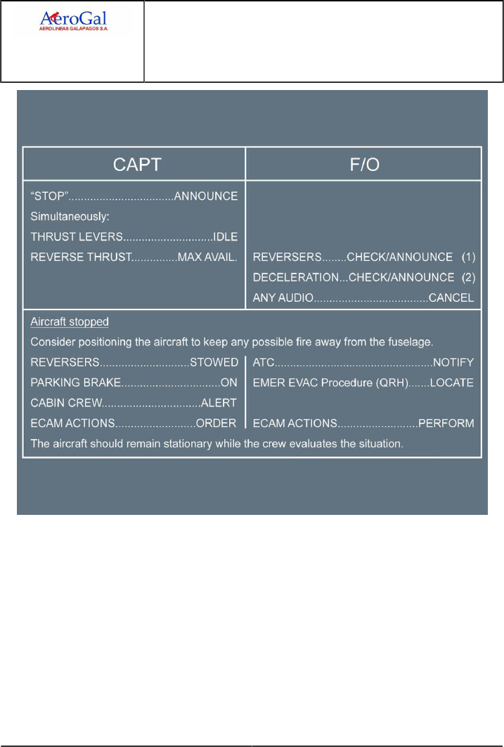
A318/A319/A320/A321
FLIGHT CREW
TECHNIQUES MANUAL
PROCEDURES
ABNORMAL AND EMERGENCY PROCEDURES
MISC
GLG A318/A319/A320/A321 FLEET PR-AEP-MISC P 18/30
FCTM ← J → 05 SEP 17
(1) : Full reverse may be used until coming to a complete stop. But, if there is enough runway
available at the end of the deceleration, it is preferable to reduce reverse thrust when
passing 70 kt

A318/A319/A320/A321
FLIGHT CREW
TECHNIQUES MANUAL
PROCEDURES
ABNORMAL AND EMERGENCY PROCEDURES
MISC
GLG A318/A319/A320/A321 FLEET PR-AEP-MISC P 19/30
FCTM ← J → 05 SEP 17
(2) : ‐ Announcing the deceleration means that the deceleration is felt by the crew, and
confirmed by the VC trend on the PFD. The deceleration may also be confirmed by the
DECEL light (if the autobrake is on). However, this light only comes on when the actual
deceleration is 80 % of the selected rate, it is not an indicator of the proper autobrake
operation. For instance, the DECEL light might not appear on a contaminated runway,
with the autobrake working properly, due to the effect of the antiskid.
‐ If a rejected takeoff is initiated and MAX auto brake decelerates the aircraft, the captain
will avoid pressing the pedals (which might be a reflex action).
‐ If the autobrake is inoperative or if the takeoff is rejected prior to 72 kt (autobrake
not active and no deployment of spoilers), the captain simultaneously reduces thrust
and applies maximum pressure on both pedals. The aircraft will stop in the minimum
distance, only if the brake pedals are maintained fully pressed until the aircraft comes
to a stop.
‐ If the brake response does not seem appropriate for the runway condition, FULL
manual braking should be applied and maintained. If IN DOUBT, TAKE OVER
MANUALLY.
‐ If normal braking is inoperative, immediately apply the Loss of Braking procedure
(Refer to FCOM/PRO-ABN-BRAKES [MEM] LOSS OF BRAKING)
After a rejected takeoff, if the aircraft comes to a complete stop using autobrake MAX, release
brakes prior to taxi by disarming spoilers.
Do not attempt to vacate the runway, until it is absolutely clear that an evacuation is not necessary
and that it is safe to do so.
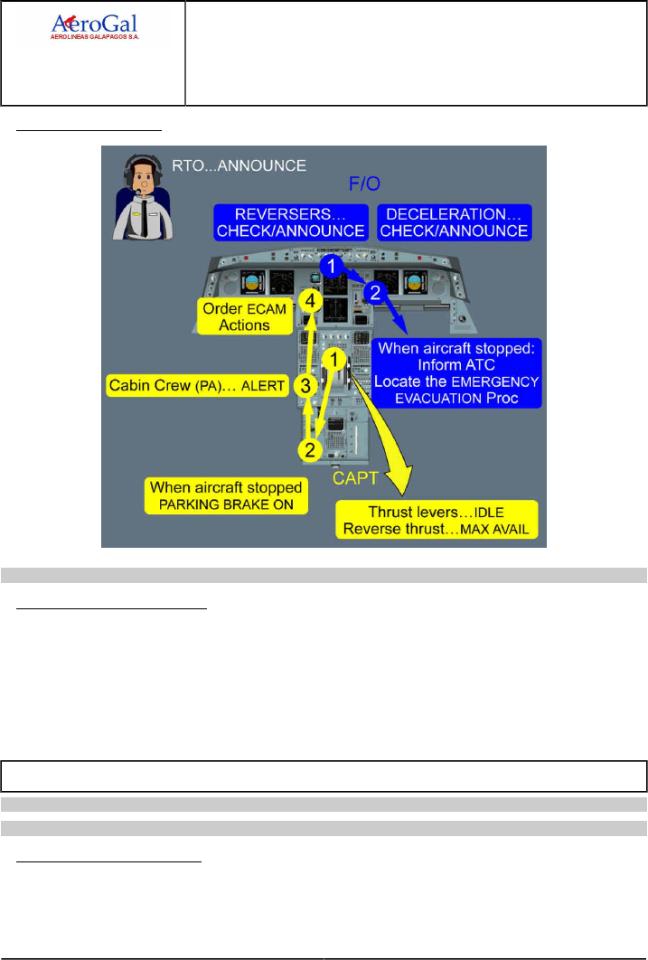
A318/A319/A320/A321
FLIGHT CREW
TECHNIQUES MANUAL
PROCEDURES
ABNORMAL AND EMERGENCY PROCEDURES
MISC
GLG A318/A319/A320/A321 FLEET PR-AEP-MISC P 20/30
FCTM ← J to K → 05 SEP 17
RTO FLOW PATTERN
Ident.: PR-AEP-MISC-C-00020585.0001001 / 20 MAR 17
TAKEOFF FOLLOWING RTO
Depending on the technical condition of the aircraft and the reason for the RTO (e.g. ATC
instruction), the flight crew may consider a new takeoff attempt subsequent to the RTO.
In this case, the flight crew should:
‐ Reset both FD s and set FCU
‐ Restart Standard Operating Procedures from the AFTER START checklist.
STALL RECOVERY
Applicable to: ALL
Ident.: PR-AEP-MISC-D-00016361.0001001 / 20 MAR 17
DEFINITION OF THE STALL
The stall is a condition in aerodynamics where the Angle of Attack (AOA) increases beyond a point
such that the lift begins to decrease.
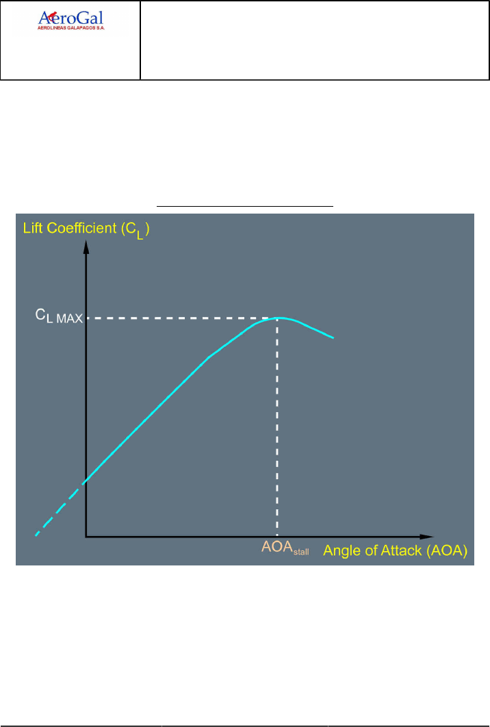
A318/A319/A320/A321
FLIGHT CREW
TECHNIQUES MANUAL
PROCEDURES
ABNORMAL AND EMERGENCY PROCEDURES
MISC
GLG A318/A319/A320/A321 FLEET PR-AEP-MISC P 21/30
FCTM ← K → 05 SEP 17
As per basic aerodynamic rules, the lift coefficient (CL ) increases linearly with the AOA up to a
point where the airflow starts to separate from the upper surface of the wing. At and beyond this
point, the flight crew may observe:
‐ Buffeting, which depends on the slats/flaps configuration and increases at high altitude due to
the high Mach number
‐ Pitch up effect, mainly for swept wings and aft CG . This effect further increases the AOA.
Lift Coefficient versus Angle of Attack
If the AOA further increases up to a value called AOA stall , the lift coefficient will reach a maximum
value called CL MAX.
When the AOA is higher than AOA stall, the airflow separates from the wing surface and the lift
coefficient decreases. This is the stall.
The stall will always occur at the same AOA for a given configuration, Mach number and altitude.
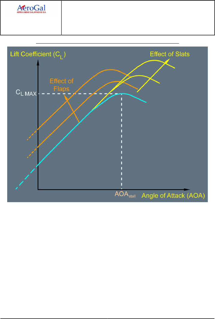
A318/A319/A320/A321
FLIGHT CREW
TECHNIQUES MANUAL
PROCEDURES
ABNORMAL AND EMERGENCY PROCEDURES
MISC
GLG A318/A319/A320/A321 FLEET PR-AEP-MISC P 22/30
FCTM ← K → 05 SEP 17
Influence of Slats and Flaps on Lift Coefficient versus Angle of Attack
Slats and Flaps have a different impact on the Lift coefficient obtained for a given AOA. Both Slats
and Flaps create an increase in the maximum lift coefficient.
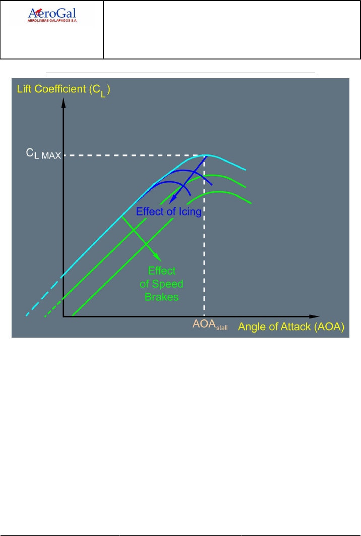
A318/A319/A320/A321
FLIGHT CREW
TECHNIQUES MANUAL
PROCEDURES
ABNORMAL AND EMERGENCY PROCEDURES
MISC
GLG A318/A319/A320/A321 FLEET PR-AEP-MISC P 23/30
FCTM ← K → 05 SEP 17
Influence of Speed Brakes and Icing on Lift Coefficient versus Angle of Attack
On the contrary, speed brake extension and ice accretion reduce the maximum lift coefficient.
Flight control laws and stall warning threshold take into account these possible degradations.
To summarize, loss of lift is only dependant on AOA . The AOA stall depends on:
‐ Aircraft configuration (slats, flaps, speed brakes)
‐ Mach and altitude
‐ Wing contamination

A318/A319/A320/A321
FLIGHT CREW
TECHNIQUES MANUAL
PROCEDURES
ABNORMAL AND EMERGENCY PROCEDURES
MISC
GLG A318/A319/A320/A321 FLEET PR-AEP-MISC P 24/30
FCTM ← K → 05 SEP 17
Ident.: PR-AEP-MISC-D-00016362.0001001 / 20 MAR 17
STALL RECOGNITION
The flight crew must apply the stall recovery procedure as soon as they recognize any of the
following stall indications:
‐ Aural stall warning
The aural stall warning is designed to sound when AOA exceeds a given threshold, which
depends on the aircraft configuration. This warning provides sufficient margin to alert the flight
crew in advance of the actual stall even with contaminated wings.
‐ Stall buffet
Buffet is recognized by airframe vibrations that are caused by the non-stationary airflow
separation from the wing surface when approaching AOA stall.
When the Mach number increases, both the AOA stall and CL MAX will decrease.
The aural stall warning is set close to AOA at which the buffet starts. For some Mach numbers
the buffet may appear just before the aural stall warning.
Ident.: PR-AEP-MISC-D-00019236.0001001 / 20 MAR 17
STALL RECOVERY
‐ The immediate key action is to reduce AOA:
The reduction of AOA will enable the wing to regain lift.
This must be achieved by applying a nose down pitch order on the sidestick. This pilot action
ensures an immediate aircraft response and reduction of the AOA.
In case of lack of pitch down authority, it may be necessary to reduce thrust.
Simultaneously, the flight crew must ensure that the wings are level in order to reduce the lift
necessary for the flight, and as a consequence, the required AOA.
As a general rule, minimizing the loss of altitude is secondary to the reduction of the AOA as the
first priority is to regain lift.
As AOA reduces below the AOA stall, lift and drag will return to their normal values.
‐ The secondary action is to increase energy:
When stall indications have stopped, the flight crew should increase thrust smoothly as needed
and must ensure that the speed brakes are retracted.
Immediate maximum thrust application upon stall recognition is not appropriate. Due to the
engine spool up time, the aircraft speed increase that results from thrust increase, is slow and
does not enable to reduce the AOA instantaneously.
Furthermore, for under wing mounted engines, the thrust increase generates a pitch up that
may prevent the required reduction of AOA.
When stall indications have stopped, and when the aircraft has recovered sufficient energy, the
flight crew can smoothly recover the initial flight path. If in clean configuration and below FL 200,

A318/A319/A320/A321
FLIGHT CREW
TECHNIQUES MANUAL
PROCEDURES
ABNORMAL AND EMERGENCY PROCEDURES
MISC
GLG A318/A319/A320/A321 FLEET PR-AEP-MISC P 25/30
FCTM ← K to L 05 SEP 17
during flight path recovery, the flight crew must select FLAPS 1 in order to increase the margin to
AOA stall.
Ident.: PR-AEP-MISC-D-00019237.0001001 / 20 MAR 17
STALL WARNING AT LIFT-OFF
At lift-off, a damaged AOA probe may cause a stall warning to spuriously sound in the cockpit.
If the aural stall warning sounds at liftoff, the flight crew must fly the appropriate thrust and pitch for
takeoff in order to attempt to stop the aural stall warning and ensure a safe flight path.
The flight crew applies TOGA thrust in order to get the maximum available thrust. Simultaneously,
the pilot flying must target a pitch angle of 15 ° and keep the wings level in order to ensure safe
climb.
Then, when a safe flight path and speed are achieved, if the aural stall warning is still activated the
flight crew must consider that it is a spurious warning.
VOLCANIC ASH ENCOUNTER
Ident.: PR-AEP-MISC-00020616.0001001 / 20 MAR 17
Applicable to: ALL
Avoid flight into areas of known volcanic activity.
If a volcanic eruption is reported while the aircraft is in flight, reroute the flight to remain well clear
of the affected area (volcanic dust may spread over several hundred miles). If possible, stay on the
upwind side of the volcano (at least 20 NM upwind of it if it is erupting).
In hours of darkness or in meteorological conditions that obscure volcanic dust, one or several of the
following phenomena indicate that the aircraft may be flying into ash cloud:
• smoke or dust in the cockpit,
• acrid odor similar to electrical smoke,
• at night, the appearance of St. Elmo’s fire and static discharges around the windshield,
• bright white or orange glow appearing in the engine inlets,
• sharp, distinct beams from the landing lights,
• multiple engine malfunctions, such as rising EGT, decreasing power, stall, or flame out.
REPORTING
• Whenever operating in areas affected by volcanic activity, flight crews should be aware of
volcanic reporting procedures and be familiar with the use of the ICAO Special Air Report of
Volcanic Activity (Model VAR).
• If the aircraft encounters a volcanic ash cloud, the flight crew should report the location, altitude,
and direction of drift for the ash cloud to ATC, flight conditions and crew duties permitting.

A318/A319/A320/A321
FLIGHT CREW
TECHNIQUES MANUAL
PROCEDURES
ABNORMAL AND EMERGENCY PROCEDURES
MISC
GLG A318/A319/A320/A321 FLEET PR-AEP-MISC P 26/30
FCTM M → 05 SEP 17
UPSET PREVENTION AND RECOVERY
Applicable to: ALL
Ident.: PR-AEP-MISC-E-00020629.0001001 / 20 MAR 17
DEFINITION OF UPSET
An aircraft upset is an undesired aircraft state characterized by unintentional divergences from
parameters normally experienced during operations. An aircraft upset may involve pitch and/or
bank angle divergences and may lead to inappropriate airspeeds for the conditions.
An upset condition exists any time an aircraft diverges from what the flight crew is intending to do.
Deviations from the desired aircraft state will become larger until the flight crew takes action to
stop the divergence. Return to the desired aircraft state can be achieved through natural aircraft
reaction to accelerations, auto-flight system response or flight crew intervention.
Ident.: PR-AEP-MISC-E-00020630.0001001 / 20 MAR 17
UPSET PREVENTION
The prevention of an upset situation is possible thanks to an effective monitoring of:
‐ The environment (turbulences, icing conditions, weather)
‐ The aircraft energy state
‐ The aircraft flight path
‐ The aircraft technical state (Flight controls laws, systems failure).
All flight crew members are responsible of the monitoring to ensure that the aircraft state is
understood and correct for the situation.
Each flight crew member should:
‐ Know and understand the expected aircraft state for the situation
‐ Communicate expectations
‐ Keep track of current aircraft state
‐ Detect and communicate deviations from the intended situation
‐ Assess risk and decide on a response
‐ Update and communicate understanding.
An efficient monitoring and effective coordination and communication are keys to prevent upset
situations. As such, the flight crew should be able to assess the energy, to stop any flight path
divergence, and to recover a stabilized flight path before the upset situation.
Ident.: PR-AEP-MISC-E-00020631.0001001 / 20 MAR 17
RECOVERY TECHNIQUES
The flight crew must be or become aware of the upset situation, i.e. recognize and confirm the
situation before they take appropriate actions.

A318/A319/A320/A321
FLIGHT CREW
TECHNIQUES MANUAL
PROCEDURES
ABNORMAL AND EMERGENCY PROCEDURES
MISC
GLG A318/A319/A320/A321 FLEET PR-AEP-MISC P 27/30
FCTM ← M → 05 SEP 17
COMMUNICATION
Communication between crew members will assist in the recognition of upset situation and
recovery actions. At the first indication of a flight path divergence, the first pilot who observes
the divergence must announce it. The flight crew must use the flight instruments as primary
means to analyze the upset situation.
SITUATION ANALYSIS
The situation analysis process is to:
‐ Assess the energy (airspeed, altitude, attitude, load factor, thrust setting, position of drag and
high-lift devices and the rate of change of those conditions)
‐ Determine the aircraft attitude (pitch and bank angle)
‐ Communicate with other crew member(s)
‐ Confirm attitude by reference to other indicators:
• For a nose low upset, normally the airspeed is increasing, altitude is decreasing and the
Vertical Speed Indicator (VSI) indicates a descent
• For a nose high upset, the airspeed normally is decreasing, altitude is increasing and the
VSI indicates a climb.
A stalled condition can exist at any attitude and could be recognized by stall buffet and/or stall
aural alert. If the aircraft is stalled, apply the stall recovery procedure. Refer to PR-AEP-MISC
Definition of the Stall
REFERENCES FOR RECOVERY
The Primary Flight Display (PFD) is a primary reference for recovery.
Pitch attitude is determined from the PFD pitch reference scale. Even in extreme attitudes,
some portion of the sky or ground indications is present to assist the pilot in analyzing the
situation. The bank indicator on the PFD should be used to determine the aircraft bank.
Other attitude sources should be checked: Standby Attitude Indications, the pilot monitoring
(PM) instruments, or references outside the cockpit when possible.
ACTIONS FOR RECOVERY
An overview of actions to take to recover from an upset would gather three basic activities:
‐ Assess the energy (become situationally aware)
‐ Stop the flight path divergence
‐ Recover to a stabilized flight path.
The Nose high/Nose low techniques represent a logical progression for recovering the aircraft.
They are not necessarily procedural. The sequence of actions is for guidance only and
represents a series of options for the pilot to consider and to use depending on the situation.
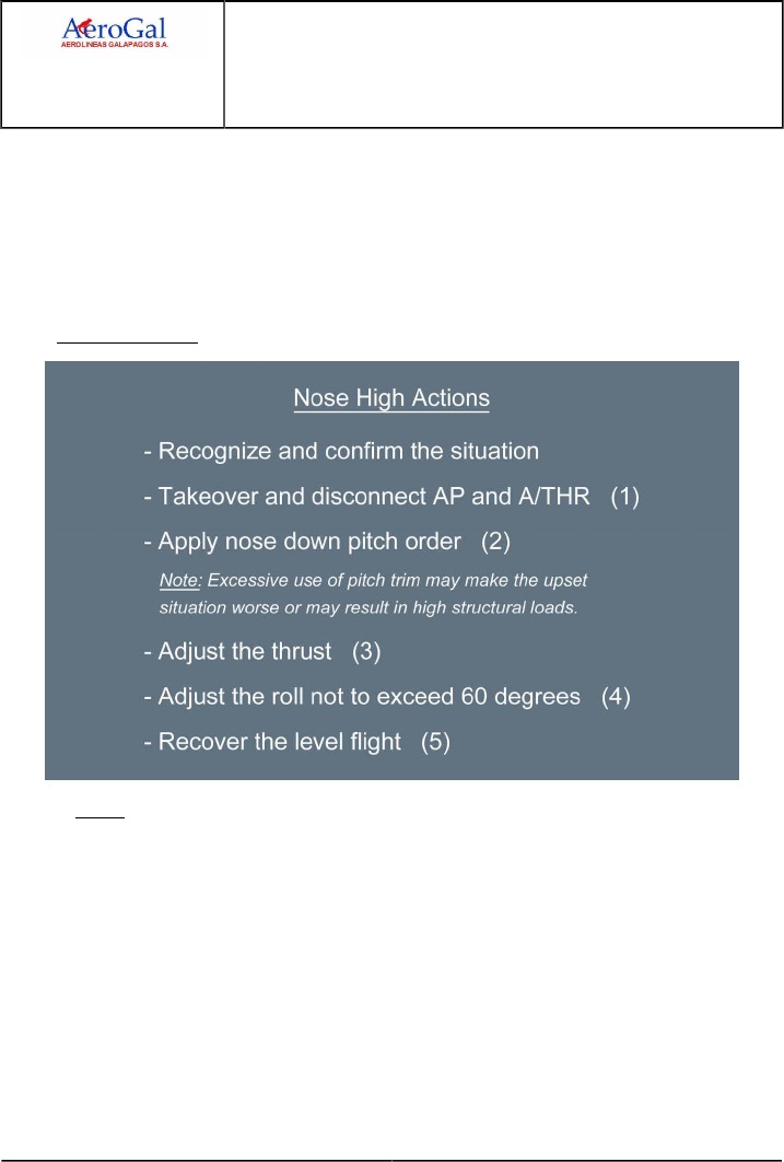
A318/A319/A320/A321
FLIGHT CREW
TECHNIQUES MANUAL
PROCEDURES
ABNORMAL AND EMERGENCY PROCEDURES
MISC
GLG A318/A319/A320/A321 FLEET PR-AEP-MISC P 28/30
FCTM ← M → 05 SEP 17
The flight crew may apply these actions or part of these actions, mainly if the recovery is
effective.
Depending on the situation, the PF should apply the required actions (See figures "Nose High"
and "Nose Low").
During the maneuver, the PM must monitor the airspeed and the attitude throughout the
recovery. The PM must also announce the flight path divergence if the recovery maneuver is not
efficient.
Nose High Actions
Notes:
(1) If the AP and A/THR responses enable to stop the flight path divergence, the flight
crew may keep the AP and A/THR engaged.
(2) The flight crew must apply as much nose down pitch order as required to obtain a
nose down pitch rate.
In the case of lack of pitch down authority, the flight crew may use incremental inputs
on the trim (nose down) to improve the effectiveness of the elevator control.
(3) Select up to maximum thrust available while ensuring adequate pitch control.
Increasing thrust may reduce the effectiveness of nose-down pitch control. It may be
necessary to limit or reduce thrust to the point where control of the pitch is achieved.
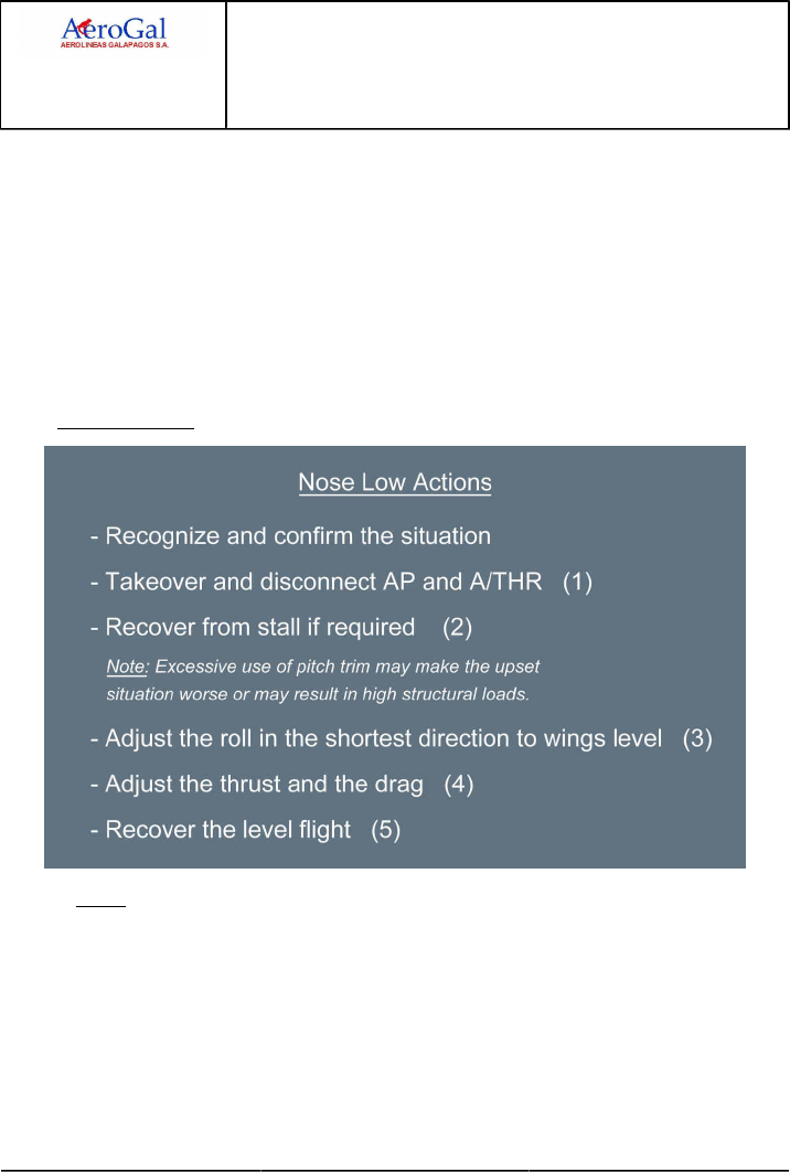
A318/A319/A320/A321
FLIGHT CREW
TECHNIQUES MANUAL
PROCEDURES
ABNORMAL AND EMERGENCY PROCEDURES
MISC
GLG A318/A319/A320/A321 FLEET PR-AEP-MISC P 29/30
FCTM ← M → 05 SEP 17
(4) The bank angle must not exceed 60 degrees.
If all normal pitch control techniques are unsuccessful, the flight crew can keep the
current bank or bank the aircraft to enable the nose to drop toward the horizon.
The bank angle should be the least possible to start the nose down and never
exceed approximately 60 degrees. If the bank angle is already greater than 60
degrees, the flight crew should reduce it to an amount less than 60 degrees.
The flight crew must avoid entering a stall due to premature recovery at low speed or
excessive g-loading at high speed.
(5) Recover to level flight at a sufficient airspeed while avoiding a stall due to premature
recovery at low speed, or excessive g-loading at high speed.
Nose Low Actions
Notes:
(1) If the AP and A/THR responses enable to stop the flight path divergence, the flight
crew may keep the AP and A/THR engaged.
(2) Even in a nose low situation, the aircraft may be stalled and it would be necessary to
recover from a stall first.
(3) In general, a nose low, high-angle-of-bank requires prompt action, because the
decreasing altitude is rapidly being exchanged for an increasing airspeed.
The flight crew must avoid entering a stall due to premature recovery at low speed or
excessive g-loading at high speed.

A318/A319/A320/A321
FLIGHT CREW
TECHNIQUES MANUAL
PROCEDURES
ABNORMAL AND EMERGENCY PROCEDURES
MISC
GLG A318/A319/A320/A321 FLEET PR-AEP-MISC P 30/30
FCTM ← M 05 SEP 17
(4) The flight crew should reduce the thrust and/or use the speedbrakes to control the
speed.
(5) Recover to level flight at a sufficient airspeed while avoiding a stall due to premature
recovery at low speed, or excessive g-loading at high speed.

A318/A319/A320/A321
FLIGHT CREW
TECHNIQUES MANUAL
PROCEDURES
ABNORMAL AND EMERGENCY PROCEDURES
NAV
GLG A318/A319/A320/A321 FLEET PR-AEP-NAV P 1/16
FCTM A 05 SEP 17
ADR/IRS FAULT
Ident.: PR-AEP-NAV-00019311.0002001 / 20 MAR 17
Criteria: P9171, SA
Applicable to: HC-CJV, HC-CJW
Each ADIRS has two parts (ADR and IRS ), that may fail independently of each other. Additionally
the IRS part may fail totally or may be available in ATT mode.
Single NAV ADR FAULT or NAV IRS FAULT are simple procedures, and only require action on the
switching panel as indicated by the ECAM.
Dual NAV ADR or NAV IRS failures will cause the loss of AP and A/THR and the flight controls revert
to ALTN law.
In the case of a triple ADR failure, AP and A/THR are lost and the flight controls revert to ALTN law.
The NAV ADR 1+2+3 FAULT warning is triggered and the ECAM procedure requires that the 3 ADR
s be switched OFF, to replace the PFD 's normal speed scale and altitude indication by the Back-Up
Speed Scale (BUSS ) and GPS altitude information.
There is no procedure for IRS 1 + 2 + 3 failure but the ECAM status page will give approach
procedure and inoperative systems. In this unlikely event, the standby instruments are the only
attitude, altitude, speed and heading references
Note: To switch off an ADR , the flight crew must use the ADR pb. Do not use the rotary selector,
because this would also cut off the electrical supply to the IR part.
ADR/IRS FAULT
Ident.: PR-AEP-NAV-00019311.0001001 / 20 MAR 17
Criteria: SA
Applicable to: HC-CJM, HC-CKN, HC-CLF, HC-CRU, HC-CSA, HC-CSB, HC-CSF
Each ADIRS has two parts (ADR and IRS ), that may fail independently of each other. Additionally
the IRS part may fail totally or may be available in ATT mode.
Single NAV ADR FAULT or NAV IRS FAULT are simple procedures, and only require action on the
switching panel as indicated by the ECAM.
Dual NAV ADR or NAV IRS failures will cause the loss of AP , A/THR and flight controls revert to
ALTN law.
Due to the low probability of a triple ADR failure, the associated procedure will not be displayed on
the ECAM . In this case, the crew will refer to QRH procedure for ADR 1 + 2 + 3 failure.
There is no procedure for IRS 1 + 2 + 3 failure but the ECAM status page will give approach
procedure and inoperative systems. In this unlikely event, the standby instruments are the only
attitude, altitude, speed and heading references.
Note: To switch off an ADR , the flight crew must use the ADR pb. Do not use the rotary selector,
because this would also cut off the electrical supply to the IR part.

A318/A319/A320/A321
FLIGHT CREW
TECHNIQUES MANUAL
PROCEDURES
ABNORMAL AND EMERGENCY PROCEDURES
NAV
GLG A318/A319/A320/A321 FLEET PR-AEP-NAV P 2/16
FCTM B → 05 SEP 17
UNRELIABLE AIRSPEED INDICATIONS
Ident.: PR-AEP-NAV-00019312.0001001 / 25 JUL 17
Applicable to: ALL
PREFACE
The ADRs detect most of the failures affecting the airspeed or altitude indications. These failures
lead to:
‐ Lose the associated speed or altitude indications in the cockpit
‐ Trigger the associated ECAM alerts.
However, there may be cases where an airspeed and/or altitude output is erroneous, while the
ADR s do not detect it as erroneous. In such a case, no ECAM alert is triggered and the cockpit
indications may appear to be normal whereas they are actually false. Flight crews must have in
mind the typical symptoms associated with such cases in order to detect this situation early and
apply the "UNRELIABLE SPEED INDICATION" QRH procedure.
MAIN REASONS FOR ERRONEOUS AIRSPEED/ALTITUDE DATA
The most probable reason for erroneous airspeed and/or altitude information is an obstruction of
the pitot and/or static probes. Depending on how the probe(s) is obstructed, the effects on cockpit
indications differ.
It is highly unlikely that the aircraft probes will be obstructed at the same time, to the same degree
and in the same way. Therefore, the first effect of erroneous airspeed/altitude data in the cockpit
will most probably be a discrepancy between the various indications (CAPT PFD , F/O PFD and
STBY instruments).
CONSEQUENCES OF OBSTRUCTED PITOT TUBES OR STATIC PROBES
All the aircraft systems which use anemometric data, have built-in fault accommodation logics.
The fault accommodation logics rely on a voting principle: When the data provided by one source
diverges from the average value, the systems automatically reject this source and continue
to operate normally using the remaining two sources. The flight controls system and the flight
guidance system both use this voting principle.
NORMAL SITUATION
Each ELAC receives speed information from the three ADR s and compares the three values. The
ELACs do not use the pressure altitude.
Each FAC receives speed and pressure altitude information from the three ADRs and compares
the three values.
ONE ADR OUTPUT IS ERRONEOUS AND THE TWO REMAINING ARE CORRECT
The ELAC s and the FAC and/or FMGC eliminate the erroneous ADR.

A318/A319/A320/A321
FLIGHT CREW
TECHNIQUES MANUAL
PROCEDURES
ABNORMAL AND EMERGENCY PROCEDURES
NAV
GLG A318/A319/A320/A321 FLEET PR-AEP-NAV P 3/16
FCTM ← B → 05 SEP 17
There is no cockpit effect (no caution, normal operation is continued), except that one display is
wrong and the autoland capability is downgraded to CAT 3 SINGLE.
TWO ADR OUTPUTS ARE ERRONEOUS, BUT DIFFERENT, AND THE REMAINING ADR IS
CORRECT, OR IF ALL THREE ADRS ARE ERRONEOUS, BUT DIFFERENT :
Both the AP and A/THR disconnect. The ELAC s trigger the NAV ADR DISAGREE ECAM caution.
The flight controls revert to alternate law without high and low speed protection.
On both PFDs:
‐ The SPD LIM flag appears
‐ No VLS , no VSW and no VMAX are displayed
This situation is latched for the remainder of the flight, until the ELACs are reset on ground, without
any hydraulic pressure.
However, if the anomaly is only transient, the AP and the A/THR can be re-engaged when the
disagree disappears.
ONE ADR IS CORRECT, BUT THE OTHER TWO ADR S PROVIDE THE SAME ERRONEOUS
OUTPUT, OR IF ALL THREE ADRS PROVIDE CONSISTENT AND ERRONEOUS DATA :
The systems reject the correct ADR and continue to operate using the two erroneous but
consistent ADRs. The flight crew can encounter such a situation when, for example, two or all
three pitot tubes are obstructed at the same time, to the same degree, and in the same way.
(Flight through a cloud of volcanic ash, takeoff with two pitots obstructed by foreign matter (mud,
insects)).
1EXAMPLE OF FAILURE CASES AND THEIR CONSEQUENCES
The following chart provides a non-exhaustive list of the failure cases and their consequences
on airspeed and altitude indications. It should be noted that the cases described below cover
situations where probes (e.g. pitot) are totally obstructed. There can be multiple intermediate
configurations with similar, but not exactly identical consequences.
FAILURE CASE CONSEQUENCES
Water accumulated due to heavy
rain. Drain holes unobstructed.
Transient speed drop until water drains. IAS
fluctuations. IAS step drop and gradual return to normal.
Water accumulated due to heavy
rain. Drain holes obstructed.
Permanent IAS drop.
Ice accretion due to pitot heat failure, or transient pitot
blocked due to severe icing. Unobstructed drain holes.
Total pressure leaks towards static pressure.
IAS drop until obstruction cleared/fluctuation,
if transient erratic A/THR is transient.
Continued on the following page

A318/A319/A320/A321
FLIGHT CREW
TECHNIQUES MANUAL
PROCEDURES
ABNORMAL AND EMERGENCY PROCEDURES
NAV
GLG A318/A319/A320/A321 FLEET PR-AEP-NAV P 4/16
FCTM ← B 05 SEP 17
Continued from the previous page
Ice accretion due to pitot heat failure, or pitot obstruction
due to foreign objects. Obstructed drain holes.
Total pressure blocked. Constant IAS in
level flight, until obstruction is cleared.
In climb, IAS increases. In descent, IAS decreases.
Abnormal AP /FD and A/THR behavior :
a. AP /FD pitch up in OP CLB to hold target IAS.
b. AP /FD pitch down in OP DES to hold target IAS
Total obstruction of static ports on ground. Static pressure blocked at airfield level. Normal indications
during T/O roll. After lift-off altitude remains constant.
IAS decreases, after lift-off. IAS decreases, when
aircraft climbs. IAS increases, when aircraft descends.
The above table clearly illustrates that no single rule can be given to conclusively identify all
possible erroneous airspeed/altitude indications cases.
IN-SERVICE EXPERIENCE OF HIGH ALTITUDE PITOT OBSTRUCTIONS
Analysis of the in-service events shows that:
‐ The majority of unreliable speed events at low altitude are permanent situations, due to the
obstruction of pitot probes by rain, severe icing, or foreign objects (refer to the table above).
‐ At high altitude, typically above FL 250, the cases of unreliable speed situation are mostly a
temporary phenomenon: They are usually due to contamination of the pitots, by water or ice,
in particular meteorological conditions. In-service experience shows that such a contamination
typically disappears after few minutes, allowing to recover normal speed indications.
POTENTIAL EFFECTS ON THE BAROMETRIC ALTITUDE
If the barometric altitude is unreliable, the Flight Path Vector (FPV ) and the Vertical Speed (V/S)
are affected.
In addition, the ATC transponder may transmit an incorrect altitude to ATC or to other aircraft,
which can lead to confusion. Therefore, the flight crew should advise ATC of the situation without
delay.
Because the barometric altitude may be erroneous, the Autopilot (AP) may not be able to maintain
accurately the level flight.

A318/A319/A320/A321
FLIGHT CREW
TECHNIQUES MANUAL
PROCEDURES
ABNORMAL AND EMERGENCY PROCEDURES
NAV
GLG A318/A319/A320/A321 FLEET PR-AEP-NAV P 5/16
FCTM C → 05 SEP 17
"UNRELIABLE SPEED INDICATION" QRH PROCEDURE
Ident.: PR-AEP-NAV-00019313.0002001 / 20 MAR 17
Criteria: P9171, SA
Applicable to: HC-CJV, HC-CJW
INTRODUCTION
The "UNRELIABLE SPEED INDICATION" procedure has two objectives:
‐ To fly the aircraft,
‐ To identify and isolate the affected ADR(s).
It includes the following steps:
1. Memory items (if necessary),
2. Flight path stabilization,
3. Troubleshooting and isolation,
4. Flight using pitch/thrust references or the BackUp Speed Scale (BUSS , below FL 250), if the
troubleshooting has not enabled to isolate the faulty ADR(s).
WHEN TO APPLY THIS PROCEDURE?
The flight crew should consider applying the “UNRELIABLE SPEED INDICATION” procedure
when:
‐ The “ADR CHECK PROC... APPLY” action line is displayed on ECAM, for example due to the
NAV ADR DISAGREE alert, or
‐ The flight crew suspects an erroneous indication, without any ECAM alert.
The flight crew can suspect an erroneous speed/altitude indication, in the following cases:
‐ A speed discrepancy (between ADR1, 2, 3 and standby indications),
‐ Fluctuating or unexpected changes of the indicated airspeed or altitude,
‐ Abnormal correlation between the basic flight parameters (pitch, thrust, airspeed, altitude and
vertical speed indications). For example:
• The altitude does not increase, whereas there is an important nose-up pitch and high thrust,
• The IAS increases, whereas there is an important nose-up pitch,
• The IAS decreases, whereas there is an important nose-down pitch,
• The IAS decreases, whereas there is a nose-down pitch and the aircraft is descending.
‐ An abnormal behavior of the AP /FD and/or the A/THR,
‐ The STALL warning triggers, the OVERSPEED warning triggers, or the FLAP RELIEF message
appears on the E/WD, and this is in contradiction with the indicated airspeeds. In this case:
• Rely on the STALL warning. Erroneous airspeed data does not affect the STALL warning,
because the STALL warning is based on angle of attack (AOA) data,
• Depending on the situation, the OVERSPEED warning may be false or justified. When the
OVERSPEED VFE warning triggers, the appearance of aircraft buffet is a symptom that the
airspeed is indeed excessive.
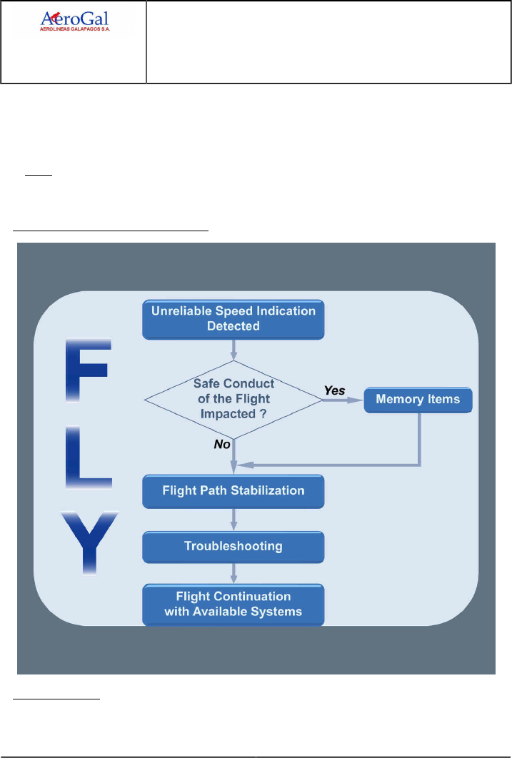
A318/A319/A320/A321
FLIGHT CREW
TECHNIQUES MANUAL
PROCEDURES
ABNORMAL AND EMERGENCY PROCEDURES
NAV
GLG A318/A319/A320/A321 FLEET PR-AEP-NAV P 6/16
FCTM ← C → 05 SEP 17
‐ The barometric altitude is not consistent with the Radio Altimeter (RA ) height (when the RA is
displayed),
‐ The aerodynamic noise reduces whereas the indicated airspeed increases, or vice versa,
‐ In approach, it is not possible to extend the landing gear using the normal landing gear system.
Note: Crew coordination is important. The PM should confirm any discrepancy:
‐ Between the standby airspeed indication and the speed indication on his/her PFD,
‐ Between his/her PFD and the Pilot Flying's PFD.
HOW TO APPLY THIS PROCEDURE?
MEMORY ITEMS
The flight crew must ensure a safe flight path. If the safe conduct of the flight is affected, the flight
crew applies the memory items.

A318/A319/A320/A321
FLIGHT CREW
TECHNIQUES MANUAL
PROCEDURES
ABNORMAL AND EMERGENCY PROCEDURES
NAV
GLG A318/A319/A320/A321 FLEET PR-AEP-NAV P 7/16
FCTM ← C → 05 SEP 17
The memory items enable to rapidly establish safe flight conditions for a limited period of time in all
phases of flight and in all aircraft configurations (weight and slats/flaps).
The flight crew must apply the memory items, if they have a doubt on their ability to safely fly the
aircraft in the short term with the current parameters, i.e.:
‐ The flight crew has lost situation awareness, or
‐ The current pitch and thrust are not appropriate for the current flight conditions, or
‐ The aircraft has an unexpected flight path for the current flight conditions.
When the PF has stabilized the target pitch and thrust values, the flight crew applies the QRH
procedure without delay. The flight crew must apply the QRH procedure without delay, because
flying with the memory pitch/thrust values for an extended period of time can lead to exceed the
aircraft speed limits.
Note: The flight crew must respect the STALL warning.
FLIGHT PATH STABILIZATION
According to the procedure, the flight crew can:
‐ Level off the aircraft then keep the flight path stabilized, or
‐ Keep the flight path stabilized.
Note: If the flight crew has applied the Memory Items, then the flight crew must level off the
aircraft to stabilize the flight path.
The objective of these two conditions is to have a stabilized flight path to start the troubleshooting.
In all cases, the initial actions are to disconnect the automations. This prevents the Flight
Guidance to use erroneous data for the computation of the aircraft guidance. Initial disconnection
of the automation can prevent:
‐ Erroneous orders, if AP /FD are engaged
‐ Erroneous thrust change, if A/THR is engaged.
Refer to Example of Failure Cases and their Consequences.
Note: If the A/THR automatically disconnects, the Thrust Lock function activates. The thrust
is locked at its level at the moment of the disconnection until the flight crew moves the
levers. The thrust may be locked at idle, due to normal A/THR behaviour, or due to the
use of erroneous data.
To level off the aircraft, the flight crew uses Pitch and Thrust tables of the QRH, Pitch/Thrust
Tables.
The GPS altitude can be used to confirm that the aircraft is maintaining level flight.
Note: A difference may exist between the barometric altitude and the GPS altitude.
The GPS altitude remains available on the MCDU GPS MONITOR page.

A318/A319/A320/A321
FLIGHT CREW
TECHNIQUES MANUAL
PROCEDURES
ABNORMAL AND EMERGENCY PROCEDURES
NAV
GLG A318/A319/A320/A321 FLEET PR-AEP-NAV P 8/16
FCTM ← C → 05 SEP 17
TROUBLESHOOTING AND ISOLATION
In order to identify and isolate the faulty ADR (s), the flight crew must crosscheck speed and
altitude indications on CAPT PFD , F/O PFD and STBY instruments.
To help the identification of the affected ADR (s), the flight crew can use the Pitch and Thrust
tables of the QRH procedure.
The Pitch and Thrust tables provide the resulting speed for a given aircraft weight and flight level.
WARNING Do not instinctively reject an outlier ADR.
When one indication differs from the others, the flight crew may be tempted to reject the outlier
information. However, they should be aware that two or even all three ADRs can provide identical
but erroneous data.
When the flight crew has identified the affected ADR (s), they must turn off the affected ADR (s).
As a consequence this triggers the corresponding ECAM alerts. The flight crew must apply the
associated procedures to address all the consequences on the various aircraft systems.
‐ If the flight crew identifies at least one ADR to be reliable: the flight crew must use it and turn off
affected ADR(s),
‐ If the flight crew cannot identify the affected ADR(s) or if all speed indications remain unreliable,
the flight crew must:
• Above FL 250, turn two ADR s off to prevent the flight control laws from using two consistent
but unreliable ADR data. The flight crew must keep one ADR on. For flight continuation, the
flight crew uses pitch and thrust tables of the QRH.
• Below FL 250, turn off all ADR s then use the BUSS for the flight continuation.
FLYING TECHNIQUE
PITCH/THRUST TABLES
When flying the aircraft with unreliable speed and/or altitude indications, it is recommended to
change only one flight parameter at a time (i.e. speed, altitude or configuration).
If the FPV is reliable (i.e. barometric altitude is reliable), or with the GPS altitude
information:
‐ Maintain level flight (FPV on the horizon or constant GPS altitude),
‐ Adjust thrust,
‐ Observe the resulting pitch attitude, and compare it with the recommended pitch target in
the table:
• If the pitch necessary to maintain level flight is above the pitch target of the table, the
aircraft is slow. Then increase the thrust.
• If the pitch necessary to maintain level flight is below the pitch target of the table, the
aircraft is fast. Then decrease the thrust.

A318/A319/A320/A321
FLIGHT CREW
TECHNIQUES MANUAL
PROCEDURES
ABNORMAL AND EMERGENCY PROCEDURES
NAV
GLG A318/A319/A320/A321 FLEET PR-AEP-NAV P 9/16
FCTM ← C → 05 SEP 17
When the pitch required to maintain level off gets close to the table pitch target, re-adjust
thrust to keep this target pitch.
When the conditions are stabilized, the resulting thrust should be close to the value
provided in the table.
This technique enables a fast stabilization of the speed while maintaining level flight.
If the FPV is not reliable and the GPS altitude information is not available (no means
to ensure level flight):
Adjust pitch and thrust according to QRH tables, and wait for speed stabilization.
Expect a significant time to stabilize the flight path and important altitude variations during
the stabilization.
BACKUP SPEED SCALE (BUSS)
For the description of the BUSS, Refer to FCOM/DSC-31-40 Backup Speed/Altitude Scale -
General.
When the BUSS is active:
‐ The AP /FD and A/THR must be disconnected,
‐ The F/CTL Laws are in Alternate law,
‐ The STALL warning remains operative,
‐ Cabin pressure must be controlled manually,
‐ Depending on the ADIRS standard, the FPV can be available on one or both PFD s as soon
as the flight crew switch off all ADRs,
‐ Do not use the HUD .
‐CAUTION When flying with the BUSS, do not use the speed brakes.
Flying with speed brakes extended affects the relationship between the speed and AOA , and
therefore the BUSS may provide erroneous data.
The flight crew adjusts the pitch and thrust to fly the green area of the speed scale.
The BUSS is directly based on the current Angle-Of-Attack (AOA ). Any longitudinal input on the
stick will induce an AOA change, and therefore will cause the BUSS to move. If not, the flight
crew must disregard the BUSS and use pitch and thrust tables.
When the flight crew turns off all ADR s, the NAV ADR 1+2+3 FAULT ECAM alert triggers. The
flight crew apply the associated procedure then, as requested by the ECAM , apply the “ALL
ADR OFF” QRH procedure. This QRH procedure provides guidance to:
‐ Manually control the cabin pressure,
‐ Prepare the approach and landing.
For approach, the flight crew should perform a stabilized approach.
The flight crew should change the aircraft configuration with level wings.

A318/A319/A320/A321
FLIGHT CREW
TECHNIQUES MANUAL
PROCEDURES
ABNORMAL AND EMERGENCY PROCEDURES
NAV
GLG A318/A319/A320/A321 FLEET PR-AEP-NAV P 10/16
FCTM ← C → 05 SEP 17
To retract or to extend flaps, apply the following technique:
‐ Before retracting the next flaps configuration, fly the upper part of the green band,
‐ Before extending the next flaps configuration, fly the lower part of the green band.
This technique limits the excursion in the amber zones when changing the flaps configuration.
"UNRELIABLE SPEED INDICATION" QRH PROCEDURE
Ident.: PR-AEP-NAV-00019313.0001001 / 20 MAR 17
Criteria: SA
Applicable to: HC-CJM, HC-CKN, HC-CLF, HC-CRU, HC-CSA, HC-CSB, HC-CSF
INTRODUCTION
The "UNRELIABLE SPEED INDICATION" procedure has two objectives:
‐ To fly the aircraft,
‐ To identify and isolate the affected ADR(s).
It includes the following steps:
1. Memory items (if necessary),
2. Flight path stabilization,
3. Troubleshooting and isolation,
4. Flight using pitch/thrust references.
WHEN TO APPLY THE PROCEDURE?
The flight crew should consider applying the “UNRELIABLE SPEED INDICATION” procedure
when:
‐ The “ADR CHECK PROC... APPLY” action line is displayed on ECAM, for example due to the
NAV ADR DISAGREE alert, or
‐ The flight crew suspects an erroneous indication, without any ECAM alert.
The flight crew can suspect an erroneous speed/altitude indication, in the following cases:
‐ A speed discrepancy (between ADR1, 2, 3 and standby indications),
‐ Fluctuating or unexpected changes of the indicated airspeed or altitude,
‐ Abnormal correlation between the basic flight parameters (pitch, thrust, airspeed, altitude and
vertical speed indications). For example:
• The altitude does not increase, whereas there is an important nose-up pitch and high thrust,
• The IAS increases, whereas there is an important nose-up pitch,
• The IAS decreases, whereas there is an important nose-down pitch,
• The IAS decreases, whereas there is a nose-down pitch and the aircraft is descending.
‐ An abnormal behavior of the AP /FD and/or the A/THR,

A318/A319/A320/A321
FLIGHT CREW
TECHNIQUES MANUAL
PROCEDURES
ABNORMAL AND EMERGENCY PROCEDURES
NAV
GLG A318/A319/A320/A321 FLEET PR-AEP-NAV P 11/16
FCTM ← C → 05 SEP 17
‐ The STALL warning triggers, the OVERSPEED warning triggers, or the FLAP RELIEF message
appears on the E/WD, and this is in contradiction with the indicated airspeeds. In this case:
• Rely on the STALL warning. Erroneous airspeed data does not affect the STALL warning,
because the STALL warning is based on angle of attack (AOA) data,
• Depending on the situation, the OVERSPEED warning may be false or justified. When the
OVERSPEED VFE warning triggers, the appearance of aircraft buffet is a symptom that the
airspeed is indeed excessive.
‐ The barometric altitude is not consistent with the Radio Altimeter (RA ) height (when the RA is
displayed),
‐ The aerodynamic noise reduces whereas the indicated airspeed increases, or vice versa,
‐ In approach, it is not possible to extend the landing gear using the normal landing gear system.
Note: Crew coordination is important. The PM should confirm any discrepancy:
‐ Between the standby airspeed indication and the speed indication on his/her PFD,
‐ Between his/her PFD and the Pilot Flying's PFD.
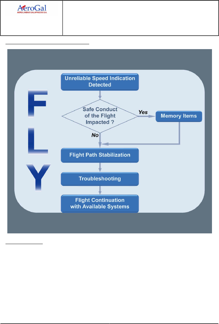
A318/A319/A320/A321
FLIGHT CREW
TECHNIQUES MANUAL
PROCEDURES
ABNORMAL AND EMERGENCY PROCEDURES
NAV
GLG A318/A319/A320/A321 FLEET PR-AEP-NAV P 12/16
FCTM ← C → 05 SEP 17
HOW TO APPLY THIS PROCEDURE?
MEMORY ITEMS
The flight crew must ensure a safe flight path. If the safe conduct of the flight is affected, the flight
crew applies the memory items.
The memory items enable to rapidly establish safe flight conditions for a limited period of time in all
phases of flight and in all aircraft configurations (weight and slats/flaps).
The flight crew must apply the memory items, if they have a doubt on their ability to safely fly the
aircraft in the short term with the current parameters, i.e.:
‐ The flight crew has lost situation awareness, or
‐ The current pitch and thrust are not appropriate for the current flight conditions, or
‐ The aircraft has an unexpected flight path for the current flight conditions.

A318/A319/A320/A321
FLIGHT CREW
TECHNIQUES MANUAL
PROCEDURES
ABNORMAL AND EMERGENCY PROCEDURES
NAV
GLG A318/A319/A320/A321 FLEET PR-AEP-NAV P 13/16
FCTM ← C → 05 SEP 17
When the PF has stabilized the target pitch and thrust values, the flight crew applies the QRH
procedure without delay. The flight crew must apply the QRH procedure without delay, because
flying with the memory pitch/thrust values for an extended period of time can lead to exceed the
aircraft speed limits.
Note: The flight crew must respect the STALL warning.
FLIGHT PATH STABILIZATION
According to the procedure, the flight crew can:
‐ Level off the aircraft then keep the flight path stabilized, or
‐ Keep the flight path stabilized.
Note: If the flight crew has applied the Memory Items, then the flight crew must level off the
aircraft to stabilize the flight path.
The objective of these two conditions is to have a stabilized flight path to start the troubleshooting.
In all cases, the initial actions are to disconnect the automations. This prevents the Flight
Guidance to use erroneous data for the computation of the aircraft guidance. Initial disconnection
of the automation can prevent:
‐ Erroneous orders, if AP /FD are engaged
‐ Erroneous thrust change, if A/THR is engaged.
Refer to Example of Failure Cases and their Consequences.
Note: If the A/THR automatically disconnects, the Thrust Lock function activates. The thrust
is locked at its level at the moment of the disconnection until the flight crew moves the
levers. The thrust may be locked at idle, due to normal A/THR behaviour, or due to the
use of erroneous data.
To level off the aircraft, the flight crew uses Pitch and Thrust tables of the QRH, Pitch/Thrust
Tables.
The GPS altitude can be used to confirm that the aircraft is maintaining level flight.
Note: A difference may exist between the barometric altitude and the GPS altitude.
The GPS altitude remains available on the MCDU GPS MONITOR page.
TROUBLESHOOTING AND ISOLATION
In order to identify and isolate the faulty ADR (s), the flight crew must crosscheck speed and
altitude indications on CAPT PFD , F/O PFD and STBY instruments.
To help the identification of the affected ADR (s), the flight crew can use the Pitch and Thrust
tables of the QRH procedure.
The Pitch and Thrust tables provide the resulting speed for a given aircraft weight and flight level.

A318/A319/A320/A321
FLIGHT CREW
TECHNIQUES MANUAL
PROCEDURES
ABNORMAL AND EMERGENCY PROCEDURES
NAV
GLG A318/A319/A320/A321 FLEET PR-AEP-NAV P 14/16
FCTM ← C → 05 SEP 17
WARNING Do not instinctively reject an outlier ADR.
When one indication differs from the others, the flight crew may be tempted to reject the outlier
information. However, they should be aware that two or even all three ADRs can provide identical
but erroneous data.
When the flight crew has identified the affected ADR (s), they must turn off the affected ADR (s).
As a consequence this triggers the corresponding ECAM alerts. The flight crew must apply the
associated procedures to address all the consequences on the various aircraft systems.
‐ If the flight crew identifies at least one ADR to be reliable: the flight crew must use it,
‐ If the flight crew cannot identify the affected ADR (s) or if all speed indications remain
unreliable, the flight crew must turn two ADR s off to prevent the flight control laws from using
two consistent but unreliable ADR data. The flight crew must keep one ADR on. For flight
continuation, the flight crew uses pitch and thrust tables of the QRH.
FLYING TECHNIQUE
PITCH/THRUST TABLES
When flying the aircraft with unreliable speed and/or altitude indications, it is recommended to
change only one flight parameter at a time (i.e. speed, altitude or configuration).
If the FPV is reliable (i.e. barometric altitude is reliable), or with the GPS altitude
information:
‐ Maintain level flight (FPV on the horizon or constant GPS altitude),
‐ Adjust thrust,
‐ Observe the resulting pitch attitude, and compare it with the recommended pitch target in
the table:
• If the pitch necessary to maintain level flight is above the pitch target of the table, the
aircraft is slow. Then increase the thrust.
• If the pitch necessary to maintain level flight is below the pitch target of the table, the
aircraft is fast. Then decrease the thrust.
When the pitch required to maintain level off gets close to the table pitch target, re-adjust
thrust to keep this target pitch.
When the conditions are stabilized, the resulting thrust should be close to the value
provided in the table.
This technique enables a fast stabilization of the speed while maintaining level flight.
If the FPV is not reliable and the GPS altitude information is not available (no means
to ensure level flight):
Adjust pitch and thrust according to QRH tables, and wait for speed stabilization.
Expect a significant time to stabilize the flight path and important altitude variations during
the stabilization.

A318/A319/A320/A321
FLIGHT CREW
TECHNIQUES MANUAL
PROCEDURES
ABNORMAL AND EMERGENCY PROCEDURES
NAV
GLG A318/A319/A320/A321 FLEET PR-AEP-NAV P 15/16
FCTM ← C to D 05 SEP 17
For the approach, a wide pattern and an early stabilized approach are recommended.
For the final approach, prefer a standard ILS approach with a -3 ° G/S, if available. If the
final descent is started with stabilized speed, on a -3 ° flight path with the thrust setting
recommended in the table, the resulting pitch attitude should be close to the recommended
table pitch value. If an adjustment is required, vary the thrust.
DUAL RADIO ALTIMETER FAILURE
Ident.: PR-AEP-NAV-00019314.0001001 / 20 MAR 17
Applicable to: ALL
The Radio Altimeters (RA s) provide inputs to a number of systems, including the GPWS and
FWC for auto-callouts. They also supply information to the AP and A/THR modes, plus inputs to
switch flight control laws at various stages. Although the ECAM procedure for a RA 1 + 2 FAULT is
straightforward, the consequences of the failure on the aircraft operation require consideration.
Instead of using RA information, the flight control system uses inputs from the LGCIU to determine
mode switching. Consequently, mode switching is as follows:
‐ On approach, flare law becomes active when the L/G is selected down and provided AP is
disconnected. At this point, "USE MAN PITCH TRIM" is displayed on the PFD.
‐ After landing, ground law becomes active when the MLG is compressed and the pitch attitude
becomes less than 2.5 °.
It is not possible to capture the ILS using the APPR pb and the approach must be flown to CAT 1
limits only. However, it is possible to capture the localiser using the LOC pb.
Furthermore, the final stages of the approach should be flown using raw data in order to avoid
possible excessive roll rates if LOC is still engaged. Indeed, as the autopilot gains are no longer
updated with the radio altimeter signal, the AP /FD behaviour may be unsatisfactory when
approaching the ground.
There will be no auto-callouts on approach, and no "RETARD" call in the flare
The GPWS /EGPWS will be inoperative; therefore terrain awareness becomes very important.
Similarly, the "SPEED, SPEED, SPEED" low energy warning is also inoperative, again requiring
increased awareness.

A318/A319/A320/A321
FLIGHT CREW
TECHNIQUES MANUAL
PROCEDURES
ABNORMAL AND EMERGENCY PROCEDURES
NAV
Intentionally left blank
GLG A318/A319/A320/A321 FLEET PR-AEP-NAV P 16/16
FCTM 05 SEP 17

A318/A319/A320/A321
FLIGHT CREW
TECHNIQUES MANUAL
PROCEDURES
ABNORMAL AND EMERGENCY PROCEDURES
SMOKE
GLG A318/A319/A320/A321 FLEET PR-AEP-SMOKE P 1/8
FCTM A to B → 22 MAR 17
PREFACE
Ident.: PR-AEP-SMOKE-00019269.0001001 / 20 MAR 17
Applicable to: ALL
Fire and/or smoke in the fuselage present the crew with potentially difficult situations. Not only
will they have to deal with the emergency itself but also the passengers are likely to panic should
they become aware of the situation. It is essential therefore, that action to control the source of
combustion is not delayed.
An immediate diversion should be considered as soon as the smoke is detected. If the source is not
immediately obvious, accessible and extinguishable, it should be initiated without delay.
SMOKE DETECTION AND PROCEDURE APPLICATION
Ident.: PR-AEP-SMOKE-00019270.0002001 / 20 MAR 17
Applicable to: ALL
The smoke will be identified either by an ECAM warning, or by the crew without any ECAM warning.
If the smoke is detected by the crew, without any ECAM warning, the flight crew will refer directly to
the QRH SMOKE/FUMES/AVNCS SMOKE procedure.
If the "AVIONICS SMOKE" ECAM caution is activated, the flight crew can refer directly to the QRH
SMOKE/FUMES/AVNCS SMOKE procedure, or apply first the ECAM actions, before entering the
QRH.
The AVIONICS SMOKE ECAM procedure should be applied only IF SMOKE IS PERCEPTIBLE.
The smoke is perceptible if the flight crew can confirm it visually or by smell.
If smoke is not perceptible, the flight crew should consider a spurious warning and therefore stop the
AVIONICS SMOKE procedure.
If another ECAM SMOKE warning (e.g. LAVATORY SMOKE) is triggered, the flight crew must apply
the ECAM procedure. If any doubt exists about the smoke origin, the flight crew will than refer to the
QRH SMOKE/FUMES/AVNCS SMOKE procedure.
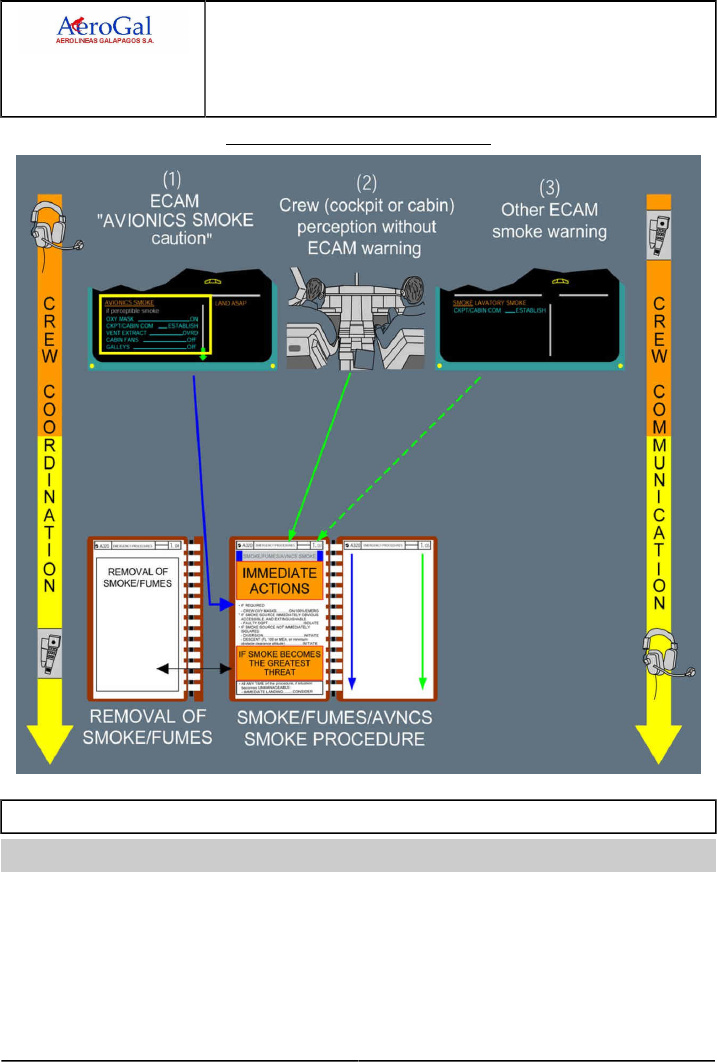
A318/A319/A320/A321
FLIGHT CREW
TECHNIQUES MANUAL
PROCEDURES
ABNORMAL AND EMERGENCY PROCEDURES
SMOKE
GLG A318/A319/A320/A321 FLEET PR-AEP-SMOKE P 2/8
FCTM ← B to C 22 MAR 17
Smoke/Fumes Procedure Architecture
COORDINATION WITH CABIN CREW
Ident.: PR-AEP-SMOKE-00019271.0001001 / 20 MAR 17
Applicable to: ALL
Good coordination between cockpit and cabin crew is a key element .
In case of smoke in the cabin, it is essential that the cabin crew estimate and inform the cockpit
concerning the density of smoke and the severity of the situation.

A318/A319/A320/A321
FLIGHT CREW
TECHNIQUES MANUAL
PROCEDURES
ABNORMAL AND EMERGENCY PROCEDURES
SMOKE
GLG A318/A319/A320/A321 FLEET PR-AEP-SMOKE P 3/8
FCTM D → 22 MAR 17
SMOKE/FUMES/AVNCS SMOKE QRH PROCEDURE
Ident.: PR-AEP-SMOKE-00019272.0001001 / 20 MAR 17
Applicable to: ALL
GENERAL
The SMOKE/FUMES/AVNCS SMOKE QRH procedure implements a global philosophy that is
applicable to both cabin and cockpit smoke cases. This philosophy includes the following main
steps:
‐ Diversion to be anticipated
‐ Immediate actions
If smoke source not immediately isolated:
‐ Diversion initiation
‐ Smoke origin identification and fighting
Furthermore, at any time during the procedure application, if smoke/fumes becomes the greatest
threat, the boxed items will be completed.
The main steps of this global philosophy may be visualized in the SMOKE/FUMES/AVNCS
SMOKE QRH procedure.
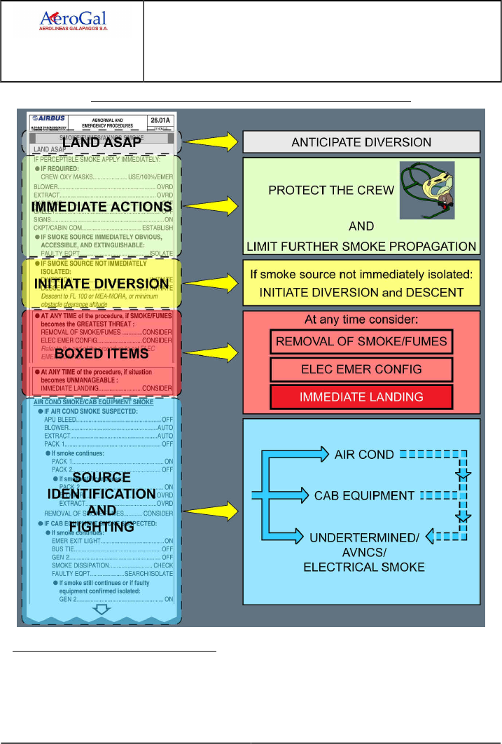
A318/A319/A320/A321
FLIGHT CREW
TECHNIQUES MANUAL
PROCEDURES
ABNORMAL AND EMERGENCY PROCEDURES
SMOKE
GLG A318/A319/A320/A321 FLEET PR-AEP-SMOKE P 4/8
FCTM ← D → 22 MAR 17
SMOKE/FUMES/AVNCS SMOKE Procedure Presentation in QRH
CONSIDERATIONS ABOUT DIVERSION
Time is critical.
This is why a diversion must be immediately anticipated (as indicated by LAND ASAP).

A318/A319/A320/A321
FLIGHT CREW
TECHNIQUES MANUAL
PROCEDURES
ABNORMAL AND EMERGENCY PROCEDURES
SMOKE
GLG A318/A319/A320/A321 FLEET PR-AEP-SMOKE P 5/8
FCTM ← D → 22 MAR 17
Then, after the immediate actions, if the smoke source cannot be immediately identified and
isolated, the diversion must be initiated before entering the SMOKE ORIGIN IDENTIFICATION
AND FIGHTING part of the procedure.
IMMEDIATE ACTIONS
These actions are common to all cases of smoke and fumes, whatever the source.
Their objectives are:
‐ Flight crew protection,
‐ Avoiding any further contamination of the cockpit/cabin,
‐ Communication with cabin crew.
SMOKE ORIGIN IDENTIFICATION AND FIGHTING
The crew tries to identify the smoke source by isolating systems. Some guidelines may help the
crew to identify the origin of smoke:
‐ If smoke initially comes out of the cockpit's ventilation outlets, or if smoke is detected in the
cabin, the crew may suspect an AIR COND SMOKE. In addition, very shortly thereafter, several
SMOKE warnings (cargo, lavatory, avionics) will be triggered. The displayed ECAM procedures
must therefore be applied.
‐ Following an identified ENG or APU failure, smoke may emanate from the faulty item through
the bleed system and be perceptible in the cockpit or the cabin. In that case, it will be
re-circulated throughout the aircraft, until it completely disappears from the air conditioning
system.
‐ If only the AVIONICS SMOKE warning is triggered, the crew may suspect an AVIONICS
SMOKE.
‐ If smoke is detected, while an equipment is declared faulty, the crew may suspect that smoke is
coming from this equipment.
According to the source he suspects, the crew will enter one of the 3 paragraphs:
1. IF AIR COND SMOKE SUSPECTED…
2. IF CAB EQUIPMENT SMOKE SUSPECTED…
3. IF AVNCS/COCKPIT SMOKE SUSPECTED…
Since electrical fire is the most critical case, he will also enter paragraph 3 if he doesn't know the
source of the smoke, or if the application of paragraph 1 and/or 2 has been unsuccessful.
In this part of the procedure, the flight crew must consider setting the Emergency Electrical
Configuration, to shed as much equipment as possible. This is in order to attempt to isolate the
smoke source.
If at least one battery is charging when one side and then the other side of the electrical system
are shed, the DC 1, DC 2, and BAT bus bars become inoperative for the remainder of the flight.
Therefore, the procedure for attempting to partially shed the electrical system was removed from

A318/A319/A320/A321
FLIGHT CREW
TECHNIQUES MANUAL
PROCEDURES
ABNORMAL AND EMERGENCY PROCEDURES
SMOKE
GLG A318/A319/A320/A321 FLEET PR-AEP-SMOKE P 6/8
FCTM ← D to E → 22 MAR 17
the smoke procedure. This change in the procedure is to enable the flight crew to recover the
normal electrical configuration for landing, particularly to recover normal braking.
If the flight crew sets the electrical emergency configuration following a smoke detection in the
avionic compartment ("AVIONICS SMOKE" ECAM caution triggered), the ECAM does not display
the same procedure as the one displayed following the loss of main generators. In fact in this
case, the ECAM displays a specific procedure that takes into account the smoke detection: As
the flight crew has voluntarily set the electrical emergency configuration, the purpose of the ELEC
EMER CONFIG ECAM procedure is not to try to restore the generators, but to remain in electrical
emergency configuration, and restore generators before landing to perform the landing in normal
electrical configuration.
BOXED ITEMS
These items (applying REMOVAL of SMOKE/FUMES procedure, setting electrical emergency
configuration, or considering immediate landing) may be applied at any time, in the procedure (but
not before the immediate actions).
Once the first step of the REMOVAL of SMOKE/FUMES procedure have been applied, the flight
crew will come back to the SMOKE/FUMES/AVNCS SMOKE procedure, to apply the appropriate
steps, depending on the suspected smoke source while descending to FL 100. Reaching FL 100,
the REMOVAL of SMOKE/FUMES procedure will be completed.
LITHIUM BATTERY FIRE IN THE COCKPIT
Ident.: PR-AEP-SMOKE-00019273.0001001 / 20 MAR 17
Applicable to: ALL
Several electronic devices contain lithium batteries, for example:
‐ Laptop computers,
‐ Mobile phones,
‐ Portable electronic tablets, etc.
Fire or smoke from lithium battery is due to thermal runaway in the battery cells.
It is important to know that halon extinguishers are efficient on flames but cannot stop thermal
runaway.
The treatment for thermal runaway of lithium battery is to cool the battery by pouring water or
non-alcoholic liquid on the device.
The first step of the procedure establishes appropriate tasksharing and communication.
If necessary, transfer control to the flight crew member seated on the opposite side of the fire.
The Pilot Flying (PF ) contacts the cabin crew to request initiation of the CCOM “STORAGE
PROCEDURE AFTER A LITHIUM BATTERY FIRE".
This CCOM procedure specifies that the cabin crew must fill a container with water or non-alcoholic
liquid and must immerse the device in it.

A318/A319/A320/A321
FLIGHT CREW
TECHNIQUES MANUAL
PROCEDURES
ABNORMAL AND EMERGENCY PROCEDURES
SMOKE
GLG A318/A319/A320/A321 FLEET PR-AEP-SMOKE P 7/8
FCTM ← E to F 22 MAR 17
If there is no cabin crew on board (e.g ferry flight, etc.), the Pilot Monitoring (PM ) must apply the
steps of the CCOM procedure.
If there are flames, the PM must use the halon extinguisher.
Before discharging the halon extinguisher, it is important to protect the flight crew respiratory system:
the PF must wear the oxygen mask and the PM must wear the smoke hood .
If there are no flames, or when the flames are extinguished, the PM must assess if the device can be
removed or not from the cockpit.
If the device is attached to a cable that cannot be easily disconnected, then the device must be
considered not removable from the cockpit, and water or non-alcoholic liquid must be poured on it.
The device must then be regularly monitored to ensure that the thermal runaway is successfully
stopped. If the device is removable, then it must be put in the container prepared in advance by the
cabin crew member who takes over the procedure.
If, at any time of the procedure, the smoke becomes the greatest threat, the flight crew must consider
applying the SMOKE/FUMES REMOVAL procedure.
Finally, if at any time of the procedure, the situation becomes unmanageable an immediate landing
must be considered.
CARGO SMOKE
Ident.: PR-AEP-SMOKE-00019274.0001001 / 20 MAR 17
Applicable to: ALL
The crew should be aware that, even after successful operation of the cargo fire bottle, the CARGO
SMOKE warning might persist due to the smoke detectors being sensitive to the extinguishing agent.
On the ground, the crew should instruct the ground crew not to open the cargo door until the
passengers have disembarked and fire services are present.
If SMOKE warning is displayed on ground with the cargo compartment door open, do not initiate an
AGENT DISCHARGE. Request the ground crew to investigate and eliminate the smoke source. On
ground, the warning may be triggered due to a high level of humidity.

A318/A319/A320/A321
FLIGHT CREW
TECHNIQUES MANUAL
PROCEDURES
ABNORMAL AND EMERGENCY PROCEDURES
SMOKE
Intentionally left blank
GLG A318/A319/A320/A321 FLEET PR-AEP-SMOKE P 8/8
FCTM 22 MAR 17
PREVENTING
IDENTIFIED RISKS
Intentionally left blank

A318/A319/A320/A321
FLIGHT CREW
TECHNIQUES MANUAL
PREVENTING IDENTIFIED RISKS
PRELIMINARY PAGES
TABLE OF CONTENTS
GLG A318/A319/A320/A321 FLEET PIR-PLP-TOC P 1/2
FCTM 19 JUN 17
Introduction...............................................................................................................................................................A
Risks related to Flight Phases................................................................................................................................ B
Risks related to System Operations/Failures..........................................................................................................C

A318/A319/A320/A321
FLIGHT CREW
TECHNIQUES MANUAL
PREVENTING IDENTIFIED RISKS
PRELIMINARY PAGES
TABLE OF CONTENTS
Intentionally left blank
GLG A318/A319/A320/A321 FLEET PIR-PLP-TOC P 2/2
FCTM 19 JUN 17
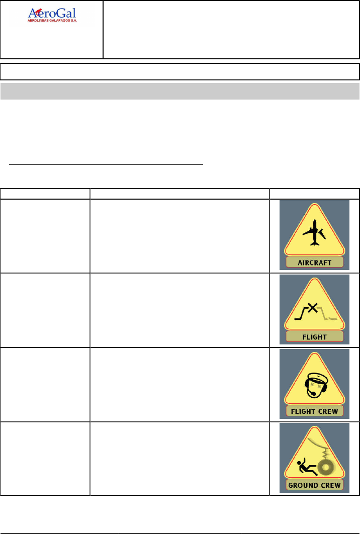
A318/A319/A320/A321
FLIGHT CREW
TECHNIQUES MANUAL
PREVENTING IDENTIFIED RISKS
GLG A318/A319/A320/A321 FLEET PIR P 1/10
FCTM A → 19 JUN 17
INTRODUCTION
Ident.: PIR-00005742.0001001 / 19 MAY 17
Applicable to: ALL
The aim of this chapter is to highlight some of the risks and potential consequences that the flight
crew may encounter, in order to improve:
‐ The awareness of the flight crew with regards to these risks
‐ The risk management.
CATEGORY OF RISKS, AND ASSOCIATED SYMBOL
7 categories of risks may be encountered:
Categories Potential Consequences Symbol
AIRCRAFT Possibility of damage to the aircraft.
FLIGHT It may not be possible to complete the initial flight.
FLIGHT CREW Possibility of flight crew incapacitation, or injury.
GROUND CREW Possibility of injury to the ground personnel.
Continued on the following page

A318/A319/A320/A321
FLIGHT CREW
TECHNIQUES MANUAL
PREVENTING IDENTIFIED RISKS
GLG A318/A319/A320/A321 FLEET PIR P 2/10
FCTM ← A → 19 JUN 17
Continued from the previous page
Categories Potential Consequences Symbol
HANDLING The handling or the control of the aircraft may be affected.
NAVIGATION The navigation may be affected.
PAX Possibility of injury to passengers.
RISKS RELATED TO FLIGHT PHASES
In normal operations, some risks may be encountered during specific flight phases.
For each risk, a dedicated table provides:
‐ The flight phase, where the risk may be encountered
‐ A description of the risk
‐ A description of the consequences, if the flight crew does not correctly manage the risk
‐ The type of the consequences of the risk (who, or what is affected) illustrated with the
appropriate risk symbol
‐ When applicable, a reference to the FCTM part, where the related explanations and
recommendations (for prevention and/or recovery) are developed.
Refer to PIR Risks related to Flight Phases.
RISKS RELATED TO SYSTEM OPERATIONS/FAILURES
Some risks may be encountered during the interaction of the flight crew with systems, or in the
case of system failure.
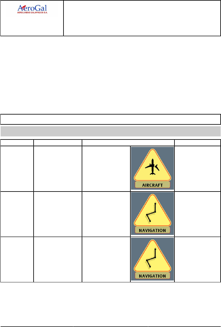
A318/A319/A320/A321
FLIGHT CREW
TECHNIQUES MANUAL
PREVENTING IDENTIFIED RISKS
GLG A318/A319/A320/A321 FLEET PIR P 3/10
FCTM ← A to B → 19 JUN 17
For each risk, a dedicated table provides:
‐ The aircraft system related to the risk
‐ A description of the risk
‐ A description of the consequences, if the flight crew does not correctly manage the risk
‐ The type of the consequences of the risk (who, or what is affected) illustrated with the
appropriate risk symbol
‐ When applicable, a reference to the FCTM part, where the related explanations and
recommendations (for prevention and/or recovery) are developed.
Refer to PIR Risks related to System Operations/Failures.
RISKS RELATED TO FLIGHT PHASES
Ident.: PIR-00005743.0001001 / 19 MAY 17
Applicable to: ALL
Flight phase Risk Consequences Refer to
Exterior
Walkaround
During the exterior
walkaround, the flight
crew does not check
that the fan cowl doors
are properly closed and
latched.
‐ In-flight loss of the fan
cowl doors
‐ Structural damage to
the aircraft
‐ Danger to people on
ground.
Refer to PR-NP-SOP-50
Exterior Walkaround
Cockpit
Preparation
The flight crew does not
correctly adjust the outer
ring of the ND brightness
knob to the maximum.
The flight crew
awareness of the weather
and the terrain will be
reduced in flight.
Cockpit
Preparation
During takeoff briefing,
the flight crew does not
check that the FMS SID
(including the constraints)
is correct.
Erroneous trajectory. Refer to PR-NP-SOP-60
Takeoff Briefing
Continued on the following page
A318/A319/A320/A321
FLIGHT CREW
TECHNIQUES MANUAL
PREVENTING IDENTIFIED RISKS
GLG A318/A319/A320/A321 FLEET PIR P 4/10
FCTM ← B → 19 JUN 17
Continued from the previous page
Flight phase Risk Consequences Refer to
Takeoff The flight crew
announces “THRUST
SET” before the thrust
reaches the target thrust
value.
Engine check not valid. Refer to
PR-NP-SOP-120
Takeoff Roll
Climb/Descent The flight crew uses the
V/S knob without setting
a target.
Climb or descent does
not stop.
Descent
Preparation
During descent
preparation the flight crew
does not properly insert
/ check the QNH and
TEMP in the PERF APPR
Page.
If the QNH is not correct,
the Cabin Pressure
Controller (CPC )
computes erroneous
cabin pressurization
segment, that may trigger
pressurization related
ECAM alert and lead
to undue emergency
descent.
Refer to FCOM DSC
22-20-50-10 PERF
APPR Page
Descent In managed descent,
the flight crew uses the
speed brakes, in an
attempt to descend below
the computed profile.
The autothrust increases
thrust to remain on the
computed profile. The
expected increased rate
of descent will not be
reached. In addition,
fuel consumption will
increase.
Refer to
PR-NP-SOP-170
Guidance and
Monitoring
Descent The flight crew does not
set the TERR ON ND
switch to ON. In addition,
the flight crew does
not correctly adjust the
brightness.
Reduced situational
awareness.
Continued on the following page
A318/A319/A320/A321
FLIGHT CREW
TECHNIQUES MANUAL
PREVENTING IDENTIFIED RISKS
GLG A318/A319/A320/A321 FLEET PIR P 5/10
FCTM ← B → 19 JUN 17
Continued from the previous page
Flight phase Risk Consequences Refer to
Approach One flight crewmember
activates the approach
phase without
crosschecking with the
other one.
The other flight
crewmember may
perceive the speed
change as abnormal, and
may react to it.
Refer to PR-NP-GEN
Communication
Approach The flight crew uses DIR
TO or DIR TO RAD IN
functions to sequence the
F-PLN, and the aircraft is
in radar vectoring.
NAV mode arms. If NAV
mode is not appropriate,
it may lead to an
erroneous trajectory.
Refer to
PR-NP-SOP-190-CONF
F-PLN Sequencing
Approach The flight crew does not
sufficiently monitor raw
data.
Any erroneous
computation leads to an
erroneous trajectory.
ILS Approach The glide slope is
intercepted from above
and the G/S mode is not
armed.
The aircraft descends
through the glide slope,
without intercepting it.
Refer to
PR-NP-SOP-190-GUI
Glide Slope Interception
from Above
Continued on the following page
A318/A319/A320/A321
FLIGHT CREW
TECHNIQUES MANUAL
PREVENTING IDENTIFIED RISKS
GLG A318/A319/A320/A321 FLEET PIR P 6/10
FCTM ← B to C → 19 JUN 17
Continued from the previous page
Flight phase Risk Consequences Refer to
Non Precision
Approach
When the aircraft reaches
the minimum height for
use of AP , the flight crew
does not set the AP to
OFF.
The AP may not
disconnect until landing
and AUTOLAND is
not provided on NPA
approach.
Refer to AS-FG-10-1
Objective
Go Around When the flight crew
initiates the Go-around,
the PF does not set the
thrust levers to the TOGA
detent.
The SRS GA mode and
the FMS go-around
phase do not engage.
Therefore, the AP /FD
remain engaged in
approach, or landing
mode and the FMS
remains in APPR
phase. The primary
F-PLN becomes
PPOS-DISCONT.
Refer to
PR-NP-SOP-260 AP/FD
Go-Around Phase
Activation
RISKS RELATED TO SYSTEM OPERATIONS/FAILURES
Ident.: PIR-00005745.0001001 / 19 MAY 17
Applicable to: ALL
Aircraft System Risk Consequences Refer to FCTM
Auto Flight In order to disconnect the
autothrust, the flight crew
presses the instinctive
disconnect pb on the
thrust levers before they
move the thrust levers to
the current thrust setting.
Immediate and undue
thrust increase.
Refer to AS-FG-10-2 To
Set Autothrust To Off
Auto Flight The flight crew does not
disconnect the autothrust
when Alpha floor/TOGA
LOCK triggers.
TOGA thrust is
maintained, with an
undue thrust increase,
and may lead to
overspeed.
Refer to AS-FG-10-2 To
Set Autothrust To Off
Continued on the following page
A318/A319/A320/A321
FLIGHT CREW
TECHNIQUES MANUAL
PREVENTING IDENTIFIED RISKS
GLG A318/A319/A320/A321 FLEET PIR P 7/10
FCTM ← C → 19 JUN 17
Continued from the previous page
Aircraft System Risk Consequences Refer to FCTM
Auto Flight The flight crew does not
use the correct knob
to change heading or
speed.
Trajectory not correct.
Auto Flight The flight crew does not
sequence the F/PLN.
Erroneous computation
(e.g. time, fuel) and
trajectory.
Refer to
PR-NP-SOP-190-CONF
F-PLN Sequencing
Communications Error in the use of RMP. Loss of transmission to
ATC due to an erroneous
setting.
Engines In the case of an engine
failure after takeoff, the
flight crew does not
stabilize the flight path
before they perform
ECAM actions.
Performing the ECAM
actions before the aircraft
is stabilized on the flight
path, reduces efficiency
due to the PF’s high
workload, and may lead
to a trajectory error.
Refer to PR-AEP-ENG
Engine Failure after V1
Engines In the case of an engine
failure in cruise, the flight
crew presses the EO
CLR key on the MCDU.
Pressing the EO CLR
key on the MCDU is an
irreversible action that
leads to the loss of single
engine computation
(discrepancy between
the computation and real
aircraft status).
Refer to PR-AEP-ENG
Engine Failure During
Cruise
Continued on the following page
A318/A319/A320/A321
FLIGHT CREW
TECHNIQUES MANUAL
PREVENTING IDENTIFIED RISKS
GLG A318/A319/A320/A321 FLEET PIR P 8/10
FCTM ← C → 19 JUN 17
Continued from the previous page
Aircraft System Risk Consequences Refer to FCTM
At takeoff:
When slats/flaps are
locked and if the flight
crew does not select the
current speed, the aircraft
continues to accelerate
and possibly exceeds
Max Speed.
Flight Controls The flight crew does not
select the speed after slat
or flap failure.
In approach:
When slats/flaps are
locked and if the flight
crew does not select the
current speed, the aircraft
continues to decelerate
down to a speed that
is not consistent with
the current aircraft
configuration.
Refer to PR-AEP-F_CTL
Abnormal Flaps/Slats
Configuration
Flight Controls –
Landing Gear
In the case of flight with
slats/flaps extended or
landing gear extended,
the flight crew takes
into account the FMS
predictions.
Erroneous computation
(e.g. time, fuel), because
the FMS does not take
into account the abnormal
configuration.
Refer to PR-AEP-F_CTL
Abnormal Flaps/Slats
Configuration
Fuel The flight crew does not
check fuel before fuel
crossfeed.
Fuel loss. Refer to PR-AEP-FUEL
Fuel Leak
Miscellaneous For EMERGENCY
DESCENT, the flight crew
turns but does not pull the
ALT knob, or does both,
but not in the correct
sequence, with no FMA
crosscheck.
The flight crew does not
detect that the descent
is not engaged. Delayed
descent leads to limited
oxygen for passengers.
Refer to AS-FG-10-1
Objective
Continued on the following page
A318/A319/A320/A321
FLIGHT CREW
TECHNIQUES MANUAL
PREVENTING IDENTIFIED RISKS
GLG A318/A319/A320/A321 FLEET PIR P 9/10
FCTM ← C 19 JUN 17
Continued from the previous page
Aircraft System Risk Consequences Refer to FCTM
Navigation The flight crew sets
the ADR pb-sw to OFF
using the ADIRS rotary
selector, instead of the
ADR pb-sw.
Irreversible loss of
redundancy. The
associated IR is lost, and
cannot be recovered until
the end of the flight.
Refer to PR-AEP-NAV
ADR/IRS FAULT
Surveillance The flight crew performs
the TCAS resolution
advisory procedure
without switching OFF the
FD s for aircraft not fitted
with the AP /FD TCAS
, or when the AP /FD
TCAS function is failed.
The autothrust mode
may remain in THR CLB
or THR DES , whereas
it must be in SPEED
mode. This may lead to
the activation of the high
speed/AOA protection.
Refer to AS-TCAS
TCAS

A318/A319/A320/A321
FLIGHT CREW
TECHNIQUES MANUAL
PREVENTING IDENTIFIED RISKS
Intentionally left blank
GLG A318/A319/A320/A321 FLEET PIR P 10/10
FCTM 19 JUN 17
