MCUXpresso SDK API Reference Manual MCIMX6G3
User Manual: Pdf
Open the PDF directly: View PDF ![]() .
.
Page Count: 677 [warning: Documents this large are best viewed by clicking the View PDF Link!]
- MCUXpresso SDK API Reference Manual
- Introduction
- Driver errors status
- Architectural Overview
- Trademarks
- ADC: 12-bit Analog to Digital Converter Driver
- ADC_5HC: 12-bit Analog to Digital Converter Driver
- Overview
- Typical use case
- Data Structure Documentation
- Macro Definition Documentation
- Enumeration Type Documentation
- Function Documentation
- ADC_5HC_Init
- ADC_5HC_Deinit
- ADC_5HC_GetDefaultConfig
- ADC_5HC_SetChannelConfig
- ADC_5HC_GetChannelConversionValue
- ADC_5HC_GetChannelStatusFlags
- ADC_5HC_DoAutoCalibration
- ADC_5HC_SetOffsetConfig
- ADC_5HC_EnableDMA
- ADC_5HC_EnableHardwareTrigger
- ADC_5HC_SetHardwareCompareConfig
- ADC_5HC_SetHardwareAverageConfig
- ADC_5HC_GetStatusFlags
- ADC_5HC_ClearStatusFlags
- Variable Documentation
- CACHE: CACHE Memory Controller
- CSI: CMOS Sensor Interface
- Overview
- Frame Buffer Queue
- Typical use case
- Data Structure Documentation
- Macro Definition Documentation
- Typedef Documentation
- Enumeration Type Documentation
- Function Documentation
- CSI_Init
- CSI_Deinit
- CSI_Reset
- CSI_GetDefaultConfig
- CSI_ClearFifo
- CSI_ReflashFifoDma
- CSI_EnableFifoDmaRequest
- CSI_Start
- CSI_Stop
- CSI_SetRxBufferAddr
- CSI_EnableInterrupts
- CSI_DisableInterrupts
- CSI_GetStatusFlags
- CSI_ClearStatusFlags
- CSI_TransferCreateHandle
- CSI_TransferStart
- CSI_TransferStop
- CSI_TransferSubmitEmptyBuffer
- CSI_TransferGetFullBuffer
- CSI_TransferHandleIRQ
- ECSPI: Serial Peripheral Interface Driver
- eLCDIF: Enhanced LCD Interface
- Overview
- Typical use case
- Data Structure Documentation
- Macro Definition Documentation
- Enumeration Type Documentation
- Function Documentation
- ELCDIF_RgbModeInit
- ELCDIF_GetStatus
- ELCDIF_GetLFifoCount
- ELCDIF_EnableInterrupts
- ELCDIF_DisableInterrupts
- ELCDIF_GetInterruptStatus
- ELCDIF_ClearInterruptStatus
- ELCDIF_SetAlphaSurfaceBufferConfig
- ELCDIF_SetAlphaSurfaceBlendConfig
- ELCDIF_SetNextAlphaSurfaceBufferAddr
- ELCDIF_SetOverlayColorKey
- ELCDIF_EnableOverlayColorKey
- ELCDIF_EnableAlphaSurface
- ELCDIF_EnableProcessSurface
- ENET: Ethernet MAC Driver
- Overview
- Typical use case
- Data Structure Documentation
- Macro Definition Documentation
- FSL_ENET_DRIVER_VERSION
- ENET_BUFFDESCRIPTOR_RX_EMPTY_MASK
- ENET_BUFFDESCRIPTOR_RX_SOFTOWNER1_MASK
- ENET_BUFFDESCRIPTOR_RX_WRAP_MASK
- ENET_BUFFDESCRIPTOR_RX_SOFTOWNER2_Mask
- ENET_BUFFDESCRIPTOR_RX_LAST_MASK
- ENET_BUFFDESCRIPTOR_RX_MISS_MASK
- ENET_BUFFDESCRIPTOR_RX_BROADCAST_MASK
- ENET_BUFFDESCRIPTOR_RX_MULTICAST_MASK
- ENET_BUFFDESCRIPTOR_RX_LENVLIOLATE_MASK
- ENET_BUFFDESCRIPTOR_RX_NOOCTET_MASK
- ENET_BUFFDESCRIPTOR_RX_CRC_MASK
- ENET_BUFFDESCRIPTOR_RX_OVERRUN_MASK
- ENET_BUFFDESCRIPTOR_RX_TRUNC_MASK
- ENET_BUFFDESCRIPTOR_TX_READY_MASK
- ENET_BUFFDESCRIPTOR_TX_SOFTOWENER1_MASK
- ENET_BUFFDESCRIPTOR_TX_WRAP_MASK
- ENET_BUFFDESCRIPTOR_TX_SOFTOWENER2_MASK
- ENET_BUFFDESCRIPTOR_TX_LAST_MASK
- ENET_BUFFDESCRIPTOR_TX_TRANMITCRC_MASK
- ENET_BUFFDESCRIPTOR_RX_ERR_MASK
- ENET_FRAME_MAX_FRAMELEN
- ENET_FIFO_MIN_RX_FULL
- ENET_RX_MIN_BUFFERSIZE
- ENET_PHY_MAXADDRESS
- Typedef Documentation
- Enumeration Type Documentation
- Function Documentation
- ENET_GetDefaultConfig
- ENET_Init
- ENET_Deinit
- ENET_Reset
- ENET_SetMII
- ENET_SetSMI
- ENET_GetSMI
- ENET_ReadSMIData
- ENET_StartSMIRead
- ENET_StartSMIWrite
- ENET_StartExtC45SMIRead
- ENET_StartExtC45SMIWrite
- ENET_SetMacAddr
- ENET_GetMacAddr
- ENET_AddMulticastGroup
- ENET_LeaveMulticastGroup
- ENET_ActiveRead
- ENET_EnableSleepMode
- ENET_GetAccelFunction
- ENET_EnableInterrupts
- ENET_DisableInterrupts
- ENET_GetInterruptStatus
- ENET_ClearInterruptStatus
- ENET_SetCallback
- ENET_GetRxErrBeforeReadFrame
- ENET_GetRxFrameSize
- ENET_ReadFrame
- ENET_SendFrame
- ENET_TransmitIRQHandler
- ENET_ReceiveIRQHandler
- ENET_ErrorIRQHandler
- ENET_CommonFrame0IRQHandler
- EPIT: Enhanced Periodic Interrupt Timer
- Overview
- Function groups
- Typical use case
- Data Structure Documentation
- Enumeration Type Documentation
- Function Documentation
- EPIT_SoftwareReset
- EPIT_Init
- EPIT_Deinit
- EPIT_GetDefaultConfig
- EPIT_SetClockSource
- EPIT_SetClockDivider
- EPIT_GetClockDivider
- EPIT_StartTimer
- EPIT_StopTimer
- EPIT_SetTimerPeriod
- EPIT_GetCurrentTimerCount
- EPIT_SetOutputOperationMode
- EPIT_SetOutputCompareValue
- EPIT_EnableInterrupts
- EPIT_DisableInterrupts
- EPIT_GetEnabledInterrupts
- EPIT_GetStatusFlags
- EPIT_ClearStatusFlags
- FlexCAN: Flex Controller Area Network Driver
- GPT: General Purpose Timer
- Overview
- Function groups
- Typical use case
- Data Structure Documentation
- Enumeration Type Documentation
- Function Documentation
- GPT_Init
- GPT_Deinit
- GPT_GetDefaultConfig
- GPT_SoftwareReset
- GPT_SetClockSource
- GPT_GetClockSource
- GPT_SetClockDivider
- GPT_GetClockDivider
- GPT_SetOscClockDivider
- GPT_GetOscClockDivider
- GPT_StartTimer
- GPT_StopTimer
- GPT_GetCurrentTimerCount
- GPT_SetInputOperationMode
- GPT_GetInputOperationMode
- GPT_GetInputCaptureValue
- GPT_SetOutputOperationMode
- GPT_GetOutputOperationMode
- GPT_SetOutputCompareValue
- GPT_GetOutputCompareValue
- GPT_ForceOutput
- GPT_EnableInterrupts
- GPT_DisableInterrupts
- GPT_GetEnabledInterrupts
- GPT_GetStatusFlags
- GPT_ClearStatusFlags
- GPC: General Power Controller Driver
- GPIO: General-Purpose Input/Output Driver
- I2C: Inter-Integrated Circuit Driver
- PWM: Pulse Width Modulation Driver
- UART: Universal Asynchronous Receiver/Transmitter Driver
- MMDC: Multi Mode DDR Controller Driver
- Overview
- Typical use case
- Data Structure Documentation
- struct mmdc_readDQS_calibration_config_t
- struct mmdc_writeLeveling_calibration_config_t
- struct mmdc_read_calibration_config_t
- struct mmdc_fine_tuning_config_t
- struct mmdc_odt_config_t
- struct mmdc_power_config_t
- struct mmdc_zq_config_t
- struct mmdc_cmd_config_t
- struct mmdc_device_timing_t
- struct mmdc_auto_refresh_t
- struct mmdc_exaccess_config_t
- struct mmdc_profiling_config_t
- struct mmdc_performance_config_t
- struct mmdc_device_config_t
- struct mmdc_config_t
- Macro Definition Documentation
- Typedef Documentation
- Enumeration Type Documentation
- _mmdc_status
- mmdc_device_type_t
- mmdc_device_bank_num_t
- mmdc_row_addr_width_t
- mmdc_col_addr_width_t
- mmdc_burst_len_t
- mmdc_cmd_type_t
- mmdc_zq_calmode_t
- mmdc_zq_calfreq_t
- mmdc_refresh_sel_t
- mmdc_profiling_action_t
- mmdc_calibration_type_t
- mmdc_calibaration_waitcycles_t
- mmdc_fine_tuning_dutycycle_t
- mmdc_termination_config_t
- _mmdc_lpddr2_derate
- _mmdc_exaccess_type
- Function Documentation
- MMDC_GetDefaultConfig
- MMDC_Init
- MMDC_Deinit
- MMDC_HandleCommand
- MMDC_GetReadData
- MMDC_EnhancePerformance
- MMDC_EnableAutoRefresh
- MMDC_DisableAutoRefresh
- MMDC_EnablePowerSaving
- MMDC_DisablePowerSaving
- MMDC_Profiling
- MMDC_LPDDR2UpdateDerate
- MMDC_MonitorLPDDR2OperationTemp
- MMDC_ReadDQSGatingCalibration
- MMDC_WriteLevelingCalibration
- MMDC_WriteCalibration
- MMDC_ReadCalibration
- MMDC_DoFineTuning
- MMDC_SetTiming
- MMDC_DeviceInit
- MMDC_EnterConfigurationMode
- MMDC_DoZQCalibration
- MMDC_EnableLowPowerMode
- MMDC_EnableDVFSMode
- MMDC_Reset
- MMDC_SwitchDeviceFrequency
- MMDC_EnableSBS
- MMDC_TriggerSBS
- MMDC_GetAXIAddrBySBS
- MMDC_GetAXIAttributeBySBS
- MMDC_EnableProfiling
- MMDC_ResumeProfiling
- MMDC_ResetProfiling
- MMDC_ExclusiveAccess
- PMU: Power Management Unit
- Overview
- Macro Definition Documentation
- Enumeration Type Documentation
- Function Documentation
- PMU_1P1SetWeakReferenceSource
- PMU_1P1EnableWeakRegulator
- PMU_1P1SetRegulatorOutputVoltage
- PMU_1P1SetBrownoutOffsetVoltage
- PMU_1P1EnablePullDown
- PMU_1P1EnableCurrentLimit
- PMU_1P1EnableBrownout
- PMU_1P1EnableOutput
- PMU_3P0SetRegulatorOutputVoltage
- PMU_3P0SetVBusVoltageSource
- PMU_3P0SetBrownoutOffsetVoltage
- PMU_3P0EnableCurrentLimit
- PMU_3P0EnableBrownout
- PMU_3P0EnableOutput
- PMU_2P5EnableWeakRegulator
- PMU_2P5SetRegulatorOutputVoltage
- PMU_2P5SetBrownoutOffsetVoltage
- PMU_2P1EnablePullDown
- PMU_2P5EnableCurrentLimit
- PMU_2P5nableBrownout
- PMU_2P5EnableOutput
- PMU_CoreEnableIncreaseGateDrive
- PMU_CoreSetRegulatorVoltageRampRate
- PMU_CoreSetSOCDomainVoltage
- PMU_CoreSetARMCoreDomainVoltage
- PMU_GatePower
- PMU_UngatePower
- PMU_EnableLowPowerBandgap
- PXP: Pixel Pipeline
- Overview
- Typical use case
- Data Structure Documentation
- Enumeration Type Documentation
- _pxp_interrupt_enable
- _pxp_flags
- pxp_flip_mode_t
- pxp_rotate_position_t
- pxp_rotate_degree_t
- pxp_interlaced_output_mode_t
- pxp_output_pixel_format_t
- pxp_ps_pixel_format_t
- pxp_as_pixel_format_t
- pxp_alpha_mode_t
- pxp_rop_mode_t
- pxp_block_size_t
- pxp_csc1_mode_t
- pxp_csc2_mode_t
- pxp_lut_lookup_mode_t
- pxp_lut_out_mode_t
- pxp_lut_8k_bank_t
- pxp_ram_t
- _pxp_dither_mode
- _pxp_dither_lut_mode
- _pxp_dither_matrix_size
- Function Documentation
- PXP_Init
- PXP_Deinit
- PXP_Reset
- PXP_Start
- PXP_EnableLcdHandShake
- PXP_EnableContinousRun
- PXP_SetProcessBlockSize
- PXP_GetStatusFlags
- PXP_ClearStatusFlags
- PXP_GetAxiErrorId
- PXP_EnableInterrupts
- PXP_DisableInterrupts
- PXP_SetAlphaSurfaceBufferConfig
- PXP_SetAlphaSurfaceBlendConfig
- PXP_SetAlphaSurfaceOverlayColorKey
- PXP_EnableAlphaSurfaceOverlayColorKey
- PXP_SetAlphaSurfacePosition
- PXP_SetProcessSurfaceBackGroundColor
- PXP_SetProcessSurfaceBufferConfig
- PXP_SetProcessSurfaceScaler
- PXP_SetProcessSurfacePosition
- PXP_SetProcessSurfaceColorKey
- PXP_SetOutputBufferConfig
- PXP_SetOverwrittenAlphaValue
- PXP_EnableOverWrittenAlpha
- PXP_SetRotateConfig
- PXP_SetNextCommand
- PXP_IsNextCommandPending
- PXP_CancelNextCommand
- PXP_SetCsc2Config
- PXP_EnableCsc2
- PXP_SetCsc1Mode
- PXP_EnableCsc1
- PXP_SetLutConfig
- PXP_LoadLutTable
- PXP_EnableLut
- PXP_Select8kLutBank
- QSPI: Quad Serial Peripheral Interface Driver
- Overview
- Data Structure Documentation
- Macro Definition Documentation
- Enumeration Type Documentation
- Function Documentation
- QSPI_Init
- QSPI_GetDefaultQspiConfig
- QSPI_Deinit
- QSPI_SetFlashConfig
- QSPI_SoftwareReset
- QSPI_Enable
- QSPI_GetStatusFlags
- QSPI_GetErrorStatusFlags
- QSPI_ClearErrorFlag
- QSPI_EnableInterrupts
- QSPI_DisableInterrupts
- QSPI_EnableDMA
- QSPI_GetTxDataRegisterAddress
- QSPI_GetRxDataRegisterAddress
- QSPI_SetIPCommandAddress
- QSPI_SetIPCommandSize
- QSPI_ExecuteIPCommand
- QSPI_ExecuteAHBCommand
- QSPI_EnableIPParallelMode
- QSPI_EnableAHBParallelMode
- QSPI_UpdateLUT
- QSPI_ClearFifo
- QSPI_ClearCommandSequence
- QSPI_EnableDDRMode
- QSPI_SetReadDataArea
- QSPI_WriteBlocking
- QSPI_WriteData
- QSPI_ReadBlocking
- QSPI_ReadData
- QSPI_TransferSendBlocking
- QSPI_TransferReceiveBlocking
- QSPI eDMA Driver
- SAI: Serial Audio Interface
- Overview
- Typical use case
- Data Structure Documentation
- Macro Definition Documentation
- Enumeration Type Documentation
- Function Documentation
- SAI_TxInit
- SAI_RxInit
- SAI_TxGetDefaultConfig
- SAI_RxGetDefaultConfig
- SAI_Deinit
- SAI_TxReset
- SAI_RxReset
- SAI_TxEnable
- SAI_RxEnable
- SAI_TxGetStatusFlag
- SAI_TxClearStatusFlags
- SAI_RxGetStatusFlag
- SAI_RxClearStatusFlags
- SAI_TxSoftwareReset
- SAI_RxSoftwareReset
- SAI_TxSetChannelFIFOMask
- SAI_RxSetChannelFIFOMask
- SAI_TxEnableInterrupts
- SAI_RxEnableInterrupts
- SAI_TxDisableInterrupts
- SAI_RxDisableInterrupts
- SAI_TxEnableDMA
- SAI_RxEnableDMA
- SAI_TxGetDataRegisterAddress
- SAI_RxGetDataRegisterAddress
- SAI_TxSetFormat
- SAI_RxSetFormat
- SAI_WriteBlocking
- SAI_WriteData
- SAI_ReadBlocking
- SAI_ReadData
- SAI_TransferTxCreateHandle
- SAI_TransferRxCreateHandle
- SAI_TransferTxSetFormat
- SAI_TransferRxSetFormat
- SAI_TransferSendNonBlocking
- SAI_TransferReceiveNonBlocking
- SAI_TransferGetSendCount
- SAI_TransferGetReceiveCount
- SAI_TransferAbortSend
- SAI_TransferAbortReceive
- SAI_TransferTerminateSend
- SAI_TransferTerminateReceive
- SAI_TransferTxHandleIRQ
- SAI_TransferRxHandleIRQ
- SAI DMA Driver
- SAI eDMA Driver
- SAI SDMA Driver
- SDMA: Smart Direct Memory Access (SDMA) Controller Driver
- Overview
- Typical use case
- Data Structure Documentation
- Macro Definition Documentation
- Typedef Documentation
- Enumeration Type Documentation
- Function Documentation
- SDMA_Init
- SDMA_Deinit
- SDMA_GetDefaultConfig
- SDMA_ResetModule
- SDMA_EnableChannelErrorInterrupts
- SDMA_DisableChannelErrorInterrupts
- SDMA_ConfigBufferDescriptor
- SDMA_SetChannelPriority
- SDMA_SetSourceChannel
- SDMA_StartChannelSoftware
- SDMA_StartChannelEvents
- SDMA_StopChannel
- SDMA_SetContextSwitchMode
- SDMA_GetChannelInterruptStatus
- SDMA_ClearChannelInterruptStatus
- SDMA_GetChannelStopStatus
- SDMA_ClearChannelStopStatus
- SDMA_GetChannelPendStatus
- SDMA_ClearChannelPendStatus
- SDMA_GetErrorStatus
- SDMA_GetRequestSourceStatus
- SDMA_CreateHandle
- SDMA_InstallBDMemory
- SDMA_SetCallback
- SDMA_PrepareTransfer
- SDMA_SubmitTransfer
- SDMA_StartTransfer
- SDMA_StopTransfer
- SDMA_AbortTransfer
- SDMA_HandleIRQ
- SNVS_HP: Secure Non-Volatile Storage
- Overview
- SNVS_HP Driver Initialization and Configuration
- Set & Get Datetime
- Set & Get Alarm
- Start & Stop timer
- Status
- Interrupt
- Typical use case
- Data Structure Documentation
- Enumeration Type Documentation
- Function Documentation
- SNVS_HP_RTC_Init
- SNVS_HP_RTC_Deinit
- SNVS_HP_RTC_GetDefaultConfig
- SNVS_HP_RTC_SetDatetime
- SNVS_HP_RTC_GetDatetime
- SNVS_HP_RTC_SetAlarm
- SNVS_HP_RTC_GetAlarm
- SNVS_HP_RTC_EnableInterrupts
- SNVS_HP_RTC_DisableInterrupts
- SNVS_HP_RTC_GetEnabledInterrupts
- SNVS_HP_RTC_GetStatusFlags
- SNVS_HP_RTC_ClearStatusFlags
- SNVS_HP_RTC_StartTimer
- SNVS_HP_RTC_StopTimer
- Variable Documentation
- SRC: System Reset Controller Driver
- Overview
- Macro Definition Documentation
- Enumeration Type Documentation
- Function Documentation
- SRC_EnableWDOG3Reset
- SRC_SetMixResetStretchCycles
- SRC_EnableCoreDebugResetAfterPowerGate
- SRC_SetWdog3ResetOption
- SRC_DoSoftwareResetARMCoreDebug
- SRC_GetSoftwareResetARMCoreDebugDone
- SRC_DoSoftwareResetARMCore0
- SRC_GetSoftwareResetARMCore0Done
- SRC_AssertEIMReset
- SRC_EnableWDOGReset
- SRC_SetWarmResetBypassCount
- SRC_EnableWarmReset
- SRC_GetStatusFlags
- SRC_GetBootModeWord1
- SRC_GetBootModeWord2
- SRC_SetWarmBootIndication
- SRC_GetResetStatusFlags
- SRC_ClearResetStatusFlags
- SRC_SetGeneralPurposeRegister
- SRC_GetGeneralPurposeRegister
- TSC: Touch Screen Controller Driver
- USDHC: ultra Secured Digital Host Controller Driver
- Overview
- Typical use case
- Data Structure Documentation
- Macro Definition Documentation
- Typedef Documentation
- Enumeration Type Documentation
- _usdhc_status
- _usdhc_capability_flag
- _usdhc_wakeup_event
- _usdhc_reset
- _usdhc_transfer_flag
- _usdhc_present_status_flag
- _usdhc_interrupt_status_flag
- _usdhc_auto_command12_error_status_flag
- _usdhc_standard_tuning
- _usdhc_adma_error_status_flag
- usdhc_adma_error_state_t
- _usdhc_force_event
- usdhc_data_bus_width_t
- usdhc_endian_mode_t
- usdhc_dma_mode_t
- _usdhc_sdio_control_flag
- usdhc_boot_mode_t
- usdhc_card_command_type_t
- usdhc_card_response_type_t
- _usdhc_adma1_descriptor_flag
- _usdhc_adma2_descriptor_flag
- usdhc_burst_len_t
- Function Documentation
- USDHC_Init
- USDHC_Deinit
- USDHC_Reset
- USDHC_SetAdmaTableConfig
- USDHC_EnableInterruptStatus
- USDHC_DisableInterruptStatus
- USDHC_EnableInterruptSignal
- USDHC_DisableInterruptSignal
- USDHC_GetInterruptStatusFlags
- USDHC_ClearInterruptStatusFlags
- USDHC_GetAutoCommand12ErrorStatusFlags
- USDHC_GetAdmaErrorStatusFlags
- USDHC_GetPresentStatusFlags
- USDHC_GetCapability
- USDHC_ForceClockOn
- USDHC_SetSdClock
- USDHC_SetCardActive
- USDHC_AssertHardwareReset
- USDHC_SetDataBusWidth
- USDHC_WriteData
- USDHC_ReadData
- USDHC_SendCommand
- USDHC_EnableWakeupEvent
- USDHC_CardDetectByData3
- USDHC_DetectCardInsert
- USDHC_EnableSdioControl
- USDHC_SetContinueRequest
- USDHC_SetMmcBootConfig
- USDHC_SetForceEvent
- UDSHC_SelectVoltage
- USDHC_RequestTuningForSDR50
- USDHC_RequestReTuning
- USDHC_EnableAutoTuning
- USDHC_SetRetuningTimer
- USDHC_EnableAutoTuningForCmdAndData
- USDHC_EnableManualTuning
- USDHC_AdjustDelayForManualTuning
- USDHC_EnableStandardTuning
- USDHC_GetExecuteStdTuningStatus
- USDHC_CheckStdTuningResult
- USDHC_CheckTuningError
- USDHC_EnableDDRMode
- USDHC_TransferBlocking
- USDHC_TransferCreateHandle
- USDHC_TransferNonBlocking
- USDHC_TransferHandleIRQ
- WDOG: Watchdog Timer Driver
- Clock Driver
- Overview
- Get frequency
- External clock frequency
- Data Structure Documentation
- Macro Definition Documentation
- FSL_SDK_DISABLE_DRIVER_CLOCK_CONTROL
- FSL_CLOCK_DRIVER_VERSION
- ADC_CLOCKS
- ADC_5HC_CLOCKS
- ECSPI_CLOCKS
- ENET_CLOCKS
- EPIT_CLOCKS
- FLEXCAN_CLOCKS
- FLEXCAN_PERIPH_CLOCKS
- GPIO_CLOCKS
- GPT_CLOCKS
- GPT_PERIPH_CLOCKS
- I2C_CLOCKS
- PWM_CLOCKS
- QSPI_CLOCKS
- SAI_CLOCKS
- SDMA_CLOCKS
- SIM_CLOCKS
- TSC_CLOCKS
- UART_CLOCKS
- USDHC_CLOCKS
- WDOG_CLOCKS
- LCDIF_CLOCKS
- LCDIF_PERIPH_CLOCKS
- PXP_CLOCKS
- SNVS_HP_CLOCKS
- SNVS_LP_CLOCKS
- CSI_CLOCKS
- CSI_MCLK_CLOCKS
- FSL_CLOCK_MMDC_IPG_GATE_COUNT
- MMDC_ACLK_CLOCKS
- kCLOCK_CoreSysClk
- CLOCK_GetCoreSysClkFreq
- Enumeration Type Documentation
- Function Documentation
- CLOCK_SetMux
- CLOCK_GetMux
- CLOCK_SetDiv
- CLOCK_GetDiv
- CLOCK_ControlGate
- CLOCK_EnableClock
- CLOCK_DisableClock
- CLOCK_SetMode
- CLOCK_GetFreq
- CLOCK_InitExternalClk
- CLOCK_DeinitExternalClk
- CLOCK_SwitchOsc
- CLOCK_GetOscFreq
- CLOCK_GetRtcFreq
- CLOCK_SetXtalFreq
- CLOCK_SetRtcXtalFreq
- CLOCK_InitArmPll
- CLOCK_InitSysPll
- CLOCK_InitUsb1Pll
- CLOCK_InitUsb2Pll
- CLOCK_InitAudioPll
- CLOCK_InitVideoPll
- CLOCK_InitEnetPll
- CLOCK_DeinitEnetPll
- CLOCK_GetPllFreq
- CLOCK_InitSysPfd
- CLOCK_DeinitSysPfd
- CLOCK_InitUsb1Pfd
- CLOCK_DeinitUsb1Pfd
- CLOCK_GetSysPfdFreq
- CLOCK_GetUsb1PfdFreq
- CLOCK_EnableUsbhs0Clock
- CLOCK_EnableUsbhs0PhyPllClock
- CLOCK_DisableUsbhs0PhyPllClock
- CLOCK_EnableUsbhs1Clock
- CLOCK_EnableUsbhs1PhyPllClock
- CLOCK_DisableUsbhs1PhyPllClock
- Variable Documentation
- Debug Console

MCUXpresso SDK API Reference Manual
NXP Semiconductors
Document Number: MCUXSDKIMX6ULAPIRM
Rev. 0
Jun 2017

Contents
Chapter Introduction
Chapter Driver errors status
Chapter Architectural Overview
Chapter Trademarks
Chapter ADC: 12-bit Analog to Digital Converter Driver
5.1 Overview ........................................ 11
5.2 Typical use case .................................... 11
5.2.1 Polling Configuration ................................ 11
5.2.2 Polling Configuration ................................ 12
5.3 Data Structure Documentation ............................ 15
5.3.1 struct adc_config_t .................................. 15
5.3.2 struct adc_offest_config_t .............................. 16
5.3.3 struct adc_hardware_compare_config_t ....................... 16
5.3.4 struct adc_channel_config_t ............................. 16
5.4 Macro Definition Documentation ........................... 17
5.4.1 FSL_ADC_DRIVER_VERSION .......................... 17
5.5 Enumeration Type Documentation .......................... 17
5.5.1 adc_status_flags_t .................................. 17
5.5.2 adc_reference_voltage_source_t ........................... 17
5.5.3 adc_sample_period_mode_t ............................. 17
5.5.4 adc_clock_source_t ................................. 17
5.5.5 adc_clock_driver_t .................................. 18
5.5.6 adc_resolution_t ................................... 18
5.5.7 adc_hardware_compare_mode_t .......................... 18
5.5.8 adc_hardware_average_mode_t ........................... 18
5.6 Function Documentation ............................... 19
5.6.1 ADC_Init ....................................... 19
5.6.2 ADC_Deinit ..................................... 19
NXP Semiconductors
MCUXpresso SDK API Reference Manual
iii

Section
Number
Contents
Title
Page
Number
5.6.3 ADC_GetDefaultConfig ............................... 19
5.6.4 ADC_SetChannelConfig ............................... 20
5.6.5 ADC_GetChannelConversionValue ......................... 20
5.6.6 ADC_GetChannelStatusFlags ............................ 21
5.6.7 ADC_DoAutoCalibration .............................. 21
5.6.8 ADC_SetOffsetConfig ................................ 22
5.6.9 ADC_EnableDMA .................................. 22
5.6.10 ADC_EnableHardwareTrigger ........................... 22
5.6.11 ADC_SetHardwareCompareConfig ......................... 22
5.6.12 ADC_SetHardwareAverageConfig ......................... 23
5.6.13 ADC_GetStatusFlags ................................ 23
5.6.14 ADC_ClearStatusFlags ............................... 23
5.7 Variable Documentation ................................ 24
5.7.1 enableOverWrite ................................... 24
5.7.2 enableContinuousConversion ............................ 24
5.7.3 enableHighSpeed .................................. 24
5.7.4 enableLowPower ................................... 24
5.7.5 enableLongSample .................................. 24
5.7.6 enableAsynchronousClockOutput .......................... 24
5.7.7 referenceVoltageSource ............................... 24
5.7.8 samplePeriodMode ................................. 24
5.7.9 clockSource ..................................... 24
5.7.10 clockDriver ...................................... 24
5.7.11 resolution ....................................... 24
5.7.12 enableSigned ..................................... 24
5.7.13 offsetValue ...................................... 24
5.7.14 hardwareCompareMode ............................... 24
5.7.15 value1 ........................................ 25
5.7.16 value2 ........................................ 25
5.7.17 channelNumber ................................... 25
5.7.18 enableInterruptOnConversionCompleted ...................... 25
Chapter ADC_5HC: 12-bit Analog to Digital Converter Driver
6.1 Overview ........................................ 27
6.2 Typical use case .................................... 27
6.2.1 Polling Configuration ................................ 27
6.2.2 Polling Configuration ................................ 28
6.3 Data Structure Documentation ............................ 31
6.3.1 struct adc_5hc_config_t ............................... 31
6.3.2 struct adc_5hc_offest_config_t ........................... 32
6.3.3 struct adc_5hc_hardware_compare_config_t .................... 32
iv
MCUXpresso SDK API Reference Manual
NXP Semiconductors

Section
Number
Contents
Title
Page
Number
6.3.4 struct adc_5hc_channel_config_t .......................... 33
6.4 Macro Definition Documentation ........................... 33
6.4.1 FSL_ADC_5HC_DRIVER_VERSION ....................... 33
6.5 Enumeration Type Documentation .......................... 33
6.5.1 adc_5hc_status_flags_t ............................... 33
6.5.2 adc_5hc_reference_voltage_source_t ........................ 33
6.5.3 adc_5hc_sample_period_mode_t .......................... 33
6.5.4 adc_5hc_clock_source_t ............................... 34
6.5.5 adc_5hc_clock_driver_t ............................... 34
6.5.6 adc_5hc_resolution_t ................................ 34
6.5.7 adc_5hc_hardware_compare_mode_t ........................ 34
6.5.8 adc_5hc_hardware_average_mode_t ........................ 35
6.6 Function Documentation ............................... 35
6.6.1 ADC_5HC_Init ................................... 35
6.6.2 ADC_5HC_Deinit .................................. 35
6.6.3 ADC_5HC_GetDefaultConfig ............................ 35
6.6.4 ADC_5HC_SetChannelConfig ........................... 36
6.6.5 ADC_5HC_GetChannelConversionValue ...................... 36
6.6.6 ADC_5HC_GetChannelStatusFlags ......................... 37
6.6.7 ADC_5HC_DoAutoCalibration ........................... 37
6.6.8 ADC_5HC_SetOffsetConfig ............................. 38
6.6.9 ADC_5HC_EnableDMA .............................. 38
6.6.10 ADC_5HC_EnableHardwareTrigger ........................ 38
6.6.11 ADC_5HC_SetHardwareCompareConfig ...................... 38
6.6.12 ADC_5HC_SetHardwareAverageConfig ...................... 39
6.6.13 ADC_5HC_GetStatusFlags ............................. 39
6.6.14 ADC_5HC_ClearStatusFlags ............................ 39
6.7 Variable Documentation ................................ 40
6.7.1 enableOverWrite ................................... 40
6.7.2 enableContinuousConversion ............................ 40
6.7.3 enableHighSpeed .................................. 40
6.7.4 enableLowPower ................................... 40
6.7.5 enableLongSample .................................. 40
6.7.6 enableAsynchronousClockOutput .......................... 40
6.7.7 referenceVoltageSource ............................... 40
6.7.8 samplePeriodMode ................................. 40
6.7.9 clockSource ..................................... 40
6.7.10 clockDriver ...................................... 40
6.7.11 resolution ....................................... 40
6.7.12 enableSigned ..................................... 40
6.7.13 offsetValue ...................................... 40
NXP Semiconductors
MCUXpresso SDK API Reference Manual
v

Section
Number
Contents
Title
Page
Number
6.7.14 hardwareCompareMode ............................... 40
6.7.15 value1 ........................................ 41
6.7.16 value2 ........................................ 41
6.7.17 channelNumber ................................... 41
6.7.18 enableInterruptOnConversionCompleted ...................... 41
Chapter CACHE: CACHE Memory Controller
7.1 Overview ........................................ 43
7.2 Function groups .................................... 43
7.3 Macro Definition Documentation ........................... 44
7.3.1 FSL_CACHE_DRIVER_VERSION ........................ 44
7.4 Function Documentation ............................... 44
7.4.1 L1CACHE_InvalidateICacheByRange ....................... 44
7.4.2 L1CACHE_InvalidateDCacheByRange ....................... 45
7.4.3 L1CACHE_CleanDCacheByRange ......................... 46
7.4.4 L1CACHE_CleanInvalidateDCacheByRange .................... 46
7.4.5 ICACHE_InvalidateByRange ............................ 47
7.4.6 DCACHE_InvalidateByRange ............................ 48
7.4.7 DCACHE_CleanByRange .............................. 48
7.4.8 DCACHE_CleanInvalidateByRange ........................ 49
Chapter CSI: CMOS Sensor Interface
8.1 Overview ........................................ 51
8.2 Frame Buffer Queue .................................. 51
8.3 Typical use case .................................... 51
8.3.1 Receive with functional APIs ............................ 51
8.3.2 Receive with transactional APIs ........................... 52
8.4 Data Structure Documentation ............................ 56
8.4.1 struct csi_config_t .................................. 56
8.4.2 struct _csi_handle .................................. 57
8.5 Macro Definition Documentation ........................... 58
8.5.1 CSI_DRIVER_QUEUE_SIZE ........................... 58
8.6 Typedef Documentation ................................ 59
8.6.1 csi_transfer_callback_t ............................... 59
8.7 Enumeration Type Documentation .......................... 59
vi
MCUXpresso SDK API Reference Manual
NXP Semiconductors

Section
Number
Contents
Title
Page
Number
8.7.1 _csi_status ...................................... 59
8.7.2 csi_work_mode_t .................................. 59
8.7.3 csi_data_bus_t .................................... 59
8.7.4 _csi_polarity_flags .................................. 59
8.7.5 csi_fifo_t ....................................... 60
8.7.6 _csi_interrupt_enable ................................ 60
8.7.7 _csi_flags ....................................... 60
8.8 Function Documentation ............................... 61
8.8.1 CSI_Init ....................................... 61
8.8.2 CSI_Deinit ...................................... 62
8.8.3 CSI_Reset ...................................... 62
8.8.4 CSI_GetDefaultConfig ................................ 62
8.8.5 CSI_ClearFifo .................................... 63
8.8.6 CSI_ReflashFifoDma ................................ 63
8.8.7 CSI_EnableFifoDmaRequest ............................ 63
8.8.8 CSI_Start ....................................... 63
8.8.9 CSI_Stop ....................................... 64
8.8.10 CSI_SetRxBufferAddr ................................ 64
8.8.11 CSI_EnableInterrupts ................................ 64
8.8.12 CSI_DisableInterrupts ................................ 64
8.8.13 CSI_GetStatusFlags ................................. 64
8.8.14 CSI_ClearStatusFlags ................................ 65
8.8.15 CSI_TransferCreateHandle ............................. 65
8.8.16 CSI_TransferStart .................................. 66
8.8.17 CSI_TransferStop .................................. 66
8.8.18 CSI_TransferSubmitEmptyBuffer .......................... 66
8.8.19 CSI_TransferGetFullBuffer ............................. 67
8.8.20 CSI_TransferHandleIRQ ............................... 67
Chapter ECSPI: Serial Peripheral Interface Driver
9.1 Overview ........................................ 69
9.2 ECSPI Driver ..................................... 70
9.2.1 Overview ....................................... 70
9.2.2 Typical use case ................................... 70
9.2.3 Data Structure Documentation ............................ 76
9.2.4 Macro Definition Documentation .......................... 78
9.2.5 Enumeration Type Documentation ......................... 78
9.2.6 Function Documentation ............................... 81
9.3 ECSPI FreeRTOS Driver ............................... 93
9.3.1 Overview ....................................... 93
9.3.2 Function Documentation ............................... 93
NXP Semiconductors
MCUXpresso SDK API Reference Manual
vii

Section
Number
Contents
Title
Page
Number
9.4 ECSPI SDMA Driver ................................. 95
9.4.1 Overview ....................................... 95
9.4.2 Data Structure Documentation ............................ 95
9.4.3 Typedef Documentation ............................... 96
9.4.4 Function Documentation ............................... 96
Chapter eLCDIF: Enhanced LCD Interface
10.1 Overview ........................................101
10.2 Typical use case ....................................101
10.2.1 Frame buffer update .................................101
10.2.2 Alpha surface ....................................102
10.3 Data Structure Documentation ............................106
10.3.1 struct elcdif_pixel_format_reg_t ...........................106
10.3.2 struct elcdif_rgb_mode_config_t ..........................106
10.3.3 struct elcdif_as_buffer_config_t ...........................107
10.3.4 struct elcdif_as_blend_config_t ...........................108
10.4 Macro Definition Documentation ...........................108
10.4.1 FSL_ELCDIF_DRIVER_VERSION ........................108
10.5 Enumeration Type Documentation ..........................108
10.5.1 _elcdif_polarity_flags ................................108
10.5.2 _elcdif_interrupt_enable ...............................109
10.5.3 _elcdif_interrupt_flags ................................109
10.5.4 _elcdif_status_flags .................................109
10.5.5 elcdif_pixel_format_t ................................110
10.5.6 elcdif_lcd_data_bus_t ................................110
10.5.7 elcdif_as_pixel_format_t ..............................110
10.5.8 elcdif_alpha_mode_t .................................110
10.5.9 elcdif_rop_mode_t ..................................111
10.6 Function Documentation ...............................111
10.6.1 ELCDIF_RgbModeInit ...............................111
10.6.2 ELCDIF_GetStatus .................................111
10.6.3 ELCDIF_GetLFifoCount ..............................113
10.6.4 ELCDIF_EnableInterrupts ..............................113
10.6.5 ELCDIF_DisableInterrupts .............................113
10.6.6 ELCDIF_GetInterruptStatus .............................114
10.6.7 ELCDIF_ClearInterruptStatus ............................114
10.6.8 ELCDIF_SetAlphaSurfaceBufferConfig ......................114
10.6.9 ELCDIF_SetAlphaSurfaceBlendConfig .......................114
10.6.10 ELCDIF_SetNextAlphaSurfaceBufferAddr .....................115
viii
MCUXpresso SDK API Reference Manual
NXP Semiconductors

Section
Number
Contents
Title
Page
Number
10.6.11 ELCDIF_SetOverlayColorKey ...........................115
10.6.12 ELCDIF_EnableOverlayColorKey .........................115
10.6.13 ELCDIF_EnableAlphaSurface ............................116
10.6.14 ELCDIF_EnableProcessSurface ...........................117
Chapter ENET: Ethernet MAC Driver
11.1 Overview ........................................119
11.2 Typical use case ....................................119
11.2.1 ENET Initialization, receive, and transmit operations ................119
11.3 Data Structure Documentation ............................127
11.3.1 struct enet_rx_bd_struct_t ..............................127
11.3.2 struct enet_tx_bd_struct_t ..............................128
11.3.3 struct enet_data_error_stats_t ............................128
11.3.4 struct enet_buffer_config_t .............................129
11.3.5 struct enet_intcoalesce_config_t ...........................130
11.3.6 struct enet_config_t .................................130
11.3.7 struct _enet_handle .................................132
11.4 Macro Definition Documentation ...........................133
11.4.1 FSL_ENET_DRIVER_VERSION .........................133
11.4.2 ENET_BUFFDESCRIPTOR_RX_EMPTY_MASK ................135
11.4.3 ENET_BUFFDESCRIPTOR_RX_SOFTOWNER1_MASK ............135
11.4.4 ENET_BUFFDESCRIPTOR_RX_WRAP_MASK .................135
11.4.5 ENET_BUFFDESCRIPTOR_RX_SOFTOWNER2_Mask .............135
11.4.6 ENET_BUFFDESCRIPTOR_RX_LAST_MASK .................135
11.4.7 ENET_BUFFDESCRIPTOR_RX_MISS_MASK .................135
11.4.8 ENET_BUFFDESCRIPTOR_RX_BROADCAST_MASK .............135
11.4.9 ENET_BUFFDESCRIPTOR_RX_MULTICAST_MASK .............135
11.4.10 ENET_BUFFDESCRIPTOR_RX_LENVLIOLATE_MASK ...........135
11.4.11 ENET_BUFFDESCRIPTOR_RX_NOOCTET_MASK ..............135
11.4.12 ENET_BUFFDESCRIPTOR_RX_CRC_MASK ..................135
11.4.13 ENET_BUFFDESCRIPTOR_RX_OVERRUN_MASK ..............135
11.4.14 ENET_BUFFDESCRIPTOR_RX_TRUNC_MASK ................135
11.4.15 ENET_BUFFDESCRIPTOR_TX_READY_MASK ................135
11.4.16 ENET_BUFFDESCRIPTOR_TX_SOFTOWENER1_MASK ...........135
11.4.17 ENET_BUFFDESCRIPTOR_TX_WRAP_MASK .................135
11.4.18 ENET_BUFFDESCRIPTOR_TX_SOFTOWENER2_MASK ...........135
11.4.19 ENET_BUFFDESCRIPTOR_TX_LAST_MASK .................135
11.4.20 ENET_BUFFDESCRIPTOR_TX_TRANMITCRC_MASK ............135
11.4.21 ENET_BUFFDESCRIPTOR_RX_ERR_MASK ..................135
11.4.22 ENET_FRAME_MAX_FRAMELEN ........................136
11.4.23 ENET_FIFO_MIN_RX_FULL ...........................136
NXP Semiconductors
MCUXpresso SDK API Reference Manual
ix

Section
Number
Contents
Title
Page
Number
11.4.24 ENET_RX_MIN_BUFFERSIZE ..........................136
11.4.25 ENET_PHY_MAXADDRESS ...........................136
11.5 Typedef Documentation ................................136
11.5.1 enet_callback_t ...................................136
11.6 Enumeration Type Documentation ..........................136
11.6.1 _enet_status .....................................136
11.6.2 enet_mii_mode_t ...................................136
11.6.3 enet_mii_speed_t ..................................136
11.6.4 enet_mii_duplex_t ..................................137
11.6.5 enet_mii_write_t ...................................137
11.6.6 enet_mii_read_t ...................................137
11.6.7 enet_mii_extend_opcode ..............................137
11.6.8 enet_special_control_flag_t .............................137
11.6.9 enet_interrupt_enable_t ...............................138
11.6.10 enet_event_t .....................................138
11.6.11 enet_tx_accelerator_t ................................139
11.6.12 enet_rx_accelerator_t ................................139
11.7 Function Documentation ...............................139
11.7.1 ENET_GetDefaultConfig ..............................139
11.7.2 ENET_Init ......................................139
11.7.3 ENET_Deinit ....................................140
11.7.4 ENET_Reset .....................................140
11.7.5 ENET_SetMII ....................................140
11.7.6 ENET_SetSMI ....................................141
11.7.7 ENET_GetSMI ...................................141
11.7.8 ENET_ReadSMIData ................................141
11.7.9 ENET_StartSMIRead ................................142
11.7.10 ENET_StartSMIWrite ................................142
11.7.11 ENET_StartExtC45SMIRead ............................142
11.7.12 ENET_StartExtC45SMIWrite ............................143
11.7.13 ENET_SetMacAddr .................................143
11.7.14 ENET_GetMacAddr .................................143
11.7.15 ENET_AddMulticastGroup .............................144
11.7.16 ENET_LeaveMulticastGroup ............................145
11.7.17 ENET_ActiveRead ..................................145
11.7.18 ENET_EnableSleepMode ..............................145
11.7.19 ENET_GetAccelFunction ..............................145
11.7.20 ENET_EnableInterrupts ...............................146
11.7.21 ENET_DisableInterrupts ...............................146
11.7.22 ENET_GetInterruptStatus ..............................147
11.7.23 ENET_ClearInterruptStatus .............................147
11.7.24 ENET_SetCallback .................................147
x
MCUXpresso SDK API Reference Manual
NXP Semiconductors

Section
Number
Contents
Title
Page
Number
11.7.25 ENET_GetRxErrBeforeReadFrame .........................148
11.7.26 ENET_GetRxFrameSize ...............................148
11.7.27 ENET_ReadFrame ..................................149
11.7.28 ENET_SendFrame ..................................150
11.7.29 ENET_TransmitIRQHandler ............................150
11.7.30 ENET_ReceiveIRQHandler .............................151
11.7.31 ENET_ErrorIRQHandler ..............................151
11.7.32 ENET_CommonFrame0IRQHandler ........................151
Chapter EPIT: Enhanced Periodic Interrupt Timer
12.1 Overview ........................................153
12.2 Function groups ....................................153
12.2.1 Initialization and deinitialization ..........................153
12.3 Typical use case ....................................153
12.3.1 EPIT interrupt example ...............................153
12.4 Data Structure Documentation ............................156
12.4.1 struct epit_config_t ..................................156
12.5 Enumeration Type Documentation ..........................157
12.5.1 epit_clock_source_t .................................157
12.5.2 epit_output_operation_mode_t ...........................157
12.5.3 epit_interrupt_enable_t ...............................157
12.5.4 epit_status_flags_t ..................................157
12.6 Function Documentation ...............................157
12.6.1 EPIT_SoftwareReset .................................157
12.6.2 EPIT_Init .......................................158
12.6.3 EPIT_Deinit .....................................158
12.6.4 EPIT_GetDefaultConfig ...............................158
12.6.5 EPIT_SetClockSource ................................159
12.6.6 EPIT_SetClockDivider ...............................159
12.6.7 EPIT_GetClockDivider ...............................159
12.6.8 EPIT_StartTimer ...................................159
12.6.9 EPIT_StopTimer ...................................160
12.6.10 EPIT_SetTimerPeriod ................................160
12.6.11 EPIT_GetCurrentTimerCount ............................160
12.6.12 EPIT_SetOutputOperationMode ...........................161
12.6.13 EPIT_SetOutputCompareValue ...........................161
12.6.14 EPIT_EnableInterrupts ...............................161
12.6.15 EPIT_DisableInterrupts ...............................161
12.6.16 EPIT_GetEnabledInterrupts .............................162
NXP Semiconductors
MCUXpresso SDK API Reference Manual
xi

Section
Number
Contents
Title
Page
Number
12.6.17 EPIT_GetStatusFlags ................................162
12.6.18 EPIT_ClearStatusFlags ...............................162
Chapter FlexCAN: Flex Controller Area Network Driver
13.1 Overview ........................................163
13.2 FlexCAN Driver ....................................164
13.2.1 Overview .......................................164
13.2.2 Typical use case ...................................164
13.2.3 Data Structure Documentation ............................172
13.2.4 Macro Definition Documentation ..........................176
13.2.5 Typedef Documentation ...............................181
13.2.6 Enumeration Type Documentation .........................181
13.2.7 Function Documentation ...............................184
13.3 FlexCAN eDMA Driver ................................199
13.3.1 Overview .......................................199
13.3.2 Data Structure Documentation ............................199
13.3.3 Typedef Documentation ...............................200
13.3.4 Function Documentation ...............................200
Chapter GPT: General Purpose Timer
14.1 Overview ........................................203
14.2 Function groups ....................................203
14.2.1 Initialization and deinitialization ..........................203
14.3 Typical use case ....................................203
14.3.1 GPT interrupt example ................................203
14.4 Data Structure Documentation ............................207
14.4.1 struct gpt_config_t ..................................207
14.5 Enumeration Type Documentation ..........................208
14.5.1 gpt_clock_source_t .................................208
14.5.2 gpt_input_capture_channel_t ............................208
14.5.3 gpt_input_operation_mode_t ............................208
14.5.4 gpt_output_compare_channel_t ...........................209
14.5.5 gpt_output_operation_mode_t ............................209
14.5.6 gpt_interrupt_enable_t ................................209
14.5.7 gpt_status_flag_t ...................................209
14.6 Function Documentation ...............................210
14.6.1 GPT_Init .......................................210
xii
MCUXpresso SDK API Reference Manual
NXP Semiconductors

Section
Number
Contents
Title
Page
Number
14.6.2 GPT_Deinit .....................................210
14.6.3 GPT_GetDefaultConfig ...............................210
14.6.4 GPT_SoftwareReset .................................210
14.6.5 GPT_SetClockSource ................................211
14.6.6 GPT_GetClockSource ................................211
14.6.7 GPT_SetClockDivider ................................211
14.6.8 GPT_GetClockDivider ................................211
14.6.9 GPT_SetOscClockDivider ..............................212
14.6.10 GPT_GetOscClockDivider .............................212
14.6.11 GPT_StartTimer ...................................212
14.6.12 GPT_StopTimer ...................................212
14.6.13 GPT_GetCurrentTimerCount ............................213
14.6.14 GPT_SetInputOperationMode ............................213
14.6.15 GPT_GetInputOperationMode ...........................213
14.6.16 GPT_GetInputCaptureValue .............................214
14.6.17 GPT_SetOutputOperationMode ...........................215
14.6.18 GPT_GetOutputOperationMode ...........................215
14.6.19 GPT_SetOutputCompareValue ...........................215
14.6.20 GPT_GetOutputCompareValue ...........................216
14.6.21 GPT_ForceOutput ..................................216
14.6.22 GPT_EnableInterrupts ................................216
14.6.23 GPT_DisableInterrupts ...............................217
14.6.24 GPT_GetEnabledInterrupts .............................217
14.6.25 GPT_GetStatusFlags .................................217
14.6.26 GPT_ClearStatusFlags ................................218
Chapter GPC: General Power Controller Driver
15.1 Overview ........................................221
15.2 Macro Definition Documentation ...........................221
15.2.1 FSL_GPC_DRIVER_VERSION ..........................221
15.3 Function Documentation ...............................222
15.3.1 GPC_AllowIRQs ..................................222
15.3.2 GPC_DisallowIRQs .................................223
15.3.3 GPC_EnableIRQ ...................................223
15.3.4 GPC_DisableIRQ ..................................223
15.3.5 GPC_GetIRQStatusFlag ...............................223
15.3.6 GPC_RequestL2CachePowerDown .........................224
15.3.7 GPC_RequestVADCPowerDown ..........................224
15.3.8 GPC_GetVADCPowerDownFlag ..........................224
15.3.9 GPC_HasDVFS0ChangeRequest ..........................224
15.3.10 GPC_RequestDisplayPowerOn ...........................225
15.3.11 GPC_RequestMEGAPowerOn ...........................225
NXP Semiconductors
MCUXpresso SDK API Reference Manual
xiii

Section
Number
Contents
Title
Page
Number
Chapter GPIO: General-Purpose Input/Output Driver
16.1 Overview ........................................227
16.2 GPIO Driver ......................................228
16.2.1 Overview .......................................228
16.2.2 Typical use case ...................................228
16.2.3 Data Structure Documentation ............................229
16.2.4 Macro Definition Documentation ..........................230
16.2.5 Enumeration Type Documentation .........................230
16.2.6 Function Documentation ...............................230
Chapter I2C: Inter-Integrated Circuit Driver
17.1 Overview ........................................235
17.2 I2C Driver .......................................236
17.2.1 Overview .......................................236
17.2.2 Typical use case ...................................236
17.2.3 Data Structure Documentation ............................242
17.2.4 Macro Definition Documentation ..........................246
17.2.5 Typedef Documentation ...............................246
17.2.6 Enumeration Type Documentation .........................246
17.2.7 Function Documentation ...............................248
17.3 I2C FreeRTOS Driver .................................261
17.3.1 Overview .......................................261
17.3.2 Function Documentation ...............................261
Chapter PWM: Pulse Width Modulation Driver
18.1 Overview ........................................263
18.2 PWM Driver ......................................264
18.2.1 Overview .......................................264
18.2.2 Typical use case ...................................264
18.2.3 Enumeration Type Documentation .........................268
18.2.4 Function Documentation ...............................270
Chapter UART: Universal Asynchronous Receiver/Transmitter Driver
19.1 Overview ........................................277
19.2 UART Driver ......................................278
19.2.1 Overview .......................................278
xiv
MCUXpresso SDK API Reference Manual
NXP Semiconductors

Section
Number
Contents
Title
Page
Number
19.2.2 Typical use case ...................................278
19.2.3 Data Structure Documentation ............................288
19.2.4 Macro Definition Documentation ..........................290
19.2.5 Typedef Documentation ...............................290
19.2.6 Enumeration Type Documentation .........................290
19.2.7 Function Documentation ...............................292
19.2.8 Variable Documentation ...............................307
19.3 UART FreeRTOS Driver ...............................308
19.3.1 Overview .......................................308
19.3.2 Data Structure Documentation ............................308
19.3.3 Function Documentation ...............................309
19.4 UART SDMA Driver .................................312
19.4.1 Overview .......................................312
19.4.2 Data Structure Documentation ............................312
19.4.3 Typedef Documentation ...............................313
19.4.4 Function Documentation ...............................313
Chapter MMDC: Multi Mode DDR Controller Driver
20.1 Overview ........................................317
20.2 Typical use case ....................................317
20.3 Data Structure Documentation ............................324
20.3.1 struct mmdc_readDQS_calibration_config_t ....................324
20.3.2 struct mmdc_writeLeveling_calibration_config_t ..................325
20.3.3 struct mmdc_read_calibration_config_t .......................326
20.3.4 struct mmdc_fine_tuning_config_t .........................326
20.3.5 struct mmdc_odt_config_t ..............................327
20.3.6 struct mmdc_power_config_t ............................328
20.3.7 struct mmdc_zq_config_t ..............................329
20.3.8 struct mmdc_cmd_config_t .............................329
20.3.9 struct mmdc_device_timing_t ............................330
20.3.10 struct mmdc_auto_refresh_t .............................332
20.3.11 struct mmdc_exaccess_config_t ...........................332
20.3.12 struct mmdc_profiling_config_t ...........................333
20.3.13 struct mmdc_performance_config_t .........................333
20.3.14 struct mmdc_device_config_t ............................334
20.3.15 struct mmdc_config_t ................................334
20.4 Macro Definition Documentation ...........................335
20.4.1 MMDC_READ_DQS_FINE_TUNING_MASK ..................335
20.4.2 MMDC_WRITE_DQS_FINE_TUNING_MASK .................335
NXP Semiconductors
MCUXpresso SDK API Reference Manual
xv

Section
Number
Contents
Title
Page
Number
20.4.3 MMDC_PRE_DEFINE_VALUE_DEFAULT ...................335
20.4.4 MMDC_MEASUREUNIT_ERR_FREQ ......................335
20.5 Typedef Documentation ................................336
20.5.1 MMDC_SwitchFrequency ..............................336
20.6 Enumeration Type Documentation ..........................336
20.6.1 _mmdc_status ....................................336
20.6.2 mmdc_device_type_t ................................336
20.6.3 mmdc_device_bank_num_t .............................336
20.6.4 mmdc_row_addr_width_t ..............................336
20.6.5 mmdc_col_addr_width_t ..............................337
20.6.6 mmdc_burst_len_t ..................................337
20.6.7 mmdc_cmd_type_t ..................................337
20.6.8 mmdc_zq_calmode_t ................................337
20.6.9 mmdc_zq_calfreq_t .................................338
20.6.10 mmdc_refresh_sel_t .................................338
20.6.11 mmdc_profiling_action_t ..............................338
20.6.12 mmdc_calibration_type_t ..............................338
20.6.13 mmdc_calibaration_waitcycles_t ..........................338
20.6.14 mmdc_fine_tuning_dutycycle_t ...........................339
20.6.15 mmdc_termination_config_t .............................339
20.6.16 _mmdc_lpddr2_derate ................................339
20.6.17 _mmdc_exaccess_type ................................339
20.7 Function Documentation ...............................340
20.7.1 MMDC_GetDefaultConfig .............................340
20.7.2 MMDC_Init .....................................341
20.7.3 MMDC_Deinit ....................................341
20.7.4 MMDC_HandleCommand ..............................342
20.7.5 MMDC_GetReadData ................................342
20.7.6 MMDC_EnhancePerformance ............................342
20.7.7 MMDC_EnableAutoRefresh ............................342
20.7.8 MMDC_DisableAutoRefresh ............................343
20.7.9 MMDC_EnablePowerSaving ............................343
20.7.10 MMDC_DisablePowerSaving ............................343
20.7.11 MMDC_Profiling ..................................343
20.7.12 MMDC_LPDDR2UpdateDerate ...........................344
20.7.13 MMDC_MonitorLPDDR2OperationTemp .....................344
20.7.14 MMDC_ReadDQSGatingCalibration ........................344
20.7.15 MMDC_WriteLevelingCalibration .........................345
20.7.16 MMDC_WriteCalibration ..............................345
20.7.17 MMDC_ReadCalibration ..............................346
20.7.18 MMDC_DoFineTuning ...............................347
20.7.19 MMDC_SetTiming .................................347
xvi
MCUXpresso SDK API Reference Manual
NXP Semiconductors

Section
Number
Contents
Title
Page
Number
20.7.20 MMDC_DeviceInit .................................347
20.7.21 MMDC_EnterConfigurationMode ..........................348
20.7.22 MMDC_DoZQCalibration ..............................349
20.7.23 MMDC_EnableLowPowerMode ..........................349
20.7.24 MMDC_EnableDVFSMode .............................349
20.7.25 MMDC_Reset ....................................350
20.7.26 MMDC_SwitchDeviceFrequency ..........................350
20.7.27 MMDC_EnableSBS .................................350
20.7.28 MMDC_TriggerSBS .................................351
20.7.29 MMDC_GetAXIAddrBySBS ............................351
20.7.30 MMDC_GetAXIAttributeBySBS ..........................351
20.7.31 MMDC_EnableProfiling ...............................351
20.7.32 MMDC_ResumeProfiling ..............................352
20.7.33 MMDC_ResetProfiling ...............................353
20.7.34 MMDC_ExclusiveAccess ..............................353
Chapter PMU: Power Management Unit
21.1 Overview ........................................355
21.2 Macro Definition Documentation ...........................357
21.2.1 FSL_PMU_DRIVER_VERSION ..........................357
21.3 Enumeration Type Documentation ..........................358
21.3.1 _pmu_status_flags ..................................358
21.3.2 pmu_1p1_weak_reference_source_t .........................358
21.3.3 pmu_3p0_vbus_voltage_source_t ..........................358
21.3.4 pmu_core_reg_voltage_ramp_rate_t .........................358
21.3.5 _pmu_power_gate ..................................359
21.3.6 pmu_power_bandgap_t ...............................359
21.4 Function Documentation ...............................359
21.4.1 PMU_1P1SetWeakReferenceSource ........................359
21.4.2 PMU_1P1EnableWeakRegulator ..........................359
21.4.3 PMU_1P1SetRegulatorOutputVoltage ........................360
21.4.4 PMU_1P1SetBrownoutOffsetVoltage ........................360
21.4.5 PMU_1P1EnablePullDown .............................360
21.4.6 PMU_1P1EnableCurrentLimit ...........................361
21.4.7 PMU_1P1EnableBrownout .............................361
21.4.8 PMU_1P1EnableOutput ...............................361
21.4.9 PMU_3P0SetRegulatorOutputVoltage ........................361
21.4.10 PMU_3P0SetVBusVoltageSource ..........................362
21.4.11 PMU_3P0SetBrownoutOffsetVoltage ........................362
21.4.12 PMU_3P0EnableCurrentLimit ...........................362
21.4.13 PMU_3P0EnableBrownout .............................363
NXP Semiconductors
MCUXpresso SDK API Reference Manual
xvii

Section
Number
Contents
Title
Page
Number
21.4.14 PMU_3P0EnableOutput ...............................363
21.4.15 PMU_2P5EnableWeakRegulator ..........................363
21.4.16 PMU_2P5SetRegulatorOutputVoltage ........................363
21.4.17 PMU_2P5SetBrownoutOffsetVoltage ........................364
21.4.18 PMU_2P1EnablePullDown .............................364
21.4.19 PMU_2P5EnableCurrentLimit ...........................364
21.4.20 PMU_2P5nableBrownout ..............................365
21.4.21 PMU_2P5EnableOutput ...............................365
21.4.22 PMU_CoreEnableIncreaseGateDrive ........................365
21.4.23 PMU_CoreSetRegulatorVoltageRampRate .....................365
21.4.24 PMU_CoreSetSOCDomainVoltage .........................366
21.4.25 PMU_CoreSetARMCoreDomainVoltage ......................366
21.4.26 PMU_GatePower ..................................367
21.4.27 PMU_UngatePower .................................367
21.4.28 PMU_EnableLowPowerBandgap ..........................367
Chapter PXP: Pixel Pipeline
22.1 Overview ........................................369
22.2 Typical use case ....................................369
22.2.1 PXP normal operation ................................369
22.2.2 PXP operation queue .................................370
22.3 Data Structure Documentation ............................377
22.3.1 struct pxp_output_buffer_config_t ..........................377
22.3.2 struct pxp_ps_buffer_config_t ............................378
22.3.3 struct pxp_as_buffer_config_t ............................379
22.3.4 struct pxp_as_blend_config_t ............................379
22.3.5 struct pxp_csc2_config_t ..............................380
22.3.6 struct pxp_lut_config_t ...............................381
22.3.7 struct pxp_dither_final_lut_data_t ..........................382
22.3.8 struct pxp_dither_config_t ..............................382
22.4 Enumeration Type Documentation ..........................384
22.4.1 _pxp_interrupt_enable ................................384
22.4.2 _pxp_flags ......................................384
22.4.3 pxp_flip_mode_t ...................................384
22.4.4 pxp_rotate_position_t ................................385
22.4.5 pxp_rotate_degree_t .................................385
22.4.6 pxp_interlaced_output_mode_t ...........................385
22.4.7 pxp_output_pixel_format_t .............................385
22.4.8 pxp_ps_pixel_format_t ...............................386
22.4.9 pxp_as_pixel_format_t ................................386
22.4.10 pxp_alpha_mode_t ..................................386
xviii
MCUXpresso SDK API Reference Manual
NXP Semiconductors

Section
Number
Contents
Title
Page
Number
22.4.11 pxp_rop_mode_t ...................................387
22.4.12 pxp_block_size_t ..................................387
22.4.13 pxp_csc1_mode_t ..................................387
22.4.14 pxp_csc2_mode_t ..................................388
22.4.15 pxp_lut_lookup_mode_t ...............................388
22.4.16 pxp_lut_out_mode_t .................................388
22.4.17 pxp_lut_8k_bank_t .................................388
22.4.18 pxp_ram_t ......................................388
22.4.19 _pxp_dither_mode ..................................389
22.4.20 _pxp_dither_lut_mode ................................389
22.4.21 _pxp_dither_matrix_size ...............................389
22.5 Function Documentation ...............................389
22.5.1 PXP_Init .......................................389
22.5.2 PXP_Deinit .....................................390
22.5.3 PXP_Reset ......................................390
22.5.4 PXP_Start ......................................390
22.5.5 PXP_EnableLcdHandShake .............................390
22.5.6 PXP_EnableContinousRun .............................391
22.5.7 PXP_SetProcessBlockSize .............................391
22.5.8 PXP_GetStatusFlags .................................391
22.5.9 PXP_ClearStatusFlags ................................392
22.5.10 PXP_GetAxiErrorId .................................392
22.5.11 PXP_EnableInterrupts ................................392
22.5.12 PXP_DisableInterrupts ...............................394
22.5.13 PXP_SetAlphaSurfaceBufferConfig .........................394
22.5.14 PXP_SetAlphaSurfaceBlendConfig .........................394
22.5.15 PXP_SetAlphaSurfaceOverlayColorKey ......................395
22.5.16 PXP_EnableAlphaSurfaceOverlayColorKey ....................395
22.5.17 PXP_SetAlphaSurfacePosition ...........................395
22.5.18 PXP_SetProcessSurfaceBackGroundColor .....................396
22.5.19 PXP_SetProcessSurfaceBufferConfig ........................396
22.5.20 PXP_SetProcessSurfaceScaler ............................396
22.5.21 PXP_SetProcessSurfacePosition ...........................397
22.5.22 PXP_SetProcessSurfaceColorKey ..........................397
22.5.23 PXP_SetOutputBufferConfig ............................397
22.5.24 PXP_SetOverwrittenAlphaValue ..........................398
22.5.25 PXP_EnableOverWrittenAlpha ...........................398
22.5.26 PXP_SetRotateConfig ................................398
22.5.27 PXP_SetNextCommand ...............................399
22.5.28 PXP_IsNextCommandPending ...........................400
22.5.29 PXP_CancelNextCommand .............................400
22.5.30 PXP_SetCsc2Config .................................400
22.5.31 PXP_EnableCsc2 ..................................400
22.5.32 PXP_SetCsc1Mode .................................401
NXP Semiconductors
MCUXpresso SDK API Reference Manual
xix

Section
Number
Contents
Title
Page
Number
22.5.33 PXP_EnableCsc1 ..................................401
22.5.34 PXP_SetLutConfig ..................................401
22.5.35 PXP_LoadLutTable .................................402
22.5.36 PXP_EnableLut ...................................402
22.5.37 PXP_Select8kLutBank ...............................402
Chapter QSPI: Quad Serial Peripheral Interface Driver
23.1 Overview ........................................405
23.2 Data Structure Documentation ............................409
23.2.1 struct qspi_dqs_config_t ...............................409
23.2.2 struct qspi_flash_timing_t ..............................410
23.2.3 struct qspi_config_t .................................410
23.2.4 struct qspi_flash_config_t ..............................411
23.2.5 struct qspi_transfer_t .................................412
23.3 Macro Definition Documentation ...........................412
23.3.1 FSL_QSPI_DRIVER_VERSION ..........................412
23.4 Enumeration Type Documentation ..........................412
23.4.1 _status_t .......................................412
23.4.2 qspi_read_area_t ...................................412
23.4.3 qspi_command_seq_t ................................412
23.4.4 qspi_fifo_t ......................................413
23.4.5 qspi_endianness_t ..................................413
23.4.6 _qspi_error_flags ...................................413
23.4.7 _qspi_flags ......................................413
23.4.8 _qspi_interrupt_enable ................................414
23.4.9 _qspi_dma_enable ..................................415
23.4.10 qspi_dqs_phrase_shift_t ...............................415
23.5 Function Documentation ...............................415
23.5.1 QSPI_Init ......................................415
23.5.2 QSPI_GetDefaultQspiConfig ............................415
23.5.3 QSPI_Deinit .....................................415
23.5.4 QSPI_SetFlashConfig ................................416
23.5.5 QSPI_SoftwareReset .................................416
23.5.6 QSPI_Enable .....................................416
23.5.7 QSPI_GetStatusFlags ................................416
23.5.8 QSPI_GetErrorStatusFlags .............................417
23.5.9 QSPI_ClearErrorFlag ................................417
23.5.10 QSPI_EnableInterrupts ...............................417
23.5.11 QSPI_DisableInterrupts ...............................418
23.5.12 QSPI_EnableDMA .................................418
xx
MCUXpresso SDK API Reference Manual
NXP Semiconductors

Section
Number
Contents
Title
Page
Number
23.5.13 QSPI_GetTxDataRegisterAddress ..........................418
23.5.14 QSPI_GetRxDataRegisterAddress ..........................418
23.5.15 QSPI_SetIPCommandAddress ...........................419
23.5.16 QSPI_SetIPCommandSize ..............................419
23.5.17 QSPI_ExecuteIPCommand .............................419
23.5.18 QSPI_ExecuteAHBCommand ............................419
23.5.19 QSPI_EnableIPParallelMode ............................420
23.5.20 QSPI_EnableAHBParallelMode ...........................420
23.5.21 QSPI_UpdateLUT ..................................420
23.5.22 QSPI_ClearFifo ...................................420
23.5.23 QSPI_ClearCommandSequence ...........................421
23.5.24 QSPI_EnableDDRMode ...............................421
23.5.25 QSPI_SetReadDataArea ...............................421
23.5.26 QSPI_WriteBlocking ................................421
23.5.27 QSPI_WriteData ...................................422
23.5.28 QSPI_ReadBlocking .................................422
23.5.29 QSPI_ReadData ...................................422
23.5.30 QSPI_TransferSendBlocking ............................423
23.5.31 QSPI_TransferReceiveBlocking ...........................423
23.6 QSPI eDMA Driver ..................................424
23.6.1 Overview .......................................424
23.6.2 Data Structure Documentation ............................425
23.6.3 Function Documentation ...............................425
Chapter SAI: Serial Audio Interface
24.1 Overview ........................................429
24.2 Typical use case ....................................429
24.2.1 SAI Send/receive using an interrupt method ....................429
24.2.2 SAI Send/receive using a DMA method .......................430
24.3 Data Structure Documentation ............................436
24.3.1 struct sai_config_t ..................................436
24.3.2 struct sai_transfer_format_t .............................436
24.3.3 struct sai_transfer_t .................................437
24.3.4 struct _sai_handle ..................................437
24.4 Macro Definition Documentation ...........................437
24.4.1 SAI_XFER_QUEUE_SIZE .............................437
24.5 Enumeration Type Documentation ..........................438
24.5.1 _sai_status_t .....................................438
24.5.2 sai_protocol_t ....................................438
NXP Semiconductors
MCUXpresso SDK API Reference Manual
xxi

Section
Number
Contents
Title
Page
Number
24.5.3 sai_master_slave_t ..................................438
24.5.4 sai_mono_stereo_t ..................................438
24.5.5 sai_sync_mode_t ...................................439
24.5.6 sai_mclk_source_t ..................................439
24.5.7 sai_bclk_source_t ..................................439
24.5.8 _sai_interrupt_enable_t ...............................439
24.5.9 _sai_dma_enable_t ..................................439
24.5.10 _sai_flags .......................................440
24.5.11 sai_reset_type_t ...................................440
24.5.12 sai_sample_rate_t ..................................440
24.5.13 sai_word_width_t ..................................440
24.6 Function Documentation ...............................441
24.6.1 SAI_TxInit ......................................441
24.6.2 SAI_RxInit ......................................441
24.6.3 SAI_TxGetDefaultConfig ..............................441
24.6.4 SAI_RxGetDefaultConfig ..............................442
24.6.5 SAI_Deinit ......................................442
24.6.6 SAI_TxReset .....................................442
24.6.7 SAI_RxReset .....................................442
24.6.8 SAI_TxEnable ....................................443
24.6.9 SAI_RxEnable ....................................443
24.6.10 SAI_TxGetStatusFlag ................................443
24.6.11 SAI_TxClearStatusFlags ...............................443
24.6.12 SAI_RxGetStatusFlag ................................444
24.6.13 SAI_RxClearStatusFlags ..............................444
24.6.14 SAI_TxSoftwareReset ................................444
24.6.15 SAI_RxSoftwareReset ................................445
24.6.16 SAI_TxSetChannelFIFOMask ............................445
24.6.17 SAI_RxSetChannelFIFOMask ...........................445
24.6.18 SAI_TxEnableInterrupts ...............................445
24.6.19 SAI_RxEnableInterrupts ...............................446
24.6.20 SAI_TxDisableInterrupts ..............................447
24.6.21 SAI_RxDisableInterrupts ..............................447
24.6.22 SAI_TxEnableDMA .................................448
24.6.23 SAI_RxEnableDMA .................................448
24.6.24 SAI_TxGetDataRegisterAddress ..........................448
24.6.25 SAI_RxGetDataRegisterAddress ..........................449
24.6.26 SAI_TxSetFormat ..................................449
24.6.27 SAI_RxSetFormat ..................................450
24.6.28 SAI_WriteBlocking .................................450
24.6.29 SAI_WriteData ...................................450
24.6.30 SAI_ReadBlocking .................................451
24.6.31 SAI_ReadData ....................................451
24.6.32 SAI_TransferTxCreateHandle ............................451
xxii
MCUXpresso SDK API Reference Manual
NXP Semiconductors

Section
Number
Contents
Title
Page
Number
24.6.33 SAI_TransferRxCreateHandle ............................452
24.6.34 SAI_TransferTxSetFormat ..............................452
24.6.35 SAI_TransferRxSetFormat .............................453
24.6.36 SAI_TransferSendNonBlocking ...........................453
24.6.37 SAI_TransferReceiveNonBlocking .........................454
24.6.38 SAI_TransferGetSendCount .............................454
24.6.39 SAI_TransferGetReceiveCount ...........................455
24.6.40 SAI_TransferAbortSend ...............................455
24.6.41 SAI_TransferAbortReceive .............................456
24.6.42 SAI_TransferTerminateSend .............................456
24.6.43 SAI_TransferTerminateReceive ...........................456
24.6.44 SAI_TransferTxHandleIRQ .............................457
24.6.45 SAI_TransferRxHandleIRQ .............................457
24.7 SAI DMA Driver ....................................458
24.7.1 Overview .......................................458
24.7.2 Data Structure Documentation ............................459
24.7.3 Function Documentation ...............................459
24.8 SAI eDMA Driver ...................................465
24.8.1 Overview .......................................465
24.8.2 Data Structure Documentation ............................466
24.8.3 Function Documentation ...............................467
24.9 SAI SDMA Driver ...................................474
24.9.1 Overview .......................................474
24.9.2 Data Structure Documentation ............................475
24.9.3 Function Documentation ...............................476
Chapter SDMA: Smart Direct Memory Access (SDMA) Controller Driver
25.1 Overview ........................................481
25.2 Typical use case ....................................481
25.2.1 SDMA Operation ..................................481
25.3 Data Structure Documentation ............................485
25.3.1 struct sdma_config_t .................................485
25.3.2 struct sdma_transfer_config_t ............................485
25.3.3 struct sdma_buffer_descriptor_t ...........................486
25.3.4 struct sdma_channel_control_t ...........................486
25.3.5 struct sdma_context_data_t .............................487
25.3.6 struct sdma_handle_t ................................487
25.4 Macro Definition Documentation ...........................488
25.4.1 FSL_SDMA_DRIVER_VERSION .........................488
NXP Semiconductors
MCUXpresso SDK API Reference Manual
xxiii

Section
Number
Contents
Title
Page
Number
25.5 Typedef Documentation ................................488
25.5.1 sdma_callback ....................................488
25.6 Enumeration Type Documentation ..........................488
25.6.1 sdma_transfer_size_t .................................488
25.6.2 sdma_bd_status_t ..................................488
25.6.3 sdma_bd_command_t ................................489
25.6.4 sdma_context_switch_mode_t ............................489
25.6.5 sdma_clock_ratio_t .................................489
25.6.6 sdma_transfer_type_t ................................489
25.6.7 sdma_peripheral_t ..................................490
25.6.8 _sdma_transfer_status ................................490
25.7 Function Documentation ...............................490
25.7.1 SDMA_Init .....................................490
25.7.2 SDMA_Deinit ....................................490
25.7.3 SDMA_GetDefaultConfig ..............................491
25.7.4 SDMA_ResetModule ................................491
25.7.5 SDMA_EnableChannelErrorInterrupts .......................491
25.7.6 SDMA_DisableChannelErrorInterrupts .......................491
25.7.7 SDMA_ConfigBufferDescriptor ...........................492
25.7.8 SDMA_SetChannelPriority .............................492
25.7.9 SDMA_SetSourceChannel .............................493
25.7.10 SDMA_StartChannelSoftware ............................493
25.7.11 SDMA_StartChannelEvents .............................493
25.7.12 SDMA_StopChannel ................................493
25.7.13 SDMA_SetContextSwitchMode ...........................494
25.7.14 SDMA_GetChannelInterruptStatus .........................494
25.7.15 SDMA_ClearChannelInterruptStatus ........................494
25.7.16 SDMA_GetChannelStopStatus ...........................494
25.7.17 SDMA_ClearChannelStopStatus ..........................495
25.7.18 SDMA_GetChannelPendStatus ...........................495
25.7.19 SDMA_ClearChannelPendStatus ..........................495
25.7.20 SDMA_GetErrorStatus ...............................496
25.7.21 SDMA_GetRequestSourceStatus ..........................496
25.7.22 SDMA_CreateHandle ................................496
25.7.23 SDMA_InstallBDMemory ..............................497
25.7.24 SDMA_SetCallback .................................498
25.7.25 SDMA_PrepareTransfer ...............................498
25.7.26 SDMA_SubmitTransfer ...............................499
25.7.27 SDMA_StartTransfer ................................499
25.7.28 SDMA_StopTransfer ................................499
25.7.29 SDMA_AbortTransfer ................................500
25.7.30 SDMA_HandleIRQ .................................500
xxiv
MCUXpresso SDK API Reference Manual
NXP Semiconductors

Section
Number
Contents
Title
Page
Number
Chapter SNVS_HP: Secure Non-Volatile Storage
26.1 Overview ........................................501
26.2 SNVS_HP Driver Initialization and Configuration .................501
26.3 Set & Get Datetime ..................................501
26.4 Set & Get Alarm ....................................502
26.5 Start & Stop timer ...................................502
26.6 Status ..........................................502
26.7 Interrupt ........................................502
26.8 Typical use case ....................................502
26.8.1 SNVS_HP RTC example ..............................502
26.9 Data Structure Documentation ............................505
26.9.1 struct snvs_hp_rtc_datetime_t ............................505
26.9.2 struct snvs_hp_rtc_config_t .............................506
26.10 Enumeration Type Documentation ..........................506
26.10.1 snvs_hp_interrupt_enable_t .............................506
26.10.2 snvs_hp_status_flags_t ................................506
26.11 Function Documentation ...............................506
26.11.1 SNVS_HP_RTC_Init ................................506
26.11.2 SNVS_HP_RTC_Deinit ...............................507
26.11.3 SNVS_HP_RTC_GetDefaultConfig .........................507
26.11.4 SNVS_HP_RTC_SetDatetime ............................507
26.11.5 SNVS_HP_RTC_GetDatetime ...........................508
26.11.6 SNVS_HP_RTC_SetAlarm .............................508
26.11.7 SNVS_HP_RTC_GetAlarm .............................508
26.11.8 SNVS_HP_RTC_EnableInterrupts .........................509
26.11.9 SNVS_HP_RTC_DisableInterrupts .........................509
26.11.10 SNVS_HP_RTC_GetEnabledInterrupts .......................509
26.11.11 SNVS_HP_RTC_GetStatusFlags ..........................509
26.11.12 SNVS_HP_RTC_ClearStatusFlags .........................510
26.11.13 SNVS_HP_RTC_StartTimer ............................510
26.11.14 SNVS_HP_RTC_StopTimer .............................510
26.12 Variable Documentation ................................511
26.12.1 year ..........................................511
26.12.2 month ........................................511
26.12.3 day ..........................................511
NXP Semiconductors
MCUXpresso SDK API Reference Manual
xxv

Section
Number
Contents
Title
Page
Number
26.12.4 hour .........................................511
26.12.5 minute ........................................511
26.12.6 second ........................................511
Chapter SRC: System Reset Controller Driver
27.1 Overview ........................................513
27.2 Macro Definition Documentation ...........................515
27.2.1 FSL_SRC_DRIVER_VERSION ..........................515
27.3 Enumeration Type Documentation ..........................515
27.3.1 _src_reset_status_flags ................................515
27.3.2 _src_status_flags ...................................515
27.3.3 src_mix_reset_stretch_cycles_t ...........................515
27.3.4 src_wdog3_reset_option_t ..............................516
27.3.5 src_warm_reset_bypass_count_t ..........................516
27.4 Function Documentation ...............................516
27.4.1 SRC_EnableWDOG3Reset .............................516
27.4.2 SRC_SetMixResetStretchCycles ..........................516
27.4.3 SRC_EnableCoreDebugResetAfterPowerGate ...................517
27.4.4 SRC_SetWdog3ResetOption ............................517
27.4.5 SRC_DoSoftwareResetARMCoreDebug ......................517
27.4.6 SRC_GetSoftwareResetARMCoreDebugDone ...................517
27.4.7 SRC_DoSoftwareResetARMCore0 .........................518
27.4.8 SRC_GetSoftwareResetARMCore0Done ......................518
27.4.9 SRC_AssertEIMReset ................................518
27.4.10 SRC_EnableWDOGReset ..............................518
27.4.11 SRC_SetWarmResetBypassCount ..........................520
27.4.12 SRC_EnableWarmReset ...............................520
27.4.13 SRC_GetStatusFlags .................................520
27.4.14 SRC_GetBootModeWord1 .............................521
27.4.15 SRC_GetBootModeWord2 .............................522
27.4.16 SRC_SetWarmBootIndication ............................522
27.4.17 SRC_GetResetStatusFlags ..............................522
27.4.18 SRC_ClearResetStatusFlags .............................523
27.4.19 SRC_SetGeneralPurposeRegister ..........................523
27.4.20 SRC_GetGeneralPurposeRegister ..........................523
Chapter TSC: Touch Screen Controller Driver
28.1 Overview ........................................525
28.2 Typical use case ....................................525
xxvi
MCUXpresso SDK API Reference Manual
NXP Semiconductors

Section
Number
Contents
Title
Page
Number
28.2.1 4-wire Polling Configuration ............................525
28.2.2 4-wire Interrupt Configuration ............................526
28.3 Data Structure Documentation ............................529
28.3.1 struct tsc_config_t ..................................529
28.4 Macro Definition Documentation ...........................530
28.4.1 FSL_TSC_DRIVER_VERSION ..........................530
28.5 Enumeration Type Documentation ..........................530
28.5.1 tsc_detection_mode_t ................................530
28.5.2 tsc_corrdinate_value_selection_t ..........................530
28.5.3 _tsc_interrupt_signal_mask .............................530
28.5.4 _tsc_interrupt_mask .................................531
28.5.5 _tsc_interrupt_status_flag_mask ...........................531
28.5.6 _tsc_adc_status_flag_mask .............................531
28.5.7 _tsc_status_flag_mask ................................531
28.5.8 tsc_state_machine_t .................................532
28.5.9 tsc_glitch_threshold_t ................................532
28.5.10 tsc_trigger_signal_t .................................532
28.5.11 tsc_port_source_t ..................................533
28.5.12 tsc_port_mode_t ...................................533
28.6 Function Documentation ...............................533
28.6.1 TSC_Init .......................................533
28.6.2 TSC_Deinit .....................................533
28.7 Variable Documentation ................................534
28.7.1 enableAutoMeasure .................................534
28.7.2 measureDelayTime .................................534
28.7.3 prechargeTime ....................................534
28.7.4 detectionMode ....................................534
Chapter USDHC: ultra Secured Digital Host Controller Driver
29.1 Overview ........................................535
29.2 Typical use case ....................................535
29.2.1 USDHC Operation ..................................535
29.3 Data Structure Documentation ............................545
29.3.1 struct usdhc_adma2_descriptor_t ..........................545
29.3.2 struct usdhc_capability_t ..............................545
29.3.3 struct usdhc_boot_config_t .............................546
29.3.4 struct usdhc_config_t ................................546
29.3.5 struct usdhc_data_t ..................................547
NXP Semiconductors
MCUXpresso SDK API Reference Manual
xxvii

Section
Number
Contents
Title
Page
Number
29.3.6 struct usdhc_command_t ..............................547
29.3.7 struct usdhc_adma_config_t .............................548
29.3.8 struct usdhc_transfer_t ................................548
29.3.9 struct usdhc_transfer_callback_t ...........................548
29.3.10 struct _usdhc_handle .................................549
29.3.11 struct usdhc_host_t ..................................549
29.4 Macro Definition Documentation ...........................550
29.4.1 FSL_USDHC_DRIVER_VERSION ........................550
29.5 Typedef Documentation ................................550
29.5.1 usdhc_adma1_descriptor_t .............................550
29.5.2 usdhc_transfer_function_t ..............................550
29.6 Enumeration Type Documentation ..........................550
29.6.1 _usdhc_status ....................................550
29.6.2 _usdhc_capability_flag ...............................550
29.6.3 _usdhc_wakeup_event ................................551
29.6.4 _usdhc_reset .....................................551
29.6.5 _usdhc_transfer_flag .................................551
29.6.6 _usdhc_present_status_flag .............................552
29.6.7 _usdhc_interrupt_status_flag ............................552
29.6.8 _usdhc_auto_command12_error_status_flag ....................553
29.6.9 _usdhc_standard_tuning ...............................553
29.6.10 _usdhc_adma_error_status_flag ...........................553
29.6.11 usdhc_adma_error_state_t ..............................554
29.6.12 _usdhc_force_event .................................554
29.6.13 usdhc_data_bus_width_t ...............................554
29.6.14 usdhc_endian_mode_t ................................555
29.6.15 usdhc_dma_mode_t .................................555
29.6.16 _usdhc_sdio_control_flag ..............................555
29.6.17 usdhc_boot_mode_t .................................555
29.6.18 usdhc_card_command_type_t ............................555
29.6.19 usdhc_card_response_type_t ............................556
29.6.20 _usdhc_adma1_descriptor_flag ...........................556
29.6.21 _usdhc_adma2_descriptor_flag ...........................556
29.6.22 usdhc_burst_len_t ..................................557
29.7 Function Documentation ...............................557
29.7.1 USDHC_Init .....................................557
29.7.2 USDHC_Deinit ...................................557
29.7.3 USDHC_Reset ....................................557
29.7.4 USDHC_SetAdmaTableConfig ...........................558
29.7.5 USDHC_EnableInterruptStatus ...........................558
29.7.6 USDHC_DisableInterruptStatus ...........................559
xxviii
MCUXpresso SDK API Reference Manual
NXP Semiconductors

Section
Number
Contents
Title
Page
Number
29.7.7 USDHC_EnableInterruptSignal ...........................559
29.7.8 USDHC_DisableInterruptSignal ...........................559
29.7.9 USDHC_GetInterruptStatusFlags ..........................559
29.7.10 USDHC_ClearInterruptStatusFlags .........................560
29.7.11 USDHC_GetAutoCommand12ErrorStatusFlags ..................560
29.7.12 USDHC_GetAdmaErrorStatusFlags .........................560
29.7.13 USDHC_GetPresentStatusFlags ...........................561
29.7.14 USDHC_GetCapability ...............................562
29.7.15 USDHC_ForceClockOn ...............................562
29.7.16 USDHC_SetSdClock ................................562
29.7.17 USDHC_SetCardActive ...............................563
29.7.18 USDHC_AssertHardwareReset ...........................564
29.7.19 USDHC_SetDataBusWidth .............................564
29.7.20 USDHC_WriteData .................................564
29.7.21 USDHC_ReadData .................................565
29.7.22 USDHC_SendCommand ..............................566
29.7.23 USDHC_EnableWakeupEvent ............................566
29.7.24 USDHC_CardDetectByData3 ............................566
29.7.25 USDHC_DetectCardInsert ..............................566
29.7.26 USDHC_EnableSdioControl ............................567
29.7.27 USDHC_SetContinueRequest ............................567
29.7.28 USDHC_SetMmcBootConfig ............................567
29.7.29 USDHC_SetForceEvent ...............................568
29.7.30 UDSHC_SelectVoltage ...............................569
29.7.31 USDHC_RequestTuningForSDR50 .........................569
29.7.32 USDHC_RequestReTuning .............................569
29.7.33 USDHC_EnableAutoTuning .............................569
29.7.34 USDHC_SetRetuningTimer .............................570
29.7.35 USDHC_EnableAutoTuningForCmdAndData ...................570
29.7.36 USDHC_EnableManualTuning ...........................570
29.7.37 USDHC_AdjustDelayForManualTuning ......................570
29.7.38 USDHC_EnableStandardTuning ..........................571
29.7.39 USDHC_GetExecuteStdTuningStatus ........................571
29.7.40 USDHC_CheckStdTuningResult ..........................571
29.7.41 USDHC_CheckTuningError .............................571
29.7.42 USDHC_EnableDDRMode .............................572
29.7.43 USDHC_TransferBlocking .............................572
29.7.44 USDHC_TransferCreateHandle ...........................573
29.7.45 USDHC_TransferNonBlocking ...........................573
29.7.46 USDHC_TransferHandleIRQ ............................574
Chapter WDOG: Watchdog Timer Driver
30.1 Overview ........................................575
NXP Semiconductors
MCUXpresso SDK API Reference Manual
xxix

Section
Number
Contents
Title
Page
Number
30.2 Typical use case ....................................575
30.3 Data Structure Documentation ............................577
30.3.1 struct wdog_work_mode_t ..............................577
30.3.2 struct wdog_config_t .................................577
30.3.3 struct wdog_test_config_t ..............................578
30.4 Macro Definition Documentation ...........................578
30.4.1 FSL_WDOG_DRIVER_VERSION .........................578
30.5 Enumeration Type Documentation ..........................578
30.5.1 wdog_clock_source_t ................................578
30.5.2 wdog_clock_prescaler_t ...............................578
30.5.3 wdog_test_mode_t ..................................579
30.5.4 wdog_tested_byte_t .................................579
30.5.5 _wdog_interrupt_enable_t ..............................579
30.5.6 _wdog_status_flags_t ................................579
30.6 Function Documentation ...............................579
30.6.1 WDOG_GetDefaultConfig ..............................579
30.6.2 WDOG_Init .....................................580
30.6.3 WDOG_Deinit ....................................580
30.6.4 WDOG_SetTestModeConfig ............................581
30.6.5 WDOG_Enable ...................................581
30.6.6 WDOG_Disable ...................................581
30.6.7 WDOG_EnableInterrupts ..............................582
30.6.8 WDOG_DisableInterrupts ..............................582
30.6.9 WDOG_GetStatusFlags ...............................582
30.6.10 WDOG_ClearStatusFlags ..............................583
30.6.11 WDOG_SetTimeoutValue ..............................583
30.6.12 WDOG_SetWindowValue ..............................584
30.6.13 WDOG_Unlock ...................................584
30.6.14 WDOG_Refresh ...................................584
30.6.15 WDOG_GetResetCount ...............................585
30.6.16 WDOG_ClearResetCount ..............................586
Chapter Clock Driver
31.1 Overview ........................................587
31.2 Get frequency .....................................587
31.3 External clock frequency ...............................587
31.4 Data Structure Documentation ............................597
31.4.1 struct clock_arm_pll_config_t ............................597
xxx
MCUXpresso SDK API Reference Manual
NXP Semiconductors

Section
Number
Contents
Title
Page
Number
31.4.2 struct clock_usb_pll_config_t ............................597
31.4.3 struct clock_sys_pll_config_t ............................598
31.4.4 struct clock_audio_pll_config_t ...........................598
31.4.5 struct clock_video_pll_config_t ...........................598
31.4.6 struct clock_enet_pll_config_t ............................599
31.5 Macro Definition Documentation ...........................600
31.5.1 FSL_SDK_DISABLE_DRIVER_CLOCK_CONTROL ..............600
31.5.2 FSL_CLOCK_DRIVER_VERSION ........................600
31.5.3 ADC_CLOCKS ...................................600
31.5.4 ADC_5HC_CLOCKS ................................600
31.5.5 ECSPI_CLOCKS ..................................600
31.5.6 ENET_CLOCKS ...................................601
31.5.7 EPIT_CLOCKS ...................................601
31.5.8 FLEXCAN_CLOCKS ................................601
31.5.9 FLEXCAN_PERIPH_CLOCKS ...........................601
31.5.10 GPIO_CLOCKS ...................................601
31.5.11 GPT_CLOCKS ...................................602
31.5.12 GPT_PERIPH_CLOCKS ..............................602
31.5.13 I2C_CLOCKS ....................................602
31.5.14 PWM_CLOCKS ...................................602
31.5.15 QSPI_CLOCKS ...................................602
31.5.16 SAI_CLOCKS ....................................603
31.5.17 SDMA_CLOCKS ..................................603
31.5.18 SIM_CLOCKS ....................................603
31.5.19 TSC_CLOCKS ...................................603
31.5.20 UART_CLOCKS ..................................603
31.5.21 USDHC_CLOCKS .................................604
31.5.22 WDOG_CLOCKS ..................................604
31.5.23 LCDIF_CLOCKS ..................................604
31.5.24 LCDIF_PERIPH_CLOCKS .............................604
31.5.25 PXP_CLOCKS ...................................604
31.5.26 SNVS_HP_CLOCKS ................................605
31.5.27 SNVS_LP_CLOCKS ................................605
31.5.28 CSI_CLOCKS ....................................605
31.5.29 CSI_MCLK_CLOCKS ...............................605
31.5.30 FSL_CLOCK_MMDC_IPG_GATE_COUNT ...................605
31.5.31 MMDC_ACLK_CLOCKS .............................605
31.5.32 kCLOCK_CoreSysClk ................................606
31.5.33 CLOCK_GetCoreSysClkFreq ............................606
31.6 Enumeration Type Documentation ..........................606
31.6.1 clock_name_t ....................................606
31.6.2 clock_ip_name_t ...................................606
31.6.3 clock_osc_t .....................................609
NXP Semiconductors
MCUXpresso SDK API Reference Manual
xxxi

Section
Number
Contents
Title
Page
Number
31.6.4 clock_gate_value_t ..................................609
31.6.5 clock_mode_t ....................................609
31.6.6 clock_mux_t .....................................609
31.6.7 clock_div_t ......................................610
31.6.8 clock_pll_t ......................................611
31.6.9 clock_pfd_t .....................................612
31.6.10 clock_usb_src_t ...................................612
31.6.11 clock_usb_phy_src_t .................................612
31.7 Function Documentation ...............................612
31.7.1 CLOCK_SetMux ..................................612
31.7.2 CLOCK_GetMux ..................................613
31.7.3 CLOCK_SetDiv ...................................613
31.7.4 CLOCK_GetDiv ...................................613
31.7.5 CLOCK_ControlGate ................................613
31.7.6 CLOCK_EnableClock ................................614
31.7.7 CLOCK_DisableClock ...............................614
31.7.8 CLOCK_SetMode ..................................614
31.7.9 CLOCK_GetFreq ..................................614
31.7.10 CLOCK_InitExternalClk ..............................615
31.7.11 CLOCK_DeinitExternalClk .............................615
31.7.12 CLOCK_SwitchOsc .................................615
31.7.13 CLOCK_GetOscFreq ................................615
31.7.14 CLOCK_GetRtcFreq ................................616
31.7.15 CLOCK_SetXtalFreq ................................616
31.7.16 CLOCK_SetRtcXtalFreq ..............................616
31.7.17 CLOCK_InitArmPll .................................616
31.7.18 CLOCK_InitSysPll .................................616
31.7.19 CLOCK_InitUsb1Pll .................................617
31.7.20 CLOCK_InitUsb2Pll .................................617
31.7.21 CLOCK_InitAudioPll ................................617
31.7.22 CLOCK_InitVideoPll ................................617
31.7.23 CLOCK_InitEnetPll .................................618
31.7.24 CLOCK_DeinitEnetPll ...............................619
31.7.25 CLOCK_GetPllFreq .................................619
31.7.26 CLOCK_InitSysPfd .................................619
31.7.27 CLOCK_DeinitSysPfd ................................619
31.7.28 CLOCK_InitUsb1Pfd ................................620
31.7.29 CLOCK_DeinitUsb1Pfd ...............................620
31.7.30 CLOCK_GetSysPfdFreq ...............................620
31.7.31 CLOCK_GetUsb1PfdFreq ..............................620
31.7.32 CLOCK_EnableUsbhs0Clock ............................621
31.7.33 CLOCK_EnableUsbhs0PhyPllClock ........................621
31.7.34 CLOCK_DisableUsbhs0PhyPllClock ........................622
31.7.35 CLOCK_EnableUsbhs1Clock ............................622
xxxii
MCUXpresso SDK API Reference Manual
NXP Semiconductors

Section
Number
Contents
Title
Page
Number
31.7.36 CLOCK_EnableUsbhs1PhyPllClock ........................622
31.7.37 CLOCK_DisableUsbhs1PhyPllClock ........................622
31.8 Variable Documentation ................................623
31.8.1 g_xtalFreq ......................................623
31.8.2 g_rtcXtalFreq ....................................623
Chapter Debug Console
32.1 Overview ........................................625
32.2 Function groups ....................................625
32.2.1 Initialization .....................................625
32.2.2 Advanced Feature ..................................626
32.3 Typical use case ....................................629
32.4 Semihosting .......................................631
32.4.1 Guide Semihosting for IAR .............................631
32.4.2 Guide Semihosting for Keil µVision .........................631
32.4.3 Guide Semihosting for KDS .............................633
32.4.4 Guide Semihosting for ATL .............................633
32.4.5 Guide Semihosting for ARMGCC ..........................634
NXP Semiconductors
MCUXpresso SDK API Reference Manual
xxxiii

Chapter 1
Introduction
The MCUXpresso Software Development Kit (MCUXpresso SDK) is a collection of software enable-
ment for NXP Microcontrollers that includes peripheral drivers, multicore support, USB stack, and in-
tegrated RTOS support for FreeRTOSTM . In addition to the base enablement, the MCUXpresso SD-
K is augmented with demo applications, driver example projects, and API documentation to help users
quickly leverage the support provided by MCUXpresso SDK. The KEx Web UI is available to pro-
vide access to all MCUXpresso SDK packages. See the MCUXpresso Software Development Kit (SD-
K) Release Notes (document MCUXSDKRN) in the Supported Devices section at MCUXpresso-SDK:
Software Development Kit for MCUXpresso for details.
The MCUXpresso SDK is built with the following runtime software components:
• ARM®and DSP standard libraries, and CMSIS-compliant device header files which provide direct
access to the peripheral registers.
• Peripheral drivers that provide stateless, high-performance, ease-of-use APIs. Communication
drivers provide higher-level transactional APIs for a higher-performance option.
• RTOS wrapper driver built on on top of MCUXpresso SDK peripheral drivers and leverage native
RTOS services to better comply to the RTOS cases.
• Real time operation systems (RTOS) for FreeRTOS OS.
• Stacks and middleware in source or object formats including:
–A USB device, host, and OTG stack with comprehensive USB class support.
–CMSIS-DSP, a suite of common signal processing functions.
–The MCUXpresso SDK comes complete with software examples demonstrating the usage of
the peripheral drivers, RTOS wrapper drivers, middleware, and RTOSes.
All demo applications and driver examples are provided with projects for the following toolchains:
–IAR Embedded Workbench
–Keil MDK
–MCUXpresso IDE
The peripheral drivers and RTOS driver wrappers can be used across multiple devices within the product
family without modification. The configuration items for each driver are encapsulated into C language
data structures. Device-specific configuration information is provided as part of the MCUXpresso SDK
and need not be modified by the user. If necessary, the user is able to modify the peripheral driver and
RTOS wrapper driver configuration during runtime. The driver examples demonstrate how to configure
the drivers by passing the proper configuration data to the APIs. The folder structure is organized to reduce
the total number of includes required to compile a project.
The rest of this document describes the API references in detail for the peripheral drivers and RTOS
wrapper drivers. For the latest version of this and other MCUXpresso SDK documents, see the kex.-
nxp.com/apidoc.
NXP Semiconductors
MCUXpresso SDK API Reference Manual
1

Deliverable Location
Demo Applications <install_dir>/boards/<board_name>/demo_-
apps
Driver Examples <install_dir>/boards/<board_name>/driver_-
examples
Documentation <install_dir>/docs
Middleware <install_dir>/middleware
Drivers <install_dir>/<device_name>/drivers/
CMSIS Standard ARM Cortex-M Headers, math
and DSP Libraries
<install_dir>/CMSIS
Device Startup and Linker <install_dir>/<device_name>/<toolchain>/
MCUXpresso SDK Utilities <install_dir>/devices/<device_name>/utilities
RTOS Kernel Code <install_dir>/rtos
Table 2: MCUXpresso SDK Folder Structure
2
MCUXpresso SDK API Reference Manual
NXP Semiconductors

Chapter 2
Driver errors status
•kStatus_CSI_NoEmptyBuffer = 2900
•kStatus_CSI_NoFullBuffer = 2901
•kStatus_CSI_QueueFull = 2902
•kStatus_ENET_RxFrameError = 4000
•kStatus_ENET_RxFrameFail = 4001
•kStatus_ENET_RxFrameEmpty = 4002
•kStatus_ENET_TxFrameBusy = 4003
•kStatus_ENET_TxFrameFail = 4004
• #kStatus_ENET_PtpTsRingFull = 4005
• #kStatus_ENET_PtpTsRingEmpty = 4006
•kStatus_QSPI_Idle = 4500
•kStatus_QSPI_Busy = 4501
•kStatus_QSPI_Error = 4502
•kStatus_SAI_TxBusy = 1900
•kStatus_SAI_RxBusy = 1901
•kStatus_SAI_TxError = 1902
•kStatus_SAI_RxError = 1903
•kStatus_SAI_QueueFull = 1904
•kStatus_SAI_TxIdle = 1905
•kStatus_SAI_RxIdle = 1906
•kStatus_SDMA_ERROR = 7300
•kStatus_SDMA_Busy = 7301
NXP Semiconductors
MCUXpresso SDK API Reference Manual
3

4
MCUXpresso SDK API Reference Manual
NXP Semiconductors
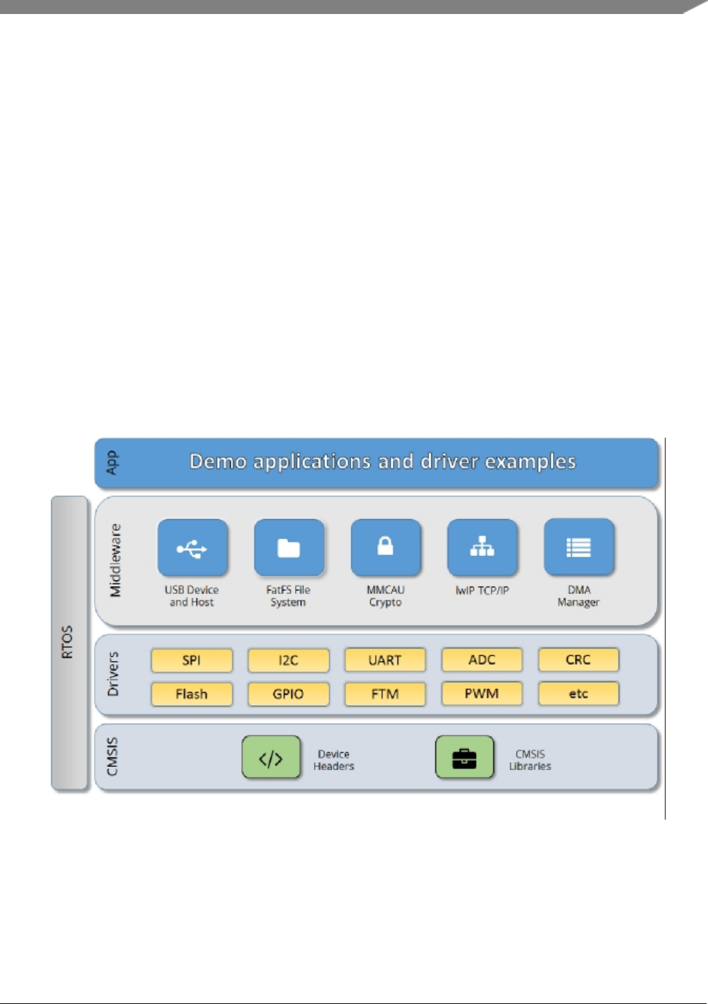
Chapter 3
Architectural Overview
This chapter provides the architectural overview for the MCUXpresso Software Development Kit (MCU-
Xpresso SDK). It describes each layer within the architecture and its associated components.
Overview
The MCUXpresso SDK architecture consists of five key components listed below.
1. The ARM Cortex Microcontroller Software Interface Standard (CMSIS) CORE compliance device-
specific header files, SOC Header, and CMSIS math/DSP libraries.
2. Peripheral Drivers
3. Real-time Operating Systems (RTOS)
4. Stacks and Middleware that integrate with the MCUXpresso SDK
5. Demo Applications based on the MCUXpresso SDK
Figure 1: MCUXpresso SDK Block Diagram
MCU header files
Each supported MCU device in the MCUXpresso SDK has an overall System-on Chip (SoC) memory-
NXP Semiconductors
MCUXpresso SDK API Reference Manual
5

mapped header file. This header file contains the memory map and register base address for each peripheral
and the IRQ vector table with associated vector numbers. The overall SoC header file provides a access to
the peripheral registers through pointers and predefined bit masks. In addition to the overall SoC memory-
mapped header file, the MCUXpresso SDK includes a feature header file for each device. The feature
header file allows NXP to deliver a single software driver for a given peripheral. The feature file ensures
that the driver is properly compiled for the target SOC.
CMSIS Support
Along with the SoC header files and peripheral extension header files, the MCUXpresso SDK also includes
common CMSIS header files for the ARM Cortex-M core and the math and DSP libraries from the latest
CMSIS release. The CMSIS DSP library source code is also included for reference.
MCUXpresso SDK Peripheral Drivers
The MCUXpresso SDK peripheral drivers mainly consist of low-level functional APIs for the MCU
product family on-chip peripherals and also of high-level transactional APIs for some bus drivers/DM-
A driver/eDMA driver to quickly enable the peripherals and perform transfers.
All MCUXpresso SDK peripheral drivers only depend on the CMSIS headers, device feature files, fsl_-
common.h, and fsl_clock.h files so that users can easily pull selected drivers and their dependencies into
projects. With the exception of the clock/power-relevant peripherals, each peripheral has its own driver.
Peripheral drivers handle the peripheral clock gating/ungating inside the drivers during initialization and
deinitialization respectively.
Low-level functional APIs provide common peripheral functionality, abstracting the hardware peripheral
register accesses into a set of stateless basic functional operations. These APIs primarily focus on the
control, configuration, and function of basic peripheral operations. The APIs hide the register access
details and various MCU peripheral instantiation differences so that the application can be abstracted from
the low-level hardware details. The API prototypes are intentionally similar to help ensure easy portability
across supported MCUXpresso SDK devices.
Transactional APIs provide a quick method for customers to utilize higher-level functionality of the pe-
ripherals. The transactional APIs utilize interrupts and perform asynchronous operations without user
intervention. Transactional APIs operate on high-level logic that requires data storage for internal oper-
ation context handling. However, the Peripheral Drivers do not allocate this memory space. Rather, the
user passes in the memory to the driver for internal driver operation. Transactional APIs ensure the NVIC
is enabled properly inside the drivers. The transactional APIs do not meet all customer needs, but provide
a baseline for development of custom user APIs.
Note that the transactional drivers never disable an NVIC after use. This is due to the shared nature of
interrupt vectors on devices. It is up to the user to ensure that NVIC interrupts are properly disabled after
usage is complete.
Interrupt handling for transactional APIs
A double weak mechanism is introduced for drivers with transactional API. The double weak indicates
two levels of weak vector entries. See the examples below:
PUBWEAK SPI0_IRQHandler
PUBWEAK SPI0_DriverIRQHandler
SPI0_IRQHandler
6
MCUXpresso SDK API Reference Manual
NXP Semiconductors

LDR R0, =SPI0_DriverIRQHandler
BX R0
The first level of the weak implementation are the functions defined in the vector table. In the devices/<-
DEVICE_NAME>/<TOOLCHAIN>/startup_<DEVICE_NAME>.s/.S file, the implementation of the
first layer weak function calls the second layer of weak function. The implementation of the second
layer weak function (ex. SPI0_DriverIRQHandler) jumps to itself (B .). The MCUXpresso SDK drivers
with transactional APIs provide the reimplementation of the second layer function inside of the peripheral
driver. If the MCUXpresso SDK drivers with transactional APIs are linked into the image, the SPI0_-
DriverIRQHandler is replaced with the function implemented in the MCUXpresso SDK SPI driver.
The reason for implementing the double weak functions is to provide a better user experience when using
the transactional APIs. For drivers with a transactional function, call the transactional APIs and the drivers
complete the interrupt-driven flow. Users are not required to redefine the vector entries out of the box. At
the same time, if users are not satisfied by the second layer weak function implemented in the MCU-
Xpresso SDK drivers, users can redefine the first layer weak function and implement their own interrupt
handler functions to suit their implementation.
The limitation of the double weak mechanism is that it cannot be used for peripherals that share the same
vector entry. For this use case, redefine the first layer weak function to enable the desired peripheral
interrupt functionality. For example, if the MCU’s UART0 and UART1 share the same vector entry,
redefine the UART0_UART1_IRQHandler according to the use case requirements.
Feature Header Files
The peripheral drivers are designed to be reusable regardless of the peripheral functional differences from
one MCU device to another. An overall Peripheral Feature Header File is provided for the MCUXpresso
SDK-supported MCU device to define the features or configuration differences for each sub-family device.
Application
See the Getting Started with MCUXpresso SDK document (MCUXSDKGSUG).
NXP Semiconductors
MCUXpresso SDK API Reference Manual
7

8
MCUXpresso SDK API Reference Manual
NXP Semiconductors

Chapter 4
Trademarks
Information in this document is provided solely to enable system and software implementers to use NXP
products. There are no express or implied copyright licenses granted hereunder to design or fabricate any
integrated circuits based on the information in this document.
How to Reach Us:
Home Page: nxp.com
Web Support: nxp.com/support
NXP reserves the right to make changes without further notice to any products herein. NXP makes no
warranty, representation, or guarantee regarding the suitability of its products for any particular purpose,
nor does NXP assume any liability arising out of the application or use of any product or circuit, and
specifically disclaims any and all liability, including without limitation consequential or incidental dam-
ages. “Typical” parameters that may be provided in NXP data sheets and/or specifications can and do vary
in different applications, and actual performance may vary over time. All operating parameters, including
“typicals,” must be validated for each customer application by customer’s technical experts. NXP does
not convey any license under its patent rights nor the rights of others. NXP sells products pursuant to
standard terms and conditions of sale, which can be found at the following address: nxp.com/Sales-
TermsandConditions
NXP, the NXP logo, Freescale, the Freescale logo, Kinetis, and Processor Expert are trademarks of N-
XP B.V. Tower is a trademark of NXP B.V. All other product or service names are the property of their
respective owners. ARM, ARM powered logo, Keil, and Cortex are registered trademarks of ARM Limited
(or its subsidiaries) in the EU and/or elsewhere. All rights reserved.
© 2017 NXP B.V.
NXP Semiconductors
MCUXpresso SDK API Reference Manual
9

10
MCUXpresso SDK API Reference Manual
NXP Semiconductors

Chapter 5
ADC: 12-bit Analog to Digital Converter Driver
5.1 Overview
The MCUXpresso SDK provides Peripheral driver for the 12-bit Analog to Digital Converter (ADC)
module of MCUXpresso SDK devices.
5.2 Typical use case
5.2.1 Polling Configuration
volatile bool g_AdcConversionDoneFlag;
volatile uint32_t g_AdcConversionValue;
volatile uint32_t g_AdcInterruptCounter;
// ...
adc_config_t adcConfigStrcut;
adc_channel_config_t adcChannelConfigStruct;
ADC_GetDefaultConfig(&adcConfigStrcut);
ADC_Init(DEMO_ADC_BASE, &adcConfigStrcut);
ADC_EnableHardwareTrigger(DEMO_ADC_BASE, false);
if (kStatus_Success == ADC_DoAutoCalibration(DEMO_ADC_BASE))
{
PRINTF("ADC_DoAntoCalibration() Done.\r\n");
}
else
{
PRINTF("ADC_DoAutoCalibration() Failed.\r\n");
}
adcChannelConfigStruct.channelNumber = DEMO_ADC_USER_CHANNEL;
adcChannelConfigStruct.enableInterruptOnConversionCompleted =true;
g_AdcInterruptCounter = 0U;
while (1)
{
PRINTF("Press any key to get user channel’s ADC value.\r\n");
GETCHAR();
g_AdcConversionDoneFlag = false;
ADC_SetChannelConfig(DEMO_ADC_BASE, DEMO_ADC_CHANNEL_GROUP, &adcChannelConfigStruct
);
while (g_AdcConversionDoneFlag == false)
{
}
PRINTF("ADC Value: %d\r\n", g_AdcConversionValue);
PRINTF("ADC Interrupt Counter: %d\r\n", g_AdcInterruptCounter);
}
// ...
void DEMO_ADC_IRQ_HANDLER_FUNC(void)
{
g_AdcConversionDoneFlag = true;
g_AdcConversionValue = ADC_GetChannelConversionValue(DEMO_ADC_BASE,
DEMO_ADC_CHANNEL_GROUP);
g_AdcInterruptCounter++;
NXP Semiconductors
MCUXpresso SDK API Reference Manual
11

Typical use case
}
5.2.2 Polling Configuration
adc_config_t adcConfigStrcut;
adc_channel_config_t adcChannelConfigStruct;
ADC_GetDefaultConfig(&adcConfigStrcut);
ADC_Init(DEMO_ADC_BASE, &adcConfigStrcut);
ADC_EnableHardwareTrigger(DEMO_ADC_BASE, false);
if (KStatus_Success == ADC_DoAutoCalibration(DEMO_ADC_BASE))
{
PRINTF("ADC_DoAntoCalibration() Done.\r\n");
}
else
{
PRINTF("ADC_DoAutoCalibration() Failed.\r\n");
}
adcChannelConfigStruct.channelNumber = DEMO_ADC_USER_CHANNEL;
adcChannelConfigStruct.enableInterruptOnConversionCompleted =false;
while (1)
{
PRINTF("Press any key to get user channel’s ADC value.\r\n");
GETCHAR();
ADC_SetChannelConfig(DEMO_ADC_BASE, DEMO_ADC_CHANNEL_GROUP, &adcChannelConfigStruct
);
while (0U == ADC_GetChannelStatusFlags(DEMO_ADC_BASE, DEMO_ADC_CHANNEL_GROUP))
{
}
PRINTF("ADC Value: %d\r\n",ADC_GetChannelConversionValue(DEMO_ADC_BASE,
DEMO_ADC_CHANNEL_GROUP));
}
Data Structures
• struct adc_config_t
Converter configuration. More...
• struct adc_offest_config_t
Converter Offset configuration. More...
• struct adc_hardware_compare_config_t
ADC hardware compare configuration. More...
• struct adc_channel_config_t
ADC channel conversion configuration. More...
Macros
• #define FSL_ADC_DRIVER_VERSION (MAKE_VERSION(2, 0, 0))
ADC driver version.
Enumerations
• enum adc_status_flags_t {
kADC_ConversionActiveFlag = ADC_GS_ADACT_MASK,
kADC_CalibrationFailedFlag = ADC_GS_CALF_MASK,
kADC_AsynchronousWakeupInterruptFlag }
12
MCUXpresso SDK API Reference Manual
NXP Semiconductors

Typical use case
Converter’s status flags.
• enum adc_reference_voltage_source_t {kADC_ReferenceVoltageSourceAlt0 = 0U }
Reference voltage source.
• enum adc_sample_period_mode_t {
kADC_SamplePeriod2or12Clocks = 0U,
kADC_SamplePeriod4or16Clocks = 1U,
kADC_SamplePeriod6or20Clocks = 2U,
kADC_SamplePeriod8or24Clocks = 3U,
kADC_SamplePeriodLong12Clcoks = kADC_SamplePeriod2or12Clocks,
kADC_SamplePeriodLong16Clcoks = kADC_SamplePeriod4or16Clocks,
kADC_SamplePeriodLong20Clcoks = kADC_SamplePeriod6or20Clocks,
kADC_SamplePeriodLong24Clcoks = kADC_SamplePeriod8or24Clocks,
kADC_SamplePeriodShort2Clocks = kADC_SamplePeriod2or12Clocks,
kADC_SamplePeriodShort4Clocks = kADC_SamplePeriod4or16Clocks,
kADC_SamplePeriodShort6Clocks = kADC_SamplePeriod6or20Clocks,
kADC_SamplePeriodShort8Clocks = kADC_SamplePeriod8or24Clocks }
Sample time duration.
• enum adc_clock_source_t {
kADC_ClockSourceIPG = 0U,
kADC_ClockSourceIPGDiv2 = 1U,
kADC_ClockSourceALT = 2U,
kADC_ClockSourceAD = 3U }
Clock source.
• enum adc_clock_driver_t {
kADC_ClockDriver1 = 0U,
kADC_ClockDriver2 = 1U,
kADC_ClockDriver4 = 2U,
kADC_ClockDriver8 = 3U }
Clock divider for the converter.
• enum adc_resolution_t {
kADC_Resolution8Bit = 0U,
kADC_Resolution10Bit = 1U,
kADC_Resolution12Bit = 2U }
Converter’s resolution.
• enum adc_hardware_compare_mode_t {
kADC_HardwareCompareMode0 = 0U,
kADC_HardwareCompareMode1 = 1U,
kADC_HardwareCompareMode2 = 2U,
kADC_HardwareCompareMode3 = 3U }
Converter hardware compare mode.
• enum adc_hardware_average_mode_t {
kADC_HardwareAverageCount4 = 0U,
kADC_HardwareAverageCount8 = 1U,
kADC_HardwareAverageCount16 = 2U,
kADC_HardwareAverageCount32 = 3U,
kADC_HardwareAverageDiasable = 4U }
NXP Semiconductors
MCUXpresso SDK API Reference Manual
13

Typical use case
Converter hardware average mode.
Variables
• bool adc_config_t::enableOverWrite
Enable the overwriting.
• bool adc_config_t::enableContinuousConversion
Enable the continuous conversion mode.
• bool adc_config_t::enableHighSpeed
Enable the high-speed mode.
• bool adc_config_t::enableLowPower
Enable the low power mode.
• bool adc_config_t::enableLongSample
Enable the long sample mode.
• bool adc_config_t::enableAsynchronousClockOutput
Enable the asynchronous clock output.
•adc_reference_voltage_source_t adc_config_t::referenceVoltageSource
Select the reference voltage source.
•adc_sample_period_mode_t adc_config_t::samplePeriodMode
Select the sample period in long sample mode or short mode.
•adc_clock_source_t adc_config_t::clockSource
Select the input clock source to generate the internal clock ADCK.
•adc_clock_driver_t adc_config_t::clockDriver
Select the divide ratio used by the ADC to generate the internal clock ADCK.
•adc_resolution_t adc_config_t::resolution
Select the ADC resolution mode.
• bool adc_offest_config_t::enableSigned
if false,The offset value is added with the raw result.
• uint32_t adc_offest_config_t::offsetValue
User configurable offset value(0-4095).
•adc_hardware_compare_mode_t adc_hardware_compare_config_t::hardwareCompareMode
Select the hardware compare mode.
• uint16_t adc_hardware_compare_config_t::value1
Setting value1(0-4095) for hardware compare mode.
• uint16_t adc_hardware_compare_config_t::value2
Setting value2(0-4095) for hardware compare mode.
• uint32_t adc_channel_config_t::channelNumber
Setting the conversion channel number.
• bool adc_channel_config_t::enableInterruptOnConversionCompleted
Generate an interrupt request once the conversion is completed.
Initialization
• void ADC_Init (ADC_Type ∗base, const adc_config_t ∗config)
Initialize the ADC module.
• void ADC_Deinit (ADC_Type ∗base)
De-initializes the ADC module.
• void ADC_GetDefaultConfig (adc_config_t ∗config)
Gets an available pre-defined settings for the converter’s configuration.
• void ADC_SetChannelConfig (ADC_Type ∗base, uint32_t channelGroup, const adc_channel_-
config_t ∗config)
14
MCUXpresso SDK API Reference Manual
NXP Semiconductors

Data Structure Documentation
Configures the conversion channel.
• static uint32_t ADC_GetChannelConversionValue (ADC_Type ∗base, uint32_t channelGroup)
Gets the conversion value.
• static uint32_t ADC_GetChannelStatusFlags (ADC_Type ∗base, uint32_t channelGroup)
Gets the status flags of channel.
• status_t ADC_DoAutoCalibration (ADC_Type ∗base)
Automates the hardware calibration.
• void ADC_SetOffsetConfig (ADC_Type ∗base, const adc_offest_config_t ∗config)
Set user defined offset.
• static void ADC_EnableDMA (ADC_Type ∗base, bool enable)
Enables generating the DMA trigger when the conversion is complete.
• static void ADC_EnableHardwareTrigger (ADC_Type ∗base, bool enable)
Enables the hardware trigger mode.
• void ADC_SetHardwareCompareConfig (ADC_Type ∗base, const adc_hardware_compare_config-
_t ∗config)
Configures the hardware compare mode.
• void ADC_SetHardwareAverageConfig (ADC_Type ∗base, adc_hardware_average_mode_t mode)
Configures the hardware average mode.
• static uint32_t ADC_GetStatusFlags (ADC_Type ∗base)
Gets the converter’s status flags.
• void ADC_ClearStatusFlags (ADC_Type ∗base, uint32_t mask)
Clears the converter’s status falgs.
5.3 Data Structure Documentation
5.3.1 struct adc_config_t
Data Fields
• bool enableOverWrite
Enable the overwriting.
• bool enableContinuousConversion
Enable the continuous conversion mode.
• bool enableHighSpeed
Enable the high-speed mode.
• bool enableLowPower
Enable the low power mode.
• bool enableLongSample
Enable the long sample mode.
• bool enableAsynchronousClockOutput
Enable the asynchronous clock output.
•adc_reference_voltage_source_t referenceVoltageSource
Select the reference voltage source.
•adc_sample_period_mode_t samplePeriodMode
Select the sample period in long sample mode or short mode.
•adc_clock_source_t clockSource
Select the input clock source to generate the internal clock ADCK.
•adc_clock_driver_t clockDriver
Select the divide ratio used by the ADC to generate the internal clock ADCK.
•adc_resolution_t resolution
NXP Semiconductors
MCUXpresso SDK API Reference Manual
15

Data Structure Documentation
Select the ADC resolution mode.
5.3.2 struct adc_offest_config_t
Data Fields
• bool enableSigned
if false,The offset value is added with the raw result.
• uint32_t offsetValue
User configurable offset value(0-4095).
5.3.3 struct adc_hardware_compare_config_t
In kADC_HardwareCompareMode0, compare true if the result is less than the value1. In kADC_-
HardwareCompareMode1, compare true if the result is greater than or equal to value1. In kADC_-
HardwareCompareMode2, Value1 <= Value2, compare true if the result is less than value1 Or the result
is Greater than value2. Value1 >Value2, compare true if the result is less than value1 And the result is
Greater than value2. In kADC_HardwareCompareMode3, Value1 <= Value2, compare true if the result
is greater than or equal to value1 And the result is less than or equal to value2. Value1 >Value2, compare
true if the result is greater than or equal to value1 Or the result is less than or equal to value2.
Data Fields
•adc_hardware_compare_mode_t hardwareCompareMode
Select the hardware compare mode.
• uint16_t value1
Setting value1(0-4095) for hardware compare mode.
• uint16_t value2
Setting value2(0-4095) for hardware compare mode.
5.3.4 struct adc_channel_config_t
Data Fields
• uint32_t channelNumber
Setting the conversion channel number.
• bool enableInterruptOnConversionCompleted
Generate an interrupt request once the conversion is completed.
16
MCUXpresso SDK API Reference Manual
NXP Semiconductors

Enumeration Type Documentation
5.4 Macro Definition Documentation
5.4.1 #define FSL_ADC_DRIVER_VERSION (MAKE_VERSION(2, 0, 0))
Version 2.0.0.
5.5 Enumeration Type Documentation
5.5.1 enum adc_status_flags_t
Enumerator
kADC_ConversionActiveFlag Conversion is active,not support w1c.
kADC_CalibrationFailedFlag Calibration is failed,support w1c.
kADC_AsynchronousWakeupInterruptFlag Asynchronous wakeup interrupt occured, support w1c.
5.5.2 enum adc_reference_voltage_source_t
Enumerator
kADC_ReferenceVoltageSourceAlt0 For external pins pair of VrefH and VrefL.
5.5.3 enum adc_sample_period_mode_t
Enumerator
kADC_SamplePeriod2or12Clocks Long sample 12 clocks or short sample 2 clocks.
kADC_SamplePeriod4or16Clocks Long sample 16 clocks or short sample 4 clocks.
kADC_SamplePeriod6or20Clocks Long sample 20 clocks or short sample 6 clocks.
kADC_SamplePeriod8or24Clocks Long sample 24 clocks or short sample 8 clocks.
kADC_SamplePeriodLong12Clcoks Long sample 12 clocks.
kADC_SamplePeriodLong16Clcoks Long sample 16 clocks.
kADC_SamplePeriodLong20Clcoks Long sample 20 clocks.
kADC_SamplePeriodLong24Clcoks Long sample 24 clocks.
kADC_SamplePeriodShort2Clocks Short sample 2 clocks.
kADC_SamplePeriodShort4Clocks Short sample 4 clocks.
kADC_SamplePeriodShort6Clocks Short sample 6 clocks.
kADC_SamplePeriodShort8Clocks Short sample 8 clocks.
5.5.4 enum adc_clock_source_t
Enumerator
kADC_ClockSourceIPG Select IPG clock to generate ADCK.
NXP Semiconductors
MCUXpresso SDK API Reference Manual
17

Enumeration Type Documentation
kADC_ClockSourceIPGDiv2 Select IPG clock divided by 2 to generate ADCK.
kADC_ClockSourceALT Select alternate clock to generate ADCK.
kADC_ClockSourceAD Select Asynchronous clock to generate ADCK.
5.5.5 enum adc_clock_driver_t
Enumerator
kADC_ClockDriver1 For divider 1 from the input clock to the module.
kADC_ClockDriver2 For divider 2 from the input clock to the module.
kADC_ClockDriver4 For divider 4 from the input clock to the module.
kADC_ClockDriver8 For divider 8 from the input clock to the module.
5.5.6 enum adc_resolution_t
Enumerator
kADC_Resolution8Bit Single End 8-bit resolution.
kADC_Resolution10Bit Single End 10-bit resolution.
kADC_Resolution12Bit Single End 12-bit resolution.
5.5.7 enum adc_hardware_compare_mode_t
Enumerator
kADC_HardwareCompareMode0 Compare true if the result is less than the value1.
kADC_HardwareCompareMode1 Compare true if the result is greater than or equal to value1.
kADC_HardwareCompareMode2 Value1 <= Value2, compare true if the result is less than value1
Or the result is Greater than value2. Value1 >Value2, compare true if the result is less than
value1 And the result is greater than value2
kADC_HardwareCompareMode3 Value1 <= Value2, compare true if the result is greater than or
equal to value1 And the result is less than or equal to value2. Value1 >Value2, compare true if
the result is greater than or equal to value1 Or the result is less than or equal to value2.
5.5.8 enum adc_hardware_average_mode_t
Enumerator
kADC_HardwareAverageCount4 For hardware average with 4 samples.
kADC_HardwareAverageCount8 For hardware average with 8 samples.
18
MCUXpresso SDK API Reference Manual
NXP Semiconductors

Function Documentation
kADC_HardwareAverageCount16 For hardware average with 16 samples.
kADC_HardwareAverageCount32 For hardware average with 32 samples.
kADC_HardwareAverageDiasable Disable the hardware average function.
5.6 Function Documentation
5.6.1 void ADC_Init ( ADC_Type ∗base, const adc_config_t ∗config )
Parameters
base ADC peripheral base address.
config Pointer to "adc_config_t" structure.
5.6.2 void ADC_Deinit ( ADC_Type ∗base )
Parameters
base ADC peripheral base address.
5.6.3 void ADC_GetDefaultConfig ( adc_config_t ∗config )
This function initializes the converter configuration structure with available settings. The default values
are:
*config->enableAsynchronousClockOutput = true;
*config->enableOverWrite = false;
*config->enableContinuousConversion = false;
*config->enableHighSpeed = false;
*config->enableLowPower = false;
*config->enableLongSample = false;
*config->referenceVoltageSource = kADC_ReferenceVoltageSourceAlt0;
*config->samplePeriodMode = kADC_SamplePeriod2or12Clocks;
*config->clockSource = kADC_ClockSourceAD;
*config->clockDriver = kADC_ClockDriver1;
*config->resolution = kADC_Resolution12Bit;
*
Parameters
NXP Semiconductors
MCUXpresso SDK API Reference Manual
19

Function Documentation
base ADC peripheral base address.
config Pointer to the configuration structure.
5.6.4 void ADC_SetChannelConfig ( ADC_Type ∗base, uint32_t channelGroup,
const adc_channel_config_t ∗config )
This operation triggers the conversion when in software trigger mode. When in hardware trigger mode,
this API configures the channel while the external trigger source helps to trigger the conversion.
Note that the "Channel Group" has a detailed description. To allow sequential conversions of the ADC
to be triggered by internal peripherals, the ADC has more than one group of status and control registers,
one for each conversion. The channel group parameter indicates which group of registers are used, for
example channel group 0 is for Group A registers and channel group 1 is for Group B registers. The
channel groups are used in a "ping-pong" approach to control the ADC operation. At any point, only
one of the channel groups is actively controlling ADC conversions. The channel group 0 is used for
both software and hardware trigger modes. Channel groups 1 and greater indicate potentially multiple
channel group registers for use only in hardware trigger mode. See the chip configuration information in
the appropriate MCU reference manual about the number of SC1n registers (channel groups) specific to
this device. None of the channel groups 1 or greater are used for software trigger operation. Therefore,
writing to these channel groups does not initiate a new conversion. Updating the channel group 0 while a
different channel group is actively controlling a conversion is allowed and vice versa. Writing any of the
channel group registers while that specific channel group is actively controlling a conversion aborts the
current conversion.
Parameters
base ADC peripheral base address.
channelGroup Channel group index.
config Pointer to the "adc_channel_config_t" structure for the conversion channel.
5.6.5 static uint32_t ADC_GetChannelConversionValue ( ADC_Type ∗base,
uint32_t channelGroup )[inline],[static]
Parameters
base ADC peripheral base address.
20
MCUXpresso SDK API Reference Manual
NXP Semiconductors

Function Documentation
channelGroup Channel group index.
Returns
Conversion value.
5.6.6 static uint32_t ADC_GetChannelStatusFlags ( ADC_Type ∗base, uint32_t
channelGroup )[inline],[static]
A conversion is completed when the result of the conversion is transferred into the data result registers.
(provided the compare function & hardware averaging is disabled), this is indicated by the setting of CO-
COn. If hardware averaging is enabled, COCOn sets only, if the last of the selected number of conversions
is complete. If the compare function is enabled, COCOn sets and conversion result data is transferred
only if the compare condition is true. If both hardware averaging and compare functions are enabled, then
COCOn sets only if the last of the selected number of conversions is complete and the compare condition
is true.
Parameters
base ADC peripheral base address.
channelGroup Channel group index.
Returns
Status flags of channel.return 0 means COCO flag is 0,return 1 means COCOflag is 1.
5.6.7 status_t ADC_DoAutoCalibration ( ADC_Type ∗base )
This auto calibration helps to adjust the plus/minus side gain automatically. Execute the calibration before
using the converter. Note that the software trigger should be used during calibration.
Parameters
base ADC peripheral base address.
Returns
Execution status.
NXP Semiconductors
MCUXpresso SDK API Reference Manual
21

Function Documentation
Return values
kStatus_Success Calibration is done successfully.
kStatus_Fail Calibration has failed.
5.6.8 void ADC_SetOffsetConfig ( ADC_Type ∗base, const adc_offest_config_t ∗
config )
Parameters
base ADC peripheral base address.
config Pointer to "adc_offest_config_t" structure.
5.6.9 static void ADC_EnableDMA ( ADC_Type ∗base, bool enable )[inline],
[static]
Parameters
base ADC peripheral base address.
enable Switcher of the DMA feature. "true" means enabled, "false" means not enabled.
5.6.10 static void ADC_EnableHardwareTrigger ( ADC_Type ∗base, bool enable )
[inline],[static]
Parameters
base ADC peripheral base address.
enable Switcher of the trigger mode. "true" means hardware tirgger mode,"false" means
software mode.
5.6.11 void ADC_SetHardwareCompareConfig ( ADC_Type ∗base, const
adc_hardware_compare_config_t ∗config )
The hardware compare mode provides a way to process the conversion result automatically by using
hardware. Only the result in the compare range is available. To compare the range, see "adc_hardware_-
compare_mode_t" or the appopriate reference manual for more information.
22
MCUXpresso SDK API Reference Manual
NXP Semiconductors

Function Documentation
Parameters
base ADC peripheral base address.
Pointer to "adc_hardware_compare_config_t" structure.
5.6.12 void ADC_SetHardwareAverageConfig ( ADC_Type ∗base,
adc_hardware_average_mode_t mode )
The hardware average mode provides a way to process the conversion result automatically by using hard-
ware. The multiple conversion results are accumulated and averaged internally making them easier to
read.
Parameters
base ADC peripheral base address.
mode Setting the hardware average mode. See "adc_hardware_average_mode_t".
5.6.13 static uint32_t ADC_GetStatusFlags ( ADC_Type ∗base )[inline],
[static]
Parameters
base ADC peripheral base address.
Returns
Flags’ mask if indicated flags are asserted. See "adc_status_flags_t".
5.6.14 void ADC_ClearStatusFlags ( ADC_Type ∗base, uint32_t mask )
Parameters
base ADC peripheral base address.
NXP Semiconductors
MCUXpresso SDK API Reference Manual
23

Variable Documentation
mask Mask value for the cleared flags. See "adc_status_flags_t".
5.7 Variable Documentation
5.7.1 bool adc_config_t::enableOverWrite
5.7.2 bool adc_config_t::enableContinuousConversion
5.7.3 bool adc_config_t::enableHighSpeed
5.7.4 bool adc_config_t::enableLowPower
5.7.5 bool adc_config_t::enableLongSample
5.7.6 bool adc_config_t::enableAsynchronousClockOutput
5.7.7 adc_reference_voltage_source_t adc_config_t::referenceVoltageSource
5.7.8 adc_sample_period_mode_t adc_config_t::samplePeriodMode
5.7.9 adc_clock_source_t adc_config_t::clockSource
5.7.10 adc_clock_driver_t adc_config_t::clockDriver
5.7.11 adc_resolution_t adc_config_t::resolution
5.7.12 bool adc_offest_config_t::enableSigned
if true,The offset value is subtracted from the raw converted value.
5.7.13 uint32_t adc_offest_config_t::offsetValue
5.7.14 adc_hardware_compare_mode_t adc_hardware_compare_config_t-
::hardwareCompareMode
See "adc_hardware_compare_mode_t".
24
MCUXpresso SDK API Reference Manual
NXP Semiconductors

Variable Documentation
5.7.15 uint16_t adc_hardware_compare_config_t::value1
5.7.16 uint16_t adc_hardware_compare_config_t::value2
5.7.17 uint32_t adc_channel_config_t::channelNumber
The available range is 0-31. See channel connection information for each chip in Reference Manual
document.
5.7.18 bool adc_channel_config_t::enableInterruptOnConversionCompleted
NXP Semiconductors
MCUXpresso SDK API Reference Manual
25

Variable Documentation
26
MCUXpresso SDK API Reference Manual
NXP Semiconductors

Chapter 6
ADC_5HC: 12-bit Analog to Digital Converter Driver
6.1 Overview
The MCUXpresso SDK provides Peripheral driver for the 12-bit Analog to Digital Converter (ADC_5HC)
module of MCUXpresso SDK devices. There are some differences between ADC and ADC_5HC. Firstly,
the number of ADC_HCn reigsters is different. Secondly, ADC_5HC could work with TSC module to
control touch screen, but ADC couldn’t. If user try to use TSC, ADC_5HC should be configured to work
with TSC.
6.2 Typical use case
6.2.1 Polling Configuration
volatile bool g_AdcConversionDoneFlag;
volatile uint32_t g_AdcConversionValue;
volatile uint32_t g_AdcInterruptCounter;
// ...
adc_5hc_config_t adcConfigStrcut;
adc_5hc_channel_config_t adcChannelConfigStruct;
ADC_5HC_GetDefaultConfig(&adcConfigStrcut);
ADC_5HC_Init(DEMO_ADC_5HC_BASE, &adcConfigStrcut);
ADC_5HC_EnableHardwareTrigger(DEMO_ADC_5HC_BASE, false);
if (kStatus_Success == ADC_5HC_DoAutoCalibration(DEMO_ADC_5HC_BASE))
{
PRINTF("ADC_5HC_DoAntoCalibration() Done.\r\n");
}
else
{
PRINTF("ADC_5HC_DoAutoCalibration() Failed.\r\n");
}
adcChannelConfigStruct.channelNumber = DEMO_ADC_5HC_USER_CHANNEL;
adcChannelConfigStruct.enableInterruptOnConversionCompleted =true;
g_AdcInterruptCounter = 0U;
while (1)
{
PRINTF("Press any key to get user channel’s ADC_5HC value.\r\n");
GETCHAR();
g_AdcConversionDoneFlag = false;
ADC_5HC_SetChannelConfig(DEMO_ADC_5HC_BASE, DEMO_ADC_5HC_CHANNEL_GROUP, &
adcChannelConfigStruct);
while (g_AdcConversionDoneFlag == false)
{
}
PRINTF("ADC_5HC Value: %d\r\n", g_AdcConversionValue);
PRINTF("ADC_5HC Interrupt Counter: %d\r\n", g_AdcInterruptCounter);
}
// ...
void DEMO_ADC_5HC_IRQ_HANDLER_FUNC(void)
NXP Semiconductors
MCUXpresso SDK API Reference Manual
27

Typical use case
{
g_AdcConversionDoneFlag = true;
g_AdcConversionValue = ADC_5HC_GetChannelConversionValue(
DEMO_ADC_5HC_BASE, DEMO_ADC_5HC_CHANNEL_GROUP);
g_AdcInterruptCounter++;
}
6.2.2 Polling Configuration
adc_5hc_config_t adcConfigStrcut;
adc_5hc_channel_config_t adcChannelConfigStruct;
ADC_5HC_GetDefaultConfig(&adcConfigStrcut);
ADC_5HC_Init(DEMO_ADC_5HC_BASE, &adcConfigStrcut);
ADC_5HC_EnableHardwareTrigger(DEMO_ADC_5HC_BASE, false);
if (KStatus_Success == ADC_5HC_DoAutoCalibration(DEMO_ADC_5HC_BASE))
{
PRINTF("ADC_5HC_DoAntoCalibration() Done.\r\n");
}
else
{
PRINTF("ADC_5HC_DoAutoCalibration() Failed.\r\n");
}
adcChannelConfigStruct.channelNumber = DEMO_ADC_5HC_USER_CHANNEL;
adcChannelConfigStruct.enableInterruptOnConversionCompleted =false;
while (1)
{
PRINTF("Press any key to get user channel’s ADC_5HC value.\r\n");
GETCHAR();
ADC_5HC_SetChannelConfig(DEMO_ADC_5HC_BASE, DEMO_ADC_5HC_CHANNEL_GROUP, &
adcChannelConfigStruct);
while (0U == ADC_5HC_GetChannelStatusFlags(DEMO_ADC_5HC_BASE,
DEMO_ADC_5HC_CHANNEL_GROUP))
{
}
PRINTF("ADC_5HC Value: %d\r\n",ADC_5HC_GetChannelConversionValue(
DEMO_ADC_5HC_BASE, DEMO_ADC_5HC_CHANNEL_GROUP));
}
Data Structures
• struct adc_5hc_config_t
Converter configuration. More...
• struct adc_5hc_offest_config_t
Converter Offset configuration. More...
• struct adc_5hc_hardware_compare_config_t
ADC hardware compare configuration. More...
• struct adc_5hc_channel_config_t
ADC channel conversion configuration. More...
Macros
• #define FSL_ADC_5HC_DRIVER_VERSION (MAKE_VERSION(2, 0, 0))
ADC driver version.
28
MCUXpresso SDK API Reference Manual
NXP Semiconductors

Typical use case
Enumerations
• enum adc_5hc_status_flags_t {
kADC_5HC_ConversionActiveFlag = ADC_5HC_GS_ADACT_MASK,
kADC_5HC_CalibrationFailedFlag = ADC_5HC_GS_CALF_MASK,
kADC_5HC_AsynchronousWakeupInterruptFlag }
Converter’s status flags.
• enum adc_5hc_reference_voltage_source_t {kADC_5HC_ReferenceVoltageSourceAlt0 = 0U }
Reference voltage source.
• enum adc_5hc_sample_period_mode_t {
kADC_5HC_SamplePeriod2or12Clocks = 0U,
kADC_5HC_SamplePeriod4or16Clocks = 1U,
kADC_5HC_SamplePeriod6or20Clocks = 2U,
kADC_5HC_SamplePeriod8or24Clocks = 3U,
kADC_5HC_SamplePeriodLong12Clcoks = kADC_5HC_SamplePeriod2or12Clocks,
kADC_5HC_SamplePeriodLong16Clcoks = kADC_5HC_SamplePeriod4or16Clocks,
kADC_5HC_SamplePeriodLong20Clcoks = kADC_5HC_SamplePeriod6or20Clocks,
kADC_5HC_SamplePeriodLong24Clcoks = kADC_5HC_SamplePeriod8or24Clocks,
kADC_5HC_SamplePeriodShort2Clocks = kADC_5HC_SamplePeriod2or12Clocks,
kADC_5HC_SamplePeriodShort4Clocks = kADC_5HC_SamplePeriod4or16Clocks,
kADC_5HC_SamplePeriodShort6Clocks = kADC_5HC_SamplePeriod6or20Clocks,
kADC_5HC_SamplePeriodShort8Clocks = kADC_5HC_SamplePeriod8or24Clocks }
Sample time duration.
• enum adc_5hc_clock_source_t {
kADC_5HC_ClockSourceIPG = 0U,
kADC_5HC_ClockSourceIPGDiv2 = 1U,
kADC_5HC_ClockSourceAD = 3U }
Clock source.
• enum adc_5hc_clock_driver_t {
kADC_5HC_ClockDriver1 = 0U,
kADC_5HC_ClockDriver2 = 1U,
kADC_5HC_ClockDriver4 = 2U,
kADC_5HC_ClockDriver8 = 3U }
Clock divider for the converter.
• enum adc_5hc_resolution_t {
kADC_5HC_Resolution8Bit = 0U,
kADC_5HC_Resolution10Bit = 1U,
kADC_5HC_Resolution12Bit = 2U }
Converter’s resolution.
• enum adc_5hc_hardware_compare_mode_t {
kADC_5HC_HardwareCompareMode0 = 0U,
kADC_5HC_HardwareCompareMode1 = 1U,
kADC_5HC_HardwareCompareMode2 = 2U,
kADC_5HC_HardwareCompareMode3 = 3U }
Converter hardware compare mode.
• enum adc_5hc_hardware_average_mode_t {
NXP Semiconductors
MCUXpresso SDK API Reference Manual
29

Typical use case
kADC_5HC_HardwareAverageCount4 = 0U,
kADC_5HC_HardwareAverageCount8 = 1U,
kADC_5HC_HardwareAverageCount16 = 2U,
kADC_5HC_HardwareAverageCount32 = 3U,
kADC_5HC_HardwareAverageDiasable = 4U }
Converter hardware average mode.
Variables
• bool adc_5hc_config_t::enableOverWrite
Enable the overwriting.
• bool adc_5hc_config_t::enableContinuousConversion
Enable the continuous conversion mode.
• bool adc_5hc_config_t::enableHighSpeed
Enable the high-speed mode.
• bool adc_5hc_config_t::enableLowPower
Enable the low power mode.
• bool adc_5hc_config_t::enableLongSample
Enable the long sample mode.
• bool adc_5hc_config_t::enableAsynchronousClockOutput
Enable the asynchronous clock output.
•adc_5hc_reference_voltage_source_t adc_5hc_config_t::referenceVoltageSource
Select the reference voltage source.
•adc_5hc_sample_period_mode_t adc_5hc_config_t::samplePeriodMode
Select the sample period in long sample mode or short mode.
•adc_5hc_clock_source_t adc_5hc_config_t::clockSource
Select the input clock source to generate the internal clock ADCK.
•adc_5hc_clock_driver_t adc_5hc_config_t::clockDriver
Select the divide ratio used by the ADC to generate the internal clock ADCK.
•adc_5hc_resolution_t adc_5hc_config_t::resolution
Select the ADC resolution mode.
• bool adc_5hc_offest_config_t::enableSigned
if false,The offset value is added with the raw result.
• uint32_t adc_5hc_offest_config_t::offsetValue
User configurable offset value(0-4095).
•adc_5hc_hardware_compare_mode_t adc_5hc_hardware_compare_config_t::hardwareCompare-
Mode
Select the hardware compare mode.
• uint16_t adc_5hc_hardware_compare_config_t::value1
Setting value1(0-4095) for hardware compare mode.
• uint16_t adc_5hc_hardware_compare_config_t::value2
Setting value2(0-4095) for hardware compare mode.
• uint32_t adc_5hc_channel_config_t::channelNumber
Setting the conversion channel number.
• bool adc_5hc_channel_config_t::enableInterruptOnConversionCompleted
Generate an interrupt request once the conversion is completed.
Initialization
• void ADC_5HC_Init (ADC_5HC_Type ∗base, const adc_5hc_config_t ∗config)
30
MCUXpresso SDK API Reference Manual
NXP Semiconductors

Data Structure Documentation
Initialize the ADC module.
• void ADC_5HC_Deinit (ADC_5HC_Type ∗base)
De-initializes the ADC module.
• void ADC_5HC_GetDefaultConfig (adc_5hc_config_t ∗config)
Gets an available pre-defined settings for the converter’s configuration.
• void ADC_5HC_SetChannelConfig (ADC_5HC_Type ∗base, uint32_t channelGroup, const adc_-
5hc_channel_config_t ∗config)
Configures the conversion channel.
• static uint32_t ADC_5HC_GetChannelConversionValue (ADC_5HC_Type ∗base, uint32_-
t channelGroup)
Gets the conversion value.
• static uint32_t ADC_5HC_GetChannelStatusFlags (ADC_5HC_Type ∗base, uint32_t channel-
Group)
Gets the status flags of channel.
• status_t ADC_5HC_DoAutoCalibration (ADC_5HC_Type ∗base)
Automates the hardware calibration.
• void ADC_5HC_SetOffsetConfig (ADC_5HC_Type ∗base, const adc_5hc_offest_config_t ∗config)
Set user defined offset.
• static void ADC_5HC_EnableDMA (ADC_5HC_Type ∗base, bool enable)
Enables generating the DMA trigger when the conversion is complete.
• static void ADC_5HC_EnableHardwareTrigger (ADC_5HC_Type ∗base, bool enable)
Enables the hardware trigger mode.
• void ADC_5HC_SetHardwareCompareConfig (ADC_5HC_Type ∗base, const adc_5hc_hardware-
_compare_config_t ∗config)
Configures the hardware compare mode.
• void ADC_5HC_SetHardwareAverageConfig (ADC_5HC_Type ∗base, adc_5hc_hardware_-
average_mode_t mode)
Configures the hardware average mode.
• static uint32_t ADC_5HC_GetStatusFlags (ADC_5HC_Type ∗base)
Gets the converter’s status flags.
• void ADC_5HC_ClearStatusFlags (ADC_5HC_Type ∗base, uint32_t mask)
Clears the converter’s status falgs.
6.3 Data Structure Documentation
6.3.1 struct adc_5hc_config_t
Data Fields
• bool enableOverWrite
Enable the overwriting.
• bool enableContinuousConversion
Enable the continuous conversion mode.
• bool enableHighSpeed
Enable the high-speed mode.
• bool enableLowPower
Enable the low power mode.
• bool enableLongSample
Enable the long sample mode.
• bool enableAsynchronousClockOutput
NXP Semiconductors
MCUXpresso SDK API Reference Manual
31

Data Structure Documentation
Enable the asynchronous clock output.
•adc_5hc_reference_voltage_source_t referenceVoltageSource
Select the reference voltage source.
•adc_5hc_sample_period_mode_t samplePeriodMode
Select the sample period in long sample mode or short mode.
•adc_5hc_clock_source_t clockSource
Select the input clock source to generate the internal clock ADCK.
•adc_5hc_clock_driver_t clockDriver
Select the divide ratio used by the ADC to generate the internal clock ADCK.
•adc_5hc_resolution_t resolution
Select the ADC resolution mode.
6.3.2 struct adc_5hc_offest_config_t
Data Fields
• bool enableSigned
if false,The offset value is added with the raw result.
• uint32_t offsetValue
User configurable offset value(0-4095).
6.3.3 struct adc_5hc_hardware_compare_config_t
In kADC_5HC_HardwareCompareMode0, compare true if the result is less than the value1. In kADC_-
5HC_HardwareCompareMode1, compare true if the result is greater than or equal to value1. In kADC_-
5HC_HardwareCompareMode2, Value1 <= Value2, compare true if the result is less than value1 Or the
result is Greater than value2. Value1 >Value2, compare true if the result is less than value1 And the result
is Greater than value2. In kADC_5HC_HardwareCompareMode3, Value1 <= Value2, compare true if the
result is greater than or equal to value1 And the result is less than or equal to value2. Value1 >Value2,
compare true if the result is greater than or equal to value1 Or the result is less than or equal to value2.
Data Fields
•adc_5hc_hardware_compare_mode_t hardwareCompareMode
Select the hardware compare mode.
• uint16_t value1
Setting value1(0-4095) for hardware compare mode.
• uint16_t value2
Setting value2(0-4095) for hardware compare mode.
32
MCUXpresso SDK API Reference Manual
NXP Semiconductors

Enumeration Type Documentation
6.3.4 struct adc_5hc_channel_config_t
Data Fields
• uint32_t channelNumber
Setting the conversion channel number.
• bool enableInterruptOnConversionCompleted
Generate an interrupt request once the conversion is completed.
6.4 Macro Definition Documentation
6.4.1 #define FSL_ADC_5HC_DRIVER_VERSION (MAKE_VERSION(2, 0, 0))
Version 2.0.0.
6.5 Enumeration Type Documentation
6.5.1 enum adc_5hc_status_flags_t
Enumerator
kADC_5HC_ConversionActiveFlag Conversion is active,not support w1c.
kADC_5HC_CalibrationFailedFlag Calibration is failed,support w1c.
kADC_5HC_AsynchronousWakeupInterruptFlag Asynchronous wakeup interrupt occured, sup-
port w1c.
6.5.2 enum adc_5hc_reference_voltage_source_t
Enumerator
kADC_5HC_ReferenceVoltageSourceAlt0 For external pins pair of VrefH and VrefL.
6.5.3 enum adc_5hc_sample_period_mode_t
Enumerator
kADC_5HC_SamplePeriod2or12Clocks Long sample 12 clocks or short sample 2 clocks.
kADC_5HC_SamplePeriod4or16Clocks Long sample 16 clocks or short sample 4 clocks.
kADC_5HC_SamplePeriod6or20Clocks Long sample 20 clocks or short sample 6 clocks.
kADC_5HC_SamplePeriod8or24Clocks Long sample 24 clocks or short sample 8 clocks.
kADC_5HC_SamplePeriodLong12Clcoks Long sample 12 clocks.
kADC_5HC_SamplePeriodLong16Clcoks Long sample 16 clocks.
kADC_5HC_SamplePeriodLong20Clcoks Long sample 20 clocks.
NXP Semiconductors
MCUXpresso SDK API Reference Manual
33

Enumeration Type Documentation
kADC_5HC_SamplePeriodLong24Clcoks Long sample 24 clocks.
kADC_5HC_SamplePeriodShort2Clocks Short sample 2 clocks.
kADC_5HC_SamplePeriodShort4Clocks Short sample 4 clocks.
kADC_5HC_SamplePeriodShort6Clocks Short sample 6 clocks.
kADC_5HC_SamplePeriodShort8Clocks Short sample 8 clocks.
6.5.4 enum adc_5hc_clock_source_t
Enumerator
kADC_5HC_ClockSourceIPG Select IPG clock to generate ADCK.
kADC_5HC_ClockSourceIPGDiv2 Select IPG clock divided by 2 to generate ADCK.
kADC_5HC_ClockSourceAD Select Asynchronous clock to generate ADCK.
6.5.5 enum adc_5hc_clock_driver_t
Enumerator
kADC_5HC_ClockDriver1 For divider 1 from the input clock to the module.
kADC_5HC_ClockDriver2 For divider 2 from the input clock to the module.
kADC_5HC_ClockDriver4 For divider 4 from the input clock to the module.
kADC_5HC_ClockDriver8 For divider 8 from the input clock to the module.
6.5.6 enum adc_5hc_resolution_t
Enumerator
kADC_5HC_Resolution8Bit Single End 8-bit resolution.
kADC_5HC_Resolution10Bit Single End 10-bit resolution.
kADC_5HC_Resolution12Bit Single End 12-bit resolution.
6.5.7 enum adc_5hc_hardware_compare_mode_t
Enumerator
kADC_5HC_HardwareCompareMode0 Compare true if the result is less than the value1.
kADC_5HC_HardwareCompareMode1 Compare true if the result is greater than or equal to value1.
kADC_5HC_HardwareCompareMode2 Value1 <= Value2, compare true if the result is less than
value1 Or the result is Greater than value2. Value1 >Value2, compare true if the result is less
than value1 And the result is greater than value2
34
MCUXpresso SDK API Reference Manual
NXP Semiconductors

Function Documentation
kADC_5HC_HardwareCompareMode3 Value1 <= Value2, compare true if the result is greater than
or equal to value1 And the result is less than or equal to value2. Value1 >Value2, compare true
if the result is greater than or equal to value1 Or the result is less than or equal to value2.
6.5.8 enum adc_5hc_hardware_average_mode_t
Enumerator
kADC_5HC_HardwareAverageCount4 For hardware average with 4 samples.
kADC_5HC_HardwareAverageCount8 For hardware average with 8 samples.
kADC_5HC_HardwareAverageCount16 For hardware average with 16 samples.
kADC_5HC_HardwareAverageCount32 For hardware average with 32 samples.
kADC_5HC_HardwareAverageDiasable Disable the hardware average function.
6.6 Function Documentation
6.6.1 void ADC_5HC_Init ( ADC_5HC_Type ∗base, const adc_5hc_config_t ∗
config )
Parameters
base ADC peripheral base address.
config Pointer to "adc_5hc_config_t" structure.
6.6.2 void ADC_5HC_Deinit ( ADC_5HC_Type ∗base )
Parameters
base ADC peripheral base address.
6.6.3 void ADC_5HC_GetDefaultConfig ( adc_5hc_config_t ∗config )
This function initializes the converter configuration structure with available settings. The default values
are:
*config->enableAsynchronousClockOutput = true;
*config->enableOverWrite = false;
*config->enableContinuousConversion = false;
*config->enableHighSpeed = false;
*config->enableLowPower = false;
*config->enableLongSample = false;
*config->referenceVoltageSource = kADC_5HC_ReferenceVoltageSourceAlt0
NXP Semiconductors
MCUXpresso SDK API Reference Manual
35

Function Documentation
;
*config->samplePeriodMode = kADC_5HC_SamplePeriod2or12Clocks
;
*config->clockSource = kADC_5HC_ClockSourceAD;
*config->clockDriver = kADC_5HC_ClockDriver1;
*config->resolution = kADC_5HC_Resolution12Bit;
*
Parameters
base ADC peripheral base address.
config Pointer to the configuration structure.
6.6.4 void ADC_5HC_SetChannelConfig ( ADC_5HC_Type ∗base, uint32_t
channelGroup, const adc_5hc_channel_config_t ∗config )
This operation triggers the conversion when in software trigger mode. When in hardware trigger mode,
this API configures the channel while the external trigger source helps to trigger the conversion.
Note that the "Channel Group" has a detailed description. To allow sequential conversions of the ADC
to be triggered by internal peripherals, the ADC has more than one group of status and control registers,
one for each conversion. The channel group parameter indicates which group of registers are used, for
example channel group 0 is for Group A registers and channel group 1 is for Group B registers. The
channel groups are used in a "ping-pong" approach to control the ADC operation. At any point, only
one of the channel groups is actively controlling ADC conversions. The channel group 0 is used for
both software and hardware trigger modes. Channel groups 1 and greater indicate potentially multiple
channel group registers for use only in hardware trigger mode. See the chip configuration information in
the appropriate MCU reference manual about the number of HCn registers (channel groups) specific to
this device. None of the channel groups 1 or greater are used for software trigger operation. Therefore,
writing to these channel groups does not initiate a new conversion. Updating the channel group 0 while a
different channel group is actively controlling a conversion is allowed and vice versa. Writing any of the
channel group registers while that specific channel group is actively controlling a conversion aborts the
current conversion.
Parameters
base ADC peripheral base address.
channelGroup Channel group index.
config Pointer to the "adc_5hc_channel_config_t" structure for the conversion channel.
6.6.5 static uint32_t ADC_5HC_GetChannelConversionValue ( ADC_5HC_Type ∗
base, uint32_t channelGroup )[inline],[static]
36
MCUXpresso SDK API Reference Manual
NXP Semiconductors

Function Documentation
Parameters
base ADC peripheral base address.
channelGroup Channel group index.
Returns
Conversion value.
6.6.6 static uint32_t ADC_5HC_GetChannelStatusFlags ( ADC_5HC_Type ∗base,
uint32_t channelGroup )[inline],[static]
A conversion is completed when the result of the conversion is transferred into the data result registers.
(provided the compare function & hardware averaging is disabled), this is indicated by the setting of CO-
COn. If hardware averaging is enabled, COCOn sets only, if the last of the selected number of conversions
is complete. If the compare function is enabled, COCOn sets and conversion result data is transferred
only if the compare condition is true. If both hardware averaging and compare functions are enabled, then
COCOn sets only if the last of the selected number of conversions is complete and the compare condition
is true.
Parameters
base ADC peripheral base address.
channelGroup Channel group index.
Returns
Status flags of channel.return 0 means COCO flag is 0,return 1 means COCOflag is 1.
6.6.7 status_t ADC_5HC_DoAutoCalibration ( ADC_5HC_Type ∗base )
This auto calibration helps to adjust the plus/minus side gain automatically. Execute the calibration before
using the converter. Note that the software trigger should be used during calibration.
Parameters
NXP Semiconductors
MCUXpresso SDK API Reference Manual
37

Function Documentation
base ADC peripheral base address.
Returns
Execution status.
Return values
kStatus_Success Calibration is done successfully.
kStatus_Fail Calibration has failed.
6.6.8 void ADC_5HC_SetOffsetConfig ( ADC_5HC_Type ∗base, const
adc_5hc_offest_config_t ∗config )
Parameters
base ADC peripheral base address.
config Pointer to "adc_5hc_offest_config_t" structure.
6.6.9 static void ADC_5HC_EnableDMA ( ADC_5HC_Type ∗base, bool enable )
[inline],[static]
Parameters
base ADC peripheral base address.
enable Switcher of the DMA feature. "true" means enabled, "false" means not enabled.
6.6.10 static void ADC_5HC_EnableHardwareTrigger ( ADC_5HC_Type ∗base,
bool enable )[inline],[static]
Parameters
base ADC peripheral base address.
enable Switcher of the trigger mode. "true" means hardware tirgger mode,"false" means
software mode.
38
MCUXpresso SDK API Reference Manual
NXP Semiconductors
Function Documentation
6.6.11 void ADC_5HC_SetHardwareCompareConfig ( ADC_5HC_Type ∗base,
const adc_5hc_hardware_compare_config_t ∗config )
The hardware compare mode provides a way to process the conversion result automatically by using
hardware. Only the result in the compare range is available. To compare the range, see "adc_5hc_-
hardware_compare_mode_t" or the appopriate reference manual for more information.
Parameters
base ADC peripheral base address.
Pointer to "adc_5hc_hardware_compare_config_t" structure.
6.6.12 void ADC_5HC_SetHardwareAverageConfig ( ADC_5HC_Type ∗base,
adc_5hc_hardware_average_mode_t mode )
The hardware average mode provides a way to process the conversion result automatically by using hard-
ware. The multiple conversion results are accumulated and averaged internally making them easier to
read.
Parameters
base ADC peripheral base address.
mode Setting the hardware average mode. See "adc_5hc_hardware_average_mode_t".
6.6.13 static uint32_t ADC_5HC_GetStatusFlags ( ADC_5HC_Type ∗base )
[inline],[static]
Parameters
base ADC peripheral base address.
Returns
Flags’ mask if indicated flags are asserted. See "adc_5hc_status_flags_t".
6.6.14 void ADC_5HC_ClearStatusFlags ( ADC_5HC_Type ∗base, uint32_t mask )
NXP Semiconductors
MCUXpresso SDK API Reference Manual
39

Variable Documentation
Parameters
base ADC peripheral base address.
mask Mask value for the cleared flags. See "adc_5hc_status_flags_t".
6.7 Variable Documentation
6.7.1 bool adc_5hc_config_t::enableOverWrite
6.7.2 bool adc_5hc_config_t::enableContinuousConversion
6.7.3 bool adc_5hc_config_t::enableHighSpeed
6.7.4 bool adc_5hc_config_t::enableLowPower
6.7.5 bool adc_5hc_config_t::enableLongSample
6.7.6 bool adc_5hc_config_t::enableAsynchronousClockOutput
6.7.7 adc_5hc_reference_voltage_source_t adc_5hc_config_t::referenceVoltage-
Source
6.7.8 adc_5hc_sample_period_mode_t adc_5hc_config_t::samplePeriodMode
6.7.9 adc_5hc_clock_source_t adc_5hc_config_t::clockSource
6.7.10 adc_5hc_clock_driver_t adc_5hc_config_t::clockDriver
6.7.11 adc_5hc_resolution_t adc_5hc_config_t::resolution
6.7.12 bool adc_5hc_offest_config_t::enableSigned
if true,The offset value is subtracted from the raw converted value.
40
MCUXpresso SDK API Reference Manual
NXP Semiconductors

Variable Documentation
6.7.13 uint32_t adc_5hc_offest_config_t::offsetValue
6.7.14 adc_5hc_hardware_compare_mode_t adc_5hc_hardware_compare_config_-
t::hardwareCompareMode
See "adc_5hc_hardware_compare_mode_t".
6.7.15 uint16_t adc_5hc_hardware_compare_config_t::value1
6.7.16 uint16_t adc_5hc_hardware_compare_config_t::value2
6.7.17 uint32_t adc_5hc_channel_config_t::channelNumber
The available range is 0-31. See channel connection information for each chip in Reference Manual
document.
6.7.18 bool adc_5hc_channel_config_t::enableInterruptOnConversionCompleted
NXP Semiconductors
MCUXpresso SDK API Reference Manual
41

Variable Documentation
42
MCUXpresso SDK API Reference Manual
NXP Semiconductors

Chapter 7
CACHE: CACHE Memory Controller
7.1 Overview
The MCUXpresso SDK provides Peripheral driver for the CACHE Controller.
CACHE driver is created to help user to operate the Cache memory more easy. The APIs for basic
operations are including the following two levels: 1L. The L1 cache driver API. The L1 cache driver A-
PI here is a defined as core integrated caches controller driver for all core-A intergreated caches: a. L1
maintain only if L2 is not supported b. L1 and L2 cache maintain together.
2L. The combined cache driver API. This level provides unified APIs for combined cache maintain oper-
ations. This is provided for MCUXpresso SDK drivers (DMA, ENET, USDHC etc) which should do the
cache maintenance in their transactional APIs. In this architecture, there is only core intergrated cache, so
the unified APIs here is directly call the L1 cache driver API.
7.2 Function groups
L1 CACHE Operation {#L1CACHE MaintainOperation}
The L1 CACHE has both code cache and data cache. This function group provides independent two
groups API for both code cache and data cache. There are Enable/Disable APIs for code cache and data
cache control and cache maintenance operations as Invalidate/Clean/CleanInvalidate by all and by address
range.
Driver version
• #define FSL_CACHE_DRIVER_VERSION (MAKE_VERSION(2, 0, 0))
cache driver version 2.0.0.
Cache Control for Cortex-a L1 cache
• static void L1CACHE_EnableICache (void)
Enables L1 instruction cache.
• static void L1CACHE_DisableICache (void)
Disables L1 instruction cache.
• static void L1CACHE_InvalidateICache (void)
Invalidates L1 instruction cache all.
• static void L1CACHE_InvalidateICacheByRange (uint32_t startAddr, uint32_t size_byte)
Invalidates L1 instruction cache by range.
• static void L1CACHE_EnableDCache (void)
Enables L1 data cache.
• static void L1CACHE_DisableDCache (void)
Disables L1 data cache.
• static void L1CACHE_InvalidateDCache (void)
NXP Semiconductors
MCUXpresso SDK API Reference Manual
43

Function Documentation
Invalidates L1 data cache all.
• static void L1CACHE_InvalidateDCacheByRange (uint32_t startAddr, uint32_t size_byte)
Invalidates L1 data cache by range.
• static void L1CACHE_CleanDCache (void)
Clean L1 data cache all.
• static void L1CACHE_CleanDCacheByRange (uint32_t startAddr, uint32_t size_byte)
Cleans L1 data cache by range.
• static void L1CACHE_CleanInvalidateDCache (void)
Cleans and invalidates L1 data cache all.
• static void L1CACHE_CleanInvalidateDCacheByRange (uint32_t startAddr, uint32_t size_byte)
Cleans and invalidates L1 data cache by range.
Unified Cache Control for all caches which is mainly used for
SDK Driver easy use cache driver
• void ICACHE_InvalidateByRange (uint32_t address, uint32_t size_byte)
Invalidates instruction cache by range.
• void DCACHE_InvalidateByRange (uint32_t address, uint32_t size_byte)
Invalidates data cache by range.
• void DCACHE_CleanByRange (uint32_t address, uint32_t size_byte)
Cleans data cache by range.
• void DCACHE_CleanInvalidateByRange (uint32_t address, uint32_t size_byte)
Cleans and Invalidates data cache by range.
7.3 Macro Definition Documentation
7.3.1 #define FSL_CACHE_DRIVER_VERSION (MAKE_VERSION(2, 0, 0))
7.4 Function Documentation
7.4.1 static void L1CACHE_InvalidateICacheByRange ( uint32_t startAddr, uint32_t
size_byte )[inline],[static]
Parameters
startAddr The start startAddr of the memory to be invalidated.
size_byte The memory size.
Note
The start startAddr and size_byte should be 32-byte(FSL_FEATURE_L1ICACHE_LINESIZE_BY-
TE) aligned due to the cache operation unit is one L1 I-cache line. The startAddr here will be forced
to align to L1 I-cache line size if startAddr is not aligned. For the size_byte, application should make
sure the alignment or make sure the right operation order if the size_byte is not aligned.
44
MCUXpresso SDK API Reference Manual
NXP Semiconductors

Function Documentation
7.4.2 static void L1CACHE_InvalidateDCacheByRange ( uint32_t startAddr,
uint32_t size_byte )[inline],[static]
NXP Semiconductors
MCUXpresso SDK API Reference Manual
45

Function Documentation
Parameters
startAddr The start startAddr of the memory to be invalidated.
size_byte The memory size.
Note
The start startAddr and size_byte should be 64-byte(FSL_FEATURE_L1DCACHE_LINESIZE_B-
YTE) aligned due to the cache operation unit is one L1 D-cache line. The startAddr here will be
forced to align to L1 D-cache line size if startAddr is not aligned. For the size_byte, application
should make sure the alignment or make sure the right operation order if the size_byte is not aligned.
7.4.3 static void L1CACHE_CleanDCacheByRange ( uint32_t startAddr, uint32_t
size_byte )[inline],[static]
Parameters
startAddr The start startAddr of the memory to be cleaned.
size_byte The memory size.
Note
The start startAddr and size_byte should be 64-byte(FSL_FEATURE_L1DCACHE_LINESIZE_B-
YTE) aligned due to the cache operation unit is one L1 D-cache line. The startAddr here will be
forced to align to L1 D-cache line size if startAddr is not aligned. For size_byte, application should
make sure the alignment or make sure the right operation order if the size_byte is not aligned.
7.4.4 static void L1CACHE_CleanInvalidateDCacheByRange ( uint32_t startAddr,
uint32_t size_byte )[inline],[static]
Parameters
startAddr The start startAddr of the memory to be clean and invalidated.
size_byte The memory size.
Note
The start startAddr and size_byte should be 64-byte(FSL_FEATURE_L1DCACHE_LINESIZE_B-
YTE) aligned due to the cache operation unit is one L1 D-cache line. The startAddr here will be
forced to align to L1 D-cache line size if startAddr is not aligned. For size_byte, application should
make sure the alignment or make sure the right operation order if the size_byte is not aligned.
46
MCUXpresso SDK API Reference Manual
NXP Semiconductors

Function Documentation
7.4.5 void ICACHE_InvalidateByRange ( uint32_t address, uint32_t size_byte )
Cortex-a L1 instruction cache line length is 32-byte.
NXP Semiconductors
MCUXpresso SDK API Reference Manual
47

Function Documentation
Parameters
address The physical address.
size_byte size of the memory to be invalidated.
Note
Address and size should be aligned to cache line size 32-Byte due to the cache operation unit is one
cache line. The startAddr here will be forced to align to the cache line size if startAddr is not aligned.
For the size_byte, application should make sure the alignment or make sure the right operation order
if the size_byte is not aligned.
7.4.6 void DCACHE_InvalidateByRange ( uint32_t address, uint32_t size_byte )
Cortex-a L1 data cache line length is 64-byte.
Parameters
address The physical address.
size_byte size of the memory to be invalidated.
Note
Address and size should be aligned to cache line size 64-byte due to the cache operation unit is one
cache line. The startAddr here will be forced to align to the cache line size if startAddr is not aligned.
For the size_byte, application should make sure the alignment or make sure the right operation order
if the size_byte is not aligned.
7.4.7 void DCACHE_CleanByRange ( uint32_t address, uint32_t size_byte )
Cortex-a L1 data cache line length is 64-byte.
Parameters
address The physical address.
48
MCUXpresso SDK API Reference Manual
NXP Semiconductors

Function Documentation
size_byte size of the memory to be cleaned.
Note
Address and size should be aligned to cache line size 64-byte due to the cache operation unit is one
cache line. The startAddr here will be forced to align to the cache line size if startAddr is not aligned.
For the size_byte, application should make sure the alignment or make sure the right operation order
if the size_byte is not aligned.
7.4.8 void DCACHE_CleanInvalidateByRange ( uint32_t address, uint32_t
size_byte )
Cortex-a L1 data cache line length is 64-byte.
Parameters
address The physical address.
size_byte size of the memory to be cleaned and invalidated.
Note
Address and size should be aligned to cache line size 64-byte due to the cache operation unit is one
cache line. The startAddr here will be forced to align to the cache line size if startAddr is not aligned.
For the size_byte, application should make sure the alignment or make sure the right operation order
if the size_byte is not aligned.
NXP Semiconductors
MCUXpresso SDK API Reference Manual
49

Function Documentation
50
MCUXpresso SDK API Reference Manual
NXP Semiconductors

Chapter 8
CSI: CMOS Sensor Interface
8.1 Overview
The MCUXpresso SDK provides a driver for the CMOS Sensor Interface (CSI)
The CSI enables the chip to connect directly to external CMOS image sensors. The CSI driver provides
functional APIs and transactional APIs for the CSI module. The functional APIs implement the basic
functions, so user can construct them for a special use case. The transactional APIs provide a queue
mechanism in order for the user to submit an empty frame buffer and get a fully-filled frame buffer easily.
8.2 Frame Buffer Queue
The CSI transactional functions maintain a frame buffer queue. The queue size is defined by the macro
CSI_DRIVER_QUEUE_SIZE. The queue size is 4 by default, but the user can override it by re-defining
the macro value in the project setting.
To use transactional APIs, first call CSI_TransferCreateHandle to create a handle to save the CSI driver
state. This function initializes the frame buffer queue to empty status.
After the handle is created, the function CSI_TransferSubmitEmptyBuffer can be used to submit the empty
frame buffer to the queue. If the queue does not have room to save the new empty frame buffers, this
function returns with an error. It is not necessary to check the queue rooms before submitting an empty
frame buffer. After this step, the application can call CSI_TransferStart to start the transfer. There must
be at least two empty buffers in the queue, otherwise this function returns an error. The incoming frames
are saved to the empty buffers one by one, and a callback is provided when every frame completed. To get
the fully-filled frame buffer, call the function CSI_TransferGetFullBuffer. This function returns an error
if the frame buffer queue does not have full buffers. Therefore, it is not necessary to check the full buffer
number in the queue before this function.
To stop the transfer, call the function CSI_TransferStop at anytime. If the queue has some full frame
buffers, the application can still read them out after this stop function.
During the transfer, if all empty buffers are fully-filled, the CSI module will be stopped silently. Be aware
that the stop here is different with the stop by CSI_TransferStop. When the application submits new
buffers to the queue and the queue has more than two empty buffers, the CSI module starts automatically
to same frame to the empty buffer.
8.3 Typical use case
8.3.1 Receive with functional APIs
In this example, the CSI is enabled to save 10 frames.
uint32_t frameBuffers[10][320][240];
NXP Semiconductors
MCUXpresso SDK API Reference Manual
51

Typical use case
volatile uint32_t frameIdx = 0;
volatile uint32_t frameRecv = 0;
void CSI_IRQHandler(void)
{
uint32_t intStat = CSI_GetStatusFlags(CSI);
if (frameIdx < 10)
{
if (intStat & kCSI_RxBuffer0DmaDoneFlag)
{
CSI_SetRxBufferAddr(CSI, 0, (uint32_t)frameBuffer[frameIdx++]);
}
if (intStat & kCSI_RxBuffer1DmaDoneFlag)
{
CSI_SetRxBufferAddr(CSI, 1, (uint32_t)frameBuffer[frameIdx++]);
}
}
CSI_ClearStatusFlags(CSI, kCSI_RxBuffer0DmaDoneFlag | kCSI_RxBuffer1DmaDoneFlag);
frameRecv ++;
}
void main(void)
{
/*Initialize the CSI first. */
const csi_config_t csiConfig =
{
// ...
};
CSI_Init(CSI, &csiConfig);
CSI_EnableInterrupts(CSI,
kCSI_RxBuffer1DmaDoneInterruptEnable |
kCSI_RxBuffer0DmaDoneInterruptEnable);
/*Set frame buffer address to CSI. */
CSI_SetRxBufferAddr(CSI, 0, (uint32_t)frameBuffer[frameIdx++]);
CSI_SetRxBufferAddr(CSI, 1, (uint32_t)frameBuffer[frameIdx++]);
CSI_Start(TEST_CSI);
while (frameRecv < 10)
{
}
CSI_DisableInterrupts(CSI,
kCSI_RxBuffer1DmaDoneInterruptEnable |
kCSI_RxBuffer0DmaDoneInterruptEnable);
CSI_Stop(TEST_CSI);
}
8.3.2 Receive with transactional APIs
This example shows how to receive the frame using CSI driver transactional APIs.
#define FRAME_BUFFER_CNT 3
uint32_t frameBuffers[FRAME_BUFFER_CNT][320][240];
csi_handle_t handle;
52
MCUXpresso SDK API Reference Manual
NXP Semiconductors

Typical use case
uint32_t bufferToProcess;
void main(void)
{
uint32_t i;
/*Initialize the CSI first. */
const csi_config_t csiConfig =
{
// ...
};
CSI_Init(CSI, &csiConfig);
/*Create the handle. */
CSI_TransferCreateHandle(CSI, &handle, NULL, NULL);
/*Put the buffer to the queue. */
for (i=0; i<FRAME_BUFFER_CNT; i++)
{
CSI_TransferSubmitEmptyBuffer(CSI, &handle, (uint32_t)(frameBuffers[i]
));
}
/*Start transfer. */
CSI_TransferStart(CSI, &handle);
while (1)
{
/*Wait to get the full frame buffer. */
while (kStatus_Success != CSI_TransferGetFullBuffer(CSI, &handle, &
bufferToProcess))
{
}
/*Now bufferToProcess points to the full-filled buffer, could start process. */
// ...
/*Process finished, put the buffer back to the queue. */
CSI_TransferSubmitEmptyBuffer(CSI, &handle, bufferToProcess);
}
}
In this example, there is only 3 buffers, the CSI driver queue size is 4, so it is not necessary to check queue
room before submit the empty buffer.
Data Structures
• struct csi_config_t
Configuration to initialize the CSI module. More...
• struct csi_handle_t
CSI handle structure. More...
Macros
• #define CSI_DRIVER_QUEUE_SIZE 4U
Size of the frame buffer queue used in CSI transactional function.
NXP Semiconductors
MCUXpresso SDK API Reference Manual
53

Typical use case
Typedefs
• typedef void(∗csi_transfer_callback_t )(CSI_Type ∗base, csi_handle_t ∗handle, status_t status, void
∗userData)
CSI transfer callback function.
Enumerations
• enum _csi_status {
kStatus_CSI_NoEmptyBuffer = MAKE_STATUS(kStatusGroup_CSI, 0),
kStatus_CSI_NoFullBuffer = MAKE_STATUS(kStatusGroup_CSI, 1),
kStatus_CSI_QueueFull = MAKE_STATUS(kStatusGroup_CSI, 2),
kStatus_CSI_FrameDone = MAKE_STATUS(kStatusGroup_CSI, 3) }
Error codes for the CSI driver.
• enum csi_work_mode_t {
kCSI_GatedClockMode = CSI_CSICR1_GCLK_MODE(1U),
kCSI_NonGatedClockMode = 0U,
kCSI_CCIR656ProgressiveMode = CSI_CSICR1_CCIR_EN(1U) }
CSI work mode.
• enum csi_data_bus_t {kCSI_DataBus8Bit }
CSI data bus witdh.
• enum _csi_polarity_flags {
kCSI_HsyncActiveLow = 0U,
kCSI_HsyncActiveHigh = CSI_CSICR1_HSYNC_POL_MASK,
kCSI_DataLatchOnRisingEdge = CSI_CSICR1_REDGE_MASK,
kCSI_DataLatchOnFallingEdge = 0U }
CSI signal polarity.
• enum csi_fifo_t {
kCSI_RxFifo = (1U << 0U),
kCSI_StatFifo = (1U << 1U),
kCSI_AllFifo = 0x01 |0x02 }
The CSI FIFO, used for FIFO operation.
• enum _csi_interrupt_enable {
kCSI_EndOfFrameInterruptEnable = CSI_CSICR1_EOF_INT_EN_MASK,
kCSI_ChangeOfFieldInterruptEnable = CSI_CSICR1_COF_INT_EN_MASK,
kCSI_StatFifoOverrunInterruptEnable = CSI_CSICR1_SF_OR_INTEN_MASK,
kCSI_RxFifoOverrunInterruptEnable = CSI_CSICR1_RF_OR_INTEN_MASK,
kCSI_StatFifoDmaDoneInterruptEnable,
kCSI_StatFifoFullInterruptEnable = CSI_CSICR1_STATFF_INTEN_MASK,
kCSI_RxBuffer1DmaDoneInterruptEnable,
kCSI_RxBuffer0DmaDoneInterruptEnable,
kCSI_RxFifoFullInterruptEnable = CSI_CSICR1_RXFF_INTEN_MASK,
kCSI_StartOfFrameInterruptEnable = CSI_CSICR1_SOF_INTEN_MASK,
kCSI_EccErrorInterruptEnable = CSI_CSICR3_ECC_INT_EN_MASK,
kCSI_AhbResErrorInterruptEnable = CSI_CSICR3_HRESP_ERR_EN_MASK,
kCSI_BaseAddrChangeErrorInterruptEnable = CSI_CSICR18_BASEADDR_CHANGE_ERROR-
54
MCUXpresso SDK API Reference Manual
NXP Semiconductors

Typical use case
_IE_MASK << 6U,
kCSI_Field0DoneInterruptEnable = CSI_CSICR18_FIELD0_DONE_IE_MASK << 6U,
kCSI_Field1DoneInterruptEnable = CSI_CSICR18_DMA_FIELD1_DONE_IE_MASK << 6U }
CSI feature interrupt source.
• enum _csi_flags {
kCSI_RxFifoDataReadyFlag = CSI_CSISR_DRDY_MASK,
kCSI_EccErrorFlag = CSI_CSISR_ECC_INT_MASK,
kCSI_AhbResErrorFlag = CSI_CSISR_HRESP_ERR_INT_MASK,
kCSI_ChangeOfFieldFlag = CSI_CSISR_COF_INT_MASK,
kCSI_Field0PresentFlag = CSI_CSISR_F1_INT_MASK,
kCSI_Field1PresentFlag = CSI_CSISR_F2_INT_MASK,
kCSI_StartOfFrameFlag = CSI_CSISR_SOF_INT_MASK,
kCSI_EndOfFrameFlag = CSI_CSISR_EOF_INT_MASK,
kCSI_RxFifoFullFlag = CSI_CSISR_RxFF_INT_MASK,
kCSI_RxBuffer1DmaDoneFlag = CSI_CSISR_DMA_TSF_DONE_FB2_MASK,
kCSI_RxBuffer0DmaDoneFlag = CSI_CSISR_DMA_TSF_DONE_FB1_MASK,
kCSI_StatFifoFullFlag = CSI_CSISR_STATFF_INT_MASK,
kCSI_StatFifoDmaDoneFlag = CSI_CSISR_DMA_TSF_DONE_SFF_MASK,
kCSI_StatFifoOverrunFlag = CSI_CSISR_SF_OR_INT_MASK,
kCSI_RxFifoOverrunFlag = CSI_CSISR_RF_OR_INT_MASK,
kCSI_Field0DoneFlag = CSI_CSISR_DMA_FIELD0_DONE_MASK,
kCSI_Field1DoneFlag = CSI_CSISR_DMA_FIELD1_DONE_MASK,
kCSI_BaseAddrChangeErrorFlag = CSI_CSISR_BASEADDR_CHHANGE_ERROR_MASK }
CSI status flags.
Driver version
• #define FSL_CSI_DRIVER_VERSION (MAKE_VERSION(2, 0, 0))
Initialization and deinitialization
• status_t CSI_Init (CSI_Type ∗base, const csi_config_t ∗config)
Initialize the CSI.
• void CSI_Deinit (CSI_Type ∗base)
De-initialize the CSI.
• void CSI_Reset (CSI_Type ∗base)
Reset the CSI.
• void CSI_GetDefaultConfig (csi_config_t ∗config)
Get the default configuration for to initialize the CSI.
Module operation
• void CSI_ClearFifo (CSI_Type ∗base, csi_fifo_t fifo)
Clear the CSI FIFO.
• void CSI_ReflashFifoDma (CSI_Type ∗base, csi_fifo_t fifo)
Reflash the CSI FIFO DMA.
• void CSI_EnableFifoDmaRequest (CSI_Type ∗base, csi_fifo_t fifo, bool enable)
Enable or disable the CSI FIFO DMA request.
NXP Semiconductors
MCUXpresso SDK API Reference Manual
55

Data Structure Documentation
• static void CSI_Start (CSI_Type ∗base)
Start to receive data.
• static void CSI_Stop (CSI_Type ∗base)
Stop to receiving data.
• void CSI_SetRxBufferAddr (CSI_Type ∗base, uint8_t index, uint32_t addr)
Set the RX frame buffer address.
Interrupts
• void CSI_EnableInterrupts (CSI_Type ∗base, uint32_t mask)
Enables CSI interrupt requests.
• void CSI_DisableInterrupts (CSI_Type ∗base, uint32_t mask)
Disable CSI interrupt requests.
Status
• static uint32_t CSI_GetStatusFlags (CSI_Type ∗base)
Gets the CSI status flags.
• static void CSI_ClearStatusFlags (CSI_Type ∗base, uint32_t statusMask)
Clears the CSI status flag.
Transactional
• status_t CSI_TransferCreateHandle (CSI_Type ∗base, csi_handle_t ∗handle, csi_transfer_callback-
_t callback, void ∗userData)
Initializes the CSI handle.
• status_t CSI_TransferStart (CSI_Type ∗base, csi_handle_t ∗handle)
Start the transfer using transactional functions.
• status_t CSI_TransferStop (CSI_Type ∗base, csi_handle_t ∗handle)
Stop the transfer using transactional functions.
• status_t CSI_TransferSubmitEmptyBuffer (CSI_Type ∗base, csi_handle_t ∗handle, uint32_t frame-
Buffer)
Submit empty frame buffer to queue.
• status_t CSI_TransferGetFullBuffer (CSI_Type ∗base, csi_handle_t ∗handle, uint32_t ∗frame-
Buffer)
Get one full frame buffer from queue.
• void CSI_TransferHandleIRQ (CSI_Type ∗base, csi_handle_t ∗handle)
CSI IRQ handle function.
8.4 Data Structure Documentation
8.4.1 struct csi_config_t
Data Fields
• uint16_t width
Pixels of the input frame.
• uint16_t height
Lines of the input frame.
56
MCUXpresso SDK API Reference Manual
NXP Semiconductors

Data Structure Documentation
• uint32_t polarityFlags
Timing signal polarity flags, OR’ed value of _csi_polarity_flags.
• uint8_t bytesPerPixel
Bytes per pixel, valid values are:
• uint16_t linePitch_Bytes
Frame buffer line pitch, must be 8-byte aligned.
•csi_work_mode_t workMode
CSI work mode.
•csi_data_bus_t dataBus
Data bus width.
• bool useExtVsync
In CCIR656 progressive mode, set true to use external VSYNC signal, set false to use internal VSYNC
signal decoded from SOF.
8.4.1.0.0.1 Field Documentation
8.4.1.0.0.1.1 uint16_t csi_config_t::width
8.4.1.0.0.1.2 uint16_t csi_config_t::height
8.4.1.0.0.1.3 uint32_t csi_config_t::polarityFlags
8.4.1.0.0.1.4 uint8_t csi_config_t::bytesPerPixel
• 2: Used for RGB565, YUV422, and so on.
• 3: Used for packed RGB888, packed YUV444, and so on.
• 4: Used for XRGB8888, XYUV444, and so on.
8.4.1.0.0.1.5 uint16_t csi_config_t::linePitch_Bytes
8.4.1.0.0.1.6 csi_work_mode_t csi_config_t::workMode
8.4.1.0.0.1.7 csi_data_bus_t csi_config_t::dataBus
8.4.1.0.0.1.8 bool csi_config_t::useExtVsync
8.4.2 struct _csi_handle
Please see the user guide for the details of the CSI driver queue mechanism.
Data Fields
• uint32_t frameBufferQueue [CSI_DRIVER_ACTUAL_QUEUE_SIZE]
Frame buffer queue.
• volatile uint8_t queueUserReadIdx
Application gets full-filled frame buffer from this index.
• volatile uint8_t queueUserWriteIdx
Application puts empty frame buffer to this index.
• volatile uint8_t queueDrvReadIdx
NXP Semiconductors
MCUXpresso SDK API Reference Manual
57

Macro Definition Documentation
Driver gets empty frame buffer from this index.
• volatile uint8_t queueDrvWriteIdx
Driver puts the full-filled frame buffer to this index.
• volatile uint8_t activeBufferNum
How many frame buffers are in progres currently.
• volatile uint8_t nextBufferIdx
The CSI frame buffer index to use for next frame.
• volatile bool transferStarted
User has called CSI_TransferStart to start frame receiving.
• volatile bool transferOnGoing
CSI is working and receiving incoming frames.
•csi_transfer_callback_t callback
Callback function.
• void ∗userData
CSI callback function parameter.
8.4.2.0.0.2 Field Documentation
8.4.2.0.0.2.1 uint32_t csi_handle_t::frameBufferQueue[CSI_DRIVER_ACTUAL_QUEUE_SIZE]
8.4.2.0.0.2.2 volatile uint8_t csi_handle_t::queueUserReadIdx
8.4.2.0.0.2.3 volatile uint8_t csi_handle_t::queueUserWriteIdx
8.4.2.0.0.2.4 volatile uint8_t csi_handle_t::queueDrvReadIdx
8.4.2.0.0.2.5 volatile uint8_t csi_handle_t::queueDrvWriteIdx
8.4.2.0.0.2.6 volatile uint8_t csi_handle_t::activeBufferNum
8.4.2.0.0.2.7 volatile uint8_t csi_handle_t::nextBufferIdx
8.4.2.0.0.2.8 volatile bool csi_handle_t::transferStarted
8.4.2.0.0.2.9 volatile bool csi_handle_t::transferOnGoing
8.4.2.0.0.2.10 csi_transfer_callback_t csi_handle_t::callback
8.4.2.0.0.2.11 void∗csi_handle_t::userData
8.5 Macro Definition Documentation
8.5.1 #define CSI_DRIVER_QUEUE_SIZE 4U
58
MCUXpresso SDK API Reference Manual
NXP Semiconductors

Enumeration Type Documentation
8.6 Typedef Documentation
8.6.1 typedef void(∗csi_transfer_callback_t)(CSI_Type ∗base, csi_handle_t
∗handle, status_t status, void ∗userData)
When a new frame is received and saved to the frame buffer queue, the callback is called and the pass the
status kStatus_CSI_FrameDone to upper layer.
8.7 Enumeration Type Documentation
8.7.1 enum _csi_status
Enumerator
kStatus_CSI_NoEmptyBuffer No empty frame buffer in queue to load to CSI.
kStatus_CSI_NoFullBuffer No full frame buffer in queue to read out.
kStatus_CSI_QueueFull Queue is full, no room to save new empty buffer.
kStatus_CSI_FrameDone New frame received and saved to queue.
8.7.2 enum csi_work_mode_t
The CCIR656 interlace mode is not supported currently.
Enumerator
kCSI_GatedClockMode HSYNC, VSYNC, and PIXCLK signals are used.
kCSI_NonGatedClockMode VSYNC, and PIXCLK signals are used.
kCSI_CCIR656ProgressiveMode CCIR656 progressive mode.
8.7.3 enum csi_data_bus_t
Currently only support 8-bit width.
Enumerator
kCSI_DataBus8Bit 8-bit data bus.
8.7.4 enum _csi_polarity_flags
Enumerator
kCSI_HsyncActiveLow HSYNC is active low.
NXP Semiconductors
MCUXpresso SDK API Reference Manual
59

Enumeration Type Documentation
kCSI_HsyncActiveHigh HSYNC is active high.
kCSI_DataLatchOnRisingEdge Pixel data latched at rising edge of pixel clock.
kCSI_DataLatchOnFallingEdge Pixel data latched at falling edge of pixel clock.
8.7.5 enum csi_fifo_t
Enumerator
kCSI_RxFifo RXFIFO.
kCSI_StatFifo STAT FIFO.
kCSI_AllFifo Both RXFIFO and STAT FIFO.
8.7.6 enum _csi_interrupt_enable
Enumerator
kCSI_EndOfFrameInterruptEnable End of frame interrupt enable.
kCSI_ChangeOfFieldInterruptEnable Change of field interrupt enable.
kCSI_StatFifoOverrunInterruptEnable STAT FIFO overrun interrupt enable.
kCSI_RxFifoOverrunInterruptEnable RXFIFO overrun interrupt enable.
kCSI_StatFifoDmaDoneInterruptEnable STAT FIFO DMA done interrupt enable.
kCSI_StatFifoFullInterruptEnable STAT FIFO full interrupt enable.
kCSI_RxBuffer1DmaDoneInterruptEnable RX frame buffer 1 DMA transfer done.
kCSI_RxBuffer0DmaDoneInterruptEnable RX frame buffer 0 DMA transfer done.
kCSI_RxFifoFullInterruptEnable RXFIFO full interrupt enable.
kCSI_StartOfFrameInterruptEnable Start of frame (SOF) interrupt enable.
kCSI_EccErrorInterruptEnable ECC error detection interrupt enable.
kCSI_AhbResErrorInterruptEnable AHB response Error interrupt enable.
kCSI_BaseAddrChangeErrorInterruptEnable The DMA output buffer base address changes be-
fore DMA completed.
kCSI_Field0DoneInterruptEnable Field 0 done interrupt enable.
kCSI_Field1DoneInterruptEnable Field 1 done interrupt enable.
8.7.7 enum _csi_flags
The following status register flags can be cleared:
• kCSI_EccErrorFlag
• kCSI_AhbResErrorFlag
• kCSI_ChangeOfFieldFlag
• kCSI_StartOfFrameFlag
60
MCUXpresso SDK API Reference Manual
NXP Semiconductors

Function Documentation
• kCSI_EndOfFrameFlag
• kCSI_RxBuffer1DmaDoneFlag
• kCSI_RxBuffer0DmaDoneFlag
• kCSI_StatFifoDmaDoneFlag
• kCSI_StatFifoOverrunFlag
• kCSI_RxFifoOverrunFlag
• kCSI_Field0DoneFlag
• kCSI_Field1DoneFlag
• kCSI_BaseAddrChangeErrorFlag
Enumerator
kCSI_RxFifoDataReadyFlag RXFIFO data ready.
kCSI_EccErrorFlag ECC error detected.
kCSI_AhbResErrorFlag Hresponse (AHB bus response) Error.
kCSI_ChangeOfFieldFlag Change of field.
kCSI_Field0PresentFlag Field 0 present in CCIR mode.
kCSI_Field1PresentFlag Field 1 present in CCIR mode.
kCSI_StartOfFrameFlag Start of frame (SOF) detected.
kCSI_EndOfFrameFlag End of frame (EOF) detected.
kCSI_RxFifoFullFlag RXFIFO full (Number of data reaches trigger level).
kCSI_RxBuffer1DmaDoneFlag RX frame buffer 1 DMA transfer done.
kCSI_RxBuffer0DmaDoneFlag RX frame buffer 0 DMA transfer done.
kCSI_StatFifoFullFlag STAT FIFO full (Reach trigger level).
kCSI_StatFifoDmaDoneFlag STAT FIFO DMA transfer done.
kCSI_StatFifoOverrunFlag STAT FIFO overrun.
kCSI_RxFifoOverrunFlag RXFIFO overrun.
kCSI_Field0DoneFlag Field 0 transfer done.
kCSI_Field1DoneFlag Field 1 transfer done.
kCSI_BaseAddrChangeErrorFlag The DMA output buffer base address changes before DMA
completed.
8.8 Function Documentation
8.8.1 status_t CSI_Init ( CSI_Type ∗base, const csi_config_t ∗config )
This function enables the CSI peripheral clock, and resets the CSI registers.
Parameters
NXP Semiconductors
MCUXpresso SDK API Reference Manual
61

Function Documentation
base CSI peripheral base address.
config Pointer to the configuration structure.
Return values
kStatus_Success Initialize successfully.
kStatus_InvalidArgument Initialize failed because of invalid argument.
8.8.2 void CSI_Deinit ( CSI_Type ∗base )
This function disables the CSI peripheral clock.
Parameters
base CSI peripheral base address.
8.8.3 void CSI_Reset ( CSI_Type ∗base )
This function resets the CSI peripheral registers to default status.
Parameters
base CSI peripheral base address.
8.8.4 void CSI_GetDefaultConfig ( csi_config_t ∗config )
The default configuration value is:
config->width = 320U;
config->height = 240U;
config->polarityFlags = kCSI_HsyncActiveHigh |
kCSI_DataLatchOnRisingEdge;
config->bytesPerPixel = 2U;
config->linePitch_Bytes = 320U *2U;
config->workMode = kCSI_GatedClockMode;
config->dataBus = kCSI_DataBus8Bit;
config->useExtVsync = true;
62
MCUXpresso SDK API Reference Manual
NXP Semiconductors

Function Documentation
Parameters
config Pointer to the CSI configuration.
8.8.5 void CSI_ClearFifo ( CSI_Type ∗base, csi_fifo_t fifo )
This function clears the CSI FIFO.
Parameters
base CSI peripheral base address.
fifo The FIFO to clear.
8.8.6 void CSI_ReflashFifoDma ( CSI_Type ∗base, csi_fifo_t fifo )
This function reflashes the CSI FIFO DMA.
For RXFIFO, there are two frame buffers. When the CSI module started, it saves the frames to frame buffer
0 then frame buffer 1, the two buffers will be written by turns. After reflash DMA using this function, the
CSI is reset to save frame to buffer 0.
Parameters
base CSI peripheral base address.
fifo The FIFO DMA to reflash.
8.8.7 void CSI_EnableFifoDmaRequest ( CSI_Type ∗base, csi_fifo_t fifo, bool
enable )
Parameters
base CSI peripheral base address.
fifo The FIFO DMA reques to enable or disable.
enable True to enable, false to disable.
8.8.8 static void CSI_Start ( CSI_Type ∗base )[inline],[static]
NXP Semiconductors
MCUXpresso SDK API Reference Manual
63

Function Documentation
Parameters
base CSI peripheral base address.
8.8.9 static void CSI_Stop ( CSI_Type ∗base )[inline],[static]
Parameters
base CSI peripheral base address.
8.8.10 void CSI_SetRxBufferAddr ( CSI_Type ∗base, uint8_t index, uint32_t addr )
Parameters
base CSI peripheral base address.
index Buffer index.
addr Frame buffer address to set.
8.8.11 void CSI_EnableInterrupts ( CSI_Type ∗base, uint32_t mask )
Parameters
base CSI peripheral base address.
mask The interrupts to enable, pass in as OR’ed value of _csi_interrupt_enable.
8.8.12 void CSI_DisableInterrupts ( CSI_Type ∗base, uint32_t mask )
Parameters
base CSI peripheral base address.
64
MCUXpresso SDK API Reference Manual
NXP Semiconductors

Function Documentation
mask The interrupts to disable, pass in as OR’ed value of _csi_interrupt_enable.
8.8.13 static uint32_t CSI_GetStatusFlags ( CSI_Type ∗base )[inline],
[static]
Parameters
base CSI peripheral base address.
Returns
status flag, it is OR’ed value of _csi_flags.
8.8.14 static void CSI_ClearStatusFlags ( CSI_Type ∗base, uint32_t statusMask )
[inline],[static]
The flags to clear are passed in as OR’ed value of _csi_flags. The following flags are cleared automatically
by hardware:
•kCSI_RxFifoFullFlag,
•kCSI_StatFifoFullFlag,
•kCSI_Field0PresentFlag,
•kCSI_Field1PresentFlag,
•kCSI_RxFifoDataReadyFlag,
Parameters
base CSI peripheral base address.
statusMask The status flags mask, OR’ed value of _csi_flags.
8.8.15 status_t CSI_TransferCreateHandle ( CSI_Type ∗base, csi_handle_t ∗
handle, csi_transfer_callback_t callback, void ∗userData )
This function initializes CSI handle, it should be called before any other CSI transactional functions.
NXP Semiconductors
MCUXpresso SDK API Reference Manual
65

Function Documentation
Parameters
base CSI peripheral base address.
handle Pointer to the handle structure.
callback Callback function for CSI transfer.
userData Callback function parameter.
Return values
kStatus_Success Handle created successfully.
8.8.16 status_t CSI_TransferStart ( CSI_Type ∗base, csi_handle_t ∗handle )
When the empty frame buffers have been submit to CSI driver using function CSI_TransferSubmitEmpty-
Buffer, user could call this function to start the transfer. The incoming frame will be saved to the empty
frame buffer, and user could be optionally notified through callback function.
Parameters
base CSI peripheral base address.
handle Pointer to the handle structure.
Return values
kStatus_Success Started successfully.
kStatus_CSI_NoEmpty-
Buffer
Could not start because no empty frame buffer in queue.
8.8.17 status_t CSI_TransferStop ( CSI_Type ∗base, csi_handle_t ∗handle )
The driver does not clean the full frame buffers in queue. In other words, after calling this function, user
still could get the full frame buffers in queue using function CSI_TransferGetFullBuffer.
Parameters
base CSI peripheral base address.
handle Pointer to the handle structure.
66
MCUXpresso SDK API Reference Manual
NXP Semiconductors

Function Documentation
Return values
kStatus_Success Stoped successfully.
8.8.18 status_t CSI_TransferSubmitEmptyBuffer ( CSI_Type ∗base, csi_handle_t ∗
handle, uint32_t frameBuffer )
This function could be called before CSI_TransferStart or after CSI_TransferStart. If there is no room in
queue to store the empty frame buffer, this function returns error.
Parameters
base CSI peripheral base address.
handle Pointer to the handle structure.
frameBuffer Empty frame buffer to submit.
Return values
kStatus_Success Started successfully.
kStatus_CSI_QueueFull Could not submit because there is no room in queue.
8.8.19 status_t CSI_TransferGetFullBuffer ( CSI_Type ∗base, csi_handle_t ∗
handle, uint32_t ∗frameBuffer )
After the transfer started using function CSI_TransferStart, the incoming frames will be saved to the empty
frame buffers in queue. This function gets the full-filled frame buffer from the queue. If there is no full
frame buffer in queue, this function returns error.
Parameters
base CSI peripheral base address.
handle Pointer to the handle structure.
frameBuffer Full frame buffer.
Return values
kStatus_Success Started successfully.
kStatus_CSI_NoFull-
Buffer
There is no full frame buffer in queue.
NXP Semiconductors
MCUXpresso SDK API Reference Manual
67

Function Documentation
8.8.20 void CSI_TransferHandleIRQ ( CSI_Type ∗base, csi_handle_t ∗handle )
This function handles the CSI IRQ request to work with CSI driver transactional APIs.
68
MCUXpresso SDK API Reference Manual
NXP Semiconductors

Function Documentation
Parameters
base CSI peripheral base address.
handle CSI handle pointer.
NXP Semiconductors
MCUXpresso SDK API Reference Manual
69

Function Documentation
70
MCUXpresso SDK API Reference Manual
NXP Semiconductors


ECSPI Driver
9.2 ECSPI Driver
9.2.1 Overview
ECSPI driver includes functional APIs and transactional APIs.
Functional APIs are feature/property target low level APIs. Functional APIs can be used for ecSPI ini-
tialization/configuration/operation for optimization/customization purpose. Using the functional API re-
quires the knowledge of the SPI peripheral and how to organize functional APIs to meet the application
requirements. All functional API use the peripheral base address as the first parameter. ECSPI functional
operation groups provide the functional API set.
Transactional APIs are transaction target high level APIs. Transactional APIs can be used to enable the
peripheral and in the application if the code size and performance of transactional APIs satisfy the require-
ments. If the code size and performance are a critical requirement, see the transactional API implementa-
tion and write a custom code. All transactional APIs use the spi_handle_t as the first parameter. Initialize
the handle by calling the SPI_MasterTransferCreateHandle() or SPI_SlaveTransferCreateHandle() API.
Transactional APIs support asynchronous transfer. This means that the functions SPI_MasterTransferNon-
Blocking() and SPI_SlaveTransferNonBlocking() set up the interrupt for data transfer. When the transfer
completes, the upper layer is notified through a callback function with the kStatus_SPI_Idle status.
9.2.2 Typical use case
9.2.2.1 SPI master transfer using polling method
#define TRANSFER_SIZE 64U /*Transfer dataSize */
uint32_t masterRxData[TRANSFER_SIZE] = {0U};
uint32_t masterTxData[TRANSFER_SIZE] = {0U};
void main(void)
{
uint32_t srcClock_Hz;
uint32_t errorCount;
uint32_t loopCount = 1U;
ecspi_master_config_t masterConfig;
ecspi_transfer_t masterXfer;
/*Master config */
ECSPI_MasterGetDefaultConfig(&masterConfig);
srcClock_Hz = CLOCK_GetFreq(ECSPI_MASTER_CLK_SRC);
ECSPI_MasterInit(EXAMPLE_ECSPI_MASTER_BASEADDR, &masterConfig, srcClock_Hz);
while (1)
{
/*Start master transfer, send data to slave */
masterXfer.txData = masterTxData;
masterXfer.rxData = NULL;
masterXfer.dataSize = TRANSFER_SIZE;
masterXfer.channel =kECSPI_Channel0;
ECSPI_MasterTransferBlocking(EXAMPLE_ECSPI_MASTER_BASEADDR, &masterXfer
);
/*Delay to wait slave is ready */
for (i = 0U; i < EXAMPLE_ECSPI_DEALY_COUNT; i++)
72
MCUXpresso SDK API Reference Manual
NXP Semiconductors

ECSPI Driver
{
__NOP();
}
/*Start master transfer, receive data from slave */
masterXfer.txData = NULL;
masterXfer.rxData = masterRxData;
masterXfer.dataSize = TRANSFER_SIZE;
masterXfer.channel =kECSPI_Channel0;
ECSPI_MasterTransferBlocking(EXAMPLE_ECSPI_MASTER_BASEADDR, &masterXfer
);
/*Wait for press any key */
PRINTF("\r\n Press any key to run again\r\n");
GETCHAR();
/*Increase loop count to change transmit buffer */
loopCount++;
}
}
9.2.2.2 SPI master transfer using an interrupt method
#define BUFFER_LEN (64)
ecspi_master_handle_t spiHandle;
ecspi_master_config_t masterConfig;
ecspi_transfer_t xfer;
volatile bool isFinished = false;
const uint32_t sendData[BUFFER_LEN] = [......];
uint32_t receiveBuff[BUFFER_LEN];
void ECSPI_UserCallback(ECSPI_Type *base, ecspi_master_handle_t *handle, status_t status, void *userData)
{
isFinished = true;
}
void main(void)
{
//...
ECSPI_MasterGetDefaultConfig(&masterConfig);
ECSPI_MasterInit(ECSPI4, &masterConfig);
ECSPI_MasterTransferCreateHandle(ECSPI4, &ecspiHandle,
ECSPI_UserCallback, NULL);
// Prepare to send.
xfer.txData = sendData;
xfer.rxData = receiveBuff;
xfer.dataSize = BUFFER_LEN;
// Send out.
ECSPI_MasterTransferNonBlocking(ECSPI4, &ecspiHandle, &xfer);
// Wait send finished.
while (!isFinished)
{
}
// ...
}
NXP Semiconductors
MCUXpresso SDK API Reference Manual
73

ECSPI Driver
Data Structures
• struct ecspi_channel_config_t
ECSPI user channel configure structure. More...
• struct ecspi_master_config_t
ECSPI master configure structure. More...
• struct ecspi_slave_config_t
ECSPI slave configure structure. More...
• struct ecspi_transfer_t
ECSPI transfer structure. More...
• struct ecspi_master_handle_t
ECSPI master handle structure. More...
Macros
• #define ECSPI_DUMMYDATA (0xFFFFFFFFU)
ECSPI dummy transfer data, the data is sent while txBuff is NULL.
Typedefs
• typedef ecspi_master_handle_t ecspi_slave_handle_t
Slave handle is the same with master handle.
• typedef void(∗ecspi_master_callback_t )(ECSPI_Type ∗base, ecspi_master_handle_t ∗handle,
status_t status, void ∗userData)
ECSPI master callback for finished transmit.
• typedef void(∗ecspi_slave_callback_t )(ECSPI_Type ∗base, ecspi_slave_handle_t ∗handle, status_t
status, void ∗userData)
ECSPI slave callback for finished transmit.
Enumerations
• enum _ecspi_status {
kStatus_ECSPI_Busy = MAKE_STATUS(kStatusGroup_ECSPI, 0),
kStatus_ECSPI_Idle = MAKE_STATUS(kStatusGroup_ECSPI, 1),
kStatus_ECSPI_Error = MAKE_STATUS(kStatusGroup_ECSPI, 2),
kStatus_ECSPI_HardwareOverFlow = MAKE_STATUS(kStatusGroup_ECSPI, 3) }
Return status for the ECSPI driver.
• enum ecspi_clock_polarity_t {
kECSPI_PolarityActiveHigh = 0x0U,
kECSPI_PolarityActiveLow }
ECSPI clock polarity configuration.
• enum ecspi_clock_phase_t {
kECSPI_ClockPhaseFirstEdge,
kECSPI_ClockPhaseSecondEdge }
ECSPI clock phase configuration.
74
MCUXpresso SDK API Reference Manual
NXP Semiconductors

ECSPI Driver
• enum _ecspi_interrupt_enable {
kECSPI_TxfifoEmptyInterruptEnable = ECSPI_INTREG_TEEN_MASK,
kECSPI_TxFifoDataRequstInterruptEnable = ECSPI_INTREG_TDREN_MASK,
kECSPI_TxFifoFullInterruptEnable = ECSPI_INTREG_TFEN_MASK,
kECSPI_RxFifoReadyInterruptEnable = ECSPI_INTREG_RREN_MASK,
kECSPI_RxFifoDataRequstInterruptEnable = ECSPI_INTREG_RDREN_MASK,
kECSPI_RxFifoFullInterruptEnable = ECSPI_INTREG_RFEN_MASK,
kECSPI_RxFifoOverFlowInterruptEnable = ECSPI_INTREG_ROEN_MASK,
kECSPI_TransferCompleteInterruptEnable = ECSPI_INTREG_TCEN_MASK,
kECSPI_AllInterruptEnable }
ECSPI interrupt sources.
• enum _ecspi_flags {
kECSPI_TxfifoEmptyFlag = ECSPI_STATREG_TE_MASK,
kECSPI_TxFifoDataRequstFlag = ECSPI_STATREG_TDR_MASK,
kECSPI_TxFifoFullFlag = ECSPI_STATREG_TF_MASK,
kECSPI_RxFifoReadyFlag = ECSPI_STATREG_RR_MASK,
kECSPI_RxFifoDataRequstFlag = ECSPI_STATREG_RDR_MASK,
kECSPI_RxFifoFullFlag = ECSPI_STATREG_RF_MASK,
kECSPI_RxFifoOverFlowFlag = ECSPI_STATREG_RO_MASK,
kECSPI_TransferCompleteFlag = ECSPI_STATREG_TC_MASK }
ECSPI status flags.
• enum _ecspi_dma_enable_t {
kECSPI_TxDmaEnable = ECSPI_DMAREG_TEDEN_MASK,
kECSPI_RxDmaEnable = ECSPI_DMAREG_RXDEN_MASK,
kECSPI_DmaAllEnable = (ECSPI_DMAREG_TEDEN_MASK |ECSPI_DMAREG_RXDEN_M-
ASK) }
ECSPI DMA enable.
• enum ecspi_Data_ready_t {
kECSPI_DataReadyIgnore = 0x0U,
kECSPI_DataReadyFallingEdge,
kECSPI_DataReadyLowLevel }
ECSPI SPI_RDY signal configuration.
• enum ecspi_channel_source_t {
kECSPI_Channel0 = 0x0U,
kECSPI_Channel1,
kECSPI_Channel2,
kECSPI_Channel3 }
ECSPI channel select source.
• enum ecspi_master_slave_mode_t {
kECSPI_Slave = 0U,
kECSPI_Master }
ECSPI master or slave mode configuration.
• enum ecspi_data_line_inactive_state_t {
kECSPI_DataLineInactiveStateHigh = 0x0U,
kECSPI_DataLineInactiveStateLow }
ECSPI data line inactive state configuration.
NXP Semiconductors
MCUXpresso SDK API Reference Manual
75

ECSPI Driver
• enum ecspi_clock_inactive_state_t {
kECSPI_ClockInactiveStateLow = 0x0U,
kECSPI_ClockInactiveStateHigh }
ECSPI clock inactive state configuration.
• enum ecspi_chip_select_active_state_t {
kECSPI_ChipSelectActiveStateLow = 0x0U,
kECSPI_ChipSelectActiveStateHigh }
ECSPI active state configuration.
• enum ecspi_wave_form_t {
kECSPI_WaveFormSingle = 0x0U,
kECSPI_WaveFormMultiple }
ECSPI wave form configuration.
• enum ecspi_sample_period_clock_source_t {
kECSPI_spiClock = 0x0U,
kECSPI_lowFreqClock }
ECSPI sample period clock configuration.
Driver version
• #define FSL_ECSPI_DRIVER_VERSION (MAKE_VERSION(2, 0, 0))
ECSPI driver version 2.0.0.
Initialization and deinitialization
• void ECSPI_MasterGetDefaultConfig (ecspi_master_config_t ∗config)
Sets the ECSPI configuration structure to default values.
• void ECSPI_MasterInit (ECSPI_Type ∗base, const ecspi_master_config_t ∗config, uint32_t src-
Clock_Hz)
Initializes the ECSPI with configuration.
• void ECSPI_SlaveGetDefaultConfig (ecspi_slave_config_t ∗config)
Sets the ECSPI configuration structure to default values.
• void ECSPI_SlaveInit (ECSPI_Type ∗base, const ecspi_slave_config_t ∗config)
Initializes the ECSPI with configuration.
• void ECSPI_Deinit (ECSPI_Type ∗base)
De-initializes the ECSPI.
• static void ECSPI_Enable (ECSPI_Type ∗base, bool enable)
Enables or disables the ECSPI.
Status
• static uint32_t ECSPI_GetStatusFlags (ECSPI_Type ∗base)
Gets the status flag.
• static void ECSPI_ClearStatusFlags (ECSPI_Type ∗base, uint32_t mask)
Clear the status flag.
76
MCUXpresso SDK API Reference Manual
NXP Semiconductors

ECSPI Driver
Interrupts
• static void ECSPI_EnableInterrupts (ECSPI_Type ∗base, uint32_t mask)
Enables the interrupt for the ECSPI.
• static void ECSPI_DisableInterrupts (ECSPI_Type ∗base, uint32_t mask)
Disables the interrupt for the ECSPI.
Software Reset
• static void ECSPI_SoftwareReset (ECSPI_Type ∗base)
Software reset.
Channel mode check
• static bool ECSPI_IsMaster (ECSPI_Type ∗base, ecspi_channel_source_t channel)
Mode check.
DMA Control
• static void ECSPI_EnableDMA (ECSPI_Type ∗base, uint32_t mask, bool enable)
Enables the DMA source for ECSPI.
FIFO Operation
• static uint8_t ECSPI_GetTxFifoCount (ECSPI_Type ∗base)
Get the Tx FIFO data count.
• static uint8_t ECSPI_GetRxFifoCount (ECSPI_Type ∗base)
Get the Rx FIFO data count.
Bus Operations
• static void ECSPI_SetChannelSelect (ECSPI_Type ∗base, ecspi_channel_source_t channel)
Set channel select for transfer.
• void ECSPI_SetChannelConfig (ECSPI_Type ∗base, ecspi_channel_source_t channel, const ecspi-
_channel_config_t ∗config)
Set channel select configuration for transfer.
• void ECSPI_SetBaudRate (ECSPI_Type ∗base, uint32_t baudRate_Bps, uint32_t srcClock_Hz)
Sets the baud rate for ECSPI transfer.
• void ECSPI_WriteBlocking (ECSPI_Type ∗base, uint32_t ∗buffer, size_t size)
Sends a buffer of data bytes using a blocking method.
• static void ECSPI_WriteData (ECSPI_Type ∗base, uint32_t data)
Writes a data into the ECSPI data register.
• static uint32_t ECSPI_ReadData (ECSPI_Type ∗base)
Gets a data from the ECSPI data register.
NXP Semiconductors
MCUXpresso SDK API Reference Manual
77

ECSPI Driver
Transactional
• void ECSPI_MasterTransferCreateHandle (ECSPI_Type ∗base, ecspi_master_handle_t ∗handle,
ecspi_master_callback_t callback, void ∗userData)
Initializes the ECSPI master handle.
• status_t ECSPI_MasterTransferBlocking (ECSPI_Type ∗base, ecspi_transfer_t ∗xfer)
Transfers a block of data using a polling method.
• status_t ECSPI_MasterTransferNonBlocking (ECSPI_Type ∗base, ecspi_master_handle_t ∗handle,
ecspi_transfer_t ∗xfer)
Performs a non-blocking ECSPI interrupt transfer.
• status_t ECSPI_MasterTransferGetCount (ECSPI_Type ∗base, ecspi_master_handle_t ∗handle,
size_t ∗count)
Gets the bytes of the ECSPI interrupt transferred.
• void ECSPI_MasterTransferAbort (ECSPI_Type ∗base, ecspi_master_handle_t ∗handle)
Aborts an ECSPI transfer using interrupt.
• void ECSPI_MasterTransferHandleIRQ (ECSPI_Type ∗base, ecspi_master_handle_t ∗handle)
Interrupts the handler for the ECSPI.
• void ECSPI_SlaveTransferCreateHandle (ECSPI_Type ∗base, ecspi_slave_handle_t ∗handle, ecspi-
_slave_callback_t callback, void ∗userData)
Initializes the ECSPI slave handle.
• static status_t ECSPI_SlaveTransferNonBlocking (ECSPI_Type ∗base, ecspi_slave_handle_t
∗handle, ecspi_transfer_t ∗xfer)
Performs a non-blocking ECSPI slave interrupt transfer.
• static status_t ECSPI_SlaveTransferGetCount (ECSPI_Type ∗base, ecspi_slave_handle_t ∗handle,
size_t ∗count)
Gets the bytes of the ECSPI interrupt transferred.
• static void ECSPI_SlaveTransferAbort (ECSPI_Type ∗base, ecspi_slave_handle_t ∗handle)
Aborts an ECSPI slave transfer using interrupt.
• void ECSPI_SlaveTransferHandleIRQ (ECSPI_Type ∗base, ecspi_slave_handle_t ∗handle)
Interrupts a handler for the ECSPI slave.
9.2.3 Data Structure Documentation
9.2.3.1 struct ecspi_channel_config_t
Data Fields
•ecspi_master_slave_mode_t channelMode
Channel mode.
•ecspi_clock_inactive_state_t clockInactiveState
Clock line (SCLK) inactive state.
•ecspi_data_line_inactive_state_t dataLineInactiveState
Data line (MOSI&MISO) inactive state.
•ecspi_chip_select_active_state_t chipSlectActiveState
Chip select(SS) line active state.
•ecspi_wave_form_t waveForm
Wave form.
•ecspi_clock_polarity_t polarity
78
MCUXpresso SDK API Reference Manual
NXP Semiconductors

ECSPI Driver
Clock polarity.
•ecspi_clock_phase_t phase
Clock phase.
9.2.3.2 struct ecspi_master_config_t
Data Fields
•ecspi_channel_source_t channel
Channel number.
•ecspi_channel_config_t channelConfig
Channel configuration.
•ecspi_sample_period_clock_source_t samplePeriodClock
Sample period clock source.
• uint8_t burstLength
Burst length.
• uint8_t chipSelectDelay
SS delay time.
• uint16_t samplePeriod
Sample period.
• uint8_t txFifoThreshold
TX Threshold.
• uint8_t rxFifoThreshold
RX Threshold.
• uint32_t baudRate_Bps
ECSPI baud rate for master mode.
9.2.3.3 struct ecspi_slave_config_t
Data Fields
• uint8_t burstLength
Burst length.
• uint8_t txFifoThreshold
TX Threshold.
• uint8_t rxFifoThreshold
RX Threshold.
•ecspi_channel_config_t channelConfig
Channel configuration.
9.2.3.4 struct ecspi_transfer_t
Data Fields
• uint32_t ∗txData
Send buffer.
• uint32_t ∗rxData
Receive buffer.
NXP Semiconductors
MCUXpresso SDK API Reference Manual
79

ECSPI Driver
• size_t dataSize
Transfer bytes.
•ecspi_channel_source_t channel
ECSPI channel select.
9.2.3.5 struct _ecspi_master_handle
Data Fields
•ecspi_channel_source_t channel
Channel number.
• uint32_t ∗volatile txData
Transfer buffer.
• uint32_t ∗volatile rxData
Receive buffer.
• volatile size_t txRemainingBytes
Send data remaining in bytes.
• volatile size_t rxRemainingBytes
Receive data remaining in bytes.
• volatile uint32_t state
ECSPI internal state.
• size_t transferSize
Bytes to be transferred.
•ecspi_master_callback_t callback
ECSPI callback.
• void ∗userData
Callback parameter.
9.2.4 Macro Definition Documentation
9.2.4.1 #define FSL_ECSPI_DRIVER_VERSION (MAKE_VERSION(2, 0, 0))
9.2.4.2 #define ECSPI_DUMMYDATA (0xFFFFFFFFU)
9.2.5 Enumeration Type Documentation
9.2.5.1 enum _ecspi_status
Enumerator
kStatus_ECSPI_Busy ECSPI bus is busy.
kStatus_ECSPI_Idle ECSPI is idle.
kStatus_ECSPI_Error ECSPI error.
kStatus_ECSPI_HardwareOverFlow ECSPI hardware overflow.
80
MCUXpresso SDK API Reference Manual
NXP Semiconductors

ECSPI Driver
9.2.5.2 enum ecspi_clock_polarity_t
Enumerator
kECSPI_PolarityActiveHigh Active-high ECSPI polarity high (idles low).
kECSPI_PolarityActiveLow Active-low ECSPI polarity low (idles high).
9.2.5.3 enum ecspi_clock_phase_t
Enumerator
kECSPI_ClockPhaseFirstEdge First edge on SPSCK occurs at the middle of the first cycle of a data
transfer.
kECSPI_ClockPhaseSecondEdge First edge on SPSCK occurs at the start of the first cycle of a data
transfer.
9.2.5.4 enum _ecspi_interrupt_enable
Enumerator
kECSPI_TxfifoEmptyInterruptEnable Transmit FIFO buffer empty interrupt.
kECSPI_TxFifoDataRequstInterruptEnable Transmit FIFO data requst interrupt.
kECSPI_TxFifoFullInterruptEnable Transmit FIFO full interrupt.
kECSPI_RxFifoReadyInterruptEnable Receiver FIFO ready interrupt.
kECSPI_RxFifoDataRequstInterruptEnable Receiver FIFO data requst interrupt.
kECSPI_RxFifoFullInterruptEnable Receiver FIFO full interrupt.
kECSPI_RxFifoOverFlowInterruptEnable Receiver FIFO buffer overflow interrupt.
kECSPI_TransferCompleteInterruptEnable Transfer complete interrupt.
kECSPI_AllInterruptEnable All interrupt.
9.2.5.5 enum _ecspi_flags
Enumerator
kECSPI_TxfifoEmptyFlag Transmit FIFO buffer empty flag.
kECSPI_TxFifoDataRequstFlag Transmit FIFO data requst flag.
kECSPI_TxFifoFullFlag Transmit FIFO full flag.
kECSPI_RxFifoReadyFlag Receiver FIFO ready flag.
kECSPI_RxFifoDataRequstFlag Receiver FIFO data requst flag.
kECSPI_RxFifoFullFlag Receiver FIFO full flag.
kECSPI_RxFifoOverFlowFlag Receiver FIFO buffer overflow flag.
kECSPI_TransferCompleteFlag Transfer complete flag.
NXP Semiconductors
MCUXpresso SDK API Reference Manual
81

ECSPI Driver
9.2.5.6 enum _ecspi_dma_enable_t
Enumerator
kECSPI_TxDmaEnable Tx DMA request source.
kECSPI_RxDmaEnable Rx DMA request source.
kECSPI_DmaAllEnable All DMA request source.
9.2.5.7 enum ecspi_Data_ready_t
Enumerator
kECSPI_DataReadyIgnore SPI_RDY signal is ignored.
kECSPI_DataReadyFallingEdge SPI_RDY signal will be triggerd by the falling edge.
kECSPI_DataReadyLowLevel SPI_RDY signal will be triggerd by a low level.
9.2.5.8 enum ecspi_channel_source_t
Enumerator
kECSPI_Channel0 Channel 0 is selectd.
kECSPI_Channel1 Channel 1 is selectd.
kECSPI_Channel2 Channel 2 is selectd.
kECSPI_Channel3 Channel 3 is selectd.
9.2.5.9 enum ecspi_master_slave_mode_t
Enumerator
kECSPI_Slave ECSPI peripheral operates in slave mode.
kECSPI_Master ECSPI peripheral operates in master mode.
9.2.5.10 enum ecspi_data_line_inactive_state_t
Enumerator
kECSPI_DataLineInactiveStateHigh The data line inactive state stays high.
kECSPI_DataLineInactiveStateLow The data line inactive state stays low.
82
MCUXpresso SDK API Reference Manual
NXP Semiconductors

ECSPI Driver
9.2.5.11 enum ecspi_clock_inactive_state_t
Enumerator
kECSPI_ClockInactiveStateLow The SCLK inactive state stays low.
kECSPI_ClockInactiveStateHigh The SCLK inactive state stays high.
9.2.5.12 enum ecspi_chip_select_active_state_t
Enumerator
kECSPI_ChipSelectActiveStateLow The SS signal line active stays low.
kECSPI_ChipSelectActiveStateHigh The SS signal line active stays high.
9.2.5.13 enum ecspi_wave_form_t
Enumerator
kECSPI_WaveFormSingle The wave form for signal burst.
kECSPI_WaveFormMultiple The wave form for multiple burst.
9.2.5.14 enum ecspi_sample_period_clock_source_t
Enumerator
kECSPI_spiClock The sample period clock source is SCLK.
kECSPI_lowFreqClock The sample seriod clock source is low_frequency reference clock(32.768
kHz).
9.2.6 Function Documentation
9.2.6.1 void ECSPI_MasterGetDefaultConfig ( ecspi_master_config_t ∗config )
The purpose of this API is to get the configuration structure initialized for use in ECSPI_MasterInit(). User
may use the initialized structure unchanged in ECSPI_MasterInit, or modify some fields of the structure
before calling ECSPI_MasterInit. After calling this API, the master is ready to transfer. Example:
ecspi_master_config_t config;
ECSPI_MasterGetDefaultConfig(&config);
NXP Semiconductors
MCUXpresso SDK API Reference Manual
83

ECSPI Driver
Parameters
config pointer to config structure
9.2.6.2 void ECSPI_MasterInit ( ECSPI_Type ∗base, const ecspi_master_config_t ∗
config, uint32_t srcClock_Hz )
The configuration structure can be filled by user from scratch, or be set with default values by ECSPI_-
MasterGetDefaultConfig(). After calling this API, the slave is ready to transfer. Example
ecspi_master_config_t config = {
.baudRate_Bps = 400000,
...
};
ECSPI_MasterInit(ECSPI0, &config);
Parameters
base ECSPI base pointer
config pointer to master configuration structure
srcClock_Hz Source clock frequency.
9.2.6.3 void ECSPI_SlaveGetDefaultConfig ( ecspi_slave_config_t ∗config )
The purpose of this API is to get the configuration structure initialized for use in ECSPI_SlaveInit(). User
may use the initialized structure unchanged in ECSPI_SlaveInit(), or modify some fields of the structure
before calling ECSPI_SlaveInit(). After calling this API, the master is ready to transfer. Example:
ecspi_Slaveconfig_t config;
ECSPI_SlaveGetDefaultConfig(&config);
Parameters
config pointer to config structure
9.2.6.4 void ECSPI_SlaveInit ( ECSPI_Type ∗base, const ecspi_slave_config_t ∗config )
The configuration structure can be filled by user from scratch, or be set with default values by ECSPI_-
SlaveGetDefaultConfig(). After calling this API, the slave is ready to transfer. Example
ecspi_Salveconfig_t config = {
.baudRate_Bps = 400000,
...
};
ECSPI_SlaveInit(ECSPI1, &config);
84
MCUXpresso SDK API Reference Manual
NXP Semiconductors

ECSPI Driver
Parameters
base ECSPI base pointer
config pointer to master configuration structure
9.2.6.5 void ECSPI_Deinit ( ECSPI_Type ∗base )
Calling this API resets the ECSPI module, gates the ECSPI clock. The ECSPI module can’t work unless
calling the ECSPI_MasterInit/ECSPI_SlaveInit to initialize module.
Parameters
base ECSPI base pointer
9.2.6.6 static void ECSPI_Enable ( ECSPI_Type ∗base, bool enable )[inline],
[static]
Parameters
base ECSPI base pointer
enable pass true to enable module, false to disable module
9.2.6.7 static uint32_t ECSPI_GetStatusFlags ( ECSPI_Type ∗base )[inline],
[static]
Parameters
base ECSPI base pointer
Returns
ECSPI Status, use status flag to AND _ecspi_flags could get the related status.
9.2.6.8 static void ECSPI_ClearStatusFlags ( ECSPI_Type ∗base, uint32_t mask )
[inline],[static]
NXP Semiconductors
MCUXpresso SDK API Reference Manual
85

ECSPI Driver
Parameters
base ECSPI base pointer
mask ECSPI Status, use status flag to AND _ecspi_flags could get the related status.
9.2.6.9 static void ECSPI_EnableInterrupts ( ECSPI_Type ∗base, uint32_t mask )
[inline],[static]
Parameters
base ECSPI base pointer
mask ECSPI interrupt source. The parameter can be any combination of the following
values:
• kECSPI_TxfifoEmptyInterruptEnable
• kECSPI_TxFifoDataRequstInterruptEnable
• kECSPI_TxFifoFullInterruptEnable
• kECSPI_RxFifoReadyInterruptEnable
• kECSPI_RxFifoDataRequstInterruptEnable
• kECSPI_RxFifoFullInterruptEnable
• kECSPI_RxFifoOverFlowInterruptEnable
• kECSPI_TransferCompleteInterruptEnable
• kECSPI_AllInterruptEnable
86
MCUXpresso SDK API Reference Manual
NXP Semiconductors

ECSPI Driver
9.2.6.10 static void ECSPI_DisableInterrupts ( ECSPI_Type ∗base, uint32_t mask )
[inline],[static]
Parameters
base ECSPI base pointer
mask ECSPI interrupt source. The parameter can be any combination of the following
values:
• kECSPI_TxfifoEmptyInterruptEnable
• kECSPI_TxFifoDataRequstInterruptEnable
• kECSPI_TxFifoFullInterruptEnable
• kECSPI_RxFifoReadyInterruptEnable
• kECSPI_RxFifoDataRequstInterruptEnable
• kECSPI_RxFifoFullInterruptEnable
• kECSPI_RxFifoOverFlowInterruptEnable
• kECSPI_TransferCompleteInterruptEnable
• kECSPI_AllInterruptEnable
9.2.6.11 static void ECSPI_SoftwareReset ( ECSPI_Type ∗base )[inline],
[static]
Parameters
base ECSPI base pointer
9.2.6.12 static bool ECSPI_IsMaster ( ECSPI_Type ∗base, ecspi_channel_source_t
channel )[inline],[static]
Parameters
base ECSPI base pointer
channel ECSPI channel source
Returns
mode of channel
9.2.6.13 static void ECSPI_EnableDMA ( ECSPI_Type ∗base, uint32_t mask, bool enable
)[inline],[static]
NXP Semiconductors
MCUXpresso SDK API Reference Manual
87

ECSPI Driver
Parameters
base ECSPI base pointer
source ECSPI DMA source.
enable True means enable DMA, false means disable DMA
9.2.6.14 static uint8_t ECSPI_GetTxFifoCount ( ECSPI_Type ∗base )[inline],
[static]
Parameters
base ECSPI base pointer.
Returns
the number of words in Tx FIFO buffer.
9.2.6.15 static uint8_t ECSPI_GetRxFifoCount ( ECSPI_Type ∗base )[inline],
[static]
Parameters
base ECSPI base pointer.
Returns
the number of words in Rx FIFO buffer.
9.2.6.16 static void ECSPI_SetChannelSelect ( ECSPI_Type ∗base,
ecspi_channel_source_t channel )[inline],[static]
Parameters
base ECSPI base pointer
88
MCUXpresso SDK API Reference Manual
NXP Semiconductors

ECSPI Driver
channel Channel source.
9.2.6.17 void ECSPI_SetChannelConfig ( ECSPI_Type ∗base, ecspi_channel_source_t
channel, const ecspi_channel_config_t ∗config )
The purpose of this API is to set the channel will be use to transfer. User may use this API after instance
has been initialized or before transfer start. The configuration structure #_ecspi_channel_config_ can be
filled by user from scratch. After calling this API, user can select this channel as transfer channel.
Parameters
base ECSPI base pointer
channel Channel source.
config Configuration struct of channel
9.2.6.18 void ECSPI_SetBaudRate ( ECSPI_Type ∗base, uint32_t baudRate_Bps,
uint32_t srcClock_Hz )
This is only used in master.
Parameters
base ECSPI base pointer
baudRate_Bps baud rate needed in Hz.
srcClock_Hz ECSPI source clock frequency in Hz.
9.2.6.19 void ECSPI_WriteBlocking ( ECSPI_Type ∗base, uint32_t ∗buffer, size_t size )
Note
This function blocks via polling until all bytes have been sent.
Parameters
base ECSPI base pointer
NXP Semiconductors
MCUXpresso SDK API Reference Manual
89
ECSPI Driver
buffer The data bytes to send
size The number of data bytes to send
9.2.6.20 static void ECSPI_WriteData ( ECSPI_Type ∗base, uint32_t data )[inline],
[static]
Parameters
base ECSPI base pointer
data Data needs to be write.
9.2.6.21 static uint32_t ECSPI_ReadData ( ECSPI_Type ∗base )[inline],[static]
Parameters
base ECSPI base pointer
Returns
Data in the register.
9.2.6.22 void ECSPI_MasterTransferCreateHandle ( ECSPI_Type ∗base,
ecspi_master_handle_t ∗handle, ecspi_master_callback_t callback, void ∗
userData )
This function initializes the ECSPI master handle which can be used for other ECSPI master transactional
APIs. Usually, for a specified ECSPI instance, call this API once to get the initialized handle.
Parameters
base ECSPI peripheral base address.
handle ECSPI handle pointer.
callback Callback function.
90
MCUXpresso SDK API Reference Manual
NXP Semiconductors

ECSPI Driver
userData User data.
9.2.6.23 status_t ECSPI_MasterTransferBlocking ( ECSPI_Type ∗base, ecspi_transfer_t
∗xfer )
Parameters
base SPI base pointer
xfer pointer to spi_xfer_config_t structure
Return values
kStatus_Success Successfully start a transfer.
kStatus_InvalidArgument Input argument is invalid.
9.2.6.24 status_t ECSPI_MasterTransferNonBlocking ( ECSPI_Type ∗base,
ecspi_master_handle_t ∗handle, ecspi_transfer_t ∗xfer )
Note
The API immediately returns after transfer initialization is finished.
If ECSPI transfer data frame size is 16 bits, the transfer size cannot be an odd number.
Parameters
base ECSPI peripheral base address.
handle pointer to ecspi_master_handle_t structure which stores the transfer state
xfer pointer to ecspi_transfer_t structure
Return values
kStatus_Success Successfully start a transfer.
kStatus_InvalidArgument Input argument is invalid.
kStatus_ECSPI_Busy ECSPI is not idle, is running another transfer.
9.2.6.25 status_t ECSPI_MasterTransferGetCount ( ECSPI_Type ∗base,
ecspi_master_handle_t ∗handle, size_t ∗count )
NXP Semiconductors
MCUXpresso SDK API Reference Manual
91

ECSPI Driver
Parameters
base ECSPI peripheral base address.
handle Pointer to ECSPI transfer handle, this should be a static variable.
count Transferred bytes of ECSPI master.
Return values
kStatus_ECSPI_Success Succeed get the transfer count.
kStatus_NoTransferIn-
Progress
There is not a non-blocking transaction currently in progress.
9.2.6.26 void ECSPI_MasterTransferAbort ( ECSPI_Type ∗base, ecspi_master_handle_t
∗handle )
Parameters
base ECSPI peripheral base address.
handle Pointer to ECSPI transfer handle, this should be a static variable.
9.2.6.27 void ECSPI_MasterTransferHandleIRQ ( ECSPI_Type ∗base,
ecspi_master_handle_t ∗handle )
Parameters
base ECSPI peripheral base address.
handle pointer to ecspi_master_handle_t structure which stores the transfer state.
9.2.6.28 void ECSPI_SlaveTransferCreateHandle ( ECSPI_Type ∗base,
ecspi_slave_handle_t ∗handle, ecspi_slave_callback_t callback, void ∗userData
)
This function initializes the ECSPI slave handle which can be used for other ECSPI slave transactional
APIs. Usually, for a specified ECSPI instance, call this API once to get the initialized handle.
92
MCUXpresso SDK API Reference Manual
NXP Semiconductors

ECSPI Driver
Parameters
base ECSPI peripheral base address.
handle ECSPI handle pointer.
callback Callback function.
userData User data.
9.2.6.29 static status_t ECSPI_SlaveTransferNonBlocking ( ECSPI_Type ∗base,
ecspi_slave_handle_t ∗handle, ecspi_transfer_t ∗xfer )[inline],[static]
Note
The API returns immediately after the transfer initialization is finished.
Parameters
base ECSPI peripheral base address.
handle pointer to ecspi_master_handle_t structure which stores the transfer state
xfer pointer to ecspi_transfer_t structure
Return values
kStatus_Success Successfully start a transfer.
kStatus_InvalidArgument Input argument is invalid.
kStatus_ECSPI_Busy ECSPI is not idle, is running another transfer.
9.2.6.30 static status_t ECSPI_SlaveTransferGetCount ( ECSPI_Type ∗base,
ecspi_slave_handle_t ∗handle, size_t ∗count )[inline],[static]
Parameters
base ECSPI peripheral base address.
handle Pointer to ECSPI transfer handle, this should be a static variable.
count Transferred bytes of ECSPI slave.
NXP Semiconductors
MCUXpresso SDK API Reference Manual
93

ECSPI Driver
Return values
kStatus_ECSPI_Success Succeed get the transfer count.
kStatus_NoTransferIn-
Progress
There is not a non-blocking transaction currently in progress.
9.2.6.31 static void ECSPI_SlaveTransferAbort ( ECSPI_Type ∗base,
ecspi_slave_handle_t ∗handle )[inline],[static]
Parameters
base ECSPI peripheral base address.
handle Pointer to ECSPI transfer handle, this should be a static variable.
9.2.6.32 void ECSPI_SlaveTransferHandleIRQ ( ECSPI_Type ∗base, ecspi_slave_handle_t
∗handle )
Parameters
base ECSPI peripheral base address.
handle pointer to ecspi_slave_handle_t structure which stores the transfer state
94
MCUXpresso SDK API Reference Manual
NXP Semiconductors

ECSPI FreeRTOS Driver
9.3 ECSPI FreeRTOS Driver
9.3.1 Overview
ECSPI RTOS Operation
• status_t ECSPI_RTOS_Init (ecspi_rtos_handle_t ∗handle, ECSPI_Type ∗base, const ecspi_master-
_config_t ∗masterConfig, uint32_t srcClock_Hz)
Initializes ECSPI.
• status_t ECSPI_RTOS_Deinit (ecspi_rtos_handle_t ∗handle)
Deinitializes the ECSPI.
• status_t ECSPI_RTOS_Transfer (ecspi_rtos_handle_t ∗handle, ecspi_transfer_t ∗transfer)
Performs ECSPI transfer.
9.3.2 Function Documentation
9.3.2.1 status_t ECSPI_RTOS_Init ( ecspi_rtos_handle_t ∗handle, ECSPI_Type ∗base,
const ecspi_master_config_t ∗masterConfig, uint32_t srcClock_Hz )
This function initializes the ECSPI module and related RTOS context.
Parameters
handle The RTOS ECSPI handle, the pointer to an allocated space for RTOS context.
base The pointer base address of the ECSPI instance to initialize.
masterConfig Configuration structure to set-up ECSPI in master mode.
srcClock_Hz Frequency of input clock of the ECSPI module.
Returns
status of the operation.
9.3.2.2 status_t ECSPI_RTOS_Deinit ( ecspi_rtos_handle_t ∗handle )
This function deinitializes the ECSPI module and related RTOS context.
Parameters
NXP Semiconductors
MCUXpresso SDK API Reference Manual
95

ECSPI FreeRTOS Driver
handle The RTOS ECSPI handle.
9.3.2.3 status_t ECSPI_RTOS_Transfer ( ecspi_rtos_handle_t ∗handle, ecspi_transfer_t
∗transfer )
This function performs an ECSPI transfer according to data given in the transfer structure.
Parameters
handle The RTOS ECSPI handle.
transfer Structure specifying the transfer parameters.
Returns
status of the operation.
96
MCUXpresso SDK API Reference Manual
NXP Semiconductors

ECSPI SDMA Driver
9.4 ECSPI SDMA Driver
9.4.1 Overview
Data Structures
• struct ecspi_sdma_handle_t
ECSPI SDMA transfer handle, users should not touch the content of the handle. More...
Typedefs
• typedef void(∗ecspi_sdma_callback_t )(ECSPI_Type ∗base, ecspi_sdma_handle_t ∗handle, status-
_t status, void ∗userData)
ECSPI SDMA callback called at the end of transfer.
DMA Transactional
• void ECSPI_MasterTransferCreateHandleSDMA (ECSPI_Type ∗base, ecspi_sdma_handle_-
t∗handle, ecspi_sdma_callback_t callback, void ∗userData, sdma_handle_t ∗txHandle, sdma-
_handle_t ∗rxHandle, uint32_t eventSourceTx, uint32_t eventSourceRx, uint32_t TxChannel,
uint32_t RxChannel)
Initialize the ECSPI master SDMA handle.
• void ECSPI_SlaveTransferCreateHandleSDMA (ECSPI_Type ∗base, ecspi_sdma_handle_-
t∗handle, ecspi_sdma_callback_t callback, void ∗userData, sdma_handle_t ∗txHandle, sdma-
_handle_t ∗rxHandle, uint32_t eventSourceTx, uint32_t eventSourceRx, uint32_t TxChannel,
uint32_t RxChannel)
Initialize the ECSPI Slave SDMA handle.
• status_t ECSPI_MasterTransferSDMA (ECSPI_Type ∗base, ecspi_sdma_handle_t ∗handle, ecspi_-
transfer_t ∗xfer)
Perform a non-blocking ECSPI master transfer using SDMA.
• status_t ECSPI_SlaveTransferSDMA (ECSPI_Type ∗base, ecspi_sdma_handle_t ∗handle, ecspi_-
transfer_t ∗xfer)
Perform a non-blocking ECSPI slave transfer using SDMA.
• void ECSPI_MasterTransferAbortSDMA (ECSPI_Type ∗base, ecspi_sdma_handle_t ∗handle)
Abort a ECSPI master transfer using SDMA.
• void ECSPI_SlaveTransferAbortSDMA (ECSPI_Type ∗base, ecspi_sdma_handle_t ∗handle)
Abort a ECSPI slave transfer using SDMA.
9.4.2 Data Structure Documentation
9.4.2.1 struct _ecspi_sdma_handle
Data Fields
• bool txInProgress
NXP Semiconductors
MCUXpresso SDK API Reference Manual
97

ECSPI SDMA Driver
Send transfer finished.
• bool rxInProgress
Receive transfer finished.
•sdma_handle_t ∗txSdmaHandle
DMA handler for ECSPI send.
•sdma_handle_t ∗rxSdmaHandle
DMA handler for ECSPI receive.
•ecspi_sdma_callback_t callback
Callback for ECSPI SDMA transfer.
• void ∗userData
User Data for ECSPI SDMA callback.
• uint32_t state
Internal state of ECSPI SDMA transfer.
• uint32_t ChannelTx
Channel for send handle.
• uint32_t ChannelRx
Channel for receive handler.
9.4.3 Typedef Documentation
9.4.3.1 typedef void(∗ecspi_sdma_callback_t)(ECSPI_Type ∗base, ecspi_sdma_handle_t
∗handle, status_t status, void ∗userData)
9.4.4 Function Documentation
9.4.4.1 void ECSPI_MasterTransferCreateHandleSDMA ( ECSPI_Type ∗base,
ecspi_sdma_handle_t ∗handle, ecspi_sdma_callback_t callback, void ∗userData,
sdma_handle_t ∗txHandle, sdma_handle_t ∗rxHandle, uint32_t eventSourceTx,
uint32_t eventSourceRx, uint32_t TxChannel, uint32_t RxChannel )
This function initializes the ECSPI master SDMA handle which can be used for other SPI master transac-
tional APIs. Usually, for a specified ECSPI instance, user need only call this API once to get the initialized
handle.
Parameters
base ECSPI peripheral base address.
handle ECSPI handle pointer.
callback User callback function called at the end of a transfer.
98
MCUXpresso SDK API Reference Manual
NXP Semiconductors

ECSPI SDMA Driver
userData User data for callback.
txHandle SDMA handle pointer for ECSPI Tx, the handle shall be static allocated by users.
rxHandle SDMA handle pointer for ECSPI Rx, the handle shall be static allocated by users.
eventSourceTx event source for ECSPI send, which can be found in SDMA mapping.
eventSourceRx event source for ECSPI receive, which can be found in SDMA mapping.
TxChannel SDMA channel for ECSPI send.
RxChannel SDMA channel for ECSPI receive.
9.4.4.2 void ECSPI_SlaveTransferCreateHandleSDMA ( ECSPI_Type ∗base,
ecspi_sdma_handle_t ∗handle, ecspi_sdma_callback_t callback, void ∗userData,
sdma_handle_t ∗txHandle, sdma_handle_t ∗rxHandle, uint32_t eventSourceTx,
uint32_t eventSourceRx, uint32_t TxChannel, uint32_t RxChannel )
This function initializes the ECSPI Slave SDMA handle which can be used for other SPI Slave transac-
tional APIs. Usually, for a specified ECSPI instance, user need only call this API once to get the initialized
handle.
Parameters
base ECSPI peripheral base address.
handle ECSPI handle pointer.
callback User callback function called at the end of a transfer.
userData User data for callback.
txHandle SDMA handle pointer for ECSPI Tx, the handle shall be static allocated by users.
rxHandle SDMA handle pointer for ECSPI Rx, the handle shall be static allocated by users.
eventSourceTx event source for ECSPI send, which can be found in SDMA mapping.
eventSourceRx event source for ECSPI receive, which can be found in SDMA mapping.
TxChannel SDMA channel for ECSPI send.
RxChannel SDMA channel for ECSPI receive.
9.4.4.3 status_t ECSPI_MasterTransferSDMA ( ECSPI_Type ∗base, ecspi_sdma_handle_t
∗handle, ecspi_transfer_t ∗xfer )
Note
This interface returned immediately after transfer initiates.
NXP Semiconductors
MCUXpresso SDK API Reference Manual
99

ECSPI SDMA Driver
Parameters
base ECSPI peripheral base address.
handle ECSPI SDMA handle pointer.
xfer Pointer to sdma transfer structure.
Return values
kStatus_Success Successfully start a transfer.
kStatus_InvalidArgument Input argument is invalid.
kStatus_ECSPI_Busy EECSPI is not idle, is running another transfer.
9.4.4.4 status_t ECSPI_SlaveTransferSDMA ( ECSPI_Type ∗base, ecspi_sdma_handle_t
∗handle, ecspi_transfer_t ∗xfer )
Note
This interface returned immediately after transfer initiates.
Parameters
base ECSPI peripheral base address.
handle ECSPI SDMA handle pointer.
xfer Pointer to sdma transfer structure.
Return values
kStatus_Success Successfully start a transfer.
kStatus_InvalidArgument Input argument is invalid.
kStatus_ECSPI_Busy EECSPI is not idle, is running another transfer.
9.4.4.5 void ECSPI_MasterTransferAbortSDMA ( ECSPI_Type ∗base,
ecspi_sdma_handle_t ∗handle )
Parameters
100
MCUXpresso SDK API Reference Manual
NXP Semiconductors

ECSPI SDMA Driver
base ECSPI peripheral base address.
handle ECSPI SDMA handle pointer.
9.4.4.6 void ECSPI_SlaveTransferAbortSDMA ( ECSPI_Type ∗base,
ecspi_sdma_handle_t ∗handle )
Parameters
base ECSPI peripheral base address.
handle ECSPI SDMA handle pointer.
NXP Semiconductors
MCUXpresso SDK API Reference Manual
101

ECSPI SDMA Driver
102
MCUXpresso SDK API Reference Manual
NXP Semiconductors

Chapter 10
eLCDIF: Enhanced LCD Interface
10.1 Overview
The MCUXpresso SDK provides a peripheral driver for the Enhanced LCD Interface(eLCDIF)
The Enhanced LCD Interface supports MPU mode, VSYNC mode, RGB mode (or DOTCLK mode), and
DVI mode. The current eLCDIF driver only supports RGB mode.
10.2 Typical use case
10.2.1 Frame buffer update
The function ELCDIF_SetNextBufferAddr sets the next frame to show to eLCDIF, the eLCDIF load the
new frame and set the interrupt kELCDIF_CurFrameDone. If no new frame set, the old one is displayed.
volatile bool s_frameDone = false;
void LCDIF_IRQHandler(void)
{
uint32_t intStatus;
intStatus = ELCDIF_GetInterruptStatus(TEST_ELCDIF);
ELCDIF_ClearInterruptStatus(TEST_ELCDIF, intStatus);
if (intStatus & kELCDIF_CurFrameDone)
{
s_frameDone = true;
}
}
void main(void)
{
// Initialize the eLCDIF. */
const elcdif_rgb_mode_config_t config =
{
// ...
};
ELCDIF_RgbModeInit(LCDIF, &config);
/*
*Now the eLCDIF has not started to display, application could do other
*initialize work here.
*/
/*Enable interrupt and start to display. */
ELCDIF_EnableInterrupts(LCDIF,
kELCDIF_CurFrameDoneInterruptEnable);
ELCDIF_RgbModeStart(LCDIF);
while (1)
{
/*Prepare the new frame here. */
NXP Semiconductors
MCUXpresso SDK API Reference Manual
103

Typical use case
// ...
ELCDIF_SetNextBufferAddr(LCDIF, frameBuffer);
/*Wait the previous frame loaded to eLCDIF. */
while (!s_frameDone)
{
}
}
}
10.2.2 Alpha surface
The alpha surface could be enabled to add an extra overlay on the normal display buffer. In this example,
the alpha surface is enabled, and the alpha value is updated after every frame loaded to eLCDIF.
volatile bool s_frameDone = false;
void LCDIF_IRQHandler(void)
{
uint32_t intStatus;
intStatus = ELCDIF_GetInterruptStatus(TEST_ELCDIF);
ELCDIF_ClearInterruptStatus(TEST_ELCDIF, intStatus);
if (intStatus & kELCDIF_CurFrameDone)
{
s_frameDone = true;
}
}
void main(void)
{
/*Initialize the eLCDIF. */
const elcdif_rgb_mode_config_t config =
{
// ...
};
ELCDIF_RgbModeInit(LCDIF, &config);
/*Configure the alpha surface. */
const elcdif_as_buffer_config_t asBufferConfig =
{
.bufferAddr = (uint32_t)s_asBuffer,
.pixelFormat = kELCDIF_AsPixelFormatARGB8888,
};
elcdif_as_blend_config_t asBlendConfig =
{
.alpha = 0,
.invertAlpha = false,
.alphaMode = kELCDIF_AlphaOverride,
.ropMode = kELCDIF_RopMaskAs,/*Don’t care. */
};
ELCDIF_SetAlphaSurfaceBufferConfig(ELCDIF, &asBufferConfig);
ELCDIF_SetAlphaSurfaceBlendConfig(LCDIF, &asBlendConfig);
ELCDIF_EnableAlphaSurface(ELCDIF, true);
/*
*Now the eLCDIF has not started to display, application could do other
104
MCUXpresso SDK API Reference Manual
NXP Semiconductors

Typical use case
*initialize work here.
*/
/*Enable interrupt and start to display. */
ELCDIF_EnableInterrupts(LCDIF,
kELCDIF_CurFrameDoneInterruptEnable);
ELCDIF_RgbModeStart(LCDIF);
while (1)
{
/*Prepare the new frame here. */
// ...
/*Wait the previous frame loaded to eLCDIF. */
while (!s_frameDone)
{
}
/*Change to use the new alpha value. */
asBlendConfig.alpha = newAlphaValue;
}
}
Data Structures
• struct elcdif_pixel_format_reg_t
The register value when using different pixel format. More...
• struct elcdif_rgb_mode_config_t
eLCDIF configure structure for RGB mode (DOTCLK mode). More...
• struct elcdif_as_buffer_config_t
eLCDIF alpha surface buffer configuration. More...
• struct elcdif_as_blend_config_t
eLCDIF alpha surface blending configuration. More...
Enumerations
• enum _elcdif_polarity_flags {
kELCDIF_VsyncActiveLow = 0U,
kELCDIF_VsyncActiveHigh = LCDIF_VDCTRL0_VSYNC_POL_MASK,
kELCDIF_HsyncActiveLow = 0U,
kELCDIF_HsyncActiveHigh = LCDIF_VDCTRL0_HSYNC_POL_MASK,
kELCDIF_DataEnableActiveLow = 0U,
kELCDIF_DataEnableActiveHigh = LCDIF_VDCTRL0_ENABLE_POL_MASK,
kELCDIF_DriveDataOnFallingClkEdge = 0U,
kELCDIF_DriveDataOnRisingClkEdge = LCDIF_VDCTRL0_DOTCLK_POL_MASK }
eLCDIF signal polarity flags
• enum _elcdif_interrupt_enable {
kELCDIF_BusMasterErrorInterruptEnable = LCDIF_CTRL1_BM_ERROR_IRQ_EN_MASK,
kELCDIF_TxFifoOverflowInterruptEnable = LCDIF_CTRL1_OVERFLOW_IRQ_EN_MASK,
kELCDIF_TxFifoUnderflowInterruptEnable = LCDIF_CTRL1_UNDERFLOW_IRQ_EN_MASK,
kELCDIF_CurFrameDoneInterruptEnable,
kELCDIF_VsyncEdgeInterruptEnable,
kELCDIF_SciSyncOnInterruptEnable }
The eLCDIF interrupts to enable.
NXP Semiconductors
MCUXpresso SDK API Reference Manual
105

Typical use case
• enum _elcdif_interrupt_flags {
kELCDIF_BusMasterError = LCDIF_CTRL1_BM_ERROR_IRQ_MASK,
kELCDIF_TxFifoOverflow = LCDIF_CTRL1_OVERFLOW_IRQ_MASK,
kELCDIF_TxFifoUnderflow = LCDIF_CTRL1_UNDERFLOW_IRQ_MASK,
kELCDIF_CurFrameDone,
kELCDIF_VsyncEdge = LCDIF_CTRL1_VSYNC_EDGE_IRQ_MASK,
kELCDIF_SciSyncOn = LCDIF_AS_CTRL_CSI_SYNC_ON_IRQ_MASK }
The eLCDIF interrupt status flags.
• enum _elcdif_status_flags {
kELCDIF_LFifoFull = LCDIF_STAT_LFIFO_FULL_MASK,
kELCDIF_LFifoEmpty = LCDIF_STAT_LFIFO_EMPTY_MASK,
kELCDIF_TxFifoFull = LCDIF_STAT_TXFIFO_FULL_MASK,
kELCDIF_TxFifoEmpty = LCDIF_STAT_TXFIFO_EMPTY_MASK,
kELCDIF_LcdControllerBusy = LCDIF_STAT_BUSY_MASK,
kELCDIF_CurDviField2 = LCDIF_STAT_DVI_CURRENT_FIELD_MASK }
eLCDIF status flags
• enum elcdif_pixel_format_t {
kELCDIF_PixelFormatRAW8 = 0,
kELCDIF_PixelFormatRGB565 = 1,
kELCDIF_PixelFormatRGB666 = 2,
kELCDIF_PixelFormatRGB888 =3}
The pixel format.
• enum elcdif_lcd_data_bus_t {
kELCDIF_DataBus8Bit = LCDIF_CTRL_LCD_DATABUS_WIDTH(1),
kELCDIF_DataBus16Bit = LCDIF_CTRL_LCD_DATABUS_WIDTH(0),
kELCDIF_DataBus18Bit = LCDIF_CTRL_LCD_DATABUS_WIDTH(2),
kELCDIF_DataBus24Bit = LCDIF_CTRL_LCD_DATABUS_WIDTH(3) }
The LCD data bus type.
• enum elcdif_as_pixel_format_t {
kELCDIF_AsPixelFormatARGB8888 = 0x0,
kELCDIF_AsPixelFormatRGB888 = 0x4,
kELCDIF_AsPixelFormatARGB1555 = 0x8,
kELCDIF_AsPixelFormatARGB4444 = 0x9,
kELCDIF_AsPixelFormatRGB555 = 0xC,
kELCDIF_AsPixelFormatRGB444 = 0xD,
kELCDIF_AsPixelFormatRGB565 = 0xE }
eLCDIF alpha surface pixel format.
• enum elcdif_alpha_mode_t {
kELCDIF_AlphaEmbedded,
kELCDIF_AlphaOverride,
kELCDIF_AlphaMultiply,
kELCDIF_AlphaRop }
eLCDIF alpha mode during blending.
• enum elcdif_rop_mode_t {
106
MCUXpresso SDK API Reference Manual
NXP Semiconductors

Typical use case
kELCDIF_RopMaskAs = 0x0,
kELCDIF_RopMaskNotAs = 0x1,
kELCDIF_RopMaskAsNot = 0x2,
kELCDIF_RopMergeAs = 0x3,
kELCDIF_RopMergeNotAs = 0x4,
kELCDIF_RopMergeAsNot = 0x5,
kELCDIF_RopNotCopyAs = 0x6,
kELCDIF_RopNot = 0x7,
kELCDIF_RopNotMaskAs = 0x8,
kELCDIF_RopNotMergeAs = 0x9,
kELCDIF_RopXorAs = 0xA,
kELCDIF_RopNotXorAs = 0xB }
eLCDIF ROP mode during blending.
Driver version
• #define FSL_ELCDIF_DRIVER_VERSION (MAKE_VERSION(2, 0, 0))
eLCDIF driver version
eLCDIF initialization and de-initialization
• void ELCDIF_RgbModeInit (LCDIF_Type ∗base, const elcdif_rgb_mode_config_t ∗config)
Initializes the eLCDIF to work in RGB mode (DOTCLK mode).
• static uint32_t ELCDIF_GetStatus (LCDIF_Type ∗base)
Gets the eLCDIF default configuration structure for RGB (DOTCLK) mode.
• static uint32_t ELCDIF_GetLFifoCount (LCDIF_Type ∗base)
Get current count in Latency buffer (LFIFO).
Interrupts
• static void ELCDIF_EnableInterrupts (LCDIF_Type ∗base, uint32_t mask)
Enables eLCDIF interrupt requests.
• static void ELCDIF_DisableInterrupts (LCDIF_Type ∗base, uint32_t mask)
Disables eLCDIF interrupt requests.
• static uint32_t ELCDIF_GetInterruptStatus (LCDIF_Type ∗base)
Get eLCDIF interrupt peding status.
• static void ELCDIF_ClearInterruptStatus (LCDIF_Type ∗base, uint32_t mask)
Clear eLCDIF interrupt peding status.
Alpha surface
• void ELCDIF_SetAlphaSurfaceBufferConfig (LCDIF_Type ∗base, const elcdif_as_buffer_config_t
∗config)
Set the configuration for alpha surface buffer.
• void ELCDIF_SetAlphaSurfaceBlendConfig (LCDIF_Type ∗base, const elcdif_as_blend_config_t
∗config)
Set the alpha surface blending configuration.
• static void ELCDIF_SetNextAlphaSurfaceBufferAddr (LCDIF_Type ∗base, uint32_t bufferAddr)
Set the next alpha surface buffer address.
NXP Semiconductors
MCUXpresso SDK API Reference Manual
107

Data Structure Documentation
• static void ELCDIF_SetOverlayColorKey (LCDIF_Type ∗base, uint32_t colorKeyLow, uint32_-
t colorKeyHigh)
Set the overlay color key.
• static void ELCDIF_EnableOverlayColorKey (LCDIF_Type ∗base, bool enable)
Enable or disable the color key.
• static void ELCDIF_EnableAlphaSurface (LCDIF_Type ∗base, bool enable)
Enable or disable the alpha surface.
• static void ELCDIF_EnableProcessSurface (LCDIF_Type ∗base, bool enable)
Enable or disable the process surface.
10.3 Data Structure Documentation
10.3.1 struct elcdif_pixel_format_reg_t
These register bits control the pixel format:
• CTRL[DATA_FORMAT_24_BIT]
• CTRL[DATA_FORMAT_18_BIT]
• CTRL[DATA_FORMAT_16_BIT]
• CTRL[WORD_LENGTH]
• CTRL1[BYTE_PACKING_FORMAT]
Data Fields
• uint32_t regCtrl
Value of register CTRL.
• uint32_t regCtrl1
Value of register CTRL1.
10.3.1.0.0.3 Field Documentation
10.3.1.0.0.3.1 uint32_t elcdif_pixel_format_reg_t::regCtrl
10.3.1.0.0.3.2 uint32_t elcdif_pixel_format_reg_t::regCtrl1
10.3.2 struct elcdif_rgb_mode_config_t
Data Fields
• uint16_t panelWidth
Display panel width, pixels per line.
• uint16_t panelHeight
Display panel height, how many lines per panel.
• uint8_t hsw
HSYNC pulse width.
• uint8_t hfp
Horizontal front porch.
• uint8_t hbp
108
MCUXpresso SDK API Reference Manual
NXP Semiconductors

Data Structure Documentation
Horizontal back porch.
• uint8_t vsw
VSYNC pulse width.
• uint8_t vfp
Vrtical front porch.
• uint8_t vbp
Vertical back porch.
• uint32_t polarityFlags
OR’ed value of _elcdif_polarity_flags, used to contol the signal polarity.
• uint32_t bufferAddr
Frame buffer address.
•elcdif_pixel_format_t pixelFormat
Pixel format.
•elcdif_lcd_data_bus_t dataBus
LCD data bus.
10.3.2.0.0.4 Field Documentation
10.3.2.0.0.4.1 uint16_t elcdif_rgb_mode_config_t::panelWidth
10.3.2.0.0.4.2 uint16_t elcdif_rgb_mode_config_t::panelHeight
10.3.2.0.0.4.3 uint8_t elcdif_rgb_mode_config_t::hsw
10.3.2.0.0.4.4 uint8_t elcdif_rgb_mode_config_t::hfp
10.3.2.0.0.4.5 uint8_t elcdif_rgb_mode_config_t::hbp
10.3.2.0.0.4.6 uint8_t elcdif_rgb_mode_config_t::vsw
10.3.2.0.0.4.7 uint8_t elcdif_rgb_mode_config_t::vfp
10.3.2.0.0.4.8 uint8_t elcdif_rgb_mode_config_t::vbp
10.3.2.0.0.4.9 uint32_t elcdif_rgb_mode_config_t::polarityFlags
10.3.2.0.0.4.10 uint32_t elcdif_rgb_mode_config_t::bufferAddr
10.3.2.0.0.4.11 elcdif_pixel_format_t elcdif_rgb_mode_config_t::pixelFormat
10.3.2.0.0.4.12 elcdif_lcd_data_bus_t elcdif_rgb_mode_config_t::dataBus
10.3.3 struct elcdif_as_buffer_config_t
Data Fields
• uint32_t bufferAddr
Buffer address.
•elcdif_as_pixel_format_t pixelFormat
Pixel format.
NXP Semiconductors
MCUXpresso SDK API Reference Manual
109

Enumeration Type Documentation
10.3.3.0.0.5 Field Documentation
10.3.3.0.0.5.1 uint32_t elcdif_as_buffer_config_t::bufferAddr
10.3.3.0.0.5.2 elcdif_as_pixel_format_t elcdif_as_buffer_config_t::pixelFormat
10.3.4 struct elcdif_as_blend_config_t
Data Fields
• uint8_t alpha
User defined alpha value, only used when alphaMode is kELCDIF_AlphaOverride or kELCDIF_Alpha-
Rop.
• bool invertAlpha
Set true to invert the alpha.
•elcdif_alpha_mode_t alphaMode
Alpha mode.
•elcdif_rop_mode_t ropMode
ROP mode, only valid when alphaMode is kELCDIF_AlphaRop.
10.3.4.0.0.6 Field Documentation
10.3.4.0.0.6.1 uint8_t elcdif_as_blend_config_t::alpha
10.3.4.0.0.6.2 bool elcdif_as_blend_config_t::invertAlpha
10.3.4.0.0.6.3 elcdif_alpha_mode_t elcdif_as_blend_config_t::alphaMode
10.3.4.0.0.6.4 elcdif_rop_mode_t elcdif_as_blend_config_t::ropMode
10.4 Macro Definition Documentation
10.4.1 #define FSL_ELCDIF_DRIVER_VERSION (MAKE_VERSION(2, 0, 0))
Version 2.0.0.
10.5 Enumeration Type Documentation
10.5.1 enum _elcdif_polarity_flags
Enumerator
kELCDIF_VsyncActiveLow VSYNC active low.
kELCDIF_VsyncActiveHigh VSYNC active high.
kELCDIF_HsyncActiveLow HSYNC active low.
kELCDIF_HsyncActiveHigh HSYNC active high.
kELCDIF_DataEnableActiveLow Data enable line active low.
kELCDIF_DataEnableActiveHigh Data enable line active high.
110
MCUXpresso SDK API Reference Manual
NXP Semiconductors

Enumeration Type Documentation
kELCDIF_DriveDataOnFallingClkEdge Drive data on falling clock edge, capture data on rising
clock edge.
kELCDIF_DriveDataOnRisingClkEdge Drive data on falling clock edge, capture data on rising
clock edge.
10.5.2 enum _elcdif_interrupt_enable
Enumerator
kELCDIF_BusMasterErrorInterruptEnable Bus master error interrupt.
kELCDIF_TxFifoOverflowInterruptEnable TXFIFO overflow interrupt.
kELCDIF_TxFifoUnderflowInterruptEnable TXFIFO underflow interrupt.
kELCDIF_CurFrameDoneInterruptEnable Interrupt when hardware enters vertical blanking state.
kELCDIF_VsyncEdgeInterruptEnable Interrupt when hardware encounters VSYNC edge.
kELCDIF_SciSyncOnInterruptEnable Interrupt when eLCDIF lock with CSI input.
10.5.3 enum _elcdif_interrupt_flags
Enumerator
kELCDIF_BusMasterError Bus master error interrupt.
kELCDIF_TxFifoOverflow TXFIFO overflow interrupt.
kELCDIF_TxFifoUnderflow TXFIFO underflow interrupt.
kELCDIF_CurFrameDone Interrupt when hardware enters vertical blanking state.
kELCDIF_VsyncEdge Interrupt when hardware encounters VSYNC edge.
kELCDIF_SciSyncOn Interrupt when eLCDIF lock with CSI input.
10.5.4 enum _elcdif_status_flags
Enumerator
kELCDIF_LFifoFull LFIFO full.
kELCDIF_LFifoEmpty LFIFO empty.
kELCDIF_TxFifoFull TXFIFO full.
kELCDIF_TxFifoEmpty TXFIFO empty.
kELCDIF_LcdControllerBusy The external LCD controller busy signal.
kELCDIF_CurDviField2 Current DVI filed, if set, then current filed is 2, otherwise current filed is
1.
NXP Semiconductors
MCUXpresso SDK API Reference Manual
111

Enumeration Type Documentation
10.5.5 enum elcdif_pixel_format_t
This enumerator should be defined together with the array s_pixelFormatReg. To support new pixel format,
enhance this enumerator and s_pixelFormatReg.
Enumerator
kELCDIF_PixelFormatRAW8 RAW 8 bit, four data use 32 bits.
kELCDIF_PixelFormatRGB565 RGB565, two pixel use 32 bits.
kELCDIF_PixelFormatRGB666 RGB666 unpacked, one pixel uses 32 bits, high byte unused, up-
per 2 bits of other bytes unused.
kELCDIF_PixelFormatRGB888 RGB888 unpacked, one pixel uses 32 bits, high byte unused.
10.5.6 enum elcdif_lcd_data_bus_t
Enumerator
kELCDIF_DataBus8Bit 8-bit data bus.
kELCDIF_DataBus16Bit 16-bit data bus, support RGB565.
kELCDIF_DataBus18Bit 18-bit data bus, support RGB666.
kELCDIF_DataBus24Bit 24-bit data bus, support RGB888.
10.5.7 enum elcdif_as_pixel_format_t
Enumerator
kELCDIF_AsPixelFormatARGB8888 32-bit pixels with alpha.
kELCDIF_AsPixelFormatRGB888 32-bit pixels without alpha (unpacked 24-bit format)
kELCDIF_AsPixelFormatARGB1555 16-bit pixels with alpha.
kELCDIF_AsPixelFormatARGB4444 16-bit pixels with alpha.
kELCDIF_AsPixelFormatRGB555 16-bit pixels without alpha.
kELCDIF_AsPixelFormatRGB444 16-bit pixels without alpha.
kELCDIF_AsPixelFormatRGB565 16-bit pixels without alpha.
10.5.8 enum elcdif_alpha_mode_t
Enumerator
kELCDIF_AlphaEmbedded The alpha surface pixel alpha value will be used for blend.
kELCDIF_AlphaOverride The user defined alpha value will be used for blend directly.
kELCDIF_AlphaMultiply The alpha surface pixel alpha value scaled the user defined alpha value
will be used for blend, for example, pixel alpha set set to 200, user defined alpha set to 100, then
the reault alpha is 200 ∗100 / 255.
112
MCUXpresso SDK API Reference Manual
NXP Semiconductors

Function Documentation
kELCDIF_AlphaRop Raster operation.
10.5.9 enum elcdif_rop_mode_t
Explanation:
• AS: Alpha surface
• PS: Process surface
• nAS: Alpha surface NOT value
• nPS: Process surface NOT value
Enumerator
kELCDIF_RopMaskAs AS AND PS.
kELCDIF_RopMaskNotAs nAS AND PS.
kELCDIF_RopMaskAsNot AS AND nPS.
kELCDIF_RopMergeAs AS OR PS.
kELCDIF_RopMergeNotAs nAS OR PS.
kELCDIF_RopMergeAsNot AS OR nPS.
kELCDIF_RopNotCopyAs nAS.
kELCDIF_RopNot nPS.
kELCDIF_RopNotMaskAs AS NAND PS.
kELCDIF_RopNotMergeAs AS NOR PS.
kELCDIF_RopXorAs AS XOR PS.
kELCDIF_RopNotXorAs AS XNOR PS.
10.6 Function Documentation
10.6.1 void ELCDIF_RgbModeInit ( LCDIF_Type ∗base, const
elcdif_rgb_mode_config_t ∗config )
This function ungates the eLCDIF clock and configures the eLCDIF peripheral according to the configu-
ration structure.
Parameters
base eLCDIF peripheral base address.
config Pointer to the configuration structure.
10.6.2 static uint32_t ELCDIF_GetStatus ( LCDIF_Type ∗base )[inline],
[static]
This function sets the configuration structure to default values. The default configuration is set to the
following values.
NXP Semiconductors
MCUXpresso SDK API Reference Manual
113

Function Documentation
config->panelWidth = 480U;
config->panelHeight = 272U;
config->hsw = 41;
config->hfp = 4;
config->hbp = 8;
config->vsw = 10;
config->vfp = 4;
config->vbp = 2;
config->polarityFlags =kELCDIF_VsyncActiveLow |
kELCDIF_HsyncActiveLow |
kELCDIF_DataEnableActiveLow |
kELCDIF_DriveDataOnFallingClkEdge;
config->bufferAddr = 0U;
config->pixelFormat =kELCDIF_PixelFormatRGB888;
config->dataBus =kELCDIF_DataBus24Bit;
@code
*
*@param config Pointer to the eLCDIF configuration structure.
*/
void ELCDIF_RgbModeGetDefaultConfig(elcdif_rgb_mode_config_t *config);
void ELCDIF_Deinit(LCDIF_Type *base);
/*@} */
static inline void ELCDIF_RgbModeStart(LCDIF_Type *base)
{
base->CTRL_SET = LCDIF_CTRL_RUN_MASK | LCDIF_CTRL_DOTCLK_MODE_MASK;
}
void ELCDIF_RgbModeStop(LCDIF_Type *base);
static inline void ELCDIF_SetNextBufferAddr(LCDIF_Type *base, uint32_t bufferAddr)
{
base->NEXT_BUF = bufferAddr;
}
void ELCDIF_Reset(LCDIF_Type *base);
static inline void ELCDIF_PullUpResetPin(LCDIF_Type *base, bool pullUp)
{
if (pullUp)
{
base->CTRL1_SET = LCDIF_CTRL1_RESET_MASK;
}
else
{
base->CTRL1_CLR = LCDIF_CTRL1_RESET_MASK;
}
}
static inline void ELCDIF_EnablePxpHandShake(LCDIF_Type *base, bool enable)
{
if (enable)
{
base->CTRL_SET = LCDIF_CTRL_ENABLE_PXP_HANDSHAKE_MASK;
}
else
{
base->CTRL_CLR = LCDIF_CTRL_ENABLE_PXP_HANDSHAKE_MASK;
}
}
/*@} */
static inline uint32_t ELCDIF_GetCrcValue(LCDIF_Type *base)
{
return base->CRC_STAT;
114
MCUXpresso SDK API Reference Manual
NXP Semiconductors

Function Documentation
}
static inline uint32_t ELCDIF_GetBusMasterErrorAddr(LCDIF_Type *base)
{
return base->BM_ERROR_STAT;
}
Parameters
base eLCDIF peripheral base address.
Returns
The mask value of status flags, it is OR’ed value of _elcdif_status_flags.
10.6.3 static uint32_t ELCDIF_GetLFifoCount ( LCDIF_Type ∗base )[inline],
[static]
Parameters
base eLCDIF peripheral base address.
Returns
The LFIFO current count
10.6.4 static void ELCDIF_EnableInterrupts ( LCDIF_Type ∗base, uint32_t mask )
[inline],[static]
Parameters
base eLCDIF peripheral base address.
mask interrupt source, OR’ed value of _elcdif_interrupt_enable.
10.6.5 static void ELCDIF_DisableInterrupts ( LCDIF_Type ∗base, uint32_t mask )
[inline],[static]
NXP Semiconductors
MCUXpresso SDK API Reference Manual
115

Function Documentation
Parameters
base eLCDIF peripheral base address.
mask interrupt source, OR’ed value of _elcdif_interrupt_enable.
10.6.6 static uint32_t ELCDIF_GetInterruptStatus ( LCDIF_Type ∗base )
[inline],[static]
Parameters
base eLCDIF peripheral base address.
Returns
Interrupt pending status, OR’ed value of _elcdif_interrupt_flags.
10.6.7 static void ELCDIF_ClearInterruptStatus ( LCDIF_Type ∗base, uint32_t
mask )[inline],[static]
Parameters
base eLCDIF peripheral base address.
mask of the flags to clear, OR’ed value of _elcdif_interrupt_flags.
10.6.8 void ELCDIF_SetAlphaSurfaceBufferConfig ( LCDIF_Type ∗base, const
elcdif_as_buffer_config_t ∗config )
Parameters
base eLCDIF peripheral base address.
config Pointer to the configuration structure.
10.6.9 void ELCDIF_SetAlphaSurfaceBlendConfig ( LCDIF_Type ∗base, const
elcdif_as_blend_config_t ∗config )
116
MCUXpresso SDK API Reference Manual
NXP Semiconductors

Function Documentation
Parameters
base eLCDIF peripheral base address.
config Pointer to the configuration structure.
10.6.10 static void ELCDIF_SetNextAlphaSurfaceBufferAddr ( LCDIF_Type ∗base,
uint32_t bufferAddr )[inline],[static]
Parameters
base eLCDIF peripheral base address.
bufferAddr Alpha surface buffer address.
10.6.11 static void ELCDIF_SetOverlayColorKey ( LCDIF_Type ∗base, uint32_t
colorKeyLow, uint32_t colorKeyHigh )[inline],[static]
If a pixel in the current overlay image with a color that falls in the range from the colorKeyLow to
colorKeyHigh range, it will use the process surface pixel value for that location.
Parameters
base eLCDIF peripheral base address.
colorKeyLow Color key low range.
colorKeyHigh Color key high range.
Note
Colorkey operations are higher priority than alpha or ROP operations
10.6.12 static void ELCDIF_EnableOverlayColorKey ( LCDIF_Type ∗base, bool
enable )[inline],[static]
Parameters
NXP Semiconductors
MCUXpresso SDK API Reference Manual
117

Function Documentation
base eLCDIF peripheral base address.
enable True to enable, false to disable.
10.6.13 static void ELCDIF_EnableAlphaSurface ( LCDIF_Type ∗base, bool enable
)[inline],[static]
Parameters
base eLCDIF peripheral base address.
enable True to enable, false to disable.
10.6.14 static void ELCDIF_EnableProcessSurface ( LCDIF_Type ∗base, bool
enable )[inline],[static]
Process surface is the normal frame buffer. The process surface content is controlled by ELCDIF_Set-
NextBufferAddr.
Parameters
base eLCDIF peripheral base address.
enable True to enable, false to disable.
118
MCUXpresso SDK API Reference Manual
NXP Semiconductors

Chapter 11
ENET: Ethernet MAC Driver
11.1 Overview
The MCUXpresso SDK provides a peripheral driver for the 10/100 Mbps Ethernet MAC (ENET) module
of MCUXpresso SDK devices.
The MII interface is the interface connected with MAC and PHY. the Serial management interface - MII
management interface should be set before any access to the external PHY chip register. Call ENET_-
SetSMI() to initialize MII management interface. Use ENET_StartSMIRead(),ENET_StartSMIWrite(),
and ENET_ReadSMIData() to read/write to PHY registers. This function group sets up the MII and serial
management SMI interface, gets data from the SMI interface, and starts the SMI read and write command.
Use ENET_SetMII() to configure the MII before successfully getting data from the external PHY.
This group sets/gets the ENET mac address and the multicast group address filter. ENET_AddMulticast-
Group() should be called to add the ENET MAC to the multicast group. The IEEE 1588 feature requires
receiving the PTP message.
For ENET receive, the ENET_GetRxFrameSize() function must be called to get the received data size.
Then, call the ENET_ReadFrame() function to get the received data. If the received error occurs, call the
ENET_GetRxErrBeforeReadFrame() function after ENET_GetRxFrameSize() and before ENET_Read-
Frame() functions to get the detailed error information.
For ENET transmit, call the ENET_SendFrame() function to send the data out. The transmit data error
information is only accessible for the IEEE 1588 enhanced buffer descriptor mode. When the ENET_-
ENHANCEDBUFFERDESCRIPTOR_MODE is defined, the ENET_GetTxErrAfterSendFrame() can be
used to get the detail transmit error information. The transmit error information can only be updated by
uDMA after the data is transmitted. The ENET_GetTxErrAfterSendFrame() function is recommended to
be called on the transmit interrupt handler.
This function group configures the PTP IEEE 1588 feature, starts/stops/gets/sets/adjusts the PTP IEEE
1588 timer, gets the receive/transmit frame timestamp, and PTP IEEE 1588 timer channel feature setting.
The ENET_Ptp1588Configure() function must be called when the ENET_ENHANCEDBUFFERDESC-
RIPTOR_MODE is defined and the IEEE 1588 feature is required. The ENET_GetRxFrameTime() and
ENET_GetTxFrameTime() functions are called by the PTP stack to get the timestamp captured by the
ENET driver.
11.2 Typical use case
11.2.1 ENET Initialization, receive, and transmit operations
For the ENET_ENHANCEDBUFFERDESCRIPTOR_MODE undefined use case, use the legacy type
buffer descriptor transmit/receive the frame as follows.
NXP Semiconductors
MCUXpresso SDK API Reference Manual
119

Typical use case
enet_config_t config;
uint32_t length = 0;
uint32_t sysClock;
uint32_t phyAddr = 0;
bool link = false;
phy_speed_t speed;
phy_duplex_t duplex;
enet_status_t result;
enet_data_error_stats_t eErrorStatic;
// Prepares the buffer configuration.
enet_buffer_config_t buffCfg =
{
ENET_RXBD_NUM,
ENET_TXBD_NUM,
ENET_BuffSizeAlign(ENET_RXBUFF_SIZE),
ENET_BuffSizeAlign(ENET_TXBUFF_SIZE),
&RxBuffDescrip[0], // Prepare buffers
&TxBuffDescrip[0], // Prepare buffers
&RxDataBuff[0][0], // Prepare buffers
&TxDataBuff[0][0], // Prepare buffers
};
sysClock = CLOCK_GetFreq(kCLOCK_CoreSysClk);
// Gets the default configuration.
ENET_GetDefaultConfig(&config);
PHY_Init(EXAMPLE_ENET, 0, sysClock);
// Changes the link status to PHY auto-negotiated link status.
PHY_GetLinkStatus(EXAMPLE_ENET, phyAddr, &link);
if (link)
{
PHY_GetLinkSpeedDuplex(EXAMPLE_ENET, phyAddr, &speed, &duplex);
config.miiSpeed = (enet_mii_speed_t)speed;
config.miiDuplex = (enet_mii_duplex_t)duplex;
}
ENET_Init(EXAMPLE_ENET, &handle, &config, &buffCfg, &macAddr[0], sysClock);
ENET_ActiveRead(EXAMPLE_ENET);
while (1)
{
// Gets the frame size.
result = ENET_GetRxFrameSize(&handle, &length);
// Calls the ENET_ReadFrame when there is a received frame.
if (length != 0)
{
// Receives a valid frame and delivers the receive buffer with the size equal to length.
uint8_t *data = (uint8_t *)malloc(length);
ENET_ReadFrame(EXAMPLE_ENET, &handle, data, length);
// Delivers the data to the upper layer.
.........
free(data);
}
else if (result == kStatus_ENET_RxFrameErr)
{
// Updates the received buffer when an error occurs.
ENET_GetRxErrBeforeReadFrame(&handle, &eErrStatic);
// Updates the receive buffer.
ENET_ReadFrame(EXAMPLE_ENET, &handle, NULL, 0);
}
// Sends a multicast frame when the PHY is linked up.
if(kStatus_Success == PHY_GetLinkStatus(EXAMPLE_ENET, phyAddr, &link))
{
if(link)
{
ENET_SendFrame(EXAMPLE_ENET, &handle, &frame[0], ENET_DATA_LENGTH);
}
}
120
MCUXpresso SDK API Reference Manual
NXP Semiconductors

Typical use case
}
For the ENET_ENHANCEDBUFFERDESCRIPTOR_MODE defined use case, add the PTP IEEE 1588
configuration to enable the PTP IEEE 1588 feature. The initialization occurs as follows.
enet_config_t config;
uint32_t length = 0;
uint32_t sysClock;
uint32_t phyAddr = 0;
bool link = false;
phy_speed_t speed;
phy_duplex_t duplex;
enet_status_t result;
enet_data_err_stats_t eErrStatic;
enet_buffer_config_t buffCfg =
{
ENET_RXBD_NUM,
ENET_TXBD_NUM,
ENET_BuffSizeAlign(ENET_RXBUFF_SIZE),
ENET_BuffSizeAlign(ENET_TXBUFF_SIZE),
&RxBuffDescrip[0],
&TxBuffDescrip[0],
&RxDataBuff[0][0],
&TxDataBuff[0][0],
};
sysClock = CLOCK_GetFreq(kCLOCK_CoreSysClk);
// Sets the PTP 1588 source.
CLOCK_SetEnetTime0Clock(2);
ptpClock = CLOCK_GetFreq(kCLOCK_Osc0ErClk);
// Prepares the PTP configuration.
enet_ptp_config_t ptpConfig =
{
ENET_RXBD_NUM,
ENET_TXBD_NUM,
&g_rxPtpTsBuff[0],
&g_txPtpTsBuff[0],
kENET_PtpTimerChannel1,
ptpClock,
};
// Gets the default configuration.
ENET_GetDefaultConfig(&config);
PHY_Init(EXAMPLE_ENET, 0, sysClock);
// Changes the link status to PHY auto-negotiated link status.
PHY_GetLinkStatus(EXAMPLE_ENET, phyAddr, &link);
if (link)
{
PHY_GetLinkSpeedDuplex(EXAMPLE_ENET, phyAddr, &speed, &duplex);
config.miiSpeed = (enet_mii_speed_t)speed;
config.miiDuplex = (enet_mii_duplex_t)duplex;
}
ENET_Init(EXAMPLE_ENET, &handle, &config, &buffCfg, &macAddr[0], sysClock);
// Configures the PTP 1588 feature.
ENET_Ptp1588Configure(EXAMPLE_ENET, &handle, &ptpConfig);
// Adds the device to the PTP multicast group.
ENET_AddMulticastGroup(EXAMPLE_ENET, &mGAddr[0]);
ENET_ActiveRead(EXAMPLE_ENET);
NXP Semiconductors
MCUXpresso SDK API Reference Manual
121

Typical use case
Data Structures
• struct enet_rx_bd_struct_t
Defines the receive buffer descriptor structure for the little endian system. More...
• struct enet_tx_bd_struct_t
Defines the enhanced transmit buffer descriptor structure for the little endian system. More...
• struct enet_data_error_stats_t
Defines the ENET data error statistic structure. More...
• struct enet_buffer_config_t
Defines the receive buffer descriptor configuration structure. More...
• struct enet_intcoalesce_config_t
Defines the interrupt coalescing configure structure. More...
• struct enet_config_t
Defines the basic configuration structure for the ENET device. More...
• struct enet_handle_t
Defines the ENET handler structure. More...
Macros
• #define ENET_BUFFDESCRIPTOR_RX_ERR_MASK
Defines the receive error status flag mask.
• #define ENET_FIFO_MIN_RX_FULL 5U
ENET minimum receive FIFO full.
• #define ENET_RX_MIN_BUFFERSIZE 256U
ENET minimum buffer size.
• #define ENET_PHY_MAXADDRESS (ENET_MMFR_PA_MASK >> ENET_MMFR_PA_SHI-
FT)
Defines the PHY address scope for the ENET.
Typedefs
• typedef void(∗enet_callback_t )(ENET_Type ∗base, enet_handle_t ∗handle, enet_event_t event,
void ∗userData)
ENET callback function.
Enumerations
• enum _enet_status {
kStatus_ENET_RxFrameError = MAKE_STATUS(kStatusGroup_ENET, 0U),
kStatus_ENET_RxFrameFail = MAKE_STATUS(kStatusGroup_ENET, 1U),
kStatus_ENET_RxFrameEmpty = MAKE_STATUS(kStatusGroup_ENET, 2U),
kStatus_ENET_TxFrameBusy,
kStatus_ENET_TxFrameFail = MAKE_STATUS(kStatusGroup_ENET, 4U) }
Defines the status return codes for transaction.
• enum enet_mii_mode_t {
kENET_MiiMode = 0U,
kENET_RmiiMode }
Defines the RMII or MII mode for data interface between the MAC and the PHY.
122
MCUXpresso SDK API Reference Manual
NXP Semiconductors

Typical use case
• enum enet_mii_speed_t {
kENET_MiiSpeed10M = 0U,
kENET_MiiSpeed100M }
Defines the 10 Mbps or 100 Mbps speed for the MII data interface.
• enum enet_mii_duplex_t {
kENET_MiiHalfDuplex = 0U,
kENET_MiiFullDuplex }
Defines the half or full duplex for the MII data interface.
• enum enet_mii_write_t {
kENET_MiiWriteNoCompliant = 0U,
kENET_MiiWriteValidFrame }
Defines the write operation for the MII management frame.
• enum enet_mii_read_t {
kENET_MiiReadValidFrame = 2U,
kENET_MiiReadNoCompliant = 3U }
Defines the read operation for the MII management frame.
• enum enet_mii_extend_opcode {
kENET_MiiAddrWrite_C45 = 0U,
kENET_MiiWriteFrame_C45 = 1U,
kENET_MiiReadFrame_C45 = 3U }
Define the MII opcode for extended MDIO_CLAUSES_45 Frame.
• enum enet_special_control_flag_t {
kENET_ControlFlowControlEnable = 0x0001U,
kENET_ControlRxPayloadCheckEnable = 0x0002U,
kENET_ControlRxPadRemoveEnable = 0x0004U,
kENET_ControlRxBroadCastRejectEnable = 0x0008U,
kENET_ControlMacAddrInsert = 0x0010U,
kENET_ControlStoreAndFwdDisable = 0x0020U,
kENET_ControlSMIPreambleDisable = 0x0040U,
kENET_ControlPromiscuousEnable = 0x0080U,
kENET_ControlMIILoopEnable = 0x0100U,
kENET_ControlVLANTagEnable = 0x0200U }
Defines a special configuration for ENET MAC controller.
• enum enet_interrupt_enable_t {
NXP Semiconductors
MCUXpresso SDK API Reference Manual
123

Typical use case
kENET_BabrInterrupt = ENET_EIR_BABR_MASK,
kENET_BabtInterrupt = ENET_EIR_BABT_MASK,
kENET_GraceStopInterrupt = ENET_EIR_GRA_MASK,
kENET_TxFrameInterrupt = ENET_EIR_TXF_MASK,
kENET_TxBufferInterrupt = ENET_EIR_TXB_MASK,
kENET_RxFrameInterrupt = ENET_EIR_RXF_MASK,
kENET_RxBufferInterrupt = ENET_EIR_RXB_MASK,
kENET_MiiInterrupt = ENET_EIR_MII_MASK,
kENET_EBusERInterrupt = ENET_EIR_EBERR_MASK,
kENET_LateCollisionInterrupt = ENET_EIR_LC_MASK,
kENET_RetryLimitInterrupt = ENET_EIR_RL_MASK,
kENET_UnderrunInterrupt = ENET_EIR_UN_MASK,
kENET_PayloadRxInterrupt = ENET_EIR_PLR_MASK,
kENET_WakeupInterrupt = ENET_EIR_WAKEUP_MASK,
kENET_TsAvailInterrupt = ENET_EIR_TS_AVAIL_MASK,
kENET_TsTimerInterrupt = ENET_EIR_TS_TIMER_MASK }
List of interrupts supported by the peripheral.
• enum enet_event_t {
kENET_RxEvent,
kENET_TxEvent,
kENET_ErrEvent,
kENET_WakeUpEvent,
kENET_TimeStampEvent,
kENET_TimeStampAvailEvent }
Defines the common interrupt event for callback use.
• enum enet_tx_accelerator_t {
kENET_TxAccelIsShift16Enabled = ENET_TACC_SHIFT16_MASK,
kENET_TxAccelIpCheckEnabled = ENET_TACC_IPCHK_MASK,
kENET_TxAccelProtoCheckEnabled = ENET_TACC_PROCHK_MASK }
Defines the transmit accelerator configuration.
• enum enet_rx_accelerator_t {
kENET_RxAccelPadRemoveEnabled = ENET_RACC_PADREM_MASK,
kENET_RxAccelIpCheckEnabled = ENET_RACC_IPDIS_MASK,
kENET_RxAccelProtoCheckEnabled = ENET_RACC_PRODIS_MASK,
kENET_RxAccelMacCheckEnabled = ENET_RACC_LINEDIS_MASK,
kENET_RxAccelisShift16Enabled = ENET_RACC_SHIFT16_MASK }
Defines the receive accelerator configuration.
Driver version
• #define FSL_ENET_DRIVER_VERSION (MAKE_VERSION(2, 1, 1))
Defines the driver version.
Control and status region bit masks of the receive buffer descriptor.
• #define ENET_BUFFDESCRIPTOR_RX_EMPTY_MASK 0x8000U
Empty bit mask.
124
MCUXpresso SDK API Reference Manual
NXP Semiconductors

Typical use case
• #define ENET_BUFFDESCRIPTOR_RX_SOFTOWNER1_MASK 0x4000U
Software owner one mask.
• #define ENET_BUFFDESCRIPTOR_RX_WRAP_MASK 0x2000U
Next buffer descriptor is the start address.
• #define ENET_BUFFDESCRIPTOR_RX_SOFTOWNER2_Mask 0x1000U
Software owner two mask.
• #define ENET_BUFFDESCRIPTOR_RX_LAST_MASK 0x0800U
Last BD of the frame mask.
• #define ENET_BUFFDESCRIPTOR_RX_MISS_MASK 0x0100U
Received because of the promiscuous mode.
• #define ENET_BUFFDESCRIPTOR_RX_BROADCAST_MASK 0x0080U
Broadcast packet mask.
• #define ENET_BUFFDESCRIPTOR_RX_MULTICAST_MASK 0x0040U
Multicast packet mask.
• #define ENET_BUFFDESCRIPTOR_RX_LENVLIOLATE_MASK 0x0020U
Length violation mask.
• #define ENET_BUFFDESCRIPTOR_RX_NOOCTET_MASK 0x0010U
Non-octet aligned frame mask.
• #define ENET_BUFFDESCRIPTOR_RX_CRC_MASK 0x0004U
CRC error mask.
• #define ENET_BUFFDESCRIPTOR_RX_OVERRUN_MASK 0x0002U
FIFO overrun mask.
• #define ENET_BUFFDESCRIPTOR_RX_TRUNC_MASK 0x0001U
Frame is truncated mask.
Control and status bit masks of the transmit buffer descriptor.
• #define ENET_BUFFDESCRIPTOR_TX_READY_MASK 0x8000U
Ready bit mask.
• #define ENET_BUFFDESCRIPTOR_TX_SOFTOWENER1_MASK 0x4000U
Software owner one mask.
• #define ENET_BUFFDESCRIPTOR_TX_WRAP_MASK 0x2000U
Wrap buffer descriptor mask.
• #define ENET_BUFFDESCRIPTOR_TX_SOFTOWENER2_MASK 0x1000U
Software owner two mask.
• #define ENET_BUFFDESCRIPTOR_TX_LAST_MASK 0x0800U
Last BD of the frame mask.
• #define ENET_BUFFDESCRIPTOR_TX_TRANMITCRC_MASK 0x0400U
Transmit CRC mask.
Defines the maximum Ethernet frame size.
• #define ENET_FRAME_MAX_FRAMELEN 1518U
Default maximum Ethernet frame size.
Initialization and de-initialization
• void ENET_GetDefaultConfig (enet_config_t ∗config)
Gets the ENET default configuration structure.
• void ENET_Init (ENET_Type ∗base, enet_handle_t ∗handle, const enet_config_t ∗config, const
enet_buffer_config_t ∗bufferConfig, uint8_t ∗macAddr, uint32_t srcClock_Hz)
NXP Semiconductors
MCUXpresso SDK API Reference Manual
125

Typical use case
Initializes the ENET module.
• void ENET_Deinit (ENET_Type ∗base)
Deinitializes the ENET module.
• static void ENET_Reset (ENET_Type ∗base)
Resets the ENET module.
MII interface operation
• void ENET_SetMII (ENET_Type ∗base, enet_mii_speed_t speed, enet_mii_duplex_t duplex)
Sets the ENET MII speed and duplex.
• void ENET_SetSMI (ENET_Type ∗base, uint32_t srcClock_Hz, bool isPreambleDisabled)
Sets the ENET SMI (serial management interface) - MII management interface.
• static bool ENET_GetSMI (ENET_Type ∗base)
Gets the ENET SMI- MII management interface configuration.
• static uint32_t ENET_ReadSMIData (ENET_Type ∗base)
Reads data from the PHY register through an SMI interface.
• void ENET_StartSMIRead (ENET_Type ∗base, uint32_t phyAddr, uint32_t phyReg, enet_mii_-
read_t operation)
Starts an SMI (Serial Management Interface) read command.
• void ENET_StartSMIWrite (ENET_Type ∗base, uint32_t phyAddr, uint32_t phyReg, enet_mii_-
write_t operation, uint32_t data)
Starts an SMI write command.
• void ENET_StartExtC45SMIRead (ENET_Type ∗base, uint32_t phyAddr, uint32_t phyReg)
Starts the extended IEEE802.3 Clause 45 MDIO format SMI read command.
• void ENET_StartExtC45SMIWrite (ENET_Type ∗base, uint32_t phyAddr, uint32_t phyReg,
uint32_t data)
Starts the extended IEEE802.3 Clause 45 MDIO format SMI write command.
MAC Address Filter
• void ENET_SetMacAddr (ENET_Type ∗base, uint8_t ∗macAddr)
Sets the ENET module Mac address.
• void ENET_GetMacAddr (ENET_Type ∗base, uint8_t ∗macAddr)
Gets the ENET module Mac address.
• void ENET_AddMulticastGroup (ENET_Type ∗base, uint8_t ∗address)
Adds the ENET device to a multicast group.
• void ENET_LeaveMulticastGroup (ENET_Type ∗base, uint8_t ∗address)
Moves the ENET device from a multicast group.
Other basic operations
• static void ENET_ActiveRead (ENET_Type ∗base)
Activates ENET read or receive.
• static void ENET_EnableSleepMode (ENET_Type ∗base, bool enable)
Enables/disables the MAC to enter sleep mode.
• static void ENET_GetAccelFunction (ENET_Type ∗base, uint32_t ∗txAccelOption, uint32_t ∗rx-
AccelOption)
Gets ENET transmit and receive accelerator functions from the MAC controller.
126
MCUXpresso SDK API Reference Manual
NXP Semiconductors

Data Structure Documentation
Interrupts
• static void ENET_EnableInterrupts (ENET_Type ∗base, uint32_t mask)
Enables the ENET interrupt.
• static void ENET_DisableInterrupts (ENET_Type ∗base, uint32_t mask)
Disables the ENET interrupt.
• static uint32_t ENET_GetInterruptStatus (ENET_Type ∗base)
Gets the ENET interrupt status flag.
• static void ENET_ClearInterruptStatus (ENET_Type ∗base, uint32_t mask)
Clears the ENET interrupt events status flag.
Transactional operation
• void ENET_SetCallback (enet_handle_t ∗handle, enet_callback_t callback, void ∗userData)
Sets the callback function.
• void ENET_GetRxErrBeforeReadFrame (enet_handle_t ∗handle, enet_data_error_stats_t ∗eError-
Static)
Gets the ENET the error statistics of a received frame.
• status_t ENET_GetRxFrameSize (enet_handle_t ∗handle, uint32_t ∗length)
Gets the size of the read frame.
• status_t ENET_ReadFrame (ENET_Type ∗base, enet_handle_t ∗handle, uint8_t ∗data, uint32_t
length)
Reads a frame from the ENET device.
• status_t ENET_SendFrame (ENET_Type ∗base, enet_handle_t ∗handle, const uint8_t ∗data, uint32-
_t length)
Transmits an ENET frame.
• void ENET_TransmitIRQHandler (ENET_Type ∗base, enet_handle_t ∗handle)
The transmit IRQ handler.
• void ENET_ReceiveIRQHandler (ENET_Type ∗base, enet_handle_t ∗handle)
The receive IRQ handler.
• void ENET_ErrorIRQHandler (ENET_Type ∗base, enet_handle_t ∗handle)
The error IRQ handler.
• void ENET_CommonFrame0IRQHandler (ENET_Type ∗base)
the common IRQ handler for the tx/rx/error etc irq handler.
11.3 Data Structure Documentation
11.3.1 struct enet_rx_bd_struct_t
Data Fields
• uint16_t length
Buffer descriptor data length.
• uint16_t control
Buffer descriptor control and status.
• uint8_t ∗buffer
Data buffer pointer.
NXP Semiconductors
MCUXpresso SDK API Reference Manual
127

Data Structure Documentation
11.3.1.0.0.7 Field Documentation
11.3.1.0.0.7.1 uint16_t enet_rx_bd_struct_t::length
11.3.1.0.0.7.2 uint16_t enet_rx_bd_struct_t::control
11.3.1.0.0.7.3 uint8_t∗enet_rx_bd_struct_t::buffer
11.3.2 struct enet_tx_bd_struct_t
Data Fields
• uint16_t length
Buffer descriptor data length.
• uint16_t control
Buffer descriptor control and status.
• uint8_t ∗buffer
Data buffer pointer.
11.3.2.0.0.8 Field Documentation
11.3.2.0.0.8.1 uint16_t enet_tx_bd_struct_t::length
11.3.2.0.0.8.2 uint16_t enet_tx_bd_struct_t::control
11.3.2.0.0.8.3 uint8_t∗enet_tx_bd_struct_t::buffer
11.3.3 struct enet_data_error_stats_t
Data Fields
• uint32_t statsRxLenGreaterErr
Receive length greater than RCR[MAX_FL].
• uint32_t statsRxAlignErr
Receive non-octet alignment/.
• uint32_t statsRxFcsErr
Receive CRC error.
• uint32_t statsRxOverRunErr
Receive over run.
• uint32_t statsRxTruncateErr
Receive truncate.
128
MCUXpresso SDK API Reference Manual
NXP Semiconductors

Data Structure Documentation
11.3.3.0.0.9 Field Documentation
11.3.3.0.0.9.1 uint32_t enet_data_error_stats_t::statsRxLenGreaterErr
11.3.3.0.0.9.2 uint32_t enet_data_error_stats_t::statsRxFcsErr
11.3.3.0.0.9.3 uint32_t enet_data_error_stats_t::statsRxOverRunErr
11.3.3.0.0.9.4 uint32_t enet_data_error_stats_t::statsRxTruncateErr
11.3.4 struct enet_buffer_config_t
Note that for the internal DMA requirements, the buffers have a corresponding alignment requirements.
1. The aligned receive and transmit buffer size must be evenly divisible by ENET_BUFF_ALIGNM-
ENT. when the data buffers are in cacheable region when cache is enabled, all those size should be
aligned to the maximum value of "ENET_BUFF_ALIGNMENT" and the cache line size.
2. The aligned transmit and receive buffer descriptor start address must be at least 64 bit aligned. How-
ever, it’s recommended to be evenly divisible by ENET_BUFF_ALIGNMENT. buffer descriptors
should be put in non-cacheable region when cache is enabled.
3. The aligned transmit and receive data buffer start address must be evenly divisible by ENET_BUF-
F_ALIGNMENT. Receive buffers should be continuous with the total size equal to "rxBdNumber ∗
rxBuffSizeAlign". Transmit buffers should be continuous with the total size equal to "txBdNumber
∗txBuffSizeAlign". when the data buffers are in cacheable region when cache is enabled, all those
size should be aligned to the maximum value of "ENET_BUFF_ALIGNMENT" and the cache line
size.
Data Fields
• uint16_t rxBdNumber
Receive buffer descriptor number.
• uint16_t txBdNumber
Transmit buffer descriptor number.
• uint32_t rxBuffSizeAlign
Aligned receive data buffer size.
• uint32_t txBuffSizeAlign
Aligned transmit data buffer size.
• volatile enet_rx_bd_struct_t ∗rxBdStartAddrAlign
Aligned receive buffer descriptor start address.
• volatile enet_tx_bd_struct_t ∗txBdStartAddrAlign
Aligned transmit buffer descriptor start address.
• uint8_t ∗rxBufferAlign
Receive data buffer start address.
• uint8_t ∗txBufferAlign
Transmit data buffer start address.
NXP Semiconductors
MCUXpresso SDK API Reference Manual
129

Data Structure Documentation
11.3.4.0.0.10 Field Documentation
11.3.4.0.0.10.1 uint16_t enet_buffer_config_t::rxBdNumber
11.3.4.0.0.10.2 uint16_t enet_buffer_config_t::txBdNumber
11.3.4.0.0.10.3 uint32_t enet_buffer_config_t::rxBuffSizeAlign
11.3.4.0.0.10.4 uint32_t enet_buffer_config_t::txBuffSizeAlign
11.3.4.0.0.10.5 volatile enet_rx_bd_struct_t∗enet_buffer_config_t::rxBdStartAddrAlign
11.3.4.0.0.10.6 volatile enet_tx_bd_struct_t∗enet_buffer_config_t::txBdStartAddrAlign
11.3.4.0.0.10.7 uint8_t∗enet_buffer_config_t::rxBufferAlign
11.3.4.0.0.10.8 uint8_t∗enet_buffer_config_t::txBufferAlign
11.3.5 struct enet_intcoalesce_config_t
Data Fields
• uint8_t txCoalesceFrameCount [FSL_FEATURE_ENET_QUEUE]
Transmit interrupt coalescing frame count threshold.
• uint16_t txCoalesceTimeCount [FSL_FEATURE_ENET_QUEUE]
Transmit interrupt coalescing timer count threshold.
• uint8_t rxCoalesceFrameCount [FSL_FEATURE_ENET_QUEUE]
Receive interrupt coalescing frame count threshold.
• uint16_t rxCoalesceTimeCount [FSL_FEATURE_ENET_QUEUE]
Receive interrupt coalescing timer count threshold.
11.3.5.0.0.11 Field Documentation
11.3.5.0.0.11.1 uint8_t enet_intcoalesce_config_t::txCoalesceFrameCount[FSL_FEATURE_ENET-
_QUEUE]
11.3.5.0.0.11.2 uint16_t enet_intcoalesce_config_t::txCoalesceTimeCount[FSL_FEATURE_ENET-
_QUEUE]
11.3.5.0.0.11.3 uint8_t enet_intcoalesce_config_t::rxCoalesceFrameCount[FSL_FEATURE_ENET-
_QUEUE]
11.3.5.0.0.11.4 uint16_t enet_intcoalesce_config_t::rxCoalesceTimeCount[FSL_FEATURE_ENET-
_QUEUE]
11.3.6 struct enet_config_t
Note:
130
MCUXpresso SDK API Reference Manual
NXP Semiconductors

Data Structure Documentation
1. macSpecialConfig is used for a special control configuration, a logical OR of "enet_special_control-
_flag_t". For a special configuration for MAC, set this parameter to 0.
2. txWatermark is used for a cut-through operation. It is in steps of 64 bytes. 0/1 - 64 bytes written to
TX FIFO before transmission of a frame begins. 2 - 128 bytes written to TX FIFO .... 3 - 192 bytes
written to TX FIFO .... The maximum of txWatermark is 0x2F - 4032 bytes written to TX FIFO.
txWatermark allows minimizing the transmit latency to set the txWatermark to 0 or 1 or for larger
bus access latency 3 or larger due to contention for the system bus.
3. rxFifoFullThreshold is similar to the txWatermark for cut-through operation in RX. It is in 64-bit
words. The minimum is ENET_FIFO_MIN_RX_FULL and the maximum is 0xFF. If the end of
the frame is stored in FIFO and the frame size if smaller than the txWatermark, the frame is still
transmitted. The rule is the same for rxFifoFullThreshold in the receive direction.
4. When "kENET_ControlFlowControlEnable" is set in the macSpecialConfig, ensure that the pause-
Duration, rxFifoEmptyThreshold, and rxFifoStatEmptyThreshold are set for flow control enabled
case.
5. When "kENET_ControlStoreAndFwdDisabled" is set in the macSpecialConfig, ensure that the rx-
FifoFullThreshold and txFifoWatermark are set for store and forward disable.
6. The rxAccelerConfig and txAccelerConfig default setting with 0 - accelerator are disabled. The
"enet_tx_accelerator_t" and "enet_rx_accelerator_t" are recommended to be used to enable the
transmit and receive accelerator. After the accelerators are enabled, the store and forward feature
should be enabled. As a result, kENET_ControlStoreAndFwdDisabled should not be set.
Data Fields
• uint32_t macSpecialConfig
Mac special configuration.
• uint32_t interrupt
Mac interrupt source.
• uint16_t rxMaxFrameLen
Receive maximum frame length.
•enet_mii_mode_t miiMode
MII mode.
•enet_mii_speed_t miiSpeed
MII Speed.
•enet_mii_duplex_t miiDuplex
MII duplex.
• uint8_t rxAccelerConfig
Receive accelerator, A logical OR of "enet_rx_accelerator_t".
• uint8_t txAccelerConfig
Transmit accelerator, A logical OR of "enet_rx_accelerator_t".
• uint16_t pauseDuration
For flow control enabled case: Pause duration.
• uint8_t rxFifoEmptyThreshold
For flow control enabled case: when RX FIFO level reaches this value, it makes MAC generate XOFF
pause frame.
• uint8_t rxFifoFullThreshold
For store and forward disable case, the data required in RX FIFO to notify
the MAC receive ready status.
NXP Semiconductors
MCUXpresso SDK API Reference Manual
131

Data Structure Documentation
• uint8_t txFifoWatermark
For store and forward disable case, the data required in TX FIFO
before a frame transmit start.
11.3.6.0.0.12 Field Documentation
11.3.6.0.0.12.1 uint32_t enet_config_t::macSpecialConfig
A logical OR of "enet_special_control_flag_t".
11.3.6.0.0.12.2 uint32_t enet_config_t::interrupt
A logical OR of "enet_interrupt_enable_t".
11.3.6.0.0.12.3 uint16_t enet_config_t::rxMaxFrameLen
11.3.6.0.0.12.4 enet_mii_mode_t enet_config_t::miiMode
11.3.6.0.0.12.5 enet_mii_speed_t enet_config_t::miiSpeed
11.3.6.0.0.12.6 enet_mii_duplex_t enet_config_t::miiDuplex
11.3.6.0.0.12.7 uint8_t enet_config_t::rxAccelerConfig
11.3.6.0.0.12.8 uint8_t enet_config_t::txAccelerConfig
11.3.6.0.0.12.9 uint16_t enet_config_t::pauseDuration
11.3.6.0.0.12.10 uint8_t enet_config_t::rxFifoEmptyThreshold
11.3.6.0.0.12.11 uint8_t enet_config_t::rxFifoFullThreshold
11.3.6.0.0.12.12 uint8_t enet_config_t::txFifoWatermark
11.3.7 struct _enet_handle
Data Fields
• volatile enet_rx_bd_struct_t ∗rxBdBase
Receive buffer descriptor base address pointer.
• volatile enet_rx_bd_struct_t ∗rxBdCurrent
The current available receive buffer descriptor pointer.
• volatile enet_tx_bd_struct_t ∗txBdBase
Transmit buffer descriptor base address pointer.
• volatile enet_tx_bd_struct_t ∗txBdCurrent
The current available transmit buffer descriptor pointer.
• uint32_t rxBuffSizeAlign
Receive buffer size alignment.
• uint32_t txBuffSizeAlign
Transmit buffer size alignment.
132
MCUXpresso SDK API Reference Manual
NXP Semiconductors

Macro Definition Documentation
•enet_callback_t callback
Callback function.
• void ∗userData
Callback function parameter.
11.3.7.0.0.13 Field Documentation
11.3.7.0.0.13.1 volatile enet_rx_bd_struct_t∗enet_handle_t::rxBdBase
11.3.7.0.0.13.2 volatile enet_rx_bd_struct_t∗enet_handle_t::rxBdCurrent
11.3.7.0.0.13.3 volatile enet_tx_bd_struct_t∗enet_handle_t::txBdBase
11.3.7.0.0.13.4 volatile enet_tx_bd_struct_t∗enet_handle_t::txBdCurrent
11.3.7.0.0.13.5 uint32_t enet_handle_t::rxBuffSizeAlign
11.3.7.0.0.13.6 uint32_t enet_handle_t::txBuffSizeAlign
11.3.7.0.0.13.7 enet_callback_t enet_handle_t::callback
11.3.7.0.0.13.8 void∗enet_handle_t::userData
11.4 Macro Definition Documentation
11.4.1 #define FSL_ENET_DRIVER_VERSION (MAKE_VERSION(2, 1, 1))
Version 2.1.1.
NXP Semiconductors
MCUXpresso SDK API Reference Manual
133

Macro Definition Documentation
134
MCUXpresso SDK API Reference Manual
NXP Semiconductors

Macro Definition Documentation
11.4.2 #define ENET_BUFFDESCRIPTOR_RX_EMPTY_MASK 0x8000U
11.4.3 #define ENET_BUFFDESCRIPTOR_RX_SOFTOWNER1_MASK 0x4000U
11.4.4 #define ENET_BUFFDESCRIPTOR_RX_WRAP_MASK 0x2000U
11.4.5 #define ENET_BUFFDESCRIPTOR_RX_SOFTOWNER2_Mask 0x1000U
11.4.6 #define ENET_BUFFDESCRIPTOR_RX_LAST_MASK 0x0800U
11.4.7 #define ENET_BUFFDESCRIPTOR_RX_MISS_MASK 0x0100U
11.4.8 #define ENET_BUFFDESCRIPTOR_RX_BROADCAST_MASK 0x0080U
11.4.9 #define ENET_BUFFDESCRIPTOR_RX_MULTICAST_MASK 0x0040U
11.4.10 #define ENET_BUFFDESCRIPTOR_RX_LENVLIOLATE_MASK 0x0020U
11.4.11 #define ENET_BUFFDESCRIPTOR_RX_NOOCTET_MASK 0x0010U
11.4.12 #define ENET_BUFFDESCRIPTOR_RX_CRC_MASK 0x0004U
11.4.13 #define ENET_BUFFDESCRIPTOR_RX_OVERRUN_MASK 0x0002U
11.4.14 #define ENET_BUFFDESCRIPTOR_RX_TRUNC_MASK 0x0001U
11.4.15 #define ENET_BUFFDESCRIPTOR_TX_READY_MASK 0x8000U
11.4.16 #define ENET_BUFFDESCRIPTOR_TX_SOFTOWENER1_MASK 0x4000U
11.4.17 #define ENET_BUFFDESCRIPTOR_TX_WRAP_MASK 0x2000U
11.4.18 #define ENET_BUFFDESCRIPTOR_TX_SOFTOWENER2_MASK 0x1000U
11.4.19 #define ENET_BUFFDESCRIPTOR_TX_LAST_MASK 0x0800U
11.4.20 #define ENET_BUFFDESCRIPTOR_TX_TRANMITCRC_MASK 0x0400U
11.4.21 #define ENET_BUFFDESCRIPTOR_RX_ERR_MASK
Value:
NXP Semiconductors
MCUXpresso SDK API Reference Manual
135

Enumeration Type Documentation
(ENET_BUFFDESCRIPTOR_RX_TRUNC_MASK |
ENET_BUFFDESCRIPTOR_RX_OVERRUN_MASK |\
ENET_BUFFDESCRIPTOR_RX_LENVLIOLATE_MASK |
ENET_BUFFDESCRIPTOR_RX_NOOCTET_MASK |
ENET_BUFFDESCRIPTOR_RX_CRC_MASK)
11.4.22 #define ENET_FRAME_MAX_FRAMELEN 1518U
11.4.23 #define ENET_FIFO_MIN_RX_FULL 5U
11.4.24 #define ENET_RX_MIN_BUFFERSIZE 256U
11.4.25 #define ENET_PHY_MAXADDRESS (ENET_MMFR_PA_MASK >>
ENET_MMFR_PA_SHIFT)
11.5 Typedef Documentation
11.5.1 typedef void(∗enet_callback_t)(ENET_Type ∗base, enet_handle_t ∗handle,
enet_event_t event, void ∗userData)
11.6 Enumeration Type Documentation
11.6.1 enum _enet_status
Enumerator
kStatus_ENET_RxFrameError A frame received but data error happen.
kStatus_ENET_RxFrameFail Failed to receive a frame.
kStatus_ENET_RxFrameEmpty No frame arrive.
kStatus_ENET_TxFrameBusy Transmit buffer descriptors are under process.
kStatus_ENET_TxFrameFail Transmit frame fail.
11.6.2 enum enet_mii_mode_t
Enumerator
kENET_MiiMode MII mode for data interface.
kENET_RmiiMode RMII mode for data interface.
11.6.3 enum enet_mii_speed_t
Enumerator
kENET_MiiSpeed10M Speed 10 Mbps.
136
MCUXpresso SDK API Reference Manual
NXP Semiconductors

Enumeration Type Documentation
kENET_MiiSpeed100M Speed 100 Mbps.
11.6.4 enum enet_mii_duplex_t
Enumerator
kENET_MiiHalfDuplex Half duplex mode.
kENET_MiiFullDuplex Full duplex mode.
11.6.5 enum enet_mii_write_t
Enumerator
kENET_MiiWriteNoCompliant Write frame operation, but not MII-compliant.
kENET_MiiWriteValidFrame Write frame operation for a valid MII management frame.
11.6.6 enum enet_mii_read_t
Enumerator
kENET_MiiReadValidFrame Read frame operation for a valid MII management frame.
kENET_MiiReadNoCompliant Read frame operation, but not MII-compliant.
11.6.7 enum enet_mii_extend_opcode
Enumerator
kENET_MiiAddrWrite_C45 Address Write operation.
kENET_MiiWriteFrame_C45 Write frame operation for a valid MII management frame.
kENET_MiiReadFrame_C45 Read frame operation for a valid MII management frame.
11.6.8 enum enet_special_control_flag_t
These control flags are provided for special user requirements. Normally, these control flags are unused
for ENET initialization. For special requirements, set the flags to macSpecialConfig in the enet_config_t.
The kENET_ControlStoreAndFwdDisable is used to disable the FIFO store and forward. FIFO store and
forward means that the FIFO read/send is started when a complete frame is stored in TX/RX FIFO. If this
flag is set, configure rxFifoFullThreshold and txFifoWatermark in the enet_config_t.
NXP Semiconductors
MCUXpresso SDK API Reference Manual
137

Enumeration Type Documentation
Enumerator
kENET_ControlFlowControlEnable Enable ENET flow control: pause frame.
kENET_ControlRxPayloadCheckEnable Enable ENET receive payload length check.
kENET_ControlRxPadRemoveEnable Padding is removed from received frames.
kENET_ControlRxBroadCastRejectEnable Enable broadcast frame reject.
kENET_ControlMacAddrInsert Enable MAC address insert.
kENET_ControlStoreAndFwdDisable Enable FIFO store and forward.
kENET_ControlSMIPreambleDisable Enable SMI preamble.
kENET_ControlPromiscuousEnable Enable promiscuous mode.
kENET_ControlMIILoopEnable Enable ENET MII loop back.
kENET_ControlVLANTagEnable Enable VLAN tag frame.
11.6.9 enum enet_interrupt_enable_t
This enumeration uses one-bot encoding to allow a logical OR of multiple members. Members usually
map to interrupt enable bits in one or more peripheral registers.
Enumerator
kENET_BabrInterrupt Babbling receive error interrupt source.
kENET_BabtInterrupt Babbling transmit error interrupt source.
kENET_GraceStopInterrupt Graceful stop complete interrupt source.
kENET_TxFrameInterrupt TX FRAME interrupt source.
kENET_TxBufferInterrupt TX BUFFER interrupt source.
kENET_RxFrameInterrupt RX FRAME interrupt source.
kENET_RxBufferInterrupt RX BUFFER interrupt source.
kENET_MiiInterrupt MII interrupt source.
kENET_EBusERInterrupt Ethernet bus error interrupt source.
kENET_LateCollisionInterrupt Late collision interrupt source.
kENET_RetryLimitInterrupt Collision Retry Limit interrupt source.
kENET_UnderrunInterrupt Transmit FIFO underrun interrupt source.
kENET_PayloadRxInterrupt Payload Receive interrupt source.
kENET_WakeupInterrupt WAKEUP interrupt source.
kENET_TsAvailInterrupt TS AVAIL interrupt source for PTP.
kENET_TsTimerInterrupt TS WRAP interrupt source for PTP.
11.6.10 enum enet_event_t
Enumerator
kENET_RxEvent Receive event.
kENET_TxEvent Transmit event.
kENET_ErrEvent Error event: BABR/BABT/EBERR/LC/RL/UN/PLR .
138
MCUXpresso SDK API Reference Manual
NXP Semiconductors

Function Documentation
kENET_WakeUpEvent Wake up from sleep mode event.
kENET_TimeStampEvent Time stamp event.
kENET_TimeStampAvailEvent Time stamp available event.
11.6.11 enum enet_tx_accelerator_t
Enumerator
kENET_TxAccelIsShift16Enabled Transmit FIFO shift-16.
kENET_TxAccelIpCheckEnabled Insert IP header checksum.
kENET_TxAccelProtoCheckEnabled Insert protocol checksum.
11.6.12 enum enet_rx_accelerator_t
Enumerator
kENET_RxAccelPadRemoveEnabled Padding removal for short IP frames.
kENET_RxAccelIpCheckEnabled Discard with wrong IP header checksum.
kENET_RxAccelProtoCheckEnabled Discard with wrong protocol checksum.
kENET_RxAccelMacCheckEnabled Discard with Mac layer errors.
kENET_RxAccelisShift16Enabled Receive FIFO shift-16.
11.7 Function Documentation
11.7.1 void ENET_GetDefaultConfig ( enet_config_t ∗config )
The purpose of this API is to get the default ENET MAC controller configuration structure for ENET_-
Init(). Users may use the initialized structure unchanged in ENET_Init() or modify fields of the structure
before calling ENET_Init(). This is an example.
enet_config_t config;
ENET_GetDefaultConfig(&config);
Parameters
config The ENET mac controller configuration structure pointer.
11.7.2 void ENET_Init ( ENET_Type ∗base, enet_handle_t ∗handle, const
enet_config_t ∗config, const enet_buffer_config_t ∗bufferConfig, uint8_t ∗
macAddr, uint32_t srcClock_Hz )
This function ungates the module clock and initializes it with the ENET configuration.
NXP Semiconductors
MCUXpresso SDK API Reference Manual
139

Function Documentation
Parameters
base ENET peripheral base address.
handle ENET handler pointer.
config ENET Mac configuration structure pointer. The "enet_config_t" type mac configura-
tion return from ENET_GetDefaultConfig can be used directly. It is also possible to
verify the Mac configuration using other methods.
bufferConfig ENET buffer configuration structure pointer. The buffer configuration should be pre-
pared for ENET Initialization.
macAddr ENET mac address of the Ethernet device. This Mac address should be provided.
srcClock_Hz The internal module clock source for MII clock.
Note
ENET has two buffer descriptors legacy buffer descriptors and enhanced IEEE 1588 buffer descrip-
tors. The legacy descriptor is used by default. To use the IEEE 1588 feature, use the enhanced IE-
EE 1588 buffer descriptor by defining "ENET_ENHANCEDBUFFERDESCRIPTOR_MODE" and
calling ENET_Ptp1588Configure() to configure the 1588 feature and related buffers after calling
ENET_Init().
11.7.3 void ENET_Deinit ( ENET_Type ∗base )
This function gates the module clock, clears ENET interrupts, and disables the ENET module.
Parameters
base ENET peripheral base address.
11.7.4 static void ENET_Reset ( ENET_Type ∗base )[inline],[static]
This function restores the ENET module to the reset state. Note that this function sets all registers to the
reset state. As a result, the ENET module can’t work after calling this function.
Parameters
140
MCUXpresso SDK API Reference Manual
NXP Semiconductors

Function Documentation
base ENET peripheral base address.
11.7.5 void ENET_SetMII ( ENET_Type ∗base, enet_mii_speed_t speed,
enet_mii_duplex_t duplex )
Parameters
base ENET peripheral base address.
speed The speed of the RMII mode.
duplex The duplex of the RMII mode.
11.7.6 void ENET_SetSMI ( ENET_Type ∗base, uint32_t srcClock_Hz, bool
isPreambleDisabled )
Parameters
base ENET peripheral base address.
srcClock_Hz This is the ENET module clock frequency. Normally it’s the system clock. See clock
distribution.
isPreamble-
Disabled
The preamble disable flag.
• true Enables the preamble.
• false Disables the preamble.
11.7.7 static bool ENET_GetSMI ( ENET_Type ∗base )[inline],[static]
This API is used to get the SMI configuration to check whether the MII management interface has been
set.
Parameters
base ENET peripheral base address.
Returns
The SMI setup status true or false.
NXP Semiconductors
MCUXpresso SDK API Reference Manual
141

Function Documentation
11.7.8 static uint32_t ENET_ReadSMIData ( ENET_Type ∗base )[inline],
[static]
142
MCUXpresso SDK API Reference Manual
NXP Semiconductors

Function Documentation
Parameters
base ENET peripheral base address.
Returns
The data read from PHY
11.7.9 void ENET_StartSMIRead ( ENET_Type ∗base, uint32_t phyAddr, uint32_t
phyReg, enet_mii_read_t operation )
Parameters
base ENET peripheral base address.
phyAddr The PHY address.
phyReg The PHY register.
operation The read operation.
11.7.10 void ENET_StartSMIWrite ( ENET_Type ∗base, uint32_t phyAddr, uint32_t
phyReg, enet_mii_write_t operation, uint32_t data )
Parameters
base ENET peripheral base address.
phyAddr The PHY address.
phyReg The PHY register.
operation The write operation.
data The data written to PHY.
11.7.11 void ENET_StartExtC45SMIRead ( ENET_Type ∗base, uint32_t phyAddr,
uint32_t phyReg )
NXP Semiconductors
MCUXpresso SDK API Reference Manual
143

Function Documentation
Parameters
base ENET peripheral base address.
phyAddr The PHY address.
phyReg The PHY register. For MDIO IEEE802.3 Clause 45, the phyReg is a 21-bits combi-
nation of the devaddr (5 bits device address) and the regAddr (16 bits phy register):
phyReg = (devaddr << 16) |regAddr.
11.7.12 void ENET_StartExtC45SMIWrite ( ENET_Type ∗base, uint32_t phyAddr,
uint32_t phyReg, uint32_t data )
Parameters
base ENET peripheral base address.
phyAddr The PHY address.
phyReg The PHY register. For MDIO IEEE802.3 Clause 45, the phyReg is a 21-bits combi-
nation of the devaddr (5 bits device address) and the regAddr (16 bits phy register):
phyReg = (devaddr << 16) |regAddr.
data The data written to PHY.
11.7.13 void ENET_SetMacAddr ( ENET_Type ∗base, uint8_t ∗macAddr )
Parameters
base ENET peripheral base address.
macAddr The six-byte Mac address pointer. The pointer is allocated by application and input
into the API.
11.7.14 void ENET_GetMacAddr ( ENET_Type ∗base, uint8_t ∗macAddr )
Parameters
144
MCUXpresso SDK API Reference Manual
NXP Semiconductors

Function Documentation
base ENET peripheral base address.
macAddr The six-byte Mac address pointer. The pointer is allocated by application and input
into the API.
11.7.15 void ENET_AddMulticastGroup ( ENET_Type ∗base, uint8_t ∗address )
Parameters
base ENET peripheral base address.
address The six-byte multicast group address which is provided by application.
11.7.16 void ENET_LeaveMulticastGroup ( ENET_Type ∗base, uint8_t ∗address )
Parameters
base ENET peripheral base address.
address The six-byte multicast group address which is provided by application.
11.7.17 static void ENET_ActiveRead ( ENET_Type ∗base )[inline],
[static]
Parameters
base ENET peripheral base address.
Note
This must be called after the MAC configuration and state are ready. It must be called after the EN-
ET_Init() and ENET_Ptp1588Configure(). This should be called when the ENET receive required.
11.7.18 static void ENET_EnableSleepMode ( ENET_Type ∗base, bool enable )
[inline],[static]
This function is used to set the MAC enter sleep mode. When entering sleep mode, the magic frame
wakeup interrupt should be enabled to wake up MAC from the sleep mode and reset it to normal mode.
NXP Semiconductors
MCUXpresso SDK API Reference Manual
145

Function Documentation
Parameters
base ENET peripheral base address.
enable True enable sleep mode, false disable sleep mode.
11.7.19 static void ENET_GetAccelFunction ( ENET_Type ∗base, uint32_t ∗
txAccelOption, uint32_t ∗rxAccelOption )[inline],[static]
Parameters
base ENET peripheral base address.
txAccelOption The transmit accelerator option. The "enet_tx_accelerator_t" is recommended as the
mask to get the exact the accelerator option.
rxAccelOption The receive accelerator option. The "enet_rx_accelerator_t" is recommended as the
mask to get the exact the accelerator option.
11.7.20 static void ENET_EnableInterrupts ( ENET_Type ∗base, uint32_t mask )
[inline],[static]
This function enables the ENET interrupt according to the provided mask. The mask is a logical OR of
enumeration members. See enet_interrupt_enable_t. For example, to enable the TX frame interrupt and
RX frame interrupt, do the following.
*ENET_EnableInterrupts(ENET, kENET_TxFrameInterrupt |
kENET_RxFrameInterrupt);
*
Parameters
base ENET peripheral base address.
mask ENET interrupts to enable. This is a logical OR of the enumeration :: enet_interrupt-
_enable_t.
11.7.21 static void ENET_DisableInterrupts ( ENET_Type ∗base, uint32_t mask )
[inline],[static]
This function disables the ENET interrupts according to the provided mask. The mask is a logical OR of
enumeration members. See enet_interrupt_enable_t. For example, to disable the TX frame interrupt and
RX frame interrupt, do the following.
146
MCUXpresso SDK API Reference Manual
NXP Semiconductors

Function Documentation
*ENET_DisableInterrupts(ENET, kENET_TxFrameInterrupt |
kENET_RxFrameInterrupt);
*
Parameters
base ENET peripheral base address.
mask ENET interrupts to disable. This is a logical OR of the enumeration :: enet_interrupt-
_enable_t.
11.7.22 static uint32_t ENET_GetInterruptStatus ( ENET_Type ∗base )
[inline],[static]
Parameters
base ENET peripheral base address.
Returns
The event status of the interrupt source. This is the logical OR of members of the enumeration ::
enet_interrupt_enable_t.
11.7.23 static void ENET_ClearInterruptStatus ( ENET_Type ∗base, uint32_t mask
)[inline],[static]
This function clears enabled ENET interrupts according to the provided mask. The mask is a logical OR
of enumeration members. See the enet_interrupt_enable_t. For example, to clear the TX frame interrupt
and RX frame interrupt, do the following.
*ENET_ClearInterruptStatus(ENET,
kENET_TxFrameInterrupt |kENET_RxFrameInterrupt);
*
Parameters
base ENET peripheral base address.
mask ENET interrupt source to be cleared. This is the logical OR of members of the enu-
meration :: enet_interrupt_enable_t.
NXP Semiconductors
MCUXpresso SDK API Reference Manual
147

Function Documentation
11.7.24 void ENET_SetCallback ( enet_handle_t ∗handle, enet_callback_t
callback, void ∗userData )
This API is provided for the application callback required case when ENET interrupt is enabled. This API
should be called after calling ENET_Init.
148
MCUXpresso SDK API Reference Manual
NXP Semiconductors

Function Documentation
Parameters
handle ENET handler pointer. Should be provided by application.
callback The ENET callback function.
userData The callback function parameter.
11.7.25 void ENET_GetRxErrBeforeReadFrame ( enet_handle_t ∗handle,
enet_data_error_stats_t ∗eErrorStatic )
This API must be called after the ENET_GetRxFrameSize and before the ENET_ReadFrame(). If the
ENET_GetRxFrameSize returns kStatus_ENET_RxFrameError, the ENET_GetRxErrBeforeReadFrame
can be used to get the exact error statistics. This is an example.
*status = ENET_GetRxFrameSize(&g_handle, &length);
*if (status == kStatus_ENET_RxFrameError)
*{
*// Get the error information of the received frame.
*ENET_GetRxErrBeforeReadFrame(&g_handle, &eErrStatic);
*// update the receive buffer.
*ENET_ReadFrame(EXAMPLE_ENET, &g_handle, NULL, 0);
*}
*
Parameters
handle The ENET handler structure pointer. This is the same handler pointer used in the
ENET_Init.
eErrorStatic The error statistics structure pointer.
11.7.26 status_t ENET_GetRxFrameSize ( enet_handle_t ∗handle, uint32_t ∗
length )
This function gets a received frame size from the ENET buffer descriptors.
Note
The FCS of the frame is automatically removed by Mac and the size is the length without the FCS.
After calling ENET_GetRxFrameSize, ENET_ReadFrame() should be called to update the receive
buffers If the result is not "kStatus_ENET_RxFrameEmpty".
NXP Semiconductors
MCUXpresso SDK API Reference Manual
149

Function Documentation
Parameters
handle The ENET handler structure. This is the same handler pointer used in the ENET_Init.
length The length of the valid frame received.
Return values
kStatus_ENET_RxFrame-
Empty
No frame received. Should not call ENET_ReadFrame to read frame.
kStatus_ENET_RxFrame-
Error
Data error happens. ENET_ReadFrame should be called with NULL data
and NULL length to update the receive buffers.
kStatus_Success Receive a frame Successfully then the ENET_ReadFrame should be called
with the right data buffer and the captured data length input.
11.7.27 status_t ENET_ReadFrame ( ENET_Type ∗base, enet_handle_t ∗handle,
uint8_t ∗data, uint32_t length )
This function reads a frame (both the data and the length) from the ENET buffer descriptors. The ENET-
_GetRxFrameSize should be used to get the size of the prepared data buffer. This is an example.
*uint32_t length;
*enet_handle_t g_handle;
*//Get the received frame size firstly.
*status = ENET_GetRxFrameSize(&g_handle, &length);
*if (length != 0)
*{
*//Allocate memory here with the size of "length"
*uint8_t *data = memory allocate interface;
*if (!data)
*{
*ENET_ReadFrame(ENET, &g_handle, NULL, 0);
*//Add the console warning log.
*}
*else
*{
*status = ENET_ReadFrame(ENET, &g_handle, data, length);
*//Call stack input API to deliver the data to stack
*}
*}
*else if (status == kStatus_ENET_RxFrameError)
*{
*//Update the received buffer when a error frame is received.
*ENET_ReadFrame(ENET, &g_handle, NULL, 0);
*}
*
150
MCUXpresso SDK API Reference Manual
NXP Semiconductors

Function Documentation
Parameters
base ENET peripheral base address.
handle The ENET handler structure. This is the same handler pointer used in the ENET_Init.
data The data buffer provided by user to store the frame which memory size should be at
least "length".
length The size of the data buffer which is still the length of the received frame.
Returns
The execute status, successful or failure.
11.7.28 status_t ENET_SendFrame ( ENET_Type ∗base, enet_handle_t ∗handle,
const uint8_t ∗data, uint32_t length )
Note
The CRC is automatically appended to the data. Input the data to send without the CRC.
Parameters
base ENET peripheral base address.
handle The ENET handler pointer. This is the same handler pointer used in the ENET_Init.
data The data buffer provided by user to be send.
length The length of the data to be send.
Return values
kStatus_Success Send frame succeed.
kStatus_ENET_TxFrame-
Busy
Transmit buffer descriptor is busy under transmission. The transmit busy
happens when the data send rate is over the MAC capacity. The waiting
mechanism is recommended to be added after each call return with kStatus-
_ENET_TxFrameBusy.
11.7.29 void ENET_TransmitIRQHandler ( ENET_Type ∗base, enet_handle_t ∗
handle )
NXP Semiconductors
MCUXpresso SDK API Reference Manual
151

Function Documentation
Parameters
base ENET peripheral base address.
handle The ENET handler pointer.
11.7.30 void ENET_ReceiveIRQHandler ( ENET_Type ∗base, enet_handle_t ∗
handle )
Parameters
base ENET peripheral base address.
handle The ENET handler pointer.
11.7.31 void ENET_ErrorIRQHandler ( ENET_Type ∗base, enet_handle_t ∗handle
)
Parameters
base ENET peripheral base address.
handle The ENET handler pointer.
11.7.32 void ENET_CommonFrame0IRQHandler ( ENET_Type ∗base )
This is used for the combined tx/rx/error interrupt for single ring (ring 0).
Parameters
base ENET peripheral base address.
152
MCUXpresso SDK API Reference Manual
NXP Semiconductors

Chapter 12
EPIT: Enhanced Periodic Interrupt Timer
12.1 Overview
The MCUXpresso SDK provides a driver for the Enhanced Periodic Interrupt Timer (EPIT) of MCU-
Xpresso SDK devices.
12.2 Function groups
The epit driver supports the generation of PWM signals, input capture and setting up the timer match
conditions.
12.2.1 Initialization and deinitialization
The function EPIT_Init() initializes the epit with specified configurations. The function EPIT_GetDefault-
Config() gets the default configurations. The initialization function configures the restart/free-run mode
and input selection when running.
The function EPIT_Deinit() stops the timer and turns off the module clock.
12.3 Typical use case
12.3.1 EPIT interrupt example
Set up a channel to trigger a periodic interrupt after every 1 second.
int main(void)
{
/*Structure of initialize EPIT */
epit_config_t epitConfig;
/*Board pin, clock, debug console init */
BOARD_InitHardware();
EPIT_GetDefaultConfig(&epitConfig);
/*Init EPIT module */
EPIT_Init(EXAMPLE_EPIT, &epitConfig);
/*Set timer period */
EPIT_SetTimerPeriod(EXAMPLE_EPIT, USEC_TO_COUNT(1000000U, EXAMPLE_EPIT_CLK_FREQ) - 1
);
EPIT_SetOutputCompareValue(EXAMPLE_EPIT, 0);
/*Enable output compare interrupts */
EPIT_EnableInterrupts(EXAMPLE_EPIT,
kEPIT_OutputCompareInterruptEnable);
/*Enable at the Interrupt */
NXP Semiconductors
MCUXpresso SDK API Reference Manual
153

Typical use case
EnableIRQ(EPIT_IRQ_ID);
/*Start Timer */
PRINTF("\r\nStarting EPIT timer ...");
EPIT_StartTimer(EXAMPLE_EPIT);
while (true)
{
/*Check whether occur interupt and toggle LED */
if (true == epitIsrFlag)
{
PRINTF("\r\n EPIT interrupt is occured !");
epitIsrFlag = false;
}
else
{
__WFI();
}
}
}
Data Structures
• struct epit_config_t
Structure to configure the running mode. More...
Enumerations
• enum epit_clock_source_t {
kEPIT_ClockSource_Off = 0U,
kEPIT_ClockSource_Periph = 1U,
kEPIT_ClockSource_HighFreq = 2U,
kEPIT_ClockSource_LowFreq = 3U }
List of clock sources.
• enum epit_output_operation_mode_t {
kEPIT_OutputOperation_Disconnected = 0U,
kEPIT_OutputOperation_Toggle = 1U,
kEPIT_OutputOperation_Clear = 2U,
kEPIT_OutputOperation_Set = 3U }
List of output compare operation mode.
• enum epit_interrupt_enable_t {kEPIT_OutputCompareInterruptEnable = EPIT_CR_OCIEN_MA-
SK }
List of EPIT interrupts.
• enum epit_status_flags_t {kEPIT_OutputCompareFlag = EPIT_SR_OCIF_MASK }
List of EPIT status flags.
Driver version
• #define FSL_EPIT_DRIVER_VERSION (MAKE_VERSION(2, 0, 0))
Version 2.0.0.
Software Reset
• static void EPIT_SoftwareReset (EPIT_Type ∗base)
Software reset of EPIT module.
154
MCUXpresso SDK API Reference Manual
NXP Semiconductors

Typical use case
Initialization and deinitialization
• void EPIT_Init (EPIT_Type ∗base, const epit_config_t ∗config)
Ungates the EPIT clock and configures the peripheral for a basic operation.
• void EPIT_Deinit (EPIT_Type ∗base)
Disables the module and gates the EPIT clock.
• void EPIT_GetDefaultConfig (epit_config_t ∗config)
Fills in the EPIT configuration structure with default settings.
Clock source and frequency control
• static void EPIT_SetClockSource (EPIT_Type ∗base, epit_clock_source_t source)
Set clock source of EPIT.
• static void EPIT_SetClockDivider (EPIT_Type ∗base, uint32_t divider)
Set clock divider inside EPIT module.
• static uint32_t EPIT_GetClockDivider (EPIT_Type ∗base)
Get clock divider inside EPIT module.
Timer Start and Stop
• static void EPIT_StartTimer (EPIT_Type ∗base)
Start EPIT timer.
• static void EPIT_StopTimer (EPIT_Type ∗base)
Stop EPIT timer.
Read and Write the timer period
• static void EPIT_SetTimerPeriod (EPIT_Type ∗base, uint32_t ticks)
Sets the timer period in units of count.
• static uint32_t EPIT_GetCurrentTimerCount (EPIT_Type ∗base)
Reads the current timer counting value.
Output Signal Control
• static void EPIT_SetOutputOperationMode (EPIT_Type ∗base, epit_output_operation_mode_t
mode)
Set EPIT output compare operation mode.
• static void EPIT_SetOutputCompareValue (EPIT_Type ∗base, uint32_t value)
Set EPIT output compare value.
Interrupt Interface
• static void EPIT_EnableInterrupts (EPIT_Type ∗base, uint32_t mask)
Enables the selected EPIT interrupts.
• static void EPIT_DisableInterrupts (EPIT_Type ∗base, uint32_t mask)
Disables the selected EPIT interrupts.
• static uint32_t EPIT_GetEnabledInterrupts (EPIT_Type ∗base)
Gets the enabled EPIT interrupts.
NXP Semiconductors
MCUXpresso SDK API Reference Manual
155

Data Structure Documentation
Status Interface
• static uint32_t EPIT_GetStatusFlags (EPIT_Type ∗base)
Gets the EPIT status flags.
• static void EPIT_ClearStatusFlags (EPIT_Type ∗base, uint32_t mask)
Clears the EPIT status flags.
12.4 Data Structure Documentation
12.4.1 struct epit_config_t
Data Fields
•epit_clock_source_t clockSource
clock source for EPIT module.
• uint32_t divider
clock divider (prescaler+1) from clock source to counter.
• bool enableRunInStop
EPIT enabled in stop mode.
• bool enableRunInWait
EPIT enabled in wait mode.
• bool enableRunInDbg
EPIT enabled in debug mode.
• bool enableCounterOverwrite
set timer period results in counter value being overwritten.
• bool enableFreeRun
true: free-running mode, counter will be reset to 0xFFFFFFFF when timer expires; false: set-and-forget
mode, counter will be reloaded from set timer periods.
• bool enableResetMode
true: counter is reset to timer periods in set-and-forget mode or 0xFFFFFFFF in free-running mode when
enabled; false: counter restores the value that it was disabled when enabled.
12.4.1.0.0.14 Field Documentation
12.4.1.0.0.14.1 epit_clock_source_t epit_config_t::clockSource
12.4.1.0.0.14.2 uint32_t epit_config_t::divider
12.4.1.0.0.14.3 bool epit_config_t::enableRunInStop
12.4.1.0.0.14.4 bool epit_config_t::enableRunInWait
12.4.1.0.0.14.5 bool epit_config_t::enableRunInDbg
12.4.1.0.0.14.6 bool epit_config_t::enableCounterOverwrite
12.4.1.0.0.14.7 bool epit_config_t::enableFreeRun
12.4.1.0.0.14.8 bool epit_config_t::enableResetMode
156
MCUXpresso SDK API Reference Manual
NXP Semiconductors

Function Documentation
12.5 Enumeration Type Documentation
12.5.1 enum epit_clock_source_t
Note
Actual number of clock sources is SoC dependent
Enumerator
kEPIT_ClockSource_Off EPIT Clock Source Off.
kEPIT_ClockSource_Periph EPIT Clock Source from Peripheral Clock.
kEPIT_ClockSource_HighFreq EPIT Clock Source from High Frequency Reference Clock.
kEPIT_ClockSource_LowFreq EPIT Clock Source from Low Frequency Reference Clock.
12.5.2 enum epit_output_operation_mode_t
Enumerator
kEPIT_OutputOperation_Disconnected EPIT Output Operation: Disconnected from pad.
kEPIT_OutputOperation_Toggle EPIT Output Operation: Toggle output pin.
kEPIT_OutputOperation_Clear EPIT Output Operation: Clear output pin.
kEPIT_OutputOperation_Set EPIT Output Operation: Set putput pin.
12.5.3 enum epit_interrupt_enable_t
Enumerator
kEPIT_OutputCompareInterruptEnable Output Compare interrupt enable.
12.5.4 enum epit_status_flags_t
Enumerator
kEPIT_OutputCompareFlag Output Compare flag.
12.6 Function Documentation
12.6.1 static void EPIT_SoftwareReset ( EPIT_Type ∗base )[inline],
[static]
NXP Semiconductors
MCUXpresso SDK API Reference Manual
157
Function Documentation
Parameters
base EPIT peripheral base address.
12.6.2 void EPIT_Init ( EPIT_Type ∗base, const epit_config_t ∗config )
This function issues a software reset to reset all the registers to their reset values, except for the EN,
ENMOD, STOPEN, WAITEN and DBGEN bits in Control register.
Note
This API should be called at the beginning of the application using the EPIT driver.
Parameters
base EPIT peripheral base address.
config Pointer to the user configuration structure.
12.6.3 void EPIT_Deinit ( EPIT_Type ∗base )
Parameters
base EPIT peripheral base address.
12.6.4 void EPIT_GetDefaultConfig ( epit_config_t ∗config )
The default values are:
*config->clockSource = kEPIT_ClockSource_Periph;
*config->divider = 1U;
*config->enableRunInStop = true;
*config->enableRunInWait = true;
*config->enableRunInDbg = false;
*config->enableCounterOverwrite = false;
*config->enableFreeRun = false;
*config->enableResetMode = true;
*
158
MCUXpresso SDK API Reference Manual
NXP Semiconductors

Function Documentation
Parameters
config Pointer to the user configuration structure.
12.6.5 static void EPIT_SetClockSource ( EPIT_Type ∗base, epit_clock_source_t
source )[inline],[static]
Parameters
base EPIT peripheral base address.
source clock source to switch to.
12.6.6 static void EPIT_SetClockDivider ( EPIT_Type ∗base, uint32_t divider )
[inline],[static]
Parameters
base EPIT peripheral base address.
divider Clock divider in EPIT module (1-4096, divider = prescaler + 1).
12.6.7 static uint32_t EPIT_GetClockDivider ( EPIT_Type ∗base )[inline],
[static]
Parameters
base EPIT base pointer.
Returns
clock divider in EPIT module (1-4096).
12.6.8 static void EPIT_StartTimer ( EPIT_Type ∗base )[inline],[static]
NXP Semiconductors
MCUXpresso SDK API Reference Manual
159

Function Documentation
Parameters
base EPIT peripheral base address.
12.6.9 static void EPIT_StopTimer ( EPIT_Type ∗base )[inline],[static]
Parameters
base EPIT peripheral base address.
12.6.10 static void EPIT_SetTimerPeriod ( EPIT_Type ∗base, uint32_t ticks )
[inline],[static]
Timers begin counting down from the value set by this function until it reaches 0, at which point it gen-
erates an interrupt and loads this register value again. When enableCounterOverwrite is false, writing a
new value to this register does not restart the timer, and the value is loaded after the timer expires. When
enableCounterOverwrite is true, the counter will be set immediately and starting counting down from that
value.
Note
User can call the utility macros provided in fsl_common.h to convert to ticks.
Parameters
base EPIT peripheral base address.
ticks Timer period in units of ticks.
12.6.11 static uint32_t EPIT_GetCurrentTimerCount ( EPIT_Type ∗base )
[inline],[static]
This function returns the real-time timer counting value, in a range from 0 to a timer period.
Note
User can call the utility macros provided in fsl_common.h to convert ticks to microseconds or mil-
liseconds.
160
MCUXpresso SDK API Reference Manual
NXP Semiconductors

Function Documentation
Parameters
base EPIT peripheral base address.
Returns
Current timer counting value in ticks.
12.6.12 static void EPIT_SetOutputOperationMode ( EPIT_Type ∗base,
epit_output_operation_mode_t mode )[inline],[static]
Parameters
base EPIT peripheral base address.
mode EPIT output compare operation mode.
12.6.13 static void EPIT_SetOutputCompareValue ( EPIT_Type ∗base, uint32_t
value )[inline],[static]
Parameters
base EPIT peripheral base address.
value EPIT output compare value.
12.6.14 static void EPIT_EnableInterrupts ( EPIT_Type ∗base, uint32_t mask )
[inline],[static]
Parameters
base EPIT peripheral base address.
mask The interrupts to enable. This is a logical OR of members of the enumeration epit_-
interrupt_enable_t
12.6.15 static void EPIT_DisableInterrupts ( EPIT_Type ∗base, uint32_t mask )
[inline],[static]
NXP Semiconductors
MCUXpresso SDK API Reference Manual
161

Function Documentation
Parameters
base EPIT peripheral base address
mask The interrupts to disable. This is a logical OR of members of the enumeration epit_-
interrupt_enable_t
12.6.16 static uint32_t EPIT_GetEnabledInterrupts ( EPIT_Type ∗base )
[inline],[static]
Parameters
base EPIT peripheral base address
Returns
The enabled interrupts. This is the logical OR of members of the enumeration epit_interrupt_enable-
_t
12.6.17 static uint32_t EPIT_GetStatusFlags ( EPIT_Type ∗base )[inline],
[static]
Parameters
base EPIT peripheral base address
Returns
The status flags. This is the logical OR of members of the enumeration epit_status_flags_t
12.6.18 static void EPIT_ClearStatusFlags ( EPIT_Type ∗base, uint32_t mask )
[inline],[static]
Parameters
162
MCUXpresso SDK API Reference Manual
NXP Semiconductors


Function Documentation
164
MCUXpresso SDK API Reference Manual
NXP Semiconductors


FlexCAN Driver
13.2 FlexCAN Driver
13.2.1 Overview
This section describes the programming interface of the FlexCAN driver. The FlexCAN driver configures
FlexCAN module and provides functional and transactional interfaces to build the FlexCAN application.
13.2.2 Typical use case
13.2.2.1 Message Buffer Send Operation
flexcan_config_t flexcanConfig;
flexcan_frame_t txFrame;
/*Init FlexCAN module. */
FLEXCAN_GetDefaultConfig(&flexcanConfig);
FLEXCAN_Init(EXAMPLE_CAN, &flexcanConfig);
/*Enable FlexCAN module. */
FLEXCAN_Enable(EXAMPLE_CAN, true);
/*Sets up the transmit message buffer. */
FLEXCAN_SetTxMbConfig(EXAMPLE_CAN, TX_MESSAGE_BUFFER_INDEX, true);
/*Prepares the transmit frame for sending. */
txFrame.format = KFLEXCAN_FrameFormatStandard;
txFrame.type = KFLEXCAN_FrameTypeData;
txFrame.id =FLEXCAN_ID_STD(0x123);
txFrame.length = 8;
txFrame.dataWord0 = CAN_WORD0_DATA_BYTE_0(0x11) |
CAN_WORD0_DATA_BYTE_1(0x22) |
CAN_WORD0_DATA_BYTE_2(0x33) |
CAN_WORD0_DATA_BYTE_3(0x44);
txFrame.dataWord1 = CAN_WORD1_DATA_BYTE_4(0x55) |
CAN_WORD1_DATA_BYTE_5(0x66) |
CAN_WORD1_DATA_BYTE_6(0x77) |
CAN_WORD1_DATA_BYTE_7(0x88);
/*Writes a transmit message buffer to send a CAN Message. */
FLEXCAN_WriteTxMb(EXAMPLE_CAN, TX_MESSAGE_BUFFER_INDEX, &txFrame);
/*Waits until the transmit message buffer is empty. */
while (!FLEXCAN_GetMbStatusFlags(EXAMPLE_CAN, 1 << TX_MESSAGE_BUFFER_INDEX));
/*Cleans the transmit message buffer empty status. */
FLEXCAN_ClearMbStatusFlags(EXAMPLE_CAN, 1 << TX_MESSAGE_BUFFER_INDEX);
13.2.2.2 Message Buffer Receive Operation
flexcan_config_t flexcanConfig;
flexcan_frame_t rxFrame;
/*Initializes the FlexCAN module. */
FLEXCAN_GetDefaultConfig(&flexcanConfig);
FLEXCAN_Init(EXAMPLE_CAN, &flexcanConfig);
/*Enables the FlexCAN module. */
FLEXCAN_Enable(EXAMPLE_CAN, true);
/*Sets up the receive message buffer. */
166
MCUXpresso SDK API Reference Manual
NXP Semiconductors

FlexCAN Driver
mbConfig.format = KFLEXCAN_FrameFormatStandard;
mbConfig.type = KFLEXCAN_FrameTypeData;
mbConfig.id = FLEXCAN_ID_STD(0x123);
FLEXCAN_SetRxMbConfig(EXAMPLE_CAN, RX_MESSAGE_BUFFER_INDEX, &mbConfig, true);
/*Waits until the receive message buffer is full. */
while (!FLEXCAN_GetMbStatusFlags(EXAMPLE_CAN, 1 << RX_MESSAGE_BUFFER_INDEX));
/*Reads the received message from the receive message buffer. */
FLEXCAN_ReadRxMb(EXAMPLE_CAN, RX_MESSAGE_BUFFER_INDEX, &rxFrame);
/*Cleans the receive message buffer full status. */
FLEXCAN_ClearMbStatusFlags(EXAMPLE_CAN, 1 << RX_MESSAGE_BUFFER_INDEX);
13.2.2.3 Receive FIFO Operation
uint32_t rxFifoFilter[] = {FLEXCAN_RX_FIFO_STD_FILTER_TYPE_A(0x321, 0, 0),
FLEXCAN_RX_FIFO_STD_FILTER_TYPE_A(0x321, 1, 0),
FLEXCAN_RX_FIFO_STD_FILTER_TYPE_A(0x123, 0, 0),
FLEXCAN_RX_FIFO_STD_FILTER_TYPE_A(0x123, 1, 0)}
;
flexcan_config_t flexcanConfig;
flexcan_frame_t rxFrame;
/*Initializes the FlexCAN module. */
FLEXCAN_GetDefaultConfig(&flexcanConfig);
FLEXCAN_Init(EXAMPLE_CAN, &flexcanConfig);
/*Enables the FlexCAN module. */
FLEXCAN_Enable(EXAMPLE_CAN, true);
/*Sets up the receive FIFO. */
rxFifoConfig.idFilterTable = rxFifoFilter;
rxFifoConfig.idFilterType = KFLEXCAN_RxFifoFilterTypeA;
rxFifoConfig.idFilterNum = sizeof(rxFifoFilter) / sizeof(rxFifoFilter[0]);
rxFifoConfig.priority = KFLEXCAN_RxFifoPrioHigh;
FlEXCAN_SetRxFifoConfig(EXAMPLE_CAN, &rxFifoConfig, true);
/*Waits until the receive FIFO becomes available. */
while (!FLEXCAN_GetMbStatusFlags(EXAMPLE_CAN, KFLEXCAN_RxFifoFrameAvlFlag));
/*Reads the message from the receive FIFO. */
FlEXCAN_ReadRxFifo(EXAMPLE_CAN, &rxFrame);
/*Cleans the receive FIFO available status. */
FLEXCAN_ClearMbStatusFlags(EXAMPLE_CAN, KFLEXCAN_RxFifoFrameAvlFlag);
Data Structures
• struct flexcan_frame_t
FlexCAN message frame structure. More...
• struct flexcan_config_t
FlexCAN module configuration structure. More...
• struct flexcan_timing_config_t
FlexCAN protocol timing characteristic configuration structure. More...
• struct flexcan_rx_mb_config_t
FlexCAN Receive Message Buffer configuration structure. More...
• struct flexcan_rx_fifo_config_t
NXP Semiconductors
MCUXpresso SDK API Reference Manual
167

FlexCAN Driver
FlexCAN Rx FIFO configuration structure. More...
• struct flexcan_mb_transfer_t
FlexCAN Message Buffer transfer. More...
• struct flexcan_fifo_transfer_t
FlexCAN Rx FIFO transfer. More...
• struct flexcan_handle_t
FlexCAN handle structure. More...
Macros
• #define FLEXCAN_ID_STD(id) (((uint32_t)(((uint32_t)(id)) << CAN_ID_STD_SHIFT)) & CA-
N_ID_STD_MASK)
FlexCAN Frame ID helper macro.
• #define FLEXCAN_ID_EXT(id)
Extend Frame ID helper macro.
• #define FLEXCAN_RX_MB_STD_MASK(id, rtr, ide)
FlexCAN Rx Message Buffer Mask helper macro.
• #define FLEXCAN_RX_MB_EXT_MASK(id, rtr, ide)
Extend Rx Message Buffer Mask helper macro.
• #define FLEXCAN_RX_FIFO_STD_MASK_TYPE_A(id, rtr, ide)
FlexCAN Rx FIFO Mask helper macro.
• #define FLEXCAN_RX_FIFO_STD_MASK_TYPE_B_HIGH(id, rtr, ide)
Standard Rx FIFO Mask helper macro Type B upper part helper macro.
• #define FLEXCAN_RX_FIFO_STD_MASK_TYPE_B_LOW(id, rtr, ide)
Standard Rx FIFO Mask helper macro Type B lower part helper macro.
• #define FLEXCAN_RX_FIFO_STD_MASK_TYPE_C_HIGH(id) (((uint32_t)(id) & 0x7F8) <<
21)
Standard Rx FIFO Mask helper macro Type C upper part helper macro.
• #define FLEXCAN_RX_FIFO_STD_MASK_TYPE_C_MID_HIGH(id) (((uint32_t)(id) & 0x7F8)
<< 13)
Standard Rx FIFO Mask helper macro Type C mid-upper part helper macro.
• #define FLEXCAN_RX_FIFO_STD_MASK_TYPE_C_MID_LOW(id) (((uint32_t)(id) & 0x7F8)
<< 5)
Standard Rx FIFO Mask helper macro Type C mid-lower part helper macro.
• #define FLEXCAN_RX_FIFO_STD_MASK_TYPE_C_LOW(id) (((uint32_t)(id) & 0x7F8) >> 3)
Standard Rx FIFO Mask helper macro Type C lower part helper macro.
• #define FLEXCAN_RX_FIFO_EXT_MASK_TYPE_A(id, rtr, ide)
Extend Rx FIFO Mask helper macro Type A helper macro.
• #define FLEXCAN_RX_FIFO_EXT_MASK_TYPE_B_HIGH(id, rtr, ide)
Extend Rx FIFO Mask helper macro Type B upper part helper macro.
• #define FLEXCAN_RX_FIFO_EXT_MASK_TYPE_B_LOW(id, rtr, ide)
Extend Rx FIFO Mask helper macro Type B lower part helper macro.
• #define FLEXCAN_RX_FIFO_EXT_MASK_TYPE_C_HIGH(id) ((FLEXCAN_ID_EXT(id) &
0x1FE00000) << 3)
Extend Rx FIFO Mask helper macro Type C upper part helper macro.
• #define FLEXCAN_RX_FIFO_EXT_MASK_TYPE_C_MID_HIGH(id)
Extend Rx FIFO Mask helper macro Type C mid-upper part helper macro.
• #define FLEXCAN_RX_FIFO_EXT_MASK_TYPE_C_MID_LOW(id)
Extend Rx FIFO Mask helper macro Type C mid-lower part helper macro.
168
MCUXpresso SDK API Reference Manual
NXP Semiconductors

FlexCAN Driver
• #define FLEXCAN_RX_FIFO_EXT_MASK_TYPE_C_LOW(id) ((FLEXCAN_ID_EXT(id) &
0x1FE00000) >> 21)
Extend Rx FIFO Mask helper macro Type C lower part helper macro.
• #define FLEXCAN_RX_FIFO_STD_FILTER_TYPE_A(id, rtr, ide) FLEXCAN_RX_FIFO_STD-
_MASK_TYPE_A(id, rtr, ide)
FlexCAN Rx FIFO Filter helper macro.
• #define FLEXCAN_RX_FIFO_STD_FILTER_TYPE_B_HIGH(id, rtr, ide)
Standard Rx FIFO Filter helper macro Type B upper part helper macro.
• #define FLEXCAN_RX_FIFO_STD_FILTER_TYPE_B_LOW(id, rtr, ide)
Standard Rx FIFO Filter helper macro Type B lower part helper macro.
• #define FLEXCAN_RX_FIFO_STD_FILTER_TYPE_C_HIGH(id)
Standard Rx FIFO Filter helper macro Type C upper part helper macro.
• #define FLEXCAN_RX_FIFO_STD_FILTER_TYPE_C_MID_HIGH(id)
Standard Rx FIFO Filter helper macro Type C mid-upper part helper macro.
• #define FLEXCAN_RX_FIFO_STD_FILTER_TYPE_C_MID_LOW(id)
Standard Rx FIFO Filter helper macro Type C mid-lower part helper macro.
• #define FLEXCAN_RX_FIFO_STD_FILTER_TYPE_C_LOW(id) FLEXCAN_RX_FIFO_STD_-
MASK_TYPE_C_LOW(id)
Standard Rx FIFO Filter helper macro Type C lower part helper macro.
• #define FLEXCAN_RX_FIFO_EXT_FILTER_TYPE_A(id, rtr, ide) FLEXCAN_RX_FIFO_EXT-
_MASK_TYPE_A(id, rtr, ide)
Extend Rx FIFO Filter helper macro Type A helper macro.
• #define FLEXCAN_RX_FIFO_EXT_FILTER_TYPE_B_HIGH(id, rtr, ide)
Extend Rx FIFO Filter helper macro Type B upper part helper macro.
• #define FLEXCAN_RX_FIFO_EXT_FILTER_TYPE_B_LOW(id, rtr, ide)
Extend Rx FIFO Filter helper macro Type B lower part helper macro.
• #define FLEXCAN_RX_FIFO_EXT_FILTER_TYPE_C_HIGH(id) FLEXCAN_RX_FIFO_EXT-
_MASK_TYPE_C_HIGH(id)
Extend Rx FIFO Filter helper macro Type C upper part helper macro.
• #define FLEXCAN_RX_FIFO_EXT_FILTER_TYPE_C_MID_HIGH(id)
Extend Rx FIFO Filter helper macro Type C mid-upper part helper macro.
• #define FLEXCAN_RX_FIFO_EXT_FILTER_TYPE_C_MID_LOW(id)
Extend Rx FIFO Filter helper macro Type C mid-lower part helper macro.
• #define FLEXCAN_RX_FIFO_EXT_FILTER_TYPE_C_LOW(id) FLEXCAN_RX_FIFO_EXT_-
MASK_TYPE_C_LOW(id)
Extend Rx FIFO Filter helper macro Type C lower part helper macro.
Typedefs
• typedef void(∗flexcan_transfer_callback_t )(CAN_Type ∗base, flexcan_handle_t ∗handle, status_t
status, uint32_t result, void ∗userData)
FlexCAN transfer callback function.
NXP Semiconductors
MCUXpresso SDK API Reference Manual
169

FlexCAN Driver
Enumerations
• enum _flexcan_status {
kStatus_FLEXCAN_TxBusy = MAKE_STATUS(kStatusGroup_FLEXCAN, 0),
kStatus_FLEXCAN_TxIdle = MAKE_STATUS(kStatusGroup_FLEXCAN, 1),
kStatus_FLEXCAN_TxSwitchToRx,
kStatus_FLEXCAN_RxBusy = MAKE_STATUS(kStatusGroup_FLEXCAN, 3),
kStatus_FLEXCAN_RxIdle = MAKE_STATUS(kStatusGroup_FLEXCAN, 4),
kStatus_FLEXCAN_RxOverflow = MAKE_STATUS(kStatusGroup_FLEXCAN, 5),
kStatus_FLEXCAN_RxFifoBusy = MAKE_STATUS(kStatusGroup_FLEXCAN, 6),
kStatus_FLEXCAN_RxFifoIdle = MAKE_STATUS(kStatusGroup_FLEXCAN, 7),
kStatus_FLEXCAN_RxFifoOverflow = MAKE_STATUS(kStatusGroup_FLEXCAN, 8),
kStatus_FLEXCAN_RxFifoWarning = MAKE_STATUS(kStatusGroup_FLEXCAN, 9),
kStatus_FLEXCAN_ErrorStatus = MAKE_STATUS(kStatusGroup_FLEXCAN, 10),
kStatus_FLEXCAN_UnHandled = MAKE_STATUS(kStatusGroup_FLEXCAN, 11) }
FlexCAN transfer status.
• enum flexcan_frame_format_t {
kFLEXCAN_FrameFormatStandard = 0x0U,
kFLEXCAN_FrameFormatExtend = 0x1U }
FlexCAN frame format.
• enum flexcan_frame_type_t {
kFLEXCAN_FrameTypeData = 0x0U,
kFLEXCAN_FrameTypeRemote = 0x1U }
FlexCAN frame type.
• enum flexcan_rx_fifo_filter_type_t {
kFLEXCAN_RxFifoFilterTypeA = 0x0U,
kFLEXCAN_RxFifoFilterTypeB,
kFLEXCAN_RxFifoFilterTypeC,
kFLEXCAN_RxFifoFilterTypeD = 0x3U }
FlexCAN Rx Fifo Filter type.
• enum flexcan_rx_fifo_priority_t {
kFLEXCAN_RxFifoPrioLow = 0x0U,
kFLEXCAN_RxFifoPrioHigh = 0x1U }
FlexCAN Rx FIFO priority.
• enum _flexcan_interrupt_enable {
kFLEXCAN_BusOffInterruptEnable = CAN_CTRL1_BOFFMSK_MASK,
kFLEXCAN_ErrorInterruptEnable = CAN_CTRL1_ERRMSK_MASK,
kFLEXCAN_RxWarningInterruptEnable = CAN_CTRL1_RWRNMSK_MASK,
kFLEXCAN_TxWarningInterruptEnable = CAN_CTRL1_TWRNMSK_MASK,
kFLEXCAN_WakeUpInterruptEnable = CAN_MCR_WAKMSK_MASK }
FlexCAN interrupt configuration structure, default settings all disabled.
• enum _flexcan_flags {
170
MCUXpresso SDK API Reference Manual
NXP Semiconductors

FlexCAN Driver
kFLEXCAN_SynchFlag = CAN_ESR1_SYNCH_MASK,
kFLEXCAN_TxWarningIntFlag = CAN_ESR1_TWRNINT_MASK,
kFLEXCAN_RxWarningIntFlag = CAN_ESR1_RWRNINT_MASK,
kFLEXCAN_TxErrorWarningFlag = CAN_ESR1_TXWRN_MASK,
kFLEXCAN_RxErrorWarningFlag = CAN_ESR1_RXWRN_MASK,
kFLEXCAN_IdleFlag = CAN_ESR1_IDLE_MASK,
kFLEXCAN_FaultConfinementFlag = CAN_ESR1_FLTCONF_MASK,
kFLEXCAN_TransmittingFlag = CAN_ESR1_TX_MASK,
kFLEXCAN_ReceivingFlag = CAN_ESR1_RX_MASK,
kFLEXCAN_BusOffIntFlag = CAN_ESR1_BOFFINT_MASK,
kFLEXCAN_ErrorIntFlag = CAN_ESR1_ERRINT_MASK,
kFLEXCAN_WakeUpIntFlag = CAN_ESR1_WAKINT_MASK,
kFLEXCAN_ErrorFlag }
FlexCAN status flags.
• enum _flexcan_error_flags {
kFLEXCAN_StuffingError = CAN_ESR1_STFERR_MASK,
kFLEXCAN_FormError = CAN_ESR1_FRMERR_MASK,
kFLEXCAN_CrcError = CAN_ESR1_CRCERR_MASK,
kFLEXCAN_AckError = CAN_ESR1_ACKERR_MASK,
kFLEXCAN_Bit0Error = CAN_ESR1_BIT0ERR_MASK,
kFLEXCAN_Bit1Error = CAN_ESR1_BIT1ERR_MASK }
FlexCAN error status flags.
• enum _flexcan_rx_fifo_flags {
kFLEXCAN_RxFifoOverflowFlag = CAN_IFLAG1_BUF7I_MASK,
kFLEXCAN_RxFifoWarningFlag = CAN_IFLAG1_BUF6I_MASK,
kFLEXCAN_RxFifoFrameAvlFlag = CAN_IFLAG1_BUF5I_MASK }
FlexCAN Rx FIFO status flags.
Driver version
• #define FLEXCAN_DRIVER_VERSION (MAKE_VERSION(2, 2, 0))
FlexCAN driver version 2.2.0.
Initialization and deinitialization
• void FLEXCAN_Init (CAN_Type ∗base, const flexcan_config_t ∗config, uint32_t sourceClock_Hz)
Initializes a FlexCAN instance.
• void FLEXCAN_Deinit (CAN_Type ∗base)
De-initializes a FlexCAN instance.
• void FLEXCAN_GetDefaultConfig (flexcan_config_t ∗config)
Gets the default configuration structure.
NXP Semiconductors
MCUXpresso SDK API Reference Manual
171

FlexCAN Driver
Configuration.
• void FLEXCAN_SetTimingConfig (CAN_Type ∗base, const flexcan_timing_config_t ∗config)
Sets the FlexCAN protocol timing characteristic.
• void FLEXCAN_SetRxMbGlobalMask (CAN_Type ∗base, uint32_t mask)
Sets the FlexCAN receive message buffer global mask.
• void FLEXCAN_SetRxFifoGlobalMask (CAN_Type ∗base, uint32_t mask)
Sets the FlexCAN receive FIFO global mask.
• void FLEXCAN_SetRxIndividualMask (CAN_Type ∗base, uint8_t maskIdx, uint32_t mask)
Sets the FlexCAN receive individual mask.
• void FLEXCAN_SetTxMbConfig (CAN_Type ∗base, uint8_t mbIdx, bool enable)
Configures a FlexCAN transmit message buffer.
• void FLEXCAN_SetRxMbConfig (CAN_Type ∗base, uint8_t mbIdx, const flexcan_rx_mb_config-
_t ∗config, bool enable)
Configures a FlexCAN Receive Message Buffer.
• void FLEXCAN_SetRxFifoConfig (CAN_Type ∗base, const flexcan_rx_fifo_config_t ∗config, bool
enable)
Configures the FlexCAN Rx FIFO.
Status
• static uint32_t FLEXCAN_GetStatusFlags (CAN_Type ∗base)
Gets the FlexCAN module interrupt flags.
• static void FLEXCAN_ClearStatusFlags (CAN_Type ∗base, uint32_t mask)
Clears status flags with the provided mask.
• static void FLEXCAN_GetBusErrCount (CAN_Type ∗base, uint8_t ∗txErrBuf, uint8_t ∗rxErrBuf)
Gets the FlexCAN Bus Error Counter value.
• static uint64_t FLEXCAN_GetMbStatusFlags (CAN_Type ∗base, uint64_t mask)
Gets the FlexCAN Message Buffer interrupt flags.
• static void FLEXCAN_ClearMbStatusFlags (CAN_Type ∗base, uint64_t mask)
Clears the FlexCAN Message Buffer interrupt flags.
Interrupts
• static void FLEXCAN_EnableInterrupts (CAN_Type ∗base, uint32_t mask)
Enables FlexCAN interrupts according to the provided mask.
• static void FLEXCAN_DisableInterrupts (CAN_Type ∗base, uint32_t mask)
Disables FlexCAN interrupts according to the provided mask.
• static void FLEXCAN_EnableMbInterrupts (CAN_Type ∗base, uint64_t mask)
Enables FlexCAN Message Buffer interrupts.
• static void FLEXCAN_DisableMbInterrupts (CAN_Type ∗base, uint64_t mask)
Disables FlexCAN Message Buffer interrupts.
Bus Operations
• static void FLEXCAN_Enable (CAN_Type ∗base, bool enable)
Enables or disables the FlexCAN module operation.
172
MCUXpresso SDK API Reference Manual
NXP Semiconductors

FlexCAN Driver
• status_t FLEXCAN_WriteTxMb (CAN_Type ∗base, uint8_t mbIdx, const flexcan_frame_t ∗tx-
Frame)
Writes a FlexCAN Message to the Transmit Message Buffer.
• status_t FLEXCAN_ReadRxMb (CAN_Type ∗base, uint8_t mbIdx, flexcan_frame_t ∗rxFrame)
Reads a FlexCAN Message from Receive Message Buffer.
• status_t FLEXCAN_ReadRxFifo (CAN_Type ∗base, flexcan_frame_t ∗rxFrame)
Reads a FlexCAN Message from Rx FIFO.
Transactional
• status_t FLEXCAN_TransferSendBlocking (CAN_Type ∗base, uint8_t mbIdx, flexcan_frame_-
t∗txFrame)
Performs a polling send transaction on the CAN bus.
• status_t FLEXCAN_TransferReceiveBlocking (CAN_Type ∗base, uint8_t mbIdx, flexcan_frame_t
∗rxFrame)
Performs a polling receive transaction on the CAN bus.
• status_t FLEXCAN_TransferReceiveFifoBlocking (CAN_Type ∗base, flexcan_frame_t ∗rxFrame)
Performs a polling receive transaction from Rx FIFO on the CAN bus.
• void FLEXCAN_TransferCreateHandle (CAN_Type ∗base, flexcan_handle_t ∗handle, flexcan_-
transfer_callback_t callback, void ∗userData)
Initializes the FlexCAN handle.
• status_t FLEXCAN_TransferSendNonBlocking (CAN_Type ∗base, flexcan_handle_t ∗handle,
flexcan_mb_transfer_t ∗xfer)
Sends a message using IRQ.
• status_t FLEXCAN_TransferReceiveNonBlocking (CAN_Type ∗base, flexcan_handle_t ∗handle,
flexcan_mb_transfer_t ∗xfer)
Receives a message using IRQ.
• status_t FLEXCAN_TransferReceiveFifoNonBlocking (CAN_Type ∗base, flexcan_handle_-
t∗handle, flexcan_fifo_transfer_t ∗xfer)
Receives a message from Rx FIFO using IRQ.
• void FLEXCAN_TransferAbortSend (CAN_Type ∗base, flexcan_handle_t ∗handle, uint8_t mbIdx)
Aborts the interrupt driven message send process.
• void FLEXCAN_TransferAbortReceive (CAN_Type ∗base, flexcan_handle_t ∗handle, uint8_t mb-
Idx)
Aborts the interrupt driven message receive process.
• void FLEXCAN_TransferAbortReceiveFifo (CAN_Type ∗base, flexcan_handle_t ∗handle)
Aborts the interrupt driven message receive from Rx FIFO process.
• void FLEXCAN_TransferHandleIRQ (CAN_Type ∗base, flexcan_handle_t ∗handle)
FlexCAN IRQ handle function.
NXP Semiconductors
MCUXpresso SDK API Reference Manual
173

FlexCAN Driver
13.2.3 Data Structure Documentation
13.2.3.1 struct flexcan_frame_t
13.2.3.1.0.15 Field Documentation
13.2.3.1.0.15.1 uint32_t flexcan_frame_t::timestamp
13.2.3.1.0.15.2 uint32_t flexcan_frame_t::length
13.2.3.1.0.15.3 uint32_t flexcan_frame_t::type
13.2.3.1.0.15.4 uint32_t flexcan_frame_t::format
13.2.3.1.0.15.5 uint32_t flexcan_frame_t::__pad0__
13.2.3.1.0.15.6 uint32_t flexcan_frame_t::idhit
13.2.3.1.0.15.7 uint32_t flexcan_frame_t::id
13.2.3.1.0.15.8 uint32_t flexcan_frame_t::dataWord0
13.2.3.1.0.15.9 uint32_t flexcan_frame_t::dataWord1
13.2.3.1.0.15.10 uint8_t flexcan_frame_t::dataByte3
13.2.3.1.0.15.11 uint8_t flexcan_frame_t::dataByte2
13.2.3.1.0.15.12 uint8_t flexcan_frame_t::dataByte1
13.2.3.1.0.15.13 uint8_t flexcan_frame_t::dataByte0
13.2.3.1.0.15.14 uint8_t flexcan_frame_t::dataByte7
13.2.3.1.0.15.15 uint8_t flexcan_frame_t::dataByte6
13.2.3.1.0.15.16 uint8_t flexcan_frame_t::dataByte5
13.2.3.1.0.15.17 uint8_t flexcan_frame_t::dataByte4
13.2.3.2 struct flexcan_config_t
Data Fields
• uint32_t baudRate
FlexCAN baud rate in bps.
• uint8_t maxMbNum
The maximum number of Message Buffers used by user.
• bool enableLoopBack
Enable or Disable Loop Back Self Test Mode.
174
MCUXpresso SDK API Reference Manual
NXP Semiconductors

FlexCAN Driver
• bool enableSelfWakeup
Enable or Disable Self Wakeup Mode.
• bool enableIndividMask
Enable or Disable Rx Individual Mask.
13.2.3.2.0.16 Field Documentation
13.2.3.2.0.16.1 uint32_t flexcan_config_t::baudRate
13.2.3.2.0.16.2 uint8_t flexcan_config_t::maxMbNum
13.2.3.2.0.16.3 bool flexcan_config_t::enableLoopBack
13.2.3.2.0.16.4 bool flexcan_config_t::enableSelfWakeup
13.2.3.2.0.16.5 bool flexcan_config_t::enableIndividMask
13.2.3.3 struct flexcan_timing_config_t
Data Fields
• uint16_t preDivider
Clock Pre-scaler Division Factor.
• uint8_t rJumpwidth
Re-sync Jump Width.
• uint8_t phaseSeg1
Phase Segment 1.
• uint8_t phaseSeg2
Phase Segment 2.
• uint8_t propSeg
Propagation Segment.
13.2.3.3.0.17 Field Documentation
13.2.3.3.0.17.1 uint16_t flexcan_timing_config_t::preDivider
13.2.3.3.0.17.2 uint8_t flexcan_timing_config_t::rJumpwidth
13.2.3.3.0.17.3 uint8_t flexcan_timing_config_t::phaseSeg1
13.2.3.3.0.17.4 uint8_t flexcan_timing_config_t::phaseSeg2
13.2.3.3.0.17.5 uint8_t flexcan_timing_config_t::propSeg
13.2.3.4 struct flexcan_rx_mb_config_t
This structure is used as the parameter of FLEXCAN_SetRxMbConfig() function. The FLEXCAN_-
SetRxMbConfig() function is used to configure FlexCAN Receive Message Buffer. The function abort
previous receiving process, clean the Message Buffer and activate the Rx Message Buffer using given
Message Buffer setting.
NXP Semiconductors
MCUXpresso SDK API Reference Manual
175

FlexCAN Driver
Data Fields
• uint32_t id
CAN Message Buffer Frame Identifier, should be set using FLEXCAN_ID_EXT() or FLEXCAN_ID_STD()
macro.
•flexcan_frame_format_t format
CAN Frame Identifier format(Standard of Extend).
•flexcan_frame_type_t type
CAN Frame Type(Data or Remote).
13.2.3.4.0.18 Field Documentation
13.2.3.4.0.18.1 uint32_t flexcan_rx_mb_config_t::id
13.2.3.4.0.18.2 flexcan_frame_format_t flexcan_rx_mb_config_t::format
13.2.3.4.0.18.3 flexcan_frame_type_t flexcan_rx_mb_config_t::type
13.2.3.5 struct flexcan_rx_fifo_config_t
Data Fields
• uint32_t ∗idFilterTable
Pointer to the FlexCAN Rx FIFO identifier filter table.
• uint8_t idFilterNum
The quantity of filter elements.
•flexcan_rx_fifo_filter_type_t idFilterType
The FlexCAN Rx FIFO Filter type.
•flexcan_rx_fifo_priority_t priority
The FlexCAN Rx FIFO receive priority.
13.2.3.5.0.19 Field Documentation
13.2.3.5.0.19.1 uint32_t∗flexcan_rx_fifo_config_t::idFilterTable
13.2.3.5.0.19.2 uint8_t flexcan_rx_fifo_config_t::idFilterNum
13.2.3.5.0.19.3 flexcan_rx_fifo_filter_type_t flexcan_rx_fifo_config_t::idFilterType
13.2.3.5.0.19.4 flexcan_rx_fifo_priority_t flexcan_rx_fifo_config_t::priority
13.2.3.6 struct flexcan_mb_transfer_t
Data Fields
•flexcan_frame_t ∗frame
The buffer of CAN Message to be transfer.
• uint8_t mbIdx
The index of Message buffer used to transfer Message.
176
MCUXpresso SDK API Reference Manual
NXP Semiconductors

FlexCAN Driver
13.2.3.6.0.20 Field Documentation
13.2.3.6.0.20.1 flexcan_frame_t∗flexcan_mb_transfer_t::frame
13.2.3.6.0.20.2 uint8_t flexcan_mb_transfer_t::mbIdx
13.2.3.7 struct flexcan_fifo_transfer_t
Data Fields
•flexcan_frame_t ∗frame
The buffer of CAN Message to be received from Rx FIFO.
13.2.3.7.0.21 Field Documentation
13.2.3.7.0.21.1 flexcan_frame_t∗flexcan_fifo_transfer_t::frame
13.2.3.8 struct _flexcan_handle
FlexCAN handle structure definition.
Data Fields
•flexcan_transfer_callback_t callback
Callback function.
• void ∗userData
FlexCAN callback function parameter.
•flexcan_frame_t ∗volatile mbFrameBuf [CAN_WORD1_COUNT]
The buffer for received data from Message Buffers.
•flexcan_frame_t ∗volatile rxFifoFrameBuf
The buffer for received data from Rx FIFO.
• volatile uint8_t mbState [CAN_WORD1_COUNT]
Message Buffer transfer state.
• volatile uint8_t rxFifoState
Rx FIFO transfer state.
NXP Semiconductors
MCUXpresso SDK API Reference Manual
177

FlexCAN Driver
13.2.3.8.0.22 Field Documentation
13.2.3.8.0.22.1 flexcan_transfer_callback_t flexcan_handle_t::callback
13.2.3.8.0.22.2 void∗flexcan_handle_t::userData
13.2.3.8.0.22.3 flexcan_frame_t∗volatile flexcan_handle_t::mbFrameBuf[CAN_WORD1_COUNT]
13.2.3.8.0.22.4 flexcan_frame_t∗volatile flexcan_handle_t::rxFifoFrameBuf
13.2.3.8.0.22.5 volatile uint8_t flexcan_handle_t::mbState[CAN_WORD1_COUNT]
13.2.3.8.0.22.6 volatile uint8_t flexcan_handle_t::rxFifoState
13.2.4 Macro Definition Documentation
13.2.4.1 #define FLEXCAN_DRIVER_VERSION (MAKE_VERSION(2, 2, 0))
13.2.4.2 #define FLEXCAN_ID_STD( id ) (((uint32_t)(((uint32_t)(id)) <<
CAN_ID_STD_SHIFT)) & CAN_ID_STD_MASK)
Standard Frame ID helper macro.
13.2.4.3 #define FLEXCAN_ID_EXT( id )
Value:
(((uint32_t)(((uint32_t)(id)) << CAN_ID_EXT_SHIFT)) & \
(CAN_ID_EXT_MASK | CAN_ID_STD_MASK))
13.2.4.4 #define FLEXCAN_RX_MB_STD_MASK( id, rtr, ide )
Value:
(((uint32_t)((uint32_t)(rtr) << 31) | (uint32_t)((uint32_t)(ide) << 30)) | \
FLEXCAN_ID_STD(id))
Standard Rx Message Buffer Mask helper macro.
13.2.4.5 #define FLEXCAN_RX_MB_EXT_MASK( id, rtr, ide )
Value:
(((uint32_t)((uint32_t)(rtr) << 31) | (uint32_t)((uint32_t)(ide) << 30)) | \
FLEXCAN_ID_EXT(id))
178
MCUXpresso SDK API Reference Manual
NXP Semiconductors

FlexCAN Driver
13.2.4.6 #define FLEXCAN_RX_FIFO_STD_MASK_TYPE_A( id, rtr, ide )
Value:
(((uint32_t)((uint32_t)(rtr) << 31) | (uint32_t)((uint32_t)(ide) << 30)) | \
(FLEXCAN_ID_STD(id) << 1))
Standard Rx FIFO Mask helper macro Type A helper macro.
13.2.4.7 #define FLEXCAN_RX_FIFO_STD_MASK_TYPE_B_HIGH( id, rtr, ide )
Value:
(((uint32_t)((uint32_t)(rtr) << 31) | (uint32_t)((uint32_t)(ide) << 30)) | \
(((uint32_t)(id) & 0x7FF) << 19))
13.2.4.8 #define FLEXCAN_RX_FIFO_STD_MASK_TYPE_B_LOW( id, rtr, ide )
Value:
(((uint32_t)((uint32_t)(rtr) << 15) | (uint32_t)((uint32_t)(ide) << 14)) | \
(((uint32_t)(id) & 0x7FF) << 3))
13.2.4.9 #define FLEXCAN_RX_FIFO_STD_MASK_TYPE_C_HIGH( id ) (((uint32_t)(id) &
0x7F8) << 21)
13.2.4.10 #define FLEXCAN_RX_FIFO_STD_MASK_TYPE_C_MID_HIGH( id
) (((uint32_t)(id) & 0x7F8) << 13)
13.2.4.11 #define FLEXCAN_RX_FIFO_STD_MASK_TYPE_C_MID_LOW( id
) (((uint32_t)(id) & 0x7F8) << 5)
13.2.4.12 #define FLEXCAN_RX_FIFO_STD_MASK_TYPE_C_LOW( id ) (((uint32_t)(id) &
0x7F8) >> 3)
13.2.4.13 #define FLEXCAN_RX_FIFO_EXT_MASK_TYPE_A( id, rtr, ide )
Value:
(((uint32_t)((uint32_t)(rtr) << 31) | (uint32_t)((uint32_t)(ide) << 30)) | \
(FLEXCAN_ID_EXT(id) << 1))
NXP Semiconductors
MCUXpresso SDK API Reference Manual
179

FlexCAN Driver
13.2.4.14 #define FLEXCAN_RX_FIFO_EXT_MASK_TYPE_B_HIGH( id, rtr, ide )
Value:
(((uint32_t)((uint32_t)(rtr) << 31) | (uint32_t)((uint32_t)(ide) << 30)) | \
((FLEXCAN_ID_EXT(id) & 0x1FFF8000) << 1))
13.2.4.15 #define FLEXCAN_RX_FIFO_EXT_MASK_TYPE_B_LOW( id, rtr, ide )
Value:
(((uint32_t)((uint32_t)(rtr) << 15) | (uint32_t)((uint32_t)(ide) << 14)) | \
((FLEXCAN_ID_EXT(id) & 0x1FFF8000) >> \
15))
13.2.4.16 #define FLEXCAN_RX_FIFO_EXT_MASK_TYPE_C_HIGH( id
) ((FLEXCAN_ID_EXT(id) & 0x1FE00000) << 3)
13.2.4.17 #define FLEXCAN_RX_FIFO_EXT_MASK_TYPE_C_MID_HIGH( id )
Value:
((FLEXCAN_ID_EXT(id) & 0x1FE00000) >> \
5)
13.2.4.18 #define FLEXCAN_RX_FIFO_EXT_MASK_TYPE_C_MID_LOW( id )
Value:
((FLEXCAN_ID_EXT(id) & 0x1FE00000) >> \
13)
13.2.4.19 #define FLEXCAN_RX_FIFO_EXT_MASK_TYPE_C_LOW( id
) ((FLEXCAN_ID_EXT(id) & 0x1FE00000) >> 21)
13.2.4.20 #define FLEXCAN_RX_FIFO_STD_FILTER_TYPE_A( id, rtr, ide
)FLEXCAN_RX_FIFO_STD_MASK_TYPE_A(id, rtr, ide)
Standard Rx FIFO Filter helper macro Type A helper macro.
180
MCUXpresso SDK API Reference Manual
NXP Semiconductors

FlexCAN Driver
13.2.4.21 #define FLEXCAN_RX_FIFO_STD_FILTER_TYPE_B_HIGH( id, rtr, ide )
Value:
FLEXCAN_RX_FIFO_STD_MASK_TYPE_B_HIGH(\
id, rtr, ide)
13.2.4.22 #define FLEXCAN_RX_FIFO_STD_FILTER_TYPE_B_LOW( id, rtr, ide )
Value:
FLEXCAN_RX_FIFO_STD_MASK_TYPE_B_LOW(\
id, rtr, ide)
13.2.4.23 #define FLEXCAN_RX_FIFO_STD_FILTER_TYPE_C_HIGH( id )
Value:
FLEXCAN_RX_FIFO_STD_MASK_TYPE_C_HIGH(\
id)
13.2.4.24 #define FLEXCAN_RX_FIFO_STD_FILTER_TYPE_C_MID_HIGH( id )
Value:
FLEXCAN_RX_FIFO_STD_MASK_TYPE_C_MID_HIGH(\
id)
13.2.4.25 #define FLEXCAN_RX_FIFO_STD_FILTER_TYPE_C_MID_LOW( id )
Value:
FLEXCAN_RX_FIFO_STD_MASK_TYPE_C_MID_LOW(\
id)
13.2.4.26 #define FLEXCAN_RX_FIFO_STD_FILTER_TYPE_C_LOW( id
)FLEXCAN_RX_FIFO_STD_MASK_TYPE_C_LOW(id)
\
NXP Semiconductors
MCUXpresso SDK API Reference Manual
181

FlexCAN Driver
13.2.4.27 #define FLEXCAN_RX_FIFO_EXT_FILTER_TYPE_A( id, rtr, ide
)FLEXCAN_RX_FIFO_EXT_MASK_TYPE_A(id, rtr, ide)
13.2.4.28 #define FLEXCAN_RX_FIFO_EXT_FILTER_TYPE_B_HIGH( id, rtr, ide )
Value:
FLEXCAN_RX_FIFO_EXT_MASK_TYPE_B_HIGH(\
id, rtr, ide)
13.2.4.29 #define FLEXCAN_RX_FIFO_EXT_FILTER_TYPE_B_LOW( id, rtr, ide )
Value:
FLEXCAN_RX_FIFO_EXT_MASK_TYPE_B_LOW(\
id, rtr, ide)
13.2.4.30 #define FLEXCAN_RX_FIFO_EXT_FILTER_TYPE_C_HIGH( id
)FLEXCAN_RX_FIFO_EXT_MASK_TYPE_C_HIGH(id)
\
13.2.4.31 #define FLEXCAN_RX_FIFO_EXT_FILTER_TYPE_C_MID_HIGH( id )
Value:
FLEXCAN_RX_FIFO_EXT_MASK_TYPE_C_MID_HIGH(\
id)
13.2.4.32 #define FLEXCAN_RX_FIFO_EXT_FILTER_TYPE_C_MID_LOW( id )
Value:
FLEXCAN_RX_FIFO_EXT_MASK_TYPE_C_MID_LOW(\
id)
182
MCUXpresso SDK API Reference Manual
NXP Semiconductors

FlexCAN Driver
13.2.4.33 #define FLEXCAN_RX_FIFO_EXT_FILTER_TYPE_C_LOW( id
)FLEXCAN_RX_FIFO_EXT_MASK_TYPE_C_LOW(id)
13.2.5 Typedef Documentation
13.2.5.1 typedef void(∗flexcan_transfer_callback_t)(CAN_Type ∗base, flexcan_handle_t
∗handle, status_t status, uint32_t result, void ∗userData)
The FlexCAN transfer callback returns a value from the underlying layer. If the status equals to kStatus-
_FLEXCAN_ErrorStatus, the result parameter is the Content of FlexCAN status register which can be
used to get the working status(or error status) of FlexCAN module. If the status equals to other FlexCAN
Message Buffer transfer status, the result is the index of Message Buffer that generate transfer event. If
the status equals to other FlexCAN Message Buffer transfer status, the result is meaningless and should
be Ignored.
13.2.6 Enumeration Type Documentation
13.2.6.1 enum _flexcan_status
Enumerator
kStatus_FLEXCAN_TxBusy Tx Message Buffer is Busy.
kStatus_FLEXCAN_TxIdle Tx Message Buffer is Idle.
kStatus_FLEXCAN_TxSwitchToRx Remote Message is send out and Message buffer changed to
Receive one.
kStatus_FLEXCAN_RxBusy Rx Message Buffer is Busy.
kStatus_FLEXCAN_RxIdle Rx Message Buffer is Idle.
kStatus_FLEXCAN_RxOverflow Rx Message Buffer is Overflowed.
kStatus_FLEXCAN_RxFifoBusy Rx Message FIFO is Busy.
kStatus_FLEXCAN_RxFifoIdle Rx Message FIFO is Idle.
kStatus_FLEXCAN_RxFifoOverflow Rx Message FIFO is overflowed.
kStatus_FLEXCAN_RxFifoWarning Rx Message FIFO is almost overflowed.
kStatus_FLEXCAN_ErrorStatus FlexCAN Module Error and Status.
kStatus_FLEXCAN_UnHandled UnHadled Interrupt asserted.
13.2.6.2 enum flexcan_frame_format_t
Enumerator
kFLEXCAN_FrameFormatStandard Standard frame format attribute.
kFLEXCAN_FrameFormatExtend Extend frame format attribute.
NXP Semiconductors
MCUXpresso SDK API Reference Manual
183

FlexCAN Driver
13.2.6.3 enum flexcan_frame_type_t
Enumerator
kFLEXCAN_FrameTypeData Data frame type attribute.
kFLEXCAN_FrameTypeRemote Remote frame type attribute.
13.2.6.4 enum flexcan_rx_fifo_filter_type_t
Enumerator
kFLEXCAN_RxFifoFilterTypeA One full ID (standard and extended) per ID Filter element.
kFLEXCAN_RxFifoFilterTypeB Two full standard IDs or two partial 14-bit ID slices per ID Filter
Table element.
kFLEXCAN_RxFifoFilterTypeC Four partial 8-bit Standard or extended ID slices per ID Filter Ta-
ble element.
kFLEXCAN_RxFifoFilterTypeD All frames rejected.
13.2.6.5 enum flexcan_rx_fifo_priority_t
The matching process starts from the Rx MB(or Rx FIFO) with higher priority. If no MB(or Rx FIFO
filter) is satisfied, the matching process goes on with the Rx FIFO(or Rx MB) with lower priority.
Enumerator
kFLEXCAN_RxFifoPrioLow Matching process start from Rx Message Buffer first.
kFLEXCAN_RxFifoPrioHigh Matching process start from Rx FIFO first.
13.2.6.6 enum _flexcan_interrupt_enable
This structure contains the settings for all of the FlexCAN Module interrupt configurations. Note: FlexC-
AN Message Buffers and Rx FIFO have their own interrupts.
Enumerator
kFLEXCAN_BusOffInterruptEnable Bus Off interrupt.
kFLEXCAN_ErrorInterruptEnable Error interrupt.
kFLEXCAN_RxWarningInterruptEnable Rx Warning interrupt.
kFLEXCAN_TxWarningInterruptEnable Tx Warning interrupt.
kFLEXCAN_WakeUpInterruptEnable Wake Up interrupt.
184
MCUXpresso SDK API Reference Manual
NXP Semiconductors

FlexCAN Driver
13.2.6.7 enum _flexcan_flags
This provides constants for the FlexCAN status flags for use in the FlexCAN functions. Note: The CPU
read action clears FlEXCAN_ErrorFlag, therefore user need to read FlEXCAN_ErrorFlag and distinguish
which error is occur using _flexcan_error_flags enumerations.
Enumerator
kFLEXCAN_SynchFlag CAN Synchronization Status.
kFLEXCAN_TxWarningIntFlag Tx Warning Interrupt Flag.
kFLEXCAN_RxWarningIntFlag Rx Warning Interrupt Flag.
kFLEXCAN_TxErrorWarningFlag Tx Error Warning Status.
kFLEXCAN_RxErrorWarningFlag Rx Error Warning Status.
kFLEXCAN_IdleFlag CAN IDLE Status Flag.
kFLEXCAN_FaultConfinementFlag Fault Confinement State Flag.
kFLEXCAN_TransmittingFlag FlexCAN In Transmission Status.
kFLEXCAN_ReceivingFlag FlexCAN In Reception Status.
kFLEXCAN_BusOffIntFlag Bus Off Interrupt Flag.
kFLEXCAN_ErrorIntFlag Error Interrupt Flag.
kFLEXCAN_WakeUpIntFlag Wake-Up Interrupt Flag.
kFLEXCAN_ErrorFlag All FlexCAN Error Status.
13.2.6.8 enum _flexcan_error_flags
The FlexCAN Error Status enumerations is used to report current error of the FlexCAN bus. This enumer-
ations should be used with KFLEXCAN_ErrorFlag in _flexcan_flags enumerations to ditermine which
error is generated.
Enumerator
kFLEXCAN_StuffingError Stuffing Error.
kFLEXCAN_FormError Form Error.
kFLEXCAN_CrcError Cyclic Redundancy Check Error.
kFLEXCAN_AckError Received no ACK on transmission.
kFLEXCAN_Bit0Error Unable to send dominant bit.
kFLEXCAN_Bit1Error Unable to send recessive bit.
13.2.6.9 enum _flexcan_rx_fifo_flags
The FlexCAN Rx FIFO Status enumerations are used to determine the status of the Rx FIFO. Because Rx
FIFO occupy the MB0 ∼MB7 (Rx Fifo filter also occupies more Message Buffer space), Rx FIFO status
flags are mapped to the corresponding Message Buffer status flags.
Enumerator
kFLEXCAN_RxFifoOverflowFlag Rx FIFO overflow flag.
NXP Semiconductors
MCUXpresso SDK API Reference Manual
185

FlexCAN Driver
kFLEXCAN_RxFifoWarningFlag Rx FIFO almost full flag.
kFLEXCAN_RxFifoFrameAvlFlag Frames available in Rx FIFO flag.
13.2.7 Function Documentation
13.2.7.1 void FLEXCAN_Init ( CAN_Type ∗base, const flexcan_config_t ∗config, uint32_t
sourceClock_Hz )
This function initializes the FlexCAN module with user-defined settings. This example shows how to
set up the flexcan_config_t parameters and how to call the FLEXCAN_Init function by passing in these
parameters.
*flexcan_config_t flexcanConfig;
*flexcanConfig.clkSrc = kFLEXCAN_ClkSrcOsc;
*flexcanConfig.baudRate = 125000U;
*flexcanConfig.maxMbNum = 16;
*flexcanConfig.enableLoopBack =false;
*flexcanConfig.enableSelfWakeup =false;
*flexcanConfig.enableIndividMask =false;
*flexcanConfig.enableDoze = false;
*FLEXCAN_Init(CAN0, &flexcanConfig, 8000000UL);
*
Parameters
base FlexCAN peripheral base address.
config Pointer to the user-defined configuration structure.
sourceClock_-
Hz
FlexCAN Protocol Engine clock source frequency in Hz.
13.2.7.2 void FLEXCAN_Deinit ( CAN_Type ∗base )
This function disables the FlexCAN module clock and sets all register values to the reset value.
Parameters
base FlexCAN peripheral base address.
13.2.7.3 void FLEXCAN_GetDefaultConfig ( flexcan_config_t ∗config )
This function initializes the FlexCAN configuration structure to default values. The default values are
as follows. flexcanConfig->clkSrc = KFLEXCAN_ClkSrcOsc; flexcanConfig->baudRate = 125000U;
flexcanConfig->maxMbNum = 16; flexcanConfig->enableLoopBack = false; flexcanConfig->enable-
SelfWakeup = false; flexcanConfig->enableIndividMask = false; flexcanConfig->enableDoze = false;
186
MCUXpresso SDK API Reference Manual
NXP Semiconductors

FlexCAN Driver
Parameters
config Pointer to the FlexCAN configuration structure.
13.2.7.4 void FLEXCAN_SetTimingConfig ( CAN_Type ∗base, const
flexcan_timing_config_t ∗config )
This function gives user settings to CAN bus timing characteristic. The function is for an experienced
user. For less experienced users, call the FLEXCAN_Init() and fill the baud rate field with a desired value.
This provides the default timing characteristics to the module.
Note that calling FLEXCAN_SetTimingConfig() overrides the baud rate set in FLEXCAN_Init().
Parameters
base FlexCAN peripheral base address.
config Pointer to the timing configuration structure.
13.2.7.5 void FLEXCAN_SetRxMbGlobalMask ( CAN_Type ∗base, uint32_t mask )
This function sets the global mask for the FlexCAN message buffer in a matching process. The configu-
ration is only effective when the Rx individual mask is disabled in the FLEXCAN_Init().
Parameters
base FlexCAN peripheral base address.
mask Rx Message Buffer Global Mask value.
13.2.7.6 void FLEXCAN_SetRxFifoGlobalMask ( CAN_Type ∗base, uint32_t mask )
This function sets the global mask for FlexCAN FIFO in a matching process.
Parameters
base FlexCAN peripheral base address.
mask Rx Fifo Global Mask value.
NXP Semiconductors
MCUXpresso SDK API Reference Manual
187

FlexCAN Driver
13.2.7.7 void FLEXCAN_SetRxIndividualMask ( CAN_Type ∗base, uint8_t maskIdx,
uint32_t mask )
This function sets the individual mask for the FlexCAN matching process. The configuration is only
effective when the Rx individual mask is enabled in the FLEXCAN_Init(). If the Rx FIFO is disabled, the
individual mask is applied to the corresponding Message Buffer. If the Rx FIFO is enabled, the individual
mask for Rx FIFO occupied Message Buffer is applied to the Rx Filter with the same index. Note that
only the first 32 individual masks can be used as the Rx FIFO filter mask.
Parameters
base FlexCAN peripheral base address.
maskIdx The Index of individual Mask.
mask Rx Individual Mask value.
13.2.7.8 void FLEXCAN_SetTxMbConfig ( CAN_Type ∗base, uint8_t mbIdx, bool enable
)
This function aborts the previous transmission, cleans the Message Buffer, and configures it as a Transmit
Message Buffer.
Parameters
base FlexCAN peripheral base address.
mbIdx The Message Buffer index.
enable Enable/disable Tx Message Buffer.
• true: Enable Tx Message Buffer.
• false: Disable Tx Message Buffer.
13.2.7.9 void FLEXCAN_SetRxMbConfig ( CAN_Type ∗base, uint8_t mbIdx, const
flexcan_rx_mb_config_t ∗config, bool enable )
This function cleans a FlexCAN build-in Message Buffer and configures it as a Receive Message Buffer.
Parameters
188
MCUXpresso SDK API Reference Manual
NXP Semiconductors

FlexCAN Driver
base FlexCAN peripheral base address.
mbIdx The Message Buffer index.
config Pointer to the FlexCAN Message Buffer configuration structure.
enable Enable/disable Rx Message Buffer.
• true: Enable Rx Message Buffer.
• false: Disable Rx Message Buffer.
13.2.7.10 void FLEXCAN_SetRxFifoConfig ( CAN_Type ∗base, const
flexcan_rx_fifo_config_t ∗config, bool enable )
This function configures the Rx FIFO with given Rx FIFO configuration.
Parameters
base FlexCAN peripheral base address.
config Pointer to the FlexCAN Rx FIFO configuration structure.
enable Enable/disable Rx FIFO.
• true: Enable Rx FIFO.
• false: Disable Rx FIFO.
13.2.7.11 static uint32_t FLEXCAN_GetStatusFlags ( CAN_Type ∗base )[inline],
[static]
This function gets all FlexCAN status flags. The flags are returned as the logical OR value of the enumer-
ators _flexcan_flags. To check the specific status, compare the return value with enumerators in _flexcan-
_flags.
Parameters
base FlexCAN peripheral base address.
NXP Semiconductors
MCUXpresso SDK API Reference Manual
189

FlexCAN Driver
Returns
FlexCAN status flags which are ORed by the enumerators in the _flexcan_flags.
13.2.7.12 static void FLEXCAN_ClearStatusFlags ( CAN_Type ∗base, uint32_t mask )
[inline],[static]
This function clears the FlexCAN status flags with a provided mask. An automatically cleared flag can’t
be cleared by this function.
190
MCUXpresso SDK API Reference Manual
NXP Semiconductors

FlexCAN Driver
Parameters
base FlexCAN peripheral base address.
mask The status flags to be cleared, it is logical OR value of _flexcan_flags.
13.2.7.13 static void FLEXCAN_GetBusErrCount ( CAN_Type ∗base, uint8_t ∗txErrBuf,
uint8_t ∗rxErrBuf )[inline],[static]
This function gets the FlexCAN Bus Error Counter value for both Tx and Rx direction. These values may
be needed in the upper layer error handling.
Parameters
base FlexCAN peripheral base address.
txErrBuf Buffer to store Tx Error Counter value.
rxErrBuf Buffer to store Rx Error Counter value.
13.2.7.14 static uint64_t FLEXCAN_GetMbStatusFlags ( CAN_Type ∗base, uint64_t mask
)[inline],[static]
This function gets the interrupt flags of a given Message Buffers.
Parameters
base FlexCAN peripheral base address.
mask The ORed FlexCAN Message Buffer mask.
Returns
The status of given Message Buffers.
13.2.7.15 static void FLEXCAN_ClearMbStatusFlags ( CAN_Type ∗base, uint64_t mask )
[inline],[static]
This function clears the interrupt flags of a given Message Buffers.
NXP Semiconductors
MCUXpresso SDK API Reference Manual
191

FlexCAN Driver
Parameters
base FlexCAN peripheral base address.
mask The ORed FlexCAN Message Buffer mask.
13.2.7.16 static void FLEXCAN_EnableInterrupts ( CAN_Type ∗base, uint32_t mask )
[inline],[static]
This function enables the FlexCAN interrupts according to the provided mask. The mask is a logical OR
of enumeration members, see _flexcan_interrupt_enable.
Parameters
base FlexCAN peripheral base address.
mask The interrupts to enable. Logical OR of _flexcan_interrupt_enable.
13.2.7.17 static void FLEXCAN_DisableInterrupts ( CAN_Type ∗base, uint32_t mask )
[inline],[static]
This function disables the FlexCAN interrupts according to the provided mask. The mask is a logical OR
of enumeration members, see _flexcan_interrupt_enable.
Parameters
base FlexCAN peripheral base address.
mask The interrupts to disable. Logical OR of _flexcan_interrupt_enable.
13.2.7.18 static void FLEXCAN_EnableMbInterrupts ( CAN_Type ∗base, uint64_t mask )
[inline],[static]
This function enables the interrupts of given Message Buffers.
Parameters
base FlexCAN peripheral base address.
mask The ORed FlexCAN Message Buffer mask.
192
MCUXpresso SDK API Reference Manual
NXP Semiconductors

FlexCAN Driver
13.2.7.19 static void FLEXCAN_DisableMbInterrupts ( CAN_Type ∗base, uint64_t mask )
[inline],[static]
This function disables the interrupts of given Message Buffers.
NXP Semiconductors
MCUXpresso SDK API Reference Manual
193

FlexCAN Driver
Parameters
base FlexCAN peripheral base address.
mask The ORed FlexCAN Message Buffer mask.
13.2.7.20 static void FLEXCAN_Enable ( CAN_Type ∗base, bool enable )[inline],
[static]
This function enables or disables the FlexCAN module.
Parameters
base FlexCAN base pointer.
enable true to enable, false to disable.
13.2.7.21 status_t FLEXCAN_WriteTxMb ( CAN_Type ∗base, uint8_t mbIdx, const
flexcan_frame_t ∗txFrame )
This function writes a CAN Message to the specified Transmit Message Buffer and changes the Message
Buffer state to start CAN Message transmit. After that the function returns immediately.
Parameters
base FlexCAN peripheral base address.
mbIdx The FlexCAN Message Buffer index.
txFrame Pointer to CAN message frame to be sent.
Return values
kStatus_Success - Write Tx Message Buffer Successfully.
kStatus_Fail - Tx Message Buffer is currently in use.
13.2.7.22 status_t FLEXCAN_ReadRxMb ( CAN_Type ∗base, uint8_t mbIdx,
flexcan_frame_t ∗rxFrame )
This function reads a CAN message from a specified Receive Message Buffer. The function fills a receive
CAN message frame structure with just received data and activates the Message Buffer again. The function
returns immediately.
194
MCUXpresso SDK API Reference Manual
NXP Semiconductors

FlexCAN Driver
Parameters
base FlexCAN peripheral base address.
mbIdx The FlexCAN Message Buffer index.
rxFrame Pointer to CAN message frame structure for reception.
Return values
kStatus_Success - Rx Message Buffer is full and has been read successfully.
kStatus_FLEXCAN_Rx-
Overflow
- Rx Message Buffer is already overflowed and has been read successfully.
kStatus_Fail - Rx Message Buffer is empty.
13.2.7.23 status_t FLEXCAN_ReadRxFifo ( CAN_Type ∗base, flexcan_frame_t ∗rxFrame
)
This function reads a CAN message from the FlexCAN build-in Rx FIFO.
Parameters
base FlexCAN peripheral base address.
rxFrame Pointer to CAN message frame structure for reception.
Return values
kStatus_Success - Read Message from Rx FIFO successfully.
kStatus_Fail - Rx FIFO is not enabled.
13.2.7.24 status_t FLEXCAN_TransferSendBlocking ( CAN_Type ∗base, uint8_t mbIdx,
flexcan_frame_t ∗txFrame )
Note that a transfer handle does not need to be created before calling this API.
Parameters
base FlexCAN peripheral base pointer.
NXP Semiconductors
MCUXpresso SDK API Reference Manual
195

FlexCAN Driver
mbIdx The FlexCAN Message Buffer index.
txFrame Pointer to CAN message frame to be sent.
Return values
kStatus_Success - Write Tx Message Buffer Successfully.
kStatus_Fail - Tx Message Buffer is currently in use.
13.2.7.25 status_t FLEXCAN_TransferReceiveBlocking ( CAN_Type ∗base, uint8_t
mbIdx, flexcan_frame_t ∗rxFrame )
Note that a transfer handle does not need to be created before calling this API.
Parameters
base FlexCAN peripheral base pointer.
mbIdx The FlexCAN Message Buffer index.
rxFrame Pointer to CAN message frame structure for reception.
Return values
kStatus_Success - Rx Message Buffer is full and has been read successfully.
kStatus_FLEXCAN_Rx-
Overflow
- Rx Message Buffer is already overflowed and has been read successfully.
kStatus_Fail - Rx Message Buffer is empty.
13.2.7.26 status_t FLEXCAN_TransferReceiveFifoBlocking ( CAN_Type ∗base,
flexcan_frame_t ∗rxFrame )
Note that a transfer handle does not need to be created before calling this API.
Parameters
base FlexCAN peripheral base pointer.
rxFrame Pointer to CAN message frame structure for reception.
196
MCUXpresso SDK API Reference Manual
NXP Semiconductors

FlexCAN Driver
Return values
kStatus_Success - Read Message from Rx FIFO successfully.
kStatus_Fail - Rx FIFO is not enabled.
13.2.7.27 void FLEXCAN_TransferCreateHandle ( CAN_Type ∗base, flexcan_handle_t ∗
handle, flexcan_transfer_callback_t callback, void ∗userData )
This function initializes the FlexCAN handle, which can be used for other FlexCAN transactional APIs.
Usually, for a specified FlexCAN instance, call this API once to get the initialized handle.
Parameters
base FlexCAN peripheral base address.
handle FlexCAN handle pointer.
callback The callback function.
userData The parameter of the callback function.
13.2.7.28 status_t FLEXCAN_TransferSendNonBlocking ( CAN_Type ∗base,
flexcan_handle_t ∗handle, flexcan_mb_transfer_t ∗xfer )
This function sends a message using IRQ. This is a non-blocking function, which returns right away.
When messages have been sent out, the send callback function is called.
Parameters
base FlexCAN peripheral base address.
handle FlexCAN handle pointer.
xfer FlexCAN Message Buffer transfer structure. See the flexcan_mb_transfer_t.
Return values
kStatus_Success Start Tx Message Buffer sending process successfully.
kStatus_Fail Write Tx Message Buffer failed.
kStatus_FLEXCAN_Tx-
Busy
Tx Message Buffer is in use.
NXP Semiconductors
MCUXpresso SDK API Reference Manual
197

FlexCAN Driver
13.2.7.29 status_t FLEXCAN_TransferReceiveNonBlocking ( CAN_Type ∗base,
flexcan_handle_t ∗handle, flexcan_mb_transfer_t ∗xfer )
This function receives a message using IRQ. This is non-blocking function, which returns right away.
When the message has been received, the receive callback function is called.
198
MCUXpresso SDK API Reference Manual
NXP Semiconductors

FlexCAN Driver
Parameters
base FlexCAN peripheral base address.
handle FlexCAN handle pointer.
xfer FlexCAN Message Buffer transfer structure. See the flexcan_mb_transfer_t.
Return values
kStatus_Success - Start Rx Message Buffer receiving process successfully.
kStatus_FLEXCAN_Rx-
Busy
- Rx Message Buffer is in use.
13.2.7.30 status_t FLEXCAN_TransferReceiveFifoNonBlocking ( CAN_Type ∗base,
flexcan_handle_t ∗handle, flexcan_fifo_transfer_t ∗xfer )
This function receives a message using IRQ. This is a non-blocking function, which returns right away.
When all messages have been received, the receive callback function is called.
Parameters
base FlexCAN peripheral base address.
handle FlexCAN handle pointer.
xfer FlexCAN Rx FIFO transfer structure. See the flexcan_fifo_transfer_t.
Return values
kStatus_Success - Start Rx FIFO receiving process successfully.
kStatus_FLEXCAN_Rx-
FifoBusy
- Rx FIFO is currently in use.
13.2.7.31 void FLEXCAN_TransferAbortSend ( CAN_Type ∗base, flexcan_handle_t ∗
handle, uint8_t mbIdx )
This function aborts the interrupt driven message send process.
Parameters
base FlexCAN peripheral base address.
handle FlexCAN handle pointer.
mbIdx The FlexCAN Message Buffer index.
NXP Semiconductors
MCUXpresso SDK API Reference Manual
199

FlexCAN Driver
13.2.7.32 void FLEXCAN_TransferAbortReceive ( CAN_Type ∗base, flexcan_handle_t ∗
handle, uint8_t mbIdx )
This function aborts the interrupt driven message receive process.
200
MCUXpresso SDK API Reference Manual
NXP Semiconductors

FlexCAN Driver
Parameters
base FlexCAN peripheral base address.
handle FlexCAN handle pointer.
mbIdx The FlexCAN Message Buffer index.
13.2.7.33 void FLEXCAN_TransferAbortReceiveFifo ( CAN_Type ∗base, flexcan_handle_t
∗handle )
This function aborts the interrupt driven message receive from Rx FIFO process.
Parameters
base FlexCAN peripheral base address.
handle FlexCAN handle pointer.
13.2.7.34 void FLEXCAN_TransferHandleIRQ ( CAN_Type ∗base, flexcan_handle_t ∗
handle )
This function handles the FlexCAN Error, the Message Buffer, and the Rx FIFO IRQ request.
Parameters
base FlexCAN peripheral base address.
handle FlexCAN handle pointer.
NXP Semiconductors
MCUXpresso SDK API Reference Manual
201

FlexCAN eDMA Driver
13.3 FlexCAN eDMA Driver
13.3.1 Overview
Data Structures
• struct flexcan_edma_handle_t
FlexCAN eDMA handle. More...
Typedefs
• typedef void(∗flexcan_edma_transfer_callback_t )(CAN_Type ∗base, flexcan_edma_handle_t
∗handle, status_t status, void ∗userData)
FlexCAN transfer callback function.
eDMA transactional
• void FLEXCAN_TransferCreateHandleEDMA (CAN_Type ∗base, flexcan_edma_handle_-
t∗handle, flexcan_edma_transfer_callback_t callback, void ∗userData, edma_handle_t ∗rxFifo-
EdmaHandle)
Initializes the FlexCAN handle, which is used in transactional functions.
• status_t FLEXCAN_TransferReceiveFifoEDMA (CAN_Type ∗base, flexcan_edma_handle_t
∗handle, flexcan_fifo_transfer_t ∗xfer)
Receives the CAN Message from the Rx FIFO using eDMA.
• void FLEXCAN_TransferAbortReceiveFifoEDMA (CAN_Type ∗base, flexcan_edma_handle_t
∗handle)
Aborts the receive process which used eDMA.
13.3.2 Data Structure Documentation
13.3.2.1 struct _flexcan_edma_handle
Data Fields
•flexcan_edma_transfer_callback_t callback
Callback function.
• void ∗userData
FlexCAN callback function parameter.
• edma_handle_t ∗rxFifoEdmaHandle
The EDMA Rx FIFO channel used.
• volatile uint8_t rxFifoState
Rx FIFO transfer state.
202
MCUXpresso SDK API Reference Manual
NXP Semiconductors

FlexCAN eDMA Driver
13.3.2.1.0.23 Field Documentation
13.3.2.1.0.23.1 flexcan_edma_transfer_callback_t flexcan_edma_handle_t::callback
13.3.2.1.0.23.2 void∗flexcan_edma_handle_t::userData
13.3.2.1.0.23.3 edma_handle_t∗flexcan_edma_handle_t::rxFifoEdmaHandle
13.3.2.1.0.23.4 volatile uint8_t flexcan_edma_handle_t::rxFifoState
13.3.3 Typedef Documentation
13.3.3.1 typedef void(∗flexcan_edma_transfer_callback_t)(CAN_Type ∗base,
flexcan_edma_handle_t ∗handle, status_t status, void ∗userData)
13.3.4 Function Documentation
13.3.4.1 void FLEXCAN_TransferCreateHandleEDMA ( CAN_Type ∗base,
flexcan_edma_handle_t ∗handle, flexcan_edma_transfer_callback_t callback,
void ∗userData, edma_handle_t ∗rxFifoEdmaHandle )
NXP Semiconductors
MCUXpresso SDK API Reference Manual
203

FlexCAN eDMA Driver
Parameters
base FlexCAN peripheral base address.
handle Pointer to flexcan_edma_handle_t structure.
callback The callback function.
userData The parameter of the callback function.
rxFifoEdma-
Handle
User-requested DMA handle for Rx FIFO DMA transfer.
13.3.4.2 status_t FLEXCAN_TransferReceiveFifoEDMA ( CAN_Type ∗base,
flexcan_edma_handle_t ∗handle, flexcan_fifo_transfer_t ∗xfer )
This function receives the CAN Message using eDMA. This is a non-blocking function, which returns
right away. After the CAN Message is received, the receive callback function is called.
Parameters
base FlexCAN peripheral base address.
handle Pointer to flexcan_edma_handle_t structure.
xfer FlexCAN Rx FIFO EDMA transfer structure, see flexcan_fifo_transfer_t.
Return values
kStatus_Success if succeed, others failed.
kStatus_FLEXCAN_Rx-
FifoBusy
Previous transfer ongoing.
13.3.4.3 void FLEXCAN_TransferAbortReceiveFifoEDMA ( CAN_Type ∗base,
flexcan_edma_handle_t ∗handle )
This function aborts the receive process which used eDMA.
Parameters
base FlexCAN peripheral base address.
204
MCUXpresso SDK API Reference Manual
NXP Semiconductors

FlexCAN eDMA Driver
handle Pointer to flexcan_edma_handle_t structure.
NXP Semiconductors
MCUXpresso SDK API Reference Manual
205

FlexCAN eDMA Driver
206
MCUXpresso SDK API Reference Manual
NXP Semiconductors

Chapter 14
GPT: General Purpose Timer
14.1 Overview
The MCUXpresso SDK provides a driver for the General Purpose Timer (GPT) of MCUXpresso SDK
devices.
14.2 Function groups
The gpt driver supports the generation of PWM signals, input capture and setting up the timer match
conditions.
14.2.1 Initialization and deinitialization
The function GPT_Init() initializes the gpt with specified configurations. The function GPT_GetDefault-
Config() gets the default configurations. The initialization function configures the restart/free-run mode
and input selection when running.
The function GPT_Deinit() stops the timer and turns off the module clock.
14.3 Typical use case
14.3.1 GPT interrupt example
Set up a channel to trigger a periodic interrupt after every 1 second.
int main(void)
{
uint32_t gptFreq;
gpt_config_t gptConfig;
/*Board pin, clock, debug console init */
BOARD_InitHardware();
GPT_GetDefaultConfig(&gptConfig);
/*Initialize GPT module */
GPT_Init(EXAMPLE_GPT, &gptConfig);
/*Divide GPT clock source frequency by 3 inside GPT module */
GPT_SetClockDivider(EXAMPLE_GPT, 3);
/*Get GPT clock frequency */
gptFreq = EXAMPLE_GPT_CLK_FREQ;
/*GPT frequency is divided by 3 inside module */
gptFreq /= 3;
/*Set both GPT modules to 1 second duration */
NXP Semiconductors
MCUXpresso SDK API Reference Manual
207

Typical use case
GPT_SetOutputCompareValue(EXAMPLE_GPT,
kGPT_OutputCompare_Channel1, gptFreq);
/*Enable GPT Output Compare1 interrupt */
GPT_EnableInterrupts(EXAMPLE_GPT,
kGPT_OutputCompare1InterruptEnable);
/*Enable at the Interrupt */
EnableIRQ(GPT_IRQ_ID);
/*Start Timer */
PRINTF("\r\nStarting GPT timer ...");
GPT_StartTimer(EXAMPLE_GPT);
while (true)
{
/*Check whether occur interupt and toggle LED */
if (true == gptIsrFlag)
{
PRINTF("\r\n GPT interrupt is occured !");
gptIsrFlag = false;
}
else
{
__WFI();
}
}
}
Data Structures
• struct gpt_config_t
Structure to configure the running mode. More...
Enumerations
• enum gpt_clock_source_t {
kGPT_ClockSource_Off = 0U,
kGPT_ClockSource_Periph = 1U,
kGPT_ClockSource_HighFreq = 2U,
kGPT_ClockSource_Ext = 3U,
kGPT_ClockSource_LowFreq = 4U,
kGPT_ClockSource_Osc = 5U }
List of clock sources.
• enum gpt_input_capture_channel_t {
kGPT_InputCapture_Channel1 = 0U,
kGPT_InputCapture_Channel2 = 1U }
List of input capture channel number.
• enum gpt_input_operation_mode_t {
kGPT_InputOperation_Disabled = 0U,
kGPT_InputOperation_RiseEdge = 1U,
kGPT_InputOperation_FallEdge = 2U,
kGPT_InputOperation_BothEdge = 3U }
List of input capture operation mode.
• enum gpt_output_compare_channel_t {
208
MCUXpresso SDK API Reference Manual
NXP Semiconductors

Typical use case
kGPT_OutputCompare_Channel1 = 0U,
kGPT_OutputCompare_Channel2 = 1U,
kGPT_OutputCompare_Channel3 = 2U }
List of output compare channel number.
• enum gpt_output_operation_mode_t {
kGPT_OutputOperation_Disconnected = 0U,
kGPT_OutputOperation_Toggle = 1U,
kGPT_OutputOperation_Clear = 2U,
kGPT_OutputOperation_Set = 3U,
kGPT_OutputOperation_Activelow = 4U }
List of output compare operation mode.
• enum gpt_interrupt_enable_t {
kGPT_OutputCompare1InterruptEnable = GPT_IR_OF1IE_MASK,
kGPT_OutputCompare2InterruptEnable = GPT_IR_OF2IE_MASK,
kGPT_OutputCompare3InterruptEnable = GPT_IR_OF3IE_MASK,
kGPT_InputCapture1InterruptEnable = GPT_IR_IF1IE_MASK,
kGPT_InputCapture2InterruptEnable = GPT_IR_IF2IE_MASK,
kGPT_RollOverFlagInterruptEnable = GPT_IR_ROVIE_MASK }
List of GPT interrupts.
• enum gpt_status_flag_t {
kGPT_OutputCompare1Flag = GPT_SR_OF1_MASK,
kGPT_OutputCompare2Flag = GPT_SR_OF2_MASK,
kGPT_OutputCompare3Flag = GPT_SR_OF3_MASK,
kGPT_InputCapture1Flag = GPT_SR_IF1_MASK,
kGPT_InputCapture2Flag = GPT_SR_IF2_MASK,
kGPT_RollOverFlag = GPT_SR_ROV_MASK }
Status flag.
Driver version
• #define FSL_GPT_DRIVER_VERSION (MAKE_VERSION(2, 0, 0))
Version 2.0.0.
Initialization and deinitialization
• void GPT_Init (GPT_Type ∗base, const gpt_config_t ∗initConfig)
Initialize GPT to reset state and initialize running mode.
• void GPT_Deinit (GPT_Type ∗base)
Disables the module and gates the GPT clock.
• void GPT_GetDefaultConfig (gpt_config_t ∗config)
Fills in the GPT configuration structure with default settings.
Software Reset
• static void GPT_SoftwareReset (GPT_Type ∗base)
Software reset of GPT module.
NXP Semiconductors
MCUXpresso SDK API Reference Manual
209

Typical use case
Clock source and frequency control
• static void GPT_SetClockSource (GPT_Type ∗base, gpt_clock_source_t source)
Set clock source of GPT.
• static gpt_clock_source_t GPT_GetClockSource (GPT_Type ∗base)
Get clock source of GPT.
• static void GPT_SetClockDivider (GPT_Type ∗base, uint32_t divider)
Set pre scaler of GPT.
• static uint32_t GPT_GetClockDivider (GPT_Type ∗base)
Get clock divider in GPT module.
• static void GPT_SetOscClockDivider (GPT_Type ∗base, uint32_t divider)
OSC 24M pre-scaler before selected by clock source.
• static uint32_t GPT_GetOscClockDivider (GPT_Type ∗base)
Get OSC 24M clock divider in GPT module.
Timer Start and Stop
• static void GPT_StartTimer (GPT_Type ∗base)
Start GPT timer.
• static void GPT_StopTimer (GPT_Type ∗base)
Stop GPT timer.
Read the timer period
• static uint32_t GPT_GetCurrentTimerCount (GPT_Type ∗base)
Reads the current GPT counting value.
GPT Input/Output Signal Control
• static void GPT_SetInputOperationMode (GPT_Type ∗base, gpt_input_capture_channel_t channel,
gpt_input_operation_mode_t mode)
Set GPT operation mode of input capture channel.
• static gpt_input_operation_mode_t GPT_GetInputOperationMode (GPT_Type ∗base, gpt_input_-
capture_channel_t channel)
Get GPT operation mode of input capture channel.
• static uint32_t GPT_GetInputCaptureValue (GPT_Type ∗base, gpt_input_capture_channel_t chan-
nel)
Get GPT input capture value of certain channel.
• static void GPT_SetOutputOperationMode (GPT_Type ∗base, gpt_output_compare_channel_t
channel, gpt_output_operation_mode_t mode)
Set GPT operation mode of output compare channel.
• static gpt_output_operation_mode_t GPT_GetOutputOperationMode (GPT_Type ∗base, gpt_-
output_compare_channel_t channel)
Get GPT operation mode of output compare channel.
• static void GPT_SetOutputCompareValue (GPT_Type ∗base, gpt_output_compare_channel_t chan-
nel, uint32_t value)
Set GPT output compare value of output compare channel.
• static uint32_t GPT_GetOutputCompareValue (GPT_Type ∗base, gpt_output_compare_channel_t
channel)
Get GPT output compare value of output compare channel.
210
MCUXpresso SDK API Reference Manual
NXP Semiconductors

Data Structure Documentation
• static void GPT_ForceOutput (GPT_Type ∗base, gpt_output_compare_channel_t channel)
Force GPT output action on output compare channel, ignoring comparator.
GPT Interrupt and Status Interface
• static void GPT_EnableInterrupts (GPT_Type ∗base, uint32_t mask)
Enables the selected GPT interrupts.
• static void GPT_DisableInterrupts (GPT_Type ∗base, uint32_t mask)
Disables the selected GPT interrupts.
• static uint32_t GPT_GetEnabledInterrupts (GPT_Type ∗base)
Gets the enabled GPT interrupts.
Status Interface
• static uint32_t GPT_GetStatusFlags (GPT_Type ∗base, gpt_status_flag_t flags)
Get GPT status flags.
• static void GPT_ClearStatusFlags (GPT_Type ∗base, gpt_status_flag_t flags)
Clears the GPT status flags.
14.4 Data Structure Documentation
14.4.1 struct gpt_config_t
Data Fields
•gpt_clock_source_t clockSource
clock source for GPT module.
• uint32_t divider
clock divider (prescaler+1) from clock source to counter.
• bool enableFreeRun
true: FreeRun mode, false: Restart mode.
• bool enableRunInWait
GPT enabled in wait mode.
• bool enableRunInStop
GPT enabled in stop mode.
• bool enableRunInDoze
GPT enabled in doze mode.
• bool enableRunInDbg
GPT enabled in debug mode.
• bool enableMode
true: counter reset to 0 when enabled;
false: counter retain its value when enabled.
NXP Semiconductors
MCUXpresso SDK API Reference Manual
211

Enumeration Type Documentation
14.4.1.0.0.24 Field Documentation
14.4.1.0.0.24.1 gpt_clock_source_t gpt_config_t::clockSource
14.4.1.0.0.24.2 uint32_t gpt_config_t::divider
14.4.1.0.0.24.3 bool gpt_config_t::enableFreeRun
14.4.1.0.0.24.4 bool gpt_config_t::enableRunInWait
14.4.1.0.0.24.5 bool gpt_config_t::enableRunInStop
14.4.1.0.0.24.6 bool gpt_config_t::enableRunInDoze
14.4.1.0.0.24.7 bool gpt_config_t::enableRunInDbg
14.4.1.0.0.24.8 bool gpt_config_t::enableMode
14.5 Enumeration Type Documentation
14.5.1 enum gpt_clock_source_t
Note
Actual number of clock sources is SoC dependent
Enumerator
kGPT_ClockSource_Off GPT Clock Source Off.
kGPT_ClockSource_Periph GPT Clock Source from Peripheral Clock.
kGPT_ClockSource_HighFreq GPT Clock Source from High Frequency Reference Clock.
kGPT_ClockSource_Ext GPT Clock Source from external pin.
kGPT_ClockSource_LowFreq GPT Clock Source from Low Frequency Reference Clock.
kGPT_ClockSource_Osc GPT Clock Source from Crystal oscillator.
14.5.2 enum gpt_input_capture_channel_t
Enumerator
kGPT_InputCapture_Channel1 GPT Input Capture Channel1.
kGPT_InputCapture_Channel2 GPT Input Capture Channel2.
14.5.3 enum gpt_input_operation_mode_t
Enumerator
kGPT_InputOperation_Disabled Don’t capture.
212
MCUXpresso SDK API Reference Manual
NXP Semiconductors

Enumeration Type Documentation
kGPT_InputOperation_RiseEdge Capture on rising edge of input pin.
kGPT_InputOperation_FallEdge Capture on falling edge of input pin.
kGPT_InputOperation_BothEdge Capture on both edges of input pin.
14.5.4 enum gpt_output_compare_channel_t
Enumerator
kGPT_OutputCompare_Channel1 Output Compare Channel1.
kGPT_OutputCompare_Channel2 Output Compare Channel2.
kGPT_OutputCompare_Channel3 Output Compare Channel3.
14.5.5 enum gpt_output_operation_mode_t
Enumerator
kGPT_OutputOperation_Disconnected Don’t change output pin.
kGPT_OutputOperation_Toggle Toggle output pin.
kGPT_OutputOperation_Clear Set output pin low.
kGPT_OutputOperation_Set Set output pin high.
kGPT_OutputOperation_Activelow Generate a active low pulse on output pin.
14.5.6 enum gpt_interrupt_enable_t
Enumerator
kGPT_OutputCompare1InterruptEnable Output Compare Channel1 interrupt enable.
kGPT_OutputCompare2InterruptEnable Output Compare Channel2 interrupt enable.
kGPT_OutputCompare3InterruptEnable Output Compare Channel3 interrupt enable.
kGPT_InputCapture1InterruptEnable Input Capture Channel1 interrupt enable.
kGPT_InputCapture2InterruptEnable Input Capture Channel1 interrupt enable.
kGPT_RollOverFlagInterruptEnable Counter rolled over interrupt enable.
14.5.7 enum gpt_status_flag_t
Enumerator
kGPT_OutputCompare1Flag Output compare channel 1 event.
kGPT_OutputCompare2Flag Output compare channel 2 event.
kGPT_OutputCompare3Flag Output compare channel 3 event.
NXP Semiconductors
MCUXpresso SDK API Reference Manual
213

Function Documentation
kGPT_InputCapture1Flag Input Capture channel 1 event.
kGPT_InputCapture2Flag Input Capture channel 2 event.
kGPT_RollOverFlag Counter reaches maximum value and rolled over to 0 event.
14.6 Function Documentation
14.6.1 void GPT_Init ( GPT_Type ∗base, const gpt_config_t ∗initConfig )
Parameters
base GPT peripheral base address.
initConfig GPT mode setting configuration.
14.6.2 void GPT_Deinit ( GPT_Type ∗base )
Parameters
base GPT peripheral base address.
14.6.3 void GPT_GetDefaultConfig ( gpt_config_t ∗config )
The default values are:
*config->clockSource = kGPT_ClockSource_Periph;
*config->divider = 1U;
*config->enableRunInStop = true;
*config->enableRunInWait = true;
*config->enableRunInDoze = false;
*config->enableRunInDbg = false;
*config->enableFreeRun = true;
*config->enableMode = true;
*
Parameters
config Pointer to the user configuration structure.
14.6.4 static void GPT_SoftwareReset ( GPT_Type ∗base )[inline],
[static]
214
MCUXpresso SDK API Reference Manual
NXP Semiconductors

Function Documentation
Parameters
base GPT peripheral base address.
14.6.5 static void GPT_SetClockSource ( GPT_Type ∗base, gpt_clock_source_t
source )[inline],[static]
Parameters
base GPT peripheral base address.
source Clock source (see gpt_clock_source_t typedef enumeration).
14.6.6 static gpt_clock_source_t GPT_GetClockSource ( GPT_Type ∗base )
[inline],[static]
Parameters
base GPT peripheral base address.
Returns
clock source (see gpt_clock_source_t typedef enumeration).
14.6.7 static void GPT_SetClockDivider ( GPT_Type ∗base, uint32_t divider )
[inline],[static]
Parameters
base GPT peripheral base address.
divider Divider of GPT (1-4096).
14.6.8 static uint32_t GPT_GetClockDivider ( GPT_Type ∗base )[inline],
[static]
NXP Semiconductors
MCUXpresso SDK API Reference Manual
215

Function Documentation
Parameters
base GPT peripheral base address.
Returns
clock divider in GPT module (1-4096).
14.6.9 static void GPT_SetOscClockDivider ( GPT_Type ∗base, uint32_t divider )
[inline],[static]
Parameters
base GPT peripheral base address.
divider OSC Divider(1-16).
14.6.10 static uint32_t GPT_GetOscClockDivider ( GPT_Type ∗base )[inline],
[static]
Parameters
base GPT peripheral base address.
Returns
OSC clock divider in GPT module (1-16).
14.6.11 static void GPT_StartTimer ( GPT_Type ∗base )[inline],[static]
Parameters
base GPT peripheral base address.
14.6.12 static void GPT_StopTimer ( GPT_Type ∗base )[inline],[static]
216
MCUXpresso SDK API Reference Manual
NXP Semiconductors

Function Documentation
Parameters
base GPT peripheral base address.
14.6.13 static uint32_t GPT_GetCurrentTimerCount ( GPT_Type ∗base )
[inline],[static]
Parameters
base GPT peripheral base address.
Returns
Current GPT counter value.
14.6.14 static void GPT_SetInputOperationMode ( GPT_Type ∗base,
gpt_input_capture_channel_t channel, gpt_input_operation_mode_t mode
)[inline],[static]
Parameters
base GPT peripheral base address.
channel GPT capture channel (see gpt_input_capture_channel_t typedef enumeration).
mode GPT input capture operation mode (see gpt_input_operation_mode_t typedef enu-
meration).
14.6.15 static gpt_input_operation_mode_t GPT_GetInputOperationMode (
GPT_Type ∗base, gpt_input_capture_channel_t channel )[inline],
[static]
Parameters
base GPT peripheral base address.
NXP Semiconductors
MCUXpresso SDK API Reference Manual
217

Function Documentation
channel GPT capture channel (see gpt_input_capture_channel_t typedef enumeration).
Returns
GPT input capture operation mode (see gpt_input_operation_mode_t typedef enumeration).
14.6.16 static uint32_t GPT_GetInputCaptureValue ( GPT_Type ∗base,
gpt_input_capture_channel_t channel )[inline],[static]
Parameters
base GPT peripheral base address.
channel GPT capture channel (see gpt_input_capture_channel_t typedef enumeration).
Returns
GPT input capture value.
14.6.17 static void GPT_SetOutputOperationMode ( GPT_Type ∗base,
gpt_output_compare_channel_t channel, gpt_output_operation_mode_t
mode )[inline],[static]
Parameters
base GPT peripheral base address.
channel GPT output compare channel (see gpt_output_compare_channel_t typedef enumera-
tion).
mode GPT output operation mode (see gpt_output_operation_mode_t typedef enumera-
tion).
14.6.18 static gpt_output_operation_mode_t GPT_GetOutputOperationMode (
GPT_Type ∗base, gpt_output_compare_channel_t channel )[inline],
[static]
218
MCUXpresso SDK API Reference Manual
NXP Semiconductors

Function Documentation
Parameters
base GPT peripheral base address.
channel GPT output compare channel (see gpt_output_compare_channel_t typedef enumera-
tion).
Returns
GPT output operation mode (see gpt_output_operation_mode_t typedef enumeration).
14.6.19 static void GPT_SetOutputCompareValue ( GPT_Type ∗base,
gpt_output_compare_channel_t channel, uint32_t value )[inline],
[static]
Parameters
base GPT peripheral base address.
channel GPT output compare channel (see gpt_output_compare_channel_t typedef enumera-
tion).
value GPT output compare value.
14.6.20 static uint32_t GPT_GetOutputCompareValue ( GPT_Type ∗base,
gpt_output_compare_channel_t channel )[inline],[static]
Parameters
base GPT peripheral base address.
channel GPT output compare channel (see gpt_output_compare_channel_t typedef enumera-
tion).
Returns
GPT output compare value.
14.6.21 static void GPT_ForceOutput ( GPT_Type ∗base, gpt_output_compare_-
channel_t channel )[inline],[static]
NXP Semiconductors
MCUXpresso SDK API Reference Manual
219

Function Documentation
Parameters
base GPT peripheral base address.
channel GPT output compare channel (see gpt_output_compare_channel_t typedef enumera-
tion).
14.6.22 static void GPT_EnableInterrupts ( GPT_Type ∗base, uint32_t mask )
[inline],[static]
Parameters
base GPT peripheral base address.
mask The interrupts to enable. This is a logical OR of members of the enumeration gpt_-
interrupt_enable_t
14.6.23 static void GPT_DisableInterrupts ( GPT_Type ∗base, uint32_t mask )
[inline],[static]
Parameters
base GPT peripheral base address
mask The interrupts to disable. This is a logical OR of members of the enumeration gpt_-
interrupt_enable_t
14.6.24 static uint32_t GPT_GetEnabledInterrupts ( GPT_Type ∗base )
[inline],[static]
Parameters
base GPT peripheral base address
Returns
The enabled interrupts. This is the logical OR of members of the enumeration gpt_interrupt_enable_t
220
MCUXpresso SDK API Reference Manual
NXP Semiconductors

Function Documentation
14.6.25 static uint32_t GPT_GetStatusFlags ( GPT_Type ∗base, gpt_status_flag_t
flags )[inline],[static]
NXP Semiconductors
MCUXpresso SDK API Reference Manual
221

Function Documentation
Parameters
base GPT peripheral base address.
flags GPT status flag mask (see gpt_status_flag_t for bit definition).
Returns
GPT status, each bit represents one status flag.
14.6.26 static void GPT_ClearStatusFlags ( GPT_Type ∗base, gpt_status_flag_t
flags )[inline],[static]
Parameters
base GPT peripheral base address.
flags GPT status flag mask (see gpt_status_flag_t for bit definition).
222
MCUXpresso SDK API Reference Manual
NXP Semiconductors

Chapter 15
GPC: General Power Controller Driver
15.1 Overview
The MCUXpresso SDK provides a peripheral driver for the General Power Controller (GPC) module of
MCUXpresso SDK devices.
API functions are provided to configure the system about working in dedicated power mode. There are
mainly about enabling the power for memory, enabling the wakeup sources for STOP modes and power
up/down operations for various peripherals.
Functions
• static void GPC_AllowIRQs (GPC_Type ∗base)
Allow all the IRQ/Events within the charge of GPC.
• static void GPC_DisallowIRQs (GPC_Type ∗base)
Disallow all the IRQ/Events within the charge of GPC.
• void GPC_EnableIRQ (GPC_Type ∗base, uint32_t irqId)
Enable the IRQ.
• void GPC_DisableIRQ (GPC_Type ∗base, uint32_t irqId)
Disable the IRQ.
• bool GPC_GetIRQStatusFlag (GPC_Type ∗base, uint32_t irqId)
Get the IRQ/Event flag.
• static void GPC_RequestL2CachePowerDown (GPC_Type ∗base, bool enable)
L2 Cache Power Gate Enable.
• static void GPC_RequestVADCPowerDown (GPC_Type ∗base, bool enable)
VADC power down.
• static bool GPC_GetVADCPowerDownFlag (GPC_Type ∗base)
Checks if the VADC is power off.
• static bool GPC_HasDVFS0ChangeRequest (GPC_Type ∗base)
Checks if the DVFS0 is requesting for frequency/voltage update.
• static void GPC_RequestDisplayPowerOn (GPC_Type ∗base, bool enable)
Requests the display power switch sequence.
• static void GPC_RequestMEGAPowerOn (GPC_Type ∗base, bool enable)
Requests the MEGA power switch sequence.
Driver version
• #define FSL_GPC_DRIVER_VERSION (MAKE_VERSION(2, 0, 0))
GPC driver version 2.0.0.
15.2 Macro Definition Documentation
15.2.1 #define FSL_GPC_DRIVER_VERSION (MAKE_VERSION(2, 0, 0))
NXP Semiconductors
MCUXpresso SDK API Reference Manual
223

Function Documentation
15.3 Function Documentation
15.3.1 static void GPC_AllowIRQs ( GPC_Type ∗base )[inline],[static]
224
MCUXpresso SDK API Reference Manual
NXP Semiconductors

Function Documentation
Parameters
base GPC peripheral base address.
15.3.2 static void GPC_DisallowIRQs ( GPC_Type ∗base )[inline],[static]
Parameters
base GPC peripheral base address.
15.3.3 void GPC_EnableIRQ ( GPC_Type ∗base, uint32_t irqId )
Parameters
base GPC peripheral base address.
irqId ID number of IRQ to be enabled, available range is 32-159.
15.3.4 void GPC_DisableIRQ ( GPC_Type ∗base, uint32_t irqId )
Parameters
base GPC peripheral base address.
irqId ID number of IRQ to be disabled, available range is 32-159.
15.3.5 bool GPC_GetIRQStatusFlag ( GPC_Type ∗base, uint32_t irqId )
Parameters
base GPC peripheral base address.
irqId ID number of IRQ to be enabled, available range is 32-159.
Returns
Indicated IRQ/Event is asserted or not.
NXP Semiconductors
MCUXpresso SDK API Reference Manual
225

Function Documentation
15.3.6 static void GPC_RequestL2CachePowerDown ( GPC_Type ∗base, bool
enable )[inline],[static]
This function configures the L2 cache if it will keep power when in low power mode. When the L2 cache
power is OFF, L2 cache will be power down once when CPU core is power down and will be hardware
invalidated automatically when CPU core is re-power up. When the L2 cache power is ON, L2 cache will
keep power on even if CPU core is power down and will not be hardware invalidated. When CPU core is
re-power up, the default setting is OFF.
Parameters
base GPC peripheral base address.
enable Enable the request or not.
15.3.7 static void GPC_RequestVADCPowerDown ( GPC_Type ∗base, bool enable
)[inline],[static]
This function requests the VADC power down.
Parameters
base GPC peripheral base address.
enable Enable the request or not.
15.3.8 static bool GPC_GetVADCPowerDownFlag ( GPC_Type ∗base )
[inline],[static]
Parameters
base GPC peripheral base address.
Returns
Whether the VADC is power off or not.
15.3.9 static bool GPC_HasDVFS0ChangeRequest ( GPC_Type ∗base )
[inline],[static]
226
MCUXpresso SDK API Reference Manual
NXP Semiconductors

Function Documentation
Parameters
base GPC peripheral base address.
Returns
Whether the DVFS0 is requesting for frequency/voltage update.
15.3.10 static void GPC_RequestDisplayPowerOn ( GPC_Type ∗base, bool enable
)[inline],[static]
Parameters
base GPC peripheral base address.
enable Enable the power on sequence, or the power down sequence.
15.3.11 static void GPC_RequestMEGAPowerOn ( GPC_Type ∗base, bool enable
)[inline],[static]
Parameters
base GPC peripheral base address.
enable Enable the power on sequence, or the power down sequence.
NXP Semiconductors
MCUXpresso SDK API Reference Manual
227

Function Documentation
228
MCUXpresso SDK API Reference Manual
NXP Semiconductors


GPIO Driver
16.2 GPIO Driver
16.2.1 Overview
The MCUXpresso SDK provides a peripheral driver for the General-Purpose Input/Output (GPIO) module
of MCUXpresso SDK devices.
16.2.2 Typical use case
16.2.2.1 Input Operation
/*Input pin configuration */
EnableIRQ(EXAMPLE_SW_IRQ);
gpio_pin_config_t sw_config = {
kGPIO_DigitalInput, 0,
kGPIO_IntRisingEdge,
};
/*Sets the input pin configuration */
GPIO_PinInit(EXAMPLE_SW_GPIO, EXAMPLE_SW_GPIO_PIN, &sw_config);
Data Structures
• struct gpio_pin_config_t
GPIO Init structure definition. More...
Enumerations
• enum gpio_pin_direction_t {
kGPIO_DigitalInput = 0U,
kGPIO_DigitalOutput = 1U }
GPIO direction definition.
• enum gpio_interrupt_mode_t {
kGPIO_NoIntmode = 0U,
kGPIO_IntLowLevel = 1U,
kGPIO_IntHighLevel = 2U,
kGPIO_IntRisingEdge = 3U,
kGPIO_IntFallingEdge = 4U,
kGPIO_IntRisingOrFallingEdge = 5U }
GPIO interrupt mode definition.
Driver version
• #define FSL_GPIO_DRIVER_VERSION (MAKE_VERSION(2, 0, 0))
GPIO driver version 2.0.0.
230
MCUXpresso SDK API Reference Manual
NXP Semiconductors

GPIO Driver
GPIO Initialization and Configuration functions
• void GPIO_PinInit (GPIO_Type ∗base, uint32_t pin, const gpio_pin_config_t ∗Config)
Initializes the GPIO peripheral according to the specified parameters in the initConfig.
GPIO Reads and Write Functions
• void GPIO_WritePinOutput (GPIO_Type ∗base, uint32_t pin, uint8_t output)
Sets the output level of the individual GPIO pin to logic 1 or 0.
• static void GPIO_SetPinsOutput (GPIO_Type ∗base, uint32_t mask)
Sets the output level of the multiple GPIO pins to the logic 1.
• static void GPIO_ClearPinsOutput (GPIO_Type ∗base, uint32_t mask)
Sets the output level of the multiple GPIO pins to the logic 0.
• static uint32_t GPIO_ReadPinInput (GPIO_Type ∗base, uint32_t pin)
Reads the current input value of the GPIO port.
GPIO Reads Pad Status Functions
• static uint8_t GPIO_ReadPadStatus (GPIO_Type ∗base, uint32_t pin)
Reads the current GPIO pin pad status.
Interrupts and flags management functions
• void GPIO_SetPinInterruptConfig (GPIO_Type ∗base, uint32_t pin, gpio_interrupt_mode_t pin-
InterruptMode)
Sets the current pin interrupt mode.
• static void GPIO_EnableInterrupts (GPIO_Type ∗base, uint32_t mask)
Enables the specific pin interrupt.
• static void GPIO_DisableInterrupts (GPIO_Type ∗base, uint32_t mask)
Disables the specific pin interrupt.
• static uint32_t GPIO_GetPinsInterruptFlags (GPIO_Type ∗base)
Reads individual pin interrupt status.
• static void GPIO_ClearPinsInterruptFlags (GPIO_Type ∗base, uint32_t mask)
Clears pin interrupt flag.
16.2.3 Data Structure Documentation
16.2.3.1 struct gpio_pin_config_t
Data Fields
•gpio_pin_direction_t direction
Specifies the pin direction.
• uint8_t outputLogic
Set a default output logic, which has no use in input.
NXP Semiconductors
MCUXpresso SDK API Reference Manual
231

GPIO Driver
•gpio_interrupt_mode_t interruptMode
Specifies the pin interrupt mode, a value of gpio_interrupt_mode_t.
16.2.3.1.0.25 Field Documentation
16.2.3.1.0.25.1 gpio_pin_direction_t gpio_pin_config_t::direction
16.2.3.1.0.25.2 gpio_interrupt_mode_t gpio_pin_config_t::interruptMode
16.2.4 Macro Definition Documentation
16.2.4.1 #define FSL_GPIO_DRIVER_VERSION (MAKE_VERSION(2, 0, 0))
16.2.5 Enumeration Type Documentation
16.2.5.1 enum gpio_pin_direction_t
Enumerator
kGPIO_DigitalInput Set current pin as digital input.
kGPIO_DigitalOutput Set current pin as digital output.
16.2.5.2 enum gpio_interrupt_mode_t
Enumerator
kGPIO_NoIntmode Set current pin general IO functionality.
kGPIO_IntLowLevel Set current pin interrupt is low-level sensitive.
kGPIO_IntHighLevel Set current pin interrupt is high-level sensitive.
kGPIO_IntRisingEdge Set current pin interrupt is rising-edge sensitive.
kGPIO_IntFallingEdge Set current pin interrupt is falling-edge sensitive.
kGPIO_IntRisingOrFallingEdge Enable the edge select bit to override the ICR register’s configu-
ration.
16.2.6 Function Documentation
16.2.6.1 void GPIO_PinInit ( GPIO_Type ∗base, uint32_t pin, const gpio_pin_config_t ∗
Config )
232
MCUXpresso SDK API Reference Manual
NXP Semiconductors

GPIO Driver
Parameters
base GPIO base pointer.
pin Specifies the pin number
initConfig pointer to a gpio_pin_config_t structure that contains the configuration information.
16.2.6.2 void GPIO_WritePinOutput ( GPIO_Type ∗base, uint32_t pin, uint8_t output )
Parameters
base GPIO base pointer.
pin GPIO port pin number.
output GPIOpin output logic level.
• 0: corresponding pin output low-logic level.
• 1: corresponding pin output high-logic level.
16.2.6.3 static void GPIO_SetPinsOutput ( GPIO_Type ∗base, uint32_t mask )
[inline],[static]
Parameters
base GPIO peripheral base pointer (GPIO1, GPIO2, GPIO3, and so on.)
mask GPIO pin number macro
16.2.6.4 static void GPIO_ClearPinsOutput ( GPIO_Type ∗base, uint32_t mask )
[inline],[static]
Parameters
base GPIO peripheral base pointer (GPIO1, GPIO2, GPIO3, and so on.)
mask GPIO pin number macro
16.2.6.5 static uint32_t GPIO_ReadPinInput ( GPIO_Type ∗base, uint32_t pin )
[inline],[static]
NXP Semiconductors
MCUXpresso SDK API Reference Manual
233

GPIO Driver
Parameters
base GPIO base pointer.
pin GPIO port pin number.
Return values
GPIO port input value.
16.2.6.6 static uint8_t GPIO_ReadPadStatus ( GPIO_Type ∗base, uint32_t pin )
[inline],[static]
Parameters
base GPIO base pointer.
pin GPIO port pin number.
Return values
GPIO pin pad status value.
16.2.6.7 void GPIO_SetPinInterruptConfig ( GPIO_Type ∗base, uint32_t pin,
gpio_interrupt_mode_t pinInterruptMode )
Parameters
base GPIO base pointer.
pin GPIO port pin number.
pininterrupt-
Mode
pointer to a gpio_interrupt_mode_t structure that contains the interrupt mode infor-
mation.
16.2.6.8 static void GPIO_EnableInterrupts ( GPIO_Type ∗base, uint32_t mask )
[inline],[static]
234
MCUXpresso SDK API Reference Manual
NXP Semiconductors

GPIO Driver
Parameters
base GPIO base pointer.
mask GPIO pin number macro.
16.2.6.9 static void GPIO_DisableInterrupts ( GPIO_Type ∗base, uint32_t mask )
[inline],[static]
Parameters
base GPIO base pointer.
mask GPIO pin number macro.
16.2.6.10 static uint32_t GPIO_GetPinsInterruptFlags ( GPIO_Type ∗base )[inline],
[static]
Parameters
base GPIO base pointer.
Return values
current pin interrupt status flag.
16.2.6.11 static void GPIO_ClearPinsInterruptFlags ( GPIO_Type ∗base, uint32_t mask )
[inline],[static]
Status flags are cleared by writing a 1 to the corresponding bit position.
Parameters
base GPIO base pointer.
mask GPIO pin number macro.
NXP Semiconductors
MCUXpresso SDK API Reference Manual
235

GPIO Driver
236
MCUXpresso SDK API Reference Manual
NXP Semiconductors


I2C Driver
17.2 I2C Driver
17.2.1 Overview
The MCUXpresso SDK provides a peripheral driver for the Inter-Integrated Circuit (I2C) module of MC-
UXpresso SDK devices.
The I2C driver includes functional APIs and transactional APIs.
Functional APIs target the low-level APIs. Functional APIs can be used for the I2C master/slave initializa-
tion/configuration/operation for optimization/customization purpose. Using the functional APIs requires
knowing the I2C master peripheral and how to organize functional APIs to meet the application require-
ments. The I2C functional operation groups provide the functional APIs set.
Transactional APIs target the high-level APIs. The transactional APIs can be used to enable the periph-
eral quickly and also in the application if the code size and performance of transactional APIs satisfy
the requirements. If the code size and performance are critical requirements, see the transactional API
implementation and write custom code using the functional APIs or accessing the hardware registers.
Transactional APIs support asynchronous transfer. This means that the functions I2C_MasterTransfer-
NonBlocking() set up the interrupt non-blocking transfer. When the transfer completes, the upper layer is
notified through a callback function with the status.
17.2.2 Typical use case
17.2.2.1 Master Operation in functional method
i2c_master_config_t masterConfig;
uint8_t status;
status_t result = kStatus_Success;
uint8_t txBuff[BUFFER_SIZE];
/*Gets the default configuration for master. */
I2C_MasterGetDefaultConfig(&masterConfig);
/*Inititializes the I2C master. */
I2C_MasterInit(EXAMPLE_I2C_MASTER_BASEADDR, &masterConfig, I2C_MASTER_CLK);
/*Sends a start and a slave address. */
I2C_MasterStart(EXAMPLE_I2C_MASTER_BASEADDR, 7-bit slave address,
kI2C_Write/kI2C_Read);
/*Waits for the sent out address. */
while(!((status = I2C_MasterGetStatusFlags(EXAMPLE_I2C_MASTER_BASEADDR)) &
kI2C_IntPendingFlag))
{
}
if(status & kI2C_ReceiveNakFlag)
{
return kStatus_I2C_Nak;
}
result = I2C_MasterWriteBlocking(EXAMPLE_I2C_MASTER_BASEADDR, txBuff, BUFFER_SIZE,
kI2C_TransferDefaultFlag);
238
MCUXpresso SDK API Reference Manual
NXP Semiconductors

I2C Driver
return result;
17.2.2.2 Master Operation in interrupt transactional method
i2c_master_handle_t g_m_handle;
volatile bool g_MasterCompletionFlag = false;
i2c_master_config_t masterConfig;
uint8_t status;
status_t result = kStatus_Success;
uint8_t txBuff[BUFFER_SIZE];
i2c_master_transfer_t masterXfer;
static void i2c_master_callback(I2C_Type *base, i2c_master_handle_t *handle, status_t status, void *
userData)
{
/*Signal transfer success when received success status. */
if (status == kStatus_Success)
{
g_MasterCompletionFlag = true;
}
}
/*Gets a default configuration for master. */
I2C_MasterGetDefaultConfig(&masterConfig);
/*Initializes the I2C master. */
I2C_MasterInit(EXAMPLE_I2C_MASTER_BASEADDR, &masterConfig, I2C_MASTER_CLK);
masterXfer.slaveAddress = I2C_MASTER_SLAVE_ADDR_7BIT;
masterXfer.direction =kI2C_Write;
masterXfer.subaddress = NULL;
masterXfer.subaddressSize = 0;
masterXfer.data = txBuff;
masterXfer.dataSize = BUFFER_SIZE;
masterXfer.flags =kI2C_TransferDefaultFlag;
I2C_MasterTransferCreateHandle(EXAMPLE_I2C_MASTER_BASEADDR, &g_m_handle,
i2c_master_callback, NULL);
I2C_MasterTransferNonBlocking(EXAMPLE_I2C_MASTER_BASEADDR, &g_m_handle, &
masterXfer);
/*Waits for a transfer to be completed. */
while (!g_MasterCompletionFlag)
{
}
g_MasterCompletionFlag = false;
17.2.2.3 Slave Operation in functional method
i2c_slave_config_t slaveConfig;
uint8_t status;
status_t result = kStatus_Success;
I2C_SlaveGetDefaultConfig(&slaveConfig); /*A default configuration 7-bit
addressing mode*/
slaveConfig.slaveAddr = 7-bit address;
I2C_SlaveInit(EXAMPLE_I2C_SLAVE_BASEADDR, &slaveConfig);
/*Waits for an address match. */
while(!((status = I2C_SlaveGetStatusFlags(EXAMPLE_I2C_SLAVE_BASEADDR)) &
kI2C_AddressMatchFlag))
{
NXP Semiconductors
MCUXpresso SDK API Reference Manual
239

I2C Driver
}
/*A slave transmits; master is reading from the slave. */
if (status & kI2C_TransferDirectionFlag)
{
result = I2C_SlaveWriteBlocking(EXAMPLE_I2C_SLAVE_BASEADDR);
}
else
{
I2C_SlaveReadBlocking(EXAMPLE_I2C_SLAVE_BASEADDR);
}
return result;
17.2.2.4 Slave Operation in interrupt transactional method
i2c_slave_config_t slaveConfig;
i2c_slave_handle_t g_s_handle;
volatile bool g_SlaveCompletionFlag = false;
static void i2c_slave_callback(I2C_Type *base, i2c_slave_transfer_t *xfer, void *
userData)
{
switch (xfer->event)
{
/*Transmit request */
case kI2C_SlaveTransmitEvent:
/*Update information for transmit process */
xfer->data = g_slave_buff;
xfer->dataSize = I2C_DATA_LENGTH;
break;
/*Receives request */
case kI2C_SlaveReceiveEvent:
/*Update information for received process */
xfer->data = g_slave_buff;
xfer->dataSize = I2C_DATA_LENGTH;
break;
/*Transfer is done */
case kI2C_SlaveCompletionEvent:
g_SlaveCompletionFlag = true;
break;
default:
g_SlaveCompletionFlag = true;
break;
}
}
I2C_SlaveGetDefaultConfig(&slaveConfig); /*A default configuration 7-bit
addressing mode*/
slaveConfig.slaveAddr = 7-bit address;
I2C_SlaveInit(EXAMPLE_I2C_SLAVE_BASEADDR, &slaveConfig);
I2C_SlaveTransferCreateHandle(EXAMPLE_I2C_SLAVE_BASEADDR, &g_s_handle,
i2c_slave_callback, NULL);
I2C_SlaveTransferNonBlocking(EXAMPLE_I2C_SLAVE_BASEADDR, &g_s_handle,
kI2C_SlaveCompletionEvent);
/*Waits for a transfer to be completed. */
while (!g_SlaveCompletionFlag)
{
240
MCUXpresso SDK API Reference Manual
NXP Semiconductors

I2C Driver
}
g_SlaveCompletionFlag = false;
Data Structures
• struct i2c_master_config_t
I2C master user configuration. More...
• struct i2c_master_transfer_t
I2C master transfer structure. More...
• struct i2c_master_handle_t
I2C master handle structure. More...
• struct i2c_slave_config_t
I2C slave user configuration. More...
• struct i2c_slave_transfer_t
I2C slave transfer structure. More...
• struct i2c_slave_handle_t
I2C slave handle structure. More...
Typedefs
• typedef void(∗i2c_master_transfer_callback_t )(I2C_Type ∗base, i2c_master_handle_t ∗handle,
status_t status, void ∗userData)
I2C master transfer callback typedef.
• typedef void(∗i2c_slave_transfer_callback_t )(I2C_Type ∗base, i2c_slave_transfer_t ∗xfer, void
∗userData)
I2C slave transfer callback typedef.
Enumerations
• enum _i2c_status {
kStatus_I2C_Busy = MAKE_STATUS(kStatusGroup_I2C, 0),
kStatus_I2C_Idle = MAKE_STATUS(kStatusGroup_I2C, 1),
kStatus_I2C_Nak = MAKE_STATUS(kStatusGroup_I2C, 2),
kStatus_I2C_ArbitrationLost = MAKE_STATUS(kStatusGroup_I2C, 3),
kStatus_I2C_Timeout = MAKE_STATUS(kStatusGroup_I2C, 4),
kStatus_I2C_Addr_Nak = MAKE_STATUS(kStatusGroup_I2C, 5) }
I2C status return codes.
• enum _i2c_flags {
kI2C_ReceiveNakFlag = I2C_I2SR_RXAK_MASK,
kI2C_IntPendingFlag = I2C_I2SR_IIF_MASK,
kI2C_TransferDirectionFlag = I2C_I2SR_SRW_MASK,
kI2C_ArbitrationLostFlag = I2C_I2SR_IAL_MASK,
kI2C_BusBusyFlag = I2C_I2SR_IBB_MASK,
kI2C_AddressMatchFlag = I2C_I2SR_IAAS_MASK,
kI2C_TransferCompleteFlag = I2C_I2SR_ICF_MASK }
NXP Semiconductors
MCUXpresso SDK API Reference Manual
241

I2C Driver
I2C peripheral flags.
• enum _i2c_interrupt_enable {kI2C_GlobalInterruptEnable = I2C_I2CR_IIEN_MASK }
I2C feature interrupt source.
• enum i2c_direction_t {
kI2C_Write = 0x0U,
kI2C_Read = 0x1U }
The direction of master and slave transfers.
• enum _i2c_master_transfer_flags {
kI2C_TransferDefaultFlag = 0x0U,
kI2C_TransferNoStartFlag = 0x1U,
kI2C_TransferRepeatedStartFlag = 0x2U,
kI2C_TransferNoStopFlag = 0x4U }
I2C transfer control flag.
• enum i2c_slave_transfer_event_t {
kI2C_SlaveAddressMatchEvent = 0x01U,
kI2C_SlaveTransmitEvent = 0x02U,
kI2C_SlaveReceiveEvent = 0x04U,
kI2C_SlaveTransmitAckEvent = 0x08U,
kI2C_SlaveCompletionEvent = 0x20U,
kI2C_SlaveAllEvents }
Set of events sent to the callback for nonblocking slave transfers.
Driver version
• #define FSL_I2C_DRIVER_VERSION (MAKE_VERSION(2, 0, 0))
I2C driver version 2.0.0.
Initialization and deinitialization
• void I2C_MasterInit (I2C_Type ∗base, const i2c_master_config_t ∗masterConfig, uint32_t src-
Clock_Hz)
Initializes the I2C peripheral.
• void I2C_MasterDeinit (I2C_Type ∗base)
De-initializes the I2C master peripheral.
• void I2C_MasterGetDefaultConfig (i2c_master_config_t ∗masterConfig)
Sets the I2C master configuration structure to default values.
• void I2C_SlaveInit (I2C_Type ∗base, const i2c_slave_config_t ∗slaveConfig)
Initializes the I2C peripheral.
• void I2C_SlaveDeinit (I2C_Type ∗base)
De-initializes the I2C slave peripheral.
• void I2C_SlaveGetDefaultConfig (i2c_slave_config_t ∗slaveConfig)
Sets the I2C slave configuration structure to default values.
• static void I2C_Enable (I2C_Type ∗base, bool enable)
Enables or disabless the I2C peripheral operation.
242
MCUXpresso SDK API Reference Manual
NXP Semiconductors

I2C Driver
Status
• static uint32_t I2C_MasterGetStatusFlags (I2C_Type ∗base)
Gets the I2C status flags.
• static void I2C_MasterClearStatusFlags (I2C_Type ∗base, uint32_t statusMask)
Clears the I2C status flag state.
• static uint32_t I2C_SlaveGetStatusFlags (I2C_Type ∗base)
Gets the I2C status flags.
• static void I2C_SlaveClearStatusFlags (I2C_Type ∗base, uint32_t statusMask)
Clears the I2C status flag state.
Interrupts
• void I2C_EnableInterrupts (I2C_Type ∗base, uint32_t mask)
Enables I2C interrupt requests.
• void I2C_DisableInterrupts (I2C_Type ∗base, uint32_t mask)
Disables I2C interrupt requests.
Bus Operations
• void I2C_MasterSetBaudRate (I2C_Type ∗base, uint32_t baudRate_Bps, uint32_t srcClock_Hz)
Sets the I2C master transfer baud rate.
• status_t I2C_MasterStart (I2C_Type ∗base, uint8_t address, i2c_direction_t direction)
Sends a START on the I2C bus.
• status_t I2C_MasterStop (I2C_Type ∗base)
Sends a STOP signal on the I2C bus.
• status_t I2C_MasterRepeatedStart (I2C_Type ∗base, uint8_t address, i2c_direction_t direction)
Sends a REPEATED START on the I2C bus.
• status_t I2C_MasterWriteBlocking (I2C_Type ∗base, const uint8_t ∗txBuff, size_t txSize, uint32_t
flags)
Performs a polling send transaction on the I2C bus.
• status_t I2C_MasterReadBlocking (I2C_Type ∗base, uint8_t ∗rxBuff, size_t rxSize, uint32_t flags)
Performs a polling receive transaction on the I2C bus.
• status_t I2C_SlaveWriteBlocking (I2C_Type ∗base, const uint8_t ∗txBuff, size_t txSize)
Performs a polling send transaction on the I2C bus.
• void I2C_SlaveReadBlocking (I2C_Type ∗base, uint8_t ∗rxBuff, size_t rxSize)
Performs a polling receive transaction on the I2C bus.
• status_t I2C_MasterTransferBlocking (I2C_Type ∗base, i2c_master_transfer_t ∗xfer)
Performs a master polling transfer on the I2C bus.
Transactional
• void I2C_MasterTransferCreateHandle (I2C_Type ∗base, i2c_master_handle_t ∗handle, i2c_-
master_transfer_callback_t callback, void ∗userData)
Initializes the I2C handle which is used in transactional functions.
• status_t I2C_MasterTransferNonBlocking (I2C_Type ∗base, i2c_master_handle_t ∗handle, i2c_-
master_transfer_t ∗xfer)
NXP Semiconductors
MCUXpresso SDK API Reference Manual
243

I2C Driver
Performs a master interrupt non-blocking transfer on the I2C bus.
• status_t I2C_MasterTransferGetCount (I2C_Type ∗base, i2c_master_handle_t ∗handle, size_t
∗count)
Gets the master transfer status during a interrupt non-blocking transfer.
• void I2C_MasterTransferAbort (I2C_Type ∗base, i2c_master_handle_t ∗handle)
Aborts an interrupt non-blocking transfer early.
• void I2C_MasterTransferHandleIRQ (I2C_Type ∗base, void ∗i2cHandle)
Master interrupt handler.
• void I2C_SlaveTransferCreateHandle (I2C_Type ∗base, i2c_slave_handle_t ∗handle, i2c_slave_-
transfer_callback_t callback, void ∗userData)
Initializes the I2C handle which is used in transactional functions.
• status_t I2C_SlaveTransferNonBlocking (I2C_Type ∗base, i2c_slave_handle_t ∗handle, uint32_t
eventMask)
Starts accepting slave transfers.
• void I2C_SlaveTransferAbort (I2C_Type ∗base, i2c_slave_handle_t ∗handle)
Aborts the slave transfer.
• status_t I2C_SlaveTransferGetCount (I2C_Type ∗base, i2c_slave_handle_t ∗handle, size_t ∗count)
Gets the slave transfer remaining bytes during a interrupt non-blocking transfer.
• void I2C_SlaveTransferHandleIRQ (I2C_Type ∗base, void ∗i2cHandle)
Slave interrupt handler.
17.2.3 Data Structure Documentation
17.2.3.1 struct i2c_master_config_t
Data Fields
• bool enableMaster
Enables the I2C peripheral at initialization time.
• uint32_t baudRate_Bps
Baud rate configuration of I2C peripheral.
17.2.3.1.0.26 Field Documentation
17.2.3.1.0.26.1 bool i2c_master_config_t::enableMaster
17.2.3.1.0.26.2 uint32_t i2c_master_config_t::baudRate_Bps
17.2.3.2 struct i2c_master_transfer_t
Data Fields
• uint32_t flags
A transfer flag which controls the transfer.
• uint8_t slaveAddress
7-bit slave address.
•i2c_direction_t direction
A transfer direction, read or write.
• uint32_t subaddress
244
MCUXpresso SDK API Reference Manual
NXP Semiconductors

I2C Driver
A sub address.
• uint8_t subaddressSize
A size of the command buffer.
• uint8_t ∗volatile data
A transfer buffer.
• volatile size_t dataSize
A transfer size.
17.2.3.2.0.27 Field Documentation
17.2.3.2.0.27.1 uint32_t i2c_master_transfer_t::flags
17.2.3.2.0.27.2 uint8_t i2c_master_transfer_t::slaveAddress
17.2.3.2.0.27.3 i2c_direction_t i2c_master_transfer_t::direction
17.2.3.2.0.27.4 uint32_t i2c_master_transfer_t::subaddress
Transferred MSB first.
17.2.3.2.0.27.5 uint8_t i2c_master_transfer_t::subaddressSize
17.2.3.2.0.27.6 uint8_t∗volatile i2c_master_transfer_t::data
17.2.3.2.0.27.7 volatile size_t i2c_master_transfer_t::dataSize
17.2.3.3 struct _i2c_master_handle
I2C master handle typedef.
Data Fields
•i2c_master_transfer_t transfer
I2C master transfer copy.
• size_t transferSize
Total bytes to be transferred.
• uint8_t state
A transfer state maintained during transfer.
•i2c_master_transfer_callback_t completionCallback
A callback function called when the transfer is finished.
• void ∗userData
A callback parameter passed to the callback function.
NXP Semiconductors
MCUXpresso SDK API Reference Manual
245

I2C Driver
17.2.3.3.0.28 Field Documentation
17.2.3.3.0.28.1 i2c_master_transfer_t i2c_master_handle_t::transfer
17.2.3.3.0.28.2 size_t i2c_master_handle_t::transferSize
17.2.3.3.0.28.3 uint8_t i2c_master_handle_t::state
17.2.3.3.0.28.4 i2c_master_transfer_callback_t i2c_master_handle_t::completionCallback
17.2.3.3.0.28.5 void∗i2c_master_handle_t::userData
17.2.3.4 struct i2c_slave_config_t
Data Fields
• bool enableSlave
Enables the I2C peripheral at initialization time.
• uint16_t slaveAddress
A slave address configuration.
17.2.3.4.0.29 Field Documentation
17.2.3.4.0.29.1 bool i2c_slave_config_t::enableSlave
17.2.3.4.0.29.2 uint16_t i2c_slave_config_t::slaveAddress
17.2.3.5 struct i2c_slave_transfer_t
Data Fields
•i2c_slave_transfer_event_t event
A reason that the callback is invoked.
• uint8_t ∗volatile data
A transfer buffer.
• volatile size_t dataSize
A transfer size.
• status_t completionStatus
Success or error code describing how the transfer completed.
• size_t transferredCount
A number of bytes actually transferred since the start or since the last repeated start.
246
MCUXpresso SDK API Reference Manual
NXP Semiconductors

I2C Driver
17.2.3.5.0.30 Field Documentation
17.2.3.5.0.30.1 i2c_slave_transfer_event_t i2c_slave_transfer_t::event
17.2.3.5.0.30.2 uint8_t∗volatile i2c_slave_transfer_t::data
17.2.3.5.0.30.3 volatile size_t i2c_slave_transfer_t::dataSize
17.2.3.5.0.30.4 status_t i2c_slave_transfer_t::completionStatus
Only applies for kI2C_SlaveCompletionEvent.
17.2.3.5.0.30.5 size_t i2c_slave_transfer_t::transferredCount
17.2.3.6 struct _i2c_slave_handle
I2C slave handle typedef.
Data Fields
• volatile uint8_t state
A transfer state maintained during transfer.
•i2c_slave_transfer_t transfer
I2C slave transfer copy.
• uint32_t eventMask
A mask of enabled events.
•i2c_slave_transfer_callback_t callback
A callback function called at the transfer event.
• void ∗userData
A callback parameter passed to the callback.
NXP Semiconductors
MCUXpresso SDK API Reference Manual
247

I2C Driver
17.2.3.6.0.31 Field Documentation
17.2.3.6.0.31.1 volatile uint8_t i2c_slave_handle_t::state
17.2.3.6.0.31.2 i2c_slave_transfer_t i2c_slave_handle_t::transfer
17.2.3.6.0.31.3 uint32_t i2c_slave_handle_t::eventMask
17.2.3.6.0.31.4 i2c_slave_transfer_callback_t i2c_slave_handle_t::callback
17.2.3.6.0.31.5 void∗i2c_slave_handle_t::userData
17.2.4 Macro Definition Documentation
17.2.4.1 #define FSL_I2C_DRIVER_VERSION (MAKE_VERSION(2, 0, 0))
17.2.5 Typedef Documentation
17.2.5.1 typedef void(∗i2c_master_transfer_callback_t)(I2C_Type ∗base,
i2c_master_handle_t ∗handle, status_t status, void ∗userData)
17.2.5.2 typedef void(∗i2c_slave_transfer_callback_t)(I2C_Type ∗base,
i2c_slave_transfer_t ∗xfer, void ∗userData)
17.2.6 Enumeration Type Documentation
17.2.6.1 enum _i2c_status
Enumerator
kStatus_I2C_Busy I2C is busy with current transfer.
kStatus_I2C_Idle Bus is Idle.
kStatus_I2C_Nak NAK received during transfer.
kStatus_I2C_ArbitrationLost Arbitration lost during transfer.
kStatus_I2C_Timeout Wait event timeout.
kStatus_I2C_Addr_Nak NAK received during the address probe.
17.2.6.2 enum _i2c_flags
The following status register flags can be cleared:
•kI2C_ArbitrationLostFlag
•kI2C_IntPendingFlag
248
MCUXpresso SDK API Reference Manual
NXP Semiconductors

I2C Driver
Note
These enumerations are meant to be OR’d together to form a bit mask.
Enumerator
kI2C_ReceiveNakFlag I2C receive NAK flag.
kI2C_IntPendingFlag I2C interrupt pending flag.
kI2C_TransferDirectionFlag I2C transfer direction flag.
kI2C_ArbitrationLostFlag I2C arbitration lost flag.
kI2C_BusBusyFlag I2C bus busy flag.
kI2C_AddressMatchFlag I2C address match flag.
kI2C_TransferCompleteFlag I2C transfer complete flag.
17.2.6.3 enum _i2c_interrupt_enable
Enumerator
kI2C_GlobalInterruptEnable I2C global interrupt.
17.2.6.4 enum i2c_direction_t
Enumerator
kI2C_Write Master transmits to the slave.
kI2C_Read Master receives from the slave.
17.2.6.5 enum _i2c_master_transfer_flags
Enumerator
kI2C_TransferDefaultFlag A transfer starts with a start signal, stops with a stop signal.
kI2C_TransferNoStartFlag A transfer starts without a start signal.
kI2C_TransferRepeatedStartFlag A transfer starts with a repeated start signal.
kI2C_TransferNoStopFlag A transfer ends without a stop signal.
17.2.6.6 enum i2c_slave_transfer_event_t
These event enumerations are used for two related purposes. First, a bit mask created by OR’ing together
events is passed to I2C_SlaveTransferNonBlocking() to specify which events to enable. Then, when the
slave callback is invoked, it is passed the current event through its transfer parameter.
NXP Semiconductors
MCUXpresso SDK API Reference Manual
249

I2C Driver
Note
These enumerations are meant to be OR’d together to form a bit mask of events.
Enumerator
kI2C_SlaveAddressMatchEvent Received the slave address after a start or repeated start.
kI2C_SlaveTransmitEvent A callback is requested to provide data to transmit (slave-transmitter
role).
kI2C_SlaveReceiveEvent A callback is requested to provide a buffer in which to place received data
(slave-receiver role).
kI2C_SlaveTransmitAckEvent A callback needs to either transmit an ACK or NACK.
kI2C_SlaveCompletionEvent A stop was detected or finished transfer, completing the transfer.
kI2C_SlaveAllEvents A bit mask of all available events.
17.2.7 Function Documentation
17.2.7.1 void I2C_MasterInit ( I2C_Type ∗base, const i2c_master_config_t ∗
masterConfig, uint32_t srcClock_Hz )
Call this API to ungate the I2C clock and configure the I2C with master configuration.
Note
This API should be called at the beginning of the application. Otherwise, any operation to the I2C
module can cause a hard fault because the clock is not enabled. The configuration structure can be
custom filled or it can be set with default values by using the I2C_MasterGetDefaultConfig(). After
calling this API, the master is ready to transfer. This is an example.
*i2c_master_config_t config = {
*.enableMaster =true,
*.baudRate_Bps = 100000
*};
*I2C_MasterInit(I2C0, &config, 12000000U);
*
Parameters
base I2C base pointer
masterConfig A pointer to the master configuration structure
srcClock_Hz I2C peripheral clock frequency in Hz
17.2.7.2 void I2C_MasterDeinit ( I2C_Type ∗base )
Call this API to gate the I2C clock. The I2C master module can’t work unless the I2C_MasterInit is called.
250
MCUXpresso SDK API Reference Manual
NXP Semiconductors

I2C Driver
Parameters
base I2C base pointer
17.2.7.3 void I2C_MasterGetDefaultConfig ( i2c_master_config_t ∗masterConfig )
The purpose of this API is to get the configuration structure initialized for use in the I2C_MasterInit().
Use the initialized structure unchanged in the I2C_MasterInit() or modify the structure before calling the
I2C_MasterInit(). This is an example.
*i2c_master_config_t config;
*I2C_MasterGetDefaultConfig(&config);
*
Parameters
masterConfig A pointer to the master configuration structure.
17.2.7.4 void I2C_SlaveInit ( I2C_Type ∗base, const i2c_slave_config_t ∗slaveConfig )
Call this API to ungate the I2C clock and initialize the I2C with the slave configuration.
Note
This API should be called at the beginning of the application. Otherwise, any operation to the I2C
module can cause a hard fault because the clock is not enabled. The configuration structure can
partly be set with default values by I2C_SlaveGetDefaultConfig() or it can be custom filled by the
user. This is an example.
*i2c_slave_config_t config = {
*.enableSlave =true,
*.slaveAddress = 0x1DU,
*};
*I2C_SlaveInit(I2C0, &config);
*
Parameters
base I2C base pointer
NXP Semiconductors
MCUXpresso SDK API Reference Manual
251

I2C Driver
slaveConfig A pointer to the slave configuration structure
srcClock_Hz I2C peripheral clock frequency in Hz
17.2.7.5 void I2C_SlaveDeinit ( I2C_Type ∗base )
Calling this API gates the I2C clock. The I2C slave module can’t work unless the I2C_SlaveInit is called
to enable the clock.
Parameters
base I2C base pointer
17.2.7.6 void I2C_SlaveGetDefaultConfig ( i2c_slave_config_t ∗slaveConfig )
The purpose of this API is to get the configuration structure initialized for use in the I2C_SlaveInit().
Modify fields of the structure before calling the I2C_SlaveInit(). This is an example.
*i2c_slave_config_t config;
*I2C_SlaveGetDefaultConfig(&config);
*
Parameters
slaveConfig A pointer to the slave configuration structure.
17.2.7.7 static void I2C_Enable ( I2C_Type ∗base, bool enable )[inline],[static]
Parameters
base I2C base pointer
enable Pass true to enable and false to disable the module.
17.2.7.8 static uint32_t I2C_MasterGetStatusFlags ( I2C_Type ∗base )[inline],
[static]
252
MCUXpresso SDK API Reference Manual
NXP Semiconductors

I2C Driver
Parameters
base I2C base pointer
Returns
status flag, use status flag to AND _i2c_flags to get the related status.
17.2.7.9 static void I2C_MasterClearStatusFlags ( I2C_Type ∗base, uint32_t statusMask
)[inline],[static]
The following status register flags can be cleared kI2C_ArbitrationLostFlag and kI2C_IntPendingFlag.
Parameters
base I2C base pointer
statusMask The status flag mask, defined in type i2c_status_flag_t. The parameter can be any
combination of the following values:
• kI2C_ArbitrationLostFlag
• kI2C_IntPendingFlagFlag
17.2.7.10 static uint32_t I2C_SlaveGetStatusFlags ( I2C_Type ∗base )[inline],
[static]
Parameters
base I2C base pointer
Returns
status flag, use status flag to AND _i2c_flags to get the related status.
17.2.7.11 static void I2C_SlaveClearStatusFlags ( I2C_Type ∗base, uint32_t statusMask
)[inline],[static]
The following status register flags can be cleared kI2C_ArbitrationLostFlag and kI2C_IntPendingFlag
NXP Semiconductors
MCUXpresso SDK API Reference Manual
253

I2C Driver
Parameters
base I2C base pointer
statusMask The status flag mask, defined in type i2c_status_flag_t. The parameter can be any
combination of the following values:
• kI2C_IntPendingFlagFlag
17.2.7.12 void I2C_EnableInterrupts ( I2C_Type ∗base, uint32_t mask )
Parameters
base I2C base pointer
mask interrupt source The parameter can be combination of the following source if defined:
• kI2C_GlobalInterruptEnable
• kI2C_StopDetectInterruptEnable/kI2C_StartDetectInterruptEnable
• kI2C_SdaTimeoutInterruptEnable
17.2.7.13 void I2C_DisableInterrupts ( I2C_Type ∗base, uint32_t mask )
Parameters
base I2C base pointer
mask interrupt source The parameter can be combination of the following source if defined:
• kI2C_GlobalInterruptEnable
• kI2C_StopDetectInterruptEnable/kI2C_StartDetectInterruptEnable
• kI2C_SdaTimeoutInterruptEnable
17.2.7.14 void I2C_MasterSetBaudRate ( I2C_Type ∗base, uint32_t baudRate_Bps,
uint32_t srcClock_Hz )
Parameters
base I2C base pointer
baudRate_Bps the baud rate value in bps
srcClock_Hz Source clock
254
MCUXpresso SDK API Reference Manual
NXP Semiconductors

I2C Driver
17.2.7.15 status_t I2C_MasterStart ( I2C_Type ∗base, uint8_t address, i2c_direction_t
direction )
This function is used to initiate a new master mode transfer by sending the START signal. The slave
address is sent following the I2C START signal.
NXP Semiconductors
MCUXpresso SDK API Reference Manual
255

I2C Driver
Parameters
base I2C peripheral base pointer
address 7-bit slave device address.
direction Master transfer directions(transmit/receive).
Return values
kStatus_Success Successfully send the start signal.
kStatus_I2C_Busy Current bus is busy.
17.2.7.16 status_t I2C_MasterStop ( I2C_Type ∗base )
Return values
kStatus_Success Successfully send the stop signal.
kStatus_I2C_Timeout Send stop signal failed, timeout.
17.2.7.17 status_t I2C_MasterRepeatedStart ( I2C_Type ∗base, uint8_t address,
i2c_direction_t direction )
Parameters
base I2C peripheral base pointer
address 7-bit slave device address.
direction Master transfer directions(transmit/receive).
Return values
kStatus_Success Successfully send the start signal.
kStatus_I2C_Busy Current bus is busy but not occupied by current I2C master.
17.2.7.18 status_t I2C_MasterWriteBlocking ( I2C_Type ∗base, const uint8_t ∗txBuff,
size_t txSize, uint32_t flags )
256
MCUXpresso SDK API Reference Manual
NXP Semiconductors
I2C Driver
Parameters
base The I2C peripheral base pointer.
txBuff The pointer to the data to be transferred.
txSize The length in bytes of the data to be transferred.
flags Transfer control flag to decide whether need to send a stop, use kI2C_Transfer-
DefaultFlag to issue a stop and kI2C_TransferNoStop to not send a stop.
Return values
kStatus_Success Successfully complete the data transmission.
kStatus_I2C_Arbitration-
Lost
Transfer error, arbitration lost.
kStataus_I2C_Nak Transfer error, receive NAK during transfer.
17.2.7.19 status_t I2C_MasterReadBlocking ( I2C_Type ∗base, uint8_t ∗rxBuff, size_t
rxSize, uint32_t flags )
Note
The I2C_MasterReadBlocking function stops the bus before reading the final byte. Without stopping
the bus prior for the final read, the bus issues another read, resulting in garbage data being read into
the data register.
Parameters
base I2C peripheral base pointer.
rxBuff The pointer to the data to store the received data.
rxSize The length in bytes of the data to be received.
flags Transfer control flag to decide whether need to send a stop, use kI2C_Transfer-
DefaultFlag to issue a stop and kI2C_TransferNoStop to not send a stop.
Return values
kStatus_Success Successfully complete the data transmission.
NXP Semiconductors
MCUXpresso SDK API Reference Manual
257
I2C Driver
kStatus_I2C_Timeout Send stop signal failed, timeout.
17.2.7.20 status_t I2C_SlaveWriteBlocking ( I2C_Type ∗base, const uint8_t ∗txBuff,
size_t txSize )
Parameters
base The I2C peripheral base pointer.
txBuff The pointer to the data to be transferred.
txSize The length in bytes of the data to be transferred.
Return values
kStatus_Success Successfully complete the data transmission.
kStatus_I2C_Arbitration-
Lost
Transfer error, arbitration lost.
kStataus_I2C_Nak Transfer error, receive NAK during transfer.
17.2.7.21 void I2C_SlaveReadBlocking ( I2C_Type ∗base, uint8_t ∗rxBuff, size_t rxSize
)
Parameters
base I2C peripheral base pointer.
rxBuff The pointer to the data to store the received data.
rxSize The length in bytes of the data to be received.
17.2.7.22 status_t I2C_MasterTransferBlocking ( I2C_Type ∗base, i2c_master_transfer_t
∗xfer )
Note
The API does not return until the transfer succeeds or fails due to arbitration lost or receiving a NAK.
258
MCUXpresso SDK API Reference Manual
NXP Semiconductors

I2C Driver
Parameters
base I2C peripheral base address.
xfer Pointer to the transfer structure.
Return values
kStatus_Success Successfully complete the data transmission.
kStatus_I2C_Busy Previous transmission still not finished.
kStatus_I2C_Timeout Transfer error, wait signal timeout.
kStatus_I2C_Arbitration-
Lost
Transfer error, arbitration lost.
kStataus_I2C_Nak Transfer error, receive NAK during transfer.
17.2.7.23 void I2C_MasterTransferCreateHandle ( I2C_Type ∗base, i2c_master_handle_t
∗handle, i2c_master_transfer_callback_t callback, void ∗userData )
Parameters
base I2C base pointer.
handle pointer to i2c_master_handle_t structure to store the transfer state.
callback pointer to user callback function.
userData user parameter passed to the callback function.
17.2.7.24 status_t I2C_MasterTransferNonBlocking ( I2C_Type ∗base,
i2c_master_handle_t ∗handle, i2c_master_transfer_t ∗xfer )
Note
Calling the API returns immediately after transfer initiates. The user needs to call I2C_MasterGet-
TransferCount to poll the transfer status to check whether the transfer is finished. If the return status
is not kStatus_I2C_Busy, the transfer is finished.
Parameters
base I2C base pointer.
handle pointer to i2c_master_handle_t structure which stores the transfer state.
xfer pointer to i2c_master_transfer_t structure.
NXP Semiconductors
MCUXpresso SDK API Reference Manual
259

I2C Driver
Return values
kStatus_Success Successfully start the data transmission.
kStatus_I2C_Busy Previous transmission still not finished.
kStatus_I2C_Timeout Transfer error, wait signal timeout.
17.2.7.25 status_t I2C_MasterTransferGetCount ( I2C_Type ∗base, i2c_master_handle_t
∗handle, size_t ∗count )
Parameters
base I2C base pointer.
handle pointer to i2c_master_handle_t structure which stores the transfer state.
count Number of bytes transferred so far by the non-blocking transaction.
Return values
kStatus_InvalidArgument count is Invalid.
kStatus_Success Successfully return the count.
17.2.7.26 void I2C_MasterTransferAbort ( I2C_Type ∗base, i2c_master_handle_t ∗
handle )
Note
This API can be called at any time when an interrupt non-blocking transfer initiates to abort the
transfer early.
Parameters
base I2C base pointer.
handle pointer to i2c_master_handle_t structure which stores the transfer state
17.2.7.27 void I2C_MasterTransferHandleIRQ ( I2C_Type ∗base, void ∗i2cHandle )
260
MCUXpresso SDK API Reference Manual
NXP Semiconductors

I2C Driver
Parameters
base I2C base pointer.
i2cHandle pointer to i2c_master_handle_t structure.
17.2.7.28 void I2C_SlaveTransferCreateHandle ( I2C_Type ∗base, i2c_slave_handle_t ∗
handle, i2c_slave_transfer_callback_t callback, void ∗userData )
Parameters
base I2C base pointer.
handle pointer to i2c_slave_handle_t structure to store the transfer state.
callback pointer to user callback function.
userData user parameter passed to the callback function.
17.2.7.29 status_t I2C_SlaveTransferNonBlocking ( I2C_Type ∗base, i2c_slave_handle_t
∗handle, uint32_t eventMask )
Call this API after calling the I2C_SlaveInit() and I2C_SlaveTransferCreateHandle() to start processing
transactions driven by an I2C master. The slave monitors the I2C bus and passes events to the callback
that was passed into the call to I2C_SlaveTransferCreateHandle(). The callback is always invoked from
the interrupt context.
The set of events received by the callback is customizable. To do so, set the eventMask parameter to the
OR’d combination of i2c_slave_transfer_event_t enumerators for the events you wish to receive. The k-
I2C_SlaveTransmitEvent and #kLPI2C_SlaveReceiveEvent events are always enabled and do not need to
be included in the mask. Alternatively, pass 0 to get a default set of only the transmit and receive events
that are always enabled. In addition, the kI2C_SlaveAllEvents constant is provided as a convenient way
to enable all events.
Parameters
base The I2C peripheral base address.
handle Pointer to #i2c_slave_handle_t structure which stores the transfer state.
eventMask Bit mask formed by OR’ing together i2c_slave_transfer_event_t enumerators to spec-
ify which events to send to the callback. Other accepted values are 0 to get a default
set of only the transmit and receive events, and kI2C_SlaveAllEvents to enable all
events.
NXP Semiconductors
MCUXpresso SDK API Reference Manual
261

I2C Driver
Return values
#kStatus_Success Slave transfers were successfully started.
kStatus_I2C_Busy Slave transfers have already been started on this handle.
17.2.7.30 void I2C_SlaveTransferAbort ( I2C_Type ∗base, i2c_slave_handle_t ∗handle )
Note
This API can be called at any time to stop slave for handling the bus events.
Parameters
base I2C base pointer.
handle pointer to i2c_slave_handle_t structure which stores the transfer state.
17.2.7.31 status_t I2C_SlaveTransferGetCount ( I2C_Type ∗base, i2c_slave_handle_t ∗
handle, size_t ∗count )
Parameters
base I2C base pointer.
handle pointer to i2c_slave_handle_t structure.
count Number of bytes transferred so far by the non-blocking transaction.
Return values
kStatus_InvalidArgument count is Invalid.
kStatus_Success Successfully return the count.
17.2.7.32 void I2C_SlaveTransferHandleIRQ ( I2C_Type ∗base, void ∗i2cHandle )
Parameters
262
MCUXpresso SDK API Reference Manual
NXP Semiconductors

I2C Driver
base I2C base pointer.
i2cHandle pointer to i2c_slave_handle_t structure which stores the transfer state
NXP Semiconductors
MCUXpresso SDK API Reference Manual
263

I2C FreeRTOS Driver
17.3 I2C FreeRTOS Driver
17.3.1 Overview
I2C RTOS Operation
• status_t I2C_RTOS_Init (i2c_rtos_handle_t ∗handle, I2C_Type ∗base, const i2c_master_config_t
∗masterConfig, uint32_t srcClock_Hz)
Initializes I2C.
• status_t I2C_RTOS_Deinit (i2c_rtos_handle_t ∗handle)
Deinitializes the I2C.
• status_t I2C_RTOS_Transfer (i2c_rtos_handle_t ∗handle, i2c_master_transfer_t ∗transfer)
Performs the I2C transfer.
17.3.2 Function Documentation
17.3.2.1 status_t I2C_RTOS_Init ( i2c_rtos_handle_t ∗handle, I2C_Type ∗base, const
i2c_master_config_t ∗masterConfig, uint32_t srcClock_Hz )
This function initializes the I2C module and the related RTOS context.
Parameters
handle The RTOS I2C handle, the pointer to an allocated space for RTOS context.
base The pointer base address of the I2C instance to initialize.
masterConfig The configuration structure to set-up I2C in master mode.
srcClock_Hz The frequency of an input clock of the I2C module.
Returns
status of the operation.
17.3.2.2 status_t I2C_RTOS_Deinit ( i2c_rtos_handle_t ∗handle )
This function deinitializes the I2C module and the related RTOS context.
Parameters
264
MCUXpresso SDK API Reference Manual
NXP Semiconductors

I2C FreeRTOS Driver
handle The RTOS I2C handle.
17.3.2.3 status_t I2C_RTOS_Transfer ( i2c_rtos_handle_t ∗handle, i2c_master_transfer_t
∗transfer )
This function performs the I2C transfer according to the data given in the transfer structure.
Parameters
handle The RTOS I2C handle.
transfer A structure specifying the transfer parameters.
Returns
status of the operation.
NXP Semiconductors
MCUXpresso SDK API Reference Manual
265

I2C FreeRTOS Driver
266
MCUXpresso SDK API Reference Manual
NXP Semiconductors


PWM Driver
18.2 PWM Driver
Main function ∗/ int main(void) { pwm_config_t pwmConfig;.
18.2.1 Overview
The MCUXpresso SDK provides a peripheral driver for the Pulse Width Modulation (PWM) module of
MCUXpresso SDK devices.
The function PWM_Init() initializes the PWM with a specified configurations. The function PWM_Get-
DefaultConfig() gets the default configurations.The initialization function configures the PWM for the
requested register update mode for registers with buffers.
The function PWM_Deinit() disables the PWM counter and turns off the module clock.
18.2.2 Typical use case
18.2.2.1 PWM output
Output PWM signal on PWM3 module with different dutycycles. Periodically update the PWM signal
duty cycle.
void DEMO_PWM_IRQHandler(void)
{
/*Gets interrupt kPWM_FIFOEmptyFlag */
if(PWM_GetStatusFlags(DEMO_PWM_BASEADDR) & kPWM_FIFOEmptyFlag)
{
if(pwmDutyUp)
{
/*Increase duty cycle until it reach limited value. */
if(++pwmDutycycle > PWM_PERIOD_VALUE)
{
pwmDutycycle = PWM_PERIOD_VALUE;
pwmDutyUp = false;
}
}
else
{
/*Decrease duty cycle until it reach limited value. */
if(--pwmDutycycle == 0U)
{
pwmDutyUp = true;
}
}
/*Write duty cycle to PWM sample register. */
PWM_SetSampleValue(DEMO_PWM_BASEADDR, pwmDutycycle);
/*Clear kPWM_FIFOEmptyFlag */
PWM_clearStatusFlags(DEMO_PWM_BASEADDR, kPWM_FIFOEmptyFlag);
}
}
BOARD_InitHardware();
SystemInstallIrqHandler(DEMO_PWM_IRQn, (system_irq_handler_t)DEMO_PWM_IRQHandler, NULL);
PRINTF("\r\nPWM driver example.\r\n");
268
MCUXpresso SDK API Reference Manual
NXP Semiconductors

PWM Driver
PWM_GetDefaultConfig(&pwmConfig);
/*Initialize PWM module */
PWM_Init(DEMO_PWM_BASEADDR, &pwmConfig);
/*Enable FIFO empty interrupt */
PWM_EnableInterrupts(DEMO_PWM_BASEADDR,
kPWM_FIFOEmptyInterruptEnable);
/*Three initial samples be written to the PWM Sample Register */
for(pwmDutycycle = 0u; pwmDutycycle < 3; pwmDutycycle++)
{
PWM_SetSampleValue(DEMO_PWM_BASEADDR, pwmDutycycle);
}
/*Check and Clear interrupt status flags */
if(PWM_GetStatusFlags(DEMO_PWM_BASEADDR))
{
PWM_clearStatusFlags(DEMO_PWM_BASEADDR, kPWM_FIFOEmptyFlag |
kPWM_RolloverFlag |kPWM_CompareFlag |
kPWM_FIFOWriteErrorFlag);
}
/*Write the period to the PWM Period Register */
PWM_SetPeriodValue(DEMO_PWM_BASEADDR, PWM_PERIOD_VALUE);
/*Enable PWM interrupt request */
EnableIRQ(DEMO_PWM_IRQn);
PWM_StartTimer(DEMO_PWM_BASEADDR);
while (1)
{
}
}
Enumerations
• enum pwm_clock_source_t {
kPWM_PeripheralClock = 0U,
kPWM_HighFrequencyClock,
kPWM_LowFrequencyClock }
PWM clock source select.
• enum pwm_fifo_water_mark_t {
kPWM_FIFOWaterMark_1 = 0U,
kPWM_FIFOWaterMark_2,
kPWM_FIFOWaterMark_3,
kPWM_FIFOWaterMark_4 }
PWM FIFO water mark select.
• enum pwm_byte_data_swap_t {
kPWM_ByteNoSwap = 0U,
kPWM_ByteSwap }
PWM byte data swap select.
• enum pwm_half_word_data_swap_t {
kPWM_HalfWordNoSwap = 0U,
kPWM_HalfWordSwap }
PWM half-word data swap select.
NXP Semiconductors
MCUXpresso SDK API Reference Manual
269

PWM Driver
• enum pwm_output_configuration_t {
kPWM_SetAtRolloverAndClearAtcomparison = 0U,
kPWM_ClearAtRolloverAndSetAtcomparison,
kPWM_NoConfigure }
PWM Output Configuration.
• enum pwm_sample_repeat_t {
kPWM_EachSampleOnce = 0u,
kPWM_EachSampletwice,
kPWM_EachSampleFourTimes,
kPWM_EachSampleEightTimes }
PWM FIFO sample repeat It determines the number of times each sample from the FIFO is to be used.
• enum pwm_interrupt_enable_t {
kPWM_FIFOEmptyInterruptEnable = (1U << 0),
kPWM_RolloverInterruptEnable = (1U << 1),
kPWM_CompareInterruptEnable = (1U << 2) }
List of PWM interrupt options.
• enum pwm_status_flags_t {
kPWM_FIFOEmptyFlag = (1U << 3),
kPWM_RolloverFlag = (1U << 4),
kPWM_CompareFlag = (1U << 5),
kPWM_FIFOWriteErrorFlag = (1U << 6) }
List of PWM status flags.
• enum pwm_fifo_available_t {
kPWM_NoDataInFIFOFlag = 0U,
kPWM_OneWordInFIFOFlag,
kPWM_TwoWordsInFIFOFlag,
kPWM_ThreeWordsInFIFOFlag,
kPWM_FourWordsInFIFOFlag }
List of PWM FIFO available.
Functions
• static void PWM_SoftwareReset (PWM_Type ∗base)
Sofrware reset.
• static void PWM_SetPeriodValue (PWM_Type ∗base, uint32_t value)
Sets the PWM period value.
• static uint32_t PWM_GetPeriodValue (PWM_Type ∗base)
Gets the PWM period value.
• static uint32_t PWM_GetCounterValue (PWM_Type ∗base)
Gets the PWM counter value.
Driver version
• #define FSL_PWM_DRIVER_VERSION (MAKE_VERSION(2, 0, 0))
Version 2.0.0.
270
MCUXpresso SDK API Reference Manual
NXP Semiconductors

PWM Driver
Initialization and deinitialization
• status_t PWM_Init (PWM_Type ∗base, const pwm_config_t ∗config)
Ungates the PWM clock and configures the peripheral for basic operation.
• void PWM_Deinit (PWM_Type ∗base)
Gate the PWM submodule clock.
• void PWM_GetDefaultConfig (pwm_config_t ∗config)
Fill in the PWM config struct with the default settings.
PWM start and stop.
• static void PWM_StartTimer (PWM_Type ∗base)
Starts the PWM counter when the PWM is enabled.
• static void PWM_StopTimer (PWM_Type ∗base)
Stops the PWM counter when the pwm is disabled.
Interrupt Interface
• static void PWM_EnableInterrupts (PWM_Type ∗base, uint32_t mask)
Enables the selected PWM interrupts.
• static void PWM_DisableInterrupts (PWM_Type ∗base, uint32_t mask)
Disables the selected PWM interrupts.
• static uint32_t PWM_GetEnabledInterrupts (PWM_Type ∗base)
Gets the enabled PWM interrupts.
Status Interface
• static uint32_t PWM_GetStatusFlags (PWM_Type ∗base)
Gets the PWM status flags.
• static void PWM_clearStatusFlags (PWM_Type ∗base, uint32_t mask)
Clears the PWM status flags.
• static uint32_t PWM_GetFIFOAvailable (PWM_Type ∗base)
Gets the PWM FIFO available.
Sample Interface
• static void PWM_SetSampleValue (PWM_Type ∗base, uint32_t value)
Sets the PWM sample value.
• static uint32_t PWM_GetSampleValue (PWM_Type ∗base)
Gets the PWM sample value.
NXP Semiconductors
MCUXpresso SDK API Reference Manual
271

PWM Driver
18.2.3 Enumeration Type Documentation
18.2.3.1 enum pwm_clock_source_t
Enumerator
kPWM_PeripheralClock The Peripheral clock is used as the clock.
kPWM_HighFrequencyClock High-frequency reference clock is used as the clock.
kPWM_LowFrequencyClock Low-frequency reference clock(32KHz) is used as the clock.
18.2.3.2 enum pwm_fifo_water_mark_t
Sets the data level at which the FIFO empty flag will be set
Enumerator
kPWM_FIFOWaterMark_1 FIFO empty flag is set when there are more than or equal to 1 empty
slots.
kPWM_FIFOWaterMark_2 FIFO empty flag is set when there are more than or equal to 2 empty
slots.
kPWM_FIFOWaterMark_3 FIFO empty flag is set when there are more than or equal to 3 empty
slots.
kPWM_FIFOWaterMark_4 FIFO empty flag is set when there are more than or equal to 4 empty
slots.
18.2.3.3 enum pwm_byte_data_swap_t
It determines the byte ordering of the 16-bit data when it goes into the FIFO from the sample register.
Enumerator
kPWM_ByteNoSwap byte ordering remains the same
kPWM_ByteSwap byte ordering is reversed
18.2.3.4 enum pwm_half_word_data_swap_t
Enumerator
kPWM_HalfWordNoSwap Half word swapping does not take place.
kPWM_HalfWordSwap Half word from write data bus are swapped.
272
MCUXpresso SDK API Reference Manual
NXP Semiconductors

PWM Driver
18.2.3.5 enum pwm_output_configuration_t
Enumerator
kPWM_SetAtRolloverAndClearAtcomparison Output pin is set at rollover and cleared at compari-
son.
kPWM_ClearAtRolloverAndSetAtcomparison Output pin is cleared at rollover and set at compari-
son.
kPWM_NoConfigure PWM output is disconnected.
18.2.3.6 enum pwm_sample_repeat_t
Enumerator
kPWM_EachSampleOnce Use each sample once.
kPWM_EachSampletwice Use each sample twice.
kPWM_EachSampleFourTimes Use each sample four times.
kPWM_EachSampleEightTimes Use each sample eight times.
18.2.3.7 enum pwm_interrupt_enable_t
Enumerator
kPWM_FIFOEmptyInterruptEnable This bit controls the generation of the FIFO Empty interrupt.
kPWM_RolloverInterruptEnable This bit controls the generation of the Rollover interrupt.
kPWM_CompareInterruptEnable This bit controls the generation of the Compare interrupt.
18.2.3.8 enum pwm_status_flags_t
Enumerator
kPWM_FIFOEmptyFlag This bit indicates the FIFO data level in comparison to the water level set
by FWM field in the control register.
kPWM_RolloverFlag This bit shows that a roll-over event has occurred.
kPWM_CompareFlag This bit shows that a compare event has occurred.
kPWM_FIFOWriteErrorFlag This bit shows that an attempt has been made to write FIFO when it
is full.
18.2.3.9 enum pwm_fifo_available_t
Enumerator
kPWM_NoDataInFIFOFlag No data available.
NXP Semiconductors
MCUXpresso SDK API Reference Manual
273

PWM Driver
kPWM_OneWordInFIFOFlag 1 word of data in FIFO
kPWM_TwoWordsInFIFOFlag 2 word of data in FIFO
kPWM_ThreeWordsInFIFOFlag 3 word of data in FIFO
kPWM_FourWordsInFIFOFlag 4 word of data in FIFO
18.2.4 Function Documentation
18.2.4.1 status_t PWM_Init ( PWM_Type ∗base, const pwm_config_t ∗config )
Note
This API should be called at the beginning of the application using the PWM driver.
Parameters
base PWM peripheral base address
config Pointer to user’s PWM config structure.
Returns
kStatus_Success means success; else failed.
18.2.4.2 void PWM_Deinit ( PWM_Type ∗base )
Parameters
base PWM peripheral base address
18.2.4.3 void PWM_GetDefaultConfig ( pwm_config_t ∗config )
The default values are:
*config->enableStopMode = false;
*config->enableDozeMode = false;
*config->enableWaitMode = false;
*config->enableDozeMode = false;
*config->clockSource = kPWM_LowFrequencyClock;
*config->prescale = 0U;
*config->outputConfig = kPWM_SetAtRolloverAndClearAtcomparison;
*config->fifoWater = kPWM_FIFOWaterMark_2;
*config->sampleRepeat = kPWM_EachSampleOnce;
*config->byteSwap = kPWM_ByteNoSwap;
*config->halfWordSwap = kPWM_HalfWordNoSwap;
*
274
MCUXpresso SDK API Reference Manual
NXP Semiconductors

PWM Driver
Parameters
config Pointer to user’s PWM config structure.
18.2.4.4 static void PWM_StartTimer ( PWM_Type ∗base )[inline],[static]
When the PWM is enabled, it begins a new period, the output pin is set to start a new period while the
prescaler and counter are released and counting begins.
Parameters
base PWM peripheral base address
18.2.4.5 static void PWM_StopTimer ( PWM_Type ∗base )[inline],[static]
Parameters
base PWM peripheral base address
18.2.4.6 static void PWM_SoftwareReset ( PWM_Type ∗base )[inline],[static]
PWM is reset when this bit is set to 1. It is a self clearing bit. Setting this bit resets all the registers to their
reset values except for the STOPEN, DOZEN, WAITEN, and DBGEN bits in this control register.
Parameters
base PWM peripheral base address
18.2.4.7 static void PWM_EnableInterrupts ( PWM_Type ∗base, uint32_t mask )
[inline],[static]
Parameters
base PWM peripheral base address
mask The interrupts to enable. This is a logical OR of members of the enumeration pwm_-
interrupt_enable_t
NXP Semiconductors
MCUXpresso SDK API Reference Manual
275

PWM Driver
18.2.4.8 static void PWM_DisableInterrupts ( PWM_Type ∗base, uint32_t mask )
[inline],[static]
276
MCUXpresso SDK API Reference Manual
NXP Semiconductors

PWM Driver
Parameters
base PWM peripheral base address
mask The interrupts to disable. This is a logical OR of members of the enumeration pwm-
_interrupt_enable_t
18.2.4.9 static uint32_t PWM_GetEnabledInterrupts ( PWM_Type ∗base )[inline],
[static]
Parameters
base PWM peripheral base address
Returns
The enabled interrupts. This is the logical OR of members of the enumeration pwm_interrupt_-
enable_t
18.2.4.10 static uint32_t PWM_GetStatusFlags ( PWM_Type ∗base )[inline],
[static]
Parameters
base PWM peripheral base address
Returns
The status flags. This is the logical OR of members of the enumeration pwm_status_flags_t
18.2.4.11 static void PWM_clearStatusFlags ( PWM_Type ∗base, uint32_t mask )
[inline],[static]
Parameters
base PWM peripheral base address
NXP Semiconductors
MCUXpresso SDK API Reference Manual
277

PWM Driver
mask The status flags to clear. This is a logical OR of members of the enumeration pwm_-
status_flags_t
18.2.4.12 static uint32_t PWM_GetFIFOAvailable ( PWM_Type ∗base )[inline],
[static]
Parameters
base PWM peripheral base address
Returns
The status flags. This is the logical OR of members of the enumeration pwm_fifo_available_t
18.2.4.13 static void PWM_SetSampleValue ( PWM_Type ∗base, uint32_t value )
[inline],[static]
Parameters
base PWM peripheral base address
mask The sample value. This is the input to the 4x16 FIFO. The value in this register
denotes the value of the sample being currently used.
18.2.4.14 static uint32_t PWM_GetSampleValue ( PWM_Type ∗base )[inline],
[static]
Parameters
base PWM peripheral base address
Returns
The sample value. It can be read only when the PWM is enable.
18.2.4.15 static void PWM_SetPeriodValue ( PWM_Type ∗base, uint32_t value )
[inline],[static]
278
MCUXpresso SDK API Reference Manual
NXP Semiconductors

PWM Driver
Parameters
base PWM peripheral base address
mask The period value. The PWM period register (PWM_PWMPR) determines the period
of the PWM output signal. Writing 0xFFFF to this register will achieve the same
result as writing 0xFFFE. PWMO (Hz) = PCLK(Hz) / (period +2)
18.2.4.16 static uint32_t PWM_GetPeriodValue ( PWM_Type ∗base )[inline],
[static]
Parameters
base PWM peripheral base address
Returns
The period value. The PWM period register (PWM_PWMPR) determines the period of the PWM
output signal.
18.2.4.17 static uint32_t PWM_GetCounterValue ( PWM_Type ∗base )[inline],
[static]
Parameters
base PWM peripheral base address
Returns
The counter value. The current count value.
NXP Semiconductors
MCUXpresso SDK API Reference Manual
279

PWM Driver
280
MCUXpresso SDK API Reference Manual
NXP Semiconductors


UART Driver
19.2 UART Driver
19.2.1 Overview
The MCUXpresso SDK provides a peripheral driver for the Universal Asynchronous Receiver/Transmitter
(UART) module of MCUXpresso SDK devices.
The UART driver includes functional APIs and transactional APIs.
Functional APIs are used for UART initialization/configuration/operation for optimization/customization
purpose. Using the functional API requires the knowledge of the UART peripheral and how to organize
functional APIs to meet the application requirements. All functional APIs use the peripheral base address
as the first parameter. UART functional operation groups provide the functional API set.
Transactional APIs can be used to enable the peripheral quickly and in the application if the code size
and performance of transactional APIs can satisfy the requirements. If the code size and performance are
critical requirements, see the transactional API implementation and write custom code. All transactional
APIs use the uart_handle_t as the second parameter. Initialize the handle by calling the UART_Transfer-
CreateHandle() API.
Transactional APIs support asynchronous transfer, which means that the functions UART_TransferSend-
NonBlocking() and UART_TransferReceiveNonBlocking() set up an interrupt for data transfer. When the
transfer completes, the upper layer is notified through a callback function with the kStatus_UART_TxIdle
and kStatus_UART_RxIdle.
Transactional receive APIs support the ring buffer. Prepare the memory for the ring buffer and pass in the
start address and size while calling the UART_TransferCreateHandle(). If passing NULL, the ring buffer
feature is disabled. When the ring buffer is enabled, the received data is saved to the ring buffer in the
background. The UART_TransferReceiveNonBlocking() function first gets data from the ring buffer. If
the ring buffer does not have enough data, the function first returns the data in the ring buffer and then
saves the received data to user memory. When all data is received, the upper layer is informed through a
callback with the kStatus_UART_RxIdle.
If the receive ring buffer is full, the upper layer is informed through a callback with the kStatus_UART-
_RxRingBufferOverrun. In the callback function, the upper layer reads data out from the ring buffer. If
not, existing data is overwritten by the new data.
The ring buffer size is specified when creating the handle. Note that one byte is reserved for the ring buffer
maintenance. When creating handle using the following code.
UART_TransferCreateHandle(UART0, &handle, UART_UserCallback, NULL);
In this example, the buffer size is 32, but only 31 bytes are used for saving data.
19.2.2 Typical use case
19.2.2.1 UART Send/receive using a polling method
UART_GetDefaultConfig(&config);
282
MCUXpresso SDK API Reference Manual
NXP Semiconductors

UART Driver
config.baudRate_Bps = DEMO_UART_BAUDRATE;
config.enableTx =true;
config.enableRx =true;
UART_Init(DEMO_UART, &config, DEMO_UART_FREQ);
UART_WriteBlocking(DEMO_UART, txbuff, sizeof(txbuff) - 1);
while (1)
{
UART_ReadBlocking(DEMO_UART, &ch, 1);
UART_WriteBlocking(DEMO_UART, &ch, 1);
}
19.2.2.2 UART Send/receive using an interrupt method
void DEMO_UART_IRQHandler(void)
{
uint8_t data;
/*If new data arrived. */
if ((UART_GetStatusFlag(DEMO_UART, kUART_RxDataReadyFlag)) || (
UART_GetStatusFlag(DEMO_UART, kUART_RxOverrunFlag)))
{
data = UART_ReadByte(DEMO_UART);
/*If ring buffer is not full, add data to ring buffer. */
if (((rxIndex + 1) % DEMO_RING_BUFFER_SIZE) != txIndex)
{
demoRingBuffer[rxIndex] = data;
rxIndex++;
rxIndex %= DEMO_RING_BUFFER_SIZE;
}
}
}
int main(void)
{
uart_config_t config;
BOARD_InitHardware();
SystemInstallIrqHandler(DEMO_IRQn, (system_irq_handler_t)DEMO_UART_IRQHandler, NULL);
/*
*config.baudRate_Bps = 115200U;
*config.parityMode = kUART_ParityDisabled;
*config.dataBitsCount = kUART_EightDataBits;
*config.stopBitCount = kUART_OneStopBit;
*config.txFifoWatermark = 2;
*config.rxFifoWatermark = 1;
*config.enableTx = false;
*config.enableRx = false;
*/
UART_GetDefaultConfig(&config);
config.baudRate_Bps = DEMO_UART_BAUDRATE;
config.enableTx =true;
config.enableRx =true;
UART_Init(DEMO_UART, &config, DEMO_UART_CLKSRC);
/*Send g_tipString out. */
UART_WriteBlocking(DEMO_UART, g_tipString, sizeof(g_tipString) / sizeof(g_tipString[0
]) - 1);
/*Enable RX interrupt. */
UART_EnableInterrupts(DEMO_UART, kUART_RxDataReadyEnable | kUART_RxOverrunEnable);
NXP Semiconductors
MCUXpresso SDK API Reference Manual
283

UART Driver
EnableIRQ(DEMO_IRQn);
while (1)
{
/*Send data only when UART TX register is empty and ring buffer has data to send out. */
while ((UART_GetStatusFlag(DEMO_UART,
kUART_TxReadyFlag)) && (rxIndex != txIndex))
{
UART_WriteByte(DEMO_UART, demoRingBuffer[txIndex]);
txIndex++;
txIndex %= DEMO_RING_BUFFER_SIZE;
}
}
}
19.2.2.3 UART Receive using the ringbuffer feature
#define RX_RING_BUFFER_SIZE 20U
#define ECHO_BUFFER_SIZE 8U
/*******************************************************************************
*Prototypes
******************************************************************************/
/*UART user callback */
void UART_UserCallback(UART_Type *base, uart_handle_t *handle, status_t status, void *userData);
/*******************************************************************************
*Variables
******************************************************************************/
uart_handle_t g_uartHandle;
uint8_t g_tipString[] = "UART RX ring buffer example\r\nSend back received data\r\nEcho every 8 bytes\r\n";
uint8_t g_rxRingBuffer[RX_RING_BUFFER_SIZE] = {0}; /*RX ring buffer. */
uint8_t g_rxBuffer[ECHO_BUFFER_SIZE] = {0}; /*Buffer for receive data to echo. */
uint8_t g_txBuffer[ECHO_BUFFER_SIZE] = {0}; /*Buffer for send data to echo. */
volatile bool rxBufferEmpty = true;
volatile bool txBufferFull = false;
volatile bool txOnGoing = false;
volatile bool rxOnGoing = false;
/*******************************************************************************
*Code
******************************************************************************/
/*UART user callback */
void UART_UserCallback(UART_Type *base, uart_handle_t *handle, status_t status, void *userData)
{
userData = userData;
if (kStatus_UART_TxIdle == status)
{
txBufferFull = false;
txOnGoing = false;
}
}
int main(void)
{
uart_config_t config;
uart_transfer_t xfer;
uart_transfer_t sendXfer;
uart_transfer_t receiveXfer;
size_t receivedBytes;
uint32_t i;
284
MCUXpresso SDK API Reference Manual
NXP Semiconductors

UART Driver
BOARD_InitHardware();
/*
*config.baudRate_Bps = 115200U;
*config.parityMode = kUART_ParityDisabled;
*config.dataBitsCount = kUART_EightDataBits;
*config.stopBitCount = kUART_OneStopBit;
*config.txFifoWatermark = 2;
*config.rxFifoWatermark = 16;
*config.enableTx = false;
*config.enableRx = false;
*/
UART_GetDefaultConfig(&config);
config.baudRate_Bps = DEMO_UART_BAUDRATE;
config.txFifoWatermark = 2;
config.rxFifoWatermark = 16;
config.enableTx =true;
config.enableRx =true;
UART_Init(DEMO_UART, &config, DEMO_UART_CLKSRC);
UART_TransferCreateHandle(DEMO_UART, &g_uartHandle, UART_UserCallback, NULL);
UART_TransferStartRingBuffer(DEMO_UART, &g_uartHandle, g_rxRingBuffer,
RX_RING_BUFFER_SIZE);
/*Send g_tipString out. */
xfer.data = g_tipString;
xfer.dataSize =sizeof(g_tipString) - 1;
txOnGoing = true;
UART_TransferSendNonBlocking(DEMO_UART, &g_uartHandle, &xfer);
/*Wait send finished */
while (txOnGoing)
{
}
/*Start to echo. */
sendXfer.data = g_txBuffer;
sendXfer.dataSize = ECHO_BUFFER_SIZE;
receiveXfer.data = g_rxBuffer;
receiveXfer.dataSize = ECHO_BUFFER_SIZE;
while (1)
{
/*If g_txBuffer is empty and g_rxBuffer is full, copy g_rxBuffer to g_txBuffer. */
if ((!rxBufferEmpty) && (!txBufferFull))
{
memcpy(g_txBuffer, g_rxBuffer, ECHO_BUFFER_SIZE);
rxBufferEmpty = true;
txBufferFull = true;
}
/*If the data in ring buffer reach ECHO_BUFFER_SIZE, then start to read data from ring buffer. */
if (ECHO_BUFFER_SIZE <= UART_TransferGetRxRingBufferLength(&
g_uartHandle))
{
UART_TransferReceiveNonBlocking(DEMO_UART, &g_uartHandle, &
receiveXfer, &receivedBytes);
rxBufferEmpty = false;
}
/*If TX is idle and g_txBuffer is full, start to send data. */
if ((!txOnGoing) && txBufferFull)
{
txOnGoing = true;
UART_TransferSendNonBlocking(DEMO_UART, &g_uartHandle, &sendXfer);
}
/*Delay some time, simulate the app is processing other things, input data save to ring buffer. */
NXP Semiconductors
MCUXpresso SDK API Reference Manual
285

UART Driver
i = 0x10U;
while (i--)
{
__NOP();
}
}
}
19.2.2.4 UART automatic baud rate detect feature
int main(void)
{
uint8_t ch;
uart_config_t config;
BOARD_InitHardware();
/*
*config.baudRate_Bps = 115200U;
*config.parityMode = kUART_ParityDisabled;
*config.stopBitCount = kUART_OneStopBit;
*config.txFifoWatermark = 2;
*config.rxFifoWatermark = 1;
*config.enableTx = false;
*config.enableRx = false;
*/
UART_GetDefaultConfig(&config);
config.baudRate_Bps = NULL;
config.enableTx =true;
config.enableRx =true;
UART_Init(DEMO_UART, &config, DEMO_UART_FREQ);
UART_EnableAutoBaudRate(DEMO_UART, true);
while (!UART_IsAutoBaudRateComplete(DEMO_UART))
{
}
UART_WriteBlocking(DEMO_UART, infobuff, sizeof(infobuff) - 1);
/*Read the detect character from recevier register */
UART_ReadBlocking(DEMO_UART, &ch, 1);
UART_WriteBlocking(DEMO_UART, &ch, 1);
UART_WriteBlocking(DEMO_UART, txbuff, sizeof(txbuff) - 1);
while (1)
{
UART_ReadBlocking(DEMO_UART, &ch, 1);
UART_WriteBlocking(DEMO_UART, &ch, 1);
}
}
Data Structures
• struct uart_config_t
UART configuration structure. More...
• struct uart_transfer_t
UART transfer structure. More...
• struct uart_handle_t
UART handle structure. More...
286
MCUXpresso SDK API Reference Manual
NXP Semiconductors

UART Driver
Typedefs
• typedef void(∗uart_transfer_callback_t )(UART_Type ∗base, uart_handle_t ∗handle, status_t sta-
tus, void ∗userData)
UART transfer callback function.
Enumerations
• enum _uart_status {
kStatus_UART_TxBusy = MAKE_STATUS(kStatusGroup_IUART, 0),
kStatus_UART_RxBusy = MAKE_STATUS(kStatusGroup_IUART, 1),
kStatus_UART_TxIdle = MAKE_STATUS(kStatusGroup_IUART, 2),
kStatus_UART_RxIdle = MAKE_STATUS(kStatusGroup_IUART, 3),
kStatus_UART_TxWatermarkTooLarge = MAKE_STATUS(kStatusGroup_IUART, 4),
kStatus_UART_RxWatermarkTooLarge = MAKE_STATUS(kStatusGroup_IUART, 5),
kStatus_UART_FlagCannotClearManually,
kStatus_UART_Error = MAKE_STATUS(kStatusGroup_IUART, 7),
kStatus_UART_RxRingBufferOverrun = MAKE_STATUS(kStatusGroup_IUART, 8),
kStatus_UART_RxHardwareOverrun = MAKE_STATUS(kStatusGroup_IUART, 9),
kStatus_UART_NoiseError = MAKE_STATUS(kStatusGroup_IUART, 10),
kStatus_UART_FramingError = MAKE_STATUS(kStatusGroup_IUART, 11),
kStatus_UART_ParityError = MAKE_STATUS(kStatusGroup_IUART, 12),
kStatus_UART_BaudrateNotSupport,
kStatus_UART_BreakDetect = MAKE_STATUS(kStatusGroup_IUART, 14) }
Error codes for the UART driver.
• enum uart_data_bits_t {
kUART_SevenDataBits = 0x0U,
kUART_EightDataBits = 0x1U }
UART data bits count.
• enum uart_parity_mode_t {
kUART_ParityDisabled = 0x0U,
kUART_ParityEven = 0x2U,
kUART_ParityOdd = 0x3U }
UART parity mode.
• enum uart_stop_bit_count_t {
kUART_OneStopBit = 0x0U,
kUART_TwoStopBit = 0x1U }
UART stop bit count.
• enum _uart_interrupt_enable
This structure contains the settings for all of the UART interrupt configurations.
• enum _uart_flags {
NXP Semiconductors
MCUXpresso SDK API Reference Manual
287

UART Driver
kUART_RxCharReadyFlag = 0x0000000FU,
kUART_RxErrorFlag = 0x0000000EU,
kUART_RxOverrunErrorFlag = 0x0000000DU,
kUART_RxFrameErrorFlag = 0x0000000CU,
kUART_RxBreakDetectFlag = 0x0000000BU,
kUART_RxParityErrorFlag = 0x0000000AU,
kUART_ParityErrorFlag = 0x0094000FU,
kUART_RtsStatusFlag = 0x0094000EU,
kUART_TxReadyFlag = 0x0094000DU,
kUART_RtsDeltaFlag = 0x0094000CU,
kUART_EscapeFlag = 0x0094000BU,
kUART_FrameErrorFlag = 0x0094000AU,
kUART_RxReadyFlag = 0x00940009U,
kUART_AgingTimerFlag = 0x00940008U,
kUART_DtrDeltaFlag = 0x00940007U,
kUART_RxDsFlag = 0x00940006U,
kUART_tAirWakeFlag = 0x00940005U,
kUART_AwakeFlag = 0x00940004U,
kUART_Rs485SlaveAddrMatchFlag = 0x00940003U,
kUART_AutoBaudFlag = 0x0098000FU,
kUART_TxEmptyFlag = 0x0098000EU,
kUART_DtrFlag = 0x0098000DU,
kUART_IdleFlag = 0x0098000CU,
kUART_AutoBaudCntStopFlag = 0x0098000BU,
kUART_RiDeltaFlag = 0x0098000AU,
kUART_RiFlag = 0x00980009U,
kUART_IrFlag = 0x00980008U,
kUART_WakeFlag = 0x00980007U,
kUART_DcdDeltaFlag = 0x00980006U,
kUART_DcdFlag = 0x00980005U,
kUART_RtsFlag = 0x00980004U,
kUART_TxCompleteFlag = 0x00980003U,
kUART_BreakDetectFlag = 0x00980002U,
kUART_RxOverrunFlag = 0x00980001U,
kUART_RxDataReadyFlag = 0x00980000U }
UART status flags.
Variables
• uint32_t uart_config_t::baudRate_Bps
UART baud rate.
•uart_parity_mode_t uart_config_t::parityMode
Parity error check mode of this module.
•uart_data_bits_t uart_config_t::dataBitsCount
Data bits count, eight (default), seven.
288
MCUXpresso SDK API Reference Manual
NXP Semiconductors

UART Driver
•uart_stop_bit_count_t uart_config_t::stopBitCount
Number of stop bits in one frame.
• uint8_t uart_config_t::txFifoWatermark
TX FIFO watermark.
• uint8_t uart_config_t::rxFifoWatermark
RX FIFO watermark.
• bool uart_config_t::enableAutoBaudRate
Enable automatic baud rate detection.
• bool uart_config_t::enableTx
Enable TX.
• bool uart_config_t::enableRx
Enable RX.
• uint8_t ∗uart_transfer_t::data
The buffer of data to be transfer.
• size_t uart_transfer_t::dataSize
The byte count to be transfer.
• uint8_t ∗volatile uart_handle_t::txData
Address of remaining data to send.
• volatile size_t uart_handle_t::txDataSize
Size of the remaining data to send.
• size_t uart_handle_t::txDataSizeAll
Size of the data to send out.
• uint8_t ∗volatile uart_handle_t::rxData
Address of remaining data to receive.
• volatile size_t uart_handle_t::rxDataSize
Size of the remaining data to receive.
• size_t uart_handle_t::rxDataSizeAll
Size of the data to receive.
• uint8_t ∗uart_handle_t::rxRingBuffer
Start address of the receiver ring buffer.
• size_t uart_handle_t::rxRingBufferSize
Size of the ring buffer.
• volatile uint16_t uart_handle_t::rxRingBufferHead
Index for the driver to store received data into ring buffer.
• volatile uint16_t uart_handle_t::rxRingBufferTail
Index for the user to get data from the ring buffer.
•uart_transfer_callback_t uart_handle_t::callback
Callback function.
• void ∗uart_handle_t::userData
UART callback function parameter.
• volatile uint8_t uart_handle_t::txState
TX transfer state.
• volatile uint8_t uart_handle_t::rxState
RX transfer state.
Driver version
• #define FSL_UART_DRIVER_VERSION (MAKE_VERSION(2, 0, 0))
UART driver version 2.0.0.
NXP Semiconductors
MCUXpresso SDK API Reference Manual
289

UART Driver
Software Reset
• static void UART_SoftwareReset (UART_Type ∗base)
Resets the UART using software.
Initialization and deinitialization
• status_t UART_Init (UART_Type ∗base, const uart_config_t ∗config, uint32_t srcClock_Hz)
Initializes an UART instance with the user configuration structure and the peripheral clock.
• void UART_Deinit (UART_Type ∗base)
Deinitializes a UART instance.
• void UART_GetDefaultConfig (uart_config_t ∗config)
l
• status_t UART_SetBaudRate (UART_Type ∗base, uint32_t baudRate_Bps, uint32_t srcClock_Hz)
Sets the UART instance baud rate.
• static void UART_Enable (UART_Type ∗base)
This function is used to Enable the UART Module.
• static void UART_Disable (UART_Type ∗base)
This function is used to Disable the UART Module.
Status
• bool UART_GetStatusFlag (UART_Type ∗base, uint32_t flag)
This function is used to get the current status of specific UART status flag(including interrupt flag).
• void UART_ClearStatusFlag (UART_Type ∗base, uint32_t flag)
This function is used to clear the current status of specific UART status flag.
Interrupts
• void UART_EnableInterrupts (UART_Type ∗base, uint32_t mask)
Enables UART interrupts according to the provided mask.
• void UART_DisableInterrupts (UART_Type ∗base, uint32_t mask)
Disables the UART interrupts according to the provided mask.
• uint32_t UART_GetEnabledInterrupts (UART_Type ∗base)
Gets enabled UART interrupts.
Bus Operations
• static void UART_EnableTx (UART_Type ∗base, bool enable)
Enables or disables the UART transmitter.
• static void UART_EnableRx (UART_Type ∗base, bool enable)
Enables or disables the UART receiver.
• static void UART_WriteByte (UART_Type ∗base, uint8_t data)
Writes to the transmitter register.
• static uint8_t UART_ReadByte (UART_Type ∗base)
290
MCUXpresso SDK API Reference Manual
NXP Semiconductors

UART Driver
Reads the receiver register.
• void UART_WriteBlocking (UART_Type ∗base, const uint8_t ∗data, size_t length)
Writes to the TX register using a blocking method.
• status_t UART_ReadBlocking (UART_Type ∗base, uint8_t ∗data, size_t length)
Read RX data register using a blocking method.
Transactional
• void UART_TransferCreateHandle (UART_Type ∗base, uart_handle_t ∗handle, uart_transfer_-
callback_t callback, void ∗userData)
Initializes the UART handle.
• void UART_TransferStartRingBuffer (UART_Type ∗base, uart_handle_t ∗handle, uint8_t ∗ring-
Buffer, size_t ringBufferSize)
Sets up the RX ring buffer.
• void UART_TransferStopRingBuffer (UART_Type ∗base, uart_handle_t ∗handle)
Aborts the background transfer and uninstalls the ring buffer.
• size_t UART_TransferGetRxRingBufferLength (uart_handle_t ∗handle)
Get the length of received data in RX ring buffer.
• status_t UART_TransferSendNonBlocking (UART_Type ∗base, uart_handle_t ∗handle, uart_-
transfer_t ∗xfer)
Transmits a buffer of data using the interrupt method.
• void UART_TransferAbortSend (UART_Type ∗base, uart_handle_t ∗handle)
Aborts the interrupt-driven data transmit.
• status_t UART_TransferGetSendCount (UART_Type ∗base, uart_handle_t ∗handle, uint32_t
∗count)
Gets the number of bytes written to the UART TX register.
• status_t UART_TransferReceiveNonBlocking (UART_Type ∗base, uart_handle_t ∗handle, uart_-
transfer_t ∗xfer, size_t ∗receivedBytes)
Receives a buffer of data using an interrupt method.
• void UART_TransferAbortReceive (UART_Type ∗base, uart_handle_t ∗handle)
Aborts the interrupt-driven data receiving.
• status_t UART_TransferGetReceiveCount (UART_Type ∗base, uart_handle_t ∗handle, uint32_-
t∗count)
Gets the number of bytes that have been received.
• void UART_TransferHandleIRQ (UART_Type ∗base, uart_handle_t ∗handle)
UART IRQ handle function.
DMA control functions.
• static void UART_EnableTxDMA (UART_Type ∗base, bool enable)
Enables or disables the UART transmitter DMA request.
• static void UART_EnableRxDMA (UART_Type ∗base, bool enable)
Enables or disables the UART receiver DMA request.
NXP Semiconductors
MCUXpresso SDK API Reference Manual
291

UART Driver
FIFO control functions.
• static void UART_SetTxFifoWatermark (UART_Type ∗base, uint8_t watermark)
This function is used to set the watermark of UART Tx FIFO.
• static void UART_SetRxFifoWatermark (UART_Type ∗base, uint8_t watermark)
This function is used to set the watermark of UART Rx FIFO.
Auto baud rate detection.
• static void UART_EnableAutoBaudRate (UART_Type ∗base, bool enable)
This function is used to set the enable condition of Automatic Baud Rate Detection feature.
• static bool UART_IsAutoBaudRateComplete (UART_Type ∗base)
This function is used to read if the automatic baud rate detection has finished.
19.2.3 Data Structure Documentation
19.2.3.1 struct uart_config_t
Data Fields
• uint32_t baudRate_Bps
UART baud rate.
•uart_parity_mode_t parityMode
Parity error check mode of this module.
•uart_data_bits_t dataBitsCount
Data bits count, eight (default), seven.
•uart_stop_bit_count_t stopBitCount
Number of stop bits in one frame.
• uint8_t txFifoWatermark
TX FIFO watermark.
• uint8_t rxFifoWatermark
RX FIFO watermark.
• bool enableAutoBaudRate
Enable automatic baud rate detection.
• bool enableTx
Enable TX.
• bool enableRx
Enable RX.
19.2.3.2 struct uart_transfer_t
Data Fields
• uint8_t ∗data
The buffer of data to be transfer.
• size_t dataSize
The byte count to be transfer.
292
MCUXpresso SDK API Reference Manual
NXP Semiconductors

UART Driver
19.2.3.3 struct _uart_handle
Data Fields
• uint8_t ∗volatile txData
Address of remaining data to send.
• volatile size_t txDataSize
Size of the remaining data to send.
• size_t txDataSizeAll
Size of the data to send out.
• uint8_t ∗volatile rxData
Address of remaining data to receive.
• volatile size_t rxDataSize
Size of the remaining data to receive.
• size_t rxDataSizeAll
Size of the data to receive.
• uint8_t ∗rxRingBuffer
Start address of the receiver ring buffer.
• size_t rxRingBufferSize
Size of the ring buffer.
• volatile uint16_t rxRingBufferHead
Index for the driver to store received data into ring buffer.
• volatile uint16_t rxRingBufferTail
Index for the user to get data from the ring buffer.
•uart_transfer_callback_t callback
Callback function.
• void ∗userData
UART callback function parameter.
• volatile uint8_t txState
TX transfer state.
• volatile uint8_t rxState
RX transfer state.
NXP Semiconductors
MCUXpresso SDK API Reference Manual
293

UART Driver
19.2.4 Macro Definition Documentation
19.2.4.1 #define FSL_UART_DRIVER_VERSION (MAKE_VERSION(2, 0, 0))
19.2.5 Typedef Documentation
19.2.5.1 typedef void(∗uart_transfer_callback_t)(UART_Type ∗base, uart_handle_t
∗handle, status_t status, void ∗userData)
19.2.6 Enumeration Type Documentation
19.2.6.1 enum _uart_status
Enumerator
kStatus_UART_TxBusy Transmitter is busy.
kStatus_UART_RxBusy Receiver is busy.
kStatus_UART_TxIdle UART transmitter is idle.
kStatus_UART_RxIdle UART receiver is idle.
kStatus_UART_TxWatermarkTooLarge TX FIFO watermark too large.
kStatus_UART_RxWatermarkTooLarge RX FIFO watermark too large.
kStatus_UART_FlagCannotClearManually UART flag can’t be manually cleared.
kStatus_UART_Error Error happens on UART.
kStatus_UART_RxRingBufferOverrun UART RX software ring buffer overrun.
kStatus_UART_RxHardwareOverrun UART RX receiver overrun.
kStatus_UART_NoiseError UART noise error.
kStatus_UART_FramingError UART framing error.
kStatus_UART_ParityError UART parity error.
kStatus_UART_BaudrateNotSupport Baudrate is not support in current clock source.
kStatus_UART_BreakDetect Receiver detect BREAK signal.
19.2.6.2 enum uart_data_bits_t
Enumerator
kUART_SevenDataBits Seven data bit.
kUART_EightDataBits Eight data bit.
19.2.6.3 enum uart_parity_mode_t
Enumerator
kUART_ParityDisabled Parity disabled.
294
MCUXpresso SDK API Reference Manual
NXP Semiconductors

UART Driver
kUART_ParityEven Even error check is selected.
kUART_ParityOdd Odd error check is selected.
19.2.6.4 enum uart_stop_bit_count_t
Enumerator
kUART_OneStopBit One stop bit.
kUART_TwoStopBit Two stop bits.
19.2.6.5 enum _uart_interrupt_enable
19.2.6.6 enum _uart_flags
This provides constants for the UART status flags for use in the UART functions.
Enumerator
kUART_RxCharReadyFlag Rx Character Ready Flag.
kUART_RxErrorFlag Rx Error Detect Flag.
kUART_RxOverrunErrorFlag Rx Overrun Flag.
kUART_RxFrameErrorFlag Rx Frame Error Flag.
kUART_RxBreakDetectFlag Rx Break Detect Flag.
kUART_RxParityErrorFlag Rx Parity Error Flag.
kUART_ParityErrorFlag Parity Error Interrupt Flag.
kUART_RtsStatusFlag RTS_B Pin Status Flag.
kUART_TxReadyFlag Transmitter Ready Interrupt/DMA Flag.
kUART_RtsDeltaFlag RTS Delta Flag.
kUART_EscapeFlag Escape Sequence Interrupt Flag.
kUART_FrameErrorFlag Frame Error Interrupt Flag.
kUART_RxReadyFlag Receiver Ready Interrupt/DMA Flag.
kUART_AgingTimerFlag Aging Timer Interrupt Flag.
kUART_DtrDeltaFlag DTR Delta Flag.
kUART_RxDsFlag Receiver IDLE Interrupt Flag.
kUART_tAirWakeFlag Asynchronous IR WAKE Interrupt Flag.
kUART_AwakeFlag Asynchronous WAKE Interrupt Flag.
kUART_Rs485SlaveAddrMatchFlag RS-485 Slave Address Detected Interrupt Flag.
kUART_AutoBaudFlag Automatic Baud Rate Detect Complete Flag.
kUART_TxEmptyFlag Transmit Buffer FIFO Empty.
kUART_DtrFlag DTR edge triggered interrupt flag.
kUART_IdleFlag Idle Condition Flag.
kUART_AutoBaudCntStopFlag Auto-baud Counter Stopped Flag.
kUART_RiDeltaFlag Ring Indicator Delta Flag.
NXP Semiconductors
MCUXpresso SDK API Reference Manual
295

UART Driver
kUART_RiFlag Ring Indicator Input Flag.
kUART_IrFlag Serial Infrared Interrupt Flag.
kUART_WakeFlag Wake Flag.
kUART_DcdDeltaFlag Data Carrier Detect Delta Flag.
kUART_DcdFlag Data Carrier Detect Input Flag.
kUART_RtsFlag RTS Edge Triggered Interrupt Flag.
kUART_TxCompleteFlag Transmitter Complete Flag.
kUART_BreakDetectFlag BREAK Condition Detected Flag.
kUART_RxOverrunFlag Overrun Error Flag.
kUART_RxDataReadyFlag Receive Data Ready Flag.
19.2.7 Function Documentation
19.2.7.1 static void UART_SoftwareReset ( UART_Type ∗base )[inline],[static]
This function resets the transmit and receive state machines, all FIFOs and register USR1, USR2, UBIR,
UBMR, UBRC , URXD, UTXD and UTS[6-3]
Parameters
base UART peripheral base address.
19.2.7.2 status_t UART_Init ( UART_Type ∗base, const uart_config_t ∗config, uint32_t
srcClock_Hz )
This function configures the UART module with user-defined settings. Call the UART_GetDefault-
Config() function to configure the configuration structure and get the default configuration. The example
below shows how to use this API to configure the UART.
*uart_config_t uartConfig;
*uartConfig.baudRate_Bps = 115200U;
*uartConfig.parityMode =kUART_ParityDisabled;
*uartConfig.dataBitsCount =kUART_EightDataBits;
*uartConfig.stopBitCount =kUART_OneStopBit;
*uartConfig.txFifoWatermark = 2;
*uartConfig.rxFifoWatermark = 1;
*uartConfig.enableAutoBaudrate = false;
*uartConfig.enableTx =true;
*uartConfig.enableRx =true;
*UART_Init(UART1, &uartConfig, 24000000U);
*
296
MCUXpresso SDK API Reference Manual
NXP Semiconductors

UART Driver
Parameters
base UART peripheral base address.
config Pointer to a user-defined configuration structure.
srcClock_Hz UART clock source frequency in HZ.
Return values
kStatus_Success UART initialize succeed
19.2.7.3 void UART_Deinit ( UART_Type ∗base )
This function waits for transmit to complete, disables TX and RX, and disables the UART clock.
Parameters
base UART peripheral base address.
19.2.7.4 void UART_GetDefaultConfig ( uart_config_t ∗config )
Gets the default configuration structure.
This function initializes the UART configuration structure to a default value. The default values are-
: uartConfig->baudRate_Bps = 115200U; uartConfig->parityMode = kUART_ParityDisabled; uart-
Config->dataBitsCount = kUART_EightDataBits; uartConfig->stopBitCount = kUART_OneStopBit;
uartConfig->txFifoWatermark = 2; uartConfig->rxFifoWatermark = 1; uartConfig->enableAutoBaudrate
= flase; uartConfig->enableTx = false; uartConfig->enableRx = false;
Parameters
config Pointer to a configuration structure.
19.2.7.5 status_t UART_SetBaudRate ( UART_Type ∗base, uint32_t baudRate_Bps,
uint32_t srcClock_Hz )
This function configures the UART module baud rate. This function is used to update the UART module
baud rate after the UART module is initialized by the UART_Init.
*UART_SetBaudRate(UART1, 115200U, 20000000U);
*
NXP Semiconductors
MCUXpresso SDK API Reference Manual
297

UART Driver
Parameters
base UART peripheral base address.
baudRate_Bps UART baudrate to be set.
srcClock_Hz UART clock source freqency in Hz.
Return values
kStatus_UART_Baudrate-
NotSupport
Baudrate is not support in the current clock source.
kStatus_Success Set baudrate succeeded.
19.2.7.6 static void UART_Enable ( UART_Type ∗base )[inline],[static]
Parameters
base UART base pointer.
19.2.7.7 static void UART_Disable ( UART_Type ∗base )[inline],[static]
Parameters
base UART base pointer.
19.2.7.8 bool UART_GetStatusFlag ( UART_Type ∗base, uint32_t flag )
The available status flag can be select from uart_status_flag_t enumeration.
Parameters
base UART base pointer.
flag Status flag to check.
Return values
298
MCUXpresso SDK API Reference Manual
NXP Semiconductors

UART Driver
current state of corresponding status flag.
19.2.7.9 void UART_ClearStatusFlag ( UART_Type ∗base, uint32_t flag )
The available status flag can be select from uart_status_flag_t enumeration.
Parameters
base UART base pointer.
flag Status flag to clear.
19.2.7.10 void UART_EnableInterrupts ( UART_Type ∗base, uint32_t mask )
This function enables the UART interrupts according to the provided mask. The mask is a logical OR of
enumeration members. See _uart_interrupt_enable. For example, to enable TX empty interrupt and RX
data ready interrupt, do the following.
*UART_EnableInterrupts(UART1,kUART_TxEmptyEnable | kUART_RxDataReadyEnable);
*
Parameters
base UART peripheral base address.
mask The interrupts to enable. Logical OR of _uart_interrupt_enable.
19.2.7.11 void UART_DisableInterrupts ( UART_Type ∗base, uint32_t mask )
This function disables the UART interrupts according to the provided mask. The mask is a logical OR of
enumeration members. See _uart_interrupt_enable. For example, to disable TX empty interrupt and RX
data ready interrupt do the following.
*UART_EnableInterrupts(UART1,kUART_TxEmptyEnable | kUART_RxDataReadyEnable);
*
Parameters
NXP Semiconductors
MCUXpresso SDK API Reference Manual
299

UART Driver
base UART peripheral base address.
mask The interrupts to disable. Logical OR of _uart_interrupt_enable.
19.2.7.12 uint32_t UART_GetEnabledInterrupts ( UART_Type ∗base )
This function gets the enabled UART interrupts. The enabled interrupts are returned as the logical OR
value of the enumerators _uart_interrupt_enable. To check a specific interrupt enable status, compare the
return value with enumerators in _uart_interrupt_enable. For example, to check whether the TX empty
interrupt is enabled:
*uint32_t enabledInterrupts = UART_GetEnabledInterrupts(UART1);
*
*if (kUART_TxEmptyEnable & enabledInterrupts)
*{
*...
*}
*
Parameters
base UART peripheral base address.
Returns
UART interrupt flags which are logical OR of the enumerators in _uart_interrupt_enable.
19.2.7.13 static void UART_EnableTx ( UART_Type ∗base, bool enable )[inline],
[static]
This function enables or disables the UART transmitter.
Parameters
base UART peripheral base address.
enable True to enable, false to disable.
19.2.7.14 static void UART_EnableRx ( UART_Type ∗base, bool enable )[inline],
[static]
This function enables or disables the UART receiver.
300
MCUXpresso SDK API Reference Manual
NXP Semiconductors

UART Driver
Parameters
base UART peripheral base address.
enable True to enable, false to disable.
19.2.7.15 static void UART_WriteByte ( UART_Type ∗base, uint8_t data )[inline],
[static]
This function is used to write data to transmitter register. The upper layer must ensure that the TX register
is empty or that the TX FIFO has room before calling this function.
Parameters
base UART peripheral base address.
data Data write to the TX register.
19.2.7.16 static uint8_t UART_ReadByte ( UART_Type ∗base )[inline],[static]
This function is used to read data from receiver register. The upper layer must ensure that the receiver
register is full or that the RX FIFO has data before calling this function.
Parameters
base UART peripheral base address.
Returns
Data read from data register.
19.2.7.17 void UART_WriteBlocking ( UART_Type ∗base, const uint8_t ∗data, size_t
length )
This function polls the TX register, waits for the TX register to be empty or for the TX FIFO to have room
and writes data to the TX buffer.
Note
This function does not check whether all data is sent out to the bus. Before disabling the TX, check
kUART_TransmissionCompleteFlag to ensure that the TX is finished.
NXP Semiconductors
MCUXpresso SDK API Reference Manual
301

UART Driver
Parameters
base UART peripheral base address.
data Start address of the data to write.
length Size of the data to write.
19.2.7.18 status_t UART_ReadBlocking ( UART_Type ∗base, uint8_t ∗data, size_t
length )
This function polls the RX register, waits for the RX register to be full or for RX FIFO to have data, and
reads data from the TX register.
Parameters
base UART peripheral base address.
data Start address of the buffer to store the received data.
length Size of the buffer.
Return values
kStatus_UART_Rx-
HardwareOverrun
Receiver overrun occurred while receiving data.
kStatus_UART_Noise-
Error
A noise error occurred while receiving data.
kStatus_UART_Framing-
Error
A framing error occurred while receiving data.
kStatus_UART_Parity-
Error
A parity error occurred while receiving data.
kStatus_Success Successfully received all data.
19.2.7.19 void UART_TransferCreateHandle ( UART_Type ∗base, uart_handle_t ∗handle,
uart_transfer_callback_t callback, void ∗userData )
This function initializes the UART handle which can be used for other UART transactional APIs. Usually,
for a specified UART instance, call this API once to get the initialized handle.
302
MCUXpresso SDK API Reference Manual
NXP Semiconductors

UART Driver
Parameters
base UART peripheral base address.
handle UART handle pointer.
callback The callback function.
userData The parameter of the callback function.
19.2.7.20 void UART_TransferStartRingBuffer ( UART_Type ∗base, uart_handle_t ∗
handle, uint8_t ∗ringBuffer, size_t ringBufferSize )
This function sets up the RX ring buffer to a specific UART handle.
When the RX ring buffer is used, data received are stored into the ring buffer even when the user doesn’t
call the UART_TransferReceiveNonBlocking() API. If data is already received in the ring buffer, the user
can get the received data from the ring buffer directly.
Note
When using the RX ring buffer, one byte is reserved for internal use. In other words, if ring-
BufferSize is 32, only 31 bytes are used for saving data.
Parameters
base UART peripheral base address.
handle UART handle pointer.
ringBuffer Start address of the ring buffer for background receiving. Pass NULL to disable the
ring buffer.
ringBufferSize Size of the ring buffer.
19.2.7.21 void UART_TransferStopRingBuffer ( UART_Type ∗base, uart_handle_t ∗
handle )
This function aborts the background transfer and uninstalls the ring buffer.
Parameters
NXP Semiconductors
MCUXpresso SDK API Reference Manual
303

UART Driver
base UART peripheral base address.
handle UART handle pointer.
19.2.7.22 size_t UART_TransferGetRxRingBufferLength ( uart_handle_t ∗handle )
Parameters
handle UART handle pointer.
Returns
Length of received data in RX ring buffer.
19.2.7.23 status_t UART_TransferSendNonBlocking ( UART_Type ∗base, uart_handle_t
∗handle, uart_transfer_t ∗xfer )
This function sends data using an interrupt method. This is a non-blocking function, which returns directly
without waiting for all data to be written to the TX register. When all data is written to the TX register
in the ISR, the UART driver calls the callback function and passes the kStatus_UART_TxIdle as status
parameter.
Note
The kStatus_UART_TxIdle is passed to the upper layer when all data is written to the TX register.
However, it does not ensure that all data is sent out. Before disabling the TX, check the kUART_-
TransmissionCompleteFlag to ensure that the TX is finished.
Parameters
base UART peripheral base address.
handle UART handle pointer.
xfer UART transfer structure. See uart_transfer_t.
Return values
304
MCUXpresso SDK API Reference Manual
NXP Semiconductors

UART Driver
kStatus_Success Successfully start the data transmission.
kStatus_UART_TxBusy Previous transmission still not finished; data not all written to TX register
yet.
kStatus_InvalidArgument Invalid argument.
19.2.7.24 void UART_TransferAbortSend ( UART_Type ∗base, uart_handle_t ∗handle )
This function aborts the interrupt-driven data sending. The user can get the remainBytes to find out how
many bytes are not sent out.
Parameters
base UART peripheral base address.
handle UART handle pointer.
19.2.7.25 status_t UART_TransferGetSendCount ( UART_Type ∗base, uart_handle_t ∗
handle, uint32_t ∗count )
This function gets the number of bytes written to the UART TX register by using the interrupt method.
Parameters
base UART peripheral base address.
handle UART handle pointer.
count Send bytes count.
Return values
kStatus_NoTransferIn-
Progress
No send in progress.
kStatus_InvalidArgument The parameter is invalid.
kStatus_Success Get successfully through the parameter count;
19.2.7.26 status_t UART_TransferReceiveNonBlocking ( UART_Type ∗base,
uart_handle_t ∗handle, uart_transfer_t ∗xfer, size_t ∗receivedBytes )
This function receives data using an interrupt method. This is a non-blocking function, which returns
without waiting for all data to be received. If the RX ring buffer is used and not empty, the data in the ring
buffer is copied and the parameter receivedBytes shows how many bytes are copied from the ring
NXP Semiconductors
MCUXpresso SDK API Reference Manual
305

UART Driver
buffer. After copying, if the data in the ring buffer is not enough to read, the receive request is saved by the
UART driver. When the new data arrives, the receive request is serviced first. When all data is received,
the UART driver notifies the upper layer through a callback function and passes the status parameter k-
Status_UART_RxIdle. For example, the upper layer needs 10 bytes but there are only 5 bytes in the ring
buffer. The 5 bytes are copied to the xfer->data and this function returns with the parameter received-
Bytes set to 5. For the left 5 bytes, newly arrived data is saved from the xfer->data[5]. When 5 bytes
are received, the UART driver notifies the upper layer. If the RX ring buffer is not enabled, this function
enables the RX and RX interrupt to receive data to the xfer->data. When all data is received, the upper
layer is notified.
Parameters
base UART peripheral base address.
handle UART handle pointer.
xfer UART transfer structure, see uart_transfer_t.
receivedBytes Bytes received from the ring buffer directly.
Return values
kStatus_Success Successfully queue the transfer into transmit queue.
kStatus_UART_RxBusy Previous receive request is not finished.
kStatus_InvalidArgument Invalid argument.
19.2.7.27 void UART_TransferAbortReceive ( UART_Type ∗base, uart_handle_t ∗handle
)
This function aborts the interrupt-driven data receiving. The user can get the remainBytes to know how
many bytes are not received yet.
Parameters
base UART peripheral base address.
handle UART handle pointer.
19.2.7.28 status_t UART_TransferGetReceiveCount ( UART_Type ∗base, uart_handle_t ∗
handle, uint32_t ∗count )
This function gets the number of bytes that have been received.
306
MCUXpresso SDK API Reference Manual
NXP Semiconductors

UART Driver
Parameters
base UART peripheral base address.
handle UART handle pointer.
count Receive bytes count.
Return values
kStatus_NoTransferIn-
Progress
No receive in progress.
kStatus_InvalidArgument Parameter is invalid.
kStatus_Success Get successfully through the parameter count;
19.2.7.29 void UART_TransferHandleIRQ ( UART_Type ∗base, uart_handle_t ∗handle )
This function handles the UART transmit and receive IRQ request.
Parameters
base UART peripheral base address.
handle UART handle pointer.
19.2.7.30 static void UART_EnableTxDMA ( UART_Type ∗base, bool enable )
[inline],[static]
This function enables or disables the transmit request when the transmitter has one or more slots available
in the TxFIFO. The fill level in the TxFIFO that generates the DMA request is controlled by the TXTL
bits.
Parameters
base UART peripheral base address.
enable True to enable, false to disable.
19.2.7.31 static void UART_EnableRxDMA ( UART_Type ∗base, bool enable )
[inline],[static]
This function enables or disables the receive request when the receiver has data in the RxFIFO. The fill
level in the RxFIFO at which a DMA request is generated is controlled by the RXTL bits .
NXP Semiconductors
MCUXpresso SDK API Reference Manual
307

UART Driver
Parameters
base UART peripheral base address.
enable True to enable, false to disable.
19.2.7.32 static void UART_SetTxFifoWatermark ( UART_Type ∗base, uint8_t watermark
)[inline],[static]
A maskable interrupt is generated whenever the data level in
the TxFIFO falls below the Tx FIFO watermark.
Parameters
base UART base pointer.
watermark The Tx FIFO watermark.
19.2.7.33 static void UART_SetRxFifoWatermark ( UART_Type ∗base, uint8_t watermark
)[inline],[static]
A maskable interrupt is generated whenever the data level in
the RxFIFO reaches the Rx FIFO watermark.
Parameters
base UART base pointer.
watermark The Rx FIFO watermark.
19.2.7.34 static void UART_EnableAutoBaudRate ( UART_Type ∗base, bool enable )
[inline],[static]
Parameters
base UART base pointer.
enable Enable/Disable Automatic Baud Rate Detection feature.
• true: Enable Automatic Baud Rate Detection feature.
• false: Disable Automatic Baud Rate Detection feature.
308
MCUXpresso SDK API Reference Manual
NXP Semiconductors

UART Driver
19.2.7.35 static bool UART_IsAutoBaudRateComplete ( UART_Type ∗base )[inline],
[static]
NXP Semiconductors
MCUXpresso SDK API Reference Manual
309

UART Driver
Parameters
base UART base pointer.
Returns
- true: Automatic baud rate detection has finished.
• false: Automatic baud rate detection has not finished.
310
MCUXpresso SDK API Reference Manual
NXP Semiconductors

UART Driver
19.2.8 Variable Documentation
19.2.8.1 uint32_t uart_config_t::baudRate_Bps
19.2.8.2 uart_parity_mode_t uart_config_t::parityMode
19.2.8.3 uart_stop_bit_count_t uart_config_t::stopBitCount
19.2.8.4 uint8_t∗uart_transfer_t::data
19.2.8.5 size_t uart_transfer_t::dataSize
19.2.8.6 uint8_t∗volatile uart_handle_t::txData
19.2.8.7 volatile size_t uart_handle_t::txDataSize
19.2.8.8 size_t uart_handle_t::txDataSizeAll
19.2.8.9 uint8_t∗volatile uart_handle_t::rxData
19.2.8.10 volatile size_t uart_handle_t::rxDataSize
19.2.8.11 size_t uart_handle_t::rxDataSizeAll
19.2.8.12 uint8_t∗uart_handle_t::rxRingBuffer
19.2.8.13 size_t uart_handle_t::rxRingBufferSize
19.2.8.14 volatile uint16_t uart_handle_t::rxRingBufferHead
19.2.8.15 volatile uint16_t uart_handle_t::rxRingBufferTail
19.2.8.16 uart_transfer_callback_t uart_handle_t::callback
19.2.8.17 void∗uart_handle_t::userData
19.2.8.18 volatile uint8_t uart_handle_t::txState
NXP Semiconductors
MCUXpresso SDK API Reference Manual
311

UART FreeRTOS Driver
19.3 UART FreeRTOS Driver
19.3.1 Overview
Data Structures
• struct uart_rtos_config_t
UART configuration structure. More...
UART RTOS Operation
• int UART_RTOS_Init (uart_rtos_handle_t ∗handle, uart_handle_t ∗t_handle, const uart_rtos_-
config_t ∗cfg)
Initializes a UART instance for operation in RTOS.
• int UART_RTOS_Deinit (uart_rtos_handle_t ∗handle)
Deinitializes a UART instance for operation.
UART transactional Operation
• int UART_RTOS_Send (uart_rtos_handle_t ∗handle, const uint8_t ∗buffer, uint32_t length)
Sends data in the background.
• int UART_RTOS_Receive (uart_rtos_handle_t ∗handle, uint8_t ∗buffer, uint32_t length, size_t
∗received)
Receives data.
19.3.2 Data Structure Documentation
19.3.2.1 struct uart_rtos_config_t
Data Fields
• UART_Type ∗base
UART base address.
• uint32_t srcclk
UART source clock in Hz.
• uint32_t baudrate
Desired communication speed.
•uart_parity_mode_t parity
Parity setting.
•uart_stop_bit_count_t stopbits
Number of stop bits to use.
• uint8_t ∗buffer
Buffer for background reception.
• uint32_t buffer_size
Size of buffer for background reception.
312
MCUXpresso SDK API Reference Manual
NXP Semiconductors

UART FreeRTOS Driver
19.3.3 Function Documentation
19.3.3.1 int UART_RTOS_Init ( uart_rtos_handle_t ∗handle, uart_handle_t ∗t_handle,
const uart_rtos_config_t ∗cfg )
NXP Semiconductors
MCUXpresso SDK API Reference Manual
313

UART FreeRTOS Driver
Parameters
handle The RTOS UART handle, the pointer to an allocated space for RTOS context.
t_handle The pointer to the allocated space to store the transactional layer internal state.
cfg The pointer to the parameters required to configure the UART after initialization.
Returns
0 succeed; otherwise fail.
19.3.3.2 int UART_RTOS_Deinit ( uart_rtos_handle_t ∗handle )
This function deinitializes the UART module, sets all register values to reset value, and frees the resources.
Parameters
handle The RTOS UART handle.
19.3.3.3 int UART_RTOS_Send ( uart_rtos_handle_t ∗handle, const uint8_t ∗buffer,
uint32_t length )
This function sends data. It is a synchronous API. If the hardware buffer is full, the task is in the blocked
state.
Parameters
handle The RTOS UART handle.
buffer The pointer to the buffer to send.
length The number of bytes to send.
19.3.3.4 int UART_RTOS_Receive ( uart_rtos_handle_t ∗handle, uint8_t ∗buffer,
uint32_t length, size_t ∗received )
This function receives data from UART. It is a synchronous API. If data is immediately available, it is
returned immediately and the number of bytes received.
314
MCUXpresso SDK API Reference Manual
NXP Semiconductors

UART FreeRTOS Driver
Parameters
handle The RTOS UART handle.
buffer The pointer to the buffer to write received data.
length The number of bytes to receive.
received The pointer to a variable of size_t where the number of received data is filled.
NXP Semiconductors
MCUXpresso SDK API Reference Manual
315

UART SDMA Driver
19.4 UART SDMA Driver
19.4.1 Overview
Data Structures
• struct uart_sdma_handle_t
UART sDMA handle. More...
Typedefs
• typedef void(∗uart_sdma_transfer_callback_t )(UART_Type ∗base, uart_sdma_handle_t ∗handle,
status_t status, void ∗userData)
UART transfer callback function.
sDMA transactional
• void UART_TransferCreateHandleSDMA (UART_Type ∗base, uart_sdma_handle_t ∗handle, uart-
_sdma_transfer_callback_t callback, void ∗userData, sdma_handle_t ∗txSdmaHandle, sdma_-
handle_t ∗rxSdmaHandle, uint32_t eventSourceTx, uint32_t eventSourceRx)
Initializes the UART handle which is used in transactional functions.
• status_t UART_SendSDMA (UART_Type ∗base, uart_sdma_handle_t ∗handle, uart_transfer_-
t∗xfer)
Sends data using sDMA.
• status_t UART_ReceiveSDMA (UART_Type ∗base, uart_sdma_handle_t ∗handle, uart_transfer_t
∗xfer)
Receives data using sDMA.
• void UART_TransferAbortSendSDMA (UART_Type ∗base, uart_sdma_handle_t ∗handle)
Aborts the sent data using sDMA.
• void UART_TransferAbortReceiveSDMA (UART_Type ∗base, uart_sdma_handle_t ∗handle)
Aborts the receive data using sDMA.
19.4.2 Data Structure Documentation
19.4.2.1 struct _uart_sdma_handle
Data Fields
•uart_sdma_transfer_callback_t callback
Callback function.
• void ∗userData
UART callback function parameter.
• size_t rxDataSizeAll
Size of the data to receive.
• size_t txDataSizeAll
316
MCUXpresso SDK API Reference Manual
NXP Semiconductors

UART SDMA Driver
Size of the data to send out.
•sdma_handle_t ∗txSdmaHandle
The sDMA TX channel used.
•sdma_handle_t ∗rxSdmaHandle
The sDMA RX channel used.
• volatile uint8_t txState
TX transfer state.
• volatile uint8_t rxState
RX transfer state.
19.4.2.1.0.32 Field Documentation
19.4.2.1.0.32.1 uart_sdma_transfer_callback_t uart_sdma_handle_t::callback
19.4.2.1.0.32.2 void∗uart_sdma_handle_t::userData
19.4.2.1.0.32.3 size_t uart_sdma_handle_t::rxDataSizeAll
19.4.2.1.0.32.4 size_t uart_sdma_handle_t::txDataSizeAll
19.4.2.1.0.32.5 sdma_handle_t∗uart_sdma_handle_t::txSdmaHandle
19.4.2.1.0.32.6 sdma_handle_t∗uart_sdma_handle_t::rxSdmaHandle
19.4.2.1.0.32.7 volatile uint8_t uart_sdma_handle_t::txState
19.4.3 Typedef Documentation
19.4.3.1 typedef void(∗uart_sdma_transfer_callback_t)(UART_Type ∗base,
uart_sdma_handle_t ∗handle, status_t status, void ∗userData)
19.4.4 Function Documentation
19.4.4.1 void UART_TransferCreateHandleSDMA ( UART_Type ∗base,
uart_sdma_handle_t ∗handle, uart_sdma_transfer_callback_t callback, void ∗
userData, sdma_handle_t ∗txSdmaHandle, sdma_handle_t ∗rxSdmaHandle,
uint32_t eventSourceTx, uint32_t eventSourceRx )
Parameters
base UART peripheral base address.
NXP Semiconductors
MCUXpresso SDK API Reference Manual
317

UART SDMA Driver
handle Pointer to the uart_sdma_handle_t structure.
callback UART callback, NULL means no callback.
userData User callback function data.
rxSdmaHandle User-requested DMA handle for RX DMA transfer.
txSdmaHandle User-requested DMA handle for TX DMA transfer.
eventSourceTx Eventsource for TX DMA transfer.
eventSourceRx Eventsource for RX DMA transfer.
19.4.4.2 status_t UART_SendSDMA ( UART_Type ∗base, uart_sdma_handle_t ∗handle,
uart_transfer_t ∗xfer )
This function sends data using sDMA. This is a non-blocking function, which returns right away. When
all data is sent, the send callback function is called.
Parameters
base UART peripheral base address.
handle UART handle pointer.
xfer UART sDMA transfer structure. See uart_transfer_t.
Return values
kStatus_Success if succeeded; otherwise failed.
kStatus_UART_TxBusy Previous transfer ongoing.
kStatus_InvalidArgument Invalid argument.
19.4.4.3 status_t UART_ReceiveSDMA ( UART_Type ∗base, uart_sdma_handle_t ∗
handle, uart_transfer_t ∗xfer )
This function receives data using sDMA. This is a non-blocking function, which returns right away. When
all data is received, the receive callback function is called.
Parameters
318
MCUXpresso SDK API Reference Manual
NXP Semiconductors

UART SDMA Driver
base UART peripheral base address.
handle Pointer to the uart_sdma_handle_t structure.
xfer UART sDMA transfer structure. See uart_transfer_t.
Return values
kStatus_Success if succeeded; otherwise failed.
kStatus_UART_RxBusy Previous transfer ongoing.
kStatus_InvalidArgument Invalid argument.
19.4.4.4 void UART_TransferAbortSendSDMA ( UART_Type ∗base, uart_sdma_handle_t
∗handle )
This function aborts sent data using sDMA.
Parameters
base UART peripheral base address.
handle Pointer to the uart_sdma_handle_t structure.
19.4.4.5 void UART_TransferAbortReceiveSDMA ( UART_Type ∗base,
uart_sdma_handle_t ∗handle )
This function aborts receive data using sDMA.
Parameters
base UART peripheral base address.
handle Pointer to the uart_sdma_handle_t structure.
NXP Semiconductors
MCUXpresso SDK API Reference Manual
319

UART SDMA Driver
320
MCUXpresso SDK API Reference Manual
NXP Semiconductors

Chapter 20
MMDC: Multi Mode DDR Controller Driver
20.1 Overview
The MCUXpresso SDK provides a peripheral driver for the Multi Mode DDR Controller block of MCU-
Xpresso SDK devices.
The MMDC is configurable high performance and optimized DDR controller that support LPDDR2 x16
memory type. The MMDC driver provide function API to config the MMDC core and PHY register.
20.2 Typical use case
This example shows how to use the MMDC driver to initialize the external 16 bit DDR device. Initialize
the MMDC controller and run the initialization sequence. The external DDR device is initialized and the
DDR read and write is available.
Initialize the LPDDR2 Controller and external device.
mmdc_device_timing_t timing =
{
.tCKE_Clocks = 3U,
.tCKSRE_Clocks = 2U,
.tCKSRX_Clocks = 2U,
.tRFC_Clocks = 40U,
.tXSR_Clocks = 43U,
.tXP_Clocks = 3U,
.tFAW_Clocks = 16U,
.tCL_Clocks = 3U,
.tMRD_Clocks = 3U,
.tRAS_Clocks = 13U,
.tWR_Clocks = 5U,
.tRTP_Clocks = 3U,
.tWTR_Clocks = 4U,
.tRRD_Clocks = 4U,
.ralat_Clocks = 5U,
.walat_Clocks = 0U,
.tRC_Clocks = 19U,
.tRCD_Clocks = 6U,
.tRP_Clocks = 6U,
.tRPA_Clocks = 7U,
.tCWL_Clocks = 1U,
.tRSTtoCKE_Clocks = 14U,
.tXPR_Clocks = 159U,
.tRTWSAME_Clocks = 2U,
.tWTRDIFF_Clocks = 3U,
.tWTWDIFF_Clocks = 3U,
.tRTWDIFF_Clocks = 2U,
.tRTRDIFF_Clocks = 2U,
.tDAI_Clocks = 3001U,
};
mmdc_fine_tuning_config_t tuning =
{
.caDelay = 0x47U,
.rDQOffset0 = 0x33333333U,
NXP Semiconductors
MCUXpresso SDK API Reference Manual
321

Typical use case
.rDQOffset1 = 0x33333333U,
.wDQOffset0 = 0xf3333333U,
.wDQOffset1 = 0xf3333333U,
.rDQDuty0 = kMMDC_DutyHighPercent50,
.rDQDuty1 = kMMDC_DutyHighPercent50,
.ddrCKDutyCtl0 = kMMDC_DutyHighPercent50,
.ddrCKDutyCtl1 = kMMDC_DutyHighPercent50,
.wDQDuty0 = kMMDC_DutyHighPercent50,
.wDQDuty1 = kMMDC_DutyHighPercent50,
};
mmdc_zq_config_t zqCal =
{
.mode =kMMDC_ZQCaltoIODeviceLongShort,
.earlyCompTimer = 21U,
.hwZQFreq = kMMDC_ZQCalFreq1ms,
.cmpOutSample = 15U,
.tZQCl_Clocks = 144U,
.tZQCs_Clocks = 112U,
.tZQInit_Clocks = 400U,
.cmpOutSample = 7,
.hwPullDownOffset = 0U,
.hwPullUpOffset = 0U,
};
mmdc_config_t userConfig;
mmdc_zq_config_t zqCal;
mmdc_read_calibration_config_t readCal;
mmdc_write_calibration_config_t writeCal;
mmdc_device_config_t config;
mmdc_auto_refresh_t autoRefresh;
readCal.mode =kMMDC_CalWithMPR;
readCal.readDelay0 = 0x40U;
readCal.readDelay1 = 0x40U;
writeCal.mode = kMMDC_CalWithPreDefine;
writeCal.writeDelay0 = 0x40U;
writeCal.writeDelay1 = 0x40U;
config.MR1 = 0x82U;
config.MR2 = 0x01U;
config.MR3 = 0x01U;
autoRefresh.refreshCnt = 0;
autoRefresh.refreshRate = 4;
autoRefresh.refreshTrigSrc =kMMDC_RefreshTrigBy64K;
/*
*config->bankInterleave = true;
*config->secondDDRClock = true;
*config->enableOnlyCS0 = true;
*config->devType = kMMDC_DDR3;
*config->devSize = 0x40000000U;
*config->devBank = kMMDC_Bank8;
*config->rowWidth = kMMDC_Row16Bits;
*config->colWidth = kMMDC_Col10Bits;
*config->burstLen = kMMDC_BurstLen8;
*config->odtByte1Config = kMMDC_RttNom60ohm;
*config->odtByte0Config = kMMDC_RttNom60ohm;
*config->enableActiveReadOdt = false;
*config->enableInactiveReadOdt = true;
*config->enableActiveWriteOdt = true;
*config->enableInactiveWriteOdt = true;
*/
MMDC_GetDefaultConfig(&userConfig);
userConfig.devType =kMMDC_LPDDR2_S4;
userConfig.devSize = EXAMPLE_DDR_SIZE;
322
MCUXpresso SDK API Reference Manual
NXP Semiconductors

Typical use case
userConfig.rowWidth = EXAMPLE_DDR_ROW_WIDTH;
userConfig.colWidth = EXAMPLE_DDR_COL_WIDTH;
userConfig.burstLen = EXAMPLE_DDR_BURST_LEN;
userConfig.timing = &timing;
userConfig.deviceConfig[0] = &config;
userConfig.readCalibration[0] = &readCal;
userConfig.writeCalibration[0] = &writeCal;
userConfig.tuning = &tuning;
userConfig.autoRefresh = &autoRefresh;
userConfig.zqCalibration = &zqCal;
/*MMDC Initialization. */
if (MMDC_Init(EXAMPLE_MMDC, &userConfig) != kStatus_Success)
{
PRINTF("\r\n MMDC Init Failed. \r\n");
}
Data Structures
• struct mmdc_readDQS_calibration_config_t
MMDC read DQS gating calibration configuration collection. More...
• struct mmdc_writeLeveling_calibration_config_t
MMDC write leveling calibration configuration collection. More...
• struct mmdc_read_calibration_config_t
MMDC read calibration configuration collection. More...
• struct mmdc_fine_tuning_config_t
MMDC write calibration configuration collection. More...
• struct mmdc_odt_config_t
MMDC odt configuration collection. More...
• struct mmdc_power_config_t
MMDC power configutation collection. More...
• struct mmdc_zq_config_t
MMDC ZQ configuration collection. More...
• struct mmdc_cmd_config_t
MMDC cmd configuration collection. More...
• struct mmdc_device_timing_t
MMDC device device timing configuration collection. More...
• struct mmdc_auto_refresh_t
MMDC auto refresh configuration collection. More...
• struct mmdc_exaccess_config_t
MMDC exclusive access configuration collection. More...
• struct mmdc_profiling_config_t
MMDC module profiling configuration collection. More...
• struct mmdc_performance_config_t
MMDC performance configuration collection. More...
• struct mmdc_device_config_t
MMDC module relate configuration collection. More...
• struct mmdc_config_t
MMDC module relate configuration collection. More...
Typedefs
• typedef void(∗MMDC_SwitchFrequency )(MMDC_Type ∗, void ∗, void ∗, uint32_t)
MMDC switch frequency api prototype.
NXP Semiconductors
MCUXpresso SDK API Reference Manual
323

Typical use case
Enumerations
• enum _mmdc_status {
kStatus_MMDC_ErrorDGCalibration = MAKE_STATUS(kStatusGroup_MMDC, 1),
kStatus_MMDC_ErrorReadCalibration = MAKE_STATUS(kStatusGroup_MMDC, 2),
kStatus_MMDC_ErrorWriteCalibration = MAKE_STATUS(kStatusGroup_MMDC, 3),
kStatus_MMDC_ErrorWriteLevelingCalibration = MAKE_STATUS(kStatusGroup_MMDC, 4),
kStatus_MMDC_WaitFlagTimeout = MAKE_STATUS(kStatusGroup_MMDC, 5) }
MMDC status return codes.
• enum mmdc_device_type_t {
kMMDC_LPDDR2_S4 = 0x0U,
kMMDC_LPDDR2_S2 = 0x1U,
kMMDC_DDR3 = 0x2U }
LPDDR2 device list.
• enum mmdc_device_bank_num_t {
kMMDC_Bank8 = 0U,
kMMDC_Bank4 = 1U }
LPDDR2 device bank number.
• enum mmdc_row_addr_width_t {
kMMDC_Row11Bits = 0U,
kMMDC_Row12Bits = 1U,
kMMDC_Row13Bits = 2U,
kMMDC_Row14Bits = 3U,
kMMDC_Row15Bits = 4U,
kMMDC_Row16Bits = 5U }
define for row addr width
• enum mmdc_col_addr_width_t {
kMMDC_Col9Bits = 0U,
kMMDC_Col10Bits = 1U,
kMMDC_Col11Bits = 2U,
kMMDC_Col8Bits = 3U,
kMMDC_Col12Bits = 4U }
define for col addr width
• enum mmdc_burst_len_t {
kMMDC_BurstLen4 = 0U,
kMMDC_BurstLen8,
kMMDC_BurstLen16 }
define for burst length
• enum mmdc_cmd_type_t {
kMMDC_NormalOperation = 0x0U,
kMMDC_AutoRefresh = 0x2U,
kMMDC_WriteModeRegister = 0x3U,
kMMDC_ZQCalibration = 0x04U,
kMMDC_PreChargeAll = 0x05U,
kMMDC_ReadModeRegister = 0x6U }
define for command type auto refresh cmd: select correct CMD_CS before issue this cmd write mode
register cmd: DDR2/DDR3: CMD_CS,CMD_BA,CMD_ADDR_LSB,CMD_ADDR_MSB LPDDR2: CM-
324
MCUXpresso SDK API Reference Manual
NXP Semiconductors

Typical use case
D_CS,MR_OP,MR_ADDR ZQ calibration cmd: DDR2/DDR3: CMD_CS,{CMD_ADDR_MSB,CMD_A-
DDR_LSB}=0x400,or 0x0 LPDDR2: through MRW cmd PreChargeAll cmd: selecet correct CMD_CS
MRR cmd: only for LPDDR2/LPDDR3 device,must set correct CMD_CS,MR_ADDR
• enum mmdc_zq_calmode_t {
kMMDC_ZQCaltoIOHW = 0x4U,
kMMDC_ZQCaltoIODeviceLong = 0x01U,
kMMDC_ZQCaltoDeviceOnly = 0x02U,
kMMDC_ZQCaltoIODeviceLongShort,
kMMDC_ZQFinetuning = 0x0AU,
kMMDC_DisZQFinetuning = 0x0BU }
MMDC ZQ calibration type.
• enum mmdc_zq_calfreq_t {
kMMDC_ZQCalFreq1ms = 0x0U,
kMMDC_ZQCalFreq2ms = 0x1U,
kMMDC_ZQCalFreq4ms = 0x2U,
kMMDC_ZQCalFreq1s = 0x6U,
kMMDC_ZQCalFreq16s = 0xEU,
kMMDC_ZQCalFreq32s = 0xFU }
MMDC ZQ calibration frequency.
• enum mmdc_refresh_sel_t {
kMMDC_RefreshTrigBy64K = 0U,
kMMDC_RefreshTrigBy32K,
kMMDC_RefreshTrigDDRCycles,
kMMDC_RefreshTrigNone }
define MMDC refresh selector-select source of the clock that will trigger each refresh cycle.
• enum mmdc_profiling_action_t {
kMMDC_EnProfilingWithID,
kMMDC_FreezeProfiling,
kMMDC_CheckOverFlow }
define MMDC profiling action define .
• enum mmdc_calibration_type_t {
kMMDC_CalWithPreSetValue,
kMMDC_CalWithMPR,
kMMDC_CalWithPreDefine }
MMDC calibration type define .
• enum mmdc_calibaration_waitcycles_t {
kMMDC_Wait16DDRCycles = 0U,
kMMDC_Wait32DDRCycles = 0x01U }
define MMDC wait cycles before comparing data during calibration.
• enum mmdc_fine_tuning_dutycycle_t {
kMMDC_DutyHighPercent48_5 = 0x1U,
kMMDC_DutyHighPercent50 = 0x2U,
kMMDC_DutyHighPercent51_5 = 0x4U }
define MMDC parameter fine tuning duty cyle.
• enum mmdc_termination_config_t {
NXP Semiconductors
MCUXpresso SDK API Reference Manual
325

Typical use case
kMMDC_RttNomDisabled = 0x0U,
kMMDC_RttNom120ohm = 0x1U,
kMMDC_RttNom60ohm = 0x2U,
kMMDC_RttNom40ohm = 0x3U,
kMMDC_RttNom30ohm = 0x4U,
kMMDC_RttNom24ohm = 0x5U,
kMMDC_RttNom20ohm = 0x6U,
kMMDC_RttNom17ohm = 0x7U }
define MMDC on chip termination configurations.
• enum _mmdc_lpddr2_derate {
kMMDC_NoUpdateDerate = 0U,
kMMDC_UpdateRefreshRate = 0x01U,
kMMDC_DerateTiming = 0x02U }
define LPDDR2 device derating type.
• enum _mmdc_exaccess_type {
kMMDC_ExMonitorID0 = 0x01U,
kMMDC_ExMonitorID1 = 0x02U,
kMMDC_ExMonitorID2 = 0x04U,
kMMDC_ExMonitorID3 = 0x08U,
kMMDC_ExAccessResponse = 0x10U }
MMDC exclusive acess config type.
Driver version
• #define FSL_MMDC_DRIVER_VERSION (MAKE_VERSION(2U, 1U, 1U))
MMDC driver Version 2.1.1.
• #define MMDC_TIMEOUT (500U)
MMDC retry times.
• #define MMDC_READ_DQS_FINE_TUNING_MASK (0x77777777U)
<
• #define MMDC_WRITE_DQS_FINE_TUNING_MASK (0xF3333333U)
<
• #define MMDC_PRE_DEFINE_VALUE_DEFAULT (0xCCU)
<
• #define MMDC_MEASUREUNIT_ERR_FREQ (100000000U)
<
Initialization and deinitialization
• void MMDC_GetDefaultConfig (mmdc_config_t ∗config)
MMDC module get the default configutation get timing/power/zq configuration.
• status_t MMDC_Init (MMDC_Type ∗base, mmdc_config_t ∗config)
MMDC module initialization function.
• void MMDC_Deinit (MMDC_Type ∗base)
MMDC module deinit function.
326
MCUXpresso SDK API Reference Manual
NXP Semiconductors

Typical use case
device operation
• void MMDC_HandleCommand (MMDC_Type ∗base, mmdc_cmd_config_t ∗config)
MMDC module process the command,support transfer multi cmd in once function call.
• status_t MMDC_GetReadData (MMDC_Type ∗base, uint32_t ∗data)
MMDC get the read data.
• void MMDC_EnhancePerformance (MMDC_Type ∗base, const mmdc_performance_config_-
t∗config)
MMDC module enhance performance function.
• void MMDC_EnableAutoRefresh (MMDC_Type ∗base, mmdc_auto_refresh_t ∗config)
Enable MMDC module periodic refresh scheme config.
• static void MMDC_DisableAutoRefresh (MMDC_Type ∗base)
Disable MMDC module periodic refresh scheme.
• void MMDC_EnablePowerSaving (MMDC_Type ∗base, mmdc_power_config_t ∗config)
MMDC enable automatic power saving.
• static void MMDC_DisablePowerSaving (MMDC_Type ∗base)
uint8_t targetCS,
• void MMDC_Profiling (MMDC_Type ∗base, mmdc_profiling_config_t ∗config)
MMDC profiling mechanism.
• status_t MMDC_LPDDR2UpdateDerate (MMDC_Type ∗base, mmdc_auto_refresh_t ∗config,
uint32_t type)
MMDC update device refresh rate and derate timing for LPDDR2 device only.
• status_t MMDC_MonitorLPDDR2OperationTemp (MMDC_Type ∗base, uint32_t ∗mr4)
MMDC device operation temp monitor function.
• status_t MMDC_ReadDQSGatingCalibration (MMDC_Type ∗base, mmdc_readDQS_calibration_-
config_t ∗config)
MMDC module read DQS gating calibration function.
• status_t MMDC_WriteLevelingCalibration (MMDC_Type ∗base, mmdc_writeLeveling_calibration-
_config_t ∗config)
MMDC module write leveling calibration function.
• status_t MMDC_WriteCalibration (MMDC_Type ∗base, mmdc_write_calibration_config_-
t∗config)
MMDC module write calibration function.
• status_t MMDC_ReadCalibration (MMDC_Type ∗base, mmdc_read_calibration_config_t ∗config)
MMDC module read calibration function.
• void MMDC_DoFineTuning (MMDC_Type ∗base, mmdc_device_type_t devType, mmdc_fine_-
tuning_config_t ∗config)
MMDC module read calibration function.
• void MMDC_SetTiming (MMDC_Type ∗base, mmdc_device_type_t devType, mmdc_device_-
timing_t ∗timing)
set timing parameter
• void MMDC_DeviceInit (MMDC_Type ∗base, mmdc_device_type_t devType, uint8_t targetCS,
mmdc_device_config_t ∗devConfig)
Initialize MMDC controlled device.
• status_t MMDC_EnterConfigurationMode (MMDC_Type ∗base, bool enable)
MMDC module enter/exit configuration mode function.
• void MMDC_DoZQCalibration (MMDC_Type ∗base, mmdc_device_type_t devType, mmdc_zq_-
config_t ∗zqCal)
MMDC do ZQ calibration function.
• status_t MMDC_EnableLowPowerMode (MMDC_Type ∗base, bool enable)
NXP Semiconductors
MCUXpresso SDK API Reference Manual
327

Data Structure Documentation
MMDC enable/disable low power mode Once enable device will enter self-refresh mode.
• status_t MMDC_EnableDVFSMode (MMDC_Type ∗base, bool enable)
MMDC enable/disable dynamic frequency change mode Once enable device will enter self-refresh mode.
• void MMDC_Reset (MMDC_Type ∗base)
MMDC module reset function when you call this function will reset all internal register user need bo
module init function bue do not need to do device init.
• static void MMDC_SwitchDeviceFrequency (MMDC_Type ∗base, void ∗ccm, void ∗iomux, uint32-
_t param, uint32_t codeAddr)
define the mmdc switch frequency.
debug
• static void MMDC_EnableSBS (MMDC_Type ∗base, bool enable)
MMDC enable/disable the SBS-step by step debug feature.
• static void MMDC_TriggerSBS (MMDC_Type ∗base)
MMDC trigger the MMDC dispatch the one pending request to device.
• static uint32_t MMDC_GetAXIAddrBySBS (MMDC_Type ∗base)
MMDC get AXI ddr which was dispatched by MMDC in SBS mode.
• static uint32_t MMDC_GetAXIAttributeBySBS (MMDC_Type ∗base)
MMDC get AXI attribute which was dispatched by MMDC in SBS mode.
• static void MMDC_EnableProfiling (MMDC_Type ∗base, bool enable)
MMDC enable/disable profiling feature.
• static void MMDC_ResumeProfiling (MMDC_Type ∗base)
MMDC resume profiling.
• static void MMDC_ResetProfiling (MMDC_Type ∗base)
MMDC reset profiling.
• void MMDC_ExclusiveAccess (MMDC_Type ∗base, mmdc_exaccess_config_t ∗config, uint32_t
type)
MMDC exclusive access config function,config the monitor ID and response.
20.3 Data Structure Documentation
20.3.1 struct mmdc_readDQS_calibration_config_t
Data Fields
•mmdc_calibration_type_t mode
select calibration mode.
•mmdc_calibaration_waitcycles_t waitCycles
MMDC wait cycles before comparing sample data.
• uint8_t dqsGatingHalfDelay0
Read DQS gating half cycles delay count for Byte0.
• uint8_t dqsGatingAbsDelay0
Absolute read DQS gating delay offset for Byte0, So the total read DQS gating delay is (dqsGatingHalf-
Delay0)∗0.5∗cycle + (dqsGatingAbsDelay0)∗1/256∗cycle.
• uint8_t dqsGatingHalfDelay1
Read DQS gating half cycles delay count for Byte1.
• uint8_t dqsGatingAbsDelay1
Absolute read DQS gating delay offset for Byte1, So the total read DQS gating delay is (dqsGatingHalf-
Delay1)∗0.5∗cycle + (dqsGatingAbsDelay1)∗1/256∗cycle.
328
MCUXpresso SDK API Reference Manual
NXP Semiconductors

Data Structure Documentation
• uint8_t readDelay0
When using hardware calibration(MPR/Predefined mode), user should input RD_DL_ABS_OFFSET to
place read DQS inside the read DQ window.
• uint8_t readDelay1
When using hardware calibration(MPR/Predefined mode), user should input RD_DL_ABS_OFFSET to
place read DQS inside the read DQ window.
20.3.1.0.0.33 Field Documentation
20.3.1.0.0.33.1 mmdc_calibration_type_t mmdc_readDQS_calibration_config_t::mode
20.3.1.0.0.33.2 mmdc_calibaration_waitcycles_t mmdc_readDQS_calibration_config_t::wait-
Cycles
20.3.1.0.0.33.3 uint8_t mmdc_readDQS_calibration_config_t::dqsGatingHalfDelay0
20.3.1.0.0.33.4 uint8_t mmdc_readDQS_calibration_config_t::dqsGatingAbsDelay0
20.3.1.0.0.33.5 uint8_t mmdc_readDQS_calibration_config_t::dqsGatingHalfDelay1
20.3.1.0.0.33.6 uint8_t mmdc_readDQS_calibration_config_t::dqsGatingAbsDelay1
20.3.1.0.0.33.7 uint8_t mmdc_readDQS_calibration_config_t::readDelay0
20.3.1.0.0.33.8 uint8_t mmdc_readDQS_calibration_config_t::readDelay1
20.3.2 struct mmdc_writeLeveling_calibration_config_t
Data Fields
•mmdc_calibration_type_t mode
select calibration mode.
• uint8_t wLevelingOneDelay0
Write leveling one cycles delay count for Byte0.
• uint8_t wLevelingHalfDelay0
Write leveling half cycles delay count for Byte0.
• uint8_t wLevelingAbsDelay0
Absolute Write leveling delay offset for Byte0, So the total delay is the sum of
(wLevelingAbsDelay0/256∗cycle) + (wLevelingHalfDelay0∗halfcycle) + (wLevelingOneDelay0∗cycle).
• uint8_t wLevelingOneDelay1
Write leveling one cycles delay count for Byte1.
• uint8_t wLevelingHalfDelay1
Write leveling half cycles delay count for Byte1.
• uint8_t wLevelingAbsDelay1
Absolute Write leveling delay offset for Byte1, So the total delay is the sum of
(wLevelingAbsDelay1/256∗cycle) + (wLevelingHalfDelay1∗halfcycle) + (wLevelingOneDelay1∗cycle).
NXP Semiconductors
MCUXpresso SDK API Reference Manual
329

Data Structure Documentation
20.3.2.0.0.34 Field Documentation
20.3.2.0.0.34.1 mmdc_calibration_type_t mmdc_writeLeveling_calibration_config_t::mode
20.3.2.0.0.34.2 uint8_t mmdc_writeLeveling_calibration_config_t::wLevelingAbsDelay0
20.3.2.0.0.34.3 uint8_t mmdc_writeLeveling_calibration_config_t::wLevelingAbsDelay1
20.3.3 struct mmdc_read_calibration_config_t
Data Fields
•mmdc_calibration_type_t mode
select calibration mode.
• uint8_t readDelay0
delay between read DQS strobe and read data of Byte0, RD_DL_ABS_OFFSET0.
• uint8_t readDelay1
delay between read DQS strobe and read data of Byte1, RD_DL_ABS_OFFSET1.
20.3.3.0.0.35 Field Documentation
20.3.3.0.0.35.1 mmdc_calibration_type_t mmdc_read_calibration_config_t::mode
20.3.3.0.0.35.2 uint8_t mmdc_read_calibration_config_t::readDelay0
The delay of the delay-line would be (RD_DL_ABS_OFFSET0 / 256) ∗MMDC AXIclock (fast clock).
when using hardware calibration(MPR/Predefined mode), user should input RD_DL_ABS_OFFSET0 to
place read DQS inside the read DQ window.
20.3.3.0.0.35.3 uint8_t mmdc_read_calibration_config_t::readDelay1
The delay of the delay-line would be (RD_DL_ABS_OFFSET1 / 256) ∗MMDC AXIclock (fast clock).
when using hardware calibration(MPR/Predefined mode), user should input RD_DL_ABS_OFFSET1 to
place read DQS inside the read DQ window.
20.3.4 struct mmdc_fine_tuning_config_t
Data Fields
• uint32_t rDQOffset0
fine-tuning adjustment to every bit in the read DQ byte0 relative to the read DQS, max dealy units can be
add is 7
• uint32_t rDQOffset1
fine-tuning adjustment to every bit in the read DQ byte1 relative to the read DQS, max dealy units can be
add is 7
• uint32_t wDQOffset0
fine-tuning adjustment to every bit in the write DQ byte0 relative to the write DQS, max dealy units can be
330
MCUXpresso SDK API Reference Manual
NXP Semiconductors

Data Structure Documentation
add is 7
• uint32_t wDQOffset1
fine-tuning adjustment to every bit in the write DQ byte1 relative to the write DQS, max dealy units can be
add is 7
• uint32_t caDelay
CA delay line fine tuning parameter.
•mmdc_fine_tuning_dutycycle_t rDQDuty0
Read DQS duty cycle fine tuning control of Byte1.
•mmdc_fine_tuning_dutycycle_t rDQDuty1
Read DQS duty cycle fine tuning control of Byte0.
•mmdc_fine_tuning_dutycycle_t ddrCKDutyCtl0
Primary duty cycle fine tuning control of DDR clock.
•mmdc_fine_tuning_dutycycle_t ddrCKDutyCtl1
Secondary duty cycle fine tuning control of DDR clock.
•mmdc_fine_tuning_dutycycle_t wDQDuty0
Write DQS duty cycle fine tuning control of Byte0.
•mmdc_fine_tuning_dutycycle_t wDQDuty1
Write DQS duty cycle fine tuning control of Byte1.
20.3.4.0.0.36 Field Documentation
20.3.4.0.0.36.1 uint32_t mmdc_fine_tuning_config_t::caDelay
20.3.5 struct mmdc_odt_config_t
Data Fields
•mmdc_termination_config_t odtByte0Config
On chip ODT byte1 resistor.
• bool enableActiveReadOdt
On chip ODT byte0 resistor.
• bool enableInactiveReadOdt
Active read CS ODT enable.
• bool enableActiveWriteOdt
Inactive read CS ODT enable.
• bool enableInactiveWriteOdt
Active write CS ODT enable.
NXP Semiconductors
MCUXpresso SDK API Reference Manual
331

Data Structure Documentation
20.3.5.0.0.37 Field Documentation
20.3.5.0.0.37.1 mmdc_termination_config_t mmdc_odt_config_t::odtByte0Config
20.3.5.0.0.37.2 bool mmdc_odt_config_t::enableActiveReadOdt
20.3.5.0.0.37.3 bool mmdc_odt_config_t::enableInactiveReadOdt
20.3.5.0.0.37.4 bool mmdc_odt_config_t::enableActiveWriteOdt
20.3.5.0.0.37.5 bool mmdc_odt_config_t::enableInactiveWriteOdt
20.3.6 struct mmdc_power_config_t
Data Fields
• bool wIdle
get write request buffer Idle status
• bool rIdle
get read request buffer Idle status
• bool isInAutoPS
indicate mmdc if in a automatic power saving mode
• uint8_t idleClockToPS
define the idle clock which device will automatically enter auto self-refresh mode ,default is 1024 clock
cycles, max is 16320 cycles,calucate formula is idleClockToPS ∗64 = idle clock note: idleClockToPS = 0
is forbidden
• uint8_t idleClockToPrecharge0
define the idle clock which device will automatically precharged.
• uint8_t idleClockToPD0
define the idle clock which device will enter power down, default is disable ,max clock is 32768 clocks,
calucate formula idleClockToPD ∗16 = idle clock
• uint8_t idleClockToPrecharge1
define the idle clock which device will automatically precharged.
• uint8_t idleClockToPD1
define the idle clock which device will enter power down, default is disable ,max clock is 32768 clocks,
calucate formula idleClockToPD ∗16 = idle clock
20.3.6.0.0.38 Field Documentation
20.3.6.0.0.38.1 uint8_t mmdc_power_config_t::idleClockToPrecharge0
default is disable ,max clock is 128 clocks, calucate formula 2∧idleClockToPrecharge = idle clock
20.3.6.0.0.38.2 uint8_t mmdc_power_config_t::idleClockToPrecharge1
default is disable ,max clock is 128 clocks, calucate formula 2∧idleClockToPrecharge = idle clock
332
MCUXpresso SDK API Reference Manual
NXP Semiconductors

Data Structure Documentation
20.3.7 struct mmdc_zq_config_t
Data Fields
•mmdc_zq_calmode_t mode
zq calibration mode.
• uint8_t earlyCompTimer
this field define the interval between the warming up of the comp of the ultra cal pad and the begining of
the ZQ cal process with pads
• uint16_t tZQCl_Clocks
This is the period of time that the MMDC has to wait after sending a short ZQ calibration and before
sending other commands,max value 112 cycles,see RM for more detail ,lpddr2 device default is 360ns.
• uint16_t tZQCs_Clocks
This is the period of time that the MMDC has to wait after sending a long ZQ calibration and before
sending other commands.
• uint16_t tZQInit_Clocks
This is the period of time that the MMDC has to wait after sending a init ZQ calibration and before sending
other commands.lpddr2 device default is 1us.
•mmdc_zq_calfreq_t hwZQFreq
ZQ periodic calibration freq.
• uint8_t cmpOutSample
define the amount of cycle between driving the ZQ signal to pad and till sampling the cmp enable output
• uint8_t hwPullDownOffset
define ZQ hardware pull down offset, used for fine tuning
• uint8_t hwPullUpOffset
define ZQ hardware pull up offset, used for fine tuning
20.3.7.0.0.39 Field Documentation
20.3.7.0.0.39.1 mmdc_zq_calmode_t mmdc_zq_config_t::mode
20.3.8 struct mmdc_cmd_config_t
Data Fields
• uint8_t argMsb
define the CMD_ADDR_MSB_MR_OP, for lpddr2 device this field is mode register oprand
• uint8_t argLsb
define the CMD_ADDR_LSB_MR_ADDR,for lpddr2 device this field is mode register addr
• uint8_t bankAddr
define the bank address,this field not relate with lpddr2 device
• uint8_t targetCS
select which CS to drive low.
•mmdc_cmd_type_t cmd
define the cmd to be send
NXP Semiconductors
MCUXpresso SDK API Reference Manual
333

Data Structure Documentation
20.3.8.0.0.40 Field Documentation
20.3.8.0.0.40.1 uint8_t mmdc_cmd_config_t::targetCS
20.3.9 struct mmdc_device_timing_t
clocks is ddr clock,(a+b), a is the value write to reigster,b is offset
Data Fields
• uint8_t tRFC_Clocks
Refresh cmd to active or refresh cmd time
default is (0x32+1) clocks,max is (255+1) clocks
• uint8_t tCKSRX_Clocks
Valid clock before self-refresh exit,self-refresh timing
default is 2 clocks,max is 7 clocks
• uint8_t tCKSRE_Clocks
Valid clock after self-refresh entry,self-refresh timing
default is 2 clocks.max is 7 clocks
• uint8_t tXSR_Clocks
exit self refresh to a valid cmd,self-refresh timing
min value should set to 0x16,represent 23 clocks,max is 256 clocks
• uint8_t tCKE_Clocks
CKE minimum pulse width,default is (3+1) clocks,max is (7+1) clocks.
• uint8_t tCL_Clocks
CAS read latency,default is(3+3) clocks, max is (8+3) clocks.
• uint8_t tCWL_Clocks
CAS write latency, default is (3+1)clocks, max is (6+1) clocks.
• uint8_t ralat_Clocks
define write additional latency in misc, default is disable, max is (7+2)clocks
• uint8_t walat_Clocks
define read additional latency in misc, default is disable, max is 3 clocks
• uint8_t tFAW_Clocks
Four bank active window,all bank,default is (6+1) clocks,max is (31+1)clocks.
• uint8_t tRAS_Clocks
row active time,Active to Precharge cmd period,same bank,default is (9+1) clocks ,max is (30+1)clocks
• uint8_t tRC_Clocks
Active to active or refresh cmd period,default is (0+1)clocks,max is (62+1)clocks.
• uint8_t tRCD_Clocks
Active cmd to internal read/write delay time,default is 0+1 clocks,max is 14+1 clocks.
• uint8_t tRP_Clocks
Precharge cmd period-per bank,default is 0+1 clock,max is 14+1 clocks.
• uint8_t tRPA_Clocks
Precharge cmd period-all bank,default is 0+1 clock,max is 14+1 clocks.
• uint8_t tWR_Clocks
Write recovery time,default is 0+1 clock,max is 7+1 clocks.
• uint8_t tMRD_Clocks
Mode register set cmd cycle,should set to max(tMRR,tMRW), default is 1+1 clock,max is 15+1 clocks.
• uint8_t tRTP_Clocks
334
MCUXpresso SDK API Reference Manual
NXP Semiconductors

Data Structure Documentation
Internal read cmd to pre-charge cmd delay,default is 2+1 clock,max is 7+1 clocks.
• uint8_t tWTR_Clocks
Internal write cmd to read cmd delay,default is 2+1 clock,max is 7+1 clocks.
• uint8_t tRRD_Clocks
active bankA to active bankB ,Internal read cmd to pre-charge cmd, default is 0+1 clock,max is 6+1 clocks
• uint8_t tXP_Clocks
exit power down to any cmd, default (1+1) clocks, max is (7 +1) clocks
• uint8_t tRSTtoCKE_Clocks
idle time until first reset is assert,default is 14-2 clock,max is 0X3f-2 clocks,for LPDDR2 device default is
200us
• uint32_t tDAI_Clocks
Maximum device auto initialization period for LPDDR2, not relavant to DDR3.
• uint8_t tRTWSAME_Clocks
Read to write commands delay for same chip select, total delay is calculated
according to: BL/2 + RTW_SAME + (tCL-tCWL) + RALAT
• uint8_t tWTRDIFF_Clocks
Write to read commands delay for different chip select, total delay is calculated
according to: BL/2 + WTR_DIFF + (tCL-tCWL) + RALAT
• uint8_t tWTWDIFF_Clocks
Write to write commands delay for different chip select, total delay is
calculated according to: BL/2 + WTW_DIFF
• uint8_t tRTWDIFF_Clocks
Read to write commands delay for different chip select, total delay is calculated
according to: BL/2 + RTW_DIFF + (tCL - tCWL) + RALAT
• uint8_t tRTRDIFF_Clocks
Read to read commands delay for different chip select.
• uint8_t tXPDLL_Clocks
Exit precharge power down with DLL frozen to commands requiring DLL, not relavant to LPDDR2.
• uint16_t tDLLK_Clocks
DLL locking time, not relavant to LPDDR2.
• uint8_t tXPR_Clocks
CLKE High to a valid command, not relevant to LPDDR2.
• uint8_t tSDEtoRST_Clocks
Time from SDE enable until DDR #reset is high, not relavant to LPDDR2.
• uint8_t tAOFPD_Clocks
Asynchronous RTT turn-off delay, not relavant to LPDDR2.
• uint8_t tAONPD_Clocks
Asynchronous RTT turn-on delay, not relavant to LPDDR2.
• uint8_t tODTIdleOff_Clocks
ODT turn off latency, not relavant to LPDDR2.
20.3.9.0.0.41 Field Documentation
20.3.9.0.0.41.1 uint32_t mmdc_device_timing_t::tDAI_Clocks
20.3.9.0.0.41.2 uint8_t mmdc_device_timing_t::tRTRDIFF_Clocks
total delay is calculated according to: BL/2 + RTR_DIFF
NXP Semiconductors
MCUXpresso SDK API Reference Manual
335

Data Structure Documentation
20.3.9.0.0.41.3 uint8_t mmdc_device_timing_t::tXPDLL_Clocks
20.3.9.0.0.41.4 uint16_t mmdc_device_timing_t::tDLLK_Clocks
20.3.9.0.0.41.5 uint8_t mmdc_device_timing_t::tXPR_Clocks
20.3.9.0.0.41.6 uint8_t mmdc_device_timing_t::tSDEtoRST_Clocks
20.3.9.0.0.41.7 uint8_t mmdc_device_timing_t::tAOFPD_Clocks
20.3.9.0.0.41.8 uint8_t mmdc_device_timing_t::tAONPD_Clocks
20.3.9.0.0.41.9 uint8_t mmdc_device_timing_t::tODTIdleOff_Clocks
20.3.10 struct mmdc_auto_refresh_t
Data Fields
• uint16_t refreshCnt
define refresh counter which is how many DDR clock cycles arrive
will trigger auto refresh, only applied when choose refreshTrigSrc as kMMDC_RefreshTrigDDRCycles
• uint16_t refreshRate
refresh rate-means how much cmd will send once auto refresh being trigger
•mmdc_refresh_sel_t refreshTrigSrc
select refresh trigger clock source
20.3.11 struct mmdc_exaccess_config_t
Data Fields
• uint16_t excMonitorID0
exclusive monitor ID 0
• uint16_t excMonitorID1
exclusive monitor ID 1
• uint16_t excMonitorID2
exclusive monitor ID 2
• uint16_t excMonitorID3
exclusive monitor ID 3
• bool secErrLock
define if lock ARCR_SEC_ERR_EN this bit can’t update if locked
• bool secErrEn
This bit defines whether security read/write access violation result in SLV Error response or in OKAY
response.
• bool excErrEn
This bit defines whether exclusive read/write access violation of AXI 6.2.4 rule result in SLV Error response
or in OKAY response .
336
MCUXpresso SDK API Reference Manual
NXP Semiconductors

Data Structure Documentation
20.3.11.0.0.42 Field Documentation
20.3.11.0.0.42.1 bool mmdc_exaccess_config_t::excErrEn
Default value is 0x1 response is SLV Error
20.3.12 struct mmdc_profiling_config_t
Data Fields
•mmdc_profiling_action_t type
profiling action
• bool overFlowCount
profiling cycle counter over flag
• uint16_t axiIDMask
profiling AXI ID mask
• uint16_t axiID
profiling AXI ID
• uint32_t totalCount
total cycle count-readonly
• uint32_t busyCount
busy count-readonly
• uint32_t readCount
total read count-readonly
• uint32_t writeCount
total write count-readonly
• uint32_t readByteCount
read byte count-readonly
• uint32_t writeByteCount
total write byte count-readonly
20.3.13 struct mmdc_performance_config_t
Data Fields
• bool enRCH
define if enable real time channel in MAARCR
• uint32_t ratePageHit
static score taken into account in case the pending access has a page hit in MAARCR
• uint32_t rateAccessHit
static score taken into account in case the pending access
is same as before in MAARCR
• uint32_t dynJump
dynamic score give to any pending access in case it was not chosen in arbitration in MAARCR
• uint32_t dynMax
dynamic score max value in MAARCR
• uint32_t guard
NXP Semiconductors
MCUXpresso SDK API Reference Manual
337

Data Structure Documentation
use to prevent a starvation of access
• uint32_t cmdPredict
define cmd prediction work mode in misc
20.3.14 struct mmdc_device_config_t
20.3.15 struct mmdc_config_t
Data Fields
•mmdc_device_type_t devType
define device type
• uint32_t devSize
define the size of the device
•mmdc_device_bank_num_t devBank
define device total bank number
•mmdc_row_addr_width_t rowWidth
define row width in MDCTL
•mmdc_col_addr_width_t colWidth
define col width in MDCTL
•mmdc_burst_len_t burstLen
define burst length MDCTL
• bool bankInterleave
define indicate bank interleave on/off in misc
• bool secondDDRClock
define gating the secondary DDR clock in misc
• bool enableOnlyCS0
Only enable CS0.
•mmdc_odt_config_t ∗ODTConfig
Pointer to on die termination config, NULL means disable, for LPDDR2, pass NULL.
•mmdc_zq_config_t ∗zqCalibration
Pointer to device timing structure.
•mmdc_device_config_t ∗deviceConfig [2]
Pointer to ZQ calibration config, NULL means do not need.
•mmdc_readDQS_calibration_config_t ∗readDQSCalibration [2]
Pointer to device configuration CS0/CS1, NULL means do not need.
•mmdc_writeLeveling_calibration_config_t ∗wLevelingCalibration [2]
Pointer to read DQS calibration config CS0/CS1, NULL meansdo not need, for LPDDR2, pass NULL.
•mmdc_read_calibration_config_t ∗readCalibration [2]
Pointer to write leveling calibration config, NULL means do not need, for LPDDR2, pass NULL.
• mmdc_write_calibration_config_t ∗writeCalibration [2]
Pointer to read calibration config CS0/CS1, NULL means do not need.
•mmdc_fine_tuning_config_t ∗tuning
Pointer to write calibration config CS0/CS1, NULL means do not need.
•mmdc_auto_refresh_t ∗autoRefresh
Pointer to fine tuning config, NULL means do not need.
•mmdc_power_config_t ∗powerConfig
Pointer to auto refresh config structure, NULL means do not need.
338
MCUXpresso SDK API Reference Manual
NXP Semiconductors

Macro Definition Documentation
20.3.15.0.0.43 Field Documentation
20.3.15.0.0.43.1 mmdc_odt_config_t∗mmdc_config_t::ODTConfig
20.3.15.0.0.43.2 mmdc_zq_config_t∗mmdc_config_t::zqCalibration
20.3.15.0.0.43.3 mmdc_device_config_t∗mmdc_config_t::deviceConfig[2]
20.3.15.0.0.43.4 mmdc_readDQS_calibration_config_t∗mmdc_config_t::readDQSCalibration[2]
20.3.15.0.0.43.5 mmdc_writeLeveling_calibration_config_t∗mmdc_config_t::wLeveling-
Calibration[2]
20.3.15.0.0.43.6 mmdc_read_calibration_config_t∗mmdc_config_t::readCalibration[2]
20.3.15.0.0.43.7 mmdc_write_calibration_config_t∗mmdc_config_t::writeCalibration[2]
20.3.15.0.0.43.8 mmdc_fine_tuning_config_t∗mmdc_config_t::tuning
20.3.15.0.0.43.9 mmdc_auto_refresh_t∗mmdc_config_t::autoRefresh
20.3.15.0.0.43.10 mmdc_power_config_t∗mmdc_config_t::powerConfig
20.4 Macro Definition Documentation
20.4.1 #define MMDC_READ_DQS_FINE_TUNING_MASK (0x77777777U)
define the read DQS fine tuning mask value
20.4.2 #define MMDC_WRITE_DQS_FINE_TUNING_MASK (0xF3333333U)
define the write DQS fine tuning mask value
20.4.3 #define MMDC_PRE_DEFINE_VALUE_DEFAULT (0xCCU)
define the calibration predefine value
20.4.4 #define MMDC_MEASUREUNIT_ERR_FREQ (100000000U)
according to ERR005778 description
NXP Semiconductors
MCUXpresso SDK API Reference Manual
339

Enumeration Type Documentation
20.5 Typedef Documentation
20.5.1 typedef void(∗MMDC_SwitchFrequency)(MMDC_Type ∗, void ∗, void ∗,
uint32_t)
20.6 Enumeration Type Documentation
20.6.1 enum _mmdc_status
Enumerator
kStatus_MMDC_ErrorDGCalibration MMDC error DG calibration.
kStatus_MMDC_ErrorReadCalibration MMDC error read calibration.
kStatus_MMDC_ErrorWriteCalibration MMDC error write calibration.
kStatus_MMDC_ErrorWriteLevelingCalibration MMDC error write leveling calibration.
kStatus_MMDC_WaitFlagTimeout MMDC wait flag timeout.
20.6.2 enum mmdc_device_type_t
Enumerator
kMMDC_LPDDR2_S4 LPDDR2-S4.
kMMDC_LPDDR2_S2 LPDDR2-S2.
kMMDC_DDR3 DDR3 device.
20.6.3 enum mmdc_device_bank_num_t
Enumerator
kMMDC_Bank8 bank number 8
kMMDC_Bank4 bank number 4
20.6.4 enum mmdc_row_addr_width_t
Enumerator
kMMDC_Row11Bits row addr 11 bits
kMMDC_Row12Bits row addr 12 bits
kMMDC_Row13Bits row addr 13 bits
kMMDC_Row14Bits row addr 14 bits
kMMDC_Row15Bits row addr 15 bits
kMMDC_Row16Bits row addr 16 bits
340
MCUXpresso SDK API Reference Manual
NXP Semiconductors

Enumeration Type Documentation
20.6.5 enum mmdc_col_addr_width_t
Enumerator
kMMDC_Col9Bits col addr 9 bits
kMMDC_Col10Bits col addr 10 bits
kMMDC_Col11Bits col addr 11 bits
kMMDC_Col8Bits col addr 8 bits
kMMDC_Col12Bits col addr 12 bits
20.6.6 enum mmdc_burst_len_t
Enumerator
kMMDC_BurstLen4 brust len 4
kMMDC_BurstLen8 burst len 8
kMMDC_BurstLen16 reserved
20.6.7 enum mmdc_cmd_type_t
Enumerator
kMMDC_NormalOperation normal operation cmd
kMMDC_AutoRefresh auto refresh cmd
kMMDC_WriteModeRegister load mode register for DDR2/DDR3,MRW for LPDDR2
kMMDC_ZQCalibration ZQ calibration cmd.
kMMDC_PreChargeAll Precharge all cmd.
kMMDC_ReadModeRegister mode register read cmd
20.6.8 enum mmdc_zq_calmode_t
Enumerator
kMMDC_ZQCaltoIOHW ZQ calibration to IO pads only through HW.
kMMDC_ZQCaltoIODeviceLong ZQ calibration to IO pads together with ZQ long cmd to device.
kMMDC_ZQCaltoDeviceOnly ZQ calibration to device with long/short cmd.
kMMDC_ZQCaltoIODeviceLongShort ZQ calibration to IO pads together with ZQ calibration cmd
long/short to device.
kMMDC_ZQFinetuning HW ZQ res offset fine tuning.
kMMDC_DisZQFinetuning disable HW ZQ res offset
NXP Semiconductors
MCUXpresso SDK API Reference Manual
341

Enumeration Type Documentation
20.6.9 enum mmdc_zq_calfreq_t
Enumerator
kMMDC_ZQCalFreq1ms ZQ calibration is peformed every 1ms.
kMMDC_ZQCalFreq2ms ZQ calibration is peformed every 2ms.
kMMDC_ZQCalFreq4ms ZQ calibration is peformed every 4ms.
kMMDC_ZQCalFreq1s ZQ calibration is peformed every 1s.
kMMDC_ZQCalFreq16s ZQ calibration is peformed every 16s.
kMMDC_ZQCalFreq32s ZQ calibration is peformed every 32s.
20.6.10 enum mmdc_refresh_sel_t
Enumerator
kMMDC_RefreshTrigBy64K refresh trigger frequency 64K
kMMDC_RefreshTrigBy32K refresh trigger frequency 32K
kMMDC_RefreshTrigDDRCycles refresh trigger every amount of cycles that are configured in RE-
F_CNT field
kMMDC_RefreshTrigNone auto refresh disable
20.6.11 enum mmdc_profiling_action_t
Enumerator
kMMDC_EnProfilingWithID enable profiling with special ID
kMMDC_FreezeProfiling freeze profiling
kMMDC_CheckOverFlow check the counter overflow
20.6.12 enum mmdc_calibration_type_t
Enumerator
kMMDC_CalWithPreSetValue calibration with preset value
kMMDC_CalWithMPR HW calibration with the MPR.
kMMDC_CalWithPreDefine calibration with Pre-defined value
20.6.13 enum mmdc_calibaration_waitcycles_t
Enumerator
kMMDC_Wait16DDRCycles wait 16 DDR cycles before comparing sample data
342
MCUXpresso SDK API Reference Manual
NXP Semiconductors

Enumeration Type Documentation
kMMDC_Wait32DDRCycles wait 32 DDR cycles before comparing sample data
20.6.14 enum mmdc_fine_tuning_dutycycle_t
Enumerator
kMMDC_DutyHighPercent48_5 51.5% low 48.5% high
kMMDC_DutyHighPercent50 50% duty cycle
kMMDC_DutyHighPercent51_5 48.5% low 51.5% high
20.6.15 enum mmdc_termination_config_t
Enumerator
kMMDC_RttNomDisabled Rtt_Nom Disabled.
kMMDC_RttNom120ohm Rtt_Nom 120 Ohm.
kMMDC_RttNom60ohm Rtt_Nom 60 Ohm.
kMMDC_RttNom40ohm Rtt_Nom 40 Ohm.
kMMDC_RttNom30ohm Rtt_Nom 30 Ohm.
kMMDC_RttNom24ohm Rtt_Nom 24 Ohm.
kMMDC_RttNom20ohm Rtt_Nom 20 Ohm.
kMMDC_RttNom17ohm Rtt_Nom 17 Ohm.
20.6.16 enum _mmdc_lpddr2_derate
Enumerator
kMMDC_NoUpdateDerate no derate
kMMDC_UpdateRefreshRate refresh rate derate
kMMDC_DerateTiming derating relate timing
20.6.17 enum _mmdc_exaccess_type
Enumerator
kMMDC_ExMonitorID0 config the exclusive access ID0
kMMDC_ExMonitorID1 config the exclusive access ID1
kMMDC_ExMonitorID2 config the exclusive access ID2
kMMDC_ExMonitorID3 config the exclusive access ID3
kMMDC_ExAccessResponse config the exclusive access reponse
NXP Semiconductors
MCUXpresso SDK API Reference Manual
343

Function Documentation
20.7 Function Documentation
20.7.1 void MMDC_GetDefaultConfig ( mmdc_config_t ∗config )
344
MCUXpresso SDK API Reference Manual
NXP Semiconductors

Function Documentation
Parameters
base MMDC peripheral base address
mmdc config collection pointer config->bankInterleave = true; config->secondDDR-
Clock = true; config->enableOnlyCS0 = true; config->devType = kMMDC_-
DDR3; config->devSize = 0x40000000U; config->devBank = kMMDC_Bank8;
config->rowWidth = kMMDC_Row16Bits; config->colWidth = kMMDC_Col10-
Bits; config->burstLen = kMMDC_BurstLen8; config->ODTConfig = NULL;
config->timing = NULL; config->zqCalibration = NULL; config->deviceConfig[0]
= NULL; config->deviceConfig[1] = NULL; config->readDQSCalibration[0] = N-
ULL; config->readDQSCalibration[1] = NULL; config->wLevelingCalibration[0]
= NULL; config->wLevelingCalibration[1] = NULL; config->readCalibration[0] =
NULL; config->readCalibration[1] = NULL; config->writeCalibration[0] = NUL-
L; config->writeCalibration[1] = NULL; config->tuning = NULL; config->auto-
Refresh = NULL; config->powerConfig = NULL;
20.7.2 status_t MMDC_Init ( MMDC_Type ∗base, mmdc_config_t ∗config )
Parameters
base MMDC peripheral base address
mmdc config collection pointer
Return values
kStatus_Success Initialization succeed
kStatus_MMDC_ErrorD-
GCalibration
Error happened during hardware DQS gate calibration
kStatus_MMDC_Error-
ReadCalibration
Error happened during hardware read calibration
kStatus_MMDC_Error-
WriteCalibration
Error happened during hardware write calibration
kStatus_MMDC_Error-
WriteLevelingCalibration
Error happened during hardware write leveling calibration
20.7.3 void MMDC_Deinit ( MMDC_Type ∗base )
NXP Semiconductors
MCUXpresso SDK API Reference Manual
345

Function Documentation
Parameters
base MMDC peripheral base address
20.7.4 void MMDC_HandleCommand ( MMDC_Type ∗base, mmdc_cmd_config_t ∗
config )
Parameters
base MMDC peripheral base address
cmd configuration collection
20.7.5 status_t MMDC_GetReadData ( MMDC_Type ∗base, uint32_t ∗data )
Parameters
base MMDC peripheral base address
the pointer which used to store read data
Return values
kStatus_Success Read data succeed
kStatus_MMDC_Wait-
FlagTimeout
Read data flag wait timeout
20.7.6 void MMDC_EnhancePerformance ( MMDC_Type ∗base, const
mmdc_performance_config_t ∗config )
Parameters
base MMDC peripheral base address
performance configuration collection
20.7.7 void MMDC_EnableAutoRefresh ( MMDC_Type ∗base,
mmdc_auto_refresh_t ∗config )
346
MCUXpresso SDK API Reference Manual
NXP Semiconductors

Function Documentation
Parameters
base MMDC peripheral base address
mmdc auto refresh configuration collection
20.7.8 static void MMDC_DisableAutoRefresh ( MMDC_Type ∗base )[inline],
[static]
Parameters
base MMDC peripheral base address
20.7.9 void MMDC_EnablePowerSaving ( MMDC_Type ∗base,
mmdc_power_config_t ∗config )
Parameters
base MMDC peripheral base address
mmdc device configuration collection, pointer for the configuration.
20.7.10 static void MMDC_DisablePowerSaving ( MMDC_Type ∗base )
[inline],[static]
MMDC disable automatic power saving.
Parameters
base MMDC peripheral base address
20.7.11 void MMDC_Profiling ( MMDC_Type ∗base, mmdc_profiling_config_t ∗
config )
NXP Semiconductors
MCUXpresso SDK API Reference Manual
347

Function Documentation
Parameters
base MMDC peripheral base address
mmdc profiling status and control
20.7.12 status_t MMDC_LPDDR2UpdateDerate ( MMDC_Type ∗base,
mmdc_auto_refresh_t ∗config, uint32_t type )
Parameters
base MMDC peripheral base address
auto refresh configuration collection,can set to NULL,when do not change refresh rate
derating type
Return values
kStatus_Success Read data succeed
kStatus_MMDC_Wait-
FlagTimeout
LPDDR2 AC timing/refresh derate wait flag timeout
20.7.13 status_t MMDC_MonitorLPDDR2OperationTemp ( MMDC_Type ∗base,
uint32_t ∗mr4 )
Parameters
base MMDC peripheral base address
MR4 pointer,use to store the mode register4 value
Return values
kStatus_Success Read data succeed
kStatus_MMDC_Wait-
FlagTimeout
Get MR4 data flag timeout
20.7.14 status_t MMDC_ReadDQSGatingCalibration ( MMDC_Type ∗base,
mmdc_readDQS_calibration_config_t ∗config )
348
MCUXpresso SDK API Reference Manual
NXP Semiconductors

Function Documentation
Parameters
base MMDC peripheral base address
config calibration configuration collection
Return values
kStatus_Success Read data succeed
kStatus_MMDC_ErrorD-
GCalibration
Read DQS data gate hardware calibration error
20.7.15 status_t MMDC_WriteLevelingCalibration ( MMDC_Type ∗base,
mmdc_writeLeveling_calibration_config_t ∗config )
Parameters
base MMDC peripheral base address
config calibration configuration collection
Return values
kStatus_Success Read data succeed
kStatus_MMDC_Error-
WriteLevelingCalibration
write leveling hardware calibration error
20.7.16 status_t MMDC_WriteCalibration ( MMDC_Type ∗base,
mmdc_write_calibration_config_t ∗config )
Parameters
base MMDC peripheral base address
config calibration configuration collection
Return values
NXP Semiconductors
MCUXpresso SDK API Reference Manual
349

Function Documentation
kStatus_Success Read data succeed
kStatus_MMDC_Error-
WriteCalibration
write hardware calibration error
20.7.17 status_t MMDC_ReadCalibration ( MMDC_Type ∗base,
mmdc_read_calibration_config_t ∗config )
Parameters
base MMDC peripheral base address
config calibration configuration collection
Return values
kStatus_Success Read data succeed
kStatus_MMDC_Error-
ReadCalibration
read hardware calibration error
20.7.18 void MMDC_DoFineTuning ( MMDC_Type ∗base, mmdc_device_type_t
devType, mmdc_fine_tuning_config_t ∗config )
Parameters
base MMDC peripheral base address
devType MMDC device type
config fine tuning configuration collection
20.7.19 void MMDC_SetTiming ( MMDC_Type ∗base, mmdc_device_type_t
devType, mmdc_device_timing_t ∗timing )
Parameters
MMDC peripheral base address
timing pointer to timing structure
350
MCUXpresso SDK API Reference Manual
NXP Semiconductors

Function Documentation
20.7.20 void MMDC_DeviceInit ( MMDC_Type ∗base, mmdc_device_type_t
devType, uint8_t targetCS, mmdc_device_config_t ∗devConfig )
NXP Semiconductors
MCUXpresso SDK API Reference Manual
351

Function Documentation
Parameters
MMDC base address
device basic config info pointer
20.7.21 status_t MMDC_EnterConfigurationMode ( MMDC_Type ∗base, bool
enable )
Parameters
base MMDC peripheral base address
enable enter/exit flag
Return values
kStatus_Success Read data succeed
kStatus_MMDC_Wait-
FlagTimeout
Enter configuration mode time out
20.7.22 void MMDC_DoZQCalibration ( MMDC_Type ∗base, mmdc_device_type_t
devType, mmdc_zq_config_t ∗zqCal )
Parameters
base MMDC peripheral base address
devType device type
zqCal info pointer
20.7.23 status_t MMDC_EnableLowPowerMode ( MMDC_Type ∗base, bool enable
)
Parameters
base MMDC peripheral base address
enable enable/disable flag
352
MCUXpresso SDK API Reference Manual
NXP Semiconductors

Function Documentation
Return values
kStatus_Success Read data succeed
kStatus_MMDC_Wait-
FlagTimeout
Enter low power mode timeout
20.7.24 status_t MMDC_EnableDVFSMode ( MMDC_Type ∗base, bool enable )
Parameters
base MMDC peripheral base address
enable enable/disable flag
Return values
kStatus_Success Read data succeed
kStatus_MMDC_Wait-
FlagTimeout
Enter DVFS mode timeout
20.7.25 void MMDC_Reset ( MMDC_Type ∗base )
Parameters
base MMDC peripheral base address
20.7.26 static void MMDC_SwitchDeviceFrequency ( MMDC_Type ∗base, void ∗
ccm, void ∗iomux, uint32_t param, uint32_t codeAddr )[inline],
[static]
Parameters
MMDC base address
CCM base address
iomux base address
target frequency value for LPDDR2 and parameter address for DDR3
assembly switch frequency code address
NXP Semiconductors
MCUXpresso SDK API Reference Manual
353

Function Documentation
20.7.27 static void MMDC_EnableSBS ( MMDC_Type ∗base, bool enable )
[inline],[static]
354
MCUXpresso SDK API Reference Manual
NXP Semiconductors

Function Documentation
Parameters
base MMDC peripheral base address
20.7.28 static void MMDC_TriggerSBS ( MMDC_Type ∗base )[inline],
[static]
Parameters
base MMDC peripheral base address
20.7.29 static uint32_t MMDC_GetAXIAddrBySBS ( MMDC_Type ∗base )
[inline],[static]
Parameters
base MMDC peripheral base address
20.7.30 static uint32_t MMDC_GetAXIAttributeBySBS ( MMDC_Type ∗base )
[inline],[static]
Parameters
base MMDC peripheral base address
20.7.31 static void MMDC_EnableProfiling ( MMDC_Type ∗base, bool enable )
[inline],[static]
Parameters
base MMDC peripheral base address
NXP Semiconductors
MCUXpresso SDK API Reference Manual
355
Function Documentation
enable or disable flag
20.7.32 static void MMDC_ResumeProfiling ( MMDC_Type ∗base )[inline],
[static]
Parameters
base MMDC peripheral base address
20.7.33 static void MMDC_ResetProfiling ( MMDC_Type ∗base )[inline],
[static]
Parameters
base MMDC peripheral base address
20.7.34 void MMDC_ExclusiveAccess ( MMDC_Type ∗base,
mmdc_exaccess_config_t ∗config, uint32_t type )
Parameters
base MMDC peripheral base address
exclusive access config collection
exclusive access config type
356
MCUXpresso SDK API Reference Manual
NXP Semiconductors

Chapter 21
PMU: Power Management Unit
21.1 Overview
The MCUXpresso SDK provides a Peripheral driver for the Power Management Unit (PMU) module of
MCUXpresso SDK devices. The power management unit (PMU) is designed to simplify the external
power interface. The power system can be split into the input power sources and their characteristics, the
integrated power transforming and controlling elements, and the final load interconnection and require-
ments. By using the internal LDO regulators, the number of external supplies is greatly reduced.
The PMU driver provides the APIs to adjust the work condition of each regulator, and can gate the power
of some modules.
Enumerations
• enum _pmu_status_flags {
kPMU_1P1RegulatorOutputOK = (1U << 0U),
kPMU_1P1BrownoutOnOutput = (1U << 1U),
kPMU_3P0RegulatorOutputOK = (1U << 2U),
kPMU_3P0BrownoutOnOutput = (1U << 3U),
kPMU_2P5RegulatorOutputOK = (1U << 4U),
kPMU_2P5BrownoutOnOutput = (1U << 5U) }
Status flags.
• enum pmu_1p1_weak_reference_source_t {
kPMU_1P1WeakReferenceSourceAlt0 = 0U,
kPMU_1P1WeakReferenceSourceAlt1 = 1U }
The source for the reference voltage of the weak 1P1 regulator.
• enum pmu_3p0_vbus_voltage_source_t {
kPMU_3P0VBusVoltageSourceAlt0 = 0U,
kPMU_3P0VBusVoltageSourceAlt1 = 1U }
Input voltage source for LDO_3P0 from USB VBus.
• enum pmu_core_reg_voltage_ramp_rate_t {
kPMU_CoreRegVoltageRampRateFast = 0U,
kPMU_CoreRegVoltageRampRateMediumFast = 1U,
kPMU_CoreRegVoltageRampRateMediumSlow = 2U,
kPMU_CoreRegVoltageRampRateSlow = 0U }
Regulator voltage ramp rate.
• enum _pmu_power_gate {
kPMU_PowerGateDisplay = PMU_LOWPWR_CTRL_MIX_PWRGATE_MASK,
kPMU_PowerGateDisplayLogic = PMU_LOWPWR_CTRL_DISPLAY_PWRGATE_MASK,
kPMU_PowerGateL2 = PMU_LOWPWR_CTRL_L2_PWRGATE_MASK,
kPMU_PowerGateL1 = PMU_LOWPWR_CTRL_L1_PWRGATE_MASK,
kPMU_PowerGateRefTopIBias = PMU_LOWPWR_CTRL_REFTOP_IBIAS_OFF_MASK }
NXP Semiconductors
MCUXpresso SDK API Reference Manual
357

Overview
Mask values of power gate.
• enum pmu_power_bandgap_t {
kPMU_NormalPowerBandgap = 0U,
kPMU_LowPowerBandgap = 1U }
Bandgap select.
Driver version
• #define FSL_PMU_DRIVER_VERSION (MAKE_VERSION(2, 0, 0))
PMU driver version.
Status.
• uint32_t PMU_GetStatusFlags (PMU_Type ∗base)
1P1 Regular
• static void PMU_1P1SetWeakReferenceSource (PMU_Type ∗base, pmu_1p1_weak_reference_-
source_t option)
Selects the source for the reference voltage of the weak 1P1 regulator.
• static void PMU_1P1EnableWeakRegulator (PMU_Type ∗base, bool enable)
Enables the weak 1P1 regulator.
• static void PMU_1P1SetRegulatorOutputVoltage (PMU_Type ∗base, uint32_t value)
Adjust the 1P1 regulator output voltage.
• static void PMU_1P1SetBrownoutOffsetVoltage (PMU_Type ∗base, uint32_t value)
Adjust the 1P1 regulator brownout offset voltage.
• static void PMU_1P1EnablePullDown (PMU_Type ∗base, bool enable)
Enable the pull-down circuitry in the regulator.
• static void PMU_1P1EnableCurrentLimit (PMU_Type ∗base, bool enable)
Enable the current-limit circuitry in the regulator.
• static void PMU_1P1EnableBrownout (PMU_Type ∗base, bool enable)
Enable the brownout circuitry in the regulator.
• static void PMU_1P1EnableOutput (PMU_Type ∗base, bool enable)
Enable the regulator output.
3P0 Regular
• static void PMU_3P0SetRegulatorOutputVoltage (PMU_Type ∗base, uint32_t value)
Adjust the 3P0 regulator output voltage.
• static void PMU_3P0SetVBusVoltageSource (PMU_Type ∗base, pmu_3p0_vbus_voltage_source_t
option)
Select input voltage source for LDO_3P0.
• static void PMU_3P0SetBrownoutOffsetVoltage (PMU_Type ∗base, uint32_t value)
Adjust the 3P0 regulator brownout offset voltage.
• static void PMU_3P0EnableCurrentLimit (PMU_Type ∗base, bool enable)
Enable the current-limit circuitry in the 3P0 regulator.
• static void PMU_3P0EnableBrownout (PMU_Type ∗base, bool enable)
Enable the brownout circuitry in the 3P0 regulator.
• static void PMU_3P0EnableOutput (PMU_Type ∗base, bool enable)
Enable the 3P0 regulator output.
358
MCUXpresso SDK API Reference Manual
NXP Semiconductors

Macro Definition Documentation
2P5 Regulator
• static void PMU_2P5EnableWeakRegulator (PMU_Type ∗base, bool enable)
Enables the weak 2P5 regulator.
• static void PMU_2P5SetRegulatorOutputVoltage (PMU_Type ∗base, uint32_t value)
Adjust the 1P1 regulator output voltage.
• static void PMU_2P5SetBrownoutOffsetVoltage (PMU_Type ∗base, uint32_t value)
Adjust the 2P5 regulator brownout offset voltage.
• static void PMU_2P1EnablePullDown (PMU_Type ∗base, bool enable)
Enable the pull-down circuitry in the 2P5 regulator.
• static void PMU_2P5EnableCurrentLimit (PMU_Type ∗base, bool enable)
Enable the current-limit circuitry in the 2P5 regulator.
• static void PMU_2P5nableBrownout (PMU_Type ∗base, bool enable)
Enable the brownout circuitry in the 2P5 regulator.
• static void PMU_2P5EnableOutput (PMU_Type ∗base, bool enable)
Enable the 2P5 regulator output.
Core Regulator
• static void PMU_CoreEnableIncreaseGateDrive (PMU_Type ∗base, bool enable)
Increase the gate drive on power gating FETs.
• static void PMU_CoreSetRegulatorVoltageRampRate (PMU_Type ∗base, pmu_core_reg_voltage_-
ramp_rate_t option)
Set the CORE regulator voltage ramp rate.
• static void PMU_CoreSetSOCDomainVoltage (PMU_Type ∗base, uint32_t value)
Define the target voltage for the SOC power domain.
• static void PMU_CoreSetARMCoreDomainVoltage (PMU_Type ∗base, uint32_t value)
Define the target voltage for the ARM Core power domain.
Power Gate Controller & other
• static void PMU_GatePower (PMU_Type ∗base, uint32_t gates)
Gate the power to modules.
• static void PMU_UngatePower (PMU_Type ∗base, uint32_t gates)
Ungate the power to modules.
• static void PMU_EnableLowPowerBandgap (PMU_Type ∗base, bool enable)
Enable the low power bandgap.
21.2 Macro Definition Documentation
21.2.1 #define FSL_PMU_DRIVER_VERSION (MAKE_VERSION(2, 0, 0))
Version 2.0.0.
NXP Semiconductors
MCUXpresso SDK API Reference Manual
359

Enumeration Type Documentation
21.3 Enumeration Type Documentation
21.3.1 enum _pmu_status_flags
Enumerator
kPMU_1P1RegulatorOutputOK Status bit that signals when the 1p1 regulator output is ok. 1 =
regulator output >brownout target.
kPMU_1P1BrownoutOnOutput Status bit that signals when a 1p1 brownout is detected on the reg-
ulator output.
kPMU_3P0RegulatorOutputOK Status bit that signals when the 3p0 regulator output is ok. 1 =
regulator output >brownout target.
kPMU_3P0BrownoutOnOutput Status bit that signals when a 3p0 brownout is detected on the reg-
ulator output.
kPMU_2P5RegulatorOutputOK Status bit that signals when the 2p5 regulator output is ok. 1 =
regulator output >brownout target.
kPMU_2P5BrownoutOnOutput Status bit that signals when a 2p5 brownout is detected on the reg-
ulator output.
21.3.2 enum pmu_1p1_weak_reference_source_t
Enumerator
kPMU_1P1WeakReferenceSourceAlt0 Weak-linreg output tracks low-power-bandgap voltage.
kPMU_1P1WeakReferenceSourceAlt1 Weak-linreg output tracks VDD_SOC_CAP voltage.
21.3.3 enum pmu_3p0_vbus_voltage_source_t
Enumerator
kPMU_3P0VBusVoltageSourceAlt0 USB_OTG1_VBUS - Utilize VBUS OTG1 for power.
kPMU_3P0VBusVoltageSourceAlt1 USB_OTG2_VBUS - Utilize VBUS OTG2 for power.
21.3.4 enum pmu_core_reg_voltage_ramp_rate_t
Enumerator
kPMU_CoreRegVoltageRampRateFast Fast.
kPMU_CoreRegVoltageRampRateMediumFast Medium Fast.
kPMU_CoreRegVoltageRampRateMediumSlow Medium Slow.
kPMU_CoreRegVoltageRampRateSlow Slow.
360
MCUXpresso SDK API Reference Manual
NXP Semiconductors

Function Documentation
21.3.5 enum _pmu_power_gate
Enumerator
kPMU_PowerGateDisplay Display power gate control.
kPMU_PowerGateDisplayLogic Display logic power gate control.
kPMU_PowerGateL2 L2 power gate control.
kPMU_PowerGateL1 L1 power gate control.
kPMU_PowerGateRefTopIBias Low power reftop ibias disable.
21.3.6 enum pmu_power_bandgap_t
Enumerator
kPMU_NormalPowerBandgap Normal power bandgap.
kPMU_LowPowerBandgap Low power bandgap.
21.4 Function Documentation
21.4.1 static void PMU_1P1SetWeakReferenceSource ( PMU_Type ∗base,
pmu_1p1_weak_reference_source_t option )[inline],[static]
Parameters
base PMU peripheral base address.
option The option for reference voltage source, see to pmu_1p1_weak_reference_source_t.
21.4.2 static void PMU_1P1EnableWeakRegulator ( PMU_Type ∗base, bool enable
)[inline],[static]
This regulator can be used when the main 1P1 regulator is disabled, under low-power conditions.
Parameters
base PMU peripheral base address.
enable Enable the feature or not.
NXP Semiconductors
MCUXpresso SDK API Reference Manual
361

Function Documentation
21.4.3 static void PMU_1P1SetRegulatorOutputVoltage ( PMU_Type ∗base,
uint32_t value )[inline],[static]
Each LSB is worth 25mV. Programming examples are detailed below. Other output target voltages may
be interpolated from these examples. Choices must be in this range:
• 0x1b(1.375V) >= output_trg >= 0x04(0.8V)
• 0x04 : 0.8V
• 0x10 : 1.1V (typical)
• 0x1b : 1.375V NOTE: There may be reduced chip functionality or reliability at the extremes of the
programming range.
Parameters
base PMU peripheral base address.
value Setting value for the output.
21.4.4 static void PMU_1P1SetBrownoutOffsetVoltage ( PMU_Type ∗base,
uint32_t value )[inline],[static]
Control bits to adjust the regulator brownout offset voltage in 25mV steps. The reset brown-offset is
175mV below the programmed target code. Brownout target = OUTPUT_TRG - BO_OFFSET. Some
steps may be irrelevant because of input supply limitations or load operation.
Parameters
base PMU peripheral base address.
value Setting value for the brownout offset. The available range is in 3-bit.
21.4.5 static void PMU_1P1EnablePullDown ( PMU_Type ∗base, bool enable )
[inline],[static]
Parameters
base PMU peripheral base address.
enable Enable the feature or not.
21.4.6 static void PMU_1P1EnableCurrentLimit ( PMU_Type ∗base, bool enable )
[inline],[static]
362
MCUXpresso SDK API Reference Manual
NXP Semiconductors

Function Documentation
Parameters
base PMU peripheral base address.
enable Enable the feature or not.
21.4.7 static void PMU_1P1EnableBrownout ( PMU_Type ∗base, bool enable )
[inline],[static]
Parameters
base PMU peripheral base address.
enable Enable the feature or not.
21.4.8 static void PMU_1P1EnableOutput ( PMU_Type ∗base, bool enable )
[inline],[static]
Parameters
base PMU peripheral base address.
enable Enable the feature or not.
21.4.9 static void PMU_3P0SetRegulatorOutputVoltage ( PMU_Type ∗base,
uint32_t value )[inline],[static]
Each LSB is worth 25mV. Programming examples are detailed below. Other output target voltages may
be interpolated from these examples. Choices must be in this range:
• 0x00(2.625V) >= output_trg >= 0x1f(3.4V)
• 0x00 : 2.625V
• 0x0f : 3.0V (typical)
• 0x1f : 3.4V
Parameters
base PMU peripheral base address.
value Setting value for the output.
NXP Semiconductors
MCUXpresso SDK API Reference Manual
363

Function Documentation
21.4.10 static void PMU_3P0SetVBusVoltageSource ( PMU_Type ∗base,
pmu_3p0_vbus_voltage_source_t option )[inline],[static]
Select input voltage source for LDO_3P0 from either USB_OTG1_VBUS or USB_OTG2_VBUS. If only
one of the two VBUS voltages is present, it is automatically selected.
364
MCUXpresso SDK API Reference Manual
NXP Semiconductors

Function Documentation
Parameters
base PMU peripheral base address.
option User-defined input voltage source for LDO_3P0.
21.4.11 static void PMU_3P0SetBrownoutOffsetVoltage ( PMU_Type ∗base,
uint32_t value )[inline],[static]
Control bits to adjust the 3P0 regulator brownout offset voltage in 25mV steps. The reset brown-offset
is 175mV below the programmed target code. Brownout target = OUTPUT_TRG - BO_OFFSET. Some
steps may be irrelevant because of input supply limitations or load operation.
Parameters
base PMU peripheral base address.
value Setting value for the brownout offset. The available range is in 3-bit.
21.4.12 static void PMU_3P0EnableCurrentLimit ( PMU_Type ∗base, bool enable )
[inline],[static]
Parameters
base PMU peripheral base address.
enable Enable the feature or not.
21.4.13 static void PMU_3P0EnableBrownout ( PMU_Type ∗base, bool enable )
[inline],[static]
Parameters
base PMU peripheral base address.
enable Enable the feature or not.
21.4.14 static void PMU_3P0EnableOutput ( PMU_Type ∗base, bool enable )
[inline],[static]
NXP Semiconductors
MCUXpresso SDK API Reference Manual
365

Function Documentation
Parameters
base PMU peripheral base address.
enable Enable the feature or not.
21.4.15 static void PMU_2P5EnableWeakRegulator ( PMU_Type ∗base, bool
enable )[inline],[static]
This low power regulator is used when the main 2P5 regulator is disabled to keep the 2.5V output roughly
at 2.5V. Scales directly with the value of VDDHIGH_IN.
Parameters
base PMU peripheral base address.
enable Enable the feature or not.
21.4.16 static void PMU_2P5SetRegulatorOutputVoltage ( PMU_Type ∗base,
uint32_t value )[inline],[static]
Each LSB is worth 25mV. Programming examples are detailed below. Other output target voltages may
be interpolated from these examples. Choices must be in this range:
• 0x00(2.1V) >= output_trg >= 0x1f(2.875V)
• 0x00 : 2.1V
• 0x10 : 2.5V (typical)
• 0x1f : 2.875V NOTE: There may be reduced chip functionality or reliability at the extremes of the
programming range.
Parameters
base PMU peripheral base address.
value Setting value for the output.
21.4.17 static void PMU_2P5SetBrownoutOffsetVoltage ( PMU_Type ∗base,
uint32_t value )[inline],[static]
Adjust the regulator brownout offset voltage in 25mV steps. The reset brown-offset is 175mV below the
programmed target code. Brownout target = OUTPUT_TRG - BO_OFFSET. Some steps may be irrelevant
because of input supply limitations or load operation.
366
MCUXpresso SDK API Reference Manual
NXP Semiconductors

Function Documentation
Parameters
base PMU peripheral base address.
value Setting value for the brownout offset. The available range is in 3-bit.
21.4.18 static void PMU_2P1EnablePullDown ( PMU_Type ∗base, bool enable )
[inline],[static]
Parameters
base PMU peripheral base address.
enable Enable the feature or not.
21.4.19 static void PMU_2P5EnableCurrentLimit ( PMU_Type ∗base, bool enable )
[inline],[static]
Parameters
base PMU peripheral base address.
enable Enable the feature or not.
21.4.20 static void PMU_2P5nableBrownout ( PMU_Type ∗base, bool enable )
[inline],[static]
Parameters
base PMU peripheral base address.
enable Enable the feature or not.
21.4.21 static void PMU_2P5EnableOutput ( PMU_Type ∗base, bool enable )
[inline],[static]
NXP Semiconductors
MCUXpresso SDK API Reference Manual
367

Function Documentation
Parameters
base PMU peripheral base address.
enable Enable the feature or not.
21.4.22 static void PMU_CoreEnableIncreaseGateDrive ( PMU_Type ∗base, bool
enable )[inline],[static]
If set, increases the gate drive on power gating FETs to reduce leakage in the off state. Care must be taken
to apply this bit only when the input supply voltage to the power FET is less than 1.1V. NOTE: This bit
should only be used in low-power modes where the external input supply voltage is nominally 0.9V.
Parameters
base PMU peripheral base address.
enable Enable the feature or not.
21.4.23 static void PMU_CoreSetRegulatorVoltageRampRate ( PMU_Type ∗base,
pmu_core_reg_voltage_ramp_rate_t option )[inline],[static]
Parameters
base PMU peripheral base address.
option User-defined option for voltage ramp rate, see to pmu_core_reg_voltage_ramp_rate-
_t.
21.4.24 static void PMU_CoreSetSOCDomainVoltage ( PMU_Type ∗base, uint32_t
value )[inline],[static]
Define the target voltage for the SOC power domain. Single-bit increments reflect 25mV core voltage
steps. Some steps may not be relevant because of input supply limitations or load operation.
• 0x00 : Power gated off.
• 0x01 : Target core voltage = 0.725V
• 0x02 : Target core voltage = 0.750V
• ...
• 0x10 : Target core voltage = 1.100V
• ...
• 0x1e : Target core voltage = 1.450V
368
MCUXpresso SDK API Reference Manual
NXP Semiconductors

Function Documentation
• 0x1F : Power FET switched full on. No regulation. NOTE: This register is capable of program-
ming an over-voltage condition on the device. Consult the datasheet Operating Ranges table for the
allowed voltages.
Parameters
base PMU peripheral base address.
value Setting value for target voltage. 5-bit available
21.4.25 static void PMU_CoreSetARMCoreDomainVoltage ( PMU_Type ∗base,
uint32_t value )[inline],[static]
Define the target voltage for the ARM Core power domain. Single-bit increments reflect 25mV core
voltage steps. Some steps may not be relevant because of input supply limitations or load operation.
• 0x00 : Power gated off.
• 0x01 : Target core voltage = 0.725V
• 0x02 : Target core voltage = 0.750V
• ...
• 0x10 : Target core voltage = 1.100V
• ...
• 0x1e : Target core voltage = 1.450V
• 0x1F : Power FET switched full on. No regulation. NOTE: This register is capable of program-
ming an over-voltage condition on the device. Consult the datasheet Operating Ranges table for the
allowed voltages.
Parameters
base PMU peripheral base address.
value Setting value for target voltage. 5-bit available
21.4.26 static void PMU_GatePower ( PMU_Type ∗base, uint32_t gates )
[inline],[static]
Parameters
base PMU peripheral base address.
gates Mask value for the module to be gated. See to _pmu_power_gate.
NXP Semiconductors
MCUXpresso SDK API Reference Manual
369

Function Documentation
21.4.27 static void PMU_UngatePower ( PMU_Type ∗base, uint32_t gates )
[inline],[static]
370
MCUXpresso SDK API Reference Manual
NXP Semiconductors

Function Documentation
Parameters
base PMU peripheral base address.
gates Mask value for the module to be gated. See to _pmu_power_gate.
21.4.28 static void PMU_EnableLowPowerBandgap ( PMU_Type ∗base, bool
enable )[inline],[static]
Parameters
base PMU peripheral base address.
enable Enable the low power bandgap or use the normal power bandgap. @
NXP Semiconductors
MCUXpresso SDK API Reference Manual
371

Function Documentation
372
MCUXpresso SDK API Reference Manual
NXP Semiconductors

Chapter 22
PXP: Pixel Pipeline
22.1 Overview
The MCUXpresso SDK provides a driver for the Pixel Pipeline (PXP)
The PXP is used to process graphics buffers or composite video and graphics data before sending to an
LCD display or TV encoder. The PXP driver only provides functional APIs. It does not maintain software
level state, so that the APIs could be involved directly to any upper layer graphics framework easily.
To use the PXP driver, call PXP_Init first to enable and initialize the peripheral. Generally, call the PXP
driver APIs the configure input buffer, output buffer, and other setting such as flip, rotate, then call PXP_-
Start, thus the PXP starts the processing. When finished, the flag kPXP_CompleteFlag asserts. PXP also
supports operation queuing, it means that a new operation could be submited to PXP while the current
PXP operation is running. When current operation finished, the new operation configurations are loaded
to PXP register and new processing starts.
22.2 Typical use case
22.2.1 PXP normal operation
This example shows how to perform vertical flip to process surface and save to output buffer. The input
and output buffer pixel format are RGB888.
/*Initialize the PXP first. */
PXP_Init(PXP);
/*PS configure. */
const pxp_ps_buffer_config_t psBufferConfig =
{
.pixelFormat =kPXP_PsPixelFormatRGB888,
.swapByte = false,
.bufferAddr = psBufferAddr,
.bufferAddrU = 0U,
.bufferAddrV = 0U,
.pitchBytes = PS_BUF_PITCH,
};
const pxp_output_buffer_config_t outputBufferConfig =
{
.pixelFormat =kPXP_OutputPixelFormatRGB888,
.interlacedMode = kPXP_OutputProgressive,
.buffer0Addr = outputBufferAddr,
.buffer1Addr = 0U,
.pitchBytes = OUT_BUF_PITCH,
.width = IMG_WIDTH,
.height = IMG_HEIGHT,
};
PXP_SetProcessSurfaceBackGroundColor(PXP, 0U);
PXP_SetProcessSurfaceBufferConfig(PXP, &psBufferConfig);
NXP Semiconductors
MCUXpresso SDK API Reference Manual
373

Typical use case
PXP_SetProcessSurfacePosition(PXP, PS_ULC_X, PS_ULC_Y, PS_LRC_X, PS_LRC_Y);
/*Disable AS if not used. */
PXP_SetAlphaSurfacePosition(PXP, 0xFFFFU, 0xFFFFU, 0U, 0U);
/*Output config. */
PXP_SetOutputBufferConfig(PXP, &outputBufferConfig);
/*Disable CSC1, it is enabled by default. */
PXP_EnableCsc1(PXP, false);
/*Set FLIP configuration */
PXP_SetRotateConfig(PXP, kPXP_RotateOutputBuffer,
kPXP_Rotate0,kPXP_FlipVertical);
/*Start processing. */
PXP_Start(PXP);
/*Wait for process complete. Interrupt method could be used alternatively. */
while (!(kPXP_CompleteFlag &PXP_GetStatusFlags(PXP)))
{
}
22.2.2 PXP operation queue
This example shows how to perform vertical flip to process surface using operation queue. The input and
output buffer pixel format are RGB888.
/*Initialize the PXP first. */
PXP_Init(PXP);
/*The commands are organized following PXP memory map. */
static uint32_t pxpCommands[] =
{
PXP_CTRL_VFLIP_MASK | PXP_CTRL_ENABLE_MASK, /*CTRL */
0x00000000, /*STAT, don’t care */
PXP_PS_CTRL_FORMAT(kPXP_OutputPixelFormatRGB888), /*OUT_CTRL */
outputBufferAddr, /*OUT_BUF */
0x00000000, /*OUT_BUF2 */
OUT_PITCH, /*OUT_PITCH */
PXP_OUT_LRC_Y(IMG_HEIGHT - 1U) | PXP_OUT_LRC_X(IMG_WIDTH - 1U), /*OUT_LRC */
PXP_OUT_PS_ULC_Y(PS_ULC_Y) | PXP_OUT_PS_ULC_X(PS_ULC_X), /*OUT_PS_ULC */
PXP_OUT_PS_LRC_Y(PS_LRC_Y) | PXP_OUT_PS_LRC_X(PS_LRC_X), /*OUT_PS_LRC */
/*Disable AS. */
0x3FFF3FFF, /*OUT_AS_ULC */
0x00000000, /*OUT_AS_LRC */
0x00000004, /*PS_CTRL */
bufferAddr, /*PS_BUF */
0x00000000, /*PS_UBUF */
0x00000000, /*PS_VBUF */
PS_PITCH, /*PS_PITCH */
0x00000000, /*PS_BACHGROUND */
0x10001000, /*PS_SCALE */
0x00000000, /*PS_OFFSET */
0x00FFFFFF, /*PS_CLRKEYLOW */
0x00000000, /*PS_CLRKEYHIGH */
0x00000000, /*AS_CTRL */
0x00000000, /*AS_BUF */
0x00000000, /*AS_PITCH */
0x00FFFFFF, /*AS_CLRKEYLOW */
0x00000000, /*AS_CLRKEYHIGH */
374
MCUXpresso SDK API Reference Manual
NXP Semiconductors

Typical use case
PXP_CSC1_COEF0_BYPASS_MASK, /*CSC1_COEF0, don’t care. */
0x00000000, /*CSC1_COEF1, don’t care. */
0x00000000, /*CSC1_COEF2, don’t care. */
PXP_CSC2_CTRL_BYPASS_MASK, /*CSC2_CTRL */
0x00000000, /*CSC2_COEF0, don’t care. */
0x00000000, /*CSC2_COEF1, don’t care. */
0x00000000, /*CSC2_COEF2, don’t care. */
0x00000000, /*CSC2_COEF3, don’t care. */
0x00000000, /*CSC2_COEF4, don’t care. */
0x00000000, /*CSC2_COEF5, don’t care. */
PXP_LUT_CTRL_BYPASS_MASK, /*LUT_CTRL */
0x00000000, /*LUT_ADDR */
0x00000000, /*LUT_DATA */
0x00000000, /*LUT_EXTMEM */
0x00000000, /*CFA */
0x00000020, /*HIST_CTRL */
0x00000F00, /*HIST2_PARAM */
0x0F0A0500, /*HIST4_PARAM */
0x06040200, /*HIST8_PARAM0 */
0x0F0D0B09, /*HIST8_PARAM1 */
0x03020100, /*HIST16_PARAM0 */
0x07060504, /*HIST16_PARAM1 */
0x0B0A0908, /*HIST16_PARAM2 */
0x0F0E0D0C, /*HIST16_PARAM3 */
0x00000000, /*POWER */
0x00000000, /*NEXT, don’t care */
};
while (PXP_IsNextCommandPending(PXP))
{
}
PXP_SetNextCommand(PXP, pxpCommands);
/*Wait for process complete. Interrupt method could be used alternatively. */
while (!(kPXP_CompleteFlag &PXP_GetStatusFlags(PXP)))
{
}
Data Structures
• struct pxp_output_buffer_config_t
PXP output buffer configuration. More...
• struct pxp_ps_buffer_config_t
PXP process surface buffer configuration. More...
• struct pxp_as_buffer_config_t
PXP alphs surface buffer configuration. More...
• struct pxp_as_blend_config_t
PXP alpha surface blending configuration. More...
• struct pxp_csc2_config_t
PXP CSC2 configuration. More...
• struct pxp_lut_config_t
PXP LUT configuration. More...
• struct pxp_dither_final_lut_data_t
PXP dither final LUT data. More...
• struct pxp_dither_config_t
PXP dither configuration. More...
NXP Semiconductors
MCUXpresso SDK API Reference Manual
375

Typical use case
Enumerations
• enum _pxp_interrupt_enable {
kPXP_CommandLoadInterruptEnable = PXP_CTRL_NEXT_IRQ_ENABLE_MASK,
kPXP_CompleteInterruptEnable = PXP_CTRL_IRQ_ENABLE_MASK,
kPXP_LutDmaLoadInterruptEnable = PXP_CTRL_LUT_DMA_IRQ_ENABLE_MASK }
PXP interrupts to enable.
• enum _pxp_flags {
kPXP_CommandLoadFlag = PXP_STAT_NEXT_IRQ_MASK,
kPXP_CompleteFlag = PXP_STAT_IRQ0_MASK,
kPXP_LutDmaLoadFlag = PXP_STAT_LUT_DMA_LOAD_DONE_IRQ_MASK,
kPXP_Axi0ReadErrorFlag = PXP_STAT_AXI_READ_ERROR_0_MASK,
kPXP_Axi0WriteErrorFlag = PXP_STAT_AXI_WRITE_ERROR_0_MASK }
PXP status flags.
• enum pxp_flip_mode_t {
kPXP_FlipDisable = 0U,
kPXP_FlipHorizontal = 0x01U,
kPXP_FlipVertical = 0x02U,
kPXP_FlipBoth = 0x03U }
PXP output flip mode.
• enum pxp_rotate_position_t {
kPXP_RotateOutputBuffer = 0U,
kPXP_RotateProcessSurface }
PXP rotate mode.
• enum pxp_rotate_degree_t {
kPXP_Rotate0 = 0U,
kPXP_Rotate90,
kPXP_Rotate180,
kPXP_Rotate270 }
PXP rotate degree.
• enum pxp_interlaced_output_mode_t {
kPXP_OutputProgressive = 0U,
kPXP_OutputField0,
kPXP_OutputField1,
kPXP_OutputInterlaced }
PXP interlaced output mode.
• enum pxp_output_pixel_format_t {
376
MCUXpresso SDK API Reference Manual
NXP Semiconductors

Typical use case
kPXP_OutputPixelFormatARGB8888 = 0x0,
kPXP_OutputPixelFormatRGB888 = 0x4,
kPXP_OutputPixelFormatRGB888P = 0x5,
kPXP_OutputPixelFormatARGB1555 = 0x8,
kPXP_OutputPixelFormatARGB4444 = 0x9,
kPXP_OutputPixelFormatRGB555 = 0xC,
kPXP_OutputPixelFormatRGB444 = 0xD,
kPXP_OutputPixelFormatRGB565 = 0xE,
kPXP_OutputPixelFormatYUV1P444 = 0x10,
kPXP_OutputPixelFormatUYVY1P422 = 0x12,
kPXP_OutputPixelFormatVYUY1P422 = 0x13,
kPXP_OutputPixelFormatY8 = 0x14,
kPXP_OutputPixelFormatY4 = 0x15,
kPXP_OutputPixelFormatYUV2P422 = 0x18,
kPXP_OutputPixelFormatYUV2P420 = 0x19,
kPXP_OutputPixelFormatYVU2P422 = 0x1A,
kPXP_OutputPixelFormatYVU2P420 = 0x1B }
PXP output buffer format.
• enum pxp_ps_pixel_format_t {
kPXP_PsPixelFormatRGB888 = 0x4,
kPXP_PsPixelFormatRGB555 = 0xC,
kPXP_PsPixelFormatRGB444 = 0xD,
kPXP_PsPixelFormatRGB565 = 0xE,
kPXP_PsPixelFormatYUV1P444 = 0x10,
kPXP_PsPixelFormatUYVY1P422 = 0x12,
kPXP_PsPixelFormatVYUY1P422 = 0x13,
kPXP_PsPixelFormatY8 = 0x14,
kPXP_PsPixelFormatY4 = 0x15,
kPXP_PsPixelFormatYUV2P422 = 0x18,
kPXP_PsPixelFormatYUV2P420 = 0x19,
kPXP_PsPixelFormatYVU2P422 = 0x1A,
kPXP_PsPixelFormatYVU2P420 = 0x1B,
kPXP_PsPixelFormatYVU422 = 0x1E,
kPXP_PsPixelFormatYVU420 = 0x1F }
PXP process surface buffer pixel format.
• enum pxp_as_pixel_format_t {
kPXP_AsPixelFormatARGB8888 = 0x0,
kPXP_AsPixelFormatRGB888 = 0x4,
kPXP_AsPixelFormatARGB1555 = 0x8,
kPXP_AsPixelFormatARGB4444 = 0x9,
kPXP_AsPixelFormatRGB555 = 0xC,
kPXP_AsPixelFormatRGB444 = 0xD,
kPXP_AsPixelFormatRGB565 = 0xE }
PXP alpha surface buffer pixel format.
• enum pxp_alpha_mode_t {
NXP Semiconductors
MCUXpresso SDK API Reference Manual
377

Typical use case
kPXP_AlphaEmbedded,
kPXP_AlphaOverride,
kPXP_AlphaMultiply,
kPXP_AlphaRop }
PXP alpha mode during blending.
• enum pxp_rop_mode_t {
kPXP_RopMaskAs = 0x0,
kPXP_RopMaskNotAs = 0x1,
kPXP_RopMaskAsNot = 0x2,
kPXP_RopMergeAs = 0x3,
kPXP_RopMergeNotAs = 0x4,
kPXP_RopMergeAsNot = 0x5,
kPXP_RopNotCopyAs = 0x6,
kPXP_RopNot = 0x7,
kPXP_RopNotMaskAs = 0x8,
kPXP_RopNotMergeAs = 0x9,
kPXP_RopXorAs = 0xA,
kPXP_RopNotXorAs = 0xB }
PXP ROP mode during blending.
• enum pxp_block_size_t {
kPXP_BlockSize8 = 0U,
kPXP_BlockSize16 }
PXP process block size.
• enum pxp_csc1_mode_t {
kPXP_Csc1YUV2RGB = 0U,
kPXP_Csc1YCbCr2RGB }
PXP CSC1 mode.
• enum pxp_csc2_mode_t {
kPXP_Csc2YUV2RGB = 0U,
kPXP_Csc2YCbCr2RGB,
kPXP_Csc2RGB2YUV,
kPXP_Csc2RGB2YCbCr }
PXP CSC2 mode.
• enum pxp_lut_lookup_mode_t {
kPXP_LutCacheRGB565 = 0U,
kPXP_LutDirectY8,
kPXP_LutDirectRGB444,
kPXP_LutDirectRGB454 }
PXP LUT lookup mode.
• enum pxp_lut_out_mode_t {
kPXP_LutOutY8 = 1U,
kPXP_LutOutRGBW4444CFA,
kPXP_LutOutRGB888 }
PXP LUT output mode.
• enum pxp_lut_8k_bank_t {
kPXP_Lut8kBank0 = 0U,
378
MCUXpresso SDK API Reference Manual
NXP Semiconductors

Typical use case
kPXP_Lut8kBank1 }
PXP LUT 8K bank index used when lookup mode is kPXP_LutDirectRGB444.
• enum pxp_ram_t {
kPXP_RamDither0Lut = 0U,
kPXP_RamDither1Lut = 3U,
kPXP_RamDither2Lut = 4U }
PXP internal memory.
• enum _pxp_dither_mode {
kPXP_DitherPassThrough = 0U,
kPXP_DitherOrdered = 3U,
kPXP_DitherQuantOnly = 4U }
PXP dither mode.
• enum _pxp_dither_lut_mode {
kPXP_DitherLutOff = 0U,
kPXP_DitherLutPreDither,
kPXP_DitherLutPostDither }
PXP dither LUT mode.
• enum _pxp_dither_matrix_size {
kPXP_DitherMatrix8 = 1,
kPXP_DitherMatrix16 }
PXP dither matrix size.
Driver version
• #define FSL_PXP_DRIVER_VERSION (MAKE_VERSION(2, 0, 0))
Version 2.0.0.
Initialization and deinitialization
• void PXP_Init (PXP_Type ∗base)
Initialize the PXP.
• void PXP_Deinit (PXP_Type ∗base)
De-initialize the PXP.
• void PXP_Reset (PXP_Type ∗base)
Reset the PXP.
Global operations
• static void PXP_Start (PXP_Type ∗base)
Start process.
• static void PXP_EnableLcdHandShake (PXP_Type ∗base, bool enable)
Enable or disable LCD hand shake.
• static void PXP_EnableContinousRun (PXP_Type ∗base, bool enable)
Enable or disable continous run.
• static void PXP_SetProcessBlockSize (PXP_Type ∗base, pxp_block_size_t size)
Set the PXP processing block size.
Status
• static uint32_t PXP_GetStatusFlags (PXP_Type ∗base)
NXP Semiconductors
MCUXpresso SDK API Reference Manual
379

Typical use case
Gets PXP status flags.
• static void PXP_ClearStatusFlags (PXP_Type ∗base, uint32_t statusMask)
Clears status flags with the provided mask.
• static uint8_t PXP_GetAxiErrorId (PXP_Type ∗base, uint8_t axiIndex)
Gets the AXI ID of the failing bus operation.
Interrupts
• static void PXP_EnableInterrupts (PXP_Type ∗base, uint32_t mask)
Enables PXP interrupts according to the provided mask.
• static void PXP_DisableInterrupts (PXP_Type ∗base, uint32_t mask)
Disables PXP interrupts according to the provided mask.
Alpha surface
• void PXP_SetAlphaSurfaceBufferConfig (PXP_Type ∗base, const pxp_as_buffer_config_t ∗config)
Set the alpha surface input buffer configuration.
• void PXP_SetAlphaSurfaceBlendConfig (PXP_Type ∗base, const pxp_as_blend_config_t ∗config)
Set the alpha surface blending configuration.
• void PXP_SetAlphaSurfaceOverlayColorKey (PXP_Type ∗base, uint32_t colorKeyLow, uint32_t
colorKeyHigh)
Set the alpha surface overlay color key.
• static void PXP_EnableAlphaSurfaceOverlayColorKey (PXP_Type ∗base, bool enable)
Enable or disable the alpha surface color key.
• void PXP_SetAlphaSurfacePosition (PXP_Type ∗base, uint16_t upperLeftX, uint16_t upperLeftY,
uint16_t lowerRightX, uint16_t lowerRightY)
Set the alpha surface position in output buffer.
Process surface
• static void PXP_SetProcessSurfaceBackGroundColor (PXP_Type ∗base, uint32_t backGround-
Color)
Set the back ground color of PS.
• void PXP_SetProcessSurfaceBufferConfig (PXP_Type ∗base, const pxp_ps_buffer_config_-
t∗config)
Set the process surface input buffer configuration.
• void PXP_SetProcessSurfaceScaler (PXP_Type ∗base, uint16_t inputWidth, uint16_t inputHeight,
uint16_t outputWidth, uint16_t outputHeight)
Set the process surface scaler configuration.
• void PXP_SetProcessSurfacePosition (PXP_Type ∗base, uint16_t upperLeftX, uint16_t upperLeftY,
uint16_t lowerRightX, uint16_t lowerRightY)
Set the process surface position in output buffer.
• void PXP_SetProcessSurfaceColorKey (PXP_Type ∗base, uint32_t colorKeyLow, uint32_t color-
KeyHigh)
Set the process surface color key.
Output buffer
• void PXP_SetOutputBufferConfig (PXP_Type ∗base, const pxp_output_buffer_config_t ∗config)
Set the PXP outpt buffer configuration.
380
MCUXpresso SDK API Reference Manual
NXP Semiconductors

Data Structure Documentation
• static void PXP_SetOverwrittenAlphaValue (PXP_Type ∗base, uint8_t alpha)
Set the global overwritten alpha value.
• static void PXP_EnableOverWrittenAlpha (PXP_Type ∗base, bool enable)
Enable or disable the global overwritten alpha value.
• static void PXP_SetRotateConfig (PXP_Type ∗base, pxp_rotate_position_t position, pxp_rotate_-
degree_t degree, pxp_flip_mode_t flipMode)
Set the rotation configuration.
Command queue
• static void PXP_SetNextCommand (PXP_Type ∗base, void ∗commandAddr)
Set the next command.
• static bool PXP_IsNextCommandPending (PXP_Type ∗base)
Check whether the next command is pending.
• static void PXP_CancelNextCommand (PXP_Type ∗base)
Cancel command set by PXP_SetNextCommand.
Color space conversion
• void PXP_SetCsc2Config (PXP_Type ∗base, const pxp_csc2_config_t ∗config)
Set the CSC2 configuration.
• static void PXP_EnableCsc2 (PXP_Type ∗base, bool enable)
Enable or disable the CSC2.
• void PXP_SetCsc1Mode (PXP_Type ∗base, pxp_csc1_mode_t mode)
Set the CSC1 mode.
• static void PXP_EnableCsc1 (PXP_Type ∗base, bool enable)
Enable or disable the CSC1.
LUT operations
• void PXP_SetLutConfig (PXP_Type ∗base, const pxp_lut_config_t ∗config)
Set the LUT configuration.
• status_t PXP_LoadLutTable (PXP_Type ∗base, pxp_lut_lookup_mode_t lookupMode, uint32_-
t bytesNum, uint32_t memAddr, uint16_t lutStartAddr)
Set the look up table to PXP.
• static void PXP_EnableLut (PXP_Type ∗base, bool enable)
Enable or disable the LUT.
• static void PXP_Select8kLutBank (PXP_Type ∗base, pxp_lut_8k_bank_t bank)
Select the 8kB LUT bank in DIRECT_RGB444 mode.
22.3 Data Structure Documentation
22.3.1 struct pxp_output_buffer_config_t
Data Fields
•pxp_output_pixel_format_t pixelFormat
Output buffer pixel format.
•pxp_interlaced_output_mode_t interlacedMode
NXP Semiconductors
MCUXpresso SDK API Reference Manual
381

Data Structure Documentation
Interlaced output mode.
• uint32_t buffer0Addr
Output buffer 0 address.
• uint32_t buffer1Addr
Output buffer 1 address, used for UV data in YUV 2-plane mode, or field 1 in output interlaced mode.
• uint16_t pitchBytes
Number of bytes between two vertically adjacent pixels.
• uint16_t width
Pixels per line.
• uint16_t height
How many lines in output buffer.
22.3.1.0.0.44 Field Documentation
22.3.1.0.0.44.1 pxp_output_pixel_format_t pxp_output_buffer_config_t::pixelFormat
22.3.1.0.0.44.2 pxp_interlaced_output_mode_t pxp_output_buffer_config_t::interlacedMode
22.3.1.0.0.44.3 uint32_t pxp_output_buffer_config_t::buffer0Addr
22.3.1.0.0.44.4 uint32_t pxp_output_buffer_config_t::buffer1Addr
22.3.1.0.0.44.5 uint16_t pxp_output_buffer_config_t::pitchBytes
22.3.1.0.0.44.6 uint16_t pxp_output_buffer_config_t::width
22.3.1.0.0.44.7 uint16_t pxp_output_buffer_config_t::height
22.3.2 struct pxp_ps_buffer_config_t
Data Fields
•pxp_ps_pixel_format_t pixelFormat
PS buffer pixel format.
• bool swapByte
For each 16 bit word, set true to swap the two bytes.
• uint32_t bufferAddr
Input buffer address for the first panel.
• uint32_t bufferAddrU
Input buffer address for the second panel.
• uint32_t bufferAddrV
Input buffer address for the third panel.
• uint16_t pitchBytes
Number of bytes between two vertically adjacent pixels.
382
MCUXpresso SDK API Reference Manual
NXP Semiconductors

Data Structure Documentation
22.3.2.0.0.45 Field Documentation
22.3.2.0.0.45.1 pxp_ps_pixel_format_t pxp_ps_buffer_config_t::pixelFormat
22.3.2.0.0.45.2 bool pxp_ps_buffer_config_t::swapByte
22.3.2.0.0.45.3 uint32_t pxp_ps_buffer_config_t::bufferAddr
22.3.2.0.0.45.4 uint32_t pxp_ps_buffer_config_t::bufferAddrU
22.3.2.0.0.45.5 uint32_t pxp_ps_buffer_config_t::bufferAddrV
22.3.2.0.0.45.6 uint16_t pxp_ps_buffer_config_t::pitchBytes
22.3.3 struct pxp_as_buffer_config_t
Data Fields
•pxp_as_pixel_format_t pixelFormat
AS buffer pixel format.
• uint32_t bufferAddr
Input buffer address.
• uint16_t pitchBytes
Number of bytes between two vertically adjacent pixels.
22.3.3.0.0.46 Field Documentation
22.3.3.0.0.46.1 pxp_as_pixel_format_t pxp_as_buffer_config_t::pixelFormat
22.3.3.0.0.46.2 uint32_t pxp_as_buffer_config_t::bufferAddr
22.3.3.0.0.46.3 uint16_t pxp_as_buffer_config_t::pitchBytes
22.3.4 struct pxp_as_blend_config_t
Data Fields
• uint8_t alpha
User defined alpha value, only used when alphaMode is kPXP_AlphaOverride or kPXP_AlphaRop.
• bool invertAlpha
Set true to invert the alpha.
•pxp_alpha_mode_t alphaMode
Alpha mode.
•pxp_rop_mode_t ropMode
ROP mode, only valid when alphaMode is kPXP_AlphaRop.
NXP Semiconductors
MCUXpresso SDK API Reference Manual
383

Data Structure Documentation
22.3.4.0.0.47 Field Documentation
22.3.4.0.0.47.1 uint8_t pxp_as_blend_config_t::alpha
22.3.4.0.0.47.2 bool pxp_as_blend_config_t::invertAlpha
22.3.4.0.0.47.3 pxp_alpha_mode_t pxp_as_blend_config_t::alphaMode
22.3.4.0.0.47.4 pxp_rop_mode_t pxp_as_blend_config_t::ropMode
22.3.5 struct pxp_csc2_config_t
Converting from YUV/YCbCr color spaces to the RGB color space uses the following equation structure:
R = A1(Y-D1) + A2(U-D2) + A3(V-D3) G = B1(Y-D1) + B2(U-D2) + B3(V-D3) B = C1(Y-D1) + C2(U-
D2) + C3(V-D3)
Converting from the RGB color space to YUV/YCbCr color spaces uses the following equation structure:
Y = A1∗R + A2∗G + A3∗B+D1U=B1∗R + B2∗G + B3∗B+D2V=C1∗R + C2∗G + C3∗B + D3
Data Fields
•pxp_csc2_mode_t mode
Convertion mode.
• float A1
A1.
• float A2
A2.
• float A3
A3.
• float B1
B1.
• float B2
B2.
• float B3
B3.
• float C1
C1.
• float C2
C2.
• float C3
C3.
• uint16_t D1
D1.
• uint16_t D2
D2.
• uint16_t D3
D3.
384
MCUXpresso SDK API Reference Manual
NXP Semiconductors

Data Structure Documentation
22.3.5.0.0.48 Field Documentation
22.3.5.0.0.48.1 pxp_csc2_mode_t pxp_csc2_config_t::mode
22.3.5.0.0.48.2 float pxp_csc2_config_t::A1
22.3.5.0.0.48.3 float pxp_csc2_config_t::A2
22.3.5.0.0.48.4 float pxp_csc2_config_t::A3
22.3.5.0.0.48.5 float pxp_csc2_config_t::B1
22.3.5.0.0.48.6 float pxp_csc2_config_t::B2
22.3.5.0.0.48.7 float pxp_csc2_config_t::B3
22.3.5.0.0.48.8 float pxp_csc2_config_t::C1
22.3.5.0.0.48.9 float pxp_csc2_config_t::C2
22.3.5.0.0.48.10 float pxp_csc2_config_t::C3
22.3.5.0.0.48.11 uint16_t pxp_csc2_config_t::D1
22.3.5.0.0.48.12 uint16_t pxp_csc2_config_t::D2
22.3.5.0.0.48.13 uint16_t pxp_csc2_config_t::D3
22.3.6 struct pxp_lut_config_t
Data Fields
•pxp_lut_lookup_mode_t lookupMode
Look up mode.
•pxp_lut_out_mode_t outMode
Out mode.
• uint32_t cfaValue
The CFA value used when look up mode is kPXP_LutOutRGBW4444CFA.
NXP Semiconductors
MCUXpresso SDK API Reference Manual
385

Data Structure Documentation
22.3.6.0.0.49 Field Documentation
22.3.6.0.0.49.1 pxp_lut_lookup_mode_t pxp_lut_config_t::lookupMode
22.3.6.0.0.49.2 pxp_lut_out_mode_t pxp_lut_config_t::outMode
22.3.6.0.0.49.3 uint32_t pxp_lut_config_t::cfaValue
22.3.7 struct pxp_dither_final_lut_data_t
Data Fields
• uint32_t data_3_0
Data 3 to data 0.
• uint32_t data_7_4
Data 7 to data 4.
• uint32_t data_11_8
Data 11 to data 8.
• uint32_t data_15_12
Data 15 to data 12.
22.3.7.0.0.50 Field Documentation
22.3.7.0.0.50.1 uint32_t pxp_dither_final_lut_data_t::data_3_0
Data 0 is the least significant byte.
22.3.7.0.0.50.2 uint32_t pxp_dither_final_lut_data_t::data_7_4
Data 4 is the least significant byte.
22.3.7.0.0.50.3 uint32_t pxp_dither_final_lut_data_t::data_11_8
Data 8 is the least significant byte.
22.3.7.0.0.50.4 uint32_t pxp_dither_final_lut_data_t::data_15_12
Data 12 is the least significant byte.
22.3.8 struct pxp_dither_config_t
Data Fields
• uint32_t enableDither0: 1
Enable dither engine 0 or not, set 1 to enable, 0 to disable.
• uint32_t enableDither1: 1
Enable dither engine 1 or not, set 1 to enable, 0 to disable.
• uint32_t enableDither2: 1
386
MCUXpresso SDK API Reference Manual
NXP Semiconductors

Data Structure Documentation
Enable dither engine 2 or not, set 1 to enable, 0 to disable.
• uint32_t ditherMode0: 3
Dither mode for dither engine 0.
• uint32_t ditherMode1: 3
Dither mode for dither engine 1.
• uint32_t ditherMode2: 3
Dither mode for dither engine 2.
• uint32_t quantBitNum: 3
Number of bits quantize down to, the valid value is 1∼7.
• uint32_t lutMode: 2
How to use the memory LUT, see _pxp_dither_lut_mode.
• uint32_t idxMatrixSize0: 2
Size of index matrix used for dither for dither engine 0, see _pxp_dither_matrix_size.
• uint32_t idxMatrixSize1: 2
Size of index matrix used for dither for dither engine 1, see _pxp_dither_matrix_size.
• uint32_t idxMatrixSize2: 2
Size of index matrix used for dither for dither engine 2, see _pxp_dither_matrix_size.
• uint32_t enableFinalLut: 1
Enable the final LUT, set 1 to enable, 0 to disable.
22.3.8.0.0.51 Field Documentation
22.3.8.0.0.51.1 uint32_t pxp_dither_config_t::enableDither0
22.3.8.0.0.51.2 uint32_t pxp_dither_config_t::enableDither1
22.3.8.0.0.51.3 uint32_t pxp_dither_config_t::enableDither2
22.3.8.0.0.51.4 uint32_t pxp_dither_config_t::ditherMode0
See _pxp_dither_mode.
22.3.8.0.0.51.5 uint32_t pxp_dither_config_t::ditherMode1
See _pxp_dither_mode.
22.3.8.0.0.51.6 uint32_t pxp_dither_config_t::ditherMode2
See _pxp_dither_mode.
22.3.8.0.0.51.7 uint32_t pxp_dither_config_t::quantBitNum
22.3.8.0.0.51.8 uint32_t pxp_dither_config_t::lutMode
This must be set to kPXP_DitherLutOff if any dither engine uses kPXP_DitherOrdered mode.
NXP Semiconductors
MCUXpresso SDK API Reference Manual
387

Enumeration Type Documentation
22.3.8.0.0.51.9 uint32_t pxp_dither_config_t::idxMatrixSize0
22.3.8.0.0.51.10 uint32_t pxp_dither_config_t::idxMatrixSize1
22.3.8.0.0.51.11 uint32_t pxp_dither_config_t::idxMatrixSize2
22.3.8.0.0.51.12 uint32_t pxp_dither_config_t::enableFinalLut
22.4 Enumeration Type Documentation
22.4.1 enum _pxp_interrupt_enable
Enumerator
kPXP_CommandLoadInterruptEnable Interrupt to show that the command set by PXP_SetNext-
Command has been loaded.
kPXP_CompleteInterruptEnable PXP process completed.
kPXP_LutDmaLoadInterruptEnable The LUT table has been loaded by DMA.
22.4.2 enum _pxp_flags
Note
These enumerations are meant to be OR’d together to form a bit mask.
Enumerator
kPXP_CommandLoadFlag The command set by PXP_SetNextCommand has been loaded, could
set new command.
kPXP_CompleteFlag PXP process completed.
kPXP_LutDmaLoadFlag The LUT table has been loaded by DMA.
kPXP_Axi0ReadErrorFlag PXP encountered an AXI read error and processing has been termi-
nated.
kPXP_Axi0WriteErrorFlag PXP encountered an AXI write error and processing has been termi-
nated.
22.4.3 enum pxp_flip_mode_t
Enumerator
kPXP_FlipDisable Flip disable.
kPXP_FlipHorizontal Horizontal flip.
kPXP_FlipVertical Vertical flip.
kPXP_FlipBoth Flip both directions.
388
MCUXpresso SDK API Reference Manual
NXP Semiconductors

Enumeration Type Documentation
22.4.4 enum pxp_rotate_position_t
Enumerator
kPXP_RotateOutputBuffer Rotate the output buffer.
kPXP_RotateProcessSurface Rotate the process surface.
22.4.5 enum pxp_rotate_degree_t
Enumerator
kPXP_Rotate0 Clock wise rotate 0 deg.
kPXP_Rotate90 Clock wise rotate 90 deg.
kPXP_Rotate180 Clock wise rotate 180 deg.
kPXP_Rotate270 Clock wise rotate 270 deg.
22.4.6 enum pxp_interlaced_output_mode_t
Enumerator
kPXP_OutputProgressive All data written in progressive format to output buffer 0.
kPXP_OutputField0 Only write field 0 data to output buffer 0.
kPXP_OutputField1 Only write field 1 data to output buffer 0.
kPXP_OutputInterlaced Field 0 write to buffer 0, field 1 write to buffer 1.
22.4.7 enum pxp_output_pixel_format_t
Enumerator
kPXP_OutputPixelFormatARGB8888 32-bit pixels with alpha.
kPXP_OutputPixelFormatRGB888 32-bit pixels without alpha (unpacked 24-bit format)
kPXP_OutputPixelFormatRGB888P 24-bit pixels without alpha (packed 24-bit format)
kPXP_OutputPixelFormatARGB1555 16-bit pixels with alpha.
kPXP_OutputPixelFormatARGB4444 16-bit pixels with alpha.
kPXP_OutputPixelFormatRGB555 16-bit pixels without alpha.
kPXP_OutputPixelFormatRGB444 16-bit pixels without alpha.
kPXP_OutputPixelFormatRGB565 16-bit pixels without alpha.
kPXP_OutputPixelFormatYUV1P444 32-bit pixels (1-plane XYUV unpacked).
kPXP_OutputPixelFormatUYVY1P422 16-bit pixels (1-plane U0,Y0,V0,Y1 interleaved bytes)
kPXP_OutputPixelFormatVYUY1P422 16-bit pixels (1-plane V0,Y0,U0,Y1 interleaved bytes)
kPXP_OutputPixelFormatY8 8-bit monochrome pixels (1-plane Y luma output)
kPXP_OutputPixelFormatY4 4-bit monochrome pixels (1-plane Y luma, 4 bit truncation)
NXP Semiconductors
MCUXpresso SDK API Reference Manual
389

Enumeration Type Documentation
kPXP_OutputPixelFormatYUV2P422 16-bit pixels (2-plane UV interleaved bytes)
kPXP_OutputPixelFormatYUV2P420 16-bit pixels (2-plane UV)
kPXP_OutputPixelFormatYVU2P422 16-bit pixels (2-plane VU interleaved bytes)
kPXP_OutputPixelFormatYVU2P420 16-bit pixels (2-plane VU)
22.4.8 enum pxp_ps_pixel_format_t
Enumerator
kPXP_PsPixelFormatRGB888 32-bit pixels without alpha (unpacked 24-bit format)
kPXP_PsPixelFormatRGB555 16-bit pixels without alpha.
kPXP_PsPixelFormatRGB444 16-bit pixels without alpha.
kPXP_PsPixelFormatRGB565 16-bit pixels without alpha.
kPXP_PsPixelFormatYUV1P444 32-bit pixels (1-plane XYUV unpacked).
kPXP_PsPixelFormatUYVY1P422 16-bit pixels (1-plane U0,Y0,V0,Y1 interleaved bytes)
kPXP_PsPixelFormatVYUY1P422 16-bit pixels (1-plane V0,Y0,U0,Y1 interleaved bytes)
kPXP_PsPixelFormatY8 8-bit monochrome pixels (1-plane Y luma output)
kPXP_PsPixelFormatY4 4-bit monochrome pixels (1-plane Y luma, 4 bit truncation)
kPXP_PsPixelFormatYUV2P422 16-bit pixels (2-plane UV interleaved bytes)
kPXP_PsPixelFormatYUV2P420 16-bit pixels (2-plane UV)
kPXP_PsPixelFormatYVU2P422 16-bit pixels (2-plane VU interleaved bytes)
kPXP_PsPixelFormatYVU2P420 16-bit pixels (2-plane VU)
kPXP_PsPixelFormatYVU422 16-bit pixels (3-plane)
kPXP_PsPixelFormatYVU420 16-bit pixels (3-plane)
22.4.9 enum pxp_as_pixel_format_t
Enumerator
kPXP_AsPixelFormatARGB8888 32-bit pixels with alpha.
kPXP_AsPixelFormatRGB888 32-bit pixels without alpha (unpacked 24-bit format)
kPXP_AsPixelFormatARGB1555 16-bit pixels with alpha.
kPXP_AsPixelFormatARGB4444 16-bit pixels with alpha.
kPXP_AsPixelFormatRGB555 16-bit pixels without alpha.
kPXP_AsPixelFormatRGB444 16-bit pixels without alpha.
kPXP_AsPixelFormatRGB565 16-bit pixels without alpha.
22.4.10 enum pxp_alpha_mode_t
Enumerator
kPXP_AlphaEmbedded The alpha surface pixel alpha value will be used for blend.
390
MCUXpresso SDK API Reference Manual
NXP Semiconductors

Enumeration Type Documentation
kPXP_AlphaOverride The user defined alpha value will be used for blend directly.
kPXP_AlphaMultiply The alpha surface pixel alpha value scaled the user defined alpha value will
be used for blend, for example, pixel alpha set set to 200, user defined alpha set to 100, then the
reault alpha is 200 ∗100 / 255.
kPXP_AlphaRop Raster operation.
22.4.11 enum pxp_rop_mode_t
Explanation:
• AS: Alpha surface
• PS: Process surface
• nAS: Alpha surface NOT value
• nPS: Process surface NOT value
Enumerator
kPXP_RopMaskAs AS AND PS.
kPXP_RopMaskNotAs nAS AND PS.
kPXP_RopMaskAsNot AS AND nPS.
kPXP_RopMergeAs AS OR PS.
kPXP_RopMergeNotAs nAS OR PS.
kPXP_RopMergeAsNot AS OR nPS.
kPXP_RopNotCopyAs nAS.
kPXP_RopNot nPS.
kPXP_RopNotMaskAs AS NAND PS.
kPXP_RopNotMergeAs AS NOR PS.
kPXP_RopXorAs AS XOR PS.
kPXP_RopNotXorAs AS XNOR PS.
22.4.12 enum pxp_block_size_t
Enumerator
kPXP_BlockSize8 Process 8x8 pixel blocks.
kPXP_BlockSize16 Process 16x16 pixel blocks.
22.4.13 enum pxp_csc1_mode_t
Enumerator
kPXP_Csc1YUV2RGB YUV to RGB.
kPXP_Csc1YCbCr2RGB YCbCr to RGB.
NXP Semiconductors
MCUXpresso SDK API Reference Manual
391

Enumeration Type Documentation
22.4.14 enum pxp_csc2_mode_t
Enumerator
kPXP_Csc2YUV2RGB YUV to RGB.
kPXP_Csc2YCbCr2RGB YCbCr to RGB.
kPXP_Csc2RGB2YUV RGB to YUV.
kPXP_Csc2RGB2YCbCr RGB to YCbCr.
22.4.15 enum pxp_lut_lookup_mode_t
Enumerator
kPXP_LutCacheRGB565 LUT ADDR = R[7:3],G[7:2],B[7:3]. Use all 16KB of LUT for indirect
cached 128KB lookup.
kPXP_LutDirectY8 LUT ADDR = 16’b0,Y[7:0]. Use the first 256 bytes of LUT. Only third data
path byte is tranformed.
kPXP_LutDirectRGB444 LUT ADDR = R[7:4],G[7:4],B[7:4]. Use one 8KB bank of LUT selected
by PXP_Select8kLutBank.
kPXP_LutDirectRGB454 LUT ADDR = R[7:4],G[7:3],B[7:4]. Use all 16KB of LUT.
22.4.16 enum pxp_lut_out_mode_t
Enumerator
kPXP_LutOutY8 R/Y byte lane 2 lookup, bytes 1,0 bypassed.
kPXP_LutOutRGBW4444CFA Byte lane 2 = CFA_Y8, byte lane 1,0 = RGBW4444.
kPXP_LutOutRGB888 RGB565->RGB888 conversion for Gamma correction.
22.4.17 enum pxp_lut_8k_bank_t
Enumerator
kPXP_Lut8kBank0 The first 8K bank used.
kPXP_Lut8kBank1 The second 8K bank used.
22.4.18 enum pxp_ram_t
Enumerator
kPXP_RamDither0Lut Dither 0 LUT memory.
392
MCUXpresso SDK API Reference Manual
NXP Semiconductors

Function Documentation
kPXP_RamDither1Lut Dither 1 LUT memory.
kPXP_RamDither2Lut Dither 2 LUT memory.
22.4.19 enum _pxp_dither_mode
Enumerator
kPXP_DitherPassThrough Pass through, no dither.
kPXP_DitherOrdered Ordered dither.
kPXP_DitherQuantOnly No dithering, only quantization.
22.4.20 enum _pxp_dither_lut_mode
Enumerator
kPXP_DitherLutOff The LUT memory is not used for LUT, could be used as ordered dither index
matrix.
kPXP_DitherLutPreDither Use LUT at the pre-dither stage, The pre-dither LUT could only be used
in Floyd mode or Atkinson mode, which are not supported by current PXP module.
kPXP_DitherLutPostDither Use LUT at the post-dither stage.
22.4.21 enum _pxp_dither_matrix_size
Enumerator
kPXP_DitherMatrix8 The dither index matrix is 8x8.
kPXP_DitherMatrix16 The dither index matrix is 16x16.
22.5 Function Documentation
22.5.1 void PXP_Init ( PXP_Type ∗base )
This function enables the PXP peripheral clock, and resets the PXP registers to default status.
Parameters
NXP Semiconductors
MCUXpresso SDK API Reference Manual
393

Function Documentation
base PXP peripheral base address.
22.5.2 void PXP_Deinit ( PXP_Type ∗base )
This function disables the PXP peripheral clock.
Parameters
base PXP peripheral base address.
22.5.3 void PXP_Reset ( PXP_Type ∗base )
This function resets the PXP peripheral registers to default status.
Parameters
base PXP peripheral base address.
22.5.4 static void PXP_Start ( PXP_Type ∗base )[inline],[static]
Start PXP process using current configuration.
Parameters
base PXP peripheral base address.
22.5.5 static void PXP_EnableLcdHandShake ( PXP_Type ∗base, bool enable )
[inline],[static]
Parameters
base PXP peripheral base address.
394
MCUXpresso SDK API Reference Manual
NXP Semiconductors

Function Documentation
enable True to enable, false to disable.
22.5.6 static void PXP_EnableContinousRun ( PXP_Type ∗base, bool enable )
[inline],[static]
If continous run not enabled, PXP_Start starts the PXP process. When completed, PXP enters idle mode
and flag kPXP_CompleteFlag asserts.
If continous run enabled, the PXP will repeat based on the current configuration register settings.
Parameters
base PXP peripheral base address.
enable True to enable, false to disable.
22.5.7 static void PXP_SetProcessBlockSize ( PXP_Type ∗base, pxp_block_size_t
size )[inline],[static]
This function chooses the pixel block size that PXP using during process. Larger block size means better
performace, but be careful that when PXP is rotating, the output must be divisible by the block size
selected.
Parameters
base PXP peripheral base address.
size The pixel block size.
22.5.8 static uint32_t PXP_GetStatusFlags ( PXP_Type ∗base )[inline],
[static]
This function gets all PXP status flags. The flags are returned as the logical OR value of the enumerators
_pxp_flags. To check a specific status, compare the return value with enumerators in _pxp_flags. For
example, to check whether the PXP has completed process, use like this:
if (kPXP_CompleteFlag &PXP_GetStatusFlags(PXP))
{
...
}
NXP Semiconductors
MCUXpresso SDK API Reference Manual
395

Function Documentation
Parameters
base PXP peripheral base address.
Returns
PXP status flags which are OR’ed by the enumerators in the _pxp_flags.
22.5.9 static void PXP_ClearStatusFlags ( PXP_Type ∗base, uint32_t statusMask
)[inline],[static]
This function clears PXP status flags with a provided mask.
Parameters
base PXP peripheral base address.
statusMask The status flags to be cleared; it is logical OR value of _pxp_flags.
22.5.10 static uint8_t PXP_GetAxiErrorId ( PXP_Type ∗base, uint8_t axiIndex )
[inline],[static]
Parameters
base PXP peripheral base address.
axiIndex Whitch AXI to get
• 0: AXI0
• 1: AXI1
Returns
The AXI ID of the failing bus operation.
22.5.11 static void PXP_EnableInterrupts ( PXP_Type ∗base, uint32_t mask )
[inline],[static]
This function enables the PXP interrupts according to the provided mask. The mask is a logical OR
of enumeration members. See _pxp_interrupt_enable. For example, to enable PXP process complete
interrupt and command loaded interrupt, do the following.
396
MCUXpresso SDK API Reference Manual
NXP Semiconductors


Function Documentation
Parameters
base PXP peripheral base address.
mask The interrupts to enable. Logical OR of _pxp_interrupt_enable.
22.5.12 static void PXP_DisableInterrupts ( PXP_Type ∗base, uint32_t mask )
[inline],[static]
This function disables the PXP interrupts according to the provided mask. The mask is a logical OR of
enumeration members. See _pxp_interrupt_enable.
Parameters
base PXP peripheral base address.
mask The interrupts to disable. Logical OR of _pxp_interrupt_enable.
22.5.13 void PXP_SetAlphaSurfaceBufferConfig ( PXP_Type ∗base, const
pxp_as_buffer_config_t ∗config )
Parameters
base PXP peripheral base address.
config Pointer to the configuration.
22.5.14 void PXP_SetAlphaSurfaceBlendConfig ( PXP_Type ∗base, const
pxp_as_blend_config_t ∗config )
Parameters
base PXP peripheral base address.
config Pointer to the configuration structure.
398
MCUXpresso SDK API Reference Manual
NXP Semiconductors

Function Documentation
22.5.15 void PXP_SetAlphaSurfaceOverlayColorKey ( PXP_Type ∗base, uint32_t
colorKeyLow, uint32_t colorKeyHigh )
If a pixel in the current overlay image with a color that falls in the range from the colorKeyLow to
colorKeyHigh range, it will use the process surface pixel value for that location. If no PS image is
present or if the PS image also matches its colorkey range, the PS background color is used.
Parameters
base PXP peripheral base address.
colorKeyLow Color key low range.
colorKeyHigh Color key high range.
Note
Colorkey operations are higher priority than alpha or ROP operations
22.5.16 static void PXP_EnableAlphaSurfaceOverlayColorKey ( PXP_Type ∗base,
bool enable )[inline],[static]
Parameters
base PXP peripheral base address.
enable True to enable, false to disable.
22.5.17 void PXP_SetAlphaSurfacePosition ( PXP_Type ∗base, uint16_t
upperLeftX, uint16_t upperLeftY, uint16_t lowerRightX, uint16_t
lowerRightY )
Parameters
base PXP peripheral base address.
upperLeftX X of the upper left corner.
NXP Semiconductors
MCUXpresso SDK API Reference Manual
399

Function Documentation
upperLeftY Y of the upper left corner.
lowerRightX X of the lower right corner.
lowerRightY Y of the lower right corner.
22.5.18 static void PXP_SetProcessSurfaceBackGroundColor ( PXP_Type ∗base,
uint32_t backGroundColor )[inline],[static]
Parameters
base PXP peripheral base address.
backGround-
Color
Pixel value of the background color.
22.5.19 void PXP_SetProcessSurfaceBufferConfig ( PXP_Type ∗base, const
pxp_ps_buffer_config_t ∗config )
Parameters
base PXP peripheral base address.
config Pointer to the configuration.
22.5.20 void PXP_SetProcessSurfaceScaler ( PXP_Type ∗base, uint16_t
inputWidth, uint16_t inputHeight, uint16_t outputWidth, uint16_t
outputHeight )
The valid down scale fact is 1/(2∧12) ∼16.
Parameters
base PXP peripheral base address.
inputWidth Input image width.
inputHeight Input image height.
400
MCUXpresso SDK API Reference Manual
NXP Semiconductors

Function Documentation
outputWidth Output image width.
outputHeight Output image height.
22.5.21 void PXP_SetProcessSurfacePosition ( PXP_Type ∗base, uint16_t
upperLeftX, uint16_t upperLeftY, uint16_t lowerRightX, uint16_t
lowerRightY )
Parameters
base PXP peripheral base address.
upperLeftX X of the upper left corner.
upperLeftY Y of the upper left corner.
lowerRightX X of the lower right corner.
lowerRightY Y of the lower right corner.
22.5.22 void PXP_SetProcessSurfaceColorKey ( PXP_Type ∗base, uint32_t
colorKeyLow, uint32_t colorKeyHigh )
If the PS image matches colorkey range, the PS background color is output. Set colorKeyLow to 0xF-
FFFFFFF and colorKeyHigh to 0 will disable the colorkeying.
Parameters
base PXP peripheral base address.
colorKeyLow Color key low range.
colorKeyHigh Color key high range.
22.5.23 void PXP_SetOutputBufferConfig ( PXP_Type ∗base, const
pxp_output_buffer_config_t ∗config )
Parameters
NXP Semiconductors
MCUXpresso SDK API Reference Manual
401

Function Documentation
base PXP peripheral base address.
config Pointer to the configuration.
22.5.24 static void PXP_SetOverwrittenAlphaValue ( PXP_Type ∗base, uint8_t
alpha )[inline],[static]
If global overwritten alpha is enabled, the alpha component in output buffer pixels will be overwritten,
otherwise the computed alpha value is used.
Parameters
base PXP peripheral base address.
alpha The alpha value.
22.5.25 static void PXP_EnableOverWrittenAlpha ( PXP_Type ∗base, bool enable
)[inline],[static]
If global overwritten alpha is enabled, the alpha component in output buffer pixels will be overwritten,
otherwise the computed alpha value is used.
Parameters
base PXP peripheral base address.
enable True to enable, false to disable.
22.5.26 static void PXP_SetRotateConfig ( PXP_Type ∗base, pxp_rotate_position_t
position, pxp_rotate_degree_t degree, pxp_flip_mode_t flipMode )
[inline],[static]
The PXP could rotate the process surface or the output buffer. There are two PXP versions:
• Version 1: Only has one rotate sub module, the output buffer and process surface share the same
rotate sub module, which means the process surface and output buffer could not be rotate at the same
time. When pass in kPXP_RotateOutputBuffer, the process surface could not use the rotate, Also
when pass in kPXP_RotateProcessSurface, output buffer could not use the rotate.
• Version 2: Has two seperate rotate sub modules, the output buffer and process surface could config-
ure the rotation independently.
Upper layer could use the macro PXP_SHARE_ROTATE to check which version is. PXP_SHARE_RO-
TATE=1 means version 1.
402
MCUXpresso SDK API Reference Manual
NXP Semiconductors

Function Documentation
Parameters
base PXP peripheral base address.
position Rotate process surface or output buffer.
degree Rotate degree.
flipMode Flip mode.
Note
This function is different depends on the macro PXP_SHARE_ROTATE.
22.5.27 static void PXP_SetNextCommand ( PXP_Type ∗base, void ∗
commandAddr )[inline],[static]
The PXP supports a primitive ability to queue up one operation while the current operation is running.
Workflow:
1. Prepare the PXP register values except STAT, CSCCOEFn, NEXT in the memory in the order they
appear in the register map.
2. Call this function sets the new operation to PXP.
3. There are two methods to check whether the PXP has loaded the new operation. The first method
is using PXP_IsNextCommandPending. If there is new operation not loaded by the PXP, this func-
tion returns true. The second method is checking the flag kPXP_CommandLoadFlag, if command
loaded, this flag asserts. User could enable interrupt kPXP_CommandLoadInterruptEnable to get
the loaded signal in interrupt way.
4. When command loaded by PXP, a new command could be set using this function.
uint32_t pxp_command1[48];
uint32_t pxp_command2[48];
// Prepare the register values.
pxp_command1[0] = ...;
pxp_command1[1] = ...;
// ...
pxp_command2[0] = ...;
pxp_command2[1] = ...;
// ...
// Make sure no new command pending.
while (PXP_IsNextCommandPending(PXP))
{
}
// Set new operation.
PXP_SetNextCommand(PXP, pxp_command1);
// Wait for new command loaded. Here could check @ref kPXP_CommandLoadFlag too.
while (PXP_IsNextCommandPending(PXP))
{
}
PXP_SetNextCommand(PXP, pxp_command2);
NXP Semiconductors
MCUXpresso SDK API Reference Manual
403

Function Documentation
Parameters
base PXP peripheral base address.
commandAddr Address of the new command.
22.5.28 static bool PXP_IsNextCommandPending ( PXP_Type ∗base )
[inline],[static]
Parameters
base UART peripheral base address.
Returns
True is pending, false is not.
22.5.29 static void PXP_CancelNextCommand ( PXP_Type ∗base )[inline],
[static]
Parameters
base UART peripheral base address.
22.5.30 void PXP_SetCsc2Config ( PXP_Type ∗base, const pxp_csc2_config_t ∗
config )
The CSC2 module receives pixels in any color space and can convert the pixels into any of RGB, YUV, or
YCbCr color spaces. The output pixels are passed onto the LUT and rotation engine for further processing
Parameters
base PXP peripheral base address.
config Pointer to the configuration.
22.5.31 static void PXP_EnableCsc2 ( PXP_Type ∗base, bool enable )
[inline],[static]
404
MCUXpresso SDK API Reference Manual
NXP Semiconductors

Function Documentation
Parameters
base PXP peripheral base address.
enable True to enable, false to disable.
22.5.32 void PXP_SetCsc1Mode ( PXP_Type ∗base, pxp_csc1_mode_t mode )
The CSC1 module receives scaled YUV/YCbCr444 pixels from the scale engine and converts the pixels
to the RGB888 color space. It could only be used by process surface.
Parameters
base PXP peripheral base address.
mode The conversion mode.
22.5.33 static void PXP_EnableCsc1 ( PXP_Type ∗base, bool enable )
[inline],[static]
Parameters
base PXP peripheral base address.
enable True to enable, false to disable.
22.5.34 void PXP_SetLutConfig ( PXP_Type ∗base, const pxp_lut_config_t ∗
config )
The lookup table (LUT) is used to modify pixels in a manner that is not linear and that cannot be achieved
by the color space conversion modules. To setup the LUT, the complete workflow is:
1. Use PXP_SetLutConfig to set the configuration, such as the lookup mode.
2. Use PXP_LoadLutTable to load the lookup table to PXP.
3. Use PXP_EnableLut to enable the function.
Parameters
NXP Semiconductors
MCUXpresso SDK API Reference Manual
405

Function Documentation
base PXP peripheral base address.
config Pointer to the configuration.
22.5.35 status_t PXP_LoadLutTable ( PXP_Type ∗base, pxp_lut_lookup_mode_t
lookupMode, uint32_t bytesNum, uint32_t memAddr, uint16_t lutStartAddr
)
If lookup mode is DIRECT mode, this function loads bytesNum of values from the address memAddr
into PXP LUT address lutStartAddr. So this function allows only update part of the PXP LUT.
If lookup mode is CACHE mode, this function sets the new address to memAddr and invalid the PXP
LUT cache.
Parameters
base PXP peripheral base address.
lookupMode Which lookup mode is used. Note that this parameter is only used to distinguish
DIRECT mode and CACHE mode, it does not change the register value PXP_LUT_-
CTRL[LOOKUP_MODE]. To change that value, use function PXP_SetLutConfig.
bytesNum How many bytes to set. This value must be divisable by 8.
memAddr Address of look up table to set.
lutStartAddr The LUT value will be loaded to LUT from index lutAddr. It should be 8 bytes
aligned.
Return values
kStatus_Success Load successfully.
kStatus_InvalidArgument Failed because of invalid argument.
22.5.36 static void PXP_EnableLut ( PXP_Type ∗base, bool enable )[inline],
[static]
Parameters
base PXP peripheral base address.
enable True to enable, false to disable.
406
MCUXpresso SDK API Reference Manual
NXP Semiconductors

Function Documentation
22.5.37 static void PXP_Select8kLutBank ( PXP_Type ∗base, pxp_lut_8k_bank_t
bank )[inline],[static]
NXP Semiconductors
MCUXpresso SDK API Reference Manual
407

Function Documentation
Parameters
base PXP peripheral base address.
bank The bank to select.
408
MCUXpresso SDK API Reference Manual
NXP Semiconductors

Chapter 23
QSPI: Quad Serial Peripheral Interface Driver
23.1 Overview
The MCUXpresso SDK provides a peripheral driver for the Quad Serial Peripheral Interface (QSPI) mod-
ule of MCUXpresso SDK devices.
QSPI driver includes functional APIs and EDMA transactional APIs.
Functional APIs are feature/property target low level APIs. Functional APIs can be used for QSPI initial-
ization/configuration/operation for optimization/customization purpose. Using the functional API requires
the knowledge of the QSPI peripheral and how to organize functional APIs to meet the application require-
ments. All functional API use the peripheral base address as the first parameter. QSPI functional operation
groups provide the functional API set.
Transactional APIs are transaction target high level APIs. Transactional APIs can be used to enable the
peripheral and in the application if the code size and performance of transactional APIs satisfy the require-
ments. If the code size and performance are a critical requirement, see the transactional API implementa-
tion and write a custom code. All transactional APIs use the qspi_handle_t as the first parameter. Initialize
the handle by calling the QSPI_TransferTxCreateHandleEDMA() or QSPI_TransferRxCreateHandleED-
MA() API.
Transactional APIs support asynchronous transfer. This means that the functions QSPI_TransferSendED-
MA() and QSPI_TransferReceiveEDMA() set up EDMA for data transfer. When the transfer completes,
the upper layer is notified through a callback function with the kStatus_QSPI_Idle status.
Modules
•QSPI eDMA Driver
Data Structures
• struct qspi_dqs_config_t
DQS configure features. More...
• struct qspi_flash_timing_t
Flash timing configuration. More...
• struct qspi_config_t
QSPI configuration structure. More...
• struct qspi_flash_config_t
External flash configuration items. More...
• struct qspi_transfer_t
Transfer structure for QSPI. More...
Macros
• #define QSPI_LUT_SEQ(cmd0, pad0, op0, cmd1, pad1, op1)
NXP Semiconductors
MCUXpresso SDK API Reference Manual
409

Overview
Macro functions for LUT table.
• #define QSPI_CMD (0x1U)
Macro for QSPI LUT command.
• #define QSPI_PAD_1 (0x0U)
Macro for QSPI PAD.
Enumerations
• enum _status_t {
kStatus_QSPI_Idle = MAKE_STATUS(kStatusGroup_QSPI, 0),
kStatus_QSPI_Busy = MAKE_STATUS(kStatusGroup_QSPI, 1),
kStatus_QSPI_Error = MAKE_STATUS(kStatusGroup_QSPI, 2) }
Status structure of QSPI.
• enum qspi_read_area_t {
kQSPI_ReadAHB = 0x0U,
kQSPI_ReadIP }
QSPI read data area, from IP FIFO or AHB buffer.
• enum qspi_command_seq_t {
kQSPI_IPSeq = QuadSPI_SPTRCLR_IPPTRC_MASK,
kQSPI_BufferSeq = QuadSPI_SPTRCLR_BFPTRC_MASK }
QSPI command sequence type.
• enum qspi_fifo_t {
kQSPI_TxFifo = QuadSPI_MCR_CLR_TXF_MASK,
kQSPI_RxFifo = QuadSPI_MCR_CLR_RXF_MASK,
kQSPI_AllFifo = QuadSPI_MCR_CLR_TXF_MASK |QuadSPI_MCR_CLR_RXF_MASK }
QSPI buffer type.
• enum qspi_endianness_t {
kQSPI_64BigEndian = 0x0U,
kQSPI_32LittleEndian,
kQSPI_32BigEndian,
kQSPI_64LittleEndian }
QSPI transfer endianess.
• enum _qspi_error_flags {
kQSPI_DataLearningFail = QuadSPI_FR_DLPFF_MASK,
kQSPI_TxBufferFill = QuadSPI_FR_TBFF_MASK,
kQSPI_TxBufferUnderrun = QuadSPI_FR_TBUF_MASK,
kQSPI_IllegalInstruction = QuadSPI_FR_ILLINE_MASK,
kQSPI_RxBufferOverflow = QuadSPI_FR_RBOF_MASK,
kQSPI_RxBufferDrain = QuadSPI_FR_RBDF_MASK,
kQSPI_AHBSequenceError = QuadSPI_FR_ABSEF_MASK,
kQSPI_AHBBufferOverflow = QuadSPI_FR_ABOF_MASK,
kQSPI_IPCommandUsageError = QuadSPI_FR_IUEF_MASK,
kQSPI_IPCommandTriggerDuringAHBAccess = QuadSPI_FR_IPAEF_MASK,
kQSPI_IPCommandTriggerDuringIPAccess = QuadSPI_FR_IPIEF_MASK,
kQSPI_IPCommandTriggerDuringAHBGrant = QuadSPI_FR_IPGEF_MASK,
kQSPI_IPCommandTransactionFinished = QuadSPI_FR_TFF_MASK,
kQSPI_FlagAll = 0x8C83F8D1U }
410
MCUXpresso SDK API Reference Manual
NXP Semiconductors

Overview
QSPI error flags.
• enum _qspi_flags {
kQSPI_DataLearningSamplePoint = QuadSPI_SR_DLPSMP_MASK,
kQSPI_TxBufferFull = QuadSPI_SR_TXFULL_MASK,
kQSPI_TxBufferEnoughData = QuadSPI_SR_TXEDA_MASK,
kQSPI_RxDMA = QuadSPI_SR_RXDMA_MASK,
kQSPI_RxBufferFull = QuadSPI_SR_RXFULL_MASK,
kQSPI_RxWatermark = QuadSPI_SR_RXWE_MASK,
kQSPI_AHB3BufferFull = QuadSPI_SR_AHB3FUL_MASK,
kQSPI_AHB2BufferFull = QuadSPI_SR_AHB2FUL_MASK,
kQSPI_AHB1BufferFull = QuadSPI_SR_AHB1FUL_MASK,
kQSPI_AHB0BufferFull = QuadSPI_SR_AHB0FUL_MASK,
kQSPI_AHB3BufferNotEmpty = QuadSPI_SR_AHB3NE_MASK,
kQSPI_AHB2BufferNotEmpty = QuadSPI_SR_AHB2NE_MASK,
kQSPI_AHB1BufferNotEmpty = QuadSPI_SR_AHB1NE_MASK,
kQSPI_AHB0BufferNotEmpty = QuadSPI_SR_AHB0NE_MASK,
kQSPI_AHBTransactionPending = QuadSPI_SR_AHBTRN_MASK,
kQSPI_AHBCommandPriorityGranted = QuadSPI_SR_AHBGNT_MASK,
kQSPI_AHBAccess = QuadSPI_SR_AHB_ACC_MASK,
kQSPI_IPAccess = QuadSPI_SR_IP_ACC_MASK,
kQSPI_Busy = QuadSPI_SR_BUSY_MASK,
kQSPI_StateAll = 0xEF897FE7U }
QSPI state bit.
• enum _qspi_interrupt_enable {
kQSPI_DataLearningFailInterruptEnable,
kQSPI_TxBufferFillInterruptEnable = QuadSPI_RSER_TBFIE_MASK,
kQSPI_TxBufferUnderrunInterruptEnable = QuadSPI_RSER_TBUIE_MASK,
kQSPI_IllegalInstructionInterruptEnable,
kQSPI_RxBufferOverflowInterruptEnable = QuadSPI_RSER_RBOIE_MASK,
kQSPI_RxBufferDrainInterruptEnable = QuadSPI_RSER_RBDIE_MASK,
kQSPI_AHBSequenceErrorInterruptEnable = QuadSPI_RSER_ABSEIE_MASK,
kQSPI_AHBBufferOverflowInterruptEnable = QuadSPI_RSER_ABOIE_MASK,
kQSPI_IPCommandUsageErrorInterruptEnable = QuadSPI_RSER_IUEIE_MASK,
kQSPI_IPCommandTriggerDuringAHBAccessInterruptEnable,
kQSPI_IPCommandTriggerDuringIPAccessInterruptEnable,
kQSPI_IPCommandTriggerDuringAHBGrantInterruptEnable,
kQSPI_IPCommandTransactionFinishedInterruptEnable,
kQSPI_AllInterruptEnable = 0x8C83F8D1U }
QSPI interrupt enable.
• enum _qspi_dma_enable {kQSPI_RxBufferDrainDMAEnable = QuadSPI_RSER_RBDDE_MAS-
K }
QSPI DMA request flag.
• enum qspi_dqs_phrase_shift_t {
kQSPI_DQSNoPhraseShift = 0x0U,
kQSPI_DQSPhraseShift45Degree,
kQSPI_DQSPhraseShift90Degree,
NXP Semiconductors
MCUXpresso SDK API Reference Manual
411

Overview
kQSPI_DQSPhraseShift135Degree }
Phrase shift number for DQS mode.
Driver version
• #define FSL_QSPI_DRIVER_VERSION (MAKE_VERSION(2, 0, 2))
I2C driver version 2.0.2.
Initialization and deinitialization
• void QSPI_Init (QuadSPI_Type ∗base, qspi_config_t ∗config, uint32_t srcClock_Hz)
Initializes the QSPI module and internal state.
• void QSPI_GetDefaultQspiConfig (qspi_config_t ∗config)
Gets default settings for QSPI.
• void QSPI_Deinit (QuadSPI_Type ∗base)
Deinitializes the QSPI module.
• void QSPI_SetFlashConfig (QuadSPI_Type ∗base, qspi_flash_config_t ∗config)
Configures the serial flash parameter.
• void QSPI_SoftwareReset (QuadSPI_Type ∗base)
Software reset for the QSPI logic.
• static void QSPI_Enable (QuadSPI_Type ∗base, bool enable)
Enables or disables the QSPI module.
Status
• static uint32_t QSPI_GetStatusFlags (QuadSPI_Type ∗base)
Gets the state value of QSPI.
• static uint32_t QSPI_GetErrorStatusFlags (QuadSPI_Type ∗base)
Gets QSPI error status flags.
• static void QSPI_ClearErrorFlag (QuadSPI_Type ∗base, uint32_t mask)
Clears the QSPI error flags.
Interrupts
• static void QSPI_EnableInterrupts (QuadSPI_Type ∗base, uint32_t mask)
Enables the QSPI interrupts.
• static void QSPI_DisableInterrupts (QuadSPI_Type ∗base, uint32_t mask)
Disables the QSPI interrupts.
DMA Control
• static void QSPI_EnableDMA (QuadSPI_Type ∗base, uint32_t mask, bool enable)
Enables the QSPI DMA source.
• static uint32_t QSPI_GetTxDataRegisterAddress (QuadSPI_Type ∗base)
Gets the Tx data register address.
• uint32_t QSPI_GetRxDataRegisterAddress (QuadSPI_Type ∗base)
Gets the Rx data register address used for DMA operation.
412
MCUXpresso SDK API Reference Manual
NXP Semiconductors

Data Structure Documentation
Bus Operations
• static void QSPI_SetIPCommandAddress (QuadSPI_Type ∗base, uint32_t addr)
Sets the IP command address.
• static void QSPI_SetIPCommandSize (QuadSPI_Type ∗base, uint32_t size)
Sets the IP command size.
• void QSPI_ExecuteIPCommand (QuadSPI_Type ∗base, uint32_t index)
Executes IP commands located in LUT table.
• void QSPI_ExecuteAHBCommand (QuadSPI_Type ∗base, uint32_t index)
Executes AHB commands located in LUT table.
• static void QSPI_EnableIPParallelMode (QuadSPI_Type ∗base, bool enable)
Enables/disables the QSPI IP command parallel mode.
• static void QSPI_EnableAHBParallelMode (QuadSPI_Type ∗base, bool enable)
Enables/disables the QSPI AHB command parallel mode.
• void QSPI_UpdateLUT (QuadSPI_Type ∗base, uint32_t index, uint32_t ∗cmd)
Updates the LUT table.
• static void QSPI_ClearFifo (QuadSPI_Type ∗base, uint32_t mask)
Clears the QSPI FIFO logic.
• static void QSPI_ClearCommandSequence (QuadSPI_Type ∗base, qspi_command_seq_t seq)
@ brief Clears the command sequence for the IP/buffer command.
• static void QSPI_EnableDDRMode (QuadSPI_Type ∗base, bool enable)
Enable or disable DDR mode.
• void QSPI_SetReadDataArea (QuadSPI_Type ∗base, qspi_read_area_t area)
@ brief Set the RX buffer readout area.
• void QSPI_WriteBlocking (QuadSPI_Type ∗base, uint32_t ∗buffer, size_t size)
Sends a buffer of data bytes using a blocking method.
• static void QSPI_WriteData (QuadSPI_Type ∗base, uint32_t data)
Writes data into FIFO.
• void QSPI_ReadBlocking (QuadSPI_Type ∗base, uint32_t ∗buffer, size_t size)
Receives a buffer of data bytes using a blocking method.
• uint32_t QSPI_ReadData (QuadSPI_Type ∗base)
Receives data from data FIFO.
Transactional
• static void QSPI_TransferSendBlocking (QuadSPI_Type ∗base, qspi_transfer_t ∗xfer)
Writes data to the QSPI transmit buffer.
• static void QSPI_TransferReceiveBlocking (QuadSPI_Type ∗base, qspi_transfer_t ∗xfer)
Reads data from the QSPI receive buffer in polling way.
23.2 Data Structure Documentation
23.2.1 struct qspi_dqs_config_t
Data Fields
• uint32_t portADelayTapNum
Delay chain tap number selection for QSPI port A DQS.
• uint32_t portBDelayTapNum
Delay chain tap number selection for QSPI port B DQS.
NXP Semiconductors
MCUXpresso SDK API Reference Manual
413

Data Structure Documentation
•qspi_dqs_phrase_shift_t shift
Phase shift for internal DQS generation.
• bool enableDQSClkInverse
Enable inverse clock for internal DQS generation.
• bool enableDQSPadLoopback
Enable DQS loop back from DQS pad.
• bool enableDQSLoopback
Enable DQS loop back.
23.2.2 struct qspi_flash_timing_t
Data Fields
• uint32_t dataHoldTime
Serial flash data in hold time.
• uint32_t CSHoldTime
Serial flash CS hold time in terms of serial flash clock cycles.
• uint32_t CSSetupTime
Serial flash CS setup time in terms of serial flash clock cycles.
23.2.3 struct qspi_config_t
Data Fields
• uint32_t clockSource
Clock source for QSPI module.
• uint32_t baudRate
Serial flash clock baud rate.
• uint8_t txWatermark
QSPI transmit watermark value.
• uint8_t rxWatermark
QSPI receive watermark value.
• uint32_t AHBbufferSize [FSL_FEATURE_QSPI_AHB_BUFFER_COUNT]
AHB buffer size.
• uint8_t AHBbufferMaster [FSL_FEATURE_QSPI_AHB_BUFFER_COUNT]
AHB buffer master.
• bool enableAHBbuffer3AllMaster
Is AHB buffer3 for all master.
•qspi_read_area_t area
Which area Rx data readout.
• bool enableQspi
Enable QSPI after initialization.
414
MCUXpresso SDK API Reference Manual
NXP Semiconductors

Data Structure Documentation
23.2.3.0.0.52 Field Documentation
23.2.3.0.0.52.1 uint8_t qspi_config_t::rxWatermark
23.2.3.0.0.52.2 uint32_t qspi_config_t::AHBbufferSize[FSL_FEATURE_QSPI_AHB_BUFFER_COU-
NT]
23.2.3.0.0.52.3 uint8_t qspi_config_t::AHBbufferMaster[FSL_FEATURE_QSPI_AHB_BUFFER_CO-
UNT]
23.2.3.0.0.52.4 bool qspi_config_t::enableAHBbuffer3AllMaster
23.2.4 struct qspi_flash_config_t
Data Fields
• uint32_t flashA1Size
Flash A1 size.
• uint32_t flashA2Size
Flash A2 size.
• uint32_t flashB1Size
Flash B1 size.
• uint32_t flashB2Size
Flash B2 size.
• uint32_t lookuptable [FSL_FEATURE_QSPI_LUT_DEPTH]
Flash command in LUT.
• uint32_t CSHoldTime
CS line hold time.
• uint32_t CSSetupTime
CS line setup time.
• uint32_t cloumnspace
Column space size.
• uint32_t dataLearnValue
Data Learn value if enable data learn.
•qspi_endianness_t endian
Flash data endianess.
• bool enableWordAddress
If enable word address.
NXP Semiconductors
MCUXpresso SDK API Reference Manual
415

Enumeration Type Documentation
23.2.4.0.0.53 Field Documentation
23.2.4.0.0.53.1 qspi_endianness_t qspi_flash_config_t::endian
23.2.4.0.0.53.2 bool qspi_flash_config_t::enableWordAddress
23.2.5 struct qspi_transfer_t
Data Fields
• uint32_t ∗data
Pointer to data to transmit.
• size_t dataSize
Bytes to be transmit.
23.3 Macro Definition Documentation
23.3.1 #define FSL_QSPI_DRIVER_VERSION (MAKE_VERSION(2, 0, 2))
23.4 Enumeration Type Documentation
23.4.1 enum _status_t
Enumerator
kStatus_QSPI_Idle QSPI is in idle state.
kStatus_QSPI_Busy QSPI is busy.
kStatus_QSPI_Error Error occurred during QSPI transfer.
23.4.2 enum qspi_read_area_t
Enumerator
kQSPI_ReadAHB QSPI read from AHB buffer.
kQSPI_ReadIP QSPI read from IP FIFO.
23.4.3 enum qspi_command_seq_t
Enumerator
kQSPI_IPSeq IP command sequence.
kQSPI_BufferSeq Buffer command sequence.
416
MCUXpresso SDK API Reference Manual
NXP Semiconductors

Enumeration Type Documentation
23.4.4 enum qspi_fifo_t
Enumerator
kQSPI_TxFifo QSPI Tx FIFO.
kQSPI_RxFifo QSPI Rx FIFO.
kQSPI_AllFifo QSPI all FIFO, including Tx and Rx.
23.4.5 enum qspi_endianness_t
Enumerator
kQSPI_64BigEndian 64 bits big endian
kQSPI_32LittleEndian 32 bit little endian
kQSPI_32BigEndian 32 bit big endian
kQSPI_64LittleEndian 64 bit little endian
23.4.6 enum _qspi_error_flags
Enumerator
kQSPI_DataLearningFail Data learning pattern failure flag.
kQSPI_TxBufferFill Tx buffer fill flag.
kQSPI_TxBufferUnderrun Tx buffer underrun flag.
kQSPI_IllegalInstruction Illegal instruction error flag.
kQSPI_RxBufferOverflow Rx buffer overflow flag.
kQSPI_RxBufferDrain Rx buffer drain flag.
kQSPI_AHBSequenceError AHB sequence error flag.
kQSPI_AHBBufferOverflow AHB buffer overflow flag.
kQSPI_IPCommandUsageError IP command usage error flag.
kQSPI_IPCommandTriggerDuringAHBAccess IP command trigger during AHB access error.
kQSPI_IPCommandTriggerDuringIPAccess IP command trigger cannot be executed.
kQSPI_IPCommandTriggerDuringAHBGrant IP command trigger during AHB grant error.
kQSPI_IPCommandTransactionFinished IP command transaction finished flag.
kQSPI_FlagAll All error flag.
23.4.7 enum _qspi_flags
Enumerator
kQSPI_DataLearningSamplePoint Data learning sample point.
kQSPI_TxBufferFull Tx buffer full flag.
NXP Semiconductors
MCUXpresso SDK API Reference Manual
417

Enumeration Type Documentation
kQSPI_TxBufferEnoughData Tx buffer enough data available.
kQSPI_RxDMA Rx DMA is requesting or running.
kQSPI_RxBufferFull Rx buffer full.
kQSPI_RxWatermark Rx buffer watermark exceeded.
kQSPI_AHB3BufferFull AHB buffer 3 full.
kQSPI_AHB2BufferFull AHB buffer 2 full.
kQSPI_AHB1BufferFull AHB buffer 1 full.
kQSPI_AHB0BufferFull AHB buffer 0 full.
kQSPI_AHB3BufferNotEmpty AHB buffer 3 not empty.
kQSPI_AHB2BufferNotEmpty AHB buffer 2 not empty.
kQSPI_AHB1BufferNotEmpty AHB buffer 1 not empty.
kQSPI_AHB0BufferNotEmpty AHB buffer 0 not empty.
kQSPI_AHBTransactionPending AHB access transaction pending.
kQSPI_AHBCommandPriorityGranted AHB command priority granted.
kQSPI_AHBAccess AHB access.
kQSPI_IPAccess IP access.
kQSPI_Busy Module busy.
kQSPI_StateAll All flags.
23.4.8 enum _qspi_interrupt_enable
Enumerator
kQSPI_DataLearningFailInterruptEnable Data learning pattern failure interrupt enable.
kQSPI_TxBufferFillInterruptEnable Tx buffer fill interrupt enable.
kQSPI_TxBufferUnderrunInterruptEnable Tx buffer underrun interrupt enable.
kQSPI_IllegalInstructionInterruptEnable Illegal instruction error interrupt enable.
kQSPI_RxBufferOverflowInterruptEnable Rx buffer overflow interrupt enable.
kQSPI_RxBufferDrainInterruptEnable Rx buffer drain interrupt enable.
kQSPI_AHBSequenceErrorInterruptEnable AHB sequence error interrupt enable.
kQSPI_AHBBufferOverflowInterruptEnable AHB buffer overflow interrupt enable.
kQSPI_IPCommandUsageErrorInterruptEnable IP command usage error interrupt enable.
kQSPI_IPCommandTriggerDuringAHBAccessInterruptEnable IP command trigger during AHB
access error.
kQSPI_IPCommandTriggerDuringIPAccessInterruptEnable IP command trigger cannot be exe-
cuted.
kQSPI_IPCommandTriggerDuringAHBGrantInterruptEnable IP command trigger during AHB
grant error.
kQSPI_IPCommandTransactionFinishedInterruptEnable IP command transaction finished inter-
rupt enable.
kQSPI_AllInterruptEnable All error interrupt enable.
418
MCUXpresso SDK API Reference Manual
NXP Semiconductors

Function Documentation
23.4.9 enum _qspi_dma_enable
Enumerator
kQSPI_RxBufferDrainDMAEnable Rx buffer drain DMA.
23.4.10 enum qspi_dqs_phrase_shift_t
Enumerator
kQSPI_DQSNoPhraseShift No phase shift.
kQSPI_DQSPhraseShift45Degree Select 45 degree phase shift.
kQSPI_DQSPhraseShift90Degree Select 90 degree phase shift.
kQSPI_DQSPhraseShift135Degree Select 135 degree phase shift.
23.5 Function Documentation
23.5.1 void QSPI_Init ( QuadSPI_Type ∗base, qspi_config_t ∗config, uint32_t
srcClock_Hz )
This function enables the clock for QSPI and also configures the QSPI with the input configure parameters.
Users should call this function before any QSPI operations.
Parameters
base Pointer to QuadSPI Type.
config QSPI configure structure.
srcClock_Hz QSPI source clock frequency in Hz.
23.5.2 void QSPI_GetDefaultQspiConfig ( qspi_config_t ∗config )
Parameters
config QSPI configuration structure.
23.5.3 void QSPI_Deinit ( QuadSPI_Type ∗base )
Clears the QSPI state and QSPI module registers.
NXP Semiconductors
MCUXpresso SDK API Reference Manual
419

Function Documentation
Parameters
base Pointer to QuadSPI Type.
23.5.4 void QSPI_SetFlashConfig ( QuadSPI_Type ∗base, qspi_flash_config_t ∗
config )
This function configures the serial flash relevant parameters, such as the size, command, and so on. The
flash configuration value cannot have a default value. The user needs to configure it according to the QSPI
features.
Parameters
base Pointer to QuadSPI Type.
config Flash configuration parameters.
23.5.5 void QSPI_SoftwareReset ( QuadSPI_Type ∗base )
This function sets the software reset flags for both AHB and buffer domain and resets both AHB buffer
and also IP FIFOs.
Parameters
base Pointer to QuadSPI Type.
23.5.6 static void QSPI_Enable ( QuadSPI_Type ∗base, bool enable )[inline],
[static]
Parameters
base Pointer to QuadSPI Type.
enable True means enable QSPI, false means disable.
23.5.7 static uint32_t QSPI_GetStatusFlags ( QuadSPI_Type ∗base )[inline],
[static]
420
MCUXpresso SDK API Reference Manual
NXP Semiconductors

Function Documentation
Parameters
base Pointer to QuadSPI Type.
Returns
status flag, use status flag to AND _qspi_flags could get the related status.
23.5.8 static uint32_t QSPI_GetErrorStatusFlags ( QuadSPI_Type ∗base )
[inline],[static]
Parameters
base Pointer to QuadSPI Type.
Returns
status flag, use status flag to AND _qspi_error_flags could get the related status.
23.5.9 static void QSPI_ClearErrorFlag ( QuadSPI_Type ∗base, uint32_t mask )
[inline],[static]
Parameters
base Pointer to QuadSPI Type.
mask Which kind of QSPI flags to be cleared, a combination of _qspi_error_flags.
23.5.10 static void QSPI_EnableInterrupts ( QuadSPI_Type ∗base, uint32_t mask
)[inline],[static]
Parameters
base Pointer to QuadSPI Type.
NXP Semiconductors
MCUXpresso SDK API Reference Manual
421

Function Documentation
mask QSPI interrupt source.
23.5.11 static void QSPI_DisableInterrupts ( QuadSPI_Type ∗base, uint32_t mask
)[inline],[static]
Parameters
base Pointer to QuadSPI Type.
mask QSPI interrupt source.
23.5.12 static void QSPI_EnableDMA ( QuadSPI_Type ∗base, uint32_t mask, bool
enable )[inline],[static]
Parameters
base Pointer to QuadSPI Type.
mask QSPI DMA source.
enable True means enable DMA, false means disable.
23.5.13 static uint32_t QSPI_GetTxDataRegisterAddress ( QuadSPI_Type ∗base )
[inline],[static]
It is used for DMA operation.
Parameters
base Pointer to QuadSPI Type.
Returns
QSPI Tx data register address.
23.5.14 uint32_t QSPI_GetRxDataRegisterAddress ( QuadSPI_Type ∗base )
This function returns the Rx data register address or Rx buffer address according to the Rx read area
settings.
422
MCUXpresso SDK API Reference Manual
NXP Semiconductors

Function Documentation
Parameters
base Pointer to QuadSPI Type.
Returns
QSPI Rx data register address.
23.5.15 static void QSPI_SetIPCommandAddress ( QuadSPI_Type ∗base, uint32_t
addr )[inline],[static]
Parameters
base Pointer to QuadSPI Type.
addr IP command address.
23.5.16 static void QSPI_SetIPCommandSize ( QuadSPI_Type ∗base, uint32_t
size )[inline],[static]
Parameters
base Pointer to QuadSPI Type.
size IP command size.
23.5.17 void QSPI_ExecuteIPCommand ( QuadSPI_Type ∗base, uint32_t index )
Parameters
base Pointer to QuadSPI Type.
index IP command located in which LUT table index.
23.5.18 void QSPI_ExecuteAHBCommand ( QuadSPI_Type ∗base, uint32_t index
)
NXP Semiconductors
MCUXpresso SDK API Reference Manual
423

Function Documentation
Parameters
base Pointer to QuadSPI Type.
index AHB command located in which LUT table index.
23.5.19 static void QSPI_EnableIPParallelMode ( QuadSPI_Type ∗base, bool
enable )[inline],[static]
Parameters
base Pointer to QuadSPI Type.
enable True means enable parallel mode, false means disable parallel mode.
23.5.20 static void QSPI_EnableAHBParallelMode ( QuadSPI_Type ∗base, bool
enable )[inline],[static]
Parameters
base Pointer to QuadSPI Type.
enable True means enable parallel mode, false means disable parallel mode.
23.5.21 void QSPI_UpdateLUT ( QuadSPI_Type ∗base, uint32_t index, uint32_t ∗
cmd )
Parameters
base Pointer to QuadSPI Type.
index Which LUT index needs to be located. It should be an integer divided by 4.
cmd Command sequence array.
23.5.22 static void QSPI_ClearFifo ( QuadSPI_Type ∗base, uint32_t mask )
[inline],[static]
424
MCUXpresso SDK API Reference Manual
NXP Semiconductors

Function Documentation
Parameters
base Pointer to QuadSPI Type.
mask Which kind of QSPI FIFO to be cleared.
23.5.23 static void QSPI_ClearCommandSequence ( QuadSPI_Type ∗base,
qspi_command_seq_t seq )[inline],[static]
This function can reset the command sequence.
Parameters
base QSPI base address.
seq Which command sequence need to reset, IP command, buffer command or both.
23.5.24 static void QSPI_EnableDDRMode ( QuadSPI_Type ∗base, bool enable )
[inline],[static]
Parameters
base QSPI base pointer
eanble True means enable DDR mode, false means disable DDR mode.
23.5.25 void QSPI_SetReadDataArea ( QuadSPI_Type ∗base, qspi_read_area_t
area )
This function can set the RX buffer readout, from AHB bus or IP Bus.
Parameters
base QSPI base address.
area QSPI Rx buffer readout area. AHB bus buffer or IP bus buffer.
23.5.26 void QSPI_WriteBlocking ( QuadSPI_Type ∗base, uint32_t ∗buffer, size_t
size )
NXP Semiconductors
MCUXpresso SDK API Reference Manual
425

Function Documentation
Note
This function blocks via polling until all bytes have been sent.
Parameters
base QSPI base pointer
buffer The data bytes to send
size The number of data bytes to send
23.5.27 static void QSPI_WriteData ( QuadSPI_Type ∗base, uint32_t data )
[inline],[static]
Parameters
base QSPI base pointer
data The data bytes to send
23.5.28 void QSPI_ReadBlocking ( QuadSPI_Type ∗base, uint32_t ∗buffer, size_t
size )
Note
This function blocks via polling until all bytes have been sent. Users shall notice that this receive
size shall not bigger than 64 bytes. As this interface is used to read flash status registers. For flash
contents read, please use AHB bus read, this is much more efficiency.
Parameters
base QSPI base pointer
buffer The data bytes to send
size The number of data bytes to receive
23.5.29 uint32_t QSPI_ReadData ( QuadSPI_Type ∗base )
426
MCUXpresso SDK API Reference Manual
NXP Semiconductors

Function Documentation
Parameters
base QSPI base pointer
Returns
The data in the FIFO.
23.5.30 static void QSPI_TransferSendBlocking ( QuadSPI_Type ∗base,
qspi_transfer_t ∗xfer )[inline],[static]
This function writes a continuous data to the QSPI transmit FIFO. This function is a block function and
can return only when finished. This function uses polling methods.
Parameters
base Pointer to QuadSPI Type.
xfer QSPI transfer structure.
23.5.31 static void QSPI_TransferReceiveBlocking ( QuadSPI_Type ∗base,
qspi_transfer_t ∗xfer )[inline],[static]
This function reads continuous data from the QSPI receive buffer/FIFO. This function is a blocking func-
tion and can return only when finished. This function uses polling methods. Users shall notice that this
receive size shall not bigger than 64 bytes. As this interface is used to read flash status registers. For flash
contents read, please use AHB bus read, this is much more efficiency.
Parameters
base Pointer to QuadSPI Type.
xfer QSPI transfer structure.
NXP Semiconductors
MCUXpresso SDK API Reference Manual
427

QSPI eDMA Driver
23.6 QSPI eDMA Driver
23.6.1 Overview
Data Structures
• struct qspi_edma_handle_t
QSPI DMA transfer handle, users should not touch the content of the handle. More...
Typedefs
• typedef void(∗qspi_edma_callback_t )(QuadSPI_Type ∗base, qspi_edma_handle_t ∗handle, status-
_t status, void ∗userData)
QSPI eDMA transfer callback function for finish and error.
eDMA Transactional
• void QSPI_TransferTxCreateHandleEDMA (QuadSPI_Type ∗base, qspi_edma_handle_t ∗handle,
qspi_edma_callback_t callback, void ∗userData, edma_handle_t ∗dmaHandle)
Initializes the QSPI handle for send which is used in transactional functions and set the callback.
• void QSPI_TransferRxCreateHandleEDMA (QuadSPI_Type ∗base, qspi_edma_handle_t ∗handle,
qspi_edma_callback_t callback, void ∗userData, edma_handle_t ∗dmaHandle)
Initializes the QSPI handle for receive which is used in transactional functions and set the callback.
• status_t QSPI_TransferSendEDMA (QuadSPI_Type ∗base, qspi_edma_handle_t ∗handle, qspi_-
transfer_t ∗xfer)
Transfers QSPI data using an eDMA non-blocking method.
• status_t QSPI_TransferReceiveEDMA (QuadSPI_Type ∗base, qspi_edma_handle_t ∗handle, qspi_-
transfer_t ∗xfer)
Receives data using an eDMA non-blocking method.
• void QSPI_TransferAbortSendEDMA (QuadSPI_Type ∗base, qspi_edma_handle_t ∗handle)
Aborts the sent data using eDMA.
• void QSPI_TransferAbortReceiveEDMA (QuadSPI_Type ∗base, qspi_edma_handle_t ∗handle)
Aborts the receive data using eDMA.
• status_t QSPI_TransferGetSendCountEDMA (QuadSPI_Type ∗base, qspi_edma_handle_t ∗handle,
size_t ∗count)
Gets the transferred counts of send.
• status_t QSPI_TransferGetReceiveCountEDMA (QuadSPI_Type ∗base, qspi_edma_handle_t
∗handle, size_t ∗count)
Gets the status of the receive transfer.
428
MCUXpresso SDK API Reference Manual
NXP Semiconductors

QSPI eDMA Driver
23.6.2 Data Structure Documentation
23.6.2.1 struct _qspi_edma_handle
Data Fields
• edma_handle_t ∗dmaHandle
eDMA handler for QSPI send
• size_t transferSize
Bytes need to transfer.
• uint8_t nbytes
eDMA minor byte transfer count initially configured.
• uint8_t count
The transfer data count in a DMA request.
• uint32_t state
Internal state for QSPI eDMA transfer.
•qspi_edma_callback_t callback
Callback for users while transfer finish or error occurred.
• void ∗userData
User callback parameter.
23.6.2.1.0.54 Field Documentation
23.6.2.1.0.54.1 size_t qspi_edma_handle_t::transferSize
23.6.2.1.0.54.2 uint8_t qspi_edma_handle_t::nbytes
23.6.3 Function Documentation
23.6.3.1 void QSPI_TransferTxCreateHandleEDMA ( QuadSPI_Type ∗base,
qspi_edma_handle_t ∗handle, qspi_edma_callback_t callback, void ∗userData,
edma_handle_t ∗dmaHandle )
Parameters
base QSPI peripheral base address
handle Pointer to qspi_edma_handle_t structure
callback QSPI callback, NULL means no callback.
userData User callback function data.
rxDmaHandle User requested eDMA handle for eDMA transfer
23.6.3.2 void QSPI_TransferRxCreateHandleEDMA ( QuadSPI_Type ∗base,
qspi_edma_handle_t ∗handle, qspi_edma_callback_t callback, void ∗userData,
edma_handle_t ∗dmaHandle )
NXP Semiconductors
MCUXpresso SDK API Reference Manual
429

QSPI eDMA Driver
Parameters
base QSPI peripheral base address
handle Pointer to qspi_edma_handle_t structure
callback QSPI callback, NULL means no callback.
userData User callback function data.
rxDmaHandle User requested eDMA handle for eDMA transfer
23.6.3.3 status_t QSPI_TransferSendEDMA ( QuadSPI_Type ∗base, qspi_edma_handle_t
∗handle, qspi_transfer_t ∗xfer )
This function writes data to the QSPI transmit FIFO. This function is non-blocking.
Parameters
base Pointer to QuadSPI Type.
handle Pointer to qspi_edma_handle_t structure
xfer QSPI transfer structure.
23.6.3.4 status_t QSPI_TransferReceiveEDMA ( QuadSPI_Type ∗base,
qspi_edma_handle_t ∗handle, qspi_transfer_t ∗xfer )
This function receive data from the QSPI receive buffer/FIFO. This function is non-blocking. Users shall
notice that this receive size shall not bigger than 64 bytes. As this interface is used to read flash status
registers. For flash contents read, please use AHB bus read, this is much more efficiency.
Parameters
base Pointer to QuadSPI Type.
handle Pointer to qspi_edma_handle_t structure
xfer QSPI transfer structure.
23.6.3.5 void QSPI_TransferAbortSendEDMA ( QuadSPI_Type ∗base,
qspi_edma_handle_t ∗handle )
This function aborts the sent data using eDMA.
430
MCUXpresso SDK API Reference Manual
NXP Semiconductors

QSPI eDMA Driver
Parameters
base QSPI peripheral base address.
handle Pointer to qspi_edma_handle_t structure
23.6.3.6 void QSPI_TransferAbortReceiveEDMA ( QuadSPI_Type ∗base,
qspi_edma_handle_t ∗handle )
This function abort receive data which using eDMA.
Parameters
base QSPI peripheral base address.
handle Pointer to qspi_edma_handle_t structure
23.6.3.7 status_t QSPI_TransferGetSendCountEDMA ( QuadSPI_Type ∗base,
qspi_edma_handle_t ∗handle, size_t ∗count )
Parameters
base Pointer to QuadSPI Type.
handle Pointer to qspi_edma_handle_t structure.
count Bytes sent.
Return values
kStatus_Success Succeed get the transfer count.
kStatus_NoTransferIn-
Progress
There is not a non-blocking transaction currently in progress.
23.6.3.8 status_t QSPI_TransferGetReceiveCountEDMA ( QuadSPI_Type ∗base,
qspi_edma_handle_t ∗handle, size_t ∗count )
Parameters
NXP Semiconductors
MCUXpresso SDK API Reference Manual
431

QSPI eDMA Driver
base Pointer to QuadSPI Type.
handle Pointer to qspi_edma_handle_t structure
count Bytes received.
Return values
kStatus_Success Succeed get the transfer count.
kStatus_NoTransferIn-
Progress
There is not a non-blocking transaction currently in progress.
432
MCUXpresso SDK API Reference Manual
NXP Semiconductors

Chapter 24
SAI: Serial Audio Interface
24.1 Overview
The MCUXpresso SDK provides a peripheral driver for the Serial Audio Interface (SAI) module of MC-
UXpresso SDK devices.
SAI driver includes functional APIs and transactional APIs.
Functional APIs target low-level APIs. Functional APIs can be used for SAI initialization, configuration
and operation, and for optimization and customization purposes. Using the functional API requires the
knowledge of the SAI peripheral and how to organize functional APIs to meet the application require-
ments. All functional API use the peripheral base address as the first parameter. SAI functional operation
groups provide the functional API set.
Transactional APIs target high-level APIs. Transactional APIs can be used to enable the peripheral and
in the application if the code size and performance of transactional APIs satisfy the requirements. If the
code size and performance are a critical requirement, see the transactional API implementation and write
a custom code. All transactional APIs use the sai_handle_t as the first parameter. Initialize the handle by
calling the SAI_TransferTxCreateHandle() or SAI_TransferRxCreateHandle() API.
Transactional APIs support asynchronous transfer. This means that the functions SAI_TransferSendNon-
Blocking() and SAI_TransfferReceiveNonBlocking() set up the interrupt for data transfer. When the trans-
fer completes, the upper layer is notified through a callback function with the kStatus_SAI_TxIdle and
kStatus_SAI_RxIdle status.
24.2 Typical use case
24.2.1 SAI Send/receive using an interrupt method
sai_handle_t g_saiTxHandle;
sai_config_t user_config;
sai_transfer_t sendXfer;
volatile bool txFinished;
volatile bool rxFinished;
const uint8_t sendData[] = [......];
void SAI_UserCallback(sai_handle_t *handle, status_t status, void *userData)
{
userData = userData;
if (kStatus_SAI_TxIdle == status)
{
txFinished = true;
}
}
void main(void)
{
//...
NXP Semiconductors
MCUXpresso SDK API Reference Manual
433

Typical use case
SAI_TxGetDefaultConfig(&user_config);
SAI_TxInit(SAI0, &user_config);
SAI_TransferTxCreateHandle(SAI0, &g_saiHandle, SAI_UserCallback, NULL);
//Configure sai format
SAI_TransferTxSetTransferFormat(SAI0, &g_saiHandle, mclkSource, mclk);
// Prepare to send.
sendXfer.data = sendData
sendXfer.dataSize =sizeof(sendData)/sizeof(sendData[0]);
txFinished = false;
// Send out.
SAI_TransferSendNonBlocking(SAI0, &g_saiHandle, &sendXfer);
// Wait send finished.
while (!txFinished)
{
}
// ...
}
24.2.2 SAI Send/receive using a DMA method
sai_handle_t g_saiHandle;
dma_handle_t g_saiTxDmaHandle;
dma_handle_t g_saiRxDmaHandle;
sai_config_t user_config;
sai_transfer_t sendXfer;
volatile bool txFinished;
uint8_t sendData[] = ...;
void SAI_UserCallback(sai_handle_t *handle, status_t status, void *userData)
{
userData = userData;
if (kStatus_SAI_TxIdle == status)
{
txFinished = true;
}
}
void main(void)
{
//...
SAI_TxGetDefaultConfig(&user_config);
SAI_TxInit(SAI0, &user_config);
// Sets up the DMA.
DMAMUX_Init(DMAMUX0);
DMAMUX_SetSource(DMAMUX0, SAI_TX_DMA_CHANNEL, SAI_TX_DMA_REQUEST);
DMAMUX_EnableChannel(DMAMUX0, SAI_TX_DMA_CHANNEL);
DMA_Init(DMA0);
/*Creates the DMA handle. */
DMA_CreateHandle(&g_saiTxDmaHandle, DMA0, SAI_TX_DMA_CHANNEL);
SAI_TransferTxCreateHandleDMA(SAI0, &g_saiTxDmaHandle, SAI_UserCallback,
NULL);
// Prepares to send.
434
MCUXpresso SDK API Reference Manual
NXP Semiconductors

Typical use case
sendXfer.data = sendData
sendXfer.dataSize =sizeof(sendData)/sizeof(sendData[0]);
txFinished = false;
// Sends out.
SAI_TransferSendDMA(&g_saiHandle, &sendXfer);
// Waits for send to complete.
while (!txFinished)
{
}
// ...
}
Modules
•SAI DMA Driver
•SAI SDMA Driver
•SAI eDMA Driver
Data Structures
• struct sai_config_t
SAI user configuration structure. More...
• struct sai_transfer_format_t
sai transfer format More...
• struct sai_transfer_t
SAI transfer structure. More...
• struct sai_handle_t
SAI handle structure. More...
Macros
• #define SAI_XFER_QUEUE_SIZE (4)
SAI transfer queue size, user can refine it according to use case.
Typedefs
• typedef void(∗sai_transfer_callback_t )(I2S_Type ∗base, sai_handle_t ∗handle, status_t status, void
∗userData)
SAI transfer callback prototype.
Enumerations
• enum _sai_status_t {
kStatus_SAI_TxBusy = MAKE_STATUS(kStatusGroup_SAI, 0),
kStatus_SAI_RxBusy = MAKE_STATUS(kStatusGroup_SAI, 1),
kStatus_SAI_TxError = MAKE_STATUS(kStatusGroup_SAI, 2),
kStatus_SAI_RxError = MAKE_STATUS(kStatusGroup_SAI, 3),
kStatus_SAI_QueueFull = MAKE_STATUS(kStatusGroup_SAI, 4),
kStatus_SAI_TxIdle = MAKE_STATUS(kStatusGroup_SAI, 5),
kStatus_SAI_RxIdle = MAKE_STATUS(kStatusGroup_SAI, 6) }
NXP Semiconductors
MCUXpresso SDK API Reference Manual
435

Typical use case
SAI return status.
• enum sai_protocol_t {
kSAI_BusLeftJustified = 0x0U,
kSAI_BusRightJustified,
kSAI_BusI2S,
kSAI_BusPCMA,
kSAI_BusPCMB }
Define the SAI bus type.
• enum sai_master_slave_t {
kSAI_Master = 0x0U,
kSAI_Slave = 0x1U }
Master or slave mode.
• enum sai_mono_stereo_t {
kSAI_Stereo = 0x0U,
kSAI_MonoRight,
kSAI_MonoLeft }
Mono or stereo audio format.
• enum sai_sync_mode_t {
kSAI_ModeAsync = 0x0U,
kSAI_ModeSync,
kSAI_ModeSyncWithOtherTx,
kSAI_ModeSyncWithOtherRx }
Synchronous or asynchronous mode.
• enum sai_mclk_source_t {
kSAI_MclkSourceSysclk = 0x0U,
kSAI_MclkSourceSelect1,
kSAI_MclkSourceSelect2,
kSAI_MclkSourceSelect3 }
Mater clock source.
• enum sai_bclk_source_t {
kSAI_BclkSourceBusclk = 0x0U,
kSAI_BclkSourceMclkDiv,
kSAI_BclkSourceOtherSai0,
kSAI_BclkSourceOtherSai1 }
Bit clock source.
• enum _sai_interrupt_enable_t {
kSAI_WordStartInterruptEnable,
kSAI_SyncErrorInterruptEnable = I2S_TCSR_SEIE_MASK,
kSAI_FIFOWarningInterruptEnable = I2S_TCSR_FWIE_MASK,
kSAI_FIFOErrorInterruptEnable = I2S_TCSR_FEIE_MASK,
kSAI_FIFORequestInterruptEnable = I2S_TCSR_FRIE_MASK }
The SAI interrupt enable flag.
• enum _sai_dma_enable_t {
kSAI_FIFOWarningDMAEnable = I2S_TCSR_FWDE_MASK,
kSAI_FIFORequestDMAEnable = I2S_TCSR_FRDE_MASK }
The DMA request sources.
• enum _sai_flags {
436
MCUXpresso SDK API Reference Manual
NXP Semiconductors

Typical use case
kSAI_WordStartFlag = I2S_TCSR_WSF_MASK,
kSAI_SyncErrorFlag = I2S_TCSR_SEF_MASK,
kSAI_FIFOErrorFlag = I2S_TCSR_FEF_MASK,
kSAI_FIFORequestFlag = I2S_TCSR_FRF_MASK,
kSAI_FIFOWarningFlag = I2S_TCSR_FWF_MASK }
The SAI status flag.
• enum sai_reset_type_t {
kSAI_ResetTypeSoftware = I2S_TCSR_SR_MASK,
kSAI_ResetTypeFIFO = I2S_TCSR_FR_MASK,
kSAI_ResetAll = I2S_TCSR_SR_MASK |I2S_TCSR_FR_MASK }
The reset type.
• enum sai_sample_rate_t {
kSAI_SampleRate8KHz = 8000U,
kSAI_SampleRate11025Hz = 11025U,
kSAI_SampleRate12KHz = 12000U,
kSAI_SampleRate16KHz = 16000U,
kSAI_SampleRate22050Hz = 22050U,
kSAI_SampleRate24KHz = 24000U,
kSAI_SampleRate32KHz = 32000U,
kSAI_SampleRate44100Hz = 44100U,
kSAI_SampleRate48KHz = 48000U,
kSAI_SampleRate96KHz = 96000U }
Audio sample rate.
• enum sai_word_width_t {
kSAI_WordWidth8bits = 8U,
kSAI_WordWidth16bits = 16U,
kSAI_WordWidth24bits = 24U,
kSAI_WordWidth32bits = 32U }
Audio word width.
Driver version
• #define FSL_SAI_DRIVER_VERSION (MAKE_VERSION(2, 1, 2))
Version 2.1.2.
Initialization and deinitialization
• void SAI_TxInit (I2S_Type ∗base, const sai_config_t ∗config)
Initializes the SAI Tx peripheral.
• void SAI_RxInit (I2S_Type ∗base, const sai_config_t ∗config)
Initializes the the SAI Rx peripheral.
• void SAI_TxGetDefaultConfig (sai_config_t ∗config)
Sets the SAI Tx configuration structure to default values.
• void SAI_RxGetDefaultConfig (sai_config_t ∗config)
Sets the SAI Rx configuration structure to default values.
• void SAI_Deinit (I2S_Type ∗base)
De-initializes the SAI peripheral.
• void SAI_TxReset (I2S_Type ∗base)
NXP Semiconductors
MCUXpresso SDK API Reference Manual
437

Typical use case
Resets the SAI Tx.
• void SAI_RxReset (I2S_Type ∗base)
Resets the SAI Rx.
• void SAI_TxEnable (I2S_Type ∗base, bool enable)
Enables/disables the SAI Tx.
• void SAI_RxEnable (I2S_Type ∗base, bool enable)
Enables/disables the SAI Rx.
Status
• static uint32_t SAI_TxGetStatusFlag (I2S_Type ∗base)
Gets the SAI Tx status flag state.
• static void SAI_TxClearStatusFlags (I2S_Type ∗base, uint32_t mask)
Clears the SAI Tx status flag state.
• static uint32_t SAI_RxGetStatusFlag (I2S_Type ∗base)
Gets the SAI Tx status flag state.
• static void SAI_RxClearStatusFlags (I2S_Type ∗base, uint32_t mask)
Clears the SAI Rx status flag state.
• void SAI_TxSoftwareReset (I2S_Type ∗base, sai_reset_type_t type)
Do software reset or FIFO reset .
• void SAI_RxSoftwareReset (I2S_Type ∗base, sai_reset_type_t type)
Do software reset or FIFO reset .
• void SAI_TxSetChannelFIFOMask (I2S_Type ∗base, uint8_t mask)
Set the Tx channel FIFO enable mask.
• void SAI_RxSetChannelFIFOMask (I2S_Type ∗base, uint8_t mask)
Set the Rx channel FIFO enable mask.
Interrupts
• static void SAI_TxEnableInterrupts (I2S_Type ∗base, uint32_t mask)
Enables the SAI Tx interrupt requests.
• static void SAI_RxEnableInterrupts (I2S_Type ∗base, uint32_t mask)
Enables the SAI Rx interrupt requests.
• static void SAI_TxDisableInterrupts (I2S_Type ∗base, uint32_t mask)
Disables the SAI Tx interrupt requests.
• static void SAI_RxDisableInterrupts (I2S_Type ∗base, uint32_t mask)
Disables the SAI Rx interrupt requests.
DMA Control
• static void SAI_TxEnableDMA (I2S_Type ∗base, uint32_t mask, bool enable)
Enables/disables the SAI Tx DMA requests.
• static void SAI_RxEnableDMA (I2S_Type ∗base, uint32_t mask, bool enable)
Enables/disables the SAI Rx DMA requests.
• static uint32_t SAI_TxGetDataRegisterAddress (I2S_Type ∗base, uint32_t channel)
Gets the SAI Tx data register address.
• static uint32_t SAI_RxGetDataRegisterAddress (I2S_Type ∗base, uint32_t channel)
Gets the SAI Rx data register address.
438
MCUXpresso SDK API Reference Manual
NXP Semiconductors

Typical use case
Bus Operations
• void SAI_TxSetFormat (I2S_Type ∗base, sai_transfer_format_t ∗format, uint32_t mclkSource-
ClockHz, uint32_t bclkSourceClockHz)
Configures the SAI Tx audio format.
• void SAI_RxSetFormat (I2S_Type ∗base, sai_transfer_format_t ∗format, uint32_t mclkSource-
ClockHz, uint32_t bclkSourceClockHz)
Configures the SAI Rx audio format.
• void SAI_WriteBlocking (I2S_Type ∗base, uint32_t channel, uint32_t bitWidth, uint8_t ∗buffer,
uint32_t size)
Sends data using a blocking method.
• static void SAI_WriteData (I2S_Type ∗base, uint32_t channel, uint32_t data)
Writes data into SAI FIFO.
• void SAI_ReadBlocking (I2S_Type ∗base, uint32_t channel, uint32_t bitWidth, uint8_t ∗buffer,
uint32_t size)
Receives data using a blocking method.
• static uint32_t SAI_ReadData (I2S_Type ∗base, uint32_t channel)
Reads data from the SAI FIFO.
Transactional
• void SAI_TransferTxCreateHandle (I2S_Type ∗base, sai_handle_t ∗handle, sai_transfer_callback_t
callback, void ∗userData)
Initializes the SAI Tx handle.
• void SAI_TransferRxCreateHandle (I2S_Type ∗base, sai_handle_t ∗handle, sai_transfer_callback_t
callback, void ∗userData)
Initializes the SAI Rx handle.
• status_t SAI_TransferTxSetFormat (I2S_Type ∗base, sai_handle_t ∗handle, sai_transfer_format_t
∗format, uint32_t mclkSourceClockHz, uint32_t bclkSourceClockHz)
Configures the SAI Tx audio format.
• status_t SAI_TransferRxSetFormat (I2S_Type ∗base, sai_handle_t ∗handle, sai_transfer_format_t
∗format, uint32_t mclkSourceClockHz, uint32_t bclkSourceClockHz)
Configures the SAI Rx audio format.
• status_t SAI_TransferSendNonBlocking (I2S_Type ∗base, sai_handle_t ∗handle, sai_transfer_-
t∗xfer)
Performs an interrupt non-blocking send transfer on SAI.
• status_t SAI_TransferReceiveNonBlocking (I2S_Type ∗base, sai_handle_t ∗handle, sai_transfer_t
∗xfer)
Performs an interrupt non-blocking receive transfer on SAI.
• status_t SAI_TransferGetSendCount (I2S_Type ∗base, sai_handle_t ∗handle, size_t ∗count)
Gets a set byte count.
• status_t SAI_TransferGetReceiveCount (I2S_Type ∗base, sai_handle_t ∗handle, size_t ∗count)
Gets a received byte count.
• void SAI_TransferAbortSend (I2S_Type ∗base, sai_handle_t ∗handle)
Aborts the current send.
• void SAI_TransferAbortReceive (I2S_Type ∗base, sai_handle_t ∗handle)
Aborts the the current IRQ receive.
• void SAI_TransferTerminateSend (I2S_Type ∗base, sai_handle_t ∗handle)
Terminate all SAI send.
• void SAI_TransferTerminateReceive (I2S_Type ∗base, sai_handle_t ∗handle)
NXP Semiconductors
MCUXpresso SDK API Reference Manual
439

Data Structure Documentation
Terminate all SAI receive.
• void SAI_TransferTxHandleIRQ (I2S_Type ∗base, sai_handle_t ∗handle)
Tx interrupt handler.
• void SAI_TransferRxHandleIRQ (I2S_Type ∗base, sai_handle_t ∗handle)
Tx interrupt handler.
24.3 Data Structure Documentation
24.3.1 struct sai_config_t
Data Fields
•sai_protocol_t protocol
Audio bus protocol in SAI.
•sai_sync_mode_t syncMode
SAI sync mode, control Tx/Rx clock sync.
•sai_mclk_source_t mclkSource
Master Clock source.
•sai_bclk_source_t bclkSource
Bit Clock source.
•sai_master_slave_t masterSlave
Master or slave.
24.3.2 struct sai_transfer_format_t
Data Fields
• uint32_t sampleRate_Hz
Sample rate of audio data.
• uint32_t bitWidth
Data length of audio data, usually 8/16/24/32 bits.
•sai_mono_stereo_t stereo
Mono or stereo.
• uint32_t masterClockHz
Master clock frequency in Hz.
• uint8_t watermark
Watermark value.
• uint8_t channel
Data channel used in transfer.
•sai_protocol_t protocol
Which audio protocol used.
440
MCUXpresso SDK API Reference Manual
NXP Semiconductors

Macro Definition Documentation
24.3.2.0.0.55 Field Documentation
24.3.2.0.0.55.1 uint8_t sai_transfer_format_t::channel
24.3.3 struct sai_transfer_t
Data Fields
• uint8_t ∗data
Data start address to transfer.
• size_t dataSize
Transfer size.
24.3.3.0.0.56 Field Documentation
24.3.3.0.0.56.1 uint8_t∗sai_transfer_t::data
24.3.3.0.0.56.2 size_t sai_transfer_t::dataSize
24.3.4 struct _sai_handle
Data Fields
• uint32_t state
Transfer status.
•sai_transfer_callback_t callback
Callback function called at transfer event.
• void ∗userData
Callback parameter passed to callback function.
• uint8_t bitWidth
Bit width for transfer, 8/16/24/32 bits.
• uint8_t channel
Transfer channel.
•sai_transfer_t saiQueue [SAI_XFER_QUEUE_SIZE]
Transfer queue storing queued transfer.
• size_t transferSize [SAI_XFER_QUEUE_SIZE]
Data bytes need to transfer.
• volatile uint8_t queueUser
Index for user to queue transfer.
• volatile uint8_t queueDriver
Index for driver to get the transfer data and size.
• uint8_t watermark
Watermark value.
24.4 Macro Definition Documentation
24.4.1 #define SAI_XFER_QUEUE_SIZE (4)
NXP Semiconductors
MCUXpresso SDK API Reference Manual
441

Enumeration Type Documentation
24.5 Enumeration Type Documentation
24.5.1 enum _sai_status_t
Enumerator
kStatus_SAI_TxBusy SAI Tx is busy.
kStatus_SAI_RxBusy SAI Rx is busy.
kStatus_SAI_TxError SAI Tx FIFO error.
kStatus_SAI_RxError SAI Rx FIFO error.
kStatus_SAI_QueueFull SAI transfer queue is full.
kStatus_SAI_TxIdle SAI Tx is idle.
kStatus_SAI_RxIdle SAI Rx is idle.
24.5.2 enum sai_protocol_t
Enumerator
kSAI_BusLeftJustified Uses left justified format.
kSAI_BusRightJustified Uses right justified format.
kSAI_BusI2S Uses I2S format.
kSAI_BusPCMA Uses I2S PCM A format.
kSAI_BusPCMB Uses I2S PCM B format.
24.5.3 enum sai_master_slave_t
Enumerator
kSAI_Master Master mode.
kSAI_Slave Slave mode.
24.5.4 enum sai_mono_stereo_t
Enumerator
kSAI_Stereo Stereo sound.
kSAI_MonoRight Only Right channel have sound.
kSAI_MonoLeft Only left channel have sound.
442
MCUXpresso SDK API Reference Manual
NXP Semiconductors

Enumeration Type Documentation
24.5.5 enum sai_sync_mode_t
Enumerator
kSAI_ModeAsync Asynchronous mode.
kSAI_ModeSync Synchronous mode (with receiver or transmit)
kSAI_ModeSyncWithOtherTx Synchronous with another SAI transmit.
kSAI_ModeSyncWithOtherRx Synchronous with another SAI receiver.
24.5.6 enum sai_mclk_source_t
Enumerator
kSAI_MclkSourceSysclk Master clock from the system clock.
kSAI_MclkSourceSelect1 Master clock from source 1.
kSAI_MclkSourceSelect2 Master clock from source 2.
kSAI_MclkSourceSelect3 Master clock from source 3.
24.5.7 enum sai_bclk_source_t
Enumerator
kSAI_BclkSourceBusclk Bit clock using bus clock.
kSAI_BclkSourceMclkDiv Bit clock using master clock divider.
kSAI_BclkSourceOtherSai0 Bit clock from other SAI device.
kSAI_BclkSourceOtherSai1 Bit clock from other SAI device.
24.5.8 enum _sai_interrupt_enable_t
Enumerator
kSAI_WordStartInterruptEnable Word start flag, means the first word in a frame detected.
kSAI_SyncErrorInterruptEnable Sync error flag, means the sync error is detected.
kSAI_FIFOWarningInterruptEnable FIFO warning flag, means the FIFO is empty.
kSAI_FIFOErrorInterruptEnable FIFO error flag.
kSAI_FIFORequestInterruptEnable FIFO request, means reached watermark.
24.5.9 enum _sai_dma_enable_t
Enumerator
kSAI_FIFOWarningDMAEnable FIFO warning caused by the DMA request.
NXP Semiconductors
MCUXpresso SDK API Reference Manual
443

Enumeration Type Documentation
kSAI_FIFORequestDMAEnable FIFO request caused by the DMA request.
24.5.10 enum _sai_flags
Enumerator
kSAI_WordStartFlag Word start flag, means the first word in a frame detected.
kSAI_SyncErrorFlag Sync error flag, means the sync error is detected.
kSAI_FIFOErrorFlag FIFO error flag.
kSAI_FIFORequestFlag FIFO request flag.
kSAI_FIFOWarningFlag FIFO warning flag.
24.5.11 enum sai_reset_type_t
Enumerator
kSAI_ResetTypeSoftware Software reset, reset the logic state.
kSAI_ResetTypeFIFO FIFO reset, reset the FIFO read and write pointer.
kSAI_ResetAll All reset.
24.5.12 enum sai_sample_rate_t
Enumerator
kSAI_SampleRate8KHz Sample rate 8000 Hz.
kSAI_SampleRate11025Hz Sample rate 11025 Hz.
kSAI_SampleRate12KHz Sample rate 12000 Hz.
kSAI_SampleRate16KHz Sample rate 16000 Hz.
kSAI_SampleRate22050Hz Sample rate 22050 Hz.
kSAI_SampleRate24KHz Sample rate 24000 Hz.
kSAI_SampleRate32KHz Sample rate 32000 Hz.
kSAI_SampleRate44100Hz Sample rate 44100 Hz.
kSAI_SampleRate48KHz Sample rate 48000 Hz.
kSAI_SampleRate96KHz Sample rate 96000 Hz.
24.5.13 enum sai_word_width_t
Enumerator
kSAI_WordWidth8bits Audio data width 8 bits.
444
MCUXpresso SDK API Reference Manual
NXP Semiconductors

Function Documentation
kSAI_WordWidth16bits Audio data width 16 bits.
kSAI_WordWidth24bits Audio data width 24 bits.
kSAI_WordWidth32bits Audio data width 32 bits.
24.6 Function Documentation
24.6.1 void SAI_TxInit ( I2S_Type ∗base, const sai_config_t ∗config )
Ungates the SAI clock, resets the module, and configures SAI Tx with a configuration structure. The
configuration structure can be custom filled or set with default values by SAI_TxGetDefaultConfig().
Note
This API should be called at the beginning of the application to use the SAI driver. Otherwise,
accessing the SAIM module can cause a hard fault because the clock is not enabled.
Parameters
base SAI base pointer
config SAI configuration structure.
24.6.2 void SAI_RxInit ( I2S_Type ∗base, const sai_config_t ∗config )
Ungates the SAI clock, resets the module, and configures the SAI Rx with a configuration structure. The
configuration structure can be custom filled or set with default values by SAI_RxGetDefaultConfig().
Note
This API should be called at the beginning of the application to use the SAI driver. Otherwise,
accessing the SAI module can cause a hard fault because the clock is not enabled.
Parameters
base SAI base pointer
config SAI configuration structure.
24.6.3 void SAI_TxGetDefaultConfig ( sai_config_t ∗config )
This API initializes the configuration structure for use in SAI_TxConfig(). The initialized structure can
remain unchanged in SAI_TxConfig(), or it can be modified before calling SAI_TxConfig(). This is an
example.
sai_config_t config;
SAI_TxGetDefaultConfig(&config);
NXP Semiconductors
MCUXpresso SDK API Reference Manual
445

Function Documentation
Parameters
config pointer to master configuration structure
24.6.4 void SAI_RxGetDefaultConfig ( sai_config_t ∗config )
This API initializes the configuration structure for use in SAI_RxConfig(). The initialized structure can
remain unchanged in SAI_RxConfig() or it can be modified before calling SAI_RxConfig(). This is an
example.
sai_config_t config;
SAI_RxGetDefaultConfig(&config);
Parameters
config pointer to master configuration structure
24.6.5 void SAI_Deinit ( I2S_Type ∗base )
This API gates the SAI clock. The SAI module can’t operate unless SAI_TxInit or SAI_RxInit is called
to enable the clock.
Parameters
base SAI base pointer
24.6.6 void SAI_TxReset ( I2S_Type ∗base )
This function enables the software reset and FIFO reset of SAI Tx. After reset, clear the reset bit.
Parameters
base SAI base pointer
24.6.7 void SAI_RxReset ( I2S_Type ∗base )
This function enables the software reset and FIFO reset of SAI Rx. After reset, clear the reset bit.
446
MCUXpresso SDK API Reference Manual
NXP Semiconductors

Function Documentation
Parameters
base SAI base pointer
24.6.8 void SAI_TxEnable ( I2S_Type ∗base, bool enable )
Parameters
base SAI base pointer
enable True means enable SAI Tx, false means disable.
24.6.9 void SAI_RxEnable ( I2S_Type ∗base, bool enable )
Parameters
base SAI base pointer
enable True means enable SAI Rx, false means disable.
24.6.10 static uint32_t SAI_TxGetStatusFlag ( I2S_Type ∗base )[inline],
[static]
Parameters
base SAI base pointer
Returns
SAI Tx status flag value. Use the Status Mask to get the status value needed.
24.6.11 static void SAI_TxClearStatusFlags ( I2S_Type ∗base, uint32_t mask )
[inline],[static]
NXP Semiconductors
MCUXpresso SDK API Reference Manual
447

Function Documentation
Parameters
base SAI base pointer
mask State mask. It can be a combination of the following source if defined:
• kSAI_WordStartFlag
• kSAI_SyncErrorFlag
• kSAI_FIFOErrorFlag
24.6.12 static uint32_t SAI_RxGetStatusFlag ( I2S_Type ∗base )[inline],
[static]
Parameters
base SAI base pointer
Returns
SAI Rx status flag value. Use the Status Mask to get the status value needed.
24.6.13 static void SAI_RxClearStatusFlags ( I2S_Type ∗base, uint32_t mask )
[inline],[static]
Parameters
base SAI base pointer
mask State mask. It can be a combination of the following sources if defined.
• kSAI_WordStartFlag
• kSAI_SyncErrorFlag
• kSAI_FIFOErrorFlag
24.6.14 void SAI_TxSoftwareReset ( I2S_Type ∗base, sai_reset_type_t type )
FIFO reset means clear all the data in the FIFO, and make the FIFO pointer both to 0. Software reset
means claer the Tx internal logic, including the bit clock, frame count etc. But software reset will not
clear any configuration registers like TCR1∼TCR5. This function will also clear all the error flags such
as FIFO error, sync error etc.
448
MCUXpresso SDK API Reference Manual
NXP Semiconductors

Function Documentation
Parameters
base SAI base pointer
type Reset type, FIFO reset or software reset
24.6.15 void SAI_RxSoftwareReset ( I2S_Type ∗base, sai_reset_type_t type )
FIFO reset means clear all the data in the FIFO, and make the FIFO pointer both to 0. Software reset
means claer the Rx internal logic, including the bit clock, frame count etc. But software reset will not
clear any configuration registers like RCR1∼RCR5. This function will also clear all the error flags such
as FIFO error, sync error etc.
Parameters
base SAI base pointer
type Reset type, FIFO reset or software reset
24.6.16 void SAI_TxSetChannelFIFOMask ( I2S_Type ∗base, uint8_t mask )
Parameters
base SAI base pointer
mask Channel enable mask, 0 means all channel FIFO disabled, 1 means channel 0 enabled,
3 means both channel 0 and channel 1 enabled.
24.6.17 void SAI_RxSetChannelFIFOMask ( I2S_Type ∗base, uint8_t mask )
Parameters
base SAI base pointer
mask Channel enable mask, 0 means all channel FIFO disabled, 1 means channel 0 enabled,
3 means both channel 0 and channel 1 enabled.
24.6.18 static void SAI_TxEnableInterrupts ( I2S_Type ∗base, uint32_t mask )
[inline],[static]
NXP Semiconductors
MCUXpresso SDK API Reference Manual
449

Function Documentation
Parameters
base SAI base pointer
mask interrupt source The parameter can be a combination of the following sources if de-
fined.
• kSAI_WordStartInterruptEnable
• kSAI_SyncErrorInterruptEnable
• kSAI_FIFOWarningInterruptEnable
• kSAI_FIFORequestInterruptEnable
• kSAI_FIFOErrorInterruptEnable
24.6.19 static void SAI_RxEnableInterrupts ( I2S_Type ∗base, uint32_t mask )
[inline],[static]
Parameters
base SAI base pointer
mask interrupt source The parameter can be a combination of the following sources if de-
fined.
• kSAI_WordStartInterruptEnable
• kSAI_SyncErrorInterruptEnable
• kSAI_FIFOWarningInterruptEnable
• kSAI_FIFORequestInterruptEnable
• kSAI_FIFOErrorInterruptEnable
450
MCUXpresso SDK API Reference Manual
NXP Semiconductors

Function Documentation
24.6.20 static void SAI_TxDisableInterrupts ( I2S_Type ∗base, uint32_t mask )
[inline],[static]
Parameters
base SAI base pointer
mask interrupt source The parameter can be a combination of the following sources if de-
fined.
• kSAI_WordStartInterruptEnable
• kSAI_SyncErrorInterruptEnable
• kSAI_FIFOWarningInterruptEnable
• kSAI_FIFORequestInterruptEnable
• kSAI_FIFOErrorInterruptEnable
24.6.21 static void SAI_RxDisableInterrupts ( I2S_Type ∗base, uint32_t mask )
[inline],[static]
Parameters
base SAI base pointer
mask interrupt source The parameter can be a combination of the following sources if de-
fined.
• kSAI_WordStartInterruptEnable
• kSAI_SyncErrorInterruptEnable
• kSAI_FIFOWarningInterruptEnable
• kSAI_FIFORequestInterruptEnable
• kSAI_FIFOErrorInterruptEnable
24.6.22 static void SAI_TxEnableDMA ( I2S_Type ∗base, uint32_t mask, bool
enable )[inline],[static]
Parameters
NXP Semiconductors
MCUXpresso SDK API Reference Manual
451

Function Documentation
base SAI base pointer
mask DMA source The parameter can be combination of the following sources if defined.
• kSAI_FIFOWarningDMAEnable
• kSAI_FIFORequestDMAEnable
enable True means enable DMA, false means disable DMA.
24.6.23 static void SAI_RxEnableDMA ( I2S_Type ∗base, uint32_t mask, bool
enable )[inline],[static]
Parameters
base SAI base pointer
mask DMA source The parameter can be a combination of the following sources if defined.
• kSAI_FIFOWarningDMAEnable
• kSAI_FIFORequestDMAEnable
enable True means enable DMA, false means disable DMA.
24.6.24 static uint32_t SAI_TxGetDataRegisterAddress ( I2S_Type ∗base, uint32_t
channel )[inline],[static]
This API is used to provide a transfer address for the SAI DMA transfer configuration.
Parameters
base SAI base pointer.
channel Which data channel used.
Returns
data register address.
24.6.25 static uint32_t SAI_RxGetDataRegisterAddress ( I2S_Type ∗base, uint32_t
channel )[inline],[static]
This API is used to provide a transfer address for the SAI DMA transfer configuration.
452
MCUXpresso SDK API Reference Manual
NXP Semiconductors

Function Documentation
Parameters
base SAI base pointer.
channel Which data channel used.
Returns
data register address.
24.6.26 void SAI_TxSetFormat ( I2S_Type ∗base, sai_transfer_format_t ∗format,
uint32_t mclkSourceClockHz, uint32_t bclkSourceClockHz )
The audio format can be changed at run-time. This function configures the sample rate and audio data
format to be transferred.
Parameters
base SAI base pointer.
format Pointer to the SAI audio data format structure.
mclkSource-
ClockHz
SAI master clock source frequency in Hz.
bclkSource-
ClockHz
SAI bit clock source frequency in Hz. If the bit clock source is a master clock, this
value should equal the masterClockHz.
24.6.27 void SAI_RxSetFormat ( I2S_Type ∗base, sai_transfer_format_t ∗format,
uint32_t mclkSourceClockHz, uint32_t bclkSourceClockHz )
The audio format can be changed at run-time. This function configures the sample rate and audio data
format to be transferred.
Parameters
base SAI base pointer.
format Pointer to the SAI audio data format structure.
mclkSource-
ClockHz
SAI master clock source frequency in Hz.
bclkSource-
ClockHz
SAI bit clock source frequency in Hz. If the bit clock source is a master clock, this
value should equal the masterClockHz.
NXP Semiconductors
MCUXpresso SDK API Reference Manual
453

Function Documentation
24.6.28 void SAI_WriteBlocking ( I2S_Type ∗base, uint32_t channel, uint32_t
bitWidth, uint8_t ∗buffer, uint32_t size )
Note
This function blocks by polling until data is ready to be sent.
Parameters
base SAI base pointer.
channel Data channel used.
bitWidth How many bits in an audio word; usually 8/16/24/32 bits.
buffer Pointer to the data to be written.
size Bytes to be written.
24.6.29 static void SAI_WriteData ( I2S_Type ∗base, uint32_t channel, uint32_t
data )[inline],[static]
Parameters
base SAI base pointer.
channel Data channel used.
data Data needs to be written.
24.6.30 void SAI_ReadBlocking ( I2S_Type ∗base, uint32_t channel, uint32_t
bitWidth, uint8_t ∗buffer, uint32_t size )
Note
This function blocks by polling until data is ready to be sent.
Parameters
base SAI base pointer.
channel Data channel used.
bitWidth How many bits in an audio word; usually 8/16/24/32 bits.
buffer Pointer to the data to be read.
size Bytes to be read.
454
MCUXpresso SDK API Reference Manual
NXP Semiconductors

Function Documentation
24.6.31 static uint32_t SAI_ReadData ( I2S_Type ∗base, uint32_t channel )
[inline],[static]
NXP Semiconductors
MCUXpresso SDK API Reference Manual
455

Function Documentation
Parameters
base SAI base pointer.
channel Data channel used.
Returns
Data in SAI FIFO.
24.6.32 void SAI_TransferTxCreateHandle ( I2S_Type ∗base, sai_handle_t ∗
handle, sai_transfer_callback_t callback, void ∗userData )
This function initializes the Tx handle for the SAI Tx transactional APIs. Call this function once to get
the handle initialized.
Parameters
base SAI base pointer
handle SAI handle pointer.
callback Pointer to the user callback function.
userData User parameter passed to the callback function
24.6.33 void SAI_TransferRxCreateHandle ( I2S_Type ∗base, sai_handle_t ∗
handle, sai_transfer_callback_t callback, void ∗userData )
This function initializes the Rx handle for the SAI Rx transactional APIs. Call this function once to get
the handle initialized.
Parameters
base SAI base pointer.
handle SAI handle pointer.
callback Pointer to the user callback function.
userData User parameter passed to the callback function.
456
MCUXpresso SDK API Reference Manual
NXP Semiconductors

Function Documentation
24.6.34 status_t SAI_TransferTxSetFormat ( I2S_Type ∗base, sai_handle_t ∗
handle, sai_transfer_format_t ∗format, uint32_t mclkSourceClockHz,
uint32_t bclkSourceClockHz )
The audio format can be changed at run-time. This function configures the sample rate and audio data
format to be transferred.
NXP Semiconductors
MCUXpresso SDK API Reference Manual
457

Function Documentation
Parameters
base SAI base pointer.
handle SAI handle pointer.
format Pointer to the SAI audio data format structure.
mclkSource-
ClockHz
SAI master clock source frequency in Hz.
bclkSource-
ClockHz
SAI bit clock source frequency in Hz. If a bit clock source is a master clock, this
value should equal the masterClockHz in format.
Returns
Status of this function. Return value is the status_t.
24.6.35 status_t SAI_TransferRxSetFormat ( I2S_Type ∗base, sai_handle_t ∗
handle, sai_transfer_format_t ∗format, uint32_t mclkSourceClockHz,
uint32_t bclkSourceClockHz )
The audio format can be changed at run-time. This function configures the sample rate and audio data
format to be transferred.
Parameters
base SAI base pointer.
handle SAI handle pointer.
format Pointer to the SAI audio data format structure.
mclkSource-
ClockHz
SAI master clock source frequency in Hz.
bclkSource-
ClockHz
SAI bit clock source frequency in Hz. If a bit clock source is a master clock, this
value should equal the masterClockHz in format.
Returns
Status of this function. Return value is one of status_t.
24.6.36 status_t SAI_TransferSendNonBlocking ( I2S_Type ∗base, sai_handle_t ∗
handle, sai_transfer_t ∗xfer )
458
MCUXpresso SDK API Reference Manual
NXP Semiconductors

Function Documentation
Note
This API returns immediately after the transfer initiates. Call the SAI_TxGetTransferStatusIRQ to
poll the transfer status and check whether the transfer is finished. If the return status is not kStatus_-
SAI_Busy, the transfer is finished.
Parameters
base SAI base pointer.
handle Pointer to the sai_handle_t structure which stores the transfer state.
xfer Pointer to the sai_transfer_t structure.
Return values
kStatus_Success Successfully started the data receive.
kStatus_SAI_TxBusy Previous receive still not finished.
kStatus_InvalidArgument The input parameter is invalid.
24.6.37 status_t SAI_TransferReceiveNonBlocking ( I2S_Type ∗base, sai_handle_t
∗handle, sai_transfer_t ∗xfer )
Note
This API returns immediately after the transfer initiates. Call the SAI_RxGetTransferStatusIRQ to
poll the transfer status and check whether the transfer is finished. If the return status is not kStatus_-
SAI_Busy, the transfer is finished.
Parameters
base SAI base pointer
handle Pointer to the sai_handle_t structure which stores the transfer state.
xfer Pointer to the sai_transfer_t structure.
Return values
kStatus_Success Successfully started the data receive.
kStatus_SAI_RxBusy Previous receive still not finished.
kStatus_InvalidArgument The input parameter is invalid.
NXP Semiconductors
MCUXpresso SDK API Reference Manual
459

Function Documentation
24.6.38 status_t SAI_TransferGetSendCount ( I2S_Type ∗base, sai_handle_t ∗
handle, size_t ∗count )
460
MCUXpresso SDK API Reference Manual
NXP Semiconductors

Function Documentation
Parameters
base SAI base pointer.
handle Pointer to the sai_handle_t structure which stores the transfer state.
count Bytes count sent.
Return values
kStatus_Success Succeed get the transfer count.
kStatus_NoTransferIn-
Progress
There is not a non-blocking transaction currently in progress.
24.6.39 status_t SAI_TransferGetReceiveCount ( I2S_Type ∗base, sai_handle_t ∗
handle, size_t ∗count )
Parameters
base SAI base pointer.
handle Pointer to the sai_handle_t structure which stores the transfer state.
count Bytes count received.
Return values
kStatus_Success Succeed get the transfer count.
kStatus_NoTransferIn-
Progress
There is not a non-blocking transaction currently in progress.
24.6.40 void SAI_TransferAbortSend ( I2S_Type ∗base, sai_handle_t ∗handle )
Note
This API can be called any time when an interrupt non-blocking transfer initiates to abort the transfer
early.
NXP Semiconductors
MCUXpresso SDK API Reference Manual
461

Function Documentation
Parameters
base SAI base pointer.
handle Pointer to the sai_handle_t structure which stores the transfer state.
24.6.41 void SAI_TransferAbortReceive ( I2S_Type ∗base, sai_handle_t ∗handle )
Note
This API can be called when an interrupt non-blocking transfer initiates to abort the transfer early.
Parameters
base SAI base pointer
handle Pointer to the sai_handle_t structure which stores the transfer state.
24.6.42 void SAI_TransferTerminateSend ( I2S_Type ∗base, sai_handle_t ∗handle
)
This function will clear all transfer slots buffered in the sai queue. If users only want to abort the current
transfer slot, please call SAI_TransferAbortSend.
Parameters
base SAI base pointer.
handle SAI eDMA handle pointer.
24.6.43 void SAI_TransferTerminateReceive ( I2S_Type ∗base, sai_handle_t ∗
handle )
This function will clear all transfer slots buffered in the sai queue. If users only want to abort the current
transfer slot, please call SAI_TransferAbortReceive.
Parameters
462
MCUXpresso SDK API Reference Manual
NXP Semiconductors

Function Documentation
base SAI base pointer.
handle SAI eDMA handle pointer.
24.6.44 void SAI_TransferTxHandleIRQ ( I2S_Type ∗base, sai_handle_t ∗handle )
Parameters
base SAI base pointer.
handle Pointer to the sai_handle_t structure.
24.6.45 void SAI_TransferRxHandleIRQ ( I2S_Type ∗base, sai_handle_t ∗handle )
Parameters
base SAI base pointer.
handle Pointer to the sai_handle_t structure.
NXP Semiconductors
MCUXpresso SDK API Reference Manual
463

SAI DMA Driver
24.7 SAI DMA Driver
24.7.1 Overview
Data Structures
• struct sai_dma_handle_t
SAI DMA transfer handle, users should not touch the content of the handle. More...
Typedefs
• typedef void(∗sai_dma_callback_t )(I2S_Type ∗base, sai_dma_handle_t ∗handle, status_t status,
void ∗userData)
Define SAI DMA callback.
DMA Transactional
• void SAI_TransferTxCreateHandleDMA (I2S_Type ∗base, sai_dma_handle_t ∗handle, sai_dma_-
callback_t callback, void ∗userData, dma_handle_t ∗dmaHandle)
Initializes the SAI master DMA handle.
• void SAI_TransferRxCreateHandleDMA (I2S_Type ∗base, sai_dma_handle_t ∗handle, sai_dma_-
callback_t callback, void ∗userData, dma_handle_t ∗dmaHandle)
Initializes the SAI slave DMA handle.
• void SAI_TransferTxSetFormatDMA (I2S_Type ∗base, sai_dma_handle_t ∗handle, sai_transfer_-
format_t ∗format, uint32_t mclkSourceClockHz, uint32_t bclkSourceClockHz)
Configures the SAI Tx audio format.
• void SAI_TransferRxSetFormatDMA (I2S_Type ∗base, sai_dma_handle_t ∗handle, sai_transfer_-
format_t ∗format, uint32_t mclkSourceClockHz, uint32_t bclkSourceClockHz)
Configures the SAI Rx audio format.
• status_t SAI_TransferSendDMA (I2S_Type ∗base, sai_dma_handle_t ∗handle, sai_transfer_t ∗xfer)
Performs a non-blocking SAI transfer using DMA.
• status_t SAI_TransferReceiveDMA (I2S_Type ∗base, sai_dma_handle_t ∗handle, sai_transfer_-
t∗xfer)
Performs a non-blocking SAI transfer using DMA.
• void SAI_TransferAbortSendDMA (I2S_Type ∗base, sai_dma_handle_t ∗handle)
Aborts a SAI transfer using DMA.
• void SAI_TransferAbortReceiveDMA (I2S_Type ∗base, sai_dma_handle_t ∗handle)
Aborts a SAI transfer using DMA.
• status_t SAI_TransferGetSendCountDMA (I2S_Type ∗base, sai_dma_handle_t ∗handle, size_-
t∗count)
Gets byte count sent by SAI.
• status_t SAI_TransferGetReceiveCountDMA (I2S_Type ∗base, sai_dma_handle_t ∗handle, size_t
∗count)
Gets byte count received by SAI.
464
MCUXpresso SDK API Reference Manual
NXP Semiconductors

SAI DMA Driver
24.7.2 Data Structure Documentation
24.7.2.1 struct _sai_dma_handle
Data Fields
• dma_handle_t ∗dmaHandle
DMA handler for SAI send.
• uint8_t bytesPerFrame
Bytes in a frame.
• uint8_t channel
Which Data channel SAI use.
• uint32_t state
SAI DMA transfer internal state.
•sai_dma_callback_t callback
Callback for users while transfer finish or error occured.
• void ∗userData
User callback parameter.
•sai_transfer_t saiQueue [SAI_XFER_QUEUE_SIZE]
Transfer queue storing queued transfer.
• size_t transferSize [SAI_XFER_QUEUE_SIZE]
Data bytes need to transfer.
• volatile uint8_t queueUser
Index for user to queue transfer.
• volatile uint8_t queueDriver
Index for driver to get the transfer data and size.
24.7.2.1.0.57 Field Documentation
24.7.2.1.0.57.1 sai_transfer_t sai_dma_handle_t::saiQueue[SAI_XFER_QUEUE_SIZE]
24.7.2.1.0.57.2 volatile uint8_t sai_dma_handle_t::queueUser
24.7.3 Function Documentation
24.7.3.1 void SAI_TransferTxCreateHandleDMA ( I2S_Type ∗base, sai_dma_handle_t
∗handle, sai_dma_callback_t callback, void ∗userData, dma_handle_t ∗
dmaHandle )
This function initializes the SAI master DMA handle, which can be used for other SAI master transactional
APIs. Usually, for a specified SAI instance, call this API once to get the initialized handle.
Parameters
NXP Semiconductors
MCUXpresso SDK API Reference Manual
465

SAI DMA Driver
base SAI base pointer.
handle SAI DMA handle pointer.
base SAI peripheral base address.
callback Pointer to user callback function.
userData User parameter passed to the callback function.
dmaHandle DMA handle pointer, this handle shall be static allocated by users.
24.7.3.2 void SAI_TransferRxCreateHandleDMA ( I2S_Type ∗base, sai_dma_handle_t
∗handle, sai_dma_callback_t callback, void ∗userData, dma_handle_t ∗
dmaHandle )
This function initializes the SAI slave DMA handle, which can be used for other SAI master transactional
APIs. Usually, for a specified SAI instance, call this API once to get the initialized handle.
Parameters
base SAI base pointer.
handle SAI DMA handle pointer.
base SAI peripheral base address.
callback Pointer to user callback function.
userData User parameter passed to the callback function.
dmaHandle DMA handle pointer, this handle shall be static allocated by users.
24.7.3.3 void SAI_TransferTxSetFormatDMA ( I2S_Type ∗base, sai_dma_handle_t ∗
handle, sai_transfer_format_t ∗format, uint32_t mclkSourceClockHz, uint32_t
bclkSourceClockHz )
The audio format can be changed at run-time. This function configures the sample rate and audio data
format to be transferred. This function also sets the eDMA parameter according to the format.
Parameters
base SAI base pointer.
handle SAI DMA handle pointer.
466
MCUXpresso SDK API Reference Manual
NXP Semiconductors

SAI DMA Driver
format Pointer to SAI audio data format structure.
mclkSource-
ClockHz
SAI master clock source frequency in Hz.
bclkSource-
ClockHz
SAI bit clock source frequency in Hz. If bit clock source is master. clock, this value
should equals to masterClockHz in format.
Return values
kStatus_Success Audio format set successfully.
kStatus_InvalidArgument The input arguments is invalid.
24.7.3.4 void SAI_TransferRxSetFormatDMA ( I2S_Type ∗base, sai_dma_handle_t ∗
handle, sai_transfer_format_t ∗format, uint32_t mclkSourceClockHz, uint32_t
bclkSourceClockHz )
The audio format can be changed at run-time. This function configures the sample rate and audio data
format to be transferred. This function also sets eDMA parameter according to format.
Parameters
base SAI base pointer.
handle SAI DMA handle pointer.
format Pointer to SAI audio data format structure.
mclkSource-
ClockHz
SAI master clock source frequency in Hz.
bclkSource-
ClockHz
SAI bit clock source frequency in Hz. If bit clock source is master. clock, this value
should equals to masterClockHz in format.
Return values
kStatus_Success Audio format set successfully.
kStatus_InvalidArgument The input arguments is invalid.
24.7.3.5 status_t SAI_TransferSendDMA ( I2S_Type ∗base, sai_dma_handle_t ∗handle,
sai_transfer_t ∗xfer )
Note
This interface returns immediately after the transfer initiates. Call the SAI_GetTransferStatus to poll
the transfer status to check whether the SAI transfer finished.
NXP Semiconductors
MCUXpresso SDK API Reference Manual
467

SAI DMA Driver
Parameters
base SAI base pointer.
handle SAI DMA handle pointer.
xfer Pointer to DMA transfer structure.
Return values
kStatus_Success Successfully start the data receive.
kStatus_SAI_TxBusy Previous receive still not finished.
kStatus_InvalidArgument The input parameter is invalid.
24.7.3.6 status_t SAI_TransferReceiveDMA ( I2S_Type ∗base, sai_dma_handle_t ∗
handle, sai_transfer_t ∗xfer )
Note
This interface returns immediately after transfer initiates. Call SAI_GetTransferStatus to poll the
transfer status to check whether the SAI transfer is finished.
Parameters
base SAI base pointer
handle SAI DMA handle pointer.
xfer Pointer to DMA transfer structure.
Return values
kStatus_Success Successfully start the data receive.
kStatus_SAI_RxBusy Previous receive still not finished.
kStatus_InvalidArgument The input parameter is invalid.
24.7.3.7 void SAI_TransferAbortSendDMA ( I2S_Type ∗base, sai_dma_handle_t ∗handle
)
468
MCUXpresso SDK API Reference Manual
NXP Semiconductors

SAI DMA Driver
Parameters
base SAI base pointer.
handle SAI DMA handle pointer.
24.7.3.8 void SAI_TransferAbortReceiveDMA ( I2S_Type ∗base, sai_dma_handle_t ∗
handle )
Parameters
base SAI base pointer.
handle SAI DMA handle pointer.
24.7.3.9 status_t SAI_TransferGetSendCountDMA ( I2S_Type ∗base, sai_dma_handle_t
∗handle, size_t ∗count )
Parameters
base SAI base pointer.
handle SAI DMA handle pointer.
count Bytes count sent by SAI.
Return values
kStatus_Success Succeed get the transfer count.
kStatus_NoTransferIn-
Progress
There is not a non-blocking transaction currently in progress.
24.7.3.10 status_t SAI_TransferGetReceiveCountDMA ( I2S_Type ∗base,
sai_dma_handle_t ∗handle, size_t ∗count )
Parameters
base SAI base pointer.
NXP Semiconductors
MCUXpresso SDK API Reference Manual
469

SAI DMA Driver
handle SAI DMA handle pointer.
count Bytes count received by SAI.
Return values
kStatus_Success Succeed get the transfer count.
kStatus_NoTransferIn-
Progress
There is not a non-blocking transaction currently in progress.
470
MCUXpresso SDK API Reference Manual
NXP Semiconductors

SAI eDMA Driver
24.8 SAI eDMA Driver
24.8.1 Overview
Data Structures
• struct sai_edma_handle_t
SAI DMA transfer handle, users should not touch the content of the handle. More...
Typedefs
• typedef void(∗sai_edma_callback_t )(I2S_Type ∗base, sai_edma_handle_t ∗handle, status_t status,
void ∗userData)
SAI eDMA transfer callback function for finish and error.
eDMA Transactional
• void SAI_TransferTxCreateHandleEDMA (I2S_Type ∗base, sai_edma_handle_t ∗handle, sai_-
edma_callback_t callback, void ∗userData, edma_handle_t ∗dmaHandle)
Initializes the SAI eDMA handle.
• void SAI_TransferRxCreateHandleEDMA (I2S_Type ∗base, sai_edma_handle_t ∗handle, sai_-
edma_callback_t callback, void ∗userData, edma_handle_t ∗dmaHandle)
Initializes the SAI Rx eDMA handle.
• void SAI_TransferTxSetFormatEDMA (I2S_Type ∗base, sai_edma_handle_t ∗handle, sai_transfer-
_format_t ∗format, uint32_t mclkSourceClockHz, uint32_t bclkSourceClockHz)
Configures the SAI Tx audio format.
• void SAI_TransferRxSetFormatEDMA (I2S_Type ∗base, sai_edma_handle_t ∗handle, sai_transfer-
_format_t ∗format, uint32_t mclkSourceClockHz, uint32_t bclkSourceClockHz)
Configures the SAI Rx audio format.
• status_t SAI_TransferSendEDMA (I2S_Type ∗base, sai_edma_handle_t ∗handle, sai_transfer_-
t∗xfer)
Performs a non-blocking SAI transfer using DMA.
• status_t SAI_TransferReceiveEDMA (I2S_Type ∗base, sai_edma_handle_t ∗handle, sai_transfer_t
∗xfer)
Performs a non-blocking SAI receive using eDMA.
• void SAI_TransferTerminateSendEDMA (I2S_Type ∗base, sai_edma_handle_t ∗handle)
Terminate all SAI send.
• void SAI_TransferTerminateReceiveEDMA (I2S_Type ∗base, sai_edma_handle_t ∗handle)
Terminate all SAI receive.
• void SAI_TransferAbortSendEDMA (I2S_Type ∗base, sai_edma_handle_t ∗handle)
Aborts a SAI transfer using eDMA.
• void SAI_TransferAbortReceiveEDMA (I2S_Type ∗base, sai_edma_handle_t ∗handle)
Aborts a SAI receive using eDMA.
• status_t SAI_TransferGetSendCountEDMA (I2S_Type ∗base, sai_edma_handle_t ∗handle, size_t
∗count)
Gets byte count sent by SAI.
NXP Semiconductors
MCUXpresso SDK API Reference Manual
471

SAI eDMA Driver
• status_t SAI_TransferGetReceiveCountEDMA (I2S_Type ∗base, sai_edma_handle_t ∗handle, size-
_t ∗count)
Gets byte count received by SAI.
24.8.2 Data Structure Documentation
24.8.2.1 struct _sai_edma_handle
Data Fields
• edma_handle_t ∗dmaHandle
DMA handler for SAI send.
• uint8_t nbytes
eDMA minor byte transfer count initially configured.
• uint8_t bytesPerFrame
Bytes in a frame.
• uint8_t channel
Which data channel.
• uint8_t count
The transfer data count in a DMA request.
• uint32_t state
Internal state for SAI eDMA transfer.
•sai_edma_callback_t callback
Callback for users while transfer finish or error occurs.
• void ∗userData
User callback parameter.
• edma_tcd_t tcd [SAI_XFER_QUEUE_SIZE+1U]
TCD pool for eDMA transfer.
•sai_transfer_t saiQueue [SAI_XFER_QUEUE_SIZE]
Transfer queue storing queued transfer.
• size_t transferSize [SAI_XFER_QUEUE_SIZE]
Data bytes need to transfer.
• volatile uint8_t queueUser
Index for user to queue transfer.
• volatile uint8_t queueDriver
Index for driver to get the transfer data and size.
472
MCUXpresso SDK API Reference Manual
NXP Semiconductors

SAI eDMA Driver
24.8.2.1.0.58 Field Documentation
24.8.2.1.0.58.1 uint8_t sai_edma_handle_t::nbytes
24.8.2.1.0.58.2 edma_tcd_t sai_edma_handle_t::tcd[SAI_XFER_QUEUE_SIZE+1U]
24.8.2.1.0.58.3 sai_transfer_t sai_edma_handle_t::saiQueue[SAI_XFER_QUEUE_SIZE]
24.8.2.1.0.58.4 volatile uint8_t sai_edma_handle_t::queueUser
24.8.3 Function Documentation
24.8.3.1 void SAI_TransferTxCreateHandleEDMA ( I2S_Type ∗base, sai_edma_handle_t
∗handle, sai_edma_callback_t callback, void ∗userData, edma_handle_t ∗
dmaHandle )
This function initializes the SAI master DMA handle, which can be used for other SAI master transactional
APIs. Usually, for a specified SAI instance, call this API once to get the initialized handle.
NXP Semiconductors
MCUXpresso SDK API Reference Manual
473

SAI eDMA Driver
Parameters
base SAI base pointer.
handle SAI eDMA handle pointer.
base SAI peripheral base address.
callback Pointer to user callback function.
userData User parameter passed to the callback function.
dmaHandle eDMA handle pointer, this handle shall be static allocated by users.
24.8.3.2 void SAI_TransferRxCreateHandleEDMA ( I2S_Type ∗base, sai_edma_handle_t
∗handle, sai_edma_callback_t callback, void ∗userData, edma_handle_t ∗
dmaHandle )
This function initializes the SAI slave DMA handle, which can be used for other SAI master transactional
APIs. Usually, for a specified SAI instance, call this API once to get the initialized handle.
Parameters
base SAI base pointer.
handle SAI eDMA handle pointer.
base SAI peripheral base address.
callback Pointer to user callback function.
userData User parameter passed to the callback function.
dmaHandle eDMA handle pointer, this handle shall be static allocated by users.
24.8.3.3 void SAI_TransferTxSetFormatEDMA ( I2S_Type ∗base, sai_edma_handle_t ∗
handle, sai_transfer_format_t ∗format, uint32_t mclkSourceClockHz, uint32_t
bclkSourceClockHz )
The audio format can be changed at run-time. This function configures the sample rate and audio data for-
mat to be transferred. This function also sets the eDMA parameter according to formatting requirements.
Parameters
base SAI base pointer.
474
MCUXpresso SDK API Reference Manual
NXP Semiconductors

SAI eDMA Driver
handle SAI eDMA handle pointer.
format Pointer to SAI audio data format structure.
mclkSource-
ClockHz
SAI master clock source frequency in Hz.
bclkSource-
ClockHz
SAI bit clock source frequency in Hz. If bit clock source is master clock, this value
should equals to masterClockHz in format.
Return values
kStatus_Success Audio format set successfully.
kStatus_InvalidArgument The input argument is invalid.
24.8.3.4 void SAI_TransferRxSetFormatEDMA ( I2S_Type ∗base, sai_edma_handle_t ∗
handle, sai_transfer_format_t ∗format, uint32_t mclkSourceClockHz, uint32_t
bclkSourceClockHz )
The audio format can be changed at run-time. This function configures the sample rate and audio data for-
mat to be transferred. This function also sets the eDMA parameter according to formatting requirements.
Parameters
base SAI base pointer.
handle SAI eDMA handle pointer.
format Pointer to SAI audio data format structure.
mclkSource-
ClockHz
SAI master clock source frequency in Hz.
bclkSource-
ClockHz
SAI bit clock source frequency in Hz. If a bit clock source is the master clock, this
value should equal to masterClockHz in format.
Return values
kStatus_Success Audio format set successfully.
kStatus_InvalidArgument The input argument is invalid.
24.8.3.5 status_t SAI_TransferSendEDMA ( I2S_Type ∗base, sai_edma_handle_t ∗
handle, sai_transfer_t ∗xfer )
NXP Semiconductors
MCUXpresso SDK API Reference Manual
475

SAI eDMA Driver
Note
This interface returns immediately after the transfer initiates. Call SAI_GetTransferStatus to poll the
transfer status and check whether the SAI transfer is finished.
Parameters
base SAI base pointer.
handle SAI eDMA handle pointer.
xfer Pointer to the DMA transfer structure.
Return values
kStatus_Success Start a SAI eDMA send successfully.
kStatus_InvalidArgument The input argument is invalid.
kStatus_TxBusy SAI is busy sending data.
24.8.3.6 status_t SAI_TransferReceiveEDMA ( I2S_Type ∗base, sai_edma_handle_t ∗
handle, sai_transfer_t ∗xfer )
Note
This interface returns immediately after the transfer initiates. Call the SAI_GetReceiveRemaining-
Bytes to poll the transfer status and check whether the SAI transfer is finished.
Parameters
base SAI base pointer
handle SAI eDMA handle pointer.
xfer Pointer to DMA transfer structure.
Return values
kStatus_Success Start a SAI eDMA receive successfully.
kStatus_InvalidArgument The input argument is invalid.
kStatus_RxBusy SAI is busy receiving data.
24.8.3.7 void SAI_TransferTerminateSendEDMA ( I2S_Type ∗base, sai_edma_handle_t ∗
handle )
This function will clear all transfer slots buffered in the sai queue. If users only want to abort the current
transfer slot, please call SAI_TransferAbortSendEDMA.
476
MCUXpresso SDK API Reference Manual
NXP Semiconductors

SAI eDMA Driver
Parameters
base SAI base pointer.
handle SAI eDMA handle pointer.
24.8.3.8 void SAI_TransferTerminateReceiveEDMA ( I2S_Type ∗base, sai_edma_handle_t
∗handle )
This function will clear all transfer slots buffered in the sai queue. If users only want to abort the current
transfer slot, please call SAI_TransferAbortReceiveEDMA.
Parameters
base SAI base pointer.
handle SAI eDMA handle pointer.
24.8.3.9 void SAI_TransferAbortSendEDMA ( I2S_Type ∗base, sai_edma_handle_t ∗
handle )
This function only aborts the current transfer slots, the other transfer slots’ information still kept in the
handler. If users want to terminate all transfer slots, just call SAI_TransferTerminateSendEDMA.
Parameters
base SAI base pointer.
handle SAI eDMA handle pointer.
24.8.3.10 void SAI_TransferAbortReceiveEDMA ( I2S_Type ∗base, sai_edma_handle_t ∗
handle )
This function only aborts the current transfer slots, the other transfer slots’ information still kept in the
handler. If users want to terminate all transfer slots, just call SAI_TransferTerminateReceiveEDMA.
Parameters
base SAI base pointer
NXP Semiconductors
MCUXpresso SDK API Reference Manual
477

SAI eDMA Driver
handle SAI eDMA handle pointer.
24.8.3.11 status_t SAI_TransferGetSendCountEDMA ( I2S_Type ∗base,
sai_edma_handle_t ∗handle, size_t ∗count )
Parameters
base SAI base pointer.
handle SAI eDMA handle pointer.
count Bytes count sent by SAI.
Return values
kStatus_Success Succeed get the transfer count.
kStatus_NoTransferIn-
Progress
There is no non-blocking transaction in progress.
24.8.3.12 status_t SAI_TransferGetReceiveCountEDMA ( I2S_Type ∗base,
sai_edma_handle_t ∗handle, size_t ∗count )
Parameters
base SAI base pointer
handle SAI eDMA handle pointer.
count Bytes count received by SAI.
Return values
kStatus_Success Succeed get the transfer count.
kStatus_NoTransferIn-
Progress
There is no non-blocking transaction in progress.
478
MCUXpresso SDK API Reference Manual
NXP Semiconductors

SAI SDMA Driver
24.9 SAI SDMA Driver
24.9.1 Overview
Data Structures
• struct sai_sdma_handle_t
SAI DMA transfer handle, users should not touch the content of the handle. More...
Typedefs
• typedef void(∗sai_sdma_callback_t )(I2S_Type ∗base, sai_sdma_handle_t ∗handle, status_t status,
void ∗userData)
SAI SDMA transfer callback function for finish and error.
SDMA Transactional
• void SAI_TransferTxCreateHandleSDMA (I2S_Type ∗base, sai_sdma_handle_t ∗handle, sai_-
sdma_callback_t callback, void ∗userData, sdma_handle_t ∗dmaHandle, uint32_t eventSource)
Initializes the SAI SDMA handle.
• void SAI_TransferRxCreateHandleSDMA (I2S_Type ∗base, sai_sdma_handle_t ∗handle, sai_-
sdma_callback_t callback, void ∗userData, sdma_handle_t ∗dmaHandle, uint32_t eventSource)
Initializes the SAI Rx SDMA handle.
• void SAI_TransferTxSetFormatSDMA (I2S_Type ∗base, sai_sdma_handle_t ∗handle, sai_transfer-
_format_t ∗format, uint32_t mclkSourceClockHz, uint32_t bclkSourceClockHz)
Configures the SAI Tx audio format.
• void SAI_TransferRxSetFormatSDMA (I2S_Type ∗base, sai_sdma_handle_t ∗handle, sai_transfer-
_format_t ∗format, uint32_t mclkSourceClockHz, uint32_t bclkSourceClockHz)
Configures the SAI Rx audio format.
• status_t SAI_TransferSendSDMA (I2S_Type ∗base, sai_sdma_handle_t ∗handle, sai_transfer_-
t∗xfer)
Performs a non-blocking SAI transfer using DMA.
• status_t SAI_TransferReceiveSDMA (I2S_Type ∗base, sai_sdma_handle_t ∗handle, sai_transfer_t
∗xfer)
Performs a non-blocking SAI receive using SDMA.
• void SAI_TransferAbortSendSDMA (I2S_Type ∗base, sai_sdma_handle_t ∗handle)
Aborts a SAI transfer using SDMA.
• void SAI_TransferAbortReceiveSDMA (I2S_Type ∗base, sai_sdma_handle_t ∗handle)
Aborts a SAI receive using SDMA.
NXP Semiconductors
MCUXpresso SDK API Reference Manual
479

SAI SDMA Driver
24.9.2 Data Structure Documentation
24.9.2.1 struct _sai_sdma_handle
Data Fields
•sdma_handle_t ∗dmaHandle
DMA handler for SAI send.
• uint8_t bytesPerFrame
Bytes in a frame.
• uint8_t channel
Which data channel.
• uint8_t count
The transfer data count in a DMA request.
• uint32_t state
Internal state for SAI SDMA transfer.
• uint32_t eventSource
SAI event source number.
•sai_sdma_callback_t callback
Callback for users while transfer finish or error occurs.
• void ∗userData
User callback parameter.
•sdma_buffer_descriptor_t bdPool [SAI_XFER_QUEUE_SIZE]
BD pool for SDMA transfer.
•sai_transfer_t saiQueue [SAI_XFER_QUEUE_SIZE]
Transfer queue storing queued transfer.
• size_t transferSize [SAI_XFER_QUEUE_SIZE]
Data bytes need to transfer.
• volatile uint8_t queueUser
Index for user to queue transfer.
• volatile uint8_t queueDriver
Index for driver to get the transfer data and size.
480
MCUXpresso SDK API Reference Manual
NXP Semiconductors

SAI SDMA Driver
24.9.2.1.0.59 Field Documentation
24.9.2.1.0.59.1 sdma_buffer_descriptor_t sai_sdma_handle_t::bdPool[SAI_XFER_QUEUE_SIZ-
E]
24.9.2.1.0.59.2 sai_transfer_t sai_sdma_handle_t::saiQueue[SAI_XFER_QUEUE_SIZE]
24.9.2.1.0.59.3 volatile uint8_t sai_sdma_handle_t::queueUser
24.9.3 Function Documentation
24.9.3.1 void SAI_TransferTxCreateHandleSDMA ( I2S_Type ∗base, sai_sdma_handle_t
∗handle, sai_sdma_callback_t callback, void ∗userData, sdma_handle_t ∗
dmaHandle, uint32_t eventSource )
This function initializes the SAI master DMA handle, which can be used for other SAI master transactional
APIs. Usually, for a specified SAI instance, call this API once to get the initialized handle.
NXP Semiconductors
MCUXpresso SDK API Reference Manual
481

SAI SDMA Driver
Parameters
base SAI base pointer.
handle SAI SDMA handle pointer.
base SAI peripheral base address.
callback Pointer to user callback function.
userData User parameter passed to the callback function.
dmaHandle SDMA handle pointer, this handle shall be static allocated by users.
24.9.3.2 void SAI_TransferRxCreateHandleSDMA ( I2S_Type ∗base, sai_sdma_handle_t
∗handle, sai_sdma_callback_t callback, void ∗userData, sdma_handle_t ∗
dmaHandle, uint32_t eventSource )
This function initializes the SAI slave DMA handle, which can be used for other SAI master transactional
APIs. Usually, for a specified SAI instance, call this API once to get the initialized handle.
Parameters
base SAI base pointer.
handle SAI SDMA handle pointer.
base SAI peripheral base address.
callback Pointer to user callback function.
userData User parameter passed to the callback function.
dmaHandle SDMA handle pointer, this handle shall be static allocated by users.
24.9.3.3 void SAI_TransferTxSetFormatSDMA ( I2S_Type ∗base, sai_sdma_handle_t ∗
handle, sai_transfer_format_t ∗format, uint32_t mclkSourceClockHz, uint32_t
bclkSourceClockHz )
The audio format can be changed at run-time. This function configures the sample rate and audio data for-
mat to be transferred. This function also sets the SDMA parameter according to formatting requirements.
Parameters
base SAI base pointer.
482
MCUXpresso SDK API Reference Manual
NXP Semiconductors

SAI SDMA Driver
handle SAI SDMA handle pointer.
format Pointer to SAI audio data format structure.
mclkSource-
ClockHz
SAI master clock source frequency in Hz.
bclkSource-
ClockHz
SAI bit clock source frequency in Hz. If bit clock source is master clock, this value
should equals to masterClockHz in format.
Return values
kStatus_Success Audio format set successfully.
kStatus_InvalidArgument The input argument is invalid.
24.9.3.4 void SAI_TransferRxSetFormatSDMA ( I2S_Type ∗base, sai_sdma_handle_t ∗
handle, sai_transfer_format_t ∗format, uint32_t mclkSourceClockHz, uint32_t
bclkSourceClockHz )
The audio format can be changed at run-time. This function configures the sample rate and audio data for-
mat to be transferred. This function also sets the SDMA parameter according to formatting requirements.
Parameters
base SAI base pointer.
handle SAI SDMA handle pointer.
format Pointer to SAI audio data format structure.
mclkSource-
ClockHz
SAI master clock source frequency in Hz.
bclkSource-
ClockHz
SAI bit clock source frequency in Hz. If a bit clock source is the master clock, this
value should equal to masterClockHz in format.
Return values
kStatus_Success Audio format set successfully.
kStatus_InvalidArgument The input argument is invalid.
24.9.3.5 status_t SAI_TransferSendSDMA ( I2S_Type ∗base, sai_sdma_handle_t ∗
handle, sai_transfer_t ∗xfer )
NXP Semiconductors
MCUXpresso SDK API Reference Manual
483

SAI SDMA Driver
Note
This interface returns immediately after the transfer initiates. Call SAI_GetTransferStatus to poll the
transfer status and check whether the SAI transfer is finished.
Parameters
base SAI base pointer.
handle SAI SDMA handle pointer.
xfer Pointer to the DMA transfer structure.
Return values
kStatus_Success Start a SAI SDMA send successfully.
kStatus_InvalidArgument The input argument is invalid.
kStatus_TxBusy SAI is busy sending data.
24.9.3.6 status_t SAI_TransferReceiveSDMA ( I2S_Type ∗base, sai_sdma_handle_t ∗
handle, sai_transfer_t ∗xfer )
Note
This interface returns immediately after the transfer initiates. Call the SAI_GetReceiveRemaining-
Bytes to poll the transfer status and check whether the SAI transfer is finished.
Parameters
base SAI base pointer
handle SAI SDMA handle pointer.
xfer Pointer to DMA transfer structure.
Return values
kStatus_Success Start a SAI SDMA receive successfully.
kStatus_InvalidArgument The input argument is invalid.
kStatus_RxBusy SAI is busy receiving data.
24.9.3.7 void SAI_TransferAbortSendSDMA ( I2S_Type ∗base, sai_sdma_handle_t ∗
handle )
484
MCUXpresso SDK API Reference Manual
NXP Semiconductors

SAI SDMA Driver
Parameters
base SAI base pointer.
handle SAI SDMA handle pointer.
24.9.3.8 void SAI_TransferAbortReceiveSDMA ( I2S_Type ∗base, sai_sdma_handle_t ∗
handle )
Parameters
base SAI base pointer
handle SAI SDMA handle pointer.
NXP Semiconductors
MCUXpresso SDK API Reference Manual
485

SAI SDMA Driver
486
MCUXpresso SDK API Reference Manual
NXP Semiconductors

Chapter 25
SDMA: Smart Direct Memory Access (SDMA) Controller Driver
25.1 Overview
The MCUXpresso SDK provides a peripheral driver for the Smart Direct Memory Access (SDMA) of
devices.
25.2 Typical use case
25.2.1 SDMA Operation
sdma_transfer_config_t transferConfig;
sdma_config_t userConfig;
uint32_t transferDone = false;
SDMA_GetDefaultConfig(&userConfig);
SDMA_Init(SDMAARM, &userConfig);
SDMA_CreateHandle(&g_SDMA_Handle, SDMAARM, channel);
SDMA_SetCallback(&g_SDMA_Handle, SDMA_Callback, &transferDone);
SDMA_PrepareTransfer(&transferConfig, srcAddr, srcWidth, destAddr, destWidth,
bytesEachRequest, transferBytes, kSDMA_PeripheralTypeMemory,
kSDMA_MemoryToMemory);
SDMA_SetChannelPriority(SDMAARM, channel, 2U);
SDMA_SubmitTransfer(&g_SDMA_Handle, &transferConfig);
SDMA_StartTransfer(&g_SDMA_Handle);
/*Waits for the SDMA transfer to finish */
while (transferDone != true);
Data Structures
• struct sdma_config_t
SDMA global configuration structure. More...
• struct sdma_transfer_config_t
SDMA transfer configuration. More...
• struct sdma_buffer_descriptor_t
SDMA buffer descriptor structure. More...
• struct sdma_channel_control_t
SDMA channel control descriptor structure. More...
• struct sdma_context_data_t
SDMA context structure for each channel. More...
• struct sdma_handle_t
SDMA transfer handle structure. More...
Typedefs
• typedef void(∗sdma_callback )(struct _sdma_handle ∗handle, void ∗userData, bool transferDone,
uint32_t bdIndex)
Define callback function for SDMA.
NXP Semiconductors
MCUXpresso SDK API Reference Manual
487

Typical use case
Enumerations
• enum sdma_transfer_size_t {
kSDMA_TransferSize1Bytes = 0x1U,
kSDMA_TransferSize2Bytes = 0x2U,
kSDMA_TransferSize4Bytes = 0x0U }
SDMA transfer configuration.
• enum sdma_bd_status_t {
kSDMA_BDStatusDone = 0x1U,
kSDMA_BDStatusWrap = 0x2U,
kSDMA_BDStatusContinuous = 0x4U,
kSDMA_BDStatusInterrupt = 0x8U,
kSDMA_BDStatusError = 0x10U,
kSDMA_BDStatusLast,
kSDMA_BDStatusExtend = 0x80 }
SDMA buffer descriptor status.
• enum sdma_bd_command_t {
kSDMA_BDCommandSETDM = 0x1U,
kSDMA_BDCommandGETDM = 0x2U,
kSDMA_BDCommandSETPM = 0x4U,
kSDMA_BDCommandGETPM = 0x6U,
kSDMA_BDCommandSETCTX = 0x7U,
kSDMA_BDCommandGETCTX = 0x3U }
SDMA buffer descriptor command.
• enum sdma_context_switch_mode_t {
kSDMA_ContextSwitchModeStatic = 0x0U,
kSDMA_ContextSwitchModeDynamicLowPower,
kSDMA_ContextSwitchModeDynamicWithNoLoop,
kSDMA_ContextSwitchModeDynamic }
SDMA context switch mode.
• enum sdma_clock_ratio_t {
kSDMA_HalfARMClockFreq = 0x0U,
kSDMA_ARMClockFreq }
SDMA core clock frequency ratio to the ARM DMA interface.
• enum sdma_transfer_type_t {
kSDMA_MemoryToMemory = 0x0U,
kSDMA_PeripheralToMemory,
kSDMA_MemoryToPeripheral }
SDMA transfer type.
• enum sdma_peripheral_t {
kSDMA_PeripheralTypeMemory = 0x0,
kSDMA_PeripheralTypeUART,
kSDMA_PeripheralTypeUART_SP,
kSDMA_PeripheralTypeSPDIF,
kSDMA_PeripheralNormal,
kSDMA_PeripheralNormal_SP }
Peripheral type use SDMA.
488
MCUXpresso SDK API Reference Manual
NXP Semiconductors

Typical use case
• enum _sdma_transfer_status {
kStatus_SDMA_ERROR = MAKE_STATUS(kStatusGroup_SDMA, 0),
kStatus_SDMA_Busy = MAKE_STATUS(kStatusGroup_SDMA, 1) }
SDMA transfer status.
Driver version
• #define FSL_SDMA_DRIVER_VERSION (MAKE_VERSION(2, 0, 0))
SDMA driver version.
SDMA initialization and de-initialization
• void SDMA_Init (SDMAARM_Type ∗base, const sdma_config_t ∗config)
Initializes the SDMA peripheral.
• void SDMA_Deinit (SDMAARM_Type ∗base)
Deinitializes the SDMA peripheral.
• void SDMA_GetDefaultConfig (sdma_config_t ∗config)
Gets the SDMA default configuration structure.
• void SDMA_ResetModule (SDMAARM_Type ∗base)
Sets all SDMA core register to reset status.
SDMA Channel Operation
• static void SDMA_EnableChannelErrorInterrupts (SDMAARM_Type ∗base, uint32_t channel)
Enables the interrupt source for the SDMA error.
• static void SDMA_DisableChannelErrorInterrupts (SDMAARM_Type ∗base, uint32_t channel)
Disables the interrupt source for the SDMA error.
SDMA Buffer Descriptor Operation
• void SDMA_ConfigBufferDescriptor (sdma_buffer_descriptor_t ∗bd, uint32_t srcAddr, uint32_-
t destAddr, sdma_transfer_size_t busWidth, size_t bufferSize, bool isLast, bool enableInterrupt,
bool isWrap, sdma_transfer_type_t type)
Sets buffer descriptor contents.
SDMA Channel Transfer Operation
• static void SDMA_SetChannelPriority (SDMAARM_Type ∗base, uint32_t channel, uint8_t prior-
ity)
Set SDMA channel priority.
• static void SDMA_SetSourceChannel (SDMAARM_Type ∗base, uint32_t source, uint32_t channel-
Mask)
Set SDMA request source mapping channel.
• static void SDMA_StartChannelSoftware (SDMAARM_Type ∗base, uint32_t channel)
Start a SDMA channel by software trigger.
• static void SDMA_StartChannelEvents (SDMAARM_Type ∗base, uint32_t channel)
Start a SDMA channel by hardware events.
• static void SDMA_StopChannel (SDMAARM_Type ∗base, uint32_t channel)
Stop a SDMA channel.
NXP Semiconductors
MCUXpresso SDK API Reference Manual
489

Typical use case
• void SDMA_SetContextSwitchMode (SDMAARM_Type ∗base, sdma_context_switch_mode_t
mode)
Set the SDMA context switch mode.
SDMA Channel Status Operation
• static uint32_t SDMA_GetChannelInterruptStatus (SDMAARM_Type ∗base)
Gets the SDMA interrupt status of all channels.
• static void SDMA_ClearChannelInterruptStatus (SDMAARM_Type ∗base, uint32_t mask)
Clear the SDMA channel interrupt status of specific channels.
• static uint32_t SDMA_GetChannelStopStatus (SDMAARM_Type ∗base)
Gets the SDMA stop status of all channels.
• static void SDMA_ClearChannelStopStatus (SDMAARM_Type ∗base, uint32_t mask)
Clear the SDMA channel stop status of specific channels.
• static uint32_t SDMA_GetChannelPendStatus (SDMAARM_Type ∗base)
Gets the SDMA channel pending status of all channels.
• static void SDMA_ClearChannelPendStatus (SDMAARM_Type ∗base, uint32_t mask)
Clear the SDMA channel pending status of specific channels.
• static uint32_t SDMA_GetErrorStatus (SDMAARM_Type ∗base)
Gets the SDMA channel error status.
• bool SDMA_GetRequestSourceStatus (SDMAARM_Type ∗base, uint32_t source)
Gets the SDMA request source pending status.
SDMA Transactional Operation
• void SDMA_CreateHandle (sdma_handle_t ∗handle, SDMAARM_Type ∗base, uint32_t channel,
sdma_context_data_t ∗context)
Creates the SDMA handle.
• void SDMA_InstallBDMemory (sdma_handle_t ∗handle, sdma_buffer_descriptor_t ∗BDPool,
uint32_t BDCount)
Installs the BDs memory pool into the SDMA handle.
• void SDMA_SetCallback (sdma_handle_t ∗handle, sdma_callback callback, void ∗userData)
Installs a callback function for the SDMA transfer.
• void SDMA_PrepareTransfer (sdma_transfer_config_t ∗config, uint32_t srcAddr, uint32_t dest-
Addr, uint32_t srcWidth, uint32_t destWidth, uint32_t bytesEachRequest, uint32_t transferSize,
uint32_t eventSource, sdma_peripheral_t peripheral, sdma_transfer_type_t type)
Prepares the SDMA transfer structure.
• void SDMA_SubmitTransfer (sdma_handle_t ∗handle, const sdma_transfer_config_t ∗config)
Submits the SDMA transfer request.
• void SDMA_StartTransfer (sdma_handle_t ∗handle)
SDMA starts transfer.
• void SDMA_StopTransfer (sdma_handle_t ∗handle)
SDMA stops transfer.
• void SDMA_AbortTransfer (sdma_handle_t ∗handle)
SDMA aborts transfer.
• void SDMA_HandleIRQ (sdma_handle_t ∗handle)
SDMA IRQ handler for complete a buffer descriptor transfer.
490
MCUXpresso SDK API Reference Manual
NXP Semiconductors

Data Structure Documentation
25.3 Data Structure Documentation
25.3.1 struct sdma_config_t
Data Fields
• bool enableRealTimeDebugPin
If enable real-time debug pin, default is closed to reduce power consumption.
• bool isSoftwareResetClearLock
If software reset clears the LOCK bit which prevent writing SDMA scripts into SDMA.
•sdma_clock_ratio_t ratio
SDMA core clock ratio to ARM platform DMA interface.
25.3.1.0.0.60 Field Documentation
25.3.1.0.0.60.1 bool sdma_config_t::enableRealTimeDebugPin
25.3.1.0.0.60.2 bool sdma_config_t::isSoftwareResetClearLock
25.3.2 struct sdma_transfer_config_t
This structure configures the source/destination transfer attribute.
Data Fields
• uint32_t srcAddr
Source address of the transfer.
• uint32_t destAddr
Destination address of the transfer.
•sdma_transfer_size_t srcTransferSize
Source data transfer size.
•sdma_transfer_size_t destTransferSize
Destination data transfer size.
• uint32_t bytesPerRequest
Bytes to transfer in a minor loop.
• uint32_t transferSzie
Bytes to transfer for this descriptor.
• uint32_t scriptAddr
SDMA script address located in SDMA ROM.
• uint32_t eventSource
Event source number for the channel.
• bool isEventIgnore
True means software trigger, false means hardware trigger.
• bool isSoftTriggerIgnore
If ignore the HE bit, 1 means use hardware events trigger, 0 means software trigger.
•sdma_transfer_type_t type
Transfer type, transfer type used to decide the SDMA script.
NXP Semiconductors
MCUXpresso SDK API Reference Manual
491

Data Structure Documentation
25.3.2.0.0.61 Field Documentation
25.3.2.0.0.61.1 sdma_transfer_size_t sdma_transfer_config_t::srcTransferSize
25.3.2.0.0.61.2 sdma_transfer_size_t sdma_transfer_config_t::destTransferSize
25.3.2.0.0.61.3 uint32_t sdma_transfer_config_t::scriptAddr
25.3.2.0.0.61.4 uint32_t sdma_transfer_config_t::eventSource
0 means no event, use software trigger
25.3.2.0.0.61.5 sdma_transfer_type_t sdma_transfer_config_t::type
25.3.3 struct sdma_buffer_descriptor_t
This structure is a buffer descriptor, this structure describes the buffer start address and other options
Data Fields
• uint32_t count: 16
Bytes of the buffer length for this buffer descriptor.
• uint32_t status: 8
E,R,I,C,W,D status bits stored here.
• uint32_t command: 8
command mostlky used for channel 0
• uint32_t bufferAddr
Buffer start address for this descriptor.
• uint32_t extendBufferAddr
External buffer start address, this is an optional for a transfer.
25.3.3.0.0.62 Field Documentation
25.3.3.0.0.62.1 uint32_t sdma_buffer_descriptor_t::count
25.3.3.0.0.62.2 uint32_t sdma_buffer_descriptor_t::bufferAddr
25.3.3.0.0.62.3 uint32_t sdma_buffer_descriptor_t::extendBufferAddr
25.3.4 struct sdma_channel_control_t
Data Fields
• uint32_t currentBDAddr
Address of current buffer descriptor processed.
• uint32_t baseBDAddr
The start address of the buffer descriptor array.
• uint32_t channelDesc
492
MCUXpresso SDK API Reference Manual
NXP Semiconductors

Data Structure Documentation
Optional for transfer.
• uint32_t status
Channel status.
25.3.5 struct sdma_context_data_t
This structure can be load into SDMA core, with this structure, SDMA scripts can start work.
Data Fields
• uint32_t GeneralReg [8]
8 general regsiters used for SDMA RISC core
25.3.6 struct sdma_handle_t
Data Fields
•sdma_callback callback
Callback function for major count exhausted.
• void ∗userData
Callback function parameter.
• SDMAARM_Type ∗base
SDMA peripheral base address.
•sdma_buffer_descriptor_t ∗BDPool
Pointer to memory stored BD arrays.
• uint32_t bdCount
How many buffer descriptor.
• uint32_t bdIndex
How many buffer descriptor.
• uint32_t eventSource
Event source count for the channel.
•sdma_context_data_t ∗context
Channel context to exectute in SDMA.
• uint8_t channel
SDMA channel number.
• uint8_t priority
SDMA channel priority.
• uint8_t flags
The status of the current channel.
NXP Semiconductors
MCUXpresso SDK API Reference Manual
493

Enumeration Type Documentation
25.3.6.0.0.63 Field Documentation
25.3.6.0.0.63.1 sdma_callback sdma_handle_t::callback
25.3.6.0.0.63.2 void∗sdma_handle_t::userData
25.3.6.0.0.63.3 SDMAARM_Type∗sdma_handle_t::base
25.3.6.0.0.63.4 sdma_buffer_descriptor_t∗sdma_handle_t::BDPool
25.3.6.0.0.63.5 uint8_t sdma_handle_t::channel
25.3.6.0.0.63.6 uint8_t sdma_handle_t::flags
25.4 Macro Definition Documentation
25.4.1 #define FSL_SDMA_DRIVER_VERSION (MAKE_VERSION(2, 0, 0))
Version 2.0.0.
25.5 Typedef Documentation
25.5.1 typedef void(∗sdma_callback)(struct _sdma_handle ∗handle, void
∗userData, bool transferDone, uint32_t bdIndex)
25.6 Enumeration Type Documentation
25.6.1 enum sdma_transfer_size_t
Enumerator
kSDMA_TransferSize1Bytes Source/Destination data transfer size is 1 byte every time.
kSDMA_TransferSize2Bytes Source/Destination data transfer size is 2 bytes every time.
kSDMA_TransferSize4Bytes Source/Destination data transfer size is 4 bytes every time.
25.6.2 enum sdma_bd_status_t
Enumerator
kSDMA_BDStatusDone BD ownership, 0 means ARM core owns the BD, while 1 means SDMA
owns BD.
kSDMA_BDStatusWrap While this BD is last one, the next BD will be the first one.
kSDMA_BDStatusContinuous Buffer is allowed to transfer/receive to/from multiple buffers.
kSDMA_BDStatusInterrupt While this BD finished, send an interrupt.
kSDMA_BDStatusError Error occured on buffer descriptor command.
kSDMA_BDStatusLast This BD is the last BD in this array. It means the transfer ended after this
buffer
494
MCUXpresso SDK API Reference Manual
NXP Semiconductors

Enumeration Type Documentation
kSDMA_BDStatusExtend Buffer descriptor extend status for SDMA scripts.
25.6.3 enum sdma_bd_command_t
Enumerator
kSDMA_BDCommandSETDM Load SDMA data memory from ARM core memory buffer.
kSDMA_BDCommandGETDM Copy SDMA data memory to ARM core memory buffer.
kSDMA_BDCommandSETPM Load SDMA program memory from ARM core memory buffer.
kSDMA_BDCommandGETPM Copy SDMA program memory to ARM core memory buffer.
kSDMA_BDCommandSETCTX Load context for one channel into SDMA RAM from ARM plat-
form memory buffer.
kSDMA_BDCommandGETCTX Copy context for one channel from SDMA RAM to ARM plat-
form memory buffer.
25.6.4 enum sdma_context_switch_mode_t
Enumerator
kSDMA_ContextSwitchModeStatic SDMA context switch mode static.
kSDMA_ContextSwitchModeDynamicLowPower SDMA context switch mode dynamic with low
power.
kSDMA_ContextSwitchModeDynamicWithNoLoop SDMA context switch mode dynamic with no
loop.
kSDMA_ContextSwitchModeDynamic SDMA context switch mode dynamic.
25.6.5 enum sdma_clock_ratio_t
Enumerator
kSDMA_HalfARMClockFreq SDMA core clock frequency half of ARM platform.
kSDMA_ARMClockFreq SDMA core clock frequency equals to ARM platform.
25.6.6 enum sdma_transfer_type_t
Enumerator
kSDMA_MemoryToMemory Transfer from memory to memory.
kSDMA_PeripheralToMemory Transfer from peripheral to memory.
kSDMA_MemoryToPeripheral Transfer from memory to peripheral.
NXP Semiconductors
MCUXpresso SDK API Reference Manual
495

Function Documentation
25.6.7 enum sdma_peripheral_t
Enumerator
kSDMA_PeripheralTypeMemory Peripheral DDR memory.
kSDMA_PeripheralTypeUART UART use SDMA.
kSDMA_PeripheralTypeUART_SP UART instance in SPBA use SDMA.
kSDMA_PeripheralTypeSPDIF SPDIF use SDMA.
kSDMA_PeripheralNormal Normal peripheral use SDMA.
kSDMA_PeripheralNormal_SP Normal peripheral in SPBA use SDMA.
25.6.8 enum _sdma_transfer_status
Enumerator
kStatus_SDMA_ERROR SDMA context error.
kStatus_SDMA_Busy Channel is busy and can’t handle the transfer request.
25.7 Function Documentation
25.7.1 void SDMA_Init ( SDMAARM_Type ∗base, const sdma_config_t ∗config )
This function ungates the SDMA clock and configures the SDMA peripheral according to the configuration
structure.
Parameters
base SDMA peripheral base address.
config A pointer to the configuration structure, see "sdma_config_t".
Note
This function enables the minor loop map feature.
25.7.2 void SDMA_Deinit ( SDMAARM_Type ∗base )
This function gates the SDMA clock.
496
MCUXpresso SDK API Reference Manual
NXP Semiconductors

Function Documentation
Parameters
base SDMA peripheral base address.
25.7.3 void SDMA_GetDefaultConfig ( sdma_config_t ∗config )
This function sets the configuration structure to default values. The default configuration is set to the
following values.
*config.enableRealTimeDebugPin = false;
*config.isSoftwareResetClearLock = true;
*config.ratio = kSDMA_HalfARMClockFreq;
*
Parameters
config A pointer to the SDMA configuration structure.
25.7.4 void SDMA_ResetModule ( SDMAARM_Type ∗base )
If only reset ARM core, SDMA register cannot return to reset value, shall call this function to reset all
SDMA register to reset vaule. But the internal status cannot be reset.
Parameters
base SDMA peripheral base address.
25.7.5 static void SDMA_EnableChannelErrorInterrupts ( SDMAARM_Type ∗base,
uint32_t channel )[inline],[static]
Enable this will trigger an interrupt while SDMA occurs error while executing scripts.
Parameters
base SDMA peripheral base address.
channel SDMA channel number.
25.7.6 static void SDMA_DisableChannelErrorInterrupts ( SDMAARM_Type ∗base,
uint32_t channel )[inline],[static]
NXP Semiconductors
MCUXpresso SDK API Reference Manual
497

Function Documentation
Parameters
base SDMA peripheral base address.
channel SDMA channel number.
25.7.7 void SDMA_ConfigBufferDescriptor ( sdma_buffer_descriptor_t ∗bd,
uint32_t srcAddr, uint32_t destAddr, sdma_transfer_size_t busWidth,
size_t bufferSize, bool isLast, bool enableInterrupt, bool isWrap,
sdma_transfer_type_t type )
This function sets the descriptor contents such as source, dest address and status bits.
Parameters
bd Pointer to the buffer descriptor structure.
srcAddr Source address for the buffer descriptor.
destAddr Destination address for the buffer descriptor.
busWidth The transfer width, it only can be a member of sdma_transfer_size_t.
bufferSize Buffer size for this descriptor, this number shall less than 0xFFFF. If need to transfer
a big size, shall divide into several buffer descriptors.
isLast Is the buffer descriptor the last one for the channel to transfer. If only one descriptor
used for the channel, this bit shall set to TRUE.
enableInterrupt If trigger an interrupt while this buffer descriptor transfer finished.
isWrap Is the buffer descriptor need to be wrapped. While this bit set to true, it will automat-
ically wrap to the first buffer descrtiptor to do transfer.
type Transfer type, memory to memory, peripheral to memory or memory to peripheral.
25.7.8 static void SDMA_SetChannelPriority ( SDMAARM_Type ∗base, uint32_t
channel, uint8_t priority )[inline],[static]
This function sets the channel priority. The default value is 0 for all channels, priority 0 will prevents
channel from starting, so the priority must be set before start a channel.
Parameters
498
MCUXpresso SDK API Reference Manual
NXP Semiconductors

Function Documentation
base SDMA peripheral base address.
channel SDMA channel number.
priority SDMA channel priority.
25.7.9 static void SDMA_SetSourceChannel ( SDMAARM_Type ∗base, uint32_t
source, uint32_t channelMask )[inline],[static]
This function sets which channel will be triggered by the dma request source.
Parameters
base SDMA peripheral base address.
source SDMA dma request source number.
channelMask SDMA channel mask. 1 means channel 0, 2 means channel 1, 4 means channel 3.
SDMA supports an event trigger multi-channel. A channel can also be triggered by
several source events.
25.7.10 static void SDMA_StartChannelSoftware ( SDMAARM_Type ∗base,
uint32_t channel )[inline],[static]
This function start a channel.
Parameters
base SDMA peripheral base address.
channel SDMA channel number.
25.7.11 static void SDMA_StartChannelEvents ( SDMAARM_Type ∗base, uint32_t
channel )[inline],[static]
This function start a channel.
Parameters
base SDMA peripheral base address.
channel SDMA channel number.
NXP Semiconductors
MCUXpresso SDK API Reference Manual
499

Function Documentation
25.7.12 static void SDMA_StopChannel ( SDMAARM_Type ∗base, uint32_t
channel )[inline],[static]
This function stops a channel.
500
MCUXpresso SDK API Reference Manual
NXP Semiconductors

Function Documentation
Parameters
base SDMA peripheral base address.
channel SDMA channel number.
25.7.13 void SDMA_SetContextSwitchMode ( SDMAARM_Type ∗base,
sdma_context_switch_mode_t mode )
Parameters
base SDMA peripheral base address.
mode SDMA context switch mode.
25.7.14 static uint32_t SDMA_GetChannelInterruptStatus ( SDMAARM_Type ∗base
)[inline],[static]
Parameters
base SDMA peripheral base address.
Returns
The interrupt status for all channels. Check the relevant bits for specific channel.
25.7.15 static void SDMA_ClearChannelInterruptStatus ( SDMAARM_Type ∗base,
uint32_t mask )[inline],[static]
Parameters
base SDMA peripheral base address.
mask The interrupt status need to be cleared.
25.7.16 static uint32_t SDMA_GetChannelStopStatus ( SDMAARM_Type ∗base )
[inline],[static]
NXP Semiconductors
MCUXpresso SDK API Reference Manual
501
Function Documentation
Parameters
base SDMA peripheral base address.
Returns
The stop status for all channels. Check the relevant bits for specific channel.
25.7.17 static void SDMA_ClearChannelStopStatus ( SDMAARM_Type ∗base,
uint32_t mask )[inline],[static]
Parameters
base SDMA peripheral base address.
mask The stop status need to be cleared.
25.7.18 static uint32_t SDMA_GetChannelPendStatus ( SDMAARM_Type ∗base )
[inline],[static]
Parameters
base SDMA peripheral base address.
Returns
The pending status for all channels. Check the relevant bits for specific channel.
25.7.19 static void SDMA_ClearChannelPendStatus ( SDMAARM_Type ∗base,
uint32_t mask )[inline],[static]
Parameters
base SDMA peripheral base address.
502
MCUXpresso SDK API Reference Manual
NXP Semiconductors

Function Documentation
mask The pending status need to be cleared.
25.7.20 static uint32_t SDMA_GetErrorStatus ( SDMAARM_Type ∗base )
[inline],[static]
SDMA channel error flag is asserted while an incoming DMA request was detected and it triggers a
channel that is already pending or being serviced. This probably means there is an overflow of data for
that channel.
Parameters
base SDMA peripheral base address.
Returns
The error status for all channels. Check the relevant bits for specific channel.
25.7.21 bool SDMA_GetRequestSourceStatus ( SDMAARM_Type ∗base, uint32_t
source )
Parameters
base SDMA peripheral base address.
source DMA request source number.
Returns
True means the request source is pending, otherwise not pending.
25.7.22 void SDMA_CreateHandle ( sdma_handle_t ∗handle, SDMAARM_Type ∗
base, uint32_t channel, sdma_context_data_t ∗context )
This function is called if using the transactional API for SDMA. This function initializes the internal state
of the SDMA handle.
NXP Semiconductors
MCUXpresso SDK API Reference Manual
503

Function Documentation
Parameters
handle SDMA handle pointer. The SDMA handle stores callback function and parameters.
base SDMA peripheral base address.
channel SDMA channel number.
context Context structure for the channel to download into SDMA. Users shall make sure the
context located in a non-cacheable memory, or it will cause SDMA run fail. Users
shall not touch the context contents, it only be filled by SDMA driver in SDMA_-
SubmitTransfer function.
25.7.23 void SDMA_InstallBDMemory ( sdma_handle_t ∗handle,
sdma_buffer_descriptor_t ∗BDPool, uint32_t BDCount )
This function is called after the SDMA_CreateHandle to use multi-buffer feature.
Parameters
handle SDMA handle pointer.
BDPool A memory pool to store BDs. It must be located in non-cacheable address.
BDCount The number of BD slots.
25.7.24 void SDMA_SetCallback ( sdma_handle_t ∗handle, sdma_callback
callback, void ∗userData )
This callback is called in the SDMA IRQ handler. Use the callback to do something after the current major
loop transfer completes.
Parameters
handle SDMA handle pointer.
callback SDMA callback function pointer.
userData A parameter for the callback function.
504
MCUXpresso SDK API Reference Manual
NXP Semiconductors

Function Documentation
25.7.25 void SDMA_PrepareTransfer ( sdma_transfer_config_t ∗config, uint32_t
srcAddr, uint32_t destAddr, uint32_t srcWidth, uint32_t destWidth,
uint32_t bytesEachRequest, uint32_t transferSize, uint32_t eventSource,
sdma_peripheral_t peripheral, sdma_transfer_type_t type )
This function prepares the transfer configuration structure according to the user input.
NXP Semiconductors
MCUXpresso SDK API Reference Manual
505

Function Documentation
Parameters
config The user configuration structure of type sdma_transfer_t.
srcAddr SDMA transfer source address.
destAddr SDMA transfer destination address.
srcWidth SDMA transfer source address width(bytes).
destWidth SDMA transfer destination address width(bytes).
bytesEach-
Request
SDMA transfer bytes per channel request.
transferSize SDMA transfer bytes to be transferred.
eventSource Event source number for the transfer, if use software trigger, just write 0.
peripheral Peripheral type, used to decide if need to use some special scripts.
type SDMA transfer type. Used to decide the correct SDMA script address in SDMA
ROM.
Note
The data address and the data width must be consistent. For example, if the SRC is 4 bytes, the
source address must be 4 bytes aligned, or it results in source address error.
25.7.26 void SDMA_SubmitTransfer ( sdma_handle_t ∗handle, const
sdma_transfer_config_t ∗config )
This function submits the SDMA transfer request according to the transfer configuration structure.
Parameters
handle SDMA handle pointer.
config Pointer to SDMA transfer configuration structure.
25.7.27 void SDMA_StartTransfer ( sdma_handle_t ∗handle )
This function enables the channel request. Users can call this function after submitting the transfer request
or before submitting the transfer request.
506
MCUXpresso SDK API Reference Manual
NXP Semiconductors

Function Documentation
Parameters
handle SDMA handle pointer.
25.7.28 void SDMA_StopTransfer ( sdma_handle_t ∗handle )
This function disables the channel request to pause the transfer. Users can call SDMA_StartTransfer()
again to resume the transfer.
Parameters
handle SDMA handle pointer.
25.7.29 void SDMA_AbortTransfer ( sdma_handle_t ∗handle )
This function disables the channel request and clear transfer status bits. Users can submit another transfer
after calling this API.
Parameters
handle DMA handle pointer.
25.7.30 void SDMA_HandleIRQ ( sdma_handle_t ∗handle )
This function clears the interrupt flags and also handle the CCB for the channel.
Parameters
handle SDMA handle pointer.
NXP Semiconductors
MCUXpresso SDK API Reference Manual
507

Function Documentation
508
MCUXpresso SDK API Reference Manual
NXP Semiconductors

Chapter 26
SNVS_HP: Secure Non-Volatile Storage
26.1 Overview
The MCUXpresso SDK provides a peripheral driver for the Secure Non-Volatile Storage (SNVS) module.
The SNVS module is designed to safely hold security-related data such as cryptographic key, time counter,
monotonic counter, and general purpose security information. The SNVS includes a low power section,
namely SNVS_LP, that is battery-backed by the SVNS (or VBAT) power domain. This enables it to keep
this data valid while continuing to increment the time counter when the power is lost in the rest of the
SoC. The always-powered-up part of the module is isolated from the rest of the logic to ensure that it
does not get corrupted when the SoC is powered down. The SNVS is designed to comply with Digital
Rights Management (DRM) and other security application rules and requirements. This trusted hardware
provides features that allow the system software designer to ensure that the data kept by the device is
certifiable. Specifically, it incorporates a security monitor that checks for various security conditions. If
a security violation is indicated then it invalidates access to its sensitive data, and the secret data, for
example, Zeroizable Secret Key, is zeroized. the SNVS can be also configured to bypass its security
features and protection mechanism. In this case it can be used by systems that do not require security.
26.2 SNVS_HP Driver Initialization and Configuration
The function SNVS_HP_RTC_Init() initializes the SNVS with specified configurations. The function
SNVS_HP_RTC_GetDefaultConfig() gets the default configurations.
The function SNVS_HP_RTC_Deinit() disables the SNVS RTC timer and disables the module clock.
26.3 Set & Get Datetime
The function SNVS_HP_RTC_SetDatetime() sets the SNVS RTC date and time according to the given
time structure described below.
typedef struct _snvs_hp_rtc_datetime
{
uint16_t year;
uint8_t month;
uint8_t day;
uint8_t hour;
uint8_t minute;
uint8_t second;
}snvs_hp_rtc_datetime_t;
The function SNVS_HP_RTC_GetDatetime() reads the current timer value in seconds, converts it to date
& time format and stores it into a datetime structure passed in by the user.
NXP Semiconductors
MCUXpresso SDK API Reference Manual
509

Typical use case
26.4 Set & Get Alarm
The function SNVS_HP_RTC_SetAlarm() sets the alarm time period in seconds. Users pass in the details
in date & time format by using the datetime data structure.
The function SNVS_HP_RTC_GetAlarm() reads the alarm time in seconds, converts it to date & time
format and stores it into a datetime structure passed in by the user.
26.5 Start & Stop timer
The function SNVS_HP_RTC_StartTimer() starts the SNVS_HP RTC time counter.
The function SNVS_HP_RTC_StopTimer() stops the SNVS_HP RTC time counter.
26.6 Status
Provides functions to get and clear the SNVS_HP status.
26.7 Interrupt
Provides functions to enable/disable SNVS_HP interrupts and get current enabled interrupts.
26.8 Typical use case
26.8.1 SNVS_HP RTC example
Example to set the SNVS_HP RTC current time and trigger an alarm.
int main(void)
{
uint32_t sec;
snvs_hp_rtc_datetime_t rtcDate;
snvs_hp_rtc_config_t snvsRtcConfig;
/*Board pin, clock, debug console init */
BOARD_InitHardware();
/*Init SNVS */
/*
*snvsConfig->rtccalenable = false;
*snvsConfig->rtccalvalue = 0U;
*snvsConfig->srtccalenable = false;
*snvsConfig->srtccalvalue = 0U;
*snvsConfig->PIFreq = 0U;
*/
SNVS_HP_RTC_GetDefaultConfig(&snvsRtcConfig);
SNVS_HP_RTC_Init(SNVS, &snvsRtcConfig);
PRINTF("SNVS HP example:\r\n");
/*Set a start date time and start RT */
rtcDate.year = 2014U;
rtcDate.month = 12U;
rtcDate.day = 25U;
rtcDate.hour = 19U;
rtcDate.minute = 0;
rtcDate.second = 0;
/*Set RTC time to default time and date and start the RTC */
510
MCUXpresso SDK API Reference Manual
NXP Semiconductors

Typical use case
SNVS_HP_RTC_SetDatetime(SNVS, &rtcDate);
SNVS_HP_RTC_StartTimer(SNVS);
/*Enable SNVS alarm interrupt */
SNVS_HP_RTC_EnableInterrupts(SNVS,
kSNVS_RTC_AlarmInterruptEnable);
/*Enable at the NVIC */
EnableIRQ(EXAMPLE_SNVS_IRQn);
PRINTF("Set up time to wake up an alarm.\r\n");
/*This loop will set the SNVS alarm */
while (1)
{
busyWait = true;
/*Get date time */
SNVS_HP_RTC_GetDatetime(SNVS, &rtcDate);
/*print default time */
PRINTF("Current datetime: %04hd-%02hd-%02hd %02hd:%02hd:%02hd\r\n", rtcDate.
year, rtcDate.month, rtcDate.day,
rtcDate.hour, rtcDate.minute, rtcDate.second);
/*Get alarm time from user */
sec = 0;
PRINTF("Please input the number of second to wait for alarm and press enter \r\n");
PRINTF("The second must be positive value\r\n");
while (sec < 1)
{
SCANF("%d", &sec);
}
SNVS_HP_RTC_GetDatetime(SNVS, &rtcDate);
if ((rtcDate.second + sec) < 60)
{
rtcDate.second += sec;
}
else
{
rtcDate.minute += (rtcDate.second + sec) / 60U;
rtcDate.second = (rtcDate.second + sec) % 60U;
}
SNVS_HP_RTC_SetAlarm(SNVS, &rtcDate);
/*Get alarm time */
SNVS_HP_RTC_GetAlarm(SNVS, &rtcDate);
/*Print alarm time */
PRINTF("Alarm will occur at: %04hd-%02hd-%02hd %02hd:%02hd:%02hd\r\n", rtcDate.
year, rtcDate.month, rtcDate.day,
rtcDate.hour, rtcDate.minute, rtcDate.second);
/*Wait until alarm occurs */
while (busyWait)
{
}
PRINTF("\r\n Alarm occurs !!!! ");
}
}
Data Structures
• struct snvs_hp_rtc_datetime_t
NXP Semiconductors
MCUXpresso SDK API Reference Manual
511

Typical use case
Structure is used to hold the date and time. More...
• struct snvs_hp_rtc_config_t
SNVS config structure. More...
Enumerations
• enum snvs_hp_interrupt_enable_t {
kSNVS_RTC_PeriodicInterruptEnable = 1U,
kSNVS_RTC_AlarmInterruptEnable = 2U }
List of SNVS interrupts.
• enum snvs_hp_status_flags_t {
kSNVS_RTC_PeriodicInterruptFlag = 1U,
kSNVS_RTC_AlarmInterruptFlag = 2U }
List of SNVS flags.
Variables
• uint16_t snvs_hp_rtc_datetime_t::year
Range from 1970 to 2099.
• uint8_t snvs_hp_rtc_datetime_t::month
Range from 1 to 12.
• uint8_t snvs_hp_rtc_datetime_t::day
Range from 1 to 31 (depending on month).
• uint8_t snvs_hp_rtc_datetime_t::hour
Range from 0 to 23.
• uint8_t snvs_hp_rtc_datetime_t::minute
Range from 0 to 59.
• uint8_t snvs_hp_rtc_datetime_t::second
Range from 0 to 59.
• bool snvs_hp_rtc_config_t::rtcCalEnable
true: RTC calibration mechanism is enabled; false:No calibration is used
• uint32_t snvs_hp_rtc_config_t::rtcCalValue
Defines signed calibration value for nonsecure RTC; This is a 5-bit 2’s complement value, range from -16
to +15.
• uint32_t snvs_hp_rtc_config_t::periodicInterruptFreq
Defines frequency of the periodic interrupt; Range from 0 to 15.
Driver version
• #define FSL_SNVS_HP_DRIVER_VERSION (MAKE_VERSION(2, 0, 0))
Version 2.0.0.
Initialization and deinitialization
• void SNVS_HP_RTC_Init (SNVS_Type ∗base, const snvs_hp_rtc_config_t ∗config)
Ungates the SNVS clock and configures the peripheral for basic operation.
• void SNVS_HP_RTC_Deinit (SNVS_Type ∗base)
Stops the RTC and SRTC timers.
• void SNVS_HP_RTC_GetDefaultConfig (snvs_hp_rtc_config_t ∗config)
Fills in the SNVS config struct with the default settings.
512
MCUXpresso SDK API Reference Manual
NXP Semiconductors

Data Structure Documentation
Non secure RTC current Time & Alarm
• status_t SNVS_HP_RTC_SetDatetime (SNVS_Type ∗base, const snvs_hp_rtc_datetime_-
t∗datetime)
Sets the SNVS RTC date and time according to the given time structure.
• void SNVS_HP_RTC_GetDatetime (SNVS_Type ∗base, snvs_hp_rtc_datetime_t ∗datetime)
Gets the SNVS RTC time and stores it in the given time structure.
• status_t SNVS_HP_RTC_SetAlarm (SNVS_Type ∗base, const snvs_hp_rtc_datetime_t ∗alarm-
Time)
Sets the SNVS RTC alarm time.
• void SNVS_HP_RTC_GetAlarm (SNVS_Type ∗base, snvs_hp_rtc_datetime_t ∗datetime)
Returns the SNVS RTC alarm time.
Interrupt Interface
• void SNVS_HP_RTC_EnableInterrupts (SNVS_Type ∗base, uint32_t mask)
Enables the selected SNVS interrupts.
• void SNVS_HP_RTC_DisableInterrupts (SNVS_Type ∗base, uint32_t mask)
Disables the selected SNVS interrupts.
• uint32_t SNVS_HP_RTC_GetEnabledInterrupts (SNVS_Type ∗base)
Gets the enabled SNVS interrupts.
Status Interface
• uint32_t SNVS_HP_RTC_GetStatusFlags (SNVS_Type ∗base)
Gets the SNVS status flags.
• void SNVS_HP_RTC_ClearStatusFlags (SNVS_Type ∗base, uint32_t mask)
Clears the SNVS status flags.
Timer Start and Stop
• static void SNVS_HP_RTC_StartTimer (SNVS_Type ∗base)
Starts the SNVS RTC time counter.
• static void SNVS_HP_RTC_StopTimer (SNVS_Type ∗base)
Stops the SNVS RTC time counter.
26.9 Data Structure Documentation
26.9.1 struct snvs_hp_rtc_datetime_t
Data Fields
• uint16_t year
Range from 1970 to 2099.
• uint8_t month
Range from 1 to 12.
• uint8_t day
Range from 1 to 31 (depending on month).
• uint8_t hour
Range from 0 to 23.
NXP Semiconductors
MCUXpresso SDK API Reference Manual
513

Function Documentation
• uint8_t minute
Range from 0 to 59.
• uint8_t second
Range from 0 to 59.
26.9.2 struct snvs_hp_rtc_config_t
This structure holds the configuration settings for the SNVS peripheral. To initialize this structure to
reasonable defaults, call the SNVS_GetDefaultConfig() function and pass a pointer to your config structure
instance.
The config struct can be made const so it resides in flash
Data Fields
• bool rtcCalEnable
true: RTC calibration mechanism is enabled; false:No calibration is used
• uint32_t rtcCalValue
Defines signed calibration value for nonsecure RTC; This is a 5-bit 2’s complement value, range from -16
to +15.
• uint32_t periodicInterruptFreq
Defines frequency of the periodic interrupt; Range from 0 to 15.
26.10 Enumeration Type Documentation
26.10.1 enum snvs_hp_interrupt_enable_t
Enumerator
kSNVS_RTC_PeriodicInterruptEnable RTC periodic interrupt.
kSNVS_RTC_AlarmInterruptEnable RTC time alarm.
26.10.2 enum snvs_hp_status_flags_t
Enumerator
kSNVS_RTC_PeriodicInterruptFlag RTC periodic interrupt flag.
kSNVS_RTC_AlarmInterruptFlag RTC time alarm flag.
26.11 Function Documentation
26.11.1 void SNVS_HP_RTC_Init ( SNVS_Type ∗base, const snvs_hp_rtc_config_t
∗config )
514
MCUXpresso SDK API Reference Manual
NXP Semiconductors
Function Documentation
Note
This API should be called at the beginning of the application using the SNVS driver.
Parameters
base SNVS peripheral base address
config Pointer to the user’s SNVS configuration structure.
26.11.2 void SNVS_HP_RTC_Deinit ( SNVS_Type ∗base )
Parameters
base SNVS peripheral base address
26.11.3 void SNVS_HP_RTC_GetDefaultConfig ( snvs_hp_rtc_config_t ∗config )
The default values are as follows.
*config->rtccalenable = false;
*config->rtccalvalue = 0U;
*config->PIFreq = 0U;
*
Parameters
config Pointer to the user’s SNVS configuration structure.
26.11.4 status_t SNVS_HP_RTC_SetDatetime ( SNVS_Type ∗base, const
snvs_hp_rtc_datetime_t ∗datetime )
Parameters
base SNVS peripheral base address
NXP Semiconductors
MCUXpresso SDK API Reference Manual
515

Function Documentation
datetime Pointer to the structure where the date and time details are stored.
Returns
kStatus_Success: Success in setting the time and starting the SNVS RTC kStatus_InvalidArgument:
Error because the datetime format is incorrect
26.11.5 void SNVS_HP_RTC_GetDatetime ( SNVS_Type ∗base,
snvs_hp_rtc_datetime_t ∗datetime )
Parameters
base SNVS peripheral base address
datetime Pointer to the structure where the date and time details are stored.
26.11.6 status_t SNVS_HP_RTC_SetAlarm ( SNVS_Type ∗base, const
snvs_hp_rtc_datetime_t ∗alarmTime )
The function sets the RTC alarm. It also checks whether the specified alarm time is greater than the present
time. If not, the function does not set the alarm and returns an error.
Parameters
base SNVS peripheral base address
alarmTime Pointer to the structure where the alarm time is stored.
Returns
kStatus_Success: success in setting the SNVS RTC alarm kStatus_InvalidArgument: Error because
the alarm datetime format is incorrect kStatus_Fail: Error because the alarm time has already passed
26.11.7 void SNVS_HP_RTC_GetAlarm ( SNVS_Type ∗base,
snvs_hp_rtc_datetime_t ∗datetime )
516
MCUXpresso SDK API Reference Manual
NXP Semiconductors

Function Documentation
Parameters
base SNVS peripheral base address
datetime Pointer to the structure where the alarm date and time details are stored.
26.11.8 void SNVS_HP_RTC_EnableInterrupts ( SNVS_Type ∗base, uint32_t mask
)
Parameters
base SNVS peripheral base address
mask The interrupts to enable. This is a logical OR of members of the enumeration ::snvs-
_interrupt_enable_t
26.11.9 void SNVS_HP_RTC_DisableInterrupts ( SNVS_Type ∗base, uint32_t
mask )
Parameters
base SNVS peripheral base address
mask The interrupts to enable. This is a logical OR of members of the enumeration ::snvs-
_interrupt_enable_t
26.11.10 uint32_t SNVS_HP_RTC_GetEnabledInterrupts ( SNVS_Type ∗base )
Parameters
base SNVS peripheral base address
Returns
The enabled interrupts. This is the logical OR of members of the enumeration ::snvs_interrupt_-
enable_t
26.11.11 uint32_t SNVS_HP_RTC_GetStatusFlags ( SNVS_Type ∗base )
NXP Semiconductors
MCUXpresso SDK API Reference Manual
517

Function Documentation
Parameters
base SNVS peripheral base address
Returns
The status flags. This is the logical OR of members of the enumeration ::snvs_status_flags_t
26.11.12 void SNVS_HP_RTC_ClearStatusFlags ( SNVS_Type ∗base, uint32_t
mask )
Parameters
base SNVS peripheral base address
mask The status flags to clear. This is a logical OR of members of the enumeration ::snvs-
_status_flags_t
26.11.13 static void SNVS_HP_RTC_StartTimer ( SNVS_Type ∗base )[inline],
[static]
Parameters
base SNVS peripheral base address
26.11.14 static void SNVS_HP_RTC_StopTimer ( SNVS_Type ∗base )[inline],
[static]
Parameters
base SNVS peripheral base address
518
MCUXpresso SDK API Reference Manual
NXP Semiconductors

Variable Documentation
26.12 Variable Documentation
26.12.1 uint16_t snvs_hp_rtc_datetime_t::year
26.12.2 uint8_t snvs_hp_rtc_datetime_t::month
26.12.3 uint8_t snvs_hp_rtc_datetime_t::day
26.12.4 uint8_t snvs_hp_rtc_datetime_t::hour
26.12.5 uint8_t snvs_hp_rtc_datetime_t::minute
26.12.6 uint8_t snvs_hp_rtc_datetime_t::second
NXP Semiconductors
MCUXpresso SDK API Reference Manual
519

Variable Documentation
520
MCUXpresso SDK API Reference Manual
NXP Semiconductors

Chapter 27
SRC: System Reset Controller Driver
27.1 Overview
The MCUXpresso SDK provides a peripheral driver for the System Reset Controller (SRC) module.
The System Reset Controller (SRC) controls the reset and boot operation of the SoC. It is responsible for
the generation of all reset signals and boot decoding. The reset controller determines the source and the
type of reset, such as POR, WARM, COLD, and performs the necessary reset qualification and stretching
sequences. Based on the type of reset, the reset logic generates the reset sequence for the entire IC.
Enumerations
• enum _src_reset_status_flags {
kSRC_WarmBootIndicationFlag = SRC_SRSR_WBI_MASK,
kSRC_TemperatureSensorResetFlag = SRC_SRSR_TSR_MASK,
kSRC_Wdog3ResetFlag = SRC_SRSR_WDOG3_RST_B_MASK,
kSRC_JTAGSoftwareResetFlag = SRC_SRSR_SJC_MASK,
kSRC_JTAGGeneratedResetFlag = SRC_SRSR_JTAG_MASK,
kSRC_WatchdogResetFlag = SRC_SRSR_WDOG_MASK,
kSRC_IppUserResetFlag = SRC_SRSR_IPP_USER_RESET_B_MASK,
kSRC_CsuResetFlag = SRC_SRSR_CSU_RESET_B_MASK,
kSRC_IppResetPinFlag = SRC_SRSR_IPP_RESET_B_MASK }
SRC reset status flags.
• enum _src_status_flags {kSRC_Core0WdogResetReqFlag }
SRC interrupt status flag.
• enum src_mix_reset_stretch_cycles_t {
kSRC_MixResetStretchCycleAlt0 = 0U,
kSRC_MixResetStretchCycleAlt1 = 1U,
kSRC_MixResetStretchCycleAlt2 = 2U,
kSRC_MixResetStretchCycleAlt3 = 3U }
Selection of SoC mix power reset stretch.
• enum src_wdog3_reset_option_t {
kSRC_Wdog3ResetOptionAlt0 = 0U,
kSRC_Wdog3ResetOptionAlt1 = 1U }
Selection of WDOG3 reset option.
• enum src_warm_reset_bypass_count_t {
kSRC_WarmResetWaitAlways = 0U,
kSRC_WarmResetWaitClk16 = 1U,
kSRC_WarmResetWaitClk32 = 2U,
kSRC_WarmResetWaitClk64 = 3U }
Selection of WARM reset bypass count.
NXP Semiconductors
MCUXpresso SDK API Reference Manual
521

Overview
Functions
• static void SRC_EnableWDOG3Reset (SRC_Type ∗base, bool enable)
Enable the WDOG3 reset.
• static void SRC_SetMixResetStretchCycles (SRC_Type ∗base, src_mix_reset_stretch_cycles_t op-
tion)
Set the mix power up reset stretch mix reset width.
• static void SRC_EnableCoreDebugResetAfterPowerGate (SRC_Type ∗base, bool enable)
Debug reset would be asserted after power gating event.
• static void SRC_SetWdog3ResetOption (SRC_Type ∗base, src_wdog3_reset_option_t option)
Set the Wdog3_rst_b option.
• static void SRC_DoSoftwareResetARMCoreDebug (SRC_Type ∗base)
Software reset for debug of arm platform only.
• static bool SRC_GetSoftwareResetARMCoreDebugDone (SRC_Type ∗base)
Check if the software reset for debug of arm platform only is done.
• static void SRC_DoSoftwareResetARMCore0 (SRC_Type ∗base)
Do software reset the ARM core0 only.
• static bool SRC_GetSoftwareResetARMCore0Done (SRC_Type ∗base)
Check if the software for ARM core0 is done.
• static void SRC_AssertEIMReset (SRC_Type ∗base, bool enable)
Assert the EIM reset.
• static void SRC_EnableWDOGReset (SRC_Type ∗base, bool enable)
Enable the WDOG Reset in SRC.
• static void SRC_SetWarmResetBypassCount (SRC_Type ∗base, src_warm_reset_bypass_count_t
option)
Set the delay count of waiting MMDC’s acknowledge.
• static void SRC_EnableWarmReset (SRC_Type ∗base, bool enable)
Enable the WARM reset.
• static uint32_t SRC_GetStatusFlags (SRC_Type ∗base)
Get interrupt status flags.
• static uint32_t SRC_GetBootModeWord1 (SRC_Type ∗base)
Get the boot mode register 1 value.
• static uint32_t SRC_GetBootModeWord2 (SRC_Type ∗base)
Get the boot mode register 2 value.
• static void SRC_SetWarmBootIndication (SRC_Type ∗base, bool enable)
Set the warm boot indication flag.
• static uint32_t SRC_GetResetStatusFlags (SRC_Type ∗base)
Get the status flags of SRC.
• void SRC_ClearResetStatusFlags (SRC_Type ∗base, uint32_t flags)
Clear the status flags of SRC.
• static void SRC_SetGeneralPurposeRegister (SRC_Type ∗base, uint32_t index, uint32_t value)
Set value to general purpose registers.
• static uint32_t SRC_GetGeneralPurposeRegister (SRC_Type ∗base, uint32_t index)
Get the value from general purpose registers.
Driver version
• #define FSL_SRC_DRIVER_VERSION (MAKE_VERSION(2, 0, 0))
SRC driver version 2.0.0.
522
MCUXpresso SDK API Reference Manual
NXP Semiconductors

Enumeration Type Documentation
27.2 Macro Definition Documentation
27.2.1 #define FSL_SRC_DRIVER_VERSION (MAKE_VERSION(2, 0, 0))
27.3 Enumeration Type Documentation
27.3.1 enum _src_reset_status_flags
Enumerator
kSRC_WarmBootIndicationFlag WARM boot indication shows that WARM boot was initiated by
software.
kSRC_TemperatureSensorResetFlag Indicates whether the reset was the result of software reset
from on-chip Temperature Sensor. Temperature Sensor Interrupt need be served before this bit
can be cleaned.
kSRC_Wdog3ResetFlag IC Watchdog3 Time-out reset. Indicates whether the reset was the result of
the watchdog3 time-out event.
kSRC_JTAGSoftwareResetFlag Indicates whether the reset was the result of setting SJC_GPCCR
bit 31.
kSRC_JTAGGeneratedResetFlag Indicates a reset has been caused by JTAG selection of certain IR
codes: EXTEST or HIGHZ.
kSRC_WatchdogResetFlag Indicates a reset has been caused by the watchdog timer timing out. This
reset source can be blocked by disabling the watchdog.
kSRC_IppUserResetFlag Indicates whether the reset was the result of the ipp_user_reset_b qualified
reset.
kSRC_CsuResetFlag Indicates whether the reset was the result of the csu_reset_b input.
kSRC_IppResetPinFlag Indicates whether reset was the result of ipp_reset_b pin (Power-up se-
quence).
27.3.2 enum _src_status_flags
Enumerator
kSRC_Core0WdogResetReqFlag WDOG reset request from core0. Read-only status bit.
27.3.3 enum src_mix_reset_stretch_cycles_t
This type defines the SoC mix (Audio, ENET, uSDHC, EIM, QSPI, OCRAM, MMDC, etc) power up reset
stretch mix reset width with the optional count of cycles
Enumerator
kSRC_MixResetStretchCycleAlt0 mix reset width is 1 x 88 ipg_cycle cycles.
kSRC_MixResetStretchCycleAlt1 mix reset width is 2 x 88 ipg_cycle cycles.
NXP Semiconductors
MCUXpresso SDK API Reference Manual
523

Function Documentation
kSRC_MixResetStretchCycleAlt2 mix reset width is 3 x 88 ipg_cycle cycles.
kSRC_MixResetStretchCycleAlt3 mix reset width is 4 x 88 ipg_cycle cycles.
27.3.4 enum src_wdog3_reset_option_t
Enumerator
kSRC_Wdog3ResetOptionAlt0 Wdog3_rst_b asserts M4 reset (default).
kSRC_Wdog3ResetOptionAlt1 Wdog3_rst_b asserts global reset.
27.3.5 enum src_warm_reset_bypass_count_t
This type defines the 32KHz clock cycles to count before bypassing the MMDC acknowledge for WARM
reset. If the MMDC acknowledge is not asserted before this counter is elapsed, a COLD reset will be
initiated.
Enumerator
kSRC_WarmResetWaitAlways System will wait until MMDC acknowledge is asserted.
kSRC_WarmResetWaitClk16 Wait 16 32KHz clock cycles before switching the reset.
kSRC_WarmResetWaitClk32 Wait 32 32KHz clock cycles before switching the reset.
kSRC_WarmResetWaitClk64 Wait 64 32KHz clock cycles before switching the reset.
27.4 Function Documentation
27.4.1 static void SRC_EnableWDOG3Reset ( SRC_Type ∗base, bool enable )
[inline],[static]
The WDOG3 reset is enabled by default.
Parameters
base SRC peripheral base address.
enable Enable the reset or not.
27.4.2 static void SRC_SetMixResetStretchCycles ( SRC_Type ∗base,
src_mix_reset_stretch_cycles_t option )[inline],[static]
524
MCUXpresso SDK API Reference Manual
NXP Semiconductors

Function Documentation
Parameters
base SRC peripheral base address.
option Setting option, see to src_mix_reset_stretch_cycles_t.
27.4.3 static void SRC_EnableCoreDebugResetAfterPowerGate ( SRC_Type ∗
base, bool enable )[inline],[static]
Parameters
base SRC peripheral base address.
enable Enable the reset or not.
27.4.4 static void SRC_SetWdog3ResetOption ( SRC_Type ∗base,
src_wdog3_reset_option_t option )[inline],[static]
Parameters
base SRC peripheral base address.
option Setting option, see to src_wdog3_reset_option_t.
27.4.5 static void SRC_DoSoftwareResetARMCoreDebug ( SRC_Type ∗base )
[inline],[static]
Parameters
base SRC peripheral base address.
27.4.6 static bool SRC_GetSoftwareResetARMCoreDebugDone ( SRC_Type ∗base
)[inline],[static]
NXP Semiconductors
MCUXpresso SDK API Reference Manual
525

Function Documentation
Parameters
base SRC peripheral base address.
27.4.7 static void SRC_DoSoftwareResetARMCore0 ( SRC_Type ∗base )
[inline],[static]
Parameters
base SRC peripheral base address.
27.4.8 static bool SRC_GetSoftwareResetARMCore0Done ( SRC_Type ∗base )
[inline],[static]
Parameters
base SRC peripheral base address.
Returns
If the reset is done.
27.4.9 static void SRC_AssertEIMReset ( SRC_Type ∗base, bool enable )
[inline],[static]
EIM reset is needed in order to reconfigure the EIM chip select. The software reset bit must de-asserted
since this is not self-refresh.
Parameters
base SRC peripheral base address.
enable Make the assertion or not.
27.4.10 static void SRC_EnableWDOGReset ( SRC_Type ∗base, bool enable )
[inline],[static]
WDOG Reset is enabled in SRC by default. If the WDOG event to SRC is masked, it would not create
a reset to the chip. During the time the WDOG event is masked, when the WDOG event flag is asserted,
526
MCUXpresso SDK API Reference Manual
NXP Semiconductors

Function Documentation
it would remain asserted regardless of servicing the WDOG module. The only way to clear that bit is the
hardware reset.
NXP Semiconductors
MCUXpresso SDK API Reference Manual
527

Function Documentation
Parameters
base SRC peripheral base address.
enable Enable the reset or not.
27.4.11 static void SRC_SetWarmResetBypassCount ( SRC_Type ∗base,
src_warm_reset_bypass_count_t option )[inline],[static]
This function would define the 32KHz clock cycles to count before bypassing the MMDC acknowledge
for WARM reset. If the MMDC acknowledge is not asserted before this counter is elapsed, a COLD reset
will be initiated.
Parameters
base SRC peripheral base address.
option The option of setting mode, see to src_warm_reset_bypass_count_t.
27.4.12 static void SRC_EnableWarmReset ( SRC_Type ∗base, bool enable )
[inline],[static]
Only when the WARM reset is enabled, the WARM reset requests would be served by WARM reset.
Otherwise, all the WARM reset sources would generate COLD reset.
Parameters
base SRC peripheral base address.
enable Enable the WARM reset or not.
27.4.13 static uint32_t SRC_GetStatusFlags ( SRC_Type ∗base )[inline],
[static]
Parameters
base SRC peripheral base address.
Returns
Mask value of status flags. See to $_src_status_flags.
528
MCUXpresso SDK API Reference Manual
NXP Semiconductors

Function Documentation
27.4.14 static uint32_t SRC_GetBootModeWord1 ( SRC_Type ∗base )[inline],
[static]
The Boot Mode register contains bits that reflect the status of BOOT_CFGx pins of the chip. See to
chip-specific document for detail information about value.
NXP Semiconductors
MCUXpresso SDK API Reference Manual
529

Function Documentation
Parameters
base SRC peripheral base address.
Returns
status of BOOT_CFGx pins of the chip.
27.4.15 static uint32_t SRC_GetBootModeWord2 ( SRC_Type ∗base )[inline],
[static]
The Boot Mode register contains bits that reflect the status of BOOT_MODEx Pins and fuse values that
controls boot of the chip. See to chip-specific document for detail information about value.
Parameters
base SRC peripheral base address.
Returns
status of BOOT_MODEx Pins and fuse values that controls boot of the chip.
27.4.16 static void SRC_SetWarmBootIndication ( SRC_Type ∗base, bool enable )
[inline],[static]
WARM boot indication shows that WARM boot was initiated by software. This indicates to the software
that it saved the needed information in the memory before initiating the WARM reset. In this case,
software will set this bit to ’1’, before initiating the WARM reset. The warm_boot bit should be used as
indication only after a warm_reset sequence. Software should clear this bit after warm_reset to indicate
that the next warm_reset is not performed with warm_boot.
Parameters
base SRC peripheral base address.
enable Assert the flag or not.
27.4.17 static uint32_t SRC_GetResetStatusFlags ( SRC_Type ∗base )
[inline],[static]
530
MCUXpresso SDK API Reference Manual
NXP Semiconductors

Function Documentation
Parameters
base SRC peripheral base address.
Returns
Mask value of status flags, see to _src_reset_status_flags.
27.4.18 void SRC_ClearResetStatusFlags ( SRC_Type ∗base, uint32_t flags )
Parameters
base SRC peripheral base address.
Mask value of status flags to be cleared, see to _src_reset_status_flags.
27.4.19 static void SRC_SetGeneralPurposeRegister ( SRC_Type ∗base, uint32_t
index, uint32_t value )[inline],[static]
General purpose registers (GPRx) would hold the value during reset process. Wakeup function could be
kept in these register. For example, the GPR1 holds the entry function for waking-up from Partial SLEEP
mode while the GPR2 holds the argument. Other GPRx register would store the arbitray values.
Parameters
base SRC peripheral base address.
index The index of GPRx register array. Note index 0 reponses the GPR1 register.
value Setting value for GPRx register.
27.4.20 static uint32_t SRC_GetGeneralPurposeRegister ( SRC_Type ∗base,
uint32_t index )[inline],[static]
Parameters
NXP Semiconductors
MCUXpresso SDK API Reference Manual
531

Function Documentation
base SRC peripheral base address.
index The index of GPRx register array. Note index 0 reponses the GPR1 register.
Returns
The setting value for GPRx register.
532
MCUXpresso SDK API Reference Manual
NXP Semiconductors

Chapter 28
TSC: Touch Screen Controller Driver
28.1 Overview
The MCUXpresso SDK provides Peripheral driver for the Touch Screen Controller(TSC) module of MC-
UXpresso SDK devices.
28.2 Typical use case
28.2.1 4-wire Polling Configuration
// ...
tsc_config_t k_tscConfig;
BOARD_InitHardware();
PRINTF("TSC fourWireModePolling Example Start!\r\n");
ADC_Configuration();
TSC_GetDefaultConfig(&k_tscConfig);
k_tscConfig.enableAutoMeasure =true;
TSC_Init(DEMO_TSC_BASE, &k_tscConfig);
TSC_EnableInterruptSignals(DEMO_TSC_BASE, kTSC_ValidSignalEnable);
PRINTF("Please touch screen.\r\n");
while (1)
{
TSC_SoftwareReset(DEMO_TSC_BASE);
TSC_StartSenseDetection(DEMO_TSC_BASE);
while ((TSC_GetStatusFlags(DEMO_TSC_BASE) & kTSC_StateMachineFlag) !=
kTSC_IdleState)
{
}
if ((TSC_GetInterruptStatusFlags(DEMO_TSC_BASE) & kTSC_ValidSignalFlag) == kTSC_ValidSignalFlag)
{
TSC_ClearInterruptStatusFlags(DEMO_TSC_BASE, kTSC_ValidSignalFlag);
PRINTF("x = %d, y = %d\r\n", TSC_GetMeasureValue(TSC,
kTSC_XCoordinateValueSelection),
TSC_GetMeasureValue(TSC, kTSC_YCoordinateValueSelection));
}
}
// ...
void ADC_Configuration(void)
{
adc_5hc_config_t k_adcConfig;
adc_5hc_channel_config_t k_adcChannelConfig;
ADC_5HC_GetDefaultConfig(&k_adcConfig);
ADC_5HC_Init(DEMO_ADC_BASE, &k_adcConfig);
ADC_5HC_EnableHardwareTrigger(DEMO_ADC_BASE, true);
k_adcChannelConfig.channelNumber = 1U;
k_adcChannelConfig.enableInterruptOnConversionCompleted =false;
NXP Semiconductors
MCUXpresso SDK API Reference Manual
533

Typical use case
ADC_5HC_SetChannelConfig(DEMO_ADC_BASE, 3U, &k_adcChannelConfig);
k_adcChannelConfig.channelNumber = 3U;
ADC_5HC_SetChannelConfig(DEMO_ADC_BASE, 1U, &k_adcChannelConfig);
if (kStatus_Success == ADC_5HC_DoAutoCalibration(DEMO_ADC_BASE))
{
PRINTF("ADC_5HC_DoAntoCalibration() Done.\r\n");
}
else
{
PRINTF("ADC_5HC_DoAutoCalibration() Failed.\r\n");
}
}
28.2.2 4-wire Interrupt Configuration
// ...
tsc_config_t k_tscConfig;
BOARD_InitHardware();
PRINTF("TSC fourWireModeInterrupt Example Start!\r\n");
ADC_Configuration();
GIC_Configuration();
TSC_GetDefaultConfig(&k_tscConfig);
TSC_Init(DEMO_TSC_BASE, &k_tscConfig);
TSC_EnableInterruptSignals(DEMO_TSC_BASE,
kTSC_ValidSignalEnable |
kTSC_MeasureSignalEnable |kTSC_DetectSignalEnable);
TSC_EnableInterrupts(DEMO_TSC_BASE, kTSC_MeasureInterruptEnable |
kTSC_DetectInterruptEnable);
PRINTF("Please touch screen.\r\n");
while (1)
{
TSC_SoftwareReset(DEMO_TSC_BASE);
TSC_StartSenseDetection(DEMO_TSC_BASE);
while ((TSC_GetStatusFlags(DEMO_TSC_BASE) & kTSC_StateMachineFlag) !=
kTSC_IdleState)
{
}
if (g_tscTouch)
{
g_tscTouch = false;
PRINTF("x = %d, y = %d\r\n", TSC_GetMeasureValue(DEMO_TSC_BASE,
kTSC_XCoordinateValueSelection),
TSC_GetMeasureValue(DEMO_TSC_BASE, kTSC_YCoordinateValueSelection
));
}
}
// ...
void ADC_Configuration(void)
{
adc_5hc_config_t k_adcConfig;
adc_5hc_channel_config_t k_adcChannelConfig;
ADC_5HC_GetDefaultConfig(&k_adcConfig);
ADC_5HC_Init(DEMO_ADC_BASE, &k_adcConfig);
ADC_5HC_EnableHardwareTrigger(DEMO_ADC_BASE, true);
534
MCUXpresso SDK API Reference Manual
NXP Semiconductors

Typical use case
k_adcChannelConfig.channelNumber = 1U; /*Channel1 is ynlr port. */
k_adcChannelConfig.enableInterruptOnConversionCompleted =false;
ADC_5HC_SetChannelConfig(DEMO_ADC_BASE, 3U, &k_adcChannelConfig);
k_adcChannelConfig.channelNumber = 3U; /*Channel3 is xnur port. */
ADC_5HC_SetChannelConfig(DEMO_ADC_BASE, 1U, &k_adcChannelConfig);
if (kStatus_Success == ADC_5HC_DoAutoCalibration(DEMO_ADC_BASE))
{
PRINTF("ADC_5HC_DoAntoCalibration() Done.\r\n");
}
else
{
PRINTF("ADC_5HC_DoAutoCalibration() Failed.\r\n");
}
}
void GIC_Configuration(void)
{
GIC_EnableIRQ(TSC_IRQn);
}
void EXAMPLE_TSC_IRQHandler(void)
{
if ((TSC_GetInterruptStatusFlags(DEMO_TSC_BASE) & kTSC_DetectSignalFlag) == kTSC_DetectSignalFlag)
{
TSC_ClearInterruptStatusFlags(DEMO_TSC_BASE, kTSC_DetectSignalFlag);
TSC_StartMeasure(DEMO_TSC_BASE);
}
else
{
if ((TSC_GetInterruptStatusFlags(DEMO_TSC_BASE) & kTSC_ValidSignalFlag) == kTSC_ValidSignalFlag)
{
TSC_ClearInterruptStatusFlags(DEMO_TSC_BASE, kTSC_ValidSignalFlag);
g_tscTouch = true;
}
TSC_ClearInterruptStatusFlags(DEMO_TSC_BASE, kTSC_MeasureSignalFlag);
}
}
Data Structures
• struct tsc_config_t
@ Controller configuration. More...
Macros
• #define FSL_TSC_DRIVER_VERSION (MAKE_VERSION(2, 0, 0))
TSC driver version.
Enumerations
• enum tsc_detection_mode_t {
kTSC_Detection4WireMode = 0U,
kTSC_Detection5WireMode = 1U }
@ Controller detection mode.
• enum tsc_corrdinate_value_selection_t {
kTSC_XCoordinateValueSelection = 0U,
kTSC_YCoordinateValueSelection = 1U }
@ Coordinate value mask.
NXP Semiconductors
MCUXpresso SDK API Reference Manual
535

Typical use case
• enum _tsc_interrupt_signal_mask {
kTSC_IdleSoftwareSignalEnable = TSC_INT_SIG_EN_IDLE_SW_SIG_EN_MASK,
kTSC_ValidSignalEnable,
kTSC_DetectSignalEnable,
kTSC_MeasureSignalEnable = TSC_INT_SIG_EN_MEASURE_SIG_EN_MASK }
@ Interrupt signal enable/disable mask.
• enum _tsc_interrupt_mask {
kTSC_IdleSoftwareInterruptEnable,
kTSC_DetectInterruptEnable,
kTSC_MeasureInterruptEnable = TSC_INT_EN_MEASURE_INT_EN_MASK }
@ Interrupt enable/disable mask.
• enum _tsc_interrupt_status_flag_mask {
kTSC_IdleSoftwareFlag,
kTSC_ValidSignalFlag,
kTSC_DetectSignalFlag = TSC_INT_STATUS_DETECT_MASK,
kTSC_MeasureSignalFlag }
@ Interrupt Status flag mask.
• enum _tsc_adc_status_flag_mask {
kTSC_ADCCOCOSignalFlag,
kTSC_ADCConversionValueFlag }
@ ADC status flag mask.
• enum _tsc_status_flag_mask {
kTSC_IntermediateStateFlag = TSC_DEBUG_MODE2_INTERMEDIATE_MASK,
kTSC_DetectFiveWireFlag = TSC_DEBUG_MODE2_DETECT_FIVE_WIRE_MASK,
kTSC_DetectFourWireFlag = TSC_DEBUG_MODE2_DETECT_FOUR_WIRE_MASK,
kTSC_GlitchThresholdFlag = TSC_DEBUG_MODE2_DE_GLITCH_MASK,
kTSC_StateMachineFlag }
@ TSC status flag mask.
• enum tsc_state_machine_t {
kTSC_IdleState = 0U << TSC_DEBUG_MODE2_STATE_MACHINE_SHIFT,
kTSC_1stPreChargeState = 1U << TSC_DEBUG_MODE2_STATE_MACHINE_SHIFT,
kTSC_1stDetectState = 2U << TSC_DEBUG_MODE2_STATE_MACHINE_SHIFT,
kTSC_XMeasureState = 3U << TSC_DEBUG_MODE2_STATE_MACHINE_SHIFT,
kTSC_YMeasureState = 4U << TSC_DEBUG_MODE2_STATE_MACHINE_SHIFT,
kTSC_2ndPreChargeState = 5U << TSC_DEBUG_MODE2_STATE_MACHINE_SHIFT,
kTSC_2ndDetectState = 6U << TSC_DEBUG_MODE2_STATE_MACHINE_SHIFT }
TSC state machine.
• enum tsc_glitch_threshold_t {
kTSC_glitchThresholdALT0,
kTSC_glitchThresholdALT1,
kTSC_glitchThresholdALT2,
kTSC_glitchThresholdALT3 }
TSC glitch threshold.
• enum tsc_trigger_signal_t {
536
MCUXpresso SDK API Reference Manual
NXP Semiconductors

Data Structure Documentation
kTSC_TriggerToChannel0 = 1U << 0U,
kTSC_TriggerToChannel1 = 1U << 1U,
kTSC_TriggerToChannel2 = 1U << 2U,
kTSC_TriggerToChannel3 = 1U << 3U,
kTSC_TriggerToChannel4 = 1U << 4U }
@ Hardware trigger select signal, select which ADC channel to start conversion.
• enum tsc_port_source_t {
kTSC_WiperPortSource = 0U,
kTSC_YnlrPortSource = 1U,
kTSC_YpllPortSource = 2U,
kTSC_XnurPortSource = 3U,
kTSC_XpulPortSource = 4U }
@ TSC controller ports.
• enum tsc_port_mode_t {
kTSC_PortOffMode = 0U,
kTSC_Port200k_PullUpMode = 1U << 2U,
kTSC_PortPullUpMode = 1U << 1U,
kTSC_PortPullDownMode = 1U << 0U }
@ TSC port mode.
Functions
• void TSC_Init (TSC_Type ∗base, const tsc_config_t ∗config)
Initialize the TSC module.
• void TSC_Deinit (TSC_Type ∗base)
De-initializes the TSC module.
Variables
• bool tsc_config_t::enableAutoMeasure
Enable the auto-measure.
• uint32_t tsc_config_t::measureDelayTime
Set delay time(0U∼0xFFFFFFU) to even potential distribution ready.It is a preparation for measure stage.
• uint32_t tsc_config_t::prechargeTime
Set pre-charge time(1U∼0xFFFFFFFFU) to make the upper layer of screen to charge to positive high.
•tsc_detection_mode_t tsc_config_t::detectionMode
Select the detection mode.
28.3 Data Structure Documentation
28.3.1 struct tsc_config_t
Data Fields
• bool enableAutoMeasure
Enable the auto-measure.
• uint32_t measureDelayTime
Set delay time(0U∼0xFFFFFFU) to even potential distribution ready.It is a preparation for measure stage.
NXP Semiconductors
MCUXpresso SDK API Reference Manual
537

Enumeration Type Documentation
• uint32_t prechargeTime
Set pre-charge time(1U∼0xFFFFFFFFU) to make the upper layer of screen to charge to positive high.
•tsc_detection_mode_t detectionMode
Select the detection mode.
28.4 Macro Definition Documentation
28.4.1 #define FSL_TSC_DRIVER_VERSION (MAKE_VERSION(2, 0, 0))
Version 2.0.0.
28.5 Enumeration Type Documentation
28.5.1 enum tsc_detection_mode_t
Enumerator
kTSC_Detection4WireMode 4-Wire Detection Mode.
kTSC_Detection5WireMode 5-Wire Detection Mode.
28.5.2 enum tsc_corrdinate_value_selection_t
Enumerator
kTSC_XCoordinateValueSelection X coordinate value is selected.
kTSC_YCoordinateValueSelection Y coordinate value is selected.
28.5.3 enum _tsc_interrupt_signal_mask
Enumerator
kTSC_IdleSoftwareSignalEnable Enable the interrupt signal when the controller has return to idle
status. The signal is only valid after using TSC_ReturnToIdleStatus API.
kTSC_ValidSignalEnable Enable the interrupt signal when controller receives a detect signal after
measurement.
kTSC_DetectSignalEnable Enable the interrupt signal when controller receives a detect signal.
kTSC_MeasureSignalEnable Enable the interrupt signal after the touch detection which follows
measurement.
538
MCUXpresso SDK API Reference Manual
NXP Semiconductors

Enumeration Type Documentation
28.5.4 enum _tsc_interrupt_mask
Enumerator
kTSC_IdleSoftwareInterruptEnable Enable the interrupt when the controller has return to idle sta-
tus. The interrupt is only valid after using TSC_ReturnToIdleStatus API.
kTSC_DetectInterruptEnable Enable the interrupt when controller receive a detect signal.
kTSC_MeasureInterruptEnable Enable the interrupt after the touch detection which follows mea-
surement.
28.5.5 enum _tsc_interrupt_status_flag_mask
Enumerator
kTSC_IdleSoftwareFlag This flag is set if the controller has return to idle status. The flag is only
valid after using TSC_ReturnToIdleStatus API.
kTSC_ValidSignalFlag This flag is set if controller receives a detect signal after measurement.
kTSC_DetectSignalFlag This flag is set if controller receives a detect signal.
kTSC_MeasureSignalFlag This flag is set after the touch detection which follows measurement.
Note: Valid signal falg will be cleared along with measure signal flag.
28.5.6 enum _tsc_adc_status_flag_mask
Enumerator
kTSC_ADCCOCOSignalFlag This signal is generated by ADC when a conversion is completed.
kTSC_ADCConversionValueFlag This signal is generated by ADC and indicates the result of an
ADC conversion.
28.5.7 enum _tsc_status_flag_mask
Enumerator
kTSC_IntermediateStateFlag This flag is set if TSC is in intermediate state, between two state ma-
chine states.
kTSC_DetectFiveWireFlag This flag is set if TSC receives a 5-wire detect signal. It is only valid
when the TSC in detect state and DETECT_ENABLE_FIVE_WIRE bit is set.
kTSC_DetectFourWireFlag This flag is set if TSC receives a 4-wire detect signal. It is only valid
when the TSC in detect state and DETECT_ENABLE_FOUR_WIRE bit is set.
kTSC_GlitchThresholdFlag This field indicates glitch threshold.The threshold is defined by number
of clock cycles. See "tsc_glitch_threshold_t". If value = 00, Normal function: 0x1fff ipg clock
cycles, Low power mode: 0x9 low power clock cycles. If value = 01, Normal function: 0xfff ipg
NXP Semiconductors
MCUXpresso SDK API Reference Manual
539

Enumeration Type Documentation
clock cycles, Low power mode: :0x7 low power clock cycles. If value = 10, Normal function:
0x7ff ipg clock cycles, Low power mode:0x5 low power clock cycles. If value = 11, Normal
function: 0x3 ipg clock cycles, Low power mode:0x3 low power clock cycles.
kTSC_StateMachineFlag This field indicates the state of TSC. See "tsc_state_machine_t"; if value
= 000, Controller is in idle state. if value = 001, Controller is in 1st-Pre-charge state. if value
= 010, Controller is in 1st-detect state. if value = 011, Controller is in x-measure state. if value
= 100, Controller is in y-measure state. if value = 101, Controller is in 2nd-Pre-charge state. if
value = 110, Controller is in 2nd-detect state.
28.5.8 enum tsc_state_machine_t
These seven states are TSC complete workflow.
Enumerator
kTSC_IdleState Controller is in idle state.
kTSC_1stPreChargeState Controller is in 1st-Pre-charge state.
kTSC_1stDetectState Controller is in 1st-detect state.
kTSC_XMeasureState Controller is in x-measure state.
kTSC_YMeasureState Controller is in y-measure state.
kTSC_2ndPreChargeState Controller is in 2nd-Pre-charge state.
kTSC_2ndDetectState Controller is in 2nd-detect state.
28.5.9 enum tsc_glitch_threshold_t
Enumerator
kTSC_glitchThresholdALT0 Normal function: 0x1fff ipg clock cycles, Low power mode: 0x9 low
power clock cycles.
kTSC_glitchThresholdALT1 Normal function: 0xfff ipg clock cycles, Low power mode: :0x7 low
power clock cycles.
kTSC_glitchThresholdALT2 Normal function: 0x7ff ipg clock cycles, Low power mode: :0x5 low
power clock cycles.
kTSC_glitchThresholdALT3 Normal function: 0x3 ipg clock cycles, Low power mode: :0x3 low
power clock cycles.
28.5.10 enum tsc_trigger_signal_t
Enumerator
kTSC_TriggerToChannel0 Trigger to ADC channel0. ADC_HC0 register will be used to conver-
sion.
540
MCUXpresso SDK API Reference Manual
NXP Semiconductors

Function Documentation
kTSC_TriggerToChannel1 Trigger to ADC channel1. ADC_HC1 register will be used to conver-
sion.
kTSC_TriggerToChannel2 Trigger to ADC channel2. ADC_HC2 register will be used to conver-
sion.
kTSC_TriggerToChannel3 Trigger to ADC channel3. ADC_HC3 register will be used to conver-
sion.
kTSC_TriggerToChannel4 Trigger to ADC channel4. ADC_HC4 register will be used to conver-
sion.
28.5.11 enum tsc_port_source_t
Enumerator
kTSC_WiperPortSource TSC controller wiper port.
kTSC_YnlrPortSource TSC controller ynlr port.
kTSC_YpllPortSource TSC controller ypll port.
kTSC_XnurPortSource TSC controller xnur port.
kTSC_XpulPortSource TSC controller xpul port.
28.5.12 enum tsc_port_mode_t
Enumerator
kTSC_PortOffMode Disable pull up/down mode.
kTSC_Port200k_PullUpMode 200k-pull up mode.
kTSC_PortPullUpMode Pull up mode.
kTSC_PortPullDownMode Pull down mode.
28.6 Function Documentation
28.6.1 void TSC_Init ( TSC_Type ∗base, const tsc_config_t ∗config )
Parameters
base TSC peripheral base address.
config Pointer to "tsc_config_t" structure.
28.6.2 void TSC_Deinit ( TSC_Type ∗base )
NXP Semiconductors
MCUXpresso SDK API Reference Manual
541

Variable Documentation
Parameters
base TSC peripheral base address.
28.7 Variable Documentation
28.7.1 bool tsc_config_t::enableAutoMeasure
It indicates after detect touch, whether automatic start measurement
28.7.2 uint32_t tsc_config_t::measureDelayTime
If measure dalay time is too short, maybe it would have an undesired effect on measure value.
28.7.3 uint32_t tsc_config_t::prechargeTime
It is a preparation for detection stage. Pre-charge time must is greater than 0U, otherwise TSC could
not work normally. If pre-charge dalay time is too short, maybe it would have an undesired effect on
generation of valid signal(kTSC_ValidSignalFlag).
28.7.4 tsc_detection_mode_t tsc_config_t::detectionMode
See "tsc_detection_mode_t".
542
MCUXpresso SDK API Reference Manual
NXP Semiconductors

Chapter 29
USDHC: ultra Secured Digital Host Controller Driver
29.1 Overview
The MCUXpresso SDK provides a peripheral driver for the ultra Secured Digital Host Controller (USD-
HC) module of MCUXpresso SDK/i.MX devices.
29.2 Typical use case
29.2.1 USDHC Operation
/*Initializes the USDHC. */
usdhcConfig->dataTimeout = 0xFU;
usdhcConfig->endianMode = kUSDHC_EndianModeLittle;
usdhcConfig->readWatermarkLevel = 0x80U;
usdhcConfig->writeWatermarkLevel = 0x80U;
usdhcConfig->readBurstLen = 16U;
usdhcConfig->writeBurstLen = 16U;
USDHC_Init(BOARD_USDHC_BASEADDR, usdhcConfig);
/*Fills state in the card driver. */
card->usdhcBase = BOARD_USDHC_BASEADDR;
card->usdhcSourceClock = CLOCK_GetFreq(BOARD_USDHC_CLKSRC);
card->usdhcTransfer = usdhc_transfer_function;
/*Initializes the card. */
if (SD_Init(card))
{
PRINTF("\r\nSD card init failed.\r\n");
}
PRINTF("\r\nRead/Write/Erase the card continuously until it encounters error......\r\n");
while (true)
{
if (kStatus_Success != SD_WriteBlocks(card, g_dataWrite, DATA_BLOCK_START, DATA_BLOCK_COUNT))
{
PRINTF("Write multiple data blocks failed.\r\n");
}
if (kStatus_Success != SD_ReadBlocks(card, g_dataRead, DATA_BLOCK_START, DATA_BLOCK_COUNT))
{
PRINTF("Read multiple data blocks failed.\r\n");
}
if (kStatus_Success != SD_EraseBlocks(card, DATA_BLOCK_START, DATA_BLOCK_COUNT))
{
PRINTF("Erase multiple data blocks failed.\r\n");
}
}
SD_Deinit(card);
Data Structures
• struct usdhc_adma2_descriptor_t
Defines the ADMA2 descriptor structure. More...
NXP Semiconductors
MCUXpresso SDK API Reference Manual
543

Typical use case
• struct usdhc_capability_t
USDHC capability information. More...
• struct usdhc_boot_config_t
Data structure to configure the MMC boot feature. More...
• struct usdhc_config_t
Data structure to initialize the USDHC. More...
• struct usdhc_data_t
Card data descriptor. More...
• struct usdhc_command_t
Card command descriptor. More...
• struct usdhc_adma_config_t
ADMA configuration. More...
• struct usdhc_transfer_t
Transfer state. More...
• struct usdhc_transfer_callback_t
USDHC callback functions. More...
• struct usdhc_handle_t
USDHC handle. More...
• struct usdhc_host_t
USDHC host descriptor. More...
Macros
• #define USDHC_MAX_BLOCK_COUNT (USDHC_BLK_ATT_BLKCNT_MASK >> USDHC-
_BLK_ATT_BLKCNT_SHIFT)
Maximum block count can be set one time.
• #define USDHC_ADMA1_ADDRESS_ALIGN (4096U)
The alignment size for ADDRESS filed in ADMA1’s descriptor.
• #define USDHC_ADMA1_LENGTH_ALIGN (4096U)
The alignment size for LENGTH field in ADMA1’s descriptor.
• #define USDHC_ADMA2_ADDRESS_ALIGN (4U)
The alignment size for ADDRESS field in ADMA2’s descriptor.
• #define USDHC_ADMA2_LENGTH_ALIGN (4U)
The alignment size for LENGTH filed in ADMA2’s descriptor.
• #define USDHC_ADMA1_DESCRIPTOR_ADDRESS_SHIFT (12U)
The bit shift for ADDRESS filed in ADMA1’s descriptor.
• #define USDHC_ADMA1_DESCRIPTOR_ADDRESS_MASK (0xFFFFFU)
The bit mask for ADDRESS field in ADMA1’s descriptor.
• #define USDHC_ADMA1_DESCRIPTOR_LENGTH_SHIFT (12U)
The bit shift for LENGTH filed in ADMA1’s descriptor.
• #define USDHC_ADMA1_DESCRIPTOR_LENGTH_MASK (0xFFFFU)
The mask for LENGTH field in ADMA1’s descriptor.
• #define USDHC_ADMA1_DESCRIPTOR_MAX_LENGTH_PER_ENTRY (USDHC_ADMA1_-
DESCRIPTOR_LENGTH_MASK - 3U)
The maximum value of LENGTH filed in ADMA1’s descriptor.
• #define USDHC_ADMA2_DESCRIPTOR_LENGTH_SHIFT (16U)
The bit shift for LENGTH field in ADMA2’s descriptor.
• #define USDHC_ADMA2_DESCRIPTOR_LENGTH_MASK (0xFFFFU)
The bit mask for LENGTH field in ADMA2’s descriptor.
• #define USDHC_ADMA2_DESCRIPTOR_MAX_LENGTH_PER_ENTRY (USDHC_ADMA2_-
DESCRIPTOR_LENGTH_MASK - 3U)
544
MCUXpresso SDK API Reference Manual
NXP Semiconductors

Typical use case
The maximum value of LENGTH field in ADMA2’s descriptor.
Typedefs
• typedef uint32_t usdhc_adma1_descriptor_t
Defines the adma1 descriptor structure.
• typedef status_t(∗usdhc_transfer_function_t )(USDHC_Type ∗base, usdhc_transfer_t ∗content)
USDHC transfer function.
Enumerations
• enum _usdhc_status {
kStatus_USDHC_BusyTransferring = MAKE_STATUS(kStatusGroup_USDHC, 0U),
kStatus_USDHC_PrepareAdmaDescriptorFailed = MAKE_STATUS(kStatusGroup_USDHC, 1U),
kStatus_USDHC_SendCommandFailed = MAKE_STATUS(kStatusGroup_USDHC, 2U),
kStatus_USDHC_TransferDataFailed = MAKE_STATUS(kStatusGroup_USDHC, 3U),
kStatus_USDHC_DMADataAddrNotAlign = MAKE_STATUS(kStatusGroup_USDHC, 4U),
kStatus_USDHC_ReTuningRequest = MAKE_STATUS(kStatusGroup_USDHC, 5U),
kStatus_USDHC_TuningError = MAKE_STATUS(kStatusGroup_USDHC, 6U) }
USDHC status.
• enum _usdhc_capability_flag {
kUSDHC_SupportAdmaFlag = USDHC_HOST_CTRL_CAP_ADMAS_MASK,
kUSDHC_SupportHighSpeedFlag = USDHC_HOST_CTRL_CAP_HSS_MASK,
kUSDHC_SupportDmaFlag = USDHC_HOST_CTRL_CAP_DMAS_MASK,
kUSDHC_SupportSuspendResumeFlag = USDHC_HOST_CTRL_CAP_SRS_MASK,
kUSDHC_SupportV330Flag = USDHC_HOST_CTRL_CAP_VS33_MASK,
kUSDHC_SupportV300Flag = USDHC_HOST_CTRL_CAP_VS30_MASK,
kUSDHC_SupportV180Flag = USDHC_HOST_CTRL_CAP_VS18_MASK,
kUSDHC_Support4BitFlag = (USDHC_HOST_CTRL_CAP_MBL_SHIFT << 0U),
kUSDHC_Support8BitFlag = (USDHC_HOST_CTRL_CAP_MBL_SHIFT << 1U),
kUSDHC_SupportDDR50Flag = USDHC_HOST_CTRL_CAP_DDR50_SUPPORT_MASK,
kUSDHC_SupportSDR104Flag = USDHC_HOST_CTRL_CAP_SDR104_SUPPORT_MASK,
kUSDHC_SupportSDR50Flag = USDHC_HOST_CTRL_CAP_SDR50_SUPPORT_MASK }
Host controller capabilities flag mask.
• enum _usdhc_wakeup_event {
kUSDHC_WakeupEventOnCardInt = USDHC_PROT_CTRL_WECINT_MASK,
kUSDHC_WakeupEventOnCardInsert = USDHC_PROT_CTRL_WECINS_MASK,
kUSDHC_WakeupEventOnCardRemove = USDHC_PROT_CTRL_WECRM_MASK,
kUSDHC_WakeupEventsAll }
Wakeup event mask.
• enum _usdhc_reset {
kUSDHC_ResetAll = USDHC_SYS_CTRL_RSTA_MASK,
kUSDHC_ResetCommand = USDHC_SYS_CTRL_RSTC_MASK,
kUSDHC_ResetData = USDHC_SYS_CTRL_RSTD_MASK,
kUSDHC_ResetTuning = USDHC_SYS_CTRL_RSTT_MASK,
kUSDHC_ResetsAll }
Reset type mask.
NXP Semiconductors
MCUXpresso SDK API Reference Manual
545

Typical use case
• enum _usdhc_transfer_flag {
kUSDHC_EnableDmaFlag = USDHC_MIX_CTRL_DMAEN_MASK,
kUSDHC_CommandTypeSuspendFlag = (USDHC_CMD_XFR_TYP_CMDTYP(1U)),
kUSDHC_CommandTypeResumeFlag = (USDHC_CMD_XFR_TYP_CMDTYP(2U)),
kUSDHC_CommandTypeAbortFlag = (USDHC_CMD_XFR_TYP_CMDTYP(3U)),
kUSDHC_EnableBlockCountFlag = USDHC_MIX_CTRL_BCEN_MASK,
kUSDHC_EnableAutoCommand12Flag = USDHC_MIX_CTRL_AC12EN_MASK,
kUSDHC_DataReadFlag = USDHC_MIX_CTRL_DTDSEL_MASK,
kUSDHC_MultipleBlockFlag = USDHC_MIX_CTRL_MSBSEL_MASK,
kUSDHC_EnableAutoCommand23Flag = USDHC_MIX_CTRL_AC23EN_MASK,
kUSDHC_ResponseLength136Flag = USDHC_CMD_XFR_TYP_RSPTYP(1U),
kUSDHC_ResponseLength48Flag = USDHC_CMD_XFR_TYP_RSPTYP(2U),
kUSDHC_ResponseLength48BusyFlag = USDHC_CMD_XFR_TYP_RSPTYP(3U),
kUSDHC_EnableCrcCheckFlag = USDHC_CMD_XFR_TYP_CCCEN_MASK,
kUSDHC_EnableIndexCheckFlag = USDHC_CMD_XFR_TYP_CICEN_MASK,
kUSDHC_DataPresentFlag = USDHC_CMD_XFR_TYP_DPSEL_MASK }
Transfer flag mask.
• enum _usdhc_present_status_flag {
kUSDHC_CommandInhibitFlag = USDHC_PRES_STATE_CIHB_MASK,
kUSDHC_DataInhibitFlag = USDHC_PRES_STATE_CDIHB_MASK,
kUSDHC_DataLineActiveFlag = USDHC_PRES_STATE_DLA_MASK,
kUSDHC_SdClockStableFlag = USDHC_PRES_STATE_SDSTB_MASK,
kUSDHC_WriteTransferActiveFlag = USDHC_PRES_STATE_WTA_MASK,
kUSDHC_ReadTransferActiveFlag = USDHC_PRES_STATE_RTA_MASK,
kUSDHC_BufferWriteEnableFlag = USDHC_PRES_STATE_BWEN_MASK,
kUSDHC_BufferReadEnableFlag = USDHC_PRES_STATE_BREN_MASK,
kUSDHC_ReTuningRequestFlag = USDHC_PRES_STATE_RTR_MASK,
kUSDHC_DelaySettingFinishedFlag = USDHC_PRES_STATE_TSCD_MASK,
kUSDHC_CardInsertedFlag = USDHC_PRES_STATE_CINST_MASK,
kUSDHC_CommandLineLevelFlag = USDHC_PRES_STATE_CLSL_MASK,
kUSDHC_Data0LineLevelFlag = (1U << USDHC_PRES_STATE_DLSL_SHIFT),
kUSDHC_Data1LineLevelFlag = (1U << (USDHC_PRES_STATE_DLSL_SHIFT + 1U)),
kUSDHC_Data2LineLevelFlag = (1U << (USDHC_PRES_STATE_DLSL_SHIFT + 2U)),
kUSDHC_Data3LineLevelFlag = (1U << (USDHC_PRES_STATE_DLSL_SHIFT + 3U)),
kUSDHC_Data4LineLevelFlag = (1U << (USDHC_PRES_STATE_DLSL_SHIFT + 4U)),
kUSDHC_Data5LineLevelFlag = (1U << (USDHC_PRES_STATE_DLSL_SHIFT + 5U)),
kUSDHC_Data6LineLevelFlag = (1U << (USDHC_PRES_STATE_DLSL_SHIFT + 6U)),
kUSDHC_Data7LineLevelFlag = (1U << (USDHC_PRES_STATE_DLSL_SHIFT + 7U)) }
Present status flag mask.
• enum _usdhc_interrupt_status_flag {
546
MCUXpresso SDK API Reference Manual
NXP Semiconductors

Typical use case
kUSDHC_CommandCompleteFlag = USDHC_INT_STATUS_CC_MASK,
kUSDHC_DataCompleteFlag = USDHC_INT_STATUS_TC_MASK,
kUSDHC_BlockGapEventFlag = USDHC_INT_STATUS_BGE_MASK,
kUSDHC_DmaCompleteFlag = USDHC_INT_STATUS_DINT_MASK,
kUSDHC_BufferWriteReadyFlag = USDHC_INT_STATUS_BWR_MASK,
kUSDHC_BufferReadReadyFlag = USDHC_INT_STATUS_BRR_MASK,
kUSDHC_CardInsertionFlag = USDHC_INT_STATUS_CINS_MASK,
kUSDHC_CardRemovalFlag = USDHC_INT_STATUS_CRM_MASK,
kUSDHC_CardInterruptFlag = USDHC_INT_STATUS_CINT_MASK,
kUSDHC_ReTuningEventFlag = USDHC_INT_STATUS_RTE_MASK,
kUSDHC_TuningPassFlag = USDHC_INT_STATUS_TP_MASK,
kUSDHC_TuningErrorFlag = USDHC_INT_STATUS_TNE_MASK,
kUSDHC_CommandTimeoutFlag = USDHC_INT_STATUS_CTOE_MASK,
kUSDHC_CommandCrcErrorFlag = USDHC_INT_STATUS_CCE_MASK,
kUSDHC_CommandEndBitErrorFlag = USDHC_INT_STATUS_CEBE_MASK,
kUSDHC_CommandIndexErrorFlag = USDHC_INT_STATUS_CIE_MASK,
kUSDHC_DataTimeoutFlag = USDHC_INT_STATUS_DTOE_MASK,
kUSDHC_DataCrcErrorFlag = USDHC_INT_STATUS_DCE_MASK,
kUSDHC_DataEndBitErrorFlag = USDHC_INT_STATUS_DEBE_MASK,
kUSDHC_AutoCommand12ErrorFlag = USDHC_INT_STATUS_AC12E_MASK,
kUSDHC_DmaErrorFlag = USDHC_INT_STATUS_DMAE_MASK,
kUSDHC_CommandErrorFlag,
kUSDHC_DataErrorFlag,
kUSDHC_ErrorFlag = (kUSDHC_CommandErrorFlag |kUSDHC_DataErrorFlag |kUSDHC_-
DmaErrorFlag),
kUSDHC_DataFlag,
kUSDHC_CommandFlag = (kUSDHC_CommandErrorFlag |kUSDHC_CommandCompleteFlag),
kUSDHC_CardDetectFlag = (kUSDHC_CardInsertionFlag |kUSDHC_CardRemovalFlag) ,
kUSDHC_AllInterruptFlags }
Interrupt status flag mask.
• enum _usdhc_auto_command12_error_status_flag {
kUSDHC_AutoCommand12NotExecutedFlag = USDHC_AUTOCMD12_ERR_STATUS_AC12-
NE_MASK,
kUSDHC_AutoCommand12TimeoutFlag = USDHC_AUTOCMD12_ERR_STATUS_AC12TOE-
_MASK,
kUSDHC_AutoCommand12EndBitErrorFlag = USDHC_AUTOCMD12_ERR_STATUS_AC12-
EBE_MASK,
kUSDHC_AutoCommand12CrcErrorFlag = USDHC_AUTOCMD12_ERR_STATUS_AC12CE_-
MASK,
kUSDHC_AutoCommand12IndexErrorFlag = USDHC_AUTOCMD12_ERR_STATUS_AC12IE-
_MASK,
kUSDHC_AutoCommand12NotIssuedFlag = USDHC_AUTOCMD12_ERR_STATUS_CNIBA-
C12E_MASK }
Auto CMD12 error status flag mask.
• enum _usdhc_standard_tuning {
NXP Semiconductors
MCUXpresso SDK API Reference Manual
547

Typical use case
kUSDHC_ExecuteTuning = USDHC_AUTOCMD12_ERR_STATUS_EXECUTE_TUNING_M-
ASK,
kUSDHC_TuningSampleClockSel }
standard tuning flag
• enum _usdhc_adma_error_status_flag {
kUSDHC_AdmaLenghMismatchFlag = USDHC_ADMA_ERR_STATUS_ADMALME_MASK,
kUSDHC_AdmaDescriptorErrorFlag = USDHC_ADMA_ERR_STATUS_ADMADCE_MASK }
ADMA error status flag mask.
• enum usdhc_adma_error_state_t {
kUSDHC_AdmaErrorStateStopDma = 0x00U,
kUSDHC_AdmaErrorStateFetchDescriptor = 0x01U,
kUSDHC_AdmaErrorStateChangeAddress = 0x02U,
kUSDHC_AdmaErrorStateTransferData = 0x03U }
ADMA error state.
• enum _usdhc_force_event {
kUSDHC_ForceEventAutoCommand12NotExecuted = USDHC_FORCE_EVENT_FEVTAC12N-
E_MASK,
kUSDHC_ForceEventAutoCommand12Timeout = USDHC_FORCE_EVENT_FEVTAC12TOE_-
MASK,
kUSDHC_ForceEventAutoCommand12CrcError = USDHC_FORCE_EVENT_FEVTAC12CE_-
MASK,
kUSDHC_ForceEventEndBitError = USDHC_FORCE_EVENT_FEVTAC12EBE_MASK,
kUSDHC_ForceEventAutoCommand12IndexError = USDHC_FORCE_EVENT_FEVTAC12IE_-
MASK,
kUSDHC_ForceEventAutoCommand12NotIssued = USDHC_FORCE_EVENT_FEVTCNIBA-
C12E_MASK,
kUSDHC_ForceEventCommandTimeout = USDHC_FORCE_EVENT_FEVTCTOE_MASK,
kUSDHC_ForceEventCommandCrcError = USDHC_FORCE_EVENT_FEVTCCE_MASK,
kUSDHC_ForceEventCommandEndBitError = USDHC_FORCE_EVENT_FEVTCEBE_MASK,
kUSDHC_ForceEventCommandIndexError = USDHC_FORCE_EVENT_FEVTCIE_MASK,
kUSDHC_ForceEventDataTimeout = USDHC_FORCE_EVENT_FEVTDTOE_MASK,
kUSDHC_ForceEventDataCrcError = USDHC_FORCE_EVENT_FEVTDCE_MASK,
kUSDHC_ForceEventDataEndBitError = USDHC_FORCE_EVENT_FEVTDEBE_MASK,
kUSDHC_ForceEventAutoCommand12Error = USDHC_FORCE_EVENT_FEVTAC12E_MAS-
K,
kUSDHC_ForceEventCardInt = USDHC_FORCE_EVENT_FEVTCINT_MASK,
kUSDHC_ForceEventDmaError = USDHC_FORCE_EVENT_FEVTDMAE_MASK,
kUSDHC_ForceEventTuningError = USDHC_FORCE_EVENT_FEVTTNE_MASK,
kUSDHC_ForceEventsAll }
Force event mask.
• enum usdhc_data_bus_width_t {
kUSDHC_DataBusWidth1Bit = 0U,
kUSDHC_DataBusWidth4Bit = 1U,
kUSDHC_DataBusWidth8Bit = 2U }
Data transfer width.
• enum usdhc_endian_mode_t {
548
MCUXpresso SDK API Reference Manual
NXP Semiconductors

Typical use case
kUSDHC_EndianModeBig = 0U,
kUSDHC_EndianModeHalfWordBig = 1U,
kUSDHC_EndianModeLittle = 2U }
Endian mode.
• enum usdhc_dma_mode_t {
kUSDHC_DmaModeSimple = 0U,
kUSDHC_DmaModeAdma1 = 1U,
kUSDHC_DmaModeAdma2 = 2U,
kUSDHC_ExternalDMA = 3U }
DMA mode.
• enum _usdhc_sdio_control_flag {
kUSDHC_StopAtBlockGapFlag = USDHC_PROT_CTRL_SABGREQ_MASK,
kUSDHC_ReadWaitControlFlag = USDHC_PROT_CTRL_RWCTL_MASK,
kUSDHC_InterruptAtBlockGapFlag = USDHC_PROT_CTRL_IABG_MASK,
kUSDHC_ReadDoneNo8CLK = USDHC_PROT_CTRL_RD_DONE_NO_8CLK_MASK,
kUSDHC_ExactBlockNumberReadFlag = USDHC_PROT_CTRL_NON_EXACT_BLK_RD_M-
ASK }
SDIO control flag mask.
• enum usdhc_boot_mode_t {
kUSDHC_BootModeNormal = 0U,
kUSDHC_BootModeAlternative = 1U }
MMC card boot mode.
• enum usdhc_card_command_type_t {
kCARD_CommandTypeNormal = 0U,
kCARD_CommandTypeSuspend = 1U,
kCARD_CommandTypeResume = 2U,
kCARD_CommandTypeAbort = 3U }
The command type.
• enum usdhc_card_response_type_t {
kCARD_ResponseTypeNone = 0U,
kCARD_ResponseTypeR1 = 1U,
kCARD_ResponseTypeR1b = 2U,
kCARD_ResponseTypeR2 = 3U,
kCARD_ResponseTypeR3 = 4U,
kCARD_ResponseTypeR4 = 5U,
kCARD_ResponseTypeR5 = 6U,
kCARD_ResponseTypeR5b = 7U,
kCARD_ResponseTypeR6 = 8U,
kCARD_ResponseTypeR7 = 9U }
The command response type.
• enum _usdhc_adma1_descriptor_flag {
NXP Semiconductors
MCUXpresso SDK API Reference Manual
549

Typical use case
kUSDHC_Adma1DescriptorValidFlag = (1U << 0U),
kUSDHC_Adma1DescriptorEndFlag = (1U << 1U),
kUSDHC_Adma1DescriptorInterrupFlag = (1U << 2U),
kUSDHC_Adma1DescriptorActivity1Flag = (1U << 4U),
kUSDHC_Adma1DescriptorActivity2Flag = (1U << 5U),
kUSDHC_Adma1DescriptorTypeNop = (kUSDHC_Adma1DescriptorValidFlag),
kUSDHC_Adma1DescriptorTypeTransfer,
kUSDHC_Adma1DescriptorTypeLink,
kUSDHC_Adma1DescriptorTypeSetLength }
The mask for the control/status field in ADMA1 descriptor.
• enum _usdhc_adma2_descriptor_flag {
kUSDHC_Adma2DescriptorValidFlag = (1U << 0U),
kUSDHC_Adma2DescriptorEndFlag = (1U << 1U),
kUSDHC_Adma2DescriptorInterruptFlag = (1U << 2U),
kUSDHC_Adma2DescriptorActivity1Flag = (1U << 4U),
kUSDHC_Adma2DescriptorActivity2Flag = (1U << 5U),
kUSDHC_Adma2DescriptorTypeNop = (kUSDHC_Adma2DescriptorValidFlag),
kUSDHC_Adma2DescriptorTypeReserved,
kUSDHC_Adma2DescriptorTypeTransfer,
kUSDHC_Adma2DescriptorTypeLink }
ADMA1 descriptor control and status mask.
• enum usdhc_burst_len_t {
kUSDHC_EnBurstLenForINCR = 0x01U,
kUSDHC_EnBurstLenForINCR4816 = 0x02U,
kUSDHC_EnBurstLenForINCR4816WRAP = 0x04U }
dma transfer burst len config.
Driver version
• #define FSL_USDHC_DRIVER_VERSION (MAKE_VERSION(2U, 1U, 1U))
Driver version 2.1.1.
Initialization and deinitialization
• void USDHC_Init (USDHC_Type ∗base, const usdhc_config_t ∗config)
USDHC module initialization function.
• void USDHC_Deinit (USDHC_Type ∗base)
Deinitializes the USDHC.
• bool USDHC_Reset (USDHC_Type ∗base, uint32_t mask, uint32_t timeout)
Resets the USDHC.
DMA Control
• status_t USDHC_SetAdmaTableConfig (USDHC_Type ∗base, usdhc_adma_config_t ∗dmaConfig,
usdhc_data_t ∗dataConfig, uint32_t flags)
Sets the ADMA descriptor table configuration.
550
MCUXpresso SDK API Reference Manual
NXP Semiconductors

Typical use case
Interrupts
• static void USDHC_EnableInterruptStatus (USDHC_Type ∗base, uint32_t mask)
Enables the interrupt status.
• static void USDHC_DisableInterruptStatus (USDHC_Type ∗base, uint32_t mask)
Disables the interrupt status.
• static void USDHC_EnableInterruptSignal (USDHC_Type ∗base, uint32_t mask)
Enables the interrupt signal corresponding to the interrupt status flag.
• static void USDHC_DisableInterruptSignal (USDHC_Type ∗base, uint32_t mask)
Disables the interrupt signal corresponding to the interrupt status flag.
Status
• static uint32_t USDHC_GetInterruptStatusFlags (USDHC_Type ∗base)
Gets the current interrupt status.
• static void USDHC_ClearInterruptStatusFlags (USDHC_Type ∗base, uint32_t mask)
Clears a specified interrupt status.
• static uint32_t USDHC_GetAutoCommand12ErrorStatusFlags (USDHC_Type ∗base)
Gets the status of auto command 12 error.
• static uint32_t USDHC_GetAdmaErrorStatusFlags (USDHC_Type ∗base)
Gets the status of the ADMA error.
• static uint32_t USDHC_GetPresentStatusFlags (USDHC_Type ∗base)
Gets a present status.
Bus Operations
• void USDHC_GetCapability (USDHC_Type ∗base, usdhc_capability_t ∗capability)
Gets the capability information.
• static void USDHC_ForceClockOn (USDHC_Type ∗base, bool enable)
force the card clock on.
• uint32_t USDHC_SetSdClock (USDHC_Type ∗base, uint32_t srcClock_Hz, uint32_t busClock_-
Hz)
Sets the SD bus clock frequency.
• bool USDHC_SetCardActive (USDHC_Type ∗base, uint32_t timeout)
Sends 80 clocks to the card to set it to the active state.
• static void USDHC_AssertHardwareReset (USDHC_Type ∗base, bool high)
trigger a hardware reset.
• static void USDHC_SetDataBusWidth (USDHC_Type ∗base, usdhc_data_bus_width_t width)
Sets the data transfer width.
• static void USDHC_WriteData (USDHC_Type ∗base, uint32_t data)
Fills the the data port.
• static uint32_t USDHC_ReadData (USDHC_Type ∗base)
Retrieves the data from the data port.
• void USDHC_SendCommand (USDHC_Type ∗base, usdhc_command_t ∗command)
send command function
• static void USDHC_EnableWakeupEvent (USDHC_Type ∗base, uint32_t mask, bool enable)
Enables or disables a wakeup event in low-power mode.
• static void USDHC_CardDetectByData3 (USDHC_Type ∗base, bool enable)
detect card insert status.
• static bool USDHC_DetectCardInsert (USDHC_Type ∗base)
detect card insert status.
NXP Semiconductors
MCUXpresso SDK API Reference Manual
551

Typical use case
• static void USDHC_EnableSdioControl (USDHC_Type ∗base, uint32_t mask, bool enable)
Enables or disables the SDIO card control.
• static void USDHC_SetContinueRequest (USDHC_Type ∗base)
Restarts a transaction which has stopped at the block GAP for the SDIO card.
• void USDHC_SetMmcBootConfig (USDHC_Type ∗base, const usdhc_boot_config_t ∗config)
Configures the MMC boot feature.
• static void USDHC_SetForceEvent (USDHC_Type ∗base, uint32_t mask)
Forces generating events according to the given mask.
• static void UDSHC_SelectVoltage (USDHC_Type ∗base, bool en18v)
select the usdhc output voltage
• static bool USDHC_RequestTuningForSDR50 (USDHC_Type ∗base)
check the SDR50 mode request tuning bit When this bit set, user should call USDHC_StandardTuning
function
• static bool USDHC_RequestReTuning (USDHC_Type ∗base)
check the request re-tuning bit When this bit is set, user should do manual tuning or standard tuning
function
• static void USDHC_EnableAutoTuning (USDHC_Type ∗base, bool enable)
the SDR104 mode auto tuning enable and disable This function should call after tuning function execute
pass, auto tuning will handle by hardware
• static void USDHC_SetRetuningTimer (USDHC_Type ∗base, uint32_t counter)
the config the re-tuning timer for mode 1 and mode 3 This timer is used for standard tuning auto re-tuning,
• void USDHC_EnableAutoTuningForCmdAndData (USDHC_Type ∗base)
the auto tuning enbale for CMD/DATA line
• void USDHC_EnableManualTuning (USDHC_Type ∗base, bool enable)
manual tuning trigger or abort User should handle the tuning cmd and find the boundary of the delay then
calucate a average value which will be config to the CLK_TUNE_CTRL_STATUS This function should
called before USDHC_AdjustDelayforSDR104 function
• status_t USDHC_AdjustDelayForManualTuning (USDHC_Type ∗base, uint32_t delay)
the SDR104 mode delay setting adjust This function should called after USDHC_ManualTuningForSD-
R104
• void USDHC_EnableStandardTuning (USDHC_Type ∗base, uint32_t tuningStartTap, uint32_t step,
bool enable)
the enable standard tuning function The standard tuning window and tuning counter use the default config
tuning cmd is send by the software, user need to check the tuning result can be used for SDR50,SDR104,H-
S200 mode tuning
• static uint32_t USDHC_GetExecuteStdTuningStatus (USDHC_Type ∗base)
Get execute std tuning status.
• static uint32_t USDHC_CheckStdTuningResult (USDHC_Type ∗base)
check std tuning result
• static uint32_t USDHC_CheckTuningError (USDHC_Type ∗base)
check tuning error
• static void USDHC_EnableDDRMode (USDHC_Type ∗base, bool enable, uint32_t nibblePos)
the enable/disable DDR mode
Transactional
the enable/disable HS400 mode
552
MCUXpresso SDK API Reference Manual
NXP Semiconductors

Data Structure Documentation
Parameters
base USDHC peripheral base address.
enable/disable flag
• status_t USDHC_TransferBlocking (USDHC_Type ∗base, usdhc_adma_config_t ∗dmaConfig,
usdhc_transfer_t ∗transfer)
Transfers the command/data using a blocking method.
• void USDHC_TransferCreateHandle (USDHC_Type ∗base, usdhc_handle_t ∗handle, const usdhc-
_transfer_callback_t ∗callback, void ∗userData)
Creates the USDHC handle.
• status_t USDHC_TransferNonBlocking (USDHC_Type ∗base, usdhc_handle_t ∗handle, usdhc_-
adma_config_t ∗dmaConfig, usdhc_transfer_t ∗transfer)
Transfers the command/data using an interrupt and an asynchronous method.
• void USDHC_TransferHandleIRQ (USDHC_Type ∗base, usdhc_handle_t ∗handle)
IRQ handler for the USDHC.
29.3 Data Structure Documentation
29.3.1 struct usdhc_adma2_descriptor_t
Data Fields
• uint32_t attribute
The control and status field.
• const uint32_t ∗address
The address field.
29.3.2 struct usdhc_capability_t
Defines a structure to save the capability information of USDHC.
Data Fields
• uint32_t sdVersion
support SD card/sdio version
• uint32_t mmcVersion
support emmc card version
• uint32_t maxBlockLength
Maximum block length united as byte.
• uint32_t maxBlockCount
Maximum block count can be set one time.
• uint32_t flags
Capability flags to indicate the support information(_usdhc_capability_flag)
NXP Semiconductors
MCUXpresso SDK API Reference Manual
553

Data Structure Documentation
29.3.3 struct usdhc_boot_config_t
Data Fields
• uint32_t ackTimeoutCount
Timeout value for the boot ACK.
•usdhc_boot_mode_t bootMode
Boot mode selection.
• uint32_t blockCount
Stop at block gap value of automatic mode.
• bool enableBootAck
Enable or disable boot ACK.
• bool enableBoot
Enable or disable fast boot.
• bool enableAutoStopAtBlockGap
Enable or disable auto stop at block gap function in boot period.
29.3.3.0.0.64 Field Documentation
29.3.3.0.0.64.1 uint32_t usdhc_boot_config_t::ackTimeoutCount
The available range is 0 ∼15.
29.3.3.0.0.64.2 usdhc_boot_mode_t usdhc_boot_config_t::bootMode
29.3.3.0.0.64.3 uint32_t usdhc_boot_config_t::blockCount
Available range is 0 ∼65535.
29.3.4 struct usdhc_config_t
Data Fields
• uint32_t dataTimeout
Data timeout value.
•usdhc_endian_mode_t endianMode
Endian mode.
• uint8_t readWatermarkLevel
Watermark level for DMA read operation.
• uint8_t writeWatermarkLevel
Watermark level for DMA write operation.
• uint8_t readBurstLen
Read burst len.
• uint8_t writeBurstLen
Write burst len.
554
MCUXpresso SDK API Reference Manual
NXP Semiconductors

Data Structure Documentation
29.3.4.0.0.65 Field Documentation
29.3.4.0.0.65.1 uint8_t usdhc_config_t::readWatermarkLevel
Available range is 1 ∼128.
29.3.4.0.0.65.2 uint8_t usdhc_config_t::writeWatermarkLevel
Available range is 1 ∼128.
29.3.5 struct usdhc_data_t
Defines a structure to contain data-related attribute. ’enableIgnoreError’ is used for the case that upper
card driver want to ignore the error event to read/write all the data not to stop read/write immediately
when error event happen for example bus testing procedure for MMC card.
Data Fields
• bool enableAutoCommand12
Enable auto CMD12.
• bool enableAutoCommand23
Enable auto CMD23.
• bool enableIgnoreError
Enable to ignore error event to read/write all the data.
• bool executeTuning
execute tuning flag
• size_t blockSize
Block size.
• uint32_t blockCount
Block count.
• uint32_t ∗rxData
Buffer to save data read.
• const uint32_t ∗txData
Data buffer to write.
29.3.6 struct usdhc_command_t
Define card command-related attribute.
Data Fields
• uint32_t index
Command index.
• uint32_t argument
Command argument.
NXP Semiconductors
MCUXpresso SDK API Reference Manual
555

Data Structure Documentation
•usdhc_card_command_type_t type
Command type.
•usdhc_card_response_type_t responseType
Command response type.
• uint32_t response [4U]
Response for this command.
• uint32_t responseErrorFlags
response error flag, the flag which need to check the command reponse
• uint32_t flags
Cmd flags.
29.3.7 struct usdhc_adma_config_t
Data Fields
•usdhc_dma_mode_t dmaMode
DMA mode.
•usdhc_burst_len_t burstLen
burst len config
• uint32_t ∗admaTable
ADMA table address, can’t be null if transfer way is ADMA1/ADMA2.
• uint32_t admaTableWords
ADMA table length united as words, can’t be 0 if transfer way is ADMA1/ADMA2.
29.3.8 struct usdhc_transfer_t
Data Fields
•usdhc_data_t ∗data
Data to transfer.
•usdhc_command_t ∗command
Command to send.
29.3.9 struct usdhc_transfer_callback_t
Data Fields
• void(∗CardInserted )(void)
Card inserted occurs when DAT3/CD pin is for card detect.
• void(∗CardRemoved )(void)
Card removed occurs.
• void(∗SdioInterrupt )(void)
SDIO card interrupt occurs.
• void(∗SdioBlockGap )(void)
SDIO card stopped at block gap occurs.
556
MCUXpresso SDK API Reference Manual
NXP Semiconductors

Data Structure Documentation
• void(∗TransferComplete )(USDHC_Type ∗base, usdhc_handle_t ∗handle, status_t status, void
∗userData)
Transfer complete callback.
• void(∗ReTuning )(void)
handle the re-tuning
29.3.10 struct _usdhc_handle
USDHC handle typedef.
Defines the structure to save the USDHC state information and callback function. The detailed interrupt
status when sending a command or transfering data can be obtained from the interruptFlags field by using
the mask defined in usdhc_interrupt_flag_t.
Note
All the fields except interruptFlags and transferredWords must be allocated by the user.
Data Fields
•usdhc_data_t ∗volatile data
Data to transfer.
•usdhc_command_t ∗volatile command
Command to send.
• volatile uint32_t interruptFlags
Interrupt flags of last transaction.
• volatile uint32_t transferredWords
Words transferred by DATAPORT way.
•usdhc_transfer_callback_t callback
Callback function.
• void ∗userData
Parameter for transfer complete callback.
29.3.11 struct usdhc_host_t
Data Fields
• USDHC_Type ∗base
USDHC peripheral base address.
• uint32_t sourceClock_Hz
USDHC source clock frequency united in Hz.
•usdhc_config_t config
USDHC configuration.
•usdhc_capability_t capability
USDHC capability information.
•usdhc_transfer_function_t transfer
NXP Semiconductors
MCUXpresso SDK API Reference Manual
557

Enumeration Type Documentation
USDHC transfer function.
29.4 Macro Definition Documentation
29.4.1 #define FSL_USDHC_DRIVER_VERSION (MAKE_VERSION(2U, 1U, 1U))
29.5 Typedef Documentation
29.5.1 typedef uint32_t usdhc_adma1_descriptor_t
29.5.2 typedef status_t(∗usdhc_transfer_function_t)(USDHC_Type ∗base,
usdhc_transfer_t ∗content)
29.6 Enumeration Type Documentation
29.6.1 enum _usdhc_status
Enumerator
kStatus_USDHC_BusyTransferring Transfer is on-going.
kStatus_USDHC_PrepareAdmaDescriptorFailed Set DMA descriptor failed.
kStatus_USDHC_SendCommandFailed Send command failed.
kStatus_USDHC_TransferDataFailed Transfer data failed.
kStatus_USDHC_DMADataAddrNotAlign data address not align
kStatus_USDHC_ReTuningRequest re-tuning request
kStatus_USDHC_TuningError tuning error
29.6.2 enum _usdhc_capability_flag
Enumerator
kUSDHC_SupportAdmaFlag Support ADMA.
kUSDHC_SupportHighSpeedFlag Support high-speed.
kUSDHC_SupportDmaFlag Support DMA.
kUSDHC_SupportSuspendResumeFlag Support suspend/resume.
kUSDHC_SupportV330Flag Support voltage 3.3V.
kUSDHC_SupportV300Flag Support voltage 3.0V.
kUSDHC_SupportV180Flag Support voltage 1.8V.
kUSDHC_Support4BitFlag Support 4 bit mode.
kUSDHC_Support8BitFlag Support 8 bit mode.
kUSDHC_SupportDDR50Flag support DDR50 mode
kUSDHC_SupportSDR104Flag support SDR104 mode
kUSDHC_SupportSDR50Flag support SDR50 mode
558
MCUXpresso SDK API Reference Manual
NXP Semiconductors

Enumeration Type Documentation
29.6.3 enum _usdhc_wakeup_event
Enumerator
kUSDHC_WakeupEventOnCardInt Wakeup on card interrupt.
kUSDHC_WakeupEventOnCardInsert Wakeup on card insertion.
kUSDHC_WakeupEventOnCardRemove Wakeup on card removal.
kUSDHC_WakeupEventsAll All wakeup events.
29.6.4 enum _usdhc_reset
Enumerator
kUSDHC_ResetAll Reset all except card detection.
kUSDHC_ResetCommand Reset command line.
kUSDHC_ResetData Reset data line.
kUSDHC_ResetTuning reset tuning circuit
kUSDHC_ResetsAll All reset types.
29.6.5 enum _usdhc_transfer_flag
Enumerator
kUSDHC_EnableDmaFlag Enable DMA.
kUSDHC_CommandTypeSuspendFlag Suspend command.
kUSDHC_CommandTypeResumeFlag Resume command.
kUSDHC_CommandTypeAbortFlag Abort command.
kUSDHC_EnableBlockCountFlag Enable block count.
kUSDHC_EnableAutoCommand12Flag Enable auto CMD12.
kUSDHC_DataReadFlag Enable data read.
kUSDHC_MultipleBlockFlag Multiple block data read/write.
kUSDHC_EnableAutoCommand23Flag Enable auto CMD23.
kUSDHC_ResponseLength136Flag 136 bit response length
kUSDHC_ResponseLength48Flag 48 bit response length
kUSDHC_ResponseLength48BusyFlag 48 bit response length with busy status
kUSDHC_EnableCrcCheckFlag Enable CRC check.
kUSDHC_EnableIndexCheckFlag Enable index check.
kUSDHC_DataPresentFlag Data present flag.
NXP Semiconductors
MCUXpresso SDK API Reference Manual
559

Enumeration Type Documentation
29.6.6 enum _usdhc_present_status_flag
Enumerator
kUSDHC_CommandInhibitFlag Command inhibit.
kUSDHC_DataInhibitFlag Data inhibit.
kUSDHC_DataLineActiveFlag Data line active.
kUSDHC_SdClockStableFlag SD bus clock stable.
kUSDHC_WriteTransferActiveFlag Write transfer active.
kUSDHC_ReadTransferActiveFlag Read transfer active.
kUSDHC_BufferWriteEnableFlag Buffer write enable.
kUSDHC_BufferReadEnableFlag Buffer read enable.
kUSDHC_ReTuningRequestFlag re-tuning request flag ,only used for SDR104 mode
kUSDHC_DelaySettingFinishedFlag delay setting finished flag
kUSDHC_CardInsertedFlag Card inserted.
kUSDHC_CommandLineLevelFlag Command line signal level.
kUSDHC_Data0LineLevelFlag Data0 line signal level.
kUSDHC_Data1LineLevelFlag Data1 line signal level.
kUSDHC_Data2LineLevelFlag Data2 line signal level.
kUSDHC_Data3LineLevelFlag Data3 line signal level.
kUSDHC_Data4LineLevelFlag Data4 line signal level.
kUSDHC_Data5LineLevelFlag Data5 line signal level.
kUSDHC_Data6LineLevelFlag Data6 line signal level.
kUSDHC_Data7LineLevelFlag Data7 line signal level.
29.6.7 enum _usdhc_interrupt_status_flag
Enumerator
kUSDHC_CommandCompleteFlag Command complete.
kUSDHC_DataCompleteFlag Data complete.
kUSDHC_BlockGapEventFlag Block gap event.
kUSDHC_DmaCompleteFlag DMA interrupt.
kUSDHC_BufferWriteReadyFlag Buffer write ready.
kUSDHC_BufferReadReadyFlag Buffer read ready.
kUSDHC_CardInsertionFlag Card inserted.
kUSDHC_CardRemovalFlag Card removed.
kUSDHC_CardInterruptFlag Card interrupt.
kUSDHC_ReTuningEventFlag Re-Tuning event,only for SD3.0 SDR104 mode.
kUSDHC_TuningPassFlag SDR104 mode tuning pass flag.
kUSDHC_TuningErrorFlag SDR104 tuning error flag.
kUSDHC_CommandTimeoutFlag Command timeout error.
kUSDHC_CommandCrcErrorFlag Command CRC error.
kUSDHC_CommandEndBitErrorFlag Command end bit error.
560
MCUXpresso SDK API Reference Manual
NXP Semiconductors

Enumeration Type Documentation
kUSDHC_CommandIndexErrorFlag Command index error.
kUSDHC_DataTimeoutFlag Data timeout error.
kUSDHC_DataCrcErrorFlag Data CRC error.
kUSDHC_DataEndBitErrorFlag Data end bit error.
kUSDHC_AutoCommand12ErrorFlag Auto CMD12 error.
kUSDHC_DmaErrorFlag DMA error.
kUSDHC_CommandErrorFlag Command error.
kUSDHC_DataErrorFlag Data error.
kUSDHC_ErrorFlag All error.
kUSDHC_DataFlag Data interrupts.
kUSDHC_CommandFlag Command interrupts.
kUSDHC_CardDetectFlag Card detection interrupts.
kUSDHC_AllInterruptFlags All flags mask.
29.6.8 enum _usdhc_auto_command12_error_status_flag
Enumerator
kUSDHC_AutoCommand12NotExecutedFlag Not executed error.
kUSDHC_AutoCommand12TimeoutFlag Timeout error.
kUSDHC_AutoCommand12EndBitErrorFlag End bit error.
kUSDHC_AutoCommand12CrcErrorFlag CRC error.
kUSDHC_AutoCommand12IndexErrorFlag Index error.
kUSDHC_AutoCommand12NotIssuedFlag Not issued error.
29.6.9 enum _usdhc_standard_tuning
Enumerator
kUSDHC_ExecuteTuning used to start tuning procedure
kUSDHC_TuningSampleClockSel when std_tuning_en bit is set, this bit is used select sampleing
clock
29.6.10 enum _usdhc_adma_error_status_flag
Enumerator
kUSDHC_AdmaLenghMismatchFlag Length mismatch error.
kUSDHC_AdmaDescriptorErrorFlag Descriptor error.
NXP Semiconductors
MCUXpresso SDK API Reference Manual
561

Enumeration Type Documentation
29.6.11 enum usdhc_adma_error_state_t
This state is the detail state when ADMA error has occurred.
Enumerator
kUSDHC_AdmaErrorStateStopDma Stop DMA.
kUSDHC_AdmaErrorStateFetchDescriptor Fetch descriptor.
kUSDHC_AdmaErrorStateChangeAddress Change address.
kUSDHC_AdmaErrorStateTransferData Transfer data.
29.6.12 enum _usdhc_force_event
Enumerator
kUSDHC_ForceEventAutoCommand12NotExecuted Auto CMD12 not executed error.
kUSDHC_ForceEventAutoCommand12Timeout Auto CMD12 timeout error.
kUSDHC_ForceEventAutoCommand12CrcError Auto CMD12 CRC error.
kUSDHC_ForceEventEndBitError Auto CMD12 end bit error.
kUSDHC_ForceEventAutoCommand12IndexError Auto CMD12 index error.
kUSDHC_ForceEventAutoCommand12NotIssued Auto CMD12 not issued error.
kUSDHC_ForceEventCommandTimeout Command timeout error.
kUSDHC_ForceEventCommandCrcError Command CRC error.
kUSDHC_ForceEventCommandEndBitError Command end bit error.
kUSDHC_ForceEventCommandIndexError Command index error.
kUSDHC_ForceEventDataTimeout Data timeout error.
kUSDHC_ForceEventDataCrcError Data CRC error.
kUSDHC_ForceEventDataEndBitError Data end bit error.
kUSDHC_ForceEventAutoCommand12Error Auto CMD12 error.
kUSDHC_ForceEventCardInt Card interrupt.
kUSDHC_ForceEventDmaError Dma error.
kUSDHC_ForceEventTuningError Tuning error.
kUSDHC_ForceEventsAll All force event flags mask.
29.6.13 enum usdhc_data_bus_width_t
Enumerator
kUSDHC_DataBusWidth1Bit 1-bit mode
kUSDHC_DataBusWidth4Bit 4-bit mode
kUSDHC_DataBusWidth8Bit 8-bit mode
562
MCUXpresso SDK API Reference Manual
NXP Semiconductors

Enumeration Type Documentation
29.6.14 enum usdhc_endian_mode_t
Enumerator
kUSDHC_EndianModeBig Big endian mode.
kUSDHC_EndianModeHalfWordBig Half word big endian mode.
kUSDHC_EndianModeLittle Little endian mode.
29.6.15 enum usdhc_dma_mode_t
Enumerator
kUSDHC_DmaModeSimple external DMA
kUSDHC_DmaModeAdma1 ADMA1 is selected.
kUSDHC_DmaModeAdma2 ADMA2 is selected.
kUSDHC_ExternalDMA external dma mode select
29.6.16 enum _usdhc_sdio_control_flag
Enumerator
kUSDHC_StopAtBlockGapFlag Stop at block gap.
kUSDHC_ReadWaitControlFlag Read wait control.
kUSDHC_InterruptAtBlockGapFlag Interrupt at block gap.
kUSDHC_ReadDoneNo8CLK read done without 8 clk for block gap
kUSDHC_ExactBlockNumberReadFlag Exact block number read.
29.6.17 enum usdhc_boot_mode_t
Enumerator
kUSDHC_BootModeNormal Normal boot.
kUSDHC_BootModeAlternative Alternative boot.
29.6.18 enum usdhc_card_command_type_t
Enumerator
kCARD_CommandTypeNormal Normal command.
kCARD_CommandTypeSuspend Suspend command.
kCARD_CommandTypeResume Resume command.
kCARD_CommandTypeAbort Abort command.
NXP Semiconductors
MCUXpresso SDK API Reference Manual
563

Enumeration Type Documentation
29.6.19 enum usdhc_card_response_type_t
Define the command response type from card to host controller.
Enumerator
kCARD_ResponseTypeNone Response type: none.
kCARD_ResponseTypeR1 Response type: R1.
kCARD_ResponseTypeR1b Response type: R1b.
kCARD_ResponseTypeR2 Response type: R2.
kCARD_ResponseTypeR3 Response type: R3.
kCARD_ResponseTypeR4 Response type: R4.
kCARD_ResponseTypeR5 Response type: R5.
kCARD_ResponseTypeR5b Response type: R5b.
kCARD_ResponseTypeR6 Response type: R6.
kCARD_ResponseTypeR7 Response type: R7.
29.6.20 enum _usdhc_adma1_descriptor_flag
Enumerator
kUSDHC_Adma1DescriptorValidFlag Valid flag.
kUSDHC_Adma1DescriptorEndFlag End flag.
kUSDHC_Adma1DescriptorInterrupFlag Interrupt flag.
kUSDHC_Adma1DescriptorActivity1Flag Activity 1 flag.
kUSDHC_Adma1DescriptorActivity2Flag Activity 2 flag.
kUSDHC_Adma1DescriptorTypeNop No operation.
kUSDHC_Adma1DescriptorTypeTransfer Transfer data.
kUSDHC_Adma1DescriptorTypeLink Link descriptor.
kUSDHC_Adma1DescriptorTypeSetLength Set data length.
29.6.21 enum _usdhc_adma2_descriptor_flag
Enumerator
kUSDHC_Adma2DescriptorValidFlag Valid flag.
kUSDHC_Adma2DescriptorEndFlag End flag.
kUSDHC_Adma2DescriptorInterruptFlag Interrupt flag.
kUSDHC_Adma2DescriptorActivity1Flag Activity 1 mask.
kUSDHC_Adma2DescriptorActivity2Flag Activity 2 mask.
kUSDHC_Adma2DescriptorTypeNop No operation.
kUSDHC_Adma2DescriptorTypeReserved Reserved.
kUSDHC_Adma2DescriptorTypeTransfer Transfer type.
kUSDHC_Adma2DescriptorTypeLink Link type.
564
MCUXpresso SDK API Reference Manual
NXP Semiconductors
Function Documentation
29.6.22 enum usdhc_burst_len_t
Enumerator
kUSDHC_EnBurstLenForINCR enable burst len for INCR
kUSDHC_EnBurstLenForINCR4816 enable burst len for INCR4/INCR8/INCR16
kUSDHC_EnBurstLenForINCR4816WRAP enable burst len for INCR4/8/16 WRAP
29.7 Function Documentation
29.7.1 void USDHC_Init ( USDHC_Type ∗base, const usdhc_config_t ∗config )
Configures the USDHC according to the user configuration.
Example:
usdhc_config_t config;
config.cardDetectDat3 = false;
config.endianMode =kUSDHC_EndianModeLittle;
config.dmaMode = kUSDHC_DmaModeAdma2;
config.readWatermarkLevel = 128U;
config.writeWatermarkLevel = 128U;
USDHC_Init(USDHC, &config);
Parameters
base USDHC peripheral base address.
config USDHC configuration information.
Return values
kStatus_Success Operate successfully.
29.7.2 void USDHC_Deinit ( USDHC_Type ∗base )
Parameters
base USDHC peripheral base address.
29.7.3 bool USDHC_Reset ( USDHC_Type ∗base, uint32_t mask, uint32_t timeout
)
NXP Semiconductors
MCUXpresso SDK API Reference Manual
565

Function Documentation
Parameters
base USDHC peripheral base address.
mask The reset type mask(_usdhc_reset).
timeout Timeout for reset.
Return values
true Reset successfully.
false Reset failed.
29.7.4 status_t USDHC_SetAdmaTableConfig ( USDHC_Type ∗base,
usdhc_adma_config_t ∗dmaConfig, usdhc_data_t ∗dataConfig, uint32_t
flags )
Parameters
base USDHC peripheral base address.
adma configuration
data Data descriptor
command flags
Return values
kStatus_OutOfRange ADMA descriptor table length isn’t enough to describe data.
kStatus_Success Operate successfully.
29.7.5 static void USDHC_EnableInterruptStatus ( USDHC_Type ∗base, uint32_t
mask )[inline],[static]
Parameters
base USDHC peripheral base address.
566
MCUXpresso SDK API Reference Manual
NXP Semiconductors

Function Documentation
mask Interrupt status flags mask(_usdhc_interrupt_status_flag).
29.7.6 static void USDHC_DisableInterruptStatus ( USDHC_Type ∗base, uint32_t
mask )[inline],[static]
Parameters
base USDHC peripheral base address.
mask The interrupt status flags mask(_usdhc_interrupt_status_flag).
29.7.7 static void USDHC_EnableInterruptSignal ( USDHC_Type ∗base, uint32_t
mask )[inline],[static]
Parameters
base USDHC peripheral base address.
mask The interrupt status flags mask(_usdhc_interrupt_status_flag).
29.7.8 static void USDHC_DisableInterruptSignal ( USDHC_Type ∗base, uint32_t
mask )[inline],[static]
Parameters
base USDHC peripheral base address.
mask The interrupt status flags mask(_usdhc_interrupt_status_flag).
29.7.9 static uint32_t USDHC_GetInterruptStatusFlags ( USDHC_Type ∗base )
[inline],[static]
Parameters
NXP Semiconductors
MCUXpresso SDK API Reference Manual
567
Function Documentation
base USDHC peripheral base address.
Returns
Current interrupt status flags mask(_usdhc_interrupt_status_flag).
29.7.10 static void USDHC_ClearInterruptStatusFlags ( USDHC_Type ∗base,
uint32_t mask )[inline],[static]
write 1 clears
Parameters
base USDHC peripheral base address.
mask The interrupt status flags mask(_usdhc_interrupt_status_flag).
29.7.11 static uint32_t USDHC_GetAutoCommand12ErrorStatusFlags (
USDHC_Type ∗base )[inline],[static]
Parameters
base USDHC peripheral base address.
Returns
Auto command 12 error status flags mask(_usdhc_auto_command12_error_status_flag).
29.7.12 static uint32_t USDHC_GetAdmaErrorStatusFlags ( USDHC_Type ∗base )
[inline],[static]
Parameters
base USDHC peripheral base address.
Returns
ADMA error status flags mask(_usdhc_adma_error_status_flag).
568
MCUXpresso SDK API Reference Manual
NXP Semiconductors

Function Documentation
29.7.13 static uint32_t USDHC_GetPresentStatusFlags ( USDHC_Type ∗base )
[inline],[static]
This function gets the present USDHC’s status except for an interrupt status and an error status.
NXP Semiconductors
MCUXpresso SDK API Reference Manual
569

Function Documentation
Parameters
base USDHC peripheral base address.
Returns
Present USDHC’s status flags mask(_usdhc_present_status_flag).
29.7.14 void USDHC_GetCapability ( USDHC_Type ∗base, usdhc_capability_t ∗
capability )
Parameters
base USDHC peripheral base address.
capability Structure to save capability information.
29.7.15 static void USDHC_ForceClockOn ( USDHC_Type ∗base, bool enable )
[inline],[static]
Parameters
base USDHC peripheral base address.
enable/disable flag.
29.7.16 uint32_t USDHC_SetSdClock ( USDHC_Type ∗base, uint32_t srcClock_Hz,
uint32_t busClock_Hz )
Parameters
base USDHC peripheral base address.
srcClock_Hz USDHC source clock frequency united in Hz.
busClock_Hz SD bus clock frequency united in Hz.
Returns
The nearest frequency of busClock_Hz configured to SD bus.
570
MCUXpresso SDK API Reference Manual
NXP Semiconductors

Function Documentation
29.7.17 bool USDHC_SetCardActive ( USDHC_Type ∗base, uint32_t timeout )
This function must be called each time the card is inserted to ensure that the card can receive the command
correctly.
NXP Semiconductors
MCUXpresso SDK API Reference Manual
571

Function Documentation
Parameters
base USDHC peripheral base address.
timeout Timeout to initialize card.
Return values
true Set card active successfully.
false Set card active failed.
29.7.18 static void USDHC_AssertHardwareReset ( USDHC_Type ∗base, bool high
)[inline],[static]
Parameters
base USDHC peripheral base address.
1or 0 level
29.7.19 static void USDHC_SetDataBusWidth ( USDHC_Type ∗base,
usdhc_data_bus_width_t width )[inline],[static]
Parameters
base USDHC peripheral base address.
width Data transfer width.
29.7.20 static void USDHC_WriteData ( USDHC_Type ∗base, uint32_t data )
[inline],[static]
This function is used to implement the data transfer by Data Port instead of DMA.
Parameters
572
MCUXpresso SDK API Reference Manual
NXP Semiconductors

Function Documentation
base USDHC peripheral base address.
data The data about to be sent.
29.7.21 static uint32_t USDHC_ReadData ( USDHC_Type ∗base )[inline],
[static]
This function is used to implement the data transfer by Data Port instead of DMA.
Parameters
base USDHC peripheral base address.
Returns
The data has been read.
29.7.22 void USDHC_SendCommand ( USDHC_Type ∗base, usdhc_command_t ∗
command )
Parameters
base USDHC peripheral base address.
command configuration
29.7.23 static void USDHC_EnableWakeupEvent ( USDHC_Type ∗base, uint32_t
mask, bool enable )[inline],[static]
Parameters
base USDHC peripheral base address.
mask Wakeup events mask(_usdhc_wakeup_event).
enable True to enable, false to disable.
29.7.24 static void USDHC_CardDetectByData3 ( USDHC_Type ∗base, bool enable
)[inline],[static]
NXP Semiconductors
MCUXpresso SDK API Reference Manual
573

Function Documentation
Parameters
base USDHC peripheral base address.
enable/disable flag
29.7.25 static bool USDHC_DetectCardInsert ( USDHC_Type ∗base )[inline],
[static]
Parameters
base USDHC peripheral base address.
29.7.26 static void USDHC_EnableSdioControl ( USDHC_Type ∗base, uint32_t
mask, bool enable )[inline],[static]
Parameters
base USDHC peripheral base address.
mask SDIO card control flags mask(_usdhc_sdio_control_flag).
enable True to enable, false to disable.
29.7.27 static void USDHC_SetContinueRequest ( USDHC_Type ∗base )
[inline],[static]
Parameters
base USDHC peripheral base address.
29.7.28 void USDHC_SetMmcBootConfig ( USDHC_Type ∗base, const
usdhc_boot_config_t ∗config )
Example:
usdhc_boot_config_t config;
config.ackTimeoutCount = 4;
config.bootMode =kUSDHC_BootModeNormal;
config.blockCount = 5;
config.enableBootAck =true;
574
MCUXpresso SDK API Reference Manual
NXP Semiconductors

Function Documentation
config.enableBoot =true;
config.enableAutoStopAtBlockGap =true;
USDHC_SetMmcBootConfig(USDHC, &config);
Parameters
base USDHC peripheral base address.
config The MMC boot configuration information.
29.7.29 static void USDHC_SetForceEvent ( USDHC_Type ∗base, uint32_t mask )
[inline],[static]
Parameters
base USDHC peripheral base address.
mask The force events mask(_usdhc_force_event).
29.7.30 static void UDSHC_SelectVoltage ( USDHC_Type ∗base, bool en18v )
[inline],[static]
Parameters
base USDHC peripheral base address.
true 1.8V, false 3.0V
29.7.31 static bool USDHC_RequestTuningForSDR50 ( USDHC_Type ∗base )
[inline],[static]
Parameters
base USDHC peripheral base address.
29.7.32 static bool USDHC_RequestReTuning ( USDHC_Type ∗base )[inline],
[static]
NXP Semiconductors
MCUXpresso SDK API Reference Manual
575

Function Documentation
Parameters
base USDHC peripheral base address.
29.7.33 static void USDHC_EnableAutoTuning ( USDHC_Type ∗base, bool enable
)[inline],[static]
Parameters
base USDHC peripheral base address.
enable/disable flag
29.7.34 static void USDHC_SetRetuningTimer ( USDHC_Type ∗base, uint32_t
counter )[inline],[static]
Parameters
base USDHC peripheral base address.
timer counter value
29.7.35 void USDHC_EnableAutoTuningForCmdAndData ( USDHC_Type ∗base )
Parameters
base USDHC peripheral base address.
29.7.36 void USDHC_EnableManualTuning ( USDHC_Type ∗base, bool enable )
Parameters
base USDHC peripheral base address.
tuning enable flag
576
MCUXpresso SDK API Reference Manual
NXP Semiconductors

Function Documentation
29.7.37 status_t USDHC_AdjustDelayForManualTuning ( USDHC_Type ∗base,
uint32_t delay )
NXP Semiconductors
MCUXpresso SDK API Reference Manual
577
Function Documentation
Parameters
base USDHC peripheral base address.
delay setting configuration
Return values
kStatus_Fail config the delay setting fail
kStatus_Success config the delay setting success
29.7.38 void USDHC_EnableStandardTuning ( USDHC_Type ∗base, uint32_t
tuningStartTap, uint32_t step, bool enable )
Parameters
base USDHC peripheral base address.
tuning start tap
tuning step
enable/disable flag
29.7.39 static uint32_t USDHC_GetExecuteStdTuningStatus ( USDHC_Type ∗base
)[inline],[static]
Parameters
base USDHC peripheral base address.
29.7.40 static uint32_t USDHC_CheckStdTuningResult ( USDHC_Type ∗base )
[inline],[static]
Parameters
base USDHC peripheral base address.
578
MCUXpresso SDK API Reference Manual
NXP Semiconductors

Function Documentation
29.7.41 static uint32_t USDHC_CheckTuningError ( USDHC_Type ∗base )
[inline],[static]
NXP Semiconductors
MCUXpresso SDK API Reference Manual
579

Function Documentation
Parameters
base USDHC peripheral base address.
29.7.42 static void USDHC_EnableDDRMode ( USDHC_Type ∗base, bool enable,
uint32_t nibblePos )[inline],[static]
Parameters
base USDHC peripheral base address.
enable/disable flag
nibble position
29.7.43 status_t USDHC_TransferBlocking ( USDHC_Type ∗base,
usdhc_adma_config_t ∗dmaConfig, usdhc_transfer_t ∗transfer )
This function waits until the command response/data is received or the USDHC encounters an error by
polling the status flag. The application must not call this API in multiple threads at the same time. Because
of that this API doesn’t support the re-entry mechanism.
Note
There is no need to call the API ’USDHC_TransferCreateHandle’ when calling this API.
Parameters
base USDHC peripheral base address.
adma configuration
transfer Transfer content.
580
MCUXpresso SDK API Reference Manual
NXP Semiconductors

Function Documentation
Return values
kStatus_InvalidArgument Argument is invalid.
kStatus_USDHC_-
PrepareAdmaDescriptor-
Failed
Prepare ADMA descriptor failed.
kStatus_USDHC_Send-
CommandFailed
Send command failed.
kStatus_USDHC_-
TransferDataFailed
Transfer data failed.
kStatus_Success Operate successfully.
29.7.44 void USDHC_TransferCreateHandle ( USDHC_Type ∗base,
usdhc_handle_t ∗handle, const usdhc_transfer_callback_t ∗callback,
void ∗userData )
Parameters
base USDHC peripheral base address.
handle USDHC handle pointer.
callback Structure pointer to contain all callback functions.
userData Callback function parameter.
29.7.45 status_t USDHC_TransferNonBlocking ( USDHC_Type ∗base,
usdhc_handle_t ∗handle, usdhc_adma_config_t ∗dmaConfig,
usdhc_transfer_t ∗transfer )
This function sends a command and data and returns immediately. It doesn’t wait the transfer complete or
encounter an error. The application must not call this API in multiple threads at the same time. Because
of that this API doesn’t support the re-entry mechanism.
Note
Call the API ’USDHC_TransferCreateHandle’ when calling this API.
NXP Semiconductors
MCUXpresso SDK API Reference Manual
581

Function Documentation
Parameters
base USDHC peripheral base address.
handle USDHC handle.
adma configuration.
transfer Transfer content.
Return values
kStatus_InvalidArgument Argument is invalid.
kStatus_USDHC_Busy-
Transferring
Busy transferring.
kStatus_USDHC_-
PrepareAdmaDescriptor-
Failed
Prepare ADMA descriptor failed.
kStatus_Success Operate successfully.
29.7.46 void USDHC_TransferHandleIRQ ( USDHC_Type ∗base, usdhc_handle_t ∗
handle )
This function deals with the IRQs on the given host controller.
Parameters
base USDHC peripheral base address.
handle USDHC handle.
582
MCUXpresso SDK API Reference Manual
NXP Semiconductors

Chapter 30
WDOG: Watchdog Timer Driver
30.1 Overview
The MCUXpresso SDK provides a peripheral driver for the Watchdog module (WDOG) of MCUXpresso
SDK devices.
30.2 Typical use case
wdog_config_t config;
WDOG_GetDefaultConfig(&config);
config.timeoutValue = 0x7ffU;
config.enableWindowMode =true;
config.windowValue = 0x1ffU;
WDOG_Init(wdog_base,&config);
Data Structures
• struct wdog_work_mode_t
Defines WDOG work mode. More...
• struct wdog_config_t
Describes WDOG configuration structure. More...
• struct wdog_test_config_t
Describes WDOG test mode configuration structure. More...
Enumerations
• enum wdog_clock_source_t {
kWDOG_LpoClockSource = 0U,
kWDOG_AlternateClockSource = 1U }
Describes WDOG clock source.
• enum wdog_clock_prescaler_t {
kWDOG_ClockPrescalerDivide1 = 0x0U,
kWDOG_ClockPrescalerDivide2 = 0x1U,
kWDOG_ClockPrescalerDivide3 = 0x2U,
kWDOG_ClockPrescalerDivide4 = 0x3U,
kWDOG_ClockPrescalerDivide5 = 0x4U,
kWDOG_ClockPrescalerDivide6 = 0x5U,
kWDOG_ClockPrescalerDivide7 = 0x6U,
kWDOG_ClockPrescalerDivide8 = 0x7U }
Describes the selection of the clock prescaler.
• enum wdog_test_mode_t {
kWDOG_QuickTest = 0U,
kWDOG_ByteTest = 1U }
Describes WDOG test mode.
NXP Semiconductors
MCUXpresso SDK API Reference Manual
583

Typical use case
• enum wdog_tested_byte_t {
kWDOG_TestByte0 = 0U,
kWDOG_TestByte1 = 1U,
kWDOG_TestByte2 = 2U,
kWDOG_TestByte3 = 3U }
Describes WDOG tested byte selection in byte test mode.
• enum _wdog_interrupt_enable_t {kWDOG_InterruptEnable = WDOG_STCTRLH_IRQRSTEN_-
MASK }
WDOG interrupt configuration structure, default settings all disabled.
• enum _wdog_status_flags_t {
kWDOG_RunningFlag = WDOG_STCTRLH_WDOGEN_MASK,
kWDOG_TimeoutFlag = WDOG_STCTRLL_INTFLG_MASK }
WDOG status flags.
Driver version
• #define FSL_WDOG_DRIVER_VERSION (MAKE_VERSION(2, 0, 0))
Defines WDOG driver version 2.0.0.
Unlock sequence
• #define WDOG_FIRST_WORD_OF_UNLOCK (0xC520U)
First word of unlock sequence.
• #define WDOG_SECOND_WORD_OF_UNLOCK (0xD928U)
Second word of unlock sequence.
Refresh sequence
• #define WDOG_FIRST_WORD_OF_REFRESH (0xA602U)
First word of refresh sequence.
• #define WDOG_SECOND_WORD_OF_REFRESH (0xB480U)
Second word of refresh sequence.
WDOG Initialization and De-initialization
• void WDOG_GetDefaultConfig (wdog_config_t ∗config)
Initializes the WDOG configuration sturcture.
• void WDOG_Init (WDOG_Type ∗base, const wdog_config_t ∗config)
Initializes the WDOG.
• void WDOG_Deinit (WDOG_Type ∗base)
Shuts down the WDOG.
• void WDOG_SetTestModeConfig (WDOG_Type ∗base, wdog_test_config_t ∗config)
Configures the WDOG functional test.
WDOG Functional Operation
• static void WDOG_Enable (WDOG_Type ∗base)
Enables the WDOG module.
• static void WDOG_Disable (WDOG_Type ∗base)
584
MCUXpresso SDK API Reference Manual
NXP Semiconductors

Data Structure Documentation
Disables the WDOG module.
• static void WDOG_EnableInterrupts (WDOG_Type ∗base, uint32_t mask)
Enables the WDOG interrupt.
• static void WDOG_DisableInterrupts (WDOG_Type ∗base, uint32_t mask)
Disables the WDOG interrupt.
• uint32_t WDOG_GetStatusFlags (WDOG_Type ∗base)
Gets the WDOG all status flags.
• void WDOG_ClearStatusFlags (WDOG_Type ∗base, uint32_t mask)
Clears the WDOG flag.
• static void WDOG_SetTimeoutValue (WDOG_Type ∗base, uint32_t timeoutCount)
Sets the WDOG timeout value.
• static void WDOG_SetWindowValue (WDOG_Type ∗base, uint32_t windowValue)
Sets the WDOG window value.
• static void WDOG_Unlock (WDOG_Type ∗base)
Unlocks the WDOG register written.
• void WDOG_Refresh (WDOG_Type ∗base)
Refreshes the WDOG timer.
• static uint16_t WDOG_GetResetCount (WDOG_Type ∗base)
Gets the WDOG reset count.
• static void WDOG_ClearResetCount (WDOG_Type ∗base)
Clears the WDOG reset count.
30.3 Data Structure Documentation
30.3.1 struct wdog_work_mode_t
Data Fields
• bool enableStop
Enables or disables WDOG in stop mode.
• bool enableDebug
Enables or disables WDOG in debug mode.
30.3.2 struct wdog_config_t
Data Fields
• bool enableWdog
Enables or disables WDOG.
•wdog_clock_source_t clockSource
Clock source select.
•wdog_clock_prescaler_t prescaler
Clock prescaler value.
•wdog_work_mode_t workMode
Configures WDOG work mode in debug stop and wait mode.
• bool enableUpdate
Update write-once register enable.
• bool enableInterrupt
NXP Semiconductors
MCUXpresso SDK API Reference Manual
585

Enumeration Type Documentation
Enables or disables WDOG interrupt.
• bool enableWindowMode
Enables or disables WDOG window mode.
• uint32_t windowValue
Window value.
• uint32_t timeoutValue
Timeout value.
30.3.3 struct wdog_test_config_t
Data Fields
•wdog_test_mode_t testMode
Selects test mode.
•wdog_tested_byte_t testedByte
Selects tested byte in byte test mode.
• uint32_t timeoutValue
Timeout value.
30.4 Macro Definition Documentation
30.4.1 #define FSL_WDOG_DRIVER_VERSION (MAKE_VERSION(2, 0, 0))
30.5 Enumeration Type Documentation
30.5.1 enum wdog_clock_source_t
Enumerator
kWDOG_LpoClockSource WDOG clock sourced from LPO.
kWDOG_AlternateClockSource WDOG clock sourced from alternate clock source.
30.5.2 enum wdog_clock_prescaler_t
Enumerator
kWDOG_ClockPrescalerDivide1 Divided by 1.
kWDOG_ClockPrescalerDivide2 Divided by 2.
kWDOG_ClockPrescalerDivide3 Divided by 3.
kWDOG_ClockPrescalerDivide4 Divided by 4.
kWDOG_ClockPrescalerDivide5 Divided by 5.
kWDOG_ClockPrescalerDivide6 Divided by 6.
kWDOG_ClockPrescalerDivide7 Divided by 7.
kWDOG_ClockPrescalerDivide8 Divided by 8.
586
MCUXpresso SDK API Reference Manual
NXP Semiconductors

Function Documentation
30.5.3 enum wdog_test_mode_t
Enumerator
kWDOG_QuickTest Selects quick test.
kWDOG_ByteTest Selects byte test.
30.5.4 enum wdog_tested_byte_t
Enumerator
kWDOG_TestByte0 Byte 0 selected in byte test mode.
kWDOG_TestByte1 Byte 1 selected in byte test mode.
kWDOG_TestByte2 Byte 2 selected in byte test mode.
kWDOG_TestByte3 Byte 3 selected in byte test mode.
30.5.5 enum _wdog_interrupt_enable_t
This structure contains the settings for all of the WDOG interrupt configurations.
Enumerator
kWDOG_InterruptEnable WDOG timeout generates an interrupt before reset.
30.5.6 enum _wdog_status_flags_t
This structure contains the WDOG status flags for use in the WDOG functions.
Enumerator
kWDOG_RunningFlag Running flag, set when WDOG is enabled.
kWDOG_TimeoutFlag Interrupt flag, set when an exception occurs.
30.6 Function Documentation
30.6.1 void WDOG_GetDefaultConfig ( wdog_config_t ∗config )
This function initializes the WDOG configuration structure to default values. The default values are as
follows.
NXP Semiconductors
MCUXpresso SDK API Reference Manual
587

Function Documentation
*wdogConfig->enableWdog = true;
*wdogConfig->clockSource = kWDOG_LpoClockSource;
*wdogConfig->prescaler = kWDOG_ClockPrescalerDivide1;
*wdogConfig->workMode.enableWait = true;
*wdogConfig->workMode.enableStop = false;
*wdogConfig->workMode.enableDebug = false;
*wdogConfig->enableUpdate = true;
*wdogConfig->enableInterrupt = false;
*wdogConfig->enableWindowMode = false;
*wdogConfig->windowValue = 0;
*wdogConfig->timeoutValue = 0xFFFFU;
*
Parameters
config Pointer to the WDOG configuration structure.
See Also
wdog_config_t
30.6.2 void WDOG_Init ( WDOG_Type ∗base, const wdog_config_t ∗config )
This function initializes the WDOG. When called, the WDOG runs according to the configuration. To
reconfigure WDOG without forcing a reset first, enableUpdate must be set to true in the configuration.
This is an example.
*wdog_config_t config;
*WDOG_GetDefaultConfig(&config);
*config.timeoutValue = 0x7ffU;
*config.enableUpdate =true;
*WDOG_Init(wdog_base,&config);
*
Parameters
base WDOG peripheral base address
config The configuration of WDOG
30.6.3 void WDOG_Deinit ( WDOG_Type ∗base )
This function shuts down the WDOG. Ensure that the WDOG_STCTRLH.ALLOWUPDATE is 1 which
indicates that the register update is enabled.
588
MCUXpresso SDK API Reference Manual
NXP Semiconductors

Function Documentation
30.6.4 void WDOG_SetTestModeConfig ( WDOG_Type ∗base, wdog_test_config_t
∗config )
This function is used to configure the WDOG functional test. When called, the WDOG goes into test
mode and runs according to the configuration. Ensure that the WDOG_STCTRLH.ALLOWUPDATE is
1 which means that the register update is enabled.
This is an example.
*wdog_test_config_t test_config;
*test_config.testMode =kWDOG_QuickTest;
*test_config.timeoutValue = 0xfffffu;
*WDOG_SetTestModeConfig(wdog_base, &test_config);
*
Parameters
base WDOG peripheral base address
config The functional test configuration of WDOG
30.6.5 static void WDOG_Enable ( WDOG_Type ∗base )[inline],[static]
This function write value into WDOG_STCTRLH register to enable the WDOG, it is a write-once register,
make sure that the WCT window is still open and this register has not been written in this WCT while this
function is called.
Parameters
base WDOG peripheral base address
30.6.6 static void WDOG_Disable ( WDOG_Type ∗base )[inline],[static]
This function writes a value into the WDOG_STCTRLH register to disable the WDOG. It is a write-once
register. Ensure that the WCT window is still open and that register has not been written to in this WCT
while the function is called.
Parameters
NXP Semiconductors
MCUXpresso SDK API Reference Manual
589

Function Documentation
base WDOG peripheral base address
30.6.7 static void WDOG_EnableInterrupts ( WDOG_Type ∗base, uint32_t mask )
[inline],[static]
This function writes a value into the WDOG_STCTRLH register to enable the WDOG interrupt. It is a
write-once register. Ensure that the WCT window is still open and the register has not been written to in
this WCT while the function is called.
Parameters
base WDOG peripheral base address
mask The interrupts to enable The parameter can be combination of the following source if
defined.
• kWDOG_InterruptEnable
30.6.8 static void WDOG_DisableInterrupts ( WDOG_Type ∗base, uint32_t mask )
[inline],[static]
This function writes a value into the WDOG_STCTRLH register to disable the WDOG interrupt. It is a
write-once register. Ensure that the WCT window is still open and the register has not been written to in
this WCT while the function is called.
Parameters
base WDOG peripheral base address
mask The interrupts to disable The parameter can be combination of the following source
if defined.
• kWDOG_InterruptEnable
30.6.9 uint32_t WDOG_GetStatusFlags ( WDOG_Type ∗base )
This function gets all status flags.
This is an example for getting the Running Flag.
*uint32_t status;
*status = WDOG_GetStatusFlags (wdog_base) &
kWDOG_RunningFlag;
590
MCUXpresso SDK API Reference Manual
NXP Semiconductors

Function Documentation
*
Parameters
base WDOG peripheral base address
Returns
State of the status flag: asserted (true) or not-asserted (false).
See Also
_wdog_status_flags_t
• true: a related status flag has been set.
• false: a related status flag is not set.
30.6.10 void WDOG_ClearStatusFlags ( WDOG_Type ∗base, uint32_t mask )
This function clears the WDOG status flag.
This is an example for clearing the timeout (interrupt) flag.
*WDOG_ClearStatusFlags(wdog_base,kWDOG_TimeoutFlag);
*
Parameters
base WDOG peripheral base address
mask The status flags to clear. The parameter could be any combination of the following
values. kWDOG_TimeoutFlag
30.6.11 static void WDOG_SetTimeoutValue ( WDOG_Type ∗base, uint32_t
timeoutCount )[inline],[static]
This function sets the timeout value. It should be ensured that the time-out value for the WDOG is always
greater than 2xWCT time + 20 bus clock cycles. This function writes a value into WDOG_TOVALH
and WDOG_TOVALL registers which are wirte-once. Ensure the WCT window is still open and the two
registers have not been written to in this WCT while the function is called.
NXP Semiconductors
MCUXpresso SDK API Reference Manual
591

Function Documentation
Parameters
base WDOG peripheral base address
timeoutCount WDOG timeout value; count of WDOG clock tick.
30.6.12 static void WDOG_SetWindowValue ( WDOG_Type ∗base, uint32_t
windowValue )[inline],[static]
This function sets the WDOG window value. This function writes a value into WDOG_WINH and W-
DOG_WINL registers which are wirte-once. Ensure the WCT window is still open and the two registers
have not been written to in this WCT while the function is called.
Parameters
base WDOG peripheral base address
windowValue WDOG window value.
30.6.13 static void WDOG_Unlock ( WDOG_Type ∗base )[inline],[static]
This function unlocks the WDOG register written. Before starting the unlock sequence and following con-
gfiguration, disable the global interrupts. Otherwise, an interrupt may invalidate the unlocking sequence
and the WCT may expire. After the configuration finishes, re-enable the global interrupts.
Parameters
base WDOG peripheral base address
30.6.14 void WDOG_Refresh ( WDOG_Type ∗base )
This function feeds the WDOG. This function should be called before the WDOG timer is in timeout.
Otherwise, a reset is asserted.
Parameters
base WDOG peripheral base address
592
MCUXpresso SDK API Reference Manual
NXP Semiconductors

Function Documentation
30.6.15 static uint16_t WDOG_GetResetCount ( WDOG_Type ∗base )[inline],
[static]
This function gets the WDOG reset count value.
NXP Semiconductors
MCUXpresso SDK API Reference Manual
593

Function Documentation
Parameters
base WDOG peripheral base address
Returns
WDOG reset count value.
30.6.16 static void WDOG_ClearResetCount ( WDOG_Type ∗base )[inline],
[static]
This function clears the WDOG reset count value.
Parameters
base WDOG peripheral base address
594
MCUXpresso SDK API Reference Manual
NXP Semiconductors

Chapter 31
Clock Driver
31.1 Overview
The MCUXpresso SDK provides APIs for MCUXpresso SDK devices’ clock operation.
31.2 Get frequency
A centralized function CLOCK_GetFreq gets different clock type frequencies by passing a clock name.
For example, pass a kCLOCK_CoreSysClk to get the core clock and pass a kCLOCK_BusClk to get the
bus clock. Additionally, there are separate functions to get the frequency. For example, use CLOCK-
_GetCoreSysClkFreq to get the core clock frequency and CLOCK_GetBusClkFreq to get the bus clock
frequency. Using these functions reduces the image size.
31.3 External clock frequency
The external clocks EXTAL0/EXTAL1/EXTAL32 are decided by the board level design. The Clock
driver uses variables g_xtal0Freq/g_xtal1Freq/g_xtal32Freq to save clock frequencies. Likewise, the APIs
CLOCK_SetXtal0Freq, CLOCK_SetXtal1Freq, and CLOCK_SetXtal32Freq are used to set these vari-
ables.
The upper layer must set these values correctly. For example, after OSC0(SYSOSC) is initialized using
CLOCK_InitOsc0 or CLOCK_InitSysOsc, the upper layer should call the CLOCK_SetXtal0Freq. Other-
wise, the clock frequency get functions may not receive valid values. This is useful for multicore platforms
where only one core calls CLOCK_InitOsc0 to initialize OSC0 and other cores call CLOCK_SetXtal0-
Freq.
Data Structures
• struct clock_arm_pll_config_t
PLL configuration for ARM. More...
• struct clock_usb_pll_config_t
PLL configuration for USB. More...
• struct clock_sys_pll_config_t
PLL configuration for System. More...
• struct clock_audio_pll_config_t
PLL configuration for AUDIO and VIDEO. More...
• struct clock_video_pll_config_t
PLL configuration for AUDIO and VIDEO. More...
• struct clock_enet_pll_config_t
PLL configuration for ENET. More...
Macros
• #define FSL_SDK_DISABLE_DRIVER_CLOCK_CONTROL 0
NXP Semiconductors
MCUXpresso SDK API Reference Manual
595

External clock frequency
Configure whether driver controls clock.
• #define ADC_CLOCKS
Clock ip name array for ADC.
• #define ADC_5HC_CLOCKS
Clock ip name array for ADC_5HC.
• #define ECSPI_CLOCKS
Clock ip name array for ECSPI.
• #define ENET_CLOCKS
Clock ip name array for ENET.
• #define EPIT_CLOCKS
Clock ip name array for EPIT.
• #define FLEXCAN_CLOCKS
Clock ip name array for FLEXCAN.
• #define FLEXCAN_PERIPH_CLOCKS
Serial Clock ip name array for FLEXCAN.
• #define GPIO_CLOCKS
Clock ip name array for GPIO.
• #define GPT_CLOCKS
Clock ip name array for GPT.
• #define GPT_PERIPH_CLOCKS
Serial Clock ip name array for GPT.
• #define I2C_CLOCKS
Clock ip name array for I2C.
• #define PWM_CLOCKS
Clock ip name array for PWM.
• #define QSPI_CLOCKS
Clock ip name array for QSPI.
• #define SAI_CLOCKS
Clock ip name array for SAI.
• #define SDMA_CLOCKS
Clock ip name array for SDMA.
• #define SIM_CLOCKS
Clock ip name array for SIM.
• #define TSC_CLOCKS
Clock ip name array for TSC.
• #define UART_CLOCKS
Clock ip name array for UART.
• #define USDHC_CLOCKS
Clock ip name array for USDHC.
• #define WDOG_CLOCKS
Clock ip name array for WDOG.
• #define LCDIF_CLOCKS
eLCDIF apb_clk.
• #define LCDIF_PERIPH_CLOCKS
eLCDIF pix_clk.
• #define PXP_CLOCKS
PXP clock.
• #define SNVS_HP_CLOCKS
Clock ip name array for SNVS HP.
• #define SNVS_LP_CLOCKS
Clock ip name array for SNVS LP.
596
MCUXpresso SDK API Reference Manual
NXP Semiconductors

External clock frequency
• #define CSI_CLOCKS
CSI clock.
• #define CSI_MCLK_CLOCKS
CSI MCLK.
• #define FSL_CLOCK_MMDC_IPG_GATE_COUNT 2U
MMDC IPG clock.
• #define MMDC_ACLK_CLOCKS
MMDC ACLK.
• #define kCLOCK_CoreSysClk kCLOCK_CpuClk
For compatible with other platforms without CCM.
• #define CLOCK_GetCoreSysClkFreq CLOCK_GetCpuClkFreq
For compatible with other platforms without CCM.
Enumerations
• enum clock_name_t {
kCLOCK_CpuClk = 0x0U,
kCLOCK_AxiClk = 0x1U,
kCLOCK_AhbClk = 0x2U,
kCLOCK_IpgClk = 0x3U,
kCLOCK_MmdcClk = 0x4U,
kCLOCK_OscClk = 0x5U,
kCLOCK_RtcClk = 0x6U,
kCLOCK_ArmPllClk = 0x7U,
kCLOCK_Usb1PllClk = 0x8U,
kCLOCK_Usb1PllPfd0Clk = 0x9U,
kCLOCK_Usb1PllPfd1Clk = 0xAU,
kCLOCK_Usb1PllPfd2Clk = 0xBU,
kCLOCK_Usb1PllPfd3Clk = 0xCU,
kCLOCK_Usb2PllClk = 0xDU,
kCLOCK_SysPllClk = 0xEU,
kCLOCK_SysPllPfd0Clk = 0xFU,
kCLOCK_SysPllPfd1Clk = 0x10U,
kCLOCK_SysPllPfd2Clk = 0x11U,
kCLOCK_SysPllPfd3Clk = 0x12U,
kCLOCK_EnetPll0Clk = 0x13U,
kCLOCK_EnetPll1Clk = 0x14U,
kCLOCK_EnetPll2Clk = 0x15U,
kCLOCK_AudioPllClk = 0x16U,
kCLOCK_VideoPllClk = 0x17U }
Clock name used to get clock frequency.
• enum clock_ip_name_t { ,
NXP Semiconductors
MCUXpresso SDK API Reference Manual
597

External clock frequency
kCLOCK_AipsTz1 = (0U << 8) |0x0U,
kCLOCK_AipsTz2 = (0U << 8) |0x1U,
kCLOCK_Apbhdma = (0U << 8) |0x2U,
kCLOCK_Asrc = (0U << 8) |0x3U,
kCLOCK_Caamsm = (0U << 8) |0x4U,
kCLOCK_Caamwa = (0U << 8) |0x5U,
kCLOCK_Caamwi = (0U << 8) |0x6U,
kCLOCK_Can1 = (0U << 8) |0x7U,
kCLOCK_Can1S = (0U << 8) |0x8U,
kCLOCK_Can2 = (0U << 8) |0x9U,
kCLOCK_Can2S = (0U << 8) |0xAU,
kCLOCK_CpuDbg = (0U << 8) |0xBU,
kCLOCK_Gpt2 = (0U << 8) |0xCU,
kCLOCK_Gpt2S = (0U << 8) |0xDU,
kCLOCK_Uart2 = (0U << 8) |0xEU,
kCLOCK_Gpio2 = (0U << 8) |0xFU,
kCLOCK_Ecspi1 = (1U << 8) |0x0U,
kCLOCK_Ecspi2 = (1U << 8) |0x1U,
kCLOCK_Ecspi3 = (1U << 8) |0x2U,
kCLOCK_Ecspi4 = (1U << 8) |0x3U,
kCLOCK_Adc_5hc = (1U << 8) |0x4U,
kCLOCK_Uart3 = (1U << 8) |0x5U,
kCLOCK_Epit1 = (1U << 8) |0x6U,
kCLOCK_Epit2 = (1U << 8) |0x7U,
kCLOCK_Adc1 = (1U << 8) |0x8U,
kCLOCK_SimS = (1U << 8) |0x9U,
kCLOCK_Gpt1 = (1U << 8) |0xAU,
kCLOCK_Gpt1S = (1U << 8) |0xBU,
kCLOCK_Uart4 = (1U << 8) |0xCU,
kCLOCK_Gpio1 = (1U << 8) |0xDU,
kCLOCK_Csu = (1U << 8) |0xEU,
kCLOCK_Gpio5 = (1U << 8) |0xFU,
kCLOCK_Csi = (2U << 8) |0x1U,
kCLOCK_I2c1S = (2U << 8) |0x3U,
kCLOCK_I2c2S = (2U << 8) |0x4U,
kCLOCK_I2c3S = (2U << 8) |0x5U,
kCLOCK_Ocotp = (2U << 8) |0x6U,
kCLOCK_IomuxcIpt = (2U << 8) |0x7U,
kCLOCK_Ipmux1 = (2U << 8) |0x8U,
kCLOCK_Ipmux2 = (2U << 8) |0x9U,
kCLOCK_Ipmux3 = (2U << 8) |0xAU,
kCLOCK_Ipsync = (2U << 8) |0xBU,
kCLOCK_Gpio3 = (2U << 8) |0xDU,
kCLOCK_Lcd = (2U << 8) |0xEU,
kCLOCK_Pxp = (2U << 8) |0xFU,
kCLOCK_CsiMclk = (3U << 8) |0x0U,
kCLOCK_Uart5 = (3U << 8) |0x1U,
kCLOCK_Enet = (3U << 8) |0x2U,
kCLOCK_Uart6 = (3U << 8) |0x3U,
kCLOCK_Dap = (3U << 8) |0x4U,
kCLOCK_Lcdif1 = (3U << 8) |0x5U,
kCLOCK_Gpio4 = (3U << 8) |0x6U,
kCLOCK_Qspi1 = (3U << 8) |0x7U,
kCLOCK_Wdog1 = (3U << 8) |0x8U,
kCLOCK_Patch = (3U << 8) |0x9U,
kCLOCK_MmdcAClk = (3U << 8) |0xAU,
kCLOCK_MmdcIpgP0 = (3U << 8) |0xCU,
kCLOCK_MmdcIpgP1 = (3U << 8) |0xDU,
kCLOCK_Axi = (3U << 8) |0xEU,
kCLOCK_Iomuxc = (4U << 8) |0x1U,
kCLOCK_IomuxcGpr = (4U << 8) |0x2U,
kCLOCK_SimCpu = (4U << 8) |0x3U,
kCLOCK_ApbSlave = (4U << 8) |0x4U,
kCLOCK_Tsc = (4U << 8) |0x5U,
kCLOCK_SimM = (4U << 8) |0x6U,
kCLOCK_Axi2Apb = (4U << 8) |0x7U,
kCLOCK_Pwm1 = (4U << 8) |0x8U,
kCLOCK_Pwm2 = (4U << 8) |0x9U,
kCLOCK_Pwm3 = (4U << 8) |0xAU,
kCLOCK_Pwm4 = (4U << 8) |0xBU,
kCLOCK_RawNandBchApb = (4U << 8) |0xCU,
kCLOCK_RawNandBch = (4U << 8) |0xDU,
kCLOCK_RawNandGpmi = (4U << 8) |0xEU,
kCLOCK_RawNandGpmiApb = (4U << 8) |0xFU,
kCLOCK_Rom = (5U << 8) |0x0U,
kCLOCK_Stcr = (5U << 8) |0x1U,
kCLOCK_SnvsDryice = (5U << 8) |0x2U,
kCLOCK_Sdma = (5U << 8) |0x3U,
kCLOCK_Kpp = (5U << 8) |0x4U,
kCLOCK_Wdog2 = (5U << 8) |0x5U,
kCLOCK_Spba = (5U << 8) |0x6U,
kCLOCK_Spdif = (5U << 8) |0x7U,
kCLOCK_SimMain = (5U << 8) |0x8U,
kCLOCK_SnvsHp = (5U << 8) |0x9U,
kCLOCK_SnvsLp = (5U << 8) |0xAU,
kCLOCK_Sai3 = (5U << 8) |0xBU,
kCLOCK_Uart1 = (5U << 8) |0xCU,
kCLOCK_Uart7 = (5U << 8) |0xDU,
kCLOCK_Sai1 = (5U << 8) |0xEU,
kCLOCK_Sai2 = (5U << 8) |0xFU,
kCLOCK_UsbOh3 = (6U << 8) |0x0U,
kCLOCK_Usdhc1 = (6U << 8) |0x1U,
kCLOCK_Usdhc2 = (6U << 8) |0x2U,
kCLOCK_Sim1 = (6U << 8) |0x3U,
kCLOCK_Sim2 = (6U << 8) |0x4U,
kCLOCK_EimSlow = (6U << 8) |0x5U,
kCLOCK_Uart8 = (6U << 8) |0x7U,
kCLOCK_Pwm8 = (6U << 8) |0x8U,
kCLOCK_Wdog3 = (6U << 8) |0xAU,
kCLOCK_Anadig = (6U << 8) |0xBU,
kCLOCK_I2c4S = (6U << 8) |0xCU,
kCLOCK_Pwm5 = (6U << 8) |0xDU,
kCLOCK_Pwm6 = (6U << 8) |0xEU,
598
MCUXpresso SDK API Reference Manual
NXP Semiconductors

External clock frequency
kCLOCK_Pwm7 = (6U << 8) |0xFU }
Clock name used to enable/disable gate.
• enum clock_osc_t {
kCLOCK_RcOsc = 0U,
kCLOCK_XtalOsc = 1U }
OSC 24M sorce select.
• enum clock_gate_value_t {
kCLOCK_ClockNotNeeded = 0U,
kCLOCK_ClockNeededRun = 1U,
kCLOCK_ClockNeededRunWait = 3U }
Clock gate value.
• enum clock_mode_t {
kCLOCK_ModeRun = 0U,
kCLOCK_ModeWait = 1U,
kCLOCK_ModeStop = 2U }
System clock mode.
• enum clock_mux_t {
kCLOCK_StepMux = CCM_TUPLE(CCSR, CCM_CCSR_STEP_SEL_SHIFT, CCM_CCSR_ST-
EP_SEL_MASK, CCM_NO_BUSY_WAIT),
kCLOCK_SecMux = CCM_TUPLE(CCSR, CCM_CCSR_SECONDARY_CLK_SEL_SHIFT, C-
CM_CCSR_SECONDARY_CLK_SEL_MASK, CCM_NO_BUSY_WAIT),
kCLOCK_Pll1SwMux = CCM_TUPLE(CCSR, CCM_CCSR_PLL1_SW_CLK_SEL_SHIFT, CC-
M_CCSR_PLL1_SW_CLK_SEL_MASK, CCM_NO_BUSY_WAIT),
kCLOCK_Pll3SwMux = CCM_TUPLE(CCSR, CCM_CCSR_PLL3_SW_CLK_SEL_SHIFT, CC-
M_CCSR_PLL3_SW_CLK_SEL_MASK, CCM_NO_BUSY_WAIT),
kCLOCK_Periph2Mux = CCM_TUPLE(CBCDR, CCM_CBCDR_PERIPH2_CLK_SEL_SHIFT,
CCM_CBCDR_PERIPH2_CLK_SEL_MASK, CCM_CDHIPR_PERIPH2_CLK_SEL_BUSY_S-
HIFT),
kCLOCK_PeriphMux = CCM_TUPLE(CBCDR, CCM_CBCDR_PERIPH_CLK_SEL_SHIFT,
CCM_CBCDR_PERIPH_CLK_SEL_MASK, CCM_CDHIPR_PERIPH_CLK_SEL_BUSY_SHI-
FT),
kCLOCK_AxiAltMux = CCM_TUPLE(CBCDR, CCM_CBCDR_AXI_ALT_SEL_SHIFT, CCM-
_CBCDR_AXI_ALT_SEL_MASK, CCM_NO_BUSY_WAIT),
kCLOCK_AxiMux = CCM_TUPLE(CBCDR, CCM_CBCDR_AXI_SEL_SHIFT, CCM_CBCDR-
_AXI_SEL_MASK, CCM_NO_BUSY_WAIT),
kCLOCK_PrePeriph2Mux = CCM_TUPLE(CBCMR, CCM_CBCMR_PRE_PERIPH2_CLK_SE-
L_SHIFT, CCM_CBCMR_PRE_PERIPH2_CLK_SEL_MASK, CCM_NO_BUSY_WAIT),
kCLOCK_PrePeriphMux = CCM_TUPLE(CBCMR, CCM_CBCMR_PRE_PERIPH_CLK_SEL_-
SHIFT, CCM_CBCMR_PRE_PERIPH_CLK_SEL_MASK, CCM_NO_BUSY_WAIT),
kCLOCK_Periph2Clk2Mux = CCM_TUPLE(CBCMR, CCM_CBCMR_PERIPH2_CLK2_SEL_-
SHIFT, CCM_CBCMR_PERIPH2_CLK2_SEL_MASK, CCM_NO_BUSY_WAIT),
kCLOCK_PeriphClk2Mux = CCM_TUPLE(CBCMR, CCM_CBCMR_PERIPH_CLK2_SEL_SH-
IFT, CCM_CBCMR_PERIPH_CLK2_SEL_MASK, CCM_NO_BUSY_WAIT),
kCLOCK_EimSlowMux = CCM_TUPLE(CSCMR1, CCM_CSCMR1_ACLK_EIM_SLOW_SE-
L_SHIFT, CCM_CSCMR1_ACLK_EIM_SLOW_SEL_MASK, CCM_NO_BUSY_WAIT),
kCLOCK_GpmiMux = CCM_TUPLE(CSCMR1, CCM_CSCMR1_GPMI_CLK_SEL_SHIFT, C-
NXP Semiconductors
MCUXpresso SDK API Reference Manual
599

External clock frequency
CM_CSCMR1_GPMI_CLK_SEL_MASK, CCM_NO_BUSY_WAIT),
kCLOCK_BchMux = CCM_TUPLE(CSCMR1, CCM_CSCMR1_BCH_CLK_SEL_SHIFT, CC-
M_CSCMR1_BCH_CLK_SEL_MASK, CCM_NO_BUSY_WAIT),
kCLOCK_Usdhc2Mux = CCM_TUPLE(CSCMR1, CCM_CSCMR1_USDHC2_CLK_SEL_SHI-
FT, CCM_CSCMR1_USDHC2_CLK_SEL_MASK, CCM_NO_BUSY_WAIT),
kCLOCK_Usdhc1Mux = CCM_TUPLE(CSCMR1, CCM_CSCMR1_USDHC1_CLK_SEL_SHI-
FT, CCM_CSCMR1_USDHC1_CLK_SEL_MASK, CCM_NO_BUSY_WAIT),
kCLOCK_Sai3Mux = CCM_TUPLE(CSCMR1, CCM_CSCMR1_SAI3_CLK_SEL_SHIFT, CC-
M_CSCMR1_SAI3_CLK_SEL_MASK, CCM_NO_BUSY_WAIT),
kCLOCK_Sai2Mux = CCM_TUPLE(CSCMR1, CCM_CSCMR1_SAI2_CLK_SEL_SHIFT, CC-
M_CSCMR1_SAI2_CLK_SEL_MASK, CCM_NO_BUSY_WAIT),
kCLOCK_Sai1Mux = CCM_TUPLE(CSCMR1, CCM_CSCMR1_SAI1_CLK_SEL_SHIFT, CC-
M_CSCMR1_SAI1_CLK_SEL_MASK, CCM_NO_BUSY_WAIT),
kCLOCK_Qspi1Mux = CCM_TUPLE(CSCMR1, CCM_CSCMR1_QSPI1_CLK_SEL_SHIFT, C-
CM_CSCMR1_QSPI1_CLK_SEL_MASK, CCM_NO_BUSY_WAIT),
kCLOCK_PerclkMux = CCM_TUPLE(CSCMR1, CCM_CSCMR1_PERCLK_CLK_SEL_SHIFT,
CCM_CSCMR1_PERCLK_CLK_SEL_MASK, CCM_NO_BUSY_WAIT),
kCLOCK_VidMux = CCM_TUPLE(CSCMR2, CCM_CSCMR2_VID_CLK_SEL_SHIFT, CCM-
_CSCMR2_VID_CLK_SEL_MASK, CCM_NO_BUSY_WAIT),
kCLOCK_CanMux = CCM_TUPLE(CSCMR2, CCM_CSCMR2_CAN_CLK_SEL_SHIFT, CC-
M_CSCMR2_CAN_CLK_SEL_MASK, CCM_NO_BUSY_WAIT),
kCLOCK_UartMux = CCM_TUPLE(CSCDR1, CCM_CSCDR1_UART_CLK_SEL_SHIFT, CC-
M_CSCDR1_UART_CLK_SEL_MASK, CCM_NO_BUSY_WAIT),
kCLOCK_EnfcMux = CCM_TUPLE(CS2CDR, CCM_CS2CDR_ENFC_CLK_SEL_SHIFT, CC-
M_CS2CDR_ENFC_CLK_SEL_MASK, CCM_NO_BUSY_WAIT),
kCLOCK_LdbDi0Mux = CCM_TUPLE(CS2CDR, CCM_CS2CDR_LDB_DI0_CLK_SEL_SHIF-
T, CCM_CS2CDR_LDB_DI0_CLK_SEL_MASK, CCM_NO_BUSY_WAIT),
kCLOCK_SpdifMux = CCM_TUPLE(CDCDR, CCM_CDCDR_SPDIF0_CLK_SEL_SHIFT, CC-
M_CDCDR_SPDIF0_CLK_SEL_MASK, CCM_NO_BUSY_WAIT),
kCLOCK_SimPreMux = CCM_TUPLE(CHSCCDR, CCM_CHSCCDR_SIM_PRE_CLK_SEL_-
SHIFT, CCM_CHSCCDR_SIM_PRE_CLK_SEL_MASK, CCM_NO_BUSY_WAIT),
kCLOCK_SimMux = CCM_TUPLE(CHSCCDR, CCM_CHSCCDR_SIM_CLK_SEL_SHIFT, C-
CM_CHSCCDR_SIM_CLK_SEL_MASK, CCM_NO_BUSY_WAIT),
kCLOCK_EcspiMux = CCM_TUPLE(CSCDR2, CCM_CSCDR2_ECSPI_CLK_SEL_SHIFT, C-
CM_CSCDR2_ECSPI_CLK_SEL_MASK, CCM_NO_BUSY_WAIT),
kCLOCK_Lcdif1PreMux = CCM_TUPLE(CSCDR2, CCM_CSCDR2_LCDIF1_PRE_CLK_SEL-
_SHIFT, CCM_CSCDR2_LCDIF1_PRE_CLK_SEL_MASK, CCM_NO_BUSY_WAIT),
kCLOCK_Lcdif1Mux = CCM_TUPLE(CSCDR2, CCM_CSCDR2_LCDIF1_CLK_SEL_SHIFT,
CCM_CSCDR2_LCDIF1_CLK_SEL_MASK, CCM_NO_BUSY_WAIT),
kCLOCK_CsiMux = CCM_TUPLE(CSCDR3, CCM_CSCDR3_CSI_CLK_SEL_SHIFT, CCM_-
CSCDR3_CSI_CLK_SEL_MASK, CCM_NO_BUSY_WAIT) }
MUX control names for clock mux setting.
• enum clock_div_t {
kCLOCK_ArmDiv = CCM_TUPLE(CACRR, CCM_CACRR_ARM_PODF_SHIFT, CCM_CAC-
600
MCUXpresso SDK API Reference Manual
NXP Semiconductors

External clock frequency
RR_ARM_PODF_MASK, CCM_CDHIPR_ARM_PODF_BUSY_SHIFT),
kCLOCK_PeriphClk2Div = CCM_TUPLE(CBCDR, CCM_CBCDR_PERIPH_CLK2_PODF_SH-
IFT, CCM_CBCDR_PERIPH_CLK2_PODF_MASK, CCM_NO_BUSY_WAIT),
kCLOCK_Periph2Clk2Div = CCM_TUPLE(CBCDR, CCM_CBCDR_PERIPH2_CLK2_PODF_-
SHIFT, CCM_CBCDR_PERIPH2_CLK2_PODF_MASK, CCM_NO_BUSY_WAIT),
kCLOCK_AxiDiv = CCM_TUPLE(CBCDR, CCM_CBCDR_AXI_PODF_SHIFT, CCM_CBCD-
R_AXI_PODF_MASK, CCM_CDHIPR_AXI_PODF_BUSY_SHIFT),
kCLOCK_AhbDiv = CCM_TUPLE(CBCDR, CCM_CBCDR_AHB_PODF_SHIFT, CCM_CBC-
DR_AHB_PODF_MASK, CCM_CDHIPR_AHB_PODF_BUSY_SHIFT),
kCLOCK_IpgDiv = CCM_TUPLE(CBCDR, CCM_CBCDR_IPG_PODF_SHIFT, CCM_CBCDR-
_IPG_PODF_MASK, CCM_NO_BUSY_WAIT),
kCLOCK_FabricMmdcDiv = CCM_TUPLE(CBCDR, CCM_CBCDR_FABRIC_MMDC_PODF-
_SHIFT, CCM_CBCDR_FABRIC_MMDC_PODF_MASK, CCM_CDHIPR_MMDC_PODF_B-
USY_SHIFT),
kCLOCK_Lcdif1Div = CCM_TUPLE(CBCMR, CCM_CBCMR_LCDIF1_PODF_SHIFT, CCM_-
CBCMR_LCDIF1_PODF_MASK, CCM_NO_BUSY_WAIT),
kCLOCK_Qspi1Div = CCM_TUPLE(CSCMR1, CCM_CSCMR1_QSPI1_PODF_SHIFT, CCM_-
CSCMR1_QSPI1_PODF_MASK, CCM_NO_BUSY_WAIT),
kCLOCK_EimSlowDiv = CCM_TUPLE(CSCMR1, CCM_CSCMR1_ACLK_EIM_SLOW_POD-
F_SHIFT, CCM_CSCMR1_ACLK_EIM_SLOW_PODF_MASK, CCM_NO_BUSY_WAIT),
kCLOCK_PerclkDiv = CCM_TUPLE(CSCMR1, CCM_CSCMR1_PERCLK_PODF_SHIFT, CC-
M_CSCMR1_PERCLK_PODF_MASK, CCM_NO_BUSY_WAIT),
kCLOCK_VidDiv = CCM_TUPLE(CSCMR2, CCM_CSCMR2_VID_CLK_PODF_SHIFT, CCM-
_CSCMR2_VID_CLK_PODF_MASK, CCM_NO_BUSY_WAIT),
kCLOCK_VidPreDiv = CCM_TUPLE(CSCMR2, CCM_CSCMR2_VID_CLK_PRE_PODF_SHI-
FT, CCM_CSCMR2_VID_CLK_PRE_PODF_MASK, CCM_NO_BUSY_WAIT),
kCLOCK_LdbDi0Div = CCM_TUPLE(CSCMR2, CCM_CSCMR2_LDB_DI0_DIV_SHIFT, CC-
M_CSCMR2_LDB_DI0_DIV_MASK, CCM_NO_BUSY_WAIT),
kCLOCK_LdbDi1Div = CCM_TUPLE(CSCMR2, CCM_CSCMR2_LDB_DI1_DIV_SHIFT, CC-
M_CSCMR2_LDB_DI1_DIV_MASK, CCM_NO_BUSY_WAIT),
kCLOCK_CanDiv = CCM_TUPLE(CSCMR2, CCM_CSCMR2_CAN_CLK_PODF_SHIFT, CC-
M_CSCMR2_CAN_CLK_PODF_MASK, CCM_NO_BUSY_WAIT),
kCLOCK_GpmiDiv = CCM_TUPLE(CSCDR1, CCM_CSCDR1_GPMI_PODF_SHIFT, CCM_C-
SCDR1_GPMI_PODF_MASK, CCM_NO_BUSY_WAIT),
kCLOCK_BchDiv = CCM_TUPLE(CSCDR1, CCM_CSCDR1_BCH_PODF_SHIFT, CCM_CSC-
DR1_BCH_PODF_MASK, CCM_NO_BUSY_WAIT),
kCLOCK_Usdhc2Div = CCM_TUPLE(CSCDR1, CCM_CSCDR1_USDHC2_PODF_SHIFT, CC-
M_CSCDR1_USDHC2_PODF_MASK, CCM_NO_BUSY_WAIT),
kCLOCK_Usdhc1Div = CCM_TUPLE(CSCDR1, CCM_CSCDR1_USDHC1_PODF_SHIFT, CC-
M_CSCDR1_USDHC1_PODF_MASK, CCM_NO_BUSY_WAIT),
kCLOCK_UartDiv = CCM_TUPLE(CSCDR1, CCM_CSCDR1_UART_CLK_PODF_SHIFT, CC-
M_CSCDR1_UART_CLK_PODF_MASK, CCM_NO_BUSY_WAIT),
kCLOCK_Sai3PreDiv = CCM_TUPLE(CS1CDR, CCM_CS1CDR_SAI3_CLK_PRED_SHIFT, C-
CM_CS1CDR_SAI3_CLK_PRED_MASK, CCM_NO_BUSY_WAIT),
kCLOCK_Sai3Div = CCM_TUPLE(CS1CDR, CCM_CS1CDR_SAI3_CLK_PODF_SHIFT, CC-
NXP Semiconductors
MCUXpresso SDK API Reference Manual
601

External clock frequency
M_CS1CDR_SAI3_CLK_PODF_MASK, CCM_NO_BUSY_WAIT),
kCLOCK_Sai1PreDiv = CCM_TUPLE(CS1CDR, CCM_CS1CDR_SAI1_CLK_PRED_SHIFT, C-
CM_CS1CDR_SAI1_CLK_PRED_MASK, CCM_NO_BUSY_WAIT),
kCLOCK_Sai1Div = CCM_TUPLE(CS1CDR, CCM_CS1CDR_SAI1_CLK_PODF_SHIFT, CC-
M_CS1CDR_SAI1_CLK_PODF_MASK, CCM_NO_BUSY_WAIT),
kCLOCK_EnfcPreDiv = CCM_TUPLE(CS2CDR, CCM_CS2CDR_ENFC_CLK_PRED_SHIFT,
CCM_CS2CDR_ENFC_CLK_PRED_MASK, CCM_NO_BUSY_WAIT),
kCLOCK_EnfcDiv = CCM_TUPLE(CS2CDR, CCM_CS2CDR_ENFC_CLK_PODF_SHIFT, CC-
M_CS2CDR_ENFC_CLK_PODF_MASK, CCM_NO_BUSY_WAIT),
kCLOCK_Sai2PreDiv = CCM_TUPLE(CS2CDR, CCM_CS2CDR_SAI2_CLK_PRED_SHIFT, C-
CM_CS2CDR_SAI2_CLK_PRED_MASK, CCM_NO_BUSY_WAIT),
kCLOCK_Sai2Div = CCM_TUPLE(CS2CDR, CCM_CS2CDR_SAI2_CLK_PODF_SHIFT, CC-
M_CS2CDR_SAI2_CLK_PODF_MASK, CCM_NO_BUSY_WAIT),
kCLOCK_Spdif0PreDiv = CCM_TUPLE(CDCDR, CCM_CDCDR_SPDIF0_CLK_PRED_SHIF-
T, CCM_CDCDR_SPDIF0_CLK_PRED_MASK, CCM_NO_BUSY_WAIT),
kCLOCK_Spdif0Div = CCM_TUPLE(CDCDR, CCM_CDCDR_SPDIF0_CLK_PODF_SHIFT, C-
CM_CDCDR_SPDIF0_CLK_PODF_MASK, CCM_NO_BUSY_WAIT),
kCLOCK_SimDiv = CCM_TUPLE(CHSCCDR, CCM_CHSCCDR_SIM_PODF_SHIFT, CCM_-
CHSCCDR_SIM_PODF_MASK, CCM_NO_BUSY_WAIT),
kCLOCK_EcspiDiv = CCM_TUPLE(CSCDR2, CCM_CSCDR2_ECSPI_CLK_PODF_SHIFT, C-
CM_CSCDR2_ECSPI_CLK_PODF_MASK, CCM_NO_BUSY_WAIT),
kCLOCK_Lcdif1PreDiv = CCM_TUPLE(CSCDR2, CCM_CSCDR2_LCDIF1_PRED_SHIFT, C-
CM_CSCDR2_LCDIF1_PRED_MASK, CCM_NO_BUSY_WAIT),
kCLOCK_CsiDiv = CCM_TUPLE(CSCDR3, CCM_CSCDR3_CSI_PODF_SHIFT, CCM_CSCD-
R3_CSI_PODF_MASK, CCM_NO_BUSY_WAIT) }
DIV control names for clock div setting.
• enum clock_pll_t {
kCLOCK_PllArm = 0U,
kCLOCK_PllSys = 1U,
kCLOCK_PllUsb1 = 2U,
kCLOCK_PllAudio = 3U,
kCLOCK_PllVideo = 4U,
kCLOCK_PllEnet0 = 5U,
kCLOCK_PllEnet1 = 6U,
kCLOCK_PllEnet2 = 7U,
kCLOCK_PllUsb2 = 8U }
PLL name.
• enum clock_pfd_t {
kCLOCK_Pfd0 = 0U,
kCLOCK_Pfd1 = 1U,
kCLOCK_Pfd2 = 2U,
kCLOCK_Pfd3 = 3U }
PLL PFD name.
• enum clock_usb_src_t {
kCLOCK_Usb480M = 0,
602
MCUXpresso SDK API Reference Manual
NXP Semiconductors

External clock frequency
kCLOCK_UsbSrcUnused = 0xFFFFFFFFU }
USB clock source definition.
• enum clock_usb_phy_src_t {kCLOCK_Usbphy480M =0}
Source of the USB HS PHY.
Functions
• static void CLOCK_SetMux (clock_mux_t mux, uint32_t value)
Set CCM MUX node to certain value.
• static uint32_t CLOCK_GetMux (clock_mux_t mux)
Get CCM MUX value.
• static void CLOCK_SetDiv (clock_div_t divider, uint32_t value)
Set CCM DIV node to certain value.
• static uint32_t CLOCK_GetDiv (clock_div_t divider)
Get CCM DIV node value.
• static void CLOCK_ControlGate (clock_ip_name_t name, clock_gate_value_t value)
Control the clock gate for specific IP.
• static void CLOCK_EnableClock (clock_ip_name_t name)
Enable the clock for specific IP.
• static void CLOCK_DisableClock (clock_ip_name_t name)
Disable the clock for specific IP.
• static void CLOCK_SetMode (clock_mode_t mode)
Setting the low power mode that system will enter on next assertion of dsm_request signal.
• uint32_t CLOCK_GetFreq (clock_name_t name)
Gets the clock frequency for a specific clock name.
Variables
• uint32_t g_xtalFreq
External XTAL (24M OSC/SYSOSC) clock frequency.
• uint32_t g_rtcXtalFreq
External RTC XTAL (32K OSC) clock frequency.
Driver version
• #define FSL_CLOCK_DRIVER_VERSION (MAKE_VERSION(2, 1, 0))
CLOCK driver version 2.1.0.
OSC operations
• void CLOCK_InitExternalClk (bool bypassXtalOsc)
Initialize the external 24MHz clock.
• void CLOCK_DeinitExternalClk (void)
Deinitialize the external 24MHz clock.
• void CLOCK_SwitchOsc (clock_osc_t osc)
Switch the OSC.
• static uint32_t CLOCK_GetOscFreq (void)
Gets the OSC clock frequency.
• static uint32_t CLOCK_GetRtcFreq (void)
Gets the RTC clock frequency.
NXP Semiconductors
MCUXpresso SDK API Reference Manual
603

External clock frequency
• static void CLOCK_SetXtalFreq (uint32_t freq)
Set the XTAL (24M OSC) frequency based on board setting.
• static void CLOCK_SetRtcXtalFreq (uint32_t freq)
Set the RTC XTAL (32K OSC) frequency based on board setting.
• void CLOCK_InitRcOsc24M (void)
Initialize the RC oscillator 24MHz clock.
• void CLOCK_DeinitRcOsc24M (void)
Power down the RCOSC 24M clock.
PLL/PFD operations
• void CLOCK_InitArmPll (const clock_arm_pll_config_t ∗config)
Initialize the ARM PLL.
• void CLOCK_DeinitArmPll (void)
De-initialize the ARM PLL.
• void CLOCK_InitSysPll (const clock_sys_pll_config_t ∗config)
Initialize the System PLL.
• void CLOCK_DeinitSysPll (void)
De-initialize the System PLL.
• void CLOCK_InitUsb1Pll (const clock_usb_pll_config_t ∗config)
Initialize the USB1 PLL.
• void CLOCK_DeinitUsb1Pll (void)
Deinitialize the USB1 PLL.
• void CLOCK_InitUsb2Pll (const clock_usb_pll_config_t ∗config)
Initialize the USB2 PLL.
• void CLOCK_DeinitUsb2Pll (void)
Deinitialize the USB2 PLL.
• void CLOCK_InitAudioPll (const clock_audio_pll_config_t ∗config)
Initializes the Audio PLL.
• void CLOCK_DeinitAudioPll (void)
De-initialize the Audio PLL.
• void CLOCK_InitVideoPll (const clock_video_pll_config_t ∗config)
Initialize the video PLL.
• void CLOCK_DeinitVideoPll (void)
De-initialize the Video PLL.
• void CLOCK_InitEnetPll (const clock_enet_pll_config_t ∗config)
Initialize the ENET PLL.
• void CLOCK_DeinitEnetPll (void)
Deinitialize the ENET PLL.
• uint32_t CLOCK_GetPllFreq (clock_pll_t pll)
Get current PLL output frequency.
• void CLOCK_InitSysPfd (clock_pfd_t pfd, uint8_t pfdFrac)
Initialize the System PLL PFD.
• void CLOCK_DeinitSysPfd (clock_pfd_t pfd)
De-initialize the System PLL PFD.
• void CLOCK_InitUsb1Pfd (clock_pfd_t pfd, uint8_t pfdFrac)
Initialize the USB1 PLL PFD.
• void CLOCK_DeinitUsb1Pfd (clock_pfd_t pfd)
De-initialize the USB1 PLL PFD.
• uint32_t CLOCK_GetSysPfdFreq (clock_pfd_t pfd)
Get current System PLL PFD output frequency.
604
MCUXpresso SDK API Reference Manual
NXP Semiconductors

Data Structure Documentation
• uint32_t CLOCK_GetUsb1PfdFreq (clock_pfd_t pfd)
Get current USB1 PLL PFD output frequency.
• bool CLOCK_EnableUsbhs0Clock (clock_usb_src_t src, uint32_t freq)
Enable USB HS clock.
• bool CLOCK_EnableUsbhs0PhyPllClock (clock_usb_phy_src_t src, uint32_t freq)
Enable USB HS PHY PLL clock.
• void CLOCK_DisableUsbhs0PhyPllClock (void)
Disable USB HS PHY PLL clock.
• bool CLOCK_EnableUsbhs1Clock (clock_usb_src_t src, uint32_t freq)
Enable USB HS clock.
• bool CLOCK_EnableUsbhs1PhyPllClock (clock_usb_phy_src_t src, uint32_t freq)
Enable USB HS PHY PLL clock.
• void CLOCK_DisableUsbhs1PhyPllClock (void)
Disable USB HS PHY PLL clock.
31.4 Data Structure Documentation
31.4.1 struct clock_arm_pll_config_t
Data Fields
• uint32_t loopDivider
PLL loop divider.
31.4.1.0.0.66 Field Documentation
31.4.1.0.0.66.1 uint32_t clock_arm_pll_config_t::loopDivider
Valid range for divider value: 54-108. Fout=Fin∗loopDivider/2.
31.4.2 struct clock_usb_pll_config_t
Data Fields
• uint8_t loopDivider
PLL loop divider.
31.4.2.0.0.67 Field Documentation
31.4.2.0.0.67.1 uint8_t clock_usb_pll_config_t::loopDivider
0 - Fout=Fref∗20; 1 - Fout=Fref∗22
NXP Semiconductors
MCUXpresso SDK API Reference Manual
605

Data Structure Documentation
31.4.3 struct clock_sys_pll_config_t
Data Fields
• uint8_t loopDivider
PLL loop divider.
• uint32_t numerator
30 bit numerator of fractional loop divider.
• uint32_t denominator
30 bit denominator of fractional loop divider
31.4.3.0.0.68 Field Documentation
31.4.3.0.0.68.1 uint8_t clock_sys_pll_config_t::loopDivider
Intended to be 1 (528M). 0 - Fout=Fref∗20; 1 - Fout=Fref∗22
31.4.3.0.0.68.2 uint32_t clock_sys_pll_config_t::numerator
31.4.4 struct clock_audio_pll_config_t
Data Fields
• uint8_t loopDivider
PLL loop divider.
• uint8_t postDivider
Divider after the PLL, should only be 1, 2, 4, 8, 16.
• uint32_t numerator
30 bit numerator of fractional loop divider.
• uint32_t denominator
30 bit denominator of fractional loop divider
31.4.4.0.0.69 Field Documentation
31.4.4.0.0.69.1 uint8_t clock_audio_pll_config_t::loopDivider
Valid range for DIV_SELECT divider value: 27∼54.
31.4.4.0.0.69.2 uint8_t clock_audio_pll_config_t::postDivider
31.4.4.0.0.69.3 uint32_t clock_audio_pll_config_t::numerator
31.4.5 struct clock_video_pll_config_t
Data Fields
• uint8_t loopDivider
PLL loop divider.
606
MCUXpresso SDK API Reference Manual
NXP Semiconductors

Data Structure Documentation
• uint8_t postDivider
Divider after the PLL, should only be 1, 2, 4, 8, 16.
• uint32_t numerator
30 bit numerator of fractional loop divider.
• uint32_t denominator
30 bit denominator of fractional loop divider
31.4.5.0.0.70 Field Documentation
31.4.5.0.0.70.1 uint8_t clock_video_pll_config_t::loopDivider
Valid range for DIV_SELECT divider value: 27∼54.
31.4.5.0.0.70.2 uint8_t clock_video_pll_config_t::postDivider
31.4.5.0.0.70.3 uint32_t clock_video_pll_config_t::numerator
31.4.6 struct clock_enet_pll_config_t
Data Fields
• bool enableClkOutput0
Power on and enable PLL clock output for ENET0 (ref_enetpll0).
• bool enableClkOutput1
Power on and enable PLL clock output for ENET1 (ref_enetpll1).
• bool enableClkOutput2
Power on and enable PLL clock output for ENET2 (ref_enetpll2).
• uint8_t loopDivider0
Controls the frequency of the ENET0 reference clock.
• uint8_t loopDivider1
Controls the frequency of the ENET1 reference clock.
31.4.6.0.0.71 Field Documentation
31.4.6.0.0.71.1 bool clock_enet_pll_config_t::enableClkOutput0
31.4.6.0.0.71.2 bool clock_enet_pll_config_t::enableClkOutput1
31.4.6.0.0.71.3 bool clock_enet_pll_config_t::enableClkOutput2
31.4.6.0.0.71.4 uint8_t clock_enet_pll_config_t::loopDivider0
b00 25MHz b01 50MHz b10 100MHz (not 50% duty cycle) b11 125MHz
31.4.6.0.0.71.5 uint8_t clock_enet_pll_config_t::loopDivider1
b00 25MHz b01 50MHz b10 100MHz (not 50% duty cycle) b11 125MHz
NXP Semiconductors
MCUXpresso SDK API Reference Manual
607

Macro Definition Documentation
31.5 Macro Definition Documentation
31.5.1 #define FSL_SDK_DISABLE_DRIVER_CLOCK_CONTROL 0
When set to 0, peripheral drivers will enable clock in initialize function and disable clock in de-initialize
function. When set to 1, peripheral driver will not control the clock, application could control the clock
out of the driver.
Note
All drivers share this feature switcher. If it is set to 1, application should handle clock enable and
disable for all drivers.
31.5.2 #define FSL_CLOCK_DRIVER_VERSION (MAKE_VERSION(2, 1, 0))
31.5.3 #define ADC_CLOCKS
Value:
{\
kCLOCK_IpInvalid, kCLOCK_Adc1 \
}
31.5.4 #define ADC_5HC_CLOCKS
Value:
{\
kCLOCK_Adc_5hc \
}
31.5.5 #define ECSPI_CLOCKS
Value:
{\
kCLOCK_IpInvalid, kCLOCK_Ecspi1,kCLOCK_Ecspi2,
\
kCLOCK_Ecspi3,kCLOCK_Ecspi4 \
}
608
MCUXpresso SDK API Reference Manual
NXP Semiconductors

Macro Definition Documentation
31.5.6 #define ENET_CLOCKS
Value:
{\
kCLOCK_IpInvalid, kCLOCK_Enet, kCLOCK_Enet \
}
31.5.7 #define EPIT_CLOCKS
Value:
{\
kCLOCK_IpInvalid, kCLOCK_Epit1,kCLOCK_Epit2 \
}
31.5.8 #define FLEXCAN_CLOCKS
Value:
{\
kCLOCK_IpInvalid, kCLOCK_Can1,kCLOCK_Can2 \
}
31.5.9 #define FLEXCAN_PERIPH_CLOCKS
Value:
{\
kCLOCK_IpInvalid, kCLOCK_Can1S,kCLOCK_Can2S \
}
31.5.10 #define GPIO_CLOCKS
Value:
{\
kCLOCK_IpInvalid, kCLOCK_Gpio1,kCLOCK_Gpio2,
\
kCLOCK_Gpio3,kCLOCK_Gpio4,kCLOCK_Gpio5
\
}
NXP Semiconductors
MCUXpresso SDK API Reference Manual
609

Macro Definition Documentation
31.5.11 #define GPT_CLOCKS
Value:
{\
kCLOCK_IpInvalid, kCLOCK_Gpt1,kCLOCK_Gpt2 \
}
31.5.12 #define GPT_PERIPH_CLOCKS
Value:
{\
kCLOCK_IpInvalid, kCLOCK_Gpt1S,kCLOCK_Gpt2S \
}
31.5.13 #define I2C_CLOCKS
Value:
{\
kCLOCK_IpInvalid, kCLOCK_I2c1S,kCLOCK_I2c2S,
\
kCLOCK_I2c3S,kCLOCK_I2c4S \
}
31.5.14 #define PWM_CLOCKS
Value:
{\
kCLOCK_IpInvalid, \
kCLOCK_Pwm1,kCLOCK_Pwm2,kCLOCK_Pwm3,
kCLOCK_Pwm4,\
kCLOCK_Pwm5,kCLOCK_Pwm6,kCLOCK_Pwm7,
kCLOCK_Pwm8,\
}
31.5.15 #define QSPI_CLOCKS
Value:
{\
kCLOCK_Qspi1 \
}
610
MCUXpresso SDK API Reference Manual
NXP Semiconductors

Macro Definition Documentation
31.5.16 #define SAI_CLOCKS
Value:
{\
kCLOCK_IpInvalid, kCLOCK_Sai1,kCLOCK_Sai2,
kCLOCK_Sai3,\
}
31.5.17 #define SDMA_CLOCKS
Value:
{\
kCLOCK_Sdma \
}
31.5.18 #define SIM_CLOCKS
Value:
{\
kCLOCK_IpInvalid, kCLOCK_Sim1,kCLOCK_Sim2,\
}
31.5.19 #define TSC_CLOCKS
Value:
{\
kCLOCK_Tsc \
}
31.5.20 #define UART_CLOCKS
Value:
{\
kCLOCK_IpInvalid, \
kCLOCK_Uart1,kCLOCK_Uart2,kCLOCK_Uart3,
kCLOCK_Uart4,\
kCLOCK_Uart5,kCLOCK_Uart6,kCLOCK_Uart7,
kCLOCK_Uart8 \
}
NXP Semiconductors
MCUXpresso SDK API Reference Manual
611

Macro Definition Documentation
31.5.21 #define USDHC_CLOCKS
Value:
{\
kCLOCK_IpInvalid, kCLOCK_Usdhc1,kCLOCK_Usdhc2 \
}
31.5.22 #define WDOG_CLOCKS
Value:
{\
kCLOCK_IpInvalid, kCLOCK_Wdog1,kCLOCK_Wdog2,
kCLOCK_Wdog3 \
}
31.5.23 #define LCDIF_CLOCKS
Value:
{\
kCLOCK_Lcd \
}
31.5.24 #define LCDIF_PERIPH_CLOCKS
Value:
{\
kCLOCK_Lcdif1 \
}
31.5.25 #define PXP_CLOCKS
Value:
{\
kCLOCK_Pxp \
}
612
MCUXpresso SDK API Reference Manual
NXP Semiconductors

Macro Definition Documentation
31.5.26 #define SNVS_HP_CLOCKS
Value:
{\
kCLOCK_SnvsHp \
}
31.5.27 #define SNVS_LP_CLOCKS
Value:
{\
kCLOCK_SnvsLp \
}
31.5.28 #define CSI_CLOCKS
Value:
{\
kCLOCK_Csi \
}
31.5.29 #define CSI_MCLK_CLOCKS
Value:
{\
kCLOCK_CsiMclk \
}
31.5.30 #define FSL_CLOCK_MMDC_IPG_GATE_COUNT 2U
31.5.31 #define MMDC_ACLK_CLOCKS
Value:
{\
kCLOCK_MmdcAClk \
}
NXP Semiconductors
MCUXpresso SDK API Reference Manual
613

Enumeration Type Documentation
31.5.32 #define kCLOCK_CoreSysClk kCLOCK_CpuClk
31.5.33 #define CLOCK_GetCoreSysClkFreq CLOCK_GetCpuClkFreq
31.6 Enumeration Type Documentation
31.6.1 enum clock_name_t
Enumerator
kCLOCK_CpuClk CPU clock.
kCLOCK_AxiClk AXI clock.
kCLOCK_AhbClk AHB clock.
kCLOCK_IpgClk IPG clock.
kCLOCK_MmdcClk MMDC clock.
kCLOCK_OscClk OSC clock selected by PMU_LOWPWR_CTRL[OSC_SEL].
kCLOCK_RtcClk RTC clock. (RTCCLK)
kCLOCK_ArmPllClk ARMPLLCLK.
kCLOCK_Usb1PllClk USB1PLLCLK.
kCLOCK_Usb1PllPfd0Clk USB1PLLPDF0CLK.
kCLOCK_Usb1PllPfd1Clk USB1PLLPFD1CLK.
kCLOCK_Usb1PllPfd2Clk USB1PLLPFD2CLK.
kCLOCK_Usb1PllPfd3Clk USB1PLLPFD3CLK.
kCLOCK_Usb2PllClk USB2PLLCLK.
kCLOCK_SysPllClk SYSPLLCLK.
kCLOCK_SysPllPfd0Clk SYSPLLPDF0CLK.
kCLOCK_SysPllPfd1Clk SYSPLLPFD1CLK.
kCLOCK_SysPllPfd2Clk SYSPLLPFD2CLK.
kCLOCK_SysPllPfd3Clk SYSPLLPFD3CLK.
kCLOCK_EnetPll0Clk Enet PLLCLK ref_enetpll0.
kCLOCK_EnetPll1Clk Enet PLLCLK ref_enetpll1.
kCLOCK_EnetPll2Clk Enet PLLCLK ref_enetpll2.
kCLOCK_AudioPllClk Audio PLLCLK.
kCLOCK_VideoPllClk Video PLLCLK.
31.6.2 enum clock_ip_name_t
Enumerator
kCLOCK_AipsTz1 CCGR0, CG0.
kCLOCK_AipsTz2 CCGR0, CG1.
kCLOCK_Apbhdma CCGR0, CG2.
kCLOCK_Asrc CCGR0, CG3.
kCLOCK_Caamsm CCGR0, CG4 , caam_secure_mem clock.
614
MCUXpresso SDK API Reference Manual
NXP Semiconductors

Enumeration Type Documentation
kCLOCK_Caamwa CCGR0, CG5 , caam_wrapper_aclk clock.
kCLOCK_Caamwi CCGR0, CG6 , caam_wrapper_ipg clock.
kCLOCK_Can1 CCGR0, CG7.
kCLOCK_Can1S CCGR0, CG8 , Serial Clock.
kCLOCK_Can2 CCGR0, CG9.
kCLOCK_Can2S CCGR0, CG10, Serial Clock.
kCLOCK_CpuDbg CCGR0, CG11.
kCLOCK_Gpt2 CCGR0, CG12.
kCLOCK_Gpt2S CCGR0, CG13, Serial Clock.
kCLOCK_Uart2 CCGR0, CG14.
kCLOCK_Gpio2 CCGR0, CG15. CCM CCGR1
kCLOCK_Ecspi1 CCGR1, CG0.
kCLOCK_Ecspi2 CCGR1, CG1.
kCLOCK_Ecspi3 CCGR1, CG2.
kCLOCK_Ecspi4 CCGR1, CG3.
kCLOCK_Adc_5hc CCGR1, CG4.
kCLOCK_Uart3 CCGR1, CG5.
kCLOCK_Epit1 CCGR1, CG6.
kCLOCK_Epit2 CCGR1, CG7.
kCLOCK_Adc1 CCGR1, CG8.
kCLOCK_SimS CCGR1, CG9.
kCLOCK_Gpt1 CCGR1, CG10.
kCLOCK_Gpt1S CCGR1, CG11, Serial Clock.
kCLOCK_Uart4 CCGR1, CG12.
kCLOCK_Gpio1 CCGR1, CG13.
kCLOCK_Csu CCGR1, CG14.
kCLOCK_Gpio5 CCGR1, CG15. CCM CCGR2 CCGR2, CG0 reserved
kCLOCK_Csi CCGR2, CG1. CCGR2, CG2 reserved
kCLOCK_I2c1S CCGR2, CG3, Serial Clock.
kCLOCK_I2c2S CCGR2, CG4, Serial Clock.
kCLOCK_I2c3S CCGR2, CG5, Serial Clock.
kCLOCK_Ocotp CCGR2, CG6.
kCLOCK_IomuxcIpt CCGR2, CG7.
kCLOCK_Ipmux1 CCGR2, CG8.
kCLOCK_Ipmux2 CCGR2, CG9.
kCLOCK_Ipmux3 CCGR2, CG10.
kCLOCK_Ipsync CCGR2, CG11. CCGR2, CG12 reserved
kCLOCK_Gpio3 CCGR2, CG13.
kCLOCK_Lcd CCGR2, CG14.
kCLOCK_Pxp CCGR2, CG15. CCM CCGR3
kCLOCK_CsiMclk CCGR3, CG0.
kCLOCK_Uart5 CCGR3, CG1.
kCLOCK_Enet CCGR3, CG2.
kCLOCK_Uart6 CCGR3, CG3.
kCLOCK_Dap CCGR3, CG4.
NXP Semiconductors
MCUXpresso SDK API Reference Manual
615

Enumeration Type Documentation
kCLOCK_Lcdif1 CCGR3, CG5.
kCLOCK_Gpio4 CCGR3, CG6.
kCLOCK_Qspi1 CCGR3, CG7.
kCLOCK_Wdog1 CCGR3, CG8.
kCLOCK_Patch CCGR3, CG9.
kCLOCK_MmdcAClk CCGR3, CG10. CCGR3, CG11 reserved
kCLOCK_MmdcIpgP0 CCGR3, CG12.
kCLOCK_MmdcIpgP1 CCGR3, CG13.
kCLOCK_Axi CCGR3, CG14. CCGR3, CG15 reserved CCM CCGR4 CCGR4, CG0 reserved
kCLOCK_Iomuxc CCGR4, CG1.
kCLOCK_IomuxcGpr CCGR4, CG2.
kCLOCK_SimCpu CCGR4, CG3.
kCLOCK_ApbSlave CCGR4, CG4.
kCLOCK_Tsc CCGR4, CG5.
kCLOCK_SimM CCGR4, CG6.
kCLOCK_Axi2Apb CCGR4, CG7.
kCLOCK_Pwm1 CCGR4, CG8.
kCLOCK_Pwm2 CCGR4, CG9.
kCLOCK_Pwm3 CCGR4, CG10.
kCLOCK_Pwm4 CCGR4, CG11.
kCLOCK_RawNandBchApb CCGR4, CG12.
kCLOCK_RawNandBch CCGR4, CG13.
kCLOCK_RawNandGpmi CCGR4, CG14.
kCLOCK_RawNandGpmiApb CCGR4, CG15. CCM CCGR5
kCLOCK_Rom CCGR5, CG0.
kCLOCK_Stcr CCGR5, CG1.
kCLOCK_SnvsDryice CCGR5, CG2.
kCLOCK_Sdma CCGR5, CG3.
kCLOCK_Kpp CCGR5, CG4.
kCLOCK_Wdog2 CCGR5, CG5.
kCLOCK_Spba CCGR5, CG6.
kCLOCK_Spdif CCGR5, CG7.
kCLOCK_SimMain CCGR5, CG8.
kCLOCK_SnvsHp CCGR5, CG9.
kCLOCK_SnvsLp CCGR5, CG10.
kCLOCK_Sai3 CCGR5, CG11.
kCLOCK_Uart1 CCGR5, CG12.
kCLOCK_Uart7 CCGR5, CG13.
kCLOCK_Sai1 CCGR5, CG14.
kCLOCK_Sai2 CCGR5, CG15. CCM CCGR6
kCLOCK_UsbOh3 CCGR6, CG0.
kCLOCK_Usdhc1 CCGR6, CG1.
kCLOCK_Usdhc2 CCGR6, CG2.
kCLOCK_Sim1 CCGR6, CG3.
kCLOCK_Sim2 CCGR6, CG4.
616
MCUXpresso SDK API Reference Manual
NXP Semiconductors

Enumeration Type Documentation
kCLOCK_EimSlow CCGR6, CG5. CCGR6, CG6 reserved
kCLOCK_Uart8 CCGR6, CG7.
kCLOCK_Pwm8 CCGR6, CG8. CCGR6, CG9 reserved
kCLOCK_Wdog3 CCGR6, CG10.
kCLOCK_Anadig CCGR6, CG11.
kCLOCK_I2c4S CCGR6, CG12, Serial Clock.
kCLOCK_Pwm5 CCGR6, CG13.
kCLOCK_Pwm6 CCGR6, CG14.
kCLOCK_Pwm7 CCGR6, CG15.
31.6.3 enum clock_osc_t
Enumerator
kCLOCK_RcOsc On chip OSC.
kCLOCK_XtalOsc 24M Xtal OSC
31.6.4 enum clock_gate_value_t
Enumerator
kCLOCK_ClockNotNeeded Clock is off during all modes.
kCLOCK_ClockNeededRun Clock is on in run mode, but off in WAIT and STOP modes.
kCLOCK_ClockNeededRunWait Clock is on during all modes, except STOP mode.
31.6.5 enum clock_mode_t
Enumerator
kCLOCK_ModeRun Remain in run mode.
kCLOCK_ModeWait Transfer to wait mode.
kCLOCK_ModeStop Transfer to stop mode.
31.6.6 enum clock_mux_t
These constants define the mux control names for clock mux setting.
• 0:7: REG offset to CCM_BASE in bytes.
• 8:15: Root clock setting bit field shift.
• 16:31: Root clock setting bit field width.
NXP Semiconductors
MCUXpresso SDK API Reference Manual
617

Enumeration Type Documentation
Enumerator
kCLOCK_StepMux atep clock mux name
kCLOCK_SecMux secondary clock mux name
kCLOCK_Pll1SwMux pll1_sw_clk mux name
kCLOCK_Pll3SwMux Pll3_sw_clk mux name.
kCLOCK_Periph2Mux periph2 mux name
kCLOCK_PeriphMux periph mux name
kCLOCK_AxiAltMux axi alt mux name
kCLOCK_AxiMux axi mux name
kCLOCK_PrePeriph2Mux pre-periph2 mux name
kCLOCK_PrePeriphMux pre-periph mux name
kCLOCK_Periph2Clk2Mux periph2 clock2 mux name
kCLOCK_PeriphClk2Mux periph clock2 mux name
kCLOCK_EimSlowMux aclk eim slow mux name
kCLOCK_GpmiMux gpmi mux name
kCLOCK_BchMux bch mux name
kCLOCK_Usdhc2Mux usdhc2 mux name
kCLOCK_Usdhc1Mux usdhc1 mux name
kCLOCK_Sai3Mux sai3 mux name
kCLOCK_Sai2Mux sai2 mux name
kCLOCK_Sai1Mux sai1 mux name
kCLOCK_Qspi1Mux qspi1 mux name
kCLOCK_PerclkMux perclk mux name
kCLOCK_VidMux vid mux name
kCLOCK_CanMux can mux name
kCLOCK_UartMux uart mux name
kCLOCK_EnfcMux enfc mux name
kCLOCK_LdbDi0Mux ldb di0 mux name
kCLOCK_SpdifMux spdif mux name
kCLOCK_SimPreMux sim pre mux name
kCLOCK_SimMux sim mux name
kCLOCK_EcspiMux ecspi mux name
kCLOCK_Lcdif1PreMux lcdif1 pre mux name
kCLOCK_Lcdif1Mux lcdif1 mux name
kCLOCK_CsiMux csi mux name
31.6.7 enum clock_div_t
These constants define div control names for clock div setting.
• 0:7: REG offset to CCM_BASE in bytes.
• 8:15: Root clock setting bit field shift.
• 16:31: Root clock setting bit field width.
618
MCUXpresso SDK API Reference Manual
NXP Semiconductors

Enumeration Type Documentation
Enumerator
kCLOCK_ArmDiv core div name
kCLOCK_PeriphClk2Div periph clock2 div name
kCLOCK_Periph2Clk2Div periph2 clock2 div name
kCLOCK_AxiDiv axi div name
kCLOCK_AhbDiv ahb div name
kCLOCK_IpgDiv ipg div name
kCLOCK_FabricMmdcDiv mmdc/fabric div name
kCLOCK_Lcdif1Div lcdif1 div name
kCLOCK_Qspi1Div qspi1 div name
kCLOCK_EimSlowDiv eim slow div name
kCLOCK_PerclkDiv perclk div name
kCLOCK_VidDiv vid div name
kCLOCK_VidPreDiv vid pre div name
kCLOCK_LdbDi0Div ldb di0 div name
kCLOCK_LdbDi1Div ldb di1 div name
kCLOCK_CanDiv can div name
kCLOCK_GpmiDiv gpmi div name
kCLOCK_BchDiv bch div name
kCLOCK_Usdhc2Div usdhc2 div name
kCLOCK_Usdhc1Div usdhc1 div name
kCLOCK_UartDiv uart div name
kCLOCK_Sai3PreDiv sai3 pre div name
kCLOCK_Sai3Div sai3 div name
kCLOCK_Sai1PreDiv sai1 pre div name
kCLOCK_Sai1Div sai1 div name
kCLOCK_EnfcPreDiv enfc pre div name
kCLOCK_EnfcDiv enfc div name
kCLOCK_Sai2PreDiv sai2 pre div name
kCLOCK_Sai2Div sai2 div name
kCLOCK_Spdif0PreDiv spdif pre div name
kCLOCK_Spdif0Div spdif div name
kCLOCK_SimDiv sim div name
kCLOCK_EcspiDiv ecspi div name
kCLOCK_Lcdif1PreDiv lcdif1 pre div name
kCLOCK_CsiDiv csi div name
31.6.8 enum clock_pll_t
Enumerator
kCLOCK_PllArm PLL ARM.
kCLOCK_PllSys PLL SYS.
NXP Semiconductors
MCUXpresso SDK API Reference Manual
619

Function Documentation
kCLOCK_PllUsb1 PLL USB1.
kCLOCK_PllAudio PLL Audio.
kCLOCK_PllVideo PLL Video.
kCLOCK_PllEnet0 PLL Enet0.
kCLOCK_PllEnet1 PLL Enet1.
kCLOCK_PllEnet2 PLL Enet2.
kCLOCK_PllUsb2 PLL USB2.
31.6.9 enum clock_pfd_t
Enumerator
kCLOCK_Pfd0 PLL PFD0.
kCLOCK_Pfd1 PLL PFD1.
kCLOCK_Pfd2 PLL PFD2.
kCLOCK_Pfd3 PLL PFD3.
31.6.10 enum clock_usb_src_t
Enumerator
kCLOCK_Usb480M Use 480M.
kCLOCK_UsbSrcUnused Used when the function does not care the clock source.
31.6.11 enum clock_usb_phy_src_t
Enumerator
kCLOCK_Usbphy480M Use 480M.
31.7 Function Documentation
31.7.1 static void CLOCK_SetMux ( clock_mux_t mux, uint32_t value )
[inline],[static]
Parameters
620
MCUXpresso SDK API Reference Manual
NXP Semiconductors

Function Documentation
mux Which mux node to set, see clock_mux_t.
value Clock mux value to set, different mux has different value range.
31.7.2 static uint32_t CLOCK_GetMux ( clock_mux_t mux )[inline],
[static]
Parameters
mux Which mux node to get, see clock_mux_t.
Returns
Clock mux value.
31.7.3 static void CLOCK_SetDiv ( clock_div_t divider, uint32_t value )
[inline],[static]
Parameters
divider Which div node to set, see clock_div_t.
value Clock div value to set, different divider has different value range.
31.7.4 static uint32_t CLOCK_GetDiv ( clock_div_t divider )[inline],
[static]
Parameters
divider Which div node to get, see clock_div_t.
31.7.5 static void CLOCK_ControlGate ( clock_ip_name_t name,
clock_gate_value_t value )[inline],[static]
NXP Semiconductors
MCUXpresso SDK API Reference Manual
621

Function Documentation
Parameters
name Which clock to enable, see clock_ip_name_t.
value Clock gate value to set, see clock_gate_value_t.
31.7.6 static void CLOCK_EnableClock ( clock_ip_name_t name )[inline],
[static]
Parameters
name Which clock to enable, see clock_ip_name_t.
31.7.7 static void CLOCK_DisableClock ( clock_ip_name_t name )[inline],
[static]
Parameters
name Which clock to disable, see clock_ip_name_t.
31.7.8 static void CLOCK_SetMode ( clock_mode_t mode )[inline],
[static]
Parameters
mode Which mode to enter, see clock_mode_t.
31.7.9 uint32_t CLOCK_GetFreq ( clock_name_t name )
This function checks the current clock configurations and then calculates the clock frequency for a specific
clock name defined in clock_name_t.
Parameters
622
MCUXpresso SDK API Reference Manual
NXP Semiconductors

Function Documentation
clockName Clock names defined in clock_name_t
Returns
Clock frequency value in hertz
31.7.10 void CLOCK_InitExternalClk ( bool bypassXtalOsc )
This function supports two modes:
1. Use external crystal oscillator.
2. Bypass the external crystal oscillator, using input source clock directly.
After this function, please call CLOCK_SetXtal0Freq to inform clock driver the external clock frequency.
Parameters
bypassXtalOsc Pass in true to bypass the external crystal oscillator.
Note
This device does not support bypass external crystal oscillator, so the input parameter should always
be false.
31.7.11 void CLOCK_DeinitExternalClk ( void )
This function disables the external 24MHz clock.
After this function, please call CLOCK_SetXtal0Freq to set external clock frequency to 0.
31.7.12 void CLOCK_SwitchOsc ( clock_osc_t osc )
This function switches the OSC source for SoC.
Parameters
osc OSC source to switch to.
31.7.13 static uint32_t CLOCK_GetOscFreq ( void ) [inline],[static]
This function will return the external XTAL OSC frequency if it is selected as the source of OSC, otherwise
internal 24MHz RC OSC frequency will be returned.
NXP Semiconductors
MCUXpresso SDK API Reference Manual
623

Function Documentation
Parameters
osc OSC type to get frequency.
Returns
Clock frequency; If the clock is invalid, returns 0.
31.7.14 static uint32_t CLOCK_GetRtcFreq ( void ) [inline],[static]
Returns
Clock frequency; If the clock is invalid, returns 0.
31.7.15 static void CLOCK_SetXtalFreq ( uint32_t freq )[inline],[static]
Parameters
freq The XTAL input clock frequency in Hz.
31.7.16 static void CLOCK_SetRtcXtalFreq ( uint32_t freq )[inline],
[static]
Parameters
freq The RTC XTAL input clock frequency in Hz.
31.7.17 void CLOCK_InitArmPll ( const clock_arm_pll_config_t ∗config )
This function initialize the ARM PLL with specific settings
Parameters
624
MCUXpresso SDK API Reference Manual
NXP Semiconductors

Function Documentation
config configuration to set to PLL.
31.7.18 void CLOCK_InitSysPll ( const clock_sys_pll_config_t ∗config )
This function initializes the System PLL with specific settings
Parameters
config Configuration to set to PLL.
31.7.19 void CLOCK_InitUsb1Pll ( const clock_usb_pll_config_t ∗config )
This function initializes the USB1 PLL with specific settings
Parameters
config Configuration to set to PLL.
31.7.20 void CLOCK_InitUsb2Pll ( const clock_usb_pll_config_t ∗config )
This function initializes the USB2 PLL with specific settings
Parameters
config Configuration to set to PLL.
31.7.21 void CLOCK_InitAudioPll ( const clock_audio_pll_config_t ∗config )
This function initializes the Audio PLL with specific settings
Parameters
config Configuration to set to PLL.
31.7.22 void CLOCK_InitVideoPll ( const clock_video_pll_config_t ∗config )
This function configures the Video PLL with specific settings
NXP Semiconductors
MCUXpresso SDK API Reference Manual
625

Function Documentation
Parameters
config configuration to set to PLL.
31.7.23 void CLOCK_InitEnetPll ( const clock_enet_pll_config_t ∗config )
This function initializes the ENET PLL with specific settings.
Parameters
config Configuration to set to PLL.
31.7.24 void CLOCK_DeinitEnetPll ( void )
This function disables the ENET PLL.
31.7.25 uint32_t CLOCK_GetPllFreq ( clock_pll_t pll )
This function get current output frequency of specific PLL
Parameters
pll pll name to get frequency.
Returns
The PLL output frequency in hertz.
31.7.26 void CLOCK_InitSysPfd ( clock_pfd_t pfd, uint8_t pfdFrac )
This function initializes the System PLL PFD. During new value setting, the clock output is disabled to
prevent glitch.
Parameters
pfd Which PFD clock to enable.
pfdFrac The PFD FRAC value.
626
MCUXpresso SDK API Reference Manual
NXP Semiconductors

Function Documentation
Note
It is recommended that PFD settings are kept between 12-35.
31.7.27 void CLOCK_DeinitSysPfd ( clock_pfd_t pfd )
This function disables the System PLL PFD.
Parameters
pfd Which PFD clock to disable.
31.7.28 void CLOCK_InitUsb1Pfd ( clock_pfd_t pfd, uint8_t pfdFrac )
This function initializes the USB1 PLL PFD. During new value setting, the clock output is disabled to
prevent glitch.
Parameters
pfd Which PFD clock to enable.
pfdFrac The PFD FRAC value.
Note
It is recommended that PFD settings are kept between 12-35.
31.7.29 void CLOCK_DeinitUsb1Pfd ( clock_pfd_t pfd )
This function disables the USB1 PLL PFD.
Parameters
pfd Which PFD clock to disable.
31.7.30 uint32_t CLOCK_GetSysPfdFreq ( clock_pfd_t pfd )
This function get current output frequency of specific System PLL PFD
NXP Semiconductors
MCUXpresso SDK API Reference Manual
627

Function Documentation
Parameters
pfd pfd name to get frequency.
Returns
The PFD output frequency in hertz.
31.7.31 uint32_t CLOCK_GetUsb1PfdFreq ( clock_pfd_t pfd )
This function get current output frequency of specific USB1 PLL PFD
Parameters
pfd pfd name to get frequency.
Returns
The PFD output frequency in hertz.
31.7.32 bool CLOCK_EnableUsbhs0Clock ( clock_usb_src_t src, uint32_t freq )
This function only enables the access to USB HS prepheral, upper layer should first call the CLOCK_-
EnableUsbhs0PhyPllClock to enable the PHY clock to use USB HS.
Parameters
src USB HS does not care about the clock source, here must be kCLOCK_UsbSrc-
Unused.
freq USB HS does not care about the clock source, so this parameter is ignored.
Return values
true The clock is set successfully.
false The clock source is invalid to get proper USB HS clock.
31.7.33 bool CLOCK_EnableUsbhs0PhyPllClock ( clock_usb_phy_src_t src,
uint32_t freq )
This function enables the internal 480MHz USB PHY PLL clock.
628
MCUXpresso SDK API Reference Manual
NXP Semiconductors

Function Documentation
Parameters
src USB HS PHY PLL clock source.
freq The frequency specified by src.
Return values
true The clock is set successfully.
false The clock source is invalid to get proper USB HS clock.
31.7.34 void CLOCK_DisableUsbhs0PhyPllClock ( void )
This function disables USB HS PHY PLL clock.
31.7.35 bool CLOCK_EnableUsbhs1Clock ( clock_usb_src_t src, uint32_t freq )
This function only enables the access to USB HS prepheral, upper layer should first call the CLOCK_-
EnableUsbhs0PhyPllClock to enable the PHY clock to use USB HS.
Parameters
src USB HS does not care about the clock source, here must be kCLOCK_UsbSrc-
Unused.
freq USB HS does not care about the clock source, so this parameter is ignored.
Return values
true The clock is set successfully.
false The clock source is invalid to get proper USB HS clock.
31.7.36 bool CLOCK_EnableUsbhs1PhyPllClock ( clock_usb_phy_src_t src,
uint32_t freq )
This function enables the internal 480MHz USB PHY PLL clock.
NXP Semiconductors
MCUXpresso SDK API Reference Manual
629

Variable Documentation
Parameters
src USB HS PHY PLL clock source.
freq The frequency specified by src.
Return values
true The clock is set successfully.
false The clock source is invalid to get proper USB HS clock.
31.7.37 void CLOCK_DisableUsbhs1PhyPllClock ( void )
This function disables USB HS PHY PLL clock.
31.8 Variable Documentation
31.8.1 uint32_t g_xtalFreq
The XTAL (24M OSC/SYSOSC) clock frequency in Hz, when the clock is setup, use the function CLO-
CK_SetXtalFreq to set the value in to clock driver. For example, if XTAL is 24MHz,
*CLOCK_InitExternalClk(false); // Setup the 24M OSC/SYSOSC
*CLOCK_SetXtalFreq(240000000); // Set the XTAL value to clock driver.
*
31.8.2 uint32_t g_rtcXtalFreq
The RTC XTAL (32K OSC) clock frequency in Hz, when the clock is setup, use the function CLOCK_-
SetRtcXtalFreq to set the value in to clock driver.
630
MCUXpresso SDK API Reference Manual
NXP Semiconductors

Chapter 32
Debug Console
32.1 Overview
This chapter describes the programming interface of the debug console driver.
The debug console enables debug log messages to be output via the specified peripheral with frequency of
the peripheral source clock and base address at the specified baud rate. Additionally, it provides input and
output functions to scan and print formatted data.
32.2 Function groups
32.2.1 Initialization
To initialize the debug console, call the DbgConsole_Init() function with these parameters. This function
automatically enables the module and the clock.
/*
*@brief Initializes the the peripheral used to debug messages.
*
*@param baseAddr Indicates which address of the peripheral is used to send debug messages.
*@param baudRate The desired baud rate in bits per second.
*@param device Low level device type for the debug console, can be one of:
*@arg DEBUG_CONSOLE_DEVICE_TYPE_UART,
*@arg DEBUG_CONSOLE_DEVICE_TYPE_LPUART,
*@arg DEBUG_CONSOLE_DEVICE_TYPE_LPSCI,
*@arg DEBUG_CONSOLE_DEVICE_TYPE_USBCDC.
*@param clkSrcFreq Frequency of peripheral source clock.
*
*@return Whether initialization was successful or not.
*/
status_t DbgConsole_Init(uint32_t baseAddr, uint32_t baudRate, uint8_t device, uint32_t clkSrcFreq)
Selects the supported debug console hardware device type, such as
DEBUG_CONSOLE_DEVICE_TYPE_NONE
DEBUG_CONSOLE_DEVICE_TYPE_LPSCI
DEBUG_CONSOLE_DEVICE_TYPE_UART
DEBUG_CONSOLE_DEVICE_TYPE_LPUART
DEBUG_CONSOLE_DEVICE_TYPE_USBCDC
After the initialization is successful, stdout and stdin are connected to the selected peripheral. The debug
console state is stored in the debug_console_state_t structure, such as shown here.
typedef struct DebugConsoleState
{
uint8_t type;
void*base;
debug_console_ops_t ops;
} debug_console_state_t;
NXP Semiconductors
MCUXpresso SDK API Reference Manual
631

Function groups
This example shows how to call the DbgConsole_Init() given the user configuration structure.
uint32_t uartClkSrcFreq = CLOCK_GetFreq(BOARD_DEBUG_UART_CLKSRC);
DbgConsole_Init(BOARD_DEBUG_UART_BASEADDR, BOARD_DEBUG_UART_BAUDRATE, DEBUG_CONSOLE_DEVICE_TYPE_UART,
uartClkSrcFreq);
32.2.2 Advanced Feature
The debug console provides input and output functions to scan and print formatted data.
• Support a format specifier for PRINTF following this prototype " %[flags][width][.precision][length]specifier",
which is explained below
flags Description
- Left-justified within the given field width. Right-
justified is the default.
+ Forces to precede the result with a plus or minus
sign (+ or -) even for positive numbers. By default,
only negative numbers are preceded with a - sign.
(space) If no sign is written, a blank space is inserted be-
fore the value.
# Used with o, x, or X specifiers the value is pre-
ceded with 0, 0x, or 0X respectively for values
other than zero. Used with e, E and f, it forces
the written output to contain a decimal point even
if no digits would follow. By default, if no digits
follow, no decimal point is written. Used with g or
G the result is the same as with e or E but trailing
zeros are not removed.
0 Left-pads the number with zeroes (0) instead of
spaces, where padding is specified (see width sub-
specifier).
Width Description
(number) A minimum number of characters to be printed. If
the value to be printed is shorter than this number,
the result is padded with blank spaces. The value
is not truncated even if the result is larger.
∗The width is not specified in the format string, but
as an additional integer value argument preceding
the argument that has to be formatted.
632
MCUXpresso SDK API Reference Manual
NXP Semiconductors

Function groups
.precision Description
.number For integer specifiers (d, i, o, u, x, X) precision
specifies the minimum number of digits to be writ-
ten. If the value to be written is shorter than this
number, the result is padded with leading zeros.
The value is not truncated even if the result is
longer. A precision of 0 means that no character
is written for the value 0. For e, E, and f speci-
fiers this is the number of digits to be printed after
the decimal point. For g and G specifiers This
is the maximum number of significant digits to be
printed. For s this is the maximum number of
characters to be printed. By default, all characters
are printed until the ending null character is en-
countered. For c type it has no effect. When no
precision is specified, the default is 1. If the period
is specified without an explicit value for precision,
0 is assumed.
.∗The precision is not specified in the format string,
but as an additional integer value argument pre-
ceding the argument that has to be formatted.
length Description
Do not support
specifier Description
d or i Signed decimal integer
f Decimal floating point
F Decimal floating point capital letters
x Unsigned hexadecimal integer
X Unsigned hexadecimal integer capital letters
o Signed octal
b Binary value
p Pointer address
u Unsigned decimal integer
c Character
s String of characters
n Nothing printed
NXP Semiconductors
MCUXpresso SDK API Reference Manual
633

Function groups
• Support a format specifier for SCANF following this prototype " %[∗][width][length]specifier",
which is explained below
∗Description
An optional starting asterisk indicates that the data is to be read from the stream but ignored. In other
words, it is not stored in the corresponding argument.
width Description
This specifies the maximum number of characters to be read in the current reading operation.
length Description
hh The argument is interpreted as a signed charac-
ter or unsigned character (only applies to integer
specifiers: i, d, o, u, x, and X).
h The argument is interpreted as a short integer
or unsigned short integer (only applies to integer
specifiers: i, d, o, u, x, and X).
l The argument is interpreted as a long integer or
unsigned long integer for integer specifiers (i, d,
o, u, x, and X) and as a wide character or wide
character string for specifiers c and s.
ll The argument is interpreted as a long long integer
or unsigned long long integer for integer specifiers
(i, d, o, u, x, and X) and as a wide character or
wide character string for specifiers c and s.
L The argument is interpreted as a long double (only
applies to floating point specifiers: e, E, f, g, and
G).
j or z or t Not supported
specifier Qualifying Input Type of argument
c Single character: Reads the next
character. If a width different
from 1 is specified, the function
reads width characters and stores
them in the successive locations
of the array passed as argument.
No null character is appended at
the end.
char ∗
634
MCUXpresso SDK API Reference Manual
NXP Semiconductors

Typical use case
specifier Qualifying Input Type of argument
i Integer: : Number optionally
preceded with a + or - sign
int ∗
d Decimal integer: Number op-
tionally preceded with a + or -
sign
int ∗
a, A, e, E, f, F, g, G Floating point: Decimal number
containing a decimal point, op-
tionally preceded by a + or - sign
and optionally followed by the
e or E character and a decimal
number. Two examples of valid
entries are -732.103 and 7.12e4
float ∗
o Octal Integer: int ∗
s String of characters. This reads
subsequent characters until a
white space is found (white
space characters are considered
to be blank, newline, and tab).
char ∗
u Unsigned decimal integer. unsigned int ∗
The debug console has its own printf/scanf/putchar/getchar functions which are defined in the header file.
int DbgConsole_Printf(const char *fmt_s, ...);
int DbgConsole_Putchar(int ch);
int DbgConsole_Scanf(const char *fmt_ptr, ...);
int DbgConsole_Getchar(void);
This utility supports selecting toolchain’s printf/scanf or the MCUXpresso SDK printf/scanf.
#if SDK_DEBUGCONSOLE /*Select printf, scanf, putchar, getchar of SDK version. */
#define PRINTF DbgConsole_Printf
#define SCANF DbgConsole_Scanf
#define PUTCHAR DbgConsole_Putchar
#define GETCHAR DbgConsole_Getchar
#else /*Select printf, scanf, putchar, getchar of toolchain. */
#define PRINTF printf
#define SCANF scanf
#define PUTCHAR putchar
#define GETCHAR getchar
#endif /*SDK_DEBUGCONSOLE */
32.3 Typical use case
Some examples use the PUTCHAR & GETCHAR function
ch = GETCHAR();
PUTCHAR(ch);
NXP Semiconductors
MCUXpresso SDK API Reference Manual
635

Typical use case
Some examples use the PRINTF function
Statement prints the string format.
PRINTF("%s %s\r\n","Hello","world!");
Statement prints the hexadecimal format/
PRINTF("0x%02X hexadecimal number equivalents 255", 255);
Statement prints the decimal floating point and unsigned decimal.
PRINTF("Execution timer: %s\n\rTime: %u ticks %2.5f milliseconds\n\rDONE\n\r","1 day", 86400, 86.4);
Some examples use the SCANF function
PRINTF("Enter a decimal number: ");
SCANF("%d", &i);
PRINTF("\r\nYou have entered %d.\r\n", i, i);
PRINTF("Enter a hexadecimal number: ");
SCANF("%x", &i);
PRINTF("\r\nYou have entered 0x%X (%d).\r\n", i, i);
Print out failure messages using KSDK __assert_func:
void __assert_func(const char *file, int line, const char *func, const char *failedExpr)
{
PRINTF("ASSERT ERROR \" %s \": file \"%s\" Line \"%d\" function name \"%s\"\n", failedExpr, file ,
line, func);
for (;;)
{}
}
Note:
To use ’printf’ and ’scanf’ for GNUC Base, add file ’fsl_sbrk.c’ in path: ..\{package}\devices\{subset}\utilities\fsl-
_sbrk.c to your project.
Modules
•Semihosting
636
MCUXpresso SDK API Reference Manual
NXP Semiconductors

Semihosting
32.4 Semihosting
Semihosting is a mechanism for ARM targets to communicate input/output requests from application code
to a host computer running a debugger. This mechanism can be used, for example, to enable functions in
the C library, such as printf() and scanf(), to use the screen and keyboard of the host rather than having a
screen and keyboard on the target system.
32.4.1 Guide Semihosting for IAR
NOTE: After the setting both "printf" and "scanf" are available for debugging.
Step 1: Setting up the environment
1. To set debugger options, choose Project>Options. In the Debugger category, click the Setup tab.
2. Select Run to main and click OK. This ensures that the debug session starts by running the main
function.
3. The project is now ready to be built.
Step 2: Building the project
1. Compile and link the project by choosing Project>Make or F7.
2. Alternatively, click the Make button on the tool bar. The Make command compiles and links those
files that have been modified.
Step 3: Starting semihosting
1. Choose "Semihosting_IAR" project ->"Options" ->"Debugger" ->"J-Link/J-Trace".
2. Choose tab "J-Link/J-Trace" ->"Connection" tab ->"SWD".
3. Start the project by choosing Project>Download and Debug.
4. Choose View>Terminal I/O to display the output from the I/O operations.
32.4.2 Guide Semihosting for Keil µVision
NOTE: Keil supports Semihosting only for Cortex-M3/Cortex-M4 cores.
Step 1: Prepare code
Remove function fputc and fgetc is used to support KEIL in "fsl_debug_console.c" and add the following
code to project.
#pragma import(__use_no_semihosting_swi)
volatile int ITM_RxBuffer = ITM_RXBUFFER_EMPTY; /*used for Debug Input */
NXP Semiconductors
MCUXpresso SDK API Reference Manual
637

Semihosting
struct __FILE
{
int handle;
};
FILE __stdout;
FILE __stdin;
int fputc(int ch, FILE *f)
{
return (ITM_SendChar(ch));
}
int fgetc(FILE *f)
{/*blocking */
while (ITM_CheckChar() != 1)
;
return (ITM_ReceiveChar());
}
int ferror(FILE *f)
{
/*Your implementation of ferror */
return EOF;
}
void _ttywrch(int ch)
{
ITM_SendChar(ch);
}
void _sys_exit(int return_code)
{
label:
goto label; /*endless loop */
}
Step 2: Setting up the environment
1. In menu bar, choose Project>Options for target or using Alt+F7 or click.
2. Select "Target" tab and not select "Use MicroLIB".
3. Select “Debug” tab, select “J-Link/J-Trace Cortex” and click “Setting button”.
4. Select “Debug” tab and choose Port:SW, then select "Trace" tab, choose "Enable" and click OK.
Step 3: Building the project
1. Compile and link the project by choosing Project>Build Target or using F7.
Step 4: Building the project
1. Choose “Debug” on menu bar or Ctrl F5.
2. In menu bar, choose "Serial Window" and click to "Debug (printf) Viewer".
3. Run line by line to see result in Console Window.
638
MCUXpresso SDK API Reference Manual
NXP Semiconductors

Semihosting
32.4.3 Guide Semihosting for KDS
NOTE: After the setting use "printf" for debugging.
Step 1: Setting up the environment
1. In menu bar, choose Project>Properties>C/C++ Build>Settings>Tool Settings.
2. Select “Libraries” on “Cross ARM C Linker” and delete “nosys”.
3. Select “Miscellaneous” on "Cross ARM C Linker”, add “-specs=rdimon.specs” to “Other link
flages” and tick “Use newlib-nano”, and click OK.
Step 2: Building the project
1. In menu bar, choose Project>Build Project.
Step 3: Starting semihosting
1. In Debug configurations, choose "Startup" tab, tick “Enable semihosting and Telnet”. Press “Apply”
and “Debug”.
2. After clicking Debug, the Window is displayed same as below. Run line by line to see the result in
the Console Window.
32.4.4 Guide Semihosting for ATL
NOTE: J-Link has to be used to enable semihosting.
Step 1: Prepare code
Add the following code to the project.
int _write(int file, char *ptr, int len)
{
/*Implement your write code here. This is used by puts and printf. */
int i=0;
for(i=0 ; i<len ; i++)
ITM_SendChar((*ptr++));
return len;
}
Step 2: Setting up the environment
1. In menu bar, choose Debug Configurations. In tab "Embedded C/C++ Aplication" choose "-
Semihosting_ATL_xxx debug J-Link".
2. In tab "Debugger" set up as follows.
• JTAG mode must be selected
NXP Semiconductors
MCUXpresso SDK API Reference Manual
639

Semihosting
• SWV tracing must be enabled
• Enter the Core Clock frequency, which is hardware board-specific.
• Enter the desired SWO Clock frequency. The latter depends on the JTAG Probe and must be a
multiple of the Core Clock value.
3. Click "Apply" and "Debug".
Step 3: Starting semihosting
1. In the Views menu, expand the submenu SWV and open the docking view “SWV Console". 2. Open
the SWV settings panel by clicking the "Configure Serial Wire Viewer" button in the SWV Console
view toolbar. 3. Configure the data ports to be traced by enabling the ITM channel 0 check-box
in the ITM stimulus ports group: Choose "EXETRC: Trace Exceptions" and In tab "ITM Stimulus
Ports" choose "Enable Port" 0. Then click "OK".
2. It is recommended not to enable other SWV trace functionalities at the same time because this may
over use the SWO pin causing packet loss due to a limited bandwidth (certain other SWV tracing
capabilities can send a lot of data at very high-speed). Save the SWV configuration by clicking the
OK button. The configuration is saved with other debug configurations and remains effective until
changed.
3. Press the red Start/Stop Trace button to send the SWV configuration to the target board to enable
SWV trace recoding. The board does not send any SWV packages until it is properly configured.
The SWV Configuration must be present, if the configuration registers on the target board are reset.
Also, tracing does not start until the target starts to execute.
4. Start the target execution again by pressing the green Resume Debug button.
5. The SWV console now shows the printf() output.
32.4.5 Guide Semihosting for ARMGCC
Step 1: Setting up the environment
1. Turn on "J-LINK GDB Server" ->Select suitable "Target device" ->"OK".
2. Turn on "PuTTY". Set up as follows.
• "Host Name (or IP address)" : localhost
• "Port" :2333
• "Connection type" : Telet.
• Click "Open".
3. Increase "Heap/Stack" for GCC to 0x2000:
Add to "CMakeLists.txt"
SET(CMAKE_EXE_LINKER_FLAGS_RELEASE "${CMAKE_EXE_LINKER_FLAGS_RELEASE}
--defsym=__stack_size__=0x2000")
SET(CMAKE_EXE_LINKER_FLAGS_DEBUG "${CMAKE_EXE_LINKER_FLAGS_DEBUG} --
defsym=__stack_size__=0x2000")
SET(CMAKE_EXE_LINKER_FLAGS_DEBUG "${CMAKE_EXE_LINKER_FLAGS_DEBUG} --
640
MCUXpresso SDK API Reference Manual
NXP Semiconductors

Semihosting
defsym=__heap_size__=0x2000")
SET(CMAKE_EXE_LINKER_FLAGS_RELEASE "${CMAKE_EXE_LINKER_FLAGS_RELEASE}
--defsym=__heap_size__=0x2000")
Step 2: Building the project
1. Change "CMakeLists.txt":
Change "SET(CMAKE_EXE_LINKER_FLAGS_RELEASE "${CMAKE_EXE_LINKER_FLA-
GS_RELEASE} –specs=nano.specs")"
to "SET(CMAKE_EXE_LINKER_FLAGS_RELEASE "${CMAKE_EXE_LINKER_FLAGS_R-
ELEASE} –specs=rdimon.specs")"
Replace paragraph
SET(CMAKE_EXE_LINKER_FLAGS_DEBUG "${CMAKE_EXE_LINKER_FLAGS_DEBU-
G} -fno-common")
SET(CMAKE_EXE_LINKER_FLAGS_DEBUG "${CMAKE_EXE_LINKER_FLAGS_DEBU-
G} -ffunction-sections")
SET(CMAKE_EXE_LINKER_FLAGS_DEBUG "${CMAKE_EXE_LINKER_FLAGS_DEBU-
G} -fdata-sections")
SET(CMAKE_EXE_LINKER_FLAGS_DEBUG "${CMAKE_EXE_LINKER_FLAGS_DEBU-
G} -ffreestanding")
SET(CMAKE_EXE_LINKER_FLAGS_DEBUG "${CMAKE_EXE_LINKER_FLAGS_DEBU-
G} -fno-builtin")
SET(CMAKE_EXE_LINKER_FLAGS_DEBUG "${CMAKE_EXE_LINKER_FLAGS_DEBU-
G} -mthumb")
SET(CMAKE_EXE_LINKER_FLAGS_DEBUG "${CMAKE_EXE_LINKER_FLAGS_DEBU-
G} -mapcs")
SET(CMAKE_EXE_LINKER_FLAGS_DEBUG "${CMAKE_EXE_LINKER_FLAGS_DEBU-
G} -Xlinker")
SET(CMAKE_EXE_LINKER_FLAGS_DEBUG "${CMAKE_EXE_LINKER_FLAGS_DEBU-
G} --gc-sections")
SET(CMAKE_EXE_LINKER_FLAGS_DEBUG "${CMAKE_EXE_LINKER_FLAGS_DEBU-
G} -Xlinker")
SET(CMAKE_EXE_LINKER_FLAGS_DEBUG "${CMAKE_EXE_LINKER_FLAGS_DEBU-
G} -static")
SET(CMAKE_EXE_LINKER_FLAGS_DEBUG "${CMAKE_EXE_LINKER_FLAGS_DEBU-
G} -Xlinker")
SET(CMAKE_EXE_LINKER_FLAGS_DEBUG "${CMAKE_EXE_LINKER_FLAGS_DEBU-
G} -z")
SET(CMAKE_EXE_LINKER_FLAGS_DEBUG "${CMAKE_EXE_LINKER_FLAGS_DEBU-
G} -Xlinker")
SET(CMAKE_EXE_LINKER_FLAGS_DEBUG "${CMAKE_EXE_LINKER_FLAGS_DEBU-
G} muldefs")
To
SET(CMAKE_EXE_LINKER_FLAGS_DEBUG "${CMAKE_EXE_LINKER_FLAGS_DEBU-
NXP Semiconductors
MCUXpresso SDK API Reference Manual
641

Semihosting
G} --specs=rdimon.specs ")
Remove
target_link_libraries(semihosting_ARMGCC.elf debug nosys)
2. Run "build_debug.bat" to build project
Step 3: Starting semihosting
(a) Download the image and set as follows.
cd D:\mcu-sdk-2.0-origin\boards\twrk64f120m\driver_examples\semihosting\armgcc\debug
d:
C:\PROGRA~2\GNUTOO~1\4BD65~1.920\bin\arm-none-eabi-gdb.exe
target remote localhost:2331
monitor reset
monitor semihosting enable
monitor semihosting thumbSWI 0xAB
monitor semihosting IOClient 1
monitor flash device = MK64FN1M0xxx12
load semihosting_ARMGCC.elf
monitor reg pc = (0x00000004)
monitor reg sp = (0x00000000)
continue
(b) After the setting, press "enter". The PuTTY window now shows the printf() output.
642
MCUXpresso SDK API Reference Manual
NXP Semiconductors

How to Reach Us:
Home Page:
nxp.com
Web Support:
nxp.com/support
Information in this document is provided solely to enable system and
software implementers to use NXP products. There are no express or
implied copyright licenses granted hereunder to design or fabricate any
integrated circuits based on the information in this document.
NXP reserves the right to make changes without further notice to any
products herein. NXP makes no warranty, representation, or guarantee
regarding the suitability of its products for any particular purpose, nor
does NXP assume any liability arising out of the application or use of
any product or circuit, and specifically disclaims any and all liability,
including without limitation consequential or incidental damages.
“Typical” parameters that may be provided in NXP data sheets and/or
specifications can and do vary in different applications, and actual
performance may vary over time. All operating parameters, including
“typicals,” must be validated for each customer application by
customer’s technical experts. NXP does not convey any license under
its patent rights nor the rights of others. NXP sells products pursuant to
standard terms and conditions of sale, which can be found at the
following address: nxp.com/SalesTermsandConditions.
NXP, the NXP logo, Freescale, the Freescale logo, Kinetis, Processor
Expert are trademarks of NXP B.V. Tower is a trademark of NXP. All
other product or service names are the property of their respective
owners. ARM, ARM Powered logo, and Cortex are registered
trademarks of ARM Limited (or its subsidiaries) in the EU and/or
elsewhere. All rights reserved.
© 2017 NXP B.V.
Document Number: MCUXSDKIMX6ULAPIRM
Rev. 0
Jun 2017
