MCUXpresso SDK API Reference Manual QN908x
User Manual: Pdf
Open the PDF directly: View PDF ![]() .
.
Page Count: 445 [warning: Documents this large are best viewed by clicking the View PDF Link!]
- MCUXpresso SDK API Reference Manual
- Introduction
- Driver errors status
- Trademarks
- Architectural Overview
- ACMP: Analog Comparator Driver
- ADC: 16-bit sigma-delta Analog-to-Digital Converter Driver
- Overview
- Typical use case
- Data Structure Documentation
- Macro Definition Documentation
- Enumeration Type Documentation
- Function Documentation
- ADC_Init
- ADC_Deinit
- ADC_GetDefaultConfig
- ADC_SetSdConfig
- ADC_GetSdDefaultConfig
- ADC_GetBandgapCalibrationResult
- ADC_GetVinnCalibrationResult
- ADC_GetOffsetCalibrationResult
- ADC_EnableTemperatureSensor
- ADC_EnableBatteryMonitor
- ADC_WindowCompareConfig
- ADC_Enable
- ADC_DoSoftwareTrigger
- ADC_EnableInterrupts
- ADC_DisableInterrupts
- ADC_GetStatusFlags
- ADC_ClearStatusFlags
- ADC_GetConversionResult
- ADC_ConversionResult2Mv
- ADC_EmptyChannelConversionBuffer
- ADC_EnableInputSignalInvert
- ADC_PgaChopperEnable
- BOD: Browned Out Detector
- Common Driver
- Overview
- Macro Definition Documentation
- MAKE_STATUS
- MAKE_VERSION
- DEBUG_CONSOLE_DEVICE_TYPE_NONE
- DEBUG_CONSOLE_DEVICE_TYPE_UART
- DEBUG_CONSOLE_DEVICE_TYPE_LPUART
- DEBUG_CONSOLE_DEVICE_TYPE_LPSCI
- DEBUG_CONSOLE_DEVICE_TYPE_USBCDC
- DEBUG_CONSOLE_DEVICE_TYPE_FLEXCOMM
- DEBUG_CONSOLE_DEVICE_TYPE_IUART
- DEBUG_CONSOLE_DEVICE_TYPE_VUSART
- ARRAY_SIZE
- FSL_QN9080_POWER_VERSION
- MAKE_PD_BITS
- Typedef Documentation
- Enumeration Type Documentation
- Function Documentation
- EnableIRQ
- DisableIRQ
- DisableGlobalIRQ
- EnableGlobalIRQ
- InstallIRQHandler
- EnableDeepSleepIRQ
- DisableDeepSleepIRQ
- POWER_WritePmuCtrl1
- POWER_EnablePD
- POWER_DisablePD
- POWER_EnableDCDC
- POWER_EnableADC
- POWER_LatchIO
- POWER_RestoreIO
- POWER_EnableSwdWakeup
- POWER_PreEnterLowPower
- POWER_PostExitLowPower
- POWER_EnterPowerDown
- RESET_SetPeripheralReset
- RESET_ClearPeripheralReset
- RESET_PeripheralReset
- RESET_GetResetSource
- CRC: Cyclic Redundancy Check Driver
- CTIMER: Standard counter/timers
- Overview
- Function groups
- Typical use case
- Data Structure Documentation
- Enumeration Type Documentation
- Function Documentation
- CTIMER_Init
- CTIMER_Deinit
- CTIMER_GetDefaultConfig
- CTIMER_SetupPwm
- CTIMER_UpdatePwmDutycycle
- CTIMER_SetupMatch
- CTIMER_SetupCapture
- CTIMER_RegisterCallBack
- CTIMER_EnableInterrupts
- CTIMER_DisableInterrupts
- CTIMER_GetEnabledInterrupts
- CTIMER_GetStatusFlags
- CTIMER_ClearStatusFlags
- CTIMER_StartTimer
- CTIMER_StopTimer
- CTIMER_Reset
- DAC: Digital-to-Analog Converter Driver
- Debug Console
- DMA: Direct Memory Access Controller Driver
- Overview
- Typical use case
- Data Structure Documentation
- Macro Definition Documentation
- Typedef Documentation
- Enumeration Type Documentation
- Function Documentation
- DMA_Init
- DMA_Deinit
- DMA_ChannelIsActive
- DMA_EnableChannelInterrupts
- DMA_DisableChannelInterrupts
- DMA_EnableChannel
- DMA_DisableChannel
- DMA_EnableChannelPeriphRq
- DMA_DisableChannelPeriphRq
- DMA_ConfigureChannelTrigger
- DMA_GetRemainingBytes
- DMA_SetChannelPriority
- DMA_GetChannelPriority
- DMA_CreateDescriptor
- DMA_AbortTransfer
- DMA_CreateHandle
- DMA_SetCallback
- DMA_PrepareTransfer
- DMA_SubmitTransfer
- DMA_StartTransfer
- DMA_HandleIRQ
- FLASH: flash driver
- FLASH_DMA: flash_dma driver
- I2C: Inter-Integrated Circuit Driver
- SPI: Serial Peripheral Interface Driver
- USART: Universal Asynchronous Receiver/Transmitter Driver
- FSP: Fusion Signal Processing
- GPIO: General Purpose I/O
- Overview
- Function groups
- Typical use case
- Data Structure Documentation
- Macro Definition Documentation
- Enumeration Type Documentation
- Function Documentation
- GPIO_PinInit
- GPIO_WritePinOutput
- GPIO_SetPinsOutput
- GPIO_ClearPinsOutput
- GPIO_TogglePinsOutput
- GPIO_ReadPinInput
- GPIO_GetPinsInterruptFlags
- GPIO_ClearPinsInterruptFlags
- GPIO_SetHighLevelInterrupt
- GPIO_SetRisingEdgeInterrupt
- GPIO_SetLowLevelInterrupt
- GPIO_SetFallingEdgeInterrupt
- GPIO_EnableInterrupt
- GPIO_DisableInterrupt
- INPUTMUX: Input Multiplexing Driver
- IOCON: I/O pin configuration
- PINT: Pin Interrupt and Pattern Match Driver
- Overview
- Pin Interrupt and Pattern match Driver operation
- Typedef Documentation
- Enumeration Type Documentation
- Function Documentation
- PINT_Init
- PINT_PinInterruptConfig
- PINT_PinInterruptGetConfig
- PINT_PinInterruptClrStatus
- PINT_PinInterruptGetStatus
- PINT_PinInterruptClrStatusAll
- PINT_PinInterruptGetStatusAll
- PINT_PinInterruptClrFallFlag
- PINT_PinInterruptGetFallFlag
- PINT_PinInterruptClrFallFlagAll
- PINT_PinInterruptGetFallFlagAll
- PINT_PinInterruptClrRiseFlag
- PINT_PinInterruptGetRiseFlag
- PINT_PinInterruptClrRiseFlagAll
- PINT_PinInterruptGetRiseFlagAll
- PINT_PatternMatchConfig
- PINT_PatternMatchGetConfig
- PINT_PatternMatchGetStatus
- PINT_PatternMatchGetStatusAll
- PINT_PatternMatchResetDetectLogic
- PINT_PatternMatchEnable
- PINT_PatternMatchDisable
- PINT_PatternMatchEnableRXEV
- PINT_PatternMatchDisableRXEV
- PINT_EnableCallback
- PINT_DisableCallback
- PINT_Deinit
- RNG: Random Number Generator
- RTC: Real Time Clock
- Overview
- Typical use case
- Data Structure Documentation
- Enumeration Type Documentation
- Function Documentation
- RTC_Init
- RTC_Deinit
- RTC_SetDatetime
- RTC_GetDatetime
- RTC_Calibration
- RTC_GetSecond
- RTC_GetCount
- RTC_EnableFreeRunningReset
- RTC_SetFreeRunningInterruptThreshold
- RTC_GetFreeRunningInterruptThreshold
- RTC_SetFreeRunningResetThreshold
- RTC_GetFreeRunningResetThreshold
- RTC_GetFreeRunningCount
- RTC_FreeRunningEnable
- RTC_GetStatusFlags
- RTC_ClearStatusFlags
- RTC_EnableInterrupts
- RTC_DisableInterrupts
- SCTimer: SCTimer/PWM (SCT)
- Overview
- Function groups
- SCTimer State machine and operations
- 16-bit counter mode
- Typical use case
- Data Structure Documentation
- Typedef Documentation
- Enumeration Type Documentation
- Function Documentation
- SCTIMER_Init
- SCTIMER_Deinit
- SCTIMER_GetDefaultConfig
- SCTIMER_SetupPwm
- SCTIMER_UpdatePwmDutycycle
- SCTIMER_EnableInterrupts
- SCTIMER_DisableInterrupts
- SCTIMER_GetEnabledInterrupts
- SCTIMER_GetStatusFlags
- SCTIMER_ClearStatusFlags
- SCTIMER_StartTimer
- SCTIMER_StopTimer
- SCTIMER_CreateAndScheduleEvent
- SCTIMER_ScheduleEvent
- SCTIMER_IncreaseState
- SCTIMER_GetCurrentState
- SCTIMER_SetupCaptureAction
- SCTIMER_SetCallback
- SCTIMER_SetupNextStateAction
- SCTIMER_SetupOutputSetAction
- SCTIMER_SetupOutputClearAction
- SCTIMER_SetupOutputToggleAction
- SCTIMER_SetupCounterLimitAction
- SCTIMER_SetupCounterStopAction
- SCTIMER_SetupCounterStartAction
- SCTIMER_SetupCounterHaltAction
- SCTIMER_SetupDmaTriggerAction
- SCTIMER_EventHandleIRQ
- SPIFI: SPIFI flash interface driver
- Overview
- Data Structure Documentation
- Macro Definition Documentation
- Enumeration Type Documentation
- Function Documentation
- SPIFI_Init
- SPIFI_GetDefaultConfig
- SPIFI_Deinit
- SPIFI_SetCommand
- SPIFI_SetCommandAddress
- SPIFI_SetIntermediateData
- SPIFI_SetCacheLimit
- SPIFI_ResetCommand
- SPIFI_SetMemoryCommand
- SPIFI_EnableInterrupt
- SPIFI_DisableInterrupt
- SPIFI_GetStatusFlag
- SPIFI_EnableDMA
- SPIFI_GetDataRegisterAddress
- SPIFI_WriteData
- SPIFI_ReadData
- SPIFI_TransferTxCreateHandleDMA
- SPIFI_TransferRxCreateHandleDMA
- SPIFI_TransferSendDMA
- SPIFI_TransferReceiveDMA
- SPIFI_TransferAbortSendDMA
- SPIFI_TransferAbortReceiveDMA
- SPIFI_TransferGetSendCountDMA
- SPIFI_TransferGetReceiveCountDMA
- SPIFI Driver
- SPIFI DMA Driver
- SYSCON: System Configuration
- WDT: Watchdog Timer
- Calibration
- Rf
- MCUXpresso SDK API Reference Manual

MCUXpresso SDK API Reference Manual
NXP Semiconductors
Document Number: MCUXSDKQN9080APIRM
Rev. 0
May 2017

Contents
Chapter Introduction
Chapter Driver errors status
Chapter Trademarks
Chapter Architectural Overview
Chapter ACMP: Analog Comparator Driver
5.1 Overview ........................................ 11
5.2 Typical use case .................................... 11
5.3 Data Structure Documentation ............................ 13
5.3.1 struct acmp_config_t ................................. 13
5.4 Enumeration Type Documentation .......................... 13
5.4.1 acmp_channel_t ................................... 13
5.4.2 acmp_hysteresis_t .................................. 13
5.4.3 acmp_reference_voltage_divider_t ......................... 14
5.5 Function Documentation ............................... 14
5.5.1 ACMP_Init ...................................... 14
5.5.2 ACMP_Enable .................................... 14
5.5.3 ACMP_Disable ................................... 15
5.5.4 ACMP_EnableInterrupts ............................... 15
5.5.5 ACMP_DisableInterrupts .............................. 15
5.5.6 ACMP_GetValue .................................. 15
5.5.7 ACMP_Deinit .................................... 16
5.5.8 ACMP_GetDefaultConfig .............................. 16
Chapter ADC: 16-bit sigma-delta Analog-to-Digital Converter Driver
6.1 Overview ........................................ 17
6.2 Typical use case .................................... 17
6.2.1 Basic Configuration ................................. 17
NXP Semiconductors
MCUXpresso SDK API Reference Manual
iii

Section
Number
Contents
Title
Page
Number
6.3 Data Structure Documentation ............................ 22
6.3.1 struct adc_config_t .................................. 22
6.3.2 struct adc_sd_config_t ................................ 23
6.3.3 struct adc_window_compare_config_t ....................... 23
6.4 Macro Definition Documentation ........................... 23
6.4.1 FSL_ADC_DRIVER_VERSION .......................... 23
6.5 Enumeration Type Documentation .......................... 24
6.5.1 adc_ref_source_t ................................... 24
6.5.2 adc_down_sample_t ................................. 24
6.5.3 adc_ref_gain_t .................................... 24
6.5.4 adc_gain_t ...................................... 24
6.5.5 adc_vinn_select_t .................................. 24
6.5.6 adc_pga_gain_t ................................... 25
6.5.7 adc_conv_mode_t .................................. 25
6.5.8 adc_pga_adjust_direction_t ............................. 25
6.5.9 adc_vcm_voltage_t ................................. 25
6.5.10 _adc_interrupt_enable ................................ 26
6.5.11 _adc_status_flags .................................. 26
6.5.12 adc_trigger_select_t ................................. 26
6.6 Function Documentation ............................... 28
6.6.1 ADC_Init ....................................... 28
6.6.2 ADC_Deinit ..................................... 28
6.6.3 ADC_GetDefaultConfig ............................... 28
6.6.4 ADC_SetSdConfig .................................. 29
6.6.5 ADC_GetSdDefaultConfig ............................. 29
6.6.6 ADC_GetBandgapCalibrationResult ........................ 29
6.6.7 ADC_GetVinnCalibrationResult .......................... 30
6.6.8 ADC_GetOffsetCalibrationResult .......................... 30
6.6.9 ADC_EnableTemperatureSensor .......................... 30
6.6.10 ADC_EnableBatteryMonitor ............................ 31
6.6.11 ADC_WindowCompareConfig ........................... 31
6.6.12 ADC_Enable ..................................... 31
6.6.13 ADC_DoSoftwareTrigger .............................. 31
6.6.14 ADC_EnableInterrupts ............................... 32
6.6.15 ADC_DisableInterrupts ............................... 32
6.6.16 ADC_GetStatusFlags ................................ 32
6.6.17 ADC_ClearStatusFlags ............................... 32
6.6.18 ADC_GetConversionResult ............................. 33
6.6.19 ADC_ConversionResult2Mv ............................ 33
6.6.20 ADC_EmptyChannelConversionBuffer ....................... 33
6.6.21 ADC_EnableInputSignalInvert ........................... 34
6.6.22 ADC_PgaChopperEnable .............................. 34
iv
MCUXpresso SDK API Reference Manual
NXP Semiconductors

Section
Number
Contents
Title
Page
Number
Chapter BOD: Browned Out Detector
7.1 Overview ........................................ 35
7.2 Typical use case .................................... 35
7.3 Data Structure Documentation ............................ 36
7.3.1 struct bod_config_t .................................. 36
7.4 Enumeration Type Documentation .......................... 36
7.4.1 bod_interrupt_threshold_t .............................. 36
7.4.2 bod_reset_threshold_t ................................ 37
7.4.3 bod_mode_t ..................................... 37
7.5 Function Documentation ............................... 37
7.5.1 BOD_Init ....................................... 37
7.5.2 BOD_Deinit ..................................... 37
7.5.3 BOD_Enable ..................................... 38
7.5.4 BOD_Disable .................................... 38
7.5.5 BOD_GetDefaultConfig ............................... 38
Chapter Common Driver
8.1 Overview ........................................ 39
8.2 Macro Definition Documentation ........................... 45
8.2.1 MAKE_STATUS .................................. 45
8.2.2 MAKE_VERSION ................................. 45
8.2.3 DEBUG_CONSOLE_DEVICE_TYPE_NONE ................... 45
8.2.4 DEBUG_CONSOLE_DEVICE_TYPE_UART ................... 45
8.2.5 DEBUG_CONSOLE_DEVICE_TYPE_LPUART ................. 45
8.2.6 DEBUG_CONSOLE_DEVICE_TYPE_LPSCI ................... 45
8.2.7 DEBUG_CONSOLE_DEVICE_TYPE_USBCDC ................. 45
8.2.8 DEBUG_CONSOLE_DEVICE_TYPE_FLEXCOMM ............... 45
8.2.9 DEBUG_CONSOLE_DEVICE_TYPE_IUART .................. 45
8.2.10 DEBUG_CONSOLE_DEVICE_TYPE_VUSART ................. 45
8.2.11 ARRAY_SIZE .................................... 45
8.2.12 FSL_QN9080_POWER_VERSION ......................... 45
8.2.13 MAKE_PD_BITS .................................. 45
8.3 Typedef Documentation ................................ 46
8.3.1 status_t ........................................ 46
8.3.2 p_POWER_RegisterWakeupEntry ......................... 46
8.4 Enumeration Type Documentation .......................... 46
8.4.1 _status_groups .................................... 46
NXP Semiconductors
MCUXpresso SDK API Reference Manual
v

Section
Number
Contents
Title
Page
Number
8.4.2 _generic_status .................................... 47
8.4.3 power_mode_t .................................... 47
8.4.4 SYSCON_RSTn_t .................................. 48
8.4.5 reset_source_t .................................... 49
8.5 Function Documentation ............................... 49
8.5.1 EnableIRQ ...................................... 49
8.5.2 DisableIRQ ..................................... 49
8.5.3 DisableGlobalIRQ .................................. 50
8.5.4 EnableGlobalIRQ .................................. 50
8.5.5 InstallIRQHandler .................................. 50
8.5.6 EnableDeepSleepIRQ ................................ 51
8.5.7 DisableDeepSleepIRQ ................................ 51
8.5.8 POWER_WritePmuCtrl1 .............................. 51
8.5.9 POWER_EnablePD ................................. 52
8.5.10 POWER_DisablePD ................................. 53
8.5.11 POWER_EnableDCDC ............................... 53
8.5.12 POWER_EnableADC ................................ 53
8.5.13 POWER_LatchIO .................................. 53
8.5.14 POWER_RestoreIO ................................. 53
8.5.15 POWER_EnableSwdWakeup ............................ 54
8.5.16 POWER_PreEnterLowPower ............................ 54
8.5.17 POWER_PostExitLowPower ............................ 54
8.5.18 POWER_EnterPowerDown ............................. 54
8.5.19 RESET_SetPeripheralReset ............................. 54
8.5.20 RESET_ClearPeripheralReset ............................ 55
8.5.21 RESET_PeripheralReset ............................... 56
8.5.22 RESET_GetResetSource ............................... 56
Chapter CRC: Cyclic Redundancy Check Driver
9.1 Overview ........................................ 57
9.2 CRC Driver Initialization and Configuration .................... 57
9.3 CRC Write Data .................................... 57
9.4 CRC Get Checksum .................................. 57
9.5 Comments about API usage in RTOS ........................ 58
9.6 Comments about API usage in interrupt handler .................. 58
9.7 CRC Driver Examples ................................. 58
9.7.1 Simple examples ................................... 58
9.7.2 Advanced examples ................................. 59
vi
MCUXpresso SDK API Reference Manual
NXP Semiconductors

Section
Number
Contents
Title
Page
Number
9.8 Data Structure Documentation ............................ 62
9.8.1 struct crc_config_t .................................. 62
9.9 Macro Definition Documentation ........................... 62
9.9.1 FSL_CRC_DRIVER_VERSION .......................... 62
9.9.2 CRC_DRIVER_USE_CRC16_CCITT_FALSE_AS_DEFAULT ......... 63
9.10 Enumeration Type Documentation .......................... 63
9.10.1 crc_polynomial_t .................................. 63
9.11 Function Documentation ............................... 63
9.11.1 CRC_Init ....................................... 63
9.11.2 CRC_Deinit ..................................... 63
9.11.3 CRC_Reset ...................................... 63
9.11.4 CRC_GetDefaultConfig ............................... 64
9.11.5 CRC_GetConfig ................................... 64
9.11.6 CRC_WriteData ................................... 64
9.11.7 CRC_Get32bitResult ................................ 65
9.11.8 CRC_Get16bitResult ................................ 65
Chapter CTIMER: Standard counter/timers
10.1 Overview ........................................ 67
10.2 Function groups .................................... 67
10.2.1 Initialization and deinitialization .......................... 67
10.2.2 PWM Operations .................................. 67
10.2.3 Match Operation ................................... 67
10.2.4 Input capture operations ............................... 67
10.3 Typical use case .................................... 68
10.3.1 Match example .................................... 68
10.3.2 PWM output example ................................ 68
10.4 Data Structure Documentation ............................ 71
10.4.1 struct ctimer_match_config_t ............................ 71
10.4.2 struct ctimer_config_t ................................ 71
10.5 Enumeration Type Documentation .......................... 72
10.5.1 ctimer_capture_channel_t .............................. 72
10.5.2 ctimer_capture_edge_t ................................ 72
10.5.3 ctimer_match_t ................................... 72
10.5.4 ctimer_match_output_control_t ........................... 73
10.5.5 ctimer_interrupt_enable_t .............................. 73
10.5.6 ctimer_status_flags_t ................................. 73
10.5.7 ctimer_callback_type_t ............................... 73
NXP Semiconductors
MCUXpresso SDK API Reference Manual
vii

Section
Number
Contents
Title
Page
Number
10.6 Function Documentation ............................... 74
10.6.1 CTIMER_Init .................................... 74
10.6.2 CTIMER_Deinit ................................... 74
10.6.3 CTIMER_GetDefaultConfig ............................. 74
10.6.4 CTIMER_SetupPwm ................................ 74
10.6.5 CTIMER_UpdatePwmDutycycle .......................... 75
10.6.6 CTIMER_SetupMatch ................................ 75
10.6.7 CTIMER_SetupCapture ............................... 76
10.6.8 CTIMER_RegisterCallBack ............................. 76
10.6.9 CTIMER_EnableInterrupts ............................. 76
10.6.10 CTIMER_DisableInterrupts ............................. 77
10.6.11 CTIMER_GetEnabledInterrupts ........................... 77
10.6.12 CTIMER_GetStatusFlags .............................. 77
10.6.13 CTIMER_ClearStatusFlags ............................. 78
10.6.14 CTIMER_StartTimer ................................ 79
10.6.15 CTIMER_StopTimer ................................. 79
10.6.16 CTIMER_Reset ................................... 79
Chapter DAC: Digital-to-Analog Converter Driver
11.1 Overview ........................................ 81
11.2 Typical use case .................................... 81
11.3 Data Structure Documentation ............................ 87
11.3.1 struct dac_analog_config_t ............................. 87
11.3.2 struct dac_sinwave_config_t ............................. 87
11.3.3 struct dac_modulator_config_t ............................ 87
11.3.4 struct dac_trigger_config_t ............................. 88
11.3.5 struct dac_config_t .................................. 88
11.4 Macro Definition Documentation ........................... 88
11.4.1 FSL_DAC_DRIVER_VERSION .......................... 88
11.5 Enumeration Type Documentation .......................... 89
11.5.1 dac_filter_bandwidth_t ............................... 89
11.5.2 dac_voltage_common_mode_t ........................... 89
11.5.3 dac_enable_t ..................................... 89
11.5.4 dac_sin_enable_t ................................... 89
11.5.5 dac_modulator_enable_t ............................... 90
11.5.6 dac_modulator_output_width_t ........................... 90
11.5.7 dac_buffer_out_align_t ............................... 90
11.5.8 dac_buffer_in_align_t ................................ 90
11.5.9 dac_trigger_mode_t ................................. 90
11.5.10 dac_trigger_edge_select_t .............................. 91
viii
MCUXpresso SDK API Reference Manual
NXP Semiconductors

Section
Number
Contents
Title
Page
Number
11.5.11 dac_trigger_select_t ................................. 91
11.5.12 _dac_buffer_status_flags ............................... 92
11.5.13 _dac_buffer_interrupt_enable ............................ 93
11.6 Function Documentation ............................... 93
11.6.1 DAC_Init ....................................... 93
11.6.2 DAC_Deinit ..................................... 93
11.6.3 DAC_Enable ..................................... 93
11.6.4 DAC_GetDefaultConfig ............................... 94
11.6.5 DAC_GetStatusFlags ................................ 94
11.6.6 DAC_ClearStatusFlags ............................... 95
11.6.7 DAC_EnableInterrupts ............................... 96
11.6.8 DAC_DisableInterrupts ............................... 96
11.6.9 DAC_SetData .................................... 96
11.6.10 DAC_DoSoftwareTrigger .............................. 97
Chapter Debug Console
12.1 Overview ........................................ 99
12.2 Function groups .................................... 99
12.2.1 Initialization ..................................... 99
12.2.2 Advanced Feature ..................................100
12.3 Typical use case ....................................103
12.4 Semihosting .......................................105
12.4.1 Guide Semihosting for IAR .............................105
12.4.2 Guide Semihosting for Keil µVision .........................105
12.4.3 Guide Semihosting for KDS .............................107
12.4.4 Guide Semihosting for ATL .............................107
12.4.5 Guide Semihosting for ARMGCC ..........................108
Chapter DMA: Direct Memory Access Controller Driver
13.1 Overview ........................................111
13.2 Typical use case ....................................111
13.2.1 DMA Operation ...................................111
13.3 Data Structure Documentation ............................114
13.3.1 struct dma_descriptor_t ...............................114
13.3.2 struct dma_xfercfg_t .................................115
13.3.3 struct dma_channel_trigger_t ............................115
13.3.4 struct dma_transfer_config_t ............................115
13.3.5 struct dma_handle_t .................................116
NXP Semiconductors
MCUXpresso SDK API Reference Manual
ix

Section
Number
Contents
Title
Page
Number
13.4 Macro Definition Documentation ...........................116
13.4.1 FSL_DMA_DRIVER_VERSION ..........................116
13.5 Typedef Documentation ................................116
13.5.1 dma_callback ....................................116
13.6 Enumeration Type Documentation ..........................116
13.6.1 dma_priority_t ....................................116
13.6.2 dma_irq_t ......................................117
13.6.3 dma_trigger_type_t .................................117
13.6.4 dma_trigger_burst_t .................................117
13.6.5 dma_burst_wrap_t ..................................117
13.6.6 dma_transfer_type_t .................................118
13.6.7 _dma_transfer_status ................................118
13.7 Function Documentation ...............................118
13.7.1 DMA_Init ......................................118
13.7.2 DMA_Deinit .....................................118
13.7.3 DMA_ChannelIsActive ...............................118
13.7.4 DMA_EnableChannelInterrupts ...........................119
13.7.5 DMA_DisableChannelInterrupts ..........................119
13.7.6 DMA_EnableChannel ................................119
13.7.7 DMA_DisableChannel ................................119
13.7.8 DMA_EnableChannelPeriphRq ...........................120
13.7.9 DMA_DisableChannelPeriphRq ...........................120
13.7.10 DMA_ConfigureChannelTrigger ..........................120
13.7.11 DMA_GetRemainingBytes .............................120
13.7.12 DMA_SetChannelPriority ..............................121
13.7.13 DMA_GetChannelPriority ..............................121
13.7.14 DMA_CreateDescriptor ...............................121
13.7.15 DMA_AbortTransfer .................................122
13.7.16 DMA_CreateHandle .................................122
13.7.17 DMA_SetCallback ..................................122
13.7.18 DMA_PrepareTransfer ................................123
13.7.19 DMA_SubmitTransfer ................................123
13.7.20 DMA_StartTransfer .................................124
13.7.21 DMA_HandleIRQ ..................................124
Chapter FLASH: flash driver
14.1 Overview ........................................125
14.2 Typical use case ....................................125
14.3 Data Structure Documentation ............................127
x
MCUXpresso SDK API Reference Manual
NXP Semiconductors

Section
Number
Contents
Title
Page
Number
14.3.1 struct flash_config_t .................................127
14.3.2 struct flash_lock_bit_t ................................128
14.4 Macro Definition Documentation ...........................129
14.4.1 FSL_FLASH_DRIVER_VERSION .........................129
14.5 Enumeration Type Documentation ..........................129
14.5.1 flash_status_t .....................................129
14.5.2 flash_block_t .....................................129
14.6 Function Documentation ...............................130
14.6.1 FLASH_GetStatusFlags ...............................130
14.6.2 FLASH_ClearStatusFlags ..............................130
14.6.3 FLASH_EnableInterrupts ..............................130
14.6.4 FLASH_DisableInterrupts ..............................130
14.6.5 FLASH_GetBusyStatusFlags ............................131
14.6.6 FLASH_GetDefaultConfig .............................131
14.6.7 FLASH_Erase ....................................131
14.6.8 FLASH_PageErase .................................132
14.6.9 FLASH_BlockErase .................................132
14.6.10 FLASH_Program ..................................132
14.6.11 FLASH_GetLockBit .................................133
14.6.12 FLASH_SetLockBit .................................133
Chapter FLASH_DMA: flash_dma driver
15.1 Overview ........................................135
15.2 Typical use case ....................................135
15.3 Data Structure Documentation ............................137
15.3.1 struct _flash_dma_handle ..............................137
15.4 Typedef Documentation ................................137
15.4.1 flash_dma_callback_t ................................137
15.5 Function Documentation ...............................137
15.5.1 FLASH_CreateHandleDMA .............................137
15.5.2 FLASH_StartReadDMA ...............................138
15.5.3 FLASH_StartWriteDMA ..............................138
15.5.4 FLASH_AbortDMA .................................139
Chapter I2C: Inter-Integrated Circuit Driver
16.1 Overview ........................................141
NXP Semiconductors
MCUXpresso SDK API Reference Manual
xi

Section
Number
Contents
Title
Page
Number
16.2 Typical use case ....................................141
16.2.1 Master Operation in functional method .......................141
16.2.2 Master Operation in interrupt transactional method .................142
16.2.3 Master Operation in DMA transactional method ..................143
16.2.4 Slave Operation in functional method ........................143
16.2.5 Slave Operation in interrupt transactional method ..................144
16.3 I2C Driver .......................................146
16.3.1 Overview .......................................146
16.3.2 Macro Definition Documentation ..........................147
16.3.3 Enumeration Type Documentation .........................147
16.4 I2C Master Driver ...................................148
16.4.1 Overview .......................................148
16.4.2 Data Structure Documentation ............................150
16.4.3 Typedef Documentation ...............................153
16.4.4 Enumeration Type Documentation .........................154
16.4.5 Function Documentation ...............................155
16.5 I2C Slave Driver ....................................164
16.5.1 Overview .......................................164
16.5.2 Data Structure Documentation ............................166
16.5.3 Typedef Documentation ...............................169
16.5.4 Enumeration Type Documentation .........................169
16.5.5 Function Documentation ...............................171
16.6 I2C DMA Driver ....................................179
16.6.1 Overview .......................................179
16.6.2 Data Structure Documentation ............................179
16.6.3 Typedef Documentation ...............................180
16.6.4 Function Documentation ...............................180
16.7 I2C FreeRTOS Driver .................................183
16.7.1 Overview .......................................183
16.7.2 Data Structure Documentation ............................183
16.7.3 Function Documentation ...............................183
Chapter SPI: Serial Peripheral Interface Driver
17.1 Overview ........................................185
17.2 Typical use case ....................................185
17.2.1 SPI master transfer using an interrupt method ....................185
17.2.2 SPI Send/receive using a DMA method .......................186
17.3 SPI Driver .......................................188
xii
MCUXpresso SDK API Reference Manual
NXP Semiconductors

Section
Number
Contents
Title
Page
Number
17.3.1 Overview .......................................188
17.3.2 Data Structure Documentation ............................192
17.3.3 Macro Definition Documentation ..........................194
17.3.4 Enumeration Type Documentation .........................194
17.3.5 Function Documentation ...............................197
17.4 SPI DMA Driver ....................................205
17.4.1 Overview .......................................205
17.4.2 Data Structure Documentation ............................206
17.4.3 Typedef Documentation ...............................206
17.4.4 Function Documentation ...............................206
17.5 SPI FreeRTOS driver .................................211
17.5.1 Overview .......................................211
17.5.2 Data Structure Documentation ............................211
17.5.3 Function Documentation ...............................212
Chapter USART: Universal Asynchronous Receiver/Transmitter Driver
18.1 Overview ........................................215
18.2 Typical use case ....................................216
18.2.1 USART Send/receive using a polling method ....................216
18.2.2 USART Send/receive using an interrupt method ..................216
18.2.3 USART Receive using the ringbuffer feature ....................217
18.2.4 USART Send/Receive using the DMA method ...................218
18.3 USART Driver .....................................220
18.3.1 Overview .......................................220
18.3.2 Data Structure Documentation ............................223
18.3.3 Macro Definition Documentation ..........................226
18.3.4 Typedef Documentation ...............................226
18.3.5 Enumeration Type Documentation .........................226
18.3.6 Function Documentation ...............................228
18.4 USART DMA Driver .................................240
18.4.1 Overview .......................................240
18.4.2 Data Structure Documentation ............................241
18.4.3 Typedef Documentation ...............................242
18.4.4 Function Documentation ...............................242
18.5 USART FreeRTOS Driver ..............................246
18.5.1 Overview .......................................246
18.5.2 Data Structure Documentation ............................246
18.5.3 Function Documentation ...............................247
NXP Semiconductors
MCUXpresso SDK API Reference Manual
xiii

Section
Number
Contents
Title
Page
Number
Chapter FSP: Fusion Signal Processing
19.1 Overview ........................................251
19.2 Variable Documentation ................................251
19.2.1 num_rows ......................................251
19.2.2 num_cols .......................................251
19.2.3 p_data ........................................251
19.2.4 mat_op_cfg .....................................252
19.2.5 scale_a_u32 .....................................252
19.2.6 scale_a_u32 .....................................252
19.2.7 scale_b_u32 .....................................252
19.2.8 scale_b_u32 .....................................252
19.2.9 te_point .......................................252
19.2.10 te_scale ........................................252
19.2.11 ch_idx ........................................252
19.2.12 fir_cfg ........................................252
19.3 Fsp_driver .......................................253
19.3.1 Overview .......................................253
19.3.2 Typical use case ...................................253
19.3.3 Data Structure Documentation ............................260
19.3.4 Macro Definition Documentation ..........................261
19.3.5 Enumeration Type Documentation .........................261
19.3.6 Function Documentation ...............................263
19.3.7 Sum .........................................294
19.3.8 Power ........................................298
19.3.9 Correlation ......................................303
Chapter GPIO: General Purpose I/O
20.1 Overview ........................................305
20.2 Function groups ....................................305
20.2.1 Initialization and deinitialization ..........................305
20.2.2 Pin manipulation ...................................305
20.2.3 Port manipulation ..................................305
20.3 Typical use case ....................................305
20.4 Data Structure Documentation ............................307
20.4.1 struct gpio_pin_config_t ...............................307
20.5 Macro Definition Documentation ...........................307
20.5.1 FSL_GPIO_DRIVER_VERSION ..........................307
xiv
MCUXpresso SDK API Reference Manual
NXP Semiconductors

Section
Number
Contents
Title
Page
Number
20.6 Enumeration Type Documentation ..........................307
20.6.1 gpio_pin_direction_t .................................307
20.7 Function Documentation ...............................308
20.7.1 GPIO_PinInit ....................................308
20.7.2 GPIO_WritePinOutput ................................308
20.7.3 GPIO_SetPinsOutput ................................308
20.7.4 GPIO_ClearPinsOutput ...............................309
20.7.5 GPIO_TogglePinsOutput ..............................309
20.7.6 GPIO_ReadPinInput .................................309
20.7.7 GPIO_GetPinsInterruptFlags ............................310
20.7.8 GPIO_ClearPinsInterruptFlags ...........................311
20.7.9 GPIO_SetHighLevelInterrupt ............................311
20.7.10 GPIO_SetRisingEdgeInterrupt ...........................311
20.7.11 GPIO_SetLowLevelInterrupt ............................311
20.7.12 GPIO_SetFallingEdgeInterrupt ...........................312
20.7.13 GPIO_EnableInterrupt ................................312
20.7.14 GPIO_DisableInterrupt ...............................312
Chapter INPUTMUX: Input Multiplexing Driver
21.1 Overview ........................................313
21.2 Input Multiplexing Driver operation .........................313
21.3 Typical use case ....................................313
21.4 Macro Definition Documentation ...........................314
21.4.1 FSL_INPUTMUX_DRIVER_VERSION ......................314
21.5 Enumeration Type Documentation ..........................314
21.5.1 inputmux_connection_t ...............................314
21.6 Function Documentation ...............................314
21.6.1 INPUTMUX_Init ..................................314
21.6.2 INPUTMUX_AttachSignal .............................314
21.6.3 INPUTMUX_Deinit .................................315
Chapter IOCON: I/O pin configuration
22.1 Overview ........................................317
22.2 Function groups ....................................317
22.2.1 Pin mux set ......................................317
22.2.2 Pin mux set ......................................317
NXP Semiconductors
MCUXpresso SDK API Reference Manual
xv

Section
Number
Contents
Title
Page
Number
22.3 Typical use case ....................................317
22.4 Data Structure Documentation ............................319
22.4.1 struct iocon_group_t .................................319
22.5 Macro Definition Documentation ...........................319
22.5.1 LPC_IOCON_DRIVER_VERSION ........................319
22.5.2 IOCON_FUNC0 ...................................319
22.6 Enumeration Type Documentation ..........................319
22.6.1 iocon_pull_mode_t .................................319
22.6.2 iocon_drive_strength_t ................................319
22.7 Function Documentation ...............................320
22.7.1 IOCON_PinMuxSet .................................320
22.7.2 IOCON_SetPinMuxing ...............................320
22.7.3 IOCON_FuncSet ...................................320
22.7.4 IOCON_DriveSet ..................................321
22.7.5 IOCON_PullSet ...................................321
Chapter PINT: Pin Interrupt and Pattern Match Driver
23.1 Overview ........................................323
23.2 Pin Interrupt and Pattern match Driver operation .................323
23.2.1 Pin Interrupt use case ................................323
23.2.2 Pattern match use case ................................323
23.3 Typedef Documentation ................................326
23.3.1 pint_cb_t .......................................326
23.4 Enumeration Type Documentation ..........................326
23.4.1 pint_pin_enable_t ..................................326
23.4.2 pint_pin_int_t ....................................326
23.4.3 pint_pmatch_input_src_t ...............................327
23.4.4 pint_pmatch_bslice_t ................................327
23.4.5 pint_pmatch_bslice_cfg_t ..............................327
23.5 Function Documentation ...............................327
23.5.1 PINT_Init ......................................327
23.5.2 PINT_PinInterruptConfig ..............................328
23.5.3 PINT_PinInterruptGetConfig ............................328
23.5.4 PINT_PinInterruptClrStatus .............................329
23.5.5 PINT_PinInterruptGetStatus .............................329
23.5.6 PINT_PinInterruptClrStatusAll ...........................329
23.5.7 PINT_PinInterruptGetStatusAll ...........................330
xvi
MCUXpresso SDK API Reference Manual
NXP Semiconductors

Section
Number
Contents
Title
Page
Number
23.5.8 PINT_PinInterruptClrFallFlag ............................330
23.5.9 PINT_PinInterruptGetFallFlag ...........................330
23.5.10 PINT_PinInterruptClrFallFlagAll ..........................331
23.5.11 PINT_PinInterruptGetFallFlagAll ..........................331
23.5.12 PINT_PinInterruptClrRiseFlag ...........................332
23.5.13 PINT_PinInterruptGetRiseFlag ...........................333
23.5.14 PINT_PinInterruptClrRiseFlagAll ..........................333
23.5.15 PINT_PinInterruptGetRiseFlagAll .........................333
23.5.16 PINT_PatternMatchConfig .............................334
23.5.17 PINT_PatternMatchGetConfig ............................334
23.5.18 PINT_PatternMatchGetStatus ............................335
23.5.19 PINT_PatternMatchGetStatusAll ..........................335
23.5.20 PINT_PatternMatchResetDetectLogic ........................335
23.5.21 PINT_PatternMatchEnable .............................336
23.5.22 PINT_PatternMatchDisable .............................336
23.5.23 PINT_PatternMatchEnableRXEV ..........................336
23.5.24 PINT_PatternMatchDisableRXEV .........................337
23.5.25 PINT_EnableCallback ................................337
23.5.26 PINT_DisableCallback ...............................337
23.5.27 PINT_Deinit .....................................338
Chapter RNG: Random Number Generator
24.1 Overview ........................................339
24.2 Typical use case ....................................339
24.3 Macro Definition Documentation ...........................340
24.3.1 FSL_RNG_DRIVER_VERSION ..........................340
24.4 Enumeration Type Documentation ..........................341
24.4.1 _rng_status_flags ...................................341
24.5 Function Documentation ...............................341
24.5.1 RNG_Init .......................................341
24.5.2 RNG_Deinit .....................................341
24.5.3 RNG_Enable .....................................341
24.5.4 RNG_EnableInterrupt ................................341
24.5.5 RNG_DisableInterrupt ................................342
24.5.6 RNG_ClearInterruptFlag ..............................342
24.5.7 RNG_GetStatusFlags ................................342
24.5.8 RNG_Start ......................................342
24.5.9 RNG_GetRandomNumber ..............................343
24.5.10 RNG_GetRandomData ...............................343
NXP Semiconductors
MCUXpresso SDK API Reference Manual
xvii

Section
Number
Contents
Title
Page
Number
Chapter RTC: Real Time Clock
25.1 Overview ........................................345
25.2 Typical use case ....................................345
25.3 Data Structure Documentation ............................347
25.3.1 struct rtc_datetime_t .................................347
25.4 Enumeration Type Documentation ..........................348
25.4.1 rtc_calibration_direction_t ..............................348
25.5 Function Documentation ...............................348
25.5.1 RTC_Init .......................................348
25.5.2 RTC_Deinit .....................................348
25.5.3 RTC_SetDatetime ..................................348
25.5.4 RTC_GetDatetime ..................................349
25.5.5 RTC_Calibration ...................................349
25.5.6 RTC_GetSecond ...................................349
25.5.7 RTC_GetCount ...................................350
25.5.8 RTC_EnableFreeRunningReset ...........................351
25.5.9 RTC_SetFreeRunningInterruptThreshold ......................351
25.5.10 RTC_GetFreeRunningInterruptThreshold ......................351
25.5.11 RTC_SetFreeRunningResetThreshold ........................351
25.5.12 RTC_GetFreeRunningResetThreshold .......................352
25.5.13 RTC_GetFreeRunningCount ............................352
25.5.14 RTC_FreeRunningEnable ..............................352
25.5.15 RTC_GetStatusFlags .................................353
25.5.16 RTC_ClearStatusFlags ................................354
25.5.17 RTC_EnableInterrupts ................................354
25.5.18 RTC_DisableInterrupts ...............................354
Chapter SCTimer: SCTimer/PWM (SCT)
26.1 Overview ........................................355
26.2 Function groups ....................................355
26.2.1 Initialization and deinitialization ..........................355
26.2.2 PWM Operations ..................................355
26.2.3 Status .........................................355
26.2.4 Interrupt .......................................355
26.3 SCTimer State machine and operations .......................356
26.3.1 SCTimer event operations ..............................356
26.3.2 SCTimer state operations ..............................356
26.3.3 SCTimer action operations ..............................356
xviii
MCUXpresso SDK API Reference Manual
NXP Semiconductors

Section
Number
Contents
Title
Page
Number
26.4 16-bit counter mode ..................................356
26.5 Typical use case ....................................357
26.5.1 PWM output .....................................357
26.6 Data Structure Documentation ............................362
26.6.1 struct sctimer_pwm_signal_param_t ........................362
26.6.2 struct sctimer_config_t ................................362
26.7 Typedef Documentation ................................363
26.7.1 sctimer_event_callback_t ..............................363
26.8 Enumeration Type Documentation ..........................363
26.8.1 sctimer_pwm_mode_t ................................363
26.8.2 sctimer_counter_t ..................................363
26.8.3 sctimer_input_t ...................................364
26.8.4 sctimer_out_t .....................................364
26.8.5 sctimer_pwm_level_select_t .............................364
26.8.6 sctimer_clock_mode_t ................................364
26.8.7 sctimer_clock_select_t ................................365
26.8.8 sctimer_conflict_resolution_t ............................365
26.8.9 sctimer_interrupt_enable_t .............................365
26.8.10 sctimer_status_flags_t ................................366
26.9 Function Documentation ...............................366
26.9.1 SCTIMER_Init ....................................366
26.9.2 SCTIMER_Deinit ..................................367
26.9.3 SCTIMER_GetDefaultConfig ............................367
26.9.4 SCTIMER_SetupPwm ................................367
26.9.5 SCTIMER_UpdatePwmDutycycle .........................368
26.9.6 SCTIMER_EnableInterrupts .............................368
26.9.7 SCTIMER_DisableInterrupts ............................369
26.9.8 SCTIMER_GetEnabledInterrupts ..........................369
26.9.9 SCTIMER_GetStatusFlags .............................369
26.9.10 SCTIMER_ClearStatusFlags ............................370
26.9.11 SCTIMER_StartTimer ................................371
26.9.12 SCTIMER_StopTimer ................................371
26.9.13 SCTIMER_CreateAndScheduleEvent ........................371
26.9.14 SCTIMER_ScheduleEvent .............................372
26.9.15 SCTIMER_IncreaseState ..............................372
26.9.16 SCTIMER_GetCurrentState .............................373
26.9.17 SCTIMER_SetupCaptureAction ...........................374
26.9.18 SCTIMER_SetCallback ...............................374
26.9.19 SCTIMER_SetupNextStateAction ..........................375
26.9.20 SCTIMER_SetupOutputSetAction .........................376
NXP Semiconductors
MCUXpresso SDK API Reference Manual
xix

Section
Number
Contents
Title
Page
Number
26.9.21 SCTIMER_SetupOutputClearAction ........................376
26.9.22 SCTIMER_SetupOutputToggleAction .......................376
26.9.23 SCTIMER_SetupCounterLimitAction .......................377
26.9.24 SCTIMER_SetupCounterStopAction ........................377
26.9.25 SCTIMER_SetupCounterStartAction ........................377
26.9.26 SCTIMER_SetupCounterHaltAction ........................378
26.9.27 SCTIMER_SetupDmaTriggerAction ........................378
26.9.28 SCTIMER_EventHandleIRQ ............................378
Chapter SPIFI: SPIFI flash interface driver
27.1 Overview ........................................381
27.2 Data Structure Documentation ............................384
27.2.1 struct spifi_command_t ...............................384
27.2.2 struct spifi_config_t .................................384
27.2.3 struct spifi_transfer_t ................................385
27.2.4 struct _spifi_dma_handle ..............................385
27.3 Macro Definition Documentation ...........................385
27.3.1 FSL_SPIFI_DRIVER_VERSION ..........................385
27.4 Enumeration Type Documentation ..........................386
27.4.1 _status_t .......................................386
27.4.2 spifi_interrupt_enable_t ...............................386
27.4.3 spifi_spi_mode_t ...................................386
27.4.4 spifi_dual_mode_t ..................................386
27.4.5 spifi_data_direction_t ................................386
27.4.6 spifi_command_format_t ..............................387
27.4.7 spifi_command_type_t ................................387
27.4.8 _spifi_status_flags ..................................387
27.5 Function Documentation ...............................387
27.5.1 SPIFI_Init ......................................387
27.5.2 SPIFI_GetDefaultConfig ...............................388
27.5.3 SPIFI_Deinit .....................................388
27.5.4 SPIFI_SetCommand .................................388
27.5.5 SPIFI_SetCommandAddress ............................388
27.5.6 SPIFI_SetIntermediateData .............................389
27.5.7 SPIFI_SetCacheLimit ................................389
27.5.8 SPIFI_ResetCommand ................................389
27.5.9 SPIFI_SetMemoryCommand ............................389
27.5.10 SPIFI_EnableInterrupt ................................390
27.5.11 SPIFI_DisableInterrupt ...............................390
27.5.12 SPIFI_GetStatusFlag .................................390
xx
MCUXpresso SDK API Reference Manual
NXP Semiconductors

Section
Number
Contents
Title
Page
Number
27.5.13 SPIFI_EnableDMA .................................391
27.5.14 SPIFI_GetDataRegisterAddress ...........................392
27.5.15 SPIFI_WriteData ...................................392
27.5.16 SPIFI_ReadData ...................................392
27.5.17 SPIFI_TransferTxCreateHandleDMA ........................393
27.5.18 SPIFI_TransferRxCreateHandleDMA ........................393
27.5.19 SPIFI_TransferSendDMA ..............................393
27.5.20 SPIFI_TransferReceiveDMA ............................394
27.5.21 SPIFI_TransferAbortSendDMA ...........................394
27.5.22 SPIFI_TransferAbortReceiveDMA .........................394
27.5.23 SPIFI_TransferGetSendCountDMA .........................395
27.5.24 SPIFI_TransferGetReceiveCountDMA .......................396
27.6 SPIFI Driver ......................................397
27.6.1 Typical use case ...................................397
27.7 SPIFI DMA Driver ..................................398
27.7.1 Typical use case ...................................398
Chapter SYSCON: System Configuration
28.1 Overview ........................................399
28.2 Macro Definition Documentation ...........................399
28.2.1 LPC_SYSCON_DRIVER_VERSION .......................399
28.3 Function Documentation ...............................399
28.3.1 SYSCON_SetLoadCap ...............................399
28.4 Clock driver ......................................401
28.4.1 Overview .......................................401
28.4.2 Function description .................................401
28.4.3 Typical use case ...................................401
28.4.4 Macro Definition Documentation ..........................404
28.4.5 Enumeration Type Documentation .........................408
28.4.6 Function Documentation ...............................409
Chapter WDT: Watchdog Timer
29.1 Overview ........................................413
29.2 Typical use case ....................................413
29.3 Data Structure Documentation ............................415
29.3.1 struct wdt_config_t ..................................415
NXP Semiconductors
MCUXpresso SDK API Reference Manual
xxi

Section
Number
Contents
Title
Page
Number
29.4 Function Documentation ...............................415
29.4.1 WDT_Init ......................................415
29.4.2 WDT_Deinit .....................................415
29.4.3 WDT_Unlock ....................................415
29.4.4 WDT_Lock .....................................415
29.4.5 WDT_ClearStatusFlags ...............................416
29.4.6 WDT_GetDefaultConfig ...............................416
29.4.7 WDT_Refresh ....................................416
Chapter Calibration
30.1 Overview ........................................417
30.2 Macro Definition Documentation ...........................417
30.2.1 FSL_CALIB_DRIVER_VERSION .........................417
Chapter Rf
31.1 Overview ........................................419
31.2 Macro Definition Documentation ...........................420
31.2.1 FSL_QN9080_RADIO_FREQUENCY_VERSION ................420
31.3 Enumeration Type Documentation ..........................420
31.3.1 tx_power_t ......................................420
31.3.2 rx_mode_t ......................................421
31.4 Function Documentation ...............................421
31.4.1 RF_SetTxPowerLevel ................................421
31.4.2 RF_GetTxPowerLevel ................................421
31.4.3 RF_ConfigRxMode .................................421
xxii
MCUXpresso SDK API Reference Manual
NXP Semiconductors

Chapter 1
Introduction
The MCUXpresso Software Development Kit (MCUXpresso SDK) is a collection of software enable-
ment for NXP Microcontrollers that includes peripheral drivers, multicore support, USB stack, and in-
tegrated RTOS support for FreeRTOSTM . In addition to the base enablement, the MCUXpresso SD-
K is augmented with demo applications, driver example projects, and API documentation to help users
quickly leverage the support provided by MCUXpresso SDK. The KEx Web UI is available to pro-
vide access to all MCUXpresso SDK packages. See the MCUXpresso Software Development Kit (SD-
K) Release Notes (document MCUXSDKRN) in the Supported Devices section at MCUXpresso-SDK:
Software Development Kit for MCUXpresso for details.
The MCUXpresso SDK is built with the following runtime software components:
• ARM®and DSP standard libraries, and CMSIS-compliant device header files which provide direct
access to the peripheral registers.
• Peripheral drivers that provide stateless, high-performance, ease-of-use APIs. Communication
drivers provide higher-level transactional APIs for a higher-performance option.
• RTOS wrapper driver built on on top of MCUXpresso SDK peripheral drivers and leverage native
RTOS services to better comply to the RTOS cases.
• Real time operation systems (RTOS) for FreeRTOS OS.
• Stacks and middleware in source or object formats including:
–A USB device, host, and OTG stack with comprehensive USB class support.
–CMSIS-DSP, a suite of common signal processing functions.
–The MCUXpresso SDK comes complete with software examples demonstrating the usage of
the peripheral drivers, RTOS wrapper drivers, middleware, and RTOSes.
All demo applications and driver examples are provided with projects for the following toolchains:
–IAR Embedded Workbench
–Keil MDK
–MCUXpresso IDE
The peripheral drivers and RTOS driver wrappers can be used across multiple devices within the product
family without modification. The configuration items for each driver are encapsulated into C language
data structures. Device-specific configuration information is provided as part of the MCUXpresso SDK
and need not be modified by the user. If necessary, the user is able to modify the peripheral driver and
RTOS wrapper driver configuration during runtime. The driver examples demonstrate how to configure
the drivers by passing the proper configuration data to the APIs. The folder structure is organized to reduce
the total number of includes required to compile a project.
The rest of this document describes the API references in detail for the peripheral drivers and RTOS
wrapper drivers. For the latest version of this and other MCUXpresso SDK documents, see the kex.-
nxp.com/apidoc.
NXP Semiconductors
MCUXpresso SDK API Reference Manual
1

Deliverable Location
Examples <install_dir>/examples/
Demo Applications <install_dir>/examples/<board_name>/demo_-
apps/
Driver Examples <install_dir>/examples/<board_name>/driver_-
examples/
Documentation <install_dir>/doc/
USB Documentation <install_dir>/doc/usb/
Middleware <install_dir>/middleware/
USB Stack <install_dir>/middleware/usb_<version>
Drivers <install_dir>/<device_name>/drivers/
CMSIS Standard ARM Cortex-M Headers, math
and DSP Libraries
<install_dir>/<device_name>/CMSIS/
Device Startup and Linker <install_dir>/<device_name>/<toolchain>/
MCUXpresso SDK Utilities <install_dir>/<device_name>/utilities/
RTOS Kernels <install_dir>/rtos/
Table 1: MCUXpresso SDK Folder Structure
2
MCUXpresso SDK API Reference Manual
NXP Semiconductors


4
MCUXpresso SDK API Reference Manual
NXP Semiconductors

Chapter 3
Trademarks
Information in this document is provided solely to enable system and software implementers to use NXP
products. There are no express or implied copyright licenses granted hereunder to design or fabricate any
integrated circuits based on the information in this document.
How to Reach Us:
Home Page: nxp.com
Web Support: nxp.com/support
NXP reserves the right to make changes without further notice to any products herein. NXP makes no
warranty, representation, or guarantee regarding the suitability of its products for any particular purpose,
nor does NXP assume any liability arising out of the application or use of any product or circuit, and
specifically disclaims any and all liability, including without limitation consequential or incidental dam-
ages. “Typical” parameters that may be provided in NXP data sheets and/or specifications can and do vary
in different applications, and actual performance may vary over time. All operating parameters, including
“typicals,” must be validated for each customer application by customer’s technical experts. NXP does
not convey any license under its patent rights nor the rights of others. NXP sells products pursuant to
standard terms and conditions of sale, which can be found at the following address: nxp.com/Sales-
TermsandConditions
NXP, the NXP logo, Freescale, the Freescale logo, Kinetis, and Processor Expert are trademarks of N-
XP B.V. Tower is a trademark of NXP B.V. All other product or service names are the property of their
respective owners. ARM, ARM powered logo, Keil, and Cortex are registered trademarks of ARM Limited
(or its subsidiaries) in the EU and/or elsewhere. All rights reserved.
© 2017 NXP B.V.
NXP Semiconductors
MCUXpresso SDK API Reference Manual
5

6
MCUXpresso SDK API Reference Manual
NXP Semiconductors
Chapter 4
Architectural Overview
This chapter provides the architectural overview for the MCUXpresso Software Development Kit (MCU-
Xpresso SDK). It describes each layer within the architecture and its associated components.
Overview
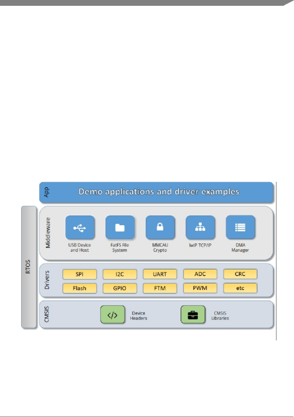
The MCUXpresso SDK architecture consists of five key components listed below.
1. The ARM Cortex Microcontroller Software Interface Standard (CMSIS) CORE compliance device-
specific header files, SOC Header, and CMSIS math/DSP libraries.
2. Peripheral Drivers
3. Real-time Operating Systems (RTOS)
4. Stacks and Middleware that integrate with the MCUXpresso SDK
5. Demo Applications based on the MCUXpresso SDK
Figure 1: MCUXpresso SDK Block Diagram
MCU header files
Each supported MCU device in the MCUXpresso SDK has an overall System-on Chip (SoC) memory-
NXP Semiconductors
MCUXpresso SDK API Reference Manual
7

mapped header file. This header file contains the memory map and register base address for each peripheral
and the IRQ vector table with associated vector numbers. The overall SoC header file provides a access to
the peripheral registers through pointers and predefined bit masks. In addition to the overall SoC memory-
mapped header file, the MCUXpresso SDK includes a feature header file for each device. The feature
header file allows NXP to deliver a single software driver for a given peripheral. The feature file ensures
that the driver is properly compiled for the target SOC.
CMSIS Support
Along with the SoC header files and peripheral extension header files, the MCUXpresso SDK also includes
common CMSIS header files for the ARM Cortex-M core and the math and DSP libraries from the latest
CMSIS release. The CMSIS DSP library source code is also included for reference.
MCUXpresso SDK Peripheral Drivers
The MCUXpresso SDK peripheral drivers mainly consist of low-level functional APIs for the MCU
product family on-chip peripherals and also of high-level transactional APIs for some bus drivers/DM-
A driver/eDMA driver to quickly enable the peripherals and perform transfers.
All MCUXpresso SDK peripheral drivers only depend on the CMSIS headers, device feature files, fsl_-
common.h, and fsl_clock.h files so that users can easily pull selected drivers and their dependencies into
projects. With the exception of the clock/power-relevant peripherals, each peripheral has its own driver.
Peripheral drivers handle the peripheral clock gating/ungating inside the drivers during initialization and
deinitialization respectively.
Low-level functional APIs provide common peripheral functionality, abstracting the hardware peripheral
register accesses into a set of stateless basic functional operations. These APIs primarily focus on the
control, configuration, and function of basic peripheral operations. The APIs hide the register access
details and various MCU peripheral instantiation differences so that the application can be abstracted from
the low-level hardware details. The API prototypes are intentionally similar to help ensure easy portability
across supported MCUXpresso SDK devices.
Transactional APIs provide a quick method for customers to utilize higher-level functionality of the pe-
ripherals. The transactional APIs utilize interrupts and perform asynchronous operations without user
intervention. Transactional APIs operate on high-level logic that requires data storage for internal oper-
ation context handling. However, the Peripheral Drivers do not allocate this memory space. Rather, the
user passes in the memory to the driver for internal driver operation. Transactional APIs ensure the NVIC
is enabled properly inside the drivers. The transactional APIs do not meet all customer needs, but provide
a baseline for development of custom user APIs.
Note that the transactional drivers never disable an NVIC after use. This is due to the shared nature of
interrupt vectors on devices. It is up to the user to ensure that NVIC interrupts are properly disabled after
usage is complete.
Interrupt handling for transactional APIs
A double weak mechanism is introduced for drivers with transactional API. The double weak indicates
two levels of weak vector entries. See the examples below:
PUBWEAK SPI0_IRQHandler
PUBWEAK SPI0_DriverIRQHandler
SPI0_IRQHandler
8
MCUXpresso SDK API Reference Manual
NXP Semiconductors

LDR R0, =SPI0_DriverIRQHandler
BX R0
The first level of the weak implementation are the functions defined in the vector table. In the devices/<-
DEVICE_NAME>/<TOOLCHAIN>/startup_<DEVICE_NAME>.s/.S file, the implementation of the
first layer weak function calls the second layer of weak function. The implementation of the second
layer weak function (ex. SPI0_DriverIRQHandler) jumps to itself (B .). The MCUXpresso SDK drivers
with transactional APIs provide the reimplementation of the second layer function inside of the peripheral
driver. If the MCUXpresso SDK drivers with transactional APIs are linked into the image, the SPI0_-
DriverIRQHandler is replaced with the function implemented in the MCUXpresso SDK SPI driver.
The reason for implementing the double weak functions is to provide a better user experience when using
the transactional APIs. For drivers with a transactional function, call the transactional APIs and the drivers
complete the interrupt-driven flow. Users are not required to redefine the vector entries out of the box. At
the same time, if users are not satisfied by the second layer weak function implemented in the MCU-
Xpresso SDK drivers, users can redefine the first layer weak function and implement their own interrupt
handler functions to suit their implementation.
The limitation of the double weak mechanism is that it cannot be used for peripherals that share the same
vector entry. For this use case, redefine the first layer weak function to enable the desired peripheral
interrupt functionality. For example, if the MCU’s UART0 and UART1 share the same vector entry,
redefine the UART0_UART1_IRQHandler according to the use case requirements.
Feature Header Files
The peripheral drivers are designed to be reusable regardless of the peripheral functional differences from
one MCU device to another. An overall Peripheral Feature Header File is provided for the MCUXpresso
SDK-supported MCU device to define the features or configuration differences for each sub-family device.
Application
See the Getting Started with MCUXpresso SDK document (MCUXSDKGSUG).
NXP Semiconductors
MCUXpresso SDK API Reference Manual
9

10
MCUXpresso SDK API Reference Manual
NXP Semiconductors

Chapter 5
ACMP: Analog Comparator Driver
5.1 Overview
The MCUXpresso SDK provides a peripheral driver for the Comparator (ACMP) module of MCUXpresso
SDK devices.
The ACMP driver is created to help the user better operate the ACMP module. This driver can be consid-
ered as a basic comparator with advanced features. The APIs for a basic comparator can make the CMP
work as a general comparator, which compares the two input channel’s voltage and creates the output of
the comparator result immediately. The APIs for advanced feature can be used as the plug-in function
based on the basic comparator, and can provide more ways to process the comparator’s output.
5.2 Typical use case
Example use of ACMP API.
int main(void)
{
acmp_config_t config;
BOARD_InitHardware();
PRINTF("\r\nACMP example.\r\n");
/*PA24--ACMP0N*/
/*PA25--ACMP0P*/
ACMP_GetDefaultConfig(&config);
config.ch = DEMO_ACMP_USER_CHANNEL;
config.refDiv =kACMP_ReferenceVoltageDivider4;/*0.75V*/
config.refSrc = kACMP_ReferenceSourceVcc;
config.hystEn =kACMP_HysteresisEnable;
ACMP_Init(DEMO_ACMP_BASE, &config);
ACMP_EnableInterrupts(DEMO_ACMP_BASE, DEMO_ACMP_USER_CHANNEL);
ACMP_Enable(DEMO_ACMP_BASE, DEMO_ACMP_USER_CHANNEL);
NVIC_EnableIRQ(ACMP0_IRQn);
while (1)
{
while (!g_AcmpIntFlags)
{
}
PRINTF("\r\nACMP0 interrupt. Input voltage is higher than 0.75V\r\n");
g_AcmpIntFlags = 0;
}
}
Files
• file fsl_acmp.h
NXP Semiconductors
MCUXpresso SDK API Reference Manual
11

Typical use case
Data Structures
• struct acmp_config_t
Describes ACMP configuration structure. More...
Enumerations
• enum acmp_channel_t {
kACMP_Channel0 = 0U,
kACMP_Channel1 = 1U }
Analog comparator channel.
• enum acmp_reference_voltage_source_t
Analog comparator reference voltage source.
• enum acmp_hysteresis_t {
kACMP_HysteresisDisable = 0U,
kACMP_HysteresisEnable = 1U }
Analog comparator hysteresis status.
• enum acmp_triger_edge_t
Analog comparator interrupt triger edge.
• enum acmp_reference_voltage_divider_t {
kACMP_ReferenceVoltageDivider1 = 1U,
kACMP_ReferenceVoltageDivider2,
kACMP_ReferenceVoltageDivider3,
kACMP_ReferenceVoltageDivider4,
kACMP_ReferenceVoltageDivider5,
kACMP_ReferenceVoltageDivider6,
kACMP_ReferenceVoltageDivider7,
kACMP_ReferenceVoltageDivider8,
kACMP_ReferenceVoltageDivider9,
kACMP_ReferenceVoltageDivider10,
kACMP_ReferenceVoltageDivider11,
kACMP_ReferenceVoltageDivider12,
kACMP_ReferenceVoltageDivider13,
kACMP_ReferenceVoltageDivider14,
kACMP_ReferenceVoltageDivider15 }
Analog comparator reference voltage divider.
Functions
• void ACMP_Init (SYSCON_Type ∗base, const acmp_config_t ∗config)
Initializes the ACMP with configuration.
• void ACMP_Enable (SYSCON_Type ∗base, acmp_channel_t ch)
Enable the ACMP module.
• void ACMP_Disable (SYSCON_Type ∗base, acmp_channel_t ch)
Disable the ACMP module.
• void ACMP_EnableInterrupts (SYSCON_Type ∗base, acmp_channel_t ch)
Enables the ACMP interrupt.
• void ACMP_DisableInterrupts (SYSCON_Type ∗base, acmp_channel_t ch)
Disables the ACMP interrupt.
12
MCUXpresso SDK API Reference Manual
NXP Semiconductors

Enumeration Type Documentation
• uint8_t ACMP_GetValue (SYSCON_Type ∗base, acmp_channel_t ch)
Get the ACMP value.
• static void ACMP_Deinit (SYSCON_Type ∗base)
Disable the ACMP module.
• void ACMP_GetDefaultConfig (acmp_config_t ∗config)
Gets the default configuration structure.
Driver version
• #define FSL_ACMP_DRIVER_VERSION (MAKE_VERSION(2, 0, 0))
QN ACMP driver version.
5.3 Data Structure Documentation
5.3.1 struct acmp_config_t
Data Fields
•acmp_channel_t ch
Analog comparator channel.
•acmp_reference_voltage_source_t refSrc
Analog comparator reference voltage source.
•acmp_reference_voltage_divider_t refDiv
Analog comparator reference voltage divider.
•acmp_hysteresis_t hystEn
Analog comparator hysteresis.
•acmp_triger_edge_t trigerEdge
Analog comparator channel.
5.4 Enumeration Type Documentation
5.4.1 enum acmp_channel_t
Enumerator
kACMP_Channel0 Analog comparator channel 0.
kACMP_Channel1 Analog comparator channel 1.
5.4.2 enum acmp_hysteresis_t
Enumerator
kACMP_HysteresisDisable Analog comparator disable Hysteresis.
kACMP_HysteresisEnable Analog comparator enable Hysteresis.
NXP Semiconductors
MCUXpresso SDK API Reference Manual
13

Function Documentation
5.4.3 enum acmp_reference_voltage_divider_t
Enumerator
kACMP_ReferenceVoltageDivider1 Set reference valtage to 1/16 Band-Gap Voltage or Vcc.
kACMP_ReferenceVoltageDivider2 Set reference valtage to 2/16 Band-Gap Voltage or Vcc.
kACMP_ReferenceVoltageDivider3 Set reference valtage to 3/16 Band-Gap Voltage or Vcc.
kACMP_ReferenceVoltageDivider4 Set reference valtage to 4/16 Band-Gap Voltage or Vcc.
kACMP_ReferenceVoltageDivider5 Set reference valtage to 5/16 Band-Gap Voltage or Vcc.
kACMP_ReferenceVoltageDivider6 Set reference valtage to 6/16 Band-Gap Voltage or Vcc.
kACMP_ReferenceVoltageDivider7 Set reference valtage to 7/16 Band-Gap Voltage or Vcc.
kACMP_ReferenceVoltageDivider8 Set reference valtage to 8/16 Band-Gap Voltage or Vcc.
kACMP_ReferenceVoltageDivider9 Set reference valtage to 9/16 Band-Gap Voltage or Vcc.
kACMP_ReferenceVoltageDivider10 Set reference valtage to 10/16 Band-Gap Voltage or Vcc.
kACMP_ReferenceVoltageDivider11 Set reference valtage to 11/16 Band-Gap Voltage or Vcc.
kACMP_ReferenceVoltageDivider12 Set reference valtage to 12/16 Band-Gap Voltage or Vcc.
kACMP_ReferenceVoltageDivider13 Set reference valtage to 13/16 Band-Gap Voltage or Vcc.
kACMP_ReferenceVoltageDivider14 Set reference valtage to 14/16 Band-Gap Voltage or Vcc.
kACMP_ReferenceVoltageDivider15 Set reference valtage to 15/16 Band-Gap Voltage or Vcc.
5.5 Function Documentation
5.5.1 void ACMP_Init ( SYSCON_Type ∗base, const acmp_config_t ∗config )
This function configures the ACMP module with the user-defined settings.
Parameters
base ACMP peripheral base address.
config pointer to configuration structure
5.5.2 void ACMP_Enable ( SYSCON_Type ∗base, acmp_channel_t ch )
This function enable the ACMP module.
Parameters
base ACMP peripheral base address.
14
MCUXpresso SDK API Reference Manual
NXP Semiconductors

Function Documentation
ch Specified the channel to be enabled
5.5.3 void ACMP_Disable ( SYSCON_Type ∗base, acmp_channel_t ch )
This function disable the ACMP module.
Parameters
base ACMP peripheral base address.
ch Specified the channel to be disabled
5.5.4 void ACMP_EnableInterrupts ( SYSCON_Type ∗base, acmp_channel_t ch )
This function enables the ACMP interrupt.
Parameters
base ACMP peripheral base address.
ch Specified the channel.
5.5.5 void ACMP_DisableInterrupts ( SYSCON_Type ∗base, acmp_channel_t ch )
This function disables the ACMP interrupt.
Parameters
base ACMP peripheral base address.
ch Specified the channel
5.5.6 uint8_t ACMP_GetValue ( SYSCON_Type ∗base, acmp_channel_t ch )
This function get ACMP output value.
NXP Semiconductors
MCUXpresso SDK API Reference Manual
15

Function Documentation
Parameters
base ACMP peripheral base address.
ch Specified the channel
Returns
acmp value
5.5.7 static void ACMP_Deinit ( SYSCON_Type ∗base )[inline],[static]
This function disable the ACMP module.
Parameters
base ACMP peripheral base address.
5.5.8 void ACMP_GetDefaultConfig ( acmp_config_t ∗config )
This function initializes the ACMP configuration structure to a default value. The default values are:
config->ch = kACMP_Channel0; config->refSrc = kACMP_ReferenceSourceExternalReferenceVoltage;
config->hystEn = kACMP_HysteresisDisable; config->trigerEdge = kACMP_TrigerRising; config->ref-
Div = kACMP_ReferenceVoltageDivider1;
Parameters
config Pointer to configuration structure.
16
MCUXpresso SDK API Reference Manual
NXP Semiconductors

Chapter 6
ADC: 16-bit sigma-delta Analog-to-Digital Converter Driver
6.1 Overview
The MCUXpresso SDK provides a peripheral driver for the 16-bit sigma-delta Analog-to-Digital Con-
verter (ADC) module of MCUXpresso SDK devices.
6.2 Typical use case
Example use of ADC API.
6.2.1 Basic Configuration
static void ADC_Configuration(void)
{
adc_config_t adcConfigStruct;
adc_sd_config_t adcSdConfigStruct;
ADC_GetDefaultConfig(&adcConfigStruct);
adcConfigStruct.channelEnable = (1U << DEMO_ADC_CHANNEL);
adcConfigStruct.channelConfig = (DEMO_ADC_CFG_IDX << DEMO_ADC_CHANNEL);
adcConfigStruct.triggerSource = DEMO_ADC_TRIGGER;
adcConfigStruct.convMode =kADC_ConvModeSingle;
ADC_Init(DEMO_ADC_BASE, &adcConfigStruct);
/*Initial ADC Sigma Delta(SD) configuration */
ADC_GetSdDefaultConfig(&adcSdConfigStruct);
ADC_SetSdConfig(DEMO_ADC_BASE, DEMO_ADC_CFG_IDX, &adcSdConfigStruct);
/*Bandgap voltage */
g_AdcBandgap = ADC_GetBandgapCalibrationResult(DEMO_ADC_BASE,
DEMO_ADC_CFG_IDX);
/*Calibration VINN value */
g_AdcVinn = ADC_GetVinnCalibrationResult(DEMO_ADC_BASE, &adcConfigStruct);
/*Enable ADC */
ADC_Enable(DEMO_ADC_BASE, true);
}
Files
• file fsl_adc.h
Data Structures
• struct adc_config_t
Define structure for configuring the block. More...
• struct adc_sd_config_t
Define structure for configuring Sigma Delta(SD) block. More...
NXP Semiconductors
MCUXpresso SDK API Reference Manual
17

Typical use case
• struct adc_window_compare_config_t
ADC window comparison configuration. More...
Enumerations
• enum adc_clock_t
Clock source.
• enum adc_ref_source_t {
kADC_RefSourceBandgapWithDriver = 0U,
kADC_RefSourceExtWithDriver,
kADC_RefSourceExtWithoutDriver,
kADC_RefSourceVccWithDriver }
Reference voltage source.
• enum adc_data_format_t
Data format.
• enum adc_down_sample_t {
kADC_DownSample32 = 1U,
kADC_DownSample64 = 3U,
kADC_DownSample128 = 5U,
kADC_DownSample256 = 4U }
Cic down sample rate.
• enum adc_ref_gain_t {
kADC_RefGain1 = 0U,
kADC_RefGain1P5 }
ADC reference gain.
• enum adc_gain_t {
kADC_Gain0P5 = 0U,
kADC_Gain1,
kADC_Gain1P5,
kADC_Gain2 }
ADC gain.
• enum adc_vinn_select_t {
kADC_VinnSelectVref = 0U,
kADC_VinnSelectVref0P75,
kADC_VinnSelectVref0P5,
kADC_VinnSelectAvss }
ADC vinn select.
• enum adc_pga_gain_t {
kADC_PgaBypass = ADC_CFG_PGA_BP(1),
kADC_PgaGain1 = ADC_CFG_PGA_GAIN(0),
kADC_PgaGain2 = ADC_CFG_PGA_GAIN(1),
kADC_PgaGain4 = ADC_CFG_PGA_GAIN(2),
kADC_PgaGain8 = ADC_CFG_PGA_GAIN(3),
kADC_PgaGain16 = ADC_CFG_PGA_GAIN(4) }
PGA gain.
• enum adc_conv_mode_t {
18
MCUXpresso SDK API Reference Manual
NXP Semiconductors

Typical use case
kADC_ConvModeSingle = (ADC_CTRL_CONV_MODE(1) |ADC_CTRL_SCAN_EN(0)),
kADC_ConvModeBurst = (ADC_CTRL_CONV_MODE(0) |ADC_CTRL_SCAN_EN(0)),
kADC_ConvModeSingleScan = (ADC_CTRL_CONV_MODE(1) |ADC_CTRL_SCAN_EN(1)),
kADC_ConvModeBurstScan = (ADC_CTRL_CONV_MODE(0) |ADC_CTRL_SCAN_EN(1)) }
Convert mode.
• enum adc_pga_adjust_direction_t {
kADC_PgaAdjustMoveDown = 0U,
kADC_PgaAdjustMoveUp }
PGA adjust direction.
• enum adc_vcm_voltage_t {
kADC_VcmVoltage1D16 = 0U,
kADC_VcmVoltage1D8,
kADC_VcmVoltage2D8,
kADC_VcmVoltage3D8,
kADC_VcmVoltage4D8,
kADC_VcmVoltage5D8,
kADC_VcmVoltage6D8,
kADC_VcmVoltage7D8 }
VCM voltage select.
• enum _adc_interrupt_enable {
kADC_InterruptMaskEnable = (int)ADC_INTEN_ADC_INTEN_MASK,
kADC_InterruptDataReadyEnable = ADC_INTEN_DAT_RDY_INTEN_MASK,
kADC_InterruptCompareEnable = ADC_INTEN_WCMP_INTEN_MASK,
kADC_InterruptOverflowEnable = ADC_INTEN_FIFO_OF_INTEN_MASK }
Interrupts.
• enum _adc_status_flags {
kADC_InterruptFlag = (int)ADC_INT_ADC_INT_MASK,
kADC_DataReadyFlag = ADC_INT_DAT_RDY_INT_MASK,
kADC_WindowCompareFlag = ADC_INT_WCMP_INT_MASK,
kADC_OverflowFlag = ADC_INT_FIFO_OF_INT_MASK }
Status flag.
• enum adc_trigger_select_t {
NXP Semiconductors
MCUXpresso SDK API Reference Manual
19

Typical use case
kADC_TriggerSelectGPIOA0 = 0U,
kADC_TriggerSelectGPIOA1 = 1U,
kADC_TriggerSelectGPIOA2 = 2U,
kADC_TriggerSelectGPIOA3 = 3U,
kADC_TriggerSelectGPIOA4 = 4U,
kADC_TriggerSelectGPIOA5 = 5U,
kADC_TriggerSelectGPIOA6 = 6U,
kADC_TriggerSelectGPIOA7 = 7U,
kADC_TriggerSelectGPIOA8 = 8U,
kADC_TriggerSelectGPIOA9 = 9U,
kADC_TriggerSelectGPIOA10 = 10U,
kADC_TriggerSelectGPIOA11 = 11U,
kADC_TriggerSelectGPIOA12 = 12U,
kADC_TriggerSelectGPIOA13 = 13U,
kADC_TriggerSelectGPIOA14 = 14U,
kADC_TriggerSelectGPIOA15 = 15U,
kADC_TriggerSelectGPIOA16 = 16U,
kADC_TriggerSelectGPIOA17 = 17U,
kADC_TriggerSelectGPIOA18 = 18U,
kADC_TriggerSelectGPIOA19 = 19U,
kADC_TriggerSelectGPIOA20 = 20U,
kADC_TriggerSelectGPIOA21 = 21U,
kADC_TriggerSelectGPIOA22 = 22U,
kADC_TriggerSelectGPIOA23 = 23U,
kADC_TriggerSelectGPIOA24 = 24U,
kADC_TriggerSelectGPIOA25 = 25U,
kADC_TriggerSelectGPIOA26 = 26U,
kADC_TriggerSelectGPIOA27 = 27U,
kADC_TriggerSelectGPIOA28 = 28U,
kADC_TriggerSelectGPIOA29 = 29U,
kADC_TriggerSelectGPIOA30 = 30U,
kADC_TriggerSelectGPIOA31 = 31U,
kADC_TriggerSelectGPIOB0 = 32u,
kADC_TriggerSelectGPIOB1 = 33u,
kADC_TriggerSelectGPIOB2 = 34u,
kADC_TriggerSelectSoftware = 35U,
kADC_TriggerSelectRNG = 36U,
kADC_TriggerSelectPWMOUT0 = 38U,
kADC_TriggerSelectPWMOUT1 = 39U,
kADC_TriggerSelectPWMOUT2 = 40U,
kADC_TriggerSelectPWMOUT3 = 41U,
kADC_TriggerSelectPWMOUT4 = 42U,
kADC_TriggerSelectPWMOUT5 = 43U,
kADC_TriggerSelectPWMOUT6 = 44U,
kADC_TriggerSelectPWMOUT7 = 45U,
kADC_TriggerSelectPWMOUT8 = 46U,
kADC_TriggerSelectPWMOUT9 = 47U,
kADC_TriggerSelectTIMER0OUT0 = 48U,
kADC_TriggerSelectTIMER0OUT1 = 49U,
kADC_TriggerSelectTIMER0OUT2 = 50U,
kADC_TriggerSelectTIMER0OUT3 = 51U,
kADC_TriggerSelectTIMER1OUT0 = 52U,
kADC_TriggerSelectTIMER1OUT1 = 53U,
kADC_TriggerSelectTIMER1OUT2 = 54U,
kADC_TriggerSelectTIMER1OUT3 = 55U,
kADC_TriggerSelectTIMER2OUT0 = 56U,
kADC_TriggerSelectTIMER2OUT1 = 57U,
kADC_TriggerSelectTIMER2OUT2 = 58U,
kADC_TriggerSelectTIMER2OUT3 = 59U,
kADC_TriggerSelectTIMER3OUT0 = 60U,
kADC_TriggerSelectTIMER3OUT1 = 61U,
kADC_TriggerSelectTIMER3OUT2 = 62U,
20
MCUXpresso SDK API Reference Manual
NXP Semiconductors

Typical use case
kADC_TriggerSelectTIMER3OUT3 = 63U }
Driver version
• #define FSL_ADC_DRIVER_VERSION (MAKE_VERSION(2, 0, 0))
QN ADC driver version 2.0.0.
Initialization
• void ADC_Init (ADC_Type ∗base, const adc_config_t ∗config)
Initialize the ADC module.
• void ADC_Deinit (ADC_Type ∗base)
Deinitialize the ADC module.
• void ADC_GetDefaultConfig (adc_config_t ∗config)
Gets an available pre-defined settings for initial configuration.
• void ADC_SetSdConfig (ADC_Type ∗base, uint8_t idx, const adc_sd_config_t ∗config)
Set the sigma delta configuration.
• void ADC_GetSdDefaultConfig (adc_sd_config_t ∗config)
Gets an available pre-defined settings for SD configuration.
• float ADC_GetBandgapCalibrationResult (ADC_Type ∗base, uint8_t idx)
Get Bandgap calibration result.
• uint32_t ADC_GetVinnCalibrationResult (ADC_Type ∗base, const adc_config_t ∗config)
Get VINN calibration result.
• uint32_t ADC_GetOffsetCalibrationResult (ADC_Type ∗base, const adc_config_t ∗config)
Get VINN calibration result.
• static void ADC_EnableTemperatureSensor (ADC_Type ∗base, bool enable)
Enable the internal temperature sensor measurement.
• static void ADC_EnableBatteryMonitor (bool enable)
Enable the internal battery monitor.
• void ADC_WindowCompareConfig (ADC_Type ∗base, const adc_window_compare_config_t
∗config)
Configures the window compare mode.
• static void ADC_Enable (ADC_Type ∗base, bool enable)
Enable/Disable the ADC.
• static void ADC_DoSoftwareTrigger (ADC_Type ∗base)
Do trigger conversion by software.
Interrupts.
• static void ADC_EnableInterrupts (ADC_Type ∗base, uint32_t mask)
Enable interrupts for conversion sequences.
• static void ADC_DisableInterrupts (ADC_Type ∗base, uint32_t mask)
Disable interrupts for conversion sequences.
Status.
• static uint32_t ADC_GetStatusFlags (ADC_Type ∗base)
Get status flags of ADC module.
• static void ADC_ClearStatusFlags (ADC_Type ∗base, uint32_t mask)
Clear status flags of ADC module.
NXP Semiconductors
MCUXpresso SDK API Reference Manual
21

Data Structure Documentation
Data result.
• static uint32_t ADC_GetConversionResult (ADC_Type ∗base)
Get the conversion value.
• float ADC_ConversionResult2Mv (ADC_Type ∗base, uint8_t ch, uint8_t idx, float vref, uint32_t
vinn, uint32_t result)
Conversion result to mv.
• static void ADC_EmptyChannelConversionBuffer (ADC_Type ∗base)
Empty conversion buffer.
Advanced Features
• static void ADC_EnableInputSignalInvert (ADC_Type ∗base, bool enable)
Enable/Disable the signal invert.
• static void ADC_PgaChopperEnable (ADC_Type ∗base, bool enable)
Enable/Disable the PGA chopper.
6.3 Data Structure Documentation
6.3.1 struct adc_config_t
Data Fields
• uint32_t channelEnable
Channel enable, each bit represent one channel.
• uint32_t channelConfig
Channel configure for Sigma Delta(SD) select, 0: indicate the channel use SD configure0 1: indicate the
channel use SD configura1.
•adc_trigger_select_t triggerSource
Triger source select, only one triger source can be selected.
•adc_conv_mode_t convMode
Convert mode.
•adc_clock_t clock
Select the ADC working clock.
•adc_ref_source_t refSource
Select the reference voltage source.
•adc_data_format_t dataFormat
Select the Data format.
6.3.1.0.0.1 Field Documentation
6.3.1.0.0.1.1 uint32_t adc_config_t::channelConfig
6.3.1.0.0.1.2 adc_trigger_select_t adc_config_t::triggerSource
6.3.1.0.0.1.3 adc_conv_mode_t adc_config_t::convMode
Single convert, only one conversion performed and the first channel from LSB with 1 set will be converted.
Burst convert, stop until ADC enable bit cleared and the first channel from LSB with 1 set will be con-
verted. Single Scan convert, scan all channels with 1 set , automatic stoped after all channels conversion
22
MCUXpresso SDK API Reference Manual
NXP Semiconductors

Macro Definition Documentation
complete. Burst Scan convert, scan all channels with 1 set , stop until ADC enable bit cleared
6.3.1.0.0.1.4 adc_ref_source_t adc_config_t::refSource
6.3.2 struct adc_sd_config_t
Data Fields
•adc_gain_t gain
ADC gain.
•adc_ref_gain_t refGain
ADC reference gain.
•adc_pga_gain_t pgaGain
PGA gain.
•adc_vinn_select_t vinnSelect
Vinn select, take effect when single-ended channel configured.
•adc_down_sample_t downSample
Down sample rate.
•adc_pga_adjust_direction_t adjustDirection
PGA adjust direction.
• uint8_t adjustValue
PGA adjust value,Passing 0 to disable PGA adjust feature adjustment = (adjustValue[5] + 1)∗(adjust-
Value[3:0] + 1)∗40mv.
•adc_vcm_voltage_t vcmSelect
ADC input Voltage of Common Mode(VCM) selection.
6.3.3 struct adc_window_compare_config_t
Data Fields
• int16_t lowValue
Setting window low threshold.
• int16_t highValue
Setting window high threshold.
6.3.3.0.0.2 Field Documentation
6.3.3.0.0.2.1 int16_t adc_window_compare_config_t::lowValue
6.3.3.0.0.2.2 int16_t adc_window_compare_config_t::highValue
6.4 Macro Definition Documentation
6.4.1 #define FSL_ADC_DRIVER_VERSION (MAKE_VERSION(2, 0, 0))
NXP Semiconductors
MCUXpresso SDK API Reference Manual
23

Enumeration Type Documentation
6.5 Enumeration Type Documentation
6.5.1 enum adc_ref_source_t
Enumerator
kADC_RefSourceBandgapWithDriver Internal 1.2v.
kADC_RefSourceExtWithDriver External reference with driver .
kADC_RefSourceExtWithoutDriver External reference without driver .
kADC_RefSourceVccWithDriver VCC.
6.5.2 enum adc_down_sample_t
Enumerator
kADC_DownSample32 Down sample 32.
kADC_DownSample64 Down sample 64.
kADC_DownSample128 Down sample 128.
kADC_DownSample256 Down sample 256.
6.5.3 enum adc_ref_gain_t
Enumerator
kADC_RefGain1 Reference gain 1.
kADC_RefGain1P5 Reference gain 1.5.
6.5.4 enum adc_gain_t
Enumerator
kADC_Gain0P5 ADC gain 0.5.
kADC_Gain1 ADC gain 1.
kADC_Gain1P5 ADC gain 1.5.
kADC_Gain2 ADC gain 2.
6.5.5 enum adc_vinn_select_t
Enumerator
kADC_VinnSelectVref Select Vref as VINN.
24
MCUXpresso SDK API Reference Manual
NXP Semiconductors

Enumeration Type Documentation
kADC_VinnSelectVref0P75 Select 0.75Vref as VINN.
kADC_VinnSelectVref0P5 Select 0.5Vref as VINN.
kADC_VinnSelectAvss Select AVSS as VINN.
6.5.6 enum adc_pga_gain_t
Enumerator
kADC_PgaBypass PGA bypass.
kADC_PgaGain1 PGA gain 1.
kADC_PgaGain2 PGA gain 2.
kADC_PgaGain4 PGA gain 4.
kADC_PgaGain8 PGA gain 8.
kADC_PgaGain16 PGA gain 16.
6.5.7 enum adc_conv_mode_t
Enumerator
kADC_ConvModeSingle Single convert mode.
kADC_ConvModeBurst Burst convert mode.
kADC_ConvModeSingleScan Single scan convert mode.
kADC_ConvModeBurstScan Burst scan convert mode.
6.5.8 enum adc_pga_adjust_direction_t
Enumerator
kADC_PgaAdjustMoveDown PGA adjust move down.
kADC_PgaAdjustMoveUp PGA adjust move up.
6.5.9 enum adc_vcm_voltage_t
Enumerator
kADC_VcmVoltage1D16 VCM voltage selection 1/16VCC.
kADC_VcmVoltage1D8 VCM voltage selection 1/8VCC.
kADC_VcmVoltage2D8 VCM voltage selection 2/8VCC.
kADC_VcmVoltage3D8 VCM voltage selection 3/8VCC.
kADC_VcmVoltage4D8 VCM voltage selection 4/8VCC.
NXP Semiconductors
MCUXpresso SDK API Reference Manual
25

Enumeration Type Documentation
kADC_VcmVoltage5D8 VCM voltage selection 5/8VCC.
kADC_VcmVoltage6D8 VCM voltage selection 6/8VCC.
kADC_VcmVoltage7D8 VCM voltage selection 7/8VCC.
6.5.10 enum _adc_interrupt_enable
Note
kADC_InterruptMaskEnable item is the ADC interrupts mask
Enumerator
kADC_InterruptMaskEnable Interrupt enalbe mask.
kADC_InterruptDataReadyEnable Data ready interrupt enable.
kADC_InterruptCompareEnable Window comparation interrupt enable.
kADC_InterruptOverflowEnable Fifo overflow enable.
6.5.11 enum _adc_status_flags
Enumerator
kADC_InterruptFlag Interrupt flag.
kADC_DataReadyFlag Data ready flag.
kADC_WindowCompareFlag Window comparation flag.
kADC_OverflowFlag Fifo overflow flag.
6.5.12 enum adc_trigger_select_t
Enumerator
kADC_TriggerSelectGPIOA0 GPIOA0 trigger.
kADC_TriggerSelectGPIOA1 GPIOA1 trigger.
kADC_TriggerSelectGPIOA2 GPIOA2 trigger.
kADC_TriggerSelectGPIOA3 GPIOA3 trigger.
kADC_TriggerSelectGPIOA4 GPIOA4 trigger.
kADC_TriggerSelectGPIOA5 GPIOA5 trigger.
kADC_TriggerSelectGPIOA6 GPIOA6 trigger.
kADC_TriggerSelectGPIOA7 GPIOA7 trigger.
kADC_TriggerSelectGPIOA8 GPIOA8 trigger.
kADC_TriggerSelectGPIOA9 GPIOA9 trigger.
kADC_TriggerSelectGPIOA10 GPIOA10 trigger.
kADC_TriggerSelectGPIOA11 GPIOA11 trigger.
26
MCUXpresso SDK API Reference Manual
NXP Semiconductors

Enumeration Type Documentation
kADC_TriggerSelectGPIOA12 GPIOA12 trigger.
kADC_TriggerSelectGPIOA13 GPIOA13 trigger.
kADC_TriggerSelectGPIOA14 GPIOA14 trigger.
kADC_TriggerSelectGPIOA15 GPIOA15 trigger.
kADC_TriggerSelectGPIOA16 GPIOA16 trigger.
kADC_TriggerSelectGPIOA17 GPIOA17 trigger.
kADC_TriggerSelectGPIOA18 GPIOA18 trigger.
kADC_TriggerSelectGPIOA19 GPIOA19 trigger.
kADC_TriggerSelectGPIOA20 GPIOA20 trigger.
kADC_TriggerSelectGPIOA21 GPIOA21 trigger.
kADC_TriggerSelectGPIOA22 GPIOA22 trigger.
kADC_TriggerSelectGPIOA23 GPIOA23 trigger.
kADC_TriggerSelectGPIOA24 GPIOA24 trigger.
kADC_TriggerSelectGPIOA25 GPIOA25 trigger.
kADC_TriggerSelectGPIOA26 GPIOA26 trigger.
kADC_TriggerSelectGPIOA27 GPIOA27 trigger.
kADC_TriggerSelectGPIOA28 GPIOA28 trigger.
kADC_TriggerSelectGPIOA29 GPIOA29 trigger.
kADC_TriggerSelectGPIOA30 GPIOA30 trigger.
kADC_TriggerSelectGPIOA31 GPIOA31 trigger.
kADC_TriggerSelectGPIOB0 GPIOB0 trigger.
kADC_TriggerSelectGPIOB1 GPIOB1 trigger.
kADC_TriggerSelectGPIOB2 GPIOB2 trigger.
kADC_TriggerSelectSoftware Software trigger.
kADC_TriggerSelectRNG RNG trigger.
kADC_TriggerSelectPWMOUT0 PWMOUT0 trigger.
kADC_TriggerSelectPWMOUT1 PWMOUT1 trigger.
kADC_TriggerSelectPWMOUT2 PWMOUT2 trigger.
kADC_TriggerSelectPWMOUT3 PWMOUT3 trigger.
kADC_TriggerSelectPWMOUT4 PWMOUT4 trigger.
kADC_TriggerSelectPWMOUT5 PWMOUT5 trigger.
kADC_TriggerSelectPWMOUT6 PWMOUT6 trigger.
kADC_TriggerSelectPWMOUT7 PWMOUT7 trigger.
kADC_TriggerSelectPWMOUT8 PWMOUT8 trigger.
kADC_TriggerSelectPWMOUT9 PWMOUT9 trigger.
kADC_TriggerSelectTIMER0OUT0 TIMER0OUT0 trigger.
kADC_TriggerSelectTIMER0OUT1 TIMER0OUT1 trigger.
kADC_TriggerSelectTIMER0OUT2 TIMER0OUT2 trigger.
kADC_TriggerSelectTIMER0OUT3 TIMER0OUT3 trigger.
kADC_TriggerSelectTIMER1OUT0 TIMER1OUT0 trigger.
kADC_TriggerSelectTIMER1OUT1 TIMER1OUT1 trigger.
kADC_TriggerSelectTIMER1OUT2 TIMER1OUT2 trigger.
kADC_TriggerSelectTIMER1OUT3 TIMER1OUT3 trigger.
kADC_TriggerSelectTIMER2OUT0 TIMER2OUT0 trigger.
kADC_TriggerSelectTIMER2OUT1 TIMER2OUT1 trigger.
NXP Semiconductors
MCUXpresso SDK API Reference Manual
27

Function Documentation
kADC_TriggerSelectTIMER2OUT2 TIMER2OUT2 trigger.
kADC_TriggerSelectTIMER2OUT3 TIMER2OUT3 trigger.
kADC_TriggerSelectTIMER3OUT0 TIMER3OUT0 trigger.
kADC_TriggerSelectTIMER3OUT1 TIMER3OUT1 trigger.
kADC_TriggerSelectTIMER3OUT2 TIMER3OUT2 trigger.
kADC_TriggerSelectTIMER3OUT3 TIMER3OUT3 trigger.
6.6 Function Documentation
6.6.1 void ADC_Init ( ADC_Type ∗base, const adc_config_t ∗config )
This function initializes the ADC module, including:
• Enable ADC module clock.
• Reset ADC module.
• Configure the ADC with user configuration.
Parameters
base ADC peripheral base address.
config Pointer to configuration structure, see to adc_config_t.
6.6.2 void ADC_Deinit ( ADC_Type ∗base )
This function de-nitializes the ADC module, including:
• Disable the ADC module clock.
Parameters
base ADC peripheral base address.
6.6.3 void ADC_GetDefaultConfig ( adc_config_t ∗config )
This function initializes the initial configuration structure with an available settings. The default values
are:
*config->channelEnable = 0;
*config->channelConfig = 0;
*config->triggerSource = kADC_TriggerSelectSoftware;
*config->convMode = kADC_ConvModeSingle;
*config->clock = kADC_Clock500K;
*config->refSource = kADC_RefSourceBandgapWithDriver;
*config->dataFormat = kADC_DataFormat1WithIdx;
*
28
MCUXpresso SDK API Reference Manual
NXP Semiconductors

Function Documentation
Parameters
config Pointer to configuration structure.
6.6.4 void ADC_SetSdConfig ( ADC_Type ∗base, uint8_t idx, const
adc_sd_config_t ∗config )
This function set the sigma delta with user configuration. There are two SD configuration registers, and
the idx parameter is used to choose the register.
Parameters
base ADC peripheral base address.
idx Configure register index, 0 for register CFG0 and 1 for register CFG1
config Pointer to the "adc_sd_config_t" structure
6.6.5 void ADC_GetSdDefaultConfig ( adc_sd_config_t ∗config )
This function initializes the initial configuration structure with an available settings. The default values
are:
*config->gain = kADC_Gain1;
*config->refGain = kADC_RefGain1P5;
*config->pgaGain = kADC_PgaGain1;
*config->vinnSelect = kADC_VinnSelectVref0P75;
*config->downSample = kADC_DownSample256;
*config->adjustDirection = kADC_PgaAdjustMoveDown;
*config->adjustValue = 0;
*config->vcmSelect = kADC_VcmVoltage4D8;
*
Parameters
config Pointer to configuration structure.
6.6.6 float ADC_GetBandgapCalibrationResult ( ADC_Type ∗base, uint8_t idx )
NXP Semiconductors
MCUXpresso SDK API Reference Manual
29

Function Documentation
Parameters
base ADC peripheral base address.
Returns
Bandgap voltage in mv.
6.6.7 uint32_t ADC_GetVinnCalibrationResult ( ADC_Type ∗base, const
adc_config_t ∗config )
This function is use to measure the VINN value with channel 20.
Parameters
base ADC peripheral base address.
idx Configure register index, 0 for register CFG0 and 1 for register CFG1.
Returns
VINN calibration result.
6.6.8 uint32_t ADC_GetOffsetCalibrationResult ( ADC_Type ∗base, const
adc_config_t ∗config )
This function is use to measure the offset value with channel 15.
Parameters
base ADC peripheral base address.
idx Configure register index, 0 for register CFG0 and 1 for register CFG1.
Returns
Offset calibration result.
6.6.9 static void ADC_EnableTemperatureSensor ( ADC_Type ∗base, bool enable
)[inline],[static]
30
MCUXpresso SDK API Reference Manual
NXP Semiconductors

Function Documentation
Parameters
base ADC peripheral base address.
enable Switcher to enable the feature or not.
6.6.10 static void ADC_EnableBatteryMonitor ( bool enable )[inline],
[static]
Parameters
enable Switcher to enable the feature or not.
6.6.11 void ADC_WindowCompareConfig ( ADC_Type ∗base, const
adc_window_compare_config_t ∗config )
Parameters
base ADC peripheral base address.
config Pointer to the "adc_window_compare_config_t" structure. Passing "NULL" disables
the feature.
6.6.12 static void ADC_Enable ( ADC_Type ∗base, bool enable )[inline],
[static]
Parameters
base ADC peripheral base address.
enable true to enable the ADC, false to disable.
6.6.13 static void ADC_DoSoftwareTrigger ( ADC_Type ∗base )[inline],
[static]
NXP Semiconductors
MCUXpresso SDK API Reference Manual
31

Function Documentation
Parameters
base ADC peripheral base address.
6.6.14 static void ADC_EnableInterrupts ( ADC_Type ∗base, uint32_t mask )
[inline],[static]
Parameters
base ADC peripheral base address.
mask Mask value for the interrupts. See "_adc_interrupt_enable".
6.6.15 static void ADC_DisableInterrupts ( ADC_Type ∗base, uint32_t mask )
[inline],[static]
Parameters
base ADC peripheral base address.
mask Mask value for the interrupts. See "_adc_interrupt_enable".
6.6.16 static uint32_t ADC_GetStatusFlags ( ADC_Type ∗base )[inline],
[static]
Parameters
base ADC peripheral base address.
Returns
Mask of status flags of module. See "_adc_status_flags".
6.6.17 static void ADC_ClearStatusFlags ( ADC_Type ∗base, uint32_t mask )
[inline],[static]
32
MCUXpresso SDK API Reference Manual
NXP Semiconductors

Function Documentation
Parameters
base ADC peripheral base address.
mask Mask of status flags of module, see to "_adc_status_flags".
6.6.18 static uint32_t ADC_GetConversionResult ( ADC_Type ∗base )[inline],
[static]
Parameters
base ADC peripheral base address.
Returns
Conversion result value.
6.6.19 float ADC_ConversionResult2Mv ( ADC_Type ∗base, uint8_t ch, uint8_t
idx, float vref, uint32_t vinn, uint32_t result )
Parameters
base ADC peripheral base address.
ch ADC channel number.
idx Configure register index, 0 for register CFG0 and 1 for register CFG1
verf ADC reference voltage in mv.
vinn ADC conversion result get from ADC_GetConversionResult function.
result ADC conversion result get from ADC_GetConversionResult() function.
Returns
Conversion result in mv.
6.6.20 static void ADC_EmptyChannelConversionBuffer ( ADC_Type ∗base )
[inline],[static]
NXP Semiconductors
MCUXpresso SDK API Reference Manual
33

Function Documentation
Parameters
base ADC peripheral base address.
6.6.21 static void ADC_EnableInputSignalInvert ( ADC_Type ∗base, bool enable )
[inline],[static]
Parameters
base ADC peripheral base address.
enable true to enable the signal invert, false to disable.
6.6.22 static void ADC_PgaChopperEnable ( ADC_Type ∗base, bool enable )
[inline],[static]
Parameters
base ADC peripheral base address.
enable true to enable the PGA chopper, false to disable.
34
MCUXpresso SDK API Reference Manual
NXP Semiconductors

Chapter 7
BOD: Browned Out Detector
7.1 Overview
The MCUXpresso SDK provides a peripheral driver for the Browned Out Detector (BOD) module of
MCUXpresso SDK devices.
7.2 Typical use case
Example use of BOD API.
int main(void)
{
bod_config_t config;
BOARD_InitHardware();
PRINTF("\r\nBOD example.\r\n");
/*Check Reset source(Brown-Down reset source will be set when voltage is less than the user-defined)
*/
if (kRESET_SrcBrownDown == RESET_GetResetSource())
{
PRINTF("Brown-Down reset occurred\r\n");
}
/*Clear reset source */
RESET_ClearResetSource();
BOD_GetDefaultConfig(&config);
config.int_thr = kBOD_InterruptThreshold2;/*2.72V*/
config.reset_thr = kBOD_ResetThreshold2;/*2.0V*/
/*Init BOD module*/
BOD_Init(DEMO_BOD_BASE, &config);
BOD_Enable(DEMO_BOD_BASE, kBOD_InterruptEnable |
kBOD_ResetEnable);
NVIC_EnableIRQ(BOD_IRQn);
while (!g_BodIntFlags)
;
PRINTF("\r\nBOD interrupt. Input voltage is lower than 2.72V\r\n");
PRINTF("CPU will be reset when input voltage is lower than 2.0V\r\n");
while (1)
{
}
}
Files
• file fsl_bod.h
Data Structures
• struct bod_config_t
NXP Semiconductors
MCUXpresso SDK API Reference Manual
35

Enumeration Type Documentation
Describes BOD configuration structure. More...
Enumerations
• enum bod_interrupt_threshold_t {
kBOD_InterruptThreshold0 = 0U,
kBOD_InterruptThreshold1,
kBOD_InterruptThreshold2,
kBOD_InterruptThreshold3 }
BOD interrupt threshold voltages.
• enum bod_reset_threshold_t {
kBOD_ResetThreshold0 = 0U,
kBOD_ResetThreshold1,
kBOD_ResetThreshold2,
kBOD_ResetThreshold3 }
BOD reset threshold voltages.
• enum bod_mode_t {
kBOD_InterruptEnable = 1U,
kBOD_ResetEnable = 2U }
Functions
• void BOD_Init (SYSCON_Type ∗base, const bod_config_t ∗config)
Initializes the BOD with configuration.
• void BOD_Deinit (SYSCON_Type ∗base)
Disable the BOD module.
• void BOD_Enable (SYSCON_Type ∗base, uint8_t mode)
Enable the BOD module.
• void BOD_Disable (SYSCON_Type ∗base, uint8_t mode)
Disable the BOD module.
• void BOD_GetDefaultConfig (bod_config_t ∗config)
Gets the default configuration structure.
BOD Driver version
• #define FSL_BOD_DRIVER_VERSION (MAKE_VERSION(2, 0, 0))
BOD driver version.
7.3 Data Structure Documentation
7.3.1 struct bod_config_t
7.4 Enumeration Type Documentation
7.4.1 enum bod_interrupt_threshold_t
Enumerator
kBOD_InterruptThreshold0 trigger at 2.06V
36
MCUXpresso SDK API Reference Manual
NXP Semiconductors

Function Documentation
kBOD_InterruptThreshold1 trigger at 2.45V
kBOD_InterruptThreshold2 trigger at 2.72V
kBOD_InterruptThreshold3 trigger at 3.04V
7.4.2 enum bod_reset_threshold_t
Enumerator
kBOD_ResetThreshold0 trigger at 1.5V
kBOD_ResetThreshold1 trigger at 1.85V
kBOD_ResetThreshold2 trigger at 2.0V
kBOD_ResetThreshold3 trigger at 3.0V
7.4.3 enum bod_mode_t
Enumerator
kBOD_InterruptEnable interrupt enable
kBOD_ResetEnable reset enable
7.5 Function Documentation
7.5.1 void BOD_Init ( SYSCON_Type ∗base, const bod_config_t ∗config )
This function configures the BOD module with the user-defined settings.
Parameters
base BOD peripheral base address.
config pointer to configuration structure
7.5.2 void BOD_Deinit ( SYSCON_Type ∗base )
This function disable the BOD module.
Parameters
NXP Semiconductors
MCUXpresso SDK API Reference Manual
37

Function Documentation
base BOD peripheral base address.
7.5.3 void BOD_Enable ( SYSCON_Type ∗base, uint8_t mode )
This function enable the ACMP module.
Parameters
base BOD peripheral base address.
mode Specified the work mode to be enabled.The mode is a logical OR of the enumeration
members. see bod_mode_t
7.5.4 void BOD_Disable ( SYSCON_Type ∗base, uint8_t mode )
This function enable the BOD module.
Parameters
base BOD peripheral base address.
mode Specified the work mode to be disabled.The mode is a logical OR of the enumeration
members. see bod_mode_t
7.5.5 void BOD_GetDefaultConfig ( bod_config_t ∗config )
This function initializes the BOD configuration structure to a default value. The default values are: config-
>int_thr = kBOD_InterruptThreshold2; config->reset_thr = kBOD_ResetThreshold2;
Parameters
config Pointer to configuration structure.
38
MCUXpresso SDK API Reference Manual
NXP Semiconductors

Chapter 8
Common Driver
8.1 Overview
The MCUXpresso SDK provides a driver for the common module of MCUXpresso SDK devices.
Files
• file fsl_power.h
Macros
• #define MAKE_STATUS(group, code) ((((group)∗100) + (code)))
Construct a status code value from a group and code number.
• #define MAKE_VERSION(major, minor, bugfix) (((major) << 16) |((minor) << 8) |(bugfix))
Construct the version number for drivers.
• #define DEBUG_CONSOLE_DEVICE_TYPE_NONE 0U
No debug console.
• #define DEBUG_CONSOLE_DEVICE_TYPE_UART 1U
Debug console base on UART.
• #define DEBUG_CONSOLE_DEVICE_TYPE_LPUART 2U
Debug console base on LPUART.
• #define DEBUG_CONSOLE_DEVICE_TYPE_LPSCI 3U
Debug console base on LPSCI.
• #define DEBUG_CONSOLE_DEVICE_TYPE_USBCDC 4U
Debug console base on USBCDC.
• #define DEBUG_CONSOLE_DEVICE_TYPE_FLEXCOMM 5U
Debug console base on USBCDC.
• #define DEBUG_CONSOLE_DEVICE_TYPE_IUART 6U
Debug console base on i.MX UART.
• #define DEBUG_CONSOLE_DEVICE_TYPE_VUSART 7U
Debug console base on LPC_USART.
• #define ARRAY_SIZE(x) (sizeof(x) / sizeof((x)[0]))
Computes the number of elements in an array.
• #define SWDIO_GPIO_PIN 23U
SWDIO pin is used as wakeup source, in order to provide better debug experience.
• #define MAKE_PD_BITS(reg, slot) ((reg << 8) |slot)
Power name used for POWER_EnablePD/POWER_DisablePD.
Typedefs
• typedef int32_t status_t
Type used for all status and error return values.
• typedef void(∗p_POWER_RegisterWakeupEntry )(uint32_t ram_addr)
Register address to bootloader.
NXP Semiconductors
MCUXpresso SDK API Reference Manual
39

Overview
40
MCUXpresso SDK API Reference Manual
NXP Semiconductors

Overview
Enumerations
• enum _status_groups {
kStatusGroup_Generic = 0,
kStatusGroup_FLASH = 1,
kStatusGroup_LPSPI = 4,
kStatusGroup_FLEXIO_SPI = 5,
kStatusGroup_DSPI = 6,
kStatusGroup_FLEXIO_UART = 7,
kStatusGroup_FLEXIO_I2C = 8,
kStatusGroup_LPI2C = 9,
kStatusGroup_UART = 10,
kStatusGroup_I2C = 11,
kStatusGroup_LPSCI = 12,
kStatusGroup_LPUART = 13,
kStatusGroup_SPI = 14,
kStatusGroup_XRDC = 15,
kStatusGroup_SEMA42 = 16,
kStatusGroup_SDHC = 17,
kStatusGroup_SDMMC = 18,
kStatusGroup_SAI = 19,
kStatusGroup_MCG = 20,
kStatusGroup_SCG = 21,
kStatusGroup_SDSPI = 22,
kStatusGroup_FLEXIO_I2S = 23,
kStatusGroup_FLEXIO_MCULCD = 24,
kStatusGroup_FLASHIAP = 25,
kStatusGroup_FLEXCOMM_I2C = 26,
kStatusGroup_I2S = 27,
kStatusGroup_IUART = 28,
kStatusGroup_CSI = 29,
kStatusGroup_SDRAMC = 35,
kStatusGroup_POWER = 39,
kStatusGroup_ENET = 40,
kStatusGroup_PHY = 41,
kStatusGroup_TRGMUX = 42,
kStatusGroup_SMARTCARD = 43,
kStatusGroup_LMEM = 44,
kStatusGroup_QSPI = 45,
kStatusGroup_DMA = 50,
kStatusGroup_EDMA = 51,
kStatusGroup_DMAMGR = 52,
kStatusGroup_FLEXCAN = 53,
kStatusGroup_LTC = 54,
kStatusGroup_FLEXIO_CAMERA = 55,
kStatusGroup_LPC_SPI = 56,
kStatusGroup_LPC_USART = 57,
kStatusGroup_DMIC = 58,
kStatusGroup_SDIF = 59,
kStatusGroup_SPIFI = 60,
kStatusGroup_OTP = 61,
kStatusGroup_MCAN = 62,
kStatusGroup_CAAM = 63,
kStatusGroup_ECSPI = 64,
kStatusGroup_USDHC = 65,
kStatusGroup_ESAI = 69,
kStatusGroup_FLEXSPI = 70,
kStatusGroup_MMDC = 71,
kStatusGroup_MICFIL = 72,
kStatusGroup_SDMA = 73,
kStatusGroup_NOTIFIER = 98,
kStatusGroup_DebugConsole = 99,
NXP Semiconductors
MCUXpresso SDK API Reference Manual
41

Overview
kStatusGroup_ApplicationRangeStart = 100 }
Status group numbers.
• enum _generic_status
Generic status return codes.
• enum power_mode_t {
kPmActive,
kPmSleep,
kPmPowerDown0,
kPmPowerDown1 }
Power modes.
• enum SYSCON_RSTn_t {
kFC0_RST_SHIFT_RSTn = 0,
kFC1_RST_SHIFT_RSTn = 1,
kFC2_RST_SHIFT_RSTn = 2,
kFC3_RST_SHIFT_RSTn = 3,
kTIM0_RST_SHIFT_RSTn = 4,
kTIM1_RST_SHIFT_RSTn = 5,
kTIM2_RST_SHIFT_RSTn = 6,
kTIM3_RST_SHIFT_RSTn = 7,
kSCT0_RST_SHIFT_RSTn = 8,
kWDT_RST_SHIFT_RSTn = 9,
kUSB_RST_SHIFT_RSTn = 10,
kGPIO_RST_SHIFT_RSTn = 11,
kRTC_RST_SHIFT_RSTn = 12,
kADC_RST_SHIFT_RSTn = 13,
kDAC_RST_SHIFT_RSTn = 14,
kCS_RST_SHIFT_RSTn = 15,
kFSP_RST_SHIFT_RSTn = 16,
kDMA_RST_SHIFT_RSTn = 32,
kPINT_RST_SHIFT_RSTn = 32,
kMUX_RST_SHIFT_RSTn = 32,
kQDEC0_RST_SHIFT_RSTn = 19,
kQDEC1_RST_SHIFT_RSTn = 20,
kSPIFI_RST_SHIFT_RSTn = 22,
kCAL_RST_SHIFT_RSTn = 25,
kCPU_RST_SHIFT_RSTn = 26,
kBLE_RST_SHIFT_RSTn = 27,
kFLASH_RST_SHIFT_RSTn = 28,
kDP_RST_SHIFT_RSTn = 29,
kREG_RST_SHIFT_RSTn = 30,
kREBOOT_RST_SHIFT_RSTn = 31 }
Enumeration for peripheral reset control bits.
• enum reset_source_t {
42
MCUXpresso SDK API Reference Manual
NXP Semiconductors

Overview
kRESET_SrcPowerOn,
kRESET_SrcBrownDown,
kRESET_SrcExternalPin,
kRESET_SrcWatchDog,
kRESET_SrcLockUp,
kRESET_SrcReboot,
kRESET_SrcCpuSystem,
kRESET_SrcWakeUp,
kRESET_SrcCpuSoftware }
Reset source.
Functions
• static status_t EnableIRQ (IRQn_Type interrupt)
Enable specific interrupt.
• static status_t DisableIRQ (IRQn_Type interrupt)
Disable specific interrupt.
• static uint32_t DisableGlobalIRQ (void)
Disable the global IRQ.
• static void EnableGlobalIRQ (uint32_t primask)
Enaable the global IRQ.
• uint32_t InstallIRQHandler (IRQn_Type irq, uint32_t irqHandler)
install IRQ handler
• void EnableDeepSleepIRQ (IRQn_Type interrupt)
Enable specific interrupt for wake-up from deep-sleep mode.
• void DisableDeepSleepIRQ (IRQn_Type interrupt)
Disable specific interrupt for wake-up from deep-sleep mode.
• void POWER_WritePmuCtrl1 (SYSCON_Type ∗base, uint32_t mask, uint32_t value)
Work around for PMU_CTRL1’s hardware issue.
• void POWER_EnablePD (pd_bit_t en)
Enable power down.
• void POWER_DisablePD (pd_bit_t en)
Disable power down.
• void POWER_EnableDCDC (bool flag)
Enable or disable DC-DC.
• void POWER_EnableADC (bool flag)
Enable or disable ADC power.
• void POWER_LatchIO (void)
Latch the output status and level of GPIO during power down.
• void POWER_RestoreIO (void)
Restore the gpio output control registers and take over controll of gpio pads.
• void POWER_EnableSwdWakeup (void)
Configure the SWDIO to gpio and as wakeup source before power down.
• void POWER_RestoreSwd (void)
Recover swdio’s pin-mux configuration that swd access is availale after waking up from power down.
• bool POWER_GpioActiveRequest (void)
Check if any wake io is active.
• void POWER_PreEnterLowPower (void)
Prepares to enter stop modes.
• void POWER_PostExitLowPower (void)
NXP Semiconductors
MCUXpresso SDK API Reference Manual
43

Overview
Recovers after wake up from stop modes.
• void POWER_EnterSleep (void)
Make the chip enter sleep mode.
• void POWER_EnterPowerDown (uint32_t exclude_from_pd)
Make the chip enter power down mode.
• void POWER_Init (void)
@ brief Init of power management unit.
• static void RESET_SetPeripheralReset (reset_ip_name_t peripheral)
Assert reset to peripheral.
• static void RESET_ClearPeripheralReset (reset_ip_name_t peripheral)
Clear reset to peripheral.
• static void RESET_PeripheralReset (reset_ip_name_t peripheral)
Reset peripheral module.
• static void RESET_SetDmaPintImputMuxReset (void)
Reset DMA, PINT and InputMux module.
•reset_source_t RESET_GetResetSource (void)
This function is used to get the CPU start up source.
• static void RESET_ClearResetSource (void)
Clear the reset source.
Min/max macros
• #define MIN(a, b) ((a) <(b) ? (a) : (b))
• #define MAX(a, b) ((a) >(b) ? (a) : (b))
UINT16_MAX/UINT32_MAX value
• #define UINT16_MAX ((uint16_t)-1)
• #define UINT32_MAX ((uint32_t)-1)
Timer utilities
• #define USEC_TO_COUNT(us, clockFreqInHz) (uint64_t)((uint64_t)us ∗clockFreqInHz /
1000000U)
Macro to convert a microsecond period to raw count value.
• #define COUNT_TO_USEC(count, clockFreqInHz) (uint64_t)((uint64_t)count ∗1000000U /
clockFreqInHz)
Macro to convert a raw count value to microsecond.
• #define MSEC_TO_COUNT(ms, clockFreqInHz) (uint64_t)((uint64_t)ms ∗clockFreqInHz / 1000-
U)
Macro to convert a millisecond period to raw count value.
• #define COUNT_TO_MSEC(count, clockFreqInHz) (uint64_t)((uint64_t)count ∗1000U / clock-
FreqInHz)
Macro to convert a raw count value to millisecond.
Alignment variable definition macros
• #define SDK_ALIGN(var, alignbytes) var
• #define SDK_SIZEALIGN(var, alignbytes) ((unsigned int)((var) + ((alignbytes)-1)) & (unsigned
int)(∼(unsigned int)((alignbytes)-1)))
Macro to change a value to a given size aligned value.
44
MCUXpresso SDK API Reference Manual
NXP Semiconductors

Macro Definition Documentation
Non-cacheable region definition macros
• #define AT_NONCACHEABLE_SECTION(var) var
• #define AT_NONCACHEABLE_SECTION_ALIGN(var, alignbytes) var
Driver version
• #define FSL_QN9080_POWER_VERSION (MAKE_VERSION(2, 0, 0))
QN9080 power version 2.0.0.
8.2 Macro Definition Documentation
8.2.1 #define MAKE_STATUS( group, code ) ((((group)∗100) + (code)))
8.2.2 #define MAKE_VERSION( major, minor, bugfix ) (((major) << 16) |((minor)
<< 8) |(bugfix))
8.2.3 #define DEBUG_CONSOLE_DEVICE_TYPE_NONE 0U
8.2.4 #define DEBUG_CONSOLE_DEVICE_TYPE_UART 1U
8.2.5 #define DEBUG_CONSOLE_DEVICE_TYPE_LPUART 2U
8.2.6 #define DEBUG_CONSOLE_DEVICE_TYPE_LPSCI 3U
8.2.7 #define DEBUG_CONSOLE_DEVICE_TYPE_USBCDC 4U
8.2.8 #define DEBUG_CONSOLE_DEVICE_TYPE_FLEXCOMM 5U
8.2.9 #define DEBUG_CONSOLE_DEVICE_TYPE_IUART 6U
8.2.10 #define DEBUG_CONSOLE_DEVICE_TYPE_VUSART 7U
8.2.11 #define ARRAY_SIZE( x) (sizeof(x) / sizeof((x)[0]))
8.2.12 #define FSL_QN9080_POWER_VERSION (MAKE_VERSION(2, 0, 0))
8.2.13 #define MAKE_PD_BITS( reg, slot ) ((reg << 8) |slot)
NXP Semiconductors
MCUXpresso SDK API Reference Manual
45

Enumeration Type Documentation
8.3 Typedef Documentation
8.3.1 typedef int32_t status_t
8.3.2 typedef void(∗p_POWER_RegisterWakeupEntry)(uint32_t ram_addr)
This is an ROM API. The ram function address registered will be stored in a global variable in the re-
served ram area for bootloader. After waking up from power down, bootloader will jump to the function
registered.
Parameters
ram_addr a function address in ram area.
8.4 Enumeration Type Documentation
8.4.1 enum _status_groups
Enumerator
kStatusGroup_Generic Group number for generic status codes.
kStatusGroup_FLASH Group number for FLASH status codes.
kStatusGroup_LPSPI Group number for LPSPI status codes.
kStatusGroup_FLEXIO_SPI Group number for FLEXIO SPI status codes.
kStatusGroup_DSPI Group number for DSPI status codes.
kStatusGroup_FLEXIO_UART Group number for FLEXIO UART status codes.
kStatusGroup_FLEXIO_I2C Group number for FLEXIO I2C status codes.
kStatusGroup_LPI2C Group number for LPI2C status codes.
kStatusGroup_UART Group number for UART status codes.
kStatusGroup_I2C Group number for UART status codes.
kStatusGroup_LPSCI Group number for LPSCI status codes.
kStatusGroup_LPUART Group number for LPUART status codes.
kStatusGroup_SPI Group number for SPI status code.
kStatusGroup_XRDC Group number for XRDC status code.
kStatusGroup_SEMA42 Group number for SEMA42 status code.
kStatusGroup_SDHC Group number for SDHC status code.
kStatusGroup_SDMMC Group number for SDMMC status code.
kStatusGroup_SAI Group number for SAI status code.
kStatusGroup_MCG Group number for MCG status codes.
kStatusGroup_SCG Group number for SCG status codes.
kStatusGroup_SDSPI Group number for SDSPI status codes.
kStatusGroup_FLEXIO_I2S Group number for FLEXIO I2S status codes.
kStatusGroup_FLEXIO_MCULCD Group number for FLEXIO LCD status codes.
kStatusGroup_FLASHIAP Group number for FLASHIAP status codes.
kStatusGroup_FLEXCOMM_I2C Group number for FLEXCOMM I2C status codes.
kStatusGroup_I2S Group number for I2S status codes.
46
MCUXpresso SDK API Reference Manual
NXP Semiconductors

Enumeration Type Documentation
kStatusGroup_IUART Group number for IUART status codes.
kStatusGroup_CSI Group number for CSI status codes.
kStatusGroup_SDRAMC Group number for SDRAMC status codes.
kStatusGroup_POWER Group number for POWER status codes.
kStatusGroup_ENET Group number for ENET status codes.
kStatusGroup_PHY Group number for PHY status codes.
kStatusGroup_TRGMUX Group number for TRGMUX status codes.
kStatusGroup_SMARTCARD Group number for SMARTCARD status codes.
kStatusGroup_LMEM Group number for LMEM status codes.
kStatusGroup_QSPI Group number for QSPI status codes.
kStatusGroup_DMA Group number for DMA status codes.
kStatusGroup_EDMA Group number for EDMA status codes.
kStatusGroup_DMAMGR Group number for DMAMGR status codes.
kStatusGroup_FLEXCAN Group number for FlexCAN status codes.
kStatusGroup_LTC Group number for LTC status codes.
kStatusGroup_FLEXIO_CAMERA Group number for FLEXIO CAMERA status codes.
kStatusGroup_LPC_SPI Group number for LPC_SPI status codes.
kStatusGroup_LPC_USART Group number for LPC_USART status codes.
kStatusGroup_DMIC Group number for DMIC status codes.
kStatusGroup_SDIF Group number for SDIF status codes.
kStatusGroup_SPIFI Group number for SPIFI status codes.
kStatusGroup_OTP Group number for OTP status codes.
kStatusGroup_MCAN Group number for MCAN status codes.
kStatusGroup_CAAM Group number for CAAM status codes.
kStatusGroup_ECSPI Group number for ECSPI status codes.
kStatusGroup_USDHC Group number for USDHC status codes.
kStatusGroup_ESAI Group number for ESAI status codes.
kStatusGroup_FLEXSPI Group number for FLEXSPI status codes.
kStatusGroup_MMDC Group number for MMDC status codes.
kStatusGroup_MICFIL Group number for MIC status codes.
kStatusGroup_SDMA Group number for SDMA status codes.
kStatusGroup_NOTIFIER Group number for NOTIFIER status codes.
kStatusGroup_DebugConsole Group number for debug console status codes.
kStatusGroup_ApplicationRangeStart Starting number for application groups.
8.4.2 enum _generic_status
8.4.3 enum power_mode_t
Enumerator
kPmActive CPU is executing.
kPmSleep CPU clock is gated.
NXP Semiconductors
MCUXpresso SDK API Reference Manual
47

Enumeration Type Documentation
kPmPowerDown0 Power is shut down except for always on domain, 32k clock and selected wakeup
source.
kPmPowerDown1 Power is shut down except for always on domain and selected wakeup source.
8.4.4 enum SYSCON_RSTn_t
Defines the enumeration for peripheral reset control bits in PRESETCTRL/ASYNCPRESETCTRL regis-
ters
Enumerator
kFC0_RST_SHIFT_RSTn Flexcomm Interface 0 reset control
kFC1_RST_SHIFT_RSTn Flexcomm Interface 1 reset control
kFC2_RST_SHIFT_RSTn Flexcomm Interface 2 reset control
kFC3_RST_SHIFT_RSTn Flexcomm Interface 3 reset control
kTIM0_RST_SHIFT_RSTn CTimer0 reset control
kTIM1_RST_SHIFT_RSTn CTimer1 reset control
kTIM2_RST_SHIFT_RSTn CTimer2 reset control
kTIM3_RST_SHIFT_RSTn CTimer3 reset control
kSCT0_RST_SHIFT_RSTn SCTimer/PWM 0 (SCT0) reset control
kWDT_RST_SHIFT_RSTn WDT reset control
kUSB_RST_SHIFT_RSTn USB reset control
kGPIO_RST_SHIFT_RSTn GPIO reset control
kRTC_RST_SHIFT_RSTn RTC reset control
kADC_RST_SHIFT_RSTn ADC reset control
kDAC_RST_SHIFT_RSTn DAC reset control
kCS_RST_SHIFT_RSTn Capacitive Sense reset control
kFSP_RST_SHIFT_RSTn FSP reset control
kDMA_RST_SHIFT_RSTn (Do not execute reset as default)DMA reset control
kPINT_RST_SHIFT_RSTn (Do not execute reset as default)Pin interrupt (PINT) reset control
kMUX_RST_SHIFT_RSTn (Do not execute reset as default)Input mux reset control
kQDEC0_RST_SHIFT_RSTn QDEC0 reset control
kQDEC1_RST_SHIFT_RSTn QDEC1 reset control
kSPIFI_RST_SHIFT_RSTn SPIFI reset control
kCAL_RST_SHIFT_RSTn Calibration reset control
kCPU_RST_SHIFT_RSTn CPU reset control
kBLE_RST_SHIFT_RSTn BLE reset control
kFLASH_RST_SHIFT_RSTn Flash reset control
kDP_RST_SHIFT_RSTn Data path reset control
kREG_RST_SHIFT_RSTn Retention register reset control
kREBOOT_RST_SHIFT_RSTn Reboot reset control
48
MCUXpresso SDK API Reference Manual
NXP Semiconductors

Function Documentation
8.4.5 enum reset_source_t
Enumerator
kRESET_SrcPowerOn Power on reset
kRESET_SrcBrownDown Brown down reset
kRESET_SrcExternalPin External pin reset
kRESET_SrcWatchDog Watch dog reset
kRESET_SrcLockUp Lock up reset
kRESET_SrcReboot Reboot reset
kRESET_SrcCpuSystem CPU system reset
kRESET_SrcWakeUp Wake up reset
kRESET_SrcCpuSoftware CPU software reset
8.5 Function Documentation
8.5.1 static status_t EnableIRQ ( IRQn_Type interrupt )[inline],[static]
Enable LEVEL1 interrupt. For some devices, there might be multiple interrupt levels. For example, there
are NVIC and intmux. Here the interrupts connected to NVIC are the LEVEL1 interrupts, because they
are routed to the core directly. The interrupts connected to intmux are the LEVEL2 interrupts, they are
routed to NVIC first then routed to core.
This function only enables the LEVEL1 interrupts. The number of LEVEL1 interrupts is indicated by the
feature macro FSL_FEATURE_NUMBER_OF_LEVEL1_INT_VECTORS.
Parameters
interrupt The IRQ number.
Return values
kStatus_Success Interrupt enabled successfully
kStatus_Fail Failed to enable the interrupt
8.5.2 static status_t DisableIRQ ( IRQn_Type interrupt )[inline],[static]
Disable LEVEL1 interrupt. For some devices, there might be multiple interrupt levels. For example, there
are NVIC and intmux. Here the interrupts connected to NVIC are the LEVEL1 interrupts, because they
are routed to the core directly. The interrupts connected to intmux are the LEVEL2 interrupts, they are
routed to NVIC first then routed to core.
This function only disables the LEVEL1 interrupts. The number of LEVEL1 interrupts is indicated by the
feature macro FSL_FEATURE_NUMBER_OF_LEVEL1_INT_VECTORS.
NXP Semiconductors
MCUXpresso SDK API Reference Manual
49

Function Documentation
Parameters
interrupt The IRQ number.
Return values
kStatus_Success Interrupt disabled successfully
kStatus_Fail Failed to disable the interrupt
8.5.3 static uint32_t DisableGlobalIRQ ( void ) [inline],[static]
Disable the global interrupt and return the current primask register. User is required to provided the
primask register for the EnableGlobalIRQ().
Returns
Current primask value.
8.5.4 static void EnableGlobalIRQ ( uint32_t primask )[inline],[static]
Set the primask register with the provided primask value but not just enable the primask. The idea is for
the convinience of integration of RTOS. some RTOS get its own management mechanism of primask.
User is required to use the EnableGlobalIRQ() and DisableGlobalIRQ() in pair.
Parameters
primask value of primask register to be restored. The primask value is supposed to be provided
by the DisableGlobalIRQ().
8.5.5 uint32_t InstallIRQHandler ( IRQn_Type irq, uint32_t irqHandler )
Parameters
irq IRQ number
50
MCUXpresso SDK API Reference Manual
NXP Semiconductors

Function Documentation
irqHandler IRQ handler address
Returns
The old IRQ handler address
8.5.6 void EnableDeepSleepIRQ ( IRQn_Type interrupt )
Enable the interrupt for wake-up from deep sleep mode. Some interrupts are typically used in sleep mode
only and will not occur during deep-sleep mode because relevant clocks are stopped. However, it is
possible to enable those clocks (significantly increasing power consumption in the reduced power mode),
making these wake-ups possible.
Note
This function also enables the interrupt in the NVIC (EnableIRQ() is called internally).
Parameters
interrupt The IRQ number.
8.5.7 void DisableDeepSleepIRQ ( IRQn_Type interrupt )
Disable the interrupt for wake-up from deep sleep mode. Some interrupts are typically used in sleep
mode only and will not occur during deep-sleep mode because relevant clocks are stopped. However, it is
possible to enable those clocks (significantly increasing power consumption in the reduced power mode),
making these wake-ups possible.
Note
This function also disables the interrupt in the NVIC (DisableIRQ() is called internally).
Parameters
interrupt The IRQ number.
8.5.8 void POWER_WritePmuCtrl1 ( SYSCON_Type ∗base, uint32_t mask,
uint32_t value )
Refer to Errata PMU.1.
NXP Semiconductors
MCUXpresso SDK API Reference Manual
51

Function Documentation
8.5.9 void POWER_EnablePD ( pd_bit_t en )
Note that enabling the bit powers down the peripheral
52
MCUXpresso SDK API Reference Manual
NXP Semiconductors

Function Documentation
Parameters
en any value defined by enum
8.5.10 void POWER_DisablePD ( pd_bit_t en )
Note that disabling the bit powers up the peripheral
Parameters
en any value defined by enum
8.5.11 void POWER_EnableDCDC ( bool flag )
Parameters
flag true to enable the DC-DC, false to disable.
8.5.12 void POWER_EnableADC ( bool flag )
Parameters
flag true to enable the ADC power, false to disable.
8.5.13 void POWER_LatchIO ( void )
During power down, GPIO registers at GPIOA_BASE and GPIOB_BASE will get lost, and GPIO con-
troller loses control of the pads. This result in uncetain level on pads during power down. Use this function
to capture the current GPIO output status and level to always-on registers, SYSCON->PIO_CAP_OUT0/1
and SYSCON->PIO_CAP_OE0/1, and hand over control of pads to these always-on registers.
8.5.14 void POWER_RestoreIO ( void )
Should be called in pair with POWER_LatchIO().
NXP Semiconductors
MCUXpresso SDK API Reference Manual
53

Function Documentation
8.5.15 void POWER_EnableSwdWakeup ( void )
By using this, the chip can be waked up by swd debugger from power down.
8.5.16 void POWER_PreEnterLowPower ( void )
This function should be called before entering low power modes.
8.5.17 void POWER_PostExitLowPower ( void )
This function should be called after wake up from low power modes. It is used with POWER_PreEnter-
LowPower.
8.5.18 void POWER_EnterPowerDown ( uint32_t exclude_from_pd )
If 32k clock source is on before calling this, the chip will go to power down 0. If 32k clock source is
turned off before this, the chip will go to power down 1.
Parameters
exclude_from_-
pd
when entering power down, leave the modules indicated by exclude_from_pd on.
8.5.19 static void RESET_SetPeripheralReset ( reset_ip_name_t peripheral )
[inline],[static]
Asserts reset signal to specified peripheral module.
Parameters
peripheral Assert reset to this peripheral. The enum argument contains encoding of reset register
and reset bit position in the reset register.
Note
The peripheral will be in reset state until function RESET_ClearPeripheralReset(...) called.
54
MCUXpresso SDK API Reference Manual
NXP Semiconductors

Function Documentation
8.5.20 static void RESET_ClearPeripheralReset ( reset_ip_name_t peripheral )
[inline],[static]
Clears reset signal to specified peripheral module, allows it to operate.
NXP Semiconductors
MCUXpresso SDK API Reference Manual
55

Function Documentation
Parameters
peripheral Clear reset to this peripheral. The enum argument contains encoding of reset register
and reset bit position in the reset register.
8.5.21 static void RESET_PeripheralReset ( reset_ip_name_t peripheral )
[inline],[static]
Reset peripheral module.
Parameters
peripheral Peripheral to reset. The enum argument contains encoding of reset register and reset
bit position in the reset register.
8.5.22 reset_source_t RESET_GetResetSource ( void )
Returns
Reset source reset_source_t
56
MCUXpresso SDK API Reference Manual
NXP Semiconductors

Chapter 9
CRC: Cyclic Redundancy Check Driver
9.1 Overview
MCUXpresso SDK provides the Peripheral driver for the Cyclic Redundancy Check (CRC) module of
MCUXpresso SDK devices.
The cyclic redundancy check (CRC) module generates 16/32-bit CRC code for error detection. The CRC
module provides three variants of polynomials, a programmable seed and other parameters required to
implement a 16-bit or 32-bit CRC standard.
9.2 CRC Driver Initialization and Configuration
CRC_Init() function enables the clock for the CRC module in the LPC SYSCON block and fully (re-
)configures the CRC module according to configuration structure. It also starts checksum computation by
writing the seed.
The seed member of the configuration structure is the initial checksum for which new data can be added
to. When starting new checksum computation, the seed shall be set to the initial checksum per the C-
RC protocol specification. For continued checksum operation, the seed shall be set to the intermediate
checksum value as obtained from previous calls to CRC_GetConfig() function. After CRC_Init(), one
or multiple CRC_WriteData() calls follow to update checksum with data, then CRC_Get16bitResult() or
CRC_Get32bitResult() follows to read the result. CRC_Init() can be called as many times as required,
thus, allows for runtime changes of CRC protocol.
CRC_GetDefaultConfig() function can be used to set the module configuration structure with parameters
for CRC-16/CCITT-FALSE protocol.
CRC_Deinit() function disables clock to the CRC module.
CRC_Reset() performs hardware reset of the CRC module.
9.3 CRC Write Data
The CRC_WriteData() function is used to add data to actual CRC. Internally it tries to use 32-bit reads
and writes for all aligned data in the user buffer and it uses 8-bit reads and writes for all unaligned data in
the user buffer. This function can update CRC with user supplied data chunks of arbitrary size, so one can
update CRC byte by byte or with all bytes at once. Prior call of CRC configuration function CRC_Init()
fully specifies the CRC module configuration for CRC_WriteData() call.
9.4 CRC Get Checksum
The CRC_Get16bitResult() or CRC_Get32bitResult() function is used to read the CRC module checksum
register. The bit reverse and 1’s complement operations are already applied to the result if previously
configured. Use CRC_GetConfig() function to get the actual checksum without bit reverse and 1’s com-
plement applied so it can be used as seed when resuming calculation later.
NXP Semiconductors
MCUXpresso SDK API Reference Manual
57

CRC Driver Examples
CRC_Init() /CRC_WriteData() /CRC_Get16bitResult() to get final checksum.
CRC_Init() /CRC_WriteData() / ... / CRC_WriteData() /CRC_Get16bitResult() to get final checksum.
CRC_Init() /CRC_WriteData() /CRC_GetConfig() to get intermediate checksum to be used as seed value
in future.
CRC_Init() /CRC_WriteData() / ... / CRC_WriteData() /CRC_GetConfig() to get intermediate checksum.
9.5 Comments about API usage in RTOS
If multiple RTOS tasks share the CRC module to compute checksums with different data and/or protocols,
the following needs to be implemented by the user:
The triplets
CRC_Init() /CRC_WriteData() /CRC_Get16bitResult() or CRC_Get32bitResult() or CRC_GetConfig()
shall be protected by RTOS mutex to protect CRC module against concurrent accesses from different
tasks. Example:
CRC_Module_RTOS_Mutex_Lock;
CRC_Init();
CRC_WriteData();
CRC_Get16bitResult();
CRC_Module_RTOS_Mutex_Unlock;
Alternatively, the context switch handler could read original configuration and restore it when switching
back to original task/thread:
CRC_GetConfig(base, &originalConfig);
/*... other task using CRC engine... */
CRC_Init(base, &originalConfig);
9.6 Comments about API usage in interrupt handler
All APIs can be used from interrupt handler although execution time shall be considered (interrupt latency
of equal and lower priority interrupts increases). Protection against concurrent accesses from different
interrupt handlers and/or tasks shall be assured by the user.
9.7 CRC Driver Examples
9.7.1 Simple examples
Simple example with default CRC-16/CCITT-FALSE protocol
crc_config_t config;
CRC_Type *base;
uint8_t data[] = {0x00, 0x01, 0x02, 0x03, 0x04};
uint16_t checksum;
base = CRC0;
CRC_GetDefaultConfig(base, &config); /*default gives CRC-16/CCITT-FALSE */
CRC_Init(base, &config);
CRC_WriteData(base, data, sizeof(data));
checksum = CRC_Get16bitResult(base);
CRC_Deinit(base);
58
MCUXpresso SDK API Reference Manual
NXP Semiconductors

CRC Driver Examples
Simple example with CRC-32 protocol configuration
crc_config_t config;
uint32_t checksum;
config.polynomial =kCRC_Polynomial_CRC_32;
config.reverseIn =true;
config.complementIn =false;
config.reverseOut =true;
config.complementOut =true;
config.seed = 0xFFFFFFFFu;
CRC_Init(base, &config);
/*example: update by 1 byte at time */
while (dataSize)
{
uint8_t c = GetCharacter();
CRC_WriteData(base, &c, 1);
dataSize--;
}
checksum = CRC_Get32bitResult(base);
CRC_Deinit(base);
9.7.2 Advanced examples
Per-partes data updates with context switch between. Assuming we have 3 tasks/threads, each using CRC
module to compute checksums of different protocol, with context switches.
Firstly, we prepare 3 CRC configurations for 3 different protocols: CRC-16 (ARC), CRC-16/CCITT-FAL-
SE and CRC-32. Table below lists the individual protocol specifications. See also: http://reveng.-
sourceforge.net/crc-catalogue/
CRC-16/CCITT-FALSE CRC-16 CRC-32
Width 16 bits 16 bits 32 bits
Polynomial 0x1021 0x8005 0x04C11DB7
Initial seed 0xFFFF 0x0000 0xFFFFFFFF
Complement check-
sum
No No Yes
Reflect In No Yes Yes
Reflect Out No Yes Yes
Corresponding functions to get configurations:
void GetConfigCrc16Ccitt(CRC_Type *base, crc_config_t *config)
{
config->polynomial =kCRC_Polynomial_CRC_CCITT;
config->reverseIn =false;
config->complementIn =false;
config->reverseOut =false;
config->complementOut =false;
config->seed = 0xFFFFU;
}
NXP Semiconductors
MCUXpresso SDK API Reference Manual
59

CRC Driver Examples
void GetConfigCrc16(CRC_Type *base, crc_config_t *config)
{
config->polynomial =kCRC_Polynomial_CRC_16;
config->reverseIn =true;
config->complementIn =false;
config->reverseOut =true;
config->complementOut =false;
config->seed = 0x0U;
}
void GetConfigCrc32(CRC_Type *base, crc_config_t *config)
{
config->polynomial =kCRC_Polynomial_CRC_32;
config->reverseIn =true;
config->complementIn =false;
config->reverseOut =true;
config->complementOut =true;
config->seed = 0xFFFFFFFFU;
}
The following context switches show possible API usage:
uint16_t checksumCrc16;
uint32_t checksumCrc32;
uint16_t checksumCrc16Ccitt;
crc_config_t configCrc16;
crc_config_t configCrc32;
crc_config_t configCrc16Ccitt;
GetConfigCrc16(base, &configCrc16);
GetConfigCrc32(base, &configCrc32);
GetConfigCrc16Ccitt(base, &configCrc16Ccitt);
/*Task A bytes[0-3] */
CRC_Init(base, &configCrc16);
CRC_WriteData(base, &data[0], 4);
CRC_GetConfig(base, &configCrc16);
/*Task B bytes[0-3] */
CRC_Init(base, &configCrc16Ccitt);
CRC_WriteData(base, &data[0], 4);
CRC_GetConfig(base, &configCrc16Ccitt);
/*Task C 4 bytes[0-3] */
CRC_Init(base, &configCrc32);
CRC_WriteData(base, &data[0], 4);
CRC_GetConfig(base, &configCrc32);
/*Task B add final 5 bytes[4-8] */
CRC_Init(base, &configCrc16Ccitt);
CRC_WriteData(base, &data[4], 5);
checksumCrc16Ccitt = CRC_Get16bitResult(base);
/*Task C 3 bytes[4-6] */
CRC_Init(base, &configCrc32);
CRC_WriteData(base, &data[4], 3);
CRC_GetConfig(base, &configCrc32);
/*Task A 3 bytes[4-6] */
CRC_Init(base, &configCrc16);
CRC_WriteData(base, &data[4], 3);
CRC_GetConfig(base, &configCrc16);
/*Task C add final 2 bytes[7-8] */
60
MCUXpresso SDK API Reference Manual
NXP Semiconductors

CRC Driver Examples
CRC_Init(base, &configCrc32);
CRC_WriteData(base, &data[7], 2);
checksumCrc32 = CRC_Get32bitResult(base);
/*Task A add final 2 bytes[7-8] */
CRC_Init(base, &configCrc16);
CRC_WriteData(base, &data[7], 2);
checksumCrc16 = CRC_Get16bitResult(base);
Files
• file fsl_crc.h
Data Structures
• struct crc_config_t
CRC protocol configuration. More...
Macros
• #define CRC_DRIVER_USE_CRC16_CCITT_FALSE_AS_DEFAULT 1
Default configuration structure filled by CRC_GetDefaultConfig().
Enumerations
• enum crc_polynomial_t {
kCRC_Polynomial_CRC_CCITT = 0U,
kCRC_Polynomial_CRC_16 = 1U,
kCRC_Polynomial_CRC_32 = 2U }
CRC polynomials to use.
Functions
• void CRC_Init (CRC_Type ∗base, const crc_config_t ∗config)
Enables and configures the CRC peripheral module.
• static void CRC_Deinit (CRC_Type ∗base)
Disables the CRC peripheral module.
• void CRC_Reset (CRC_Type ∗base)
resets CRC peripheral module.
• void CRC_GetDefaultConfig (crc_config_t ∗config)
Loads default values to CRC protocol configuration structure.
• void CRC_GetConfig (CRC_Type ∗base, crc_config_t ∗config)
Loads actual values configured in CRC peripheral to CRC protocol configuration structure.
• void CRC_WriteData (CRC_Type ∗base, const uint8_t ∗data, size_t dataSize)
Writes data to the CRC module.
• static uint32_t CRC_Get32bitResult (CRC_Type ∗base)
Reads 32-bit checksum from the CRC module.
• static uint16_t CRC_Get16bitResult (CRC_Type ∗base)
Reads 16-bit checksum from the CRC module.
NXP Semiconductors
MCUXpresso SDK API Reference Manual
61

Macro Definition Documentation
Driver version
• #define FSL_CRC_DRIVER_VERSION (MAKE_VERSION(2, 0, 1))
CRC driver version.
9.8 Data Structure Documentation
9.8.1 struct crc_config_t
This structure holds the configuration for the CRC protocol.
Data Fields
•crc_polynomial_t polynomial
CRC polynomial.
• bool reverseIn
Reverse bits on input.
• bool complementIn
Perform 1’s complement on input.
• bool reverseOut
Reverse bits on output.
• bool complementOut
Perform 1’s complement on output.
• uint32_t seed
Starting checksum value.
9.8.1.0.0.3 Field Documentation
9.8.1.0.0.3.1 crc_polynomial_t crc_config_t::polynomial
9.8.1.0.0.3.2 bool crc_config_t::reverseIn
9.8.1.0.0.3.3 bool crc_config_t::complementIn
9.8.1.0.0.3.4 bool crc_config_t::reverseOut
9.8.1.0.0.3.5 bool crc_config_t::complementOut
9.8.1.0.0.3.6 uint32_t crc_config_t::seed
9.9 Macro Definition Documentation
9.9.1 #define FSL_CRC_DRIVER_VERSION (MAKE_VERSION(2, 0, 1))
Version 2.0.1.
Current version: 2.0.1
Change log:
• Version 2.0.0
62
MCUXpresso SDK API Reference Manual
NXP Semiconductors

Function Documentation
–initial version
• Version 2.0.1
–add explicit type cast when writing to WR_DATA
9.9.2 #define CRC_DRIVER_USE_CRC16_CCITT_FALSE_AS_DEFAULT 1
Uses CRC-16/CCITT-FALSE as default.
9.10 Enumeration Type Documentation
9.10.1 enum crc_polynomial_t
Enumerator
kCRC_Polynomial_CRC_CCITT x∧16+x∧12+x∧5+1
kCRC_Polynomial_CRC_16 x∧16+x∧15+x∧2+1
kCRC_Polynomial_CRC_32 x∧32+x∧26+x∧23+x∧22+x∧16+x∧12+x∧11+x∧10+x∧8+x∧7+x∧5+x∧4+x∧2+x+1
9.11 Function Documentation
9.11.1 void CRC_Init ( CRC_Type ∗base, const crc_config_t ∗config )
This functions enables the CRC peripheral clock in the LPC SYSCON block. It also configures the CRC
engine and starts checksum computation by writing the seed.
Parameters
base CRC peripheral address.
config CRC module configuration structure.
9.11.2 static void CRC_Deinit ( CRC_Type ∗base )[inline],[static]
This functions disables the CRC peripheral clock in the LPC SYSCON block.
Parameters
base CRC peripheral address.
9.11.3 void CRC_Reset ( CRC_Type ∗base )
NXP Semiconductors
MCUXpresso SDK API Reference Manual
63

Function Documentation
Parameters
base CRC peripheral address.
9.11.4 void CRC_GetDefaultConfig ( crc_config_t ∗config )
Loads default values to CRC protocol configuration structure. The default values are:
*config->polynomial =kCRC_Polynomial_CRC_CCITT;
*config->reverseIn =false;
*config->complementIn =false;
*config->reverseOut =false;
*config->complementOut =false;
*config->seed = 0xFFFFU;
*
Parameters
config CRC protocol configuration structure
9.11.5 void CRC_GetConfig ( CRC_Type ∗base, crc_config_t ∗config )
The values, including seed, can be used to resume CRC calculation later.
Parameters
base CRC peripheral address.
config CRC protocol configuration structure
9.11.6 void CRC_WriteData ( CRC_Type ∗base, const uint8_t ∗data, size_t
dataSize )
Writes input data buffer bytes to CRC data register.
Parameters
base CRC peripheral address.
64
MCUXpresso SDK API Reference Manual
NXP Semiconductors

Function Documentation
data Input data stream, MSByte in data[0].
dataSize Size of the input data buffer in bytes.
9.11.7 static uint32_t CRC_Get32bitResult ( CRC_Type ∗base )[inline],
[static]
Reads CRC data register.
Parameters
base CRC peripheral address.
Returns
final 32-bit checksum, after configured bit reverse and complement operations.
9.11.8 static uint16_t CRC_Get16bitResult ( CRC_Type ∗base )[inline],
[static]
Reads CRC data register.
Parameters
base CRC peripheral address.
Returns
final 16-bit checksum, after configured bit reverse and complement operations.
NXP Semiconductors
MCUXpresso SDK API Reference Manual
65

Function Documentation
66
MCUXpresso SDK API Reference Manual
NXP Semiconductors

Chapter 10
CTIMER: Standard counter/timers
10.1 Overview
The MCUXpresso SDK provides a driver for the ctimer module of MCUXpresso SDK devices.
10.2 Function groups
The ctimer driver supports the generation of PWM signals, input capture and setting up the timer match
conditions.
10.2.1 Initialization and deinitialization
The function CTIMER_Init() initializes the ctimer with specified configurations. The function CTIMER_-
GetDefaultConfig() gets the default configurations. The initialization function configures the counter/timer
mode and input selection when running in counter mode.
The function CTIMER_Deinit() stops the timer and turns off the module clock.
10.2.2 PWM Operations
The function CTIMER_SetupPwm() sets up channels for PWM output. Each channel has its own duty cy-
cle, however the same PWM period is applied to all channels requesting the PWM output. The signal duty
cycle is provided as a percentage of the PWM period. Its value should be between 0 and 100 0=inactive
signal(0% duty cycle) and 100=always active signal (100% duty cycle).
The function CTIMER_UpdatePwmDutycycle() updates the PWM signal duty cycle of a particular chan-
nel.
10.2.3 Match Operation
The function CTIMER_SetupMatch() sets up channels for match operation. Each channel is configured
with a match value, if the counter should stop on match, if counter should reset on match and output pin
action. The output signal can be cleared, set or toggled on match.
10.2.4 Input capture operations
The function CTIMER_SetupCapture() sets up an channel for input capture. The user can specify the
capture edge and if a interrupt should be generated when processing the input signal.
NXP Semiconductors
MCUXpresso SDK API Reference Manual
67

Typical use case
10.3 Typical use case
10.3.1 Match example
Set up a match channel to toggle output when a match occurs.
int main(void)
{
ctimer_config_t config;
ctimer_match_config_t matchConfig;
/*Init hardware*/
BOARD_InitHardware();
PRINTF("CTimer match example to toggle the output on a match\r\n");
CTIMER_GetDefaultConfig(&config);
CTIMER_Init(CTIMER, &config);
matchConfig.enableCounterReset =true;
matchConfig.enableCounterStop =false;
matchConfig.matchValue =CLOCK_GetFreq(kCLOCK_BusClk) / 2;
matchConfig.outControl =kCTIMER_Output_Toggle;
matchConfig.outPinInitState =true;
matchConfig.enableInterrupt =false;
matchConfig.cb_func = NULL;
CTIMER_SetupMatch(CTIMER, CTIMER_MAT_OUT, &matchConfig);
CTIMER_StartTimer(CTIMER);
while (1)
{
}
}
10.3.2 PWM output example
Set up a channel for PWM output.
int main(void)
{
ctimer_config_t config;
uint32_t srcClock_Hz;
/*Init hardware*/
BOARD_InitHardware();
/*CTimer0 counter uses the AHB clock, some CTimer1 modules use the Aysnc clock */
srcClock_Hz = CLOCK_GetFreq(kCLOCK_BusClk);
PRINTF("CTimer example to generate a PWM signal\r\n");
CTIMER_GetDefaultConfig(&config);
CTIMER_Init(CTIMER, &config);
CTIMER_SetupPwm(CTIMER, CTIMER_MAT_OUT, 20, 20000, srcClock_Hz, NULL);
CTIMER_StartTimer(CTIMER);
while (1)
{
}
}
68
MCUXpresso SDK API Reference Manual
NXP Semiconductors

Typical use case
Files
• file fsl_ctimer.h
Data Structures
• struct ctimer_match_config_t
Match configuration. More...
• struct ctimer_config_t
Timer configuration structure. More...
Enumerations
• enum ctimer_capture_channel_t {
kCTIMER_Capture_0 = 0U,
kCTIMER_Capture_1,
kCTIMER_Capture_2 }
List of Timer capture channels.
• enum ctimer_capture_edge_t {
kCTIMER_Capture_RiseEdge = 1U,
kCTIMER_Capture_FallEdge = 2U,
kCTIMER_Capture_BothEdge = 3U }
List of capture edge options.
• enum ctimer_match_t {
kCTIMER_Match_0 = 0U,
kCTIMER_Match_1,
kCTIMER_Match_2,
kCTIMER_Match_3 }
List of Timer match registers.
• enum ctimer_match_output_control_t {
kCTIMER_Output_NoAction = 0U,
kCTIMER_Output_Clear,
kCTIMER_Output_Set,
kCTIMER_Output_Toggle }
List of output control options.
• enum ctimer_timer_mode_t
List of Timer modes.
• enum ctimer_interrupt_enable_t {
kCTIMER_Match0InterruptEnable = CTIMER_MCR_MR0I_MASK,
kCTIMER_Match1InterruptEnable = CTIMER_MCR_MR1I_MASK,
kCTIMER_Match2InterruptEnable = CTIMER_MCR_MR2I_MASK,
kCTIMER_Match3InterruptEnable = CTIMER_MCR_MR3I_MASK,
kCTIMER_Capture0InterruptEnable = CTIMER_CCR_CAP0I_MASK,
kCTIMER_Capture1InterruptEnable = CTIMER_CCR_CAP1I_MASK,
kCTIMER_Capture2InterruptEnable = CTIMER_CCR_CAP2I_MASK }
List of Timer interrupts.
• enum ctimer_status_flags_t {
NXP Semiconductors
MCUXpresso SDK API Reference Manual
69

Typical use case
kCTIMER_Match0Flag = CTIMER_IR_MR0INT_MASK,
kCTIMER_Match1Flag = CTIMER_IR_MR1INT_MASK,
kCTIMER_Match2Flag = CTIMER_IR_MR2INT_MASK,
kCTIMER_Match3Flag = CTIMER_IR_MR3INT_MASK,
kCTIMER_Capture0Flag = CTIMER_IR_CR0INT_MASK,
kCTIMER_Capture1Flag = CTIMER_IR_CR1INT_MASK,
kCTIMER_Capture2Flag = CTIMER_IR_CR2INT_MASK }
List of Timer flags.
• enum ctimer_callback_type_t {
kCTIMER_SingleCallback,
kCTIMER_MultipleCallback }
Callback type when registering for a callback.
Functions
• void CTIMER_SetupMatch (CTIMER_Type ∗base, ctimer_match_t matchChannel, const ctimer_-
match_config_t ∗config)
Setup the match register.
• void CTIMER_SetupCapture (CTIMER_Type ∗base, ctimer_capture_channel_t capture, ctimer_-
capture_edge_t edge, bool enableInt)
Setup the capture.
• void CTIMER_RegisterCallBack (CTIMER_Type ∗base, ctimer_callback_t ∗cb_func, ctimer_-
callback_type_t cb_type)
Register callback.
• static void CTIMER_Reset (CTIMER_Type ∗base)
Reset the counter.
Driver version
• #define FSL_CTIMER_DRIVER_VERSION (MAKE_VERSION(2, 0, 0))
Version 2.0.0.
Initialization and deinitialization
• void CTIMER_Init (CTIMER_Type ∗base, const ctimer_config_t ∗config)
Ungates the clock and configures the peripheral for basic operation.
• void CTIMER_Deinit (CTIMER_Type ∗base)
Gates the timer clock.
• void CTIMER_GetDefaultConfig (ctimer_config_t ∗config)
Fills in the timers configuration structure with the default settings.
PWM setup operations
•status_t CTIMER_SetupPwm (CTIMER_Type ∗base, ctimer_match_t matchChannel, uint8_t duty-
CyclePercent, uint32_t pwmFreq_Hz, uint32_t srcClock_Hz, bool enableInt)
Configures the PWM signal parameters.
• void CTIMER_UpdatePwmDutycycle (CTIMER_Type ∗base, ctimer_match_t matchChannel,
uint8_t dutyCyclePercent)
Updates the duty cycle of an active PWM signal.
70
MCUXpresso SDK API Reference Manual
NXP Semiconductors

Data Structure Documentation
Interrupt Interface
• static void CTIMER_EnableInterrupts (CTIMER_Type ∗base, uint32_t mask)
Enables the selected Timer interrupts.
• static void CTIMER_DisableInterrupts (CTIMER_Type ∗base, uint32_t mask)
Disables the selected Timer interrupts.
• static uint32_t CTIMER_GetEnabledInterrupts (CTIMER_Type ∗base)
Gets the enabled Timer interrupts.
Status Interface
• static uint32_t CTIMER_GetStatusFlags (CTIMER_Type ∗base)
Gets the Timer status flags.
• static void CTIMER_ClearStatusFlags (CTIMER_Type ∗base, uint32_t mask)
Clears the Timer status flags.
Counter Start and Stop
• static void CTIMER_StartTimer (CTIMER_Type ∗base)
Starts the Timer counter.
• static void CTIMER_StopTimer (CTIMER_Type ∗base)
Stops the Timer counter.
10.4 Data Structure Documentation
10.4.1 struct ctimer_match_config_t
This structure holds the configuration settings for each match register.
Data Fields
• uint32_t matchValue
This is stored in the match register.
• bool enableCounterReset
true: Match will reset the counter false: Match will not reser the counter
• bool enableCounterStop
true: Match will stop the counter false: Match will not stop the counter
•ctimer_match_output_control_t outControl
Action to be taken on a match on the EM bit/output.
• bool outPinInitState
Initial value of the EM bit/output.
• bool enableInterrupt
true: Generate interrupt upon match false: Do not generate interrupt on match
10.4.2 struct ctimer_config_t
This structure holds the configuration settings for the Timer peripheral. To initialize this structure to
reasonable defaults, call the CTIMER_GetDefaultConfig() function and pass a pointer to the configuration
NXP Semiconductors
MCUXpresso SDK API Reference Manual
71

Enumeration Type Documentation
structure instance.
The configuration structure can be made constant so as to reside in flash.
Data Fields
•ctimer_timer_mode_t mode
Timer mode.
•ctimer_capture_channel_t input
Input channel to increment the timer, used only in timer modes that rely on this input signal to increment
TC.
• uint32_t prescale
Prescale value.
10.5 Enumeration Type Documentation
10.5.1 enum ctimer_capture_channel_t
Enumerator
kCTIMER_Capture_0 Timer capture channel 0.
kCTIMER_Capture_1 Timer capture channel 1.
kCTIMER_Capture_2 Timer capture channel 2.
10.5.2 enum ctimer_capture_edge_t
Enumerator
kCTIMER_Capture_RiseEdge Capture on rising edge.
kCTIMER_Capture_FallEdge Capture on falling edge.
kCTIMER_Capture_BothEdge Capture on rising and falling edge.
10.5.3 enum ctimer_match_t
Enumerator
kCTIMER_Match_0 Timer match register 0.
kCTIMER_Match_1 Timer match register 1.
kCTIMER_Match_2 Timer match register 2.
kCTIMER_Match_3 Timer match register 3.
72
MCUXpresso SDK API Reference Manual
NXP Semiconductors

Enumeration Type Documentation
10.5.4 enum ctimer_match_output_control_t
Enumerator
kCTIMER_Output_NoAction No action is taken.
kCTIMER_Output_Clear Clear the EM bit/output to 0.
kCTIMER_Output_Set Set the EM bit/output to 1.
kCTIMER_Output_Toggle Toggle the EM bit/output.
10.5.5 enum ctimer_interrupt_enable_t
Enumerator
kCTIMER_Match0InterruptEnable Match 0 interrupt.
kCTIMER_Match1InterruptEnable Match 1 interrupt.
kCTIMER_Match2InterruptEnable Match 2 interrupt.
kCTIMER_Match3InterruptEnable Match 3 interrupt.
kCTIMER_Capture0InterruptEnable Capture 0 interrupt.
kCTIMER_Capture1InterruptEnable Capture 1 interrupt.
kCTIMER_Capture2InterruptEnable Capture 2 interrupt.
10.5.6 enum ctimer_status_flags_t
Enumerator
kCTIMER_Match0Flag Match 0 interrupt flag.
kCTIMER_Match1Flag Match 1 interrupt flag.
kCTIMER_Match2Flag Match 2 interrupt flag.
kCTIMER_Match3Flag Match 3 interrupt flag.
kCTIMER_Capture0Flag Capture 0 interrupt flag.
kCTIMER_Capture1Flag Capture 1 interrupt flag.
kCTIMER_Capture2Flag Capture 2 interrupt flag.
10.5.7 enum ctimer_callback_type_t
When registering a callback an array of function pointers is passed the size could be 1 or 8, the callback
type will tell that.
Enumerator
kCTIMER_SingleCallback Single Callback type where there is only one callback for the timer.
based on the status flags different channels needs to be handled differently
NXP Semiconductors
MCUXpresso SDK API Reference Manual
73

Function Documentation
kCTIMER_MultipleCallback Multiple Callback type where there can be 8 valid callbacks, one per
channel. for both match/capture
10.6 Function Documentation
10.6.1 void CTIMER_Init ( CTIMER_Type ∗base, const ctimer_config_t ∗config )
Note
This API should be called at the beginning of the application before using the driver.
Parameters
base Ctimer peripheral base address
config Pointer to the user configuration structure.
10.6.2 void CTIMER_Deinit ( CTIMER_Type ∗base )
Parameters
base Ctimer peripheral base address
10.6.3 void CTIMER_GetDefaultConfig ( ctimer_config_t ∗config )
The default values are:
*config->mode = kCTIMER_TimerMode;
*config->input =kCTIMER_Capture_0;
*config->prescale = 0;
*
Parameters
config Pointer to the user configuration structure.
10.6.4 status_t CTIMER_SetupPwm ( CTIMER_Type ∗base, ctimer_match_t
matchChannel, uint8_t dutyCyclePercent, uint32_t pwmFreq_Hz, uint32_t
srcClock_Hz, bool enableInt )
Enables PWM mode on the match channel passed in and will then setup the match value and other match
parameters to generate a PWM signal. This function will assign match channel 3 to set the PWM cycle.
74
MCUXpresso SDK API Reference Manual
NXP Semiconductors

Function Documentation
Note
When setting PWM output from multiple output pins, all should use the same PWM frequency
Parameters
base Ctimer peripheral base address
matchChannel Match pin to be used to output the PWM signal
dutyCycle-
Percent
PWM pulse width; the value should be between 0 to 100
pwmFreq_Hz PWM signal frequency in Hz
srcClock_Hz Timer counter clock in Hz
enableInt Enable interrupt when the timer value reaches the match value of the PWM pulse, if
it is 0 then no interrupt is generated
Returns
kStatus_Success on success kStatus_Fail If matchChannel passed in is 3; this channel is reserved to
set the PWM cycle
10.6.5 void CTIMER_UpdatePwmDutycycle ( CTIMER_Type ∗base,
ctimer_match_t matchChannel, uint8_t dutyCyclePercent )
Parameters
base Ctimer peripheral base address
matchChannel Match pin to be used to output the PWM signal
dutyCycle-
Percent
New PWM pulse width; the value should be between 0 to 100
10.6.6 void CTIMER_SetupMatch ( CTIMER_Type ∗base, ctimer_match_t
matchChannel, const ctimer_match_config_t ∗config )
User configuration is used to setup the match value and action to be taken when a match occurs.
NXP Semiconductors
MCUXpresso SDK API Reference Manual
75

Function Documentation
Parameters
base Ctimer peripheral base address
matchChannel Match register to configure
config Pointer to the match configuration structure
10.6.7 void CTIMER_SetupCapture ( CTIMER_Type ∗base, ctimer_capture-
_channel_t capture, ctimer_capture_edge_t edge, bool enableInt
)
Parameters
base Ctimer peripheral base address
capture Capture channel to configure
edge Edge on the channel that will trigger a capture
enableInt Flag to enable channel interrupts, if enabled then the registered call back is called
upon capture
10.6.8 void CTIMER_RegisterCallBack ( CTIMER_Type ∗base, ctimer_callback_t ∗
cb_func, ctimer_callback_type_t cb_type )
Parameters
base Ctimer peripheral base address
cb_func callback function
cb_type callback function type, singular or multiple
10.6.9 static void CTIMER_EnableInterrupts ( CTIMER_Type ∗base, uint32_t mask
)[inline],[static]
Parameters
76
MCUXpresso SDK API Reference Manual
NXP Semiconductors

Function Documentation
base Ctimer peripheral base address
mask The interrupts to enable. This is a logical OR of members of the enumeration ctimer-
_interrupt_enable_t
10.6.10 static void CTIMER_DisableInterrupts ( CTIMER_Type ∗base, uint32_t
mask )[inline],[static]
Parameters
base Ctimer peripheral base address
mask The interrupts to enable. This is a logical OR of members of the enumeration ctimer-
_interrupt_enable_t
10.6.11 static uint32_t CTIMER_GetEnabledInterrupts ( CTIMER_Type ∗base )
[inline],[static]
Parameters
base Ctimer peripheral base address
Returns
The enabled interrupts. This is the logical OR of members of the enumeration ctimer_interrupt_-
enable_t
10.6.12 static uint32_t CTIMER_GetStatusFlags ( CTIMER_Type ∗base )
[inline],[static]
Parameters
base Ctimer peripheral base address
Returns
The status flags. This is the logical OR of members of the enumeration ctimer_status_flags_t
NXP Semiconductors
MCUXpresso SDK API Reference Manual
77

Function Documentation
10.6.13 static void CTIMER_ClearStatusFlags ( CTIMER_Type ∗base, uint32_t
mask )[inline],[static]
78
MCUXpresso SDK API Reference Manual
NXP Semiconductors

Function Documentation
Parameters
base Ctimer peripheral base address
mask The status flags to clear. This is a logical OR of members of the enumeration ctimer-
_status_flags_t
10.6.14 static void CTIMER_StartTimer ( CTIMER_Type ∗base )[inline],
[static]
Parameters
base Ctimer peripheral base address
10.6.15 static void CTIMER_StopTimer ( CTIMER_Type ∗base )[inline],
[static]
Parameters
base Ctimer peripheral base address
10.6.16 static void CTIMER_Reset ( CTIMER_Type ∗base )[inline],
[static]
The timer counter and prescale counter are reset on the next positive edge of the APB clock.
Parameters
base Ctimer peripheral base address
NXP Semiconductors
MCUXpresso SDK API Reference Manual
79

Function Documentation
80
MCUXpresso SDK API Reference Manual
NXP Semiconductors

Chapter 11
DAC: Digital-to-Analog Converter Driver
11.1 Overview
The MCUXpresso SDK provides a peripheral driver for the Digital-to-Analog Converter (DAC) module
of MCUXpresso SDK devices.
11.2 Typical use case
Example use of DAC API.
int main(void)
{
dac_config_t config;
BOARD_InitHardware();
POWER_DisablePD(kPDRUNCFG_PD_DAC);
PRINTF("\r\nDAC example.\r\n");
/*Sin wave test*/
if (DAC_SIN_WAVE_TEST)
{
DAC_GetDefaultConfig(&config);
config.sin_cfg.amp = 0xffff;
config.sin_cfg.dc_offset = 1;
config.sin_cfg.freq = 0xffff;
config.sin_cfg.en =kDAC_SinWaveEnable;
config.sign_inv = 1;
config.output =kDAC_BufferOutAlignLeft;
config.trg_cfg.mode =kDAC_TriggerModeContinueMode;
DAC_Init(DEMO_DAC_BASE, &config);
DAC_Enable(DEMO_DAC_BASE, true);
}
/*Basic test*/
if (DAC_BASIC_TEST)
{
uint32_t i = 0;
uint32_t j = 0;
DAC_GetDefaultConfig(&config);
config.trg_cfg.src =kDAC_TriggerSelectSoftware;
config.trg_cfg.mode =kDAC_TriggerModeSingleMode;
config.trg_cfg.edge =kDAC_TriggerEdgeSelectBothEdge;
DAC_Init(DEMO_DAC_BASE, &config);
DAC_Enable(DEMO_DAC_BASE, true);
for (j = 0; j < 4; j++)
{
for (i = 0; i < 256; i++)
{
DAC_SetData(DEMO_DAC_BASE, i);
DAC_DoSoftwareTrigger(DEMO_DAC_BASE);
while (DAC_GetStatusFlags(DEMO_DAC_BASE) &
DAC_INT_STAT_BUF_FUL_INT_STAT_MASK)
;
}
NXP Semiconductors
MCUXpresso SDK API Reference Manual
81

Typical use case
}
}
while (1)
;
}
Files
• file fsl_dac.h
Data Structures
• struct dac_analog_config_t
DAC analog configuration structure definition. More...
• struct dac_sinwave_config_t
DAC sin wave configuration structure definition. More...
• struct dac_modulator_config_t
DAC Modulator configuration structure definition. More...
• struct dac_trigger_config_t
DAC trigger configuration structure definition. More...
• struct dac_config_t
DAC initial structure definition. More...
Enumerations
• enum dac_amp_t
the current bias of the DAC
• enum dac_filter_bandwidth_t {
kDAC_FilterBandwidth56FF = 0U,
kDAC_FilterBandwidth97Point6FF = 1U,
kDAC_FilterBandwidth141Point5FF = 2U,
kDAC_FilterBandwidth183Point1FF = 3U }
The Miller compensation capacitance of the OPAMP.
• enum dac_filter_150k_en_t
Set the filter type and bandwidth.
• enum dac_voltage_common_mode_t {
82
MCUXpresso SDK API Reference Manual
NXP Semiconductors

Typical use case
kDAC_VoltageCommonMode800mv = 0U,
kDAC_VoltageCommonMode900mv = 1U,
kDAC_VoltageCommonMode1000mv = 2U,
kDAC_VoltageCommonMode1100mv = 3U,
kDAC_VoltageCommonMode1200mv = 4U,
kDAC_VoltageCommonMode1300mv = 5U,
kDAC_VoltageCommonMode1400mv = 6U,
kDAC_VoltageCommonMode1500mv = 7U,
kDAC_VoltageCommonMode1600mv = 8U,
kDAC_VoltageCommonMode1700mv = 9U,
kDAC_VoltageCommonMode1800mv = 10U,
kDAC_VoltageCommonMode1900mv = 11U,
kDAC_VoltageCommonMode2000mv = 12U,
kDAC_VoltageCommonMode2100mv = 13U,
kDAC_VoltageCommonMode2200mv = 14U,
kDAC_VoltageCommonMode2300mv = 15U }
Set the common mode voltage of the filter output.
• enum dac_enable_t {
kDAC_Disable = 0U,
kDAC_Enable = 1U }
DAC module.
• enum dac_sin_enable_t {
kDAC_SinWaveDisable = 0U,
kDAC_SinWaveEnable = 1U }
Sin Wave .
• enum dac_modulator_enable_t {
kDAC_ModulatorDisable = 0U,
kDAC_ModulatorEnable = 1U }
Modulator .
• enum dac_modulator_output_width_t {
kDAC_ModulatorWidth1bit = 0U,
kDAC_ModulatorWidth8bit = 1U }
Modulator output width.
• enum dac_sample_rate_t
sigma delta modulator sample rate
• enum dac_buffer_out_align_t {
kDAC_BufferOutAlignRight = 0U,
kDAC_BufferOutAlignLeft = 1U }
FIFO output data align, when no modulation mode.
• enum dac_buffer_in_align_t {
kDAC_BufferInAlignRight = 0U,
kDAC_BufferInAlignLeft = 1U }
Input data align mode.
• enum dac_trigger_mode_t {
kDAC_TriggerModeSingleMode = 0U,
kDAC_TriggerModeContinueMode = 1U }
Trigger mode.
NXP Semiconductors
MCUXpresso SDK API Reference Manual
83

Typical use case
• enum dac_trigger_edge_select_t {
kDAC_TriggerEdgeSelectPositiveEdge = 0U,
kDAC_TriggerEdgeSelectNegativeEdge = 1U,
kDAC_TriggerEdgeSelectBothEdge = 2U }
The edge of trigger signal is used to start the DAC conversion.
• enum dac_trigger_select_t {
84
MCUXpresso SDK API Reference Manual
NXP Semiconductors

Typical use case
kDAC_TriggerSelectGPIOA0 = 0U,
kDAC_TriggerSelectGPIOA1 = 1U,
kDAC_TriggerSelectGPIOA2 = 2U,
kDAC_TriggerSelectGPIOA3 = 3U,
kDAC_TriggerSelectGPIOA4 = 4U,
kDAC_TriggerSelectGPIOA5 = 5U,
kDAC_TriggerSelectGPIOA6 = 6U,
kDAC_TriggerSelectGPIOA7 = 7U,
kDAC_TriggerSelectGPIOA8 = 8U,
kDAC_TriggerSelectGPIOA9 = 9U,
kDAC_TriggerSelectGPIOA10 = 10U,
kDAC_TriggerSelectGPIOA11 = 11U,
kDAC_TriggerSelectGPIOA12 = 12U,
kDAC_TriggerSelectGPIOA13 = 13U,
kDAC_TriggerSelectGPIOA14 = 14U,
kDAC_TriggerSelectGPIOA15 = 15U,
kDAC_TriggerSelectGPIOA16 = 16U,
kDAC_TriggerSelectGPIOA17 = 17U,
kDAC_TriggerSelectGPIOA18 = 18U,
kDAC_TriggerSelectGPIOA19 = 19U,
kDAC_TriggerSelectGPIOA20 = 20U,
kDAC_TriggerSelectGPIOA21 = 21U,
kDAC_TriggerSelectGPIOA22 = 22U,
kDAC_TriggerSelectGPIOA23 = 23U,
kDAC_TriggerSelectGPIOA24 = 24U,
kDAC_TriggerSelectGPIOA25 = 25U,
kDAC_TriggerSelectGPIOA26 = 26U,
kDAC_TriggerSelectGPIOA27 = 27U,
kDAC_TriggerSelectGPIOA28 = 28U,
kDAC_TriggerSelectGPIOA29 = 29U,
kDAC_TriggerSelectGPIOA30 = 30U,
kDAC_TriggerSelectGPIOA31 = 31U,
kDAC_TriggerSelectGPIOB0 = 32u,
kDAC_TriggerSelectGPIOB1 = 33u,
kDAC_TriggerSelectGPIOB2 = 34u,
kDAC_TriggerSelectSoftware = 35U,
kDAC_TriggerSelectPWMOUT0 = 38U,
kDAC_TriggerSelectPWMOUT1 = 39U,
kDAC_TriggerSelectPWMOUT2 = 40U,
kDAC_TriggerSelectPWMOUT3 = 41U,
kDAC_TriggerSelectPWMOUT4 = 42U,
kDAC_TriggerSelectPWMOUT5 = 43U,
kDAC_TriggerSelectPWMOUT6 = 44U,
kDAC_TriggerSelectPWMOUT7 = 45U,
kDAC_TriggerSelectPWMOUT8 = 46U,
kDAC_TriggerSelectPWMOUT9 = 47U,
kDAC_TriggerSelectTIMER0OUT0 = 48U,
kDAC_TriggerSelectTIMER0OUT1 = 49U,
kDAC_TriggerSelectTIMER0OUT2 = 50U,
kDAC_TriggerSelectTIMER0OUT3 = 51U,
kDAC_TriggerSelectTIMER1OUT0 = 52U,
kDAC_TriggerSelectTIMER1OUT1 = 53U,
kDAC_TriggerSelectTIMER1OUT2 = 54U,
kDAC_TriggerSelectTIMER1OUT3 = 55U,
kDAC_TriggerSelectTIMER2OUT0 = 56U,
kDAC_TriggerSelectTIMER2OUT1 = 57U,
kDAC_TriggerSelectTIMER2OUT2 = 58U,
kDAC_TriggerSelectTIMER2OUT3 = 59U,
kDAC_TriggerSelectTIMER3OUT0 = 60U,
kDAC_TriggerSelectTIMER3OUT1 = 61U,
kDAC_TriggerSelectTIMER3OUT2 = 62U,
NXP Semiconductors
MCUXpresso SDK API Reference Manual
85

Typical use case
kDAC_TriggerSelectTIMER3OUT3 = 63U }
• enum _dac_buffer_status_flags {
kDAC_BufferNotFullFlag = DAC_INT_BUF_NFUL_INT_MASK,
kDAC_BufferFullFlag = DAC_INT_BUF_FUL_INT_MASK,
kDAC_BufferEmptyFlag = DAC_INT_BUF_EMT_INT_MASK,
kDAC_BufferHalfEmptyFlag = DAC_INT_BUF_HEMT_INT_MASK,
kDAC_BufferOverFlowFlag = DAC_INT_BUF_OV_INT_MASK,
kDAC_BufferUnderFlowFlag = DAC_INT_BUF_UD_INT_MASK,
kDAC_BufferHalfFlag = DAC_INT_BUF_HFUL_INT_MASK }
DAC buffer flags.
• enum _dac_buffer_interrupt_enable {
kDAC_BufferNotFullInterruptEnable = DAC_INTEN_BUF_NFUL_INTEN_MASK,
kDAC_BufferFullInterruptEnable = DAC_INTEN_BUF_FUL_INTEN_MASK,
kDAC_BufferEmptyInterruptEnable = DAC_INTEN_BUF_EMT_INTEN_MASK,
kDAC_BufferHalfEmptyInterruptEnable = DAC_INTEN_BUF_HEMT_INTEN_MASK,
kDAC_BufferOverFlowInterruptEnable = DAC_INTEN_BUF_OV_INTEN_MASK,
kDAC_BufferUnderFlowInterruptEnable = DAC_INTEN_BUF_UD_INTEN_MASK,
kDAC_BufferHalfFullInterruptEnable = DAC_INTEN_BUF_HFUL_INTEN_MASK }
DAC buffer interrupts.
Functions
• void DAC_Init (DAC_Type ∗base, const dac_config_t ∗config)
Initializes the DAC with configuration.
• void DAC_Deinit (DAC_Type ∗base)
De-initialize the DAC peripheral.
• static void DAC_Enable (DAC_Type ∗base, bool enable)
Enable the DAC’s converter or not.
• void DAC_GetDefaultConfig (dac_config_t ∗config)
Sets the DAC configuration structure to default values.
• static uint32_t DAC_GetStatusFlags (DAC_Type ∗base)
Get DAC status flags.
• static void DAC_ClearStatusFlags (DAC_Type ∗base, uint32_t mask)
Clears status flags with the provided mask.
• static void DAC_EnableInterrupts (DAC_Type ∗base, uint32_t mask)
Enables the DAC interrupt.
• static void DAC_DisableInterrupts (DAC_Type ∗base, uint32_t mask)
Disables the DAC interrupt.
• static void DAC_SetData (DAC_Type ∗base, uint32_t value)
Set data into the entry of FIFO buffer.
• static void DAC_DoSoftwareTrigger (DAC_Type ∗base)
Do trigger the FIFO by software.
Driver version
• #define FSL_DAC_DRIVER_VERSION (MAKE_VERSION(2, 0, 0))
DAC driver version 2.0.0.
86
MCUXpresso SDK API Reference Manual
NXP Semiconductors

Data Structure Documentation
11.3 Data Structure Documentation
11.3.1 struct dac_analog_config_t
Data Fields
•dac_amp_t amp
the current bias of the DAC
•dac_filter_bandwidth_t filter_bandwidth
The Miller compensation capacitance of the OPAMP.
•dac_filter_150k_en_t filter_150k_en
the filter type and bandwidth
•dac_voltage_common_mode_t vcm
the common mode voltage of the filter output.
11.3.1.0.0.4 Field Documentation
11.3.1.0.0.4.1 dac_voltage_common_mode_t dac_analog_config_t::vcm
11.3.2 struct dac_sinwave_config_t
Data Fields
• uint32_t freq
Sine wave frequency.
• uint32_t amp
Sine wave amplitude.
• uint32_t dc_offset
DC value of sin wave.
•dac_sin_enable_t en
Sin Wave enable or disable.
11.3.3 struct dac_modulator_config_t
Data Fields
•dac_modulator_output_width_t out_wd
Modulator output width.
•dac_sample_rate_t smpl_rate
Modulator down-sample rate.
•dac_modulator_enable_t en
Modulator enable or disable.
NXP Semiconductors
MCUXpresso SDK API Reference Manual
87

Macro Definition Documentation
11.3.3.0.0.5 Field Documentation
11.3.3.0.0.5.1 dac_modulator_output_width_t dac_modulator_config_t::out_wd
11.3.4 struct dac_trigger_config_t
Data Fields
•dac_trigger_edge_select_t edge
Trigger edge.
•dac_trigger_mode_t mode
Trigger mode.
•dac_trigger_select_t src
Trigger source.
11.3.5 struct dac_config_t
Data Fields
•dac_analog_config_t ana_cfg
analog config
•dac_sinwave_config_t sin_cfg
sin wave config
•dac_modulator_config_t mod_cfg
Modulator config.
•dac_trigger_config_t trg_cfg
trigger config
• uint32_t sign_inv
inverse sign
• uint32_t gain_ctrl
dac gain
•dac_buffer_in_align_t input
buffer in align
•dac_buffer_out_align_t output
buffer out align
• uint32_t clk_inv
DAC clock invert.
• uint32_t clk_div
DAC clock divider.
11.4 Macro Definition Documentation
11.4.1 #define FSL_DAC_DRIVER_VERSION (MAKE_VERSION(2, 0, 0))
88
MCUXpresso SDK API Reference Manual
NXP Semiconductors

Enumeration Type Documentation
11.5 Enumeration Type Documentation
11.5.1 enum dac_filter_bandwidth_t
Enumerator
kDAC_FilterBandwidth56FF 1K∼1.4K
kDAC_FilterBandwidth97Point6FF 1.4K∼3K
kDAC_FilterBandwidth141Point5FF 3K∼11K
kDAC_FilterBandwidth183Point1FF >11k
11.5.2 enum dac_voltage_common_mode_t
Enumerator
kDAC_VoltageCommonMode800mv Analog output common mode voltage 800mv.
kDAC_VoltageCommonMode900mv Analog output common mode voltage 900mv.
kDAC_VoltageCommonMode1000mv Analog output common mode voltage 1000mv.
kDAC_VoltageCommonMode1100mv Analog output common mode voltage 1100mv.
kDAC_VoltageCommonMode1200mv Analog output common mode voltage 1200mv.
kDAC_VoltageCommonMode1300mv Analog output common mode voltage 1300mv.
kDAC_VoltageCommonMode1400mv Analog output common mode voltage 1400mv.
kDAC_VoltageCommonMode1500mv Analog output common mode voltage 1500mv.
kDAC_VoltageCommonMode1600mv Analog output common mode voltage 1600mv.
kDAC_VoltageCommonMode1700mv Analog output common mode voltage 1700mv.
kDAC_VoltageCommonMode1800mv Analog output common mode voltage 1800mv.
kDAC_VoltageCommonMode1900mv Analog output common mode voltage 1900mv.
kDAC_VoltageCommonMode2000mv Analog output common mode voltage 2000mv.
kDAC_VoltageCommonMode2100mv Analog output common mode voltage 2100mv.
kDAC_VoltageCommonMode2200mv Analog output common mode voltage 2200mv.
kDAC_VoltageCommonMode2300mv Analog output common mode voltage 2300mv.
11.5.3 enum dac_enable_t
Enumerator
kDAC_Disable DAC module disable.
kDAC_Enable DAC module enable.
11.5.4 enum dac_sin_enable_t
Enumerator
kDAC_SinWaveDisable Sin wave module disable.
NXP Semiconductors
MCUXpresso SDK API Reference Manual
89

Enumeration Type Documentation
kDAC_SinWaveEnable Sin wave module enable.
11.5.5 enum dac_modulator_enable_t
Enumerator
kDAC_ModulatorDisable Modulator disable.
kDAC_ModulatorEnable Modulator enable.
11.5.6 enum dac_modulator_output_width_t
Enumerator
kDAC_ModulatorWidth1bit feed back 1 bit
kDAC_ModulatorWidth8bit feed back 8 bit
11.5.7 enum dac_buffer_out_align_t
Enumerator
kDAC_BufferOutAlignRight right align
kDAC_BufferOutAlignLeft left align
11.5.8 enum dac_buffer_in_align_t
Enumerator
kDAC_BufferInAlignRight right align
kDAC_BufferInAlignLeft left align
11.5.9 enum dac_trigger_mode_t
Enumerator
kDAC_TriggerModeSingleMode single model
kDAC_TriggerModeContinueMode continue model
90
MCUXpresso SDK API Reference Manual
NXP Semiconductors

Enumeration Type Documentation
11.5.10 enum dac_trigger_edge_select_t
Enumerator
kDAC_TriggerEdgeSelectPositiveEdge positive edge
kDAC_TriggerEdgeSelectNegativeEdge negative edge
kDAC_TriggerEdgeSelectBothEdge both edge
11.5.11 enum dac_trigger_select_t
Enumerator
kDAC_TriggerSelectGPIOA0 GPIOA0 trigger.
kDAC_TriggerSelectGPIOA1 GPIOA1 trigger.
kDAC_TriggerSelectGPIOA2 GPIOA2 trigger.
kDAC_TriggerSelectGPIOA3 GPIOA3 trigger.
kDAC_TriggerSelectGPIOA4 GPIOA4 trigger.
kDAC_TriggerSelectGPIOA5 GPIOA5 trigger.
kDAC_TriggerSelectGPIOA6 GPIOA6 trigger.
kDAC_TriggerSelectGPIOA7 GPIOA7 trigger.
kDAC_TriggerSelectGPIOA8 GPIOA8 trigger.
kDAC_TriggerSelectGPIOA9 GPIOA9 trigger.
kDAC_TriggerSelectGPIOA10 GPIOA10 trigger.
kDAC_TriggerSelectGPIOA11 GPIOA11 trigger.
kDAC_TriggerSelectGPIOA12 GPIOA12 trigger.
kDAC_TriggerSelectGPIOA13 GPIOA13 trigger.
kDAC_TriggerSelectGPIOA14 GPIOA14 trigger.
kDAC_TriggerSelectGPIOA15 GPIOA15 trigger.
kDAC_TriggerSelectGPIOA16 GPIOA16 trigger.
kDAC_TriggerSelectGPIOA17 GPIOA17 trigger.
kDAC_TriggerSelectGPIOA18 GPIOA18 trigger.
kDAC_TriggerSelectGPIOA19 GPIOA19 trigger.
kDAC_TriggerSelectGPIOA20 GPIOA20 trigger.
kDAC_TriggerSelectGPIOA21 GPIOA21 trigger.
kDAC_TriggerSelectGPIOA22 GPIOA22 trigger.
kDAC_TriggerSelectGPIOA23 GPIOA23 trigger.
kDAC_TriggerSelectGPIOA24 GPIOA24 trigger.
kDAC_TriggerSelectGPIOA25 GPIOA25 trigger.
kDAC_TriggerSelectGPIOA26 GPIOA26 trigger.
kDAC_TriggerSelectGPIOA27 GPIOA27 trigger.
kDAC_TriggerSelectGPIOA28 GPIOA28 trigger.
kDAC_TriggerSelectGPIOA29 GPIOA29 trigger.
kDAC_TriggerSelectGPIOA30 GPIOA30 trigger.
kDAC_TriggerSelectGPIOA31 GPIOA31 trigger.
NXP Semiconductors
MCUXpresso SDK API Reference Manual
91

Enumeration Type Documentation
kDAC_TriggerSelectGPIOB0 GPIOB0 trigger.
kDAC_TriggerSelectGPIOB1 GPIOB1 trigger.
kDAC_TriggerSelectGPIOB2 GPIOB2 trigger.
kDAC_TriggerSelectSoftware Software trigger.
kDAC_TriggerSelectPWMOUT0 PWMOUT0 trigger.
kDAC_TriggerSelectPWMOUT1 PWMOUT1 trigger.
kDAC_TriggerSelectPWMOUT2 PWMOUT2 trigger.
kDAC_TriggerSelectPWMOUT3 PWMOUT3 trigger.
kDAC_TriggerSelectPWMOUT4 PWMOUT4 trigger.
kDAC_TriggerSelectPWMOUT5 PWMOUT5 trigger.
kDAC_TriggerSelectPWMOUT6 PWMOUT6 trigger.
kDAC_TriggerSelectPWMOUT7 PWMOUT7 trigger.
kDAC_TriggerSelectPWMOUT8 PWMOUT8 trigger.
kDAC_TriggerSelectPWMOUT9 PWMOUT9 trigger.
kDAC_TriggerSelectTIMER0OUT0 TIMER0OUT0 trigger.
kDAC_TriggerSelectTIMER0OUT1 TIMER0OUT1 trigger.
kDAC_TriggerSelectTIMER0OUT2 TIMER0OUT2 trigger.
kDAC_TriggerSelectTIMER0OUT3 TIMER0OUT3 trigger.
kDAC_TriggerSelectTIMER1OUT0 TIMER1OUT0 trigger.
kDAC_TriggerSelectTIMER1OUT1 TIMER1OUT1 trigger.
kDAC_TriggerSelectTIMER1OUT2 TIMER1OUT2 trigger.
kDAC_TriggerSelectTIMER1OUT3 TIMER1OUT3 trigger.
kDAC_TriggerSelectTIMER2OUT0 TIMER2OUT0 trigger.
kDAC_TriggerSelectTIMER2OUT1 TIMER2OUT1 trigger.
kDAC_TriggerSelectTIMER2OUT2 TIMER2OUT2 trigger.
kDAC_TriggerSelectTIMER2OUT3 TIMER2OUT3 trigger.
kDAC_TriggerSelectTIMER3OUT0 TIMER3OUT0 trigger.
kDAC_TriggerSelectTIMER3OUT1 TIMER3OUT1 trigger.
kDAC_TriggerSelectTIMER3OUT2 TIMER3OUT2 trigger.
kDAC_TriggerSelectTIMER3OUT3 TIMER3OUT3 trigger.
11.5.12 enum _dac_buffer_status_flags
Enumerator
kDAC_BufferNotFullFlag Buffer not full interrupt.
kDAC_BufferFullFlag Buffer full interrupt.
kDAC_BufferEmptyFlag Buffer empty interrupt.
kDAC_BufferHalfEmptyFlag Buffer half empty interrupt.
kDAC_BufferOverFlowFlag Buffer over flow interrupt.
kDAC_BufferUnderFlowFlag Buffer under flow interrupt.
kDAC_BufferHalfFlag Buffer half full interrupt.
92
MCUXpresso SDK API Reference Manual
NXP Semiconductors

Function Documentation
11.5.13 enum _dac_buffer_interrupt_enable
Enumerator
kDAC_BufferNotFullInterruptEnable Buffer not full interrupt enable.
kDAC_BufferFullInterruptEnable Buffer full interrupt enable.
kDAC_BufferEmptyInterruptEnable Buffer empty interrupt enable.
kDAC_BufferHalfEmptyInterruptEnable Buffer half empty interrupt enable.
kDAC_BufferOverFlowInterruptEnable Buffer over flow interrupt enable.
kDAC_BufferUnderFlowInterruptEnable Buffer under flow interrupt enable.
kDAC_BufferHalfFullInterruptEnable Buffer half full interrupt enable.
11.6 Function Documentation
11.6.1 void DAC_Init ( DAC_Type ∗base, const dac_config_t ∗config )
Parameters
base DAC peripheral base address.
config pointer to configuration structure
Returns
none
11.6.2 void DAC_Deinit ( DAC_Type ∗base )
Parameters
base DAC peripheral base address.
Returns
none
11.6.3 static void DAC_Enable ( DAC_Type ∗base, bool enable )[inline],
[static]
NXP Semiconductors
MCUXpresso SDK API Reference Manual
93

Function Documentation
Parameters
base DAC peripheral base address.
enable Enable the DAC’s converter or not.
11.6.4 void DAC_GetDefaultConfig ( dac_config_t ∗config )
config->ana_cfg.amp = kDAC_Amplitude100pct;
config->ana_cfg.filter_bandwidth =
kDAC_FilterBandwidth56FF;
config->ana_cfg.filter_150k_en = kDAC_Filter150kEnable150Khz;
config->ana_cfg.vcm =kDAC_VoltageCommonMode1500mv;
config->sin_cfg.en =kDAC_SinWaveDisable;
config->mod_cfg.en =kDAC_ModulatorDisable;
config->mod_cfg.out_wd =kDAC_ModulatorWidth1bit;
config->mod_cfg.smpl_rate = kDAC_SampleRate8;
config->sign_inv = 0;
config->output =kDAC_BufferOutAlignRight;
config->input =kDAC_BufferInAlignRight;
config->trg_cfg.mode =kDAC_TriggerModeSingleMode;
config->trg_cfg.edge =kDAC_TriggerEdgeSelectPositiveEdge;
config->trg_cfg.src =kDAC_TriggerSelectSoftware;
config->clk_div = apb_clk / 1000000 / 2 - 1;
config->clk_inv = 0;
config->sin_cfg.freq = 0;
config->sin_cfg.amp = 0;
config->sin_cfg.dc_offset = 0;
config->gain_ctrl = 0x10;
*
Parameters
config pointer to DAC config structure
11.6.5 static uint32_t DAC_GetStatusFlags ( DAC_Type ∗base )[inline],
[static]
Parameters
base DAC peripheral base address.
Returns
DAC status flags.
94
MCUXpresso SDK API Reference Manual
NXP Semiconductors

Function Documentation
11.6.6 static void DAC_ClearStatusFlags ( DAC_Type ∗base, uint32_t mask )
[inline],[static]
NXP Semiconductors
MCUXpresso SDK API Reference Manual
95

Function Documentation
Parameters
base DAC peripheral base address.
Returns
none
11.6.7 static void DAC_EnableInterrupts ( DAC_Type ∗base, uint32_t mask )
[inline],[static]
This function enables the DAC interrupt.
Parameters
base DAC peripheral base address.
mask interrupt source.
11.6.8 static void DAC_DisableInterrupts ( DAC_Type ∗base, uint32_t mask )
[inline],[static]
This function disables the DAC interrupt.
Parameters
base DAC peripheral base address.
mask interrupt source.
11.6.9 static void DAC_SetData ( DAC_Type ∗base, uint32_t value )[inline],
[static]
Parameters
base DAC peripheral base address.
96
MCUXpresso SDK API Reference Manual
NXP Semiconductors

Function Documentation
value Setting value into FIFO buffer.
11.6.10 static void DAC_DoSoftwareTrigger ( DAC_Type ∗base )[inline],
[static]
Parameters
base DAC peripheral base address.
NXP Semiconductors
MCUXpresso SDK API Reference Manual
97

Function Documentation
98
MCUXpresso SDK API Reference Manual
NXP Semiconductors

Chapter 12
Debug Console
12.1 Overview
This chapter describes the programming interface of the debug console driver.
The debug console enables debug log messages to be output via the specified peripheral with frequency of
the peripheral source clock and base address at the specified baud rate. Additionally, it provides input and
output functions to scan and print formatted data.
12.2 Function groups
12.2.1 Initialization
To initialize the debug console, call the DbgConsole_Init() function with these parameters. This function
automatically enables the module and the clock.
/*
*@brief Initializes the the peripheral used to debug messages.
*
*@param baseAddr Indicates which address of the peripheral is used to send debug messages.
*@param baudRate The desired baud rate in bits per second.
*@param device Low level device type for the debug console, can be one of:
*@arg DEBUG_CONSOLE_DEVICE_TYPE_UART,
*@arg DEBUG_CONSOLE_DEVICE_TYPE_LPUART,
*@arg DEBUG_CONSOLE_DEVICE_TYPE_LPSCI,
*@arg DEBUG_CONSOLE_DEVICE_TYPE_USBCDC.
*@param clkSrcFreq Frequency of peripheral source clock.
*
*@return Whether initialization was successful or not.
*/
status_t DbgConsole_Init(uint32_t baseAddr, uint32_t baudRate, uint8_t device, uint32_t clkSrcFreq)
Selects the supported debug console hardware device type, such as
DEBUG_CONSOLE_DEVICE_TYPE_NONE
DEBUG_CONSOLE_DEVICE_TYPE_LPSCI
DEBUG_CONSOLE_DEVICE_TYPE_UART
DEBUG_CONSOLE_DEVICE_TYPE_LPUART
DEBUG_CONSOLE_DEVICE_TYPE_USBCDC
After the initialization is successful, stdout and stdin are connected to the selected peripheral. The debug
console state is stored in the debug_console_state_t structure, such as shown here.
typedef struct DebugConsoleState
{
uint8_t type;
void*base;
debug_console_ops_t ops;
} debug_console_state_t;
NXP Semiconductors
MCUXpresso SDK API Reference Manual
99

Function groups
This example shows how to call the DbgConsole_Init() given the user configuration structure.
uint32_t uartClkSrcFreq = CLOCK_GetFreq(BOARD_DEBUG_UART_CLKSRC);
DbgConsole_Init(BOARD_DEBUG_UART_BASEADDR, BOARD_DEBUG_UART_BAUDRATE,
DEBUG_CONSOLE_DEVICE_TYPE_UART, uartClkSrcFreq);
12.2.2 Advanced Feature
The debug console provides input and output functions to scan and print formatted data.
• Support a format specifier for PRINTF following this prototype " %[flags][width][.precision][length]specifier",
which is explained below
flags Description
- Left-justified within the given field width. Right-
justified is the default.
+ Forces to precede the result with a plus or minus
sign (+ or -) even for positive numbers. By default,
only negative numbers are preceded with a - sign.
(space) If no sign is written, a blank space is inserted be-
fore the value.
# Used with o, x, or X specifiers the value is pre-
ceded with 0, 0x, or 0X respectively for values
other than zero. Used with e, E and f, it forces
the written output to contain a decimal point even
if no digits would follow. By default, if no digits
follow, no decimal point is written. Used with g or
G the result is the same as with e or E but trailing
zeros are not removed.
0 Left-pads the number with zeroes (0) instead of
spaces, where padding is specified (see width sub-
specifier).
Width Description
(number) A minimum number of characters to be printed. If
the value to be printed is shorter than this number,
the result is padded with blank spaces. The value
is not truncated even if the result is larger.
∗The width is not specified in the format string, but
as an additional integer value argument preceding
the argument that has to be formatted.
100
MCUXpresso SDK API Reference Manual
NXP Semiconductors

Function groups
.precision Description
.number For integer specifiers (d, i, o, u, x, X) precision
specifies the minimum number of digits to be writ-
ten. If the value to be written is shorter than this
number, the result is padded with leading zeros.
The value is not truncated even if the result is
longer. A precision of 0 means that no character
is written for the value 0. For e, E, and f speci-
fiers this is the number of digits to be printed after
the decimal point. For g and G specifiers This
is the maximum number of significant digits to be
printed. For s this is the maximum number of
characters to be printed. By default, all characters
are printed until the ending null character is en-
countered. For c type it has no effect. When no
precision is specified, the default is 1. If the period
is specified without an explicit value for precision,
0 is assumed.
.∗The precision is not specified in the format string,
but as an additional integer value argument pre-
ceding the argument that has to be formatted.
length Description
Do not support
specifier Description
d or i Signed decimal integer
f Decimal floating point
F Decimal floating point capital letters
x Unsigned hexadecimal integer
X Unsigned hexadecimal integer capital letters
o Signed octal
b Binary value
p Pointer address
u Unsigned decimal integer
c Character
s String of characters
n Nothing printed
NXP Semiconductors
MCUXpresso SDK API Reference Manual
101

Function groups
• Support a format specifier for SCANF following this prototype " %[∗][width][length]specifier",
which is explained below
∗Description
An optional starting asterisk indicates that the data is to be read from the stream but ignored. In other
words, it is not stored in the corresponding argument.
width Description
This specifies the maximum number of characters to be read in the current reading operation.
length Description
hh The argument is interpreted as a signed charac-
ter or unsigned character (only applies to integer
specifiers: i, d, o, u, x, and X).
h The argument is interpreted as a short integer
or unsigned short integer (only applies to integer
specifiers: i, d, o, u, x, and X).
l The argument is interpreted as a long integer or
unsigned long integer for integer specifiers (i, d,
o, u, x, and X) and as a wide character or wide
character string for specifiers c and s.
ll The argument is interpreted as a long long integer
or unsigned long long integer for integer specifiers
(i, d, o, u, x, and X) and as a wide character or
wide character string for specifiers c and s.
L The argument is interpreted as a long double (only
applies to floating point specifiers: e, E, f, g, and
G).
j or z or t Not supported
specifier Qualifying Input Type of argument
c Single character: Reads the next
character. If a width different
from 1 is specified, the function
reads width characters and stores
them in the successive locations
of the array passed as argument.
No null character is appended at
the end.
char ∗
102
MCUXpresso SDK API Reference Manual
NXP Semiconductors

Typical use case
specifier Qualifying Input Type of argument
i Integer: : Number optionally
preceded with a + or - sign
int ∗
d Decimal integer: Number op-
tionally preceded with a + or -
sign
int ∗
a, A, e, E, f, F, g, G Floating point: Decimal number
containing a decimal point, op-
tionally preceded by a + or - sign
and optionally followed by the
e or E character and a decimal
number. Two examples of valid
entries are -732.103 and 7.12e4
float ∗
o Octal Integer: int ∗
s String of characters. This reads
subsequent characters until a
white space is found (white
space characters are considered
to be blank, newline, and tab).
char ∗
u Unsigned decimal integer. unsigned int ∗
The debug console has its own printf/scanf/putchar/getchar functions which are defined in the header file.
int DbgConsole_Printf(const char *fmt_s, ...);
int DbgConsole_Putchar(int ch);
int DbgConsole_Scanf(const char *fmt_ptr, ...);
int DbgConsole_Getchar(void);
This utility supports selecting toolchain’s printf/scanf or the MCUXpresso SDK printf/scanf.
#if SDK_DEBUGCONSOLE /*Select printf, scanf, putchar, getchar of SDK version. */
#define PRINTF DbgConsole_Printf
#define SCANF DbgConsole_Scanf
#define PUTCHAR DbgConsole_Putchar
#define GETCHAR DbgConsole_Getchar
#else /*Select printf, scanf, putchar, getchar of toolchain. */
#define PRINTF printf
#define SCANF scanf
#define PUTCHAR putchar
#define GETCHAR getchar
#endif /*SDK_DEBUGCONSOLE */
12.3 Typical use case
Some examples use the PUTCHAR & GETCHAR function
ch = GETCHAR();
PUTCHAR(ch);
NXP Semiconductors
MCUXpresso SDK API Reference Manual
103

Typical use case
Some examples use the PRINTF function
Statement prints the string format.
PRINTF("%s %s\r\n","Hello","world!");
Statement prints the hexadecimal format/
PRINTF("0x%02X hexadecimal number equivalents 255", 255);
Statement prints the decimal floating point and unsigned decimal.
PRINTF("Execution timer: %s\n\rTime: %u ticks %2.5f milliseconds\n\rDONE\n\r","1 day", 86400, 86.4);
Some examples use the SCANF function
PRINTF("Enter a decimal number: ");
SCANF("%d", &i);
PRINTF("\r\nYou have entered %d.\r\n", i, i);
PRINTF("Enter a hexadecimal number: ");
SCANF("%x", &i);
PRINTF("\r\nYou have entered 0x%X (%d).\r\n", i, i);
Print out failure messages using KSDK __assert_func:
void __assert_func(const char *file, int line, const char *func, const char *failedExpr)
{
PRINTF("ASSERT ERROR \" %s \": file \"%s\" Line \"%d\" function name \"%s\"\n", failedExpr, file ,
line, func);
for (;;)
{}
}
Note:
To use ’printf’ and ’scanf’ for GNUC Base, add file ’fsl_sbrk.c’ in path: ..\{package}\devices\{subset}\utilities\fsl-
_sbrk.c to your project.
Modules
•Semihosting
104
MCUXpresso SDK API Reference Manual
NXP Semiconductors

Semihosting
12.4 Semihosting
Semihosting is a mechanism for ARM targets to communicate input/output requests from application code
to a host computer running a debugger. This mechanism can be used, for example, to enable functions in
the C library, such as printf() and scanf(), to use the screen and keyboard of the host rather than having a
screen and keyboard on the target system.
12.4.1 Guide Semihosting for IAR
NOTE: After the setting both "printf" and "scanf" are available for debugging.
Step 1: Setting up the environment
1. To set debugger options, choose Project>Options. In the Debugger category, click the Setup tab.
2. Select Run to main and click OK. This ensures that the debug session starts by running the main
function.
3. The project is now ready to be built.
Step 2: Building the project
1. Compile and link the project by choosing Project>Make or F7.
2. Alternatively, click the Make button on the tool bar. The Make command compiles and links those
files that have been modified.
Step 3: Starting semihosting
1. Choose "Semihosting_IAR" project ->"Options" ->"Debugger" ->"J-Link/J-Trace".
2. Choose tab "J-Link/J-Trace" ->"Connection" tab ->"SWD".
3. Start the project by choosing Project>Download and Debug.
4. Choose View>Terminal I/O to display the output from the I/O operations.
12.4.2 Guide Semihosting for Keil µVision
NOTE: Keil supports Semihosting only for Cortex-M3/Cortex-M4 cores.
Step 1: Prepare code
Remove function fputc and fgetc is used to support KEIL in "fsl_debug_console.c" and add the following
code to project.
#pragma import(__use_no_semihosting_swi)
volatile int ITM_RxBuffer = ITM_RXBUFFER_EMPTY; /*used for Debug Input */
NXP Semiconductors
MCUXpresso SDK API Reference Manual
105

Semihosting
struct __FILE
{
int handle;
};
FILE __stdout;
FILE __stdin;
int fputc(int ch, FILE *f)
{
return (ITM_SendChar(ch));
}
int fgetc(FILE *f)
{/*blocking */
while (ITM_CheckChar() != 1)
;
return (ITM_ReceiveChar());
}
int ferror(FILE *f)
{
/*Your implementation of ferror */
return EOF;
}
void _ttywrch(int ch)
{
ITM_SendChar(ch);
}
void _sys_exit(int return_code)
{
label:
goto label; /*endless loop */
}
Step 2: Setting up the environment
1. In menu bar, choose Project>Options for target or using Alt+F7 or click.
2. Select "Target" tab and not select "Use MicroLIB".
3. Select “Debug” tab, select “J-Link/J-Trace Cortex” and click “Setting button”.
4. Select “Debug” tab and choose Port:SW, then select "Trace" tab, choose "Enable" and click OK.
Step 3: Building the project
1. Compile and link the project by choosing Project>Build Target or using F7.
Step 4: Building the project
1. Choose “Debug” on menu bar or Ctrl F5.
2. In menu bar, choose "Serial Window" and click to "Debug (printf) Viewer".
3. Run line by line to see result in Console Window.
106
MCUXpresso SDK API Reference Manual
NXP Semiconductors

Semihosting
12.4.3 Guide Semihosting for KDS
NOTE: After the setting use "printf" for debugging.
Step 1: Setting up the environment
1. In menu bar, choose Project>Properties>C/C++ Build>Settings>Tool Settings.
2. Select “Libraries” on “Cross ARM C Linker” and delete “nosys”.
3. Select “Miscellaneous” on "Cross ARM C Linker”, add “-specs=rdimon.specs” to “Other link
flages” and tick “Use newlib-nano”, and click OK.
Step 2: Building the project
1. In menu bar, choose Project>Build Project.
Step 3: Starting semihosting
1. In Debug configurations, choose "Startup" tab, tick “Enable semihosting and Telnet”. Press “Apply”
and “Debug”.
2. After clicking Debug, the Window is displayed same as below. Run line by line to see the result in
the Console Window.
12.4.4 Guide Semihosting for ATL
NOTE: J-Link has to be used to enable semihosting.
Step 1: Prepare code
Add the following code to the project.
int _write(int file, char *ptr, int len)
{
/*Implement your write code here. This is used by puts and printf. */
int i=0;
for(i=0 ; i<len ; i++)
ITM_SendChar((*ptr++));
return len;
}
Step 2: Setting up the environment
1. In menu bar, choose Debug Configurations. In tab "Embedded C/C++ Aplication" choose "-
Semihosting_ATL_xxx debug J-Link".
2. In tab "Debugger" set up as follows.
• JTAG mode must be selected
NXP Semiconductors
MCUXpresso SDK API Reference Manual
107

Semihosting
• SWV tracing must be enabled
• Enter the Core Clock frequency, which is hardware board-specific.
• Enter the desired SWO Clock frequency. The latter depends on the JTAG Probe and must be a
multiple of the Core Clock value.
3. Click "Apply" and "Debug".
Step 3: Starting semihosting
1. In the Views menu, expand the submenu SWV and open the docking view “SWV Console". 2. Open
the SWV settings panel by clicking the "Configure Serial Wire Viewer" button in the SWV Console
view toolbar. 3. Configure the data ports to be traced by enabling the ITM channel 0 check-box
in the ITM stimulus ports group: Choose "EXETRC: Trace Exceptions" and In tab "ITM Stimulus
Ports" choose "Enable Port" 0. Then click "OK".
2. It is recommended not to enable other SWV trace functionalities at the same time because this may
over use the SWO pin causing packet loss due to a limited bandwidth (certain other SWV tracing
capabilities can send a lot of data at very high-speed). Save the SWV configuration by clicking the
OK button. The configuration is saved with other debug configurations and remains effective until
changed.
3. Press the red Start/Stop Trace button to send the SWV configuration to the target board to enable
SWV trace recoding. The board does not send any SWV packages until it is properly configured.
The SWV Configuration must be present, if the configuration registers on the target board are reset.
Also, tracing does not start until the target starts to execute.
4. Start the target execution again by pressing the green Resume Debug button.
5. The SWV console now shows the printf() output.
12.4.5 Guide Semihosting for ARMGCC
Step 1: Setting up the environment
1. Turn on "J-LINK GDB Server" ->Select suitable "Target device" ->"OK".
2. Turn on "PuTTY". Set up as follows.
• "Host Name (or IP address)" : localhost
• "Port" :2333
• "Connection type" : Telet.
• Click "Open".
3. Increase "Heap/Stack" for GCC to 0x2000:
Add to "CMakeLists.txt"
SET(CMAKE_EXE_LINKER_FLAGS_RELEASE "${CMAKE_EXE_LINKER_FLAGS_RELEASE}
--defsym=__stack_size__=0x2000")
SET(CMAKE_EXE_LINKER_FLAGS_DEBUG "${CMAKE_EXE_LINKER_FLAGS_DEBUG} --
defsym=__stack_size__=0x2000")
SET(CMAKE_EXE_LINKER_FLAGS_DEBUG "${CMAKE_EXE_LINKER_FLAGS_DEBUG} --
108
MCUXpresso SDK API Reference Manual
NXP Semiconductors

Semihosting
defsym=__heap_size__=0x2000")
SET(CMAKE_EXE_LINKER_FLAGS_RELEASE "${CMAKE_EXE_LINKER_FLAGS_RELEASE}
--defsym=__heap_size__=0x2000")
Step 2: Building the project
1. Change "CMakeLists.txt":
Change "SET(CMAKE_EXE_LINKER_FLAGS_RELEASE "${CMAKE_EXE_LINKER_FLA-
GS_RELEASE} –specs=nano.specs")"
to "SET(CMAKE_EXE_LINKER_FLAGS_RELEASE "${CMAKE_EXE_LINKER_FLAGS_R-
ELEASE} –specs=rdimon.specs")"
Replace paragraph
SET(CMAKE_EXE_LINKER_FLAGS_DEBUG "${CMAKE_EXE_LINKER_FLAGS_DEBU-
G} -fno-common")
SET(CMAKE_EXE_LINKER_FLAGS_DEBUG "${CMAKE_EXE_LINKER_FLAGS_DEBU-
G} -ffunction-sections")
SET(CMAKE_EXE_LINKER_FLAGS_DEBUG "${CMAKE_EXE_LINKER_FLAGS_DEBU-
G} -fdata-sections")
SET(CMAKE_EXE_LINKER_FLAGS_DEBUG "${CMAKE_EXE_LINKER_FLAGS_DEBU-
G} -ffreestanding")
SET(CMAKE_EXE_LINKER_FLAGS_DEBUG "${CMAKE_EXE_LINKER_FLAGS_DEBU-
G} -fno-builtin")
SET(CMAKE_EXE_LINKER_FLAGS_DEBUG "${CMAKE_EXE_LINKER_FLAGS_DEBU-
G} -mthumb")
SET(CMAKE_EXE_LINKER_FLAGS_DEBUG "${CMAKE_EXE_LINKER_FLAGS_DEBU-
G} -mapcs")
SET(CMAKE_EXE_LINKER_FLAGS_DEBUG "${CMAKE_EXE_LINKER_FLAGS_DEBU-
G} -Xlinker")
SET(CMAKE_EXE_LINKER_FLAGS_DEBUG "${CMAKE_EXE_LINKER_FLAGS_DEBU-
G} --gc-sections")
SET(CMAKE_EXE_LINKER_FLAGS_DEBUG "${CMAKE_EXE_LINKER_FLAGS_DEBU-
G} -Xlinker")
SET(CMAKE_EXE_LINKER_FLAGS_DEBUG "${CMAKE_EXE_LINKER_FLAGS_DEBU-
G} -static")
SET(CMAKE_EXE_LINKER_FLAGS_DEBUG "${CMAKE_EXE_LINKER_FLAGS_DEBU-
G} -Xlinker")
SET(CMAKE_EXE_LINKER_FLAGS_DEBUG "${CMAKE_EXE_LINKER_FLAGS_DEBU-
G} -z")
SET(CMAKE_EXE_LINKER_FLAGS_DEBUG "${CMAKE_EXE_LINKER_FLAGS_DEBU-
G} -Xlinker")
SET(CMAKE_EXE_LINKER_FLAGS_DEBUG "${CMAKE_EXE_LINKER_FLAGS_DEBU-
G} muldefs")
To
SET(CMAKE_EXE_LINKER_FLAGS_DEBUG "${CMAKE_EXE_LINKER_FLAGS_DEBU-
NXP Semiconductors
MCUXpresso SDK API Reference Manual
109

Semihosting
G} --specs=rdimon.specs ")
Remove
target_link_libraries(semihosting_ARMGCC.elf debug nosys)
2. Run "build_debug.bat" to build project
Step 3: Starting semihosting
(a) Download the image and set as follows.
cd D:\mcu-sdk-2.0-origin\boards\twrk64f120m\driver_examples\semihosting\armgcc\debug
d:
C:\PROGRA~2\GNUTOO~1\4BD65~1.920\bin\arm-none-eabi-gdb.exe
target remote localhost:2331
monitor reset
monitor semihosting enable
monitor semihosting thumbSWI 0xAB
monitor semihosting IOClient 1
monitor flash device = MK64FN1M0xxx12
load semihosting_ARMGCC.elf
monitor reg pc = (0x00000004)
monitor reg sp = (0x00000000)
continue
(b) After the setting, press "enter". The PuTTY window now shows the printf() output.
110
MCUXpresso SDK API Reference Manual
NXP Semiconductors

Chapter 13
DMA: Direct Memory Access Controller Driver
13.1 Overview
The MCUXpresso SDK provides a peripheral driver for the Direct Memory Access (DMA) of MCU-
Xpresso SDK devices.
13.2 Typical use case
13.2.1 DMA Operation
dma_transfer_config_t transferConfig;
uint32_t transferDone = false;
DMA_Init(DMA0);
DMA_EnableChannel(DMA0, channel);
DMA_SetChannelPriority(DMA0, channel,
kDMA_ChannelPriority0);
DMA_CreateHandle(&g_DMA_Handle, DMA0, channel);
DMA_SetCallback(&g_DMA_Handle, DMA_Callback, &transferDone);
DMA_PrepareTransfer(&transferConfig, srcAddr, destAddr, transferByteWidth, transferBytes
,
kDMA_MemoryToMemory, NULL);
DMA_SubmitTransfer(&g_DMA_Handle, &transferConfig);
DMA_StartTransfer(&g_DMA_Handle);
/*Wait for DMA transfer finish */
while (transferDone != true);
Files
• file fsl_dma.h
Data Structures
• struct dma_descriptor_t
DMA descriptor structure. More...
• struct dma_xfercfg_t
DMA transfer configuration. More...
• struct dma_channel_trigger_t
DMA channel trigger. More...
• struct dma_transfer_config_t
DMA transfer configuration. More...
• struct dma_handle_t
DMA transfer handle structure. More...
Typedefs
• typedef void(∗dma_callback )(struct _dma_handle ∗handle, void ∗userData, bool transferDone,
uint32_t intmode)
Define Callback function for DMA.
NXP Semiconductors
MCUXpresso SDK API Reference Manual
111

Typical use case
Enumerations
• enum dma_priority_t {
kDMA_ChannelPriority0 = 0,
kDMA_ChannelPriority1,
kDMA_ChannelPriority2,
kDMA_ChannelPriority3,
kDMA_ChannelPriority4,
kDMA_ChannelPriority5,
kDMA_ChannelPriority6,
kDMA_ChannelPriority7 }
DMA channel priority.
• enum dma_irq_t {
kDMA_IntA,
kDMA_IntB }
DMA interrupt flags.
• enum dma_trigger_type_t {
kDMA_NoTrigger = 0,
kDMA_LowLevelTrigger = DMA_CHANNEL_CFG_HWTRIGEN(1) |DMA_CHANNEL_CFG-
_TRIGTYPE(1),
kDMA_HighLevelTrigger = DMA_CHANNEL_CFG_HWTRIGEN(1) |DMA_CHANNEL_CFG-
_TRIGTYPE(1) |DMA_CHANNEL_CFG_TRIGPOL(1),
kDMA_FallingEdgeTrigger = DMA_CHANNEL_CFG_HWTRIGEN(1),
kDMA_RisingEdgeTrigger = DMA_CHANNEL_CFG_HWTRIGEN(1) |DMA_CHANNEL_CF-
G_TRIGPOL(1) }
DMA trigger type.
• enum dma_trigger_burst_t {
kDMA_SingleTransfer = 0,
kDMA_LevelBurstTransfer = DMA_CHANNEL_CFG_TRIGBURST(1),
kDMA_EdgeBurstTransfer1 = DMA_CHANNEL_CFG_TRIGBURST(1),
kDMA_EdgeBurstTransfer2 = DMA_CHANNEL_CFG_TRIGBURST(1) |DMA_CHANNEL_C-
FG_BURSTPOWER(1),
kDMA_EdgeBurstTransfer4 = DMA_CHANNEL_CFG_TRIGBURST(1) |DMA_CHANNEL_C-
FG_BURSTPOWER(2),
kDMA_EdgeBurstTransfer8 = DMA_CHANNEL_CFG_TRIGBURST(1) |DMA_CHANNEL_C-
FG_BURSTPOWER(3),
kDMA_EdgeBurstTransfer16 = DMA_CHANNEL_CFG_TRIGBURST(1) |DMA_CHANNEL_-
CFG_BURSTPOWER(4),
kDMA_EdgeBurstTransfer32 = DMA_CHANNEL_CFG_TRIGBURST(1) |DMA_CHANNEL_-
CFG_BURSTPOWER(5),
kDMA_EdgeBurstTransfer64 = DMA_CHANNEL_CFG_TRIGBURST(1) |DMA_CHANNEL_-
CFG_BURSTPOWER(6),
kDMA_EdgeBurstTransfer128 = DMA_CHANNEL_CFG_TRIGBURST(1) |DMA_CHANNEL-
_CFG_BURSTPOWER(7),
kDMA_EdgeBurstTransfer256 = DMA_CHANNEL_CFG_TRIGBURST(1) |DMA_CHANNEL-
112
MCUXpresso SDK API Reference Manual
NXP Semiconductors

Typical use case
_CFG_BURSTPOWER(8),
kDMA_EdgeBurstTransfer512 = DMA_CHANNEL_CFG_TRIGBURST(1) |DMA_CHANNEL-
_CFG_BURSTPOWER(9),
kDMA_EdgeBurstTransfer1024 = DMA_CHANNEL_CFG_TRIGBURST(1) |DMA_CHANNE-
L_CFG_BURSTPOWER(10) }
DMA trigger burst.
• enum dma_burst_wrap_t {
kDMA_NoWrap = 0,
kDMA_SrcWrap = DMA_CHANNEL_CFG_SRCBURSTWRAP(1),
kDMA_DstWrap = DMA_CHANNEL_CFG_DSTBURSTWRAP(1),
kDMA_SrcAndDstWrap = DMA_CHANNEL_CFG_SRCBURSTWRAP(1) |DMA_CHANNEL-
_CFG_DSTBURSTWRAP(1) }
DMA burst wrapping.
• enum dma_transfer_type_t {
kDMA_MemoryToMemory = 0x0U,
kDMA_PeripheralToMemory,
kDMA_MemoryToPeripheral,
kDMA_StaticToStatic }
DMA transfer type.
• enum _dma_transfer_status {kStatus_DMA_Busy = MAKE_STATUS(kStatusGroup_DMA, 0) }
DMA transfer status.
Driver version
• #define FSL_DMA_DRIVER_VERSION (MAKE_VERSION(2, 0, 0))
DMA driver version.
DMA initialization and De-initialization
• void DMA_Init (DMA_Type ∗base)
Initializes DMA peripheral.
• void DMA_Deinit (DMA_Type ∗base)
Deinitializes DMA peripheral.
DMA Channel Operation
• static bool DMA_ChannelIsActive (DMA_Type ∗base, uint32_t channel)
Return whether DMA channel is processing transfer.
• static void DMA_EnableChannelInterrupts (DMA_Type ∗base, uint32_t channel)
Enables the interrupt source for the DMA transfer.
• static void DMA_DisableChannelInterrupts (DMA_Type ∗base, uint32_t channel)
Disables the interrupt source for the DMA transfer.
• static void DMA_EnableChannel (DMA_Type ∗base, uint32_t channel)
Enable DMA channel.
• static void DMA_DisableChannel (DMA_Type ∗base, uint32_t channel)
Disable DMA channel.
• static void DMA_EnableChannelPeriphRq (DMA_Type ∗base, uint32_t channel)
Set PERIPHREQEN of channel configuration register.
• static void DMA_DisableChannelPeriphRq (DMA_Type ∗base, uint32_t channel)
NXP Semiconductors
MCUXpresso SDK API Reference Manual
113

Data Structure Documentation
Get PERIPHREQEN value of channel configuration register.
• void DMA_ConfigureChannelTrigger (DMA_Type ∗base, uint32_t channel, dma_channel_trigger-
_t ∗trigger)
Set trigger settings of DMA channel.
• uint32_t DMA_GetRemainingBytes (DMA_Type ∗base, uint32_t channel)
Gets the remaining bytes of the current DMA descriptor transfer.
• static void DMA_SetChannelPriority (DMA_Type ∗base, uint32_t channel, dma_priority_t priority)
Set priority of channel configuration register.
• static dma_priority_t DMA_GetChannelPriority (DMA_Type ∗base, uint32_t channel)
Get priority of channel configuration register.
• void DMA_CreateDescriptor (dma_descriptor_t ∗desc, dma_xfercfg_t ∗xfercfg, void ∗srcAddr,
void ∗dstAddr, void ∗nextDesc)
Create application specific DMA descriptor to be used in a chain in transfer.
DMA Transactional Operation
• void DMA_AbortTransfer (dma_handle_t ∗handle)
Abort running transfer by handle.
• void DMA_CreateHandle (dma_handle_t ∗handle, DMA_Type ∗base, uint32_t channel)
Creates the DMA handle.
• void DMA_SetCallback (dma_handle_t ∗handle, dma_callback callback, void ∗userData)
Installs a callback function for the DMA transfer.
• void DMA_PrepareTransfer (dma_transfer_config_t ∗config, void ∗srcAddr, void ∗dstAddr, uint32-
_t byteWidth, uint32_t transferBytes, dma_transfer_type_t type, void ∗nextDesc)
Prepares the DMA transfer structure.
•status_t DMA_SubmitTransfer (dma_handle_t ∗handle, dma_transfer_config_t ∗config)
Submits the DMA transfer request.
• void DMA_StartTransfer (dma_handle_t ∗handle)
DMA start transfer.
• void DMA_HandleIRQ (void)
DMA IRQ handler for descriptor transfer complete.
13.3 Data Structure Documentation
13.3.1 struct dma_descriptor_t
Data Fields
• uint32_t xfercfg
Transfer configuration.
• void ∗srcEndAddr
Last source address of DMA transfer.
• void ∗dstEndAddr
Last destination address of DMA transfer.
• void ∗linkToNextDesc
Address of next DMA descriptor in chain.
114
MCUXpresso SDK API Reference Manual
NXP Semiconductors

Data Structure Documentation
13.3.2 struct dma_xfercfg_t
Data Fields
• bool valid
Descriptor is ready to transfer.
• bool reload
Reload channel configuration register after current descriptor is exhausted.
• bool swtrig
Perform software trigger.
• bool clrtrig
Clear trigger.
• bool intA
Raises IRQ when transfer is done and set IRQA status register flag.
• bool intB
Raises IRQ when transfer is done and set IRQB status register flag.
• uint8_t byteWidth
Byte width of data to transfer.
• uint8_t srcInc
Increment source address by ’srcInc’ x ’byteWidth’.
• uint8_t dstInc
Increment destination address by ’dstInc’ x ’byteWidth’.
• uint16_t transferCount
Number of transfers.
13.3.2.0.0.6 Field Documentation
13.3.2.0.0.6.1 bool dma_xfercfg_t::swtrig
Transfer if fired when ’valid’ is set
13.3.3 struct dma_channel_trigger_t
13.3.4 struct dma_transfer_config_t
Data Fields
• uint8_t ∗srcAddr
Source data address.
• uint8_t ∗dstAddr
Destination data address.
• uint8_t ∗nextDesc
Chain custom descriptor.
•dma_xfercfg_t xfercfg
Transfer options.
• bool isPeriph
DMA transfer is driven by peripheral.
NXP Semiconductors
MCUXpresso SDK API Reference Manual
115

Enumeration Type Documentation
13.3.5 struct dma_handle_t
Data Fields
•dma_callback callback
Callback function.
• void ∗userData
Callback function parameter.
• DMA_Type ∗base
DMA peripheral base address.
• uint8_t channel
DMA channel number.
13.3.5.0.0.7 Field Documentation
13.3.5.0.0.7.1 dma_callback dma_handle_t::callback
Invoked when transfer of descriptor with interrupt flag finishes
13.4 Macro Definition Documentation
13.4.1 #define FSL_DMA_DRIVER_VERSION (MAKE_VERSION(2, 0, 0))
Version 2.0.0.
13.5 Typedef Documentation
13.5.1 typedef void(∗dma_callback)(struct _dma_handle ∗handle, void ∗userData,
bool transferDone, uint32_t intmode)
13.6 Enumeration Type Documentation
13.6.1 enum dma_priority_t
Enumerator
kDMA_ChannelPriority0 Highest channel priority - priority 0.
kDMA_ChannelPriority1 Channel priority 1.
kDMA_ChannelPriority2 Channel priority 2.
kDMA_ChannelPriority3 Channel priority 3.
kDMA_ChannelPriority4 Channel priority 4.
kDMA_ChannelPriority5 Channel priority 5.
kDMA_ChannelPriority6 Channel priority 6.
kDMA_ChannelPriority7 Lowest channel priority - priority 7.
116
MCUXpresso SDK API Reference Manual
NXP Semiconductors

Enumeration Type Documentation
13.6.2 enum dma_irq_t
Enumerator
kDMA_IntA DMA interrupt flag A.
kDMA_IntB DMA interrupt flag B.
13.6.3 enum dma_trigger_type_t
Enumerator
kDMA_NoTrigger Trigger is disabled.
kDMA_LowLevelTrigger Low level active trigger.
kDMA_HighLevelTrigger High level active trigger.
kDMA_FallingEdgeTrigger Falling edge active trigger.
kDMA_RisingEdgeTrigger Rising edge active trigger.
13.6.4 enum dma_trigger_burst_t
Enumerator
kDMA_SingleTransfer Single transfer.
kDMA_LevelBurstTransfer Burst transfer driven by level trigger.
kDMA_EdgeBurstTransfer1 Perform 1 transfer by edge trigger.
kDMA_EdgeBurstTransfer2 Perform 2 transfers by edge trigger.
kDMA_EdgeBurstTransfer4 Perform 4 transfers by edge trigger.
kDMA_EdgeBurstTransfer8 Perform 8 transfers by edge trigger.
kDMA_EdgeBurstTransfer16 Perform 16 transfers by edge trigger.
kDMA_EdgeBurstTransfer32 Perform 32 transfers by edge trigger.
kDMA_EdgeBurstTransfer64 Perform 64 transfers by edge trigger.
kDMA_EdgeBurstTransfer128 Perform 128 transfers by edge trigger.
kDMA_EdgeBurstTransfer256 Perform 256 transfers by edge trigger.
kDMA_EdgeBurstTransfer512 Perform 512 transfers by edge trigger.
kDMA_EdgeBurstTransfer1024 Perform 1024 transfers by edge trigger.
13.6.5 enum dma_burst_wrap_t
Enumerator
kDMA_NoWrap Wrapping is disabled.
kDMA_SrcWrap Wrapping is enabled for source.
kDMA_DstWrap Wrapping is enabled for destination.
kDMA_SrcAndDstWrap Wrapping is enabled for source and destination.
NXP Semiconductors
MCUXpresso SDK API Reference Manual
117

Function Documentation
13.6.6 enum dma_transfer_type_t
Enumerator
kDMA_MemoryToMemory Transfer from memory to memory (increment source and destination)
kDMA_PeripheralToMemory Transfer from peripheral to memory (increment only destination)
kDMA_MemoryToPeripheral Transfer from memory to peripheral (increment only source)
kDMA_StaticToStatic Peripheral to static memory (do not increment source or destination)
13.6.7 enum _dma_transfer_status
Enumerator
kStatus_DMA_Busy Channel is busy and can’t handle the transfer request.
13.7 Function Documentation
13.7.1 void DMA_Init ( DMA_Type ∗base )
This function enable the DMA clock, set descriptor table and enable DMA peripheral.
Parameters
base DMA peripheral base address.
13.7.2 void DMA_Deinit ( DMA_Type ∗base )
This function gates the DMA clock.
Parameters
base DMA peripheral base address.
13.7.3 static bool DMA_ChannelIsActive ( DMA_Type ∗base, uint32_t channel )
[inline],[static]
118
MCUXpresso SDK API Reference Manual
NXP Semiconductors

Function Documentation
Parameters
base DMA peripheral base address.
channel DMA channel number.
Returns
True for active state, false otherwise.
13.7.4 static void DMA_EnableChannelInterrupts ( DMA_Type ∗base, uint32_t
channel )[inline],[static]
Parameters
base DMA peripheral base address.
channel DMA channel number.
13.7.5 static void DMA_DisableChannelInterrupts ( DMA_Type ∗base, uint32_t
channel )[inline],[static]
Parameters
base DMA peripheral base address.
channel DMA channel number.
13.7.6 static void DMA_EnableChannel ( DMA_Type ∗base, uint32_t channel )
[inline],[static]
Parameters
base DMA peripheral base address.
channel DMA channel number.
13.7.7 static void DMA_DisableChannel ( DMA_Type ∗base, uint32_t channel )
[inline],[static]
NXP Semiconductors
MCUXpresso SDK API Reference Manual
119

Function Documentation
Parameters
base DMA peripheral base address.
channel DMA channel number.
13.7.8 static void DMA_EnableChannelPeriphRq ( DMA_Type ∗base, uint32_t
channel )[inline],[static]
Parameters
base DMA peripheral base address.
channel DMA channel number.
13.7.9 static void DMA_DisableChannelPeriphRq ( DMA_Type ∗base, uint32_t
channel )[inline],[static]
Parameters
base DMA peripheral base address.
channel DMA channel number.
Returns
True for enabled PeriphRq, false for disabled.
13.7.10 void DMA_ConfigureChannelTrigger ( DMA_Type ∗base, uint32_t channel,
dma_channel_trigger_t ∗trigger )
Parameters
base DMA peripheral base address.
channel DMA channel number.
120
MCUXpresso SDK API Reference Manual
NXP Semiconductors

Function Documentation
trigger trigger configuration.
13.7.11 uint32_t DMA_GetRemainingBytes ( DMA_Type ∗base, uint32_t channel )
Parameters
base DMA peripheral base address.
channel DMA channel number.
Returns
The number of bytes which have not been transferred yet.
13.7.12 static void DMA_SetChannelPriority ( DMA_Type ∗base, uint32_t channel,
dma_priority_t priority )[inline],[static]
Parameters
base DMA peripheral base address.
channel DMA channel number.
priority Channel priority value.
13.7.13 static dma_priority_t DMA_GetChannelPriority ( DMA_Type ∗base,
uint32_t channel )[inline],[static]
Parameters
base DMA peripheral base address.
channel DMA channel number.
Returns
Channel priority value.
13.7.14 void DMA_CreateDescriptor ( dma_descriptor_t ∗desc, dma_xfercfg_t ∗
xfercfg, void ∗srcAddr, void ∗dstAddr, void ∗nextDesc )
NXP Semiconductors
MCUXpresso SDK API Reference Manual
121

Function Documentation
Parameters
desc DMA descriptor address.
xfercfg Transfer configuration for DMA descriptor.
srcAddr Address of last item to transmit
dstAddr Address of last item to receive.
nextDesc Address of next descriptor in chain.
13.7.15 void DMA_AbortTransfer ( dma_handle_t ∗handle )
This function aborts DMA transfer specified by handle.
Parameters
handle DMA handle pointer.
13.7.16 void DMA_CreateHandle ( dma_handle_t ∗handle, DMA_Type ∗base,
uint32_t channel )
This function is called if using transaction API for DMA. This function initializes the internal state of
DMA handle.
Parameters
handle DMA handle pointer. The DMA handle stores callback function and parameters.
base DMA peripheral base address.
channel DMA channel number.
13.7.17 void DMA_SetCallback ( dma_handle_t ∗handle, dma_callback callback,
void ∗userData )
This callback is called in DMA IRQ handler. Use the callback to do something after the current major
loop transfer completes.
122
MCUXpresso SDK API Reference Manual
NXP Semiconductors

Function Documentation
Parameters
handle DMA handle pointer.
callback DMA callback function pointer.
userData Parameter for callback function.
13.7.18 void DMA_PrepareTransfer ( dma_transfer_config_t ∗config, void ∗
srcAddr, void ∗dstAddr, uint32_t byteWidth, uint32_t transferBytes,
dma_transfer_type_t type, void ∗nextDesc )
This function prepares the transfer configuration structure according to the user input.
Parameters
config The user configuration structure of type dma_transfer_t.
srcAddr DMA transfer source address.
dstAddr DMA transfer destination address.
byteWidth DMA transfer destination address width(bytes).
transferBytes DMA transfer bytes to be transferred.
type DMA transfer type.
nextDesc Chain custom descriptor to transfer.
Note
The data address and the data width must be consistent. For example, if the SRC is 4 bytes, so the
source address must be 4 bytes aligned, or it shall result in source address error(SAE).
13.7.19 status_t DMA_SubmitTransfer ( dma_handle_t ∗handle,
dma_transfer_config_t ∗config )
This function submits the DMA transfer request according to the transfer configuration structure. If the
user submits the transfer request repeatedly, this function packs an unprocessed request as a TCD and
enables scatter/gather feature to process it in the next time.
NXP Semiconductors
MCUXpresso SDK API Reference Manual
123

Function Documentation
Parameters
handle DMA handle pointer.
config Pointer to DMA transfer configuration structure.
Return values
kStatus_DMA_Success It means submit transfer request succeed.
kStatus_DMA_QueueFull It means TCD queue is full. Submit transfer request is not allowed.
kStatus_DMA_Busy It means the given channel is busy, need to submit request later.
13.7.20 void DMA_StartTransfer ( dma_handle_t ∗handle )
This function enables the channel request. User can call this function after submitting the transfer request
or before submitting the transfer request.
Parameters
handle DMA handle pointer.
13.7.21 void DMA_HandleIRQ ( void )
This function clears the channel major interrupt flag and call the callback function if it is not NULL.
124
MCUXpresso SDK API Reference Manual
NXP Semiconductors

Chapter 14
FLASH: flash driver
14.1 Overview
The MCUXpresso SDK provides a peripheral driver for the flash driver module of MCUXpresso SDK
devices.
14.2 Typical use case
Example use of FLASH API.
int main(void)
{
flash_config_t config;
bool pass = true;
status_t result = 0;
uint32_t i = 0;
uint8_t data_buf[TEST_MEM_SIZE];
/*Board pin, clock, debug console init */
BOARD_InitHardware();
/*Configure Flash */
FLASH_GetDefaultConfig(&config);
/*Flash module init*/
FLASH_Init(DEMO_FLASH_BASE, &config);
PRINTF("FLASH_Init\r\n");
/*erase test page*/
result = FLASH_PageErase(DEMO_FLASH_BASE, &config,
FLASH_ADDR_TO_PAGE(TEST_START_ADDR));
if (result)
{
PRINTF("FLASH_PageErase error result = %d \r\n", result);
while (1)
;
}
/*set test data */
for (i = 0; i < TEST_MEM_SIZE; i++)
{
data_buf[i] = (uint8_t)i;
}
result = FLASH_Program(DEMO_FLASH_BASE, &config, TEST_START_ADDR, (uint8_t *)&data_buf[0],
TEST_MEM_SIZE - 1);
if (result)
{
PRINTF("FLASH_Program error result = %d \r\n", result);
while (1)
;
}
if (memcmp((void *)TEST_START_ADDR, (uint8_t *)&data_buf[0], TEST_MEM_SIZE - 1))
{
pass = false;
}
/*show result*/
if (pass)
{
PRINTF("Passed!\r\n");
NXP Semiconductors
MCUXpresso SDK API Reference Manual
125

Typical use case
}
else
{
PRINTF("Failed!\r\n");
}
while (1)
;
}
Files
• file fsl_flash.h
Data Structures
• struct flash_config_t
Flash configuration structure. More...
• struct flash_lock_bit_t
Flash lock bit Structure definition. More...
Macros
• #define FLASH_TIME_BASE(clk)
Time base of FLASH timing, 2us: 64 cycles in 32 MHz/32 cycles in 16 MHz/16 cycles in 8 MHz.
• #define FLASH_ERASE_TIME_BASE 16000
Time base of FLASH timing, 2ms: 16000 cycles in 8 MHz(internal fixed clock)
• #define FLASH_PROG_CYCLE 30
Program times in normal write mode.
• #define FLASH_ADDR_TO_PAGE(addr) ((uint8_t)((addr) >> 11))
FLASH address convert to page.
Enumerations
• enum flash_status_t {
kStatus_FLASH_Success = MAKE_STATUS(kStatusGroup_Generic, 0),
kStatus_FLASH_Fail = MAKE_STATUS(kStatusGroup_Generic, 1),
kStatus_FLASH_InvalidArgument = MAKE_STATUS(kStatusGroup_Generic, 4),
kStatus_FLASH_AddressError = MAKE_STATUS(kStatusGroup_FLASH, 0),
kStatus_FLASH_EraseError = MAKE_STATUS(kStatusGroup_FLASH, 1),
kStatus_FLASH_WriteError = MAKE_STATUS(kStatusGroup_FLASH, 2),
kStatus_FLASH_ProtectionViolation,
kStatus_FLASH_AHBError = MAKE_STATUS(kStatusGroup_FLASH, 4),
kStatus_FLASH_Busy = MAKE_STATUS(kStatusGroup_FLASH, 5),
kStatus_FLASH_WriteDmaIdle = MAKE_STATUS(kStatusGroup_FLASH, 6),
kStatus_FLASH_ReadDmaIdle = MAKE_STATUS(kStatusGroup_FLASH, 7) }
• enum flash_block_t {
kFLASH_Block0 = 1U,
kFLASH_Block1 = 2U }
126
MCUXpresso SDK API Reference Manual
NXP Semiconductors

Data Structure Documentation
Functions
• static uint32_t FLASH_GetStatusFlags (void)
Get FLASH status flags.
• static void FLASH_ClearStatusFlags (uint32_t mask)
Clears status flags with the provided mask.
• static void FLASH_EnableInterrupts (uint32_t mask)
Enables the FLASH interrupt.
• static void FLASH_DisableInterrupts (uint32_t mask)
Disables the FLASH interrupt.
• static uint32_t FLASH_GetBusyStatusFlags (void)
Get FLASH busy status flags.
• void FLASH_GetDefaultConfig (flash_config_t ∗config)
Sets the FLASH configuration structure to default values.
•status_t FLASH_Erase (flash_config_t ∗config, uint32_t start, uint32_t lengthInBytes)
Erases flash pages encompassed by parameters passed into function.
•status_t FLASH_PageErase (flash_config_t ∗config, uint8_t pageIdx)
Erases a specified FLASH page.
•status_t FLASH_BlockErase (flash_config_t ∗config, uint32_t block)
Erases a specified FLASH block.
•status_t FLASH_Program (flash_config_t ∗config, uint32_t start, uint32_t ∗src, uint32_t lengthIn-
Bytes)
Writes n word data to a specified start address of the FLASH using a polling method.
•status_t FLASH_GetLockBit (flash_config_t ∗config, flash_lock_bit_t ∗lockBit)
Get FLASH page lock bit.
•status_t FLASH_SetLockBit (flash_config_t ∗config, flash_lock_bit_t ∗lockBit)
Set FLASH page lock bit.
Driver version
• #define FSL_FLASH_DRIVER_VERSION (MAKE_VERSION(2, 0, 0))
FLASH driver version 2.0.0.
14.3 Data Structure Documentation
14.3.1 struct flash_config_t
Data Fields
• uint32_t blockBase
A base address of the first block.
• uint32_t totalSize
The total size of Flash.
• uint32_t pageSize
The size in bytes of a page of Flash.
• uint8_t smartMaxEraseTime
The maximum number of erase attempts for one Smart Erase operation.
• uint8_t smartMaxWriteTime
The maximum number of write attempts for one Smart Write operation.
• uint16_t programCycle
NXP Semiconductors
MCUXpresso SDK API Reference Manual
127

Data Structure Documentation
The maximum number of write operations in one flash page program.
• uint32_t timeBase
The amount of AHB clock cycles equal to 2 microseconds.
• uint32_t eraseTimeBase
The amount of internal 8 MHz clock cycles to use for the erase time.
• bool smartWriteEnable
The smart write configuration.
14.3.1.0.0.8 Field Documentation
14.3.1.0.0.8.1 uint32_t flash_config_t::totalSize
14.3.1.0.0.8.2 uint32_t flash_config_t::pageSize
14.3.1.0.0.8.3 uint8_t flash_config_t::smartMaxEraseTime
14.3.1.0.0.8.4 uint8_t flash_config_t::smartMaxWriteTime
14.3.1.0.0.8.5 uint16_t flash_config_t::programCycle
14.3.1.0.0.8.6 uint32_t flash_config_t::timeBase
14.3.2 struct flash_lock_bit_t
Data Fields
• uint32_t lockCtrl0
Flash page lock register0, .
• uint32_t lockCtrl1
Flash page lock register1.
• uint32_t lockCtrl2
Flash page lock register2.
• uint32_t lockCtrl3
Flash page lock register3.
• uint32_t lockCtrl4
Flash page lock register4, .
• uint32_t lockCtrl5
Flash page lock register5.
• uint32_t lockCtrl6
Flash page lock register6.
• uint32_t lockCtrl7
Flash page lock register7.
• uint32_t lockCtrl8
Flash page lock register8.
128
MCUXpresso SDK API Reference Manual
NXP Semiconductors

Enumeration Type Documentation
14.3.2.0.0.9 Field Documentation
14.3.2.0.0.9.1 uint32_t flash_lock_bit_t::lockCtrl0
14.3.2.0.0.9.2 uint32_t flash_lock_bit_t::lockCtrl1
14.3.2.0.0.9.3 uint32_t flash_lock_bit_t::lockCtrl2
14.3.2.0.0.9.4 uint32_t flash_lock_bit_t::lockCtrl3
14.3.2.0.0.9.5 uint32_t flash_lock_bit_t::lockCtrl4
14.3.2.0.0.9.6 uint32_t flash_lock_bit_t::lockCtrl5
14.3.2.0.0.9.7 uint32_t flash_lock_bit_t::lockCtrl6
14.3.2.0.0.9.8 uint32_t flash_lock_bit_t::lockCtrl7
14.3.2.0.0.9.9 uint32_t flash_lock_bit_t::lockCtrl8
14.4 Macro Definition Documentation
14.4.1 #define FSL_FLASH_DRIVER_VERSION (MAKE_VERSION(2, 0, 0))
14.5 Enumeration Type Documentation
14.5.1 enum flash_status_t
Enumerator
kStatus_FLASH_Success flash operation is successful
kStatus_FLASH_Fail flash operation is not successful
kStatus_FLASH_InvalidArgument Invalid argument.
kStatus_FLASH_AddressError Address is out of range.
kStatus_FLASH_EraseError The erase operation is error.
kStatus_FLASH_WriteError The erase operation is error.
kStatus_FLASH_ProtectionViolation The program/erase operation is requested to execute on pro-
tected areas.
kStatus_FLASH_AHBError The AHB operation is error.
kStatus_FLASH_Busy Flash is busy.
kStatus_FLASH_WriteDmaIdle Flash write finish.
kStatus_FLASH_ReadDmaIdle Flash read finish.
14.5.2 enum flash_block_t
Enumerator
kFLASH_Block0 The block 0 of Flash.
NXP Semiconductors
MCUXpresso SDK API Reference Manual
129

Function Documentation
kFLASH_Block1 The block 1 of Flash.
14.6 Function Documentation
14.6.1 static uint32_t FLASH_GetStatusFlags ( void ) [inline],[static]
This function get all FLASH status flags.
Returns
FLASH status flags.
14.6.2 static void FLASH_ClearStatusFlags ( uint32_t mask )[inline],
[static]
This function clears FLASH status flags with a provided mask.
Parameters
mask The status flags to be cleared
14.6.3 static void FLASH_EnableInterrupts ( uint32_t mask )[inline],
[static]
This function enables the FLASH interrupt.
Parameters
mask interrupt source.
14.6.4 static void FLASH_DisableInterrupts ( uint32_t mask )[inline],
[static]
This function disables the FLASH interrupt.
Parameters
130
MCUXpresso SDK API Reference Manual
NXP Semiconductors

Function Documentation
mask interrupt source.
14.6.5 static uint32_t FLASH_GetBusyStatusFlags ( void ) [inline],
[static]
This function get all FLASH busy status flags.
Returns
FLASH busy status flags.
14.6.6 void FLASH_GetDefaultConfig ( flash_config_t ∗config )
This function initializes the UART configuration structure to a default value.
*config->blockBase = FSL_FEATURE_FLASH_BASE_ADDR;
*config->totalSize = FSL_FEATURE_FLASH_SIZE_BYTES;
*config->pageSize = FSL_FEATURE_FLASH_PAGE_SIZE_BYTES;
*config->eraseTimeBase =FLASH_ERASE_TIME_BASE;
*config->timeBase =FLASH_TIME_BASE(ahb_clk);
*config->programCycle =FLASH_PROG_CYCLE;
*config->smartMaxEraseTime = FLASH_SMART_MAX_ERASE_TIME;
*config->smartMaxWriteTime = FLASH_SMART_MAX_WRITE_TIME;
*config->smartWriteEnable =false;
*
Parameters
config pointer to flash config structure
Returns
none
14.6.7 status_t FLASH_Erase ( flash_config_t ∗config, uint32_t start, uint32_t
lengthInBytes )
This function erases the appropriate number of flash pages based on the desired start address and length.
NXP Semiconductors
MCUXpresso SDK API Reference Manual
131

Function Documentation
Parameters
config pointer to configuration structure
start Specifies the start address of the FLASH to be erased, the address should be aligned
with 4 bytes
lengthInBytes The length, given in bytes (not words or long-words) to be erased. Must be word
aligned.
14.6.8 status_t FLASH_PageErase ( flash_config_t ∗config, uint8_t pageIdx )
This function erases a page based on page_index.
Parameters
config pointer to configuration structure
pageIdx The page index to be erased
Returns
status
14.6.9 status_t FLASH_BlockErase ( flash_config_t ∗config, uint32_t block )
This function erases a block based on block.
Parameters
config pointer to configuration structure
block Specifies the block to be erased
Returns
status
14.6.10 status_t FLASH_Program ( flash_config_t ∗config, uint32_t start, uint32_t
∗src, uint32_t lengthInBytes )
This function programs the flash memory with the desired data for a given flash area as determined by the
addr and n_word.
132
MCUXpresso SDK API Reference Manual
NXP Semiconductors

Function Documentation
Parameters
base FLASH peripheral base address.
config pointer to configuration structure
start Specifies the start address of the FLASH to be written, the address should be aligned
with 4 bytes
src Pointer of the write data buffer
lengthInBytes The size of data to be written
Returns
status
14.6.11 status_t FLASH_GetLockBit ( flash_config_t ∗config, flash_lock_bit_t ∗
lockBit )
This function get the flash page lock bit.
Parameters
base FLASH peripheral base address.
config pointer to configuration structure
lockBit Pointer of the lock bit configuration structure(0: lock; 1: unlock)
Returns
status
14.6.12 status_t FLASH_SetLockBit ( flash_config_t ∗config, flash_lock_bit_t ∗
lockBit )
This function set the flash page lock bit base based on lockBit.
Parameters
NXP Semiconductors
MCUXpresso SDK API Reference Manual
133

Function Documentation
base FLASH peripheral base address.
config pointer to configuration structure
lockBit Pointer of the lock bit configuration structure(0: lock; 1: unlock)
Returns
status
134
MCUXpresso SDK API Reference Manual
NXP Semiconductors

Chapter 15
FLASH_DMA: flash_dma driver
15.1 Overview
The MCUXpresso SDK provides a peripheral driver for the flash_dma driver module of MCUXpresso
SDK devices.
15.2 Typical use case
Example use of FLASH_DMA API.
int main(void)
{
flash_config_t config;
status_t result = 0;
uint32_t i = 0;
/*Board pin, clock, debug console init */
BOARD_InitHardware();
/*Configure Flash */
FLASH_GetDefaultConfig(&config);
/*Flash module init*/
FLASH_Init(DEMO_FLASH_BASE, &config);
PRINTF("FLASH_Init\r\n");
/*Configure DMA. */
DMA_Init(DMA0);
DMA_EnableChannel(DMA0, FLASH_WRITE_DMA_CHANNEL);
DMA_EnableChannel(DMA0, FLASH_READ_DMA_CHANNEL);
DMA_CreateHandle(&g_flashWriteDMAHandle, DMA0, FLASH_WRITE_DMA_CHANNEL);
DMA_CreateHandle(&g_flashreadDMAHandle, DMA0, FLASH_READ_DMA_CHANNEL);
FLASH_CreateHandleDMA(DEMO_FLASH_BASE, &g_flashDmaHandle, FLASH_UserCallback, NULL
, &g_flashWriteDMAHandle,
&g_flashreadDMAHandle);
/*erase test page*/
result = FLASH_PageErase(DEMO_FLASH_BASE, &config,
FLASH_ADDR_TO_PAGE(TEST_START_ADDR));
if (result)
{
PRINTF("FLASH_PageErase error result = %d \r\n", result);
while (1)
;
}
/*set test data */
for (i = 0; i < TEST_MEM_SIZE; i++)
{
data_buf[i] = (uint8_t)i;
}
PRINTF("FLASH_StartWriteDMA addr = 0x%x size = %d \r\n", TEST_START_ADDR, TEST_MEM_SIZE);
FLASH_StartWriteDMA(DEMO_FLASH_BASE, &g_flashDmaHandle, &config, TEST_START_ADDR, (
uint32_t *)data_buf,
TEST_MEM_SIZE / 4);
NXP Semiconductors
MCUXpresso SDK API Reference Manual
135

Typical use case
while (g_Transfer_Done != true)
{
}
g_Transfer_Done = false;
/*show result*/
if (pass)
{
PRINTF("Passed!\r\n");
}
else
{
PRINTF("Failed!\r\n");
}
while (1)
;
}
Files
• file fsl_flash_dma.h
Data Structures
• struct flash_dma_handle_t
FLASH DMA handle, users should not touch the content of the handle. More...
Typedefs
• typedef void(∗flash_dma_callback_t )(flash_dma_handle_t ∗handle, status_t status, void ∗user-
Data)
FLASH DMA callback called at the end of transfer.
DMA Transactional
•status_t FLASH_CreateHandleDMA (flash_dma_handle_t ∗handle, flash_dma_callback_t callback,
void ∗userData, dma_handle_t ∗writeHandle, dma_handle_t ∗readHandle)
Initialize the FLASH DMA handle.
•status_t FLASH_StartReadDMA (flash_dma_handle_t ∗handle, flash_config_t ∗config, uint32_t
addr, const uint32_t ∗pBuf, uint32_t lengthInWords)
Perform a non-blocking FLASH read using DMA.
•status_t FLASH_StartWriteDMA (flash_dma_handle_t ∗handle, flash_config_t ∗config, uint32_t
addr, const uint32_t ∗pBuf, uint32_t lengthInWords)
Perform a non-blocking FLASH write using DMA.
• void FLASH_AbortDMA (flash_dma_handle_t ∗handle)
Abort a FLASH transfer using DMA.
136
MCUXpresso SDK API Reference Manual
NXP Semiconductors

Function Documentation
15.3 Data Structure Documentation
15.3.1 struct _flash_dma_handle
Data Fields
• bool writeInProgress
write finished
• bool readInProgress
read finished
•dma_handle_t ∗writeHandle
DMA handler for FLASH write.
•dma_handle_t ∗readHandle
DMA handler for FLASH read.
•flash_dma_callback_t callback
Callback for FLASH DMA transfer.
• void ∗userData
User Data for FLASH DMA callback.
• uint32_t state
Internal state of FLASH DMA transfer.
15.4 Typedef Documentation
15.4.1 typedef void(∗flash_dma_callback_t)(flash_dma_handle_t ∗handle, status_t
status, void ∗userData)
15.5 Function Documentation
15.5.1 status_t FLASH_CreateHandleDMA ( flash_dma_handle_t ∗handle,
flash_dma_callback_t callback, void ∗userData, dma_handle_t ∗
writeHandle, dma_handle_t ∗readHandle )
This function initializes the FLASH DMA handle.
Parameters
handle FLASH handle pointer.
callback User callback function called at the end of a transfer.
userData User data for callback.
writeHandle DMA handle pointer for FLASH write, the handle shall be static allocated by users.
NXP Semiconductors
MCUXpresso SDK API Reference Manual
137

Function Documentation
readHandle DMA handle pointer for FLASH read, the handle shall be static allocated by users.
Return values
kStatus_InvalidArgument Input argument is invalid.
15.5.2 status_t FLASH_StartReadDMA ( flash_dma_handle_t ∗handle,
flash_config_t ∗config, uint32_t addr, const uint32_t ∗pBuf, uint32_t
lengthInWords )
Note
This interface returned immediately after transfer initiates
Parameters
handle FLASH DMA handle pointer.
config pointer to configuration structure
addr Specifies the start address of the FLASH to be written, the address should be aligned
with 4 bytes
pBuf Pointer of the read data buffer
lengthInWords The size of data to be written
Return values
kStatus_Success Successfully start a transfer.
kStatus_InvalidArgument Input argument is invalid.
kStatus_FLASH_Busy FLASH is not idle, is running another transfer.
15.5.3 status_t FLASH_StartWriteDMA ( flash_dma_handle_t ∗handle,
flash_config_t ∗config, uint32_t addr, const uint32_t ∗pBuf, uint32_t
lengthInWords )
Note
This interface returned immediately after transfer initiates
138
MCUXpresso SDK API Reference Manual
NXP Semiconductors

Function Documentation
Parameters
handle FLASH DMA handle pointer.
config pointer to configuration structure
addr Specifies the start address of the FLASH to be written, the address should be aligned
with 4 bytes
pBuf Pointer of the write data buffer
lengthInWords The size of data to be written
Return values
kStatus_Success Successfully start a transfer.
kStatus_InvalidArgument Input argument is invalid.
kStatus_FLASH_Busy FLASH is not idle, is running another transfer.
15.5.4 void FLASH_AbortDMA ( flash_dma_handle_t ∗handle )
Parameters
base FLASH peripheral base address.
handle FLASH DMA handle pointer.
NXP Semiconductors
MCUXpresso SDK API Reference Manual
139

Function Documentation
140
MCUXpresso SDK API Reference Manual
NXP Semiconductors

Chapter 16
I2C: Inter-Integrated Circuit Driver
16.1 Overview
The MCUXpresso SDK provides a peripheral driver for the Inter-Integrated Circuit (I2C) module of MC-
UXpresso SDK devices.
The I2C driver includes functional APIs and transactional APIs.
Functional APIs are feature/property target low-level APIs. Functional APIs can be used for the I2C mas-
ter/slave initialization/configuration/operation for optimization/customization purpose. Using the func-
tional APIs requires the knowledge of the I2C master peripheral and how to organize functional APIs to
meet the application requirements. The I2C functional operation groups provide the functional APIs set.
Transactional APIs are transaction target high-level APIs. The transactional APIs can be used to enable
the peripheral quickly and also in the application if the code size and performance of transactional APIs
satisfy the requirements. If the code size and performance are critical requirements, see the transactional
API implementation and write custom code using the functional APIs or accessing the hardware registers.
Transactional APIs support asynchronous transfer. This means that the functions I2C_MasterTransfer-
NonBlocking() set up the interrupt non-blocking transfer. When the transfer completes, the upper layer is
notified through a callback function with the status.
16.2 Typical use case
16.2.1 Master Operation in functional method
i2c_master_config_t masterConfig;
uint8_t status;
status_t result = kStatus_Success;
uint8_t txBuff[BUFFER_SIZE];
/*Get default configuration for master. */
I2C_MasterGetDefaultConfig(&masterConfig);
/*Init I2C master. */
I2C_MasterInit(EXAMPLE_I2C_MASTER_BASEADDR, &masterConfig, I2C_MASTER_CLK);
/*Send start and slave address. */
I2C_MasterStart(EXAMPLE_I2C_MASTER_BASEADDR, 7-bit slave address,
kI2C_Write/kI2C_Read);
/*Wait address sent out. */
while(!((status = I2C_GetStatusFlag(EXAMPLE_I2C_MASTER_BASEADDR)) & kI2C_IntPendingFlag))
{
}
if(status & kI2C_ReceiveNakFlag)
{
return kStatus_I2C_Nak;
}
NXP Semiconductors
MCUXpresso SDK API Reference Manual
141

Typical use case
result = I2C_MasterWriteBlocking(EXAMPLE_I2C_MASTER_BASEADDR, txBuff, BUFFER_SIZE);
if(result)
{
/*If error occours, send STOP. */
I2C_MasterStop(EXAMPLE_I2C_MASTER_BASEADDR, kI2CStop);
return result;
}
while(!(I2C_GetStatusFlag(EXAMPLE_I2C_MASTER_BASEADDR) & kI2C_IntPendingFlag))
{
}
/*Wait all data sent out, send STOP. */
I2C_MasterStop(EXAMPLE_I2C_MASTER_BASEADDR, kI2CStop);
16.2.2 Master Operation in interrupt transactional method
i2c_master_handle_t g_m_handle;
volatile bool g_MasterCompletionFlag = false;
i2c_master_config_t masterConfig;
uint8_t status;
status_t result = kStatus_Success;
uint8_t txBuff[BUFFER_SIZE];
i2c_master_transfer_t masterXfer;
static void i2c_master_callback(I2C_Type *base, i2c_master_handle_t *handle,
status_t status, void *userData)
{
/*Signal transfer success when received success status. */
if (status == kStatus_Success)
{
g_MasterCompletionFlag = true;
}
}
/*Get default configuration for master. */
I2C_MasterGetDefaultConfig(&masterConfig);
/*Init I2C master. */
I2C_MasterInit(EXAMPLE_I2C_MASTER_BASEADDR, &masterConfig, I2C_MASTER_CLK);
masterXfer.slaveAddress = I2C_MASTER_SLAVE_ADDR_7BIT;
masterXfer.direction = kI2C_Write;
masterXfer.subaddress = NULL;
masterXfer.subaddressSize = 0;
masterXfer.data = txBuff;
masterXfer.dataSize = BUFFER_SIZE;
masterXfer.flags = kI2C_TransferDefaultFlag;
I2C_MasterTransferCreateHandle(EXAMPLE_I2C_MASTER_BASEADDR, &g_m_handle,
i2c_master_callback, NULL);
I2C_MasterTransferNonBlocking(EXAMPLE_I2C_MASTER_BASEADDR, &g_m_handle, &
masterXfer);
/*Wait for transfer completed. */
while (!g_MasterCompletionFlag)
{
}
g_MasterCompletionFlag = false;
142
MCUXpresso SDK API Reference Manual
NXP Semiconductors

Typical use case
16.2.3 Master Operation in DMA transactional method
i2c_master_dma_handle_t g_m_dma_handle;
dma_handle_t dmaHandle;
volatile bool g_MasterCompletionFlag = false;
i2c_master_config_t masterConfig;
uint8_t txBuff[BUFFER_SIZE];
i2c_master_transfer_t masterXfer;
static void i2c_master_callback(I2C_Type *base, i2c_master_dma_handle_t *handle,
status_t status, void *userData)
{
/*Signal transfer success when received success status. */
if (status == kStatus_Success)
{
g_MasterCompletionFlag = true;
}
}
/*Get default configuration for master. */
I2C_MasterGetDefaultConfig(&masterConfig);
/*Init I2C master. */
I2C_MasterInit(EXAMPLE_I2C_MASTER_BASEADDR, &masterConfig, I2C_MASTER_CLK);
masterXfer.slaveAddress = I2C_MASTER_SLAVE_ADDR_7BIT;
masterXfer.direction = kI2C_Write;
masterXfer.subaddress = NULL;
masterXfer.subaddressSize = 0;
masterXfer.data = txBuff;
masterXfer.dataSize = BUFFER_SIZE;
masterXfer.flags = kI2C_TransferDefaultFlag;
DMA_EnableChannel(EXAMPLE_DMA, EXAMPLE_I2C_MASTER_CHANNEL);
DMA_CreateHandle(&dmaHandle, EXAMPLE_DMA, EXAMPLE_I2C_MASTER_CHANNEL);
I2C_MasterTransferCreateHandleDMA(EXAMPLE_I2C_MASTER_BASEADDR, &
g_m_dma_handle, i2c_master_callback, NULL, &dmaHandle);
I2C_MasterTransferDMA(EXAMPLE_I2C_MASTER_BASEADDR, &g_m_dma_handle, &masterXfer);
/*Wait for transfer completed. */
while (!g_MasterCompletionFlag)
{
}
g_MasterCompletionFlag = false;
16.2.4 Slave Operation in functional method
i2c_slave_config_t slaveConfig;
uint8_t status;
status_t result = kStatus_Success;
I2C_SlaveGetDefaultConfig(&slaveConfig); /*default configuration 7-bit addressing
mode*/
slaveConfig.slaveAddr = 7-bit address
slaveConfig.addressingMode = kI2C_Address7bit/kI2C_RangeMatch;
I2C_SlaveInit(EXAMPLE_I2C_SLAVE_BASEADDR, &slaveConfig);
/*Wait address match. */
while(!((status = I2C_GetStatusFlag(EXAMPLE_I2C_SLAVE_BASEADDR)) & kI2C_AddressMatchFlag))
{
}
NXP Semiconductors
MCUXpresso SDK API Reference Manual
143

Typical use case
/*Slave transmit, master reading from slave. */
if (status & kI2C_TransferDirectionFlag)
{
result = I2C_SlaveWriteBlocking(EXAMPLE_I2C_SLAVE_BASEADDR);
}
else
{
I2C_SlaveReadBlocking(EXAMPLE_I2C_SLAVE_BASEADDR);
}
return result;
16.2.5 Slave Operation in interrupt transactional method
i2c_slave_config_t slaveConfig;
i2c_slave_handle_t g_s_handle;
volatile bool g_SlaveCompletionFlag = false;
static void i2c_slave_callback(I2C_Type *base, i2c_slave_transfer_t *xfer, void *
userData)
{
switch (xfer->event)
{
/*Transmit request */
case kI2C_SlaveTransmitEvent:
/*Update information for transmit process */
xfer->data = g_slave_buff;
xfer->dataSize = I2C_DATA_LENGTH;
break;
/*Receive request */
case kI2C_SlaveReceiveEvent:
/*Update information for received process */
xfer->data = g_slave_buff;
xfer->dataSize = I2C_DATA_LENGTH;
break;
/*Transfer done */
case kI2C_SlaveCompletionEvent:
g_SlaveCompletionFlag = true;
break;
default:
g_SlaveCompletionFlag = true;
break;
}
}
I2C_SlaveGetDefaultConfig(&slaveConfig); /*default configuration 7-bit addressing
mode*/
slaveConfig.slaveAddr = 7-bit address
slaveConfig.addressingMode = kI2C_Address7bit/kI2C_RangeMatch;
I2C_SlaveInit(EXAMPLE_I2C_SLAVE_BASEADDR, &slaveConfig);
I2C_SlaveTransferCreateHandle(EXAMPLE_I2C_SLAVE_BASEADDR, &g_s_handle,
i2c_slave_callback, NULL);
I2C_SlaveTransferNonBlocking(EXAMPLE_I2C_SLAVE_BASEADDR, &g_s_handle,
kI2C_SlaveCompletionEvent);
/*Wait for transfer completed. */
while (!g_SlaveCompletionFlag)
{
}
144
MCUXpresso SDK API Reference Manual
NXP Semiconductors


I2C Driver
16.3 I2C Driver
16.3.1 Overview
Files
• file fsl_i2c.h
Macros
• #define I2C_STAT_MSTCODE_IDLE (0)
Master Idle State Code.
• #define I2C_STAT_MSTCODE_RXREADY (1)
Master Receive Ready State Code.
• #define I2C_STAT_MSTCODE_TXREADY (2)
Master Transmit Ready State Code.
• #define I2C_STAT_MSTCODE_NACKADR (3)
Master NACK by slave on address State Code.
• #define I2C_STAT_MSTCODE_NACKDAT (4)
Master NACK by slave on data State Code.
Enumerations
• enum _i2c_status {
kStatus_I2C_Busy = MAKE_STATUS(kStatusGroup_FLEXCOMM_I2C, 0),
kStatus_I2C_Idle = MAKE_STATUS(kStatusGroup_FLEXCOMM_I2C, 1),
kStatus_I2C_Nak,
kStatus_I2C_InvalidParameter,
kStatus_I2C_BitError = MAKE_STATUS(kStatusGroup_FLEXCOMM_I2C, 4),
kStatus_I2C_ArbitrationLost = MAKE_STATUS(kStatusGroup_FLEXCOMM_I2C, 5),
kStatus_I2C_NoTransferInProgress,
kStatus_I2C_DmaRequestFail = MAKE_STATUS(kStatusGroup_FLEXCOMM_I2C, 7) }
I2C status return codes.
Driver version
• #define NXP_I2C_DRIVER_VERSION (MAKE_VERSION(1, 0, 0))
I2C driver version 1.0.0.
146
MCUXpresso SDK API Reference Manual
NXP Semiconductors

I2C Driver
16.3.2 Macro Definition Documentation
16.3.2.1 #define NXP_I2C_DRIVER_VERSION (MAKE_VERSION(1, 0, 0))
16.3.3 Enumeration Type Documentation
16.3.3.1 enum _i2c_status
Enumerator
kStatus_I2C_Busy The master is already performing a transfer.
kStatus_I2C_Idle The slave driver is idle.
kStatus_I2C_Nak The slave device sent a NAK in response to a byte.
kStatus_I2C_InvalidParameter Unable to proceed due to invalid parameter.
kStatus_I2C_BitError Transferred bit was not seen on the bus.
kStatus_I2C_ArbitrationLost Arbitration lost error.
kStatus_I2C_NoTransferInProgress Attempt to abort a transfer when one is not in progress.
kStatus_I2C_DmaRequestFail DMA request failed.
NXP Semiconductors
MCUXpresso SDK API Reference Manual
147

I2C Master Driver
16.4 I2C Master Driver
16.4.1 Overview
Data Structures
• struct i2c_master_config_t
Structure with settings to initialize the I2C master module. More...
• struct i2c_master_transfer_t
Non-blocking transfer descriptor structure. More...
• struct i2c_master_handle_t
Driver handle for master non-blocking APIs. More...
Typedefs
• typedef void(∗i2c_master_transfer_callback_t )(I2C_Type ∗base, i2c_master_handle_t ∗handle,
status_t completionStatus, void ∗userData)
Master completion callback function pointer type.
Enumerations
• enum _i2c_master_flags {
kI2C_MasterPendingFlag = I2C_STAT_MSTPENDING_MASK,
kI2C_MasterArbitrationLostFlag = I2C_STAT_MSTARBLOSS_MASK,
kI2C_MasterStartStopErrorFlag = I2C_STAT_MSTSTSTPERR_MASK }
I2C master peripheral flags.
• enum i2c_direction_t {
kI2C_Write = 0U,
kI2C_Read = 1U }
Direction of master and slave transfers.
• enum _i2c_master_transfer_flags {
kI2C_TransferDefaultFlag = 0x00U,
kI2C_TransferNoStartFlag = 0x01U,
kI2C_TransferRepeatedStartFlag = 0x02U,
kI2C_TransferNoStopFlag = 0x04U }
Transfer option flags.
• enum _i2c_transfer_states
States for the state machine used by transactional APIs.
Initialization and deinitialization
• void I2C_MasterGetDefaultConfig (i2c_master_config_t ∗masterConfig)
Provides a default configuration for the I2C master peripheral.
• void I2C_MasterInit (I2C_Type ∗base, const i2c_master_config_t ∗masterConfig, uint32_t src-
Clock_Hz)
148
MCUXpresso SDK API Reference Manual
NXP Semiconductors

I2C Master Driver
Initializes the I2C master peripheral.
• void I2C_MasterDeinit (I2C_Type ∗base)
Deinitializes the I2C master peripheral.
• static void I2C_MasterReset (I2C_Type ∗base)
Performs a software reset.
• static void I2C_MasterEnable (I2C_Type ∗base, bool enable)
Enables or disables the I2C module as master.
Status
• static uint32_t I2C_GetStatusFlags (I2C_Type ∗base)
Gets the I2C status flags.
• static void I2C_MasterClearStatusFlags (I2C_Type ∗base, uint32_t statusMask)
Clears the I2C master status flag state.
Interrupts
• static void I2C_EnableInterrupts (I2C_Type ∗base, uint32_t interruptMask)
Enables the I2C master interrupt requests.
• static void I2C_DisableInterrupts (I2C_Type ∗base, uint32_t interruptMask)
Disables the I2C master interrupt requests.
• static uint32_t I2C_GetEnabledInterrupts (I2C_Type ∗base)
Returns the set of currently enabled I2C master interrupt requests.
Bus operations
• void I2C_MasterSetBaudRate (I2C_Type ∗base, uint32_t baudRate_Bps, uint32_t srcClock_Hz)
Sets the I2C bus frequency for master transactions.
• static bool I2C_MasterGetBusIdleState (I2C_Type ∗base)
Returns whether the bus is idle.
•status_t I2C_MasterStart (I2C_Type ∗base, uint8_t address, i2c_direction_t direction)
Sends a START on the I2C bus.
•status_t I2C_MasterStop (I2C_Type ∗base)
Sends a STOP signal on the I2C bus.
• static status_t I2C_MasterRepeatedStart (I2C_Type ∗base, uint8_t address, i2c_direction_t direc-
tion)
Sends a REPEATED START on the I2C bus.
•status_t I2C_MasterWriteBlocking (I2C_Type ∗base, const void ∗txBuff, size_t txSize, uint32_t
flags)
Performs a polling send transfer on the I2C bus.
•status_t I2C_MasterReadBlocking (I2C_Type ∗base, void ∗rxBuff, size_t rxSize, uint32_t flags)
Performs a polling receive transfer on the I2C bus.
•status_t I2C_MasterTransferBlocking (I2C_Type ∗base, i2c_master_transfer_t ∗xfer)
Performs a master polling transfer on the I2C bus.
NXP Semiconductors
MCUXpresso SDK API Reference Manual
149

I2C Master Driver
Non-blocking
• void I2C_MasterTransferCreateHandle (I2C_Type ∗base, i2c_master_handle_t ∗handle, i2c_-
master_transfer_callback_t callback, void ∗userData)
Creates a new handle for the I2C master non-blocking APIs.
•status_t I2C_MasterTransferNonBlocking (I2C_Type ∗base, i2c_master_handle_t ∗handle, i2c_-
master_transfer_t ∗xfer)
Performs a non-blocking transaction on the I2C bus.
•status_t I2C_MasterTransferGetCount (I2C_Type ∗base, i2c_master_handle_t ∗handle, size_t
∗count)
Returns number of bytes transferred so far.
• void I2C_MasterTransferAbort (I2C_Type ∗base, i2c_master_handle_t ∗handle)
Terminates a non-blocking I2C master transmission early.
IRQ handler
• void I2C_MasterTransferHandleIRQ (I2C_Type ∗base, i2c_master_handle_t ∗handle)
Reusable routine to handle master interrupts.
16.4.2 Data Structure Documentation
16.4.2.1 struct i2c_master_config_t
This structure holds configuration settings for the I2C peripheral. To initialize this structure to reason-
able defaults, call the I2C_MasterGetDefaultConfig() function and pass a pointer to your configuration
structure instance.
The configuration structure can be made constant so it resides in flash.
Data Fields
• bool enableMaster
Whether to enable master mode.
• uint32_t baudRate_Bps
Desired baud rate in bits per second.
• bool enableTimeout
Enable internal timeout function.
150
MCUXpresso SDK API Reference Manual
NXP Semiconductors

I2C Master Driver
16.4.2.1.0.10 Field Documentation
16.4.2.1.0.10.1 bool i2c_master_config_t::enableMaster
16.4.2.1.0.10.2 uint32_t i2c_master_config_t::baudRate_Bps
16.4.2.1.0.10.3 bool i2c_master_config_t::enableTimeout
16.4.2.2 struct _i2c_master_transfer
I2C master transfer typedef.
This structure is used to pass transaction parameters to the I2C_MasterTransferNonBlocking() API.
Data Fields
• uint32_t flags
Bit mask of options for the transfer.
• uint16_t slaveAddress
The 7-bit slave address.
•i2c_direction_t direction
Either kI2C_Read or kI2C_Write.
• uint32_t subaddress
Sub address.
• size_t subaddressSize
Length of sub address to send in bytes.
• void ∗data
Pointer to data to transfer.
• size_t dataSize
Number of bytes to transfer.
16.4.2.2.0.11 Field Documentation
16.4.2.2.0.11.1 uint32_t i2c_master_transfer_t::flags
See enumeration _i2c_master_transfer_flags for available options. Set to 0 or kI2C_TransferDefaultFlag
for normal transfers.
16.4.2.2.0.11.2 uint16_t i2c_master_transfer_t::slaveAddress
16.4.2.2.0.11.3 i2c_direction_t i2c_master_transfer_t::direction
16.4.2.2.0.11.4 uint32_t i2c_master_transfer_t::subaddress
Transferred MSB first.
16.4.2.2.0.11.5 size_t i2c_master_transfer_t::subaddressSize
Maximum size is 4 bytes.
NXP Semiconductors
MCUXpresso SDK API Reference Manual
151

I2C Master Driver
16.4.2.2.0.11.6 void∗i2c_master_transfer_t::data
16.4.2.2.0.11.7 size_t i2c_master_transfer_t::dataSize
16.4.2.3 struct _i2c_master_handle
I2C master handle typedef.
Note
The contents of this structure are private and subject to change.
Data Fields
• uint8_t state
Transfer state machine current state.
• uint32_t transferCount
Indicates progress of the transfer.
• uint32_t remainingBytes
Remaining byte count in current state.
• uint8_t ∗buf
Buffer pointer for current state.
• i2c_master_transfer_t transfer
Copy of the current transfer info.
•i2c_master_transfer_callback_t completionCallback
Callback function pointer.
• void ∗userData
Application data passed to callback.
152
MCUXpresso SDK API Reference Manual
NXP Semiconductors

I2C Master Driver
16.4.2.3.0.12 Field Documentation
16.4.2.3.0.12.1 uint8_t i2c_master_handle_t::state
16.4.2.3.0.12.2 uint32_t i2c_master_handle_t::remainingBytes
16.4.2.3.0.12.3 uint8_t∗i2c_master_handle_t::buf
16.4.2.3.0.12.4 i2c_master_transfer_t i2c_master_handle_t::transfer
16.4.2.3.0.12.5 i2c_master_transfer_callback_t i2c_master_handle_t::completionCallback
16.4.2.3.0.12.6 void∗i2c_master_handle_t::userData
16.4.3 Typedef Documentation
16.4.3.1 typedef void(∗i2c_master_transfer_callback_t)(I2C_Type ∗base,
i2c_master_handle_t ∗handle, status_t completionStatus, void ∗userData)
This callback is used only for the non-blocking master transfer API. Specify the callback you wish to use
in the call to I2C_MasterTransferCreateHandle().
NXP Semiconductors
MCUXpresso SDK API Reference Manual
153

I2C Master Driver
Parameters
base The I2C peripheral base address.
completion-
Status
Either kStatus_Success or an error code describing how the transfer completed.
userData Arbitrary pointer-sized value passed from the application.
16.4.4 Enumeration Type Documentation
16.4.4.1 enum _i2c_master_flags
Note
These enums are meant to be OR’d together to form a bit mask.
Enumerator
kI2C_MasterPendingFlag The I2C module is waiting for software interaction.
kI2C_MasterArbitrationLostFlag The arbitration of the bus was lost. There was collision on the
bus
kI2C_MasterStartStopErrorFlag There was an error during start or stop phase of the transaction.
16.4.4.2 enum i2c_direction_t
Enumerator
kI2C_Write Master transmit.
kI2C_Read Master receive.
16.4.4.3 enum _i2c_master_transfer_flags
Note
These enumerations are intended to be OR’d together to form a bit mask of options for the _i2c_-
master_transfer::flags field.
Enumerator
kI2C_TransferDefaultFlag Transfer starts with a start signal, stops with a stop signal.
kI2C_TransferNoStartFlag Don’t send a start condition, address, and sub address.
kI2C_TransferRepeatedStartFlag Send a repeated start condition.
kI2C_TransferNoStopFlag Don’t send a stop condition.
154
MCUXpresso SDK API Reference Manual
NXP Semiconductors

I2C Master Driver
16.4.4.4 enum _i2c_transfer_states
16.4.5 Function Documentation
16.4.5.1 void I2C_MasterGetDefaultConfig ( i2c_master_config_t ∗masterConfig )
This function provides the following default configuration for the I2C master peripheral:
*masterConfig->enableMaster =true;
*masterConfig->baudRate_Bps = 100000U;
*masterConfig->enableTimeout =false;
*
After calling this function, you can override any settings in order to customize the configuration, prior to
initializing the master driver with I2C_MasterInit().
Parameters
out masterConfig User provided configuration structure for default values. Refer to i2c_-
master_config_t.
16.4.5.2 void I2C_MasterInit ( I2C_Type ∗base, const i2c_master_config_t ∗
masterConfig, uint32_t srcClock_Hz )
This function enables the peripheral clock and initializes the I2C master peripheral as described by the
user provided configuration. A software reset is performed prior to configuration.
Parameters
base The I2C peripheral base address.
masterConfig User provided peripheral configuration. Use I2C_MasterGetDefaultConfig() to get a
set of defaults that you can override.
srcClock_Hz Frequency in Hertz of the I2C functional clock. Used to calculate the baud rate divi-
sors, filter widths, and timeout periods.
16.4.5.3 void I2C_MasterDeinit ( I2C_Type ∗base )
This function disables the I2C master peripheral and gates the clock. It also performs a software reset to
restore the peripheral to reset conditions.
NXP Semiconductors
MCUXpresso SDK API Reference Manual
155

I2C Master Driver
Parameters
base The I2C peripheral base address.
16.4.5.4 static void I2C_MasterReset ( I2C_Type ∗base )[inline],[static]
Restores the I2C master peripheral to reset conditions.
Parameters
base The I2C peripheral base address.
16.4.5.5 static void I2C_MasterEnable ( I2C_Type ∗base, bool enable )[inline],
[static]
Parameters
base The I2C peripheral base address.
enable Pass true to enable or false to disable the specified I2C as master.
16.4.5.6 static uint32_t I2C_GetStatusFlags ( I2C_Type ∗base )[inline],[static]
A bit mask with the state of all I2C status flags is returned. For each flag, the corresponding bit in the
return value is set if the flag is asserted.
Parameters
base The I2C peripheral base address.
Returns
State of the status flags:
• 1: related status flag is set.
• 0: related status flag is not set.
See Also
_i2c_master_flags
156
MCUXpresso SDK API Reference Manual
NXP Semiconductors

I2C Master Driver
16.4.5.7 static void I2C_MasterClearStatusFlags ( I2C_Type ∗base, uint32_t statusMask
)[inline],[static]
The following status register flags can be cleared:
•kI2C_MasterArbitrationLostFlag
•kI2C_MasterStartStopErrorFlag
Attempts to clear other flags has no effect.
Parameters
base The I2C peripheral base address.
statusMask A bitmask of status flags that are to be cleared. The mask is composed of _i2c_-
master_flags enumerators OR’d together. You may pass the result of a previous call
to I2C_GetStatusFlags().
See Also
_i2c_master_flags.
16.4.5.8 static void I2C_EnableInterrupts ( I2C_Type ∗base, uint32_t interruptMask )
[inline],[static]
Parameters
base The I2C peripheral base address.
interruptMask Bit mask of interrupts to enable. See _i2c_master_flags for the set of constants that
should be OR’d together to form the bit mask.
16.4.5.9 static void I2C_DisableInterrupts ( I2C_Type ∗base, uint32_t interruptMask )
[inline],[static]
Parameters
base The I2C peripheral base address.
interruptMask Bit mask of interrupts to disable. See _i2c_master_flags for the set of constants that
should be OR’d together to form the bit mask.
16.4.5.10 static uint32_t I2C_GetEnabledInterrupts ( I2C_Type ∗base )[inline],
[static]
NXP Semiconductors
MCUXpresso SDK API Reference Manual
157

I2C Master Driver
Parameters
base The I2C peripheral base address.
Returns
A bitmask composed of _i2c_master_flags enumerators OR’d together to indicate the set of enabled
interrupts.
16.4.5.11 void I2C_MasterSetBaudRate ( I2C_Type ∗base, uint32_t baudRate_Bps,
uint32_t srcClock_Hz )
The I2C master is automatically disabled and re-enabled as necessary to configure the baud rate. Do not
call this function during a transfer, or the transfer is aborted.
Parameters
base The I2C peripheral base address.
srcClock_Hz I2C functional clock frequency in Hertz.
baudRate_Bps Requested bus frequency in bits per second.
16.4.5.12 static bool I2C_MasterGetBusIdleState ( I2C_Type ∗base )[inline],
[static]
Requires the master mode to be enabled.
Parameters
base The I2C peripheral base address.
Return values
true Bus is busy.
false Bus is idle.
16.4.5.13 status_t I2C_MasterStart ( I2C_Type ∗base, uint8_t address, i2c_direction_t
direction )
This function is used to initiate a new master mode transfer by sending the START signal. The slave
address is sent following the I2C START signal.
158
MCUXpresso SDK API Reference Manual
NXP Semiconductors

I2C Master Driver
Parameters
base I2C peripheral base pointer
address 7-bit slave device address.
direction Master transfer directions(transmit/receive).
Return values
kStatus_Success Successfully send the start signal.
kStatus_I2C_Busy Current bus is busy.
16.4.5.14 status_t I2C_MasterStop ( I2C_Type ∗base )
Return values
kStatus_Success Successfully send the stop signal.
kStatus_I2C_Timeout Send stop signal failed, timeout.
16.4.5.15 static status_t I2C_MasterRepeatedStart ( I2C_Type ∗base, uint8_t address,
i2c_direction_t direction )[inline],[static]
Parameters
base I2C peripheral base pointer
address 7-bit slave device address.
direction Master transfer directions(transmit/receive).
Return values
kStatus_Success Successfully send the start signal.
kStatus_I2C_Busy Current bus is busy but not occupied by current I2C master.
16.4.5.16 status_t I2C_MasterWriteBlocking ( I2C_Type ∗base, const void ∗txBuff,
size_t txSize, uint32_t flags )
Sends up to txSize number of bytes to the previously addressed slave device. The slave may reply with a
NAK to any byte in order to terminate the transfer early. If this happens, this function returns kStatus_I2-
C_Nak.
NXP Semiconductors
MCUXpresso SDK API Reference Manual
159

I2C Master Driver
Parameters
base The I2C peripheral base address.
txBuff The pointer to the data to be transferred.
txSize The length in bytes of the data to be transferred.
flags Transfer control flag to control special behavior like suppressing start or stop, for
normal transfers use kI2C_TransferDefaultFlag
Return values
kStatus_Success Data was sent successfully.
kStatus_I2C_Busy Another master is currently utilizing the bus.
kStatus_I2C_Nak The slave device sent a NAK in response to a byte.
kStatus_I2C_Arbitration-
Lost
Arbitration lost error.
16.4.5.17 status_t I2C_MasterReadBlocking ( I2C_Type ∗base, void ∗rxBuff, size_t
rxSize, uint32_t flags )
Parameters
base The I2C peripheral base address.
rxBuff The pointer to the data to be transferred.
rxSize The length in bytes of the data to be transferred.
flags Transfer control flag to control special behavior like suppressing start or stop, for
normal transfers use kI2C_TransferDefaultFlag
Return values
kStatus_Success Data was received successfully.
kStatus_I2C_Busy Another master is currently utilizing the bus.
kStatus_I2C_Nak The slave device sent a NAK in response to a byte.
kStatus_I2C_Arbitration-
Lost
Arbitration lost error.
16.4.5.18 status_t I2C_MasterTransferBlocking ( I2C_Type ∗base, i2c_master_transfer_t
∗xfer )
160
MCUXpresso SDK API Reference Manual
NXP Semiconductors

I2C Master Driver
Note
The API does not return until the transfer succeeds or fails due to arbitration lost or receiving a NAK.
Parameters
base I2C peripheral base address.
xfer Pointer to the transfer structure.
Return values
kStatus_Success Successfully complete the data transmission.
kStatus_I2C_Busy Previous transmission still not finished.
kStatus_I2C_Timeout Transfer error, wait signal timeout.
kStatus_I2C_Arbitration-
Lost
Transfer error, arbitration lost.
kStataus_I2C_Nak Transfer error, receive NAK during transfer.
16.4.5.19 void I2C_MasterTransferCreateHandle ( I2C_Type ∗base, i2c_master_handle_t
∗handle, i2c_master_transfer_callback_t callback, void ∗userData )
The creation of a handle is for use with the non-blocking APIs. Once a handle is created, there is not a
corresponding destroy handle. If the user wants to terminate a transfer, the I2C_MasterTransferAbort()
API shall be called.
Parameters
base The I2C peripheral base address.
out handle Pointer to the I2C master driver handle.
callback User provided pointer to the asynchronous callback function.
userData User provided pointer to the application callback data.
16.4.5.20 status_t I2C_MasterTransferNonBlocking ( I2C_Type ∗base,
i2c_master_handle_t ∗handle, i2c_master_transfer_t ∗xfer )
NXP Semiconductors
MCUXpresso SDK API Reference Manual
161

I2C Master Driver
Parameters
base The I2C peripheral base address.
handle Pointer to the I2C master driver handle.
xfer The pointer to the transfer descriptor.
Return values
kStatus_Success The transaction was started successfully.
kStatus_I2C_Busy Either another master is currently utilizing the bus, or a non-blocking trans-
action is already in progress.
16.4.5.21 status_t I2C_MasterTransferGetCount ( I2C_Type ∗base, i2c_master_handle_t
∗handle, size_t ∗count )
Parameters
base The I2C peripheral base address.
handle Pointer to the I2C master driver handle.
out count Number of bytes transferred so far by the non-blocking transaction.
Return values
kStatus_Success
kStatus_I2C_Busy
16.4.5.22 void I2C_MasterTransferAbort ( I2C_Type ∗base, i2c_master_handle_t ∗
handle )
Note
It is not safe to call this function from an IRQ handler that has a higher priority than the I2C periph-
eral’s IRQ priority.
Parameters
162
MCUXpresso SDK API Reference Manual
NXP Semiconductors

I2C Master Driver
base The I2C peripheral base address.
handle Pointer to the I2C master driver handle.
Return values
kStatus_Success A transaction was successfully aborted.
kStatus_I2C_Idle There is not a non-blocking transaction currently in progress.
16.4.5.23 void I2C_MasterTransferHandleIRQ ( I2C_Type ∗base, i2c_master_handle_t ∗
handle )
Note
This function does not need to be called unless you are reimplementing the nonblocking API’s inter-
rupt handler routines to add special functionality.
Parameters
base The I2C peripheral base address.
handle Pointer to the I2C master driver handle.
NXP Semiconductors
MCUXpresso SDK API Reference Manual
163

I2C Slave Driver
16.5 I2C Slave Driver
16.5.1 Overview
Data Structures
• struct i2c_slave_address_t
Data structure with 7-bit Slave address and Slave address disable. More...
• struct i2c_slave_config_t
Structure with settings to initialize the I2C slave module. More...
• struct i2c_slave_transfer_t
I2C slave transfer structure. More...
• struct i2c_slave_handle_t
I2C slave handle structure. More...
Typedefs
• typedef void(∗i2c_slave_transfer_callback_t )(I2C_Type ∗base, volatile i2c_slave_transfer_t
∗transfer, void ∗userData)
Slave event callback function pointer type.
Enumerations
• enum _i2c_slave_flags {
kI2C_SlavePendingFlag = I2C_STAT_SLVPENDING_MASK,
kI2C_SlaveNotStretching = I2C_STAT_SLVNOTSTR_MASK,
kI2C_SlaveSelected = I2C_STAT_SLVSEL_MASK,
kI2C_SaveDeselected = I2C_STAT_SLVDESEL_MASK }
I2C slave peripheral flags.
• enum i2c_slave_address_register_t {
kI2C_SlaveAddressRegister0 = 0U,
kI2C_SlaveAddressRegister1 = 1U,
kI2C_SlaveAddressRegister2 = 2U,
kI2C_SlaveAddressRegister3 = 3U }
I2C slave address register.
• enum i2c_slave_address_qual_mode_t {
kI2C_QualModeMask = 0U,
kI2C_QualModeExtend }
I2C slave address match options.
• enum i2c_slave_bus_speed_t
I2C slave bus speed options.
• enum i2c_slave_transfer_event_t {
164
MCUXpresso SDK API Reference Manual
NXP Semiconductors

I2C Slave Driver
kI2C_SlaveAddressMatchEvent = 0x01U,
kI2C_SlaveTransmitEvent = 0x02U,
kI2C_SlaveReceiveEvent = 0x04U,
kI2C_SlaveCompletionEvent = 0x20U,
kI2C_SlaveDeselectedEvent,
kI2C_SlaveAllEvents }
Set of events sent to the callback for non blocking slave transfers.
• enum i2c_slave_fsm_t
I2C slave software finite state machine states.
Slave initialization and deinitialization
• void I2C_SlaveGetDefaultConfig (i2c_slave_config_t ∗slaveConfig)
Provides a default configuration for the I2C slave peripheral.
•status_t I2C_SlaveInit (I2C_Type ∗base, const i2c_slave_config_t ∗slaveConfig, uint32_t srcClock-
_Hz)
Initializes the I2C slave peripheral.
• void I2C_SlaveSetAddress (I2C_Type ∗base, i2c_slave_address_register_t addressRegister, uint8_t
address, bool addressDisable)
Configures Slave Address n register.
• void I2C_SlaveDeinit (I2C_Type ∗base)
Deinitializes the I2C slave peripheral.
• static void I2C_SlaveEnable (I2C_Type ∗base, bool enable)
Enables or disables the I2C module as slave.
Slave status
• static void I2C_SlaveClearStatusFlags (I2C_Type ∗base, uint32_t statusMask)
Clears the I2C status flag state.
Slave bus operations
•status_t I2C_SlaveWriteBlocking (I2C_Type ∗base, const uint8_t ∗txBuff, size_t txSize)
Performs a polling send transfer on the I2C bus.
•status_t I2C_SlaveReadBlocking (I2C_Type ∗base, uint8_t ∗rxBuff, size_t rxSize)
Performs a polling receive transfer on the I2C bus.
Slave non-blocking
• void I2C_SlaveTransferCreateHandle (I2C_Type ∗base, i2c_slave_handle_t ∗handle, i2c_slave_-
transfer_callback_t callback, void ∗userData)
Creates a new handle for the I2C slave non-blocking APIs.
•status_t I2C_SlaveTransferNonBlocking (I2C_Type ∗base, i2c_slave_handle_t ∗handle, uint32_t
eventMask)
NXP Semiconductors
MCUXpresso SDK API Reference Manual
165

I2C Slave Driver
Starts accepting slave transfers.
•status_t I2C_SlaveSetSendBuffer (I2C_Type ∗base, volatile i2c_slave_transfer_t ∗transfer, const
void ∗txData, size_t txSize, uint32_t eventMask)
Starts accepting master read from slave requests.
•status_t I2C_SlaveSetReceiveBuffer (I2C_Type ∗base, volatile i2c_slave_transfer_t ∗transfer, void
∗rxData, size_t rxSize, uint32_t eventMask)
Starts accepting master write to slave requests.
• static uint32_t I2C_SlaveGetReceivedAddress (I2C_Type ∗base, volatile i2c_slave_transfer_t
∗transfer)
Returns the slave address sent by the I2C master.
• void I2C_SlaveTransferAbort (I2C_Type ∗base, i2c_slave_handle_t ∗handle)
Aborts the slave non-blocking transfers.
•status_t I2C_SlaveTransferGetCount (I2C_Type ∗base, i2c_slave_handle_t ∗handle, size_t ∗count)
Gets the slave transfer remaining bytes during a interrupt non-blocking transfer.
Slave IRQ handler
• void I2C_SlaveTransferHandleIRQ (I2C_Type ∗base, i2c_slave_handle_t ∗handle)
Reusable routine to handle slave interrupts.
16.5.2 Data Structure Documentation
16.5.2.1 struct i2c_slave_address_t
Data Fields
• uint8_t address
7-bit Slave address SLVADR.
• bool addressDisable
Slave address disable SADISABLE.
16.5.2.1.0.13 Field Documentation
16.5.2.1.0.13.1 uint8_t i2c_slave_address_t::address
16.5.2.1.0.13.2 bool i2c_slave_address_t::addressDisable
16.5.2.2 struct i2c_slave_config_t
This structure holds configuration settings for the I2C slave peripheral. To initialize this structure to rea-
sonable defaults, call the I2C_SlaveGetDefaultConfig() function and pass a pointer to your configuration
structure instance.
The configuration structure can be made constant so it resides in flash.
166
MCUXpresso SDK API Reference Manual
NXP Semiconductors

I2C Slave Driver
Data Fields
•i2c_slave_address_t address0
Slave’s 7-bit address and disable.
•i2c_slave_address_t address1
Alternate slave 7-bit address and disable.
•i2c_slave_address_t address2
Alternate slave 7-bit address and disable.
•i2c_slave_address_t address3
Alternate slave 7-bit address and disable.
•i2c_slave_address_qual_mode_t qualMode
Qualify mode for slave address 0.
• uint8_t qualAddress
Slave address qualifier for address 0.
•i2c_slave_bus_speed_t busSpeed
Slave bus speed mode.
• bool enableSlave
Enable slave mode.
16.5.2.2.0.14 Field Documentation
16.5.2.2.0.14.1 i2c_slave_address_t i2c_slave_config_t::address0
16.5.2.2.0.14.2 i2c_slave_address_t i2c_slave_config_t::address1
16.5.2.2.0.14.3 i2c_slave_address_t i2c_slave_config_t::address2
16.5.2.2.0.14.4 i2c_slave_address_t i2c_slave_config_t::address3
16.5.2.2.0.14.5 i2c_slave_address_qual_mode_t i2c_slave_config_t::qualMode
16.5.2.2.0.14.6 uint8_t i2c_slave_config_t::qualAddress
16.5.2.2.0.14.7 i2c_slave_bus_speed_t i2c_slave_config_t::busSpeed
If the slave function stretches SCL to allow for software response, it must provide sufficient data setup
time to the master before releasing the stretched clock. This is accomplished by inserting one clock time
of CLKDIV at that point. The busSpeed value is used to configure CLKDIV such that one clock time is
greater than the tSU;DAT value noted in the I2C bus specification for the I2C mode that is being used. If
the busSpeed mode is unknown at compile time, use the longest data setup time kI2C_SlaveStandardMode
(250 ns)
16.5.2.2.0.14.8 bool i2c_slave_config_t::enableSlave
16.5.2.3 struct i2c_slave_transfer_t
Data Fields
• i2c_slave_handle_t ∗handle
Pointer to handle that contains this transfer.
•i2c_slave_transfer_event_t event
NXP Semiconductors
MCUXpresso SDK API Reference Manual
167

I2C Slave Driver
Reason the callback is being invoked.
• uint8_t receivedAddress
Matching address send by master.
• uint32_t eventMask
Mask of enabled events.
• uint8_t ∗rxData
Transfer buffer for receive data.
• const uint8_t ∗txData
Transfer buffer for transmit data.
• size_t txSize
Transfer size.
• size_t rxSize
Transfer size.
• size_t transferredCount
Number of bytes transferred during this transfer.
•status_t completionStatus
Success or error code describing how the transfer completed.
16.5.2.3.0.15 Field Documentation
16.5.2.3.0.15.1 i2c_slave_handle_t∗i2c_slave_transfer_t::handle
16.5.2.3.0.15.2 i2c_slave_transfer_event_t i2c_slave_transfer_t::event
16.5.2.3.0.15.3 uint8_t i2c_slave_transfer_t::receivedAddress
7-bits plus R/nW bit0
16.5.2.3.0.15.4 uint32_t i2c_slave_transfer_t::eventMask
16.5.2.3.0.15.5 size_t i2c_slave_transfer_t::transferredCount
16.5.2.3.0.15.6 status_t i2c_slave_transfer_t::completionStatus
Only applies for kI2C_SlaveCompletionEvent.
16.5.2.4 struct _i2c_slave_handle
I2C slave handle typedef.
Note
The contents of this structure are private and subject to change.
Data Fields
• volatile i2c_slave_transfer_t transfer
I2C slave transfer.
• volatile bool isBusy
168
MCUXpresso SDK API Reference Manual
NXP Semiconductors

I2C Slave Driver
Whether transfer is busy.
• volatile i2c_slave_fsm_t slaveFsm
slave transfer state machine.
•i2c_slave_transfer_callback_t callback
Callback function called at transfer event.
• void ∗userData
Callback parameter passed to callback.
16.5.2.4.0.16 Field Documentation
16.5.2.4.0.16.1 volatile i2c_slave_transfer_t i2c_slave_handle_t::transfer
16.5.2.4.0.16.2 volatile bool i2c_slave_handle_t::isBusy
16.5.2.4.0.16.3 volatile i2c_slave_fsm_t i2c_slave_handle_t::slaveFsm
16.5.2.4.0.16.4 i2c_slave_transfer_callback_t i2c_slave_handle_t::callback
16.5.2.4.0.16.5 void∗i2c_slave_handle_t::userData
16.5.3 Typedef Documentation
16.5.3.1 typedef void(∗i2c_slave_transfer_callback_t)(I2C_Type ∗base, volatile
i2c_slave_transfer_t ∗transfer, void ∗userData)
This callback is used only for the slave non-blocking transfer API. To install a callback, use the I2C_-
SlaveSetCallback() function after you have created a handle.
Parameters
base Base address for the I2C instance on which the event occurred.
transfer Pointer to transfer descriptor containing values passed to and/or from the callback.
userData Arbitrary pointer-sized value passed from the application.
16.5.4 Enumeration Type Documentation
16.5.4.1 enum _i2c_slave_flags
Note
These enums are meant to be OR’d together to form a bit mask.
Enumerator
kI2C_SlavePendingFlag The I2C module is waiting for software interaction.
kI2C_SlaveNotStretching Indicates whether the slave is currently stretching clock (0 = yes, 1 = no).
NXP Semiconductors
MCUXpresso SDK API Reference Manual
169

I2C Slave Driver
kI2C_SlaveSelected Indicates whether the slave is selected by an address match.
kI2C_SaveDeselected Indicates that slave was previously deselected (deselect event took place,
w1c).
16.5.4.2 enum i2c_slave_address_register_t
Enumerator
kI2C_SlaveAddressRegister0 Slave Address 0 register.
kI2C_SlaveAddressRegister1 Slave Address 1 register.
kI2C_SlaveAddressRegister2 Slave Address 2 register.
kI2C_SlaveAddressRegister3 Slave Address 3 register.
16.5.4.3 enum i2c_slave_address_qual_mode_t
Enumerator
kI2C_QualModeMask The SLVQUAL0 field (qualAddress) is used as a logical mask for matching
address0.
kI2C_QualModeExtend The SLVQUAL0 (qualAddress) field is used to extend address 0 matching
in a range of addresses.
16.5.4.4 enum i2c_slave_bus_speed_t
16.5.4.5 enum i2c_slave_transfer_event_t
These event enumerations are used for two related purposes. First, a bit mask created by OR’ing together
events is passed to I2C_SlaveTransferNonBlocking() in order to specify which events to enable. Then,
when the slave callback is invoked, it is passed the current event through its transfer parameter.
Note
These enumerations are meant to be OR’d together to form a bit mask of events.
Enumerator
kI2C_SlaveAddressMatchEvent Received the slave address after a start or repeated start.
kI2C_SlaveTransmitEvent Callback is requested to provide data to transmit (slave-transmitter role).
kI2C_SlaveReceiveEvent Callback is requested to provide a buffer in which to place received data
(slave-receiver role).
kI2C_SlaveCompletionEvent All data in the active transfer have been consumed.
kI2C_SlaveDeselectedEvent The slave function has become deselected (SLVSEL flag changing
from 1 to 0.
kI2C_SlaveAllEvents Bit mask of all available events.
170
MCUXpresso SDK API Reference Manual
NXP Semiconductors

I2C Slave Driver
16.5.5 Function Documentation
16.5.5.1 void I2C_SlaveGetDefaultConfig ( i2c_slave_config_t ∗slaveConfig )
This function provides the following default configuration for the I2C slave peripheral:
*slaveConfig->enableSlave =true;
*slaveConfig->address0.disable = false;
*slaveConfig->address0.address = 0u;
*slaveConfig->address1.disable = true;
*slaveConfig->address2.disable = true;
*slaveConfig->address3.disable = true;
*slaveConfig->busSpeed = kI2C_SlaveStandardMode;
*
After calling this function, override any settings to customize the configuration, prior to initializing the
master driver with I2C_SlaveInit(). Be sure to override at least the address0.address member of the con-
figuration structure with the desired slave address.
Parameters
out slaveConfig User provided configuration structure that is set to default values. Refer
to i2c_slave_config_t.
16.5.5.2 status_t I2C_SlaveInit ( I2C_Type ∗base, const i2c_slave_config_t ∗slaveConfig,
uint32_t srcClock_Hz )
This function enables the peripheral clock and initializes the I2C slave peripheral as described by the user
provided configuration.
Parameters
base The I2C peripheral base address.
slaveConfig User provided peripheral configuration. Use I2C_SlaveGetDefaultConfig() to get a
set of defaults that you can override.
srcClock_Hz Frequency in Hertz of the I2C functional clock. Used to calculate CLKDIV value to
provide enough data setup time for master when slave stretches the clock.
16.5.5.3 void I2C_SlaveSetAddress ( I2C_Type ∗base, i2c_slave_address_register_t
addressRegister, uint8_t address, bool addressDisable )
This function writes new value to Slave Address register.
NXP Semiconductors
MCUXpresso SDK API Reference Manual
171

I2C Slave Driver
Parameters
base The I2C peripheral base address.
address-
Register
The module supports multiple address registers. The parameter determines which one
shall be changed.
address The slave address to be stored to the address register for matching.
addressDisable Disable matching of the specified address register.
16.5.5.4 void I2C_SlaveDeinit ( I2C_Type ∗base )
This function disables the I2C slave peripheral and gates the clock. It also performs a software reset to
restore the peripheral to reset conditions.
Parameters
base The I2C peripheral base address.
16.5.5.5 static void I2C_SlaveEnable ( I2C_Type ∗base, bool enable )[inline],
[static]
Parameters
base The I2C peripheral base address.
enable True to enable or flase to disable.
16.5.5.6 static void I2C_SlaveClearStatusFlags ( I2C_Type ∗base, uint32_t statusMask )
[inline],[static]
The following status register flags can be cleared:
• slave deselected flag
Attempts to clear other flags has no effect.
Parameters
172
MCUXpresso SDK API Reference Manual
NXP Semiconductors

I2C Slave Driver
base The I2C peripheral base address.
statusMask A bitmask of status flags that are to be cleared. The mask is composed of _i2c_-
slave_flags enumerators OR’d together. You may pass the result of a previous call to
I2C_SlaveGetStatusFlags().
See Also
_i2c_slave_flags.
16.5.5.7 status_t I2C_SlaveWriteBlocking ( I2C_Type ∗base, const uint8_t ∗txBuff,
size_t txSize )
The function executes blocking address phase and blocking data phase.
Parameters
base The I2C peripheral base address.
txBuff The pointer to the data to be transferred.
txSize The length in bytes of the data to be transferred.
Returns
kStatus_Success Data has been sent.
kStatus_Fail Unexpected slave state (master data write while master read from slave is expected).
16.5.5.8 status_t I2C_SlaveReadBlocking ( I2C_Type ∗base, uint8_t ∗rxBuff, size_t
rxSize )
The function executes blocking address phase and blocking data phase.
Parameters
base The I2C peripheral base address.
rxBuff The pointer to the data to be transferred.
rxSize The length in bytes of the data to be transferred.
Returns
kStatus_Success Data has been received.
kStatus_Fail Unexpected slave state (master data read while master write to slave is expected).
NXP Semiconductors
MCUXpresso SDK API Reference Manual
173

I2C Slave Driver
16.5.5.9 void I2C_SlaveTransferCreateHandle ( I2C_Type ∗base, i2c_slave_handle_t ∗
handle, i2c_slave_transfer_callback_t callback, void ∗userData )
The creation of a handle is for use with the non-blocking APIs. Once a handle is created, there is not a
corresponding destroy handle. If the user wants to terminate a transfer, the I2C_SlaveTransferAbort() API
shall be called.
Parameters
base The I2C peripheral base address.
out handle Pointer to the I2C slave driver handle.
callback User provided pointer to the asynchronous callback function.
userData User provided pointer to the application callback data.
16.5.5.10 status_t I2C_SlaveTransferNonBlocking ( I2C_Type ∗base, i2c_slave_handle_t
∗handle, uint32_t eventMask )
Call this API after calling I2C_SlaveInit() and I2C_SlaveTransferCreateHandle() to start processing trans-
actions driven by an I2C master. The slave monitors the I2C bus and pass events to the callback that
was passed into the call to I2C_SlaveTransferCreateHandle(). The callback is always invoked from the
interrupt context.
If no slave Tx transfer is busy, a master read from slave request invokes kI2C_SlaveTransmitEvent call-
back. If no slave Rx transfer is busy, a master write to slave request invokes kI2C_SlaveReceiveEvent
callback.
The set of events received by the callback is customizable. To do so, set the eventMask parameter to the
OR’d combination of i2c_slave_transfer_event_t enumerators for the events you wish to receive. The k-
I2C_SlaveTransmitEvent and kI2C_SlaveReceiveEvent events are always enabled and do not need to be
included in the mask. Alternatively, you can pass 0 to get a default set of only the transmit and receive
events that are always enabled. In addition, the kI2C_SlaveAllEvents constant is provided as a convenient
way to enable all events.
Parameters
base The I2C peripheral base address.
handle Pointer to i2c_slave_handle_t structure which stores the transfer state.
eventMask Bit mask formed by OR’ing together i2c_slave_transfer_event_t enumerators to spec-
ify which events to send to the callback. Other accepted values are 0 to get a default
set of only the transmit and receive events, and kI2C_SlaveAllEvents to enable all
events.
174
MCUXpresso SDK API Reference Manual
NXP Semiconductors

I2C Slave Driver
Return values
kStatus_Success Slave transfers were successfully started.
kStatus_I2C_Busy Slave transfers have already been started on this handle.
16.5.5.11 status_t I2C_SlaveSetSendBuffer ( I2C_Type ∗base, volatile
i2c_slave_transfer_t ∗transfer, const void ∗txData, size_t txSize, uint32_t
eventMask )
The function can be called in response to kI2C_SlaveTransmitEvent callback to start a new slave Tx
transfer from within the transfer callback.
The set of events received by the callback is customizable. To do so, set the eventMask parameter to the
OR’d combination of i2c_slave_transfer_event_t enumerators for the events you wish to receive. The k-
I2C_SlaveTransmitEvent and kI2C_SlaveReceiveEvent events are always enabled and do not need to be
included in the mask. Alternatively, you can pass 0 to get a default set of only the transmit and receive
events that are always enabled. In addition, the kI2C_SlaveAllEvents constant is provided as a convenient
way to enable all events.
Parameters
base The I2C peripheral base address.
transfer Pointer to i2c_slave_transfer_t structure.
txData Pointer to data to send to master.
txSize Size of txData in bytes.
eventMask Bit mask formed by OR’ing together i2c_slave_transfer_event_t enumerators to spec-
ify which events to send to the callback. Other accepted values are 0 to get a default
set of only the transmit and receive events, and kI2C_SlaveAllEvents to enable all
events.
Return values
kStatus_Success Slave transfers were successfully started.
kStatus_I2C_Busy Slave transfers have already been started on this handle.
16.5.5.12 status_t I2C_SlaveSetReceiveBuffer ( I2C_Type ∗base, volatile
i2c_slave_transfer_t ∗transfer, void ∗rxData, size_t rxSize, uint32_t eventMask
)
The function can be called in response to kI2C_SlaveReceiveEvent callback to start a new slave Rx transfer
from within the transfer callback.
NXP Semiconductors
MCUXpresso SDK API Reference Manual
175

I2C Slave Driver
The set of events received by the callback is customizable. To do so, set the eventMask parameter to the
OR’d combination of i2c_slave_transfer_event_t enumerators for the events you wish to receive. The k-
I2C_SlaveTransmitEvent and kI2C_SlaveReceiveEvent events are always enabled and do not need to be
included in the mask. Alternatively, you can pass 0 to get a default set of only the transmit and receive
events that are always enabled. In addition, the kI2C_SlaveAllEvents constant is provided as a convenient
way to enable all events.
Parameters
base The I2C peripheral base address.
transfer Pointer to i2c_slave_transfer_t structure.
rxData Pointer to data to store data from master.
rxSize Size of rxData in bytes.
eventMask Bit mask formed by OR’ing together i2c_slave_transfer_event_t enumerators to spec-
ify which events to send to the callback. Other accepted values are 0 to get a default
set of only the transmit and receive events, and kI2C_SlaveAllEvents to enable all
events.
Return values
kStatus_Success Slave transfers were successfully started.
kStatus_I2C_Busy Slave transfers have already been started on this handle.
16.5.5.13 static uint32_t I2C_SlaveGetReceivedAddress ( I2C_Type ∗base, volatile
i2c_slave_transfer_t ∗transfer )[inline],[static]
This function should only be called from the address match event callback kI2C_SlaveAddressMatch-
Event.
Parameters
base The I2C peripheral base address.
transfer The I2C slave transfer.
Returns
The 8-bit address matched by the I2C slave. Bit 0 contains the R/w direction bit, and the 7-bit slave
address is in the upper 7 bits.
16.5.5.14 void I2C_SlaveTransferAbort ( I2C_Type ∗base, i2c_slave_handle_t ∗handle )
176
MCUXpresso SDK API Reference Manual
NXP Semiconductors

I2C Slave Driver
Note
This API could be called at any time to stop slave for handling the bus events.
Parameters
base The I2C peripheral base address.
handle Pointer to i2c_slave_handle_t structure which stores the transfer state.
Return values
kStatus_Success
kStatus_I2C_Idle
16.5.5.15 status_t I2C_SlaveTransferGetCount ( I2C_Type ∗base, i2c_slave_handle_t ∗
handle, size_t ∗count )
Parameters
base I2C base pointer.
handle pointer to i2c_slave_handle_t structure.
count Number of bytes transferred so far by the non-blocking transaction.
Return values
kStatus_InvalidArgument count is Invalid.
kStatus_Success Successfully return the count.
16.5.5.16 void I2C_SlaveTransferHandleIRQ ( I2C_Type ∗base, i2c_slave_handle_t ∗
handle )
Note
This function does not need to be called unless you are reimplementing the non blocking API’s
interrupt handler routines to add special functionality.
NXP Semiconductors
MCUXpresso SDK API Reference Manual
177

I2C Slave Driver
Parameters
base The I2C peripheral base address.
handle Pointer to i2c_slave_handle_t structure which stores the transfer state.
178
MCUXpresso SDK API Reference Manual
NXP Semiconductors

I2C DMA Driver
16.6 I2C DMA Driver
16.6.1 Overview
Data Structures
• struct i2c_master_dma_handle_t
I2C master dma transfer structure. More...
Macros
• #define I2C_MAX_DMA_TRANSFER_COUNT 1024
Maximum lenght of single DMA transfer (determined by capability of the DMA engine)
Typedefs
• typedef void(∗i2c_master_dma_transfer_callback_t )(I2C_Type ∗base, i2c_master_dma_handle_t
∗handle, status_t status, void ∗userData)
I2C master dma transfer callback typedef.
I2C Block DMA Transfer Operation
• void I2C_MasterTransferCreateHandleDMA (I2C_Type ∗base, i2c_master_dma_handle_t ∗handle,
i2c_master_dma_transfer_callback_t callback, void ∗userData, dma_handle_t ∗dmaHandle)
Init the I2C handle which is used in transcational functions.
•status_t I2C_MasterTransferDMA (I2C_Type ∗base, i2c_master_dma_handle_t ∗handle, i2c_-
master_transfer_t ∗xfer)
Performs a master dma non-blocking transfer on the I2C bus.
•status_t I2C_MasterTransferGetCountDMA (I2C_Type ∗base, i2c_master_dma_handle_t ∗handle,
size_t ∗count)
Get master transfer status during a dma non-blocking transfer.
• void I2C_MasterTransferAbortDMA (I2C_Type ∗base, i2c_master_dma_handle_t ∗handle)
Abort a master dma non-blocking transfer in a early time.
16.6.2 Data Structure Documentation
16.6.2.1 struct _i2c_master_dma_handle
I2C master dma handle typedef.
Data Fields
• uint8_t state
NXP Semiconductors
MCUXpresso SDK API Reference Manual
179

I2C DMA Driver
Transfer state machine current state.
• uint32_t transferCount
Indicates progress of the transfer.
• uint32_t remainingBytesDMA
Remaining byte count to be transferred using DMA.
• uint8_t ∗buf
Buffer pointer for current state.
•dma_handle_t ∗dmaHandle
The DMA handler used.
• i2c_master_transfer_t transfer
Copy of the current transfer info.
•i2c_master_dma_transfer_callback_t completionCallback
Callback function called after dma transfer finished.
• void ∗userData
Callback parameter passed to callback function.
16.6.2.1.0.17 Field Documentation
16.6.2.1.0.17.1 uint8_t i2c_master_dma_handle_t::state
16.6.2.1.0.17.2 uint32_t i2c_master_dma_handle_t::remainingBytesDMA
16.6.2.1.0.17.3 uint8_t∗i2c_master_dma_handle_t::buf
16.6.2.1.0.17.4 dma_handle_t∗i2c_master_dma_handle_t::dmaHandle
16.6.2.1.0.17.5 i2c_master_transfer_t i2c_master_dma_handle_t::transfer
16.6.2.1.0.17.6 i2c_master_dma_transfer_callback_t i2c_master_dma_handle_t::completion-
Callback
16.6.2.1.0.17.7 void∗i2c_master_dma_handle_t::userData
16.6.3 Typedef Documentation
16.6.3.1 typedef void(∗i2c_master_dma_transfer_callback_t)(I2C_Type ∗base,
i2c_master_dma_handle_t ∗handle, status_t status, void ∗userData)
16.6.4 Function Documentation
16.6.4.1 void I2C_MasterTransferCreateHandleDMA ( I2C_Type ∗base,
i2c_master_dma_handle_t ∗handle, i2c_master_dma_transfer_callback_t
callback, void ∗userData, dma_handle_t ∗dmaHandle )
180
MCUXpresso SDK API Reference Manual
NXP Semiconductors

I2C DMA Driver
Parameters
base I2C peripheral base address
handle pointer to i2c_master_dma_handle_t structure
callback pointer to user callback function
userData user param passed to the callback function
dmaHandle DMA handle pointer
16.6.4.2 status_t I2C_MasterTransferDMA ( I2C_Type ∗base, i2c_master_dma_handle_t ∗
handle, i2c_master_transfer_t ∗xfer )
Parameters
base I2C peripheral base address
handle pointer to i2c_master_dma_handle_t structure
xfer pointer to transfer structure of i2c_master_transfer_t
Return values
kStatus_Success Sucessully complete the data transmission.
kStatus_I2C_Busy Previous transmission still not finished.
kStatus_I2C_Timeout Transfer error, wait signal timeout.
kStatus_I2C_Arbitration-
Lost
Transfer error, arbitration lost.
kStataus_I2C_Nak Transfer error, receive Nak during transfer.
16.6.4.3 status_t I2C_MasterTransferGetCountDMA ( I2C_Type ∗base,
i2c_master_dma_handle_t ∗handle, size_t ∗count )
Parameters
base I2C peripheral base address
handle pointer to i2c_master_dma_handle_t structure
NXP Semiconductors
MCUXpresso SDK API Reference Manual
181

I2C DMA Driver
count Number of bytes transferred so far by the non-blocking transaction.
16.6.4.4 void I2C_MasterTransferAbortDMA ( I2C_Type ∗base, i2c_master_dma_handle_t
∗handle )
Parameters
base I2C peripheral base address
handle pointer to i2c_master_dma_handle_t structure
182
MCUXpresso SDK API Reference Manual
NXP Semiconductors

I2C FreeRTOS Driver
16.7 I2C FreeRTOS Driver
16.7.1 Overview
Data Structures
• struct i2c_rtos_handle_t
I2C FreeRTOS handle. More...
I2C RTOS Operation
•status_t I2C_RTOS_Init (i2c_rtos_handle_t ∗handle, I2C_Type ∗base, const i2c_master_config_t
∗masterConfig, uint32_t srcClock_Hz)
Initializes I2C.
•status_t I2C_RTOS_Deinit (i2c_rtos_handle_t ∗handle)
Deinitializes the I2C.
•status_t I2C_RTOS_Transfer (i2c_rtos_handle_t ∗handle, i2c_master_transfer_t ∗transfer)
Performs I2C transfer.
16.7.2 Data Structure Documentation
16.7.2.1 struct i2c_rtos_handle_t
Data Fields
• I2C_Type ∗base
I2C base address.
• i2c_master_handle_t drv_handle
A handle of the underlying driver, treated as opaque by the RTOS layer.
•status_t async_status
Transactional state of the underlying driver.
• SemaphoreHandle_t mutex
A mutex to lock the handle during a transfer.
• SemaphoreHandle_t semaphore
A semaphore to notify and unblock task when the transfer ends.
16.7.3 Function Documentation
16.7.3.1 status_t I2C_RTOS_Init ( i2c_rtos_handle_t ∗handle, I2C_Type ∗base, const
i2c_master_config_t ∗masterConfig, uint32_t srcClock_Hz )
This function initializes the I2C module and the related RTOS context.
NXP Semiconductors
MCUXpresso SDK API Reference Manual
183

I2C FreeRTOS Driver
Parameters
handle The RTOS I2C handle, the pointer to an allocated space for RTOS context.
base The pointer base address of the I2C instance to initialize.
masterConfig Configuration structure to set-up I2C in master mode.
srcClock_Hz Frequency of input clock of the I2C module.
Returns
status of the operation.
16.7.3.2 status_t I2C_RTOS_Deinit ( i2c_rtos_handle_t ∗handle )
This function deinitializes the I2C module and the related RTOS context.
Parameters
handle The RTOS I2C handle.
16.7.3.3 status_t I2C_RTOS_Transfer ( i2c_rtos_handle_t ∗handle, i2c_master_transfer_t
∗transfer )
This function performs an I2C transfer according to data given in the transfer structure.
Parameters
handle The RTOS I2C handle.
transfer Structure specifying the transfer parameters.
Returns
status of the operation.
184
MCUXpresso SDK API Reference Manual
NXP Semiconductors

Chapter 17
SPI: Serial Peripheral Interface Driver
17.1 Overview
SPI driver includes functional APIs and transactional APIs.
Functional APIs are feature/property target low level APIs. Functional APIs can be used for SPI initializa-
tion/configuration/operation for optimization/customization purpose. Using the functional API requires
the knowledge of the SPI peripheral and how to organize functional APIs to meet the application require-
ments. All functional API use the peripheral base address as the first parameter. SPI functional operation
groups provide the functional API set.
Transactional APIs are transaction target high level APIs. Transactional APIs can be used to enable the
peripheral and in the application if the code size and performance of transactional APIs satisfy the require-
ments. If the code size and performance are a critical requirement, see the transactional API implementa-
tion and write a custom code. All transactional APIs use the spi_handle_t as the first parameter. Initialize
the handle by calling the SPI_MasterTransferCreateHandle() or SPI_SlaveTransferCreateHandle() API.
Transactional APIs support asynchronous transfer. This means that the functions SPI_MasterTransferNon-
Blocking() and SPI_SlaveTransferNonBlocking() set up the interrupt for data transfer. When the transfer
completes, the upper layer is notified through a callback function with the kStatus_SPI_Idle status.
17.2 Typical use case
17.2.1 SPI master transfer using an interrupt method
#define BUFFER_LEN (64)
spi_master_handle_t spiHandle;
spi_master_config_t masterConfig;
spi_transfer_t xfer;
volatile bool isFinished = false;
const uint8_t sendData[BUFFER_LEN] = [......];
uint8_t receiveBuff[BUFFER_LEN];
void SPI_UserCallback(SPI_Type *base, spi_master_handle_t *handle, status_t status, void *userData)
{
isFinished = true;
}
void main(void)
{
//...
SPI_MasterGetDefaultConfig(&masterConfig);
SPI_MasterInit(SPI0, &masterConfig, srcClock_Hz);
SPI_MasterTransferCreateHandle(SPI0, &spiHandle, SPI_UserCallback, NULL);
// Prepare to send.
xfer.txData = sendData;
xfer.rxData = receiveBuff;
NXP Semiconductors
MCUXpresso SDK API Reference Manual
185

Typical use case
xfer.dataSize =sizeof(sendData);
// Send out.
SPI_MasterTransferNonBlocking(SPI0, &spiHandle, &xfer);
// Wait send finished.
while (!isFinished)
{
}
// ...
}
17.2.2 SPI Send/receive using a DMA method
#define BUFFER_LEN (64)
spi_dma_handle_t spiHandle;
dma_handle_t g_spiTxDmaHandle;
dma_handle_t g_spiRxDmaHandle;
spi_config_t masterConfig;
spi_transfer_t xfer;
volatile bool isFinished;
/*SPI/DMA buffers MUST be always array of 4B (32 bit) words */
uint32_t sendData[BUFFER_LEN] = ...;
uint32_t receiveBuff[BUFFER_LEN];
void SPI_UserCallback(SPI_Type *base, spi_dma_handle_t *handle, status_t status, void *userData)
{
isFinished = true;
}
void main(void)
{
//...
// Initialize DMA peripheral
DMA_Init(DMA0);
// Initialize SPI peripheral
SPI_MasterGetDefaultConfig(&masterConfig);
masterConfig.sselNum = SPI_SSEL;
SPI_MasterInit(SPI0, &masterConfig, srcClock_Hz);
// Enable DMA channels connected to SPI0 Tx/SPI0 Rx request lines
DMA_EnableChannel(SPI0, SPI_MASTER_TX_CHANNEL);
DMA_EnableChannel(SPI0, SPI_MASTER_RX_CHANNEL);
// Set DMA channels priority
DMA_SetChannelPriority(SPI0, SPI_MASTER_TX_CHANNEL,
kDMA_ChannelPriority3);
DMA_SetChannelPriority(SPI0, SPI_MASTER_RX_CHANNEL,
kDMA_ChannelPriority2);
// Creates the DMA handle.
DMA_CreateHandle(&masterTxHandle, SPI0, SPI_MASTER_TX_CHANNEL);
DMA_CreateHandle(&masterRxHandle, SPI0, SPI_MASTER_RX_CHANNEL);
// Create SPI DMA handle
SPI_MasterTransferCreateHandleDMA(SPI0, spiHandle, SPI_UserCallback,
NULL, &g_spiTxDmaHandle, &g_spiRxDmaHandle);
// Prepares to send.
xfer.txData = sendData;
xfer.rxData = receiveBuff;
186
MCUXpresso SDK API Reference Manual
NXP Semiconductors


SPI Driver
17.3 SPI Driver
17.3.1 Overview
This section describes the programming interface of the SPI DMA driver.
Files
• file fsl_spi.h
Data Structures
• struct spi_master_config_t
SPI master user configure structure. More...
• struct spi_slave_config_t
SPI slave user configure structure. More...
• struct spi_transfer_t
SPI transfer structure. More...
• struct spi_config_t
Internal configuration structure used in ’spi’ and ’spi_dma’ driver. More...
• struct spi_master_handle_t
SPI transfer handle structure. More...
Typedefs
• typedef spi_master_handle_t spi_slave_handle_t
Slave handle type.
• typedef void(∗spi_master_callback_t )(SPI_Type ∗base, spi_master_handle_t ∗handle, status_t sta-
tus, void ∗userData)
SPI master callback for finished transmit.
• typedef void(∗spi_slave_callback_t )(SPI_Type ∗base, spi_slave_handle_t ∗handle, status_t status,
void ∗userData)
SPI slave callback for finished transmit.
Enumerations
• enum spi_xfer_option_t {
kSPI_FrameDelay = (SPI_FIFOWR_EOF_MASK),
kSPI_FrameAssert = (SPI_FIFOWR_EOT_MASK) }
SPI transfer option.
• enum spi_shift_direction_t {
kSPI_MsbFirst = 0U,
kSPI_LsbFirst = 1U }
SPI data shifter direction options.
188
MCUXpresso SDK API Reference Manual
NXP Semiconductors

SPI Driver
• enum spi_clock_polarity_t {
kSPI_ClockPolarityActiveHigh = 0x0U,
kSPI_ClockPolarityActiveLow }
SPI clock polarity configuration.
• enum spi_clock_phase_t {
kSPI_ClockPhaseFirstEdge = 0x0U,
kSPI_ClockPhaseSecondEdge }
SPI clock phase configuration.
• enum spi_txfifo_watermark_t {
kSPI_TxFifo0 = 0,
kSPI_TxFifo1 = 1,
kSPI_TxFifo2 = 2,
kSPI_TxFifo3 = 3,
kSPI_TxFifo4 = 4,
kSPI_TxFifo5 = 5,
kSPI_TxFifo6 = 6,
kSPI_TxFifo7 =7}
txFIFO watermark values
• enum spi_rxfifo_watermark_t {
kSPI_RxFifo1 = 0,
kSPI_RxFifo2 = 1,
kSPI_RxFifo3 = 2,
kSPI_RxFifo4 = 3,
kSPI_RxFifo5 = 4,
kSPI_RxFifo6 = 5,
kSPI_RxFifo7 = 6,
kSPI_RxFifo8 =7}
rxFIFO watermark values
• enum spi_data_width_t {
kSPI_Data4Bits = 3,
kSPI_Data5Bits = 4,
kSPI_Data6Bits = 5,
kSPI_Data7Bits = 6,
kSPI_Data8Bits = 7,
kSPI_Data9Bits = 8,
kSPI_Data10Bits = 9,
kSPI_Data11Bits = 10,
kSPI_Data12Bits = 11,
kSPI_Data13Bits = 12,
kSPI_Data14Bits = 13,
kSPI_Data15Bits = 14,
kSPI_Data16Bits = 15 }
Transfer data width.
• enum spi_ssel_t {
NXP Semiconductors
MCUXpresso SDK API Reference Manual
189

SPI Driver
kSPI_Ssel0 = 0,
kSPI_Ssel1 = 1,
kSPI_Ssel2 = 2,
kSPI_Ssel3 =3}
Slave select.
• enum spi_spol_t
ssel polarity
• enum _spi_status {
kStatus_SPI_Busy = MAKE_STATUS(kStatusGroup_LPC_SPI, 0),
kStatus_SPI_Idle = MAKE_STATUS(kStatusGroup_LPC_SPI, 1),
kStatus_SPI_Error = MAKE_STATUS(kStatusGroup_LPC_SPI, 2),
kStatus_SPI_BaudrateNotSupport }
SPI transfer status.
• enum _spi_interrupt_enable {
kSPI_RxLvlIrq = SPI_FIFOINTENSET_RXLVL_MASK,
kSPI_TxLvlIrq = SPI_FIFOINTENSET_TXLVL_MASK }
SPI interrupt sources.
• enum _spi_statusflags {
kSPI_TxEmptyFlag = SPI_FIFOSTAT_TXEMPTY_MASK,
kSPI_TxNotFullFlag = SPI_FIFOSTAT_TXNOTFULL_MASK,
kSPI_RxNotEmptyFlag = SPI_FIFOSTAT_RXNOTEMPTY_MASK,
kSPI_RxFullFlag = SPI_FIFOSTAT_RXFULL_MASK }
SPI status flags.
Functions
• uint32_t SPI_GetInstance (SPI_Type ∗base)
Returns instance number for SPI peripheral base address.
Driver version
• #define FSL_SPI_DRIVER_VERSION (MAKE_VERSION(2, 0, 0))
USART driver version 2.0.0.
Initialization and deinitialization
• void SPI_MasterGetDefaultConfig (spi_master_config_t ∗config)
Sets the SPI master configuration structure to default values.
•status_t SPI_MasterInit (SPI_Type ∗base, const spi_master_config_t ∗config, uint32_t srcClock_-
Hz)
Initializes the SPI with master configuration.
• void SPI_SlaveGetDefaultConfig (spi_slave_config_t ∗config)
Sets the SPI slave configuration structure to default values.
•status_t SPI_SlaveInit (SPI_Type ∗base, const spi_slave_config_t ∗config)
Initializes the SPI with slave configuration.
190
MCUXpresso SDK API Reference Manual
NXP Semiconductors

SPI Driver
• void SPI_Deinit (SPI_Type ∗base)
De-initializes the SPI.
• static void SPI_Enable (SPI_Type ∗base, bool enable)
Enable or disable the SPI Master or Slave.
Status
• static uint32_t SPI_GetStatusFlags (SPI_Type ∗base)
Gets the status flag.
Interrupts
• static void SPI_EnableInterrupts (SPI_Type ∗base, uint32_t irqs)
Enables the interrupt for the SPI.
• static void SPI_DisableInterrupts (SPI_Type ∗base, uint32_t irqs)
Disables the interrupt for the SPI.
DMA Control
• void SPI_EnableTxDMA (SPI_Type ∗base, bool enable)
Enables the DMA request from SPI txFIFO.
• void SPI_EnableRxDMA (SPI_Type ∗base, bool enable)
Enables the DMA request from SPI rxFIFO.
Bus Operations
•status_t SPI_MasterSetBaud (SPI_Type ∗base, uint32_t baudrate_Bps, uint32_t srcClock_Hz)
Sets the baud rate for SPI transfer.
• void SPI_WriteData (SPI_Type ∗base, uint16_t data, uint32_t configFlags)
Writes a data into the SPI data register.
• static uint32_t SPI_ReadData (SPI_Type ∗base)
Gets a data from the SPI data register.
Transactional
•status_t SPI_MasterTransferCreateHandle (SPI_Type ∗base, spi_master_handle_t ∗handle, spi_-
master_callback_t callback, void ∗userData)
Initializes the SPI master handle.
•status_t SPI_MasterTransferBlocking (SPI_Type ∗base, spi_transfer_t ∗xfer)
Transfers a block of data using a polling method.
•status_t SPI_MasterTransferNonBlocking (SPI_Type ∗base, spi_master_handle_t ∗handle, spi_-
transfer_t ∗xfer)
Performs a non-blocking SPI interrupt transfer.
NXP Semiconductors
MCUXpresso SDK API Reference Manual
191

SPI Driver
•status_t SPI_MasterTransferGetCount (SPI_Type ∗base, spi_master_handle_t ∗handle, size_t
∗count)
Gets the master transfer count.
• void SPI_MasterTransferAbort (SPI_Type ∗base, spi_master_handle_t ∗handle)
SPI master aborts a transfer using an interrupt.
• void SPI_MasterTransferHandleIRQ (SPI_Type ∗base, spi_master_handle_t ∗handle)
Interrupts the handler for the SPI.
• static status_t SPI_SlaveTransferCreateHandle (SPI_Type ∗base, spi_slave_handle_t ∗handle, spi_-
slave_callback_t callback, void ∗userData)
Initializes the SPI slave handle.
• static status_t SPI_SlaveTransferNonBlocking (SPI_Type ∗base, spi_slave_handle_t ∗handle, spi_-
transfer_t ∗xfer)
Performs a non-blocking SPI slave interrupt transfer.
• static status_t SPI_SlaveTransferGetCount (SPI_Type ∗base, spi_slave_handle_t ∗handle, size_t
∗count)
Gets the slave transfer count.
• static void SPI_SlaveTransferAbort (SPI_Type ∗base, spi_slave_handle_t ∗handle)
SPI slave aborts a transfer using an interrupt.
• static void SPI_SlaveTransferHandleIRQ (SPI_Type ∗base, spi_slave_handle_t ∗handle)
Interrupts a handler for the SPI slave.
17.3.2 Data Structure Documentation
17.3.2.1 struct spi_master_config_t
Data Fields
• bool enableLoopback
Enable loopback for test purpose.
• bool enableMaster
Enable SPI at initialization time.
•spi_clock_polarity_t polarity
Clock polarity.
•spi_clock_phase_t phase
Clock phase.
•spi_shift_direction_t direction
MSB or LSB.
• uint32_t baudRate_Bps
Baud Rate for SPI in Hz.
•spi_data_width_t dataWidth
Width of the data.
•spi_ssel_t sselNum
Slave select number.
•spi_spol_t sselPol
Configure active CS polarity.
•spi_txfifo_watermark_t txWatermark
txFIFO watermark
•spi_rxfifo_watermark_t rxWatermark
rxFIFO watermark
192
MCUXpresso SDK API Reference Manual
NXP Semiconductors

SPI Driver
17.3.2.2 struct spi_slave_config_t
Data Fields
• bool enableSlave
Enable SPI at initialization time.
•spi_clock_polarity_t polarity
Clock polarity.
•spi_clock_phase_t phase
Clock phase.
•spi_shift_direction_t direction
MSB or LSB.
•spi_data_width_t dataWidth
Width of the data.
•spi_spol_t sselPol
Configure active CS polarity.
•spi_txfifo_watermark_t txWatermark
txFIFO watermark
•spi_rxfifo_watermark_t rxWatermark
rxFIFO watermark
17.3.2.3 struct spi_transfer_t
Data Fields
• uint8_t ∗txData
Send buffer.
• uint8_t ∗rxData
Receive buffer.
• uint32_t configFlags
Additional option to control transfer.
• size_t dataSize
Transfer bytes.
17.3.2.4 struct spi_config_t
17.3.2.5 struct _spi_master_handle
Master handle type.
Data Fields
• uint8_t ∗volatile txData
Transfer buffer.
• uint8_t ∗volatile rxData
Receive buffer.
• volatile size_t txRemainingBytes
Number of data to be transmitted [in bytes].
NXP Semiconductors
MCUXpresso SDK API Reference Manual
193

SPI Driver
• volatile size_t rxRemainingBytes
Number of data to be received [in bytes].
• volatile size_t toReceiveCount
Receive data remaining in bytes.
• size_t totalByteCount
A number of transfer bytes.
• volatile uint32_t state
SPI internal state.
•spi_master_callback_t callback
SPI callback.
• void ∗userData
Callback parameter.
• uint8_t dataWidth
Width of the data [Valid values: 1 to 16].
• uint8_t sselNum
Slave select number to be asserted when transferring data [Valid values: 0 to 3].
• uint32_t configFlags
Additional option to control transfer.
•spi_txfifo_watermark_t txWatermark
txFIFO watermark
•spi_rxfifo_watermark_t rxWatermark
rxFIFO watermark
17.3.3 Macro Definition Documentation
17.3.3.1 #define FSL_SPI_DRIVER_VERSION (MAKE_VERSION(2, 0, 0))
17.3.4 Enumeration Type Documentation
17.3.4.1 enum spi_xfer_option_t
Enumerator
kSPI_FrameDelay Delay chip select.
kSPI_FrameAssert When transfer ends, assert chip select.
17.3.4.2 enum spi_shift_direction_t
Enumerator
kSPI_MsbFirst Data transfers start with most significant bit.
kSPI_LsbFirst Data transfers start with least significant bit.
194
MCUXpresso SDK API Reference Manual
NXP Semiconductors

SPI Driver
17.3.4.3 enum spi_clock_polarity_t
Enumerator
kSPI_ClockPolarityActiveHigh Active-high SPI clock (idles low).
kSPI_ClockPolarityActiveLow Active-low SPI clock (idles high).
17.3.4.4 enum spi_clock_phase_t
Enumerator
kSPI_ClockPhaseFirstEdge First edge on SCK occurs at the middle of the first cycle of a data
transfer.
kSPI_ClockPhaseSecondEdge First edge on SCK occurs at the start of the first cycle of a data
transfer.
17.3.4.5 enum spi_txfifo_watermark_t
Enumerator
kSPI_TxFifo0 SPI tx watermark is empty.
kSPI_TxFifo1 SPI tx watermark at 1 item.
kSPI_TxFifo2 SPI tx watermark at 2 items.
kSPI_TxFifo3 SPI tx watermark at 3 items.
kSPI_TxFifo4 SPI tx watermark at 4 items.
kSPI_TxFifo5 SPI tx watermark at 5 items.
kSPI_TxFifo6 SPI tx watermark at 6 items.
kSPI_TxFifo7 SPI tx watermark at 7 items.
17.3.4.6 enum spi_rxfifo_watermark_t
Enumerator
kSPI_RxFifo1 SPI rx watermark at 1 item.
kSPI_RxFifo2 SPI rx watermark at 2 items.
kSPI_RxFifo3 SPI rx watermark at 3 items.
kSPI_RxFifo4 SPI rx watermark at 4 items.
kSPI_RxFifo5 SPI rx watermark at 5 items.
kSPI_RxFifo6 SPI rx watermark at 6 items.
kSPI_RxFifo7 SPI rx watermark at 7 items.
kSPI_RxFifo8 SPI rx watermark at 8 items.
NXP Semiconductors
MCUXpresso SDK API Reference Manual
195

SPI Driver
17.3.4.7 enum spi_data_width_t
Enumerator
kSPI_Data4Bits 4 bits data width
kSPI_Data5Bits 5 bits data width
kSPI_Data6Bits 6 bits data width
kSPI_Data7Bits 7 bits data width
kSPI_Data8Bits 8 bits data width
kSPI_Data9Bits 9 bits data width
kSPI_Data10Bits 10 bits data width
kSPI_Data11Bits 11 bits data width
kSPI_Data12Bits 12 bits data width
kSPI_Data13Bits 13 bits data width
kSPI_Data14Bits 14 bits data width
kSPI_Data15Bits 15 bits data width
kSPI_Data16Bits 16 bits data width
17.3.4.8 enum spi_ssel_t
Enumerator
kSPI_Ssel0 Slave select 0.
kSPI_Ssel1 Slave select 1.
kSPI_Ssel2 Slave select 2.
kSPI_Ssel3 Slave select 3.
17.3.4.9 enum _spi_status
Enumerator
kStatus_SPI_Busy SPI bus is busy.
kStatus_SPI_Idle SPI is idle.
kStatus_SPI_Error SPI error.
kStatus_SPI_BaudrateNotSupport Baudrate is not support in current clock source.
17.3.4.10 enum _spi_interrupt_enable
Enumerator
kSPI_RxLvlIrq Rx level interrupt.
kSPI_TxLvlIrq Tx level interrupt.
196
MCUXpresso SDK API Reference Manual
NXP Semiconductors

SPI Driver
17.3.4.11 enum _spi_statusflags
Enumerator
kSPI_TxEmptyFlag txFifo is empty
kSPI_TxNotFullFlag txFifo is not full
kSPI_RxNotEmptyFlag rxFIFO is not empty
kSPI_RxFullFlag rxFIFO is full
17.3.5 Function Documentation
17.3.5.1 uint32_t SPI_GetInstance ( SPI_Type ∗base )
17.3.5.2 void SPI_MasterGetDefaultConfig ( spi_master_config_t ∗config )
The purpose of this API is to get the configuration structure initialized for use in SPI_MasterInit(). User
may use the initialized structure unchanged in SPI_MasterInit(), or modify some fields of the structure
before calling SPI_MasterInit(). After calling this API, the master is ready to transfer. Example:
spi_master_config_t config;
SPI_MasterGetDefaultConfig(&config);
Parameters
config pointer to master config structure
17.3.5.3 status_t SPI_MasterInit ( SPI_Type ∗base, const spi_master_config_t ∗config,
uint32_t srcClock_Hz )
The configuration structure can be filled by user from scratch, or be set with default values by SPI_Master-
GetDefaultConfig(). After calling this API, the slave is ready to transfer. Example
spi_master_config_t config = {
.baudRate_Bps = 400000,
...
};
SPI_MasterInit(SPI0, &config);
Parameters
NXP Semiconductors
MCUXpresso SDK API Reference Manual
197

SPI Driver
base SPI base pointer
config pointer to master configuration structure
srcClock_Hz Source clock frequency.
17.3.5.4 void SPI_SlaveGetDefaultConfig ( spi_slave_config_t ∗config )
The purpose of this API is to get the configuration structure initialized for use in SPI_SlaveInit(). Modify
some fields of the structure before calling SPI_SlaveInit(). Example:
spi_slave_config_t config;
SPI_SlaveGetDefaultConfig(&config);
Parameters
config pointer to slave configuration structure
17.3.5.5 status_t SPI_SlaveInit ( SPI_Type ∗base, const spi_slave_config_t ∗config )
The configuration structure can be filled by user from scratch or be set with default values by SPI_Slave-
GetDefaultConfig(). After calling this API, the slave is ready to transfer. Example
spi_slave_config_t config = {
.polarity = flexSPIClockPolarity_ActiveHigh;
.phase = flexSPIClockPhase_FirstEdge;
.direction = flexSPIMsbFirst;
...
};
SPI_SlaveInit(SPI0, &config);
Parameters
base SPI base pointer
config pointer to slave configuration structure
17.3.5.6 void SPI_Deinit ( SPI_Type ∗base )
Calling this API resets the SPI module, gates the SPI clock. The SPI module can’t work unless calling the
SPI_MasterInit/SPI_SlaveInit to initialize module.
198
MCUXpresso SDK API Reference Manual
NXP Semiconductors

SPI Driver
Parameters
base SPI base pointer
17.3.5.7 static void SPI_Enable ( SPI_Type ∗base, bool enable )[inline],[static]
Parameters
base SPI base pointer
enable or disable ( true = enable, false = disable)
17.3.5.8 static uint32_t SPI_GetStatusFlags ( SPI_Type ∗base )[inline],[static]
Parameters
base SPI base pointer
Returns
SPI Status, use status flag to AND _spi_statusflags could get the related status.
17.3.5.9 static void SPI_EnableInterrupts ( SPI_Type ∗base, uint32_t irqs )[inline],
[static]
Parameters
base SPI base pointer
irqs SPI interrupt source. The parameter can be any combination of the following values:
• kSPI_RxLvlIrq
• kSPI_TxLvlIrq
17.3.5.10 static void SPI_DisableInterrupts ( SPI_Type ∗base, uint32_t irqs )
[inline],[static]
NXP Semiconductors
MCUXpresso SDK API Reference Manual
199

SPI Driver
Parameters
base SPI base pointer
irqs SPI interrupt source. The parameter can be any combination of the following values:
• kSPI_RxLvlIrq
• kSPI_TxLvlIrq
17.3.5.11 void SPI_EnableTxDMA ( SPI_Type ∗base, bool enable )
Parameters
base SPI base pointer
enable True means enable DMA, false means disable DMA
17.3.5.12 void SPI_EnableRxDMA ( SPI_Type ∗base, bool enable )
Parameters
base SPI base pointer
enable True means enable DMA, false means disable DMA
17.3.5.13 status_t SPI_MasterSetBaud ( SPI_Type ∗base, uint32_t baudrate_Bps,
uint32_t srcClock_Hz )
This is only used in master.
Parameters
base SPI base pointer
baudrate_Bps baud rate needed in Hz.
srcClock_Hz SPI source clock frequency in Hz.
17.3.5.14 void SPI_WriteData ( SPI_Type ∗base, uint16_t data, uint32_t configFlags )
200
MCUXpresso SDK API Reference Manual
NXP Semiconductors
SPI Driver
Parameters
base SPI base pointer
data needs to be write.
configFlags transfer configuration options spi_xfer_option_t
17.3.5.15 static uint32_t SPI_ReadData ( SPI_Type ∗base )[inline],[static]
Parameters
base SPI base pointer
Returns
Data in the register.
17.3.5.16 status_t SPI_MasterTransferCreateHandle ( SPI_Type ∗base,
spi_master_handle_t ∗handle, spi_master_callback_t callback, void ∗userData
)
This function initializes the SPI master handle which can be used for other SPI master transactional APIs.
Usually, for a specified SPI instance, call this API once to get the initialized handle.
Parameters
base SPI peripheral base address.
handle SPI handle pointer.
callback Callback function.
userData User data.
17.3.5.17 status_t SPI_MasterTransferBlocking ( SPI_Type ∗base, spi_transfer_t ∗xfer )
Parameters
NXP Semiconductors
MCUXpresso SDK API Reference Manual
201

SPI Driver
base SPI base pointer
xfer pointer to spi_xfer_config_t structure
Return values
kStatus_Success Successfully start a transfer.
kStatus_InvalidArgument Input argument is invalid.
17.3.5.18 status_t SPI_MasterTransferNonBlocking ( SPI_Type ∗base,
spi_master_handle_t ∗handle, spi_transfer_t ∗xfer )
Parameters
base SPI peripheral base address.
handle pointer to spi_master_handle_t structure which stores the transfer state
xfer pointer to spi_xfer_config_t structure
Return values
kStatus_Success Successfully start a transfer.
kStatus_InvalidArgument Input argument is invalid.
kStatus_SPI_Busy SPI is not idle, is running another transfer.
17.3.5.19 status_t SPI_MasterTransferGetCount ( SPI_Type ∗base, spi_master_handle_t
∗handle, size_t ∗count )
This function gets the master transfer count.
Parameters
base SPI peripheral base address.
handle Pointer to the spi_master_handle_t structure which stores the transfer state.
count The number of bytes transferred by using the non-blocking transaction.
Returns
status of status_t.
202
MCUXpresso SDK API Reference Manual
NXP Semiconductors

SPI Driver
17.3.5.20 void SPI_MasterTransferAbort ( SPI_Type ∗base, spi_master_handle_t ∗
handle )
This function aborts a transfer using an interrupt.
NXP Semiconductors
MCUXpresso SDK API Reference Manual
203

SPI Driver
Parameters
base SPI peripheral base address.
handle Pointer to the spi_master_handle_t structure which stores the transfer state.
17.3.5.21 void SPI_MasterTransferHandleIRQ ( SPI_Type ∗base, spi_master_handle_t ∗
handle )
Parameters
base SPI peripheral base address.
handle pointer to spi_master_handle_t structure which stores the transfer state.
17.3.5.22 static status_t SPI_SlaveTransferCreateHandle ( SPI_Type ∗base,
spi_slave_handle_t ∗handle, spi_slave_callback_t callback, void ∗userData )
[inline],[static]
This function initializes the SPI slave handle which can be used for other SPI slave transactional APIs.
Usually, for a specified SPI instance, call this API once to get the initialized handle.
Parameters
base SPI peripheral base address.
handle SPI handle pointer.
callback Callback function.
userData User data.
17.3.5.23 static status_t SPI_SlaveTransferNonBlocking ( SPI_Type ∗base,
spi_slave_handle_t ∗handle, spi_transfer_t ∗xfer )[inline],[static]
Note
The API returns immediately after the transfer initialization is finished.
Parameters
204
MCUXpresso SDK API Reference Manual
NXP Semiconductors

SPI Driver
base SPI peripheral base address.
handle pointer to spi_master_handle_t structure which stores the transfer state
xfer pointer to spi_xfer_config_t structure
Return values
kStatus_Success Successfully start a transfer.
kStatus_InvalidArgument Input argument is invalid.
kStatus_SPI_Busy SPI is not idle, is running another transfer.
17.3.5.24 static status_t SPI_SlaveTransferGetCount ( SPI_Type ∗base,
spi_slave_handle_t ∗handle, size_t ∗count )[inline],[static]
This function gets the slave transfer count.
Parameters
base SPI peripheral base address.
handle Pointer to the spi_master_handle_t structure which stores the transfer state.
count The number of bytes transferred by using the non-blocking transaction.
Returns
status of status_t.
17.3.5.25 static void SPI_SlaveTransferAbort ( SPI_Type ∗base, spi_slave_handle_t ∗
handle )[inline],[static]
This function aborts a transfer using an interrupt.
Parameters
base SPI peripheral base address.
handle Pointer to the spi_slave_handle_t structure which stores the transfer state.
17.3.5.26 static void SPI_SlaveTransferHandleIRQ ( SPI_Type ∗base, spi_slave_handle_t
∗handle )[inline],[static]
NXP Semiconductors
MCUXpresso SDK API Reference Manual
205

SPI Driver
Parameters
base SPI peripheral base address.
handle pointer to spi_slave_handle_t structure which stores the transfer state
206
MCUXpresso SDK API Reference Manual
NXP Semiconductors

SPI DMA Driver
17.4 SPI DMA Driver
17.4.1 Overview
This section describes the programming interface of the SPI DMA driver.
Files
• file fsl_spi_dma.h
Data Structures
• struct spi_dma_handle_t
SPI DMA transfer handle, users should not touch the content of the handle. More...
Typedefs
• typedef void(∗spi_dma_callback_t )(SPI_Type ∗base, spi_dma_handle_t ∗handle, status_t status,
void ∗userData)
SPI DMA callback called at the end of transfer.
DMA Transactional
•status_t SPI_MasterTransferCreateHandleDMA (SPI_Type ∗base, spi_dma_handle_t ∗handle, spi-
_dma_callback_t callback, void ∗userData, dma_handle_t ∗txHandle, dma_handle_t ∗rxHandle)
Initialize the SPI master DMA handle.
•status_t SPI_MasterTransferDMA (SPI_Type ∗base, spi_dma_handle_t ∗handle, spi_transfer_-
t∗xfer)
Perform a non-blocking SPI transfer using DMA.
• static status_t SPI_SlaveTransferCreateHandleDMA (SPI_Type ∗base, spi_dma_handle_t ∗handle,
spi_dma_callback_t callback, void ∗userData, dma_handle_t ∗txHandle, dma_handle_t ∗rxHandle)
Initialize the SPI slave DMA handle.
• static status_t SPI_SlaveTransferDMA (SPI_Type ∗base, spi_dma_handle_t ∗handle, spi_transfer_t
∗xfer)
Perform a non-blocking SPI transfer using DMA.
• void SPI_MasterTransferAbortDMA (SPI_Type ∗base, spi_dma_handle_t ∗handle)
Abort a SPI transfer using DMA.
•status_t SPI_MasterTransferGetCountDMA (SPI_Type ∗base, spi_dma_handle_t ∗handle, size_-
t∗count)
Gets the master DMA transfer remaining bytes.
• static void SPI_SlaveTransferAbortDMA (SPI_Type ∗base, spi_dma_handle_t ∗handle)
Abort a SPI transfer using DMA.
• static status_t SPI_SlaveTransferGetCountDMA (SPI_Type ∗base, spi_dma_handle_t ∗handle, size-
_t ∗count)
Gets the slave DMA transfer remaining bytes.
NXP Semiconductors
MCUXpresso SDK API Reference Manual
207

SPI DMA Driver
17.4.2 Data Structure Documentation
17.4.2.1 struct _spi_dma_handle
Data Fields
• volatile bool txInProgress
Send transfer finished.
• volatile bool rxInProgress
Receive transfer finished.
•dma_handle_t ∗txHandle
DMA handler for SPI send.
•dma_handle_t ∗rxHandle
DMA handler for SPI receive.
• uint8_t bytesPerFrame
Bytes in a frame for SPI tranfer.
•spi_dma_callback_t callback
Callback for SPI DMA transfer.
• void ∗userData
User Data for SPI DMA callback.
• uint32_t state
Internal state of SPI DMA transfer.
• size_t transferSize
Bytes need to be transfer.
17.4.3 Typedef Documentation
17.4.3.1 typedef void(∗spi_dma_callback_t)(SPI_Type ∗base, spi_dma_handle_t ∗handle,
status_t status, void ∗userData)
17.4.4 Function Documentation
17.4.4.1 status_t SPI_MasterTransferCreateHandleDMA ( SPI_Type ∗base,
spi_dma_handle_t ∗handle, spi_dma_callback_t callback, void ∗userData,
dma_handle_t ∗txHandle, dma_handle_t ∗rxHandle )
This function initializes the SPI master DMA handle which can be used for other SPI master transactional
APIs. Usually, for a specified SPI instance, user need only call this API once to get the initialized handle.
Parameters
208
MCUXpresso SDK API Reference Manual
NXP Semiconductors

SPI DMA Driver
base SPI peripheral base address.
handle SPI handle pointer.
callback User callback function called at the end of a transfer.
userData User data for callback.
txHandle DMA handle pointer for SPI Tx, the handle shall be static allocated by users.
rxHandle DMA handle pointer for SPI Rx, the handle shall be static allocated by users.
17.4.4.2 status_t SPI_MasterTransferDMA ( SPI_Type ∗base, spi_dma_handle_t ∗handle,
spi_transfer_t ∗xfer )
Note
This interface returned immediately after transfer initiates, users should call SPI_GetTransferStatus
to poll the transfer status to check whether SPI transfer finished.
Parameters
base SPI peripheral base address.
handle SPI DMA handle pointer.
xfer Pointer to dma transfer structure.
Return values
kStatus_Success Successfully start a transfer.
kStatus_InvalidArgument Input argument is invalid.
kStatus_SPI_Busy SPI is not idle, is running another transfer.
17.4.4.3 static status_t SPI_SlaveTransferCreateHandleDMA ( SPI_Type ∗base,
spi_dma_handle_t ∗handle, spi_dma_callback_t callback, void ∗userData,
dma_handle_t ∗txHandle, dma_handle_t ∗rxHandle )[inline],[static]
This function initializes the SPI slave DMA handle which can be used for other SPI master transactional
APIs. Usually, for a specified SPI instance, user need only call this API once to get the initialized handle.
Parameters
NXP Semiconductors
MCUXpresso SDK API Reference Manual
209

SPI DMA Driver
base SPI peripheral base address.
handle SPI handle pointer.
callback User callback function called at the end of a transfer.
userData User data for callback.
txHandle DMA handle pointer for SPI Tx, the handle shall be static allocated by users.
rxHandle DMA handle pointer for SPI Rx, the handle shall be static allocated by users.
17.4.4.4 static status_t SPI_SlaveTransferDMA ( SPI_Type ∗base, spi_dma_handle_t ∗
handle, spi_transfer_t ∗xfer )[inline],[static]
Note
This interface returned immediately after transfer initiates, users should call SPI_GetTransferStatus
to poll the transfer status to check whether SPI transfer finished.
Parameters
base SPI peripheral base address.
handle SPI DMA handle pointer.
xfer Pointer to dma transfer structure.
Return values
kStatus_Success Successfully start a transfer.
kStatus_InvalidArgument Input argument is invalid.
kStatus_SPI_Busy SPI is not idle, is running another transfer.
17.4.4.5 void SPI_MasterTransferAbortDMA ( SPI_Type ∗base, spi_dma_handle_t ∗
handle )
Parameters
base SPI peripheral base address.
210
MCUXpresso SDK API Reference Manual
NXP Semiconductors

SPI DMA Driver
handle SPI DMA handle pointer.
17.4.4.6 status_t SPI_MasterTransferGetCountDMA ( SPI_Type ∗base, spi_dma_handle_t
∗handle, size_t ∗count )
This function gets the master DMA transfer remaining bytes.
Parameters
base SPI peripheral base address.
handle A pointer to the spi_dma_handle_t structure which stores the transfer state.
count A number of bytes transferred by the non-blocking transaction.
Returns
status of status_t.
17.4.4.7 static void SPI_SlaveTransferAbortDMA ( SPI_Type ∗base, spi_dma_handle_t ∗
handle )[inline],[static]
Parameters
base SPI peripheral base address.
handle SPI DMA handle pointer.
17.4.4.8 static status_t SPI_SlaveTransferGetCountDMA ( SPI_Type ∗base,
spi_dma_handle_t ∗handle, size_t ∗count )[inline],[static]
This function gets the slave DMA transfer remaining bytes.
Parameters
base SPI peripheral base address.
handle A pointer to the spi_dma_handle_t structure which stores the transfer state.
NXP Semiconductors
MCUXpresso SDK API Reference Manual
211

SPI DMA Driver
count A number of bytes transferred by the non-blocking transaction.
Returns
status of status_t.
212
MCUXpresso SDK API Reference Manual
NXP Semiconductors

SPI FreeRTOS driver
17.5 SPI FreeRTOS driver
17.5.1 Overview
This section describes the programming interface of the SPI FreeRTOS driver.
Files
• file fsl_spi_freertos.h
Data Structures
• struct spi_rtos_handle_t
SPI FreeRTOS handle. More...
SPI RTOS Operation
•status_t SPI_RTOS_Init (spi_rtos_handle_t ∗handle, SPI_Type ∗base, const spi_master_config_t
∗masterConfig, uint32_t srcClock_Hz)
Initializes SPI.
•status_t SPI_RTOS_Deinit (spi_rtos_handle_t ∗handle)
Deinitializes the SPI.
•status_t SPI_RTOS_Transfer (spi_rtos_handle_t ∗handle, spi_transfer_t ∗transfer)
Performs SPI transfer.
17.5.2 Data Structure Documentation
17.5.2.1 struct spi_rtos_handle_t
Data Fields
• SPI_Type ∗base
SPI base address.
• spi_master_handle_t drv_handle
Handle of the underlying driver, treated as opaque by the RTOS layer.
• SemaphoreHandle_t mutex
Mutex to lock the handle during a trasfer.
• SemaphoreHandle_t event
Semaphore to notify and unblock task when transfer ends.
NXP Semiconductors
MCUXpresso SDK API Reference Manual
213

SPI FreeRTOS driver
17.5.3 Function Documentation
17.5.3.1 status_t SPI_RTOS_Init ( spi_rtos_handle_t ∗handle, SPI_Type ∗base, const
spi_master_config_t ∗masterConfig, uint32_t srcClock_Hz )
This function initializes the SPI module and related RTOS context.
214
MCUXpresso SDK API Reference Manual
NXP Semiconductors
SPI FreeRTOS driver
Parameters
handle The RTOS SPI handle, the pointer to an allocated space for RTOS context.
base The pointer base address of the SPI instance to initialize.
masterConfig Configuration structure to set-up SPI in master mode.
srcClock_Hz Frequency of input clock of the SPI module.
Returns
status of the operation.
17.5.3.2 status_t SPI_RTOS_Deinit ( spi_rtos_handle_t ∗handle )
This function deinitializes the SPI module and related RTOS context.
Parameters
handle The RTOS SPI handle.
17.5.3.3 status_t SPI_RTOS_Transfer ( spi_rtos_handle_t ∗handle, spi_transfer_t ∗
transfer )
This function performs an SPI transfer according to data given in the transfer structure.
Parameters
handle The RTOS SPI handle.
transfer Structure specifying the transfer parameters.
Returns
status of the operation.
NXP Semiconductors
MCUXpresso SDK API Reference Manual
215

SPI FreeRTOS driver
216
MCUXpresso SDK API Reference Manual
NXP Semiconductors

Chapter 18
USART: Universal Asynchronous Receiver/Transmitter Driver
18.1 Overview
The MCUXpresso SDK provides a peripheral UART driver for the Universal Synchronous Receiver/-
Transmitter (USART) module of MCUXpresso SDK devices. Driver does not support synchronous mode.
The USART driver includes two parts: functional APIs and transactional APIs.
Functional APIs are used for USART initialization/configuration/operation for optimization/customization
purpose. Using the functional API requires the knowledge of the USART peripheral and know how to
organize functional APIs to meet the application requirements. All functional API use the peripheral base
address as the first parameter. USART functional operation groups provide the functional APIs set.
Transactional APIs can be used to enable the peripheral quickly and in the application if the code size
and performance of transactional APIs can satisfy the requirements. If the code size and performance are
critical requirements, see the transactional API implementation and write custom code. All transactional
APIs use the usart_handle_t as the second parameter. Initialize the handle by calling the USART_Transfer-
CreateHandle() API.
Transactional APIs support asynchronous transfer, which means that the functions USART_TransferSend-
NonBlocking() and USART_TransferReceiveNonBlocking() set up an interrupt for data transfer. When
the transfer completes, the upper layer is notified through a callback function with the kStatus_USART_-
TxIdle and kStatus_USART_RxIdle.
Transactional receive APIs support the ring buffer. Prepare the memory for the ring buffer and pass in
the start address and size while calling the USART_TransferCreateHandle(). If passing NULL, the ring
buffer feature is disabled. When the ring buffer is enabled, the received data is saved to the ring buffer in
the background. The USART_TransferReceiveNonBlocking() function first gets data from the ring buffer.
If the ring buffer does not have enough data, the function first returns the data in the ring buffer and then
saves the received data to user memory. When all data is received, the upper layer is informed through a
callback with the kStatus_USART_RxIdle.
If the receive ring buffer is full, the upper layer is informed through a callback with the kStatus_USAR-
T_RxRingBufferOverrun. In the callback function, the upper layer reads data out from the ring buffer. If
not, the oldest data is overwritten by the new data.
The ring buffer size is specified when creating the handle. Note that one byte is reserved for the ring buffer
maintenance. When creating handle using the following code:
USART_TransferCreateHandle(USART0, &handle, USART_UserCallback, NULL);
In this example, the buffer size is 32, but only 31 bytes are used for saving data.
NXP Semiconductors
MCUXpresso SDK API Reference Manual
217

Typical use case
18.2 Typical use case
18.2.1 USART Send/receive using a polling method
uint8_t ch;
USART_GetDefaultConfig(&user_config);
user_config.baudRate_Bps = 115200U;
user_config.enableTx =true;
user_config.enableRx =true;
USART_Init(USART1,&user_config,120000000U);
while(1)
{
USART_ReadBlocking(USART1, &ch, 1);
USART_WriteBlocking(USART1, &ch, 1);
}
18.2.2 USART Send/receive using an interrupt method
usart_handle_t g_usartHandle;
usart_config_t user_config;
usart_transfer_t sendXfer;
usart_transfer_t receiveXfer;
volatile bool txFinished;
volatile bool rxFinished;
uint8_t sendData[] = [’H’,’e’,’l’,’l’,’o’];
uint8_t receiveData[32];
void USART_UserCallback(usart_handle_t *handle, status_t status, void *userData)
{
userData = userData;
if (kStatus_USART_TxIdle == status)
{
txFinished = true;
}
if (kStatus_USART_RxIdle == status)
{
rxFinished = true;
}
}
void main(void)
{
//...
USART_GetDefaultConfig(&user_config);
user_config.baudRate_Bps = 115200U;
user_config.enableTx =true;
user_config.enableRx =true;
USART_Init(USART1, &user_config, 120000000U);
USART_TransferCreateHandle(USART1, &g_usartHandle, USART_UserCallback, NULL);
// Prepare to send.
sendXfer.data = sendData
sendXfer.dataSize =sizeof(sendData);
txFinished = false;
// Send out.
USART_TransferSendNonBlocking(USART1, &g_usartHandle, &sendXfer);
218
MCUXpresso SDK API Reference Manual
NXP Semiconductors

Typical use case
// Wait send finished.
while (!txFinished)
{
}
// Prepare to receive.
receiveXfer.data = receiveData;
receiveXfer.dataSize =sizeof(receiveData);
rxFinished = false;
// Receive.
USART_TransferReceiveNonBlocking(USART1, &g_usartHandle, &receiveXfer,
NULL);
// Wait receive finished.
while (!rxFinished)
{
}
// ...
}
18.2.3 USART Receive using the ringbuffer feature
#define RING_BUFFER_SIZE 64
#define RX_DATA_SIZE 32
usart_handle_t g_usartHandle;
usart_config_t user_config;
usart_transfer_t sendXfer;
usart_transfer_t receiveXfer;
volatile bool txFinished;
volatile bool rxFinished;
uint8_t receiveData[RX_DATA_SIZE];
uint8_t ringBuffer[RING_BUFFER_SIZE];
void USART_UserCallback(usart_handle_t *handle, status_t status, void *userData)
{
userData = userData;
if (kStatus_USART_RxIdle == status)
{
rxFinished = true;
}
}
void main(void)
{
size_t bytesRead;
//...
USART_GetDefaultConfig(&user_config);
user_config.baudRate_Bps = 115200U;
user_config.enableTx =true;
user_config.enableRx =true;
USART_Init(USART1, &user_config, 120000000U);
USART_TransferCreateHandle(USART1, &g_usartHandle, USART_UserCallback, NULL);
USART_TransferStartRingBuffer(USART1, &g_usartHandle, ringBuffer,
RING_BUFFER_SIZE);
// Now the RX is working in background, receive in to ring buffer.
// Prepare to receive.
receiveXfer.data = receiveData;
receiveXfer.dataSize =sizeof(receiveData);
NXP Semiconductors
MCUXpresso SDK API Reference Manual
219

Typical use case
rxFinished = false;
// Receive.
USART_TransferReceiveNonBlocking(USART1, &g_usartHandle, &receiveXfer);
if (bytesRead = RX_DATA_SIZE) /*Have read enough data. */
{
;
}
else
{
if (bytesRead) /*Received some data, process first. */
{
;
}
// Wait receive finished.
while (!rxFinished)
{
}
}
// ...
}
18.2.4 USART Send/Receive using the DMA method
usart_handle_t g_usartHandle;
dma_handle_t g_usartTxDmaHandle;
dma_handle_t g_usartRxDmaHandle;
usart_config_t user_config;
usart_transfer_t sendXfer;
usart_transfer_t receiveXfer;
volatile bool txFinished;
volatile bool rxFinished;
uint8_t sendData[] = [’H’,’e’,’l’,’l’,’o’];
uint8_t receiveData[32];
void USART_UserCallback(usart_handle_t *handle, status_t status, void *userData)
{
userData = userData;
if (kStatus_USART_TxIdle == status)
{
txFinished = true;
}
if (kStatus_USART_RxIdle == status)
{
rxFinished = true;
}
}
void main(void)
{
//...
USART_GetDefaultConfig(&user_config);
user_config.baudRate_Bps = 115200U;
user_config.enableTx =true;
user_config.enableRx =true;
USART_Init(USART1, &user_config, 120000000U);
// Set up the DMA
220
MCUXpresso SDK API Reference Manual
NXP Semiconductors

Typical use case
DMA_Init(DMA0);
DMA_EnableChannel(DMA0, USART_TX_DMA_CHANNEL);
DMA_EnableChannel(DMA0, USART_RX_DMA_CHANNEL);
DMA_CreateHandle(&g_usartTxDmaHandle, DMA0, USART_TX_DMA_CHANNEL);
DMA_CreateHandle(&g_usartRxDmaHandle, DMA0, USART_RX_DMA_CHANNEL);
USART_TransferCreateHandleDMA(USART1, &g_usartHandle, USART_UserCallback,
NULL, &g_usartTxDmaHandle, &g_usartRxDmaHandle);
// Prepare to send.
sendXfer.data = sendData
sendXfer.dataSize =sizeof(sendData);
txFinished = false;
// Send out.
USART_TransferSendDMA(USART1, &g_usartHandle, &sendXfer);
// Wait send finished.
while (!txFinished)
{
}
// Prepare to receive.
receiveXfer.data = receiveData;
receiveXfer.dataSize =sizeof(receiveData);
rxFinished = false;
// Receive.
USART_TransferReceiveDMA(USART1, &g_usartHandle, &receiveXfer);
// Wait receive finished.
while (!rxFinished)
{
}
// ...
}
Modules
•USART DMA Driver
•USART Driver
•USART FreeRTOS Driver
NXP Semiconductors
MCUXpresso SDK API Reference Manual
221

USART Driver
18.3 USART Driver
18.3.1 Overview
Data Structures
• struct usart_config_t
USART configuration structure. More...
• struct usart_transfer_t
USART transfer structure. More...
• struct usart_handle_t
USART handle structure. More...
Typedefs
• typedef void(∗usart_transfer_callback_t )(USART_Type ∗base, usart_handle_t ∗handle, status_t
status, void ∗userData)
USART transfer callback function.
Enumerations
• enum _usart_status {
kStatus_USART_TxBusy = MAKE_STATUS(kStatusGroup_LPC_USART, 0),
kStatus_USART_RxBusy = MAKE_STATUS(kStatusGroup_LPC_USART, 1),
kStatus_USART_TxIdle = MAKE_STATUS(kStatusGroup_LPC_USART, 2),
kStatus_USART_RxIdle = MAKE_STATUS(kStatusGroup_LPC_USART, 3),
kStatus_USART_TxError = MAKE_STATUS(kStatusGroup_LPC_USART, 7),
kStatus_USART_RxError = MAKE_STATUS(kStatusGroup_LPC_USART, 9),
kStatus_USART_RxRingBufferOverrun = MAKE_STATUS(kStatusGroup_LPC_USART, 8),
kStatus_USART_NoiseError = MAKE_STATUS(kStatusGroup_LPC_USART, 10),
kStatus_USART_FramingError = MAKE_STATUS(kStatusGroup_LPC_USART, 11),
kStatus_USART_ParityError = MAKE_STATUS(kStatusGroup_LPC_USART, 12),
kStatus_USART_BaudrateNotSupport }
Error codes for the USART driver.
• enum usart_parity_mode_t {
kUSART_ParityDisabled = 0x0U,
kUSART_ParityEven = 0x2U,
kUSART_ParityOdd = 0x3U }
USART parity mode.
• enum usart_stop_bit_count_t {
kUSART_OneStopBit = 0U,
kUSART_TwoStopBit = 1U }
USART stop bit count.
• enum usart_data_len_t {
kUSART_7BitsPerChar = 0U,
222
MCUXpresso SDK API Reference Manual
NXP Semiconductors

USART Driver
kUSART_8BitsPerChar = 1U }
USART data size.
• enum usart_txfifo_watermark_t {
kUSART_TxFifo0 = 0,
kUSART_TxFifo1 = 1,
kUSART_TxFifo2 = 2,
kUSART_TxFifo3 = 3,
kUSART_TxFifo4 = 4,
kUSART_TxFifo5 = 5,
kUSART_TxFifo6 = 6,
kUSART_TxFifo7 =7}
txFIFO watermark values
• enum usart_rxfifo_watermark_t {
kUSART_RxFifo1 = 0,
kUSART_RxFifo2 = 1,
kUSART_RxFifo3 = 2,
kUSART_RxFifo4 = 3,
kUSART_RxFifo5 = 4,
kUSART_RxFifo6 = 5,
kUSART_RxFifo7 = 6,
kUSART_RxFifo8 =7}
rxFIFO watermark values
• enum _usart_interrupt_enable
USART interrupt configuration structure, default settings all disabled.
• enum _usart_flags {
kUSART_TxError = (USART_FIFOSTAT_TXERR_MASK),
kUSART_RxError = (USART_FIFOSTAT_RXERR_MASK),
kUSART_TxFifoEmptyFlag = (USART_FIFOSTAT_TXEMPTY_MASK),
kUSART_TxFifoNotFullFlag = (USART_FIFOSTAT_TXNOTFULL_MASK),
kUSART_RxFifoNotEmptyFlag = (USART_FIFOSTAT_RXNOTEMPTY_MASK),
kUSART_RxFifoFullFlag = (USART_FIFOSTAT_RXFULL_MASK) }
USART status flags.
Functions
• uint32_t USART_GetInstance (USART_Type ∗base)
Returns instance number for USART peripheral base address.
Driver version
• #define FSL_USART_DRIVER_VERSION (MAKE_VERSION(2, 0, 0))
USART driver version 2.0.0.
NXP Semiconductors
MCUXpresso SDK API Reference Manual
223

USART Driver
Initialization and deinitialization
•status_t USART_Init (USART_Type ∗base, const usart_config_t ∗config, uint32_t srcClock_Hz)
Initializes a USART instance with user configuration structure and peripheral clock.
• void USART_Deinit (USART_Type ∗base)
Deinitializes a USART instance.
• void USART_GetDefaultConfig (usart_config_t ∗config)
Gets the default configuration structure.
•status_t USART_SetBaudRate (USART_Type ∗base, uint32_t baudrate_Bps, uint32_t srcClock_-
Hz)
Sets the USART instance baud rate.
Status
• static uint32_t USART_GetStatusFlags (USART_Type ∗base)
Get USART status flags.
• static void USART_ClearStatusFlags (USART_Type ∗base, uint32_t mask)
Clear USART status flags.
Interrupts
• static void USART_EnableInterrupts (USART_Type ∗base, uint32_t mask)
Enables USART interrupts according to the provided mask.
• static void USART_DisableInterrupts (USART_Type ∗base, uint32_t mask)
Disables USART interrupts according to a provided mask.
• static uint32_t USART_GetEnabledInterrupts (USART_Type ∗base)
Returns enabled USART interrupts.
• static void USART_EnableTxDMA (USART_Type ∗base, bool enable)
Enable DMA for Tx.
• static void USART_EnableRxDMA (USART_Type ∗base, bool enable)
Enable DMA for Rx.
Bus Operations
• static void USART_WriteByte (USART_Type ∗base, uint8_t data)
Writes to the FIFOWR register.
• static uint8_t USART_ReadByte (USART_Type ∗base)
Reads the FIFORD register directly.
• void USART_WriteBlocking (USART_Type ∗base, const uint8_t ∗data, size_t length)
Writes to the TX register using a blocking method.
•status_t USART_ReadBlocking (USART_Type ∗base, uint8_t ∗data, size_t length)
Read RX data register using a blocking method.
224
MCUXpresso SDK API Reference Manual
NXP Semiconductors

USART Driver
Transactional
•status_t USART_TransferCreateHandle (USART_Type ∗base, usart_handle_t ∗handle, usart_-
transfer_callback_t callback, void ∗userData)
Initializes the USART handle.
•status_t USART_TransferSendNonBlocking (USART_Type ∗base, usart_handle_t ∗handle, usart_-
transfer_t ∗xfer)
Transmits a buffer of data using the interrupt method.
• void USART_TransferStartRingBuffer (USART_Type ∗base, usart_handle_t ∗handle, uint8_t
∗ringBuffer, size_t ringBufferSize)
Sets up the RX ring buffer.
• void USART_TransferStopRingBuffer (USART_Type ∗base, usart_handle_t ∗handle)
Aborts the background transfer and uninstalls the ring buffer.
• void USART_TransferAbortSend (USART_Type ∗base, usart_handle_t ∗handle)
Aborts the interrupt-driven data transmit.
•status_t USART_TransferGetSendCount (USART_Type ∗base, usart_handle_t ∗handle, uint32_t
∗count)
Get the number of bytes that have been written to USART TX register.
•status_t USART_TransferReceiveNonBlocking (USART_Type ∗base, usart_handle_t ∗handle,
usart_transfer_t ∗xfer, size_t ∗receivedBytes)
Receives a buffer of data using an interrupt method.
• void USART_TransferAbortReceive (USART_Type ∗base, usart_handle_t ∗handle)
Aborts the interrupt-driven data receiving.
•status_t USART_TransferGetReceiveCount (USART_Type ∗base, usart_handle_t ∗handle, uint32-
_t ∗count)
Get the number of bytes that have been received.
• void USART_TransferHandleIRQ (USART_Type ∗base, usart_handle_t ∗handle)
USART IRQ handle function.
18.3.2 Data Structure Documentation
18.3.2.1 struct usart_config_t
Data Fields
• uint32_t baudRate_Bps
USART baud rate.
•usart_parity_mode_t parityMode
Parity mode, disabled (default), even, odd.
•usart_stop_bit_count_t stopBitCount
Number of stop bits, 1 stop bit (default) or 2 stop bits.
•usart_data_len_t bitCountPerChar
Data length - 7 bit, 8 bit.
• bool loopback
Enable peripheral loopback.
• bool enableRx
Enable RX.
• bool enableTx
NXP Semiconductors
MCUXpresso SDK API Reference Manual
225

USART Driver
Enable TX.
•usart_txfifo_watermark_t txWatermark
txFIFO watermark
•usart_rxfifo_watermark_t rxWatermark
rxFIFO watermark
18.3.2.2 struct usart_transfer_t
Data Fields
• uint8_t ∗data
The buffer of data to be transfer.
• size_t dataSize
The byte count to be transfer.
18.3.2.2.0.18 Field Documentation
18.3.2.2.0.18.1 uint8_t∗usart_transfer_t::data
18.3.2.2.0.18.2 size_t usart_transfer_t::dataSize
18.3.2.3 struct _usart_handle
Data Fields
• uint8_t ∗volatile txData
Address of remaining data to send.
• volatile size_t txDataSize
Size of the remaining data to send.
• size_t txDataSizeAll
Size of the data to send out.
• uint8_t ∗volatile rxData
Address of remaining data to receive.
• volatile size_t rxDataSize
Size of the remaining data to receive.
• size_t rxDataSizeAll
Size of the data to receive.
• uint8_t ∗rxRingBuffer
Start address of the receiver ring buffer.
• size_t rxRingBufferSize
Size of the ring buffer.
• volatile uint16_t rxRingBufferHead
Index for the driver to store received data into ring buffer.
• volatile uint16_t rxRingBufferTail
Index for the user to get data from the ring buffer.
•usart_transfer_callback_t callback
Callback function.
• void ∗userData
USART callback function parameter.
• volatile uint8_t txState
226
MCUXpresso SDK API Reference Manual
NXP Semiconductors


USART Driver
18.3.2.3.0.19 Field Documentation
18.3.2.3.0.19.1 uint8_t∗volatile usart_handle_t::txData
18.3.2.3.0.19.2 volatile size_t usart_handle_t::txDataSize
18.3.2.3.0.19.3 size_t usart_handle_t::txDataSizeAll
18.3.2.3.0.19.4 uint8_t∗volatile usart_handle_t::rxData
18.3.2.3.0.19.5 volatile size_t usart_handle_t::rxDataSize
18.3.2.3.0.19.6 size_t usart_handle_t::rxDataSizeAll
18.3.2.3.0.19.7 uint8_t∗usart_handle_t::rxRingBuffer
18.3.2.3.0.19.8 size_t usart_handle_t::rxRingBufferSize
18.3.2.3.0.19.9 volatile uint16_t usart_handle_t::rxRingBufferHead
18.3.2.3.0.19.10 volatile uint16_t usart_handle_t::rxRingBufferTail
18.3.2.3.0.19.11 usart_transfer_callback_t usart_handle_t::callback
18.3.2.3.0.19.12 void∗usart_handle_t::userData
18.3.2.3.0.19.13 volatile uint8_t usart_handle_t::txState
18.3.3 Macro Definition Documentation
18.3.3.1 #define FSL_USART_DRIVER_VERSION (MAKE_VERSION(2, 0, 0))
18.3.4 Typedef Documentation
18.3.4.1 typedef void(∗usart_transfer_callback_t)(USART_Type ∗base, usart_handle_t
∗handle, status_t status, void ∗userData)
18.3.5 Enumeration Type Documentation
18.3.5.1 enum _usart_status
Enumerator
kStatus_USART_TxBusy Transmitter is busy.
kStatus_USART_RxBusy Receiver is busy.
kStatus_USART_TxIdle USART transmitter is idle.
kStatus_USART_RxIdle USART receiver is idle.
kStatus_USART_TxError Error happens on txFIFO.
228
MCUXpresso SDK API Reference Manual
NXP Semiconductors

USART Driver
kStatus_USART_RxError Error happens on rxFIFO.
kStatus_USART_RxRingBufferOverrun Error happens on rx ring buffer.
kStatus_USART_NoiseError USART noise error.
kStatus_USART_FramingError USART framing error.
kStatus_USART_ParityError USART parity error.
kStatus_USART_BaudrateNotSupport Baudrate is not support in current clock source.
18.3.5.2 enum usart_parity_mode_t
Enumerator
kUSART_ParityDisabled Parity disabled.
kUSART_ParityEven Parity enabled, type even, bit setting: PE|PT = 10.
kUSART_ParityOdd Parity enabled, type odd, bit setting: PE|PT = 11.
18.3.5.3 enum usart_stop_bit_count_t
Enumerator
kUSART_OneStopBit One stop bit.
kUSART_TwoStopBit Two stop bits.
18.3.5.4 enum usart_data_len_t
Enumerator
kUSART_7BitsPerChar Seven bit mode.
kUSART_8BitsPerChar Eight bit mode.
18.3.5.5 enum usart_txfifo_watermark_t
Enumerator
kUSART_TxFifo0 USART tx watermark is empty.
kUSART_TxFifo1 USART tx watermark at 1 item.
kUSART_TxFifo2 USART tx watermark at 2 items.
kUSART_TxFifo3 USART tx watermark at 3 items.
kUSART_TxFifo4 USART tx watermark at 4 items.
kUSART_TxFifo5 USART tx watermark at 5 items.
kUSART_TxFifo6 USART tx watermark at 6 items.
kUSART_TxFifo7 USART tx watermark at 7 items.
NXP Semiconductors
MCUXpresso SDK API Reference Manual
229

USART Driver
18.3.5.6 enum usart_rxfifo_watermark_t
Enumerator
kUSART_RxFifo1 USART rx watermark at 1 item.
kUSART_RxFifo2 USART rx watermark at 2 items.
kUSART_RxFifo3 USART rx watermark at 3 items.
kUSART_RxFifo4 USART rx watermark at 4 items.
kUSART_RxFifo5 USART rx watermark at 5 items.
kUSART_RxFifo6 USART rx watermark at 6 items.
kUSART_RxFifo7 USART rx watermark at 7 items.
kUSART_RxFifo8 USART rx watermark at 8 items.
18.3.5.7 enum _usart_flags
This provides constants for the USART status flags for use in the USART functions.
Enumerator
kUSART_TxError TEERR bit, sets if TX buffer is error.
kUSART_RxError RXERR bit, sets if RX buffer is error.
kUSART_TxFifoEmptyFlag TXEMPTY bit, sets if TX buffer is empty.
kUSART_TxFifoNotFullFlag TXNOTFULL bit, sets if TX buffer is not full.
kUSART_RxFifoNotEmptyFlag RXNOEMPTY bit, sets if RX buffer is not empty.
kUSART_RxFifoFullFlag RXFULL bit, sets if RX buffer is full.
18.3.6 Function Documentation
18.3.6.1 uint32_t USART_GetInstance ( USART_Type ∗base )
18.3.6.2 status_t USART_Init ( USART_Type ∗base, const usart_config_t ∗config,
uint32_t srcClock_Hz )
This function configures the USART module with the user-defined settings. The user can configure the
configuration structure and also get the default configuration by using the USART_GetDefaultConfig()
function. Example below shows how to use this API to configure USART.
*usart_config_t usartConfig;
*usartConfig.baudRate_Bps = 115200U;
*usartConfig.parityMode =kUSART_ParityDisabled;
*usartConfig.stopBitCount =kUSART_OneStopBit;
*USART_Init(USART1, &usartConfig, 20000000U);
*
230
MCUXpresso SDK API Reference Manual
NXP Semiconductors

USART Driver
Parameters
base USART peripheral base address.
config Pointer to user-defined configuration structure.
srcClock_Hz USART clock source frequency in HZ.
Return values
kStatus_USART_-
BaudrateNotSupport
Baudrate is not support in current clock source.
kStatus_InvalidArgument USART base address is not valid
kStatus_Success Status USART initialize succeed
18.3.6.3 void USART_Deinit ( USART_Type ∗base )
This function waits for TX complete, disables TX and RX, and disables the USART clock.
Parameters
base USART peripheral base address.
18.3.6.4 void USART_GetDefaultConfig ( usart_config_t ∗config )
This function initializes the USART configuration structure to a default value. The default values are:
usartConfig->baudRate_Bps = 115200U; usartConfig->parityMode = kUSART_ParityDisabled; usart-
Config->stopBitCount = kUSART_OneStopBit; usartConfig->bitCountPerChar = kUSART_8BitsPer-
Char; usartConfig->loopback = false; usartConfig->enableTx = false; usartConfig->enableRx = false;
Parameters
config Pointer to configuration structure.
18.3.6.5 status_t USART_SetBaudRate ( USART_Type ∗base, uint32_t baudrate_Bps,
uint32_t srcClock_Hz )
This function configures the USART module baud rate. This function is used to update the USART
module baud rate after the USART module is initialized by the USART_Init.
*USART_SetBaudRate(USART1, 115200U, 20000000U);
*
NXP Semiconductors
MCUXpresso SDK API Reference Manual
231

USART Driver
Parameters
base USART peripheral base address.
baudrate_Bps USART baudrate to be set.
srcClock_Hz USART clock source freqency in HZ.
Return values
kStatus_USART_-
BaudrateNotSupport
Baudrate is not support in current clock source.
kStatus_Success Set baudrate succeed.
kStatus_InvalidArgument One or more arguments are invalid.
18.3.6.6 static uint32_t USART_GetStatusFlags ( USART_Type ∗base )[inline],
[static]
This function get all USART status flags, the flags are returned as the logical OR value of the enumerators
_usart_flags. To check a specific status, compare the return value with enumerators in _usart_flags. For
example, to check whether the TX is empty:
*if (kUSART_TxFifoNotFullFlag &
USART_GetStatusFlags(USART1))
*{
*...
*}
*
Parameters
base USART peripheral base address.
Returns
USART status flags which are ORed by the enumerators in the _usart_flags.
18.3.6.7 static void USART_ClearStatusFlags ( USART_Type ∗base, uint32_t mask )
[inline],[static]
This function clear supported USART status flags Flags that can be cleared or set are: kUSART_TxError
kUSART_RxError For example:
*USART_ClearStatusFlags(USART1, kUSART_TxError |
kUSART_RxError)
*
232
MCUXpresso SDK API Reference Manual
NXP Semiconductors

USART Driver
Parameters
base USART peripheral base address.
mask status flags to be cleared.
18.3.6.8 static void USART_EnableInterrupts ( USART_Type ∗base, uint32_t mask )
[inline],[static]
This function enables the USART interrupts according to the provided mask. The mask is a logical OR of
enumeration members. See _usart_interrupt_enable. For example, to enable TX empty interrupt and RX
full interrupt:
*USART_EnableInterrupts(USART1, kUSART_TxLevelInterruptEnable |
kUSART_RxLevelInterruptEnable);
*
Parameters
base USART peripheral base address.
mask The interrupts to enable. Logical OR of _usart_interrupt_enable.
18.3.6.9 static void USART_DisableInterrupts ( USART_Type ∗base, uint32_t mask )
[inline],[static]
This function disables the USART interrupts according to a provided mask. The mask is a logical OR of
enumeration members. See _usart_interrupt_enable. This example shows how to disable the TX empty
interrupt and RX full interrupt:
*USART_DisableInterrupts(USART1, kUSART_TxLevelInterruptEnable |
kUSART_RxLevelInterruptEnable);
*
Parameters
base USART peripheral base address.
mask The interrupts to disable. Logical OR of _usart_interrupt_enable.
18.3.6.10 static uint32_t USART_GetEnabledInterrupts ( USART_Type ∗base )
[inline],[static]
This function returns the enabled USART interrupts.
NXP Semiconductors
MCUXpresso SDK API Reference Manual
233

USART Driver
Parameters
base USART peripheral base address.
18.3.6.11 static void USART_WriteByte ( USART_Type ∗base, uint8_t data )[inline],
[static]
This function writes data to the txFIFO directly. The upper layer must ensure that txFIFO has space for
data to write before calling this function.
Parameters
base USART peripheral base address.
data The byte to write.
18.3.6.12 static uint8_t USART_ReadByte ( USART_Type ∗base )[inline],
[static]
This function reads data from the rxFIFO directly. The upper layer must ensure that the rxFIFO is not
empty before calling this function.
Parameters
base USART peripheral base address.
Returns
The byte read from USART data register.
18.3.6.13 void USART_WriteBlocking ( USART_Type ∗base, const uint8_t ∗data, size_t
length )
This function polls the TX register, waits for the TX register to be empty or for the TX FIFO to have room
and writes data to the TX buffer.
Parameters
234
MCUXpresso SDK API Reference Manual
NXP Semiconductors

USART Driver
base USART peripheral base address.
data Start address of the data to write.
length Size of the data to write.
18.3.6.14 status_t USART_ReadBlocking ( USART_Type ∗base, uint8_t ∗data, size_t
length )
This function polls the RX register, waits for the RX register to be full or for RX FIFO to have data and
read data from the TX register.
Parameters
base USART peripheral base address.
data Start address of the buffer to store the received data.
length Size of the buffer.
Return values
kStatus_USART_-
FramingError
Receiver overrun happened while receiving data.
kStatus_USART_Parity-
Error
Noise error happened while receiving data.
kStatus_USART_Noise-
Error
Framing error happened while receiving data.
kStatus_USART_RxError Overflow or underflow rxFIFO happened.
kStatus_Success Successfully received all data.
18.3.6.15 status_t USART_TransferCreateHandle ( USART_Type ∗base, usart_handle_t ∗
handle, usart_transfer_callback_t callback, void ∗userData )
This function initializes the USART handle which can be used for other USART transactional APIs.
Usually, for a specified USART instance, call this API once to get the initialized handle.
Parameters
base USART peripheral base address.
handle USART handle pointer.
callback The callback function.
userData The parameter of the callback function.
NXP Semiconductors
MCUXpresso SDK API Reference Manual
235

USART Driver
18.3.6.16 status_t USART_TransferSendNonBlocking ( USART_Type ∗base,
usart_handle_t ∗handle, usart_transfer_t ∗xfer )
This function sends data using an interrupt method. This is a non-blocking function, which returns directly
without waiting for all data to be written to the TX register. When all data is written to the TX register in
the IRQ handler, the USART driver calls the callback function and passes the kStatus_USART_TxIdle as
status parameter.
Note
The kStatus_USART_TxIdle is passed to the upper layer when all data is written to the TX register.
However it does not ensure that all data are sent out. Before disabling the TX, check the kUSART-
_TransmissionCompleteFlag to ensure that the TX is finished.
Parameters
base USART peripheral base address.
handle USART handle pointer.
xfer USART transfer structure. See usart_transfer_t.
Return values
kStatus_Success Successfully start the data transmission.
kStatus_USART_TxBusy Previous transmission still not finished, data not all written to TX register
yet.
kStatus_InvalidArgument Invalid argument.
18.3.6.17 void USART_TransferStartRingBuffer ( USART_Type ∗base, usart_handle_t ∗
handle, uint8_t ∗ringBuffer, size_t ringBufferSize )
This function sets up the RX ring buffer to a specific USART handle.
When the RX ring buffer is used, data received are stored into the ring buffer even when the user doesn’t
call the USART_TransferReceiveNonBlocking() API. If there is already data received in the ring buffer,
the user can get the received data from the ring buffer directly.
Note
When using the RX ring buffer, one byte is reserved for internal use. In other words, if ring-
BufferSize is 32, then only 31 bytes are used for saving data.
236
MCUXpresso SDK API Reference Manual
NXP Semiconductors

USART Driver
Parameters
base USART peripheral base address.
handle USART handle pointer.
ringBuffer Start address of the ring buffer for background receiving. Pass NULL to disable the
ring buffer.
ringBufferSize size of the ring buffer.
18.3.6.18 void USART_TransferStopRingBuffer ( USART_Type ∗base, usart_handle_t ∗
handle )
This function aborts the background transfer and uninstalls the ring buffer.
Parameters
base USART peripheral base address.
handle USART handle pointer.
18.3.6.19 void USART_TransferAbortSend ( USART_Type ∗base, usart_handle_t ∗
handle )
This function aborts the interrupt driven data sending. The user can get the remainBtyes to find out how
many bytes are still not sent out.
Parameters
base USART peripheral base address.
handle USART handle pointer.
18.3.6.20 status_t USART_TransferGetSendCount ( USART_Type ∗base, usart_handle_t
∗handle, uint32_t ∗count )
This function gets the number of bytes that have been written to USART TX register by interrupt method.
Parameters
base USART peripheral base address.
handle USART handle pointer.
count Send bytes count.
NXP Semiconductors
MCUXpresso SDK API Reference Manual
237

USART Driver
Return values
kStatus_NoTransferIn-
Progress
No send in progress.
kStatus_InvalidArgument Parameter is invalid.
kStatus_Success Get successfully through the parameter count;
18.3.6.21 status_t USART_TransferReceiveNonBlocking ( USART_Type ∗base,
usart_handle_t ∗handle, usart_transfer_t ∗xfer, size_t ∗receivedBytes )
This function receives data using an interrupt method. This is a non-blocking function, which returns
without waiting for all data to be received. If the RX ring buffer is used and not empty, the data in the
ring buffer is copied and the parameter receivedBytes shows how many bytes are copied from the
ring buffer. After copying, if the data in the ring buffer is not enough to read, the receive request is saved
by the USART driver. When the new data arrives, the receive request is serviced first. When all data
is received, the USART driver notifies the upper layer through a callback function and passes the status
parameter kStatus_USART_RxIdle. For example, the upper layer needs 10 bytes but there are only 5 bytes
in the ring buffer. The 5 bytes are copied to the xfer->data and this function returns with the parameter
receivedBytes set to 5. For the left 5 bytes, newly arrived data is saved from the xfer->data[5]. When
5 bytes are received, the USART driver notifies the upper layer. If the RX ring buffer is not enabled, this
function enables the RX and RX interrupt to receive data to the xfer->data. When all data is received, the
upper layer is notified.
Parameters
base USART peripheral base address.
handle USART handle pointer.
xfer USART transfer structure, see usart_transfer_t.
receivedBytes Bytes received from the ring buffer directly.
Return values
kStatus_Success Successfully queue the transfer into transmit queue.
kStatus_USART_RxBusy Previous receive request is not finished.
kStatus_InvalidArgument Invalid argument.
238
MCUXpresso SDK API Reference Manual
NXP Semiconductors

USART Driver
18.3.6.22 void USART_TransferAbortReceive ( USART_Type ∗base, usart_handle_t ∗
handle )
This function aborts the interrupt-driven data receiving. The user can get the remainBytes to find out how
many bytes not received yet.
NXP Semiconductors
MCUXpresso SDK API Reference Manual
239

USART Driver
Parameters
base USART peripheral base address.
handle USART handle pointer.
18.3.6.23 status_t USART_TransferGetReceiveCount ( USART_Type ∗base,
usart_handle_t ∗handle, uint32_t ∗count )
This function gets the number of bytes that have been received.
Parameters
base USART peripheral base address.
handle USART handle pointer.
count Receive bytes count.
Return values
kStatus_NoTransferIn-
Progress
No receive in progress.
kStatus_InvalidArgument Parameter is invalid.
kStatus_Success Get successfully through the parameter count;
18.3.6.24 void USART_TransferHandleIRQ ( USART_Type ∗base, usart_handle_t ∗
handle )
This function handles the USART transmit and receive IRQ request.
Parameters
base USART peripheral base address.
handle USART handle pointer.
240
MCUXpresso SDK API Reference Manual
NXP Semiconductors

USART DMA Driver
18.4 USART DMA Driver
18.4.1 Overview
Files
• file fsl_usart_dma.h
Data Structures
• struct usart_dma_handle_t
UART DMA handle. More...
Typedefs
• typedef void(∗usart_dma_transfer_callback_t )(USART_Type ∗base, usart_dma_handle_t ∗handle,
status_t status, void ∗userData)
UART transfer callback function.
DMA transactional
•status_t USART_TransferCreateHandleDMA (USART_Type ∗base, usart_dma_handle_t ∗handle,
usart_dma_transfer_callback_t callback, void ∗userData, dma_handle_t ∗txDmaHandle, dma_-
handle_t ∗rxDmaHandle)
Initializes the USART handle which is used in transactional functions.
•status_t USART_TransferSendDMA (USART_Type ∗base, usart_dma_handle_t ∗handle, usart_-
transfer_t ∗xfer)
Sends data using DMA.
•status_t USART_TransferReceiveDMA (USART_Type ∗base, usart_dma_handle_t ∗handle, usart-
_transfer_t ∗xfer)
Receives data using DMA.
• void USART_TransferAbortSendDMA (USART_Type ∗base, usart_dma_handle_t ∗handle)
Aborts the sent data using DMA.
• void USART_TransferAbortReceiveDMA (USART_Type ∗base, usart_dma_handle_t ∗handle)
Aborts the received data using DMA.
•status_t USART_TransferGetReceiveCountDMA (USART_Type ∗base, usart_dma_handle_t
∗handle, uint32_t ∗count)
Get the number of bytes that have been received.
NXP Semiconductors
MCUXpresso SDK API Reference Manual
241

USART DMA Driver
18.4.2 Data Structure Documentation
18.4.2.1 struct _usart_dma_handle
Data Fields
• USART_Type ∗base
UART peripheral base address.
•usart_dma_transfer_callback_t callback
Callback function.
• void ∗userData
UART callback function parameter.
• size_t rxDataSizeAll
Size of the data to receive.
• size_t txDataSizeAll
Size of the data to send out.
•dma_handle_t ∗txDmaHandle
The DMA TX channel used.
•dma_handle_t ∗rxDmaHandle
The DMA RX channel used.
• volatile uint8_t txState
TX transfer state.
• volatile uint8_t rxState
RX transfer state.
242
MCUXpresso SDK API Reference Manual
NXP Semiconductors

USART DMA Driver
18.4.2.1.0.20 Field Documentation
18.4.2.1.0.20.1 USART_Type∗usart_dma_handle_t::base
18.4.2.1.0.20.2 usart_dma_transfer_callback_t usart_dma_handle_t::callback
18.4.2.1.0.20.3 void∗usart_dma_handle_t::userData
18.4.2.1.0.20.4 size_t usart_dma_handle_t::rxDataSizeAll
18.4.2.1.0.20.5 size_t usart_dma_handle_t::txDataSizeAll
18.4.2.1.0.20.6 dma_handle_t∗usart_dma_handle_t::txDmaHandle
18.4.2.1.0.20.7 dma_handle_t∗usart_dma_handle_t::rxDmaHandle
18.4.2.1.0.20.8 volatile uint8_t usart_dma_handle_t::txState
18.4.3 Typedef Documentation
18.4.3.1 typedef void(∗usart_dma_transfer_callback_t)(USART_Type ∗base,
usart_dma_handle_t ∗handle, status_t status, void ∗userData)
18.4.4 Function Documentation
18.4.4.1 status_t USART_TransferCreateHandleDMA ( USART_Type ∗base,
usart_dma_handle_t ∗handle, usart_dma_transfer_callback_t callback, void ∗
userData, dma_handle_t ∗txDmaHandle, dma_handle_t ∗rxDmaHandle )
NXP Semiconductors
MCUXpresso SDK API Reference Manual
243

USART DMA Driver
Parameters
base USART peripheral base address.
handle Pointer to usart_dma_handle_t structure.
callback Callback function.
userData User data.
txDmaHandle User-requested DMA handle for TX DMA transfer.
rxDmaHandle User-requested DMA handle for RX DMA transfer.
18.4.4.2 status_t USART_TransferSendDMA ( USART_Type ∗base, usart_dma_handle_t
∗handle, usart_transfer_t ∗xfer )
This function sends data using DMA. This is a non-blocking function, which returns right away. When all
data is sent, the send callback function is called.
Parameters
base USART peripheral base address.
handle USART handle pointer.
xfer USART DMA transfer structure. See usart_transfer_t.
Return values
kStatus_Success if succeed, others failed.
kStatus_USART_TxBusy Previous transfer on going.
kStatus_InvalidArgument Invalid argument.
18.4.4.3 status_t USART_TransferReceiveDMA ( USART_Type ∗base,
usart_dma_handle_t ∗handle, usart_transfer_t ∗xfer )
This function receives data using DMA. This is a non-blocking function, which returns right away. When
all data is received, the receive callback function is called.
Parameters
244
MCUXpresso SDK API Reference Manual
NXP Semiconductors

USART DMA Driver
base USART peripheral base address.
handle Pointer to usart_dma_handle_t structure.
xfer USART DMA transfer structure. See usart_transfer_t.
Return values
kStatus_Success if succeed, others failed.
kStatus_USART_RxBusy Previous transfer on going.
kStatus_InvalidArgument Invalid argument.
18.4.4.4 void USART_TransferAbortSendDMA ( USART_Type ∗base,
usart_dma_handle_t ∗handle )
This function aborts send data using DMA.
Parameters
base USART peripheral base address
handle Pointer to usart_dma_handle_t structure
18.4.4.5 void USART_TransferAbortReceiveDMA ( USART_Type ∗base,
usart_dma_handle_t ∗handle )
This function aborts the received data using DMA.
Parameters
base USART peripheral base address
handle Pointer to usart_dma_handle_t structure
18.4.4.6 status_t USART_TransferGetReceiveCountDMA ( USART_Type ∗base,
usart_dma_handle_t ∗handle, uint32_t ∗count )
This function gets the number of bytes that have been received.
NXP Semiconductors
MCUXpresso SDK API Reference Manual
245

USART DMA Driver
Parameters
base USART peripheral base address.
handle USART handle pointer.
count Receive bytes count.
Return values
kStatus_NoTransferIn-
Progress
No receive in progress.
kStatus_InvalidArgument Parameter is invalid.
kStatus_Success Get successfully through the parameter count;
246
MCUXpresso SDK API Reference Manual
NXP Semiconductors

USART FreeRTOS Driver
18.5 USART FreeRTOS Driver
18.5.1 Overview
Files
• file fsl_usart_freertos.h
Data Structures
• struct rtos_usart_config
FLEX USART configuration structure. More...
• struct usart_rtos_handle_t
FLEX USART FreeRTOS handle. More...
USART RTOS Operation
• int USART_RTOS_Init (usart_rtos_handle_t ∗handle, usart_handle_t ∗t_handle, const struct rtos_-
usart_config ∗cfg)
Initializes a USART instance for operation in RTOS.
• int USART_RTOS_Deinit (usart_rtos_handle_t ∗handle)
Deinitializes a USART instance for operation.
USART transactional Operation
• int USART_RTOS_Send (usart_rtos_handle_t ∗handle, const uint8_t ∗buffer, uint32_t length)
Sends data in the background.
• int USART_RTOS_Receive (usart_rtos_handle_t ∗handle, uint8_t ∗buffer, uint32_t length, size_t
∗received)
Receives data.
18.5.2 Data Structure Documentation
18.5.2.1 struct rtos_usart_config
Data Fields
• USART_Type ∗base
USART base address.
• uint32_t srcclk
USART source clock in Hz.
• uint32_t baudrate
Desired communication speed.
•usart_parity_mode_t parity
NXP Semiconductors
MCUXpresso SDK API Reference Manual
247

USART FreeRTOS Driver
Parity setting.
•usart_stop_bit_count_t stopbits
Number of stop bits to use.
• uint8_t ∗buffer
Buffer for background reception.
• uint32_t buffer_size
Size of buffer for background reception.
18.5.2.2 struct usart_rtos_handle_t
Data Fields
• USART_Type ∗base
USART base address.
•usart_transfer_t txTransfer
TX transfer structure.
•usart_transfer_t rxTransfer
RX transfer structure.
• SemaphoreHandle_t rxSemaphore
RX semaphore for resource sharing.
• SemaphoreHandle_t txSemaphore
TX semaphore for resource sharing.
• EventGroupHandle_t rxEvent
RX completion event.
• EventGroupHandle_t txEvent
TX completion event.
• void ∗t_state
Transactional state of the underlying driver.
18.5.3 Function Documentation
18.5.3.1 int USART_RTOS_Init ( usart_rtos_handle_t ∗handle, usart_handle_t ∗
t_handle, const struct rtos_usart_config ∗cfg )
Parameters
handle The RTOS USART handle, the pointer to allocated space for RTOS context.
t_handle The pointer to allocated space where to store transactional layer internal state.
cfg The pointer to the parameters required to configure the USART after initialization.
Returns
0 succeed, others fail.
248
MCUXpresso SDK API Reference Manual
NXP Semiconductors

USART FreeRTOS Driver
18.5.3.2 int USART_RTOS_Deinit ( usart_rtos_handle_t ∗handle )
This function deinitializes the USART module, sets all register values to reset value, and releases the
resources.
NXP Semiconductors
MCUXpresso SDK API Reference Manual
249

USART FreeRTOS Driver
Parameters
handle The RTOS USART handle.
18.5.3.3 int USART_RTOS_Send ( usart_rtos_handle_t ∗handle, const uint8_t ∗buffer,
uint32_t length )
This function sends data. It is a synchronous API. If the hardware buffer is full, the task is in the blocked
state.
Parameters
handle The RTOS USART handle.
buffer The pointer to buffer to send.
length The number of bytes to send.
18.5.3.4 int USART_RTOS_Receive ( usart_rtos_handle_t ∗handle, uint8_t ∗buffer,
uint32_t length, size_t ∗received )
This function receives data from USART. It is a synchronous API. If data is immediately available, it is
returned immediately and the number of bytes received.
Parameters
handle The RTOS USART handle.
buffer The pointer to buffer where to write received data.
length The number of bytes to receive.
received The pointer to a variable of size_t where the number of received data is filled.
250
MCUXpresso SDK API Reference Manual
NXP Semiconductors

Chapter 19
FSP: Fusion Signal Processing
19.1 Overview
The MCUXpresso SDK provides a peripheral driver for the Fusion Signal Processing (FSP) module of
MCUXpresso SDK devices.
Modules
•Fsp_driver
Files
• file fsl_fsp.h
Variables
• uint8_t fsp_matrix_instance_t::num_rows
• uint8_t fsp_matrix_instance_t::num_cols
• void ∗fsp_matrix_instance_t::p_data
• uint32_t fsp_mat_op_instance_t::mat_op_cfg
• uint32_t fsp_mat_op_instance_t::scale_a_u32
• uint32_t fsp_mat_op_instance_t::scale_b_u32
•fsp_te_pts_t fsp_te_instance_t::te_point
• int8_t fsp_te_instance_t::te_scale
• uint8_t fsp_fir_instance_t::ch_idx
• uint32_t fsp_fir_instance_t::fir_cfg
19.2 Variable Documentation
19.2.1 uint8_t fsp_matrix_instance_t::num_rows
number of rows of the matrix.
19.2.2 uint8_t fsp_matrix_instance_t::num_cols
number of columns of the matrix.
19.2.3 void∗fsp_matrix_instance_t::p_data
points to the data of the matrix.
NXP Semiconductors
MCUXpresso SDK API Reference Manual
251

Variable Documentation
19.2.4 uint32_t fsp_mat_op_instance_t::mat_op_cfg
configuration of matrix operation.
19.2.5 uint32_t fsp_mat_op_instance_t::scale_a_u32
scale coefficient a for the matrix A(a∗A).
19.2.6 uint32_t { ... } ::scale_a_u32
scale coefficient a for the matrix A(a∗A).
19.2.7 uint32_t fsp_mat_op_instance_t::scale_b_u32
scale coefficient b for the matrix B(b∗B).
19.2.8 uint32_t { ... } ::scale_b_u32
scale coefficient b for the matrix B(b∗B).
19.2.9 fsp_te_pts_t fsp_te_instance_t::te_point
points of the transform(64/128/256).
19.2.10 int8_t fsp_te_instance_t::te_scale
The value of te_scale will add to 2 exponent bits of input float-pointing to make sure that the input data
range become in [-1,1).
19.2.11 uint8_t fsp_fir_instance_t::ch_idx
channel index.
19.2.12 uint32_t fsp_fir_instance_t::fir_cfg
FIR configuration.
252
MCUXpresso SDK API Reference Manual
NXP Semiconductors

Fsp_driver
19.3 Fsp_driver
19.3.1 Overview
The MCUXpresso SDK provides a peripheral FSP driver for the SYSCON module of MCUXpresso SDK
devices.
19.3.2 Typical use case
Example use of FSP API.
void matrix_example(void)
{
uint32_t fsp_cycles, mcu_cycles;
fsp_matrix_instance_t FSP_A; /*Matrix A Instance */
fsp_matrix_instance_t FSP_AT; /*Matrix AT(A transpose) instance */
fsp_matrix_instance_t FSP_ATMA; /*Matrix ATMA( AT multiply with A) instance */
arm_matrix_instance_f32 A; /*Matrix A Instance */
arm_matrix_instance_f32 AT; /*Matrix AT(A transpose) instance */
arm_matrix_instance_f32 ATMA; /*Matrix ATMA( AT multiply with A) instance */
uint32_t srcRows, srcColumns; /*Temporary variables */
START_COUNTING();
/*Initialise A Matrix Instance with numRows, numCols and data array(A_f32) */
srcRows = 4;
srcColumns = 4;
FSP_MatInit(&FSP_A, srcRows, srcColumns, (float32_t *)A_f32);
/*Initialise Matrix Instance AT with numRows, numCols and data array(AT_f32) */
srcRows = 4;
srcColumns = 4;
FSP_MatInit(&FSP_AT, srcRows, srcColumns, AT_f32);
/*calculation of A transpose */
FSP_MatTransF32(DEMO_FSP_BASE, &FSP_A, &FSP_AT);
/*Initialise ATMA Matrix Instance with numRows, numCols and data array(ATMA_f32) */
srcRows = 4;
srcColumns = 4;
FSP_MatInit(&FSP_ATMA, srcRows, srcColumns, ATMA_f32);
/*calculation of AT Multiply with A */
FSP_MatMultF32(DEMO_FSP_BASE, &FSP_AT, &FSP_A, &FSP_ATMA);
fsp_cycles = GET_CYCLES();
START_COUNTING();
/*Initialise A Matrix Instance with numRows, numCols and data array(A_f32) */
srcRows = 4;
srcColumns = 4;
arm_mat_init_f32(&A, srcRows, srcColumns, (float32_t *)A_f32);
/*Initialise Matrix Instance AT with numRows, numCols and data array(AT_f32) */
srcRows = 4;
srcColumns = 4;
arm_mat_init_f32(&AT, srcRows, srcColumns, AT_f32);
NXP Semiconductors
MCUXpresso SDK API Reference Manual
253

Fsp_driver
/*calculation of A transpose */
arm_mat_trans_f32(&A, &AT);
/*Initialise ATMA Matrix Instance with numRows, numCols and data array(ATMA_f32) */
srcRows = 4;
srcColumns = 4;
arm_mat_init_f32(&ATMA, srcRows, srcColumns, ATMA_f32);
/*calculation of AT Multiply with A */
arm_mat_mult_f32(&AT, &A, &ATMA);
mcu_cycles = GET_CYCLES();
PRINTF("-- matrix example\r\n");
PRINTF("FSP %d cycles, MCU %d cycles\r\n", fsp_cycles, mcu_cycles);
}
/*Sum of the squares of the elements of a floating-point vector */
float32_t power_acc_input[1024];
float32_t power_acc_fsp_output;
float32_t power_acc_mcu_output;
void power_example(void)
{
uint32_t fsp_cycles, mcu_cycles;
for (uint32_t i = 0; i < 256; i++)
power_acc_input[i] = 0.1 *i;
// FSP
START_COUNTING();
FSP_PowerF32(DEMO_FSP_BASE, power_acc_input, 1024, &power_acc_fsp_output);
fsp_cycles = GET_CYCLES();
// MCU
START_COUNTING();
arm_power_f32(power_acc_input, 1024, &power_acc_mcu_output);
mcu_cycles = GET_CYCLES();
PRINTF("-- Sum of the squares of the 1024 elements\r\n");
PRINTF("FSP %d cycles, MCU %d cycles\r\n", fsp_cycles, mcu_cycles);
}
/*Sin */
void sin_example(void)
{
uint32_t fsp_cycles, mcu_cycles;
float32_t sin_input = 3.14159f / 6;
// FSP
START_COUNTING();
FSP_SinF32(DEMO_FSP_BASE, sin_input / 3.14159f);
fsp_cycles = GET_CYCLES();
// MCU
START_COUNTING();
arm_sin_f32(sin_input);
mcu_cycles = GET_CYCLES();
PRINTF("-- sin(3.14159 / 6)\r\n");
PRINTF("FSP %d cycles, MCU %d cycles\r\n", fsp_cycles, mcu_cycles);
}
int main(void)
{
/*Board pin, clock, debug console init */
254
MCUXpresso SDK API Reference Manual
NXP Semiconductors

Fsp_driver
BOARD_InitHardware();
POWER_DisablePD(kPDRUNCFG_PD_FSP);
POWER_DisablePD(kPDRUNCFG_PD_FIR);
/*Fsp module init*/
FSP_Init(DEMO_FSP_BASE);
fft_example();
matrix_example();
power_example();
sin_example();
STOP_COUNTING();
while (1)
;
}
Modules
•Correlation
•Power
•Sum
Data Structures
• struct fsp_matrix_instance_t
Instance structure for the matrix. More...
• struct fsp_mat_op_instance_t
Instance structure for the matrix operation. More...
• struct fsp_fir_instance_t
Instance structure for the FIR filter. More...
Macros
• #define MAT_OP_CONFIG(inv_stop, lu_stop, mat_k, mat_n, mat_m, o_format, i_format, op_-
mode)
Macros to config the FSP Matrix operation unit.
• #define TE_CONFIG(te_point, te_scale, o_format, i_format, io_mode, type)
Macros to config the FSP transfer engine.
• #define SE_CONFIG(se_point, o_format, i_format, pwr_en, sum_en, max_idx_en, min_idx_en,
max_sel, min_sel)
Macros to config the FSP statistic engine module.
• #define CORR_CONFIG(corr_y_len, corr_x_len, o_format, i_format)
Macros to config the FSP Correlation module.
• #define FIR_CONFIG(buf_clr_en, num_taps, p_coeffs)
Macros to config the FSP FIR filter module.
NXP Semiconductors
MCUXpresso SDK API Reference Manual
255

Fsp_driver
Typedefs
• typedef int32_t q31_t
32-bit fractional data type in 1.31 format.
• typedef float float32_t
32-bit floating-point type definition.
Enumerations
• enum fsp_mou_dout_fp_sel_t {
kFSP_MouDoutFpSelFloat = 0x0U,
kFSP_MouDoutFpSelFix = 0x1U }
• enum fsp_mou_din_fp_sel_t {
kFSP_MouDinFpSelFloat = 0x0U,
kFSP_MouDinFpSelFix = 0x1U }
• enum fsp_te_dout_fp_sel_t {
kFSP_TeDoutFpSelFix = 0x0U,
kFSP_TeDoutFpSelFloat = 0x1U }
• enum fsp_te_din_fp_sel_t {
kFSP_TeDinFpSelFix = 0x0U,
kFSP_TeDinFpSelFloat = 0x1U }
• enum fsp_te_pts_t {
kFSP_TePts64Points = 0x0U,
kFSP_TePts128Points = 0x1U,
kFSP_TePts256Points = 0x2U,
kFSP_TePtsReserved = 0x3U }
• enum fsp_te_io_mode_t {
kFSP_TeIoModeRealInputComplexOutput = 0x0U,
kFSP_TeIoModeComplexInputComplexOutput = 0x1U,
kFSP_TeIoModeRealInputRealOutput = 0x2U,
kFSP_TeIoModeComplexInputRealOutput = 0x3U }
• enum fsp_te_mode_t {
kFSP_TeModeFft = 0x0U,
kFSP_TeModeIfft = 0x1U,
kFSP_TeModeDct = 0x2U,
kFSP_TeModeIdct = 0x3U }
• enum fsp_se_dout_fp_sel_t {
kFSP_SeDoutFpSelFloat = 0x00U,
kFSP_SeDoutFpSelFix = 0x01U }
• enum fsp_se_din_fp_sel_t {
kFSP_SeDinFpSelFloat = 0x00U,
kFSP_SeDinFpSelFix = 0x01U }
• enum fsp_cor_dout_fp_sel_t {
kFSP_CorDoutFpSelFloat = 0x00U,
kFSP_CorDoutFpSelFix = 0x01U }
• enum fsp_cor_din_fp_sel_t {
256
MCUXpresso SDK API Reference Manual
NXP Semiconductors

Fsp_driver
kFSP_CorDinFpSelFloat = 0x00U,
kFSP_CorDinFpSelFix = 0x01U }
• enum fir_dout_fp_sel_t {
kFSP_FirDoutFpSelFloat = 0x0U,
kFSP_FirDoutFpSelFix = 0x1U }
Enum type for the FSP module FIR output data type (float or q31).
• enum fir_din_fp_sel_t {
kFSP_FirDinFpSelFloat = 0x0U,
kFSP_FirDinFpSelFix = 0x1U }
Enum type for the FSP module FIR input data type (float or q31).
Functions
• void FSP_Init (FSP_Type ∗base)
FSP configuration.
• void FSP_Deinit (FSP_Type ∗base)
Disables the FSP and gates the FSP clock.
• static void FSP_EnableInterrupts (FSP_Type ∗base, uint32_t mask)
Enables the FSP interrupt.
• static void FSP_DisableInterrupts (FSP_Type ∗base, uint32_t mask)
Disables the FSP interrupt.
• static void FSP_ClearStatusFlags (FSP_Type ∗base, uint32_t mask)
Clears status flags with the provided mask.
• static uint32_t FSP_GetStatusFlags (FSP_Type ∗base)
Get FSP status flags.
• static uint32_t FSP_GetBusyStatusFlags (FSP_Type ∗base)
Get FSP busy status flags.
• static float32_t FSP_SinF32 (FSP_Type ∗base, float32_t x)
Cordic.
• static float32_t FSP_SinQ31 (FSP_Type ∗base, q31_t x)
Fast approximation to the trigonometric sine function for Q31 data.
• static float32_t FSP_CosF32 (FSP_Type ∗base, float32_t x)
Fast approximation to the trigonometric sine and cosine function for floating-point data.
• static q31_t FSP_CosQ31 (FSP_Type ∗base, q31_t x)
Fast approximation to the trigonometric sine function for Q31 data.
• static float32_t FSP_LnF32 (FSP_Type ∗base, float32_t x)
Floating-point log function.
• static q31_t FSP_LnQ31 (FSP_Type ∗base, q31_t x)
Q31 log function.
• static float32_t FSP_SqrtF32 (FSP_Type ∗base, float32_t x)
Floating-point root function.
• static q31_t FSP_SqrtQ31 (FSP_Type ∗base, q31_t x)
Q31 square root function.
• static void FSP_MatOperateStart (FSP_Type ∗base, const fsp_mat_op_instance_t ∗ins, const void
∗p_dat_mat_a, const void ∗p_dat_mat_b, const void ∗p_dat_dst)
Matrix Operation Unit & Transform Engine.
• void FSP_MatInit (fsp_matrix_instance_t ∗S, uint16_t n_rows, uint16_t n_columns, void ∗p_data)
Matrix initialization.
• void FSP_MatInverseF32 (FSP_Type ∗base, const fsp_matrix_instance_t ∗p_src, const fsp_matrix-
NXP Semiconductors
MCUXpresso SDK API Reference Manual
257

Fsp_driver
_instance_t ∗p_dst)
Floating-point matrix inverse.
• void FSP_MatInverseQ31 (FSP_Type ∗base, const fsp_matrix_instance_t ∗p_src, const fsp_matrix-
_instance_t ∗p_dst)
q31 matrix inverse.
• void FSP_MatMultF32 (FSP_Type ∗base, const fsp_matrix_instance_t ∗p_src_a, const fsp_matrix-
_instance_t ∗p_src_b, const fsp_matrix_instance_t ∗p_dst)
Floating-point matrix multiplication.
• void FSP_MatMultQ31 (FSP_Type ∗base, const fsp_matrix_instance_t ∗p_src_a, const fsp_matrix-
_instance_t ∗p_src_b, const fsp_matrix_instance_t ∗p_dst)
q31 matrix multiplication
• void FSP_MatDotMultF32 (FSP_Type ∗base, const fsp_matrix_instance_t ∗p_src_a, const fsp_-
matrix_instance_t ∗p_src_b, const fsp_matrix_instance_t ∗p_dst)
Floating-point matrix dot multiplication.
• void FSP_MatDotMultQ31 (FSP_Type ∗base, const fsp_matrix_instance_t ∗p_src_a, const fsp_-
matrix_instance_t ∗p_src_b, const fsp_matrix_instance_t ∗p_dst)
q31 matrix dot multiplication
• void FSP_MatTransF32 (FSP_Type ∗base, const fsp_matrix_instance_t ∗p_src, const fsp_matrix_-
instance_t ∗p_dst)
Floating-point matrix transpose.
• void FSP_MatScaleF32 (FSP_Type ∗base, const fsp_matrix_instance_t ∗p_src_a, float32_t scale_a,
const fsp_matrix_instance_t ∗p_src_b, float32_t scale_b, const fsp_matrix_instance_t ∗p_dst)
Floating-point matrix scaling(a∗A+b∗B).
• void FSP_MatScaleQ31 (FSP_Type ∗base, const fsp_matrix_instance_t ∗p_src_a, float32_t scale_a,
const fsp_matrix_instance_t ∗p_src_b, float32_t scale_b, const fsp_matrix_instance_t ∗p_dst)
q31 matrix scaling.
• void FSP_MatAddF32 (FSP_Type ∗base, const fsp_matrix_instance_t ∗p_src_a, const fsp_matrix-
_instance_t ∗p_src_b, const fsp_matrix_instance_t ∗p_dst)
Floating-point matrix addition.
• void FSP_MatAddQ31 (FSP_Type ∗base, const fsp_matrix_instance_t ∗p_src_a, const fsp_matrix-
_instance_t ∗p_src_b, const fsp_matrix_instance_t ∗p_dst)
q31 matrix addition.
• void FSP_MatSubF32 (FSP_Type ∗base, const fsp_matrix_instance_t ∗p_src_a, const fsp_matrix_-
instance_t ∗p_src_b, const fsp_matrix_instance_t ∗p_dst)
Floating-point matrix subtraction.
• void FSP_MatSubQ31 (FSP_Type ∗base, const fsp_matrix_instance_t ∗p_src_a, const fsp_matrix-
_instance_t ∗p_src_b, const fsp_matrix_instance_t ∗p_dst)
q31 matrix subtraction.
• static void FSP_TeStart (FSP_Type ∗base, uint32_t te_cfg, const void ∗p_src, const void ∗p_dst)
Transfer engine start.
• void FSP_TeIDCTPreProcess (FSP_Type ∗base, float32_t ∗p_data)
Only for IDCT: Convert the input data.
• void FSP_TePostProcess (FSP_Type ∗base, const fsp_te_instance_t ∗S, fsp_te_io_mode_t io_mode,
fsp_te_mode_t te_mode, float32_t ∗p_data)
For FFT/IFFT/CFFT: Make the output of FSP match the ARM’s For DCT/IDCT: Convert the output from
DCT-II to DCT-IV.
• void FSP_RfftF32 (FSP_Type ∗base, const fsp_te_instance_t ∗S, float32_t ∗p_src, float32_t ∗p_dst)
Processing function for the floating-point real FFT.
• void FSP_RifftF32 (FSP_Type ∗base, const fsp_te_instance_t ∗S, float32_t ∗p_src, float32_t ∗p_-
258
MCUXpresso SDK API Reference Manual
NXP Semiconductors

Fsp_driver
dst)
Processing function for the floating-point real IFFT.
• void FSP_RfftQ31 (FSP_Type ∗base, const fsp_te_instance_t ∗S, q31_t ∗p_src, q31_t ∗p_dst)
Processing function for the q31 real FFT.
• void FSP_RifftQ31 (FSP_Type ∗base, const fsp_te_instance_t ∗S, q31_t ∗p_src, q31_t ∗p_dst)
Processing function for the q31 real IFFT.
• void FSP_CfftF32 (FSP_Type ∗base, const fsp_te_instance_t ∗S, float32_t ∗p_src, float32_t ∗p_dst,
uint8_t ifft_flag)
Processing function for the floating-point complex FFT/IFFT.
• void FSP_CfftQ31 (FSP_Type ∗base, const fsp_te_instance_t ∗S, q31_t ∗p_src, q31_t ∗p_dst, uint8-
_t ifft_flag)
Processing function for the q31 complex FFT/IFFT.
• void FSP_DctF32 (FSP_Type ∗base, const fsp_te_instance_t ∗S, float32_t ∗p_src, float32_t ∗p_dst,
uint8_t idct_flag)
Processing function for the floating-point DCT/IDCT.
• void FSP_DctQ31 (FSP_Type ∗base, const fsp_te_instance_t ∗S, q31_t ∗p_src, q31_t ∗p_dst, uint8-
_t idct_flag)
Processing function for the q31 DCT/IDCT.
• static void FSP_SeStart (FSP_Type ∗base, uint32_t se_cfg, const void ∗p_src)
Statistic engine start.
• void FSP_MaxMinF32 (FSP_Type ∗base, float32_t ∗p_src, uint32_t block_size, float32_t ∗p_max,
float32_t ∗p_min)
Get Maximum and Minimum values of a floating-point vector.
• static void FSP_MaxMinIntF32 (FSP_Type ∗base, float32_t ∗p_src, uint32_t block_size)
Calculate Maximum and Minimum values of a floating-point vector.
• void FSP_GetMaxMinIntResultF32 (FSP_Type ∗base, float32_t ∗p_src, float32_t ∗p_max, float32-
_t ∗p_min)
Get the Maximum and Minimum values of a floating-point vector.
• void FSP_MaxMinQ31 (FSP_Type ∗base, q31_t ∗p_src, uint32_t block_size, q31_t ∗p_max, q31_t
∗p_min)
Get Maximum and Minimum values of a q31 vector.
• static void FSP_MaxMinIntQ31 (FSP_Type ∗base, q31_t ∗p_src, uint32_t block_size)
Calculate Maximum and Minimum values of a q31 vector.
• void FSP_GetMaxMinIntResultQ31 (FSP_Type ∗base, q31_t ∗p_src, q31_t ∗p_max, q31_t ∗p_min)
Get the Maximum and Minimum values of a q31 vector vector.
• void FSP_MaxF32 (FSP_Type ∗base, float32_t ∗p_src, uint32_t block_size, float32_t ∗p_result,
uint32_t ∗p_index)
Maximum value of a floating-point vector.
• static void FSP_MaxIntF32 (FSP_Type ∗base, float32_t ∗p_src, uint32_t block_size)
Calculate Maximum value of a floating-point vector.
• void FSP_GetMaxIntResultF32 (FSP_Type ∗base, float32_t ∗p_src, float32_t ∗p_result, uint32_t
∗p_index)
Get the Maximum value of a floating-point vector.
• void FSP_MaxQ31 (FSP_Type ∗base, q31_t ∗p_src, uint32_t block_size, q31_t ∗p_result, uint32_t
∗p_index)
Maximum value of a q31 vector.
• static void FSP_MaxIntQ31 (FSP_Type ∗base, q31_t ∗p_src, uint32_t block_size)
Calculate Maximum value of a q31 vector.
• void FSP_GetMaxIntResultQ31 (FSP_Type ∗base, q31_t ∗p_src, q31_t ∗p_result, uint32_t ∗p_-
index)
NXP Semiconductors
MCUXpresso SDK API Reference Manual
259

Fsp_driver
Get the Maximum value of a q31 vector.
• void FSP_MinF32 (FSP_Type ∗base, float32_t ∗p_src, uint32_t block_size, float32_t ∗p_result,
uint32_t ∗p_index)
Minimum value of a floating-point vector.
• static void FSP_MinIntF32 (FSP_Type ∗base, float32_t ∗p_src, uint32_t block_size)
Calculate Minimum value of a floating-point vector.
• void FSP_GetMinIntResultF32 (FSP_Type ∗base, float32_t ∗p_src, float32_t ∗p_result, uint32_t
∗p_index)
Get the Minimum value of a floating-point vector.
• void FSP_MinQ31 (FSP_Type ∗base, q31_t ∗p_src, uint32_t block_size, q31_t ∗p_result, uint32_t
∗p_index)
Minimum value of a q31 vector.
• static void FSP_MinIntQ31 (FSP_Type ∗base, q31_t ∗p_src, uint32_t block_size)
Calculate Minimum value of a q31 vector.
• void FSP_GetMinIntResultQ31 (FSP_Type ∗base, q31_t ∗p_src, q31_t ∗p_result, uint32_t ∗p_-
index)
Get the Minimum value of a q31 vector.
• static void FSP_FirBufferClear (FSP_Type ∗base, uint32_t ch_idx)
Clear FIR buffer.
• static void FSP_FirBufferClearAll (FSP_Type ∗base)
Clear All FIR buffer.
• void FSP_FirF32 (FSP_Type ∗base, const fsp_fir_instance_t ∗S, float32_t ∗p_src, float32_t ∗p_dst,
uint32_t block_size)
FIR (Finite Impulse Response) filter function of floating-point sequences.
• void FSP_FirQ31 (FSP_Type ∗base, const fsp_fir_instance_t ∗S, q31_t ∗p_src, q31_t ∗p_dst,
uint32_t block_size)
FIR (Finite Impulse Response) filter function of q31 sequences.
Driver version
• #define FSL_FSP_DRIVER_VERSION (MAKE_VERSION(2, 0, 0))
Fsp driver version 2.0.0.
19.3.3 Data Structure Documentation
19.3.3.1 struct fsp_matrix_instance_t
Data Fields
• uint8_t num_rows
• uint8_t num_cols
• void ∗p_data
260
MCUXpresso SDK API Reference Manual
NXP Semiconductors

Fsp_driver
19.3.3.2 struct fsp_mat_op_instance_t
Data Fields
• uint32_t mat_op_cfg
19.3.3.3 struct fsp_fir_instance_t
Data Fields
• uint8_t ch_idx
• uint32_t fir_cfg
19.3.4 Macro Definition Documentation
19.3.4.1 #define FSL_FSP_DRIVER_VERSION (MAKE_VERSION(2, 0, 0))
19.3.5 Enumeration Type Documentation
19.3.5.1 enum fsp_mou_dout_fp_sel_t
Enumerator
kFSP_MouDoutFpSelFloat float
kFSP_MouDoutFpSelFix fix
19.3.5.2 enum fsp_mou_din_fp_sel_t
Enumerator
kFSP_MouDinFpSelFloat float
kFSP_MouDinFpSelFix fix
19.3.5.3 enum fsp_te_dout_fp_sel_t
Enumerator
kFSP_TeDoutFpSelFix fix
kFSP_TeDoutFpSelFloat float
NXP Semiconductors
MCUXpresso SDK API Reference Manual
261

Fsp_driver
19.3.5.4 enum fsp_te_din_fp_sel_t
Enumerator
kFSP_TeDinFpSelFix fix
kFSP_TeDinFpSelFloat float
19.3.5.5 enum fsp_te_pts_t
Enumerator
kFSP_TePts64Points 64 points
kFSP_TePts128Points 128 points
kFSP_TePts256Points 256 points
kFSP_TePtsReserved reserved
19.3.5.6 enum fsp_te_io_mode_t
Enumerator
kFSP_TeIoModeRealInputComplexOutput real input, complex output
kFSP_TeIoModeComplexInputComplexOutput complex input, complex output
kFSP_TeIoModeRealInputRealOutput real input, real output
kFSP_TeIoModeComplexInputRealOutput complex input, real output
19.3.5.7 enum fsp_te_mode_t
Enumerator
kFSP_TeModeFft FFT.
kFSP_TeModeIfft IFFT.
kFSP_TeModeDct DCT.
kFSP_TeModeIdct IDCT.
19.3.5.8 enum fsp_se_dout_fp_sel_t
Enumerator
kFSP_SeDoutFpSelFloat float
kFSP_SeDoutFpSelFix fix
262
MCUXpresso SDK API Reference Manual
NXP Semiconductors

Fsp_driver
19.3.5.9 enum fsp_se_din_fp_sel_t
Enumerator
kFSP_SeDinFpSelFloat float
kFSP_SeDinFpSelFix fix
19.3.5.10 enum fsp_cor_dout_fp_sel_t
Enumerator
kFSP_CorDoutFpSelFloat float
kFSP_CorDoutFpSelFix fix
19.3.5.11 enum fsp_cor_din_fp_sel_t
Enumerator
kFSP_CorDinFpSelFloat float
kFSP_CorDinFpSelFix fix
19.3.5.12 enum fir_dout_fp_sel_t
Enumerator
kFSP_FirDoutFpSelFloat float
kFSP_FirDoutFpSelFix fix
19.3.5.13 enum fir_din_fp_sel_t
Enumerator
kFSP_FirDinFpSelFloat float
kFSP_FirDinFpSelFix fix
19.3.6 Function Documentation
19.3.6.1 void FSP_Init ( FSP_Type ∗base )
NXP Semiconductors
MCUXpresso SDK API Reference Manual
263

Fsp_driver
Parameters
base FSP peripheral base address.s
19.3.6.2 void FSP_Deinit ( FSP_Type ∗base )
Parameters
base pointer to FLEXIO_UART_Type structure
19.3.6.3 static void FSP_EnableInterrupts ( FSP_Type ∗base, uint32_t mask )
[inline],[static]
This function enables the FSP interrupt.
Parameters
base FSP peripheral base address.
mask interrupt source.
19.3.6.4 static void FSP_DisableInterrupts ( FSP_Type ∗base, uint32_t mask )
[inline],[static]
This function disables the FSP interrupt.
Parameters
base FSP peripheral base address.
mask interrupt source.
19.3.6.5 static void FSP_ClearStatusFlags ( FSP_Type ∗base, uint32_t mask )
[inline],[static]
Parameters
264
MCUXpresso SDK API Reference Manual
NXP Semiconductors

Fsp_driver
base FSP peripheral base address.
mask The status flags to be cleared
Return values
None
19.3.6.6 static uint32_t FSP_GetStatusFlags ( FSP_Type ∗base )[inline],
[static]
Parameters
base FSP peripheral base address.
Returns
FSP status flags.
19.3.6.7 static uint32_t FSP_GetBusyStatusFlags ( FSP_Type ∗base )[inline],
[static]
Parameters
base FSP peripheral base address.
Returns
FSP busy status flags.
19.3.6.8 static float32_t FSP_SinF32 ( FSP_Type ∗base, float32_t x)[inline],
[static]
Fast approximation to the trigonometric sine and cosine function for floating-point data.
Parameters
NXP Semiconductors
MCUXpresso SDK API Reference Manual
265

Fsp_driver
base FSP peripheral base address
xInput value in radians/pi.
Returns
sin(x) in floating-point format.
19.3.6.9 static float32_t FSP_SinQ31 ( FSP_Type ∗base, q31_t x)[inline],
[static]
Parameters
base FSP peripheral base address
xInput value in radians/pi.
Returns
sin(x)in Q31 format.
19.3.6.10 static float32_t FSP_CosF32 ( FSP_Type ∗base, float32_t x)[inline],
[static]
Parameters
base FSP peripheral base address
xInput value in radians/pi.
Returns
cos(x) in floating-point format.
19.3.6.11 static q31_t FSP_CosQ31 ( FSP_Type ∗base, q31_t x)[inline],
[static]
266
MCUXpresso SDK API Reference Manual
NXP Semiconductors

Fsp_driver
Parameters
base FSP peripheral base address
xInput value in radians/pi.
Returns
cos(x) in Q31 format.
The Q31 input value is in the range [0 +0.9999] and is mapped to a radian value in the range [0 2∗pi).
19.3.6.12 static float32_t FSP_LnF32 ( FSP_Type ∗base, float32_t x)[inline],
[static]
Parameters
base FSP peripheral base address
xinput value, the range of the input value is [0 +1) or 0x00000000 to 0x7FFFFFFF.
Returns
return in floating-point format, for negative inputs, the function returns 0.
19.3.6.13 static q31_t FSP_LnQ31 ( FSP_Type ∗base, q31_t x)[inline],[static]
Parameters
base FSP peripheral base address
xinput value, the range of the input value is [0 +1) or 0x00000000 to 0x7FFFFFFF.
Returns
return in Q31 format, for negative inputs, the function returns 0.
19.3.6.14 static float32_t FSP_SqrtF32 ( FSP_Type ∗base, float32_t x)[inline],
[static]
NXP Semiconductors
MCUXpresso SDK API Reference Manual
267

Fsp_driver
Parameters
base FSP peripheral base address
xinput value, the range of the input value is [0 +1) or 0x00000000 to 0x7FFFFFFF.
Returns
return square root of input value in floating-point format, for negative input, the function returns 0.
19.3.6.15 static q31_t FSP_SqrtQ31 ( FSP_Type ∗base, q31_t x)[inline],
[static]
Parameters
base FSP peripheral base address
xinput value, the range of the input value is [0 +1) or 0x00000000 to 0x7FFFFFFF.
Returns
return square root of input value in Q31 format, for negative input, the function returns 0.
19.3.6.16 static void FSP_MatOperateStart ( FSP_Type ∗base, const
fsp_mat_op_instance_t ∗ins, const void ∗p_dat_mat_a, const void ∗
p_dat_mat_b, const void ∗p_dat_dst )[inline],[static]
Processing function for the Matrix operation unit. Matrix operation start.
Parameters
base FSP peripheral base address
ins points to the matrix operation structure.
∗p_src_mat_a points to the input matrix A.
∗p_src_mat_b points to the input matrix B.
∗p_dst points to output matrix structure.
Returns
none.
19.3.6.17 void FSP_MatInit ( fsp_matrix_instance_t ∗S, uint16_t n_rows, uint16_t
n_columns, void ∗p_data )
268
MCUXpresso SDK API Reference Manual
NXP Semiconductors

Fsp_driver
Parameters
∗Spoints to an instance of the matrix structure.
n_rows number of rows in the matrix.
n_columns number of columns in the matrix.
∗p_data points to the matrix data array.
Returns
none
19.3.6.18 void FSP_MatInverseF32 ( FSP_Type ∗base, const fsp_matrix_instance_t ∗
p_src, const fsp_matrix_instance_t ∗p_dst )
Parameters
base FSP peripheral base address
∗p_src points to input matrix structure
∗p_dst points to output matrix structure
Returns
none
19.3.6.19 void FSP_MatInverseQ31 ( FSP_Type ∗base, const fsp_matrix_instance_t ∗
p_src, const fsp_matrix_instance_t ∗p_dst )
Parameters
base FSP peripheral base address
∗p_src points to input matrix structure
∗p_dst points to output matrix structure
Returns
none
19.3.6.20 void FSP_MatMultF32 ( FSP_Type ∗base, const fsp_matrix_instance_t ∗
p_src_a, const fsp_matrix_instance_t ∗p_src_b, const fsp_matrix_instance_t
∗p_dst )
NXP Semiconductors
MCUXpresso SDK API Reference Manual
269

Fsp_driver
Parameters
base FSP peripheral base address
∗p_src_a points to the first input matrix structure
∗p_src_b points to the second input matrix structure
∗p_dst points to output matrix structure
Returns
none
19.3.6.21 void FSP_MatMultQ31 ( FSP_Type ∗base, const fsp_matrix_instance_t ∗
p_src_a, const fsp_matrix_instance_t ∗p_src_b, const fsp_matrix_instance_t
∗p_dst )
Parameters
base FSP peripheral base address
∗p_src_a points to the first input matrix structure
∗p_src_b points to the second input matrix structure
∗p_dst points to output matrix structure
Returns
none
19.3.6.22 void FSP_MatDotMultF32 ( FSP_Type ∗base, const fsp_matrix_instance_t ∗
p_src_a, const fsp_matrix_instance_t ∗p_src_b, const fsp_matrix_instance_t
∗p_dst )
Parameters
base FSP peripheral base address
∗p_src_a points to the first input matrix structure
270
MCUXpresso SDK API Reference Manual
NXP Semiconductors

Fsp_driver
∗p_src_b points to the second input matrix structure
∗p_dst points to output matrix structure
Returns
none
19.3.6.23 void FSP_MatDotMultQ31 ( FSP_Type ∗base, const fsp_matrix_instance_t ∗
p_src_a, const fsp_matrix_instance_t ∗p_src_b, const fsp_matrix_instance_t
∗p_dst )
Parameters
base FSP peripheral base address
∗p_src_a points to the first input matrix structure
∗p_src_b points to the second input matrix structure
∗p_dst points to output matrix structure
Returns
none
19.3.6.24 void FSP_MatTransF32 ( FSP_Type ∗base, const fsp_matrix_instance_t ∗
p_src, const fsp_matrix_instance_t ∗p_dst )
Parameters
base FSP peripheral base address
∗p_src points to the input matrix
∗p_dst points to the output matrix
Returns
none
19.3.6.25 void FSP_MatScaleF32 ( FSP_Type ∗base, const fsp_matrix_instance_t ∗
p_src_a, float32_t scale_a, const fsp_matrix_instance_t ∗p_src_b, float32_t
scale_b, const fsp_matrix_instance_t ∗p_dst )
NXP Semiconductors
MCUXpresso SDK API Reference Manual
271

Fsp_driver
Parameters
base FSP peripheral base address
∗p_src_a points to the first input matrix structure
scale_a scale factor of matrix_a to be applied
∗p_src_b points to the second input matrix structure
scale_b scale factor of matrix_b to be applied
∗p_dst points to output matrix structure
Returns
None
19.3.6.26 void FSP_MatScaleQ31 ( FSP_Type ∗base, const fsp_matrix_instance_t ∗
p_src_a, float32_t scale_a, const fsp_matrix_instance_t ∗p_src_b, float32_t
scale_b, const fsp_matrix_instance_t ∗p_dst )
Parameters
base FSP peripheral base address
∗p_src_a points to the first input matrix structure
scale_a scale factor of matrix_a to be applied
∗p_src_b points to the second input matrix structure
scale_b scale factor of matrix_b to be applied
∗p_dst points to output matrix structure
Returns
none
19.3.6.27 void FSP_MatAddF32 ( FSP_Type ∗base, const fsp_matrix_instance_t ∗
p_src_a, const fsp_matrix_instance_t ∗p_src_b, const fsp_matrix_instance_t
∗p_dst )
272
MCUXpresso SDK API Reference Manual
NXP Semiconductors

Fsp_driver
Parameters
base FSP peripheral base address
∗p_src_a points to the first input matrix structure
∗p_src_b points to the second input matrix structure
∗p_dst points to output matrix structure
Returns
none
19.3.6.28 void FSP_MatAddQ31 ( FSP_Type ∗base, const fsp_matrix_instance_t ∗
p_src_a, const fsp_matrix_instance_t ∗p_src_b, const fsp_matrix_instance_t
∗p_dst )
Parameters
base FSP peripheral base address
∗p_src_a points to the first input matrix structure
∗p_src_b points to the second input matrix structure
∗p_dst points to output matrix structure
Returns
none The function uses saturating arithmetic. Results outside of the allowable q31 range
[0x80000000 0x7FFFFFFF] will be saturated.
19.3.6.29 void FSP_MatSubF32 ( FSP_Type ∗base, const fsp_matrix_instance_t ∗
p_src_a, const fsp_matrix_instance_t ∗p_src_b, const fsp_matrix_instance_t
∗p_dst )
Parameters
base FSP peripheral base address
∗p_src_a points to the first input matrix structure
∗p_src_b points to the second input matrix structure
∗p_dst points to output matrix structure
NXP Semiconductors
MCUXpresso SDK API Reference Manual
273

Fsp_driver
Returns
none
19.3.6.30 void FSP_MatSubQ31 ( FSP_Type ∗base, const fsp_matrix_instance_t ∗
p_src_a, const fsp_matrix_instance_t ∗p_src_b, const fsp_matrix_instance_t
∗p_dst )
Parameters
base FSP peripheral base address
∗p_src_a points to the first input matrix structure
∗p_src_b points to the second input matrix structure
∗p_dst points to output matrix structure
Returns
none The function uses saturating arithmetic. Results outside of the allowable q31 range
[0x80000000 0x7FFFFFFF] will be saturated.
19.3.6.31 static void FSP_TeStart ( FSP_Type ∗base, uint32_t te_cfg, const void ∗p_src,
const void ∗p_dst )[inline],[static]
Processing function for the transfer engine.
Parameters
base FSP peripheral base address
te_cfg config value of the transfer engine.
∗p_src points to the input data buffer.
∗p_dst points to the output data buffer.
Returns
none.
19.3.6.32 void FSP_TeIDCTPreProcess ( FSP_Type ∗base, float32_t ∗p_data )
Pre-processing function for IDCT.
274
MCUXpresso SDK API Reference Manual
NXP Semiconductors

Fsp_driver
Parameters
base FSP peripheral base address
∗p_data points to input and output data.
Returns
none.
19.3.6.33 void FSP_TePostProcess ( FSP_Type ∗base, const fsp_te_instance_t ∗S,
fsp_te_io_mode_t io_mode, fsp_te_mode_t te_mode, float32_t ∗p_data )
Post-processing function for the transfer engine.
Parameters
base FSP peripheral base address
∗Spoints to an instance of the fsp_te_instance_t structure.
io_mode input and output mode defined by enum
te_mode transfer engine mode defined by enum
∗p_data points to input and output data.
Returns
none.
19.3.6.34 void FSP_RfftF32 ( FSP_Type ∗base, const fsp_te_instance_t ∗S, float32_t ∗
p_src, float32_t ∗p_dst )
Parameters
base FSP peripheral base address
∗Spoints to an instance of the fsp_te_instance_t structure.
∗p_src points to the input buffer.
∗p_dst points to the output buffer.
Returns
none.
NXP Semiconductors
MCUXpresso SDK API Reference Manual
275

Fsp_driver
19.3.6.35 void FSP_RifftF32 ( FSP_Type ∗base, const fsp_te_instance_t ∗S, float32_t ∗
p_src, float32_t ∗p_dst )
276
MCUXpresso SDK API Reference Manual
NXP Semiconductors

Fsp_driver
Parameters
base FSP peripheral base address
∗Spoints to an instance of the fsp_te_instance_t structure.
∗p_src points to the input buffer.
∗p_dst points to the output buffer.
Returns
none.
19.3.6.36 void FSP_RfftQ31 ( FSP_Type ∗base, const fsp_te_instance_t ∗S, q31_t ∗
p_src, q31_t ∗p_dst )
Parameters
base FSP peripheral base address
∗Spoints to an instance of the fsp_te_instance_t structure.
∗p_src points to the input buffer.
∗p_dst points to the output buffer.
Returns
none.
19.3.6.37 void FSP_RifftQ31 ( FSP_Type ∗base, const fsp_te_instance_t ∗S, q31_t ∗
p_src, q31_t ∗p_dst )
Parameters
base FSP peripheral base address
∗Spoints to an instance of the fsp_te_instance_t structure.
∗p_src points to the input buffer.
∗p_dst points to the output buffer.
Returns
none.
NXP Semiconductors
MCUXpresso SDK API Reference Manual
277

Fsp_driver
19.3.6.38 void FSP_CfftF32 ( FSP_Type ∗base, const fsp_te_instance_t ∗S, float32_t ∗
p_src, float32_t ∗p_dst, uint8_t ifft_flag )
278
MCUXpresso SDK API Reference Manual
NXP Semiconductors
Fsp_driver
Parameters
base FSP peripheral base address
∗Spoints to an instance of the fsp_te_instance_t structure.
∗p_src points to the input buffer.
∗p_dst points to the output buffer.
ifft_flag flag that selects forward (ifft_flag=0) or inverse (ifft_flag=1) transform.
Returns
none.
19.3.6.39 void FSP_CfftQ31 ( FSP_Type ∗base, const fsp_te_instance_t ∗S, q31_t ∗
p_src, q31_t ∗p_dst, uint8_t ifft_flag )
Parameters
base FSP peripheral base address
∗Spoints to an instance of the fsp_te_instance_t structure.
∗p_src points to the input buffer.
∗p_dst points to the output buffer.
ifft_flag flag that selects forward (ifft_flag=0) or inverse (ifft_flag=1) transform.
Returns
none.
19.3.6.40 void FSP_DctF32 ( FSP_Type ∗base, const fsp_te_instance_t ∗S, float32_t ∗
p_src, float32_t ∗p_dst, uint8_t idct_flag )
Parameters
base FSP peripheral base address
NXP Semiconductors
MCUXpresso SDK API Reference Manual
279

Fsp_driver
∗Spoints to an instance of the fsp_te_instance_t structure.
∗p_src points to the input buffer.
∗p_dst points to the output buffer.
idct_flag flag that selects forward (idct_flag=0) or inverse (idct_flag=1) transform.
Returns
none.
19.3.6.41 void FSP_DctQ31 ( FSP_Type ∗base, const fsp_te_instance_t ∗S, q31_t ∗
p_src, q31_t ∗p_dst, uint8_t idct_flag )
Parameters
base FSP peripheral base address
∗Spoints to an instance of the fsp_te_instance_t structure.
∗p_src points to the input buffer.
∗p_dst points to the output buffer.
idct_flag flag that selects forward (idct_flag=0) or inverse (idct_flag=1) transform.
Returns
none.
19.3.6.42 static void FSP_SeStart ( FSP_Type ∗base, uint32_t se_cfg, const void ∗p_src
)[inline],[static]
Processing function for the statistic engine.
Parameters
base FSP peripheral base address
∗Spoints to an instance of the statistic engine structure.
280
MCUXpresso SDK API Reference Manual
NXP Semiconductors

Fsp_driver
∗p_src points to the input data buffer.
Returns
none.
19.3.6.43 void FSP_MaxMinF32 ( FSP_Type ∗base, float32_t ∗p_src, uint32_t
block_size, float32_t ∗p_max, float32_t ∗p_min )
Parameters
∗p_src points to the input vector
block_size length of the input vector
∗p_max maximum value returned here
∗p_min Minimum value returned here
Returns
none.
19.3.6.44 static void FSP_MaxMinIntF32 ( FSP_Type ∗base, float32_t ∗p_src, uint32_t
block_size )[inline],[static]
Interrupt-mode interface
Parameters
∗p_src points to the input vector
block_size length of the input vector
Returns
none.
19.3.6.45 void FSP_GetMaxMinIntResultF32 ( FSP_Type ∗base, float32_t ∗p_src,
float32_t ∗p_max, float32_t ∗p_min )
Interrupt-mode interface
NXP Semiconductors
MCUXpresso SDK API Reference Manual
281

Fsp_driver
Parameters
∗p_src points to the input vector
∗p_max maximum value returned here
∗p_min Minimum value returned here
Returns
none.
19.3.6.46 void FSP_MaxMinQ31 ( FSP_Type ∗base, q31_t ∗p_src, uint32_t block_size,
q31_t ∗p_max, q31_t ∗p_min )
Parameters
∗p_src points to the input vector
block_size length of the input vector
∗p_max maximum value returned here
∗p_min Minimum value returned here
Returns
none.
19.3.6.47 static void FSP_MaxMinIntQ31 ( FSP_Type ∗base, q31_t ∗p_src, uint32_t
block_size )[inline],[static]
Interrupt-mode interface
Parameters
∗p_src points to the input vector
block_size length of the input vector
Returns
none.
19.3.6.48 void FSP_GetMaxMinIntResultQ31 ( FSP_Type ∗base, q31_t ∗p_src, q31_t ∗
p_max, q31_t ∗p_min )
Interrupt-mode interface
282
MCUXpresso SDK API Reference Manual
NXP Semiconductors

Fsp_driver
Parameters
∗p_src points to the input vector
∗p_max maximum value returned here
∗p_min Minimum value returned here
Returns
none.
19.3.6.49 void FSP_MaxF32 ( FSP_Type ∗base, float32_t ∗p_src, uint32_t block_size,
float32_t ∗p_result, uint32_t ∗p_index )
Parameters
base FSP peripheral base address
∗p_src points to the input vector
block_size length of the input vector
∗p_result maximum value returned here
∗p_index index of maximum value returned here
Returns
none.
19.3.6.50 static void FSP_MaxIntF32 ( FSP_Type ∗base, float32_t ∗p_src, uint32_t
block_size )[inline],[static]
Interrupt-mode interface
Parameters
∗p_src points to the input vector
block_size length of the input vector
Returns
none.
NXP Semiconductors
MCUXpresso SDK API Reference Manual
283

Fsp_driver
19.3.6.51 void FSP_GetMaxIntResultF32 ( FSP_Type ∗base, float32_t ∗p_src, float32_t
∗p_result, uint32_t ∗p_index )
Interrupt-mode interface
284
MCUXpresso SDK API Reference Manual
NXP Semiconductors

Fsp_driver
Parameters
∗p_src points to the input vector
∗p_result maximum value returned here
∗p_index index of maximum value returned here
Returns
none.
19.3.6.52 void FSP_MaxQ31 ( FSP_Type ∗base, q31_t ∗p_src, uint32_t block_size,
q31_t ∗p_result, uint32_t ∗p_index )
Parameters
base FSP peripheral base address
∗p_src points to the input vector
block_size length of the input vector
∗p_result maximum value returned here
∗p_index index of maximum value returned here
Returns
none.
19.3.6.53 static void FSP_MaxIntQ31 ( FSP_Type ∗base, q31_t ∗p_src, uint32_t
block_size )[inline],[static]
Interrupt-mode interface
Parameters
∗p_src points to the input vector
block_size length of the input vector
Returns
none.
NXP Semiconductors
MCUXpresso SDK API Reference Manual
285

Fsp_driver
19.3.6.54 void FSP_GetMaxIntResultQ31 ( FSP_Type ∗base, q31_t ∗p_src, q31_t ∗
p_result, uint32_t ∗p_index )
Interrupt-mode interface
286
MCUXpresso SDK API Reference Manual
NXP Semiconductors

Fsp_driver
Parameters
∗p_src points to the input vector
∗p_result maximum value returned here
∗p_index index of maximum value returned here
Returns
none.
19.3.6.55 void FSP_MinF32 ( FSP_Type ∗base, float32_t ∗p_src, uint32_t block_size,
float32_t ∗p_result, uint32_t ∗p_index )
Parameters
base FSP peripheral base address
∗p_src points to the input vector
block_size length of the input vector
∗p_result minimum value returned here
∗p_index index of minimum value returned here
Returns
none.
19.3.6.56 static void FSP_MinIntF32 ( FSP_Type ∗base, float32_t ∗p_src, uint32_t
block_size )[inline],[static]
Interrupt-mode interface
Parameters
∗p_src points to the input vector
block_size length of the input vector
Returns
none.
NXP Semiconductors
MCUXpresso SDK API Reference Manual
287

Fsp_driver
19.3.6.57 void FSP_GetMinIntResultF32 ( FSP_Type ∗base, float32_t ∗p_src, float32_t ∗
p_result, uint32_t ∗p_index )
Interrupt-mode interface
288
MCUXpresso SDK API Reference Manual
NXP Semiconductors

Fsp_driver
Parameters
∗p_src points to the input vector
∗p_result minimum value returned here
∗p_index index of minimum value returned here
Returns
none.
19.3.6.58 void FSP_MinQ31 ( FSP_Type ∗base, q31_t ∗p_src, uint32_t block_size,
q31_t ∗p_result, uint32_t ∗p_index )
Parameters
base FSP peripheral base address
∗p_src points to the input vector
block_size length of the input vector
∗p_result minimum value returned here
∗p_index index of minimum value returned here
Returns
none.
19.3.6.59 static void FSP_MinIntQ31 ( FSP_Type ∗base, q31_t ∗p_src, uint32_t
block_size )[inline],[static]
Interrupt-mode interface
Parameters
∗p_src points to the input vector
block_size length of the input vector
Returns
none.
NXP Semiconductors
MCUXpresso SDK API Reference Manual
289

Fsp_driver
19.3.6.60 void FSP_GetMinIntResultQ31 ( FSP_Type ∗base, q31_t ∗p_src, q31_t ∗
p_result, uint32_t ∗p_index )
Interrupt-mode interface
290
MCUXpresso SDK API Reference Manual
NXP Semiconductors

Fsp_driver
Parameters
∗p_src points to the input vector
∗p_result minimum value returned here
∗p_index index of minimum value returned here
Returns
none.
19.3.6.61 static void FSP_FirBufferClear ( FSP_Type ∗base, uint32_t ch_idx )
[inline],[static]
Parameters
idx channel index.
Returns
none.
19.3.6.62 static void FSP_FirBufferClearAll ( FSP_Type ∗base )[inline],[static]
Returns
none.
19.3.6.63 void FSP_FirF32 ( FSP_Type ∗base, const fsp_fir_instance_t ∗S, float32_t ∗
p_src, float32_t ∗p_dst, uint32_t block_size )
Parameters
base FSP peripheral base address
∗Spoints to an instance of the FIR filter structure.
NXP Semiconductors
MCUXpresso SDK API Reference Manual
291

Fsp_driver
∗p_src points to the block of input floating-point data.
∗p_dst points to the block of output floating-point data.
block_size number of samples to process per call, this value should bigger than 2.
Returns
none.
19.3.6.64 void FSP_FirQ31 ( FSP_Type ∗base, const fsp_fir_instance_t ∗S, q31_t ∗
p_src, q31_t ∗p_dst, uint32_t block_size )
Parameters
base FSP peripheral base address
∗Spoints to an instance of the FIR filter structure.
∗p_src points to the block of input q31 data.
∗p_dst points to the block of output q31 data.
block_size number of samples to process per call.
Returns
none.
292
MCUXpresso SDK API Reference Manual
NXP Semiconductors

Fsp_driver
19.3.7 Sum
19.3.7.1 Overview
Calculates the sum of the input vector. Sum is defined as the sum of the elements in the vector. The
underlying algorithm is used:
Result = (p_src[0] + p_src[1] + p_src[2] + ... + p_src[block_size-1]);
There are separate functions for floating-point, q31 data types.
Functions
• void FSP_SumF32 (FSP_Type ∗base, float32_t ∗p_src, uint32_t block_size, float32_t ∗p_result)
Sum value of a floating-point vector.
• static void FSP_SumIntF32 (FSP_Type ∗base, float32_t ∗p_src, uint32_t block_size)
Calculate Sum value of a floating-point vector.
• static void FSP_GetSumIntResultF32 (FSP_Type ∗base, float32_t ∗p_result)
Get the Sum value of a floating-point vector.
• void FSP_SumQ31 (FSP_Type ∗base, q31_t ∗p_src, uint32_t block_size, q31_t ∗p_result)
Sum value of a q31 vector.
• static void FSP_SumIntQ31 (FSP_Type ∗base, float32_t ∗p_src, uint32_t block_size)
Calculate Sum value of a q31 vector.
• static void FSP_GetSumIntResultQ31 (FSP_Type ∗base, float32_t ∗p_result)
Get the Sum value of a q31 vector.
19.3.7.2 Function Documentation
19.3.7.2.1 void FSP_SumF32 ( FSP_Type ∗base, float32_t ∗p_src, uint32_t block_size,
float32_t ∗p_result )
Parameters
base FSP peripheral base address
∗p_src points to the input vector
block_size length of the input vector
∗p_result Sum value returned here
Returns
none.
NXP Semiconductors
MCUXpresso SDK API Reference Manual
293

Fsp_driver
19.3.7.2.2 static void FSP_SumIntF32 ( FSP_Type ∗base, float32_t ∗p_src, uint32_t block_size
)[inline],[static]
Interrupt-mode interface
294
MCUXpresso SDK API Reference Manual
NXP Semiconductors

Fsp_driver
Parameters
base FSP peripheral base address
∗p_src points to the input vector
block_size length of the input vector
Returns
none.
19.3.7.2.3 static void FSP_GetSumIntResultF32 ( FSP_Type ∗base, float32_t ∗p_result )
[inline],[static]
Interrupt-mode interface
Parameters
base FSP peripheral base address
∗p_result Sum value returned here
Returns
none.
19.3.7.2.4 void FSP_SumQ31 ( FSP_Type ∗base, q31_t ∗p_src, uint32_t block_size, q31_t ∗
p_result )
Parameters
base FSP peripheral base address
∗p_src points to the input vector
block_size length of the input vector
∗p_result Sum value returned here
Returns
none.
19.3.7.2.5 static void FSP_SumIntQ31 ( FSP_Type ∗base, float32_t ∗p_src, uint32_t block_size
)[inline],[static]
Interrupt-mode interface
NXP Semiconductors
MCUXpresso SDK API Reference Manual
295

Fsp_driver
Parameters
base FSP peripheral base address
∗p_src points to the input vector
block_size length of the input vector
Returns
none.
19.3.7.2.6 static void FSP_GetSumIntResultQ31 ( FSP_Type ∗base, float32_t ∗p_result )
[inline],[static]
Interrupt-mode interface
Parameters
base FSP peripheral base address
∗p_result Sum value returned here
Returns
none.
296
MCUXpresso SDK API Reference Manual
NXP Semiconductors

Fsp_driver
19.3.8 Power
19.3.8.1 Overview
Calculates the sum of the squares of the elements in the input vector. The underlying algorithm is used:
Result = p_src[0] *p_src[0] + p_src[1] *p_src[1] + p_src[2] *p_src[2] + ... + p_src[block_size-1] *
p_src[block_size-1];
There are separate functions for floating point, q31 data types.
Functions
• void FSP_PowerF32 (FSP_Type ∗base, float32_t ∗p_src, uint32_t block_size, float32_t ∗p_result)
Sum of the squares of the elements of a floating-point vector.
• static void FSP_PowerIntF32 (FSP_Type ∗base, float32_t ∗p_src, uint32_t block_size)
Calculate Sum of the squares of the elements of a floating-point vector.
• static void FSP_GetPowerIntResultF32 (FSP_Type ∗base, float32_t ∗p_result)
Get the Sum of the squares of the elements value of a floating-point vector.
• void FSP_PowerQ31 (FSP_Type ∗base, q31_t ∗p_src, uint32_t block_size, q31_t ∗p_result)
Sum of the squares of the elements of a q31 vector.
• static void FSP_PowerIntQ31 (FSP_Type ∗base, q31_t ∗p_src, uint32_t block_size)
Calculate Sum of the squares of the elements of a q31 vector.
• static void FSP_GetPowerIntResultQ31 (FSP_Type ∗base, q31_t ∗p_result)
Get the Sum of the squares of the elements value of a q31 vector.
• static void FSP_CorrelationStart (FSP_Type ∗base, uint32_t corr_cfg, uint8_t x_offset, uint8_t y_-
offset, const void ∗p_src_x, const void ∗p_src_y, const void ∗p_dst)
Correlation of real sequences.
19.3.8.2 Function Documentation
19.3.8.2.1 void FSP_PowerF32 ( FSP_Type ∗base, float32_t ∗p_src, uint32_t block_size,
float32_t ∗p_result )
Parameters
base FSP peripheral base address
∗p_src points to the input vector
block_size length of the input vector
NXP Semiconductors
MCUXpresso SDK API Reference Manual
297

Fsp_driver
∗p_result sum of the squares value returned here
Returns
none.
19.3.8.2.2 static void FSP_PowerIntF32 ( FSP_Type ∗base, float32_t ∗p_src, uint32_t block_size
)[inline],[static]
Interrupt-mode interface
Parameters
base FSP peripheral base address
∗p_src points to the input vector
block_size length of the input vector
Returns
none.
19.3.8.2.3 static void FSP_GetPowerIntResultF32 ( FSP_Type ∗base, float32_t ∗p_result )
[inline],[static]
Interrupt-mode interface
Parameters
base FSP peripheral base address
∗p_result sum of the squares value returned here
Returns
none.
19.3.8.2.4 void FSP_PowerQ31 ( FSP_Type ∗base, q31_t ∗p_src, uint32_t block_size, q31_t ∗
p_result )
298
MCUXpresso SDK API Reference Manual
NXP Semiconductors

Fsp_driver
Parameters
base FSP peripheral base address
∗p_src points to the input vector
block_size length of the input vector
∗p_result sum of the squares value returned here
Returns
none.
19.3.8.2.5 static void FSP_PowerIntQ31 ( FSP_Type ∗base, q31_t ∗p_src, uint32_t block_size )
[inline],[static]
Interrupt-mode interface
Parameters
base FSP peripheral base address
∗p_src points to the input vector
block_size length of the input vector
Returns
none.
19.3.8.2.6 static void FSP_GetPowerIntResultQ31 ( FSP_Type ∗base, q31_t ∗p_result )
[inline],[static]
Interrupt-mode interface
Parameters
base FSP peripheral base address
∗p_result sum of the squares value returned here
Returns
none.
NXP Semiconductors
MCUXpresso SDK API Reference Manual
299

Fsp_driver
19.3.8.2.7 static void FSP_CorrelationStart ( FSP_Type ∗base, uint32_t corr_cfg, uint8_t
x_offset, uint8_t y_offset, const void ∗p_src_x, const void ∗p_src_y, const void ∗
p_dst )[inline],[static]
300
MCUXpresso SDK API Reference Manual
NXP Semiconductors

Fsp_driver
Parameters
base FSP peripheral base address
∗p_src_x points to the first input sequence.
∗p_src_y points to the second input sequence.
∗p_dst points to the location where the output result is written.
Returns
none.
NXP Semiconductors
MCUXpresso SDK API Reference Manual
301

Fsp_driver
19.3.9 Correlation
19.3.9.1 Overview
Functions
• void FSP_CorrelateF32 (FSP_Type ∗base, float32_t ∗p_src_a, uint32_t srcALen, float32_t ∗p_src-
_b, uint32_t srcBLen, float32_t ∗p_dst)
Correlation of floating-point sequences.
• void FSP_CorrelateQ31 (FSP_Type ∗base, q31_t ∗p_src_a, uint32_t srcALen, q31_t ∗p_src_b,
uint32_t srcBLen, q31_t ∗p_dst)
Correlation of q31 sequences.
19.3.9.2 Function Documentation
19.3.9.2.1 void FSP_CorrelateF32 ( FSP_Type ∗base, float32_t ∗p_src_a, uint32_t srcALen,
float32_t ∗p_src_b, uint32_t srcBLen, float32_t ∗p_dst )
Parameters
base FSP peripheral base address
∗p_src_a points to the long input sequence.
srcALen length of the long input sequence, srcALen <2∧(Kx).
∗p_src_b points to the short input sequence.
srcBLen length of the short input sequence, srcALen <2∧(Ky).
∗p_dst points to the location where the output result is written, Length = srcALen - srcBLen
+ 1.
Returns
none.
19.3.9.2.2 void FSP_CorrelateQ31 ( FSP_Type ∗base, q31_t ∗p_src_a, uint32_t srcALen, q31_t
∗p_src_b, uint32_t srcBLen, q31_t ∗p_dst )
Parameters
302
MCUXpresso SDK API Reference Manual
NXP Semiconductors

Fsp_driver
base FSP peripheral base address
∗p_src_a points to the long input sequence.
srcALen length of the long input sequence, srcALen <2∧(Kx).
∗p_src_b points to the short input sequence.
srcBLen length of the short input sequence, srcALen <2∧(Ky).
∗p_dst points to the location where the output result is written, Length = srcALen - srcBLen
+ 1.
Returns
none.
NXP Semiconductors
MCUXpresso SDK API Reference Manual
303

Fsp_driver
304
MCUXpresso SDK API Reference Manual
NXP Semiconductors

Chapter 20
GPIO: General Purpose I/O
20.1 Overview
The MCUXpresso SDK provides a peripheral driver for the General Purpose I/O (GPIO) module of MC-
UXpresso SDK devices.
20.2 Function groups
20.2.1 Initialization and deinitialization
The function GPIO_PinInit() initializes the GPIO with specified configuration.
20.2.2 Pin manipulation
The function GPIO_WritePinOutput() set output state of the selected GPIO pin. The function GPIO_-
ReadPinInput() read input value of the selected GPIO pin.
20.2.3 Port manipulation
The function GPIO_SetPinsOutput() sets the output level of selected GPIO pins to the logic 1. The func-
tion GPIO_ClearPinsOutput() sets the output level of selected GPIO pins to the logic 1. The function
GPIO_TogglePinsOutput() reverse the output level of selected GPIO pins.
20.3 Typical use case
Example use of GPIO API.
int main(void)
{
/*Board pin, clock, debug console init */
BOARD_InitHardware();
/*Enable GPIO clock */
CLOCK_EnableClock(kCLOCK_Gpio);
/*Init output LED GPIO. */
GPIO_PinInit(BOARD_LED_GPIO, BOARD_LED_RED_GPIO_PIN, &(
gpio_pin_config_t){kGPIO_DigitalOutput, 1U});
GPIO_PinInit(BOARD_LED_GPIO, BOARD_LED_GREEN_GPIO_PIN, &(
gpio_pin_config_t){kGPIO_DigitalOutput, 1U});
GPIO_PinInit(BOARD_LED_GPIO, BOARD_LED_BLUE_GPIO_PIN, &(
gpio_pin_config_t){kGPIO_DigitalOutput, 1U});
while (1)
NXP Semiconductors
MCUXpresso SDK API Reference Manual
305

Typical use case
{
GPIO_TogglePinsOutput(BOARD_LED_GPIO, 1U << BOARD_LED_RED_GPIO_PIN);
delay(500000);
GPIO_TogglePinsOutput(BOARD_LED_GPIO, 1U << BOARD_LED_GREEN_GPIO_PIN);
delay(500000);
GPIO_TogglePinsOutput(BOARD_LED_GPIO, 1U << BOARD_LED_BLUE_GPIO_PIN);
delay(500000);
}
}
Files
• file fsl_gpio.h
Data Structures
• struct gpio_pin_config_t
The GPIO pin configuration structure. More...
Enumerations
• enum gpio_pin_direction_t {
kGPIO_DigitalInput = 0U,
kGPIO_DigitalOutput = 1U }
QN GPIO direction definition.
Driver version
• #define FSL_GPIO_DRIVER_VERSION (MAKE_VERSION(2, 0, 0))
QN GPIO driver version 2.0.0.
GPIO Configuration
• void GPIO_PinInit (GPIO_Type ∗base, uint32_t pin, const gpio_pin_config_t ∗config)
Initializes a GPIO pin used by the board.
GPIO Output Operations
• static void GPIO_WritePinOutput (GPIO_Type ∗base, uint32_t pin, uint8_t output)
Sets the output level of a GPIO pin to the logic 1 or 0.
• static void GPIO_SetPinsOutput (GPIO_Type ∗base, uint32_t mask)
Sets the output level of the multiple GPIO pins to the logic 1.
• static void GPIO_ClearPinsOutput (GPIO_Type ∗base, uint32_t mask)
Sets the output level of the multiple GPIO pins to the logic 0.
• static void GPIO_TogglePinsOutput (GPIO_Type ∗base, uint32_t mask)
Reverses current output logic of the multiple GPIO pins.
GPIO Input Operations
• static uint32_t GPIO_ReadPinInput (GPIO_Type ∗base, uint32_t pin)
Reads the current input value of the whole GPIO port.
306
MCUXpresso SDK API Reference Manual
NXP Semiconductors

Enumeration Type Documentation
GPIO Interrupt
• static uint32_t GPIO_GetPinsInterruptFlags (GPIO_Type ∗base)
Reads whole GPIO port interrupt status flag.
• static void GPIO_ClearPinsInterruptFlags (GPIO_Type ∗base, uint32_t mask)
Clears multiple GPIO pin interrupt status flag.
• static void GPIO_SetHighLevelInterrupt (GPIO_Type ∗base, uint32_t mask)
Changes the interrupt type for the specified pin to a high level interrupt.
• static void GPIO_SetRisingEdgeInterrupt (GPIO_Type ∗base, uint32_t mask)
Changes the interrupt type for the specified pin to a rising edge interrupt.
• static void GPIO_SetLowLevelInterrupt (GPIO_Type ∗base, uint32_t mask)
Changes the interrupt type for the specified pin to a low level interrupt.
• static void GPIO_SetFallingEdgeInterrupt (GPIO_Type ∗base, uint32_t mask)
Changes the interrupt type for the specified pin to a falling edge interrupt.
• static void GPIO_EnableInterrupt (GPIO_Type ∗base, uint32_t mask)
Enable GPIO pin interrupt.
• static void GPIO_DisableInterrupt (GPIO_Type ∗base, uint32_t mask)
Disable GPIO pin interrupt.
20.4 Data Structure Documentation
20.4.1 struct gpio_pin_config_t
Every pin can only be configured as either output pin or input pin at a time. If configured as a input pin,
then leave the outputLogic unused
Data Fields
•gpio_pin_direction_t pinDirection
GPIO direction, input or output.
• uint8_t outputLogic
Set default output logic, no use in input.
20.5 Macro Definition Documentation
20.5.1 #define FSL_GPIO_DRIVER_VERSION (MAKE_VERSION(2, 0, 0))
20.6 Enumeration Type Documentation
20.6.1 enum gpio_pin_direction_t
Enumerator
kGPIO_DigitalInput Set current pin as digital input.
kGPIO_DigitalOutput Set current pin as digital output.
NXP Semiconductors
MCUXpresso SDK API Reference Manual
307

Function Documentation
20.7 Function Documentation
20.7.1 void GPIO_PinInit ( GPIO_Type ∗base, uint32_t pin, const
gpio_pin_config_t ∗config )
To initialize the GPIO, define a pin configuration, either input or output, in the user file. Then, call the
GPIO_PinInit() function.
This is an example to define an input pin or output pin configuration:
*// Define a digital input pin configuration,
*gpio_pin_config_t config =
*{
*kGPIO_DigitalInput,
*0,
*}
*//Define a digital output pin configuration,
*gpio_pin_config_t config =
*{
*kGPIO_DigitalOutput,
*0,
*}
*
Parameters
base GPIO peripheral base pointer(GPIOA, GPIOB.)
pin GPIO port pin number
config GPIO pin configuration pointer
20.7.2 static void GPIO_WritePinOutput ( GPIO_Type ∗base, uint32_t pin, uint8_t
output )[inline],[static]
Parameters
base GPIO peripheral base pointer(GPIOA, GPIOB.)
pin GPIO pin number
output GPIO pin output logic level.
• 0: corresponding pin output low-logic level.
• 1: corresponding pin output high-logic level.
20.7.3 static void GPIO_SetPinsOutput ( GPIO_Type ∗base, uint32_t mask )
[inline],[static]
308
MCUXpresso SDK API Reference Manual
NXP Semiconductors

Function Documentation
Parameters
base GPIO peripheral base pointer(GPIOA, GPIOB.)
mask GPIO pin number macro
20.7.4 static void GPIO_ClearPinsOutput ( GPIO_Type ∗base, uint32_t mask )
[inline],[static]
Parameters
base GPIO peripheral base pointer(GPIOA, GPIOB.)
mask GPIO pin number macro
20.7.5 static void GPIO_TogglePinsOutput ( GPIO_Type ∗base, uint32_t mask )
[inline],[static]
Parameters
base GPIO peripheral base pointer(GPIOA, GPIOB.)
mask GPIO pin number macro
20.7.6 static uint32_t GPIO_ReadPinInput ( GPIO_Type ∗base, uint32_t pin )
[inline],[static]
Parameters
base GPIO peripheral base pointer(GPIOA, GPIOB.)
pin GPIO pin number
Return values
GPIO port input value
• 0: corresponding pin input low-logic level.
• 1: corresponding pin input high-logic level.
NXP Semiconductors
MCUXpresso SDK API Reference Manual
309

Function Documentation
20.7.7 static uint32_t GPIO_GetPinsInterruptFlags ( GPIO_Type ∗base )
[inline],[static]
The flag remains set until a logic one is written to that flag. If configured for a level sensitive interrupt that
remains asserted, the flag is set again immediately.
310
MCUXpresso SDK API Reference Manual
NXP Semiconductors

Function Documentation
Parameters
base GPIO peripheral base pointer(GPIOA, GPIOB.)
Return values
Current GPIO port interrupt status flag, for example, 0x00010001 means the pin 0
and 17 have the interrupt.
20.7.8 static void GPIO_ClearPinsInterruptFlags ( GPIO_Type ∗base, uint32_t
mask )[inline],[static]
Parameters
base GPIO peripheral base pointer(GPIOA, GPIOB.)
mask GPIO pin number macro
20.7.9 static void GPIO_SetHighLevelInterrupt ( GPIO_Type ∗base, uint32_t mask
)[inline],[static]
Parameters
base GPIO peripheral base pointer(GPIOA, GPIOB.)
mask GPIO pin number macro
20.7.10 static void GPIO_SetRisingEdgeInterrupt ( GPIO_Type ∗base, uint32_t
mask )[inline],[static]
Parameters
base GPIO peripheral base pointer(GPIOA, GPIOB.)
mask GPIO pin number macro
20.7.11 static void GPIO_SetLowLevelInterrupt ( GPIO_Type ∗base, uint32_t mask
)[inline],[static]
NXP Semiconductors
MCUXpresso SDK API Reference Manual
311

Function Documentation
Parameters
base GPIO peripheral base pointer(GPIOA, GPIOB.)
mask GPIO pin number macro
20.7.12 static void GPIO_SetFallingEdgeInterrupt ( GPIO_Type ∗base, uint32_t
mask )[inline],[static]
Parameters
base GPIO peripheral base pointer(GPIOA, GPIOB.)
mask GPIO pin number macro
20.7.13 static void GPIO_EnableInterrupt ( GPIO_Type ∗base, uint32_t mask )
[inline],[static]
Parameters
base GPIO peripheral base pointer(GPIOA, GPIOB.)
mask GPIO pin number macro
20.7.14 static void GPIO_DisableInterrupt ( GPIO_Type ∗base, uint32_t mask )
[inline],[static]
Parameters
base GPIO peripheral base pointer(GPIOA, GPIOB.)
mask GPIO pin number macro
312
MCUXpresso SDK API Reference Manual
NXP Semiconductors

Chapter 21
INPUTMUX: Input Multiplexing Driver
21.1 Overview
The MCUXpresso SDK provides a driver for the Input multiplexing (INPUTMUX).
It configures the inputs to the pin interrupt block, DMA trigger and the frequency measure function. Once
configured, the clock is not needed for the inputmux.
21.2 Input Multiplexing Driver operation
INPUTMUX_AttachSignal function configures the specified input
21.3 Typical use case
Example use of INPUTMUX API.
INPUTMUX_Init(INPUTMUX);
INPUTMUX_AttachSignal(INPUT_MUX, kPINT_PinInt0,
kINPUTMUX_GpioPort0Pin0ToPintsel);
/*Disable clock to save power */
INPUTMUX_Deinit(INPUTMUX)
Files
• file fsl_inputmux.h
• file fsl_inputmux_connections.h
Macros
• #define PINTSEL_PMUX_ID (0U)
Periphinmux IDs.
Enumerations
• enum inputmux_connection_t {
kINPUTMUX_GpioPort0Pin0ToPintsel = 0U + (PINTSEL_PMUX_ID << PMUX_SHIFT) ,
kINPUTMUX_GpioPort0Pin31ToPintsel = 31U + (PINTSEL_PMUX_ID << PMUX_SHIFT) ,
kINPUTMUX_Otrig3ToDma = 19U + (DMA_TRIG0_PMUX_ID << PMUX_SHIFT) }
INPUTMUX connections type.
Functions
• void INPUTMUX_Init (INPUTMUX_Type ∗base)
Initialize INPUTMUX peripheral.
NXP Semiconductors
MCUXpresso SDK API Reference Manual
313

Function Documentation
• void INPUTMUX_AttachSignal (INPUTMUX_Type ∗base, uint32_t index, inputmux_connection-
_t connection)
Attaches a signal.
• void INPUTMUX_Deinit (INPUTMUX_Type ∗base)
Deinitialize INPUTMUX peripheral.
Driver version
• #define FSL_INPUTMUX_DRIVER_VERSION (MAKE_VERSION(2, 0, 0))
Group interrupt driver version for SDK.
21.4 Macro Definition Documentation
21.4.1 #define FSL_INPUTMUX_DRIVER_VERSION (MAKE_VERSION(2, 0, 0))
Version 2.0.0.
21.5 Enumeration Type Documentation
21.5.1 enum inputmux_connection_t
Enumerator
kINPUTMUX_GpioPort0Pin0ToPintsel Pin Interrupt.
kINPUTMUX_GpioPort0Pin31ToPintsel DMA ITRIG.
kINPUTMUX_Otrig3ToDma DMA OTRIG.
21.6 Function Documentation
21.6.1 void INPUTMUX_Init ( INPUTMUX_Type ∗base )
This function enables the INPUTMUX clock.
Parameters
base Base address of the INPUTMUX peripheral.
Return values
None.
21.6.2 void INPUTMUX_AttachSignal ( INPUTMUX_Type ∗base, uint32_t index,
inputmux_connection_t connection )
This function gates the INPUTPMUX clock.
314
MCUXpresso SDK API Reference Manual
NXP Semiconductors

Function Documentation
Parameters
base Base address of the INPUTMUX peripheral.
index Destination peripheral to attach the signal to.
connection Selects connection.
Return values
None.
21.6.3 void INPUTMUX_Deinit ( INPUTMUX_Type ∗base )
This function disables the INPUTMUX clock.
Parameters
base Base address of the INPUTMUX peripheral.
Return values
None.
NXP Semiconductors
MCUXpresso SDK API Reference Manual
315

Function Documentation
316
MCUXpresso SDK API Reference Manual
NXP Semiconductors

Chapter 22
IOCON: I/O pin configuration
22.1 Overview
The MCUXpresso SDK provides a peripheral driver for the I/O pin configuration (IOCON) module of
MCUXpresso SDK devices.
22.2 Function groups
22.2.1 Pin mux set
The function IOCONPinMuxSet() sets a pinmux for a single pin according to selected configuration.
22.2.2 Pin mux set
The function IOCON_SetPinMuxing() sets a pinmux for a group of pins according to selected configura-
tion.
22.3 Typical use case
Example use of IOCON API to selection of GPIO mode.
int main(void)
{
/*enable clock for IOCON */
CLOCK_EnableClock(kCLOCK_Iocon);
/*Set pin mux for single pin */
IOCON_PinMuxSet(IOCON, 0, 29, IOCON_FUNC0 | IOCON_GPIO_MODE |
IOCON_DIGITAL_EN | IOCON_INPFILT_OFF);
/*Set pin mux for group of pins */
const iocon_group_t gpio_pins[] = {
{0, 24, (IOCON_FUNC0 | IOCON_GPIO_MODE | IOCON_DIGITAL_EN | IOCON_INPFILT_OFF)},
{0, 31, (IOCON_FUNC0 | IOCON_GPIO_MODE | IOCON_DIGITAL_EN | IOCON_INPFILT_OFF)},
};
Chip_IOCON_SetPinMuxing(IOCON, gpio_pins, sizeof(gpio_pins)/sizeof(gpio_pins[0]));
}
Files
• file fsl_iocon.h
Data Structures
• struct iocon_group_t
Array of IOCON pin definitions passed to IOCON_SetPinMuxing() must be in this format. More...
NXP Semiconductors
MCUXpresso SDK API Reference Manual
317

Typical use case
Macros
• #define IOCON_FUNC0 0x0U
IOCON function, mode and drive selection definitions.
• #define IOCON_FUNC1 0x1U
Selects pin function 1.
• #define IOCON_FUNC2 0x2U
Selects pin function 2.
• #define IOCON_FUNC3 0x3U
Selects pin function 3.
• #define IOCON_FUNC4 0x4U
Selects pin function 4.
• #define IOCON_FUNC5 0x5U
Selects pin function 5.
• #define IOCON_FUNC6 0x6U
Selects pin function 6.
• #define IOCON_FUNC7 0x7U
Selects pin function 7.
• #define IOCON_MODE_HIGHZ (0x0U << 4U)
Selects High-Z function.
• #define IOCON_MODE_PULLDOWN (0x1U << 4U)
Selects pull-down function.
• #define IOCON_MODE_PULLUP (0x2U << 4U)
Selects pull-up function.
• #define IOCON_DRIVE_LOW (0x0U << 6U)
Enable low drive strength.
• #define IOCON_DRIVE_HIGH (0x1U << 6U)
Enable high drive strength.
• #define IOCON_DRIVE_EXTRA (0x1U << 7U)
Enable extra drive, only valid for PA06/PA11/PA19/PA26/PA27.
Enumerations
• enum iocon_pull_mode_t {
kIOCON_HighZ = 0U,
kIOCON_PullDown,
kIOCON_PullUp }
Pull mode.
• enum iocon_drive_strength_t {
kIOCON_LowDriveStrength = 0U,
kIOCON_HighDriveStrength,
kIOCON_LowDriveWithExtraStrength,
kIOCON_HighDriveWithExtraStrength }
Drive strength.
Functions
• __STATIC_INLINE void IOCON_PinMuxSet (SYSCON_Type ∗base, uint8_t port, uint8_t pin,
uint32_t modeFunc)
Sets I/O control pin mux.
318
MCUXpresso SDK API Reference Manual
NXP Semiconductors

Enumeration Type Documentation
• __STATIC_INLINE void IOCON_SetPinMuxing (SYSCON_Type ∗base, const iocon_group_-
t∗pinArray, uint32_t arrayLength)
Set all I/O control pin muxing.
• __STATIC_INLINE void IOCON_FuncSet (SYSCON_Type ∗base, uint8_t port, uint8_t pin, uint8-
_t func)
Sets I/O control pin function.
• __STATIC_INLINE void IOCON_DriveSet (SYSCON_Type ∗base, uint8_t port, uint8_t pin,
uint8_t strength)
Sets I/O control drive capability.
• __STATIC_INLINE void IOCON_PullSet (SYSCON_Type ∗base, uint8_t port, uint8_t pin, uint8_t
pullMode)
Sets I/O control pull configuration.
Driver version
• #define LPC_IOCON_DRIVER_VERSION (MAKE_VERSION(2, 0, 0))
IOCON driver version 2.0.0.
22.4 Data Structure Documentation
22.4.1 struct iocon_group_t
22.5 Macro Definition Documentation
22.5.1 #define LPC_IOCON_DRIVER_VERSION (MAKE_VERSION(2, 0, 0))
22.5.2 #define IOCON_FUNC0 0x0U
Note
See the User Manual for specific drive levels, modes and functions supported by the various pins.-
Selects pin function 0
22.6 Enumeration Type Documentation
22.6.1 enum iocon_pull_mode_t
Enumerator
kIOCON_HighZ High Z.
kIOCON_PullDown Pull down.
kIOCON_PullUp Pull up.
22.6.2 enum iocon_drive_strength_t
Enumerator
kIOCON_LowDriveStrength Low-drive.
NXP Semiconductors
MCUXpresso SDK API Reference Manual
319

Function Documentation
kIOCON_HighDriveStrength High-drive.
kIOCON_LowDriveWithExtraStrength Low-drive with extra.
kIOCON_HighDriveWithExtraStrength High-drive with extra.
22.7 Function Documentation
22.7.1 __STATIC_INLINE void IOCON_PinMuxSet ( SYSCON_Type ∗base, uint8_t
port, uint8_t pin, uint32_t modeFunc )
Parameters
base The base of SYSCON peripheral on the chip
port GPIO port to mux (value from 0 ∼1)
pin GPIO pin to mux (value from 0 ∼31)
modeFunc OR’ed values of type IOCON_∗
Returns
Nothing
22.7.2 __STATIC_INLINE void IOCON_SetPinMuxing ( SYSCON_Type ∗base,
const iocon_group_t ∗pinArray, uint32_t arrayLength )
Parameters
base The base of SYSCON peripheral on the chip
pinArray Pointer to array of pin mux selections
arrayLength Number of entries in pinArray
Returns
Nothing
22.7.3 __STATIC_INLINE void IOCON_FuncSet ( SYSCON_Type ∗base, uint8_t
port, uint8_t pin, uint8_t func )
320
MCUXpresso SDK API Reference Manual
NXP Semiconductors

Function Documentation
Parameters
base The base of SYSCON peripheral on the chip
port GPIO port (value from 0 ∼1)
pin GPIO pin (value from 0 ∼31)
func Pin fucntion (value from 0 ∼7)
Returns
Nothing
22.7.4 __STATIC_INLINE void IOCON_DriveSet ( SYSCON_Type ∗base, uint8_t
port, uint8_t pin, uint8_t strength )
Parameters
base The base of SYSCON peripheral on the chip
port GPIO port (value from 0 ∼1)
pin GPIO pin (value from 0 ∼31)
strength Drive strength (Extra option is only valid for PA06/PA11/PA19/PA26/PA27)
• kIOCON_LowDriveStrength = 0U - Low-drive strength is configured.
• kIOCON_HighDriveStrength = 1U - High-drive strength is configured
• kIOCON_LowDriveWithExtraStrength = 2U - Low-drive with extra strength is
configured
• kIOCON_HighDriveWithExtraStrength = 3U - High-drive with extra strength
is configured
Returns
Nothing
22.7.5 __STATIC_INLINE void IOCON_PullSet ( SYSCON_Type ∗base, uint8_t
port, uint8_t pin, uint8_t pullMode )
NXP Semiconductors
MCUXpresso SDK API Reference Manual
321

Function Documentation
Parameters
base The base of SYSCON peripheral on the chip
port GPIO port (value from 0 ∼1)
pin GPIO pin (value from 0 ∼31)
pullMode Pull mode
• kIOCON_HighZ = 0U - High Z is configured.
• kIOCON_PullDown = 1U - Pull-down is configured
• kIOCON_PullUp = 2U - Pull-up is configured
Returns
Nothing
322
MCUXpresso SDK API Reference Manual
NXP Semiconductors

Chapter 23
PINT: Pin Interrupt and Pattern Match Driver
23.1 Overview
The MCUXpresso SDK provides a driver for the Pin Interrupt and Pattern match (PINT).
It can configure one or more pins to generate a pin interrupt when the pin or pattern match conditions are
met. The pins do not have to be configured as gpio pins however they must be connected to PINT via
INPUTMUX. Only the pin interrupt or pattern match function can be active for interrupt generation. If
the pin interrupt function is enabled then the pattern match function can be used for wakeup via RXEV.
23.2 Pin Interrupt and Pattern match Driver operation
PINT_PinInterruptConfig() function configures the pins for pin interrupt.
PINT_PatternMatchConfig() function configures the pins for pattern match.
23.2.1 Pin Interrupt use case
void pint_intr_callback(pint_pin_int_t pintr, uint32_t pmatch_status)
{
/*Take action for pin interrupt */
}
/*Connect trigger sources to PINT */
INPUTMUX_Init(INPUTMUX);
INPUTMUX_AttachSignal(INPUTMUX, kPINT_PinInt0, PINT_PIN_INT0_SRC);
/*Initialize PINT */
PINT_Init(PINT);
/*Setup Pin Interrupt 0 for rising edge */
PINT_PinInterruptConfig(PINT, kPINT_PinInt0,
kPINT_PinIntEnableRiseEdge, pint_intr_callback);
/*Enable callbacks for PINT */
PINT_EnableCallback(PINT);
23.2.2 Pattern match use case
void pint_intr_callback(pint_pin_int_t pintr, uint32_t pmatch_status)
{
/*Take action for pin interrupt */
}
pint_pmatch_cfg_t pmcfg;
/*Connect trigger sources to PINT */
INPUTMUX_Init(INPUTMUX);
NXP Semiconductors
MCUXpresso SDK API Reference Manual
323

Pin Interrupt and Pattern match Driver operation
INPUTMUX_AttachSignal(INPUTMUX, kPINT_PinInt0, PINT_PIN_INT0_SRC);
/*Initialize PINT */
PINT_Init(PINT);
/*Setup Pattern Match Bit Slice 0 */
pmcfg.bs_src = kPINT_PatternMatchInp0Src;
pmcfg.bs_cfg = kPINT_PatternMatchStickyFall;
pmcfg.callback = pint_intr_callback;
pmcfg.end_point = true;
PINT_PatternMatchConfig(PINT,
kPINT_PatternMatchBSlice0, &pmcfg);
/*Enable PatternMatch */
PINT_PatternMatchEnable(PINT);
/*Enable callbacks for PINT */
PINT_EnableCallback(PINT);
Files
• file fsl_pint.h
Typedefs
• typedef void(∗pint_cb_t )(pint_pin_int_t pintr, uint32_t pmatch_status)
PINT Callback function.
Enumerations
• enum pint_pin_enable_t {
kPINT_PinIntEnableNone = 0U,
kPINT_PinIntEnableRiseEdge = PINT_PIN_RISE_EDGE,
kPINT_PinIntEnableFallEdge = PINT_PIN_FALL_EDGE,
kPINT_PinIntEnableBothEdges = PINT_PIN_BOTH_EDGE,
kPINT_PinIntEnableLowLevel = PINT_PIN_LOW_LEVEL,
kPINT_PinIntEnableHighLevel = PINT_PIN_HIGH_LEVEL }
PINT Pin Interrupt enable type.
• enum pint_pin_int_t {kPINT_PinInt0 = 0U }
PINT Pin Interrupt type.
• enum pint_pmatch_input_src_t {
kPINT_PatternMatchInp0Src = 0U,
kPINT_PatternMatchInp1Src = 1U,
kPINT_PatternMatchInp2Src = 2U,
kPINT_PatternMatchInp3Src = 3U,
kPINT_PatternMatchInp4Src = 4U,
kPINT_PatternMatchInp5Src = 5U,
kPINT_PatternMatchInp6Src = 6U,
kPINT_PatternMatchInp7Src = 7U }
PINT Pattern Match bit slice input source type.
• enum pint_pmatch_bslice_t {kPINT_PatternMatchBSlice0 = 0U }
PINT Pattern Match bit slice type.
324
MCUXpresso SDK API Reference Manual
NXP Semiconductors

Pin Interrupt and Pattern match Driver operation
• enum pint_pmatch_bslice_cfg_t {
kPINT_PatternMatchAlways = 0U,
kPINT_PatternMatchStickyRise = 1U,
kPINT_PatternMatchStickyFall = 2U,
kPINT_PatternMatchStickyBothEdges = 3U,
kPINT_PatternMatchHigh = 4U,
kPINT_PatternMatchLow = 5U,
kPINT_PatternMatchNever = 6U,
kPINT_PatternMatchBothEdges = 7U }
PINT Pattern Match configuration type.
Functions
• void PINT_Init (PINT_Type ∗base)
Initialize PINT peripheral.
• void PINT_PinInterruptConfig (PINT_Type ∗base, pint_pin_int_t intr, pint_pin_enable_t enable,
pint_cb_t callback)
Configure PINT peripheral pin interrupt.
• void PINT_PinInterruptGetConfig (PINT_Type ∗base, pint_pin_int_t pintr, pint_pin_enable_t
∗enable, pint_cb_t ∗callback)
Get PINT peripheral pin interrupt configuration.
• static void PINT_PinInterruptClrStatus (PINT_Type ∗base, pint_pin_int_t pintr)
Clear Selected pin interrupt status.
• static uint32_t PINT_PinInterruptGetStatus (PINT_Type ∗base, pint_pin_int_t pintr)
Get Selected pin interrupt status.
• static void PINT_PinInterruptClrStatusAll (PINT_Type ∗base)
Clear all pin interrupts status.
• static uint32_t PINT_PinInterruptGetStatusAll (PINT_Type ∗base)
Get all pin interrupts status.
• static void PINT_PinInterruptClrFallFlag (PINT_Type ∗base, pint_pin_int_t pintr)
Clear Selected pin interrupt fall flag.
• static uint32_t PINT_PinInterruptGetFallFlag (PINT_Type ∗base, pint_pin_int_t pintr)
Get selected pin interrupt fall flag.
• static void PINT_PinInterruptClrFallFlagAll (PINT_Type ∗base)
Clear all pin interrupt fall flags.
• static uint32_t PINT_PinInterruptGetFallFlagAll (PINT_Type ∗base)
Get all pin interrupt fall flags.
• static void PINT_PinInterruptClrRiseFlag (PINT_Type ∗base, pint_pin_int_t pintr)
Clear Selected pin interrupt rise flag.
• static uint32_t PINT_PinInterruptGetRiseFlag (PINT_Type ∗base, pint_pin_int_t pintr)
Get selected pin interrupt rise flag.
• static void PINT_PinInterruptClrRiseFlagAll (PINT_Type ∗base)
Clear all pin interrupt rise flags.
• static uint32_t PINT_PinInterruptGetRiseFlagAll (PINT_Type ∗base)
Get all pin interrupt rise flags.
• void PINT_PatternMatchConfig (PINT_Type ∗base, pint_pmatch_bslice_t bslice, pint_pmatch_cfg-
_t ∗cfg)
Configure PINT pattern match.
• void PINT_PatternMatchGetConfig (PINT_Type ∗base, pint_pmatch_bslice_t bslice, pint_pmatch-
_cfg_t ∗cfg)
NXP Semiconductors
MCUXpresso SDK API Reference Manual
325

Enumeration Type Documentation
Get PINT pattern match configuration.
• static uint32_t PINT_PatternMatchGetStatus (PINT_Type ∗base, pint_pmatch_bslice_t bslice)
Get pattern match bit slice status.
• static uint32_t PINT_PatternMatchGetStatusAll (PINT_Type ∗base)
Get status of all pattern match bit slices.
• uint32_t PINT_PatternMatchResetDetectLogic (PINT_Type ∗base)
Reset pattern match detection logic.
• static void PINT_PatternMatchEnable (PINT_Type ∗base)
Enable pattern match function.
• static void PINT_PatternMatchDisable (PINT_Type ∗base)
Disable pattern match function.
• static void PINT_PatternMatchEnableRXEV (PINT_Type ∗base)
Enable RXEV output.
• static void PINT_PatternMatchDisableRXEV (PINT_Type ∗base)
Disable RXEV output.
• void PINT_EnableCallback (PINT_Type ∗base)
Enable callback.
• void PINT_DisableCallback (PINT_Type ∗base)
Disable callback.
• void PINT_Deinit (PINT_Type ∗base)
Deinitialize PINT peripheral.
Driver version
• #define FSL_PINT_DRIVER_VERSION (MAKE_VERSION(2, 0, 0))
Version 2.0.0.
23.3 Typedef Documentation
23.3.1 typedef void(∗pint_cb_t)(pint_pin_int_t pintr, uint32_t pmatch_status)
23.4 Enumeration Type Documentation
23.4.1 enum pint_pin_enable_t
Enumerator
kPINT_PinIntEnableNone Do not generate Pin Interrupt.
kPINT_PinIntEnableRiseEdge Generate Pin Interrupt on rising edge.
kPINT_PinIntEnableFallEdge Generate Pin Interrupt on falling edge.
kPINT_PinIntEnableBothEdges Generate Pin Interrupt on both edges.
kPINT_PinIntEnableLowLevel Generate Pin Interrupt on low level.
kPINT_PinIntEnableHighLevel Generate Pin Interrupt on high level.
23.4.2 enum pint_pin_int_t
Enumerator
kPINT_PinInt0 Pin Interrupt 0.
326
MCUXpresso SDK API Reference Manual
NXP Semiconductors

Function Documentation
23.4.3 enum pint_pmatch_input_src_t
Enumerator
kPINT_PatternMatchInp0Src Input source 0.
kPINT_PatternMatchInp1Src Input source 1.
kPINT_PatternMatchInp2Src Input source 2.
kPINT_PatternMatchInp3Src Input source 3.
kPINT_PatternMatchInp4Src Input source 4.
kPINT_PatternMatchInp5Src Input source 5.
kPINT_PatternMatchInp6Src Input source 6.
kPINT_PatternMatchInp7Src Input source 7.
23.4.4 enum pint_pmatch_bslice_t
Enumerator
kPINT_PatternMatchBSlice0 Bit slice 0.
23.4.5 enum pint_pmatch_bslice_cfg_t
Enumerator
kPINT_PatternMatchAlways Always Contributes to product term match.
kPINT_PatternMatchStickyRise Sticky Rising edge.
kPINT_PatternMatchStickyFall Sticky Falling edge.
kPINT_PatternMatchStickyBothEdges Sticky Rising or Falling edge.
kPINT_PatternMatchHigh High level.
kPINT_PatternMatchLow Low level.
kPINT_PatternMatchNever Never contributes to product term match.
kPINT_PatternMatchBothEdges Either rising or falling edge.
23.5 Function Documentation
23.5.1 void PINT_Init ( PINT_Type ∗base )
This function initializes the PINT peripheral and enables the clock.
NXP Semiconductors
MCUXpresso SDK API Reference Manual
327

Function Documentation
Parameters
base Base address of the PINT peripheral.
Return values
None.
23.5.2 void PINT_PinInterruptConfig ( PINT_Type ∗base, pint_pin_int_t intr,
pint_pin_enable_t enable, pint_cb_t callback )
This function configures a given pin interrupt.
Parameters
base Base address of the PINT peripheral.
intr Pin interrupt.
enable Selects detection logic.
callback Callback.
Return values
None.
23.5.3 void PINT_PinInterruptGetConfig ( PINT_Type ∗base, pint_pin_int_t pintr,
pint_pin_enable_t ∗enable, pint_cb_t ∗callback )
This function returns the configuration of a given pin interrupt.
Parameters
base Base address of the PINT peripheral.
pintr Pin interrupt.
enable Pointer to store the detection logic.
328
MCUXpresso SDK API Reference Manual
NXP Semiconductors

Function Documentation
callback Callback.
Return values
None.
23.5.4 static void PINT_PinInterruptClrStatus ( PINT_Type ∗base, pint_pin_int_t
pintr )[inline],[static]
This function clears the selected pin interrupt status.
Parameters
base Base address of the PINT peripheral.
pintr Pin interrupt.
Return values
None.
23.5.5 static uint32_t PINT_PinInterruptGetStatus ( PINT_Type ∗base,
pint_pin_int_t pintr )[inline],[static]
This function returns the selected pin interrupt status.
Parameters
base Base address of the PINT peripheral.
pintr Pin interrupt.
Return values
status = 0 No pin interrupt request. = 1 Selected Pin interrupt request active.
23.5.6 static void PINT_PinInterruptClrStatusAll ( PINT_Type ∗base )[inline],
[static]
This function clears the status of all pin interrupts.
NXP Semiconductors
MCUXpresso SDK API Reference Manual
329

Function Documentation
Parameters
base Base address of the PINT peripheral.
Return values
None.
23.5.7 static uint32_t PINT_PinInterruptGetStatusAll ( PINT_Type ∗base )
[inline],[static]
This function returns the status of all pin interrupts.
Parameters
base Base address of the PINT peripheral.
Return values
status Each bit position indicates the status of corresponding pin interrupt. = 0
No pin interrupt request. = 1 Pin interrupt request active.
23.5.8 static void PINT_PinInterruptClrFallFlag ( PINT_Type ∗base, pint_pin_int_t
pintr )[inline],[static]
This function clears the selected pin interrupt fall flag.
Parameters
base Base address of the PINT peripheral.
pintr Pin interrupt.
Return values
None.
23.5.9 static uint32_t PINT_PinInterruptGetFallFlag ( PINT_Type ∗base,
pint_pin_int_t pintr )[inline],[static]
This function returns the selected pin interrupt fall flag.
330
MCUXpresso SDK API Reference Manual
NXP Semiconductors

Function Documentation
Parameters
base Base address of the PINT peripheral.
pintr Pin interrupt.
Return values
flag = 0 Falling edge has not been detected. = 1 Falling edge has been detected.
23.5.10 static void PINT_PinInterruptClrFallFlagAll ( PINT_Type ∗base )
[inline],[static]
This function clears the fall flag for all pin interrupts.
Parameters
base Base address of the PINT peripheral.
Return values
None.
23.5.11 static uint32_t PINT_PinInterruptGetFallFlagAll ( PINT_Type ∗base )
[inline],[static]
This function returns the fall flag of all pin interrupts.
Parameters
base Base address of the PINT peripheral.
Return values
flags Each bit position indicates the falling edge detection of the corresponding
pin interrupt. 0 Falling edge has not been detected. = 1 Falling edge has
been detected.
NXP Semiconductors
MCUXpresso SDK API Reference Manual
331

Function Documentation
23.5.12 static void PINT_PinInterruptClrRiseFlag ( PINT_Type ∗base,
pint_pin_int_t pintr )[inline],[static]
This function clears the selected pin interrupt rise flag.
332
MCUXpresso SDK API Reference Manual
NXP Semiconductors

Function Documentation
Parameters
base Base address of the PINT peripheral.
pintr Pin interrupt.
Return values
None.
23.5.13 static uint32_t PINT_PinInterruptGetRiseFlag ( PINT_Type ∗base,
pint_pin_int_t pintr )[inline],[static]
This function returns the selected pin interrupt rise flag.
Parameters
base Base address of the PINT peripheral.
pintr Pin interrupt.
Return values
flag = 0 Rising edge has not been detected. = 1 Rising edge has been detected.
23.5.14 static void PINT_PinInterruptClrRiseFlagAll ( PINT_Type ∗base )
[inline],[static]
This function clears the rise flag for all pin interrupts.
Parameters
base Base address of the PINT peripheral.
Return values
None.
23.5.15 static uint32_t PINT_PinInterruptGetRiseFlagAll ( PINT_Type ∗base )
[inline],[static]
This function returns the rise flag of all pin interrupts.
NXP Semiconductors
MCUXpresso SDK API Reference Manual
333

Function Documentation
Parameters
base Base address of the PINT peripheral.
Return values
flags Each bit position indicates the rising edge detection of the corresponding
pin interrupt. 0 Rising edge has not been detected. = 1 Rising edge has
been detected.
23.5.16 void PINT_PatternMatchConfig ( PINT_Type ∗base, pint_pmatch_bslice_t
bslice, pint_pmatch_cfg_t ∗cfg )
This function configures a given pattern match bit slice.
Parameters
base Base address of the PINT peripheral.
bslice Pattern match bit slice number.
cfg Pointer to bit slice configuration.
Return values
None.
23.5.17 void PINT_PatternMatchGetConfig ( PINT_Type ∗base,
pint_pmatch_bslice_t bslice, pint_pmatch_cfg_t ∗cfg )
This function returns the configuration of a given pattern match bit slice.
Parameters
base Base address of the PINT peripheral.
bslice Pattern match bit slice number.
cfg Pointer to bit slice configuration.
334
MCUXpresso SDK API Reference Manual
NXP Semiconductors

Function Documentation
Return values
None.
23.5.18 static uint32_t PINT_PatternMatchGetStatus ( PINT_Type ∗base,
pint_pmatch_bslice_t bslice )[inline],[static]
This function returns the status of selected bit slice.
Parameters
base Base address of the PINT peripheral.
bslice Pattern match bit slice number.
Return values
status = 0 Match has not been detected. = 1 Match has been detected.
23.5.19 static uint32_t PINT_PatternMatchGetStatusAll ( PINT_Type ∗base )
[inline],[static]
This function returns the status of all bit slices.
Parameters
base Base address of the PINT peripheral.
Return values
status Each bit position indicates the match status of corresponding bit slice. = 0
Match has not been detected. = 1 Match has been detected.
23.5.20 uint32_t PINT_PatternMatchResetDetectLogic ( PINT_Type ∗base )
This function resets the pattern match detection logic if any of the product term is matching.
NXP Semiconductors
MCUXpresso SDK API Reference Manual
335

Function Documentation
Parameters
base Base address of the PINT peripheral.
Return values
pmstatus Each bit position indicates the match status of corresponding bit slice. = 0
Match was detected. = 1 Match was not detected.
23.5.21 static void PINT_PatternMatchEnable ( PINT_Type ∗base )[inline],
[static]
This function enables the pattern match function.
Parameters
base Base address of the PINT peripheral.
Return values
None.
23.5.22 static void PINT_PatternMatchDisable ( PINT_Type ∗base )[inline],
[static]
This function disables the pattern match function.
Parameters
base Base address of the PINT peripheral.
Return values
None.
23.5.23 static void PINT_PatternMatchEnableRXEV ( PINT_Type ∗base )
[inline],[static]
This function enables the pattern match RXEV output.
336
MCUXpresso SDK API Reference Manual
NXP Semiconductors

Function Documentation
Parameters
base Base address of the PINT peripheral.
Return values
None.
23.5.24 static void PINT_PatternMatchDisableRXEV ( PINT_Type ∗base )
[inline],[static]
This function disables the pattern match RXEV output.
Parameters
base Base address of the PINT peripheral.
Return values
None.
23.5.25 void PINT_EnableCallback ( PINT_Type ∗base )
This function enables the interrupt for the selected PINT peripheral. Although the pin(s) are monitored as
soon as they are enabled, the callback function is not enabled until this function is called.
Parameters
base Base address of the PINT peripheral.
Return values
None.
23.5.26 void PINT_DisableCallback ( PINT_Type ∗base )
This function disables the interrupt for the selected PINT peripheral. Although the pins are still being
monitored but the callback function is not called.
NXP Semiconductors
MCUXpresso SDK API Reference Manual
337

Function Documentation
Parameters
base Base address of the peripheral.
Return values
None.
23.5.27 void PINT_Deinit ( PINT_Type ∗base )
This function disables the PINT clock.
Parameters
base Base address of the PINT peripheral.
Return values
None.
338
MCUXpresso SDK API Reference Manual
NXP Semiconductors

Chapter 24
RNG: Random Number Generator
24.1 Overview
The MCUXpresso SDK provides a peripheral driver for the Random Number Generator (RNG) module
of MCUXpresso SDK devices.
24.2 Typical use case
Example use of RNG API.
int main(void)
{
uint32_t i;
status_t status;
uint8_t data[RNG_EXAMPLE_RANDOM_NUMBER];
/*Initialize board hardware. */
BOARD_InitHardware();
PRINTF("\r\nRandom number generator example.\r\n");
/*Enable ADC power */
POWER_EnableADC(true);
/*Configure the RNG */
RNG_Init(DEMO_RNG_BASE);
RNG_Enable(DEMO_RNG_BASE, true);
PRINTF("RNG configuration Done.\r\n");
PRINTF("Input any character to get random number ...\r\n");
while (1)
{
PRINTF("Generate %d random numbers: \r\n", RNG_EXAMPLE_RANDOM_NUMBER);
/*Get Random data*/
status = RNG_GetRandomData(RNG, data, sizeof(data));
if (status == kStatus_Success)
{
/*Print data*/
for (i = 0; i < RNG_EXAMPLE_RANDOM_NUMBER; i++)
{
PRINTF("Random[%d] = 0x%X\r\n", i, data[i]);
}
}
else
{
PRINTF("TRNG failed!\r\n");
}
/*Print a note.*/
PRINTF("\r\nInput any character to continue... \r\n");
GETCHAR();
}
}
Files
• file fsl_rng.h
NXP Semiconductors
MCUXpresso SDK API Reference Manual
339

Macro Definition Documentation
Enumerations
• enum _rng_status_flags {kRNG_BusyFlag = RNG_STAT_BUSY_MASK }
List of RNG flags.
Driver version
• #define FSL_RNG_DRIVER_VERSION (MAKE_VERSION(2, 0, 0))
QN RNG driver version 2.0.0.
Initialization
• void RNG_Init (RNG_Type ∗base)
Initializes the RNG.
• void RNG_Deinit (RNG_Type ∗base)
Deinitialize the RNG module.
• static void RNG_Enable (RNG_Type ∗base, bool enable)
Enable/Disable RNG.
Interrupt Interface
• static void RNG_EnableInterrupt (RNG_Type ∗base)
Enable RNG interrupt.
• static void RNG_DisableInterrupt (RNG_Type ∗base)
Disable RNG interrupt.
• static void RNG_ClearInterruptFlag (RNG_Type ∗base)
Clear RNG interrupt flag.
Status Interface
• static uint32_t RNG_GetStatusFlags (RNG_Type ∗base)
Get RNG status flag.
Get Random Number Interface
• static void RNG_Start (RNG_Type ∗base)
Start random number generation.
• static uint32_t RNG_GetRandomNumber (RNG_Type ∗base)
Get random number.
•status_t RNG_GetRandomData (RNG_Type ∗base, void ∗data, size_t dataSize)
Gets random data.
24.3 Macro Definition Documentation
24.3.1 #define FSL_RNG_DRIVER_VERSION (MAKE_VERSION(2, 0, 0))
340
MCUXpresso SDK API Reference Manual
NXP Semiconductors

Function Documentation
24.4 Enumeration Type Documentation
24.4.1 enum _rng_status_flags
Enumerator
kRNG_BusyFlag RNG busy flag.
24.5 Function Documentation
24.5.1 void RNG_Init ( RNG_Type ∗base )
This function initializes the RNG.
Parameters
base RNG base address
24.5.2 void RNG_Deinit ( RNG_Type ∗base )
Parameters
base RNG base address
24.5.3 static void RNG_Enable ( RNG_Type ∗base, bool enable )[inline],
[static]
Parameters
base RNG peripheral base address.
enable true to enable the RNG, false to disable.
24.5.4 static void RNG_EnableInterrupt ( RNG_Type ∗base )[inline],
[static]
NXP Semiconductors
MCUXpresso SDK API Reference Manual
341

Function Documentation
Parameters
base RNG peripheral base address.
24.5.5 static void RNG_DisableInterrupt ( RNG_Type ∗base )[inline],
[static]
Parameters
base RNG peripheral base address.
24.5.6 static void RNG_ClearInterruptFlag ( RNG_Type ∗base )[inline],
[static]
Parameters
base RNG peripheral base address.
24.5.7 static uint32_t RNG_GetStatusFlags ( RNG_Type ∗base )[inline],
[static]
Parameters
base RNG peripheral base address.
Returns
RNG status
24.5.8 static void RNG_Start ( RNG_Type ∗base )[inline],[static]
Parameters
342
MCUXpresso SDK API Reference Manual
NXP Semiconductors

Function Documentation
base RNG peripheral base address.
24.5.9 static uint32_t RNG_GetRandomNumber ( RNG_Type ∗base )[inline],
[static]
Parameters
base RNG peripheral base address.
Returns
random number
24.5.10 status_t RNG_GetRandomData ( RNG_Type ∗base, void ∗data, size_t
dataSize )
This function gets random data from the RNG.
Parameters
base RNG base address
data Pointer address used to store random data
dataSize Size of the buffer pointed by the data parameter
Returns
random data
NXP Semiconductors
MCUXpresso SDK API Reference Manual
343

Function Documentation
344
MCUXpresso SDK API Reference Manual
NXP Semiconductors

Chapter 25
RTC: Real Time Clock
25.1 Overview
The MCUXpresso SDK provides a peripheral driver for the Real Time Clock (RTC) module of MCU-
Xpresso SDK devices.
25.2 Typical use case
Example use of RTC API.
int main(void)
{
/*Initialize board hardware. */
BOARD_InitHardware();
PRINTF("\r\nRTC second example.\r\n");
RTC_Init(RTC);
/*Set a start date time and start RT */
g_RtcTime.year = 2014U;
g_RtcTime.month = 12U;
g_RtcTime.day = 25U;
g_RtcTime.hour = 19U;
g_RtcTime.minute = 0;
g_RtcTime.second = 0;
/*Set RTC time to default */
RTC_SetDatetime(RTC, &g_RtcTime);
/*Enable RTC second interrupt */
RTC_EnableInterrupts(RTC, kRTC_SecondInterruptEnable);
/*Enable at the NVIC */
NVIC_EnableIRQ(RTC_SEC_IRQn);
g_RtcSecondFlag = 0;
while (1)
{
if (g_RtcSecondFlag)
{
g_RtcSecondFlag = 0;
/*Get data */
RTC_GetDatetime(RTC, &g_RtcTime);
/*Show data */
PRINTF("Current datetime: %04hd-%02hd-%02hd %02hd:%02hd:%02hd\r\n", g_RtcTime.year, g_RtcTime.
month,
g_RtcTime.day, g_RtcTime.hour, g_RtcTime.minute, g_RtcTime.second);
}
}
}
void RTC_SEC_IRQHandler(void)
{
if (RTC_GetStatusFlags(RTC) & kRTC_SecondInterruptFlag)
{
g_RtcSecondFlag = 1;
NXP Semiconductors
MCUXpresso SDK API Reference Manual
345

Typical use case
/*Clear second interrupt flag */
RTC_ClearStatusFlags(RTC, kRTC_SecondInterruptFlag);
}
}
Data Structures
• struct rtc_datetime_t
Structure is used to hold the date and time. More...
Enumerations
• enum rtc_calibration_direction_t {
kRTC_ForwardCalibration = 0U,
kRTC_BackwardCalibration }
RTC calibration direction.
• enum _rtc_interrupt_enable
RTC interrupt configuration structure.
• enum _rtc_status_flags
RTC status flags.
Driver version
• #define FSL_RTC_DRIVER_VERSION (MAKE_VERSION(2, 0, 0))
Version 2.0.0.
Initialization and deinitialization
• static void RTC_Init (RTC_Type ∗base)
Ungates the RTC clock.
• static void RTC_Deinit (RTC_Type ∗base)
Gate the RTC clock.
Current Time
•status_t RTC_SetDatetime (RTC_Type ∗base, const rtc_datetime_t ∗datetime)
Sets the RTC date and time according to the given time structure.
• void RTC_GetDatetime (RTC_Type ∗base, rtc_datetime_t ∗datetime)
Gets the RTC time and stores it in the given time structure.
• void RTC_Calibration (RTC_Type ∗base, rtc_calibration_direction_t dir, uint16_t value)
RTC calibration.
• static uint32_t RTC_GetSecond (RTC_Type ∗base)
Get RTC’s second value.
• static uint32_t RTC_GetCount (RTC_Type ∗base)
Get RTC counter value.
RTC Free running
• void RTC_EnableFreeRunningReset (RTC_Type ∗base, bool enable)
Enable/Disable free running reset.
346
MCUXpresso SDK API Reference Manual
NXP Semiconductors

Data Structure Documentation
• void RTC_SetFreeRunningInterruptThreshold (RTC_Type ∗base, uint32_t value)
Set free running interrupt threshold.
• static uint32_t RTC_GetFreeRunningInterruptThreshold (RTC_Type ∗base)
Get free running interrupt threshold.
• void RTC_SetFreeRunningResetThreshold (RTC_Type ∗base, uint32_t value)
Set free running reset threshold.
• static uint32_t RTC_GetFreeRunningResetThreshold (RTC_Type ∗base)
Get free running reset threshold.
• static uint32_t RTC_GetFreeRunningCount (RTC_Type ∗base)
Get free running counter value.
• void RTC_FreeRunningEnable (RTC_Type ∗base, bool enable)
Enable/Disable RTC free running.
Status
• static uint32_t RTC_GetStatusFlags (RTC_Type ∗base)
Gets the RTC status flags.
• void RTC_ClearStatusFlags (RTC_Type ∗base, uint32_t mask)
Clears status flags with the provided mask.
Interrupts
• void RTC_EnableInterrupts (RTC_Type ∗base, uint32_t mask)
Enable RTC interrupts according to the provided mask.
• void RTC_DisableInterrupts (RTC_Type ∗base, uint32_t mask)
Disable RTC interrupts according to the provided mask.
25.3 Data Structure Documentation
25.3.1 struct rtc_datetime_t
Data Fields
• uint16_t year
Range from 1970 to 2099.
• uint8_t month
Range from 1 to 12.
• uint8_t day
Range from 1 to 31 (depending on month).
• uint8_t hour
Range from 0 to 23.
• uint8_t minute
Range from 0 to 59.
• uint8_t second
Range from 0 to 59.
NXP Semiconductors
MCUXpresso SDK API Reference Manual
347

Function Documentation
25.3.1.0.2.1 Field Documentation
25.3.1.0.2.1.1 uint16_t rtc_datetime_t::year
25.3.1.0.2.1.2 uint8_t rtc_datetime_t::month
25.3.1.0.2.1.3 uint8_t rtc_datetime_t::day
25.3.1.0.2.1.4 uint8_t rtc_datetime_t::hour
25.3.1.0.2.1.5 uint8_t rtc_datetime_t::minute
25.3.1.0.2.1.6 uint8_t rtc_datetime_t::second
25.4 Enumeration Type Documentation
25.4.1 enum rtc_calibration_direction_t
Enumerator
kRTC_ForwardCalibration Forward calibration.
kRTC_BackwardCalibration Backward calibration.
25.5 Function Documentation
25.5.1 static void RTC_Init ( RTC_Type ∗base )[inline],[static]
Parameters
base RTC peripheral base address
25.5.2 static void RTC_Deinit ( RTC_Type ∗base )[inline],[static]
Parameters
base RTC peripheral base address
25.5.3 status_t RTC_SetDatetime ( RTC_Type ∗base, const rtc_datetime_t ∗
datetime )
The RTC counter must be stopped prior to calling this function as writes to the RTC seconds register will
fail if the RTC counter is running.
348
MCUXpresso SDK API Reference Manual
NXP Semiconductors

Function Documentation
Parameters
base RTC peripheral base address
datetime Pointer to structure where the date and time details to set are stored
Returns
kStatus_Success: Success in setting the time and starting the RTC kStatus_InvalidArgument: Error
because the datetime format is incorrect
25.5.4 void RTC_GetDatetime ( RTC_Type ∗base, rtc_datetime_t ∗datetime )
Parameters
base RTC peripheral base address.
datetime Pointer to structure where the date and time details are stored.
25.5.5 void RTC_Calibration ( RTC_Type ∗base, rtc_calibration_direction_t dir,
uint16_t value )
Parameters
base RTC peripheral base address.
dir Forward or backward calibration.
value calibration value.
25.5.6 static uint32_t RTC_GetSecond ( RTC_Type ∗base )[inline],
[static]
Parameters
base RTC peripheral base address.
Returns
RTC’s second value
NXP Semiconductors
MCUXpresso SDK API Reference Manual
349

Function Documentation
25.5.7 static uint32_t RTC_GetCount ( RTC_Type ∗base )[inline],[static]
350
MCUXpresso SDK API Reference Manual
NXP Semiconductors

Function Documentation
Parameters
base RTC peripheral base address.
Returns
RTC counter value
25.5.8 void RTC_EnableFreeRunningReset ( RTC_Type ∗base, bool enable )
Parameters
base RTC peripheral base address.
enable true to enable the reset, false to disable.
25.5.9 void RTC_SetFreeRunningInterruptThreshold ( RTC_Type ∗base, uint32_t
value )
Parameters
base RTC peripheral base address.
value Free running interrupt threshold value.
25.5.10 static uint32_t RTC_GetFreeRunningInterruptThreshold ( RTC_Type ∗base
)[inline],[static]
Parameters
base RTC peripheral base address.
Returns
Free running interrupt threshold value.
25.5.11 void RTC_SetFreeRunningResetThreshold ( RTC_Type ∗base, uint32_t
value )
NXP Semiconductors
MCUXpresso SDK API Reference Manual
351

Function Documentation
Parameters
base RTC peripheral base address.
value Free running reset threshold value.
25.5.12 static uint32_t RTC_GetFreeRunningResetThreshold ( RTC_Type ∗base )
[inline],[static]
Parameters
base RTC peripheral base address.
Returns
Free running reset threshold value.
25.5.13 static uint32_t RTC_GetFreeRunningCount ( RTC_Type ∗base )
[inline],[static]
Parameters
base RTC peripheral base address.
Returns
Free running counter value
25.5.14 void RTC_FreeRunningEnable ( RTC_Type ∗base, bool enable )
Parameters
base RTC peripheral base address.
352
MCUXpresso SDK API Reference Manual
NXP Semiconductors

Function Documentation
enable true to enable free running, false to disable.
25.5.15 static uint32_t RTC_GetStatusFlags ( RTC_Type ∗base )[inline],
[static]
This function get all RTC status flags, the flags are returned as the logical OR value of the enumerators
_rtc_status_flags.
Parameters
base RTC peripheral base address.
Returns
RTC status flags which are ORed by the enumerators in the _rtc_status_flags.
25.5.16 void RTC_ClearStatusFlags ( RTC_Type ∗base, uint32_t mask )
This function clears RTC status flags with a provided mask.
Parameters
base RTC peripheral base address.
mask The status flags to be cleared, it is logical OR value of _rtc_status_flags.
25.5.17 void RTC_EnableInterrupts ( RTC_Type ∗base, uint32_t mask )
This function enables the RTC interrupts according to the provided mask. The mask is a logical OR of
enumeration members. See _rtc_interrupt_enable
Parameters
base RTC peripheral base address.
mask The interrupts to enable. Logical OR of _rtc_interrupt_enable.
25.5.18 void RTC_DisableInterrupts ( RTC_Type ∗base, uint32_t mask )
This function disables the RTC interrupts according to the provided mask. The mask is a logical OR of
enumeration members. See _rtc_interrupt_enable
NXP Semiconductors
MCUXpresso SDK API Reference Manual
353


Chapter 26
SCTimer: SCTimer/PWM (SCT)
26.1 Overview
The MCUXpresso SDK provides a driver for the SCTimer Module (SCT) of MCUXpresso SDK devices.
26.2 Function groups
The SCTimer driver supports the generation of PWM signals. The driver also supports enabling events in
various states of the SCTimer and the actions that will be triggered when an event occurs.
26.2.1 Initialization and deinitialization
The function SCTIMER_Init() initializes the SCTimer with specified configurations. The function SCTI-
MER_GetDefaultConfig() gets the default configurations.
The function SCTIMER_Deinit() halts the SCTimer counter and turns off the module clock.
26.2.2 PWM Operations
The function SCTIMER_SetupPwm() sets up SCTimer channels for PWM output. The function can set
up the PWM signal properties duty cycle and level-mode (active low or high) to use. However, the same
PWM period and PWM mode (edge or center-aligned) is applied to all channels requesting the PWM
output. The signal duty cycle is provided as a percentage of the PWM period. Its value should be between
1 and 100.
The function SCTIMER_UpdatePwmDutycycle() updates the PWM signal duty cycle of a particular SC-
Timer channel.
26.2.3 Status
Provides functions to get and clear the SCTimer status.
26.2.4 Interrupt
Provides functions to enable/disable SCTimer interrupts and get current enabled interrupts.
NXP Semiconductors
MCUXpresso SDK API Reference Manual
355

16-bit counter mode
26.3 SCTimer State machine and operations
The SCTimer has 10 states and each state can have a set of events enabled that can trigger a user specified
action when the event occurs.
26.3.1 SCTimer event operations
The user can create an event and enable it in the current state using the functions SCTIMER_Create-
AndScheduleEvent() and SCTIMER_ScheduleEvent().SCTIMER_CreateAndScheduleEvent() creates a
new event based on the users preference and enables it in the current state. SCTIMER_ScheduleEvent()
enables an event created earlier in the current state.
26.3.2 SCTimer state operations
The user can get the current state number by calling SCTIMER_GetCurrentState(), he can use this state
number to set state transitions when a particular event is triggered.
Once the user has created and enabled events for the current state he can go to the next state by calling
the function SCTIMER_IncreaseState(). The user can then start creating events to be enabled in this new
state.
26.3.3 SCTimer action operations
There are a set of functions that decide what action should be taken when an event is triggered. SCTIMER-
_SetupCaptureAction() sets up which counter to capture and which capture register to read on event trigger.
SCTIMER_SetupNextStateAction() sets up which state the SCTimer state machine should transition to
on event trigger. SCTIMER_SetupOutputSetAction() sets up which pin to set on event trigger. SCTI-
MER_SetupOutputClearAction() sets up which pin to clear on event trigger. SCTIMER_SetupOutput-
ToggleAction() sets up which pin to toggle on event trigger. SCTIMER_SetupCounterLimitAction() sets
up which counter will be limited on event trigger. SCTIMER_SetupCounterStopAction() sets up which
counter will be stopped on event trigger. SCTIMER_SetupCounterStartAction() sets up which counter will
be started on event trigger. SCTIMER_SetupCounterHaltAction() sets up which counter will be halted on
event trigger. SCTIMER_SetupDmaTriggerAction() sets up which DMA request will be activated on
event trigger.
26.4 16-bit counter mode
The SCTimer is configurable to run as two 16-bit counters via the enableCounterUnify flag that is available
in the configuration structure passed in to the SCTIMER_Init() function.
When operating in 16-bit mode, it is important the user specify the appropriate counter to use when
working with the functions: SCTIMER_StartTimer(),SCTIMER_StopTimer(),SCTIMER_CreateAnd-
ScheduleEvent(),SCTIMER_SetupCaptureAction(),SCTIMER_SetupCounterLimitAction(),SCTIM-
356
MCUXpresso SDK API Reference Manual
NXP Semiconductors

Typical use case
ER_SetupCounterStopAction(),SCTIMER_SetupCounterStartAction(),SCTIMER_SetupCounterHalt-
Action().
26.5 Typical use case
26.5.1 PWM output
Output a PWM signal on 2 SCTimer channels with different duty cycles.
int main(void)
{
sctimer_config_t sctimerInfo;
sctimer_pwm_signal_param_t pwmParam;
uint32_t event;
uint32_t sctimerClock;
/*Board pin, clock, debug console init */
BOARD_InitHardware();
sctimerClock = CLOCK_GetFreq(kCLOCK_BusClk);
/*Print a note to terminal */
PRINTF("\r\nSCTimer example to output 2 center-aligned PWM signals\r\n");
PRINTF("\r\nYou will see a change in LED brightness if an LED is connected to the SCTimer output pins")
;
PRINTF("\r\nIf no LED is connected to the pin, then probe the signal using an oscilloscope");
SCTIMER_GetDefaultConfig(&sctimerInfo);
/*Initialize SCTimer module */
SCTIMER_Init(SCT0, &sctimerInfo);
/*Configure first PWM with frequency 24kHZ from output 4 */
pwmParam.output =kSCTIMER_Out_4;
pwmParam.level =kSCTIMER_HighTrue;
pwmParam.dutyCyclePercent = 50;
if (SCTIMER_SetupPwm(SCT0, &pwmParam,
kSCTIMER_CenterAlignedPwm, 24000U, sctimerClock, &event) == kStatus_Fail)
{
return -1;
}
/*Configure second PWM with different duty cycle but same frequency as before */
pwmParam.output =kSCTIMER_Out_2;
pwmParam.level =kSCTIMER_LowTrue;
pwmParam.dutyCyclePercent = 20;
if (SCTIMER_SetupPwm(SCT0, &pwmParam,
kSCTIMER_CenterAlignedPwm, 24000U, sctimerClock, &event) == kStatus_Fail)
{
return -1;
}
/*Start the timer */
SCTIMER_StartTimer(SCT0, kSCTIMER_Counter_L);
while (1)
{
}
}
Files
• file fsl_sctimer.h
NXP Semiconductors
MCUXpresso SDK API Reference Manual
357

Typical use case
Data Structures
• struct sctimer_pwm_signal_param_t
Options to configure a SCTimer PWM signal. More...
• struct sctimer_config_t
SCTimer configuration structure. More...
Typedefs
• typedef void(∗sctimer_event_callback_t )(void)
SCTimer callback typedef.
Enumerations
• enum sctimer_pwm_mode_t {
kSCTIMER_EdgeAlignedPwm = 0U,
kSCTIMER_CenterAlignedPwm }
SCTimer PWM operation modes.
• enum sctimer_counter_t {
kSCTIMER_Counter_L = 0U,
kSCTIMER_Counter_H }
SCTimer counters when working as two independent 16-bit counters.
• enum sctimer_input_t {
kSCTIMER_Input_0 = 0U,
kSCTIMER_Input_1,
kSCTIMER_Input_2,
kSCTIMER_Input_3,
kSCTIMER_Input_4,
kSCTIMER_Input_5,
kSCTIMER_Input_6,
kSCTIMER_Input_7 }
List of SCTimer input pins.
• enum sctimer_out_t {
kSCTIMER_Out_0 = 0U,
kSCTIMER_Out_1,
kSCTIMER_Out_2,
kSCTIMER_Out_3,
kSCTIMER_Out_4,
kSCTIMER_Out_5,
kSCTIMER_Out_6,
kSCTIMER_Out_7 }
List of SCTimer output pins.
• enum sctimer_pwm_level_select_t {
kSCTIMER_LowTrue = 0U,
kSCTIMER_HighTrue }
SCTimer PWM output pulse mode: high-true, low-true or no output.
• enum sctimer_clock_mode_t {
358
MCUXpresso SDK API Reference Manual
NXP Semiconductors

Typical use case
kSCTIMER_System_ClockMode = 0U,
kSCTIMER_Sampled_ClockMode,
kSCTIMER_Input_ClockMode,
kSCTIMER_Asynchronous_ClockMode }
SCTimer clock mode options.
• enum sctimer_clock_select_t {
kSCTIMER_Clock_On_Rise_Input_0 = 0U,
kSCTIMER_Clock_On_Fall_Input_0,
kSCTIMER_Clock_On_Rise_Input_1,
kSCTIMER_Clock_On_Fall_Input_1,
kSCTIMER_Clock_On_Rise_Input_2,
kSCTIMER_Clock_On_Fall_Input_2,
kSCTIMER_Clock_On_Rise_Input_3,
kSCTIMER_Clock_On_Fall_Input_3,
kSCTIMER_Clock_On_Rise_Input_4,
kSCTIMER_Clock_On_Fall_Input_4,
kSCTIMER_Clock_On_Rise_Input_5,
kSCTIMER_Clock_On_Fall_Input_5,
kSCTIMER_Clock_On_Rise_Input_6,
kSCTIMER_Clock_On_Fall_Input_6,
kSCTIMER_Clock_On_Rise_Input_7,
kSCTIMER_Clock_On_Fall_Input_7 }
SCTimer clock select options.
• enum sctimer_conflict_resolution_t {
kSCTIMER_ResolveNone = 0U,
kSCTIMER_ResolveSet,
kSCTIMER_ResolveClear,
kSCTIMER_ResolveToggle }
SCTimer output conflict resolution options.
• enum sctimer_event_t
List of SCTimer event types.
• enum sctimer_interrupt_enable_t {
kSCTIMER_Event0InterruptEnable = (1U << 0),
kSCTIMER_Event1InterruptEnable = (1U << 1),
kSCTIMER_Event2InterruptEnable = (1U << 2),
kSCTIMER_Event3InterruptEnable = (1U << 3),
kSCTIMER_Event4InterruptEnable = (1U << 4),
kSCTIMER_Event5InterruptEnable = (1U << 5),
kSCTIMER_Event6InterruptEnable = (1U << 6),
kSCTIMER_Event7InterruptEnable = (1U << 7),
kSCTIMER_Event8InterruptEnable = (1U << 8),
kSCTIMER_Event9InterruptEnable = (1U << 9),
kSCTIMER_Event10InterruptEnable = (1U << 10),
kSCTIMER_Event11InterruptEnable = (1U << 11),
kSCTIMER_Event12InterruptEnable = (1U << 12) }
List of SCTimer interrupts.
NXP Semiconductors
MCUXpresso SDK API Reference Manual
359

Typical use case
• enum sctimer_status_flags_t {
kSCTIMER_Event0Flag = (1U << 0),
kSCTIMER_Event1Flag = (1U << 1),
kSCTIMER_Event2Flag = (1U << 2),
kSCTIMER_Event3Flag = (1U << 3),
kSCTIMER_Event4Flag = (1U << 4),
kSCTIMER_Event5Flag = (1U << 5),
kSCTIMER_Event6Flag = (1U << 6),
kSCTIMER_Event7Flag = (1U << 7),
kSCTIMER_Event8Flag = (1U << 8),
kSCTIMER_Event9Flag = (1U << 9),
kSCTIMER_Event10Flag = (1U << 10),
kSCTIMER_Event11Flag = (1U << 11),
kSCTIMER_Event12Flag = (1U << 12),
kSCTIMER_BusErrorLFlag,
kSCTIMER_BusErrorHFlag }
List of SCTimer flags.
Driver version
• #define FSL_SCTIMER_DRIVER_VERSION (MAKE_VERSION(2, 0, 0))
Version 2.0.0.
Initialization and deinitialization
•status_t SCTIMER_Init (SCT_Type ∗base, const sctimer_config_t ∗config)
Ungates the SCTimer clock and configures the peripheral for basic operation.
• void SCTIMER_Deinit (SCT_Type ∗base)
Gates the SCTimer clock.
• void SCTIMER_GetDefaultConfig (sctimer_config_t ∗config)
Fills in the SCTimer configuration structure with the default settings.
PWM setup operations
•status_t SCTIMER_SetupPwm (SCT_Type ∗base, const sctimer_pwm_signal_param_t ∗pwm-
Params, sctimer_pwm_mode_t mode, uint32_t pwmFreq_Hz, uint32_t srcClock_Hz, uint32_-
t∗event)
Configures the PWM signal parameters.
• void SCTIMER_UpdatePwmDutycycle (SCT_Type ∗base, sctimer_out_t output, uint8_t duty-
CyclePercent, uint32_t event)
Updates the duty cycle of an active PWM signal.
Interrupt Interface
• static void SCTIMER_EnableInterrupts (SCT_Type ∗base, uint32_t mask)
Enables the selected SCTimer interrupts.
• static void SCTIMER_DisableInterrupts (SCT_Type ∗base, uint32_t mask)
Disables the selected SCTimer interrupts.
360
MCUXpresso SDK API Reference Manual
NXP Semiconductors

Typical use case
• static uint32_t SCTIMER_GetEnabledInterrupts (SCT_Type ∗base)
Gets the enabled SCTimer interrupts.
Status Interface
• static uint32_t SCTIMER_GetStatusFlags (SCT_Type ∗base)
Gets the SCTimer status flags.
• static void SCTIMER_ClearStatusFlags (SCT_Type ∗base, uint32_t mask)
Clears the SCTimer status flags.
Counter Start and Stop
• static void SCTIMER_StartTimer (SCT_Type ∗base, sctimer_counter_t countertoStart)
Starts the SCTimer counter.
• static void SCTIMER_StopTimer (SCT_Type ∗base, sctimer_counter_t countertoStop)
Halts the SCTimer counter.
Functions to create a new event and manage the state logic
•status_t SCTIMER_CreateAndScheduleEvent (SCT_Type ∗base, sctimer_event_t howToMonitor,
uint32_t matchValue, uint32_t whichIO, sctimer_counter_t whichCounter, uint32_t ∗event)
Create an event that is triggered on a match or IO and schedule in current state.
• void SCTIMER_ScheduleEvent (SCT_Type ∗base, uint32_t event)
Enable an event in the current state.
•status_t SCTIMER_IncreaseState (SCT_Type ∗base)
Increase the state by 1.
• uint32_t SCTIMER_GetCurrentState (SCT_Type ∗base)
Provides the current state.
Actions to take in response to an event
•status_t SCTIMER_SetupCaptureAction (SCT_Type ∗base, sctimer_counter_t whichCounter,
uint32_t ∗captureRegister, uint32_t event)
Setup capture of the counter value on trigger of a selected event.
• void SCTIMER_SetCallback (SCT_Type ∗base, sctimer_event_callback_t callback, uint32_t event)
Receive noticification when the event trigger an interrupt.
• static void SCTIMER_SetupNextStateAction (SCT_Type ∗base, uint32_t nextState, uint32_t event)
Transition to the specified state.
• static void SCTIMER_SetupOutputSetAction (SCT_Type ∗base, uint32_t whichIO, uint32_t event)
Set the Output.
• static void SCTIMER_SetupOutputClearAction (SCT_Type ∗base, uint32_t whichIO, uint32_-
t event)
Clear the Output.
• void SCTIMER_SetupOutputToggleAction (SCT_Type ∗base, uint32_t whichIO, uint32_t event)
Toggle the output level.
• static void SCTIMER_SetupCounterLimitAction (SCT_Type ∗base, sctimer_counter_t which-
Counter, uint32_t event)
Limit the running counter.
• static void SCTIMER_SetupCounterStopAction (SCT_Type ∗base, sctimer_counter_t which-
Counter, uint32_t event)
NXP Semiconductors
MCUXpresso SDK API Reference Manual
361

Data Structure Documentation
Stop the running counter.
• static void SCTIMER_SetupCounterStartAction (SCT_Type ∗base, sctimer_counter_t which-
Counter, uint32_t event)
Re-start the stopped counter.
• static void SCTIMER_SetupCounterHaltAction (SCT_Type ∗base, sctimer_counter_t which-
Counter, uint32_t event)
Halt the running counter.
• static void SCTIMER_SetupDmaTriggerAction (SCT_Type ∗base, uint32_t dmaNumber, uint32_t
event)
Generate a DMA request.
• void SCTIMER_EventHandleIRQ (SCT_Type ∗base)
SCTimer interrupt handler.
26.6 Data Structure Documentation
26.6.1 struct sctimer_pwm_signal_param_t
Data Fields
•sctimer_out_t output
The output pin to use to generate the PWM signal.
•sctimer_pwm_level_select_t level
PWM output active level select.
• uint8_t dutyCyclePercent
PWM pulse width, value should be between 1 to 100 100 = always active signal (100% duty cycle).
26.6.1.0.2.2 Field Documentation
26.6.1.0.2.2.1 sctimer_pwm_level_select_t sctimer_pwm_signal_param_t::level
26.6.1.0.2.2.2 uint8_t sctimer_pwm_signal_param_t::dutyCyclePercent
26.6.2 struct sctimer_config_t
This structure holds the configuration settings for the SCTimer peripheral. To initialize this structure to
reasonable defaults, call the SCTMR_GetDefaultConfig() function and pass a pointer to the configuration
structure instance.
The configuration structure can be made constant so as to reside in flash.
Data Fields
• bool enableCounterUnify
true: SCT operates as a unified 32-bit counter; false: SCT operates as two 16-bit counters
•sctimer_clock_mode_t clockMode
SCT clock mode value.
•sctimer_clock_select_t clockSelect
SCT clock select value.
362
MCUXpresso SDK API Reference Manual
NXP Semiconductors

Enumeration Type Documentation
• bool enableBidirection_l
true: Up-down count mode for the L or unified counter false: Up count mode only for the L or unified
counter
• bool enableBidirection_h
true: Up-down count mode for the H or unified counter false: Up count mode only for the H or unified
counter.
• uint8_t prescale_l
Prescale value to produce the L or unified counter clock.
• uint8_t prescale_h
Prescale value to produce the H counter clock.
• uint8_t outInitState
Defines the initial output value.
26.6.2.0.2.3 Field Documentation
26.6.2.0.2.3.1 bool sctimer_config_t::enableBidirection_h
This field is used only if the enableCounterUnify is set to false
26.6.2.0.2.3.2 uint8_t sctimer_config_t::prescale_h
This field is used only if the enableCounterUnify is set to false
26.7 Typedef Documentation
26.7.1 typedef void(∗sctimer_event_callback_t)(void)
26.8 Enumeration Type Documentation
26.8.1 enum sctimer_pwm_mode_t
Enumerator
kSCTIMER_EdgeAlignedPwm Edge-aligned PWM.
kSCTIMER_CenterAlignedPwm Center-aligned PWM.
26.8.2 enum sctimer_counter_t
Enumerator
kSCTIMER_Counter_L Counter L.
kSCTIMER_Counter_H Counter H.
NXP Semiconductors
MCUXpresso SDK API Reference Manual
363

Enumeration Type Documentation
26.8.3 enum sctimer_input_t
Enumerator
kSCTIMER_Input_0 SCTIMER input 0.
kSCTIMER_Input_1 SCTIMER input 1.
kSCTIMER_Input_2 SCTIMER input 2.
kSCTIMER_Input_3 SCTIMER input 3.
kSCTIMER_Input_4 SCTIMER input 4.
kSCTIMER_Input_5 SCTIMER input 5.
kSCTIMER_Input_6 SCTIMER input 6.
kSCTIMER_Input_7 SCTIMER input 7.
26.8.4 enum sctimer_out_t
Enumerator
kSCTIMER_Out_0 SCTIMER output 0.
kSCTIMER_Out_1 SCTIMER output 1.
kSCTIMER_Out_2 SCTIMER output 2.
kSCTIMER_Out_3 SCTIMER output 3.
kSCTIMER_Out_4 SCTIMER output 4.
kSCTIMER_Out_5 SCTIMER output 5.
kSCTIMER_Out_6 SCTIMER output 6.
kSCTIMER_Out_7 SCTIMER output 7.
26.8.5 enum sctimer_pwm_level_select_t
Enumerator
kSCTIMER_LowTrue Low true pulses.
kSCTIMER_HighTrue High true pulses.
26.8.6 enum sctimer_clock_mode_t
Enumerator
kSCTIMER_System_ClockMode System Clock Mode.
kSCTIMER_Sampled_ClockMode Sampled System Clock Mode.
kSCTIMER_Input_ClockMode SCT Input Clock Mode.
kSCTIMER_Asynchronous_ClockMode Asynchronous Mode.
364
MCUXpresso SDK API Reference Manual
NXP Semiconductors

Enumeration Type Documentation
26.8.7 enum sctimer_clock_select_t
Enumerator
kSCTIMER_Clock_On_Rise_Input_0 Rising edges on input 0.
kSCTIMER_Clock_On_Fall_Input_0 Falling edges on input 0.
kSCTIMER_Clock_On_Rise_Input_1 Rising edges on input 1.
kSCTIMER_Clock_On_Fall_Input_1 Falling edges on input 1.
kSCTIMER_Clock_On_Rise_Input_2 Rising edges on input 2.
kSCTIMER_Clock_On_Fall_Input_2 Falling edges on input 2.
kSCTIMER_Clock_On_Rise_Input_3 Rising edges on input 3.
kSCTIMER_Clock_On_Fall_Input_3 Falling edges on input 3.
kSCTIMER_Clock_On_Rise_Input_4 Rising edges on input 4.
kSCTIMER_Clock_On_Fall_Input_4 Falling edges on input 4.
kSCTIMER_Clock_On_Rise_Input_5 Rising edges on input 5.
kSCTIMER_Clock_On_Fall_Input_5 Falling edges on input 5.
kSCTIMER_Clock_On_Rise_Input_6 Rising edges on input 6.
kSCTIMER_Clock_On_Fall_Input_6 Falling edges on input 6.
kSCTIMER_Clock_On_Rise_Input_7 Rising edges on input 7.
kSCTIMER_Clock_On_Fall_Input_7 Falling edges on input 7.
26.8.8 enum sctimer_conflict_resolution_t
Specifies what action should be taken if multiple events dictate that a given output should be both set and
cleared at the same time
Enumerator
kSCTIMER_ResolveNone No change.
kSCTIMER_ResolveSet Set output.
kSCTIMER_ResolveClear Clear output.
kSCTIMER_ResolveToggle Toggle output.
26.8.9 enum sctimer_interrupt_enable_t
Enumerator
kSCTIMER_Event0InterruptEnable Event 0 interrupt.
kSCTIMER_Event1InterruptEnable Event 1 interrupt.
kSCTIMER_Event2InterruptEnable Event 2 interrupt.
kSCTIMER_Event3InterruptEnable Event 3 interrupt.
kSCTIMER_Event4InterruptEnable Event 4 interrupt.
kSCTIMER_Event5InterruptEnable Event 5 interrupt.
NXP Semiconductors
MCUXpresso SDK API Reference Manual
365

Function Documentation
kSCTIMER_Event6InterruptEnable Event 6 interrupt.
kSCTIMER_Event7InterruptEnable Event 7 interrupt.
kSCTIMER_Event8InterruptEnable Event 8 interrupt.
kSCTIMER_Event9InterruptEnable Event 9 interrupt.
kSCTIMER_Event10InterruptEnable Event 10 interrupt.
kSCTIMER_Event11InterruptEnable Event 11 interrupt.
kSCTIMER_Event12InterruptEnable Event 12 interrupt.
26.8.10 enum sctimer_status_flags_t
Enumerator
kSCTIMER_Event0Flag Event 0 Flag.
kSCTIMER_Event1Flag Event 1 Flag.
kSCTIMER_Event2Flag Event 2 Flag.
kSCTIMER_Event3Flag Event 3 Flag.
kSCTIMER_Event4Flag Event 4 Flag.
kSCTIMER_Event5Flag Event 5 Flag.
kSCTIMER_Event6Flag Event 6 Flag.
kSCTIMER_Event7Flag Event 7 Flag.
kSCTIMER_Event8Flag Event 8 Flag.
kSCTIMER_Event9Flag Event 9 Flag.
kSCTIMER_Event10Flag Event 10 Flag.
kSCTIMER_Event11Flag Event 11 Flag.
kSCTIMER_Event12Flag Event 12 Flag.
kSCTIMER_BusErrorLFlag Bus error due to write when L counter was not halted.
kSCTIMER_BusErrorHFlag Bus error due to write when H counter was not halted.
26.9 Function Documentation
26.9.1 status_t SCTIMER_Init ( SCT_Type ∗base, const sctimer_config_t ∗config )
Note
This API should be called at the beginning of the application using the SCTimer driver.
Parameters
366
MCUXpresso SDK API Reference Manual
NXP Semiconductors

Function Documentation
base SCTimer peripheral base address
config Pointer to the user configuration structure.
Returns
kStatus_Success indicates success; Else indicates failure.
26.9.2 void SCTIMER_Deinit ( SCT_Type ∗base )
Parameters
base SCTimer peripheral base address
26.9.3 void SCTIMER_GetDefaultConfig ( sctimer_config_t ∗config )
The default values are:
*config->enableCounterUnify = true;
*config->clockMode = kSCTIMER_System_ClockMode;
*config->clockSelect = kSCTIMER_Clock_On_Rise_Input_0;
*config->enableBidirection_l = false;
*config->enableBidirection_h = false;
*config->prescale_l = 0;
*config->prescale_h = 0;
*config->outInitState = 0;
*
Parameters
config Pointer to the user configuration structure.
26.9.4 status_t SCTIMER_SetupPwm ( SCT_Type ∗base, const
sctimer_pwm_signal_param_t ∗pwmParams, sctimer_pwm_mode_t mode,
uint32_t pwmFreq_Hz, uint32_t srcClock_Hz, uint32_t ∗event )
Call this function to configure the PWM signal period, mode, duty cycle, and edge. This function will
create 2 events; one of the events will trigger on match with the pulse value and the other will trigger
when the counter matches the PWM period. The PWM period event is also used as a limit event to reset
the counter or change direction. Both events are enabled for the same state. The state number can be
retrieved by calling the function SCTIMER_GetCurrentStateNumber(). The counter is set to operate as
one 32-bit counter (unify bit is set to 1). The counter operates in bi-directional mode when generating a
center-aligned PWM.
NXP Semiconductors
MCUXpresso SDK API Reference Manual
367

Function Documentation
Note
When setting PWM output from multiple output pins, they all should use the same PWM mode i.e
all PWM’s should be either edge-aligned or center-aligned. When using this API, the PWM signal
frequency of all the initialized channels must be the same. Otherwise all the initialized channels’
PWM signal frequency is equal to the last call to the API’s pwmFreq_Hz.
Parameters
base SCTimer peripheral base address
pwmParams PWM parameters to configure the output
mode PWM operation mode, options available in enumeration sctimer_pwm_mode_t
pwmFreq_Hz PWM signal frequency in Hz
srcClock_Hz SCTimer counter clock in Hz
event Pointer to a variable where the PWM period event number is stored
Returns
kStatus_Success on success kStatus_Fail If we have hit the limit in terms of number of events created
or if an incorrect PWM dutycylce is passed in.
26.9.5 void SCTIMER_UpdatePwmDutycycle ( SCT_Type ∗base, sctimer_out_t
output, uint8_t dutyCyclePercent, uint32_t event )
Parameters
base SCTimer peripheral base address
output The output to configure
dutyCycle-
Percent
New PWM pulse width; the value should be between 1 to 100
event Event number associated with this PWM signal. This was returned to the user by the
function SCTIMER_SetupPwm().
26.9.6 static void SCTIMER_EnableInterrupts ( SCT_Type ∗base, uint32_t mask )
[inline],[static]
368
MCUXpresso SDK API Reference Manual
NXP Semiconductors

Function Documentation
Parameters
base SCTimer peripheral base address
mask The interrupts to enable. This is a logical OR of members of the enumeration sctimer-
_interrupt_enable_t
26.9.7 static void SCTIMER_DisableInterrupts ( SCT_Type ∗base, uint32_t mask )
[inline],[static]
Parameters
base SCTimer peripheral base address
mask The interrupts to enable. This is a logical OR of members of the enumeration sctimer-
_interrupt_enable_t
26.9.8 static uint32_t SCTIMER_GetEnabledInterrupts ( SCT_Type ∗base )
[inline],[static]
Parameters
base SCTimer peripheral base address
Returns
The enabled interrupts. This is the logical OR of members of the enumeration sctimer_interrupt_-
enable_t
26.9.9 static uint32_t SCTIMER_GetStatusFlags ( SCT_Type ∗base )[inline],
[static]
Parameters
base SCTimer peripheral base address
Returns
The status flags. This is the logical OR of members of the enumeration sctimer_status_flags_t
NXP Semiconductors
MCUXpresso SDK API Reference Manual
369

Function Documentation
26.9.10 static void SCTIMER_ClearStatusFlags ( SCT_Type ∗base, uint32_t mask
)[inline],[static]
370
MCUXpresso SDK API Reference Manual
NXP Semiconductors

Function Documentation
Parameters
base SCTimer peripheral base address
mask The status flags to clear. This is a logical OR of members of the enumeration sctimer-
_status_flags_t
26.9.11 static void SCTIMER_StartTimer ( SCT_Type ∗base, sctimer_counter_t
countertoStart )[inline],[static]
Parameters
base SCTimer peripheral base address
countertoStart SCTimer counter to start; if unify mode is set then function always writes to HALT_L
bit
26.9.12 static void SCTIMER_StopTimer ( SCT_Type ∗base, sctimer_counter_t
countertoStop )[inline],[static]
Parameters
base SCTimer peripheral base address
countertoStop SCTimer counter to stop; if unify mode is set then function always writes to HALT_L
bit
26.9.13 status_t SCTIMER_CreateAndScheduleEvent ( SCT_Type ∗base,
sctimer_event_t howToMonitor, uint32_t matchValue, uint32_t whichIO,
sctimer_counter_t whichCounter, uint32_t ∗event )
This function will configure an event using the options provided by the user. If the event type uses the
counter match, then the function will set the user provided match value into a match register and put this
match register number into the event control register. The event is enabled for the current state and the
event number is increased by one at the end. The function returns the event number; this event number
can be used to configure actions to be done when this event is triggered.
NXP Semiconductors
MCUXpresso SDK API Reference Manual
371

Function Documentation
Parameters
base SCTimer peripheral base address
howToMonitor Event type; options are available in the enumeration sctimer_interrupt_enable_t
matchValue The match value that will be programmed to a match register
whichIO The input or output that will be involved in event triggering. This field is ignored if
the event type is "match only"
whichCounter SCTimer counter to use when operating in 16-bit mode. In 32-bit mode, this field has
no meaning as we have only 1 unified counter; hence ignored.
event Pointer to a variable where the new event number is stored
Returns
kStatus_Success on success kStatus_Error if we have hit the limit in terms of number of events
created or if we have reached the limit in terms of number of match registers
26.9.14 void SCTIMER_ScheduleEvent ( SCT_Type ∗base, uint32_t event )
This function will allow the event passed in to trigger in the current state. The event must be created earlier
by either calling the function SCTIMER_SetupPwm() or function SCTIMER_CreateAndScheduleEvent()
.
Parameters
base SCTimer peripheral base address
event Event number to enable in the current state
26.9.15 status_t SCTIMER_IncreaseState ( SCT_Type ∗base )
All future events created by calling the function SCTIMER_ScheduleEvent() will be enabled in this new
state.
Parameters
base SCTimer peripheral base address
Returns
kStatus_Success on success kStatus_Error if we have hit the limit in terms of states used
372
MCUXpresso SDK API Reference Manual
NXP Semiconductors


Function Documentation
Parameters
base SCTimer peripheral base address
Returns
The current state
26.9.17 status_t SCTIMER_SetupCaptureAction ( SCT_Type ∗base,
sctimer_counter_t whichCounter, uint32_t ∗captureRegister, uint32_t
event )
Parameters
base SCTimer peripheral base address
whichCounter SCTimer counter to use when operating in 16-bit mode. In 32-bit mode, this field has
no meaning as only the Counter_L bits are used.
captureRegister Pointer to a variable where the capture register number will be returned. User can
read the captured value from this register when the specified event is triggered.
event Event number that will trigger the capture
Returns
kStatus_Success on success kStatus_Error if we have hit the limit in terms of number of
match/capture registers available
26.9.18 void SCTIMER_SetCallback ( SCT_Type ∗base, sctimer_event_callback_t
callback, uint32_t event )
If the interrupt for the event is enabled by the user, then a callback can be registered which will be invoked
when the event is triggered
Parameters
base SCTimer peripheral base address
374
MCUXpresso SDK API Reference Manual
NXP Semiconductors

Function Documentation
event Event number that will trigger the interrupt
callback Function to invoke when the event is triggered
26.9.19 static void SCTIMER_SetupNextStateAction ( SCT_Type ∗base, uint32_t
nextState, uint32_t event )[inline],[static]
This transition will be triggered by the event number that is passed in by the user.
Parameters
base SCTimer peripheral base address
nextState The next state SCTimer will transition to
event Event number that will trigger the state transition
26.9.20 static void SCTIMER_SetupOutputSetAction ( SCT_Type ∗base, uint32_t
whichIO, uint32_t event )[inline],[static]
This output will be set when the event number that is passed in by the user is triggered.
Parameters
base SCTimer peripheral base address
whichIO The output to set
event Event number that will trigger the output change
26.9.21 static void SCTIMER_SetupOutputClearAction ( SCT_Type ∗base, uint32_t
whichIO, uint32_t event )[inline],[static]
This output will be cleared when the event number that is passed in by the user is triggered.
Parameters
base SCTimer peripheral base address
whichIO The output to clear
event Event number that will trigger the output change
NXP Semiconductors
MCUXpresso SDK API Reference Manual
375

Function Documentation
26.9.22 void SCTIMER_SetupOutputToggleAction ( SCT_Type ∗base, uint32_t
whichIO, uint32_t event )
This change in the output level is triggered by the event number that is passed in by the user.
376
MCUXpresso SDK API Reference Manual
NXP Semiconductors

Function Documentation
Parameters
base SCTimer peripheral base address
whichIO The output to toggle
event Event number that will trigger the output change
26.9.23 static void SCTIMER_SetupCounterLimitAction ( SCT_Type ∗base,
sctimer_counter_t whichCounter, uint32_t event )[inline],[static]
The counter is limited when the event number that is passed in by the user is triggered.
Parameters
base SCTimer peripheral base address
whichCounter SCTimer counter to use when operating in 16-bit mode. In 32-bit mode, this field has
no meaning as only the Counter_L bits are used.
event Event number that will trigger the counter to be limited
26.9.24 static void SCTIMER_SetupCounterStopAction ( SCT_Type ∗base,
sctimer_counter_t whichCounter, uint32_t event )[inline],[static]
The counter is stopped when the event number that is passed in by the user is triggered.
Parameters
base SCTimer peripheral base address
whichCounter SCTimer counter to use when operating in 16-bit mode. In 32-bit mode, this field has
no meaning as only the Counter_L bits are used.
event Event number that will trigger the counter to be stopped
26.9.25 static void SCTIMER_SetupCounterStartAction ( SCT_Type ∗base,
sctimer_counter_t whichCounter, uint32_t event )[inline],[static]
The counter will re-start when the event number that is passed in by the user is triggered.
NXP Semiconductors
MCUXpresso SDK API Reference Manual
377

Function Documentation
Parameters
base SCTimer peripheral base address
whichCounter SCTimer counter to use when operating in 16-bit mode. In 32-bit mode, this field has
no meaning as only the Counter_L bits are used.
event Event number that will trigger the counter to re-start
26.9.26 static void SCTIMER_SetupCounterHaltAction ( SCT_Type ∗base,
sctimer_counter_t whichCounter, uint32_t event )[inline],[static]
The counter is disabled (halted) when the event number that is passed in by the user is triggered. When
the counter is halted, all further events are disabled. The HALT condition can only be removed by calling
the SCTIMER_StartTimer() function.
Parameters
base SCTimer peripheral base address
whichCounter SCTimer counter to use when operating in 16-bit mode. In 32-bit mode, this field has
no meaning as only the Counter_L bits are used.
event Event number that will trigger the counter to be halted
26.9.27 static void SCTIMER_SetupDmaTriggerAction ( SCT_Type ∗base, uint32_t
dmaNumber, uint32_t event )[inline],[static]
DMA request will be triggered by the event number that is passed in by the user.
Parameters
base SCTimer peripheral base address
dmaNumber The DMA request to generate
event Event number that will trigger the DMA request
26.9.28 void SCTIMER_EventHandleIRQ ( SCT_Type ∗base )
378
MCUXpresso SDK API Reference Manual
NXP Semiconductors

Function Documentation
Parameters
base SCTimer peripheral base address.
NXP Semiconductors
MCUXpresso SDK API Reference Manual
379

Function Documentation
380
MCUXpresso SDK API Reference Manual
NXP Semiconductors

Chapter 27
SPIFI: SPIFI flash interface driver
27.1 Overview
Modules
•SPIFI DMA Driver
•SPIFI Driver
Data Structures
• struct spifi_command_t
SPIFI command structure. More...
• struct spifi_config_t
SPIFI region configuration structure. More...
• struct spifi_transfer_t
Transfer structure for SPIFI. More...
• struct spifi_dma_handle_t
SPIFI DMA transfer handle, users should not touch the content of the handle. More...
Typedefs
• typedef void(∗spifi_dma_callback_t )(SPIFI_Type ∗base, spifi_dma_handle_t ∗handle, status_t sta-
tus, void ∗userData)
SPIFI DMA transfer callback function for finish and error.
Enumerations
• enum _status_t {
kStatus_SPIFI_Idle = MAKE_STATUS(kStatusGroup_SPIFI, 0),
kStatus_SPIFI_Busy = MAKE_STATUS(kStatusGroup_SPIFI, 1),
kStatus_SPIFI_Error = MAKE_STATUS(kStatusGroup_SPIFI, 2) }
Status structure of SPIFI.
• enum spifi_interrupt_enable_t {kSPIFI_CommandFinishInterruptEnable = SPIFI_CTRL_INTEN-
_MASK }
SPIFI interrupt source.
• enum spifi_spi_mode_t {
kSPIFI_SPISckLow = 0x0U,
kSPIFI_SPISckHigh = 0x1U }
SPIFI SPI mode select.
• enum spifi_dual_mode_t {
kSPIFI_QuadMode = 0x0U,
kSPIFI_DualMode = 0x1U }
SPIFI dual mode select.
NXP Semiconductors
MCUXpresso SDK API Reference Manual
381

Overview
• enum spifi_data_direction_t {
kSPIFI_DataInput = 0x0U,
kSPIFI_DataOutput = 0x1U }
SPIFI data direction.
• enum spifi_command_format_t {
kSPIFI_CommandAllSerial = 0x0,
kSPIFI_CommandDataQuad = 0x1U,
kSPIFI_CommandOpcodeSerial = 0x2U,
kSPIFI_CommandAllQuad = 0x3U }
SPIFI command opcode format.
• enum spifi_command_type_t {
kSPIFI_CommandOpcodeOnly = 0x1U,
kSPIFI_CommandOpcodeAddrOneByte = 0x2U,
kSPIFI_CommandOpcodeAddrTwoBytes = 0x3U,
kSPIFI_CommandOpcodeAddrThreeBytes = 0x4U,
kSPIFI_CommandOpcodeAddrFourBytes = 0x5U,
kSPIFI_CommandNoOpcodeAddrThreeBytes = 0x6U,
kSPIFI_CommandNoOpcodeAddrFourBytes = 0x7U }
SPIFI command type.
• enum _spifi_status_flags {
kSPIFI_MemoryCommandWriteFinished = SPIFI_STAT_MCINIT_MASK,
kSPIFI_CommandWriteFinished = SPIFI_STAT_CMD_MASK,
kSPIFI_InterruptRequest = SPIFI_STAT_INTRQ_MASK }
SPIFI status flags.
Functions
• static void SPIFI_EnableDMA (SPIFI_Type ∗base, bool enable)
Enable or disable DMA request for SPIFI.
• static uint32_t SPIFI_GetDataRegisterAddress (SPIFI_Type ∗base)
Gets the SPIFI data register address.
• static void SPIFI_WriteData (SPIFI_Type ∗base, uint32_t data)
Write a word data in address of SPIFI.
• static uint32_t SPIFI_ReadData (SPIFI_Type ∗base)
Read data from serial flash.
Driver version
• #define FSL_SPIFI_DRIVER_VERSION (MAKE_VERSION(2, 0, 0))
SPIFI driver version 2.0.0.
Initialization and deinitialization
• void SPIFI_Init (SPIFI_Type ∗base, const spifi_config_t ∗config)
Initializes the SPIFI with the user configuration structure.
• void SPIFI_GetDefaultConfig (spifi_config_t ∗config)
Get SPIFI default configure settings.
• void SPIFI_Deinit (SPIFI_Type ∗base)
Deinitializes the SPIFI regions.
382
MCUXpresso SDK API Reference Manual
NXP Semiconductors

Overview
Basic Control Operations
• void SPIFI_SetCommand (SPIFI_Type ∗base, spifi_command_t ∗cmd)
Set SPIFI flash command.
• static void SPIFI_SetCommandAddress (SPIFI_Type ∗base, uint32_t addr)
Set SPIFI command address.
• static void SPIFI_SetIntermediateData (SPIFI_Type ∗base, uint32_t val)
Set SPIFI intermediate data.
• static void SPIFI_SetCacheLimit (SPIFI_Type ∗base, uint32_t val)
Set SPIFI Cache limit value.
• static void SPIFI_ResetCommand (SPIFI_Type ∗base)
Reset the command field of SPIFI.
• void SPIFI_SetMemoryCommand (SPIFI_Type ∗base, spifi_command_t ∗cmd)
Set SPIFI flash AHB read command.
• static void SPIFI_EnableInterrupt (SPIFI_Type ∗base, uint32_t mask)
Enable SPIFI interrupt.
• static void SPIFI_DisableInterrupt (SPIFI_Type ∗base, uint32_t mask)
Disable SPIFI interrupt.
Status
• static uint32_t SPIFI_GetStatusFlag (SPIFI_Type ∗base)
Get the status of all interrupt flags for SPIFI.
DMA Transactional
• void SPIFI_TransferTxCreateHandleDMA (SPIFI_Type ∗base, spifi_dma_handle_t ∗handle, spifi-
_dma_callback_t callback, void ∗userData, dma_handle_t ∗dmaHandle)
Initializes the SPIFI handle for send which is used in transactional functions and set the callback.
• void SPIFI_TransferRxCreateHandleDMA (SPIFI_Type ∗base, spifi_dma_handle_t ∗handle, spifi-
_dma_callback_t callback, void ∗userData, dma_handle_t ∗dmaHandle)
Initializes the SPIFI handle for receive which is used in transactional functions and set the callback.
•status_t SPIFI_TransferSendDMA (SPIFI_Type ∗base, spifi_dma_handle_t ∗handle, spifi_transfer-
_t ∗xfer)
Transfers SPIFI data using an DMA non-blocking method.
•status_t SPIFI_TransferReceiveDMA (SPIFI_Type ∗base, spifi_dma_handle_t ∗handle, spifi_-
transfer_t ∗xfer)
Receives data using an DMA non-blocking method.
• void SPIFI_TransferAbortSendDMA (SPIFI_Type ∗base, spifi_dma_handle_t ∗handle)
Aborts the sent data using DMA.
• void SPIFI_TransferAbortReceiveDMA (SPIFI_Type ∗base, spifi_dma_handle_t ∗handle)
Aborts the receive data using DMA.
•status_t SPIFI_TransferGetSendCountDMA (SPIFI_Type ∗base, spifi_dma_handle_t ∗handle, size-
_t ∗count)
Gets the transferred counts of send.
•status_t SPIFI_TransferGetReceiveCountDMA (SPIFI_Type ∗base, spifi_dma_handle_t ∗handle,
size_t ∗count)
Gets the status of the receive transfer.
NXP Semiconductors
MCUXpresso SDK API Reference Manual
383

Data Structure Documentation
27.2 Data Structure Documentation
27.2.1 struct spifi_command_t
Data Fields
• uint16_t dataLen
How many data bytes are needed in this command.
• bool isPollMode
For command need to read data from serial flash.
•spifi_data_direction_t direction
Data direction of this command.
• uint8_t intermediateBytes
How many intermediate bytes needed.
•spifi_command_format_t format
Command format.
•spifi_command_type_t type
Command type.
• uint8_t opcode
Command opcode value.
27.2.1.0.2.4 Field Documentation
27.2.1.0.2.4.1 uint16_t spifi_command_t::dataLen
27.2.1.0.2.4.2 spifi_data_direction_t spifi_command_t::direction
27.2.2 struct spifi_config_t
Data Fields
• uint16_t timeout
SPI transfer timeout, the unit is SCK cycles.
• uint8_t csHighTime
CS high time cycles.
• bool disablePrefetch
True means SPIFI will not attempt a speculative prefetch.
• bool disableCachePrefech
Disable prefetch of cache line.
• bool isFeedbackClock
Is data sample uses feedback clock.
•spifi_spi_mode_t spiMode
SPIFI spi mode select.
• bool isReadFullClockCycle
If enable read full clock cycle.
•spifi_dual_mode_t dualMode
SPIFI dual mode, dual or quad.
384
MCUXpresso SDK API Reference Manual
NXP Semiconductors

Macro Definition Documentation
27.2.2.0.2.5 Field Documentation
27.2.2.0.2.5.1 bool spifi_config_t::disablePrefetch
27.2.2.0.2.5.2 bool spifi_config_t::isFeedbackClock
27.2.2.0.2.5.3 bool spifi_config_t::isReadFullClockCycle
27.2.2.0.2.5.4 spifi_dual_mode_t spifi_config_t::dualMode
27.2.3 struct spifi_transfer_t
Data Fields
• uint8_t ∗data
Pointer to data to transmit.
• size_t dataSize
Bytes to be transmit.
27.2.4 struct _spifi_dma_handle
Data Fields
•dma_handle_t ∗dmaHandle
DMA handler for SPIFI send.
• size_t transferSize
Bytes need to transfer.
• uint32_t state
Internal state for SPIFI DMA transfer.
•spifi_dma_callback_t callback
Callback for users while transfer finish or error occurred.
• void ∗userData
User callback parameter.
27.2.4.0.2.6 Field Documentation
27.2.4.0.2.6.1 size_t spifi_dma_handle_t::transferSize
27.3 Macro Definition Documentation
27.3.1 #define FSL_SPIFI_DRIVER_VERSION (MAKE_VERSION(2, 0, 0))
NXP Semiconductors
MCUXpresso SDK API Reference Manual
385

Enumeration Type Documentation
27.4 Enumeration Type Documentation
27.4.1 enum _status_t
Enumerator
kStatus_SPIFI_Idle SPIFI is in idle state.
kStatus_SPIFI_Busy SPIFI is busy.
kStatus_SPIFI_Error Error occurred during SPIFI transfer.
27.4.2 enum spifi_interrupt_enable_t
Enumerator
kSPIFI_CommandFinishInterruptEnable Interrupt while command finished.
27.4.3 enum spifi_spi_mode_t
Enumerator
kSPIFI_SPISckLow SCK low after last bit of command, keeps low while CS high.
kSPIFI_SPISckHigh SCK high after last bit of command and while CS high.
27.4.4 enum spifi_dual_mode_t
Enumerator
kSPIFI_QuadMode SPIFI uses IO3:0.
kSPIFI_DualMode SPIFI uses IO1:0.
27.4.5 enum spifi_data_direction_t
Enumerator
kSPIFI_DataInput Data input from serial flash.
kSPIFI_DataOutput Data output to serial flash.
386
MCUXpresso SDK API Reference Manual
NXP Semiconductors

Function Documentation
27.4.6 enum spifi_command_format_t
Enumerator
kSPIFI_CommandAllSerial All fields of command are serial.
kSPIFI_CommandDataQuad Only data field is dual/quad, others are serial.
kSPIFI_CommandOpcodeSerial Only opcode field is serial, others are quad/dual.
kSPIFI_CommandAllQuad All fields of command are dual/quad mode.
27.4.7 enum spifi_command_type_t
Enumerator
kSPIFI_CommandOpcodeOnly Command only have opcode, no address field.
kSPIFI_CommandOpcodeAddrOneByte Command have opcode and also one byte address field.
kSPIFI_CommandOpcodeAddrTwoBytes Command have opcode and also two bytes address field.
kSPIFI_CommandOpcodeAddrThreeBytes Command have opcode and also three bytes address
field.
kSPIFI_CommandOpcodeAddrFourBytes Command have opcode and also four bytes address field.
kSPIFI_CommandNoOpcodeAddrThreeBytes Command have no opcode and three bytes address
field.
kSPIFI_CommandNoOpcodeAddrFourBytes Command have no opcode and four bytes address
field.
27.4.8 enum _spifi_status_flags
Enumerator
kSPIFI_MemoryCommandWriteFinished Memory command write finished.
kSPIFI_CommandWriteFinished Command write finished.
kSPIFI_InterruptRequest CMD flag from 1 to 0, means command execute finished.
27.5 Function Documentation
27.5.1 void SPIFI_Init ( SPIFI_Type ∗base, const spifi_config_t ∗config )
This function configures the SPIFI module with the user-defined configuration.
NXP Semiconductors
MCUXpresso SDK API Reference Manual
387

Function Documentation
Parameters
base SPIFI peripheral base address.
config The pointer to the configuration structure.
27.5.2 void SPIFI_GetDefaultConfig ( spifi_config_t ∗config )
Parameters
config SPIFI config structure pointer.
27.5.3 void SPIFI_Deinit ( SPIFI_Type ∗base )
Parameters
base SPIFI peripheral base address.
27.5.4 void SPIFI_SetCommand ( SPIFI_Type ∗base, spifi_command_t ∗cmd )
Parameters
base SPIFI peripheral base address.
cmd SPIFI command structure pointer.
27.5.5 static void SPIFI_SetCommandAddress ( SPIFI_Type ∗base, uint32_t addr
)[inline],[static]
Parameters
base SPIFI peripheral base address.
addr Address value for the command.
388
MCUXpresso SDK API Reference Manual
NXP Semiconductors

Function Documentation
27.5.6 static void SPIFI_SetIntermediateData ( SPIFI_Type ∗base, uint32_t val )
[inline],[static]
Before writing a command wihch needs specific intermediate value, users shall call this function to write
it. The main use of this function for current serial flash is to select no-opcode mode and cancelling this
mode. As dummy cycle do not care about the value, no need to call this function.
Parameters
base SPIFI peripheral base address.
val Intermediate data.
27.5.7 static void SPIFI_SetCacheLimit ( SPIFI_Type ∗base, uint32_t val )
[inline],[static]
SPIFI includes caching of prevously-accessed data to improve performance. Software can write an address
to this function, to prevent such caching at and above the address.
Parameters
base SPIFI peripheral base address.
val Zero-based upper limit of cacheable memory.
27.5.8 static void SPIFI_ResetCommand ( SPIFI_Type ∗base )[inline],
[static]
This function is used to abort the current command or memory mode.
Parameters
base SPIFI peripheral base address.
27.5.9 void SPIFI_SetMemoryCommand ( SPIFI_Type ∗base, spifi_command_t ∗
cmd )
Call this function means SPIFI enters to memory mode, while users need to use command, a SPIFI_Reset-
Command shall be called.
NXP Semiconductors
MCUXpresso SDK API Reference Manual
389

Function Documentation
Parameters
base SPIFI peripheral base address.
cmd SPIFI command structure pointer.
27.5.10 static void SPIFI_EnableInterrupt ( SPIFI_Type ∗base, uint32_t mask )
[inline],[static]
The interrupt is triggered only in command mode, and it means the command now is finished.
Parameters
base SPIFI peripheral base address.
mask SPIFI interrupt enable mask. It is a logic OR of members the enumeration :: spifi_-
interrupt_enable_t
27.5.11 static void SPIFI_DisableInterrupt ( SPIFI_Type ∗base, uint32_t mask )
[inline],[static]
The interrupt is triggered only in command mode, and it means the command now is finished.
Parameters
base SPIFI peripheral base address.
mask SPIFI interrupt enable mask. It is a logic OR of members the enumeration :: spifi_-
interrupt_enable_t
27.5.12 static uint32_t SPIFI_GetStatusFlag ( SPIFI_Type ∗base )[inline],
[static]
Parameters
base SPIFI peripheral base address.
Returns
SPIFI flag status
390
MCUXpresso SDK API Reference Manual
NXP Semiconductors

Function Documentation
27.5.13 static void SPIFI_EnableDMA ( SPIFI_Type ∗base, bool enable )
[inline],[static]
NXP Semiconductors
MCUXpresso SDK API Reference Manual
391
Function Documentation
Parameters
base SPIFI peripheral base address.
enable True means enable DMA and false means disable DMA.
27.5.14 static uint32_t SPIFI_GetDataRegisterAddress ( SPIFI_Type ∗base )
[inline],[static]
This API is used to provide a transfer address for the SPIFI DMA transfer configuration.
Parameters
base SPIFI base pointer
Returns
data register address
27.5.15 static void SPIFI_WriteData ( SPIFI_Type ∗base, uint32_t data )
[inline],[static]
Users can write a page or at least a word data into SPIFI address.
Parameters
base SPIFI peripheral base address.
data Data need be write.
27.5.16 static uint32_t SPIFI_ReadData ( SPIFI_Type ∗base )[inline],
[static]
Users should notice before call this function, the data length field in command register shall larger than 4,
otherwise a hardfault will happen.
Parameters
392
MCUXpresso SDK API Reference Manual
NXP Semiconductors

Function Documentation
base SPIFI peripheral base address.
Returns
Data input from flash.
27.5.17 void SPIFI_TransferTxCreateHandleDMA ( SPIFI_Type ∗base,
spifi_dma_handle_t ∗handle, spifi_dma_callback_t callback, void ∗
userData, dma_handle_t ∗dmaHandle )
Parameters
base SPIFI peripheral base address
handle Pointer to spifi_dma_handle_t structure
callback SPIFI callback, NULL means no callback.
userData User callback function data.
rxDmaHandle User requested DMA handle for DMA transfer
27.5.18 void SPIFI_TransferRxCreateHandleDMA ( SPIFI_Type ∗base,
spifi_dma_handle_t ∗handle, spifi_dma_callback_t callback, void ∗
userData, dma_handle_t ∗dmaHandle )
Parameters
base SPIFI peripheral base address
handle Pointer to spifi_dma_handle_t structure
callback SPIFI callback, NULL means no callback.
userData User callback function data.
rxDmaHandle User requested DMA handle for DMA transfer
27.5.19 status_t SPIFI_TransferSendDMA ( SPIFI_Type ∗base, spifi_dma_handle_t
∗handle, spifi_transfer_t ∗xfer )
This function writes data to the SPIFI transmit FIFO. This function is non-blocking.
NXP Semiconductors
MCUXpresso SDK API Reference Manual
393

Function Documentation
Parameters
base Pointer to QuadSPI Type.
handle Pointer to spifi_dma_handle_t structure
xfer SPIFI transfer structure.
27.5.20 status_t SPIFI_TransferReceiveDMA ( SPIFI_Type ∗base,
spifi_dma_handle_t ∗handle, spifi_transfer_t ∗xfer )
This function receive data from the SPIFI receive buffer/FIFO. This function is non-blocking.
Parameters
base Pointer to QuadSPI Type.
handle Pointer to spifi_dma_handle_t structure
xfer SPIFI transfer structure.
27.5.21 void SPIFI_TransferAbortSendDMA ( SPIFI_Type ∗base,
spifi_dma_handle_t ∗handle )
This function aborts the sent data using DMA.
Parameters
base SPIFI peripheral base address.
handle Pointer to spifi_dma_handle_t structure
27.5.22 void SPIFI_TransferAbortReceiveDMA ( SPIFI_Type ∗base,
spifi_dma_handle_t ∗handle )
This function abort receive data which using DMA.
Parameters
394
MCUXpresso SDK API Reference Manual
NXP Semiconductors

Function Documentation
base SPIFI peripheral base address.
handle Pointer to spifi_dma_handle_t structure
27.5.23 status_t SPIFI_TransferGetSendCountDMA ( SPIFI_Type ∗base,
spifi_dma_handle_t ∗handle, size_t ∗count )
Parameters
base Pointer to QuadSPI Type.
handle Pointer to spifi_dma_handle_t structure.
count Bytes sent.
Return values
kStatus_Success Succeed get the transfer count.
kStatus_NoTransferIn-
Progress
There is not a non-blocking transaction currently in progress.
27.5.24 status_t SPIFI_TransferGetReceiveCountDMA ( SPIFI_Type ∗base,
spifi_dma_handle_t ∗handle, size_t ∗count )
Parameters
base Pointer to QuadSPI Type.
handle Pointer to spifi_dma_handle_t structure
count Bytes received.
Return values
kStatus_Success Succeed get the transfer count.
kStatus_NoTransferIn-
Progress
There is not a non-blocking transaction currently in progress.
NXP Semiconductors
MCUXpresso SDK API Reference Manual
395

SPIFI Driver
27.6 SPIFI Driver
SPIFI driver includes functional APIs.
Functional APIs are feature/property target low level APIs. Functional APIs can be used for SPIFI ini-
tialization/configuration/operation for optimization/customization purpose. Using the functional API re-
quires the knowledge of the SPIFI peripheral and how to organize functional APIs to meet the application
requirements. All functional API use the peripheral base address as the first parameter. SPIFI functional
operation groups provide the functional API set.
27.6.1 Typical use case
27.6.1.1 SPIFI transfer using an polling method
#define PAGE_SIZE (256)
#define SECTOR_SIZE (4096)
/*Initialize SPIFI */
SPIFI_GetDefaultConfig(&config);
SPIFI_Init(EXAMPLE_SPIFI, &config, sourceClockFreq);
/*Set the buffer */
for (i = 0; i < PAGE_SIZE; i ++)
{
g_buffer[i] = i;
}
/*Write enable */
SPIFI_SetCommand(EXAMPLE_SPIFI, &command[WRITE_ENABLE]);
/*Set address */
SPIFI_SetCommandAddress(EXAMPLE_SPIFI, FSL_FEATURE_SPIFI_START_ADDRESS);
/*Erase sector */
SPIFI_SetCommand(EXAMPLE_SPIFI, &command[ERASE_SECTOR]);
/*Check if finished */
check_if_finish();
/*Program page */
while (page < (SECTOR_SIZE/PAGE_SIZE))
{
SPIFI_SetCommand(EXAMPLE_SPIFI, &command[WRITE_ENABLE]);
SPIFI_SetCommandAddress(EXAMPLE_SPIFI, FSL_FEATURE_SPIFI_START_ADDRESS + page *
PAGE_SIZE);
SPIFI_SetCommand(EXAMPLE_SPIFI, &command[PROGRAM_PAGE]);
for (i = 0; i < PAGE_SIZE; i += 4)
{
for (j=0;j<4;j++)
{
data |= ((uint32_t)(g_buffer[i + j])) << (j *8);
}
SPIFI_WriteData(EXAMPLE_SPIFI, data);
data = 0;
}
page ++;
check_if_finish();
}
396
MCUXpresso SDK API Reference Manual
NXP Semiconductors

SPIFI DMA Driver
27.7 SPIFI DMA Driver
This chapter describes the programming interface of the SPIFI DMA driver. SPIFI DMA driver includes
transactional APIs.
Transactional APIs are transaction target high level APIs. Transactional APIs can be used to enable the
peripheral and in the application if the code size and performance of transactional APIs satisfy the require-
ments. If the code size and performance are a critical requirement, see the transactional API implementa-
tion and write a custom code. All transactional APIs use the spifi_handle_t as the first parameter. Initialize
the handle by calling the SPIFI_TransferCreateHandleDMA() API.
27.7.1 Typical use case
27.7.1.1 SPIFI Send/receive using a DMA method
/*Initialize SPIFI */
#define PAGE_SIZE (256)
#define SECTOR_SIZE (4096)
SPIFI_GetDefaultConfig(&config);
SPIFI_Init(EXAMPLE_SPIFI, &config, sourceClockFreq);
SPIFI_TransferRxCreateHandleDMA(EXAMPLE_SPIFI, &handle, callback, NULL, &
s_DmaHandle);
/*Set the buffer */
for (i = 0; i < PAGE_SIZE; i ++)
{
g_buffer[i] = i;
}
/*Write enable */
SPIFI_SetCommand(EXAMPLE_SPIFI, &command[WRITE_ENABLE]);
/*Set address */
SPIFI_SetCommandAddress(EXAMPLE_SPIFI, FSL_FEATURE_SPIFI_START_ADDRESS);
/*Erase sector */
SPIFI_SetCommand(EXAMPLE_SPIFI, &command[ERASE_SECTOR]);
/*Check if finished */
check_if_finish();
/*Program page */
while (page < (SECTOR_SIZE/PAGE_SIZE))
{
SPIFI_SetCommand(EXAMPLE_SPIFI, &command[WRITE_ENABLE]);
SPIFI_SetCommandAddress(EXAMPLE_SPIFI, FSL_FEATURE_SPIFI_START_ADDRESS + page *
PAGE_SIZE);
SPIFI_SetCommand(EXAMPLE_SPIFI, &command[PROGRAM_PAGE]);
xfer.data = g_buffer;
xfer.dataSize = PAGE_SIZE;
SPIFI_TransferSendDMA(EXAMPLE_SPIFI, &handle, &xfer);
while (!finished)
{}
finished = false;
page ++;
check_if_finish();
}
NXP Semiconductors
MCUXpresso SDK API Reference Manual
397

SPIFI DMA Driver
398
MCUXpresso SDK API Reference Manual
NXP Semiconductors

Chapter 28
SYSCON: System Configuration
28.1 Overview
The MCUXpresso SDK provides a peripheral driver for the System Configuration (SYSCON) module of
MCUXpresso SDK devices.
Modules
•Clock driver
Files
• file fsl_syscon.h
Functions
• __STATIC_INLINE void SYSCON_SetLoadCap (SYSCON_Type ∗base, uint8_t xtalType, uint8_t
loadCap)
Sets load cap for on bard crystal.
Driver version
• #define LPC_SYSCON_DRIVER_VERSION (MAKE_VERSION(2, 0, 0))
SYSCON driver version 2.0.0.
28.2 Macro Definition Documentation
28.2.1 #define LPC_SYSCON_DRIVER_VERSION (MAKE_VERSION(2, 0, 0))
28.3 Function Documentation
28.3.1 __STATIC_INLINE void SYSCON_SetLoadCap ( SYSCON_Type ∗base,
uint8_t xtalType, uint8_t loadCap )
Parameters
NXP Semiconductors
MCUXpresso SDK API Reference Manual
399

Function Documentation
base The base of SYSCON peripheral on the chip
xtalType XTAL type (1 : 16/32MHz, 0: 32KHz)
loadCap load cap value
Returns
Nothing
400
MCUXpresso SDK API Reference Manual
NXP Semiconductors

Clock driver
28.4 Clock driver
28.4.1 Overview
The MCUXpresso SDK provides a peripheral clock driver for the SYSCON module of MCUXpresso SDK
devices.
28.4.2 Function description
Clock driver provides these functions:
• Functions to initialize the Core clock to given frequency
• Functions to configure the clock selection muxes.
• Functions to setup peripheral clock dividers
• Functions to get the frequency of the selected clock
• Functions to set PLL frequency
28.4.2.1 SYSCON Clock frequency functions
SYSCON clock module provides clocks, such as MCLKCLK, ADCCLK, DMICCLK, MCGFLLCLK,
FXCOMCLK, WDTOSC, RTCOSC, and USBCLK. The functions CLOCK_EnableClock() and CLOC-
K_DisableClock() enables and disables the various clocks. The SYSCON clock driver provides functions
to receive the frequency of these clocks, such as CLOCK_GetFreq().
28.4.2.2 SYSCON clock Selection Muxes
The SYSCON clock driver provides the function to configure the clock selected. The function CLOCK_-
AttachClk() is implemented for this. The function selects the clock source for a particular peripheral like
MAINCLK, DMIC, FLEXCOMM, USB, ADC, and PLL.
28.4.2.3 SYSCON clock dividers
The SYSCON clock module provides the function to setup the peripheral clock dividers. The function C-
LOCK_SetClkDiv() configures the CLKDIV registers for various periperals like USB, DMIC, SYSTICK,
AHB, and also for CLKOUT functions.
28.4.3 Typical use case
/*when CLK_XTAL_SEL is set to 1(means 32M xtal is used), XTAL_DIV is valid
NXP Semiconductors
MCUXpresso SDK API Reference Manual
401

Clock driver
Files
• file fsl_clock.h
Macros
• #define FSL_SDK_DISABLE_DRIVER_CLOCK_CONTROL 0
Configure whether driver controls clock.
• #define LPUART_CLOCKS
Clock ip name array for LPUART.
• #define BI2C_CLOCKS
Clock ip name array for BI2C.
• #define FLEXCOMM_CLOCKS
Clock ip name array for FLEXCOMM.
• #define CRC_CLOCKS
Clock ip name array for CRC.
• #define CTIMER_CLOCKS
Clock ip name array for CTIMER.
• #define SCT_CLOCKS
Clock ip name array for SCTimer.
• #define GPIO_CLOCKS
Clock ip name array for GPIO.
• #define CAL_CLOCKS
Clock ip name array for Calibration.
• #define USBD_CLOCKS
Clock ip name array for USBD.
• #define WDT_CLOCKS
Clock ip name array for WDT.
• #define BIV_CLOCKS
Clock ip name array for BIV(including RTC and SYSCON clock).
• #define ADC_CLOCKS
Clock ip name array for ADC.
• #define DAC_CLOCKS
Clock ip name array for DAC.
• #define CS_CLOCKS
Clock ip name array for CS.
• #define FSP_CLOCKS
Clock ip name array for FSP.
• #define DMA_CLOCKS
Clock ip name array for DMA.
• #define QDEC_CLOCKS
Clock ip name array for QDEC.
• #define DP_CLOCKS
Clock ip name array for DP.
• #define SPIFI_CLOCKS
Clock ip name array for SPIFI.
• #define BLE_CLOCKS
Clock ip name array for BLE.
• #define PROP_CLOCKS
Clock ip name array for PROP.
402
MCUXpresso SDK API Reference Manual
NXP Semiconductors

Clock driver
• #define MUX_A(m, choice) (((m) << 0) |((choice + 1) << 8))
Clock Mux Switches.
Enumerations
• enum clock_ip_name_t
Clock gate name used for CLOCK_EnableClock/CLOCK_DisableClock.
• enum clock_name_t {
kCLOCK_CoreSysClk,
kCLOCK_BusClk,
kCLOCK_ApbClk,
kCLOCK_WdtClk,
kCLOCK_FroHf,
kCLOCK_Xin,
kCLOCK_32KClk }
Clock name used to get clock frequency.
• enum clock_attach_id_t {
kXTAL32K_to_32K_CLK = MUX_A(CM_32KCLKSEL, 0),
kRCO32K_to_32K_CLK = MUX_A(CM_32KCLKSEL, 1),
kOSC32M_to_SYS_CLK = MUX_A(CM_SYSCLKSEL, 0),
kXTAL_to_SYS_CLK = MUX_A(CM_SYSCLKSEL, 1),
k32K_to_SYS_CLK = MUX_A(CM_SYSCLKSEL, 2),
k32K_to_WDT_CLK = MUX_A(CM_WDTCLKSEL, 0),
kAPB_to_WDT_CLK = MUX_A(CM_WDTCLKSEL, 1),
k8M_to_BLE_CLK = MUX_A(CM_BLECLKSEL, 0),
k16M_to_BLE_CLK = MUX_A(CM_BLECLKSEL, 1),
k16M_to_XTAL_CLK = MUX_A(CM_XTALCLKSEL, 0),
k32M_to_XTAL_CLK = MUX_A(CM_XTALCLKSEL, 1) }
• enum clock_usb_src_t {kCLOCK_UsbSrcFro }
USB clock source definition.
• enum clock_clkout_src_t {
kCLOCK_Clkout_32K = SYSCON_CLK_CTRL_CLK_32K_OE_MASK,
kCLOCK_Clkout_XTAL = SYSCON_CLK_CTRL_CLK_XTAL_OE_MASK }
Functions
• void CLOCK_EnableClock (clock_ip_name_t clk)
Enable the specified peripheral clock.
• void CLOCK_DisableClock (clock_ip_name_t clk)
Disable the specified peripheral clock.
• void CLOCK_AttachClk (clock_attach_id_t connection)
Configure the clock selection muxes.
• void CLOCK_SetClkDiv (clock_div_name_t div_name, uint32_t divided_by_value)
Setup peripheral clock dividers.
• uint32_t CLOCK_GetFreq (clock_name_t clk)
Get frequency of selected clock.
NXP Semiconductors
MCUXpresso SDK API Reference Manual
403

Clock driver
• static void CLOCK_DisableUsbfs0Clock (void)
Disable USB FS clock.
• void CLOCK_EnableClkoutSource (uint32_t mask, bool enable)
Enable/Disable clock out source.
• void CLOCK_EnableClkoutPin (uint32_t mask, bool enable)
Enable/Disable clock out pin.
• uint32_t CLOCK_GetFRGInputClock (void)
Return Input frequency for the Fractional baud rate generator.
• uint32_t CLOCK_SetFRGClock (clock_div_name_t div_name, uint32_t freq)
Set output of the Fractional baud rate generator.
28.4.4 Macro Definition Documentation
28.4.4.1 #define FSL_SDK_DISABLE_DRIVER_CLOCK_CONTROL 0
When set to 0, peripheral drivers will enable clock in initialize function and disable clock in de-initialize
function. When set to 1, peripheral driver will not control the clock, application could contol the clock out
of the driver.
Note
All drivers share this feature switcher. If it is set to 1, application should handle clock enable and
disable for all drivers.
28.4.4.2 #define LPUART_CLOCKS
Value:
{\
kCLOCK_Flexcomm0, kCLOCK_Flexcomm1 \
}
28.4.4.3 #define BI2C_CLOCKS
Value:
{\
kCLOCK_Flexcomm1, kCLOCK_Flexcomm2 \
}
28.4.4.4 #define FLEXCOMM_CLOCKS
Value:
{\
kCLOCK_Flexcomm0, kCLOCK_Flexcomm1, kCLOCK_Flexcomm2, kCLOCK_Flexcomm3 \
}
404
MCUXpresso SDK API Reference Manual
NXP Semiconductors

Clock driver
28.4.4.5 #define CRC_CLOCKS
Value:
{\
kCLOCK_Crc \
}
28.4.4.6 #define CTIMER_CLOCKS
Value:
{\
kCLOCK_Ctimer0, kCLOCK_Ctimer1, kCLOCK_Ctimer2, kCLOCK_Ctimer3 \
}
28.4.4.7 #define SCT_CLOCKS
Value:
{\
kCLOCK_Sct0 \
}
28.4.4.8 #define GPIO_CLOCKS
Value:
{\
kCLOCK_Gpio \
}
28.4.4.9 #define CAL_CLOCKS
Value:
{\
kCLOCK_Cal \
}
NXP Semiconductors
MCUXpresso SDK API Reference Manual
405

Clock driver
28.4.4.10 #define USBD_CLOCKS
Value:
{\
kCLOCK_Usbd0 \
}
28.4.4.11 #define WDT_CLOCKS
Value:
{\
kCLOCK_Wdt \
}
28.4.4.12 #define BIV_CLOCKS
Value:
{\
kCLOCK_Biv \
}
Enabled as default
28.4.4.13 #define ADC_CLOCKS
Value:
{\
kCLOCK_Adc \
}
28.4.4.14 #define DAC_CLOCKS
Value:
{\
kCLOCK_Dac \
}
406
MCUXpresso SDK API Reference Manual
NXP Semiconductors

Clock driver
28.4.4.15 #define CS_CLOCKS
Value:
{\
kCLOCK_Cs \
}
28.4.4.16 #define FSP_CLOCKS
Value:
{\
kCLOCK_Fsp \
}
28.4.4.17 #define DMA_CLOCKS
Value:
{\
kCLOCK_Dma \
}
28.4.4.18 #define QDEC_CLOCKS
Value:
{\
kCLOCK_Qdec0, kCLOCK_Qdec1 \
}
28.4.4.19 #define DP_CLOCKS
Value:
{\
kCLOCK_Dp \
}
NXP Semiconductors
MCUXpresso SDK API Reference Manual
407

Clock driver
28.4.4.20 #define SPIFI_CLOCKS
Value:
{\
kCLOCK_Spifi \
}
28.4.4.21 #define BLE_CLOCKS
Value:
{\
kCLOCK_Ble \
}
28.4.4.22 #define PROP_CLOCKS
Value:
{\
kCLOCK_Prop \
}
28.4.4.23 #define MUX_A( m, choice ) (((m) << 0) |((choice + 1) << 8))
[4 bits for choice] [8 bits mux ID]
28.4.5 Enumeration Type Documentation
28.4.5.1 enum clock_ip_name_t
Clock gate name used for CLOCK_EnableClock/CLOCK_DisableClock.
28.4.5.2 enum clock_name_t
Enumerator
kCLOCK_CoreSysClk Core/system clock (aka MAIN_CLK)
kCLOCK_BusClk Bus clock (AHB clock)
kCLOCK_ApbClk Apb clock.
kCLOCK_WdtClk Wdt clock.
kCLOCK_FroHf FRO.
kCLOCK_Xin 16/32 MHz XIN
kCLOCK_32KClk 32K clock
408
MCUXpresso SDK API Reference Manual
NXP Semiconductors

Clock driver
28.4.5.3 enum clock_attach_id_t
Enumerator
kXTAL32K_to_32K_CLK XTAL 32K clock.
kRCO32K_to_32K_CLK RCO 32KHz clock.
kOSC32M_to_SYS_CLK OSC 32MHz clock.
kXTAL_to_SYS_CLK XTAL 16MHz/32MHz clock.
k32K_to_SYS_CLK 32KHz clock
k32K_to_WDT_CLK 32KHz clock
kAPB_to_WDT_CLK APB clock.
k8M_to_BLE_CLK 8M CLOCK
k16M_to_BLE_CLK 16M CLOCK
k16M_to_XTAL_CLK 16M XTAL
k32M_to_XTAL_CLK 32M XTAL
28.4.5.4 enum clock_usb_src_t
Enumerator
kCLOCK_UsbSrcFro Fake USB src clock, temporary fix until USB clock control is done properly.
28.4.5.5 enum clock_clkout_src_t
Enumerator
kCLOCK_Clkout_32K 32KHz clock out
kCLOCK_Clkout_XTAL XTAL clock out.
28.4.6 Function Documentation
28.4.6.1 void CLOCK_AttachClk ( clock_attach_id_t connection )
Parameters
connection,: Clock to be configured.
28.4.6.2 void CLOCK_SetClkDiv ( clock_div_name_t div_name, uint32_t
divided_by_value )
NXP Semiconductors
MCUXpresso SDK API Reference Manual
409

Clock driver
Parameters
div_name,: Clock divider name
divided_by_-
value,:
Value to be divided
28.4.6.3 uint32_t CLOCK_GetFreq ( clock_name_t clk )
Returns
Frequency of selected clock
28.4.6.4 static void CLOCK_DisableUsbfs0Clock ( void ) [inline],[static]
Disable USB FS clock.
28.4.6.5 void CLOCK_EnableClkoutSource ( uint32_t mask, bool enable )
Parameters
mask Mask value for the clock source, See "clock_clkout_src_t".
enable Enable/Disable the clock out source.
28.4.6.6 void CLOCK_EnableClkoutPin ( uint32_t mask, bool enable )
Parameters
mask Mask value for the clock source, See "clock_clkout_pin_t".
enable Enable/Disable the clock out pin.
28.4.6.7 uint32_t CLOCK_GetFRGInputClock ( void )
Returns
Input Frequency for FRG
28.4.6.8 uint32_t CLOCK_SetFRGClock ( clock_div_name_t div_name, uint32_t freq )
410
MCUXpresso SDK API Reference Manual
NXP Semiconductors

Clock driver
Parameters
div_name,: Clock divider name: kCLOCK_DivFrg0 and kCLOCK_DivFrg1
freq,: Desired output frequency
Returns
Error Code 0 - fail 1 - success
NXP Semiconductors
MCUXpresso SDK API Reference Manual
411

Clock driver
412
MCUXpresso SDK API Reference Manual
NXP Semiconductors

Chapter 29
WDT: Watchdog Timer
29.1 Overview
The MCUXpresso SDK provides a peripheral driver for the Watchdog Timer (WDT) module of MCU-
Xpresso SDK devices.
29.2 Typical use case
Example use of WDT API.
void WDT_IRQHandler(void)
{
wdt_int_flag = 1;
if (wdt_int_cnt < 5)
{
WDT_ClearStatusFlags(DEMO_WDT_BASE);
wdt_int_cnt++;
}
else
{
/*Wait for watchdog reset */
while (1)
{
}
}
}
int main(void)
{
wdt_config_t config;
BOARD_InitHardware();
CLOCK_AttachClk(k32K_to_WDT_CLK);
PRINTF("\r\nWatchdog example.\r\n");
/*Check Reset source(First time device power on Watch dog reset source will be set) */
if (kRESET_SrcWatchDog == RESET_GetResetSource())
{
PRINTF("Watchdog reset occurred\r\n");
}
/*Clear reset source */
RESET_ClearResetSource();
config.enableWdtReset =true;
config.loadValue = WDT_CYCLE_NUM;
WDT_Init(DEMO_WDT_BASE, &config);
NVIC_EnableIRQ(WDT_IRQn);
while (1)
{
if (wdt_int_cnt < 5)
{
PRINTF("Wait for watchdog interrupt\r\n");
}
NXP Semiconductors
MCUXpresso SDK API Reference Manual
413

Typical use case
else
{
PRINTF(
"When next watchdog interrupt occurrs and the program will stay in the watchdog interrupt "
"handler.\r\n");
PRINTF("WDT will trigger watchdog reset after load_value(3s) *2\r\n");
}
while (wdt_int_flag == 0)
{
}
wdt_int_flag = 0;
PRINTF("Watchdog interrupt occurred and interrupt is cleared in the watchdog interrupt handler\r\n"
);
}
}
Files
• file fsl_wdt.h
Data Structures
• struct wdt_config_t
Describes WDT configuration structure. More...
Functions
• void WDT_Init (WDT_Type ∗base, const wdt_config_t ∗config)
Initializes the WDT with configuration.
• void WDT_Deinit (WDT_Type ∗base)
Disable the WDT peripheral.
• static void WDT_Unlock (WDT_Type ∗base)
Unlock WDT access.
• static void WDT_Lock (WDT_Type ∗base)
Lock WDT access.
• static void WDT_ClearStatusFlags (WDT_Type ∗base)
Clears status flags.
• void WDT_GetDefaultConfig (wdt_config_t ∗config)
Initializes WDT configure sturcture.
• static void WDT_Refresh (WDT_Type ∗base, uint32_t cycle)
Refresh WDT counter.
Driver version
• #define FSL_WDT_DRIVER_VERSION (MAKE_VERSION(2, 0, 0))
WDT driver version.
414
MCUXpresso SDK API Reference Manual
NXP Semiconductors

Function Documentation
29.3 Data Structure Documentation
29.3.1 struct wdt_config_t
Data Fields
• bool enableWdtReset
true: Watchdog timeout will cause a chip reset false: Watchdog timeout will not cause a chip reset
• uint32_t loadValue
Load value, default value is 0xFFFFFFFF.
29.4 Function Documentation
29.4.1 void WDT_Init ( WDT_Type ∗base, const wdt_config_t ∗config )
This function initializes the WDT.
Parameters
base WDT peripheral base address.
config pointer to configuration structure
29.4.2 void WDT_Deinit ( WDT_Type ∗base )
This function shuts down the WDT.
Parameters
base WDT peripheral base address.
29.4.3 static void WDT_Unlock ( WDT_Type ∗base )[inline],[static]
This function unlock WDT access.
Parameters
base WDT peripheral base address.
29.4.4 static void WDT_Lock ( WDT_Type ∗base )[inline],[static]
This function unlock WDT access.
NXP Semiconductors
MCUXpresso SDK API Reference Manual
415

Function Documentation
Parameters
base WDT peripheral base address.
29.4.5 static void WDT_ClearStatusFlags ( WDT_Type ∗base )[inline],
[static]
This function clears WDT status flag.
Parameters
base WDT peripheral base address.
29.4.6 void WDT_GetDefaultConfig ( wdt_config_t ∗config )
This function initializes the WDT configure structure to default value. The default value are:
*config->enableWdtReset =true;
*config->loadValue = 0xffffffff;
*
Parameters
config pointer to WDT config structure
29.4.7 static void WDT_Refresh ( WDT_Type ∗base, uint32_t cycle )[inline],
[static]
This function feeds the WDT. This function should be called before WDT timer is in timeout.
Parameters
base WDT peripheral base address.
cycle time-out interval
416
MCUXpresso SDK API Reference Manual
NXP Semiconductors

Chapter 30
Calibration
30.1 Overview
Files
• file fsl_calibration.h
Functions
• void CALIB_SystemCalib (void)
System Calibration.
• void CALIB_CalibPLL48M (void)
PLL Calibration.
Driver version
• #define FSL_CALIB_DRIVER_VERSION (MAKE_VERSION(2, 0, 0))
QN9080 calibration version 2.0.0.
30.2 Macro Definition Documentation
30.2.1 #define FSL_CALIB_DRIVER_VERSION (MAKE_VERSION(2, 0, 0))
NXP Semiconductors
MCUXpresso SDK API Reference Manual
417

Macro Definition Documentation
418
MCUXpresso SDK API Reference Manual
NXP Semiconductors

Chapter 31
Rf
31.1 Overview
Files
• file fsl_rf.h
Enumerations
• enum tx_power_t {
kTxPowerMinimum = 0U,
kTxPowerMinus30dBm,
kTxPowerMinus25dBm,
kTxPowerMinus20dBm,
kTxPowerMinus18dBm,
kTxPowerMinus16dBm,
kTxPowerMinus14dBm,
kTxPowerMinus12dBm,
kTxPowerMinus10dBm,
kTxPowerMinus9dBm,
kTxPowerMinus8dBm,
kTxPowerMinus7dBm,
kTxPowerMinus6dBm,
kTxPowerMinus5dBm,
kTxPowerMinus4dBm,
kTxPowerMinus3dBm,
kTxPowerMinus2dBm,
kTxPowerMinus1dBm,
kTxPower0dBm,
kTxPower1dBm,
kTxPower2dBm }
Output power at SMA socket, depends on off-chip RF circuit on PCB.
• enum rx_mode_t {
kRxModeHighPerformance = 0U,
kRxModeBalanced,
kRxModeHighEfficiency }
Rx mode of the chip.
Functions
• void RF_SetTxPowerLevel (SYSCON_Type ∗base, tx_power_t txpwr)
Set Tx Power setting.
NXP Semiconductors
MCUXpresso SDK API Reference Manual
419

Enumeration Type Documentation
•tx_power_t RF_GetTxPowerLevel (SYSCON_Type ∗base)
Get Tx Power setting value.
• void RF_ConfigRxMode (SYSCON_Type ∗base, rx_mode_t rm)
Set Rx mode.
Driver version
• #define FSL_QN9080_RADIO_FREQUENCY_VERSION (MAKE_VERSION(2, 0, 0))
QN9080 radio frequency version 2.0.0.
31.2 Macro Definition Documentation
31.2.1 #define FSL_QN9080_RADIO_FREQUENCY_VERSION (MAKE_VERSION(2,
0, 0))
31.3 Enumeration Type Documentation
31.3.1 enum tx_power_t
Enumerator
kTxPowerMinimum <-30dBm
kTxPowerMinus30dBm -30 dBm
kTxPowerMinus25dBm -25 dBm
kTxPowerMinus20dBm -20 dBm
kTxPowerMinus18dBm -18 dBm
kTxPowerMinus16dBm -16 dBm
kTxPowerMinus14dBm -14 dBm
kTxPowerMinus12dBm -12 dBm
kTxPowerMinus10dBm -10 dBm
kTxPowerMinus9dBm -9 dBm
kTxPowerMinus8dBm -8 dBm
kTxPowerMinus7dBm -7 dBm
kTxPowerMinus6dBm -6 dBm
kTxPowerMinus5dBm -5 dBm
kTxPowerMinus4dBm -4 dBm
kTxPowerMinus3dBm -3 dBm
kTxPowerMinus2dBm -2 dBm
kTxPowerMinus1dBm -1 dBm
kTxPower0dBm 0 dBm
kTxPower1dBm 1 dBm
kTxPower2dBm 2 dBm
420
MCUXpresso SDK API Reference Manual
NXP Semiconductors

Function Documentation
31.3.2 enum rx_mode_t
Enumerator
kRxModeHighPerformance High performance mode, but the power consumption is high.
kRxModeBalanced Balanced mode, a trade-off between performance and power consumpiton.
kRxModeHighEfficiency High efficiency mode, but rx performance will not be so good.
31.4 Function Documentation
31.4.1 void RF_SetTxPowerLevel ( SYSCON_Type ∗base, tx_power_t txpwr )
Parameters
txpwr tx power level defined by enum
31.4.2 tx_power_t RF_GetTxPowerLevel ( SYSCON_Type ∗base )
Returns
Tx Power setting value defined by enum
31.4.3 void RF_ConfigRxMode ( SYSCON_Type ∗base, rx_mode_t rm )
Parameters
Rx mode defined by enum
NXP Semiconductors
MCUXpresso SDK API Reference Manual
421

Function Documentation
422
MCUXpresso SDK API Reference Manual
NXP Semiconductors

How to Reach Us:
Home Page:
nxp.com
Web Support:
nxp.com/support
Information in this document is provided solely to enable system and
software implementers to use NXP products. There are no express or
implied copyright licenses granted hereunder to design or fabricate any
integrated circuits based on the information in this document.
NXP reserves the right to make changes without further notice to any
products herein. NXP makes no warranty, representation, or guarantee
regarding the suitability of its products for any particular purpose, nor
does NXP assume any liability arising out of the application or use of
any product or circuit, and specifically disclaims any and all liability,
including without limitation consequential or incidental damages.
“Typical” parameters that may be provided in NXP data sheets and/or
specifications can and do vary in different applications, and actual
performance may vary over time. All operating parameters, including
“typicals,” must be validated for each customer application by
customer’s technical experts. NXP does not convey any license under
its patent rights nor the rights of others. NXP sells products pursuant to
standard terms and conditions of sale, which can be found at the
following address: nxp.com/SalesTermsandConditions.
NXP, the NXP logo, Freescale, the Freescale logo, Kinetis, Processor
Expert are trademarks of NXP B.V. Tower is a trademark of NXP. All
other product or service names are the property of their respective
owners. ARM, ARM Powered logo, and Cortex are registered
trademarks of ARM Limited (or its subsidiaries) in the EU and/or
elsewhere. All rights reserved.
© 2017 NXP B.V.
Document Number: MCUXSDKQN9080APIRM
Rev. 0
May 2017
