MDO4000B, MDO4000, MSO4000B, DPO4000B And MDO3000 Series Oscilloscopes Programmer Manual MDO4000 B MSO Oscilloscope Rev A
MDO4000-B-MSO-DPO4000B-and-MDO3000-Oscilloscope-Programmer-Manual-Rev-A
MDO4000-B-MSO-DPO4000B-and-MDO3000-Oscilloscope-Programmer-Manual-Rev-A
User Manual: Pdf
Open the PDF directly: View PDF ![]() .
.
Page Count: 1112 [warning: Documents this large are best viewed by clicking the View PDF Link!]
- toc
- Getting Started
- Syntax and Commands
- Command Syntax
- Command Groups
- Acquisition Command Group
- Act on Event Command Group
- AFG Command Group
- Alias Command Group
- ARB Command Group
- Bus Command Group
- Calibration and Diagnostic Command Group
- Configuration Command Group
- Cursor Command Group
- Display Command Group
- DVM Command Group
- Email Command Group
- Ethernet Command Group
- File System Command Group
- Hard Copy Command Group
- Histogram Command Group
- Horizontal Command Group
- Mark Command Group
- Mask Command Group
- Math Command Group
- Measurement Command Group
- Miscellaneous Command Group
- PictBridge Command Group
- Power Command Group
- RF Command Group
- Save and Recall Command Group
- Search Command Group
- Status and Error Command Group
- Trigger Command Group
- Vertical Command Group
- Video Picture Command Group
- Waveform Transfer Command Group
- Zoom Command Group
- Commands Listed in Alphabetical Order
- ACQuire? (Query Only)
- ACQuire:FASTAcq
- ACQuire:FASTAcq:PALEtte
- ACQuire:FASTAcq:STATE
- ACQuire:MAGnivu
- ACQuire:MAXSamplerate? (Query Only)
- ACQuire:MODe
- ACQuire:NUMACq? (Query Only)
- ACQuire:NUMAVg
- ACQuire:NUMEnv
- ACQuire:STATE
- ACQuire:STOPAfter
- ACTONEVent:ACTION:AUXOUT:STATE
- ACTONEVent:ACTION:EMAIL:SETUp:TOADDRess
- ACTONEVent:ACTION:EMAIL:STATE
- ACTONEVent:ACTION:PRINT:STATE
- ACTONEVent:ACTION:SAVEIMAGE:STATE
- ACTONEVent:ACTION:SAVEWFM:STATE
- ACTONEVent:ACTION:SRQ:STATE
- ACTONEVent:ACTION:STOPACQ:STATE
- ACTONEVent:ACTION:VISUAL:STATE
- ACTONEVent:EVENTTYPe
- ACTONEVent:NUMACQs
- ACTONEVent:REPEATCount
- AFG:AMPLitude
- AFG:ARBitrary:ARB<x>:DATE? (Query Only)
- AFG:ARBitrary:ARB<x>:LABel
- AFG:ARBitrary:ARB<x>:TIMe? (Query Only)
- AFG:ARBitrary:EMEM:FUNCtion? (Query Only)
- AFG:ARBitrary:EMEM:GENerate (No Query Form)
- AFG:ARBitrary:EMEM:NUMPoints? (Query Only)
- AFG:ARBitrary:EMEM:POINTS
- AFG:ARBitrary:EMEM:POINTS:ENCdg
- AFG:FREQuency
- AFG:FUNCtion
- AFG:HIGHLevel
- AFG:LEVELPreset
- AFG:LOWLevel
- AFG:NOISEAdd:PERCent
- AFG:NOISEAdd:STATE
- AFG:OFFSet
- AFG:OUTPut:LOAd:IMPEDance
- AFG:OUTPut:STATE
- AFG:PERIod
- AFG:PHASe
- AFG:PULse:WIDth
- AFG:RAMP:SYMmetry
- AFG:SQUare:DUty
- ALIas:CATalog? (Query Only)
- ALIas:DEFine
- ALIas:DELEte:ALL (No Query Form)
- ALIas:DELEte[:NAMe] (No Query Form)
- ALIas[:STATE]
- ALLEv? (Query Only)
- APPLication:LICENSE:SLOT<x>:LOCation? (Query Only)
- APPLication:LICENSE:SLOT<x>:TRANSFER (No Query Form)
- APPLication:LICENSE:SLOT<x>:TYPe? (Query Only)
- APPLication:TYPe
- AUTOSet (No Query Form)
- AUTOSet:ENAble
- AUXin? (Query Only)
- AUXin:PRObe
- AUXin:PRObe:AUTOZero (No Query Form)
- AUXin:PRObe:CALibrate:CALIBRATABLe? (Query Only)
- AUXin:PRObe:COMMAND (No Query Form)
- AUXin:PRObe:DEGAUss (No Query Form)
- AUXin:PRObe:DEGAUss:STATE? (Query Only)
- AUXin:PRObe:FORCEDRange
- AUXin:PRObe:GAIN
- AUXin:PRObe:ID:SERnumber? (Query Only)
- AUXin:PRObe:ID:TYPe? (Query Only)
- AUXin:PRObe:RESistance? (Query Only)
- AUXin:PRObe:SIGnal
- AUXin:PRObe:UNIts? (Query Only)
- AUXOut:SOUrce
- BUS? (Query Only)
- BUS:B<x>:AUDio:BITDelay
- BUS:B<x>:AUDio:BITOrder
- BUS:B<x>:AUDio:CHANnel:SIZe
- BUS:B<x>:AUDio:CLOCk:POLarity
- BUS:B<x>:AUDio:CLOCk:SOUrce
- BUS:B<x>:AUDio:DATa:POLarity
- BUS:B<x>:AUDio:DATa:SIZe
- BUS:B<x>:AUDio:DATa:SOUrce
- BUS:B<x>:AUDio:DISplay:FORMat
- BUS:B<x>:AUDio:FRAME:SIZe
- BUS:B<x>:AUDio:FRAMESync:POLarity
- BUS:B<x>:AUDio:FRAMESync:SOUrce
- BUS:B<x>:AUDio:TYPe
- BUS:B<x>:AUDio:WORDSel:POLarity
- BUS:B<x>:AUDio:WORDSel:SOUrce
- BUS:B<x>:CAN:BITRate
- BUS:B<x>:CAN:PRObe
- BUS:B<x>:CAN:SAMPLEpoint
- BUS:B<x>:CAN:SOUrce
- BUS:B<x>:DISplay:FORMat
- BUS:B<x>:DISplay:TYPe
- BUS:B<x>:ETHERnet:PRObe
- BUS:B<x>:ETHERnet:PROTOcol
- BUS:B<x>:ETHERnet:SOUrce:DIFFerential
- BUS:B<x>:ETHERnet:SOUrce:DMINus
- BUS:B<x>:ETHERnet:SOUrce:DPLUs
- BUS:B<x>:ETHERnet:TYPe
- BUS:B<x>:FLEXray:BITRate
- BUS:B<x>:FLEXray:CHannel
- BUS:B<x>:FLEXray:SIGnal
- BUS:B<x>:FLEXray:SOUrce
- BUS:B<x>:I2C:ADDRess:RWINClude
- BUS:B<x>:I2C{:CLOCk|:SCLk}:SOUrce
- BUS:B<x>:I2C{:DATa|:SDAta}:SOUrce
- BUS:B<x>:LABel
- BUS:B<x>:LIN:BITRate
- BUS:B<x>:LIN:IDFORmat
- BUS:B<x>:LIN:POLarity
- BUS:B<x>:LIN:SAMPLEpoint
- BUS:B<x>:LIN:SOUrce
- BUS:B<x>:LIN:STANDard
- BUS:B<x>:MIL1553B:POLarity
- BUS:B<x>:MIL1553B:RESPonsetime:MAXimum
- BUS:B<x>:MIL1553B:RESPonsetime:MINimum
- BUS:B<x>:MIL1553B:SOUrce
- BUS:B<x>:PARallel:BIT<x>:SOUrce
- BUS:B<x>:PARallel:CLOCk:EDGE
- BUS:B<x>:PARallel:CLOCk:ISCLOCKed
- BUS:B<x>:PARallel:CLOCk:SOUrce
- BUS:B<x>:PARallel:WIDth
- BUS:B<x>:POSition
- BUS:B<x>:RS232C:BITRate
- BUS:B<x>:RS232C:DATABits
- BUS:B<x>:RS232C:DELIMiter
- BUS:B<x>:RS232C:DISplaymode
- BUS:B<x>:RS232C:PARity
- BUS:B<x>:RS232C:POLarity
- BUS:B<x>:RS232C:RX:SOUrce
- BUS:B<x>:RS232C:TX:SOUrce
- BUS:B<x>:SPI:BITOrder
- BUS:B<x>:SPI{:CLOCk|:SCLk}:POLarity
- BUS:B<x>:SPI{:CLOCk|:SCLk}:SOUrce
- BUS:B<x>:SPI:DATa{:IN|:MISO}:POLarity
- BUS:B<x>:SPI:DATa{:IN|:MISO}:SOUrce
- BUS:B<x>:SPI:DATa{:OUT|:MOSI}:POLarity
- BUS:B<x>:SPI:DATa{:OUT|:MOSI}:SOUrce
- BUS:B<x>:SPI:DATa:SIZe
- BUS:B<x>:SPI:FRAMING
- BUS:B<x>:SPI:IDLETime
- BUS:B<x>:SPI{:SELect|:SS}:POLarity
- BUS:B<x>:SPI{:SELect|:SS}:SOUrce
- BUS:B<x>:STATE
- BUS:B<x>:TYPe
- BUS:B<x>:USB:BITRate
- BUS:B<x>:USB:PRObe
- BUS:B<x>:USB:SOUrce:DIFFerential
- BUS:B<x>:USB:SOUrce:DMINus
- BUS:B<x>:USB:SOUrce:DPLUs
- BUS:LOWerthreshold:CH<x>
- BUS:LOWerthreshold{:MATH|:MATH1}
- BUS:LOWerthreshold:REF<x>
- BUS:THReshold:CH<x>
- BUS:THReshold:D<x>
- BUS:UPPerthreshold:CH<x>
- BUS:UPPerthreshold{:MATH|:MATH1}
- BUS:UPPerthreshold:REF<x>
- BUSY? (Query Only)
- *CAL? (Query Only)
- CALibrate:FACtory:STATus? (Query Only)
- CALibrate:FACtory:STATus:AFG? (Query Only)
- CALibrate:FACtory:STATus:RF? (Query Only)
- CALibrate:FACtory:STATus:SCOPE? (Query Only)
- CALibrate:INTERNal (No Query Form)
- CALibrate:INTERNal:STARt (No Query Form)
- CALibrate:INTERNal:STATus? (Query Only)
- CALibrate:INTERNal:STATus:RF? (Query Only)
- CALibrate:INTERNal:STATus:SCOPE? (Query Only)
- CALibrate:RESults? (Query Only)
- CALibrate:RESults:FACtory? (Query Only)
- CALibrate:RESults:FACtory:AFG? (Query Only)
- CALibrate:RESults:FACtory:RF? (Query Only)
- CALibrate:RESults:FACtory:SCOPE? (Query Only)
- CALibrate:RESults:SPC? (Query Only)
- CALibrate:RESults:SPC:RF? (Query Only)
- CALibrate:RESults:SPC:SCOPE? (Query Only)
- CALibrate:RF (No Query Form)
- CALibrate:RF:STARt (No Query Form)
- CALibrate:RF:STATus? (Query Only)
- CH<x>? (Query Only)
- CH<x>:AMPSVIAVOLTs:ENAble
- CH<x>:AMPSVIAVOLTs:FACtor
- CH<x>:BANdwidth
- CH<x>:COUPling
- CH<x>:DESKew
- CH<x>:INVert
- CH<x>:LABel
- CH<x>:OFFSet
- CH<x>:POSition
- CH<x>:PRObe? (Query Only)
- CH<x>:PRObe:AUTOZero (No Query Form)
- CH<x>:PRObe:CALibrate (No Query Form)
- CH<x>:PRObe:CALibrate:CALIBRATABLe? (Query Only)
- CH<x>:PRObe:CALibrate:STATE? (Query Only)
- CH<x>:PRObe:COMMAND (No Query Form)
- CH<x>:PRObe:DEGAUss (No Query Form)
- CH<x>:PRObe:DEGAUss:STATE? (Query Only)
- CH<x>:PRObe:FORCEDRange
- CH<x>:PRObe:GAIN
- CH<x>:PRObe:ID? (Query Only)
- CH<x>:PRObe:ID:SERnumber? (Query Only)
- CH<x>:PRObe:ID:TYPe? (Query Only)
- CH<x>:PRObe:MODel
- CH<x>:PRObe:PROPDELay
- CH<x>:PRObe:RECDESkew? (Query Only)
- CH<x>:PRObe:RESistance? (Query Only)
- CH<x>:PRObe:SIGnal
- CH<x>:PRObe:UNIts? (Query Only)
- CH<x>:SCAle
- CH<x>:TERmination
- CH<x>:YUNits
- CLEARMenu (No Query Form)
- *CLS (No Query Form)
- CONFIGuration:ADVMATH? (Query Only)
- CONFIGuration:AFG? (Query Only)
- CONFIGuration:ANALOg:BANDWidth? (Query Only)
- CONFIGuration:ANALOg:GNDCPLG? (Query Only)
- CONFIGuration:ANALOg:MAXBANDWidth? (Query Only)
- CONFIGuration:ANALOg:MAXSAMPLERate? (Query Only)
- CONFIGuration:ANALOg:NUMCHANnels? (Query Only)
- CONFIGuration:ANALOg:RECLENS? (Query Only)
- CONFIGuration:ANALOg:VERTINVert? (Query Only)
- CONFIGuration:APPLications:CUSTOMMask? (Query Only)
- CONFIGuration:APPLications:LIMITMask? (Query Only)
- CONFIGuration:APPLications:POWer? (Query Only)
- CONFIGuration:APPLications:STANDARDMask? (Query Only)
- CONFIGuration:APPLications:VIDPIC? (Query Only)
- CONFIGuration:ARB? (Query Only)
- CONFIGuration:AUXIN? (Query Only)
- CONFIGuration:BUSWAVEFORMS:AUDIO? (Query Only)
- CONFIGuration:BUSWAVEFORMS:CAN? (Query Only)
- CONFIGuration:BUSWAVEFORMS:ETHERNET? (Query Only)
- CONFIGuration:BUSWAVEFORMS:FLEXRAY? (Query Only)
- CONFIGuration:BUSWAVEFORMS:I2C? (Query Only)
- CONFIGuration:BUSWAVEFORMS:LIN? (Query Only)
- CONFIGuration:BUSWAVEFORMS:MIL1553B? (Query Only)
- CONFIGuration:BUSWAVEFORMS:NUMBUS? (Query Only)
- CONFIGuration:BUSWAVEFORMS:PARallel? (Query Only)
- CONFIGuration:BUSWAVEFORMS:RS232C? (Query Only)
- CONFIGuration:BUSWAVEFORMS:SPI? (Query Only)
- CONFIGuration:BUSWAVEFORMS:USB? (Query Only)
- CONFIGuration:BUSWAVEFORMS:USB:HS? (Query Only)
- CONFIGuration:DIGITAl:MAGnivu? (Query Only)
- CONFIGuration:DIGITAl:MAXSAMPLERate? (Query Only)
- CONFIGuration:DIGITAl:NUMCHANnels? (Query Only)
- CONFIGuration:DVM? (Query Only)
- CONFIGuration:EXTVIDEO? (Query Only)
- CONFIGuration:HISTOGRAM? (Query Only)
- CONFIGuration:NETWORKDRIVES? (Query Only)
- CONFIGuration:NUMMEAS? (Query Only)
- CONFIGuration:REFS:NUMREFS? (Query Only)
- CONFIGuration:RF:ADVTRIG? (Query Only)
- CONFIGuration:RF:BANDWidth? (Query Only)
- CONFIGuration:RF:MAXBANDWidth? (Query Only)
- CONFIGuration:RF:NUMCHANnels? (Query Only)
- CONFIGuration:ROSC? (Query Only)
- CURSor?
- CURSor:DDT? (Query Only)
- CURSor:FUNCtion
- CURSor:HBArs? (Query Only)
- CURSor:HBArs:DELTa? (Query Only)
- CURSor:HBArs:POSITION<x>
- CURSor:HBArs:UNIts
- CURSor:HBArs:USE (No Query Form)
- CURSor:MODe
- CURSor:SOUrce
- CURSor:VBArs? (Query Only)
- CURSor:VBArs:ALTERNATE<x>? (Query Only)
- CURSor:VBArs:DELTa? (Query Only)
- CURSor:VBArs:HPOS<x>? (Query Only)
- CURSor:VBArs:POSITION<x>
- CURSor:VBArs:UNIts
- CURSor:VBArs:USE (No Query Form)
- CURSor:VBArs:VDELTa? (Query Only)
- CURSor:XY:POLar:RADIUS:DELta? (Query Only)
- CURSor:XY:POLar:RADIUS:POSITION<x>? (Query Only)
- CURSor:XY:POLar:RADIUS:UNIts? (Query Only)
- CURSor:XY:POLar:THETA:DELta? (Query Only)
- CURSor:XY:POLar:THETA:POSITION<x>? (Query Only)
- CURSor:XY:POLar:THETA:UNIts? (Query Only)
- CURSor:XY:PRODUCT:DELta? (Query Only)
- CURSor:XY:PRODUCT:POSITION<x>? (Query Only)
- CURSor:XY:PRODUCT:UNIts? (Query Only)
- CURSor:XY:RATIO:DELta? (Query Only)
- CURSor:XY:RATIO:POSITION<x>? (Query Only)
- CURSor:XY:RATIO:UNIts? (Query Only)
- CURSor:XY:READOUT
- CURSor:XY:RECTangular:X:DELta? (Query Only)
- CURSor:XY:RECTangular:X:POSITION<x>
- CURSor:XY:RECTangular:X:UNIts? (Query Only)
- CURSor:XY:RECTangular:Y:DELta? (Query Only)
- CURSor:XY:RECTangular:Y:POSITION<x>
- CURSor:XY:RECTangular:Y:UNIts? (Query Only)
- CURVe
- DATa
- DATa:DESTination
- DATa:ENCdg
- DATa:SOUrce
- DATa:STARt
- DATa:STOP
- DATa:WIDth
- DATE
- *DDT
- DESE
- DESkew (No Query Form)
- DESkew:DISPlay
- DIAg:LOOP:OPTion
- DIAg:LOOP:OPTion:NTIMes
- DIAg:LOOP:STOP (No Query Form)
- DIAg:RESUlt:FLAg? (Query Only)
- DIAg:RESUlt:LOG? (Query Only)
- DIAg:SELect (No Query Form)
- DIAg:SELect:<function> (No Query Form)
- DIAg:STATE (No Query Form)
- DISplay? (Query Only)
- DISplay:CLOCk
- DISplay:DIGital:ACTIVity
- DISplay:DIGital:HEIght
- DISplay:GRAticule
- DISplay:INTENSITy? (Query Only)
- DISplay:INTENSITy:BACKLight
- DISplay:INTENSITy:BACKLight:AUTODim:ENAble
- DISplay:INTENSITy:BACKLight:AUTODim:TIMe
- DISplay:INTENSITy:GRAticule
- DISplay:INTENSITy:WAVEform
- DISplay:PERSistence
- DISplay:STYle:DOTsonly
- DISplay:TRIGFrequency
- DISplay:XY
- DISplay:XY:WITHYT
- DVM (No Query Form)
- DVM:AUTORange
- DVM:DISPLAYSTYle
- DVM:MEASUrement:FREQuency? (Query Only)
- DVM:MEASUrement:HIStory:AVErage? (Query Only)
- DVM:MEASUrement:HIStory:MAXimum? (Query Only)
- DVM:MEASUrement:HIStory:MINImum? (Query Only)
- DVM:MEASUrement:INFMAXimum? (Query Only)
- DVM:MEASUrement:INFMINimum? (Query Only)
- DVM:MEASUrement:VALue? (Query Only)
- DVM:MODe
- DVM:SOUrce
- D<x>
- D<x>:LABel
- D<x>:POSition
- D<x>:THReshold
- *ESE
- *ESR? (Query Only)
- EMAIL:SETUp:FROMADDRess
- EMAIL:SETUp:HOSTALIASNAMe
- EMAIL:SETUp:SMTPLOGIn
- EMAIL:SETUp:SMTPPASSWord (No Query Form)
- EMAIL:SETUp:SMTPPort
- EMAIL:SETUp:SMTPServer
- ETHERnet:DHCPbootp
- ETHERnet:DNS:IPADDress
- ETHERnet:DOMAINname
- ETHERnet:ENET:ADDress? (Query Only)
- ETHERnet:GATEWay:IPADDress
- ETHERnet:HTTPPort
- ETHERnet:IPADDress
- ETHERnet:LXI:LAN:PASSWord:ENABle
- ETHERnet:LXI:LAN:PASSWord:ESCOPEENABle
- ETHERnet:LXI:LAN:RESET (No Query Form)
- ETHERnet:LXI:LAN:SERVICENAMe
- ETHERnet:LXI:LAN:STATus? (Query Only)
- ETHERnet:NAME
- ETHERnet:NETWORKCONFig
- ETHERnet:PASSWord
- ETHERnet:PING (No Query Form)
- ETHERnet:PING:STATus? (Query Only)
- ETHERnet:SUBNETMask
- EVENT? (Query Only)
- EVMsg? (Query Only)
- EVQty? (Query Only)
- FACtory (No Query Form)
- FILESystem? (Query Only)
- FILESystem:COPy (No Query Form)
- FILESystem:CWD
- FILESystem:DELEte (No Query Form)
- FILESystem:DIR? (Query Only)
- FILESystem:FORMat (No Query Form)
- FILESystem:FREESpace? (Query Only)
- FILESystem:LDIR? (Query Only)
- FILESystem:MKDir (No Query Form)
- FILESystem:MOUNT:AVAILable? (Query Only)
- FILESystem:MOUNT:DRIve
- FILESystem:MOUNT:LIST? (Query Only)
- FILESystem:READFile (No Query Form)
- FILESystem:REName (No Query Form)
- FILESystem:RMDir (No Query Form)
- FILESystem:UNMOUNT:DRIve (No Query Form)
- FILESystem:WRITEFile (No Query Form)
- FPAnel:HOLD (No Query Form)
- FPAnel:PRESS (No Query Form)
- FPAnel:TURN (No Query Form)
- GPIBUsb:ADDress? (Query Only)
- GPIBUsb:ID? (Query Only)
- HARDCopy (No Query Form)
- HARDCopy:ACTIVeprinter
- HARDCopy:INKSaver
- HARDCopy:LAYout
- HARDCopy:PREVIEW (No Query Form)
- HARDCopy:PRINTer:ADD (No Query Form)
- HARDCopy:PRINTer:DELete (No Query Form)
- HARDCopy:PRINTer:LIST? (Query Only)
- HARDCopy:PRINTer:REName (No Query Form)
- HEADer|:HDR
- HIStogram? (Query Only)
- HIStogram:BOX
- HIStogram:BOXPcnt
- HIStogram:COUNt (No Query Form)
- HIStogram:DATa? (Query Only)
- HIStogram:DISplay
- HIStogram:END? (Query Only)
- HIStogram:MODe
- HIStogram:SOUrce
- HIStogram:STARt? (Query Only)
- HORizontal? (Query Only)
- HORizontal:DELay:MODe
- HORizontal:DELay:TIMe
- HORizontal:DIGital:RECOrdlength:MAGnivu? (Query Only)
- HORizontal:DIGital:RECOrdlength:MAIn? (Query Only)
- HORizontal:DIGital:SAMPLERate:MAGnivu? (Query Only)
- HORizontal:DIGital:SAMPLERate:MAIn? (Query Only)
- HORizontal:POSition
- HORizontal:PREViewstate? (Query Only)
- HORizontal:RECOrdlength
- HORizontal:SCAle
- ID? (Query Only)
- *IDN? (Query Only)
- LANGuage
- LOCk
- *LRN? (Query Only)
- MARK
- MARK:CREATE (No Query Form)
- MARK:DELEte (No Query Form)
- MARK:FREE? (Query Only)
- MARK:SAVEALL (No Query Form)
- MARK:SELected:END? (Query Only)
- MARK:SELected:FOCUS? (Query Only)
- MARK:SELected:MARKSINCOLumn? (Query Only)
- MARK:SELected:OWNer? (Query Only)
- MARK:SELected:SOURCe? (Query Only)
- MARK:SELected:STARt? (Query Only)
- MARK:SELected:STATE? (Query Only)
- MARK:SELected:ZOOm:POSition? (Query Only)
- MARK:TOTal? (Query Only)
- MARK:USERLIST
- MARKER:MANual
- MARKER:M<x>:AMPLitude:ABSolute? (Query Only)
- MARKER:M<x>:AMPLitude:DELTa? (Query Only)
- MARKER:M<x>:FREQuency:ABSolute
- MARKER:M<x>:FREQuency:DELTa? (Query Only)
- MARKER:M<x>:NOISEDensity? (Query Only)
- MARKER:M<x>:PHASENoise? (Query Only)
- MARKER:PEAK:EXCURsion
- MARKER:PEAK:MAXimum
- MARKER:PEAK:STATE
- MARKER:PEAK:THReshold
- MARKER:REFERence (No Query Form)
- MARKER:REFERence:AMPlitude? (Query Only)
- MARKER:REFERence:FREQuency? (Query Only)
- MARKER:TYPe
- MASK:COPy:SOUrce
- MASK:COPy:USER (No Query Form)
- MASK:COUNt (No Query Form)
- MASK:COUNt:FAILURES? (Query Only)
- MASK:COUNt:HITS? (Query Only)
- MASK:COUNt:SEG<x>:HITS? (Query Only)
- MASK:COUNt:TESTS? (Query Only)
- MASK:COUNt:VIOLATIONS? (Query Only)
- MASK:COUNt:WAVEFORMS? (Query Only)
- MASK:CUSTom (No Query Form)
- MASK:DISplay
- MASK:LOCk
- MASK:MARgin:PERCent
- MASK:SOUrce
- MASK:STANdard
- MASK:STOPOnviolation
- MASK:TEMPLate:CREATEmask (No Query Form)
- MASK:TEMPLate:SOUrce
- MASK:TEMPLate:TOLerance:HORizontal
- MASK:TEMPLate:TOLerance:VERTical
- MASK:TESt:AUXout:COMPLetion
- MASK:TESt:AUXout:FAILure
- MASK:TESt:COMPLetion:CRITerion
- MASK:TESt:DELay
- MASK:TESt:HARDCopy
- MASK:TESt:REPeat
- MASK:TESt:SAVEIMAGE
- MASK:TESt:SAVEWFM
- MASK:TESt:SRQ:COMPLetion
- MASK:TESt:SRQ:FAILure
- MASK:TESt:STATE
- MASK:TESt:STATus? (Query Only)
- MASK:TESt:STOP:FAILure
- MASK:TESt:THReshold
- MASK:TESt:TIME
- MASK:TESt:WAVEform
- MASK:USER:AMPLitude
- MASK:USER:HSCAle
- MASK:USER:HTRIGPOS
- MASK:USER:LABel
- MASK:USER:RECOrdlength
- MASK:USER{:SEG<x>|:MASK<x>} (No Query Form)
- MASK:USER{:SEG<x>|:MASK<x>}:NR_Pt? (Query Only)
- MASK:USER{:SEG<x>|:MASK<x>}:POINTS
- MASK:USER:TRIGTOSAMP
- MASK:USER:VOFFSet
- MASK:USER:VPOS
- MASK:USER:VSCAle
- MASK:USER:WIDth
- MATH[1]? (Query Only)
- MATH[1]:AUTOSCale
- MATH[1]:DEFine
- MATH[1]:HORizontal:POSition
- MATH[1]:HORizontal:SCAle
- MATH[1]:HORizontal:UNIts
- MATH[1]:LABel
- MATH[1]:SPECTral:MAG
- MATH[1]:SPECTral:WINdow
- MATH[1]:TYPe
- MATH[1]:VERTical:POSition
- MATH[1]:VERTical:SCAle
- MATH[1]:VERTical:UNIts
- MATHVAR? (Query Only)
- MATHVAR:VAR<x>
- MEASUrement? (Query Only)
- MEASUrement:CLEARSNapshot (No Query Form)
- MEASUrement:GATing
- MEASUrement:IMMed? (Query Only)
- MEASUrement:IMMed:DELay? (Query Only)
- MEASUrement:IMMed:DELay:DIRection
- MEASUrement:IMMed:DELay:EDGE<x>
- MEASUrement:IMMed:SOUrce<x>
- MEASUrement:IMMed:TYPe
- MEASUrement:IMMed:UNIts? (Query Only)
- MEASUrement:IMMed:VALue? (Query Only)
- MEASUrement:INDICators? (Query Only)
- MEASUrement:INDICators:HORZ<x>? (Query Only)
- MEASUrement:INDICators:NUMHORZ? (Query Only)
- MEASUrement:INDICators:NUMVERT? (Query Only)
- MEASUrement:INDICators:STATE
- MEASUrement:INDICators:VERT<x>? (Query Only)
- MEASUrement:MEAS<x>? (Query Only)
- MEASUrement:MEAS<x>:COUNt? (Query Only)
- MEASUrement:MEAS<x>:DELay? (Query Only)
- MEASUrement:MEAS<x>:DELay:DIRection
- MEASUrement:MEAS<x>:DELay:EDGE<x>
- MEASUrement:MEAS<x>:MAXimum? (Query Only)
- MEASUrement:MEAS<x>:MEAN? (Query Only)
- MEASUrement:MEAS<x>:MINImum? (Query Only)
- MEASUrement:MEAS<x>:SOUrce<x>
- MEASUrement:MEAS<x>:STATE
- MEASUrement:MEAS<x>:STDdev? (Query Only)
- MEASUrement:MEAS<x>:TYPe
- MEASUrement:MEAS<x>:UNIts? (Query Only)
- MEASUrement:MEAS<x>:VALue? (Query Only)
- MEASUrement:METHod
- MEASUrement:REFLevel? (Query Only)
- MEASUrement:REFLevel:ABSolute:HIGH
- MEASUrement:REFLevel:ABSolute:LOW
- MEASUrement:REFLevel:ABSolute:MID<x>
- MEASUrement:REFLevel:METHod
- MEASUrement:REFLevel:PERCent:HIGH
- MEASUrement:REFLevel:PERCent:LOW
- MEASUrement:REFLevel:PERCent:MID<x>
- MEASUrement:STATIstics (No Query Form)
- MEASUrement:STATIstics:MODe
- MEASUrement:STATIstics:WEIghting
- MESSage
- MESSage:BOX
- MESSage:CLEAR (No Query Form)
- MESSage:SHOW
- MESSage:STATE
- NEWpass (No Query Form)
- *OPC
- *OPT? (Query Only)
- PASSWord(No Query Form)
- PAUSe (No Query Form)
- PICTBridge:DATEPrint
- PICTBridge:DEFault (No Query Form)
- PICTBridge:IDPrint
- PICTBridge:IMAGESize
- PICTBridge:PAPERSize
- PICTBridge:PAPERType
- PICTBridge:PRINTQual
- POWer:CURRENTSOurce
- POWer:DISplay
- POWer:GATESOurce
- POWer:GATing
- POWer:HARMonics:DISplay:SELect
- POWer:HARMonics:DISplay:TYPe
- POWer:HARMonics:FREQRef
- POWer:HARMonics:FREQRef:FIXEDFREQValue
- POWer:HARMonics:IEC:CLAss
- POWer:HARMonics:IEC:FILter
- POWer:HARMonics:IEC:FUNDamental
- POWer:HARMonics:IEC:GROUPing
- POWer:HARMonics:IEC:INPUTPOWer
- POWer:HARMonics:IEC:LINEFREQuency
- POWer:HARMonics:IEC:OBSPERiod
- POWer:HARMonics:IEC:POWERFACtor
- POWer:HARMonics:MIL:FUNDamental:CALCmethod
- POWer:HARMonics:MIL:FUNDamental:USER:CURrent
- POWer:HARMonics:MIL:LINEFREQuency
- POWer:HARMonics:MIL:POWERLEVel
- POWer:HARMonics:NR_HARMonics
- POWer:HARMonics:RESults:HAR<1-400>:FREQuency? (Query Only)
- POWer:HARMonics:RESults:HAR<1-400>:IECMAX? (Query Only)
- POWer:HARMonics:RESults:HAR<1-400>:LIMit? (Query Only)
- POWer:HARMonics:RESults:HAR<1-400>:PHASe? (Query Only)
- POWer:HARMonics:RESults:HAR<1-400>:RMS:ABSolute? (Query Only)
- POWer:HARMonics:RESults:HAR<1-400>:RMS:PERCent? (Query Only)
- POWer:HARMonics:RESults:HAR<1-400>:TEST:IEC:CLASSALIMit? (Query
- POWer:HARMonics:RESults:HAR<1-400>:TEST:IEC:NORMAL? (Query Only)
- POWer:HARMonics:RESults:HAR<1-400>:TEST:IEC:POHCLIMit? (Query On
- POWer:HARMonics:RESults:HAR<1-400>:TEST:MIL:NORMAL? (Query Only)
- POWer:HARMonics:RESults:IEC:FUNDamental? (Query Only)
- POWer:HARMonics:RESults:IEC:HARM3ALTernate? (Query Only)
- POWer:HARMonics:RESults:IEC:HARM5ALTernate? (Query Only)
- POWer:HARMonics:RESults:IEC:POHC? (Query Only)
- POWer:HARMonics:RESults:IEC:POHL? (Query Only)
- POWer:HARMonics:RESults:IEC:POWer? (Query Only)
- POWer:HARMonics:RESults:IEC:POWERFactor? (Query Only)
- POWer:HARMonics:RESults:PASSFail? (Query Only)
- POWer:HARMonics:RESults:RMS? (Query Only)
- POWer:HARMonics:RESults:SAVe (No Query Form)
- POWer:HARMonics:RESults:THDF? (Query Only)
- POWer:HARMonics:RESults:THDR? (Query Only)
- POWer:HARMonics:SOURce
- POWer:HARMonics:STANDard
- POWer:INDICators
- POWer:MODulation:SOUrce
- POWer:MODulation:TYPe
- POWer:QUALity:APPpwr? (Query Only)
- POWer:QUALity:DISplay:APPpwr
- POWer:QUALity:DISplay:FREQuency
- POWer:QUALity:DISplay:ICRESTfactor
- POWer:QUALity:DISplay:IRMS
- POWer:QUALity:DISplay:PHASEangle
- POWer:QUALity:DISplay:POWERFACtor
- POWer:QUALity:DISplay:REACTpwr
- POWer:QUALity:DISplay:TRUEpwr
- POWer:QUALity:DISplay:VCRESTfactor
- POWer:QUALity:DISplay:VRMS
- POWer:QUALity:FREQREFerence
- POWer:QUALity:FREQuency? (Query Only)
- POWer:QUALity:ICRESTfactor? (Query Only)
- POWer:QUALity:IRMS? (Query Only)
- POWer:QUALity:PHASEangle? (Query Only)
- POWer:QUALity:POWERFACtor? (Query Only)
- POWer:QUALity:REACTpwr? (Query Only)
- POWer:QUALity:TRUEpwr? (Query Only)
- POWer:QUALity:VCRESTfactor? (Query Only)
- POWer:QUALity:VRMS? (Query Only)
- POWer:REFLevel:ABSolute (No Query Form)
- POWer:REFLevel:ABSolute:HIGH
- POWer:REFLevel:ABSolute:LOW
- POWer:REFLevel:ABSolute:MID<x>
- POWer:REFLevel:HYSTeresis
- POWer:REFLevel:METHod
- POWer:REFLevel:PERCent (No Query Form)
- POWer:REFLevel:PERCent:HIGH
- POWer:REFLevel:PERCent:LOW
- POWer:REFLevel:PERCent:MID<x>
- POWer:RIPPle (No Query Form)
- POWer:RIPPle:RESults:AMPLitude? (Query Only)
- POWer:RIPPle:RESults:MAX? (Query Only)
- POWer:RIPPle:RESults:MEAN? (Query Only)
- POWer:RIPPle:RESults:MIN? (Query Only)
- POWer:RIPPle:RESults:STDdev? (Query Only)
- POWer:RIPPle:SOUrce
- POWer:SOA:LINear:XMAX
- POWer:SOA:LINear:XMIN
- POWer:SOA:LINear:YMAX
- POWer:SOA:LINear:YMIN
- POWer:SOA:LOG:XMAX
- POWer:SOA:LOG:XMIN
- POWer:SOA:LOG:YMAX
- POWer:SOA:LOG:YMIN
- POWer:SOA:MASK:DEFine
- POWer:SOA:MASK:MAXAmps
- POWer:SOA:MASK:MAXVolts
- POWer:SOA:MASK:MAXWatts
- POWer:SOA:MASK:NR_Pt? (Query Only)
- POWer:SOA:MASK:STATE
- POWer:SOA:MASK:STOPOnviol
- POWer:SOA:PLOTTYPe
- POWer:SOA:RESult:FAILures:QTY? (Query Only)
- POWer:SOA:RESult:NUMACq? (Query Only)
- POWer:SOA:RESult:STATE? (Query Only)
- POWer:STATIstics (No Query Form)
- POWer:STATIstics:MODe
- POWer:STATIstics:WEIghting
- POWer:SWLoss:CONDCALCmethod
- POWer:SWLoss:CONDuction:ENERGY:MAX? (Query Only)
- POWer:SWLoss:CONDuction:ENERGY:MEAN? (Query Only)
- POWer:SWLoss:CONDuction:ENERGY:MIN? (Query Only)
- POWer:SWLoss:CONDuction:POWer:MAX? (Query Only)
- POWer:SWLoss:CONDuction:POWer:MEAN? (Query Only)
- POWer:SWLoss:CONDuction:POWer:MIN? (Query Only)
- POWer:SWLoss:DISplay
- POWer:SWLoss:GATe:POLarity
- POWer:SWLoss:GATe:TURNON
- POWer:SWLoss:NUMCYCles? (Query Only)
- POWer:SWLoss:RDSon
- POWer:SWLoss:REFLevel:ABSolute:GATEMid
- POWer:SWLoss:REFLevel:ABSolute:LOWCurrent
- POWer:SWLoss:REFLevel:ABSolute:LOWVoltage
- POWer:SWLoss:REFLevel:PERCent:GATEMid
- POWer:SWLoss:REFLevel:PERCent:LOWCurrent
- POWer:SWLoss:REFLevel:PERCent:LOWVoltage
- POWer:SWLoss:TOFF:ENERGY:MAX? (Query Only)
- POWer:SWLoss:TOFF:ENERGY:MEAN? (Query Only)
- POWer:SWLoss:TOFF:ENERGY:MIN? (Query Only)
- POWer:SWLoss:TOFF:POWer:MAX? (Query Only)
- POWer:SWLoss:TOFF:POWer:MEAN? (Query Only)
- POWer:SWLoss:TOFF:POWer:MIN? (Query Only)
- POWer:SWLoss:TON:ENERGY:MAX? (Query Only)
- POWer:SWLoss:TON:ENERGY:MEAN? (Query Only)
- POWer:SWLoss:TON:ENERGY:MIN? (Query Only)
- POWer:SWLoss:TON:POWer:MAX? (Query Only)
- POWer:SWLoss:TON:POWer:MEAN? (Query Only)
- POWer:SWLoss:TON:POWer:MIN? (Query Only)
- POWer:SWLoss:TOTal:ENERGY:MAX? (Query Only)
- POWer:SWLoss:TOTal:ENERGY:MEAN? (Query Only)
- POWer:SWLoss:TOTal:ENERGY:MIN? (Query Only)
- POWer:SWLoss:TOTal:POWer:MAX? (Query Only)
- POWer:SWLoss:TOTal:POWer:MEAN? (Query Only)
- POWer:SWLoss:TOTal:POWer:MIN? (Query Only)
- POWer:SWLoss:VCEsat
- POWer:TYPe
- POWer:VOLTAGESOurce
- *PSC
- *PUD
- *RCL (No Query Form)
- RECAll:MASK (No Query Form)
- RECAll:SETUp (No Query Form)
- RECAll:SETUp:DEMO<x> (No Query Form)
- RECAll:WAVEform (No Query Form)
- REF<x>? (Query Only)
- REF<x>:DATE? (Query Only)
- REF<x>:HORizontal:DELay:TIMe
- REF<x>:HORizontal:SCAle
- REF<x>:LABel
- REF<x>:TIMe? (Query Only)
- REF<x>:VERTical:POSition
- REF<x>:VERTical:SCAle
- REM (No Query Form)
- RF:CLIPPing? (Query Only)
- RF:DETECTionmethod:MODe
- RF:DETECTionmethod:RF_AVErage
- RF:DETECTionmethod:RF_MAXHold
- RF:DETECTionmethod:RF_MINHold
- RF:DETECTionmethod:RF_NORMal
- RF:FREQuency
- RF:LABel
- RF:MEASUre:ACPR:ADJACENTPAIRs
- RF:MEASUre:ACPR:CHANBW
- RF:MEASUre:ACPR:CHANSPACing
- RF:MEASUre:ACPR:LA1DB? (Query Only)
- RF:MEASUre:ACPR:LA2DB? (Query Only)
- RF:MEASUre:ACPR:LA3DB? (Query Only)
- RF:MEASUre:ACPR:POWer? (Query Only)
- RF:MEASUre:ACPR:UA1DB? (Query Only)
- RF:MEASUre:ACPR:UA2DB? (Query Only)
- RF:MEASUre:ACPR:UA3DB? (Query Only)
- RF:MEASUre:CP:CHANBW
- RF:MEASUre:CP:POWer? (Query Only)
- RF:MEASUre:OBW:CHANBW
- RF:MEASUre:OBW:LOWERFreq? (Query Only)
- RF:MEASUre:OBW:PERCENTdown
- RF:MEASUre:OBW:POWer? (Query Only)
- RF:MEASUre:OBW:UPPERFreq? (Query Only)
- RF:MEASUre:TYPe
- RF:POSition
- RF:PRObe:AUTOZero (No Query Form)
- RF:PRObe:CALibrate (No Query Form)
- RF:PRObe:CALibrate:CALIBRATABLe? (Query Only)
- RF:PRObe:CALibrate:STATE? (Query Only)
- RF:PRObe:COMMAND
- RF:PRObe:DEGAUss (No Query Form)
- RF:PRObe:DEGAUss:STATE? (Query Only)
- RF:PRObe:FORCEDRange
- RF:PRObe:GAIN
- RF:PRObe:ID:SERnumber? (Query Only)
- RF:PRObe:ID:TYPe? (Query Only)
- RF:PRObe:PREAmp:MODe
- RF:PRObe:PREAmp:STATus? (Query Only)
- RF:PRObe:RESistance? (Query Only)
- RF:PRObe:SIGnal
- RF:PRObe:UNIts? (Query Only)
- RF:RBW
- RF:RBW:MODe
- RF:REFLevel
- RF:RF_AMPlitude:LABel
- RF:RF_AMPlitude:VERTical:POSition
- RF:RF_AMPlitude:VERTical:SCAle
- RF:RF_AVErage:COUNt? (Query Only)
- RF:RF_AVErage:NUMAVg
- RF:RF_FREQuency:LABel
- RF:RF_FREQuency:VERTical:POSition
- RF:RF_FREQuency:VERTical:SCAle
- RF:RF_PHASe:LABel
- RF:RF_PHASe:REFERence:DEGrees
- RF:RF_PHASe:VERTical:POSition
- RF:RF_PHASe:VERTical:SCAle
- RF:RF_PHASe:WRAP:DEGrees
- RF:RF_PHASe:WRAP:STATE
- RF:RF_V_TIMe:BANDWidth
- RF:SCAle
- RF:SPAN
- RF:SPANRbwratio
- RF:SPECTRogram (No Query Form)
- RF:SPECTRogram:NUMSLICEs? (Query Only)
- RF:SPECTRogram:SLICESELect
- RF:SPECTRogram:SLICETIMe? (Query Only)
- RF:SPECTRogram:STATE
- RF:SPECTRogram:TIMe? (Query Only)
- RF:SPECTRUMMode
- RF:SPECTRUMTrace (No Query Form)
- RF:SQUELCH:STATE
- RF:SQUELCH:THReshold
- RF:STARt
- RF:STOP
- RF:UNIts
- RF:WINdow
- ROSc:SOUrce
- ROSc:STATE? (Query Only)
- *RST (No Query Form)
- *SAV (No Query Form)
- SAVe:ASSIgn:TYPe
- SAVe:EVENTtable:{BUS<x>|B<x>} (No Query Form)
- SAVe:IMAGe (No Query Form)
- SAVe:IMAGe:FILEFormat
- SAVe:IMAGe:INKSaver
- SAVe:IMAGe:LAYout
- SAVe:MASK (No Query Form)
- SAVe:SETUp (No Query Form)
- SAVe:WAVEform (No Query Form)
- SAVe:WAVEform:FILEFormat
- SAVe:WAVEform:FILEFormat:RF_BB_IQ
- SAVe:WAVEform:GATIng
- SEARCH? (Query Only)
- SEARCH:SEARCH<x>:COPy (No Query Form)
- SEARCH:SEARCH<x>:LIST? (Query Only)
- SEARCH:SEARCH<x>:STATE
- SEARCH:SEARCH<x>:TOTal? (Query Only)
- SEARCH:SEARCH<x>:TRIGger:A:BUS? (Query Only)
- SEARCH:SEARCH<x>:TRIGger:A:BUS:B<x>:AUDio:CONDition
- SEARCH:SEARCH<x>:TRIGger:A:BUS:B<x>:AUDio:DATa:HIVALue
- SEARCH:SEARCH<x>:TRIGger:A:BUS:B<x>:AUDio:DATa:OFFSet
- SEARCH:SEARCH<x>:TRIGger:A:BUS:B<x>:AUDio:DATa:QUALifier
- SEARCH:SEARCH<x>:TRIGger:A:BUS:B<x>:AUDio:DATa:VALue
- SEARCH:SEARCH<x>:TRIGger:A:BUS:B<x>:AUDio:DATa:WORD
- SEARCH:SEARCH<x>:TRIGger:A:BUS:B<x>:CAN:CONDition
- SEARCH:SEARCH<x>:TRIGger:A:BUS:B<x>:CAN:DATa:DIRection
- SEARCH:SEARCH<x>:TRIGger:A:BUS:B<x>:CAN:DATa:QUALifier
- SEARCH:SEARCH<x>:TRIGger:A:BUS:B<x>:CAN:DATa:SIZe
- SEARCH:SEARCH<x>:TRIGger:A:BUS:B<x>:CAN:DATa:VALue
- SEARCH:SEARCH<x>:TRIGger:A:BUS:B<x>:CAN:FRAMEtype
- SEARCH:SEARCH<x>:TRIGger:A:BUS:B<x>:CAN{:IDentifier|:ADDRess}:MO
- SEARCH:SEARCH<x>:TRIGger:A:BUS:B<x>:CAN{:IDentifier|:ADDRess}:VA
- SEARCH:SEARCH<x>:TRIGger:A:BUS:B<x>:ETHERnet:CONDition
- SEARCH:SEARCH<x>:TRIGger:A:BUS:B<x>:ETHERnet:DATa:HIVALue
- SEARCH:SEARCH<x>:TRIGger:A:BUS:B<x>:ETHERnet:DATa:OFFSet
- SEARCH:SEARCH<x>:TRIGger:A:BUS:B<x>:ETHERnet:DATa:SIZe
- SEARCH:SEARCH<x>:TRIGger:A:BUS:B<x>:ETHERnet:DATa:VALue
- SEARCH:SEARCH<x>:TRIGger:A:BUS:B<x>:ETHERnet:FRAMETYPe
- SEARCH:SEARCH<x>:TRIGger:A:BUS:B<x>:ETHERnet:IPHeader:PROTOcol:V
- SEARCH:SEARCH<x>:TRIGger:A:BUS:B<x>:ETHERnet:IPHeader:SOUrceaddr
- SEARCH:SEARCH<x>:TRIGger:A:BUS:B<x>:ETHERnet:IPHeader:DESTinati
- SEARCH:SEARCH<x>:TRIGger:A:BUS:B<x>:ETHERnet:MAC:ADDRess:SOUrce:
- SEARCH:SEARCH<x>:TRIGger:A:BUS:B<x>:ETHERnet:MAC:ADDRess:DESTin
- SEARCH:SEARCH<x>:TRIGger:A:BUS:B<x>:ETHERnet:MAC{:LENgth|:TYPe}:
- SEARCH:SEARCH<x>:TRIGger:A:BUS:B<x>:ETHERnet:MAC{:LENgth|:TYPe}:
- SEARCH:SEARCH<x>:TRIGger:A:BUS:B<x>:ETHERnet:QTAG:VALue
- SEARCH:SEARCH<x>:TRIGger:A:BUS:B<x>:ETHERnet:QUALifier
- SEARCH:SEARCH<x>:TRIGger:A:BUS:B<x>:ETHERnet:TCPHeader:ACKnum:VA
- SEARCH:SEARCH<x>:TRIGger:A:BUS:B<x>:ETHERnet:TCPHeader:SEQnum:VA
- SEARCH:SEARCH<x>:TRIGger:A:BUS:B<x>:ETHERnet:TCPHeader:DESTinat
- SEARCH:SEARCH<x>:TRIGger:A:BUS:B<x>:ETHERnet:TCPHeader:SOUrcepo
- SEARCH:SEARCH<x>:TRIGger:A:BUS:B<x>:FLEXray:CONDition
- SEARCH:SEARCH<x>:TRIGger:A:BUS:B<x>:FLEXray:CYCLEcount:HIVALue
- SEARCH:SEARCH<x>:TRIGger:A:BUS:B<x>:FLEXray:CYCLEcount:QUALifier
- SEARCH:SEARCH<x>:TRIGger:A:BUS:B<x>:FLEXray:CYCLEcount:VALue
- SEARCH:SEARCH<x>:TRIGger:A:BUS:B<x>:FLEXray:DATa:HIVALue
- SEARCH:SEARCH<x>:TRIGger:A:BUS:B<x>:FLEXray:DATa:OFFSet
- SEARCH:SEARCH<x>:TRIGger:A:BUS:B<x>:FLEXray:DATa:QUALifier
- SEARCH:SEARCH<x>:TRIGger:A:BUS:B<x>:FLEXray:DATa:SIZe
- SEARCH:SEARCH<x>:TRIGger:A:BUS:B<x>:FLEXray:DATa:VALue
- SEARCH:SEARCH<x>:TRIGger:A:BUS:B<x>:FLEXray:EOFTYPE
- SEARCH:SEARCH<x>:TRIGger:A:BUS:B<x>:FLEXray:ERRTYPE
- SEARCH:SEARCH<x>:TRIGger:A:BUS:B<x>:FLEXray:FRAMEID:HIVALue
- SEARCH:SEARCH<x>:TRIGger:A:BUS:B<x>:FLEXray:FRAMEID:QUALifier
- SEARCH:SEARCH<x>:TRIGger:A:BUS:B<x>:FLEXray:FRAMEID:VALue
- SEARCH:SEARCH<x>:TRIGger:A:BUS:B<x>:FLEXray:FRAMEType
- SEARCH:SEARCH<x>:TRIGger:A:BUS:B<x>:FLEXray:HEADER:CRC
- SEARCH:SEARCH<x>:TRIGger:A:BUS:B<x>:FLEXray:HEADER:CYCLEcount
- SEARCH:SEARCH<x>:TRIGger:A:BUS:B<x>:FLEXray:HEADER:FRAMEID
- SEARCH:SEARCH<x>:TRIGger:A:BUS:B<x>:FLEXray:HEADER:INDBits
- SEARCH:SEARCH<x>:TRIGger:A:BUS:B<x>:FLEXray:HEADER:PAYLength
- SEARCH:SEARCH<x>:TRIGger:A:BUS:B<x>:I2C:ADDRess:MODe
- SEARCH:SEARCH<x>:TRIGger:A:BUS:B<x>:I2C:ADDRess:TYPe
- SEARCH:SEARCH<x>:TRIGger:A:BUS:B<x>:I2C:ADDRess:VALue
- SEARCH:SEARCH<x>:TRIGger:A:BUS:B<x>:I2C:CONDition
- SEARCH:SEARCH<x>:TRIGger:A:BUS:B<x>:I2C:DATa:DIRection
- SEARCH:SEARCH<x>:TRIGger:A:BUS:B<x>:I2C:DATa:SIZe
- SEARCH:SEARCH<x>:TRIGger:A:BUS:B<x>:I2C:DATa:VALue
- SEARCH:SEARCH<x>:TRIGger:A:BUS:B<x>:LIN:CONDition
- SEARCH:SEARCH<x>:TRIGger:A:BUS:B<x>:LIN:DATa:HIVALue
- SEARCH:SEARCH<x>:TRIGger:A:BUS:B<x>:LIN:DATa:QUALifier
- SEARCH:SEARCH<x>:TRIGger:A:BUS:B<x>:LIN:DATa:SIZe
- SEARCH:SEARCH<x>:TRIGger:A:BUS:B<x>:LIN:DATa:VALue
- SEARCH:SEARCH<x>:TRIGger:A:BUS:B<x>:LIN:ERRTYPE
- SEARCH:SEARCH<x>:TRIGger:A:BUS:B<x>:LIN:IDentifier:VALue
- SEARCH:SEARCH<x>:TRIGger:A:BUS:B<x>:MIL1553B:COMMAND:ADDRess:HIV
- SEARCH:SEARCH<x>:TRIGger:A:BUS:B<x>:MIL1553B:COMMAND:ADDRess:VAL
- SEARCH:SEARCH<x>:TRIGger:A:BUS:B<x>:MIL1553B:COMMAND:ADDRess:QU
- SEARCH:SEARCH<x>:TRIGger:A:BUS:B<x>:MIL1553B:COMMAND:COUNt
- SEARCH:SEARCH<x>:TRIGger:A:BUS:B<x>:MIL1553B:COMMAND:PARity
- SEARCH:SEARCH<x>:TRIGger:A:BUS:B<x>:MIL1553B:COMMAND:SUBADdress
- SEARCH:SEARCH<x>:TRIGger:A:BUS:B<x>:MIL1553B:COMMAND:TRBit
- SEARCH:SEARCH<x>:TRIGger:A:BUS:B<x>:MIL1553B:CONDition
- SEARCH:SEARCH<x>:TRIGger:A:BUS:B<x>:MIL1553B:DATa:PARity
- SEARCH:SEARCH<x>:TRIGger:A:BUS:B<x>:MIL1553B:DATa:VALue
- SEARCH:SEARCH<x>:TRIGger:A:BUS:B<x>:MIL1553B:ERRTYPE
- SEARCH:SEARCH<x>:TRIGger:A:BUS:B<x>:MIL1553B:STATus:ADDRess:HIVA
- SEARCH:SEARCH<x>:TRIGger:A:BUS:B<x>:MIL1553B:STATus:ADDRess:QUAL
- SEARCH:SEARCH<x>:TRIGger:A:BUS:B<x>:MIL1553B:STATus:ADDRess:VALu
- SEARCH:SEARCH<x>:TRIGger:A:BUS:B<x>:MIL1553B:STATus:BIT:BCR
- SEARCH:SEARCH<x>:TRIGger:A:BUS:B<x>:MIL1553B:STATus:BIT:BUSY
- SEARCH:SEARCH<x>:TRIGger:A:BUS:B<x>:MIL1553B:STATus:BIT:DBCA
- SEARCH:SEARCH<x>:TRIGger:A:BUS:B<x>:MIL1553B:STATus:BIT:INSTR
- SEARCH:SEARCH<x>:TRIGger:A:BUS:B<x>:MIL1553B:STATus:BIT:ME
- SEARCH:SEARCH<x>:TRIGger:A:BUS:B<x>:MIL1553B:STATus:BIT:SRQ
- SEARCH:SEARCH<x>:TRIGger:A:BUS:B<x>:MIL1553B:STATus:BIT:SUBSF
- SEARCH:SEARCH<x>:TRIGger:A:BUS:B<x>:MIL1553B:STATus:BIT:TF
- SEARCH:SEARCH<x>:TRIGger:A:BUS:B<x>:MIL1553B:STATus:PARity
- SEARCH:SEARCH<x>:TRIGger:A:BUS:B<x>:MIL1553B:TIMe:LESSLimit
- SEARCH:SEARCH<x>:TRIGger:A:BUS:B<x>:MIL1553B:TIMe:MORELimit
- SEARCH:SEARCH<x>:TRIGger:A:BUS:B<x>:MIL1553B:TIMe:QUALifier
- SEARCH:SEARCH<x>:TRIGger:A:BUS:B<x>:PARallel:VALue
- SEARCH:SEARCH<x>:TRIGger:A:BUS:B<x>:RS232C:CONDition
- SEARCH:SEARCH<x>:TRIGger:A:BUS:B<x>:RS232C:RX:DATa:SIZe
- SEARCH:SEARCH<x>:TRIGger:A:BUS:B<x>:RS232C:RX:DATa:VALue
- SEARCH:SEARCH<x>:TRIGger:A:BUS:B<x>:RS232C:TX:DATa:SIZe
- SEARCH:SEARCH<x>:TRIGger:A:BUS:B<x>:RS232C:TX:DATa:VALue
- SEARCH:SEARCH<x>:TRIGger:A:BUS:B<x>:SPI:CONDition
- SEARCH:SEARCH<x>:TRIGger:A:BUS:B<x>:SPI:DATa{:MISO|:IN}:VALue
- SEARCH:SEARCH<x>:TRIGger:A:BUS:B<x>:SPI:DATa{:MOSI|:OUT}:VALue
- SEARCH:SEARCH<x>:TRIGger:A:BUS:B<x>:SPI:DATa:SIZe
- SEARCH:SEARCH<x>:TRIGger:A:BUS:B<x>:USB:ADDRess:HIVALue
- SEARCH:SEARCH<x>:TRIGger:A:BUS:B<x>:USB:ADDRess:VALue
- SEARCH:SEARCH<x>:TRIGger:A:BUS:B<x>:USB:CONDition
- SEARCH:SEARCH<x>:TRIGger:A:BUS:B<x>:USB:DATa:HIVALue
- SEARCH:SEARCH<x>:TRIGger:A:BUS:B<x>:USB:DATa:OFFSet
- SEARCH:SEARCH<x>:TRIGger:A:BUS:B<x>:USB:DATa:SIZe
- SEARCH:SEARCH<x>:TRIGger:A:BUS:B<x>:USB:DATa:TYPe
- SEARCH:SEARCH<x>:TRIGger:A:BUS:B<x>:USB:DATa:VALue
- SEARCH:SEARCH<x>:TRIGger:A:BUS:B<x>:USB:ENDPoint:VALue
- SEARCH:SEARCH<x>:TRIGger:A:BUS:B<x>:USB:ERRTYPE
- SEARCH:SEARCH<x>:TRIGger:A:BUS:B<x>:USB:HANDSHAKEType
- SEARCH:SEARCH<x>:TRIGger:A:BUS:B<x>:USB:QUALifier
- SEARCH:SEARCH<x>:TRIGger:A:BUS:B<x>:USB:SOFFRAMENUMber
- SEARCH:SEARCH<x>:TRIGger:A:BUS:B<x>:USB:SPECIALType
- SEARCH:SEARCH<x>:TRIGger:A:BUS:B<x>:USB:SPLit:ET:VALue
- SEARCH:SEARCH<x>:TRIGger:A:BUS:B<x>:USB:SPLit:HUB:VALue
- SEARCH:SEARCH<x>:TRIGger:A:BUS:B<x>:USB:SPLit:PORT:VALue
- SEARCH:SEARCH<x>:TRIGger:A:BUS:B<x>:USB:SPLit:SC:VALue
- SEARCH:SEARCH<x>:TRIGger:A:BUS:B<x>:USB:SPLit:SE:VALue
- SEARCH:SEARCH<x>:TRIGger:A:BUS:B<x>:USB:TOKENType
- SEARCH:SEARCH<x>:TRIGger:A:BUS:SOUrce
- SEARCH:SEARCH<x>:TRIGger:A:EDGE:SLOpe
- SEARCH:SEARCH<x>:TRIGger:A:EDGE:SOUrce
- SEARCH:SEARCH<x>:TRIGger:A:LEVel:CH<x>
- SEARCH:SEARCH<x>:TRIGger:A:LEVel:MATH
- SEARCH:SEARCH<x>:TRIGger:A:LEVel:REF<x>
- SEARCH:SEARCH<x>:TRIGger:A:LEVel:RF_AMPlitude
- SEARCH:SEARCH<x>:TRIGger:A:LEVel:RF_FREQuency
- SEARCH:SEARCH<x>:TRIGger:A:LEVel:RF_PHASe
- SEARCH:SEARCH<x>:TRIGger:A:LOGIc:FUNCtion
- SEARCH:SEARCH<x>:TRIGger:A:LOGIc:INPut:CH<x>
- SEARCH:SEARCH<x>:TRIGger:A:LOGIc:INPut:CLOCk:EDGE
- SEARCH:SEARCH<x>:TRIGger:A:LOGIc:INPut:CLOCk:SOUrce
- SEARCH:SEARCH<x>:TRIGger:A:LOGIc:INPut:D<x>
- SEARCH:SEARCH<x>:TRIGger:A:LOGIc:INPut:MATH
- SEARCH:SEARCH<x>:TRIGger:A:LOGIc:INPut:REF<x>
- SEARCH:SEARCH<x>:TRIGger:A:LOGIc:INPut:RF_AMPlitude
- SEARCH:SEARCH<x>:TRIGger:A:LOGIc:INPut:RF_FREQuency
- SEARCH:SEARCH<x>:TRIGger:A:LOGIc:INPut:RF_PHASe
- SEARCH:SEARCH<x>:TRIGger:A:LOGIc:PATtern:INPut:CH<x>
- SEARCH:SEARCH<x>:TRIGger:A:LOGIc:PATtern:WHEn
- SEARCH:SEARCH<x>:TRIGger:A:LOGIc:PATtern:WHEn:LESSLimit
- SEARCH:SEARCH<x>:TRIGger:A:LOGIc:PATtern:WHEn:MORELimit
- SEARCH:SEARCH<x>:TRIGger:A:LOGIc:THReshold:CH<x>
- SEARCH:SEARCH<x>:TRIGger:A:LOGIc:THReshold:MATH
- SEARCH:SEARCH<x>:TRIGger:A:LOGIc:THReshold:REF<x>
- SEARCH:SEARCH<x>:TRIGger:A:LOGIc:THReshold:RF_AMPlitude
- SEARCH:SEARCH<x>:TRIGger:A:LOGIc:THReshold:RF_FREQuency
- SEARCH:SEARCH<x>:TRIGger:A:LOGIc:THReshold:RF_PHASe
- SEARCH:SEARCH<x>:TRIGger:A:LOWerthreshold:CH<x>
- SEARCH:SEARCH<x>:TRIGger:A:LOWerthreshold:MATH
- SEARCH:SEARCH<x>:TRIGger:A:LOWerthreshold:REF<x>
- SEARCH:SEARCH<x>:TRIGger:A:LOWerthreshold:RF_AMPlitude
- SEARCH:SEARCH<x>:TRIGger:A:LOWerthreshold:RF_FREQuency
- SEARCH:SEARCH<x>:TRIGger:A:LOWerthreshold:RF_PHASe
- SEARCH:SEARCH<x>:TRIGger:A:PULSEWidth:HIGHLimit
- SEARCH:SEARCH<x>:TRIGger:A:PULSEWidth:LOWLimit
- SEARCH:SEARCH<x>:TRIGger:A:PULSEWidth:POLarity
- SEARCH:SEARCH<x>:TRIGger:A:PULSEWidth:SOUrce
- SEARCH:SEARCH<x>:TRIGger:A:PULSEWidth:WHEn
- SEARCH:SEARCH<x>:TRIGger:A:PULSEWidth:WIDth
- SEARCH:SEARCH<x>:TRIGger:A:RUNT:POLarity
- SEARCH:SEARCH<x>:TRIGger:A:RUNT:SOUrce
- SEARCH:SEARCH<x>:TRIGger:A:RUNT:WHEn
- SEARCH:SEARCH<x>:TRIGger:A:RUNT:WIDth
- SEARCH:SEARCH<x>:TRIGger:A:SETHold:CLOCk:EDGE
- SEARCH:SEARCH<x>:TRIGger:A:SETHold:CLOCk:SOUrce
- SEARCH:SEARCH<x>:TRIGger:A:SETHold:CLOCk:THReshold
- SEARCH:SEARCH<x>:TRIGger:A:SETHold:DATa:SOUrce
- SEARCH:SEARCH<x>:TRIGger:A:SETHold:DATa:THReshold
- SEARCH:SEARCH<x>:TRIGger:A:SETHold:HOLDTime
- SEARCH:SEARCH<x>:TRIGger:A:SETHold:SETTime
- SEARCH:SEARCH<x>:TRIGger:A:SETHold:THReshold{:MATH|:MATH1}
- SEARCH:SEARCH<x>:TRIGger:A:SETHold:THReshold:REF<x>
- SEARCH:SEARCH<x>:TRIGger:A:TIMEOut:POLarity
- SEARCH:SEARCH<x>:TRIGger:A:TIMEOut:SOUrce
- SEARCH:SEARCH<x>:TRIGger:A:TIMEOut:TIMe
- SEARCH:SEARCH<x>:TRIGger:A{:TRANsition|:RISEFall}:DELTatime
- SEARCH:SEARCH<x>:TRIGger:A{:TRANsition|:RISEFall}:POLarity
- SEARCH:SEARCH<x>:TRIGger:A{:TRANsition|:RISEFall}:SOUrce
- SEARCH:SEARCH<x>:TRIGger:A{:TRANsition|:RISEFall}:WHEn
- SEARCH:SEARCH<x>:TRIGger:A:TYPe
- SEARCH:SEARCH<x>:TRIGger:A:UPPerthreshold:CH<x>
- SEARCH:SEARCH<x>:TRIGger:A:UPPerthreshold:MATH
- SEARCH:SEARCH<x>:TRIGger:A:UPPerthreshold:REF<x>
- SEARCH:SEARCH<x>:TRIGger:A:UPPerthreshold:RF_AMPlitude
- SEARCH:SEARCH<x>:TRIGger:A:UPPerthreshold:RF_FREQuency
- SEARCH:SEARCH<x>:TRIGger:A:UPPerthreshold:RF_PHASe
- SEARCH:SPECTral:LIST? (Query Only)
- SELect? (Query Only)
- SELect:{BUS<x>|B<x>}
- SELect:CH<x>
- SELect:CONTROl
- SELect:DAll (No Query Form)
- SELect:D<x>
- SELect{:MATH|:MATH1}
- SELect:REF<x>
- SELect:RF_AMPlitude
- SELect:RF_AVErage
- SELect:RF_FREQuency
- SELect:RF_MAXHold
- SELect:RF_MINHold
- SELect:RF_NORMal
- SELect:RF_PHASe
- SET? (Query Only)
- SETUP<x>:DATE? (Query Only)
- SETUP<x>:LABEL
- SETUP<x>:TIME? (Query Only)
- SOCKETServer:ENAble
- SOCKETServer:PORT
- SOCKETServer:PROTOCol
- *SRE
- *STB? (Query Only)
- TEKSecure (No Query Form)
- TIMe
- TOTaluptime? (Query Only)
- *TRG (No Query Form)
- TRIGger (No Query Form)
- TRIGger:A
- TRIGger:A:BANDWidth:RF:HIGH? (Query Only)
- TRIGger:A:BANDWidth:RF:LOW? (Query Only)
- TRIGger:A:BUS
- TRIGger:A:BUS:B<x>:AUDio:CONDition
- TRIGger:A:BUS:B<x>:AUDio:DATa:HIVALue
- TRIGger:A:BUS:B<x>:AUDio:DATa:OFFSet
- TRIGger:A:BUS:B<x>:AUDio:DATa:QUALifier
- TRIGger:A:BUS:B<x>:AUDio:DATa:VALue
- TRIGger:A:BUS:B<x>:AUDio:DATa:WORD
- TRIGger:A:BUS:B<x>:CAN:CONDition
- TRIGger:A:BUS:B<x>:CAN:DATa:DIRection
- TRIGger:A:BUS:B<x>:CAN:DATa:QUALifier
- TRIGger:A:BUS:B<x>:CAN:DATa:SIZe
- TRIGger:A:BUS:B<x>:CAN:DATa:VALue
- TRIGger:A:BUS:B<x>:CAN:FRAMEtype
- TRIGger:A:BUS:B<x>:CAN{:IDentifier|:ADDRess}:MODe
- TRIGger:A:BUS:B<x>:CAN{:IDentifier|:ADDRess}:VALue
- TRIGger:A:BUS:B<x>:ETHERnet:CONDition
- TRIGger:A:BUS:B<x>:ETHERnet:DATa:HIVALue
- TRIGger:A:BUS:B<x>:ETHERnet:DATa:OFFSet
- TRIGger:A:BUS:B<x>:ETHERnet:DATa:SIZe
- TRIGger:A:BUS:B<x>:ETHERnet:DATa:VALue
- TRIGger:A:BUS:B<x>:ETHERnet:FRAMETYPe
- TRIGger:A:BUS:B<x>:ETHERnet:IPHeader:DESTinationaddr:VALue
- TRIGger:A:BUS:B<x>:ETHERnet:IPHeader:PROTOcol:VALue
- TRIGger:A:BUS:B<x>:ETHERnet:IPHeader:SOUrceaddr:VALue
- TRIGger:A:BUS:B<x>:ETHERnet:MAC:ADDRess:DESTination:VALue
- TRIGger:A:BUS:B<x>:ETHERnet:MAC:ADDRess:SOUrce:VALue
- TRIGger:A:BUS:B<x>:ETHERnet:MAC{:LENgth|:TYPe}:HIVALue
- TRIGger:A:BUS:B<x>:ETHERnet:MAC{:LENgth|:TYPe}:VALue
- TRIGger:A:BUS:B<x>:ETHERnet:QTAG:VALue
- TRIGger:A:BUS:B<x>:ETHERnet:QUALifier
- TRIGger:A:BUS:B<x>:ETHERnet:TCPHeader:ACKnum:VALue
- TRIGger:A:BUS:B<x>:ETHERnet:TCPHeader:DESTinationport:VALue
- TRIGger:A:BUS:B<x>:ETHERnet:TCPHeader:SEQnum:VALue
- TRIGger:A:BUS:B<x>:ETHERnet:TCPHeader:SOUrceport:VALue
- TRIGger:A:BUS:B<x>:FLEXray:CONDition
- TRIGger:A:BUS:B<x>:FLEXray:CYCLEcount:HIVALue
- TRIGger:A:BUS:B<x>:FLEXray:CYCLEcount:QUALifier
- TRIGger:A:BUS:B<x>:FLEXray:CYCLEcount:VALue
- TRIGger:A:BUS:B<x>:FLEXray:DATa:HIVALue
- TRIGger:A:BUS:B<x>:FLEXray:DATa:OFFSet
- TRIGger:A:BUS:B<x>:FLEXray:DATa:QUALifier
- TRIGger:A:BUS:B<x>:FLEXray:DATa:SIZe
- TRIGger:A:BUS:B<x>:FLEXray:DATa:VALue
- TRIGger:A:BUS:B<x>:FLEXray:EOFTYPE
- TRIGger:A:BUS:B<x>:FLEXray:ERRTYPE
- TRIGger:A:BUS:B<x>:FLEXray:FRAMEID:HIVALue
- TRIGger:A:BUS:B<x>:FLEXray:FRAMEID:QUALifier
- TRIGger:A:BUS:B<x>:FLEXray:FRAMEID:VALue
- TRIGger:A:BUS:B<x>:FLEXray:FRAMEType
- TRIGger:A:BUS:B<x>:FLEXray:HEADER:CRC
- TRIGger:A:BUS:B<x>:FLEXray:HEADER:CYCLEcount
- TRIGger:A:BUS:B<x>:FLEXray:HEADER:FRAMEID
- TRIGger:A:BUS:B<x>:FLEXray:HEADER:INDBits
- TRIGger:A:BUS:B<x>:FLEXray:HEADER:PAYLength
- TRIGger:A:BUS:B<x>:I2C:ADDRess:MODe
- TRIGger:A:BUS:B<x>:I2C:ADDRess:TYPe
- TRIGger:A:BUS:B<x>:I2C:ADDRess:VALue
- TRIGger:A:BUS:B<x>:I2C:CONDition
- TRIGger:A:BUS:B<x>:I2C:DATa:DIRection
- TRIGger:A:BUS:B<x>:I2C:DATa:SIZe
- TRIGger:A:BUS:B<x>:I2C:DATa:VALue
- TRIGger:A:BUS:B<x>:LIN:CONDition
- TRIGger:A:BUS:B<x>:LIN:DATa:HIVALue
- TRIGger:A:BUS:B<x>:LIN:DATa:QUALifier
- TRIGger:A:BUS:B<x>:LIN:DATa:SIZe
- TRIGger:A:BUS:B<x>:LIN:DATa:VALue
- TRIGger:A:BUS:B<x>:LIN:ERRTYPE
- TRIGger:A:BUS:B<x>:LIN:IDentifier:VALue
- TRIGger:A:BUS:B<x>:MIL1553B:COMMAND:ADDRess:HIVALue
- TRIGger:A:BUS:B<x>:MIL1553B:COMMAND:ADDRess:QUALifier
- TRIGger:A:BUS:B<x>:MIL1553B:COMMAND:ADDRess:VALue
- TRIGger:A:BUS:B<x>:MIL1553B:COMMAND:COUNt
- TRIGger:A:BUS:B<x>:MIL1553B:COMMAND:PARity
- TRIGger:A:BUS:B<x>:MIL1553B:COMMAND:SUBADdress
- TRIGger:A:BUS:B<x>:MIL1553B:COMMAND:TRBit
- TRIGger:A:BUS:B<x>:MIL1553B:CONDition
- TRIGger:A:BUS:B<x>:MIL1553B:DATa:PARity
- TRIGger:A:BUS:B<x>:MIL1553B:DATa:VALue
- TRIGger:A:BUS:B<x>:MIL1553B:ERRTYPE
- TRIGger:A:BUS:B<x>:MIL1553B:STATus:ADDRess:HIVALue
- TRIGger:A:BUS:B<x>:MIL1553B:STATus:ADDRess:QUALifier
- TRIGger:A:BUS:B<x>:MIL1553B:STATus:ADDRess:VALue
- TRIGger:A:BUS:B<x>:MIL1553B:STATus:BIT:BCR
- TRIGger:A:BUS:B<x>:MIL1553B:STATus:BIT:BUSY
- TRIGger:A:BUS:B<x>:MIL1553B:STATus:BIT:DBCA
- TRIGger:A:BUS:B<x>:MIL1553B:STATus:BIT:INSTR
- TRIGger:A:BUS:B<x>:MIL1553B:STATus:BIT:ME
- TRIGger:A:BUS:B<x>:MIL1553B:STATus:BIT:SRQ
- TRIGger:A:BUS:B<x>:MIL1553B:STATus:BIT:SUBSF
- TRIGger:A:BUS:B<x>:MIL1553B:STATus:BIT:TF
- TRIGger:A:BUS:B<x>:MIL1553B:STATus:PARity
- TRIGger:A:BUS:B<x>:MIL1553B:TIMe:LESSLimit
- TRIGger:A:BUS:B<x>:MIL1553B:TIMe:MORELimit
- TRIGger:A:BUS:B<x>:MIL1553B:TIMe:QUALifier
- TRIGger:A:BUS:B<x>:PARallel:VALue
- TRIGger:A:BUS:B<x>:RS232C:CONDition
- TRIGger:A:BUS:B<x>:RS232C:RX:DATa:SIZe
- TRIGger:A:BUS:B<x>:RS232C:RX:DATa:VALue
- TRIGger:A:BUS:B<x>:RS232C:TX:DATa:SIZe
- TRIGger:A:BUS:B<x>:RS232C:TX:DATa:VALue
- TRIGger:A:BUS:B<x>:SPI:CONDition
- TRIGger:A:BUS:B<x>:SPI:DATa{:IN|:MISO}:VALue
- TRIGger:A:BUS:B<x>:SPI:DATa{:OUT|:MOSI}:VALue
- TRIGger:A:BUS:B<x>:SPI:DATa:SIZe
- TRIGger:A:BUS:B<x>:USB:ADDRess:HIVALue
- TRIGger:A:BUS:B<x>:USB:ADDRess:VALue
- TRIGger:A:BUS:B<x>:USB:CONDition
- TRIGger:A:BUS:B<x>:USB:DATa:HIVALue
- TRIGger:A:BUS:B<x>:USB:DATa:OFFSet
- TRIGger:A:BUS:B<x>:USB:DATa:SIZe
- TRIGger:A:BUS:B<x>:USB:DATa:TYPe
- TRIGger:A:BUS:B<x>:USB:DATa:VALue
- TRIGger:A:BUS:B<x>:USB:ENDPoint:VALue
- TRIGger:A:BUS:B<x>:USB:ERRTYPE
- TRIGger:A:BUS:B<x>:USB:HANDSHAKEType
- TRIGger:A:BUS:B<x>:USB:QUALifier
- TRIGger:A:BUS:B<x>:USB:SOFFRAMENUMber
- TRIGger:A:BUS:B<x>:USB:SPECIALType
- TRIGger:A:BUS:B<x>:USB:SPLit:ET:VALue
- TRIGger:A:BUS:B<x>:USB:SPLit:HUB:VALue
- TRIGger:A:BUS:B<x>:USB:SPLit:PORT:VALue
- TRIGger:A:BUS:B<x>:USB:SPLit:SC:VALue
- TRIGger:A:BUS:B<x>:USB:SPLit:SE:VALue
- TRIGger:A:BUS:B<x>:USB:TOKENType
- TRIGger:A:BUS:SOUrce
- TRIGger:A:EDGE? (Query Only)
- TRIGger:A:EDGE:COUPling
- TRIGger:A:EDGE:SLOpe
- TRIGger:A:EDGE:SOUrce
- TRIGger:A:HOLDoff? (Query Only)
- TRIGger:A:HOLDoff:TIMe
- TRIGger:A:LEVel:AUXin
- TRIGger:A:LEVel:CH<x>
- TRIGger:A:LEVel:D<x>
- TRIGger:A:LOGIc? (Query Only)
- TRIGger:A:LOGIc:CLAss
- TRIGger:A:LOGIc:FUNCtion
- TRIGger:A:LOGIc:INPut? (Query Only)
- TRIGger:A:LOGIc:INPut:CH<x>
- TRIGger:A:LOGIc:INPut:CLOCk:EDGE
- TRIGger:A:LOGIc:INPut:CLOCk:SOUrce
- TRIGger:A:LOGIc:INPut:D<x>
- TRIGger:A:LOGIc:INPut:RF
- TRIGger:A:LOGIc:PATtern? (Query Only)
- TRIGger:A:LOGIc:PATtern:DELTatime
- TRIGger:A:LOGIc:PATtern:WHEn
- TRIGger:A:LOGIc:THReshold:CH<x>
- TRIGger:A:LOGIc:THReshold:D<x>
- TRIGger:A:LOGIc:THReshold:RF
- TRIGger:A:LOWerthreshold{:AUX|:EXT}
- TRIGger:A:LOWerthreshold:CH<x>
- TRIGger:A:LOWerthreshold:D<x>
- TRIGger:A:LOWerthreshold:RF
- TRIGger:A:MODe
- TRIGger:A:PULse:CLAss
- TRIGger:A:PULSEWidth:HIGHLimit
- TRIGger:A:PULSEWidth:LOWLimit
- TRIGger:A:PULSEWidth:POLarity
- TRIGger:A:PULSEWidth:SOUrce
- TRIGger:A:PULSEWidth:WHEn
- TRIGger:A:PULSEWidth:WIDth
- TRIGger:A:RUNT? (Query Only)
- TRIGger:A:RUNT:POLarity
- TRIGger:A:RUNT:SOUrce
- TRIGger:A:RUNT:WHEn
- TRIGger:A:RUNT:WIDth
- TRIGger:A:SETHold? (Query Only)
- TRIGger:A:SETHold:CLOCk? (Query Only)
- TRIGger:A:SETHold:CLOCk:EDGE
- TRIGger:A:SETHold:CLOCk:SOUrce
- TRIGger:A:SETHold:CLOCk:THReshold
- TRIGger:A:SETHold:DATa? (Query Only)
- TRIGger:A:SETHold:DATa:SOUrce
- TRIGger:A:SETHold:DATa:THReshold
- TRIGger:A:SETHold:HOLDTime
- TRIGger:A:SETHold:SETTime
- TRIGger:A:SETHold:THReshold:CH<x>
- TRIGger:A:SETHold:THReshold:D<x>
- TRIGger:A:TIMEOut:POLarity
- TRIGger:A:TIMEOut:SOUrce
- TRIGger:A:TIMEOut:TIMe
- TRIGger:A{:TRANsition|:RISEFall}? (Query Only)
- TRIGger:A{:TRANsition|:RISEFall}:DELTatime
- TRIGger:A{:TRANsition|:RISEFall}:POLarity
- TRIGger:A{:TRANsition|:RISEFall}:SOUrce
- TRIGger:A{:TRANsition|:RISEFall}:WHEn
- TRIGger:A:TYPe
- TRIGger:A:UPPerthreshold:CH<x>
- TRIGger:A:UPPerthreshold:RF
- TRIGger:A:VIDeo? (Query Only)
- TRIGger:A:VIDeo:CUSTom{:FORMat|:TYPe}
- TRIGger:A:VIDeo:CUSTom:LINEPeriod
- TRIGger:A:VIDeo:CUSTom:SYNCInterval
- TRIGger:A:VIDeo:HOLDoff:FIELD
- TRIGger:A:VIDeo:LINE
- TRIGger:A:VIDeo:POLarity
- TRIGger:A:VIDeo:SOUrce
- TRIGger:A:VIDeo:STANdard
- TRIGger:A:VIDeo{:SYNC|:FIELD}
- TRIGger:B
- TRIGger:B:BY
- TRIGger:B:EDGE? (Query Only)
- TRIGger:B:EDGE:COUPling
- TRIGger:B:EDGE:SLOpe
- TRIGger:B:EDGE:SOUrce
- TRIGger:B:EVENTS? (Query Only)
- TRIGger:B:EVENTS:COUNt
- TRIGger:B:LEVel
- TRIGger:B:LEVel:CH<x>
- TRIGger:B:LEVel:D<x>
- TRIGger:B:LOWerthreshold:CH<x>
- TRIGger:B:LOWerthreshold:D<x>
- TRIGger:B:STATE
- TRIGger:B:TIMe
- TRIGger:B:TYPe
- TRIGger:EXTernal? (Query Only)
- TRIGger:EXTernal:PRObe
- TRIGger:EXTernal:YUNIts? (Query Only)
- TRIGger:FREQuency? (Query Only)
- TRIGger:STATE? (Query Only)
- *TST? (Query Only)
- UNLock (No Query Form)
- USBDevice:CONFigure
- USBTMC? (Query Only)
- USBTMC:PRODUCTID:DECimal? (Query Only)
- USBTMC:PRODUCTID:HEXadecimal? (Query Only)
- USBTMC:SERIALnumber? (Query Only)
- USBTMC:VENDORID:DECimal? (Query Only)
- USBTMC:VENDORID:HEXadecimal? (Query Only)
- VERBose
- VIDPic:AUTOContrast
- VIDPic:AUTOContrast:UPDATERate
- VIDPic:BRIGHTNess
- VIDPic:CONTRast
- VIDPic:DISplay
- VIDPic:FRAMETYPe
- VIDPic:LOCation:HEIght
- VIDPic:LOCation:OFFSet
- VIDPic:LOCation:STARt:LINE
- VIDPic:LOCation:STARt:PIXel
- VIDPic:LOCation:WIDth
- VIDPic:LOCation:X
- VIDPic:LOCation:Y
- VIDPic:SOUrce
- VIDPic:STANdard
- *WAI (No Query Form)
- WAVFrm? (Query Only)
- WFMInpre? (Query Only)
- WFMInpre:BIT_Nr
- WFMInpre:BN_Fmt
- WFMInpre:BYT_Nr
- WFMInpre:BYT_Or
- WFMInpre:CENTERFREQuency
- WFMInpre:DOMain
- WFMInpre:ENCdg
- WFMInpre:NR_Pt
- WFMInpre:PT_Fmt
- WFMInpre:PT_Off
- WFMInpre:REFLevel
- WFMInpre:SPAN
- WFMInpre:WFMTYPe
- WFMInpre:XINcr
- WFMInpre:XUNit
- WFMInpre:XZEro
- WFMInpre:YMUlt
- WFMInpre:YOFf
- WFMInpre:YUNit
- WFMInpre:YZEro
- WFMOutpre? (Query Only)
- WFMOutpre:BIT_Nr
- WFMOutpre:BN_Fmt
- WFMOutpre:BYT_Nr
- WFMOutpre:BYT_Or
- WFMOutpre:CENTERFREQuency? (Query Only)
- WFMOutpre:DOMain? (Query Only)
- WFMOutpre:ENCdg
- WFMOutpre:NR_Pt? (Query Only)
- WFMOutpre:PT_Fmt? (Query Only)
- WFMOutpre:PT_Off? (Query Only)
- WFMOutpre:PT_ORder? (Query Only)
- WFMOutpre:REFLEvel? (Query Only)
- WFMOutpre:SPAN? (Query Only)
- WFMOutpre:WFId? (Query Only)
- WFMOutpre:WFMTYPe? (Query Only)
- WFMOutpre:XINcr? (Query Only)
- WFMOutpre:XUNit? (Query Only)
- WFMOutpre:XZEro? (Query Only)
- WFMOutpre:YMUlt? (Query Only)
- WFMOutpre:YOFf? (Query Only)
- WFMOutpre:YUNit? (Query Only)
- WFMOutpre:YZEro? (Query Only)
- ZOOm? (Query Only)
- ZOOm{:MODe|:STATE}
- ZOOm:ZOOM<x>? (Query Only)
- ZOOm:ZOOM<x>:FACtor? (Query Only)
- ZOOm:ZOOM<x>:POSition
- ZOOm:ZOOM<x>:SCAle
- ZOOm:ZOOM<x>:STATE
- ZOOm:ZOOM<x>:TRIGPOS? (Query Only)
- Status and Events
- Appendices
- Appendix A: Character Set
- Appendix B: Reserved Words
- Appendix C: Factory Defaults
- Appendix D: Waveform Transfer (WFMOutpre and CURVe Query) Exampl
- Example 1: Analog Waveform (Channels 1–4)
- Example 2: Digital Waveform (Channels DO-D15)
- Example 3: The Digital Collection with 4 Bytes Per Point and Ma
- Example 4: The Digital Collection with 8 Bytes Per Point and Ma
- Example 5: The Digital Collection with 4 Bytes Per Point and Ma
- Example 6: The Digital Collection with 8 Bytes Per Point and Ma
- Example 7: RF Frequency Domain Waveform
- Appendix E: Mask/Limit Command Sequence Examples
- Appendix F: Search and Trigger Command Sequence Examples
- Appendix G: Application Module-enabled Commands

xx
MDO4000B, MDO4000, MSO4000B, DPO4000B and
MDO3000
Series Oscilloscopes
ZZZ
Programmer Manual
*P077051006*
077-0510-06

MDO4000B, MDO4000, MSO4000B, DPO4000B and MDO3000
Series Oscilloscopes
ZZZ
Programmer Manual
xx
Revision A
MSO4000B, DPO4000B, MDO4000 and
MDO4000B models should have firmware
version 3.10 or above to use some of the
commands listed in this document.
www.tektronix.com
077-0510-06

Copyright © Tektronix. All rights reserved. Licensed software products are owned by Tektronix or its subsidiaries
or suppliers, and are protected by national copyright laws and international treaty provisions.
Tektronix products are covered by U.S. and foreign patents, issued and pending. Information in this publication
supersedes that in all previously published material. Specifications and price change privileges reserved.
TEKTRONIX and TEK are registered trademarks of Tektronix, Inc.
Contacting Tektronix
Tektronix, Inc.
14150 SW Karl Braun Drive
P.O. Box 500
Beaverton, OR 97077
USA
For product information, sales, service, and technical support:
In North America, call 1-800-833-9200.
Worldwide, visit www.tektronix.com to find contacts in your area.

Table of Contents
Getting Started
Getting Started ..................... ........................ ........................ ........................ ....... 1-1
New or Changed Functionality Updates that Impact the Programmatic Command Set ........ ..... 1-2
Setting Up Remote Communications Hardware .................. ...................... ................. 1-5
Ethernet .................................................................................................. 1-5
USB....................................................................................................... 1-6
GPIB...................................................................................................... 1-8
Setting Up Remote Communications Software ............... ................................ ........... 1-9
Using VISA.............................................................................................. 1-9
Using the LXI Web Page and e*Scope ............................................................. 1-11
Using a Socket Server................................................................................ 1-11
Documentation ........................................................................................ 1-13
Syntax and Commands
Command Syntax................................................................................................. 2-1
Command and Query Structure ............................................................................ 2-1
Clearing the oscilloscope .... .............. .............. ................................................... 2-3
Command Entry.............................................................................................. 2-3
Constructed Mnemonics .................................................................................... 2-5
Argument Types.............................................................................................. 2-7
Command Groups .............................................................................................. 2-11
Acquisition Command Group ........... ........................ ........................ ................. 2-11
Act on Event Command Group .......................................................................... 2-11
AFG Command Group.................................................................................... 2-13
Alias Command Group.................................................................................... 2-13
ARB Command Group.................................................................................... 2-14
Bus Command Group ..................................................................................... 2-15
Calibration and Diagnostic Command Group .......................................................... 2-18
Configuration Command Group.......................................................................... 2-20
Cursor Command Group.................................................................................. 2-23
Display Command Group................................................................................. 2-24
DVM Command Group................................................................................... 2-25
Email Command Group................................................................................... 2-26
Ethernet Command Group................................................................................ 2-27
File System Command Group............................................................................ 2-27
Hard Copy Command Group............................................................................. 2-28
Histogram Command Group ............................................................................. 2-29
MDO4000/B, MSO/DPO4000B and MDO3000 Series Oscilloscopes Programmer Manual i

Table of Contents
Horizontal Command Group ............................................................................. 2-29
Mark Command Group.................................................................................... 2-30
Mask Command Group ................................................................................... 2-31
Math Command Group.................................................................................... 2-35
Measurement Command Group.......................................................................... 2-36
Miscellaneous Command Group......................................................................... 2-38
PictBridge Command Group ............................................................................. 2-40
Power Command Group .................................................................................. 2-41
RF Command Group ...................................................................................... 2-47
Save and Recall Command Group....................................................................... 2-58
Search Command Group.................................................................................. 2-61
Status and Error Command Group....................................................................... 2-74
Trigger Command Group ................................................................................. 2-75
Vertical Command Group................................................................................. 2-90
Video Picture Command Group.......................................................................... 2-92
Waveform Transfer Command Group................................................................... 2-93
Transferring a Waveform from an Oscilloscope to a Computer ...... ...... ..................... 2-94
Transferring a Waveform from a Computer to an Oscilloscope’s Internal Reference
Memory ........................................................................................... 2-97
Scaling Waveform Data .............................................................................. 2-99
Further Explanation of the Digital Collection .................................................... 2-100
Zoom Command Group.................................................................................. 2-108
Commands Listed in Alphabetical Order ................................................................... 2-109
Status and Events
Status and Events................................................................................................. 3-1
Registers ...................................................................................................... 3-1
Queues ........................................................................................................ 3-4
Event Handling Sequence................................................................................... 3-5
Synchronization Methods................................................................................... 3-7
Appendices
Appendix A: Character Set..................................................................................... A-1
Appendix B: Reserved Words.................................................................................. B-1
Appendix C: Factory Defaults ................................................................................. C-1
Default Setup................................................................................................ C-1
Appendix D: Waveform Transfer (WFMOutpre and CURVe Query) Examples ......................... D-1
Example 1: Analog Waveform (Channels 1–4) ......................................................... D-1
Example 2: Digital Waveform (Channels DO-D15).................................................... D-3
Example 3: The Digital Collection with 4 Bytes Per Point and MagniVu Off....................... D-5
ii MDO4000/B, MSO/DPO4000B and MDO3000 Series Oscilloscopes Programmer Manual

Table of Contents
Example 4: The Digital Collection with 8 Bytes Per Point and MagniVu Off....................... D-7
Example 5: The Digital Collection with 4 Bytes Per Point and MagniVu On..................... D-10
Example 6: The Digital Collection with 8 Bytes Per Point and MagniVu On..................... D-12
Example 7: RF Frequency Domain Waveform........................................................ D-14
Appendix E: Mask/Limit Command Sequence Examples .................................................. E-1
Example 1: Creating custom masks ...................................................................... E-1
Example 2: Modifying an existing mask................................................................. E-2
Example 3: Creating a limit (template) mask ........................................................... E-3
Appendix F: Search and Trigger Command Sequence Examples.......................................... F-1
Example 1: Single Threshold Edge Search.............................................................. F-1
Example 2: Single Threshold Edge Trigger ............................................................. F-2
Example 3: Dual Threshold Runt Search ................................................................ F-2
Example 4: Single Threshold Logic Search on Three Waveforms.................................... F-3
Appendix G: Application Module-enabled Commands..................................................... G-1
MDO4000/B, MSO/DPO4000B and MDO3000 Series Oscilloscopes Programmer Manual iii

Table of Contents
List of Figures
Figure 3-1: The Standard Event Status Register (SESR) ................... ................................. 3-1
Figure 3-2: The Status Byte Register (SBR) .................................................................. 3-2
Figure 3-3: The Device Event Status Enable Register (DESER) .......... .............. ................... 3-3
Figure 3-4: The Event Status Enable Register (ESER) ... ........................ ........................ ... 3-3
Figure 3-5: The Service Request Enable Register (SRER) .................................................. 3-4
Figure 3-6: Status and Event Handling Process............................................................... 3-6
Figure 3-7: Command Processing Without Using Synchronization ........................................ 3-9
Figure 3-8: Processing Sequence With Synchronization................................................... 3-10
iv MDO4000/B, MSO/DPO4000B and MDO3000 Series Oscilloscopes Programmer Manual

Table of Contents
List of Tables
Table 1-1: Updates to the MDO4000, MSO4000B, DPO4000B, and MDO3000 Series Oscilloscopes 1-3
Table 1-2: USB Device Parameters ............................................................................ 1-7
Table 2-1: Symbols for Backus-Naur Form ................................................................... 2-1
Table 2-2: Command Message Elements...................................................................... 2-2
Table 2-3: Comparison of Header Off and Header On Responses.......................................... 2-3
Table 2-4: End of Message Terminator ........................................................................ 2-5
Table 2-5: Channel Mnemonics................................................................................. 2-6
Table 2-6: Cursor Mnemonics .................................................................................. 2-6
Table 2-7: Math Specifier Mnemonics......................................................................... 2-6
Table 2-8: Measurement Specifier Mnemonics ............................................................... 2-6
Table 2-9: Reference Waveform Mnemonics ................................................................. 2-6
Table 2-10: Numeric Arguments................................................................................ 2-7
Table 2-11: Quoted String Argument .......................................................................... 2-7
Table 2-12: Block Argument.................................................................................... 2-8
Table 2-13: Acquisition Commands. ........................ ........................ ........................ . 2-11
Table 2-14: Act on Event...................................................................................... 2-12
Table 2-15: AFG Commands.................................................................................. 2-13
Table 2-16: Alias Commands ................................................................................. 2-14
Table 2-17: ARB Commands ................................................................................. 2-14
Table 2-18: Bus Commands................................................................................... 2-15
Table 2-19: Calibration and Diagnostic Commands........................................................ 2-19
Table 2-20: Configuration Commands....................................................................... 2-20
Table 2-21: Cursor Commands ............................................................................... 2-23
Table 2-22: Display Commands .............................................................................. 2-25
Table 2-23: DVM Commands................................................................................. 2-25
Table 2-24: EmailCommands ................................................................................. 2-26
Table 2-25: Ethernet Commands ............................................................................. 2-27
Table 2-26: File System Commands ......................................................................... 2-28
Table 2-27: Hard Copy Commands .......................................................................... 2-29
Table 2-28: Histogram Commands........................................................................... 2-29
Table 2-29: Horizontal Commands........................................................................... 2-30
Table 2-30: Mark Commands................................................................................. 2-30
Table 2-31: Mask commands.................................................................................. 2-32
Table 2-32: Math Commands ................................................................................. 2-35
Table 2-33: Measurement Commands ....................................................................... 2-36
Table 2-34: Miscellaneous Commands ...................................................................... 2-38
Table 2-35: PictBridge Commands........................................................................... 2-40
Table 2-36: Power Commands................................................................................ 2-41
MDO4000/B, MSO/DPO4000B and MDO3000 Series Oscilloscopes Programmer Manual v

Table of Contents
Table 2-37: RF Commands.................................................................................... 2-52
Table 2-38: Save and Recall Commands .................................................................... 2-59
Table 2-39: Status and Error Commands .................................................................... 2-74
Table 2-40: Trigger Commands............................................................................... 2-79
Table 2-41: Vertical Commands .............................................................................. 2-90
Table 2-42: Video Picture Commands ....................................................................... 2-93
Table 2-43: Example Command Sequence for Transferring Waveform Data from Oscilloscope to
Computer ................................................................................................... 2-95
Table 2-44: Example Command Sequence for Transferring Waveform Data from Computer to
Oscilloscope ... ... ... .. ...... ... ...... ...... ... .. .. ... ... .. ... ... .. ...... ...... ... ...... ...... ... .. .. ... ... . 2-98
Table 2-45: Digital Collection: 4 Byte Data................................................................ 2-101
Table 2-46: Digital Collection: 8 Byte Data................................................................ 2-102
Table 2-47: Waveform Transfer Commands................................................................ 2-103
Table 2-48: Zoom Commands ............................................................................... 2-108
Table 2-49: .................................................................................................... 2-121
Table 2-50: Supported display formats...................................................................... 2-164
Table 2-51: Channel Offset Range .......................................................................... 2-216
Table 2-52: DATa and WFMOutpre Parameter Settings.................................................. 2-267
Table 2-53: FPAnel:PRESS arguments ..................................................................... 2-319
Table 2-54: FPAnel:TURN arguments ...................................................................... 2-321
Table 2-55: Math expression elements...................................................................... 2-399
Table 2-56: Available HDTV formats....................................................................... 2-889
Table 2-57: Waveform Suffixes.............................................................................. 2-938
Table 3-1: SESR Bit Functions .............. .................. ...................... .................. ......... 3-2
Table 3-2: SBR Bit Functions................................................................................... 3-2
Table 3-3: Oscilloscope operations that can generate OPC....... .............. .............. .............. . 3-8
Table 3-4: No Event Messages................................................................................ 3-14
Table 3-5: Command Error Messages (CME Bit 5)........................................................ 3-14
Table 3-6: Execution Error Messages (EXE Bit 4) ......................................................... 3-15
Table 3-7: Device Error Messages (DDE Bit 3) ............................................................ 3-17
Table 3-8: System Event Messages........................................................................... 3-17
Table 3-9: Execution Warning Messages (EXE Bit 4) ..................................................... 3-18
Table 3-10: Execution Warning Messages (EXE Bit 4).................................................... 3-18
Table 3-11: Internal Warning Messages...................................................................... 3-19
Table C-1: Default Values ...................................................................................... C-1
vi MDO4000/B, MSO/DPO4000B and MDO3000 Series Oscilloscopes Programmer Manual

Getting Started

Getting Started
This manual explains the use of commands for remotely controlling your
oscilloscope. With this information, you can write computer programs to
perform functions, such as setting the front-panel controls, taking measurements,
performing statistical calculations, and exporting data for use in other programs.
Familiarity with the User Manual for your oscilloscope is assumed. You can
download the User Manual from the Tektronix website at www.tektronix.com.
NOTE. Most examples in this document assume that both HEADer|:HDR and
VERBose are set to ON.
New in the Programmer
Manual
The following major changes were made to this version of the programmer
manual (077-0510-06):
Added MDO3000 series models:
Model Analog
Channels
Analog
Bandwidth
Spectrum Analyzer
Channel
Digital
Channels
AFG
Channels
Maximum
Record Length
Aux Input
connector
MDO3012 2 100 MHz 1 at 9 kHz - 100 MHz
9 kHz - 3 GHz Optional
Y
MDO3014 4 100 MHz1at9k
Hz - 100 MHz
9 kHz - 3 GHz Optional
N
MDO3022 2 200 MHz 1 at 9 kHz - 200 MHz
9kHz- 3 GHz Optional
Y
MDO3024 4 200 MHz 1 at 9 kHz - 200 MHz
9 kHz - 3 GHz Optional
N
MDO3032 2 350 MHz 1at9 kHz - 350 MHz
9 kHz - 3 GHz Optional
Y
MDO3034 4 350 MHz 1 at 9 kHz - 350 MHz
9k
Hz - 3 GHz Optional
N
MDO3052 2 500 MHz 1 at 9 kHz - 500 MHz
9 kHz - 3 GHz Optional
Y
MDO3054 450
0MHz 1a
t 9 kHz - 500 MHz
9 kHz - 3 GHz Optional
N
MDO3102 21GHz 1at 9 kHz - 1 GHz
9 kHz - 3 GHz Optional
Y
MDO3104 41GHz 1at9kHz-1GHz
9 kHz - 3 GHz Optional
16 Optional
8.25 GS/s max
1 Optional
50 MHz
max.
10 M Samples
on all channels
N
MDO4000/B, MSO/DPO4000B and MDO3000 Series Oscilloscopes Programmer Manual 1-1

Getting Started
Each of the new MDO3000seriesmodelshavethefollowing options available:
Option Description
MDO3AFG Arbitrary Function Generator
MDO3MSO 16-channel digital acquisition
MDO3SA Spectrum analyzer input range
increased to 9 kHz - 3 GHz.
MDO3SEC Add password protected
security to enable or disable
all communication ports and
firmware upgrades to any
MDO3000 series oscilloscope
New or Changed Functionality Updates that Impact the Programmatic Command
Set
For your convenience, the table below lists the new and changed functionality
that impacts the programmatic command set for the MDO4000B, MDO4000,
MSO4000B, DPO4000B and MDO3000 Series Oscilloscopes, along with a
hot-linked list of the applicable commands.
NOTE. The terms “waveform” and “trace” are used interchangeably.
1-2 MDO4000/B, MSO/DPO4000B and MDO3000 Series Oscilloscopes Programmer Manual

Getting Started
Table 1-1: Updates to the MDO4000, MSO4000B, DPO4000B, and MDO3000 Series Oscilloscopes
Feature Use these commands
Arbitrary Function Generator functionality (MDO3000 series
only)
AFG:AMPLitude
AFG:FREQuency
AFG:FUNCtion
AFG:HIGHLevel
AFG:LEVELPreset
AFG:LOWLevel
AFG:NOISEAdd:PERCent
AFG:NOISEAdd:STATE
AFG:OFFSet
AFG:OUTPut:LOAd:IMPEDance
AFG:OUTPut:STATE
AFG:PERIod
AFG:PHASe
AFG:PULse:WIDth
AFG:RAMP:SYMmetryAFG:SQUare:DUty
Arbitrary Waveform Generator functionality (MDO3000 series
only)
– Sine, Square Pulse, Ramp and Noise functions
available
– Ability to save and recall to or from ARB slots and .csv
files
AFG:ARBitrary:ARB<x>:DATE?
AFG:ARBitrary:ARB<x>:LABel
AFG:ARBitrary:ARB<x>:TIMe?
AFG:ARBitrary:EMEM:FUNCtion?
AFG:ARBitrary:EMEM:GENerate
AFG:ARBitrary:EMEM:NUMPoints?
AFG:ARBitrary:EMEM:POINTS
AFG:ARBitrary:EMEM:POINTS:ENCdg
SAVe:WAVEform
RECAll:WAVEform
Digital Voltmeter functionality (MDO3000 series only) DVM
DVM:AUTORange
DVM:DISPLAYSTYle
DVM:MEASUrement:FREQuency?
DVM:MEASUrement:HIStory:AVErage?
DVM:MEASUrement:HIStory:MAXimum?
DVM:MEASUrement:HIStory:MINImum?
DVM:MEASUrement:INFMAXimum?
DVM:MEASUrement:INFMINimum?
DVM:MEASUrement:VALue?
DVM:MODe
DVM:SOUrce
MDO4000/B, MSO/DPO4000B and MDO3000 Series Oscilloscopes Programmer Manual 1-3

Getting Started
Table 1-1: Updates to the MDO4000, MSO4000B, DPO4000B, and MDO3000 Series Oscilloscopes (cont.)
Feature Use these commands
Act on Event functionality
Available actions:
– Stop acquisitions
– Save waveform data to a file
– Save a screen image to a file
– Send a screen image to a printer
– Send a pulse to the Aux Out port
– Generate a service request
– Send an email
– Display a visual notification
Available events:
– Upon trigger
– When a certain number of acquisitions have completed
– None
ACTONEVent:ACTION:AUXOUT:STATE
ACTONEVent:ACTION:PRINT:STATE
ACTONEVent:ACTION:SAVEIMAGE:STATE
ACTONEVent:ACTION:SAVEWFM:STATE
ACTONEVent:ACTION:SRQ:STATE
ACTONEVent:REPEATCount
ACTONEVent:ACTION:VISUAL:STATE
ACTONEVent:EVENTTYPe
ACTONEVent:NUMACQs
ACTONEVent:REPEATCount
Email settings for both email printer support and Act on Event
“send an email” action
EMAIL:SETUp:FROMADDRess
EMAIL:SETUp:HOSTALIASNAMe
EMAIL:SETUp:SMTPLOGIn
EMAIL:SETUp:SMTPPASSWord
EMAIL:SETUp:SMTPPort
EMAIL:SETUp:SMTPServer
Video Picture functionality (Standard on MDO3000.
Requires the DPO4VID application module for use with
MSO/DPO4000B, MDO4000 and MDO4000B models)
VIDPic:AUTOContrast
VIDPic:AUTOContrast:UPDATERate
VIDPic:BRIGHTNess
VIDPic:CONTRast
VIDPic:DISplay
VIDPic:FRAMETYPe
VIDPic:LOCation:HEIght
VIDPic:LOCation:OFFSet
VIDPic:LOCation:STARt:LINE
VIDPic:LOCation:STARt:PIXel
VIDPic:LOCation:WIDth
VIDPic:LOCation:X
VIDPic:LOCation:Y
VIDPic:SOUrce
VIDPic:STANdard
Dual edge trigger/search functionality TRIGger:A:EDGE:SLOpe
SEARCH:SEARCH<x>:TRIGger:A:EDGE:SLOpe
1-4 MDO4000/B, MSO/DPO4000B and MDO3000 Series Oscilloscopes Programmer Manual

Getting Started
Table 1-1: Updates to the MDO4000, MSO4000B, DPO4000B, and MDO3000 Series Oscilloscopes (cont.)
Feature Use these commands
FastAcq™ high-speed waveform acquisition mode
New color palettes (Temperature, Spectral, Normal, Inverted)
ACQuire:FASTAcq:STATE
ACQuire:FASTAcq:PALEtte
Digital Channel Activity Monitor DISplay:DIGital:ACTIVity
Additional calibration status queries CALibrate:INTERNal:STATus:RF?
CALibrate:INTERNal:STATus:SCOPE?
CALibrate:RESults:FACtory:AFG?
CALibrate:RESults:FACtory:RF?
CALibrate:RESults:FACtory:SCOPE?
CALibrate:RESults:SPC:RF?
CALibrate:RESults:SPC:SCOPE?
Additional configuration queries
(AFG, ARB, DVM, and VidPic are available for
MDO3000 series. VidPic requires the DPO4VID application
module for use with MSO/DPO4000B, MDO4000 and
MDO4000B models)
CONFIGuration:AFG?
CONFIGuration:APPLications:CUSTOMMask?
CONFIGuration:APPLications:STANDARDMask?
CONFIGuration:APPLications:VIDPIC?
CONFIGuration:ARB?
CONFIGuration:DVM?
Math vertical autoscale feature MATH[1]:AUTOSCale
Total overshoot measurement type MEASUrement:IMMed:TYPe
MEASUrement:MEAS<x>:TYPe
Additional RF Spectrogram and Spectrum Trace commands RF:SPECTRogram
RF:SPECTRogram:SLICETIMe?
RF:SPECTRogram:TIMe?
RF:SPECTRUMTrace
Ability to save RF baseband I & Q data to a Matlab level 5
file or .TIQ file
SAVe:WAVEform:FILEFormat:RF_BB_IQ
SettingUpRemoteCommunicationsHardware
You can remotely control communications between your oscilloscope and a PC
via Ethernet, USB, or GPIB cables.
Ethernet If you are using Ethernet, start by connecting an appropriate Ethernet cable to the
Ethernet port (RJ-45 connector) on the rear panel of your oscilloscope. This
connects the oscilloscope to a 10BASE-T/100BASE-TX/1000BASE-T local area
network.
MDO4000/B, MSO/DPO4000B and MDO3000 Series Oscilloscopes Programmer Manual 1-5

Getting Started
To change the Ethernet settings on your oscilloscope, do the following:
1. On the front panel, push Utility.
2. Push Utility Page.
3. Select I/O with the Multipurpose knob.
4. Push Network Configuration.
5. On the side menu, if you are on a DHCP Ethernet network and using a through
cable, push Automatic (DHCP & Auto-IP).
6. If you are using a cross-over cable, push Manual, and press Set IP Addresses
Manually to set a hard coded TCP/IP address.
USB If you are using USB, start by connecting the appropriate USB cable to the USB
2.0 high-speed (HS) device port on the rear panel of your oscilloscope. This
port requires that the cable connected from the port to the host computer meets
the USB 2.0 specification for high speed connections. Typically, such cables
should be 3 feet or shorter in length, but this is determined by the quality of the
cable and, with higher quality cables, this length can be extended. (It is also
dependent upon the drive capability of the host USB port to which the instrument
is connected.) The use of high quality short cables is recommended to avoid USB
connection problems.
1-6 MDO4000/B, MSO/DPO4000B and MDO3000 Series Oscilloscopes Programmer Manual

Getting Started
With USB, the system automatically configures itself. To verify that the USB is
enabled:
1. On the front panel, push Utility.
2. Push Utility Page.
3. Select I/O with the Multipurpose knob.
4. Push USB, and verify that USB is enabled.
5. If USB is disabled, push Connect to Computer on the side menu.
After connection, the host, with appropriate software, can list the oscilloscope as a
USB device with the following parameters: (See Table 1-2.)
Table 1-2: USB Device Parameters
Parameter Value
Manufacturer ID 0x0699 (decimal 1689)
Product ID
The product id varies by model number as
follows:
(You can send the
USBTMC:PRODUCTID:HEXadecimal?
query to read the value)
DPO4104B 0x0405 (decimal 1029)
DPO4054B 0x0406 (decimal 1030)
DPO4034B 0x0407 (decimal 1031)
MSO4104B 0x0409 (decimal 1033)
MSO4054B 0x040A (decimal 1034)
MSO4034B 0x040B (decimal 1035)
MDO4104-6 0x040C (decimal 1036)
MDO4104-3 0x040D (decimal 1037)
MDO4054-6 0x040E (decimal 1038)
MDO4054-3 0x040F (decimal 1039)
DPO4102B 0x0417 (decimal 1047)
DPO4102B-L 0x0418 (decimal 1048)
DPO4104B-L 0x0419 (decimal 1049)
MSO4102B 0x041A (decimal 1050)
MSO4102B-L 0x041B (decimal 1051)
MSO4104B-L 0x041C (decimal 1052)
DPO4014B 0x0426 (decimal 1062)
MSO4014B 0x0428 (decimal 1064)
MDO4014-3 0x042a (decimal 1066)
MDO4034-3 0x042e (decimal 1070)
MDO3000 (all) 0x408 (decimal 1032)
Serial number Serial number
Manufacturer description “Tektronix”
Interface description “USBTMC-USB488”
MDO4000/B, MSO/DPO4000B and MDO3000 Series Oscilloscopes Programmer Manual 1-7
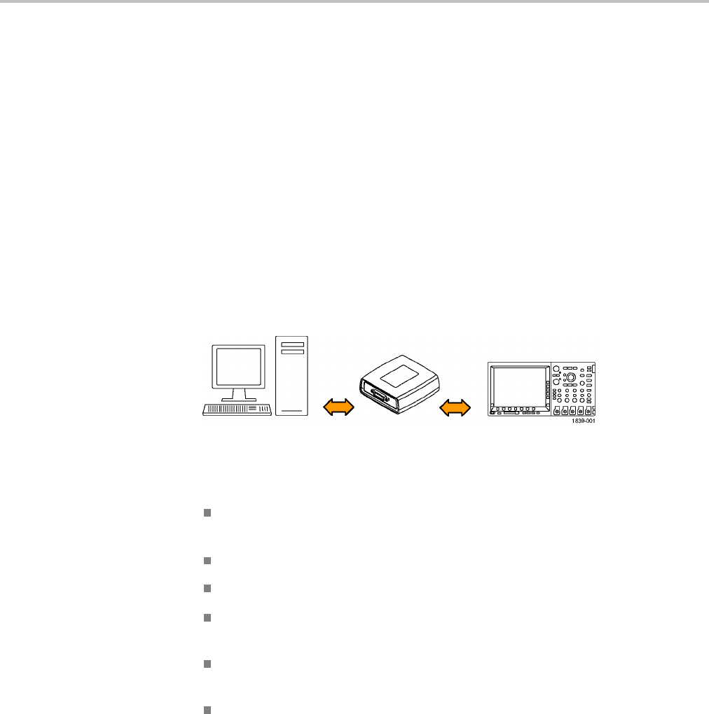
Getting Started
GPIB To use GPIB (General Purpose Interface Bus), start by connecting an appropriate
USB cable to the USB 2.0 high-speed (HS) device port on the rear panel of your
oscilloscope. Connect the other end to the TEK-USB-488 Adapter host port. Then
connect a GPIB cable from the TEK-USB-488 Adapter to your PC.
Supply power to the Adapter in either of these two ways:
1. Use the optional 5 VDC power adapter connected to the 5 VDC power input
on the Adapter.
2. Use an appropriate USB cable connected to a powered USB host port on your
PC and the Device port on the TEK-USB-488 Adapter.
The oscilloscope has a USB 2.0 high-speed (HS) device port to control the
oscilloscope through USBTMC or GPIB with a TEK-USB-488 Adapter. The
USBTMC protocol allows USB devices to communicate using IEEE488 style
messages. This lets you run your GPIB software applications on USB hardware.
Before setting up the oscilloscope for remote communication using the electronic
(physical) GPIB interface, you should familiarize yourself with the following
GPIB requirements:
A unique device address must be assigned to each device on the bus. No two
devices can share the same device address.
No more than 15 devices can be connected to any one line.
One device should be connected for every 6 feet (2 meters) of cable used.
No more than 65 feet (20 meters) of cable should be used to connect devices
to a bus.
At least two-thirds of the devices on the network should be powered on while
using the network.
Connect the devices on the network in a star or linear configuration. Do not
use loop or parallel configurations.
To function correctly, your oscilloscope must have a unique device address. The
default setting for the GPIB configuration is GPIB Address 1.
1-8 MDO4000/B, MSO/DPO4000B and MDO3000 Series Oscilloscopes Programmer Manual

Getting Started
To change the GPIB address settings, do the following:
1. On the front panel, push Utility.
2. Push Utility Page.
3. Select I/O with the Multipurpose knob.
4. Push GPIB.
5. Enter the GPIB address on the side menu, using the multipurpose knob. This
will set the GPIB address on an attached TEK-USB-488 Adapter.
The oscilloscope is now set up for bidirectional communication with your
controller.
Setting Up Remote Communications Software
Connect your oscilloscope directly to a computer to let the PC analyze your data,
collect screen images, or to control the oscilloscope using a program of your own
creation. Three ways to connect your oscilloscope to a computer are through the
VISA drivers, the e*Scope Web-enabled tools, or via a socket server.
Using VISA VISA lets you use your MS-Windows computer to acquire data from your
oscilloscope for use in an analysis package that runs on your PC, such as
Microsoft Excel, National Instruments LabVIEW, Tektronix OpenChoice Desktop
software, or your own custom software. You can use a common communications
connection, such as USB, Ethernet, or GPIB, to connect the computer to the
oscilloscope.
To set up VISA communications between your oscilloscope and a computer:
MDO4000/B, MSO/DPO4000B and MDO3000 Series Oscilloscopes Programmer Manual 1-9

Getting Started
1. Load the VISA drivers on your computer. Also, load your application, such
as OpenChoice Desktop. You will find the drivers and OpenChoice Desktop
software on the appropriate CD that comes with your oscilloscope or at the
Tektronix software finder Web page (www.tektronix.com\downloads).
2. Connect the oscilloscope to your computer with the appropriate USB or
Ethernet cable. To communicate between the oscilloscope and a GPIB system,
connect the oscilloscope to the TEK-USB-488 GPIB-to-USB Adapter with
a USB cable. Then connect the adapter to your GPIB system with a GPIB
cable. Cycle the power on the oscilloscope.
3. Push Utility.
4. Push Utility Page.
5. Turn multipurpose knob aand select I/O.
6. If you are using USB, the system sets itself up automatically for you, if USB is
enabled. Check USB on the lower menu to be sure that USB is enabled. If it is
not enabled, push USB. Then push Connect to Computer on the side menu.
7. To use Ethernet, push Ethernet & LXI on the lower menu. Use the side menu
buttons to adjust your network settings, as needed. For more information, see
the e*Scope setup information below.
8. If you want to change socket server parameters, push Socket Server and enter
new values through the resulting side menu.
9. If you are using GPIB, push GPIB. Enter the GPIB address on the side menu,
using multipurpose knob a. This will set the GPIB address on an attached
TEK-USB-488 Adapter.
10. Run your application software on your computer.
Quick Tips Your oscilloscope shipped with a CD containing a variety of Windows-based
software tools for efficient connectivity between your oscilloscope and your
computer. These include toolbars that speed connectivity with Microsoft
Excel and Word. There are also two standalone acquisition programs called
NI LabVIEW SignalExpress™, Tektronix Edition and Tektronix OpenChoice
Desktop.
The rear-panel USB 2.0 high-speed (HS) device port is the correct USB port
for computer connectivity. Use the rear- and front-panel USB 2.0 host ports
to connect your oscilloscope to USB flash drives, hard drives, printers and
keyboards. Use the USB Device port to connect your oscilloscope to a PC or
a PictBridge printer.
1-10 MDO4000/B, MSO/DPO4000B and MDO3000 Series Oscilloscopes Programmer Manual

Getting Started
Using the LXI Web Page
and e*Scope
With e*Scope, you can access any Internet-connected MSO/DPO4000B,
MDO4000/B or MDO3000 Series oscilloscope from a web browser. To set up
e*Scope communications between your oscilloscope and a Web browser running
on a remote computer:
1. Connect the oscilloscope to your computer network with an appropriate
Ethernet cable.
2. Push Utility.
3. Push Utility Page.
4. Turn multipurpose knob aand select I/O.
5. Push Ethernet & LXI.
6. On top of the side menu, there is an indicator light which turns green for
good status and red if the device detects a fault. Look at it to determine the
condition of the LAN.
7. Push LAN Settings to display the network parameters configured on your
oscilloscope.
8. Push LAN Reset to restore the LAN defaults to your oscilloscope.
9. Push Test Connection to check if your oscilloscope can find an attached
network.
10. Push More to see another page of side-menu items.
11. Push Change Names to change the name of the oscilloscope, the network
domain, or the service name.
12. Push Change Ethernet & LXI Password to use the LXI password to also
protect your oscilloscope from changes made to LAN settings from a Web
browser.
13. Start your browser on your remote computer. In the browser address line,
enter the host name, a dot, and the domain name together. Alternatively, just
enter the IP address of the instrument. Either way, you should then see the
LXI Welcome page on your Web browser on your computer screen.
14. Click “Network Configuration” to view and edit the network configuration
settings. If you are using a password and changing your settings, you need to
know that the default user name is “lxiuser”.
15. For e*Scope, click the Instrument Control (e*Scope) link on the left side of
the LXI Welcome page. You should then see a new tab (or window) open in
your browser with e*Scope running.
Using a Socket Server A socket server provides two-way communication over an Internet Protocol-based
computer network. You can use your oscilloscope’s socket server feature to let
your oscilloscope talk to a remote-terminal device or computer.
MDO4000/B, MSO/DPO4000B and MDO3000 Series Oscilloscopes Programmer Manual 1-11

Getting Started
To set up and use a socket server between your oscilloscope and a remote terminal
or computer:
1. Connect the oscilloscope to your computer network with an appropriate
Ethernet cable.
2. Push Utility.
3. Push Utility Page.
4. Turn multipurpose knob aand select I/O.
5. Push Socket Server.
6. On the resulting Socket Server side menu, push the top entry to highlight
Enabled.
7. Choose whether the protocol should be None or Termin al. A communication
session run by a human at a keyboard typically uses a terminal protocol.
An automated session might handle its own communications without using
such a protocol.
8. If required, change the port number by rotating multipurpose knob a.
9. If required, press OK to set the new port number.
10. After setting up the socket server parameters, you can now have the computer
“talk” to the oscilloscope. If you are running an MS Windows PC, you could
run its default client with its command-like interface. One way to do this is
by typing “ Telnet ” in the Run window. The Telnet window will open on
the PC.
NOTE. On MS Windows 7, you must first enable Telnet in order for it to work.
11.Start a terminal session between your computer and your oscilloscope by
typing in an open command with the oscilloscope's LAN address and port #.
You can obtain the LAN address by pushing the Ethernet & LXI bottom
menu item and the resulting LAN Settings side menu item to view the
resulting Ethernet and LXI Setting screen. You can obtain the port # by
pushing the Socket Server bottom menu item and viewing the Current Port
side menu item.
For example, if the oscilloscope IP address was 123.45.67.89 and the port
# was the default of 4000, you could open a session by writing into the MS
Windows Telnet screen:
o 123.45.67.89 4000
The oscilloscope will send a help screen to the computer when it is done
connecting.
1-12 MDO4000/B, MSO/DPO4000B and MDO3000 Series Oscilloscopes Programmer Manual

Getting Started
12. You can now type in a standard query, as found in the programmer manual,
such as *idn?
The Telnet session window will respond by displaying a character string
describing your instrument. You can type in more queries and view more
results on this Telnet session window. You can find the syntax for relevant
queries and related status codes in other sections of this manual.
NOTE. Do not use the computer’s backspace key during an MS Windows' Telnet
session with the oscilloscope.
Socket Server Terminal Protocol Mode Commands. Following are Tektronix
Instrument Control Terminal Session Control commands:
!t <timeout> : set the response timeout in milliseconds.
!d : send device clear to the instrument.
!r : read response from instrument.
!h : print this usage info.
NOTE. Commands containing a ? are treated as queries, and the responses are
read automatically.
Documentation The following documents are available for download at www.tektronix.com:
MDO4000B Series Mixed Domain Oscilloscopes User Manual. Information
about installing and operating the oscilloscope.
MDO4000B Series Mixed Domain Oscilloscopes Specifications and
Performance Verification Technical Reference. Oscilloscope specifications and
a performance verification procedure.
MDO4000 Series Mixed Domain Oscilloscopes User Manual. Information about
installing and operating the oscilloscope.
MDO4000 Series Mixed Domain Oscilloscopes Specifications and Performance
Ve r i fication Technical Reference. Oscilloscope specifications and a performance
verification procedure.
MSO4000B and DPO4000B Series Digital Phosphor Oscilloscopes User
Manual. Information about installing and operating the oscilloscope.
MSO4000B and DPO4000B Series Digital Phosphor Oscilloscopes Technical
Reference. Oscilloscope specifications and a performance verification procedure.
MDO3000 Series Mixed Domain Oscilloscopes User Manual. Information about
installing and operating the oscilloscope.
MDO4000/B, MSO/DPO4000B and MDO3000 Series Oscilloscopes Programmer Manual 1-13

Getting Started
MDO3000 Series Mixed Domain Oscilloscopes Specifications and Performance
Verification Technical Reference. Oscilloscope specifications and a performance
verification procedure.
Getting Started with OpenChoice ™ Solutions Manual. Options for getting data
from your oscilloscope into any one of several available analysis tools.
TekVISA Programmer Manual. Description of TekVISA, the Tektronix
implementation of the VISA Application Programming Interface (API). TekVISA
is industry-compliant software for writing interoperable oscilloscope drivers in a
variety of Application Development Environments (ADEs).
1-14 MDO4000/B, MSO/DPO4000B and MDO3000 Series Oscilloscopes Programmer Manual

Syntax and Commands

Command Syntax
You can control the operations and functions of the oscilloscope through the
Ethernet port or the USB 2.0 high-speed (HS) device port using commands and
queries. The related topics listed below describe the syntax of these commands
and queries. The topics also describe the conventions that the oscilloscope uses
to process them. See the Command Groups topic in the table of contents for a
listing of the commands by command group, or use the index to locate a specific
command.
Backus-Naur Form
Notation
This documentation describes the commands and queries using Backus-Naur
Form (BNF) notation. Refer to the following table for the symbols that are used.
Table 2-1: Symbols for Backus-Naur Form
Symbol Meaning
<> Defined element
=Is defined as
| Exclusive OR
{ } Group; one element is required
[] Optional; can be omitted
.. . Previous element(s) may be repeated
Command and Query Structure
Commands consist of set commands and query commands (usually called
commands and queries). Commands modify oscilloscope settings or tell the
oscilloscope to perform a specific action. Queries cause the oscilloscope to return
data and status information.
Most commands have both a set form and a query form. The query form of the
command differs from the set form by its question mark at the end. For example,
the set command ACQuire:MODe has a query form ACQuire:MODe?.Notall
commands have both a set and a query form. Some commands have set only and
some have query only.
Messages A command message is a command or query name followed by any information
the oscilloscope needs to execute the command or query. Command messages
may contain five element types, defined in the following table.
MDO4000/B, MSO/DPO4000B and MDO3000 Series Oscilloscopes Programmer Manual 2-1

Command Syntax
Table 2-2: Command Message Elements
Symbol Meaning
<Header> This is the basic command name. If the header ends with a question
mark, the command is a query. The header may begin with a colon
(:) character. If the command is concatenated with other commands,
the beginning colon is required. Never use the beginning colon with
command headers beginning with a star (*).
<Mnemonic> This is a header subfunction. Some command headers have only one
mnemonic. If a command header has multiple mnemonics, a colon (:)
character always separates them from each other.
<Argument>This is a quantity, quality, restriction, or limit associated with the header.
Some commands have no arguments while others have multiple
arguments. A <space> separates arguments from the header. A
<comma> separates arguments from each other.
<Comma> A single comma is used between arguments of multiple-argument
commands. Optionally, there may be white space characters before
and after the comma.
<Space> A white space character is used between a command header and the
related argument. Optionally, a white space may consist of multiple
white space characters.
Commands Commands cause the oscilloscope to perform a specific function or change one of
the settings. Commands have the structure:
[:]<Header>[<Space><Argument>[<Comma> <Argument>]...]
A command header consists of one or more mnemonics arranged in a hierarchical
or tree structure. The first mnemonic is the base or root of the tree and each
subsequent mnemonic is a level or branch off the previous one. Commands at a
higher level in the tree may affect those at a lower level. The leading colon (:)
always returns you to the base of the command tree.
2-2 MDO4000/B, MSO/DPO4000B and MDO3000 Series Oscilloscopes Programmer Manual
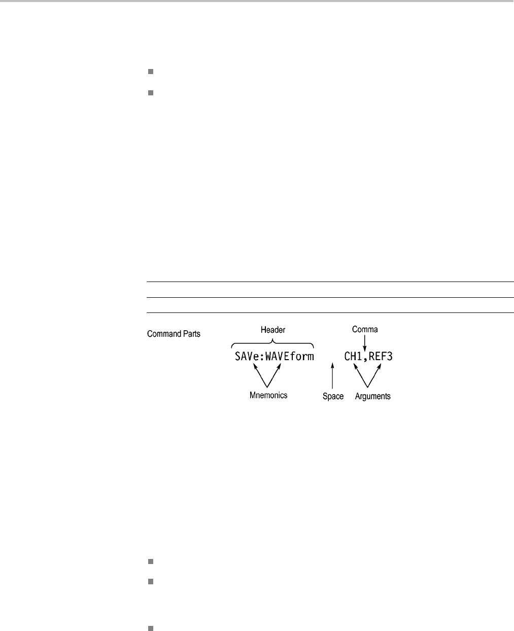
Command Syntax
Queries Queries cause the oscilloscope to return status or setting information. Queries
have the structure:
[:]<Header>
[:]<Header>[<Space><Argument> [<Comma><Argument>]...]
You can specify a query command at any level within the command tree unless
otherwise noted. These branch queries return information about all the mnemonics
below the specified branch or level.
Headers Use the HEADer command to control whether the oscilloscope returns headers as
part of the query response. If header is on, the query response returns command
headers, then formats itself as a valid set command. When header is off, the
response includes only the values. This may make it easier to parse and extract the
information from the response. The table below shows the difference in responses.
Table 2-3: Comparison of Header Off and Header On Responses
Query Header Off Header On
TIME? 14:30:00 :TIME “14:30:00”
ACQuire:NUMAVg? 100 :ACQUIRE:NUMAVG 100
Clearing the oscilloscope
You can clear the Output Queue and reset the oscilloscope to accept a new
command or query by using the selected Device Clear (DCL) function.
Command Entry
The following rules apply when entering commands:
You can enter commands in upper or lower case.
You can precede any command with white space characters. White space
characters include any combination of the ASCII control characters 00 through
09 and 0B through 20 hexadecimal (0 through 9 and 11 through 32 decimal).
The oscilloscope ignores commands consisting of any combination of white
space characters and line feeds.
MDO4000/B, MSO/DPO4000B and MDO3000 Series Oscilloscopes Programmer Manual 2-3

Command Syntax
Abbreviating You can abbreviate many oscilloscope commands. Each command in this
documentation shows the minimum acceptable abbreviations in capitals. For
example, you can enter the command ACQuire:NUMAvg simply as ACQ:NUMA
or acq:numa.
Abbreviation rules may change over time as new oscilloscope models are
introduced. Thus, for the most robust code, use the full spelling.
If you use the HEADer command to have command headers included as part
of query responses, you can further control whether the returned headers are
abbreviated or are full-length with the VERBose command.
Concatenating You can concatenate any combination of set commands and queries using a
semicolon (;). The oscilloscope executes concatenated commands in the order
received.
When concatenating commands and queries, you must follow these rules:
1. Separate completely different headers by a semicolon and by the beginning
colon on all commands except the first one. For example, the commands
TRIGger:MODe NORMal and ACQuire:NUMAVg 8, can be concatenated
into the following single command:
TRIGger:MODe NORMal;:ACQuire:NUMAVg 8
2. If concatenated commands have headers that differ by only the last mnemonic,
you can abbreviate the second command and eliminate the beginning colon.
For example, you can concatenate the commands ACQuire:MODe ENVelope
and ACQuire:NUMAVg 8 into a single command:
ACQuire:MODe ENVelope; NUMAVg 8
The longer version works equally well:
ACQuire:MODe ENVelope;:ACQuire:NUMAVg 8
3. Never precede a star (*) command with a colon:
ACQuire:STATE 1;*OPC
Any commands that follow will be processed as if the star command was
not there so the commands, ACQuire:MODe ENVelope;*OPC;NUMAVg 8
will set the acquisition mode to envelope and set the number of acquisitions
for averaging to 8.
4. When you concatenate queries, the responses to all the queries are
concatenated into a single response message. For example, if the display
graticule is set to Full and the display style is set to dotsonly, the concatenated
query DISplay:GRAticule?;STYle:DOTsonly? will return the following.
If the header is on:
DISPLAY:GRATICULE FULL;:DISPLAY:STYLE:DOTSONLY 1
2-4 MDO4000/B, MSO/DPO4000B and MDO3000 Series Oscilloscopes Programmer Manual

Command Syntax
If the header is off:
FULL;1
1. Set commands and queries may be concatenated in the same message. For
example,
ACQuire:MODe SAMple;NUMAVg?;STATE?
is a valid message that sets the acquisition mode to sample. The message then
queries the number of acquisitions for averaging and the acquisition state.
Concatenated commands and queries are executed in the order received.
Here are some invalid concatenations:
DISPlay:STYle:DOTsonly OFF;ACQuire:NUMAVg 8 (no colon before
ACQuire)
DISPlay:GRAticule FULL;:STYle:DOTSONLY OFF (extra colon before
STYle.
DISPlay:GRAticule FULL;:*TRG (colon before a star (*) command)
MATH:HORizontal:SCAle 1.0e-1;HORizontal:POSition 5.0el
(levels of the mnemonics are different; either remove the second use of
HORizontal: or place :MATH in front of HORizontal:POSition)
Terminating This documentation uses <EOM> (End of Message) to represent a message
terminator.
Table 2-4: End of Message Terminator
Symbol Meaning
<EOM> Message terminator
The end-of-message terminator must be the END message (EOI asserted
concurrently with the last data byte). The last data byte may be an ASCII line
feed (LF) character.
This oscilloscope does not support ASCII LF only message termination. The
oscilloscope always terminates outgoing messages with LF and EOI.
Constructed Mnemonics
Some header mnemonics specify one of a range of mnemonics. For example, a
channel mnemonic can be CH1, CH2, CH3, or CH4. You use these mnemonics
in the command just as you do any other mnemonic. For example, there is a
CH1:POSition command, and there is also a CH2:POSition command. In the
command descriptions, this list of choices is abbreviated as CH<x>.
MDO4000/B, MSO/DPO4000B and MDO3000 Series Oscilloscopes Programmer Manual 2-5

Command Syntax
Cursor Position
Mnemonics
When cursors are displayed, commands may specify which cursor of the pair to
use.
Table 2-5: Channel Mnemonics
Symbol Meaning
CH<x> A channel specifier; <x> is 1 through 4.
Table 2-6: Cursor Mnemonics
Symbol Meaning
CURSOR<x> A cursor selector; <x> is either 1 or 2.
POSITION<x> A cursor selector; <x> is either 1 or 2.
HPOS<x> A cursor selector; <x> is either 1 or 2.
Math Specifier Mnemonics Commands can specify the mathematical waveform to use as a mnemonic in
the header.
Table 2-7: Math Specifier Mnemonics
Symbol Meaning
Math<x> A math waveform specifier; <x> is 1.
Measurement Specifier
Mnemonics
Commands can specify which measurement to set or query as a mnemonic in the
header. Up to eight automated measurements may be displayed.
Table 2-8: Measurement Specifier Mnemonics
Symbol Meaning
MEAS<x> A measurement specifier; <x> is 1 through 8.
Channel Mnemonics Commands specify the channel to use as a mnemonic in the header.
Reference Waveform
Mnemonics
Commands can specify the reference waveform to use as a mnemonic in the
header.
Table 2-9: Reference Waveform Mnemonics
Symbol Meaning
REF<x> A reference waveform specifier; <x> is 1, 2, 3, or 4 for 4-channel
oscilloscopes and 1 or 2 for 2-channel oscilloscopes.
2-6 MDO4000/B, MSO/DPO4000B and MDO3000 Series Oscilloscopes Programmer Manual

Command Syntax
Argument Types
Commands use arguments such as enumeration, numeric, quoted string and block.
Each of these arguments are listed in detail below.
Enumeration Enter these arguments as unquoted text words. Like key words, enumeration
arguments follow the same convention where the portion indicated in uppercase is
required and that in lowercase is optional.
For example: SAVe:WAVEform:FILEFormat INTERNal
Numeric Many oscilloscope commands require numeric arguments. The syntax shows
the format that the oscilloscope returns in response to a query. This is also the
preferred format when sending the command to the oscilloscope, though any of
the formats will be accepted. This documentation represents these arguments as
described below.
Table 2-10: Numeric Arguments
Symbol Meaning
<NR1> Signed integer value
<NR2> Floating point value without an exponent
<NR3> Floating point value with an exponent
<bin> Signed or unsigned integer in binary format
Most numeric arguments will be automatically forced to a valid setting, by either
rounding or truncating, when an invalid number is input, unless otherwise noted
in the command description.
Quoted String Some commands accept or return data in the form of a quoted string, which is
simply a group of ASCII characters enclosed by a single quote (') or double quote
("). The following is an example of a quoted string: "This is a quoted
string". This documentation represents these arguments as follows:
Table 2-11: Quoted String Argument
Symbol Meaning
<QString> Quoted string of ASCII text
MDO4000/B, MSO/DPO4000B and MDO3000 Series Oscilloscopes Programmer Manual 2-7

Command Syntax
A quoted string can include any character defined in the 7-bit ASCII character
set. Follow these rules when you use quoted strings:
1. Use the same type of quote character to open and close the string. For
example: "this is a valid string".
2. You can mix quotation marks within a string as long as you follow the
previous rule. For example: "this is an 'acceptable' string".
3. You c an inc lude a quote character within a string by repeating the quote. For
example: "here is a "" mark".
4. Strings can have upper or lower case characters.
5. If you use a GPIB network, you cannot terminate a quoted string with the
END message before the closing delimiter.
6. A carriage return or line feed embedded in a quoted string does not terminate
the string. The return is treated as another character in the string.
7. The maximum length of a quoted string returned from a query is 1000
characters.
Here are some invalid strings:
"Invalid string argument' (quotes are not of the same type)
"test<EOI>" (termination character is embedded in the string)
Block Several oscilloscope commands use a block argument form, as defined in the
table below.
Table 2-12: Block Argument
Symbol Meaning
<NZDig> A nonzero digit character in the range of 1–9
<Dig> A digit character, in the range of 0–9
<DChar> A character with the hexadecimal equivalent of 00 through FF (0
through 255 decimal)
<Block> A block of data bytes defined as: <Block> ::=
{#<NZDig><Dig>[<Dig>...][<DChar>...] |#0[<DChar>...]<terminator>}
<NZDig> specifies the number of <Dig> elements that follow. Taken together,
the <NZDig> and <Dig> elements form a decimal integer that specifies how
many <DChar> elements follow.
2-8 MDO4000/B, MSO/DPO4000B and MDO3000 Series Oscilloscopes Programmer Manual

Command Syntax
MDO4000/B, MSO/DPO4000B and MDO3000 Series Oscilloscopes Programmer Manual 2-9

Command Syntax
2-10 MDO4000/B, MSO/DPO4000B and MDO3000 Series Oscilloscopes Programmer Manual

Command Groups
This manual lists the MDO4000B, MDO4000, MSO4000B, DPO4000B and
MDO3000 Series IEEE488.2 commands in two ways. First, it presents them by
functional groups. Then, it lists them alphabetically. The functional group list
starts below. The alphabetical list provides detail on each command.
Acquisition Command Group
Use the commands in the Acquisition Command Group to set up the modes and
functions that control how the oscilloscope acquires signals input to the channels,
and processes them into waveforms.
Using the commands in this group, you can do the following:
Start and stop acquisitions.
Control whether each waveform is simply acquired, averaged, or enveloped
over successive acquisitions of that waveform.
Set the controls or conditions that start and stop acquisitions.
Control acquisition of channel waveforms.
Set acquisition parameters.
Table 2-13: Acquisition Commands
Command Description
ACQuire? Returns acquisition parameters
ACQuire:FASTAcq Sets or queries the fast acquisition feature.
ACQuire:FASTAcq:PALEtte Sets (or queries) which palette to use for fast acquisition mode.
ACQuire:FASTAcq:STATE Turns fast acquisition mode on or off, or queries the state of the mode.
ACQuire:MAGnivu This command specifies the MagniVu feature
ACQuire:MAXSamplerate? Returns the maximum real-time sample rate
ACQuire:MODe Specifies the acquisition mode of the oscilloscope for all analog channel waveforms.
ACQuire:NUMACq? Returns number of acquisitions that have occurred
ACQuire:NUMAVg This command specifies the number of acquisitions for an averaged waveform
ACQuire:NUMEnv This command controls the number of envelopes (when acquisition mode is set to ENVelope
using ACQuire:MODe).
ACQuire:STATE Starts or stops the acquisition system
ACQuire:STOPAfter This command specifies whether the acquisition is continuous or single sequence
Act on Event Command Group
Use the Act on Event commands to Act once a certain type of Event has happened.
MDO4000/B, MSO/DPO4000B and MDO3000 Series Oscilloscopes Programmer Manual 2-11

Command Groups
Available actions:
- Stop acquisitions
- Save waveform data to a file
- Save a screen image to a file
- Send a screen image to a printer
-SendapulsetotheAuxOutport
- Generate a service request
-Sendanemail
- Display a visual notification
Available events:
- Upon trigger
-When a certain number of acquisitions have completed
-None
Table 2-14: Act on Event
Command Description
ACTONEVent:ACTION:AUXOUT:
STATE
Sends a pulse to the AUX OUT port when a specified event occurs, or queries the state
of the “pulse to aux out” action.
ACTONEVent:ACTION:EMAIL:
STATE
Sends an email when a specified event occurs, or queries the state of the “send email” action.
ACTONEVent:ACTION:PRINT:
STATE
Sends a screen image to a printer when a specified event occurs, or queries the state of
the “send screen image” action.
ACTONEVent:ACTION:
SAVEIMAGE:STATE
Saves a screen image to file when a specified event occurs, or queries the state of the
“save screen image to a file” action.
ACTONEVent:ACTION:SAVEWFM:
STATE
Saves the currently selected waveform data to a file when a specified event occurs, or
queries the state of the “save waveform to file” action.
ACTONEVent:ACTION:SRQ:STATE Sets or returns the enabled state of the generate service request (SRQ) action when a
specified event occurs. The default state is 0.
ACTONEVent:ACTION:STOPACQ:
STATE
Stops acquisitions when a specified event occurs, or queries the state of the “stop
acquisition” action.
ACTONEVent:ACTION:VISUAL:
STATE
Sends a visual notification when a specified event occurs, or queries the state of the “send a
visual notification” action.
ACTONEVent:EVENTTYPe Specifies (or queries) which event to act on (TRIGger, ACQCOMPLete, or NONe) when
using an Act on Event command.
ACTONEVent:NUMACQs Sets (or queries) the number of acquisitions to complete for the event type ACQCOMPLete.
ACTONEVent:REPEATCount Sets or returns the number of events to run.
2-12 MDO4000/B, MSO/DPO4000B and MDO3000 Series Oscilloscopes Programmer Manual

Command Groups
AFG Command Group
Use the AFG commands for Arbitrary Function Generator functionality.
Available for the MDO3000 series only. Requires the MDO3AFG option to be
installed.
The AFG functionality is available when either the time domain acquisition or
RF acquisition is active.
Table 2-15: AFG Commands
Command Description
AFG:AMPLitude Sets (or queries) the AFG amplitude in volts, peak to peak.
AFG:FREQuency Sets (or queries) the AFG frequency.
AFG:FUNCtion Sets (or queries) which AFG function to execute.
AFG:HIGHLevel Sets (or queries) the AFG high level, in volts.
AFG:LEVELPreset Sets (or queries) the AFG preset levels to values that correspond to the logic standard
specified by the argument The presets set the vertical controls for AMPLitude, OFFSet ,
HIGHLevel, and LOWLevel.
AFG:LOWLevel Sets (or queries) the AFG low level, in volts.
AFG:NOISEAdd:PERCent Sets (or queries) the AFG additive noise level as a percentage.
AFG:NOISEAdd:STATE Sets (or queries) the AFG additive noise state.
AFG:OFFSet Sets (or queries) the AFG offset, in volts.
AFG:OUTPut:LOAd:IMPEDance Sets (or queries) the AFG output load impedance.
AFG:OUTPut:STATE Sets (or queries) the AFG output state.
AFG:PERIod Sets (or queries) the period of the AFG waveform, in seconds.
AFG:PHASe Sets (or queries) the AFG phase.
AFG:PULse:WIDth Sets (or queries) the AFG pulse width, in seconds.
AFG:RAMP:SYMmetry Sets (or queries) the AFG ramp symmetry as a percentage.
AFG:SQUare:DUty Sets (or queries) the AFG duty cycle, as a percentage.
Alias Command Group
Use the Alias commands to define new commands as a sequence of standard
commands. You may find this useful when repeatedly using the same commands
to perform certain tasks like setting up measurements.
Aliases are similar to macros but do not include the capability to substitute
parameters into alias bodies. To use Alias commands, first define the alias, then
turn on the alias state.
The alias mechanism obeys the following rules:
MDO4000/B, MSO/DPO4000B and MDO3000 Series Oscilloscopes Programmer Manual 2-13
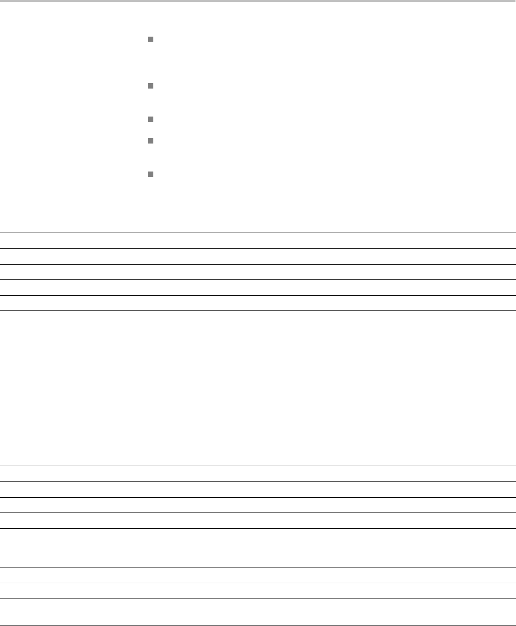
Command Groups
thealiasnamem
ust consist of a valid IEEE488.2 message unit, which may
not appear in a message preceded by a colon, comma, or a command or query
program header.
the alias name may not appear in a message followed by a colon, comma,
or question mark.
an alias name must be distinct from any keyword or keyword short form.
an alias name cannot be redefined without first being deleted using one of
the alias deletion functions.
alias names do not appear in response messages.
Table 2-16: Alias Commands
Command Description
ALIas:CATalog? Returns a list of the currently defined alias labels
ALIas:DEFine Assigns a sequence of program messages to an alias label
ALIas:DELEte:ALL Deletes all existing aliases
ALIas:DELEte[:NAMe] Removes a specified alias
ALIas[:STATE] This command specifies the alias state
ARB Command Group
Use the ARB commands for Arbitrary Waveform Generator functionality.
Available for the MDO3000 series only. Requires the MDO3AFG option to be
installed.
Table 2-17: ARB Commands
Command Description
AFG:ARBitrary:ARB<x>:DATE? Returns the date that the data in the specified arbitrary waveform slot 1-4 was saved.
AFG:ARBitrary:ARB<x>:LABel Sets (or queries) the waveform label for arbitrary waveform slots 1- 4.
AFG:ARBitrary:ARB<x>:TIMe? Returns the time that the data in the specified arbitrary waveform slot was saved.
AFG:ARBitrary:EMEM:FUNCtion? Returns the currently selected arbitrary waveform pre-defined function.
AFG:ARBitrary:EMEM:GENerate This command generates the arbitrary waveform function specified by the enumeration
argument, with the number of points optionally specified by the NR1 argument. To query the
arbitrary waveform function set by this command, use AFG:ARBitrary:EMEM:FUNCtion?
AFG:ARBitrary:EMEM:NUMPoints? Returns the number of points in the AFB arbitrary waveform edit memory.
AFG:ARBitrary:EMEM:POINTS Specifies which points to load into the AFG arbitrary waveform edit memory.
AFG:ARBitrary:EMEM:POINTS:
ENCdg
This command specifies the data encoding format for the AFG:ARBitrary:EMEM:POINTS
query (either ASCII or binary).
2-14 MDO4000/B, MSO/DPO4000B and MDO3000 Series Oscilloscopes Programmer Manual

Command Groups
Bus Command Group
Use the Bus commands when working with serial or parallel bus measurements.
Bus commands let you specify the bus number (B1-B4), except for MDO3000,
which has only two buses (B1-B2).
Parallel bus trigger and analysis functionality is included standard with the MSO
and MDO Series. All other bus triggers require installation of an application
module.
A table is available that lists all commands enabled by each application module
(See page G-1, Application Module-enabled Commands.)
For I2C or SPI bus signals, install the DPO4EMBD application module,
except for MDO3000 models, which require MDO3EMBD.
For RS-232, RS-422, RS-485, or UART bus signals, install the DPO4COMP
module, except for MDO3000 models, which require MDO3COMP.
For I2S, Left Justified (LJ), Right Justified (RJ), or TDM bus signals, install
the DPO4AUDIO module, except for MDO3000 models, which require
MDO3AUDIO.
For CAN or LIN bus signals, install the DPO4AUTO or DPO4AUTOMAX
module, except for MDO3000 models, which require MDO3AUTO.
For FlexRay bus signals, install the DPO4AUTOMAX module, except for
MDO3000 models, which require MDO3FLEX.
For Ethernet signals, when tested with the MDO4000/B and MSO/DPO4000B,
install the DPO4ENET module. Note that ≥350 MHz bandwidth models
are recommended for 100BASE-TX.
For MIL-STD-1553 bus signals, install the DPO4AERO module, except for
MDO3000 models, which require MDO3AERO.
For USB bus signals, install the DPO4USB module, except for
MDO3000 models, which require MDO3USB. Note that 1 GHz bandwidth
models are recommended for high-speed (HS) USB.
NOTE. The Search Command Group and the Trigger Command Group also
contain bus-related commands.
Table 2-18: Bus Commands
Commands Description
BUS? Returns the parameters for each serial (if installed) and parallel bus.
BUS:B<x>:AUDio:BITDelay This command specifies the number of delay bits for the AUDIO bus
BUS:B<x>:AUDio:BITOrder This command specifies the bit order for the AUDIO bus
BUS:B<x>:AUDio:CHANnel:SIZe This command specifies the number of bits per channel for the AUDIO bus
MDO4000/B, MSO/DPO4000B and MDO3000 Series Oscilloscopes Programmer Manual 2-15

Command Groups
Table 2-18: Bus Commands (cont.)
Commands Description
BUS:B<x>:AUDio:CLOCk:POLarity This command specifies the clock polarity for the AUDIO bus
BUS:B<x>:AUDio:CLOCk:SOUrce This command specifies the clock source waveform for the AUDIO bus
BUS:B<x>:AUDio:DATa:POLarity This command specifies the data polarity for the AUDIO bus
BUS:B<x>:AUDio:DATa:SIZe This command specifies the number of bits per word for the AUDIO bus
BUS:B<x>:AUDio:DATa:SOUrce This command specifies the data source waveform for the AUDIO bus
BUS:B<x>:AUDio:DISplay:FORMat This command specifies the display format for the AUDIO bus
BUS:B<x>:AUDio:FRAME:SIZe This command specifies the number of channels in each frame for the AUDIO bus
BUS:B<x>:AUDio:FRAMESync:
POLarity
This command specifies the frame sync polarity for the AUDIO bus
BUS:B<x>:AUDio:FRAMESync:
SOUrce
This command specifies the frame sync source waveform for the AUDIO bus
BUS:B<x>:AUDio:TYPe This command specifies the audio format (type) for the AUDIO bus
BUS:B<x>:AUDio:WORDSel:
POLarity
This command specifies the word select polarity for the AUDIO bus
BUS:B<x>:AUDio:WORDSel:SOUrce This command specifies the word select source waveform for the AUDIO bus
BUS:B<x>:CAN:BITRate This command specifies the bit rate for the CAN bus
BUS:B<x>:CAN:PRObe This command specifies the probing method for the CAN bus
BUS:B<x>:CAN:SAMPLEpoint This command specifies the sample point (in %) to sample during each bit period
BUS:B<x>:CAN:SOUrce This command specifies the CAN bus data source
BUS:B<x>:DISplay:FORMat Sets the display format for the numerical information in the specified bus waveform
BUS:B<x>:DISplay:TYPe Sets the display type for the specified bus
BUS:B<x>:ETHERnet:PRObe This command specifies the Ethernet probe type: differential or single-ended.
BUS:B<x>:ETHERnet:PROTOcol Use this command to set the Ethernet protocol type to TCP/IPv4, or to OTHER.
BUS:B<x>:ETHERnet:SOUrce:
DIFFerential
This command specifies the Ethernet data source for differential input.
BUS:B<x>:ETHERnet:SOUrce:
DMINus
This command specifies the Ethernet data source for D- input for single-ended probing.
BUS:B<x>:ETHERnet:SOUrce:
DPLUs
This command specifies the Ethernet data source for the D+ input for single-ended probing.
BUS:B<x>:ETHERnet:TYPe This command specifies the Ethernet standard type: 10Base-T or 100Base-T.
BUS:B<x>:FLEXray:BITRate This command specifies the bit rate for the FlexRay bus signal
BUS:B<x>:FLEXray:CHannel This command specifies the FlexRay bus ID format
BUS:B<x>:FLEXray:SIGnal This command specifies the FlexRay bus standard
BUS:B<x>:FLEXray:SOUrce This command specifies the FlexRay bus data source
BUS:B<x>:I2C:ADDRess:RWINClude Sets and returns whether the read/write bit is included in the address
BUS:B<x>:I2C{:CLOCk|:SCLk}:
SOUrce
This command specifies the I2C bus SCLK source
BUS:B<x>:I2C{:DATa|:SDAta}:
SOUrce
This command specifies the I2C bus SDATA source
2-16 MDO4000/B, MSO/DPO4000B and MDO3000 Series Oscilloscopes Programmer Manual

Command Groups
Table 2-18: Bus Commands (cont.)
Commands Description
BUS:B<x>:LABel This command specifies the waveform label for the specified bus
BUS:B<x>:LIN:BITRate This command specifies the bit rate for the LIN bus.
BUS:B<x>:LIN:IDFORmat This command specifies the LIN bus ID format
BUS:B<x>:LIN:POLarity This command specifies the LIN bus polarity
BUS:B<x>:LIN:SAMPLEpoint This command specifies the point to sample during each bit period, as a percent, for the
LIN bus.
BUS:B<x>:LIN:SOUrce This command specifies the LIN bus data source
BUS:B<x>:LIN:STANDard This command specifies the LIN bus standard
BUS:B<x>:MIL1553B:POLarity This command sets the MIL-STD-1553 bus polarity to normal or inverted.
BUS:B<x>:MIL1553B:
RESPonsetime:MAXimum
This command specifies the maximum response time to a valid command issued for the
MIL-STD-1553 bus.
BUS:B<x>:MIL1553B:
RESPonsetime:MINimum
This command specifies the minimum response time to a valid command issued for the
MIL-STD-1553 bus.
BUS:B<x>:MIL1553B:SOUrce This command specifies the source for differential input for the MIL-STD-1553 bus.
BUS:B<x>:PARallel:BIT<x>:SOUrce This command specifies the bit source for the parallel bus.
BUS:B<x>:PARallel:CLOCk:EDGE This command specifies the clock edge for the parallel bus
BUS:B<x>:PARallel:CLOCk:
ISCLOCKed
This command specifies the state of the clock function for the parallel bus.
BUS:B<x>:PARallel:CLOCk:SOUrce This command specifies the clock source waveform for the parallel bus.
BUS:B<x>:PARallel:WIDth This command specifies the number of bits to use for the width of the parallel bus.
BUS:B<x>:POSition This command specifies the position of the bus waveform on the display.
BUS:B<x>:RS232C:BITRate This command specifies the bit rate for the RS-232 bus.
BUS:B<x>:RS232C:DATABits This command specifies the number of bits in the data frame for the RS-232 bus.
BUS:B<x>:RS232C:DELIMiter This command specifies the delimiting value for a packet on the RS-232 bus.
BUS:B<x>:RS232C:DISplaymode This command specifies the display mode for the RS-232 bus (frame or packet).
BUS:B<x>:RS232C:PARity This command specifies parity for the RS-232 bus
BUS:B<x>:RS232C:POLarity This command specifies the polarity for the RS-232C bus
BUS:B<x>:RS232C:RX:SOUrce This command specifies the RX source waveform for the RS-232 bus.
BUS:B<x>:RS232C:TX:SOUrce This command specifies the TX source waveform for the RS-232 bus.
BUS:B<x>:SPI:BITOrder This command specifies the bit order for the SPI bus
BUS:B<x>:SPI{:CLOCk|:SCLk}:
POLarity
This command specifies the SCLK polarity for the SPI bus.
BUS:B<x>:SPI{:CLOCk|:SCLk}:
SOUrce
This command specifies the SCLK source for the SPI bus.
BUS:B<x>:SPI:DATa{:IN|:MISO}:
POLarity
This command specifies the MISO polarity for the SPI bus.
BUS:B<x>:SPI:DATa{:IN|:MISO}:
SOUrce
This command specifies the MISO source for the SPI bus.
MDO4000/B, MSO/DPO4000B and MDO3000 Series Oscilloscopes Programmer Manual 2-17

Command Groups
Table 2-18: Bus Commands (cont.)
Commands Description
BUS:B<x>:SPI:DATa{:OUT|:MOSI}:
POLarity
This command specifies the MOSI polarity for the SPI bus.
BUS:B<x>:SPI:DATa{:OUT|:MOSI}:
SOUrce
This command specifies the MOSI source for the SPI bus.
BUS:B<x>:SPI:DATa:SIZe This command specifies the number of bits per word (data size) for the specified SPI bus.
BUS:B<x>:SPI:FRAMING This command specifies the type of framing to use for the SPI bus.
BUS:B<x>:SPI:IDLETime This command specifies the idle time, in seconds, for the SPI bus.
BUS:B<x>:SPI{:SELect|:SS}:
POLarity
This command specifies the polarity for the SPI bus.
BUS:B<x>:SPI{:SELect|:SS}:SOUrce This command specifies the source waveform for the SPI bus.
BUS:B<x>:STATE This command specifies the on/off state of the bus.
BUS:B<x>:TYPe This command specifies the bus type
BUS:B<x>:USB:BITRate This command specifies the bit rate for the USB bus.
BUS:B<x>:USB:PRObe This command specifies the type of probe connected to the USB bus.
BUS:B<x>:USB:SOUrce:DIFFerential This command specifies the source waveform for the eUSB bus when using a differential
probe.
BUS:B<x>:USB:SOUrce:DMINus This command specifies the source waveform for the USB bus D- input.
BUS:B<x>:USB:SOUrce:DPLUs This command specifies the source for the USB D+ input.
BUS:LOWerthreshold:CH<x> This command specifies the lower threshold for each channel.
BUS:LOWerthreshold{:MATH|:
MATH1}
This command specifies the lower threshold for the math waveform.
BUS:LOWerthreshold:REF<x> This command sets the lower threshold for each reference waveform.
BUS:THReshold:CH<x> This command specifies the threshold for a channel.
BUS:THReshold:D<x> This command specifies the threshold for a digital channel.
BUS:UPPerthreshold:CH<x> This command specifies the upper threshold for each channel.
BUS:UPPerthreshold{:MATH|:
MATH1}
This command specifies the upper threshold for the math waveform.
BUS:UPPerthreshold:REF<x> This command sets the upper threshold for each reference waveform.
Calibration and Diagnostic Command Group
The Calibration and Diagnostic commands provide information about the
current state of oscilloscope calibration. They also initiate internal signal path
calibration (SPC) or execute diagnostic tests. Commands that are specificto
factory calibration are not described in this manual. Instead, they are described
in the Service Manual Documentation CD-ROM in PDF format. You can also
order a printed copy.
2-18 MDO4000/B, MSO/DPO4000B and MDO3000 Series Oscilloscopes Programmer Manual

Command Groups
Table 2-19: Calibration and Diagnostic Commands
Command Description
*CAL? Instructs the oscilloscope to perform self-calibration and returns the oscilloscope self
calibration status.
CALibrate:FACtory:STATus? Returns the factory calibration status value saved in nonvolatile memory.
CALibrate:FACtory:STATus:AFG? Returns the factory calibration status for the Arbitrary Function Generator portion of the
instrument, if present.
CALibrate:FACtory:STATus:RF? Returns the factory calibration status value saved in nonvolatile memory for the RF portion
of the oscilloscope.
CALibrate:FACtory:STATus:SCOPE? Returns the factory calibration status value saved in nonvolatile memory for the non-RF
portion of the oscilloscope.
CALibrate:INTERNal Starts a signal path compensation
CALibrate:INTERNal:STARt Starts the internal signal path calibration.
CALibrate:INTERNal:STATus? Returns the current status of the internal signal path calibration.
CALibrate:INTERNal:STATus:RF? This query returns the status of the last SPC run for the RF portion of the instrument:
(doesn't include the analog channels).
CALibrate:INTERNal:STATus:
SCOPE?
This query returns the status of the last SPC run for the oscilloscope portion of the
instrument (doesn't include the RF portion).
CALibrate:RESults? Returns the status of all calibration subsystems without performing an SPC operation.
CALibrate:RESults:FACtory? Returns the status of internal and factory calibration.
CALibrate:RESults:FACtory:AFG? This query returns the factory calibration status for the Arbitrary Function Generator portion
of the instrument, if present.
CALibrate:RESults:FACtory:RF? This query returns the factory calibration status for the RF portion of the instrument,
if present.
CALibrate:RESults:FACtory:SCOPE? This query returns the factory calibration status for the oscilloscope (doesn't include RF or
AFG) of the instrument.
CALibrate:RESults:SPC? Returns the results of the last SPC operation.
CALibrate:RESults:SPC:RF? This query returns the status of the last SPC run for the RF portion of the
instrument (doesn't include analog channels) . This query is synonymous with
CALibrate:INTERNal:STATus:RF?
CALibrate:RESults:SPC:SCOPE? This query returns the status of the last SPC run for the oscilloscope portion of
the instrument (doesn't include the RF portion). This query is synonymous to
CALibrate:INTERNal:STATus:SCOPE?
CALibrate:RF This command begins the RF calibration process.
CALibrate:RF:STARt This command is identical to CALIBRATE:RF.
CALibrate:RF:STATus? This query returns the status of the last RF calibration.
DIAg:LOOP:OPTion Sets the self-test loop option.
DIAg:LOOP:OPTion:NTIMes Sets the self-test loop option to run N times.
DIAg:LOOP:STOP Stops the self-test at the end of the current loop.
DIAg:RESUlt:FLAg? Returns the pass/fail status from the last self-test sequence execution.
DIAg:RESUlt:LOG? Returns the internal results log from the last self-test sequence execution.
DIAg:SELect Runs self tests on the specified system subsystem.
MDO4000/B, MSO/DPO4000B and MDO3000 Series Oscilloscopes Programmer Manual 2-19

Command Groups
Table 2-19: Calibration and Diagnostic Commands (cont.)
Command Description
DIAg:SELect:<function> Specifies which of the subsystems will be tested when the DIAg:STATE EXECute
command is run.
DIAg:STATE Sets the oscilloscope operating state.
Configuration Command Group
Use the queries in the Configuration Command Group to determine whether a
particular feature is present. “RF” commands work on MDO models only
Table 2-20: Configuration Commands
Command Description
CONFIGuration:ADVMATH? This query returns a boolean value to
indicate whether the instrument supports the
advanced math feature.
CONFIGuration:AFG? Indicates whether or not the arbitrary
function generator hardware is present, and
the arbitrary function generation feature is
enabled.
CONFIGuration:ANALOg:BANDWidth? This query returns the maximum bandwidth
for analog channels.
CONFIGuration:ANALOg:GNDCPLG? This query returns a boolean value to indicate
whether the instrument supports the ground
coupling feature for analog channels. As this
feature is not supported on MSO/DPO4000B
or MDO4000/B models, this query always
returns 0.
CONFIGuration:ANALOg:MAXBANDWidth? Returns the maximum bandwidth for analog
channels.
CONFIGuration:ANALOg:
MAXSAMPLERate?
This query returns the maximum sample rate
for analog channels.
CONFIGuration:ANALOg:NUMCHANnels? This query returns the number of analog
channels.
CONFIGuration:ANALOg:RECLENS? This query returns a list of supported record
lengths for analog channels.
CONFIGuration:ANALOg:VERTINVert? This query returns a boolean value to
indicate whether the instrument supports the
vertical invert feature for analog channels.
CONFIGuration:APPLications:
CUSTOMMask?
Indicates whether the Custom Mask test
feature is present and enabled.
CONFIGuration:APPLications:LIMITMask? This query returns a boolean value to
indicate whether the instrument supports the
mask/limit test application feature.
2-20 MDO4000/B, MSO/DPO4000B and MDO3000 Series Oscilloscopes Programmer Manual

Command Groups
Table 2-20: Configuration Commands (cont.)
Command Description
CONFIGuration:APPLications:POWer? This query returns a boolean value to indicate
whether the optional power application
feature is present.
CONFIGuration:APPLications:
STANDARDMask?
Indicates whether the Standard Mask test
feature is present and enabled.
CONFIGuration:APPLications:VIDPIC? Indicates whether the Video Picture feature
is present and enabled.
CONFIGuration:ARB? Indicates whether or not the arbitrary function
generator hardware is present, and the
user-defined arbitrary waveform generation
feature is enabled. Note that this is different
than the CONFIGuration:AFG? query.
CONFIGuration:AUXIN? This query returns a boolean value to
indicate whether the instrument has an Aux
Input connector.
CONFIGuration:BUSWAVEFORMS:AUDIO? This query returns a boolean value to
indicate whether the optional audio bus
triggering and analysis feature is present.
CONFIGuration:BUSWAVEFORMS:CAN? This query returns a boolean value to indicate
whether the optional CAN bus triggering and
analysis feature is present.
CONFIGuration:BUSWAVEFORMS:
ETHERNET?
This query returns a boolean value to indicate
whether the optional Ethernet triggering and
analysis feature is present.
CONFIGuration:BUSWAVEFORMS:
FLEXRAY?
This query returns a boolean value to
indicate whether the optional FlexRay bus
triggering and analysis feature is present.
CONFIGuration:BUSWAVEFORMS:I2C? This query returns a boolean value to indicate
whether the optional I2C bus triggering and
analysis feature is present.
CONFIGuration:BUSWAVEFORMS:LIN? This query returns a boolean value to indicate
whether the optional LIN bus triggering and
analysis feature is present.
CONFIGuration:BUSWAVEFORMS:
MIL1553B?
This query returns a boolean value to indicate
whether the optional MIL-STD-1553 bus
triggering and analysis feature is present.
CONFIGuration:BUSWAVEFORMS:
NUMBUS?
This query returns the number of bus
waveforms.
CONFIGuration:BUSWAVEFORMS:
PARallel?
This query returns a boolean value to
indicate whether the parallel bus triggering
and analysis feature is present.
CONFIGuration:BUSWAVEFORMS:
RS232C?
This query returns a boolean value to
indicate whether the optional RS232 bus
triggering and analysis feature is present.
MDO4000/B, MSO/DPO4000B and MDO3000 Series Oscilloscopes Programmer Manual 2-21

Command Groups
Table 2-20: Configuration Commands (cont.)
Command Description
CONFIGuration:BUSWAVEFORMS:SPI? This query returns a boolean value to indicate
whether the optional SPI bus triggering and
analysis feature is present.
CONFIGuration:BUSWAVEFORMS:USB? This query returns a boolean value to
indicate whether the USB bus triggering and
analysis feature is present.
CONFIGuration:BUSWAVEFORMS:USB:
HS?
This query returns a boolean value to
indicate whether the high-speed USB bus
triggering and analysis feature is present.
CONFIGuration:DIGITAl:MAGnivu? This query returns a boolean value to
indicate whether the instrument supports the
MagniVu feature for digital channels. If there
are no digital channels, the value returned
is 0.
CONFIGuration:DIGITAl:
MAXSAMPLERate?
This query returns the maximum sample rate
for digital channels, in samples per second.
CONFIGuration:DIGITAl:NUMCHANnels? This query returns the number of digital
channels.
CONFIGuration:DVM? Indicates whether the Digital Voltmeter
hardware is present. and the DVM feature
is enabled.
CONFIGuration:EXTVIDEO? This query returns a boolean value to
indicate whether the optional extended video
trigger features are present.
CONFIGuration:HISTOGRAM? This query returns a boolean value to
indicate whether the waveform histogram
feature is present.
CONFIGuration:NETWORKDRIVES? This query returns a boolean value to
indicate whether network drives are present.
CONFIGuration:NUMMEAS? This query returns the number of periodic
measurements.
CONFIGuration:REFS:NUMREFS? This query returns the number of reference
waveforms.
CONFIGuration:RF:ADVTRIG? This query returns a boolean value to
indicate whether the advanced RF trigger
and analysis feature is present.
CONFIGuration:RF:BANDWidth? This query returns the maximum bandwidth,
in hertz, for RF channels. If there are no RF
channels, the value returned is 0.
CONFIGuration:RF:MAXBANDWidth? Returns the maximum bandwidth, in hertz,
for RF channels.
2-22 MDO4000/B, MSO/DPO4000B and MDO3000 Series Oscilloscopes Programmer Manual

Command Groups
Table 2-20: Configuration Commands (cont.)
Command Description
CONFIGuration:RF:NUMCHANnels? This query returns the number of RF
channels present.
CONFIGuration:ROSC? This query returns a boolean value to
indicate whether the instrument has an
external reference oscillator (ROSC) input.
Cursor Command Group
Use the commands in the Cursor Command Group to control the cursor display
and readout. You can use these commands to control the setups for cursor 1 and
cursor 2, such as cursor position.
You can also use the commands to select one of the following cursor functions:
Off. Turns off the display of all cursors.
Waveform Cursors. Consists of two cursors. Waveform cursors enable you
to conveniently measure waveform amplitude and time.
Screen Cursors. Consists of two pairs of independent horizontal and vertical
cursors. You can use these cursors to indicate an arbitrary position within
the waveform display area.
Table 2-21: Cursor Commands
Command Description
CURSor? Returns cursor settings
CURSor:DDT? Returns the cursor deltaY/deltaT (dY/dT) readout
CURSor:FUNCtion This command specifies the cursor type
CURSor:HBArs? Returns hbar cursor settings
CURSor:HBArs:DELTa? Returns hbars cursors vertical difference
CURSor:HBArs:POSITION<x> This command specifies the hbar cursor<x> vertical position
CURSor:HBArs:UNIts Returns hbar cursor units
CURSor:HBArs:USE Sets the horizontal bar cursor measurement scale, for use with ratio cursors
CURSor:MODe This command specifies whether cursors move in unison or separately
CURSor:SOUrce This command specifies the cursor source, which can be one of channels 1–4, reference
waveforms 1–4, math waveform, bus 1–4, digital channels 0– 15 (MSO/MDO4000 models
and MDO3000 models with option MDO3MSO installed), the RF time domain traces,
(MDO4000/B models) or AUTO.
CURSor:VBArs? This command specifies the position of vertical bar cursors
CURSor:VBArs:ALTERNATE<x>? Returns the alternate readout for the waveform (Vbar) cursors
CURSor:VBArs:DELTa? Returns the horizontal difference between vbar cursors
CURSor:VBArs:HPOS<x>? Returns the vertical value of the specified vertical bar tick
MDO4000/B, MSO/DPO4000B and MDO3000 Series Oscilloscopes Programmer Manual 2-23

Command Groups
Table 2-21: Cursor Commands (cont.)
Command Description
CURSor:VBArs:POSITION<x> This command specifies the vbar cursor<x> horizontal position
CURSor:VBArs:UNIts This command specifies the horizontal units for vbar cursors
CURSor:VBArs:USE Sets the vertical bar cursor measurement scale
CURSor:VBArs:VDELTa? Returns the vertical difference between the two vertical bar cursor ticks
CURSor:XY:POLar:RADIUS:DELta? Returns the difference between the cursors X radius and the cursor Y radius
CURSor:XY:POLar:RADIUS:
POSITION<x>?
Returns the polar radius of the specified cursor
CURSor:XY:POLar:RADIUS:UNIts? Returns the polar radius units
CURSor:XY:POLar:THETA:DELta? Returns the XY cursor polar coordinate delta
CURSor:XY:POLar:THETA:
POSITION<x>?
Returns the cursor X or cursor Y polar coordinate
CURSor:XY:POLar:THETA:UNIts? Returns the cursor polar coordinate units
CURSor:XY:PRODUCT:DELta? Returns the difference between the cursors X position and cursor Y position
CURSor:XY:PRODUCT:
POSITION<x>?
Returns the position of the X or Y cursor used to calculate the X × Y cursor measurement
CURSor:XY:PRODUCT:UNIts? Returns the XY cursor product units
CURSor:XY:RATIO:DELta? Returns the ratio of the difference between the cursor X position and cursor Y position
CURSor:XY:RATIO:POSITION<x>? Returns the X or Y position for the specified cursor
CURSor:XY:RATIO:UNIts? Returns the X and Y cursor units for the ratio measurement
CURSor:XY:READOUT This command specifies the XY cursor readout selection.
CURSor:XY:RECTangular:X:DELta? Returns the cursor X delta value in rectangular coordinates
CURSor:XY:RECTangular:X:
POSITION<x>
This command specifies the cursor X rectangular coordinates
CURSor:XY:RECTangular:X:UNIts? Returns the Cursor X rectangular units
CURSor:XY:RECTangular:Y:DELta? Returns The cursor Y delta value in rectangular coordinates
CURSor:XY:RECTangular:Y:
POSITION<x> >
This command specifies the cursor Y rectangular coordinate
CURSor:XY:RECTangular:Y:UNIts? Returns the cursor Y rectangular units
Display Command Group
Use the commands in the Display Command Group to change the graticule style,
the display intensities, and to set the characteristics of the waveform display.
NOTE. Your settings globally affect all displayed waveforms.
2-24 MDO4000/B, MSO/DPO4000B and MDO3000 Series Oscilloscopes Programmer Manual

Command Groups
Table 2-22: Display Commands
Command Description
DISplay? Returns current display settings
DISplay:CLOCk This command specifies the display of the date/time stamp
DISplay:DIGital:ACTIVity Sets or returns the state of the digital channel monitor display.
DISplay:DIGital:HEIght This command specifies the number of available digital waveform position slots.
DISplay:GRAticule This command specifies the type of graticule that is displayed
DISplay:INTENSITy? Returns all display intensity settings
DISplay:INTENSITy:BACKLight This command specifies the backlight intensity for the display
DISplay:INTENSITy:BACKLight:
AUTODim:ENAble
Sets or returns the state of the display auto-dim feature. The default is enabled.
DISplay:INTENSITy:BACKLight:
AUTODim:TIMe
Sets or returns the amount of time, in minutes, to wait for no UI activity before automatically
dimming the display.
DISplay:INTENSITy:GRAticule This command specifies the graticule intensity for the display
DISplay:INTENSITy:WAVEform This command specifies the intensity of the waveforms
DISplay:PERSistence This command specifies the display persistence for analog waveforms. This affects the
display only.
DISplay:STYle:DOTsonly This command turns on or off the dots-only mode for the waveforms displayed in the time
domain.
DISplay:TRIGFrequency This command switches the trigger frequency readout on or off.
DISplay:XY This command turns on or off the XY display mode.
DISplay:XY:WITHYT Sets or returns the state of simultaneous display of the XY and YT waveforms when in
TRIGgered XY display mode. When both are displayed, the YT waveform is displayed in the
upper graticule, and the XY waveform is displayed in the lower graticule.
MESSage Sets or queries message box (screen annotation) parameters
MESSage:BOX This command specifies the coordinates of the message box
MESSage:CLEAR Clears the contents of the message box.
MESSage:SHOW This command specifies the contents of the message box
MESSage:STATE Controls the display of the message box
DVM Command Group
Use the commands in the DVM command group for Digital Voltmeter
functionality.
Available for the MDO3000 series only.
Table 2-23: DVM Commands
Command Description
DVM Resets the Digital Voltmeter measurements and history
DVM:AUTORange Sets (or queries) the auto range state for the Digital Voltmeter.
MDO4000/B, MSO/DPO4000B and MDO3000 Series Oscilloscopes Programmer Manual 2-25

Command Groups
Table 2-23: DVM Commands (cont.)
Command Description
DVM:DISPLAYSTYle Sets (or queries) the display style for the Digital Voltmeter.
DVM:MEASUrement:FREQuency? Returns the current frequency value for the Digital Voltmeter.
DVM:MEASUrement:HIStory:
AVErage?
Returns the average readout value for the Digital Voltmeter function over the history period.
DVM:MEASUrement:HIStory:
MAXimum?
Returns the maximum readout value for the DVM function over the history period.
DVM:MEASUrement:HIStory:
MINImum?
Returns the minimum readout value for the DVM function over the history period.
DVM:MEASUrement:INFMAXimum? Returns the maximum DVM readout value over the entire time that the DVM has been on
since the last change using the DVM:MODe or DVM:SOUrce commands or DVM RESET.
DVM:MEASUrement:INFMINimum? Returns the minimum readout value of the DVM function over the entire time that the DVM
has been on since the last change using the DVM:MODe or DVM:SOUrce commands or
DVM RESET.
DVM:MEASUrement:VALue? Returns the DVM readout value (the large displayed value at the top of the DVM screen).
DVM:MODe Specifies (or queries) the mode to use for the Digital Voltmeter (ACRMS, ACDCRMS, DC,
Frequency, or OFF).
DVM:SOUrce Sets (or queries) the source for the Digital Voltmeter: Channel 1 - 4.
Email Command Group
Use the email commands for both email printer support and Act on Event “send
an email” actions.
Different email systems require different information. See your system
administrator to determine which commands are necessary for your email system.
Table 2-24: EmailCommands
Command Description
EMAIL:SETUp:FROMADDRess Sets (or queries) the sender’s email address for the common server setup information that is
shared between the Act on Event commands and the Hardcopy Email commands.
EMAIL:SETUp:HOSTALIASNAMe Sets (or queries) the email host alias name for the common server setup information that is
shared between the Act on Event commands and the Hardcopy Email commands.
EMAIL:SETUp:SMTPLOGIn Sets or returns the email SMTP server login ID for the common server setup information that
is shared between the Act on Event commands and the Hardcopy Email commands.
EMAIL:SETUp:SMTPPASSWord Sets the email SMTP server login password for the common server setup information that is
shared between the Act on Event commands and the Hardcopy Email commands.
EMAIL:SETUp:SMTPPort Sets or returns the email SMTP server port number for the common server setup information
that is shared between the Act on Event commands and the Hardcopy Email commands
EMAIL:SETUp:SMTPServer Sets or returns the email SMTP server DNS name for the common server setup information
that is shared between the Act on Event commands and the Hardcopy Email commands.
2-26 MDO4000/B, MSO/DPO4000B and MDO3000 Series Oscilloscopes Programmer Manual

Command Groups
Ethernet Command Group
Use the commands in the Ethernet Command Group to set up the 10BASE-T or
100BASE-TX Ethernet remote interface.
Table 2-25: Ethernet Commands
Command Description
ETHERnet:DHCPbootp This command specifies the network initialization search for a DHCP/BOOTP server
ETHERnet:DNS:IPADDress This command specifies the network Domain Name Server (Dns) IP address
ETHERnet:DOMAINname This command specifies the network domain name
ETHERnet:ENET:ADDress? Returns the Ethernet address value assigned to the oscilloscope
ETHERnet:GATEWay:IPADDress This command specifies the remote interface gateway IP address
ETHERnet:HTTPPort This command specifies the remote interface HTTP port value
ETHERnet:IPADDress This command specifies the IP address assigned to the oscilloscope
ETHERnet:NAME This command specifies the network name assigned to the oscilloscope
ETHERnet:PASSWord This command specifies the Ethernet access password
ETHERnet:PING Causes the oscilloscope to ping the gateway IP address
ETHERnet:PING:STATus? Returns the results from pinging the gateway IP address
ETHERnet:SUBNETMask This command specifies the remote interface subnet mask value
File System Command Group
Use the commands in the File System Command Group to help you use USB
media. You can use the commands to do the following:
List the contents of a directory
Create and delete directories
Create, read, rename, or delete a file
Format media
When using these commands, keep the following points in mind:
File arguments are always enclosed within double quotes:
"E:/MYDIR/TEK00001.SET"
File names follow the non-case sensitive, MSDOS format:
[DRIVE:][\PATH\]filename
Path separators may be either forwardslashes(/)orbackslashes(\)
MDO4000/B, MSO/DPO4000B and MDO3000 Series Oscilloscopes Programmer Manual 2-27

Command Groups
NOTE. Using back slash as a path separator may produce some unexpected
results, depending on how your application treats escaped characters. Many
applications recognize the sequence of back slash followed by an alphabetic
character as an escaped character, and, as such, interpret that alphabetic
character as a control character. For example, the sequence "\n" may be
interpreted as a newline character; "\t" may be interpreted as a tab character. To
ensure that this interpretation does not occur, you can use double back slashes.
For example, "E:\\testfile.txt".
Table 2-26: File System Commands
Command Description
FILESystem? Returns the file system state
FILESystem:COPy This command copies a named file to a new file.
FILESystem:CWD This command specifies the current working directory for FILESystem commands
FILESystem:DELEte Deletes a named file or directory
FILESystem:DIR? Returns a list of directory contents
FILESystem:FORMat Formats a named drive
FILESystem:FREESpace? Returns the number of bytes of free space on the current drive
FILESystem:LDIR? Returns a semicolon separated list of every file and directory in a folder.
FILESystem:MKDir Creates a new directory
FILESystem:MOUNT:AVAILable? This query returns a comma-separated list of available drive letters that can be used for
mounting network drives.
FILESystem:MOUNT:DRIve This command attempts to mount the network drive specified by the quoted string argument.
FILESystem:MOUNT:LIST? This query returns a comma-separated list of the mounted network drives, including the
drive letter, server identity (DNS name or IP address), mount path and type. If no network
drives are mounted, an empty string is returned.
FILESystem:READFile Writes the contents of the specified file to the specified interface
FILESystem:REName Assigns a new name to an existing file
FILESystem:RMDir Deletes a named directory
FILESystem:UNMOUNT:DRIve This command attempts to un-mount the network drive specified by the quoted string
argument.
FILESystem:WRITEFile Writes the specified block data to the oscilloscope current working directory
Hard Copy Command Group
Use the commands in the Hard Copy Command Group to make hard copies.
PictBridge commands belong to a separate group. (See page 2-40, PictBridge
Command Group.)
2-28 MDO4000/B, MSO/DPO4000B and MDO3000 Series Oscilloscopes Programmer Manual

Command Groups
Table 2-27: Hard Copy Commands
Command Description
HARDCopy Sends a copy of the screen display to the selected printer
HARDCopy:ACTIVeprinter This command specifies the currently active printer
HARDCopy:INKSaver Changes hard copy output to print color traces and graticule on a white background
HARDCopy:LAYout This command specifies the page orientation for hard copy
HARDCopy:PREVIEW Previews the current screen contents with the InkSaver palette applied
HARDCopy:PRINTer:ADD This command is used to add a network or email printer to the list of available printers.
HARDCopy:PRINTer:DELete Removes a network printer from the list of available printers
HARDCopy:PRINTer:LIST? Displays the list of currently defined printers.
HARDCopy:PRINTer:REName Renames a network or email printer on the list of available printers, replacing the currently
stored settings with the settings specified in the command.
Histogram Command Group
Use the commands in the Histogram Command Group to set up a histogram for
measurements.
Table 2-28: Histogram Commands
Command Description
HIStogram? Returns all histogram parameters
HIStogram:BOX This command specifies the histogram box coordinates
HIStogram:BOXPcnt Specifies the histogram box coordinates in terms of percentages of the full screen extents
of the source waveform.
HIStogram:COUNt Clears the histogram count and statistics
HIStogram:DATa? Returns the histogram data
HIStogram:DISplay This command specifies the scaling of the histogram display
HIStogram:END? Returns the time of the last bin of the histogram
HIStogram:MODe This command specifies the type of the histogram, vertical or horizontal
HIStogram:SOUrce Sets or queries the source used to create the histogram
HIStogram:STARt? Returns the time of the first bin of the histogram
Horizontal Command Group
Use the commands in the Horizontal Command Group to control the oscilloscope
horizontal parameters.
MDO4000/B, MSO/DPO4000B and MDO3000 Series Oscilloscopes Programmer Manual 2-29

Command Groups
Table 2-29: Horizontal Commands
Command Description
HORizontal? Returns settings for the horizontal commands
HORizontal:DELay:MODe This command specifies the horizontal delay mode
HORizontal:DELay:TIMe This command specifies the horizontal delay time
HORizontal:DIGital:RECOrdlength:
MAGnivu?
Returns the record length of the MagniVu digital acquisition
HORizontal:DIGital:RECOrdlength:
MAIn?
Returns the record length of the main digital acquisition.
HORizontal:DIGital:SAMPLERate:
MAGnivu?
Returns the sample rate of the Magnivu digital acquisition
HORizontal:DIGital:SAMPLERate:
MAIn?
Returns the sample rate of the main digital acquisition
HORizontal:POSition This command specifies the horizontal position, in percent, that is used when delay is off
HORizontal:PREViewstate? Returns the display system preview state
HORizontal:RECOrdlength This command specifies the record length.
HORizontal:SCAle This command specifies the horizontal scale
Mark Command Group
Use the commands in the Mark Command Group to identify areas of the acquired
waveform that warrant further investigation.
Table 2-30: Mark Commands
Command Description
MARK Move to the next or previous mark on the waveform or returns all learnable settings from
the mark commands
MARK:CREATE Creates a mark on a particular waveform or all waveforms in a column
MARK:DELEte Deletes a mark on a particular waveform, all waveforms in a column, or all marks
MARK:FREE? Returns how many marks are free to be used
MARK:SAVEALL This command saves all current marks on waveforms in the time domain to an internal
memory location. (This is equivalent to pressing the “Save All Marks" button in the Search
button menu on the front panel.) In order to retrieve the information, use the query form of
MARK:USERLIST.
MARK:SELected:END? Returns the end of the selected mark, in terms of 0 to 100% of the waveform
MARK:SELected:FOCUS? Returns the focus of the selected mark, in terms of 0 to 100% of the waveform
MARK:SELected:
MARKSINCOLumn?
Returns how many marks are in the current zoom pixel column
MARK:SELected:OWNer? Returns the owner of the selected mark
MARK:SELected:SOURCe? Returns the source waveform of the selected mark
MARK:SELected:STARt? Returns the start of the selected mark, in terms of 0 to 100% of the waveform
2-30 MDO4000/B, MSO/DPO4000B and MDO3000 Series Oscilloscopes Programmer Manual

Command Groups
Table 2-30: Mark Commands (cont.)
Command Description
MARK:SELected:STATE? Returns the on or off state of the selected mark
MARK:SELected:ZOOm:POSition? Returns the position of the selected mark, in terms of 0 to 100% of the upper window
MARK:TOTal? Returns how many marks are used
MARK:USERLIST The command creates a single user mark on a waveform in the time domain. The arguments
consist of an enumeration specifying the source waveform, followed by 7 time mark
parameters. You can create up to 1,024 marks. To save all the marks to memory, use
the command MARK:SAVEALL TOUSER.
Mask Command Group
Use the commands in the Mask Command Group to perform mask and limit
testing, useful for long-term signal monitoring, characterizing signals during
design, or testing on a production line. The commands simplify many tasks, such
as conducting pass/fail tests in search of glitches or other waveform anomalies,
comparing a signal against a known good signal, or against a standard or custom
mask, counting hits against specific mask segments, and much more.
NOTE. In order to use Mask commands, you need to install an optional Limit and
mask test application module, Tektronix part number DPO4LMT. Also, ≥350 MHz
bandwidth models are recommended for telecommunication standards >55 Mb/s.
NOTE. To ensure that Mask commands are enabled, use the command
APPLication:TYPe LIMITMask.
There are three categories of masks available:
Standard The instrument has a built-in set of pre-defined standard
telecommunications masks (see the MASK:STANdard command for a complete
list). Although these masks are non-editable, they can be copied and used to
initialize user-defined custom masks.
Limit Test: Limit testing is used to compare a tested signal against a known good
or "golden" version of the same signal with user-defined vertical and horizontal
tolerances. These non-editable masks are created using a Reference waveform or
template. Use the MASK:TEMPLate commands for limit testing.
Custom: (also referred to in this document as “user mask”). You can create
custom masks and tailor them to your own specific testing requirements. These
commands provide granular control over the points of the mask and offer a
variety of testing options. For instance, you can specify test duration either by
number of waveforms or by time, or specify a violation threshold that must be
met before considering a test a failure, or specify an action (such as writing to a
MDO4000/B, MSO/DPO4000B and MDO3000 Series Oscilloscopes Programmer Manual 2-31

Command Groups
file or sending an SRQ) that is to be performed upon a violation, a test failure,
or test completion. Use MASK:CUSTom andthenthe:MASK:USER commands
to create user-defined custom masks.
A series of examples showing how to use mask commands for typical tasks
is included as an appendix. (See page E-1, Mask/Limit Command Sequence
Examples.)
Table 2-31: Mask commands
Command Description
APPLication:TYPe When a mask/limit or power test application module is installed, one of the associated test
types is always selected by default. This command allows the test type to be changed
from the default.
MASK:COPy:SOUrce Specifies the standard mask that is to be copied to a user created custom mask.
MASK:COPy:USER Copies the specified standard mask to a user created custom mask.
MASK:COUNt Resets to zero the number of hits and failures for all mask segments.
MASK:COUNt:FAILURES? Returns the number of pass/fail mask tests that have failed
MASK:COUNt:HITS? This query returns the sum of all hits in all mask segments.
MASK:COUNt:SEG<x>:HITS? This query returns the number of hits for the specified mask segment.
MASK:COUNt:TESTS? Returns the number of pass/fail tests that have occurred
MASK:COUNt:VIOLATIONS? Returns the number of test violations that have occurred in the current pass/fail test.
MASK:COUNt:WAVEFORMS? Returns the number of waveforms that have been acquired and processed during pass/fail
mask testing.
MASK:CUSTom Sets the user-defined custom mask to its initialized state, or copies the currently active
mask to the user-defined custom mask.
MASK:DISplay Controls whether a user-defined custom mask is displayed on the screen.
MASK:LOCk Locks the mask to the waveform so that any changes made to the horizontal and/or vertical
scale settings of the waveform will redraw the mask segments in proportion.
MASK:MARgin:PERCent Sets or returns the tolerance for the mask test. A positive value expands the mask and a
negative margin shrinks the mask by the specified percentage.
MASK:SOUrce Specifies the mask source waveform to be used during pass/fail mask testing
MASK:STANdard Replaces the existing mask, if any, with a specified standard mask.
MASK:STOPOnviolation Stops the waveform acquisitions upon the first occurrence of a waveform violation.
MASK:TEMPLate:CREATEmask Causes a template mask to be created for limit testing, based on the settings of the
MASK:TEMPLate:SOUrce,MASK:TEMPLate:TOLerance:HORizontal, and
MASK:TEMPLate:VERTical commands.
MASK:TEMPLate:SOUrce Specifies the source waveform to be used to create a mask template for limit testing.
MASK:TEMPLate:TOLerance:
HORizontal
Specifies the +/- horizontal limit (tolerance) for a mask template to be used for limit testing.
MASK:TEMPLate:TOLerance:
VERTical
Specifies the +/- vertical limit (tolerance) for a mask template to be used for limit testing.
MASK:TESt:AUXout:COMPLetion Causes the instrument to send a TTL signal to the AUX:out port whenever a pass/fail
mask test completes.
2-32 MDO4000/B, MSO/DPO4000B and MDO3000 Series Oscilloscopes Programmer Manual

Command Groups
Table 2-31: Mask commands (cont.)
Command Description
MASK:TESt:AUXout:FAILure Causes the instrument to send a TTL signal to the AUX:out port whenever a pass/fail
mask test fails.
MASK:TESt:COMPLetion:CRITerion Specifies the criterion to be used for test completion (either by waveform or time) during
pass/fail mask testing.
MASK:TESt:DELay Specifies the amount of time, in seconds, the instrument should wait after the start of
pass/fail mask testing before it evaluates the waveforms.
MASK:TESt:HARDCopy Causes the instrument to generate a screen hard copy to the default printer as soon as a
pass/fail mask test fails, using the current instrument hard copy settings
MASK:TESt:REPeat Causes the mask test cycle to continuously repeat upon the completion of the previous
test cycle.
MASK:TESt:SAVEIMAGE Causes the instrument to copy the screen image to a USB media file or a mounted network
drive if a pass/fail mask test fails.
MASK:TESt:SAVEWFM Copies the waveform data from all active channels to a file if a pass/fail mask test fails.
MASK:TESt:SRQ:COMPLetion Causes the instrument to send an SRQ command when a pass/fail mask test completes
MASK:TESt:SRQ:FAILure Causes the instrument to send an SRQ command when a pass/fail mask test fails.
MASK:TESt:STATE Turns the pass/fail mask test on or off.
MASK:TESt:STATus? Indicates the result of a pass/fail mask test.
MASK:TESt:STOP:FAILure Causes the instrument to stop acquiring data when a pass/fail mask test fails.
MASK:TESt:THReshold Specifies the number of failed tested waveforms needed in a pass/fail mask test to cause
the test status to change to ‘Failing’.
MASK:TESt:TIME Specifies the duration, in seconds, the instrument should run a pass/fail mask test.
MASK:TESt:WAVEform Specifies the number of waveforms the instrument should test during a pass/fail mask test.
MASK:USER:AMPLitude Specifies the nominal pulse amplitude, in volts, to be used for a user-defined custom mask.
MASK:USER:HSCAle Specifies the nominal timing resolution, in time/division, to be used to draw a user-defined
custom mask pulse shape.
MASK:USER:HTRIGPOS Specifies the nominal trigger position (pulse leading edge) to be used to draw a user-defined
custom mask, as a fraction of the display width.
MASK:USER:LABel This command specifies a user-defined label for a custom mask.
MASK:USER:RECOrdlength Specifies the nominal record length to be used for pulse mask testing with a user-defined
custom mask.
MASK:USER{:SEG<x>|:MASK<x>} This command deletes the specified mask segment from the current mask segment. There
canbeupto8segments.
MASK:USER{:SEG<x>|:MASK<x>}:
NR_Pt?
This query returns the number of points that make up the specified mask segment of a
user-defined custom mask. There can be up to 8 segments.
MASK:USER{:SEG<x>|:MASK<x>}:
POINTS
This command specifies the x and y coordinates of the points that make up the segment
1–8. The units are normal waveform units. The x-coordinate is specified relative to the
trigger. The points are specified as a sequence of (x,y) points which traverse the boundary
of the segment in a counter-clockwise direction.
MASK:USER:TRIGTOSAMP Specifies the nominal time, in seconds, from the (leading edge) trigger position to the pulse
bit sampling position, to be used for testing with a user-defined custom mask.
MDO4000/B, MSO/DPO4000B and MDO3000 Series Oscilloscopes Programmer Manual 2-33

Command Groups
Table 2-31: Mask commands (cont.)
Command Description
MASK:USER:VOFFSet Specifies the nominal value, in volts, to be used to vertically offset the input channels
for a user-defined custom mask.
MASK:USER:VPOS Specifies the nominal value, in divisions, to be used to vertically position the input channels
for a user-defined custom mask.
MASK:USER:VSCAle Specifies the nominal value, in volts per division, to be used to vertically scale the input
channels for a user-defined custom mask.
MASK:USER:WIDth Specifies the nominal bit width value, in seconds, to be used for a user-defined custom
mask.
RECAll:MASK This command recalls the mask from a specified file that was saved to the current working
directory using the SAVe:MASK command.
SAVe:MASK This command saves the current mask definition to the file specified with a quoted string,
into the current working directory. You can recall the mask from the file by using the
command RECAll:MASK.
2-34 MDO4000/B, MSO/DPO4000B and MDO3000 Series Oscilloscopes Programmer Manual

Command Groups
Math Command Group
Use the commands in the Math Command Group to create and define a
math waveform. First, specify the math type using MATH[1]:TYPe – either
dual waveform, FFT, advanced math, or spectrum math. Then, using the
MATH[1]:DEFine command, you can build simple math expressions that
contain no computation, such as :MATH:DEFine CH1. You can also build
complex expressions that consist of up to 128 characters in a quoted string,
and comprise many sources, functions, and operands, such as :MATH:DEFINE
"SINE(CH1)*(VAR1+CH2)*CH3 - CAREA(CH4)".
Note that when your program updates a live waveform or alters a reference
waveform, the math waveforms containing those waveforms as sources are also
updated to reflect the changes.
NOTE. If you set the math type to
FFT
, your math expression can only be the
FFT of a live analog or reference waveform. However, if the math type is set
to
ADVanced
, then you can include FFT as part of a math expression. See the
examples of advanced math in MATH[1]:DEFine for more information.
Table 2-32: Math Commands
Command Description
MATH[1]? Returns the definition of the math waveform
MATH[1]:AUTOSCale Sets (or queries) the state of automatic vertical scaling of the math waveform.
MATH[1]:DEFine This command specifies the current math function as a text string.
MATH[1]:HORizontal:POSition This command specifies the math horizontal display position for FFT or (non-live) math
reference waveforms
MATH[1]:HORizontal:SCAle This command specifies the math horizontal display scale for FFT or for Dual Math
waveforms
MATH[1]:HORizontal:UNIts Returns the math waveform horizontal unit value
MATH[1]:LABel Sets or queries the waveform label for the math waveform
MATH[1]:SPECTral:MAG This command specifies the units of spectral magnification in the math string
MATH[1]:SPECTral:WINdow This command specifies the window function for math waveform spectral input data
MATH[1]:TYPe This command specifies the math waveform type (DUAL, FFT, ADVanced or
SPECTRUM). This command is used along with MATH:DEFine.
MATH[1]:VERTical:POSition This command specifies the vertical position of the currently selected math type
MATH[1]:VERTical:SCAle This command specifies the vertical scale of the currently selected math type
MATH[1]:VERTical:UNIts Returns the math waveform vertical units
MATHVAR? Returns all numerical values used within math expressions
MATHVAR:VAR<x> This command specifies numerical values you can use within math expressions
MDO4000/B, MSO/DPO4000B and MDO3000 Series Oscilloscopes Programmer Manual 2-35

Command Groups
Measurement Command Group
Use the commands in the Measurement Command Group to control the automated
measurement system.
Up to eight automated measurements can be displayed on the screen. In the
commands, these measurement readouts are named MEAS<x>, where <x> is the
measurement number.
In addition to the eight displayed measurements, the measurement commands let
you specify an additional measurement, IMMed. The immediate measurement
has no front-panel equivalent. Immediate measurements are never displayed.
Because they are computed only when needed, immediate measurements slow the
waveform update rate less than displayed measurements.
To obtain measurement results, use the MEASUrement:MEAS<x>:VALue?
query for displayed results or the MEASUrement:IMMed:VALue? query for
immediate measurements.
Measurement commands can set and query measurement parameters. You
can assign some parameters, such as waveform sources, differently for each
measurement. Other parameters, such as reference levels, have only one value,
which applies to all measurements.
Readout values for the 8 displayed measurements are updated periodically. As
such, queries of these measurement values may return 9.91E+37, which represents
NaN (not a number) and a measurement warning event (e.g. 2225. “Measurement
error. No waveform to measure”) when the measurement is not yet computed.
Immediate measurement queries will return values once the measurement has
been computed.
Example of Immediate
Measurements
An example command sequence follows that illustrates immediate measurements
of Cycle Mean on channel 1:
:MEASUrement:IMMed:SOUrce1 CH1
:MEASUrement:IMMed:TYPe CMEan
:MEASUrement:IMMed:VALue? -18.5568E-3
:MEASUrement:IMMed:VALue?;VALue?;VALue?
-21.6400E-3;-23.8023E-3;-21.0064E-3
Table 2-33: Measurement Commands
Command Description
MEASUrement? Returns all measurement parameters
MEASUrement:CLEARSNapshot Removes the measurement snapshot display
MEASUrement:GATing This command specifies the measurement gating
MEASUrement:IMMed? Returns all immediate measurement setup parameters
2-36 MDO4000/B, MSO/DPO4000B and MDO3000 Series Oscilloscopes Programmer Manual

Command Groups
Table 2-33: Measurement Commands (cont.)
Command Description
MEASUrement:IMMed:DELay? Returns information about the immediate delay measurement
MEASUrement:IMMed:DELay:
DIRection
This command specifies the search direction to use for immediate delay measurements
MEASUrement:IMMed:DELay:
EDGE<x>
This command specifies the slope of the edge used for immediate delay “from” and “to”
waveform measurements
MEASUrement:IMMed:SOUrce<x> This command specifies the “from” source for all single channel immediate measurements
This command specifies the source to measure “to” for two-channel measurements
MEASUrement:IMMed:TYPe This command specifies the type of the immediate measurement
MEASUrement:IMMed:UNIts? Returns the units of the immediate measurement
MEASUrement:IMMed:VALue? Returns the value of the immediate measurement
MEASUrement:INDICators? Returns all measurement indicator parameters
MEASUrement:INDICators:
HORZ<x>?
Returns the position of the specified horizontal measurement indicator
MEASUrement:INDICators:
NUMHORZ?
Returns the number of horizontal measurement indicators currently being displayed
MEASUrement:INDICators:
NUMVERT?
Returns the number of vertical measurement indicators currently being displayed
MEASUrement:INDICators:STATE This command specifies the state of visible measurement indicators
MEASUrement:INDICators:
VERT<x>?
Returns the value of the specified vertical measurement indicator
MEASUrement:MEAS<x>? Returns all measurement parameters
MEASUrement:MEAS<x>:COUNt? Returns the number of values accumulated since the last statistical reset
MEASUrement:MEAS<x>:DELay? Returns the delay measurement parameters for the specified measurement
MEASUrement:MEAS<x>:DELay:
DIRection
This command specifies the search direction to use for delay measurements
MEASUrement:MEAS<x>:DELay:
EDGE<x>
This command specifies the slope of the edge to use for delay “from” and “to” waveform
measurements
MEASUrement:MEAS<x>:
MAXimum?
Returns the maximum value found since the last statistical reset
MEASUrement:MEAS<x>:MEAN? Returns the mean value accumulated since the last statistical reset
MEASUrement:MEAS<x>:
MINImum?
Returns the minimum value found since the last statistical reset
MEASUrement:MEAS<x>:
SOUrce<x>
This command specifies the “from” source for all single channel immediate measurements
This command specifies the source to measure “to” for two-channel measurements
MEASUrement:MEAS<x>:STATE This command specifies whether the specified measurement slot is computed and displayed
MEASUrement:MEAS<x>:STDdev? Returns the standard deviation of values accumulated since the last statistical reset
MEASUrement:MEAS<x>:TYPe This command specifies the measurement<x> type
MEASUrement:MEAS<x>:UNIts? Returns measurement<x> units
MEASUrement:MEAS<x>:VALue? Returns the value of measurement<x>
MDO4000/B, MSO/DPO4000B and MDO3000 Series Oscilloscopes Programmer Manual 2-37

Command Groups
Table 2-33: Measurement Commands (cont.)
Command Description
MEASUrement:METHod This command specifies the method used for calculating reference levels
MEASUrement:REFLevel? Returns the current reference level parameters
MEASUrement:REFLevel:ABSolute:
HIGH
This command specifies the top reference level for rise time
MEASUrement:REFLevel:ABSolute:
LOW
This command specifies the low reference level for rise time
MEASUrement:REFLevel:ABSolute:
MID<x>
This command specifies the mid reference level for the specified channel in absolute volts
MEASUrement:REFLevel:METHod This command specifies the method for assigning high and low reference levels
MEASUrement:REFLevel:PERCent:
HIGH
This command specifies the top reference percent level for rise time
MEASUrement:REFLevel:PERCent:
LOW
This command specifies the low reference percent level for rise time
MEASUrement:REFLevel:PERCent:
MID<x>
This command specifies the mid reference level for the specified channel in percent
MEASUrement:STATIstics Clears or returns all of the statistics accumulated for all period measurements (MEAS1
through MEAS4)
MEASUrement:STATIstics:MODe Turns measurement statistics on or off
MEASUrement:STATIstics:
WEIghting
Controls the responsiveness of the mean and standard deviation to waveform changes
Miscellaneous Command Group
Use the commands in the Miscellaneous Command Group to perform actions that
do not fit into other categories.
Table 2-34: Miscellaneous Commands
Command Description
APPLication:LICENSE:SLOT<x>:
LOCation?
This query returns the application license location. < x> can be slot number 1–4.
APPLication:LICENSE:SLOT<x>:
TRANSFER
You can use this command to transfer an application license from the module to internal
memory in the oscilloscope, and transfer it back.
APPLication:LICENSE:SLOT<x>:
TYPe?
This query returns the application license type of the module that is currently inserted in the
specified application module slot.
APPLication:TYPe When a mask/limit or power test application module is installed, one of the associated test
types is always selected by default. This command allows the test type to be changed
from the default.
AUTOSet Sets the vertical, horizontal and trigger controls to provide a stable display of the appropriate
waveform. This is equivalent to pressing the front panel Autoset button
AUTOSet:ENAble Enables or disables the autoset feature
2-38 MDO4000/B, MSO/DPO4000B and MDO3000 Series Oscilloscopes Programmer Manual

Command Groups
Table 2-34: Miscellaneous Commands (cont.)
Command Description
AUXOut:SOUrce This command specifies the source for the auxiliary-out port.
CLEARMenu Clears the current menu from the display
DATE This command specifies the date displayed by the oscilloscope
*DDT This command specifies the commands that will be executed by the group execute trigger
DESkew Causes the deskew values for all channels to be set to the recommended values
DISplay:INTENSITy:BACKLight:
AUTODim:TIMe
This command specifies the state of the deskew table display
ETHERnet:LXI:LAN:PASSWord:
ENABle
This command controls whether LXI (LAN eXtensions for Instrumentation) is password
protected.
ETHERnet:LXI:LAN:PASSWord:
ESCOPEENABle
This command controls whether to use the LXI password for e*Scope (effectively equal
to enabling password protection for e*Scope). With e*Scope, you can access any
Internet-connected MSO/DPO4000B or MDO4000/B Series Oscilloscope from a web
browser.
ETHERnet:LXI:LAN:RESET This command resets the LXI local area network. The items which this command reset
include: DHCP/BOOTP, mDNS and DNS-SD, e*Scope password protection, LXI password
protection, and e*Scope and LXI password.
ETHERnet:LXI:LAN:SERVICENAMe This command specifies the mDNS service name used for the LXI interface.
ETHERnet:LXI:LAN:STATus? This query returns the LXI network status.
ETHERnet:NETWORKCONFig This command specifies the Ethernet network configuration setting.
FPAnel:HOLD This command is used to emulate the push-and-hold feature of the Cursor button.
FPAnel:PRESS Simulates the action of pressing a specified front-panel button
FPAnel:TURN Simulates the action of turning a specified front-panel control knob
GPIBUsb:ADDress? Returns the current GPIB address
GPIBUsb:ID? Returns the identification string of the connected adaptor module and firmware version
HEADer|:HDR This command specifies the Response Header Enable State
ID? Returns the instrument identification data similar to that returned by the *IDN? IEEE488.2
common query, including the addition of any enabled application modules. However, it does
not include the instrument serial number.
*IDN? Returns the same information as the ID? command except the data is formatted according
to Tektronix Codes & Formats
LANGuage This command specifies the user interface display language
LOCk This command specifies the front panel lock state
*LRN? Returns a listing of oscilloscope settings
NEWpass Changes the password for user protected data
PASSWord Enables the *PUD and NEWpass set commands
PAUSe This command causes the interface to pause the specified number of seconds before
processing any other commands.
REM Specifies a comment, which is ignored by the oscilloscope
MDO4000/B, MSO/DPO4000B and MDO3000 Series Oscilloscopes Programmer Manual 2-39

Command Groups
Table 2-34: Miscellaneous Commands (cont.)
Command Description
ROSc:SOUrce This command specifies the source for the time base reference oscillator. The reference
oscillator locks to this source. Depending on the command argument that you specify,
you can use an external reference or use the internal crystal oscillator as the time base
reference.
ROSc:STATE? This query returns an enumeration value that indicates the lock state of the reference
oscillator specified by the ROSc:SOUrce command.
SET? Returns a listing of oscilloscope settings
SOCKETServer:ENAble This command enables or disables the socket server which supports a Telnet or other
TCPIP socket connection to send commands and queries to the instrument.
SOCKETServer:PORT This command sets the TCPIP port for the socket server connection.
SOCKETServer:PROTOCol This command sets the protocol for the socket server.
TEKSecure Initializes both waveform and setup memories
TIMe This command specifies the time displayed by the oscilloscope
TOTaluptime? Returns the total number of hours that the oscilloscope has been turned on since the
nonvolatile memory was last programmed
*TRG Performs the group execute trigger (GET)
*TST? Tests the interface and returns the status
UNLock Unlocks front panel
USBTMC? Returns the USBTMC information used by the USB hosts to determine the instrument
interfaces.
USBTMC:PRODUCTID:DECimal? This query returns the product ID number as a decimal.
USBTMC:PRODUCTID:
HEXadecimal?
This query returns the product ID number as a decimal.
USBTMC:SERIALnumber? This query returns the serial number of the oscilloscope.
USBTMC:VENDORID:DECimal? This query returns the vendor ID number as a decimal.
USBTMC:VENDORID:HEXadecimal? This query returns the vendor ID number as a hexadecimal value. The hexadecimal vendor
ID for Tektronix instruments is 0x699.
VERBose This command specifies the verbose state
PictBridge Command Group
Use the commands in the PictBridge Command Group to store printer settings.
Table 2-35: PictBridge Commands
Command Description
PICTBridge:DATEPrint Enables or disables printing the date on the print output
PICTBridge:DEFault Sets the arguments for all PICTBridge commands to their default values
PICTBridge:IDPrint Enables or disables printing the oscilloscope model and serial number on the print output
PICTBridge:IMAGESize This command specifies the image print size
2-40 MDO4000/B, MSO/DPO4000B and MDO3000 Series Oscilloscopes Programmer Manual

Command Groups
Table 2-35: PictBridge Commands (cont.)
Command Description
PICTBridge:PAPERSize Sets the output print paper size
PICTBridge:PAPERType This command specifies the paper type
PICTBridge:PRINTQual This command specifies the output print quality
USBDevice:CONFigure Enables or disables the rear USB port for use with Pictbridge printers
Power Command Group
Use the commands in the Power Command Group for power analysis. The power
measurements include:
Power quality
Switching loss
Safe operating area
Harmonics
Ripple
Modulation analysis
This command group is available when the DPO4PWR application module
is installed, except for the MDO3000 series, which requires the MDO3PWR
application module..
NOTE. To ensure that the power commands are enabled, use the command
APPLication:TYPe LIMITMask.
Table 2-36: Power Commands
Command Description
APPLication:TYPe When a mask/limit or power test application module is installed, one of the associated test
types is always selected by default. This command allows the test type to be changed
from the default.
POWer:CURRENTSOurce This command specifies the current source for the power application
POWer:DISplay This command controls whether or not to display the power test results.
POWer:QUALity:VCRESTfactor? This query returns the measurement for the voltage crest factor.
POWer:GATESOurce This command specifies the gate source for the power application
POWer:GATing This command specifies the power application gating
POWer:HARMonics:DISplay:SELect This command specifies the harmonics to be displayed when the harmonics standard is None
POWer:HARMonics:DISplay:TYPe This command specifies the display type for harmonics tests
POWer:HARMonics:FREQRef This command specifies the frequency reference waveform for harmonics tests
MDO4000/B, MSO/DPO4000B and MDO3000 Series Oscilloscopes Programmer Manual 2-41

Command Groups
Table 2-36: Power Commands (cont.)
Command Description
POWer:HARMonics:FREQRef:
FIXEDFREQValue
This command specifies the fixed reference frequency value for harmonics measurements
POWer:HARMonics:IEC:CLAss This command specifies the filtering class for IEC harmonics
POWer:HARMonics:IEC:FILter This command specifies the enabled state for filtering of IEC harmonics
POWer:HARMonics:IEC:
FUNDamental
This command specifies the fundamental current for IEC harmonics
POWer:HARMonics:IEC:GROUPing This command specifies the enabled state for grouping of IEC harmonics
POWer:HARMonics:IEC:
INPUTPOWer
Sets of returns the class D input power for IEC harmonics
POWer:HARMonics:IEC:
LINEFREQuency
This command specifies the line frequency for the IEC standard
POWer:HARMonics:IEC:
OBSPERiod
This command specifies the IEC observation period
POWer:HARMonics:IEC:
POWERFACtor
This command specifies the power factor for IEC harmonics
POWer:HARMonics:MIL:
FUNDamental:CALCmethod
This command specifies the measurement method for the MIL harmonics fundamental
frequency
POWer:HARMonics:MIL:
FUNDamental:USER:CURrent
This command specifies RMS amperes for User calculation method
POWer:HARMonics:MIL:
LINEFREQuency
This command specifies the line frequency for MIL-STD-1399 Section 300A harmonics tests
POWer:HARMonics:MIL:
POWERLEVel
This command specifies the power level for MIL-STD-1399 Section 300A harmonics tests
POWer:HARMonics:NR_HARMonics Sets of returns the number of harmonics (a value in the range of 20 to 400) when the
harmonics standard is NONe
POWer:HARMonics:RESults:
HAR<1-400>:FREQuency?
Returns the frequency of the harmonic
POWer:HARMonics:RESults:
HAR<1-400>:IECMAX?
The IEC standard specifies harmonics measurements to be computed in windows of time,
with each time window being nominally 200 ms. This returns the maximum of the RMS
magnitude of the harmonic, computed across successive 200 ms time windows within an
observation period entered by the user
POWer:HARMonics:RESults:
HAR<1-400>:LIMit?
The IEC and MIL standards specify a limit for each harmonic magnitude. Returns the limit
in absolute units, or as a percentage of the fundamental as specified by the standard. IEC
Class C (Table 2) and MIL standards specify the limit as a percentage of the fundamental
POWer:HARMonics:RESults:
HAR<1-400>:PHASe?
Returns the phase of the harmonic in degrees. The phase is measured relative to the
zero-crossing of the reference waveform. When there is no reference waveform, the phase
is relative to the fundamental component
POWer:HARMonics:RESults:
HAR<1-400>:RMS:ABSolute?
Returns the RMS magnitude of the harmonic expressed in absolute units
POWer:HARMonics:RESults:
HAR<1-400>:RMS:PERCent?
Returns the RMS magnitude of the harmonic expressed as a percentage of the fundamental
2-42 MDO4000/B, MSO/DPO4000B and MDO3000 Series Oscilloscopes Programmer Manual

Command Groups
Table 2-36: Power Commands (cont.)
Command Description
POWer:HARMonics:RESults:
HAR<1-400>:TEST:IEC:
CLASSALIMit?
Returns PASS, FAIL or NA. Specifies if the IEC Class A higher harmonic limit (and
conditions) are met
POWer:HARMonics:RESults:
HAR<1-400>:TEST:IEC:NORMAL?
Returns PASS, FAIL or NA. Specifies if the Normal IEC harmonic limits are met
POWer:HARMonics:RESults:
HAR<1-400>:TEST:IEC:POHCLIMit?
Returns PASS, FAIL or NA. Specifies if the higher harmonic limit (and conditions) for the 21st
and higher order odd harmonics are met
POWer:HARMonics:RESults:
HAR<1-400>:TEST:MIL:NORMAL?
Returns the test result for the specified harmonic for the MIL-STD-1399 Section 300A testing
standard
POWer:HARMonics:RESults:IEC:
FUNDamental?
Returns the IEC fundamental frequency
POWer:HARMonics:RESults:IEC:
HARM3ALTernate?
Returns the IEC harmonics test result for the 3rd harmonic: PASS, FAIL or NA
POWer:HARMonics:RESults:IEC:
HARM5ALTernate?
Returns the IEC harmonics test result for the 5th harmonic: PASS, FAIL or NA
POWer:HARMonics:RESults:IEC:
POHC?
Returns the IEC POHC measurement
POWer:HARMonics:RESults:IEC:
POHL?
Returns the IEC POHL measurement
POWer:HARMonics:RESults:IEC:
POWer?
Returns the IEC input power measurement
POWer:HARMonics:RESults:IEC:
POWERFactor?
Returns the IEC power factor measurement
POWer:HARMonics:RESults:
PASSFail?
Returns the overall harmonics test result: PASS, FAIL or NA
POWer:HARMonics:RESults:RMS? Returns the root mean square value of the source waveform
POWer:HARMonics:RESults:SAVe Saves the harmonic results to the specified file in CSV format
POWer:HARMonics:RESults:THDF? Returns the Total Harmonic Distortion (THD) in percentage, measured as a ratio to the RMS
value of the fundamental component of the source waveform
POWer:HARMonics:RESults:THDR? Returns the Total Harmonic Distortion (THD) in percentage, measured as a ratio to the
RMS value of the source waveform
POWer:HARMonics:SOURce This command specifies the source waveform for harmonics tests
POWer:HARMonics:STANDard This command specifies the standard for harmonics tests
POWer:INDICators This command specifies the state of the measurement indicators for the power application
POWer:MODulation:SOUrce This command specifies the source waveform for modulation tests
POWer:MODulation:TYPe This command specifies the modulation type
POWer:QUALity:APPpwr? Returns the apparent power measurement
POWer:QUALity:DISplay:APPpwr This command specifies the display state for the apparent power readout
POWer:QUALity:DISplay:
FREQuency
This command specifies the display state for the frequency readout
MDO4000/B, MSO/DPO4000B and MDO3000 Series Oscilloscopes Programmer Manual 2-43

Command Groups
Table 2-36: Power Commands (cont.)
Command Description
POWer:QUALity:DISplay:
ICRESTfactor
This command specifies the display state for the current crest factor readout
POWer:QUALity:DISplay:IRMS This command specifies the display state for the rms current (IRMS) readout
POWer:QUALity:DISplay:
PHASEangle
This command specifies the display state for the phase angle readout
POWer:QUALity:DISplay:
POWERFACtor
This command specifies the display state for the power factor readout
POWer:QUALity:DISplay:REACTpwr This command specifies the display state for the reactive power readout
POWer:QUALity:DISplay:TRUEpwr This command specifies the display state for the true power readout
POWer:QUALity:DISplay:
VCRESTfactor
This command specifies the display state for the voltage crest factor readout
POWer:QUALity:DISplay:VRMS This command specifies the display state for the rms voltage (VRMS) readout
POWer:QUALity:FREQREFerence This command specifies the power quality frequency reference
POWer:QUALity:FREQuency? Returns the frequency measurement
POWer:QUALity:ICRESTfactor? Returns the current crest factor measurement
POWer:QUALity:IRMS? Returns the rms current measurement
POWer:QUALity:PHASEangle? Returns the phase angle measurement
POWer:QUALity:POWERFACtor? Returns the power factor measurement
POWer:QUALity:REACTpwr? Returns the reactive power measurement
POWer:QUALity:TRUEpwr? Returns the true power measurement
POWer:QUALity:VRMS? Returns the rms voltage measurement
POWer:REFLevel:ABSolute Sets the reference levels to their default unit values
POWer:REFLevel:ABSolute:HIGH This command specifies the top reference level for rise time
POWer:REFLevel:ABSolute:LOW This command specifies the low reference level for rise time
POWer:REFLevel:ABSolute:MID<x> This command specifies the mid reference level for measurements
POWer:REFLevel:HYSTeresis This command specifies the measurement reference level hysteresis value
POWer:REFLevel:METHod This command specifies the method used to calculate the 0% and 100% reference level
POWer:REFLevel:PERCent Sets the reference levels to the default percentage values
POWer:REFLevel:PERCent:HIGH This command specifies the top reference percent level for rise time
POWer:REFLevel:PERCent:LOW This command specifies the low reference percent level for rise time
POWer:REFLevel:PERCent:MID<x> This command specifies the mid reference percent level for waveform measurements
POWer:RIPPle Sets the vertical offset of the source waveform
POWer:RIPPle:RESults:AMPLitude? Returns the peak-to-peak ripple measurement
POWer:RIPPle:RESults:MAX? Returns the maximum of the peak-to-peak ripple measurements
POWer:RIPPle:RESults:MEAN? Returns the mean of the peak-to-peak ripple measurements
POWer:RIPPle:RESults:MIN? Returns the minimum of the peak-to-peak ripple measurement
POWer:RIPPle:RESults:STDdev? Returns the standard deviation of the peak-to-peak ripple measurements
POWer:RIPPle:SOUrce This command specifies the source waveform for ripple tests
2-44 MDO4000/B, MSO/DPO4000B and MDO3000 Series Oscilloscopes Programmer Manual

Command Groups
Table 2-36: Power Commands (cont.)
Command Description
POWer:SOA:LINear:XMAX This command specifies the user XMAX value for use in linear SOA calculations
POWer:SOA:LINear:XMIN This command specifies the user XMIN value for use in linear SOA calculations
POWer:SOA:LINear:YMAX This command specifies the user YMAX value for use in linear SOA calculations
POWer:SOA:LINear:YMIN This command specifies the user YMIN value for use in linear SOA calculations
POWer:SOA:LOG:XMAX This command specifies the user XMAX value for use in log SOA calculations
POWer:SOA:LOG:XMIN This command specifies the user XMIN value for use in log SOA calculations
POWer:SOA:LOG:YMAX This command specifies the user YMAX value for use in log SOA calculations
POWer:SOA:LOG:YMIN This command specifies the user YMIN value for use in log SOA calculations
POWer:SOA:MASK:DEFine This command specifies the X (volts) and Y (Amps) coordinates of the current SOA mask
POWer:SOA:MASK:MAXAmps This command specifies the maximum current applied to SOA mask testing
POWer:SOA:MASK:MAXVolts This command specifies the maximum voltage applied to SOA mask testing
POWer:SOA:MASK:MAXWatts This command specifies the maximum power applied to SOA mask testing
POWer:SOA:MASK:NR_Pt? Returns the number of mask points defined
POWer:SOA:MASK:STATE This command specifies the state of the mask for SOA calculations
POWer:SOA:MASK:STOPOnviol This command specifies the enabled state of the mask stop on violation condition
POWer:SOA:PLOTTYPe This command specifies the SOA plot type
POWer:SOA:RESult:FAILures:QTY? Returns the number of failures in the test
POWer:SOA:RESult:NUMACq? Returns the number of acquisitions in the test
POWer:SOA:RESult:STATE? Returns the pass/fail state of the SOA test
POWer:STATIstics Clears all the accumulated statistics of all measurements
POWer:STATIstics:MODe Enables or disables the display of the measurement statistics
POWer:STATIstics:WEIghting Sets the number of samples which are included for the statistics computations for mean
and the standard deviation
POWer:SWLoss:
CONDCALCmethod
This command specifies the power application switching loss conduction calculation method
POWer:SWLoss:CONDuction:
ENERGY:MAX?
Returns the maximum conduction energy for the switching loss calculation
POWer:SWLoss:CONDuction:
ENERGY:MEAN?
Returns the mean conduction energy for the switching loss calculation
POWer:SWLoss:CONDuction:
ENERGY:MIN?
Returns the minimum conduction energy for the switching loss calculation
POWer:SWLoss:CONDuction:
POWer:MAX?
Returns the maximum conduction power for the switching loss calculation
POWer:SWLoss:CONDuction:
POWer:MEAN?
Returns the mean conduction power for the switching loss calculation
POWer:SWLoss:CONDuction:
POWer:MIN?
Returns the minimum conduction power for the switching loss calculation
POWer:SWLoss:DISplay This command specifies the display selection for switching loss results
POWer:SWLoss:GATe:POLarity This command specifies the switching loss gate polarity
MDO4000/B, MSO/DPO4000B and MDO3000 Series Oscilloscopes Programmer Manual 2-45

Command Groups
Table 2-36: Power Commands (cont.)
Command Description
POWer:SWLoss:GATe:TURNON This command specifies the gate turn on level for switching loss power measurements
POWer:SWLoss:NUMCYCles? Returns the number of cycles counted for the switching loss calculation
POWer:SWLoss:RDSon This command specifies RDSON value for use in switching loss calculations when the
conduction calculation method is RDSON
POWer:SWLoss:REFLevel:
ABSolute:GATEMid
This command specifies the mid voltage reference level used in switching loss power
measurements in volts
POWer:SWLoss:REFLevel:
ABSolute:LOWCurrent
This command specifies the low current reference level used in switching loss power
measurements in amperes
POWer:SWLoss:REFLevel:
ABSolute:LOWVoltage
This command specifies the low voltage reference level used in switching loss power
measurements in volts
POWer:SWLoss:REFLevel:
PERCent:GATEMid
This command specifies the mid voltage reference level used in switching loss power
measurements in percentage
POWer:SWLoss:REFLevel:
PERCent:LOWCurrent
This command specifies the low current reference level used in switching loss power
measurements in percentage
POWer:SWLoss:REFLevel:
PERCent:LOWVoltage
This command specifies the low voltage reference level used in switching loss power
measurements in percentage
POWer:SWLoss:TOFF:ENERGY:
MAX?
Returns the maximum Toff energy switching loss calculation
POWer:SWLoss:TOFF:ENERGY:
MEAN?
Returns the mean Toff energy switching loss calculation
POWer:SWLoss:TOFF:ENERGY:
MIN?
Returns the minimum Toff energy switching loss calculation
POWer:SWLoss:TOFF:POWer:
MAX?
Returns the maximum Toff power switching loss calculation
POWer:SWLoss:TOFF:POWer:
MEAN?
Returns the mean Toff power switching loss calculation
POWer:SWLoss:TOFF:POWer:MIN? Returns the minimum Toff power switching loss calculation
POWer:SWLoss:TON:ENERGY:
MAX?
Returns the maximum Ton energy switching loss calculation
POWer:SWLoss:TON:ENERGY:
MEAN?
Returns the mean Ton energy switching loss calculation
POWer:SWLoss:TON:ENERGY:
MIN?
Returns the minimum Ton energy switching loss calculation
POWer:SWLoss:TON:POWer:MAX? Returns the maximum Ton power switching loss calculation
POWer:SWLoss:TON:POWer:
MEAN?
Returns the mean Ton power switching loss calculation
POWer:SWLoss:TON:POWer:MIN? Returns the minimum Ton power switching loss calculation
POWer:SWLoss:TOTal:ENERGY:
MAX?
Returns the maximum total energy switching loss calculation
POWer:SWLoss:TOTal:ENERGY:
MEAN?
Returns the mean total energy switching loss calculation
2-46 MDO4000/B, MSO/DPO4000B and MDO3000 Series Oscilloscopes Programmer Manual

Command Groups
Table 2-36: Power Commands (cont.)
Command Description
POWer:SWLoss:TOTal:ENERGY:
MIN?
Returns the minimum total energy switching loss calculation
POWer:SWLoss:TOTal:POWer:
MAX?
Returns the maximum total power switching loss calculation
POWer:SWLoss:TOTal:POWer:
MEAN?
Returns the mean total power switching loss calculation
POWer:SWLoss:TOTal:POWer:MIN? Returns the minimum total power switching loss calculation
POWer:SWLoss:VCEsat This command specifies VCESAT value for use in switching loss calculations when the
conduction calculation method is VCESAT
POWer:TYPe This command specifies the power application measurement type
POWer:VOLTAGESOurce This command specifies the voltage source for the power application
RF Command Group
The Tektronix MDO4000/B and MDO3000 Series Mixed Domain Oscilloscopes
have a built-in RF input, in addition to analog and digital channels, which allows
you to display, measure, perform math on and analyze both time and frequency
domain signals with one instrument.
The MDO4000/B combines the functionality of a mid-range oscilloscope and a
standard spectrum analyzer, which makes it able to provide several time-correlated
display and measurement options for RF traces.
The MDO3000 allows frequency domain measurements but does not offer
time-correlated display and measurement options for RF traces.
The RF commands are concentrated in the RF Command Group, but also appear
in other command groups, including Save and Recall, Waveform Transfer, Trigger
and Search. A table is available that links the RF features to their corresponding
commands, regardless of command group. (See page 1-2, New or Changed
Functionality Updates that Impact the Programmatic Command Set.)
Frequency Domain Trace
Types
The MDO4000/B and MDO3000 support four frequency waveform types:
The frequency domain window provides support for four spectrum traces, which
may be turned on and off independently.
1. RF Normal trace: Each acquisition is discarded as new data is acquired.
2. RF Max Hold trace: The maximum data values are accumulated over multiple
acquisitions of the RF Normal trace.
3. RF Min Hold trace: The minimum data values are accumulated over multiple
acquisitions of the RF Normal trace.
MDO4000/B, MSO/DPO4000B and MDO3000 Series Oscilloscopes Programmer Manual 2-47

Command Groups
4. RF Average trace: Data from the RF Normal trace is averaged over multiple
acquisitions. This is true power averaging, which occurs before the log
conversion. Each power of 2 average reduces the displayed noise by 3 dB.
Time Domain Trace Types The MDO4000/B offers three additional time domain trace types in addition to
the usual analog and digital waveforms one expects on an oscilloscope. On these
instruments, the time domain window can also display three RF time domain
traces derived from the time-domain I&Q data acquired for the RF input. They are
time-correlated with the analog and digital channels, and represent a continuous
time domain data stream. The time domain trace options are:
1. The RF Amplitude vs. Time trace: The instantaneous amplitude of the input,
after band-pass filtering, relative to the current frequency range (as definedbythe
center frequency and span settings.)
2. The RF Frequency vs. Time trace: The instantaneous frequency of the input,
relative to the center frequency. The vertical axis displays frequency. The
frequency versus time waveform handle (baseline indicator) indicates the center
frequency. When the trace is above the waveform handle, it is above the center
frequency. When the trace is below the waveform handle, it is below the center
frequency.
3. The RF Phase vs. Time trace: The instantaneous phase of the input, relative to
the center frequency. The vertical axis displays phase, with wrapping at roughly
+/- 180°.
The squelch function is used to suppress the phase and frequency information
when the amplitude of the RF input is below a user-specified value. This keeps
both the RF Frequency vs. Time and the RF Phase vs. Time traces from displaying
broad bands of noise when there is no signal present on the RF input.
Time-Correlated
Multi-Domain Display
(MDO4000/B only.)
A single trigger event coordinates acquisition across all analog, digital, and
RF inputs. This enables a time-correlated view of both the time and frequency
domain signals in a single instrument.
Spectrum Time: This is the period of time used to calculate the spectrum shown
in the frequency domain graticule.
Analog Time: This is the amount of time acquired in the time domain graticule.
RF Acquisition Time: This is the amount of time acquired by the RF system. At
mid-to-fast time base settings, it equals analog time. At slower time base settings,
it can be less than analog time.
Acquisition Stages RF acquisitions travel through their own signal path before being digitized by the
oscilloscope. This signal path includes a combination of analog amplification,
2-48 MDO4000/B, MSO/DPO4000B and MDO3000 Series Oscilloscopes Programmer Manual

Command Groups
attenuation, filtering and down-conversion, depending on the parameters set by
the user (frequency, span, reference level, and so forth.)
For the MDO4000/B series models, the acquisition system uses one of three
frequency bands to acquire RF data depending on where the center frequency and
span are set. The bands are: 50 kHz to 3.75 GHz, 2.75 GHz to 4.5 GHz, and
3.5 GHz to 6.0 GHz.
For the MDO3000 series models, there is one frequency band (up to 3 GHz
depending on the model and installed options).
Specifying the Reference
Level and Resolution
Bandwidth (RBW) Settings
For the MDO4000/B series models, the reference level is adjustable from
–140 dBm to +30 dBm. For the MDO3000 series models, the reference level
is adjustable from –140 dBm to +20 dBm. For all series, attenuation is set
automatically with the reference level. The RBW setting is adjustable down to
20 Hz. By default, the RBW tracks span in automatic mode in a 1000:1 ratio;
this ratio is adjustable.
Detection Types All MDO instruments calculate Fast Fourier Transform calculations (FFTs) with a
1,000 to ~2,000,000 point output, depending on the acquisition settings. It then
reduces that FFT output into a 1,000 pixel-wide display (for the MDO4000/B) or
750 pixel-wide display (for the MDO3000). This means that approximately 1 to
2,000 FFT points get compressed into each pixel column. There are four choices
as to how this compression is done: +peak, sample, average, and -peak.
TriggeringUsingRFPower
Level as a Source
You can use the RF power level as a source for triggering with the
MDO4000/B series models (but not the MDO3000 models). The MDO4000/B
triggered acquisition system is fully integrated with both the frequency and time
domains. This means that a single event can trigger all of the analog, digital and
RF acquisitions, regardless of whether that event came from an analog, digital or
RF input. The RF power level has been distilled through special processing and
may be used as a trigger. RF Power may be used as a source for Edge triggering.
With an MDO4TRIG application module installed, the RF Power level can also
be used as a source for pulse width, timeout, runt, logic and sequence triggering.
(For more information, see Triggering on the RF input. (See page 2-75, Trigger
Command Group.)
Spectrogram Display (MDO4000/B and MDO3000). The spectrogram is a graph of frequency domain
traces over time. It provides an intuitive display that is useful for monitoring
slowly changing RF events, and for identifying low amplitude signals too subtle
for the eye to catch in a regular spectrum display. The x-axis shows frequency,
and the y-axis shows time. Amplitude is represented by the color of the trace.
Cold colors (blue, green) indicate low amplitude, and hot colors (red, yellow)
indicate high amplitude.
MDO4000/B, MSO/DPO4000B and MDO3000 Series Oscilloscopes Programmer Manual 2-49

Command Groups
Spectrogram slices are generated by taking each spectrum and flipping it on its
edge, so that it is one pixel row tall. Each new acquisition adds another slice at the
bottom of the spectrogram, and the previous acquisitions (slices) move up one
row; you can then navigate backwards through the history of the spectrogram by
selecting slice numbers to view. (The spectrogram slice trace is displayed as
the RF Normal trace.)
Spectrum Mode: Triggered
and Free Run
When only the frequency domain waveforms are displayed (no time domain
waveforms), you can choose whether the MDO4000/B should use Triggered
mode or Free Run mode. (MDO3000 only uses Free Run mode.) When Triggered
mode is selected, you can control all trigger settings, including Normal and
Auto triggering. When Free Run mode is selected, the oscilloscope generates
RF acquisitions as fast as possible. (To display only the frequency domain
waveforms, turn off all time domain waveforms, including channels 1- 4, digital
channels 0 - 15, buses, time domain math waveforms, time domain reference
waveforms, and any RF vs. Time traces.)
When the oscilloscope displays both time and frequency domain waveforms,
then the instrument’s trigger system is in control of the Triggered mode and the
RF acquisitions.
Using Markers in the
Frequency Domain for
Measurement and Analysis
For frequency domain measurements, up to 11 automatic markers are available
to assist with quickly identifying the frequency and amplitude of peaks in the
spectrum based upon user threshold and excursion settings. If more peaks meet
the criteria than the desired number of markers, then the highest amplitude peaks
are shown. Two manual markers are also available for measuring non-peak areas
of interest, and to measure Noise Density and Phase Noise. If manual markers are
off, the reference marker is automatically placed on the highest amplitude peak.
With manual markers on, the reference marker becomes the “A” manual marker.
Automatic peak markers are on by default.
Each automatic marker has a readout associated with it. These can be absolute
or delta readouts. An absolute marker readout shows the actual frequency and
amplitude of the associated marker. A delta marker readout shows the frequency
and amplitude of the automatic markers relative to the Reference Marker.
The Reference Marker’s readout indicates absolute frequency and amplitude,
regardless of the readout type. (It is marked on the display with a red R in a
triangle.) The marker measurement readouts are absolute in dBm or relative to the
reference marker in dBc (dB below carrier amplitude).
The threshold and excursion settings define which peaks are marked automatically.
The threshold is a minimum amplitude that a signal must cross to be a valid peak.
If the threshold is lower, more peaks will tend to qualify for markers. If the
threshold is higher, fewer peaks tend to qualify for markers. The excursion is how
far a signal needs to fall in amplitude between marked peaks to be another valid
peak. If the excursion is low, more peaks will tend to qualify for markers. If the
excursion is high, fewer peaks will tend to qualify for markers.
2-50 MDO4000/B, MSO/DPO4000B and MDO3000 Series Oscilloscopes Programmer Manual

Command Groups
When the two manual markers are turned on, the Reference Marker is no longer
automatically attached to the highest amplitude peak. It can now be moved to any
desired location. This enables easy measurement of any part of the spectrum,
as well as delta measurements to any part of the spectrum. This also lets you
measure non-peak spectral content of interest. The readouts for manual markers
indicate frequency, amplitude and noise (just like automatic marker readouts).
Taking Automatic
Measurements in the
Frequency Domain
You can take three automatic measurements in the frequency domain:
1. Channel Power (CP) — The total power within the bandwidth, defined by
the Channel Width.
2. Adjacent Channel Power Ratio (ACPR) — The power in the main channel
and the ratio of channel power to main power, for the upper and lower halves of
each adjacent channel.
3. Occupied Bandwidth (OBW) — The bandwidth that contains the specified
percentage of power within the analysis bandwidth.
Triggering using RF
Power Level as a Source;
Searching
The ability to use the RF power level as the source for edge triggering and
searching is provided standard with the MDO4000/B series. With the MDO4TRIG
(Advanced Trigger) application module installed, the RF power level can also be
used as the source for pulse width, time-out, runt, logic, and sequence triggering.
(See page 2-75, Trigger Command Group.) A number of search commands are
also available. (See page 2-61, Search Command Group.)
Transferring and Saving
RF Trace Information
You can perform waveform transfer commands and queries using RF traces. (See
page 2-93, Waveform Transfer Command Group.)
RF traces can be saved to an .ISF or .CSV file for subsequent recall to any of the
4i
nternal reference memory locations. The oscilloscope can also save, but not
recall, RF acquisitions as .TIQ files. You can import .TIQ files into Tektronix
SignalVu-PC software (PC based), SignalVu software (oscilloscope based),
RSAVu software (PC based) or into a Tektronix real-time spectrum analyzer for
pulse analysis and demodulation analysis. (See page 2-58, Save and Recall
Command Group.)
NOTE. The RF input replaces the Aux Input connector on the front panel,
therefore aux-in commands and arguments are not supported on the MDO4000/B
and MDO3000 models with 4-channels.
MDO4000/B, MSO/DPO4000B and MDO3000 Series Oscilloscopes Programmer Manual 2-51

Command Groups
Table 2-37: RF Commands
Item Description
MARKER:M<x>:AMPLitude:
ABSolute?
This query returns the actual amplitude (vertical) value of the either of the two manual markers
that are available for frequency domain traces, in dBm.
MARKER:M<x>:AMPLitude:
DELTa?
This query returns the delta amplitude (vertical) value of either of the two manual markers that
are available for frequency domain traces, in relation to the Reference Marker.
MARKER:M<x>:FREQuency:
ABSolute
This command specifies the actual frequency (horizontal) value of either of the two manual
markers that are available for frequency domain traces.
MARKER:M<x>:FREQuency:
DELTa?
This query returns the delta frequency (horizontal) value of either of the two manual markers
that are available for frequency domain traces, in relation to the Reference Marker.
MARKER:M<x>:NOISEDensity?, This command returns the noise density of the RF_NORMal trace at the specified marker
position in <RF Units>/Hz units, where <RF Units> are the units specified by the command
RF:UNIts.
MARKER:M<x>:PHASENoise? This command returns the phase noise of the RF_NORMal trace at the specified marker
position in dBc/Hz units.
MARKER:MANual This command switches on or off the manual markers aand bthat are available for frequency
domain traces.
MARKER:PEAK:EXCURsion This command specifies the excursion value, in user-selected units, for the frequency domain
trace automatic peak markers. You can select the units with the command RF:UNIts.
MARKER:PEAK:MAXimum This command specifies the maximum number of frequency domain trace peaks that should
have automatic markers associated with them. This can be a number between 1 and 11.
MARKER:PEAK:STATE This command switches on or off the automatic peak markers that are available for frequency
domain traces. The default is 1 (on). There are up to 11 automatic markers.
MARKER:PEAK:THReshold This command specifies the threshold value, in the same vertical units as the source waveform,
of the automatic peak markers available for frequency domain traces. (Use the RF:UNIts
to specify the units.)
MARKER:REFERence This command changes the Center Frequency to the frequency indicated by the Reference
Marker, in effect moving the Reference Marker to the center of the screen.
MARKER:REFERence:
AMPlitude?
This query returns the amplitude (vertical) value of the Reference Marker in dBm when markers
are turned on (using the command MARKER:PEAK:STATE or MARKER:MANual).
MARKER:REFERence:
FREQuency?
This query returns the frequency of the Reference Marker when the frequency domain
trace markers have been turned on (using either the command MARKER:PEAK:STATE or
MARKER:MANual).
MARKER:TYPe This command specifies the marker type (either DELTa or ABSolute) to use when the automatic
markers for the frequency domain traces are turned on. To turn on the automatic markers,
use the command MARKER:PEAK:STATE.
RF:CLIPPing? Returns a boolean indicating whether the RF input is “clipping” due to input over/under-range
detection.
RF:DETECTionmethod:MODe This command specifies whether the RF detection within the oscilloscope occurs automatically
or manually. The default is AUTO. If you set the detection method mode to MANual, you
are then able to use the related RF:DETECTionmethod commands to specify detection
method options for the frequency domain traces (the options are MINUSpeak,SAMple,
PLUSpeak and AVErage).
2-52 MDO4000/B, MSO/DPO4000B and MDO3000 Series Oscilloscopes Programmer Manual

Command Groups
Table 2-37: RF Commands (cont.)
Item Description
RF:DETECTionmethod:
RF_AVErage
This command specifies the detection method the oscilloscope should use when creating an
RF Average trace in the frequency domain. The Average trace displays the average of values
from multiple acquisitions at each trace point.
RF:DETECTionmethod:
RF_MAXHold
This command specifies the detection method the oscilloscope should use when creating an
RF Max Hold trace in the frequency domain. The Max Hold trace displays the largest value
in all acquisition history at each trace point.
RF:DETECTionmethod:
RF_MINHold
This command specifies the detection method the oscilloscope should use when creating an
RF Min Hold trace in the frequency domain. The Min Hold trace displays the smallest value
throughout the acquisition history at each trace point.
RF:DETECTionmethod:
RF_NORMal
This command specifies the detection method the oscilloscope should use when creating
an RF Normal trace in the frequency domain. The Normal trace displays the most recently
acquired sample at each trace point.
RF:FREQuency This command specifies the center frequency of the RF acquisition system. The center
frequency range varies with the model:
RF:LABel This command specifies a general label for the RF frequency domain traces.
RF:MEASUre:ACPR:
ADJACENTPAIRs
When the RF measurement type has been set to ACPR, the frequency domain displays a Main
channel in the center (Ch:Main), and a side channel group on either side of the Main Channel.
There can be either 1, 2 or 3 channels within each side group; this command specifies that
number. (Lower Area 1, 2 and 3 would be on the left side of the Main channel; Upper Area 1, 2
and 3 would be on the right side).
To set the measurement type to ACPR, use the command RFMEASUre:TYPe ACPR.
RF:MEASUre:ACPR:CHANBW This command configures the measurement bandwidth to use for the Main channel, as well
as the adjacent side channels, when performing ACPR measurements using a frequency
domain trace. The RF measurement type must first be set to ACPR using the command
RFMEASUre:TYPe ACPR.
RF:MEASUre:ACPR:
CHANSPACing
This command specifies the center-to-center spacing between the Main channel and adjacent
channels when performing ACPR measurements using a frequency domain trace. (The RF
measurement type must be set to ACPR using the command RF:MEASUre:TYPe.) Note that
if the channel spacing is adjusted to be more narrow than the channel bandwidth, then the
oscilloscope will automatically decrease the channel bandwidth.
NOTE. The oscilloscope will maintain the span to fit all the channels
on-screen, plus a margin of 10% (5% on either side.)
RF:MEASUre:ACPR:LA1DB? This query measures a ratio between the first lower adjacent side channel and the Main channel
when performing ACPR measurements. The power in the adjacent channel is equivalent to the
power in the main channel (dBm) added to the power ratio (dB) of the adjacent channel. (The
RF measurement type must be set to ACPR using the command RF:MEASUre:TYPe)
RF:MEASUre:ACPR:LA2DB? This query measures a ratio between the second lower side channel and the Main channel
when performing ACPR measurements using a frequency domain trace. The power in the
adjacent channel is equivalent to the power in the main channel (dBm) added to the power
ratio (dB) of the adjacent channel. (The RF measurement type must be set to ACPR using
the command RF:MEASUre:TYPe)
MDO4000/B, MSO/DPO4000B and MDO3000 Series Oscilloscopes Programmer Manual 2-53

Command Groups
Table 2-37: RF Commands (cont.)
Item Description
RF:MEASUre:ACPR:LA3DB? This query measures a ratio between the third lower side channel and the Main channel when
performing ACPR measurements using a frequency domain trace. The power in the adjacent
channel is equivalent to the power in the main channel (dBm) added to the power ratio (dB) of
the adjacent channel. (The RF measurement type must be set to ACPR using the command
RF:MEASUre:TYPe.)
RF:MEASUre:ACPR:POWer? This query returns the measure of the total RF power in the Main channel when performing
ACPR measurements using a frequency domain trace. It uses the units that have been
selected with the command RF:UNIts.
RF:MEASUre:ACPR:UA1DB? This query measures a ratio between the first upper side channel and the Main channel when
performing ACPR measurements using a frequency domain trace. The power in the adjacent
channel is equivalent to the power in the main channel (dBm) added to the power ratio (dB) of
the adjacent channel. (The RF measurement type must be set to ACPR using the command
RF:MEASUre:TYPe.)
RF:MEASUre:ACPR:UA2DB? This query measures a ratio between the second upper side channel and the Main channel
when performing ACPR measurements using a frequency domain trace. The power in the
adjacent channel is equivalent to the power in the main channel (dBm) added to the power
ratio (dB) of the adjacent channel. (The RF measurement type must be set to ACPR using
the command RF:MEASUre:TYPe.)
RF:MEASUre:ACPR:UA3DB? This query measures a ratio between the third upper side channel and the Main channel
when performing ACPR measurements using a frequency domain trace. The power in the
adjacent channel is equivalent to the power in the main channel (dBm) added to the power
ratio (dB) of the adjacent channel. (The RF measurement type must be set to ACPR using
the command RF:MEASUre:TYPe.)
RF:MEASUre:CP:CHANBW This command specifies the channel bandwidth to use when the RF measurement type has
been set to Channel Power (CP) using the command RF:MEASUre:TYPe.
RF:MEASUre:CP:POWer? This query returns the total channel power within the displayed channel bandwidth, when the
RF measurement type has been set to CP (using the command RF:MEASUre:TYPe).
RF:MEASUre:OBW:CHANBW This command specifies the Analysis Bandwidth to use, when the measurement type has been
set to OBW (using the command RF:MEASUre:TYPe). Note that the span automatically
increases or decreases to be 10% more than the Analysis Bandwidth (providing some room
around the signal of interest).
RF:MEASUre:OBW:LOWERFreq? This query returns the lower frequency threshold (on the display, the white line to the left
bracketing OBW power). The RF measurement type must be set to OBW using the command
RF:MEASUre:TYPe.
RF:MEASUre:OBW:
PERCENTdown
This command specifies the percentage of total power within the Analysis Bandwidth (the OBW
power) such that half of the remaining power will be below the OBW:LOWERFreq level and the
other half of the remaining power will be above the OBW:UPPERFreq level.
RF:MEASUre:OBW:POWer? This query returns the total channel power within the occupied bandwidth, when the RF
measurement type has been set to OBW (using the command RF:MEASUre:TYPe).
RF:MEASUre:OBW:UPPERFreq? This query returns the upper frequency threshhold (on the display, the white line to the right
bracketing OBW power). The RF measurement type must be set to OBW using the command
RF:MEASUre:TYPe.
RF:MEASUre:TYPe This command specifies the RF measurement type: Channel Power, Adjacent Channel Power
Ratio, Occupied Bandwidth, or none.
2-54 MDO4000/B, MSO/DPO4000B and MDO3000 Series Oscilloscopes Programmer Manual

Command Groups
Table 2-37: RF Commands (cont.)
Item Description
RF:POSition This command specifies the vertical position for the frequency domain traces. The vertical
position is the location of the Reference Level with respect to the top of the graticule, in
divisions. The lower limit is –10 divisions. The upper limit is +10 divisions.
RF:PRObe:AUTOZero This command executes the attached probe’s AutoZero function, for probes that support
this feature.
RF:PRObe:CALibrate This command executes a calibration or initialization for a probe attached to the RF input, if
the probe is calibratable.
RF:PRObe:CALibrate:
CALIBRATABLe?
This query returns a boolean value that indicates whether the attached probe is calibratable.
RF:PRObe:CALibrate:STATE? This command returns the calibration state of the probe connected to the RF input.
RF:PRObe:COMMAND This command sets the state of the probe control specified with the first argument to the
state specified with the second argument.
RF:PRObe:DEGAUss This command starts a degauss/AutoZero cycle on a TekVPI current probe attached to the
RF input.
RF:PRObe:DEGAUss:STATE? This command returns the state of the probe degauss for the RF input.
RF:PRObe:FORCEDRange This command specifies the range of a TekVPI probe attached to the RF input.
RF:PRObe:GAIN This command specifies the scale factor for the probe attached to the RF input.
RF:PRObe:ID:SERnumber? This query returns the serial number of the probe attached to the RF input.
RF:PRObe:ID:TYPe? This query returns the type of probe attached to the RF input.
RF:PRObe:PREAmp:MODe Sets or returns the user selected mode for an RF pre-amp connected to the RF input. BYPass
or AUTO
RF:PRObe:PREAmp:STATus? Returns the actual state of the RF pre-amp connected to the RF input. NONe,ON,orBYPass
RF:PRObe:RESistance? This query returns the input resistance of the probe attached to the RF input, if the probe
supports it (otherwise, it returns 0.0). The RF input is 50 Ωimpedance.
RF:PRObe:SIGnal This command specifies the input bypass setting of a TekVPI probe attached to the RF input.
The probe must support input bypass.
RF:PRObe:UNIts? This query returns a quoted string that describes the units of measure for the probe attached
to the RF input.
RF:RBW This command specifies the resolution bandwidth (RBW) setting when the RBW mode has
been set to MANUAL (using the command RF:RBW:MODe). The resolution bandwidth is the
width of the narrowest measurable band of frequencies in a frequency domain trace. The RBW
is adjustable down to 20Hz. By default, the RBW tracks the span value in a 1000:1 ratio.
RF:RBW:MODe This command specifies the resolution bandwidth (RBW) mode, either automatic or manual.
RF:REFLevel This command sets the Reference Level of the RF input. The Reference Level can either be
specified as a numeric floating point value, or set automatically.
RF:RF_AMPlitude:LABel This command specifies the label for the RF Amplitude vs. Time trace.
RF:RF_AMPlitude:VERTical:
POSition
This command specifies the vertical position of the RF Amplitude vs. Time trace. The position
value determines the vertical graticule location at which the trace is displayed. Increasing the
position value of a waveform causes the waveform to move up. Decreasing the position value
causes the waveform to move down. The minimum is -50 divisions and the maximum is
50 divisions with a resolution of 0.02 divisions.
MDO4000/B, MSO/DPO4000B and MDO3000 Series Oscilloscopes Programmer Manual 2-55

Command Groups
Table 2-37: RF Commands (cont.)
Item Description
RF:RF_AMPlitude:VERTical:
SCAle
This command specifies the vertical scale for the RF Amplitude vs. Time trace. For a signal
with constant amplitude, increasing the scale causes the waveform to be displayed smaller.
Decreasing the scale causes the waveform to be displayed larger.
RF:RF_AVErage:COUNt? This query returns the number of RF traces that have been accumulated to create an RF
Average frequency domain trace.
RF:RF_AVErage:NUMAVg This command specifies the number of acquisitions to be used when creating an RF Average
frequency domain trace, which displays the average of values from multiple acquisitions at
each trace point. The default is 16. The range is 2 – 512, in exponential increments.
RF:RF_FREQuency:LABel This command specifies the label for the RF Frequency vs. Time trace.
RF:RF_FREQuency:VERTical:
POSition
This command specifies the vertical position for the RF Frequency vs. Time trace. The position
value determines the vertical graticule location at which the trace is displayed. Increasing the
position value of a waveform causes the waveform to move up. Decreasing the position value
causes the waveform to move down. The minimum is -50 divisions and the maximum is
50 divisions with a resolution of 0.02 divisions.
RF:RF_FREQuency:VERTical:
SCAle
This command specifies the vertical scale for the RF Frequency vs. Time trace. For a signal
with constant amplitude, increasing the scale causes the waveform to be displayed smaller.
Decreasing the scale causes the waveform to be displayed larger.
RF:RF_PHASe:LABel This command specifies the label for the RF Phase vs. Time trace.
RF:RF_PHASe:REFERence:
DEGrees
Sets or returns the phase, in degrees, at the trigger point for the RF_PHASe time domain trace.
RF:RF_PHASe:VERTical:POSition This command specifies the vertical position for RF Phase vs. Time trace. The position value
determines the vertical graticule location at which the trace is displayed. Increasing the position
value of a waveform causes the waveform to move up. Decreasing the position value causes
the waveform to move down. The minimum is -50 divisions and the maximum is 50 divisions
with a resolution of 0.02 divisions.
RF:RF_PHASe:VERTical:SCAle This command specifies the vertical scale for RF Phase vs. Time trace. For a signal with
constant amplitude, increasing the scale causes the waveform to be displayed smaller.
Decreasing the scale causes the waveform to be displayed larger.
RF:RF_PHASe:WRAP:DEGrees Sets or returns the number of degrees to wrap the RF_PHASe time domain trace.
RF:RF_PHASe:WRAP:STATE Sets or returns the state of the phase wrap control for the RF_PHASE time domain trace.
RF:RF_V_TIMe:BANDWidth Sets or returns the RF versus time bandwidth as an NR3 value in Hz.
RF:SCAle This command specifies the overall vertical scale setting of the frequency domain window.
The lower limit is 0.1 dB/division. The upper limit is 100dB/division. The vertical scale is
adjustable in a 1–2–5 sequence.
RF:SPAN This command specifies the span setting. The span is the range of frequencies that can be
observed around the center frequency. This is the width of the frequency domain trace, which
is equal to the stop frequency minus the start frequency. The span maximum varies according
to the oscilloscope model; either 3GHz or 6GHz.
RF:SPANRbwratio This command specifies the ratio of the span to the resolution bandwidth (RBW) that will be
used when the RBW Mode is set to AUTO. (In order to set the RBW Mode to AUTO, use the
command RF:RBW:MODe.)
RF:SPECTRogram Clears the spectrogram.
2-56 MDO4000/B, MSO/DPO4000B and MDO3000 Series Oscilloscopes Programmer Manual

Command Groups
Table 2-37: RF Commands (cont.)
Item Description
RF:SPECTRogram:NUMSLICEs? This query returns the number of spectrogram slices that are currently being rendered. A
spectrogram slice is a section of the spectrogram representing oneinterval,orslice,oftime
in the spectrogram record.
RF:SPECTRogram:SLICESELect This command specifies the spectrogram slice number that is to be displayed. Allowable
slice numbers range from 0 to –327 in full-screen mode, and 0 to –147 in split-screen mode.
(The range is negative because the numbering starts with the latest slice (0) and proceeds
backwards in time.) The slice can only be selected or changed when acquisitions have been
stopped. As soon as acquisitions start again, the slice number is reset to 0 (the latest slice).
Attempts to select a slice number outside of range, or when acquisitions are running, are
ignored. The query form returns the currently selected spectrogram slice.
To use this command, first turn on the spectrogram (RF:SPECTRogram:STATE). Then
query the number of slices (RF:SPECTRogram:NUMSLICEs?). Stop the acquisition
when you’ve reached the number of desired slices. Then select the slice to display
(RF:SPECTRogram:SLICESELect).
Each slice of the spectrogram corresponds to a single RF acquisition. The FFT samples the
entire spectrum for the incoming signal (at the rate with which new spectrums are acquired).
The newest spectrum is on the bottom edge of the spectrogram, and the oldest is on the top
edge. When the oscilloscope is stopped, you can scroll “back in time” through the spectrogram
using the spectrum slice control. When you select a spectrogram slice, it is displayed in the
bottom window as the RF Normal trace.
RF:SPECTRogram:SLICETIMe? Returns the time stamp of the selected spectrogram slice, as specified by the command
:RF:SPECTRogram:SLICESELect.
RF:SPECTRogram:STATE This command switches the frequency domain spectrogram display on or off.
RF:SPECTRogram:TIMe? Queries the number of seconds in the spectrogram since continuous acquisition started. The
value returned is always <= 0.
RF:SPECTRUMMode When only the frequency domain waveforms are displayed, this command specifies the RF
spectrum mode: either TRIGgered or FREErun. The default is FREErun.
RF:SPECTRUMTrace Resets the spectrum traces, RF_MINHold, RF_MAXHold and RF_AVErage.
RF:SQUELCH:STATE This command turns the squelch control on or off for the RF Frequency vs. Time and RF Phase
vs. Time traces. When squelch is on, only the portions of these traces where the amplitude
exceeds the squelch threshold are displayed. This prevents the display of Phase and/or
Frequency for signals that are at or near noise levels. The RF amplitude can be observed in
the RF Amplitude vs. Time trace.
RF:SQUELCH:THReshold This command specifies the squelch threshold level, in volts, for the RF Frequency vs. Time
and RF Phase vs. Time traces.
RF:STARt This command specifies to exclude frequencies below a certain level from use.
RF:STOP This command specifies to exclude frequencies above a certain level from use.
RF:UNIts This command specifies the vertical units to be used in all RF-related absolute logarithmic
amplitudes.
RF:WINdow This command specifies which window will be used for the windowing function, which is only
used for the three time domain RF traces (Amplitude vs. Time, Frequency vs. Time and
Phase vs. Time). The default window is Kaiser.
MDO4000/B, MSO/DPO4000B and MDO3000 Series Oscilloscopes Programmer Manual 2-57

Command Groups
Table 2-37: RF Commands (cont.)
Item Description
SEARCH:SPECTral:LIST? This query will return a list of all automatically placed peak markers displayed in the frequency
domain graticule. (To return information about manual markers, use the MARKER:M<x>
commands.)
SELect:RF_AMPlitude This command switches the RF Amplitude vs. Timetracedisplayonoroffinthetimedomain
graticule.
SELect:RF_AVErage This command switches the RF Average trace display on or off in the frequency domain
graticule.
SELect:RF_FREQuency This command switches the RF Frequency vs. Time trace display on or off in the time domain
graticule.
SELect:RF_MAXHold This command switches the frequency domain Max Hold trace display on or off in the
frequency domain graticule.
SELect:RF_MINHold This command switches the frequency domain Min Hold trace display on or off in the frequency
domain graticule.
SELect:RF_NORMal This command switches the frequency domain Normal trace display on or off in the frequency
domain graticule.
SELect:RF_PHASe This command switches the RF Phase vs. Time trace display on or off in the time domain
graticule.
Save and Recall Command Group
UsethecommandsintheSaveandRecallCommand Group to store and retrieve
waveforms and settings. When you save a setup, you save all the settings of the
oscilloscope. When you recall a setup, the oscilloscope restores itself to the state
it was in when you originally saved the setting.
NOTE. External filestructureisasfollows:
E: is the USB memory device plugged into the first USB port on the front of the
oscilloscope.
F: is the USB memory device plugged into the second USB port on the front of the
oscilloscope. (Not available for MDO3000 models).
G: and H: are the USB memory device plugged into the USB ports on the rear of
the oscilloscope. (Not available for MDO3000 models.)
I: — Z are for network storage.
2-58 MDO4000/B, MSO/DPO4000B and MDO3000 Series Oscilloscopes Programmer Manual

Command Groups
NOTE. Analog, digital, and RF waveforms and traces and those waveforms and
traces derived from them (such as math and reference) can be saved to an ISF
file. When saving all channels in ISF format, a group of files will be saved.
Each will have the same value for XXXX, but the YYY values will be set to the
different channels that were turned on when the Save All Waveforms operation
was performed.
The oscilloscope can save, but not recall, RF acquisitions as .TIQ files. You can
import .TIQ files into Tektronix SignalVu-PC software (PC based), SignalVu
software (oscilloscope based), RSAVu software (PC based) or into a Tektronix
real-time spectrum analyzer for pulse analysis and demodulation analysis.
Table 2-38: Save and Recall Commands
Command Description
FACtory Resets the oscilloscope to factory default settings
*RCL Recalls saved oscilloscope settings
RECAll:SETUp Recalls saved oscilloscope settings
RECAll:SETUp:DEMO<x> This command recalls one of the 6 specified built-in demonstration setups of RF functionality.
<x> can be 1 through 6. The demonstrations include 1. Multiple Peaks, 2. spectrogram, 3.
VCO/PLL Turn On, 4. ASK Modulation, 5. Frequency Hop and 6. Capture BW.
RECAll:WAVEform This command (no query form) recalls a stored waveform to a reference memory location,
and, for instruments with the arbitrary waveform feature, to arbitrary waveform edit memory
(EMEM). Only the first waveform in the .CSV file is recalled for multiple waveform .CSV files.
Recall of digital waveforms (D0 through D15) is not supported.
*SAVStores the state of the oscilloscope to a specified memory location
SAVe:ASSIgn:TYPe This command specifies the assignment of the save button
SAVe:EVENTtable:{BUS<x>|B<x>} Saves event table data from bus<x> to a specified file
SAVe:IMAGe Saves a capture of the screen image to the specified file
SAVe:IMAGe:FILEFormat This command specifies the file format to use for saving screen images. The file format is
not automatically determined by the file name extension. You need to choose a file name
with an extension which is consistent with the selected file format
SAVe:IMAGe:INKSaver This command specifies the current inksaver setting for the SAVe:IMAGe command
SAVe:IMAGe:LAYout This command specifies the layout to use for saved screen images
SAVe:SETUp Saves the state of the oscilloscope to a specified memory location or file
SAVe:WAVEform This command saves the specified waveform to the specified destination reference memory
slot, or saves the specified waveform(s) to the specified destination file. The same function
can be accomplished from the front panel Menu->save waveform menu. The type of file
saved is dependent upon the SAVe:WAVEform:FILEFormat command.
SAVe:WAVEform:FILEFormat This command specifies the format for saving waveforms.
This command specifies the file format to be used when saving waveforms — either an
internal format, .ISF, or an external comma-delimited spreadsheet format, .CSV, that
includes waveform header and timing information.
SAVe:WAVEform:FILEFormat:
RF_BB_IQ
This command specifies the file format for saving the RF baseband I & Q data. The default
format is TIQ.
MDO4000/B, MSO/DPO4000B and MDO3000 Series Oscilloscopes Programmer Manual 2-59

Command Groups
Table 2-38: Save and Recall Commands (cont.)
Command Description
SAVe:WAVEform:GATIng Specifies whether save waveform operations should save the entire waveform or a specified
portion of the waveform
SETUP<x>:DATE? Returns the date when the specified oscilloscope setup was saved
SETUP<x>:LABEL This command specifies the specified oscilloscope setup label
SETUP<x>:TIME? Returns the time when the specified oscilloscope setup was saved
2-60 MDO4000/B, MSO/DPO4000B and MDO3000 Series Oscilloscopes Programmer Manual

Command Groups
Search CommandGroup
The search commands let you analyze your source waveform record for conditions
specified by a search’s criteria. Once these criteria are matched, the oscilloscope
places a search mark at that location in the waveform record. You can then
navigate or save the marks. (See page 2-30, Mark Command Group.)
When performing an edge, pulse width, runt, transition (rise/fall time), time-out,
or bus search, you can use only one waveform at a time.
When performing a logic or a setup/hold search, you can use any or all of the
displayed waveforms at the same time. For example, with a logic search, you can
search for instances when CH1 is high and CH2 is low. Likewise, with a setup
and hold search, you can search for instances when the clock source is CH1 and
the data sources are CH2 and CH3.
With pulse width searching, the oscilloscope can search for pulses with widths
less than, greater than, equal to, or not equal to a specified time. Additionally, it
can search for pulses with widths within, or outside of a range of two different
specified times. Searching can take place on either positive or negative pulses.
Searches on RF waveforms can only use time domain traces (RF Amplitude vs.
Time, RF Frequency vs. Time and RF Phase vs. Time). (MDO4000/B only.)
A series of example command sequences showing different searches and triggers
is included as an appendix. (See page F-1, Search and Trigger Command
Sequence Examples.)
Searching using
Thresholds
All search types except bus searches use thresholds, which are vertical values that
the source waveform must cross in order for a mark to be placed. For example, if
you set the search type to EDGE, and the search source to CH1, the search’s slope
to RISE, and the search’s threshold value to 1.5V, then that search will find all
places where CH1 transitions from below 1.5 volts to above 1.5 volts.
Each individual search source waveform has two threshold values: a low threshold
and a high threshold. Note that if you change the search source waveform, you
must explicitly set the thresholds. For example, if you set the search’s CH1 lower
threshold to 1.5 volts, and then decide to change the search’s source waveform to
CH2, you must then explicitly set CH2’s lower threshold value to the value you
would like (it will not automatically be 1.5 volts). If you have an edge search set
up on CH1 with the threshold you’d like, then decide to change to a logic search
and change the threshold on CH1 to fit your logic search, and then change back to
an edge search, your initial threshold setting on the edge search will be lost.
MDO4000/B, MSO/DPO4000B and MDO3000 Series Oscilloscopes Programmer Manual 2-61

Command Groups
Bus, Video, and RF
application modules
A table is available that lists all commands enabled by each application module
(See page G-1, Application Module-enabled Commands.)
For I2C or SPI bus signals, install the DPO4EMBD application module,
except for MDO3000 models, which require MDO3EMBD.
For RS-232, RS-422, RS-485, or UART bus signals, install the DPO4COMP
module, except for MDO3000 models, which require MDO3AUDIO.
For I2S, Left Justified (LJ), Right Justified (RJ), or TDM bus signals, install
the DPO4AUDIO module, except for MDO3000 models, which require
MDO3AUDIO.
For CAN or LIN bus signals, install the DPO4AUTO or DPO4AUTOMAX
module, except for MDO3000 models, which require MDO3AUTO.
For FlexRay bus signals, install the DPO4AUTOMAX module, except for
MDO3000 models, which require MDO3FLEX.
For Ethernet signals, when tested with the MDO4000/B and MSO/DPO4000B,
install the DPO4ENET module. Note that ≥350 MHz bandwidth models
are recommended for 100BASE-TX.
For MIL-STD-1553 bus signals, install the DPO4AERO module, except for
MDO3000 models, which require MDO3AERO.
For USB bus signals, install the DPO4USB module, except for MDO3000
models, which require MDO3USB. Note that 1 GHz bandwidth models are
recommended for high-speed (HS) USB.
For video signals, install the DPO4VID module, except for the MDO3000
models, which do not require a module.
For RF signals (MDO4000/B Series only), install the MDO4TRIG module.
Search Commands
Command Description
SEARCH? Returns all search-related settings
SEARCH:SEARCH<x>:COPy Copies the search criteria to the trigger, or the trigger criteria to
the search
SEARCH:SEARCH<x>:LIST? This query returns a list of all automatically created search marks
on waveforms in the time domain (leaving out any manually created
marks). These automatic marks are created using a search
command. The entries returned are in the form of an enumeration
representing the source waveform, followed by 7 time mark
parameters.
SEARCH:SEARCH<x>:STATE Sets the search state to on or off
SEARCH:SEARCH<x>:TOTal? Returns the total number of matches for search <x>
SEARCH:SEARCH<x>:TRIGger:A:BUS? Queries the SEARCH:SEARCH<x>:TRIGger:A:BUS settings.
2-62 MDO4000/B, MSO/DPO4000B and MDO3000 Series Oscilloscopes Programmer Manual

Command Groups
Search Commands (cont.)
Command Description
SEARCH:SEARCH<x>:TRIGger:A:BUS:B<x>:AUDio:
CONDition
This command sets the condition (start of frame or matching data)
to be used to search on audio bus data.
SEARCH:SEARCH<x>:TRIGger:A:BUS:B<x>:AUDio:DATa:
HIVALue
This command sets the upper word value to be used to search on
audio bus data.
SEARCH:SEARCH<x>:TRIGger:A:BUS:B<x>:AUDio:DATa:
OFFSet
This commands sets the data offset value to be used to search
on audio bus data.
SEARCH:SEARCH<x>:TRIGger:A:BUS:B<x>:AUDio:DATa:
QUALifier
This command sets the qualifier (<, >, =, <=, >=, not =, in range, out
of range) to be used to search on audio bus data.
SEARCH:SEARCH<x>:TRIGger:A:BUS:B<x>:AUDio:DATa:
VALue
This command sets the lower word value to be used to search on
audio bus data.
SEARCH:SEARCH<x>:TRIGger:A:BUS:B<x>:AUDio:DATa:
WORD
This command sets the alignment of the data (left, right or either) to
be used to search on audio bus data.
SEARCH:SEARCH<x>:TRIGger:A:BUS:B<x>:CAN:
CONDition
This command sets the condition (start of frame, frame type,
identifier, matching data, EOF, missing ACK field, bit-stuffing error)
to be used to search on CAN bus data.
SEARCH:SEARCH<x>:TRIGger:A:BUS:B<x>:CAN:DATa:
DIRection
This command sets the data direction (read, write or either) to be
used to search on CAN bus data.
SEARCH:SEARCH<x>:TRIGger:A:BUS:B<x>:CAN:DATa:
QUALifier
This command sets the qualifier (<, >, =, not =, <=) to be used to
search on CAN bus data.
SEARCH:SEARCH<x>:TRIGger:A:BUS:B<x>:CAN:DATa:
SIZe
This command sets the length of the data string, in bytes, to be
used to search on CAN bus data.
SEARCH:SEARCH<x>:TRIGger:A:BUS:B<x>:CAN:DATa:
VALue
This command sets the binary data value to be used to search on
CAN bus data.
SEARCH:SEARCH<x>:TRIGger:A:BUS:B<x>:CAN:
FRAMEtype
This command sets the frame type (data, remote, error or overload)
to be used to search on CAN bus data.
SEARCH:SEARCH<x>:TRIGger:A:BUS:B<x>:CAN{:
IDentifier|:ADDRess}:MODe
This command sets the addressing mode (standard or extended
format) to be used to search on CAN bus data.
SEARCH:SEARCH<x>:TRIGger:A:BUS:B<x>:CAN{:
IDentifier|:ADDRess}:VALue
This command sets the binary address value to be used to search
on CAN bus data.
SEARCH:SEARCH<x>:TRIGger:A:BUS:B<x>:ETHERnet:
CONDition
When searching through Ethernet data, this command specifies the
field or condition to search on.
SEARCH:SEARCH<x>:TRIGger:A:BUS:B<x>:ETHERnet:
DATa:HIVALue
When the search condition is set to DATa, and the qualifier is set
to either INrange or OUTrange, this command specifies the
upper data value of the range.
SEARCH:SEARCH<x>:TRIGger:A:BUS:B<x>:ETHERnet:
DATa:OFFSet
When the search condition is set to DATa, this command specifies
where in the data field to look for the data search value.
SEARCH:SEARCH<x>:TRIGger:A:BUS:B<x>:ETHERnet:
DATa:SIZe
When the search condition is set to DATa, this command specifies
the number of contiguous TCP/IPv4/MAC client data bytes to
search for.
SEARCH:SEARCH<x>:TRIGger:A:BUS:B<x>:ETHERnet:
DATa:VALue
When the search condition is set to DATa, and the qualifier is set to
LESSthan, MOREthan, EQual, UNEQual, LESSEQual
or MOREEQual, this command specifies the value to search on.
MDO4000/B, MSO/DPO4000B and MDO3000 Series Oscilloscopes Programmer Manual 2-63

Command Groups
Search Commands (cont.)
Command Description
SEARCH:SEARCH<x>:TRIGger:A:BUS:B<x>:ETHERnet:
FRAMETYPe
This command specifies which Ethernet frame type to search on:
either Basic or QTAG (IEEE 802.1Q, or VLAN tagging).
SEARCH:SEARCH<x>:TRIGger:A:BUS:B<x>:ETHERnet:
IPHeader:DESTinationaddr:VALue
When the Ethernet search condition is set to IPHeader,this
command specifies the value of the 32–bit destination address that
is to be used in the search (along with the protocol and source
address).
SEARCH:SEARCH<x>:TRIGger:A:BUS:B<x>:ETHERnet:
IPHeader:PROTOcol:VALue
When the Ethernet search condition is set to IPHeader,this
command specifies the value of the 8–bit protocol field that is
to be used in the search (along with the source and destination
addresses).
SEARCH:SEARCH<x>:TRIGger:A:BUS:B<x>:ETHERnet:
IPHeader:SOUrceaddr:VALue
When the Ethernet search condition is set to IPHeader,this
command specifies the value of the 32–bit source address that
will be used in the search (along with the protocol and destination
address).
SEARCH:SEARCH<x>:TRIGger:A:BUS:B<x>:ETHERnet:
MAC:ADDRess:DESTination:VALue
When the Ethernet search condition is set to MACADDress,this
command specifies the 48–bit MAC destination address value that
is to be used in the search (along with the source address value).
SEARCH:SEARCH<x>:TRIGger:A:BUS:B<x>:ETHERnet:
MAC:ADDRess:SOUrce:VALue
When the Ethernet search condition is set to MACADDress,this
command specifies the 48–bit MAC source address value that is to
be used in the search (along with the destination address value).
SEARCH:SEARCH<x>:TRIGger:A:BUS:B<x>:ETHERnet:
MAC{:LENgth|:TYPe}:HIVALue
When the Ethernet search condition is set to MACLENgth, and the
qualifier is set to either INrange or OUTrange, this command
specifies the upper data value of this range.
SEARCH:SEARCH<x>:TRIGger:A:BUS:B<x>:ETHERnet:
MAC{:LENgth|:TYPe}:VALue
When the Ethernet search condition is set to MACLENgth, and
the qualifier is set to LESSthan, MOREthan, EQual,
UNEQual, LESSEQual or MOREEQual, this command
specifies the 16–bit value to search for.
SEARCH:SEARCH<x>:TRIGger:A:BUS:B<x>:ETHERnet:
QTAG:VALue
When the Ethernet search condition is set to QTAG, this command
specifies the 32–bit QTAG value to search for.
SEARCH:SEARCH<x>:TRIGger:A:BUS:B<x>:ETHERnet:
QUALifier
This command specifies the qualifier to be used when the Ethernet
search condition is set to MACLENgth or DATa.
SEARCH:SEARCH<x>:TRIGger:A:BUS:B<x>:ETHERnet:
TCPHeader:ACKnum:VALue
When the Ethernet search condition is set to TCPHeader,this
command specifies the 32–bit acknowledgement value that is to
be used in the search (along with the destination and source port
addresses and the sequence number). The default is all X’s (don’t
care).
SEARCH:SEARCH<x>:TRIGger:A:BUS:B<x>:ETHERnet:
TCPHeader:DESTinationport:VALue
When the Ethernet search condition is set to TCPHeader,this
command specifies the 16–bit destination port address that is to be
used in the search (along with the acknowledgement value, source
port address and the sequence number).
SEARCH:SEARCH<x>:TRIGger:A:BUS:B<x>:ETHERnet:
TCPHeader:SEQnum:VALue
When the Ethernet search condition is set to TCPHEADER,this
command specifies the 32–bit sequence number that is to be used
in the search (along with the destination and source port addresses
and the acknowledgement value).
2-64 MDO4000/B, MSO/DPO4000B and MDO3000 Series Oscilloscopes Programmer Manual

Command Groups
Search Commands (cont.)
Command Description
SEARCH:SEARCH<x>:TRIGger:A:BUS:B<x>:ETHERnet:
TCPHeader:SOUrceport:VALue
When the Ethernet search condition is set to TCPHEADER,this
command specifies the 16–bit source port address that is to be
used in the search (along with the destination port address, the
sequence number and the acknowledgement number).
SEARCH:SEARCH<x>:TRIGger:A:BUS:B<x>:FLEXray:
CONDition
This command specifies the condition to use when searching on
FlexRay bus data (start of frame, frame type, ID, cycle count,
header, data, ID and data, EOF, error).
SEARCH:SEARCH<x>:TRIGger:A:BUS:B<x>:FLEXray:
CYCLEcount:HIVALue
This command specifies the upper data value of the range to be
used when searching on the FlexRay bus cycle count field.
SEARCH:SEARCH<x>:TRIGger:A:BUS:B<x>:FLEXray:
CYCLEcount:QUALifier
This command specifies the qualifier (<, >, =, <=, >=, not =, in
range, out of range) to use when searching on the FlexRay bus
cycle count field.
SEARCH:SEARCH<x>:TRIGger:A:BUS:B<x>:FLEXray:
CYCLEcount:VALue
This command specifies the low data value to be used when
searching on the FlexRay bus cycle count field.
SEARCH:SEARCH<x>:TRIGger:A:BUS:B<x>:FLEXray:
DATa:HIVALue
This command specifies the high value to use when searching on
the FlexRay bus data field.
SEARCH:SEARCH<x>:TRIGger:A:BUS:B<x>:FLEXray:
DATa:OFFSet
This command specifies the offset of the data string in bytes to be
used when searching on the FlexRay bus data field.
SEARCH:SEARCH<x>:TRIGger:A:BUS:B<x>:FLEXray:
DATa:QUALifier
This command specifies the qualifier (<, >, =, <=, >=, not =, in range,
out of range) to use when searching on the FlexRay bus data field.
SEARCH:SEARCH<x>:TRIGger:A:BUS:B<x>:FLEXray:
DATa:SIZe
This command specifies the length of the data string, in bytes, to
use when searching on the FlexRay bus data field.
SEARCH:SEARCH<x>:TRIGger:A:BUS:B<x>:FLEXray:
DATa:VALue
This command specifies the low value to use when searching on
the FlexRay bus data field.
SEARCH:SEARCH<x>:TRIGger:A:BUS:B<x>:FLEXray:
EOFTYPE
This command specifies which end of file type to use (static,
dynamic or any) when searching on the FlexRay bus EOF field.
SEARCH:SEARCH<x>:TRIGger:A:BUS:B<x>:FLEXray:
ERRTYPE
This command specifies the error type to use when searching on
the FlexRay bus signal.
SEARCH:SEARCH<x>:TRIGger:A:BUS:B<x>:FLEXray:
FRAMEID:HIVALue
This command specifies the high value to use when searching on
the FlexRay bus frame ID field.
SEARCH:SEARCH<x>:TRIGger:A:BUS:B<x>:FLEXray:
FRAMEID:QUALifier
This command specifies the qualifier to use when searching on
the FlexRay bus frame ID field.
SEARCH:SEARCH<x>:TRIGger:A:BUS:B<x>:FLEXray:
FRAMEID:VALue
This command specifies the low value to use when searching on
the FlexRay bus frame ID field.
SEARCH:SEARCH<x>:TRIGger:A:BUS:B<x>:FLEXray:
FRAMEType
This command specifies the frame type (normal, payload, null, sync
or startup) to use when searching on FlexRay bus data.
SEARCH:SEARCH<x>:TRIGger:A:BUS:B<x>:FLEXray:
HEADER:CRC
This command specifies the CRC portion of the binary header string
to be used when searching on FlexRay bus data.
SEARCH:SEARCH<x>:TRIGger:A:BUS:B<x>:FLEXray:
HEADER:CYCLEcount
This command specifies to use the cycle count portion of the binary
header string when searching on the FlexRay bus header.
SEARCH:SEARCH<x>:TRIGger:A:BUS:B<x>:FLEXray:
HEADER:FRAMEID
This command specifies to use the frame ID portion of the binary
header string when searching on the FlexRay bus header.
MDO4000/B, MSO/DPO4000B and MDO3000 Series Oscilloscopes Programmer Manual 2-65

Command Groups
Search Commands (cont.)
Command Description
SEARCH:SEARCH<x>:TRIGger:A:BUS:B<x>:FLEXray:
HEADER:INDBits
This command specifies to use the indicator bits portion of the
binary header string when searching on the FlexRay bus header.
SEARCH:SEARCH<x>:TRIGger:A:BUS:B<x>:FLEXray:
HEADER:PAYLength
This command specifies to use the payload length portion of the
binary header string when searching on the FlexRay bus header.
SEARCH:SEARCH<x>:TRIGger:A:BUS:B<x>:I2C:ADDRess:
MODe
This command specifies the I2C address mode to 7 or 10-Bit
SEARCH:SEARCH<x>:TRIGger:A:BUS:B<x>:I2C:ADDRess:
TYPe
This command specifies the I2C address type to I2C special
addresses
SEARCH:SEARCH<x>:TRIGger:A:BUS:B<x>:I2C:ADDRess:
VALue
This command specifies the binary address string to be used for
I2C search
SEARCH:SEARCH<x>:TRIGger:A:BUS:B<x>:I2C:CONDition This command specifies the search condition for I2C search
SEARCH:SEARCH<x>:TRIGger:A:BUS:B<x>:I2C:DATa:
DIRection
This command specifies the I2C search condition to be valid on a
READ, WRITE or either
SEARCH:SEARCH<x>:TRIGger:A:BUS:B<x>:I2C:DATa:SIZe This command specifies the length of the data string in bytes to
be used for I2C search
SEARCH:SEARCH<x>:TRIGger:A:BUS:B<x>:I2C:DATa:
VALue
This command specifiesthebinarydatastringtobeusedforI2C
search
SEARCH:SEARCH<x>:TRIGger:A:BUS:B<x>:LIN:CONDition This command specifies the search condition for a LIN search
SEARCH:SEARCH<x>:TRIGger:A:BUS:B<x>:LIN:DATa:
HIVALue
This command specifies the binary data string
SEARCH:SEARCH<x>:TRIGger:A:BUS:B<x>:LIN:DATa:
QUALifier
This command specifies the LIN data qualifier
SEARCH:SEARCH<x>:TRIGger:A:BUS:B<x>:LIN:DATa:SIZe This command specifies the length of the data string in bytes
SEARCH:SEARCH<x>:TRIGger:A:BUS:B<x>:LIN:DATa:
VALue
This command specifies the binary data string used for a LIN search
SEARCH:SEARCH<x>:TRIGger:A:BUS:B<x>:LIN:ERRTYPE This command specifies the error type used for a LIN search
SEARCH:SEARCH<x>:TRIGger:A:BUS:B<x>:LIN:IDentifier:
VALue
This command specifies the binary address string used for LIN
search
SEARCH:SEARCH<x>:TRIGger:A:BUS:B<x>:MIL1553B:
COMMAND:ADDRess:HIVALue
When the MIL-STD-1553 bus search condition is set to COMMAND,
and the qualifier is set to INrange or OUTrange, this command
specifies the upper limit of the range for the remote terminal
address field.
SEARCH:SEARCH<x>:TRIGger:A:BUS:B<x>:MIL1553B:
COMMAND:ADDRess:QUALifier
When the MIL-STD-1553 bus search condition is set to COMMAND,
this command specifies the qualifier to be used with the remote
terminal address field.
SEARCH:SEARCH<x>:TRIGger:A:BUS:B<x>:MIL1553B:
COMMAND:ADDRess:VALue
When the MIL-STD-1553 bus search condition is set to COMMAND,
and the qualifier is set to LESSthan, MOREthan, EQual,
UNEQual, LESSEQual or MOREEQual, this command
specifies the value of the 5–bit remote terminal address to be used
in the search.
2-66 MDO4000/B, MSO/DPO4000B and MDO3000 Series Oscilloscopes Programmer Manual

Command Groups
Search Commands (cont.)
Command Description
SEARCH:SEARCH<x>:TRIGger:A:BUS:B<x>:MIL1553B:
COMMAND:COUNt
When the MIL-STD-1553 bus search condition is set to COMMAND,
this command specifies the bit pattern for the 5–bit Word
Count/Mode Code sub-address field that is to be used in the search.
SEARCH:SEARCH<x>:TRIGger:A:BUS:B<x>:MIL1553B:
COMMAND:PARity
When the MIL-STD-1553 bus search condition is set to COMMAND,
this command specifies the Command word parity that is to be used
in the search.
SEARCH:SEARCH<x>:TRIGger:A:BUS:B<x>:MIL1553B:
COMMAND:SUBADdress
When the MIL-STD-1553 bus search condition is set to COMMAND,
this command specifies the 5 bit sub-address that is to be used
in the search.
SEARCH:SEARCH<x>:TRIGger:A:BUS:B<x>:MIL1553B:
COMMAND:TRBit
When the MIL-STD-1553 bus search condition is set to COMMAND,
this command specifies that the transmit/receive bit (bit 9) is to be
used in the search.
SEARCH:SEARCH<x>:TRIGger:A:BUS:B<x>:MIL1553B:
CONDition
This command specifies a word type or condition within a
MIL-STD-1553 bus word to search for. SEARCH<x> is the search
number, which is always 1, and B<x> is the bus number (1-4),
except for MDO3000, which has only two buses.
SEARCH:SEARCH<x>:TRIGger:A:BUS:B<x>:MIL1553B:
DATa:PARity
When the MIL-STD-1553 bus search condition is set to DATa,this
command specifies the data parity bit to be used in the search.
SEARCH:SEARCH<x>:TRIGger:A:BUS:B<x>:MIL1553B:
DATa:VALue
When the MIL-STD-1553 bus search condition is set to DATa,this
command specifies the data binary pattern to be used in the search.
SEARCH:SEARCH<x>:TRIGger:A:BUS:B<x>:MIL1553B:
ERRTYPE
When the MIL-STD-1553 bus search condition is set to ERRor,
this command specifies the signaling error type to be used in the
search: Parity, Sync, Manchester or Data.
SEARCH:SEARCH<x>:TRIGger:A:BUS:B<x>:MIL1553B:
STATus:ADDRess:HIVALue
When the MIL-STD-1553 bus search condition is set to STATus,
and the qualifier is set to INrange or OUTrange, this command
specifies the upper limit for the 5 bit remote terminal address field
of the Status word.
SEARCH:SEARCH<x>:TRIGger:A:BUS:B<x>:MIL1553B:
STATus:ADDRess:VALue
When the MIL-STD-1553 bus search condition is set to STATus,
and the qualifier is set to LESSthan, MOREthan, EQual,
UNEQual, LESSEQual or MOREEQual, this command
specifies the value of the 5–bit remote terminal address to be used
in the search.
SEARCH:SEARCH<x>:TRIGger:A:BUS:B<x>:MIL1553B:
STATus:ADDRess:QUALifier
When the MIL-STD-1553 bus search condition is set to STATus,
this command specifies the qualifier to be used with the address
field.
SEARCH:SEARCH<x>:TRIGger:A:BUS:B<x>:MIL1553B:
STATus:BIT:BCR
When the MIL-STD-1553 bus search condition is set to STATus,
this command specifies the status word broadcast command
received (BCR) bit value (bit 15) to be used in the search.
SEARCH:SEARCH<x>:TRIGger:A:BUS:B<x>:MIL1553B:
STATus:BIT:BUSY
When the MIL-STD-1553 bus search condition is set to STATus,
this command specifies the status word busy bit value (bit 16) to be
used in the search.
SEARCH:SEARCH<x>:TRIGger:A:BUS:B<x>:MIL1553B:
STATus:BIT:DBCA
When the MIL-STD-1553 bus search condition is set to STATus,
this command specifies the status word dynamic bus control
acceptance (DBCA) bit value (bit 18) to be used in the search.
MDO4000/B, MSO/DPO4000B and MDO3000 Series Oscilloscopes Programmer Manual 2-67

Command Groups
Search Commands (cont.)
Command Description
SEARCH:SEARCH<x>:TRIGger:A:BUS:B<x>:MIL1553B:
STATus:BIT:INSTR
When the MIL-STD-1553 bus search condition is set to STATus,
this command specifies the status word instrumentation bit value
(bit 10) to be used in the search.
SEARCH:SEARCH<x>:TRIGger:A:BUS:B<x>:MIL1553B:
STATus:BIT:ME
When the MIL-STD-1553 bus search condition is set to STATus,
this command specifies the status word message error bit value
(bit 9) to be used in the search.
SEARCH:SEARCH<x>:TRIGger:A:BUS:B<x>:MIL1553B:
STATus:BIT:SRQ
When the MIL-STD-1553 bus search condition is set to STATus,
this command specifies the status word service request (SRQ) bit
value (bit 11) to be used in the search.
SEARCH:SEARCH<x>:TRIGger:A:BUS:B<x>:MIL1553B:
STATus:BIT:SUBSF
When the MIL-STD-1553 bus search condition is set to STATus,
this command specifies the status word subsystem flag bit value
(bit 17) to be used in the search.
SEARCH:SEARCH<x>:TRIGger:A:BUS:B<x>:MIL1553B:
STATus:BIT:TF
When theMIL-STD-1553 bus search condition is set to STATus,
this command specifies the status word terminal flag bit value (bit
19) to be used in the search.
SEARCH:SEARCH<x>:TRIGger:A:BUS:B<x>:MIL1553B:
STATus:PARity
When the MIL-STD-1553 bus search condition is set to STATus,
this command specifies the status parity bit value to be used in
the search.
SEARCH:SEARCH<x>:TRIGger:A:BUS:B<x>:MIL1553B:
TIMe:LESSLimit
When the MIL-STD-1553 bus search condition is set to TIMe,this
command specifies either the minimum remote terminal response
time (RT) limit for the amount of time the terminal has to transmit, or
it specifies the minimum inter-message gap (IMG).
SEARCH:SEARCH<x>:TRIGger:A:BUS:B<x>:MIL1553B:
TIMe:MORELimit
When the MIL-STD-1553 bus search condition is set to TIMe,this
command specifies either the maximum remote terminal response
time (RT) limit for the amount of time the terminal has to transmit, or
it specifies the maximum inter-message gap (IMG).
SEARCH:SEARCH<x>:TRIGger:A:BUS:B<x>:MIL1553B:
TIMe:QUALifier
When the MIL-STD-1553 bus search condition is set to TIMe,this
command specifies the trigger data time qualifier.
SEARCH:SEARCH<x>:TRIGger:A:BUS:B<x>:PARallel:
VALue
This command specifiesthebinarydatastringtobeusedfora
Parallel search
SEARCH:SEARCH<x>:TRIGger:A:BUS:B<x>:RS232C:
CONDition
This command specifies the search condition for an RS-232 trigger
SEARCH:SEARCH<x>:TRIGger:A:BUS:B<x>:RS232C:RX:
DATa:SIZe
This command specifies the length of the data string for an
RS-232search, if the search condition is RX
SEARCH:SEARCH<x>:TRIGger:A:BUS:B<x>:RS232C:RX:
DATa:VALue
This command specifies the binary data string for an RS-232 search,
if the condition involves RX
SEARCH:SEARCH<x>:TRIGger:A:BUS:B<x>:RS232C:TX:
DATa:SIZe
This command specifies the length of the data string to be used for
an RS-232 search, if the search condition is TX
SEARCH:SEARCH<x>:TRIGger:A:BUS:B<x>:RS232C:TX:
DATa:VALue
This command specifies the binary data string to be used for an
RS-232 search, if the condition involves RX
SEARCH:SEARCH<x>:TRIGger:A:BUS:B<x>:SPI:CONDition This command specifies the search condition for SPI search
SEARCH:SEARCH<x>:TRIGger:A:BUS:B<x>:SPI:DATa{:
MISO|:IN}:VALue
This command specifies the binary data string to be used for SPI
search if the search condition is MISO or MISOMOSI
2-68 MDO4000/B, MSO/DPO4000B and MDO3000 Series Oscilloscopes Programmer Manual

Command Groups
Search Commands (cont.)
Command Description
SEARCH:SEARCH<x>:TRIGger:A:BUS:B<x>:SPI:DATa{:
MOSI|:OUT}:VALue
This command specifies the binary data string for an SPI search if
the search condition is MISO or MISOMOSI
SEARCH:SEARCH<x>:TRIGger:A:BUS:B<x>:SPI:DATa:SIZe This command specifies the length of the data string in bytes to
be used for SPI search
SEARCH:SEARCH<x>:TRIGger:A:BUS:B<x>:USB:
ADDRess:HIVALue
This command specifies the high limit for USB address searches
SEARCH:SEARCH<x>:TRIGger:A:BUS:B<x>:USB:
ADDRess:VALue
This command specifies the value for USB address searches
SEARCH:SEARCH<x>:TRIGger:A:BUS:B<x>:USB:
CONDition
This command specifies the USB search condition.
SEARCH:SEARCH<x>:TRIGger:A:BUS:B<x>:USB:DATa:
HIVALue
This command specifies the high limit for USB data searches
SEARCH:SEARCH<x>:TRIGger:A:BUS:B<x>:USB:DATa:
OFFSet
This command specifies the data offset for USB data searches
SEARCH:SEARCH<x>:TRIGger:A:BUS:B<x>:USB:DATa:
SIZe
This command specifies the number of data bytes for USB searches
SEARCH:SEARCH<x>:TRIGger:A:BUS:B<x>:USB:DATa:
TYPe
This command specifies the data type for USB searches
SEARCH:SEARCH<x>:TRIGger:A:BUS:B<x>:USB:DATa:
VALue
This command specifies the data value for USB data searches
SEARCH:SEARCH<x>:TRIGger:A:BUS:B<x>:USB:
ENDPoint:VALue
This command specifies the endpoint value for USB searches
SEARCH:SEARCH<x>:TRIGger:A:BUS:B<x>:USB:
ERRTYPE
This command specifies the error type for USB searches
SEARCH:SEARCH<x>:TRIGger:A:BUS:B<x>:USB:
HANDSHAKEType
This command specifies the handshake type for USB searches
SEARCH:SEARCH<x>:TRIGger:A:BUS:B<x>:USB:QUALifier This command specifies the qualifier for USB searches
SEARCH:SEARCH<x>:TRIGger:A:BUS:B<x>:USB:
SOFFRAMENUMber
This command specifies the SOF number for USB searches
SEARCH:SEARCH<x>:TRIGger:A:BUS:B<x>:USB:
SPECIALType
This command specifies the special packet type for USB searches
SEARCH:SEARCH<x>:TRIGger:A:BUS:B<x>:USB:SPLit:ET:
VALue
When searching on a high-speed USB split transaction, this
command specifies the split transaction endpoint type value to
search for.
SEARCH:SEARCH<x>:TRIGger:A:BUS:B<x>:USB:SPLit:
HUB:VALue
When searching on a high-speed USB split transaction, this
command specifies the split transaction hub address value to
search for.
SEARCH:SEARCH<x>:TRIGger:A:BUS:B<x>:USB:SPLit:
PORT:VALue
When searching on a high-speed USB split transaction, this
command specifies the split transaction port address value to
search for.
MDO4000/B, MSO/DPO4000B and MDO3000 Series Oscilloscopes Programmer Manual 2-69

Command Groups
Search Commands (cont.)
Command Description
SEARCH:SEARCH<x>:TRIGger:A:BUS:B<x>:USB:SPLit:SC:
VALue
When searching on a high-speed USB split transaction, this
command specifies whether to search for the start or complete
phase of the split transaction, based on the Start/Complete bit field
value.
SEARCH:SEARCH<x>:TRIGger:A:BUS:B<x>:USB:SPLit:SE:
VALue
When searching for a high-speed USB split transaction, this
command specifies the split transaction start/end bit value to search
for.
SEARCH:SEARCH<x>:TRIGger:A:BUS:B<x>:USB:
TOKENType
This command specifies the token type for USB searches
SEARCH:SEARCH<x>:TRIGger:A:BUS:SOUrce This command specifies the bus for a serial search
SEARCH:SEARCH<x>:TRIGger:A:EDGE:SLOpe This command specifies the slope to be used in an edge search:
rising, falling or either
SEARCH:SEARCH<x>:TRIGger:A:EDGE:SOUrce This command specifies the source waveform for an edge search
SEARCH:SEARCH<x>:TRIGger:A:LEVel:CH<x>
Sets the threshold level to use when searching on an analog
waveform.
SEARCH:SEARCH<x>:TRIGger:A:LEVel:MATH
Sets the threshold level to use when searching on the math
waveform.
SEARCH:SEARCH<x>:TRIGger:A:LEVel:REF<x>
Sets the threshold level to use when searching on a reference
waveform.
SEARCH:SEARCH<x>:TRIGger:A:LEVel:RF_AMPlitude
Sets the threshold level to use when searching on the RF Amplitude
vs. Time trace.
SEARCH:SEARCH<x>:TRIGger:A:LEVel:RF_FREQuency
Sets the threshold level to use when searching on the RF Frequency
vs. Time trace.
SEARCH:SEARCH<x>:TRIGger:A:LEVel:RF_PHASe
Sets the threshold level to use when searching on the RF Phase
vs. Time trace.
SEARCH:SEARCH<x>:TRIGger:A:LOGIc:FUNCtion Specifies the logic operator to be used in a logic search.
SEARCH:SEARCH<x>:TRIGger:A:LOGIc:PATtern:INPut:
CH<x>
This command specifies the logic operator for the logic search
SEARCH:SEARCH<x>:TRIGger:A:LOGIc:INPut:CH<x> Specifies the logic condition to be used in a logic search when the
input is an analog channel.
SEARCH:SEARCH<x>:TRIGger:A:LOGIc:INPut:CLOCk:
EDGE
This command specifies whether the clock edge is rise or fall for
a logic search
SEARCH:SEARCH<x>:TRIGger:A:LOGIc:INPut:CLOCk:
SOUrce
This command specifies the clock source definition for logic search
SEARCH:SEARCH<x>:TRIGger:A:LOGIc:INPut:D<x> This command specifies the criteria for a logic search to determine
where to place a mark for digital channel <x>
SEARCH:SEARCH<x>:TRIGger:A:LOGIc:INPut:MATH This command specifies the Boolean logic criteria for the logic
search
SEARCH:SEARCH<x>:TRIGger:A:LOGIc:INPut:REF<x> This command specifies the Boolean logic criteria for the logic
search
2-70 MDO4000/B, MSO/DPO4000B and MDO3000 Series Oscilloscopes Programmer Manual

Command Groups
Search Commands (cont.)
Command Description
SEARCH:SEARCH<x>:TRIGger:A:LOGIc:INPut:
RF_AMPlitude
This command specifies the logic criteria to search for when
searching using the RF Amplitude vs. Time trace. This command
is used together with SEARCH:SEARCH<x>:TRIGger:A:LOGIc:
THReshold:RF_AMPlitude to search for an instance when the
waveform goes higher or lower than the specified threshold.
SEARCH:SEARCH<x>:TRIGger:A:LOGIc:INPut:
RF_FREQuency
This command specifies the logic criteria to search for when
searching using the RF Frequency vs. Time trace. This command
is used together with SEARCH:SEARCH<x>:TRIGger:A:LOGIc:
THReshold:RF_FREQuency to search for an instance when the
waveform goes higher or lower than the specified threshold.
SEARCH:SEARCH<x>:TRIGger:A:LOGIc:INPut:RF_PHASe This command specifies the logic criteria to search for when
searching using the RF Phase vs. Time trace. This command
is used together with SEARCH:SEARCH<x>:TRIGger:A:LOGIc:
THReshold:RF_PHASe to search for an instance when the
waveform goes higher or lower than the specified threshold.
SEARCH:SEARCH<x>:TRIGger:A:LOGIc:PATtern:WHEn This command specifies the condition for generating a logic pattern
search.
SEARCH:SEARCH<x>:TRIGger:A:LOGIc:PATtern:WHEn:
LESSLimit
This command specifies the maximum time that the selected pattern
may be true.
SEARCH:SEARCH<x>:TRIGger:A:LOGIc:PATtern:WHEn:
MORELimit
This command specifies the minimum time that the selected pattern
may be true.
SEARCH:SEARCH<x>:TRIGger:A:LOGIc:THReshold:CH<x> This command specifies the channel threshold level for a logic
search.
SEARCH:SEARCH<x>:TRIGger:A:LOGIc:THReshold:MATH This command specifies the math waveform threshold level for a
logic search.
SEARCH:SEARCH<x>:TRIGger:A:LOGIc:THReshold:
REF<x>
This command specifies the reference waveform threshold level
for a logic search
SEARCH:SEARCH<x>:TRIGger:A:LOGIc:THReshold:
RF_AMPlitude
This command specifies the threshold to use when searching the
RF Amplitude vs. Time waveform. (Same as the command
SEARCH:SEARCH<x>:TRIGger:A:LOWerthreshold:RF_AMPlitude.)
This command is used together with
SEARCH:SEARCH<x>:TRIGger:A:LOGIc:INPut:RF_AMPlitude to
search for an instance when the RF Amplitude vs. Time waveform
goes higher or lower than the specified threshold.
SEARCH:SEARCH<x>:TRIGger:A:LOGIc:THReshold:
RF_FREQuency
This command specifies the threshold to use
when searching the RF Frequency vs. Time
waveform. (It does the same thing as the command
SEARCH:SEARCH<x>:TRIGger:A:LOWerthreshold:RF_FREQuency.)
This command is used together with
SEARCH:SEARCH<x>:TRIGger:A:LOGIc:INPut:RF_FREQuency
to search for an instance when the RF Frequency vs. Time
waveform goes higher or lower than the specified threshold.
MDO4000/B, MSO/DPO4000B and MDO3000 Series Oscilloscopes Programmer Manual 2-71

Command Groups
Search Commands (cont.)
Command Description
SEARCH:SEARCH<x>:TRIGger:A:LOGIc:THReshold:
RF_PHASe
This command specifies the threshold, in degrees, to use when
searching the RF Phase vs. Time waveform. (It does the same thing
asSEARCH:SEARCH<x>:TRIGger:A:LOWerthreshold:RF_PHASe.)
This command is used together with
SEARCH:SEARCH<x>:TRIGger:A:LOGIc:INPut:RF_PHASe to
search for an instance when the RF Phase vs. Time waveform goes
higher or lower than the specified threshold.
SEARCH:SEARCH<x>:TRIGger:A:LOWerthreshold:CH<x> This command specifies the lower waveform threshold level for
all channel waveform searches
SEARCH:SEARCH<x>:TRIGger:A:LOWerthreshold:MATH This command specifies the lower waveform threshold level for all
math waveform searches
SEARCH:SEARCH<x>:TRIGger:A:LOWerthreshold:REF<x> This command specifies the lower waveform threshold level for all
reference waveform searches
SEARCH:SEARCH<x>:TRIGger:A:LOWerthreshold:
RF_AMPlitude
This command specifies the threshold for RF Amplitude vs.
Time trace searches. For runt and transition searches, this
level is the lower threshold. For other search types, this is
the single threshold. This command is used together with
SEARCH:SEARCH<x>:TRIGger:A:LOGIc:INPut:RF_AMPlitude to
search for an instance when the waveform goes higher or lower
than the specified threshold.
SEARCH:SEARCH<x>:TRIGger:A:LOWerthreshold:
RF_FREQuency
This command specifies the threshold for RF Frequency vs.
Time trace searches. For runt and transition searches, this
level is the lower threshold. For other search types, this is
the single threshold. This command is used together with
SEARCH:SEARCH<x>:TRIGger:A:LOGIc:INPut:RF_FREQuency
to search for an instance when the waveform goes higher or lower
than the specified threshold.
SEARCH:SEARCH<x>:TRIGger:A:LOWerthreshold:
RF_PHASe
This command specifies the lower threshold, in degrees, for
searching the RF Phase vs. Time waveform. For runt and transition
searches, this level is the lower threshold. For other search types,
this is the single threshold. This command is used together with
SEARCH:SEARCH<x>:TRIGger:A:LOGIc:INPut:RF_PHASe to
search for an instance when the waveform goes higher or lower
than the specified threshold.
SEARCH:SEARCH<x>:TRIGger:A:PULSEWidth:HIGHLimit This command specifies the upper limit, in seconds,
when searching the record for pulses whose widths are
within or outside of a specified range of two values. (Use
SEARCH:SEARCH<x>:TRIGger:A:PULSEWidth:LOWLimit to
specify the lower limit of the range.)
SEARCH:SEARCH<x>:TRIGger:A:PULSEWidth:LOWLimit This command specifies the lower limit, in seconds, when
searching the record for pulses whose widths are within
or outside of a specified range of two values. (Use
SEARCH:SEARCH<x>:TRIGger:A:PULSEWidth:HIGHLimit to
specify the upper limit of the range.)
SEARCH:SEARCH<x>:TRIGger:A:PULSEWidth:POLarity This command specifies the polarity for a pulse search
2-72 MDO4000/B, MSO/DPO4000B and MDO3000 Series Oscilloscopes Programmer Manual

Command Groups
Search Commands (cont.)
Command Description
SEARCH:SEARCH<x>:TRIGger:A:PULSEWidth:SOUrce This command specifies the source waveform for a pulse search
SEARCH:SEARCH<x>:TRIGger:A:PULSEWidth:WHEn This command specifies to search the waveform record for
pulses with a width (duration) that is less than, greater than,
equal to, or unequal to a specified value (set using SEARCH:
SEARCH<x>:TRIGger:A:PULSEWidth:WIDth), OR whose widths
fall outside of or within a specified range of two values (set using
SEARCH:SEARCH<x>:TRIGger:A:PULSEWidth:LOWLimit and
SEARCH:SEARCH<x>:TRIGger:A:PULSEWidth:HIGHLimit).
SEARCH:SEARCH<x>:TRIGger:A:PULSEWidth:WIDth This command specifies the width setting to use, in seconds,
when searching the waveform record for pulses of a certain width
(duration).
SEARCH:SEARCH<x>:TRIGger:A:RUNT:POLarity This command specifies the polarity setting for a runt search
SEARCH:SEARCH<x>:TRIGger:A:RUNT:SOUrce This command specifies the source setting for a runt search
SEARCH:SEARCH<x>:TRIGger:A:RUNT:WHEn This command specifies the condition setting for a runt search
SEARCH:SEARCH<x>:TRIGger:A:RUNT:WIDth This command specifies the width setting for a runt search
SEARCH:SEARCH<x>:TRIGger:A:SETHold:CLOCk:EDGE This command specifies the clock slope setting for a setup/hold
search
SEARCH:SEARCH<x>:TRIGger:A:SETHold:CLOCk:SOUrce This command specifies the clock source setting for an setup/hold
search
SEARCH:SEARCH<x>:TRIGger:A:SETHold:CLOCk:
THReshold
This command specifies the clock threshold setting for an setup/hold
search
SEARCH:SEARCH<x>:TRIGger:A:SETHold:DATa:SOUrce This command specifies the data source setting for an setup/hold
search
SEARCH:SEARCH<x>:TRIGger:A:SETHold:DATa:
THReshold
This command specifies the data threshold setting for an setup/hold
search
SEARCH:SEARCH<x>:TRIGger:A:SETHold:HOLDTime This command specifies the hold time setting for an setup/hold
search
SEARCH:SEARCH<x>:TRIGger:A:SETHold:SETTime This command specifies the setup time setting for an setup/hold
search
SEARCH:SEARCH<x>:TRIGger:A:SETHold:THReshold{:
MATH|:MATH1}
This command specifies the search setup and hold threshold for
the math waveform
SEARCH:SEARCH<x>:TRIGger:A:SETHold:THReshold:
REF<x>
This command specifies the search setup and hold threshold for
the selected reference waveform
SEARCH:SEARCH<x>:TRIGger:A:TIMEOut:POLarity When searching using the TIMEOut search type, this commands
specifies the polarity to be used.
SEARCH:SEARCH<x>:TRIGger:A:TIMEOut:SOUrce When searching using the TIMEOut search type, this command
specifies the source.
SEARCH:SEARCH<x>:TRIGger:A:TIMEOut:TIMe When searching using the TIMEOut search type, this command
specifies the timeout time, in seconds.
SEARCH:SEARCH<x>:TRIGger:A{:TRANsition|:RISEFall}:
DELTatime
This command specifies the transition time setting for an transition
search
MDO4000/B, MSO/DPO4000B and MDO3000 Series Oscilloscopes Programmer Manual 2-73

Command Groups
Search Commands (cont.)
Command Description
SEARCH:SEARCH<x>:TRIGger:A{:TRANsition|:RISEFall}:
POLarity
This command specifies the polarity setting for a transition search
SEARCH:SEARCH<x>:TRIGger:A{:TRANsition|:RISEFall}:
SOUrce
This command specifies the source setting for a transition search
SEARCH:SEARCH<x>:TRIGger:A{:TRANsition|:RISEFall}:
WHEn
This command specifies the condition setting for a transition search
SEARCH:SEARCH<x>:TRIGger:A:TYPe This command specifies the search type, ie.
EDGe|PULSEWidth|SETHold|RUNt|TRANsition|LOGIc|TIMEOut|BUS.
SEARCH:SEARCH<x>:TRIGger:A:UPPerthreshold:CH<x> This command specifies the waveform upper threshold level for
all channel waveform searches.
SEARCH:SEARCH<x>:TRIGger:A:UPPerthreshold:MATH This command specifies the waveform upper threshold level for all
math waveform searches.
SEARCH:SEARCH<x>:TRIGger:A:UPPerthreshold:REF<x> This command specifies the waveform upper threshold level for all
reference waveform searches.
SEARCH:SEARCH<x>:TRIGger:A:UPPerthreshold:
RF_AMPlitude
For a runt or transition search using the RF Amplitude vs. Time
trace, this command specifies the upper threshold to be used by
the search engine.
SEARCH:SEARCH<x>:TRIGger:A:UPPerthreshold:
RF_FREQuency
For a runt or transition search using the RF Frequency vs. Time
trace, this command specifies the upper threshold to be used by
the search engine.
SEARCH:SEARCH<x>:TRIGger:A:UPPerthreshold:
RF_PHASe
This command specifies the upper threshold to be used by the
search engine when performing a runt or transition search using
the RF Phase vs. Time trace.
Status and Error Command Group
Use the commands in the Status and Error Command Group to determine the
status of the oscilloscope and control events.
Several commands and queries used with the oscilloscope are common to all
IEEE488.2 compliant devices. The IEEE Std 488.2-1987 defines these commands
and queries. The common commands begin with an asterisk (*) character.
Table 2-39: Status and Error Commands
Command Description
ALLEv? Returns all events and their messages
BUSY? Returns oscilloscope status
*CLS Clears status
DESE This command specifies the bits in the Device Event Status Enable Register
*ESE This command specifies the bits in the Event Status Enable Register
*ESR? Returns the contents of the Standard Event Status Register
2-74 MDO4000/B, MSO/DPO4000B and MDO3000 Series Oscilloscopes Programmer Manual

Command Groups
Table 2-39: Status and Error Commands (cont.)
Command Description
EVENT? Returns event code from the event queue
EVMsg? Returns event code, message from the event queue
EVQty? Return number of events in the event queue
*OPC Generates the operation complete message in the standard event status register when all
pending operations are finished
Or returns "1" when all current operations are finished
*OPT? Returns a comma-separated list of installed options (not to be confused with
application modules) as an arbitrary ASCII string.
*PSC This command specifies the power on status flag
*PUD This command specifies a string of protected user data
*RST Resets the oscilloscope to factory default settings
*SRE This command specifies the bits in the Service Request Enable Register
*STB? Returns the contents of the Status Byte Register
*WAI Prevents the oscilloscope from executing further commands until all pending operations
finish
Trigger Command Group
Use the commands in the Trigger Command Group to control all aspects of
triggering the oscilloscope. You can perform edge, pulse width, logic, video, runt,
timeout, transition (rise/fall time), setup & hold and bus triggering using the A
trigger. You can perform sequence edge triggering using the A and B triggers.
The MDO4000/B allows you to use a change in the RF power level as a source
for edge triggering. Using an MDO4000/B oscilloscope with a MDO4TRIG
application module installed, a change in the RF power level can also be used as a
source for pulse width, timeout, runt, logic and sequence triggers.
With the MDO4000/B, the acquisition system is fully integrated with both the
time and frequency domain channels. This means that a single event triggers
all of the analog, digital and RF acquisitions, regardless of where that trigger
event came from.
NOTE. MDO3000 models only have two digital threshold controls: one for digital
channels D0 - D7, and the other for D8 - D15. Digital channel trigger levels
cannot be set independently for these models. Changing one digital channel’s
threshold level changes all of the channels’ levels in the same set.
Example command sequences that show different triggers and searches are
available. (See page F-1, Search and Trigger Command Sequence Examples.)
MDO4000/B, MSO/DPO4000B and MDO3000 Series Oscilloscopes Programmer Manual 2-75

Command Groups
Edge Trigger
Edge triggering lets you display a waveform at or near the point where the signal
passes through a voltage level of your choosing.
To set up an edge trigger, set the A trigger type to EDGe using the command
TRIGger:A:TYPe. Then use the commands TRIGger:A:EDGE:COUPling,
TRIGger:A:EDGE:SLOpe,andTRIGger:A:EDGE:SOUrce You can
set the threshold voltage levels using TRIGger:A:LEVel:AUXin,
TRIGger:A:LEVel:CH<x>,orTRIGger:A:LEVel:D<x>.
Using an MDO4000/B oscilloscope, you can use the RF power level as a source
in an edge trigger without installing an MDO4TRIG application module. To do
this, set the oscilloscope to trigger on a rising edge with the RF power level as the
source, in order to trigger on events where the RF turns on. Conversely, set it to
trigger on a falling edge in order to trigger on events where the RF turns off.
Logic Trigger
Logic triggering lets you logically combine the signals on one or more channels;
the oscilloscope then triggers when it detects a certain combination of signal
levels (set using one of the TRIGger:A:LOGIc:INPut commands as well as
TRIGger:A:LOGIc:FUNCtion). Using an MDO4000/B oscilloscope with an
MDO4TRIG application module installed, you can use the RF power level as a
source in a logic trigger.
To set up a logic trigger, first set the trigger type to LOGIc using the command
TRIGger:A:TYPe, and then use the command TRIGger:A:LOGIc:CLAss to
select LOGIC.
You can perform logic triggering using a clock (by setting TRIGger:A:LOGIc:
INPut:CLOCk:SOUrce to one of the channels), so that the oscilloscope triggers
when the specified logical combination of data channels is true during a
transition on the clock channel. The specified data sources cannot include the
waveform specified as the clock source. (Use TRIGger:A:LOGIc:INPut:CH<x>,
TRIGger:A:LOGIc:INPut:D<x>,etc.)
You can also perform logic triggering without using a clock (by
setting TRIGger:A:LOGIc:INPut:CLOCk:SOUrce to NONE), so that the
oscilloscope triggers when the specified logical pattern of data channels
is met. (Use the commands TRIGger:A:LOGIc:PATtern:WHEn and
TRIGger:A:LOGIc:PATtern:DELTatime.)
Setup and Hold Trigger
A setup and hold trigger occurs when a logic data input changes state inside of the
setup or hold time relative to a clock edge.
To set up a setup/hold trigger, first set the trigger type to LOGIc using the command
TRIGger:A:TYPe, and then use the command TRIGger:A:LOGIc:CLAss
to select SETHold.ThenuseTRIGger:A:SETHold:DATa:SOUrce,
2-76 MDO4000/B, MSO/DPO4000B and MDO3000 Series Oscilloscopes Programmer Manual

Command Groups
TRIGger:A:SETHold:CLOCk:SOUrce,TRIGger:A:SETHold:CLOCk:EDGE
and related commands.
Pulse width Trigger
A pulse width trigger occurs whenever the oscilloscope detects a pulse that is less
than, greater than, equal to, or not equal to a specified time. Additionally, it can
occur when the pulse width is within, or outside of a specified range. You can
trigger on either positive or negative pulses. Using an MDO4000/B oscilloscope
with an MDO4TRIG application module installed, you can use the RF power
level as a source in a pulse width trigger.
To set up a pulse width trigger, first set the trigger type to PULSe using
the command TRIGger:A:TYPe. Then select WIDth using the command
TRIGger:A:PULse:CLAss.ThenuseTRIGger:A:PULSEWidth:SOUrce,
TRIGger:A:PULSEWidth:WHEn,TRIGger:A:PULSEWidth:WIDth and related
commands. You can set the threshold voltage levels using TRIGger:A:LEVel:
AUXin,TRIGger:A:LEVel:CH<x>,orTRIGger:A:LEVel:D<x>.
Runt Trigger
Runt triggering lets you trigger on a pulse amplitude that crosses one threshold but
fails to cross a second threshold before recrossing the first. Using an MDO4000/B
oscilloscope with an MDO4TRIG application module installed, you can use the
RF power level as the source in a runt trigger.
To set up a runt trigger, first set the trigger type to PULSe using the
command TRIGger:A:TYPe. Then select RUNt using the command
TRIGger:A:PULse:CLAss.ThenuseTRIGger:A:RUNT:SOUrce,
TRIGger:A:RUNT:WIDth,TRIGger:A:RUNT:WHEn,TRIGger:A:
UPPerthreshold:CH<x> and related commands. You can set the threshold
voltage levels using TRIGger:A:LEVel:AUXin,TRIGger:A:LEVel:CH<x>,or
TRIGger:A:LEVel:D<x>.
Timeout Trigger
Timeout triggering causes a trigger when a signal stays above or below a specified
threshold for a specified amount of time. Using an MDO4000/B oscilloscope with
an MDO4TRIG application module installed, you can use the RF power level as
a source in a timeout trigger.
To set up a timeout trigger, first set the trigger type to PULSe using the
command TRIGger:A:TYPe. Then select TIMEOut using the command
TRIGger:A:PULse:CLAss.ThenuseTRIGger:A:TIMEOut:SOUrce,
TRIGger:A:TIMEOut:TIMe and related commands.
Transition Trigger
Transition triggering (also called rise/fall time, and once known as slew rate)
causes a trigger on pulse edges that traverse between two thresholds at a rate faster
than or slower than the specified time.
MDO4000/B, MSO/DPO4000B and MDO3000 Series Oscilloscopes Programmer Manual 2-77

Command Groups
To set up a transition trigger, first set the trigger type to PULSe using the command
TRIGger:A:TYPe.Thenselect
TRANsition using the command TRIGger:
A:PULse:CLAss.ThenuseTRIGger:A{:TRANsition|:RISEFall}:SOUrce,
TRIGger:A{:TRANsition|:RISEFall}:DELTatime and related commands.
You can set the threshold voltage levels using TRIGger:A:LEVel:AUXin,
TRIGger:A:LEVel:CH<x>,orTRIGger:A:LEVel:D<x>.
Bus Trigger
Bus triggering can be performed if you have one or more appropriate application
modules installed (see below for application module list), except for parallel bus
trigger and analysis, which is included standard with the MSO and MDO Series.
To set up a bus trigger, set the A trigger type to BUS using the command
TRIGger:A:TYPe. Specify which bus (1-4) to trigger on using
TRIGger:A:BUS:SOUrce. Set the bus type (i.e., parallel, I2C, etc. using the
command TRIGger:A:BUS. Then set the appropriate trigger criteria according to
bus type (using TRIGger:A:BUS:B<x>:AUDio:CONDition,etc.)
Video Trigger
Video triggering enables you to trigger on the most common Standard Definition
video standards. With the DPO4VID module installed, you can also trigger on
the most common HDTV standards and non-standard video (bi-level sync and
trilevel sync). This feature is standard for the MDO3000 series models and does
not require a module.
To set up a video trigger, set the A trigger type to VIDeo using the
command TRIGger:A:TYPe.ThenuseTRIGger:A:VIDeo:SOUrce,
TRIGger:A:VIDeo:STANdard,TRIGger:A:VIDeo:CUSTom{:FORMat|:TYPe},
and related commands.
Sequence Trigger
Sequence triggering occurs when both the A and B triggers are used in edge
triggering. Using an MDO4000/B oscilloscope with an MDO4TRIG application
module installed, you can use the RF power level as a source in a sequence trigger.
To set up a sequence trigger, first set up an edge trigger for the A channel as
above. Then use TRIGger:B:EDGE:COUPling,TRIGger:B:EDGE:SLOpe,and
TRIGger:B:EDGE:SOUrce.
Triggering on the RF Power
Level (MDO4000/B Series
Models Only)
The MDO4000/B allows you to trigger on a change in the RF power level
as a source for Edge triggering. This enables your oscilloscope to trigger
as the RF power envelope passes through a specific power level. Using an
MDO4000/B model with an MDO4TRIG application module installed, the RF
power level can also be used as a source for pulse width, timeout, runt, logic and
sequence (A and B) triggers.
To do this, use TRIGger:A:PULSEWidth:SOUrce,TRIGger:A:TIMEOut:
SOUrce,TRIGger:A:RUNT:SOUrce,TRIGger:A:LOWerthreshold:RF,
2-78 MDO4000/B, MSO/DPO4000B and MDO3000 Series Oscilloscopes Programmer Manual

Command Groups
TRIGger:A:UPPerthreshold:RF,TRIGger:A:LOGIc:INPut:CLOCk:SOUrce,
TRIGger:A:LOGIc:INPut:RF,TRIGger:A:LOGIc:THReshold:RF,etc.
The RF power level being triggered on is the total power acquired within the
band, not just the current span.
Bus, Video and RF
application modules
A table is available that lists all commands enabled by each application module
(See page G-1, Application Module-enabled Commands.)
For I2C or SPI bus signals, install the DPO4EMBD application module,
except for MDO3000 models, which require MDO3EMBD.
For RS-232, RS-422, RS-485, or UART bus signals, install the DPO4COMP
module, except for MDO3000 models, which require MDO3COMP.
For I2S, Left Justified (LJ), Right Justified (RJ), or TDM bus signals, install
the DPO4AUDIO module, except for MDO3000 models, which require
MDO3AUDIO.
For CAN or LIN bus signals, install the DPO4AUTO or DPO4AUTOMAX
module, except for MDO3000 models, which require MDO3AUTO.
For FlexRay bus signals, install the DPO4AUTOMAX module, except for
MDO3000 models, which require MDO3FLEX.
For Ethernet signals, when tested with the MDO4000/B and MSO/DPO4000B,
install the DPO4ENET module. Note that ≥350 MHz bandwidth models
are recommended for 100BASE-TX.
For MIL-STD-1553 bus signals, install the DPO4AERO module, except for
MDO3000 models, which require MDO3AERO.
For USB bus signals, install the DPO4USB module, except for
MDO3000 models, which require MDO3USB. Note that 1 GHz bandwidth
models are recommended for high-speed (HS) USB.
For video signals, install the DPO4VID module, except for the
MDO3000 models, which do not require a module.
For RF signals (MDO4000/B Series only), install the MDO4TRIG module.
Table 2-40: Trigger Commands
Command Description
TRIGger Forces a trigger event to occur
TRIGger:A Sets A trigger level to 50% or returns current A trigger parameters
TRIGger:A:BANDWidth:RF:HIGH? Returns the high end of the power level trigger bandwidth range as an NR3
valueinhertz.
TRIGger:A:BANDWidth:RF:LOW? Returns the low end of the power level trigger bandwidth range as an NR3
valueinhertz.
TRIGger:A:BUS This command specifies the bus type to trigger on.
MDO4000/B, MSO/DPO4000B and MDO3000 Series Oscilloscopes Programmer Manual 2-79

Command Groups
Table 2-40: Trigger Commands (cont.)
Command Description
TRIGger:A:BUS:B<x>:AUDio:CONDition This command sets the condition (start of frame or matching data) to be used
when triggering on an audio bus signal.
TRIGger:A:BUS:B<x>:AUDio:DATa:HIVALue This command sets the upper word value to be used when triggering on an
audio bus signal.
TRIGger:A:BUS:B<x>:AUDio:DATa:OFFSet This command sets the data offset value to be used when triggering on an
audio bus signal.
TRIGger:A:BUS:B<x>:AUDio:DATa:QUALifier This command sets the qualifier (<, >, =, <=, >=, not =, in range, out of range)
to be used when triggering on an audio bus signal.
TRIGger:A:BUS:B<x>:AUDio:DATa:VALue This command sets the lower word value to be used when triggering on an
audio bus signal.
TRIGger:A:BUS:B<x>:AUDio:DATa:WORD This command sets the alignment of the data (left, right or either) to be used
to trigger on an audio bus signal.
TRIGger:A:BUS:B<x>:CAN:CONDition This command sets the condition (start of frame, frame type, identifier,
matching data, EOF, missing ACK field, bit-stuffing error) to be used when
triggering on a CAN bus signal.
TRIGger:A:BUS:B<x>:CAN:DATa:DIRection This command sets the data direction (read, write or “nocare”) to be used to
search on a CAN bus signal.
TRIGger:A:BUS:B<x>:CAN:DATa:QUALifier This command sets the qualifier (<, >, =, not =, <=) to be used when triggering
on a CAN bus signal.
TRIGger:A:BUS:B<x>:CAN:DATa:SIZe This command sets the length of the data string, in bytes, to be used when
triggering on a CAN bus signal.
TRIGger:A:BUS:B<x>:CAN:DATa:VALue This command sets the binary data value to be used when triggering on a
CAN bus signal.
TRIGger:A:BUS:B<x>:CAN:FRAMEtype This command sets the frame type (data, remote, error or overload) to be
used when triggering on a CAN bus signal.
TRIGger:A:BUS:B<x>:CAN{:IDentifier|:ADDRess}:
MODe
This command sets the addressing mode (standard or extended format) to be
used when triggering on a CAN bus signal.
TRIGger:A:BUS:B<x>:CAN{:IDentifier|:ADDRess}:
VALue
This command sets the binary address value to be used when triggering on a
CAN bus signal.
TRIGger:A:BUS:B<x>:ETHERnet:CONDition This command specifies a field or condition within an Ethernet frame to trigger
on.
TRIGger:A:BUS:B<x>:ETHERnet:DATa:HIVALue When the Ethernet trigger condition is set to DATa, and the qualifier is set to
either INrange orOUTrange, this command specifies the upper data value
of the range.
TRIGger:A:BUS:B<x>:ETHERnet:DATa:OFFSet When the Ethernet trigger condition is set to DATa, this command specifies
where in the data field to look for the data trigger value.
TRIGger:A:BUS:B<x>:ETHERnet:DATa:SIZe When the Ethernet trigger condition is set to DATa, this command specifies
the number of contiguous TCP/IPv4/MAC client data bytes to trigger on.
TRIGger:A:BUS:B<x>:ETHERnet:DATa:VALue When the Ethernet trigger condition is set to DATa, and the qualifier is set
to LESSthan, MOREthan, EQual, UNEQual, LESSEQual or
MOREEQual, this command specifies the value to trigger on.
2-80 MDO4000/B, MSO/DPO4000B and MDO3000 Series Oscilloscopes Programmer Manual

Command Groups
Table 2-40: Trigger Commands (cont.)
Command Description
TRIGger:A:BUS:B<x>:ETHERnet:FRAMETYPe This command specifies the Ethernet frame type: either Basic or QTag (IEEE
802.1Q, or VLAN tagging).
TRIGger:A:BUS:B<x>:ETHERnet:IPHeader:
DESTinationaddr:VALue
When the Ethernet trigger condition is set to IPHeader, this command
specifies the value of the 32–bit destination address that is to be used in the
trigger (along with the source address and protocol value).
TRIGger:A:BUS:B<x>:ETHERnet:IPHeader:
PROTOcol:VALue
When the Ethernet trigger condition is set to IPHeader, this command
specifies the value of the 8–bit protocol field that is to be used in the trigger
(along with the source and destination addresses).
TRIGger:A:BUS:B<x>:ETHERnet:IPHeader:
SOUrceaddr:VALue
When the Ethernet trigger condition is set to IPHeader, this command
specifies the value of the 32–bit source address that is to be used in the trigger
(along with the destination address and protocol value).
TRIGger:A:BUS:B<x>:ETHERnet:MAC:ADDRess:
DESTination:VALue
When the Ethernet trigger condition is set to MACADDress, this command
specifies the 48–bit MAC destination address that is to be used in the trigger
(along with the source address value).
TRIGger:A:BUS:B<x>:ETHERnet:MAC:ADDRess:
SOUrce:VALue
When the Ethernet trigger condition is set toMACADDress, this command
specifies the 48–bit MAC source address value that is to be used in the trigger
(along with the destination address value).
TRIGger:A:BUS:B<x>:ETHERnet:MAC{:LENgth|:
TYPe}:HIVALue
When the Ethernet trigger condition is set to MACLENgth, and the qualifier
is set to INrange or OUTrange, this command specifies the upper data
value of the range.
TRIGger:A:BUS:B<x>:ETHERnet:MAC{:LENgth|:
TYPe}:VALue
When the Ethernet trigger condition is set to MACLENgth, and the qualifier is
set to LESSthan, MOREthan, EQual, UNEQual, LESSEQual or
MOREEQual, this command specifies the 16–bit value to trigger on.
TRIGger:A:BUS:B<x>:ETHERnet:QTAG:VALue When the Ethernet trigger condition is set to QTAG, this command specifies
the 32–bit Q-Tag value to trigger on.
TRIGger:A:BUS:B<x>:ETHERnet:QUALifier This command specifies the qualifier to be used when the Ethernet trigger
condition is set to MACLENgth or DATa.
TRIGger:A:BUS:B<x>:ETHERnet:TCPHeader:
ACKnum:VALue
When the Ethernet trigger condition is set to TCPHeader, this command
specifies the 32–bit acknowledgement number that is to be used in the trigger
(along with the destination and source port addresses and the sequence
number).
TRIGger:A:BUS:B<x>:ETHERnet:TCPHeader:
DESTinationport:VALue
When the Ethernet trigger condition is set TCPHeader, this command
specifies the 16–bit destination port address value that is to be used in the
trigger (along with the acknowledgement value, source port address and the
sequence number).
TRIGger:A:BUS:B<x>:ETHERnet:TCPHeader:
SEQnum:VALue
When the Ethernet trigger condition is set to TCPHeader, this command
specifies the 32–bit sequence number that is to be used in the trigger (along
with the destination and source port addresses and the acknowledgement
value).
TRIGger:A:BUS:B<x>:ETHERnet:TCPHeader:
SOUrceport:VALue
When the Ethernet trigger condition is set to TCPHeader, this command
specifies the 16–bit source port address that is to be used in the trigger
(along with the destination port address, the sequence number and the
acknowledgement number).
MDO4000/B, MSO/DPO4000B and MDO3000 Series Oscilloscopes Programmer Manual 2-81

Command Groups
Table 2-40: Trigger Commands (cont.)
Command Description
TRIGger:A:BUS:B<x>:FLEXray:CONDition This command specifies the condition to use when triggering on a FlexRay
bus signal (start of frame, frame type, ID, cycle count, header, data, ID and
data, EOF, error).
TRIGger:A:BUS:B<x>:FLEXray:CYCLEcount:
HIVALue
This command specifies the high value when triggering on a FlexRay bus
cycle count field.
TRIGger:A:BUS:B<x>:FLEXray:CYCLEcount:
QUALifier
This command specifies the qualifier (<, >, =, <=, >=, not =, in range, out of
range) to use when triggering on the FlexRay bus cycle count field.
TRIGger:A:BUS:B<x>:FLEXray:CYCLEcount:
VALue
This command specifies the low value when triggering on the FlexRay bus
cycle count field.
TRIGger:A:BUS:B<x>:FLEXray:DATa:HIVALue This command specifies the high value when triggering on the FlexRay bus
data field.
TRIGger:A:BUS:B<x>:FLEXray:DATa:OFFSet This command specifies the offset of the data string, in bytes, when triggering
on the FlexRay bus data field.
TRIGger:A:BUS:B<x>:FLEXray:DATa:QUALifier This command specifies the qualifier (<, >, =, <=, >=, not =, in range, out of
range) to use when triggering on the FlexRay bus data field.
TRIGger:A:BUS:B<x>:FLEXray:DATa:SIZe This command specifies the length of the data string, in bytes, when triggering
on the FlexRay bus data field.
TRIGger:A:BUS:B<x>:FLEXray:DATa:VALue This command specifies the low value when triggering on the FlexRay bus
data field.
TRIGger:A:BUS:B<x>:FLEXray:EOFTYPE This command specifies the end of file type (static, dynamic or any) when
triggering on the FlexRay bus EOF field.
TRIGger:A:BUS:B<x>:FLEXray:ERRTYPE This command specifies the error type when triggering on the FlexRay bus
signal.
TRIGger:A:BUS:B<x>:FLEXray:FRAMEID:
HIVALue
This command specifies the high value when triggering on the FlexRay bus
frame ID field.
TRIGger:A:BUS:B<x>:FLEXray:FRAMEID:
QUALifier
This command specifies the qualifier to use when triggering on the FlexRay
bus frame ID field.
TRIGger:A:BUS:B<x>:FLEXray:FRAMEID:VALue This command specifies the low value when triggering on the FlexRay bus
frame ID field.
TRIGger:A:BUS:B<x>:FLEXray:FRAMEType This command specifies the frame type (normal, payload, null, sync or startup)
when triggering on the FlexRay bus signal.
TRIGger:A:BUS:B<x>:FLEXray:HEADER:CRC This command specifies the CRC portion of the binary header string when
triggering on the FlexRay bus signal.
TRIGger:A:BUS:B<x>:FLEXray:HEADER:
CYCLEcount
This command specifies the cycle count portion of the binary header string
when triggering on the FlexRay bus header.
TRIGger:A:BUS:B<x>:FLEXray:HEADER:
FRAMEID
This command specifies the frame ID portion of the binary header string when
triggering on the FlexRay bus header.
TRIGger:A:BUS:B<x>:FLEXray:HEADER:INDBits This command specifies the indicator bits portion of the binary header string
when triggering on the FlexRay bus header.
TRIGger:A:BUS:B<x>:FLEXray:HEADER:
PAYLength
This command specifies the payload length portion of the binary header string
when triggering on the FlexRay bus header.
TRIGger:A:BUS:B<x>:I2C:ADDRess:MODe This command specifies the I2C address mode to 7 or 10-bit
2-82 MDO4000/B, MSO/DPO4000B and MDO3000 Series Oscilloscopes Programmer Manual

Command Groups
Table 2-40: Trigger Commands (cont.)
Command Description
TRIGger:A:BUS:B<x>:I2C:ADDRess:TYPe This command specifies the I2C address type to USER
TRIGger:A:BUS:B<x>:I2C:ADDRess:VALue This command specifies the binary address string used for the I2C trigger
TRIGger:A:BUS:B<x>:I2C:CONDition This command specifies the trigger condition for I2C trigger
TRIGger:A:BUS:B<x>:I2C:DATa:DIRection This command specifies the I2C trigger condition valid on a READ, WRITE,
or either
TRIGger:A:BUS:B<x>:I2C:DATa:SIZe This command specifies the length of the data string in bytes to be used for
I2C trigger
TRIGger:A:BUS:B<x>:I2C:DATa:VALue This command specifies the binary data string used for I2C triggering
TRIGger:A:BUS:B<x>:LIN:CONDition This command specifies the trigger condition for LIN
TRIGger:A:BUS:B<x>:LIN:DATa:HIVALue This command specifies the binary data string to be used for LIN trigger
TRIGger:A:BUS:B<x>:LIN:DATa:QUALifier This command specifies the LIN data qualifier
TRIGger:A:BUS:B<x>:LIN:DATa:SIZe This command specifies the length of the data string in bytes to be used for
LIN trigger
TRIGger:A:BUS:B<x>:LIN:DATa:VALue This command specifies the binary data string
TRIGger:A:BUS:B<x>:LIN:ERRTYPE This command specifies the error type
TRIGger:A:BUS:B<x>:LIN:IDentifier:VALue This command specifies the binary address string used for LIN trigger
TRIGger:A:BUS:B<x>:MIL1553B:COMMAND:
ADDRess:HIVALue
When the MIL-STD-1553 bus trigger condition is set to COMMAND, and the
qualifier is set to INrange or OUTrange, this command specifies the upper
limit of the range for the remote terminal address field.
TRIGger:A:BUS:B<x>:MIL1553B:COMMAND:
ADDRess:QUALifier
When the MIL-STD-1553 bus trigger condition is set to COMMAND,this
command specifies the qualifier to be used with the remote terminal address
field.
TRIGger:A:BUS:B<x>:MIL1553B:COMMAND:
ADDRess:VALue
When the MIL-STD-1553 bus trigger condition is set to COMMAND, and
the qualifier is set to LESSthan, MOREthan, EQual, UNEQual,
LESSEQual or MOREEQual, this command specifies the value of the 5–bit
remote terminal address to be used in the trigger.
TRIGger:A:BUS:B<x>:MIL1553B:COMMAND:
COUNt
When the MIL-STD-1553 bus trigger condition is set to COMMAND,this
command specifies the bit pattern for the 5–bit Word Count/Mode Code
sub-address field that is to be used in the trigger.
TRIGger:A:BUS:B<x>:MIL1553B:COMMAND:
PARity
When the MIL-STD-1553 bus trigger condition is set to COMMAND,this
command specifies the Command word parity that is to be used in the trigger.
TRIGger:A:BUS:B<x>:MIL1553B:COMMAND:
SUBADdress
When the MIL-STD-1553 bus trigger condition is set to COMMAND,this
command specifies the 5 bit sub-address that is to be used in the trigger.
TRIGger:A:BUS:B<x>:MIL1553B:COMMAND:
TRBit
When the MIL-STD-1553 bus trigger condition is set to COMMAND,this
command specifies that the transmit/receive bit (bit 9) is to be used in the
trigger.
TRIGger:A:BUS:B<x>:MIL1553B:CONDition This command specifies a word type or condition within a MIL-STD-1553
bus word to trigger on.
TRIGger:A:BUS:B<x>:MIL1553B:DATa:PARity When the MIL-STD-1553 bus trigger condition is set to DATa, this command
specifies the data parity bit to be used in the trigger.
MDO4000/B, MSO/DPO4000B and MDO3000 Series Oscilloscopes Programmer Manual 2-83

Command Groups
Table 2-40: Trigger Commands (cont.)
Command Description
TRIGger:A:BUS:B<x>:MIL1553B:DATa:VALue When the MIL-STD-1553 bus trigger condition is set to DATa, this command
specifies the data binary pattern to be used in the trigger.
TRIGger:A:BUS:B<x>:MIL1553B:ERRTYPE When the MIL-STD-1553 bus trigger condition is set to ERRor, this command
specifies the signaling error type to be used in the trigger: Parity, Sync,
Manchester or Data.
TRIGger:A:BUS:B<x>:MIL1553B:STATus:
ADDRess:HIVALue
When the MIL-STD-1553 bus trigger condition is set to STATus, and the
qualifier is set to INrange or OUTrange, this command specifies the upper
limit for the 5 bit remote terminal address field of the Status word.
TRIGger:A:BUS:B<x>:MIL1553B:STATus:
ADDRess:QUALifier
When the MIL-STD-1553 bus trigger condition is set to STATus,this
command specifies the qualifier to be used with the address field.
TRIGger:A:BUS:B<x>:MIL1553B:STATus:
ADDRess:VALue
When the MIL-STD-1553 bus trigger condition is set to STATus, and
the qualifier is set to LESSthan, MOREthan, EQual, UNEQual,
LESSEQual or MOREEQual, this command specifies the value of the 5–bit
remote terminal address to be used in the trigger.
TRIGger:A:BUS:B<x>:MIL1553B:STATus:BIT:BCR When the MIL-STD-1553 bus trigger condition is set to STATus,this
command specifies the status word broadcast command received (BCR) bit
value (bit 15) to be used in the trigger.
TRIGger:A:BUS:B<x>:MIL1553B:STATus:BIT:
BUSY
When the MIL-STD-1553 bus trigger condition is set to STATus,this
command specifies the status word busy bit value (bit 16) to be used in the
trigger.
TRIGger:A:BUS:B<x>:MIL1553B:STATus:BIT:
DBCA
When the MIL-STD-1553 bus trigger condition is set to STATus,this
command specifies the status word dynamic bus control acceptance (DBCA)
bit value (bit 18) to be used in the trigger.
TRIGger:A:BUS:B<x>:MIL1553B:STATus:BIT:
INSTR
When the MIL-STD-1553 bus trigger condition is set to STATus,this
command specifies the status word instrumentation bit value (bit 10) to be
used in the trigger.
TRIGger:A:BUS:B<x>:MIL1553B:STATus:BIT:ME When the MIL-STD-1553 bus trigger condition is set to STATus,this
command specifies the status word message error bit value (bit 9) to be used
in the trigger.
TRIGger:A:BUS:B<x>:MIL1553B:STATus:BIT:SRQ When the MIL-STD-1553 bus trigger condition is set to STATus,this
command specifies the status word service request (SRQ) bit value (bit 11) to
be used in the trigger.
TRIGger:A:BUS:B<x>:MIL1553B:STATus:BIT:
SUBSF
When the MIL-STD-1553 bus trigger condition is set to STATus,this
command specifies the status word subsystem flag bit value (bit 17) to be
used in the trigger.
TRIGger:A:BUS:B<x>:MIL1553B:STATus:BIT:TF When the MIL-STD-1553 bus trigger condition is set to STATus,this
command specifies the status word terminal flag bit value (bit 19) to be used
in the trigger.
TRIGger:A:BUS:B<x>:MIL1553B:STATus:PARity When the MIL-STD-1553 bus trigger condition is set to STATus,this
command specifies the status parity bit value to be used in the trigger.
TRIGger:A:BUS:B<x>:MIL1553B:TIMe:LESSLimit When the MIL-STD-1553 bus trigger condition is set to TIMe, this command
specifies either the minimum remote terminal response time (RT) limit for
the amount of time the terminal has to transmit, or it specifies the minimum
inter-message gap (IMG).
2-84 MDO4000/B, MSO/DPO4000B and MDO3000 Series Oscilloscopes Programmer Manual

Command Groups
Table 2-40: Trigger Commands (cont.)
Command Description
TRIGger:A:BUS:B<x>:MIL1553B:TIMe:MORELimit When the MIL-STD-1553 bus trigger condition is set to TIMe, this command
specifies either the maximum remote terminal response time (RT) limit for
the amount of time the terminal has to transmit, or it specifies the maximum
inter-message gap (IMG).
TRIGger:A:BUS:B<x>:MIL1553B:TIMe:QUALifier When the MIL-STD-1553 bus trigger condition is set to TIMe, this command
specifies the trigger data time qualifier.
TRIGger:A:BUS:B<x>:PARallel:VALue This command specifies the binary data string to be used for a Parallel trigger
TRIGger:A:BUS:B<x>:RS232C:CONDition This command specifies the condition for an RS-232C trigger
TRIGger:A:BUS:B<x>:RS232C:RX:DATa:SIZe This command specifies the length of the data string in Bytes for an RX
RS-232 Trigger
TRIGger:A:BUS:B<x>:RS232C:RX:DATa:VALue This command specifies the binary data string for an RX RS-232 trigger
TRIGger:A:BUS:B<x>:RS232C:TX:DATa:SIZe This command specifies the length of the data string for a TX RS-232 trigger
TRIGger:A:BUS:B<x>:RS232C:TX:DATa:VALue This command specifies the binary data string for an RS-232 trigger if the
trigger condition involves TX
TRIGger:A:BUS:B<x>:SPI:CONDition This command specifies the trigger condition for SPI triggering
TRIGger:A:BUS:B<x>:SPI:DATa{:IN|:MISO}:VALue This command specifies the binary data string to be used for SPI trigger
TRIGger:A:BUS:B<x>:SPI:DATa{:OUT|:MOSI}:
VALue
This command specifies the binary data string used for the SPI trigger
TRIGger:A:BUS:B<x>:SPI:DATa:SIZe This command specifies the length of the data string in bytes to be used for
SPI trigger
TRIGger:A:BUS:B<x>:USB:ADDRess:HIVALue This command specifies the high limit for the USB trigger address
TRIGger:A:BUS:B<x>:USB:ADDRess:VALue This command specifies the value for the USB trigger address
TRIGger:A:BUS:B<x>:USB:CONDition This command specifies the USB trigger condition
TRIGger:A:BUS:B<x>:USB:DATa:HIVALue This command specifies the high limit for the USB trigger data
TRIGger:A:BUS:B<x>:USB:DATa:OFFSet This command specifies the data offset for the USB trigger data
TRIGger:A:BUS:B<x>:USB:DATa:SIZe This command specifies the number of data bytes for the USB trigger
TRIGger:A:BUS:B<x>:USB:DATa:TYPe This command specifies the data type for the USB trigger
TRIGger:A:BUS:B<x>:USB:DATa:VALue This command specifies the data value for the USB trigger
TRIGger:A:BUS:B<x>:USB:ENDPoint:VALue This command specifies the endpoint value for the USB trigger
TRIGger:A:BUS:B<x>:USB:ERRTYPE This command specifies the error type for the USB trigger
TRIGger:A:BUS:B<x>:USB:HANDSHAKEType This command specifies the handshake type for the USB trigger
TRIGger:A:BUS:B<x>:USB:QUALifier This command specifies the qualifier for USB trigger
TRIGger:A:BUS:B<x>:USB:SOFFRAMENUMber This command specifies the SOF number for the USB trigger
TRIGger:A:BUS:B<x>:USB:SPECIALType This command specifies the special packet type for the USB trigger
TRIGger:A:BUS:B<x>:USB:SPLit:ET:VALue When triggering on a high-speed USB split transaction, this command
specifies the split transaction endpoint type value to trigger on.
TRIGger:A:BUS:B<x>:USB:SPLit:HUB:VALue When triggering on a high-speed USB split transaction, this command
specifies the split transaction hub address value to trigger on.
MDO4000/B, MSO/DPO4000B and MDO3000 Series Oscilloscopes Programmer Manual 2-85

Command Groups
Table 2-40: Trigger Commands (cont.)
Command Description
TRIGger:A:BUS:B<x>:USB:SPLit:PORT:VALue When triggering on a high-speed USB split transaction, this command
specifies the split transaction port address value to trigger on.
TRIGger:A:BUS:B<x>:USB:SPLit:SC:VALue When triggering on a high-speed USB split transaction, this command
specifies whether to trigger on the start or complete phase of the split
transaction, based on the Start/Complete bit field value.
TRIGger:A:BUS:B<x>:USB:SPLit:SE:VALue When triggering on a high-speed USB split transaction, this command
specifies the split transaction start/end bit value to trigger on.
TRIGger:A:BUS:B<x>:USB:TOKENType This command specifies the token type for the USB trigger
TRIGger:A:BUS:SOUrce This command specifies the source for a bus trigger
TRIGger:A:EDGE? Returns the source, coupling and source for the A edge trigger
TRIGger:A:EDGE:COUPling This command specifies the type of coupling for the A edge trigger
TRIGger:A:EDGE:SLOpe This command specifies the slope for the A edge trigger: rising, falling or
either.
TRIGger:A:EDGE:SOUrce This command specifies the source for the A edge trigger
TRIGger:A:HOLDoff? Returns the A trigger holdoff parameters
TRIGger:A:HOLDoff:TIMe This command specifies the A trigger holdoff time
TRIGger:A:LEVel:AUXin Sets the threshold voltage level for an Edge, Pulse Width, Runt or Rise/Fall
(aka Transition, aka Slew Rate) trigger to use when triggering on the Aux
Input connector signal.
TRIGger:A:LEVel:CH<x> Sets the threshold voltage level for an Edge, Pulse Width, Runt or Rise/Fall
(aka Transition, aka Slew Rate) trigger to use when triggering on an analog
channel waveform.
TRIGger:A:LEVel:D<x> Sets the threshold voltage level for an Edge, Pulse Width, Runt or Rise/Fall
(aka Transition, aka Slew Rate) trigger to use when triggering on a digital
channel waveform.
TRIGger:A:LOGIc? Returns all A trigger logic settings
TRIGger:A:LOGIc:CLAss This command sets the class of the logic trigger (either logic or setup/hold).
You also need to set the trigger type using the command TRIGger:A:TYPe.
TRIGger:A:LOGIc:FUNCtion This command specifies the logical combination of the input channels for
the A logic trigger
TRIGger:A:LOGIc:INPut? Returns the logic input values for all channels
TRIGger:A:LOGIc:INPut:CH<x> Specifies or returns the logic setting for the specified channel
TRIGger:A:LOGIc:INPut:CLOCk:EDGE Sets the polarity of the clock channel
TRIGger:A:LOGIc:INPut:CLOCk:SOUrce This command specifies the channel to use as the clock source
TRIGger:A:LOGIc:INPut:D<x> This command specifies the logic pattern for a trigger on digital channel <x>
TRIGger:A:LOGIc:INPut:RF This command specifies the logic level to use when the internal RF power
level is the source for a logic pattern trigger.
TRIGger:A:LOGIc:PATtern? Returns the conditions for generating an A logic pattern trigger
TRIGger:A:LOGIc:PATtern:DELTatime This command specifies the pattern trigger delta time value
2-86 MDO4000/B, MSO/DPO4000B and MDO3000 Series Oscilloscopes Programmer Manual

Command Groups
Table 2-40: Trigger Commands (cont.)
Command Description
TRIGger:A:LOGIc:PATtern:WHEn This command specifies the pattern logic condition on which to trigger the
oscilloscope
TRIGger:A:LOGIc:THReshold:CH<x> Sets or queries the trigger A logic threshold voltage for the specified channel.
TRIGger:A:LOGIc:THReshold:RF This command specifies the threshold to use when the internal RF power level
is the source for a logic trigger. It will affect all trigger types using the channel.
TRIGger:A:LOGIc:THReshold:D<x> This command specifies the trigger A logic threshold level for the specified
digital channel.
TRIGger:A:LOWerthreshold:CH<x> This command specifies the lower threshold for the channel selected.
TRIGger:A:LOWerthreshold:D<x> Sets the A trigger lower threshold for the digital channel selected.
TRIGger:A:LOWerthreshold{:AUX|:EXT} This command specifies the lower threshold for the Aux Input connector.
TRIGger:A:LOWerthreshold:RF This command specifies the lower threshold when using the internal RF power
level for a RUNT trigger, or the single threshold in the cases of the PULSE
and TIMEOUT triggers.
TRIGger:A:MODe This command specifies the A trigger mode – either AUTO or NORMAL.
TRIGger:A:PULse:CLAss This command specifies which kind of pulse to trigger on (either runt, width,
transition (rise/fall or slew rate) or timeout). You also need to set the trigger
type to PULSe using the command TRIGger:A:TYPe.
TRIGger:A:PULSEWidth:HIGHLimit This command specifies the upper limit to use, in seconds, when triggering
on detection of a pulse whose duration is inside or outside a range of two
values. (Use TRIGger:A:PULSEWidth:LOWLimit to specify the lower value
of the range.)
TRIGger:A:PULSEWidth:LOWLimit This command specifies the lower limit to use, in seconds, when triggering
on detection of a pulse whose duration is inside or outside a range of two
values. (Use TRIGger:A:PULSEWidth:HIGHLimit to specify the upper limit
of the range.)
TRIGger:A:PULSEWidth:POLarity This command specifies the polarity for the A pulse width trigger
TRIGger:A:PULSEWidth:SOUrce This command specifies the source for the pulse width trigger
TRIGger:A:PULSEWidth:WHEn This command specifies to trigger when a pulse is detected with a
width (duration) that is less than, greater than, equal to, or unequal to
a specified value (set using TRIGger:A:PULSEWidth:WIDth), OR whose
width falls outside of or within a specified range of two values (set using
TRIGger:A:PULSEWidth:LOWLimit and TRIGger:A:PULSEWidth:HIGHLimit).
TRIGger:A:PULSEWidth:WIDth This command specifies the pulse width (duration), in seconds, for triggering
on pulses whose widths are greater than, less than, equal to, or not equal
to the specified value.
TRIGger:A:RUNT? Returns the current A runt pulse trigger logic parameters
TRIGger:A:RUNT:POLarity This command specifies the polarity for the A pulse runt trigger
TRIGger:A:RUNT:SOUrce This command specifies the source for the A pulse trigger
TRIGger:A:RUNT:WHEn This command specifies the type of pulse width the trigger checks for when it
uncovers a runt
TRIGger:A:RUNT:WIDth This command specifies the minimum width for A pulse runt trigger
TRIGger:A:SETHold? Returns settings for setup and hold violation triggering
MDO4000/B, MSO/DPO4000B and MDO3000 Series Oscilloscopes Programmer Manual 2-87

Command Groups
Table 2-40: Trigger Commands (cont.)
Command Description
TRIGger:A:SETHold:CLOCk? Returns clock edge polarity, voltage threshold and source input for setup/hold
triggering
TRIGger:A:SETHold:CLOCk:EDGE This command specifies the clock edge polarity for setup and hold triggering
TRIGger:A:SETHold:CLOCk:SOUrce This command specifies the clock source for the A logic trigger setup and
hold input
TRIGger:A:SETHold:CLOCk:THReshold This command specifies the clock voltage threshold for setup and hold trigger
TRIGger:A:SETHold:DATa? Returns the voltage threshold and data source for the setup/hold trigger
TRIGger:A:SETHold:DATa:SOUrce This command specifies the data source for the setup and hold trigger
TRIGger:A:SETHold:DATa:THReshold This command specifies the data voltage threshold for setup and hold trigger
TRIGger:A:SETHold:HOLDTime This command specifies the hold time for the setup and hold violation triggering
TRIGger:A:SETHold:SETTime This command specifies the setup time for setup and hold violation triggering
TRIGger:A:SETHold:THReshold:CH<x> Sets or queries the threshold for the channel
TRIGger:A:SETHold:THReshold:D<x> Sets the A trigger setup and hold threshold for the selected digital channel
TRIGger:A:TIMEOut:POLarity When triggering using the TIMEOut trigger type, this commands specifies
the polarity to be used.
TRIGger:A:TIMEOut:SOUrce When triggering using the TIMEOut trigger type, this command specifies the
source. The available sources are live channels, external (or auxillary) input,
and digital channels. The default is channel 1.
TRIGger:A:TIMEOut:TIMe When triggering using the TIMEOut trigger type, this command specifies the
timeout time, in seconds. The default and minimum is 4.0E-9 seconds and the
maximum is 8.0 seconds. The resolution is 800.0E-12 which means that the
increments of time specified is 800 picoseconds.
TRIGger:A:TYPe This command sets the type of A trigger (edge, logic, pulse, bus or video). If
you set the trigger type to LOGIc, you also need to set the logic trigger class
(logic or setup/hold) using the command TRIGger:A:LOGIc:CLAss.Ifyouset
the trigger type to PULSe, you also need to set the pulse trigger class (runt,
width, transition or timeout), using the command TRIGger:A:PULse:CLAss.
TRIGger:A{:TRANsition|:RISEFall}? Returns the delta time, polarity, and both upper and lower threshold limits
for the transition time trigger
TRIGger:A{:TRANsition|:RISEFall}:DELTatime This command specifies the delta time used in calculating the transition value
TRIGger:A{:TRANsition|:RISEFall}:POLarity This command specifies the polarity for the A pulse transition trigger
TRIGger:A{:TRANsition|:RISEFall}:SOUrce This command specifies the source for transition trigger.
TRIGger:A{:TRANsition|:RISEFall}:WHEn This command specifies the relationship of delta time to transitioning signal
TRIGger:A:TYPe This command specifies the type of A trigger. Once you have set the trigger
type, you may also need to identify the associated trigger class. For details on
selecting Logic and Pulse trigger classes, see TRIGger:A:LOGIc:CLAss and
TRIGger:A:PULse:CLAss respectively.
TRIGger:A:UPPerthreshold:CH<x> Sets the upper threshold for the channel selected
TRIGger:A:UPPerthreshold:RF This command specifies the upper threshold when the internal RF power level
is used as a trigger. This is only applicable to the RUNT trigger type.
TRIGger:A:VIDeo? Returns the video parameters for the A trigger
2-88 MDO4000/B, MSO/DPO4000B and MDO3000 Series Oscilloscopes Programmer Manual

Command Groups
Table 2-40: Trigger Commands (cont.)
Command Description
TRIGger:A:VIDeo:CUSTom{:FORMat|:TYPe} This command sets the video trigger format (either interlaced or progressive)
to use for triggering on video signals.
TRIGger:A:VIDeo:CUSTom:LINEPeriod This command sets the line period for the standard under test.
TRIGger:A:VIDeo:CUSTom:SYNCInterval This command sets the sync interval for the standard under test to use for
triggering on video signals. This is only required for BiLevel Custom.
TRIGger:A:VIDeo:HOLDoff:FIELD This command sets the video trigger holdoff, in terms of video fields, to use for
triggering on video signals.
TRIGger:A:VIDeo:LINE This command sets the video line number to use for triggering on video signals.
TRIGger:A:VIDeo:POLarity This command sets the polarity to use for triggering on video signals.
TRIGger:A:VIDeo:SOUrce This command sets the source channel to use for triggering on video signals
(CH1–4).
TRIGger:A:VIDeo:STANdard This command sets the standard to use for triggering on video signals.
TRIGger:A:VIDeo{:SYNC|:FIELD} This command sets the video field to use for triggering on video signals (odd,
even, all fields, all lines, numeric).
TRIGger:B Sets the B trigger level to 50% or returns the B trigger parameters
TRIGger:B:BY This command specifies B trigger time or event qualifiers
TRIGger:B:EDGE? Returns B trigger edge type parameters
TRIGger:B:EDGE:COUPling This command specifies the type of B trigger coupling
TRIGger:B:EDGE:SLOpe This command specifies the B edge trigger slope
TRIGger:B:EDGE:SOUrce This command specifies the B edge trigger source
TRIGger:B:EVENTS? Returns the current B trigger events parameter
TRIGger:B:EVENTS:COUNt This command specifies the number of events that must occur before the
B trigger occurs
TRIGger:B:LEVel This command specifies the level for the B trigger
TRIGger:B:LEVel:CH<x> This command specifies the level for the B trigger for a specific channel
TRIGger:B:LEVel:D<x> This command specifies the B trigger level for digital channel <x>
TRIGger:B:LOWerthreshold:CH<x> This command specifies the B trigger lower threshold for the channel selected
TRIGger:B:LOWerthreshold:D<x> Sets or queries the B trigger lower threshold for the digital channel selected
TRIGger:B:STATE Returns the current state of the B trigger
TRIGger:B:TIMe This command specifies the B trigger delay time
TRIGger:B:TYPe This command specifies the type of B trigger
TRIGger:EXTernal? Returns all external trigger-related parameters for the probe connected to
the Aux Input connector connector.
TRIGger:EXTernal:PRObe This command specifies the attenuation factor value of the probe connected
to the Aux Input connector connector.
TRIGger:EXTernal:YUNIts? Returns the external trigger vertical (Y) units value
TRIGger:FREQuency? Returns the trigger frequency in hertz, if available
TRIGger:STATE? Returns the current state of the triggering system
MDO4000/B, MSO/DPO4000B and MDO3000 Series Oscilloscopes Programmer Manual 2-89

Command Groups
Vertical Command Group
Use the commands in the Vertical Command Group to control the vertical setup of
all live (channel) waveforms for acquisition and display of channel, reference,
and math waveforms.
Use the command CH<x>:YUNits to set the vertical units for each channel. The
vertical units affect the “Probe Type” that is shown in the “Probe Setup” menu:
Setting CH<x>:YUNits to “V” causes the probe type to be displayed as
“Voltage”.
When CH1:AMSVIAVOLTs:ENAble is set to OFF, setting CH<x>:YUNits to
“A” causes the probe type to be displayed as “Current”.
Setting CH<x>:YUNits to anything else causes the probe type not to be
displayed (neither “Voltage” nor “Current” are highlighted).
Table 2-41: Vertical Commands
Command Description
AUXin? Returns Aux Input connector parameters
AUXin:PRObe Returns all information concerning the probe attached to Aux Input connector
AUXin:PRObe:AUTOZero Sets the TekVPI probe attached to the Aux Input connector to autozero
AUXin:PRObe:CALibrate:CALIBRATABLe? This query indicates whether the attached probe is calibratable.
AUXin:PRObe:COMMAND Sets the state of the specified probe control
AUXin:PRObe:DEGAUss Starts a degauss/autozero cycle on a TekVPI current probe attached to the
Aux Input connector
AUXin:PRObe:DEGAUss:STATE? Returns the degauss state of the TekVPI current probe attached to the Aux
Input connector
AUXin:PRObe:FORCEDRange This command specifies the range of the TekVPI probe attached to the Aux
Input connector
AUXin:PRObe:GAIN This command specifies the gain factor of the probe that is attached to the
Aux Input connector
AUXin:PRObe:ID:SERnumber? Returns the serial number of the probe that is attached to the Aux Input
connector
AUXin:PRObe:ID:TYPe? Returns the type of probe that is attached to the Aux Input connector
AUXin:PRObe:RESistance? Returns the resistance of the probe that is attached to the Aux Input connector
AUXin:PRObe:SIGnal This command specifies the input bypass setting on VPI probes that support
input bypass
AUXin:PRObe:UNIts? Returns the units of measure of the probe that is attached to the Aux Input
connector
CH<x>? Returns vertical parameters for the specified channel
CH<x>:AMPSVIAVOLTs:ENAble This command specifies the state of the amps via volts feature for the specified
channel
CH<x>:AMPSVIAVOLTs:FACtor This command specifies the amps via volts factor for the specified channel
CH<x>:BANdwidth This command specifies the bandwidth of the specified channel
2-90 MDO4000/B, MSO/DPO4000B and MDO3000 Series Oscilloscopes Programmer Manual

Command Groups
Table 2-41: Vertical Commands (cont.)
Command Description
CH<x>:COUPling This command specifies the coupling setting for the specified channel
CH<x>:DESKew This command specifies the deskew time for the specified channel
CH<x>:INVert This command specifies the invert function for the specified channel
CH<x>:LABel This command specifies the waveform label for channel <x>
CH<x>:OFFSet This command specifies the channel offset
CH<x>:POSition This command specifies the channel vertical position
CH<x>:PRObe? Returns the gain, resistance, units, and ID of the probe that is attached to
the specified channel
CH<x>:PRObe:AUTOZero Sets the TekVPI probe attached to the specified channel input to autozero
CH<x>:PRObe:CALibrate This command executes a calibration or initialization for the probe attached
to the auxilliary input, if the probe is calibratable.
CH<x>:PRObe:CALibrate:CALIBRATABLe? This query returns the state of the probe attached to channel 1–4, either 0 if
the probe is not calibratable, or 1 if the probe is calibratable.
CH<x>:PRObe:CALibrate:STATE? This query returns the calibration state of the probe connected to the specified
channel.
CH<x>:PRObe:COMMAND Sets the state of the specified probe control
CH<x>:PRObe:DEGAUss Starts a degauss/autozero cycle on a TekVPI current probe attached to the
specified channel input
CH<x>:PRObe:DEGAUss:STATE? Returns the state of the probe degauss
CH<x>:PRObe:FORCEDRange This command specifies the range on a TekVPI probe attached to the specified
channel
CH<x>:PRObe:GAIN This command specifies the gain factor of the probe that is attached to the
specified channel
CH<x>:PRObe:ID? Returns the type and serial number of the probe that is attached to the
specified channel
CH<x>:PRObe:ID:SERnumber? Returns the serial number of the probe that is attached to the specified channel
CH<x>:PRObe:ID:TYPe? Returns the type of probe that is attached to the specified channel
CH<x>:PRObe:MODel This command specifies the probe model for the specified channel
CH<x>:PRObe:PROPDELay This command specifies the propagation delay for the probe connected to
the specified channel
CH<x>:PRObe:RECDESkew? Returns the recommended deskew for the probe connected to the specified
channel
CH<x>:PRObe:RESistance? Returns the resistance of the probe that is attached to the specified channel
CH<x>:PRObe:SIGnal This command specifies the input bypass setting of channel <x>TekVPI probe
CH<x>:PRObe:UNIts? Returns the units of measure of the probe that is attached to the specified
channel
CH<x>:SCAle This command specifies the vertical scale of the specified channel
CH<x>:TERmination This command specifies channel input termination
CH<x>:YUNits This command specifies the units for the specified channel
MDO4000/B, MSO/DPO4000B and MDO3000 Series Oscilloscopes Programmer Manual 2-91

Command Groups
Table 2-41: Vertical Commands (cont.)
Command Description
D<x> Returns parameters for digital channel <x>
D<x>:LABel This command specifies the waveform label for digital channel<x>
D<x>:THReshold This command specifies the logical threshold for the digital channel <x>, where
x is the digital channel number D0 – D15.
D<x>:POSition This command specifies the vertical position for digital channel <x>
DESkew Causes the deskew values for all channels to be set to the recommended
values
DESkew:DISPlay Specifies the state of the deskew table display.
DISplay:INTENSITy:BACKLight:AUTODim:TIMe This command specifies the state of the deskew table display
REF<x>? Returns reference waveform data for channel <x>
REF<x>:DATE? Returns the date that a reference waveform was stored
REF<x>:HORizontal:DELay:TIMe This command specifies the horizontal position of the specified reference
waveform in percent of the waveform that is displayed to the right of the center
vertical graticule
REF<x>:HORizontal:SCAle This command specifies the horizontal scale for a reference waveform
REF<x>:LABel This command specifies the specified reference waveform label
REF<x>:TIMe? Returns the time that a reference waveform was stored
REF<x>:VERTical:POSition This command specifies the vertical position of the specified reference
waveform
REF<x>:VERTical:SCAle This command specifies the reference waveform vertical scale in vertical
units/div
SELect? Returns information on which waveforms are on or off and which waveform
is selected.
SELect:{BUS<x>|B<x>} Turnsonoroffthespecified bus waveform or returns whether the specified
bus channel is on or off
SELect:CH<x> Turnsonoroffthespecified waveform or returns whether the specified
channel is on or off
SELect:CONTROl This command specifies the waveform that is selected as the implied recipient
of channel-related commands
SELect:DAll This command turns on or off all digital channels (D0 — D15).
SELect:D<x> Turns on the display of digital channel <x> and resets the acquisition
SELect{:MATH|:MATH1} Turns on or off the math waveform or returns whether the math waveform is
on or off
SELect:REF<x> Turnsonoroffthespecified reference waveform or returns whether the
specified reference waveform is on or off
VideoPictureCommandGroup
The video picture features as well as triggering on a video signal are included
standard with the MDO3000 series models. They require the DPO4VID
2-92 MDO4000/B, MSO/DPO4000B and MDO3000 Series Oscilloscopes Programmer Manual

Command Groups
application module for use with MSO/DPO4000B, MDO4000 and MDO4000B
models.
Use the video picture commands for video picture functionality.
Table 2-42: Video Picture Commands
Command Description
VIDPic:AUTOContrast Sets (or queries) the video picture automatic contrast state.
VIDPic:AUTOContrast:UPDATERate Sets (or queries) the number of frames between automatic contrast updates
VIDPic:BRIGHTNess Sets (or queries) the video picture brightness level as an integer percentage.
VIDPic:CONTRast Sets (or queries) the video picture contrast level as an integer percentage.
VIDPic:DISplay Sets (or queries) the video picture display state.
VIDPic:FRAMETYPe Sets (or queries) the video picture frame type (ODD, EVEN or INTERLAced).
VIDPic:LOCation:HEIght Sets (or queries) the video picture height, in rows.
VIDPic:LOCation:OFFSet Sets (or queries) the video picture line-to-line offset. This is the amount of
additional delay time to add between lines of the video picture.
VIDPic:LOCation:STARt:LINE Sets (or queries) the video picture starting line number.
VIDPic:LOCation:STARt:PIXel Sets (or queries) the video picture starting pixel in each line
VIDPic:LOCation:WIDth Sets (or queries) the video picture width, in columns.
VIDPic:LOCation:X Sets (or queries) the video picture X origin location, in columns.
VIDPic:LOCation:Y Sets (or queries) the video picture Y origin location, in rows.
VIDPic:SOUrce Sets (or queries) the channel to use for the video picture source waveform.
VIDPic:STANdard Sets (or queries) which video picture standard to use (either NTSC or PAL).
Waveform Transfer Command Group
(See Table 2-47.)
The CURVe and other commands and queries in the Waveform Transfer Command
Group are used to transfer waveform data points to and from the oscilloscope.
Thewaveformdatapointsareacollectionofvaluesthatrepresenttheamplitude
of the waveform samples. One data value usually represents one data point in the
waveform record. Only one waveform can be transferred at a time.
Each waveform you transfer has an associated waveform preamble, which
contains information such as data format, horizontal scale, vertical scale, and the
other settings in effect when the waveform was created. When you transfer a
waveform, you need to specify at least some of the general and preamble settings
(using the DATa, WFMInpre or WFMOutpre commands) before you specify the
raw data point information (using the CURVe command or query.)
Waveform data can be transferred to or from the oscilloscope using the Ethernet
or USBTMC interfaces in binary or ASCII format. Binary data transfer is
considerably more efficient than ASCII data transfer. Binary data is transferred to
MDO4000/B, MSO/DPO4000B and MDO3000 Series Oscilloscopes Programmer Manual 2-93

Command Groups
and from the oscilloscope using the IEEE488.2 arbitrary block format (7.7.6 of
the IEEE488.2 spec) which we refer to in this document as “binary block format”.
A binary block is represented as:
#N<N-Digits><binary data>
Where:
The “#” is the arbitrary block token.
N is a single hexadecimal digit specifying how many decimal digits
immediately follow.
<N-Digits> is a decimal number N digits long, that specifies the number of
binary data bytes to follow.
<binary data> is the binary data which should be exactly N-Digits bytes in
length.
NOTE. If you would like to save or recall a waveform to or from a file, use the
SAVe:WAVEform and RECAll:WAVEform commands.
Transferring a Waveform
from an Oscilloscope to a
Computer
Use theDATa commands and WFMOutpre commands to specify the attributes of
the waveform being transferred from the oscilloscope. You must, at a minimum,
specify the waveform source (using the DATa:SOUrce command) and data format
(using the DATa:ENCdg and DATa:WIDth commands).
Then, use the WFMOutpre? query, which provides the context needed to interpret
the waveform data points. Finally, use the CURVE? query to transfer the waveform
data points. (You can also use the WAVFrm? query, which concatenates the
WFMOutpre? and CURVe? queries. )
NOTE. In order to guarantee that the waveform data returned from
CURVE?
queries of multiple waveforms are correlated to the same acquisition, you
should use single sequence acquisition mode to acquire the waveform data
from a single acquisition. Single sequence acquisition mode is enabled using
ACQuire:STOPAfter
SEQuence
.
NOTE. The
WFMOutpre:BYT_Nr
and
WFMOutpre:BIT_Nr
settings are
directly related; setting one causes the other to be set accordingly. For
example,
WFMOutpre:BYT_Nr 2
causes
WFMOutpre_BIT_Nr
to be set to
16 (2 * 8 bits/byte). Similarly, setting
WFMOutpre:BIT_Nr
to 16 causes
WFMOutpre:BYT_Nr
to be set to 2.
Following is an example command sequence that illustrates how to transfer
waveform data from the oscilloscope to the computer.
2-94 MDO4000/B, MSO/DPO4000B and MDO3000 Series Oscilloscopes Programmer Manual

Command Groups
In this case, let’s say you’d like to transfer 10,000 points from channel 1, in ASCii
format with 1 byte per point, to your computer program.
Table 2-43: Example Command Sequence for Transferring Waveform Data from Oscilloscope to Computer
Item Description
:DATa:SOUrce CH1 Sets the source waveform to be transferred to Channel 1.
:DATa:STARt 1 This, along with DATa:STOP, specifies the portion of the waveform record that will
be transferred .
:DATa:STOP 10000
:DATa:ENCdg ASCIi Sets the data format to ASCII. (This command replaces WFMOutpre:ENCdg,
WFMOutpre:BN_Fmt and WFMOutpre:BYT_Or with a single command.)
:DATa:WIDth 1 Sets 1 byte per point (same as WFMOutpre:BYT_Nr).
:HEADer 1 Turning on HEADer and VERBose will allow you to view the WFMOutpre?
parameters in context.
:VERBose 1
:WFMOutpre? The WFMOutpre? query provides the information needed to interpret the waveform
data point information that will be returned from the CURVe query.
:HEADer 0 You may want to turn the header off before doing the CURVe query, because with
the header on, a CURVe query will return the CURVe command header followed by
a space and the ASCII waveform data.
:CURVe? Transfers the data points.
NOTE. Command sequence examples as well as several comprehensive examples
of what the
WFMOutpre?
query might return using different data sources are
included as an appendix. (See page D-1, Waveform Transfer (WFMOutpre and
CURVe Query) Examples.)
Example 1: Analog Waveform (channel 1 - 4)
Example 2: Digital Waveform (channel DO-D15)
Example 3: The Digital Collection with 4 Bytes Per Point with MagniVu Off
Example 4: The Digital Collection with 8 Bytes Per Point with MagniVu Off
Example 5: The Digital Collection with 4 Bytes Per Point with MagniVu On
Example 6: The Digital Collection with 8 Bytes Per Point with MagniVu On
Example 7: RF Frequency Domain Waveform
NOTE. Whenyoudoa
WFMOutpre?
query in an interactive session during
program development, it’s a good idea to first turn on the header and verbose
features (using the
HEADer
and
VERBose
commands) in order to see the returned
values in context.
MDO4000/B, MSO/DPO4000B and MDO3000 Series Oscilloscopes Programmer Manual 2-95

Command Groups
Waveform Sources. Valid waveform sources that can be transferred from the
oscilloscope (using the DATa:SOUrce command) include:
CH1–CH4-Anal
og channels. When DATa:SOUrce is set to one of these
sources, the data points represent digitizing levels. There are 25 digitizing levels
per vertical division for 1-byte data, and 6400 digitizing levels per vertical
division for 2-byte data. These data points can be transferred in signed or
unsigned integer formats.
D0 – D15 - The digital input channels (MSO/MDO4000/B models only as well as
MDO3000 models with option MDO3MSO installed). When DATa:SOUrce is
set to one of these, the data points are binary states (0 or 1). These data points can
be transferred in widths of 1 or 2 bytes, as signed or unsigned integers.
DIGital - The Digital Collection. These data points are binary states (0 or 1) that
can be transferred in widths of 4 or 8 bytes, as signed or unsigned integers. For
ASCII encoding, the data is transferred as hexadecimal values with leading zeroes
suppressed. When DATa:SOUrce is set to DIGital, this represents a collection
of information that differs depending on the data width (set using either the
DATa:WIDth or WFMOutpre:BYT_Nr command.)
When the data width is set to 4 bytes, the Digital Collection is the states of
digital channels D0 – D15, plus the digital representations of analog channels
1 – 4, plus the trigger state.
When the data width is set to 8 bytes, the Digital Collection is the
transition state information for digital channels D0 – D15, plus the digital
representations of analog channels 1 – 4. For more information, see the section
below “Further Explanation of Digital Collection Data”. (MSO/MDO4000/B
models only as well as MDO3000 models with option MDO3MSO installed.)
RF_NORMal, RF_AVErage, RF_MAXHold, RF_MINHold -thesearethe
RF frequency domain traces (MDO4000/B and MDO3000 models only). When
DATa:SOUrce is set to one of these traces, the data points represent the amplitude
of the trace in watts, and are floating point values. The frequency domain trace
data is returned as 4-byte floating point values. (Note that CURVe? always returns
linear watts, not the display units.)
RF_AMPlitude, RF_FREQuency, RF_PHASe – these are the RF time domain
traces (MDO4000/B series models only.) When DATa:SOUrce is set to one of
these traces, the data points are the Amplitude vs. Time, Frequency vs. Time, or
Phase vs. Time representations of the RF input signal.
The RF time domain traces are returned as 1-byte or 2-byte integers, depending
on the DATa:WIDth setting. The default is 1 byte per point.
RF_FREQuency – frequency in Hz.
RF_PHASe – phase in degrees.
RF_AMPlitude – amplitude in Volts.
2-96 MDO4000/B, MSO/DPO4000B and MDO3000 Series Oscilloscopes Programmer Manual

Command Groups
MATH —Theforma
t of MATH data is dependent upon the sources for the math
waveform. For analog channel sources, the format is that for the analog channels
described above. For spectrum math, the format is the same as for RF frequency
domain traces, which is 4-byte floating point data.
REF1-REF4 — The format of REF data is dependent upon the sources from
which the reference waveform was created. For analog channel sources, the
format is that for the analog channels described above. For RF frequency domain
sources, the format is that for the RF frequency domain traces, which is 4-byte
floating point data.
NOTE. When you change the
DATa:SOUrce
setting, all of the associated settings
for the waveform preamble (
WFMOutpre
commands) are automatically adjusted
for the specified source waveform. The specified source waveform must be turned
on.
Data Encoding and Widths. Data transferred from the oscilloscope using the
CURVe query can be sent in either ASCII or binary formats. ASCII data is sent as
a comma-separated list of decimal values. Binary data is sent with the IEEE488.2
binary block header, immediately followed by the binary data.
You can specify the format for waveform transfers from the oscilloscope
using the combination of WFMOutpre:ENCdg, WFMOutpre:BN_Fmt and
WFMOutpre:BYT_Or commands. Or else you can simply use the DATa:ENCdg
command, which combines all three.
ASCII data is represented by signed integer values for analog and digital
channels and by 4-byte floating point values for the RF frequency domain traces
(RF_NORMal, RF_AVErage, RF_MAXHold, RF_MINHold). The range of the
values depends on the data width (specified using the WFMOutpre:BYT-Nr or
DATa:WIDth command). One byte wide data ranges from -128 to 127. Two byte
wide data ranges from -32768 to 32767. For digital channels D0 through D15, the
values returned are 0 or 1. For the Digital Collection, ASCII data is returned in
hexadecimal format with any leading zeroes omitted.
Transferring a Waveform
from a Computer to an
Oscilloscope’s Internal
Reference Memory
Waveforms sent from a computer program TO the oscilloscope are always
stored in one of the internal reference memory locations (REF1-4). Use
DATa:DESTination to specify the reference memory location, as well other
DATa commands to specify record start and stop points. Next, use the WFMInpre
commands to specify the waveform’s data format, scale, domain and other
attributes that will be used to convert raw data points into the scope's internal
waveform points. Then, use WFMInpre? to verify your settings. Finally, use the
CURVe command to transfer the raw data points.
Following is an example command sequence that illustrates how to transfer
waveform data to the oscilloscope’s internal reference memory.
MDO4000/B, MSO/DPO4000B and MDO3000 Series Oscilloscopes Programmer Manual 2-97

Command Groups
In this case, let’s say you have created a waveform on your computer and would
like to transfer 10,000 data points of it, in ASCii format with 1 byte per point, to
your oscilloscope’s internal reference memory location REF2.
NOTE. The
WFMInpre:BYT_Nr
and
WFMInpre:BIT_Nr
settings are directly
related; setting one causes the other to be set accordingly. For example,
WFMInpre:BYT_Nr 2
causes
WFMInpre_BIT_Nr
tobesetto16(2*8bits/byte).
Similarly, setting
WFMInpre:BIT_Nr
to 16 causes
WFMInpre:BYT_Nr
to be
set to 2.
Table 2-44: Example Command Sequence for Transferring Waveform Data from Computer to Oscilloscope
Item Description
:DATa:DESTination REF2 Selects REF 2 as the internal reference memory location that the incoming
waveform will be transferred to.
:DATa:STARt 1 This, along with DATa:STOP, specifies the starting and ending points of the
waveform record that will be transferred to REF2.
:DATa:STOP 10000
:WFMInpre:DOMain TIMe Specifies that the data to be transferred is a time domain waveform, and
therefore should be treated as integers (as opposed to a frequency domain
waveform, which uses floating point).
:WFMInpre:BYT_Nr 1 Sets the number of bytes per data point in the waveform data to be sent
to REF2 to 1.
:WFMInpre:BIT_Nr 8 Sets the number of bits per binary data point to 8.
:WFMInpre:ENCdg ASCII Specifies that the incoming waveform uses the ASCII format.
:WFMInpre:NR_Pt 10000 Sets the number of data points that are being sent to REF2 to 10000.
:WFMInpre:PT_Fmt Y Specifies that the incoming waveform is a normal one, where one ASCII
or binary data point is transmitted for each point in the waveform record
(as opposed to envelope).
:WFMInpre:XUNit "S" Sets the horizontal units of the x-axis of the data points to seconds.
:WFMInpre:XINcr 4.0000E-9 Sets the horizontal interval between the incoming waveform points, using the
units specified above.
:WFMInpre:XZERo -20.0000E-6 Sets the position value of the first data point in the incoming waveform record.
:WFMInpre:YUNit "V" Specifies that Volts are the vertical units of the data points being sent.
:WFMInpre:YMUlt 4.0000E-3 Specifies the vertical scale multiplying factor used to convert the incoming
data points from digitizing levels into the units specified above.
:WFMInpre:YOFf 0.0E+0 Specifies that the vertical position in digitizing levels of the incoming reference
waveform is 0.
:WFMInpre:YZEro 0.0E+0 Specifies that the vertical offset of the incoming waveform is 0.
:HEADer 1 Turning on HEADer and VERBose will allow the WFMInpre? parameters
to be viewed in context.
:VERBose 1
2-98 MDO4000/B, MSO/DPO4000B and MDO3000 Series Oscilloscopes Programmer Manual

Command Groups
Table 2-44: Example Command Sequence for Transferring Waveform Data from Computer to Oscilloscope (cont.)
Item Description
:WFMInpre? Do this query to verify your settings.
:CURVe <10,000 ASCIi data points, each separated
by a comma>
Sends the data points to REF2.
Scaling Waveform Data Once you transfer waveform data from an oscilloscope to a computer, you can
convert the data points (which are digitizing levels) into engineering units such as
Volts or Amps for analysis using information from the waveform preamble.
The following is an example for converting transferred data into the appropriate
engineering units. The transfer data is from an analog waveform in YT (single
point) format. (See WFMInpre:PT_Fmt for the definition of the point formats.)
The data points returned from the CURVE? query for analog channel data are in
digitizing levels. The YMULT value is in vertical units (e.g. volts) per digitizing
level.
Formula for computing horizontal (time) point value:
Xi= XZEro + XINcr * (i - 1)
Formula for computing vertical (amplitude) point value:
Yi= YZEro + (YMUlt * DataPointi)
where:
iis the index of a curve data point (1–based: first data point is point number 1)
Xiis the ith horizontal value in XUNits
Yiis the ith vertical value in YUNits
DataPointiis the waveform data point value, in digitizing levels.
Commands used:
:DATa:SOUrce CH1
:DATa:START 1
:DATa:STOP 1000
:WFMOutpre:NR_pt? 1000
:WFMOutpre:XUNit? “s”
:WFMOutpre:XZEro? -500.000E-3
:WFMOutpre:XINcr? 1.0000E-3
:WFMOutpre:YUNit? “V”
:WFMOutpre:YZEro? 0.0E+0
MDO4000/B, MSO/DPO4000B and MDO3000 Series Oscilloscopes Programmer Manual 2-99

Command Groups
:WFMOutpre:YMUlt? 4.0000E-3
:WFMOutpre:BYT_nr? 1
Horizontal (time) values:
Xi= XZEro + XINcr * (i - 1)
= -500ms + 1ms * (i – 1)
X1= -500ms + 1ms * (1 - 1)
= -500ms
X2= -500ms + 1ms * (2 - 1)
= -499ms
.. .
X1000 = -500ms + 1ms * (1000 - 1) = 499ms
Vertical (amplitude) values:
Yi=YZEro+(YMUlt*DataPoint
i)
= 0.0V + (0.004 * DataPointi)
YZERO is in vertical units; in this example, 0.0 Volts.
YMULT is in vertical units per digitizing level (DL), in this example,
0.004 Volts per digitizing level.
From CURVe query:
DataPoint1=-10
DataPoint2=-11
DataPoint1000 =23
Y1= 0.0V + (0.004V/DL * -10DL) = –0.040V
Y2= 0.0V + (0.004V/DL * -11DL) = –0.044V
Y1000 = 0.0V + (0.004V/DL * 23DL) = 0.092V
Further Explanation of the
Digital Collection
When the waveform source is set to DIGital using the DATa:SOUrce command, a
WFMOutpre? and CURVe? query (or a WAVFRM? query) will return the Digital
Collection data. The format and content of this data will depend upon the width
that has been specified using the DATa:WIDth command, which can be either
4 or 8 bytes per point.
NOTE. Applies to MSO/MDO4000/B models only as well as MDO3000 models
with option MDO3MSO installed.
2-100 MDO4000/B, MSO/DPO4000B and MDO3000 Series Oscilloscopes Programmer Manual

Command Groups
4ByteData. When the data width is set to 4 bytes (using either DATa:WIDth or
WFMOutpre:BYT_Nr, the Digital Collection represents
the states of digital channels D0 – D15,
the digital representations of analog Channels 1 – 4, and
the trigger state.
In this case, the Digital Collection data returned will be 32-bit packed integers,
where each point is represented as follows. Note that the trigger state bit described
below is only available when ACQuire:MAGnivu is 1 (on).
Table 2-45: Digital Collection: 4 Byte Data
Bit number Description
31– 22 not used
21 trigger state
20 not used (always 1)
19 CH4 digital state
18 CH3 digital state
17 CH2 digital state
16 CH1 digital state
15 D15 state
...
1 D1 state
0 D0 state
8ByteData. When the data width is set to 8 bytes, the Digital Collection
represents
the transition state information for digital channels D0 – D15 and
the digital representations of analog Channels 1 – 4.
The "transition state" refers to MSB and LSB bits which together represent the
state of the digital channel during the sampling period, as follows:
MSB LSB Transition/State
0 0 Low
01High
10Single transition
1 1 Multiple transitions
If the width specified using the DATa:WIDth command is 8 bytes, the Digital
Collection data returned will be 64-bit packed integers, where each point is
represented as follows:
MDO4000/B, MSO/DPO4000B and MDO3000 Series Oscilloscopes Programmer Manual 2-101

Command Groups
Table 2-46: Digital Collection: 8 Byte Data
Bit Number Description
63 — 52 not used
51 CH4 transition state MSB
50 CH3 transition state MSB
49 CH2 transition state MSB
48 CH1 transition state MSB
47 D15transitionstateMSB
...
33 D1 transition state MSB
32 D0 transition state MSB
31 — 20 not used
19 CH4 transition state LSB
18 CH3 transition state LSB
17 CH2 transition state LSB
16 CH1 transition state LSB
15 D15 transition state LSB
...
1D1 transition state LSB
0D0 transition state LSB
For example, to find the transition state of the digital channel D0, set
DATa:SOUrce to DIGITAL and DATa:WIDth to 8. Look at bits 0 and 32 in the
data returned by the CURVe? or WAVFrm? queries, where bit 0 is the transition
state LSB and bit 32 is the transition state MSB for D0.
2-102 MDO4000/B, MSO/DPO4000B and MDO3000 Series Oscilloscopes Programmer Manual

Command Groups
Table 2-47: Waveform Transfer Commands
Command Description
CURVe The CURVe command transfers the waveform data points TO the oscilloscope’s internal
reference memory location (REF1–4), which is specified by the DATa:DESTination
command. The CURVe? query transfers data FROM the oscilloscope; the source waveform
is specified by the DATa:SOUrce command. The first and last data points are specified by
the DATa:STARt and DATa:STOP commands.
Associated with each waveform transferred using the CURVe command or query is a
waveform preamble that provides the data format, scale and associated information needed
to interpret the waveform data points. The preamble information for waveforms sent TO the
oscilloscope is specified using the WFMInpre commands. The preamble information for
waveforms transferred FROM the oscilloscope is specified or queried using the WFMOutpre
commands. If the waveform is not displayed, the query form generates an error.
The CURVe command and CURVe? query transfer waveform data in ASCII or binary
format. ASCII data is sent as a comma-separated list of decimal values. Binary data is sent
with the IEEE488.2 binary block header immediately followed by the binary data.
DATa These commands specify the format and location of waveform data that is transferred
using the CURVe command, or return the format and location of the waveform data that
is transferred with the CURVe? query. You can use the INIT argument to reset all of
the DATa parameters to default values. (Note that the *RST and FACtory commands
do not reset the DATa parameters.) You can use the SNap argument to automatically
set the DATa:STARt and DATa:STOP values to the starting and stopping point of the
waveform cursors (if on). Note that setting DATa:STARt and DATa:STOP automatically
sets WFMOutpre:NR_Pt.
DATa:DESTination This command specifies the reference memory location (REF1–4) for storing waveform data
transferred into the oscilloscope using the CURVe command.
DATa:ENCdg This command specifies the encoding format for outgoing waveform data. This command is
equivalent to setting WFMOutpre:ENCdg,WFMOutpre:BN_Fmt, and WFMOutpre:BYT_Or.
Setting the DATa:ENGdg value causes the corresponding WFMOutpre values to be
updated.
DATa:SOUrce This command specifies the source waveform to be transferred from the oscilloscope
using the CURVe? query. The valid waveform sources are CH1-CH4, MATH,
REF1-REF4, D0-D15, DIGital, RF_AMPlitude, RF_FREQuency,
RF_PHASe, RF_NORMal, RF_AVErage, RF_MAXHold, and RF_MINHold.
Setting DATa:SOUrce automatically constrains the following to valid values for the
specified source waveform: WFMOutpre:BYT_Nr, WFMOutpre:BIT_Nr and
WFMOutpre:BN_Fmt.
NOTE. The RF time domain traces, RF_AMPlitude, RF_FREQuency and
RF_PHASe, are only available on the MDO4000/B series models.
DATa:STARt This command specifies the starting data point for incoming or outgoing waveform transfer
using the CURVe command or query. (Use DATa:STOP to specify the ending data point.)
You can set the DATa:STARt and DATa:STOP values automatically to the starting
and stopping points of the waveform cursors, if on, using DATa SNap. Note that setting
DATa:STARt and DATa:STOP automatically sets WFMOutpre:NR_Pt.
DATa:STOP This command specifies the final data point that will be transferred when using the CURVe
command or query for incoming or outgoing waveform transfer. (UseDATa:STARt to
specify the starting data point.)
MDO4000/B, MSO/DPO4000B and MDO3000 Series Oscilloscopes Programmer Manual 2-103

Command Groups
Table 2-47: Waveform Transfer Commands (cont.)
Command Description
DATa:WIDth This command specifies the width, in bytes per point, for waveform data transferred from the
scope via the CURVe? query. (This command is synonymous with WFMOutpre:BYT_Nr
.) When the source isCH1-CH4, REF1-REF4, MATH, D0-D15, RF_AMPlitude,
RF_FREQuency and RF_PHASe, the default width is 1 byte. When the source is
RF_NORMal, RF_AVERage, RF_MAXHold, or RF_MINHold, the default width
is 4 bytes.
NOTE. The RF time domain traces, RF_AMPlitude, RF_FREQuency and
RF_PHASe, are only available on the MDO4000/B series models.
WAVFrm? This query returns the waveform preamble and the waveform data for the source waveform
specified by the DATa:SOUrce command. This command is equivalent to sending both
WFMOutpre? and CURVe?, with the additional provision that the response to WAVFrm?
is guaranteed to provide a synchronized preamble and curve.
WFMInpre? Returns the waveform formatting and scaling specifications to be applied to the next
incoming CURVe command data.
WFMInpre:BIT_Nr This command specifies the number of bits per data point in the waveform data to be sent
to the oscilloscope using the CURVe command. Changing this value also changes the
value of WFMInpre:BYT_Nr.
WFMInpre:BN_Fmt This command specifies the format of the data for outgoing waveforms when
WFMInpre:ENCdg is set to BINary. The format can either be RI (signed integer), RP
(positive integer) or FP (floating point).
WFMInpre:BYT_Nr This command specifies the number of bytes per data point in the waveform data to be
sent to the oscilloscope using the CURVe command. Changing this value also changes
the value of WFMInpre:BIT_Nr.
WFMInpre:BYT_Or This command specifies which byte of incoming binary waveform data is transmitted first
(the byte order). The byte order can either be MSB (most significant byte first) or LSB (least
significant byte first, also known as IBM format). This specification only has meaning when
WFMInpre:ENCdg is set to BINary and WFMInpre:BYT_Nr is 2.
WFMInpre:CENTERFREQuency This command specifies the center frequency of the incoming RF trace (waveform), in hertz.
The center frequency is a precise frequency at the center of the frequency domain display.
In many applications, it is a carrier frequency.
WFMInpre:DOMain This command specifies whether the information being sent to a reference location should
be treated as integer (time domain) information, or floating point (frequency domain)
information, for the purposes of storing the data internally. The default is TIMe.This
parameter should be set before using the CURVe command to transfer a waveform from a
PC to an internal reference location.
WFMInpre:ENCdg This command specifies the type of encoding of the incoming waveform data to be sent to
the oscilloscope using the CURVe command. Supported types are BINary and ASCii.
WFMInpre:NR_Pt This command specifies the number of data points that are in the incoming waveform record
to be sent to the oscilloscope using the CURVe command.
WFMInpre:PT_Fmt This command specifies the format of the data points to be sent to the oscilloscope using the
CURVE command. This can be Y for YT format, or ENV for envelope format (min/max pairs).
Regardless of the argument used, the scale, offset, and so on are interpreted similarly.
When ENV is used, waveform data is interpreted as min-max pairs (the minimum value
precedes the maximum for each pair); when Y is used, it is interpreted over a single point.
2-104 MDO4000/B, MSO/DPO4000B and MDO3000 Series Oscilloscopes Programmer Manual

Command Groups
Table 2-47: Waveform Transfer Commands (cont.)
Command Description
WFMInpre:PT_Off The set form of this command is ignored. The query form always returns a 0.
WFMInpre:REFLevel This command specifies the Reference Level of the incoming waveform. This command
applies only to frequency domain waveforms. The Reference Level is adjustable from 10
pico Watts (–140dBm) to 1 Watt (+30dBm).
WFMInpre:SPAN This command specifies the frequency span of the incoming RF trace. The span is the
range of frequencies that can be observed around the center frequency. It can range from 1
KHzto6GHz.
WFMInpre:WFMTYPe This command specifies the type of waveform that is being transferred to the oscilloscope
for storage in one of the REF1 — REF4 memory locations. The waveform type possibilities
are the ANALOG, the RF time domain waveforms (RF_TD), or the RF frequency domain
waveforms (RF_FD). The default is ANALOG. This parameter should be set before using
the CURVe command to transfer a waveform from a PC to an internal reference location.
The type of waveform that is being transferred in turn determines which window will display
it on the instrument screen: the time domain window or frequency domain window. Both
the analog and RF-TD arguments specify the time domain window; the RF_FD argument
specifies the frequency domain window.
WFMInpre:XINcr This command specifies the horizontal interval between incoming waveform points sent
to the oscilloscope using the CURVE command. The units can be time, in seconds,
or frequency, in hertz, and can be specified or queried using the WFMInpre:XUNit
command.
WFMInpre:XUNit This command specifies the horizontal units of the x-axis of the data points being sent to the
oscilloscope using the CURVE command. This value can be in “s” or “Hz”.
WFMInpre:XZEro This command specifies the position value of the first data point in the incoming waveform
record being sent to the oscilloscope using the CURVE command. The units are determined
or queried using the WFMInpre:XUNit command and are typically time, in seconds, or
frequency, in hertz. This time or frequency is relative to the time or frequency of the trigger,
which is always 0. Thus, the XZEro value can be negative.
WFMInpre:YMUlt This command specifies the vertical scale multiplying factor to be used to convert the
incoming data point values being sent to the oscilloscope, from digitizing levels into the units
specified by the WFMInpre:YUNit command. For one byte waveform data, there are 256
digitizing levels. For two byte waveform data there are 65,536 digitizing levels.
WFMInpre:YOFf This command specifies the vertical position of the destination reference waveform in
digitizing levels. There are 25 digitizing levels per vertical division for 1-byte data, and 6400
digitizing levels per vertical division for 2-byte data. Variations in this number are analogous
to changing the vertical position of the waveform.
WFMInpre:YUNit This command specifies the vertical units of data points in the incoming waveform record
sent to the oscilloscope using the CURVE command. This can be any of several string
values, depending upon the vertical units of the waveform being sent.
WFMInpre:YZEro This command specifies the vertical offset of the destination reference waveform in units
specified by the WFMInpre:YUNit command. Variations in this number are analogous to
changing the vertical offset of the waveform. The WFMInpre:YMUlt,WFMInpre:YOFf,
and WFMInpre:YZEro commands are used to convert waveform record values to units
specified using the WFMInpre:YUNit command (YUNit units).
MDO4000/B, MSO/DPO4000B and MDO3000 Series Oscilloscopes Programmer Manual 2-105

Command Groups
Table 2-47: Waveform Transfer Commands (cont.)
Command Description
WFMOutpre? This query returns the information needed to interpret the waveform data points returned by
the CURVe? query. It returns the waveform transmission and formatting parameters for the
waveform specified by the DATa:SOUrce command.
WFMOutpre:BIT_Nr This command specifies the number of bits per data point in the outgoing waveform being
transferred using the CURVe? query. Changing the value of WFMOutpre:BIT_Nr also
changes the values of WFMOutpre:BYT_Or and DATa:WIDth.
WFMOutpre:BN_Fmt This command specifies the format of the binary data for outgoing waveforms when
WFMOutpre:ENCdg is set to BINary. The format can be RI (signed integer) or RP
(positive integer) for analog channels, and FP for RF frequency domain traces. Changing
the value of WFMOutpre:BN_Fmt also changes the value of DATa:ENCdg.Thewaveformis
specified by the DATa:SOUrce command.
WFMOutpre:BYT_Nr This command specifies the data width for the outgoing waveform specified by the
DATa:SOUrce command. (This command is synonymous withDATa:WIDTH.) Note that
changing WFMOutpre:BYT_Nr also changes WFMOutpre:BIT_Nr and DATa:WIDth.
WFMOutpre:BYT_Or This command specifies which byte of outgoing binary waveform data is transmitted first
(the byte order). The byte order can either be MSB (most significant byte first) or LSB (least
significant byte first, also known as IBM format). This specification only has meaning when
WFMOutpre:ENCdg is set to BINary and WFMOutpre:BYT_Nr is 2.
WFMOutpre:CENTERFREQuency? This query returns the center frequency of the incoming waveform. For non-MDO models,
this query always returns 0.
WFMOutpre:DOMain? This query returns the domain of the outgoing waveform — either TIMe or FREQuency. If
the domain is TIMe, it indicates that the data is to be treated as integer information. If the
domain is FREQuency, it indicates that the data is to be treated as floating point information.
WFMOutpre:ENCdg This command specifies the type of encoding (BINary or ASCii) of the outgoing
waveform data queried using the CURVe? query. (This can also be set using the
DATa:ENCdg command, which provides the ability to set WFMOutpre:ENCdg,
WFMOutpre:BN_Fmt, and WFMOutpre:BYT_Or using a single command.)
WFMOutpre:NR_Pt? This query returns the number of data points in the waveform record that will be
transmitted in response to a CURVe? query. This value is the adjusted range specified by
DATA:START and DATA:STOP commands. Note that the oscilloscope automatically
adjusts the DATA:START and DATA:STOP values when the DATA:STOP value is less
than the DATA:START value, and when the DATA:START and/or DATA:STOP value is
greater than the record length of the source waveform. The adjusted DATA:START and
DATA:STOP values determine WFMOUTPRE:NR_PT. (You can use DATa:STARt and
DATa:STOP to transfer partial waveforms.) If the waveform specified by the DATa:SOUrce
command is not turned on, an error will be generated.
WFMOutpre:PT_Fmt? This query returns the point format of the data points in the outgoing waveform record
transferred using the CURVe? query. The returned values can be Y, which indicates normal
waveform points for YT format, or ENV, which indicates envelope mode format in which the
data is returned as a series of min/max pairs. The minimum value precedes the maximum.
The outgoing waveform is specified by the DATa:SOUrce command. The query command
will time out and an error will be generated if the waveform specified by DATa:SOUrce is
not turned on.
WFMOutpre:PT_Off? This query always returns 0 if the outgoing waveform specified by DATA:SOUrce is on or
displayed.
2-106 MDO4000/B, MSO/DPO4000B and MDO3000 Series Oscilloscopes Programmer Manual

Command Groups
Table 2-47: Waveform Transfer Commands (cont.)
Command Description
WFMOutpre:PT_ORder? This query returns the point ordering, which is always linear.
WFMOutpre:REFLEvel? This query returns the Reference Level of the outgoing waveform. It applies only to the four
frequency domain waveforms (RF Normal, RF Average, RF Max Hold, and RF Min Hold).
WFMOutpre:SPAN? This query returns the frequency span of the outgoing waveform. For non-MDO models, this
query always returns 0.0.
The span is the range of frequencies you can observe around the center frequency.
WFMOutpre:WFId? This query returns a string that describes several aspects of the acquisition parameters for
the source waveform, including Source, Coupling, Vertical Scale, Horizontal Scale, Record
Length and Acquisition Mode. If the waveform specified by DATa:SOUrce command is
not turned on, an error will be generated.
WFMOutpre:WFMTYPe? This query returns the type of the outgoing waveform. RF_FD indicates an RF frequency
domain waveform; RF_TD indicates an RF time domain waveform; ANALOG indicates
Channel 1–4 or the Math waveform. The default is analog. For non-MDO models, this
query always returns ANALOG.
The type of waveform that is being transferred in turn determines which window will display
it on the instrument screen: (the time domain window or frequency domain window).
WFMOutpre:XINcr? This query returns the horizontal point spacing in units of time (seconds), or frequency
(hertz) between data points in the waveform record transferred using the CURVe? query.
This value corresponds to the sampling interval.
WFMOutpre:XUNit? This query indicates the horizontal units of the x-axis of the waveform record transferred
using the CURVe? query. Typically, this value is "s" when the waveform source is displayed
in the time domain, and "Hz" when the waveform source is displayed in the frequency
domain. When the waveform source is Math or a reference waveform, the value can be
"s" or "Hz".
WFMOutpre:XZEro? This query returns the time coordinate, in seconds, or frequency, in hertz, of the first data
point in the outgoing waveform record transferred using the CURVe? query. This time or
frequency is relative to the time of the trigger, which is always 0. Thus, the XZEro time or
frequency can be negative.
WFMOutpre:YMUlt? This query returns the vertical scale multiplying factor used to convert the waveform data
point values in the outgoing waveform record from digitizing levels to the YUNit units. You
can determine the units by using the WFMOutpre:YUNit query.
See the description of the WFMInpre:YMUlt command to see how this scale factor is used to
convert waveform sample values to volts.
WFMOutpre:YOFf? This query returns the vertical position of the source waveform in digitizing levels. There are
25 digitizing levels per vertical division for 1-byte data, and 6400 digitizing levels per vertical
division for 2-byte data. See the description of WFMInpre:YOFf to see how this position is
used to convert waveform sample values to volts.
WFMOutpre:YUNit? This query returns the units of data points in the outgoing waveform record transferred
using the CURVe? query. This can be any of several string values, depending upon the
vertical units of the source waveform (specified by the DATa:SOUrce command). Typically,
this is “V” for volts.
WFMOutpre:YZEro? This query returns the vertical offset of the source waveform. You can determine the units
using the WFMOutpre:YUNit? query. See the description of WFMInpre:YZEro to see how
this offset is used to convert waveform sample values to volts.
MDO4000/B, MSO/DPO4000B and MDO3000 Series Oscilloscopes Programmer Manual 2-107

Command Groups
Zoom Command Group
Use the commands in the Zoom Command Group to expand and position the
waveform display horizontally, without changing the time base settings.
Table 2-48: Zoom Commands
Command Description
ZOOm? Returns the horizontal positioning and scaling of the zoom display
ZOOm{:MODe|:STATE} This command specifies the zoom mode
ZOOm:ZOOM<x>? Returns the current horizontal positioning and scaling of the zoom display
ZOOm:ZOOM<x>:FACtor? Returns the zoom factor of the zoom window. <x> can only be 1
ZOOm:ZOOM<x>:POSition This command specifies the horizontal position of the zoom window in terms of 0 to 100% of
the overview window. <x> can only be 1
ZOOm:ZOOM<x>:SCAle This command specifies the horizontal zoom scale of the zoom window. <x> can only be 1
ZOOm:ZOOM<x>:STATE Specifies or returns a trace as zoomed, on or off. <x> can only be 1
ZOOm:ZOOM<x>:TRIGPOS? This query returns the time relative to trigger of the center of the zoom box, for the currently
selected waveform.
2-108 MDO4000/B, MSO/DPO4000B and MDO3000 Series Oscilloscopes Programmer Manual

Commands Listed in Alphabetical Order
ACQuire? (Query Only)
Returns the following current acquisition parameters:
Stop after
Acquisition state
Mode
Number of averages
Sampling mode
Group Acquisition
Syntax ACQuire?
Related Commands ACQuire:MODe,
ACQuire:NUMACq?,
ACQuire:NUMAVg,
ACQuire:STOPAfter
ACQuire:FASTAcq
Sets or queries the FastAcq feature. This feature provides a high-speed waveform
capture rate to help capture signal anomalies.
Conditions MDO models only.
Group Acquisition
Syntax ACQuire:FASTAcq
Examples :ACQUIRE:FASTACQ? might return: :ACQUIRE:FASTACQ:STATE 0;PALETTE
TEMPERATURE
MDO4000/B, MSO/DPO4000B and MDO3000 Series Oscilloscopes Programmer Manual 2-109

Commands Listed in Alphabetical Order
ACQuire:FASTAcq:PALEtte
Sets (or queries) which palette to use for fast acquisition mode.
Group Acquisition
Syntax ACQuire:FASTAcq:PALEtte
{NORMal|TEMPErature|SPECTral|INVERTed}
ACQuire:FASTAcq:PALEtte?
Arguments NORMal – Normal displays hues and lightness levels for best overall viewing.
The color of each channel waveform matches the color of the corresponding
front-panel vertical knob.
TEMPErature - Temperature Grading displays areas of the waveform with the
highest sample density in red shades. The areas of lowest sample density appear
in blue shades.
SPECTra – Spectral Grading displays areas of the waveform with the highest
sample density in blue shades. The areas of lowest sample density appear in
red shades.
INVERTed – Inverts the normal display hues and lightness levels based on sample
intensity. The areas of lowest sample density appear the brightest, while the areas
with the highest sample density appear the darkest.
Examples ACQ:FASTA:PALETTE SPECT sets the palette for fast acquisition mode to
Spectral.
ACQuire:FASTAcq:STATE
Turns fast acquisition mode on or off, or queries the state of the mode.
NOTE. When fast acquisition mode is on, waveforms cannot be queried, saved or
recalled, and reference waveforms cannot be turned on. Attempting any of these
results in a settings conflict error event.
Group Acquisition
Syntax ACQuire:FASTAcq:STATE {0|1|OFF|ON}
ACQuire:FASTAcq:STATE?
2-110 MDO4000/B, MSO/DPO4000B and MDO3000 Series Oscilloscopes Programmer Manual

Commands Listed in Alphabetical Order
Arguments 1or ON turns on fast acquisition mode.
0or OFF turns it off.
Examples ACQ:FASTA:STATE ON turns on fast acquisition mode.
ACQuire:MAGnivu
Turns on the MagniVu feature, which provides up to 32 times signal detail for fast
viewing of short events. This feature is not recommended for slow data formats
such as RS-232.
NOTE. MagniVu channel sampling is available on MSO/MDO4000/B
oscilloscopes only as well as MDO3000 models with option MDO3MSO installed.
Group Acquisition
Syntax ACQuire:MAGnivu {<NR1>|OFF|ON}
ACQuire:MAGnivu?
Arguments <NR1> = 0 disables the MagniVu feature; any other value turns this feature on.
ON enables the MagniVu feature.
OFF disables the MagniVu feature.
ACQuire:MAXSamplerate? (Query Only)
Returns the maximum real-time sample rate, which varies from model to model.
Group Acquisition
Syntax ACQuire:MAXSamplerate?
Examples ACQUIRE:MAXSAMPLERATE? might return 2.5000E+9 indicating the maximum
real-timesamplerateis2.5GS/s.
MDO4000/B, MSO/DPO4000B and MDO3000 Series Oscilloscopes Programmer Manual 2-111

Commands Listed in Alphabetical Order
ACQuire:MODe
Specifies the acquisition mode of the oscilloscope for all analog channel
waveforms. The acquisition mode determines how the final value of the
acquisition interval is generated from the many data samples.
Waveforms are the displayed data point values taken from acquisition intervals.
Each acquisition interval represents a time duration set by the horizontal scale
(time per division). The oscilloscope sampling system always samples at the
maximum rate, so the acquisition interval may include more than one sample.
Group Acquisition
Syntax ACQuire:MODe {SAMple|PEAKdetect|HIRes|AVErage|ENVelope}
ACQuire:MODe?
Related Commands ACQuire:NUMAVg,ACQuire:NUMEnv
CURVe
Arguments SAMple specifies that the displayed data point value is the first sampled value
that is taken during the acquisition interval. In sample mode, all waveform data
has 8 bits of precision. You can request 16 bit data with a CURVe query but the
lower-order 8 bits of data will be zero. SAMple is the default mode.
PEAKdetect specifies the display of high-low range of the samples taken from a
single waveform acquisition. The high-low range is displayed as a vertical column
that extends from the highest to the lowest value sampled during the acquisition
interval. PEAKdetect mode can reveal the presence of aliasing or narrow spikes.
HIRes specifies Hi Res mode where the displayed data point value is the
average of all the samples taken during the acquisition interval. This is a form
of averaging, where the average comes from a single waveform acquisition. The
number of samples taken during the acquisition interval determines the number of
data values that compose the average.
AVErage specifies averaging mode, in which the resulting waveform shows an
average of SAMple data points from several separate waveform acquisitions. The
oscilloscope processes the number of waveforms you specify into the acquired
waveform, creating a running exponential average of the input signal. The number
of waveform acquisitions that go into making up the average waveform is set or
queried using the ACQuire:NUMAVg command.
ENVelope specifies envelope mode, where the resulting waveform shows the
PEAKdetect range of data points from every waveform acquisition.
2-112 MDO4000/B, MSO/DPO4000B and MDO3000 Series Oscilloscopes Programmer Manual

Commands Listed in Alphabetical Order
Examples ACQUIRE:MODE ENVELOPE sets the acquisition mode to display a waveform that
is an envelope of many individual waveform acquisitions.
ACQUIRE:MODE?might return:ACQuire:MODe AVERAGE indicating that
the displayed waveform is the average of the specified number of waveform
acquisitions.
ACQuire:NUMACq? (Query Only)
Returns the number of waveform acquisitions that have occurred since starting
acquisition with the ACQuire:STATE RUN command. This value is reset to zero
when any acquisition, horizontal, or vertical arguments that affect the waveform
are changed. The maximum number of acquisitions that can be counted is 232 1.
Group Acquisition
Syntax ACQuire:NUMACq?
Related Commands ACQuire:STATE
Returns ACQuire:NUMACq? might return :ACQUIRE:NUMACQ 350 indicating that 350
acquisitions have occurred since executing an ACQuire:STATE RUN command.
ACQuire:NUMAVg
Specifies the number of waveform acquisitions that should make up an averaged
waveform. Use the ACQuire:MODe command to enable the Average mode.
Sending this command is equivalent to turning a multipurpose knob to enter the
number of waveform acquisitions to average.
Group Acquisition
Syntax ACQuire:NUMAVg <NR1>
ACQuire:NUMAVg?
Related Commands ACQuire:MODe,ACQuire:STATE
Arguments <NR1> is the number of waveform acquisitions to average. The range of values is
from2to512inpowersoftwo.
MDO4000/B, MSO/DPO4000B and MDO3000 Series Oscilloscopes Programmer Manual 2-113

Commands Listed in Alphabetical Order
Examples ACQUIRE:NUMAVG16specifies that 16 waveform averages will be performed
before exponential averaging starts.
ACQUIRE:NUMAVG? might return :ACQUIRE:NUMAVG 64 indicating that there
are 64 acquisitions specified for averaging.
ACQuire:NUMEnv
This command controls the number of envelopes (when acquisition mode has
been set to ENVelope using ACQuire:MODe). The number of envelopes can
be set from 1 to 2000 in increments of 1, or to INFInite. Setting the value to a
number greater than 2000 sets the number of envelopes to INFInite.
Group Acquisition
Syntax ACQuire:NUMEnv {<NR1>|INFInite}
ACQuire:NUMEnv?
Related Commands ACQuire:MODe,ACQuire:STATE
Arguments <NR1> is an integer that specifies the number of envelopes to use when the
acquisition mode has been set to ENVelope.
INFInite specifies to use an infinite number of envelopes.
Examples ACQuire:NUMEnv 22 sets the number of envelopes to 22.
ACQuire:NUMEnv? returns the number of envelopes that has been specified,
either an integer or INFINITE.
ACQuire:STATE
Starts or stops acquisitions. When state is set to ON or RUN, a new acquisition
will be started. If the last acquisition was a single acquisition sequence, a new
single sequence acquisition will be started. If the last acquisition was continuous,
a new continuous acquisition will be started.
If RUN is issued in the process of completing a single sequence acquisition (for
example, averaging or enveloping), the acquisition sequence is restarted, and
any accumulated data is discarded. Also, the oscilloscope resets the number of
acquisitions. If the RUN argument is issued while in continuous mode, acquisition
continues.
2-114 MDO4000/B, MSO/DPO4000B and MDO3000 Series Oscilloscopes Programmer Manual

Commands Listed in Alphabetical Order
Group Acquisition
Syntax ACQuire:STATE {OFF|ON|RUN|STOP|<NR1>}
ACQuire:STATE?
Related Commands ACQuire:STOPAfter
Arguments OFF stops acquisitions.
STOP stops acquisitions.
ON starts acquisitions.
RUN starts acquisitions.
<NR1> = 0 stops acquisitions; any other value starts acquisitions.
Examples ACQUIRE:STATE RUN starts the acquisition of waveform data and resets the count
of the number of acquisitions.
ACQUIRE:STATE? might return:ACQUIRE:STATE 0 indicating that the
acquisition is stopped.
ACQuire:STOPAfter
Specifies whether the oscilloscope should continually acquire acquisitions or
acquire only a single sequence.
Group Acquisition
Syntax ACQuire:STOPAfter {RUNSTop|SEQuence}
ACQuire:STOPAfter?
Related Commands ACQuire:STATE
Arguments RUNSTop specifies that the oscilloscope will continually acquire data, if
ACQuire:STATE is turned on.
SEQuence specifies that the next acquisition will be a single-sequence acquisition.
MDO4000/B, MSO/DPO4000B and MDO3000 Series Oscilloscopes Programmer Manual 2-115

Commands Listed in Alphabetical Order
Examples ACQUIRE:STOPAFTER RUnsTOP sets the oscilloscope to continually acquire data.
ACQUIRE:STOPAFTER? might return:ACQUIRE:STOPAFTER SEQUENCE
indicating that the next acquisition the oscilloscope makes will be of the
single-sequence type.
ACTONEVent:ACTION:AUXOUT:STATE
Sends a pulse to the Auxiliary Out port when a specified event occurs, or queries
the state of the “pulse to aux out” action. The default state is 0 (off).
To specify an event, use the command ACTONEVent:EVENTTYPe.
Group Act on Event
Syntax ACTONEVent:ACTION:AUXOUT:STATE <0|1|OFF|ON>
ACTONEVent:ACTION:AUXOUT:STATE?
Arguments 1, ON sends a pulse to the Auxiliary Out port when the specified event occurs.
0, OFF turns off this action.
Examples ACTONEVENT:ACTION:AUXOUT:STATE ON specifies to send a pulse to the
Auxiliary Out port when the specified event occurs.
ACTONEVent:ACTION:EMAIL:SETUp:TOADDRess
Sets (or queries) the email address for the recipient when the
ACTONEVent:ACTION:EMAIL:STATE command is used.
To set up the email address for the sender, use EMAIL:SETUp:FROMADDRess.
Group Act on Event
Syntax ACTONEVent:ACTION:EMAIL:SETUp:TOADDRess <QString>
ACTONEVent:ACTION:EMAIL:SETUp:TOADDRess?
Arguments Quoted string that represents the recipient’s email address. The maximum number
of characters allowed is 128.
2-116 MDO4000/B, MSO/DPO4000B and MDO3000 Series Oscilloscopes Programmer Manual

Commands Listed in Alphabetical Order
Examples ACTONEVENT:ACTION:EMAIL:SETUP:TOADDRESS
“george.wilcox@tektronix.com” sets the recipient’s email address to
george.wilcox@tektronix.com.
ACTONEVent:ACTION:EMAIL:STATE
Sends an email when a specified event occurs, or queries the state of the “send
email” action. The default state is 0 (off).
To specify an email address for the recipient, use the command
ACTONEVent:ACTION:EMAIL:SETUp:TOADDRess
To specify an event, use the command ACTONEVent:EVENTTYPe.
Group Act on Event
Syntax ACTONEVent:ACTION:EMAIL:STATE <0|1|OFF|ON>
ACTONEVent:ACTION:EMAIL:STATE?
Arguments 1, ON sends an email when the specified event occurs.
0, OFF turns off this action.
Examples ACTONEVENT:ACTION:EMAIL:STATE ON specifies to send an email when the
specified event occurs.
ACTONEVent:ACTION:PRINT:STATE
Sends a screen image to a printer when a specified event occurs, or queries the
state of the “send screen image” action. The default state is 0 (off).
To specify an event, use the command ACTONEVent:EVENTTYPe.
Group Act on Event
Syntax ACTONEVent:ACTION:PRINT:STATE <0|1|OFF|ON>
ACTONEVent:ACTION:PRINT:STATE?
Arguments 1, ON sends a screen image to the printer when the specified event occurs.
0, OFF turns off this action.
MDO4000/B, MSO/DPO4000B and MDO3000 Series Oscilloscopes Programmer Manual 2-117

Commands Listed in Alphabetical Order
Examples ACTONEVENT:ACTION:PRINT:STATE ON specifies to send a screen image to the
printer when the specified event occurs.
ACTONEVent:ACTION:SAVEIMAGE:STATE
Saves a screen image to file when a specified event occurs, or queries the state of
the “save screen image to a file”action. Thedefaultstateis0(off).
To specify an event, use the command ACTONEVent:EVENTTYPe.
Group Act on Event
Syntax ACTONEVent:ACTION:SAVEIMAGE:STATE <0|1|OFF|ON>
ACTONEVent:ACTION:SAVEIMAGE:STATE?
Arguments 1, ON saves a screen image to a file when the specified event occurs.
0, OFF turns off this action.
Examples ACTONEVENT:ACTION:SAVEIMAGE:STATE ON specifies to save a screen image
to a file when the specified event occurs.
ACTONEVent:ACTION:SAVEWFM:STATE
Saves the currently selected waveform data to a file when a specified event occurs,
or queries the state of the “save waveform to file” action. The default state is 0
(off).
To specify an event, use the command ACTONEVent:EVENTTYPe.
Group Act on Event
Syntax ACTONEVent:ACTION:SAVEWFM:STATE <0|1|OFF|ON>
ACTONEVent:ACTION:SAVEWFM:STATE?
Arguments 1, ON saves the waveform to a file when the specified event occurs.
0, OFF turns off this action.
Examples ACTONEVENT:ACTION:SAVEWFM:STATE ON specifies to save a waveform to a
file when the specified event occurs.
2-118 MDO4000/B, MSO/DPO4000B and MDO3000 Series Oscilloscopes Programmer Manual

Commands Listed in Alphabetical Order
ACTONEVent:ACTION:SRQ:STATE
Sets or returns the enabled state of the generate service request (SRQ) action
when a specified event occurs. The default state is 0.
When this control is set, the instrument will set the OPC bit (bit 0) in the SESR
(Standard Events Status Register) when the specified event occurs. In order to
generate a service request interrupt (SRQ), theSRER(ServiceRequestEnable
Register), DESER (Device Event Status Enable Register), and the ESER (Event
Status Enable Register) must be set appropriately as described in the programmer
manual Synchronization Methods section. Upon completion of the mask test,
event code 2600 ("Mask testing complete") is queued to the event queue.
NOTE. With this setting enabled, a *OPC? query will not return until the specified
event occurs. Users should be aware of this when using synchronization methods
such as *OPC? and *WAI for other operations.
To specify an event, use the command ACTONEVent:EVENTTYPe.
Group Act on Event
Syntax ACTONEVent:ACTION:SRQ:STATE <0|1|OFF|ON>
ACTONEVent:ACTION:SRQ:STATE?
Arguments 1, ON generates an SRQ when the specified event occurs.
0, OFF turns off this action.
Examples ACTONEVENT:ACTION:SRQ:STATE ON specifies to generate an SRQ when the
specified event occurs.
ACTONEVent:ACTION:STOPACQ:STATE
Stops acquisitions when a specified event occurs, or queries the state of the “stop
acquisition” action. The default state is 0 (off).
To specify an event, use the command ACTONEVent:EVENTTYPe.
Group Act on Event
Syntax ACTONEVent:ACTION:STOPACQ:STATE <0|1|OFF|ON>
ACTONEVent:ACTION:STOPACQ:STATE?
MDO4000/B, MSO/DPO4000B and MDO3000 Series Oscilloscopes Programmer Manual 2-119

Commands Listed in Alphabetical Order
Arguments 1, ON stops acquisitions when the specified event occurs.
0, OFF turns off this action.
Examples ACTONEVENT:ACTION:STOPACQ:STATE ON specifies to stop acquisitions when
the specified event occurs.
ACTONEVent:ACTION:VISUAL:STATE
Displays a visual notification when a specified event occurs, or queries the state of
the “display a visual notification” action. The default state is 0 (off).
To specify an event, use the command ACTONEVent:EVENTTYPe.
Group Act on Event
Syntax ACTONEVent:ACTION:VISUAL:STATE <0|1|OFF|ON>
ACTONEVent:ACTION:VISUAL:STATE?
Arguments 1, ON displays a visual notification when the specified event occurs.
0, OFF turns off this action.
Examples ACTONEVENT:ACTION:VISUAL:STATE ON specifies to display a visual
notificationwhenthespecified event occurs.
ACTONEVent:EVENTTYPe
Specifies (or queries) which event to act on (TRIGger, ACQCOMPLete, or
NONe) when using an Act on Event command. The default is NONe.
To specify the action to take, use the ACTONEVent:ACTION commands.
Group Act on Event
Syntax ACTONEVent:EVENTTYPe <NONe|TRIGger|ACQCOMPLete>
ACTONEVent:EVENTTYPe?
Arguments NONe no event (this is the default).
TRIGger specifies to act when a trigger occurs.
2-120 MDO4000/B, MSO/DPO4000B and MDO3000 Series Oscilloscopes Programmer Manual

Commands Listed in Alphabetical Order
ACQCOMPLete specifies to act when acquisition completes.
Examples ACTONEVENT:EVENTTYPE ACQCOMPLETE specifies to take action when
acquisition completes.
ACTONEVent:NUMACQs
Sets (or queries) the number of acquisitions to complete for the event type
ACQCOMPLete. The default is 1 acquisition.
To set the event type to ACQCOMPLete,usetheACTONEVent:EVENTTYPe
command.
Group Act on Event
Syntax ACTONEVent:NUMACQs <NR1>
ACTONEVent:NUMACQs?
Arguments Integer which can be set as follows:
Table 2-49:
From To Resolution
1 100 1
100 1000 10
1000 10,000 100
10,000 1,000,000 1000
Examples ACTONEVENT:NUMACQS 350 specifies to take the specifiedactionwhen350
acquisitions have been completed.
ACTONEVent:REPEATCount
Sets or returns the number of events to run.
To specify an event, use the command ACTONEVent:EVENTTYPe.
Group Act on Event
Syntax ACTONEVent:REPEATCount <NR1>
ACTONEVent:REPEATCount?
MDO4000/B, MSO/DPO4000B and MDO3000 Series Oscilloscopes Programmer Manual 2-121

Commands Listed in Alphabetical Order
Arguments NR1 is an integer that specifies the number of events to run. The default
is 1 event and the maximum is 1000000 events. A repeat count greater
than 1000000 specifiestorunforever. Inthiscase,theactiononeventcanbe
terminated by setting the state for all actions to OFF. When the repeat count is set
to infinite, the query returns 9.9E+37 (IEEE positive infinity).
AFG:AMPLitude
Sets (or queries) the AFG amplitude in volts, peak to peak. The minimum and
maximum allowable settings are dependent upon the output load impedance setting
(AFG:OUTPut:LOAd:IMPEDance) and the selected function (AFG:FUNCtion).
NOTE. The AFG:OUTPut:LOAd:IMPEDance command must be used before
using any of the amplitude/offset/highLevel/lowLevel/Preset commands, so that
saved setups are recalled with the proper load factor applied.
The following values can be set for AFG:AMPLitude:
AFG AMPLitude Setting Value
Load Impedance
FIFTY Ohm
Load Impedance
HIGHZ
Function
Min Max Resolution Min Max Resolution
SINE
SQUare
PULSe
RAMP
NOISe
DC 1
HAVERSINe
CARDIac
ARBitrary
10.0mV 2.5V 500uV20.0mV 5.0V 1mV
SINC 10.0mV 1.5V 500uV 20.0mV 3.0V 1mV
LORENtz 10.0mV 1.2V 500uV 20.0mV 2.4V 1mV
GAUSsian
ERISe
EDECAy
10.0mV 1.25V 500uV 20.0mV 2.5V 1mV
1The DC function does not use the amplitude setting. The DC level is set using :AFG:OFFSet. Ampltude settings that are set when the :AFG:FUNCtion is DC
are remembered and applied when the function is changed to other than DC.
Conditions MDO3000 series only. Requires the MDO3AFG option installed.
2-122 MDO4000/B, MSO/DPO4000B and MDO3000 Series Oscilloscopes Programmer Manual

Commands Listed in Alphabetical Order
Group AFG
Syntax AFG:AMPLitude <NR3>
AFG:AMPLitude?
Arguments Floating point number that represents the AFG amplitude, peak to peak, in volts.
Examples AFG:AMPLITUDE 1.0 sets the AFG amplitude to 1.0 volts, peak to peak.
AFG:ARBitrary:ARB<x>:DATE? (Query Only)
Returns the date that the data in the specified arbitrary waveform slot 1-4 was
saved.
Conditions MDO3000 only. Requires the MDO3AFG option to be installed.
Group ARB
Syntax AFG:ARBitrary:ARB<x>:DATE?
Examples AFG:ARB:ARB3:DATE? might return 11-11-13, which represents the date that
the data in slot 3 was saved.
AFG:ARBitrary:ARB<x>:LABel
Sets (or queries) the waveform label for arbitrary waveform slots 1- 4.
Conditions MDO3000 series only. Requires the MDO3AFG option to be installed.
Group ARB
Syntax AFG:ARBitrary:ARB<x>:LABel <QString>
AFG:ARBitrary:ARB<x>:LABel?
Arguments Quoted string that represents the waveform label for one of the arbitrary waveform
slots 1-4.
MDO4000/B, MSO/DPO4000B and MDO3000 Series Oscilloscopes Programmer Manual 2-123

Commands Listed in Alphabetical Order
Examples AFG:ARBITRARY:ARB4 “Foo” sets the waveform label for arbitrary waveform
slot4to“Foo.”
AFG:ARBitrary:ARB<x>:TIMe? (Query Only)
Returns the time that the data in the specified arbitrary waveform slot was saved.
Conditions MDO3000 series only. Requires the MDO3AFG option to be installed.
Group ARB
Syntax AFG:ARBitrary:ARB<x>:TIMe?
Examples AFG:ARB:ARB3:TIME? might return "14:43:29", which represents the time
that the data in the slot 3 was saved.
AFG:ARBitrary:EMEM:FUNCtion? (Query Only)
Returns the currently selected arbitrary waveform pre-defined function.
The pre-definedARBfunctionisselectedusingthecommand
AFG:ARBitrary:EMEM:GENerate.
This query may also return USER, which indicates that the arbitrary waveform in
edit memory has been altered from one of the predefined functions.
Conditions MDO3000 series only. Requires the MDO3AFG option to be installed.
Group ARB
Syntax AFG:ARBitrary:EMEM:FUNCtion?
Examples AFG:ARB:EMEM:FUNC? might return SINE, indicating that the currently selected
arbitrary waveform function is Sine.
AFG:ARBitrary:EMEM:GENerate (No Query Form)
This command generates the arbitrary waveform function specified by the
enumeration argument.
2-124 MDO4000/B, MSO/DPO4000B and MDO3000 Series Oscilloscopes Programmer Manual

Commands Listed in Alphabetical Order
The NR1 argument is optional; it can be usedtospecifythenumber
of points; if it is used, it also sets the value that will be used by
AFG:ARBitrary:EMEM:NUMPoints? until the instrument is reset via
TEKSecure.
In the absence of the NR1 argument, the number of points used with the function
is that number returned by the AFG:ARBitrary:EMEM:NUMPoints? query.
To query the arbitrary waveform function set by this command, use
AFG:ARBitrary:EMEM:FUNCtion?
(This value is not reset by default setup or by power cycle).
Conditions MDO3000 series only. Requires the MDO3AFG option to be installed.
Group ARB
Syntax AFG:ARBitrary:EMEM:GENerate
{SINE|SQUare|PULSe|RAMP|NOISe[,NR1]}
AFG:ARBitrary:EMEM:GENerate?
Arguments <NR1> (Optional) Specifies the number of points for the arbitrary waveform
function. The number of points, if specified, must be >= 2 and <= 131072. The
default number of points is 100.
SINE generates the Sine AFG function.
SQUare generates the Square AFG function.
PULSe generates the Pulse AFG function.
RAMP generates the Ramp AFG function.
NOISe generates the Noise AFG function.
Examples AFG:ARB:EMEM:GEN SQU will generate a 100 point square wave if the previous
setting of AFG:ARB:EMEM:NUMP is 100.
AFG:ARB:EMEM:GEN SQU 1000 will generate a 1000 point square wave.
AFG:ARBitrary:EMEM:NUMPoints? (Query Only)
Returns the number of points in the AFB arbitrary waveform edit memory.
This value will be used with the AFG:ARBitrary:EMEM:GENerate
command in the event that the number of points is not specified. See the
AFG:ARBitrary:EMEM:GENerate command description for more information.
MDO4000/B, MSO/DPO4000B and MDO3000 Series Oscilloscopes Programmer Manual 2-125

Commands Listed in Alphabetical Order
Conditions MDO3000 series only. Requires the MDO3AFG option to be installed.
Group ARB
Syntax AFG:ARBitrary:EMEM:NUMPoints?
Examples AFG:ARB:EMEM:NUMP? might return 100, indicating that there are 100 points in
the AFB arbitrary waveform edit memory being used to generate the function.
AFG:ARBitrary:EMEM:POINTS
Specifies which points to load into the AFG arbitrary waveform edit memory.
The point data to be loaded may be specified as an IEEE488.2 binary block with
4-byte floating point data values, or as a comma-separated list of NR2 or NR3
data values. The data values must be in the range of -1.0 to 1.0. The minimum
number of points is 2 and maximum is 131072.
Upon successful transfer of the data points, the AFG:ARBitrary:EMEM:
NUMPoints? query will return the number of points loaded into arbitrary
waveform edit memory and the AFG:ARBitrary:EMEM:FUNCtion? query will
return USER. Note that the output, if turned on, will not change unless or until the
AFG function is set to ARBitrary using the AFG:FUNCtion command.
Point values may be coerced to the nearest valid step size.
Refer to the AFG:ARBitrary:EMEM:POINTS:ENCdg command description
for more information.
NOTE. If a waveform does not specify points that extend to values of -1.0 and
1.0, then the waveform will not utilize the full available amplitude range. The
resulting amplitude will be the fraction of the range specified by the points. For
example, "AFG:ARBitrary:EMEM:POINTS 0.5,-0.5" with 1.0Vpp amplitude will
result in a 500mVpp Square waveform.
Conditions MDO3000 series only. Requires the MDO3AFG option to be installed.
Group ARB
Syntax AFG:ARBitrary:EMEM:POINTS <BlockWfmInDTO> |<NrfWfmInDTO>
AFG:ARBitrary:EMEM:POINTS?
2-126 MDO4000/B, MSO/DPO4000B and MDO3000 Series Oscilloscopes Programmer Manual

Commands Listed in Alphabetical Order
Arguments BlockWfmInDTO – an IEEE488.2 binary block with 4-byte floating point data
values
NrfWfmInDTO –a comma-separated list of NR2 or NR3 data values
Returns The query form returns the points datathatisstoredintheAFG
arbitrary waveform edit memory in the format specified by the
AFG:ARBitrary:EMEM:POINTS:ENCdg command (either ASCII or binary).
Examples AFG:ARB:EMEM:POINTS
-0.2,-0.1,0.0,0.1,0.2,0.3,0.2,0.1,0.0,-0.1 specifies 10 data point
values to be loaded into edit memory.
AFG:ARBitrary:EMEM:POINTS:ENCdg
This command specifies the data encoding format for the AFG:ARBitrary:EMEM:
POINTS query (either ASCII or binary).
The default format is ASCii. Note that this setting is volatile: it defaults to ASCii
upon power-up.
Refer to the AFG:ARBitrary:EMEM:POINTS command description for more
information.
Conditions MDO3000 series only. Requires the MDO3AFG option to be installed.
Group ARB
Syntax AFG:ARBitrary:EMEM:POINTS:ENCdg {ASCii|BINary}
AFG:ARBitrary:EMEM:POINTS:ENCdg?
Arguments ASCii –ASCIINR3format
BINary – IEEE488.2 binary block in 4-byte floating point format.
Examples AFG:ARB:EMEM:POINTS:ENC ASC sets the data encoding format for the
:AFG:ARBitrary:EMEM:POINTS? query to ASCII.
MDO4000/B, MSO/DPO4000B and MDO3000 Series Oscilloscopes Programmer Manual 2-127

Commands Listed in Alphabetical Order
AFG:FREQuency
Sets (or queries) the AFG frequency, in Hz. The following frequency values
canbesetforeachAFGfunction(usethecommandAFG:FUNCtion to select a
function):
Frequency
Function Min Max Resolution
SINE 0.1Hz 50MHz 0.1Hz
SQUare
PULSe
ARBitrary
0.1Hz 25MHz 0.1Hz
LORENtz
GAUSsian
ERISe
EDECAy
NOISe 1
DC 1
HAVERSINe
0.1Hz 5MHz 0.1Hz
SINC (Sin(x)/x) 0.1Hz 2MHz 0.1Hz
CARDIac
RAMP
0.1Hz 500kHz 0.1Hz
1DC and NOISe waveforms do not use the frequency setting. Frequency settings that are set when the
AFG:FUNCtion is DC or NOISe are remembered and applied when the function is changed to other than DC
or NOISe.
Conditions MDO3000 series only. Requires the MDO3AFG option to be installed.
Group AFG
Syntax AFG:FREQuency <NR3>
AFG:FREQuency?
Arguments Floating point number that represents the AFG frequency, in Hz.
Returns Query response is returned in high precision NR3 format (up to 12 digits with
more than 4 trailing 0 digits after the decimal point is omitted).
Examples AFG:FREQUENCY 100.0E3 sets the AFG frequency to 100 kHz.
2-128 MDO4000/B, MSO/DPO4000B and MDO3000 Series Oscilloscopes Programmer Manual

Commands Listed in Alphabetical Order
AFG:FUNCtion
Sets (or queries) which AFG function to execute.
NOTE. The DC level is controlled by AFG:OFFSet.
Conditions MDO3000 series only. Requires the MDO3AFG option to be installed.
Group AFG
Syntax AFG:FUNCtion
{SINE|SQUare|PULSe|RAMP|NOISe|DC|SINC|GAUSsian|LORENtz
|ERISe|EDECAy|HAVERSINe|CARDIac|ARBitrary}
AFG:FUNCtion?
Arguments SINE
SQUare
PULSe
RAMP
NOISe
DC – The DC level is controlled by AFG:OFFSet.
SINC (Sin(x)/x)
GAUSsian
LORENtz
ERISe
EDECAy
HAVERSINe
CARDIac
ARBitrary
Examples AFG:FUNC LOREN specifies to generate the Lorentz function.
AFG:HIGHLevel
This command sets (or queries) the high level value of the output waveform, in
volts, when using the arbitrary function generator feature. The high level value
MDO4000/B, MSO/DPO4000B and MDO3000 Series Oscilloscopes Programmer Manual 2-129

Commands Listed in Alphabetical Order
is constrained by the requirements for amplitude and offset; updating this value
changes the amplitude and offset values.
To set or query the amplitude or offset values, use the commands AFG:AMPLitude
and AFG:OFFSet.
NOTE. The AFG:OUTPut:LOAd:IMPEDance command must be used before
using any of the amplitude/offset/highLevel/lowLevel/Preset commands, so that
saved setups are recalled with the proper load factor applied.
The following values can be set for high level:
AFG:HIGHLevel Setting Value
Load Impedance
FIFTY Ohm
Load Impedance
HIGHZ
Min Max Resolution Min Max Resolution
SINE
SQUare
PULSe
RAMP
NOISe
DC 1
HAVERSINe
CARDIac
ARBitrary
-1.245V 2.5V 1mV -2.49V 5.0V 2mV
SINC (Sin(x)/x) -1.241V 2.5V 1mV -2.482V 5.0V 2mV
LORENtz -1.239V 2.5V 1mV -2.478V 5.0V 2mV
GAUSsian
ERISe
EDECAy
-1.24V 2.5V 1mV -2.48V 5.0V 2mV
1When the :AFG:FUNCtion is specified as DC, a change to the AFG:HIGHLevel value results in a corresponding change to :AFG:OFFset. A corresponding
change to :AFG:AMPLitude is remembered but is not applied until the :AFG:FUNCtion is changed to a function other than DC.
Conditions MDO3000 series only. Requires the MDO3AFG option to be installed.
Group AFG
Syntax AFG:HIGHLevel <NR3>
AFG:HIGHLevel?
2-130 MDO4000/B, MSO/DPO4000B and MDO3000 Series Oscilloscopes Programmer Manual

Commands Listed in Alphabetical Order
Arguments Floating point number that represents the AFG high level value, in volts.
Examples AFG:HIGHLEVEL 1.0 sets the AFG high level value to 1.0 volts.
AFG:LEVELPreset
Sets (or queries) the AFG preset levels to values that correspond to the logic
standard specified by the argument. The presets set the following vertical controls:
AMPLitude
OFFSet
HIGHLevel
LOWLevel
Note that once any of these vertical settings are changed from the preset values, or
the output load impedance is changed, the query form returns USER.
NOTE. Specifying a level preset attempts to set the High and Low level values
to valid levels for the selected logic standard. Because some waveforms (e.g.,
LORENtz, SINC, etc.) have limited amplitude/offset ranges, these values may not
be achievable. In such cases they are limited to by the maximum levels specified
by the commands AFG:HIGHLevel and AFG:LOWLevel.
NOTE. The AFG:OUTPut:LOAd:IMPEDance command must be used before
using any of the amplitude/offset/highLevel/lowLevel/Preset commands, so that
saved setups are recalled with the proper load factor applied.
The AFG:LEVELPreset command sets the high level and low level values as
follows:
AFG:HIGHLevel and AFG:LOWLevel Setting Values
Load Impedance
FIFTY Ohm
Load Impedance
HIGHZ
LEVEL Preset High Low High Low
TTL N/A N/A 5.0V 0V
CMOS_5_0V N/A N/A 5.0V 0V
CMOS_3_3V 2.5V 0V 3.3V 0V
CMOS_2_5V 2.5V 0V 2.5V 0V
ECL -0.85V -1.65V -0.9V -1.7V
MDO4000/B, MSO/DPO4000B and MDO3000 Series Oscilloscopes Programmer Manual 2-131

Commands Listed in Alphabetical Order
Conditions MDO3000 series only. Requires the MDO3AFG option to be installed.
Group AFG
Syntax AFG:LEVELPreset {CMOS_5_0V|CMOS_3_3V|CMOS_2_5V|ECL|TTL|USER}
AFG:LEVELPreset?
Arguments CMOS_5_0V – standard 5-volt CMOS levels. Not available when the load
impedance is 50 Ohm.
CMOS_3_3V – standard 3.3-volt CMOS levels
CMOS_2_5V – standard 2.5-volt CMOS levels
USER– user-defined.
ECL – -1.7 to -0.9 volts (note the full range is not available in 50 Ohm – actual is
-1.65 to -0.85. See table below.
TTL – 5.0 volts. Not available when the load impedance is 50 Ohm.
Note: The TTL standard power supply is 5V. Since the Typical standard is >2.6V
for high, this is unachievable in 50 Ohm mode. See table below.
Returns Once any of the vertical settings are changed from the preset values, or the output
load impedance is changed, the query form returns USER.
Examples AFG:LEVELPRESET CMOS_3_3V sets the AFG preset levels to standard 3.3 volt
CMOS levels for the AMPLitude, OFFSet, HIGHLevel and LOWLevel settings.
AFG:LOWLevel
This command sets (or queries) the low level value of the output waveform, in
volts, when using the arbitrary function generator feature. The low level value
is constrained by the requirements for amplitude and offset; updating this value
changes the amplitude and offset values.
To set or query the amplitude or offset values, use the commands AFG:AMPLitude
and AFG:OFFSet.
NOTE. The AFG:OUTPut:LOAd:IMPEDance command must be used before
using any of the amplitude/offset/highLevel/lowLevel/Preset commands, so that
saved setups are recalled with the proper load factor applied.
2-132 MDO4000/B, MSO/DPO4000B and MDO3000 Series Oscilloscopes Programmer Manual

Commands Listed in Alphabetical Order
The following values can be set for low level:
AFG:LOWLevel Setting Value
Load Impedance
FIFTY Ohm
Load Impedance
HIGHZ
Min Max Resolution Min Max Resolution
SINE
SQUare
PULSe
RAMP
NOISe
DC 1
HAVERSINe
CARDIac
ARBitrary
-2.5V 1.24V 1mV -5.0V 2.49V 2mV
SINC (Sin(x)/x) -1.518V 1.248V 1mV -3.036V 2.496V 2mV
LORENtz -1.233V 1.266V 1mV -2.466V 2.532V 2mV
GAUSsian
ERISe
EDECAy
-1.25V 1.24V 1mV -2.5V 2.5V 2mV
1When the :AFG:FUNCtion is specified as DC, a change to the AFG:LOWLevel value results in a corresponding change to :AFG:OFFset. A corresponding
change to :AFG:AMPLitude is remembered but is not applied until the :AFG:FUNCtion is changed to a function other than DC.
Conditions MDO3000 series only. Requires the MDO3AFG option to be installed.
Group AFG
Syntax AFG:LOWLevel <NR3>
AFG:LOWLevel?
Arguments Floating point number that represents the AFG low level value, in volts.
Examples AFG:LOWLEVEL 1.0 sets the AFG low level value to 1.00 volts.
AFG:NOISEAdd:PERCent
Sets (or queries) the AFG additive noise level as a percentage. Minimum is 0.0%,
maximum is 100.0% and increment is 1.0%.
MDO4000/B, MSO/DPO4000B and MDO3000 Series Oscilloscopes Programmer Manual 2-133

Commands Listed in Alphabetical Order
The maximum noise percent is limited when AFG:AMPLitude is greater than
50% of its maximum setting value for the current function, in accordance with
the following formula:
Noise Percent Max = 100.0 * (Amplitudemax/Amplitude – 1.0)
Conditions MDO3000 series only. Requires the MDO3AFG option to be installed.
Group AFG
Syntax AFG:NOISEAdd:PERCent <NR3>
AFG:NOISEAdd:PERCent?
Arguments Floating point number that represents the AFG additive noise level, as a
percentage.
Examples AFG:NOISEADD:PERCENT 50 sets the AFG additive noise level to 50 percent.
AFG:NOISEAdd:STATE
Sets (or queries) the AFG additive noise state.
Conditions MDO3000 series only. Requires the MDO3AFG option to be installed.
Group AFG
Syntax AFG:NOISEAdd:STATE {0|1|OFF|ON}
AFG:NOISEAdd:STATE?
Arguments 1orON turns on the AFG additive noise state.
0or OFF turns it off.
Examples AFG:NOISEADD:STATE ON turns on the additive noise state.
AFG:OFFSet
Sets (or queries) the AFG offset value, in volts. The offset values that can be
specified for each function and load impedance are in the table below. (To
2-134 MDO4000/B, MSO/DPO4000B and MDO3000 Series Oscilloscopes Programmer Manual

Commands Listed in Alphabetical Order
specify the function and load impedance, use the commands AFG:FUNCtion
and AFG:OUTPut:LOAd:IMPEDance.)
NOTE. The AFG:OUTPut:LOAd:IMPEDance command must be used before
using any of the amplitude/offset/highLevel/lowLevel/Preset commands, so that
saved setups are recalled with the proper load factor applied.
AFG:OFFSet Setting Value
Load Impedance
FIFTY Ohm
Load Impedance
HIGHZ
Min Max Resolution Min Max Resolution
SINE
SQUare
PULSe
RAMP
NOISe
DC
SINC (Sin(x)/x)
GAUSsian
LORENtz
ERISe
EDECAy
HAVERSINe
CARDIac
ARBitrary
-1.25V 1.25V 500uV -2.5V 2.5V 1mV
Conditions MDO3000 series only. Requires the MDO3AFG option to be installed.
Group AFG
Syntax AFG:OFFSet <NR3>
AFG:OFFSet?
Arguments Floating point number that represents the AFG offset, in volts.
Examples AFG:OFFSET 1.0 sets the AFG offset to 1.0 volts.
MDO4000/B, MSO/DPO4000B and MDO3000 Series Oscilloscopes Programmer Manual 2-135

Commands Listed in Alphabetical Order
AFG:OUTPut:LOAd:IMPEDance
Sets (or queries) the AFG output load impedance.
Conditions MDO3000 series only. Requires the MDO3AFG option to be installed.
Group AFG
Syntax AFG:OUTPut:LOAd:IMPEDance {FIFty|HIGHZ}
AFG:OUTPut:LOAd:IMPEDance?
Arguments FIFty sets the output load impedance to 50 Ohms.
HIGHZ sets the output load impedance to the high-impedance state.
Examples AFG:OUTP:LOA:IMPED FIF sets the AFG output load impedance to 50 Ohms.
AFG:OUTPut:STATE
Sets (or queries) the AFG output state.
Conditions MDO3000 series only. Requires the MDO3AFG option to be installed.
Group AFG
Syntax AFG:OUTPut:STATE {0|1|OFF|ON}
AFG:OUTPut:STATE?
Arguments 1orON turns on the AFG output state.
0or OFF turns it off.
Examples AFG:OUTPUT:STATE ON turns on the AFG output state.
AFG:PERIod
Sets (or queries) the period of the AFG waveform, in seconds. (Period =
1.0/Frequency).
2-136 MDO4000/B, MSO/DPO4000B and MDO3000 Series Oscilloscopes Programmer Manual

Commands Listed in Alphabetical Order
The period value is constrained by the frequency max/min/resolution (see
AFG:FREQuency). For example, frequency resolution steps from 0.1Hz to 1Hz,
result in the following valid settings for period: 10, 5, 3.33…, 2.5, 2, 1.66…,
1.428571…, 1.25, 1.11…, 1.0.
Conditions MDO3000 series only. Requires the MDO3AFG option to be installed.
Group AFG
Syntax AFG:PERIod <NR3>
AFG:PERIod?
Arguments Floating point number that represents the AFG period value, in seconds.
Returns The query response is returned in high precision NR3 format (up to 12 digits with
more than 4 trailing 0 digits after the decimal point is omitted).
Examples AFG:PERIOD 1 sets the AFG period value to 1 second.
AFG:PHASe
Sets (or queries) the AFG phase. The AFG phase setting controls the phase
difference between the trigger signal output and the AFG waveform output.
Phase is expressed in degrees and ranges from -180.0 to 180.0 in increments of
0.1 degrees.
Conditions MDO3000 series only. Requires the MDO3AFG option to be installed.
Group AFG
Syntax AFG:PHASe <NR3>
AFG:PHASe?
Arguments Floating point number that represents the AFG phase, in degrees.
Examples AFG:PHASE -145.0 sets the phase of the AFG to -145.0 degrees.
MDO4000/B, MSO/DPO4000B and MDO3000 Series Oscilloscopes Programmer Manual 2-137

Commands Listed in Alphabetical Order
AFG:PULse:WIDth
Sets (or queries) the AFG pulse width, in seconds.
Pulse width has an absolute minimum of 10ns and has a relative range of 10% -
90% of the current period setting. Resolution is 0.1ns.
Conditions MDO3000 series only. Requires the MDO3AFG option to be installed.
Group AFG
Syntax AFG:PULse:WIDth <NR3>
AFG:PULse:WIDth?
Arguments Floating point number that represents the pulse width, in seconds.
Examples AFG:PULSE:WIDTH 100.0E-6 sets the AFG pulse width to 100 microseconds.
AFG:RAMP:SYMmetry
Sets (or queries) the AFG ramp symmetry as a percentage. Minimum is 0.0%,
maximum is 100.0% and increment is 0.10%.
Conditions MDO3000 series only. Requires the MDO3AFG option to be installed.
Group AFG
Syntax AFG:RAMP:SYMmetry <NR3>
AFG:RAMP:SYMmetry?
Arguments Floating point number that represents the AFG ramp symmetry, as a percentage.
Examples AFG:RAMP:SYMMETRY 50.0 sets the AFG ramp symmetry to 50 percent.
AFG:SQUare:DUty
Sets (or queries) the AFG duty cycle, as a percentage. The minimum is 10.0%,
maximum is 90.0% and increment is 0.10%.
2-138 MDO4000/B, MSO/DPO4000B and MDO3000 Series Oscilloscopes Programmer Manual

Commands Listed in Alphabetical Order
Conditions MDO3000 series only. Requires the MDO3AFG option to be installed.
Group AFG
Syntax AFG:SQUare:DUty <NR3>
AFG:SQUare:DUty?
Arguments Floating point number that represents the AFG duty cycle, as a percentage.
Examples AFG:SQUARE:DUTY 50.0 sets the AFG duty cycle to 50 percent.
ALIas:CATalog? (Query Only)
Returns a list of the currently defined alias labels, separated by commas. If no
aliases are defined, the query returns the string "".
Group Alias
Syntax ALIas:CATalog?
Examples ALIAS:CATALOG? might return the string :ALIAS:CATALOG
"SETUP1","TESTMENU1","DEFAULT" showing that there are three aliases
named SETUP1, TESTMENU1, and DEFAULT.
ALIas:DEFine
Assigns a sequence of program messages to an alias label. These messages are
then substituted for the alias whenever it is received as a commandorquery,
provided that ALIas:STATE has been turned on. The query form of this command
returns the definitions of a selected alias.
NOTE. Attempting to give two aliases the same name causes an error. To give a
new alias the name of an existing alias, the existing alias must first be deleted.
Group Alias
Syntax ALIas:DEFine <QString><,>{<QString>|<Block>}
ALIas:DEFine? <QString>
MDO4000/B, MSO/DPO4000B and MDO3000 Series Oscilloscopes Programmer Manual 2-139

Commands Listed in Alphabetical Order
Related Commands ALIas[:STATE]
Arguments The first <QString> is the alias label.
This label cannot be a command name. Labels must start with a letter and can
contain only letters, numbers, and underscores; other characters are not allowed.
The label must be less than or equal to 12 characters.
The second<QString> or <Block> is a complete sequence of program messages.
The messages can contain only valid commands that must be separated by
semicolons and must follow all rules for concatenating commands. The sequence
must be less than or equal to 256 characters.
Examples ALIAS:DEFINE "ST1",":RECALL:SETUP 5;:AUTOSET
EXECUTE;:SELECT:CH1 ON" defines an alias named "ST1" that sets
up the oscilloscope.
ALIAS:DEFINE? "ST1" returns :ALIAS:DEFINE "ST1",#246
:RECALL:SETUP 5;:AUTOSET EXECUTE;:SELECT:CH1 ON
ALIas:DELEte:ALL (No Query Form)
Deletes all existing aliases.
Group Alias
Syntax ALIas:DELEte:ALL
Related Commands ALIas:DELEte[:NAMe]
Examples ALIAS:DELETE:ALL deletes all existing aliases.
ALIas:DELEte[:NAMe] (No Query Form)
Removesaspecified alias.
Group Alias
Syntax ALIas:DELEte[:NAMe] <QString>
2-140 MDO4000/B, MSO/DPO4000B and MDO3000 Series Oscilloscopes Programmer Manual

Commands Listed in Alphabetical Order
Arguments <QString> is the name of the alias to remove. Using ALIas:DELEte[:NAMe]
without specifying an aliascausesanexecutionerror. <QString> must be an
existing alias.
Examples ALIAS:DELETE[:NAME] “STARTUP” deletes the alias named STARTUP.
ALIas[:STATE]
Turns aliases on or off. (See page 2-13, Alias Command Group.)
Group Alias
Syntax ALIas[:STATE] {<NR1>|OFF|ON}
ALIas[:STATE]?
Arguments OFF or <NR1> = 0 turns alias expansion off. If a definedaliasissentwhen
ALIas:STATE is OFF, a command error (102) is generated.
ON or <NR1>0 turns alias expansion on. When a defined alias is received, the
specified command sequence is substituted for the alias and executed.
Examples ALIAS[:STATE] OFF turns the command alias feature off.
ALIAS[:STATE]? returns 0 when the alias feature is off.
ALLEv? (Query Only)
Prompts the oscilloscope to return all events and their messages (delimited by
commas), and removes the returned events from the Event Queue. Use the *ESR?
query to enable the events to be returned. This command is similar to repeatedly
sending *EVMsg? queries to the oscilloscope.
Group Status and Error
Syntax ALLEv?
Related Commands *ESR?,EVMsg?
Examples ALLEV? might return :ALLEV 2225,"Measurement error, No waveform
to measure; "420,"Query UNTERMINATED;"
MDO4000/B, MSO/DPO4000B and MDO3000 Series Oscilloscopes Programmer Manual 2-141

Commands Listed in Alphabetical Order
APPLication:LICENSE:SLOT<x>:LOCation? (Query Only)
This query returns the license location. < x> can be slot number 1-4 (1-2 for
MDO3000 models).
NOTE. In order to use many of the advanced oscilloscope features, you must
purchase an application module that contains a license. A license turns on a
feature that is already present in the firmware. The module can be inserted
into any of the four application module slots in the oscilloscope (two for the
MDO3000 series). While only four of the more than twelve physical application
modules available can be supported at one time (or two for the MDO3000 series),
more than this number of applications can be used simultaneously: a license can
be transferred from the physical application module to an internal location within
the oscilloscope. Once a license has been transferred to an internal location, the
application that it enables can be used without the physical application module
being present; the physical application module can be removed, thus freeing up
a slot. However, the license then needs to be transferred back to the physical
application module in order to use the license with another instrument.
Group Miscellaneous
Syntax APPLication:LICENSE:SLOT<x>:LOCation?
Related Commands APPLication:LICENSE:SLOT<x>:TRANSFER,
APPLication:LICENSE:SLOT<x>:TYPe?
Returns SCOPE - The license has been transferred to the oscilloscope and is active
internally.
MODULE - The license is in the application module and has not been transferred
to the scope.
BOTH - The license is in the application module and the license from another
application module of the same type has already been transferred to the scope.
NEITHER - The license is neither in the application module nor in the scope's
internal memory. (In this situation, the license must have been transferred to a
different oscilloscope.)
NONE - There is no application module in the slot.
Examples APPLication:LICENSE:SLOT1:LOCation? might return SCOPE, indicating
that the license is active internally.
2-142 MDO4000/B, MSO/DPO4000B and MDO3000 Series Oscilloscopes Programmer Manual

Commands Listed in Alphabetical Order
APPLication:LICENSE:SLOT<x>:TRANSFER (No Query Form)
You can use this command to transfer a license from a physical application module
to an internal memory location within the oscilloscope, and to transfer it back.
Once a license has been transferred to an internal location, the application that it
enables can be used without the physical application module being present; the
physical application module can be removed, thus freeing up a slot. However,
the license then needs to be transferred back to the physical application module
in order to use the license with another instrument.
After licenses have been transferred, the oscilloscope power must be cycled in
order to enable/disable the features affected by the module. Applications modules
must only be installed and removed when the oscilloscope power is off.
CAUTION.Applications modules must only be installed and removed when the
oscilloscope power is off.
<x>canbe slot number 1-4 (1-2 for MDO3000 models).
NOTE. In order to use many of the advanced oscilloscope features, you must
purchase an application module that contains a license. A license turns on a
feature that is already present in the firmware. The module can be inserted
into any of the four application module slots in the oscilloscope (two for the
MDO3000 series). While only four of the more than twelve physical application
modules available can be supported at one time (or two for the MDO3000 series),
more than this number of applications can be used simultaneously: a license
can be transferred from the physical application module to an internal location
within the oscilloscope.
Conditions If the license currently resides in the physical application module and the license
does not also reside in the scope, it is transferred to the scope and the license is no
longer in the module.
If the license currently resides in the scope and the license does not also reside in
the module, the license is transferred from the scope to the module.
If the application module slot is empty, an error event is posted to the event queue
so indicating and no operation is performed.
If the license resides in both the scope and the module, an error event is posted to
the event queue so indicating and no operation is performed.
If the license resides in neither the scope nor the module, an error event is posted
to the event queue so indicating and no operation is performed.
Group Miscellaneous
MDO4000/B, MSO/DPO4000B and MDO3000 Series Oscilloscopes Programmer Manual 2-143

Commands Listed in Alphabetical Order
Syntax APPLication:LICENSE:SLOT<x>:TRANSFER EXECute
Related Commands APPLication:LICENSE:SLOT<x>:LOCation?,
APPLication:LICENSE:SLOT<x>:TYPe?
APPLication:LICENSE:SLOT<x>:TYPe? (Query Only)
This query returns the application license type of the module that is currently
inserted in the specified application module slot. If there is no application
module in the slot, NONE is returned. < x> can be slot number 1-4 (1-2 for
MDO3000 models).
NOTE. In order to use many of the advanced oscilloscope features, you must
purchase an application module that contains a license. A license turns on a
feature that is already present in the firmware. The module can be inserted
into any of the four application module slots in the oscilloscope (two for the
MDO3000 series). While only four of the more than twelve physical application
modules available can be supported at one time (or two for the MDO3000 series),
more than this number of applications can be used simultaneously: a license can
be transferred from the physical application module to an internal location within
the oscilloscope. Once a license has been transferred to an internal location, the
application that it enables can be used without the physical application module
being present; the physical application module can be removed, thus freeing up
a slot. However, the license then needs to be transferred back to the physical
application module in order to use the license with another instrument.
Group Miscellaneous
Syntax APPLication:LICENSE:SLOT<x>:TYPe?
Related Commands APPLication:LICENSE:SLOT<x>:TRANSFER,
APPLication:LICENSE:SLOT<x>:LOCation?
Examples APPLication:MODule:SLOT1:TYPe? might return DPO4AUTO, indicating that
the DPO4AUTO license is installed in slot 1.
2-144 MDO4000/B, MSO/DPO4000B and MDO3000 Series Oscilloscopes Programmer Manual

Commands Listed in Alphabetical Order
APPLication:TYPe
This command sets or returns the application type. These are the applications
available when the front panel "Test" button is pressed. The query form will return
NONe if none of the supported test application modules are installed.
Attempting to set the application type to a type with no application module
installed will result in a settings conflict error event.
NOTE. The Video Picture features are standard on MDO3000 series models.
They require the DPO4VID application module for use with MSO/DPO4000B,
MDO4000 and MDO4000B models.
NOTE. The Act on Event features are standard on all models. The Limit/Mask and
Power features are optional for all models.
Conditions Video Picture commands are available for MDO3000 series models. They require
the DPO4VID application module for use with MSO/DPO4000B, MDO4000
and MDO4000B models
The Limit/Mask and Power features require the MDO3LMT or MDO3PWR
application modules for the MDO3000 series models, or the DPO4LMT or
DPO4PWR application modules for the MDO4000/B series.
Group Miscellaneous
Syntax APPLication:TYPe {POWer|LIMITMask|VIDPic|ACTONEVent|NONe}
APPLication:TYPe?
Related Commands All of the commands associated with the specified application type.
Arguments POWer sets the application type to power analysis.
LIMITMask sets the application type to limit mask test.
VIDPic sets the application type to video picture.
ACTONEVent sets the application type to act on event.
NONe
Returns The query form will return NONe if none of the supported application modules
are installed.
MDO4000/B, MSO/DPO4000B and MDO3000 Series Oscilloscopes Programmer Manual 2-145

Commands Listed in Alphabetical Order
Examples APPL:TYP? mightreturnLIMITMASK, indicating that the DPO4LMT application
module is currently being used.
AUTOSet (No Query Form)
Sets the vertical, horizontal, and trigger controls of the oscilloscope to
automatically acquire and display the selected waveform.
Group Miscellaneous
Syntax AUTOSet {EXECute|UNDo}
Arguments EXECute autosets the displayed waveform.
UNDo restores the oscilloscope settings to those present prior to the autoset
execution.
Examples AUTOSET EXECUTE vertical, horizontal, and trigger controls of the oscilloscope to
automatically acquire and display all waveforms which are turned on.
AUTOSet:ENAble
Enables or disables the autoset feature. This is useful for classroom purposes
where the instructor wants the students to achieve the desired instrument settings
without the benefit of the autoset feature. This setting is not saved in setup files or
SET? or *LRN? queries. The default state is 1 (autoset enabled).
Group Miscellaneous
Syntax AUTOSet:ENAble {OFF|ON|0|1}
AUTOSet:ENAble?
Arguments OFFor0disables autoset.
ON or 1 enables autoset.
Examples AUTOSET:ENABLE 1 enables the front-panel Autoset button.
AUTOSET:ENABLE? might return AUTOSET:ENABLE 0 indicating that the autoset
feature is disabled.
2-146 MDO4000/B, MSO/DPO4000B and MDO3000 Series Oscilloscopes Programmer Manual

Commands Listed in Alphabetical Order
AUXin? (Query Only)
Returns all Aux Input connector parameters.
Conditions Available for MSO/DPO4000B series models and 2-channel MDO3000 models
only.
Group Vertical
Syntax AUXin?
AUXin:PRObe
Returns all information concerning the probe attached to Aux Input connector.
Conditions Available for MSO/DPO4000B series models and 2-channel MDO3000 models
only.
Group Vertical
Syntax AUXin:PRObe
AUXin:PRObe?
Examples AUXIN:PROBE? might return AUXIN:PROBE:ID:TYPE "No Probe
Detected";SERNUMBER "";:AUXIN:PROBE:UNITS "";RESISTANCE
1.0000E+6 giving information about the probe attached to the Aux Input
connector.
AUXin:PRObe:AUTOZero (No Query Form)
This command executes the attached probe’s Auto Zero function, for probes that
support this feature. See your probe documentation for more details.
Conditions Available for MSO/DPO4000B series models and 2-channel MDO3000 models
only.
Group Vertical
MDO4000/B, MSO/DPO4000B and MDO3000 Series Oscilloscopes Programmer Manual 2-147

Commands Listed in Alphabetical Order
Syntax AUXin:PRObe:AUTOZero EXECute
Arguments EXECute sets the probe to autozero.
Examples AUXin:PRObe:AUTOZero EXECute performs the AutoZero function in the
probe.
AUXin:PRObe:CALibrate:CALIBRATABLe? (Query Only)
This query indicates whether the attached probe is calibratable. It returns a
boolean value.
Conditions Available for MSO/DPO4000B series models and 2-channel MDO3000 models
only.
Group Vertical
Syntax AUXin:PRObe:CALibrate:CALIBRATABLe?
Examples AUXin:PRObe:CALibrate:CALIBRATABLe? might return 0, indicating that the
probe attached to the Aux Input connector is not calibratable.
AUXin:PRObe:COMMAND (No Query Form)
Sets the state of the probe control specified with the first argument to the state
specified with the second argument. The commands and states are unique to the
attached probe type. Only certain VPI probes support this command. See the
probe documentation for how to set these string arguments.
Conditions Available for MSO/DPO4000B series models and 2-channel MDO3000 models
only.
Group Vertical
Syntax AUXin:PRObe:COMMAND <QString>, <QString>
Arguments <QString> are quoted strings specifying the probe command and value to set in
the probe attached to the Aux Input connector.
2-148 MDO4000/B, MSO/DPO4000B and MDO3000 Series Oscilloscopes Programmer Manual

Commands Listed in Alphabetical Order
Examples AUXIN:PROBE:COMMAND “OUTPUT”, “ON” turns the output of a Tektronix
VPI-DPG probe on.
AUXIN:PROBE:COMMAND “MODE”, “4–4V1MHz” sets a Tektronix VPI-DPG
probe to the 4-4V1MHz mode.
AUXIN:PROBE:COMMAND? might return AUXIN:PROBE:COMMAND
“MODE”,“4-4V1MHZ”.
AUXin:PRObe:DEGAUss (No Query Form)
Starts a degauss/autozero cycle on a TekVPI current probe attached to the Aux
Input connector. If you send this command to a probe that does not support this
function, it is ignored.
Conditions Available for MSO/DPO4000B series models and 2-channel MDO3000 models
only.
Group Vertical
Syntax AUXin:PRObe:DEGAUss {EXECute}
Arguments EXECute starts a probe degauss cycle.
Examples AUXin:PROBE:DEGAUSS EXECUTE degausses the probe attached to the Aux
Input connector.
AUXin:PRObe:DEGAUss:STATE? (Query Only)
Returns the state of the probe degauss (NEEDED,RECOMMENDED,PASSED,
FAILED,RUNNING). The command will return PASSED for probes that do not
support degauss operations.
Conditions Available for MSO/DPO4000B series models and 2-channel MDO3000 models
only.
Group Vertical
Syntax AUXin:PRObe:DEGAUss:STATE?
MDO4000/B, MSO/DPO4000B and MDO3000 Series Oscilloscopes Programmer Manual 2-149

Commands Listed in Alphabetical Order
Examples AUXin:PROBE:DEGAUSS:STATE? might return:
AUXin:PROBE:DEGAUSS:STATE PASSED indicating that the probe has been
degaussed.
AUXin:PRObe:FORCEDRange
Changes or returns the range on a TekVPI probe attached to the Aux Input
connector.
Conditions Available for MSO/DPO4000B series models and 2-channel MDO3000 models
only.
Group Vertical
Syntax AUXin:PRObe:FORCEDRange <NR3>
AUXin:PRObe:FORCEDRange?
Arguments <NR3> is a floating point number that specifies the probe range, which is probe
dependent.
AUXin:PRObe:GAIN
Specifies the gain factor of a probe that is attached to the Aux Input connector.
Conditions Available for MSO/DPO4000B series models and 2-channel MDO3000 models
only.
Group Vertical
Syntax AUXin:PRObe:GAIN <NR3>
AUXin:PRObe:GAIN?
Arguments <NR3> is a floating point number that specifies the probe gain, which is probe
dependent.
Examples AUXin:PROBE:GAIN? might return 100.0000E-3 indicating that the attached
10x probe delivers 0.1 V to the Aux In BNC for every 1.0 V applied to the probe
input.
2-150 MDO4000/B, MSO/DPO4000B and MDO3000 Series Oscilloscopes Programmer Manual

Commands Listed in Alphabetical Order
AUXin:PRObe:ID:SERnumber? (Query Only)
Returns the serial number of the probe that is attached to the Aux Input connector.
Conditions Available for MSO/DPO4000B series models and 2-channel MDO3000 models
only.
Group Vertical
Syntax AUXin:PRObe:ID:SERnumber?
AUXin:PRObe:ID:TYPe? (Query Only)
Returns the type of probe that is attached to the Aux Input connector.
Conditions Available for MSO/DPO4000B series models and 2-channel MDO3000 models
only.
Group Vertical
Syntax AUXin:PRObe:ID:TYPe?
AUXin:PRObe:RESistance? (Query Only)
Returns the resistance of the probe attached to the front panel Aux In connector.
Conditions Available for MSO/DPO4000B series models and 2-channel MDO3000 models
only.
Group Vertical
Syntax AUXin:PRObe:RESistance?
Examples AUXin:PRObe:RESistance? might return :AUXin:PROBE:RESISTANCE
1.0000E+6 indicating that the input resistance of the probe attached to the front
panel Aux In connector is 1 MΩ.
MDO4000/B, MSO/DPO4000B and MDO3000 Series Oscilloscopes Programmer Manual 2-151

Commands Listed in Alphabetical Order
NOTE. This query will return 0.0 if no probe is attached or the attached probe
does not report the input resistance.
AUXin:PRObe:SIGnal
This command changes the input bypass setting on VPI probes that support input
bypass, for example the TCP0001. If sent to a probe that does not support input
bypass, it is ignored.
Conditions Available for MSO/DPO4000B series models and 2-channel MDO3000 models
only.
Group Vertical
Syntax AUXin:PRObe:SIGnal {BYPass|PASS}
AUXin:PRObe:SIGnal?
Arguments ByPass sets the probe to Bypass mode.
PASS sets the probe to Pass mode.
AUXin:PRObe:UNIts? (Query Only)
Returns a string describing the units of measure of the probe attached to the Aux
Input connector.
Conditions Available for MSO/DPO4000B series models and 2-channel MDO3000 models
only.
Group Vertical
Syntax AUXin:PRObe:UNIts?
Examples AUXin:PROBE:UNITS? might return: :AUXin:PROBE:UNITS “V” indicating
that the units of measure for the attached probe are volts.
AUXOut:SOUrce
This command sets (or queries) the source for the Auxiliary Output port.
2-152 MDO4000/B, MSO/DPO4000B and MDO3000 Series Oscilloscopes Programmer Manual

Commands Listed in Alphabetical Order
Group Miscellaneous
Syntax AUXOut:SOUrce {ATRIGger|MAIn|REFOut|EVENT|AFG}
AUXOut:SOUrce?
Arguments ATRIGger is the default signal output of the auxiliary out port. MAIn is
synonymous with ATRIGger.
REFOut specifies the reference oscillator output as the source for the auxiliary
output. (Not supported on MDO3000 models.)
EVENT refers to an internally generated oscilloscope event. The Mask and Act
on Event commands can cause an event output, such as a mask test completion
notification event.
AFG specifies the AFG sync out pulse. (Only available for MDO3000 models
with the AFG option installed.)
Examples AUXOut:SOUrce REFOut sets the instrument to use the reference oscillator
output as the source for the auxiliary output.
AUXOut:SOUrce? might return ATRIGGER, indicating the source for the
auxilliary out port is the A Trigger.
BUS? (Query Only)
Returns the parameters for each serial (if installed) and parallel bus.
Group Bus
Syntax BUS?
BUS:B<x>:AUDio:BITDelay
Specifies the number of delay bits for the AUDIO bus.
NOTE. This command is applicable only for TDM audio bus type
(
BUS:B<x>AUDio:TYPe TDM
)
Conditions This command requires the DPO4AUDIO application module for the
MDO4000/B series, or the MDO3AUDIO for MDO3000 series.
MDO4000/B, MSO/DPO4000B and MDO3000 Series Oscilloscopes Programmer Manual 2-153

Commands Listed in Alphabetical Order
Group Bus
Syntax BUS:B<x>:AUDio:BITDelay <NR1>
BUS:B<x>:AUDio:BITDelay?
Arguments <NR1> specifies the number of delay bits.
Examples BUS:B1:AUDIO:BITDELAY 2 sets the bit delay to 2.
BUS:B1:AUDIO:BITDELAY? might return :BUS:B1:AUDIO:BITDELAY 1
indicating that the number of delay bits is 1.
BUS:B<x>:AUDio:BITOrder
Specifies the bit order for the AUDIO bus.
Conditions This command requires the DPO4AUDIO application module for the
MDO4000/B series, or the MDO3AUDIO for MDO3000 series.
Group Bus
Syntax BUS:B<x>:AUDio:BITOrder {MSB|LSB}
BUS:B<x>:AUDio:BITOrder?
Arguments MSB specifies that the most significant bit will be expected first in the order.
LSB specifies that the least significant bit will be expected first in the order.
Examples BUS:B1:AUDIO:BITORDER LSB sets the bit order to LSB.
BUS:B1:AUDIO:BITORDER? might return :BUS:B1:AUDIO:BITORDER MSB
indicating that the MSB is first in the bit order.
BUS:B<x>:AUDio:CHANnel:SIZe
Specifies the number of bits per channel for the AUDIO bus. (To specify the
number of bits per word, use BUS:B<x>:AUDio:DATa:SIZe).
NOTE. This command is applicable only for TDM audio bus type
(
BUS:B<x>AUDio:TYPe TDM
)
2-154 MDO4000/B, MSO/DPO4000B and MDO3000 Series Oscilloscopes Programmer Manual

Commands Listed in Alphabetical Order
Conditions This command requires the DPO4AUDIO application module for the
MDO4000/B series, or the MDO3AUDIO for MDO3000 series.
Group Bus
Syntax BUS:B<x>:AUDio:CHANnel:SIZe <NR1>
BUS:B<x>:AUDio:CHANnel:SIZe?
Arguments <NR1> specifies the number of bits per channel.
Examples BUS:B1:AUDIO:CHANNEL:SIZE 8 sets the number of bits per channel to 8.
BUS:B1:AUDIO:CHANNEL:SIZE? might return
:BUS:B1:AUDIO:CHANNEL:SIZe 24 indicating that the number of bits per
channel is 24.
BUS:B<x>:AUDio:CLOCk:POLarity
Specifies the clock polarity for the AUDIO bus.
Conditions This command requires the DPO4AUDIO application module for the
MDO4000/B series, or the MDO3AUDIO for MDO3000 series.
Group Bus
Syntax BUS:B<x>:AUDio:CLOCk:POLarity {FALL|RISe}
BUS:B<x>:AUDio:CLOCk:POLarity?
Arguments FALL sets falling edge as the clock polarity.
RISe sets rising edge as the clock polarity.
Examples BUS:B1:AUDIO:CLOCK:POLARITY Fall sets the clock polarity to Fall.
BUS:B1:AUDIO:CLOCK:POLARITY? might return
:BUS:B1:AUDIO:CLOCK:POLARITY RISe indicating that the clock polarity
is set to Rise.
MDO4000/B, MSO/DPO4000B and MDO3000 Series Oscilloscopes Programmer Manual 2-155

Commands Listed in Alphabetical Order
BUS:B<x>:AUDio:CLOCk:SOUrce
Specifies the clock source waveform for the AUDIO bus.
Conditions This command requires the DPO4AUDIO application module for the
MDO4000/B series, or the MDO3AUDIO for MDO3000 series.
Group Bus
Syntax BUS:B<x>:AUDio:CLOCk:SOUrce {CH1|CH2|CH3|CH4|
D0|D1|D2|D3|D4|D5|D6|D7|D8|D9|D10|D11|D12|D13|D14|D15}
BUS:B<x>:AUDio:CLOCk:SOUrce?
Arguments CH1–CH4 specifies an analog channel as the clock source waveform for the audio
bus.
D0-D15 specifies a digital channel as the clock source waveform for the audio
bus. (MSO/MDO4000/B models only as well as MDO3000 models with option
MDO3MSO installed.)
Examples BUS:B1:AUDIO:CLOCK:SOURCE D1 sets D1 as the clock source for the audio
bus.
BUS:B1:AUDIO:CLOCK:SOURCE? might return
:BUS:B1:AUDIO:CLOCK:SOURCE CH1 indicating that the clock source is
set to CH1.
BUS:B<x>:AUDio:DATa:POLarity
Specifies the data polarity for the AUDIO bus.
Conditions This command requires the DPO4AUDIO application module for the
MDO4000/B series, or the MDO3AUDIO for MDO3000 series.
Group Bus
Syntax BUS:B<x>:AUDio:DATa:POLarity {NORMal|INVERTed}
BUS:B<x>:AUDio:DATa:POLarity?
2-156 MDO4000/B, MSO/DPO4000B and MDO3000 Series Oscilloscopes Programmer Manual

Commands Listed in Alphabetical Order
Arguments NORMal specifies positive data polarity for the audio bus.
INVERTed specifies negative data polarity for the audio bus.
Examples BUS:B1:AUDIO:DATA:POLARITY INVERTed sets the data polarity to Inverted.
BUS:B1:AUDIO:DATA:POLARITY? might return
:BUS:B1:AUDIO:DATA:POLARITY NORMAL indicating that the data polarity is
set to Normal.
BUS:B<x>:AUDio:DATa:SIZe
Specifies the number of bits per word for the AUDIO bus.
NOTE. The number of bits specified for this command must be always
less than or equal to the number of bits per channel (set using
BUS:B<x>:AUDio:CHANnel:SIZe).
Conditions This command requires DPO4AUDIO application module for the
MDO4000/B series, and MDO3AUDIO for MDO3000 series.
Group Bus
Syntax BUS:B<x>:AUDio:DATa:SIZe <NR1>
BUS:B<x>:AUDio:DATa:SIZe?
Arguments NR1 specifies the number of bits per word.
Examples BUS:B1:AUDIO:DATA:SIZE 8 sets the number of bits per word to 8.
BUS:B1:AUDIO:DATA:SIZE? might return :BUS:B1:AUDIO:DATA:SIZE 24
indicating that the number of bits per wordissetto24.
BUS:B<x>:AUDio:DATa:SOUrce
Specifies the data source waveform for the AUDIO bus.
Conditions This command requires the DPO4AUDIO application module for the
MDO4000/B series, or the MDO3AUDIO for MDO3000 series.
MDO4000/B, MSO/DPO4000B and MDO3000 Series Oscilloscopes Programmer Manual 2-157

Commands Listed in Alphabetical Order
Group Bus
Syntax BUS:B<x>:AUDio:DATa:SOUrce {CH1|CH2|CH3|CH4|
D0|D1|D2|D3|D4|D5|D6|D7|D8|D9|D10|D11|D12|D13|D14|D15}
BUS:B<x>:AUDio:DATa:SOUrce?
Arguments CH1–CH4 specifies an analog channel as the data source waveform for the audio
bus.
D0-D15 specifies a digital channel as the data source waveform for the audio
bus. (MSO/MDO4000/B models only as well as MDO3000 models with option
MDO3MSO installed.)
Examples BUS:B1:AUDIO:DATA:SOURCE D1 sets the data source to D1.
BUS:B1:AUDIO:DATA:SOURCE? might return :BUS:B1:AUDIO:DATA:SOURCE
CH3 indicating that the data source is set to CH3.
BUS:B<x>:AUDio:DISplay:FORMat
Specifies the display format for the AUDIO bus.
Conditions This command requires the DPO4AUDIO application module for the
MDO4000/B series, or the MDO3AUDIO for MDO3000 series.
Group Bus
Syntax BUS:B<x>:AUDio:DISplay:FORMat
{BINary|HEXadecimal|SIGNEDDECimal}
BUS:B<x>:AUDio:DISplay:FORMat?
Arguments BINary specifies a binary data display.
HEXadecimal specifies a hexadecimal data display.
SIGNEDDECimal specifies a signed decimal data display.
Examples BUS:B1:AUDIO:DISPLAY:FORMat BINARY sets the display format to Binary.
BUS:B1:AUDIO:DISPLAY:FORMat? might return
:BUS:B1:AUDIO:DISPLAY:FORMAT SIGNEDDECIMAL indicating that the
display format is set to signed decimal.
2-158 MDO4000/B, MSO/DPO4000B and MDO3000 Series Oscilloscopes Programmer Manual

Commands Listed in Alphabetical Order
BUS:B<x>:AUDio:FRAME:SIZe
Specifies the number of channels in each frame for the AUDIO bus.
NOTE. This command is applicable only for TDM audio bus type
(
BUS:B<x>AUDio:TYPe TDM
)
Conditions This command requires the DPO4AUDIO application module for the
MDO4000/B series, or the MDO3AUDIO for MDO3000 series.
Group Bus
Syntax BUS:B<x>:AUDio:FRAME:SIZe <NR1>
BUS:B<x>:AUDio:FRAME:SIZe?
Arguments <NR1> specifies the number of channels in each frame.
Examples BUS:B1:AUDIO:FRAME:SIZE 2 sets the frame size to 2.
BUS:B1:AUDIO:FRAME:SIZE? might return :BUS:B1:AUDIO:FRAME:SIZE 8
indicating that the number of channels in each frame is set to 8.
BUS:B<x>:AUDio:FRAMESync:POLarity
Specifies the frame sync polarity for the AUDIO bus - falling or rising edge.
Conditions This command requires the DPO4AUDIO application module for the
MDO4000/B series, or the MDO3AUDIO for MDO3000 series.
Group Bus
Syntax BUS:B<x>:AUDio:FRAMESync:POLarity {FALL|RISe}
BUS:B<x>:AUDio:FRAMESync:POLarity?
Arguments FALL specifies the falling edge as the frame sync polarity.
RISe specifies the rising edge as the frame sync polarity.
MDO4000/B, MSO/DPO4000B and MDO3000 Series Oscilloscopes Programmer Manual 2-159

Commands Listed in Alphabetical Order
Examples BUS:B1:AUDIO:FRAMESYNC:POLARITY FALL sets the falling edge for frame
sync polarity.
BUS:B1:AUDIO:FRAMESYNC:POLARITY? might return
:BUS:B1:AUDIO:FRAMESYNC:POLARITY RISe indicating that the
polarity is set to Rise.
BUS:B<x>:AUDio:FRAMESync:SOUrce
Specifies the frame sync source waveform for the AUDIO bus.
Conditions This command requires the DPO4AUDIO application module for the
MDO4000/B series, or the MDO3AUDIO for MDO3000 series.
Group Bus
Syntax BUS:B<x>:AUDio:FRAMESync:SOUrce {CH1|CH2|CH3|CH4|
D0|D1|D2|D3|D4|D5|D6|D7|D8|D9|D10|D11|D12|D13|D14|D15}
BUS:B<x>:AUDio:FRAMESync:SOUrce?
Arguments CH1–CH4 specifies an analog channel as the frame sync source waveform.
D0-D15 specifies a digital channel as the frame sync source waveform. (MSO
/MDO4000/B models only as well as MDO3000 models with option MDO3MSO
installed.)
Examples BUS:B1:AUDIO:FRAMESYNC:SOURCE CH1 sets CH1 as the frame sync source.
BUS:B1:AUDIO:FRAMESYNC:SOURCE? might return
:BUS:B1:AUDIO:FRAMESYNC:SOURCE CH2 indicating that the source is set to
Ch2.
BUS:B<x>:AUDio:TYPe
Specifies the audio format (type) for the AUDIO bus.
Conditions This command requires the DPO4AUDIO application module for the
MDO4000/B series, or the MDO3AUDIO for MDO3000 series.
Group Bus
2-160 MDO4000/B, MSO/DPO4000B and MDO3000 Series Oscilloscopes Programmer Manual

Commands Listed in Alphabetical Order
Syntax BUS:B<x>:AUDio:TYPe {I2S|LJ|RJ|TDM}
BUS:B<x>:AUDio:TYPe?
Arguments I2S specifies the I2Saudioformat.
LJ specifies the left-justified audio format.
RJ specifies the right justified audio format.
TDM specifies the time-division multiplexing audio format.
Examples BUS:B1:AUDIO:TYPE RJ sets right-justified as the audio format.
BUS:B1:AUDIO:TYPE? might return :BUS:B1:AUDIO:TYPE I2S indicating
that the audio format is set to I2S.
BUS:B<x>:AUDio:WORDSel:POLarity
Specifies the word select polarity for the AUDIO bus.
Conditions This command requires the DPO4AUDIO application module for the
MDO4000/B series, or the MDO3AUDIO for MDO3000 series.
Group Bus
Syntax BUS:B<x>:AUDio:WORDSel:POLarity {NORMal|INVERTed}
BUS:B<x>:AUDio:WORDSel:POLarity?
Arguments NORMal specifies positive WORDSel polarity.
INVERTed specifies negative WORDSel polarity.
Examples BUS:B1:AUDIO:WORDSEL:POLARITY NORMal sets normal as the word select
polarity.
BUS:B1:AUDIO:WORDSEl:POLARITY? might return
:BUS:B1:AUDIO:WORDSEL:POLARITY NORMAL indicating that the word select
polarity is set to normal.
BUS:B<x>:AUDio:WORDSel:SOUrce
Specifies the word select source waveform for the AUDIO bus.
MDO4000/B, MSO/DPO4000B and MDO3000 Series Oscilloscopes Programmer Manual 2-161

Commands Listed in Alphabetical Order
Conditions This command requires the DPO4AUDIO application module for the
MDO4000/B series, or the MDO3AUDIO for MDO3000 series.
Group Bus
Syntax BUS:B<x>:AUDio:WORDSel:SOUrce {CH1|CH2|CH3|CH4
|D0|D1|D2|D3|D4|D5|D6|D7|D8|D9|D10|D11|D12|D13|D14|D15}
BUS:B<x>:AUDio:WORDSel:SOUrce?
Arguments CH1–CH4 specifies an analog channel as the word select source waveform .
D0-D15 specifies a digital channel as the word select source waveform.
(MSO/MDO4000/B models only as well as MDO3000 models with option
MDO3MSO installed.)
Examples BUS:B1:AUDIO:WORDSEL:SOURCE CH1 sets CH1 as the word select source.
BUS:B1:AUDIO:WORDSEL:SOURCE? might return
:BUS:B1:AUDIO:WORDSEL:SOURCE CH2 indicating that the word select source
is set to CH2.
BUS:B<x>:CAN:BITRate
Specifies the bit rate for the CAN bus.
Conditions This command requires a DPO4AUTO or DPO4AUTOMAX application
module for all 4000 series models, or the MDO3AUTO application module for
MDO3000 series models.
Group Bus
Syntax BUS:B<x>:CAN:BITRate <NR1>
BUS:B<x>:CAN:BITRate?
Arguments <NR1> is the bit rate. The instrument supports bit rates at 10 bps intervals. You
can enter any positive integer, and the instrument will coerce the value to the
closest supported bit rate.
Returns The query always returns the numerical bit rate value.
2-162 MDO4000/B, MSO/DPO4000B and MDO3000 Series Oscilloscopes Programmer Manual

Commands Listed in Alphabetical Order
Examples bus:b1:can:bitrate 50000 sets the CAN bit rate to 50000.
bus:b1:can:bitrate? might return :BUS:B1:CAN:BITRATE 50000
indicating the bit rate is set to 50K.
BUS:B<x>:CAN:PRObe
Specifies the probing method for the CAN bus.
Conditions This command requires a DPO4AUTO or DPO4AUTOMAX application
module for all 4000 series models, or the MDO3AUTO application module for
MDO3000 series models.
Group Bus
Syntax BUS:B<x>:CAN:PRObe {CANH|CANL|RX|TX|DIFFerential}
BUS:B<x>:CAN:PRObe?
Arguments CANH specifies the single-ended CANH signal, as specified by the CAN standard.
CANL specifies the single-ended CANL signal, as specified by the CAN standard.
RX specifies the receive signal on the bus side of the CAN transceiver.
TX specifies the transmit signal.
DIFFerential specifies the differential CAN signal.
BUS:B<x>:CAN:SAMPLEpoint
Specifies the sampling point, as a percent, to sample during each bit period for
the CAN bus.
Conditions This command requires a DPO4AUTO or DPO4AUTOMAX application
module for all 4000 series models, and the MDO3AUTO application module
for MDO3000 series models.
Group Bus
Syntax BUS:B<x>:CAN:SAMPLEpoint <NR1>
BUS:B<x>:CAN:SAMPLEpoint?
MDO4000/B, MSO/DPO4000B and MDO3000 Series Oscilloscopes Programmer Manual 2-163

Commands Listed in Alphabetical Order
Arguments <NR1> is the sample point in percent. Values are limited to 25, 30, ... 70, 75.
BUS:B<x>:CAN:SOUrce
Specifies the CAN bus data source.
Conditions This command requires a DPO4AUTO or DPO4AUTOMAX application
module for all 4000 series models, and the MDO3AUTO application module
for MDO3000 series models.
Group Bus
Syntax BUS:B<x>:CAN:SOUrce {CH1|CH2|CH3|CH4|
D0|D1|D2|D3|D4|D5|D6|D7|D8|D9|D10|D11|D12|D13|D14|D15}
BUS:B<x>:CAN:SOUrce?
Arguments CH1–CH4 specifies an analog channel as the data source waveform.
D0–D15 specifies a digital channel as the data source waveform.
(MSO/MDO4000/B models only as well as MDO3000 models with option
MDO3MSO installed.)
BUS:B<x>:DISplay:FORMat
Specifies the display format for the numerical information in the bus waveform.
The display formats supported depend on the BUS:B<x>:TYPe.
Table 2-50: Supported display formats
Bus type Display format
Audio BINary | HEXadecimal | ASCII | SIGNEDDECimal 1
CAN BINary | HEXadecimal
Ethernet BINary | HEXadecimal | ASCII|MIXed
FlexRay BINary | HEXadecimal | MIXed
I2C BINary | HEXadecimal
LIN BINary | HEXadecimal | MiXed
MIL-STD-1553 BINary | HEXadecimal | ASCII|MIXed|BLOCKHEX
Parallel BINary | HEXadecimal
RS232C BINary | HEXadecimal | ASCII
2-164 MDO4000/B, MSO/DPO4000B and MDO3000 Series Oscilloscopes Programmer Manual

Commands Listed in Alphabetical Order
Table 2-50: Supported display formats (cont.)
Bus type Display format
SPI BINary | HEXadecimal
USB BINary | HEXadecimal | MIXed | MIXED2
1SIGNEDDECimal is set using the audio application BUS:B<x>:AUDio:DISplay:FORMat command.
Group Bus
Syntax BUS:B<x>:DISplay:FORMat
{BINary|HEXadecimal|ASCII|MIXed|MIXED2|BLOCKHEX}
BUS:B<x>:DISplay:FORMat?
Related Commands BUS:B<x>:TYPe
Arguments BINary – All values are displayed in binary.
HEXadecimal – All values are displayed in hexadecimal.
ASCII – All values are displayed in an ASCII format, for RS-232 only.
MIXed – Values are displayed in a mixture of hexadecimal, binary, and decimal,
depending on the field.
MIXED2 – Values are displayed in a mixture of hexadecimal, binary, decimal and
ASCII, depending on the field.
BLOCKHEX – Displays the 16-bits of each payload as a block of 4 hexadecimal
digits.
BUS:B<x>:DISplay:TYPe
Specifies the display type for bus. You can set up the bus to display the protocol
information, the logic waveforms that comprise the bus, or both.
Group Bus
Syntax BUS:B<x>:DISplay:TYPe {BUS|BOTh}
BUS:B<x>:DISplay:TYPe?
Arguments BUS displays the bus waveforms only.
BOTh displays both the bus and logic waveforms.
MDO4000/B, MSO/DPO4000B and MDO3000 Series Oscilloscopes Programmer Manual 2-165

Commands Listed in Alphabetical Order
BUS:B<x>:ETHERnet:PRObe
This command specifies the Ethernet probe type: differential or single-ended. The
default is DIFFerential.B<x> is the bus number 1-4.
Conditions This command requires a DPO4ENET application module for DPO/MSO4000B
and MDO4000/B models.
Group Bus
Syntax BUS:B<x>:ETHERnet:PRObe {DIFFerential|SINGleended}
BUS:B<x>:ETHERnet:PRObe?
Related Commands BUS:B<x>:ETHERnet:SOUrce:DIFFerential
BUS:B<x>:ETHERnet:SOUrce:DMINus
BUS:B<x>:ETHERnet:SOUrce:DPLUs
Arguments DIFFerential
SINGleended
Examples BUS:B1:ETHERnet:PRObe DIFFerential specifies that
a differential probe is connected to the input channels
specified by BUS:B<x>:ETHERnet:SOUrce:DPLUs and
BUS:B<x>:ETHERnet:SOUrce:DMINus.
BUS:B1:ETHERnet:PRObe? might return SINGLEENDED, indicating that the
probe type has been set to single-ended.
BUS:B<x>:ETHERnet:PROTOcol
Use this command to set the Ethernet protocol type to TCP/IPv4, or to OTHER.
The default is IPV4.
NOTE. The commands TRIGger:A:BUS:B<x>:ETHERnet:CONDition DATa and
SEARCH:SEARCH<x>:TRIGger:A:BUS:B<x>:ETHERnet:CONDition DATa
are impacted by the setting of this command.
Conditions This command requires a DPO4ENET application module for DPO/MSO4000B
and MDO4000/B models.
2-166 MDO4000/B, MSO/DPO4000B and MDO3000 Series Oscilloscopes Programmer Manual

Commands Listed in Alphabetical Order
Group Bus
Syntax BUS:B<x>:ETHERnet:PROTOcol {IPv4|OTHER}
BUS:B<x>:ETHERnet:PROTOcol?
Related Commands TRIGger:A:BUS:B<x>:ETHERnet:CONDition
SEARCH:SEARCH<x>:TRIGger:A:BUS:B<x>:ETHERnet:CONDition
Arguments IPv4 sets the Ethernet protocol type to Internet Protocol version 4.
OTHER sets the Ethernet protocol type to other than IPv4.
Examples BUS:B1:ETHERnet:PROTOcol IPv4 specifies IPv4 as the Ethernet protocol.
BUS:B1:ETHERnet:PROTOcol? might return OTHER.
BUS:B<x>:ETHERnet:SOUrce:DIFFerential
This command specifies the Ethernet data source for differential input. The
supported source waveforms are channels 1–4, math waveform, and reference
waveforms 1–4. The default is channel 1.
Conditions This command requires a DPO4ENET application module for DPO/MSO4000B
and MDO4000/B models.
Group Bus
Syntax BUS:B<x>:ETHERnet:SOUrce:DIFFerential {CH1|CH2|CH3|CH4|MATH
|REF1|REF2|REF3|REF4}
BUS:B<x>:ETHERnet:SOUrce:DIFFerential?
Related Commands BUS:B<x>:ETHERnet:PRObe
TRIGger:A:BUS:B<x>:ETHERnet:CONDition
SEARCH:SEARCH<x>:TRIGger:A:BUS:B<x>:ETHERnet:CONDition
Arguments CH1–4 specifies to use one of the channels 1–4 as the Ethernet data source for
differential input.
MDO4000/B, MSO/DPO4000B and MDO3000 Series Oscilloscopes Programmer Manual 2-167

Commands Listed in Alphabetical Order
MATH specifies to use the math waveform as the source for Ethernet data
differential input
REF1–4 specifies to use one of the reference waveforms 1–4 as the source for
Ethernet data differential input.
Examples BUS:B1:ETHERnet:SOUrce:DIFFerential ref4 specifies to use reference
waveform 4 as the source for the Ethernet data differential input.
BUS:B1:ETHERnet:SOUrce:DIFFerential? might return CH2, indicating
that channel 2 is the currently specified source for Ethernet data differential input.
BUS:B<x>:ETHERnet:SOUrce:DMINus
This command specifies the Ethernet data source for D- input for single-ended
probing. The default is Channel 2.
Conditions This command requires a DPO4ENET application module for DPO/MSO4000B
and MDO4000/B models.
Group Bus
Syntax BUS:B<x>:ETHERnet:SOUrce:DMINus {CH1|CH2|CH3|CH4|D0|D1|D2|D3
|D4|D5|D6|D7|D8|D9|D10|D11|D12|D13|D14|D15}
BUS:B<x>:ETHERnet:SOUrce:DMINus?
Related Commands BUS:B<x>:ETHERnet:PRObe
BUS:B<x>:ETHERnet:SOUrce:DPLUs
Arguments CH1–4 specifies to use one of the analog channels as the Ethernet data source
for the D- input.
D0–D15 specifies to use one of the digital channels D0 – D15 as the Ethernet data
source for the D- input. (MSO/MDO4000/B models only. )
Examples BUS:B1:ETHERnet:SOUrce:DMINus D5 specifies the Ethernet data source
for the D- input as D5.
BUS:B1:ETHERnet:SOUrce:DMINus? might return CH3, indicating that
channel 3 is the Ethernet data source for the D- input.
2-168 MDO4000/B, MSO/DPO4000B and MDO3000 Series Oscilloscopes Programmer Manual

Commands Listed in Alphabetical Order
BUS:B<x>:ETHERnet:SOUrce:DPLUs
This command specifies the Ethernet data source for the D+ input for single-ended
probing. The default is channel 1.
Conditions This command requires a DPO4ENET application module for DPO/MSO4000B
and MDO4000/B models.
Group Bus
Syntax BUS:B<x>:ETHERnet:SOUrce:DPLUs {CH1|CH2|CH3|CH4|D0|D1|D2|D3|
D4|D5|D6|D7|D8|D9|D10|D11|D12|D13|D14|D15}
BUS:B<x>:ETHERnet:SOUrce:DPLUs?
Related Commands BUS:B<x>:ETHERnet:PRObe
BUS:B<x>:ETHERnet:SOUrce:DMINus
Arguments CH1–4 specifies to use one of the analog channels 1–4 as the Ethernet data source
for the D+ input.
D0–D15 specifies to use one of the digital channels D0 — D15 as the Ethernet
data source for the D+ input. (MSO/MDO4000/B models only as well as
MDO3000 models with option MDO3MSO installed.)
Examples BUS:B1:ETHERnet:SOUrce:DPLUs D5 specifies the Ethernet data source for
the D+ input as D5.
BUS:B1:ETHERnet:SOUrce:DPLUs? might return CH3, indicating that channel
3 is the Ethernet data source for the D+ input.
BUS:B<x>:ETHERnet:TYPe
This command specifies the Ethernet standard type: 10Base-T or 100Base-T.
The default is ENET 100 BASETX.
Conditions This command requires a DPO4ENET application module for DPO/MSO4000B
and MDO4000/B models.
Group Bus
MDO4000/B, MSO/DPO4000B and MDO3000 Series Oscilloscopes Programmer Manual 2-169

Commands Listed in Alphabetical Order
Syntax BUS:B<x>:ETHERnet:TYPe {ENET10BASET|ENET100BASETX}
BUS:B<x>:ETHERnet:TYPe?
Related Commands BUS:B<x>:ETHERnet:PRObe
TRIGger:A:BUS:B<x>:ETHERnet:CONDition
SEARCH:SEARCH<x>:TRIGger:A:BUS:B<x>:ETHERnet:CONDition
Arguments ENET10BASET specifies the Ethernet type as 10Base-T standard. This standard
supports data transfer rates up to 10 Mbps (also called Twisted Pair Ethernet).
ENET100BASETX specifies the Ethernet type as 100Base-T standard. This
standard supports data transfer rates up to 100 Mbps (also called Fast Ethernet).
Examples BUS:B1:ETHERnet:TYPe ENET100BASETX specifies the Ethernet type as
100Base-T.
BUS:B1:ETHERnet:TYPe? might return ENET10BASET, indicating that the
Ethernet type has been set to 10Base-T.
BUS:B<x>:FLEXray:BITRate
Specifies the bit rate for the FlexRay bus signal. The maximum bitrate is
100 Mbps.
Conditions This command requires a DPO4AUTOMAX application module for 4000 series
models, and MDO3FLEX application module for MDO3000 series models.
Group Bus
Syntax BUS:B<x>:FLEXray:BITRate <NR1>
BUS:B<x>:FLEXray:BITRate?
Arguments <NR1> specifies the FlexRay bus bit rate. You can enter any positive integer, and
the instrument will coerce the value to the closest supported bit rate.
Examples BUS:B1:FLEXRAY:BITRATE 9600 sets the FlexRay bus bit rate to 9600 bits per
second.
BUS:B1:FLEXRAY:BITRATE? might return BUS:B1:FLEXRAY:BITRATE
10000000 indicating the FlexRay bit rate is 10,000,000 bits per second.
2-170 MDO4000/B, MSO/DPO4000B and MDO3000 Series Oscilloscopes Programmer Manual

Commands Listed in Alphabetical Order
BUS:B<x>:FLEXray:CHannel
Specifies the FlexRay bus ID format.
Conditions This command requires a DPO4AUTOMAX application module for 4000 series
models, and MDO3FLEX application module for MDO3000 series models.
Group Bus
Syntax BUS:B<x>:FLEXray:CHannel {A|B}
BUS:B<x>:FLEXray:CHannel?
Arguments Asets the FlexRay ID format to channel A.
Bsets the FlexRay ID format to channel B.
Examples BUS:B1:FLEXRAY:CHANNEL B sets the ID format to channel B.
BUS:B1:FLEXRAY:CHANNEL? might return BUS:B1:FLEXRAY:CHANNEL A
indicating that the ID format is channel A.
BUS:B<x>:FLEXray:SIGnal
Specifies the FlexRay bus standard.
Conditions This command requires a DPO4AUTOMAX application module for 4000 series
models, and MDO3FLEX application module for MDO3000 series models.
Group Bus
Syntax BUS:B<x>:FLEXray:SIGnal {BDIFFBP|BM|TXRX}
BUS:B<x>:FLEXray:SIGnal?
Arguments BDIFFBP sets the FlexRay standard to BDIFFBP.
BM sets the FlexRay standard to BM.
TXRX sets the FlexRay standard to TXRX.
MDO4000/B, MSO/DPO4000B and MDO3000 Series Oscilloscopes Programmer Manual 2-171

Commands Listed in Alphabetical Order
Examples BUS:B1:FLEXRAY:SIGNAL BM sets the FlexRay bus standard to BM.
BUS:B1:FLEXRAY:SIGNAL? might return BUS:B1:FLEXRAY:SIGNAL
BDIFFBP indicating the FlexRay standard is BDIFFBP.
BUS:B<x>:FLEXray:SOUrce
Specifies the FlexRay bus source waveform.
Conditions This command requires a DPO4AUTOMAX application module for 4000 series
models, and MDO3FLEX application module for MDO3000 series models.
Group Bus
Syntax BUS:B<x>:FLEXray:SOUrce
{CH1|CH2|CH3|CH4|D0|D1|D2|D3|D4|D5|D6|D7|D8|D9|D10
|D11|D12|D13|D14|D15}
BUS:B<x>:FLEXray:SOUrce?
Arguments CH1–CH4 specifies an analog channel as the source waveform.
D0-D15 specifies a digital channel as the source waveform.
(MSO/MDO4000/B models only as well as MDO3000 models with option
MDO3MSO installed.)
Examples BUS:B1:FLEXRAY:SOURCE CH4 sets the source waveform to channel 4.
BUS:B1:FLEXRAY:SOURCE? might return BUS:B1:FLEXRAY:SOURCE CH1
indicating the source waveform is channel 1.
BUS:B<x>:I2C:ADDRess:RWINClude
Sets and returns whether the read/write bit is included in the address.
Conditions This command requires a DPO4EMBD application module for 4000 series
models, and an MDO3EMBD application module for MDO3000 series models.
Group Bus
2-172 MDO4000/B, MSO/DPO4000B and MDO3000 Series Oscilloscopes Programmer Manual

Commands Listed in Alphabetical Order
Syntax BUS:B<x>:I2C:ADDRess:RWINClude {<NR1>|OFF|ON}
BUS:B<x>:I2C:ADDRess:RWINClude?
Arguments <NR1> = 0 does not include the read/write bit in the addess; any other value
includes the read/write bit in the address.
OFF does not include the read/write bit in the address.
ON includes the read/write bit in the address.
Examples BUS:B1:I2C:ADDRESS:RWINCLUDE ON includes the read/write bit in the
address.
BUS:B1:I2C:ADDRESS:RWINCLUDE? might return
BUS:B1:I2C:ADDRESS:RWINCLUDE 0 indicating the read/write bit is not
included in the address.
BUS:B<x>:I2C{:CLOCk|:SCLk}:SOUrce
This command specifies the SCLK source for the I2C bus.
Conditions This command requires a DPO4EMBD application module for 4000 series
models, and an MDO3EMBD application module for MDO3000 series models.
Group Bus
Syntax BUS:B<x>:I2C{:CLOCk|:SCLk}:SOUrce {CH1|CH2|CH3|CH4|
D0|D1|D2|D3|D4|D5|D6|D7|D8|D9|D10|D11|D12|D13|D14|D15}
BUS:B<x>:I2C{:CLOCk|:SCLk}:SOUrce?
Arguments CH1–CH4 specifies an analog channel as the SCLK source waveform.
D0–D15 specifies a digital channel as the SCLK source waveform.
(MSO/MDO4000/B models only as well as MDO3000 models with option
MDO3MSO installed.)
BUS:B<x>:I2C{:DATa|:SDAta}:SOUrce
Specifies the SDATA source for the I2C bus.
MDO4000/B, MSO/DPO4000B and MDO3000 Series Oscilloscopes Programmer Manual 2-173

Commands Listed in Alphabetical Order
Conditions This command requires a DPO4EMBD application module for 4000 series
models, and an MDO3EMBD application module for MDO3000 series models.
Group Bus
Syntax BUS:B<x>:I2C{:DATa|:SDAta}:SOUrce {CH1|CH2|CH3|CH4|
D0|D1|D2|D3|D4|D5|D6|D7|D8|D9|D10|D11|D12|D13|D14|D15}
BUS:B<x>:I2C{:DATa|:SDAta}:SOUrce?
Arguments CH1–CH4 specifies an analog channel as the I2C SDATA source waveform.
D0–D15 specifies a digital channel as the I2C SDATA source waveform.
(MSO/MDO4000/B models only as well as MDO3000 models with option
MDO3MSO installed.)
BUS:B<x>:LABel
Specifies the waveform label for the bus.
Group Bus
Syntax BUS:B<x>:LABel <Qstring>
BUS:B<x>:LABel?
Arguments <Qstring> is an alphanumeric string of text, enclosed in quotes, that contains the
text label information for bus <x>. The text string is limited to 30 characters.
BUS:B<x>:LIN:BITRate
Specifies the bit rate for the LIN bus.
Conditions This command requires a DPO4AUTO or DPO4AUTOMAX application
module for all 4000 series models, and the MDO3AUTO application module
for MDO3000 series models.
Group Bus
Syntax BUS:B<x>:LIN:BITRate <NR1>
BUS:B<x>:LIN:BITRate?
2-174 MDO4000/B, MSO/DPO4000B and MDO3000 Series Oscilloscopes Programmer Manual

Commands Listed in Alphabetical Order
Arguments <NR1> is the LIN bus bit rate. You can enter any positive integer, and the
instrument will coerce the value to the closest supported bit rate.
Examples BUS:B1:LIN:BITRATE 9600 sets the bit rate 9600.
BUS:B1:LIN:BITRATE? might return BUS:B1:LIN:BITRATE 2400 indicating
the bit rate is set to 2400.
BUS:B<x>:LIN:IDFORmat
Specifies the LIN bus ID format.
Conditions This command requires a DPO4AUTO or DPO4AUTOMAX application
module for all 4000 series models, and the MDO3AUTO application module
for MDO3000 series models.
Group Bus
Syntax BUS:B<x>:LIN:IDFORmat {NOPARity|PARity}
BUS:B<x>:LIN:IDFORmat?
Arguments NOPARity sets the LIN bus ID format to no parity.
PARity sets the LIN bus ID format to parity.
Examples BUS:B1:LIN:IDFORMAT PARITY sets the LIN bus ID format to parity.
BUS:B1:LIN:IDFORMAT? might return BUS:B1:LIN:IDFORMAT NOPARITY
indicating the LIN bus ID format is no parity.
BUS:B<x>:LIN:POLarity
Specifies the LIN bus polarity.
Conditions This command requires a DPO4AUTO or DPO4AUTOMAX application
module for all 4000 series models, and the MDO3AUTO application module
for MDO3000 series models.
Group Bus
MDO4000/B, MSO/DPO4000B and MDO3000 Series Oscilloscopes Programmer Manual 2-175

Commands Listed in Alphabetical Order
Syntax BUS:B<x>:LIN:POLarity {NORMal|INVerted}
BUS:B<x>:LIN:POLarity?
Arguments NORMal specifies normal polarity.
INVerted specifies inverted polarity.
Examples BUS:B1:LIN:POLARITY INVERTED sets the polarity to INVERTED.
BUS:B1:LIN:POLARITY? might return BUS:B1:LIN:POLARITY NORMAL
indicating the polarity is normal.
BUS:B<x>:LIN:SAMPLEpoint
Specifies the point to sample during each bit period, as a percent, for the LIN bus.
Conditions This command requires a DPO4AUTO or DPO4AUTOMAX application
module for all 4000 series models, and the MDO3AUTO application module
for MDO3000 series models.
Group Bus
Syntax BUS:B<x>:LIN:SAMPLEpoint <NR1>
BUS:B<x>:LIN:SAMPLEpoint?
Arguments <NR1> is a percentage that represents the point at which to sample during each
bit period.
Examples BUS:B1:LIN:SAMPLEPOINT 10 sets the sample point to 10% of the bit period
BUS:B1:LIN:SAMPLEPOINT? might return BUS:B1:LIN:SAMPLEPOINT 50
indicating that the sample point is set to 50% of the bit period
BUS:B<x>:LIN:SOUrce
Specifies the source waveform for the LIN bus.
Conditions This command requires a DPO4AUTO or DPO4AUTOMAX application
module for all 4000 series models, and the MDO3AUTO application module
for MDO3000 series models.
2-176 MDO4000/B, MSO/DPO4000B and MDO3000 Series Oscilloscopes Programmer Manual

Commands Listed in Alphabetical Order
Group Bus
Syntax BUS:B<x>:LIN:SOUrce
{CH1|CH2|CH3|CH4|D0|D1|D2|D3|D4|D5|D6|D7|D8|D9|D10|D11
|D12|D13|D14|D15}
BUS:B<x>:LIN:SOUrce?
Arguments CH1–CH4 specifies an analog channel as the source waveform.
D0-D15 specifies a digital channel as the source waveform. (MSO/MDO4000/B
models only as well as MDO3000 models with option MDO3MSO installed.)
Examples BUS:B1:LIN:SOURCE CH4 sets the source waveform to channel 4.
BUS:B1:LIN:SOURCE? might return BUS:B1:LIN:SOURCE CH1 indicating the
source waveform is channel 1.
BUS:B<x>:LIN:STANDard
Specifies the LIN bus standard to use.
Conditions This command requires a DPO4AUTO or DPO4AUTOMAX application
module for all 4000 series models, and the MDO3AUTO application module
for MDO3000 series models.
Group Bus
Syntax BUS:B<x>:LIN:STANDard {V1X|V2X|MIXed}
BUS:B<x>:LIN:STANDard?
Arguments V1X sets the LIN bus standard to V1X.
V2X sets the LIN bus standard to V2X
MIXed sets the LIN bus standard to MIXED.
Examples BUS:B1:LIN:STANDARD V1X sets the LIN bus standard is V1X.
BUS:B1:LIN:STANDARD? might return BUS:B1:LIN:STANDARD V2X
indicating the LIN bus standard is V2X.
MDO4000/B, MSO/DPO4000B and MDO3000 Series Oscilloscopes Programmer Manual 2-177

Commands Listed in Alphabetical Order
BUS:B<x>:MIL1553B:POLarity
This command sets the polarity of the MIL-STD-1553 bus (normal or inverted).
Conditions This command requires a DPO4AERO application module for 4000 series models,
and an MDO3AERO application module for MDO3000 series models.
Group Bus
Syntax BUS:B<x>:MIL1553B:POLarity {NORMal|INVERTed}
BUS:B<x>:MIL1553B:POLarity?
Related Commands TRIGger:A:BUS:B<x>:MIL1553B:CONDition
SEARCH:SEARCH<x>:TRIGger:A:BUS:B<x>:MIL1553B:CONDition
BUS:B<x>:MIL1553B:SOUrce
Arguments NORMal - A high-low transition represents a 1 on the Data+ line.
INVERTed - A high-low transition represents a 0 on the Data+ line.
Examples BUS:B1:MIL1553B:POLarity INVERTED sets the polarity so that a high-low
transition represents a 0 on the Data+ line.
BUS:B1:MIL1553B:POLarity? might return NORMAL.
BUS:B<x>:MIL1553B:RESPonsetime:MAXimum
This command specifies the maximum response time to a valid command issued
for the MIL-STD-1553 bus.
NOTE. The MIL-STD-1553 bus specification requires devices to respond to a
valid command within 4 to 12 microseconds.
Conditions This command requires a DPO4AERO application module for 4000 series models,
and an MDO3AERO application module for MDO3000 series models.
Group Bus
2-178 MDO4000/B, MSO/DPO4000B and MDO3000 Series Oscilloscopes Programmer Manual

Commands Listed in Alphabetical Order
Syntax BUS:B<x>:MIL1553B:RESPonsetime:MAXimum <NR3>
BUS:B<x>:MIL1553B:RESPonsetime:MAXimum?
Related Commands BUS:B<x>:MIL1553B:RESPonsetime:MINimum
Arguments <NR3> is a floating point number that specifies the maximum response time, in
seconds.
Examples BUS:B1:MIL1553B:RESPonsetime:MAXimum 12.0E-6 specifies the maximum
response time to a valid command received to be 12.0000E-6 microseconds.
BUS:B1:MIL1553B:RESPonsetime:MAXimum? might return 12.0000E-6.
BUS:B<x>:MIL1553B:RESPonsetime:MINimum
This command specifies the minimum response time to a valid command issued
for the MIL-STD-1553 bus.
NOTE. The MIL-STD-1553 bus specification requires devices to respond to a
valid command within 4 to 12 microseconds.
Conditions This command requires a DPO4AERO application module for 4000 series models,
and an MDO3AERO application module for MDO3000 series models.
Group Bus
Syntax BUS:B<x>:MIL1553B:RESPonsetime:MINimum <NR3>
BUS:B<x>:MIL1553B:RESPonsetime:MINimum?
Related Commands BUS:B<x>:MIL1553B:RESPonsetime:MAXimum
Arguments <NR3> is a floating point number that specifies the minimum response time in
seconds.
Examples BUS:B1:MIL1553B:RESPonsetime:MINimum 4.0E-6 specifies the minimum
responsetimetoavalidcommandreceivedto4.0E-6microseconds.
BUS:B1:MIL1553B:RESPonsetime:MINimum? might return 4.0000E-6.
MDO4000/B, MSO/DPO4000B and MDO3000 Series Oscilloscopes Programmer Manual 2-179

Commands Listed in Alphabetical Order
BUS:B<x>:MIL1553B:SOUrce
This command specifies the source for differential input for the MIL-STD-1553
bus. The supported source waveforms are channels 1–4, math waveform, and
reference waveforms 1–4. The default is channel 1.
Conditions This command requires a DPO4AERO application module for 4000 series models,
and an MDO3AERO application module for MDO3000 series models.
Group Bus
Syntax BUS:B<x>:MIL1553B:SOUrce
{CH1|CH2|CH3|CH4|MATH|REF1|REF2|REF3|REF4}
BUS:B<x>:MIL1553B:SOUrce?
Related Commands BUS:B<x>:ETHERnet:PRObe
SEARCH:SEARCH<x>:TRIGger:A:BUS:B<x>:MIL1553B:CONDition
TRIGger:A:BUS:B<x>:MIL1553B:CONDition
Arguments CH1–4 specifies an analog channel as the source for differential input.
MATH specifies the math waveform as the MIL-STD-1553 bus source for
differential input
REF1–4 specifies a reference waveform as the source for differential input.
Examples BUS:B1:MIL1553B:SOUrce ref4 specifies to use reference waveform 4 as
the source.
BUS:B1:MIL1553B:SOUrce? might return CH2, indicating that channel 2 is
the currently specified source.
BUS:B<x>:PARallel:BIT<x>:SOUrce
Specifies the bit source waveform for the parallel bus.
Conditions Requires an MSO/MDO model, with the MDO3MSO option installed for the
MDO3000 series. The MSO4000B and MDO4000/B models can trigger on
parallel buses without an application module.
Group Bus
2-180 MDO4000/B, MSO/DPO4000B and MDO3000 Series Oscilloscopes Programmer Manual

Commands Listed in Alphabetical Order
Syntax BUS:B<x>:PARallel:BIT<x>:SOUrce {CH1|CH2|CH3|CH4|
D0|D1|D2|D3|D4|D5|D6|D7|D8|D9|D10|D11|D12|D13|D14|D15}
BUS:B<x>:PARallel:BIT<x>:SOUrce?
Arguments CH1–CH4 specifies an analog channel as the bit source waveform.
D0-D15 specifies a digital channel as the bit source waveform.
(MSO/MDO4000/B models only as well as MDO3000 models with option
MDO3MSO installed.)
BUS:B<x>:PARallel:CLOCk:EDGE
Specifies the clock edge for the parallel bus.
Conditions Requires an MSO/MDO model, with the MDO3MSO option installed for the
MDO3000 series. The MSO4000B and MDO4000/B models can trigger on
parallel buses without an application module.
Group Bus
Syntax BUS:B<x>:PARallel:CLOCk:EDGE {EITher|RISing|FALling}
BUS:B<x>:PARallel:CLOCk:EDGE?
Arguments EIther specifies either edge as the clock edge.
RISing specifies the rising edge as the clock edge.
FALling specifies the falling edge as the clock edge.
BUS:B<x>:PARallel:CLOCk:ISCLOCKed
Specifies the state of the clock function for the parallel bus.
Conditions Requires an MSO/MDO model, with the MDO3MSO option installed for the
MDO3000 series. The MSO4000B and MDO4000/B models can trigger on
parallel buses without an application module.
Group Bus
MDO4000/B, MSO/DPO4000B and MDO3000 Series Oscilloscopes Programmer Manual 2-181

Commands Listed in Alphabetical Order
Syntax BUS:B<x>:PARallel:CLOCk:ISCLOCKed {YES|NO}
BUS:B<x>:PARallel:CLOCk:ISCLOCKed?
Arguments YES specifes that the parallel bus is clocked.
NO specifes that the parallel bus is not clocked.
BUS:B<x>:PARallel:CLOCk:SOUrce
Specifies the clock source waveform for the parallel bus.
Conditions Requires an MSO/MDO model, with the MDO3MSO option installed for the
MDO3000 series. The MSO4000B and MDO4000/B models can trigger on
parallel buses without an application module.
Group Bus
Syntax BUS:B<x>:PARallel:CLOCk:SOUrce {CH1|CH2|CH3|CH4|
D0|D1|D2|D3|D4|D5|D6|D7|D8|D9|D10|D11|D12|D13|D14|D15}
BUS:B<x>:PARallel:CLOCk:SOUrce?
Arguments CH1–CH4 specifies an analog channel to use the clock source waveform.
D0-D15 specifies a digital channelas the clock source waveform.
(MSO/MDO4000/B models only as well as MDO3000 models with option
MDO3MSO installed.)
BUS:B<x>:PARallel:WIDth
This command specifies the number of bits to use for the width of the parallel bus.
Conditions Requires an MSO/MDO model, with the MDO3MSO option installed for the
MDO3000 series. The MSO4000B and MDO4000/B models can trigger on
parallel buses without an application module.
Group Bus
Syntax BUS:B<x>:PARallel:WIDth <NR1>
BUS:B<x>:PARallel:WIDth?
2-182 MDO4000/B, MSO/DPO4000B and MDO3000 Series Oscilloscopes Programmer Manual

Commands Listed in Alphabetical Order
Arguments <NR1> is the numberofbits.
BUS:B<x>:POSition
This command specifies the position of the bus waveform on the display.
Group Bus
Syntax BUS:B<x>:POSition <NR3>
BUS:B<x>:POSition?
Arguments <NR3> is a floating point number that specifies the position of the bus <x>
waveform on the display.
BUS:B<x>:RS232C:BITRate
This command specifies the bit rate for the RS-232 bus.
Conditions This command requires a DPO4COMP application module for 4000 series
models, and an MDO3COMP application module for MDO3000 series models.
Group Bus
Syntax BUS:B<x>:RS232C:BITRate <NR1>
BUS:B<x>:RS232C:BITRate?
Arguments <NR1> is the bit rate in bits-per-second. You can enter any positive integer, and
the instrument will coerce the value to the closest supported bit rate.
BUS:B<x>:RS232C:DATABits
This command specifies the number of bits in the data frame for the RS-232 bus.
Conditions This command requires a DPO4COMP application module for 4000 series
models, and an MDO3COMP application module for MDO3000 series models.
Group Bus
MDO4000/B, MSO/DPO4000B and MDO3000 Series Oscilloscopes Programmer Manual 2-183

Commands Listed in Alphabetical Order
Syntax BUS:B<x>:RS232C:DATABits {7|8|9}
BUS:B<x>:RS232C:DATABits?
Arguments 7specifies seven bits in the RS-232 data frame.
8specifies eight bits in the RS-232 data frame.
BUS:B<x>:RS232C:DELIMiter
This command specifies the delimiting value for a packet on the RS-232 bus.
Conditions This command requires a DPO4COMP application module for 4000 series
models, and an MDO3COMP application module for MDO3000 series models.
Group Bus
Syntax BUS:B<x>:RS232C:DELIMiter {NULl|LF|CR|SPace|XFF}
BUS:B<x>:RS232C:DELIMiter?
Arguments NULl specifies 0x00.
LF specifies 0x0A.
CR specifies 0x0D.
XFF specifies 0xFF.
BUS:B<x>:RS232C:DISplaymode
This command specifies the display mode for the RS-232 bus (frame or packet).
Conditions This command requires a DPO4COMP application module for 4000 series
models, and an MDO3COMP application module for MDO3000 series models.
Group Bus
Syntax BUS:B<x>:RS232C:DISplaymode {FRAme|PACKET}
BUS:B<x>:RS232C:DISplaymode?
2-184 MDO4000/B, MSO/DPO4000B and MDO3000 Series Oscilloscopes Programmer Manual

Commands Listed in Alphabetical Order
Arguments FRAme displays each frame as a single entity.
PACKET displays a group of frames terminated with a single frame definedbythe
BUS:B<x>:RS232C:DELImiter command or the front panel.
BUS:B<x>:RS232C:PARity
This command specifies the parity for the RS-232C bus.
Conditions This command requires a DPO4COMP application module for 4000 series
models, and an MDO3COMP application module for MDO3000 series models.
Group Bus
Syntax BUS:B<x>:RS232C:PARity {NONe|EVEN|ODD}
BUS:B<x>:RS232C:PARity?
Arguments NONe specifies no parity.
EVEN specifies even parity.
ODD specifies odd parity.
BUS:B<x>:RS232C:POLarity
This command specifies the polarity for the RS-232C bus.
Conditions This command requires a DPO4COMP application module for 4000 series
models, and an MDO3COMP application module for MDO3000 series models.
Group Bus
Syntax BUS:B<x>:RS232C:POLarity {NORMal|INVERTed}
BUS:B<x>:RS232C:POLarity?
Arguments NORMal sets the polarity to positive.
INVERTed sets the polarity to negative.
MDO4000/B, MSO/DPO4000B and MDO3000 Series Oscilloscopes Programmer Manual 2-185

Commands Listed in Alphabetical Order
BUS:B<x>:RS232C:RX:SOUrce
This command specifies the RX source waveform for the RS-232 bus.
Conditions This command requires a DPO4COMP application module for 4000 series
models, and an MDO3COMP application module for MDO3000 series models.
Group Bus
Syntax BUS:B<x>:RS232C:RX:SOUrce {CH1|CH2|CH3|CH4|
D0|D1|D2|D3|D4|D5|D6|D7|D8|D9|D10|D11|D12|D13|D14|D15|Off}
BUS:B<x>:RS232C:RX:SOUrce?
Arguments CH1–CH4 specifies an analog channel as the RX source waveform.
D0-D15 specifies a digital channel as the RX source waveform.
(MSO/MDO4000/B models only as well as MDO3000 models with option
MDO3MSO installed.)
Off sets the specified bus input to off.
BUS:B<x>:RS232C:TX:SOUrce
This command specifies the TX source waveform for the RS-232 bus.
Conditions This command requires a DPO4COMP application module for 4000 series
models, and an MDO3COMP application module for MDO3000 series models.
Group Bus
Syntax BUS:B<x>:RS232C:TX:SOUrce {CH1|CH2|CH3|CH4|
D0|D1|D2|D3|D4|D5|D6|D7|D8|D9|D10|D11|D12|D13|D14|D15|Off}
BUS:B<x>:RS232C:TX:SOUrce?
Arguments CH1–CH4 specifies an analog channel as the TX source waveform.
D0-D15 specifies a digital channel as the TX source waveform.
(MSO/MDO4000/B models only as well as MDO3000 models with option
MDO3MSO installed.)
Off sets the specified bus input to off.
2-186 MDO4000/B, MSO/DPO4000B and MDO3000 Series Oscilloscopes Programmer Manual

Commands Listed in Alphabetical Order
BUS:B<x>:SPI:BITOrder
This command specifies the bit order for the SPI bus. LSB is least significant bit
first; MSB is most significant bit first.
Conditions This command requires a DPO4EMBD application module for 4000 series
models, and an MDO3EMBD application module for MDO3000 series models.
Group Bus
Syntax BUS:B<x>:SPI:BITOrder {LSB|MSB}
BUS:B<x>:SPI:BITOrder?
Arguments LSB sets the bit order to least significant bit first.
MSB sets the bit order to most significant bit first.
Examples BUS:B1:SPI:BITORDER LSB sets the bit order to least significant bit first.
BUS:B1:SPI:BITORDER? might return BUS:B1:SPI:BITORDER MSB
indicating the bit order is set to most significant bit first.
BUS:B<x>:SPI{:CLOCk|:SCLk}:POLarity
This command specifies the SCLK polarity for the SPI bus.
Conditions This command requires a DPO4EMBD application module for 4000 series
models, and an MDO3EMBD application module for MDO3000 series models.
Group Bus
Syntax BUS:B<x>:SPI{:CLOCk|:SCLk}:POLarity {FALL|RISe}
BUS:B<x>:SPI{:CLOCk|:SCLk}:POLarity?
Arguments FALL specifies the SCLK polarity as falling edge.
RISe specifies the SCLK polarity as rising edge.
MDO4000/B, MSO/DPO4000B and MDO3000 Series Oscilloscopes Programmer Manual 2-187

Commands Listed in Alphabetical Order
BUS:B<x>:SPI{:CLOCk|:SCLk}:SOUrce
This command specifies the SCLK source waveform for the SPI bus.
Conditions This command requires a DPO4EMBD application module for 4000 series
models, and an MDO3EMBD application module for MDO3000 series models.
Group Bus
Syntax BUS:B<x>:SPI{:CLOCk|:SCLk}:SOUrce {CH1|CH2|CH3|CH4|
D0|D1|D2|D3|D4|D5|D6|D7|D8|D9|D10|D11|D12|D13|D14|D15}
BUS:B<x>:SPI{:CLOCk|:SCLk}:SOUrce?
Arguments CH1–CH4 specifies an analog channel as the SCLK source waveform.
D0-D15 specifies a digital channel as the SCLK source waveform.
(MSO/MDO4000/B models only as well as MDO3000 models with option
MDO3MSO installed.)
BUS:B<x>:SPI:DATa{:IN|:MISO}:POLarity
This command specifies the MISO polarity for the SPI bus.
Conditions This command requires a DPO4EMBD application module for 4000 series
models, and an MDO3EMBD application module for MDO3000 series models.
Group Bus
Syntax BUS:B<x>:SPI:DATa{:IN|:MISO}:POLarity {LOW|HIGH}
BUS:B<x>:SPI:DATa{:IN|:MISO}:POLarity?
Arguments LOW specifies an active low polarity.
HIGH specifies an active high polarity.
BUS:B<x>:SPI:DATa{:IN|:MISO}:SOUrce
This command specifies the MISO source waveform for the SPI bus.
2-188 MDO4000/B, MSO/DPO4000B and MDO3000 Series Oscilloscopes Programmer Manual

Commands Listed in Alphabetical Order
Conditions This command requires a DPO4EMBD application module for 4000 series
models, and an MDO3EMBD application module for MDO3000 series models.
Group Bus
Syntax BUS:B<x>:SPI:DATa{:IN|:MISO}:SOUrce {CH1|CH2|CH3|CH4|
D0|D1|D2|D3|D4|D5|D6|D7|D8|D9|D10|D11|D12|D13|D14|D15}
BUS:B<x>:SPI:DATa{:IN|:MISO}:SOUrce?
Arguments CH1–CH4 specifies an analog channel as the MISO source waveform.
D0-D15 specifies a digital channel as the MISO source waveform.
(MSO/MDO4000/B models only as well as MDO3000 models with option
MDO3MSO installed.)
BUS:B<x>:SPI:DATa{:OUT|:MOSI}:POLarity
This command specifies the MOSI polarity for the SPI bus.
Conditions This command requires a DPO4EMBD application module for 4000 series
models, and an MDO3EMBD application module for MDO3000 series models.
Group Bus
Syntax BUS:B<x>:SPI:DATa{:OUT|:MOSI}:POLarity {LOW|HIGH}
BUS:B<x>:SPI:DATa{:OUT|:MOSI}:POLarity?
Arguments LOW specifies the active low polarity.
HIGH specifies the active high polarity.
BUS:B<x>:SPI:DATa{:OUT|:MOSI}:SOUrce
This command specifies the MOSI source for the SPI bus.
Conditions This command requires a DPO4EMBD application module for 4000 series
models, and an MDO3EMBD application module for MDO3000 series models.
Group Bus
MDO4000/B, MSO/DPO4000B and MDO3000 Series Oscilloscopes Programmer Manual 2-189

Commands Listed in Alphabetical Order
Syntax BUS:B<x>:SPI:DATa{:OUT|:MOSI}:SOUrce {CH1|CH2|CH3|CH4|
D0|D1|D2|D3|D4|D5|D6|D7|D8|D9|D10|D11|D12|D13|D14|D15}
BUS:B<x>:SPI:DATa{:OUT|:MOSI}:SOUrce?
Arguments CH1–CH4 specifies an analog channel as the MOSI source waveform.
D0-D15 specifies a digital channel as the SPI MOSI source waveform.
(MSO/MDO4000/B models only as well as MDO3000 models with option
MDO3MSO installed.)
BUS:B<x>:SPI:DATa:SIZe
This command specifies the number of bits per word (data size) for the specified
SPI bus.
Conditions This command requires a DPO4EMBD application module for 4000 series
models, and an MDO3EMBD application module for MDO3000 series models.
Group Bus
Syntax BUS:B<x>:SPI:DATa:SIZe <NR1>
BUS:B<x>:SPI:DATa:SIZe?
Arguments NR1 is the data size of the specified bus.
Examples BUS:B1:SPI:DATA:SIZE 8 sets the data size to 8 bits per word.
BUS:B1:SPI:DATA:SIZE? might return BUS:B1:SPI:DATA:SIZE 8
indicating the data size is 8 bits per word.
BUS:B<x>:SPI:FRAMING
This command specifiesthetypeofframingtousefortheSPIbus.
Conditions This command requires a DPO4EMBD application module for 4000 series
models, and an MDO3EMBD application module for MDO3000 series models.
Group Bus
2-190 MDO4000/B, MSO/DPO4000B and MDO3000 Series Oscilloscopes Programmer Manual

Commands Listed in Alphabetical Order
Syntax BUS:B<x>:SPI:FRAMING {SS|IDLEtime}
BUS:B<x>:SPI:FRAMING?
Arguments SS specifies to use the SS (non 2-wire) framing type.
IDLEtime specifies to use the Idle Time (2-wire) framing type.
Examples BUS:B1:SPI:FRAMING SS sets the framing type to SS.
BUS:B1:SPI:FRAMING IDELTIME might return BUS:B1:SPI:FRAMING
IDELTIME indicating the framing type is set to IDLETIME.
BUS:B<x>:SPI:IDLETime
This command specifies the idle time, in seconds, for the SPI bus.
Conditions This command requires a DPO4EMBD application module for 4000 series
models, and an MDO3EMBD application module for MDO3000 series models.
Group Bus
Syntax BUS:B<x>:SPI:IDLETime <NR3>
BUS:B<x>:SPI:IDLETime?
Arguments NR3 is the idle time, in seconds, for the SPI bus.
Examples BUS:B1:SPI:IDLETIME 100.0000E-9 sets the idle time to 100 ns.
BUS:B1:SPI:IDLETIME? might return BUS:B1:SPI:IDLETIME
100.0000E-9 indicating the idle time is set to 100 ns.
BUS:B<x>:SPI{:SELect|:SS}:POLarity
This command specifies the polarity for the SPI bus.
Conditions This command requires a DPO4EMBD application module for 4000 series
models, and an MDO3EMBD application module for MDO3000 series models.
Group Bus
MDO4000/B, MSO/DPO4000B and MDO3000 Series Oscilloscopes Programmer Manual 2-191

Commands Listed in Alphabetical Order
Syntax BUS:B<x>:SPI{:SELect|:SS}:POLarity {LOW|HIGH}
BUS:B<x>:SPI{:SELect|:SS}:POLarity?
Arguments LOW specifies an active low polarity.
HIGH specifies an active high polarity.
BUS:B<x>:SPI{:SELect|:SS}:SOUrce
This command specifies the source waveform for the SPI bus.
Conditions This command requires a DPO4EMBD application module for 4000 series
models, and an MDO3EMBD application module for MDO3000 series models.
Group Bus
Syntax BUS:B<x>:SPI{:SELect|:SS}:SOUrce {CH1|CH2|CH3|CH4|
D0|D1|D2|D3|D4|D5|D6|D7|D8|D9|D10|D11|D12|D13|D14|D15}
BUS:B<x>:SPI{:SELect|:SS}:SOUrce?
Arguments CH1–CH4 specifies an analog channel as the source waveform.
D0-D15 specifies a digital channel as the source waveform.
(MSO/MDO4000/B models only as well as MDO3000 models with option
MDO3MSO installed.)
BUS:B<x>:STATE
This command specifies the on/off state of the bus.
Group Bus
Syntax BUS:B<x>:STATE {<NR1>|OFF|ON}
BUS:B<x>:STATE?
Related Commands SELect:{BUS<x>|B<x>}
Arguments ON or <NR1> ≠0 turns on the bus.
OFF or <NR1> =0turnsoffthebus.
2-192 MDO4000/B, MSO/DPO4000B and MDO3000 Series Oscilloscopes Programmer Manual

Commands Listed in Alphabetical Order
BUS:B<x>:TYPe
This command specifies (or queries) the bus type. The supported bus types are
dependent on the oscilloscope model and the installed application models. With
the exception of the parallel bus, all bus types require installation of an application
module. (Seepage2-15,Bus Command Group.)
NOTE. The PARallel bus is available on MSO/MDO4000/B models only as well
as MDO3000 models with option MDO3MSO installed.
Group Bus
Syntax BUS:B<x>:TYPe
{I2C|SPI|CAN|RS232C|PARallel|USB|LIN|FLEXRay|AUDio|ETHERnet|
MIL1553B}
BUS:B<x>:TYPe?
Arguments I2C specifies the Inter-IC bus.
SPI specifies the Serial Peripheral Interface bus (not available on two-channel
models).
CAN specifies the Controller Area Network bus.
RS232C specifies the RS-232C bus.
PARallel specifies the Parallel bus.
USB specifies the USB bus.
LIN specifies the LIN bus.
FLEXRay specifies the FLexRay bus.
AUDio specifies the audio bus.
ETHERnet specifies the Ethernet bus.
MIL1553B specifies the MIL-STD-1553 bus.
BUS:B<x>:USB:BITRate
This command specifies the bit rate for the USB bus.
Conditions This command requires a DPO4USB application module for 4000 series models,
and an MDO3USB application module for MDO3000 series models.
MDO4000/B, MSO/DPO4000B and MDO3000 Series Oscilloscopes Programmer Manual 2-193

Commands Listed in Alphabetical Order
Group Bus
Syntax BUS:B<x>:USB:BITRate {LOW|FULL|HIGH}
BUS:B<x>:USB:BITRate?
Arguments LOW indicates the bit rate is 1.5 Mbps.
FULL indicates the bit rate is 12 Mbps.
HIGH indicates the bit rate is 480 Mbps.
Examples BUS:B1:USB:BITRATE FULL sets the bit rate to 12 Mbps.
BUS:B1:USB:BITRATE? might return :BUS:B1:USB:BITRATE LOW,which
indicates that the bit rate is 1.5 Mbps.
BUS:B<x>:USB:PRObe
This command specifies the type of probe connected to the USB bus.
Conditions This command requires a DPO4USB application module for 4000 series models,
and an MDO3USB application module for MDO3000 series models.
Group Bus
Syntax BUS:B<x>:USB:PRObe {DIFFerential|SINGleended}
BUS:B<x>:USB:PRObe?
Arguments DIFFerential indicates the bus probe is a differential probe.
SINGleended indicates the bus probe is not a differential probe.
Examples BUS:B1:USB:PROBE DIFFERENTIAL sets the bus probe to differential.
BUS:B1:USB:PROBE? might return :BUS:B1:USB:PROBE SINGLEENDED,
which indicates that the bus probe is not a differential probe.
BUS:B<x>:USB:SOUrce:DIFFerential
This command specifies the source waveform for the USB bus when using a
differential probe.
2-194 MDO4000/B, MSO/DPO4000B and MDO3000 Series Oscilloscopes Programmer Manual

Commands Listed in Alphabetical Order
Conditions This command requires a DPO4USB application module for 4000 series models,
and an MDO3USB application module for MDO3000 series models.
Group Bus
Syntax BUS:B<x>:USB:SOUrce:DIFFerential
{CH1|CH2|CH3|CH4|MATH|REF1|REF2|REF3|REF4}
BUS:B<x>:USB:SOUrce:DIFFerential?
Arguments CH1–4 specifies an analog waveform as the source. This channel should have
an attached differential probe.
MATH specifies the math waveform as the source.
REF1–4 specifies a reference waveform as the source.
Examples BUS:B1:USB:SOURCE:DIFFERENTIAL CH2 sets the source to channel 2. You
should have a differential probe attached to channel 2 and connect it to the USB
data signal.
BUS:B1:USB:SOURCE:DIFFERENTIAL? might return
:BUS:B1:USB:SOURCE:DIFFERENTIAL CH4 indicating that channel 4 is
the source.
BUS:B<x>:USB:SOUrce:DMINus
This command specifiesthesourcefortheUSBbusD-input. Ifyouareusing
single-ended probes, you need to set the sources for both the D+ and D- inputs.
Conditions This command requires a DPO4USB application module for 4000 series models,
and an MDO3USB application module for MDO3000 series models.
Group Bus
Syntax BUS:B<x>:USB:SOUrce:DMINus
{CH1|CH2|CH3|CH4|D0|D1|D2|D3|D4|D5|D6|D7|D8
|D9|D10|D11|D12|D13|D14|D15}
BUS:B<x>:USB:SOUrce:DMINus?
MDO4000/B, MSO/DPO4000B and MDO3000 Series Oscilloscopes Programmer Manual 2-195

Commands Listed in Alphabetical Order
Arguments CH1–CH4 specifies an analog channel as the source waveform for the D- input.
D0-D15 specifies a digital channel as the source waveform for the D- input.
(MSO/MDO4000/B models only as well as MDO3000 models with option
MDO3MSO installed.)
Examples BUS:B1:USB:SOURCE:DMINUS CH2 sets the source to channel 2.
BUS:B1:USB:SOURCE:DMINUS? might return :BUS:B1:USB:SOURCE:DMINUS
CH4 indicating that channel 4 is the source.
BUS:B<x>:USB:SOUrce:DPLUs
This command specifies the source for the USB D+ input. If you are using
single-ended probes, you need to set the sources for both the D+ and D- inputs.
Conditions This command requires a DPO4USB application module for 4000 series models,
and an MDO3USB application module for MDO3000 series models.
Group Bus
Syntax BUS:B<x>:USB:SOUrce:DPLUs
{CH1|CH2|CH3|CH4|D0|D1|D2|D3|D4|D5|D6|D7|D8
|D9|D10|D11|D12|D13|D14|D15}
BUS:B<x>:USB:SOUrce:DPLUs?
Arguments CH1–CH4 specifies an analog channel as the source waveform for D+ input.
D0-D15 specifies a digital channel as the source waveform for D+ input.
(MSO/MDO4000/B models only as well as MDO3000 models with option
MDO3MSO installed.)
Examples BUS:B1:USB:SOURCE:DPLUS CH1 sets the D+ source to channel 1.
BUS:B1:USB:SOURCE:DPLUS? might return :BUS:B1:USB:SOURCE:DPLUS
CH3 indicating that channel 3 is the source.
BUS:LOWerthreshold:CH<x>
This command sets the lower threshold for each channel. This applies to all search
and trigger types that use the channel.
2-196 MDO4000/B, MSO/DPO4000B and MDO3000 Series Oscilloscopes Programmer Manual

Commands Listed in Alphabetical Order
Group Bus
Syntax BUS:LOWerthreshold:CH<x> {<NR3>|ECL|TTL}
BUS:LOWerthreshold:CH<x>?
Arguments <NR3> is a floating point number that specifies the threshold, in volts.
ECL specifies a preset ECL high level of -1.3V.
TTL specifies a preset TTL high level of 1.4V.
Examples BUS:LOWERTHRESHOLD:CH1 TTL sets the CH1 lower threshold to 800mV.
BUS:LOWERTHRESHOLD:CH1? might return :BUS:LOWERTHRESHOLD:CH1
-800.0000E-3 indicatingtheCH1lowerthresholdis-800mV.
BUS:LOWerthreshold{:MATH|:MATH1}
This command specifies the lower threshold for the math waveform. This will
apply to all search and trigger types that use the math waveform.
Group Bus
Syntax BUS:LOWerthreshold{:MATH|:MATH1} {<NR3>|ECL|TTL}
BUS:LOWerthreshold{:MATH|:MATH1}?
Related Commands BUS:UPPerthreshold{:MATH|:MATH1}
Arguments <NR3> is a floating point number that specifies the lower threshold for the
reference waveform, in volts.
ECL – ECL (-1.3 volts). Note that this setting is constrained, depending upon the
vertical scale of the specified math waveform.
TTL – TTL (1.4 volts). Note that this setting is constrained, depending upon the
vertical scale of the specified math waveform.
Examples BUS:LOWerthreshold:MATH TTL sets the lower threshold for the math
waveform to 1.4 volts.
BUS:LOWerthreshold:MATH? might return 0.0E+0, which is the default.
MDO4000/B, MSO/DPO4000B and MDO3000 Series Oscilloscopes Programmer Manual 2-197

Commands Listed in Alphabetical Order
BUS:LOWerthreshold:REF<x>
This command sets the lower threshold for each reference waveform. This applies
to all search and trigger types that use that reference waveform.
Group Bus
Syntax BUS:LOWerthreshold:REF<x> {<NR3>|ECL|TTL}
BUS:LOWerthreshold:REF<x>?
Related Commands BUS:UPPerthreshold:REF<x>
Arguments <NR3> is a floating point number that specifies the lower threshold for the
reference waveform, in volts
ECL – ECL (-1.3 volts). Note that this setting is constrained, depending upon the
vertical scale for the specified reference waveform.
TTL – TTL (1.4 volts). Note that this setting is constrained, depending upon the
vertical scale for the specified reference waveform.
Examples BUS:LOWerthreshold:REF2 TTL sets the lower threshold for reference
waveform 2 to 1.4 volts. Note that this setting is constrained, depending upon the
vertical scale for the specified reference waveform.
BUS:LOWerthreshold:REF3? might return 0.0E+0, which is the default.
BUS:THReshold:CH<x>
This command specifies the threshold for analog channel <x>, where x is the
channel number (1–4). This setting applies to all trigger types that use the channel.
Conditions This command requires a serial bus analysis module on DPO models.
Group Bus
Syntax BUS:THReshold:CH<x> {ECL|TTL|<NR3>}
BUS:THReshold:CH<x>?
Arguments ECL specifies a preset ECL high level of –1.3V.
TTL specifies a TTL preset high level of 1.4V.
2-198 MDO4000/B, MSO/DPO4000B and MDO3000 Series Oscilloscopes Programmer Manual

Commands Listed in Alphabetical Order
<NR3> is a floating point number that specifies the threshold level, in volts.
BUS:THReshold:D<x>
This command specifies the threshold for digital channel <x>, where x is the
digital channel number (0–15). This will apply to all Search and Trigger Types
that use the channel.
NOTE. MDO3000 models only have two digital threshold controls: one for digital
channels D0 - D7, and the other for D8 - D15. Changing one digital channel’s
threshold level changes all of the channels’ levels in the same set.
Group Bus
Syntax BUS:THReshold:D<x> {<NR3>|ECL|TTL}
BUS:THReshold:D<x>?
Arguments ECL specifies a preset ECL high level of -1.3V.
TTL specifies a preset TTL high level of 1.4V.
<NR3> is a floating point number that specifies the threshold level, in volts.
BUS:UPPerthreshold:CH<x>
Sets the upper threshold for each analog channel (1–4). This applies to all search
and trigger types that use the channel.
Group Bus
Syntax BUS:UPPerthreshold:CH<x> {<NR3>|ECL|TTL}
BUS:UPPerthreshold:CH<x>?
Arguments <NR3> is a floating point number that specifies the threshold, in volts.
ECL specifies a preset ECL high level of -1.3V.
TTL specifies a preset TTL high level of 1.4V.
Examples BUS:UPPERTHRESHOLD:CH1 800.0000E-3 sets the CH1 upper threshold to
800 mV.
MDO4000/B, MSO/DPO4000B and MDO3000 Series Oscilloscopes Programmer Manual 2-199

Commands Listed in Alphabetical Order
BUS:UPPERTHRESHOLD:CH1? might return :BUS:UPPERTHRESHOLD:CH1
-800.0000E-3 indicating that the CH1 upper threshold is set to -800 mV.
BUS:UPPerthreshold{:MATH|:MATH1}
This command specifies the upper threshold of the math waveform. This will
apply to all search and trigger types that use the math waveform.
Group Bus
Syntax BUS:UPPerthreshold{:MATH|:MATH1} {<NR3>|ECL|TTL}
BUS:UPPerthreshold{:MATH|:MATH1}?
Related Commands BUS:LOWerthreshold{:MATH|:MATH1}
Arguments <NR3> is a floating point number that specifies the upper threshold of the math
waveform, in volts.
ECL – ECL (-1.3 volts). Note that this setting is constrained, depending upon the
vertical scale for the specified math waveform.
TTL – TTL (1.4 volts). Note that this setting is constrained, depending upon the
vertical scale for the specified math waveform.
Examples BUS:UPPerhreshold:MATH TTL sets the upper threshold for the math
waveform to 1.4000 volts.
BUS:UPPerhreshold:MATH? might return 0.0E+0, which is the default.
BUS:UPPerthreshold:REF<x>
This command sets the upper threshold for each reference waveform. This applies
to all search and trigger types that use that reference waveform.
Group Bus
Syntax BUS:UPPerthreshold:REF<x> {<NR3>|ECL|TTL}
BUS:UPPerthreshold:REF<x>?
Related Commands BUS:LOWerthreshold:REF<x>
2-200 MDO4000/B, MSO/DPO4000B and MDO3000 Series Oscilloscopes Programmer Manual

Commands Listed in Alphabetical Order
Arguments <NR3> is a floating point number that specifies the upper threshold for the
reference waveform, in volts.
ECL — ECL (-1.3 volts). Note that this setting is constrained, depending upon the
vertical scale for the specified reference waveform.
TTL — TTL (1.4 volts). Note that this setting is constrained, depending upon the
vertical scale for the specified reference waveform.
Examples BUS:UPPerthreshold:REF2 TTL sets the upper threshold for reference
waveform 2 to 1.4000.
BUS:UPPerthreshold:REF3? might return 0.0E+0, which is the default.
BUSY? (Query Only)
Returns the status of the oscilloscope. This command allows you to synchronize
the operation of the oscilloscope with your application program. (See page 3-7,
Synchronization Methods.)
Certain oscilloscope operations can affect the BUSY? response. (See Table 3-3
on page 3-8.)
Group Status and Error
Syntax BUSY?
Related Commands *OPT?,*WAI
Returns <NR1> = 0 means the oscilloscope is not busy processing a command whose
execution time is extensive.
<NR1> = 1 means the oscilloscope is busy processing a command whose execution
time is extensive. (See Table 3-3 on page 3-8.)
Examples BUSY? might return :BUSY 1 indicating that the oscilloscope is currently busy.
*CAL? (Query Only)
Performs an internal self-calibration and returns the oscilloscope calibration status.
MDO4000/B, MSO/DPO4000B and MDO3000 Series Oscilloscopes Programmer Manual 2-201

Commands Listed in Alphabetical Order
NOTE. Disconnect or otherwise remove all input signals prior to starting
self-calibration. The self-calibration can take several minutes to complete.
Group Calibration and Diagnostic
Syntax *CAL?
Returns <NR1> = 1 indicates the calibration did not complete successfully.
<NR1> = 0 indicates the calibration completed without errors.
Examples *CAL? starts the internal signal path calibration and might return 0 to indicate that
the calibration was successful.
CALibrate:FACtory:STATus? (Query Only)
Returns the factory calibration status value saved in nonvolatile memory.
Group Calibration and Diagnostic
Syntax CALibrate:FACtory:STATus?
Examples CAL:FAC:STAT? might return CALIBRATE:FACTORY:STATUS PASS indicating
that factory calibration passed.
CALibrate:FACtory:STATus:AFG? (Query Only)
This query returns the factory calibration status for the Arbitrary Function
Generator portion of the instrument, if present.
This query is synonymous with CALibrate:RESults:FACtory:AFG?
Group Calibration and Diagnostic
Syntax CALibrate:FACtory:STATus:AFG?
Related Commands CALibrate:FACtory:STATus:SCOPE?,CALibrate:FACtory:STATus:RF?
2-202 MDO4000/B, MSO/DPO4000B and MDO3000 Series Oscilloscopes Programmer Manual

Commands Listed in Alphabetical Order
Returns PASS -factoryc
alibration has passed
INIT - factory calibration is unadjusted
RUNNING - factory calibration is running
Examples CALIBRATE:FACTORY:STATUS:AFG? might return RUNNING, indicating that the
factory calibration for the AFG portion of the instrument is in progress.
CALibrate:FACtory:STATus:RF? (Query Only)
Returns the factory calibration status value saved in nonvolatile memory for the
RF portion of the oscilloscope.
This query is synonymous with CALibrate:RESults:FACtory:RF?.
Conditions MDO models only
Group Calibration and Diagnostic
Syntax CALibrate:FACtory:STATus:RF?
Returns PASS: shows the RF portion of the factory calibration has succeeded.
INIT: shows the RF portion of the factory calibration has not been adjusted.
RUNNING: shows the RF portion of the factory calibration is in progress.
Examples CAL:FAC:STAT:RF? might return RUNNING, indicating that the factory
calibration for the RF portion of the instrument is in progress.
CALibrate:FACtory:STATus:SCOPE? (Query Only)
Returns the factory calibration status value saved in nonvolatile memory
for the non-RF portion of the oscilloscope. It is synonymous with the
:CALibrate:RESults:FACtory:SCOPE? query.
Conditions MDO models only
Group Calibration and Diagnostic
MDO4000/B, MSO/DPO4000B and MDO3000 Series Oscilloscopes Programmer Manual 2-203

Commands Listed in Alphabetical Order
Syntax CALibrate:FACtory:STATus:SCOPE?
Returns PASS: shows the non-RF portion of the factory calibration has succeeded.
INIT: shows the non-RF portion of the factory calibration has not been adjusted.
RUNNING: shows the non-RF portion of the factory calibration is in progress.
FAIL: show the non-RF portion of the factory calibration has failed.
Examples CAL:FAC:STAT:SCOPE? might return CALIBRATE:FACTORY:STATUS:SCOPE
PASS indicating that factory calibration passed.
CALibrate:INTERNal (No Query Form)
This command starts a signal path compensation.
NOTE. Disconnect or otherwise remove all input signals prior to starting
self-calibration. The self-calibration can take several minutes to complete.
Group Calibration and Diagnostic
Syntax CALibrate:INTERNal
Arguments None
Examples CALIBRATE:INTERNAL starts a serial path compensation cycle.
CALibrate:INTERNal:STARt (No Query Form)
This command starts the internal signal path calibration (SPC) of the oscilloscope
– exactly the same as :CALibrate:INTERnal. First, disconnect all probes
and cables from all channels. You can use the CALibrate:INTERNal:STATus?
query to return the current status of the internal signal path calibration of the
oscilloscope. This query can only be sent when internal calibration (SPC) is
not running.
NOTE. Disconnect or otherwise remove all input signals prior to starting
self-calibration. The self-calibration can take several minutes to complete.
2-204 MDO4000/B, MSO/DPO4000B and MDO3000 Series Oscilloscopes Programmer Manual

Commands Listed in Alphabetical Order
Group Calibration and Diagnostic
Syntax CALibrate:INTERNal:STARt
Related Commands CALibrate:RESults:SPC?
Examples CALIBRATE:INTERNAL:START initiates the internal signal path calibration of
the oscilloscope.
CALibrate:INTERNal:STATus? (Query Only)
Returns the current status of the oscilloscope internal signal path calibration for
the last SPC operation.
NOTE. Disconnect or otherwise remove all input signals prior to starting
self-calibration. The self-calibration can take several minutes to complete.
Group Calibration and Diagnostic
Syntax CALibrate:INTERNal:STATus?
Related Commands *CAL?
Returns This query will return one of the following:
INIT indicates the oscilloscope has not had internal signal path calibration
run.
PASS indicates the signal path calibration completed successfully.
FAIL indicates the signal path calibration did not complete successfully.
RUNNING indicates the signal path calibration is currently running.
Examples CAL:INTERN:STAT? might return :CALIBRATE:INTERNAL:STATus INIT
indicating that the current status of the internal signal path calibration is that it
has not been run.
MDO4000/B, MSO/DPO4000B and MDO3000 Series Oscilloscopes Programmer Manual 2-205

Commands Listed in Alphabetical Order
CALibrate:INTERNal:STATus:RF? (Query Only)
This query returns the status of the last SPC run for the RF portion of the
instrument: (doesn't include the analog channels). This query is synonymous
with CALibrate:RESults:SPC:RF?
Group Calibration and Diagnostic
Syntax CALibrate:INTERNal:STATus:RF?
Returns This query will return one of the following:
INIT indicates the RF portion of the instrument has not been calibrated.
PASS indicates the RF internal calibration completed successfully.
RUNNING indicates the oscilloscope internal calibration is currently running.
FAIL indicates the RF internal calibration did not complete successfully.
Examples CAL:INTERN:STAT:RF? might return INIT indicating that the RF portion of the
instrument has not been internally calibrated.
CALibrate:INTERNal:STATus:SCOPE? (Query Only)
This query returns the status of the last SPC run for the oscilloscope portion of
the instrument (doesn't include the RF portion). To query the status of the RF
portions, use CALibrate:INTERNal:STATus:RF?
This query is synonymous to CALibrate:RESults:SPC:SCOPE?
Group Calibration and Diagnostic
Syntax CALibrate:INTERNal:STATus:SCOPE?
Returns This query will return one of the following:
INIT indicates the oscilloscope portion of the instrument has not been calibrated.
PASS indicates the oscilloscope internal calibration completed successfully.
RUNNING indicates the oscilloscope internal calibration is currently running.
FAIL indicates the oscilloscope internal calibration did not complete successfully.
2-206 MDO4000/B, MSO/DPO4000B and MDO3000 Series Oscilloscopes Programmer Manual

Commands Listed in Alphabetical Order
Examples CAL:INTERN:STAT:SCOPE? might return INIT indicating that the oscilloscope
portion of the instrument has not been calibrated.
CALibrate:RESults? (Query Only)
Returns the status of internal and factory calibrations, without performing any
calibration operations. The results returned do not include the calibration status
of attached probes. The CALibrate:RESults? query is intended to support
GO/NoGO testing of the oscilloscope calibration readiness: all returned results
should indicate PASS status if the oscilloscope is "fit for duty". It is quite
common, however, to use uncalibrated probes (particularly when the oscilloscope
inputs are connected into a test system with coaxial cables).
Group Calibration and Diagnostic
Syntax CALibrate:RESults?
Related Commands *CAL?
CALibrate:RESults:FACtory? (Query Only)
Returns the status of internal and factory calibration, without performing any
calibration operations.
Group Calibration and Diagnostic
Syntax CALibrate:RESults:FACtory?
CALibrate:RESults:FACtory:AFG? (Query Only)
This query returns the factory calibration status for the Arbitrary Function
Generator portion of the instrument, if present.
This query is synonymous with CALibrate:FACtory:STATus:AFG?
Conditions Available for MDO3000 series only.
Group Calibration and Diagnostic
MDO4000/B, MSO/DPO4000B and MDO3000 Series Oscilloscopes Programmer Manual 2-207

Commands Listed in Alphabetical Order
Syntax CALibrate:RESults:FACtory:AFG?
Returns PASS - factory calibration has passed
INIT - factory calibration is unadjusted
RUNNING - factory calibration is running
Examples CALIBRATE:RESULTS:FACTORY:AFG? might return RUNNING, indicating that
the factory calibration for the AFG portion of the instrument is in progress.
CALibrate:RESults:FACtory:RF? (Query Only)
This query returns the factory calibration status for the RF portion of the
instrument, if present.
This query is synonymous with CALibrate:FACtory:STATus:RF?
Group Calibration and Diagnostic
Syntax CALibrate:RESults:FACtory:RF?
Returns PASS - factory calibration has passed
INIT - factory calibration is unadjusted
RUNNING - factory calibrationisinprogress
Examples CALIBRATE:RESULTS:FACTORY:RF? might return RUNNING, indicating that the
factory calibration for the RF portion of the instrument is in progress.
CALibrate:RESults:FACtory:SCOPE? (Query Only)
This query returns the factory calibration status for the oscilloscope (doesn't
include RF or AFG) of the instrument.
This query is synonymous with the following query:
:CALibrateFACtory:STATus:SCOPE?
Group Calibration and Diagnostic
2-208 MDO4000/B, MSO/DPO4000B and MDO3000 Series Oscilloscopes Programmer Manual

Commands Listed in Alphabetical Order
Syntax CALibrate:RESults:FACtory:SCOPE?
Returns This query will return one of the following:
INIT indicates the oscilloscope portion of the instrument has not been calibrated.
PASS indicates the oscilloscope internal calibration completed successfully.
RUNNING indicates the oscilloscope internal calibration is currently running.
Examples CAL:RESULTS:SPC:SCOPE? might return INIT indicating that the oscilloscope
portion of the instrument has not been calibrated.
CALibrate:RESults:SPC? (Query Only)
Returns the status of the SPC operation. This query does not initiate a SPC.
Group Calibration and Diagnostic
Syntax CALibrate:RESults:SPC?
Related Commands *CAL?
Returns INIT indicates that SPC has never successfully completed.
PASS indicates that the last SPC operation passed.
FAIL indicates that the last SPC operation failed.
RUNNING indicates that the SPC operation is running.
Examples CALIBRATE:RESULTS:SPC? might return FAIL, indicating that the last SPC
operation failed.
CALibrate:RESults:SPC:RF? (Query Only)
This query returns the status of the last SPC run for the RF portion of the
instrument (doesn't include analog channels) . This query is synonymous with
CALibrate:INTERNal:STATus:RF?
Group Calibration and Diagnostic
MDO4000/B, MSO/DPO4000B and MDO3000 Series Oscilloscopes Programmer Manual 2-209

Commands Listed in Alphabetical Order
Syntax CALibrate:RESults:SPC:RF?
Returns This query will return one of the following:
INIT indicates the RF portion of the instrument has not been calibrated.
PASS indicates the RF internal calibration completed successfully.
RUNNING indicates the oscilloscope internal calibration is currently running.
FAIL indicates the RF internal calibration did not complete successfully.
Examples CAL:RESULS:SPC:RF? might return INIT indicating that the RF portion of the
instrument has not been internally calibrated.
CALibrate:RESults:SPC:SCOPE? (Query Only)
This query returns the status of the last SPC run for the oscilloscope portion of
the instrument (doesn't include the RF portion). This query is synonymous to
CALibrate:INTERNal:STATus:SCOPE?
Group Calibration and Diagnostic
Syntax CALibrate:RESults:SPC:SCOPE?
Returns This query will return one of the following:
INIT indicates the oscilloscope portion of the instrument has not been calibrated.
PASS indicates the oscilloscope internal calibration completed successfully.
FAIL indicates the oscilloscope internal calibration did not complete successfully.
RUNNING indicates the oscilloscope internal calibration is currently running.
Examples CAL:RESULTS:SPC:SCOPE? might return INIT indicating that the oscilloscope
portion of the instrument has not been calibrated.
CALibrate:RF (No Query Form)
This command begins the RF calibration process. You should first disconnect
all cables and probes from the RF input before using this command. The
calibration process takes approximately 3 minutes. This command is identical to
CALibrate:RF:STARt.
2-210 MDO4000/B, MSO/DPO4000B and MDO3000 Series Oscilloscopes Programmer Manual

Commands Listed in Alphabetical Order
NOTE. If you run the signal path calibration (SPC) commands, you don’t need
to run this command as well.
NOTE. Disconnect or otherwise remove all input signals prior to starting
self-calibration. The self-calibration can take several minutes to complete.
Conditions MDO models only.
Group Calibration and Diagnostic
Syntax CALibrate:RF
Related Commands *CAL?,CALibrate:RESults:SPC?,CALibrate:INTERNal:STARt,
CALibrate:RF:STATus?
CALibrate:RF:STARt (No Query Form)
This command is identical to CALIBRATE:RF.
NOTE. Disconnect or otherwise remove all input signals prior to starting
self-calibration. The self-calibration can take several minutes to complete.
Conditions MDO models only.
Group Calibration and Diagnostic
Syntax CALibrate:RF:STARt
CALibrate:RF:STATus? (Query Only)
This query returns the status of the last RF calibration.
Conditions MDO models only.
Group Calibration and Diagnostic
MDO4000/B, MSO/DPO4000B and MDO3000 Series Oscilloscopes Programmer Manual 2-211

Commands Listed in Alphabetical Order
Syntax CALibrate:RF:STATus?
Related Commands CALibrate:RF:STARt
Examples CAL:RF:STAT? might return PASS.
CH<x>? (Query Only)
Returns the vertical parameters for channel <x>, where x is the channel number
(1–4).
Group Vertical
Syntax CH<x>?
CH<x>:AMPSVIAVOLTs:ENAble
This command specifies the state of the amps via volts feature for the specified
channel. This feature supports measuring current via the voltage drop across a
resistor (1–4).
Group Vertical
Syntax CH<x>:AMPSVIAVOLTs:ENAble {<NR1>|OFF|ON}
CH<x>:AMPSVIAVOLTs:ENAble?
Arguments OFF sets the amps via volts function for channel <x> to off.
ON sets the amps via volts function for channel <x> to on.
<NR1> = 0 sets the amps via volts function to off. Any other value sets the
functiontoon.
Examples CH1:AMSVIAVOLTS:ENABLE ON turns on the amps via volts feature for
channel 1.
CH<x>:AMPSVIAVOLTs:FACtor
This command specifies the amps via volts factor for the specified channel (1–4).
2-212 MDO4000/B, MSO/DPO4000B and MDO3000 Series Oscilloscopes Programmer Manual

Commands Listed in Alphabetical Order
Group Vertical
Syntax CH<x>:AMPSVIAVOLTs:FACtor <NR3>
CH<x>:AMPSVIAVOLTs:FACtor?
Arguments <NR3> is a double-precision ASCII string that represents the amps via volts factor.
Examples CH1:AMPSVIAVOLTS:FACTOR 15.5 sets the amps via volts factor for channel 1
to 15.5.
CH<x>:BANdwidth
This command specifies the selectable low-pass bandwidth limit filter for channel
<x>, where x is the channel number (1–4).
Available bandwidth limits vary by model, and are also influenced by attached
probes. Furthermore, some oscilloscope models support options to increase
the analog bandwidth. The presence of those options also affects the available
bandwidth limits.
To see what the available bandwidth limits are, on the UI, push the relevant
channel's front panel button and the push the Bandwidth lower menu button, and
see what bandwidths are listed in the side menu.
Group Vertical
Syntax CH<x>:BANdwidth {FULl|<NR3>}
CH<x>:BANdwidth?
Arguments FULl disables any optional bandwidth limiting. The specified channel operates
at its maximum attainable bandwidth.
<NR3> is a double-precision ASCII string. The oscilloscope rounds this value to
an available bandwidth using geometric rounding, and then uses this value to
set the upper bandwidth limit.
Examples CH1:BANDWIDTH 20E6 sets the bandwidth of channel 1 to 20 MHz.
CH<x>:COUPling
This command specifies the input attenuator coupling setting for channel <x>,
where x is the channel number (1–4).
MDO4000/B, MSO/DPO4000B and MDO3000 Series Oscilloscopes Programmer Manual 2-213

Commands Listed in Alphabetical Order
Group Vertical
Syntax CH<x>:COUPling {AC|DC|DCREJect}
CH<x>:COUPling?
Arguments AC sets channel <x> to AC coupling.
DC sets channel <x> to DC coupling.
DCREJect sets channel <x> to DC Reject coupling when a probe that supports
DC Reject coupling is attached. Attempting to set the coupling to DCREJect for a
channel that has no probe attached or a probe that does not support DCREJect
coupling attached results in a settings conflict error event and the coupling
remains unchanged.
Examples CH2:COUPLING AC sets channel 2 to AC coupling.
CH3:COUPling? might return :CH3:COUPling DC indicating that channel 3
is set to DC coupling.
CH<x>:DESKew
This command specifies the deskew time for channel <x>, where x is the
channel number (1–4). You can adjust the deskew time to add an independent,
channel-based delay time to the delay (set by the horizontal position control and
common to all channels) from the common trigger point to first sample taken for
each channel. This lets you compensate individual channels for different delays
introduced by their individual input hook ups.
Group Vertical
Syntax CH<x>:DESKew <NR3>
CH<x>:DESKew?
Arguments <NR3> is a floating point number that specifies the deskew time for channel <x>,
ranging from -100 ns to +100 ns with a resolution of 1 ps.
Examples CH4:DESKew 5.0E-9 sets the deskew time for channel 4 to 5 ns.
CH2:DESKew? might return :CH2:DESKEW 2.0000E-09 indicating that the
deskew time for channel 2 is set to 2 ns.
2-214 MDO4000/B, MSO/DPO4000B and MDO3000 Series Oscilloscopes Programmer Manual

Commands Listed in Alphabetical Order
CH<x>:INVert
This command specifies the invert function for channel <x>, where is the channel
number (1–4) . When on, the invert function inverts the waveform for the
specified channel.
NOTE. This command inverts the waveform for display purposes only. The
oscilloscope does not use an inverted waveform for triggers or trigger logic inputs.
Group Vertical
Syntax CH<x>:INVert {ON|OFF}
CH<x>:INVert?
Arguments OFF sets the invert function for channel <x> to off.
ON sets the invert function for channel <x> to on.
Examples CH4:INVert ON inverts the waveform on channel 4.
CH2:INVert? might return :CH2:INVERT 0 indicating that channel 2 is not
inverted.
CH<x>:LABel
This command specifies the waveform label for channel <x>, where x is the
channel number (1–4).
Group Vertical
Syntax CH<x>:LABel <Qstring>
CH<x>:LABel?
Arguments <Qstring> is an alphanumeric string of text, enclosed in quotes, that contains the
text label information for the channel <x> waveform. The text string is limited
to 30 characters.
CH<x>:OFFSet
This command specifies the vertical offset for channel <x>, where x is the channel
number (1–4).
MDO4000/B, MSO/DPO4000B and MDO3000 Series Oscilloscopes Programmer Manual 2-215

Commands Listed in Alphabetical Order
This command offsets the vertical acquisition window (moves the level at the
vertical center of the acquisition window) for the specified channel. Visualize
offset as scrolling the acquisition window towards the top of a large signal for
increased offset values, and scrolling towards the bottom for decreased offset
values. The resolution of the vertical window sets the offset increment for this
control.
Offset adjusts only the vertical center of the acquisition window for channel
waveforms to help determine what data is acquired. The oscilloscope always
displays the input signal minus the offset value.
The channel offset range depends on the vertical scale factor.
Table 2-51: Channel Offset Range
Offset range
V/Div Setting 1 MΩInput 50 ΩInput
1 mV/div — 50 mV/div ±1 V ±1 V
50.5 mV/div — 99.5 mV/div ±0.5 V ±0.5 V
100 mV/div — 500 mV/div ±10 V ±5 V
505 mV/div — 995 mV/div ±5 V ±5 V
1V/div—5V/div
1
±100 V±5 V
5.05 V/div — 10 V/div
1
±50 V N/A
1For 50 Ωinput, 1 V/div is the maximum setting.
NOTE. The above table describes oscilloscope behavior only when no probe is
attached, and when the external attenuation factor is 1.0.
Group Vertical
Syntax CH<x>:OFFSet <NR3>
CH<x>:OFFSet?
Related Commands CH<x>:POSition
Arguments <NR3> is a floating point number that specifies the offset value for the specified
channel <x>.
2-216 MDO4000/B, MSO/DPO4000B and MDO3000 Series Oscilloscopes Programmer Manual

Commands Listed in Alphabetical Order
Examples CH3:OFFSet 2.0E-3 sets the offset for channel 3 to 2 mV.
CH4:OFFSet? might return :CH4:OFFSET 1.0000E-03 indicating that the
offset for channel 4 is set to 1 mV.
CH<x>:POSition
This command specifies the vertical position of channel <x>, where x is the
channel number (1–4). The position value is applied to the signal before it is
digitized.
Increasing the position value of a waveform causes the waveform to move up.
Decreasing the position value causes the waveform to move down. The position
value determines the vertical graticule coordinate at which input signal values,
minus the present offset setting for that channel, are displayed. For example,
if the position for Channel 3 is set to 2.0 and the offset is set to 3.0, then input
signals equal to 3.0 units are displayed 2.0 divisions above the center of the screen
(at 1 V/div).
Group Vertical
Syntax CH<x>:POSition <NR3>
CH<x>:POSition?
Related Commands CH<x>:OFFSet,REF<x>:VERTical:POSition,MATH[1]:VERTical:POSition
Arguments <NR3> is a floating point number that specifies the position value for channel <x>,
in divisions, from the center graticule. The range is 8 to -8 divisions.
Examples CH2:POSition 1.3 positions the Channel 2 input signal 1.3 divisions above the
center graticule.
CH1:POSition? might return :CH1:POSITION -1.3000 indicating that the
current position of Channel 1 is 1.3 divisions below the center graticule.
CH<x>:PRObe? (Query Only)
Returns all information concerning the probe attached to channel <x>, where x
is the channel number.
Group Vertical
MDO4000/B, MSO/DPO4000B and MDO3000 Series Oscilloscopes Programmer Manual 2-217

Commands Listed in Alphabetical Order
Syntax CH<x>:PRObe?
CH<x>:PRObe:AUTOZero (No Query Form)
This command executes the attached probe’s Auto Zero function, for probes that
support this feature. See your probe documentation for more details.
Group Vertical
Syntax CH<x>:PRObe:AUTOZero EXECute
Examples EXECute performs the AutoZero function in the probe.
CH<x>:PRObe:CALibrate (No Query Form)
This command executes a calibration or initialization for the probe attached to
channel 1–4, if the probe is calibratable. To determine whether the probe is
calibratable, use CH<x>:PRObe:CALibrate:CALIBRATABLe?. The channel is
specified by x, which can range from 1 through 4.
Group Vertical
Syntax CH<x>:PRObe:CALibrate {EXECute|INITialize}
Related Commands CH<x>:PRObe:CALibrate:CALIBRATABLe?
CH<x>:PRObe:CALibrate:STATE?
Arguments EXECute — executes a calibration for the attached probe.
INITialize — initializes the attached probe.
Examples CH2:PRObe:CALibrate execute executes a calibration for the attached probe.
0
2-218 MDO4000/B, MSO/DPO4000B and MDO3000 Series Oscilloscopes Programmer Manual

Commands Listed in Alphabetical Order
CH<x>:PRObe:CALibrate:CALIBRATABLe? (Query Only)
This query returns the state of the probe attached to channel 1–4, either 0 if the
probe is not calibratable, or 1 if the probe is calibratable. The channel is specified
by x, which can range from 1 through 4.
Group Ver t i cal
Syntax CH<x>:PRObe:CALibrate:CALIBRATABLe?
Related Commands CH<x>:PRObe:CALibrate
CH<x>:PRObe:CALibrate:STATE?
Examples CH2:PRObe:CALibrate:CALIBRATABLe? might return 0, indicating that the
probe attached to channel 2 is not calibratable.
CH<x>:PRObe:CALibrate:STATE? (Query Only)
This query returns the calibration state of the probe connected to the specified
channel. If the probe is calibratable, the state could be either DEFAULT (not
calibrated), COMPensated, or RUNNING (calibration is proceeding). If the probe
is not calibratable, DEFAULT will be returned. The channel is specified by x,
which can range from 1 through 4.
Group Vertical
Syntax CH<x>:PRObe:CALibrate:STATE?
Related Commands CH<x>:PRObe:CALibrate
CH<x>:PRObe:CALibrate:CALIBRATABLe?
Returns DEFAULT — not calibrated.
COMPensated — last calibration passed.
RUNNING — probe calibration is in progress.
Examples CH2:PRObe:CALibrate:STATE? might return DEFAULT, indicating that the
probe is not calibrated.
MDO4000/B, MSO/DPO4000B and MDO3000 Series Oscilloscopes Programmer Manual 2-219

Commands Listed in Alphabetical Order
CH<x>:PRObe:COMMAND (No Query Form)
Sets the state of the probe control specified with the first argument to the state
specified with the second argument. The commands and states are unique to the
attached probe. Only certain VPI probes support this command. See the specific
probe documentation for how to set these string arguments.
The command form takes 2 string arguments: the first is the probe command
enumeration and the second is the data value.
The query form requires a single quoted string argument to specify the probe
command enumeration for which the response data is requested.
Group Vertical
Syntax CH<x>:PRObe:COMMAND <QString>, <QString>
Arguments <QString> are quoted strings specifying the probe command and value to set in
the probe attached to the specified channel.
Examples CH1:PROBE:COMMAND “MODE”, “4–4V1MHz” sets a Tektronix VPI-DPG probe
to the 4-4V1MHz mode.
CH1:PROBE:COMMAND “OUTPUT”, “ON” turns the output of a Tektronix
VPI-DPG probe on.
CH1:PROBE:COMMAND?“MODE” might return CH1:PROBE:COMMAND
“MODE”,“4-4V1MHZ”.
CH<x>:PRObe:DEGAUss (No Query Form)
This command starts a degauss auto-zero cycle on a TekVPI current probe
attached to the input channel specified by <x>, where x is the channel number.
Group Vertical
Syntax CH<x>:PRObe:DEGAUss EXECute
Arguments EXECute initiates the degauss operation.
2-220 MDO4000/B, MSO/DPO4000B and MDO3000 Series Oscilloscopes Programmer Manual

Commands Listed in Alphabetical Order
CH<x>:PRObe:DEGAUss:STATE? (Query Only)
This command returns the state of the probe degauss for the channel specified by
<x>, where is x is the channel number.
NOTE. This command will return
PASSED
for probes that do not support degauss
operations.
Group Vertical
Syntax CH<x>:PRObe:DEGAUss:STATE?
Returns NEEDED indicates the probe should be degaussed before taking measurements.
RECOMMENDED indicates the measurement accuracy might be improved by
degaussing the probe.
PASSED indicates the probe is degaussed.
FAILED indicates the degauss operation failed.
RUNNING indicates the probe degauss operation is currently in progress.
CH<x>:PRObe:FORCEDRange
This command specifies the range of a TekVPI probe attached to the channel
specified by <x>, where x is the channel number.
NOTE. This command will return
PASSED
for probes that do not support degauss
operations.
Group Vertical
Syntax CH<x>:PRObe:FORCEDRange <NR3>
CH<x>:PRObe:FORCEDRange?
Arguments <NR3> is a floating point number that specifies the range, which is probe specific.
Returns The query form of this command returns 0.0 for probes that do not support
forced ranges.
MDO4000/B, MSO/DPO4000B and MDO3000 Series Oscilloscopes Programmer Manual 2-221

Commands Listed in Alphabetical Order
CH<x>:PRObe:GAIN
This command specifies the gain factor for the probe attached to the channel
specified by <x>, where x is the channel number. The "gain" of a probe is the
output divided by the input transfer ratio. For example, a common 10x probe
hasagainof1V.
Group Vertical
Syntax CH<x>:PRObe:GAIN <NR3>
CH<x>:PRObe:GAIN?
Related Commands CH<x>:SCAle
Arguments <NR3> is a floating point number that specifies the probe gain. Allowed values
depend on the specificprobe.
Examples CH2:PROBE:GAIN? might return :CH2:PROBE:GAIN 0.1000E+00 indicating
that the attached 10x probe delivers 1 V to the channel 2 BNC for every 10 V
appliedtothepr
obe input.
CH<x>:PRObe:ID? (Query Only)
Returns the type and serial number of the probe attached to channel <x>, where x
is the channel number.
Group Vertical
Syntax CH<x>:PRObe:ID?
Examples CH2:PROBE:ID? might return :CH2:PROBE:ID:TYPE "10X";SERNUMBER
"N/A" indicating that a passive 10x probe of unknown serial number is attached
to channel 2.
CH<x>:PRObe:ID:SERnumber? (Query Only)
Returns the serial number of the probe attached to channel <x>, where x is the
channel number.
2-222 MDO4000/B, MSO/DPO4000B and MDO3000 Series Oscilloscopes Programmer Manual

Commands Listed in Alphabetical Order
NOTE. For Level 0 and 1 probes, the serial number will be "".
Group Vertical
Syntax CH<x>:PRObe:ID:SERnumber?
Examples CH1:PROBE:ID:SERNUMBER? might return :CH1:PROBE:ID:SERNUMBER
"B010289" indicating that the serial number of the probe attached to channel 1
is B010289.
CH<x>:PRObe:ID:TYPe? (Query Only)
Returns the type of probe attached to the channel specified by <x>, where x
is the channel number. Level 2 (or higher) probes supply their exact product
nomenclature; for Level 0 or 1 probes, a generic “No Probe Detected message is
returned.
NOTE. Use the command CH<x>:YUNits to query the probe type – either
“Voltage” or “Current”.
Group Vertical
Syntax CH<x>:PRObe:ID:TYPe?
Examples CH1:PROBE:ID:TYPE? might return :CH1:PROBE:ID:TYPE "P6203"
indicating that P6203-type probe is attached to channel 1.
CH<x>:PRObe:MODel
This command specifies the probe model for the specified channel. If a coded
probe is attached or the specified model is not recognized, an error event is set.
The argument must be a supported probe.
To find the list of supported probes, push the front-panel channel 1,2,3,or4
button, then push the lower-menu More item as many times as needed to select
Deskew.PushProbe Model on the side menu and turn knob ato help you read
from the resulting list. Alternatively, you can push Test >Analysis >Deskew >
Configure >Probe Model and read from the resulting list.
MDO4000/B, MSO/DPO4000B and MDO3000 Series Oscilloscopes Programmer Manual 2-223

Commands Listed in Alphabetical Order
Group Vertical
Syntax CH<x>:PRObe:MODel <String>
CH<x>:PRObe:MODel?
CH<x>:PRObe:PROPDELay
This command specifies the propagation delay for the probe connected to the
specified channel.
Group Vertical
Syntax CH<x>:PRObe:PROPDELay <NR3>
CH<x>:PRObe:PROPDELay?
Arguments <NR3> is a floating point number that specifies the propagation time delay for the
connected probe.
Examples CH1:PROBE:PROPDELAY 100E-12 sets the CH1 propagation delay to 100 ps.
CH1:PROBE:PROPDELAY? might return :CH1:PROBE:PROPDELAY 1.1E-9
indicating that the CH1 propagation delay is set to 1.1 ns.
CH<x>:PRObe:RECDESkew? (Query Only)
Returns the recommended deskew for the probe connected to the specified
channel.
Group Vertical
Syntax CH<x>:PRObe:RECDESkew?
CH<x>:PRObe:RESistance? (Query Only)
Returns the resistance factor of the probe attached to channel <x>, where x is the
channel number.
Group Vertical
2-224 MDO4000/B, MSO/DPO4000B and MDO3000 Series Oscilloscopes Programmer Manual

Commands Listed in Alphabetical Order
Syntax CH<x>:PRObe:RESistance?
Examples CH2:PRObe:RESistance? might return :CH2:PROBE:RESISTANCE
1.0000E+6 indicating that the input resistance of the probe attached to Channel 2
is 1 MΩ.
NOTE. This query will return 0.0 if no probe is attached or the attached probe
does not report the input resistance.
CH<x>:PRObe:SIGnal
This command specifies the input bypass setting of a TekVPI probe attached to
channel <x>, where x is the channel number. The probe must support input bypass,
for example TCP0001. This command is ignored if sent to an unsupported probe.
Group Vertical
Syntax CH<x>:PRObe:SIGnal {BYPass|PASS}
CH<x>:PRObe:SIGnal?
Arguments BYPass sets the probe to Bypass mode.
PASS sets the probe to Pass mode.
CH<x>:PRObe:UNIts? (Query Only)
Returns a string describing the units of measure for the probe attached to channel
<x>, where x is the channel number.
NOTE. Use the command CH<x>:YUNits to set the probe type to “Voltage”
or “Current”.
Group Vertical
Syntax CH<x>:PRObe:UNIts?
Examples CH4:PROBE:UNITS? might return :CH4:PROBE:UNITS "V" indicating that the
units of measure for the probe attached to channel 4 are volts.
MDO4000/B, MSO/DPO4000B and MDO3000 Series Oscilloscopes Programmer Manual 2-225

Commands Listed in Alphabetical Order
CH<x>:SCAle
This command specifies the vertical scale for the channel specified by <x>, where
x is the channel number. This setting controls the vertical size of the acquisition
window as well as the display scale. The range and resolution of scale values
depends on the probe attached and any other external factors you have specified.
For a signal with constant amplitude, increasing the scale causes the waveform to
be displayed smaller. Decreasing the scale causes the waveform to be displayed
larger.
Group Vertical
Syntax CH<x>:SCAle <NR3>
CH<x>:SCAle?
Related Commands CH<x>:OFFSet,CH<x>:POSition,REF<x>:VERTical:SCAle,
MATH[1]:VERTical:SCAle
Arguments <NR3> is a floating point number that specifies the vertical channel scale in
units-per-division. The value entered here is truncated to three significant digits.
Examples CH4:SCALE 100E-03 sets the channel 4 scale to 100 mV per division.
CH2:SCALE? might return :CH2:SCALE 1.0000 indicating that the current scale
setting of channel 2 is 1 V per division.
CH<x>:TERmination
Sets the connected-disconnected status of a 50 Ωresistor (or 75 Ωwith
MDO3000 models) which may be connected between the specified channel's
coupled input and oscilloscope ground. The channel is specified by <x>. There is
also a corresponding query that requests the termination parameter and translates
this enumeration into one of the two float values.
NOTE. 75 Ωtermination is not available on the MDO3104 or MDO3102 models.
Group Vertical
Syntax CH<x>:TERmination {FIFty|MEG|<NR3>}
CH<x>:TERmination?
2-226 MDO4000/B, MSO/DPO4000B and MDO3000 Series Oscilloscopes Programmer Manual

Commands Listed in Alphabetical Order
Arguments FIFty sets the channel <x> input resistance to 50 Ω.
MEG sets the channel <x> input resistance to 1 MΩ.
<NR3> is a floating point number that specifies the channel <x> input resistance
numerically.
Examples CH4:TERMINATION 50.0E+0 establishes 50 Ωimpedance on channel 1.
CH2:TERMINATION? might return :CH2:TERMINATION 50.0E+0 indicating
that channel 2 is set to 50 Ωimpedance.
CH<x>:YUNits
This command specifies the vertical units for the channel specified by <x>,
where x is the channel number. String arguments are case insensitive and any
unsupported units will generate an error.
Supported units are:
%, /Hz, A, A/A, A/V, A/W, A/dB, A/s, AA, AW, AdB, As, B, Hz, IRE, S/s, V,
V/A, V/V, V/W, V/dB, V/s, VV, VW, VdB, volts, Vs, W, W/A, W/V, W/W, W/dB,
W/s,WA,WV,WW,WdB,Ws,dB,dB/A,dB/V,dB/W,dB/dB,dBA,dBV,dBW,
dBdB, day, degrees, div, hr, min, ohms, percent, s
The vertical units affect the “Probe Type” that is shown in the “Probe Setup” menu:
Setting CH<x>:YUNits to “V” causes the probe type to be displayed as
“Voltage”.
When CH1:AMSVIAVOLTs:ENAble is set to OFF, setting CH<x>:YUNits to
“A” causes the probe type to be displayed as “Current”.
Setting CH<x>:YUNits to anything else causes the probe type not to be
displayed (neither “Voltage” nor “Current” are highlighted).
Group Vertical
Syntax CH<x>:YUNits <QString>
CH<x>:YUNits?
Arguments QString is a string of text surrounded by quotes, specifying the supported units.
Examples CH4:YUN “V” causes the probe type to be displayed as “Voltage”.
MDO4000/B, MSO/DPO4000B and MDO3000 Series Oscilloscopes Programmer Manual 2-227

Commands Listed in Alphabetical Order
CLEARMenu (No Query Form)
Clears the current menu from the display. This command is equivalent to pressing
the front panel Menu off.
Group Miscellaneous
Syntax CLEARMenu
*CLS (No Query Form)
Clears the following:
Event Queue
Standard Event Status Register
Status Byte Register (except the MAV bit)
If the *CLS command immediately follows an <EOI>, the Output Queue and
MAV bit (Status Byte Register bit 4) are also cleared. The MAV bit indicates that
information is in the output queue. The device clear (DCL) control message
will clear the output queue and thus MAV. *CLS does not clear the output queue
o r M AV.
*CLS can suppress a Service Request that is to be generated by an *OPC. This
will happen if a single sequence acquisition operation is still being processed
when the *CLS command is executed.
Group Status and Error
Syntax *CLS
Related Commands DESE,*ESE,*ESR?,EVENT?,EVMsg?,*SRE,*STB?
Examples *CLS clears the oscilloscope status data structures.
CONFIGuration:ADVMATH? (Query Only)
This query returns a boolean value to indicate whether the advanced math feature
is present.
2-228 MDO4000/B, MSO/DPO4000B and MDO3000 Series Oscilloscopes Programmer Manual

Commands Listed in Alphabetical Order
Group Configuration
Syntax CONFIGuration:ADVMATH?
Related Commands MATH[1]:TYPe ADVanced
Returns <NR1> = 1 if the advanced math feature is present.
<NR1> = 0 if the advanced math feature is not present.
CONFIGuration:AFG? (Query Only)
Indicates whether or not the arbitrary function generator hardware is present, and
the arbitrary function generation feature is enabled.
Conditions Available for MDO3000 series models only.
Group Configuration
Syntax CONFIGuration:AFG?
Returns 1indicates that the arbitrary function generator hardware is present and the AFG
feature is enabled.
0indicates that either the arbitrary function generator hardware is not present,
or the feature is not enabled.
Examples CONFIG:AFG? might return 1, indicating that the hardware is present and the
feature is enabled.
CONFIGuration:ANALOg:BANDWidth? (Query Only)
This query returns the bandwidth, in Hz, for the analog channels.
Group Configuration
Syntax CONFIGuration:ANALOg:BANDWidth?
MDO4000/B, MSO/DPO4000B and MDO3000 Series Oscilloscopes Programmer Manual 2-229

Commands Listed in Alphabetical Order
Related Commands (See page 2-29, Horizontal Command Group.)
Returns <NR3>,whichisafloating point number that represents the bandwidth, in hertz,
for the analog channels.
CONFIGuration:ANALOg:GNDCPLG? (Query Only)
This query returns a boolean value to indicate whether the ground coupling
feature for analog channels is present. As this feature is not supported on
MSO/DPO4000B, MDO4000/B or MDO3000 models, this query always returns 0.
Group Configuration
Syntax CONFIGuration:ANALOg:GNDCPLG?
Related Commands (See page 2-90, Vertical Command Group.)
Returns 0
CONFIGuration:ANALOg:MAXBANDWidth? (Query Only)
This query returns the maximum bandwidth for analog channels.
Group Configuration
Syntax CONFIGuration:ANALOg:MAXBANDWidth?
Related Commands (See page 2-29, Horizontal Command Group.)
Returns <NR3>,whichisafloating point number that represents the maximum bandwidth,
in hertz, for the analog channels.
CONFIGuration:ANALOg:MAXSAMPLERate? (Query Only)
This query returns the maximum sample rate for analog channels.
Group Configuration
2-230 MDO4000/B, MSO/DPO4000B and MDO3000 Series Oscilloscopes Programmer Manual

Commands Listed in Alphabetical Order
Syntax CONFIGuration:ANALOg:MAXSAMPLERate?
Related Commands (See page 2-29, Horizontal Command Group.)
Returns <NR3>,whichisafloating point number that represents the maximum sample
rate, in samples per second, for the analog channels.
CONFIGuration:ANALOg:NUMCHANnels? (Query Only)
This query returns the number of analog channels.
Group Configuration
Syntax CONFIGuration:ANALOg:NUMCHANnels?
Returns <NR1>
CONFIGuration:ANALOg:RECLENS? (Query Only)
This query returns a comma-separated list of supported record lengths for the
analog channels.
Group Configuration
Syntax CONFIGuration:ANALOg:RECLENS?
Related Commands (See page 2-29, Horizontal Command Group.)
Returns List of <NR1> values.
CONFIGuration:ANALOg:VERTINVert? (Query Only)
This query returns a boolean value to indicate whether the vertical invert feature
for analog channels is present.
Group Configuration
MDO4000/B, MSO/DPO4000B and MDO3000 Series Oscilloscopes Programmer Manual 2-231

Commands Listed in Alphabetical Order
Syntax CONFIGuration:ANALOg:VERTINVert?
Related Commands (See page 2-90, Vertical Command Group.)
Returns <NR1> = 1 if the vertical invert feature is present.
<NR1> = 0 if the vertical invert feature is not present.
CONFIGuration:APPLications:CUSTOMMask? (Query Only)
Indicates whether the Custom Mask test feature is present and enabled.
Conditions Requires installation of a DPO4LMT application module, or an MDO3LMT
for MDO3000 models.
Group Configuration
Syntax CONFIGuration:APPLications:CUSTOMMask?
Returns 1indicates that the Custom Mask test feature is present and enabled.
0indicates that either the Custom Mask test feature is not present, or it is not
enabled.
Examples CONFIG:APPL:CUSTOMM? might return 1, indicating that the feature is present
and enabled.
CONFIGuration:APPLications:LIMITMask? (Query Only)
This query returns a boolean value to indicate whether the optional mask/limit
test feature is present.
Conditions Requires installation of a DPO4LMT application module, or MDO3LMT for
MDO3000 models)
Group Configuration
Syntax CONFIGuration:APPLications:LIMITMask?
2-232 MDO4000/B, MSO/DPO4000B and MDO3000 Series Oscilloscopes Programmer Manual

Commands Listed in Alphabetical Order
Related Commands (See page 2-31, Mask Command Group.)
Returns 1indicates the mask/limit test feature is present.
0indicates the mask/limit test feature is not present.
CONFIGuration:APPLications:POWer? (Query Only)
This query returns a boolean value to indicate whether the optional power
application feature is present.
Conditions This feature requires installation of a DPO4PWR application module, or
MDO3PWR for MDO3000 models.
Group Configuration
Syntax CONFIGuration:APPLications:POWer?
Related Commands (See page 2-41, Power Command Group.)
Returns 1indicates the power application feature is present.
0indicates the power application feature is not present.
CONFIGuration:APPLications:STANDARDMask? (Query Only)
Indicates whether the Standard Mask test feature is present and enabled.
Conditions Available for DPO/MSO4000B and MDO4000/B series models only when the
DPO4LMT option is present. Not available for MDO3000 models.
Group Configuration
Syntax CONFIGuration:APPLications:STANDARDMask?
Returns 1indicates that the Standard Mask test feature is present and enabled.
0indicates that either the Standard Mask test feature is not present, or it is not
enabled.
MDO4000/B, MSO/DPO4000B and MDO3000 Series Oscilloscopes Programmer Manual 2-233

Commands Listed in Alphabetical Order
Examples CONFIG:APPL:STANDARDM? might return 1, indicating that the hardware is
present and the feature is enabled.
CONFIGuration:APPLications:VIDPIC? (Query Only)
Indicates whether the Video Picture feature is present and enabled.
Conditions Available for MDO3000 series models. Requires the DPO4VID application
module for use with MSO/DPO4000B, MDO4000 and MDO4000B models.
Group Configuration
Syntax CONFIGuration:APPLications:VIDPIC?
Returns 1indicates that the Video Picture featureispresentandisenabled.
0indicates either the Video Picture feature is not present or the feature is not
enabled.
Examples CONFIG:APPL:VIDPIC? might return 1, indicating that the hardware is present
and the feature is enabled.
CONFIGuration:ARB? (Query Only)
Indicates whether or not the arbitrary function generator hardware is present, and
the user-defined arbitrary waveform generation feature is enabled. Note that this is
different than the CONFIGuration:AFG? query. The ability to generate arbitrary
waveforms is an extension of the standard AFG features.
Conditions Available for MDO3000 series models only.
Group Configuration
Syntax CONFIGuration:ARB?
Returns 1indicates that the arbitrary function generator hardware is present and the
arbitrary function generation feature is enabled.
2-234 MDO4000/B, MSO/DPO4000B and MDO3000 Series Oscilloscopes Programmer Manual

Commands Listed in Alphabetical Order
0indicates that either the arbitrary function generator hardware is not present, or
the user-defined arbitrary waveform generation feature is not enabled.
Examples CONFIG:ARB? might return 1, indicating that the hardware is present and the
feature is enabled.
CONFIGuration:AUXIN? (Query Only)
This query returns a boolean value to indicate whether the instrument has an
Aux Input connector.
NOTE. The MSO/DPO4000B series and 2-channel MDO3000 series models
contain an Aux Input connector.
Group Configuration
Syntax CONFIGuration:AUXIN?
Related Commands (See page 2-90, Vertical Command Group.)
Returns <NR1> = 1 if the instrument has an Aux Input connector.
<NR1> = 0 if the instrument does not have an Aux Input connector.
CONFIGuration:BUSWAVEFORMS:AUDIO? (Query Only)
This query returns a boolean value to indicate whether the optional audio bus
triggering and analysis feature is present.
Conditions This feature requires installation of a DPO4AUDIO application module, or
MDO3AUDIO for MDO3000 models.
Group Configuration
Syntax CONFIGuration:BUSWAVEFORMS:AUDIO?
Related Commands (See page 2-15, Bus Command Group.)
(See page 2-75, Trigger Command Group.)
MDO4000/B, MSO/DPO4000B and MDO3000 Series Oscilloscopes Programmer Manual 2-235

Commands Listed in Alphabetical Order
(See page 2-61, Search Command Group.)
Returns <NR1> =1iftheaudiobusfeatureispresent.
<NR1> = 0 if the audio bus feature is not present.
CONFIGuration:BUSWAVEFORMS:CAN? (Query Only)
This query returns a boolean value to indicate whether the optional CAN bus
triggering and analysis feature is present.
Conditions This feature requires installation of a DPO4AUTO application module, or
MDO3AUTO for MDO3000 models.
GroupConfiguration
Syntax CONFIGuration:BUSWAVEFORMS:CAN?
Related Commands (See page 2-15, Bus Command Group.)
(See page 2-75, Trigger Command Group.)
(See page 2-61, Search Command Group.)
Returns <NR1> =1iftheCANbusfeatureispresent.
<NR1> = 0 if the CAN bus feature is not present.
CONFIGuration:BUSWAVEFORMS:ETHERNET? (Query Only)
This query returns a boolean value to indicate whether the optional Ethernet
triggering and analysis feature is present. (Enabling this feature on MDO4000/B
and MSO/DPO4000B requires installation of a DPO4ENET application module.)
Group Configuration
Syntax CONFIGuration:BUSWAVEFORMS:ETHERNET?
Related Commands (See page 2-15, Bus Command Group.)
(See page 2-75, Trigger Command Group.)
2-236 MDO4000/B, MSO/DPO4000B and MDO3000 Series Oscilloscopes Programmer Manual

Commands Listed in Alphabetical Order
(See page 2-61, Search Command Group.)
Returns <NR1> = 1 if the Ethernet feature is present.
<NR1> = 0 if the Ethernet feature is not present.
CONFIGuration:BUSWAVEFORMS:FLEXRAY? (Query Only)
This query returns a boolean value to indicate whether the optional FlexRay bus
triggering and analysis feature is present.
Conditions This command requires a DPO4AUTOMAX application module for
DPO/MSO4000B and MDO4000/B models or an MDO3FLEX application
module for MDO3000 models.
Group Configuration
Syntax CONFIGuration:BUSWAVEFORMS:FLEXRAY?
Related Commands (See page 2-15, Bus Command Group.)
(See page 2-75, Trigger Command Group.)
(See page 2-61, Search Command Group.)
Returns <NR1> = 1 if the FlexRay bus feature is present.
<NR1> = 0 if the FlexRay bus feature is not present.
CONFIGuration:BUSWAVEFORMS:I2C? (Query Only)
This query returns a boolean value to indicate whether the optional I2C bus
triggering and analysis feature is present.
Conditions This feature requires installation of a DPO4EMBD application module, or
MDO3EMBD for MDO3000 models.
Group Configuration
Syntax CONFIGuration:BUSWAVEFORMS:I2C?
MDO4000/B, MSO/DPO4000B and MDO3000 Series Oscilloscopes Programmer Manual 2-237

Commands Listed in Alphabetical Order
Related Commands (See page 2-15, Bus Command Group.)
(See page 2-75, Trigger Command Group.)
(See page 2-61, Search Command Group.)
Returns <NR1> = 1 if the I2C bus feature is present.
<NR1> = 0 if the I2C bus feature is not present.
CONFIGuration:BUSWAVEFORMS:LIN? (Query Only)
This query returns a boolean value to indicate whether the optional LIN bus
triggering and analysis feature is present.
Conditions This feature requires installation of a DPO4AUTO application module, or
MDO3AUTO for MDO3000 models.
Group Configuration
Syntax CONFIGuration:BUSWAVEFORMS:LIN?
Related Commands (See page 2-15, Bus Command Group.)
(See page 2-75, Trigger Command Group.)
(See page 2-61, Search Command Group.)
Returns <NR1> = 1 if the LIN bus feature is present.
<NR1> = 0 if the LIN bus feature is not present.
CONFIGuration:BUSWAVEFORMS:MIL1553B? (Query Only)
This query returns a boolean value to indicate whether the optional MIL-STD-1553
bus triggering and analysis feature is present.
Conditions This feature requires installation of a DPO4AERO application module, or
MDO3AERO for MDO3000 models.
Group Configuration
2-238 MDO4000/B, MSO/DPO4000B and MDO3000 Series Oscilloscopes Programmer Manual

Commands Listed in Alphabetical Order
Syntax CONFIGuration:BUSWAVEFORMS:MIL1553B?
Related Commands (See page 2-15, Bus Command Group.)
(See page 2-75, Trigger Command Group.)
(See page 2-61, Search Command Group.)
Returns <NR1> = 1 if the MIL-STD-1553 bus feature is present.
<NR1> = 0 if the MIL-STD-1553 bus feature is not present.
CONFIGuration:BUSWAVEFORMS:NUMBUS? (Query Only)
This query returns the number of bus waveforms.
Group Configuration
Syntax CONFIGuration:BUSWAVEFORMS:NUMBUS?
Returns <NR1>
CONFIGuration:BUSWAVEFORMS:PARallel? (Query Only)
This query returns a boolean value to indicate whether the parallel bus triggering
and analysis feature is present.
Group Configuration
Syntax CONFIGuration:BUSWAVEFORMS:PARallel?
Related Commands (See page 2-15, Bus Command Group.)
(See page 2-75, Trigger Command Group.)
(See page 2-61, Search Command Group.)
Returns <NR1> = 1 if the parallel bus feature is present.
<NR1> = 0 if the parallel bus feature is not present.
MDO4000/B, MSO/DPO4000B and MDO3000 Series Oscilloscopes Programmer Manual 2-239

Commands Listed in Alphabetical Order
CONFIGuration:BUSWAVEFORMS:RS232C? (Query Only)
This query returns a boolean value to indicate whether the optional RS232 bus
triggering and analysis feature is present.
Conditions This feature requires installation of a DPO4COMP application module, or
MDO3COMP for MDO3000 models.
Group Configuration
Syntax CONFIGuration:BUSWAVEFORMS:RS232C?
Related Commands (See page 2-15, Bus Command Group.)
(See page 2-75, Trigger Command Group.)
(See page 2-61, Search Command Group.)
Returns <NR1> = 1 if the RS232 bus feature is present.
<NR1> = 0 if the RS232 bus feature is not present.
CONFIGuration:BUSWAVEFORMS:SPI? (Query Only)
This query returns a boolean value to indicate whether the optional SPI bus
triggering and analysis feature is present.
Conditions This feature requires installation of a DPO4EMBD application module, or
MDO3EMBD for MDO3000 models.
Group Configuration
Syntax CONFIGuration:BUSWAVEFORMS:SPI?
Related Commands (See page 2-15, Bus Command Group.)
(See page 2-75, Trigger Command Group.)
(See page 2-61, Search Command Group.)
Returns <NR1> = 1 if the SPI bus feature is present.
2-240 MDO4000/B, MSO/DPO4000B and MDO3000 Series Oscilloscopes Programmer Manual

Commands Listed in Alphabetical Order
<NR1> = 0 if the SPI bus feature is not present.
CONFIGuration:BUSWAVEFORMS:USB? (Query Only)
This query returns a boolean value to indicate whether the USB bus triggering
and analysis feature is present.
Conditions This feature requires installation of a DPO4USB application module, or
MDO3USB for MDO3000 models.
Group Configuration
Syntax CONFIGuration:BUSWAVEFORMS:USB?
Related Commands (See page 2-15, Bus Command Group.)
(See page 2-75, Trigger Command Group.)
(See page 2-61, Search Command Group.)
Returns <NR1> = 1 if the USB bus feature is present.
<NR1> = 0 if the USB bus feature is not present.
CONFIGuration:BUSWAVEFORMS:USB:HS? (Query Only)
This query returns a boolean value to indicate whether the high-speed USB bus
triggering and analysis feature is present.
Depending upon the bandwidth of the instrument, USB bus triggering and
analysis features may be limited to USB low-speed or full-speed. If the instrument
bandwidth is sufficient, USB high-speed (HS) triggering and analysis is supported
as long as the DPO4USB or MDO3USB application module is installed.
Group Configuration
Syntax CONFIGuration:BUSWAVEFORMS:USB:HS?
Related Commands (See page 2-15, Bus Command Group.)
(See page 2-75, Trigger Command Group.)
MDO4000/B, MSO/DPO4000B and MDO3000 Series Oscilloscopes Programmer Manual 2-241

Commands Listed in Alphabetical Order
(See page 2-61, Search Command Group.)
Returns <NR1> = 1 if the high-speed USB bus feature is present.
<NR1> = 0 if the high-speed USB bus feature is not present.
CONFIGuration:DIGITAl:MAGnivu? (Query Only)
This query returns a boolean value to indicate whether the instrument supports
the MagniVu feature for digital channels. If there are no digital channels, the
value returned is 0.
Group Configuration
Syntax CONFIGuration:DIGITAl:MAGnivu?
Related Commands (See page 2-29, Horizontal Command Group.)
Returns <NR1> =1ifMagniVuispresent.
<NR1> = 0 if MagniVu is not present.
CONFIGuration:DIGITAl:MAXSAMPLERate? (Query Only)
This query returns the maximum sample rate for digital channels, in samples per
second. If there are no digital channels, the value returned is 0.
Group Configuration
Syntax CONFIGuration:DIGITAl:MAXSAMPLERate?
Related Commands (See page 2-29, Horizontal Command Group.)
Returns <NR3>,whichisafloating point number.
CONFIGuration:DIGITAl:NUMCHANnels? (Query Only)
This query returns the number of digital channels.
2-242 MDO4000/B, MSO/DPO4000B and MDO3000 Series Oscilloscopes Programmer Manual

Commands Listed in Alphabetical Order
Group Configuration
Syntax CONFIGuration:DIGITAl:NUMCHANnels?
Returns <NR1>
CONFIGuration:DVM? (Query Only)
Indicates whether the Digital Voltmeter hardware is present. and the DVM feature
is enabled.
Conditions Available for MDO3000 series models only.
Group Configuration
Syntax CONFIGuration:DVM?
Returns 1indicates that the Digital Voltmeter hardware is present and the DMV feature is
enabled.
0indicates that either the digital volt meter hardware is not present, or the feature
is not enabled.
Examples CONFIG:DVM? might return 1, indicating that the hardware is present and the
feature is enabled.
CONFIGuration:EXTVIDEO? (Query Only)
This query returns a boolean value to indicate whether the extended video trigger
features are present.
Conditions This feature requires installation of a DPO4VID application module for all except
the MDO3000 series.
Group Configuration
Syntax CONFIGuration:EXTVIDEO?
MDO4000/B, MSO/DPO4000B and MDO3000 Series Oscilloscopes Programmer Manual 2-243

Commands Listed in Alphabetical Order
Related Commands (See page 2-75, Trigger Command Group.)
Returns <NR1> = 1 if the extended video trigger features are present.
<NR1> = 0 if the extended video trigger features are not present.
CONFIGuration:HISTOGRAM? (Query Only)
This query returns a boolean value to indicate whether the waveform histogram
featureispresent.
Group Configuration
Syntax CONFIGuration:HISTOGRAM?
Related Commands (See page 2-29, Histogram Command Group.)
Returns <NR1> = 1 if the histogram feature is present.
<NR1> = 0 if the histogram feature is not present.
CONFIGuration:NETWORKDRIVES? (Query Only)
This query returns a boolean value to indicate whether network drives are
supported.
Group Configuration
Syntax CONFIGuration:NETWORKDRIVES?
Related Commands (See page 2-27, File System Command Group.)
Returns <NR1> = 1 if network drives are supported.
<NR1> = 0 if network drives are not supported.
CONFIGuration:NUMMEAS? (Query Only)
This query returns the maximum number of periodic measurements.
2-244 MDO4000/B, MSO/DPO4000B and MDO3000 Series Oscilloscopes Programmer Manual

Commands Listed in Alphabetical Order
Group Configuration
Syntax CONFIGuration:NUMMEAS?
Related Commands (See page 2-36, Measurement Command Group.)
Returns <NR1>
CONFIGuration:REFS:NUMREFS? (Query Only)
This query returns the number of reference waveforms.
Group Configuration
Syntax CONFIGuration:REFS:NUMREFS?
Related Commands (See page 2-90, Vertical Command Group.)
Returns <NR1>
CONFIGuration:RF:ADVTRIG? (Query Only)
This query returns a boolean value to indicate whether the advanced RF trigger
and analysis feature is present. (Enabling this feature requires an MDO4000/B
Series oscilloscope and installation of a MDO4TRIG application module.)
Group Configuration
Syntax CONFIGuration:RF:ADVTRIG?
Related Commands (See page 2-47, RF Command Group .)
Returns <NR1> = 1 if the advanced RF feature is present.
<NR1> = 0 if the advanced RF feature is not present.
MDO4000/B, MSO/DPO4000B and MDO3000 Series Oscilloscopes Programmer Manual 2-245

Commands Listed in Alphabetical Order
CONFIGuration:RF:BANDWidth? (Query Only)
This query returns the bandwidth, in Hz, for the RF channel(s). If there are no
RF channels, the value returned is 0.
Group Configuration
Syntax CONFIGuration:RF:BANDWidth?
Returns Floating point number that represents the bandwidth, in Hz, for the RF channel.
CONFIGuration:RF:MAXBANDWidth? (Query Only)
This query returns the maximum bandwidth, in hertz, for RF channels. If no
RF channels are present, the query returns 0. Enabling this feature requires an
MDO4000/B Series oscilloscope and installation of a MDO4TRIG application
module.
Group Configuration
Syntax CONFIGuration:RF:MAXBANDWidth?
Related Commands (See page 2-47, RF Command Group .)
Returns <NR3>,whichisafloating point number that represents the maximum RF
bandwidth, in hertz.
CONFIGuration:RF:NUMCHANnels? (Query Only)
This query returns the number of RF channels present. If no RF channels are
present, the query returns 0. )
Group Configuration
Syntax CONFIGuration:RF:NUMCHANnels?
Related Commands (See page 2-47, RF Command Group .)
2-246 MDO4000/B, MSO/DPO4000B and MDO3000 Series Oscilloscopes Programmer Manual

Commands Listed in Alphabetical Order
Returns <NR1>
CONFIGuration:ROSC? (Query Only)
This query returns a boolean value to indicate whether the instrument has an
external reference oscillator (ROSC) input.
Group Configuration
Syntax CONFIGuration:ROSC?
Returns <NR1> = 1 if a ROSC input is present.
<NR1> = 0 if a ROSC input is not present.
CURSor?
Returns all of the current cursor settings.
Group Cursor
Syntax CURSor?
Examples CURSOR? might return the following as the current cursor settings:
:CURSOR:FUNCTION SCREEN;HBARS:POSITION1 0.0000;POSITION2
0.0000;UNITS BASE;:CURSOR:MODE INDEPENDENT;VBARS:POSITION1
-19.0006E-6;POSITION2 -18.9994E-6;UNITS SECONDS
CURSor:DDT? (Query Only)
Returns the cursor deltaY/deltaT (dY/dT) readout.
Conditions This command requires a DPO4PWR application module.
Group Cursor
Syntax CURSor:DDT?
MDO4000/B, MSO/DPO4000B and MDO3000 Series Oscilloscopes Programmer Manual 2-247

Commands Listed in Alphabetical Order
Examples CURSOR:DDT? might return :CURSOR:DDT -166.6670 indicating that the
cursor dV/dt read out is -166.6670
CURSor:FUNCtion
This command selects the cursor mode. In Waveform mode, the cursors are
attached to the selected waveform; in Screen mode, cursors are attached to the
display area .
Group Cursor
Syntax CURSor:FUNCtion {SCREEN|WAVEform|OFF}
CURSor:FUNCtion?
Related Commands CURSor:SOUrce,
CURSor:MODe
Arguments SCREEN specifies to display both horizontal and vertical bar cursors, which
measure the selected waveform in horizontal and vertical units. Use these cursors
to measure anywhere in the waveform display area.
WAVEform specifies to display the paired cursors in YT display format for
measuring waveform amplitude and time. In XY and XYZ format, these cursors
indicate the amplitude positions of an XY pair (Ch1 vs Ch2 voltage, where Ch1 is
the X axis and Ch2 is the Y axis) relative to the trigger.
OFF removes the cursors from the display.
Examples CURSOR:FUNCTION WAVEFORM selects the paired cursors for measuring waveform
amplitude and time.
CURSOR:FUNCTION? might return :CURSor:FUNCtion SCREEN indicating that
the screen cursors are currently selected.
CURSor:HBArs? (Query Only)
Returns the current settings for the horizontal bar cursors.
Group Cursor
Syntax CURSor:HBArs?
2-248 MDO4000/B, MSO/DPO4000B and MDO3000 Series Oscilloscopes Programmer Manual

Commands Listed in Alphabetical Order
Examples CURSOR:HBARS? might return the horizontal
bar setting as :CURSOR:HBARS:POSITION1
320.0000E-03;POSITION2-320.0000E-03;UNITS BASE
CURSor:HBArs:DELTa? (Query Only)
Returns the vertical difference between the two horizontal bar cursors.
Group Cursor
Syntax CURSor:HBArs:DELTa?
Related Commands CURSor:HBArs:UNIts
Returns Afloating point value with an exponent.
Examples CURSOR:HBARS:DELTA? might return :CURSOR:HBARS:DELTA 5.0800E+00
indicating that the difference between the two cursors is 5.08.
CURSor:HBArs:POSITION<x>
This command specifies the horizontal bar cursor position relative to ground,
which is expressed in vertical units (usually volts). The cursor is specified by
x,whichcanbe1or2.
Group Cursor
Syntax CURSor:HBArs:POSITION<x> <NR3>
CURSor:HBArs:POSITION<x>?
Related Commands CURSor:FUNCtion
Arguments <NR3> is a floating point number that specifies the cursor position relative to
ground.
Examples CURSOR:HBARS:POSITION1 25.0E-3 positions Cursor 1 of the horizontal
cursors at 25 mV.
MDO4000/B, MSO/DPO4000B and MDO3000 Series Oscilloscopes Programmer Manual 2-249

Commands Listed in Alphabetical Order
CURSOR:HBARS:POSITION2? might return :CURSOR:HBARS:POSITION2
-64.0000E-03 indicating that Cursor 2 of the horizontal bar cursors is at -64 mV.
CURSor:HBArs:UNIts
This command specifies the units for the horizontal bar cursors.
Group Cursor
Syntax CURSor:HBArs:UNIts {BASE|PERcent}
CURSor:HBArs:UNIts?
Arguments BASE selects the vertical units for the selected waveform.
PERcent selects ratio cursors.
Examples CURSOR:HBARS:UNITS might return :CURSOR:HBARS:UNITS BASE indicating
that the units for the horizontal bar cursors are base.
CURSor:HBArs:USE (No Query Form)
This command specifies the horizontal bar cursor measurement scale. This
command is only applicable when the ratio cursors are turned on.
Group Cursor
Syntax CURSor:HBArs:USE {CURrent|HALFgrat}
Related Commands CURSor:HBArs:UNIts
Arguments CURrent sets the H Bar measurement scale so that 0% is the current position of the
lowest H Bar cursor and 100% is the current position of the highest H Bar cursor.
HALFgrat sets H Bar measurement scale so that half the screen major divisions
(five on the MSO/DPO4000B and MDO4000/B, four on the MDO3000) is 100%,
where 0% is -2.5 divisions and 100% is +2.5 divisions from the center horizontal
graticule.
Examples CURSOR:HBARS:USE HALFGRAT sets the H Bar measurement scale so that
five screen major divisions equals 100%.
2-250 MDO4000/B, MSO/DPO4000B and MDO3000 Series Oscilloscopes Programmer Manual

Commands Listed in Alphabetical Order
CURSor:MODe
This command specifies whether the two cursors move linked together in unison
or separately. This command is equivalent to setting Linked to On or Off in the
Cursor menu.
Group Cursor
Syntax CURSor:MODe {TRACk|INDependent}
CURSor:MODe?
Arguments TRACk ties the navigational functionality of the two cursors together. For cursor 1
adjustments, this ties the movement of the two cursors together; however, cursor 2
continues to move independently of cursor 1. This mode only applies when the
DISplay:XY:WITHYT is set to OFF.
INDependent allows independent adjustment of the two cursors.
Examples CURSOR:MODE TRACK specifies that the cursor positions move in unison.
CURSOR:MODE? might return :CURSOR:MODE TRACK indicating that the two
cursors move in unison.
CURSor:SOUrce
This command specifies the cursor source waveform, which can be one of
channels 1-4, reference waveforms 1-4, math waveform, bus 1-4, digital channels
0-15 (MSO /MDO4000/B models only as well as MDO3000 models with option
MDO3MSO installed), the RF time domain traces (MDO4000/B models), or
AUTO. When the cursor source is set to AUTO, cursor readouts apply to the
currently selected waveform.
Group Cursor
Syntax CURSor:SOUrce {CH1|CH2|CH3|CH4|REF1|REF2|REF3|REF4|MATH
|BUS1|BUS2|BUS3|BUS4|D0|D1|D2|D3|D4|D5|D6|D7|D8|D9|D10
|D11|D12|D13|D14|D15|RF_AMPlitude|RF_FREQuency|RF_PHASe|AUTO}
CURSor:SOUrce?
Related Commands SELect:CONTROl,
CURSor:MODe,
MDO4000/B, MSO/DPO4000B and MDO3000 Series Oscilloscopes Programmer Manual 2-251

Commands Listed in Alphabetical Order
CURSor:FUNCtion
Arguments CH1-4 –specifies one of the analog waveforms as the cursor source.
REF1-4 –specifies one of the reference waveforms as the cursor source.
MATH –specifies the cursor source as the math waveform.
BUS1-4 –specifies the cursor source as one of the bus waveforms.
D0–D15 – specifies the cursor source as one of the digital waveforms.
(MSO/MDO4000/B models only as well as MDO3000 models with option
MDO3MSO installed.)
RF_AMPlitude|RF_FREQuency|RF_PHASe –specifiesthecursorsourceasone
of the RF time domain traces (Amplitude vs. Time, Frequency vs. Time or Phase
vs. Time). (MDO4000/B series models only.)
AUTO –specifies the currently selected waveform. The selected waveform can be
determined by querying SELect:CONTROl
Examples CURSor:SOUrce CH3 sets the cursor source to Channel 3.
CURSor:SOUrce? might return AUTO, indicating that the cursor source has been
set to the currently selected waveform.
CURSor:VBArs? (Query Only)
Returns the current settings for the vertical bar cursors.
Group Cursor
Syntax CURSor:VBArs?
Examples CURSOR:VBARS? might return the following vertical bar settings
:CURSOR:VBARS:UNITS SECONDS;POSITION1 1.0000E-06;POSITION2
9.0000E-06
CURSor:VBArs:ALTERNATE<x>? (Query Only)
Returns the alternate readout for the waveform (Vbar) cursors specified by <x>.
This alternate readout is in effect when the selected waveform is a bus or digital
channel.
2-252 MDO4000/B, MSO/DPO4000B and MDO3000 Series Oscilloscopes Programmer Manual

Commands Listed in Alphabetical Order
Group Cursor
Syntax CURSor:VBArs:ALTERNATE<x>?
Arguments X=1specifies vertical bar cursor1.
X=2specifies vertical bar cursor2.
CURSor:VBArs:DELTa? (Query Only)
Returns the horizontal difference between the two vertical bar cursors. The units
are specified by the CURSor:VBArs:UNIts command.
Group Cursor
Syntax CURSor:VBArs:DELTa?
Related Commands CURSor:VBArs:UNIts
Returns <NR3>
Examples CURSOR:VBARS:DELTA? might return :CURSOR:VBARS:DELTa 1.0640E+00
indicating that the time between the vertical bar cursors is 1.064 s.
CURSor:VBArs:HPOS<x>? (Query Only)
Returns the vertical value of the specified vertical bar ticks for cursor <x>.
Group Cursor
Syntax CURSor:VBArs:HPOS<x>?
Related Commands CURSor:VBArs:UNIts
Arguments <x> specifies the cursor. Valid values are 1 and 2.
MDO4000/B, MSO/DPO4000B and MDO3000 Series Oscilloscopes Programmer Manual 2-253

Commands Listed in Alphabetical Order
Returns <NR3> is a floating point number that indicates the value of one of the ticks. The
units are the same as the selected waveform.
Examples CURSor:VBArs:HPOS2? might return CURSOR:VBARS:HPOS2 100E-3,
indicating the waveform value where the cursor intersects it is 0.100.
CURSor:VBArs:POSITION<x>
This command specifies the horizontal position for the specified vertical bar
cursor. The cursor is specified by <x>, which can be 1 or 2. Values are with
respect to trigger position or the zero reference point for the designated waveform
(if horizontal units are not set to time). Use the CURSor:VBArs:UNIts command
to specify units.
Group Cursor
Syntax CURSor:VBArs:POSITION<x> <NR3>
CURSor:VBArs:POSITION<x>?
Related Commands CURSor:VBArs:UNIts
Arguments <NR3> is a floating point number that specifies the cursor position.
Returns Afloating point value with an exponent.
Examples CURSor:VBArs:POSITION2 9.00E-6 positions the cursor2 vertical bar cursor
at 9 ms.
CURSor:VBArs:POSITION1? this command might return
:CURSOR:VBARS:POSITION1 1.0000E-06 indicatingthatthe
cursor1 vertical bar is positioned at 1 μs.
CURSor:VBArs:UNIts
This command specifies the units for the vertical bar cursors.
Group Cursor
2-254 MDO4000/B, MSO/DPO4000B and MDO3000 Series Oscilloscopes Programmer Manual

Commands Listed in Alphabetical Order
Syntax CURSor:VBArs:UNIts {SEConds|HERtz|DEGrees|PERcent}
CURSor:VBArs:UNIts?
Arguments SEConds sets the units of the vertical bar cursors for the time domain (seconds).
HERtz sets the units of the vertical bar cursors for the frequency domain (hertz).
DEGrees sets the units to degrees for measuring phase.
PERcent sets the units to percent for use with ratio cursors.
Returns SECONDS,HERTZ,DEGREES,orPERCENT, depending on the current vertical bar
cursor units.
Examples CURSOR:VBARS:UNITS HERtz sets the units of the VBArs cursors to 1/seconds.
CURSOR:VBARS:UNITS? might return :CURSOR:VBARS:UNITS SECONDS
indicating that the units for the vertical bar cursor are currently set to seconds.
CURSor:VBArs:USE (No Query Form)
Sets the vertical bar cursor measurement scale.
Conditions This command is only applicable when ratio cursors are on.
Group Cursor
Syntax CURSor:VBArs:USE {CURrent|HALFgrat|FIVEdivs}
Related Commands CURSor:VBArs:UNIts
Arguments CURrent sets the V Bar measurement scale so that 0% is the current position of
the left-most V Bar cursor and 100% is the current position of the right-most
VBarcursor.
HALFgrat resets the ratio range to the default positions on the screen, half of the
number of horizontal divisions (five on the MSO/DPO4000B and MDO4000/B),
from 25% to 75% of the screen.
FIVEdivs sets V Bar measurement scale so that 5 screen major divisions is
100%, where 0% is -2.5 divisions and 100% is +2.5 divisions from the center
vertical graticule.
MDO4000/B, MSO/DPO4000B and MDO3000 Series Oscilloscopes Programmer Manual 2-255

Commands Listed in Alphabetical Order
Examples CURSOR:VBARS:USE CURRENT sets the V Bar measurement scale to use the
current cursor positions as 0% and 100% of scale if units are set to %.
CURSor:VBArs:VDELTa? (Query Only)
Returns the vertical difference between the two vertical bar cursor ticks.
Group Cursor
Syntax CURSor:VBArs:VDELTa?
Related Commands CURSor:HBArs:UNIts
Returns <NR3> indicates the vertical difference between the two vertical bar cursors' ticks.
Examples CURSOR:VBARS:VDELTA? might return CURSOR:VBARS:VDELTA 1.064E+0,
indicating that the vertical difference between the vertical bar cursors ticks is
1.064 units.
CURSor:XY:POLar:RADIUS:DELta? (Query Only)
Returns the difference between the cursors X radius and the cursor Y radius (ΔY¸
ΔX). The ratio is calculated as (cursor 2 Y - cursor 1 Y) ÷ (cursor 2 X - cursor 1 X).
Group Cursor
Syntax CURSor:XY:POLar:RADIUS:DELta?
CURSor:XY:POLar:RADIUS:POSITION<x>? (Query Only)
Returns the polar radius for the specified cursor, where x can be either 1 or 2.
Group Cursor
Syntax CURSor:XY:POLar:RADIUS:POSITION<x>?
2-256 MDO4000/B, MSO/DPO4000B and MDO3000 Series Oscilloscopes Programmer Manual

Commands Listed in Alphabetical Order
CURSor:XY:POLar:RADIUS:UNIts? (Query Only)
Returns the polar radius units.
Group Cursor
Syntax CURSor:XY:POLar:RADIUS:UNIts?
CURSor:XY:POLar:THETA:DELta? (Query Only)
Returns the XY cursor polar angle delta.
Group Cursor
Syntax CURSor:XY:POLar:THETA:DELta?
CURSor:XY:POLar:THETA:POSITION<x>? (Query Only)
Returns the cursor X or cursor Y polar coordinate, where x is either 1 or 2.
Group Cursor
Syntax CURSor:XY:POLar:THETA:POSITION<x>?
CURSor:XY:POLar:THETA:UNIts? (Query Only)
Returns the cursor coordinate units.
Group Cursor
Syntax CURSor:XY:POLar:THETA:UNIts?
CURSor:XY:PRODUCT:DELta? (Query Only)
Returns the difference between the cursors X position and cursor Y position. The
ΔX×ΔY value is calculated as (X2 - X1) × (Y2 - Y1).
MDO4000/B, MSO/DPO4000B and MDO3000 Series Oscilloscopes Programmer Manual 2-257

Commands Listed in Alphabetical Order
Group Cursor
Syntax CURSor:XY:PRODUCT:DELta?
CURSor:XY:PRODUCT:POSITION<x>? (Query Only)
Returns the position of the X or Y cursor used to calculate the X × Y cursor
measurement, Position 1 = (X1 × Y1); Position 2 = (X2 × Y2). The cursor is
specified by x, which can be 1 or 2.
Group Cursor
Syntax CURSor:XY:PRODUCT:POSITION<x>?
CURSor:XY:PRODUCT:UNIts? (Query Only)
Returns the XY cursor product units.
Group Cursor
Syntax CURSor:XY:PRODUCT:UNIts?
CURSor:XY:RATIO:DELta? (Query Only)
Returns the ratio of the difference between the cursors X position and cursor Y
position (ΔY¸ ΔX). The ratio is calculated as (Y2 - Y1) / (X2 - X1).
Group Cursor
Syntax CURSor:XY:RATIO:DELta?
CURSor:XY:RATIO:POSITION<x>? (Query Only)
Returns the X (horizontal) or Y (vertical) position for the specified cursor, which
can be 1 (X) or 2 (Y). The ratio is calculated as Position 1 = (Y1/X1); Position
2 = (Y2/X2).
2-258 MDO4000/B, MSO/DPO4000B and MDO3000 Series Oscilloscopes Programmer Manual

Commands Listed in Alphabetical Order
Group Cursor
Syntax CURSor:XY:RATIO:POSITION<x>?
CURSor:XY:RATIO:UNIts? (Query Only)
Returns the cursor X and cursor Y units for the ratio measurement.
Group Cursor
Syntax CURSor:XY:RATIO:UNIts?
CURSor:XY:READOUT
This command specifies the XY cursor readout selection.
Group Cursor
Syntax CURSor:XY:READOUT {RECTangular|POLARCord|PRODuct|RATio}
CURSor:XY:READOUT?
Arguments RECTangular specifies the XY readout as rectangular coordinates.
POLARCord specifies the XY readout as polar coordinates.
PRODuct specifies the XY readout in X*Y format.
RATio specifies the XY readout in X:Y format.
CURSor:XY:RECTangular:X:DELta? (Query Only)
Returns the cursor X delta value in rectangular coordinates.
Group Cursor
Syntax CURSor:XY:RECTangular:X:DELta?
MDO4000/B, MSO/DPO4000B and MDO3000 Series Oscilloscopes Programmer Manual 2-259

Commands Listed in Alphabetical Order
CURSor:XY:RECTangular:X:POSITION<x>
This command specifies the X rectangular coordinate for cursor 1 or cursor 2. The
cursor is specified by x and can be either 1 or 2.
Group Cursor
Syntax CURSor:XY:RECTangular:X:POSITION<x> <NR3>
CURSor:XY:RECTangular:X:POSITION<x>?
Arguments <NR3> is a floating point number that specifies the coordinate in volts.
CURSor:XY:RECTangular:X:UNIts? (Query Only)
Returns the cursor X rectangular units.
Group Cursor
Syntax CURSor:XY:RECTangular:X:UNIts?
CURSor:XY:RECTangular:Y:DELta? (Query Only)
Returns The cursor Y delta value in rectangular coordinates.
Group Cursor
Syntax CURSor:XY:RECTangular:Y:DELta?
CURSor:XY:RECTangular:Y:POSITION<x>
This command specifies the Y rectangular coordinate for cursor 1 or cursor 2. The
cursor is specified by x and can be either 1 or 2.
Group Cursor
Syntax CURSor:XY:RECTangular:Y:POSITION<x> <NR3>
CURSor:XY:RECTangular:Y:POSITION<x>?
2-260 MDO4000/B, MSO/DPO4000B and MDO3000 Series Oscilloscopes Programmer Manual

Commands Listed in Alphabetical Order
Arguments <NR3> is a floating point number that specifies the coordinate in volts.
CURSor:XY:RECTangular:Y:UNIts? (Query Only)
Returns the cursor Y rectangular units.
Group Cursor
Syntax CURSor:XY:RECTangular:Y:UNIts?
CURVe
The CURVe command transfers the waveform data points to the oscilloscope’s
internal reference memory location (REF1–4), which is specified by the
DATa:DESTination command. The CURVe? query transfers data from the
oscilloscope; the source waveform is specified by the DATa:SOUrce command.
The first and last data points are specified by the DATa:STARt and DATa:STOP
commands.
Associated with each waveform transferred using the CURVe command or query
is a waveform preamble that provides the data format, scale and associated
information needed to interpret the waveform data points. The preamble
information for waveforms sent to the oscilloscope is specified using the
WFMInpre commands. The preamble information for waveforms transferred from
the oscilloscope is specified or queried using the WFMOutpre commands. If the
waveform is not displayed, the query form generates an error.
The CURVe command and CURVe? query transfer waveform data in ASCII or
binary format. ASCII data is sent as a comma-separated list of decimal values.
Binary data is sent with the IEEE488.2 binary block header immediately followed
by the binary data. The IEEE488.2 binary block header is defined as follows:
#N<N-digits>
where: N is a single decimal or hexadecimal digit indicating the number of digits
to follow. <N-digits> are the decimal digits representing the number of bytes in
the data that immediately follows this binary block header.
The Waveform Transfer command group text contains more comprehensive
information. (See page 2-93, Waveform Transfer Command Group.)
(See page D-1, Waveform Transfer (WFMOutpre and CURVe Query) Examples.)
MDO4000/B, MSO/DPO4000B and MDO3000 Series Oscilloscopes Programmer Manual 2-261

Commands Listed in Alphabetical Order
NOTE. In order to guarantee that the waveform data returned from
CURVE?
queries of multiple waveforms are correlated to the same acquisition, you
should use single sequence acquisition mode to acquire the waveform data
from a single acquisition. Single sequence acquisition mode is enabled using
ACQuire:STOPAfter
SEQuence
.
NOTE. A series of examples of waveform transfer command sequences is included
as an appendix. (See page D-1, Waveform Transfer (WFMOutpre and CURVe
Query) Examples.)
Example 1: Analog Waveform (channel 1 - 4)
Example 2: Digital Waveform (channel DO-D15)
Example 3: The Digital Collection with 4 Bytes Per Point with MagniVu Off
Example 4: The Digital Collection with 8 Bytes Per Point with MagniVu Off
Example 5: The Digital Collection with 4 Bytes Per Point with MagniVu On
Example 6: The Digital Collection with 8 Bytes Per Point with MagniVu On
Example 7: RF Frequency Domain Waveform
Group Waveform Transfer
Syntax CURVe {<Block>|<asc curve>}
CURVe?
Related Commands DATa:DESTination
DATa:ENCdg
DATa:SOUrce
DATa:STARt
DATa:STOP
WFMInpre?
WFMOutpre?
ACQuire:MODe
Arguments <Block> is the waveform data in binary format. The waveform is formatted as
follows:
<IEEE488.2 binary block header><data><newline>
2-262 MDO4000/B, MSO/DPO4000B and MDO3000 Series Oscilloscopes Programmer Manual

Commands Listed in Alphabetical Order
<IEEE488.2 binary block> is the header, which is defined as #N<N-digits>
N is a single decimal or hexadecimal digit indicating the number of digits
to follow.
<N-digits> are the decimal digits representing the number of bytes in
the data that immediately follows this binary block header. (Use the
WFMInpre:BYT_Nr command to set the width for waveforms transferred
into the oscilloscope. Use WFMOutpre:BYT_Nr to set the width for
waveforms transferred out from the oscilloscope.)
<data> is the curve data.
<newline> is a single byte new line character at the end of the data.
<asc curve> is the waveform data in ASCII format. The format for ASCII data
is <NR1>[,<NR1>..], where each <NR1> represents a data point. For RF frequency
domain waveforms, the data is transmitted as 4-byte floating point values (NR2
or NR3).
Examples CURVe 0,1,4,32,-120 … — This command sends ASCII data values to the
specified destination reference waveform (DATa:DESTination).
CURVe #510000<10000 binary bytes> — This command sends
10,000 binary data bytes to the specified destination reference waveform
(DATa:DESTination).
CURVE? with ASCII encoding, START and STOP of 1 and 10 respectively, and a
width set to 1 might return :CURVe 61,62,61,60,60,-59,-59,-58,-58,-59
CURVe? with ASCII encoding, START and STOP of 1 and 5
respectively, and DATa:SOUrce set to RF_NORMal might return :CURVE
1.20635E-11,6.30522E-12,1.46334E-11,8.97143E-12,4.87173E-12.
CURVe? with ASCII encoding, START and STOP of 1 and 5
respectively, and DATa:SOUrce set to RF_NORMal might return :CURVE
1.20635E-11,6.30522E-12,1.46334E-11,8.97143E-12,4.87173E-12.
NOTE. Curve data is transferred from the oscilloscope asynchronously, depending
on the length of the curve record. Such transfers may require several seconds
to complete. During this period, the oscilloscope will not respond to the user
controls. You can interrupt these asynchronous data transfers by sending a device
clear message to the oscilloscope or by interrupting the query with another
command or query. In order to verify that curve data has been completely
transferred, it is recommended that you follow such queries with an *ESR?
query to verify there are no error bits set. You can also check the event queue to
determine the cause of the error, if any. If the error was caused by an interrupted
query, then the asynchronous data transfer was not complete when the *ESR?
query was sent. In such cases, it may be necessary to increase the program's
time-out value to ensure that all data is transferred and read.
MDO4000/B, MSO/DPO4000B and MDO3000 Series Oscilloscopes Programmer Manual 2-263

Commands Listed in Alphabetical Order
DATa
Thesecommandsspecifytheformatand location of waveform data that is
transferred using the CURVe command, or return the format and location of the
waveform data that is transferred with the CURVe? query. You can use the INIT
argument to reset all of the DATa parameters to default values. (Note that the *RST
and FACtory commands do not reset the DATa parameters.) You can use the
SNap argument to automatically set the DATa:STARt and DATa:STOP values to
the starting and stopping point of the waveform cursors (if on). Note that setting
DATa:STARt and DATa:STOP automatically sets WFMOutpre:NR_Pt.
(See page 2-93, Waveform Transfer Command Group.)
Group Waveform Transfer
Syntax DATa {INIT|SNAp}
DATa?
Related Commands CURVe,
DATa:STARt,
DATa:STOP,
DATa:ENCdg,
WFMInpre:NR_Pt,
WFMOutpre:NR_Pt?
Arguments INIT initializes the waveform data parameters to their factory defaults except
for DATa:STOP, which is set to the current acquisition record length. The data
waveform preamble parameters are initialized to the following values:
:DATa:SOUrce CH1
:DATa:DESTination REF1
:WFMInpre:BYT_NR 1
:WFMInpre:BIT_NR 8
:WFMInpre:ENCDG BINARY
:WFMInpre:BN_FMT RI
:WFMInpre:BYT_OR MSB
:WFMInpre:PT_FMT Y
2-264 MDO4000/B, MSO/DPO4000B and MDO3000 Series Oscilloscopes Programmer Manual

Commands Listed in Alphabetical Order
:WFMOutpre:BYT_NR 1
:WFMOutpre:BIT_NR 8
:WFMOutpre:ENCDG BINARY
:WFMOutpre:BN_FMT RI
:WFMOutpre:BYT_OR MSB
:WFMOutpre:NR_PT <current acquisition record length>
:WFMOutpre:PT_FMT Y
SNAp sets DATa:STARt and DATa:STOP to match the current waveform cursor
positions.
Examples DATA? might return :DATA:DESTINATION REF1:ENCDG RIBINARY;SOURCE
CH1;START 1;STOP 500;WIDTH 1
DATA INIT initializes the waveform data parameters to their factory defaults.
DATa:DESTination
This command specifies the reference memory location (REF1–4) for storing
waveform data transferred into the oscilloscope using the CURVe command.
(See page 2-93, Waveform Transfer Command Group.)
Group Waveform Transfer
Syntax DATa:DESTination REF<x>
DATa:DESTination?
Related Commands CURVe
Arguments REF<x> is the reference location where the waveform will be stored.
Examples DATA:DESTINATION? might return :DATA:DESTINATION REF3 indicating that
reference 3 is the currently selected reference memory location for incoming
waveform data. DATA:DESTINATION REF1 indicates that incoming waveform
data be stored in reference 1.
MDO4000/B, MSO/DPO4000B and MDO3000 Series Oscilloscopes Programmer Manual 2-265

Commands Listed in Alphabetical Order
DATa:ENCdg
This command specifies the encoding format for outgoing waveform data. This
command is equivalent to setting WFMOutpre:ENCdg,WFMOutpre:BN_Fmt,
and WFMOutpre:BYT_Or. Setting the DATa:ENGdg value causes the
corresponding WFMOutpre values to be updated.
NOTE. This command and query does not apply to incoming waveform data.
(See page 2-93, Waveform Transfer Command Group.)
(See page D-1, Waveform Transfer (WFMOutpre and CURVe Query) Examples.)
Group Waveform Transfer
Syntax DATa:ENCdg
{ASCIi|FAStest|RIBinary|RPBinary|SRIbinary|SRPbinary|FPbinary|
SFPbinary}
DATa:ENCdg?
Related Commands WFMOutpre:ENCdg,
WFMOutpre:BN_Fmt,
WFMOutpre:BYT_Or
Arguments ASCIi specifies to use ASCII encoding for the waveform data queried using the
CURVe? query. Data values are returned as signed decimal integers for analog
channel and RF time domain data, 4-byte floating point values for RF frequency
domain data, or hexadecimal values for Digital Collection data with4or8bytes
per point. The maximum number of ASCII data points that can be queried using
the CURVe? query is 1 million points. If more than 1 million points are desired,
you must use one of the binary encodings. If ASCII is the value, then BN_Fmt
and BYT_Or are ignored.
FAStest specifies the encoding which results in the fastest waveform
data transfer rate. This sets the following: WFMOutpre:ENCdg BINary,
WFMOutpre:BIN_Fmt RI and WFMOutpre:BYT_Or MSB.
RIBinary specifies the signed integer data point format, with the most significant
byte transferred first.
When DATa:WIDTH is set to 1, the range is from -128 through 127. When
DATa:WIDTH is 2, the range is from -32,768 through 32,768. Center screen
is 0 (zero). The upper limit is the top of the screen and the lower limit is
2-266 MDO4000/B, MSO/DPO4000B and MDO3000 Series Oscilloscopes Programmer Manual

Commands Listed in Alphabetical Order
the bottom of the screen. The default encoding is RIBINARY. This sets the
following: WFMOutpre:ENCdg BINary, WFMOutpre:BN_Fmt RI and
WFMOutpre:BYT_Or MSB.
RPBinary specifies the positive integer data-point representation, with the most
significant byte transferred first.
When BYT_Nr is 1, the range of data values is 0 through 255. When BYT_Nr
is 2, the range of data values is 0 to 65,535. The center of the screen is 127
for 1-byte data and is 32768 for 2-byte data. The upper limit is the top of
the screen and the lower limit is the bottom of the screen. This sets the
following: :WFMOutpre:ENCdg BINary,:WFMOutpre:BN_Fmt RP and
WFMOutpre:BYT_Or MSB.
SRIbinary specifies the signed integer format. It is the same as RIBinary
except that the byte order is swapped, meaning that the least significant byte
is transferred first. This sets the following: WFMOutpre:ENCdg BINary,
WFMOutpre:BIN_Fmt RI and WFMOutpre:BYT_Or LSB.
SRPbinary specifies the positive integer format. It is the same as RPBinary
except that the byte order is swapped, meaning that the least significant byte
is transferred first. This sets the following: WFMOutpre:ENCdg BINary,
WFMOutpre:BN_Fmt RP and WFMOutpre:BYT_Or LSB.
FPbinary specifies floating point binary. It automatically forces DATa:WIDTH to
4andBYT_OR to MSB (most significant byte transmitted first). This argument
only applies to the frequency domain waveforms (MDO4000/B models only).
SFPbinary specifies floating point binary. It automatically forces DATa:WIDTH
to4andBYT_OR to LSB (least significant byte transmitted first). This argument
only applies to the frequency domain waveforms (MDO4000/B models only).
Table 2-52: DATa and WFMOutpre Parameter Settings
WFMOutpre Settings
DATa:ENCdg
Setting :ENCdg :BN_Fmt :BYT_Or :BYT_NR
ASCii ASC N/A N/A 1,2,4,8
FAStest BIN RI MSB 1,2
RIBinary BIN RI MSB 1,2
RPBinary BIN RP MSB 1,2
SRIbinary BIN RI LSB 1,2
SRPbinary BIN RP LSB 1,2
FPbinary BIN FP MSB 4
SFPbinary BIN FP LSB 4
Examples DATA:ENCDG? might return :DATa:ENCDG SRPBINARY for the format of the
outgoing waveform data.
MDO4000/B, MSO/DPO4000B and MDO3000 Series Oscilloscopes Programmer Manual 2-267

Commands Listed in Alphabetical Order
DATA:ENCDG RPBinary sets the data encoding format to be a positive integer
where the most significant byte is transferred first.
DATa:SOUrce
This command specifies the source waveform to be transferred from the
oscilloscope using the CURVe? query. The valid waveform sources are CH1-CH4,
MATH, REF1-REF4, D0-D15, DIGital, RF_AMPlitude, RF_FREQuency,
RF_PHASe, RF_NORMal, RF_AVErage, RF_MAXHold, and RF_MINHold.
Setting DATa:SOUrce automatically constrains the following to valid values for
the specified source waveform: WFMOutpre:BYT_Nr, WFMOutpre:BIT_Nr and
WFMOutpre:BN_Fmt.
(See page 2-93, Waveform Transfer Command Group.)
Group Waveform Transfer
Syntax DATa:SOUrce
{CH1|CH2|CH3|CH4|MATH|REF1|REF2|REF3|REF4|D0|D1|D2|D3
|D4|D5|D6|D7|D8|D9|D10|D11|D12|D13|D14|D15|DIGital
|RF_AMPlitude|RF_FREQuency|RF_PHASe|RF_NORMal|RF_AVErage|
RF_MAXHold|RF_MINHold}
DATa:SOUrce?
Related Commands CURVe
Arguments CH1–CH4 specifies which analog channel waveform data will be transferred from
the oscilloscope to the controller, channels 1 through 4.
MATH specifies that the Math waveform data will be transferred from the
oscilloscope to the controller.
REF1–REF4 specifies which Reference waveform data will be transferred from
the oscilloscope to the controller.
D0–D15 specifies which digital channel waveform data will be transferred from
the oscilloscope to the controller. (MSO/MDO4000/B models only as well as
MDO3000 models with option MDO3MSO installed.)
DIGital specifies that the Digital Collection waveform data will be transferred
from the oscilloscope to the controller. (MSO/MDO4000/B models only as well
as MDO3000 models with option MDO3MSO installed.)
RF_AMPlitude|RF_FREQuency|RF_PHASe (MDO4000/B models only)
2-268 MDO4000/B, MSO/DPO4000B and MDO3000 Series Oscilloscopes Programmer Manual

Commands Listed in Alphabetical Order
and RF_NORMal|RF_AVErage| RF_MAXHold|RF_MINHold specify that the
RF data will be transferred from the oscilloscope to the controller (MDO models
only).
Examples DATA:SOURCE? might return :DATA:SOURCE REF3 indicating that Reference
location 3 is the source for the waveform data that is transferred using a CURVe?
query.
DATA:SOURCE CH1 specifies that the CH1 waveform will be transferred in the
next CURVe? query.
DATa:STARt
This command specifies the starting data point for incoming or outgoing
waveform transfer using the CURVe command or query. (Use DATa:STOP to
specify the ending data point.) You can set the DATa:STARt and DATa:STOP
values automatically to the starting and stopping points of the waveform cursors,
if on, using DATa SNap. Note that setting DATa:STARt and DATa:STOP
automatically sets WFMOutpre:NR_Pt.
(See page 2-93, Waveform Transfer Command Group.)
Group Waveform Transfer
Syntax DATa:STARt <NR1>
DATa:STARt?
Related Commands CURVe,
DATa,
DATa:STOP,
WFMInpre:NR_Pt,
WFMOutpre:NR_Pt?
Arguments <NR1> is the first data point that will be transferred, which ranges from 1 to the
record length. Data will be transferred from <NR1> to DATa:STOP or the record
length, whichever is less. If <NR1> is greater than the record length, the last
data point in the record is transferred.
DATa:STARt and DATa:STOP are order independent. When DATa:STOP is
greater than DATa:STARt, the values will be swapped internally for the CURVe?
query.
MDO4000/B, MSO/DPO4000B and MDO3000 Series Oscilloscopes Programmer Manual 2-269

Commands Listed in Alphabetical Order
Examples DATA:START? might return :DATA:START 214 indicating that data point 214 is
the first waveform data point that will be transferred.
DATA:START 10 specifies that the waveform transfer will begin with data point 10.
DATa:STOP
This command specifies the final data point that will be transferred when using
the CURVe command or query for incoming or outgoing waveform transfer.
(UseDATa:STARt to specify the starting data point.)
NOTE. The oscilloscope automatically adjusts the
DATa:START
and
DATa:STOP
values for
CURVe
queries when the
DATa:STOP
value is less than the
DATa:START
value, and also when the
DATa:START
and/or
DATa:STOP
values are greater
than the record length of the source waveform. The adjusted
DATa:START
and
DATa:STOP
values determine
WFMOutpre:NR_Pt.
You can set the DATa:STARt and DATa:STOP values to automatically to the
starting and stopping points of the waveform cursors, if on, using the DATa
command with the SNap argument. Note that setting DATa:STARt and
DATa:STOP automatically sets WFMOutpre:NR_Pt.
Changes to the record length value are not automatically reflectedinthe
DATa:STOP value. As record length is varied, the DATa:STOP value must be
explicitly changed to ensure the entire record is transmitted. In other words, curve
results will not automatically and correctly reflect increases in record length if the
difference of DATa:STARt and DATa:STOP remains smaller than the increased
record length. Note that DATa:STOP can be larger than the record length. (Use
WFMOutpre:NR_Pt? to find how many samples are available.)
(See page 2-93, Waveform Transfer Command Group.)
Group Waveform Transfer
Syntax DATa:STOP <NR1>
DATa:STOP?
Related Commands CURVe,
DATa,
DATa:STARt,
WFMInpre:NR_Pt,
WFMOutpre:NR_Pt?
2-270 MDO4000/B, MSO/DPO4000B and MDO3000 Series Oscilloscopes Programmer Manual

Commands Listed in Alphabetical Order
Arguments <NR1> is the last data point that will be transferred, which ranges from 1 to
the record length. If<NR1> is greater than the record length, then data will be
transferred up to the record length. If both DATa:STARt and DATa:STOP are
greater than the record length, the last data point in the record is returned.
DATa:STARt and DATa:STOP are order independent. When DATa:STOP is less
than DATa:STARt, the values will be swapped internally for the CURVe? query.
If you always want to transfer complete waveforms, set DATa:STARt to1and
DATa:STOP to the record length of the source waveform, or larger.
Examples DATA:STOP? might return DATA:STOP 14900 indicating that 14900 is the last
waveform data point that will be transferred.
DATA:STOP 15000 specifies that the waveform transfer will stop at data point
15000.
DATa:WIDth
This command specifies the width, in bytes per point, for waveform data
transferred from the scope via the CURVe? query. (This command is synonymous
with WFMOutpre:BYT_Nr .) WhenthesourceisCH1-CH4, REF1-REF4,
MATH, D0-D15, RF_AMPlitude, RF_FREQuency and RF_PHASe, the
default width is 1 byte. When the source is RF_NORMal, RF_AVERage,
RF_MAXHold, RF_MINHold or DIGital, the default width is 4 bytes.
NOTE. The RF time domain traces, RF_AMPlitude, RF_FREQuency and
RF_PHASe, are only available on the MDO4000/B series models.
NOTE. This command is equivalent to the
WFMOutpre:BYT_Nr
command.
(See page 2-93, Waveform Transfer Command Group.)
Group Waveform Transfer
Syntax DATa:WIDth <NR1>
DATa:WIDth?
Related Commands CURVe?,
DATa:SOUrce,
DATa:DESTination,
WFMOutpre:BYT_Nr
MDO4000/B, MSO/DPO4000B and MDO3000 Series Oscilloscopes Programmer Manual 2-271

Commands Listed in Alphabetical Order
Arguments <NR1> is an integer that indicates the number of bytes per point for the outgoing
waveform data when queried using the CURVe? command. For analog channel
and RF_FREQuency, RF_PHASe and RF_AMPlitude traces (MDO4000/B only),
the values can be 1 or 2. For digital channels (D0 through D15), the values can be
1 or 2. For the digital collection (DATa:SOUrce DIGital), the values can be
4 or 8. For RF_NORMal, RF_AVERage, RF_MAXHold, or RF_MINHold, the
value can onlybe4asthisis32-bitfloating point data.
Examples DATa:WIDth 2 sets the width of waveform data to be read from the scope to
2 bytes.
DATa:WIDth? might return 1, indicating that a width of 1 byte has been set.
DATE
This command specifies the date the oscilloscope displays.
Group Miscellaneous
Syntax DATE <QString>
DATE?
Related Commands TIMe
Arguments <QString> is a date in the form "yyyy-mm-dd" where yyyy refers to a four-digit
year number, mm refers to a two-digit month number from 01 to 12, and dd refers
to a two-digit day number in the month.
Examples DATE "2006-01-24" specifies that the date is set to January 24, 2006.
DATE? might return :DATE 2006-01-24 indicating the current date is set to
January 24, 2014.
*DDT
Allows you to specify a command or a list of commands that execute when the
oscilloscope receives a *TRG command or the GET IEEE488.2 interface message.
Define Device Trigger (*DDT) is a special alias that the *TRG command uses.
Group Miscellaneous
2-272 MDO4000/B, MSO/DPO4000B and MDO3000 Series Oscilloscopes Programmer Manual

Commands Listed in Alphabetical Order
Syntax *DDT {<Block>|<QString>}
*DDT?
Related Commands *TRG
Arguments <Block> is a complete sequence of program messages. The messages can contain
only valid commands that must be separated by semicolons and must follow all
rules for concatenating commands. The sequence must be less than or equal to 80
characters. The format of this argument is always returned as a query.
<QString> is a complete sequence of program messages. The messages can
contain only valid commands that must be separated by semicolons and must
follow all rules for concatenating commands. The sequence must be less than or
equal to 80 characters.
Examples *DDT #OACQUIRE:STATE RUN specifies that the acquisition system will be
started each time a *TRG command is sent.
DESE
This command specifies the bits in the Device Event Status Enable Register
(DESER). The DESER is the mask that determines whether events are reported to
the Standard Event Status Register (SESR), and entered into the Event Queue. For
a detailed discussion of the use of these registers, see Registers. (See page 3-1,
Registers.)
Group Status and Error
Syntax DESE <NR1>
DESE?
Related Commands *CLS,*ESE,*ESR?,EVENT?,EVMsg?,*SRE,*STB?
Arguments <NR1> sets the binary bits of the DESER according to this value, which ranges
from 1 through 255. For example, DESE 209 sets the DESER to the binary value
11010001 (that is, the most significant bit in the register is set to 1, the next most
significant bit to 1, the next bit to 0, etc.).
The power-on default for DESER is all bits set if *PSC is 1. If *PSC is 0, the
DESER maintains the previous power cycle value through the current power cycle.
MDO4000/B, MSO/DPO4000B and MDO3000 Series Oscilloscopes Programmer Manual 2-273

Commands Listed in Alphabetical Order
NOTE. Setting the DESER and ESER to the same value allows only those codes
to be entered into the Event Queue and summarized on the ESB bit (bit 5) of the
Status Byte Register. Use the *ESE command to set the ESER.
Examples DESE 209 sets the DESER to binary 11010001, which enables the PON, URQ,
EXE and OPC bits.
DESE? might return:DESE 186, showing that the DESER contains the binary
value 10111010.
DESkew (No Query Form)
Causes the deskew values for all channels to be set to the recommended values.
Equivalent to pressing the "Set all deskews to recommended values" button in
the application UI.
NOTE. The actual deskew values for each channel can be set or queried using the
CH<x>:DESKew command.
Group Vertical
Syntax DESkew {SETALLtorec}
Arguments <SETALLtorec> sets the deskew for all channels to the recommended values.
DESkew:DISPlay
This command specifies the state of the deskew table display.
Group Vertical
Syntax DESkew:DISPlay {OFF|ON|0|1}
DESkew:DISPlay?
Arguments OFF or 0 turns off the deskew table display.
ON or 1 turns on the deskew table display.
2-274 MDO4000/B, MSO/DPO4000B and MDO3000 Series Oscilloscopes Programmer Manual

Commands Listed in Alphabetical Order
DIAg:LOOP:OPTion
Sets the self-test loop option.
Group Calibration and Diagnostic
Syntax DIAg:LOOP:OPTion {ALWAYS|FAIL|ONFAIL|ONCE|NTIMES}
Arguments ALWAYS continues looping until the self tests (diagnostics) are stopped via the
front panel or by an oscilloscope command.
FAIL causes looping until the first self test (diagnostic) failure or until self tests
(diagnostics) are stopped.
ONFAIL causes looping on a specific test group as long as a FAIL status is
returned from the test.
ONCE executes self test (diagnostics test) sequence once.
NTIMES runs “n” number of loops.
Examples DIAG:LOOP:OPTION ONCE runs one loop of self tests.
DIAg:LOOP:OPTion:NTIMes
Sets the self-test loop option to run N times.
Group Calibration and Diagnostic
Syntax DIAg:LOOP:OPTion:NTIMes <NR1>
DIAg:LOOP:OPTion:NTIMes?
Arguments <NR1> is the number of self-test loops.
Examples DIAG:LOOP:OPTION:NTIMES 3 sets the self-test loop to run three times.
DIAG:LOOP:OPTION:NTIMES? might return :DIAG:LOOP:OPTION:NTIMES 5,
indicating the self-test loop is set to run five times.
DIAg:LOOP:STOP (No Query Form)
Stops the self-test at the end of the current loop.
MDO4000/B, MSO/DPO4000B and MDO3000 Series Oscilloscopes Programmer Manual 2-275

Commands Listed in Alphabetical Order
Group Calibration and Diagnostic
Syntax DIAg:LOOP:STOP
Examples DIAG:LOOP:STOP stops the self test at the end of the current loop.
DIAg:RESUlt:FLAg? (Query Only)
Returns the pass/fail status from the last self-test sequence execution. Use this
query to determine which test(s) has failed.
Group Calibration and Diagnostic
Syntax DIAg:RESUlt:FLAg?
Related Commands DIAg:RESUlt:LOG?
Returns PASS indicates that all of the selected self (diagnostic) tests have passed.
FAIL indicates that at least one of the selected self (diagnostic) tests has failed.
IN PROGRESS indicates that at least one of the selected self (diagnostic) tests is
ongoing.
NOT RUN indicates that the selected diagnostic test suite has not been run since
the instrument was powered on.
Examples DIAG:RESULT:FLAG? might return DIAG:RESULT:FLAG PASS.
DIAg:RESUlt:LOG? (Query Only)
Returns the internal results log from the last self-test sequence execution. The
list contains all modules and module interfaces that were tested along with the
pass/fail status of each.
Group Calibration and Diagnostic
Syntax DIAg:RESUlt:LOG?
2-276 MDO4000/B, MSO/DPO4000B and MDO3000 Series Oscilloscopes Programmer Manual

Commands Listed in Alphabetical Order
Related Commands DIAg:RESUlt:FLAg?
Returns <QString> in the following format:
<Status>--<Module name>[,<Status>--<Module name>..]
Examples DIAG:RESULT:LOG? might return :DIAG:RESULT:LOG "NOT
RUN--CPU,PASS--DISPLAY,NOT RUN--FPANEL,NOT RUN--IO,NOT
RUN--ACQ,NOT RUN--RO M,NOT RUN--APPKEY"
DIAg:SELect (No Query Form)
This command specifies which of the diagnostic groups will be tested when the
DIAg:STATE EXECute command is run.
Group Calibration and Diagnostic
Syntax DIAg:SELect
{ALL|APPKey|CPU|DISplay|FPAnel|IO|ROM|ACQ|RF|AFG}
Arguments ALL runs all diagnostic groups.
APPKey runs just the application key diagnostic group.
CPU runs just the CPU diagnostic group.
DISplay runs just the display circuit diagnostic group.
FPAnel runs just the front panel diagnostic group.
IO runs just the IO board diagnostic group.
ROM runs just the ROM board diagnostic group.
ACQ runs just the acquisition system diagnostic group.
RF runs just the RF system diagnostic group (MDO models only).
AFG runs just the AFG system diagnostic group (models with AFG hardware).
DIAg:SELect:<function> (No Query Form)
This command specifies which of the subsystems will be tested when the
DIAg:STATE EXECute command is run.
Group Calibration and Diagnostic
MDO4000/B, MSO/DPO4000B and MDO3000 Series Oscilloscopes Programmer Manual 2-277

Commands Listed in Alphabetical Order
Syntax DIAg:SELect:<function>
Related Commands DIAg:STATE EXECute
Arguments <function> specifies a single oscilloscope subsystem on which to run self tests
(diagnostics). Valid values are:
ACQ tests the acquisition system.
APPKey tests the application keys.
CPU tests the CPU.
DISplay tests the display.
FPAnel tests the front panel controls.
IO tests the IO ports.
ROM tests the system read only memory.
Examples DIAG:SELECT:CPU specifies that the oscilloscope will test the CPU when the
diagnostic test is run.
DIAG:STATE EXECute will actually run the test.
DIAg:STATE (No Query Form)
This command starts or stops the oscilloscope diagnostic self-tests. Which
self-test is run is specified by the DIAg:SELect: orDIAg:SELect:<function>
commands.
Group Calibration and Diagnostic
Syntax DIAg:STATE {EXECute|ABORt}
Arguments EXECute starts diagnostics.
ABORt stops diagnostics at the end of the current loop.
Examples DIAG:STATE EXECute starts diagnostics.
2-278 MDO4000/B, MSO/DPO4000B and MDO3000 Series Oscilloscopes Programmer Manual

Commands Listed in Alphabetical Order
DISplay? (Query Only)
Returns the current display settings.
Group Display
Syntax DISplay?
DISplay:CLOCk
This command specifies whether the oscilloscope displays the date and time. The
query form of this command returns an ON (1) or an OFF (0).
Group Display
Syntax DISplay:CLOCk {ON|OFF|<NR1>}
DISplay:CLOCk?
Related Commands DATE,
TIMe
Arguments ON enables the display of date and time.
OFF disables the display of date and time.
<NR1> = 0 disables the display of date and time; any other value enables the
display of date and time.
Examples DISPLAY:CLOCK ON enables display of date and time.
DISPLAY:CLOCK? might return :DISPLAY:CLOCK 1 indicating that the display
of date and time is currently enabled.
DISplay:DIGital:ACTIVity
Sets or returns the state of the digital channel monitor display. When enabled, the
digital channel monitor is displayed when one or more of D0-D15 are turned on.
The data that is summarized in that display can be obtained by querying CURVe
with the DATa:SOUrce set to DIGital and one or more digital channels D0-D15
turned on.
MDO4000/B, MSO/DPO4000B and MDO3000 Series Oscilloscopes Programmer Manual 2-279

Commands Listed in Alphabetical Order
For more information, refer to the description of DIGital in the section entitled
“Transferring a Waveform From an Oscilloscope to a Computer”. (See page 2-94,
Transferring a Waveform from an Oscilloscope to a Computer.)
Conditions Available only for MSO/MDO4000/B models and MDO3000 models with option
MDO3MSO enabled.
Group Display
Syntax DISplay:DIGital:ACTIVity {0|1|OFF|ON}
DISplay:DIGital:ACTIVity?
Arguments 1or ON turns on the digital channel activity monitor display.
0or OFF turns it off.
Examples DIS:DIG:ACTIV ON turns on the digital channel activity monitor.
DISplay:DIGital:HEIght
This command specifies the number of available digital waveform position slots.
NOTE. If the number of live digital channels exceeds the number of slots, their
height is reduced to a smaller size, allowing all digital channels to be displayed.
Group Display
Syntax DISplay:DIGital:HEIght {SMAll|MEDium|LARge}
DISplay:DIGital:HEIght?
Arguments SMAll sets the height to display 4 digital waveforms per division.
MEDium sets the height to display 2 digital waveforms per division.
LARge sets the height to display 1 digital waveform per division.
DISplay:GRAticule
This command specifies the type of graticule the oscilloscope displays.
2-280 MDO4000/B, MSO/DPO4000B and MDO3000 Series Oscilloscopes Programmer Manual

Commands Listed in Alphabetical Order
Group Display
Syntax DISplay:GRAticule {CROSSHair|FRAme|FULl|GRId|SOLid}
DISplay:GRAticule?
Arguments CROSSHair specifies a frame and cross hairs.
FRAme specifies a frame only.
FULl specifies a frame, a grid and cross hairs.
GRId specifiesaframeandgridonly.
SOLid specifies a solid graticule.
Examples DISPLAY:GRATICULE FRAme sets the graticule type to display the frame only.
DISPLAY:GRATICULE? might return :DISPLAY:GRATICULE FULL indicating
that all graticule elements are selected.
DISplay:INTENSITy? (Query Only)
Returns the display intensity settings.
Group Display
Syntax DISplay:INTENSITy?
Examples DISPLAY:INTENSITY? might return: :DISPLAY:INTEnsITY:WAVEFORM
30;GRATICULE 75;BACKLIGHT HIGH
DISplay:INTENSITy:BACKLight
Sets and returns the waveform backlight intensity settings.
Group Display
Syntax DISplay:INTENSITy:BACKLight {LOW|MEDium|HIGH}
DISplay:INTENSITy:BACKLight?
MDO4000/B, MSO/DPO4000B and MDO3000 Series Oscilloscopes Programmer Manual 2-281

Commands Listed in Alphabetical Order
Examples DISPLAY:INTENSITY:BACKLIGHT? might return
DISPLAY:INTEnsITY:BACKLIGHT HIGH
DISplay:INTENSITy:BACKLight:AUTODim:ENAble
Sets or returns the state of the display auto-dim feature. The default is enabled.
Once the backlight has dimmed, any buttonpushorknobturnreturnsthebacklight
value to the value set by DISplay:INTENSITy:BACKLight.
Group Display
Syntax DISplay:INTENSITy:BACKLight:AUTODim:ENAble {OFF|ON|0|1}
DISplay:INTENSITy:BACKLight:AUTODim:ENAble?
Arguments OFF or 0 turns off the display auto-dim feature.
ON or 1 turns it on.
DISplay:INTENSITy:BACKLight:AUTODim:TIMe
Sets or returns the amount of time, in minutes, to wait for no UI activity before
automatically dimming the display. The time can range from a minimum of
10 minutes to a maximum of 1440 minutes (24 hours). The default is 60 minutes.
Group Display
Syntax DISplay:INTENSITy:BACKLight:AUTODim:TIMe <NR1>
DISplay:INTENSITy:BACKLight:AUTODim:TIMe?
Arguments An integer that represents the amount of time, in minutes, to wait for no UI
activity before automatically dimming the display.
DISplay:INTENSITy:GRAticule
Sets and returns the display graticule intensity settings.
Group Display
2-282 MDO4000/B, MSO/DPO4000B and MDO3000 Series Oscilloscopes Programmer Manual

Commands Listed in Alphabetical Order
Syntax DISplay:INTENSITy:GRAticule <NR1>
DISplay:INTENSITy:GRAticule?
Arguments <NR1> is the graticule intensity and ranges from 0 to 100 percent.
Examples DISPLAY:INTENSITY:GRATICULE? might return
DISPLAY:INTEnsITY:GRATICULE 30
DISplay:INTENSITy:WAVEform
Sets and returns the display waveform intensity settings.
Group Display
Syntax DISplay:INTENSITy:WAVEform <NR1>
DISplay:INTENSITy:WAVEform?
Arguments <NR1> is the waveform intensity and ranges from 1 to 100 percent.
Examples DISPLAY:INTENSITY:WAVEFORM? might return
DISPLAY:INTEnsITY:WAVEFORM 60
as the intensity of the waveforms.
DISplay:PERSistence
This command specifies the display persistence for analog waveforms. This
affects the display only.
Group Display
Syntax DISplay:PERSistence {<NR3>|CLEAR|AUTO|INFInite|OFF}
DISplay:PERSistence?
Arguments <NR3> is a floating point number that specifies the time of the persistence.
CLEAR resets the persist time count down and clears the display of acquired points.
INFInite displays waveform points until a control change resets the acquisition
system.
MDO4000/B, MSO/DPO4000B and MDO3000 Series Oscilloscopes Programmer Manual 2-283

Commands Listed in Alphabetical Order
NOTE. When persistence is set to infinite, it does not mean that the brightness
of any pixel should never decrease. The brightness of a pixel is proportionally
dependent on the ratio between its intensity, which does NOT decrease at infinite
persistence, and the maximum value of intensity of any pixel on the screen. Thus,
if a particular pixel gets hit less often than others, its brightness will decrease
over time. It will become less bright relative to the pixels that get hit more often.
AUTO specifies that the oscilloscope automatically determines the
best waveform persistence based on the value of waveform intensity
(DISplay:INTENSITy:WAVEform)
OFF turns off DPO mode (0 seconds of persistence).
Examples DISPLAY:PERSISTENCE 3 specifies that the waveform points are displayed
fading for 3 seconds before they completely disappear.
DISplay:STYle:DOTsonly
This command turns on or off the dots-only mode for the waveforms displayed in
the time domain.
Group Display
Syntax DISplay:STYle:DOTsonly {ON|OFF|<NR1>}
DISplay:STYle:DOTsonly?
Arguments ON or <NR1> ≠0 turns on the dots-only display.
OFF or <NR1> = 0 turns off the dots-only display.
DISplay:TRIGFrequency
This command switches the trigger frequency readout on or off.
Group Display
Syntax DISplay:TRIGFrequency {OFF|ON|0|1}
DISplay:TRIGFrequency?
Related Commands TRIGger:FREQuency?
2-284 MDO4000/B, MSO/DPO4000B and MDO3000 Series Oscilloscopes Programmer Manual

Commands Listed in Alphabetical Order
Examples DISplay:TRIGFrequency ON turns the trigger frequency read out on.
DISplay:TRIGFrequency? might return 0, indicating that the trigger frequency
readout is turned off.
DISplay:XY
This command turns on or off the XY display mode.
Group Display
Syntax DISplay:XY {OFF|TRIGgered}
DISplay:XY?
Related Commands All CURSOR:XY commands.
Arguments OFF – The channels are displayed individually as a function of time.
TRIGgered – The channels are displayed in “X-Y” pairs with CH1 being
displayed as a function of CH2, and so on.
Examples DISplay:XY TRIG specifies to use the XY display mode.
DISPLAY:XY? might return OFF, indicating that the XY display mode is not
currently on.
DISplay:XY:WITHYT
Sets or returns the state of simultaneous display of the XY and YT waveforms
when in TRIGgered XY display mode. (To set the mode to TRIGgered XY
display, first use the command :DISplay:XY TRIGgered.)
When both the XY and YT waveforms are displayed, the YT waveform is
displayed in the upper graticule, and the XY waveform is displayed in the lower
graticule.
This command applies to the MDO3000 series only. For this platform, the default
stateis0(XYdisplayonly).
For the DPO/MSO4000B and MDO4000/B platforms, this command is ignored
and the state is always 1 (to display both the XY and YT waveforms when in
XY display mode).
MDO4000/B, MSO/DPO4000B and MDO3000 Series Oscilloscopes Programmer Manual 2-285

Commands Listed in Alphabetical Order
NOTE. For models with the DVM feature, such as the MDO3000, this command
does not take effect if the :DVM:DISPLAYSTYle is set to FULl, but will take effect
once the :DVM:DISPLAYSTYle is set to MINimum or if the DVM is turned off.
Group Display
Syntax DISplay:XY:WITHYT {0|1|OFF|ON}
DISplay:XY:WITHYT?
Related Commands All CURSOR:XY commands.
DVM:DISPLAYSTYle
Arguments 1or ON turns on simultaneous display of the XY and YT waveforms when in
TRIGgered XY display mode.
0or OFF turns simultaneous display off.
Examples DISplay:XY:WITHYT turns simultaneous display of the XY and YT waveforms
when in TRIGgered XY display mode
DVM (No Query Form)
Resets the Digital Voltmeter measurements and history.
Conditions MDO3000 only; requires DVM option key to be installed.
Group DVM
Syntax DVM {RESET}
Arguments None
Examples DVM:RESET resets the DVM measurement and history.
DVM:AUTORange
Sets (or queries) the auto range state for the Digital Voltmeter.
2-286 MDO4000/B, MSO/DPO4000B and MDO3000 Series Oscilloscopes Programmer Manual

Commands Listed in Alphabetical Order
Conditions MDO3000 only; requires DVM option key to be installed.
Group DVM
Syntax DVM:AUTORange {0|1|OFF|ON}
DVM:AUTORange?
Arguments 1or ON turns on the auto range state for the Digital Voltmeter.
0or OFF turns it off.
Examples DVM:AUTOR ON turns on the auto range state for the Digital Voltmeter.
DVM:DISPLAYSTYle
Sets (or queries) the display style for the Digital Voltmeter.
Conditions MDO3000 only; requires DVM option key to be installed.
Group DVM
Syntax DVM:DISPLAYSTYle {FULl|MINimum}
DVM:DISPLAYSTYle?
Arguments FULl sets the display style for the DVM to Full.
MINimum sets the display style for the DVM to Minimum.
Examples DVM:DISPLAYSTYLE MIN sets the display style for the DVM to Minimum.
DVM:MEASUrement:FREQuency? (Query Only)
Returns the current frequency value for the Digital Voltmeter.
Any qualifier, such as "Measurement warning, Clipping positive", is automatically
set as an error event.
Conditions MDO3000 only; requires DVM option key to be installed.
MDO4000/B, MSO/DPO4000B and MDO3000 Series Oscilloscopes Programmer Manual 2-287

Commands Listed in Alphabetical Order
Group DVM
Syntax DVM:MEASUrement:FREQuency?
Examples DVM:MEASU:FREQ? might return 100.0000E+3, which represents 100 KHz as
the current frequency value for the DVM.
DVM:MEASUrement:HIStory:AVErage? (Query Only)
Returns the average readout value for the Digital Voltmeter function over the
history period.
Any qualifier, such as "Measurement warning, Clipping positive", is automatically
set as an error event.
Conditions MDO3000 only; requires DVM option key to be installed.
Group DVM
Syntax DVM:MEASUrement:HIStory:AVErage?
Examples DVM:MEASU:HIS:AVE? might return 100.0000E+3, which represents the
average DVM readout value over the history period.
DVM:MEASUrement:HIStory:MAXimum? (Query Only)
Returns the maximum readout value for the DVM function over the history period.
Any qualifier, such as "Measurement warning, Clipping positive", is automatically
set as an error event.
Conditions MDO3000 only; requires DVM option key to be installed.
Group DVM
Syntax DVM:MEASUrement:HIStory:MAXimum?
2-288 MDO4000/B, MSO/DPO4000B and MDO3000 Series Oscilloscopes Programmer Manual

Commands Listed in Alphabetical Order
Examples DVM:MEASU:HIS:MAX? might return 100.0000E+3, which represents the
maximum readout value for the DVM function over the history period.
DVM:MEASUrement:HIStory:MINImum? (Query Only)
Returns the minimum readout value for the DVM function over the history period.
Any qualifier, such as "Measurement warning, Clipping positive", is automatically
set as an error event.
Conditions MDO3000 only; requires DVM option key to be installed.
Group DVM
Syntax DVM:MEASUrement:HIStory:MINImum?
Examples DVM:MEASU:HIS:MINI? might return 100.0000E+3, which represents the
minimum readout value for the DVM function over the history period.
DVM:MEASUrement:INFMAXimum? (Query Only)
Returns the maximum DVM readout value over the entire time that the DVM has
been on since the last change using the DVM:MODe or DVM:SOUrce commands
or DVM RESET.
Any qualifier, such as "Measurement warning, Clipping positive", is automatically
set as an error event.
Conditions MDO3000 only; requires DVM option key to be installed.
Group DVM
Syntax DVM:MEASUrement:INFMAXimum?
Examples DVM:MEASU:INFMAX? might return 100.0000E+3, which represents the
maximum readout value of the DVM function over the entire time that the DVM
has been on since the last change using the DVM:MODe or DVM:SOUrce
commands or DVM RESET.
MDO4000/B, MSO/DPO4000B and MDO3000 Series Oscilloscopes Programmer Manual 2-289

Commands Listed in Alphabetical Order
DVM:MEASUrement:INFMINimum? (Query Only)
Returns the minimum readout value of the DVM function over the entire time
that the DVM has been on since the last change using the DVM:MODe or
DVM:SOUrce commands or DVM RESET.
Any qualifier, such as "Measurement warning, Clipping positive", is automatically
set as an error event.
Conditions MDO3000 only; requires DVM option key to be installed.
Group DVM
Syntax DVM:MEASUrement:INFMINimum?
Examples DVM:MEASU:INMIN? might return 100.0000E+3, which represents the
minimum readout value of the DVM function over the entire time that the DVM
has been on since the last change using the DVM:MODe or DVM:SOUrce
commands or DVM RESET.
DVM:MEASUrement:VALue? (Query Only)
Returns the Digital Voltmeter value.
Any qualifier, such as "Measurement warning, Clipping positive", is automatically
set as an error event.
Conditions MDO3000 only; requires DVM option key to be installed.
Group DVM
Syntax DVM:MEASUrement:VALue?
Examples DVM:MEASU:VAL? might return 100.0000E+3, which represents the DVM value.
DVM:MODe
Specifies (or queries) the mode to use for the Digital Voltmeter (ACRMS,
ACDCRMS, DC, Frequency, or OFF).
2-290 MDO4000/B, MSO/DPO4000B and MDO3000 Series Oscilloscopes Programmer Manual

Commands Listed in Alphabetical Order
Conditions MDO3000 only; requires DVM option key to be installed.
Group DVM
Syntax DVM:MODe {ACRMS|ACDCRMS|DC|FREQuency|OFF}
DVM:MODe?
Arguments ACRMS – displays the root-mean-square value of the acquired data, with the DC
component removed.
ACDCRMS – displays the RMS value of the acquired data.
DC – displays the DC value of the acquired data.
FREQuency – displays the frequency counter measurement.
OFF
Examples DVM:MODE DC sets the mode for the DVM to DC, which displays the DC value of
the acquired data.
DVM:MOD? might return ACRMS, which indicates the mode is currently set
to ACRMS.
DVM:SOUrce
Sets (or queries) the source for the Digital Voltmeter: Channel 1 - 4.
Conditions MDO3000 only; requires DVM option key to be installed.
Group DVM
Syntax DVM:SOUrce {CH1|CH2|CH3|CH4}
DVM:SOUrce?
Arguments CH1|CH2|CH3|CH4 specify which channel to use as the source for the DVM.
Examples DVM:SOURCE CH4 sets the DVM source to Channel 4.
MDO4000/B, MSO/DPO4000B and MDO3000 Series Oscilloscopes Programmer Manual 2-291

Commands Listed in Alphabetical Order
D<x>
This command specifies parameters for digital channel <x>, where x is the
channel number.
Conditions Requires an MSO or MDO4000/B model, or MDO3000 with option MDO3MSO
installed.
Group Vertical
Syntax D<x>
D<x>:LABel
This command specifies the waveform label for digital channel <x>, where x
is the channel number.
Conditions Requires an MSO or MDO4000/B model, or MDO3000 with option MDO3MSO
installed.
Group Vertical
Syntax D<x>:LABel <Qstring>
D<x>:LABel?
Arguments <Qstring> is an alphanumeric string of text, enclosed in quotes, that contains the
text label information for the digital channel <x> waveform. The text string is
limited to 30 characters.
Examples D4:LABEL? might return :D4:LABEL “Clk Wfm 4”.
D<x>:POSition
This command specifies the vertical position for digital channel <x>, where x
is the channel number.
2-292 MDO4000/B, MSO/DPO4000B and MDO3000 Series Oscilloscopes Programmer Manual

Commands Listed in Alphabetical Order
NOTE. Unlike analog channels, which use the center baseline as the zero point,
digital channels use the bottom logic level as the zero point. Because of the slot
model used to describe digital channel position, the oscilloscope rounds off
divisions to the nearest slot.
Conditions Requires an MSO or MDO4000/B model, or MDO3000 with option MDO3MSO
installed.
Group Vertical
Syntax D<x>:POSition <NR3>
D<x>:POSition?
Arguments <NR3> is a floating point number that specifies the position of the digital channel,
in slot units. Use the oscilloscope front-panel controls to place the channel; then
query the channel to obtain an exact value for the position.
D<x>:THReshold
This command specifies the logical threshold for the digital channel <x>, where x
is the digital channel number D0 – D15.
NOTE. MDO3000 models only have two digital threshold controls: one for digital
channels D0 - D7, and the other for D8 - D15. Changing one digital channel’s
threshold level changes all of the channels’ levels in the same set.
Conditions Requires an MSO or MDO4000/B model, or MDO3000 with option MDO3MSO
installed.
Group Vertical
Syntax D<x>:THReshold {ECL|TTL|<NR3>}
D<x>:THReshold?
Arguments ECL sets the digital threshold for channel <x> to a preset ECL high level of -1.3V.
TTL sets the digital threshold for channel <x> to a preset TTL high level of 1.4V.
<NR3> is a floating point number that specifies the digital threshold for channel
<x>, in volts.
MDO4000/B, MSO/DPO4000B and MDO3000 Series Oscilloscopes Programmer Manual 2-293

Commands Listed in Alphabetical Order
Examples D5:THRESHOLD ECL sets the threshold for D5 digital channel to ECL levels.
D14:threshold? might return :D14:THRESHOLD 1.2500 indicating that the
threshold level for the D14 digital channel is 1.25 volts.
*ESE
Sets and queries the bits in the Event Status Enable Register (ESER). The
ESER prevents events from being reported to the Status Byte Register (STB).
For a detailed discussion on how to use registers, see Registers. (See page 3-1,
Registers.)
Group Status and Error
Syntax *ESE <NR1>
*ESE?
Related Commands *CLS,DESE,*ESR?,EVENT?,EVMsg?,*SRE,*STB?
Arguments <NR1> specifies the binary bits of the ESER according to this value, which ranges
from 0 through 255.
The power-on default for the ESER is 0 if *PSC is 1. If *PSC is 0, the ESER
maintains the previous power cycle value through the current power cycle.
NOTE. Setting the DESER and the ESER to the same values allows only those
codes to be entered into the Event Queue and summarized on the ESB bit (bit 5) of
the Status Byte Register. Use the DESE command to set the DESER.
Examples *ESE 209 sets the ESER to binary 11010001, which enables the PON, URQ,
EXE, and OPC bits.
*ESE? might return 186, showing that the ESER contains the binary value
10111010.
*ESR? (Query Only)
Returns the contents of the Standard Event Status Register (SESR). *ESR? also
clears the SESR (reading the SESR clears it). For a detailed discussion on how to
use registers, see Registers. (See page 3-1, Registers.)
Group Status and Error
2-294 MDO4000/B, MSO/DPO4000B and MDO3000 Series Oscilloscopes Programmer Manual

Commands Listed in Alphabetical Order
Syntax *ESR?
Related Commands ALLEv?,*CLS,DESE,*ESE,EVENT?,EVMsg?,*SRE,*STB?
Examples *ESR? might return 213, showing that the SESR contains the binary value
11010101.
EMAIL:SETUp:FROMADDRess
Sets (or queries) the sender’s email address for the common server setup
information that is shared between the Act on Event commands and the Hardcopy
Email commands.
Note: to set the email recipient address for Act on Event commands, use
ACTONEVent:ACTION:EMAIL:SETUp:TOADDRess.
Group Email
Syntax EMAIL:SETUp:FROMADDRess <QString>
EMAIL:SETUp:FROMADDRess?
Arguments Quoted string that represents the sender’s email address. The maximum number
of characters allowed is 128.
Examples EMAIL:SETUP:FROMADDRESS “george.wilcox@tektronix.com” sets the
sender’s email address to george.wilcox@tektronix.com.
EMAIL:SETUp:HOSTALIASNAMe
Sets (or queries) the email host alias name for the common server setup
information that is shared between the Act on Event commands and the Hardcopy
Email commands. If this is an empty string, the DNS name of the instrument is
used. This string is included in the email message.
Group Email
Syntax EMAIL:SETUp:HOSTALIASNAMe <QString>
EMAIL:SETUp:HOSTALIASNAMe?
MDO4000/B, MSO/DPO4000B and MDO3000 Series Oscilloscopes Programmer Manual 2-295

Commands Listed in Alphabetical Order
Arguments Quoted string that represents the email host alias name. The maximum number
of characters allowed is 128.
Examples EMAIL:SETUP:HOSTALIASNAME “pop2.mail.com” sets the email host alias
name to pop2.mail.com.
EMAIL:SETUp:SMTPLOGIn
Sets or returns the email SMTP server login ID for the common server setup
information that is shared between the Act on Event commands and the Hardcopy
Email commands.
Group Email
Syntax EMAIL:SETUp:SMTPLOGIn <QString>
EMAIL:SETUp:SMTPLOGIn?
Arguments Quoted string that represents the email SMTP server login ID. The maximum
number of characters allowed is 128.
Examples EMAIL:SETUP:SMTPLOGIN “johnnysmith” sets the email SMTP server login
ID to johnnysmith.
EMAIL:SETUp:SMTPPASSWord (No Query Form)
Sets the email SMTP server login password for the common server setup
information that is shared between the Act on Event commands and the Hardcopy
Email commands. For security reasons, no query form is provided.
Group Email
Syntax EMAIL:SETUp:SMTPPASSWord <QString>
Arguments Quoted string that represents the email SMTP server login password. The
maximum number of characters allowed is 128.
Examples EMAIL:SETUP:SMTPPASSWORD “foo7acme” sets the email SMTP server login
ID to foo7acme.
2-296 MDO4000/B, MSO/DPO4000B and MDO3000 Series Oscilloscopes Programmer Manual

Commands Listed in Alphabetical Order
EMAIL:SETUp:SMTPPort
Sets or returns the email SMTP server port number for the common server setup
information that is shared between the Act on Event commands and the Hardcopy
Email commands. The default port number is 25.
Group Email
Syntax EMAIL:SETUp:SMTPPort <NR1>
EMAIL:SETUp:SMTPPort?
Arguments Integer that represents the email SMTP server port number.
Examples EMAIL:SETUP:SMTPPORT 19 sets the email SMTP server port number to 19.
EMAIL:SETUp:SMTPServer
Sets or returns the email SMTP server DNS name for the common server setup
information that is shared between the Act on Event commands and the Hardcopy
Email commands.
Group Email
Syntax EMAIL:SETUp:SMTPServer <QString>
EMAIL:SETUp:SMTPServer?
Arguments Integer that represents the email SMTP server DNS name.
Examples EMAIL:SETUP:SMTPSERVER“SMTP1.mail.com” sets the email SMTP server to
SMTP1.mail.com.
ETHERnet:DHCPbootp
This command specifies the network initialization search for a DHCP/BOOTP
server.
Group Ethernet
MDO4000/B, MSO/DPO4000B and MDO3000 Series Oscilloscopes Programmer Manual 2-297

Commands Listed in Alphabetical Order
Syntax ETHERnet:DHCPbootp {ON|OFF}
ETHERnet:DHCPbootp?
Arguments ON enables the oscilloscope to search the network for a DHCP or BOOTP server
in order to automatically assign a dynamic IP address to the oscilloscope.
NOTE. Do not use DHCP/BOOTP searching if your oscilloscope has been
assigned a static address on a network. If you set this command to ON, the
DHCP/BOOTP search will delete or change your static IP address information.
OFF disables the oscilloscope to search the network for a DHCP or BOOTP server.
Examples ETHERNET:DHCPBOOTP ON sets the oscilloscope to search for a DHCP or BOOTP
server and assign a dynamic IP address to the oscilloscope.
ETHERnet:DNS:IPADDress
This command specifies the network Domain Name Server (Dns) IP address.
Group Ethernet
Syntax ETHERnet:DNS:IPADDress <QString>
ETHERnet:DNS:IPADDress?
Arguments <QString> is a standard IP address value, enclosed in quotes.
Examples ETHERNET:DNS:IPADDRESS “128.196.13.352” sets the Dns IP address that
the oscilloscope uses to communicate with the network.
ETHERnet:DOMAINname
This command specifies the network domain name.
Group Ethernet
Syntax ETHERnet:DOMAINname <Qstring>
ETHERnet:DOMAINname?
2-298 MDO4000/B, MSO/DPO4000B and MDO3000 Series Oscilloscopes Programmer Manual

Commands Listed in Alphabetical Order
Arguments <QString> is the network domain name, enclosed in quotes.
Examples ETHERNET:DOMAINNAME “Alpha1.Mycorp.com” sets the domain name that
the oscilloscope uses to communicate with the network.
ETHERnet:ENET:ADDress? (Query Only)
Returns the Ethernet address value assigned to the oscilloscope. This is assigned
at the factory and can not be changed.
Group Ethernet
Syntax ETHERnet:ENET:ADDress?
Examples ETHERNET:ENET:ADDRESS? returns an Ethernet address such as
08:00:11:01:02:03
ETHERnet:GATEWay:IPADDress
This command specifies the remote interface gateway IP address.
Group Ethernet
Syntax ETHERnet:GATEWay:IPADDress <QString>
ETHERnet:GATEWay:IPADDress?
Related Commands ETHERnet:NETWORKCONFig,ETHERnet:IPADDress,ETHERnet:
SUBNETMask
Arguments <QString> is a standard IP address value, enclosed in quotes.
Examples ETHERNET:GATEWAY:IPADDRESS “128.143.16.1” sets the gateway IP
address.
ETHERnet:HTTPPort
This command specifies the remote interface HTTP port value.
MDO4000/B, MSO/DPO4000B and MDO3000 Series Oscilloscopes Programmer Manual 2-299

Commands Listed in Alphabetical Order
Group Ethernet
Syntax ETHERnet:HTTPPort <QString>
ETHERnet:HTTPPort?
Arguments <QString> is an integer port number, enclosed in quotes.
NOTE. Consider the following if you are using the e*Scope™ control software. If
you don't enter a port address in the URL, then the ETHERnet:HTTPPort value
must be set to "80", which is the default port for HTTP protocol. If you use a URL
with a port address (for example: http://DPO4104B-04WKL4:1234), the port
number is specified by the number after the colon. Set the ETHERnet:HTTPPort
valuetothissamenumber.
Examples ETHERNET:HTTPPORT “80” sets the HTTP port value to 80.
ETHERnet:IPADDress
This command specifies the IP address assigned to the oscilloscope.
Group Ethernet
Syntax ETHERnet:IPADDress <QString>
ETHERnet:IPADDress?
Related Commands ETHERnet:NETWORKCONFig,
ETHERnet:SUBNETMask,
ETHERnet:GATEWay:IPADDress
Arguments <QString> is a standard IP address value, enclosed in quotes.
Examples ETHERNET:IPADDRESS “123.121.13.214” sets the oscilloscope's IP address.
ETHERnet:LXI:LAN:PASSWord:ENABle
This command controls whether LXI (LAN eXtensions for Instrumentation) is
password protected.
2-300 MDO4000/B, MSO/DPO4000B and MDO3000 Series Oscilloscopes Programmer Manual

Commands Listed in Alphabetical Order
Group Miscellaneous
Syntax ETHERnet:LXI:LAN:PASSWord:ENABle {0|1|ON|OFF}
ETHERnet:LXI:LAN:PASSWord:ENABle?
Related Commands ETHERnet:LXI:LAN:PASSWord:ESCOPEENABle,ETHERnet:PASSWord
Arguments 0, OFF — turns off the LXI password feature. This is the default.
1, ON — turns on the LXI password feature.
Examples ETHERnet:LXI:LAN:PASSWord:ENABle ON turns on the LXI password
feature.
ETHERnet:LXI:LAN:PASSWord:ENABle? might return 1, indicating that this
feature is turned on.
ETHERnet:LXI:LAN:PASSWord:ESCOPEENABle
This command controls whether to use the LXI password for e*Scope (effectively
equal to enabling password protection for e*Scope). With e*Scope, you can
access any Internet-connected MDO4000/B, MSO/DPO4000B or MDO3000
Series Oscilloscope from a web browser.
Group Miscellaneous
Syntax ETHERnet:LXI:LAN:PASSWord:ESCOPEENABle {0|1|ON|OFF}
ETHERnet:LXI:LAN:PASSWord:ESCOPEENABle?
Related Commands ETHERnet:PASSWord,
ETHERnet:LXI:LAN:PASSWord:ENABle
Arguments 0, OFF turns off the LXI password feature for e*Scope. This is the default.
1, ON turns on the LXI password feature for e*Scope.
Examples ETHERnet:LXI:LAN:PASSWord:ESCOPEENABle ON turns on the LXI
password feature for e*Scope.
ETHERnet:LXI:LAN:PASSWord:ESCOPEENABle? might return 1, indicating
that this feature is turned on.
MDO4000/B, MSO/DPO4000B and MDO3000 Series Oscilloscopes Programmer Manual 2-301

Commands Listed in Alphabetical Order
ETHERnet:LXI:LAN:RESET (No Query Form)
This command resets the LXI local area network. The items which this command
reset include: DHCP/BOOTP, mDNS and DNS-SD, e*Scope password protection,
LXI password protection, and e*Scope and LXI password.
Group Miscellaneous
Syntax ETHERnet:LXI:LAN:RESET
Examples ETHERnet:LXI:LAN:RESET resets the LXI local area network.
ETHERnet:LXI:LAN:SERVICENAMe
This command specifiesthemDNSservicenameusedfortheLXIinterface.
Group Miscellaneous
Syntax ETHERnet:LXI:LAN:SERVICENAMe QString
ETHERnet:LXI:LAN:SERVICENAMe?
Arguments QString is a quoted string of up to 64 characters that specifies the mDNS service
name used for the LXI interface.
Examples ETHERnet:LXI:LAN:SERVICENAMe? might return "Tektronix Oscilloscope
MSO4104B 053CVV"
ETHERnet:LXI:LAN:STATus? (Query Only)
This query returns the LXI network status.
Group Miscellaneous
Syntax ETHERnet:LXI:LAN:STATus?
Related Commands ETHERnet:PING,
ETHERnet:PING:STATus?
2-302 MDO4000/B, MSO/DPO4000B and MDO3000 Series Oscilloscopes Programmer Manual

Commands Listed in Alphabetical Order
Returns OK — indicates the network is running and the oscilloscope can “see” the network.
FAULT — indicates the network is not visible, or the network settings are incorrect.
IDENTIFY indicates that a message is being displayed on the oscilloscope’s front
panel indicating which scope the user is currently accessing.
Examples ETHER:LXI:LAN:STAT? might return FAULT, indicating the network is not
visible, or the network settings are incorrect.
ETHERnet:NAME
This command specifies the network name assigned to the oscilloscope.
Group Ethernet
Syntax ETHERnet:NAME <QString>
ETHERnet:NAME?
Arguments <QString> is the network name assigned to the oscilloscope, enclosed in quotes.
Examples ETHERNET:NAME “labscope1” sets the oscilloscope's network name.
ETHERnet:NETWORKCONFig
This command specifies the Ethernet network configuration setting. The default
is automatic.
Group Miscellaneous
Syntax ETHERnet:NETWORKCONFig {AUTOmatic|MANual}
ETHERnet:NETWORKCONFig?
Related Commands ETHERnet:NAME,
ETHERnet:IPADDress,
ETHERnet:SUBNETMask,
ETHERnet:GATEWay:IPADDress,
ETHERnet:DHCPbootp
MDO4000/B, MSO/DPO4000B and MDO3000 Series Oscilloscopes Programmer Manual 2-303

Commands Listed in Alphabetical Order
Arguments AUTOmatic specifies that the oscilloscope’s IP address, subnet mask and gateway
settings will be received from a DHCP server on the local network.
MANual specifies that the Ethernet settings will be configured
manually, using ETHERnet:IPADDress,ETHERnet:SUBNETMask,and
ETHERnet:GATEWay:IPADDress.
Examples ETHERnet:NETWORKCONFig MANual specifies to configure the Ethernet
settings manually.
ETHERnet:NETWORKCONFig? might return AUTOMATIC, indicating the
settings are being configured automatically.
ETHERnet:PASSWord
This command specifies the HTTP Ethernet access password. If a password is
set, the user must enter the password before the user's Web browser can access
the oscilloscope.
Group Ethernet
Syntax ETHERnet:PASSWord <new>
ETHERnet:PASSWord?
Related Commands ETHERnet:LXI:LAN:PASSWord:ENABle,
ETHERnet:LXI:LAN:PASSWord:ESCOPEENABle
Arguments <new> is a new password, enclosed in quotes.
Examples ETHERNET:PASSWORD ”ZEN53” replaces the current Ethernet password with the
new password ZEN53.
ETHERNET:PASSWORD? might return :ETHERNET:PASSWORD “ZEN53”.
ETHERnet:PING (No Query Form)
Causes the oscilloscope to ping the gateway IP address.
Group Ethernet
2-304 MDO4000/B, MSO/DPO4000B and MDO3000 Series Oscilloscopes Programmer Manual

Commands Listed in Alphabetical Order
Syntax ETHERnet:PING EXECute
Examples ETHERNET:PING EXECUTE causes the oscilloscope to ping the gateway IP
address.
ETHERnet:PING:STATus? (Query Only)
Returns the results from sending the ETHERnet:PING command to ping the
gateway IP address.
Group Ethernet
Syntax ETHERnet:PING:STATus?
Returns OK is returned if the computer at the gateway IP address answers.
NORESPOnsE is returned if the computer at the gateway IP address does not
answer.
INPROGRESS is returned if the ping operation is still executing.
NEVER is returned if ETHERnet:PING EXECute has not been previously
sent, indicating that no ping response has ever been received in response to an
ETHERnet:PING EXECute command since the instrument was powered on.
ETHERnet:SUBNETMask
This command specifies the remote interface subnet mask value.
Group Ethernet
Syntax ETHERnet:SUBNETMask <QString>
ETHERnet:SUBNETMask?
Related Commands ETHERnet:NETWORKCONFig,
ETHERnet:IPADDress,
ETHERnet:GATEWay:IPADDress
Arguments <QString> is the subnet mask value, enclosed in quotes.
MDO4000/B, MSO/DPO4000B and MDO3000 Series Oscilloscopes Programmer Manual 2-305

Commands Listed in Alphabetical Order
Examples ETHERNET:SUBNETMASK “255.255.255.0” sets the subnet mask value using
standard IP address notation format.
EVENT? (Query Only)
Returns an event code from the Event Queue that provides information about the
results of the last *ESR? read. EVENT? also removes the returned value from
the Event Queue.
Group Status and Error
Syntax EVENT?
Related Commands ALLEv?,*CLS,DESE,*ESE,*ESR?,EVMsg?,*SRE,*STB?
Examples EVENT? might return:EVENT 110, showing that there was an error in a command
header. (See page 3-13, Messages.)
EVMsg? (Query Only)
Removes a single event code from the Event Queue that is associated with the
results of the last *ESR? read and returns the event code along with an explanatory
message. For information, see Event Handling.
Group Status and Error
Syntax EVMsg?
Related Commands ALLEv?
*CLS,DESE,*ESE,*ESR?,EVENT?,*SRE,*STB?
Returns The event code and message in the following format:
<Event Code><Comma><QString>[<Event
Code><Comma><QString>..]<QString>::= <Message>;[<Command>] where
<Command> is the command that caused the error and may be returned when a
command error is detected by the oscilloscope. As much of the command will be
returned as possible without exceeding the 60 character limit of the <Message>
and <Command> string combined. The command string is right-justified.
2-306 MDO4000/B, MSO/DPO4000B and MDO3000 Series Oscilloscopes Programmer Manual

Commands Listed in Alphabetical Order
Examples EVMSG? might return:EVMSG 110,"Command header error".
EVQty? (Query Only)
Returns the number of event codes in the Event Queue. This is useful when using
the ALLEv? query, which returns the exact number of events.
Group Status and Error
Syntax EVQty?
Related Commands ALLEv?,EVENT?,EVMsg?
Examples EVQTY? might return :EVQTY 3, indicating the number of event codes in the
Event Queue.
FACtory (No Query Form)
Resets the oscilloscope to its factory default settings.
This command does the following:
Clears the Event Status Enable Register
Clears the Service Request Enable Register
Sets the Device Event Status Enable Register to 255
Purges all defined aliases
Enables all Command Headers
Sets the macro definedby*DDTtoa"zero-lengthfield"
Clears the pending operation flag and associated operations
MDO4000/B, MSO/DPO4000B and MDO3000 Series Oscilloscopes Programmer Manual 2-307

Commands Listed in Alphabetical Order
This command does not reset the following:
Communication settings
Selected GPIB address.
Sate of the VXI-11 (Ethernet IEEE Std 488.2) interface.
Calibration data that affects device specifications
Protected user data
Stored settings
Power On Status Clear Flag
Oscilloscope password
Group Save and Recall
Syntax FACtory
Related Commands *PSC,*RCL,RECAll:SETUp,*RST,*SAV,SAVe:SETUp
Arguments None
Examples FACTORY resets the oscilloscope to its factory default settings.
FILESystem? (Query Only)
Returns the directory listing of the current working directory and the number of
bytes of free space available. This query is the same as the FILESystem:DIR?
query and the FILESystem:FREESpace? query.
Group File System
Syntax FILESystem?
Related Commands FILESystem:CWD,
FILESystem:DELEte,
FILESystem:DIR?,
FILESystem:REName
2-308 MDO4000/B, MSO/DPO4000B and MDO3000 Series Oscilloscopes Programmer Manual

Commands Listed in Alphabetical Order
Arguments None.
Examples FILESYSTEM? might return
:FILESYSTEM:DIR
"tek00000.bmp","elusiveGlitch1.png","TEMP.TMP",
"file1.wfm","file2.wfm", "MATH1.wfm","
REF1.wfm","REF2.wfm";FREESPACE 30212096
FILESystem:COPy (No Query Form)
This command copies a named file to a new file. The new file may be in a totally
separate directory than the old file. You can only copy one file at a time using this
command. Wild card characters are not allowed.
Group File System
Syntax FILESystem:COPy {<source QString>,<destination QString>}
Related Commands FILESystem:CWD,
FILESystem:DELEte
Arguments QString is a quoted string that defines the file name and path. If the file path is
within the current working directory, you need only specify the file name.
Examples FILESYSTEM:COPY
“E:/myTestData/tek00001.isf”,”I:/archive/tek00001.isf” copies
the file named TEK00001.SET, located in the /myTestData/ directory on the E:
drive to a file named TEK00001.SET in the /archive/ directory on the I:
drive. Note that I: is a mounted drive.
FILESystem:CWD
This command specifies the current working directory (CWD) for FILESystem
commands. The default working directory is "E:/". Anytime you use this
command to change the directory, the directory that you specify is retained as the
current working directory until you either change the directory or you delete the
directory. If you delete the current working directory, the oscilloscope resets
current working directory to the default directory the next time the oscilloscope is
powered on or the next time you execute a file system command.
MDO4000/B, MSO/DPO4000B and MDO3000 Series Oscilloscopes Programmer Manual 2-309

Commands Listed in Alphabetical Order
This command supports the permutations of file and directory names supported
by Microsoft Windows:
Relative path names; for example, "./Temp"
Absolute path names; for example, "E:/MyWaveform"
Implied relative path names; for example "newfile.txt" becomes
"E:/TekScope/newfile.txt" if the current working directory is "E:/TekScope"
Group File System
Syntax FILESystem:CWD {<new working directory path>}
Arguments <new working directory path> is a quoted string that defines the current
working; a directory name can be up to 128 characters.
Examples FILESYSTEM:CWD "E:/TekScope/images" sets the current working directory
to images.
FILESYSTEM:CWD? might return
:FILESYSTEM:CWD "E:/TekScope/Waveforms" indicating that the current
working directory is set to Waveforms.
FILESystem:DELEte (No Query Form)
This command deletes a named file. If you specify a directory name, it will delete
the directory and all of its contents, the same as the RMDir command. You can
also specify the filename as *.* to delete all of the files in the current or specified
directory.
Group File System
Syntax FILESystem:DELEte <file path>
Related Commands FILESystem:CWD
FILESystem:RMDir
Arguments <file path> is a quoted string that defines the file name and path. If the file
path is within the current working directory, you need only specify the file name.
2-310 MDO4000/B, MSO/DPO4000B and MDO3000 Series Oscilloscopes Programmer Manual

Commands Listed in Alphabetical Order
The argument *.*will delete all files and subdirectories within the current
working directory.
Examples FILESYSTEM:DELETE "NOT_MINE.SET" deletes the file named
NOT_MINE.SET from the current working directory.
FILESystem:DIR? (Query Only)
Returns a list of quoted strings. Each string contains the name of a file or directory
in the current working directory.
Group File System
Syntax FILESystem:DIR?
Related Commands FILESystem:CWD,
FILESystem:MKDir
Arguments None
Returns FILESystem:DIR? returns a list of files and directories in the current working
directory.
Examples FILESYSTEM:DIR? might return
:FILESYSTEM:DIR
"tek00000.png","my_CAN_setup.set","savedWfm1.isf","myImages"
FILESystem:FORMat (No Query Form)
Formats a mass storage device. This command should be used with extreme
caution as it causes all data on the specified mass storage device to be lost.
Drive letters (e.g., E:) are case sensitive and must be upper case. For all other
FILESYSTEM commands, drives letters are not case sensitive. Example:
FILES:FORMAT "E:/" Formats the USB flash drive installed in the oscilloscope's
front panel USB port.
Group File System
MDO4000/B, MSO/DPO4000B and MDO3000 Series Oscilloscopes Programmer Manual 2-311

Commands Listed in Alphabetical Order
Syntax FILESystem:FORMat
Arguments <drive name> is a quoted string that defines the disk drive to format.
Examples FILESYSTEM:FORMAT "E:/" formats the USB flash drive installed in the
oscilloscope's front panel USB port.
FILESystem:FREESpace? (Query Only)
Returns the number of bytes of free space on the current drive.
Group File System
Syntax FILESystem:FREESpace?
Related Commands FILESystem:FREESpace?,
FILESystem:CWD
FILESystem:LDIR? (Query Only)
Returns a semicolon separated list of every file and directory in the folder
referred to by the FILESystem:CWD command. This is different than the
FILESystem:DIR? query in that it provides a long output format with the file size,
type, and modification date/time. Each entry is a semicolon separated list:
<file name>;<type DIR or FILE>;<size in bytes>;<date>;<time>
Group File System
Syntax FILESystem:LDIR?
Related Commands FILESystem:CWD,
FILESystem:DIR?
Returns A string of the form: <file name>;<type DIR or FILE>;<size in
bytes>;<date>;<time>
2-312 MDO4000/B, MSO/DPO4000B and MDO3000 Series Oscilloscopes Programmer Manual

Commands Listed in Alphabetical Order
Examples FILESYSTEM:LDIR? might return :FILESYSTEM:LDIR
".;DIR;4096;2007-06-22;14:13:43";"tek0000CH1.isf;FILE;
20342;2009-05-21;13:58:24";"TEMP;DIR;4096;2009-09-15;06:20:44"
FILESystem:MKDir (No Query Form)
Creates a new folder.
Group File System
Syntax FILESystem:MKDir <directory path>
Related Commands FILESystem:CWD,FILESystem:DIR?,FILESystem:MOUNT:DRIve
Arguments <directory path> is a quoted string that specifies the directory to create
Examples FILESYSTEM:MKDIR "E:/NewDirectory" creates the directory named
NewDirectory at the root of the D drive.
These two commands create the directory MyNewSubDirectory within the
existing directory MyDirectory at the root of the D drive:
FILESYSTEM:CWD "E:/MyDirectory"; FILESYSTEM:MKDIR
"MyNewSubDirectory"
This, of course, assumes that E:/MyDirectory already existed and was not a
read-only directory.
FILESystem:MOUNT:AVAILable? (Query Only)
This query returns a comma-separated list of available drive letters that can be
used for mounting network drives.
Group File System
Syntax FILESystem:MOUNT:AVAILable?
Related Commands FILESystem:CWD,
FILESystem:MOUNT:DRIve
MDO4000/B, MSO/DPO4000B and MDO3000 Series Oscilloscopes Programmer Manual 2-313

Commands Listed in Alphabetical Order
Examples FILESystem:MOUNT:AVAILable? might return
I:,J:,K:,L:,M:,N:,O:,P:,Q:,R:,S:,T:,U:,V:,W:,X:,Y:,Z: specifying all available drive
letters that can be used for mounting network drives.
FILESystem:MOUNT:DRIve
This command attempts to mount the network drive specified by the quoted
string argument. The query form takes a quoted string argument specifying the
drive letter, and returns a Boolean to indicate whether the specified drive letter is
mounted. 1 = mounted; 0 = not mounted. You can get the details of the mounted
drives by querying FILESystem:MOUNT:LIST?
Group File System
Syntax FILESystem:MOUNT:DRIve <Qstring>
Related Commands FILESystem:MOUNT:LIST?,
FILESystem:UNMOUNT:DRIve
Arguments Qstring is a semicolon separated list of fields described as follows:
Drive Name: The drive name to use, which should be a case insensitive single
letter followed by a colon. The drive name must be a letter between 'I' and 'Z',
inclusive. Drives A: through D: are not used and drives E: through H: are reserved
for the USB host ports.
Server Identity: One of:
- DNS name of the server.
- IP address of the server.
Path: The path to be mounted; e.g. /this/that/mydir
User Name: The user name.
User Password: The user password.
NOTE. "User Name" and "User Password" are optional and are only used for
mounts on Microsoft Windows networks.
Examples FILESystem:MOUNT:DRIve
"I:;192.168.1.10;C$;mywindowsusername;mywindowspassword"
would mount the shared C: drive on the Windows server at IP address
2-314 MDO4000/B, MSO/DPO4000B and MDO3000 Series Oscilloscopes Programmer Manual

Commands Listed in Alphabetical Order
192.168.1.10, using the Windows login name mywindowsusername and the
Windows password mywindowspassword.
FILESystem:MOUNT:LIST? (Query Only)
This query returns a comma-separated list of the mounted network drives,
including the drive letter, server identity (DNS name or IP address), mount path
and type. If no network drives are mounted, an empty string is returned. Mount
types are either NFS or CIFS (for Microsoft Windows networks).
NOTE. There are no new lines or white spaces in the returned string.
Group File System
Syntax FILESystem:MOUNT:LIST?
Related Commands FILESystem:UNMOUNT:DRIve,
FILESystem:MOUNT:DRIve
Examples FILESystem:MOUNT:LIST? might return
"X:;network.xyz.com;/net/users/mike/home;NFS,:;winnet.xyz.com;\net
\users\fred\home;CIFS"
FILESystem:READFile (No Query Form)
Writes the contents of the specified file to the specified interface. If the specified
file does not exist or is not readable, an appropriate error event is posted.
Group File System
Syntax FILESystem:READFile <QString>
Related Commands FILESystem:CWD
Arguments <QString> is a quoted string that defines the file name and path. If the file path is
within the current working directory, specify only the file name.
MDO4000/B, MSO/DPO4000B and MDO3000 Series Oscilloscopes Programmer Manual 2-315

Commands Listed in Alphabetical Order
Examples FILESYSTEM:READFILE “E:/test_data/tek00016CH1.csv” reads the
content of the specified file, if the file exists and is readable, and sends the content
of the file to the current interface.
FILESystem:REName (No Query Form)
Assigns a new name to an existing file.
Group File System
Syntax FILESystem:REName <old file path>,<new file path>
Related Commands FILESystem:CWD
Arguments <old file path> is a quoted string that defines the file name and path. If the file
path is within the current working directory, you need only specify the file name.
<new file path> is a quoted string that defines the file name and path. If the file
path is within the current working directory, you need only specify the file name.
Examples FILESYSTEM:RENAME "E:/TEK00000.SET","E:/MYSETTING.SET" gives the
file named TEK00000.SET the new name of MYSETTING.SET. The file remains
in the root directory on the D drive.
FILESystem:RMDir (No Query Form)
Deletes a named directory. This command deletes the specified directory and all
of its contents. The directory must not be a read-only directory.
Group File System
Syntax FILESystem:RMDir <directory path>
Related Commands FILESystem:CWD
Arguments <directory path> is a quoted string that defines the directory name and path.
If the file path is within the current working directory, you need only specify
the file name.
2-316 MDO4000/B, MSO/DPO4000B and MDO3000 Series Oscilloscopes Programmer Manual

Commands Listed in Alphabetical Order
Examples FILESYSTEM:RMDIR"E:/OldDirectory" removes the directory named
OldDirectory from the root of the D drive.
FILESystem:UNMOUNT:DRIve (No Query Form)
This command attempts to un-mount the network drive specified by the quoted
string argument.
Group File System
Syntax FILESystem:UNMOUNT:DRIve QString
Related Commands FILESystem:MOUNT:DRIve,FILESystem:MOUNT:LIST?
Arguments QString is a quoted string that specifies which network drive to un-mount.
Examples FILES:UNMOUNT:DRIVE "I:" specifies to un-mount network drive I:.
FILESystem:WRITEFile (No Query Form)
Writes the specified block data to a file in the oscilloscope current working
directory. If the specified file does not exist or is not readable, an appropriate
error event is posted.
Group File System
Syntax FILESystem:WRITEFile <file path>, <data>
Related Commands FILESystem:CWD
Arguments <file path> is the quoted string that defines the file name and path. If the path
is within the current working directory, specify the file name only.
<data> can be either DEFINITE LENGTH encoding or INDEFINITE LENGTH
ARBITRARY BLOCK PROGRAM DATA encoding as described in IEEE488.2.
MDO4000/B, MSO/DPO4000B and MDO3000 Series Oscilloscopes Programmer Manual 2-317

Commands Listed in Alphabetical Order
FPAnel:HOLD (No Query Form)
This command is used to emulate the button push-and-hold feature. Presently,
only the Cursors button is supported by this command, even though any of the
button enumerations described for FPAnel:PREss are accepted. (When the
Cursors button on the front panel is held, the cursor menu is displayed on screen.)
This command contains two arguments: a button, and an optional hold time.
Group Miscellaneous
Syntax FPAnel:HOLD CURsor [,<NR1>]
Related Commands FPAnel:PRESS,FPAnel:TURN
Arguments CURsor — currently this is the only button supported by this command. If the
hold time is not specified, it defaults to 1200 milliseconds. The range is 0 to
10,000 milliseconds. The system expects a minimum of 1 second to recognize a
hold.
<NR1> (optional), an integer, is the hold time — ie. the time to emulate holding
the button down before releasing it, in milliseconds. If the hold time is not
specified, it defaults to 1200 milliseconds.
Examples FPAnel:HOLD CURsor — This simulates pressing and holding the CURSOR
button for 1200 milliseconds.
FPAnel:PRESS (No Query Form)
Simulates the action of pressing a specified front-panel button.
When the front panel is locked, the front-panel button and multipurpose
knob operations are suspended. The FPAnel:PRESS and the FPAnel:TURN
commands will also not work. You can work around this by using the appropriate
programmatic interface commands, instead of the front-panel commands.
Group Miscellaneous
Syntax FPAnel:PRESS <button>
2-318 MDO4000/B, MSO/DPO4000B and MDO3000 Series Oscilloscopes Programmer Manual

Commands Listed in Alphabetical Order
Arguments <button> is the name of a front-panel button. Most of the argument names
associate directly with their front panel buttons. For example, AUTOSet is for
the Autoset button.
Table 2-53: FPAnel:PRESS arguments
Argument Description
ACQuire Acquire button
AFG Arbitrary Function Generator button
AUTOset Autoset button
BMENU<x> Screen bottom menu buttons, where <x>=1
for the left-most bottom menu button and
<x>=7 for the right-most bottom menu button
B<x> Bus select buttons, where <x> = 1–4 or 1–2
depending on the model
CH<x> Channel select button, where <x>=1 for
channel 1, <x>=2 for channel 2, and so on
CURsor Cursors button
D15D0 D15–D0 button
DEFaultsetup Default Setup button
FINe Fine button
FORCetrig Force Trig button
HARDcopy Print button
HORZPos Push to center (MDO3000 only)
INTensity Intensity button
MAGnify Magnify (zoom) button (not the zoom/pan
knob)
MARk MarkSet/Clear button
MATh Mbutton
MENUOff Menu Off button
MEASurement Measure button
NEXt Right arrow button
PAUse Play/pause button
PREv Left arrow button
REF Rbutton
RMENU<x> Screen side menu buttons, where <x>=1 for
top-most side menu button and <x>=5 for the
bottom-most side menu button
RUnstop Run/Stop button
SAVEBUtton Save button
SAVERecall Save/Recall Menu button
SEArch Search button
MDO4000/B, MSO/DPO4000B and MDO3000 Series Oscilloscopes Programmer Manual 2-319

Commands Listed in Alphabetical Order
Table 2-53: FPAnel:PRESS arguments (cont.)
Argument Description
SELect Select button
SINGleseq Single button
TESt Test button
TRIGger Trigger Menu button
TRIGLevel Trigger Level knob – sets the trigger level to
the midpoint of the waveform.
VERTPOS1–4 Vertical position knob — push to center
(MDO3000 only)
VERTSCALE1–4 Vertical scale knob — push for Fine
(MDO3000 only)
UTILity Utility button
Examples FPANEL:PRESS AUTOSET executes the oscilloscope Autoset function.
FPAnel:TURN (No Query Form)
Simulates the action of turning a specified front-panel control knob.
When the front panel is locked, the front-panel button and multipurpose knob
operations are suspended. The FPAnel:PRESS and FPAnel:TURN commands
will also not work, and, they will not generate an error. You can work around
this by using the appropriate programmatic interface commands, instead of the
front-panel commands. For example, to set the trigger level to 50%, you could
use TRIGger:A SETLevel. To force a trigger, you could use TRIGger FORCe.
Group Miscellaneous
Syntax FPAnel:TURN <knob>,<n>
Arguments <knob> is the name of a rotating control.
A comma (,) separates the control knob argument from the numeric rotation value
argument. You do not need a white space between the arguments and the comma.
<n> represents the rotation direction and magnitude of rotation. Negative values
represent a counterclockwise knob rotation, and positive values represent a
clockwise rotation. The magnitude of <n> specifies the amount of the turn, where
<n> = 1 represents turning the knob one unit, <n> = 2 represents turning the knob
two units, <n> = 4 represents turning the knob four units, and so on. The range of
units depends on which front panel knob is specified.
2-320 MDO4000/B, MSO/DPO4000B and MDO3000 Series Oscilloscopes Programmer Manual

Commands Listed in Alphabetical Order
Table 2-54: FPAnel:TURN arguments
Argument Description
GPKNOB1 Multipurpose a knob
GPKNOB2 Multipurpose b knob
HORZPOS Horizontal Position knob
HORZScale Horizontal Scale knob
PANKNOB1 Outer pan knob
TRIGLevel Trigger Level knob
VERTPOS<n> Vertical Position knob
VERTSCALE<n> VerticalScale knob
ZOOM Inner zoom knob
Examples FPANEL:TURN TRIGLEVEL,10 duplicates turning the front-panel Trigger Level
knob clockwise by 10 units.
GPIBUsb:ADDress? (Query Only)
Returns the current GPIB address setting for a connected TEK-USB-488 adaptor
module.
Group Miscellaneous
Syntax GPIBUsb:ADDress?
GPIBUsb:ID? (Query Only)
Returns the identification string of the connected TEK-USB-488 adaptor module
and firmware version. If a TEK-USB-488.2 module is not connected, the system
returns “Not detected”.
Group Miscellaneous
Syntax GPIBUsb:ID?
HARDCopy (No Query Form)
Sends a hard copy of the screen display to the currently active printer using the
current palette and layout settings.
MDO4000/B, MSO/DPO4000B and MDO3000 Series Oscilloscopes Programmer Manual 2-321

Commands Listed in Alphabetical Order
Group Hard Copy
Syntax HARDCopy {STARt}
Related Commands *WAI,*CLS
Arguments STARt sends a block of data representing the current screen image to
the requested port. The data sent is in the image format specified by the
SAVe:IMAGe:FILEFormat command and the compression level is controlled
by the selected format (BMP and TIFF are uncompressed whereas PNG is
compressed). The HARDCopy:INKSaver determines whether the data sent is
in InkSaver mode.
NOTE. The Hardcopy command with no arguments is equivalent to pressing the
“HardCopy” button on the front panel, when the data is sent to the printer. As
there is no front panel equivalent of the HARDCOPY START, you can choose to
save the images to a different location using the “SAVE” button.
Examples HARDCOPY initiates a screen copy to the active printer.
HARDCopy:ACTIVeprinter
This command specifies the currently active printer. When a hard copy operation
is performed, the output will be sent to this printer. One of two methods of
specifying the printer can be used: specifying an index value obtained from
looking at the list of attached printers or by specifying the printer name.
Group Hard Copy
Syntax HARDCopy:ACTIVeprinter {<NR1>|<name>}
HARDCopy:ACTIVeprinter?
Arguments <NR1> is the index of the desired printer as returned from HARDCopy:PRINTer:
LIST?
<name> is the name of the printer as specified in the printer list. This name is case
sensitive and must be entered exactly as shown in the list.
2-322 MDO4000/B, MSO/DPO4000B and MDO3000 Series Oscilloscopes Programmer Manual

Commands Listed in Alphabetical Order
HARDCopy:INKSaver
Changes hard copy output to print traces and graticule on a white background
while retaining waveform color information (except for channel 1, which prints as
dark blue because yellow does not show up well and is difficult to see on a white
background). This option can significantly reduce print time and quantities of ink
required compared with WYSIWYG dark background images.
Group Hard Copy
Syntax HARDCopy:INKSaver?
Arguments ON or <NR1> ≠0 sets the ink saver mode on.
OFF or <NR1> = 0 sets the ink saver mode off.
Examples HARDCOPY:INKSAVER ON will cause subsequent hard copy output to display the
screen on a white background.
HARDCopy:LAYout
This command specifies the page orientation for hard copy. If you set the layout to
LANdscape, the printer will print hard copies in landscape mode where the long
edge of the screen will print to the long edge of the sheet of paper. If you set the
layout to PORTRait, the printer will print hard copies in portrait mode.
This command is not applicable for PictBridge hardcopies.
Group Hard Copy
Syntax HARDCopy:LAYout {PORTRait|LANdscape}
HARDCopy:LAYout?
Arguments PORTRait orients the screen image vertically on the printed page.
LANdscape orients the screen image horizontally on the printed page.
Examples HARDCOPY:LAYOUT LANDSCAPE sets the hard copy page orientation to Landscape.
HARDCOPY:LAYOUT? might return :HARDCOPY:LAYOUT PORTRAIT indicating
that the hard copy page orientation is set to portrait.
MDO4000/B, MSO/DPO4000B and MDO3000 Series Oscilloscopes Programmer Manual 2-323

Commands Listed in Alphabetical Order
HARDCopy:PREVIEW (No Query Form)
Displays a preview of the current screen contents with the InkSaver palette
applied.
Group Hard Copy
Syntax HARDCopy:PREVIEW {ON|OFF|<NR1>}
Arguments ON or <NR1> ≠0 turns preview mode on.
OFF or <NR1> = 0 turns preview mode off.
HARDCopy:PRINTer:ADD (No Query Form)
This command is used to add a network or email printer to the list of available
printers. Adding a network printer requires 3 arguments, but only one of server
name or server IP address should be specified. An empty string can be used for
blank arguments. Adding an email printer requires only one argument.
Group Hard Copy
Syntax HARDCopy:PRINTer:ADD
<name>,<server>,<address>|<emailaddress>
Arguments Network printers:
<name> is the name of the network printer queue.
<server> is the host name of the print (LPR) server.
<address> is the IP address of the print server.
Specifying the printer name and server name or server address adds a network
printer to the list of available printers. All three arguments must be present, but
only one of server name or server IP address should be specified. An empty
string should be used for the second or third argument (server name or server
address) which is not specified. If both are specified and neither is an empty
string, then the server name takes precedence.
Email printers:
<emailaddress> is the internet email address of the printer. Must contain an
@ character.
2-324 MDO4000/B, MSO/DPO4000B and MDO3000 Series Oscilloscopes Programmer Manual

Commands Listed in Alphabetical Order
Specifying only a single argument, the printer email address adds an email printer
to the list of available printers, as does specifying 2 or more arguments where the
first argument contains an @ character. When the firstargumentcontainsan@
symbol, the command is interpreted as a request to add an email printer and,
therefore, any additional arguments are ignored.
Examples Network printer:
To add a networked printer called 'labprn1', hosted from a compatible print server
called 'printhost.example.com':
HARDCopy:PRINTer:ADD "labprn1", "printhost.example.com",
""
To add a networked printer called 'labprn2', hosted from a print server at IP
address '192.168.0.20':
HARDCopy:PRINTer:ADD "labprn2", "", "192.168.0.20"
Email printer:
To add an email printer at labprn3@example.com:
HARDCopy:PRINTer:ADD "labprn3@example.com"
HARDCopy:PRINTer:DELete (No Query Form)
Removes a network printer from the list of available printers. The printer name
is case sensitive.
Group Hard Copy
Syntax HARDCopy:PRINTer:DELete <name>
Arguments <name> is the name of the printer to be deleted.
HARDCopy:PRINTer:LIST? (Query Only)
Displays the list of currently defined printers.
The fields for each entry represent the printer number, whether the printer is
currently active (Y=active, N=inactive), the printer name, the printer type (USB,
Net or Email), print server name or IP address.
Group Hard Copy
MDO4000/B, MSO/DPO4000B and MDO3000 Series Oscilloscopes Programmer Manual 2-325

Commands Listed in Alphabetical Order
Syntax HARDCopy:PRINTer:LIST?
Examples With a single printer configured, the HARDCopy:PRINTer:LIST? query might
return a result similar to the following:
"1:Y:labprn1:Net:printhost.example.com:;"
HARDCopy:PRINTer:REName (No Query Form)
Renames a network or email printer on the list of available printers, replacing
the currently stored settings with the settings specified in the command. The
first argument can be either the printer name, or the index from querying
HARDCopy:PRINTer:LIST?
Group Hard Copy
Syntax HARDCopy:PRINTer:REName
<name>,<new_name>,<new_server>,<new_address>
Arguments Network printer:
<index> | <name> is the name of the printer to be renamed (deleted).
<new_printer_name> is the new name for this printer.
<new_server_name> is the new print server for this printer.
<new_server_address> is the new IP address for the server.
All four arguments must be present when renaming a network printer to another
network printer. Either the server name or the server IP address should be
specified, but not both. An empty string or server address should be used for the
third or fourth argument (server name or server address) which is not specified.
If both are specified, and neither is an empty string, then the server name takes
precedence. which is not specified.
If the second argument contains an @ symbol, the command is interpreted as
a request to rename an existing printer to an email printer and, therefore, any
additional arguments are ignored.
Email printer:
<index> | <name> is the index or name of the printer to be renamed.
<new printer email address> is the new email address for this printer.
2-326 MDO4000/B, MSO/DPO4000B and MDO3000 Series Oscilloscopes Programmer Manual

Commands Listed in Alphabetical Order
If the second argument contains an @ symbol, the command is interpreted as
a request to replace the printer entry with an email printer and, therefore, any
additional arguments are ignored.
Examples Network printer:
If the first entry on the printer list is for a network printer called 'labprn1', either of
the following commands could be used to change the print server for the printer
to 'newserver.example.com':
HARDCopy:PRINTer:REName "labprn1", "labprn1",
"newserver.example.com", ""
HARDCopy:PRINTer:REName 1, "labprn1",
"newserver.example.com", ""
Using the same example printer list entry, the name of the network printer could
be changed to 'labprn2' with either of the following commands:
HARDCopy:PRINTer:REName "labprn1", "labprn2",
"newserver.example.com", ""
HARDCopy:PRINTer:REName 1, "labprn2",
"newserver.example.com", ""
Emailprinter:
If the first entry on the printer list is for a network printer called 'labprn1', either
of the following commands could be used to replace this printer with an email
printer 'emailPrinter@example.com':
HARDCopy:PRINTer:REName "labprn1", "labprn3@example.com"
HARDCopy:PRINTer:REName 1, "labprn3@example.com"
If the first entry on the printer list is for an email printer whose email address is
'oldEmail@example.com', either of the following commands could be used to
replace this printer with an email printer 'newEmail@example.com':
HARDCopy:PRINTer:REName "oldEmail@example.com",
"newEmail@example.com"
HARDCopy:PRINTer:REName 1, "newEmail@example.com"
HEADer|:HDR
This command specifies the Response Header Enable State that causes the
oscilloscope to either include or omit headers on query responses.
MDO4000/B, MSO/DPO4000B and MDO3000 Series Oscilloscopes Programmer Manual 2-327

Commands Listed in Alphabetical Order
NOTE. This command does not affect IEEE Std 488.2-1987 Common Commands
(those starting with an asterisk); these commands never return headers. This
command does affect the Response Header Enable State of both the USBTMC and
VXI-11 interfaces. Refer to the Introduction for additional information.
NOTE. Refer to the Waveform Transfer Command Group text for more
comprehensive information.
Group Miscellaneous
Syntax HEADer|:HDR {OFF|ON|<NR1>}
HEADer|:HDR?
Related Commands VERBose
Arguments OFF sets the Response Header Enable State to false. This causes the oscilloscope
to omit headers on query responses, so that only the argument is returned.
ON sets the Response Header Enable State to true. This causes the oscilloscope
to include headers on applicable query responses. You can then use the query
response as a command.
<NR1> = 0 sets the Response Header Enable State to false; any other value sets
this state to true.
Examples HEADER|:HDR OFF specifies that the oscilloscope omits headers on query
responses, so that only the argument is returned.
HEADER|:HDR? might return :HEADER 1 indicating that the oscilloscope is
including headers on applicable query responses.
HIStogram? (Query Only)
This query-only query returns all histogram parameters; it queries the state of
all histogram parameters that the user can set. This command is equivalent to
selecting Waveform Histograms from the Measure menu.
Group Histogram
Syntax HIStogram?
2-328 MDO4000/B, MSO/DPO4000B and MDO3000 Series Oscilloscopes Programmer Manual

Commands Listed in Alphabetical Order
Related Commands MEASUrement:METHod
Examples HISTOGRAM? might return the histogram parameters as :HISTOGRAM:BOXPCNT
30.0000,25.1000,70.0000,75.2000;DISPLAY LINEAR;STATE
1;FUNCTION VERTICAL;SIZE 2.0000;SOURCE CH1.
HIStogram:BOX
This command specifies the histogram box coordinates in terms of source
waveform vertical and horizontal units.
Group Histogram
Syntax HIStogram:BOX <NR3>, <NR3>, <NR3>, <NR3>
HIStogram:BOX?
Related Commands HIStogram:BOXPcnt
Arguments <NR3> is a floating point number that specifies the left position of the histogram
box in source waveform horizontal units.
<NR3> specifies the top position of the histogram box in source waveform vertical
units.
<NR3> specifies the right position of the histogram box in source waveform
horizontal units.
<NR3> specifies the bottom position of the histogram box in source waveform
vertical units.
Examples HISTOGRAM:BOX 1E-9, 0.250, 2E-9, 0.500 defines the coordinates of the
histogram box in source waveform coordinates.
HISTOGRAM:BOX? might return :HISTOGRAM:BOX 1.0000E-09, 0.2500,
2.0000E-09, 0.5000, which identifies the coordinates of the histogram box in
source waveform coordinates.
HIStogram:BOXPcnt
This command specifies the histogram box coordinates in terms of percentages
of the full screen extents of the source waveform. The arguments refer to the
left (percent of the horizontal screen extent), top (percent of the vertical screen
MDO4000/B, MSO/DPO4000B and MDO3000 Series Oscilloscopes Programmer Manual 2-329

Commands Listed in Alphabetical Order
extent), right (percent of the horizontal screen extent), bottom (percent of the
vertical screen extent). The valid range for these values is 0.0 to 100.0.
Group Histogram
Syntax HIStogram:BOXPcnt <NR2>, <NR2>, <NR2>, <NR2>
HIStogram:BOXPcnt?
Related Commands HIStogram:BOX
Arguments <NR3> is a floating point number that specifies the left position of the histogram
box in percentage coordinates. The default value is 20%
<NR3> specifies the top position of the histogram box in percentage coordinates.
Thedefaultvalueis80%
<NR3> specifies the right position of the histogram box in percentage coordinates.
Thedefaultvalueis80%
<NR3> specifies the bottom position of the histogram box in percentage
coordinates. The default value is 20%
Examples HISTOGRAM:BOXPCNT 30.0,25.0,70.0,75.0 sets the left boundary of the
histogram box to 30% of the graticule (3 divisions from the left edge); the top
boundary to 25% of the graticule (0.25 × 10 = 2.5 divisions from the top edge);
the right boundary to 70% of the graticule (7 divisions from the left edge); and
the bottom boundary to 75% of the graticule (0.75 × 10 = 7.5 divisions from
the top edge).
HISTOGRAM:BOXPCNT? might return :HISTOGRAM:BOXPCNT
30.0000,25.1000,70.0000,75.2000.
HIStogram:COUNt (No Query Form)
This command (no query form) clears the count and statistics for the histogram
and the histogram source data. If the histogram is on, then counting restarts.
Group Histogram
Syntax HIStogram:COUNt RESET
Related Commands HIStogram:BOX
2-330 MDO4000/B, MSO/DPO4000B and MDO3000 Series Oscilloscopes Programmer Manual

Commands Listed in Alphabetical Order
HIStogram:BOXPcnt
Arguments RESET
Examples HISTOGRAM:COUNT RESET clears the count and statistics for the histogram and
the histogram source data.
HIStogram:DATa? (Query Only)
This query returns the histogram data when HIStogram:MODe is HORizontal or
VERTical. If the mode is OFF, then no data is returned and an error event is set.
The data values returned for this query represent the number of times the histogram
source waveform samples were coincident with a particular histogram bin.
For vertical histograms, this query returns 256 values, representing the number
of times the histogram source waveform samples were coincident with each of
the 256 digitizing levels. Of these 256 values, the first 2 and last 3 are always
0, as they represent digitizing levels that fall above and beneath the waveform
graticule, respectively.
For horizontal histograms, this query returns 1000 values, representing the
number of times the histogram source waveform samples were coincident with
each horizontal pixel column. The time of occurrence for each of the horizontal
bins can be derived using the HIStogram:STARt? and HIStogram:END? queries.
Group Histogram
Syntax HIStogram:DATa?
Related Commands HIStogram:BOX
HIStogram:BOXPcnt
HIStogram:COUNt
HIStogram:DISplay
HIStogram:MODe
HIStogram:SOUrce
Examples HISTOGRAM:DATA? might return :HISTOGRAM:DATA
0,0,0,0,0,0,0,0,0,0,0,0,0,0,0,0,0,0,0,0,0,0,
0,0,0,0,0,0,0,0,0,0,0,0,0,0,0,0,0,0,0,0,0,0,
MDO4000/B, MSO/DPO4000B and MDO3000 Series Oscilloscopes Programmer Manual 2-331

Commands Listed in Alphabetical Order
0,0,0,0,0,0,1245,933,903,1003,838,782,764,697,
687,620,582,566,530,595,557,552,518,524,606,
503,526,470,498,554,534,487,546,548,504,554,
513,566,639,508,643,704,662,769,785,806,922,
960,1153,1336,1478,1960,4515,17598,52184,
67040,50417,12885,4104,2382,1866,1699,1428,
1288,1271,1140,975,1024,894,841,841,678,841,
804,685,713,746,729,644,640,787,768,668,671,
661,745,755,692,882,772,802,862,770,854,799,
969,1102,1080,1040,1272,1329,1394,1760,1428,
2418,3313,4475,0,0,0,0,0,0,0,0,0,0,0,0,0,0,0,
0,0,0,0,0,0,0,0,0,0,0,0,0,0,0,0,0,0,0,0,0,0,0,
0,0,0,0,0,0,0,0,0,0,0.
HIStogram:DISplay
This command sets the scaling of the histogram data display to be the count of
each histogram bin or the log of that count. The default scaling is linear.
Group Histogram
Syntax HIStogram:DISplay {OFF|LOG|LINEAr}
HIStogram:DISplay?
Related Commands HIStogram:MODe
Arguments <LOG> sets the histogram display to logarithmic scaling
<LINEAr> sets the histogram display to linear scaling. This is the default setting.
Examples HISTOGRAM:DISPLAYLOG sets the histogram scaling to be the log count of each
histogram bin.
HISTOGRAM:DISPLAY? might return :HISTOGRAM:DISPLAY LOG indicating
that the current histogram display scaling is the log count of each histogram bin.
HIStogram:END? (Query Only)
Returns the time (horizontal) or vertical units value (vertical) of the last bin where
the histogram data ends. The HIStogram:MODe must be either HORizontal or
VERTical for a value to be returned. If the mode is OFF, an error event is set
and nothing is returned.
2-332 MDO4000/B, MSO/DPO4000B and MDO3000 Series Oscilloscopes Programmer Manual

Commands Listed in Alphabetical Order
If the HIStogram:MODe is HORizontal, the value returned is the time of the
right bin. If the HIStogram:MODe is VERTical the value returned is the vertical
units value of the bottom bin. The returned value is an <NR3>.
Group Histogram
Syntax HIStogram:END?
Related Commands HIStogram:MODe
HIStogram:STARt?
Returns <NR3>
Examples HISTOGRAM:END? might return :HISTOGRAM:END 1.6000E-05 indicating that
the last bin is at 16 μs.
HIStogram:MODe
This command selects the type of histogram to create or disables the histogram
display. The query form either returns the current histogram type or that the
histogram display is disabled.
Group Histogram
Syntax HIStogram:MODe {HORizontal|VERTical|OFF}
HIStogram:MODe?
Related Commands HIStogram:DISplay
Arguments HORizontal enables a horizontally positioned histogram that shows time
distribution.
VERTical enables a vertically positioned histogram that shows a voltage
distribution, or another distribution such as amperes.
OFF disables the collection of the histogram measurement.
Examples HISTOGRAM:MODE HORIZONTAL sets the type of histogram created to horizontal,
which displays a horizontally positioned histogram that shows time distribution.
MDO4000/B, MSO/DPO4000B and MDO3000 Series Oscilloscopes Programmer Manual 2-333

Commands Listed in Alphabetical Order
HISTOGRAM:MODE? might return :HISTOGRAM:MODE OFF, indicating that the
histogram display is disabled.
HIStogram:SOUrce
This command sets or queries which source will be compared against the
histogram box when the histogram testing is enabled.
Group Histogram
Syntax HIStogram:SOUrce {CH1|CH2|CH3|CH4|MATH|REF1|CH2|CH3|CH4}
HIStogram:SOUrce?
Related Commands HIStogram:DISplay
Arguments CH1–4> selects the analog channel waveform to use as the source for the
histogram. The x variable can be expressed as an integer ranging from 1 through 4.
MATH selects the math waveform as the source for the histogram.
REF<1–4> selects a reference waveform as the source for the histogram. The x
variable can be expressed as an integer ranging from 1 through 4.
Examples HISTOGRAM:SOURCE CH1 enables the Channel 1 waveform to be compared
against the histogram box.
HISTOGRAM:SOURCE? might return :HISTOGRAM:SOURCE CH1, indicating that
the waveform for Channel 1 is the source for the histogram.
HIStogram:STARt? (Query Only)
Returns the time (horizontal) or vertical units value (vertical) of the first bin where
the histogram data starts. The HIStogram:MODe must be either HORizontal
or VERTical for a value to be returned. If the mode is OFF, an error event is set
and nothing is returned.
If the HIStogram:MODe is HORizontal, the value returned is the time of the left
bin. If the HIStogram:MODe is VERTical the value returned is the vertical units
value of the top bin. The returned value is an <NR3>.
Group Histogram
2-334 MDO4000/B, MSO/DPO4000B and MDO3000 Series Oscilloscopes Programmer Manual

Commands Listed in Alphabetical Order
Syntax HIStogram:STARt?
Related Commands HIStogram:END?
HIStogram:MODe
Returns <NR3> showing the returned value.
Examples HISTOGRAM:START? might return :HISTOGRAM:START 2.0000E-06
indicating that the first bin is at 2 μs.
HORizontal? (Query Only)
Returns all settings for the horizontal commands.
Group Horizontal
Syntax HORizontal?
Examples HORIZONTAL? might return the following horizontal settings
:HORIZONTAL:DELAY:MODE 1;TIME 0.0000;:HORIZONTAL:MAIN:SCALE
20.0000E-9;SAMPLERATE 5.0000E+9;UNITS "s";UNITS:STRING
"s";:HORIZONTAL:SAMPLERATE 5.0000E+9;RECORDLENGTH 1000000
HORizontal:DELay:MODe
This command specifies the horizontal delay mode.
Group Horizontal
Syntax HORizontal:DELay:MODe {OFF|ON|<NR1>}
HORizontal:DELay:MODe?
Related Commands HORizontal:POSition
Arguments OFF sets the Horizontal Delay Mode to off. This causes the HORizontal:POSition
command to operate like the HORIZONTAL POSITION knob on the front panel.
MDO4000/B, MSO/DPO4000B and MDO3000 Series Oscilloscopes Programmer Manual 2-335

Commands Listed in Alphabetical Order
ON sets the Horizontal Delay Mode to on. This causes the
HORizontal:DELay:TIMe command to operate like the HORIZONTAL
POSITION knob on the front panel.
<NR1> = 0 sets the Horizontal Delay Mode to off; any other value sets this mode
to on.
Examples HORIZONTAL:DELAY:MODE OFF sets the Horizontal Delay Mode to off, allowing
the horizontal position command to operate like the HORIZONTAL POSITION
knob on the front panel.
HORIZONTAL:DELAY:MODE? might return HORIZONTAL:DELAY:MODE OFF
indicating that the Horizontal Delay Mode is off and that the horizontal position
command operates like the HORIZONTAL POSITION knob on the front panel.
HORizontal:DELay:TIMe
This command specifies the horizontal delay time (position) that is used when
delay is on (the default mode).
Group Horizontal
Syntax HORizontal:DELay:TIMe <NR3>
HORizontal:DELay:TIMe?
Related Commands HORizontal:POSition
Arguments NR3 is the delay in seconds.
Examples HORizontal:DELay:TIME 0.3 sets the delay of acquisition data so that the
resulting waveform is centered 300 ms after the trigger occurs.
HORizontal:DIGital:RECOrdlength:MAGnivu? (Query Only)
Returns the record length of the MagniVu digital acquisition.
Group Horizontal
Syntax HORizontal:DIGital:RECOrdlength:MAGnivu?
2-336 MDO4000/B, MSO/DPO4000B and MDO3000 Series Oscilloscopes Programmer Manual

Commands Listed in Alphabetical Order
HORizontal:DIGital:RECOrdlength:MAIn? (Query Only)
Returns the record length of the main digital acquisition.
Group Horizontal
Syntax HORizontal:DIGital:RECOrdlength:MAIn?
HORizontal:DIGital:SAMPLERate:MAGnivu? (Query Only)
Returns the sample rate of the MagniVu digital acquisition.
Group Horizontal
Syntax HORizontal:DIGital:SAMPLERate:MAGnivu?
HORizontal:DIGital:SAMPLERate:MAIn? (Query Only)
Returns the sample rate of the main digital acquisition.
Group Horizontal
Syntax HORizontal:DIGital:SAMPLERate:MAIn?
HORizontal:POSition
This command specifies the horizontal position, in percent, that is used when
delay if off. If Horizontal Delay Mode is turned off, this command is equivalent
to adjusting the HORIZONTAL POSITION knob on the front panel. When
Horizontal Delay Mode is on, this command stores a new horizontal position that
is used when Horizontal Delay Mode is turned off.
Group Horizontal
Syntax HORizontal:POSition <NR3>
HORizontal:POSition?
Related Commands HORizontal:DELay:TIMe
MDO4000/B, MSO/DPO4000B and MDO3000 Series Oscilloscopes Programmer Manual 2-337

Commands Listed in Alphabetical Order
Arguments <NR3> is a floating point number that specifies the horizontal position expressed
as the percentage of the waveform acquired before the trigger.
Examples HORIZONTAL:POSITION 50 sets the horizontal position to 50%.
HORIZONTAL:POSITION? might return :HORIZONTAL:POSITION 100
indicating that the horizontal position is set to 100%.
HORizontal:PREViewstate? (Query Only)
Returns a boolean value to indicate whether the display system is in the preview
state.
Group Horizontal
Syntax HORizontal:PREViewstate?
Returns <NR1> = 1 if the display system is in the preview state.
<NR1> = 0 if the display system is not in the preview state.
HORizontal:RECOrdlength
Sets the horizontal record length. The query form of this command returns the
current horizontal record length.
Group Horizontal
Syntax HORizontal:RECOrdlength <NR1>
HORizontal:RECOrdlength?
Arguments <NR1> represents the horizontal record length value.
NOTE. The supported horizontal record length values for models MSO4104B–L,
MSO4102B-L, DPO4104B-L, and DPO4102B-L are 1,000, 10,000, 100,000,
1M and 5M. The supported record length values for all other models are 1,000,
10,000, 100,000, 1M, 5M, 10M and 20M, with the exception of MDO3000, which
does not support 20M record length.
2-338 MDO4000/B, MSO/DPO4000B and MDO3000 Series Oscilloscopes Programmer Manual

Commands Listed in Alphabetical Order
Examples HORIZONTAL:RECORDLENGTH 10000 specifies that 10000 data points will be
acquired for each record.
HORIZONTAL:RECORDLENGTH? might return :HORIZONTAL:RECOrdlength
1000 indicating that the horizontal record length is equal to 1000 data points.
HORizontal:SCAle
This command specifies the time base horizontal scale.
Group Horizontal
Syntax HORizontal:SCAle <NR3>
HORizontal:SCAle?
Arguments <NR3> is a floating point number that specifies the range from 400 ps to 1000 s,
depending on the record length.
Examples HORIZONTAL:SCALE 2E-6 sets the main scale to 2µs per division.
HORIZONTAL:SCALE? might return :HORIZONTAL:MAIN:SCALE 2.0000E-06
indicating that the main scale is currently set to 2 µs per division.
ID? (Query Only)
Returns the instrument identification data. This is similar to the data returned by
the *IDN? IEEE488.2 common query, but also includes any enabled application
modules and enabled options. However, it does not include the instrument
serial number.
The format of the returned string is an extension of that specified in Tektronix
Codes and Formats with the addition of the application information (and is not
dependent upon :HEADer or :VERBose settings):
ID TEK/<model>,CF:91.1CT FV:v<firmware version> <app module info>
where:
<firmware version> is comprised of 2 numerical values separated by a decimal
point representing the major and minor version numbers, respectively.
<app module info> is a list of application modules separated by a space of
the form:
<App ID> such as DPO4EMBD:V1.00, MDO3AUTO:V1.00, etc.
MDO4000/B, MSO/DPO4000B and MDO3000 Series Oscilloscopes Programmer Manual 2-339

Commands Listed in Alphabetical Order
Group Miscellaneous
Syntax ID?
Related Commands *IDN?
Examples ID? might return ID TEK/MDO4104-3,CF:91.1CT FV:v2.95144
DPO4EMBD:V1.00 DPO4USB:V1.00 DPO4ENET:V1.00. This indicates the
oscilloscope model number, configured format, firmware version number and
enabled application modules.
*IDN? (Query Only)
Returns the oscilloscope identification code.
Group Miscellaneous
Syntax *IDN?
Related Commands ID?
Examples *IDN? might return :TEKTRONIX,DPO4034B,SN123456789,CF:91.1CT
FV:v1.00000 indicating the oscilloscope model number, serial number,
configured number, and firmware version number.
LANGuage
This command specifies the user interface display language. This command
only affects the oscilloscope displayed language. Remote commands and their
responses are always in English.
Group Miscellaneous
Syntax LANGuage
{ENGLish|FRENch|GERMan|ITALian|SPANish|PORTUguese|JAPAnese|
KOREan|RUSSian|SIMPlifiedchinese|TRADitionalchinese}
LANGuage?
2-340 MDO4000/B, MSO/DPO4000B and MDO3000 Series Oscilloscopes Programmer Manual

Commands Listed in Alphabetical Order
Examples LANGUAGE? mightreturn:LANGUAGE ENGLISH.
LOCk
Enables or disables all front-panel buttons and knobs. There is no front panel
equivalent.
When the front panel is locked, neither the FPAnel:PRESS nor the FPAnel:TURN
commands will work. They will not generate an error event either. You can work
around this by using the appropriate programmatic interface commands, instead of
the front-panel commands. For example, to set the trigger level to 50%, you could
use TRIGger:A SETLevel. To force a trigger, you could use TRIGger FORCe.
Group Miscellaneous
Syntax LOCk {ALL|NONe}
LOCk?
Related Commands UNLock
Arguments ALL disables all front-panel controls.
NONe enables all front-panel controls. ThisisequivalenttotheUNLockALL
command.
Examples LOCK ALL locks the front-panel controls.
LOCK? might return :LOCK NONE indicating that the front-panel controls are
enabled by this command.
*LRN? (Query Only)
Returns the commands that list the oscilloscope settings except for configuration
information for the calibration values, the WFMInpre? query, and the
WFMOutpre? query. This query allows you to record or "learn" the current
oscilloscope settings. You can use these commands to return the oscilloscope to
the state it was in when you made the *LRN? query. This command is identical
to the SET? Command.
Group Miscellaneous
Syntax *LRN?
MDO4000/B, MSO/DPO4000B and MDO3000 Series Oscilloscopes Programmer Manual 2-341

Commands Listed in Alphabetical Order
Related Commands SET?
Examples *LRN? might return a long response, part of which could be as follows:
:ACQUIRE:STOPAFTER RUnsTOP;STATE 1;MODE SAMPLE;NUMENV
INFINITE;NUMAVG 16;SAMPLINGMODE RT;:HEADER 1;:LOCK
NONE;:LANGUAGE ENGLISH;:VERBOSE 1;:ALIAS:STATE
0;:DISPLAY:COLOR:PALETTE NORMAL;:DISPLAY:STYLE:DOTSONLY
0;:DISPLAY:PERSISTENCE 0.0000;CLOCK 1;GRATICULE
FULL;INTEnsITY:WAVEFORM 30;GRATICULE 75;BACKLIGHT
HIGH;:HARDCOPY :INKSAVER OFF;LAYOUT LANDSCAPE;PREVIEW
0;:SAVE:IMAGE:FILEFORMAT BMP;:SAVE:WAVEFORM:FILEFORMAT
INTERNAL;:SAVE:ASSIGN:TYPE SETUP;:TRIGGER:A:MODE
AUTO;TYPE EDGE;LE VEL 20.0000E-3;LEVEL:CH1
20.0000E-3;CH2 0.0000;CH3 0.0000;CH4 0.0000;:TRIGGER:A:
UPPERTHRESHOLD:CH1 1.4000;CH2 800.0000E-3;CH3
800.0000E-3;CH4 800.0000E-3;:TRIGG ER:A:LOWERTHRESHOLD:CH1
20.0000E-3;CH2 0.0000;CH3 0.0000;CH4 0.0000;:TRIGGER:A:H
OLDOFF:TIME 20.0000E-9;:TRIGGER:A:EDGE:SOURCE
CH1;COUPLING DC;SLOPE RISE;:TRIGGER:A:LOGIC:CLASS
SETHOLD;FUNCTION AND;THRESHOLD:CH1 20.0000E-3;CH2
0.0000;CH3 0.0 000;CH4 0.0000;:TRIGGER:A:LOGIC:INPUT:CH1
X;CH2 X;CH3 X;CH4 X;CLOCK:SOURCE NONE; EDGE
RISE;:TRIGGER:A:LOGIC:PATTERN:INPUT:CH1 X;CH2
X;CH3 X;CH4 X;:TRIGGER:A:LOGIC:PATTERN:WHEN
TRUE;WHEN:LESSLIMIT 4.0000E-9;LIMIT
4.0000E-9;:TRIGGER:A:SETHOLD:CLOCK:SOURCE CH1;EDGE
RISE;THRESHOLD 20.0000E-3;:TRIGGER:A:SETHOLD:DATA:SOURCE
CH2;THRESHOLD 0.0000;:TRIGGER:A:SETHOLD:HOLDTIME
4.0000E-9;SETTIME 4.0000E-9; :TRIGGER:A:PULSE:CLASS
TRANSITION;:TRIGGER:A:PULSEWIDTH:SOURCE
CH1;POLARITY POSITIVE;WHEN LESSTHAN;WIDTH
4.0000E-9;:TRIGGER:A:RUNT:SOURCE CH1;POLARITY POSITIVE; WHEN
OCCURS;WIDTH 4.0000E-9;:TRIGGER:A:TRANSITION:SOURCE CH1
..
MARK
Moves to the next or previous reference mark on the waveform. Returns the
current mark position.
Group Mark
Syntax MARK {NEXT|PREVious}
MARK?
2-342 MDO4000/B, MSO/DPO4000B and MDO3000 Series Oscilloscopes Programmer Manual

Commands Listed in Alphabetical Order
Arguments NEXT moves to the next reference mark on the right.
PREVious moves to the next reference mark on the left.
MARK:CREATE (No Query Form)
Creates a mark on a specified waveform or all waveforms in a column.
Group Mark
Syntax MARK:CREATE {CH1|CH2|CH3|CH4|MATH|REF1
|REF2|REF3|REF4|B1|B2|B3|B4|REF1|REF2|REF3|REF4|DIGital|
COLUMN|RF_AMPlitude|RF_FREQuency|RF_PHASe}
Arguments CH<x> creates the mark on a channel waveform, where <x> is the channel number.
MATH creates the mark on the math waveform.
B<x> creates the mark on a bus waveform, where <x> is the bus number (1-4),
except for MDO3000, which has only two buses.
REF<x> creates the mark on a reference waveform, where <x> is the reference
waveform number.
DIGital creates the mark on a digital waveform. (An error will result if no
digital channel is turned on.) (MSO/MDO4000/B models only as well as
MDO3000 models with option MDO3MSO installed.)
COLUMN creates marks on all waveforms in the current zoom pixel column.
RF_AMPlitude|RF_FREQuency|RF_PHASe creates the mark on an RF time
domain trace. (MDO4000/B models only.)
MARK:DELEte (No Query Form)
This command deletes a mark on a particular waveform, all waveforms in a
column, the selected mark, or all marks.
Group Mark
Syntax MARK:DELEte
{CH1|CH2|CH3|CH4|MATH|REF1|REF2|REF3|REF4|B1|B2|B3|B4|REF1|REF2|
REF3|REF4|DIGital|COLUMN|SELECTED|ALL||RF_AMPlitude|RF_FREQuency|
RF_PHASe}
MDO4000/B, MSO/DPO4000B and MDO3000 Series Oscilloscopes Programmer Manual 2-343

Commands Listed in Alphabetical Order
Arguments CH<x> deletes the mark on a channel waveform, where <x> is the channel number.
MATH deletes the mark on the math waveform.
B<x> deletes the mark on a bus waveform, where <x> is the bus number (1-4),
except for MDO3000, which has only two buses.
REF<x> deletes the mark on a reference waveform, where <x> is the reference
waveform number.
DIGital deletes all marks on all digital channels. (MSO/MDO4000/B models
only as well as MDO3000 models with option MDO3MSO installed.)
RF_AMPlitude|RF_FREQuency|RF_PHASe deletes the mark on an RF time
domain trace. (MDO4000/B models only.)
COLUMN deletes marks on all waveforms in the current zoom pixel column.
MARK:FREE? (Query Only)
Returns how many marks are available for use. There can be a total of 1,024 marks
returned.
Group Mark
Syntax MARK:FREE?
MARK:SAVEALL (No Query Form)
This command saves all current marks on waveforms in the time domain to the
user search mark list in internal memory. (This is equivalent to pressing the “Save
AllMarks"buttonintheSearchbuttonmenuonthefrontpanel.) Inorderto
retrieve the information, use the query form of MARK:USERLIST.
Group Mark
Syntax MARK:SAVEALL TOUSER
Related Commands MARK:USERLIST,SEARCH:SEARCH<x>:LIST?
MARK:SELected:END? (Query Only)
Returns the end of the selected mark, 0 to 100% of the waveform.
2-344 MDO4000/B, MSO/DPO4000B and MDO3000 Series Oscilloscopes Programmer Manual

Commands Listed in Alphabetical Order
Group Mark
Syntax MARK:SELected:END?
MARK:SELected:FOCUS? (Query Only)
Returns the focus of the selected mark, 0 to 100% of the waveform.
Group Mark
Syntax MARK:SELected:FOCUS?
MARK:SELected:MARKSINCOLumn? (Query Only)
Returns the number of marks in the current zoom pixel column.
Group Mark
Syntax MARK:SELected:MARKSINCOLumn?
MARK:SELected:OWNer? (Query Only)
Returns the owner of the selected mark.
Group Mark
Syntax MARK:SELected:OWNer?
Returns <QString> is the owner of the mark.
Examples MARK:SELECTED:OWNER? might return: USER, SEARCH1
MARK:SELected:SOURCe? (Query Only)
Returns the source waveform for the selected mark.
MDO4000/B, MSO/DPO4000B and MDO3000 Series Oscilloscopes Programmer Manual 2-345

Commands Listed in Alphabetical Order
Group Mark
Syntax MARK:SELected:SOURCe?
MARK:SELected:STARt? (Query Only)
Returns the starting point of the selected mark, 0 to 100% of the waveform.
Group Mark
Syntax MARK:SELected:STARt?
MARK:SELected:STATE? (Query Only)
Returns the on or off state of the selected mark. The selected mark is at or near
the center of the screen. If you press the front-panel Set/Clear button, this mark
will disappear.
Group Mark
Syntax MARK:SELected:STATE?
MARK:SELected:ZOOm:POSition? (Query Only)
Returns the position of the selected mark, 0 to 100% of the zoom overview
window.
Group Mark
Syntax MARK:SELected:ZOOm:POSition?
MARK:TOTal? (Query Only)
Returns how many marks are currently in use. There can be a total of 1,024 marks
returned.
Group Mark
2-346 MDO4000/B, MSO/DPO4000B and MDO3000 Series Oscilloscopes Programmer Manual

Commands Listed in Alphabetical Order
Syntax MARK:TOTal?
MARK:USERLIST
The command creates a single user mark on a waveform in the time domain. The
arguments consist of an enumeration specifying the source waveform, followed
by 7 time mark parameters. You can create up to 1,024 marks. To save all the
marks to memory, use the command MARK:SAVEALL TOUSER.
The query form retrieves a list of all user marks, separated by a semicolon.
To retrieve the list of all system generated marks, use the command
SEARCH:SEARCH<x>:LIST?
A "Settings conflict" error event is set for the command form if any of the
following conditions are true:
The source waveform is not turned on.
The position of the mark is not on the waveform.
The maximum number of marks would be exceeded.
NOTE. The search marks returned from the
MARK:USERLIST?
query are those
marks saved to the internal user list of marks. The search marks returned by the
SEARCH:SEARCH:LIST?
query are the automatically generated system marks.
Group Mark
Syntax MARK:USERLIST
<Enum>,<NR3>,<NR3>,<NR3>,<NR3>,<NR3>,<NR3>,<NR3>
MARK:USERLIST?
Related Commands MARK:SAVEALL,SEARCH:SEARCH<x>:LIST?
Arguments The first argument <Enum> can be any one of the following source waveforms:
CH<x> – analog channels 1–4
B<x> – serial (if installed) or parallel bus 1–4
MATH – math waveform
REF<x> – reference waveforms 1–4
D0 — D15 – digital channels 0 — 15 (MSO/MDO4000/B models only as well
as MDO3000 models with option MDO3MSO installed.)
MDO4000/B, MSO/DPO4000B and MDO3000 Series Oscilloscopes Programmer Manual 2-347

Commands Listed in Alphabetical Order
RF_AMPlitude|RF_FREQuency|RF_PHASe – RF time domain traces
(MDO4000/B models only.)
The next 7 <NR3> arguments are time mark parameters as follows:
Start – start value in percentage of record
End – end value in percentage of record
Focus – focus value in percentage of record
X value – horizontal value of the focus point in the mark’s waveform units
(This is ignored in the command form – use any value.)
Y value – vertical value of the focus point in the mark’s waveform units (This
is ignored in the command form – use any value.)
Delta X value – always 0, since there is no time-domain reference mark. (This
is ignored in the command form – use any value.)
Delta Y value – always 0, since there is no time-domain reference mark. (This
is ignored in the command form – use any value.)
Returns If no user time marks have been set, the query returns
NONe,0.0E0,0.0E0,0.0E0,0.0E0,0.0E0,0.0E0,0.0E0.
Examples MARK:USERLIST
CH1,62.5000,62.5000,62.5000,0E+0,0E+0,0.0E+0,0.0E+0;USERLIST
CH1,79.5000,79.5000,79.5000,0E+0,0E+0,0.0E+0,0.0E+0 sets two
marks on the Channel 1 waveform.
MARK:USERLIST? might return
CH1,62.5000,62.5000,62.5000,5.0000E-6,infE-315,0.0E+0,0.0E+0;USERLIST
CH1,79.5000,79.5000,79.5000,11.8000E-6,infE-315,0.0E+0,0.0E+0, indicating
that two marks were set on the Channel 1 waveform.
MARKER:MANual
This command switches on or off the manual markers aand bthat are available
for frequency domain traces.
Two manual markers are available for measuring non-peak areas of interest. The
absolute measurements are in dBm; the relative measurements (relative to the
Reference Marker) are in dBc (dB relative to the carrier).
When the manual markers are turned off, and the peak markers are turned on, the
Reference Marker is placed on the highest amplitude peak. With manual markers
on, the Reference Marker is placed at the amanual marker. The manual markers
use the units specified with the command RF:UNIts.
2-348 MDO4000/B, MSO/DPO4000B and MDO3000 Series Oscilloscopes Programmer Manual

Commands Listed in Alphabetical Order
Conditions MDO models only.
Group RF
Syntax MARKER:MANual {OFF|ON|0|1}
MARKER:MANual?
Related Commands MARKER:M<x>:AMPLitude:ABSolute?,MARKER:M<x>:AMPLitude:
DELTa?,MARKER:M<x>:FREQuency:DELTa?,MARKER:M<x>:FREQuency:
ABSolute
Arguments OFF or 0 turns the manual markers off.
ON or 1 turns the manual markers on.
Examples MARKER:MANual 1 turns on the manual markers.
MARKER:MANual? might return 0, indicating that the manual markers are turned
off.
MARKER:M<x>:AMPLitude:ABSolute? (Query Only)
This query returns the actual amplitude (vertical) value of either of the two
manual markers that are available for frequency domain traces, in user-set units.
M<x> can be either M1, which specifies manual marker a,orM2,whichspecifies
manual marker b.(UseRF:UNIts to specify the units.)
Conditions MDO models only.
Group RF
Syntax MARKER:M<x>:AMPLitude:ABSolute?
Related Commands MARKER:MANual,MARKER:M<x>:AMPLitude:DELTa?,MARKER:M<x>:
FREQuency:DELTa?,MARKER:M<x>:FREQuency:ABSolute
Examples MARKER:M2:AMPLitude:ABSolute? might return -1.0E+01, indicating a
marker amplitude of -10 dBm.
MDO4000/B, MSO/DPO4000B and MDO3000 Series Oscilloscopes Programmer Manual 2-349

Commands Listed in Alphabetical Order
MARKER:M<x>:AMPLitude:DELTa? (Query Only)
This query returns the delta amplitude (vertical) value of either of the two
manual markers that are available for frequency domain traces, in relation to the
Reference Marker. M<x> can be either M1, which specifies manual marker a,or
M2, which specifies manual marker b.
NOTE. Querying the delta of M1 will always return 0, because M1 is always the
Reference Marker when manual markers are turned on.
Conditions MDO models only.
Group RF
Syntax MARKER:M<x>:AMPLitude:DELTa?
Related Commands MARKER:MANual,MARKER:M<x>:AMPLitude:ABSolute?,
MARKER:M<x>:FREQuency:DELTa?,MARKER:M<x>:FREQuency:ABSolute
Examples MARKER:M2:AMPLitude:DELTa? might return –5.0E+00, indicating that marker
bis –5 dBc below marker a, which is also the Reference Marker.
MARKER:M<x>:FREQuency:ABSolute
This command specifies the actual frequency (horizontal) value of either of the
two manual markers that are available for frequency domain traces. M<x> can
be either M1, which specifies manual marker a,orM2,whichspecifies manual
marker b.
NOTE. Markers cannot be placed outside the frequency range defined by
RF:STARt and RF:STOP.
Conditions MDO models only.
Group RF
Syntax MARKER:M<x>:FREQuency:ABSolute <NR3>
MARKER:M<x>:FREQuency:ABSolute?
2-350 MDO4000/B, MSO/DPO4000B and MDO3000 Series Oscilloscopes Programmer Manual

Commands Listed in Alphabetical Order
Related Commands MARKER:MANual,MARKER:M<x>:AMPLitude:ABSolute?,
MARKER:M<x>:AMPLitude:DELTa?,MARKER:M<x>:FREQuency:DELTa?
Arguments <NR3> is a floating point value that indicates the actual frequency of either of the
two manual markers.
Examples MARKER:M1:FREQuency:ABSolute 1.50E+9 sets the absolute frequency
value of manual marker ato 1.5 GHz.
MARKER:M2:FREQuency:ABSolute? might return 1.50E+9, indicating that the
absolute frequency value of manual marker bhas been set to 1.5 GHz.
MARKER:M<x>:FREQuency:DELTa? (Query Only)
This query returns the delta frequency (horizontal) value of either of the two
manual markers that are available for frequency domain traces, in relation to the
Reference Marker. M<x> can be either M1, which specifies manual marker a,or
M2, which specifies manual marker b.
The manual marker readouts use the units specified with the command RF:UNIts.
NOTE. Querying the delta of M1 will always return 0, because M1 is always the
Reference Marker when manual markers are turned on.
Conditions MDO models only.
Group RF
Syntax MARKER:M<x>:FREQuency:DELTa?
Related Commands MARKER:MANual,MARKER:M<x>:AMPLitude:ABSolute?,
MARKER:M<x>:AMPLitude:DELTa?,MARKER:M<x>:FREQuency:ABSolute
Examples MARKER:M2:FREQuency:DELTa? might return 1.00E+08, indicating that marker
bis 100 MHz to the right of the Reference Marker.
MDO4000/B, MSO/DPO4000B and MDO3000 Series Oscilloscopes Programmer Manual 2-351

Commands Listed in Alphabetical Order
MARKER:M<x>:NOISEDensity? (Query Only)
This command returns the noise density of the RF_NORMal trace at the specified
marker position in <RF Units>/Hz units, where <RF Units> are the units specified
by the commandRF:UNIts.
Conditions MDO models only.
Group RF
Syntax MARKER:M<x>:NOISEDensity?
Related Commands MARKER:MANual,MARKER:M<x>:PHASENoise?
Returns floating point number
Examples MARKER:M2:NOISEDensity? might return –133.2350, indicating noise density
of –133.2350 dBm/Hz at the marker position.
MARKER:M<x>:PHASENoise? (Query Only)
This command returns the phase noise of the RF_NORMal trace at the specified
marker position in dBc/Hz units.
Conditions MDO models only.
Group RF
Syntax MARKER:M<x>:PHASENoise?
Related Commands MARKER:MANual,MARKER:M<x>:NOISEDensity?
Returns floating point number
Examples MARKER:M2:PHASENoise? might return –60.1289, indicating phase noise of
–60.1289 dBc/Hz at the marker position.
2-352 MDO4000/B, MSO/DPO4000B and MDO3000 Series Oscilloscopes Programmer Manual

Commands Listed in Alphabetical Order
MARKER:PEAK:EXCURsion
This command specifies the peak excursion value, in dB, for the frequency
domain trace automatic peak markers.
Peak excursion refers to how far an RF signal needs to fall in amplitude between
marked peaks, in order to be considered another valid peak. If the peak excursion
value is low, more peaks will tend to qualify as valid peaks and have associated
markers. If the peak excursion value is high, fewer peaks will tend to qualify as
valid peaks and have associated markers.
Conditions MDO models only.
Group RF
Syntax MARKER:PEAK:EXCURsion <NR3>
MARKER:PEAK:EXCURsion?
Related Commands MARKER:PEAK:THReshold,MARKER:TYPe,MARKER:PEAK:STATE
MARKER:PEAK:MAXimum
Arguments <NR3> is a floating point number that specifies the automatic marker excursion
value.
Examples MARKER:PEAK:EXCURsion 30 sets the peak excursion value to 30 dB.
MARKER:PEAK:EXCURsion? might return 30.0000, indicating a peak excursion
value of 30 dB.
MARKER:PEAK:MAXimum
This command specifies the maximum number of frequency domain trace peaks
that could have automatic markers placed on them. This can be a number
between 1 and 11. The default is 5. To turn on the automatic peak markers, use
the command MARKER:PEAK:STATE. To list all of the peak markers, use the
command SEARCH:SPECTral:LIST?
The actual number of automatic markers may be less than the maximum,
depending on the threshold and excursion values and the spectral content of the
RF signal.
If more peaks than the maximum are detected that meet the threshold and
excursion criteria, only the highest amplitude peaks will have automatic markers
placed on them.
MDO4000/B, MSO/DPO4000B and MDO3000 Series Oscilloscopes Programmer Manual 2-353

Commands Listed in Alphabetical Order
Group RF
Syntax MARKER:PEAK:MAXimum <NR1>
MARKER:PEAK:MAXimum?
Related Commands MARKER:PEAK:STATE,MARKER:PEAK:EXCURsion,MARKER:PEAK:
THReshold,MARKER:TYPe,
Arguments <NR1> is an integer that represents the maximum number of peaks that could
have automatic markers.
Examples MARKER:PEAK:MAXimum 3 sets the maximum number of peaks that could have
automatic markers to 3.
MARKER:PEAK:MAXimum? might return 11, indicating that the maximum number
of peaks that should have automatic markers has been set to 11.
MARKER:PEAK:STATE
This command switches on or off the automatic peak markers that are available for
frequency domain traces. There are up to 11 automatic markers. The maximum
number of markers can be set using the command MARKER:PEAK:MAXimum.
The automatic peak markers find amplitude peaks based upon user threshold
and excursion settings (set with the MARKER:PEAK:EXCURsion and
MARKER:PEAK:THReshold commands.)
Each automatic marker has a readout associated with it. These can be absolute or
delta readouts (set with the MARKER:TYPe command.) To list all of the peak
markers, use the command SEARCH:SPECTral:LIST?
Group RF
Syntax MARKER:PEAK:STATE {OFF|ON|0|1}
MARKER:PEAK:STATE?
Related Commands MARKER:PEAK:MAXimum,MARKER:PEAK:EXCURsion,
MARKER:PEAK:THReshold,MARKER:TYPe
Arguments OFF or 0turns the automatic peak markers off.
ON or 1turns the automatic peak markers on.
2-354 MDO4000/B, MSO/DPO4000B and MDO3000 Series Oscilloscopes Programmer Manual

Commands Listed in Alphabetical Order
Examples MARKER:PEAK:STATE 1 turns the automatic peak markers on.
MARKER:PEAK:STATE? might return 0, indicating that automatic peak markers
are turned off.
MARKER:PEAK:THReshold
This command specifies the threshold value of the automatic peak markers
available for frequency domain traces. (Use the RF:UNIts command to specify
the units.) Only peaks with an amplitude greater than the threshold value will
qualify for automatic peak marker placement.
To set the excursion value for the automatic markers, use the command
MARKER:PEAK:EXCURsion. To switch the automatic marker readout between
absolute and delta, use the command MARKER:TYPe. Toturnonandsetthe
number of automatic markers, use the commands MARKER:PEAK:STATE and
MARKER:PEAK:MAXimum. To list all of the peak markers, use the command
SEARCH:SPECTral:LIST?
Conditions MDO models only.
Group RF
Syntax MARKER:PEAK:THReshold <NR3>
MARKER:PEAK:THReshold?
Related Commands MARKER:PEAK:EXCURsion,MARKER:TYPe,MARKER:PEAK:STATE,
MARKER:PEAK:MAXimum
Arguments <NR3> is a floating point number that indicates the automatic marker threshold
value.
Examples MARKER:PEAK:THReshold –50 sets the automatic marker threshold to
–50 dBm.
MARKER:PEAK:THReshold? might return –50.000, indicating that only peaks
with an amplitude greater than –50 dBm will qualify for automatic peak marker
placement.
MARKER:REFERence (No Query Form)
This command changes the Center Frequency to the frequency indicated by
the Reference Marker, in effect moving the Reference Marker to the center
MDO4000/B, MSO/DPO4000B and MDO3000 Series Oscilloscopes Programmer Manual 2-355

Commands Listed in Alphabetical Order
of the screen. This applies when markers are turned on (using the command
MARKER:PEAK:STATE or MARKER:MANual). This is equivalent to the 'R' to
Center side menu button in the front panel Markers menu.
Conditions MDO models only.
Group RF
Syntax MARKER:REFERence CENTER
Examples MARKER:REFERence CENTER moves the Reference Marker location to the center
of the screen.
MARKER:REFERence:AMPlitude? (Query Only)
This query returns the actual amplitude (vertical) value of the Reference Marker
in user-set units. This value indicates the absolute amplitude of the Reference
Marker, regardless of whether the other markers are manual or automatic.
This data is equivalent to the number that appears on the display next to the red R
inside a triangle when markers are turned on. If all markers are turned off, the
value returned will be the last value displayed.
Conditions MDO models only.
Group RF
Syntax MARKER:REFERence:AMPlitude?
Related Commands RF:UNIts
Examples MARKER:REFER:AMP? might return -65.6218, indicating an amplitude value
of -65.6218 dBm.
MARKER:REFERence:FREQuency? (Query Only)
This query returns the frequency of the Reference Marker, in Hz, when
the frequency domain trace markers are on (using either the command
MARKER:PEAK:STATE or MARKER:MANual). This data is equivalent to the
2-356 MDO4000/B, MSO/DPO4000B and MDO3000 Series Oscilloscopes Programmer Manual

Commands Listed in Alphabetical Order
number that appears on the display next to the red R inside a triangle when markers
areon. If all markers are off, the value returned will be the last value displayed.
Conditions MDO models only.
Group RF
Syntax MARKER:REFERence:FREQuency?
Examples MARKER:REFERence:FREQuency? might return 1.6830E+9.
MARKER:TYPe
This command specifies the marker type (either DELTa or ABSolute). An absolute
marker shows the frequency and amplitude at the location of the marker. A delta
marker shows the frequency and amplitude of the marker relative to the Reference
Marker. The Reference Marker shows the absolute frequency and amplitude,
regardless of this command. The marker amplitude measurements are in dBm for
absolute, or in dBc (dB below carrier amplitude) for delta.
Conditions MDO models only.
Group RF
Syntax MARKER:TYPe {DELTa|ABSolute}
MARKER:TYPe?
Related Commands MARKER:PEAK:STATE,MARKER:PEAK:MAXimum,RF:UNIts
Arguments DELTa specifies to display the frequency and amplitude of the markers relative
to the Reference Marker. The relative amplitude is in dBc (dB below carrier
amplitude); the relative frequency is in Hz.
ABSolute specifies to display the actual frequency and amplitude of each marker.
The absolute amplitude is in user-set units; the absolute frequency is in Hz.
Examples MARKER:TYPe DELta changes the marker type to delta.
MARKER:TYPe? might return ABSOLUTE.
MDO4000/B, MSO/DPO4000B and MDO3000 Series Oscilloscopes Programmer Manual 2-357

Commands Listed in Alphabetical Order
MASK:COPy:SOUrce
This command specifiesthemaskthatistobecopiedtoauser-defined custom
mask. The specified mask is not copied until after the MASK:COPy:USER
command is executed. Note that in addition to a standard mask, LIMit, USER
and NONe can also be specified.
NOTE. The only argument enumerations available for the MDO3000 series
models are
CUSTom | LIMit | NONe | USER
.
A series of examples showing how to use mask commands for typical tasks
is included in an appendix. (See page E-1, Mask/Limit Command Sequence
Examples.)
Conditions This command requires a DPO4LMT application module for 4000 series models,
and an MDO3LMT application module for MDO3000 series models.
Group Mask
Syntax MASK:COPy:SOUrce
{DS1|DS1A|DS1C|DS2|DS3|DS4NA|DS4XNA|STS1Pulse|STS1Eye|STS3
|STSX3|CLOCKCoax|CLOCKSymmetrical|DSOContra|DSODouble
|DSOSingle|DSOTiming|G703DS1|DS1Rate|DS2RATECoax
|DS2RATESymmetrical|G703DS3|DS3Rate|E1Coax
|E1Symmetrical|E2|E3|HST1|HST2|HST3|HST4|HST5|HST6|NONe|USER
|LIMit}
MASK:COPy:SOUrce?
Related Commands MASK:CUSTom
MASK:COPy:USER
Arguments ANSI T1.102:
DS1 –DS11.544Mb/s
DS1A – DS1A 2.048 Mb/s
DS1C – DS1C 3.152 Mb/s
DS2 – DS2 6.312 Mb/s
DS3 –DS344.736Mb/s
DS4NA – DS4NA 139.26 Mb/s
2-358 MDO4000/B, MSO/DPO4000B and MDO3000 Series Oscilloscopes Programmer Manual

Commands Listed in Alphabetical Order
DS4XNA –DS4NAM
ax Output 138.26 Mb/s
STS1Pulse – STS–1 Pulse 51.84 Mb/s
STS1Eye – STS–1 Eye 51.84 Mb/s
STS3 – STS–3 155.52 Mb/s
STSX3 – STS–3 Max Output 155.52 Mb/s
ITU-T:
CLOCKCoax – Clock Interface Coaxial Pair 2.048 Mb/s
CLOCKSymmetrical – Clock Interface Symmetrical Pair 2.048 Mb/s
DSOContra – DSO Data Contradirectional 64 kb/s
DSODouble – DSO Double 64 kb/s
DSOSingle – DSO Single 64 kb/s
DSOTiming – DSO Timing 64 kb/s
G703DS1 – DS1 G.7031.544 Mb/s
DS1Rate –DS1OldRate1.544Mb/s
DS2RATECoax – DS2 Rate Coaxial Pair 6.312 Mb/s
DS2RATESymmetrical – DS2 Rate Symmetrical Pair 6.312 Mb/s
G703DS3 – DS3 G.703 44.736 Mb/s
DS3Rate – DS3 Old Rate 44.736 Mb/s
E1Coax –E1CoaxialPair2.048Mb/s
E1Symmetrical – E1 Symmetric Pair 2.048 Mb/s
E2 – E2 8.448 Mb/s
E3 – E3 34.368 Mb/s
USB:
HST1 – HS:T1 480 Mb/s
HST2 – HS:T1 480 Mb/s
HST3 – HS:T1 480 Mb/s
HST4 – HS:T1 480 Mb/s
HST5 – HS:T1 480 Mb/s
HST6 – HS:T1 480 Mb/s
In addition to the standard masks, LIMit, USER, and NONe can be input as well.
MDO4000/B, MSO/DPO4000B and MDO3000 Series Oscilloscopes Programmer Manual 2-359

Commands Listed in Alphabetical Order
Examples MASK:COPy:SOUrce E1Coax specifies that the source for a user-defined custom
mask (to be created with the command MASK:COPy:USER)istobeastandard
ITU-T E1 Coaxial Pair mask.
MASK:COPy:SOUrce? might return NONE, indicating that no source has been
specified.
MASK:COPy:USER (No Query Form)
This creates a user-defined custom mask by making a copy of the source mask
that was specified prior with the command .MASK:COPy:SOUrce The source
mask could be a standard, limit or another custom mask.
A series of examples showing how to use mask commands for typical tasks
is included in an appendix. (See page E-1, Mask/Limit Command Sequence
Examples.)
Conditions This command requires a DPO4LMT application module for 4000 series models,
and an MDO3LMT application module for MDO3000 series models.
Group Mask
Syntax MASK:COPy:USER
Related Commands MASK:CUSTom
MASK:COPy:SOUrce
Examples MASK:COPy:USER creates a user-defined custom mask from a copy of the source
mask.
MASK:COUNt (No Query Form)
This command resets to zero the number of hits and failures for all mask segments.
A series of examples showing how to use mask commands for typical tasks
is included in an appendix. (See page E-1, Mask/Limit Command Sequence
Examples.)
Conditions This command requires a DPO4LMT application module for 4000 series models,
and an MDO3LMT application module for MDO3000 series models.
2-360 MDO4000/B, MSO/DPO4000B and MDO3000 Series Oscilloscopes Programmer Manual

Commands Listed in Alphabetical Order
Group Mask
Syntax MASK:COUNt RESET
Related Commands MASK:COUNt:HITS?
MASK:COUNt:SEG<x>:HITS?
MASK:COUNt:FAILURES?
Examples MASK:COUNt RESET resets to zero the number of hits and failures for all mask
segments.
MASK:COUNt:FAILURES? (Query Only)
This query returns the number of pass/fail mask tests that have failed.
A series of examples showing how to use mask commands for typical tasks
is included in an appendix. (See page E-1, Mask/Limit Command Sequence
Examples.)
Conditions This command requires a DPO4LMT application module for 4000 series models,
and an MDO3LMT application module for MDO3000 series models.
Group Mask
Syntax MASK:COUNt:FAILURES?
Related Commands MASK:COUNt:HITS?
MASK:COUNt:SEG<x>:HITS?
Returns Integer which represents the number of pass/fail mask tests that have failed.
Examples MASK:COUNT:FAILURES? might return :MASK:COUNT:FAILURES 3, showing
that three tests have failed.
MASK:COUNt:HITS? (Query Only)
This query returns the sum of all hits in all mask segments.
MDO4000/B, MSO/DPO4000B and MDO3000 Series Oscilloscopes Programmer Manual 2-361

Commands Listed in Alphabetical Order
Aseriesofexam
ples showing how to use mask commands for typical tasks
is included in an appendix. (See page E-1, Mask/Limit Command Sequence
Examples.)
Conditions This command requires a DPO4LMT application module for 4000 series models,
and an MDO3LMT application module for MDO3000 series models.
Group Mask
Syntax MASK:COUNt:HITS?
Related Commands MASK:COUNt
MASK:COUNt:SEG<x>:HITS?
Returns <NR1>
Examples MASK:COUNT:TOTAL? might return :MASK:COUNT:TOTAL 150, showing 150
hits have occurred.
MASK:COUNt:SEG<x>:HITS? (Query Only)
This query returns the number of hits for the specified mask segment. There
are up to 8 segments.
A series of examples showing how to use mask commands for typical tasks
is included in an appendix. (See page E-1, Mask/Limit Command Sequence
Examples.)
Conditions This command requires a DPO4LMT application module for 4000 series models,
and an MDO3LMT application module for MDO3000 series models.
Group Mask
Syntax MASK:COUNt:SEG<x>:HITS?
Related Commands MASK:COUNt:HITS?
MASK:COUNt
2-362 MDO4000/B, MSO/DPO4000B and MDO3000 Series Oscilloscopes Programmer Manual

Commands Listed in Alphabetical Order
Returns Integer, representing the number of hits in the mask segment.
Examples MASK:COUNT:SEG1:HITS? might return MASK:COUNT:SEG1:HITS 0, showing
that there have been no hits to mask segment 1.
MASK:COUNt:TESTS? (Query Only)
This query returns the number of pass/fail mask tests that have occurred.
A series of examples showing how to use mask commands for typical tasks
is included in an appendix. (See page E-1, Mask/Limit Command Sequence
Examples.)
Conditions This command requires a DPO4LMT application module for 4000 series models,
and an MDO3LMT application module for MDO3000 series models.
Group Mask
Syntax MASK:COUNt:TESTS?
Related Commands MASK:COUNt:HITS?
MASK:COUNt
Returns Integer that represents how many mask tests have occurred.
Examples MASK:COUNT:TESTS? might return 50, showing that 50 mask tests have occurred.
MASK:COUNt:VIOLATIONS? (Query Only)
This query returns the number of test violations that have occurred in the current
mask pass/fail test. A test violation occurs when any part of a waveform falls
within any mask segment. The default is 0.
A series of examples showing how to use mask commands for typical tasks
is included in an appendix. (See page E-1, Mask/Limit Command Sequence
Examples.)
Conditions This command requires a DPO4LMT application module for 4000 series models,
and an MDO3LMT application module for MDO3000 series models.
MDO4000/B, MSO/DPO4000B and MDO3000 Series Oscilloscopes Programmer Manual 2-363

Commands Listed in Alphabetical Order
Group Mask
Syntax MASK:COUNt:VIOLATIONS?
Related Commands MASK:COUNt:TESTS?,MASK:COUNt:WAVEFORMS?
Returns <NR1>
Examples MASK:COUNT:VIOLATIONS? might return: 250 showing that 250 test violations
have occurred.
MASK:COUNt:WAVEFORMS? (Query Only)
This query returns the number of waveforms that have been acquired and
processed during pass/fail mask testing.
A series of examples showing how to use mask commands for typical tasks
is included in an appendix. (See page E-1, Mask/Limit Command Sequence
Examples.)
Conditions This command requires a DPO4LMT application module for 4000 series models,
and an MDO3LMT application module for MDO3000 series models.
Group Mask
Syntax MASK:COUNt:WAVEFORMS?
Related Commands MASK:COUNt:TESTS?,
MASK:COUNt
Returns Integer
Examples MASK:COUNT:WAVEFORMS? might return: 1,000, showing that 1,000 waveforms
have been acquired and processed.
2-364 MDO4000/B, MSO/DPO4000B and MDO3000 Series Oscilloscopes Programmer Manual

Commands Listed in Alphabetical Order
MASK:CUSTom (No Query Form)
This command initializes a custom mask using a default triangle segment 1 mask
(:MASK:CUSTOM INIT), or copies the currently active mask to the user-defined
custom mask (:MASK:CUSTOM COPYActive).
NOTE. When you create a custom mask, the horizontal position setting is
converted from percent to time, and sets the trigtosamp value. If you change
trigtosamp value after the mask has been displayed, the mask will be horizontally
offset, and the segment x values recalculated. Note that the segment x values are
the relative time between the trigger position and the mask point's x value.
A series of examples showing how to use mask commands for typical tasks
is included in an appendix. (See page E-1, Mask/Limit Command Sequence
Examples.)
Conditions This command requires a DPO4LMT application module for 4000 series models,
and an MDO3LMT application module for MDO3000 series models.
Group Mask
Syntax MASK:CUSTom {INIT|COPYACTive}
Related Commands MASK:USER:AMPLitude,
MASK:USER:WIDth,
MASK:MARgin:PERCent
Arguments INIT sets the user-defined custom mask to its initialized state.
COPYACTive copies the currently active mask to the user-defined custom mask.
Examples MASK:CUSTom INIT creates an initialized user-defined custom mask.
MASK:DISplay
This command controls whether a mask is displayed on the screen. This is useful
for temporarily turning off masks without deleting them. This is equivalent to
pushing the bottom bezel "Setup Mask" button, and then pushing the side bezel
"Display Mask" button.
MDO4000/B, MSO/DPO4000B and MDO3000 Series Oscilloscopes Programmer Manual 2-365

Commands Listed in Alphabetical Order
Aseriesofexam
ples showing how to use mask commands for typical tasks
is included in an appendix. (See page E-1, Mask/Limit Command Sequence
Examples.)
Conditions This command requires a DPO4LMT application module for 4000 series models,
and an MDO3LMT application module for MDO3000 series models.
Group Mask
Syntax MASK:DISplay {ON|OFF|1|0}
MASK:DISplay?
Related Commands MASK:TEMPLate:CREATEmask
Arguments ON shows the mask on the display. This is the default value.
OFF removes the mask from the display.
0removes the mask from the display;
1shows the mask on the display.
Examples MASK:DISplay ON shows the mask on the display.
MASK:DISplay? might return 0, indicating that the mask is not being shown
on the display.
MASK:LOCk
This command locks the mask to the source waveform so that any changes made
to the horizontal and/or vertical scale settings of the waveform will redraw the
mask segments in proportion. This feature is useful for expanding the horizontal
and/or vertical settings in order to zoom in on waveforms and masks, and visually
examine violation areas in more detail.
A series of examples showing how to use mask commands for typical tasks
is included in an appendix. (See page E-1, Mask/Limit Command Sequence
Examples.)
Conditions This command requires a DPO4LMT application module for 4000 series models,
and an MDO3LMT application module for MDO3000 series models.
Group Mask
2-366 MDO4000/B, MSO/DPO4000B and MDO3000 Series Oscilloscopes Programmer Manual

Commands Listed in Alphabetical Order
Syntax MASK:LOCk {ON|OFF|<NR1>}
MASK:LOCk?
Related Commands MASK:SOUrce
Arguments ON turnsonthisfeature,sothatthemask is locked to the waveform.
OFF turns off this feature.
<NR1> = 0 turns off this feature. Any other value turns it on.
Examples MASK:LOCK? might return :MASK:LOCK 1, indicating that the mask lock to
waveform mode is enabled.
MASK:MARgin:PERCent
Sets or returns the tolerance for the mask test. A positive value expands the mask
and a negative margin shrinks the mask by the specified percentage.
A series of examples showing how to use mask commands for typical tasks
is included in an appendix. (See page E-1, Mask/Limit Command Sequence
Examples.)
Conditions This command requires a DPO4LMT application module for 4000 series models,
and an MDO3LMT application module for MDO3000 series models.
Group Mask
Syntax MASK:MARgin:PERCent <NR3>
MASK:MARgin:PERCent?
Related Commands MASK:CUSTom
MASK:USER:WIDth
Arguments <NR3> is a floating point value that ranges from -50.0 to +50.0. The default is 5.
Examples MASK:MARGIN:PERCENT 25 sets the mask margin percentage to 25.
MASK:MARGIN:PERCENT? might return :MASK:MARGIN:PERCENT
1.00000000000E+001, indicating that the mask margin is set to 10%.
MDO4000/B, MSO/DPO4000B and MDO3000 Series Oscilloscopes Programmer Manual 2-367

Commands Listed in Alphabetical Order
MASK:SOUrce
This command specifies the mask source waveform to be used during pass/fail
mask testing. Must be one of CH1 through CH4.
A series of examples showing how to use mask commands for typical tasks
is included in an appendix. (See page E-1, Mask/Limit Command Sequence
Examples.)
Conditions This command requires a DPO4LMT application module for 4000 series models,
and an MDO3LMT application module for MDO3000 series models.
Group Mask
Syntax MASK:SOUrce {CH1|CH2|CH3|CH4}
MASK:SOUrce?
Related Commands MASK:LOCk
Examples MASK:SOUrce CH2 sets the source waveform for the mask to channel 2.
MASK:STANdard
This command replaces the existing mask, if any, with a specified standard mask.
There are three categories of standard masks: ANSI T1.102, ITU-T, and USB.
To ensure that Mask commands are enabled, use the command APPLication:TYPe
LIMITMask.
A series of examples showing how to use mask commands for typical tasks
is included in an appendix. (See page E-1, Mask/Limit Command Sequence
Examples.)
NOTE. The only argument enumerations available for the MDO3000 series
models are
CUSTom | LIMit | NONe | USER
.
Conditions This command requires a DPO4LMT application module for 4000 series models,
or an MDO3LMT application module for MDO3000 series models.
Group Mask
2-368 MDO4000/B, MSO/DPO4000B and MDO3000 Series Oscilloscopes Programmer Manual

Commands Listed in Alphabetical Order
Syntax MASK:STANdard
{DS1|DS1A|DS1C|DS2|DS3|DS4NA|DS4XNA|STS1Pulse|STS1Eye|STS3
|STSX3|CLOCKCoax|CLOCKSymmetrical|DSOContra|DSODouble
|DSOSingle|DSOTiming|G703DS1|DS1Rate|DS2RATECoax
|DS2RATESymmetrical|G703DS3|DS3Rate|E1Coax|E1Symmetrical
|E2|E3|HST1|HST2|HST3|HST4|HST5 |HST6|NONe |USER|LIMit}
MASK:STANdard?
Arguments ANSI T1.102:
DS1 – DS1 1.544 Mb/s
DS1A – DS1A 2.048 Mb/s
DS1C – DS1C 3.152 Mb/s
DS2 – DS2 6.312 Mb/s
DS3 – DS3 44.736 Mb/s
DS4NA – DS4NA 139.26 Mb/s
DS4XNA – DS4NA Max Output 138.26 Mb/s
STS1Pulse – STS–1 Pulse 51.84 Mb/s
STS1Eye – STS–1 Eye 51.84 Mb/s
STS3 – STS–3 155.52 Mb/s
STSX3 – STS–3 Max Output 155.52 Mb/s
ITU-T:
CLOCKCoax – Clock Interface Coaxial Pair 2.048 Mb/s
CLOCKSymmetrical – Clock Interface Symmetrical Pair 2.048 Mb/s
DSOContra – DSO Data Contradirectional 64 kb/s
DSODouble – DSO Double 64 kb/s
DSOSingle – DSO Single 64 kb/s
DSOTiming – DSO Timing 64 kb/s
G703DS1 – DS1 G.7031.544 Mb/s
DS1Rate –DS1OldRate1.544Mb/s
DS2RATECoax – DS2 Rate Coaxial Pair 6.312 Mb/s
DS2RATESymmetrical – DS2 Rate Symmetrical Pair 6.312 Mb/s
G703DS3 – DS3 G.703 44.736 Mb/s
DS3Rate – DS3 Old Rate 44.736 Mb/s
MDO4000/B, MSO/DPO4000B and MDO3000 Series Oscilloscopes Programmer Manual 2-369

Commands Listed in Alphabetical Order
E1Coax –E1Coax
ial Pair 2.048 Mb/s
E1Symmetrical – E1 Symmetric Pair 2.048 Mb/s
E2 – E2 8.448 Mb/s
E3 – E3 34.368 Mb/s
USB:
HST1 – HS:T1 480 Mb/s
HST2 –HS:T
1480Mb/s
HST3 – HS:T1 480 Mb/s
HST4 – HS:T1 480 Mb/s
HST5 – HS:T1 480 Mb/s
HST6 – HS:T1 480 Mb/s
In addition to the standard masks, LIMit, USER, and NONe can be input as well.
Returns MASK:STANdard? returns one of the following:
NONE indicates that the mask application is not active.
USER indicates one of the following:
the current mask has been recalled from a file or
the current mask has been created from scratch using the MASK commands or
the current mask has been created by modifying one of the built-in standard
telecommunications masks.
LIMIT indicates that the mask is a limit test (template) mask.
DS1, etc. indicates that the current mask is one of the built-in standard masks.
Examples MASK:STANdard DSO Double replaces the existing mask, if any, with a
standard ITU-T DSO Double mask.
MASK:STANdard? might return NONE, indicating that the mask application
is not currently active.
MASK:STOPOnviolation
This command stops the waveform acquisitions upon the first occurrence
of a waveform violation. You can also specify an action to be performed
when acquisitions are stopped by using the commands such as MASK:TESt:
2-370 MDO4000/B, MSO/DPO4000B and MDO3000 Series Oscilloscopes Programmer Manual

Commands Listed in Alphabetical Order
SAVEWFM,MASK:TESt:SAVEIMAGE,MASK:TESt:AUXout:FAILure,
MASK:TESt:HARDCopy,orMASK:TESt:SRQ:FAILure.
Aseriesofexa
mples showing how to use mask commands for typical tasks
is included in an appendix. (See page E-1, Mask/Limit Command Sequence
Examples.)
Conditions This command requires a DPO4LMT application module for 4000 series models,
and an MDO3LMT application module for MDO3000 series models.
Group Mask
Syntax MASK:STOPOnviolation {ON|OFF|<NR1>}
MASK:STOPOnviolation?
Related Commands MASK:TESt:SAVEWFM,
MASK:TESt:SAVEIMAGE,
MASK:TESt:AUXout:FAILure,
MASK:TESt:HARDCopy,
MASK:TESt:SRQ:FAILure
Arguments ON stops waveform acquisition on the first occurrence of a mask violation.
OFF turns this feature off.
<NR1>=0 turns this feature off ; any other value turns it on.
Examples MASK:STOPONVIOLATION ON sets the instrument to stop waveform acquisition
on the first occurrence of a waveform violation.
MASK:STOPONVIOLATION? might return :MASK:STOPONVIOLATION ON,
indicating that the waveform acquisitions will be stopped upon the first occurrence
of a waveform violation.
MASK:TEMPLate:CREATEmask (No Query Form)
This command, used for limit mask testing, causes a template mask to be created
based on the settings of the MASK:TEMPLate:SOUrce,MASK:TEMPLate:
TOLerance:HORizontal,andMASK:TEMPLate:TOLerance:VERTical
commands. If you do not specify horizontal or vertical tolerances, the default
tolerance of one minor division will be used.
MDO4000/B, MSO/DPO4000B and MDO3000 Series Oscilloscopes Programmer Manual 2-371

Commands Listed in Alphabetical Order
Aseriesofexam
ples showing how to use mask commands for typical tasks
is included in an appendix. (See page E-1, Mask/Limit Command Sequence
Examples.)
NOTE. To ensure that Mask commands are enabled, use the command
APPLication:TYPe LIMITMask.
Conditions This command requires a DPO4LMT application module for 4000 series models,
and an MDO3LMT application module for MDO3000 series models.
Group Mask
Syntax MASK:TEMPLate:CREATEmask
Related Commands MASK:TEMPLate:SOUrce,
MASK:TEMPLate:TOLerance:HORizontal,
MASK:TEMPLate:TOLerance:VERTical,
SAVe:MASK
MASK:TEMPLate:SOUrce
This command, typically used for limit mask testing, specifies the source
waveform to be used to create a template mask. The source can be either
one of four channels, or one of four saved reference waveforms. See the
SAVe:WAVEform commands for more information on creating reference
waveforms.
A series of examples showing how to use mask commands for typical tasks
is included in an appendix. (See pageE-1,Mask/Limit Command Sequence
Examples.)
NOTE. To ensure that Mask commands are enabled, use the command
APPLication:TYPe LIMITMask.
Conditions This command requires a DPO4LMT application module for 4000 series models,
andanMDO3LMTapplicationmodu
le for MDO3000 series models.
Group Mask
2-372 MDO4000/B, MSO/DPO4000B and MDO3000 Series Oscilloscopes Programmer Manual

Commands Listed in Alphabetical Order
Syntax MASK:TEMPLate:SOUrce {CH1|CH2|CH3|CH4|REF1|REF2|REF3|REF4}
MASK:TEMPLate:SOUrce?
Related Commands MASK:TEMPLate:CREATEmask,
MASK:TEMPLate:TOLerance:HORizontal,
MASK:TEMPLate:TOLerance:VERTical,
SAVe:MASK
MASK:TEMPLate:TOLerance:HORizontal
This command specifies the horizontal limit (tolerance) for a template mask to
be used for limit testing. This indicates how far horizontally from the template
source to create the mask.
A series of examples showing how to use mask commands for typical tasks
is included in an appendix. (See page E-1, Mask/Limit Command Sequence
Examples.)
Conditions This command requires a DPO4LMT application module for 4000 series models,
and an MDO3LMT application module for MDO3000 series models.
Group Mask
Syntax MASK:TEMPLate:TOLerance:HORizontal <NR3>
MASK:TEMPLate:TOLerance:HORizontal?
Related Commands MASK:TEMPLate:CREATEmask,
MASK:TEMPLate:TOLerance:VERTical,
SAVe:MASK
Arguments <NR3> is a floating point value that specifies the horizontal limit (tolerence) in
milli-divisions. Range: 0 to 500 mDiv, resolution: 1mDiv, default: 40mDiv.
This value cannot be negative.
Examples If you create a limit mask after a default setup, then query:
:MASK:TEMPLate:TOLerance:HORizontal?
you get the response: 200.000E-3
Now send the commands:
MDO4000/B, MSO/DPO4000B and MDO3000 Series Oscilloscopes Programmer Manual 2-373

Commands Listed in Alphabetical Order
:MASK:TEMPLate:TOLerance:HORizontal 0.4
:MASK:TEMPLate:CREATEmask
Notice that the horizontal gap in the mask is twice as tall.
MASK:TEMPLate:TOLerance:VERTical
This command specifies the vertical limit (tolerance) for a template mask to be
used for limit testing. This indicates how far vertically from the template source
to create the mask.
A series of examples showing how to use mask commands for typical tasks
is included in an appendix. (See page E-1, Mask/Limit Command Sequence
Examples.)
Conditions This command requires a DPO4LMT application module for 4000 series models,
and an MDO3LMT application module for MDO3000 series models.
Group Mask
Syntax MASK:TEMPLate:TOLerance:VERTical <NR3>
MASK:TEMPLate:TOLerance:VERTical?
Related Commands MASK:TEMPLate:CREATEmask,MASK:TEMPLate:TOLerance:HORizontal,
SAVe:MASK
Arguments <NR3> is a floating point value that specifies the vertical limit (tolerence) in
milli-divisions. Range: 0 to 1000 mDiv, resolution: 1 mDiv, default: 40mDiv.
This value cannot be negative.
Examples If you create a limit mask after a default setup, then query:
:MASK:TEMPLate:TOLerance:VERTical?
you get the response: 200.000E-3
Now send the commands:
:MASK:TEMPLate:TOLerance:VERTical 0.4
:MASK:TEMPLate:CREATEmask
Notice that the vertical gap in the mask is twice as tall.
2-374 MDO4000/B, MSO/DPO4000B and MDO3000 Series Oscilloscopes Programmer Manual

Commands Listed in Alphabetical Order
MASK:TESt:AUXout:COMPLetion
This command will cause the instrument to send a TTL signal to the AUX:out
port whenever a pass/fail mask test completes.
A series of examples showing how to use mask commands for typical tasks
is included in an appendix. (See page E-1, Mask/Limit Command Sequence
Examples.)
Conditions This command requires a DPO4LMT application module for 4000 series models,
and an MDO3LMT application module for MDO3000 series models.
Group Mask
Syntax MASK:TESt:AUXout:COMPLetion {ON|OFF|<NR1>}
MASK:TESt:AUXout:COMPLetion?
Related Commands MASK:TESt:STATE,
MASK:TESt:COMPLetion:CRITerion,
MASK:TESt:AUXout:FAILure
Arguments ON turns on this feature, so that a signal is sent to the AUX:out port whenever a
mask test status changes to ‘Complete’.
OFF turns off this feature.
<NR1>=0 turns off this feature; any other value turns it on.
Examples MASK:TESt:AUXout:COMPLetion ON will send a TTL signal to the AUX:out
port upon test completion.
MASK:TESt:AUXout:COMPLetion? might return 0, indicating that the
instrument has not been set to send a TTL signal upon completion.
MASK:TESt:AUXout:FAILure
This command causes the instrument to send a TTL signal to the AUX:out port
whenever a pass/fail mask test fails.
A series of examples showing how to use mask commands for typical tasks
is included in an appendix. (See page E-1, Mask/Limit Command Sequence
Examples.)
MDO4000/B, MSO/DPO4000B and MDO3000 Series Oscilloscopes Programmer Manual 2-375

Commands Listed in Alphabetical Order
Conditions This command requires a DPO4LMT application module for 4000 series models,
and an MDO3LMT application module for MDO3000 series models.
Group Mask
Syntax MASK:TESt:AUXout:FAILure {ON|OFF|<NR1>}
MASK:TESt:AUXout:FAILure?
Related Commands MASK:TESt:STATE,
MASK:TESt:COMPLetion:CRITerion,
MASK:TESt:AUXout:COMPLetion
Arguments ON turns on this feature, so that a signal is sent to the AUX:out port whenever a
mask test status changes to ‘failing’.
OFF turns off this feature.
<NR1>= 0 turns off this feature; any other value turns it on.
Examples MASK:TESt:AUXout:FAILure ON will send a TTL signal to the AUX:out port
upon test failure.
MASK:TESt:AUXout:FAILure? might return 0, indicating that the instrument
has not been set to send a TTL signal upon failure.
MASK:TESt:COMPLetion:CRITerion
This command specifies the criterion to be used (either by waveform or by time)
for test completion during pass/fail mask testing.
A series of examples showing how to use mask commands for typical tasks
is included in an appendix. (See page E-1, Mask/Limit Command Sequence
Examples.)
Conditions This command requires a DPO4LMT application module for 4000 series models,
and an MDO3LMT application module for MDO3000 series models.
Group Mask
Syntax MASK:TESt:COMPLetion:CRITerion {WAVEform|TIMe}
MASK:TESt:COMPLetion:CRITerion?
2-376 MDO4000/B, MSO/DPO4000B and MDO3000 Series Oscilloscopes Programmer Manual

Commands Listed in Alphabetical Order
Related Commands MASK:TESt:STATE,
MASK:TESt:WAVEform,
MASK:TESt:TIME,
MASK:TESt:THReshold
Arguments WAVEform specifies that the test is to be considered complete when a specified
number of waveforms has been tested. (The number of waveforms is specified
using MASK:TEST:WAVEform (<NR1>|INFInite)) .
TIMe specifies that the test is to be considered complete when a specified amount
of time has elapsed. (The amount of time is specified using MASK:TEST:TIME
(<NR1>|INFInite)).
Examples Create a limit mask. The display should be a waveform inside a mask with no
mask hits accumulating.
Now send the following commands:
MASK:TESt:COMPLetion:CRITerion WAVEform
MASK:TESt:WAVEform 10
MASK:TESt:STATE ON
Fairly quickly, the RunTest button should say OFF and the Show Results button
should say Passed.
If you push the Show Results button, it should say Total Waveforms 10.
If instead you send:
mask:test:completion:criterion time
mask:test:time 10
mask:test:state on
The Run Test button should display ON for ten seconds, then display OFF. If you
push the Show Results button, Elapsed time should display 10 S.
MASK:TESt:DELay
This command specifies the amount of time, in seconds, the instrument should
wait after the start of pass/fail mask testing before it evaluates the waveforms.
This command is useful if the test system requires some ‘settling’ time.
A series of examples showing how to use mask commands for typical tasks
is included in an appendix. (See page E-1, Mask/Limit Command Sequence
Examples.)
MDO4000/B, MSO/DPO4000B and MDO3000 Series Oscilloscopes Programmer Manual 2-377

Commands Listed in Alphabetical Order
Conditions This command requires a DPO4LMT application module for 4000 series models,
and an MDO3LMT application module for MDO3000 series models.
Group Mask
Syntax MASK:TESt:DELay <NR3>
MASK:TESt:DELay?
Related Commands MASK:TESt:STATE,MASK:TESt:TIME
Arguments <NR3> is a floating point number that specifies the amount of time in seconds, to
delay the start of the mask pass/fail test.
Examples MASK:TEST:DELAY 2.5 delays waveform evaluation by 2.5 seconds after the
start of pass/fail testing.
MASK:TEST:DELAY? might return 5, indicating that the instrument has been set
to wait 5 seconds after the start of a mask test before it evaluates the waveforms.
MASK:TESt:HARDCopy
This command will cause the instrument to generate a screen shot to the default
printer as soon as a pass/fail mask test fails, using the current instrument hard
copy settings. See HARDCopy:ACTIVeprinter and other Hardcopy commands
for more information on accessing printer settings.
A series of examples showing how to use mask commands for typical tasks
is included in an appendix. (See page E-1, Mask/Limit Command Sequence
Examples.)
Conditions This command requires a DPO4LMT application module for 4000 series models,
and an MDO3LMT application module for MDO3000 series models.
Group Mask
Syntax MASK:TESt:HARDCopy {ON|OFF|<NR1>}
MASK:TESt:HARDCopy?
Related Commands MASK:TESt:STATE,
HARDCopy:ACTIVeprinter
2-378 MDO4000/B, MSO/DPO4000B and MDO3000 Series Oscilloscopes Programmer Manual

Commands Listed in Alphabetical Order
Arguments ON turns on this feature, so that the instrument will generate a screen hard copy to
the default printer upon failure.
OFF turns off this feature.
<NR1> = 0 turns off this feature; any other value turns it on.
Examples MASK:TESt:HARDCopy ON generates a screen shot to the default printer upon
test failure.
MASK:TESt:HARDCopy? might return 0, indicating that the instrument is not set
to generate a screen shot upon failure.
MASK:TESt:REPeat
This command causes the mask test cycle to continuously repeat upon the
completion of the previous test cycle.
A series of examples showing how to use mask commands for typical tasks
is included in an appendix. (See page E-1, Mask/Limit Command Sequence
Examples.)
Conditions This command requires a DPO4LMT application module for 4000 series models,
and an MDO3LMT application module for MDO3000 series models.
Group Mask
Syntax MASK:TESt:REPeat {ON|OFF|<NR1>}
MASK:TESt:REPeat?
Related Commands MASK:TESt:STATE,
Arguments ON turns on this feature, so that the mask test cycle repeats continuously upon the
completion of the previous test cycle.
OFF turns off this feature.
<NR1> is an integer. 0 turns off this feature; any other integer turns it on.
Examples MASK:TESt:REPeat ON causes the mask test cycle to continuously repeat.
MASK:TESt:REPeat? might return 0, indicating that the mask test cycle is not
set to continuously repeat.
MDO4000/B, MSO/DPO4000B and MDO3000 Series Oscilloscopes Programmer Manual 2-379

Commands Listed in Alphabetical Order
MASK:TESt:SAVEIMAGE
This command causes the instrument to copy the screen image to a file on a USB
mass storage device or a mounted network drive if a pass/fail mask test fails. See
the command FILESystem:MKDir and other File System commands for more
information on saving to a file.
A series of examples showing how to use mask commands for typical tasks
is included in an appendix. (See page E-1, Mask/Limit Command Sequence
Examples.)
Conditions This command requires a DPO4LMT application module for 4000 series models,
and an MDO3LMT application module for MDO3000 series models.
Group Mask
Syntax MASK:TESt:SAVEIMAGE {ON|OFF|<NR1>}
MASK:TESt:SAVEIMAGE?
Related Commands MASK:TESt:STATE,
FILESystem:MKDir
Arguments ON turns on this feature, so that the screen image is copied to a specified file
upon test failure.
OFF turns off this feature.
<NR1> is an integer. 0 turns off this feature; any other integer turns it on.
Examples MASK:TESt:SAVEIMAGE On copies a screen image to a file upon test failure.
MASK:TESt:SAVEIMAGE? might return 0, indicating that the instrument is not set
to copy a screen image to a file upon failure.
MASK:TESt:SAVEWFM
This command copies the waveform data from all active channels to a file on a
flashmemorydevicesuchasaUSBstickor a network drive. See the command
FILESystem:MKDir and other File System commands for more information on
saving to a file.
A series of examples showing how to use mask commands for typical tasks
is included in an appendix. (See page E-1, Mask/Limit Command Sequence
Examples.)
2-380 MDO4000/B, MSO/DPO4000B and MDO3000 Series Oscilloscopes Programmer Manual

Commands Listed in Alphabetical Order
Conditions This command requires a DPO4LMT application module for 4000 series models,
and an MDO3LMT application module for MDO3000 series models.
Group Mask
Syntax MASK:TESt:SAVEWFM {ON|OFF|<NR1>}
MASK:TESt:SAVEWFM?
Related Commands MASK:TESt:STATE,
FILESystem:MKDir
Arguments ON turns on this feature, so that waveform data from all active channels is copied
to files upon test failure.
OFF turns off this feature.
<NR1> is an integer. 0 turns off this feature; any other value turns it on.
Examples MASK:TEST:SAVEWFM ON sets the instrument to save the failing waveform data
to a file.
MASK:TESt:SRQ:COMPLetion
This command causes the instrument to send an SRQ command when a pass/fail
mask test completes. Use the command MASK:TESt:COMPLetion:CRITerion to
specify criterion.
A series of examples showing how to use mask commands for typical tasks
is included in an appendix. (See page E-1, Mask/Limit Command Sequence
Examples.)
NOTE. NOTE: SRQ generation requires that the SRER ESB bit is 1 (*SRE 32)
and the ESER OPC bit is 1 (*ESE 1).
Conditions This command requires a DPO4LMT application module for 4000 series models,
and an MDO3LMT application module for MDO3000 series models.
Group Mask
Syntax MASK:TESt:SRQ:COMPLetion {ON|OFF|<NR1>}
MASK:TESt:SRQ:COMPLetion?
MDO4000/B, MSO/DPO4000B and MDO3000 Series Oscilloscopes Programmer Manual 2-381

Commands Listed in Alphabetical Order
Related Commands MASK:TESt:STATE,
MASK:TESt:COMPLetion:CRITerion
Arguments ON turns on this feature, so that upon the completion of a mask test, the instrument
will send an SRQ command (if registers are set to send SRQ when OPC is
asserted. (See page 3-1, Registers.))
OFF turns off this feature.
<NR1> is an integer. 0 turns off this feature; any other integer turns it on.
Examples MASK:TESt:SRQ:COMPLetion ON sends an SRQ command upon test
completion.
MASK:TESt:SRQ:COMPLetion? might return 0, indicating the instrument is not
settosendanSRQcommandupon test completion.
MASK:TESt:SRQ:FAILure
This command causes the instrument to send an SRQ command when a pass/fail
mask test fails.
A series of examples showing how to use mask commands for typical tasks
is included in an appendix. (See page E-1, Mask/Limit Command Sequence
Examples.)
Conditions This command requires a DPO4LMT application module for 4000 series models,
andanMDO3LMTapplicat
ion module for MDO3000 series models.
Group Mask
Syntax MASK:TESt:SRQ:FAILure {ON|OFF|<NR1>}
MASK:TESt:SRQ:FAILure?
Related Commands MASK:TESt:STATE,
MASK:TESt:COMPLetion:CRITerion
Arguments ON turnsonthisfeature,sothatwhenamask test fails, the instrument will send
an SRQ command (if registers are set to send SRQ when OPC is asserted. (See
page 3-1, Registers.)).
OFF turns off this feature.
2-382 MDO4000/B, MSO/DPO4000B and MDO3000 Series Oscilloscopes Programmer Manual

Commands Listed in Alphabetical Order
<NR1> is an integer. 0 turns off this feature; any other integer turns it on.
Examples MASK:TEST:SRQ:FAILURE? might return :MASK:TEST:SRQ:FAILURE 1,
indicating that the pass/fail SRQ on failure is turned on.
MASK:TESt:STATE
This command turns the pass/fail mask test on or off. Most of the other
MASK:TEST commands need to be executed before this command.
NOTE. To ensure that Mask commands are enabled, use the command
APPLication:TYPe LIMITMask.
A series of examples showing how to use mask commands for typical tasks
is included in an appendix. (See page E-1, Mask/Limit Command Sequence
Examples.)
Conditions This command requires a DPO4LMT application module for 4000 series models,
and an MDO3LMT application module for MDO3000 series models.
Group Mask
Syntax MASK:TESt:STATE {ON|OFF|<NR1>}
MASK:TESt:STATE?
Related Commands MASK:TESt:WAVEform
Arguments ON turns the mask test on.
OFF turns the mask test off.
<NR1> is an integer. 0 turns the mask test off; any other integer turns it on.
Examples MASK:TESt:STATE ON starts the mask test.
MASK:TESt:STATus? (Query Only)
This command indicates the result of a pass/fail mask test.
MDO4000/B, MSO/DPO4000B and MDO3000 Series Oscilloscopes Programmer Manual 2-383

Commands Listed in Alphabetical Order
Aseriesofexam
ples showing how to use mask commands for typical tasks
is included in an appendix. (See page E-1, Mask/Limit Command Sequence
Examples.)
Conditions This command requires a DPO4LMT application module for 4000 series models,
and an MDO3LMT application module for MDO3000 series models.
Group Mask
Syntax MASK:TESt:STATus?
Related Commands MASK:TESt:STATE,
Returns This query returns one of: OFF, DELAY, PASSING, FAILING, PASSED, or
FAILED, When the violation count exceeds the violation threshold during the
test, the status changes from PASSING to FAILING. When the test is complete,
it changes from FAILING to FAILED.
Examples MASK:TESt:STAT? might return PASSED indicating the test passed and is
complete.
MASK:TESt:STOP:FAILure
This command causes the instrument to stop acquiring data when a pass/fail mask
test fails.
A series of examples showing how to use mask commands for typical tasks
is included in an appendix. (See page E-1, Mask/Limit Command Sequence
Examples.)
Conditions This command requires a DPO4LMT application module for 4000 series models,
and an MDO3LMT application module for MDO3000 series models.
Group Mask
Syntax MASK:TESt:STOP:FAILure {|ON|OFF|<NR1>}
MASK:TESt:STOP:FAILure?
Related Commands MASK:TESt:STATE,
2-384 MDO4000/B, MSO/DPO4000B and MDO3000 Series Oscilloscopes Programmer Manual

Commands Listed in Alphabetical Order
MASK:TESt:COMPLetion:CRITerion
Arguments ON turns on this features, so that the instrument stops acquiring data upon failure.
OFF turns off this feature.
<NR1> is an integer. 0 turns off this feature; any other value turns it on.
Examples MASK:TESt:STOP:FAILure 1 stops data acquisition upon test failure.
MASK:TESt:STOP:FAILure? might return 0, indicating the instrument is not
set to stop acquiring data upon test failure.
MASK:TESt:THReshold
This command specifies the number of failed tested waveforms needed in a
pass/fail mask test to cause the test status to change to ‘Failing’.
Aseriesofe
xamples showing how to use mask commands for typical tasks
is included in an appendix. (See page E-1, Mask/Limit Command Sequence
Examples.)
Conditions This command requires a DPO4LMT application module for 4000 series models,
and an MDO3LMT application module for MDO3000 series models.
Group Mask
Syntax MASK:TESt:THReshold {<NR1>|INFInite}
MASK:TESt:THReshold?
Related Commands MASK:TESt:STATE,
MASK:TESt:COMPLetion:CRITerion
Arguments <NR1> is an integer that specifies the number of tested waveform violations
occurring in each mask test that will change the test status to ‘Failing’. The
maximum number of failed tested waveforms that can be specified is 1,000,000.
The default is 1.
INFInite indicates that there is no limit to the number of failed tested waveforms
that will change a test status to ‘Failing’.
MDO4000/B, MSO/DPO4000B and MDO3000 Series Oscilloscopes Programmer Manual 2-385

Commands Listed in Alphabetical Order
Examples MASK:TESt:STOP:FAILure 50000 sets the instrument to change the test status
to “failing” after 50,000 failed waveforms.
MASK:TESt:STOP:FAILure? might return INFINITE which indicates the
instrument has been set so that there is no limit to tested waveform violations
per test.
MASK:TESt:TIME
This command specifies the duration, in seconds, the instrument should run a
pass/fail mask test. The default is INFINITE.
A series of examples showing how to use mask commands for typical tasks
is included in an appendix. (See page E-1, Mask/Limit Command Sequence
Examples.)
Conditions This command requires a DPO4LMT application module for 4000 series models,
and an MDO3LMT application module for MDO3000 series models.
Group Mask
Syntax MASK:TESt:TIME {<NR1>|INFInite}
MASK:TESt:TIME?
Related Commands MASK:TESt:STATE,
MASK:TESt:DELay
Arguments <NR1> is an integer that represents the number of seconds to test. The maximum
number of seconds that can be specified is 172,800.
INFInite indicates that there is no time limit on the test run.
Examples MASK:TESt:TIME 2 specifies to run a mask test for 2 seconds.
MASK:TESt:TIME? might return INFINITE, indicating there is currently no
specified time limit. This is the default.
MASK:TESt:WAVEform
This command specifies the number of waveforms the instrument should test
during a pass/fail mask test.
2-386 MDO4000/B, MSO/DPO4000B and MDO3000 Series Oscilloscopes Programmer Manual

Commands Listed in Alphabetical Order
Aseriesofexam
ples showing how to use mask commands for typical tasks
is included in an appendix. (See page E-1, Mask/Limit Command Sequence
Examples.)
Conditions This command requires a DPO4LMT application module for 4000 series models,
and an MDO3LMT application module for MDO3000 series models.
Group Mask
Syntax MASK:TESt:WAVEform {<NR1>|INFInite}
MASK:TESt:WAVEform?
Related Commands MASK:TESt:STATE,
MASK:TESt:TIME,
MASK:TESt:THReshold
Arguments <NR1> is an integer that specifies the number of waveforms to test. The
maximum waveform count that can be specified is 1,000,000.
INFInite indicates that there is no limit on the waveform count.
Examples MASK:TESt:WAVEform 100000 specifies to test 100,000 waveforms.
MASK:TESt:TIME? might return INFINITE, indicating there is currently no
specified waveform limit.
MASK:USER:AMPLitude
This command specifies the nominal pulse amplitude, in volts, to be used for
auser-defined custom mask.
A series of examples showing how to use mask commands for typical tasks
is included in an appendix. (See page E-1, Mask/Limit Command Sequence
Examples.)
NOTE. To ensure that Mask commands are enabled, use the command
APPLication:TYPe LIMITMask.
Conditions This command requires a DPO4LMT application module for 4000 series models,
and an MDO3LMT application module for MDO3000 series models.
MDO4000/B, MSO/DPO4000B and MDO3000 Series Oscilloscopes Programmer Manual 2-387

Commands Listed in Alphabetical Order
Group Mask
Syntax MASK:USER:AMPLitude <NR3>
MASK:USER:AMPLitude?
Related Commands MASK:CUSTom,
SAVe:MASK
Arguments <NR3> is a floating point number that determines the nominal pulse amplitude, in
volts, of a user-defined custom mask.
Examples MASK:USER:AMPLITUDE 2.4 sets the nominal pulse amplitude of a user-defined
custom mask to 2.4 volts.
MASK:USER:AMPLITUDE? might return
:MASK:USER:AMPLITUDE 100.0000E–3, indicating that the user mask nominal
pulse amplitude is set to 0.1 volts.
MASK:USER:HSCAle
This command specifies the nominal timing resolution, in time/division, to be
used to draw a user-defined custom mask pulse shape.
A series of examples showing how to use mask commands for typical tasks
is included in an appendix. (See page E-1, Mask/Limit Command Sequence
Examples.)
Conditions This command requires a DPO4LMT application module for 4000 series models,
andanMDO3LMTapplicati
on module for MDO3000 series models.
Group Mask
Syntax MASK:USER:HSCAle <NR3>
MASK:USER:HSCAle?
Related Commands MASK:CUSTom,
SAVe:MASK
2-388 MDO4000/B, MSO/DPO4000B and MDO3000 Series Oscilloscopes Programmer Manual

Commands Listed in Alphabetical Order
Arguments <NR3> is a floating point value that specifies the timing resolution used to a draw
auser-defined custom mask pulse shape.
Examples MASK:USER:HSCALE 200E–9 sets the nominal timing resolution used to draw the
mask pulse shape to 200 nanoseconds per division.
MASK:USER:HSCALE? might return :MASK:USER:HSCALE 40.0000E–9,
indicating that the nominal timing resolution used to draw the mask pulse shape
is set to 40 nanoseconds per division.
MASK:USER:HTRIGPOS
This command specifies the nominal trigger position (pulse leading edge), to be
used to draw a user-defined custom mask, as a fraction of the display width.
A series of examples showing how to use mask commands for typical tasks
is included in an appendix. (See page E-1, Mask/Limit Command Sequence
Examples.)
Conditions This command requires a DPO4LMT application module for 4000 series models,
and an MDO3LMT application module for MDO3000 series models.
Group Mask
Syntax MASK:USER:HTRIGPOS <NR3>
MASK:USER:HTRIGPOS?
Related Commands MASK:CUSTom,
SAVe:MASK
Arguments <NR3> is afloating point number in the range of 0.0 to 1.0 that sets the trigger
points as a fraction of the display width, referenced from the left edge of the
graticule.
0.0 represents the left edge.
Examples MASK:USER:HTRIGPOS 0.6 sets the nominal trigger position of the mask to 0.6.
MASK:USER:HTRIGPOS? might return :MASK:USER:HTRIGPOS 500.0000E–3,
indicating that the nominal trigger position of the mask is set to 0.5.
MDO4000/B, MSO/DPO4000B and MDO3000 Series Oscilloscopes Programmer Manual 2-389

Commands Listed in Alphabetical Order
MASK:USER:LABel
This command specifies a user-defined label for a custom mask.
Conditions This command requires a DPO4LMT application module.
Group Mask
Syntax MASK:USER:LABel <QString>
MASK:USER:LABel?
Related Commands MASK:CUSTom,MASK:USER:AMPLitude
Arguments <QString> is a quoted string of up to 32 characters.
MASK:USER:RECOrdlength
This command specifies the nominal record length to be used for pulse mask
testing with a user-defined custom mask.
A series of examples showing how to use mask commands for typical tasks
is included in an appendix. (See page E-1, Mask/Limit Command Sequence
Examples.)
Conditions This command requires a DPO4LMT application module for 4000 series models,
and an MDO3LMT application module for MDO3000 series models.
Group Mask
Syntax MASK:USER:RECOrdlength <NR1>
MASK:USER:RECOrdlength?
Related Commands MASK:CUSTom,
SAVe:MASK,
MASK:USER:TRIGTOSAMP
Arguments <NR1> is an integer that sets the record length value to be used for pulse mask
testing of a user-defined custom mask.
2-390 MDO4000/B, MSO/DPO4000B and MDO3000 Series Oscilloscopes Programmer Manual

Commands Listed in Alphabetical Order
Examples MASK:USER:RECOrdlength 5000 sets the record length for pulse mask testing
with a user-definedmaskto5,000.
MASK:USER:RECOrdlength? might return 5000, indicating that a record length
of 5,000 has been set.
MASK:USER{:SEG<x>|:MASK<x>} (No Query Form)
This command deletes the specified mask segment from the current mask segment.
There can be up to 8 segments.
A series of examples showing how to use mask commands for typical tasks
is included in an appendix. (See page E-1, Mask/Limit Command Sequence
Examples.)
Conditions This command requires a DPO4LMT application module for 4000 series models,
and an MDO3LMT application module for MDO3000 series models.
Group Mask
Syntax MASK:USER{:SEG<x>|:MASK<x>} DELEte
Related Commands MASK:CUSTom,
SAVe:MASK
Examples MASK:USER:SEG3 DELEte deletes segment 3 from the current mask segment.
MASK:USER{:SEG<x>|:MASK<x>}:NR_Pt? (Query Only)
This query returns the number of points that make up the specified mask segment
of a user-defined custom mask. There can be up to 8 segments.
A series of examples showing how to use mask commands for typical tasks
is included in an appendix. (See page E-1, Mask/Limit Command Sequence
Examples.)
Conditions This command requires a DPO4LMT application module for 4000 series models,
and an MDO3LMT application module for MDO3000 series models.
Group Mask
MDO4000/B, MSO/DPO4000B and MDO3000 Series Oscilloscopes Programmer Manual 2-391

Commands Listed in Alphabetical Order
Syntax MASK:USER{:SEG<x>|:MASK<x>}:NR_Pt?
Related Commands MASK:CUSTom,
SAVe:MASK
Returns Integer
Examples MASK:USER:SEG3:NR_Pt? might return 0, indicating that there is no segment
3 in the current mask.
MASK:USER{:SEG<x>|:MASK<x>}:POINTS
This command specifies the x and y coordinates of the points that make up the
segment 1–8. The units are normal waveform units. The x-coordinate is specified
relative to the trigger. The points are specified as a sequence of (x,y) points which
traverse the boundary of the segment in a counter-clockwise direction.
A series of examples showing how to use mask commands for typical tasks
is included in an appendix. (See page E-1, Mask/Limit Command Sequence
Examples.)
Conditions This command requires a DPO4LMT application module for 4000 series models,
and an MDO3LMT application module for MDO3000 series models.
Group Mask
Syntax MASK:USER{:SEG<x>|:MASK<x>}:POINTS <NR3>
MASK:USER{:SEG<x>|:MASK<x>}:POINTS?
Related Commands MASK:CUSTom,
SAVe:MASK
Arguments <NR3> is a floating- point number.
Examples :MASK:USER:SEG1:POINTS -20e-6,.1,20e-6,.1,20e-6,.2,-20e-6,.2
:MASK:USER:SEG2:POINTS -20e-6,-.2,20e-6,-.2,20e-6,-.1,-20e-6,-.1
2-392 MDO4000/B, MSO/DPO4000B and MDO3000 Series Oscilloscopes Programmer Manual

Commands Listed in Alphabetical Order
MASK:USER:TRIGTOSAMP
This command specifies the nominal time, in seconds, from the (leading edge)
trigger position to the pulse bit sampling position, to be used for testing with
auser-definedcustommask.
NOTE. When you create a custom mask, the horizontal position setting is
converted from percent to time, and sets the trigtosamp value. If you change
trigtosamp value after the mask has been displayed, the mask will be horizontally
offset, and the segment x values recalculated. Note that the segment x values are
the relative time between the trigger position and the mask point's x value.
A series of examples showing how to use mask commands for typical tasks
is included in an appendix. (See page E-1, Mask/Limit Command Sequence
Examples.)
Conditions This command requires a DPO4LMT application module for 4000 series models,
and an MDO3LMT application module for MDO3000 series models.
Group Mask
Syntax MASK:USER:TRIGTOSAMP <NR3>
MASK:USER:TRIGTOSAMP?
Related Commands MASK:CUSTom,
SAVe:MASK,
MASK:USER:RECOrdlength
Arguments <NR3> is a floating point number that sets the time to the pulse bit sampling
position.
Examples MASK:USER:TRIGTOSAMP 50.0000E-6 sets the time from the trigger position
to the pulse bit sampling position to 50 μS.
MASK:USER:TRIGTOSAMP? might return 100.0000E-6, indicating that a time
of 100 μS has been specified.
MDO4000/B, MSO/DPO4000B and MDO3000 Series Oscilloscopes Programmer Manual 2-393

Commands Listed in Alphabetical Order
MASK:USER:VOFFSet
This command specifies the nominal value, in volts, to be used to vertically offset
the input channels for a user-defined custom mask.
A series of examples showing how to use mask commands for typical tasks
is included in an appendix. (See page E-1, Mask/Limit Command Sequence
Examples.)
Conditions This command requires a DPO4LMT application module for 4000 series models,
and an MDO3LMT application module for MDO3000 series models.
Group Mask
Syntax MASK:USER:VOFFSet <NR3>
MASK:USER:VOFFSet?
Related Commands MASK:CUSTom,
SAVe:MASK
Arguments <NR3> is a floating point number that sets the nominal vertical offset value, in
volts.
Examples MASK:USER:VOFFSET 0.0 sets the user mask nominal vertical offset value to
0.0 volts.
MASK:USER:VOFFSET? might return :MASK:USER:VOFFSET 0.0000,
indicating that the nominal vertical offset value of the displayed mask is set to
0 volts.
MASK:USER:VPOS
This command specifies the nominal value, in divisions, to be used to vertically
position the input channels for a user-defined custom mask.
A series of examples showing how to use mask commands for typical tasks
is included in an appendix. (See page E-1, Mask/Limit Command Sequence
Examples.)
Conditions This command requires a DPO4LMT application module for 4000 series models,
and an MDO3LMT application module for MDO3000 series models.
2-394 MDO4000/B, MSO/DPO4000B and MDO3000 Series Oscilloscopes Programmer Manual

Commands Listed in Alphabetical Order
Group Mask
Syntax MASK:USER:VPOS <NR3>
MASK:USER:VPOS?
Related Commands MASK:CUSTom,
SAVe:MASK
Arguments <NR3> is a floating point number that sets the nominal vertical position value
in divisions.
Examples MASK:USER:VPOS -0.8 sets the user mask nominal vertical position value
to -0.8 divisions.
MASK:USER:VPOS? might return :MASK:USER:VPOS 0.0000, indicating that
the nominal vertical position value of the displayed mask is set to 0 divisions.
MASK:USER:VSCAle
This command specifies the nominal value, in volts per division, to be used to
vertically scale the input channels for a user-defined custom mask.
A series of examples showing how to use mask commands for typical tasks
is included in an appendix. (See page E-1, Mask/Limit Command Sequence
Examples.)
Conditions This command requires a DPO4LMT application module for 4000 series models,
and an MDO3LMT application module for MDO3000 series models.
Group Mask
Syntax MASK:USER:VSCAle <NR3>
MASK:USER:VSCAle?
Related Commands MASK:CUSTom,
SAVe:MASK
Arguments <NR3> is a floating point number that sets the nominal vertical scale value for the
input channels for a user-defined custom mask.
MDO4000/B, MSO/DPO4000B and MDO3000 Series Oscilloscopes Programmer Manual 2-395

Commands Listed in Alphabetical Order
Examples MASK:USER:VSCALE200E-3 sets the user mask nominal vertical scale to
200 millivolts per division.
MASK:USER:VSCALE? might return :MASK:USER:VSCALE 1.0000E-3,
indicating that the nominal vertical scale of the displayed mask is set to 1 millivolt
per division.
MASK:USER:WIDth
This command specifies the nominal bit width value, in seconds, to be used for
auser-defined custom mask. This is the time of one bit of data where bit width
=1/(datarate of the signal).
NOTE. Width is set to the scope's horizontal time per div setting at the time the
mask is created. If you create a mask, extract the definition, modify width, then
recall the modified mask definition, you will get the same mask you originally did.
If you change the width after the mask has been recalled, you will modify the
mask ratio metrically; i.e., if you increase it by a factor of two, the mask display
becomes twice as wide, and the mask segment points are recalculated.
A series of examples showing how to use mask commands for typical tasks
is included in an appendix. (See page E-1, Mask/Limit Command Sequence
Examples.)
Conditions This command requires a DPO4LMT application module for 4000 series models,
and an MDO3LMT application module for MDO3000 series models.
Group Mask
Syntax MASK:USER:WIDth <NR3>
MASK:USER:WIDth?
Related Commands MASK:CUSTom,
SAVe:MASK
Arguments <NR3> is a floating point number that indicates the nominal bit width value in
seconds.
Examples MASK:USER:WIDTH 648E-9 sets the nominal bit width value of the user mask to
648 nanoseconds (1.544 Mbits/second).
2-396 MDO4000/B, MSO/DPO4000B and MDO3000 Series Oscilloscopes Programmer Manual

Commands Listed in Alphabetical Order
MASK:USER:WIDTH? might return 0.0E+0, which is the default.
MATH[1]? (Query Only)
Returns the definition of the math waveform. The returned data depends on the
setting of the MATH[1]:TYPe command.
Group Math
Syntax MATH[1]?
Related Commands MATH[1]:TYPe
Examples MATH? or MATH1? might return :MATH:TYPE DUAL;DEFINE
"CH1+CH2";VERTICAL:SCALE 100.0000E-3;POSITION 0.0000;UNITS
"V";:MATH:HORIZONTAL:SCALE 4.0000E-6;POSITION 50.0000;UNITS
"s";:MATH:SPECTRAL:MAG DB;WINDOW HANNING
MATH[1]:AUTOSCale
Sets (or queries) the state of automatic vertical scaling of the math waveform. The
default state is ON (1).
Group Math
Syntax MATH[1]:AUTOSCale?
MATH[1]:AUTOSCale {0|1|OFF|ON}
Arguments 1or ON enables automatic vertical scaling of the math waveform when the RF
reference level falls below -25.0 dBm. Reference levels greater than or equal
to -25.0 dBm cause the probe to go into BYPass mode. The reference level is
set/queried using the command RF:REFLevel.
0or OFF disables math autoscaling.
Examples MATH[1]:AUTOSC ON enables automatic vertical scaling of the math waveform.
MATHAUTOSCALE? might return 1indicating that auto-scaling is enabled for the
math waveform.
MDO4000/B, MSO/DPO4000B and MDO3000 Series Oscilloscopes Programmer Manual 2-397

Commands Listed in Alphabetical Order
MATH[1]:DEFine
This command specifies the current math function as a text string. You must
also specify the type (dual waveform, FFT, advanced math, or spectrum math)
using MATH[1]:TYPe
Dual math expressions are strings of the form <wfm> <operation> <wfm>,
where the <wfm>s are any combination of live analog or reference waveforms
in the time domain display, the <operation> is any of +, -, * or /, and the type
has been settoDUAL.
FFT math expressions are strings of the form FFT(<wfm>), where <wfm> is any
live analog or reference waveforms in the time domain display, and the type has
been set to FFT.
NOTE. You can also use FFT as part of a math expression by setting the type
to
ADVanced
using MATH[1]:TYPe. See examples of advanced type math
expressions below.
Advanced math expressions extend beyond dual math expressions, incorporating
combinations of advanced math functions, measurements, and operators.
Spectrum math (MDO models) expressions are strings of the form
<wfm><operation><wfm>, where the waveforms are any combination of live RF
or reference traces in the frequency domain display, the <operation> is either +
or –, and type has been set to SPECTRUM.
Group Math
Syntax MATH[1]:DEFine <QString>
MATH[1]:DEFine?
Related Commands MATHVAR:VAR<x>,
MATH[1]:TYPe
Arguments <QString> quoted string argument is the mathematical expression that defines
the waveform.
2-398 MDO4000/B, MSO/DPO4000B and MDO3000 Series Oscilloscopes Programmer Manual

Commands Listed in Alphabetical Order
Table 2-55: Math expression elements
Element Description Example
CH1-CH4
REF1-REF4
Specifies an analog channel or
reference waveform as the data source.
Referenced as <wfm> in the math
operators descriptions.
:MATH:DEFINE "FFT(CH1)"
Automatic measurements of waveforms
See also MEASUrement:IMMed:TYPe and MEASUrement:MEAS<x>:TYPe .
AMPlitude(<wfm>) Thehighval
ue less the low value
measured over the entire waveform or
gated region.
:MATH:DEFINE
"AMPlitude(CH1)"
AREa(<wfm>) Area measurement is a voltage over
time measurement. It returns the area
over the entire waveform or gated region
in volt-seconds. Area measured above
ground is positive; area measured
below ground is negative.
:MATH:DEFINE "AREA(CH1)"
BURst(<wfm>) Burst width: the duration of a burst
(a series of transient events) and is
measured over the entire waveform or
gated region.
:MATH:DEFINE "BURST(CH1)"
CARea(<wfm>) Cycle area: a voltage over time
measurement. The measurement is the
area over the first cycle in the waveform
or the first cycle in the gated region
expressed in volt-seconds. The area
above the common reference point
is positive, and the area below the
common reference point is negative.
:MATH:DEFINE "CAREA(CH1)"
CMEan(<wfm>) Cycle mean: the arithmetic mean over
the first cycle in the waveform or the
first cycle in the gated region.
:MATH:DEFINE "CMEAN(CH1)"
CRMs(<wfm>) Cycle RMS: the true Root Mean Square
voltage over the first cycle in the
waveform or the first cycle in the gated
region.
:MATH:DEFINE "CRMS(CH1)"
DELay(<wfm>,<wfm>) The time between the mid reference
(default 50%) amplitude point of two
different waveforms. See also Phase.
:MATH:DEFINE
"DELAY(CH1,CH2)"
FALL(<wfm>) The time required for the falling edge
ofthefirst pulse in the waveform
or gated region to fall from the high
reference value (default = 90%) to the
low reference value (default = 10%) of
the final value.
:MATH:DEFINE "FALL(CH1)"
MDO4000/B, MSO/DPO4000B and MDO3000 Series Oscilloscopes Programmer Manual 2-399

Commands Listed in Alphabetical Order
Table 2-55: Math expression elements (cont.)
Element Description Example
FREQuency(<wfm>) The first cycle in a waveform or gated
region. Frequency is the reciprocal of
the period; it is measured in hertz (Hz)
where one Hz is one cycle per second.
:MATH:DEFINE
"FREQUENCY(CH1)"
HIGH(<wfm>) This value is used as 100% whenever
high reference, mid reference, or low
reference values are needed, such as
in fall time or rise time measurements.
Calculate using either the min/max
or histogram method. The min/max
method uses the maximum value
found. The histogram method uses the
most common value found above the
midpoint. This value is measured over
the entire waveform or gated region.
:MATH:DEFINE
"HIGH(CH1)*CH2"
LOW(<wfm>) This value is used as 0% whenever
high reference, mid reference, or low
reference values are needed, such as
in fall time or rise time measurements.
Calculate using either the min/max
or histogram method. The min/max
method uses the minimum value
found. The histogram method uses the
most common value found below the
midpoint. This value is measured over
the entire waveform or gated region.
:MATH:DEFINE "LOW(CH1)"
MAXimum(<wfm>) The most positive peak voltage. Max is
measured over the entire waveform or
gated region.
:MATH:DEFINE
"MAXIMUM(CH1)"
MEAN(<wfm>) The arithmetic mean over the entire
waveform or gated region.
:MATH:DEFINE "MEAN(CH1)"
MINImum(<wfm>) The most negative peak voltage. Min is
measured over the entire waveform or
gated region.
:MATH:DEFINE
"MINIMUM(CH1)"
NDUty(<wfm>) Negative duty cycle: the ratio of the
negative pulse width to the signal period
expressed as a percentage. The duty
cycle is measured on the first cycle in
the waveform or gated region.
:MATH:DEFINE "NDUTY(CH1)"
NOVershoot(<wfm>) Negative overshoot: this is measured
over the entire waveform or gated
region and is expressed as: Negative
Overshoot = (Low – Minimum) /
Amplitude x 100%.
:MATH:DEFINE
"NOVERSHOOT(CH1)"
2-400 MDO4000/B, MSO/DPO4000B and MDO3000 Series Oscilloscopes Programmer Manual

Commands Listed in Alphabetical Order
Table 2-55: Math expression elements (cont.)
Element Description Example
NWIdth(<wfm>) Negative pulse width: the distance
(time) between the mid reference
(default 50%) amplitude points of a
negative pulse. The measurement is
made on the first pulse in the waveform
or gated region.
:MATH:DEFINE "NWIDTH(CH1)"
PDUTy(<wfm>) Positive duty cycle: the ratio of the
positive pulse width to the signal period
expressed as a percentage. duty cycle
is measured on the first cycle in the
waveform or gated region.
:MATH:DEFINE "PDUTY(CH1)"
PERIod(<wfm>) The time required to complete the first
cycle in a waveform or gated region.
Period is the reciprocal of frequency
and is measured in seconds.
:MATH:DEFINE "PERIOD(CH1)"
PHAse(<wfm>) The amount of time that one waveform
leads or lags another waveform,
expressed in degrees where 360°
makes up one waveform cycle. See
also Delay.
:MATH:DEFINE
"PHASE(CH1,CH2)"
PK2pk(<wfm>) Peak to peak: the absolute difference
between the maximum and minimum
amplitude in the entire waveform or
gated region.
:MATH:DEFINE "PK2PK(CH1)"
POVershoot(<wfm>) Positive overshoot: this is measured
over the entire waveform or gated
region and is expressed as: Positive
Overshoot = (Maximum – High) /
Amplitude x 100%.
:MATH:DEFINE
"POVERSHOOT(CH1)"
PWIdth(<wfm>) Positive pulse width: the distance (time)
between the mid reference (default
50%) amplitude points of a positive
pulse. The measurement is made on
the first pulse in the waveform or gated
region.
:MATH:DEFINE "PWIDTH(CH1)"
RISe(<wfm>) The time required for the leading edge
of the first pulse in the waveform
or gated region to rise from the low
reference value (default = 10%) to the
high reference value (default = 90%) of
the final value.
:MATH:DEFINE "RISE(CH1)"
RMS(<wfm>) The true Root Mean Square voltage
over the entire waveform or gated
region.
:MATH:DEFINE "RMS(CH1)"
SINe<wfm> Sine measurement of <wfm> :MATH:DEFINE "SINE(CH1)"
MDO4000/B, MSO/DPO4000B and MDO3000 Series Oscilloscopes Programmer Manual 2-401

Commands Listed in Alphabetical Order
Table 2-55: Math expression elements (cont.)
Element Description Example
TOVershoot<wfm> Total overshoot is the summation of
positive overshoot and the absolute
value of negative overshoot.
Trigonometric operations on expressions
ABS(<expr>) Absolute value of (<expr>) :MATH:DEFINE
"ABS(CH2-CH1)"
COSINE(<expr>) Absolute value of (<expr>) :MATH:DEFINE "COSine(CH1)"
DEG(<expr>) Converts (<expr>) from radians to
degrees
:MATH:DEFINE "CH1 *
DEG(VAR1)"
DIFF(<expr>) Differential of (<expr>)
Executes a differentiation operation on
the expression that follows. Measures
the slope of a curve at each point on the
input waveform.
:MATH:DEFINE "DIFF(CH1)"
:MATH:DEFINE
"DIFF(ABS(CH1))"
EXP(<expr>) Base of natural logarithm constant "e"
raised to the power of (<expr>)
:MATH:DEFINE
"EXP(DIFF(CH1))"
FFT(<expr>) Executes a Fast Fourier Transform
operation on the expression that follows.
Calculates the set of frequencies that
are present in the input waveform.
NOTE. If the FFT operator
is used, it needs to be the
outer-most operator.
:MATH:DEFINE "FFT(CH1)"
:MATH:DEFINE
"FFT(CH1+CH2)"
:MATH:DEFINE "FFT(CH1+
INT(CH2))”
Not acceptable:: :MATH:DEFINE
“CH1 + FFT(CH2)”
INTG(<expr>) Integral of (<expr>)
Executes an integration operation on
the expression that follows. Measures
the accumulated area under the input
waveform.
:MATH:DEFINE "INTG(CH1)"
:MATH:DEFINE
"INTG(CH1+CH2)"
LOG(<expr>) Base 10 logarithm of (<expr>) :MATH:DEFINE "LOG(CH1)"
RAD(<expr>) Converts (<expr>) from degrees to
radians
:MATH:DEFINE
"RAD(PHASE(CH1,CH2))"
SQRT(<expr>) Square root of (<expr>) :MATH:DEFINE
"SQRT(SINE(CH1))"
SINe<expr>) Sine of (<expr>) :MATH:DEFINE
“SINE(CH1+CH2)”
TAN(<expr>) Tangent of (<expr>) :MATH:DEFINE "TAN(CH1)"
TRE(<expr>) Trend plot of <expr> :MATH:DEFINE
"TRE(PERIOD(CH1))"
User-defined variables
VAR1, VAR2 Specify the variables using the
MATHVAR:VAR<x> command.
:MATH:DEFINE "VAR1+CH1"
Relational and logical operators
2-402 MDO4000/B, MSO/DPO4000B and MDO3000 Series Oscilloscopes Programmer Manual

Commands Listed in Alphabetical Order
Table 2-55: Math expression elements (cont.)
Element Description Example
+,-,*,/ Addition, subtraction, multiplication, and
division operators
<“Less than” operator :MATH:DEFINE "(CH1 < CH2)"
>“Greater than” operator :MATH:DEFINE "(CH1 > CH2)"
<= “Less than or equal to” operator :MATH:DEFINE "(CH1 <=
CH2)"
>= “Greater than or equal to” operator :MATH:DEFINE "(CH1 >=
CH2)"
!= “Not equal to” operator :MATH:DEFINE "(CH1 !=
CH2)"
== “Equal to” operator :MATH:DEFINE "CH1==CH2"
|| Logical “OR” operator :MATH:DEFINE "(CH1 != CH2)
|| (CH3 == CH4)"
&& Logical “AND” of expressions :MATH:DEFINE "(CH1 != CH2)
&& (CH3 == CH4)"
!( “NOT” function, which changes
non-zero values to zero, and zero
valuesto1.
:MATH:DEFINE "(CH2-CH1) *
!(CH1 >= CH2)"
+-, 0-9, ., 0-9, E, +-, 0-9 Specifies a numeric value in (optional)
scientific notation (for example:
2.34E-9).
:MATH:DEFINE "1E2"
Examples Some examples of DUAL math expressions are as follows:
MATH1:DEFINE "CH1+CH2" adds the Ch 1 waveform and Ch 2 waveform,
storing the results in Math 1.
MATH:DEFINE? might return :MATH1:DEFINE "CH2*REF2" as the expression
that defines Math 1.
Some examples of FFT math expressions are as follows:
MATH:DEFINE "FFT(CH1)"
MATH:DEFINE "FFT(REF1)"
MATH:DEFINE "FFT(RF_NORMAL)"
Some examples of ADVanced math expressions are as follows:
MATH:DEFINE "AMPLITUDE(CH1) * (VAR1 + CH2) - CH3"
MATH:DEFINE "SINE(CH1)*(VAR1+CH2)*CH3 - CAREA(CH4)"
MDO4000/B, MSO/DPO4000B and MDO3000 Series Oscilloscopes Programmer Manual 2-403

Commands Listed in Alphabetical Order
MATH:DEFINE "INTG(1+CH1) + SINE(CH1)*(VAR1+CH2)*CH3 -
CAREA(CH4)"
Some examples of SPECTRUM math expressions are as follows:
MATH:DEFINE "RF_NORMAL - RF_AVERAGE"
MATH:DEFINE "RF_NORMAL * RF_AVERAGE"
MATH[1]:HORizontal:POSition
This command specifies the math horizontal display position for FFT or (non-live)
math reference waveforms.
Group Math
Syntax MATH[1]:HORizontal:POSition <NR3>
MATH[1]:HORizontal:POSition?
Arguments <NR3> is a floating point number that specifies the % of the math waveform that
precedes center screen. It can vary from 0.0 to 100.0.
Examples MATH:HORIZONTAL:POSITION 10 sets the horizontal position to 10% pretrigger
MATH[1]:HORizontal:SCAle
This command specifies the math horizontal display scale for FFT or for dual
math waveforms that have source waveforms that are reference waveforms. The
horizontal scale of a dual math waveform with a channel source waveform is set
through the HORizontal:SCAle command.
Group Math
Syntax MATH[1]:HORizontal:SCAle <NR3>
MATH[1]:HORizontal:SCAle?
Arguments <NR3> is a floating point number that specifies the math horizontal scale, in
seconds.
2-404 MDO4000/B, MSO/DPO4000B and MDO3000 Series Oscilloscopes Programmer Manual

Commands Listed in Alphabetical Order
Examples MATH:HORIZONTAL:SCALE? might return MATH:HORIZONTAL:SCALE 2.0E-4
indicating that the math horizontal scale is 200 μ
MATH[1]:HORizontal:UNIts
Returns the math waveform horizontal measurement unit value.
Group Math
Syntax MATH[1]:HORizontal:UNIts?
Examples MATH:HORIZONTAL:UNITS? might return MATH:HORIZONTAL:UNITS "?"
indicating that the math horizontal unit label for unknown values is the default
question mark unit.
MATH[1]:LABel
Sets or queries the waveform label for the math waveform.
Group Math
Syntax MATH[1]:LABel <QString>
MATH[1]:LABel?
Arguments <QString> is the quoted string used as the label for the math waveform.
Examples MATH:LABEL “Output” sets the label for the math waveform to Output.
MATH:LABEL? might return MATH:LABEL "Sum of channel 1 and
channel 2" indicating the current label for the math waveform.
MATH[1]:SPECTral:MAG
This command specifies the units of the Spectral Magnification function in the
math string.
Group Math
MDO4000/B, MSO/DPO4000B and MDO3000 Series Oscilloscopes Programmer Manual 2-405

Commands Listed in Alphabetical Order
Syntax MATH[1]:SPECTral:MAG {LINEAr|DB}
MATH[1]:SPECTral:MAG?
Arguments LINEAR sets the SpectralMag units to linear.
DB sets the SpectralMag units to decibels.
Examples MATH1:SPECTRAL:MAG DB sets the SpectralMag units for Math1 to decibels.
MATH1:SPECTRAL:MAG? might return :MATH1:SPECTRAL:MAG DB indicating
that the SpectralMag units for Math1 are set to decibels.
MATH[1]:SPECTral:WINdow
This command specifies the window function for the spectral analyzer input data
for the specified math waveform. A spectral window determines what the filter
shape of the spectral analyzer will be in the frequency domain. It can be described
by a mathematical function that is multiplied point-by-point times the input data
to the spectral analyzer.
Group Math
Syntax MATH[1]:SPECTral:WINdow
{RECTangular|HAMming|HANning|BLAckmanharris}
MATH[1]:SPECTral:WINdow?
Arguments RECTangular window function is equivalent to multiplying all gate data by one.
HAMming window function is based on a cosine series.
HANning window function is based on a cosine series.
BLAckmanharris window function is based on a cosine series.
Examples MATH1:SPECTRAL:WINDOW HANNING applies a Hanning window to the spectral
analyzer input data.
MATH1:SPECTRAL:WINDOW? might return :MATH1:SPECTRAL:WINDOW
HAMMING indicating that the window function used to multiply the spectral
analyzer input data is the Hamming window.
2-406 MDO4000/B, MSO/DPO4000B and MDO3000 Series Oscilloscopes Programmer Manual

Commands Listed in Alphabetical Order
MATH[1]:TYPe
This command specifies the math type (DUAL, FFT, ADVanced or
SPECTRUM). This command is used along with MATH[1]:DEFine, which specifies
the current mathematical expression as a text string which defines the waveform.
You must specify the math type before defining the math expression. For a list of
math expressions, see MATH[1]:DEFine.
Group Math
Syntax MATH[1]:TYPe {DUAL|FFT|ADVanced|SPECTRUM}
MATH[1]:TYPe?
Arguments DUAL sets the type to dual waveform math, which can use any combination of live
analog or reference waveforms in the time domain display.
FFT sets the type to FFT math, which can use any live analog or reference
waveform in the time domain.
NOTE. You can also use FFT as part of a math expression by declaring the type
ADVanced.
See examples for the command MATH[1]:DEFine.
ADVanced sets the type to advanced math.
SPECTRUM sets the type to spectrum, which can use any combination of live RF or
reference traces in the frequency domain. (MDO models only.)
Examples MATH:TYPE FFT sets the math type to FFT.
MATH:TYPE FFT;:MATH:DEFINE “FFT( CH1 )”;:SELECT:MATH1 sets the
math type to FFT and displays an FFT waveform of the channel 1 waveform,
using the current FFT scale and window settings.
MATH:TYPE ADVANCED;:MATH:DEFINE
“INTG(REF1*CH3)+DELAY(CH1,CH2)”;:SELECT:MATH1 sets the math type to
ADVanced anddisplaysanadvancedmathwaveformthatistheINTEGRAL
of the product of REF1 and CH3 plus the result of the delay measurement
between channel 1 and 2.
MATH[1]:VERTical:POSition
This command specifies the vertical position of the currently selected math type.
MDO4000/B, MSO/DPO4000B and MDO3000 Series Oscilloscopes Programmer Manual 2-407

Commands Listed in Alphabetical Order
Group Math
Syntax MATH[1]:VERTical:POSition <NR3>
MATH[1]:VERTical:POSition?
Related Commands CH<x>:POSition,REF<x>:VERTical:POSition
Arguments <NR3> is a floating point number that specifies the desired position in divisions
from the center graticule.
Examples MATH1:VERTICAL:POSITION 1.3E+00 positions the Math 1 input signal
1.3 divisions higher than a position of 0.
MATH1:VERTICAL:POSITION? might return :MATH1:VERTICAL:POSITION
-1.3000E+00 indicating that the current position of Math 1 is 1.3 divisions
below the center graticule.
MATH[1]:VERTical:SCAle
This command specifies the vertical scale of the currently selected math type. This
setting controls the display only, graphically scaling these waveforms and having
no affect on the acquisition hardware. For a signal with constant amplitude,
increasing the scale causes the waveform to be displayed smaller. Decreasing the
scale causes the waveform to be displayed larger.
Group Math
Syntax MATH[1]:VERTical:SCAle <NR3>
MATH[1]:VERTical:SCAle?
Related Commands CH<x>:SCAle,
REF<x>:VERTical:SCAle
Arguments <NR3> is a floating point number that specifies the scale-per-division in the current
math vertical units. The range is from 1.0E-12 through 500.0E+12.
Examples MATH1:VERTICAL:SCALE 100E-03 sets the Math scale to 100 mV per division.
MATH:VERTICAL:SCALE? might return :MATH:VERTICAL:SCALE
1.0000E+00 indicating that the current scale setting of Math is 1 V per division.
2-408 MDO4000/B, MSO/DPO4000B and MDO3000 Series Oscilloscopes Programmer Manual

Commands Listed in Alphabetical Order
MATH[1]:VERTical:UNIts
Returns the math waveform vertical measurement unit value.
Group Math
Syntax MATH[1]:VERTical:UNIts?
Examples MATH:VERTICAL:UNITS? might return MATH:VERTICAL:UNITS "joules"
indicating that the math vertical unit label for unknown values is joules.
MATHVAR? (Query Only)
Queries both numerical values you can use within math expressions.
Group Math
Syntax MATHVAR?
Related Commands M AT H VA R : VA R < x > ,MATH[1]:DEFine
Returns <NR3> are the stored numerical values.
Examples MATHVAR? returns the values of all variables stored in locations 1 through 2.
MATHVAR:VAR<x>
This command specifies one of two different numerical values you can use within
math expressions. These values can range from -10.0e-18 to 1.0e+15; the default
values are 0.0. <x> specifies the location, 1 or 2, in which you can store values.
Stored math variables can be referenced within math expressions as VAR1 and
VA R 2 .
For example, the following command defines MATH1 as the product of Channel
1andma
th variable 1: MATH1:DEFINE "CH1 * VAR1".
Group Math
MDO4000/B, MSO/DPO4000B and MDO3000 Series Oscilloscopes Programmer Manual 2-409

Commands Listed in Alphabetical Order
Syntax MATHVAR:VAR<x> <NR3>
MATHVAR:VAR<x>?
Related Commands MATHVAR:VAR<x>,
MATH[1]:DEFine
Arguments <NR3> is a floating point number that specifies the numerical value to be stored
in location x <1 through 2>.
Examples MATHVAR:VAR2 -2.43E-5 stores the value -2.43e-5 in the second math variable
location.
MATHVAR:VAR2? might return:MATHVAR:VAR2 24.3000E-6 for the expression
stored in location 2.
MEASUrement? (Query Only)
Returns all measurement parameters.
Group Measurement
Syntax MEASUrement?
Examples MEASUREMENT? might return :MEASUREMENT:IMMED:DELAY:DIRECTION
FORWARDS;EDGE1 RISE;EDGE2 RISE;:MEASUREMENT:IMMED:TYPE
PERIOD;UNITS "s";SOURCE1 CH1;SOURCE2
CH2;:MEASUREMENT:MEAS1:DELAY:DIRECTION FORWARDS;EDGE1
RISE;EDGE2 RISE;:MEASUREMENT:MEAS1:STATE 1;TYPE
FREQUENCY;UNITS "Hz";SOURCE1 CH1;SOURCE2 CH2;COUNT
0;MAXIMUM 0.0000;MEAN 0.0000;MINIMUM 0.0 000;STDDEV
0.0000;:MEASUREMENT:MEAS2:DELAY:DIRECTION FORWARDS;EDGE1
RISE;EDGE2 RISE;:MEASUREMENT:MEAS2:STATE 1;TYPE PERIOD;UNITS
"s";SOURCE1 CH1;SOURCE2 CH2;COUNT 0;MAXIMUM 0.0000;MEAN
0.0000;MINIMUM 0.0000;STDDEV 0.0000;:MEASUREMENT:MEAS3:
DELAY:DIRECTION FORWARDS;EDGE1 RISE;EDGE2
RISE;:MEASUREMENT:MEAS3:STATE 1;TYPE PK2PK;UNITS "V";SOURCE1
CH1;SOURCE2 CH2;COUNT 0;MAXIMUM 0.0000;MEAN 0.0000;MINIMUM
0.0000;STDDEV 0.0000;:MEASUREMENT:MEAS4:DELAY:DIRECTION
FORWARDS;EDGE1 RISE;EDGE2 RISE;:MEASUREMENT:MEAS4:STATE
0;TYPE PERIOD;UNITS "s";SOURCE1 CH1;SOURCE2 CH2;COUNT
0;MAXIMUM 0.0000;MEAN 0.0000;MINIMUM 0.0000;STDDEV
0.0000;:MEASUREMENT:METHOD AUTO;REFLEVEL:METHOD
2-410 MDO4000/B, MSO/DPO4000B and MDO3000 Series Oscilloscopes Programmer Manual

Commands Listed in Alphabetical Order
PERCENT;ABSOLUTE:HIGH 0.0000;LOW 0.0000;MID1
0.0000;MID2 0.0000;:MEASUREMENT:REFLEVEL:PERCENT:HIGH
90.0000;LOW 10.0000;MID1 50.0000;MID2
50.0000;:MEASUREMENT:INDICATORS:STATE
OFF;NUMHORZ 0;NUMVERT 0;HORZ1 99.0000E +36;HORZ2
99.0000E+36;HORZ3 99.0000E+36;HORZ4 99.0000E+36;VERT1
99.0000E+36;VERT2 99.0000E+36;VERT3 99.0000E+36;VERT4
99.0000E+36;:MEASUREMENT:STATISTICS:MODE OFF;WEIGHTING
32;:MEASUREMENT:GATING SCREEN.
MEASUrement:CLEARSNapshot (No Query Form)
Removes the measurement snapshot display.
Group Measurement
Syntax MEASUrement:CLEARSNapshot
Related Commands CLEARMenu
MEASUrement:GATing
Specifies or returns the measurement gating setting.
Group Measurement
Syntax MEASUrement:GATing {OFF|SCREen|CURSor}
MEASUrement:GATing?
Arguments OFF turns off measurement gating (full record).
SCREen turns on gating, using the left and right edges of the screen.
CURSor limits measurements to the portion of the waveform between the vertical
bar cursors, even if they are off screen.
Examples MEASUREMENT:GATING CURSOR turns on measurement gating using the cursors
as limits.
MDO4000/B, MSO/DPO4000B and MDO3000 Series Oscilloscopes Programmer Manual 2-411

Commands Listed in Alphabetical Order
MEASUREMENT:GATING? might return :MEASUREMENT:GATING CURSOR
indicating that measurements are limitedtotheportionofthewaveformbetween
the vertical bar cursors.
MEASUrement:IMMed? (Query Only)
Returns all immediate measurement setup parameters.
Group Measurement
Syntax MEASUrement:IMMed?
Examples MEASUREMENT:IMMED? might return
:MEASUREMENT:IMMED:DELAY:DIRECTION FORWARDS;EDGE1 RISE;EDGE2
RISE;:MEASUREMENT:IMMED:TYPE PERIOD;UNITS "s";SOURCE1
CH1;SOURCE2 CH2
MEASUrement:IMMed:DELay? (Query Only)
Returns information about the immediate delay measurement. This command is
equivalent to viewing the delay measurement settings on the measurement readout.
Group Measurement
Syntax MEASUrement:IMMed:DELay?
Examples MEASUREMENT:IMMED:DELAY? might return
:MEASUREMENT:IMMED:DELAY:DIRECTION FORWARDS; EDGE1
RISE;EDGE2 RISE
MEASUrement:IMMed:DELay:DIRection
This command specifies the starting point and direction that determines the delay
"to" edge when taking an immediate delay measurement.
NOTE. Use the MEASUrement:IMMed:SOUrce<x> command to specify the
delay "to" waveform.
2-412 MDO4000/B, MSO/DPO4000B and MDO3000 Series Oscilloscopes Programmer Manual

Commands Listed in Alphabetical Order
Group Measurement
Syntax MEASUrement:IMMed:DELay:DIRection {BACKWards|FORWards}
MEASUrement:IMMed:DELay:DIRection?
Related Commands MEASUrement:IMMed:SOUrce<x>
Arguments BACKWards starts the search at the end of the waveform and looks for the last
rising or falling edge in the waveform.
FORWards starts the search at the beginning of the waveform and looks for the
first rising or falling edge in the waveform.
Examples MEASUREMENT:IMMED:DELAY:DIRECTION FORWARDS starts searching from the
beginning of the waveform record and looks for the first rising or falling edge.
MEASUREMENT:IMMED:DELAY:DIRECTION? might return
:MEASUREMENT:IMMED:DELAY:DIRECTION BACKWARDS indicating
that searching begins at the end of the waveform record and looks for the last
rising or falling edge.
MEASUrement:IMMed:DELay:EDGE<x>
This command specifies the slope of the edge the oscilloscope uses for the delay
"from" or "to" waveform when taking an immediate delay measurement.
Group Measurement
Syntax MEASUrement:IMMed:DELay:EDGE<x> {FALL|RISe}
MEASUrement:IMMed:DELay:EDGE<x>?
Related Commands MEASUrement:IMMed:SOUrce<x>
Arguments <x> specifies which waveform to use, where <x> = 1 is the "from" waveform, and
<x> = 2 is the "to" waveform.
FALL specifies the falling edge.
RISe specifies the rising edge.
MDO4000/B, MSO/DPO4000B and MDO3000 Series Oscilloscopes Programmer Manual 2-413

Commands Listed in Alphabetical Order
Examples MEASUREMENT:IMMED:DELAY:EDGE1 RISE specifies that the "from" waveform
rising edge be used for the immediate delay measurement.
MEASUREMENT:IMMED:DELAY:EDGE1? returns either RISE or FALL.
MEASUrement:IMMed:SOUrce<x>
For SOURce1: This command specifies the source for all single channel
measurements. For delay or phase measurements, this command specifies the
waveform to measure "from". This is equivalent to setting the "From:" waveform
in the "Measure Delay" side menu or the "Measure Phase" side menu. SOUrce is
equivalent to SOURCE1.
For SOUrce2: This command specifies the waveform to measure "to" when taking
adelaym
easurement or phase measurement. This is equivalent to setting the "To:"
waveform in the "Measure Delay" side menu or the "Measure Phase" side menu.
NOTE. If you do not specify a numerical suffix,thesourceisassumedtobe
SOUrce1.
Group Measurement
Syntax MEASUrement:IMMed:SOUrce<x>
{CH1|CH2|CH3|CH4|MATH|D0|D1|D2|D3|D4|D5|D6|D7|D8|D9|D10
|D11|D12|D13|D14|D15|HIStogram|RF_AMPlitude|RF_FREQuency|RF_PHASe}
MEASUrement:IMMed:SOUrce<x>?
Arguments CH1–CH4 is the analog channel to use as the source waveform.
MATH is the math waveform.
D0 — D15 is the digital waveform to use as the source waveform.
(MSO/MDO4000/B models only as well as MDO3000 models with option
MDO3MSO installed.)
HIStogram indicates the histogram as the object to be measured. HIStogram only
applies to SOUrce1; it is not available for SOUrce2.
RF_AMPlitude|RF_FREQuency|RF_PHASe are the RF time domain traces.
(MDO4000/B only.)
MEASUrement:IMMed:TYPe
This command specifies the immediate measurement type.
2-414 MDO4000/B, MSO/DPO4000B and MDO3000 Series Oscilloscopes Programmer Manual

Commands Listed in Alphabetical Order
Digital channel measurements do not have a user-settable midRef threshold. If you
specify a digital channel measurement that is not available on MSO/MDO4000/B
models (or MDO3000 models with the MDO3MSO option installed),
measurement error 2200: measurement system error occurs and 9.91e37 (not
a number) is returned.
Conditions The TOVershoot (total overshoot) measurement is supported on MDO models
only.
Group Measurement
Syntax MEASUrement:IMMed:TYPe
{AMPlitude|AREa|BURst|CARea|CMEan|CRMs|DELay|FALL|FREQuency
|HIGH|HITS|LOW|MAXimum|MEAN|MEDian|MINImum|NDUty|NEDGECount
|NOVershoot|NPULSECount|NWIdth|PEAKHits|PEDGECount|PDUty
|PERIod|PHAse|PK2Pk|POVershoot|PPULSECount|PWIdth|RISe|RMS
|SIGMA1|SIGMA2|SIGMA3|STDdev|TOVershoot|WAVEFORMS}
MEASUrement:IMMed:TYPe?
Arguments AMPlitude measures the amplitude of the selected waveform. In other words, it
measures the high value less the low value measured over the entire waveform or
gated region. This measurement is applicable only to the analog channels.
Amplitude = High - Low
AREa measures the voltage over time. The area is over the entire waveform or
gated region and is measured in volt-seconds. The area measured above the
ground is positive, while the area below ground is negative. This measurement is
applicable only to the analog channels.
BURst measures the duration of a burst. The measurement is made over the entire
waveform or gated region.
CARea (cycle area) measures the voltage over time. In other words, it measures, in
volt-seconds, the area over the first cycle in the waveform or the first cycle in the
gated region. The area measured above the common reference point is positive,
while the area below the common reference point is negative. This measurement
is applicable only to the analog channels.
CMEan (cycle mean) measures the arithmetic mean over the first cycle in the
waveform or the first cycle in the gated region. This measurement is applicable
only to the analog channels.
CRMs (cycle rms) measures the true Root Mean Square voltage over the first
cycle in the waveform or the first cycle in the gated region. This measurement is
applicable only to the analog channels.
MDO4000/B, MSO/DPO4000B and MDO3000 Series Oscilloscopes Programmer Manual 2-415

Commands Listed in Alphabetical Order
DELay measures the time between the middle reference (default = 50%) amplitude
point of the source waveform and the destination waveform.
FALL measures the time taken for the falling edge of the first pulse in the
waveform or gated region to fall from a high reference value (default is 90%) to
a low reference value (default is 10%). This measurement is applicable only
to the analog channels.
FREQuency measures the first cycle in the waveform or gated region. Frequency
is the reciprocal of the period and is measured in hertz (Hz), where 1 Hz = 1
cycle per second.
HIGH measures the High reference (100% level, sometimes called Topline) of a
waveform. This measurement is applicable only to the analog channels.
HITS (histogram hits) measures the number of points in or on the histogram box.
LOW measures the Low reference (0% level, sometimes called Baseline) of a
waveform. This measurement is applicable only to the analog channels.
MAXimum finds the maximum amplitude. This value is the most positive peak
voltage found. It is measured over the entire waveform or gated region. This
measurement is applicable only to the analog channels.
MEAN amplitude measurement finds the arithmetic mean over the entire waveform
or gated region. This measurement is applicable only to the analog channels.
MEDian (histogram measurement) measures the middle point of the histogram
box. Half of all acquired points within or on the histogram box are less than this
value and half are greater than this value.
MINImum finds the minimum amplitude. This value is typically the most negative
peak voltage. It is measured over the entire waveform or gated region. This
measurement is applicable only to the analog channels.
NDUty (negative duty cycle) is the ratio of the negative pulse width to the signal
period, expressed as a percentage. The duty cycle is measured on the first cycle in
the waveform or gated region.
Negative Duty Cycle = ((Negative Width) / Period) × 100%
NEDGECount is the count of falling edges.
NOVershoot (negative overshoot) finds the negative overshoot value over the
entire waveform or gated region. This measurement is applicable only to the
analog channels.
Negative Overshoot = ((Low - Minimum) / Amplitude) × 100%)
NPULSECount is the count of negative pulses.
NWIdth (negative width) measurement is the distance (time) between the middle
reference (default = 50%) amplitude points of a negative pulse. The measurement
is made on the first pulse in the waveform or gated region.
2-416 MDO4000/B, MSO/DPO4000B and MDO3000 Series Oscilloscopes Programmer Manual

Commands Listed in Alphabetical Order
PEAKHits measures the number of points in the largest bin of the histogram.
PDUty (positive duty cycle) is the ratio of the positive pulse width to the signal
period, expressed as a percentage. It is measured on the first cycle in the
waveform or gated region.
Positive Duty Cycle = ((Positive Width)/Period) × 100%
PEDGECount is the count of rising edges.
PERIod is the time required to complete the first cycle in a waveform or gated
region. Period is the reciprocal of frequency and is measured in seconds.
PHAse measures the phase difference (amount of time a waveform leads or lags
the reference waveform) between two waveforms. The measurement is made
between the middle reference points of the two waveforms and is expressed in
degrees, where 360° represents one waveform cycle.
PK2Pk (peak-to-peak) finds the absolute difference between the maximum and
minimum amplitude in the entire waveform or gated region. This measurement is
applicable only to the analog channels.
POVershoot is the positive overshoot value over the entire waveform or gated
region. This measurement is applicable only to the analog channels.
Positive Overshoot = ((Maximum - High) / Amplitude) ×100%
PPULSECount is the count of positive pulses.
PWIdth (positive width) is the distance (time) between the middle reference
(default = 50%) amplitude points of a positive pulse. The measurement is made
on the first pulse in the waveform or gated region.
RISe timing measurement finds the rise time of the waveform. The rise time is
the time it takes for the leading edge of the first pulse encountered to rise from a
low reference value (default is 10%) to a high reference value (default is 90%).
This measurement is applicable only to the analog channels.
RMS amplitude measurement finds the true Root Mean Square voltage in the
entire waveform or gated region. This measurement is applicable only to the
analog channels.
SIGMA1 (histogram measurement) measures the percentage of points in the
histogram that are within one standard deviation of the histogram mean.
SIGMA2 (histogram measurement) measures the percentage of points in the
histogram that are within two standard deviations of the histogram mean.
SIGMA3 (histogram measurement) measures the percentage of points in the
histogram that are within three standard deviations of the histogram mean.
STDdev measures the standard deviation (Root Mean Square (RMS) deviation) of
all acquired points within or on the histogram box.
MDO4000/B, MSO/DPO4000B and MDO3000 Series Oscilloscopes Programmer Manual 2-417

Commands Listed in Alphabetical Order
TOVershoot (total overshoot) (MDO models only) measures the sum of the
positive and negative overshoot value over the entire waveform or gated region.
This measurement is applicable only to the analog channels.
WAVEFORMS (waveform count) measures the number of waveforms used to
calculate the histogram.
Examples MEASUREMENT:IMMED:TYPE FREQUENCY defines the immediate measurement to
be a frequency measurement.
MEASUREMENT:IMMED:TYPE? might return :MEASUREMENT:IMMED:TYPe RMS
indicating that the immediate measurement is the true Root Mean Square voltage.
MEASUrement:IMMed:UNIts? (Query Only)
Returns a string containing the units of the immediate measurement.
Group Measurement
Syntax MEASUrement:IMMed:UNIts?
Returns This query returns one of the following strings.
Unit string Description
"%" percent
"/Hz" inverse hertz
"?" indeterminate
"A" amperes
"A/A" amperes per ampere
"A/V" amperes per volt
"A/W" ampere per watt
"A/dB" amperes per decibel
"A/s" amperes per second
"AA" amperes squared
"AW" ampere-watts
"AdB" ampere-decibels
"As" ampere-seconds
"B" bytes
"Hz" hertz
"IRE" Institute of Radio Engineers units
"S/s" samples per second
2-418 MDO4000/B, MSO/DPO4000B and MDO3000 Series Oscilloscopes Programmer Manual

Commands Listed in Alphabetical Order
Unit string Description
"V" volts
"V/A" volts per ampere
"V/V" volts per volt
"V/W" volts per watt
"V/dB" volts per decibel
"V/s" volts per second
"VA" volt-amperes
"VAR" volt-amperes resistive
"VV" volts squared
"VW" volt-watts
"VdB" volts-decibels
"Vs" volt-seconds
"W" watts
"W/A" watts per ampere
"W/V" watts per volt
"W/W" watts per watt
"W/dB" watt per decibel
"W/s" watts per second
"WA"watt-amperes
"WV" watt-volts
"WW" watts squared
"WdB" watt-decibels
"Wfms" waveforms
"Ws" watt-seconds
"dB" decibels
"dB/A" decibels per ampere
"dB/V" decibels per volt
"dB/W" decibels per watt
"dB/dB" decibels per decibel
"dBA" decibel-amperes
"dBV" decibel-volts
"dBW" decibel-watts
"dBdB" decibels squared
"day" days
"degrees" degrees
"div" divisions
"edges" edges
"hits" hits
MDO4000/B, MSO/DPO4000B and MDO3000 Series Oscilloscopes Programmer Manual 2-419

Commands Listed in Alphabetical Order
Unit string Description
"hr" hours
"joules" joules
"min" minutes
"ohms" ohms
"percent" percent
"pulses" pulses
"s" seconds
"unk" unknown
Examples MEASUREMENT:IMMED:UNITS? might return
:MEASUREMENT:IMMED:UNIts "s"
indicating that units for the immediate measurement are in seconds.
MEASUrement:IMMed:VALue? (Query Only)
Returns the value of the measurement specified by the MEASUrement:IMMed:
TYPe command. The measurement is immediately taken on the source(s)
specified by a MEASUrement:IMMed:SOUrce<x> command.
NOTE. A change to HORizontal:MAIn:SCALe or CH<x>:SCALe will not
necessarily have taken affect if immediately followed by this command.
NOTE. Before using this query, you should make sure the prerequisites are
completed. (See page 3-7, Synchronization Methods.)
Group Measurement
Syntax MEASUrement:IMMed:VALue?
Related Commands MEASUrement:IMMed:TYPe,
MEASUrement:IMMed:SOUrce<x>,
*ESR?,
ALLEv?
2-420 MDO4000/B, MSO/DPO4000B and MDO3000 Series Oscilloscopes Programmer Manual

Commands Listed in Alphabetical Order
Examples MEASUREMENT:IMMED:VALUE? might return :MEASUREMENT:IMMED:VALUE
9.9000E+37. If the measurement has an error or warning associated with it,
then an item is added to the error queue. The error can be checked for with the
*ESR? and ALLEv? commands.
MEASUrement:INDICators? (Query Only)
Returns all measurement indicator parameters.
Group Measurement
Syntax MEASUrement:INDICators?
Examples MEASUREMENT:INDICATORS? might return
MEASUREMENT:INDICATORS:STATE MEAS1;NUMHORZ 0;NUMVERT 4;HORZ1
7.5E0;HORZ2 -3.400000095367E0;HORZ3 0.0E0;HORZ4 0.0E0;VERT1
-6.351123E-6;VERT2 -3.179753E-6;VERT3 -6.40943E-6;VERT4
-6.403E-6
MEASUrement:INDICators:HORZ<x>? (Query Only)
Returns the position of the specified horizontal measurement indicator <x>, where
<x> can be 1, 2, 3, or 4.
Group Measurement
Syntax MEASUrement:INDICators:HORZ<x>?
Examples MEASUREMENT:INDICATORS:HORZ1? might return
MEASUREMENT:INDICATORS:HORZ1 -2.0E-3 indicating that horizontal
indicator1 has a value of -2mV.
MEASUrement:INDICators:NUMHORZ? (Query Only)
Returns the number of horizontal measurement indicators currently being
displayed.
Group Measurement
MDO4000/B, MSO/DPO4000B and MDO3000 Series Oscilloscopes Programmer Manual 2-421

Commands Listed in Alphabetical Order
Syntax MEASUrement:INDICators:NUMHORZ?
Examples MEASUREMENT:INDICATORS:NUMHORZ? might return
MEASUREMENT:INDICATORS:NUMHORZ 2 indicating there are currently
2 horizontal lines drawn on the graticule. The indicators show where the
measurement specified by MEASUrement:INDICators:STATE is being
performed.
MEASUrement:INDICators:NUMVERT? (Query Only)
Returns the number of vertical measurement indicators currently being displayed.
Group Measurement
Syntax MEASUrement:INDICators:NUMVERT?
Examples MEASUREMENT:INDICATORS:NUMVERT? might return
MEASUREMENT:INDICATORS:NUMVERT 2 indicating there are currently 2
vertical lines drawn on the graticule. The indicators show where the measurement
specified by MEASUrement:INDICators:STATE is being performed.
MEASUrement:INDICators:STATE
This command specifies the state of visible measurement indicators.
Group Measurement
Syntax MEASUrement:INDICators:STATE {OFF|MEAS<x>}
MEASUrement:INDICators:STATE?
Arguments OFF turns the visible measurement indicators off.
MEAS<x> displays the visible measurement indicators for measurement <x>,
where <x> can be 1 through 8.
NOTE. Theremustbeanactivemeasurementbefore you can activate an indicator
for a specified measurement.
2-422 MDO4000/B, MSO/DPO4000B and MDO3000 Series Oscilloscopes Programmer Manual

Commands Listed in Alphabetical Order
Examples MEASUREMENT:INDICATORS:STATE MEAS2 turns on the display of visible
measurement indicators for measurement 2.
MEASUREMENT:INDICATORS:STATE? might return
MEASUREMENT:INDICATORS:STATE OFF indicating that no measurement
indicators are active.
MEASUrement:INDICators:VERT<x>? (Query Only)
Returns the value of the specified vertical measurement indicator <x> from the
trigger point, where <x> can be 1 through 8. A negative value means that the
indicator is positioned earlier in the waveform record than the trigger point.
Group Measurement
Syntax MEASUrement:INDICators:VERT<x>?
Examples MEASUREMENT:INDICATORS:VERT2? might return
MEASUREMENT:INDICATORS:VERT2 -3.724507E-6 indicating that the
second measurement indicator is positioned 3.72 μs before the trigger point.
MEASUrement:MEAS<x>? (Query Only)
Returns all measurement parameters for the specified active measurement <x>.
Group Measurement
Syntax MEASUrement:MEAS<x>?
MEASUrement:MEAS<x>:COUNt? (Query Only)
Returns the number of values accumulated for this measurement since the last
statistical reset. Values may be ignored if they generated an error. Measurements
are specified by x, which ranges from 1 through 8.
Group Measurement
Syntax MEASUrement:MEAS<x>:COUNt?
MDO4000/B, MSO/DPO4000B and MDO3000 Series Oscilloscopes Programmer Manual 2-423

Commands Listed in Alphabetical Order
Examples MEASUREMENT:MEAS3:COUNT? might return :MEASUREMENT:MEAS3:COUNT
3247.
MEASUrement:MEAS<x>:DELay? (Query Only)
Returns the delay measurement parameters for the measurement specified by
<x>, which ranges from 1 through 8.
Group Measurement
Syntax MEASUrement:MEAS<x>:DELay?
Examples MEASUREMENT:MEAS1? might return
:MEASUREMENT:MEAS1:DELAY:DIRECTION FORWARDS;EDGE1 RISE;EDGE2
RISE.
MEASUrement:MEAS<x>:DELay:DIRection
This command specifies the starting point and direction that determines
the delay "to" edge when taking a delay measurement. Use the
MEASUrement:MEAS<x>:SOUrce<x> command to specify the waveform.
Group Measurement
Syntax MEASUrement:MEAS<x>:DELay:DIRection {BACKWards|FORWards}
MEASUrement:MEAS<x>:DELay:DIRection?
Related Commands MEASUrement:MEAS<x>:SOUrce<x>
Arguments BACKWards means the search starts at the end of the waveform and
looks for the last rising or falling edge in the waveform. Use the
MEASUrement:MEAS<x>:DELay:EDGE<x> command to specify the slope
of the edge.
FORWards means the search starts at the beginning of the waveform
and looks for the first rising or falling edge in the waveform. Use the
MEASUrement:MEAS<x>:DELay:EDGE<x> command to specify the slope
of the edge.
2-424 MDO4000/B, MSO/DPO4000B and MDO3000 Series Oscilloscopes Programmer Manual

Commands Listed in Alphabetical Order
Examples MEASUREMENT:MEAS3:DELAY:DIRECTION BACKWARDS starts searching from
the end of the waveform record.
MEASUREMENT:MEAS3:DELAY:DIRECTION? might return
:MEASUREMENT:MEAS3:DELAY:DIRECTION BACKWARDS indicating
that the current search direction is backwards.
MEASUrement:MEAS<x>:DELay:EDGE<x>
This command specifies the slope of the edge used for the delay "from" or "to"
waveform when taking an immediate delay measurement. The waveform is
specified by MEASUrement:MEAS<x>:SOUrce<x>.
Group Measurement
Syntax MEASUrement:MEAS<x>:DELay:EDGE<x> {FALL|RISe}
MEASUrement:MEAS<x>:DELay:EDGE<x>?
Arguments <x> specifies which waveform to use, where <x> = 1 is the "from" waveform, and
<x> = 2 is the "to" waveform.
FALL specifies the falling edge.
RISe specifies the rising edge.
Examples MEASUREMENT:MEAS1:DELAY:EDGE1 RISE specifies that the "from" waveform
rising edge be used for the immediate delay measurement.
MEASUREMENT:MEAS1:DELAY:EDGE1? returns either RISE or FALL.
MEASUrement:MEAS<x>:MAXimum? (Query Only)
Returns the maximum value found for this measurement since the last statistical
reset. Measurements are specified by x, which ranges from 1 through 8.
Group Measurement
Syntax MEASUrement:MEAS<x>:MAXimum?
Examples MEASUREMENT:MEAS3:MAXIMUM? might return
:MEASUREMENT:MEAS3:MAXIMUM 4.18E-9.
MDO4000/B, MSO/DPO4000B and MDO3000 Series Oscilloscopes Programmer Manual 2-425

Commands Listed in Alphabetical Order
MEASUrement:MEAS<x>:MEAN? (Query Only)
Returns the mean value accumulated for this measurement since the last statistical
reset. Measurements are specified by x, which ranges from 1 through 8.
Group Measurement
Syntax MEASUrement:MEAS<x>:MEAN?
Examples MEASUREMENT:MEAS1:MEAN? might return :MEASUREMENT:MEAS1:MEAN
514.71E-09.
MEASUrement:MEAS<x>:MINImum? (Query Only)
Returns the minimum value for this measurement since the last statistical reset.
Measurements are specified by <x>, which ranges from 1 through 8.
Group Measurement
Syntax MEASUrement:MEAS<x>:MINImum?
Examples MEASUREMENT:MEAS1:MINIMUM? might return
:MEASUREMENT:MEAS1:MINIMUM 1.75E-09.
MEASUrement:MEAS<x>:SOUrce<x>
For SOURce1: This command specifies the source for all single channel
measurements. For delay or phase measurements, This command specifies the
waveform to measure "from". This is equivalent to setting the "From:" waveform
in the "Measure Delay" side menu or the "Measure Phase" side menu. SOUrce is
equivalent to SOURCE1.
For SOUrce2: This command specifies the waveform to measure "to" when taking
a delay measurement or phase measurement. This is equivalent to setting the "To:"
waveform in the "Measure Delay" side menu or the "Measure Phase" side menu.
Measurements are specified by <x>, which ranges from 1 to 8.
NOTE. If you do not specify a numeric suffix,thesourceisassumedtobeSOUrce1.
2-426 MDO4000/B, MSO/DPO4000B and MDO3000 Series Oscilloscopes Programmer Manual

Commands Listed in Alphabetical Order
Group Measurement
Syntax MEASUrement:MEAS<x>:SOUrce<x>
{CH1|CH2|CH3|CH4|MATH|R1|R2|R3|R4|D0|D1|D2|D3|D4|D5|D6|D7
|D8|D9|D10|D11|D12|D13|D14|D15|HIStogram|RF_AMPlitude|
RF_FREQuency|RF_PHASe}
MEASUrement:MEAS<x>:SOUrce<x>?
Related Commands MEASUrement:MEAS<x>:TYPe
Arguments CH1–4 is an analog channel to use as the source waveform.
MATH is the math waveform.
REF1–4 is a reference waveform to use as the source waveform.
D0–D15 is a digital channel to use as the source waveform. (MSO /MDO4000/B
models only as well as MDO3000 models with option MDO3MSO installed.).
HIStogram indicates the histogram is the object to be measured. HIStogram only
applies to SOUrce1; it is not allowed on SOUrce2.
RF_AMPlitude|RF_FREQuency|RF_PHASe are the RF time domain traces.
(MDO4000/B models only.)
Examples MEASUREMENT:MEAS4:SOURCE2 CH1 specifies CH1 as the delay "to" source
when making delay measurement.
MEASUREMENT:MEAS2:SOURCE2? might return
:MEASUREMENT:MEAS2:SOURCE2 MATH1 indicating that Math 1 is the
measurement 2 source.
MEASUrement:MEAS<x>:STATE
This command specifies whether the specified measurement slot is computed
and displayed. The measurement slot is specified by <x>, which ranges from
1 through 8.
For a measurement to display, you must have selected a source waveform
and defined the measurement you want to take and display. You select the
measurement using the MEASUrement:MEAS<x>:SOUrce<x> command.
You define the measurement type using the MEASUrement:MEAS<x>:TYPe
command.
Group Measurement
MDO4000/B, MSO/DPO4000B and MDO3000 Series Oscilloscopes Programmer Manual 2-427

Commands Listed in Alphabetical Order
Syntax MEASUrement:MEAS<x>:STATE {OFF|ON|<NR1>}
MEASUrement:MEAS<x>:STATE?
Related Commands MEASUrement:MEAS<x>:SOUrce<x>,
MEASUrement:MEAS<x>:TYPe
Arguments OFF disables calculation and display of the specified measurement slot.
ON enables calculation and display of the specified measurement slot.
<NR1> = 0 disables calculation and display of the specified measurement slot; any
other value enables calculation and display of the specified measurement slot.
Examples MEASUREMENT:MEAS2:STATE ON computes and displays the measurement
defined as measurement 2.
MEASUREMENT:MEAS1:STATE? might return :MEASUREMENT:MEAS1:STATE 0
indicating that measurement defined for measurement slot 1 is disabled.
MEASUrement:MEAS<x>:STDdev? (Query Only)
Returns the standard deviation of values accumulated for this measurement since
the last statistical reset. Measurements are specified by <x>, the measurement
slots, from 1 through 8.
Group Measurement
Syntax MEASUrement:MEAS<x>:STDdev?
Examples MEASUREMENT:MEAS1:STDDEV? might return :MEASUREMENT:MEAS1:STDDEV
21.0E-12.
MEASUrement:MEAS<x>:TYPe
This command specifies the measurement type defined for the specified
measurement slot. The measurement slot is specified by <x>, which ranges from
1 through 8 in all models except MDO3000, which only support 4 simultaneous
measurements.
Digital channel measurements do not have a user-settable midRef threshold. If
you specify a digital channel measurement that is not available, measurement
error 2200: measurement system error occurs and 9.9e37 is returned.
2-428 MDO4000/B, MSO/DPO4000B and MDO3000 Series Oscilloscopes Programmer Manual

Commands Listed in Alphabetical Order
Conditions The TOVershoot (total overshoot) measurement is supported on MDO models
only.
Group Measurement
Syntax MEASUrement:MEAS<x>:TYPe
{AMPlitude|AREa|BURst|CARea|CMEan|CRMs|DELay|FALL|FREQuency
|HIGH|HITS|LOW|MAXimum|MEAN|MEDian|MINImum|NDUty|NEDGECount
|NOVershoot|NPULSECount|NWIdth|PEAKHits|PDUty|PEDGECount|PERIod
|PHAse|PK2Pk|POVershoot|PPULSECount|PWIdth|RISe|RMS|SIGMA1|SIGMA2
|SIGMA3|STDdev|TOVershoot|WAVEFORMS}
MEASUrement:MEAS<x>:TYPe?
Arguments AMPlitude measures the amplitude of the selected waveform. In other words, it
measures the high value less the low value measured over the entire waveform or
gated region. This measurement is applicable only to the analog channels.
Amplitude = High - Low
AREa measures the voltage over time. The area is over the entire waveform or
gated region and is measured in volt-seconds. The area measured above the
ground is positive, while the area below ground is negative. This measurement is
applicable only to the analog channels.
BURst measures the duration of a burst. The measurement is made over the entire
waveform or gated region.
CARea (cycle area) measures the voltage over time. In other words, it measures, in
volt-seconds, the area over the first cycle in the waveform or the first cycle in the
gated region. The area measured above the common reference point is positive,
while the area below the common reference point is negative. This measurement
is applicable only to the analog channels.
CMEan (cycle mean) measures the arithmetic mean over the first cycle in the
waveform or the first cycle in the gated region. This measurement is applicable
only to the analog channels.
CRMs (cycle rms) measures the true Root Mean Square voltage over the first
cycle in the waveform or the first cycle in the gated region. This measurement is
applicable only to the analog channels.
DELay measures the time between the middle reference (default = 50%) amplitude
point of the source waveform and the destination waveform. This measurement is
applicable only to the analog channels.
FALL measures the time taken for the falling edge of the first pulse in the
waveform or gated region to fall from a high reference value (default is 90%) to
MDO4000/B, MSO/DPO4000B and MDO3000 Series Oscilloscopes Programmer Manual 2-429

Commands Listed in Alphabetical Order
a low reference value (default is 10%). This measurement is applicable only
to the analog channels.
FREQuency measures the first cycle in the waveform or gated region. Frequency
is the reciprocal of the period and is measured in hertz (Hz), where 1 Hz = 1
cycle per second.
HIGH measures the High reference (100% level, sometimes called Topline) of a
waveform. This measurement is applicable only to the analog channels.
HITS (histogram hits) measures the number of points in or on the histogram box.
LOW measures the Low reference (0% level, sometimes called Baseline) of a
waveform. This measurement is applicable only to the analog channels.
MAXimum finds the maximum amplitude. This value is the most positive peak
voltage found. It is measured over the entire waveform or gated region. This
measurement is applicable only to the analog channels.
MEAN amplitude measurement finds the arithmetic mean over the entire waveform
or gated region. This measurement is applicable only to the analog channels.
MEDian (histogram measurement) measures the middle point of the histogram
box. Half of all acquired points within or on the histogram box are less than this
value and half are greater than this value.
MINImum finds the minimum amplitude. This value is typically the most negative
peak voltage. It is measured over the entire waveform or gated region. This
measurement is applicable only to the analog channels.
NDUty (negative duty cycle) is the ratio of the negative pulse width to the signal
period, expressed as a percentage. The duty cycle is measured on the first cycle in
the waveform or gated region.
Negative Duty Cycle = ((Negative Width) / Period) × 100%
NEDGECount is the count of negative edges.
NOVershoot (negative overshoot) finds the negative overshoot value over the
entire waveform or gated region. This measurement is applicable only to the
analog channels.
Negative Overshoot = ((Low - Minimum) / Amplitude) × 100%)
NPULSECount is the count of negative pulses.
NWIdth (negative width) measurement is the distance (time) between the middle
reference (default = 50%) amplitude points of a negative pulse. The measurement
is made on the first pulse in the waveform or gated region.
PEAKHits measures the number of points in the largest bin of the histogram.
PDUty (positive duty cycle) is the ratio of the positive pulse width to the signal
period, expressed as a percentage. It is measured on the first cycle in the
waveform or gated region.
2-430 MDO4000/B, MSO/DPO4000B and MDO3000 Series Oscilloscopes Programmer Manual

Commands Listed in Alphabetical Order
Positive Duty Cycle = ((Positive Width)/Period) × 100%
PEDGECount is the count of positive edges.
PERIod is the time required to complete the first cycle in a waveform or gated
region. Period is the reciprocal of frequency and is measured in seconds.
PHAse measures the phase difference (amount of time a waveform leads or lags
the reference waveform) between two waveforms. The measurement is made
between the middle reference points of the two waveforms and is expressed in
degrees, where 360° represents one waveform cycle.
PK2Pk (peak-to-peak) finds the absolute difference between the maximum and
minimum amplitude in the entire waveform or gated region. This measurement is
applicable only to the analog channels.
POVershoot is the positive overshoot value over the entire waveform or gated
region. This measurement is applicable only to the analog channels.
Positive Overshoot = ((Maximum - High) / Amplitude) ×100%
PPULSECount is the count of positive pulses.
PWIdth (positive width) is the distance (time) between the middle reference
(default = 50%) amplitude points of a positive pulse. The measurement is made
on the first pulse in the waveform or gated region.
RISe timing measurement finds the rise time of the waveform. The rise time is
the time it takes for the leading edge of the first pulse encountered to rise from a
low reference value (default is 10%) to a high reference value (default is 90%).
This measurement is applicable only to the analog channels.
RMS amplitude measurement finds the true Root Mean Square voltage in the
entire waveform or gated region. This measurement is applicable only to the
analog channels.
SIGMA1 (histogram measurement) measures the percentage of points in the
histogram that are within one standard deviation of the histogram mean.
SIGMA2 (histogram measurement) measures the percentage of points in the
histogram that are within two standard deviations of the histogram mean.
SIGMA3 (histogram measurement) measures the percentage of points in the
histogram that are within three standard deviations of the histogram mean.
STDdev measures the standard deviation (Root Mean Square (RMS) deviation) of
all acquired points within or on the histogram box.
TOVershoot (total overshoot) (MDO only) measures the sum of the positive
and negative overshoot value over the entire waveform or gated region. This
measurement is applicable only to the analog channels.
WAVEFORMS (waveform count) measures the number of waveforms used to
calculate the histogram.
MDO4000/B, MSO/DPO4000B and MDO3000 Series Oscilloscopes Programmer Manual 2-431

Commands Listed in Alphabetical Order
Examples MEASUREMENT:MEAS2:TYPE FREQUENCY defines measurement 2 as a
measurement of the frequency of a waveform.
MEASUREMENT:MEAS1:TYPE? might return :MEASUREMENT:MEAS1:TYPE RMS
indicating that measurement 1 is defined to measure the RMS value of a waveform.
MEASUrement:MEAS<x>:UNIts? (Query Only)
Returns the units associated with the specified measurement. The measurement
slots are specified by <x>, which ranges from 1 through 8 (only 4 in
MDO3000 models).
Group Measurement
Syntax MEASUrement:MEAS<x>:UNIts?
Related Commands MEASUrement:MEAS<x>:TYPe
Returns This query returns one of the following strings.
Unit string Description
"%" percent
"/Hz" inverse hertz
"?" indeterminate
"A" amperes
"A/A" amperes per ampere
"A/V" amperes per volt
"A/W" ampere per watt
"A/dB" amperes per decibel
"A/s" amperes per second
"AA" amperes squared
"AW" ampere-watts
"AdB" ampere-decibels
"As" ampere-seconds
"B" bytes
"Hz" hertz
"IRE" Institute of Radio Engineers units
"S/s" samples per second
"V" volts
"V/A" volts per ampere
2-432 MDO4000/B, MSO/DPO4000B and MDO3000 Series Oscilloscopes Programmer Manual

Commands Listed in Alphabetical Order
Unit string Description
"V/V" volts per volt
"V/W" volts per watt
"V/dB" volts per decibel
"V/s" volts per second
"VA" volt-amperes
"VAR" volt-amperes resistive
"VV" volts squared
"VW" volt-watts
"VdB" volts-decibels
"Vs" volt-seconds
"W" watts
"W/A" watts per ampere
"W/V" watts per volt
"W/W" watts per watt
"W/dB" watt per decibel
"W/s" watts per second
"WA" watt-amperes
"WV" watt-volts
"WW" watts squared
"WdB" watt-decibels
"Wfms" waveforms
"Ws" watt-seconds
"dB" decibels
"dB/A" decibels per ampere
"dB/V" decibels per volt
"dB/W" decibels per watt
"dB/dB" decibels per decibel
"dBA" decibel-amperes
"dBV" decibel-volts
"dBW" decibel-watts
"dBdB" decibels squared
"day" days
"degrees" degrees
"div" divisions
"edges" edges
"hits" hits
"hr" hours
"joules" joules
MDO4000/B, MSO/DPO4000B and MDO3000 Series Oscilloscopes Programmer Manual 2-433

Commands Listed in Alphabetical Order
Unit string Description
"min" minutes
"ohms" ohms
"percent" percent
"pulses" pulses
"s" seconds
"unk" unknown
Examples MEASUREMENT:MEAS1:UNITS? might return :MEASUREMENT:MEAS1:UNIts %
indicating units for measurement 1 are set to percent.
MEASUrement:MEAS<x>:VALue? (Query Only)
Returns a calculate value for the measurement specified by <x>, which ranges
from 1 through 8 (only 4 in MDO3000 models).
NOTE. This is the same value as displayed on-screen. If measurement statistics
are enabled, a new value is calculated with every waveform. In addition, this
value is updated approximately every 1/3 second. If you are acquiring a long
acquisition record, the oscilloscope may take longer to update.
Group Measurement
Syntax MEASUrement:MEAS<x>:VALue?
Related Commands MEASUrement:MEAS<x>:UNIts?,
*ESR?,
ALLEv?
Examples MEASUREMENT:MEAS1:VALUE? might return :MEASUREMENT:MEAS1:VALue
2.8740E-06. If the measurement has an error or warning associated with it,
then an item is added to the error queue. The error can be checked for with the
*ESR? and ALLEv? commands.
MEASUrement:METHod
This command specifies the method used to calculate the 0% and 100% reference
level.
2-434 MDO4000/B, MSO/DPO4000B and MDO3000 Series Oscilloscopes Programmer Manual

Commands Listed in Alphabetical Order
Group Measurement
Syntax MEASUrement:METHod {Auto|HIStogram|MINMax}
MEASUrement:METHod?
Related Commands MEASUrement:REFLevel:PERCent:HIGH,
MEASUrement:REFLevel:PERCent:LOW,
MEASUrement:REFLevel:PERCent:MID<x>,
Arguments Auto selects the best method for each data set.
HIStogram sets the high and low waveform levels statistically using a histogram
algorithm.
MINMax uses the highest and lowest values of the waveform record. This selection
is best for examining waveforms with no large, flat portions of a common value,
such as sine waves and triangle waves.
Examples MEASUREMENT:METHOD? might return :MEASUREMENT:METHOD MINMAX
indicating that the reference levels are set to MIN and MAX.
MEASUrement:REFLevel? (Query Only)
Returns the current reference level parameters.
Group Measurement
Syntax MEASUrement:REFLevel?
Examples MEASUREMENT:REFLEVEL? might return these reference
level settings :MEASUREMENT:REFLEVEL:METHOD
PERCENT;ABSOLUTE:HIGH 0.0000;LOW 0.0000;MID1 0.0000 ;MID2
0.0000;:MEASUREMENT:REFLEVEL:PERCENT:HIGH 90.0000;LOW
10.0000;MID1 50.0000 ;MID2 50.0000
MEASUrement:REFLevel:ABSolute:HIGH
This command specifies the high reference level, and is the upper reference level
when MEASUrement:REFLevel:METHod is set to Absolute. This command
affects the results of rise and fall measurements.
MDO4000/B, MSO/DPO4000B and MDO3000 Series Oscilloscopes Programmer Manual 2-435

Commands Listed in Alphabetical Order
NOTE. this command affects the associated reference level parameter for all
MEASurements:IMMed and the four periodic measurements.
Group Measurement
Syntax MEASUrement:REFLevel:ABSolute:HIGH <NR3>
MEASUrement:REFLevel:ABSolute:HIGH?
Related Commands MEASUrement:REFLevel:METHod,
MEASUrement:IMMed:TYPe,
MEASUrement:MEAS<x>:TYPe
Arguments <NR3> is a floating point number that specifies the high reference level, in volts.
The default is 0.0 V.
Examples MEASUREMENT:REFLEVEL:ABSOLUTE:HIGH 1.71 sets the high reference level
to 1.71 V.
MEASUREMENT:REFLEVEL:ABSOLUTE:HIGH? might return
:MEASUREMENT:REFLEVEL:ABSOLUTE:HIGH 1.7100E+00 indicating that the
absolute high reference level is set to 1.71 V.
MEASUrement:REFLevel:ABSolute:LOW
This command specifies the low reference level, and is the lower reference level
when MEASUrement:REFLevel:METHod is set to Absolute.
NOTE. this command affects the associated reference level parameter for all
MEASurements:IMMed and the four periodic measurements.
Group Measurement
Syntax MEASUrement:REFLevel:ABSolute:LOW <NR3>
MEASUrement:REFLevel:ABSolute:LOW?
Related Commands MEASUrement:REFLevel:METHod,
MEASUrement:IMMed:TYPe,
MEASUrement:MEAS<x>:TYPe
2-436 MDO4000/B, MSO/DPO4000B and MDO3000 Series Oscilloscopes Programmer Manual

Commands Listed in Alphabetical Order
Arguments <NR3> is a floating point number that specifies the low reference level, in volts.
The default is 0.0 V.
Examples MEASUREMENT:REFLEVEL:ABSOLUTE:LOW 0.0 sets the low reference level
to 0.0 V.
MEASUREMENT:REFLEVEL:ABSOLUTE:LOW? might return
:MEASUREMENT:REFLEVEL:ABSOLUTE:LOW 0.0000E+00 indicating
that the absolute low reference level is set to 0.0 V.
MEASUrement:REFLevel:ABSolute:MID<x>
This command specifies an absolute mid reference level (the 50% reference level)
for the "to" waveform when taking a delay measurement, in volts. There are
two absolute mid reference levels; thus MID<x> can either be MID1 or MID2.
This command applies when MEASUrement:REFLevel:METHod has been set
to Absolute. This command is equivalent to setting the Reference Levels in the
MEASURE menu on the oscilloscope front panel.
NOTE. This command affects the results of period, frequency, delay, and all cyclic
measurements. This command affects the associated reference level parameter for
all MEASurements:IMMed and the four periodic measurements.
Group Measurement
Syntax MEASUrement:REFLevel:ABSolute:MID<x> <NR3>
MEASUrement:REFLevel:ABSolute:MID<x>?
Related Commands MEASUrement:REFLevel:METHod
Arguments <NR3> is a floating point number that specifies the mid reference level in volts.
Examples MEASUrement:REFLevel:ABSolute:MID 0.5 sets the absolute MID1
reference level for the delay waveform to 0.5 V.
MEASUrement:REFLevel:ABSolute:MID? might return
:MEASUREMENT:REFLEVEL:ABSOLUTE:MID2 0.5000E+00 indicating that the
absolute MID2 reference level is set to 0.5 V.
MDO4000/B, MSO/DPO4000B and MDO3000 Series Oscilloscopes Programmer Manual 2-437

Commands Listed in Alphabetical Order
MEASUrement:REFLevel:METHod
Specifies or returns the reference level units used for measurement calculations.
NOTE. this command affects the associated reference level parameter
for all MEASurements:IMMed and the eight periodic measurements (4 in
MDO3000). To change the parameter for individual measurements, use the
MEASUrement:MEAS<x>:REFLevel commands.
Group Measurement
Syntax MEASUrement:REFLevel:METHod {ABSolute|PERCent}
MEASUrement:REFLevel:METHod?
Arguments ABSolute specifies that the reference levels are set explicitly using the
MEASUrement:REFLevel:ABSolute commands. This method is useful when
precise values are required (for example, when designing to published interface
specifications, such as RS-232-C).
PERCent specifies that the reference levels are calculated as a percent
relative to HIGH and LOW. The percentages are defined using the
MEASUrement:REFLevel:PERCent commands.
Examples MEASUREMENT:REFLEVEL:METHODABSOLUTE specifies that explicit user-defined
values are used for the reference levels.
MEASUREMENT:REFLEVEL:METHOD? might return
:MEASUREMENT:REFLEVEL:METHOD PERCENT indicating that the reference
level units used are calculated as a percent relative to HIGH and LOW.
MEASUrement:REFLevel:PERCent:HIGH
This command specifies the percent (where 100% is equal to HIGH) used to
calculate the high reference level when MEASUrement:REFLevel:METHod is set
to Percent. This command affects the results of rise and fall measurements.
NOTE. This command affects the associated reference level parameter for all
MEASurements:IMMed and the four periodic measurements.
Group Measurement
2-438 MDO4000/B, MSO/DPO4000B and MDO3000 Series Oscilloscopes Programmer Manual

Commands Listed in Alphabetical Order
Syntax MEASUrement:REFLevel:PERCent:HIGH <NR3>
MEASUrement:REFLevel:PERCent:HIGH?
Related Commands MEASUrement:REFLevel:METHod,
MEASUrement:IMMed:TYPe,
MEASUrement:MEAS<x>:TYPe
Arguments <NR3> is a floating point number that specifies the high reference level, ranging
from 0 to 100%. The default high reference level is 90%.
Examples MEASUREMENT:REFLEVEL:PERCENT:HIGH95 sets the high reference level to
95% of HIGH.
MEASUREMENT:REFLEVEL:PERCENT:HIGH? might return
:MEASUREMENT:REFLEVEL:PERCENT:HIGH 90 indicating that the
percentage high reference level is set to 90% of HIGH.
MEASUrement:REFLevel:PERCent:LOW
This command specifies the percent (where 100% is equal to HIGH) used to
calculate the low reference level when MEASUrement:REFLevel:METHod is set
to Percent. This command affects the results of rise and fall measurements.
NOTE. this command affects the associated reference level parameter for all
MEASurements:IMMed and the periodic measurements.
Group Measurement
Syntax MEASUrement:REFLevel:PERCent:LOW <NR3>
MEASUrement:REFLevel:PERCent:LOW?
Related Commands MEASUrement:REFLevel:METHod,
MEASUrement:IMMed:TYPe,
MEASUrement:MEAS<x>:TYPe
Arguments <NR3> is a floating point number that specifies the low reference level, ranging
from 0 to 100%. The default low reference level is 10%.
MDO4000/B, MSO/DPO4000B and MDO3000 Series Oscilloscopes Programmer Manual 2-439

Commands Listed in Alphabetical Order
Examples MEASUREMENT:REFLEVEL:PERCENT:LOW 15 sets the high reference level to
15% of HIGH.
MEASUREMENT:REFLEVEL:PERCENT:LOW? might return
:MEASUREMENT:REFLEVEL:PERCENT:LOW 10 indicating that the
percentage high reference level is set to 10% of HIGH.
MEASUrement:REFLevel:PERCent:MID<x>
This command specifies the percent (where 100% is equal to HIGH) that is
used to calculate a mid reference level. There are two mid reference levels;
thus, MID<x> can be either MID1 or MID2. This command applies when the
command MEASUrement:REFLevel:METHod has been set to Percent. This
command is equivalent to setting the Reference Levels in the MEASURE menu
on the oscilloscope front panel.
NOTE. This command affects the results of period, frequency, delay, and all cyclic
measurements. This command affects the associated reference level parameter for
all MEASurements:IMMed and the four periodic measurements.
Group Measurement
Syntax MEASUrement:REFLevel:PERCent:MID<x> <NR3>
MEASUrement:REFLevel:PERCent:MID<x>?
Related Commands MEASUrement:REFLevel:METHod
Arguments <NR3> is a floating point number that specifies the mid reference level, ranging
from 0 to 100%. The default mid reference level is 50%.
Examples MEASUrement:REFLevel:PERCent:MID 60 sets the MID1 reference level
to 60% of HIGH.
MEASUrement:REFLevel:PERCent:MID? might return
:MEASUREMENT:REFLEVEL:PERCENT:MID2 65 indicating that the
MID2 reference level has been set to 65% of HIGH.
MEASUrement:STATIstics (No Query Form)
Clears all of the statistics accumulated for all periodic measurements(MEAS1
through MEAS4).
2-440 MDO4000/B, MSO/DPO4000B and MDO3000 Series Oscilloscopes Programmer Manual

Commands Listed in Alphabetical Order
The query form returns statistic settings.
Group Measurement
Syntax MEASUrement:STATIstics RESET
MEASUrement:STATIstics?
Arguments RESET clears the measurements.
MEASUrement:STATIstics:MODe
Controls the operation and display of management statistics.
Group Measurement
Syntax MEASUrement:STATIstics:MODe {OFF|ALL}
MEASUrement:STATIstics:MODe?
Related Commands MEASUrement:STATIstics
Arguments OFF turns all measurements off. This is the default value.
AL turns on statistics and displays all statistics for each measurement.
Examples MEASUREMENT:STATISTICS:MODE OFF turns statistic measurements off.
MEASUREMENT:STATISTICS:MODE? might return
:MEASUREMENT:STATISTICS:MODE ON indicating that measurement statistics
are turned on and all statistics are being displayed for each measurement.
MEASUrement:STATIstics:WEIghting
This command specifies the time constant for mean and standard deviation
statistical accumulations.
Group Measurement
Syntax MEASUrement:STATIstics:WEIghting <NR1>
MEASUrement:STATIstics:WEIghting?
MDO4000/B, MSO/DPO4000B and MDO3000 Series Oscilloscopes Programmer Manual 2-441

Commands Listed in Alphabetical Order
Related Commands MEASUrement:STATIstics:MODe
Arguments <NR1> is the number of samples used for the mean and standard deviation
statistical accumulations.
Examples MEASUREMENT:STATISTICS:WEIGHTING 4 sets statistical weighting to four
samples.
MEASUREMENT:STATISTICS:WEIGHTING? might return
:MEASUREMENT:STATISTICS:WEIGHTING 4 indicating that
measurement statistics weightingiscurrentlysetto4samples.
MESSage
This command sets or queries message box (screen annotation) parameters.
Group Display
Syntax MESSage
MESSage?
Examples MESSAGE? might return MESSAGE:SHOW "TP401";BOX
271,82,292,114;STATE 0 indicating the message parameters.
MESSage:BOX
This command specifies the co-ordinates of the message box. This command does
not display the message unless MESSage:STATE is on.
X1 and Y1 are the screen coordinates of the top left corner of the message box.
X2 and Y2 are the screen coordinates of the bottom right corner of the message
box. All four coordinates are returned by the query.
Changing the text in the message box, using the MESSAGE:SHOW command,
automatically resizes the message box. If you want a custom message box
size, send the MESSAGE:BOX command after changing the text using the
MESSAGE:SHOW command.
Message box settings and data are saved and restored in saved setups.
Group Display
2-442 MDO4000/B, MSO/DPO4000B and MDO3000 Series Oscilloscopes Programmer Manual

Commands Listed in Alphabetical Order
Syntax MESSage:BOX <X1>,<Y1>[,<X2>,<Y2>]
MESSage:BOX?
Related Commands MESSage:STATE,
MESSage:SHOW,
MESSage:CLEAR
Arguments <X1> and <X2> = 0 to 1023, and are pixel positions along the horizontal axis.
<X1> defines the left and <X2> defines the right side of the window.
<Y1> and <Y2> = 0 to 767, and are pixel positions along the vertical axis. <Y1>
defines the top and <Y2> defines the bottom of the window. The reserved height
of all characters is 16 pixels so the window must be at least that high to fully
display characters. <X2> and <Y2> are optional because the MESSAGE:SHOW
command automatically sizes the box to fit the message. All four values are
returned in a query.
MESSage:CLEAR (No Query Form)
Clears the contents of the message box.
Group Display
Syntax MESSage:CLEAR
Related Commands MESSage:BOX,MESSage:SHOW,MESSage:STATE
Examples MESSage:CLEAR
removes the message from the message window.
MESSage:SHOW
This command specifies the contents of the message box. MESSage:SHOW
<Qstring> defines the content of the message box. Change in string length causes
automatic resize of the message box to fit the text. The box may be resized using
the MESSage:BOX command. The MESSage:STATE commandisusedtoturn
on and off the message box display.
Group Display
MDO4000/B, MSO/DPO4000B and MDO3000 Series Oscilloscopes Programmer Manual 2-443

Commands Listed in Alphabetical Order
Syntax MESSage:SHOW <QString>
MESSage:SHOW?
Related Commands MESSage:BOX
MESSage:CLEAR
MESSage:STATE
Arguments <QString> is the message and can include any of the characters shown in
the Character Set. (See page A-1, Character Set.)The maximum length of the
message is 1000 characters; the instrument ignores longer strings.
The message box size is set to fit the message. You can also set the message area
height and width using the MESSage:BOX command. The length of the message
that fits in the message area depends on the contents of the message because
the width of characters varies.
If the message exceeds the limits of the message box, either horizontally or
vertically, the portion of the message that exceeds the limits will not be displayed.
The message string itself is not altered. The entire message can be returned as a
query response regardless of what is displayed in the message box.
The message is left-justified, and is displayed on a single line starting with the
topmostlineinthewindow.Anewlinecharactercanbeembeddedinthestring
to position the message on multiple lines. You can also use white space and tab
characters to position the message within a line. Text which does not fit within
the message box is truncated. Defining a message box text string erases any
previously displayed text within the message box.
You can send a tab by transmitting a tab character (\t or \x09) followed characters
representing the most significant eight bits followed by significant eight bits of a
16-bit number. The number specifies the position relative to the left margin of
the message area. For example, to tab send TAB (\t or \x09), NUL (decimal 0),
and CR (decimal 13).
For example, using hexadecimal escape sequences, MESSAGE:SHOW
’\x09\x01\x17Hello’ when sent as a command would cause the ’Hello’ to be
displayed starting at pixel position 279 relative to the left margin set by the
MESSAGE:BOX command. If you want to display characters starting at position
279, then 279 = 0x0117; split the hexadecimal number into two characters 0x01
and 0x17 and send \x09\x01\x17.
Special characters which control decoration are two character sequences where the
first character is an escape (0x1b) and the second character is as described below.
2-444 MDO4000/B, MSO/DPO4000B and MDO3000 Series Oscilloscopes Programmer Manual

Commands Listed in Alphabetical Order
Bit 7 0
Bit 6 If set, inverse video is toggled from current state and the following text
is displayed in the new inverse state until the state is toggled again.
Remaining bits are ignored
Bit 5 If set, the color index in the four LSB’s (bits 0 through 3) is applied to
the foreground or background color depending on the fg/bg bit (bit 4).
Bit 4 If set, color change is applied to the background, otherwise applies to
the foreground.
Bit0–3 Specifies the color index (0 through 15) to change color as specified
below:
Index 0 Black (transparent)
Index 1 Yellow (Ch 1)
Index 2 Cyan (Ch 2)
Index 3 Magenta (Ch 3)
Index 4 Green (Ch 4)
Index 5 Red (math)
Index 6 White (reference)
Index 7 Orange
Index 8 Black
Index9 Black
Index 10 Blue
Index 11 Dark Green
Index 12 Tan
Index 13 Black
Index 14 White (text color)
Index 15 Dark gray
Bit 4 If set, the foreground color is set to the default foreground color.
Bit 3 If set, the background color is set to the default background color.
Bit 2 Undefined
Bit 1 Undefined
Bit 0 Undefined
The ESC (escape) character followed by the @ character turns inverse video on or
off and can be embedded in the message string. Example: “abcESC@defESC@
ghi” specifies the string “abcdefghi” where the “def” portion is displayed in
inverse video.
Example: “abcESC#defESC)ESC@ghi” specifies the string “abcdefghi” where
the “def” portion appears in the channel 3 color (magenta) and the “ghi” portion
appears in the normal text color except it’s in inverse video.
An alternate way to enter characters is octal escape sequences. This consists of a
backslash followed by numerals in the standard C language printf fashion.
MDO4000/B, MSO/DPO4000B and MDO3000 Series Oscilloscopes Programmer Manual 2-445

Commands Listed in Alphabetical Order
Another way to enter characters is \xnn where the nn is the hexadecimal value of
the character to display.
An advantage of these methods is that any controller program can be used.
Another advantage is it’s easy to access characters with the high bit set, that is,
those characters with a decimal value greater than 127.
An alternate way to enter certain characters is with a backslash followed by a
single character (following “standard” Unix) as described in the table below.
nNewline (carriage return and line feed)
\ Backslash (\\ is required to get a backslash character)
tHorizontal tab; the next 2 characters specify the pixel column to tab to
as explained earlier
If a backslash is followed by an undefined special character, the backslash is
ignored and the character following it is accepted as is.
NOTE. The use of any escape codes other than those described above may
produce unpredictable results.
Examples MESSage:SHOW “Hello World”
displays “Hello world” in the upper left corner of the box (you can define the box
size with the MESSAGE BOX command).
MESSage:SHOW “@Hello World@ .. hello”
displays “Hello world .. hello” in the upper left corner of the box and the word
“world” is displayed in inverse video. In this example, stands for the escape
character. The escape character may appear differently for you depending on
your controller program.
MESSage:STATE
Controls the display of the message box.
Group Display
Syntax MESSage:STATE {OFF|ON|<NR1>}
MESSage:STATE?
Related Commands MESSage:BOX
MESSage:SHOW,MESSage:CLEAR
2-446 MDO4000/B, MSO/DPO4000B and MDO3000 Series Oscilloscopes Programmer Manual

Commands Listed in Alphabetical Order
Arguments OFF or <NR1> = 0 removes the message window from the screen.
ON or <NR1> ≠0displays the message window and its contents on the screen.
NEWpass (No Query Form)
This command changes the password that enables access to password protected
data. The PASSWord command must be successfully executed before using this
command or an execution error will be generated.
Group Miscellaneous
Syntax NEWpass <QString>
Related Commands *PUD
PASSWord
Arguments <QString> is the new password, which can contain up to 16 characters.
Examples NEWPASS "mypassword" creates a new password (mypassword) for accessing
your protected data.
*OPC
Generates the Operation Complete message in the Standard Event Status Register
(SESR) when all pending commands that generate an OPC message are complete.
The *OPC command allows you to synchronize the operation of the oscilloscope
with your application program. Examples of this commands usage are
available(See page 3-7, Synchronization Methods.) The *OPC? query places
the ASCII character "1" into the output queue when all such OPC commands
are complete.
The *OPC? response is not available to read until all pending operations finish.
(See page 3-948, Status and Events.)
Certain oscilloscope operations can affect the *OPC response. (See Table 3-3
on page 3-8.)
Group Status and Error
MDO4000/B, MSO/DPO4000B and MDO3000 Series Oscilloscopes Programmer Manual 2-447

Commands Listed in Alphabetical Order
Syntax *OPC
*OPC?
Related Commands BUSY?,*WAI
Examples *OPC generates the operation complete message in the SESR at the completion of
all pending OPC operations.
*OPC? might return 1 to indicate that all pending OPC operations are finished.
*OPT? (Query Only)
Returns a comma-separated list of installed options (not to be confused with
application modules) as an arbitrary ASCII string (no quotes) of the form:
<optionCode>:<optionDescription>,<optionCode>:<optionDescription>..
If no options are found, NONE is returned.
To obtain a list of installed application modules, use the ID? query instead.
Conditions Available for MDO3000 series models only.
Group Status and Error
Syntax *OPT?
Examples *OPT? might return ”DVM:Digital Voltmeter,AFG:Arbitrary Function
Generator,MSO:Mixed Signal Oscilloscope,SA:Spectrum analyzer
maximum input frequency,MDO3SEC:Security lockout”
PASSWord(No Query Form)
Enables the *PUD and NEWpass set commands. Sending PASSWord without any
arguments disables these same commands. Once the password is successfully
entered, the *PUD and NEWpass commands are enabled until the oscilloscope
is powered off, or until the FACtory command or the PASSWord command with
no arguments is issued.
To change the password, you must first enter the valid password with the
PASSWord command and then change to your new password with the NEWpass
command. Remember that the password is case sensitive.
2-448 MDO4000/B, MSO/DPO4000B and MDO3000 Series Oscilloscopes Programmer Manual

Commands Listed in Alphabetical Order
Group Miscellaneous
Syntax PASSWord <QString>
Related Commands NEWpass,*PUD
Arguments <QString> is the password and can include up to 10 characters. The factory
default password is “XYZZY” and is always valid.
Examples PASSWORD“XYZZY” enables the *PUD and NEWpass set commands.
PASSWORD disables the *PUB and NEWpass set commands. You can still use the
query version of *PUD.
PAUSe (No Query Form)
This command causes the interface to pause the specified number of seconds
before processing any other commands.
Group Miscellaneous
Syntax PAUSe <NR3>
Arguments <NR3>isafloating-point number that represents the number of seconds the
interface should pause before processing any other commands. It must be greater
than 0.0 and less than or equal to 1800.0.
Examples PAUSE 2.0 causes the interface to pause for 2 seconds before processing any
other commands.
PICTBridge:DATEPrint
Enables or disables printing the date on the print output
Group PictBridge
Syntax PICTBridge:DATEPrint {DEFLT|OFF|ON}
PICTBridge:DATEPrint?
MDO4000/B, MSO/DPO4000B and MDO3000 Series Oscilloscopes Programmer Manual 2-449

Commands Listed in Alphabetical Order
Arguments DEFLT is the default setting of the printer.
ON enables the date print on the print output.
OFF disables the date print on the print output.
Examples PICTBRIDGE:DATEPRINT ON enables the date print on the print output.
PICTBRIDGE:DATEPRINT? might return PICTBRIDGE:DATEPRINT DEFLT
indicating the default setting of the printer.
PICTBridge:DEFault (No Query Form)
Sets the arguments for all PictBridge commands to their default values. The
default values are same as printer default settings.
Group PictBridge
Syntax PICTBridge:DEFault
Examples PICTBRIDGE:DEFAULT sets all PICTBridge commands to their default values.
PICTBridge:IDPrint
Enables or disables printing the oscilloscope model and serial number on the
print output.
Group PictBridge
Syntax PICTBridge:IDPrint {DEFLT|OFF|ON}
PICTBridge:IDPrint?
Arguments DEFLT is the default setting of the printer.
ON enables the oscilloscope model and serial number print on the print output.
OFF disables the oscilloscope model and serial number print on the print output.
Examples PICTBRIDGE:IDPRINT ON enables the printing of oscilloscope model and serial
number on the print output.
2-450 MDO4000/B, MSO/DPO4000B and MDO3000 Series Oscilloscopes Programmer Manual

Commands Listed in Alphabetical Order
PICTBRIDGE:IDPRINT? might return PICTBRIDGE:IDPRINT OFF indicating
that the ID print is disabled on the print output.
PICTBridge:IMAGESize
This command specifies the image print size.
Group PictBridge
Syntax PICTBridge:IMAGESize
{DEFLT|IN2P5BY3P25|L|IN4BY6|L2|IN8BY10|L4|E|CARD|HAGAKIPcard
|CM6BY8|CM7BY10|CM9BY13|CM10BY15|CM13BY18|CM15BY21|CM18BY24|
A4|LETTER}
PICTBridge:IMAGESize?
Arguments DEFLT for a default image print size.
IN2P5BY3P25 for a 2_5*3_25 image print size.
Lfor a 3_5*5 image print size.
IN4BY6 for a 4*6 image print size.
L2 for a 5*7 image print size.
IN8BY10 for a 8*10 image print size.
L4 for a 254 MM*178 MM image print size.
Efor a 110 MM*74 MM image print size.
CARD for a 89 MM*55 MM image print size.
HAGAKIPcard for a 100 MM*148 MM image print size.
CM6BY8 fora6CM*8CMimageprintsize.
CM7BY10 for a 7 CM*10 CM image print size.
CM9BY13 for a 9 CM*13 CM image print size.
CM10BY15 for a 10 CM*15 CM image print size.
CM13BY18 or a 13 CM*18 CM image print size.
CM15BY21 for a 15 CM*21 CM image print size.
CM18BY24 for a 18 CM*24 CM image print size.
A4 for a A4 image print size.
LETTER for a Letter image print size.
MDO4000/B, MSO/DPO4000B and MDO3000 Series Oscilloscopes Programmer Manual 2-451

Commands Listed in Alphabetical Order
Examples PICTBRIDGE:IMAGESIZE CARD sets the image print size to 89 MM* 55 MM.
PICTBRIDGE:IMAGESIZE? might return PICTBRIDGE:IMAGESIZE DEFLT
indicating the default image print size.
PICTBridge:PAPERSize
Sets the output print paper size.
Group PictBridge
Syntax PICTBridge:PAPERSize
DEFLT|L|L2|HAGAKIPCARD|MM54BY86|MM100BY150|IN4BY6|IN8BY10
|LETTER|IN11BY17|A0|A1|A2|A3|A4|A5|A6|A7|A8
|A9|B0|B1|B2|B3|B4|B5|B6|B7|B8|B9|ROLL89MM|ROLL127MM|ROLL100MM
|ROLL210MM}
PICTBridge:PAPERSize?
Arguments DEFLT for a default paper size.
Lfor a paper size L
L2 for a paper size 2L.
HAGAKIPCARD forapapersizeHagaki.
MM54BY86 for a card paper size.
MM100BY150 for paper size of 100*150 MM.
IN4BY6 forapapersizeof4*6.
IN8BY10 for a paper size of 8*10.
LETTER for a letter paper size.
IN11BY17 for a paper size of 11*17.
A0 for a A0 paper size.
A1 for a A1 paper size.
A2 for a A2 paper size.
A3 for a A3 paper size.
A4 for a A4 paper size.
A5 for a A5 paper size.
A6 for a A6 paper size.
2-452 MDO4000/B, MSO/DPO4000B and MDO3000 Series Oscilloscopes Programmer Manual

Commands Listed in Alphabetical Order
A7 for a A7 paper size.
A8 for a A8 paper size.
A9 for a A9 paper size.
B0 for a B0 paper size.
B1 for a B1 paper size.
B2 for a B2 paper size.
B3 for a B3 paper size.
B4 for a B4 paper size.
B5 for a B5 paper size.
B6 for a B6 paper size.
B7 for a B7 paper size.
B8 for a B8 paper size.
B9 for a B9 paper size.
ROLL89MM for a 89 MM Roll paper size.
ROLL127MM for a 127 MM Roll paper size.
ROLL100MM for a 100 MM Roll paper size.
ROLL210MM for a 210 MM Roll paper size.
Examples PICTBRIDGE:PAPERSIZEL sets the paper size to L.
PICTBRIDGE:PAPERSIZE? might return PICTBRIDGE:PAPERSIZE DEFLT
indicating the paper size is set to Default.
PICTBridge:PAPERType
This command specifies the paper type.
Group PictBridge
Syntax PICTBridge:PAPERType {DEFLT|PLAIN|PHOTO|FASTPHOTO}
PICTBridge:PAPERType?
Arguments DEFLT for a default print paper type.
PLAIN for a plain print paper type.
MDO4000/B, MSO/DPO4000B and MDO3000 Series Oscilloscopes Programmer Manual 2-453

Commands Listed in Alphabetical Order
PHOTO for a photo print paper type.
FASTPHOTO for a fastphoto print paper type.
Examples PICTBRIDGE:PAPERTYPE PLAIN sets the paper type to Plain.
PICTBRIDGE:PAPERTYPE? might return PICTBRIDGE:PAPERTYPE DEFLT
indicating the default paper type.
PICTBridge:PRINTQual
This command specifies the output print quality.
Group PictBridge
Syntax PICTBridge:PRINTQual {DEFLT|NRMAL|FINE|DRAFT}
PICTBridge:PRINTQual?
Arguments DEFLT for the default quality print.
NRMAL for a normal quality print.
FINE for a fine quality print.
DRAFT for a draft quality print.
Examples PICTBRIDGE:PRINTQUAL FINE sets the print quality to Fine.
PICTBRIDGE:PRINTQUAL? might return PICTBRIDGE:PRINTQUAL DEFLT
indicating the default quality print.
POWer:CURRENTSOurce
This command specifies the current source for the power application.
Conditions This command requires a DPO4PWR application module for 4000 series models,
or an MDO3PWR application module for MDO3000 series models.
Group Power
Syntax POWer:CURRENTSOurce {CH1|CH2|CH3|CH4|REF1|REF2|REF3|REF4}
POWer:CURRENTSOurce?
2-454 MDO4000/B, MSO/DPO4000B and MDO3000 Series Oscilloscopes Programmer Manual

Commands Listed in Alphabetical Order
Arguments CH1–CH4 sets an analog channel as the current source.
REF1–REF4 sets a reference waveform as the current source.
Examples POWER:CURRENTSOURCE CH1 sets the current source as CH1.
POWER:CURRENTSOURCE? might return POWER:CURRENTSOURCE CH2 indicating
that CH2 is the current source.
POWer:DISplay
This command controls whether or not to display the power test results. This is the
equivalent to pressing the Test button and then selecting the power application.
The same control is provided for each application.
Conditions This command requires a DPO4PWR or a MDO3PWR application module.
Group Power
Syntax POWer:DISplay {OFF|ON|0|1}
POWer:DISplay?
Arguments OFF or 0 turns off the display settings.
ON or 1 turns on the display settings.
Examples POWER:DISPLAY 1 turns on the display.
POWER:DISPLAY? might return :POWER:DISPLAY 0 indicating that the display
is off.
POWer:GATESOurce
This command specifies the gate source for the power application.
NOTE. This command is not applicable to 2-channel models. Any attempt to set
the
:GATESOurce
to other than
NONe
will not take effect.
Conditions This command requires a DPO4PWR application module for 4000 series models,
or an MDO3PWR application module for MDO3000 series models.
MDO4000/B, MSO/DPO4000B and MDO3000 Series Oscilloscopes Programmer Manual 2-455

Commands Listed in Alphabetical Order
Group Power
Syntax POWer:GATESOurce {CH1|CH2|CH3|CH4|REF1|REF2|REF3|REF4|NONe}
POWer:GATESOurce?
Arguments CH1–CH4 sets an analog channel as the gate source.
REF1–REF4 sets a reference waveform as the gate source.
NONe is set when the gate source is not used in the application.
Examples POWER:GATESOURCE CH1 sets the gated source as CH1.
POWER:GATESOURCE? might return POWER:GATESOURCE CH2 indicating that
CH2 is the gated source.
POWer:GATing
This command specifies the power application gating.
Conditions This command requires a DPO4PWR application module for 4000 series models,
or an MDO3PWR application module for MDO3000 series models.
Group Power
Syntax POWer:GATing {OFF|SCREen|CURSor}
POWer:GATing?
Arguments OFF turns off measurement gating (full record).
SCREen turns on gating, using the left and right edges of the screen.
CURSor limits measurements to the portion of the waveform between the vertical
bar cursors, even if they are off screen.
Examples POWER:GATING CURSOr sets cursor gating on the oscilloscope.
POWER:GATING? might return POWER:GATING OFF indicating that gating is
turned off on the oscilloscope.
2-456 MDO4000/B, MSO/DPO4000B and MDO3000 Series Oscilloscopes Programmer Manual

Commands Listed in Alphabetical Order
POWer:HARMonics:DISplay:SELect
This command specifies the harmonics to be displayed when the harmonics
standard is NONe.
Conditions This command requires a DPO4PWR application module for 4000 series models,
or an MDO3PWR application module for MDO3000 series models.
Group Power
Syntax POWer:HARMonics:DISplay:SELect {ODD|EVEN|ALL}
POWer:HARMonics:DISplay:SELect?
Arguments ODD to display only odd harmonics.
EVEN todisplayonlyevenharmonics.
ALL todisplaybothoddandevenharmonics.
Examples POWER:HARMONICS:DISPLAY:SELECT EVEN displays only even harmonics.
POWER:HARMONICS:DISPLAY:SELECT? might return
:POWER:HARMONICS:DISPLAY:SELECT ALL indicating that both odd and
even harmonics are displayed.
POWer:HARMonics:DISplay:TYPe
This command specifies the display type for harmonics tests.
Conditions This command requires a DPO4PWR application module for 4000 series models,
or an MDO3PWR application module for MDO3000 series models.
Group Power
Syntax POWer:HARMonics:DISplay:TYPe {GRAph|TABle}
POWer:HARMonics:DISplay:TYPe?
Arguments GRAph displays harmonic tests results in graphical format.
TABle displays harmonic tests results in tabular format.
MDO4000/B, MSO/DPO4000B and MDO3000 Series Oscilloscopes Programmer Manual 2-457

Commands Listed in Alphabetical Order
Examples POWER:HARMONICS:DISPLAY:TYPE GRAph sets the display type to graphical.
POWER:HARMONICS:DISPLAY:TYPE? might return
:POWER:HARMONICS:DISPLAY:TYPE TAB indicating that the display type is
set to tabular.
POWer:HARMonics:FREQRef
This commandspecifies the frequency reference used when the harmonic standard
is None.
Conditions This command requires a DPO4PWR application module for 4000 series models,
or an MDO3PWR application module for MDO3000 series models.
Group Power
Syntax POWer:HARMonics:FREQRef
{VOLTage|CURRent|HARMSOURce|FIXEDFREQuency}
POWer:HARMonics:FREQRef?
Arguments VOLTage to use a voltage waveform as the frequency reference.
CURRent to use a current waveform as the frequency reference.
HARMSOURce to use a harmonic source waveform as the frequency reference.
FIXEDFREQuency to use a fixed frequency value instead of a waveform for the
frequency reference.
Examples POWER:HARMONICS:FREQREF VOLTage sets voltage source as the frequency
reference.
POWER:HARMONICS:FREQREF? might return :POWER:HARMONICS:FREQREF
FIXEDFREQ indicating that the frequency reference is a fixed value.
POWer:HARMonics:FREQRef:FIXEDFREQValue
This command specifies the frequency value when the :FREQRef selection is
FIXEDFREQuency.
Conditions This command requires a DPO4PWR application module for 4000 series models,
or an MDO3PWR application module for MDO3000 series models.
2-458 MDO4000/B, MSO/DPO4000B and MDO3000 Series Oscilloscopes Programmer Manual

Commands Listed in Alphabetical Order
Group Power
Syntax POWer:HARMonics:FREQRef:FIXEDFREQValue <NR3>
POWer:HARMonics:FREQRef:FIXEDFREQValue?
Arguments <NR3> is a floating point number that specifies the fixed frequency value.
Examples POWER:HARMONICS:FREQREF:FIXEDFREQVALUE 100 sets the frequency to
100 Hz.
POWER:HARMONICS:FREQREF:FIXEDFREQVALUE? might return
:POWer:HARMonics:FREQREF:FIXEDFREQVALUE 60 indicating that the fixed
frequency value is set to 60 Hz.
POWer:HARMonics:IEC:CLAss
This command specifies the equipment class for IEC harmonics.
Conditions This command requires a DPO4PWR application module for 4000 series models,
or an MDO3PWR application module for MDO3000 series models.
Group Power
Syntax POWer:HARMonics:IEC:CLAss {A|B|C1|C2|C3|D}
POWer:HARMonics:IEC:CLAss?
Arguments Aspecifies Class A Equipment.
Bspecifies Class B Equipment.
C1 specifies Class C Equipment that use Table 1 limits of the IEC standard.
C2 specifies Class C Equipment that use Table 2 limits of the IEC standard.
C3 specifies Class C Equipment that use Table 3 limits of the IEC standard.
Dspecifies Class D Equipment.
Examples POWER:HARMONICS:IEC:CLASSB sets Equipment Class B for IEC harmonics.
POWER:HARMONICS:IEC:CLASS? might return
:POWER:HARMONICS:IEC:CLASS A indicating that the Equipment Class is A
for IEC harmonics.
MDO4000/B, MSO/DPO4000B and MDO3000 Series Oscilloscopes Programmer Manual 2-459

Commands Listed in Alphabetical Order
POWer:HARMonics:IEC:FILter
This command specifies the enabled state for filtering of IEC harmonics.
Conditions This command requires a DPO4PWR application module for 4000 series models,
or an MDO3PWR application module for MDO3000 series models.
Group Power
Syntax POWer:HARMonics:IEC:FILter {OFF|ON|0|1}
POWer:HARMonics:IEC:FILter?
Arguments ON or 1 enables filtering of IEC harmonics.
OFF or 0 disables filtering of IEC harmonics.
Examples POWER:HARMONICS:IEC:FILTER OFF disables filtering of IEC harmonics.
POWER:HARMONICS:IEC:FILTER? might return
:POWER:HARMONICS:IEC:FILTER 1 indicating that the IEC harmonics are
filtered.
POWer:HARMonics:IEC:FUNDamental
This command specifies the rated fundamental current for IEC harmonics. Valid
values ranges from 0 to 16 in increments of 0.1. The unit is ampere.
Conditions This command requires a DPO4PWR application module for 4000 series models,
or an MDO3PWR application module for MDO3000 series models.
Group Power
Syntax POWer:HARMonics:IEC:FUNDamental <NR3>
POWer:HARMonics:IEC:FUNDamental?
Arguments <NR3> is a floating point number that specifies the fundamental current in
amperes.
Examples POWER:HARMONICS:IEC:FUNDAMENTAL 1 sets the fundamental current to
1.0000 A.
2-460 MDO4000/B, MSO/DPO4000B and MDO3000 Series Oscilloscopes Programmer Manual

Commands Listed in Alphabetical Order
POWER:HARMONICS:IEC:FUNDAMENTAL? might return
:POWER:HARMONICS:IEC:FUNDAMENTAL 16 indicating that the
fundamental current for IEC harmonics is set to 16.0000 A.
POWer:HARMonics:IEC:GROUPing
This command specifies the enabled state for grouping of IEC harmonics.
Conditions This command requires a DPO4PWR application module for 4000 series models,
or an MDO3PWR application module for MDO3000 series models.
Group Power
Syntax POWer:HARMonics:IEC:GROUPing {OFF|ON|1|0}
POWer:HARMonics:IEC:GROUPing?
Arguments ON or 1 enables grouping of IEC harmonics.
OFF or 0 disables grouping of IEC harmonics.
Examples POWER:HARMONICS:IEC:GROUPING OFF disables grouping of IEC harmonics.
POWER:HARMONICS:IEC:GROUPING? might return
:POWER:HARMONICS:IEC:GROUPING 1 indicating that the grouping is enabled
for IEC harmonics.
POWer:HARMonics:IEC:INPUTPOWer
This command specifies the class D rated input power for IEC harmonics.
Conditions This command requires a DPO4PWR application module for 4000 series models,
or an MDO3PWR application module for MDO3000 series models.
Group Power
Syntax POWer:HARMonics:IEC:INPUTPOWer <NR3>
POWer:HARMonics:IEC:INPUTPOWer?
Arguments <NR3> is a floating point number that specifies the class D input power. Valid
values ranges from 0 to 600 in increments of 10. The unit of measure is watt.
MDO4000/B, MSO/DPO4000B and MDO3000 Series Oscilloscopes Programmer Manual 2-461

Commands Listed in Alphabetical Order
Examples POWER:HARMONICS:IEC:INPUTPOWER 600 sets the class D input power to
600 W.
POWER:HARMONICS:IEC:INPUTPOWER? might return
:POWER:HARMONICS:IEC:INPUTPOWER 100 indicating that the class D input
power is set to 100 W.
POWer:HARMonics:IEC:LINEFREQuency
This command specifies the line frequency for the IEC standard.
Conditions This command requires a DPO4PWR application module for 4000 series models,
or an MDO3PWR application module for MDO3000 series models.
Group Power
Syntax POWer:HARMonics:IEC:LINEFREQuency <NR1>
POWer:HARMonics:IEC:LINEFREQuency?
Arguments <NR1> is an unsigned integer that specifies the line frequency. The valid values
are 50 and 60.
Examples POWER:HARMONICS:IEC:LINEFREQUENCY 50 sets the line frequency to 50 Hz.
POWER:HARMONICS:IEC:LINEFREQUENCY? might return
:POWER:HARMONICS:IEC:LINEFREQUENCY 60 indicating that the
line frequency value is set to 60 Hz.
POWer:HARMonics:IEC:OBSPERiod
This command specifies the IEC observation period.
Conditions This command requires a DPO4PWR application module for 4000 series models,
or an MDO3PWR application module for MDO3000 series models.
Group Power
Syntax POWer:HARMonics:IEC:OBSPERiod <NR3>
POWer:HARMonics:IEC:OBSPERiod?
2-462 MDO4000/B, MSO/DPO4000B and MDO3000 Series Oscilloscopes Programmer Manual

Commands Listed in Alphabetical Order
Arguments <NR3> is a floating point number that specifies the IEC observation period. Valid
values ranges from 0.2 to 10 s.
Examples POWER:HARMONICS:IEC:OBSPERIOD 3 sets the IEC observation period to
3.0000 s.
POWER:HARMONICS:IEC:OBSPERIOD? might return
:POWER:HARMONICS:IEC:OBSPERIOD 10 indicating that the IEC observation
period is set to 10 s.
POWer:HARMonics:IEC:POWERFACtor
This command specifies the rated power factor for IEC harmonics.
Conditions This command requires a DPO4PWR application module for 4000 series models,
or an MDO3PWR application module for MDO3000 series models.
Group Power
Syntax POWer:HARMonics:IEC:POWERFACtor <NR3>
POWer:HARMonics:IEC:POWERFACtor?
Arguments <NR3> is a floating point number that specifies the power factor. Valid values
ranges from 0 to 1 in increments of 0.1.
Examples POWER:HARMONICS:IEC:POWERFACTOR 1 sets the power factor to 1.0000.
POWER:HARMONICS:IEC:POWERFACTOR? might return
:POWER:HARMONICS:IEC:POWERFACTOR 900.0000E-03 indicating
that the power factor is set to 0.9.
POWer:HARMonics:MIL:FUNDamental:CALCmethod
This command specifies the measurement method for the MIL harmonics
fundamental current for use in calculating limits.
Conditions This command requires a DPO4PWR application module for 4000 seriesmodels,
or an MDO3PWR application module for MDO3000 series models.
Group Power
MDO4000/B, MSO/DPO4000B and MDO3000 Series Oscilloscopes Programmer Manual 2-463

Commands Listed in Alphabetical Order
Syntax POWer:HARMonics:MIL:FUNDamental:CALCmethod {MEAS|USER}
POWer:HARMonics:MIL:FUNDamental:CALCmethod?
Arguments MEAS specifies that the value of the fundamental current used in calculating limits
is measured.
USER specifies that the value of the fundamental current used in calculated limits
is user defined.
Examples POWER:HARMONICS:MIL:FUNDAMENTAL:CALCMETHOD USER sets the
measurement method to User.
POWER:HARMONICS:MIL:FUNDAMENTAL:CALCMETHOD? might return
:POWER:HARMONICS:MIL:FUNDAMENTAL:CALCMETHOD MEAS indicating that
the measurement method is set to Meas.
POWer:HARMonics:MIL:FUNDamental:USER:CURrent
This command specifies RMS amperes for USER CALCmethod.
Conditions This command requires a DPO4PWR application module for 4000 series models,
or an MDO3PWR application module for MDO3000 series models.
Group Power
Syntax POWer:HARMonics:MIL:FUNDamental:USER:CURrent <NR3>
POWer:HARMonics:MIL:FUNDamental:USER:CURrent?
Arguments <NR3> is a floating point number that specifies the current in amperes for USER
CALCmethod.
Examples POWER:HARMONICS:MIL:FUNDAMENTAL:USER:CURRENT 2 sets the RMS
fundamental current to 2 A in calculating limits.
POWER:HARMONICS:MIL:FUNDAMENTAL:USER:CURRENT? might return
:POWER:HARMONICS:MIL:FUNDAMENTAL:USER:CURRENT 1.0000 indicating
that the RMS fundamental current for use in calculating limits is 1.0000 A.
POWer:HARMonics:MIL:LINEFREQuency
This command specifies the line frequency for MIL-STD-1399 Section 300A
harmonics tests. Valid values are 60 or 400 Hz.
2-464 MDO4000/B, MSO/DPO4000B and MDO3000 Series Oscilloscopes Programmer Manual

Commands Listed in Alphabetical Order
Conditions This command requires a DPO4PWR application module for 4000 series models,
or an MDO3PWR application module for MDO3000 series models.
Group Power
Syntax POWer:HARMonics:MIL:LINEFREQuency <NR1>
POWer:HARMonics:MIL:LINEFREQuency?
Arguments <NR1> is an unsigned integer that specifies the line frequency for the MIL
standard.
Examples POWER:HARMONICS:MIL:LINEFREQUENCY 60 sets the MIL line frequency to
60 Hz.
POWER:HARMONICS:MIL:LINEFREQUENCY? might return
:POWER:HARMONICS:MIL:LINEFREQUENCY 400 indicating that the
MIL line frequency is set to 400 Hz.
POWer:HARMonics:MIL:POWERLEVel
This command specifies the power level for calculating limits for MIL-STD-1399
Section 300A harmonics tests.
Conditions This command requires a DPO4PWR application module for 4000 series models,
or an MDO3PWR application module for MDO3000 series models.
Group Power
Syntax POWer:HARMonics:MIL:POWERLEVel {LOW|HIGH}
POWer:HARMonics:MIL:POWERLEVel?
Arguments LOW specifies low power level for MIL-STD-1399 harmonics tests.
HIGH specifies high power level for MIL-STD-1399 harmonics tests.
Examples POWER:HARMONICS:MIL:POWERLEVEL HIGH sets the MIL power level to High.
POWER:HARMONICS:MIL:POWERLEVEL? might return
:POWER:HARMONICS:MIL:POWERLEVEL LOW indicating that the MIL power
level is set to Low.
MDO4000/B, MSO/DPO4000B and MDO3000 Series Oscilloscopes Programmer Manual 2-465

Commands Listed in Alphabetical Order
POWer:HARMonics:NR_HARMonics
This command specifies the number of harmonics (value ranging from 20 to 400)
when the harmonics standard is NONe.
Conditions This command requires a DPO4PWR application module for 4000 series models,
or an MDO3PWR application module for MDO3000 series models.
Group Power
Syntax POWer:HARMonics:NR_HARMonics <NR3>
POWer:HARMonics:NR_HARMonics?
Arguments <NR3> is a floating point number that specifies the number of harmonics.
Examples POWER:HARMONICS:NR_HARMONICS 100 sets the number of harmonics to 100.
POWER:HARMONICS:NR_HARMONICS? might return
:POWer:HARMonics:NR_HARMONICS 40 indicating that the number of
harmonics is set to 40.
POWer:HARMonics:RESults:HAR<1-400>:FREQuency? (Query Only)
Returns the frequency of the harmonic.
NOTE. The query returns NA, if the current harmonic standard is set to a new
standard other than the returned query.
Conditions This command requires a DPO4PWR application module for 4000 series models,
or an MDO3PWR application module for MDO3000 series models.
Group Power
Syntax POWer:HARMonics:RESults:HAR<1-400>:FREQuency?
Examples POWER:HARMONICS:RESULTS:HAR400:FREQUENCY? might return
:POWER:HARMONICS:RESULTS:HAR400:FREQUENCY 24000 indicating that
the harmonic frequency is set to 24000.
2-466 MDO4000/B, MSO/DPO4000B and MDO3000 Series Oscilloscopes Programmer Manual

Commands Listed in Alphabetical Order
POWer:HARMonics:RESults:HAR<1-400>:IECMAX? (Query Only)
The IEC Standard specifies harmonics measurements to be computed in time
windows, with each time window being nominally 200 ms. This returns the
maximum of the RMS magnitude of the harmonic, computed across successive
200 ms time windows within an observation period entered by the user.
NOTE. The query returns NA, if the current harmonic standard is set to a new
standard other than the returned query.
Conditions This command requires a DPO4PWR application module for 4000 series models,
or an MDO3PWR application module for MDO3000 series models.
Group Power
Syntax POWer:HARMonics:RESults:HAR<1-400>:IECMAX?
Examples POWER:HARMONICS:RESULTS:HAR400:IECMAX? might return
:POWER:HARMONICS:RESULTS:HAR400:IECMAX 1.0 indicating that the
maximum value is 1.0 A for the 400th harmonic.
POWer:HARMonics:RESults:HAR<1-400>:LIMit? (Query Only)
The IEC and MIL standards specify a limit for each harmonic magnitude. Returns
the limit in absolute units, or as a percentage of the fundamental as specified by
the standard. IEC Class C (Table 2) and MIL standards specify the limit as a
percentage of the fundamental.
Conditions This command requires a DPO4PWR application module for 4000 series models,
or an MDO3PWR application module for MDO3000 series models.
Group Power
Syntax POWer:HARMonics:RESults:HAR<1-400>:LIMit?
Examples POWER:HARMONICS:RESULTS:HAR3:LIMIT? might return
:POWER:HARMONICS:RESULTS:HAR3:LIMIT 2.30 indicating that
the harmonic magnitude limit for IEC standard for the 3rd harmonic is set to
2.30 A.
MDO4000/B, MSO/DPO4000B and MDO3000 Series Oscilloscopes Programmer Manual 2-467

Commands Listed in Alphabetical Order
POWer:HARMonics:RESults:HAR<1-400>:PHASe? (Query Only)
Returns the phase of the harmonic in degrees. The phase is measured relative
to the zero-crossing of the reference waveform. When there is no reference
waveform, the phase is relative to the fundamental component.
Conditions This command requires a DPO4PWR application module for 4000 series models,
or an MDO3PWR application module for MDO3000 series models.
Group Power
Syntax POWer:HARMonics:RESults:HAR<1-400>:PHASe?
Examples POWER:HARMONICS:RESULTS:HAR400:PHASE? might return
:POWER:HARMONICS:RESULTS:HAR400:PHASE 0 indicating that the harmonic
phaseissetto0indegrees.
POWer:HARMonics:RESults:HAR<1-400>:RMS:ABSolute? (Query Only)
Returns the RMS magnitude of the harmonic in absolute units.
Conditions This command requires a DPO4PWR application module for 4000 series models,
or an MDO3PWR application module for MDO3000 series models.
Group Power
Syntax POWer:HARMonics:RESults:HAR<1-400>:RMS:ABSolute?
Examples POWER:HARMONICS:RESULTS:HAR400:RMS:ABSOLUTE? might return
:POWER:HARMONICS:RESULTS:HAR400:RMS:ABSOLUTE 1.0 indicating that
the RMS magnitude of the harmonic is set to 1.0 A.
POWer:HARMonics:RESults:HAR<1-400>:RMS:PERCent? (Query Only)
Returns the RMS magnitude of the harmonic expressed as a percentage of the
fundamental.
Conditions This command requires a DPO4PWR application module for 4000 series models,
or an MDO3PWR application module for MDO3000 series models.
2-468 MDO4000/B, MSO/DPO4000B and MDO3000 Series Oscilloscopes Programmer Manual

Commands Listed in Alphabetical Order
Group Power
Syntax POWer:HARMonics:RESults:HAR<1-400>:RMS:PERCent?
Examples POWER:HARMONICS:RESULTS:HAR400:RMS:PERCENT? might return
:POWER:HARMONICS:RESULTS:HAR400:RMS:PERCENT 33 indicating that the
RMS magnitude of the harmonic is set to 33%.
POWer:HARMonics:RESults:HAR<1-400>:TEST:IEC:CLASSALIMit? (Query Only)
Specifies if the IEC Class A higher harmonic limit (and conditions) are met.
NOTE. The query returns NA if the standard does not specify a limit or the
equipment is not class A.
Conditions This command requires a DPO4PWR application module for 4000 series models,
or an MDO3PWR application module for MDO3000 series models.
Group Power
Syntax POWer:HARMonics:RESults:HAR<1-400>:TEST:IEC:CLASSALIMit?
Returns PASS,FAIL,orNA.
POWer:HARMonics:RESults:HAR<1-400>:TEST:IEC:NORMAL? (Query Only)
Specifies if the Normal IEC harmonic limits are met.
NOTE. The query returns NA if the standard does not specify a limit.
Conditions This command requires a DPO4PWR application module for 4000 series models,
or an MDO3PWR application module for MDO3000 series models.
Group Power
Syntax POWer:HARMonics:RESults:HAR<1-400>:TEST:IEC:NORMAL?
MDO4000/B, MSO/DPO4000B and MDO3000 Series Oscilloscopes Programmer Manual 2-469

Commands Listed in Alphabetical Order
Returns PASS,FAIL,orNA.
POWer:HARMonics:RESults:HAR<1-400>:TEST:IEC:POHCLIMit? (Query Only)
Specifies if the higher harmonic limit (and conditions) for the 21st and higher
order odd harmonics are met.
NOTE. The query returns NA if the limit does not apply for a specific harmonic.
Conditions This command requires a DPO4PWR application module for 4000 series models,
or an MDO3PWR application module for MDO3000 series models.
Group Power
Syntax POWer:HARMonics:RESults:HAR<1-400>:TEST:IEC:POHCLIMit?
Returns PASS,FAIL,orNA.
POWer:HARMonics:RESults:HAR<1-400>:TEST:MIL:NORMAL? (Query Only)
Returns the test result for the specified harmonic for the MIL-STD-1399 Section
300A testing standard.
This query is analogous to that for the IEC 61000-3-2 standard
POWer:HARMonics:RESults:HAR<1-400>:TEST:IEC:NORMAL? command.
NOTE. The query returns NA if the standard does not specify a limit for the
specific harmonic.
Conditions This command requires a DPO4PWR application module for 4000 series models,
or an MDO3PWR application module for MDO3000 series models.
Group Power
Syntax POWer:HARMonics:RESults:HAR<1-400>:TEST:MIL:NORMAL?
Returns PASS,FAIL,orNA.
2-470 MDO4000/B, MSO/DPO4000B and MDO3000 Series Oscilloscopes Programmer Manual

Commands Listed in Alphabetical Order
POWer:HARMonics:RESults:IEC:FUNDamental? (Query Only)
Returns the IEC fundamental current used in calculating limits.
Conditions This command requires a DPO4PWR application module for 4000 series models,
or an MDO3PWR application module for MDO3000 series models.
Group Power
Syntax POWer:HARMonics:RESults:IEC:FUNDamental?
Examples POWER:HARMONICS:RESULTS:IEC:FUNDAMENTAL? might return
:POWER:HARMONICS:RESULTS:IEC:FUNDAMENTAL 1.0 indicating that the
IEC fundamental frequency is set to 1.0 A.
POWer:HARMonics:RESults:IEC:HARM3ALTernate? (Query Only)
Returns the IEC harmonics test result for the 3rd harmonic.
NOTE. The query returns NA if the limit does not apply.
Conditions This command requires a DPO4PWR application module for 4000 series models,
or an MDO3PWR application module for MDO3000 series models.
Group Power
Syntax POWer:HARMonics:RESults:IEC:HARM3ALTernate?
Returns PASS,FAIL,orNA.
Examples POWER:HARMONICS:RESULTS:IEC:HARM3ALTERNATE? might return
POWER:HARMONICS:RESULTS:IEC:HARM3ALTERNATE PASS indicating the
test result.
POWer:HARMonics:RESults:IEC:HARM5ALTernate? (Query Only)
Returns the overall harmonics test result for the 5th harmonic.
MDO4000/B, MSO/DPO4000B and MDO3000 Series Oscilloscopes Programmer Manual 2-471

Commands Listed in Alphabetical Order
NOTE. The query returns NA the harmonic limit does not apply.
Conditions This command requires a DPO4PWR application module for 4000 series models,
or an MDO3PWR application module for MDO3000 series models.
Group Power
Syntax POWer:HARMonics:RESults:IEC:HARM5ALTernate?
Returns PASS,FAIL,orNA.
Examples POWER:HARMONICS:RESULTS:IEC:HARM5ALTERNATE? might return
POWER:HARMONICS:RESULTS:IEC:HARM5ALTERNATE PASS indicating the
test result.
POWer:HARMonics:RESults:IEC:POHC? (Query Only)
Returns the IEC POHC measurement.
Conditions This command requires a DPO4PWR application module for 4000 series models,
or an MDO3PWR application module for MDO3000 series models.
Group Power
Syntax POWer:HARMonics:RESults:IEC:POHC?
Examples POWER:HARMONICS:RESULTS:IEC:POHC? might return
:POWER:HARMONICS:RESULTS:IEC:POHC 0.5 indicating that the
IECPOHCissetto0.5A.
POWer:HARMonics:RESults:IEC:POHL? (Query Only)
Returns the IEC POHL measurement.
Conditions This command requires a DPO4PWR application module for 4000 series models,
or an MDO3PWR application module for MDO3000 series models.
2-472 MDO4000/B, MSO/DPO4000B and MDO3000 Series Oscilloscopes Programmer Manual

Commands Listed in Alphabetical Order
Group Power
Syntax POWer:HARMonics:RESults:IEC:POHL?
Examples POWER:HARMONICS:RESULTS:IEC:POHL? might return
:POWER:HARMONICS:RESULTS:IEC:POHL 0.5 indicating that the
IEC POHL is set to 0.5 A.
POWer:HARMonics:RESults:IEC:POWer? (Query Only)
Returns the IEC input power that is used to calculate limits.
Conditions This command requires a DPO4PWR application module for 4000 series models,
or an MDO3PWR application module for MDO3000 series models.
Group Power
Syntax POWer:HARMonics:RESults:IEC:POWer?
Examples POWER:HARMONICS:RESULTS:IEC:POWER? might return
:POWER:HARMONICS:RESULTS:IEC:POWER 5 indicating that the
IEC power is set to 5 W.
POWer:HARMonics:RESults:IEC:POWERFactor? (Query Only)
Returns the IEC power factor measurement.
Conditions This command requires a DPO4PWR application module for 4000 series models,
or an MDO3PWR application module for MDO3000 series models.
Group Power
Syntax POWer:HARMonics:RESults:IEC:POWERFactor?
Examples POWER:HARMONICS:RESULTS:IEC:POWERFACTOR? might return
:POWER:HARMONICS:RESULTS:IEC:POWERFACTOR 9.1900E+37 indicating
that the IEC power factor is set to 9.1900E+37.
MDO4000/B, MSO/DPO4000B and MDO3000 Series Oscilloscopes Programmer Manual 2-473

Commands Listed in Alphabetical Order
POWer:HARMonics:RESults:PASSFail? (Query Only)
Returns the overall harmonics test result: PASS, FAIL or NA.
Conditions This command requires a DPO4PWR application module for 4000 series models,
or an MDO3PWR application module for MDO3000 series models.
Group Power
Syntax POWer:HARMonics:RESults:PASSFail?
Examples POWER:HARMONICS:RESULTS:PASSFAIL? might return
:POWER:HARMONICS:RESULTS:PASSFAIL PASS indicating that the
harmonics test passed.
POWer:HARMonics:RESults:RMS? (Query Only)
Returns the root mean square value of the harmonics source waveform.
Conditions This command requires a DPO4PWR application module for 4000 series models,
or an MDO3PWR application module for MDO3000 series models.
Group Power
Syntax POWer:HARMonics:RESults:RMS?
Examples POWER:HARMONICS:RESULTS:RMS? might return
:POWER:HARMONICS:RESULTS:RMS 1.0 indicating that the harmonics source
waveform RMS is set to 1.0.
POWer:HARMonics:RESults:SAVe (No Query Form)
Saves the harmonic results to the specified file in CSV format.
Conditions This command requires a DPO4PWR application module for 4000 series models,
or an MDO3PWR application module for MDO3000 series models.
Group Power
2-474 MDO4000/B, MSO/DPO4000B and MDO3000 Series Oscilloscopes Programmer Manual

Commands Listed in Alphabetical Order
Syntax POWer:HARMonics:RESults:SAVe <String>
POWer:HARMonics:RESults:THDF? (Query Only)
Returns the Total Harmonic Distortion (THD) in percentage, measured as a ratio
to the RMS value of the fundamental component of the source waveform.
Conditions This command requires a DPO4PWR application module for 4000 series models,
or an MDO3PWR application module for MDO3000 series models.
Group Power
Syntax POWer:HARMonics:RESults:THDF?
Examples POWER:HARMONICS:RESULTS:THDF? might return
:POWER:HARMONICS:RESULTS:THDF 40 indicating that the THDF is set to 40.
POWer:HARMonics:RESults:THDR? (Query Only)
Returns the Total Harmonic Distortion (THD) in percentage, measured as a ratio
to the RMS value of the source waveform.
Conditions This command requires a DPO4PWR application module for 4000 series models,
or an MDO3PWR application module for MDO3000 series models.
Group Power
Syntax POWer:HARMonics:RESults:THDR?
Examples POWER:HARMONICS:RESULTS:THDR? might return
:POWER:HARMONICS:RESULTS:THDR 40 indicating that the THDR is set to 40.
POWer:HARMonics:SOURce
This command specifies the source waveform for harmonics tests. The voltage
source waveform is specified using the POWer:VOLTAGESOurce command and
the current waveform is specified using the POWer:CURRENTSOurce command.
MDO4000/B, MSO/DPO4000B and MDO3000 Series Oscilloscopes Programmer Manual 2-475

Commands Listed in Alphabetical Order
Conditions This command requires a DPO4PWR application module for 4000 series models,
or an MDO3PWR application module for MDO3000 series models.
Group Power
Syntax POWer:HARMonics:SOURce {VOLTage|CURRent}
POWer:HARMonics:SOURce?
Arguments VOLTage specifies voltage source waveform for harmonic tests.
CURRent specifies current source waveform for harmonic tests.
Examples POWER:HARMONICS:SOURCE VOLTage sets voltage source for harmonic tests.
POWER:HARMONICS:SOURCE? might return :POWer:HARMonics:SOURCE
CURRENT indicating that the harmonic source is set to current.
POWer:HARMonics:STANDard
This command specifies the standard for harmonics tests.
Conditions This command requires a DPO4PWR application module for 4000 series models,
or an MDO3PWR application module for MDO3000 series models.
Group Power
Syntax POWer:HARMonics:STANDard {NONe|IEC|MIL}
POWer:HARMonics:STANDard?
Arguments NONe sets no standard for harmonic tests.
IEC sets IEC 610003-2 standard for harmonic tests.
MIL sets MIL1399 standard for harmonic tests.
Examples POWER:HARMONICS:STANDARD IEC sets IEC standard for harmonic tests.
POWER:HARMONICS:STANDARD? might return :POWer:HARMonics:STANDard
NONe indicating that no standard is set.
2-476 MDO4000/B, MSO/DPO4000B and MDO3000 Series Oscilloscopes Programmer Manual

Commands Listed in Alphabetical Order
POWer:INDICators
This command specifies the state of the measurement indicators for the power
application.
Conditions This command requires a DPO4PWR application module for 4000 series models,
or an MDO3PWR application module for MDO3000 series models.
Group Power
Syntax POWer:INDICators {OFF|ON|0|1}
POWer:INDICators?
Arguments OFF or 0 turns off the measurement indicators.
ON or 1 turns on the measurement indicators.
Examples POWER:INDICATORS 1 turns on the indicator.
POWER:INDICATORS? might return :POWER:INDICators 0 indicating that
the indicator is off.
POWer:MODulation:SOUrce
This command specifies the source waveform for modulation tests. The voltage
source waveform is specified using the POWer:VOLTAGESOurce command and
the current waveform is specified using the POWer:CURRENTSOurce command.
Conditions This command requires a DPO4PWR application module for 4000 series models,
or an MDO3PWR application module for MDO3000 series models.
Group Power
Syntax POWer:MODulation:SOUrce {VOLTage|CURRent}
POWer:MODulation:SOUrce?
Arguments VOLTage specifies voltage source waveform for modulation tests.
CURRent specifies current source waveform for modulation tests.
MDO4000/B, MSO/DPO4000B and MDO3000 Series Oscilloscopes Programmer Manual 2-477

Commands Listed in Alphabetical Order
Examples POWER:MODULATION:SOURCE CURRent sets the modulation source to Current.
POWER:MODULATION:SOURCE? might return :POWER:MODULATION:SOURCE
VOLT indicating that the modulation source is set to Voltage.
POWer:MODulation:TYPe
This command specifies the modulation type.
Conditions This command requires a DPO4PWR application module for 4000 series models,
or an MDO3PWR application module for MDO3000 series models.
Group Power
Syntax POWer:MODulation:TYPe
{PWIdth|NWIdth|PERIod|PDUty|NDUty|FREQuency}
POWer:MODulation:TYPe?
Arguments PWIdth (positive width) is the distance (time) between the middle reference
(default = 50%) amplitude points of a positive pulse. The measurement is made
on all the cycles in the waveform or gated region.
NWIdth (negative width) measurement is the distance (time) between the middle
reference (default = 50%) amplitude points of a negative pulse. The measurement
is made on all the cycles in the waveform or gated region.
PERIod is the time required to complete the first cycle in a waveform or the
gated region. The time is measured between the mid reference (default being
50%) amplitude points of the waveform.
PDUty (positive duty cycle) is the ratio of the positive pulse width to the signal
period, expressed as a percentage. It is measured on all the cycles in the waveform
or gated region.
Positive Duty Cycle = ((Positive Width)/Period) × 100%
NDUty (negative duty cycle) is the ratio of the negative pulse width to the signal
period, expressed as a percentage. The duty cycle is measured on all the cycles in
the waveform or gated region.
Negative Duty Cycle = ((Negative Width) / Period) × 100%
FREQuency measures all the cycles in the waveform or gated region. Frequency
is the reciprocal of the period and is measured in hertz (Hz), where 1 Hz = 1
cycle per second.
Frequency = 1 / Period
2-478 MDO4000/B, MSO/DPO4000B and MDO3000 Series Oscilloscopes Programmer Manual

Commands Listed in Alphabetical Order
Examples POWER:MODULATION:TYPE NWIDTH sets the modulation type to Negative Width.
POWER:MODULATION:TYPE? might return :POWER:MODULATION:TYPE PWI
indicating that the modulation type is set to Positive Width.
POWer:QUALity:APPpwr? (Query Only)
Returns the apparent power measurement.
Conditions This command requires a DPO4PWR application module for 4000 series models,
or an MDO3PWR application module for MDO3000 series models.
Group Power
Syntax POWer:QUALity:APPpwr?
Examples POWER:QUALITY:APPPWR? might return :POWER:QUALITY:APPpwr 100
indicating that the apparent power value is set to 100 VA.
POWer:QUALity:DISplay:APPpwr
This command specifies the display state for the apparent power readout.
Conditions This command requires a DPO4PWR application module for 4000 series models,
or an MDO3PWR application module for MDO3000 series models.
Group Power
Syntax POWer:QUALity:DISplay:APPpwr {OFF|ON|0|1}
POWer:QUALity:DISplay:APPpwr?
Arguments OFF or 0 turns off the apparent power display.
ON or 1 turns on the apparent power display.
Examples POWER:QUALITY:DISPLAY:APPPWR 1 turns on the apparent power display.
POWER:QUALITY:DISPLAY:APPPWR? might return
:POWER:QUALITY:DISPLAY:APPPWR 0 indicating that the apparent power
display is off.
MDO4000/B, MSO/DPO4000B and MDO3000 Series Oscilloscopes Programmer Manual 2-479

Commands Listed in Alphabetical Order
POWer:QUALity:DISplay:FREQuency
This command specifies the display state for the frequency readout.
Conditions This command requires a DPO4PWR application module for 4000 series models,
or an MDO3PWR application module for MDO3000 series models.
Group Power
Syntax POWer:QUALity:DISplay:FREQuency {OFF|ON|0|1}
POWer:QUALity:DISplay:FREQuency?
Arguments OFF or 0 turns off the frequency display.
ON or 1 turns on the frequency display.
Examples POWER:QUALITY:DISPLAY:FREQUENCY 1 turns on the frequency readout
display.
POWER:QUALITY:DISPLAY:FREQUENCY? might return
:POWER:QUALITY:DISPLAY:FREQUENCY 0 indicating that the
frequency readout display is off.
POWer:QUALity:DISplay:ICRESTfactor
This command specifies the display state for the current crest factor readout.
Conditions This command requires a DPO4PWR application module for 4000 series models,
or an MDO3PWR application module for MDO3000 series models.
Group Power
Syntax POWer:QUALity:DISplay:ICRESTfactor {OFF|ON|0|1}
POWer:QUALity:DISplay:ICRESTfactor?
Arguments OFF or 0 turns off the current crest factor display.
ON or 1 turns on the current crest factor display.
Examples POWER:QUALITY:DISPLAY:ICRESTFACTOR 1 turns on the current crest factor
display.
2-480 MDO4000/B, MSO/DPO4000B and MDO3000 Series Oscilloscopes Programmer Manual

Commands Listed in Alphabetical Order
POWER:QUALITY:DISPLAY:ICRESTFACTOR? might return
:POWER:QUALITY:DISPLAY:ICRESTFACTOR 0 indicating that the
current crest factor display is off.
POWer:QUALity:DISplay:IRMS
This command specifies the display state for the rms current readout.
Conditions This command requires a DPO4PWR application module for 4000 series models,
or an MDO3PWR application module for MDO3000 series models.
Group Power
Syntax POWer:QUALity:DISplay:IRMS {OFF|ON|0|1}
POWer:QUALity:DISplay:IRMS?
Arguments OFF or 0 turns off the rms current display.
ON or 1 turns on the rms current display.
Examples POWER:QUALITY:DISPLAY:IRMS 1 turns on the rms current display.
POWER:QUALITY:DISPLAY:IRMS? might return
:POWER:QUALITY:DISPLAY:IRMS 0 indicating that the rms current display
is off.
POWer:QUALity:DISplay:PHASEangle
This command specifies the display state for the phase angle readout.
Conditions This command requires a DPO4PWR application module for 4000 series models,
or an MDO3PWR application module for MDO3000 series models.
Group Power
Syntax POWer:QUALity:DISplay:PHASEangle {OFF|ON|0|1}
POWer:QUALity:DISplay:PHASEangle?
MDO4000/B, MSO/DPO4000B and MDO3000 Series Oscilloscopes Programmer Manual 2-481

Commands Listed in Alphabetical Order
Arguments OFF or 0 turns off the phase angle display.
ON or 1 turns on the phase angle display.
Examples POWER:QUALITY:DISPLAY:PHASEANGLE 1 turns on the phase angle display.
POWER:QUALITY:DISPLAY:PHASEANGLE? might return
:POWER:QUALITY:DISPLAY:PHASEANGLE 0 indicating that the
phase angle display is off.
POWer:QUALity:DISplay:POWERFACtor
This command specifies the display state for the power factor readout.
Conditions This command requires a DPO4PWR application module for 4000 series models,
or an MDO3PWR application module for MDO3000 series models.
Group Power
Syntax POWer:QUALity:DISplay:POWERFACtor {OFF|ON|0|1}
POWer:QUALity:DISplay:POWERFACtor?
Arguments OFF or 0 turns off the power factor display.
ON or 1 turns on the power factor display.
Examples POWER:QUALITY:DISPLAY:POWERFACTOR 1 turns on the power factor display.
POWER:QUALITY:DISPLAY:POWERFACTOR? might return
:POWER:QUALITY:DISPLAY:POWERFACTOR 0 indicating that the
power factor display is off.
POWer:QUALity:DISplay:REACTpwr
This command specifies the display state for the reactor power readout.
Conditions This command requires a DPO4PWR application module for 4000 series models,
or an MDO3PWR application module for MDO3000 series models.
Group Power
2-482 MDO4000/B, MSO/DPO4000B and MDO3000 Series Oscilloscopes Programmer Manual

Commands Listed in Alphabetical Order
Syntax POWer:QUALity:DISplay:REACTpwr {OFF|ON|0|1}
POWer:QUALity:DISplay:REACTpwr?
Arguments OFF or 0 turns off the reactor power display.
ON or 1 turns on the reactor power display.
Examples POWER:QUALITY:DISPLAY:REACTPWR 1 turns on the reactor power display.
POWER:QUALITY:DISPLAY:REACTPWR? might return
:POWER:QUALITY:DISPLAY:REACTPWR 0 indicating that the reactor power
display is off.
POWer:QUALity:DISplay:TRUEpwr
This command specifies the display state for the true power readout.
Conditions This command requires a DPO4PWR application module for 4000 series models,
or an MDO3PWR application module for MDO3000 series models.
Group Power
Syntax POWer:QUALity:DISplay:TRUEpwr {OFF|ON|0|1}
POWer:QUALity:DISplay:TRUEpwr?
Arguments OFF or 0 turns off the true power display.
ON or 1 turns on the true power display.
Examples POWER:QUALITY:DISPLAY:TRUEPWR 1 turns on the true power display.
POWER:QUALITY:DISPLAY:TRUEPWR? might return
:POWER:QUALITY:DISPLAY:TRUEPWR 0 indicating that the true power
display is off.
POWer:QUALity:DISplay:VCRESTfactor
This command specifies the display state for the voltage crest factor readout.
Conditions This command requires a DPO4PWR application module for 4000 series models,
or an MDO3PWR application module for MDO3000 series models.
MDO4000/B, MSO/DPO4000B and MDO3000 Series Oscilloscopes Programmer Manual 2-483

Commands Listed in Alphabetical Order
Group Power
Syntax POWer:QUALity:DISplay:VCRESTfactor {OFF|ON|0|1}
POWer:QUALity:DISplay:VCRESTfactor?
Arguments OFF or 0 turns off the voltage crest factor display.
ON or 1 turns on the voltage crest factor display.
Examples POWER:QUALITY:DISPLAY:VCRESTFACTOR 1 turns on the voltage crest factor
display.
POWER:QUALITY:DISPLAY:VCRESTFACTOR? might return
:POWER:QUALITY:DISPLAY:VCRESTFACTOR 0 indicating that the
voltage crest factor display is off.
POWer:QUALity:DISplay:VRMS
This command specifies the display state for the rms voltage readout.
Conditions This command requires a DPO4PWR application module for 4000 series models,
or an MDO3PWR application module for MDO3000 series models.
Group Power
Syntax POWer:QUALity:DISplay:VRMS {OFF|ON|0|1}
POWer:QUALity:DISplay:VRMS?
Arguments OFF or 0 turns off the rms voltage display.
ON or 1 turns on the rms voltage display.
Examples POWER:QUALITY:DISPLAY:VRMS0 turns off the rms voltage display.
POWER:QUALITY:DISPLAY:VRMS? might return
:POWER:QUALITY:DISPLAY:VRMS 1 indicating that the rms voltage display
is on.
POWer:QUALity:FREQREFerence
This command specifies the power quality frequency reference.
2-484 MDO4000/B, MSO/DPO4000B and MDO3000 Series Oscilloscopes Programmer Manual

Commands Listed in Alphabetical Order
Conditions This command requires a DPO4PWR application module for 4000 series models,
or an MDO3PWR application module for MDO3000 series models.
Group Power
Syntax POWer:QUALity:FREQREFerence {VOLTage|CURRent}
POWer:QUALity:FREQREFerence?
Arguments VOLTage sets voltage as the power quality frequency reference source.
CURRent sets current as the power quality frequency reference source.
Examples POWER:QUALITY:FREQREFERENCE CURRent sets current as the power quality
frequency reference source.
POWER:QUALITY:FREQREFERENCE? might return
:POWER:QUALITY:FREQREFERENCE VOLTAGE indicating that the power quality
frequency reference source is set to Voltage.
POWer:QUALity:FREQuency? (Query Only)
Returns the frequency measurement.
Conditions This command requires a DPO4PWR application module for 4000 series models,
or an MDO3PWR application module for MDO3000 series models.
Group Power
Syntax POWer:QUALity:FREQuency?
Examples POWER:QUALITY:FREQUENCY? might return :POWER:QUALITY:FREQUENCY
60 indicating that the frequency is set to 60 Hz.
POWer:QUALity:ICRESTfactor? (Query Only)
Returns the current crest factor measurement.
Conditions This command requires a DPO4PWR application module for 4000 series models,
or an MDO3PWR application module for MDO3000 series models.
MDO4000/B, MSO/DPO4000B and MDO3000 Series Oscilloscopes Programmer Manual 2-485

Commands Listed in Alphabetical Order
Group Power
Syntax POWer:QUALity:ICRESTfactor?
Examples POWER:QUALITY:ICRESTFACTOR? might return
:POWER:QUALITY:ICRESTfactor 1.4 indicating that the current crest factor
valueissetto1.4.
POWer:QUALity:IRMS? (Query Only)
Returns the RMS current measurement.
Conditions This command requires a DPO4PWR application module for 4000 series models,
or an MDO3PWR application module for MDO3000 series models.
Group Power
Syntax POWer:QUALity:IRMS?
Examples POWER:QUALITY:IRMS? might return :POWER:QUALITY:IRMS 1.00
indicating that the RMS current value is set to 1.00 A.
POWer:QUALity:PHASEangle? (Query Only)
Returns the phase angle measurement.
Conditions This command requires a DPO4PWR application module for 4000 series models,
or an MDO3PWR application module for MDO3000 series models.
Group Power
Syntax POWer:QUALity:PHASEangle?
Examples POWER:QUALITY:PHASEANGLE? might return :POWER:QUALITY:PHASEANGLE
0indicating that the phase angle is set to 0.
2-486 MDO4000/B, MSO/DPO4000B and MDO3000 Series Oscilloscopes Programmer Manual

Commands Listed in Alphabetical Order
POWer:QUALity:POWERFACtor? (Query Only)
Returns the power factor measurement.
Conditions This command requires a DPO4PWR application module for 4000 series models,
or an MDO3PWR application module for MDO3000 series models.
Group Power
Syntax POWer:QUALity:POWERFACtor?
Examples POWER:QUALITY:POWERFACTOR? might return
:POWER:QUALITY:POWERFACTOR 1.0 indicating that the power factor is
set to 1.0.
POWer:QUALity:REACTpwr? (Query Only)
Returns the reactive power measurement.
Conditions This command requires a DPO4PWR application module for 4000 series models,
or an MDO3PWR application module for MDO3000 series models.
Group Power
Syntax POWer:QUALity:REACTpwr?
Examples POWER:QUALITY:REACTPWR? might return :POWER:QUALITY:REACTpwr 100
indicating that the reactor power value is set to 100 VAR.
POWer:QUALity:TRUEpwr? (Query Only)
Returns the true power measurement.
Conditions This command requires a DPO4PWR application module for 4000 series models,
or an MDO3PWR application module for MDO3000 series models.
Group Power
MDO4000/B, MSO/DPO4000B and MDO3000 Series Oscilloscopes Programmer Manual 2-487

Commands Listed in Alphabetical Order
Syntax POWer:QUALity:TRUEpwr?
Examples POWER:QUALITY:TRUEPWR? might return :POWER:QUALITY:TRUEpwr
1000 W indicating that the true power value is set to 1000 W.
POWer:QUALity:VCRESTfactor? (Query Only)
This query returns the measurement for the voltage crest factor.
Conditions This command requires the optional power analysis application module
DPO4PWR
Group Power
Syntax POWer:QUALity:VCRESTfactor?
Related Commands POWer:QUALity:DISplay:ICRESTfactor,
APPLication:TYPe
POWer:TYPe
Returns Floating point number.
Examples POWer:QUALity:VCRESTfactor? might return 1.4, indicating that the crest
factor is 1.4.
POWer:QUALity:VCRESTfactor? might return 9.9100E+37, indicating that the
voltage crest factor measurement has not been computed.
POWer:QUALity:VRMS? (Query Only)
Returns the RMS voltage measurement.
Conditions This command requires a DPO4PWR application module for 4000 series models,
or an MDO3PWR application module for MDO3000 series models.
Group Power
2-488 MDO4000/B, MSO/DPO4000B and MDO3000 Series Oscilloscopes Programmer Manual

Commands Listed in Alphabetical Order
Syntax POWer:QUALity:VRMS?
Examples POWER:QUALITY:VRMS? might return :POWER:QUALITY:VRMS 115 indicating
that the rms voltage value is set to 115 V.
POWer:REFLevel:ABSolute (No Query Form)
This command sets the reference levels to be used for power measurements their
default unit values.
Conditions This command requires a DPO4PWR application module for 4000 series models,
or an MDO3PWR application module for MDO3000 series models.
Group Power
Syntax POWer:REFLevel:ABSolute {SETTODEFaults}
Arguments SETTODEFaults sets the reference levels to their default values.
POWer:REFLevel:ABSolute:HIGH
This command specifies the top reference level to be used for power
measurements.
Conditions This command requires a DPO4PWR application module for 4000 series models,
or an MDO3PWR application module for MDO3000 series models.
Group Power
Syntax POWer:REFLevel:ABSolute:HIGH <NR3>; Ranges={D,-1e6,+1E6}
POWer:REFLevel:ABSolute:HIGH?
Arguments <NR3> is a floating point number that specifies the absolute high value in volts.
Default value is 0.0E+0
MDO4000/B, MSO/DPO4000B and MDO3000 Series Oscilloscopes Programmer Manual 2-489

Commands Listed in Alphabetical Order
Examples POWER:REFLEVEL:ABSOLUTE:HIGH 2 sets the absolute high value to 2.000.
POWER:REFLEVEL:ABSOLUTE:HIGH? might return
POWER:REFLEVEL:ABSOLUTE:HIGH 2 indicating that the absolute high
valueissetto2V.
POWer:REFLevel:ABSolute:LOW
This command specifies the low reference level to be used for power
measurements.
Conditions This command requires a DPO4PWR application module for 4000 series models,
or an MDO3PWR application module for MDO3000 series models.
Group Power
Syntax POWer:REFLevel:ABSolute:LOW <NR3>; Ranges={D,-1e6,+1E6}
POWer:REFLevel:ABSolute:LOW?
Arguments <NR3> is a floating point number that specifies the absolute low value in volts.
Default value is 0.0E+0.
Examples POWER:REFLEVEL:ABSOLUTE:LOW 1.0 sets the absolute high value to 1.0000.
POWER:REFLEVEL:ABSOLUTE:LOW? might return
POWER:REFLEVEL:ABSOLUTE:LOW 1.0000 indicating that the absolute low
valueissetto1V.
POWer:REFLevel:ABSolute:MID<x>
This command specifies the mid reference level to be used for power
measurements. MID1 is used on the user’s voltage waveform. MID2 is used on
the user’s current waveform. MID3 is used on the user’s gate waveform. (MID3
is specific to the power application.)
Conditions This command requires a DPO4PWR application module for 4000 series models,
or an MDO3PWR application module for MDO3000 series models.
Group Power
2-490 MDO4000/B, MSO/DPO4000B and MDO3000 Series Oscilloscopes Programmer Manual

Commands Listed in Alphabetical Order
Syntax POWer:REFLevel:ABSolute:MID<x> <NR3>; Ranges={D,-1e6,+1E6}
POWer:REFLevel:ABSolute:MID<x>?
Arguments <NR3> is a floating point number that specifies the absolute mid reference value.
Examples POWER:REFLEVEL:ABSOLUTE:MID1 1 sets the mid reference voltage to 1V.
POWER:REFLEVEL:ABSOLUTE:MID1? might return
POWER:REFLEVEL:ABSOLUTE:MID1 0.0E+0 indicating that the absolute
reference voltage level is set to 0.0E+0 V.
POWer:REFLevel:HYSTeresis
This command specifies the reference level hysteresis value to be used for power
measurements.
Conditions This command requires a DPO4PWR application module for 4000 series models,
or an MDO3PWR application module for MDO3000 series models.
Group Power
Syntax POWer:REFLevel:HYSTeresis <NR3>
POWer:REFLevel:HYSTeresis?
Arguments <NR3> is a floating point number that specifies the hysteresis value.
Examples POWER:REFLEVEL:HYSTERESIS 30 sets the hysteresis value to 30.
POWER:REFLEVEL:HYSTERESIS? might return
POWER:REFLEVEL:HYSTERESIS 10 indicating that the hysteresis value is
set to 10.
POWer:REFLevel:METHod
This command specifies the method used to calculate the 0% and 100% reference
level to be used for power measurements.
Conditions This command requires a DPO4PWR application module for 4000 series models,
or an MDO3PWR application module for MDO3000 series models.
MDO4000/B, MSO/DPO4000B and MDO3000 Series Oscilloscopes Programmer Manual 2-491

Commands Listed in Alphabetical Order
Group Power
Syntax POWer:REFLevel:METHod {ABSolute|PERCent}
POWer:REFLevel:METHod?
Arguments ABSolute specifies that the reference levels are set explicitly using the
MEASUrement:REFLevel:ABSolute commands. This method is useful when
precise values are required.
PERCent specifies that the reference levels are calculated as a percent
of the signal amplitude. The percentages are defined using the
MEASUrement:REFLevel:PERCent commands.
Examples POWER:REFLEVEL:METHOD ABSOLUTE specifies that explicit user-defined values
are used for the reference levels.
POWER:REFLEVEL:METHOD? might return POWER:REFLEVEL:METHOD
PERCENT indicating that the reference level units used are calculated as a percent
relative to HIGH and LOW.
POWer:REFLevel:PERCent (No Query Form)
This command sets the reference levels to be used for power measurements to
the default percentage values.
Conditions This command requires a DPO4PWR application module for 4000 series models,
or an MDO3PWR application module for MDO3000 series models.
Group Power
Syntax POWer:REFLevel:PERCent <SETTODEFaults>
Arguments SETTODEFaults sets the reference levels to their default percentage values.
POWer:REFLevel:PERCent:HIGH
This command specifies the top reference percent level to be used for power
measurements.
2-492 MDO4000/B, MSO/DPO4000B and MDO3000 Series Oscilloscopes Programmer Manual

Commands Listed in Alphabetical Order
Conditions This command requires a DPO4PWR application module for 4000 series models,
or an MDO3PWR application module for MDO3000 series models.
Group Power
Syntax POWer:REFLevel:PERCent:HIGH <NR3>; Ranges={D,0.0,100.0}
POWer:REFLevel:PERCent:HIGH?
Arguments <NR3> is a floating point number that specifies the high value in percent.
Examples POWER:REFLEVEL:PERCENT:HIGH 95 sets the high reference level to 95% of
the signal amplitude.
POWER:REFLEVEL:PERCENT:HIGH? might return
:POWER:REFLEVEL:PERCENT:HIGH 90 indicating that the percentage high
reference level is set to 90% of the signal amplitude.
POWer:REFLevel:PERCent:LOW
This command specifies the low reference percent level to be used for power
measurements.
Conditions This command requires a DPO4PWR application module for 4000 series models,
or an MDO3PWR application module for MDO3000 series models.
Group Power
Syntax POWer:REFLevel:PERCent:LOW <NR3>; Ranges={D,0.0,100.0}
POWer:REFLevel:PERCent:LOW?
Arguments <NR3> is a floating point number that specifies the low value in percentage.
Examples POWER:REFLEVEL:PERCENT:LOW 15 sets the low reference level to 15% of the
signal amplitude.
POWER:REFLEVEL:PERCENT:LOW? might return
:POWER:REFLEVEL:PERCENT:LOW 10 indicating that the percentage low
reference level is set to 90% of the signal amplitude.
MDO4000/B, MSO/DPO4000B and MDO3000 Series Oscilloscopes Programmer Manual 2-493

Commands Listed in Alphabetical Order
POWer:REFLevel:PERCent:MID<x>
This command specifies one of 3 mid reference percentage levels to be used for
power measurements. MID1 is used on the user’s voltage waveform. MID2 is
used on the user’s current waveform. MID3 is used on the user’s gate waveform.
(MID3 is specific to power applications.)
Conditions This command requires a DPO4PWR application module for 4000 series models,
or an MDO3PWR application module for MDO3000 series models.
Group Power
Syntax POWer:REFLevel:PERCent:MID<x> <NR3>; Ranges={D,0.0,100.0}
POWer:REFLevel:PERCent:MID<x>?
Arguments <NR3> is a floating point number that specifies the mid value in percentage.
Examples POWER:REFLEVEL:PERCENT:MID1 25 sets the mid reference voltage to 25%.
POWER:REFLEVEL:PERCENT:MID1? might return
POWER:REFLEVEL:PERCENT:MID1 50.0000 indicating that the mid reference
voltage level is set to 50%.
POWer:RIPPle (No Query Form)
This command performs a vertical autoset for ripple measurements or sets the
vertical offset to 0.
Conditions This command requires a DPO4PWR application module for 4000 series models,
or an MDO3PWR application module for MDO3000 series models.
Group Power
Syntax POWer:RIPPle {VERTAUTOset|VERTDEFault}
Arguments VERTAUTOset automatically scales the source waveform to optimize ripple
measurements.
VERTDEFault sets the vertical offset of the source waveform to 0 volts (for
voltage source) or 0 amperes (for current source).
2-494 MDO4000/B, MSO/DPO4000B and MDO3000 Series Oscilloscopes Programmer Manual

Commands Listed in Alphabetical Order
POWer:RIPPle:RESults:AMPLitude? (Query Only)
Returns the peak-to-peak ripple measurement.
Conditions This command requires a DPO4PWR application module for 4000 series models,
or an MDO3PWR application module for MDO3000 series models.
Group Power
Syntax POWer:RIPPle:RESults:AMPLitude?
Examples POWER:RIPPLE:RESULTS:AMPLITUDE? might return
:POWER:RIPPLE:RESULTS:AMPLITUDE 1 indicating that the peak-to-peak
amplitude is set to 1 V.
POWer:RIPPle:RESults:MAX? (Query Only)
Returns the maximum of the peak-to-peak ripple measurements.
Conditions This command requires a DPO4PWR application module for 4000 series models,
or an MDO3PWR application module for MDO3000 series models.
Group Power
Syntax POWer:RIPPle:RESults:MAX?
Examples POWER:RIPPLE:RESULTS:MAX? might return :POWER:RIPPLE:RESULTS:MAX
1.1 indicating that the maximum peak-to-peak amplitude is set to 1.1 V.
POWer:RIPPle:RESults:MEAN? (Query Only)
Returns the mean of the peak-to-peak ripple measurements.
Conditions This command requires a DPO4PWR application module for 4000 series models,
or an MDO3PWR application module for MDO3000 series models.
Group Power
MDO4000/B, MSO/DPO4000B and MDO3000 Series Oscilloscopes Programmer Manual 2-495

Commands Listed in Alphabetical Order
Syntax POWer:RIPPle:RESults:MEAN?
Examples POWER:RIPPLE:RESULTS:MEAN? might return
:POWER:RIPPLE:RESULTS:MEAN 1.0 indicating that the mean peak-to-peak
amplitude is set to 1.0 V.
POWer:RIPPle:RESults:MIN? (Query Only)
Returns the minimum of the peak-to-peak ripple measurement.
Conditions This command requires a DPO4PWR application module for 4000 series models,
or an MDO3PWR application module for MDO3000 series models.
Group Power
Syntax POWer:RIPPle:RESults:MIN?
Examples POWER:RIPPLE:RESULTS:MIN? might return :POWER:RIPPLE:RESULTS:MIN
0.9 indicating that the minimum peak-to-peak amplitude is set to 0.9 V.
POWer:RIPPle:RESults:STDdev? (Query Only)
Returns the standard deviation of the peak-to-peak ripple measurements.
Conditions This command requires a DPO4PWR application module for 4000 series models,
or an MDO3PWR application module for MDO3000 series models.
Group Power
Syntax POWer:RIPPle:RESults:STDdev?
Examples POWER:RIPPLE:RESULTS:STDDEV? might return
:POWER:RIPPLE:RESULTS:STDDEV 0.14 indicating that the standard
deviation of the peak-to-peak amplitude is set to 0.14.
2-496 MDO4000/B, MSO/DPO4000B and MDO3000 Series Oscilloscopes Programmer Manual

Commands Listed in Alphabetical Order
POWer:RIPPle:SOUrce
This command specifies the source waveform for ripple tests. The voltage source
waveform is specified using the POWer:VOLTAGESOurce command and the
current waveform is specified using the POWer:CURRENTSOurce command.
Conditions This command requires a DPO4PWR application module for 4000 series models,
or an MDO3PWR application module for MDO3000 series models.
Group Power
Syntax POWer:RIPPle:SOUrce {VOLTage|CURRent}
Arguments VOLTage specifies voltage source waveform for ripple tests.
CURRent specifies current source waveform for ripple tests.
Examples POWER:RIPPLE:SOURCE CURRent sets the ripple source to Current.
POWER:RIPPLE:SOURCE? might return :POWER:RIPPLE:SOURCE VOLT
indicating that the ripple source is set to Voltage.
POWer:SOA:LINear:XMAX
This command specifies the user XMAX value for use in linear SOA calculations.
Conditions This command requires a DPO4PWR application module for 4000 series models,
or an MDO3PWR application module for MDO3000 series models.
Group Power
Syntax POWer:SOA:LINear:XMAX <NR3>
POWer:SOA:LINear:XMAX?
Arguments <NR3> is a floating point number that specifies the XMAX value used for linear
SOA calculations.
MDO4000/B, MSO/DPO4000B and MDO3000 Series Oscilloscopes Programmer Manual 2-497

Commands Listed in Alphabetical Order
Examples POWER:SOA:LINEAR:XMAX 700 sets the XMAX value to 700.0000.
POWER:SOA:LINEAR:XMAX ? might return :POWER:SOA:LINear:XMAX
500.0000 indicating that the XMAX value for linear plot type is set to 500.0000.
POWer:SOA:LINear:XMIN
This command specifies the user XMIN value for use in linear SOA calculations.
Conditions This command requires a DPO4PWR application module for 4000 series models,
or an MDO3PWR application module for MDO3000 series models.
Group Power
Syntax POWer:SOA:LINear:XMIN <NR3>
POWer:SOA:LINear:XMIN?
Arguments <NR3> is a floating point number that specifies the XMIN value used for linear
SOA calculations.
Examples POWER:SOA:LINEAR:XMIN 2 sets the XMIN value to 2.0000.
POWER:SOA:LINEAR:XMIN ? might return :POWER:SOA:LINear:XMIN
0.0E+0 indicating that the XMIN value for linear plot type is set to 0.0E+0.
POWer:SOA:LINear:YMAX
This command specifies the user YMAX value for use in linear SOA calculations.
Conditions This command requires a DPO4PWR application module for 4000 series models,
or an MDO3PWR application module for MDO3000 series models.
Group Power
Syntax POWer:SOA:LINear:YMAX <NR3>
POWer:SOA:LINear:YMAX?
Arguments <NR3> is a floating point number that specifies the YMAX value used for linear
SOA calculations.
2-498 MDO4000/B, MSO/DPO4000B and MDO3000 Series Oscilloscopes Programmer Manual

Commands Listed in Alphabetical Order
Examples POWER:SOA:LINEAR:YMAX 700 sets the YMAX value to 700.0000.
POWER:SOA:LINEAR:YMAX ? might return :POWER:SOA:LINear:YMAX
50.0000 indicating that the YMAX value for linear plot type is set to 50.0000.
POWer:SOA:LINear:YMIN
This command specifies the user YMIN value for use in linear SOA calculations.
Conditions This command requires a DPO4PWR application module for 4000 series models,
or an MDO3PWR application module for MDO3000 series models.
Group Power
Syntax POWer:SOA:LINear:YMIN <NR3>
POWer:SOA:LINear:YMIN?
Arguments <NR3> is a floating point number that specifies the YMIN value used for linear
SOA calculations.
Examples POWER:SOA:LINEAR:YMIN 2 sets the YMIN value to 2.0000.
POWER:SOA:LINEAR:YMIN ? might return :POWER:SOA:LINear:YMIN
0.0E+0 indicating that the YMIN value for linear plot type is set to 0.0E+0.
POWer:SOA:LOG:XMAX
This command specifies the user XMAX value for use in Log SOA calculations.
Conditions This command requires a DPO4PWR application module for 4000 series models,
or an MDO3PWR application module for MDO3000 series models.
Group Power
Syntax POWer:SOA:LOG:XMAX <NR3>
POWer:SOA:LOG:XMAX?
Arguments <NR3> is a floating point number that specifies the XMAX value used for log
SOA calculations.
MDO4000/B, MSO/DPO4000B and MDO3000 Series Oscilloscopes Programmer Manual 2-499

Commands Listed in Alphabetical Order
Examples POWER:SOA:LOG:XMAX 1 sets the XMAX value to 1.0000.
POWER:SOA:LOG:XMAX ? might return :POWER:SOA:LOG:XMAX 1.0000E+3
indicating that the XMAX value for log plot type is set to 1.0000E+3.
POWer:SOA:LOG:XMIN
This command specifies the user XMIN value for use in Log SOA calculations.
Conditions This command requires a DPO4PWR application module for 4000 series models,
or an MDO3PWR application module for MDO3000 series models.
Group Power
Syntax POWer:SOA:LOG:XMIN <NR3>
POWer:SOA:LOG:XMIN?
Arguments <NR3> is a floating point number that specifies the XMIN value used for log
SOA calculations.
Examples POWER:SOA:LOG:XMIN 2 sets the XMIN value to 2.0000.
POWER:SOA:LOG:XMIN ? might return :POWER:SOA:LOG:XMIN 100.0000E-3
indicating that the XMIN value for log plot type is set to 100.0000E-3.
POWer:SOA:LOG:YMAX
This command specifies the user YMAX value for use in Log SOA calculations.
Conditions This command requires a DPO4PWR application module for 4000 series models,
or an MDO3PWR application module for MDO3000 series models.
Group Power
Syntax POWer:SOA:LOG:YMAX <NR3>
POWer:SOA:LOG:YMAX?
Arguments <NR3> is a floating point number that specifies the YMAX value used for log
SOA calculations.
2-500 MDO4000/B, MSO/DPO4000B and MDO3000 Series Oscilloscopes Programmer Manual

Commands Listed in Alphabetical Order
Examples POWER:SOA:LOG:YMAX 10 sets the YMAX value to 10.0000.
POWER:SOA:LOG:YMAX ? might return :POWER:SOA:LOG:YMAX 100.0000
indicating that the YMAX value for log plot type is set to 100.0000.
POWer:SOA:LOG:YMIN
This command specifies the user YMIN value for use in Log SOA calculations.
Conditions This command requires a DPO4PWR application module for 4000 series models,
or an MDO3PWR application module for MDO3000 series models.
Group Power
Syntax POWer:SOA:LOG:YMIN <NR3>
POWer:SOA:LOG:YMIN?
Arguments <NR3> is a floating point number that specifies the YMIN value used for log
SOA calculations.
Examples POWER:SOA:LOG:YMIN 1 sets the YMIN value to 1.0000.
POWER:SOA:LOG:YMIN ? might return :POWER:SOA:LOG:YMIN 100.0000E-3
indicating that the YMIN value for log plot type is set to 100.0000E-3.
POWer:SOA:MASK:DEFine
This command specifies the X (volts) and Y (Amps) coordinates of the current
SOA mask. You can specify the number of points from 2 to 10, minimum being 2.
Successive X values must be ≥the preceding X values. The number of XY points
sent determines the value of NR_PT.
Conditions This command requires a DPO4PWR application module for 4000 series models,
or an MDO3PWR application module for MDO3000 series models.
Group Power
Syntax POWer:SOA:MASK:DEFine <NR3>
POWer:SOA:MASK:DEFine?
MDO4000/B, MSO/DPO4000B and MDO3000 Series Oscilloscopes Programmer Manual 2-501

Commands Listed in Alphabetical Order
Arguments <NR3> is a floating point number that represents the SOA mask coordinates.
Examples POWER:SOA:MASK:DEFINE 10 specifies the SOA mask coordinates as
0.0E+0,0.0E+0,0.0E+0,0.0E+0,0.0E+0,30.0000,25.0000,30.0000,300.0000,2.5000,
300.0000,2.4000,300.0000,2.2000,300.0000,1.9000,300.0000,1.3000,
300.0000,0.0E+0.
POWER:SOA:MASK:DEFINE ? might return :POWER:SOA:MASK:DEFINE
0.0E+0,30.0000,25.0000,30.0000,300.0000,2.5000,300.0000,0.0E+0
indicating that the SOA mask coordinates are set to
0.0E+0,30.0000,25.0000,30.0000,300.0000,2.5000,300.0000,0.0E+0.
POWer:SOA:MASK:MAXAmps
This command specifies the maximum current applied to SOA mask testing.
Conditions This command requires a DPO4PWR application module for 4000 series models,
or an MDO3PWR application module for MDO3000 series models.
Group Power
Syntax POWer:SOA:MASK:MAXAmps <NR3>
POWer:SOA:MASK:MAXAmps?
Arguments <NR3> is a floating point number that specifies the maximum current applied
to SOA mask testing.
Examples POWER:SOA:MASK:MAXAMPS 40 sets the SOA mask testing current to 40 A.
POWER:SOA:MASK:MAXAMPS ? might return :POWER:SOA:MASK:MAXAMPS
30.0000 indicating that the SOA mask testing maximum current is set to 30 A.
POWer:SOA:MASK:MAXVolts
This command specifies the maximum voltage applied to SOA mask testing.
Conditions This command requires a DPO4PWR application module for 4000 series models,
or an MDO3PWR application module for MDO3000 series models.
Group Power
2-502 MDO4000/B, MSO/DPO4000B and MDO3000 Series Oscilloscopes Programmer Manual

Commands Listed in Alphabetical Order
Syntax POWer:SOA:MASK:MAXVolts <NR3>
POWer:SOA:MASK:MAXVolts?
Arguments <NR3> is a floating point number that specifies the maximum voltage applied
to SOA mask testing.
Examples POWER:SOA:MASK:MAXVOLTS 200 sets the SOA mask testing voltage to 200 V.
POWER:SOA:MASK:MAXVOLTS ? might return :POWER:SOA:MASK:MAXVOLTS
300.0000 indicating that the SOA mask testing maximum voltage is set to 300 V.
POWer:SOA:MASK:MAXWatts
This command specifies the maximum power applied to SOA mask testing.
Conditions This command requires a DPO4PWR application module for 4000 series models,
or an MDO3PWR application module for MDO3000 series models.
Group Power
Syntax POWer:SOA:MASK:MAXWatts <NR3>
POWer:SOA:MASK:MAXWatts?
Arguments <NR3> is a floating point number that specifies the maximum power applied to
SOA mask testing.
Examples POWER:SOA:MASK:MAXWATTS 1000 sets the SOA mask testing power to
1.0000E+3 W.
POWER:SOA:MASK:MAXWATTS ? might return :POWER:SOA:MASK:MAXWATTS
750.0000 indicating that the SOA mask testing maximum power is set to 750 W.
POWer:SOA:MASK:NR_Pt? (Query Only)
Returns the number of mask points defined.
Conditions This command requires a DPO4PWR application module for 4000 series models,
or an MDO3PWR application module for MDO3000 series models.
Group Power
MDO4000/B, MSO/DPO4000B and MDO3000 Series Oscilloscopes Programmer Manual 2-503

Commands Listed in Alphabetical Order
Syntax POWer:SOA:MASK:NR_Pt?
Examples POWER:SOA:MASK:NR_PT? might return :POWER:SOA:MASK:NR_PT 4
indicating that the number of mask points defined is 4.
POWer:SOA:MASK:STATE
This command specifies the state of the mask for SOA calculations.
Conditions This command requires a DPO4PWR application module for 4000 series models,
or an MDO3PWR application module for MDO3000 series models.
Group Power
Syntax POWer:SOA:MASK:STATE {OFF|LIMITS|POINTS}
POWer:SOA:MASK:STATE?
Arguments OFF disables mask testing.
LIMITS enables mask testing based on limits specified using
POWer:SOA:MASK:MAXAmps,POWer:SOA:MASK:MAXVolts,and
POWer:SOA:MASK:MAXWatts commands
POINTS enables mask testing based on masks points defined.
Examples POWER:SOA:MASK:STATEPOINTS enables mask testing power based on points
defined.
POWER:SOA:MASK:STATE? might return :POWER:SOA:MASK:STATE LIMITS
indicating that the mask testing is enabled based on limits.
POWer:SOA:MASK:STOPOnviol
This command specifies the enabled state of the mask stop on violation condition.
Conditions This command requires a DPO4PWR application module for 4000 series models,
or an MDO3PWR application module for MDO3000 series models.
Group Power
2-504 MDO4000/B, MSO/DPO4000B and MDO3000 Series Oscilloscopes Programmer Manual

Commands Listed in Alphabetical Order
Syntax POWer:SOA:MASK:STOPOnviol {OFF|ON|0|1}
POWer:SOA:MASK:STOPOnviol?
Arguments OFF or 0 enables mask stop on violations.
ON or 1 disables mask stop on violations.
Examples POWER:SOA:MASK:STOPONVIOL 1 disables the state of the mask stop on
violation condition.
POWER:SOA:MASK:STOPONVIOL ? might return
:POWER:SOA:MASK:STOPONVIOL 0 indicating that the mask stop is enabled.
POWer:SOA:PLOTTYPe
This command specifies the Safe Operating Area (SOA) plot type.
Conditions This command requires a DPO4PWR application module for 4000 series models,
or an MDO3PWR application module for MDO3000 series models.
Group Power
Syntax POWer:SOA:PLOTTYPe {LOG|LINear}
POWer:SOA:PLOTTYPe?
Arguments LOG for logarithmic SOA plot type.
LINear for linear SOA plot type.
Examples POWER:SOA:PLOTTYPE LINear sets the SOA plot type to Linear.
POWER:SOA:PLOTTYPE ? might return :POWER:SOA:PLOTTYPE LOG indicating
that the SOA plot type is set to Log.
POWer:SOA:RESult:FAILures:QTY? (Query Only)
Returns the number of failures in the test.
Conditions This command requires a DPO4PWR application module for 4000 series models,
or an MDO3PWR application module for MDO3000 series models.
MDO4000/B, MSO/DPO4000B and MDO3000 Series Oscilloscopes Programmer Manual 2-505

Commands Listed in Alphabetical Order
Group Power
Syntax POWer:SOA:RESult:FAILures:QTY?
Examples POWER:SOA:RESULT:FAILURES:QTY? might return
:POWER:SOA:RESULT:FAILURES 0 indicating that the number of failures is 0.
POWer:SOA:RESult:NUMACq? (Query Only)
Returns the number of acquisitions in the test.
Conditions This command requires a DPO4PWR application module for 4000 series models,
or an MDO3PWR application module for MDO3000 series models.
Group Power
Syntax POWer:SOA:RESult:NUMACq?
Examples POWER:SOA:RESULT:NUMACQ? might return :POWER:SOA:RESULT:NUMACQ
10 indicating that the number of acquisitions is 10.
POWer:SOA:RESult:STATE? (Query Only)
Returns the pass/fail state of the SOA test.
Conditions This command requires a DPO4PWR application module for 4000 series models,
or an MDO3PWR application module for MDO3000 series models.
Group Power
Syntax POWer:SOA:RESult:STATE?
Returns PASS or FAIL.
Examples POWER:SOA:RESULT:STATE? might return :POWER:SOA:MASK:STATE PASS
indicating that the SOA test state is PASS.
2-506 MDO4000/B, MSO/DPO4000B and MDO3000 Series Oscilloscopes Programmer Manual

Commands Listed in Alphabetical Order
POWer:STATIstics (No Query Form)
Clears all the accumulated statistics of all measurements. Performs the same
function as the MEASUrement:STATIstics command.
Conditions This command requires a DPO4PWR application module for 4000 series models,
or an MDO3PWR application module for MDO3000 series models.
Group Power
Syntax POWer:STATIstics {RESET}
Arguments RESET clears the measurement statistics.
POWer:STATIstics:MODe
Enables or disables the display of the measurement statistics. Performs the same
function as the MEASUrement:STATIstics:MODe command.
Conditions This command requires a DPO4PWR application module for 4000 series models,
or an MDO3PWR application module for MDO3000 series models.
Group Power
Syntax POWer:STATIstics:MODe {OFF|ALL}
POWer:STATIstics:MODe?
Arguments ALL turns on measurement statistics display.
OFF turns all measurements statistics off.
Examples POWER:STATISTICS:MODE OFF turns measurements statistics display off.
POWER:STATISTICS:MODE? might return :MEASUREMENT:STATISTICS:MODE
ALL indicating that measurement statistics are turned on and all statistics are
being displayed for each measurement.
MDO4000/B, MSO/DPO4000B and MDO3000 Series Oscilloscopes Programmer Manual 2-507

Commands Listed in Alphabetical Order
POWer:STATIstics:WEIghting
Sets the number of samples which are included for the statistics computations
for mean and the standard deviation. Performs the same function as the
MEASUrement:STATIstics:WEIghting command.
Conditions This command requires a DPO4PWR application module for 4000 series models,
or an MDO3PWR application module for MDO3000 series models.
Group Power
Syntax POWer:STATIstics:WEIghting <NR1>;Ranges {L,2,1000}
POWer:STATIstics:WEIghting?
Arguments <NR1> is the number of samples used for the mean and standard deviation
statistical accumulations
Examples POWER:STATISTICS:WEIGHTING 4 sets statistical weighting to four samples.
POWER:STATISTICS:WEIGHTING ? might return
:POWER:STATISTICS:WEIGHTING 4 indicating that statistics weighting is
currently set to 4 samples.
POWer:SWLoss:CONDCALCmethod
This command specifies the power application switching loss conduction
calculation method.
Conditions This command requires a DPO4PWR application module for 4000 series models,
or an MDO3PWR application module for MDO3000 series models.
Group Power
Syntax POWer:SWLoss:CONDCALCmethod {VOLTage|RDSon|VCEsat}
POWer:SWLoss:CONDCALCmethod?
Arguments VOLTage sets voltage as the conduction calculation method.
RDSon sets RDSon as the conduction calculation method.
VCEsat sets VCEsat as the conduction calculation method.
2-508 MDO4000/B, MSO/DPO4000B and MDO3000 Series Oscilloscopes Programmer Manual

Commands Listed in Alphabetical Order
Examples POWER:SWLOSS:CONDCALCMETHOD RDSon sets the conduction calculation
method to RDSon.
POWER:SWLOSS:CONDCALCMETHOD ? might return
:POWER:SWLOSS:CONDCALCMETHOD VOLT indicating that the conduction
calculation method is set to Voltage.
POWer:SWLoss:CONDuction:ENERGY:MAX? (Query Only)
Returns the maximum conduction energy for switching loss calculation.
Conditions This command requires a DPO4PWR application module for 4000 series models,
or an MDO3PWR application module for MDO3000 series models.
Group Power
Syntax POWer:SWLoss:CONDuction:ENERGY:MAX?
Examples POWER:SWLOSS:CONDUCTION:ENERGY:MAX? might return
:POWER:SWLOSS:CONDUCTION:ENERGY:MAX 1 indicating that the
maximum conduction energy switching loss calculation is set to 1 J.
POWer:SWLoss:CONDuction:ENERGY:MEAN? (Query Only)
Returns the mean conduction energy in the conduction period for the switching
loss calculation.
Conditions This command requires a DPO4PWR application module for 4000 series models,
or an MDO3PWR application module for MDO3000 series models.
Group Power
Syntax POWer:SWLoss:CONDuction:ENERGY:MEAN?
Examples POWER:SWLOSS:CONDUCTION:ENERGY:MEAN? might return
:POWER:SWLOSS:CONDUCTION:ENERGY:MEAN 1 indicating that the mean
conduction energy switching loss calculation is set to 1 J.
MDO4000/B, MSO/DPO4000B and MDO3000 Series Oscilloscopes Programmer Manual 2-509

Commands Listed in Alphabetical Order
POWer:SWLoss:CONDuction:ENERGY:MIN? (Query Only)
Returns the minimum conduction energy for the switching loss calculation.
Conditions This command requires a DPO4PWR application module for 4000 series models,
or an MDO3PWR application module for MDO3000 series models.
Group Power
Syntax POWer:SWLoss:CONDuction:ENERGY:MIN?
Examples POWER:SWLOSS:CONDUCTION:ENERGY:MIN? might return
:POWER:SWLOSS:CONDUCTION:ENERGY:MIN 1 indicating that the
minimum conduction energy switching loss calculation is set to 1 J.
POWer:SWLoss:CONDuction:POWer:MAX? (Query Only)
Returns the maximum conduction power for the switching loss calculation.
Conditions This command requires a DPO4PWR application module for 4000 series models,
or an MDO3PWR application module for MDO3000 series models.
Group Power
Syntax POWer:SWLoss:CONDuction:POWer:MAX?
Examples POWER:SWLOSS:CONDUCTION:POWER:MAX? might return
:POWER:SWLOSS:CONDUCTION:POWER:MAX 1 indicating that the
maximum conduction power switching loss calculation is set to 1 W.
POWer:SWLoss:CONDuction:POWer:MEAN? (Query Only)
Returns the mean conduction power for the switching loss calculation.
Conditions This command requires a DPO4PWR application module for 4000 series models,
or an MDO3PWR application module for MDO3000 series models.
Group Power
2-510 MDO4000/B, MSO/DPO4000B and MDO3000 Series Oscilloscopes Programmer Manual

Commands Listed in Alphabetical Order
Syntax POWer:SWLoss:CONDuction:POWer:MEAN?
Examples POWER:SWLOSS:CONDUCTION:POWER:MEAN? might return
:POWER:SWLOSS:CONDUCTION:POWER:MEAN 1 indicating that the
mean conduction power switching loss calculation is set to 1 W.
POWer:SWLoss:CONDuction:POWer:MIN? (Query Only)
Returns the minimum conduction power for the switching loss calculation.
Conditions This command requires a DPO4PWR application module for 4000 series models,
or an MDO3PWR application module for MDO3000 series models.
Group Power
Syntax POWer:SWLoss:CONDuction:POWer:MIN?
Examples POWER:SWLOSS:CONDUCTION:POWER:MIN? might return
:POWER:SWLOSS:CONDUCTION:POWER:MIN 1indicating that the
minimum conduction power switching loss calculation is set to 1 W.
POWer:SWLoss:DISplay
This command specifies the display selection for switching loss results: All
measurements, energy loss measurements or power loss measurements.
Conditions This command requires a DPO4PWR application module for 4000 series models,
or an MDO3PWR application module for MDO3000 series models.
Group Power
Syntax POWer:SWLoss:DISplay {ALL|ENERGYLoss|POWERLoss}
POWer:SWLoss:DISplay?
Arguments ALL displays both energy and power loss measurements in the results.
ENERGYLoss displays only energy loss measurements in the results.
POWERLoss displays only power loss measurements in the results.
MDO4000/B, MSO/DPO4000B and MDO3000 Series Oscilloscopes Programmer Manual 2-511

Commands Listed in Alphabetical Order
Examples POWER:SWLOSS:DISPLAY ENERGYLoss displays only energy loss measurements
in the results.
POWER:SWLOSS:DISPLAY ? might return :POWER:SWLOSS:DISPLAY ALL
indicating that the results displays both energy and power loss measurements.
POWer:SWLoss:GATe:POLarity
This command specifies the switching loss gate polarity.
Conditions This command requires a DPO4PWR application module for 4000 series models,
or an MDO3PWR application module for MDO3000 series models.
Group Power
Syntax POWer:SWLoss:GATe:POLarity {FALL|RISe}
POWer:SWLoss:GATe:POLarity?
Arguments FALL sets falling edge as the switching loss gate polarity.
RISe sets rising edge as the switching loss gate polarity.
Examples POWER:SWLOSS:GATE:POLARITY FALL sets the gate polarity to Fall.
POWER:SWLOSS:GATE:POLARITY ? might return
:POWER:SWLOSS:GATE:POLARITY RISE indicating that the gate polarity
is set to Rise.
POWer:SWLoss:GATe:TURNON
This command specifies the gate turn on level for switching loss power
measurements.
Conditions This command requires a DPO4PWR application module for 4000 series models,
or an MDO3PWR application module for MDO3000 series models.
Group Power
Syntax POWer:SWLoss:GATe:TURNON <NR3>
POWer:SWLoss:GATe:TURNON?
2-512 MDO4000/B, MSO/DPO4000B and MDO3000 Series Oscilloscopes Programmer Manual

Commands Listed in Alphabetical Order
Examples POWER:SWLOSS:GATE:TURNON 3.5 sets the gate turn on level to 3.5000.
POWER:SWLOSS:GATE:TURNON ? might return :POWER:SWLOSS:GATE:TURNON
1.5 indicatingthatthegatingturnonlevelissetto1.5.
POWer:SWLoss:NUMCYCles? (Query Only)
Returns the number of cycles counted for the switching loss calculation.
Conditions This command requires a DPO4PWR application module for 4000 series models,
or an MDO3PWR application module for MDO3000 series models.
Group Power
Syntax POWer:SWLoss:NUMCYCles? <NR3>
Examples POWER:SWLOSS:NUMCYCLES? might return the number of cycles for
switching loss calculation, if the POWer:TYPe is set to Switching Loss
(POWer:TYPe:SWITCHingLoss). If the query times out with the Switching
Loss power enabled, it indicates the possibility of incorrect settings and might
return the following:
*ESR?
20
ALLEV?
2202,"Measurement error, No period found;
:power:swloss:numcycles?",410,"Query INTERRUPTED"
POWer:SWLoss:RDSon
This command specifies the user RDSON value for use in switching loss
calculations when the conduction calculation method is RDSON.
Conditions This command requires a DPO4PWR application module for 4000 series models,
or an MDO3PWR application module for MDO3000 series models.
Group Power
Syntax POWer:SWLoss:RDSon <NR3>
POWer:SWLoss:RDSon?
MDO4000/B, MSO/DPO4000B and MDO3000 Series Oscilloscopes Programmer Manual 2-513

Commands Listed in Alphabetical Order
Arguments <NR3> is a floating point number that specifies the RDSON switching loss
calculation.
Examples POWER:SWLOSS:RDSON 30 sets the RDSon value to 30.0000.
POWER:SWLOSS:RDSON ? might return :POWER:SWLOSS:RDSon 20.0000E-3
indicating that the RDSon value is set to 20.0000E-3.
POWer:SWLoss:REFLevel:ABSolute:GATEMid
This command specifies the mid voltage reference level used in switching loss
power measurements in volts.
Conditions This command requires a DPO4PWR application module for 4000 series models,
or an MDO3PWR application module for MDO3000 series models.
Group Power
Syntax POWer:SWLoss:REFLevel:ABSolute:GATEMid <NR3>
POWer:SWLoss:REFLevel:ABSolute:GATEMid?
Arguments <NR3> is a floating point number that specifies the mid voltage reference level
in volts.
Examples POWER:SWLOSS:REFLEVEL:ABSOLUTE:GATEMID 100 sets the absolute gate
mid reference voltage to 100.0000 V.
POWER:SWLOSS:REFLEVEL:ABSOLUTE:GATEMID ? might return
:POWER:SWLOSS:REFLEVEL:ABSOLUTE:GATEMID 50.0000 indicating that
the gate mid reference voltage is set to 50.0000 V.
POWer:SWLoss:REFLevel:ABSolute:LOWCurrent
This command specifies the low current reference level used in switching loss
power measurements in amperes.
Conditions This command requires a DPO4PWR application module for 4000 series models,
or an MDO3PWR application module for MDO3000 series models.
Group Power
2-514 MDO4000/B, MSO/DPO4000B and MDO3000 Series Oscilloscopes Programmer Manual

Commands Listed in Alphabetical Order
Syntax POWer:SWLoss:REFLevel:ABSolute:LOWCurrent <NR3>
POWer:SWLoss:REFLevel:ABSolute:LOWCurrent?
Arguments <NR3> is a floating point number that specifies the low voltage current level in
amperes.
Examples POWER:SWLOSS:REFLEVEL:ABSOLUTE:LOWCURRENT 2.8 sets the absolute
reference low current to 2.8000 A.
POWER:SWLOSS:REFLEVEL:ABSOLUTE:LOWCURRENT ? might return
:POWER:SWLOSS:REFLEVEL:ABSOLUTE:LOWCURRENT 5.0000 indicating that
the absolute reference low current is set to 5.0000 A.
POWer:SWLoss:REFLevel:ABSolute:LOWVoltage
This command specifies the low voltage reference level used in switching loss
power measurements in volts.
Conditions This command requires a DPO4PWR application module for 4000 series models,
or an MDO3PWR application module for MDO3000 series models.
Group Power
Syntax POWer:SWLoss:REFLevel:ABSolute:LOWVoltage <NR3>
POWer:SWLoss:REFLevel:ABSolute:LOWVoltage?
Arguments <NR3> is a floating point number that specifies the low voltage reference level
in volts.
Examples POWER:SWLOSS:REFLEVEL:ABSOLUTE:LOWVOLTAGE 2.5 sets the absolute
reference low voltage to 2.5000 V.
POWER:SWLOSS:REFLEVEL:ABSOLUTE:LOWVOLTAGE ? might return
:POWER:SWLOSS:REFLEVEL:ABSOLUTE:LOWVOLTAGE 5.0000 indicating that
the absolute reference low voltage is set to 5.0000 V.
POWer:SWLoss:REFLevel:PERCent:GATEMid
This command specifies the mid voltage reference level used in switching loss
power measurements in percent.
MDO4000/B, MSO/DPO4000B and MDO3000 Series Oscilloscopes Programmer Manual 2-515

Commands Listed in Alphabetical Order
Conditions This command requires a DPO4PWR application module for 4000 series models,
or an MDO3PWR application module for MDO3000 series models.
Group Power
Syntax POWer:SWLoss:REFLevel:PERCent:GATEMid <NR3>
POWer:SWLoss:REFLevel:PERCent:GATEMid?
Arguments <NR3> is a floating point number that specifies the mid voltage reference level
in volts.
Examples POWER:SWLOSS:REFLEVEL:PERCENT:GATEMID 30 sets the gate mid reference
voltage to 30%.
POWER:SWLOSS:REFLEVEL:PERCENT:GATEMID ? might return
:POWER:SWLOSS:REFLEVEL:PERCENT:GATEMID 50.0000 indicating that the
gate mid reference voltage is set to 50%.
POWer:SWLoss:REFLevel:PERCent:LOWCurrent
This command specifies the low current reference level used in switching loss
power measurements in percent.
Conditions This command requires a DPO4PWR application module for 4000 series models,
or an MDO3PWR application module for MDO3000 series models.
Group Power
Syntax POWer:SWLoss:REFLevel:PERCent:LOWCurrent <NR3>
POWer:SWLoss:REFLevel:PERCent:LOWCurrent?
Arguments <NR3> is a floating point number that specifies the low voltage reference level
percent.
Examples POWER:SWLOSS:REFLEVEL:PERCENT:LOWCURRENT 15 sets the reference low
current to 15%.
POWER:SWLOSS:REFLEVEL:PERCENT:LOWCURRENT ? might return
:POWER:SWLOSS:REFLEVEL:PERCENT:LOWCURRENT 5.0000 indicating that
the reference low current is set to 5%.
2-516 MDO4000/B, MSO/DPO4000B and MDO3000 Series Oscilloscopes Programmer Manual

Commands Listed in Alphabetical Order
POWer:SWLoss:REFLevel:PERCent:LOWVoltage
This command specifies the low voltage reference level used in switching loss
power measurements in percent.
Conditions This command requires a DPO4PWR application module for 4000 series models,
or an MDO3PWR application module for MDO3000 series models.
Group Power
Syntax POWer:SWLoss:REFLevel:PERCent:LOWVoltage <NR3>
POWer:SWLoss:REFLevel:PERCent:LOWVoltage?
Arguments <NR3> is a floating point number that specifies the low voltage reference level in
percent.
Examples POWER:SWLOSS:REFLEVEL:PERCENT:LOWVOLTAGE 10 sets the reference low
voltage to 10%.
POWER:SWLOSS:REFLEVEL:PERCENT:LOWVOLTAGE ? might return
:POWER:SWLOSS:REFLEVEL:PERCENT:LOWVOLTAGE 5.0000 indicating that
the reference low voltage is set to 5%.
POWer:SWLoss:TOFF:ENERGY:MAX? (Query Only)
Returns the maximum Toff energy for the switching loss calculation.
Conditions This command requires a DPO4PWR application module for 4000 series models,
or an MDO3PWR application module for MDO3000 series models.
Group Power
Syntax POWer:SWLoss:TOFF:ENERGY:MAX?
Examples POWER:SWLOSS:TOFF:ENERGY:MAX? might return
:POWER:SWLOSS:TON:ENERGY:MAX 1 indicating that the maximum Toff energy
switching loss calculation is set to 1 J.
MDO4000/B, MSO/DPO4000B and MDO3000 Series Oscilloscopes Programmer Manual 2-517

Commands Listed in Alphabetical Order
POWer:SWLoss:TOFF:ENERGY:MEAN? (Query Only)
Returns the mean Toff energy for the switching loss calculation.
Conditions This command requires a DPO4PWR application module for 4000 series models,
or an MDO3PWR application module for MDO3000 series models.
Group Power
Syntax POWer:SWLoss:TOFF:ENERGY:MEAN?
Examples POWER:SWLOSS:TOFF:ENERGY:MEAN? might return
:POWER:SWLOSS:TON:ENERGY:MEAN 1 indicating that the mean Toff energy
switching loss calculation is set to 1 J.
POWer:SWLoss:TOFF:ENERGY:MIN? (Query Only)
Returns the minimum Toff energy for the switching loss calculation.
Conditions This command requires a DPO4PWR application module for 4000 series models,
or an MDO3PWR application module for MDO3000 series models.
Group Power
Syntax POWer:SWLoss:TOFF:ENERGY:MIN?
Examples POWER:SWLOSS:TOFF:ENERGY:MIN? might return
:POWER:SWLOSS:TON:ENERGY:MIN 1 indicating that the minimum Toff energy
switching loss calculation is set to 1 J.
POWer:SWLoss:TOFF:POWer:MAX? (Query Only)
Returns the maximum Toff power for the switching loss calculation.
Conditions This command requires a DPO4PWR application module for 4000 series models,
or an MDO3PWR application module for MDO3000 series models.
Group Power
2-518 MDO4000/B, MSO/DPO4000B and MDO3000 Series Oscilloscopes Programmer Manual

Commands Listed in Alphabetical Order
Syntax POWer:SWLoss:TOFF:POWer:MAX?
Examples POWER:SWLOSS:TOFF:POWER:MAX? might return
:POWER:SWLOSS:TON:POWER:MAX 1 indicating that the maximum Toff power
switching loss calculation is set to 1 W.
POWer:SWLoss:TOFF:POWer:MEAN? (Query Only)
Returns the mean Toff power for the switching loss calculation.
Conditions This command requires a DPO4PWR application module for 4000 series models,
or an MDO3PWR application module for MDO3000 series models.
Group Power
Syntax POWer:SWLoss:TOFF:POWer:MEAN?
Examples POWER:SWLOSS:TOFF:POWER:MEAN? might return
:POWER:SWLOSS:TON:POWER:MEAN 1 indicating that the mean Toff power
switching loss calculation is set to 1 W.
POWer:SWLoss:TOFF:POWer:MIN? (Query Only)
Returns the minimum Toff power for the switching loss calculation.
Conditions This command requires a DPO4PWR application module for 4000 series models,
or an MDO3PWR application module for MDO3000 series models.
Group Power
Syntax POWer:SWLoss:TOFF:POWer:MIN?
Examples POWER:SWLOSS:TOFF:POWER:MIN? might return
:POWER:SWLOSS:TON:POWER:MIN 1 indicating that the minimum Toff power
switching loss calculation is set to 1 W.
MDO4000/B, MSO/DPO4000B and MDO3000 Series Oscilloscopes Programmer Manual 2-519

Commands Listed in Alphabetical Order
POWer:SWLoss:TON:ENERGY:MAX? (Query Only)
Returns the maximum Ton energy for the switching loss calculation.
Conditions This command requires a DPO4PWR application module for 4000 series models,
or an MDO3PWR application module for MDO3000 series models.
Group Power
Syntax POWer:SWLoss:TON:ENERGY:MAX?
Examples POWER:SWLOSS:TON:ENERGY:MAX? might return
:POWER:SWLOSS:TON:ENERGY:MAX 1 indicating that the maximum Ton energy
switching loss calculation is set to 1 J.
POWer:SWLoss:TON:ENERGY:MEAN? (Query Only)
Returns the mean Ton energy for the switching loss calculation.
Conditions This command requires a DPO4PWR application module for 4000 series models,
or an MDO3PWR application module for MDO3000 series models.
Group Power
Syntax POWer:SWLoss:TON:ENERGY:MEAN?
Examples POWER:SWLOSS:TON:ENERGY:MEAN? might return
:POWER:SWLOSS:TON:ENERGY:MEAN 1 indicating that the mean Ton energy
switching loss calculation is set to 1 J.
POWer:SWLoss:TON:ENERGY:MIN? (Query Only)
Returns the minimum Ton energy for the switching loss calculation.
Conditions This command requires a DPO4PWR application module for 4000 series models,
or an MDO3PWR application module for MDO3000 series models.
Group Power
2-520 MDO4000/B, MSO/DPO4000B and MDO3000 Series Oscilloscopes Programmer Manual

Commands Listed in Alphabetical Order
Syntax POWer:SWLoss:TON:ENERGY:MIN?
Examples POWER:SWLOSS:TON:ENERGY:MIN? might return
:POWER:SWLOSS:TON:ENERGY:MIN 1 indicating that the minimum Ton energy
switching loss calculation is set to 1 J.
POWer:SWLoss:TON:POWer:MAX? (Query Only)
Returns the maximum Ton power for the switching loss calculation.
Conditions This command requires a DPO4PWR application module for 4000 series models,
or an MDO3PWR application module for MDO3000 series models.
Group Power
Syntax POWer:SWLoss:TON:POWer:MAX?
Examples POWER:SWLOSS:TON:POWER:MAX? might return
:POWER:SWLOSS:TON:POWER:MAX 1 indicating that the maximum Ton power
switching loss calculation is set to 1 W.
POWer:SWLoss:TON:POWer:MEAN? (Query Only)
Returns the mean Ton power for the switching loss calculation.
Conditions This command requires a DPO4PWR application module for 4000 series models,
or an MDO3PWR application module for MDO3000 series models.
Group Power
Syntax POWer:SWLoss:TON:POWer:MEAN?
Examples POWER:SWLOSS:TON:POWER:MEAN? might return
:POWER:SWLOSS:TON:POWER:MEAN 1 indicating that the mean Ton power
switching loss calculation is set to 1 W.
MDO4000/B, MSO/DPO4000B and MDO3000 Series Oscilloscopes Programmer Manual 2-521

Commands Listed in Alphabetical Order
POWer:SWLoss:TON:POWer:MIN? (Query Only)
Returns the minimum Ton power for the switching loss calculation.
Conditions This command requires a DPO4PWR application module for 4000 series models,
or an MDO3PWR application module for MDO3000 series models.
Group Power
Syntax POWer:SWLoss:TON:POWer:MIN?
Examples POWER:SWLOSS:TON:POWER:MIN? might return
:POWER:SWLOSS:TON:POWER:MIN 1 indicating that the minimum Ton power
switching loss calculation is set to 1 W.
POWer:SWLoss:TOTal:ENERGY:MAX? (Query Only)
Returns the maximum total energy for the switching loss calculation.
Conditions This command requires a DPO4PWR application module for 4000 series models,
or an MDO3PWR application module for MDO3000 series models.
Group Power
Syntax POWer:SWLoss:TOTal:ENERGY:MAX?
Examples POWER:SWLOSS:TOTAL:ENERGY:MAX? might return
:POWER:SWLOSS:TOTAL:ENERGY:MAX 1 indicating that the maximum
conduction energy switching loss calculation is set to 1 J.
POWer:SWLoss:TOTal:ENERGY:MEAN? (Query Only)
Returns the mean total energy for the switching loss calculation.
Conditions This command requires a DPO4PWR application module for 4000 series models,
or an MDO3PWR application module for MDO3000 series models.
Group Power
2-522 MDO4000/B, MSO/DPO4000B and MDO3000 Series Oscilloscopes Programmer Manual

Commands Listed in Alphabetical Order
Syntax POWer:SWLoss:TOTal:ENERGY:MEAN?
Examples POWER:SWLOSS:TOTAL:ENERGY:MEAN? might return
:POWER:SWLOSS:TOTAL:ENERGY:MEAN 1 indicating that the mean conduction
energy switching loss calculation is set to 1 J.
POWer:SWLoss:TOTal:ENERGY:MIN? (Query Only)
Returns the minimum total energy for the switching loss calculation.
Conditions This command requires a DPO4PWR application module for 4000 series models,
or an MDO3PWR application module for MDO3000 series models.
Group Power
Syntax POWer:SWLoss:TOTal:ENERGY:MIN?
Examples POWER:SWLOSS:TOTAL:ENERGY:MIN? might return
:POWER:SWLOSS:TOTAL:ENERGY:MIN 1 indicating that the minimum
conduction energy switching loss calculation is set to 1 J.
POWer:SWLoss:TOTal:POWer:MAX? (Query Only)
Returns the maximum total power loss.
Conditions This command requires a DPO4PWR application module for 4000 series models,
or an MDO3PWR application module for MDO3000 series models.
Group Power
Syntax POWer:SWLoss:TOTal:POWer:MAX?
Examples POWER:SWLOSS:TOTAL:POWER:MAX? might return
:POWER:SWLOSS:TOTAL:POWER:MAX 1 indicating that the maximum total
power switching loss calculation is set to 1 W.
MDO4000/B, MSO/DPO4000B and MDO3000 Series Oscilloscopes Programmer Manual 2-523

Commands Listed in Alphabetical Order
POWer:SWLoss:TOTal:POWer:MEAN? (Query Only)
Returns the mean total power loss.
Conditions This command requires a DPO4PWR application module for 4000 series models,
or an MDO3PWR application module for MDO3000 series models.
Group Power
Syntax POWer:SWLoss:TOTal:POWer:MEAN?
Examples POWER:SWLOSS:TOTAL:POWER:MEAN? might return
:POWER:SWLOSS:TOTAL:POWER:MEAN 1 indicating that the mean total power
switching loss calculation is set to 1 W.
POWer:SWLoss:TOTal:POWer:MIN? (Query Only)
Returns the minimum total power loss.
Conditions This command requires a DPO4PWR application module for 4000 series models,
or an MDO3PWR application module for MDO3000 series models.
Group Power
Syntax POWer:SWLoss:TOTal:POWer:MIN?
Examples POWER:SWLOSS:TOTAL:POWER:MIN? might return
:POWER:SWLOSS:TOTAL:POWER:MIN 1 indicating that the minimum total
power switching loss calculation is set to 1 W.
POWer:SWLoss:VCEsat
This command specifies VCESAT value for use in switching loss calculations
when the conduction calculation method is VCESAT.
Conditions This command requires a DPO4PWR application module for 4000 series models,
or an MDO3PWR application module for MDO3000 series models.
2-524 MDO4000/B, MSO/DPO4000B and MDO3000 Series Oscilloscopes Programmer Manual

Commands Listed in Alphabetical Order
Group Power
Syntax POWer:SWLoss:VCEsat <NR3>
POWer:SWLoss:VCEsat?
Arguments <NR3> is a floating point number that specifies the VCEsat switching loss
calculation.
Examples POWER:SWLOSS:VCESAT 5 sets the VCEsat value to 5.0000.
POWER:SWLOSS:VCESAT ? might return :POWER:SWLOSS:VCEsat 2.0000
indicating that the VCEsat value is set to 2.0000.
POWer:TYPe
This command specifies the power application measurement type.
Conditions This command requires a DPO4PWR application module for 4000 series models,
or an MDO3PWR application module for MDO3000 series models.
Group Power
Syntax POWer:TYPe {NONe|QUALity|SWITCHingloss|SOA
|HARMonics|RIPPle|MODULationanalysis|DESKew}
POWer:TYPe?
Arguments NONe Use to set the measurement type to None.
QUALity Use the power quality functions to obtain measurements and statistics
about the general power quality in your test circuit
SWITCHingloss Use the switching loss functions to obtain the power loss and
energy loss across the acquired waveform, including turn-on loss, turn-off loss,
conduction loss, and total loss. Typically, use these functions to characterize
losses in power supply switching devices, as they switch on and off.
SOA Use the safe operating functions to obtain an X-Y display of the switching
device-under-test's voltage and current. Also use them to perform a mask test of
the X-Y signal relative to the graphical X-Y description of the device specification
table. Thesafeoperatingareaistypicallythe voltage and current values that a
semiconductor can operate without damaging itself.
MDO4000/B, MSO/DPO4000B and MDO3000 Series Oscilloscopes Programmer Manual 2-525

Commands Listed in Alphabetical Order
HARMonics Use the harmonics functions to obtain the frequency spectrum of the
source waveform and associated measurement values. Harmonic measurements
can help one perform in-depth troubleshooting of power quality problems.
RIPPle Use the ripple functions to obtain measurements and statistics for the
AC components of the acquired waveform. Ripples are often found on top of a
large DC signal.
MODULationanalysis Use the modulation functions to obtain a trend plot of a
measurement value across the acquired waveform. This is useful for showing the
variations in the modulated switching signal.
DESKew Run the deskew procedure to match the delays through the probes.
Different probes introduce different delays between the probe tip and the
oscilloscope. Many oscilloscope users do not have to worry about this because
they use the same type of probe on all channels. Power measurement users,
however, frequently use both a voltage probe and a current probe. A current
probe typically has a larger delay than a voltage probe, so setting deskew values
becomes important.
Examples POWER:TYPE HARMonics sets the measurement type to Harmonics.
POWER:TYPE? might return POWER:TYPE NON indicating that no measurement
type is set.
POWer:VOLTAGESOurce
This command specifies the voltage source for the power application.
Conditions This command requires a DPO4PWR application module for 4000 series models,
or an MDO3PWR application module for MDO3000 series models.
Group Power
Syntax POWer:VOLTAGESOurce {CH1|CH2|CH3|CH4|REF1|REF2|REF3|REF4}
POWer:VOLTAGESOurce?
Arguments CH1–CH4 or REF1–REF4 sets the analog channel 1–4 or reference waveform
1–4 as the voltage source.
Examples POWER:VOLTAGESOURCE CH1 sets the voltage source as CH1.
POWER:VOLTAGESOURCE? might return POWER:VOLTAGESOURCE CH1 indicating
that the voltage source is set to CH1.
2-526 MDO4000/B, MSO/DPO4000B and MDO3000 Series Oscilloscopes Programmer Manual

Commands Listed in Alphabetical Order
*PSC
This command specifies the power-on status flag that controls the automatic
power-on handling of the DESER, SRER, and ESER registers. When *PSC is
true, the DESER register is set to 255 and the SRER and ESER registers are set
to 0 at power-on. When *PSC is false, the current values in the DESER, SRER,
and ESER registers are preserved in nonvolatile memory when power is shut off
and are restored at power-on.
Group Status and Error
Syntax *PSC {OFF|ON|NR1>}
*PSC?
Related Commands DESE,*ESE,FACtory,*RST,*SRE
Arguments OFF sets the power-on status clear flag to false.
ON sets the power-on status clear flag to true.
<NR1> = 0 sets the power-on status clear flag to false. This disables the power-on
clear allowing the oscilloscope to possibly assert SRQ after power-on; any other
value sets the power-on status clear flag to true, enabling the power-on status clear
preventing any SRQ assertion after power on.
Examples *PSC 0 sets the power-on status clear flag to false.
*PSC? might return 1 to indicate that the power-on status clear flag is set to true.
*PUD
This command specifies a string of Protected User Data. This data is protected
by the PASSWord command. You can modify it only by first entering the correct
password. This password is not necessary to query the data.
Group Status and Error
Syntax *PUD {<Block>|<QString>}
*PUD?
Related Commands PASSWord
MDO4000/B, MSO/DPO4000B and MDO3000 Series Oscilloscopes Programmer Manual 2-527

Commands Listed in Alphabetical Order
Arguments <Block> is a block containing up to 300 ASCII characters.
<QString> is a string containing up to 300 ASCII characters.
Examples *PUD #229This oscilloscope belongs to me stores the string "This
oscilloscope belongs to me" in the user protected data area.
*PUD? might return #221PROPERTY OF COMPANY X
*RCL (No Query Form)
This command restores the state of the oscilloscope from a copy of the settings
stored in memory (The settings are stored using the *SAV command).
Group Save and Recall
Syntax *RCL <NR1>
Related Commands FACtory,*LRN?,RECAll:SETUp,*RST,*SAV,SAVe:SETUp
Arguments <NR1> is a value in the range from 1 to 10, which specifies a saved setup storage
location.
Examples *RCL 3 restores the oscilloscope from a copy of the settings stored in memory
location 3.
RECAll:MASK (No Query Form)
This command recalls the mask from a specified file that was saved to the current
working directory using the SAVe:MASK command.
A series of examples showing how to use mask commands for typical tasks
is included in an appendix. (See page E-1, Mask/Limit Command Sequence
Examples.)
Conditions This command requires a DPO4LMT application module.
Group Mask
Syntax RECAll:MASK <QString>
2-528 MDO4000/B, MSO/DPO4000B and MDO3000 Series Oscilloscopes Programmer Manual

Commands Listed in Alphabetical Order
Related Commands SAVe:MASK
Arguments QString is a quoted string that is the name of the mask definition being recalled
from the current working directory.
Examples :RECall:MASK ”FOO.MSK” will recall a copy of the mask “FOO” from the
current working directory.
RECAll:SETUp (No Query Form)
Restores the state of the oscilloscope from a copy of the settings stored in memory.
The settings are stored using the *SAV command.
Group Save and Recall
Syntax RECAll:SETUp {FACtory|<NR1>|<file path>}
Related Commands FACtory,*RCL,*RST,*SAV,SAVe:SETUp,FILESystem:CWD
Arguments FACtory restores the factory setup.
<NR1> is a value in the range from 1 to 10, which specifies a saved setup storage
location.
<file path> specifies a location for an oscilloscope setup file. <file path> is
a quoted string that defines the file name and path. Input the file path using the
form <drive>:/<dir>/<filename>.<extension> and one or <dir>s are
optional. If you do not specify them, the oscilloscope will read the file from the
default directory (see FILESystem:CWD). <filename> stands for a filename; the
use of wildcard characters in filenames is not supported. Filename extensions are
not required, but highly recommended.
Examples RECALL:SETUP FACTORY recalls (and makes current) the oscilloscope setup
to its factory defaults.
RECALL:SETUP 2 recalls the oscilloscope setup from setup storage location 2.
RECALL:SETUP "TEK00000.SET" recalls the setup from the file TEK00000.SET
in the current working directory.
MDO4000/B, MSO/DPO4000B and MDO3000 Series Oscilloscopes Programmer Manual 2-529

Commands Listed in Alphabetical Order
RECAll:SETUp:DEMO<x> (No Query Form)
This command recalls one of up to 22 built-in demonstration setups of oscilloscope
functionality. <x> varies by model.
Conditions MDO only.
Group Save and Recall
Syntax RECAll:SETUp:DEMO<x>
Examples RECAll:SETUp:DEMO4 recalls the Demonstration #4 setup.
RECAll:WAVEform (No Query Form)
This command (no query form) recalls a stored waveform to a reference memory
location, and, for instruments with the arbitrary waveform feature, to arbitrary
waveform edit memory (EMEM). Only the first waveform in a .CSV file is
recalled for multiple waveform .CSV files. Recall of digital waveforms (D0
through D15) is not supported.
NOTE. For MDO3000 series models, a saved ARB waveform cannot be recalled
toareferencelocation. ItcanonlyberecalledtoanEMEMlocation.However,
an AFG waveform can be recalled into either a reference or EMEM location.
Group Save and Recall
Syntax RECAll:WAVEform <Source>, <Destination>
Related Commands SAVe:WAVEform,FILESystem:CWD,FILESystem?
Arguments <Source> is one of:
<file path>
Specifies an ISF (internal save format) or CSV (comma separated values) file.
For CSV files containing multiple waveforms (created using :SAVe:WAVEform
ALL), only the first waveform column is recalled. Recalling digital waveforms to
reference memory is not supported and attempting to recall a CSV file with only
digital waveforms to REF1-4 results in an error event.
2-530 MDO4000/B, MSO/DPO4000B and MDO3000 Series Oscilloscopes Programmer Manual

Commands Listed in Alphabetical Order
The instrument with the arbitrary waveform feature, supports recalling CSV or
ISF files from time domain waveforms to EMEM. The list of supported time
domain waveforms include CH1-4, D0-D15, Math and REF and ARB. Recalling
CSV files which contain data from an RF frequency domain is not supported and
results in an error event. Similarly, recalling ISF files with RF frequency domain
waveforms to EMEM is not supported.
ARB1-ARB4 -
For instruments with the arbitrary waveform feature, the internal arbitrary
waveform memory locations ARB1-ARB4 can be recalled to edit memory
(EMEM). These sources cannot be recalled to reference memory locations.
<QString> is a quoted string that specifies a location for an
oscilloscope file. The file name and path should be input using the form
<drive>:/<dir>/<filename>.<extension>.
<Destination> is one of:
REF1-REF4 - Specifies a reference memory location to receive the saved ISF or
CSV data. ARB1-ARB4 cannot be recalled to reference memory locations and
attempting to do so on an instrument with the arbitrary waveform feature results
in an error event.
EMEM -For instruments with the arbitrary waveform feature, specifies arbitrary
waveform edit memory (EMEM). If the source is a file, the file can be either an
ISF or CSV file with the following restrictions:
The source waveform must be a time domain waveform. MATH FFT and
REF waveforms saved from RF frequency domain sources are not supported
and will result in an error event.
Waveform files containing more that 131072 points are decimated in order to
fit into the 131072 point edit memory.
Examples RECALL:WAVEFORM "TEK00000.ISF",REF1 recalls the waveform stored in the
file named TEK00000.ISF from the current directory to the reference location 1.
REF<x>? (Query Only)
This query returns data for the reference waveform specified by <x>.
Group Vertical
Syntax REF<x>?
MDO4000/B, MSO/DPO4000B and MDO3000 Series Oscilloscopes Programmer Manual 2-531

Commands Listed in Alphabetical Order
REF<x>:DATE? (Query Only)
Returns the date that reference waveform data for reference waveform <x> was
copied into the internal reference memory.
Group Vertical
Syntax REF<x>:DATE?
REF<x>:HORizontal:DELay:TIMe
This command specifies the horizontal delay time for reference waveform <x>.
The delay time is expressed in seconds and is limited to ±5 times the reference
horizontal scale.
Group Vertical
Syntax REF<x>:HORizontal:DELay:TIMe <NR3>
REF<x>:HORizontal:DELay:TIMe?
Arguments <NR3> is a floating point number that specifies the delay time, in seconds.
Examples REF2:HORIZONTAL:DELAY:TIME 4.0E-6 sets the horizontal delay time for
the REF2 waveform to 4 μs.
REF<x>:HORizontal:SCAle
This command specifies the horizontal scale for the reference waveform specified
by <x>.
Group Vertical
Syntax REF<x>:HORizontal:SCAle <NR3>
REF<x>:HORizontal:SCAle?
Arguments <NR3> is a floating point number that specifies the horizontal scale in seconds.
Examples REF1:HORIZONTAL:SCALE? might return REF1:HORIZONTAL:SCALE 4.0E-4.
2-532 MDO4000/B, MSO/DPO4000B and MDO3000 Series Oscilloscopes Programmer Manual

Commands Listed in Alphabetical Order
REF<x>:LABel
This command specifies the label for the reference waveform specified by <x>.
Group Vertical
Syntax REF<x>:LABel <Qstring>
REF<x>:LABel?
Arguments <Qstring> is an alphanumeric string of text, enclosed in quotes, that contains
the label text for the reference channel <x> waveform. The text string is limited
to 30 characters.
Examples REF4:LABEL? might return :REF4:LABEL “Clk Wfm 2”.
REF<x>:TIMe? (Query Only)
Returns the time that reference waveform data was copied into the internal
reference memory for reference waveform <x>.
Group Vertical
Syntax REF<x>:TIMe?
Examples REF4:TIME? might return “16:54:05”.
REF<x>:VERTical:POSition
This command specifies the vertical position of the reference waveform specified
by <x>.
Increasing the position value of a waveform causes the waveform to move up,
and decreasing the position value causes the waveform to move down. Position
adjusts only the display position of a waveform. The position value determines the
vertical graticule coordinate at which signal values are displayed. For example, if
the position for Reference 3 is set to 2.0, the signal represented by that reference
will be displayed at 2.0 divisions above the center of the screen.
Group Vertical
MDO4000/B, MSO/DPO4000B and MDO3000 Series Oscilloscopes Programmer Manual 2-533

Commands Listed in Alphabetical Order
Syntax REF<x>:VERTical:POSition <NR3>
REF<x>:VERTical:POSition?
Related Commands CH<x>:POSition,
MATH[1]:VERTical:POSition
Arguments <NR3> is a floating point number that specifies the desired position, in divisions
from the center horizontal graticule. The range is from -5.0 to 5.0 divisions.
Examples REF2:VERTICAL:POSITION 1.3E+00 positions the Reference 2 input signal
1.3 divisions above the center horizontal graticule.
REF1:VERTICAL:POSITION? might return :REF1:VERTICAL:POSITION
-1.3000E+00 indicating that the current position of Reference 1 is 1.3 divisions
below the center horizontal graticule.
REF<x>:VERTical:SCAle
This command specifies the vertical scale for the reference waveform specified by
<x>. This setting controls the display only. For a signal with constant amplitude,
increasing the scale causes the waveform to be displayed smaller. Decreasing the
scale causes the waveform to be displayed larger.
Group Vertical
Syntax REF<x>:VERTical:SCAle <NR3>
REF<x>:VERTical:SCAle?
Related Commands CH<x>:SCAle,
MATH[1]:VERTical:SCAle
Arguments <NR3> is a floating point number that specifies the gain in user units-per-division.
Examples REF4:VERTICAL:SCALE 100E-03 sets the Reference 4 scale to 100 mV per
division.
REF4:VERTICAL:SCALE? might return :REF2:VERTICAL:SCALE
1.0000e+00 indicating that the current vertical scale setting for Reference 2 is
1 V per division.
2-534 MDO4000/B, MSO/DPO4000B and MDO3000 Series Oscilloscopes Programmer Manual

Commands Listed in Alphabetical Order
REM (No Query Form)
Embeds a comment within programs as a means of internally documenting the
programs. The oscilloscope ignores these embedded comment lines.
Group Miscellaneous
Syntax REM <QString>
Arguments <QString> is a string that can contain a maximum of 80 characters.
Examples REM "This is a comment" is a comment string that the oscilloscope will
ignore.
RF:CLIPPing? (Query Only)
Returns a boolean indicating whether the RF input is “clipping” due to input
over/under-range detection.
Group RF
Syntax RF:CLIPPing?
Returns 1 or ON indicates that the RF input is clipping.
0 or OFF indicates that the RF input is not clipping.
Examples RF:CLIPPING? might return 0, indicating that the RF input is not clipping.
RF:DETECTionmethod:MODe
This command specifies whether the RF detection within the oscilloscope occurs
automatically or manually. If you set the detection method mode to MANual, you
are able to use the related RF:DETECTionmethod commands to specify detection
method options for the frequency domain traces (the options are MINUSpeak,
SAMple,PLUSpeak and AVErage).
The detection method is the internal calculation that decimates (reduces) a
long frequency domain waveform down to display resolution, by dividing the
MDO4000/B, MSO/DPO4000B and MDO3000 Series Oscilloscopes Programmer Manual 2-535

Commands Listed in Alphabetical Order
waveform into intervals and choosing a single value to represent each interval
on screen.
Conditions MDO models only.
Group RF
Syntax RF:DETECTionmethod:MODe {AUTO|MANual}
RF:DETECTionmethod:MODe?
Related Commands RF:DETECTionmethod:RF_AVErage,RF:DETECTionmethod:RF_MAXHold,
RF:DETECTionmethod:RF_MINHold,RF:DETECTionmethod:RF_NORMal
Examples RF:DETECTionmethod:MODe MANual sets the detection mode to manual.
RF:DETECTionmethod:MODe? might return AUTO, indicating that the RF
detection mode has been set to automatic.
RF:DETECTionmethod:RF_AVErage
This command specifies the detection method the oscilloscope should use when
acquiring an RF Average frequency domain trace.
In order to change the detection method, you must first change the detection
method mode to MANUAL using the command RF:DETECTionmethod:MODe.
The detection method is the internal calculation that decimates (reduces) a
long frequency domain waveform down to display resolution, by dividing the
waveform into intervals and choosing a single value to represent each interval
on screen.
Conditions MDO models only.
Group RF
Syntax RF:DETECTionmethod:RF_AVErage
{PLUSpeak|MINUSpeak|SAMple|AVErage}
RF:DETECTionmethod:RF_AVErage?
2-536 MDO4000/B, MSO/DPO4000B and MDO3000 Series Oscilloscopes Programmer Manual

Commands Listed in Alphabetical Order
Related Commands RF:DETECTionmethod:MODe,
RF:DETECTionmethod:RF_MAXHold,
RF:DETECTionmethod:RF_MINHold,
RF:DETECTionmethod:RF_NORMal
Arguments PLUSpeak — Detection method that selects the largest value in each interval.
MINUSpeak — Detection method that selects the smallest value in each interval.
SAMple — Detection method that selects the first point in each interval.
AVErage — Detection method that selects the mean value within an interval.
Examples RF:DETECTionmethod:RF_AVErage SAM sets the detection method to sample.
RF:DETECTionmethod:RF_AVE? might return MINUSPEAK, indicating the
detection method has been set to select the smallest value in each waveform
interval.
RF:DETECTionmethod:RF_MAXHold
This command specifies the detection method the oscilloscope should use when
acquiring an RF Max Hold frequency domain trace. The Max Hold trace displays
the largest value in all acquisition history at each trace point.
In order to change the detection method, you must first change the detection
method mode to MANUAL using the command RF:DETECTionmethod:MODe.
The detection method is the internal calculation that decimates (reduces) a
long frequency domain waveform down to display resolution, by dividing the
waveform into intervals and choosing a single value to represent each interval
on screen.
Conditions MDO models only.
Group RF
Syntax RF:DETECTionmethod:RF_MAXHold
{PLUSpeak|MINUSpeak|SAMple|AVErage}
RF:DETECTionmethod:RF_MAXHold?
Related Commands RF:DETECTionmethod:MODe,RF:DETECTionmethod:RF_AVErage,
RF:DETECTionmethod:RF_MINHold,RF:DETECTionmethod:RF_NORMal
MDO4000/B, MSO/DPO4000B and MDO3000 Series Oscilloscopes Programmer Manual 2-537

Commands Listed in Alphabetical Order
Arguments PLUSpeak —Dete
ction method that selects the largest value in each interval.
MINUSpeak — Detection method that selects the smallest value in each interval.
SAMple — Detection method that selects the first point in each interval.
AVErage — Detection method that selects the mean value within an interval.
Examples RF:DETECTionmethod:RF_MAXHold SAM sets the detection method to sample.
RF:DETECTionmethod:RF_MAXHold? might return AVERAGE, indicating the
detection method has been set to select the mean value within a waveform interval.
RF:DETECTionmethod:RF_MINHold
This command specifies the detection method the oscilloscope should use when
acquiring an RF Min Hold frequency domain trace. The Min Hold trace displays
the smallest value throughout the acquisition history at each trace point.
In order to change the detection method, you must first change the detection
method mode to MANUAL using the command RF:DETECTionmethod:MODe.
The detection method is the internal calculation that decimates (reduces) a
long frequency domain waveform down to display resolution, by dividing the
waveform into intervals and choosing a single value to represent each interval
on screen.
Conditions MDO models only.
Group RF
Syntax RF:DETECTionmethod:RF_MINHold
{PLUSpeak|MINUSpeak|SAMple|AVErage}
RF:DETECTionmethod:RF_MINHold?
Related Commands RF:DETECTionmethod:MODe,RF:DETECTionmethod:RF_AVErage,
RF:DETECTionmethod:RF_MAXHold,RF:DETECTionmethod:RF_NORMal
Arguments PLUSpeak — Detection method that selects the largest value in each interval.
MINUSpeak — Detection method that selects the smallest value in each interval.
SAMple — Detection method that selects the first point in each interval.
AVErage — Detection method that selects the mean value within an interval.
2-538 MDO4000/B, MSO/DPO4000B and MDO3000 Series Oscilloscopes Programmer Manual

Commands Listed in Alphabetical Order
Examples RF:DETECTionmethod:RF_MINHold SAM changes the detection method to
sample.
RF:DETECTionmethod:RF_MINHold? might return AVERAGE, indicating the
detection method has been set to select the mean value within a waveform interval.
RF:DETECTionmethod:RF_NORMal
This command specifies the detection method the oscilloscope should use when
acquiring an RF Normal frequency domain trace. The Normal trace displays the
most recently acquired sample at each trace point. .
In order to change the detection method, you must first change the detection
method mode to MANUAL using the command RF:DETECTionmethod:MODe.
The detection method is the internal calculation that decimates (reduces) a
long frequency domain waveform down to display resolution, by dividing the
waveform into intervals and choosing a single value to represent each interval
on screen.
Conditions MDO models only.
Group RF
Syntax RF:DETECTionmethod:RF_NORMal
{PLUSpeak|MINUSpeak|SAMple|AVErage}
RF:DETECTionmethod:RF_NORMal?
Related Commands RF:DETECTionmethod:MODe,RF:DETECTionmethod:RF_AVErage,
RF:DETECTionmethod:RF_MAXHold,RF:DETECTionmethod:RF_MINHold
Arguments PLUSpeak — Detection method that selects the largest value in each interval.
MINUSpeak — Detection method that selects the smallest value in each interval.
SAMple — Detection method that selects the first point in each interval.
AVErage — Detection method that selects the mean value within an interval.
Examples RF:DETECTionmethod:RF_NORMal SAM sets the detection method to sample.
RF:DETECTionmethod:RF_NORMal? might return AVERAGE, indicating the
detection method has been set to select the mean value within a waveform interval.
MDO4000/B, MSO/DPO4000B and MDO3000 Series Oscilloscopes Programmer Manual 2-539

Commands Listed in Alphabetical Order
RF:FREQuency
This command specifies the center frequency of the RF acquisition system.
NOTE. For the parameters RF:STARt, RF:STOP, RF:FREQuency and RF:SPAN,
when any one of the parameters is changed, the following relationship is enforced:
START = FREQ — SPAN/2
STOP = FREQ + SPAN/2
FREQ = (START + STOP)/2
SPAN = STOP — START
Conditions MDO models only.
Group RF
Syntax RF:FREQuency <NR3>
RF:FREQuency?
Related Commands RF:POSition,RF:REFLevel
Arguments <NR3> is a floating point value.
Returns Query response is returned in high precision NR3 format (up to 12 digits with
more than 4 trailing 0 digits after the decimal point omitted).
Examples RF:FREQuency 3.0E+06 sets the center frequency to 3 MHz.
RF:FREQuency? might return 3.0E+06, indicating that the center frequency
has been set to 3 MHz.
RF:LABel
This command specifies (or queries) a label for the RF frequency domain
waveform.
Conditions MDO models only.
Group RF
2-540 MDO4000/B, MSO/DPO4000B and MDO3000 Series Oscilloscopes Programmer Manual

Commands Listed in Alphabetical Order
Syntax RF:LABel <QString>
RF:LABel?
Related Commands RF:RF_AMPlitude:LABel,RF:RF_FREQuency:LABel,RF:RF_PHASe:LABel
Arguments <QString>isaquotedstringofupto32characters.
RF:MEASUre:ACPR:ADJACENTPAIRs
When the RF measurement type has been set to ACPR, the frequency domain
displays a Main channel in the center (Ch:Main), and a side channel group on
either side of the Main Channel. There can be either 1, 2 or 3 channels within
each side group; this command specifies that number. (Lower Area 1, 2 and 3
would be on the left side of the Main channel; Upper Area 1, 2 and 3 would be
on the right side).
To set the measurement type to ACPR, use the command RFMEASUre:TYPe
ACPR.
The Adjacent Channel Power Ratio (ACPR) is the ratio of channel power between
two user-selected channels (a side channel and a main channel).
NOTE. The oscilloscope will maintain the span to fit all the channels on-screen,
plus a margin of 10% (5% on either side.)
Conditions MDO models only.
Group RF
Syntax RF:MEASUre:ACPR:ADJACENTPAIRs[1|2|3]
RF:MEASUre:ACPR:ADJACENTPAIRs?
Related Commands RF:MEASUre:TYPe,RF:MEASUre:ACPR:CHANBW,RF:MEASUre:ACPR:
CHANSPACing,RF:MEASUre:ACPR:POWer?,RF:MEASUre:ACPR:LA1DB?,
RF:MEASUre:ACPR:LA2DB?,RF:MEASUre:ACPR:LA3DB?,
RF:MEASUre:ACPR:UA1DB?,RF:MEASUre:ACPR:UA2DB?,
RF:MEASUre:ACPR:UA3DB?
Examples RF:MEASUre:ACPR:ADJACENTPAIRs 2 sets the number of adjacent pairs to
use to 2.
MDO4000/B, MSO/DPO4000B and MDO3000 Series Oscilloscopes Programmer Manual 2-541

Commands Listed in Alphabetical Order
RF:MEASUre:ACPR:ADJACENTPAIRs? might return 3, indicating the number of
adjacent pairs has been set to 3.
RF:MEASUre:ACPR:CHANBW
This command configures the measurement bandwidth to use for the Main
channel, as well as the adjacent side channels, when performing ACPR
measurements using a frequency domain trace. The RF measurement type must
first be set to ACPR using the command RFMEASUre:TYPe ACPR.
Note that adjusting the channel bandwidth automatically adjusts the channel
spacing. If the bandwidth is adjusted to be wider than the channel spacing, the
oscilloscope will automatically increase the channel spacing and the span.
NOTE. The oscilloscope will maintain the span to fit all the channels on-screen,
plus a margin of 10% (5% on either side.)
Conditions MDO models only.
Group RF
Syntax RF:MEASUre:ACPR:CHANBW <NR3>
RF:MEASUre:ACPR:CHANBW?
Related Commands RF:MEASUre:TYPe,RF:MEASUre:ACPR:ADJACENTPAIRs,RF:
MEASUre:ACPR:CHANSPACing,RF:MEASUre:ACPR:POWer?,
RF:MEASUre:ACPR:LA1DB?,RF:MEASUre:ACPR:LA2DB?,
RF:MEASUre:ACPR:LA3DB?,RF:MEASUre:ACPR:UA1DB?,
RF:MEASUre:ACPR:UA2DB?,RF:MEASUre:ACPR:UA3DB?
Arguments <NR3> is a floating point number.
Examples RF:MEASUre:ACPR:CHANBW 1.5E+6 sets the width to use for Main and side
channels to 1.5 MHz.
RF:MEASUre:ACPR:CHANBW? might return 4.0000E+6, indicating the ACPR
Mainandsidechannelwidthissetto4MHz.
2-542 MDO4000/B, MSO/DPO4000B and MDO3000 Series Oscilloscopes Programmer Manual

Commands Listed in Alphabetical Order
RF:MEASUre:ACPR:CHANSPACing
This command specifies the center-to-center spacing between the Main channel
and adjacent channels when performing ACPR measurements using a frequency
domain trace. (The RF measurement type must be set to ACPR using the
command RF:MEASUre:TYPe.) Note that if the channel spacing is adjusted to be
more narrow than the channel bandwidth, then the oscilloscope will automatically
decrease the channel bandwidth.
NOTE. The oscilloscope will maintain the span to fit all the channels on-screen,
plus a margin of 10% (5% on either side.)
Conditions MDO models only.
Group RF
Syntax RF:MEASUre:ACPR:CHANSPACing <NR3>
RF:MEASUre:ACPR:CHANSPACing?
Related Commands RF:MEASUre:ACPR:ADJACENTPAIRs,RF:MEASUre:ACPR:CHANBW,
RF:MEASUre:ACPR:POWer?,RF:MEASUre:ACPR:LA1DB?,
RF:MEASUre:ACPR:LA2DB?,RF:MEASUre:ACPR:LA3DB?,
RF:MEASUre:ACPR:UA1DB?,RF:MEASUre:ACPR:UA2DB?,
RF:MEASUre:ACPR:UA3DB?
Arguments <NR3> is a floating point number.
Examples RF:MEASUre:ACPR:CHANSPACing 5.0000E+6 sets the ACPR channel
center-to-center spacing between the Main channel and the side channels to
5.0000E+6 MHz.
RF:MEASUre:ACPR:CHANSPACing? might return 5.0000E+6, indicating the
ACPR channel spacing has been set to 5 MHz.
RF:MEASUre:ACPR:LA1DB? (Query Only)
This query measures a ratio between the first lower adjacent side channel and the
Main channel when performing ACPR measurements. The power in the adjacent
channel is equivalent to the power in the main channel (dBm) added to the power
ratio (dB) of the adjacent channel. (The RF measurement type must be set to
ACPR using the command RF:MEASUre:TYPe.)
MDO4000/B, MSO/DPO4000B and MDO3000 Series Oscilloscopes Programmer Manual 2-543

Commands Listed in Alphabetical Order
Conditions MDO models only.
Group RF
Syntax RF:MEASUre:ACPR:LA1DB?
Related Commands RF:MEASUre:ACPR:ADJACENTPAIRs,RF:MEASUre:ACPR:CHANBW,RF:
MEASUre:ACPR:CHANSPACing,RF:MEASUre:ACPR:POWer?,
RF:MEASUre:ACPR:LA2DB?,RF:MEASUre:ACPR:LA3DB?,
RF:MEASUre:ACPR:UA1DB?,RF:MEASUre:ACPR:UA2DB?,
RF:MEASUre:ACPR:UA3DB?
Examples RF:MEASUre:ACPR:LA1DB might return –30.000, indicating that the Lower Area
1 side channel (left side of Main channel) has 1/1000 the power of the Main
channel.
If the main channel power is –41.0dBm and :RF:MEASUre:ACPR:LA1DB returns
–12.0 dB, then the actual power in the adjacent channel is –41.0dBm + –12.0 dB
or –53.0dBm.
RF:MEASUre:ACPR:LA2DB? (Query Only)
This query measures a ratio between the second lower side channel and the
Main channel when performing ACPR measurements using a frequency domain
trace. The power in the adjacent channel is equivalent to the power in the main
channel (dBm) added to the power ratio (dB) of the adjacent channel. (The RF
measurement type must be set to ACPR using the command RF:MEASUre:TYPe.)
Conditions MDO models only.
Group RF
Syntax RF:MEASUre:ACPR:LA2DB?
Related Commands RF:MEASUre:ACPR:ADJACENTPAIRs,RF:MEASUre:ACPR:CHANBW,
RF:MEASUre:ACPR:CHANSPACing,RF:MEASUre:ACPR:POWer?,
RF:MEASUre:ACPR:LA1DB?,RF:MEASUre:ACPR:UA1DB?,
RF:MEASUre:ACPR:UA2DB?,RF:MEASUre:ACPR:UA3DB?
2-544 MDO4000/B, MSO/DPO4000B and MDO3000 Series Oscilloscopes Programmer Manual

Commands Listed in Alphabetical Order
Examples RF:MEASUre:ACPR:LA2DB might return –30.000, indicating that the Lower Area
2 side channel (left side of Main channel) has 1/1000 the power of the Main
channel.
If the main channel power is –41.0dBm and RF:MEASUre:ACPR:LA2DB returns
–12.0 dB, then the actual power in the adjacent channel is –41.0dBm + –12.0 dB
or –53.0dBm.
RF:MEASUre:ACPR:LA3DB? (Query Only)
This query measures a ratio between the third lower side channel and the Main
channel when performing ACPR measurements using a frequency domain
trace. The power in the adjacent channel is equivalent to the power in the main
channel (dBm) added to the power ratio (dB) of the adjacent channel. (The RF
measurement type must be set to ACPR using the command RF:MEASUre:TYPe.)
Conditions MDO models only.
Group RF
Syntax RF:MEASUre:ACPR:LA3DB?
Related Commands RF:MEASUre:ACPR:ADJACENTPAIRs,RF:MEASUre:ACPR:CHANBW,
RF:MEASUre:ACPR:CHANSPACing,RF:MEASUre:ACPR:POWer?,
RF:MEASUre:ACPR:LA1DB?,RF:MEASUre:ACPR:LA2DB?,
RF:MEASUre:ACPR:UA1DB?,RF:MEASUre:ACPR:UA2DB?,
RF:MEASUre:ACPR:UA3DB?
Examples RF:MEASUre:ACPR:LA3DB might return –30.000, indicating that the Lower Area
3sidechannel (left side of Main channel) has 1/1000 the power of the Main
channel.
If the main channel power is –41.0dBm and RF:MEASUre:ACPR:LA3DB returns
–12.0 dB, then the actual power in the adjacent channel is –41.0dBm + –12.0 dB
or –53.0dBm.
RF:MEASUre:ACPR:POWer? (Query Only)
This query returns the measure of the total RF power in the Main channel within
the channel bandwidth when performing ACPR measurements using a frequency
domain trace. It uses the units that have been selected with the command
RF:UNIts. The RF measurement type must be set to ACPR using the command
RF:MEASUre:TYPe.
MDO4000/B, MSO/DPO4000B and MDO3000 Series Oscilloscopes Programmer Manual 2-545

Commands Listed in Alphabetical Order
Conditions MDO models only.
Group RF
Syntax RF:MEASUre:ACPR:POWer?
Related Commands RF:MEASUre:ACPR:ADJACENTPAIRs,RF:MEASUre:ACPR:CHANBW,
RF:MEASUre:ACPR:CHANSPACing,RF:MEASUre:ACPR:LA1DB?,
RF:MEASUre:ACPR:LA2DB?,RF:MEASUre:ACPR:LA3DB?,
RF:MEASUre:ACPR:UA1DB?,RF:MEASUre:ACPR:UA2DB?,
RF:MEASUre:ACPR:UA3DB?
Examples RF:MEASUre:ACPR:POWer? might return –20.0000, in whatever units have
been selected using RF:UNIts.
RF:MEASUre:ACPR:UA1DB? (Query Only)
This query measures a ratio between the first upper side channel and the Main
channel when performing ACPR measurements using a frequency domain
trace. The power in the adjacent channel is equivalent to the power in the main
channel (dBm) added to the power ratio (dB) of the adjacent channel. (The RF
measurement type must be set to ACPR using the command RF:MEASUre:TYPe.)
Conditions MDO models only.
Group RF
Syntax RF:MEASUre:ACPR:UA1DB?
Related Commands RF:MEASUre:ACPR:ADJACENTPAIRs,RF:MEASUre:ACPR:CHANBW,
RF:MEASUre:ACPR:CHANSPACing,RF:MEASUre:ACPR:POWer?,
RF:MEASUre:ACPR:LA1DB?,RF:MEASUre:ACPR:LA2DB?,
RF:MEASUre:ACPR:LA3DB?,RF:MEASUre:ACPR:UA2DB?,
RF:MEASUre:ACPR:UA3DB?
Examples RF:MEASUre:ACPR:UA1DB might return –30.000, indicating that the Upper
Area 1 side channel (right side of Main channel) has 1/1000 the power of the
Main channel.
2-546 MDO4000/B, MSO/DPO4000B and MDO3000 Series Oscilloscopes Programmer Manual

Commands Listed in Alphabetical Order
RF:MEASUre:ACPR:UA2DB? (Query Only)
This query measures a ratio between the second upper side channel and the
Main channel when performing ACPR measurements using a frequency domain
trace. The power in the adjacent channel is equivalent to the power in the main
channel (dBm) added to the power ratio (dB) of the adjacent channel. (The RF
measurement type must be set to ACPR using the command RF:MEASUre:TYPe.)
Conditions MDO models only.
Group RF
Syntax RF:MEASUre:ACPR:UA2DB?
Related Commands RF:MEASUre:ACPR:ADJACENTPAIRs,RF:MEASUre:ACPR:CHANBW,
RF:MEASUre:ACPR:CHANSPACing,RF:MEASUre:ACPR:POWer?,
RF:MEASUre:ACPR:LA1DB?,RF:MEASUre:ACPR:LA2DB?,
RF:MEASUre:ACPR:LA3DB?,RF:MEASUre:ACPR:UA1DB?,
RF:MEASUre:ACPR:UA3DB?
Examples RF:MEASUre:ACPR:UA2DB might return –30.000, indicating that the Upper
Area 2 side channel (right side of the Main channel) has 1/1000 the power of
the Main channel.
RF:MEASUre:ACPR:UA3DB? (Query Only)
This query measures a ratio between the third upper side channel and the Main
channel when performing ACPR measurements using a frequency domain
trace. The power in the adjacent channel is equivalent to the power in the main
channel (dBm) added to the power ratio (dB) of the adjacent channel. (The RF
measurement type must be set to ACPR using the command RF:MEASUre:TYPe.)
Conditions MDO models only.
Group RF
Syntax RF:MEASUre:ACPR:UA3DB?
Related Commands RF:MEASUre:ACPR:ADJACENTPAIRs,RF:MEASUre:ACPR:CHANBW,
RF:MEASUre:ACPR:CHANSPACing,RF:MEASUre:ACPR:POWer?,
MDO4000/B, MSO/DPO4000B and MDO3000 Series Oscilloscopes Programmer Manual 2-547

Commands Listed in Alphabetical Order
RF:MEASUre:ACPR:LA1DB?,RF:MEASUre:ACPR:LA2DB?,
RF:MEASUre:ACPR:LA3DB?,RF:MEASUre:ACPR:UA1DB?,
RF:MEASUre:ACPR:UA2DB?
Examples RF:MEASUre:ACPR:UA3DB might return –30.000, indicating that the Upper Area
3 side channel (on the right side of the Main channel) has 1/1000 the power of
the Main channel.
RF:MEASUre:CP:CHANBW
This command specifies the channel bandwidth to use when the RF measurement
type has been set to Channel Power (CP) using the command RF:MEASUre:TYPe.
The channel bandwidth is centered about the CF (center frequency).
Note that the span is automatically controlledtobe10%widerthanthechannel
width. The span maximum varies according to the oscilloscope model; either
3GHz or 6GHz.
Conditions MDO models only.
Group RF
Syntax RF:MEASUre:CP:CHANBW <NR3>
RF:MEASUre:CP:CHANBW?
Related Commands RF:MEASUre:CP:POWer?
Arguments <NR3> is a floating point number.
Examples RF:MEASUre:CP:CHANBW 5.0000E+6 sets the channel width to 5 MHz.
RF:MEASUre:CP:POWer? (Query Only)
This query returns the total channel power within the displayed channel
bandwidth, when the RF measurement type has been set to CP (using the
command RF:MEASUre:TYPe).
Group RF
2-548 MDO4000/B, MSO/DPO4000B and MDO3000 Series Oscilloscopes Programmer Manual

Commands Listed in Alphabetical Order
Syntax RF:MEASUre:CP:POWer?
Related Commands RF:MEASUre:CP:CHANBW
Examples RF:MEASure:CP:POWer? might return 5.23 in whatever units have been selected
using RF:UNIts.
RF:MEASUre:OBW:CHANBW
This command specifies the Analysis Bandwidth to use, when the RF measurement
type has been set to OBW (using the command RF:MEASUre:TYPe). Note that
the span automatically increases or decreases to be 10% more than the Analysis
Bandwidth (providing some room around the signal of interest).
Conditions MDO models only.
Group RF
Syntax RF:MEASUre:OBW:CHANBW <NR3>
RF:MEASUre:OBW:CHANBW?
Related Commands RF:MEASUre:OBW:POWer?,RF:MEASUre:OBW:PERCENTdown,
RF:MEASUre:OBW:LOWERFreq?,RF:MEASUre:OBW:UPPERFreq?
RF:MEASUre:OBW:LOWERFreq? (Query Only)
This query returns the lower frequency threshold (on the display, the white line to
the left bracketing OBW power). The RF measurement type must be set to OBW
using the command RF:MEASUre:TYPe.
Conditions MDO models only.
Group RF
Syntax RF:MEASUre:OBW:LOWERFreq?
Related Commands RF:MEASUre:OBW:CHANBW,RF:MEASUre:OBW:POWer?,
RF:MEASUre:OBW:PERCENTdown,RF:MEASUre:OBW:UPPERFreq?
MDO4000/B, MSO/DPO4000B and MDO3000 Series Oscilloscopes Programmer Manual 2-549

Commands Listed in Alphabetical Order
Examples RF:MEASUre:OBW:LOWERFreq? might return 2.6000E+9, indicating that the
lower frequency threshold is 2.6000E+9 Hz. If OBW:PERCENTdown is 80%, then
(100%-80%)/2 or 10% of the total power will be above 2.6000E+9 Hz.
RF:MEASUre:OBW:PERCENTdown
This command specifies the percentage of total power within the Analysis
Bandwidth (the OBW power) such that half of the remaining power will be below
the OBW:LOWERFreq level and the other half of the remaining power will be
above the OBW:UPPERFreq level.
The value canbesetfrom99.9downto60.0in0.1increments. TheRF
measurement type must be set to OBW using the command RF:MEASUre:TYPe.
Conditions MDO models only.
Group RF
Syntax RF:MEASUre:OBW:PERCENTdown <NR3>
RF:MEASUre:OBW:PERCENTdown?
Related Commands RF:MEASUre:OBW:CHANBW,RF:MEASUre:OBW:POWer?,
RF:MEASUre:OBW:LOWERFreq?,RF:MEASUre:OBW:UPPERFreq?
Arguments <NR3> is a floating point number.
Examples RF:MEASUre:OBW:PERCENTdown 80 sets the OBW upper and lower frequencies
such that 80% of the total power is contained within these two frequencies, with
20% remaining (10% on either side of these bounding frequencies).
RF:MEASUre:OBW:PERCENTdown? might return 85.0000, indicating that 85% of
the total power has been set to fit within the occupied bandwidth.
RF:MEASUre:OBW:POWer? (Query Only)
This query returns the total channel power within the occupied bandwidth,
when the RF measurement type has been set to OBW (using the command
RF:MEASUre:TYPe). The units are user-set (with the command RF:UNIts).
Conditions MDO models only.
2-550 MDO4000/B, MSO/DPO4000B and MDO3000 Series Oscilloscopes Programmer Manual

Commands Listed in Alphabetical Order
Group RF
Syntax RF:MEASUre:OBW:POWer?
Related Commands RF:MEASUre:OBW:CHANBW,RF:MEASUre:OBW:PERCENTdown,
RF:MEASUre:OBW:LOWERFreq?,RF:MEASUre:OBW:UPPERFreq?
Examples RF:MEASUre:OBW:POWer? might return –26.1607, indicating that the total
channel power within the occupied bandwidth is 26.1607 user-set units.
RF:MEASUre:OBW:UPPERFreq? (Query Only)
This query returns the upper frequency threshold (on the display, the white line to
the right bracketing OBW power). The RF measurement type must be set to OBW
using the command RF:MEASUre:TYPe. This frequency will locate the position
where (100% — OBW:PERCENTdown)/2 power is above this frequency.
Conditions MDO models only.
Group RF
Syntax RF:MEASUre:OBW:UPPERFreq?
Related Commands RF:MEASUre:OBW:CHANBW,RF:MEASUre:OBW:POWer?,
RF:MEASUre:OBW:PERCENTdown,RF:MEASUre:OBW:LOWERFreq?
Examples RF:MEASUre:OBW:UPPERFreq? might return 2.4000E+9, indicating that the
upper frequency threshold is 2.4000E+9 Hz. If OBW:PERCENTdown is 80%, then
(100%-80%)/2 or 10% of the total power will be above 2.4000E+9 Hz.
RF:MEASUre:TYPe
This command specifies the RF measurement type: Channel Power, Adjacent
Channel Power Ratio, Occupied Bandwidth, or none.
Conditions MDO models only.
Group RF
MDO4000/B, MSO/DPO4000B and MDO3000 Series Oscilloscopes Programmer Manual 2-551

Commands Listed in Alphabetical Order
Syntax RF:MEASUre:TYPe {NONe|CP|ACPR|OBW}
RF:MEASUre:TYPe?
Arguments CP — Channel Power is the total power within the bandwidth defined by the
channel width. When this measurement is active, the span is automatically set
10% wider than the channel width, and the auto detection method is set to Average.
To configure the channel width, use the command RF:MEASUre:CP:CHANBW.
To query the total power within the channel bandwidth, use the command
RF:MEASUre:CP:POWer?
ACPR — The Adjacent Channel Power Ratio returns the power in the main
channel and the ratio of channel power to main power for the upper and lower
halves of each adjacent channel. When this measurement is active, the span is
automatically set 10% larger than required to capture all channels, and the auto
detection method is set to Average. To configure the number of adjacent channels,
use the command RF:MEASUre:ACPR:ADJACENTPAIRs.Toconfigure the
channel width, use the command RF:MEASUre:ACPR:CHANBW.Toconfigure
the channel spacing, use the command RF:MEASUre:ACPR:CHANSPACing
OBW — Occupied Bandwidth (OBW) is the bandwidth that contains the specified
% of power within the Analysis Bandwidth. The OBW is the difference between
the Upper Frequency and the Lower Frequency. When this measurement is active,
the span is automatically set 10% larger than required to capture all channels, and
the auto detection method is set to Average. To specify the Analysis Bandwidth,
use the command RF:MEASUre:OBW:CHANBW. To specify the % of power,
use the command RF:MEASUre:OBW:PERCENTdown.
NONe
Examples RF:MEASUre:TYPe ACPR sets the RF measurement type to ACPR.
RF:MEASUre:TYPe? might return NONE, the default.
RF:POSition
This command specifies the vertical position for the frequency domain traces. The
vertical position is the location of the Reference Level with respect to the top
of the graticule, in divisions. The lower limit is –10 divisions. The upper limit
is +10 divisions.
Conditions MDO models only.
Group RF
2-552 MDO4000/B, MSO/DPO4000B and MDO3000 Series Oscilloscopes Programmer Manual

Commands Listed in Alphabetical Order
Syntax RF:POSition <NR3>
RF:POSition?
Related Commands RF:UNIts
Arguments <NR3> is a floating point number.
Examples RF:POSITION –3 moves the frequency domain baseline indicator down3 graticule
divisions from its default position.
RF:POSITION? might return 3.0000, indicating the baseline indicator has been
set 3 divisions up from its default position.
RF:PRObe:AUTOZero (No Query Form)
This command executes the attached probe’s AutoZero function, for probes that
support this feature. See your probe documentation for more details.
Conditions MDO models only.
Group RF
Syntax RF:PRObe:AUTOZero EXECute
Examples RF:PROBE:AUTOZERO EXECute performs the AutoZero function in the probe.
RF:PRObe:CALibrate (No Query Form)
This command executes a calibration or initialization for a probe attached to
the RF input, if the probe is calibratable. To determine whether the probe is
calibratable, use RF:PRObe:CALibrate:CALIBRATABLe?.
Conditions MDO models only.
Group RF
Syntax RF:PRObe:CALibrate {EXECute|INITialize}
MDO4000/B, MSO/DPO4000B and MDO3000 Series Oscilloscopes Programmer Manual 2-553

Commands Listed in Alphabetical Order
Related Commands RF:PRObe:CALibrate:STATE?,RF:PRObe:CALibrate:CALIBRATABLe?
Arguments EXECute — executes a calibration for the attached probe.
INITialize — initializes the attached probe.
Examples RF:PROBE:CALIBRATE INIT initializes the probe attached to the RF input.
RF:PRObe:CALibrate:CALIBRATABLe? (Query Only)
This query returns a boolean value that indicates whether the attached probe is
calibratable.
Conditions MDO models only.
Group RF
Syntax RF:PRObe:CALibrate:CALIBRATABLe?
Examples RF:PRObe:CALibrate:CALIBRATABLe? might return 0, indicating that the
probe attached to the RF input is not calibratable.
RF:PRObe:CALibrate:STATE? (Query Only)
This command returns the calibration state of the probe connected to the RF input.
Conditions MDO models only.
Group RF
Syntax RF:PRObe:CALibrate:STATE?
Returns DEFAULT — Not calibrated
COMPensated — Last calibration passed
RUNNING — Probe calibration is in progress.
2-554 MDO4000/B, MSO/DPO4000B and MDO3000 Series Oscilloscopes Programmer Manual

Commands Listed in Alphabetical Order
Examples RF:PRObe:CALibrate:STATE? might return DEFAULT, indicating that the
probe is not calibrated.
RF:PRObe:COMMAND
This command sets the state of the probe control specified with the first argument
to the state specified with the second argument. The commands and states are
unique to the attached probe type. See the probe documentation for how to set
these string arguments.
The command form takes 2 string arguments: the first is the probe command
enumeration and the second is the data value.
The query form requires a single quoted string argument to specify the probe
command enumeration for which the response data is requested.
Conditions MDO models only.
Group RF
Syntax RF:PRObe:COMMAND <QString>, <QString>
RF:PRObe:COMMAND? <QString>
Arguments <QString> are quoted strings specifying the probe command and value to set in
the probe attached to the specified channel.
Examples RF:PROBE:COMMAND “MODE”, “4–4V1MHz” sets a Tektronix VPI-DPG probe
to the 4-4V1MHz mode.
RF:PROBE:COMMAND “OUTPUT”, “ON” turns the output of a Tektronix
VPI-DPG probe on.
RF:PROBE:COMMAND?“MODE” might return RF:PROBE:COMMAND
“MODE”,“4-4V1MHZ”.
RF:PRObe:DEGAUss (No Query Form)
This command starts a degauss/AutoZero cycle on a TekVPI current probe
attached to the RF input.
Conditions MDO models only.
MDO4000/B, MSO/DPO4000B and MDO3000 Series Oscilloscopes Programmer Manual 2-555

Commands Listed in Alphabetical Order
Group RF
Syntax RF:PRObe:DEGAUss EXECute
Examples RF:PROBE:DEGAUSS EXECute begins the degauss/AutoZero operation.
RF:PRObe:DEGAUss:STATE? (Query Only)
This command returns the state of the probe degauss for the RF input.
NOTE. This command will return
PASSED
for probes that do not support degauss
operations.
Conditions MDO models only.
Group RF
Syntax RF:PRObe:DEGAUss:STATE?
Returns NEEDED indicates the probe should be degaussed before taking measurements.
RECOMMENDED indicates the measurement accuracy might be improved by
degaussing the probe.
PASSED indicates the probe is degaussed.
FAILED indicates the degauss operation failed.
RUNNING indicates the probe degauss operation is currently in progress.
Examples RF:PROBE:DEGAUSS:STATE? might return FAILED, indicating the degauss
operation failed.
RF:PRObe:FORCEDRange
This command specifies the range of a TekVPI probe attached to the RF input.
Conditions MDO models only.
2-556 MDO4000/B, MSO/DPO4000B and MDO3000 Series Oscilloscopes Programmer Manual

Commands Listed in Alphabetical Order
Group RF
Syntax RF:PRObe:FORCEDRange <NR3>
RF:PRObe:FORCEDRange?
Arguments <NR3> is a floating point number that specifies the range, which is probe specific.
Returns The query form of this command returns 0.0 for probes that do not support
forced ranges.
RF:PRObe:GAIN
This command specifies the scale factor for the probe attached to the RF input.
Conditions MDO models only.
Group RF
Syntax RF:PRObe:GAIN <NR3>
RF:PRObe:GAIN?
Arguments <NR3> is a floating point number that specifies the probe scale factor. Allowed
values depend on the specificprobe.
Examples RF:PROBE:GAIN? might return RF:PROBE:GAIN 0.1000E+00 indicating that
the attached 10x probe delivers 1 V to the RF input for every 10 V applied to the
probe input.
RF:PRObe:ID:SERnumber? (Query Only)
This query returns the serial number of the probe attached to the RF input.
NOTE. For Level 0 and 1 probes, the serial number will be "".
Conditions MDO models only.
Group RF
MDO4000/B, MSO/DPO4000B and MDO3000 Series Oscilloscopes Programmer Manual 2-557

Commands Listed in Alphabetical Order
Syntax RF:PRObe:ID:SERnumber?
Related Commands RF:PRObe:ID:TYPe?
Examples RF:PROBE:ID:SERNUMBER? might return :RF:PROBE:ID:SERNUMBER
"B010289" indicating that the serial number of the probe attached to the RF
input is B010289.
RF:PRObe:ID:TYPe? (Query Only)
This query returns the type of probe attached to the RF input. Level 2 (or higher)
probes supply their exact product nomenclature; for Level 0 or 1 probes, a generic
*“No Probe Detected” message is returned.
Conditions MDO models only.
Group RF
Syntax RF:PRObe:ID:TYPe?
Related Commands RF:PRObe:ID:SERnumber?
Examples RF:PROBE:ID:TYPE? might return :RF:PROBE:ID:TYPE "P6203" indicating
that P6203-type probe is attached to the RF input.
RF:PRObe:PREAmp:MODe
Sets or returns the user-selected mode for an RF pre-amp connected to the RF
input - either BYPass or AUTO.
Note that the actual status of the pre-amp (either NONE,ON or BYPass)is
determined by the selected mode along with the RF reference level. You can query
the status of the pre-amp using the command RF:PRObe:PREAmp:STATus?
Conditions MDO models only.
Group RF
2-558 MDO4000/B, MSO/DPO4000B and MDO3000 Series Oscilloscopes Programmer Manual

Commands Listed in Alphabetical Order
Syntax RF:PRObe:PREAmp:MODe <BYPass|AUTO>
RF:PRObe:PREAmp:MODe?
Related Commands RF:PRObe:PREAmp:STATus?
Arguments BYPass means the pre-amp will not amplify the signal. When the mode is set to
BYPass, the pre-amp amplification is always off, regardless of the RF reference
level.
AUTO means the pre-amp will turn its amplificationonoroffbasedontheRF
reference level. When the MODe is set to AUTO and the RF reference level is below
the RF reference level threshold, then the pre-amp amplification is automatically
turned on, and the STATus is set to ON. When the RF reference level is at or above
the RF reference level threshold, then the pre-amp amplification is automatically
turned off, and the STATus is set to BYPass.
NOTE. The RF reference level threshold for the TPA-N-PRE model pre-amp is
-25 dBm on MDO4000/B models, and -15 dBm on MDO3000 models.
Examples RF:PRObe:PREAmp:MODe BYP sets the preamp so that it will not amplify the
signal.
RF:PRObe:PREAmp:MODe? might return AUTO, indicating that the pre-amp
amplification has been set to turn on or off depending on whether the RF reference
level is above or below the RF reference level threshold.
RF:PRObe:PREAmp:STATus? (Query Only)
Returns the actual status of the RF pre-amp connected to the RF input. The
returned status enumerations are:
NONe –nopre-ampisconnected.
ON – the pre-amp is connected and is in the amplification (non-bypassed)
state.
BYPass – the pre-amp is connected but is in the bypassed state because the
mode is set to BYPass, or the mode is set to AUTO and the RF reference level
is at or above the RF reference level threshold.
You can set the mode for the pre-amp (either BYPass or AUTO)usingthe
command RF:PRObe:PREAmp:MODe.
NOTE. The RF reference level threshold for the TPA-N-PRE model pre-amp is
-25 dBm, and -15 dBm on MDO3000 models..
MDO4000/B, MSO/DPO4000B and MDO3000 Series Oscilloscopes Programmer Manual 2-559

Commands Listed in Alphabetical Order
Conditions MDO models only.
Group RF
Syntax RF:PRObe:PREAmp:STATus?
Related Commands RF:PRObe:PREAmp:MODe
Examples RF:PRObe:PREAmp:STATus? might return ON, indicating that the pre-amp
connected to the RF input is in the amplification (non-bypassed) state.
RF:PRObe:RESistance? (Query Only)
This query returns the input resistance of the probe attached to the RF input, if the
probe supports it (otherwise, it returns 0.0). The RF input is 50 Ωimpedance.
Conditions MDO models only.
Group RF
Syntax RF:PRObe:RESistance?
Examples RF:PRObe:RESistance? might return :RF:PROBE:RESISTANCE 1.0000E+6
indicating that the input resistance of the probe attached to the RF input is 1 MΩ.
NOTE. This query will return 0.0 if no probe is attached or if the attached probe
does not report the input resistance.
RF:PRObe:SIGnal
This command specifies the input bypass setting of a TekVPI probe attached to
the RF input. The probe must support input bypass (for example, TCP0001).
Conditions MDO models only.
Group RF
2-560 MDO4000/B, MSO/DPO4000B and MDO3000 Series Oscilloscopes Programmer Manual

Commands Listed in Alphabetical Order
Syntax RF:PRObe:SIGnal {BYPass|PASS}
RF:PRObe:SIGnal?
Arguments BYPass sets the probe to Bypass mode.
PASS sets the probe to Pass mode.
RF:PRObe:UNIts? (Query Only)
This query returns a quoted string that describes the units of measure for the
probe attached to the RF input.
Conditions MDO models only.
Group RF
Syntax RF:PRObe:UNIts?
Examples RF:PROBE:UNITS? might return :RF:PROBE:UNITS "A" indicating that the
probe attached to the RF input is a current probe.
RF:RBW
This command specifies the resolution bandwidth (RBW) when the RBW mode
has been set to MANUAL (using the command RF:RBW:MODe). The resolution
bandwidth is the width of the narrowest measurable band of frequencies in a
frequency domain trace. The RBW is adjustable down to 20Hz. By default, the
RBW tracks the span value in a 1000:1 ratio.
The RBW determines the level to which the oscilloscope can resolve individual
frequencies in the frequency domain. For example, if the input signal contains
two carriers separated by 1 kHz, you will not be able to discriminate between
them unless the RBW is less than 1 kHz.
Conditions MDO models only.
Group RF
Syntax RF:RBW <NR3>
RF:RBW?
MDO4000/B, MSO/DPO4000B and MDO3000 Series Oscilloscopes Programmer Manual 2-561

Commands Listed in Alphabetical Order
Arguments <NR3> is a floating point number that represents the width of the narrowest
measurable band of frequencies in a frequency domain trace.
Examples RF:RBW 2.0E+04 sets the RBW to 20 kHz.
RF:RBW? might return 3.0000E+6, indicating that the RBW has been set to 3 MHz.
RF:RBW:MODe
This command specifies the resolution bandwidth (RBW) mode, either automatic
or manual.
Conditions MDO models only.
Group RF
Syntax RF:RBW:MODe {AUTO|MANual}
RF:RBW:MODe?
Arguments AUTO sets the resolution bandwidth automatically as the span is changed. The
default behavior is 1000:1, but you can set it to other values in a 1–2–5 sequence
(e.g. 10000, 20000, 50000). To specify the RBW ratio that will be used when the
mode is set to automatic, use the command RF:SPANRbwratio.
MANual allows you to set the resolution bandwidth, independently from the span,
using the command RF:RBW.
Examples RF:RBW:MODe MANual sets the mode to manual.
RF:RBW:MODe? might return AUTO, the default.
RF:REFLevel
This command sets the Reference Level of the RF input. The Reference Level can
either be specified as a numeric floating point value, or set automatically.
Conditions MDO models only.
Group RF
2-562 MDO4000/B, MSO/DPO4000B and MDO3000 Series Oscilloscopes Programmer Manual

Commands Listed in Alphabetical Order
Syntax RF:REFLevel {<NR3>|AUTO}
RF:REFLevel?
Arguments <NR3> is a floating point number.
AUTO directs the oscilloscope to automatically calculate and set the Reference
Level. This is a one-time calculation based on the content of the RF input signal.
It is not a “mode”.
Examples RF:REFLevel –10 sets the Reference Level to –10 dBm.
RF:REFLevel? might return 0.0E+0, indicating a Reference Level of 0 dBm.
RF:RF_AMPlitude:LABel
This command specifies the label for the RF Amplitude vs. Time trace.
Conditions MDO4000/B models only.
Group RF
Syntax RF:RF_AMPlitude:LABel <QString>
RF:RF_AMPlitude:LABel?
Related Commands RF:RF_FREQuency:LABel,RF:RF_PHASe:LABel,RF:LABel
Arguments <QString>isaquotedstringofupto32characters.
RF:RF_AMPlitude:VERTical:POSition
This command specifies the vertical position of the RF Amplitude vs. Time trace.
The position value determines the vertical graticule location at which the trace
is displayed. Increasing the position value of a waveform causes the waveform
to move up. Decreasing the position value causes the waveform to move down.
The minimum is -50 divisions and the maximum is 50 divisions with a resolution
of 0.02 divisions.
Conditions MDO4000/B models only.
Group RF
MDO4000/B, MSO/DPO4000B and MDO3000 Series Oscilloscopes Programmer Manual 2-563

Commands Listed in Alphabetical Order
Syntax RF:RF_AMPlitude:VERTical:POSition <NR3>
RF:RF_AMPlitude:VERTical:POSition?
Arguments <NR3> is a floating point number.
Examples RF:RF_AMPlitude:VERTical:POSition —1 sets the vertical position of the
RF Amplitude vs. Time trace to -1 division.
RF:RF_AMPlitude:VERTical:POSition? might return 0.0E+0, indicating a
vertical position of 0.
RF:RF_AMPlitude:VERTical:SCAle
This command specifies the vertical scale for the RF Amplitude vs. Time trace.
For a signal with constant amplitude, increasing the scale causes the waveform to
be displayed smaller. Decreasing the scale causes the waveform to be displayed
larger.
Conditions MDO4000/B models only.
Group RF
Syntax RF:RF_AMPlitude:VERTical:SCAle <NR3>
RF:RF_AMPlitude:VERTical:SCAle?
Arguments <NR3> is a floating point number that specifies the vertical scale.
Examples RF:RF_AMPlitude:VERTical:SCAle 50E-3 sets the vertical scale to
50mV/division.
RF:RF_AMPlitude:VERTical:SCAle? might return 10.0000E-3, indicating
that the vertical scale has been set to 10mV/division.
RF:RF_AVErage:COUNt? (Query Only)
This query returns the number of RF traces that have been accumulated to create
the RF Average frequency domain trace.
Conditions MDO models only.
2-564 MDO4000/B, MSO/DPO4000B and MDO3000 Series Oscilloscopes Programmer Manual

Commands Listed in Alphabetical Order
Group RF
Syntax RF:RF_AVErage:COUNt?
Returns This command returns an integer that ranges from 0 to the number of acquisitions
specified in the command RF:RF_AVErage:NUMAVg.
Examples RF:RF_AVErage:COUNt? might return 15, indicating that 15 traces have been
accumulated to create the RF Average trace.
RF:RF_AVErage:NUMAVg
This command specifies the number of acquisitions to be used when creating the
RF Average frequency domain trace, which displays the average of values from
multiple acquisitions at each trace point. The range is 2 – 512, in exponential
increments.
Conditions MDO models only.
Group RF
Syntax RF:RF_AVErage:NUMAVg <NR1>
RF:RF_AVErage:NUMAVg?
Related Commands RF:RF_AVErage:COUNt?
Arguments <NR1> is an integer.
Examples RF:RF_AVErage:NUMAVg 100 sets the number of acquisitions to be used for the
RF average trace to 128 (the closest power of 2 increment).
RF:RF_AVErage:NUMAVg? might return 16, indicating that the number of
averages for the RF average trace has been set to 16.
RF:RF_FREQuency:LABel
This command specifies the label for the RF Frequency vs. Time trace.
MDO4000/B, MSO/DPO4000B and MDO3000 Series Oscilloscopes Programmer Manual 2-565

Commands Listed in Alphabetical Order
Conditions MDO4000/B models only.
Group RF
Syntax RF:RF_FREQuency:LABel <QString>
RF:RF_FREQuency:LABel?
Related Commands RF:RF_AMPlitude:LABel,RF:RF_PHASe:LABel,RF:LABel
Arguments <QString> is a quoted string of up to 32 characters.
RF:RF_FREQuency:VERTical:POSition
This command specifies the vertical position for the RF Frequency vs. Time trace.
The position value determines the vertical graticule location at which the trace
is displayed. Increasing the position value of a waveform causes the waveform
to move up. Decreasing the position value causes the waveform to move down.
The minimum is -50 divisions and the maximum is 50 divisions with a resolution
of 0.02 divisions.
Conditions MDO4000/B models only.
Group RF
Syntax RF:RF_FREQuency:VERTical:POSition <NR3>
RF:RF_FREQuency:VERTical:POSition?
Related Commands RF:RF_FREQuency:VERTical:SCAle
Arguments <NR3> is a floating point number.
Examples RF:RF_FREQuency:VERTical:POSition —1 sets the vertical position of the
RF Frequency vs. Time trace to –1 division.
RF:RF_FREQuency:VERTical:POSition? might return 0.0E+0, indicating a
vertical position of 0.
2-566 MDO4000/B, MSO/DPO4000B and MDO3000 Series Oscilloscopes Programmer Manual

Commands Listed in Alphabetical Order
RF:RF_FREQuency:VERTical:SCAle
This command specifies the vertical scale for the RF Frequency vs. Time trace.
For a signal with constant amplitude, increasing the scale causes the waveform to
be displayed smaller. Decreasing the scale causes the waveform to be displayed
larger.
Conditions MDO4000/B models only.
Group RF
Syntax RF:RF_FREQuency:VERTical:SCAle <NR3>
RF:RF_FREQuency:VERTical:SCAle?
Related Commands RF:RF_FREQuency:VERTical:POSition
Arguments <NR3> is a floating point number that specifies the vertical scale.
Examples RF:RF_FREQuency:VERTical:SCAle 1.0000E+6 sets the vertical scale to
1 MHz/division.
RF:RF_FREQuency:VERTical:SCAle? might return 1.0000E+6, indicating
that the vertical scale has been set to 1 MHz/division.
RF:RF_PHASe:LABel
This command specifies the label for the RF Phase vs. Time trace.
Conditions MDO4000/B models only.
Group RF
Syntax RF:RF_PHASe:LABel <QString>
RF:RF_PHASe:LABel?
Related Commands RF:RF_AMPlitude:LABel,RF:RF_FREQuency:LABel,RF:LABel
Arguments <QString>isaquotedstringofupto32characters.
MDO4000/B, MSO/DPO4000B and MDO3000 Series Oscilloscopes Programmer Manual 2-567

Commands Listed in Alphabetical Order
RF:RF_PHASe:REFERence:DEGrees
This command sets or returns the phase, in degrees, at the trigger point for the
RF_PHASe time domain trace. The value can range from –180 to +180 degrees.
The default is 0.0 degrees and the resolution is 1.0 degrees.
Conditions MDO models only.
Group RF
Syntax RF:RF_PHASe:REFERence:DEGrees?
RF:RF_PHASe:REFERence:DEGrees <NR3>
RF:RF_PHASe:VERTical:POSition
This command specifies the vertical position for RF Phase vs. Time trace. The
position value determines the vertical graticule location at which the trace is
displayed. Increasing the position value of a waveform causes the waveform to
move up. Decreasing the position value causes the waveform to move down. The
minimum is -50 divisions and the maximum is 50 divisions with a resolution
of 0.02 divisions.
Conditions MDO4000/B models only.
Group RF
Syntax RF:RF_PHASe:VERTical:POSition <NR3>
RF:RF_PHASe:VERTical:POSition?
Related Commands RF:RF_PHASe:VERTical:SCAle
Arguments <NR3> is a floating point number that specifies the vertical position.
Examples RF:RF_PHASe:VERTical:POSition —1 sets the vertical position of the RF
Phase vs. Time trace to –1 division.
RF:RF_PHASe:VERTical:POSition? might return 0.0E+0, indicating a
vertical position of 0.
2-568 MDO4000/B, MSO/DPO4000B and MDO3000 Series Oscilloscopes Programmer Manual

Commands Listed in Alphabetical Order
RF:RF_PHASe:VERTical:SCAle
This command specifies the vertical scale for RF Phase vs. Time trace. For a signal
with constant amplitude, increasing the scale causes the waveform to be displayed
smaller. Decreasing the scale causes the waveform to be displayed larger.
Conditions MDO4000/B models only.
Group RF
Syntax RF:RF_PHASe:VERTical:SCAle <NR3>
RF:RF_PHASe:VERTical:SCAle?
Related Commands RF:RF_PHASe:VERTical:POSition
Arguments <NR3> is a floating point number that specifies the vertical scale.
Examples RF:RF_PHASe:VERTical:SCAle 50 sets the vertical scale to 50
degrees/division.
RF:RF_PHASe:VERTical:SCAle? might return 50.0000, indicating that the
vertical scale has been set to 50 degrees/division.
RF:RF_PHASe:WRAP:DEGrees
Sets or returns the number of degrees to wrap the RF_PHASe time domain trace.
The value can range from –180.0 to 54,000.0 degrees. The default is 360.0
degrees and the resolution is 180.0 degrees.
Conditions MDO models only
Group RF
Syntax RF:RF_PHASe:WRAP:DEGrees?
RF:RF_PHASe:WRAP:DEGrees <NR3>
MDO4000/B, MSO/DPO4000B and MDO3000 Series Oscilloscopes Programmer Manual 2-569

Commands Listed in Alphabetical Order
RF:RF_PHASe:WRAP:STATE
Sets or returns the state of the phase wrap control for the RF_PHASE time domain
trace. The default is 1, meaning that wrapping the RF_PHASe time domain
trace is enabled.
Conditions MDO models only
Group RF
Syntax RF:RF_PHASe:WRAP:STATE?
RF:RF_PHASe:WRAP:STATE <Boolean>
RF:RF_V_TIMe:BANDWidth
Sets or returns the RF versus time bandwidth as an NR3 value in Hz. This is the
same as the "RF v T BW" readout, which is displayed when at least one of the
RF Versus Time traces is on.
Conditions MDO4000/B only
Group RF
Syntax RF:RF_V_TIMe:BANDWidth?
RF:RF_V_TIMe:BANDWidth
RF:SCAle
This command specifies the overall vertical scale setting of the frequency domain
window. The lower limit is 0.1 dB/division. The upper limit is 100dB/division.
The vertical scale is adjustable in a 1–2–5 sequence.
Conditions MDO models only.
Group RF
Syntax RF:SCAle <NR3>
RF:SCAle?
2-570 MDO4000/B, MSO/DPO4000B and MDO3000 Series Oscilloscopes Programmer Manual

Commands Listed in Alphabetical Order
Arguments <NR3> is a floating point number.
Examples RF:SCAle 10 sets the vertical scale to 10 dB/division.
RF:SCAle? might return 10.000, indicating that the vertical scale has been set
to 10 dB/division.
RF:SPAN
This command specifies the span setting. The span is the range of frequencies that
can be observed around the center frequency. This is the width of the frequency
domain trace, which is equal to the stop frequency minus the start frequency.
The maximum span varies according to the oscilloscope model. For the
4000 series models, the maximum span is either 3 GHz or 6 GHz. For the
MDO3000 series models, the maximum span matches the analog bandwidth
rating; however, if the MDO3SA option is installed, then the maximum span
is 3 GHz.
NOTE. For the parameters RF:STARt, RF:STOP, RF:FREQuency and RF:SPAN,
when any one of the parameters is changed, the following relationship is enforced:
START = FREQ – SPAN/2
STOP = FREQ + SPAN/2
FREQ = (START + STOP)/2
SPAN = STOP – START
Conditions MDO models only.
Group RF
Syntax RF:SPAN <NR3>
RF:SPAN?
Related Commands RF:FREQuency,RF:STARt,RF:STOP
Arguments <NR3> is a floating point number.
Examples RF:SPAN 2E9 sets the span to 2 GHz.
RF:SPAN? might return 10.0000E+6, indicating the span is 10MHz.
MDO4000/B, MSO/DPO4000B and MDO3000 Series Oscilloscopes Programmer Manual 2-571

Commands Listed in Alphabetical Order
RF:SPANRbwratio
This command specifies the ratio of the span to the resolution bandwidth (RBW)
that will be used when the RBW Mode is set to AUTO. (In order to set the RBW
Mode to AUTO, use the command RF:RBW:MODe.)
The span is the width of the frequency domain trace in Hz, which is equal to the
stop frequency minus the start frequency. The RBW is the width of the narrowest
measurable band of frequencies in a frequency domain trace. The default RBW
ratio is a factor of 1000.
Conditions MDO models only.
Group RF
Syntax RF:SPANRbwratio <NR3>
RF:SPANRbwratio?
Arguments <NR3> is a floating point number.
Examples RF:SPANRbwratio 1000 would force the scope to adjust the RBW to one
one-thousandth of the span.
RF:SPANRbwratio? might return 1.0000E+3, which means the RBW has been
set to one one-thousandth of the span.
RF:SPECTRogram (No Query Form)
Clears the spectrogram.
Conditions Available for MDO4000/B and MDO3000 series models only.
Group RF commands
Syntax RF:SPECTRogram {CLEAR}
Arguments CLEAR clears the spectrogram.
Examples RF:SPECTR CLEAR clears the spectrogram.
2-572 MDO4000/B, MSO/DPO4000B and MDO3000 Series Oscilloscopes Programmer Manual

Commands Listed in Alphabetical Order
RF:SPECTRogram:NUMSLICEs? (Query Only)
This query returns the number of spectrogram slices that are currently being
rendered. A spectrogram slice is a section of the spectrogram representing one
interval, or slice, of time in the spectrogram record.
Conditions MDO models only.
Group RF
Syntax RF:SPECTRogram:NUMSLICEs?
Related Commands RF:SPECTRogram:STATE,RF:SPECTRogram:NUMSLICEs?,
Examples RF:SPECTRogram:NUMSLICEs? might return 85, indicating that the spectrogram
is made up of 85 individual time slices.
RF:SPECTRogram:SLICESELect
This command specifies the spectrogram slice number that is to be displayed.
The slice can only be selected or changed when acquisitions have been stopped.
As soon as acquisitions start again, the slice number is reset to 0 (the latest slice).
Attempts to select a slice number outside of range, or when acquisitions are
running, are ignored. The query form returns the currently selected spectrogram
slice.
To use this command, first turn on the spectrogram (RF:SPECTRogram:STATE).
Then query the number of slices (RF:SPECTRogram:NUMSLICEs?). Stop the
acquisition when you’ve reached the number of desired slices. Then select the
slice to display (RF:SPECTRogram:SLICESELect).
Each slice of the spectrogram corresponds to a single RF acquisition. The FFT
samples the entire spectrum for the incoming signal (at the rate with which new
spectrums are acquired). The newest spectrum is on the bottom edge of the
spectrogram, and the oldest is on the top edge. When the oscilloscope is stopped,
you can scroll “back in time” through the spectrogram using the spectrum slice
control. When you select a spectrogram slice, it is displayed in the bottom
window as the RF Normal trace.
NOTE. When acquisitions are stopped and the spectrogram is displayed, the
spectrogram slice trace is displayed as the RF Normal frequency domain trace.
MDO4000/B, MSO/DPO4000B and MDO3000 Series Oscilloscopes Programmer Manual 2-573

Commands Listed in Alphabetical Order
Conditions MDO models only.
Group RF
Syntax RF:SPECTRogram:SLICESELect <NR1>
RF:SPECTRogram:SLICESELect?
Related Commands RF:SPECTRogram:STATE,RF:SPECTRogram:NUMSLICEs?,
Arguments <NR1> is an integer that specifies the spectrogram slice number that is to be
displayed.
For the MDO4000/B models, allowable slice numbers range from 0 to –327 in
full-screenmode,and0to–147insplit-screen mode. For MDO3000 models,
there is no split-screen mode – the slice numbers always range from 0 to –197.
(The range is negative because the numbering starts with the latest slice (0) and
proceeds backwards in time.)
Examples RF:SPECTRogram:SLICESELect –5 would select the slice that is five
acquisitions before the most recent one.
RF:SPECTRogram:SLICESELect? might return 0, indicating that the latest
spectrogram slice is being displayed.
RF:SPECTRogram:SLICETIMe? (Query Only)
Returns the time stamp of the selected spectrogram slice (specified using
:RF:SPECTRogram:SLICESELect).
The value represents the number of seconds since spectrogram acquisitions were
started after the instrument was powered up, or since the spectrogram was cleared
(see RF:SPECTRogram).
Group RF commands
Syntax RF:SPECTRogram:SLICETIMe?
Examples RF:SPECTR:SLICETIME? returns 0.0E+0.
2-574 MDO4000/B, MSO/DPO4000B and MDO3000 Series Oscilloscopes Programmer Manual

Commands Listed in Alphabetical Order
RF:SPECTRogram:STATE
This command switches the frequency domainspectrogramdisplayonoroff.
The spectrogram illustrates how frequency and amplitude change over time.
It is useful for monitoring slowly-changing RF events, and for identifying
low amplitude signals too subtle for the eye to catch in a regular frequency
domain display. The x-axis shows frequency, and the y-axis shows time.
Amplitude is represented by the color of the trace. Cold colors (blue, green)
indicate low amplitude, and hot colors (red, yellow) indicate high amplitude.
When acquisitions are stopped, you can navigate back through each spectrum
slice in the spectrogram by using the RF:SPECTRogram:NUMSLICEs? and
RF:SPECTRogram:SLICESELect commands.
Conditions MDO models only.
Group RF
Syntax RF:SPECTRogram:STATE {OFF|ON|0|1}
RF:SPECTRogram:STATE?
Related Commands RF:SPECTRogram:NUMSLICEs?,RF:SPECTRogram:SLICESELect
Examples RF:SPECTRogram:STATE ON or 1turns the frequency domain spectrogram
display on.
RF:SPECTRogram:STATE? might return 0, indicating that the spectrogram
function is off.
RF:SPECTRogram:TIMe? (Query Only)
Queries the number of seconds in the spectrogram since continuous acquisition
started. The value returned is always <= 0.
Group RF commands
Syntax RF:SPECTRogram:TIMe?
Examples RF:SPECTR:TIME? might return -66.8174, indicating that there were
66.8174 seconds in the spectrogram since continuous acquisition started.
MDO4000/B, MSO/DPO4000B and MDO3000 Series Oscilloscopes Programmer Manual 2-575

Commands Listed in Alphabetical Order
RF:SPECTRUMMode
When only the frequency domain waveforms are displayed (no time domain
waveforms), you can choose whether the MDO4000/B should use Triggered mode
or Free Run mode. (MDO3000 series models only use Free Run mode.) When
Triggered mode is selected, you can control all trigger settings, including Normal
and Auto triggering. When Free Run mode is selected, the oscilloscope generates
RF acquisitions as fast as possible. The default is FREErun. (On an MDO4000/B
series model, in order to display only the frequency domain waveforms, you need
turn off all time domain waveforms, including channels 1- 4, digital channels 0
- 15, buses, time domain math waveforms, time domain reference waveforms,
and any RF vs. Time traces.)
When the MDO4000/B oscilloscope displays both time and frequency domain
waveforms, then the instrument’s trigger system is in control of the Triggered
mode and the RF acquisitions.
NOTE. Note: the Free Run spectrum mode is only possible when all analog and
digital channels are turned off.
Conditions MDO4000/B models only.
Group RF
Syntax RF:SPECTRUMMode {TRIGgered|FREErun}
RF:SPECTRUMMode?
Arguments TRIGgered ties RF acquisitions to the scope's unified triggering system for all
channels.
FREErun acquires RF data as often as processing allows, without waiting for
trigger events.
Examples RF:SPECTRUMMode TRIG sets the RF spectrum mode to TRIGgered.
RF:SPECTRUMMode? might return FREERUN, indicating the spectrum mode
is free run, the default.
RF:SPECTRUMTrace (No Query Form)
Resets the spectrum traces, RF_MINHold, RF_MAXHold and RF_AVErage.
Group RF commands
2-576 MDO4000/B, MSO/DPO4000B and MDO3000 Series Oscilloscopes Programmer Manual

Commands Listed in Alphabetical Order
Syntax RF:SPECTRUMTrace {RESET}
Examples RF:SPECTRUMTRACE RESET resets the spectrum traces: RF_MINHold,
RF_MAXHold and RF_AVErage.
RF:SQUELCH:STATE
This command turns the squelch control on or off for the RF Frequency vs. Time
and RF Phase vs. Time traces. When squelch is on, only the portions of these
traces where the amplitude exceeds the squelch threshold are displayed. This
prevents the display of Phase and/or Frequency for signals that are at or near noise
levels. The RF amplitude can be observed in the RF Amplitude vs. Time trace.
Conditions MDO4000/B models only.
Group RF
Syntax RF:SQUELCH:STATE {OFF|ON|0|1}
RF:SQUELCH:STATE?
Related Commands RF:SQUELCH:THReshold
Examples RF:SQUELCH:STATE ON turns the squelch control on.
RF:SQUELCH:STATE? might return 0, indicating that squelch has been turned off.
RF:SQUELCH:THReshold
This command specifies the squelch threshold level, in volts, for the RF Frequency
vs. Time and RF Phase vs. Time traces.
Conditions MDO4000/B models only.
Group RF
Syntax RF:SQUELCH:THReshold <NR3>
RF:SQUELCH:THReshold?
Related Commands RF:SQUELCH:STATE
MDO4000/B, MSO/DPO4000B and MDO3000 Series Oscilloscopes Programmer Manual 2-577

Commands Listed in Alphabetical Order
Arguments <NR3> is a floating point number.
Examples RF:SQUELCH:THReshold 200.0000E-6 sets the squelch threshold level to
200 μV.
RF:SQUELCH:THReshold? might return 22.0000E-6, indicating the squelch
threshold level is 22 μV.
RF:STARt
This command specifies to exclude frequencies below a certain level from use.
NOTE. For the parameters RF:STARt, RF:STOP, RF:FREQuency and RF:SPAN,
when any one of the parameters is changed, the following relationship is enforced:
START = FREQ — SPAN/2
STOP = FREQ + SPAN/2
FREQ = (START + STOP)/2
SPAN = STOP — START
Conditions MDO models only.
Group RF
Syntax RF:STARt <NR3>
RF:STARt?
Arguments <NR3> is a floating point value that represents the Start frequency.
Examples RF:STARt 0 specifies to exclude frequencies below 0 Hz from use.
RF:STARt? might return 0.0E+0, indicating that the Start frequency is 0 Hz.
RF:STOP
This command specifies to exclude frequencies above a certain level from use.
2-578 MDO4000/B, MSO/DPO4000B and MDO3000 Series Oscilloscopes Programmer Manual

Commands Listed in Alphabetical Order
NOTE. For the parameters RF:STARt, RF:STOP, RF:FREQuency and RF:SPAN,
when any one of the parameters is changed, the following relationship is enforced:
START = FREQ — SPAN/2
STOP = FREQ + SPAN/2
FREQ = (START + STOP)/2
SPAN = STOP — START
Conditions MDO models only.
Group RF
Syntax RF:STOP <NR3>
RF:STOP?
Arguments <NR3> is a floating point value.
Examples RF:STOP 3.0000E+9 specifies to exclude frequencies above 3 GHz from use.
RF:STOP? might return 3.0000E+9, the default.
RF:UNIts
This command specifies the vertical units to be used in all RF-related absolute
logarithmic amplitudes.
Conditions MDO models only.
Group RF
Syntax RF:UNIts {DBM|DBUW|DBMV|DBUV|DBMA|DBUA}
RF:UNIts?
Arguments DBM — Decibel milliwatts.
DBUW — Decibel microwatts.
DBMV — Decibel millivolts.
DBUV — Decibel microvolts.
MDO4000/B, MSO/DPO4000B and MDO3000 Series Oscilloscopes Programmer Manual 2-579

Commands Listed in Alphabetical Order
DBMA — Decibel milliamperes.
DBUA — Decibel microamperes.
Examples RF:UNIts DBUV sets the units to be used in marker and measurement commands
to decibel microvolts.
RF:UNIts? might return DBM, indicating that the current units are in decibel
milliwatts.
RF:WINdow
This command specifies which window will be used for the windowing function,
which is only used for the three time domain RF traces (RF Amplitude vs. Time,
RF Frequency vs. Time and RF Phase vs. Time). The windowing function is a
Fast Fourier Transform (FFT) technique used to minimize the discontinuities
between successive frames of an RF time domain signal. The MDO4000/B Series
Oscilloscope includes a set of standard window functions. The default window
is Kaiser.
Conditions MDO models only.
Group RF
Syntax RF:WINdow
{RECTangular|HAMming|HANning|BLAckmanharris|KAIser|FLATtop}
RF:WINdow?
Arguments RECTangular — window function equivalent to multiplying all gate data by one
(sometimes known as a Dirichlet window).
HAMming — a high or moderate resolution window based on a cosine series.
HANning — a high or moderate resolution window based on a cosine series.
BLAckmanharris — a low-resolution (high dynamic range) window based on a
cosine series.
KAIser — a high or moderate resolution window.
FLATtop — a low-resolution (high dynamic range) window.
Examples RF:WINdow BLA sets the window to BLAckmanharris.
RF:WINDOW? KAISER indicates that the window function is set to the default,
Kaiser.
2-580 MDO4000/B, MSO/DPO4000B and MDO3000 Series Oscilloscopes Programmer Manual

Commands Listed in Alphabetical Order
ROSc:SOUrce
This command specifies the source for the time base reference oscillator. The
reference oscillator locks to this source. Depending on the command argument
that you specify, you can use an external reference or use the internal crystal
oscillator as the time base reference.
This command is also useful for synchronizing multiple instruments.
NOTE. If using an external oscillator, its input frequency variation tolerance
needs to be 10MHz +- 1% (ie. 9.9 MHz to 10.1MHz) and 7Vp-p maximum voltage.
Conditions Available for 4000 series models only. For MDO3000, this query always returns
UNLOCKED.
Group Miscellaneous
Syntax ROSc:SOUrce {INTERnal|EXTernal}
ROSc:SOUrce?
Related Commands ROSc:STATE?
Arguments INTERnal specifies to use the internal 10 MHz crystal oscillator as the time
base reference.
EXTernal specifies to use a user-supplied external signal as the time base
reference.
Examples ROSC:SOURCE? might return INTERNAL, indicating that the 10 MHz crystal
oscillator is being used as the time base reference.
ROSc:STATE? (Query Only)
This query returns an enumeration value that indicates the lock state of the
reference oscillator specified by the ROSc:SOUrce command. The values
returned are LOCKED or UNLOCKED.
Group Miscellaneous
Syntax ROSc:STATE?
MDO4000/B, MSO/DPO4000B and MDO3000 Series Oscilloscopes Programmer Manual 2-581

Commands Listed in Alphabetical Order
Related Commands ROSc:SOUrce
Examples ROSC:STATE? might return LOCKED, indicating that the time base reference is
locked.
*RST (No Query Form)
Resets the oscilloscope to the factory default settings. The *RST command does
not alter the following:
Calibration data that affect device specifications
The Output Queue
The Service Request Enable Register setting
The Power-on status clear flag setting
Alias definitions
Stored settings
The *PUD? Response
Any of the values associated with the DATA command.
Oscilloscope password
Group Status and Error
Syntax *RST
Related Commands FACtory,
RECAll:SETUp,
SAVe:SETUp,
*PSC,
*RCL,
*SAV
Arguments None
Examples *RST resets the oscilloscope settings to factory defaults.
2-582 MDO4000/B, MSO/DPO4000B and MDO3000 Series Oscilloscopes Programmer Manual

Commands Listed in Alphabetical Order
*SAV (No Query Form)
Stores the state of the oscilloscope to a specified memory location. You can use
the *RCL command to restore the oscilloscope to this saved state at a later time.
Group Save and Recall
Syntax *SAV <NR1>
Related Commands *RCL,RECAll:SETUp,
SAVe:SETUp
Arguments <NR1> specifies a location in which to save the state of the oscilloscope. Location
values range from 1 through 10. Using an out-of-range location value causes an
execution error. Any settings that have been stored previously at this location
will be overwritten.
Examples *SAV 2 saves the current oscilloscope state in memory location 2.
SAVe:ASSIgn:TYPe
This command specifies the assignment of the data to be saved when the
front-panel Save button is pressed.
Group Save and Recall
Syntax SAVe:ASSIgn:TYPe {IMAGe|WAVEform|SETUp}
SAVe:ASSIgn:TYPe?
Arguments IMAGe assigns the Save button to save screen images.
WAVEform assigns the Save button to save waveforms.
SETUp assigns the Save button to save setups.
SAVe:EVENTtable:{BUS<x>|B<x>} (No Query Form)
Saves the data from bus<x> to a specified file and location; where x is the bus
number (1-4), except MDO3000, which has two buses B1–B2.
MDO4000/B, MSO/DPO4000B and MDO3000 Series Oscilloscopes Programmer Manual 2-583

Commands Listed in Alphabetical Order
NOTE. External filestructureisasfollows:
E: is the USB memory device plugged into the first USB port on the front of the
oscilloscope.
F: is the USB memory device plugged into the second USB port on the front of
the oscilloscope.
G: and H: are the USB memory device plugged into the USB ports on the rear of
the oscilloscope.
I: is the network storage.
However, the MDO3000 only has two ports. E: is on the front and F: is on the rear.
Group Save and Recall
Syntax SAVe:EVENTtable:{BUS<x>|B<x>} <file path>
Arguments <file path> is a quoted string that defines the file name and path location
where the event table will be stored.
NOTE. <filename> stands for a filename of up to 125 characters, followed by a
period (".") and the three-character extension. Waveform files should have a .csv
extension for comma-separated spreadsheet format files.
SAVe:IMAGe (No Query Form)
Saves a capture of the screen image to the specified file. Supported image
formats are PNG, Windows Bitmap, and TIFF. The file format is specified by the
SAVe:IMAGe:FILEFormat command. The SAVe:IMAGe:INKSaver command
determines whether the data is saved in InkSaver mode.
NOTE. The external file structure is as follows:
E: is the USB memory device plugged into the first USB port on the front of the
oscilloscope.
F: is the USB memory device plugged into the second USB port on the front of the
oscilloscope. .(Not available for MDO3000.)
G: and H: are the USB memory device plugged into the USB ports on the rear of
the oscilloscope. (Not available for MDO3000 models.)
I: is the network storage.
2-584 MDO4000/B, MSO/DPO4000B and MDO3000 Series Oscilloscopes Programmer Manual

Commands Listed in Alphabetical Order
Group Save and Recall
Syntax SAVe:IMAGe <file path>
Related Commands SAVe:ASSIgn:TYPe
Arguments <file path> is a filename, including path, where the image will be saved. If you
do not specify a directory, the oscilloscope will store the file in the current working
directory. File name extensions are not required but are highly recommended.
SAVe:IMAGe:FILEFormat
This command specifies the file format to use for saving screen images.
NOTE. The file format is not automatically determined by the file name extension.
Youneedtochooseafile format with an extension which is consistent with the
selected file format.
Group Save and Recall
Syntax SAVe:IMAGe:FILEFormat {PNG|BMP|TIFf}
SAVe:IMAGe:FILEFormat?
Related Commands SAVe:IMAGe
Arguments PNG saves the file in Portable Network Graphics format.
BMP saves the file in Microsoft Windows bitmap format.
TIFf saves the file in Tagged Image File Format.
SAVe:IMAGe:INKSaver
This command specifies the current ink saver setting for the SAVe:IMAGe
command. If set to “ON” or “1”, images will be generated using the ink saver
palette. If set to “OFF” or “0”, images will be generated using the standard palette.
Group Save and Recall
MDO4000/B, MSO/DPO4000B and MDO3000 Series Oscilloscopes Programmer Manual 2-585

Commands Listed in Alphabetical Order
Syntax SAVe:IMAGe:INKSaver {OFF|ON|0|1}
SAVe:IMAGe:INKSaver?
Related Commands SAVe:IMAGe
Arguments OFF or 0 generates images from the Inksaver palette.
ON or 1 generates images using the Standard palette.
SAVe:IMAGe:LAYout
This command specifies the layout to use for saved screen images.
Group Save and Recall
Syntax SAVe:IMAGe:LAYout {LANdscape|PORTRait}
SAVe:IMAGe:LAYout?
Arguments LANdscape specifies that screen images are saved in landscape format.
PORTRait specifies that screen images are saved in portrait format.
SAVe:MASK (No Query Form)
This command saves the current mask definition to the file specified with a quoted
string, into the current working directory. You can recall the mask from the file by
using the command RECAll:MASK
NOTE. If you would like to save the mask definition plus the rest of the scope
settings to the current working directory, use the command
SAVE:SETUP.
A series of examples showing how to use mask commands for typical tasks
is included in an appendix. (See page E-1, Mask/Limit Command Sequence
Examples.)
Conditions This command requires a DPO4LMT application module.
Group Mask
2-586 MDO4000/B, MSO/DPO4000B and MDO3000 Series Oscilloscopes Programmer Manual

Commands Listed in Alphabetical Order
Syntax SAVe:MASK <QString>
Related Commands RECAll:MASK
Arguments QString is a quoted string that is the name of the mask definition being saved to
the current working directory.
Examples :SAVE:MASK ”FOO.MSK” will save a copy of the mask “FOO” to the current
working directory.
SAVe:SETUp (No Query Form)
Stores the state of the oscilloscope to a specified memory location. You can later
use the *RCL command to restore the oscilloscope to this saved state.
NOTE. External filestructureisasfollows:
E: is the USB memory device plugged into the first USB port on the front of the
oscilloscope.
F: is the USB memory device plugged into the second USB port on the front of the
oscilloscope. (Not available for MDO3000.)
G: and H: are the USB memory device plugged into the USB ports on the rear of
the oscilloscope. (Not available for MDO3000 models.)
I: – Z are the network storage.
Group Save and Recall
Syntax SAVe:SETUp {<file path>|<NR1>}
Related Commands *RCL,RECAll:SETUp,
*SAV
Arguments <file path> is the target location for storing the setup file. <file path> is a
quoted string that defines the file name and path. Input the file path using the
form <drive>:<dir>/<filename>. <extension> and one or <dir>s are optional.
If you do not specify them, the oscilloscope will store the file in the current
working directory. <filename> stands for a filename. (Use of wildcard characters
MDO4000/B, MSO/DPO4000B and MDO3000 Series Oscilloscopes Programmer Manual 2-587

Commands Listed in Alphabetical Order
in filenamesisn
ot supported.) Filename extensions are not required but are highly
recommended. For setups, use the extension ".SET".
<NR1> specifies a location for saving the current front-panel setup. The
front-panel setup value ranges from 1 to 10. Using an out-of-range value causes
an execution error. Any settings that have been stored previously at this location
will be overwritten.
Examples SAVE:SETUP 5 saves the current oscilloscope setup in memory location 5.
SAVE:SETUP "TEK00000.SET" saves the current oscilloscope setup in the file
TEK00000.SET in the current working directory.
SAVe:WAVEform (No Query Form)
This command saves the specified waveform to the specified destination
reference memory slot, or saves the specified waveform(s) to the specified
destination file. The same function can be accomplished from the front panel
Menu->save waveform menu. The type of file saved is dependent upon the
SAVe:WAVEform:FILEFormat command.
For instruments with the arbitrary waveform feature, the source can be arbitrary
waveform edit memory (EMEM) or one of the internal arbitrary waveform
locations (ARB1 - ARB4).
Specifying ALL saves all displayed waveforms, depending upon the specified
SAVe:WAVEform:FILEFormat, to the specified destination path. ALL can only be
used to save all waveforms to a single CSV file (SAVe:WAVEform:FILEFormat
SPREADSheet) or to individual ISF files with the path and file name prefix
specified by <file path> (SAVe:WAVEform:FILEFormat INTERNal). It cannot be
used to save to a reference memory slot.
With the INTERNal format, all displayed waveforms, excluding digital
waveforms (D0-15) are saved to files in the specified destination path named as
<file path>_<wfm>.isf.
Arbitrary waveforms EMEM, ARB1 - ARB4 are not saved with the
:SAVe:WAVEform ALL, <file> command.
For example: With CH1,CH2 and MATH only displayed, the command
:SAVE:WAVEFORM ALL,"E:/MyWaveforms/Test1"
saves
CH1 to E:/MyWaveforms/Test1_CH1.isf
CH2 to E:/MyWaveforms/Test1_CH2.isf
MATH to E:/MyWaveforms/Test1_MATH.isf
2-588 MDO4000/B, MSO/DPO4000B and MDO3000 Series Oscilloscopes Programmer Manual

Commands Listed in Alphabetical Order
For SPREADSheet format, the displayed waveforms are saved to a single CSV
file.
Attempting to save a waveform to itself, such as: :
SAVe:WAVEform REF1,REF1
:SAVe:WAVEform ARB1,ARB1
results in an error event: 100,"Command error; Source and destination are the
same; ..
The MATLAB Level 5 file format description is as follows:
The RF_BB_IQ data can be exported to a file in a format that is readable by
MATLAB when RF_BB_IQ is saved with the MATLAB file format, which
is specified using :SAVe:WAVEform:FILEFormat:RF_BB_IQ MATLAB.
The MATLAB file format is the Level 5 format described in the "MAT-File
Format R2013a" document available from the MathWorks web site at
http://www.mathworks.com/help/pdf_doc/matlab/matfile_format.pdf. This
section describes our use of the Level 5 format for the export of RF_BB_IQ data
from the instrument. Please reference the MAT-File Format document for detailed
information about the file header and data elements.
The 128-byte header is comprised of the following fields:
Descriptive Text (116 bytes):
MATLAB 5.0 MAT-file, Platform: <ID>, Created on: <date>
where:
<ID> is the instrument ID string of the form:
TEK/MSO4104B/SN C001023/FV v2.97061
<date> is the date/time of the form:
Tue Aug 6 18:30:28 2013
This 116-byte field is padded at the end with spaces.
Subsystem Data Offset (8 bytes):
This is always written as 8 ASCII spaces (0x20).
Version (2 bytes):
This is the MATLAB file format version number and is always written as
0x0100.
How this is read is determined by the next field.
Endian Indicator (2 bytes):
This is written as a 16-bit value of ('M' << 8) | 'I' and is used by the reader to
MDO4000/B, MSO/DPO4000B and MDO3000 Series Oscilloscopes Programmer Manual 2-589

Commands Listed in Alphabetical Order
determine whether byte swapping is needed. If it reads as MI, then no byte
swapping is needed.
The pertinent instrument settings, comprised of center frequency, span and sample
rate are written as miMATRIX elements. Each of these elements have an ASCII
name and the values are miDOUBLE:
CenterFreq is the center frequency in hertz.
Span is the frequency span in hertz.
SampleRate is the sampling rate in samples per second.
Each of these is written as an miMATRIX element, a complex record of the
following format:
Array Type (4 bytes) = miMATRIX (14)
Array Size (4 bytes) = 56 + nameLen + padding
nameLen is the string length of the name
padding = (8 - (nameLen % 8)) % 8
Type of Array Flags (4 bytes) = miUINT32 (6)
Size of Array Flags (4 bytes) = 8
ArrayFlags(8bytes)=000mxDOUBLE_CLASS=60000
Dimensions Array Type (4 bytes) = miINT32 (5)
Dimensions Array Length (4 bytes) = 8
X Dimension (4 bytes) = 1
Y Dimension (4 bytes) = 1
Array Name Type (4 bytes) = miINT8 (1)
Array Name Length (string length of name - e.g. 10 for CenterFreq)
Array Name (including pad bytes which are 0's) (see Array Size above)
Array Data Element Type (4 bytes) = miDOUBLE (9)
SizeofArray(4bytes)=8
The Instrument Setting Value (8 bytes)
Pad Bytes: 0 or more 0 bytes to end the record on an 8-byte boundary
The actual IQ data record with values written as single precision floating point
values (miSINGLE):
The I data array is written first:
2-590 MDO4000/B, MSO/DPO4000B and MDO3000 Series Oscilloscopes Programmer Manual

Commands Listed in Alphabetical Order
Array Type (4 bytes) = miSINGLE (7)
Array Size (4 bytes) = 56 + nameLen + padding
nameLen is the string length of the name
padding = (8 - (nameLen % 8)) % 8
Type of Array Flags (4 bytes) = miUINT32 (6)
Size of Array Flags (4 bytes) = 8
Array Flags (8 bytes) = 0 0 miFLAGS_COMPLEX=8 mxSINGLE_CLASS=7
0000
Dimensions Array Type (4 bytes) = miINT32 (5)
Dimensions Array Length (4 bytes) = 8
X Dimension (4 bytes) = number of IQ samples (IQ record length)
Y Dimension (4 bytes) = 1
Array Name Type (4 bytes) = miINT8 (1)
Array Name Length (string length of name - e.g. 6 for IQData)
Array Name (including pad bytes which are 0's) (see Array Size above)
Array Data Element Type (4 bytes) = miSINGLE (7)
Size of Array (4 bytes) = (IQ record length) * 4
The I data values as 4-byte floating point values
Pad Bytes: 0 or more 0 bytes to end the record on an 8-byte boundary
The Q data is written next:
Data Type (4 bytes) = miSINGLE (7)
Size of Array (4 bytes) = (IQ record length) * 4
The Q data values as 4-byte floating point values
Pad Bytes: 0 or more 0 bytes to end the record on an 8-byte boundary
MDO4000/B, MSO/DPO4000B and MDO3000 Series Oscilloscopes Programmer Manual 2-591

Commands Listed in Alphabetical Order
NOTE. The external file structure is as follows:
E: is the USB memory device plugged into the first (left) USB port on the front of
the oscilloscope.
F: is the USB memory device plugged into the second (right) USB port on the
front of the oscilloscope. (Not available for MDO3000).
G: and H: are the USB memory device plugged into the USB ports on the rear of
the oscilloscope. (Not available for MDO3000 models.)
I: – Z: are for network storage.
Group Save and Recall
Syntax SAVe:WAVEform <Source>,<Destination>
Related Commands RECAll:WAVEform,
SAVe:WAVEform:FILEFormat
Arguments <source> can be one of:
CH1-4, MATH, REF1-4 -
These sources can be saved to REF1-4, an ISF or CSV file. For instruments
with the arbitrary waveform feature, these sources can be saved to EMEM (edit
memory) with the restriction that MATH and REF1-4 sources must be time
domain waveforms. Waveform sources with record lengths greater than 131072
points saved to EMEM are decimated to fit in the 131072 point edit memory.
D0-D15 -
These digital waveform sources can only be saved to CSV files and, for
instruments with the arbitrary waveform feature, to EMEM.
EMEM (instruments with the arbitrary waveform feature) - EMEM is the arbitrary
waveform edit memory. EMEM can be saved to a CSV file or to one of the
4 internal arbitrary waveform storage locations (ARB1-4).
ARB1-4 is one of the internal arbitrary waveform storage locations. These sources
can only be saved to ARB1-4 or to a CSV file. ARB1-4 can be copied to another
of the internal arbitrary waveform storage locations: e.g. :SAVe:WAVEform
ARB1,ARB2. To recall from an arbitrary storage location to EMEM, use the
:RECAll:WAVEform command.
RF_NORMal, RF_AVErage, RF_MAXHold, RF_MINHold - These sources can
be saved to REF1-4, an ISF or CSV file
2-592 MDO4000/B, MSO/DPO4000B and MDO3000 Series Oscilloscopes Programmer Manual

Commands Listed in Alphabetical Order
RF_BB_IQ –spec
ifies to save baseband I & Q data. This file format is
automatically saved using a .TIQ file extension. You can import .TIQ files into
Tektronix SignalVu-PC software (PC based), SignalVu software (oscilloscope
based), RSAVu software (PC based) or into a Tektronix real-time spectrum
analyzer for pulse analysis and demodulation analysis.
ALL -Specifies all displayed waveforms subject to the restrictions indicated in the
note below for saving ALL waveforms.
<destination> can be one of:
REF1-4 - For saving a single scope waveform to one of the 4 internal reference
waveform memory storage locations (see descriptions for source waveforms
above for which waveforms can be saved to REF1-4).
EMEM - For instruments with the arbitrary waveform feature, scope waveforms
(CH1-4, MATH, REF1-4, D0-D15) can be saved to arbitrary waveform edit
memory. MATH and REF1-4 waveforms can only be time domain.
ARB1-ARB4 - For instruments with the arbitrary waveform feature, EMEM
can be saved to one of the 4 internal arbitrary waveform memorylocations.
Additionally, ARB1-4 can be copied to another of the internal arbitrary waveform
memory locations: e.g. :SAVe:WAVEform ARB1,ARB2
<file path> -Specifies the destination file path to save the specified
waveform(s). The file path is a quoted string that specifies the file name and
path. Specify the file path using the form <drive>:<dir>/<filename>. <drive> and
one or more <dir>s are optional. If you do not specify them, the instrument will
write the waveform to the current working directory. <filename> stands for a
filename of up to 125 characters, followed by a period (".") and the three-character
extension. Waveform files should have a .isf extension for internal save format
files or a .csv extension for comma-separated value format files. The fileformat is
specified using the SAVe:WAVEform:FILEFormat:RF_BB_IQ command.
Examples SAVE:WAVEFORM CH1,REF1 saves the CH1 waveform to reference memory
location 1.
SAVE:WAVEFORM ALL,"E:/test_folder/test1_all.csv"
saves all displayed waveforms (excluding serial bus waveforms) to
E:/test_folder/test1_all.csv when the file format is set to
SPREADSHEET.
SAVe:WAVEform ALL,"E:/test_folder/test1" saves all displayed
waveforms (excluding serial bus waveforms and digital channels for MSO/MDO
models) to individual files named E:/test_folder/test1_<wfm>.isf (for
example test1_CH1.isf) when the file format is set to INTERNAL.
MDO4000/B, MSO/DPO4000B and MDO3000 Series Oscilloscopes Programmer Manual 2-593

Commands Listed in Alphabetical Order
SAVe:WAVEform:FILEFormat
This command specifies the file format to be used when saving waveforms – either
an internal format, .ISF, or an external comma-delimited spreadsheet format,
.CSV, that includes waveform header and timing information.
NOTE. If the waveform source is RF_BB_IQ (baseband I&Q), then the
SAVe:WAVEform:FILEFormat
is not applicable. Use the command
SAVe:WAVEform:FILEFormat:RF_BB_IQ
instead.
Group Save and Recall
Syntax SAVe:WAVEform:FILEFormat {INTERNal|SPREADSheet}
SAVe:WAVEform:FILEFormat?
Related Commands CURVe,
DATa,
DATa:STARt,
DATa:STOP,
SAVe:WAVEform,
WFMInpre:NR_Pt,
WFMOutpre:NR_Pt?
Arguments INTERNal specifies to save waveforms using an internal format. The file name
should be specified with .ISF filename extension. These files can be recalled as
reference waveforms.
SPREADSheet specifies that waveform data is saved in a format that contains
comma delimited values. These waveform data files should be named using the
.CSV filename extension. Saving waveforms in .CSV format enables spreadsheet
programs to import the data.
Examples SAVE:WAVEFORM:FILEFORMAT INTERNAL specifies that the internal .ISV file
format is the format specified for saved waveforms.
SAVE:WAVEFORM:FILEFORMAT? might return :SAVE:WAVEFORM:FILEFORMAT
SPREADSHEET indicating that waveforms are saved using the comma-delimited
.CSV format, enabling them to be imported by spreadsheet programs.
2-594 MDO4000/B, MSO/DPO4000B and MDO3000 Series Oscilloscopes Programmer Manual

Commands Listed in Alphabetical Order
SAVe:WAVEform:FILEFormat:RF_BB_IQ
This command specifies the file format for saving the RF baseband I & Q data.
The default format is TIQ. See the description of the SAVe:WAVEform command
for detailed information about these formats.
Group Save and Recall
Syntax SAVe:WAVEform:FILEFormat:RF_BB_IQ {TIQ|MATLAB}
SAVe:WAVEform:FILEFormat:RF_BB_IQ?
Arguments TIQ specifies to use the TIQ file format for saving the RF baseband I & Q data.
MATLAB specifies to use the MATLAB file format for saving the RF baseband I
&Qdata.
Examples SAVE:WAVEFORM:FILEFORMAT:RF_BB_IQ TIQ specifies the the TIQ file format
for saving the RF baseband I & Q data.
SAVE:WAVEFORM:FILEFORMAT:RF_BB_IQ? might return
:SAVE:WAVEFORM:FILEFORMAT MATLAB indicating that MATLAB is
the currently selected file format for saving the RF baseband I & Q data.
SAVe:WAVEform:GATIng
Specifies whether save waveform operations should save the entire waveform
(NONe)oraspecified portion of the waveform.
Group Save and Recall
Syntax SAVe:WAVEform:GATIng {NONe|CURSors|SCREEN}
SAVe:WAVEform:GATIng?
Arguments CURSors turns on cursors and the gates are the waveform record points at the
cursor positions.
NONe saves the entire waveform.
SCREEN, if zoom is on, the gates are the start and end waveform record points of
the zoom (upper) graticule, otherwise the gates are the start and end waveform
record points of the main graticule.
MDO4000/B, MSO/DPO4000B and MDO3000 Series Oscilloscopes Programmer Manual 2-595

Commands Listed in Alphabetical Order
Examples SAVE:WAVEFORM:GATING CURSors specifies that, when the waveform gating
is set to cursors, save waveform operations should save the waveform points
between the cursors. If cursors are turned off, waveform gating automatically
reverts to NONE.
SEARCH? (Query Only)
Returns all search-related settings.
Group Search
Syntax SEARCH?
Examples SEARCH? might return:
:SEARCH:SEARCH1:TRIG:A:BUS:B1:SPI:COND SS;DAT:MOSI:VAL
"XXXXXXXX";:SEARCH:SEARCH1:TRIG:A:BUS:B1:SPI: DAT:MISO:VAL
"XXXXXXXX";:SEARCH:SEARCH1:TRIG:A:BUS:B1:SPI:DAT:SIZ
1;:SEARCH:SEARCH1:TRIG:A:BUS:B1:I2C:COND
STAR;DAT:VAL "XXXXXXXX";SIZ 1;DIR
NOCARE;:SEARCH:SEARCH1:TRIG:A:BUS:B1:I2C:ADDR:MOD ADDR7;TYP
USER;VAL "XXXXXXX";:SEARCH:SEARCH1:TRIG:A:BUS:B1:CAN:COND
SOF;FRAME DATA;DAT:VAL "XXXXXXXX";SIZ 1;D IR
NOCARE;QUAL EQU;:SEARCH:SEARCH1:TRIG:A:BUS:B1:CAN:ID:MOD
ST;VAL "XXXXXXXXXXX";:SEARCH:SEARCH1:TRI
G:A:BUS:B2:SPI:COND SS;DAT:MOSI:VAL
"XXXXXXXX";:SEARCH:SEARCH1:TRIG:A:BUS:B2:SPI:DAT:MISO:VAL
"XXXXX XXX";:SEARCH:SEARCH1:TRIG:A:BUS:B2:SPI:DAT:SIZ
1;:SEARCH:SEARCH1:TRIG:A:BUS:B2:I2C:COND
STAR;DAT:VAL "XXXXXXXX";SIZ 1;DIR
NOCARE;:SEARCH:SEARCH1:TRIG:A:BUS:B2:I2C:ADDR:MOD ADDR7;TYP
USER;VAL "XXXXXXX" ;:SEARCH:SEARCH1:TRIG:A:BUS:B2:CAN:COND
SOF;FRAME DATA;DAT:VAL "XXXXXXXX";SIZ 1;DIR NOCARE;QUAL
EQU; :SEARCH:SEARCH1:TRIG:A:BUS:B2:CAN:ID:MOD ST;VAL
"XXXXXXXXXXX";:SEARCH:SEARCH1:TRIG:A:BUS:SOU B1;:SEA
RCH:SEARCH1:TRIG:A:TYP EDG;LEV 0.0000;LEV:CH1
0.0000;CH2 0.0000;CH3 0.0000;CH4 0.0000;MATH
0.0000;RE F1 0.0000;REF2 0.0000;REF3 0.0000;REF4
0.0000;:SEARCH:SEARCH1:TRIG:A:UPP:CH1 800.0000E-3;CH2
800.000 0E-3;CH3 800.0000E-3;CH4 800.0000E-3;MATH
800.0000E-3;REF1 800.0000E-3;REF2 800.0000E-3;REF3 800.000
0E-3;REF4 800.0000E-3;:SEARCH:SEARCH1:TRIG:A:LOW:CH1
0.0000;CH2 0.0000;CH3 0.0000;CH4 0.0000;MATH 0.
0000;REF1 0.0000;REF2 0.0000;REF3 0.0000;REF4
0.0000;:SEARCH:SEARCH1:TRIG:A:EDGE:SOU CH1;SLO
2-596 MDO4000/B, MSO/DPO4000B and MDO3000 Series Oscilloscopes Programmer Manual

Commands Listed in Alphabetical Order
RIS;:SE ARCH:SEARCH1:TRIG:A:LOGI:FUNC AND;THR:CH1
0.0000;CH2 0.0000;CH3 0.0000;CH4 0.0000;MATH
0.0000;REF1 0 .0000;REF2 0.0000;REF3 0.0000;REF4
0.0000;:SEARCH:SEARCH1:TRIG:A:LOGI:INP:CH1 X;CH2 X;CH3
X;CH4 X;MA TH X;REF1 X;REF2 X;REF3 X;REF4 X;CLOC:SOU
NONE;EDGE RIS;:SEARCH:SEARCH1:TRIG:A:LOGI:PAT:INP:CH1
X;CH 2 X;CH3 X;CH4 X;MATH X;REF1 X;REF2 X;REF3 X;REF4
X;:SEARCH:SEARCH1:TRIG:A:LOGI:PAT:WHE TRU;WHE:LESSL
8.0000E-9;L 8.0000E-9;:SEARCH:SEARCH1:TRIG:A:PULSEW:SOU
CH1;POL POS;WHE LESS;WID 8.0000E-9;:SEA
RCH:SEARCH1:TRIG:A:RUNT:SOU CH1;POL POS;WHE OCCURS;WID
8.0000E-9;:SEARCH:SEARCH1:TRIG:A:TRAN:SOU CH1 ;POL POS;WHE
SLOW;DELT 8.0000E-9;:SEARCH:SEARCH1:TRIG:A:SETH:CLOC:SOU
CH1;EDGE RIS;THR 0.0000;:SEARC H:SEARCH1:TRIG:A:SETH:DAT:SOU
CH2;THR 0.0000;:SEARCH:SEARCH1:TRIG:A:SETH:HOLDT
8.0000E-9;SETT 8.0000 E-9;:SEARCH:SEARCH1:STATE 0
SEARCH:SEARCH<x>:COPy (No Query Form)
Copies the search criteria to the trigger, or the trigger criteria to a search. <x> is
the search number, which is always 1.
Group Search
Syntax SEARCH:SEARCH<x>:COPy {SEARCHtotrigger|TRIGgertosearch}
Arguments SEARCHtotrigger copies the search criteria to the trigger
TRIGgertosearch copies the trigger criteria to the search
SEARCH:SEARCH<x>:LIST? (Query Only)
This query returns a list of all automatically created search marks on waveforms
in the time domain (leaving out any manually created marks). These automatic
marks are created using a search command. The entries returned are in the form
of an enumeration representing the source waveform, followed by 7 time mark
parameters. SEARCH<x> is the search number, which is always 1. To return a list
of manual marks, use the query form of MARK:USERLIST.
NOTE. A series of example command sequences showing different searches and
triggers is included as an appendix. (See page F-1, Search and Trigger Command
Sequence Examples.)
MDO4000/B, MSO/DPO4000B and MDO3000 Series Oscilloscopes Programmer Manual 2-597

Commands Listed in Alphabetical Order
Group Search
Syntax SEARCH:SEARCH<x>:LIST?
Related Commands MARK:USERLIST,MARK:SAVEALL
Returns The query is returned in the form: (
<Enum>,<NR3>,<NR3>,<NR3>,<NR3>,<NR3>,<NR3>,<NR3>) ..
<Enum> is the source waveform.
The 7 NR3 time mark parameters returned are as follows:
Start — start value in percent of record
End — end value in percent of record
Focus — focus value in percent of record
X value — horizontal value of the focus point in the mark’s waveform units
Y value — vertical value of the focus point in the mark’s waveform units
Delta X value — always 0, since there is no time-domain reference mark.
Delta Y value — always 0, since there is no time-domain reference mark.
Examples SEARCH:SEARCH1:LIST? might return
CH1,23.6824,23.6824,23.6824,-1.0527E-3,-26.7798,0.0E+0,0.0E+0;CH1,50.0050,
50.0050,50.0050,200.0200E-9,-25.4704,0.0E+0,0.0E+0;CH1,
76.3376,76.3376,76.3376,1.0535E-3,0.0E+0,0.0E+0,0.0E+0 which
indicates three search marks on Channel 1.
SEARCH:SEARCH<x>:STATE
Sets the search state to on or off. <x> is the search number, which is always 1.
The query form returns the search state.
A series of example command sequences showing different searches and triggers
is included as an appendix. (See page F-1, Search and Trigger Command
Sequence Examples.)
Group Search
Syntax SEARCH:SEARCH<x>:STATE {<NR1>|OFF|ON}
SEARCH:SEARCH<x>:STATE?
2-598 MDO4000/B, MSO/DPO4000B and MDO3000 Series Oscilloscopes Programmer Manual

Commands Listed in Alphabetical Order
Arguments OFF or <NR1> =0s
ets the search state to off.
ON or <NR1> ≠0 sets the search state to on.
SEARCH:SEARCH<x>:TOTal? (Query Only)
Returns the total number of matches for the search. The total number of matches
may be than the number of marks placed. <x> is the search number, which
is always 1.
NOTE. A series of example command sequences showing different searches and
triggers is included as an appendix. (See page F-1, Search and Trigger Command
Sequence Examples.)
Group Search
Syntax SEARCH:SEARCH<x>:TOTal?
Returns <NR1> is the total number of matches.
SEARCH:SEARCH<x>:TRIGger:A:BUS? (Query Only)
Queries the SEARCH:SEARCH<x>:TRIGger:A:BUS settings. <x> is the search
number, which is always 1. There are four buses, B1 through B4, except for
MDO3000, which only has two buses, B1–B2.
To set the search type to bus, use SEARCH:SEARCH<x>:TRIGger:A:TYPe BUS.
NOTE. Parallel bus commands work with MSO4000B Series, MDO4000/B Series,
and MDO3000 Series oscilloscopes only.
MDO4000/B, MSO/DPO4000B and MDO3000 Series Oscilloscopes Programmer Manual 2-599

Commands Listed in Alphabetical Order
Conditions For I2C or SPI bus signals, install the DPO4EMBD application module,
except for MDO3000 models, which require MDO3EMBD.
For RS-232, RS-422, RS-485, or UART bus signals, install the DPO4COMP
module, except for MDO3000 models, which require MDO3COMP.
For I2S, Left Justified (LJ), Right Justified (RJ), or TDM bus signals, install
the DPO4AUDIO module, except for MDO3000 models, which require
MDO3AUDIO.
For CAN or LIN bus signals, install the DPO4AUTO or DPO4AUTOMAX
module, except for MDO3000 models, which require MDO3AUTO.
For FlexRay bus signals, install the DPO4AUTOMAX module, except for
MDO3000 models, which require MDO3FLEX.
For Ethernet signals on the MDO4000/B and MSO4000B and DPO4000B,
install the DPO4ENET module. Note that ≥350 MHz bandwidth models
are recommended for 100BASE-TX.
For MIL-STD-1553 bus signals, install the DPO4AERO module, except for
MDO3000 models, which require MDO3AERO.
For USB bus signals, install the DPO4USB module, except for
MDO3000 models, which require MDO3USB. Note that 1 GHz bandwidth
models are recommended for high-speed (HS) USB.
A table is available listing the commandsenabledbyeachapplicationmodule.
(See page G-1, Application Module-enabled Commands.)
Group Search
Syntax SEARCH:SEARCH<x>:TRIGger:A:BUS?
Returns I2C specifies the Inter-IC bus.
SPI specifies the Serial Peripheral Interface bus (not available on two-channel
models).
CAN specifies the Controller Area Network bus.
RS232C specifies the RS-232C bus.
PARallel specifies the Parallel bus.
USB specifies the USB bus.
LIN specifies the LIN bus.
FLEXRay specifies the FlexRay bus.
AUDio specifies the audio bus.
2-600 MDO4000/B, MSO/DPO4000B and MDO3000 Series Oscilloscopes Programmer Manual

Commands Listed in Alphabetical Order
ETHERnet specifies the Ethernet bus.
MIL1553B specifies the MIL-STD-1553 bus.
Examples SEARCH:SEARCH1:TRIGGER:A:BUS? might return
SEARCH:SEARCH1:TRIGGER:A:BUS:B1:SPI:CONDITION
SS;:SEARCH:SEARCH1:TRIGGER:A:BUS:B2:SPI:CONDITION
SS;:SEARCH:SEARCH1:TRIGGER:A:BUS:B3:SPI:CONDITION
SS;:SEARCH:SEARCH1:TRIGGER:A:BUS:B4:SPI:CONDITION
SS;:SEARCH:SEARCH1:TRIGGER:A:BUS:B1:SPI:DATA:MOSI:VALUE "XX".
SEARCH:SEARCH<x>:TRIGger:A:BUS:B<x>:AUDio:CONDition
This command sets the condition (start of frame or matching data) to be used to
search on audio bus data. SEARCH<x> is the search number, which is always 1,
and B<x> is the bus number (1-4), except for MDO3000 models, which only
have two buses, B1–B2.
Conditions This command requires a DPO4AUDIO application module on DPO/MSO4000B
and MDO4000/B models and a MDO3AUDIO application module on
MDO3000 models.
Group Search
Syntax SEARCH:SEARCH<x>:TRIGger:A:BUS:B<x>:AUDio:CONDition
{SOF|DATA}
SEARCH:SEARCH<x>:TRIGger:A:BUS:B<x>:AUDio:CONDition?
Arguments SOF specifies to search on the start of frame.
DATA specifies to search on matching data.
SEARCH:SEARCH<x>:TRIGger:A:BUS:B<x>:AUDio:DATa:HIVALue
This command sets the upper word value to be used to search on audio bus data.
(Use SEARCH:SEARCH<x>:TRIGger:A:BUS:B<x>:AUDio:DATa:VALue to
search on the lower word value.) The search condition must be set to DATA using
SEARCH:SEARCH<x>:TRIGger:A:BUS:B<x>:AUDio:CONDition.
SEARCH<x> is the search number, which is always 1, and B<x> is the bus number
(1-4), except for MDO3000, which has only two buses.
MDO4000/B, MSO/DPO4000B and MDO3000 Series Oscilloscopes Programmer Manual 2-601

Commands Listed in Alphabetical Order
Conditions This command requires a DPO4AUDIO application module on DPO/MSO4000B
and MDO4000/B models and a MDO3AUDIO application module on
MDO3000 models.
Group Search
Syntax SEARCH:SEARCH<x>:TRIGger:A:BUS:B<x>:AUDio:DATa:HIVALue
<String>
SEARCH:SEARCH<x>:TRIGger:A:BUS:B<x>:AUDio:DATa:HIVALue?
Arguments <String> specifies the upper word value.
SEARCH:SEARCH<x>:TRIGger:A:BUS:B<x>:AUDio:DATa:OFFSet
Thiscommandssetsthedataoffsetvaluetobeusedtosearchon
audio bus data. The search condition must be set to DATA using
SEARCH:SEARCH<x>:TRIGger:A:BUS:B<x>:AUDio:CONDition.
SEARCH<x> is the search number, which is always 1, and B<x> is the bus number
(1-4), except for MDO3000, which has only two buses.
Conditions This command requires a DPO4AUDIO application module on DPO/MSO4000B
and MDO4000/B models and a MDO3AUDIO application module on
MDO3000 models.
Group Search
Syntax SEARCH:SEARCH<x>:TRIGger:A:BUS:B<x>:AUDio:DATa:OFFSet <NR1>
SEARCH:SEARCH<x>:TRIGger:A:BUS:B<x>:AUDio:DATa:OFFSet?
Arguments <NR1> is the data offset value.
SEARCH:SEARCH<x>:TRIGger:A:BUS:B<x>:AUDio:DATa:QUALifier
This command sets the qualifier (<, >, =, <=, >=, not =, in range, out of range) to
be used to search on audio bus data. The search condition must be set to DATA
using SEARCH:SEARCH<x>:TRIGger:A:BUS:B<x>:AUDio:CONDition.
SEARCH<x> is the search number, which is always 1, and B<x> is the bus number
(1-4), except for MDO3000, which has only two buses.
2-602 MDO4000/B, MSO/DPO4000B and MDO3000 Series Oscilloscopes Programmer Manual

Commands Listed in Alphabetical Order
Conditions This command requires a DPO4AUDIO application module on DPO/MSO4000B
and MDO4000/B models and a MDO3AUDIO application module on
MDO3000 models.
Group Search
Syntax SEARCH:SEARCH<x>:TRIGger:A:BUS:B<x>:AUDio:DATa:QUALifier
{LESSthan|MOREthan|EQual|UNEQual|LESSEQual|MOREEQual
|INrange|OUTrange}
SEARCH:SEARCH<x>:TRIGger:A:BUS:B<x>:AUDio:DATa:QUALifier?
Arguments LESSthan sets the qualifier to less than.
MOREthan sets the qualifier to greater than.
EQual sets the qualifier to equal.
UNEQual sets the qualifier to not equal.
LESSEQual sets the qualifier to less than or equal.
MOREEQual sets the qualifier to greater than or equal.
INrange sets the qualifier to in range.
OUTrange sets the qualifier to out of range.
SEARCH:SEARCH<x>:TRIGger:A:BUS:B<x>:AUDio:DATa:VALue
This command sets the lower word value to be used to search on audio bus data.
(Use SEARCH:SEARCH<x>:TRIGger:A:BUS:B<x>:AUDio:DATa:HIVALue
to set the upper word value.) The search condition must be set to DATA using
SEARCH:SEARCH<x>:TRIGger:A:BUS:B<x>:AUDio:CONDition.
SEARCH<x> is the search number, which is always 1, and B<x> is the bus number
(1-4), except for MDO3000, which has only two buses.
Conditions This command requires a DPO4AUDIO application module on DPO/MSO4000B
and MDO4000/B models and a MDO3AUDIO application module on
MDO3000 models.
Group Search
Syntax SEARCH:SEARCH<x>:TRIGger:A:BUS:B<x>:AUDio:DATa:VALue
<String>
SEARCH:SEARCH<x>:TRIGger:A:BUS:B<x>:AUDio:DATa:VALue?
MDO4000/B, MSO/DPO4000B and MDO3000 Series Oscilloscopes Programmer Manual 2-603

Commands Listed in Alphabetical Order
Arguments <String> is the lower word value.
SEARCH:SEARCH<x>:TRIGger:A:BUS:B<x>:AUDio:DATa:WORD
This command sets the alignment of the data (left, right or either) to be used
to search on audio bus data. The search condition must be set to DATA using
SEARCH:SEARCH<x>:TRIGger:A:BUS:B<x>:AUDio:CONDition.
SEARCH<x> is the search number, which is always 1, and B<x> is the bus number
(1-4), except for MDO3000, which has only two buses.
Conditions This command requires a DPO4AUDIO application module on DPO/MSO4000B
and MDO4000/B models and a MDO3AUDIO application module on
MDO3000 models.
Group Search
Syntax SEARCH:SEARCH<x>:TRIGger:A:BUS:B<x>:AUDio:DATa:WORD
{EITher|LEFt|RIGht}
SEARCH:SEARCH<x>:TRIGger:A:BUS:B<x>:AUDio:DATa:WORD?
Arguments EITher aligns the data to either left or right.
LEFt aligns the data to the left.
RIGht aligns the data to the right.
SEARCH:SEARCH<x>:TRIGger:A:BUS:B<x>:CAN:CONDition
This command sets the condition (start of frame, frame type, identifier, matching
data, EOF, missing ACK field, bit-stuffing error) to be used to search on CAN bus
data. SEARCH<x> is the search number, which is always 1, and B<x> is the bus
number (1-4), except for MDO3000, which has only two buses.
Conditions This command requires a DPO4AUTO application module on DPO/MSO4000B
and MDO4000/B models and a MDO3AUTO application module on
MDO3000 models.
Group Search
Syntax SEARCH:SEARCH<x>:TRIGger:A:BUS:B<x>:CAN:CONDition
{SOF|FRAMEtype|IDentifier|DATA|IDANDDATA|EOF|ACKMISS:ERROR}
2-604 MDO4000/B, MSO/DPO4000B and MDO3000 Series Oscilloscopes Programmer Manual

Commands Listed in Alphabetical Order
SEARCH:SEARCH<x>:TRIGger:A:BUS:B<x>:CAN:CONDition?
Arguments SOF specifies a search based on the start of frame.
FRAMEtype specifies a search based on the frame type.
IDentifier specifies a search based on the frame identifier.
DATA specifies a search based on the frame data.
IDANDDATA specifies a search based on the frame identifier and data.
EOF specifies a search based on the end of frame.
ACKMISS specifies a search based on the missing ACK field.
ERROR specifies a search based on a bit stuffing error.
SEARCH:SEARCH<x>:TRIGger:A:BUS:B<x>:CAN:DATa:DIRection
This command sets the data direction (read, write or nocare) to be used to search on
CAN bus data. This only applies if the search condition has been set to IDentifier
(using SEARCH:SEARCH<x>:TRIGger:A:BUS:B<x>:CAN:CONDition).
SEARCH<x> is the search number, which is always 1, and B<x> is the bus number
(1-4), except for MDO3000, which has only two buses.
Conditions This command requires a DPO4AUTO application module on DPO/MSO4000B
and MDO4000/B models and a MDO3AUTO application module on
MDO3000 models.
Group Search
Syntax SEARCH:SEARCH<x>:TRIGger:A:BUS:B<x>:CAN:DATa:DIRection
{READ|WRITE|NOCARE}
SEARCH:SEARCH<x>:TRIGger:A:BUS:B<x>:CAN:DATa:DIRection?
Related Commands SEARCH:SEARCH<x>:TRIGger:A:BUS:B<x>:CAN:CONDition
Arguments READ specifies the read direction.
WRITE specifies the write direction.
NOCARE specifies either a read or write direction.
MDO4000/B, MSO/DPO4000B and MDO3000 Series Oscilloscopes Programmer Manual 2-605

Commands Listed in Alphabetical Order
SEARCH:SEARCH<x>:TRIGger:A:BUS:B<x>:CAN:DATa:QUALifier
This command sets the qualifier(<,>,=,not=,<=)tobeusedtosearchonCAN
bus data. This only applies if the search condition has been set to IDANDDATA or
DATA (using SEARCH:SEARCH<x>:TRIGger:A:BUS:B<x>:CAN:CONDition).
SEARCH<x> is the search number, which is always 1, and B<x> is the bus number
(1-4), except for MDO3000, which has only two buses.
Conditions This command requires a DPO4AUTO application module on DPO/MSO4000B
and MDO4000/B models and a MDO3AUTO application module on
MDO3000 models.
Group Search
Syntax SEARCH:SEARCH<x>:TRIGger:A:BUS:B<x>:CAN:DATa:QUALifier
{LESSthan|MOREthan|EQual|UNEQual|LESSEQual|EQual}
SEARCH:SEARCH<x>:TRIGger:A:BUS:B<x>:CAN:DATa:QUALifier?
Related Commands SEARCH:SEARCH<x>:TRIGger:A:BUS:B<x>:CAN:DATa:VALue
Arguments LESSthan searches for bus data less than the value specified by
SEARCH:SEARCH<x>:TRIGger:A:BUS:B<x>:CAN:DATa:VALue.
MOREthan searches for bus data greater than the value specified by
SEARCH:SEARCH<x>:TRIGger:A:BUS:B<x>:CAN:DATa:VALue.
EQual searches for bus data equal to the value specified by SEARCH:
SEARCH<x>:TRIGger:A:BUS:B<x>:CAN:DATa:VALue.
UNEQual searches for bus data not equal to the value specified by
SEARCH:SEARCH<x>:TRIGger:A:BUS:B<x>:CAN:DATa:VALue.
LESSEQual searches for bus data less equal to the value specified by
SEARCH:SEARCH<x>:TRIGger:A:BUS:B<x>:CAN:DATa:VALue.
EQual searches for bus data equal to the value specified by SEARCH:
SEARCH<x>:TRIGger:A:BUS:B<x>:CAN:DATa:VALue.
SEARCH:SEARCH<x>:TRIGger:A:BUS:B<x>:CAN:DATa:SIZe
This command sets the length of the data string, in bytes, to be used to search
on CAN bus data. This only applies if the search condition has been set to
IDANDDATA or DATA (using SEARCH:SEARCH<x>:TRIGger:A:BUS:B<x>:
CAN:CONDition).
2-606 MDO4000/B, MSO/DPO4000B and MDO3000 Series Oscilloscopes Programmer Manual

Commands Listed in Alphabetical Order
SEARCH<x> is the search number, which is always 1, and B<x> is the bus number
(1-4), except for MDO3000, which has only two buses.
Conditions This command requires a DPO4AUTO application module on DPO/MSO4000B
and MDO4000/B models and a MDO3AUTO application module on
MDO3000 models.
Group Search
Syntax SEARCH:SEARCH<x>:TRIGger:A:BUS:B<x>:CAN:DATa:SIZe <NR1>
SEARCH:SEARCH<x>:TRIGger:A:BUS:B<x>:CAN:DATa:SIZe?
Arguments <NR1> is the data string length in bytes.
SEARCH:SEARCH<x>:TRIGger:A:BUS:B<x>:CAN:DATa:VALue
This command sets the binary data value to be used to search on CAN bus data.
This only applies if the search condition has been set to IDANDDATA or DATA
(using SEARCH:SEARCH<x>:TRIGger:A:BUS:B<x>:CAN:CONDition).
SEARCH<x> is the search number, which is always 1, and B<x> is the bus number
(1-4), except for MDO3000, which has only two buses.
Conditions This command requires a DPO4AUTO application module on DPO/MSO4000B
and MDO4000/B models and a MDO3AUTO application module on
MDO3000 models.
Group Search
Syntax SEARCH:SEARCH<x>:TRIGger:A:BUS:B<x>:CAN:DATa:VALue <bin>
SEARCH:SEARCH<x>:TRIGger:A:BUS:B<x>:CAN:DATa:VALue?
Related Commands SEARCH:SEARCH<x>:TRIGger:A:BUS:B<x>:CAN:DATa:QUALifier
Arguments <bin> is the data in binary format.
MDO4000/B, MSO/DPO4000B and MDO3000 Series Oscilloscopes Programmer Manual 2-607

Commands Listed in Alphabetical Order
SEARCH:SEARCH<x>:TRIGger:A:BUS:B<x>:CAN:FRAMEtype
This command sets the frame type (data, remote, error or overload) to be used
to search on CAN bus data. This only applies if the search condition has been
set to FRAMEtype (using SEARCH:SEARCH<x>:TRIGger:A:BUS:B<x>:CAN:
CONDition).
SEARCH<x> is the search number, which is always 1, and B<x> is the bus number
(1-4), except for MDO3000, which has only two buses.
Conditions This command requires a DPO4AUTO application module on DPO/MSO4000B
and MDO4000/B models and a MDO3AUTO application module on
MDO3000 models.
Group Search
Syntax SEARCH:SEARCH<x>:TRIGger:A:BUS:B<x>:CAN:FRAMEtype
{DATA|REMote|ERRor|OVERLoad}
SEARCH:SEARCH<x>:TRIGger:A:BUS:B<x>:CAN:FRAMEtype?
Arguments DATA specifiesadataframe.
REMote specifies a remote frame.
ERRor specifies an error frame.
OVERLoad specifies an overload frame.
SEARCH:SEARCH<x>:TRIGger:A:BUS:B<x>:CAN{:IDentifier|:ADDRess}:MODe
This command sets the addressing mode (standard or extended
format) to be used to search on CAN bus data. This only applies if
the search condition has been set to IDANDDATA or DATA (using
SEARCH:SEARCH<x>:TRIGger:A:BUS:B<x>:CAN:CONDition).
SEARCH<x> is the search number, which is always 1, and B<x> is the bus number
(1-4), except for MDO3000, which has only two buses.
Conditions This command requires a DPO4AUTO application module on DPO/MSO4000B
and MDO4000/B models and a MDO3AUTO application module on
MDO3000 models.
Group Search
2-608 MDO4000/B, MSO/DPO4000B and MDO3000 Series Oscilloscopes Programmer Manual

Commands Listed in Alphabetical Order
Syntax SEARCH:SEARCH<x>:TRIGger:A:BUS:B<x>:CAN{:IDentifier|:
ADDRess}:MODe {STandard|EXTended}
SEARCH:SEARCH<x>:TRIGger:A:BUS:B<x>:CAN{:IDentifier|:
ADDRess}:MODe?
Arguments STandard specifies an 11-bit identifier field.
EXTended specifies a 29-bit identifier field.
SEARCH:SEARCH<x>:TRIGger:A:BUS:B<x>:CAN{:IDentifier|:ADDRess}:VALue
This command sets the binary address value to be used to search on CAN bus data.
This only applies if the search condition has been set to IDANDDATA or DATA
(using SEARCH:SEARCH<x>:TRIGger:A:BUS:B<x>:CAN:CONDition).
SEARCH<x> is the search number, which is always 1, and B<x> is the bus number
(1-4), except for MDO3000, which has only two buses.
Conditions This command requires a DPO4AUTO application module on DPO/MSO4000B
and MDO4000/B models and a MDO3AUTO application module on
MDO3000 models.
Group Search
Syntax SEARCH:SEARCH<x>:TRIGger:A:BUS:B<x>:CAN{:IDentifier|:
ADDRess}:VALue <bin>
SEARCH:SEARCH<x>:TRIGger:A:BUS:B<x>:CAN{:IDentifier|:
ADDRess}:VALue?
Arguments <bin> is the address in binary format.
SEARCH:SEARCH<x>:TRIGger:A:BUS:B<x>:ETHERnet:CONDition
When searching through Ethernet data, this command specifies the field or
condition to search for. SEARCH<x> is the search number, which is always 1,
and B<x> is the bus number B1–B4.
Conditions This command requires a DPO4ENET application module for DPO/MSO4000B
and MDO4000/B models.
Group Search
MDO4000/B, MSO/DPO4000B and MDO3000 Series Oscilloscopes Programmer Manual 2-609

Commands Listed in Alphabetical Order
Syntax SEARCH:SEARCH<x>:TRIGger:A:BUS:B<x>:
ETHERnet:CONDition {SFD|MACADDRess|MACLENgth|
IPHeader|TCPHeader|DATa|EOP|IDLe|FCSError|QTAG}
SEARCH:SEARCH<x>:TRIGger:A:BUS:B<x>:ETHERnet:CONDition?
Related Commands Most of the other SEARCH:SEARCH<x>:TRIGger:A:BUS:B<x>:ETHERnet
commands are impacted by the setting of this command.
TRIGger:A:BUS:B<x>:ETHERnet:CONDition
BUS:B<x>:ETHERnet:PROTOcol
Arguments SFD — Start of frame delimiter field.
MACADDRess — MAC addresses field.
MACLENgth — MAC length/type field.
IPHeader —IPheaderfield. This argument is only available when PROTOCOL
issettoIPv4(usingthecommandBUS:B<x>:ETHERnet:PROTOcol).
TCPHeader — TCP header field. This argument is only available when
PROTOCOL is set to IPv4 (using the command BUS:B<x>:ETHERnet:
PROTOcol).
DATa — TCP/IPv4 or MAC protocol client data field. Use the command
BUS:B<x>:ETHERnet:PROTOcol to specify either TCP/IPv4 or OTHER
protocol. If the protocol is set to OTHER, DATa refers to the MAC client data.
EOP — End of Packet field.
IDLe —Idlefield.
FCSError — Frame Check Sequence Error (CRC) field.
QTAG — IEEE 802.1Q (VLAN) control information field. In order to use
QTAG as a search condition, the frame type must be set to QTAG (using
TRIGger:A:BUS:B<x>:ETHERnet:FRAMETYPe).
Examples SEARCH:SEARCH1:TRIGger:A:BUS:B1:ETHERnet:CONDition
MACADDRess sets the condition to search for to MACADDRESS.
SEARCH:SEARCH<x>:TRIGger:A:BUS:B<x>:ETHERnet:DATa:HIVALue
When the search condition is set to DATa, and the qualifier is set to either
INrange or OUTrange, this command specifies the upper data value of the range.
(Use the command SEARCH:SEARCH<x>:TRIGger:A:BUS:B<x>:ETHERnet:
DATa:VALue to specify the lower data value of the range.) The default is all X’s
2-610 MDO4000/B, MSO/DPO4000B and MDO3000 Series Oscilloscopes Programmer Manual

Commands Listed in Alphabetical Order
(don’t care). SEARCH<x> is the search number, which is always 1, and B<x> is
the bus number B1–B4.
Conditions This command requires a DPO4ENET application module for DPO/MSO4000B
and MDO4000/B models.
Group Search
Syntax SEARCH:SEARCH<x>:TRIGger:A:BUS:B<x>:ETHERnet:DATa:HIVALue
<QString>
SEARCH:SEARCH<x>:TRIGger:A:BUS:B<x>:ETHERnet:DATa:HIVALue?
Related Commands SEARCH:SEARCH<x>:TRIGger:A:BUS:B<x>:ETHERnet:CONDition
SEARCH:SEARCH<x>:TRIGger:A:BUS:B<x>:ETHERnet:QUALifier
SEARCH:SEARCH<x>:TRIGger:A:BUS:B<x>:ETHERnet:DATa:SIZe
SEARCH:SEARCH<x>:TRIGger:A:BUS:B<x>:ETHERnet:DATa:VALue
Arguments QString is a quoted string whose length varies depending on the size setting, up
to 32 bits. (Use the command SEARCH:SEARCH<x>:TRIGger:A:BUS:B<x>:
ETHERnet:DATa:SIZe to specify size.) The allowable characters are 0, 1, and X.
Thebitsspecified in the quoted string replace the least significant bits, leaving
any unspecified upper bits unchanged.
Examples SEARCH:SEARCH1:TRIGger:A:BUS:B1:ETHERnet:DATa:HIVALue
“XXXXXXXXXXXXXXXXXXXXXXXX00001000” sets the upper limit of the range to
XXXXXXXXXXXXXXXXXXXXXXXX00001000.
SEARCH:SEARCH1:TRIGger:A:BUS:B1:ETHERnet:DATa:HIVALue? might
return “XXXXXXXXXXXXXXXXXXXXXXXXXXXXXXXX”
SEARCH:SEARCH<x>:TRIGger:A:BUS:B<x>:ETHERnet:DATa:OFFSet
When the search condition is set to DATa, this command specifies where in the
data field to look for the data search value. In other words, it specifies the offset
into the data field, in bytes, where the value will be matched. SEARCH<x> is the
search number, which is always 1, and B<x> is the bus number 1-4.
Conditions This command requires a DPO4ENET application module for DPO/MSO4000B
and MDO4000/B models.
MDO4000/B, MSO/DPO4000B and MDO3000 Series Oscilloscopes Programmer Manual 2-611

Commands Listed in Alphabetical Order
Group Search
Syntax SEARCH:SEARCH<x>:TRIGger:A:BUS:B<x>:ETHERnet:DATa:OFFSet
<NR1>
SEARCH:SEARCH<x>:TRIGger:A:BUS:B<x>:ETHERnet:DATa:OFFSet?
Related Commands SEARCH:SEARCH<x>:TRIGger:A:BUS:B<x>:ETHERnet:CONDition
SEARCH:SEARCH<x>:TRIGger:A:BUS:B<x>:ETHERnet:DATa:VALue
Arguments NR1 is an integer. The minimum and default values are -1 (don't care) and the
maximum is 1,499.
Examples SEARCH:SEARCH1:TRIGger:A:BUS:B1:ETHERnet:DATa:OFFSet 36 sets
the data offset to 36 bytes.
SEARCH:SEARCH1:TRIGger:A:BUS:B1:ETHERnet:DATa:OFFSet? might
return –1, indicating that the data offset value is the default value, –1, meaning
“don’t care”.
SEARCH:SEARCH<x>:TRIGger:A:BUS:B<x>:ETHERnet:DATa:SIZe
When the search condition is set to DATa, this command specifies the number of
contiguous TCP/IPv4/MAC client data bytes to search for. SEARCH<x> is the
search number, which is always 1, and B<x> is the bus number 1-4.
Conditions This command requires a DPO4ENET application module for DPO/MSO4000B
and MDO4000/B models.
Group Search
Syntax SEARCH:SEARCH<x>:TRIGger:A:BUS:B<x>:ETHERnet:DATa:SIZe <NR1>
SEARCH:SEARCH<x>:TRIGger:A:BUS:B<x>:ETHERnet:DATa:SIZe?
Related Commands SEARCH:SEARCH<x>:TRIGger:A:BUS:B<x>:ETHERnet:CONDition
SEARCH:SEARCH<x>:TRIGger:A:BUS:B<x>:ETHERnet:QUALifier
SEARCH:SEARCH<x>:TRIGger:A:BUS:B<x>:ETHERnet:DATa:VALue
2-612 MDO4000/B, MSO/DPO4000B and MDO3000 Series Oscilloscopes Programmer Manual

Commands Listed in Alphabetical Order
Arguments NR1 is an integer. The minimum and default values are 1 and maximum is 16,
except when the qualifier is set to either INrange or OUTrange. In these cases,
the maximum size is 4.
Examples SEARCH:SEARCH1:TRIGger:A:BUS:B1:ETHERnet:DATa:SIZe “4” sets the
oscilloscope to search for 4 contiguous data bytes.
SEARCH:SEARCH<x>:TRIGger:A:BUS:B<x>:ETHERnet:DATa:VALue
When the search condition is set to DATa, and the qualifier is set to
LESSthan, MOREthan, EQual, UNEQual, LESSEQual or MOREEQual,
this command specifies the value to search for. When the search condition
is set to DATa, and the qualifier is set to INrange or OUTrange, this
command specifies the lower limit of the range. (Use the command
SEARCH:SEARCH<x>:TRIGger:A:BUS:B<x>:ETHERnet:DATa:HIVALue
to specify the upper limit of the range.) The default is all X’s (don’t care).
SEARCH<x> is the search number, which is always 1, and B<x> is the bus number
1-4.
Conditions This command requires a DPO4ENET application module for DPO/MSO4000B
and MDO4000/B models.
Group Search
Syntax SEARCH:SEARCH<x>:TRIGger:A:BUS:B<x>:ETHERnet:DATa:VALue
<QString>
SEARCH:SEARCH<x>:TRIGger:A:BUS:B<x>:ETHERnet:DATa:VALue?
Related Commands SEARCH:SEARCH<x>:TRIGger:A:BUS:B<x>:ETHERnet:CONDition
SEARCH:SEARCH<x>:TRIGger:A:BUS:B<x>:ETHERnet:QUALifier
SEARCH:SEARCH<x>:TRIGger:A:BUS:B<x>:ETHERnet:DATa:OFFSet
SEARCH:SEARCH<x>:TRIGger:A:BUS:B<x>:ETHERnet:DATa:SIZe
SEARCH:SEARCH<x>:TRIGger:A:BUS:B<x>:ETHERnet:DATa:HIVALue
Arguments QString is a quoted string where the allowable characters are 0, 1, and X. The
allowable number of characters depends on the setting for size. (Use the command
SEARCH:SEARCH<x>:TRIGger:A:BUS:B<x>:ETHERnet:DATa:SIZe to
specify size.) The bits specified in the quoted string replace the least significant
bits, leaving any unspecified upper bits unchanged.
MDO4000/B, MSO/DPO4000B and MDO3000 Series Oscilloscopes Programmer Manual 2-613

Commands Listed in Alphabetical Order
Examples SEARCH:SEARCH1:TRIGger:A:BUS:B1:ETHERnet:DATa:VALue
“00001000” sets the binary data to search on to 00001000, assuming the
qualifier is set to LESSthan, MOREthan, EQual, UNEQual, LESSEQual or
MOREEQual,andDATa:SIZe issetto1byte
SEARCH:SEARCH1:TRIGger:A:BUS:B1:ETHERnet:DATa:VALue
“00001000” sets the lower limit of the range to 00001000, assuming the qualifier
is set to INrange or OUTrange,andDATa:SIZe is set to 1 byte.
SEARCH:SEARCH<x>:TRIGger:A:BUS:B<x>:ETHERnet:FRAMETYPe
This command specifies which Ethernet frame type to search for: either Basic or
QTAG (IEEE 802.1Q, or VLAN tagging). The default is Basic.SEARCH<x> is the
search number, which is always 1, and B<x> is the bus number 1-4.
NOTE. Once this command is used to specify QTAG, then the command
TRIGger:A:BUS:B<x>:ETHERnet:CONDition canbeusedtospecifyQTAG
as the condition to search on.
Conditions This command requires a DPO4ENET application module for DPO/MSO4000B
and MDO4000/B models.
Group Search
Syntax SEARCH:SEARCH<x>:TRIGger:A:BUS:B<x>:ETHERnet:FRAMETYPe
{BASic|QTAG}
SEARCH:SEARCH<x>:TRIGger:A:BUS:B<x>:ETHERnet:FRAMETYPe?
Related Commands SEARCH:SEARCH<x>:TRIGger:A:BUS:B<x>:ETHERnet:CONDition
Arguments BASic is the standard Ethernet frame.
QTAG is the Q-Tag Ethernet frame (also called VLAN tagging.)
Examples SEARCH:SEARCH1:TRIGger:A:BUS:B1:ETHERnet:FRAMETYPe QTAG sets
the frame type to QTag (VLAN tagging).
SEARCH:SEARCH1:TRIGger:A:BUS:B1:ETHERnet:FRAMETYPe? might
return BASIC, indicating the frame type is a standard Ethernet frame.
2-614 MDO4000/B, MSO/DPO4000B and MDO3000 Series Oscilloscopes Programmer Manual

Commands Listed in Alphabetical Order
SEARCH:SEARCH<x>:TRIGger:A:BUS:B<x>:ETHERnet:IPHeader:PROTOcol:VALue
When the Ethernet search condition is set to IPHeader, this command specifies
the value of the 8–bit protocol field that is to be used in the search (along with the
source and destination addresses). The default is all X’s (don’t care). SEARCH<x>
is the search number, which is always 1, and B<x> is the bus number 1-4.
NOTE. Commonly used protocol values are 1 (ICMP), 2 (IGMP), 6 (TCP) and
17 (UDP).
Conditions This command requires a DPO4ENET application module for DPO/MSO4000B
and MDO4000/B models.
Group Search
Syntax SEARCH:SEARCH<x>:TRIGger:A:BUS:B<x>:ETHERnet:IPHeader:
PROTOcol:VALue <QString>
SEARCH:SEARCH<x>:TRIGger:A:BUS:B<x>:ETHERnet:IPHeader:
PROTOcol:VALue?
Related Commands SEARCH:SEARCH<x>:TRIGger:A:BUS:B<x>:ETHERnet:CONDition
SEARCH:SEARCH<x>:TRIGger:A:BUS:B<x>:ETHERnet:IPHeader:
SOUrceaddr:VALue
SEARCH:SEARCH<x>:TRIGger:A:BUS:B<x>:ETHERnet:IPHeader:
DESTinationaddr:VALue
Arguments QString is a quoted string of up to 8 characters where the allowable characters
are0,1,andX.Thebitsspecified in the quoted string replace the least significant
bits, leaving any unspecified upper bits unchanged.
Examples SEARCH:SEARCH1:TRIGGER:A:BUS:B1:ETHERNET:IPHEADER:
PROTOCOL:VALUE “01010010” would set the value to be used in the search to
01010010.
SEARCH:SEARCH1:TRIGger:A:BUS:B1:ETHERnet:IPHeader:
PROTOcol:VALue? might return “XXXXXXXX”.
SEARCH:SEARCH<x>:TRIGger:A:BUS:B<x>:ETHERnet:IPHeader:SOUrceaddr:VALue
When the Ethernet search condition is set to IPHeader, this command specifies
the value of the 32–bit source address that will be used in the search (along with
MDO4000/B, MSO/DPO4000B and MDO3000 Series Oscilloscopes Programmer Manual 2-615

Commands Listed in Alphabetical Order
the protocol and destination address). The IP source address is a standard IP
address such as 192.168.0.1. The default is all X’s (don’t care). SEARCH<x> is the
search number, which is always 1, and B<x> is the bus number 1-4.
Conditions This command requires a DPO4ENET application module for DPO/MSO4000B
and MDO4000/B models.
Group Search
Syntax SEARCH:SEARCH<x>:TRIGger:A:BUS:B<x>:ETHERnet:IPHeader:
SOUrceaddr:VALue <QString>
SEARCH:SEARCH<x>:TRIGger:A:BUS:B<x>:ETHERnet:IPHeader:
SOUrceaddr:VALue?
Related Commands SEARCH:SEARCH<x>:TRIGger:A:BUS:B<x>:ETHERnet:CONDition
SEARCH:SEARCH<x>:TRIGger:A:BUS:B<x>:ETHERnet:IPHeader:
PROTOcol:VALue
SEARCH:SEARCH<x>:TRIGger:A:BUS:B<x>:ETHERnet:IPHeader:
DESTinationaddr:V
ALue
Arguments QString is a quoted string of up to 32 characters where the allowable characters
are0,1,andX.Thebitsspecified in the quoted string replace the least significant
bits, leaving any unspecified upper bits unchanged.
Examples TRIGger:A:BUS:B1:ETHERnet:IPHeader:SOUrceaddr:VALue
“00011001001000010110100000000001” sets the IP source address to search
for to 192.168.0.1.
TRIGger:A:BUS:B1:ETHERnet:IPHeader:SOUrceaddr:VALue might return
"XXXXXXXXXXXXXXXXXXXXXXXXXXXXXX01".
SEARCH:SEARCH<x>:TRIGger:A:BUS:B<x>:ETHERnet:IPHeader:
DESTinationaddr:VALue
When the Ethernet search condition is set to IPHeader, this command specifies
the value of the 32–bit destination address that is to be used in the search (along
with the protocol and source address). The IP destination address is a standard IP
address such as 192.168.0.1. The default is all X’s (don’t care). SEARCH<x> is the
search number, which is always 1, and B<x> is the bus number 1-4.
2-616 MDO4000/B, MSO/DPO4000B and MDO3000 Series Oscilloscopes Programmer Manual

Commands Listed in Alphabetical Order
Conditions This command requires a DPO4ENET application module for DPO/MSO4000B
and MDO4000/B models.
Group Search
Syntax SEARCH:SEARCH<x>:TRIGger:A:BUS:B<x>:ETHERnet:IPHeader:
DESTinationaddr:VALue <QString>
SEARCH:SEARCH<x>:TRIGger:A:BUS:B<x>:ETHERnet:IPHeader:
DESTinationaddr:VALue?
Related Commands SEARCH:SEARCH<x>:TRIGger:A:BUS:B<x>:ETHERnet:CONDition
SEARCH:SEARCH<x>:TRIGger:A:BUS:B<x>:ETHERnet:IPHeader:
PROTOcol:VALue
SEARCH:SEARCH<x>:TRIGger:A:BUS:B<x>:ETHERnet:IPHeader:
SOUrceaddr:VALue
Arguments QString is a quoted string of up to 32 characters where the allowable characters
are0,1,andX.Thebitsspecified in the quoted string replace the least significant
bits, leaving any unspecified upper bits unchanged.
Examples SEARCH:SEARCH1:TRIGger:A:BUS:B1:ETHERnet:IPHeader:
DESTinationaddr:VALue “00011001001000010110100000000001” sets
the IP destination address to search for to 192.168.0.1.
SEARCH:SEARCH1:TRIGger:A:BUS:B1:ETHERnet:IPHeader:
DESTinationaddr:VALue might return
"XXXXXXXXXXXXXXXXXXXXXXXXXXXXXX01".
SEARCH:SEARCH<x>:TRIGger:A:BUS:B<x>:ETHERnet:MAC:ADDRess:SOUrce:
VALue
When the Ethernet search condition is set to MACADDress, this command specifies
the 48–bit MAC source address value thatistobeusedinthesearch(alongwith
the destination address value). The default is all X’s (don’t care). SEARCH<x> is
the search number, which is always 1, and B<x> is the bus number 1-4.
Conditions This command requires a DPO4ENET application module for DPO/MSO4000B
and MDO4000/B models.
MDO4000/B, MSO/DPO4000B and MDO3000 Series Oscilloscopes Programmer Manual 2-617

Commands Listed in Alphabetical Order
Group Search
Syntax SEARCH:SEARCH<x>:TRIGger:A:BUS:B<x>:ETHERnet:MAC:ADDRess:
SOUrce:VALue <QString>
SEARCH:SEARCH<x>:TRIGger:A:BUS:B<x>:ETHERnet:MAC:ADDRess:
SOUrce:VALue?
Related Commands SEARCH:SEARCH<x>:TRIGger:A:BUS:B<x>:ETHERnet:CONDition
SEARCH:SEARCH<x>:TRIGger:A:BUS:B<x>:ETHERnet:MAC:ADDRess:
DESTination:VALue
Arguments QString is a quoted string of up to 48 characters where the allowable characters
are0,1,andX.Thebitsspecified in the quoted string replace the least significant
bits, leaving any unspecified upper bits unchanged.
Examples SEARCH:SEARCH1:TRIGger:A:BUS:B1:ETHERnet:MAC:ADDRess:
SOUrce:VALue
”XXXXXXXXXX01010111111100000001111010101010101000” would set the
MAC destination address to search for to XX:35:FC:07:AA:C8 hex.
SEARCH:SEARCH1:TRIGger:A:BUS:B1:ETHERnet:MAC:ADDRess:
SOUrce:VALue? might return
”XXXXXXXXXX01010111111100000001111010101010101000”.
SEARCH:SEARCH<x>:TRIGger:A:BUS:B<x>:ETHERnet:MAC:ADDRess:
DESTination:VALue
When the Ethernet search condition is set to MACADDress, this command specifies
the 48-bit MAC destination address value that is to be used in the search (along
with the source address value). The default is all X’s (don’t care). SEARCH<x> is
the search number, which is always 1, and B<x> is the bus number B1-B4.
NOTE. MAC Addresses are 48–bit values such as 08:00:11:1E:C9:AE hex. Use
the command BUS:B<x>:DISplay:FORMat to change the display format to hex.
Conditions This command requires a DPO4ENET application module for DPO/MSO4000B
and MDO4000/B models.
Group Search
2-618 MDO4000/B, MSO/DPO4000B and MDO3000 Series Oscilloscopes Programmer Manual

Commands Listed in Alphabetical Order
Syntax SEARCH:SEARCH<x>:TRIGger:A:BUS:B<x>:ETHERnet:MAC:ADDRess:
DESTination:VALue <QString>
SEARCH:SEARCH<x>:TRIGger:A:BUS:B<x>:ETHERnet:MAC:ADDRess:
DESTination:VALue?
Related Commands SEARCH:SEARCH<x>:TRIGger:A:BUS:B<x>:ETHERnet:CONDition
SEARCH:SEARCH<x>:TRIGger:A:BUS:B<x>:ETHERnet:MAC:ADDRess:
SOUrce:VALue
Arguments QString is a quoted string of up to 48 characters where the allowable characters
are0,1,andX.Thebitsspecified in the quoted string replace the least significant
bits, leaving any unspecified upper bits unchanged.
Examples SEARCH:SEARCH1:TRIGger:A:BUS:B1:ETHERnet:MAC:
ADDRess:DESTination:VALue
”XXXXXXXXXX01010111111100000001111010101010101000” would set the
MAC destination address to search for to XX:35:FC:07:AA:C8 hex.
SEARCH:SEARCH1:TRIGger:A:BUS:B1:ETHERnet:MAC:ADDRess:
DESTination:VALue? might return ”XXXXXXXXXX010101111111000
00001111010101010101000”.
SEARCH:SEARCH<x>:TRIGger:A:BUS:B<x>:ETHERnet:MAC{:LENgth|:TYPe}:VALue
When the Ethernet search condition is set to MACLENgth,andthe
qualifier is set to LESSthan, MOREthan, EQual, UNEQual,
LESSEQual or MOREEQual, this command specifies the 16–bit value
to search for. When the qualifier is set to INrange or OUTrange,this
command specifies the lower limit of the range. (Use the command
SEARCH:SEARCH<x>:TRIGger:A:BUS:B<x>:ETHERnet:MAC{:LENgth|
:TYPe}:HIVALue to set the upper limit of the range.) The default is all X’s
(don’t care). SEARCH<x> is the search number, which is always 1, and B<x> is
the bus number B1-B4.
Conditions This command requires a DPO4ENET application module for DPO/MSO4000B
and MDO4000/B models.
Group Search
MDO4000/B, MSO/DPO4000B and MDO3000 Series Oscilloscopes Programmer Manual 2-619

Commands Listed in Alphabetical Order
Syntax SEARCH:SEARCH<x>:TRIGger:A:BUS:B<x>:ETHERnet:MAC{:LENgth|:
TYPe}:VALue <QString>
SEARCH:SEARCH<x>:TRIGger:A:BUS:B<x>:ETHERnet:MAC{:LENgth|:
TYPe}:VALue?
Related Commands SEARCH:SEARCH<x>:TRIGger:A:BUS:B<x>:ETHERnet:CONDition
SEARCH:SEARCH<x>:TRIGger:A:BUS:B<x>:ETHERnet:MAC{:LENgth|:
TYPe}:HIVALue
Arguments QString is a quoted string of up to 16 characters where the allowable characters
are0,1,andX.Thebitsspecified in the quoted string replace the least significant
bits, leaving any unspecified upper bits unchanged.
Examples SEARCH:SEARCH1:TRIGger:A:BUS:B1:ETHERnet:MAC{:LENgth|
:TYPe}:VALue “XXXXXXXX00001000” sets the MAC length/type value
to search on to the hexadecimal value XX08, assuming the qualifier is set to
LESSthan, MOREthan, EQual, UNEQual, LESSEQual or MOREEQual.
SEARCH:SEARCH1:TRIGger:A:BUS:B1:ETHERnet:MAC{:LENgth|
:TYPe}:VALue “XXXXXXXX00001000” sets the lower limit of the range to the
hexadecimal value XX08, assuming the qualifier is set to INrange or OUTrange.
SEARCH:SEARCH<x>:TRIGger:A:BUS:B<x>:ETHERnet:MAC{:LENgth|:TYPe}:
HIVALue
When the Ethernet search condition is set to MACLENgth,andthe
qualifier is set to either INrange or OUTrange, this command
specifies the upper data value of this range. (Use the command
SEARCH:SEARCH<x>:TRIGger:A:BUS:B<x>:ETHERnet:
MAC{:LENgth|:TYPe}:VALue to set the lower limit of the range.)
The default is all X’s (don’t care). SEARCH<x> is the search number, which is
always 1, and B<x> is the bus number B1-B4.
Conditions This command requires a DPO4ENET application module for DPO/MSO4000B
and MDO4000/B models.
Group Search
Syntax SEARCH:SEARCH<x>:TRIGger:A:BUS:B<x>:ETHERnet:MAC{:LENgth|:
TYPe}:HIVALue <QString>
2-620 MDO4000/B, MSO/DPO4000B and MDO3000 Series Oscilloscopes Programmer Manual

Commands Listed in Alphabetical Order
SEARCH:SEARCH<x>:TRIGger:A:BUS:B<x>:ETHERnet:MAC{:LENgth|:
TYPe}:HIVALue?
Related Commands SEARCH:SEARCH<x>:TRIGger:A:BUS:B<x>:ETHERnet:CONDition
SEARCH:SEARCH<x>:TRIGger:A:BUS:B<x>:ETHERnet:MAC{:LENgth|:
TYPe}:VALue
SEARCH:SEARCH<x>:TRIGger:A:BUS:B<x>:ETHERnet:QUALifier
Arguments QString is a quoted string of up to 16 characters where the allowable characters
are0,1,andX.Thebitsspecified in the quoted string replace the least significant
bits, leaving any unspecified upper bits unchanged.
Examples SEARCH:SEARCH1:TRIGger:A:BUS:B1:ETHERnet:MAC{:LENgth| :TYPe}
:HIVALue “XXXXXXXX00001000” sets the upper limit of the range to the
hexadecimal value XX08 (when the search condition is set to MACLENgth,and
the qualifier is set to INrange or OUTrange).
SEARCH:SEARCH1:TRIGGER:A:BUS:B1:ETHERNET:MAC{:LENGTH|
:TYPE}:HIVALUE? might return “XXXXXXXX00001000”.
SEARCH:SEARCH<x>:TRIGger:A:BUS:B<x>:ETHERnet:QTAG:VALue
When the Ethernet search condition is set to QTAG, this command specifies the
32–bit QTAG value to search for. The default is all X’s (don’t care). SEARCH<x>
is the search number, which is always 1, and B<x> is the bus number B1-B4.
Conditions This command requires a DPO4ENET application module for DPO/MSO4000B
and MDO4000/B models.
Group Search
Syntax SEARCH:SEARCH<x>:TRIGger:A:BUS:B<x>:ETHERnet:QTAG:VALue
<QString>
SEARCH:SEARCH<x>:TRIGger:A:BUS:B<x>:ETHERnet:QTAG:VALue?
Related Commands SEARCH:SEARCH<x>:TRIGger:A:BUS:B<x>:ETHERnet:CONDition
Arguments QString is a quoted string of up to 32 characters where the allowable characters
are0,1,andX.Thebitsspecified in the quoted string replace the least significant
bits, leaving any unspecified upper bits unchanged.
MDO4000/B, MSO/DPO4000B and MDO3000 Series Oscilloscopes Programmer Manual 2-621

Commands Listed in Alphabetical Order
Examples SEARCH:SEARCH1:TRIGGER:A:BUS:B1:ETHERNET:QTAG:VALUE
“XXXXXXXXXXXXXXXXXXXX010010001010” would specify to search for
the Q-Tag value of hexadecimal XXXXX48A.
SEARCH:SEARCH1:TRIGGER:A:BUS:B1:ETHERNET:QTAG:VALUE? might
return "XXXXXXXXXXXXXXXXXXXX010010001010".
SEARCH:SEARCH<x>:TRIGger:A:BUS:B<x>:ETHERnet:QUALifier
This command specifies the qualifier to be used when the Ethernet search
condition is set to MACLENgth or DATa. Normally, the Ethernet qualifier is set
to “Equal to”. SEARCH<x> is the search number, which is always 1, and B<x> is
the bus number B1-B4.
Conditions This command requires a DPO4ENET application module for DPO/MSO4000B
and MDO4000/B models.
Group Search
Syntax SEARCH:SEARCH<x>:TRIGger:A:BUS:B<x>:ETHERnet:QUALifier
{LESSthan|MOREthan|EQual|UNEQual|LESSEQual|MOREEQual
|INrange|OUTrange}
SEARCH:SEARCH<x>:TRIGger:A:BUS:B<x>:ETHERnet:QUALifier?
Related Commands SEARCH:SEARCH<x>:TRIGger:A:BUS:B<x>:ETHERnet:CONDition
SEARCH:SEARCH<x>:TRIGger:A:BUS:B<x>:ETHERnet:MAC{:LENgth|:
TYPe}:HIVALue
SEARCH:SEARCH<x>:TRIGger:A:BUS:B<x>:ETHERnet:DATa:HIVALue
Examples SEARCH:SEARCH1:TRIGger:A:BUS:B1:ETHERnet:QUALifier LESSthan
sets the MACLENgth or DATa qualifier to less than.
SEARCH:SEARCH<x>:TRIGger:A:BUS:B<x>:ETHERnet:TCPHeader:ACKnum:VALue
When the Ethernet search condition is set to TCPHeader, this command specifies
the 32–bit acknowledgement value that is to be used in the search (along with the
destination and source port addresses and the sequence number). The default is
all X’s (don’t care). SEARCH<x> is the search number, which is always 1, and
B<x> is the bus number B1-B4.
2-622 MDO4000/B, MSO/DPO4000B and MDO3000 Series Oscilloscopes Programmer Manual

Commands Listed in Alphabetical Order
Conditions This command requires a DPO4ENET application module for DPO/MSO4000B
and MDO4000/B models.
Group Search
Syntax SEARCH:SEARCH<x>:TRIGger:A:BUS:B<x>:ETHERnet:TCPHeader:
ACKnum:VALue <QString>
SEARCH:SEARCH<x>:TRIGger:A:BUS:B<x>:ETHERnet:TCPHeader:
ACKnum:VALue?
Related Commands SEARCH:SEARCH<x>:TRIGger:A:BUS:B<x>:ETHERnet:CONDition
SEARCH:SEARCH<x>:TRIGger:A:BUS:B<x>:ETHERnet:TCPHeader:
DESTinationport:VALue
SEARCH:SEARCH<x>:TRIGger:A:BUS:B<x>:ETHERnet:TCPHeader:
SOUrceport:VALue
SEARCH:SEARCH<x>:TRIGger:A:BUS:B<x>:ETHERnet:TCPHeader:
SEQnum:VALue
Arguments QString is a quoted string of up to 32 characters where the allowable characters
are0,1,andX.Thebitsspecified in the quoted string replace the least significant
bits, leaving any unspecified upper bits unchanged.
Examples SEARCH:SEARCH1:TRIGger:A:BUS:B1:ETHERnet:TCPHeader:ACKnum:VALue
“XXXXXXXXXXXXXXXXXXXX00001000” sets the acknowledgement number to be
used in the search to hexadecimal XXXXXX08.
SEARCH:SEARCH<x>:TRIGger:A:BUS:B<x>:ETHERnet:TCPHeader:SEQnum:VALue
When the Ethernet search condition is set to TCPHEADER, this command specifies
the 32–bit sequence number that is to be used in the search (along with the
destination and source port addresses and the acknowledgement value). The
default is all X’s (don’t care). SEARCH<x> is the search number, which is always
1, and B<x> is the bus number B1-B4.
Conditions This command requires a DPO4ENET application module for DPO/MSO4000B
and MDO4000/B models.
Group Search
MDO4000/B, MSO/DPO4000B and MDO3000 Series Oscilloscopes Programmer Manual 2-623

Commands Listed in Alphabetical Order
Syntax SEARCH:SEARCH<x>:TRIGger:A:BUS:B<x>:ETHERnet:TCPHeader:
SEQnum:VALue <QString>
SEARCH:SEARCH<x>:TRIGger:A:BUS:B<x>:ETHERnet:TCPHeader:
SEQnum:VALue?
Related Commands SEARCH:SEARCH<x>:TRIGger:A:BUS:B<x>:ETHERnet:CONDition
SEARCH:SEARCH<x>:TRIGger:A:BUS:B<x>:ETHERnet:TCPHeader:
ACKnum:VALue
SEARCH:SEARCH<x>:TRIGger:A:BUS:B<x>:ETHERnet:TCPHeader:
DESTinationport:VALue
SEARCH:SEARCH<x>:TRIGger:A:BUS:B<x>:ETHERnet:TCPHeader:
SOUrceport:VALue
Arguments QString is a quoted string of up to 32 characters where the allowable characters
are0,1,andX.Thebitsspecified in the quoted string replace the least significant
bits, leaving any unspecified upper bits unchanged.
Examples SEARCH:SEARCH1:TRIGger:A:BUS:B1:ETHERnet:TCPHeader:SEQnum:VALue
“XXXXXXXXXXXXXXXXXXXX000100010001” would set the sequence number
that is to be used in the search to hexadecimal XXXXX111.
SEARCH:SEARCH1:TRIGger:A:BUS:B1:ETHERnet:TCPHeader:SEQnum:VALue?
might return "XXXXXXXXXXXXXXXXXXXXXX0010010100" .
SEARCH:SEARCH<x>:TRIGger:A:BUS:B<x>:ETHERnet:TCPHeader:
DESTinationport:VALue
When the Ethernet search condition is set to TCPHeader, this command specifies
the 16–bit destination port address that is to be used in the search (along with the
acknowledgement value, source port address and the sequence number). The
default is all X’s (don’t care). SEARCH<x> is the search number, which is always
1, and B<x> is the bus number B1-B4.
Conditions This command requires a DPO4ENET application module for DPO/MSO4000B
and MDO4000/B models.
Group Search
2-624 MDO4000/B, MSO/DPO4000B and MDO3000 Series Oscilloscopes Programmer Manual

Commands Listed in Alphabetical Order
Syntax SEARCH:SEARCH<x>:TRIGger:A:BUS:B<x>:ETHERnet:TCPHeader:
DESTinationport:VALue <QString>
SEARCH:SEARCH<x>:TRIGger:A:BUS:B<x>:ETHERnet:TCPHeader:
DESTinationport:VALue?
Related Commands SEARCH:SEARCH<x>:TRIGger:A:BUS:B<x>:ETHERnet:CONDition
SEARCH:SEARCH<x>:TRIGger:A:BUS:B<x>:ETHERnet:TCPHeader:
ACKnum:VALue
SEARCH:SEARCH<x>:TRIGger:A:BUS:B<x>:ETHERnet:TCPHeader:
SOUrceport:VALue
SEARCH:SEARCH<x>:TRIGger:A:BUS:B<x>:ETHERnet:TCPHeader:
SEQnum:VALue
Arguments QString is a quoted string of up to 16 characters where the allowable characters
are0,1,andX.Thebitsspecified in the quoted string replace the least significant
bits, leaving any unspecified upper bits unchanged.
Examples SEARCH:SEARCH1:TRIGger:A:BUS:B1:ETHERnet:TCPHeader:
DESTinationport:VALue “XXXXXXXX00100010” would set the destination
port address value that is to be used in the search to hexadecimal XX22.
SEARCH:SEARCH1:TRIGger:A:BUS:B1:ETHERnet:TCPHeader:
DESTinationport:VALue? might return “XXXXXXXXXXXXXXXX”.
SEARCH:SEARCH<x>:TRIGger:A:BUS:B<x>:ETHERnet:TCPHeader:
SOUrceport:VALue
When the Ethernet search condition is set to TCPHEADER, this command specifies
the 16–bit source port address that is to be used in the search (along with the
destination port address, the sequence number and the acknowledgement number).
The default is all X’s (don’t care). SEARCH<x> is the search number, which is
always 1, and B<x> is the bus number B1-B4.
Conditions This command requires a DPO4ENET application module for DPO/MSO4000B
and MDO4000/B models.
Group Search
MDO4000/B, MSO/DPO4000B and MDO3000 Series Oscilloscopes Programmer Manual 2-625

Commands Listed in Alphabetical Order
Syntax SEARCH:SEARCH<x>:TRIGger:A:BUS:B<x>:ETHERnet:TCPHeader:
SOUrceport:VALue <QString>
SEARCH:SEARCH<x>:TRIGger:A:BUS:B<x>:ETHERnet:TCPHeader:
SOUrceport:VALue?
Related Commands SEARCH:SEARCH<x>:TRIGger:A:BUS:B<x>:ETHERnet:CONDition
SEARCH:SEARCH<x>:TRIGger:A:BUS:B<x>:ETHERnet:TCPHeader:
ACKnum:VALue
SEARCH:SEARCH<x>:TRIGger:A:BUS:B<x>:ETHERnet:TCPHeader:
DESTinationport:VALue
SEARCH:SEARCH<x>:TRIGger:A:BUS:B<x>:ETHERnet:TCPHeader:
SEQnum:VALue
Arguments QString is a quoted string of up to 16 characters where the allowable characters
are0,1,andX.Thebitsspecified in the quoted string replace the least significant
bits, leaving any unspecified upper bits unchanged.
Examples SEARCH:SEARCH1:TRIGger:A:BUS:B1:ETHERnet:TCPHeader:SOUrceport:
VALue “XXXX000010100110” would set the source port address that is to be
used in the search to hexadecimal X0A6.
SEARCH:SEARCH1:TRIGger:A:BUS:B1:ETHERnet:TCPHeader:SOUrceport:
VALue? might return “XXXXX01001010110”.
SEARCH:SEARCH<x>:TRIGger:A:BUS:B<x>:FLEXray:CONDition
This command specifies the condition to use when searching on FlexRay bus data
(start of frame, frame type, ID, cycle count, header, data, ID and data, EOF, error).
SEARCH<x> is the search number, which is always 1, and B<x> is the bus number
B1–B4, except for MDO3000, which has two buses B1–B2.
Conditions This command requires a DPO4AUTOMAX application module for
DPO/MSO4000B and MDO4000/B models or MDO3FLEX application module
for MDO3000 models.
Group Search
Syntax SEARCH:SEARCH<x>:TRIGger:A:BUS:B<x>:FLEXray:CONDition
{SOF|FRAMETypeid|CYCLEcount|HEADer|DATA|IDANDDATA|EOF|ERROR}
2-626 MDO4000/B, MSO/DPO4000B and MDO3000 Series Oscilloscopes Programmer Manual

Commands Listed in Alphabetical Order
SEARCH:SEARCH<x>:TRIGger:A:BUS:B<x>:FLEXray:CONDition?
Arguments SOF sets the search condition to start of frame.
FRAMETypeid sets the search condition to a frame type id.
CYCLEcount sets the search condition to cycle count.
HEADer sets the search condition to header.
DATA sets the search condition to data.
IDANDDATA sets the search condition to ID and data.
EOF sets the search condition to EOF.
ERROR sets the search condition to an error.
Examples SEARCH:SEARCH1:TRIGGER:A:BUS:B1:FLEXRAY:CONDITION ERROR sets
the FlexRay condition to ERROR
SEARCH:SEARCH1:TRIGGER:A:BUS:B1:FLEXRAY:CONDITION? might
return SEARCH:SEARCH1:TRIGGER:A:BUS:B1:FLEXRAY:CONDITION SOF
indicating the FlexRay condition is start of frame.
SEARCH:SEARCH<x>:TRIGger:A:BUS:B<x>:FLEXray:CYCLEcount:HIVALue
This command specifies the upper data value of the range to be
used when searching on the FlexRay bus cycle count field. (Use
SEARCH:SEARCH<x>:TRIGger:A:BUS:B<x>:FLEXray:CYCLEcount:VALue
to set the low value.) The search condition must be set to CYCLEcount
(using SEARCH:SEARCH<x>:TRIGger:A:BUS:B<x>:FLEXray:CONDition).
SEARCH<x> is the search number, which is always 1, and B<x> is the bus number
(1-4), except for MDO3000, which has only two buses.
Conditions This command requires a DPO4AUTOMAX application module for
DPO/MSO4000B and MDO4000/B models or MDO3FLEX application module
for MDO3000 models.
Group Search
Syntax SEARCH:SEARCH<x>:TRIGger:A:BUS:B<x>:FLEXray:CYCLEcount:
HIVALue <QString>
SEARCH:SEARCH<x>:TRIGger:A:BUS:B<x>:FLEXray:CYCLEcount:
HIVALue?
MDO4000/B, MSO/DPO4000B and MDO3000 Series Oscilloscopes Programmer Manual 2-627

Commands Listed in Alphabetical Order
Arguments <QString> is a quoted string that is the cycle count high value.
Examples SEARCH:SEARCH1:TRIGGER:A:BUS:B1:FLEXRAY:CYCLECOUNT:HIVALUE
“110010” sets the cycle count high value to 110010.
SEARCH:SEARCH1:TRIGGER:A:BUS:B1:FLEXRAY:CYCLECOUNT:HIVALUE?
might return
SEARCH:SEARCH1:TRIGGER:A:BUS:B1:FLEXRAY:CYCLECOUNT:HIVALUE
"XXXXXX" indicating the cycle count high value is set to don't cares.
SEARCH:SEARCH<x>:TRIGger:A:BUS:B<x>:FLEXray:CYCLEcount:QUALifier
This command specifies the qualifier(<,>,=,<=,>=,not=,in
range, out of range) to use when searching on the FlexRay bus cycle
count field. The search condition must be set to CYCLEcount (using
SEARCH:SEARCH<x>:TRIGger:A:BUS:B<x>:FLEXray:CONDition).
SEARCH<x> is the search number, which is always 1, and B<x> is the bus number
(1-4), except for MDO3000, which has only two buses.
Conditions This command requires a DPO4AUTOMAX application module for
DPO/MSO4000B and MDO4000/B models or MDO3FLEX application module
for MDO3000 models.
Group Search
Syntax SEARCH:SEARCH<x>:TRIGger:A:BUS:
B<x>:FLEXray:CYCLEcount:QUALifier
{LESSthan|MOREthan|EQual|UNEQual|LESSEQual|MOREEQual
|INrange|OUTrange}
SEARCH:SEARCH<x>:TRIGger:A:BUS:B<x>:FLEXray:CYCLEcount:
QUALifier?
Arguments LESSthan sets the cycle count qualifier to less than.
MOREthan sets the cycle count qualifier to greater than.
EQual sets the cycle count qualifier to equal.
UNEQual sets the cycle count qualifier to not equal.
LESSEQual sets the cycle count qualifier to less than or equal.
MOREEQual sets the cycle count qualifier to greater than or equal.
INrange sets the cycle count qualifier to in range.
2-628 MDO4000/B, MSO/DPO4000B and MDO3000 Series Oscilloscopes Programmer Manual

Commands Listed in Alphabetical Order
OUTrange sets the cycle count qualifier to out of range.
Examples SEARCH:SEARCH1:TRIGGER:A:BUS:B1:FLEXRAY:CYCLECOUNT:QUALIFIER
LESSthan sets the cycle count qualifier to less than.
SEARCH:SEARCH1:TRIGGER:A:BUS:B1:FLEXRAY:CYCLECOUNT:QUALIFIER?
might return
SEARCH:SEARCH1:TRIGGER:A:BUS:B1:FLEXRAY:CYCLECOUNT:QUALIFIER
EQUAL indicating the cycle count qualifier is set to =.
SEARCH:SEARCH<x>:TRIGger:A:BUS:B<x>:FLEXray:CYCLEcount:VALue
This command specifies the low data value to be used when searching on the
FlexRay bus cycle count field. The search condition must be set to CYCLEcount
(using SEARCH:SEARCH<x>:TRIGger:A:BUS:B<x>:FLEXray:CONDition).
SEARCH<x> is the search number, which is always 1, and B<x> is the bus number
(1-4), except for MDO3000, which has only two buses.
Conditions This command requires a DPO4AUTOMAX application module for
DPO/MSO4000B and MDO4000/B models or MDO3FLEX application module
for MDO3000 models.
Group Search
Syntax SEARCH:SEARCH<x>:TRIGger:A:BUS:B<x>:FLEXray:CYCLEcount:VALue
<QString>
SEARCH:SEARCH<x>:TRIGger:A:BUS:B<x>:FLEXray:CYCLEcount:
VALue?
Arguments <QString> is a quoted string that is the cycle count binary value.
Examples SEARCH:SEARCH1:TRIGGER:A:BUS:B1:FLEXRAY:CYCLECOUNT:VALUE
“110010” sets the cycle count value to 110010.
SEARCH:SEARCH1:TRIGGER:A:BUS:B1:FLEXRAY:CYCLECOUNT:VALUE?
might return
SEARCH:SEARCH1:TRIGGER:A:BUS:B1:FLEXRAY:CYCLECOUNT:VALUE
"XXXXXX" indicating the cycle count value is don't cares.
MDO4000/B, MSO/DPO4000B and MDO3000 Series Oscilloscopes Programmer Manual 2-629

Commands Listed in Alphabetical Order
SEARCH:SEARCH<x>:TRIGger:A:BUS:B<x>:FLEXray:DATa:HIVALue
This command specifies the high value to use when searching on the
FlexRay bus data field. The search condition needs to be set to ID or
IDANDDATA (using SEARCH:SEARCH<x>:TRIGger:A:BUS:B<x>:FLEXray:
CONDition).SEARCH<x> is the search number, which is always 1, and B<x> is the
bus number (1-4), except for MDO3000, which has only two buses.
Conditions This command requires a DPO4AUTOMAX application module for
DPO/MSO4000B and MDO4000/B models or MDO3FLEX application module
for MDO3000 models.
Group Search
Syntax SEARCH:SEARCH<x>:TRIGger:A:BUS:B<x>:FLEXray:DATa:HIVALue
<QString>
SEARCH:SEARCH<x>:TRIGger:A:BUS:B<x>:FLEXray:DATa:HIVALue?
Related Commands SEARCH:SEARCH<x>:TRIGger:A:BUS:B<x>:FLEXray:CONDition
Arguments <QString> is a quoted string that is the data fieldhighbinaryvalue.
Examples SEARCH:SEARCH1:TRIGGER:A:BUS:B1:FLEXRAY:DATA:HIVALUE
“11001010” sets the high value 11001010.
SEARCH:SEARCH1:TRIGGER:A:BUS:B1:FLEXRAY:DATA:HIVALUE? might
return SEARCH:SEARCH1:TRIGGER:A:BUS:B1:FLEXRAY:DATA:HIVALUE
"XXXXXXXX" indicating the high value is don't cares.
SEARCH:SEARCH<x>:TRIGger:A:BUS:B<x>:FLEXray:DATa:OFFSet
This command specifies the offset of the data string in bytes to be used when
searching on the FlexRay bus data field. The search condition needs to be set to
ID or IDANDDATA (using SEARCH:SEARCH<x>:TRIGger:A:BUS:B<x>:
FLEXray:CONDition).SEARCH<x> is the search number, which is always 1, and
B<x> is the bus number (1-4), except for MDO3000, which has only two buses.
Conditions This command requires a DPO4AUTOMAX application module for
DPO/MSO4000B and MDO4000/B models or MDO3FLEX application module
for MDO3000 models.
2-630 MDO4000/B, MSO/DPO4000B and MDO3000 Series Oscilloscopes Programmer Manual

Commands Listed in Alphabetical Order
Group Search
Syntax SEARCH:SEARCH<x>:TRIGger:A:BUS:B<x>:FLEXray:DATa:OFFSet
<NR1>
SEARCH:SEARCH<x>:TRIGger:A:BUS:B<x>:FLEXray:DATa:OFFSet?
Arguments <NR1> is the data offset in bytes. A byte offset of -1 signifies don't care, and no
byte offset is used. The instrument will search or match any byte value that fits.
Examples SEARCH:SEARCH1:TRIGGER:A:BUS:B1:FLEXRAY:DATA:OFFSET 10 sets
the FLEXRAY data offset to 10 bytes.
SEARCH:SEARCH1:TRIGGER:A:BUS:B1:FLEXRAY:DATA:OFFSET? might
return SEARCH:SEARCH1:TRIGGER:A:BUS:B1:FLEXRAY:DATA:OFFSET 0
indicating the offset is set to 0 bytes.
SEARCH:SEARCH<x>:TRIGger:A:BUS:B<x>:FLEXray:DATa:QUALifier
This command specifies the qualifier(<,>,=,<=,>=,not=,inrange,
out of range) to use when searching on the FlexRay bus data field.
The search condition needs to be set to ID or IDANDDATA (using
SEARCH:SEARCH<x>:TRIGger:A:BUS:B<x>:FLEXray:CONDition).
SEARCH<x> is the search number, which is always 1, and B<x> is the bus number
(1-4), except for MDO3000, which has only two buses.
Conditions This command requires a DPO4AUTOMAX application module for
DPO/MSO4000B and MDO4000/B models or MDO3FLEX application module
for MDO3000 models.
Group Search
Syntax SEARCH:SEARCH<x>:TRIGger:A:BUS:B<x>:FLEXray:DATa:QUALifier
{LESSthan|MOREthan|EQual|UNEQual|LESSEQual|MOREEQual|
INrange|OUTrange}
SEARCH:SEARCH<x>:TRIGger:A:BUS:B<x>:FLEXray:DATa:QUALifier?
Arguments LESSthan sets the data qualifier to less than.
MOREthan sets the data qualifier to greater than.
EQual sets the data qualifier to equal.
UNEQual sets the data qualifier to not equal.
MDO4000/B, MSO/DPO4000B and MDO3000 Series Oscilloscopes Programmer Manual 2-631

Commands Listed in Alphabetical Order
LESSEQual sets the data qualifier to less than or equal.
MOREEQual sets the data qualifier to greater than or equal.
INrange sets the data qualifier to in range.
OUTrange sets the data qualifier to out of range.
Examples SEARCH:SEARCH1:TRIGGER:A:BUS:B1:FLEXRAY:DATA:QUALIFIER
LESSTHAN sets the data qualifier to less than.
SEARCH:SEARCH1:TRIGGER:A:BUS:B1:FLEXRAY:DATA:QUALIFIER? might
return SEARCH:SEARCH1:TRIGGER:A:BUS:B1:FLEXRAY:DATA:QUALIFIER
EQUAL indicating the data qualifier is =.
SEARCH:SEARCH<x>:TRIGger:A:BUS:B<x>:FLEXray:DATa:SIZe
This command specifies the length of the data string, in bytes, to use when
searching on the FlexRay bus data field. The search condition needs to be set to
ID or IDANDDATA (using SEARCH:SEARCH<x>:TRIGger:A:BUS:B<x>:
FLEXray:CONDition). SEARCH<x> is the search number, which is always 1, and
B<x> is the bus number (1-4), except for MDO3000, which has only two buses.
Conditions This command requires a DPO4AUTOMAX application module for
DPO/MSO4000B and MDO4000/B models or MDO3FLEX application module
for MDO3000 models.
Group Search
Syntax SEARCH:SEARCH<x>:TRIGger:A:BUS:B<x>:FLEXray:DATa:SIZe <NR1>
SEARCH:SEARCH<x>:TRIGger:A:BUS:B<x>:FLEXray:DATa:SIZe?
Arguments <NR1> is the length of the data string in bytes. Length range is 1 to 8.
Examples SEARCH:SEARCH1:TRIGGER:A:BUS:B1:FLEXRAY:DATA:SIZE 8 sets the
data size to 8 bytes.
SEARCH:SEARCH1:TRIGGER:A:BUS:B1:FLEXRAY:DATA:SIZE? might return
SEARCH:SEARCH1:TRIGGER:A:BUS:B1:FLEXRAY:DATA:SIZE 1 indicating
the data size is 1 byte.
2-632 MDO4000/B, MSO/DPO4000B and MDO3000 Series Oscilloscopes Programmer Manual

Commands Listed in Alphabetical Order
SEARCH:SEARCH<x>:TRIGger:A:BUS:B<x>:FLEXray:DATa:VALue
This command specifies the low value to use when searching on the FlexRay bus
data field. The search condition needs to be set to ID or IDANDDATA (using
TRIGger:A:BUS:B<x>:FLEXray:CONDition). SEARCH<x> is the search number,
which is always 1, and B<x> is the bus number (1-4), except for MDO3000,
which has only two buses.
Conditions This command requires a DPO4AUTOMAX application module for
DPO/MSO4000B and MDO4000/B models or MDO3FLEX application module
for MDO3000 models.
Group Search
Syntax SEARCH:SEARCH<x>:TRIGger:A:BUS:B<x>:FLEXray:DATa:VALue
<QString>
SEARCH:SEARCH<x>:TRIGger:A:BUS:B<x>:FLEXray:DATa:VALue?
Related Commands SEARCH:SEARCH<x>:TRIGger:A:BUS:B<x>:FLEXray:CONDition
Arguments <QString> is a quoted string that is the low binary data string to be used for a
FlexRay search if the search condition is set to IDANDDATA.
Examples SEARCH:SEARCH1:TRIGGER:A:BUS:B1:FLEXRAY:DATA:VALUE
“11001010” sets the binary data string to 11001010.
SEARCH:SEARCH1:TRIGGER:A:BUS:B1:FLEXRAY:DATA:VALUE? might
return SEARCH:SEARCH1:TRIGGER:A:BUS:B1:FLEXRAY:DATA:VALUE
"XXXXXXXX" indicates the binary data string is don't cares.
SEARCH:SEARCH<x>:TRIGger:A:BUS:B<x>:FLEXray:EOFTYPE
This command specifies which end of file type to use (static, dynamic or any)
when searching on the FlexRay bus EOF field. The search condition needs to be
set to EOF (using SEARCH:SEARCH<x>:TRIGger:A:BUS:B<x>:FLEXray:
CONDition). SEARCH<x> is the search number, which is always 1, and B<x> is
the bus number (1-4), except for MDO3000, which has only two buses.
Conditions This command requires a DPO4AUTOMAX application module for
DPO/MSO4000B and MDO4000/B models or MDO3FLEX application module
for MDO3000 models.
MDO4000/B, MSO/DPO4000B and MDO3000 Series Oscilloscopes Programmer Manual 2-633

Commands Listed in Alphabetical Order
Group Search
Syntax SEARCH:SEARCH<x>:TRIGger:A:BUS:B<x>:FLEXray:EOFTYPE
{STATic|DYNAMic|ANY}
SEARCH:SEARCH<x>:TRIGger:A:BUS:B<x>:FLEXray:EOFTYPE?
Arguments STATic sets the FlexRay end of frame type to STATIC.
DYNAMic sets the FlexRay end of frame type to DYNAMIC.
ANY sets the FlexRay end of frame type to ANY type.
Examples SEARCH:SEARCH1:TRIGGER:A:BUS:B1:FLEXRAY:EOFTYPE ANY sets the
FlexRay end of frame type to any type.
SEARCH:SEARCH1:TRIGGER:A:BUS:B1:FLEXRAY:EOFTYPE? might return
SEARCH:SEARCH1:TRIGGER:A:BUS:B1:FLEXRAY:EOFTYPE STATIC
indicating the FlexRay end of frame type is static.
SEARCH:SEARCH<x>:TRIGger:A:BUS:B<x>:FLEXray:ERRTYPE
This command specifies the error type to use when searching on the
FlexRay bus signal. The search condition needs to be set to ERROR (using
SEARCH:SEARCH<x>:TRIGger:A:BUS:B<x>:FLEXray:CONDition).
SEARCH<x> is the search number, which is always 1, and B<x> is the bus number
(1-4), except for MDO3000, which has only two buses.
Conditions This command requires a DPO4AUTOMAX application module for
DPO/MSO4000B and MDO4000/B models or MDO3FLEX application module
for MDO3000 models.
Group Search
Syntax SEARCH:SEARCH<x>:TRIGger:A:BUS:B<x>:FLEXray:ERRTYPE
{CRCHeader|CRCTrailer|SYNCFrame|STARTupnosync|NULLFRStatic|
NULLFRDynamic}
SEARCH:SEARCH<x>:TRIGger:A:BUS:B<x>:FLEXray:ERRTYPE?
Arguments CRCHeader sets the error type to CRC header.
CRCTrailer sets the error type to CRC trailer.
SYNCFrame sets the error type to sync frame.
STARTupnosync sets the error type to start up with no sync.
2-634 MDO4000/B, MSO/DPO4000B and MDO3000 Series Oscilloscopes Programmer Manual

Commands Listed in Alphabetical Order
NULLFRStatic sets the error type to null frame static.
NULLFRDynamic sets the error type to null frame dynamic.
Examples SEARCH:SEARCH1:TRIGGER:A:BUS:B1:FLEXRAY:ERRTYPE SYNCFRAME sets
theerrortypetosync frame
SEARCH:SEARCH1:TRIGGER:A:BUS:B1:FLEXRAY:ERRTYPE? might return
SEARCH:SEARCH1:TRIGGER:A:BUS:B1:FLEXRAY:ERRTYPE CRCHEADER
indicating the FlexRay error type is CRCHEADER
SEARCH:SEARCH<x>:TRIGger:A:BUS:B<x>:FLEXray:FRAMEID:HIVALue
This command specifies the high value to use when searching on the FlexRay bus
frame ID field. (Use SEARCH:SEARCH<x>:TRIGger:A:BUS:B<x>:FLEXray:
FRAMEID:VALue to set the low value.) The search condition needs to be set
to IDentifier(usingSEARCH:SEARCH<x>:TRIGger:A:BUS:B<x>:FLEXray:
CONDition). SEARCH<x> is the search number, which is always 1, and B<x> is
the bus number (1-4), except for MDO3000, which has only two buses.
Conditions This command requires a DPO4AUTOMAX application module for
DPO/MSO4000B and MDO4000/B models or MDO3FLEX application module
for MDO3000 models.
Group Search
Syntax SEARCH:SEARCH<x>:TRIGger:A:BUS:B<x>:FLEXray:FRAMEID:HIVALue
<QString>
SEARCH:SEARCH<x>:TRIGger:A:BUS:B<x>:FLEXray:FRAMEID:HIVALue?
Arguments <QString> is a quoted string representing the binary data string used for FlexRay
frame ID high value.
Examples SEARCH:SEARCH1:TRIGGER:A:BUS:B1:FLEXRAY:FRAMEID:HIVALUE
“00101100101” sets the frame id high value to 00101100101.
SEARCH:SEARCH1:TRIGGER:A:BUS:B1:FLEXRAY:FRAMEID:HIVALUE?
might return
SEARCH:SEARCH1:TRIGGER:A:BUS:B1:FLEXRAY:FRAMEID:HIVALUE
"XXXXXXXXXXX" indicating the frame id high value is don't cares.
MDO4000/B, MSO/DPO4000B and MDO3000 Series Oscilloscopes Programmer Manual 2-635

Commands Listed in Alphabetical Order
SEARCH:SEARCH<x>:TRIGger:A:BUS:B<x>:FLEXray:FRAMEID:QUALifier
This command specifies the qualifier to use when searching on the FlexRay
bus frame ID field. The search condition needs to be set to IDentifier (using
SEARCH:SEARCH<x>:TRIGger:A:BUS:B<x>:FLEXray:CONDition).
SEARCH<x> is the search number, which is always 1, and B<x> is the bus number
(1-4), except for MDO3000, which has only two buses.
Conditions This command requires a DPO4AUTOMAX application module for
DPO/MSO4000B and MDO4000/B models or MDO3FLEX application module
for MDO3000 models.
Group Search
Syntax SEARCH:SEARCH<x>:TRIGger:A:BUS:
B<x>:FLEXray:FRAMEID:QUALifier
{LESSthan|MOREthan|EQual|UNEQual|LESSEQual|MOREEQual|
INrange|OUTrange}
SEARCH:SEARCH<x>:TRIGger:A:BUS:B<x>:FLEXray:FRAMEID:
QUALifier?
Arguments LESSthan sets the frame ID qualifier to less than.
MOREthan sets the frame ID qualifier to more than.
EQual sets the frame ID qualifier to equal.
UNEQual sets the frame ID qualifier to unequal
LESSEQual sets the frame ID qualifier to less than or equal.
MOREEQual sets the frame ID qualifier to greater than or equal.
INrange sets the frame ID qualifier to in range.
OUTrange sets the frame ID qualifier to outside of range.
Examples SEARCH:SEARCH1:TRIGGER:A:BUS:B1:FLEXRAY:FRAMEID:QUALIFIER
OUTRANGE sets the frame ID qualifier to out of range.
SEARCH:SEARCH1:TRIGGER:A:BUS:B1:FLEXRAY:FRAMEID:QUALIFIER?
might return
SEARCH:SEARCH1:TRIGGER:A:BUS:B1:FLEXRAY:FRAMEID:QUALIFIER
EQUAL indicating the frame ID qualifier is EQUAL.
2-636 MDO4000/B, MSO/DPO4000B and MDO3000 Series Oscilloscopes Programmer Manual

Commands Listed in Alphabetical Order
SEARCH:SEARCH<x>:TRIGger:A:BUS:B<x>:FLEXray:FRAMEID:VALue
This command specifies the low value to use when searching on the FlexRay bus
frame ID field. (Use SEARCH:SEARCH<x>:TRIGger:A:BUS:B<x>:FLEXray:
FRAMEID:HIV
ALue to set the high value.) The search condition needs to be set
to IDentifier (using SEARCH:SEARCH<x>:TRIGger:A:BUS:B<x>:FLEXray:
CONDition). SEARCH<x> is the search number, which is always 1, and B<x> is
the bus number (1-4), except for MDO3000, which has only two buses.
Conditions This command requires a DPO4AUTOMAX application module for
DPO/MSO4000B and MDO4000/B models or MDO3FLEX application module
for MDO3000 models.
Group Search
Syntax SEARCH:SEARCH<x>:TRIGger:A:BUS:B<x>:FLEXray:FRAMEID:VALue
<QString>
SEARCH:SEARCH<x>:TRIGger:A:BUS:B<x>:FLEXray:FRAMEID:VALue?
Arguments <QString> is a quoted string representing the binary data string used for FlexRay
frame ID low value.
Examples SEARCH:SEARCH1:TRIGGER:A:BUS:B1:FLEXRAY:FRAMEID:VALUE
“11001101010” sets the value of the frame ID is 11001101010.
SEARCH:SEARCH1:TRIGGER:A:BUS:B1:FLEXRAY:FRAMEID:VALUE? might
return SEARCH:SEARCH1:TRIGGER:A:BUS:B1:FLEXRAY:FRAMEID:VALUE
"10110010101" indicating the value of the frame ID is 10110010101.
SEARCH:SEARCH<x>:TRIGger:A:BUS:B<x>:FLEXray:FRAMEType
This command specifies the frame type (normal, payload, null, sync or startup) to
use when searching on FlexRay bus data. The search condition needs to be set to
FRAMEType (using SEARCH:SEARCH<x>:TRIGger:A:BUS:B<x>:FLEXray:
CONDition). SEARCH<x> is the search number, which is always 1, and B<x> is
the bus number (1-4), except for MDO3000, which has only two buses.
Conditions This command requires a DPO4AUTOMAX application module for
DPO/MSO4000B and MDO4000/B models or MDO3FLEX application module
for MDO3000 models.
Group Search
MDO4000/B, MSO/DPO4000B and MDO3000 Series Oscilloscopes Programmer Manual 2-637

Commands Listed in Alphabetical Order
Syntax SEARCH:SEARCH<x>:TRIGger:A:BUS:B<x>:FLEXray:FRAMEType
{NORMal|PAYLoad|NULL|SYNC|STARTup}
SEARCH:SEARCH<x>:TRIGger:A:BUS:B<x>:FLEXray:FRAMEType?
Arguments NORMal sets the frame type to normal.
PAYLoad sets the frame type to payload.
NULL sets the frame type to NULL.
SYNC sets the frame type to sync.
STARTup sets the frame type to start up.
Examples SEARCH:SEARCH1:TRIGGER:A:BUS:B1:FLEXRAY:FRAMETYPE STARTUP
sets the FlexRay frame type to startup.
SEARCH:SEARCH1:TRIGGER:A:BUS:B1:FLEXRAY:FRAMETYPE? might return
SEARCH:SEARCH1:TRIGGER:A:BUS:B1:FLEXRAY:FRAMETYPE NORMAL
indicating the FlexRay frame type is normal.
SEARCH:SEARCH<x>:TRIGger:A:BUS:B<x>:FLEXray:HEADER:CRC
This command specifies the CRC portion of the binary header string to be used
when searching on FlexRay bus data. The search condition needs to be set
to HEADer (using SEARCH:SEARCH<x>:TRIGger:A:BUS:B<x>:FLEXray:
CONDition). SEARCH<x> is the search number, which is always 1, B<x> is the
bus number (1-4), except for MDO3000, which has only two buses.
Conditions This command requires a DPO4AUTOMAX application module for
DPO/MSO4000B and MDO4000/B models or MDO3FLEX application module
for MDO3000 models.
Group Search
Syntax SEARCH:SEARCH<x>:TRIGger:A:BUS:B<x>:FLEXray:HEADER:CRC
<QString>
SEARCH:SEARCH<x>:TRIGger:A:BUS:B<x>:FLEXray:HEADER:CRC?
Arguments <QString> is a quoted string representing the CRC portion of the binary header
string used for FlexRay search.
2-638 MDO4000/B, MSO/DPO4000B and MDO3000 Series Oscilloscopes Programmer Manual

Commands Listed in Alphabetical Order
Examples SEARCH:SEARCH1:TRIGGER:A:BUS:B1:FLEXRAY:HEADER:CRC
“00110010101” sets the CRC protion of the binary header string 00110010101.
SEARCH:SEARCH1:TRIGGER:A:BUS:B1:FLEXRAY:HEADER:CRC? might
return SEARCH:SEARCH1:TRIGGER:A:BUS:B1:FLEXRAY:HEADER:CRC
"XXXXXXXXXXX" indicating the CRC protion of the binary header string is don't
cares.
SEARCH:SEARCH<x>:TRIGger:A:BUS:B<x>:FLEXray:HEADER:CYCLEcount
This command specifies to use the cycle count portion of the binary header string
when searching on the FlexRay bus header. The search condition needs to be set
to HEADer (using SEARCH:SEARCH<x>:TRIGger:A:BUS:B<x>:FLEXray:
CONDition). SEARCH<x> is the search number, which is always 1, and B<x> is
the bus number (1-4), except for MDO3000, which has only two buses.
Conditions This command requires a DPO4AUTOMAX application module for
DPO/MSO4000B and MDO4000/B models or MDO3FLEX application module
for MDO3000 models.
Group Search
Syntax SEARCH:SEARCH<x>:TRIGger:A:BUS:B<x>:FLEXray:HEADER:
CYCLEcount <QString>
SEARCH:SEARCH<x>:TRIGger:A:BUS:B<x>:FLEXray:HEADER:
CYCLEcount?
Arguments <QString> is a quoted string representing the cycle count portion of the binary
header string used for FlexRay search.
Examples SEARCH:SEARCH1:TRIGGER:A:BUS:B1:FLEXRAY:HEADER:CYCLECOUNT
“001101” sets the cycle count to 001101.
SEARCH:SEARCH1:TRIGGER:A:BUS:B1:FLEXRAY:HEADER:CYCLECOUNT?
might return
SEARCH:SEARCH1:TRIGGER:A:BUS:B1:FLEXRAY:HEADER:CYCLECOUNT
"XXXXXX" indicating the cycle count is don't cares.
SEARCH:SEARCH<x>:TRIGger:A:BUS:B<x>:FLEXray:HEADER:FRAMEID
This command specifies to use the frame ID portion of the binary header string
when searching on the FlexRay bus header. The search condition needs to be set
to HEADer (using SEARCH:SEARCH<x>:TRIGger:A:BUS:B<x>:FLEXray:
MDO4000/B, MSO/DPO4000B and MDO3000 Series Oscilloscopes Programmer Manual 2-639

Commands Listed in Alphabetical Order
CONDition). SEARCH<x> is the search number, which is always 1, and B<x> is
the bus number (1-4), except for MDO3000, which has only two buses. .
Conditions This command requires a DPO4AUTOMAX application module for
DPO/MSO4000B and MDO4000/B models or MDO3FLEX application module
for MDO3000 models.
Group Search
Syntax SEARCH:SEARCH<x>:TRIGger:A:BUS:B<x>:FLEXray:HEADER:FRAMEID
<QString>
SEARCH:SEARCH<x>:TRIGger:A:BUS:B<x>:FLEXray:HEADER:FRAMEID?
Arguments <QString> is a quoted string representing the frame ID portion of the binary
header string used for a FlexRay search.
Examples SEARCH:SEARCH1:TRIGGER:A:BUS:B1:FLEXRAY:HEADER:FRAMEID
“10110010101” sets the frame ID portion of the binary header string to
10110010101.
SEARCH:SEARCH1:TRIGGER:A:BUS:B1:FLEXRAY:HEADER:FRAMEID? might
return SEARCH:SEARCH1:TRIGGER:A:BUS:B1:FLEXRAY:HEADER:FRAMEID
"XXXXXXXXXXX" indicating the frame ID portion of the binary header string
is don't cares.
SEARCH:SEARCH<x>:TRIGger:A:BUS:B<x>:FLEXray:HEADER:INDBits
This command specifies to use the indicator bits portion of the binary header
string when searching on the FlexRay bus header. The search condition needs
to be set to HEADer (using SEARCH:SEARCH<x>:TRIGger:A:BUS:B<x>:
FLEXray:CONDition). SEARCH<x> is the search number, which is always 1, and
B<x> is the bus number (1-4), except for MDO3000, which has only two buses.
Conditions This command requires a DPO4AUTOMAX application module for
DPO/MSO4000B and MDO4000/B models or MDO3FLEX application module
for MDO3000 models.
Group Search
Syntax SEARCH:SEARCH<x>:TRIGger:A:BUS:B<x>:FLEXray:HEADER:INDBits
<QString>
2-640 MDO4000/B, MSO/DPO4000B and MDO3000 Series Oscilloscopes Programmer Manual

Commands Listed in Alphabetical Order
SEARCH:SEARCH<x>:TRIGger:A:BUS:B<x>:FLEXray:HEADER:INDBits?
Arguments <QString> is a quoted string representing the indicator bits portion of the binary
header string used in a FlexRay search.
Examples SEARCH:SEARCH1:TRIGGER:A:BUS:B1:FLEXRAY:HEADER:INDBITS
”10100” sets the indicator bits of the header to 10100.
SEARCH:SEARCH1:TRIGGER:A:BUS:B1:FLEXRAY:HEADER:INDBITS? might
return SEARCH:SEARCH1:TRIGGER:A:BUS:B1:FLEXRAY:HEADER:INDBITS
"XXXXX" indicating the indicator bits of the header are don't cares.
SEARCH:SEARCH<x>:TRIGger:A:BUS:B<x>:FLEXray:HEADER:PAYLength
This command specifies to use the payload length portion of the binary header
string when searching on the FlexRay bus header. This command specifies the
payload length to be used in a FlexRay search. The search condition needs to be
set to HEADer (using SEARCH:SEARCH<x>:TRIGger:A:BUS:B<x>:FLEXray:
CONDition). SEARCH<x> is the search number, which is always 1, and B<x> is
the bus number (1-4), except for MDO3000, which has only two buses.
Conditions This command requires a DPO4AUTOMAX application module for
DPO/MSO4000B and MDO4000/B models or MDO3FLEX application module
for MDO3000 models.
Group Search
Syntax SEARCH:SEARCH<x>:TRIGger:A:BUS:B<x>:FLEXray:HEADER:PAYLength
<QString>
SEARCH:SEARCH<x>:TRIGger:A:BUS:B<x>:FLEXray:HEADER:
PAYLength?
Arguments <QString> is a quoted string representing the payload length portion of the
binary header string used for a FlexRay search.
Examples SEARCH:SEARCH1:TRIGGER:A:BUS:B1:FLEXRAY:HEADER:PAYLENGTH
“1001101” sets the payload length portion of the binary header string to 1001101.
SEARCH:SEARCH1:TRIGGER:A:BUS:B1:FLEXRAY:HEADER:PAYLENGTH?
might return
SEARCH:SEARCH1:TRIGGER:A:BUS:B1:FLEXRAY:HEADER:PAYLENGTH
MDO4000/B, MSO/DPO4000B and MDO3000 Series Oscilloscopes Programmer Manual 2-641

Commands Listed in Alphabetical Order
"XXXXXXX" indicating the payload length portion of the binary header string
is don't cares.
SEARCH:SEARCH<x>:TRIGger:A:BUS:B<x>:I2C:ADDRess:MODe
This command specifies the I2C address mode to be used in an I2C search: either
7 or 10-Bit. SEARCH<x> is the search number and B<x> is the bus number
(1-4), except for MDO3000, which has only two buses. SEARCH<x> is the
search number, which is always 1, and B<x> is the bus number (1-4), except for
MDO3000, which has only two buses.
Conditions This command requires a DPO4EMBD application module for DPO/MSO4000B
and MDO4000/B models or MDO3EMBD application module for
MDO3000 models.
Group Search
Syntax SEARCH:SEARCH<x>:TRIGger:A:BUS:B<x>:I2C:ADDRess:MODe
{ADDR7|ADDR10}
SEARCH:SEARCH<x>:TRIGger:A:BUS:B<x>:I2C:ADDRess:MODe?
Arguments ADDR7 specifies 7-bit addresses.
ADDR10 specifies 10-bit addresses.
SEARCH:SEARCH<x>:TRIGger:A:BUS:B<x>:I2C:ADDRess:TYPe
This command specifies the I2C address type to be used in an I2C search.
SEARCH<x> is the search number, which is always 1, and B<x> is the bus number
(1-4), except for MDO3000, which has only two buses.
Conditions This command requires a DPO4EMBD application module for DPO/MSO4000B
and MDO4000/B models or MDO3EMBD application module for
MDO3000 models.
Group Search
Syntax SEARCH:SEARCH<x>:TRIGger:A:BUS:B<x>:I2C:ADDRess:TYPe
{GENeralcall|STARtbyte|HSmode|EEPROM|USER}
2-642 MDO4000/B, MSO/DPO4000B and MDO3000 Series Oscilloscopes Programmer Manual

Commands Listed in Alphabetical Order
SEARCH:SEARCH<x>:TRIGger:A:BUS:B<x>:I2C:ADDRess:TYPe?
Arguments GENeralcall specifies the GENeralcall address type.
STARtbyte specifies the STARtbyte address type.
HSmode specifies the HSmode address type
EEPROM specifies the EEPROM address type.
USER specifies a user address.
SEARCH:SEARCH<x>:TRIGger:A:BUS:B<x>:I2C:ADDRess:VALue
This command specifies the address value to be used in an I2C search if the search
condition is ADDRess or ADDRANDDATA (address and data). SEARCH<x> is the
search number, which is always 1, and B<x> is the bus number (1-4), except for
MDO3000, which has only two buses.
Conditions This command requires a DPO4EMBD application module for DPO/MSO4000B
and MDO4000/B models or MDO3EMBD application module for
MDO3000 models.
Group Search
Syntax SEARCH:SEARCH<x>:TRIGger:A:BUS:B<x>:I2C:ADDRess:VALue <bin>
SEARCH:SEARCH<x>:TRIGger:A:BUS:B<x>:I2C:ADDRess:VALue?
Related Commands SEARCH:SEARCH<x>:TRIGger:A:BUS:B<x>:I2C:CONDition
Arguments <bin> is the address in binary format.
SEARCH:SEARCH<x>:TRIGger:A:BUS:B<x>:I2C:CONDition
This command specifies the search condition to use for an I2C search. SEARCH<x>
is the search number, which is always 1, and B<x> is the bus number (1-4), except
for MDO3000, which has only two buses.
Conditions This command requires a DPO4EMBD application module for DPO/MSO4000B
and MDO4000/B models or MDO3EMBD application module for
MDO3000 models.
MDO4000/B, MSO/DPO4000B and MDO3000 Series Oscilloscopes Programmer Manual 2-643

Commands Listed in Alphabetical Order
Group Search
Syntax SEARCH:SEARCH<x>:TRIGger:A:BUS:B<x>:I2C:CONDition
{STARt|STOP|REPEATstart|ACKMISS|ADDRess|DATA|ADDRANDDATA}
SEARCH:SEARCH<x>:TRIGger:A:BUS:B<x>:I2C:CONDition?
Arguments STARt specifies a search based on a start condition.
STOP specifies a search based on a stop condition.
REPEATstart specifies a search based on a repeat of start condition.
ACKMISS specifies a search based on a missing acknowledgement condition.
ADDRess specifies a search based on an address.
DATA specifies a search based on a data condition.
ADDRANDDATA specifies a search based on an address and data condition.
SEARCH:SEARCH<x>:TRIGger:A:BUS:B<x>:I2C:DATa:DIRection
This command specifies the data direction to use for an I2C search: either read,
write, or either. SEARCH<x> is the search number, which is always 1, and B<x> is
the bus number (1-4), except for MDO3000, which has only two buses.
Conditions This command requires a DPO4EMBD application module for DPO/MSO4000B
and MDO4000/B models or MDO3EMBD application module for
MDO3000 models.
Group Search
Syntax SEARCH:SEARCH<x>:TRIGger:A:BUS:B<x>:I2C:DATa:DIRection
{READ|WRITE|NOCARE}
SEARCH:SEARCH<x>:TRIGger:A:BUS:B<x>:I2C:DATa:DIRection?
Arguments READ specifies a read condition.
WRITE specifies a write condition.
NOCARE specifies either a read or write condition.
2-644 MDO4000/B, MSO/DPO4000B and MDO3000 Series Oscilloscopes Programmer Manual

Commands Listed in Alphabetical Order
SEARCH:SEARCH<x>:TRIGger:A:BUS:B<x>:I2C:DATa:SIZe
This command specifies the length of the data string, in bytes, to be used for an
I2C search, if the search condition is set to DATA or ADDRANDDATA (address and
data). SEARCH<x> is the search number, which is always 1, and B<x> is the bus
number (1-4), except for MDO3000, which has only two buses.
Conditions This command requires a DPO4EMBD application module for DPO/MSO4000B
and MDO4000/B models or MDO3EMBD application module for
MDO3000 models.
Group Search
Syntax SEARCH:SEARCH<x>:TRIGger:A:BUS:B<x>:I2C:DATa:SIZe <NR1>
SEARCH:SEARCH<x>:TRIGger:A:BUS:B<x>:I2C:DATa:SIZe?
Related Commands SEARCH:SEARCH<x>:TRIGger:A:BUS:B<x>:I2C:CONDition
Arguments <NR1> is the data string length in bytes.
SEARCH:SEARCH<x>:TRIGger:A:BUS:B<x>:I2C:DATa:VALue
This command specifies the data value to be used in an I2C search, if the search
condition is set to DATA or ADDRANDDATA (address and data). SEARCH<x> is the
search number, which is always 1, and B<x> is the bus number (1-4), except for
MDO3000, which has only two buses.
Conditions This command requires a DPO4EMBD application module for DPO/MSO4000B
and MDO4000/B models or MDO3EMBD application module for
MDO3000 models.
Group Search
Syntax SEARCH:SEARCH<x>:TRIGger:A:BUS:B<x>:I2C:DATa:VALue <bin>
SEARCH:SEARCH<x>:TRIGger:A:BUS:B<x>:I2C:DATa:VALue?
Arguments <bin> is the data in binary format.
MDO4000/B, MSO/DPO4000B and MDO3000 Series Oscilloscopes Programmer Manual 2-645

Commands Listed in Alphabetical Order
SEARCH:SEARCH<x>:TRIGger:A:BUS:B<x>:LIN:CONDition
This command specifies the search condition for a LIN search. SEARCH<x> is the
search number, which is always 1, and B<x> is the bus number (1-4), except for
MDO3000, which has only two buses.
Conditions This command requires a DPO4AUTO application module for DPO/MSO4000B
and MDO4000/B models or MDO3AUTO application module for
MDO3000 models.
Group Search
Syntax SEARCH:SEARCH<x>:TRIGger:A:BUS:B<x>:LIN:CONDition
{SYNCField|IDentifier|DATA|IDANDDATA|WAKEup|SLEEP|ERROR}
SEARCH:SEARCH<x>:TRIGger:A:BUS:B<x>:LIN:CONDition?
Arguments SYNCField specifies to search on the sync field.
IDentifier specifies to search on the identifier.
DATA specifies to search on the data.
IDANDDATA specifies to search on the identifier and the data.
WAKEup specifies to search on wake up.
SLEEP specifies to search on sleep.
ERROR specifies to search on errors.
Examples SEARCH:SEARCH1:TRIGGER:A:BUS:B1:LIN:CONDITION? might return
SEARCH:SEARCH1:TRIGGER:A:BUS:B1:LIN:CONDITION SYNCFIELD
indicating a search on the sync field.
SEARCH:SEARCH<x>:TRIGger:A:BUS:B<x>:LIN:DATa:HIVALue
This command specifies the high data value to be used in a LIN search, if the
search condition is set to IDentifier or IDANDDATA (identifier and data).
SEARCH<x> is the search number, which is always 1, and B<x> is the bus number
(1-4), except for MDO3000, which has only two buses.
Group Search
2-646 MDO4000/B, MSO/DPO4000B and MDO3000 Series Oscilloscopes Programmer Manual

Commands Listed in Alphabetical Order
Syntax SEARCH:SEARCH<x>:TRIGger:A:BUS:B<x>:LIN:DATa:HIVALue
<QString>
SEARCH:SEARCH<x>:TRIGger:A:BUS:B<x>:LIN:DATa:HIVALue?
Related Commands SEARCH:SEARCH<x>:TRIGger:A:BUS:B<x>:LIN:CONDition
Arguments <QString> is a quoted string of 1s, 0s, or Xs representing the binary data string
to be used in a LIN search if the search condition is IDentifier or IDANDDATA
(identifier and data).
Examples SEARCH:SEARCH1:TRIGGER:A:BUS:B1:LIN:DATA:HIVALUE? might
return SEARCH:SEARCH1:TRIGGER:A:BUS:B1:LIN:DATA:HIVALUE
"XXXXXXXXXXXXXXXXXXXXXXXXXXXXXXXXXXXXXXXXXXXXXXXXXXXX
XXXXXXXXXXXX" indicating the high value is “don't care”.
SEARCH:SEARCH<x>:TRIGger:A:BUS:B<x>:LIN:DATa:QUALifier
This command specifies the LIN data qualifier. This only applies if the search
condition is set to IDentifier or IDANDDATA (identifier and data). SEARCH<x>
is the search number, which is always 1, and B<x> is the bus number (1-4), except
for MDO3000, which has only two buses.
Conditions This command requires a DPO4AUTO application module for DPO/MSO4000B
and MDO4000/B models or MDO3AUTO application module for
MDO3000 models.
Group Search
Syntax SEARCH:SEARCH<x>:TRIGger:A:BUS:B<x>:LIN:DATa:QUALifier
{LESSthan|MOREthan|EQual|UNEQual|LESSEQual|MOREEQual|
INrange|OUTrange}
SEARCH:SEARCH<x>:TRIGger:A:BUS:B<x>:LIN:DATa:QUALifier?
Related Commands SEARCH:SEARCH<x>:TRIGger:A:BUS:B<x>:LIN:CONDition
Arguments LESSthan sets the LIN data qualifier to less than.
MOREthan sets the LIN data qualifier to greater than.
EQual sets the LIN data qualifier to equal.
MDO4000/B, MSO/DPO4000B and MDO3000 Series Oscilloscopes Programmer Manual 2-647

Commands Listed in Alphabetical Order
UNEQual sets theLINdataqualifier to not equal.
LESSEQual sets the LIN data qualifier to less than or equal.
MOREEQual sets the LIN data qualifier to greater than or equal.
INrange sets the LIN data qualifier to in range.
OUTrange sets the LIN data qualifier to out of range.
Examples SEARCH:SEARCH1:TRIGGER:A:BUS:B1:LIN:DATA:QUALIFIER LESSthan
sets the data qualifier to lessthan.
SEARCH:SEARCH1:TRIGGER:A:BUS:B1:LIN:DATA:QUALIFIER? might return
SEARCH:SEARCH1:TRIGGER:A:BUS:B1:LIN:DATA:QUALIFIER EQUAL
indicating the data qualifier is equal.
SEARCH:SEARCH<x>:TRIGger:A:BUS:B<x>:LIN:DATa:SIZe
This command specifies the length of the data string, in bytes, to be used in a LIN
search, if the search condition is set to IDentifier or IDANDDATA (identifier
and data). SEARCH<x> is the search number, which is always 1, and B<x> is the
bus number (1-4), except for MDO3000, which has only two buses.
Conditions This command requires a DPO4AUTO application module for DPO/MSO4000B
and MDO4000/B models or MDO3AUTO application module for
MDO3000 models.
Group Search
Syntax SEARCH:SEARCH<x>:TRIGger:A:BUS:B<x>:LIN:DATa:SIZe <NR1>
SEARCH:SEARCH<x>:TRIGger:A:BUS:B<x>:LIN:DATa:SIZe?
Related Commands SEARCH:SEARCH<x>:TRIGger:A:BUS:B<x>:LIN:CONDition
Arguments <NR1> is the length of the data in bytes.
Examples SEARCH:SEARCH1:TRIGGER:A:BUS:B1:LIN:DATA:SIZE 8 sets the LIN data
size is 8 bytes.
SEARCH:SEARCH1:TRIGGER:A:BUS:B1:LIN:DATA:SIZE? might return
SEARCH:SEARCH1:TRIGGER:A:BUS:B1:LIN:DATA:SIZE 1 indicating that
the LIN data size is 1 byte.
2-648 MDO4000/B, MSO/DPO4000B and MDO3000 Series Oscilloscopes Programmer Manual

Commands Listed in Alphabetical Order
SEARCH:SEARCH<x>:TRIGger:A:BUS:B<x>:LIN:DATa:VALue
This command specifies the data value to be used in a LIN search if the search
condition is set to IDentifier or IDANDDATA (identifier and data). SEARCH<x>
is the search number, which is always 1, and B<x> is the bus number (1-4), except
for MDO3000, which has only two buses.
Conditions This command requires a DPO4AUTO application module for DPO/MSO4000B
and MDO4000/B models or MDO3AUTO application module for
MDO3000 models.
Group Search
Syntax SEARCH:SEARCH<x>:TRIGger:A:BUS:B<x>:LIN:DATa:VALue <QString>
SEARCH:SEARCH<x>:TRIGger:A:BUS:B<x>:LIN:DATa:VALue?
Related Commands SEARCH:SEARCH<x>:TRIGger:A:BUS:B<x>:LIN:CONDition
Arguments <QString> is the binary data string for the search.
Examples SEARCH:SEARCH1:TRIGGER:A:BUS:B1:LIN:DATA:VALUE? might
return SEARCH:SEARCH1:TRIGGER:A:BUS:B1:LIN:DATA:VALUE
"XXXXXXXX" indicating the data value is don't care.
SEARCH:SEARCH<x>:TRIGger:A:BUS:B<x>:LIN:ERRTYPE
This command specifies the error type used for a LIN search.SEARCH<x> is the
search number, which is always 1, and B<x> is the bus number (1-4), except for
MDO3000, which has only two buses.
Conditions This command requires a DPO4AUTO application module for DPO/MSO4000B
and MDO4000/B models or MDO3AUTO application module for
MDO3000 models.
Group Search
Syntax SEARCH:SEARCH<x>:TRIGger:A:BUS:B<x>:LIN:ERRTYPE
{SYNC|PARity|CHecksum|HEADertime|RESPtime|FRAMetime}
SEARCH:SEARCH<x>:TRIGger:A:BUS:B<x>:LIN:ERRTYPE?
MDO4000/B, MSO/DPO4000B and MDO3000 Series Oscilloscopes Programmer Manual 2-649

Commands Listed in Alphabetical Order
Arguments SYNC specifies a sync error type.
PARity specifies a parity error type.
CHecksum specifies a checksum error type.
HEADertime specifies a header time error type.
RESPtime specifies a response time error type.
RAMetime specifies a frame time error type.
Examples SEARCH:SEARCH1:TRIGGER:A:BUS:B1:LIN:ERRTYPE? might return
SEARCH:SEARCH1:TRIGGER:A:BUS:B1:LIN:ERRTYPE SYNC indicating a
SYNC error type.
SEARCH:SEARCH<x>:TRIGger:A:BUS:B<x>:LIN:IDentifier:VALue
This command specifies the binary address string used for LIN search if search
condition is set to IDentifier or IDANDDATA (identifier and data). SEARCH<x>
is the search number, which is always 1, and B<x> is the bus number (1-4), except
for MDO3000, which has only two buses.
Conditions This command requires a DPO4AUTO application module for DPO/MSO4000B
and MDO4000/B models or MDO3AUTO application module for
MDO3000 models.
Group Search
Syntax SEARCH:SEARCH<x>:TRIGger:A:BUS:B<x>:LIN:IDentifier:VALue
<QString>
SEARCH:SEARCH<x>:TRIGger:A:BUS:B<x>:LIN:IDentifier:VALue?
Related Commands SEARCH:SEARCH<x>:TRIGger:A:BUS:B<x>:LIN:CONDition
Arguments <QString> is a quoted string specifying the binary address string to be used
in a LIN search if the search condition is set to IDentifier or IDANDDATA
(identifier and data).
Examples SEARCH:SEARCH1:TRIGGER:A:BUS:B1:LIN:IDENTIFIER:VALUE? might
return SEARCH:SEARCH1:TRIGGER:A:BUS:B1:LIN:IDENTIFIER:VALUE
"XXXXXX" indicating the binary address is undefined.
2-650 MDO4000/B, MSO/DPO4000B and MDO3000 Series Oscilloscopes Programmer Manual

Commands Listed in Alphabetical Order
SEARCH:SEARCH<x>:TRIGger:A:BUS:B<x>:MIL1553B:COMMAND:ADDRess:HIVALue
When the MIL-STD-1553 bus search condition is set to COMMAND,andthe
qualifier is set to INrange or OUTrange, this command specifies the upper
limit of the range for the remote terminal address field. (Use the command
SEARCH:SEARCH<x>:TRIGger:A:BUS:B<x>:MIL1553B:COMMAND:
ADDRess:VALue to specify the lower limit of the range.) SEARCH<x> is the
search number, which is always 1, and B<x> is the bus number (1-4), except for
MDO3000, which has only two buses.
Conditions This command requires a DPO4AERO application module for DPO/MSO4000B
and MDO4000/B models or MDO3AERO application module for
MDO3000 models.
Group Search
Syntax SEARCH:SEARCH<x>:TRIGger:A:BUS:B<x>:MIL1553B:COMMAND:
ADDRess:HIVALue <QString>
SEARCH:SEARCH<x>:TRIGger:A:BUS:B<x>:MIL1553B:COMMAND:
ADDRess:HIVALue?
Related Commands SEARCH:SEARCH<x>:TRIGger:A:BUS:B<x>:MIL1553B:CONDition
SEARCH:SEARCH<x>:TRIGger:A:BUS:B<x>:MIL1553B:COMMAND:
ADDRess:QUALifier
SEARCH:SEARCH<x>:TRIGger:A:BUS:B<x>:MIL1553B:COMMAND:
ADDRess:VALue
Arguments QString is a quoted string of up to 5 characters where the allowable characters are
0, 1, and X.
Examples SEARCH:SEARCH1:TRIGger:A:BUS:B1:MIL1553B:HIVALue “01000” sets
the upper limit of the remote terminal address range to 01000 (when the search
condition has been set to MIL1553B, and the qualifier has been set to INrange
or OUTrange).
SEARCH:SEARCH1:TRIGger:A:BUS:B1:MIL1553B:HIVALue? might return
“XXXXX”.
MDO4000/B, MSO/DPO4000B and MDO3000 Series Oscilloscopes Programmer Manual 2-651

Commands Listed in Alphabetical Order
SEARCH:SEARCH<x>:TRIGger:A:BUS:B<x>:MIL1553B:COMMAND:ADDRess:VALue
When the MIL-STD-1553 bus search condition is set to COMMAND,andthe
qualifier is set to LESSthan, MOREthan, EQual, UNEQual, LESSEQual
or MOREEQual, this command specifies the value of the 5–bit remote terminal
address to be used in the search. When the MIL-STD-1553 bus search condition is
set to COMMAND, and the qualifier is set to INrange or OUTrange, this command
specifies the lower limit of the remote terminal address range. The default is all
X’s (don’t care). SEARCH<x> is the search number, which is always 1, and B<x>
is the bus number (1-4), except for MDO3000, which has only two buses.
Conditions This command requires a DPO4AERO application module for DPO/MSO4000B
and MDO4000/B models or MDO3AERO application module for
MDO3000 models.
Group Search
Syntax SEARCH:SEARCH<x>:TRIGger:A:BUS:B<x>:MIL1553B:COMMAND:
ADDRess:VALue <QString>
SEARCH:SEARCH<x>:TRIGger:A:BUS:B<x>:MIL1553B:COMMAND:
ADDRess:VALue?
Related Commands SEARCH:SEARCH<x>:TRIGger:A:BUS:B<x>:MIL1553B:CONDition
SEARCH:SEARCH<x>:TRIGger:A:BUS:B<x>:MIL1553B:COMMAND:
ADDRess:HIVALue
SEARCH:SEARCH<x>:TRIGger:A:BUS:B<x>:MIL1553B:COMMAND:
ADDRess:QUALifier
Arguments QString is a quoted string of up to 5 characters, where the allowable characters are
0, 1, and X.
Examples SEARCH:SEARCH1:TRIGger:A:BUS:B1:MIL1553B:COMMAND:ADDRess:
VALue “01000” sets the remote terminal address to be used in the search to
01000.
SEARCH:SEARCH1:TRIGger:A:BUS:B1:MIL1553B:COMMAND:ADDRess:
VALue? might return 01000.
2-652 MDO4000/B, MSO/DPO4000B and MDO3000 Series Oscilloscopes Programmer Manual

Commands Listed in Alphabetical Order
SEARCH:SEARCH<x>:TRIGger:A:BUS:B<x>:MIL1553B:COMMAND:ADDRess:
QUALifier
When the MIL-STD-1553 bus search condition is set to COMMAND, this command
specifies the qualifier to be used with the remote terminal address field.
SEARCH<x> is the search number, which is always 1, and B<x> is the bus number
(1-4), except for MDO3000, which has only two buses.
Conditions This command requires a DPO4AERO application module for DPO/MSO4000B
and MDO4000/B models or MDO3AERO application module for
MDO3000 models.
Group Search
Syntax SEARCH:SEARCH<x>:TRIGger:A:BUS:B<x>:MIL1553B:
COMMAND:ADDRess:QUALifier {LESSthan|MOREthan|EQual
|UNEQual|LESSEQual|MOREEQual|INrange|OUTrange}
SEARCH:SEARCH<x>:TRIGger:A:BUS:B<x>:MIL1553B:COMMAND:
ADDRess:QUALifier?
Related Commands SEARCH:SEARCH<x>:TRIGger:A:BUS:B<x>:MIL1553B:COMMAND:
ADDRess:VALue
SEARCH:SEARCH<x>:TRIGger:A:BUS:B<x>:MIL1553B:COMMAND:
ADDRess:HIVALue
Arguments LESSthan sets the Command Address qualifier to less than.
MOREthan sets the Command Address qualifier to greater than.
EQual sets the Command Address qualifier to equal.
UNEQual sets the Command Address qualifier to not equal.
LESSEQual sets the Command Address qualifier to less than or equal.
MOREEQual sets the Command Address qualifier to greater than or equal.
INrange sets the Command Address qualifier to in range.
OUTrange sets the Command Address qualifier to out of range.
Examples SEARCH:SEARCH1:TRIGger:A:BUS:B1:MIL1553B:COMMAND:ADDRess:
QUALifier EQual sets the qualifier to be used with the remote terminal address
to equal.
MDO4000/B, MSO/DPO4000B and MDO3000 Series Oscilloscopes Programmer Manual 2-653

Commands Listed in Alphabetical Order
SEARCH:SEARCH1:TRIGger:A:BUS:B1:MIL1553B:COMMAND:ADDRess:
QUALifier? might return INRANGE.
SEARCH:SEARCH<x>:TRIGger:A:BUS:B<x>:MIL1553B:COMMAND:COUNt
When the MIL-STD-1553 bus search condition is set to COMMAND, this command
specifies the bit pattern for the 5–bit Word Count/Mode Code sub-address field
that is to be used in the search. (Use the commandSEARCH:SEARCH<x>:
TRIGger:A:BUS:B<x>:MIL1553B:COMMAND:SUBADdress to specify Word
Count or Mode Code.) In Word Count mode, this field defines the number of data
words that is to be transmitted, or received, depending on the T/R bit setting.
(Use the commandSEARCH:SEARCH<x>:TRIGger:A:BUS:B<x>:MIL1553B:
COMMAND:TRBit to set the T/R bit.) A word count value of 0 actually indicates
a transfer of 32 data words. SEARCH<x> is the search number, which is always
1, and B<x> is the bus number (1-4), except for MDO3000, which has only two
buses.
Conditions This command requires a DPO4AERO application module for DPO/MSO4000B
and MDO4000/B models or MDO3AERO application module for
MDO3000 models.
Group Search
Syntax SEARCH:SEARCH<x>:TRIGger:A:BUS:B<x>:MIL1553B:COMMAND:COUNt
<QString>
SEARCH:SEARCH<x>:TRIGger:A:BUS:B<x>:MIL1553B:COMMAND:COUNt?
Related Commands SEARCH:SEARCH<x>:TRIGger:A:BUS:B<x>:MIL1553B:CONDition
SEARCH:SEARCH<x>:TRIGger:A:BUS:B<x>:MIL1553B:COMMAND:
SUBADdress
SEARCH:SEARCH<x>:TRIGger:A:BUS:B<x>:MIL1553B:COMMAND:TRBit
Arguments QString is a quoted string of up to 5 characters, where the allowable characters
are 0, 1 and X.
Examples SEARCH:SEARCH1:TRIGger:A:BUS:B1:MIL1553B:COMMAND:COUNt
“01000” sets the bit pattern for the Word Count/Mode Code field to 01000.
SEARCH:SEARCH1:TRIGger:A:BUS:B1:MIL1553B:COMMAND:COUNt? might
return “XXXXX”.
2-654 MDO4000/B, MSO/DPO4000B and MDO3000 Series Oscilloscopes Programmer Manual

Commands Listed in Alphabetical Order
SEARCH:SEARCH<x>:TRIGger:A:BUS:B<x>:MIL1553B:COMMAND:PARity
When the MIL-STD-1553 bus search condition is set to COMMAND, this command
specifies the Command word parity that is to be used in the search. SEARCH<x> is
the search number, which is always 1, and B<x> is the bus number (1-4), except
for MDO3000, which has only two buses.
Conditions This command requires a DPO4AERO application module for DPO/MSO4000B
and MDO4000/B models or MDO3AERO application module for
MDO3000 models.
Group Search
Syntax SEARCH:SEARCH<x>:TRIGger:A:BUS:B<x>:MIL1553B:COMMAND:PARity
{0|1|X|ZERo|ONE|NOCARE|OFF|ON}
SEARCH:SEARCH<x>:TRIGger:A:BUS:B<x>:MIL1553B:COMMAND:PARity?
Related Commands SEARCH:SEARCH<x>:TRIGger:A:BUS:B<x>:MIL1553B:CONDition
Arguments 0
1
Xsets the value to X (“don’t care”) which is the default.
ZERO sets the value to 0.
ONE sets the value to 1.
NOCARE sets the value to X (“don’t care”) which is the default.
OFF sets the value to 0.
ON sets the value to 1.
Examples SEARCH:SEARCH1:TRIGger:A:BUS:B1:MIL1553B:COMMAND:PARity ZERo
sets the Command word parity bit to 0.
SEARCH:SEARCH1:TRIGger:A:BUS:B1:MIL1553B:COMMAND:PARity?
might return 0, 1 or X.
SEARCH:SEARCH<x>:TRIGger:A:BUS:B<x>:MIL1553B:COMMAND:SUBADdress
When the MIL-STD-1553 bus search condition is set to COMMAND, this command
specifies the 5 bit sub-address that is to be used in the search. When the
MDO4000/B, MSO/DPO4000B and MDO3000 Series Oscilloscopes Programmer Manual 2-655

Commands Listed in Alphabetical Order
sub-address value is set to 00000 or 11111 binary, it specifies that the command is
a “Mode Code” command. Any other value specifies that it is a “Word Count”
command. The default is all X’s (don’t care). SEARCH<x> is the search number,
whichisalways1,andB<x> is the bus number (1-4), except for MDO3000,
which has only two buses.
NOTE. The sub-address field is used to direct data to different functions within the
subsystem for values 1 — 30.
Conditions This command requires a DPO4AERO application module for DPO/MSO4000B
and MDO4000/B models or MDO3AERO application module for
MDO3000 models.
Group Search
Syntax SEARCH:SEARCH<x>:TRIGger:A:BUS:B<x>:MIL1553B:COMMAND:
SUBADdress <QString>
SEARCH:SEARCH<x>:TRIGger:A:BUS:B<x>:MIL1553B:COMMAND:
SUBADdress?
Related Commands SEARCH:SEARCH<x>:TRIGger:A:BUS:B<x>:MIL1553B:CONDition
SEARCH:SEARCH<x>:TRIGger:A:BUS:B<x>:MIL1553B:COMMAND:
COUNt
Arguments QString is a quoted string of up to 5 characters, where the allowable characters are
0, 1, and X.
Examples SEARCH:SEARCH1:TRIGger:A:BUS:B1:MIL1553B:COMMAND:
SUBADdress “01000” sets the sub-address to be used in the search to 01000.
SEARCH:SEARCH<x>:TRIGger:A:BUS:B<x>:MIL1553B:COMMAND:TRBit
When the MIL-STD-1553 bus search condition is set to COMMAND, this command
specifies that the transmit/receive bit (bit 9) is to be used in the search. The
transmit/receive bit defines the direction of information flow, and is always from
the point of view of the remote terminal. SEARCH<x> is the search number, which
is always 1, and B<x> is the bus number (1-4), except for MDO3000, which
has only two buses.
2-656 MDO4000/B, MSO/DPO4000B and MDO3000 Series Oscilloscopes Programmer Manual

Commands Listed in Alphabetical Order
Conditions This command requires a DPO4AERO application module for DPO/MSO4000B
and MDO4000/B models or MDO3AERO application module for
MDO3000 models.
Group Search
Syntax SEARCH:SEARCH<x>:TRIGger:A:BUS:B<x>:MIL1553B:COMMAND:TRBit
{RX|TX|X}
SEARCH:SEARCH<x>:TRIGger:A:BUS:B<x>:MIL1553B:COMMAND:TRBit?
Related Commands SEARCH:SEARCH<x>:TRIGger:A:BUS:B<x>:MIL1553B:CONDition
SEARCH:SEARCH<x>:TRIGger:A:BUS:B<x>:MIL1553B:COMMAND:
COUNt
Arguments RX (logic 0) directs the instrument to search for a TX or "transmit" from a remote
terminal .
TX (logic 1) directs the instrument to search for an RX or "receive" from a remote
terminal.
Xindicates “don’t care".
Examples TRIGger:A:BUS:B1:MIL1553B:COMMAND:TRBit TX directs the instrument to
search for a TX or “transmit” from a remote terminal.
TRIGger:A:BUS:B1:MIL1553B:COMMAND:TRBit TX? might return TX.
SEARCH:SEARCH<x>:TRIGger:A:BUS:B<x>:MIL1553B:CONDition
This command specifies a word type or condition within a MIL-STD-1553 bus
word to search for. SEARCH<x> is the search number, which is always 1, and
B<x> is the bus number (1-4), except for MDO3000, which has only two buses.
NOTE. There are three types of MIL-STD-1553 (Aircraft) bus words: Command,
Status, and Data, all sharing a common structure twenty bits in length. The first
three bits are used as a synchronization field. The last bit is the odd parity of the
previous 16 bits.
Conditions This command requires a DPO4AERO application module for DPO/MSO4000B
and MDO4000/B models or MDO3AERO application module for
MDO3000 models.
MDO4000/B, MSO/DPO4000B and MDO3000 Series Oscilloscopes Programmer Manual 2-657

Commands Listed in Alphabetical Order
Group Search
Syntax SEARCH:SEARCH<x>:TRIGger:A:BUS:B<x>:MIL1553B:CONDition
{SYNC|COMMAND|STATus|DATA|TIMe|ERRor}
SEARCH:SEARCH<x>:TRIGger:A:BUS:B<x>:MIL1553B:CONDition?
Related Commands Most of the other SEARCH:SEARCH1:TRIGger:A:BUS:B<x>:MIL1553B
commands are impacted by the setting of this command.
TRIGger:A:BUS:B<x>:MIL1553B:CONDition
BUS:B<x>:MIL1553B:SOUrce
Arguments SYNC refers to the 3–bit sync pulse that precedes each word.
COMMAND is one of 3 16–bit word types. It specifies the function that a remote
terminal is to perform.
STATus is one of 3 16–bit word types. Remote terminals respond to valid message
transmissions via status words.
DATA is one of 3 16–bit word types.
TIMe specifies to search for either the RT (remote terminal response
time), or the IMG (Inter-message Gap). Use the commands SEARCH:
SEARCH<x>:TRIGger:A:BUS:B<x>:MIL1553B:TIMe:QUALifier,SEARCH:
SEARCH<x>:TRIGger:A:BUS:B<x>:MIL1553B:TIMe:LESSLimit,and
SEARCH:SEARCH<x>:TRIGger:A:BUS:B<x>:MIL1553B:TIMe:MORELimit
to specify the time parameters.
ERRor specifies to search for a signaling error. (You can specify which type of error
— Parity, Sync, Manchester or Non-contiguous Data — by using the command
SEARCH:SEARCH<x>:TRIGger:A:BUS:B<x>:MIL1553B:ERRTYPE.)
2-658 MDO4000/B, MSO/DPO4000B and MDO3000 Series Oscilloscopes Programmer Manual

Commands Listed in Alphabetical Order
NOTE. Use the
SEARCH:SEARCH1:TRIGger:A:BUS:B<x>:MIL1553B:CONDition:STATus:BIT
commands to set the following bits:
9 — message error
SEARCH:SEARCH<x>:TRIGger:A:BUS:B<x>:MIL1553B:STATus:BIT:ME
10 — instrumentation
SEARCH:SEARCH<x>:TRIGger:A:BUS:B<x>:MIL1553B:STATus:BIT:INSTR
11 — SRQ (service request)
SEARCH:SEARCH<x>:TRIGger:A:BUS:B<x>:MIL1553B:STATus:BIT:SRQ
15 — BCR (broadcast command received)
SEARCH:SEARCH<x>:TRIGger:A:BUS:B<x>:MIL1553B:STATus:BIT:BCR
16 — busy
SEARCH:SEARCH<x>:TRIGger:A:BUS:B<x>:MIL1553B:STATus:BIT:BUSY
17 — subsystem flag
SEARCH:SEARCH<x>:TRIGger:A:BUS:B<x>:MIL1553B:STATus:BIT:SUBSF
18 — DBCA (dynamic bus control acceptance)
SEARCH:SEARCH<x>:TRIGger:A:BUS:B<x>:MIL1553B:STATus:BIT:DBCA
19 — terminal flag
SEARCH:SEARCH<x>:TRIGger:A:BUS:B<x>:MIL1553B:STATus:BIT:TF
Examples SEARCH:SEARCH1:TRIGger:A:BUS:B1:MIL1553B:CONDition STAT sets
the word type to search for to STATus.
SEARCH:SEARCH1:TRIGger:A:BUS:B1:MIL1553B:CONDition? might
return DATA.
SEARCH:SEARCH<x>:TRIGger:A:BUS:B<x>:MIL1553B:DATa:PARity
When the MIL-STD-1553 bus search condition is set to DATa, this command
specifies the data parity bit to be used in the search. Returned values are 0, 1, or X
(don’t care). SEARCH<x> is the search number, which is always 1, and B<x> is the
bus number (1-4), except for MDO3000, which has only two buses.
Conditions This command requires a DPO4AERO application module for DPO/MSO4000B
and MDO4000/B models or MDO3AERO application module for
MDO3000 models.
Group Search
MDO4000/B, MSO/DPO4000B and MDO3000 Series Oscilloscopes Programmer Manual 2-659

Commands Listed in Alphabetical Order
Syntax SEARCH:SEARCH<x>:TRIGger:A:BUS:B<x>:MIL1553B:DATa:PARity
{0|1|X|ZERo|ONE|NOCARE|OFF|ON}
SEARCH:SEARCH<x>:TRIGger:A:BUS:B<x>:MIL1553B:DATa:PARity?
Related Commands SEARCH:SEARCH<x>:TRIGger:A:BUS:B<x>:MIL1553B:CONDition
SEARCH:SEARCH<x>:TRIGger:A:BUS:B<x>:MIL1553B:DATa:VALue
Arguments 0
1
Xsets the value to X (“don’t care”) which is the default.
ZERO sets the value to 0.
ONE sets the value to 1.
NOCARE sets the value to X (“don’t care”) which is the default.
OFF sets the value to 0.
ON sets the value to 1.
Examples SEARCH:SEARCH1:TRIGger:A:BUS:B1:MIL1553B:DATa:PARity 1 sets the
dataparitybittobeusedinaMIL-STD-1553bussearchto1.
SEARCH:SEARCH1:TRIGger:A:BUS:B1:MIL1553B:DATa:PARity? might
return 0, indicating that the data parity bit to be used in a MIL-STD-1553 bus
search is set to 0.
SEARCH:SEARCH<x>:TRIGger:A:BUS:B<x>:MIL1553B:DATa:VALue
When the MIL-STD-1553 bus search condition is set to DATa, this command
specifies the data binary pattern to be used in the search. This is a 16-bit field.
SEARCH<x> is the search number, which is always 1, and B<x> is the bus number
(1-4), except for MDO3000, which has only two buses.
Conditions This command requires a DPO4AERO application module for DPO/MSO4000B
and MDO4000/B models or MDO3AERO application module for
MDO3000 models.
Group Search
2-660 MDO4000/B, MSO/DPO4000B and MDO3000 Series Oscilloscopes Programmer Manual

Commands Listed in Alphabetical Order
Syntax SEARCH:SEARCH<x>:TRIGger:A:BUS:B<x>:MIL1553B:DATa:VALue
<QString>
SEARCH:SEARCH<x>:TRIGger:A:BUS:B<x>:MIL1553B:DATa:VALue?
Related Commands SEARCH:SEARCH<x>:TRIGger:A:BUS:B<x>:MIL1553B:CONDition
SEARCH:SEARCH<x>:TRIGger:A:BUS:B<x>:MIL1553B:DATa:PARity
Arguments QString is a quoted string of up to 16 characters, where the allowable characters
are 0, 1, and X.
Examples SEARCH:SEARCH1:TRIGger:A:BUS:B1:MIL1553B:DATa:VALue “01000”
sets the data binary pattern to be used in a MIL-STD-1553 bus search to 01000.
SEARCH:SEARCH1:TRIGger:A:BUS:B1:MIL1553B:DATa:VALue? might
return XXXXXXXXXXX01000.
SEARCH:SEARCH<x>:TRIGger:A:BUS:B<x>:MIL1553B:ERRTYPE
When the MIL-STD-1553 bus search condition is set to ERRor, this command
specifies the signaling error type to be used in the search: Parity, Sync, Manchester
or Data. SEARCH<x> is the search number, which is always 1, and B<x> is the bus
number (1-4), except for MDO3000, which has only two buses.
Conditions This command requires a DPO4AERO application module for DPO/MSO4000B
and MDO4000/B models or MDO3AERO application module for
MDO3000 models.
Group Search
Syntax SEARCH:SEARCH<x>:TRIGger:A:BUS:B<x>:MIL1553B:ERRTYPE
{PARity|SYNC|MANCHester|DATA}
SEARCH:SEARCH<x>:TRIGger:A:BUS:B<x>:MIL1553B:ERRTYPE?
Related Commands SEARCH:SEARCH<x>:TRIGger:A:BUS:B<x>:MIL1553B:CONDition
Arguments PARity — an incorrect parity setting.
SYNc — the high to low, or low to high transition doesn’t happen in the middle
of the sync time as it should.
MANCHester — no transition in a bit time.
MDO4000/B, MSO/DPO4000B and MDO3000 Series Oscilloscopes Programmer Manual 2-661

Commands Listed in Alphabetical Order
DATA — a non-contiguous data error.
Examples SEARCH:SEARCH1:TRIGger:A:BUS:B1:MIL1553B:ERRTYPE PARity sets
the error type to be used in the search to PARITY.
SEARCH:SEARCH1:TRIGger:A:BUS:B1:MIL1553B:ERRTYPE? might return
SYNC.
SEARCH:SEARCH<x>:TRIGger:A:BUS:B<x>:MIL1553B:STATus:ADDRess:HIVALue
When the MIL-STD-1553 bus search condition is set to STATus, and the qualifier
is set to INrange or OUTrange, this command specifies the upper limit for
the 5 bit remote terminal address field of the Status word. (Use the command
TRIGger:A:BUS:B<x>:MIL1553B:STATus:ADDRess:VALue to specify the
lower limit.) The default is all X’s (don’t care).SEARCH<x> is the search number,
whichisalways1,andB<x> is the bus number (1-4), except for MDO3000,
which has only two buses.
Conditions This command requires a DPO4AERO application module for DPO/MSO4000B
and MDO4000/B models or MDO3AERO application module for
MDO3000 models.
Group Search
Syntax SEARCH:SEARCH<x>:TRIGger:A:BUS:B<x>:MIL1553B:STATus:ADDRess:
HIVALue <QString>
SEARCH:SEARCH<x>:TRIGger:A:BUS:B<x>:MIL1553B:STATus:ADDRess:
HIVALue?
Related Commands SEARCH:SEARCH<x>:TRIGger:A:BUS:B<x>:MIL1553B:CONDition
SEARCH:SEARCH<x>:TRIGger:A:BUS:B<x>:MIL1553B:STATus:ADDRess:
VA L u e
SEARCH:SEARCH<x>:TRIGger:A:BUS:B<x>:MIL1553B:STATus:ADDRess:
QUALifier
Arguments QString is a quoted string of up to 5 characters, where the allowable characters are
0, 1, and X.
2-662 MDO4000/B, MSO/DPO4000B and MDO3000 Series Oscilloscopes Programmer Manual

Commands Listed in Alphabetical Order
Examples SEARCH:SEARCH1:TRIGger:A:BUS:B1:MIL1553B:HIVALue “01000” sets
the upper limit of the range of the terminal address to 01000 (when the search
condition is set to MIL1553B, and the qualifier is set to INrange or OUTrange).
SEARCH:SEARCH1:TRIGger:A:BUS:B1:MIL1553B:HIVALue? might return
“XXXXX”.
SEARCH:SEARCH<x>:TRIGger:A:BUS:B<x>:MIL1553B:STATus:ADDRess:QUALifier
When the MIL-STD-1553 bus search condition is set to STATus, this command
specifies the qualifier to be used with the address field. SEARCH<x> is the
search number, which is always 1, and B<x> is the bus number (1-4), except for
MDO3000, which has only two buses.
Conditions This command requires a DPO4AERO application module for DPO/MSO4000B
and MDO4000/B models or MDO3AERO application module for
MDO3000 models.
Group Search
Syntax SEARCH:SEARCH<x>:TRIGger:A:BUS:B<x>:MIL1553B:STATus:ADDRess:
QUALifier {LESSthan|MOREthan|EQual|UNEQual|LESSEQual|
MOREEQual|INrange| OUTrange}
SEARCH:SEARCH<x>:TRIGger:A:BUS:B<x>:MIL1553B:STATus:ADDRess:
QUALifier?
Related Commands SEARCH:SEARCH<x>:TRIGger:A:BUS:B<x>:MIL1553B:CONDition
SEARCH:SEARCH<x>:TRIGger:A:BUS:B<x>:MIL1553B:STATus:ADDRess:
QUALifier
SEARCH:SEARCH<x>:TRIGger:A:BUS:B<x>:MIL1553B:STATus:ADDRess:
HIVALue
SEARCH:SEARCH<x>:TRIGger:A:BUS:B<x>:MIL1553B:STATus:ADDRess:
VA L u e
Arguments LESSthan sets the Status Address qualifier to less than.
MOREthan sets the Status Address qualifier to greater than.
EQual sets the Status Address qualifier to equal.
UNEQual sets the Status Address qualifier to not equal.
LESSEQual sets the Status Address qualifier to less than or equal.
MDO4000/B, MSO/DPO4000B and MDO3000 Series Oscilloscopes Programmer Manual 2-663

Commands Listed in Alphabetical Order
MOREEQual sets the Status Address qualifier to greater than or equal.
INrange sets the Status Address qualifier to in range.
OUTrange sets the Status Address qualifier to out of range.
Examples SEARCH:SEARCH1:TRIGger:A:BUS:B1:MIL1553B:STATus:ADDRess:
QUALifier MOREthan sets the qualifier to be used with the address field to
greater than.
SEARCH:SEARCH1:TRIGger:A:BUS:B1:MIL1553B:STATus:ADDRess:
QUALifier? might return MORETHAN.
SEARCH:SEARCH<x>:TRIGger:A:BUS:B<x>:MIL1553B:STATus:ADDRess:VALue
When the MIL-STD-1553 bus search condition is set to STATus,andthe
qualifier is set to LESSthan, MOREthan, EQual, UNEQual, LESSEQual
or MOREEQual, this command specifies the value of the 5–bit remote terminal
address to be used in the search. When the MIL-STD-1553 bus search condition
is set to STATus, and the qualifier is set to INrange or OUTrange, this command
specifies the lower limit of the range. (Use the command SEARCH:SEARCH<x>:
TRIGger:A:BUS:B<x>:MIL1553B:STATus:ADDRess:HIVALue to specify the
upper limit of the range.) The default is all X’s (don’t care). SEARCH<x> is the
search number, which is always 1, and B<x> is the bus number (1-4), except for
MDO3000, which has only two buses.
Conditions This command requires a DPO4AERO application module for DPO/MSO4000B
and MDO4000/B models or MDO3AERO application module for
MDO3000 models.
Group Search
Syntax SEARCH:SEARCH<x>:TRIGger:A:BUS:B<x>:MIL1553B:STATus:ADDRess:
VALue <QString>
SEARCH:SEARCH<x>:TRIGger:A:BUS:B<x>:MIL1553B:STATus:ADDRess:
VALue?
Related Commands SEARCH:SEARCH<x>:TRIGger:A:BUS:B<x>:MIL1553B:CONDition
SEARCH:SEARCH<x>:TRIGger:A:BUS:B<x>:MIL1553B:STATus:ADDRess:
QUALifier
SEARCH:SEARCH<x>:TRIGger:A:BUS:B<x>:MIL1553B:STATus:ADDRess:
HIVALue
2-664 MDO4000/B, MSO/DPO4000B and MDO3000 Series Oscilloscopes Programmer Manual

Commands Listed in Alphabetical Order
Arguments QString is a quoted string of up to 5 characters, where the allowable characters are
0, 1, and X.
Examples SEARCH:SEARCH1:TRIGger:A:BUS:B1:MIL1553B:STATus:ADDRess:
VALue "01000" sets the value of the 5–bit remote terminal address to be used in
the search, when the qualifier has been set to LESSthan, MOREthan, EQual,
UNEQual, LESSEQual or MOREEQual.
SEARCH:SEARCH1:TRIGger:A:BUS:B1:MIL1553B:STATus:ADDRess:
VALue "01000" sets the lower limit of the range to 01000, if the qualifier has
been set to INrange or OUTrange.
SEARCH:SEARCH1:TRIGger:A:BUS:B1:MIL1553B:STATus:ADDRess:
VALue? might return “01000”.
SEARCH:SEARCH<x>:TRIGger:A:BUS:B<x>:MIL1553B:STATus:BIT:BCR
When the MIL-STD-1553 bus search condition is set to STATus, this command
specifies the status word broadcast command received (BCR) bit value (bit 15) to
be used in the search. SEARCH<x> is the search number, which is always 1, and
B<x> is the bus number (1-4), except for MDO3000, which has only two buses.
Conditions This command requires a DPO4AERO application module for DPO/MSO4000B
and MDO4000/B models or MDO3AERO application module for
MDO3000 models.
Group Search
Syntax SEARCH:SEARCH<x>:TRIGger:A:BUS:B<x>:MIL1553B:STATus:BIT:BCR
{0|1|X|ZERo|ONE|NOCARE|OFF|ON}
SEARCH:SEARCH<x>:TRIGger:A:BUS:B<x>:MIL1553B:STATus:BIT:BCR?
Related Commands SEARCH:SEARCH<x>:TRIGger:A:BUS:B<x>:MIL1553B:CONDition
Arguments 0
1
Xsets the value to X (“don’t care”) which is the default.
ZERO sets the value to 0.
ONE sets the value to 1.
MDO4000/B, MSO/DPO4000B and MDO3000 Series Oscilloscopes Programmer Manual 2-665

Commands Listed in Alphabetical Order
NOCARE sets the value to X (“don’t care”) which is the default.
OFF sets the value to 0.
ON sets the value to 1.
Examples SEARCH:SEARCH1:TRIGger:A:BUS:B1:MIL1553B:STATus:BIT:BCR
NOCARE sets the BCR bit value to be used in the search to X.
SEARCH:SEARCH1:TRIGger:A:BUS:B1:MIL1553B:STATus:BIT:BCR?
might return 1.
SEARCH:SEARCH<x>:TRIGger:A:BUS:B<x>:MIL1553B:STATus:BIT:BUSY
When the MIL-STD-1553 bus search condition is set to STATus, this command
specifies the status word busy bit value (bit 16) to be used in the search. Returned
values are 0, 1, or X (don’t care, which is the default). SEARCH<x> is the
search number, which is always 1, and B<x> is the bus number (1-4), except for
MDO3000, which has only two buses.
Conditions This command requires a DPO4AERO application module for DPO/MSO4000B
and MDO4000/B models or MDO3AERO application module for
MDO3000 models.
Group Search
Syntax SEARCH:SEARCH<x>:TRIGger:A:BUS:B<x>:MIL1553B:STATus:BIT:BUSY
{0|1|X|ZERo|ONE|NOCARE|OFF|ON}
SEARCH:SEARCH<x>:TRIGger:A:BUS:B<x>:MIL1553B:STATus:BIT:
BUSY?
Related Commands SEARCH:SEARCH<x>:TRIGger:A:BUS:B<x>:MIL1553B:CONDition
Arguments 0
1
Xsets the value to X (“don’t care”) which is the default.
ZERO sets the value to 0.
ONE sets the value to 1.
NOCARE sets the value to X (“don’t care”) which is the default.
2-666 MDO4000/B, MSO/DPO4000B and MDO3000 Series Oscilloscopes Programmer Manual

Commands Listed in Alphabetical Order
OFF sets the value to 0.
ON sets the value to 1.
Examples SEARCH:SEARCH1:TRIGger:A:BUS:B1:MIL1553B:STATus:BIT:BUSY
NOCARE sets the status word busy bit value to be used in the search to X.
SEARCH:SEARCH1:TRIGger:A:BUS:B1:MIL1553B:STATus:BIT:BUSY?
might return 1.
SEARCH:SEARCH<x>:TRIGger:A:BUS:B<x>:MIL1553B:STATus:BIT:DBCA
When the MIL-STD-1553 bus search condition is set to STATus, this command
specifies the status word dynamic bus control acceptance (DBCA) bit value (bit
18) to be used in the search. Returned values are 0, 1, or X (don’t care, which is
the default). SEARCH<x> is the search number, which is always 1, and B<x> is the
bus number (1-4), except for MDO3000, which has only two buses.
Conditions This command requires a DPO4AERO application module for DPO/MSO4000B
and MDO4000/B models or MDO3AERO application module for
MDO3000 models.
Group Search
Syntax SEARCH:SEARCH<x>:TRIGger:A:BUS:B<x>:MIL1553B:STATus:BIT:DBCA
{0|1|X|ZERo|ONE|NOCARE|OFF|ON}
SEARCH:SEARCH<x>:TRIGger:A:BUS:B<x>:MIL1553B:STATus:BIT:
DBCA?
Related Commands SEARCH:SEARCH<x>:TRIGger:A:BUS:B<x>:MIL1553B:CONDition
Arguments 0
1
Xsets the value to X (“don’t care”) which is the default.
ZERO sets the value to 0.
ONE sets the value to 1.
NOCARE sets the value to X (“don’t care”) which is the default.
OFF sets the value to 0.
MDO4000/B, MSO/DPO4000B and MDO3000 Series Oscilloscopes Programmer Manual 2-667

Commands Listed in Alphabetical Order
ON sets the valueto1.
Examples SEARCH:SEARCH1:TRIGger:A:BUS:B1:MIL1553B:STATus:BIT:DBCA
NOCARE sets the status word dynamic bus control acceptance (DBCA) bit value
to be used in the search to X.
SEARCH:SEARCH1:TRIGger:A:BUS:B1:MIL1553B:STATus:BIT:DBCA?
might return 1.
SEARCH:SEARCH<x>:TRIGger:A:BUS:B<x>:MIL1553B:STATus:BIT:INSTR
When the MIL-STD-1553 bus search condition is set to STATus, this command
specifies the status word instrumentation bit value (bit 10) to be used in the search.
Returned values are 0, 1, or X (don’t care, which is the default). SEARCH<x> is
the search number, which is always 1, and B<x> is the bus number (1-4), except
for MDO3000, which has only two buses.
Conditions This command requires a DPO4AERO application module for DPO/MSO4000B
and MDO4000/B models or MDO3AERO application module for
MDO3000 models.
Group Search
Syntax SEARCH:SEARCH<x>:TRIGger:A:BUS:B<x>:MIL1553B:STATus:BIT:
INSTR {0|1|X|ZERo|ONE|NOCARE|OFF|ON}
SEARCH:SEARCH<x>:TRIGger:A:BUS:B<x>:MIL1553B:STATus:BIT:
INSTR?
Related Commands SEARCH:SEARCH<x>:TRIGger:A:BUS:B<x>:MIL1553B:CONDition
Arguments 0
1
Xsets the value to X (“don’t care”) which is the default.
ZERO sets the value to 0.
ONE sets the value to 1.
NOCARE sets the value to X (“don’t care”) which is the default.
OFF sets the value to 0.
ON sets the value to 1.
2-668 MDO4000/B, MSO/DPO4000B and MDO3000 Series Oscilloscopes Programmer Manual

Commands Listed in Alphabetical Order
Examples SEARCH:SEARCH1:TRIGger:A:BUS:B1:MIL1553B:STATus:BIT:INSTR
NOCARE sets the status word status word instrumentation bit value to be used in
the search to X.
SEARCH:SEARCH1:TRIGger:A:BUS:B1:MIL1553B:STATus:BIT:INSTR?
might return 1.
SEARCH:SEARCH<x>:TRIGger:A:BUS:B<x>:MIL1553B:STATus:BIT:ME
When the MIL-STD-1553 bus search condition is set to STATus, this command
specifies the status word message error bit value (bit 9) to be used in the search.
Returned values are 0, 1, or X (don’t care, which is the default). SEARCH<x> is
the search number, which is always 1, and B<x> is the bus number (1-4), except
for MDO3000, which has only two buses.
Conditions This command requires a DPO4AERO application module for DPO/MSO4000B
and MDO4000/B models or MDO3AERO application module for
MDO3000 models.
Group Search
Syntax SEARCH:SEARCH<x>:TRIGger:A:BUS:B<x>:MIL1553B:STATus:BIT:ME
{0|1|X|ZERo|ONE|NOCARE|OFF|ON}
SEARCH:SEARCH<x>:TRIGger:A:BUS:B<x>:MIL1553B:STATus:BIT:ME?
Related Commands SEARCH:SEARCH<x>:TRIGger:A:BUS:B<x>:MIL1553B:CONDition
Arguments 0
1
Xsets the value to X (“don’t care”) which is the default.
ZERO sets the value to 0.
ONE sets the value to 1.
NOCARE sets the value to X (“don’t care”) which is the default.
OFF sets the value to 0.
ON sets the value to 1.
MDO4000/B, MSO/DPO4000B and MDO3000 Series Oscilloscopes Programmer Manual 2-669

Commands Listed in Alphabetical Order
Examples SEARCH:SEARCH1:TRIGger:A:BUS:B1:MIL1553B:STATus:BIT:ME
NOCARE sets the status word message error bit valuetobeusedinthesearchtoX.
SEARCH:SEARCH1:TRIGger:A:BUS:B1:MIL1553B:STATus:BIT:ME? might
return 1.
SEARCH:SEARCH<x>:TRIGger:A:BUS:B<x>:MIL1553B:STATus:BIT:SRQ
When the MIL-STD-1553 bus search condition is set to STATus, this command
specifies the status word service request (SRQ) bit value (bit 11) to be used
in the search. Returned values are 0, 1, or X (don’t care, which is the default).
SEARCH<x>is the search number, which is always 1, and B<x> is the bus number
(1-4), except for MDO3000, which has only two buses.
Conditions This command requires a DPO4AERO application module for DPO/MSO4000B
and MDO4000/B models or MDO3AERO application module for
MDO3000 models.
Group Search
Syntax SEARCH:SEARCH<x>:TRIGger:A:BUS:B<x>:MIL1553B:STATus:BIT:SRQ
{0|1|X|ZERo|ONE|NOCARE|OFF|ON}
SEARCH:SEARCH<x>:TRIGger:A:BUS:B<x>:MIL1553B:STATus:BIT:SRQ?
Related Commands SEARCH:SEARCH<x>:TRIGger:A:BUS:B<x>:MIL1553B:CONDition
Examples SEARCH:SEARCH1:TRIGger:A:BUS:B1:MIL1553B:STATus:BIT:SRQ
NOCARE sets the status word SRQ bit value to be used in the search to X.
SEARCH:SEARCH1:TRIGger:A:BUS:B1:MIL1553B:STATus:BIT:SRQ?
might return 1.
SEARCH:SEARCH<x>:TRIGger:A:BUS:B<x>:MIL1553B:STATus:BIT:SUBSF
When the MIL-STD-1553 bus search condition is set to STATus, this command
specifies the status word subsystem flag bit value (bit 17) to be used in the search.
Returned values are 0, 1, or X (don’t care, which is the default). SEARCH<x> is
the search number, which is always 1, and B<x> is the bus number (1-4), except
for MDO3000, which has only two buses.
2-670 MDO4000/B, MSO/DPO4000B and MDO3000 Series Oscilloscopes Programmer Manual

Commands Listed in Alphabetical Order
Conditions This command requires a DPO4AERO application module for DPO/MSO4000B
and MDO4000/B models or MDO3AERO application module for
MDO3000 models.
Group Search
Syntax SEARCH:SEARCH<x>:TRIGger:A:BUS:B<x>:MIL1553B:STATus:BIT:
SUBSF {0|1|X|ZERo|ONE|NOCARE|OFF|ON}
SEARCH:SEARCH<x>:TRIGger:A:BUS:B<x>:MIL1553B:STATus:BIT:
SUBSF?
Related Commands SEARCH:SEARCH<x>:TRIGger:A:BUS:B<x>:MIL1553B:CONDition
Arguments 0
1
Xsets the value to X (“don’t care”) which is the default.
ZERO sets the value to 0.
ONE sets the value to 1.
NOCARE sets the value to X (“don’t care”) which is the default.
OFF sets the value to 0.
ON sets the value to 1.
Examples SEARCH:SEARCH1:TRIGger:A:BUS:B1:MIL1553B:STATus:BIT:
SUBSF NOCARE sets the status word subsystem flag bit value to be used in the
search to X.
SEARCH:SEARCH1:TRIGger:A:BUS:B1:MIL1553B:STATus:BIT:
SUBSF? might return 1.
SEARCH:SEARCH<x>:TRIGger:A:BUS:B<x>:MIL1553B:STATus:BIT:TF
When the MIL-STD-1553 bus search condition is set to STATus, this command
specifies the status word terminal flag bit value (bit 19) to be used in the search.
Returned values are 0, 1, or X (don’t care, which is the default). SEARCH<x> is
the search number, which is always 1, and B<x> is the bus number (1-4), except
for MDO3000, which has only two buses.
MDO4000/B, MSO/DPO4000B and MDO3000 Series Oscilloscopes Programmer Manual 2-671

Commands Listed in Alphabetical Order
Conditions This command requires a DPO4AERO application module for DPO/MSO4000B
and MDO4000/B models or MDO3AERO application module for
MDO3000 models.
Group Search
Syntax SEARCH:SEARCH<x>:TRIGger:A:BUS:B<x>:MIL1553B:STATus:BIT:TF
{0|1|X|ZERo|ONE|NOCARE|OFF|ON}
SEARCH:SEARCH<x>:TRIGger:A:BUS:B<x>:MIL1553B:STATus:BIT:TF?
Related Commands SEARCH:SEARCH<x>:TRIGger:A:BUS:B<x>:MIL1553B:CONDition
Arguments 0
1
Xsets the value to X (“don’t care”) which is the default.
ZERO sets the value to 0.
ONE sets the value to 1.
NOCARE sets the value to X (“don’t care”) which is the default.
OFF sets the value to 0.
ON sets the value to 1.
Examples SEARCH:SEARCH1:TRIGger:A:BUS:B1:MIL1553B:STATus:BIT:TF
NOCARE sets the status word terminal flag bit value to be used in the search to X.
SEARCH:SEARCH1:TRIGger:A:BUS:B1:MIL1553B:STATus:BIT:TF? might
return 1.
SEARCH:SEARCH<x>:TRIGger:A:BUS:B<x>:MIL1553B:STATus:PARity
When the MIL-STD-1553 bus search condition is set to STATus, this command
specifies the status parity bit value to be used in the search. Returned values are
0, 1, or X (don’t care, which is the default). SEARCH<x> is the search number,
whichisalways1,andB<x> is the bus number (1-4), except for MDO3000,
which has only two buses.
Conditions This command requires a DPO4AERO application module for DPO/MSO4000B
and MDO4000/B models or MDO3AERO application module for
MDO3000 models.
2-672 MDO4000/B, MSO/DPO4000B and MDO3000 Series Oscilloscopes Programmer Manual

Commands Listed in Alphabetical Order
Group Search
Syntax SEARCH:SEARCH<x>:TRIGger:A:BUS:B<x>:MIL1553B:STATus:PARity
{0|1|X|ZERo|ONE|NOCARE|OFF|ON}
SEARCH:SEARCH<x>:TRIGger:A:BUS:B<x>:MIL1553B:STATus:PARity?
Related Commands SEARCH:SEARCH<x>:TRIGger:A:BUS:B<x>:MIL1553B:CONDition
Arguments 0
1
Xsets the value to X (“don’t care”) which is the default.
ZERO sets the value to 0.
ONE sets the value to 1.
NOCARE sets the value to X (“don’t care”) which is the default.
OFF sets the value to 0.
ON sets the value to 1.
Examples SEARCH:SEARCH1:TRIGger:A:BUS:B1:MIL1553B:STATus:PARity
ONE sets the parity bit value to be used in the search to
1.SEARCH:SEARCH1:TRIGger:A:BUS:B1:MIL1553B:STATus:PARity?
might return X, indicating that the parity doesn’t matter.
SEARCH:SEARCH<x>:TRIGger:A:BUS:B<x>:MIL1553B:TIMe:LESSLimit
When the MIL-STD-1553 bus search condition is set to TIMe, this command
specifies either the minimum remote terminal response time (RT) limit
for the amount of time the terminal has to transmit, or it specifies the
minimum inter-message gap (IMG). (You can specify RT or IMG using the
SEARCH:SEARCH<x>:TRIGger:A:BUS:B<x>:MIL1553B:CONDition TIMe
command.) SEARCH<x> is the search number, which is always 1, and B<x> is the
bus number (1-4), except for MDO3000, which has only two buses.
Conditions This command requires a DPO4AERO application module for DPO/MSO4000B
and MDO4000/B models or MDO3AERO application module for
MDO3000 models.
Group Search
MDO4000/B, MSO/DPO4000B and MDO3000 Series Oscilloscopes Programmer Manual 2-673

Commands Listed in Alphabetical Order
Syntax SEARCH:SEARCH<x>:TRIGger:A:BUS:B<x>:MIL1553B:TIMe:LESSLimit
<NR3>
SEARCH:SEARCH<x>:TRIGger:A:BUS:B<x>:MIL1553B:TIMe:LESSLimit?
Related Commands SEARCH:SEARCH<x>:TRIGger:A:BUS:B<x>:MIL1553B:CONDition
SEARCH:SEARCH<x>:TRIGger:A:BUS:B<x>:MIL1553B:TIMe:MORELimit
Arguments <NR3> is a floating point number that specifies either the minimum remote
terminal response time (RT) or the inter-message gap (IMG) in seconds.
Examples SEARCH:SEARCH1:TRIGger:A:BUS:B1:MIL1553B:TIMe:LESSLimit
3.0000e-6 would set either the remote terminal response time (RT) or the
inter-message gap (IMG) to 3.00 μS.
SEARCH:SEARCH1:TRIGger:A:BUS:B1:MIL1553B:TIMe:LESSLimit?
might return 2.0000e-6, indicating that the RT or IMG has been set to 2.00 μS.
SEARCH:SEARCH<x>:TRIGger:A:BUS:B<x>:MIL1553B:TIMe:MORELimit
When the MIL-STD-1553 bus search condition is set to TIMe, this command
specifies either the maximum remote terminal response time (RT) limit
for the amount of time the terminal has to transmit, or it specifies the
maximum inter-message gap (IMG). (You can specify RT or IMG using the
SEARCH:SEARCH<x>:TRIGger:A:BUS:B<x>:MIL1553B:CONDition TIMe
command.) SEARCH<x> is the search number, which is always 1, and B<x> is the
bus number (1-4), except for MDO3000, which has only two buses.
Conditions This command requires a DPO4AERO application module for DPO/MSO4000B
and MDO4000/B models or MDO3AERO application module for
MDO3000 models.
Group Search
Syntax SEARCH:SEARCH<x>:TRIGger:A:BUS:B<x>:MIL1553B:TIMe:MORELimit
<NR3>
SEARCH:SEARCH<x>:TRIGger:A:BUS:B<x>:MIL1553B:TIMe:MORELimit?
Related Commands SEARCH:SEARCH<x>:TRIGger:A:BUS:B<x>:MIL1553B:CONDition
SEARCH:SEARCH<x>:TRIGger:A:BUS:B<x>:MIL1553B:TIMe:LESSLimit
2-674 MDO4000/B, MSO/DPO4000B and MDO3000 Series Oscilloscopes Programmer Manual

Commands Listed in Alphabetical Order
Arguments <NR3> is a floating point number that specifies either the maximum remote
terminal response time (RT) or the inter-message gap (IMG) in seconds.
Examples SEARCH:SEARCH1:TRIGger:A:BUS:B1:MIL1553B:TIMe:MORELimit
80.0000e-6 would set either the remote terminal response time (RT) or the
inter-message gap (IMG) to be used in the search to 80.0 μS.
SEARCH:SEARCH1:TRIGger:A:BUS:B1:MIL1553B:TIMe:MORELimit?
might return 100.0000e-6, indicating that the RT or IMG has been set to 100.00 μS.
SEARCH:SEARCH<x>:TRIGger:A:BUS:B<x>:MIL1553B:TIMe:QUALifier
When the MIL-STD-1553 bus search condition is set to TIMe, this command
specifies the search data time qualifier. (This includes a smaller set of arguments
than other qualifier commands.)B<x> is the bus number (1-4), exceptfor
MDO3000, which has only two buses.
Conditions This command requires a DPO4AERO application module for DPO/MSO4000B
and MDO4000/B models or MDO3AERO application module for
MDO3000 models.
Group Search
Syntax SEARCH:SEARCH<x>:TRIGger:A:BUS:B<x>:MIL1553B:TIMe:QUALifier
{LESSthan|MOREthan|INrange|OUTrange}
SEARCH:SEARCH<x>:TRIGger:A:BUS:B<x>:MIL1553B:TIMe:QUALifier?
Related Commands SEARCH:SEARCH<x>:TRIGger:A:BUS:B<x>:MIL1553B:CONDition
SEARCH:SEARCH<x>:TRIGger:A:BUS:B<x>:MIL1553B:TIMe:LESSLimit
SEARCH:SEARCH<x>:TRIGger:A:BUS:B<x>:MIL1553B:TIMe:MORELimit
Arguments LESSthan sets the Time qualifier to less than minimum.
MOREthan sets the Time qualifier to greater than maximum
INrange sets the Time qualifier to inside range.
OUTrange sets the Time qualifier to out of range.
Examples SEARCH:SEARCH1:TRIGger:A:BUS:B1:MIL1553B:TIMe:QUALifier
LESSthan sets the Time qualifier to less than minimum.
MDO4000/B, MSO/DPO4000B and MDO3000 Series Oscilloscopes Programmer Manual 2-675

Commands Listed in Alphabetical Order
SEARCH:SEARCH1:TRIGger:A:BUS:B1:MIL1553B:TIMe:QUALifier?
might return OUTRANGE.
SEARCH:SEARCH<x>:TRIGger:A:BUS:B<x>:PARallel:VALue
This command specifies the data value to be used in a Parallel search. SEARCH<x>
is the search number and B<x> is the bus number (1-4), except for MDO3000,
which has only two buses. SEARCH<x> is the search number, which is always 1,
and B<x> is the bus number (1-4), except for MDO3000, which has only two
buses.
Group Search
Syntax SEARCH:SEARCH<x>:TRIGger:A:BUS:B<x>:PARallel:VALue <QString>
SEARCH:SEARCH<x>:TRIGger:A:BUS:B<x>:PARallel:VALue?
Arguments <QString> is the binary data string.
SEARCH:SEARCH<x>:TRIGger:A:BUS:B<x>:RS232C:CONDition
This command specifies the condition to be used in an RS-232 search. SEARCH<x>
is the search number, which is always 1, and B<x> is the bus number (1-4), except
for MDO3000, which has only two buses.
Conditions This command requires a DPO4COMP application module for DPO/MSO4000B
and MDO4000/B models or MDO3COMP application module for
MDO3000 models.
Group Search
Syntax SEARCH:SEARCH<x>:TRIGger:A:BUS:B<x>:RS232C:CONDition
{RXSTArt|RXDATA|RXENDPacket|TXSTArt|TXDATA|TXENDPacket}
SEARCH:SEARCH<x>:TRIGger:A:BUS:B<x>:RS232C:CONDition?
Arguments RXSTArt specifies a search based on the RX Start Bit.
RXDATA specifies a search based on RX Data.
RXENDPacket specifies a search based on the RX End of Packet condition.
TXSTArt specifies a search base on the TX Start Bit.
2-676 MDO4000/B, MSO/DPO4000B and MDO3000 Series Oscilloscopes Programmer Manual

Commands Listed in Alphabetical Order
TXDATA specifies a search based on TX Data.
TXENDPacket specifies a search based on the TX End of Packet condition.
SEARCH:SEARCH<x>:TRIGger:A:BUS:B<x>:RS232C:RX:DATa:SIZe
This command specifies the length of the data string to be used in an
RS-232 search, if the search condition is set to RXDATA.SEARCH<x> is the
search number, which is always 1, and B<x> is the bus number (1-4), except for
MDO3000, which has only two buses.
Conditions This command requires a DPO4COMP application module for DPO/MSO4000B
and MDO4000/B models or MDO3COMP application module for
MDO3000 models.
Group Search
Syntax SEARCH:SEARCH<x>:TRIGger:A:BUS:B<x>:RS232C:RX:DATa:SIZe
SEARCH:SEARCH<x>:TRIGger:A:BUS:B<x>:RS232C:RX:DATa:SIZe?
Related Commands SEARCH:SEARCH<x>:TRIGger:A:BUS:B<x>:RS232C:CONDition
Arguments <NR1> is the length of the data string in Bytes.
SEARCH:SEARCH<x>:TRIGger:A:BUS:B<x>:RS232C:RX:DATa:VALue
This command specifies the data value to be used in an RS-232 search, if the
condition is set to RXDATA. SEARCH<x> is the search number, which is always
1, and B<x> is the bus number (1-4), except for MDO3000, which has only two
buses.
Conditions This command requires a DPO4COMP application module for DPO/MSO4000B
and MDO4000/B models or MDO3COMP application module for
MDO3000 models.
Group Search
Syntax SEARCH:SEARCH<x>:TRIGger:A:BUS:B<x>:RS232C:RX:DATa:VALue
SEARCH:SEARCH<x>:TRIGger:A:BUS:B<x>:RS232C:RX:DATa:VALue?
MDO4000/B, MSO/DPO4000B and MDO3000 Series Oscilloscopes Programmer Manual 2-677

Commands Listed in Alphabetical Order
Related Commands SEARCH:SEARCH<x>:TRIGger:A:BUS:B<x>:RS232C:CONDition
SEARCH:SEARCH<x>:TRIGger:A:BUS:B<x>:RS232C:TX:DATa:SIZe
This command specifies the length of the data string to be used for an
RS-232 search if the search condition is set to TXDATA. SEARCH<x> is the
search number, which is always 1, and B<x> is the bus number (1-4), except for
MDO3000, which has only two buses.
Conditions This command requires a DPO4COMP application module for DPO/MSO4000B
and MDO4000/B models or MDO3COMP application module for
MDO3000 models.
Group Search
Syntax SEARCH:SEARCH<x>:TRIGger:A:BUS:B<x>:RS232C:TX:DATa:SIZe
SEARCH:SEARCH<x>:TRIGger:A:BUS:B<x>:RS232C:TX:DATa:SIZe?
Related Commands SEARCH:SEARCH<x>:TRIGger:A:BUS:B<x>:RS232C:CONDition
Arguments <NR1> is the length of the data string in Bytes.
SEARCH:SEARCH<x>:TRIGger:A:BUS:B<x>:RS232C:TX:DATa:VALue
This command specifies the data value to be used for an RS-232 search, if the
condition is set to RXDATA.SEARCH<x> is the search number, which is always
1, and B<x> is the bus number (1-4), except for MDO3000, which has only two
buses.
Conditions This command requires a DPO4COMP application module for DPO/MSO4000B
and MDO4000/B models or MDO3COMP application module for
MDO3000 models.
Group Search
Syntax SEARCH:SEARCH<x>:TRIGger:A:BUS:B<x>:RS232C:TX:DATa:VALue
SEARCH:SEARCH<x>:TRIGger:A:BUS:B<x>:RS232C:TX:DATa:VALue?
Related Commands SEARCH:SEARCH<x>:TRIGger:A:BUS:B<x>:RS232C:CONDition
2-678 MDO4000/B, MSO/DPO4000B and MDO3000 Series Oscilloscopes Programmer Manual

Commands Listed in Alphabetical Order
SEARCH:SEARCH<x>:TRIGger:A:BUS:B<x>:SPI:CONDition
This command specifies the search condition for a SPI search. SEARCH<x> is the
search number, which is always 1, and B<x> is the bus number (1-4), except for
MDO3000, which has only two buses.
Conditions This command requires a DPO4EMBD application module for DPO/MSO4000B
and MDO4000/B models or MDO3EMBD application module for
MDO3000 models.
Group Search
Syntax SEARCH:SEARCH<x>:TRIGger:A:BUS:B<x>:SPI:CONDition
{SS|STARTofframe|MISO|MOSI|MISOMOSI}
SEARCH:SEARCH<x>:TRIGger:A:BUS:B<x>:SPI:CONDition?
Related Commands BUS:B<x>:SPI:IDLETime,
BUS:B<x>:SPI:FRAMING
Arguments SS specifies a search based on the Slave Selection condition.
STARTofframe is applicable when BUS:B<x>:SPI:FRAMING is set to
IDLEtime. When the search condition is set to STARTofframe,theinstrument
searches on the first SPI clock after an idle time when there are no clocks.
MISO specifies a search based on the Master-In Slave-Out condition.
MOSI specifies a search based on the Master-Out Slave-In condition.
MISOMOSI specifies a search based on the Master-In Slave-Out and Master-Out
Slave-In conditions.
SEARCH:SEARCH<x>:TRIGger:A:BUS:B<x>:SPI:DATa{:MISO|:IN}:VALue
This command specifies the data in value to be used in an SPI search, if the search
condition is set to MISO or MISOMOSI. SEARCH<x> is the search number, which
is always 1, and B<x> is the bus number (1-4), except for MDO3000,which
has only two buses.
Conditions This command requires a DPO4EMBD application module for DPO/MSO4000B
and MDO4000/B models or MDO3EMBD application module for
MDO3000 models.
MDO4000/B, MSO/DPO4000B and MDO3000 Series Oscilloscopes Programmer Manual 2-679

Commands Listed in Alphabetical Order
Group Search
Syntax SEARCH:SEARCH<x>:TRIGger:A:BUS:B<x>:SPI:DATa{:MISO|:IN}:
VALue <bin>
SEARCH:SEARCH<x>:TRIGger:A:BUS:B<x>:SPI:DATa{:MISO|:IN}:
VALue?
Related Commands SEARCH:SEARCH<x>:TRIGger:A:BUS:B<x>:SPI:CONDition
Arguments <bin> is the data string in binary format.
SEARCH:SEARCH<x>:TRIGger:A:BUS:B<x>:SPI:DATa{:MOSI|:OUT}:VALue
This command specifies the data out value to be used in an SPI search if the search
the condition is set to MOSI,orMISOMOSI. SEARCH<x> is the search number,
whichisalways1,andB<x> is the bus number (1-4), except for MDO3000,
which has only two buses.
Conditions This command requires a DPO4EMBD application module for DPO/MSO4000B
and MDO4000/B models or MDO3EMBD application module for
MDO3000 models.
Group Search
Syntax SEARCH:SEARCH<x>:TRIGger:A:BUS:B<x>:SPI:DATa{:MOSI|:OUT}:
VALue <bin>
SEARCH:SEARCH<x>:TRIGger:A:BUS:B<x>:SPI:DATa{:MOSI|:OUT}:
VALue?
Related Commands SEARCH:SEARCH<x>:TRIGger:A:BUS:B<x>:SPI:CONDition
Arguments <bin> is the data in binary format.
SEARCH:SEARCH<x>:TRIGger:A:BUS:B<x>:SPI:DATa:SIZe
This command specifies the length of the data string to be used in an SPI search,
if the search condition is MISO,MOSI,orMISOMOSI.SEARCH<x> is the search
number, which is always 1, and B<x> is the bus number (1-4), except for
MDO3000, which has only two buses.
2-680 MDO4000/B, MSO/DPO4000B and MDO3000 Series Oscilloscopes Programmer Manual

Commands Listed in Alphabetical Order
Conditions This command requires a DPO4EMBD application module for DPO/MSO4000B
and MDO4000/Bmodels or MDO3EMBD application module for
MDO3000 models.
Group Search
Syntax SEARCH:SEARCH<x>:TRIGger:A:BUS:B<x>:SPI:DATa:SIZe <NR1>
SEARCH:SEARCH<x>:TRIGger:A:BUS:B<x>:SPI:DATa:SIZe?
Related Commands SEARCH:SEARCH<x>:TRIGger:A:BUS:B<x>:SPI:CONDition
Arguments <NR1> is the data string length in bytes.
SEARCH:SEARCH<x>:TRIGger:A:BUS:B<x>:USB:ADDRess:HIVALue
This command specifies the upper limit of the address string for the inside-of-range
and outside-of-range qualifiers to be used in aUSB search. Use the command
SEARCH:SEARCH<x>:TRIGger:A:BUS:B<x>:USB:ADDRess:VALue to set
the lower limit. SEARCH<x> is the search number, which is always 1, and B<x> is
the bus number (1-4), except for MDO3000, which has only two buses.
Conditions This command requires the DPO4USB application module to be installed, except
for MDO3000 models, which require the MDO3USB. Note that 1 GHz bandwidth
models are recommended for high-speed (HS) USB.
Group Search
SyntaxSEARCH:SEARCH<x>:TRIGger:A:BUS:B<x>:USB:ADDRess:HIVALue
<QString>
SEARCH:SEARCH<x>:TRIGger:A:BUS:B<x>:USB:ADDRess:HIVALue?
Related Commands SEARCH:SEARCH<x>:TRIGger:A:BUS:B<x>:USB:CONDition,
SEARCH:SEARCH<x>:TRIGger:A:BUS:B<x>:USB:ADDRess:VALue
Arguments <QString> within the range 0000000 to 1111111 (00 hex to 7F hex).
Examples SEARCH:SEARCH1:TRIGGER:A:BUS:B1:USB:ADDRESS:HIVALUE
“0001000” sets the upper limit to binary 0001000 (08 hex).
MDO4000/B, MSO/DPO4000B and MDO3000 Series Oscilloscopes Programmer Manual 2-681

Commands Listed in Alphabetical Order
SEARCH:SEARCH1:TRIGGER:A:BUS:B1:USB:ADDRESS:HIVALUE? might
return :SEARCH:SEARCH1:TRIGGER:A:BUS:B1:USB:ADDRESS:HIVALUE
“1111111”, which indicates that the upper limit is 1111111 (7F hex).
SEARCH:SEARCH<x>:TRIGger:A:BUS:B<x>:USB:ADDRess:VALue
This command specifies the address value for the lower limit for inside-of-range
and outside-of-range qualifiers to be used in a USB search. SEARCH<x> is the
search number, which is always 1, and B<x> is the bus number (1-4), except for
MDO3000, which has only two buses.
Conditions This command requires the DPO4USB application module to be installed, except
for MDO3000 models, which require the MDO3USB. Note that 1 GHz bandwidth
models are recommended for high-speed (HS) USB.
Group Search
Syntax SEARCH:SEARCH<x>:TRIGger:A:BUS:B<x>:USB:ADDRess:VALue
<QString>
SEARCH:SEARCH<x>:TRIGger:A:BUS:B<x>:USB:ADDRess:VALue?
Related Commands SEARCH:SEARCH<x>:TRIGger:A:BUS:B<x>:USB:CONDition
Arguments <QString> within the range 0000000 to 1111111 (00 hex to 7F hex).
Examples SEARCH:SEARCH1:TRIGGER:A:BUS:B1:USB:ADDRESS:VALUE “0001000”
sets the binary address to 0001000 (08 hex).
SEARCH:SEARCH1:TRIGGER:A:BUS:B1:USB:ADDRESS:VALUE? might return
:SEARCH:SEARCH1:TRIGGER:A:BUS:B1:USB:ADDRESS:VALUE “1000000”,
which indicates that the binary address is 100000 (40 hex).
SEARCH:SEARCH<x>:TRIGger:A:BUS:B<x>:USB:CONDition
This command specifies the search condition for a USB search. SEARCH<x> is the
search number, which is always 1, and B<x> is the bus number (1-4), except for
MDO3000, which has only two buses.
Conditions This command requires the DPO4USB application module to be installed, except
for MDO3000 models, which require the MDO3USB. Note that 1 GHz bandwidth
models are recommended for high-speed (HS) USB.
2-682 MDO4000/B, MSO/DPO4000B and MDO3000 Series Oscilloscopes Programmer Manual

Commands Listed in Alphabetical Order
Group Search
Syntax SEARCH:SEARCH<x>:TRIGger:A:BUS:B<x>:USB:CONDition
{SYNC|RESET|SUSPEND|RESUME|EOP|TOKENPacket|DATAPacket
|HANDSHAKEPacket|SPECIALPacket|ERRor}
SEARCH:SEARCH<x>:TRIGger:A:BUS:B<x>:USB:CONDition?
Arguments SYNC specifies to search for a Sync field of a packet.
RESET specifies to search for a reset condition.
SUSPEND specifies to search for a suspend condition.
RESUME specifies to search for a resume condition.
EOP specifies to search for an end-of-packet signal.
TOKENPacket specifies to search for a token packet.
DATAPacket specifies to search for a data packet
HANDSHAKEPacket specifies to search for a handshake packet.
SPECIALPacket specifies to search for a special status packet.
ERRor specifies to search for an error condition.
Examples SEARCH:SEARCH1:TRIGGER:A:BUS:B1:USB:CONDITION TOKENPACKET sets
the search condition to be a token packet.
SEARCH:SEARCH1:TRIGGER:A:BUS:B1:USB:CONDITION? might return
:SEARCH:SEARCH1:TRIGGER:A:BUS:B1:USB:CONDITION SYNC,which
indicates that the search condition is a sync field.
SEARCH:SEARCH<x>:TRIGger:A:BUS:B<x>:USB:DATa:HIVALue
This command specifies the upper limit data value for the inside-of-range
and outside-of-range qualifiers to be used in a USB search, when
the search condition is set to DATAPacket. Use the command
SEARCH:SEARCH<x>:TRIGger:A:BUS:B<x>:USB:DATa:VALue to set the
lower limit. SEARCH<x> is the search number, which is always 1, and B<x> is the
bus number (1-4), except for MDO3000, which has only two buses.
Conditions This command requires the DPO4USB application module to be installed, except
for MDO3000 models, which require the MDO3USB. Note that 1 GHz bandwidth
models are recommended for high-speed (HS) USB.
MDO4000/B, MSO/DPO4000B and MDO3000 Series Oscilloscopes Programmer Manual 2-683

Commands Listed in Alphabetical Order
Group Search
Syntax SEARCH:SEARCH<x>:TRIGger:A:BUS:B<x>:USB:DATa:HIVALue
<QString>
SEARCH:SEARCH<x>:TRIGger:A:BUS:B<x>:USB:DATa:HIVALue?
Related Commands SEARCH:SEARCH<x>:TRIGger:A:BUS:B<x>:USB:CONDition,
SEARCH:SEARCH<x>:TRIGger:A:BUS:B<x>:USB:DATa:VALue
Arguments <QString> within the range 00000000 to 11111111 (00 hex to FF hex).
Examples SEARCH:SEARCH1:TRIGGER:A:BUS:B1:USB:DATA:HIVALUE “00001000”
sets the upper limit to binary 00001000 (08 hex).
SEARCH:SEARCH1:TRIGGER:A:BUS:B1:USB:DATA:HIVALUE? might return
:SEARCH:SEARCH1:TRIGGER:A:BUS:B1:USB:DATA:HIVALUE “01111111”,
which indicates that the upper limit is 01111111 (7F hex).
SEARCH:SEARCH<x>:TRIGger:A:BUS:B<x>:USB:DATa:OFFSet
This command specifies the data offset in bytes to search for in a USB search.
The minimum and default values are 0 and the maximum is 1024. SEARCH<x> is
the search number, which is always 1, and B<x> is the bus number (1-4), except
for MDO3000, which has only two buses.
Conditions This command requires the DPO4USB application module to be installed, except
for MDO3000 models, which require the MDO3USB. Note that 1 GHz bandwidth
models are recommended for high-speed (HS) USB.
Group Search
Syntax SEARCH:SEARCH<x>:TRIGger:A:BUS:B<x>:USB:DATa:OFFSet <NR1>
SEARCH:SEARCH<x>:TRIGger:A:BUS:B<x>:USB:DATa:OFFSet?
Arguments <NR1> is number in the range 0 to 1024.
Examples SEARCH:SEARCH1:TRIGGER:A:BUS:B1:USB:DATA:OFFSET 36 sets the data
offset to 36.
2-684 MDO4000/B, MSO/DPO4000B and MDO3000 Series Oscilloscopes Programmer Manual

Commands Listed in Alphabetical Order
SEARCH:SEARCH1:TRIGGER:A:BUS:B1:USB:DATA:OFFSET? might return
:SEARCH:SEARCH1:TRIGGER:A:BUS:B1:USB:DATA:OFFSET 0, indicating
that the data offset is the default value, 0.
SEARCH:SEARCH<x>:TRIGger:A:BUS:B<x>:USB:DATa:SIZe
This command specifies the number of contiguous data bytes to search for in a
USB search. The minimum and default values are 1 and the maximum value is 16.
SEARCH<x> is the search number, which is always 1, and B<x> is the bus number
(1-4), except for MDO3000, which has only two buses.
Conditions This command requires the DPO4USB application module to be installed, except
for MDO3000 models, which require the MDO3USB. Note that 1 GHz bandwidth
models are recommended for high-speed (HS) USB.
Group Search
Syntax SEARCH:SEARCH<x>:TRIGger:A:BUS:B<x>:USB:DATa:SIZe <NR1>
SEARCH:SEARCH<x>:TRIGger:A:BUS:B<x>:USB:DATa:SIZe?
Arguments <NR1> is number in the range 1 to 16.
Examples SEARCH:SEARCH1:TRIGGER:A:BUS:B1:USB:DATA:SIZE 4 sets the
oscilloscope to search on four contiguous data bytes.
SEARCH:SEARCH1:TRIGGER:A:BUS:B1:USB:DATA:SIZE? might return ,
:SEARCH:SEARCH1:TRIGGER:A:BUS:B1:USB:DATA:SIZE 6 indicating that
the oscilloscope will search on 6 contiguous data bytes.
SEARCH:SEARCH<x>:TRIGger:A:BUS:B<x>:USB:DATa:TYPe
This command specifies the data type to be used in a USB search, when the
search condition is set to DATAPacket. SEARCH<x> is the search number, which
is always 1, and B<x> is the bus number (1-4), except for MDO3000, which
has only two buses.
Conditions This command requires the DPO4USB application module to be installed, except
for MDO3000 models, which require the MDO3USB. Note that 1 GHz bandwidth
models are recommended for high-speed (HS) USB.
Group Search
MDO4000/B, MSO/DPO4000B and MDO3000 Series Oscilloscopes Programmer Manual 2-685

Commands Listed in Alphabetical Order
Syntax SEARCH:SEARCH<x>:TRIGger:A:BUS:B<x>:USB:DATa:TYPe
{ANY|DATA0|DATA1}
SEARCH:SEARCH<x>:TRIGger:A:BUS:B<x>:USB:DATa:TYPe?
Related Commands SEARCH:SEARCH<x>:TRIGger:A:BUS:B<x>:USB:CONDition
Arguments ANY indicates either a DATA0 or DATA1 data packet type.
DATA0 indicates a DATA0 data packet type.
DATA1 indicates a DATA1 data packet type.
Examples SEARCH:SEARCH1:TRIGGER:A:BUS:B1:USB:DATA:TYPE DATA0 sets the
oscilloscope to search on a DATA0 data packet type.
SEARCH:SEARCH1:TRIGGER:A:BUS:B1:USB:DATA:TYPE? might return
:SEARCH:SEARCH1:TRIGGER:A:BUS:B1:USB:DATA:TYPE DATA1, indicating
thatthedatapackettypeissettoDATA1.
SEARCH:SEARCH<x>:TRIGger:A:BUS:B<x>:USB:DATa:VALue
This command specifies the lower limit value for the inside-of-range and
outside-of-range qualifiers to be used in a USB search, when the search condition
is set to DATAPacket. SEARCH<x> is the search number, which is always 1, and
B<x> is the bus number (1-4), except for MDO3000, which has only two buses.
Conditions This command requires the DPO4USB application module to be installed, except
for MDO3000 models, which require the MDO3USB. Note that 1 GHz bandwidth
models are recommended for high-speed (HS) USB.
Group Search
Syntax SEARCH:SEARCH<x>:TRIGger:A:BUS:B<x>:USB:DATa:VALue <QString>
SEARCH:SEARCH<x>:TRIGger:A:BUS:B<x>:USB:DATa:VALue?
Related Commands SEARCH:SEARCH<x>:TRIGger:A:BUS:B<x>:USB:CONDition
Arguments <QString> within the range 00000000 to 11111111 (00 hex to FF hex).
2-686 MDO4000/B, MSO/DPO4000B and MDO3000 Series Oscilloscopes Programmer Manual

Commands Listed in Alphabetical Order
Examples SEARCH:SEARCH1:TRIGGER:A:BUS:B1:USB:DATA:VALUE “00001000” sets
the binary address to 00001000 (08 hex).
SEARCH:SEARCH1:TRIGGER:A:BUS:B1:USB:DATA:VALUE? might return
:SEARCH:SEARCH1:TRIGGER:A:BUS:B1:USB:DATA:VALUE “01000000”,
which indicates that the binary address is 0100000 (40 hex).
SEARCH:SEARCH<x>:TRIGger:A:BUS:B<x>:USB:ENDPoint:VALue
This command specifies the endpoint value to be used for a USB search.
SEARCH<x> is the search number, which is always 1, and B<x> is the bus number
(1-4), except for MDO3000, which has only two buses.
Conditions This command requires the DPO4USB application module to be installed, except
for MDO3000 models, which require the MDO3USB. Note that 1 GHz bandwidth
models are recommended for high-speed (HS) USB.
Group Search
Syntax SEARCH:SEARCH<x>:TRIGger:A:BUS:B<x>:USB:ENDPoint:VALue
<QString>
SEARCH:SEARCH<x>:TRIGger:A:BUS:B<x>:USB:ENDPoint:VALue?
Related Commands SEARCH:SEARCH<x>:TRIGger:A:BUS:B<x>:USB:CONDition
Arguments <QString> within the range 0000 to 1111 (00 hex to 0F hex).
Examples SEARCH:SEARCH1:TRIGGER:A:BUS:B1:USB:ENDPOINT:VALUE “1000” sets
the binary address to 1000 (08 hex).
SEARCH:SEARCH1:TRIGGER:A:BUS:B1:USB:ENDPOINT:VALUE? might return
:SEARCH:SEARCH1:TRIGGER:A:BUS:B1:USB:ENDPOINT:VALUE “1001”,
which indicates that the binary address is 1001 (09 hex).
SEARCH:SEARCH<x>:TRIGger:A:BUS:B<x>:USB:ERRTYPE
This command specifies the error type to search for in a USB search, when the
search condition is set to ERRor.SEARCH<x> is the search number, which is
always 1, and B<x> is the bus number (1-4), except for MDO3000, which has
only two buses.
MDO4000/B, MSO/DPO4000B and MDO3000 Series Oscilloscopes Programmer Manual 2-687

Commands Listed in Alphabetical Order
Conditions This command requires the DPO4USB application module to be installed, except
for MDO3000 models, which require the MDO3USB. Note that 1 GHz bandwidth
models are recommended for high-speed (HS) USB.
Group Search
Syntax SEARCH:SEARCH<x>:TRIGger:A:BUS:B<x>:USB:ERRTYPE
{PID|CRC5|CRC16|BITSTUFFing}
SEARCH:SEARCH<x>:TRIGger:A:BUS:B<x>:USB:ERRTYPE?
Related Commands SEARCH:SEARCH<x>:TRIGger:A:BUS:B<x>:USB:CONDition
Arguments PID indicates the error type is set to packet ID.
CRC5 indicates the error type is set to 5-bit CRC.
CRC16 indicates the error type is set to 16-bit CRC.
BITSTUFFing indicates the error type is set to bit stuffing.
Examples SEARCH:SEARCH1:TRIGGER:A:BUS:B1:USB:CONDITION PID sets the error
search condition to packet ID.
SEARCH:SEARCH1:TRIGGER:A:BUS:B1:USB:CONDITION? might return
:SEARCH:SEARCH1:TRIGGER:A:BUS:B1:USB:CONDITION PID, indicating
the error search condition is packet ID.
SEARCH:SEARCH<x>:TRIGger:A:BUS:B<x>:USB:HANDSHAKEType
This command specifies the handshake type to be used in a USB search.
SEARCH<x> is the search number, which is always 1, and B<x> is the bus number
(1-4), except for MDO3000, which has only two buses.
Conditions This command requires the DPO4USB application module to be installed, except
for MDO3000 models, which require the MDO3USB. Note that 1 GHz bandwidth
models are recommended for high-speed (HS) USB.
Group Search
Syntax SEARCH:SEARCH<x>:TRIGger:A:BUS:B<x>:USB:HANDSHAKEType
{ANY|NAK|ACK|STALL}
2-688 MDO4000/B, MSO/DPO4000B and MDO3000 Series Oscilloscopes Programmer Manual

Commands Listed in Alphabetical Order
SEARCH:SEARCH<x>:TRIGger:A:BUS:B<x>:USB:HANDSHAKEType?
Related Commands SEARCH:SEARCH<x>:TRIGger:A:BUS:B<x>:USB:CONDition
Arguments ANY indicates the oscilloscope will search for any handshake type.
NAK indicates the oscilloscope will search for when a device cannot send or
receive data.
ACK indicates the oscilloscope will search for when a packet is successfully
received.
STALL indicates the oscilloscope will search for when a device requires
intervention from the host.
Examples SEARCH:SEARCH1:TRIGGER:A:BUS:B1:USB:HANDSHAKETYPE ACK sets the
handshake type to acknowledgement.
SEARCH:SEARCH1:TRIGGER:A:BUS:B1:USB:HANDSHAKETYPE? might return
:SEARCH:SEARCH1:TRIGGER:A:BUS:B1:USB:HANDSHAKETYPE STALL,
indicating that the handshake type is set to stall.
SEARCH:SEARCH<x>:TRIGger:A:BUS:B<x>:USB:QUALifier
This command specifies the qualifiers for address, endpoint and data to be used in
a USB search . SEARCH<x> is the search number, which is always 1, and B<x> is
the bus number (1-4), except for MDO3000, which has only two buses.
Conditions This command requires the DPO4USB application module to be installed, except
for MDO3000 models, which require the MDO3USB. Note that 1 GHz bandwidth
models are recommended for high-speed (HS) USB.
Group Search
Syntax SEARCH:SEARCH<x>:TRIGger:A:BUS:B<x>:USB:QUALifier
{LESSthan|MOREthan|EQual|UNEQual|LESSEQual
|MOREEQual|INrange|OUTrange}
SEARCH:SEARCH<x>:TRIGger:A:BUS:B<x>:USB:QUALifier?
Related Commands SEARCH:SEARCH<x>:TRIGger:A:BUS:B<x>:USB:CONDition
MDO4000/B, MSO/DPO4000B and MDO3000 Series Oscilloscopes Programmer Manual 2-689

Commands Listed in Alphabetical Order
Arguments LESSthan indicates the oscilloscope will search for a value that is less than a
set value.
MOREthan indicates the oscilloscope will search for a value that is greater than a
set value.
EQual indicates the oscilloscope will search for a value that is equal to a set value.
UNEQual indicates the oscilloscope will search for a value that is not equal to a
set value.
LESSEQual indicates the oscilloscope will search for a value that is less than
or equal to a set value.
MOREEQual indicates the oscilloscope will search for a value that is greater than
or equal to a set value.
INrange indicates the oscilloscope will search for a value that is within a range
set by two values.
OUTrange indicates the oscilloscope will search for a value that is outside of a
range set by two values.
Examples SEARCH:SEARCH1:TRIGGER:A:BUS:B1:USB:QUALIFIER LESSTHAN sets the
oscilloscope to search when an address, data, or endpoint value is less than a
set value.
SEARCH:SEARCH1:TRIGGER:A:BUS:B1:USB:QUALIFIER? might return
:SEARCH:SEARCH1:TRIGGER:A:BUS:B1:USB:QUALIFIER EQUAL indicating
that the search condition is to search when an address, data, or endpoint is equal
to a set value.
SEARCH:SEARCH<x>:TRIGger:A:BUS:B<x>:USB:SOFFRAMENUMber
This command specifies the value for the start of frame to be used in a USB
search, when the search condition is set to TOKENPacket, and the token type is set
to SOF (Start of Frame). SEARCH<x> is the search number, which is always 1, and
B<x> is the bus number (1-4), except for MDO3000, which has only two buses.
Conditions This command requires the DPO4USB application module to be installed, except
for MDO3000 models, which require the MDO3USB. Note that 1 GHz bandwidth
models are recommended for high-speed (HS) USB.
Group Search
Syntax SEARCH:SEARCH<x>:TRIGger:A:BUS:B<x>:USB:SOFFRAMENUMber
<QString>
2-690 MDO4000/B, MSO/DPO4000B and MDO3000 Series Oscilloscopes Programmer Manual

Commands Listed in Alphabetical Order
SEARCH:SEARCH<x>:TRIGger:A:BUS:B<x>:USB:SOFFRAMENUMber?
Related Commands SEARCH:SEARCH<x>:TRIGger:A:BUS:B<x>:USB:CONDition,
SEARCH:SEARCH<x>:TRIGger:A:BUS:B<x>:USB:TOKENType
Arguments <QString> within the range 000 0000 0000 to 111 1111 1111 (000 hex to 7FF
hex).
Examples SEARCH:SEARCH1:TRIGGER:A:BUS:B1:USB:SOFFRAMENUMBER
“00000001000” sets the start of frame number to 00000001000 (008 hex).
SEARCH:SEARCH1:TRIGGER:A:BUS:B1:USB:SOFFRAMENUMBER? might
return :SEARCH:SEARCH1:TRIGGER:A:BUS:B1:USB:SOFFRAMENUMBER
“00000001001”, which indicates that the start of frame number is 00000001001
(009 hex).
SEARCH:SEARCH<x>:TRIGger:A:BUS:B<x>:USB:SPECIALType
This command specifies the packet ID (PID) for the special packet to be used in
a USB search: any, preamble or reserved. SEARCH<x> is the search number,
which is always 1, and B<x> is the bus number (1-4), except for MDO3000,
which has only two buses.
Conditions This command requires the DPO4USB application module to be installed, except
for MDO3000 models, which require the MDO3USB. Note that 1 GHz bandwidth
models are recommended for high-speed (HS) USB.
Group Search
Syntax SEARCH:SEARCH<x>:TRIGger:A:BUS:B<x>:USB:SPECIALType
{ANY|PREamble|RESERVed}
SEARCH:SEARCH<x>:TRIGger:A:BUS:B<x>:USB:SPECIALType?
Arguments ANY indicates the oscilloscope will search for any type of special packet.
PREamble indicates the oscilloscope will search for a preamble special packet.
RESERVed indicates the oscilloscope will search for a reserved special packet.
Examples SEARCH:SEARCH1:TRIGGER:A:BUS1:USB:SPECIALTYPE PREAMBLE sets
the special packet type to preamble.
MDO4000/B, MSO/DPO4000B and MDO3000 Series Oscilloscopes Programmer Manual 2-691

Commands Listed in Alphabetical Order
SEARCH:SEARCH1:TRIGGER:A:BUS1:USB:SPECIALTYPE? might return
:SEARCH:SEARCH1:TRIGGER:A:BUS1:USB:SPECIALTYPE PREAMBLE,
indicating that the special type is set to preamble.
SEARCH:SEARCH<x>:TRIGger:A:BUS:B<x>:USB:SPLit:ET:VALue
When searching on a high-speed USB split transaction, this command specifies
the split transaction endpoint type value to search for. SEARCH<x> is the search
number, which is always 1, and B<x> is the bus number (1-4), except for
MDO3000, which has only two buses.
Conditions This command requires the DPO4USB application module to be installed, except
for MDO3000 models, which require the MDO3USB. Note that 1 GHz bandwidth
models are recommended for high-speed (HS) USB.
Group Search
Syntax SEARCH:SEARCH<x>:TRIGger:A:BUS:B<x>:USB:SPLit:ET:VALue
{NOCARE|CONTRol|ISOchronous|BULK|INTERRUPT}
SEARCH:SEARCH<x>:TRIGger:A:BUS:B<x>:USB:SPLit:ET:VALue?
Related Commands SEARCH:SEARCH<x>:TRIGger:A:BUS:B<x>:USB:SPECIALType
Arguments NOCARE — any endpoint type.
CONTRol — control endpoint type.
ISOchronous — isochronous endpoint type.
BULK — bulk endpoint type (BULK-IN or BULK-OUT).
INTERRUPT — interrupt endpoint type (Interrupt-IN).
Examples SEARCH:SEARCH1:TRIGger:A:BUS:B1:USB:SPLit:ET:VALue iso sets the
endpoint type to search for to isochronous.
SEARCH:SEARCH1:TRIGger:A:BUS:B1:USB:SPLit:ET:VALue? might
return BULK, indicating that the bulk endpoint type has been specified to search
for.
2-692 MDO4000/B, MSO/DPO4000B and MDO3000 Series Oscilloscopes Programmer Manual

Commands Listed in Alphabetical Order
SEARCH:SEARCH<x>:TRIGger:A:BUS:B<x>:USB:SPLit:HUB:VALue
When searching on a high-speed USB split transaction, this command specifies
the split transaction hub address value to search for. The value can be up to 7
characters long. The default is all X’s (don’t care). SEARCH<x> is the search
number, which is always 1, and B<x> is the bus number (1-4), except for
MDO3000, which has only two buses. .
Conditions This command requires the DPO4USB application module to be installed, except
for MDO3000 models, which require the MDO3USB. Note that 1 GHz bandwidth
models are recommended for high-speed (HS) USB.
Group Search
Syntax SEARCH:SEARCH<x>:TRIGger:A:BUS:B<x>:USB:SPLit:HUB:VALue
<QString>
SEARCH:SEARCH<x>:TRIGger:A:BUS:B<x>:USB:SPLit:HUB:VALue?
Related Commands SEARCH:SEARCH<x>:TRIGger:A:BUS:B<x>:USB:SPECIALType
Arguments QString is a quoted string of up to 7 characters. The valid characters are 0 and 1.
Examples SEARCH:SEARCH1:TRIGger:A:BUS:B1:USB:SPLit:HUB:VALue “001010”
sets the split transaction hub address to search for to 001010.
SEARCH:SEARCH1:TRIGger:A:BUS:B1:USB:SPLit:HUB:VALue? might
return XXXXXXX, indicating that the hub address value to search for doesn’t
matter.
SEARCH:SEARCH<x>:TRIGger:A:BUS:B<x>:USB:SPLit:PORT:VALue
When searching on a high-speed USB split transaction, this command specifies
the split transaction port address value to search for. The value can be up to 7
characters long. The default is all X’s (don’t care). SEARCH<x> is the search
number, which is always 1, and B<x> is the bus number (1-4), except for
MDO3000, which has only two buses.
Conditions This command requires the DPO4USB application module to be installed, except
for MDO3000 models, which require the MDO3USB. Note that 1 GHz bandwidth
models are recommended for high-speed (HS) USB.
MDO4000/B, MSO/DPO4000B and MDO3000 Series Oscilloscopes Programmer Manual 2-693

Commands Listed in Alphabetical Order
Group Search
Syntax SEARCH:SEARCH<x>:TRIGger:A:BUS:B<x>:USB:SPLit:PORT:VALue
<QString>
SEARCH:SEARCH<x>:TRIGger:A:BUS:B<x>:USB:SPLit:PORT:VALue?
Related Commands SEARCH:SEARCH<x>:TRIGger:A:BUS:B<x>:USB:SPECIALType
Arguments QString is a quoted string of up to 7 characters. The valid characters are 0 and 1.
Examples SEARCH:SEARCH1:TRIGger:A:BUS:B1:USB:SPLit:PORT:VALue “001010”
sets the split transaction hub address to search for to 001010.
SEARCH:SEARCH1:TRIGger:A:BUS:B1:USB:SPLit:PORT:VALue? might
return XXXXXXX, indicating that the hub address value to search for doesn’t
matter.
SEARCH:SEARCH<x>:TRIGger:A:BUS:B<x>:USB:SPLit:SC:VALue
When searching on a high-speed USB split transaction, this command specifies
whether to search for the start or complete phase of the split transaction, based
on the Start/Complete bit field value. (0 = Start, 1 = Complete). The default is
NOCARE. SEARCH<x> is the search number, which is always 1, and B<x> is the
bus number (1-4), except for MDO3000, which has only two buses.
Conditions This command requires the DPO4USB application module to be installed, except
for MDO3000 models, which require the MDO3USB. Note that 1 GHz bandwidth
models are recommended for high-speed (HS) USB.
Group Search
Syntax SEARCH:SEARCH<x>:TRIGger:A:BUS:B<x>:USB:SPLit:SC:VALue
{NOCARE|SSPLIT|CSPLIT}
SEARCH:SEARCH<x>:TRIGger:A:BUS:B<x>:USB:SPLit:SC:VALue?
Related Commands SEARCH:SEARCH<x>:TRIGger:A:BUS:B<x>:USB:SPECIALType
Arguments NOCARE — search for either the start or complete phase of the split transaction.
SSPLIT — search for the start phase of the split transaction.
2-694 MDO4000/B, MSO/DPO4000B and MDO3000 Series Oscilloscopes Programmer Manual

Commands Listed in Alphabetical Order
CSPLIT —searchfor the complete phase of the split transaction.
Examples SEARCH:SEARCH1:TRIGger:A:BUS:B1:USB:SPLit:SC:VALue SSPLIT
specifies to search for the start phase of the split transaction.
SEARCH:SEARCH1:TRIGger:A:BUS:B1:USB:SPLit:SC:VALue? might
indicate NOCARE, specifying that it doesn’t matter whether to search for the start
or complete phase of the split transaction.
SEARCH:SEARCH<x>:TRIGger:A:BUS:B<x>:USB:SPLit:SE:VALue
When searching for a high-speed USB split transaction, this command specifies
the split transaction start/end bit value to search for.SEARCH<x> is the search
number, which is always 1, and B<x> is the bus number (1-4), except for
MDO3000, which has only two buses.
NOTE. The start and end bits are interpreted based on the type of split transaction:
For Interrupt and control transactions, the S bit means Speed: 0 = Full Speed, 1
= Low Speed.
For bulk IN/OUT and isochronous IN start-split transactions, the S field must be 0.
For bulk/control IN/OUT, interrupt IN/OUT, and isochronous IN start-split
transactions, the E field must be 0.
For full-speed isochronous OUT start-split transactions, the S (Start) and E
(End) fields specify how the high-speed data payload corresponds to data for a
full-speed data packet as shown below:
S E High-speed to Full-speed Data Relation
0 0 High-speed data is the middle of the full-speed data payload.
01High-speeddataistheendofthefull-speeddatapayload.
1 0 High-speed data is the beginning of the full-speed data payload.
1 1 High-speed data is all of the full speed data payload.
Conditions This command requires the DPO4USB application module to be installed, except
for MDO3000 models, which require the MDO3USB. Note that 1 GHz bandwidth
models are recommended for high-speed (HS) USB.
Group Search
MDO4000/B, MSO/DPO4000B and MDO3000 Series Oscilloscopes Programmer Manual 2-695

Commands Listed in Alphabetical Order
Syntax SEARCH:SEARCH<x>:TRIGger:A:BUS:B<x>:USB:SPLit:SE:VALue
{NOCARE|FULLSPeed|LOWSPeed|ISOSTART|ISOMID|ISOEND|ISOALL}
SEARCH:SEARCH<x>:TRIGger:A:BUS:B<x>:USB:SPLit:SE:VALue?
Related Commands SEARCH:SEARCH<x>:TRIGger:A:BUS:B<x>:USB:SPECIALType
Arguments NOCARE — any combination of S and E bits.
FULLSPeed —Sbit=0,Ebit=0.
LOWSPeed —Sbit=1,Ebit=0.
ISOSTART —Sbit=1,Ebit=0.
ISOMID — see note above.
ISOEND — see note above.
ISOALL — see note above.
Examples SEARCH:SEARCH1:TRIGger:A:BUS:B1:USB:SPLit:SE:VALue ISOEND
specifies to search for the ISOEND split transaction value.
SEARCH:SEARCH1:TRIGger:A:BUS:B1:USB:SPLit:SE:VALue? might
return FULLSPEED.
SEARCH:SEARCH<x>:TRIGger:A:BUS:B<x>:USB:TOKENType
This command specifies the token type to be used in a USB search: any, start of
frame, out, in, or setup. SEARCH<x> is the search number, which is always 1, and
B<x> is the bus number (1-4), except for MDO3000, which has only two buses.
Conditions This command requires the DPO4USB application module to be installed, except
for MDO3000 models, which require the MDO3USB. Note that 1 GHz bandwidth
models are recommended for high-speed (HS) USB.
Group Search
Syntax SEARCH:SEARCH<x>:TRIGger:A:BUS:B<x>:USB:TOKENType
{ANY|SOF|OUT|IN|SETUP}
SEARCH:SEARCH<x>:TRIGger:A:BUS:B<x>:USB:TOKENType?
2-696 MDO4000/B, MSO/DPO4000B and MDO3000 Series Oscilloscopes Programmer Manual

Commands Listed in Alphabetical Order
Arguments ANY indicates any of the token types.
SOF indicates a SOF (start-of-frame) token type
OUT indicates an OUT token type.
IN indicates an IN token type.
SETUP indicates a SETUP token type.
Examples SEARCH:SEARCH1:TRIGGER:A:BUS:B1:USB:TOKENTYPE SETUP sets the
token type to SETUP.
SEARCH:SEARCH1:TRIGGER:A:BUS:B1:USB:TOKENTYPE? might return
:SEARCH:SEARCH1:TRIGGER:A:BUS:B1:USB:TOKENTYPE SOF if the token
type is SOF.
SEARCH:SEARCH<x>:TRIGger:A:BUS:SOUrce
This command specifiesthesourceofabussearch. <x>isthesearchnumber.
SEARCH<x> is the search number, which is always 1.
Group Search
Syntax SEARCH:SEARCH<x>:TRIGger:A:BUS:SOUrce {B1|B2|B3|B4}
SEARCH:SEARCH<x>:TRIGger:A:BUS:SOUrce?
Arguments B1 specifies the Bus 1 source.
B2 specifies the Bus 2 source.
B3 specifies the Bus 3 source.
B4 specifies the Bus 4 source.
SEARCH:SEARCH<x>:TRIGger:A:EDGE:SLOpe
This command specifies the slope to be used in an edge search: rising, falling
or either. <x> is the search number. SEARCH<x> is the search number, which
is always 1.
Group Search
Syntax SEARCH:SEARCH<x>:TRIGger:A:EDGE:SLOpe {RISe|FALL|EITHer}
SEARCH:SEARCH<x>:TRIGger:A:EDGE:SLOpe?
MDO4000/B, MSO/DPO4000B and MDO3000 Series Oscilloscopes Programmer Manual 2-697

Commands Listed in Alphabetical Order
Arguments RISe specifies a rising edge.
FALL specifies a falling edge.
EITHer specifies to trigger on either the rising or falling edge of a signal.
SEARCH:SEARCH<x>:TRIGger:A:EDGE:SOUrce
This command specifies the source waveform to be used in an edge search . <x>
is the search number. SEARCH<x> is the search number, which is always 1.
Group Search
Syntax SEARCH:SEARCH<x>:TRIGger:A:EDGE:SOUrce
{CH1|CH2|CH3|CH4|MATH|REF1|REF2|REF3|REF4|D0|D1|D2|D3
|D4|D5|D6|D7|D8|D9|D10|D11|D12|D13|D14|D15|RF_AMPlitude|
RF_FREQuency|RF_PHASe}
SEARCH:SEARCH<x>:TRIGger:A:EDGE:SOUrce?
Arguments CH1–4 specifies an analog channel as the source waveform.
MATH specifies the math waveform as the source waveform.
REF1–4 specifies a reference waveform as the source waveform.
D0–D15 specifies a digital channel as the source waveform.
RF_AMPlitude|RF_FREQuency|RF_PHASe specifyanRFtimedomaintraceas
the source. (MDO4000/B only.)
SEARCH:SEARCH<x>:TRIGger:A:LEVel:CH<x>
This command sets the threshold level to use when searching on an analog
waveform. x can be 1 - 4.
Group Search
Syntax SEARCH:SEARCH<x>:TRIGger:A:LEVel:CH<x> {<NR3>|ECL|TTL}
SEARCH:SEARCH<x>:TRIGger:A:LEVel:CH<x>?
Arguments <NR3> is a floating point number that sets the threshold level to search for, in
Volts, when searching on channel <x>.
ECL sets the threshold level to a preset ECL high level of -1.3V.
2-698 MDO4000/B, MSO/DPO4000B and MDO3000 Series Oscilloscopes Programmer Manual

Commands Listed in Alphabetical Order
TTL sets the threshold level to a preset TTL high level of 1.4V.
SEARCH:SEARCH<x>:TRIGger:A:LEVel:MATH
This command sets the threshold level to use when searching on the math
waveform.
Group Search
Syntax SEARCH:SEARCH<x>:TRIGger:A:LEVel:MATH {<NR3>|ECL|TTL}
SEARCH:SEARCH<x>:TRIGger:A:LEVel:MATH?
Arguments <NR3> is a floating point number that sets the threshold level to search for, in
Volts, when searching on a math waveform.
ECL sets the threshold level to a preset ECL high level of -1.3V.
TTL sets the threshold level to a preset TTL high level of 1.4V.
SEARCH:SEARCH<x>:TRIGger:A:LEVel:REF<x>
This command sets the threshold level to use when searching on a reference
waveform.
Group Search
Syntax SEARCH:SEARCH<x>:TRIGger:A:LEVel:REF<x> {<NR3>|ECL|TTL}
SEARCH:SEARCH<x>:TRIGger:A:LEVel:REF<x>?
Arguments <NR3> is a floating point number that sets the threshold level to search for, in
Volts, when searching on a reference waveform.
ECL sets the threshold level to a preset ECL high level of -1.3V.
TTL sets the threshold level to a preset TTL high level of 1.4V.
SEARCH:SEARCH<x>:TRIGger:A:LEVel:RF_AMPlitude
This command sets the threshold level to use when searching on the RF Amplitude
vs. Time trace.
MDO4000/B, MSO/DPO4000B and MDO3000 Series Oscilloscopes Programmer Manual 2-699

Commands Listed in Alphabetical Order
Conditions MDO4000/B models only.
Group Search
Syntax SEARCH:SEARCH<x>:TRIGger:A:LEVel:RF_AMPlitude
{<NR3>|ECL|TTL}
SEARCH:SEARCH<x>:TRIGger:A:LEVel:RF_AMPlitude?
Arguments <NR3> is a floating point number that sets the threshold level, in Volts, to use
when searching on the RF Amplitude vs. Time trace.
ECL sets the threshold level to a preset ECL high level of -1.3V.
TTL sets the threshold level to a preset TTL high level of 1.4V.
SEARCH:SEARCH<x>:TRIGger:A:LEVel:RF_FREQuency
This command sets the threshold level to use when searching on the RF Frequency
vs. Time trace.
Conditions MDO4000/B models only.
Group Search
Syntax SEARCH:SEARCH<x>:TRIGger:A:LEVel:RF_FREQuency
{<NR3>|ECL|TTL}
SEARCH:SEARCH<x>:TRIGger:A:LEVel:RF_FREQuency?
Arguments <NR3> is a floating point number that sets the threshold level, in Volts, to use
when searching on the RF Frequency vs. Time trace.
ECL sets the threshold level to a preset ECL high level of -1.3V.
TTL sets the threshold level to a preset TTL high level of 1.4V.
SEARCH:SEARCH<x>:TRIGger:A:LEVel:RF_PHASe
This command sets the threshold level to use when searching on the RF Phase
vs. Time trace.
Conditions MDO4000/B models only.
2-700 MDO4000/B, MSO/DPO4000B and MDO3000 Series Oscilloscopes Programmer Manual

Commands Listed in Alphabetical Order
Group Search
Syntax SEARCH:SEARCH<x>:TRIGger:A:LEVel:RF_PHASe {<NR1>|ECL|TTL}
SEARCH:SEARCH<x>:TRIGger:A:LEVel:RF_PHASe?
Arguments <NR3> is a floating point number that sets the threshold level, in Volts, to use
when searching on the RF Phase vs. Time trace.
ECL sets the threshold level to a preset ECL high level of -1.3V.
TTL sets the threshold level to a preset TTL high level of 1.4V.
SEARCH:SEARCH<x>:TRIGger:A:LOGIc:FUNCtion
This command specifies the logic operator to be used in a logic search. <x> is
the search number, which is always 1.
Group Search
Syntax SEARCH:SEARCH<x>:TRIGger:A:LOGIc:FUNCtion {AND|NANd|NOR|OR}
SEARCH:SEARCH<x>:TRIGger:A:LOGIc:FUNCtion?
Arguments AND places a mark if all conditions are true.
NANd places a mark if any of the conditions are false.
NOR places a mark if all conditions are false.
OR placesamarkifanyoftheconditionsaretrue.
SEARCH:SEARCH<x>:TRIGger:A:LOGIc:INPut:CH<x>
This command specifies the logic condition to be used in a logic search when the
input is an analog channel. SEARCH<x> is the search number, which is always 1,
and CH<x> is the channel number, which can be 1–4.
Group Search
Syntax SEARCH:SEARCH<x>:TRIGger:A:LOGIc:INPut:CH<x> {HIGH|LOW|X}
SEARCH:SEARCH<x>:TRIGger:A:LOGIc:INPut:CH<x>?
MDO4000/B, MSO/DPO4000B and MDO3000 Series Oscilloscopes Programmer Manual 2-701

Commands Listed in Alphabetical Order
Arguments HIGH specifies the logic high.
LOW specifies the logic low.
Xspecifies a "don't care" state.
SEARCH:SEARCH<x>:TRIGger:A:LOGIc:INPut:CLOCk:EDGE
This commandspecifies the clock edge condition (rising or falling) to be used in a
logic search. <x> is the search number, which is always 1.
Group Search
Syntax SEARCH:SEARCH<x>:TRIGger:A:LOGIc:INPut:CLOCk:EDGE
{FALL|RISe}
SEARCH:SEARCH<x>:TRIGger:A:LOGIc:INPut:CLOCk:EDGE?
Arguments RISe specifies a rising edge.
FALL specifies a falling edge.
SEARCH:SEARCH<x>:TRIGger:A:LOGIc:INPut:CLOCk:SOUrce
This command specifies the clock source to be used in a logic search. <x> is the
search number, which is always 1. If a clock source is defined, then the logic
search is determined by the state of the other inputs at the clock transition. If
no clock source is defined, then the logic search is determined only by the state
of the inputs.
Group Search
Syntax SEARCH:SEARCH<x>:TRIGger:A:LOGIc:INPut:CLOCk:SOUrce
{CH1|CH2|CH3|CH4|MATH|REF|NONe|D0|D1|D2|D3|D4|D5|D6|D7|D8
|D9|D10|D11|D12|D13|D14|D15|RF_AMPlitude|
RF_FREQuency|RF_PHASe}
SEARCH:SEARCH<x>:TRIGger:A:LOGIc:INPut:CLOCk:SOUrce?
Arguments CH1–4 specifies an analog channel as the clock source.
MATH specifies the math waveform as the clock source.
REF specifies the reference waveform as the clock source.
2-702 MDO4000/B, MSO/DPO4000B and MDO3000 Series Oscilloscopes Programmer Manual

Commands Listed in Alphabetical Order
NONe specifies no clock source.
D0-D15 specifies a digital channel as the clock source.
RF_AMPlitude|RF_FREQuency|RF_PHASe specifyanRFtimedomaintraceas
the clock source. (MDO4000/B only.)
SEARCH:SEARCH<x>:TRIGger:A:LOGIc:INPut:D<x>
This command specifies the logic condition to be used in a logic search when the
input is a digital channel. SEARCH<x> is the search number, which is always 1,
and D<x> is the digital channel number, which can be D0 – D16.
Group Search
Syntax SEARCH:SEARCH<x>:TRIGger:A:LOGIc:INPut:D<x> {HIGH|LOW|X}
SEARCH:SEARCH<x>:TRIGger:A:LOGIc:INPut:D<x>?
Arguments HIGH specifies a high logic level.
LOW specifies a low logic level.
Xspecifies a “don't care” condition.
SEARCH:SEARCH<x>:TRIGger:A:LOGIc:INPut:MATH
This command specifies the logic condition of the math input to be used in a logic
search. <x> is the search number, which is always 1.
Group Search
Syntax SEARCH:SEARCH<x>:TRIGger:A:LOGIc:INPut:MATH {HIGH|LOW|X}
SEARCH:SEARCH<x>:TRIGger:A:LOGIc:INPut:MATH?
Arguments HIGH specifies a high logic level.
LOW specifies a low logic level.
Xspecifies a “don't care” condition.
MDO4000/B, MSO/DPO4000B and MDO3000 Series Oscilloscopes Programmer Manual 2-703

Commands Listed in Alphabetical Order
SEARCH:SEARCH<x>:TRIGger:A:LOGIc:INPut:REF<x>
This command specifies the logic condition of the reference waveform to be
used in a logic search. SEARCH<x> is the search number, which is always 1, and
REF<x> is the reference channel number, which can be 1–4.
Group Search
Syntax SEARCH:SEARCH<x>:TRIGger:A:LOGIc:INPut:REF<x> {HIGH|LOW|X}
SEARCH:SEARCH<x>:TRIGger:A:LOGIc:INPut:REF<x>?
Arguments HIGH specifies a high logic level.
LOW specifies a low logic level.
Xspecifies a “don't care” condition.
SEARCH:SEARCH<x>:TRIGger:A:LOGIc:INPut:RF_AMPlitude
This command specifies the logic criteria to search for when searching using
the RF Amplitude vs. Time trace. This command is used together with
SEARCH:SEARCH<x>:TRIGger:A:LOGIc:THReshold:RF_AMPlitude to
search for an instance when the waveform goes higher or lower than the specified
threshold. “LOW” specifies to only set a mark when the RF_AMPlitude
waveform drops below the logic threshold; likewise, “HIGH”specifies to set a
mark when the waveform goes above the logic threshold. “X” specifies “don’t
care”. SEARCH<x> is the search number, which is always 1.
Conditions MDO4000/B models only.
Group Search
Syntax SEARCH:SEARCH<x>:TRIGger:A:LOGIc:INPut:RF_AMPlitude
{HIGH|LOW|X}
SEARCH:SEARCH<x>:TRIGger:A:LOGIc:INPut:RF_AMPlitude?
Related Commands TRIGger:A:LOGIc:INPut:RF
Arguments HIGH specifies a high logic level.
LOW specifies a low logic level.
Xspecifies a “don't care” condition.
2-704 MDO4000/B, MSO/DPO4000B and MDO3000 Series Oscilloscopes Programmer Manual

Commands Listed in Alphabetical Order
Examples SEARCH:SEARCH1:TRIGger:A:LOGic:INPut:RF_AMPlitude HIGH
specifies to set a mark when the waveform goes above the logic threshold specified
by SEARCH:SEARCH<x>:TRIGger:A:LOGIc:THReshold:RF_AMPlitude.
SEARCH:SEARCH1:TRIGger:A:LOGic:INPut:RF_AMPlitude? might
return HIGH, indicating that the search engine has been set to set a
mark when a waveform goes above the logic threshold specified by
SEARCH:SEARCH<x>:TRIGger:A:LOGIc:THReshold:RF_AMPlitude.
SEARCH:SEARCH<x>:TRIGger:A:LOGIc:INPut:RF_FREQuency
This command specifies the logic criteria to search for when searching using
the RF Frequency vs. Time trace. This command is used together with
SEARCH:SEARCH<x>:TRIGger:A:LOGIc:THReshold:RF_FREQuency to
search for an instance when the waveform goes higher or lower than the specified
threshold. “LOW” specifies to only set a mark when the RF_FREQuency
waveform drops below the logic threshold; likewise, “HIGH” specifies to set a
mark when the waveform goes above the logic threshold. “X” specifies “don’t
care”. SEARCH<x> is the search number, which is always 1.
Conditions MDO4000/B models only.
Group Search
Syntax SEARCH:SEARCH<x>:TRIGger:A:LOGIc:INPut:RF_FREQuency
{HIGH|LOW|X}
SEARCH:SEARCH<x>:TRIGger:A:LOGIc:INPut:RF_FREQuency?
Related Commands TRIGger:A:LOGIc:INPut:RF
Arguments HIGH specifies a high logic level.
LOW specifies a low logic level.
Xspecifies a “don't care” condition.
Examples SEARCH:SEARCH1:TRIGger:A:LOGic:INPut:RF_FREQuency HIGH
specifies to set a mark when the waveform goes above the logic threshold specified
by SEARCH:SEARCH<x>:TRIGger:A:LOGIc:THReshold:RF_FREQuency.
SEARCH:SEARCH1:TRIGger:A:LOGic:INPut:RF_FREQuency? might
return HIGH, indicating that the search engine has been set to set a
mark when a waveform goes above the logic threshold specified by
SEARCH:SEARCH<x>:TRIGger:A:LOGIc:THReshold:RF_FREQuency.
MDO4000/B, MSO/DPO4000B and MDO3000 Series Oscilloscopes Programmer Manual 2-705

Commands Listed in Alphabetical Order
SEARCH:SEARCH<x>:TRIGger:A:LOGIc:INPut:RF_PHASe
This command specifies the logic criteria to search for when searching
using the RF Phase vs. Time trace. This command is used together with
SEARCH:SEARCH<x>:TRIGger:A:LOGIc:THReshold:RF_PHASe to search for
an instance when the waveform goes higher or lower than the specified threshold.
“LOW” specifies to only set a mark when the RF_PHASe waveform drops below
the logic threshold; likewise, “HIGH” specifies to set a mark when the waveform
goes above the logic threshold. “X” specifies “don’t care”. SEARCH<x> is the
search number, which is always 1.
Conditions MDO4000/B models only.
Group Search
Syntax SEARCH:SEARCH<x>:TRIGger:A:LOGIc:INPut:RF_PHASe {HIGH|LOW|X}
SEARCH:SEARCH<x>:TRIGger:A:LOGIc:INPut:RF_PHASe?
Related Commands TRIGger:A:LOGIc:INPut:RF
Arguments HIGH specifies a high logic level.
LOW specifies a low logic level.
Xspecifies a “don't care” condition.
Examples SEARCH:SEARCH1:TRIGger:A:LOGic:INPut:RF_PHASe HIGH specifies
to set a mark when the waveform goes above the logic threshold specified by
SEARCH:SEARCH<x>:TRIGger:A:LOGIc:THReshold:RF_PHASe.
SEARCH:SEARCH1:TRIGger:A:LOGic:INPut:RF_PHASe? might
return HIGH, indicating that the search engine has been set to set a
mark when a waveform goes above the logic threshold specified by
SEARCH:SEARCH<x>:TRIGger:A:LOGIc:THReshold:RF_PHASe.
SEARCH:SEARCH<x>:TRIGger:A:LOGIc:PATtern:INPut:CH<x>
This command specifies the logic condition to be used in a logic search when the
input is an analog channel. SEARCH<x> is the search number, which is always 1,
and CH<x> is the analog channel number, which can be 1– 4.
Group Search
2-706 MDO4000/B, MSO/DPO4000B and MDO3000 Series Oscilloscopes Programmer Manual

Commands Listed in Alphabetical Order
Syntax SEARCH:SEARCH<x>:TRIGger:A:LOGIc:PATtern:INPut:CH<x>
{HIGH|LOW|X}
SEARCH:SEARCH<x>:TRIGger:A:LOGIc:PATtern:INPut:CH<x>?
Arguments HIGH specifies a high logic level.
LOW specifies a low logic level.
Xspecifies a “don't care” condition.
SEARCH:SEARCH<x>:TRIGger:A:LOGIc:PATtern:WHEn
This command specifies the qualifier to be used in a logic pattern search. <x> is
the search number, which is always 1.
Group Search
Syntax SEARCH:SEARCH<x>:TRIGger:A:LOGIc:PATtern:WHEn
{TRUe|FALSe|LESSthan|Than|EQual|UNEQual}
SEARCH:SEARCH<x>:TRIGger:A:LOGIc:PATtern:WHEn?
Arguments TRUe places a mark when the pattern becomes true.
FALSe places a mark when the pattern becomes false.
LESSthan places a mark if the specific pattern is true less than the time set by
the SEARCH:SEARCH<x>:TRIGger:A:LOGIc:PATtern:WHEn:LESSLimit
command.
Than places a mark if the specific pattern is true longer than the specified time set
by the SEARCH:SEARCH<x>:TRIGger:A:LOGIc:PATtern:WHEn:MORELimit
command.
EQual places a mark if the specific pattern is true longer than the time set by
the SEARCH:SEARCH<x>:TRIGger:A:LOGIc:PATtern:WHEn:LESSLimit
command, but less than the specified time set by the SEARCH:SEARCH<x>:
TRIGger:A:LOGIc:PATtern:WHEn:MORELimit command.
UNEQual places a mark if the specific pattern is true less than the time set by
the SEARCH:SEARCH<x>:TRIGger:A:LOGIc:PATtern:WHEn:LESSLimit
command, or longer than the specified time set by the SEARCH:SEARCH<x>:
TRIGger:A:LOGIc:PATtern:WHEn:MORELimit command.
MDO4000/B, MSO/DPO4000B and MDO3000 Series Oscilloscopes Programmer Manual 2-707

Commands Listed in Alphabetical Order
SEARCH:SEARCH<x>:TRIGger:A:LOGIc:PATtern:WHEn:LESSLimit
This command specifies the maximum time that the selected pattern may be true
and still generate an A logic pattern search to place a mark. <x> is the search
number, whichisalways1
Group Search
Syntax SEARCH:SEARCH<x>:TRIGger:A:LOGIc:PATtern:WHEn:LESSLimit
<NR3>
SEARCH:SEARCH<x>:TRIGger:A:LOGIc:PATtern:WHEn:LESSLimit?
Arguments <NR3> is a floating point number that specifies the maximum amount of time
to hold the pattern true.
SEARCH:SEARCH<x>:TRIGger:A:LOGIc:PATtern:WHEn:MORELimit
This command specifies the minimum time that the selected pattern may be true
and still generate an A logic pattern search to place a mark. SEARCH<x> is the
search number, which is always 1.
Group Search
Syntax SEARCH:SEARCH<x>:TRIGger:A:LOGIc:PATtern:WHEn:MORELimit
<NR3>
SEARCH:SEARCH<x>:TRIGger:A:LOGIc:PATtern:WHEn:MORELimit?
Arguments <NR3> is a floating point number that specifies the minimum amount of time
to hold the pattern true.
SEARCH:SEARCH<x>:TRIGger:A:LOGIc:THReshold:CH<x>
This command specifies the channel threshold level for a logic search to determine
where to place a mark. SEARCH<x> is the search number, which is always 1, and
CH<x> is the channel number, which can be 1–4.
Group Search
Syntax SEARCH:SEARCH<x>:TRIGger:A:LOGIc:THReshold:CH<x> {<NR3>|TTL}
SEARCH:SEARCH<x>:TRIGger:A:LOGIc:THReshold:CH<x>?
2-708 MDO4000/B, MSO/DPO4000B and MDO3000 Series Oscilloscopes Programmer Manual

Commands Listed in Alphabetical Order
Arguments <NR3> is a floating point number that specifies the search level, in volts.
TTL specifies a preset TTL high level of 1.4 V.
SEARCH:SEARCH<x>:TRIGger:A:LOGIc:THReshold:MATH
This command specifies the math waveform threshold level for a logic search
to determine where to place a mark. SEARCH<x> is the search number, which
is always 1.
Group Search
Syntax SEARCH:SEARCH<x>:TRIGger:A:LOGIc:THReshold:MATH {TTL}
SEARCH:SEARCH<x>:TRIGger:A:LOGIc:THReshold:MATH?
Arguments TTL specifies a preset TTL high level of 1.4 V.
SEARCH:SEARCH<x>:TRIGger:A:LOGIc:THReshold:REF<x>
This command specifies the reference waveform threshold level for a logic search
to determine where to place a mark. SEARCH<x> is the search number, which is
always 1, and REF<x> is the reference channel number, which can be 1–4.
Group Search
Syntax SEARCH:SEARCH<x>:TRIGger:A:LOGIc:THReshold:REF<x> {TTL}
SEARCH:SEARCH<x>:TRIGger:A:LOGIc:THReshold:REF<x>?
Arguments TTL specifies a preset TTL high level of 1.4 V.
SEARCH:SEARCH<x>:TRIGger:A:LOGIc:THReshold:RF_AMPlitude
This command specifies the threshold to use when searching
the RF Amplitude vs.Time waveform. (Same as the command
SEARCH:SEARCH<x>:TRIGger:A:LOWerthreshold:RF_AMPlitude.)
SEARCH<x> is the search number, which is always 1.
Conditions MDO4000/B models only.
MDO4000/B, MSO/DPO4000B and MDO3000 Series Oscilloscopes Programmer Manual 2-709

Commands Listed in Alphabetical Order
Group Search
Syntax SEARCH:SEARCH<x>:TRIGger:A:LOGIc:THReshold:RF_AMPlitude
{<NR3>}
SEARCH:SEARCH<x>:TRIGger:A:LOGIc:THReshold:RF_AMPlitude?
Related Commands TRIGger:A:LOGIc:THReshold:RF
Examples SEARCH:SEARCH1:TRIGger:A:LOGIc:THReshold:RF_AMPlitude 1.5 sets
the search’s threshold to 1.5V.
SEARCH:SEARCH1:TRIGger:A:LOGIc:THReshold:RF_AMPlitude? might
return 1.5, indicating that the search’s threshold is 1.5V.
Following is an example command sequence showing how to generate a single
search mark on the RF_AMPLitude waveform when the waveform is logic 0
(less than 1.5V):
SEARCH:SEARCH1:TRIGger:A:LOGIc:THReshold:RF_AMPlitude 1.5
SEARCH:SEARCH1:TRIGger:A:LOGIc:INPut:RF_AMPlitude LOW
SEARCH:SEARCH1:STATE 1
SEARCH:SEARCH1:LIST? :SEARCH:SEARCH1:LIST
RF_AMPLITUDE,2.4702,2.4702,2.4702,-19.0119E-6,0.0E+0,0.0E+0,
0.0E+0
SEARCH:SEARCH<x>:TRIGger:A:LOGIc:THReshold:RF_FREQuency
This command specifies the threshold to use when searching the RF
Frequency vs. Time waveform. (It does the same thing as the command
SEARCH:SEARCH<x>:TRIGger:A:LOWerthreshold:RF_FREQuency.) This
command is used together with SEARCH:SEARCH<x>:TRIGger:A:LOGIc:
INPut:RF_FREQuency to search for an instance when the RF Frequency vs.
Time waveform goes higher or lower than the specified threshold. SEARCH<x> is
the search number, which is always 1.
Conditions MDO4000/B models only.
Group Search
Syntax SEARCH:SEARCH<x>:TRIGger:A:LOGIc:THReshold:RF_FREQuency
{<NR3>}
SEARCH:SEARCH<x>:TRIGger:A:LOGIc:THReshold:RF_FREQuency?
2-710 MDO4000/B, MSO/DPO4000B and MDO3000 Series Oscilloscopes Programmer Manual

Commands Listed in Alphabetical Order
Related Commands TRIGger:A:LOGIc:THReshold:RF
Examples SEARCH:SEARCH1:TRIGger:A:LOGIc:THReshold:RF_FREQuency
1.00E+6 sets the search’s threshold to 1 MHz.
SEARCH:SEARCH1:TRIGger:A:LOGIc:THReshold:RF_FREQuency? might
return 1.00E+6, indicating that the search’s threshold is 1 MHz.
Following is an example command sequence showing how to generate a single
search mark on the RF_FREQuency waveform when the waveform is logic 0
(less than 1 MHz):
SEARCH:SEARCH1:TRIGger:A:LOGIc:THReshold:RF_FREQuency
1.00E+6
SEARCH:SEARCH1:TRIGger:A:LOGIc:INPut:RF_FREQuency LOW
SEARCH:SEARCH1:STATE 1
SEARCH:SEARCH1:LIST? :SEARCH:SEARCH1:LIST
RF_FREQuency,2.4702,2.4702,2.4702,-19.0119E-6,0.0E+0,0.0E+0,
0.0E+0
SEARCH:SEARCH<x>:TRIGger:A:LOGIc:THReshold:RF_PHASe
This command specifies the threshold, in degrees, to use when
searching the RF Phase vs. Time waveform. (It does the same thing as
SEARCH:SEARCH<x>:TRIGger:A:LOWerthreshold:RF_PHASe.) This
command is used together with SEARCH:SEARCH<x>:TRIGger:A:LOGIc:
INPut:RF_PHASe to search for an instance when the RF Phase vs. Time
waveform goes higher or lower than the specified threshold. SEARCH<x> is the
search number, which is always 1.
Conditions MDO4000/B models only.
Group Search
Syntax SEARCH:SEARCH<x>:TRIGger:A:LOGIc:THReshold:RF_PHASe {<NR3>}
SEARCH:SEARCH<x>:TRIGger:A:LOGIc:THReshold:RF_PHASe?
Related Commands TRIGger:A:LOGIc:THReshold:RF
Examples SEARCH:SEARCH1:TRIGger:A:LOGIc:THReshold:RF_PHASe 4.500E+1
sets the search’s threshold to 45 degrees.
MDO4000/B, MSO/DPO4000B and MDO3000 Series Oscilloscopes Programmer Manual 2-711

Commands Listed in Alphabetical Order
SEARCH:SEARCH1:TRIGger:A:LOGIc:THReshold:RF_PHASe? might return
4.500E+1, indicating that the search’s threshold is 45 degrees.
Following is an example command sequence showing how to generate a single
search mark on the RF_PHASe waveform when the waveform is logic 0 (less
than 45 degrees):
SEARCH:SEARCH1:TRIGger:A:LOGIc:THReshold:RF_PHASe 4.500E+1
SEARCH:SEARCH1:TRIGger:A:LOGIc:INPut:RF_PHASe LOW
SEARCH:SEARCH1:STATE 1
SEARCH:SEARCH1:LIST? :SEARCH:SEARCH1:LIST
RF_PHASe,2.4702,2.4702,2.4702,-19.0119E-6,0.0E+0,0.0E+0,
0.0E+0
SEARCH:SEARCH<x>:TRIGger:A:LOWerthreshold:CH<x>
This command specifies the lower threshold of the channel waveform to be
used in a search. This setting is applied to all channel searches that use a lower
threshold. SEARCH<x> is the search number, which is always 1, and CH<x> is
the channel number, which can be 1–4.
Group Search
Syntax SEARCH:SEARCH<x>:TRIGger:A:LOWerthreshold:CH<x> {TTL}
SEARCH:SEARCH<x>:TRIGger:A:LOWerthreshold:CH<x>?
Arguments TTL specifies a preset TTL high level of 1.4 V.
SEARCH:SEARCH<x>:TRIGger:A:LOWerthreshold:MATH
This command specifies the math waveform lower threshold to determine where
to place a mark. This setting is applied to all math searches that use a lower
threshold.
SEARCH<x> is the search number, which is always 1.
Group Search
Syntax SEARCH:SEARCH<x>:TRIGger:A:LOWerthreshold:MATH {TTL}
SEARCH:SEARCH<x>:TRIGger:A:LOWerthreshold:MATH?
2-712 MDO4000/B, MSO/DPO4000B and MDO3000 Series Oscilloscopes Programmer Manual

Commands Listed in Alphabetical Order
Arguments TTL specifies a preset TTL high level of 1.4 V.
SEARCH:SEARCH<x>:TRIGger:A:LOWerthreshold:REF<x>
This command specifies the reference waveform lower threshold to determine
where to place a mark. This setting is applied to all reference searches that use a
lower threshold.
SEARCH<x> is the search number, which is always 1, and REF<x> is the reference
channel number, which is 1–4.
Group Search
Syntax SEARCH:SEARCH<x>:TRIGger:A:LOWerthreshold:REF<x> {TTL}
SEARCH:SEARCH<x>:TRIGger:A:LOWerthreshold:REF<x>?
Arguments TTL specifies a preset TTL high level of 1.4 V.
SEARCH:SEARCH<x>:TRIGger:A:LOWerthreshold:RF_AMPlitude
This command specifies the threshold for RF Amplitude vs. Time trace searches.
For runt and transition searches, this level is the lower threshold. For other search
types, this is the single threshold.
(To specify the upper threshold for runt and transition searches, use the command
SEARCH:SEARCH<x>:TRIGger:A:UPPerthreshold:RF_AMPlitude.)
Conditions MDO4000/B models only.
Group Search
Syntax SEARCH:SEARCH<x>:TRIGger:A:LOWerthreshold:RF_AMPlitude
{<NR3>}
SEARCH:SEARCH<x>:TRIGger:A:LOWerthreshold:RF_AMPlitude?
Related Commands TRIGger:A:LOWerthreshold:RF
Arguments <NR3> is a floating point number that specifies the lower threshold for the RF
Amplitude vs. Time trace, in Volts.
MDO4000/B, MSO/DPO4000B and MDO3000 Series Oscilloscopes Programmer Manual 2-713

Commands Listed in Alphabetical Order
Examples SEARCH:SEARCH1:TRIGger:A:LOWerthreshold:RF_AMPlitude 0.1 sets
the lower threshold to 0.1V.
SEARCH:SEARCH1:TRIGger:A:LOWerthreshold:RF_AMPlitude? might
return 1.00E–1, indicating that the lower threshold has been set to 0.1V.
Following is an example command sequence showing how to generate a single
search mark on the RF_AMPLitude waveform when the waveform is logic 0
(less than 1.5V):
SEARCH:SEARCH1:TRIGger:A:LOWerthreshold:RF_AMPlitude 1.5
SEARCH:SEARCH1:TRIGger:A:LOGIc:INPut:RF_AMPlitude LOW
SEARCH:SEARCH1:STATE 1
SEARCH:SEARCH1:LIST? :SEARCH:SEARCH1:LIST
RF_AMPLITUDE,2.4702,2.4702,2.4702,-19.0119E-6,0.0E+0,0.0E+0,
0.0E+0
SEARCH:SEARCH<x>:TRIGger:A:LOWerthreshold:RF_FREQuency
This command specifies the threshold for RF Frequency vs. Time trace searches.
For runt and transition searches, this level is the lower threshold. For other search
types, this is the single threshold.
(To specify the upper threshold for runt and transition searches, use the command
SEARCH:SEARCH<x>:TRIGger:A:UPPerthreshold:RF_FREQuency.)
Conditions MDO4000/B models only.
Group Search
Syntax SEARCH:SEARCH<x>:TRIGger:A:LOWerthreshold:RF_FREQuency
{<NR3>}
SEARCH:SEARCH<x>:TRIGger:A:LOWerthreshold:RF_FREQuency?
Related Commands TRIGger:A:LOWerthreshold:RF,SEARCH:SEARCH<x>:TRIGger:A:
UPPerthreshold:RF_FREQuency
Arguments <NR3> is a floating point number that specifies the threshold for the time domain
trace, in Hz.
Examples SEARCH:SEARCH1:TRIGger:A:LOWerthreshold:RF_FREQuency
100.0E+6 sets the lower threshold to 100 MHz.
2-714 MDO4000/B, MSO/DPO4000B and MDO3000 Series Oscilloscopes Programmer Manual

Commands Listed in Alphabetical Order
SEARCH:SEARCH1:TRIGger:A:LOWerthreshold:RF_FREQuency? might
return 100.0E+6, indicating that the lower threshold has been set to 100 MHz.
Following is an example command sequence showing how to generate a single
search mark on the RF_FREQuency waveform when the waveform is logic 0
(less than 1 MHz):
SEARCH:SEARCH1:TRIGger:A:LOWerthreshold:RF_FREQuency 1.00E+6
SEARCH:SEARCH1:TRIGger:A:LOGIc:INPut:RF_FREQuency LOW
SEARCH:SEARCH1:STATE 1
SEARCH:SEARCH1:LIST? :SEARCH:SEARCH1:LIST
RF_FREQuency,2.4702,2.4702,2.4702,-19.0119E-6,0.0E+0,0.0E+0,
0.0E+0
SEARCH:SEARCH<x>:TRIGger:A:LOWerthreshold:RF_PHASe
This command specifies the lower threshold, in degrees, for searching the RF
Phase vs. Time waveform. For runt and transition searches, this level is the lower
threshold. For other search types, this is the single threshold.
(To specify the upper threshold for runt and transition searches, use the command
SEARCH:SEARCH<x>:TRIGger:A:UPPerthreshold:RF_PHASe.)
Conditions MDO4000/B models only.
Group Search
Syntax SEARCH:SEARCH<x>:TRIGger:A:LOWerthreshold:RF_PHASe {<NR3>}
SEARCH:SEARCH<x>:TRIGger:A:LOWerthreshold:RF_PHASe?
Related Commands TRIGger:A:LOWerthreshold:RF
Arguments <NR3> is a floating point number that specifies the threshold for the time domain
trace, in degrees.
Examples SEARCH:SEARCH1:TRIGger:A:LOWerthreshold:RF_PHASe 15 sets the
lower threshold for the RF Phase vs. time trace to 15 degrees.
SEARCH:SEARCH1:TRIGger:A:LOWerthreshold:RF_PHASe? might return
0.0e+0, indicating that the trace is not turned on.
MDO4000/B, MSO/DPO4000B and MDO3000 Series Oscilloscopes Programmer Manual 2-715

Commands Listed in Alphabetical Order
Following is an example command sequence showing how to generate a single
search mark on the RF_PHASe waveform when the waveform is logic 0 (less
than 45 degrees):
SEARCH:SEARCH1:TRIGger:A:LOWerthreshold:RF_PHASe 4.500E+1
SEARCH:SEARCH1:TRIGger:A:LOGIc:INPut:RF_PHASe LOW
SEARCH:SEARCH1:STATE 1
SEARCH:SEARCH1:LIST? :SEARCH:SEARCH1:LIST
RF_PHASe,2.4702,2.4702,2.4702,-19.0119E-6,0.0E+0,0.0E+0,
0.0E+0
SEARCH:SEARCH<x>:TRIGger:A:PULSEWidth:HIGHLimit
This command specifies the upper limit, in seconds, when searching the record
for pulses whose widths are within or outside of a specified range of two values.
(Use SEARCH:SEARCH<x>:TRIGger:A:PULSEWidth:LOWLimit to specify
the lower limit of the range.)
Group Search
Syntax SEARCH:SEARCH<x>:TRIGger:A:PULSEWidth:HIGHLimit <NR3>
SEARCH:SEARCH<x>:TRIGger:A:PULSEWidth:HIGHLimit?
Related Commands SEARCH:SEARCH<x>:TRIGger:A:PULSEWidth:WHEn,SEARCH:
SEARCH<x>:TRIGger:A:PULSEWidth:LOWLimit
Arguments <NR3> is a floating point number that represents the higher value of a range.
Examples To find all pulses in the waveform record with durations (widths) that fall outside
of the range of 100 nanoseconds to 110 nanoseconds:
SEARCH:SEARCH1:TRIGger:A:PULSEWidth:LOWLimit 100.0E-9
SEARCH:SEARCH1:TRIGger:A:PULSEWidth:HIGHLimit 110.0E-9
SEARCH:SEARCH1:TRIGger:A:PULSEWidth:WHEn OUTside
SEARCH:SEARCH<x>:TRIGger:A:PULSEWidth:LOWLimit
This command specifies the lower limit, in seconds, when searching the record
for pulses whose widths are within or outside of a specified range of two values.
2-716 MDO4000/B, MSO/DPO4000B and MDO3000 Series Oscilloscopes Programmer Manual

Commands Listed in Alphabetical Order
(Use SEARCH:SEARCH<x>:TRIGger:A:PULSEWidth:HIGHLimit to specify
the upper limit of the range.)
Group Search
Syntax SEARCH:SEARCH<x>:TRIGger:A:PULSEWidth:LOWLimit <NR3>
SEARCH:SEARCH<x>:TRIGger:A:PULSEWidth:LOWLimit?
Related Commands SEARCH:SEARCH<x>:TRIGger:A:PULSEWidth:HIGHLimit,
SEARCH:SEARCH<x>:TRIGger:A:PULSEWidth:WHEn
Arguments <NR3> is a floating point number that represents the lower value of a range.
Examples To find all pulses in the waveform record with durations (widths) that fall outside
of the range of 100 nanoseconds to 110 nanoseconds:
SEARCH:SEARCH1:TRIGger:A:PULSEWidth:LOWLimit 100.0E-9
SEARCH:SEARCH1:TRIGger:A:PULSEWidth:HIGHLimit 110.0E-9
SEARCH:SEARCH1:TRIGger:A:PULSEWidth:WHEn OUTside
SEARCH:SEARCH<x>:TRIGger:A:PULSEWidth:POLarity
This command specifies the polarity for a pulse search to determine where to
place a mark. SEARCH<x> is the search number, which is always 1.
Group Search
Syntax SEARCH:SEARCH<x>:TRIGger:A:PULSEWidth:POLarity
{NEGative|POSitive}
SEARCH:SEARCH<x>:TRIGger:A:PULSEWidth:POLarity?
Arguments POSITIVe places a mark only when the polarity of the pulse is positive.
NEGative places a mark only when the polarity of the pulse is negative.
SEARCH:SEARCH<x>:TRIGger:A:PULSEWidth:SOUrce
This command specifies the source waveform for a pulse search to determine
wheretoplaceamark.SEARCH<x> is the search number, which is always 1.
MDO4000/B, MSO/DPO4000B and MDO3000 Series Oscilloscopes Programmer Manual 2-717

Commands Listed in Alphabetical Order
Group Search
Syntax SEARCH:SEARCH<x>:TRIGger:A:PULSEWidth:SOUrce
{CH1|CH2|CH3|CH4|MATH|REF1|REF2|REF3|REF4|D0|D1|D2|D3|D4
|D5|D6|D7|D8|D9|D10|D11|D12|D13|D14|D15|RF_AMPlitude|
RF_FREQuency|RF_PHASe}
SEARCH:SEARCH<x>:TRIGger:A:PULSEWidth:SOUrce?
Arguments CH1–4 specifies an analog channel as the source waveform.
MATH specifies the math waveform as the source waveform.
REF1–4 specifies a reference waveform as the source waveform.
D0–D15 specifies a digital channel as the source waveform.
RF_AMPlitude|RF_FREQuency|RF_PHASe specify an RF vs. time trace as the
source. (MDO4000/B models only.)
SEARCH:SEARCH<x>:TRIGger:A:PULSEWidth:WHEn
This command specifies to search the waveform record for pulses with a width
(duration) that is less than, greater than, equal to, or unequal to a specified
value (set using SEARCH:SEARCH<x>:TRIGger:A:PULSEWidth:WIDth),
OR whose widths fall outside of or within a specified range of two values
(set using SEARCH:SEARCH<x>:TRIGger:A:PULSEWidth:LOWLimit and
SEARCH:SEARCH<x>:TRIGger:A:PULSEWidth:HIGHLimit). SEARCH<x> is
the search number, which is always 1.
Group Search
Syntax SEARCH:SEARCH<x>:TRIGger:A:PULSEWidth:WHEn
{LESSthan|MOREthan|EQual|UNEQual|WIThin|OUTside}
SEARCH:SEARCH<x>:TRIGger:A:PULSEWidth:WHEn?
Arguments LESSthan searches for pulse widths less than the time set using the
SEARCH:SEARCH<x>:TRIGger:A:PULSEWidth:WIDth command.
MOREthan searches for pulse widths greater than the time set using the
SEARCH:SEARCH<x>:TRIGger:A:PULSEWidth:WIDth command.
EQual searches for pulse widths equal to the time set by the
SEARCH:SEARCH<x>:TRIGger:A:PULSEWidth:WIDth command within a
tolerance of ±5%.
2-718 MDO4000/B, MSO/DPO4000B and MDO3000 Series Oscilloscopes Programmer Manual

Commands Listed in Alphabetical Order
UNEQual searches for pulse widths unequal to the time set using
SEARCH:SEARCH<x>:TRIGger:A:PULSEWidth:WIDth within a tolerance
of ±5%.
WIThin searches for pulse widths less than the specified HIGHLimit
and greater than the specified LOWLimit. The limits are specified
using SEARCH:SEARCH<x>:TRIGger:A:PULSEWidth:LOWLimit and
SEARCH:SEARCH<x>:TRIGger:A:PULSEWidth:HIGHLimit.
OUTside searches for pulse widths greater than the specified HIGHLimit
or less than the specified LOWLimit. The limits are specified using
SEARCH:SEARCH<x>:TRIGger:A:PULSEWidth:LOWLimit and
SEARCH:SEARCH<x>:TRIGger:A:PULSEWidth:HIGHLimit.
Examples SEARCH:SEARCH<x>:TRIGger:A:PULSEWidth:WHEn LESSTHAN
2.0000E-9 causes the oscilloscope to search the record for pulses shorter than
2 ns duration.
SEARCH:SEARCH<x>:TRIGger:A:PULSEWidth:WHEn? might return
SEARCH:SEARCH<x>:TRIGGER:A:PULSEWIDTH:WHEN GREATER THAN
2.0000E-9 indicating that searches are set to detect pulses greater than 2 ns
duration.
To find all pulses in the waveform record with durations (widths) that fall outside
of the range of 100 nanoseconds to 110 nanoseconds:
SEARCH:SEARCH1:TRIGger:A:PULSEWidth:LOWLimit 100.0E-9
SEARCH:SEARCH1:TRIGger:A:PULSEWidth:HIGHLimit 110.0E-9
SEARCH:SEARCH1:TRIGger:A:PULSEWidth:WHEn OUTside
SEARCH:SEARCH<x>:TRIGger:A:PULSEWidth:WIDth
This command specifies the width setting to use, in seconds, when searching
the waveform record for pulses of a certain width (duration). SEARCH<x> is
the search number, which is always 1.
Group Search
Syntax SEARCH:SEARCH<x>:TRIGger:A:PULSEWidth:WIDth <NR3>
SEARCH:SEARCH<x>:TRIGger:A:PULSEWidth:WIDth?
Arguments <NR3> is a floating point number that specifies the pulse width.
MDO4000/B, MSO/DPO4000B and MDO3000 Series Oscilloscopes Programmer Manual 2-719

Commands Listed in Alphabetical Order
Examples SEARCH:SEARCH<x>:TRIGger:A:PULSEWidth:WIDth 5.0E-6 sets the pulse
widthtosearchforto5µsinduration.
SEARCH:SEARCH<x>:TRIGger:A:PULSEWidth:WIDth? might return
SEARCH:SEARCH<x>:TRIGGER:A:PULSEWIDTH:WIDTH 2.0000E-9
indicating that the oscilloscope is set to search for pulses of 2 ns in duration.
SEARCH:SEARCH<x>:TRIGger:A:RUNT:POLarity
This command specifies the polarity setting for a runt search to determine where
to place a mark. SEARCH<x> is the search number, which is always 1.
Group Search
Syntax SEARCH:SEARCH<x>:TRIGger:A:RUNT:POLarity
{EITher|NEGative|POSitive}
SEARCH:SEARCH<x>:TRIGger:A:RUNT:POLarity?
Arguments POSitive places a mark when the rising edge crosses the low threshold and
the falling edge re-crosses the low threshold without either edge ever crossing
the high threshold.
NEGative places a mark when the falling edge crosses the high threshold and
the rising edge re-crosses the high threshold without either edge ever crossing
the low threshold.
EITher places a mark on a runt of either polarity.
SEARCH:SEARCH<x>:TRIGger:A:RUNT:SOUrce
This command specifies the source setting for a runt search to determine where to
place a mark. SEARCH<x> is the search number, which is always 1.
Group Search
Syntax SEARCH:SEARCH<x>:TRIGger:A:RUNT:SOUrce
{CH1|CH2|CH3|CH4|MATH|REF1|REF2|REF3|REF4|RF_AMPlitude|
RF_FREQuency|RF_PHASe}
SEARCH:SEARCH<x>:TRIGger:A:RUNT:SOUrce?
2-720 MDO4000/B, MSO/DPO4000B and MDO3000 Series Oscilloscopes Programmer Manual

Commands Listed in Alphabetical Order
Arguments CH1–CH4 specifies an analog channel as the runt search source.
MATH specifies the math waveform as the runt search source.
REF1–REF4 specifies a reference waveform as the runt search source.
RF_AMPlitude|RF_FREQuency|RF_PHASe specifyanRFtimedomaintraceas
the source. (MDO4000/B models only.)
SEARCH:SEARCH<x>:TRIGger:A:RUNT:WHEn
This command specifies the condition setting for a runt search to determine where
to place a mark. SEARCH<x> is the search number, which is always 1.
Group Search
Syntax SEARCH:SEARCH<x>:TRIGger:A:RUNT:WHEn
{LESSthan|than|EQual|UNEQual|OCCURS}
SEARCH:SEARCH<x>:TRIGger:A:RUNT:WHEn?
Arguments LESSthan argument sets the oscilloscope to search if the a runt pulse is detected
with width less than the time set by the SEARCH:SEARCH<x>:TRIGger:A:
RUNT:WIDth command.
than argument sets the oscilloscope to search if the a runt pulse is detected with
width than the time set by the SEARCH:SEARCH<x>:TRIGger:A:RUNT:WIDth
command.
EQual argument sets the oscilloscope to search when the pattern is true for a time
period equal to the time period specified in SEARCH:SEARCH<x>:TRIGger:A:
RUNT:WIDth within a ±5% tolerance.
UNEQual argument sets the oscilloscope to search when the pattern is true for a
time period greater than or less than (but not equal) the time period specified in
SEARCH:SEARCH<x>:TRIGger:A:RUNT:WIDth within a ±5% tolerance.
OCCURS argument specifies a search event if a runt of any detectable width occurs.
SEARCH:SEARCH<x>:TRIGger:A:RUNT:WIDth
This command specifies the width setting for a runt search to determine where to
place a mark. SEARCH<x> is the search number, which is always 1.
Group Search
MDO4000/B, MSO/DPO4000B and MDO3000 Series Oscilloscopes Programmer Manual 2-721

Commands Listed in Alphabetical Order
Syntax SEARCH:SEARCH<x>:TRIGger:A:RUNT:WIDth <NR3>
SEARCH:SEARCH<x>:TRIGger:A:RUNT:WIDth?
Arguments <NR3> is a floating point number that specifies the minimum width, in seconds.
SEARCH:SEARCH<x>:TRIGger:A:SETHold:CLOCk:EDGE
This command specifies the clock slope setting for a setup/hold search to
determine where to place a mark. SEARCH<x> is the search number, which is
always 1.
Group Search
Syntax SEARCH:SEARCH<x>:TRIGger:A:SETHold:CLOCk:EDGE {FALL|RISe}
SEARCH:SEARCH<x>:TRIGger:A:SETHold:CLOCk:EDGE?
Arguments FALL specifies polarity as the clock falling edge.
RISe specifies polarity as the clock rising edge.
SEARCH:SEARCH<x>:TRIGger:A:SETHold:CLOCk:SOUrce
This command specifies the clock source setting for a setup/hold search to
determine where to place a mark. SEARCH<x> is the search number, which is
always 1.
Group Search
Syntax SEARCH:SEARCH<x>:TRIGger:A:SETHold:CLOCk:SOUrce
{CH1|CH2|CH3|CH4|MATH|REF1|REF3|REF3|REF4|D0|D1|D2|D3|D4
|D5|D6|D7|D8|D9|D10|D11|D12|D13|D14|D15|RF_AMPlitude|
RF_FREQuency|RF_PHASe}
SEARCH:SEARCH<x>:TRIGger:A:SETHold:CLOCk:SOUrce?
Related Commands SEARCH:SEARCH<x>:TRIGger:A:SETHold:DATa:SOUrce
Arguments CH1–4 specifies an analog channel as the clock source waveform.
MATH specifies the math waveform as the clock source waveform.
REF1–4 specifies a reference waveform as the clock source waveform.
2-722 MDO4000/B, MSO/DPO4000B and MDO3000 Series Oscilloscopes Programmer Manual

Commands Listed in Alphabetical Order
D0–D15 specifies a digital channel as the clock source waveform.
RF_AMPlitude|RF_FREQuency|RF_PHASe specifies an RF time domain trace
as the clock source waveform. (MDO4000/B only.)
SEARCH:SEARCH<x>:TRIGger:A:SETHold:CLOCk:THReshold
This command specifies the clock threshold setting for an setup/hold search to
determine where to place a mark. SEARCH<x> is the search number, which is
always 1.
Group Search
Syntax SEARCH:SEARCH<x>:TRIGger:A:SETHold:CLOCk:THReshold
{<NR3>|TTL|ECL}
SEARCH:SEARCH<x>:TRIGger:A:SETHold:CLOCk:THReshold?
Arguments TTL specifies a preset TTL high level of 1.4 V.
ECL specifies a preset ECL high level of -1.3V.
<NR3> is a floating point number that specifies the clock level, in volts.
SEARCH:SEARCH<x>:TRIGger:A:SETHold:DATa:SOUrce
This command specifies the data source setting for an setup/hold search to
determine where to place a mark. <x> is the search number. You cannot specify
the same source for both clock and data.
Group Search
Syntax SEARCH:SEARCH<x>:TRIGger:A:SETHold:DATa:SOUrce
{CH1|CH2|CH3|CH4|MATH|REF1|REF2|
REF3|REF4|D0|D1|D2|D3|D4|D5|D6|D7|D8|D9|D10|D11|D12
|D13|D14|D15|RF_AMPlitude|RF_FREQuency|RF_PHASe}
SEARCH:SEARCH<x>:TRIGger:A:SETHold:DATa:SOUrce?
Related Commands SEARCH:SEARCH<x>:TRIGger:A:SETHold:CLOCk:SOUrce
Arguments CH1–4 specifies an analog channel as the data source.
MATH specifies the math waveform as the data source.
MDO4000/B, MSO/DPO4000B and MDO3000 Series Oscilloscopes Programmer Manual 2-723

Commands Listed in Alphabetical Order
REF1–4 specifies a reference waveform as the data source.
D0–D15 specifies a digital input as the data source (MSO/MDO4000/B models
only as well as MDO3000 models with option MDO3MSO installed).
RF_AMPlitude|RF_FREQuency|RF_PHASe specifyanRFtimedomaintraceas
thedatasou
rce. (MDO4000/B models only.)
SEARCH:SEARCH<x>:TRIGger:A:SETHold:DATa:THReshold
This command specifies the data threshold setting for an setup/hold search to
determine where to place a mark. SEARCH<x> is the search number, which is
always 1.
Group Search
Syntax SEARCH:SEARCH<x>:TRIGger:A:SETHold:DATa:THReshold
{<NR3>|TTL}
SEARCH:SEARCH<x>:TRIGger:A:SETHold:DATa:THReshold?
Arguments TTL specifies a preset TTL high level of 1.4 V.
<NR3> is a floating point number that specifies the clock level, in volts.
SEARCH:SEARCH<x>:TRIGger:A:SETHold:HOLDTime
This command specifies the hold time setting for an setup/hold search to determine
where to place a mark. SEARCH<x> is the search number, which is always 1.
Group Search
Syntax SEARCH:SEARCH<x>:TRIGger:A:SETHold:HOLDTime <NR3>
SEARCH:SEARCH<x>:TRIGger:A:SETHold:HOLDTime?
Arguments <NR3> is a floating point number that specifies the hold time setting in seconds.
Positive values for hold time occur after the clock edge. Negative values occur
before the clock edge.
2-724 MDO4000/B, MSO/DPO4000B and MDO3000 Series Oscilloscopes Programmer Manual

Commands Listed in Alphabetical Order
SEARCH:SEARCH<x>:TRIGger:A:SETHold:SETTime
This command specifies the setup time setting for an setup/hold search to
determine where to place a mark. SEARCH<x> is the search number, which is
always 1.
Group Search
Syntax SEARCH:SEARCH<x>:TRIGger:A:SETHold:SETTime <NR3>
SEARCH:SEARCH<x>:TRIGger:A:SETHold:SETTime?
Arguments <NR3> is a floating point number that specifies the setup time for setup and hold
violation searching.
SEARCH:SEARCH<x>:TRIGger:A:SETHold:THReshold{:MATH|:MATH1}
This command specifies the search setup and hold threshold for the math
waveform. This helps to determine where to place search marks. Search<x> is
the search number, which is always 1.
Conditions MSO/MDO4000/B oscilloscopes only as well as MDO3000 series models with
option MDO3MSO installed.
Group Search
Syntax SEARCH:SEARCH<x>:TRIGger:A:SETHold:THReshold{:MATH|:MATH1}
<NR3>
SEARCH:SEARCH<x>:TRIGger:A:SETHold:THReshold{:MATH|:MATH1}?
Arguments <NR3> is a floating point number that specifies the lower threshold in volts.
SEARCH:SEARCH<x>:TRIGger:A:SETHold:THReshold:REF<x>
This command specifies the search setup and hold threshold for the selected
reference waveform. This helps to determine where to place search marks.
Search<x> is the search number, which is always 1. REF<x> is the reference
waveform number, which can be 1–4.
Group Search
MDO4000/B, MSO/DPO4000B and MDO3000 Series Oscilloscopes Programmer Manual 2-725

Commands Listed in Alphabetical Order
Syntax SEARCH:SEARCH<x>:TRIGger:A:SETHold:THReshold:REF<x> <NR3>
SEARCH:SEARCH<x>:TRIGger:A:SETHold:THReshold:REF<x>?
Arguments <NR3> is a floating point number that specifies the lower threshold in volts.
SEARCH:SEARCH<x>:TRIGger:A:TIMEOut:POLarity
When searching using the TIMEOut search type, this commands specifies the
polarity to be used. Use the command SEARCH:SEARCH<x>:TRIGger:A:TYPe
to specify the timeout search type. SEARCH<x> is the search number, which is
always 1.
Group Search
Syntax SEARCH:SEARCH<x>:TRIGger:A:TIMEOut:POLarity
{STAYSHigh|STAYSLow|EITher}
SEARCH:SEARCH<x>:TRIGger:A:TIMEOut:POLarity?
Related Commands SEARCH:SEARCH<x>:TRIGger:A:TYPe
SEARCH:SEARCH<x>:TRIGger:A:TIMEOut:SOUrce
SEARCH:SEARCH<x>:TRIGger:A:TIMEOut:TIMe
Arguments STAYSHigh — Search when the polarity stays high during the timeout time.
STAYSLow — Search when the polarity stays low during the timeout time.
EITher — Search when the polarity is either high or low.
Examples SEARCH:SEARCH1:TRIGger:A:TIMEOut:POLarity STAYSHigh specifies to
search for the condition that the polarity stays high during the timeout time.
SEARCH:SEARCH1:TRIGger:A:TIMEOut:POLarity? might return EITHER.
This indicates that the search has been set for timeout when the polarity remains
either high or low for longer than the specified timeout time.
SEARCH:SEARCH<x>:TRIGger:A:TIMEOut:SOUrce
When searching using the TIMEOut search type, this command specifies the
source. The available sources are live channels, reference waveforms, the math
waveform, or the digital channels. The default is channel 1. The timeout search
2-726 MDO4000/B, MSO/DPO4000B and MDO3000 Series Oscilloscopes Programmer Manual

Commands Listed in Alphabetical Order
type is selectedusingSEARCH:SEARCH<x>:TRIGger:A:TYPe.SEARCH<x> is
the search number, which is always 1.
Group Search
Syntax SEARCH:SEARCH<x>:TRIGger:A:TIMEOut:SOUrce
{CH1|CH2|CH3|CH4|MATH|REF1|REF2|REF3|REF4|D0|D1|D2|D3|
D4|D5|D6|D7|D8|D9|D10|D11|D12|D13|D14|D15|
RF_AMPlitude|RF_FREQuency|RF_PHASe}
SEARCH:SEARCH<x>:TRIGger:A:TIMEOut:SOUrce?
Related Commands TRIGger:A:TIMEOut:SOUrce
SEARCH:SEARCH<x>:TRIGger:A:TYPe
SEARCH:SEARCH<x>:TRIGger:A:TIMEOut:TIMe
SEARCH:SEARCH<x>:TRIGger:A:TIMEOut:POLarity
Arguments CH1–4 specifies to use one of the analog channels as the source waveform.
MATH specifies to use the math waveform as the as the source waveform.
REF1–4 specifies to use one of the reference waveforms 1–4 as the as the source
waveform.
D0-D15 specifies to use one of the digital channels as the source waveform.
(MSO/MDO4000/B models only as well as MDO3000 models with option
MDO3MSO installed.)
RF_AMPlitude|RF_FREQuency|RF_PHASe specifyanRFtimedomaintraceas
the source. (MDO4000/B models only.)
Examples SEARCH:SEARCH1:TRIGger:A:TIMEOut:SOUrce CH4 specifies to use
channel 4 as the source for the timeout search.
SEARCH:SEARCH1:TRIGger:A:TIMEOut:SOUrce? might return CH1,
indicating that channel 1 has been set as the source for the timeout search.
SEARCH:SEARCH<x>:TRIGger:A:TIMEOut:TIMe
When searching using the TIMEOut search type, this command specifies the
timeout time, in seconds. The default and minimum is 4.0E-9 seconds and the
maximum is 8.0 seconds. The resolution is 800.0E-12 which means that the
increments of time specified is 800 picoseconds. The timeout search type is
MDO4000/B, MSO/DPO4000B and MDO3000 Series Oscilloscopes Programmer Manual 2-727

Commands Listed in Alphabetical Order
selected using SEARCH:SEARCH<x>:TRIGger:A:TYPe.SEARCH<x> is the
search number, which is always 1.
Group Search
Syntax SEARCH:SEARCH<x>:TRIGger:A:TIMEOut:TIMe <NR3>
SEARCH:SEARCH<x>:TRIGger:A:TIMEOut:TIMe?
Related Commands SEARCH:SEARCH<x>:TRIGger:A:TYPe
SEARCH:SEARCH<x>:TRIGger:A:TIMEOut:POLarity
SEARCH:SEARCH<x>:TRIGger:A:TIMEOut:SOUrce
Arguments <NR3> is a floating point number that specifies the timeout time, in seconds. The
default is 8.0000E-9.
Examples SEARCH:SEARCH1:TRIGger:A:TIMEOut:TIMe 4.0E-9 specifies the timeout
time of 4.0 nsec.
SEARCH:SEARCH1:TRIGger:A:TIMEOut:TIMe? might return 8.0000E-9,
which is the default.
SEARCH:SEARCH<x>:TRIGger:A{:TRANsition|:RISEFall}:DELTatime
This command specifies the transition delta time setting to be used as the value
to compare against when a transition time is found. <SEARCH<x> is the search
number, which is always 1.
Group Search
Syntax SEARCH:SEARCH<x>:TRIGger:A{:TRANsition|:RISEFall}:DELTatime
<NR3>
SEARCH:SEARCH<x>:TRIGger:A{:TRANsition|:RISEFall}:DELTatime?
Arguments <NR3> is a floating point number that specifies the transition time, in seconds.
SEARCH:SEARCH<x>:TRIGger:A{:TRANsition|:RISEFall}:POLarity
This command specifies the polarity setting for an transition search to determine
where to place a mark. SEARCH<x> is the search number, which is always 1.
2-728 MDO4000/B, MSO/DPO4000B and MDO3000 Series Oscilloscopes Programmer Manual

Commands Listed in Alphabetical Order
Group Search
Syntax SEARCH:SEARCH<x>:TRIGger:A{:TRANsition|:RISEFall}:POLarity
{EITher|NEGative|POSitive}
SEARCH:SEARCH<x>:TRIGger:A{:TRANsition|:RISEFall}:POLarity?
Arguments POSitive specifies that a pulse edge must traverse from the lower (most
negative) to higher (most positive) level for transition searching to occur.
NEGative specifies that a pulse edge must traverse from the upper (most positive)
to lower (most negative) level for transition searching to occur.
EITher specifies either positive or negative polarity.
SEARCH:SEARCH<x>:TRIGger:A{:TRANsition|:RISEFall}:SOUrce
This command specifies the source for a transition search to determine where to
place a mark. SEARCH<x> is the search number, which is always 1.
Group Search
Syntax SEARCH:SEARCH<x>:TRIGger:A{:TRANsition|:RISEFall}:SOUrce
{CH1|CH2|CH3|CH4|MATH|REF1|REF2|REF3|REF4|RF_AMPlitude|
RF_FREQuency|RF_PHASe}
SEARCH:SEARCH<x>:TRIGger:A{:TRANsition|:RISEFall}:SOUrce?
Arguments CH1–CH4 specifies one input channel as the source.
MATH specifies the math waveform as the source.
REF1–REF4 specifies a reference waveform as the source.
RF_AMPlitude|RF_FREQuency|RF_PHASe specify an RF time
domain trace as the source. (MDO4000/B models only.) Also requires installation
of an MDO4TRIG application module.)
SEARCH:SEARCH<x>:TRIGger:A{:TRANsition|:RISEFall}:WHEn
This command specifies the condition for a transition search. SEARCH<x> is
the search number, which is always 1.
Group Search
MDO4000/B, MSO/DPO4000B and MDO3000 Series Oscilloscopes Programmer Manual 2-729

Commands Listed in Alphabetical Order
Syntax SEARCH:SEARCH<x>:TRIGger:A{:TRANsition|:RISEFall}:WHEn
{SLOWer|FASTer|EQual|UNEQual}
SEARCH:SEARCH<x>:TRIGger:A{:TRANsition|:RISEFall}:WHEn?
Arguments FASTer sets the search to occur when the transitioning signal is faster than the set
volts/second rate.
SLOWer sets the search to occur when the transitioning signal is slower than the
set volts/second rate.
EQual sets the search to occur when the transitioning signal is equal to the set
volts/second rate within a ±5% tolerance.
UNEQual sets the search to occur when the transitioning signal is not equal to
the set volts/second rate ±5%.
SEARCH:SEARCH<x>:TRIGger:A:TYPe
This command specifies the search type to determine where to place a mark. The
default search type is EDGe.SEARCH<x> is the search number, which is always 1.
NOTE. A series of example command sequences showing different searches and
triggers is included as an appendix. (See page F-1, Search and Trigger Command
Sequence Examples.)
Group Search
Syntax SEARCH:SEARCH<x>:TRIGger:A:TYPe
{EDGe|PULSEWidth|SETHold|RUNt|TRANsition|LOGIc|TIMEOut|BUS
(with the appropriate application module installed)}
SEARCH:SEARCH<x>:TRIGger:A:TYPe?
Arguments EDGe is the default search. An edge search occurs when a signal
passes through a specified voltage level in a specified direction and is
controlledbytheSEARCH:SEARCH<x>:TRIGger:A:EDGE:SOUrce and
SEARCH:SEARCH<x>:TRIGger:A:EDGE:SLOpe commands.
PULSEWIdth searches when a pulse is found that has the specified
polarity, and is either inside or outside the limits as specified by
SEARCH:SEARCH<x>:TRIGger:A:LOGIc:PATtern:WHEn:LESSLimit and
SEARCH:SEARCH<x>:TRIGger:A:LOGIc:PATtern:WHEn:MORELimit.
The polarity is selected using the SEARCH:SEARCH<x>:TRIGger:A:RUNT:
POLarity command.
SETHold specifies a setup and hold search.
2-730 MDO4000/B, MSO/DPO4000B and MDO3000 Series Oscilloscopes Programmer Manual

Commands Listed in Alphabetical Order
RUNt searches for when a pulse crosses the first preset voltage threshold, but does
not cross the second preset threshold before recrossing the first. The thresholds
are set using the SEARCH:SEARCH<x>:TRIGger:A:LOWerthreshold:CH<x>
and SEARCH:SEARCH<x>:TRIGger:A:UPPerthreshold:CH<x> commands.
TRANsition searches for when a pulse crosses both thresholds in the same
direction as the specified polarity and the transition time between the two
threshold crossings is greater or less than the specified time delta.
LOGic specifies that a search occurs when specified conditions are met, and is
controlledbytheSEARCH:A:LOGIc commands.
TIMEout specifies that a search occurs when no pulse is detected in a specified
time.
BUS specifies that a search occurs when a communications signal is found.
SEARCH:SEARCH<x>:TRIGger:A:UPPerthreshold:CH<x>
This command specifies the channel waveform upper threshold to determine
where to place a mark. This setting is applied to all channel searches that uses an
upper threshold.SEARCH<x> is the search number, which is always 1, and CH<x>
is the channel number, which is 1–4.
Group Search
Syntax SEARCH:SEARCH<x>:TRIGger:A:UPPerthreshold:CH<x> {TTL}
SEARCH:SEARCH<x>:TRIGger:A:UPPerthreshold:CH<x>?
Arguments TTL specifies a preset TTL high level of 1.4 V.
SEARCH:SEARCH<x>:TRIGger:A:UPPerthreshold:MATH
This command specifies the math waveform upper threshold to determine where
to place a mark. This setting is applied to all math waveform searches that uses an
upper threshold. <x> is the search number.
Group Search
Syntax SEARCH:SEARCH<x>:TRIGger:A:UPPerthreshold:MATH {TTL}
SEARCH:SEARCH<x>:TRIGger:A:UPPerthreshold:MATH?
Arguments TTL specifies a preset TTL high level of 1.4 V.
MDO4000/B, MSO/DPO4000B and MDO3000 Series Oscilloscopes Programmer Manual 2-731

Commands Listed in Alphabetical Order
SEARCH:SEARCH<x>:TRIGger:A:UPPerthreshold:REF<x>
This command specifies the reference waveform upper threshold to determine
where to place a mark. This setting is applied to all reference waveform searches
that use an upper threshold. SEARCH<x> is the search number, which is always 1,
and REF<x> is the reference channel number, which can be 1–4.
Group Search
Syntax SEARCH:SEARCH<x>:TRIGger:A:UPPerthreshold:REF<x> {TTL}
SEARCH:SEARCH<x>:TRIGger:A:UPPerthreshold:REF<x>?
Arguments TTL specifies a preset TTL high level of 1.4 V.
SEARCH:SEARCH<x>:TRIGger:A:UPPerthreshold:RF_AMPlitude
For a runt or transition search using the RF Amplitude vs. Time
trace, this command specifies the upper threshold to be used by the
search engine. (To specify the lower threshold, use the command
SEARCH:SEARCH<x>:TRIGger:A:LOWerthreshold:RF_AMPlitude.)
Conditions MDO4000/B models only.
Group Search
Syntax SEARCH:SEARCH<x>:TRIGger:A:UPPerthreshold:RF_AMPlitude
{<NR3>}
SEARCH:SEARCH<x>:TRIGger:A:UPPerthreshold:RF_AMPlitude?
Related Commands TRIGger:A:UPPerthreshold:RF
Arguments <NR3> is a floating point number that specifies the threshold for the time domain
trace, in volts.
Examples SEARCH:SEARCH1:TRIGger:A:UPPerthreshold:RF_AMPlitude 1 sets the
upper threshold to 1V.
SEARCH:SEARCH1:TRIGger:A:UPPerthreshold:RF_AMPlitude? might
return 1.000E+0, indicating that the upper threshold has been set to 1V.
2-732 MDO4000/B, MSO/DPO4000B and MDO3000 Series Oscilloscopes Programmer Manual

Commands Listed in Alphabetical Order
SEARCH:SEARCH<x>:TRIGger:A:UPPerthreshold:RF_FREQuency
For a runt or transition search using the RF Frequency vs. Time
trace, this command specifiestheupperthresholdtobeusedbythe
search engine. (To specify the lower threshold, use the command
SEARCH:SEARCH<x>:TRIGger:A:LOWerthreshold:RF_AMPlitude.)
Conditions MDO4000/B models only.
Group Search
Syntax SEARCH:SEARCH<x>:TRIGger:A:UPPerthreshold:RF_FREQuency
{<NR3>}
SEARCH:SEARCH<x>:TRIGger:A:UPPerthreshold:RF_FREQuency?
Related Commands TRIGger:A:UPPerthreshold:RF
Arguments <NR3> is a floating point number that specifies the threshold for the time domain
trace, in Hz.
Examples SEARCH:SEARCH1:TRIGger:A:UPPerthreshold:RF_FREQuency
100.0E+6 sets the upper threshold to 100 MHz.
SEARCH:SEARCH1:TRIGger:A:UPPerthreshold:RF_FREQuency? might
return 100.0E+6, indicating that the upper threshold has been set to 100 MHz.
SEARCH:SEARCH<x>:TRIGger:A:UPPerthreshold:RF_PHASe
This command specifies the upper threshold to be used by the search engine when
performing a runt or transition search using the RF Phase vs. Time trace.
(To specify the lower threshold, use the command SEARCH:SEARCH<x>:
TRIGger:A:LOWerthreshold:RF_AMPlitude.)
Conditions MDO4000/B models only.
Group Search
Syntax SEARCH:SEARCH<x>:TRIGger:A:UPPerthreshold:RF_PHASe {<NR3>}
SEARCH:SEARCH<x>:TRIGger:A:UPPerthreshold:RF_PHASe?
MDO4000/B, MSO/DPO4000B and MDO3000 Series Oscilloscopes Programmer Manual 2-733

Commands Listed in Alphabetical Order
Related Commands TRIGger:A:UPPerthreshold:RF
Arguments <NR3> is a floating point number that specifies the threshold for the time domain
trace, in degrees.
Examples SEARCH:SEARCH1:TRIGger:A:UPPerthreshold:RF_PHASe 15 sets the
upperthresholdto15degrees.
SEARCH:SEARCH1:TRIGger:A:UPPerthreshold:RF_PHASe? might return
15, indicating that the upper threshold has been set to 15 degrees.
SEARCH:SPECTral:LIST? (Query Only)
This query will return a list of all automatically placed peak markers displayed in
the frequency domain graticule. (To return information about manual markers,
use the MARKER:M<x> commands.) This query returns entries in the form of an
enumeration value, which is the source waveform, as well as 7 <NR3> values,
which specify the automatic peak marker attributes.
If manual markers are not turned on, this list will also include the Reference
Marker. (To determine which value is the Reference Marker, query using
RF:REFLevel and compare it with the values.) If manual markers are turned on,
this list will not include the Reference Marker (when manual markers are turned
on, the Reference Marker is MARKER:M1).
Conditions MDO4000/B models only.
Group RF
Syntax SEARCH:SPECTral:LIST?
Related Commands MARKER:PEAK:THReshold,MARKER:TYPe,MARKER:PEAK:STATE
MARKER:PEAK:MAXimum
Returns The query is returned in the form:
( <Enum>,<NR3>,<NR3>,<NR3>,<NR3>,<NR3>,<NR3>,<NR3>) ..
<Enum> is the source waveform.
The 7 NR3 automatic peak marker attributes returned are as follows:
Start — start value in percent of record
2-734 MDO4000/B, MSO/DPO4000B and MDO3000 Series Oscilloscopes Programmer Manual

Commands Listed in Alphabetical Order
End—endvaluei
n percent of record
Focus — focus value in percent of record
X value — horizontal value of the focus point in the mark’s waveform units
Y value — vertical value of the focus point in the mark’s waveform units
Delta X value — difference from the Reference Marker.
Delta Y value — difference from the Reference Marker.
If no user time marks have been set, the query returns
NONe,0.0E0,0.0E0,0.0E0,0.0E0,0.0E0,0.0E0,0.0E0.
Examples SEARCH:SPECTral:LIST? might return
RF_NORMAL,50.2000,50.2000,50.2000,100.0000E+6,3.6624,0.0E+0,0.0E+0;
RF_NORMAL,70.2000,70.20
00,70.2000,200.0000E+6,-45.7444,0.0E+0,0.0E+0;
RF_NORMAL,90.2000,90.2000,90.2000,300.0000E+ 6,-43.6428,0.0E+0,0.0E+0
This indicates that the markers automatically mark three peaks on the RF Normal
trace. Each marker is delineated by a semicolon. The values that follow each
RF_NORMAL record are Start, End, Focus, X value, Y value, Delta X value,
Delta Y value, respectively.
SELect? (Query Only)
Queries which waveforms are displayed.
Group Vertical
Syntax SELect?
Examples SELECT?? might return the following
:SELECT:BUS1 0;BUS2 0;CH1 1;CH2 0;CH3 0;CH4 0;MATH 0;REF1
0;REF2 0;REF3 0;REF4 0;CONTROL CH1
SELect:{BUS<x>|B<x>}
This command turns on and off the display of the waveform for <x>, where x is
the bus number 1-4 (can be 1–4). The query returns whether the channel is on or
off but does not indicate whether it is the specified waveform.
MDO4000/B, MSO/DPO4000B and MDO3000 Series Oscilloscopes Programmer Manual 2-735

Commands Listed in Alphabetical Order
Group Vertical
Syntax SELect:{BUS<x>|B<x>} {OFF|ON|0|1}
SELect:{BUS<x>|B<x>}?
Arguments ON or 1 turns the specified waveform display on.
OFF or 0 turns the specified waveform display off.
SELect:CH<x>
Turns the display of the channel <x> waveform on or off, where <x > is the
channel number, which can be 1–4. This command also resets the acquisition.
The query returns whether the channel is on or off but does not indicate whether
it is the specified waveform.
Group Vertical
Syntax SELect:CH<x> {ON|OFF|1|0}
SELect:CH<x>?
Arguments ON or 1 turns on the display of the specified waveform. This waveform also
becomes the selected waveform.
OFF or 0 turns off the display of the specified waveform.
Examples SELECT:CH2 ON turns the channel 2 waveform display on, and selects channel 2.
SELECT:CH1? might return :SELECT:CH1 1 indicating that channel 1 is being
displayed.
SELect:CONTROl
This command selects a waveform to be used with channel-related commands
such as the cursor commands. In addition to selecting the waveform, it turns on
the display of the waveform, if it wasn’t on already.
Group Vertical
Syntax SELect:CONTROl {CH1|CH2|CH3|CH4
|MATH|REF1|REF2|REF3|REF4|BUS1|BUS2|BUS3|BUS4|D0|D1|D2|D3|D4
2-736 MDO4000/B, MSO/DPO4000B and MDO3000 Series Oscilloscopes Programmer Manual

Commands Listed in Alphabetical Order
|D5|D6|D7|D8|D9|D10|D11|D12|D13|D14|D15|RF_AMPlitude|RF_FREQuency
|RF_PHASe|RF_NORMal|RF_AVErage| RF_MAXHold|RF_MINHold}
SELect:CONTROl?
Arguments CH1–4 specifies a channel waveform as the waveform affected by the front-panel
controls.
MATH specifies the math waveform as the waveform that is affected by the
front-panel controls.
BUS1–4 specifies a bus waveform as the waveform affected by the front-panel
controls.
D0–D15 specifies a digital waveform as the waveform affected by the front-panel
controls. (MSO/MDO4000/B models only as well as MDO3000 models with
option MDO3MSO installed).
|RF_AMPlitude|RF_FREQuency|RF_PHASe (MDO4000/B models only)
and RF_NORMal|RF_AVErage|RF_MAXHold| RF_MINHold specifyanRF
trace as the waveform affected by the front-panel controls.
Returns NONE if all the channels are turned off. NONE is ignored on input.
Examples SELECT:CONTROL CH2 resets acquisition displays on channel 2, and causes the
selected waveform to be the implied object of waveform commands.
SELECT:CONTROL? might return :SELECT:CONTROL MATH indicating that math
is the implied object of waveform commands.
SELect:DAll (No Query Form)
This command turns on or off all digital channels (D0 — D15).
NOTE. This command applies only to MSO/MDO4000/B models only as well as
MDO3000 models with option MDO3MSO installed.
Group Vertical
Syntax SELect:DAll {ON|OFF|0|1}
Related Commands SELect:CONTROl:SELect:CONTROl:SELect:D<0-15>
SELect:D<x>
MDO4000/B, MSO/DPO4000B and MDO3000 Series Oscilloscopes Programmer Manual 2-737

Commands Listed in Alphabetical Order
Arguments This command takes a Boolean argument, which means it can be used to either
turn all digital channels on or all digital channels off.
Examples SELect:DAll 1 turns on all digital channels.
SELect:D<x>
Turns on the display of the digital channel <x> and resets the acquisition. <x > is
the channel number, which can be 0–15. The query returns whether the channel is
on or off but does not indicate whether it is the selected waveform.
Group Vertical
Syntax SELect:D<x> {<NR1>|OFF|ON}
SELect:D<x>?
Arguments ON turns on the display of the specified waveform. This waveform also becomes
the selected waveform.
OFF turns off the display of the specified waveform.
<NR1> = 0 turns off the display of the specified waveform; any other value turns
on the display of the specified waveform.
Examples SELECT:D2 ON turns the digital channel 2 waveform display on, and selects
digital channel 2.
SELECT:D2? might return :SELECT:D2 1 indicating that digital channel 2 is
being displayed.
SELect{:MATH|:MATH1}
Turns on and off the display of the math waveform. The query returns whether
the math waveform is on or off but does not indicate whether it is the selected
waveform.
Group Vertical
Syntax SELect{:MATH|:MATH1} {ON|OFF|<NR1>}
SELect{:MATH|:MATH1}?
2-738 MDO4000/B, MSO/DPO4000B and MDO3000 Series Oscilloscopes Programmer Manual

Commands Listed in Alphabetical Order
Arguments ON turns on the display of the specified waveform. This waveform also becomes
the selected waveform.
OFF turns off the display of the specified waveform.
<NR1> = 0 turns off the display of the specified waveform; any other value turns
on the display of the specified waveform.
Examples SELECT:MATH ON turns the math waveform display on, and selects it.
SELECT:MATH? might return :SELECT:MATH 1 indicating that the math
waveform is being displayed.
SELect:REF<x>
Turns on and off the display of the reference waveform <x>. The <x > variable
represents the reference channel number, which can be 1–4. The query returns
whether the channel is on or off.
Group Vertical
Syntax SELect:REF<x> {ON|OFF|<NR1>}
SELect:REF<x>?
Arguments ON turns on the display of the specified waveform. This waveform also becomes
the selected waveform.
OFF turns off the display of the specified waveform.
<NR1> = 0 turns off the display of the specified waveform; any other value turns
on the display of the specified waveform.
Examples SELECT:REF2 ON turns the channel 2 waveform display on, and selects reference
waveform 2.
SELECT:REF2? might return :SELECT:REF2 1 indicating that reference
waveform 2 is being displayed.
SELect:RF_AMPlitude
This command switches the RF Amplitude vs. Time trace display on or off in the
time domain graticule.
Conditions MDO4000/B models only.
MDO4000/B, MSO/DPO4000B and MDO3000 Series Oscilloscopes Programmer Manual 2-739

Commands Listed in Alphabetical Order
Group RF
Syntax SELect:RF_AMPlitude {OFF|ON|0|1}
SELect:RF_AMPlitude?
Arguments OFF or 0turns the RF Amplitude vs. Time trace display off.
ON or 1turns it on.
SELect:RF_AVErage
This command switches the RF Average trace display on or off in the frequency
domain graticule.
Conditions MDO models only.
Group RF
Syntax SELect:RF_AVErage {OFF|ON|0|1}
SELect:RF_AVErage?
Arguments OFF or 0turnstheRFAveragetracedisplayoff.
ON or 1turns it on.
SELect:RF_FREQuency
This command switches the RF Frequency vs. Time trace display on or off in the
time domain graticule.
Conditions MDO4000/B models only.
Group RF
Syntax SELect:RF_FREQuency {OFF|ON|0|1}
SELect:RF_FREQuency?
Arguments OFF or 0turns the RF Frequency vs. Time trace display off.
ON or 1turns it on.
2-740 MDO4000/B, MSO/DPO4000B and MDO3000 Series Oscilloscopes Programmer Manual

Commands Listed in Alphabetical Order
SELect:RF_MAXHold
This command switches the frequency domain Max Hold trace display on or
off in the frequency domain graticule.
Conditions MDO models only.
Group RF
Syntax SELect:RF_MAXHold {OFF|ON|0|1}
SELect:RF_MAXHold?
Arguments OFF or 0turns the frequency domain Max Hold trace display off.
ON or 1turns it on.
SELect:RF_MINHold
This command switches the frequency domain Min Hold trace display on or
off in the frequency domain graticule.
Conditions MDO models only.
Group RF
Syntax SELect:RF_MINHold {OFF|ON|0|1}
SELect:RF_MINHold?
Arguments OFF or 0turns the frequency domain Min Hold display off.
ON or 1turns it on.
SELect:RF_NORMal
This command switches the frequency domain Normal trace display on or off in
the frequency domain graticule.
Conditions MDO models only.
Group RF
MDO4000/B, MSO/DPO4000B and MDO3000 Series Oscilloscopes Programmer Manual 2-741

Commands Listed in Alphabetical Order
Syntax SELect:RF_NORMal {OFF|ON|0|1}
SELect:RF_NORMal?
Arguments OFF or 0turns the frequency domain Normal trace display off.
ON or 1turns it on.
SELect:RF_PHASe
This command switches the RF Phase vs. Time trace display on or off in the
time domain graticule.
Conditions MDO4000/B models only.
Group RF
Syntax SELect:RF_PHASe {OFF|ON|0|1}
SELect:RF_PHASe?
Arguments OFF or 0turns the RF Phase vs. Time trace display off.
ON or 1turns it on.
SET? (Query Only)
Returns the commands that list the oscilloscope settings except for configuration
information for the calibration values, the WFMInpre? query, and the
WFMOutpre? query. This query allows you to record or "learn" the current
oscilloscope settings. You can use these commands to return the oscilloscope to
the state it was in when you made the SET? query. The SET? query always returns
command headers, regardless of the setting of the HEADer|:HDR command. This
is because the returned commands are intended to be sent back to the oscilloscope
as a command string. The VERBose command can still be used to specify whether
the returned headers should be abbreviated or full-length.
This command is identical to the *LRN? command.
Group Miscellaneous
Syntax SET?
2-742 MDO4000/B, MSO/DPO4000B and MDO3000 Series Oscilloscopes Programmer Manual

Commands Listed in Alphabetical Order
Related Commands HEADer|:HDR,*LRN?,VERBose
Examples SET? returns a long response, part of which could be as follows: :SET
:ACQUIRE:STOPAFTER RUnsTOP;STATE 1;MODE SAMPLE;NUMENV
INFINITE;NUMAVG 16;SAMPLINGMODE RT;:HEADER 1;:LOCK
NONE;:LANGUAGE ENGLISH;:VERBOSE 1;:ALIAS:STATE 0;:
DISPLAY:COLOR:PALETTE NORMAL;:DISPLAY:STYLE:DOTSONLY
0;:DISPLAY:PERSISTENCE 0.0000;CLOCK 1;GRATICULE
FULL;INTEnsITY:WAVEFORM 30;GRATICULE 75;BACKLIGHT
HIGH;:HARDCOPY:INKSAVER OFF;LAYOUT LANDSCAPE;PREVIEW
0; :SAVE:IMAGE:FILEFORMAT BMP;:SAVE:WAVEFORM:FILEFORMAT
INTERNAL;:SAVE:ASSIGN:TYPE SETUP;:TRIGGER:A:MODE
AUTO;TYPE EDGE;LEVEL 20.0000E-3;LEVEL:CH1 20.0000E-3;CH2
0.0000;CH3 0.0000;CH4 0.0000;:TRIGGER:A:UPPERTHRESHOLD:CH1
1.4000;CH2 800.0000E-3;CH3 800.0000E-3;CH4 800.0000E-3;:
TRIGGER:A:LOWERTHRESHOLD:CH1 20.0000E-3;CH2
0.0000;CH3 0.0000;CH4 0.0000;:TRIGGER:A:HOLDOFF:TIME
20.0000E-9;:TRIGGER:A:EDGE:SOURCE CH1;COUPLING
DC;SLOPE RISE;:TRIGGER:A:LOGIC:CLASS SETHOLD;FUNCTION
AND;THRESHOLD:CH1 20.0000E-3;CH2 0.0000;CH3
0.0000;CH4 0.0000;:TRIGGER:A:LOGIC:INPUT:CH1
X;CH2 X;CH3 X;CH4 X;CLOCK:SOURCE NONE;EDGE
RISE;:TRIGGER:A:LOGIC:PATTERN:INPUT:CH1 X;CH2
X;CH3 X;CH4 X;:TRIGGER:A :LOGIC:PATTERN:WHEN
TRUE;WHEN:LESSLIMIT 4.0000E-9;LIMIT 4.0000E-9;:TRIGGER:A
:SETHOLD:CLOCK:SOURCE CH1;EDGE RISE;THRESHOLD
20.0000E-3;:TRIGGER:A:SETHOLD:DATA:SOURCE CH2;
SETUP<x>:DATE? (Query Only)
Returns the date when the oscilloscope setup was saved for the specified channel
<x>, where x can be 1 through 10.
Group Save and Recall
Syntax SETUP<x>:DATE?
Examples SETUP4:DATE? might return SETUP4:DATE: 04–18–06 which is the setup
date for channel 4.
MDO4000/B, MSO/DPO4000B and MDO3000 Series Oscilloscopes Programmer Manual 2-743

Commands Listed in Alphabetical Order
SETUP<x>:LABEL
This command specifies the setup label for the specified channel <x>, where
x can be 1 through 10.
Group Save and Recall
Syntax SETUP<x>:LABEL <Qstring>
Arguments <Qstring> is an alphanumeric string of characters, enclosed in quotes, that
defines the label text for SETUP<x>. The length of the string is limited to 30
characters.
Examples SETUP:LABEL? might return SETUP1:LABEL: TEST 2 which is the label setup
for channel 1.
SETUP<x>:TIME? (Query Only)
Returns the time when the oscilloscope setup was saved for the specified channel
<x>, where x can be 1 through 10.
Group Save and Recall
Syntax SETUP<x>:TIME?
Examples SETUP2:TIME? might return “SETUP2:TIME: 15:24:07 which is the setup
time for channel 2.
SOCKETServer:ENAble
This command enables or disables the socket server which supports a Telnet or
other TCP/IP socket connection to send commands and queries to the instrument.
Thedefaultstateisenabled.(Seepage1-9,Setting Up Remote Communications
Software.)
NOTE. If the socket server state is 0 (disabled) and this command is sent to enable
the socket server when the port is in use by another service, then the error event
code 221 (settings conflict) is posted to the event queue, and the socket server
remains disabled. In this case, select a different port number and attempt to
enable the socket server again.
2-744 MDO4000/B, MSO/DPO4000B and MDO3000 Series Oscilloscopes Programmer Manual

Commands Listed in Alphabetical Order
Group Miscellaneous
Syntax SOCKETServer:ENAble {ON|OFF|<NR1>}
SOCKETServer:ENAble?
Related Commands SOCKETServer:PROTOCol,SOCKETServer:PORT
Arguments ON enables the socket server.
OFF disables the socket server.
<NR1> = 0 disables the socket server; any other value turns it on.
Examples SOCKETServer:ENAble ON enables the socket server.
SOCKETServer:ENAble? might return 1, indicating that the socket server is
enabled (the default).
SOCKETServer:PORT
This command sets the TCPIP port for the socket server connection. If the socket
server is enabled and the port specified is in use by another service, then the error
event code 221 (Settings conflict) is posted to the event queue and the socket
server remains in its current state (i.e. enabled/disabled and port address remain
unchanged). The default port is 4000.
Group Miscellaneous
Syntax SOCKETServer:PORT <NR1>
SOCKETServer:PORT?
Related Commands SOCKETServer:ENAble,
SOCKETServer:PROTOCol
Arguments <NR1> is an integer that specifies the port for the socket server connection.
Examples SOCKETServer:PORT 1080 sets the socket server port to port 1080.
SOCKETServer:PORT? might return 4000, indicating that port 4000 is currently
the TCPIP port for the socket server connection.
MDO4000/B, MSO/DPO4000B and MDO3000 Series Oscilloscopes Programmer Manual 2-745

Commands Listed in Alphabetical Order
SOCKETServer:PROTOCol
This command sets the protocol for the socket server. When set to TERMinal,a
session startup message is sent to the socket, and a command prompt is provided.
When set to NONe, these features are disabled, allowing the server to be used for
raw socket transactions, such as with a VISA socket connection. The default
setting is NONe.(Seepage1-9,Setting Up Remote Communications Software.)
Terminal protocol supports the following commands and protocol:
Tektronix Instrument Control Terminal Session Control commands:
Tektronix Instrument Control Terminal Session Control commands:
!t <timeout>: set the response timeout in milliseconds.
!d : send device clear to the instrument.
!r : read response from instrument.
!h : print this usage info.
Commands containing a ? are treated as queries and responses are read
automatically.
Note: Backspace key and delete key do not work when sent to the oscilloscope.
It is best to use a terminal that supports line editing before sending the line to
the oscilloscope.
Group Miscellaneous
Syntax SOCKETServer:PROTOCol {TERMinal|NONe}
SOCKETServer:PROTOCol?
Related Commands SOCKETServer:PORT,
SOCKETServer:ENAble
Arguments TERMinal specifies that a session startup message be sent to the socket, and a
command prompt is provided.
NONe disables these features, allowing the server to be used for raw socket
transactions.
Examples SOCKETServer:PROTOCol TERMinal sets the protocol to terminal, so that a
session startup message is sent to the socket, and a command prompt is provided.
SOCKETServer:PROTOCol? might return NONE, indicating that the protocol is
set to support raw socket connections.
2-746 MDO4000/B, MSO/DPO4000B and MDO3000 Series Oscilloscopes Programmer Manual

Commands Listed in Alphabetical Order
*SRE
The *SRE (Service Request Enable) command specifies the bits in the Service
Request Enable Register. (See page 3-1, Registers.)
Group Status and Error
Syntax *SRE <NR1>
*SRE?
Related Commands *CLS,DESE,*ESE,*ESR?,EVENT?,EVMsg?,FACtory,*STB?
Arguments <NR1> is an integer whose values can be 0, 16, 32, or 48. These correspond to the
following *SRE bits:
0 – service request is disabled
16 – request service when the MAV (message available) bit (bit 4) of the SBR
(status byte register) is true
32 – request service when the ESB (event status) bit (bit 5) of the SBR (status
byte register) is true
48 – request service when either the MAV or ESB bits of the SBR (status
byte register) is true
Other argument values may provide unexpected results.
NOTE. The power-on default for SRER is 0 if *PSC is 1. If *PSC is 0, the SRER
maintains the previous power cycle value through the current power cycle.
Examples *SRE 48 sets the bits in the SRER to binary 00110000.
*SRE? might return 32, showing that the bits in the SRER have the binary value
of 00100000.
*STB? (Query Only)
*STB? (Read Status Byte) returns the contents of the Status Byte Register (SBR)
using the Master Summary Status (MSS) bit. (See page 3-1, Registers.)
Group Status and Error
MDO4000/B, MSO/DPO4000B and MDO3000 Series Oscilloscopes Programmer Manual 2-747

Commands Listed in Alphabetical Order
Syntax *STB?
Related Commands *CLS,DESE,*ESE,*ESR?,EVENT?,EVMsg?,FACtory,*SRE
Returns <NR1>
Examples *STB? might return 96, showing that the SBR contains the binary value 01100000.
TEKSecure (No Query Form)
This command initializes both waveform and setup memories, overwriting any
previously stored data. These are the WFMInpre?,WFMOutpre?,andDATa
command values after the TEKSecure operation.
:WFMOUTPRE:BYT_NR 1 :WFMOUTPRE:BIT_NR 8 :WFMOUTPRE:ENCDG
BIN :WFMOUTPRE:BN_FMT RI :WFMOUTPRE:BYT_OR MSB
:WFMOUTPRE:WFID "Ch1, DC coupling, 100.0mV/div,
4.000us/div, 10000 points, Sample mode" :WFMOUTPRE:NR_PT
10000 :WFMOUTPRE:PT_FMT Y :WFMOUTPRE:XUNIT "s"
:WFMOUTPRE:XINCR 4.0000E-9 :WFMOUTPRE:XZERO -20.0000E-6
:WFMOUTPRE:PT_OFF 0 :WFMOUTPRE:YUNIT "V" :WFMOUTPRE:YMULT
4.0000E-3 :WFMOUTPRE:YOFF 0.0000 :WFMOUTPRE:YZERO 0.0000
:WFMINPRE:BYT_NR 1 :WFMINPRE:BIT_NR 8 :WFMINPRE:ENCDG
BIN :WFMINPRE:BN_FMT RI :WFMINPRE:BYT_OR MSB
:WFMINPRE:NR_PT 10000 :WFMINPRE:PT_FMT Y :WFMINPRE:XUNIT
"s" :WFMINPRE:XINCR 4.0000E-9 :WFMINPRE:XZERO 0.0000
:WFMINPRE:PT_OFF 0 :WFMINPRE:YUNIT "V" :WFMINPRE:YMULT
4.0000E-3 :WFMINPRE:YOFF 0.0000 :WFMINPRE:YZERO 0.0000
DATA:DESTINATION REF1 DATA:ENCDG RIBINARY DATA:SOURCE CH1
DATA:START 1 DATA:STOP 10000 DATA:WIDTH 1
NOTE. The TEKSecure command can take up to five minutes to complete. The
oscilloscope is inoperable during this period.
Group Miscellaneous
Syntax TEKSecure
Examples TEKSECURE initializes both waveform and setup memories.
This is a program example of how to generate an SRQ when TEKSECURE
completes:
2-748 MDO4000/B, MSO/DPO4000B and MDO3000 Series Oscilloscopes Programmer Manual

Commands Listed in Alphabetical Order
# Bit 0 of the DESE (Device Event Status Enable Register)
# enables OPC to be reported to the SESR (Standard Event
# Status Register)
DESE 255
# Bit 0 of the ESER (Event Status Enable Register)
# enables OPC to be summarized in the ESB (Event Status #
Bit) of the SBR (Status Byte Register)
*ESE 255
# Bit 5 of the SRE (Service Request Enable Register)
enables
# the generation of SRQ when the ESB bit of the SBR
becomes # TRUE
*SRE 32
TEKSECURE;*OPC
When the TEKSECURE operation has completed, the OPC bit of the SESR will be
TRUE and SRQ will have been generated.
TIMe
This command specifies the time that the oscilloscope displays.
Group Miscellaneous
Syntax TIMe <QString>
TIMe?
Related Commands DATE
Arguments <QString> is a time in the form "hh:mm:ss" where hh refers to a two-digit hour
number, mm refers to a two-digit minute number from 00 to 59, and ss refers to a
two-digit second number from 00 to 59.
Examples TIME "14:00:00" sets the time to exactly 2:00 p.m.
TIME? might return :TIME "14:05:17” indicating the current time is set to 2:05
p.m. and 17 seconds.
TOTaluptime? (Query Only)
This query returns the total number of hours that the oscilloscope has been
powered on since the nonvolatile memory was last programmed (usually since the
initial manufacturing process).
MDO4000/B, MSO/DPO4000B and MDO3000 Series Oscilloscopes Programmer Manual 2-749

Commands Listed in Alphabetical Order
Group Miscellaneous
Syntax TOTaluptime?
*TRG (No Query Form)
Performs a group execute trigger on commands definedby*DDT.
Group Miscellaneous
Syntax *TRG
Related Commands *DDT
Examples *TRG immediately executes all commands that have been definedby*DDT.
TRIGger (No Query Form)
Forces a trigger event to occur.
Group Trigger
Syntax TRIGger FORCe
TRIGger?
Arguments FORCe creates a trigger event. If TRIGger:STATE is set to READy, the acquisition
will complete. Otherwise, this command will be ignored.
Examples TRIGGER FORCE forces a trigger event to occur.
TRIGger:A
Sets the A trigger level automatically to 50% of the range of the minimum and
maximum values of the trigger input signal. The query returns current A trigger
parameters. The trigger level is the voltage threshold through which the trigger
source signal must pass to generate a trigger event. This command works for the
following cases: Edge Trigger (when source is not AC line or power), Logic
2-750 MDO4000/B, MSO/DPO4000B and MDO3000 Series Oscilloscopes Programmer Manual

Commands Listed in Alphabetical Order
Trigger (when Clock Source is not Off or Logic Pattern is Don't Care), and Pulse
Width Trigger.
Group Trigger
Syntax TRIGger:A SETLevel
TRIGger:A?
Related Commands TRIGger:A:EDGE?,
TRIGger:A:LOGIc?,
Arguments SETLevel sets the A trigger level to 50% of the range of the minimum and
maximum values of the trigger input signal.
Examples TRIGGER:A SETLEVEL sets the A trigger level to 50% of the range of the
minimum and maximum values of the trigger input signal.
TRIGGER:A? might return a long response with A trigger parameters,
some of which could be as follows: :TRIGGER:A:MODE AUTO;TYPE
EDGE;LEVEL 20.0000E-3;LEVEL:CH1 20.0000E-3;CH2 0.0000;
CH3 0.0000;CH4 0.0000;:TRIGGER:A:UPPERTHRESHOLD:CH1
1.4000;CH2 800.0000E-3;CH3 8 00.0000E-3;CH4
800.0000E-3;:TRIGGER:A:LOWERTHRESHOLD:CH1 20.0000E-3;CH2
0.0000;CH3 0.0000;CH4 0.0000;:TRIGGER:A:HOLDOFF:TIME
20.0000E-9;:TRIGGER:A:EDGE:SOURCE CH1;COUPLING
DC;SLOPE RISE;:TRIGGER:A:LOGIC:CLASS SETHOLD;FUNCTION
AND;THRESHOLD: CH1 20.0000E-3;CH2 0.0000;CH3
0.0000;CH4 0.0000;:TRIGGER:A:LOGIC:INPUT:CH1
X;CH2 X;CH3 X;CH4 X;CLOCK:SOURCE NONE;EDGE
RISE;:TRIGGER:A:LOGIC:PATTERN:INPUT:CH1 X; CH2
X;CH3 X;CH4 X;:TRIGGER:A:LOGIC:PATTERN:WHEN
TRUE;WHEN:LESSLIMIT 4.0000E-9;MO RELIMIT
4.0000E-9;:TRIGGER:A:SETHOLD:CLOCK:SOURCE CH1;EDGE
RISE;THRESHOLD 20.000 0E-3;:TRIGGER:A:SETHOLD:DATA:SOURCE
CH2;THRESHOLD 0.0000;:TRIGGER:A:SETHOLD:HOLD TIME
4.0000E-9;SETTIME 4.0000E-9;:TRIGGER:A:PULSE:CLASS
TRANSITION;:TRIGGER:A:PULSEWIDTH:SOURCE
CH1;POLARITY POSITIVE;WHEN LESSTHAN;WIDTH
4.0000E-9;:TRIGGER:A:RUNT:SOURCE CH1;POLARITY POSITIVE;WHEN
OCCURS;WIDTH 4.0000E-9;:TRIGGER:A:TRANSITION:SOURCE
CH1;POLARITY POSITIVE;WHEN SLOWER;DELTATIME
4.0000E-9;:TRIGGER:A:VIDEO :POLARITY POSITIVE;SOURCE
CH1;STANDARD NTSC;SYNC ALLLINES;HOLDOFF:FIELD 0.0000;:
TRIGGER:A:VIDEO:CUSTOM:FORMAT PROGRESSIVE;SCAN
MDO4000/B, MSO/DPO4000B and MDO3000 Series Oscilloscopes Programmer Manual 2-751

Commands Listed in Alphabetical Order
RATE15K;:TRIGGER:A:VIDEO:LINE 1;H DTV:FORMAT
HD1080I60;:TRIGGER:A:BUS:SOURCE B1;B1:I2C:CONDITION
START;DATA:VALUE "XXXXXXXX";SIZE 1;START 0.0000;DIRECTION
NOCARE;:TRIGGER:A:BUS:B1:I2C:ADDRESS:MODE
ADDR7;TYPE USER;VALUE
"XXXXXXX";:TRIGGER:A:BUS:B1:SPI:CONDITION MOSI;DATA:OUT
:VALUE "XXXXXXXX";:TRIGGER:A:BUS:B1:SPI:DATA:IN:VALUE
"XXXXXXXX";:TRIGGER:A:BUS: B1:SPI:DATA:SIZE 1;START 0.0000;:
TRIGger:A:BANDWidth:RF:HIGH? (Query Only)
Returns the high end of the power level trigger bandwidth range as an NR3 value
in hertz. This is the value that is displayed in the user interface when the trigger
source is RF.
This command requires the MDO4TRIG advanced trigger feature to be enabled.
Conditions MDO models only
Group Trigger
Syntax TRIGger:A:BANDWidth:RF:HIGH?
TRIGger:A:BANDWidth:RF:LOW? (Query Only)
Returns the low end of the power level trigger bandwidth range as an NR3 value
in hertz. This is the value that is displayed in the user interface when the trigger
source is RF.
This command requires the MDO4TRIG advanced trigger feature to be enabled.
Conditions MDO models only
Group Trigger
Syntax TRIGger:A:BANDWidth:RF:LOW?
TRIGger:A:BUS
This command specifies the bus type to trigger on. It supports CAN, I2C, SPI,
RS-232, Ethernet, MIL-STD-1553, LIN, USB, audio, FlexRay buses (with the
2-752 MDO4000/B, MSO/DPO4000B and MDO3000 Series Oscilloscopes Programmer Manual

Commands Listed in Alphabetical Order
appropriate application module installed) as well as parallel signals (MDO4000/B
and MDO3000 series with option MDO3MSO only.). There are up to four buses,
B1–B4, except for MDO3000, which only has two buses, B1–B2. Each bus can
be independently set to one of the serial trigger types.
Conditions For I2C or SPI bus signals, install the DPO4EMBD application module,
except for MDO3000 models, which require MDO3EMBD.
For RS-232, RS-422, RS-485, or UART bus signals, install the DPO4COMP
module, except for MDO3000 models, which require MDO3COMP.
For I2S, Left Justified (LJ), Right Justified (RJ), or TDM bus signals, install
the DPO4AUDIO module, except for MDO3000 models, which require
MDO3AUDIO.
For CAN or LIN bus signals, install the DPO4AUTO or DPO4AUTOMAX
module, except for MDO3000 models, which require MDO3AUTO.
For FlexRay bus signals, install the DPO4AUTOMAX module, except for
MDO3000 models, which require MDO3FLEX.
For Ethernet signals on the MDO4000/B and MSO4000B and DPO4000B,
install the DPO4ENET module. Note that ≥350 MHz bandwidth models
are recommended for 100BASE-TX.
For MIL-STD-1553 bus signals, install the DPO4AERO module, except for
MDO3000 models, which require MDO3AERO.
For USB bus signals, install the DPO4USB module, except for
MDO3000 models, which require MDO3USB. Note that 1 GHz bandwidth
models are recommended for high-speed (HS) USB.
A table is available listing the commands enabled by each application module.
(See page G-1, Application Module-enabled Commands.)
Group Trigger
Syntax TRIGger:A:BUS
{I2C|SPI|CAN|RS232C|PARallel|USB|LIN|FLEXRay|AUDio|
ETHERnet|MIL1553B}
TRIGger:A:BUS?
Arguments I2C specifies the Inter-IC bus.
SPI specifies the Serial Peripheral Interface bus (not available on two-channel
models).
CAN specifies the Controller Area Network bus.
RS232C specifies the RS-232C bus.
MDO4000/B, MSO/DPO4000B and MDO3000 Series Oscilloscopes Programmer Manual 2-753

Commands Listed in Alphabetical Order
PARallel specifies the Parallel bus.
USB specifies the USB bus.
LIN specifies the LIN bus.
FLEXRay specifies the FLexRay bus.
AUDio specifies the audio bus.
ETHERnet specifies the Ethernet bus.
MIL1553B specifies the MIL-STD-1553 bus.
TRIGger:A:BUS:B<x>:AUDio:CONDition
This command sets the condition (start of frame or matching data) to be used when
triggering on an audio bus signal. B<x> is the bus number (1-4), which is 1–4.
Conditions This command requires a DPO4AUDIO application module on DPO/MSO4000B
and MDO4000/B models and a MDO3AUDIO application module on
MDO3000 models.
Group Trigger
Syntax TRIGger:A:BUS:B<x>:AUDio:CONDition {SOF|DATA}
TRIGger:A:BUS:B<x>:AUDio:CONDition?
Arguments SOF enables triggering on the start of frame.
DATA enables triggering on matching data.
TRIGger:A:BUS:B<x>:AUDio:DATa:HIVALue
This command sets the upper word valuetobeusedwhentriggeringon
an audio bus signal. The trigger condition must be set to DATA using
TRIGger:A:BUS:B<x>:AUDio:CONDition.
B<x> is the bus number (1-4), except for MDO3000, which has only two buses.
Conditions This command requires a DPO4AUDIO application module on DPO/MSO4000B
and MDO4000/B models and a MDO3AUDIO application module on
MDO3000 models.
Group Trigger
2-754 MDO4000/B, MSO/DPO4000B and MDO3000 Series Oscilloscopes Programmer Manual

Commands Listed in Alphabetical Order
Syntax TRIGger:A:BUS:B<x>:AUDio:DATa:HIVALue <String>
TRIGger:A:BUS:B<x>:AUDio:DATa:HIVALue?
TRIGger:A:BUS:B<x>:AUDio:DATa:OFFSet
This command sets the data offset value to be used when triggering on
an audio bus signal. The trigger condition must be set to DATA using
TRIGger:A:BUS:B<x>:AUDio:CONDition.
B<x> is the bus number (1-4), which is 1–4.
Conditions This command requires a DPO4AUDIO application module on DPO/MSO4000B
and MDO4000/B models and a MDO3AUDIO application module on
MDO3000 models.
Group Trigger
Syntax TRIGger:A:BUS:B<x>:AUDio:DATa:OFFSet <NR1>
TRIGger:A:BUS:B<x>:AUDio:DATa:OFFSet?
Arguments <NR1> is the data offset value.
TRIGger:A:BUS:B<x>:AUDio:DATa:QUALifier
This command sets the qualifier(<,>,=,<=,>=,not=,inrange,outofrange)to
be used when triggering on an audio bus signal. The trigger condition must be set
to DATA using TRIGger:A:BUS:B<x>:AUDio:CONDition.
B<x> is the bus number (1-4), which is 1–4.
Conditions This command requires a DPO4AUDIO application module on DPO/MSO4000B
and MDO4000/B models and a MDO3AUDIO application module on
MDO3000 models.
Group Trigger
Syntax TRIGger:A:BUS:B<x>:AUDio:DATa:QUALifier
{LESSthan|MOREthan|EQual|UNEQual|LESSEQual|MOREEQual|INrange|OUTrang
e
TRIGger:A:BUS:B<x>:AUDio:DATa:QUALifier?
MDO4000/B, MSO/DPO4000B and MDO3000 Series Oscilloscopes Programmer Manual 2-755

Commands Listed in Alphabetical Order
Arguments LESSthan sets the qualifier to less than.
MOREthan sets the qualifier to greater than.
EQual sets the qualifier to equal.
UNEQual sets the qualifier to not equal.
LESSEQual sets the qualifier to less than or equal.
MOREEQual sets the qualifier to greater than or equal.
INrange sets the qualifier to in range.
OUTrange sets the qualifier to out of range.
TRIGger:A:BUS:B<x>:AUDio:DATa:VALue
This command sets the lower word valuetobeusedwhentriggeringon
an audio bus signal. The trigger condition must be set to DATA using
TRIGger:A:BUS:B<x>:AUDio:CONDition.
B<x> is the bus number (1-4), which is 1–4.
Conditions This command requires a DPO4AUDIO application module on DPO/MSO4000B
and MDO4000/B models and a MDO3AUDIO application module on
MDO3000 models.
Group Trigger
Syntax TRIGger:A:BUS:B<x>:AUDio:DATa:VALue <String>
TRIGger:A:BUS:B<x>:AUDio:DATa:VALue?
Arguments <String> specifies the trigger data lower word.
TRIGger:A:BUS:B<x>:AUDio:DATa:WORD
This command sets the alignment of the data (left, right or either) to be used to
trigger on an audio bus signal. The trigger condition must be set to DATA using
TRIGger:A:BUS:B<x>:AUDio:CONDition.
B<x> is the bus number (1-4), which is 1–4.
Conditions This command requires a DPO4AUDIO application module on DPO/MSO4000B
and MDO4000/B models and a MDO3AUDIO application module on
MDO3000 models.
2-756 MDO4000/B, MSO/DPO4000B and MDO3000 Series Oscilloscopes Programmer Manual

Commands Listed in Alphabetical Order
Group Trigger
Syntax TRIGger:A:BUS:B<x>:AUDio:DATa:WORD {EITher|LEFt|RIGht}
TRIGger:A:BUS:B<x>:AUDio:DATa:WORD?
Arguments EITher aligns the trigger data to either left or right.
LEFt aligns the trigger data to the left.
RIGht aligns the trigger data to the right.
TRIGger:A:BUS:B<x>:CAN:CONDition
This command sets the condition (start of frame, frame type, identifier, matching
data,EOF,missingACKfield, bit-stuffing error) to be used when triggering on a
CAN bus signal. B<x> is the bus number (1-4), which is 1–4.
Conditions This command requires a DPO4AUTO application module on DPO/MSO4000B
and MDO4000/B models and a MDO3AUTO application module on
MDO3000 models.
Group Trigger
Syntax TRIGger:A:BUS:B<x>:CAN:CONDition
{SOF|FRAMEtype|IDentifier|DATA|IDANDDATA|EOF|ACKMISS:ERROR}
TRIGger:A:BUS:B<x>:CAN:CONDition?
Arguments SOF enables triggering on the start of frame.
FRAMEtype enables triggering on the type of frame.
IDentifier enables triggering on a matching identifier.
DATA enables triggering on matching data.
IDANDDATA enables triggering on a matching identifier and matching data.
EOF enables triggering on the end of frame.
ACKMISS enables triggering on a missing acknowledge.
ERROR specifies a search based on a bit stuffing error.
Examples TRIGGER:A:BUS:B1:CAN:CONDITION? might return :TRIGGER:A:BUS:B1:
CAN:CONDITION EOF indicating an end of file condition.
MDO4000/B, MSO/DPO4000B and MDO3000 Series Oscilloscopes Programmer Manual 2-757

Commands Listed in Alphabetical Order
TRIGGER:A:BUS:B1:CAN:CONDITION DATA enables triggering on matching
CAN data.
TRIGger:A:BUS:B<x>:CAN:DATa:DIRection
This command sets the data direction (read, write or “nocare”) to be used to
search on a CAN bus signal. The trigger condition must be set to IDentifier
(using TRIGger:A:BUS:B<x>:CAN:CONDition). B<x> is the bus number (1-4),
which is 1–4.
Conditions This command requires a DPO4AUTO application module on DPO/MSO4000B
and MDO4000/B models and a MDO3AUTO application module on
MDO3000 models.
Group Trigger
Syntax TRIGger:A:BUS:B<x>:CAN:DATa:DIRection {READ|WRITE|NOCARE}
TRIGger:A:BUS:B<x>:CAN:DATa:DIRection?
Arguments READ sets the CAN data direction to READ.
WRITE sets the CAN data direction to WRITE.
NOCARE sets the CAN data direction to either.
Examples TRIGGER:A:BUS:B1:CAN:DATA:DIRECTION WRITE sets the CAN data
direction to Write.
TRIGger:A:BUS:B<x>:CAN:DATa:QUALifier
This command sets the qualifier (<, >, =, not =, <=) to be used when triggering
on a CAN bus signal. The trigger condition must be set to IDANDDATA OR
DATA (using TRIGger:A:BUS:B<x>:CAN:CONDition). B<x> is the bus number
(1-4), which is 1–4.
Conditions This command requires a DPO4AUTO application module on DPO/MSO4000B
and MDO4000/B models and a MDO3AUTO application module on
MDO3000 models.
Group Trigger
2-758 MDO4000/B, MSO/DPO4000B and MDO3000 Series Oscilloscopes Programmer Manual

Commands Listed in Alphabetical Order
Syntax TRIGger:A:BUS:B<x>:CAN:DATa:QUALifier
{LESSthan|Than|EQual|UNEQual|LESSEQual|EQual}
TRIGger:A:BUS:B<x>:CAN:DATa:QUALifier?
Arguments LESSthan sets the oscilloscope to trigger when the data is less than the qualifier
value.
Than sets the oscilloscope to trigger when the data is than the qualifier value.
EQual sets the oscilloscope to trigger when the data is equal to the qualifier value.
UNEQual sets the oscilloscope to trigger when the data is not equal to the qualifier
value.
LESSEQual sets the oscilloscope to trigger when the data is less than or equal
to the qualifier value.
EQual sets the oscilloscope to trigger when the data is than or equal to the
qualifier value.
Examples TRIGGER:A:BUS:B1:CAN:DATA:QUALIFIER LESSTHAN sets the oscilloscope
to trigger when the data is less than the qualifier value.
TRIGGER:A:BUS:B1:CAN:DATA:QUALIFIER? might return
:TRIGGER:A:BUS:B1:CAN:DATA:QUALIFIER THAN, indicating that the
oscilloscope is set to trigger when the data is than the qualifier value.
TRIGger:A:BUS:B<x>:CAN:DATa:SIZe
This command sets the length of the data string, in bytes, to be used when
triggering on a CAN bus signal. The trigger condition must be set to
IDANDDATA OR DATA (usingTRIGger:A:BUS:B<x>:CAN:CONDition).
B<x> is the bus number (1-4), which is 1–4.
Conditions This command requires a DPO4AUTO application module on DPO/MSO4000B
and MDO4000/B models and a MDO3AUTO application module on
MDO3000 models.
Group Trigger
Syntax TRIGger:A:BUS:B<x>:CAN:DATa:SIZe <NR1>
TRIGger:A:BUS:B<x>:CAN:DATa:SIZe?
Arguments <NR1> is the length of the data string in bytes.
MDO4000/B, MSO/DPO4000B and MDO3000 Series Oscilloscopes Programmer Manual 2-759

Commands Listed in Alphabetical Order
TRIGger:A:BUS:B<x>:CAN:DATa:VALue
This command sets the binary data value to be used when triggering on a CAN
bus signal. The trigger condition must be set to IDANDDATA OR DATA (using
TRIGger:A:BUS:B<x>:CAN:CONDition). B<x> is the bus number (1-4), which
is 1–4.
Conditions This command requires a DPO4AUTO application module on DPO/MSO4000B
and MDO4000/B models and a MDO3AUTO application module on
MDO3000 models.
Group Trigger
Syntax TRIGger:A:BUS:B<x>:CAN:DATa:VALue <QString>
TRIGger:A:BUS:B<x>:CAN:DATa:VALue?
Arguments <QString> is the data value in binary format. The only allowed characters in
the QString are0,1,andX
.
Examples TRIGGER:A:BUS:B1:CAN:DATA:VALUE 1011 sets the CAN data value to 1011.
TRIGger:A:BUS:B<x>:CAN:FRAMEtype
This command sets the frame type (data, remote, error or overload) to be used
when triggering on a CAN bus signal. The trigger condition must be set to
FRAMEtype (using TRIGger:A:BUS:B<x>:CAN:CONDition). B<x> is the bus
number (1-4), which is 1–4.
Conditions This command requires a DPO4AUTO application module on DPO/MSO4000B
and MDO4000/B models and a MDO3AUTO application module on
MDO3000 models.
Group Trigger
Syntax TRIGger:A:BUS:B<x>:CAN:FRAMEtype
{DATA|REMote|ERRor|OVERLoad}
TRIGger:A:BUS:B<x>:CAN:FRAMEtype?
Arguments DATA specifiesadataframetype.
REMote specifiesaremoteframetype.
2-760 MDO4000/B, MSO/DPO4000B and MDO3000 Series Oscilloscopes Programmer Manual

Commands Listed in Alphabetical Order
ERRor specifies an error frame type.
OVERLold specifies an overload frame type.
Examples TRIGGER:A:BUS:B1:CAN:FRAMETYPE DATA sets the CAN trigger frame type
to DATA.
TRIGger:A:BUS:B<x>:CAN{:IDentifier|:ADDRess}:MODe
This command sets the addressing mode (standard or extended format) to be
used when triggering on a CAN bus signal. The trigger condition must be set
t o I D A N D D ATA O R D ATA ( u s in g TRIGger:A:BUS:B<x>:CAN:CONDition).
B<x> is the bus number (1-4), which is 1–4.
Conditions This command requires a DPO4AUTO application module on DPO/MSO4000B
and MDO4000/B models and a MDO3AUTO application module on
MDO3000 models.
Group Trigger
Syntax TRIGger:A:BUS:B<x>:CAN{:IDentifier|:ADDRess}:MODe
{STandard|EXTended}
TRIGger:A:BUS:B<x>:CAN{:IDentifier|:ADDRess}:MODe?
Arguments STandard specifies the standard addressing mode.
EXTended specifies the extended addressing mode.
TRIGger:A:BUS:B<x>:CAN{:IDentifier|:ADDRess}:VALue
This command sets the binary address value to be used when triggering on a
CAN bus signal. The trigger condition must be set to IDANDDATA OR DATA
(using TRIGger:A:BUS:B<x>:CAN:CONDition). B<x> is the bus number (1-4),
which is 1–4.
Conditions This command requires a DPO4AUTO application module on DPO/MSO4000B
and MDO4000/B models and a MDO3AUTO application module on
MDO3000 models.
Group Trigger
MDO4000/B, MSO/DPO4000B and MDO3000 Series Oscilloscopes Programmer Manual 2-761

Commands Listed in Alphabetical Order
Syntax TRIGger:A:BUS:B<x>:CAN{:IDentifier|:ADDRess}:VALue <QString>
TRIGger:A:BUS:B<x>:CAN{:IDentifier|:ADDRess}:VALue?
Arguments <QString> is up to 29 bits specifying the binary identifier value. The only
allowedcharactersintheQString are0,1,andX.
Examples TRIGGER:A:BUS:B1:CAN:IDENTIFIER:VALUE 1011 sets the identifier value
to 1011.
TRIGger:A:BUS:B<x>:ETHERnet:CONDition
This command specifies a field or condition within an Ethernet frame to trigger
on. B<x> is the bus number B1–B4.
Conditions This command requires a DPO4ENET application module for DPO/MSO4000B
and MDO4000/B models.
Group Trigger
Syntax TRIGger:A:BUS:B<x>:ETHERnet:CONDition
{SFD|MACADDRess|MACLENgth|IPHeader|TCPHeader|DATa|EOP|IDLe
|FCSError|QTAG}
TRIGger:A:BUS:B<x>:ETHERnet:CONDition?
Related Commands Most of the other TRIGger:A:BUS:B<x>:ETHERnet commands are impacted
by the setting of this command.
BUS:B<x>:ETHERnet:PROTOcol
TRIGger:A:BUS:B<x>:ETHERnet:FRAMETYPe
SEARCH:SEARCH<x>:TRIGger:A:BUS:B<x>:ETHERnet:CONDition
Arguments SFD — Start of frame delimiter.
MACADDRess — MAC addresses field.
MACLENgth — MAC length/type field.
IPHeader —IPheaderfield. This argument is only available when PROTOCOL
issettoIPv4(usingthecommandBUS:B<x>:ETHERnet:PROTOcol).
TCPHeader — TCP header field. This argument is only available when
PROTOCOL is set to IPv4 (using the command BUS:B<x>:ETHERnet:PROTOcol).
2-762 MDO4000/B, MSO/DPO4000B and MDO3000 Series Oscilloscopes Programmer Manual

Commands Listed in Alphabetical Order
DATa —TCP/IPv4or MAC protocol client data field. Use the command
BUS:B<x>:ETHERnet:PROTOcol to specify either TCP/IPv4 or OTHER. If the
protocol is set to OTHER, then DATa refers to the MAC client data.
EOP — End of Packet field.
IDLe —Idlefield.
FCSError — Frame Check Sequence Error (CRC) field.
QTAG — IEEE 802.1Q (VLAN) control information field. In order to use
QTAG as a trigger condition, the frame type must be set to QTAG (using
TRIGger:A:BUS:B<x>:ETHERnet:FRAMETYPe ).
Examples TRIGger:A:BUS:B1:ETHERnet:CONDition MACADDRess sets the trigger
field to MACADDRess.
TRIGger:A:BUS:B1:ETHERnet:CONDition? might return DATA.
TRIGger:A:BUS:B<x>:ETHERnet:DATa:HIVALue
When the Ethernet trigger condition is set to DATa, and the qualifier is set to
either INrange orOUTrange, this command specifies the upper data value of the
range. (Use the command TRIGger:A:BUS:B<x>:ETHERnet:DATa:VALue to
specify the lower limit of the range.) The default is all X’s (don’t care). B<x> is
the bus number B1-B4.
Conditions This command requires a DPO4ENET application module for DPO/MSO4000B
and MDO4000/B models.
Group Trigger
Syntax TRIGger:A:BUS:B<x>:ETHERnet:DATa:HIVALue <QString>
TRIGger:A:BUS:B<x>:ETHERnet:DATa:HIVALue?
Related Commands TRIGger:A:BUS:B<x>:ETHERnet:DATa:VALue
TRIGger:A:BUS:B<x>:ETHERnet:DATa:SIZe
TRIGger:A:BUS:B<x>:ETHERnet:CONDition
TRIGger:A:BUS:B<x>:ETHERnet:QUALifier
Arguments QString is a quoted string whose length varies depending on the size setting, up
to 32 bits. (Use the command TRIGger:A:BUS:B<x>:ETHERnet:DATa:SIZe to
specify the size.) The allowable characters are 0, 1, and X. The bits specified
MDO4000/B, MSO/DPO4000B and MDO3000 Series Oscilloscopes Programmer Manual 2-763

Commands Listed in Alphabetical Order
in the quoted string replace the least significant bits, leaving any unspecified
upper bits unchanged.
Examples TRIGger:A:BUS:B1:ETHERnet:DATa:HIVALue
“XXXXXXXXXXXXXXXXXXXXXXXX00001000” sets the upper limit of the
range to XXXXXXXXXXXXXXXXXXXXXXXX00001000 (when the trigger
condition is set to DATa, and the qualifier is set to INrange or OUTrange).
TRIGger:A:BUS:B1:ETHERnet:DATa:HIVALue? might return
“XXXXXXXXXXXXXXXXXXXXXXXXXXXXXXXX”
TRIGger:A:BUS:B<x>:ETHERnet:DATa:OFFSet
When the Ethernet trigger condition is set to DATa, this command specifies where
in the data field to look for the data trigger value. It specifies the offset into the
data field, in bytes, where the value will be matched. The default is —1 (don’t
care). B<x> is the bus number B1-B4.
Conditions This command requires a DPO4ENET application module for DPO/MSO4000B
and MDO4000/B models.
Group Trigger
Syntax TRIGger:A:BUS:B<x>:ETHERnet:DATa:OFFSet <NR1>
TRIGger:A:BUS:B<x>:ETHERnet:DATa:OFFSet?
Related Commands TRIGger:A:BUS:B<x>:ETHERnet:CONDition
TRIGger:A:BUS:B<x>:ETHERnet:DATa:VALue
Arguments <NR1> is an integer whose minimum and default values are -1 (don't care) and
maximum is 1,499.
Examples TRIGger:A:BUS:B1:ETHERnet:DATa:OFFSet 36 sets the data offset to 36
bytes.
TRIGger:A:BUS:B1:ETHERnet:DATa:OFFSet? might return –1, indicating
that the data offset value is the default value, –1, meaning “don’t care”.
2-764 MDO4000/B, MSO/DPO4000B and MDO3000 Series Oscilloscopes Programmer Manual

Commands Listed in Alphabetical Order
TRIGger:A:BUS:B<x>:ETHERnet:DATa:SIZe
When the Ethernet trigger condition is set to DATa, this command specifies the
number of contiguous TCP/IPv4/MAC client data bytes to trigger on. B<x> is
the bus numberB1-B4.
Conditions This command requires a DPO4ENET application module for DPO/MSO4000B
and MDO4000/B models.
Group Trigger
Syntax TRIGger:A:BUS:B<x>:ETHERnet:DATa:SIZe <NR1>
TRIGger:A:BUS:B<x>:ETHERnet:DATa:SIZe?
Related Commands TRIGger:A:BUS:B<x>:ETHERnet:CONDition
TRIGger:A:BUS:B<x>:ETHERnet:QUALifier
Arguments The minimum and default values are 1 and maximum is 16, except when the
qualifier is set to Inside Range or Outside Range. In these cases, the maximum
size is 4.
Examples TRIGger:A:BUS:B1:ETHERnet:DATa:SIZe 4 sets the oscilloscope to trigger
on 4 contiguous data bytes.
TRIGger:A:BUS:B1:ETHERnet:DATa:SIZe? might return 6, indicating that
the oscilloscope is set to trigger on 6 contiguous data bytes.
TRIGger:A:BUS:B<x>:ETHERnet:DATa:VALue
When the Ethernet trigger condition is set to DATa, and the qualifier is set to
LESSthan, MOREthan, EQual, UNEQual, LESSEQual or MOREEQual,
this command specifies the value to trigger on. When the Ethernet trigger
condition is set to DATa, and the qualifier is set to INrange or OUTrange,
this command specifies the lower limit of the range. (Use the command
TRIGger:A:BUS:B<x>:ETHERnet:DATa:HIVALue to set the upper limit of the
range.) The default is all X’s (don’t care). B<x> is the bus number B1-B4.
Conditions This command requires a DPO4ENET application module for DPO/MSO4000B
and MDO4000/B models.
Group Trigger
MDO4000/B, MSO/DPO4000B and MDO3000 Series Oscilloscopes Programmer Manual 2-765

Commands Listed in Alphabetical Order
Syntax TRIGger:A:BUS:B<x>:ETHERnet:DATa:VALue <QString>
TRIGger:A:BUS:B<x>:ETHERnet:DATa:VALue?
Related Commands TRIGger:A:BUS:B<x>:ETHERnet:CONDition
TRIGger:A:BUS:B<x>:ETHERnet:QUALifier
TRIGger:A:BUS:B<x>:ETHERnet:DATa:OFFSet
TRIGger:A:BUS:B<x>:ETHERnet:DATa:SIZe
TRIGger:A:BUS:B<x>:ETHERnet:DATa:HIVALue
Arguments QString is a quoted string where the allowable characters are 0, 1, and X.
The allowable number of characters depends on the setting for size (using
TRIGger:A:BUS:B<x>:ETHERnet:DATa:SIZe). The bits specified in the
quoted string replace the least significant bits, leaving any unspecified upper
bits unchanged.
Examples TRIGger:A:BUS:B1:ETHERnet:DATa:VALue “00001000” sets the binary
data to trigger on to 00001000, assuming the qualifier is set to LESSthan,
MOREthan, EQual, UNEQual, LESSEQual or MOREEQual, and DATa:SIZe
is set to 1 byte.
TRIGger:A:BUS:B1:ETHERnet:DATa:VALue “00001000” sets the lower
limit of the range to 00001000, assuming the qualifier is set to INrange or
OUTrange,andDATa:SIZe is set to 1 byte.
TRIGger:A:BUS:B<x>:ETHERnet:FRAMETYPe
This command specifies the Ethernet frame type: either Basic or QTag (IEEE
802.1Q, or VLAN tagging). The default is Basic. B<x> is the bus number B1-B4.
NOTE. Once this command is used to specify QTAG, then the command
TRIGger:A:BUS:B<x>:ETHERnet:CONDition canbeusedtospecifyQTAG
as the condition to trigger on.
Conditions This command requires a DPO4ENET application module for DPO/MSO4000B
and MDO4000/B models.
Group Trigger
Syntax TRIGger:A:BUS:B<x>:ETHERnet:FRAMETYPe {BASic|QTAG}
TRIGger:A:BUS:B<x>:ETHERnet:FRAMETYPe?
2-766 MDO4000/B, MSO/DPO4000B and MDO3000 Series Oscilloscopes Programmer Manual

Commands Listed in Alphabetical Order
Related Commands TRIGger:A:BUS:B<x>:ETHERnet:CONDition
Arguments BASic is the standard Ethernet frame.
QTAG is the Q-Tag Ethernet frame (also called VLAN tagging.)
Examples TRIGger:A:BUS:B1:ETHERnet:FRAMETYPe QTAG sets the frame type to
QTag (VLAN tagging).
TRIGger:A:BUS:B1:ETHERnet:FRAMETYPe? might return BASIC, indicating
the frame type is a standard Ethernet frame.
TRIGger:A:BUS:B<x>:ETHERnet:IPHeader:DESTinationaddr:VALue
When the Ethernet trigger condition is set to IPHeader, this command specifies
the value of the 32–bit destination address that is to be used in the trigger (along
with the source address and protocol value). The IP destination address is a
standard IP address such as 192.168.0.1. The default is all X’s (don’t care). B<x>
is the bus number B1-B4.
Conditions This command requires a DPO4ENET application module for DPO/MSO4000B
and MDO4000/B models.
Group Trigger
Syntax TRIGger:A:BUS:B<x>:ETHERnet:IPHeader:DESTinationaddr:VALue
<QString>
TRIGger:A:BUS:B<x>:ETHERnet:IPHeader:DESTinationaddr:VALue?
Related Commands TRIGger:A:BUS:B<x>:ETHERnet:CONDition
TRIGger:A:BUS:B<x>:ETHERnet:IPHeader:SOUrceaddr:VALue
TRIGger:A:BUS:B<x>:ETHERnet:IPHeader:PROTOcol:VALue
BUS:B<x>:ETHERnet:PROTOcol
Arguments QString is a quoted string of up to 32 characters where the allowable characters
are0,1,andX.Thebitsspecified in the quoted string replace the least significant
bits, leaving any unspecified upper bits unchanged.
MDO4000/B, MSO/DPO4000B and MDO3000 Series Oscilloscopes Programmer Manual 2-767

Commands Listed in Alphabetical Order
Examples TRIGger:A:BUS:B1:ETHERnet:IPHeader:DESTinationaddr:VALue
“00011001001000010110100000000001” sets the IP destination address
to trigger on to 192.168.0.1.
TRIGger:A:BUS:B1:ETHERnet:IPHeader:DESTinationaddr:VALue
might return "XXXXXXXXXXXXXXXXXXXXXXXXXXXXXX01".
TRIGger:A:BUS:B<x>:ETHERnet:IPHeader:PROTOcol:VALue
When the Ethernet trigger condition is set to IPHeader, this command specifies
the value of the 8–bit protocol field that is to be used in the trigger (along with
the source and destination addresses). The default is all X’s (don’t care). B<x> is
the bus number B1-B4.
NOTE. Commonly used protocol values are 1 (ICMP), 2 (IGMP), 6 (TCP) and
17 (UDP).
Conditions This command requires a DPO4ENET application module for DPO/MSO4000B
and MDO4000/B models.
Group Trigger
Syntax TRIGger:A:BUS:B<x>:ETHERnet:IPHeader:PROTOcol:VALue
<QString>
TRIGger:A:BUS:B<x>:ETHERnet:IPHeader:PROTOcol:VALue?
Related Commands TRIGger:A:BUS:B<x>:ETHERnet:CONDition
TRIGger:A:BUS:B<x>:ETHERnet:IPHeader:SOUrceaddr:VALue
TRIGger:A:BUS:B<x>:ETHERnet:IPHeader:DESTinationaddr:VALue
Arguments QString is a quoted string of up to 8 characters where the allowable characters
are0,1,andX.Thebitsspecified in the quoted string replace the least significant
bits, leaving any unspecified upper bits unchanged.
Examples TRIGGER:A:BUS:B1:ETHERNET:IPHEADER:PROTOCOL:VALUE “01010010”
would set the value to be used in the trigger to 01010010.
TRIGger:A:BUS:B1:ETHERnet:IPHeader:PROTOcol:VALue? might return
“XXXXXXXX”.
2-768 MDO4000/B, MSO/DPO4000B and MDO3000 Series Oscilloscopes Programmer Manual

Commands Listed in Alphabetical Order
TRIGger:A:BUS:B<x>:ETHERnet:IPHeader:SOUrceaddr:VALue
When the Ethernet trigger condition is set to IPHeader, this command specifies
the value of the 32–bit source address that is to be used in the trigger (along with
the destination address and protocol value). The IP source address is a standard
IP address such as 192.168.0.1. The default is all X’s (don’t care). B<x> is the
bus number B1-B4.
Conditions This command requires a DPO4ENET application module for DPO/MSO4000B
and MDO4000/B models.
Group Trigger
Syntax TRIGger:A:BUS:B<x>:ETHERnet:IPHeader:SOUrceaddr:VALue
<QString>
TRIGger:A:BUS:B<x>:ETHERnet:IPHeader:SOUrceaddr:VALue?
Related Commands TRIGger:A:BUS:B<x>:ETHERnet:CONDition
TRIGger:A:BUS:B<x>:ETHERnet:IPHeader:DESTinationaddr:VALue
TRIGger:A:BUS:B<x>:ETHERnet:IPHeader:PROTOcol:VALue
Arguments QString is a quoted string of up to 32 characters where the allowable characters
are0,1,andX.Thebitsspecified in the quoted string replace the least significant
bits, leaving any unspecified upper bits unchanged.
Examples TRIGger:A:BUS:B1:ETHERnet:IPHeader:SOUrceaddr:VALue
“00011001001000010110100000000001” sets the IP source address to trigger
on to 192.168.0.1.
TRIGger:A:BUS:B1:ETHERnet:IPHeader:SOUrceaddr:VALue might return
"XXXXXXXXXXXXXXXXXXXXXXXXXXXXXX01".
TRIGger:A:BUS:B<x>:ETHERnet:MAC:ADDRess:DESTination:VALue
When the Ethernet trigger condition is set to MACADDress, this command
specifies the 48–bit MAC destination address that is to be used in the trigger
(along with the source address value). The default is all X’s (don’t care). B<x> is
the bus number B1-B4.
NOTE. MAC Addresses are 48–bit values such as 08:00:11:1E:C9:AE hex.
MDO4000/B, MSO/DPO4000B and MDO3000 Series Oscilloscopes Programmer Manual 2-769

Commands Listed in Alphabetical Order
Conditions This command requires a DPO4ENET application module for DPO/MSO4000B
and MDO4000/B models.
Group Trigger
Syntax TRIGger:A:BUS:B<x>:ETHERnet:MAC:ADDRess:DESTination:VALue
<QString>
TRIGger:A:BUS:B<x>:ETHERnet:MAC:ADDRess:DESTination:VALue?
Related Commands TRIGger:A:BUS:B<x>:ETHERnet:CONDition
TRIGger:A:BUS:B<x>:ETHERnet:MAC:ADDRess:SOUrce:VALue
Arguments QString is a quoted string of up to 48 characters where the allowable characters
are0,1,andX.Thebitsspecified in the quoted string replace the least significant
bits, leaving any unspecified upper bits unchanged.
Examples TRIGger:A:BUS:B1:ETHERnet:MAC:ADDRess:DESTination:VALue
”XXXXXXXXXX01010111111100000001111010101010101000” would set the
MAC destination address to trigger on to XX:35:FC:07:AA:C8 hex.
TRIGger:A:BUS:B1:ETHERnet:MAC:ADDRess:DESTination:VALue?
might return ”XXXXXXXXXX01010111111100000001111010101010101000”.
TRIGger:A:BUS:B<x>:ETHERnet:MAC:ADDRess:SOUrce:VALue
When the Ethernet trigger condition is set toMACADDress, this command specifies
the 48–bit MAC source address value that is to be used in the trigger (along
with the destination address value). The default is all X’s (don’t care). B<x> is
the bus number B1-B4.
NOTE. MAC Addresses are 48–bit values such as 08:00:11:1E:C9:AE hex.
Conditions This command requires a DPO4ENET application module for DPO/MSO4000B
and MDO4000/B models.
Group Trigger
Syntax TRIGger:A:BUS:B<x>:ETHERnet:MAC:ADDRess:SOUrce:VALue
<QString>
TRIGger:A:BUS:B<x>:ETHERnet:MAC:ADDRess:SOUrce:VALue?
2-770 MDO4000/B, MSO/DPO4000B and MDO3000 Series Oscilloscopes Programmer Manual

Commands Listed in Alphabetical Order
Related Commands TRIGger:A:BUS:B<x>:ETHERnet:CONDition
TRIGger:A:BUS:B<x>:ETHERnet:MAC:ADDRess:DESTination:VALue
Arguments QString is a quoted string of up to 48 characters where the allowable characters
are0,1,andX.Thebitsspecified in the quoted string replace the least significant
bits, leaving any unspecified upper bits unchanged.
Examples TRIGger:A:BUS:B1:ETHERnet:MAC:ADDRess:SOUrce:VALue
”XXXXXXXXXX01010111111100000001111010101010101000” would set the
MAC destination address to trigger on to XX:35:FC:07:AA:C8 hex.
TRIGger:A:BUS:B1:ETHERnet:MAC:ADDRess:SOUrce:VALue? might
return ”XXXXXXXXXX01010111111100000001111010101010101000”.
TRIGger:A:BUS:B<x>:ETHERnet:MAC{:LENgth|:TYPe}:HIVALue
When the Ethernet trigger condition is set to MACLENgth, and the qualifier is set
to INrange or OUTrange, this command specifies the upper data value of the
range. (Use the command TRIGger:A:BUS:B<x>:ETHERnet:MAC{:LENgth|:
TYPe}:VALue to specify the lower limit of the range.) The default is all X’s
(don’t care). B<x> is the bus number B1-B4.
Conditions This command requires a DPO4ENET application module for DPO/MSO4000B
and MDO4000/B models.
Group Trigger
Syntax TRIGger:A:BUS:B<x>:ETHERnet:MAC{:LENgth|:TYPe}:HIVALue
<QString>
TRIGger:A:BUS:B<x>:ETHERnet:MAC{:LENgth|:TYPe}:HIVALue?
Related Commands TRIGger:A:BUS:B<x>:ETHERnet:CONDition
TRIGger:A:BUS:B<x>:ETHERnet:QUALifier
TRIGger:A:BUS:B<x>:ETHERnet:MAC{:LENgth|:TYPe}:VALue
Arguments QString is a quoted string of up toe 16 characters where the allowable characters
are0,1,andX.Thebitsspecified in the quoted string replace the least significant
bits, leaving any unspecified upper bits unchanged.
MDO4000/B, MSO/DPO4000B and MDO3000 Series Oscilloscopes Programmer Manual 2-771

Commands Listed in Alphabetical Order
Examples TRIGger:A:BUS:B1:ETHERnet:MAC{:LENgth|:TYPe}:HIVALue
“XXXXXXXX00001000” sets the upper limit of the range to the hexadecimal
value XX08 (when the trigger condition is set to MACLENgth, and the qualifier is
set to INrange or OUTrange).
TRIGGER:A:BUS:B1:ETHERNET:MAC{:LENGTH|:TYPE}:HIVALUE? might
return “XXXXXXXX00001000”.
TRIGger:A:BUS:B<x>:ETHERnet:MAC{:LENgth|:TYPe}:VALue
When the Ethernet trigger condition is set to MACLENgth, and the qualifier is set
to LESSthan, MOREthan, EQual, UNEQual, LESSEQual or MOREEQual,
this command specifies the 16–bit value to trigger on. When the qualifier is set
to INrange or OUTrange, this command specifies the lower limit of the range.
(Use the command TRIGger:A:BUS:B<x>:ETHERnet:MAC{:LENgth|:TYPe}:
HIVALue to set the upper limit of the range.) The default is all X’s (don’t care).
B<x> is the bus number B1-B4.
Conditions This command requires a DPO4ENET application module for DPO/MSO4000B
and MDO4000/B models.
Group Trigger
Syntax TRIGger:A:BUS:B<x>:ETHERnet:MAC{:LENgth|:TYPe}:VALue
<QString>
TRIGger:A:BUS:B<x>:ETHERnet:MAC{:LENgth|:TYPe}:VALue?
Related Commands TRIGger:A:BUS:B<x>:ETHERnet:CONDition
TRIGger:A:BUS:B<x>:ETHERnet:QUALifier
TRIGger:A:BUS:B<x>:ETHERnet:MAC{:LENgth|:TYPe}:HIVALue
Arguments QString is a quoted string of up to 16 characters where the allowable characters
are0,1,andX.Thebitsspecified in the quoted string replace the least significant
bits, leaving any unspecified upper bits unchanged.
Examples TRIGger:A:BUS:B1:ETHERnet:MAC{:LENgth|:TYPe}:VALue
“XXXXXXXX00001000” sets the MAC length/type value to trigger on the
hexadecimal value XX08, assuming the qualifier is set to LESSthan,
MOREthan, EQual, UNEQual, LESSEQual or MOREEQual.
2-772 MDO4000/B, MSO/DPO4000B and MDO3000 Series Oscilloscopes Programmer Manual

Commands Listed in Alphabetical Order
TRIGger:A:BUS:B1:ETHERnet:MAC{:LENgth|:TYPe}:VALue
“XXXXXXXX00001000” sets the lower limit of the range to the hexadecimal value
XX08, assuming the qualifier is set to INrange or OUTrange.
TRIGger:A:BUS:B<x>:ETHERnet:QTAG:VALue
When the Ethernet trigger condition is set to QTAG, this command specifies the
32–bit Q-Tag value to trigger on. The default is all X’s (don’t care). B<x> is
the bus number B1-B4.
Conditions This command requires a DPO4ENET application module for DPO/MSO4000B
and MDO4000/B models.
Group Trigger
Syntax TRIGger:A:BUS:B<x>:ETHERnet:QTAG:VALue <QString>
TRIGger:A:BUS:B<x>:ETHERnet:QTAG:VALue?
Related Commands TRIGger:A:BUS:B<x>:ETHERnet:CONDition
Arguments QString is a quoted string of up to 32 characters where the allowable characters
are0,1,andX.Thebitsspecified in the quoted string replace the least significant
bits, leaving any unspecified upper bits unchanged.
Examples TRIGGER:A:BUS:B1:ETHERNET:QTAG:VALUE
“XXXXXXXXXXXXXXXXXXXX010010001010” would specify to trigger
on the Q-Tag value of hexadecimal XXXXX48A.
TRIGGER:A:BUS:B1:ETHERNET:QTAG:VALUE? might return
"XXXXXXXXXXXXXXXXXXXX010010001010".
TRIGger:A:BUS:B<x>:ETHERnet:QUALifier
This command specifies the qualifier to be used when the Ethernet trigger
condition is set to MACLENgth or DATa. Normally, the Ethernet qualifier is set to
“Equal to”. B<x> is the bus number B1-B4.
Conditions This command requires a DPO4ENET application module for DPO/MSO4000B
and MDO4000/B models.
MDO4000/B, MSO/DPO4000B and MDO3000 Series Oscilloscopes Programmer Manual 2-773

Commands Listed in Alphabetical Order
Group Trigger
Syntax TRIGger:A:BUS:B<x>:ETHERnet:QUALifier
{LESSthan|MOREthan|EQual|UNEQual|LESSEQual|MOREEQual
|INrange|OUTrange}
TRIGger:A:BUS:B<x>:ETHERnet:QUALifier?
Related Commands TRIGger:A:BUS:B<x>:ETHERnet:CONDition
TRIGger:A:BUS:B<x>:ETHERnet:MAC{:LENgth|:TYPe}:VALue
TRIGger:A:BUS:B<x>:ETHERnet:MAC{:LENgth|:TYPe}:HIVALue
TRIGger:A:BUS:B<x>:ETHERnet:DATa:VALue
TRIGger:A:BUS:B<x>:ETHERnet:DATa:HIVALue
Examples TRIGger:A:BUS:B1:ETHERnet:QUALifier LESSthan sets the MACLENgth
or DATa qualifier to less than.
TRIGger:A:BUS:B<x>:ETHERnet:TCPHeader:ACKnum:VALue
When the Ethernet trigger condition is set to TCPHeader, this command specifies
the 32–bit acknowledgement number that is to be used in the trigger (along with
the destination and source port addresses and the sequence number). The default
is all X’s (don’t care). B<x> is the bus number B1-B4.
Conditions This command requires a DPO4ENET application module for DPO/MSO4000B
and MDO4000/B models.
Group Trigger
Syntax TRIGger:A:BUS:B<x>:ETHERnet:TCPHeader:ACKnum:VALue <QString>
TRIGger:A:BUS:B<x>:ETHERnet:TCPHeader:ACKnum:VALue?
Related Commands TRIGger:A:BUS:B<x>:ETHERnet:CONDition
TRIGger:A:BUS:B<x>:ETHERnet:TCPHeader:DESTinationport:VALue
TRIGger:A:BUS:B<x>:ETHERnet:TCPHeader:SOUrceport:VALue
TRIGger:A:BUS:B<x>:ETHERnet:TCPHeader:SEQnum:VALue
2-774 MDO4000/B, MSO/DPO4000B and MDO3000 Series Oscilloscopes Programmer Manual

Commands Listed in Alphabetical Order
Arguments QString is a quoted string of up to 32 characters where the allowable characters
are0,1,andX.Thebitsspecified in the quoted string replace the least significant
bits, leaving any unspecified upper bits unchanged.
Examples TRIGger:A:BUS:B1:ETHERnet:TCPHeader:ACKnum:VALue
“XXXXXXXXXXXXXXXXXXXX00001000” sets the acknowledgement number to
be used in the trigger to hexadecimal XXXXXX08.
TRIGger:A:BUS:B<x>:ETHERnet:TCPHeader:DESTinationport:VALue
When the Ethernet trigger condition is set TCPHeader, this command specifies
the 16–bit destination port address valuethatistobeusedinthetrigger(along
with the acknowledgement value, source port address and the sequence number).
The default is all X’s (don’t care). B<x> is the bus number B1-B4.
Group Trigger
Syntax TRIGger:A:BUS:B<x>:ETHERnet:TCPHeader:DESTinationport:VALue
<QString>
TRIGger:A:BUS:B<x>:ETHERnet:TCPHeader:DESTinationport:VALue?
Related Commands TRIGger:A:BUS:B<x>:ETHERnet:CONDition
TRIGger:A:BUS:B<x>:ETHERnet:TCPHeader:ACKnum:VALue
TRIGger:A:BUS:B<x>:ETHERnet:TCPHeader:SOUrceport:VALue
TRIGger:A:BUS:B<x>:ETHERnet:TCPHeader:SEQnum:VALue
Arguments QString is a quoted string of up to 16 characters where the allowable characters
are0,1,andX.Thebitsspe
cified in the quoted string replace the least significant
bits, leaving any unspecified upper bits unchanged.
Examples TRIGger:A:BUS:B1:ETHERnet:TCPHeader:DESTinationport:VALue
“XXXXXXXX00100010” would set the destination port address value that is to be
used in the trigger to hexadecimal XX22.
TRIGger:A:BUS:B1:ETHERnet:TCPHeader:DESTinationport:VALue?
might return “XXXXXXXXXXXXXXXX”.
MDO4000/B, MSO/DPO4000B and MDO3000 Series Oscilloscopes Programmer Manual 2-775

Commands Listed in Alphabetical Order
TRIGger:A:BUS:B<x>:ETHERnet:TCPHeader:SEQnum:VALue
When the Ethernet trigger condition is set to TCPHeader, this command specifies
the 32–bit sequence number that is to be used in the trigger (along with the
destination and source port addresses and the acknowledgement value). The
default is all X’s (don’t care). B<x> is the bus number B1-B4.
Conditions This command requires a DPO4ENET application module for DPO/MSO4000B
and MDO4000/B models.
Group Trigger
Syntax TRIGger:A:BUS:B<x>:ETHERnet:TCPHeader:SEQnum:VALue <QString>
TRIGger:A:BUS:B<x>:ETHERnet:TCPHeader:SEQnum:VALue?
Related Commands TRIGger:A:BUS:B<x>:ETHERnet:CONDition
TRIGger:A:BUS:B<x>:ETHERnet:TCPHeader:ACKnum:VALue
TRIGger:A:BUS:B<x>:ETHERnet:TCPHeader:SOUrceport:VALue
TRIGger:A:BUS:B<x>:ETHERnet:TCPHeader:DESTinationport:VALue
Arguments QString is a quoted string of up to 32 characters where the allowable characters
are0,1,andX.Thebitsspecified in the quoted string replace the least significant
bits, leaving any unspecified upper bits unchanged.
Examples TRIGger:A:BUS:B1:ETHERnet:TCPHeader:SEQnum:VALue
“XXXXXXXXXXXXXXXXXXXX000100010001” would set the sequence number
that is to be used in the trigger to hexadecimal XXXXX111.
TRIGger:A:BUS:B1:ETHERnet:TCPHeader:SEQnum:VALue? might return
"XXXXXXXXXXXXXXXXXXXXXX0010010100" .
TRIGger:A:BUS:B<x>:ETHERnet:TCPHeader:SOUrceport:VALue
When the Ethernet trigger condition is set to TCPHeader, this command specifies
the 16–bit source port address that is to be used in the trigger (along with the
destination port address, the sequence number and the acknowledgement number).
The default is all X’s (don’t care). B<x> is the bus number B1-B4.
Conditions This command requires a DPO4ENET application module for DPO/MSO4000B
and MDO4000/B models.
2-776 MDO4000/B, MSO/DPO4000B and MDO3000 Series Oscilloscopes Programmer Manual

Commands Listed in Alphabetical Order
Group Trigger
Syntax TRIGger:A:BUS:B<x>:ETHERnet:TCPHeader:SOUrceport:VALue
<QString>
TRIGger:A:BUS:B<x>:ETHERnet:TCPHeader:SOUrceport:VALue?
Related Commands TRIGger:A:BUS:B<x>:ETHERnet:CONDition
TRIGger:A:BUS:B<x>:ETHERnet:TCPHeader:ACKnum:VALue
TRIGger:A:BUS:B<x>:ETHERnet:TCPHeader:SEQnum:VALue
TRIGger:A:BUS:B<x>:ETHERnet:TCPHeader:DESTinationport:VALue
Arguments QString is a quoted string of up to 16 characters where the allowable characters
are0,1,andX.Thebitsspecified in the quoted string replace the least significant
bits, leaving any unspecified upper bits unchanged.
Examples TRIGger:A:BUS:B1:ETHERnet:TCPHeader:SOUrceport:VALue
“XXXX000010100110” would set the source port address that is to be used in the
trigger to hexadecimal X0A6.
TRIGger:A:BUS:B1:ETHERnet:TCPHeader:SOUrceport:VALue? might
return “XXXXX01001010110”.
TRIGger:A:BUS:B<x>:FLEXray:CONDition
This command specifies the condition to use when triggering on a FlexRay bus
signal (start of frame, frame type, ID, cycle count, header, data, ID and data,
EOF, error). B<x> is the bus number B1-B4, except for MDO3000, which has
two buses B1–B2..
Conditions This command requires a DPO4AUTOMAX application module for
DPO/MSO4000B and MDO4000/B models or MDO3FLEX application module
for MDO3000 models.
Group Trigger
Syntax TRIGger:A:BUS:B<x>:FLEXray:CONDition
{SOF|FRAMEType|IDentifier|CYCLEcount|HEADer|DATA
|IDANDDATA|EOF|ERROR}
TRIGger:A:BUS:B<x>:FLEXray:CONDition?
MDO4000/B, MSO/DPO4000B and MDO3000 Series Oscilloscopes Programmer Manual 2-777

Commands Listed in Alphabetical Order
Arguments SOF sets the trigger condition to start of frame.
FRAMEType sets the trigger condition to frame type.
IDentifier sets the trigger condition to identifier.
CYCLEcount sets the trigger condition to cycle count.
HEADer sets the trigger condition to header.
DATA sets the trigger condition to data.
IDANDDATA sets the trigger condition to id and data.
EOF sets the trigger condition to end of frame.
ERROR sets the trigger condition to error.
Examples TRIGGER:A:BUS:B1:FLEXRAY:CONDITION? might return
TRIGGER:A:BUS:B1:FLEXRAY:CONDITION SOF indicating the
FlexRay condition is start of frame.
TRIGger:A:BUS:B<x>:FLEXray:CYCLEcount:HIVALue
This command specifies the high value when triggering on a FlexRay bus cycle
count field. (Use TRIGger:A:BUS:B<x>:FLEXray:CYCLEcount:VALue to
set the low value.) The trigger condition must be set to CYCLEcount (using
TRIGger:A:BUS:B<x>:FLEXray:CONDition). B<x> is the bus number (1-4),
except for MDO3000, which has only two buses.
Conditions This command requires a DPO4AUTOMAX application module for
DPO/MSO4000B and MDO4000/B models or MDO3FLEX application module
for MDO3000 models.
Group Trigger
Syntax TRIGger:A:BUS:B<x>:FLEXray:CYCLEcount:HIVALue <QString>
TRIGger:A:BUS:B<x>:FLEXray:CYCLEcount:HIVALue?
Arguments <QString> isaquotedstringthatisthecyclecounthighvalue.
Examples TRIGGER:A:BUS:B1:FLEXRAY:CYCLECOUNT:HIVALUE “110010” sets the
cycle count high value to 110010.
2-778 MDO4000/B, MSO/DPO4000B and MDO3000 Series Oscilloscopes Programmer Manual

Commands Listed in Alphabetical Order
TRIGGER:A:BUS:B1:FLEXRAY:CYCLECOUNT:HIVALUE? might return
TRIGGER:A:BUS:B1:FLEXRAY:CYCLECOUNT:HIVALUE "XXXXXX" indicating
the cycle count high value is don't care.
TRIGger:A:BUS:B<x>:FLEXray:CYCLEcount:QUALifier
This command specifies the qualifier(<,>,=,<=,>=,not=,in
range, out of range) to use when triggering on the FlexRay bus cycle
count field. The trigger condition must be set to CYCLEcount (using
TRIGger:A:BUS:B<x>:FLEXray:CONDition).B<x> is the bus number (1-4),
except for MDO3000, which has only two buses.
Conditions This command requires a DPO4AUTOMAX application module for
DPO/MSO4000B and MDO4000/B models or MDO3FLEX application module
for MDO3000 models.
Group Trigger
Syntax TRIGger:A:BUS:B<x>:FLEXray:CYCLEcount:QUALifier
{LESSthan|MOREthan|EQual|UNEQual|LESSEQual|MOREEQual|
INrange|OUTrange}
TRIGger:A:BUS:B<x>:FLEXray:CYCLEcount:QUALifier?
Arguments LESSthan sets the cycle count qualifier to less than.
MOREthan sets the cycle count qualifier to more than.
EQual sets the cycle count qualifier to equal.
UNEQual sets the cycle count qualifier to not equal.
LESSEQual sets the cycle count qualifier to less than or equal.
MOREEQual sets the cycle count qualifier to greater than or equal.
INrange sets the cycle count qualifier to in range.
OUTrange sets the cycle count qualifier to out of range.
Examples TRIGGER:A:BUS:B1:FLEXRAY:CYCLECOUNT:QUALIFIER LESSTHAN sets the
cycle count qualifier to LESSTHAN.
TRIGGER:A:BUS:B1:FLEXRAY:CYCLECOUNT:QUALIFIER? might return
TRIGGER:A:BUS:B1:FLEXRAY:CYCLECOUNT:QUALIFIER EQUAL indicating
that the cycle count qualifier is set to EQUAL.
MDO4000/B, MSO/DPO4000B and MDO3000 Series Oscilloscopes Programmer Manual 2-779

Commands Listed in Alphabetical Order
TRIGger:A:BUS:B<x>:FLEXray:CYCLEcount:VALue
This command specifies the low value when triggering on the FlexRay bus cycle
count field. (Use TRIGger:A:BUS:B<x>:FLEXray:CYCLEcount:HIVALue to
set the upper value.) The trigger condition must be set to CYCLEcount (using
TRIGger:A:BUS:B<x>:FLEXray:CONDition).B<x> is the bus number (1-4),
except for MDO3000, which has only two buses.
Conditions This command requires a DPO4AUTOMAX application module for
DPO/MSO4000B and MDO4000/B models or MDO3FLEX application module
for MDO3000 models.
Group Trigger
Syntax TRIGger:A:BUS:B<x>:FLEXray:CYCLEcount:VALue <QString>
TRIGger:A:BUS:B<x>:FLEXray:CYCLEcount:VALue?
Arguments <QString> is a quoted binary data string that represents the cycle count low
value.
Examples TRIGGER:A:BUS:B1:FLEXRAY:CYCLECOUNT:VALUE “11001101” sets the
cycle count value to 11001101.
TRIGGER:A:BUS:B1:FLEXRAY:CYCLECOUNT:VALUE? might return
TRIGGER:A:BUS:B1:FLEXRAY:CYCLECOUNT:VALUE "XXXXXX" indicating the
cycle count value is don't care.
TRIGger:A:BUS:B<x>:FLEXray:DATa:HIVALue
This command specifies the high value when triggering on the FlexRay bus
data field. (Use TRIGger:A:BUS:B<x>:FLEXray:DATa:VALue to set the lower
value.) The trigger condition needs to be set to ID or IDANDDATA (using
TRIGger:A:BUS:B<x>:FLEXray:CONDition).B<x> is the bus number (1-4),
except for MDO3000, which has only two buses.
Conditions This command requires a DPO4AUTOMAX application module for
DPO/MSO4000B and MDO4000/B models or MDO3FLEX application module
for MDO3000 models.
Group Trigger
2-780 MDO4000/B, MSO/DPO4000B and MDO3000 Series Oscilloscopes Programmer Manual

Commands Listed in Alphabetical Order
Syntax TRIGger:A:BUS:B<x>:FLEXray:DATa:HIVALue <QString>
TRIGger:A:BUS:B<x>:FLEXray:DATa:HIVALue?
Arguments <QString> is a quoted string that is the binary data high value.
Examples TRIGGER:A:BUS:B1:FLEXRAY:DATA:HIVALUE
"11001101XXXXXXXXXXXXXXXXXXXXXXXXXXXXXXXXXXXXXXXXXXXXXXXX
XXXXXXX1" sets the binary data string high value to
"11001101XXXXXXXXXXXXXXXXXXXXXXXXXXXXXXXXXXXXXXXXXXXXXXXX
XXXXXXX1".
TRIGGER:A:BUS:B1:FLEXRAY:DATA:HIVALUE? might
return TRIGGER:A:BUS:B1:FLEXRAY:DATA:HIVALUE
"XXXXXXXXXXXXXXXXXXXXXXXXXXXXXXXXXXXXXXXXXXXXXXXXXXXXXXXX
XXXXXXXX" indicating the binary data string high value is don't care.
TRIGger:A:BUS:B<x>:FLEXray:DATa:OFFSet
This command specifies the offset of the data string, in bytes, when triggering
on the FlexRay bus data field. The trigger condition needs to be set to ID or
IDANDDATA (using TRIGger:A:BUS:B<x>:FLEXray:CONDition). B<x> is the
bus number (1-4), except for MDO3000, which has only two buses.
Conditions This command requires a DPO4AUTOMAX application module for
DPO/MSO4000B and MDO4000/B models or MDO3FLEX application module
for MDO3000 models.
Group Trigger
Syntax TRIGger:A:BUS:B<x>:FLEXray:DATa:OFFSet <NR1>
TRIGger:A:BUS:B<x>:FLEXray:DATa:OFFSet?
Arguments <NR1> is the offset of the data string in bytes. A byte offset of -1 signifies “don't
care”,andnobyteoffsetisused. Theinstrument will trigger on or match any
byte value that fits.
Examples TRIGGER:A:BUS:B1:FLEXRAY:DATA:OFFSET? might return
TRIGGER:A:BUS:B1:FLEXRAY:DATA:OFFSET 0 indicating that a data offset
of 0.
MDO4000/B, MSO/DPO4000B and MDO3000 Series Oscilloscopes Programmer Manual 2-781

Commands Listed in Alphabetical Order
TRIGger:A:BUS:B<x>:FLEXray:DATa:QUALifier
This command specifies the qualifier(<,>,=,<=,>=,not=,inrange,
out of range) to use when triggering on the FlexRay bus data field.
The trigger condition needs to be set to ID or IDANDDATA (using
TRIGger:A:BUS:B<x>:FLEXray:CONDition). B<x> is the bus number (1-4),
except for MDO3000, which has only two buses.
Conditions This command requires a DPO4AUTOMAX application module for
DPO/MSO4000B and MDO4000/B models or MDO3FLEX application module
for MDO3000 models.
Group Trigger
Syntax TRIGger:A:BUS:B<x>:FLEXray:DATa:QUALifier
{LESSthan|MOREthan|EQual|UNEQual|LESSEQual|MOREEQual|
INrange|OUTrange}
TRIGger:A:BUS:B<x>:FLEXray:DATa:QUALifier?
Arguments LESSthan sets the data qualifier to less than.
MOREthan sets the data qualifier to greater than.
EQual sets the data qualifier to eqaual.
UNEQual sets the data qualifier to not equal.
LESSEQual sets the data qualifier to less than or equal.
MOREEQual sets the data qualifier to greater than or equal.
INrange sets the data qualifier to in range.
OUTrange sets the data qualifier to out of range.
Examples TRIGGER:A:BUS:B1:FLEXRAY:DATA:QUALIFIER LESSTHAN sets the data
qualifier to LESSTHAN.
TRIGGER:A:BUS:B1:FLEXRAY:DATA:QUALIFIER? might return
TRIGGER:A:BUS:B1:FLEXRAY:DATA:QUALIFIER EQUAL indicating the data
qualifier is EQUAL.
TRIGger:A:BUS:B<x>:FLEXray:DATa:SIZe
This command specifies the length of the data string, in bytes, when triggering
on the FlexRay bus data field. The trigger condition needs to be set to ID or
2-782 MDO4000/B, MSO/DPO4000B and MDO3000 Series Oscilloscopes Programmer Manual

Commands Listed in Alphabetical Order
IDANDDATA (using TRIGger:A:BUS:B<x>:FLEXray:CONDition). B<x> is the
bus number (1-4), except for MDO3000, which has only two buses.
Group Trigger
Syntax TRIGger:A:BUS:B<x>:FLEXray:DATa:SIZe <NR1>
TRIGger:A:BUS:B<x>:FLEXray:DATa:SIZe?
Arguments <NR1> is the FlexRay data string length, in bytes.
Examples TRIGGER:A:BUS:B1:FLEXRAY:DATA:SIZE 8 sets the data string size to 8
bytes.
TRIGGER:A:BUS:B1:FLEXRAY:DATA:SIZE? might return
TRIGGER:A:BUS:B1:FLEXRAY:DATA:SIZE 1 indicating the data
size is 1 byte.
TRIGger:A:BUS:B<x>:FLEXray:DATa:VALue
This command specifies the low value when triggering on the FlexRay bus data
field. (Use TRIGger:A:BUS:B<x>:FLEXray:DATa:HIVALue to set the upper
value.) The trigger condition needs to be set to ID or IDANDDATA (using
TRIGger:A:BUS:B<x>:FLEXray:CONDition). B<x> is the bus number (1-4),
except for MDO3000, which has only two buses.
Conditions This command requires a DPO4AUTOMAX application module for
DPO/MSO4000B and MDO4000/B models or MDO3FLEX application module
for MDO3000 models.
Group Trigger
Syntax TRIGger:A:BUS:B<x>:FLEXray:DATa:VALue <QString>
TRIGger:A:BUS:B<x>:FLEXray:DATa:VALue?
Arguments <QString> is a quoted string.
Examples TRIGGER:A:BUS:B1:FLEXRAY:DATA:VALUE “11001101” sets the FlexRay
data value for triggering to 11001101.
MDO4000/B, MSO/DPO4000B and MDO3000 Series Oscilloscopes Programmer Manual 2-783

Commands Listed in Alphabetical Order
TRIGGER:A:BUS:B1:FLEXRAY:DATA:VALUE? might return
TRIGGER:A:BUS:B1:FLEXRAY:DATA:VALUE "XXXXXXXX" indicating the
FlexRay data value is don't care.
TRIGger:A:BUS:B<x>:FLEXray:EOFTYPE
This command specifies the end of file type (static, dynamic or any) when
triggering on the FlexRay bus EOF field. The trigger condition needs to be set
to EOF (using TRIGger:A:BUS:B<x>:FLEXray:CONDition). B<x> is the bus
number (1-4), except for MDO3000, which has only two buses.
Conditions This command requires a DPO4AUTOMAX application module for
DPO/MSO4000B and MDO4000/B models or MDO3FLEX application module
for MDO3000 models.
Group Trigger
Syntax TRIGger:A:BUS:B<x>:FLEXray:EOFTYPE {STATic|DYNAMic|ANY}
TRIGger:A:BUS:B<x>:FLEXray:EOFTYPE?
Arguments STATic specifies triggering on the STATIC end of file type.
DYNAMic specifies triggering on the DYNAMIC end of file type.
ANY specifies triggering on a STATIC or DYNAMIC end of file type.
Examples TRIGGER:A:BUS:B1:FLEXRAY:EOFTYPE ANY sets the FlexRay end of file
type to ANY.
TRIGGER:A:BUS:B1:FLEXRAY:EOFTYPE? might return
TRIGGER:A:BUS:B1:FLEXRAY:EOFTYPE STATIC indicating the
FlexRay end of file type is STATIC
TRIGger:A:BUS:B<x>:FLEXray:ERRTYPE
This command specifies the error type when triggering on the FlexRay
bus signal. The trigger condition needs to be set to ERROR (using
TRIGger:A:BUS:B<x>:FLEXray:CONDition). B<x> is the bus number (1-4),
except for MDO3000, which has only two buses.
2-784 MDO4000/B, MSO/DPO4000B and MDO3000 Series Oscilloscopes Programmer Manual

Commands Listed in Alphabetical Order
Conditions This command requires a DPO4AUTOMAX application module for
DPO/MSO4000B and MDO4000/B models or MDO3FLEX application module
for MDO3000 models.
Group Trigger
Syntax TRIGger:A:BUS:B<x>:FLEXray:ERRTYPE
{CRCHeader|CRCTrailer|SYNCFrame|STARTupnosync|NULLFRStatic|
NULLFRDynamic}
TRIGger:A:BUS:B<x>:FLEXray:ERRTYPE?
Arguments CRCHeader sets the error type to CRCHeader.
CRCTrailer sets the error type to CRCTrailer.
SYNCFrame sets the error type to SYNCFrame.
STARTupnosync sets the error type to STARTupnosync.
NULLFRStatic sets the error type to NULLFRStatic.
NULLFRDynamic sets the error type to NULLFRDynamic.
Examples TRIGGER:A:BUS:B1:FLEXRAY:ERRTYPE SYNCFRAME sets the trigger type
is SYNCFRAME.
TRIGGER:A:BUS:B1:FLEXRAY:ERRTYPE? might return
TRIGGER:A:BUS:B1:FLEXRAY:ERRTYPE CRCHEADER indicating the
FlexRay trigger type is CRCHeader.
TRIGger:A:BUS:B<x>:FLEXray:FRAMEID:HIVALue
This command specifies the high value when triggering on the FlexRay bus
frame ID field. (Use TRIGger:A:BUS:B<x>:FLEXray:FRAMEID:VALue to
set the low value.) The trigger condition needs to be set to IDentifier (using
TRIGger:A:BUS:B<x>:FLEXray:CONDition). B<x> is the bus number (1-4),
except for MDO3000, which has only two buses.
Conditions This command requires a DPO4AUTOMAX application module for
DPO/MSO4000B and MDO4000/B models or MDO3FLEX application module
for MDO3000 models.
Group Trigger
MDO4000/B, MSO/DPO4000B and MDO3000 Series Oscilloscopes Programmer Manual 2-785

Commands Listed in Alphabetical Order
Syntax TRIGger:A:BUS:B<x>:FLEXray:FRAMEID:HIVALue <QString>
TRIGger:A:BUS:B<x>:FLEXray:FRAMEID:HIVALue?
Arguments <QString> is a quoted string that is the binary frame ID high value.
Examples TRIGGER:A:BUS:B1:FLEXRAY:FRAMEID:HIVALUE “11001100101” sets the
frame ID high value to 11001100101.
TRIGGER:A:BUS:B1:FLEXRAY:FRAMEID:HIVALUE? might return
TRIGGER:A:BUS:B1:FLEXRAY:FRAMEID:HIVALUE "XXXXXXXXXXX"
indicating the frame ID high value is “don't care”.
TRIGger:A:BUS:B<x>:FLEXray:FRAMEID:QUALifier
This command specifies the qualifier to use when triggering on the FlexRay
bus frame ID field. The trigger condition needs to be set to IDentifier (using
TRIGger:A:BUS:B<x>:FLEXray:CONDition). B<x> is the bus number (1-4),
except for MDO3000, which has only two buses.
Conditions This command requires a DPO4AUTOMAX application module for
DPO/MSO4000B and MDO4000/B models or MDO3FLEX application module
for MDO3000 models.
Group Trigger
Syntax TRIGger:A:BUS:B<x>:FLEXray:FRAMEID:QUALifier
{LESSthan|MOREthan|EQual|UNEQual|LESSEQual|MOREEQual|
INrange|OUTrange}
TRIGger:A:BUS:B<x>:FLEXray:FRAMEID:QUALifier?
Arguments LESSthan sets the frame ID qualifier to less than.
MOREthan sets the frame ID qualifier to greater than.
EQual sets the frame ID qualifier to equal.
UNEQual sets the frame ID qualifier to not equal.
LESSEQual sets the frame ID qualifier to less than or equal.
MOREEQual sets the frame ID qualifier to greater than or equal.
INrange sets the frame ID qualifier to in range.
OUTrange sets the frame ID qualifier to out of range.
2-786 MDO4000/B, MSO/DPO4000B and MDO3000 Series Oscilloscopes Programmer Manual

Commands Listed in Alphabetical Order
Examples TRIGGER:A:BUS:B1:FLEXRAY:FRAMEID:QUALIFIER LESSTHAN sets the
frame ID qualifier to less than.
TRIGGER:A:BUS:B1:FLEXRAY:FRAMEID:QUALIFIER? might return
TRIGGER:A:BUS:B1:FLEXRAY:FRAMEID:QUALIFIER EQUAL indicating the
frame ID qualifier is set to equal.
TRIGger:A:BUS:B<x>:FLEXray:FRAMEID:VALue
This command specifies the low value when triggering on the FlexRay bus
frame ID field. (Use TRIGger:A:BUS:B<x>:FLEXray:FRAMEID:HIVALue to
set the high value.) The trigger condition needs to be set to IDentifier (using
TRIGger:A:BUS:B<x>:FLEXray:CONDition). B<x> is the bus number (1-4),
except for MDO3000, which has only two buses.
Conditions This command requires a DPO4AUTOMAX application module for
DPO/MSO4000B and MDO4000/B models or MDO3FLEX application module
for MDO3000 models.
Group Trigger
Syntax TRIGger:A:BUS:B<x>:FLEXray:FRAMEID:VALue <QString>
TRIGger:A:BUS:B<x>:FLEXray:FRAMEID:VALue?
Arguments <QString> is a quoted string that is the FlexRay frame ID low value.
Examples TRIGGER:A:BUS:B1:FLEXRAY:FRAMEID:VALUE “11001100101” sets the
frame ID value to 11001100101.
TRIGGER:A:BUS:B1:FLEXRAY:FRAMEID:VALUE? might return
TRIGGER:A:BUS:B1:FLEXRAY:FRAMEID:VALUE "XXXXXXXXXXX" indicating
the frame ID value is don't care.
TRIGger:A:BUS:B<x>:FLEXray:FRAMEType
This command specifies the frame type (normal, payload, null, sync or startup)
when triggering on the FlexRay bus signal. The trigger condition needs to be set
to FRAMEType (using TRIGger:A:BUS:B<x>:FLEXray:CONDition). B<x> is
the bus number (1-4), except for MDO3000, which has only two buses.
MDO4000/B, MSO/DPO4000B and MDO3000 Series Oscilloscopes Programmer Manual 2-787

Commands Listed in Alphabetical Order
Conditions This command requires a DPO4AUTOMAX application module for
DPO/MSO4000B and MDO4000/B models or MDO3FLEX application module
for MDO3000 models.
Group Trigger
Syntax TRIGger:A:BUS:B<x>:FLEXray:FRAMEType
{NORMal|PAYLoad|NULL|SYNC|STARTup}
TRIGger:A:BUS:B<x>:FLEXray:FRAMEType?
Arguments NORMal specifies the normal frame type.
PAYLoad specifies the payload frame type.
NULL specifies the null frame type.
SYNC specifies the sync frame type.
STARTup specifies the startup frame type.
Examples TRIGGER:A:BUS:B1:FLEXRAY:FRAMETYPE PAYLOAD sets the frame type to
payload.
TRIGGER:A:BUS:B1:FLEXRAY:FRAMETYPE? might return
TRIGGER:A:BUS:B1:FLEXRAY:FRAMETYPE NORMAL indicating the
frametypeissettonormal.
TRIGger:A:BUS:B<x>:FLEXray:HEADER:CRC
This command specifies the CRC portion of the binary header string when
triggering on the FlexRay bus signal. The trigger condition needs to be set to
HEADer (using TRIGger:A:BUS:B<x>:FLEXray:CONDition).B<x> is the bus
number (1-4), except for MDO3000, which has only two buses.
Conditions This command requires a DPO4AUTOMAX application module for
DPO/MSO4000B and MDO4000/B models or MDO3FLEX application module
for MDO3000 models.
Group Trigger
Syntax TRIGger:A:BUS:B<x>:FLEXray:HEADER:CRC <QString>
TRIGger:A:BUS:B<x>:FLEXray:HEADER:CRC?
2-788 MDO4000/B, MSO/DPO4000B and MDO3000 Series Oscilloscopes Programmer Manual

Commands Listed in Alphabetical Order
Arguments <QString> is a quoted string that is the CRC portion of the binary header string.
Examples TRIGGER:A:BUS:B1:FLEXRAY:HEADER:CRC “11001100101” sets the CRC
portion of the binary header string to 11001100101.
TRIGGER:A:BUS:B1:FLEXRAY:HEADER:CRC? might return
TRIGGER:A:BUS:B1:FLEXRAY:HEADER:CRC "XXXXXXXXXXX" indicating the
CRC portion of the binary header string is don't care.
TRIGger:A:BUS:B<x>:FLEXray:HEADER:CYCLEcount
This command specifies the cycle count portion of the binary header string when
triggering on the FlexRay bus header. The trigger condition needs to be set to
HEADer (using TRIGger:A:BUS:B<x>:FLEXray:CONDition).B<x> is the bus
number (1-4), except for MDO3000, which has only two buses.
Conditions This command requires a DPO4AUTOMAX application module for
DPO/MSO4000B and MDO4000/B models or MDO3FLEX application module
for MDO3000 models.
Group Trigger
Syntax TRIGger:A:BUS:B<x>:FLEXray:HEADER:CYCLEcount <QString>
TRIGger:A:BUS:B<x>:FLEXray:HEADER:CYCLEcount?
Arguments <QString> is a quoted string that is the cycle count portion of the binary header
string.
Examples TRIGGER:A:BUS:B1:FLEXRAY:HEADER:CYCLECOUNT “110010” sets the
cycle count to 110010.
TRIGGER:A:BUS:B1:FLEXRAY:HEADER:CYCLECOUNT? might return
TRIGGER:A:BUS:B1:FLEXRAY:HEADER:CYCLECOUNT "XXXXXX" indicating
the cycle count is don't care.
TRIGger:A:BUS:B<x>:FLEXray:HEADER:FRAMEID
This command specifies the frame ID portion of the binary header string when
triggering on the FlexRay bus header. The trigger condition needs to be set to
HEADer (using TRIGger:A:BUS:B<x>:FLEXray:CONDition).B<x> is the bus
number (1-4), except for MDO3000, which has only two buses.
MDO4000/B, MSO/DPO4000B and MDO3000 Series Oscilloscopes Programmer Manual 2-789

Commands Listed in Alphabetical Order
Conditions This command requires a DPO4AUTOMAX application module for
DPO/MSO4000B and MDO4000/B models or MDO3FLEX application module
for MDO3000 models.
Group Trigger
Syntax TRIGger:A:BUS:B<x>:FLEXray:HEADER:FRAMEID <QString>
TRIGger:A:BUS:B<x>:FLEXray:HEADER:FRAMEID?
Arguments <QString> is a quoted string that represents the frame ID portion of the binary
header string.
Examples TRIGGER:A:BUS:B1:FLEXRAY:HEADER:FRAMEID “11001100101” sets the
frame ID portion of the binary header string to 11001100101.
TRIGGER:A:BUS:B1:FLEXRAY:HEADER:FRAMEID? might return
TRIGGER:A:BUS:B1:FLEXRAY:HEADER:FRAMEID "XXXXXXXXXXX"
indicating the frame ID portion of the binary header string is “don't care”.
TRIGger:A:BUS:B<x>:FLEXray:HEADER:INDBits
This command specifies the indicator bits portion of the binary header string when
triggering on the FlexRay bus header. The trigger condition needs to be set to
HEADer (using TRIGger:A:BUS:B<x>:FLEXray:CONDition). B<x> is the bus
number (1-4), except for MDO3000, which has only two buses.
Conditions This command requires a DPO4AUTOMAX application module for
DPO/MSO4000B and MDO4000/B models or MDO3FLEX application module
for MDO3000 models.
Group Trigger
Syntax TRIGger:A:BUS:B<x>:FLEXray:HEADER:INDBits <QString>
TRIGger:A:BUS:B<x>:FLEXray:HEADER:INDBits?
Arguments <QString> is a quoted string that is the indicator bits portion of the binary
header string.
Examples TRIGGER:A:BUS:B1:FLEXRAY:HEADER:INDBITS “11001” sets the indicator
bits portion of the header string to 11001.
2-790 MDO4000/B, MSO/DPO4000B and MDO3000 Series Oscilloscopes Programmer Manual

Commands Listed in Alphabetical Order
TRIGGER:A:BUS:B1:FLEXRAY:HEADER:INDBITS? might return
TRIGGER:A:BUS:B1:FLEXRAY:HEADER:INDBITS "XXXXX" indicating that
the indicator bits portion of the header string are “don't cares”.
TRIGger:A:BUS:B<x>:FLEXray:HEADER:PAYLength
This command specifies the payload length portion of the binary header string
when triggering on the FlexRay bus header. The trigger condition needs to be set
to HEADer (using TRIGger:A:BUS:B<x>:FLEXray:CONDition).B<x> is the bus
number (1-4), except for MDO3000, which has only two buses.
Conditions This command requires a DPO4AUTOMAX application module for
DPO/MSO4000B and MDO4000/B models or MDO3FLEX application module
for MDO3000 models.
Group Trigger
Syntax TRIGger:A:BUS:B<x>:FLEXray:HEADER:PAYLength <QString>
TRIGger:A:BUS:B<x>:FLEXray:HEADER:PAYLength?
Arguments <QString> is the length of the payload portion of the Binary header string.
Examples TRIGGER:A:BUS:B1:FLEXRAY:HEADER:PAYLENGTH “1100101" sets the
FlexRay header paylength to 1100101.
TRIGGER:A:BUS:B1:FLEXRAY:HEADER:PAYLENGTH? might return
TRIGGER:A:BUS:B1:FLEXRAY:HEADER:PAYLENGTH "XXXXXXX" indicating
the FlexRay header paylength is don't care.
TRIGger:A:BUS:B<x>:I2C:ADDRess:MODe
This command specifies the I2C address mode to 7 or 10-bit. B<x> is the bus
number (1-4), except for MDO3000, which has only two buses.
Conditions This command requires a DPO4EMBD application module for DPO/MSO4000B
and MDO4000/B models or MDO3EMBD application module for
MDO3000 models.
Group Trigger
MDO4000/B, MSO/DPO4000B and MDO3000 Series Oscilloscopes Programmer Manual 2-791

Commands Listed in Alphabetical Order
Syntax TRIGger:A:BUS:B<x>:I2C:ADDRess:MODe {ADDR7|ADDR10}
TRIGger:A:BUS:B<x>:I2C:ADDRess:MODe?
Arguments ADDR7 specifies the 7-bit I2C address mode.
ADDR10 specifies the 10-bit I2C address mode.
Examples TRIGGER:A:BUS:B1:I2C:ADDRESS:MODE ADDR10 sets the I2C address mode
to 10-bit.
TRIGger:A:BUS:B<x>:I2C:ADDRess:TYPe
This command specifies the I2C address type. The only supported address type
is USER. Applies to bus <x>, where x is the bus number (1-4), except for
MDO3000, which has only two buses.
Conditions This command requires a DPO4EMBD application module for DPO/MSO4000B
and MDO4000/B models or MDO3EMBD application module for
MDO3000 models.
Group Trigger
Syntax TRIGger:A:BUS:B<x>:I2C:ADDRess:TYPe
{GENeralcall|STARtbyte|HSmode|EEPROM|USER}
TRIGger:A:BUS:B<x>:I2C:ADDRess:TYPe?
Arguments GENeralcall specifies a general call address.
STARtbyte specifies a start byte address.
HSmode specifies a high-speed mode address.
EEPROM specifies an EEPROM address.
USER specifies a user address.
TRIGger:A:BUS:B<x>:I2C:ADDRess:VALue
This command specifies the binary address string used for the I2C trigger if the
trigger condition is ADDRESS or ADDRANDDATA. B<x> is the bus number
(1-4), except for MDO3000, which has only two buses.
2-792 MDO4000/B, MSO/DPO4000B and MDO3000 Series Oscilloscopes Programmer Manual

Commands Listed in Alphabetical Order
Conditions This command requires a DPO4EMBD application module for DPO/MSO4000B
and MDO4000/B models or MDO3EMBD application module for
MDO3000 models.
Group Trigger
Syntax TRIGger:A:BUS:B<x>:I2C:ADDRess:VALue <QString>
TRIGger:A:BUS:B<x>:I2C:ADDRess:VALue?
Arguments <QString> is up to 7 or 10-bits depending on the address mode that specifies the
address. The only allowed characters in the QString are 0, 1, and X.
Examples TRIGGER:A:BUS:B1:I2C:ADDRESS:VALUE 1011 sets the I2Caddressvalue
to XXX1011.
TRIGger:A:BUS:B<x>:I2C:CONDition
This command specifies the trigger condition for an I2Ctrigger. B<x> is the bus
number (1-4), except for MDO3000, which has only two buses.
Conditions This command requires a DPO4EMBD application module for DPO/MSO4000B
and MDO4000/B models or MDO3EMBD application module for
MDO3000 models.
Group Trigger
Syntax TRIGger:A:BUS:B<x>:I2C:CONDition
{STARt|STOP|REPEATstart|ACKMISS|ADDRess|DATA|ADDRANDDATA}
TRIGger:A:BUS:B<x>:I2C:CONDition?
Arguments STARt specifies a search based on start condition.
STOP specifies a search based on stop condition.
REPEATstart specifies a search based on repeat of start condition.
ACKMISS specifies a search based on missing acknowledgement condition.
ADDRess specifies a search based on address.
DATA specifies a search based on data.
MDO4000/B, MSO/DPO4000B and MDO3000 Series Oscilloscopes Programmer Manual 2-793

Commands Listed in Alphabetical Order
ADDRANDDATA specifies a search based on address and data.
Examples TRIGGER:A:BUS:B1:I2C:CONDITION START specifies start as the I2Ctrigger
condition.
TRIGger:A:BUS:B<x>:I2C:DATa:DIRection
This command specifies the I2C trigger type to be valid on a Read, Write, or Either
condition. Read or write is indicated by the R/W bit in the I2C protocol. B<x> is
the bus number (1-4), except for MDO3000, which has only two buses.
Conditions This command requires a DPO4EMBD application module for DPO/MSO4000B
and MDO4000/B models or MDO3EMBD application module for
MDO3000 models.
Group Trigger
Syntax TRIGger:A:BUS:B<x>:I2C:DATa:DIRection {READ|WRITE|NOCARE}
TRIGger:A:BUS:B<x>:I2C:DATa:DIRection?
Arguments READ specifies read as the data direction.
WRITE specifies write as the data direction.
NOCARE specifies either as the data direction.
Examples TRIGGER:A:BUS:B1:I2C:DATA:DIRECTION WRITE specifies write as the
I2C data direction.
TRIGger:A:BUS:B<x>:I2C:DATa:SIZe
This command specifies the length of the data string in bytes to be used for an I2C
trigger if the trigger condition is DATA or ADDRANDDATA. Applies to bus <x>,
where x is the bus number (1-4), except for MDO3000, which has only two buses.
Conditions This command requires a DPO4EMBD application module for DPO/MSO4000B
and MDO4000/B models or MDO3EMBD application module for
MDO3000 models.
Group Trigger
2-794 MDO4000/B, MSO/DPO4000B and MDO3000 Series Oscilloscopes Programmer Manual

Commands Listed in Alphabetical Order
Syntax TRIGger:A:BUS:B<x>:I2C:DATa:SIZe <NR1>
TRIGger:A:BUS:B<x>:I2C:DATa:SIZe?
Arguments <NR1> is the length of the data string in bytes.
TRIGger:A:BUS:B<x>:I2C:DATa:VALue
This command specifies the binary data string used for I2C triggering if the trigger
condition is DATA or ADDRANDDATA. B<x> is the bus number (1-4), except
for MDO3000, which has only two buses.
Conditions This command requires a DPO4EMBD application module for DPO/MSO4000B
and MDO4000/B models or MDO3EMBD application module for
MDO3000 models.
Group Trigger
Syntax TRIGger:A:BUS:B<x>:I2C:DATa:VALue <QString>
TRIGger:A:BUS:B<x>:I2C:DATa:VALue?
Arguments <QString> is the binary data string, where the number of bits is 8 times the
number of bytes specified. The only allowed characters in the string are 0, 1,
and X.
TRIGger:A:BUS:B<x>:LIN:CONDition
This command specifies the trigger condition for LIN. B<x> is the bus number
(1-4), except for MDO3000, which has only two buses.
Conditions This command requires a DPO4AUTO application module for DPO/MSO4000B
and MDO4000/B models or MDO3AUTO application module for
MDO3000 models.
Group Trigger
Syntax TRIGger:A:BUS:B<x>:LIN:CONDition
{SYNCField|IDentifier|DATA|IDANDDATA|WAKEup|SLEEP|ERROR}
TRIGger:A:BUS:B<x>:LIN:CONDition?
MDO4000/B, MSO/DPO4000B and MDO3000 Series Oscilloscopes Programmer Manual 2-795

Commands Listed in Alphabetical Order
Arguments SYNCField sets the LIN trigger condition to sync field.
IDentifier sets the LIN trigger condition to identifier.
DATA sets the LIN trigger condition to data.
IDANDDATA sets the LIN trigger condition to id and data.
WAKEup sets the LIN trigger condition to wake up.
SLEEP sets the LIN trigger condition to sleep.
ERROR sets the LIN trigger condition to error.
Examples TRIGGER:A:BUS:B1:LIN:CONDITION ERROR sets the LIN trigger condition
to error.
TRIGGER:A:BUS:B1:LIN:CONDITION? might return
TRIGGER:A:BUS:B1:LIN:CONDITION SYNCFIELD indicating the LIN trigger
condition is sync field.
TRIGger:A:BUS:B<x>:LIN:DATa:HIVALue
This command specifies the binary data string to be used for LIN trigger if trigger
condition is ID or IDANDDATA. B<x> is the bus number (1-4), except for
MDO3000, which has only two buses.
Conditions This command requires a DPO4AUTO application module for DPO/MSO4000B
and MDO4000/B models or MDO3AUTO application module for
MDO3000 models.
Group Trigger
Syntax TRIGger:A:BUS:B<x>:LIN:DATa:HIVALue <QString>
TRIGger:A:BUS:B<x>:LIN:DATa:HIVALue?
Arguments <QString> is a quoted string that is the binary data string used for LIN trigger if
the trigger condition is ID or IDANDDATA.
Examples TRIGGER:A:BUS:B1:LIN:DATA:HIVALUE "11001010" sets the high value
to 11001010.
TRIGGER:A:BUS:B1:LIN:DATA:HIVALUE? might return
TRIGGER:A:BUS:B1:LIN:DATA:HIVALUE "XXXXXXXX"indicating
the high value is don't care.
2-796 MDO4000/B, MSO/DPO4000B and MDO3000 Series Oscilloscopes Programmer Manual

Commands Listed in Alphabetical Order
TRIGger:A:BUS:B<x>:LIN:DATa:QUALifier
This command specifies the LIN data qualifier. This only applies if the trigger
condition is IDANDDATA or DATA. B<x> is the bus number (1-4), except for
MDO3000, which has only two buses.
Conditions This command requires a DPO4AUTO application module for DPO/MSO4000B
and MDO4000/B models or MDO3AUTO application module for
MDO3000 models.
Group Trigger
Syntax TRIGger:A:BUS:B<x>:LIN:DATa:QUALifier
{LESSthan|MOREthan|EQual|UNEQual|LESSEQual|MOREEQual|
INrange|OUTrange}
TRIGger:A:BUS:B<x>:LIN:DATa:QUALifier?
Arguments LESSthan sets the LIN data qualifier to less than.
MOREthan sets the LIN data qualifier to greater than.
EQual sets the LIN data qualifier to equal.
UNEQual sets the LIN data qualifier to not equal.
LESSEQual sets the LIN data qualifier to less than or equal.
MOREEQual sets the LIN data qualifier to greater than or equal.
INrange sets the LIN data qualifier to in range.
OUTrange sets the LIN data qualifier to out of range.
Examples TRIGGER:A:BUS:B1:LIN:DATA:QUALIFIER OUTRANGE sets the data qualifier
to out of range.
TRIGGER:A:BUS:B1:LIN:DATA:QUALIFIER? might return
TRIGGER:A:BUS:B1:LIN:DATA:QUALIFIER EQUAL indicating the data
qualifier is set to equal.
TRIGger:A:BUS:B<x>:LIN:DATa:SIZe
This command specifies the length of the data string in bytes to be used for LIN
trigger. B<x> is the bus number (1-4), except for MDO3000, which has only
two buses.
MDO4000/B, MSO/DPO4000B and MDO3000 Series Oscilloscopes Programmer Manual 2-797

Commands Listed in Alphabetical Order
Conditions This command requires a DPO4AUTO application module for DPO/MSO4000B
and MDO4000/B models or MDO3AUTO application module for
MDO3000 models.
Group Trigger
Syntax TRIGger:A:BUS:B<x>:LIN:DATa:SIZe <NR1>
TRIGger:A:BUS:B<x>:LIN:DATa:SIZe?
Arguments <NR1> is the size of the data string in bytes.
Examples TRIGGER:A:BUS:B1:LIN:DATA:SIZE 8 sets the data size to 8 bytes.
TRIGGER:A:BUS:B1:LIN:DATA:SIZE? might return
TRIGGER:A:BUS:B1:LIN:DATA:SIZE 1indicating the data size is 1 byte.
TRIGger:A:BUS:B<x>:LIN:DATa:VALue
This command specifies the binary data string to be used for LIN trigger condition
if trigger condition is ID or IDANDDATA.
Conditions This command requires a DPO4AUTO application module for DPO/MSO4000B
and MDO4000/B models or MDO3AUTO application module for
MDO3000 models.
Group Trigger
Syntax TRIGger:A:BUS:B<x>:LIN:DATa:VALue <QString>
TRIGger:A:BUS:B<x>:LIN:DATa:VALue?
Arguments <QString> is a quoted string that is the LIN trigger data value.
Examples TRIGGER:A:BUS:B1:LIN:DATA:VALUE “11001101”sets the data value to
11001101.
TRIGGER:A:BUS:B1:LIN:DATA:VALUE? might return
TRIGGER:A:BUS:B1:LIN:DATA:VALUE "XXXXXXXX" indicating the
data value is don't care.
2-798 MDO4000/B, MSO/DPO4000B and MDO3000 Series Oscilloscopes Programmer Manual

Commands Listed in Alphabetical Order
TRIGger:A:BUS:B<x>:LIN:ERRTYPE
This command specifies the error type be used for LIN trigger. B<x> is the bus
number (1-4), except for MDO3000, which has only two buses.
Conditions This command requires a DPO4AUTO application module for DPO/MSO4000B
and MDO4000/B models or MDO3AUTO application module for
MDO3000 models.
Group Trigger
Syntax TRIGger:A:BUS:B<x>:LIN:ERRTYPE
{SYNC|PARity|CHecksum|HEADertime|RESPtime|FRAMetime}
TRIGger:A:BUS:B<x>:LIN:ERRTYPE?
Arguments SYNC sets the LIN error type to SYNC.
PARity sets the LIN error type to parity.
CHecksum sets the LIN error type to checksum.
HEADertime sets the LIN error type to header time.
RESPtime sets the LIN error type to response time.
FRAMetime sets the LIN error type to frame time.
Examples TRIGGER:A:BUS:B1:LIN:ERRTYPE CHECKSUM sets the LIN error type to
checksum.
TRIGGER:A:BUS:B1:LIN:ERRTYPE? might return
TRIGGER:A:BUS:B1:LIN:ERRTYPE SYNC indicating the LIN error type
is SYNC.
TRIGger:A:BUS:B<x>:LIN:IDentifier:VALue
This command specifies the binary address string used for LIN trigger if the
trigger condition is ID or IDANDDATA. B<x> is the bus number (1-4), except for
MDO3000, which has only two buses.
Conditions This command requires a DPO4AUTO application module for DPO/MSO4000B
and MDO4000/B models or MDO3AUTO application module for
MDO3000 models.
MDO4000/B, MSO/DPO4000B and MDO3000 Series Oscilloscopes Programmer Manual 2-799

Commands Listed in Alphabetical Order
Group Trigger
Syntax TRIGger:A:BUS:B<x>:LIN:IDentifier:VALue <QString>
TRIGger:A:BUS:B<x>:LIN:IDentifier:VALue?
Arguments <QString> is the binary address string used for LIN trigger if the trigger
condition is ID or IDANDDATA.
Examples TRIGGER:A:BUS:B1:LIN:IDENTIFIER:VALUE "110010" sets the identifier
value to 110010.
TRIGGER:A:BUS:B1:LIN:IDENTIFIER:VALUE? might return
TRIGGER:A:BUS:B1:LIN:IDENTIFIER:VALUE "XXXXXX" indicating the
identifier value is XXXXXX.
TRIGger:A:BUS:B<x>:MIL1553B:COMMAND:ADDRess:HIVALue
When the MIL-STD-1553 bus trigger condition is set to COMMAND,andthe
qualifier is set to INrange or OUTrange, this command specifies the upper
limit of the range for the remote terminal address field. (Use the command
TRIGger:A:BUS:B<x>:MIL1553B:COMMAND:ADDRess:VALue to specify
the lower limit of the range.) The default is all X’s (don’t care). B<x> is the bus
number (1-4), except for MDO3000, which has only two buses.
Conditions This command requires a DPO4AERO application module for DPO/MSO4000B
and MDO4000/B models or MDO3AERO application module for
MDO3000 models.
Group Trigger
Syntax TRIGger:A:BUS:B<x>:MIL1553B:COMMAND:ADDRess:HIVALue
<QString>
TRIGger:A:BUS:B<x>:MIL1553B:COMMAND:ADDRess:HIVALue?
Related Commands TRIGger:A:BUS:B<x>:MIL1553B:CONDition
TRIGger:A:BUS:B<x>:MIL1553B:COMMAND:ADDRess:QUALifier
TRIGger:A:BUS:B<x>:MIL1553B:COMMAND:ADDRess:VALue
2-800 MDO4000/B, MSO/DPO4000B and MDO3000 Series Oscilloscopes Programmer Manual

Commands Listed in Alphabetical Order
Arguments QString is a quoted string of up to 5 characters where the allowable characters
are0,1,andX.Thebitsspecified in the quoted string replace the least significant
bits, leaving any unspecified upper bits unchanged.
Examples TRIGger:A:BUS:B1:MIL1553B:HIVALue “01000” sets the upper limit of the
remote terminal address range to 01000 (when the trigger condition has been set
to MIL1553B, and the qualifier has been set to INrange or OUTrange).
TRIGger:A:BUS:B1:MIL1553B:HIVALue? might return “XXXXX”.
TRIGger:A:BUS:B<x>:MIL1553B:COMMAND:ADDRess:QUALifier
When the MIL-STD-1553 bus trigger condition is set to COMMAND, this command
specifies the qualifier to be used with the remote terminal address field. B<x> is
the bus number (1-4), except for MDO3000, which has only two buses.
Conditions This command requires a DPO4AERO application module for DPO/MSO4000B
and MDO4000/B models or MDO3AERO application module for
MDO3000 models.
Group Trigger
Syntax TRIGger:A:BUS:B<x>:MIL1553B:COMMAND:ADDRess:QUALifier
{LESSthan|MOREthan|EQual|UNEQual|LESSEQual|MOREEQual|
INrange|OUTrange}
TRIGger:A:BUS:B<x>:MIL1553B:COMMAND:ADDRess:QUALifier?
Related Commands TRIGger:A:BUS:B<x>:MIL1553B:COMMAND:ADDRess:VALue
TRIGger:A:BUS:B<x>:MIL1553B:COMMAND:ADDRess:HIVALue
Arguments LESSthan sets the Command Address qualifier to less than.
MOREthan sets the Command Address qualifier to greater than.
EQual sets the Command Address qualifier to equal.
UNEQual sets the Command Address qualifier to not equal.
LESSEQual sets the Command Address qualifier to less than or equal.
MOREEQual sets the Command Address qualifier to greater than or equal.
INrange sets the Command Address qualifier to in range.
MDO4000/B, MSO/DPO4000B and MDO3000 Series Oscilloscopes Programmer Manual 2-801

Commands Listed in Alphabetical Order
OUTrange sets the Command Address qualifier to out of range.
Examples TRIGger:A:BUS:B1:MIL1553B:COMMAND:ADDRess:QUALifier EQual sets
the qualifier to be used with the remote terminal address to equal.
TRIGger:A:BUS:B1:MIL1553B:COMMAND:ADDRess:QUALifier? might
return INRANGE.
TRIGger:A:BUS:B<x>:MIL1553B:COMMAND:ADDRess:VALue
When the MIL-STD-1553 bus trigger condition is set to COMMAND,andthe
qualifier is set to LESSthan, MOREthan, EQual, UNEQual, LESSEQual
or MOREEQual, this command specifies the value of the 5–bit remote terminal
address to be used in the trigger. When the MIL-STD-1553 bus trigger condition
is set to COMMAND, and the qualifier is set to INrange or OUTrange, this
command specifies the lower limit of the remote terminal address range. The
default is all X’s (don’t care). B<x> is the bus number (1-4), except for MDO3000,
which has only two buses.
Conditions This command requires a DPO4AERO application module for DPO/MSO4000B
and MDO4000/B models or MDO3AERO application module for
MDO3000 models.
Group Trigger
Syntax TRIGger:A:BUS:B<x>:MIL1553B:COMMAND:ADDRess:VALue <QString>
TRIGger:A:BUS:B<x>:MIL1553B:COMMAND:ADDRess:VALue?
Related Commands TRIGger:A:BUS:B<x>:MIL1553B:CONDition
TRIGger:A:BUS:B<x>:MIL1553B:COMMAND:ADDRess:HIVALue
TRIGger:A:BUS:B<x>:MIL1553B:COMMAND:ADDRess:QUALifier
Arguments QString is a quoted string of up to 5 characters, where the allowable characters
are0,1,andX.Thebitsspecified in the quoted string replace the least significant
bits, leaving any unspecified upper bits unchanged.
Examples TRIGger:A:BUS:B1:MIL1553B:COMMAND:ADDRess:VALue “01000” sets
the remote terminal address to be used in the trigger to 01000.
TRIGger:A:BUS:B1:MIL1553B:COMMAND:ADDRess:VALue? might return
01000.
2-802 MDO4000/B, MSO/DPO4000B and MDO3000 Series Oscilloscopes Programmer Manual

Commands Listed in Alphabetical Order
TRIGger:A:BUS:B<x>:MIL1553B:COMMAND:COUNt
When the MIL-STD-1553 bus trigger condition is set to COMMAND,this
command specifies the bit pattern for the 5–bit Word Count/Mode Code
sub-address field that is to be used in the trigger. (Use the command
TRIGger:A:BUS:B<x>:MIL1553B:COMMAND:SUBADdress to specify Word
Count or Mode Code.) In Word Count mode, this field defines the number of data
words that is to be transmitted, or received, depending on the T/R bit setting. (Use
the command TRIGger:A:BUS:B<x>:MIL1553B:COMMAND:TRBit to set the
T/R bit.) A word count value of 0 actually indicates a transfer of 32 data words.
B<x> is the bus number (1-4), except for MDO3000, which has only two buses.
Conditions This command requires a DPO4AERO application module for DPO/MSO4000B
and MDO4000/B models or MDO3AERO application module for
MDO3000 models.
Group Trigger
Syntax TRIGger:A:BUS:B<x>:MIL1553B:COMMAND:COUNt <QString>
TRIGger:A:BUS:B<x>:MIL1553B:COMMAND:COUNt?
Related Commands TRIGger:A:BUS:B<x>:MIL1553B:CONDition
TRIGger:A:BUS:B<x>:MIL1553B:COMMAND:SUBADdress
TRIGger:A:BUS:B<x>:MIL1553B:COMMAND:TRBit
Arguments QString is a quoted string of up to 5 characters, where the allowable characters
are0,1andX.Thebitsspecified in the quoted string replace the least significant
bits, leaving any unspecified upper bits unchanged.
Examples TRIGger:A:BUS:B1:MIL1553B:COMMAND:COUNt “01000” sets the bit
pattern for the Word Count/Mode Code field to 01000.
TRIGger:A:BUS:B1:MIL1553B:COMMAND:COUNt? might return “XXXXX”.
TRIGger:A:BUS:B<x>:MIL1553B:COMMAND:PARity
When the MIL-STD-1553 bus trigger condition is set to COMMAND, this command
specifies the Command word parity that is to be used in the trigger. B<x> is the
bus number (1-4), except for MDO3000, which has only two buses.
MDO4000/B, MSO/DPO4000B and MDO3000 Series Oscilloscopes Programmer Manual 2-803

Commands Listed in Alphabetical Order
Conditions This command requires a DPO4AERO application module for DPO/MSO4000B
and MDO4000/B models or MDO3AERO application module for
MDO3000 models.
Group Trigger
Syntax TRIGger:A:BUS:B<x>:MIL1553B:COMMAND:PARity
{0|1|X|ZERo|ONE|NOCARE|OFF|ON}
TRIGger:A:BUS:B<x>:MIL1553B:COMMAND:PARity?
Related Commands TRIGger:A:BUS:B<x>:MIL1553B:CONDition
Arguments 0
1
Xsets the value to X (“don’t care”) which is the default.
ZERO sets the value to 0.
ONE sets the value to 1.
NOCARE sets the value to X (“don’t care”) which is the default.
OFF sets the value to 0.
ON sets the value to 1.
Examples TRIGger:A:BUS:B1:MIL1553B:COMMAND:PARity ZERo sets the Command
word parity bit to 0.
TRIGger:A:BUS:B1:MIL1553B:COMMAND:PARity? might return 0, 1 or X.
TRIGger:A:BUS:B<x>:MIL1553B:COMMAND:SUBADdress
When the MIL-STD-1553 bus trigger condition is set to COMMAND, this command
specifies the 5 bit sub-address that is to be used in the trigger. When the
sub-address value is set to 00000 or 11111 binary, it specifies that the command is
a “Mode Code” command. Any other value specifies that it is a “Word Count”
command. The default is all X’s (don’t care). B<x> is the bus number (1-4),
except for MDO3000, which has only two buses.
NOTE. The sub-address field is used to direct data to different functions within the
subsystem for values 1 — 30.
2-804 MDO4000/B, MSO/DPO4000B and MDO3000 Series Oscilloscopes Programmer Manual

Commands Listed in Alphabetical Order
Conditions This command requires a DPO4AERO application module for DPO/MSO4000B
and MDO4000/B models or MDO3AERO application module for
MDO3000 models.
Group Trigger
Syntax TRIGger:A:BUS:B<x>:MIL1553B:COMMAND:SUBADdress <QString>
TRIGger:A:BUS:B<x>:MIL1553B:COMMAND:SUBADdress?
Related Commands TRIGger:A:BUS:B<x>:MIL1553B:CONDition
TRIGger:A:BUS:B<x>:MIL1553B:COMMAND:COUNt
Arguments QString is a quoted string of up to 5 characters, where the allowable characters
are0,1,andX.Thebitsspecified in the quoted string replace the least significant
bits, leaving any unspecified upper bits unchanged.
Examples TRIGger:A:BUS:B1:MIL1553B:COMMAND:SUBADdress “01000” sets the
sub-address to be used in the trigger to 01000.
TRIGger:A:BUS:B<x>:MIL1553B:COMMAND:TRBit
When the MIL-STD-1553 bus trigger condition is set to COMMAND, this command
specifies that the transmit/receive bit (bit 9) is to be used in the trigger. The
transmit/receive bit defines the direction of information flow, and is always from
the point of view of the remote terminal. B<x> is the bus number (1-4), except for
MDO3000, which has only two buses.
Conditions This command requires a DPO4AERO application module for DPO/MSO4000B
and MDO4000/B models or MDO3AERO application module for
MDO3000 models.
Group Trigger
Syntax TRIGger:A:BUS:B<x>:MIL1553B:COMMAND:TRBit {RX|TX|X}
TRIGger:A:BUS:B<x>:MIL1553B:COMMAND:TRBit?
Related Commands TRIGger:A:BUS:B<x>:MIL1553B:CONDition
TRIGger:A:BUS:B<x>:MIL1553B:COMMAND:COUNt
MDO4000/B, MSO/DPO4000B and MDO3000 Series Oscilloscopes Programmer Manual 2-805

Commands Listed in Alphabetical Order
Arguments RX (logic 0) directs the instrument to trigger on a TX or "transmit" from a remote
terminal .
TX (logic 1) directs the instrument to trigger on an RX or "receive" from a remote
terminal.
Xindicates “don’t care".
Examples TRIGger:A:BUS:B1:MIL1553B:COMMAND:TRBit TX directs the instrument to
trigger on a TX or “transmit” from a remote terminal.
TRIGger:A:BUS:B1:MIL1553B:COMMAND:TRBit TX? might return TX.
TRIGger:A:BUS:B<x>:MIL1553B:CONDition
This command specifies a word type or condition within a MIL-STD-1553 bus
word to trigger on. B<x> is the bus number (1-4), except for MDO3000, which
has only two buses.
NOTE. There are three types of MIL-STD-1553 (Aircraft) bus words: Command,
Status, and Data, all sharing a common structure twenty bits in length. The first
three bits are used as a synchronization field. The last bit is the odd parity of the
previous 16 bits.
Conditions This command requires a DPO4AERO application module for DPO/MSO4000B
and MDO4000/B models or MDO3AERO application module for
MDO3000 models.
Group Trigger
Syntax TRIGger:A:BUS:B<x>:MIL1553B:CONDition
{SYNC|COMMAND|STATus|DATA|TIMe|ERRor}
TRIGger:A:BUS:B<x>:MIL1553B:CONDition?
Related Commands Most of the other TRIGger:A:BUS:B<x>:MIL1553B commands are impacted
by the setting of this command.
BUS:B<x>:MIL1553B:POLarity
BUS:B<x>:MIL1553B:SOUrce
2-806 MDO4000/B, MSO/DPO4000B and MDO3000 Series Oscilloscopes Programmer Manual

Commands Listed in Alphabetical Order
Arguments SYNC refers to the 3–bit sync pulse that precedes each word.
COMMAND is one of 3 16–bit word types. It specifies the function that a remote
terminal is to perform.
STATus is one of 3 16–bit word types. Remote terminals respond to valid message
transmissions via status words.
DATA is one of 3 16–bit word types.
TIMe specifies to trigger on either the RT (remote terminal response time), or
the IMG (Inter-message Gap). Use the commands TRIGger:A:BUS:B<x>:
MIL1553B:TIMe:QUALifier,TRIGger:A:BUS:B<x>:MIL1553B:TIMe:
LESSLimit,andTRIGger:A:BUS:B<x>:MIL1553B:TIMe:MORELimit to
specify the time parameters.
ERRor specifies to trigger upon a signaling error. (You can specify which type
of error — Parity, Sync, Manchester or Non-contiguous Data — by using the
TRIGger:A:BUS:B<x>:MIL1553B:ERRTYPE command.)
NOTE.
Use the
TRIGger:A:BUS:B<x>:MIL1553B:CONDition:STATus:BIT
commands to set the following bits:
9 — message error
TRIGger:A:BUS:B<x>:MIL1553B:STATus:BIT:ME
10 — instrumentation
TRIGger:A:BUS:B<x>:MIL1553B:STATus:BIT:INSTR
11 — SRQ (service request)
TRIGger:A:BUS:B<x>:MIL1553B:STATus:BIT:SRQ
15 — BCR (broadcast command received)
TRIGger:A:BUS:B<x>:MIL1553B:STATus:BIT:BCR
16 — busy
TRIGger:A:BUS:B<x>:MIL1553B:STATus:BIT:BUSY
17 — subsystem flag
TRIGger:A:BUS:B<x>:MIL1553B:STATus:BIT:SUBSF
18 — DBCA (dynamic bus control acceptance)
TRIGger:A:BUS:B<x>:MIL1553B:STATus:BIT:DBCA
19 — terminal flag
TRIGger:A:BUS:B<x>:MIL1553B:STATus:BIT:TF
Examples :TRIGger:A:BUS:B1:MIL1553B:CONDition STATus sets the word type to
trigger on to STATus.
:TRIGger:A:BUS:B1:MIL1553B:CONDition? might return DATA.
MDO4000/B, MSO/DPO4000B and MDO3000 Series Oscilloscopes Programmer Manual 2-807

Commands Listed in Alphabetical Order
TRIGger:A:BUS:B<x>:MIL1553B:DATa:PARity
When the MIL-STD-1553 bus trigger condition is set to DATa, this command
specifies the data parity bit to be used in the trigger. Returned values are 0, 1,
or X (don’t care). B<x> is the bus number (1-4), except for MDO3000, which
has only two buses.
Conditions This command requires a DPO4AERO application module for DPO/MSO4000B
and MDO4000/B models or MDO3AERO application module for
MDO3000 models.
Group Trigger
Syntax TRIGger:A:BUS:B<x>:MIL1553B:DATa:PARity
{0|1|X|ZERo|ONE|NOCARE|OFF|ON}
TRIGger:A:BUS:B<x>:MIL1553B:DATa:PARity?
Related Commands TRIGger:A:BUS:B<x>:MIL1553B:CONDition
TRIGger:A:BUS:B<x>:MIL1553B:DATa:VALue
Arguments 0
1
Xsets the value to X (“don’t care”) which is the default.
ZERO sets the value to 0.
ONE sets the value to 1.
NOCARE sets the value to X (“don’t care”) which is the default.
OFF sets the value to 0.
ON sets the value to 1.
Examples TRIGger:A:BUS:B1:MIL1553B:DATa:PARity 1 sets the data parity bit to be
used in a MIL-STD-1553 bus trigger to 1.
TRIGger:A:BUS:B1:MIL1553B:DATa:PARity? might return 0, indicating that
the data parity bit to be used in a MIL-STD-1553 bus trigger is set to 0.
2-808 MDO4000/B, MSO/DPO4000B and MDO3000 Series Oscilloscopes Programmer Manual

Commands Listed in Alphabetical Order
TRIGger:A:BUS:B<x>:MIL1553B:DATa:VALue
When the MIL-STD-1553 bus trigger condition is set to DATa, this command
specifies the data binary pattern to be used in the trigger. This is a 16-bit field.
The default isallX’s(don’tcare). B<x> is the bus number (1-4), except for
MDO3000, which has only two buses.
Conditions This command requires a DPO4AERO application module for DPO/MSO4000B
and MDO4000/B models or MDO3AERO application module for
MDO3000 models.
Group Trigger
Syntax TRIGger:A:BUS:B<x>:MIL1553B:DATa:VALue <QString>
TRIGger:A:BUS:B<x>:MIL1553B:DATa:VALue?
Related Commands TRIGger:A:BUS:B<x>:MIL1553B:CONDition
TRIGger:A:BUS:B<x>:MIL1553B:DATa:PARity
Arguments QString is a quoted string of up to 16 characters, where the allowable characters
are0,1,andX.Thebitsspecified in the quoted string replace the least significant
bits, leaving any unspecified upper bits unchanged.
Examples TRIGger:A:BUS:B1:MIL1553B:DATa:VALue “01000” sets the data binary
pattern to be used in a MIL-STD-1553 bus trigger to 01000.
TRIGger:A:BUS:B1:MIL1553B:DATa:VALue? might return
XXXXXXXXXXX01000.
TRIGger:A:BUS:B<x>:MIL1553B:ERRTYPE
When the MIL-STD-1553 bus trigger condition is set to ERRor, this command
specifies the signaling error type to be used in the trigger: Parity, Sync,
Manchester or Data. B<x> is the bus number (1-4), except for MDO3000, which
has only two buses.
Conditions This command requires a DPO4AERO application module for DPO/MSO4000B
and MDO4000/B models or MDO3AERO application module for
MDO3000 models.
Group Trigger
MDO4000/B, MSO/DPO4000B and MDO3000 Series Oscilloscopes Programmer Manual 2-809

Commands Listed in Alphabetical Order
Syntax TRIGger:A:BUS:B<x>:MIL1553B:ERRTYPE
{PARity|SYNC|MANCHester|DATA}
TRIGger:A:BUS:B<x>:MIL1553B:ERRTYPE?
Related Commands TRIGger:A:BUS:B<x>:MIL1553B:CONDition
Arguments PARity — an incorrect parity setting.
SYNc — the high to low, or low to high transition doesn’t happen in the middle
of the sync time as it should.
MANCHester — no transition in a bit time.
DATA — a non-contiguous data error.
Examples TRIGger:A:BUS:B1:MIL1553B:ERRTYPE PARity sets the error type to be
used in the trigger to PARITY.
TRIGger:A:BUS:B1:MIL1553B:ERRTYPE? might return SYNC.
TRIGger:A:BUS:B<x>:MIL1553B:STATus:ADDRess:HIVALue
When the MIL-STD-1553 bus trigger condition is set to STATus, and the qualifier
is set to INrange or OUTrange, this command specifies the upper limit for
the 5 bit remote terminal address field of the Status word. (Use the command
TRIGger:A:BUS:B<x>:MIL1553B:STATus:ADDRess:VALue to specify the
lower limit.) The default is all X’s (don’t care).B<x> is the bus number (1-4),
except for MDO3000, which has only two buses.
Conditions This command requires a DPO4AERO application module for DPO/MSO4000B
and MDO4000/B models or MDO3AERO application module for
MDO3000 models.
Group Trigger
Syntax TRIGger:A:BUS:B<x>:MIL1553B:STATus:ADDRess:HIVALue <QString>
TRIGger:A:BUS:B<x>:MIL1553B:STATus:ADDRess:HIVALue?
Related Commands TRIGger:A:BUS:B<x>:MIL1553B:CONDition
TRIGger:A:BUS:B<x>:MIL1553B:STATus:ADDRess:VALue
TRIGger:A:BUS:B<x>:MIL1553B:STATus:ADDRess:QUALifier
2-810 MDO4000/B, MSO/DPO4000B and MDO3000 Series Oscilloscopes Programmer Manual

Commands Listed in Alphabetical Order
Arguments QString is a quoted string of up to 5 characters, where the allowable characters
are0,1,andX.Thebitsspecified in the quoted string replace the least significant
bits, leaving any unspecified upper bits unchanged.
Examples TRIGger:A:BUS:B1:MIL1553B:HIVAL “01000” sets the upper limit of the
range of the terminal address to 01000 (when the trigger condition is set to
MIL1553B, and the qualifier is set to INrange or OUTrange).
TRIGger:A:BUS:B1:MIL1553B:HIVAL? might return “XXXXX”.
TRIGger:A:BUS:B<x>:MIL1553B:STATus:ADDRess:QUALifier
When the MIL-STD-1553 bus trigger condition is set to STATus, this command
specifies the qualifier to be used with the address field. The default is EQUAL.
B<x> is the bus number (1-4), except for MDO3000, which has only two buses.
Conditions This command requires a DPO4AERO application module for DPO/MSO4000B
and MDO4000/B models or MDO3AERO application module for
MDO3000 models.
Group Trigger
Syntax TRIGger:A:BUS:B<x>:MIL1553B:STATus:ADDRess:QUALifier
{LESSthan|MOREthan|EQual|UNEQual|LESSEQual|MOREEQual|
INrange|OUTrange}
TRIGger:A:BUS:B<x>:MIL1553B:STATus:ADDRess:QUALifier?
Related Commands TRIGger:A:BUS:B<x>:MIL1553B:CONDition
TRIGger:A:BUS:B<x>:MIL1553B:STATus:ADDRess:QUALifier
TRIGger:A:BUS:B<x>:MIL1553B:STATus:ADDRess:HIVALue
TRIGger:A:BUS:B<x>:MIL1553B:STATus:ADDRess:VALue
Arguments LESSthan sets the Status Address qualifier to less than.
MOREthan sets the Status Address qualifier to greater than.
EQual sets the Status Address qualifier to equal.
UNEQual sets the Status Address qualifier to not equal.
LESSEQual sets the Status Address qualifier to less than or equal.
MDO4000/B, MSO/DPO4000B and MDO3000 Series Oscilloscopes Programmer Manual 2-811

Commands Listed in Alphabetical Order
MOREEQual sets the Status Address qualifier to greater than or equal.
INrange sets the Status Address qualifier to in range.
OUTrange sets the Status Address qualifier to out of range.
Examples TRIGger:A:BUS:B1:MIL1553B:STATus:ADDRess:QUALifier MOREthan
sets the qualifier to be used with the address field to greater than.
TRIGger:A:BUS:B1:MIL1553B:STATus:ADDRess:QUALifier? might
return MORETHAN.
TRIGger:A:BUS:B<x>:MIL1553B:STATus:ADDRess:VALue
When the MIL-STD-1553 bus trigger condition is set to STATus,andthe
qualifier is set to LESSthan, MOREthan, EQual, UNEQual, LESSEQual
or MOREEQual, this command specifies the value of the 5–bit remote terminal
address to be used in the trigger. When the MIL-STD-1553 bus trigger
condition is set to STATus, and the qualifier is set to INrange or OUTrange,
this command specifies the lower limit of the range. (Use the command
TRIGger:A:BUS:B<x>:MIL1553B:STATus:ADDRess:HIVALue to specify the
upper limit of the range.) The default is all X’s (don’t care). B<x> is the bus
number (1-4), except for MDO3000, which has only two buses.
Conditions This command requires a DPO4AERO application module for DPO/MSO4000B
and MDO4000/B models or MDO3AERO application module for
MDO3000 models.
Group Trigger
Syntax TRIGger:A:BUS:B<x>:MIL1553B:STATus:ADDRess:VALue <QString>
TRIGger:A:BUS:B<x>:MIL1553B:STATus:ADDRess:VALue?
Related Commands TRIGger:A:BUS:B<x>:MIL1553B:CONDition
TRIGger:A:BUS:B<x>:MIL1553B:STATus:ADDRess:QUALifier
TRIGger:A:BUS:B<x>:MIL1553B:STATus:ADDRess:HIVALue
Arguments QString is a quoted string of up to 5 characters, where the allowable characters
are0,1,andX.Theb
its specified in the quoted string replace the least significant
bits, leaving any unspecified upper bits unchanged.
2-812 MDO4000/B, MSO/DPO4000B and MDO3000 Series Oscilloscopes Programmer Manual

Commands Listed in Alphabetical Order
Examples TRIGger:A:BUS:B1:MIL1553B:STATus:ADDRess:VALue "01000" sets
the value of the 5–bit remote terminal address to be used in the trigger, when
the qualifier has been set to LESSthan, MOREthan, EQual, UNEQual,
LESSEQual or MOREEQual.
TRIGger:A:BUS:B1:MIL1553B:STATus:ADDRess:VALue "01000" sets the
lower limit of the range to 01000, if the qualifier has been set to INrange or
OUTrange.
TRIGger:A:BUS:B1:MIL1553B:STATus:ADDRess:VALue? might return
“01000”.
TRIGger:A:BUS:B<x>:MIL1553B:STATus:BIT:BCR
When the MIL-STD-1553 bus trigger condition is set to STATus, this command
specifies the status word broadcast command received (BCR) bit value (bit 15)
to be used in the trigger. Returned values are 0, 1, or X (don’t care, which is
the default). B<x> is the bus number (1-4), except for MDO3000, which has
only two buses.
Conditions This command requires a DPO4AERO application module for DPO/MSO4000B
and MDO4000/B models or MDO3AERO application module for
MDO3000 models.
Group Trigger
Syntax TRIGger:A:BUS:B<x>:MIL1553B:STATus:BIT:BCR
{0|1|X|ZERo|ONE|NOCARE|OFF|ON}
TRIGger:A:BUS:B<x>:MIL1553B:STATus:BIT:BCR?
Related Commands TRIGger:A:BUS:B<x>:MIL1553B:CONDition
Arguments 0
1
Xsets the value to X (“don’t care”) which is the default.
ZERO sets the value to 0.
ONE sets the value to 1.
NOCARE sets the value to X (“don’t care”) which is the default.
OFF sets the value to 0.
MDO4000/B, MSO/DPO4000B and MDO3000 Series Oscilloscopes Programmer Manual 2-813

Commands Listed in Alphabetical Order
ON sets the valueto1.
Examples TRIGger:A:BUS:B1:MIL1553B:STATus:BIT:BCR NOCARE sets the BCR
bit value to be used in the trigger to X.
TRIGger:A:BUS:B1:MIL1553B:STATus:BIT:BCR? might return 1.
TRIGger:A:BUS:B<x>:MIL1553B:STATus:BIT:BUSY
When the MIL-STD-1553 bus trigger condition is set to STATus, this command
specifies the status word busy bit value (bit 16) to be used in the trigger. Returned
values are 0, 1, or X (don’t care, which is the default). B<x> is the bus number
(1-4), except for MDO3000, which has only two buses.
Conditions This command requires a DPO4AERO application module for DPO/MSO4000B
and MDO4000/B models or MDO3AERO application module for
MDO3000 models.
Group Trigger
Syntax TRIGger:A:BUS:B<x>:MIL1553B:STATus:BIT:BUSY
{0|1|X|ZERo|ONE|NOCARE|OFF|ON}
TRIGger:A:BUS:B<x>:MIL1553B:STATus:BIT:BUSY?
Related Commands TRIGger:A:BUS:B<x>:MIL1553B:CONDition
Arguments 0
1
Xsets the value to X (“don’t care”) which is the default.
ZERO sets the value to 0.
ONE sets the value to 1.
NOCARE sets the value to X (“don’t care”) which is the default.
OFF sets the value to 0.
ON sets the value to 1.
Examples TRIGger:A:BUS:B1:MIL1553B:STAT:BIT:BUSY NOCARE sets the status
word busy bit value to be used in the trigger to X.
2-814 MDO4000/B, MSO/DPO4000B and MDO3000 Series Oscilloscopes Programmer Manual

Commands Listed in Alphabetical Order
TRIGger:A:BUS:B1:MIL1553B:STAT:BIT:BUSY? might return 1.
TRIGger:A:BUS:B<x>:MIL1553B:STATus:BIT:DBCA
When the MIL-STD-1553 bus trigger condition is set to STATus, this command
specifies the status word dynamic bus control acceptance (DBCA) bit value (bit
18) to be used in the trigger. Returned values are 0, 1, or X (don’t care, which
is the default). B<x> is the bus number (1-4), except for MDO3000, which has
only two buses.
Conditions This command requires a DPO4AERO application module for DPO/MSO4000B
and MDO4000/B models or MDO3AERO application module for
MDO3000 models.
Group Trigger
Syntax TRIGger:A:BUS:B<x>:MIL1553B:STATus:BIT:DBCA
{0|1|X|ZERo|ONE|NOCARE|OFF|ON}
TRIGger:A:BUS:B<x>:MIL1553B:STATus:BIT:DBCA?
Related Commands TRIGger:A:BUS:B<x>:MIL1553B:CONDition
Arguments 0
1
Xsets the value to X (“don’t care”) which is the default.
ZERO sets the value to 0.
ONE sets the value to 1.
NOCARE sets the value to X (“don’t care”) which is the default.
OFF sets the value to 0.
ON sets the value to 1.
Examples TRIGger:A:BUS:B1:MIL1553B:STATus:BIT:DBCA NOCARE sets the status
word dynamic bus control acceptance (DBCA) bit value to be used in the trigger
to X.
TRIGger:A:BUS:B1:MIL1553B:STATus:BIT:DBCA? might return 1.
MDO4000/B, MSO/DPO4000B and MDO3000 Series Oscilloscopes Programmer Manual 2-815

Commands Listed in Alphabetical Order
TRIGger:A:BUS:B<x>:MIL1553B:STATus:BIT:INSTR
When the MIL-STD-1553 bus trigger condition is set to STATus, this command
specifies the status word instrumentation bit value (bit 10) to be used in the trigger.
Returned values are 0, 1, or X (don’t care, which is the default). B<x> is the bus
number (1-4), except for MDO3000, which has only two buses.
Conditions This command requires a DPO4AERO application module for DPO/MSO4000B
and MDO4000/B models or MDO3AERO application module for
MDO3000 models.
Group Trigger
Syntax TRIGger:A:BUS:B<x>:MIL1553B:STATus:BIT:INSTR
{0|1|X|ZERo|ONE|NOCARE|OFF|ON}
TRIGger:A:BUS:B<x>:MIL1553B:STATus:BIT:INSTR?
Related Commands TRIGger:A:BUS:B<x>:MIL1553B:CONDition
Arguments 0
1
Xsets the value to X (“don’t care”) which is the default.
ZERO sets the value to 0.
ONE sets the value to 1.
NOCARE sets the value to X (“don’t care”) which is the default.
OFF sets the value to 0.
ON sets the value to 1.
Examples TRIGger:A:BUS:B1:MIL1553B:STAT:BIT:INSTR ZERo sets the status word
instrumentation bit value to be used in the trigger to 0.
TRIGger:A:BUS:B1:MIL1553B:STAT:BIT:INSTR? might return 1.
TRIGger:A:BUS:B<x>:MIL1553B:STATus:BIT:ME
When the MIL-STD-1553 bus trigger condition is set to STATus, this command
specifies the status word message error bit value (bit 9) to be used in the trigger.
2-816 MDO4000/B, MSO/DPO4000B and MDO3000 Series Oscilloscopes Programmer Manual

Commands Listed in Alphabetical Order
Returned values are 0, 1, or X (don’t care, which is the default). B<x> is the bus
number (1-4), except for MDO3000, which has only two buses.
Conditions This command requires a DPO4AERO application module for DPO/MSO4000B
and MDO4000/B models or MDO3AERO application module for
MDO3000 models.
Group Trigger
Syntax TRIGger:A:BUS:B<x>:MIL1553B:STATus:BIT:ME
{0|1|X|ZERo|ONE|NOCARE|OFF|ON}
TRIGger:A:BUS:B<x>:MIL1553B:STATus:BIT:ME?
Related Commands TRIGger:A:BUS:B<x>:MIL1553B:CONDition
Arguments 0
1
Xsets the value to X (“don’t care”) which is the default.
ZERO sets the value to 0.
ONE sets the value to 1.
NOCARE sets the value to X (“don’t care”) which is the default.
OFF sets the value to 0.
ON sets the value to 1.
Examples TRIGger:A:BUS:B1:MIL1553B:STATus:BIT:ME NOCARE sets the status
word message error bit value tobeusedinthetriggertoX.
TRIGger:A:BUS:B1:MIL1553B:STATus:BIT:ME? might return 1.
TRIGger:A:BUS:B<x>:MIL1553B:STATus:BIT:SRQ
When the MIL-STD-1553 bus trigger condition is set to STATus, this command
specifies the status word service request (SRQ) bit value (bit 11) to be used in the
trigger. Returned values are 0, 1, or X (don’t care, which is the default). B<x> is
the bus number (1-4), except for MDO3000, which has only two buses.
MDO4000/B, MSO/DPO4000B and MDO3000 Series Oscilloscopes Programmer Manual 2-817

Commands Listed in Alphabetical Order
Conditions This command requires a DPO4AERO application module for DPO/MSO4000B
and MDO4000/B models or MDO3AERO application module for
MDO3000 models.
Group Trigger
Syntax TRIGger:A:BUS:B<x>:MIL1553B:STATus:BIT:SRQ
{0|1|X|ZERo|ONE|NOCARE|OFF|ON}
TRIGger:A:BUS:B<x>:MIL1553B:STATus:BIT:SRQ?
Related Commands TRIGger:A:BUS:B<x>:MIL1553B:CONDition
Arguments 0
1
Xsets the value to X (“don’t care”) which is the default.
ZERO sets the value to 0.
ONE sets the value to 1.
NOCARE sets the value to X (“don’t care”) which is the default.
OFF sets the value to 0.
ON sets the value to 1.
Examples TRIGger:A:BUS:B1:MIL1553B:STAT:BIT:SRQ NOCARE sets the status word
SRQ bit value to be used in the trigger to X.
TRIGger:A:BUS:B1:MIL1553B:STATUS:BIT:SRQ? might return 1.
TRIGger:A:BUS:B<x>:MIL1553B:STATus:BIT:SUBSF
When the MIL-STD-1553 bus trigger condition is set to STATus, this command
specifies the status word subsystem flag bit value (bit 17) to be used in the trigger.
Returned values are 0, 1, or X (don’t care, which is the default). B<x> is the bus
number (1-4), except for MDO3000, which has only two buses.
Conditions This command requires a DPO4AERO application module for DPO/MSO4000B
and MDO4000/B models or MDO3AERO application module for
MDO3000 models.
2-818 MDO4000/B, MSO/DPO4000B and MDO3000 Series Oscilloscopes Programmer Manual

Commands Listed in Alphabetical Order
Group Trigger
Syntax TRIGger:A:BUS:B<x>:MIL1553B:STATus:BIT:SUBSF
{0|1|X|ZERo|ONE|NOCARE|OFF|ON}
TRIGger:A:BUS:B<x>:MIL1553B:STATus:BIT:SUBSF?
Related Commands TRIGger:A:BUS:B<x>:MIL1553B:CONDition
Arguments 0
1
Xsets the value to X (“don’t care”) which is the default.
ZERO sets the value to 0.
ONE sets the value to 1.
NOCARE sets the value to X (“don’t care”) which is the default.
OFF sets the value to 0.
ON sets the value to 1.
Examples TRIGger:A:BUS:B1:MIL1553B:STAT:BIT:SUBSF NOCARE sets the status
word subsystem flag bit value to be used in the trigger to X.
TRIGger:A:BUS:B1:MIL1553B:STAT:BIT:SUBSF? might return 1.
TRIGger:A:BUS:B<x>:MIL1553B:STATus:BIT:TF
When the MIL-STD-1553 bus trigger condition is set to STATus, this command
specifies the status word terminal flag bit value (bit 19) to be used in the trigger.
Returned values are 0, 1, or X (don’t care, which is the default). B<x> is the bus
number (1-4), except for MDO3000, which has only two buses.
Conditions This command requires a DPO4AERO application module for DPO/MSO4000B
and MDO4000/B models or MDO3AERO application module for
MDO3000 models.
Group Trigger
Syntax TRIGger:A:BUS:B<x>:MIL1553B:STATus:BIT:TF
{0|1|X|ZERo|ONE|NOCARE|OFF|ON}
MDO4000/B, MSO/DPO4000B and MDO3000 Series Oscilloscopes Programmer Manual 2-819

Commands Listed in Alphabetical Order
TRIGger:A:BUS:B<x>:MIL1553B:STATus:BIT:TF?
Related Commands TRIGger:A:BUS:B<x>:MIL1553B:CONDition
Arguments 0
1
Xsets the value to X (“don’t care”) which is the default.
ZERO sets the value to 0.
ONE sets the value to 1.
NOCARE sets the value to X (“don’t care”) which is the default.
OFF sets the value to 0.
ON sets the value to 1.
Examples TRIGger:A:BUS:B1:MIL1553B:STAT:BIT:TF NOCARE sets the status word
terminal flag bit value to be used in the trigger to X.
TRIG:A:BUS:B1:MIL1553B:STAT:BIT:TF? might return 1.
TRIGger:A:BUS:B<x>:MIL1553B:STATus:PARity
When the MIL-STD-1553 bus trigger condition is set to STATus, this command
specifies the status parity bit value to be used in the trigger. Returned values are 0,
1, or X (don’t care, which is the default). B<x> is the bus number (1-4), except for
MDO3000, which has only two buses.
Conditions This command requires a DPO4AERO application module for DPO/MSO4000B
and MDO4000/B models or MDO3AERO application module for
MDO3000 models.
Group Trigger
Syntax TRIGger:A:BUS:B<x>:MIL1553B:STATus:PARity
{0|1|X|ZERo|ONE|NOCARE|OFF|ON}
TRIGger:A:BUS:B<x>:MIL1553B:STATus:PARity?
Related Commands TRIGger:A:BUS:B<x>:MIL1553B:CONDition
2-820 MDO4000/B, MSO/DPO4000B and MDO3000 Series Oscilloscopes Programmer Manual

Commands Listed in Alphabetical Order
Arguments 0
1
Xsets the value to X (“don’t care”) which is the default.
ZERO sets the value to 0.
ONE sets the value to 1.
NOCARE sets the value to X (“don’t care”) which is the default.
OFF sets the value to 0.
ON sets the value to 1.
Examples TRIGger:A:BUS:B1:MIL1553B:STAT:PAR ONE sets the parity bit value to be
used in the trigger to 1.
TRIG:A:BUS:B1:MIL1553B:STATUS:PARity? might return X, indicating
that the parity doesn’t matter.
TRIGger:A:BUS:B<x>:MIL1553B:TIMe:LESSLimit
When the MIL-STD-1553 bus trigger condition is set to TIMe, this command
specifies either the minimum remote terminal response time (RT) limit
for the amount of time the terminal has to transmit, or it specifies the
minimum inter-message gap (IMG). (You can specify RT or IMG using the
TRIGger:A:BUS:B<x>:MIL1553B:CONDition TIMe command.) B<x> is the
bus number (1-4), except for MDO3000, which has only two buses.
Conditions This command requires a DPO4AERO application module for DPO/MSO4000B
and MDO4000/B models or MDO3AERO application module for
MDO3000 models.
Group Trigger
Syntax TRIGger:A:BUS:B<x>:MIL1553B:TIMe:LESSLimit <NR3>
TRIGger:A:BUS:B<x>:MIL1553B:TIMe:LESSLimit?
Related Commands TRIGger:A:BUS:B<x>:MIL1553B:CONDition
TRIGger:A:BUS:B<x>:MIL1553B:TIMe:MORELimit
Arguments <NR3> is a floating point number that specifies either the minimum remote
terminal response time (RT) or the inter-message gap (IMG) in seconds.
MDO4000/B, MSO/DPO4000B and MDO3000 Series Oscilloscopes Programmer Manual 2-821

Commands Listed in Alphabetical Order
Examples TRIGger:A:BUS:B1:MIL1553B:TIMe:LESSLimit 3.0000e-6 would set
either the remote terminal response time (RT) or the inter-message gap (IMG) to
3.00 μS.
TRIGger:A:BUS:B1:MIL1553B:TIMe:LESSLimit? might return 2.0000e-6,
indicating that the RT or IMG has been set to 2.00 μS.
TRIGger:A:BUS:B<x>:MIL1553B:TIMe:MORELimit
When the MIL-STD-1553 bus trigger condition is set to TIMe, this command
specifies either the maximum remote terminal response time (RT) limit for
the amount of time the terminal has to transmit, or it specifies the maximum
inter-message gap (IMG). (You can specify the RT and IMG using the
TRIGger:A:BUS:B<x>:MIL1553B:CONDition TIMe command.)
Conditions This command requires a DPO4AERO application module for DPO/MSO4000B
and MDO4000/B models or MDO3AERO application module for
MDO3000 models.
Group Trigger
Syntax TRIGger:A:BUS:B<x>:MIL1553B:TIMe:MORELimit <NR3>
TRIGger:A:BUS:B<x>:MIL1553B:TIMe:MORELimit?
Related Commands TRIGger:A:BUS:B<x>:MIL1553B:CONDition
TRIGger:A:BUS:B<x>:MIL1553B:TIMe:LESSLimit
Arguments <NR3> is a floating point number that specifies either the maximum remote
terminal response time (RT) or the inter-message gap (IMG) in seconds.
Examples TRIGger:A:BUS:B1:MIL1553B:TIMe:MORELimit 80.0000e-6 would set
either the remote terminal response time (RT) or the inter-message gap (IMG) to
be used in the trigger to 80.0 μS.
TRIGger:A:BUS:B1:MIL1553B:TIMe:MORELimit? might return
100.0000e-6, indicating that the RT or IMG has been set to 100.00 μS.
TRIGger:A:BUS:B<x>:MIL1553B:TIMe:QUALifier
When the MIL-STD-1553 bus trigger condition is set to TIMe, this command
specifies the trigger data time qualifier. (This includes a smaller set of arguments
2-822 MDO4000/B, MSO/DPO4000B and MDO3000 Series Oscilloscopes Programmer Manual

Commands Listed in Alphabetical Order
than other qualifier commands.)B<x> is the bus number (1-4), except for
MDO3000, which has only two buses.
Conditions This command requires a DPO4AERO application module for DPO/MSO4000B
and MDO4000/B models or MDO3AERO application module for
MDO3000 models.
Group Trigger
Syntax TRIGger:A:BUS:B<x>:MIL1553B:TIMe:QUALifier
{LESSthan|MOREthan|INrange|OUTrange}
TRIGger:A:BUS:B<x>:MIL1553B:TIMe:QUALifier?
Related Commands TRIGger:A:BUS:B<x>:MIL1553B:CONDition
TRIGger:A:BUS:B<x>:MIL1553B:TIMe:LESSLimit
TRIGger:A:BUS:B<x>:MIL1553B:TIMe:MORELimit
Arguments LESSthan sets the Time qualifier to less than minimum.
MOREthan sets the Time qualifier to greater than maximum
INrange sets the Time qualifier to inside range.
OUTrange sets the Time qualifier to out of range.
Examples TRIGger:A:BUS:B1:MIL1553B:TIMe:QUALifier LESSthan sets the Time
qualifier to less than minimum.
TRIGger:A:BUS:B1:MIL1553B:TIMe:QUALifier? might return
OUTRANGE.
TRIGger:A:BUS:B<x>:PARallel:VALue
This command specifies the binary data string to be used for a Parallel trigger.
Applies to bus <x>, where x is the bus number (1-4), except for MDO3000, which
has only two buses.
Group Trigger
MDO4000/B, MSO/DPO4000B and MDO3000 Series Oscilloscopes Programmer Manual 2-823

Commands Listed in Alphabetical Order
Syntax TRIGger:A:BUS:B<x>:PARallel:VALue <QString>
TRIGger:A:BUS:B<x>:PARallel:VALue?
Arguments <QString> is the binary data string.
TRIGger:A:BUS:B<x>:RS232C:CONDition
This command specifies the condition for an RS-232C trigger, where x is the bus
number (1-4), except for MDO3000, which has only two buses. B<x> is the bus
number (1-4), except for MDO3000, which has only two buses.
Conditions This command requires a DPO4COMP application module for DPO/MSO4000B
and MDO4000/B models or MDO3COMP application module for
MDO3000 models.
Group Trigger
Syntax TRIGger:A:BUS:B<x>:RS232C:CONDition
{RXSTArt|RXDATA|RXENDPacket|TXSTArt|TXDATA|TXENDPacket}
TRIGger:A:BUS:B<x>:RS232C:CONDition?
Arguments RXSTArt specifies a search based on the RX Start Bit.
RXDATA specifies a search based on RX Data.
RXENDPacket specifies a search based on the RX End of Packet condition.
TXSTArt specifies a search base on the TX Start Bit.
TXDATA specifies a search based on TX Data.
TXENDPacket specifies a search based on the TX End of Packet condition.
TRIGger:A:BUS:B<x>:RS232C:RX:DATa:SIZe
This command specifies the length of the data string in Bytes for an RS-232
Trigger if the trigger condition is RXDATA. B<x> is the bus number (1-4), except
for MDO3000, which has only two buses.
Conditions This command requires a DPO4COMP application module for DPO/MSO4000B
and MDO4000/B models or MDO3COMP application module for
MDO3000 models.
2-824 MDO4000/B, MSO/DPO4000B and MDO3000 Series Oscilloscopes Programmer Manual

Commands Listed in Alphabetical Order
Group Trigger
Syntax TRIGger:A:BUS:B<x>:RS232C:RX:DATa:SIZe <NR1>
TRIGger:A:BUS:B<x>:RS232C:RX:DATa:SIZe?
Arguments <NR1> is the length of the data string in bytes.
TRIGger:A:BUS:B<x>:RS232C:RX:DATa:VALue
This command specifies the binary data string for an RS-232 trigger if the trigger
condition involves RX. B<x> is the bus number (1-4), except for MDO3000,
which has only two buses.
Conditions This command requires a DPO4COMP application module for DPO/MSO4000B
and MDO4000/B models or MDO3COMP application module for
MDO3000 models.
Group Trigger
Syntax TRIGger:A:BUS:B<x>:RS232C:RX:DATa:VALue
TRIGger:A:BUS:B<x>:RS232C:RX:DATa:VALue?
Arguments <Qstring> is the binary data string to be used for the trigger.
TRIGger:A:BUS:B<x>:RS232C:TX:DATa:SIZe
This command specifies the length of the data string for an RS-232 trigger if
the trigger condition is TXDATA. B<x> is the bus number (1-4), except for
MDO3000, which has only two buses.
Conditions This command requires a DPO4COMP application module for DPO/MSO4000B
and MDO4000/B models or MDO3COMP application module for
MDO3000 models.
Group Trigger
Syntax TRIGger:A:BUS:B<x>:RS232C:TX:DATa:SIZe <NR1>
TRIGger:A:BUS:B<x>:RS232C:TX:DATa:SIZe?
MDO4000/B, MSO/DPO4000B and MDO3000 Series Oscilloscopes Programmer Manual 2-825

Commands Listed in Alphabetical Order
Arguments <NR1> is the length of the data string in Bytes.
TRIGger:A:BUS:B<x>:RS232C:TX:DATa:VALue
This command specifies the binary data string for an RS-232 trigger if the
condition involves TX. B<x> is the bus number (1-4), except for MDO3000,
which has only two buses.
Conditions This command requires a DPO4COMP application module for DPO/MSO4000B
and MDO4000/B models or MDO3COMP application module for
MDO3000 models.
Group Trigger
Syntax TRIGger:A:BUS:B<x>:RS232C:TX:DATa:VALue
TRIGger:A:BUS:B<x>:RS232C:TX:DATa:VALue?
Arguments <Qstring> is the binary data string to be used for the trigger.
TRIGger:A:BUS:B<x>:SPI:CONDition
This command specifies the trigger condition for a SPI trigger. B<x> is the bus
number (1-4), except for MDO3000, which has only two buses.
Conditions This command requires a DPO4EMBD application module for DPO/MSO4000B
and MDO4000/B models or MDO3EMBD application module for
MDO3000 models.
Group Trigger
Syntax TRIGger:A:BUS:B<x>:SPI:CONDition
{SS|STARTofframe|MISO|MOSI|MISOMOSI}
TRIGger:A:BUS:B<x>:SPI:CONDition?
Related Commands BUS:B<x>:SPI:IDLETime,
BUS:B<x>:SPI:FRAMING
2-826 MDO4000/B, MSO/DPO4000B and MDO3000 Series Oscilloscopes Programmer Manual

Commands Listed in Alphabetical Order
Arguments SS specifies the Slave Selection condition.
STARTofframe is applicable when BUS:B<x>:SPI:FRAMING is set to
IDLEtime.Whe
n the trigger condition is set to STARTofframe,theinstrument
triggers on the first SPI clock after an idle time when there are no clocks.
MISO specifies the Master-In Slave-Out condition.
MOSI specifies the Master-Out Slave-In condition.
MISOMOSI specifies the Master-In Slave-Out and Master-Out Slave-In conditions.
TRIGger:A:BUS:B<x>:SPI:DATa{:IN|:MISO}:VALue
This command specifies the binary data string to be used for a SPI trigger if the
trigger condition is MISO or MISOMOSI. B<x> is the bus number (1-4), except
for MDO3000, which has only two buses.
Conditions This command requires a DPO4EMBD application module for DPO/MSO4000B
and MDO4000/B models or MDO3EMBD application module for
MDO3000 models.
Group Trigger
Syntax TRIGger:A:BUS:B<x>:SPI:DATa{:IN|:MISO}:VALue <QString>
TRIGger:A:BUS:B<x>:SPI:DATa{:IN|:MISO}:VALue?
Arguments <QString> is the binary data string, where the number of bits is 8 times the
number of bytes specified. The only allowed characters in the string are 0, 1,
and X.
TRIGger:A:BUS:B<x>:SPI:DATa{:OUT|:MOSI}:VALue
This command specifies the binary data string to be used for a SPI trigger if the
trigger condition is MOSI or MISOMOSI. B<x> is the bus number (1-4), except
for MDO3000, which has only two buses.
Conditions This command requires a DPO4EMBD application module for DPO/MSO4000B
and MDO4000/B models or MDO3EMBD application module for
MDO3000 models.
Group Trigger
MDO4000/B, MSO/DPO4000B and MDO3000 Series Oscilloscopes Programmer Manual 2-827

Commands Listed in Alphabetical Order
Syntax TRIGger:A:BUS:B<x>:SPI:DATa{:OUT|:MOSI}:VALue <QString>
TRIGger:A:BUS:B<x>:SPI:DATa{:OUT|:MOSI}:VALue?
Arguments <QString> is the binary data string with the number of bits specified by the
TRIGger:A:BUS:B<x>:SPI:DATa:SIZe command. The only allowed characters
in the QString are0,1,andX.
TRIGger:A:BUS:B<x>:SPI:DATa:SIZe
This command specifies the length of the data string to be used for a SPI trigger if
the trigger condition is MISO, MOSI, or MISOMOSI. B<x> is the bus number
(1-4), except for MDO3000, which has only two buses.
Conditions This command requires a DPO4EMBD application module for DPO/MSO4000B
and MDO4000/B models or MDO3EMBD application module for
MDO3000 models.
Group Trigger
Syntax TRIGger:A:BUS:B<x>:SPI:DATa:SIZe <NR1>
TRIGger:A:BUS:B<x>:SPI:DATa:SIZe?
Arguments <NR1> is the length of the data string in bytes.
TRIGger:A:BUS:B<x>:USB:ADDRess:HIVALue
This command specifies the binary address string for the upper limit for
inside-of-range and outside-of-range qualifiers for the USB trigger. Use the
command TRIGger:A:BUS:B<x>:USB:ADDRess:VALue to set the lower limit.
B<x> is the bus number (1-4), except for MDO3000, which has only two buses.
Conditions This command requires the DPO4USB application module to be installed, except
for MDO3000 models, which require the MDO3USB. Note that 1 GHz bandwidth
models are recommended for high-speed (HS) USB.
Group Trigger
Syntax TRIGger:A:BUS:B<x>:USB:ADDRess:HIVALue <QString>
TRIGger:A:BUS:B<x>:USB:ADDRess:HIVALue?
2-828 MDO4000/B, MSO/DPO4000B and MDO3000 Series Oscilloscopes Programmer Manual

Commands Listed in Alphabetical Order
Related Commands TRIGger:A:BUS:B<x>:USB:CONDition,
TRIGger:A:BUS:B<x>:USB:ADDRess:VALue
Arguments <QString> within the range 0000000 to 1111111 (00 hex to 7F hex).
Examples TRIGGER:A:BUS:B1:USB:ADDRESS:HIVALUE “0001000” sets the upper limit
to binary 0001000 (08 hex).
TRIGGER:A:BUS:B1:USB:ADDRESS:HIVALUE? might return
:TRIGGER:A:BUS:B1:USB:ADDRESS:HIVALUE “1111111”, which indicates
that the upper limit is 1111111 (7F hex).
TRIGger:A:BUS:B<x>:USB:ADDRess:VALue
This command specifies the binary address string to be used for USB trigger.
This command also specifies the binary address string for the lower limit for
inside-of-range and outside-of-range qualifiers for the USB trigger. B<x> is the
bus number (1-4), except for MDO3000, which has only two buses.
Conditions This command requires the DPO4USB application module to be installed, except
for MDO3000 models, which require the MDO3USB. Note that 1 GHz bandwidth
models are recommended for high-speed (HS) USB.
Group Trigger
Syntax TRIGger:A:BUS:B<x>:USB:ADDRess:VALue <Qstring>
TRIGger:A:BUS:B<x>:USB:ADDRess:VALue?
Related Commands TRIGger:A:BUS:B<x>:USB:CONDition
Arguments <QString> within the range 0000000 to 1111111 (00 hex to 7F hex).
Examples TRIGGER:A:BUS:B1:USB:ADDRESS:VALUE “0001000” sets the binary
address to 0001000 (08 hex).
TRIGGER:A:BUS:B1:USB:ADDRESS:VALUE? might return
:TRIGGER:A:BUS:B1:USB:ADDRESS:VALUE “1000000”,which
indicates that the binary address is 100000 (40 hex).
MDO4000/B, MSO/DPO4000B and MDO3000 Series Oscilloscopes Programmer Manual 2-829

Commands Listed in Alphabetical Order
TRIGger:A:BUS:B<x>:USB:CONDition
This command specifies the trigger condition for the USB trigger. B<x> is the bus
number (1-4), except for MDO3000, which has only two buses.
Conditions This command requires the DPO4USB application module to be installed, except
for MDO3000 models, which require the MDO3USB. Note that 1 GHz bandwidth
models are recommended for high-speed (HS) USB.
Group Trigger
Syntax TRIGger:A:BUS:B<x>:USB:CONDition
{SYNC|RESET|SUSPEND|RESUME|EOP|TOKENPacket|DATAPacket
|HANDSHAKEPacket|SPECIALPacket|ERRor}
TRIGger:A:BUS:B<x>:USB:CONDition?
Arguments SYNC indicates triggering on a Sync field of a packet.
RESET sets triggering on a reset condition.
SUSPEND setstriggeringonasuspendcondition.
RESUME sets triggering on a resume condition.
EOP indicates triggering on an end-of-packet signal.
TOKENPacket indicates triggering on a token packet.
DATAPacket indicates triggering on a data packet
HANDSHAKEPacket indicates triggering on a handshake packet.
SPECIALPacket indicates triggering on a special status packet.
ERRor indicates triggering on an error condition.
Examples TRIGGER:A:BUS:B1:USB:CONDITION TOKENPACKET sets the trigger condition
to be a token packet.
TRIGGER:A:BUS:B1:USB:CONDITION? might return
:TRIGGER:A:BUS:B1:USB:CONDITION SYNC, which indicates that the trigger
condition is a sync field.
TRIGger:A:BUS:B<x>:USB:DATa:HIVALue
This command specifies the binary data string for the upper limit for inside-of-range
and outside-of-range qualifiers for the USB trigger when the trigger condition is
2-830 MDO4000/B, MSO/DPO4000B and MDO3000 Series Oscilloscopes Programmer Manual

Commands Listed in Alphabetical Order
DATAPacket. Use the command TRIGger:A:BUS:B<x>:USB:DATa:VALue to
set the lower limit. B<x> is the bus number (1-4), except for MDO3000, which
has only two buses.
Conditions This command requires the DPO4USB application module to be installed, except
for MDO3000 models, which require the MDO3USB. Note that 1 GHz bandwidth
models are recommended for high-speed (HS) USB.
Group Trigger
Syntax TRIGger:A:BUS:B<x>:USB:DATa:HIVALue <QString>
TRIGger:A:BUS:B<x>:USB:DATa:HIVALue?
Related Commands TRIGger:A:BUS:B<x>:USB:CONDition,
TRIGger:A:BUS:B<x>:USB:DATa:VALue
Arguments <QString> within the range 00000000 to 11111111 (00 hex to FF hex).
Examples TRIGGER:A:BUS:B1:USB:DATA:HIVALUE “00001000” sets the upper limit
to binary 00001000 (08 hex).
TRIGGER:A:BUS:B1:USB:DATA:HIVALUE? might return
:TRIGGER:A:BUS:B1:USB:DATA:HIVALUE “01111111”,which
indicates that the upper limit is 01111111 (7F hex).
TRIGger:A:BUS:B<x>:USB:DATa:OFFSet
This command specifies the data offset in bytes to trigger on. The minimum and
default values are 0 and the maximum is 1024. B<x> is the bus number (1-4),
except for MDO3000, which has only two buses.
Conditions This command requires the DPO4USB application module to be installed, except
for MDO3000 models, which require the MDO3USB. Note that 1 GHz bandwidth
models are recommended for high-speed (HS) USB.
Group Trigger
Syntax TRIGger:A:BUS:B<x>:USB:DATa:OFFSet <NR1>
TRIGger:A:BUS:B<x>:USB:DATa:OFFSet?
MDO4000/B, MSO/DPO4000B and MDO3000 Series Oscilloscopes Programmer Manual 2-831

Commands Listed in Alphabetical Order
Related Commands TRIGger:A:BUS:B<x>:USB:CONDition
Arguments <NR1> is number in the range 0 to 1024.
Examples TRIGGER:A:BUS:B1:USB:DATA:OFFSET 36 sets the data offset to 36.
TRIGGER:A:BUS:B1:USB:DATA:OFFSET? might return
:TRIGGER:A:BUS:B1:USB:DATA:OFFSET 0, indicating that the
data offset is the default value, 0.
TRIGger:A:BUS:B<x>:USB:DATa:SIZe
This command specifies the number of contiguous data bytes to trigger on. The
minimum and default values are 1 and maximum is 16. B<x> is the bus number
(1-4), except for MDO3000, which has only two buses.
Conditions This command requires the DPO4USB application module to be installed, except
for MDO3000 models, which require the MDO3USB. Note that 1 GHz bandwidth
models are recommended for high-speed (HS) USB.
Group Trigger
Syntax TRIGger:A:BUS:B<x>:USB:DATa:SIZe <NR1>
TRIGger:A:BUS:B<x>:USB:DATa:SIZe?
Arguments <NR1> is number in the range 1 to 16.
Examples TRIGGER:A:BUS:B1:USB:DATA:SIZE 4 sets the oscilloscope to trigger on four
contiguous data bytes.
TRIGGER:A:BUS:B1:USB:DATA:SIZE? might return
:TRIGGER:A:BUS:B1:USB:DATA:SIZE 6 indicating that the oscilloscope will
trigger on 6 contiguous data bytes.
TRIGger:A:BUS:B<x>:USB:DATa:TYPe
This command specifies the data type for when the trigger condition is set to
DATAPacket. B<x> is the bus number (1-4), except for MDO3000, which has
only two buses.
2-832 MDO4000/B, MSO/DPO4000B and MDO3000 Series Oscilloscopes Programmer Manual

Commands Listed in Alphabetical Order
Conditions This command requires the DPO4USB application module to be installed, except
for MDO3000 models, which require the MDO3USB. Note that 1 GHz bandwidth
models are recommended for high-speed (HS) USB.
Group Trigger
Syntax TRIGger:A:BUS:B<x>:USB:DATa:TYPe {ANY|DATA0|DATA1}
TRIGger:A:BUS:B<x>:USB:DATa:TYPe?
Related Commands TRIGger:A:BUS:B<x>:USB:CONDition
Arguments ANY indicates either a DATA0 or DATA1 data packet type.
DATA0 indicates a DATA0 data packet type.
DATA1 indicates a DATA1 data packet type.
Examples TRIGGER:A:BUS:B1:USB:DATA:TYPE DATA0 sets the oscilloscope to trigger
on a DATA0 data packet type.
TRIGGER:A:BUS:B1:USB:DATA:TYPE? might return
:TRIGGER:A:BUS:B1:USB:DATA:TYPE DATA1, indicating that the data packet
type is set to DATA1.
TRIGger:A:BUS:B<x>:USB:DATa:VALue
This command specifies the binary data string to be used for the USB trigger when
the trigger condition is DATAPacket.
This command also specifies the binary data string for the lower limit for
inside-of-range and outside-of-range qualifiers for the USB trigger when trigger
condition is DATAPacket. B<x> is the bus number (1-4), except for MDO3000,
which has only two buses.
Conditions This command requires the DPO4USB application module to be installed, except
for MDO3000 models, which require the MDO3USB. Note that 1 GHz bandwidth
models are recommended for high-speed (HS) USB.
Group Trigger
Syntax TRIGger:A:BUS:B<x>:USB:DATa:VALue <QString>
TRIGger:A:BUS:B<x>:USB:DATa:VALue?
MDO4000/B, MSO/DPO4000B and MDO3000 Series Oscilloscopes Programmer Manual 2-833

Commands Listed in Alphabetical Order
Related Commands TRIGger:A:BUS:B<x>:USB:CONDition
Arguments <QString> within the range 00000000 to 11111111 (00 hex to FF hex).
Examples TRIGGER:A:BUS:B1:USB:DATA:VALUE “00001000” sets the binary address
to 00001000 (08 hex).
TRIGGER:A:BUS:B1:USB:DATA:VALUE? might return
:TRIGGER:A:BUS:B1:USB:DATA:VALUE “01000000”,which
indicates that the binary address is 0100000 (40 hex).
TRIGger:A:BUS:B<x>:USB:ENDPoint:VALue
This command specifies the binary endpoint string to be used for the USB trigger.
B<x> is the bus number (1-4), except for MDO3000, which has only two buses.
Conditions This command requires the DPO4USB application module to be installed, except
for MDO3000 models, which require the MDO3USB. Note that 1 GHz bandwidth
models are recommended for high-speed (HS) USB.
Group Trigger
Syntax TRIGger:A:BUS:B<x>:USB:ENDPoint:VALue <QString>
TRIGger:A:BUS:B<x>:USB:ENDPoint:VALue?
Related Commands TRIGger:A:BUS:B<x>:USB:CONDition
Arguments <QString> within the range 0000 to 1111 (00 hex to 0F hex).
Examples TRIGGER:A:BUS:B1:USB:ENDPOINT:VALUE “1000” sets the binary address
to 1000 (08 hex).
TRIGGER:A:BUS:B1:USB:ENDPOINT:VALUE? might return
:TRIGGER:A:BUS:B1:USB:ENDPOINT:VALUE “1001”, which indicates that
the binary address is 1001 (09 hex).
2-834 MDO4000/B, MSO/DPO4000B and MDO3000 Series Oscilloscopes Programmer Manual

Commands Listed in Alphabetical Order
TRIGger:A:BUS:B<x>:USB:ERRTYPE
This command specifies the error type to be used when the trigger condition
is set to ERRor. B<x> is the bus number (1-4), except for MDO3000, which
has only two buses.
Conditions This command requires the DPO4USB application module to be installed, except
for MDO3000 models, which require the MDO3USB. Note that 1 GHz bandwidth
models are recommended for high-speed (HS) USB.
Group Trigger
Syntax TRIGger:A:BUS:B<x>:USB:ERRTYPE {PID|CRC5|CRC16|BITSTUFFing}
TRIGger:A:BUS:B<x>:USB:ERRTYPE?
Related Commands TRIGger:A:BUS:B<x>:USB:CONDition
Arguments PID indicates the error type is set to packet ID.
CRC5 indicates the error type is set to 5-bit CRC.
CRC16 indicates the error type is set to 16-bit CRC.
BITSTUFFing indicates the error type is set to bit stuffing.
Examples TRIGGER:A:BUS:B1:USB:ERRTYPE PID sets the error trigger condition to
packet ID.
TRIGGER:A:BUS:B1:USB:ERRTYPE? might return
:TRIGGER:A:BUS:B1:USB:TYPE PID, indicating the error trigger condition is
packet ID.
TRIGger:A:BUS:B<x>:USB:HANDSHAKEType
This command specifies the handshake type for the USB trigger. B<x> is the bus
number (1-4), except for MDO3000, which has only two buses.
Conditions This command requires the DPO4USB application module to be installed, except
for MDO3000 models, which require the MDO3USB. Note that 1 GHz bandwidth
models are recommended for high-speed (HS) USB.
Group Trigger
MDO4000/B, MSO/DPO4000B and MDO3000 Series Oscilloscopes Programmer Manual 2-835

Commands Listed in Alphabetical Order
Syntax TRIGger:A:BUS:B<x>:USB:HANDSHAKEType {ANY|NAK|ACK|STALL}
TRIGger:A:BUS:B<x>:USB:HANDSHAKEType?
Related Commands TRIGger:A:BUS:B<x>:USB:CONDition
Arguments ANY indicates the oscilloscope will trigger on any handshake type.
NAK indicates the oscilloscope will trigger when a device cannot send or receive
data.
ACK indicates the oscilloscope will trigger when a packet is successfully received.
STALL indicates the oscilloscope will trigger when a device requires intervention
from the host.
Examples TRIGGER:A:BUS:B1:USB:HANDSHAKETYPE ACK sets the handshake type to
acknowledgement.
TRIGGER:A:BUS:B1:USB:HANDSHAKETYPE? might return
:TRIGGER:A:BUS:B1:USB:HANDSHAKETYPE STALL, indicating that
the handshake type is set to stall.
TRIGger:A:BUS:B<x>:USB:QUALifier
This command specifies the USB trigger qualifier for address, endpoint and data.
B<x> is the bus number (1-4), except for MDO3000, which has only two buses.
Conditions This command requires the DPO4USB application module to be installed, except
for MDO3000 models, which require the MDO3USB. Note that 1 GHz bandwidth
models are recommended for high-speed (HS) USB.
Group Trigger
Syntax TRIGger:A:BUS:B<x>:USB:QUALifier
{LESSthan|MOREthan|EQual|UNEQual|LESSEQual
|MOREEQual|INrange|OUTrange}
TRIGger:A:BUS:B<x>:USB:QUALifier?
Related Commands TRIGger:A:BUS:B<x>:USB:CONDition
2-836 MDO4000/B, MSO/DPO4000B and MDO3000 Series Oscilloscopes Programmer Manual

Commands Listed in Alphabetical Order
Arguments LESSthan triggers on an input value that is less than a set value.
MOREthan triggers on an input value that is greater than a set value.
EQual triggers on an input value that is equal to a set value.
UNEQual triggers on an input value that is not equal to a set value.
LESSEQual triggers on an input value that is less than or equal to a set value.
MOREEQual triggers on an input value that is more than or equal to a set value.
INrange triggers on an input value that is within a range set by two values.
OUTrange triggers on an input value that is outside of a range set by two values.
Examples TRIGGER:A:BUS:B1:USB:QUALIFIER LESSTHAN sets the oscilloscope to
trigger when an address, data, or endpoint value is less than a set value.
TRIGGER:A:BUS:B1:USB:QUALIFIER? might return
:TRIGGER:A:BUS:B1:USB:QUALIFIER EQUAL indicating that the trigger
condition is to trigger when an address, data, or endpoint is equal to a set value.
TRIGger:A:BUS:B<x>:USB:SOFFRAMENUMber
This command specifies the binary data string to be used for start of frame number,
when the trigger condition is Token Packet and the token type is Start of Frame.
B<x> is the bus number (1-4), except for MDO3000, which has only two buses.
Conditions This command requires the DPO4USB application module to be installed, except
for MDO3000 models, which require the MDO3USB. Note that 1 GHz bandwidth
models are recommended for high-speed (HS) USB.
Group Trigger
Syntax TRIGger:A:BUS:B<x>:USB:SOFFRAMENUMber <QString>
TRIGger:A:BUS:B<x>:USB:SOFFRAMENUMber?
Related Commands TRIGger:A:BUS:B<x>:USB:CONDition
Arguments <QString> within the range 000 0000 0000 to 111 1111 1111 (000 hex to 7FF
hex).
Examples TRIGGER:A:BUS:B1:USB:SOFFRAMENUMBER “00000001000” sets the start of
frame number to 00000001000 (008 hex).
MDO4000/B, MSO/DPO4000B and MDO3000 Series Oscilloscopes Programmer Manual 2-837

Commands Listed in Alphabetical Order
TRIGGER:A:BUS:B1:USB:SOFFRAMENUMBER? might return
:TRIGGER:A:BUS:B1:USB:SOFFRAMENUMBER “00000001001”,which
indicates that the start of frame number is 00000001001 (009 hex).
TRIGger:A:BUS:B<x>:USB:SPECIALType
This command specifies the packet ID (PID) for the special packet. B<x> is the
bus number (1-4), except for MDO3000, which has only two buses.
Conditions This command requires the DPO4USB application module to be installed, except
for MDO3000 models, which require the MDO3USB. Note that 1 GHz bandwidth
models are recommended for high-speed (HS) USB.
Group Trigger
Syntax TRIGger:A:BUS:B<x>:USB:SPECIALType {ANY|PREamble|RESERVed}
TRIGger:A:BUS:B<x>:USB:SPECIALType?
Related Commands TRIGger:A:BUS:B<x>:USB:CONDition
Arguments ANY indicates any type of special packet.
PREamble indicates a preamble special packet.
RESERVed indicates a reserved special packet.
Examples TRIGGER:A:BUS1:USB:SPECIALTYPE PREAMBLE sets the special packet type
to preamble.
TRIGGER:A:BUS1:USB:SPECIALTYPE? might return
:TRIGGER:A:BUS1:USB:SPECIALTYPE PREAMBLE, indicating that the special
type is set to preamble.
TRIGger:A:BUS:B<x>:USB:SPLit:ET:VALue
When triggering on a high-speed USB split transaction, this command specifies
the split transaction endpoint type value to trigger on. B<x> is the bus number
(1-4), except for MDO3000, which has only two buses.
Conditions This command requires the DPO4USB application module to be installed, except
for MDO3000 models, which require the MDO3USB. Note that 1 GHz bandwidth
models are recommended for high-speed (HS) USB.
2-838 MDO4000/B, MSO/DPO4000B and MDO3000 Series Oscilloscopes Programmer Manual

Commands Listed in Alphabetical Order
Group Trigger
Syntax TRIGger:A:BUS:B<x>:USB:SPLit:ET:VALue
{NOCARE|CONTRol|ISOchronous|BULK|INTERRUPT}
TRIGger:A:BUS:B<x>:USB:SPLit:ET:VALue?
Related Commands TRIGger:A:BUS:B<x>:USB:SPECIALType
Arguments NOCARE — any endpoint type.
CONTRol — control endpoint type.
ISOchronous — isochronous endpoint type.
BULK — bulk endpoint type (BULK-IN or BULK-OUT).
INTERRUPT — interrupt endpoint type (Interrupt-IN).
Examples TRIGger:A:BUS:B1:USB:SPLit:ET:VALue iso sets the endpoint type to
trigger on to isochronous.
TRIGger:A:BUS:B1:USB:SPLit:ET:VALue? might return BULK, indicating
that the bulk endpoint type has been specified to trigger on.
TRIGger:A:BUS:B<x>:USB:SPLit:HUB:VALue
When triggering on a high-speed USB split transaction, this command specifies
the split transaction hub address value to trigger on. The value can be up to 7
characters long. The default is all X’s (don’t care).B<x> is the bus number (1-4),
except for MDO3000, which has only two buses.
Conditions This command requires the DPO4USB application module to be installed, except
for MDO3000 models, which require the MDO3USB. Note that 1 GHz bandwidth
models are recommended for high-speed (HS) USB.
Group Trigger
Syntax TRIGger:A:BUS:B<x>:USB:SPLit:HUB:VALue <QString>
TRIGger:A:BUS:B<x>:USB:SPLit:HUB:VALue?
Related Commands TRIGger:A:BUS:B<x>:USB:SPECIALType
MDO4000/B, MSO/DPO4000B and MDO3000 Series Oscilloscopes Programmer Manual 2-839

Commands Listed in Alphabetical Order
Arguments QString is a quoted string of up to 7 characters. The valid characters are 0 and 1.
Examples TRIGger:A:BUS:B1:USB:SPLit:HUB:VALue “001010” sets the split
transaction hub address to trigger on to 001010.
TRIGger:A:BUS:B1:USB:SPLit:HUB:VALue? might return XXXXXXX,
indicating that the hub address value to trigger on doesn’t matter.
TRIGger:A:BUS:B<x>:USB:SPLit:PORT:VALue
When triggering on a high-speed USB split transaction, this command specifies
the split transaction port address value to trigger on. The value can be up to 7
characters long. The default is all X’s (don’t care).B<x> is the bus number (1-4),
except for MDO3000, which has only two buses.
Conditions This command requires the DPO4USB application module to be installed, except
for MDO3000 models, which require the MDO3USB. Note that 1 GHz bandwidth
models are recommended for high-speed (HS) USB.
Group Trigger
Syntax TRIGger:A:BUS:B<x>:USB:SPLit:PORT:VALue <QString>
TRIGger:A:BUS:B<x>:USB:SPLit:PORT:VALue?
Related Commands TRIGger:A:BUS:B<x>:USB:SPECIALType
Arguments QString is a quoted string of up to 7 characters. The valid characters are 0 and 1.
Examples TRIGger:A:BUS:B1:USB:SPLit:PORT:VALue “001010” sets the split
transaction hub address to trigger on to 001010.
TRIGger:A:BUS:B1:USB:SPLit:PORT:VALue? might return XXXXXXX,
indicating that the hub address value to trigger on doesn’t matter.
TRIGger:A:BUS:B<x>:USB:SPLit:SC:VALue
When triggering on a high-speed USB split transaction, this command specifies
whether to trigger on the start or complete phase of the split transaction, based
on the Start/Complete bit field value. (0 = Start, 1 = Complete). The default is
NOCARE.B<x> is the bus number (1-4), except for MDO3000, which has only
two buses.
2-840 MDO4000/B, MSO/DPO4000B and MDO3000 Series Oscilloscopes Programmer Manual

Commands Listed in Alphabetical Order
Conditions This command requires the DPO4USB application module to be installed, except
for MDO3000 models, which require the MDO3USB. Note that 1 GHz bandwidth
models are recommended for high-speed (HS) USB.
Group Trigger
Syntax TRIGger:A:BUS:B<x>:USB:SPLit:SC:VALue {NOCARE|SSPLIT|CSPLIT}
TRIGger:A:BUS:B<x>:USB:SPLit:SC:VALue?
Related Commands TRIGger:A:BUS:B<x>:USB:SPECIALType
Arguments NOCARE — trigger on either the start or complete phase of the split transaction.
SSPLIT — trigger on the start phase of the split transaction.
CSPLIT — trigger on the complete phase of the split transaction.
Examples TRIGger:A:BUS:B1:USB:SPLit:SC:VALue SSPLIT specifies to trigger on
the start phase of the split transaction.
TRIGger:A:BUS:B1:USB:SPLit:SC:VALue? might indicate NOCARE,
specifying that it doesn’t matter whether to trigger on the start or complete phase
of the split transaction.
TRIGger:A:BUS:B<x>:USB:SPLit:SE:VALue
When triggering on a high-speed USB split transaction, this command specifies
the split transaction start/end bit value to trigger on. B<x> is the bus number (1-4),
except for MDO3000, which has only two buses.
MDO4000/B, MSO/DPO4000B and MDO3000 Series Oscilloscopes Programmer Manual 2-841

Commands Listed in Alphabetical Order
NOTE. The start and end bits are interpreted based on the type of split transaction:
For Interrupt and control transactions, the S bit means Speed: 0 = Full Speed, 1
= Low Speed.
For bulk IN/OUT and isochronous IN start-split transactions, the S field must be 0.
For bulk/control IN/OUT, interrupt IN/OUT, and isochronous IN start-split
transactions, the E field must be 0.
For full-speed isochronous OUT start-split transactions, the S (Start) and E
(End) fields specify how the high-speed data payload corresponds to data for a
full-speed data packet as shown below:
S E High-speed to Full-speed Data Relation
0 0 High-speed data is the middle of the full-speed data payload.
01High-speeddataistheendofthefull-speeddatapayload.
1 0 High-speed data is the beginning of the full-speed data payload.
1 1 High-speed data is all of the full speed data payload.
Conditions This command requires the DPO4USB application module to be installed, except
for MDO3000 models, which require the MDO3USB. Note that 1 GHz bandwidth
models are recommended for high-speed (HS) USB.
Group Trigger
Syntax TRIGger:A:BUS:B<x>:USB:SPLit:SE:VALue
{NOCARE|FULLSPeed|LOWSPeed|ISOSTART|ISOMID|ISOEND|ISOALL}
TRIGger:A:BUS:B<x>:USB:SPLit:SE:VALue?
Related Commands TRIGger:A:BUS:B<x>:USB:SPECIALType
Arguments NOCARE — any combination of S and E bits.
FULLSPeed —Sbit=0,Ebit=0.
LOWSPeed —Sbit=1,Ebit=0.
ISOSTART —Sbit=1,Ebit=0.
ISOMID — see note above.
ISOEND — see note above.
ISOALL — see note above.
2-842 MDO4000/B, MSO/DPO4000B and MDO3000 Series Oscilloscopes Programmer Manual

Commands Listed in Alphabetical Order
Examples TRIGger:A:BUS:B1:USB:SPLit:SE:VALue ISOEND specifies to trigger on
the ISOEND split transaction value.
TRIGger:A:BUS:B1:USB:SPLit:SE:VALue? might return FULLSPEED.
TRIGger:A:BUS:B<x>:USB:TOKENType
This command specifies the token type for the USB trigger. B<x> is the bus
number (1-4), except for MDO3000, which has only two buses.
Conditions This command requires the DPO4USB application module to be installed, except
for MDO3000 models, which require the MDO3USB. Note that 1 GHz bandwidth
models are recommended for high-speed (HS) USB.
Group Trigger
Syntax TRIGger:A:BUS:B<x>:USB:TOKENType {ANY|SOF|OUT|IN|SETUP}
TRIGger:A:BUS:B<x>:USB:TOKENType?
Related Commands TRIGger:A:BUS:B<x>:USB:CONDition
Arguments ANY
indicates any of the token types.
SOF indicates a SOF (start-of-frame) token type
OUT indicates an OUT token type.
IN indicates an IN token type.
SETUP indicates a SETUP token type.
Examples TRIGGER:A:BUS:B1:USB:TOKENTYPE SETUP sets the token type to SETUP.
TRIGGER:A:BUS:B1:USB:TOKENTYPE? might return
:TRIGGER:A:BUS:B1:USB:TOKENTYPE SOF if the token type is SOF.
TRIGger:A:BUS:SOUrce
This command specifies the source for a serial or parallel bus trigger, with the
appropriate application module installed.
MDO4000/B, MSO/DPO4000B and MDO3000 Series Oscilloscopes Programmer Manual 2-843

Commands Listed in Alphabetical Order
Conditions For I2C or SPI bus signals, install the DPO4EMBD application module,
except for MDO3000 models, which require MDO3EMBD.
For RS-232, RS-422, RS-485, or UART bus signals, install the DPO4COMP
module, except for MDO3000 models, which require MDO3COMP.
For I2S, Left Justified (LJ), Right Justified (RJ), or TDM bus signals, install
the DPO4AUDIO module, except for MDO3000 models, which require
MDO3AUDIO.
For CAN or LIN bus signals, install the DPO4AUTO or DPO4AUTOMAX
module, except for MDO3000 models, which require MDO3AUTO.
For FlexRay bus signals, install the DPO4AUTOMAX module, except for
MDO3000 models, which require MDO3FLEX.
For Ethernet signals on the MDO4000/B and MSO4000B and DPO4000B,
install the DPO4ENET module. Note that ≥350 MHz bandwidth models
are recommended for 100BASE-TX.
For MIL-STD-1553 bus signals, install the DPO4AERO module, except for
MDO3000 models, which require MDO3AERO.
For USB bus signals, install the DPO4USB module, except for
MDO3000 models, which require MDO3USB. Note that 1 GHz bandwidth
models are recommended for high-speed (HS) USB.
A table is available listing the commandsenabledbyeachapplicationmodule.
(See page G-1, Application Module-enabled Commands.)
Group Trigger
Syntax TRIGger:A:BUS:SOUrce {B1|B2|B3|B4}
TRIGger:A:BUS:SOUrce?
Arguments B1 specifies the Bus 1 source.
B2 specifies the Bus 2 source.
B3 specifies the Bus 3 source.
B4 specifies the Bus 4 source.
TRIGger:A:EDGE? (Query Only)
Returns the trigger source, coupling, and slope for the A edge trigger.
Group Trigger
2-844 MDO4000/B, MSO/DPO4000B and MDO3000 Series Oscilloscopes Programmer Manual

Commands Listed in Alphabetical Order
Syntax TRIGger:A:EDGE?
Related Commands TRIGger:A:LOGIc?
Examples TRIGGER:A:EDGE? might return :TRIGGER:A:EDGE:SOURCE CH1;COUPLING
DC; SLOPE RISE indicating the trigger source, coupling, and slope for the A
edge trigger.
TRIGger:A:EDGE:COUPling
This command specifies the type of coupling for the A edge trigger.
Group Trigger
Syntax TRIGger:A:EDGE:COUPling {AC|DC|HFRej|LFRej|NOISErej}
TRIGger:A:EDGE:COUPling?
Related Commands TRIGger:A:EDGE:SOUrce,
TRIGger:A:EDGE:SLOpe
Arguments AC specifies AC trigger coupling,
DC specifies DC trigger coupling, which passes all input signals to the trigger
circuitry.
HFRej specifies high-frequency rejection coupling, which attenuates signals
above 50 kHz before passing the signals to the trigger circuitry.
LFRej specifies low-frequency rejection coupling, which attenuates signals below
50 kHz before passing the signals to the trigger circuitry.
NOISErej specifies noise-rejection coupling, which provides stable triggering
by increasing the trigger hysteresis. Increased hysteresis reduces the trigger
sensitivity to noise but may require greater trigger signal amplitude.
Examples TRIGGER:A:EDGE:COUPLING DC sets the A edge trigger coupling to DC.
TRIGGER:A:EDGE:COUPLING? might return :TRIGGER:A:EDGE:COUPLING
DC indicating that the A edge trigger coupling is set to DC.
MDO4000/B, MSO/DPO4000B and MDO3000 Series Oscilloscopes Programmer Manual 2-845

Commands Listed in Alphabetical Order
TRIGger:A:EDGE:SLOpe
This command specifies the slope for the A edge trigger: rising, falling or either.
NOTE. A series of example command sequences showing different searches and
triggers is included as an appendix. (See page F-1, Search and Trigger Command
Sequence Examples.)
Group Trigger
Syntax TRIGger:A:EDGE:SLOpe {RISe|FALL|EITHer}
TRIGger:A:EDGE:SLOpe?
Related Commands TRIGger:A:EDGE:SOUrce,
TRIGger:A:EDGE:COUPling
Arguments RISe specifies to trigger on the rising or positive edge of a signal.
FALL specifies to trigger on the falling or negative edge of a signal.
EITHer specifies to trigger on either the rising or falling edge of a signal.
Examples TRIGGER:A:EDGE:SLOPERISE sets the A edge trigger slope to positive, which
triggers on the rising edge of the signal.
TRIGGER:A:EDGE:SLOPE? might return :TRIGGER:A:EDGE:SLOPE FALL
indicating that the A edge trigger slope is negative.
TRIGger:A:EDGE:SOUrce
This command specifies the source for the A edge trigger.
NOTE. A series of example command sequences showing different searches and
triggers is included as an appendix. (See page F-1, Search and Trigger Command
Sequence Examples.),
To set the trigger voltage threshold level for the edge, pulse width, runt,
transition (rise/fall or slew rate) trigger, use TRIGger:A:LEVel:AUXin,
TRIGger:A:LEVel:CH<x>,orTRIGger:A:LEVel:D<x>.
Group Trigger
2-846 MDO4000/B, MSO/DPO4000B and MDO3000 Series Oscilloscopes Programmer Manual

Commands Listed in Alphabetical Order
Syntax TRIGger:A:EDGE:SOUrce {AUX|CH1|CH2|CH3|CH4|
D0|D1|D2|D3|D4|D5|D6|D7|D8|D9|D10|D11|D12|D13|D14|D15|LINE|RF}
TRIGger:A:EDGE:SOUrce?
Related Commands TRIGger:A:EDGE:SLOpe,
TRIGger:A:EDGE:COUPling
Arguments AUX specifies an external trigger using the auxiliary input connector located on the
front panel of the oscilloscope. (For MSO/DPO4000B series models or 2-channel
MDO3000 models only.)
CH1–CH4 specifies an analog input channel as the A edge trigger source.
D0–D15 specifies a digital channel as the source (MSO/MDO4000/B models only
as well as MDO3000 models with option MDO3MSO installed).
LINE specifies the AC power line as the trigger source.
RF specifies the internal RF power level as the trigger source. (MDO4000/B
models only. MDO4TRIG application module is not necessary.)
Examples TRIGGER:A:EDGE:SOURCECH1 sets channel 1 as the A edge trigger source.
TRIGGER:A:EDGE:SOURCE? might return :TRIGGER:A:EDGE:SOURCE CH1
indicating that channel 1 is the A edge trigger source.
TRIGger:A:HOLDoff? (Query Only)
Returns the A trigger holdoff parameters. These parameters specify the time
period during which the trigger circuitry is not looking to generate a trigger event.
Group Trigger
Syntax TRIGger:A:HOLDoff?
Related Commands TRIGger:A:HOLDoff:TIMe
Examples TRIGGER:A:HOLDOFF? might return :TRIGGER:A:HOLDOFF:TIME
900.0000E-09;BY DEFAULT indicating that the A edge trigger holdoff time
(by default) is 900 ns.
MDO4000/B, MSO/DPO4000B and MDO3000 Series Oscilloscopes Programmer Manual 2-847

Commands Listed in Alphabetical Order
TRIGger:A:HOLDoff:TIMe
This command specifies the A trigger holdoff time.
Group Trigger
Syntax TRIGger:A:HOLDoff:TIMe <NR3>
TRIGger:A:HOLDoff:TIMe?
Arguments <NR3> is a floating point number that specifies the holdoff time in seconds. The
range is from 20 ns through 8.0 s.
Examples TRIGGER:A:HOLDOFF:TIME ? might return :TRIGGER:A:HOLDOFFTIME
1.2000E-06 indicating that the A trigger holdoff time is set to 1.2 µs.
TRIGGER:A:HOLDOFF:TIME 10 sets the A trigger holdoff time to 10 s.
TRIGger:A:LEVel:AUXin
This command sets the threshold voltage level to use for an Edge, Pulse Width,
Runt or Rise/Fall (aka Transition, aka Slew Rate) trigger when triggering on the
Aux Input connector signal.
Conditions This command is not available for MDO4000/B series models, or 4-channel
MDO3000 series models as they have no Aux Input connector.
Group Trigger
Syntax TRIGger:A:LEVel:AUXin {<NR3>|ECL|TTL}
TRIGger:A:LEVel:AUXin?
Arguments <NR3> is a floating point number that sets the trigger threshold level, in Volts,
for the Aux Input connector.
ECL sets the threshold level to a preset ECL high level of -1.3V.
TTL sets the threshold level to a preset TTL high level of 1.4V.
2-848 MDO4000/B, MSO/DPO4000B and MDO3000 Series Oscilloscopes Programmer Manual

Commands Listed in Alphabetical Order
TRIGger:A:LEVel:CH<x>
This command sets the threshold voltage level to use for an Edge, Pulse Width,
Runt or Rise/Fall (aka Transition, aka Slew Rate) trigger when triggering on an
analog channel waveform. x can be 1 - 4. Each channel can have an independent
trigger level.
Group Trigger
Syntax TRIGger:A:LEVel:CH<x> {<NR3>|ECL|TTL}
TRIGger:A:LEVel:CH<x>?
Arguments <NR3> is a floating point number that sets the trigger threshold level, in Volts, for
the specified analog channel.
ECL sets the threshold level to a preset ECL high level of -1.3V.
TTL sets the threshold level to a preset TTL high level of 1.4V.
TRIGger:A:LEVel:D<x>
This command sets the threshold voltage level to use for an Edge or Pulse Width
trigger when triggering on a digital channel waveform. <x> can be 1 - 16. Each
channel can have an independent trigger level.
NOTE. MDO3000 models only have two digital threshold controls: one for digital
channels D0 - D7, and the other for D8 - D15. Digital channel trigger levels
cannot be set independently for these models. Changing one digital channel’s
threshold level changes all of the channels’ levels in the same set.
Conditions MSO/MDO4000/B models only as well as MDO3000 models with option
MDO3MSO installed.
Group Trigger
Syntax TRIGger:A:LEVel:D<x> {<NR3>|ECL|TTL}
TRIGger:A:LEVel:D<x>?
Arguments <NR3> is a floating point number that sets the trigger threshold level, in Volts, for
the specified digital channel.
ECL sets the threshold level to a preset ECL high level of -1.3V.
MDO4000/B, MSO/DPO4000B and MDO3000 Series Oscilloscopes Programmer Manual 2-849

Commands Listed in Alphabetical Order
TTL sets the threshold level to a preset TTL high level of 1.4V.
TRIGger:A:LOGIc? (Query Only)
Returns all of the A logic trigger parameters.
Group Trigger
Syntax TRIGger:A:LOGIc?
Related Commands TRIGger:A:LOGIc:CLAss
Examples TRIGGER:A:LOGIC? might return :TRIGGER:A:LOGIC:CLASS
SETHOLD;FUNCTION AND;THRESHOLD:CH1 20.0000E-3;CH2 0.0000;
CH3 0.0000;CH4 0.0000;:TRIGGER:A:LOGIC:INPUT:CH1
X;CH2 X;CH3 X;CH4 X;CLOCK:SOURCE NONE;EDGE
RISE;:TRIGGER:A:LOGIC:PATTERN:INPUT:CH1 X;CH2 X;CH3
X;CH4 X;:TRIGGER :A:LOGIC:PATTERN:WHEN TRUE;WHEN:LESSLIMIT
4.0000E-9;LIMIT 4.0000E-9;:TRIGGER:A:LOGIC:PATTERN:DELTATIME
4.0000E-9
TRIGger:A:LOGIc:CLAss
This command specifies what kind of logic trigger to use (either logic or
setup/hold). You also need to set the trigger type to LOGIC using the command
TRIGger:A:TYPe.
The LOGIC argument sets the oscilloscope to trigger on logical combinations
of the channels (set using the TRIGger:A:LOGIc:INPut commands as
well as TRIGger:A:LOGIc:FUNCtion). Youcanuseupto20channelsfor
a logic trigger (4 analog and 16 digital). With an MDO4000/B, you can
also use the internal RF power level in a logic trigger (requires installation
of an MDO4TRIG application module). You can perform logic triggering
using a clock; when TRIGger:A:LOGIc:INPut:CLOCk:SOUrce is set to
one of the channels, the oscilloscope triggers when the specified logical
combination of the remaining channels is true during a transition on the
clock channel. You can also perform logic triggering without using a
clock (by setting TRIGger:A:LOGIc:INPut:CLOCk:SOUrce to NONE),
so that the oscilloscope triggers when the specified logical combination
of data channels is met. Without a clock, you can also use the command
TRIGger:A:LOGIc:PATtern:DELTatime.
2-850 MDO4000/B, MSO/DPO4000B and MDO3000 Series Oscilloscopes Programmer Manual

Commands Listed in Alphabetical Order
The SETHold argument sets the oscilloscope to trigger on setup and hold
violations between a data source and a clock source. The clocking and data
levels are used to determine if a clock or data transition has occurred. You can
use up to 20 channels as Setup and Hold trigger data sources (4 analog and 16
digital) using TRIGger:A:SETHold:DATa:SOUrce. You can use one channel
input as the clock signal (TRIGger:A:SETHold:CLOCk:SOUrce). The data
sources cannot include the waveform specified for the clock source.
Group Trigger
Syntax TRIGger:A:LOGIc:CLAss {LOGIC|SETHold}
TRIGger:A:LOGIc:CLAss?
Related Commands TRIGger:A:TYPe,
TRIGger:A:PULse:CLAss
Arguments LOGIC – Use with the commands TRIGger:A:LOGIc:FUNCtion,
TRIGger:A:LOGIc:INPut:CH<x>,TRIGger:A:LOGIc:INPut:CLOCk:EDGE,
TRIGger:A:LOGIc:INPut:CLOCk:SOUrce,TRIGger:A:LOGIc:INPut:D<x>,and
TRIGger:A:LOGIc:INPut:RF. If you would like to use the logic trigger without a
clock, you can also use the command TRIGger:A:LOGIc:PATtern:DELTatime.
SETHold – Use with the commands TRIGger:A:SETHold:CLOCk:EDGE,
TRIGger:A:SETHold:CLOCk:SOUrce,TRIGger:A:SETHold:CLOCk:
THReshold,TRIGger:A:SETHold:DATa:SOUrce,TRIGger:A:SETHold:DATa:
THReshold,TRIGger:A:SETHold:HOLDTime,TRIGger:A:SETHold:SETTime,
TRIGger:A:SETHold:THReshold:CH<x>,andTRIGger:A:SETHold:THReshold:
D<x>.
Examples TRIGGER:A:LOGIC:CLASS? might return :TRIGGER:A:LOGIC:CLASS LOGIC
TRIGGER:A:LOGIC:CLASS LOGIC sets the trigger A logic class to LOGIc,which
causes the oscilloscope to trigger when the specified logical combinations of
channels 1, 2, 3, and 4 are met.
TRIGger:A:LOGIc:FUNCtion
This command specifies the logical combination of the input channels for the
A pattern and A state logic triggers.
Group Trigger
MDO4000/B, MSO/DPO4000B and MDO3000 Series Oscilloscopes Programmer Manual 2-851

Commands Listed in Alphabetical Order
Syntax TRIGger:A:LOGIc:FUNCtion {AND|NANd|NOR|OR}
TRIGger:A:LOGIc:FUNCtion?
Related Commands TRIGger:A:LOGIc:INPut:CH<x>
Arguments AND specifies to trigger if all conditions are true.
NANd specifies to trigger if any of the conditions is false.
NOR specifies to trigger if all conditions are false.
OR specifies to trigger if any of the conditions is true.
Examples TRIGGER:A:LOGIC:FUNCTION? might return :TRIGGER:A:LOGIC:FUNCTION
NAND
which indicates that the oscilloscope will trigger if the AND logic conditions
are false.
TRIGGER:A:LOGIC:FUNCTION AND sets the logical combination of channels to
be true when all conditions are true.
TRIGger:A:LOGIc:INPut? (Query Only)
Returns the logic input values for all channels. If a clock channel is defined,
it returns the clock source and edge.
Group Trigger
Syntax TRIGger:A:LOGIc:INPut?
Examples TRIGGER:A:LOGIC:INPUT? might return :TRIGGER:A:LOGIC:INPUT:CH1
HIGH;CH2 X;CH3 X indicating that a logic high is expected on channel 1 while
channel 2 and channel three are “don't care.”
TRIGger:A:LOGIc:INPut:CH<x>
This command specifies the logical input condition for the channel specified
by <x>.
Group Trigger
2-852 MDO4000/B, MSO/DPO4000B and MDO3000 Series Oscilloscopes Programmer Manual

Commands Listed in Alphabetical Order
Syntax TRIGger:A:LOGIc:INPut:CH<x> {HIGH|LOW|X}
TRIGger:A:LOGIc:INPut:CH<x>?
Arguments HIGH specifies the logic high.
LOW specifiesthelogiclow.
Xspecifies a "don't care" state.
Examples TRIGGER:A:LOGIC:INPUT:CH1? might return :TRIGGER:LOGIC:INPUT:CH1
Xindicating that the setting for the A logic trigger input to channel 1 does not
matter.
TRIGGER:A:LOGIC:INPUT:CH2 HIGH sets the A logic trigger input to logic
HIGH for channel 2.
TRIGger:A:LOGIc:INPut:CLOCk:EDGE
Sets the polarity of the clock channel.
Group Trigger
Syntax TRIGger:A:LOGIc:INPut:CLOCk:EDGE {FALL|RISe}
TRIGger:A:LOGIc:INPut:CLOCk:EDGE?
Arguments RISe specifies to trigger on the rising or positive edge of a signal.
FALL specifies to trigger on the falling or negative edge of a signal.
TRIGger:A:LOGIc:INPut:CLOCk:SOUrce
This command specifies the channel to use as the clock source. The clock can
be selected as NONE. A selection of None implies pattern trigger. Any other
selection implies state trigger.
Group Trigger
Syntax TRIGger:A:LOGIc:INPut:CLOCk:SOUrce {CH1|CH2|CH3|CH4|
D0|D1|D2|D3|D4|D5|D6|D7|D8|D9|D10|D11|D12|D13|D14|D15|RF|NONE}
TRIGger:A:LOGIc:INPut:CLOCk:SOUrce?
MDO4000/B, MSO/DPO4000B and MDO3000 Series Oscilloscopes Programmer Manual 2-853

Commands Listed in Alphabetical Order
Arguments CH1–CH4 specifies an analog channel as the clock source.
D0–D15 specifies a digital channel as the clock source. (MSO/MDO4000/B
models only as well as MDO3000 models with option MDO3MSO installed).
RF specifies the internal RF power level as the clock source. (MDO4000/B
models only. Also requires installation of an MDO4TRIG application module.)
NONE specifies a Pattern trigger.
TRIGger:A:LOGIc:INPut:D<x>
This command specifies the logic pattern for a trigger on digital channel <x>,
where x is the channel number.
Group Trigger
Syntax TRIGger:A:LOGIc:INPut:D<x> {HIGH|LOW|X}
TRIGger:A:LOGIc:INPut:D<x>?
Arguments High specifies the logic high state.
Low specifies the logic low state.
Xspecifies a "don't care" state.
TRIGger:A:LOGIc:INPut:RF
This command specifies the logic level to use when the internal RF power level is
the source for a logic pattern trigger.
Conditions MDO4000/B models only. Also requires installation of an MDO4TRIG
application module
Group Trigger
Syntax TRIGger:A:LOGIc:INPut:RF {HIGH|LOW|X}
TRIGger:A:LOGIc:INPut:RF?
Related Commands TRIGger:A:LOGIc:THReshold:RF,TRIGger:A:LOGIc:FUNCtion,
TRIGger:A:LOGIc:PATtern:WHEn
2-854 MDO4000/B, MSO/DPO4000B and MDO3000 Series Oscilloscopes Programmer Manual

Commands Listed in Alphabetical Order
Arguments HIGH specifies to trigger on a high logic level.
LOW specifies to trigger on a low logic level.
Xspecifies a “don't care” condition.
Examples TRIGger:A:LOGIc:INPut:RF HIGH specifies to trigger on a high logic level
when the internal RF power level is the source for a logic pattern trigger.
TRIGger:A:LOGIc:INPut:RF? might return X, indicating that it doesn’t matter
whether the logic level is high or low.
TRIGger:A:LOGIc:PATtern? (Query Only)
Returns the conditions used for generating an A logic pattern trigger, with respect
to the defined input pattern, and identifies the time that the selected pattern may
be true and still generate the trigger.
Group Trigger
Syntax TRIGger:A:LOGIc:PATtern?
Examples TRIGGER:A:LOGIC:PATTERN? might return
:TRIGGER:A:LOGIC:PATTERN:INPUT:CH1 HIGH;CH2
LOW;CH3 X;CH4 X;:TRIGGER:A:LOGIC:PATTERN:WHEN
LESSTHAN;WHEN:LESSLIMIT 16.0000E-9;LIMIT
16.0000E-9;:TRIGGER:A:LOGIC:PATTERN:DELTATIME 16.0000E-9
TRIGger:A:LOGIc:PATtern:DELTatime
This command specifies the pattern trigger delta time value. The time value is
used as part of the pattern trigger condition to determine if the duration of a logic
pattern meets the specified time constraints.
Group Trigger
Syntax TRIGger:A:LOGIc:PATtern:DELTatime <NR3>
TRIGger:A:LOGIc:PATtern:DELTatime?
Arguments <NR3> is a floating point value with exponent that sets the pattern trigger time
value. This argument has a range of 39.6E–9 (39.6 ns) to 10.0E0 (10 s), in
MDO4000/B, MSO/DPO4000B and MDO3000 Series Oscilloscopes Programmer Manual 2-855

Commands Listed in Alphabetical Order
increments of 13.2 ns. Values that are not an increment of 13.2 ns are rounded to
the nearest correct value.
Examples TRIGGER:A:LOGIC:PATTERN:DELTATIME 71.28E-8 sets the pattern trigger
delta time value to 712.8 ns.
TRIGger:A:LOGIc:PATtern:WHEn
This command specifies the pattern logic condition on which to trigger the
oscilloscope.
Group Trigger
Syntax TRIGger:A:LOGIc:PATtern:WHEn
{TRUe|FALSe|LESSthan|MOREthan|EQual|UNEQual}
TRIGger:A:LOGIc:PATtern:WHEn?
Arguments TRUE triggers the oscilloscope when the pattern becomes true.
FALSE triggers the oscilloscope when the pattern becomes false.
LESSTHAN triggers the oscilloscope when the input pattern is true for a time period
less than the time period specified in TRIGGER:A:LOGIC:PATTERN:DELTATIME.
MORETHAN triggers the oscilloscope when the input pattern is true
for a time period more (greater) than the time period specified in
TRIGGER:A:LOGIC:PATTERN:DELTATIME.
EQUAL triggers the oscilloscope when the input pattern is true for a time period
equal to the time period specified in TRIGGER:A:LOGIC:PATTERN:DELTATIME,
within a ±5% tolerance.
UNEQUAL triggers the oscilloscope when the input pattern is true for a time
period greater than or less than (not equal to) the time period specified in
TRIGGER:A:LOGIC:PATTERN:DELTATIME, within a ±5% tolerance.
Examples TRIGGER:A:LOGIC:PATTERN:WHEN LESSTHAN sets the oscilloscope to trigger
when the pattern is true for a time period less than the pattern trigger delta time
setting.
2-856 MDO4000/B, MSO/DPO4000B and MDO3000 Series Oscilloscopes Programmer Manual

Commands Listed in Alphabetical Order
TRIGger:A:LOGIc:THReshold:CH<x>
This command sets or queries the trigger A logic threshold voltage for the
specified channel x.
Group Trigger
Syntax TRIGger:A:LOGIc:THReshold:CH<x> {<NR3>|ECL|TTL}
TRIGger:A:LOGIc:THReshold:CH<x>?
Arguments <NR3> is a floating point number that specifies the threshold voltage, in volts.
ECL specifies a preset ECL high level of –1.3V.
TTL specifies a preset TTL high level of 1.4V.
Examples TRIGGER:A:LOGIC:THRESHOLD:CH2 3.0E-3 sets the A logic trigger threshold
voltage for Channel 2 to 3 mV.
TRIGGER:A:LOGIC:THRESHOLD:CH3? might return
:TRIGGER:A:LOGIC:THRESHOLD:CH3 1.2000E+00, indicating that the A
logic trigger threshold voltage for Channel 3 is 1.2 V.
TRIGger:A:LOGIc:THReshold:D<x>
This command specifies the trigger A logic threshold level for the specified digital
channel <x>. This commands affects all trigger types using the digital channel.
NOTE. MDO3000 models only have two digital threshold controls: one for digital
channels D0 - D7, and the other for D8 - D15. Digital channel trigger levels
cannot be set independently for these models. Changing one digital channel’s
threshold level changes all of the channels’ levels in the same set.
Group Trigger
Syntax TRIGger:A:LOGIc:THReshold:D<x> {<NR3>|ECL|TTL}
TRIGger:A:LOGIc:THReshold:D<x>?
Arguments <NR3> is a floating point number that specifies the threshold level in volts.
ECL specifies a preset ECL high level of –1.3V.
TTL specifies a preset TTL high level of 1.4V.
MDO4000/B, MSO/DPO4000B and MDO3000 Series Oscilloscopes Programmer Manual 2-857

Commands Listed in Alphabetical Order
TRIGger:A:LOGIc:THReshold:RF
This command specifies the threshold to use when the internal RF power level is
the source for a logic trigger. It will affect all trigger types using the channel.
Conditions MDO4000/B models only. Also requires installation of an MDO4TRIG
application module.
Group Trigger
Syntax TRIGger:A:LOGIc:THReshold:RF {<NR3>}
TRIGger:A:LOGIc:THReshold:RF?
Related Commands TRIGger:A:LOGIc:INPut:RF,TRIGger:A:LOGIc:FUNCtion,TRIGger:A:
LOGIc:PATtern:WHEn
Arguments <NR3> is a floating point number that specifies the thresholdtouse,inthe
currently selected RF units (using RF:UNIts). The range is (ref level – 40 dBm) to
(ref level + 10 dBm), but never less than –65 dBm or more than +30 dBm.
Examples TRIGger:A:LOGIc:THReshold:RF —1.000E+1 sets the threshold to –10 dBm
(when the selected RF units are dBm).
TRIGger:A:LOGIc:THReshold:RF? might return -30.0000, indicating that the
threshold set to –30.000 dBm (assuming the units are currently set to dBm).
TRIGger:A:LOWerthreshold{:AUX|:EXT}
This command specifies the lower threshold for the Aux Input connector.Used for
the following trigger types: runt, transition.
Conditions This command is not available for MDO4000/B series models, or the 4-channel
MDO3000 series models as they have no Aux Input connector. However, the
2-channel MDO3000 models do have an auxin, so this command is available.
Group Trigger
Syntax TRIGger:A:LOWerthreshold{:AUX|:EXT} {<NR3>|ECL|TTL}
TRIGger:A:LOWerthreshold{:AUX|:EXT}?
2-858 MDO4000/B, MSO/DPO4000B and MDO3000 Series Oscilloscopes Programmer Manual

Commands Listed in Alphabetical Order
Arguments <NR3> is a floating point number that specifies the threshold level in volts.
ECL specifies a preset ECL high level of –1.3V.
TTL specifies a preset TTL high level of 1.4V.
TRIGger:A:LOWerthreshold:CH<x>
This commandspecifies the lower threshold for the channel selected. Each
channel can have an independent level. Used in runt and transition triggers as the
lower threshold. Used for all other trigger types as the single level/threshold.
Group Trigger
Syntax TRIGger:A:LOWerthreshold:CH<x> {ECL|TTL|<NR3>}
TRIGger:A:LOWerthreshold:CH<x>?
Arguments ECL specifies a preset ECL high level of –1.3V.
TTL specifies a preset TTL high level of 1.4V.
<NR3> is a floating point number that specifies the clock level, in volts.
Examples TRIGGER:A:LOWERTHRESHOLD:CH2 50E-3 sets the lower limit threshold for
CH2 of the pulse runt trigger to 50 mV.
TRIGGER:A:LOWERTHRESHOLD:CH2? might return :TRIGGER:A:
LOWERTHRESHOLD:CH2 1.2000E-01 indicating that the lower limit threshold
for CH2 of the pulse runt trigger is set to 120 mV.
TRIGger:A:LOWerthreshold:D<x>
Sets the lower threshold for the digital channel selected. Each channel can have
an independent level. Used in runt and transition as the lower threshold. Used for
all other trigger types as the single level/threshold.
NOTE. MDO3000 models only have two digital threshold controls: one for digital
channels D0 - D7, and the other for D8 - D15. Digital channel trigger levels
cannot be set independently for these models. Changing one digital channel’s
threshold level changes all of the channels’ levels in the same set.
Group Trigger
MDO4000/B, MSO/DPO4000B and MDO3000 Series Oscilloscopes Programmer Manual 2-859

Commands Listed in Alphabetical Order
Syntax TRIGger:A:LOWerthreshold:D<x> {<NR3>|ECL|TTL}
TRIGger:A:LOWerthreshold:D<x>?
Arguments <NR3> is a floating point number that specifies the threshold voltage, in volts.
ECL specifies a preset ECL high level of –1.3V.
TTL specifies a preset TTL high level of 1.4V.
Examples TRIGGER:A:LOWERTHRESHOLD:D1 0.5 sets the lower threshold to 0.5 volts.
TRIGGER:A:LOWERTHRESHOLD:D1? might return
TRIGGER:A:LOWERTHRESHOLD:D1 -1.3000 indicating the lower threshold
is set to -1.3 volts.
TRIGger:A:LOWerthreshold:RF
This command specifies the lower threshold when using the internal RF power
level for a RUNT trigger, or the single threshold in the cases of the PULSE and
TIMEOUT triggers.
To specify the upper threshold for the internal RF power level for the RUNT
trigger type, use the command TRIGger:A:UPPerthreshold:RF. To choose the
RUNT trigger type, use the command TRIGger:A:PULse:CLAss.
Conditions MDO4000/B models only. Also requires installation of an MDO4TRIG
application module.
Group Trigger
Syntax TRIGger:A:LOWerthreshold:RF {<NR3>}
TRIGger:A:LOWerthreshold:RF?
Related Commands TRIGger:A:TYPe,TRIGger:A:EDGE:COUPling,TRIGger:A:EDGE:SLOpe,
TRIGger:A:UPPerthreshold:RF
Arguments <NR3> is a floating point number that specifies the threshold to use, in the
currently selected RF units (using RF:UNIts). The range is (ref level – 40 dBm) to
(ref level + 10 dBm), but never less than –65 dBm or more than +30 dBm.
2-860 MDO4000/B, MSO/DPO4000B and MDO3000 Series Oscilloscopes Programmer Manual

Commands Listed in Alphabetical Order
Examples TRIGger:A:LOWerthreshold:RF —1.000E+1 sets the threshold to –10 dBm.
TRIGger:A:LOWerthreshold:RF? might return -30.0000, indicating that the
threshold set to –30.000 dBm (assuming the units are currently set to dBm).
TRIGger:A:MODe
This command specifies the A trigger mode.
Group Trigger
Syntax TRIGger:A:MODe {AUTO|NORMal}
TRIGger:A:MODe?
Arguments AUTO generates a trigger if one is not detected within a specified time period.
NORMal waits for a valid trigger event.
Examples TRIGGER:A:MODE NORMAL specifies that a valid trigger event must occur before
a trigger is generated.
TRIGGER:A:MODE ? might return :TRIGGER:A:MODE NORMAL indicating that a
valid trigger event must occur before a trigger is generated.
TRIGger:A:PULse:CLAss
This command specifies which kind of pulse to trigger on (either runt, width,
transition (rise/fall or slew rate) or timeout). You also need to set the trigger type
to PULSe using the command TRIGger:A:TYPe.
To set the trigger source for a pulse trigger, use TRIGger:A:RUNT:SOUrce,
TRIGger:A:PULSEWidth:SOUrce,TRIGger:A{:TRANsition|:RISEFall}:
SOUrce,orTRIGger:A:TIMEOut:SOUrce.
To set the trigger voltage threshold level for a pulse trigger, use TRIGger:A:
LEVel:AUXin,TRIGger:A:LEVel:CH<x>,orTRIGger:A:LEVel:D<x>.
Group Trigger
Syntax TRIGger:A:PULse:CLAss {RUNt|WIDth|TRANsition|TIMEOut}
TRIGger:A:PULse:CLAss?
Related Commands TRIGger:A:TYPe,TRIGger:A:RUNT?,TRIGger:A{:TRANsition|:RISEFall}?
MDO4000/B, MSO/DPO4000B and MDO3000 Series Oscilloscopes Programmer Manual 2-861

Commands Listed in Alphabetical Order
Arguments RUNt triggers when a pulse crosses the first preset voltage threshold but
does not cross the second preset threshold before recrossing the first. Use
with the command TRIGger:A:RUNT:SOUrce,TRIGger:A:RUNT:POLarity,
TRIGger:A:RUNT:WHEn,andTRIGger:A:RUNT:WIDth.
WIDth triggers when a pulse is found that has the specified width or duration
and is either inside or outside the specified time limits. Use with the commands
TRIGger:A:PULSEWidth:HIGHLimit,TRIGger:A:PULSEWidth:LOWLimit,
TRIGger:A:PULSEWidth:POLarity,TRIGger:A:PULSEWidth:SOUrce,
TRIGger:A:PULSEWidth:WHEn,andTRIGger:A:PULSEWidth:WIDth.
TRANsition (AKA rise/fall or slew rate) triggers when a pulse crosses both
thresholds in the same direction as the specified polarity and the transition time
between the two threshold crossings is greater or less than the specified time
delta. Use with the commands TRIGger:A{:TRANsition|:RISEFall}:DELTatime,
TRIGger:A{:TRANsition|:RISEFall}:POLarity,TRIGger:A{:TRANsition|:
RISEFall}:SOUrce,andTRIGger:A{:TRANsition|:RISEFall}:WHEn,
TIMEout triggers when no pulse is detected within a specified time. The
signal stays above, below, or either above or below, a set value for a set
amount of time. Use with the commands TRIGger:A:TIMEOut:TIMe,
TRIGger:A:TIMEOut:POLarity,TRIGger:A:TIMEOut:SOUrce
Examples TRIGGER:A:PULSE:CLASS WIDTH specifies a width pulse for the A trigger.
TRIGGER:A:PULSE:CLASS? might return :TRIGGER:A:PULSE:CLASS WIDTH
indicating that the trigger is set to activate on a pulse of a specified polarity and
width.
TRIGger:A:PULSEWidth:HIGHLimit
This command specifies the upper limit to use, in seconds, when triggering on
detection of a pulse whose duration is inside or outside a range of two values. (Use
TRIGger:A:PULSEWidth:LOWLimit to specify the lower value of the range.)
Group Trigger
Syntax TRIGger:A:PULSEWidth:HIGHLimit <NR3>
TRIGger:A:PULSEWidth:HIGHLimit?
Related Commands TRIGger:A:PULSEWidth:WHEn,TRIGger:A:PULSEWidth:LOWLimit
Arguments <NR3> is a floating point number that represents the higher value of the range.
2-862 MDO4000/B, MSO/DPO4000B and MDO3000 Series Oscilloscopes Programmer Manual

Commands Listed in Alphabetical Order
Examples To trigger on pulses with durations (widths) that fall outside of the range of 100
nanoseconds to 110 nanoseconds:
TRIGger:A:PULSEWidth:LOWLimit 100.0E-9
TRIGger:A:PULSEWidth:HIGHLimit 110.0E-9
TRIGger:A:PULSEWidth:WHEn OUTside
TRIGger:A:PULSEWidth:LOWLimit
This command specifies the lower limit to use, in seconds, when triggering on
detection of a pulse whose duration is inside or outside a range of two values. (Use
TRIGger:A:PULSEWidth:HIGHLimit to specify the upper limit of the range.)
Group Trigger
Syntax TRIGger:A:PULSEWidth:LOWLimit <NR3>
TRIGger:A:PULSEWidth:LOWLimit?
Related Commands TRIGger:A:PULSEWidth:WHEn,TRIGger:A:PULSEWidth:HIGHLimit
Arguments <NR3> is a floating point number that represents the lower value of the range.
Examples To trigger on pulses with durations (widths) that fall outside of the range of 100
nanoseconds to 110 nanoseconds:
TRIGger:A:PULSEWidth:LOWLimit 100.0E-9
TRIGger:A:PULSEWidth:HIGHLimit 110.0E-9
TRIGger:A:PULSEWidth:WHEn OUTside
TRIGger:A:PULSEWidth:POLarity
This command specifies the polarity for a pulse width trigger.
Group Trigger
Syntax TRIGger:A:PULSEWidth:POLarity {NEGative|POSitive}
TRIGger:A:PULSEWidth:POLarity?
MDO4000/B, MSO/DPO4000B and MDO3000 Series Oscilloscopes Programmer Manual 2-863

Commands Listed in Alphabetical Order
Arguments NEGative specifies a negative pulse.
POSitive specifies a positive pulse.
Examples TRIGGER:A:PULSEWIDTH:POLARITY NEGATIVE sets the pulse polarity to
negative.
TRIGGER:A:PULSEWIDTH:POLARITY? might return
:TRIGGER:A:WIDTH:POLARITY POSITIVE indicating a positive pulse.
TRIGger:A:PULSEWidth:SOUrce
This command specifies the source waveform for a pulse width trigger.
Group Trigger
Syntax TRIGger:A:PULSEWidth:SOUrce
{CH1|CH2|CH3|CH4|LINE|AUX|D0|D1|D2|D3|D4|D5|D6|D7|D8|D9|
D10|D11|D12|D13|D14|D15|RF}
TRIGger:A:PULSEWidth:SOUrce?
Arguments CH1–CH4 specifies an analog input channel as the pulse-width trigger source.
AUX specifies an external trigger using the Aux In connector located on the front
panel of the oscilloscope. (For MSO/DPO 4000B series models and 2-channel
MDO3000 models only.)
LINE specifies AC line voltage as the trigger source.
D0-D15 specifies a digital channel as the trigger source.
RF specifies the internal RF power level as the trigger source. (MDO4000/B
models only. Also requires installation of an MDO4TRIG application module.)
Examples TRIGGER:A:PULSEWIDTH:SOURCE CH1 sets channel 1 as the pulse width source.
TRIGGER:A:PULSEWIDTH:SOURCE? might return :TRIGGER:A:PULSEWIDTH:
SOURCE CH1 indicating that channel 1 is the pulse width trigger source.
TRIGger:A:PULSEWidth:WHEn
This command specifies to trigger when a pulse is detected with a width (duration)
that is less than, greater than, equal to, or unequal to a specified value (set using
TRIGger:A:PULSEWidth:WIDth), OR whose width falls outside of or within a
2-864 MDO4000/B, MSO/DPO4000B and MDO3000 Series Oscilloscopes Programmer Manual

Commands Listed in Alphabetical Order
specified range of two values (set using TRIGger:A:PULSEWidth:LOWLimit and
TRIGger:A:PULSEWidth:HIGHLimit).
Group Trigger
Syntax TRIGger:A:PULSEWidth:WHEn
{LESSthan|MOREthan|EQual|UNEQual|WIThin|OUTside}
TRIGger:A:PULSEWidth:WHEn?
Related Commands TRIGger:A:PULSEWidth:WIDth
TRIGger:A:PULSEWidth:LOWLimit
TRIGger:A:PULSEWidth:HIGHLimit
TRIGger:A:PULSEWidth:SOUrce
Arguments LESSthan causes a trigger when a pulse is detected with a width less than the
time set by the TRIGger:A:PULSEWidth:WIDth command.
MOREthan causes a trigger when a pulse is detected with a width greater than the
time set by the TRIGger:A:PULSEWidth:WIDth command.
EQual causes a trigger when a pulse is detected with a width equal to the time
period specified in TRIGger:A:PULSEWidth:WIDth within a ±5% tolerance.
UNEQual causes a trigger when a pulse is detected with a width greater than or less
than (but not equal) the time period specified in TRIGger:A:PULSEWidth:WIDth
within a ±5% tolerance.
WIThin causes a trigger when a pulse is detected that is within a range set by
two values.
OUTside causes a trigger when a pulse is detected that is outside of a range set
by two values.
Examples TRIGGER:A:PULSEWIDTH:WHEN LESSTHAN 2.0000E-9 causes the
oscilloscope to trigger when a pulse is detected that is shorter than 2 ns.
TRIGGER:A:PULSEWIDTH:WHEN? might return :TRIGGER:A:PULSEWIDTH:
WHEN GREATER THAN 2.0000E-9 indicating that a trigger will be caused when
a pulse is detected greater than 2 ns.
To trigger on pulses with durations (widths) that fall outside of the range of 100
nanoseconds to 110 nanoseconds:
TRIGger:A:PULSEWidth:LOWLimit 100.0E-9
TRIGger:A:PULSEWidth:HIGHLimit 110.0E-9
MDO4000/B, MSO/DPO4000B and MDO3000 Series Oscilloscopes Programmer Manual 2-865

Commands Listed in Alphabetical Order
TRIGger:A:PULSEWidth:WHEn OUTside
TRIGger:A:PULSEWidth:WIDth
This command specifies the pulse width (duration), in seconds, for triggering
on pulses whose widths are greater than, less than, equal to, or not equal to the
specified value.
Group Trigger
Syntax TRIGger:A:PULSEWidth:WIDth <NR3>
TRIGger:A:PULSEWidth:WIDth?
Related Commands TRIGger:A:PULSEWidth:WHEn
Arguments <NR3> is a floating point number that specifies the pulse width in seconds.
Examples TRIGGER:A:PULSEWIDTH:WIDTH 5.0E-6 sets the pulse width to 5 µs.
TRIGGER:A:PULSEWIDTH:WIDTH? might return :TRIGGER:A:PULSEWIDTH:
WIDTH 2.0000E-9 indicating that the pulse width is set to 2 ns.
TRIGger:A:RUNT? (Query Only)
Returns the current A runt trigger parameters.
Group Trigger
Syntax TRIGger:A:RUNT?
Examples TRIGGER:A:RUNT? might return :TRIGGER:A:RUNT:SOURCE CH1;POLARITY
POSITIVE;WHEN OCCURS;WIDTH 4.0000E-9.
TRIGger:A:RUNT:POLarity
This command specifies the polarity for the runt trigger.
Group Trigger
2-866 MDO4000/B, MSO/DPO4000B and MDO3000 Series Oscilloscopes Programmer Manual

Commands Listed in Alphabetical Order
Syntax TRIGger:A:RUNT:POLarity {EITher|NEGative|POSitive}
TRIGger:A:RUNT:POLarity?
Arguments POSitive indicates that the rising edge crosses the low threshold and the falling
edge recrosses the low threshold without either edge ever crossing the high
threshold.
NEGative indicates that the falling edge crosses the high threshold and the
rising edge recrosses the high threshold without either edge ever crossing the
low threshold.
EITher triggers on a runt of either polarity.
Examples TRIGGER:A:RUNT:POLARITY NEGATIVE specifies that the polarity of the A
pulse runt trigger is negative.
TRIGGER:A:RUNT:POLARITY? might return :TRIGGER:A:RUNT:POLARITY
POSITIVE indicating that the polarity of the A pulse runt trigger is positive.
TRIGger:A:RUNT:SOUrce
This command specifies the source waveform for the A runt trigger.
Group Trigger
Syntax TRIGger:A:RUNT:SOUrce {CH1|CH2|CH3|CH4|RF}
TRIGger:A:RUNT:SOUrce?
Arguments CH1–CH4 specifies the analog channel number to use as the source
waveform for the runt trigger. To specify the threshold levels when using
CH1–CH4 as the source, use TRIGger:A:LOWerthreshold:CH<x> and
TRIGger:A:UPPerthreshold:CH<x>.
RF specifies the internal RF power level as the source (MDO4000/B models
only, and requires installation of an MDO4TRIG application module.) To
specify the threshold levels when using RF power level as the source, use
TRIGger:A:LOWerthreshold:RF and TRIGger:A:UPPerthreshold:RF.
Examples TRIGGER:A:RUNT:SOURCE CH4 sets channel 4 as the trigger source.
TRIGGER:A:RUNT:SOURCE? might return :TRIGGER:A:RUNT:SOURCE CH2
indicating that channel 2 is the trigger source.
MDO4000/B, MSO/DPO4000B and MDO3000 Series Oscilloscopes Programmer Manual 2-867

Commands Listed in Alphabetical Order
TRIGger:A:RUNT:WHEn
This command specifies the type of pulse width the trigger checks for when
it detects a runt.
Group Trigger
Syntax TRIGger:A:RUNT:WHEn {LESSthan|MOREthan|EQual|UNEQual|OCCURS}
TRIGger:A:RUNT:WHEn?
Related Commands TRIGger:A:RUNT:WIDth
Arguments OCCURS argument specifies a trigger event if a runt of any detectable width occurs.
LESSthan argument sets the oscilloscope to trigger if the a runt pulse is detected
with width less than the time set by the TRIGger:A:RUNT:WIDth command.
MOREthan argument sets the oscilloscope to trigger if the a runt pulse is detected
with width greater than the time set by the TRIGger:A:RUNT:WIDth command.
EQual argument sets the oscilloscope to trigger if a runt pulse is detected with
width equal to the time period specified in TRIGger:A:RUNT:WIDth within
a ±5% tolerance.
NOTEQual argument sets the oscilloscope to trigger if a runt pulse is detected with
width greater than or less than (but not equal to) the time period specified in
TRIGger:A:RUNT:WIDth within a ±5% tolerance.
Examples TRIGGER:A:RUNT:WHEN MORETHAN sets the runt trigger to occur when the
oscilloscope detects a runt in a pulse wider than the specified width.
TRIGGER:A:RUNT:WHEN? might return :TRIGGER:A:PULSE:RUNT:WHEN
OCCURS indicating that a runt trigger will occur if the oscilloscope detects a runt
of any detectable width.
TRIGger:A:RUNT:WIDth
This command specifies the width, in seconds, for a runt trigger.
To set the trigger voltage threshold level for the edge, pulse width, runt,
or transition (rise/fall or slew rate) trigger, use TRIGger:A:LEVel:AUXin,
TRIGger:A:LEVel:CH<x>,orTRIGger:A:LEVel:D<x>.
Group Trigger
2-868 MDO4000/B, MSO/DPO4000B and MDO3000 Series Oscilloscopes Programmer Manual

Commands Listed in Alphabetical Order
Syntax TRIGger:A:RUNT:WIDth <NR3>
TRIGger:A:RUNT:WIDth?
Related Commands TRIGger:A:RUNT:WHEn
Arguments <NR3> is a floating point number that specifies the minimum width, in seconds.
Examples TRIGGER:A:RUNT:WIDTH 15E-6 sets the minimum width of the pulse runt
triggerto15µs.
TRIGGER:A:RUNT:WIDTH? might return :TRIGGER:A:PULSE:RUNT:WIDTH
2.0000E-09 indicating that the minimum width of a pulse runt trigger is 2 ns.
TRIGger:A:SETHold? (Query Only)
Returns the clock edge polarity, voltage threshold and source input; data voltage
threshold and source; and both setup and hold times for setup and hold violation
triggering.
Group Trigger
Syntax TRIGger:A:SETHold?
Examples TRIGGER:A:SETHOLD? might return
:TRIGGER:A:SETHOLD:CLOCK:SOURCE CH1;EDGE RISE;THRESHOLD
100.0000E-3;:TRIGGER:A:SETHOLD:DATA:SOURCE CH2;THRESHOLD
80.0000E-3;:TRIGGER:A:SETHOLD:HOLDTIME 20.0000E-9;SETTIME
8.0000E-9
TRIGger:A:SETHold:CLOCk? (Query Only)
Returns the clock edge polarity, voltage threshold, and source input for setup
and hold triggering.
Group Trigger
Syntax TRIGger:A:SETHold:CLOCk?
MDO4000/B, MSO/DPO4000B and MDO3000 Series Oscilloscopes Programmer Manual 2-869

Commands Listed in Alphabetical Order
Examples TRIGGER:A:SETHOLD:CLOCK? might return
:TRIGGER:A:SETHOLD:CLOCK:SOURCE EXT;EDGE FALL;THRESHOLD
1.4000
TRIGger:A:SETHold:CLOCk:EDGE
This command specifies the clock edge polarity for setup and hold triggering.
Group Trigger
Syntax TRIGger:A:SETHold:CLOCk:EDGE {FALL|RISe}
TRIGger:A:SETHold:CLOCk:EDGE?
Arguments FALL specifies polarity as the clock falling edge.
RISe specifies polarity as the clock rising edge.
Examples TRIGGER:A:SETHOLD:CLOCK:EDGE RISE specifies the polarity as the clock
rising edge.
TRIGGER:A:SETHOLD:CLOCK:EDGE? might return :TRIGGER:A:SETHOLD:
CLOCK:EDGE RISE indicating that polarity is specified as the clock rising edge.
TRIGger:A:SETHold:CLOCk:SOUrce
This command specifies the clock source for the setup and hold triggering. You
cannot specify the same source for both clock and data.
Group Trigger
Syntax TRIGger:A:SETHold:CLOCk:SOUrce
{CH1|CH2|CH3|CH4|D0|D1|D2|D3|D4|D5|D6|D7|D8|D9|D10|D11|D12
|D13|D14|D15|AUX}
TRIGger:A:SETHold:CLOCk:SOUrce?
Related Commands TRIGger:A:SETHold:DATa:SOUrce
2-870 MDO4000/B, MSO/DPO4000B and MDO3000 Series Oscilloscopes Programmer Manual

Commands Listed in Alphabetical Order
Arguments CH1–CH4 specifies the analog channel to use as the clock source waveform.
D0–D15 specifies the digital channel to use as the clock source waveform.
(MSO/MDO4000/B models only as well as MDO3000 models with option
MDO3MSO installed.)
AUX specifies an external trigger using the Aux In connector located on the front
panel of the oscilloscope. (For MSO/DPO4000B series models and 2-channel
MDO3000 models only.)
Examples TRIGGER:A:SETHOLD:CLOCK:SOURCE CH1 specifies channel 1 as the clock
source for a setup and hold trigger operation.
TRIGGER:A:SETHOLD:CLOCK:SOURCE? might return :TRIGGER:A:SETHOLD:
CLOCK:SOURCE CH4 indicating that channel 4 is the clock source for a setup and
hold trigger operation.
TRIGger:A:SETHold:CLOCk:THReshold
This command specifies the clock voltage threshold for the setup and hold trigger.
Group Trigger
Syntax TRIGger:A:SETHold:CLOCk:THReshold {<NR3>|TTL}
TRIGger:A:SETHold:CLOCk:THReshold?
Arguments <NR3> is a floating point number that specifies the clock level, in volts.
TTL specifies a preset TTL high level of 1.4 V.
Examples TRIGGER:A:SETHOLD:CLOCK:THRESHOLD TTL specifies the preset TTL value
of 1.4 V as the clock threshold for the setup and hold trigger.
TRIGGER:A:SETHOLD:CLOCK:THRESHOLD? might return
:TRIGGER:A:LOGIC:SETHOLD:CLOCK:THRESHOLD 1.2000E+00
indicating that the clock threshold for the setup and hold trigger is 1.2 V.
TRIGger:A:SETHold:DATa? (Query Only)
Returns the voltage threshold and data source for the setup and hold trigger.
Group Trigger
MDO4000/B, MSO/DPO4000B and MDO3000 Series Oscilloscopes Programmer Manual 2-871

Commands Listed in Alphabetical Order
Syntax TRIGger:A:SETHold:DATa?
Related Commands TRIGger:A:SETHold:CLOCk?
Examples TRIGGER:A:SETHOLD:DATA? might return
:TRIGGER:A:SETHOLD:DATA:SOURCE CH2;THRESHOLD 80.0000E-3
TRIGger:A:SETHold:DATa:SOUrce
This command specifies the data source or sources for setup and hold triggering.
You can specify any combination of sources as long as none of them are also
the clock source.
For MSO/MDO4000/B models, (and MDO3000 models with the MDO3MSO
option installed), you can specify any combination of CH1-CH4 and D0-D15
as the data sources. On the MSO4000B and 2-channel MDO3000 models, you
canalsouseAuxInput.
Data sources for DPO models may be one of CH1-CH4 or the Aux Input.
Group Trigger
Syntax TRIGger:A:SETHold:DATa:SOUrce {CH1|CH2|CH3|CH4|
D0|D1|D2|D3|D4|D5|D6|D7|D8|D9|D10|D11|D12|D13|D14|D15| AUX}
TRIGger:A:SETHold:DATa:SOUrce?
Related Commands TRIGger:A:SETHold:CLOCk:SOUrce
Arguments CH1–CH4 specifies an analog input channel as the data source for the setup and
hold trigger.
D0–D15 specifies a digital channel as the source (MSO/MDO4000/B models only
as well as MDO3000 models with option MDO3MSO installed).
AUX specifies an external trigger using the Aux In connector located on the front
panel of the oscilloscope. (For MSO/DPO4000B series models and 2-channel
MDO3000 models only.)
Examples TRIGGER:A:SETHOLD:DATA:SOURCE CH1 sets channel 1 as the data source
for the setup and hold trigger.
TRIGGER:A:SETHOLD:DATA:SOURCE CH1,D0,D15 specifies Ch1, D0 and D15
as three data sources for the setup/hold trigger.
2-872 MDO4000/B, MSO/DPO4000B and MDO3000 Series Oscilloscopes Programmer Manual

Commands Listed in Alphabetical Order
TRIGGER:A:SETHOLD:DATA:SOURCE? might return
:TRIGGER:A:LOGIC:SETHOLD:DATA:SOURCE CH1,D0,D15 indicating that
channel 1, digital channel 0, and digital channel 15 are the current data sources for
the setup and hold trigger.
TRIGger:A:SETHold:DATa:THReshold
This command specifies the data voltage threshold for setup and hold trigger.
Group Trigger
Syntax TRIGger:A:SETHold:DATa:THReshold {<NR3>|TTL}
TRIGger:A:SETHold:DATa:THReshold?
Arguments TTL specifies the preset TTL high level of 1.4 V.
<NR3> is a floating point number that specifies the setup and hold data level,
in volts.
Examples TRIGGER:A:SETHOLD:DATA:THRESHOLD TTL specifies the preset high level of
1.4 V as the current data voltage level for the setup and hold trigger.
TRIGGER:A:SETHOLD:DATA:THRESHOLD? might return
:TRIGGER:A:SETHOLD:DATA:THRESHOLD 1.2000E+00 indicating
that 1.2 V is the current data voltage level for the setup and hold trigger.
TRIGger:A:SETHold:HOLDTime
This command specifies the hold time for setup and hold violation triggering.
Group Trigger
Syntax TRIGger:A:SETHold:HOLDTime <NR3>
TRIGger:A:SETHold:HOLDTime?
Arguments <NR3> is a floating point number that specifies the hold time setting, in seconds.
Positive values for hold time occur after the clock edge. Negative values occur
before the clock edge.
Examples TRIGGER:A:SETHOLD:HOLDTIME 3.0E-3 sets the hold time for the setup and
hold trigger to 3 ms.
MDO4000/B, MSO/DPO4000B and MDO3000 Series Oscilloscopes Programmer Manual 2-873

Commands Listed in Alphabetical Order
TRIGGER:A:SETHOLD:HOLDTIME? might return
:TRIGGER:A:SETHOLD:HOLDTIME 2.0000E-09 indicating that the current
hold time for the setup and hold trigger is 2 ns.
TRIGger:A:SETHold:SETTime
This command specifies the setup time for setup and hold violation triggering.
Group Trigger
Syntax TRIGger:A:SETHold:SETTime <NR3>
TRIGger:A:SETHold:SETTime?
Arguments <NR3> is a floating point number that specifies the setup time for setup and hold
violation triggering.
Examples TRIGGER:A:SETHOLD:SETTIME 3.0E-6 specifies that the current setup time for
setup and hold trigger is 3 µs.
TRIGGER:A:SETHOLD:SETTIME? might return
:TRIGGER:A:LOGIC:SETHOLD:SETTIME 2.0000E-09 indicating that the
current setup time for setup and hold trigger is 2 ns.
TRIGger:A:SETHold:THReshold:CH<x>
This command specifies the threshold for the analog channel <x>. x can be 1–4.
All trigger types using the channel are affected.
Group Trigger
Syntax TRIGger:A:SETHold:THReshold:CH<x> {<NR3>|ECL|TTL}
TRIGger:A:SETHold:THReshold:CH<x>?
Arguments <NR3> is a floating point number that specifies the threshold voltage, in volts.
ECL specifies a preset ECL high level of –1.3V.
TTL specifies a preset TTL high level of 1.4V.
Examples TRIGGER:A:SETHOLD:THRESHOLD:CH1 1.5 sets the channel 1 threshold
to 1.5 volts.
2-874 MDO4000/B, MSO/DPO4000B and MDO3000 Series Oscilloscopes Programmer Manual

Commands Listed in Alphabetical Order
TRIGGER:A:SETHOLD:THRESHOLD:CH1? might return
TRIGGER:A:SETHOLD:THRESHOLD:CH1 0.0E+0 indicating the
channel 1 threshold is set to 0.0 volts.
TRIGger:A:SETHold:THReshold:D<x>
This command sets the threshold for the specified digital channel. <x> can be D0
- D15. All trigger types using the digital channel are affected.
NOTE. MDO3000 models only have two digital threshold controls: one for digital
channels D0 - D7, and the other for D8 - D15. Digital channel trigger levels
cannot be set independently for these models. Changing one digital channel’s
threshold level changes all of the channels’ levels in the same set.
Group Trigger
Syntax TRIGger:A:SETHold:THReshold:D<x> {<NR3>|ECL|TTL}
TRIGger:A:SETHold:THReshold:D<x>?
Arguments <NR3> is a floating point number that specifies the threshold voltage, in volts.
ECL specifies a preset ECL high level of –1.3V.
TTL specifies a preset TTL high level of 1.4V.
Examples TRIGGER:A:SETHOLD:THRESHOLD:D1 ECL sets the threshold to ECL levels.
TRIGGER:A:SETHOLD:THRESHOLD:D1? might return
TRIGGER:A:SETHOLD:THRESHOLD:D1 -1.3000 indicating the
threshold is set to -1.3 volts.
TRIGger:A:TIMEOut:POLarity
When triggering using the TIMEOut trigger type, this commands specifies
the polarity to be used. The timeout trigger type is selected using
TRIGger:A:PULse:CLAss TIMEOut.
Group Trigger
Syntax TRIGger:A:TIMEOut:POLarity {STAYSHigh|STAYSLow|EITher}
TRIGger:A:TIMEOut:POLarity?
MDO4000/B, MSO/DPO4000B and MDO3000 Series Oscilloscopes Programmer Manual 2-875

Commands Listed in Alphabetical Order
Related Commands TRIGger:A:TIMEOut:SOUrce
TRIGger:A:TIMEOut:TIMe
TRIGger:A:PULse:CLAss
Arguments STAYSHigh — Trigger when the polarity stays high during the timeout time
specified by the command TRIGger:A:PULse:CLAss.
STAYSLow — Trigger when the polarity stays low during the timeout time
specified by the command TRIGger:A:PULse:CLAss.
EITher — Trigger when the polarity is either high or low.
Examples TRIGger:A:TIMEOut:POLarity STAYSHigh specifies to trigger when the
polarity stay high during the timeout time when triggering using the TIMEOut
trigger type (selected using TRIGger:A:PULse:CLAss TIMEOut).
TRIGger:A:TIMEOut:POLarity? might return EITHER, indicating that the
polarity doesn’t matter when triggering using the TIMEOut trigger type.
TRIGger:A:TIMEOut:SOUrce
When triggering using the TIMEOut trigger type, this command specifies the
source. The available sources are live channels, the digital channels, the Aux
Input connector, or RF power level (MDO4000/B only). The default is channel 1.
The timeout trigger type is selected using TRIGger:A:PULse:CLAss TIMEOut.
Group Trigger
Syntax TRIGger:A:TIMEOut:SOUrce {CH1|CH2|CH3|CH4|LINE|AUX|
D0|D1|D2|D3|D4|D5|D6|D7|D8|D9|D10|D11|D12|D13|D14|D15|RF}
TRIGger:A:TIMEOut:SOUrce?
Related Commands SEARCH:SEARCH<x>:TRIGger:A:TIMEOut:SOUrce
TRIGger:A:TIMEOut:TIMe
TRIGger:A:TIMEOut:POLarity
TRIGger:A:PULse:CLAss
2-876 MDO4000/B, MSO/DPO4000B and MDO3000 Series Oscilloscopes Programmer Manual

Commands Listed in Alphabetical Order
Arguments CH1–4 specifies an analog channel as the timeout trigger source.
AUX specifies an external trigger using the Aux In connector located on the front
panel of the oscilloscope. (For MSO/DPO 4000B series models and 2-channel
MDO3000 models only.)
LINE specifies the AC line as the timeout trigger source.
D0–D15 specifies a digital channel as the timeout trigger source
(MSO4000B/MDO4000/B models only, or MDO3000 models with the
MDO3MSO option enabled).
RF specifies that the internal RF power level can be used as the timeout trigger
source. (MDO4000/B models only, and requires installation of an MDO4TRIG
application module.)
Examples TRIGger:A:TIMEOut:SOUrce CH4 specifies to use channel 4 as the source
for the timeout trigger.
TRIGger:A:TIMEOut:SOUrce? might return CH1, indicating that channel 1 has
been set as the source for the timeout trigger.
TRIGger:A:TIMEOut:TIMe
When triggering using the TIMEOut trigger type, this command specifies the
timeout time, in seconds. The default and minimum is 4.0E-9 seconds and the
maximum is 8.0 seconds. The resolution is 800.0E-12 which means that the
increments of time specified is 800 picoseconds. The timeout trigger type is
selected using TRIGger:A:PULse:CLAss TIMEOut
Group Trigger
Syntax TRIGger:A:TIMEOut:TIMe <NR3>
TRIGger:A:TIMEOut:TIMe?
Related Commands TRIGger:A:TIMEOut:POLarity
TRIGger:A:TIMEOut:SOUrce
TRIGger:A:PULse:CLAss
Arguments <NR3> is a floating point number that specifies the timeout time, in seconds.
Examples :TRIGger:A:TIMEOut:TIMe 4.0E-9 specifies the timeout time of 4.0 nsec.
:TRIGger:A:TIMEOut:TIMe? might return 8.0000E-9, which is the default.
MDO4000/B, MSO/DPO4000B and MDO3000 Series Oscilloscopes Programmer Manual 2-877

Commands Listed in Alphabetical Order
TRIGger:A{:TRANsition|:RISEFall}? (Query Only)
Returns transition time trigger parameters.
Group Trigger
Syntax TRIGger:A{:TRANsition|:RISEFall}?
Related Commands TRIGger:A:UPPerthreshold:CH<x> ,TRIGger:A:LOWerthreshold:CH<x>
Examples TRIGGER:A::TRANSITION? might return
:TRIGGER:A:TRANSITION:POLARITY POSITIVE;WHEN
SLOWER;DELTATIME 8.0000E-9
TRIGger:A{:TRANsition|:RISEFall}:DELTatime
This command specifies the delta time used in calculating the transition value
for the transition trigger.
Group Trigger
Syntax TRIGger:A{:TRANsition|:RISEFall}:DELTatime <NR3>
TRIGger:A{:TRANsition|:RISEFall}:DELTatime?
Arguments <NR3> is a floating point number that specifies the delta time, in seconds.
Examples TRIGGER:A:TRANSITION:DELTATIME 15E-6 sets the delta time of the
transition trigger to 15 µs.
TRIGGER:A:TRANSITION:DELTATIME? might return :TRIGGER:A
:TRANSITION:DELTATIME 2.0000E-09 indicating that the delta time of the
transition trigger is set to 2 ns.
TRIGger:A{:TRANsition|:RISEFall}:POLarity
This command specifies the polarity for the transition trigger.
Group Trigger
2-878 MDO4000/B, MSO/DPO4000B and MDO3000 Series Oscilloscopes Programmer Manual

Commands Listed in Alphabetical Order
Syntax TRIGger:A{:TRANsition|:RISEFall}:POLarity
{EITher|NEGative|POSitive}
TRIGger:A{:TRANsition|:RISEFall}:POLarity?
Arguments POSitive indicates that a pulse edge must traverse from the lower (most
negative) to higher (most positive) level for transition triggering to occur.
NEGative indicates that a pulse edge must traverse from the upper (most positive)
to lower (most negative) level for transition triggering to occur.
EITher indicates either positive or negative polarity.
Examples TRIGGER:A:TRANSITION:POLARITY NEGATIVE sets the transition polarity to
negative.
TRIGGER:A:TRANSITION:POLARITY? might return :TRIGGER:A:
TRANSITION:POLARITY EITHER indicating that the polarity can be either
positive or negative.
TRIGger:A{:TRANsition|:RISEFall}:SOUrce
This command specifies the source for a transition trigger.
Group Trigger
Syntax TRIGger:A{:TRANsition|:RISEFall}:SOUrce {CH1|CH2|CH3|CH4}
TRIGger:A{:TRANsition|:RISEFall}:SOUrce?
Arguments CH1–CH4 specifies one of the analog channels to be used as the source for a
transition trigger.
Examples TRIGGER:A:TRANSITION:SOURCE CH4 sets channel 4 as the source for the
transition trigger.
TRIGGER:A:TRANSITION:SOURCE? might return :TRIGGER:A:TRANSITION:
SOURCE CH2 indicating that channel 2 is the source for the transition trigger.
TRIGger:A{:TRANsition|:RISEFall}:WHEn
This command specifies whether to check for a transitioning signal that is faster or
slower than the specified delta time.
MDO4000/B, MSO/DPO4000B and MDO3000 Series Oscilloscopes Programmer Manual 2-879

Commands Listed in Alphabetical Order
Group Trigger
Syntax TRIGger:A{:TRANsition|:RISEFall}:WHEn
{SLOWer|FASTer|EQual|UNEQual}
TRIGger:A{:TRANsition|:RISEFall}:WHEn?
Arguments FASTer sets the trigger to occur when the signal transition time is faster than the
time set by TRIGger:A:TRANsition:DELTatime.
SLOWer sets the trigger to occur when the signal transition time is slower than the
time set by.TRIGger:A:TRANsition:DELTatime.
EQual sets the trigger to occur when the signal transition time is equal to the time
set by TRIGger:A:TRANsition:DELTatime.
UNEQual sets the trigger to occur when the signal transition time is not equal to
the time set by TRIGger:A:TRANsition:DELTatime.
Examples TRIGGER:A:TRANSITION:WHEN SLOWER sets the trigger to occur
when the signal transition time is slower than the time set by the
TRIGger:A:TRANsition:DELTatime command.
TRIGGER:A:TRANSITION:WHEN? might return :TRIGGER:A:TRANSITION:
WHEN FASTER
TRIGger:A:TYPe
This command sets the type of A trigger (either edge, logic, pulse, bus or video).
If you set the trigger type to LOGIc, you also need to set the logic trigger class
(logic or setup/hold) using the command TRIGger:A:LOGIc:CLAss. If you set
the trigger type to PULSe, you also need to set the pulse trigger class (either runt,
width, transition or timeout), using the command TRIGger:A:PULse:CLAss.If
you set the trigger type to BUS, you also need to set the bus type (CAN, I2C,
SPI, RS-232, Ethernet, MIL-STD-1553, LIN, USB, audio, FlexRay, or parallel)
using the command TRIGger:A:BUS.
NOTE. A series of example command sequences showing different searches and
triggers is included as an appendix. (See page F-1, Search and Trigger Command
Sequence Examples.)
Group Trigger
2-880 MDO4000/B, MSO/DPO4000B and MDO3000 Series Oscilloscopes Programmer Manual

Commands Listed in Alphabetical Order
Syntax TRIGger:A:TYPe {EDGe|LOGIc|PULSe|BUS|VIDeo}
TRIGger:A:TYPe?
Related Commands TRIGger:A:EDGE?,
TRIGger:A:LOGIc:CLAss,
TRIGger:A:BUS
Arguments EDGe is the default trigger. A trigger event occurs when a signal passes through
a specified voltage level in a specified direction and is controlled by the
TRIGger:A:EDGE? commands.
LOGIc specifies that a trigger occurs when specified conditions are met and
is controlled by the TRIGger:A:LOGIc? commands. This trigger type is
equivalent to the logic and setup/hold triggers found in the user interface. Use
TRIGger:A:LOGIc:CLAss to further select the logic trigger class (either LOGIC
or SETHOLD).
PULSe specifies that a trigger occurs when a specified pulse is found. Use
TRIGger:A:PULse:CLAss to further select the pulse trigger class (either runt,
width, transition or timeout).
BUS specifies that a trigger occurs when a bus signal is found. Supports CAN,
I2C, SPI, RS-232, Ethernet, MIL-STD-1553, LIN, USB, audio, FlexRay buses
(with the appropriate application module installed) as well as parallel buses
(MSO4000B, MDO4000/B, and MDO3000 Series oscilloscopes with option
MDO3MSO installed only). Use TRIGger:A:BUS to set the bus type.
VIDeo specifies that the trigger occurs when a video signal is found.
Examples TRIGGER:A:TYPE PULSe sets the A trigger type to PULSE.
TRIGGER:A:TYPE? might return :TRIGGER:A:TYPE PULSE indicating that the
A trigger type is a pulse trigger.
TRIGger:A:UPPerthreshold:CH<x>
This command sets the upper threshold for channel <x>, where x is the analog
channel number 1–4. Each channel can have an independent level. Used only for
runt and transition trigger types.
Group Trigger
Syntax TRIGger:A:UPPerthreshold:CH<x> {<NR3>|ECL|TTL}
TRIGger:A:UPPerthreshold:CH<x>?
MDO4000/B, MSO/DPO4000B and MDO3000 Series Oscilloscopes Programmer Manual 2-881

Commands Listed in Alphabetical Order
Arguments <NR3> is a floating point number that specifies the threshold level, in volts.
ECL specifies a preset ECL high level of –1.3V.
TTL specifies a preset TTL high level of 1.4V.
Examples TRIGGER:A:UPPERTHRESHOLD:CH2 50E-3 sets the upper limit of the pulse
runt trigger to 50 mV for channel 2.
TRIGGER:A:UPPERTHRESHOLD:CH2? might return :TRIGGER:A:
UPPERTHRESHOLD:CH2 1.2000E-01 indicating that the upper limit of the pulse
runt trigger is set to 120 mV.
TRIGger:A:UPPerthreshold:RF
This command specifies the upper threshold when the internal RF power level is
used during runt triggering. To specify the lower threshold for the RUNT trigger
type as well as the single threshold for the Pulse and Timeout trigger types, use
the command TRIGger:A:LOWerthreshold:RF. To choose the RUNT trigger type,
use the command TRIGger:A:PULse:CLAss. To specify RF power as a source
during runt triggering, use TRIGger:A:RUNT:SOUrce.
Conditions MDO4000/B models only. Also requires installation of an MDO4TRIG
application module.
Group Trigger
Syntax TRIGger:A:UPPerthreshold:RF {<NR3>}
TRIGger:A:UPPerthreshold:RF?
Related Commands TRIGger:A:TYPe,TRIGger:A:LOWerthreshold:RF
Arguments <NR3> is a floating point number that specifies the threshold to use, in the
currently selected RF units (using RF:UNIts). The range is (ref level – 40 dBm) to
(ref level + 10 dBm), but never less than –65 dBm or more than +30 dBm.
Examples TRIGger:A:UPPerthreshold:RF —1.000E+1 sets the threshold to –10 dBm.
TRIGger:A:UPPerthreshold:RF? might return -30.0000, indicating that the
threshold set to –30.000 dBm (assuming the units are currently set to dBm).
2-882 MDO4000/B, MSO/DPO4000B and MDO3000 Series Oscilloscopes Programmer Manual

Commands Listed in Alphabetical Order
TRIGger:A:VIDeo? (Query Only)
Returns the A trigger video parameters.
Conditions This command requires a DPO4VID application module to use any standard
besides NTSc, PAL, or SECAM, except for MDO3000 models, which do not
require an application module.
Group Trigger
Syntax TRIGger:A:VIDeo?
Examples TRIGGER:A:VIDEO? might return :TRIGGER:A:VIDEO:STANDARD
BILEVELCUSTOM;SYNC ALLLINES;LINE 4;HOLDOFF:FIELD
0.0E+0;:TRIGGER:A:VIDEO:POLARITY POSITIVE;CUSTOM:FORMAT
PROGRESSIVE;LINEPERIOD 63.5600E-6;SYNCINTERVAL 4.7200E-6
TRIGger:A:VIDeo:CUSTom{:FORMat|:TYPe}
This command sets the video trigger format (either interlaced or progressive)
to use for triggering on video signals. To use this command, you must also
set the video standard to BILevelcustom or TRILevelcustom (using
TRIGger:A:VIDeo:STANdard).
Conditions This command requires a DPO4VID application module to use any standard
besides NTSc, PAL, or SECAM, except for MDO3000 models, which do not
require an application module.
Group Trigger
Syntax TRIGger:A:VIDeo:CUSTom{:FORMat|:TYPe}
{INTERLAced|PROGressive}
TRIGger:A:VIDeo:CUSTom{:FORMat|:TYPe}?
Arguments INTERLAced argument sets the format to interlaced video lines.
PROGressive argument sets the format to progressive video lines.
Examples TRIGGER:A:VIDEO:CUSTOM:FORMAT PROGRESSIVE sets the custom format for
the A video trigger to progressive lines.
MDO4000/B, MSO/DPO4000B and MDO3000 Series Oscilloscopes Programmer Manual 2-883

Commands Listed in Alphabetical Order
TRIGGER:A:VIDEO:CUSTOM:FORMAT? might return :TRIGGER:A:VIDEO:
CUSTOM:FORMAT INTERLACED indicating that interlaced is selected as the
custom format for the A video trigger.
TRIGger:A:VIDeo:CUSTom:LINEPeriod
This command sets the line period for the standard under test. To use this
command, you must also set the video standard to BILevelcustom or
TRILevelcustom (using TRIGger:A:VIDeo:STANdard).
Conditions This command requires a DPO4VID application module to use any standard
besides NTSc, PAL, or SECAM, except for MDO3000 models, which do not
require an application module.
Group Trigger
Syntax TRIGger:A:VIDeo:CUSTom:LINEPeriod <NR3>
TRIGger:A:VIDeo:CUSTom:LINEPeriod?
Arguments <NR3> is the custom video line period.
Examples TRIGGER:A:VIDEO:CUSTOM:LINEPERIOD 50.5E-6 sets the video line period
to 50.5 μs.
TRIGGER:A:VIDEO:CUSTOM:LINEPERIOD? might return
TRIGGER:A:VIDEO:CUSTOM:LINEPERIOD 63.5600E-6 indicating
the video line period is set to 63.56 μs.
TRIGger:A:VIDeo:CUSTom:SYNCInterval
This command sets the sync interval for the standard under test to use for
triggering on video signals. This is only required for BiLevel Custom. To use
this command, you must also set the video standard to BILevelcustom (using
TRIGger:A:VIDeo:STANdard).
Conditions This command requires a DPO4VID application module to use any standard
besides NTSc, PAL, or SECAM, except for MDO3000 models, which do not
require an application module.
Group Trigger
2-884 MDO4000/B, MSO/DPO4000B and MDO3000 Series Oscilloscopes Programmer Manual

Commands Listed in Alphabetical Order
Syntax TRIGger:A:VIDeo:CUSTom:SYNCInterval <NR3>
TRIGger:A:VIDeo:CUSTom:SYNCInterval?
Arguments <NR3> is the sync interval.
Examples TRIGGER:A:VIDEO:CUSTOM:SYNCINTERVAL 4.0E-6 sets the sync interval is
set to 4.0 μs.
TRIGGER:A:VIDEO:CUSTOM:SYNCINTERVAL? might return
TRIGGER:A:VIDEO:CUSTOM:SYNCINTERVAL 4.7200E-6 indicating the sync
interval is set to 4.72 μs.
TRIGger:A:VIDeo:HOLDoff:FIELD
This command sets the video trigger holdoff, in terms of video fields, to use for
triggering on video signals.
Conditions This command requires a DPO4VID application module to use any standard
besides NTSc, PAL, or SECAM, except for MDO3000 models, which do not
require an application module.
Group Trigger
Syntax TRIGger:A:VIDeo:HOLDoff:FIELD <NR3>
TRIGger:A:VIDeo:HOLDoff:FIELD?
Arguments <NR3> argument is a real number from 0.0 to 8.5 in increments of 0.5. The
argument sets the number of fields that the oscilloscope waits before rearming
the video trigger.
Examples TRIGGER:A:VIDEO:HOLDOFF:FIELD? might return
:TRIGger:A:VIDeo:HOLdoff:FIELD 5 indicating that the oscilloscope is set
to wait 5 video fields before rearming the trigger.
TRIGGER:A:VIDEO:HOLDOFF:FIELD 4.5 sets the oscilloscope to wait 4.5 video
fields before rearming the trigger.
MDO4000/B, MSO/DPO4000B and MDO3000 Series Oscilloscopes Programmer Manual 2-885

Commands Listed in Alphabetical Order
TRIGger:A:VIDeo:LINE
This command lets you set the specific video line number to be used for triggering
on a video signal. You must also use the TRIGger:A:VIDeo{:SYNC|:FIELD}
command to specify NUMERic as the video fieldtouse.
Conditions This command requires a DPO4VID application module to use any standard
besides NTSc, PAL, or SECAM, except for MDO3000 models, which do not
require an application module.
Group Trigger
Syntax TRIGger:A:VIDeo:LINE <NR1>
TRIGger:A:VIDeo:LINE?
Related Commands TRIGger:A:VIDeo{:SYNC|:FIELD}
Arguments <NR1> argument is an integer that sets the video line number on which the
oscilloscope triggers. The following table lists the valid choices, depending on the
active video standard.
Video Standard Line Number Range
525/NTSC 1–525
625/PAL 1–625
SECAM 1–625
The following HDTV and custom standards become available with installation of
a DPO4VID application module:
Video Standard Line Number Range
480 1–525
576 1–625
720 1–750
875 1–875
1080 1–1125
Bilevel Custom 4–3000
Trilevel Custom 4–3000
Examples TRIGGER:A:VIDEO:LINE 23 sets the oscilloscope to trigger on the line 23.
TRIGGER:A:VIDEO:LINE ? might return :TRIGger:A:VIDeo:LINE 10
indicating that the oscilloscope is set to trigger on line 10.
2-886 MDO4000/B, MSO/DPO4000B and MDO3000 Series Oscilloscopes Programmer Manual

Commands Listed in Alphabetical Order
TRIGger:A:VIDeo:POLarity
This command sets the polarity to use for triggering on video signals.
Conditions This command requires a DPO4VID application module to use any standard
besides NTSc, PAL, or SECAM, except for MDO3000 models, which do not
require an application module.
Group Trigger
Syntax TRIGger:A:VIDeo:POLarity {NEGative|POSitive}
TRIGger:A:VIDeo:POLarity?
Arguments POSitive argument sets the oscilloscope to trigger on a positive video sync pulse.
NEGative argument sets the oscilloscope to trigger on a negative video sync
pulse.
Examples TRIGGER:A:VIDEO:POLARITY NEGATIVE sets the oscilloscope to trigger on a
negative video pulse.
TRIGGER:A:VIDEO:POLARITY? might return :TRIGger:A:VIDeo:POLARITY
POSITIVE indicating that the oscilloscope is set to trigger on a positive video
sync pulse.
TRIGger:A:VIDeo:SOUrce
This command sets the source channel to use for triggering on video signals
(CH1-4).
Conditions This command requires a DPO4VID application module to use any standard
besides NTSc, PAL, or SECAM, except for MDO3000 models, which do not
require an application module.
Group Trigger
Syntax TRIGger:A:VIDeo:SOUrce
{CH1|CH2|CH3|CH4}
TRIGger:A:VIDeo:SOUrce?
Arguments CH1–CH4 specifies the input channel to use as the A video trigger.
MDO4000/B, MSO/DPO4000B and MDO3000 Series Oscilloscopes Programmer Manual 2-887

Commands Listed in Alphabetical Order
Examples TRIGGER:A:VIDEO:SOURCE CH1 sets Channel 1 as the source for the video
trigger operation.
TRIGGER:A:VIDEO:SOURCE? might return :TRIGger:A:VIDeo:SOURCE CH2
indicating that the source for the video trigger operation is set to Channel 2.
TRIGger:A:VIDeo:STANdard
This command sets the standard to use for triggering on video signals.
Conditions This command requires a DPO4VID application module to use any standard
besides NTSc, PAL, or SECAM, except for MDO3000 models, which do not
require an application module.
Group Trigger
Syntax TRIGger:A:VIDeo:STANdard {NTSc|PAL|SECAM|BILevelcustom|
TRILevelcustom| HD480P60|HD576P50|HD720P30|HD720P50
|HD720P60|HD875I60|HD1080P24|HD1080SF24|HD1080I50
|HD1080I60|HD1080P25|HD1080P30|HD1080P50|HD1080P60}
TRIGger:A:VIDeo:STANdard?
Related Commands TRIGger:A:VIDeo:CUSTom{:FORMat|:TYPe},TRIGger:A:VIDeo:CUSTom:
LINEPeriod,TRIGger:A:VIDeo:CUSTom:SYNCInterval
Arguments NTSc sets the oscilloscope to trigger on video signals that meet the NTSC
525/60/2:1 standard (a line rate of 525 lines per frame and a fieldrateof60Hz).
PAL sets the oscilloscope to trigger on video signals that meet the NTSC
625/50/2:1 standard (a line rate of 625 lines per frame and a fieldrateof50Hz).
SECAM sets the oscilloscope to trigger on video signals that meet the SECAM
standard.
BILevelcustom sets the oscilloscope to trigger on video horizontal scan rate
parameters defined by the TRIGger:A:VIDeo:CUSTom{:FORMat|:TYPe},
TRIGger:A:VIDeo:CUSTom:LINEPeriod and TRIGger:A:VIDeo:CUSTom:
SYNCInterval commands. (Requires installation of a DPO4VID application
module for 4000 series models.)
TRILevelcustom sets the oscilloscope to trigger on video horizontal scan rate
parameters defined by the TRIGger:A:VIDeo:CUSTom{:FORMat|:TYPe},
TRIGger:A:VIDeo:CUSTom:LINEPeriod command. (Requires installation of a
DPO4VID application module for 4000 series models.)
2-888 MDO4000/B, MSO/DPO4000B and MDO3000 Series Oscilloscopes Programmer Manual

Commands Listed in Alphabetical Order
HD480P60|HD576P50|HD720P30|HD720P50|HD720P60|HD875I60
|HD1080P24|HD1080SF24|HD1080I50|HD1080I60|HD1080P25|HD1080P30
|HD1080P50|HD1080P60 set the oscilloscope to trigger on an HDTV video
signal that meets standards defined in the following table. (Requires installation
of a DPO4VID application module for 4000 series models.)
Table 2-56: Available HDTV formats
HDTV format Description
480p60 525 lines (480 active), 640 or 704 x 480
pixel, progressive, 60 fps
576p50 EDTV with 625 lines (576 active), 1024 x 576
pixel, progressive, 50 fps
720p30 750 lines (720 active), 1280 x 720 pixel,
progressive, 30 fps
720p50 750 lines (720 active), 1280 x 720 pixel,
progressive, 50 fps
720p60 750 lines (720 active), 1280 x 720 pixel,
progressive, 60 fps
875i60 875 active lines, interlaced, 60 fps
1080i50 1125 Lines (1080 active), 1920 x 1080 pixel,
interlaced, 50 fps
1080i60 1125 lines (1080 active), 1920 x 1080 pixel,
interlaced, 60 fps
1080p24 1125 lines (1080 active), 1920 x 1080 pixel,
progressive, 24 fps
1080sF24 1125 lines (1080 active), 1920 x 1080 pixel,
progressive (sF), 24 fps
1080p25 1125 lines (1080 active), 1920 x 1080 pixel,
progressive, 25 fps
1080P30 1125 lines (1080 active), 1920 x 1080 pixel,
progressive, 30 fps
1080P50 1125 lines (1080 active), 1920 x 1080 pixel,
progressive, 50 fps
1080P60 1125 lines (1080 active), 1920 x 1080 pixel,
progressive, 60 fps
Examples TRIGGER:A:VIDEO:STANDARD NTSC sets the oscilloscope to trigger on
NTSC-standard video signals.
TRIGGER:A:VIDEO:STANDARD? might return :TRIGger:A:VIDeo:STANDARD
NTSC indicating that the oscilloscope is set to trigger on an NTSC format.
MDO4000/B, MSO/DPO4000B and MDO3000 Series Oscilloscopes Programmer Manual 2-889

Commands Listed in Alphabetical Order
TRIGger:A:VIDeo{:SYNC|:FIELD}
This command sets the video field to use for triggering on video signals (odd
fields, even fields, all fields, all lines, numeric).
Conditions This command requires a DPO4VID application module to use any standard
besides NTSc, PAL, or SECAM, except for MDO3000 models, which do not
require an application module.
Group Trigger
Syntax TRIGger:A:VIDeo{:SYNC|:FIELD}
{ODD|EVEN|ALLFields|ALLLines|NUMERic}
TRIGger:A:VIDeo{:SYNC|:FIELD}?
Arguments ODD argument sets the oscilloscope to trigger on interlaced video odd fields.
EVEN argument sets the oscilloscope to trigger on interlaced video even fields.
ALLFields argument sets the oscilloscope to trigger on all fields.
ALLLines argument sets the oscilloscope to trigger on all video lines.
NUMERic argument sets the oscilloscope to trigger on the video signal line
specified by the TRIGger:A:VIDeo:LINE command.
Examples TRIGGER:A:VIDEO:FIELD EVEN sets the A video trigger so that it will trigger
on even fields.
TRIGGER:A:VIDEO:FIELD? might return :TRIGGER:A:VIDEO:FIELD
ALLFIELDS indicating that the A video will trigger on all video fields.
TRIGger:B
Sets the B trigger level to 50% of minimum and maximum. The query form
of this command returns the B trigger parameters. This command is similar to
selecting B Event (Delayed) Trigger Setup from the Trigger menu and then
viewing the current setups.
Group Trigger
Syntax TRIGger:B SETLevel
TRIGger:B?
2-890 MDO4000/B, MSO/DPO4000B and MDO3000 Series Oscilloscopes Programmer Manual

Commands Listed in Alphabetical Order
Related Commands TRIGger:A
Arguments SETLevel sets the B trigger level to 50% of MIN and MAX.
Examples TRIGGER:B SETLEVEL sets the B trigger level to 50% of MIN and MAX.
TRIGGER:B? might return the following B trigger parameters:
:TRIGGER:B:STATE 0;TYPE EDGE; LEVEL -220.0000E-3;BY
TIME;EDGE:SOURCE CH1;SLOPE RISE;COUPLING DC; :TRIGGER:B:TIME
16.0000E-9;EVENTS:COUNT 2
TRIGger:B:BY
Selects or returns whether the B trigger occurs after a specified number of events
or a specified period of time after the A trigger.
Group Trigger
Syntax TRIGger:B:BY {EVENTS|TIMe}
TRIGger:B:BY?
Related Commands TRIGger:B:EVENTS:COUNt,TRIGger:B:TIMe,,
Arguments EVENTS sets the B trigger to take place following a set number of trigger
events after the A trigger occurs. The number of events is specified by
TRIGger:B:EVENTS:COUNt.
TIMe sets the B trigger to occur a set time after the A trigger event. The time
period is specified by TRIGger:B:TIMe.
Examples TRIGGER:B:BY TIME sets the B trigger to occur at a set time after the A trigger
event.
TRIGGER:B:BY? might return :TRIGGER:B:BY EVENTS indicating that the B
trigger takes place following a set number of trigger events after the A trigger
occurs.
TRIGger:B:EDGE? (Query Only)
Returns the source, slope, and coupling for B trigger.
MDO4000/B, MSO/DPO4000B and MDO3000 Series Oscilloscopes Programmer Manual 2-891

Commands Listed in Alphabetical Order
Group Trigger
Syntax TRIGger:B:EDGE?
Related Commands TRIGger:B:EDGE:COUPling,
TRIGger:B:EDGE:SLOpe,
TRIGger:B:EDGE:SOUrce
Examples TRIGGER:B:EDGE? might return :TRIGGER:B:EDGE:SOURCE CH1; SLOPE
RISE;COUPLING DC
TRIGger:B:EDGE:COUPling
This command specifies the type of coupling for the B edge trigger.
Group Trigger
Syntax TRIGger:B:EDGE:COUPling {DC|HFRej|LFRej|NOISErej}
TRIGger:B:EDGE:COUPling?
Related Commands TRIGger:B:EDGE?
Arguments DC selects DC trigger coupling.
HFRej selects high-frequency reject coupling.
LFRej selects low-frequency reject coupling.
NOISErej selects DC low sensitivity.
Examples TRIGGER:B:EDGE:COUPLING DC selects DC for the B trigger coupling.
TRIGGER:B:EDGE:COUPLING? might return :TRIGGER:B:EDGE:COUPLING
HFR which indicates that the B trigger type is set to high-frequency reject coupling.
TRIGger:B:EDGE:SLOpe
This command specifies the slope for the B trigger.
2-892 MDO4000/B, MSO/DPO4000B and MDO3000 Series Oscilloscopes Programmer Manual

Commands Listed in Alphabetical Order
Group Trigger
Syntax TRIGger:B:EDGE:SLOpe {RISe|FALL}
TRIGger:B:EDGE:SLOpe?
Related Commands TRIGger:B:EDGE?
Arguments RISe triggers on the rising or positive edge of a signal.
FALL triggers on the falling or negative edge of a signal.
Examples TRIGGER:B:EDGE:SLOPE FALL sets the B edge trigger to occur on the falling
slope.
TRIGGER:B:EDGE:SLOPE? might return :TRIGGER:B:EDGE:SLOPE RISE
indicating that the B edge trigger occurs on the rising slope.
TRIGger:B:EDGE:SOUrce
This command specifies the source for the B trigger.
Group Trigger
Syntax TRIGger:B:EDGE:SOUrce {CH1|CH2|CH3|CH4|AUX|LINE|RF}
TRIGger:B:EDGE:SOUrce?
Related Commands TRIGger:B:EDGE?
Arguments CH1–4 specifies an analog channel as the B trigger source.
AUX specifies an external trigger using the Aux In connector located on the front
panel of the oscilloscope as the B trigger source. (For MSO/DPO 4000B series
models and 2-channel MDO3000 models only.)
LINE specifies the AC power line as the B trigger source.
RF specifies to use the internal RF power level as the source. (MDO4000/B
models only). Also requires installation of an MDO4TRIG application module.)
Examples TRIGGER:B:EDGE:SOURCE CH4 sets channel 4 as the input source for the B
trigger.
MDO4000/B, MSO/DPO4000B and MDO3000 Series Oscilloscopes Programmer Manual 2-893

Commands Listed in Alphabetical Order
TRIGGER:B:EDGE:SOURCE? might return :TRIGGER:B:EDGE:SOURCE CH1
indicating that the current input source for the B trigger is channel 1.
TRIGger:B:EVENTS? (Query Only)
Returns the current B trigger events parameter.
Group Trigger
Syntax TRIGger:B:EVENTS?
Related Commands TRIGger:B:EVENTS:COUNt
Examples TRIGGER:B:EVENTS? might return
:TRIGGER:B:EVENTS:COUNT 2
indicating that 2 events must occur before the B trigger occurs.
TRIGger:B:EVENTS:COUNt
This command specifies the number of events that must occur before the B trigger
(when TRIG:DELay:BY is set to EVENTS).
Group Trigger
Syntax TRIGger:B:EVENTS:COUNt <NR1>
TRIGger:B:EVENTS:COUNt?
Related Commands TRIGger:B:EVENTS?
Arguments <NR1> is the number of B trigger events, which can range from 1 to 10,000,000.
Examples TRIGGER:B:EVENTS:COUNT 4 specifies that the B trigger will occur four trigger
events after the A trigger.
TRIGGER:B:EVENTS:COUNT? might return :TRIGGER:B:EVENTS:COUNT 2
indicating that two events must occur after the A trigger before the B trigger
can occur.
2-894 MDO4000/B, MSO/DPO4000B and MDO3000 Series Oscilloscopes Programmer Manual

Commands Listed in Alphabetical Order
TRIGger:B:LEVel
This command specifies the level for the B trigger.
Group Trigger
Syntax TRIGger:B:LEVel {TTL|<NR3>}
TRIGger:B:LEVel?
Related Commands TRIGger:B,TRIGger:B:EDGE:SOUrce
Arguments TTL specifies a preset TTL high level of 1.4 V.
<NR3> is a floating point number that specifies the B trigger level, in volts.
Examples TRIGGER:B:LEVEL TTL sets the B trigger level to 1.4 V.
TRIGGER:B:LEVEL? might return :TRIGGER:B:LEVEL 173.0000E-03
indicating that the B trigger level is currently set at 173 mV.
TRIGger:B:LEVel:CH<x>
This command specifies the B trigger level for channel <x>, where x is the
channel number. Each Channel can have an independent Level.
Group Trigger
Syntax TRIGger:B:LEVel:CH<x> {ECL|TTL|<NR3>}
TRIGger:B:LEVel:CH<x>?
Arguments ECL specifies a preset ECL high level of –1.3V.
TTL specifies a preset TTL high level of 1.4V.
<NR3> is a floating point number that specifies the trigger level in user units
(usually volts).
Examples TRIGGER:B:LEVEL:CH2? might return :TRIGGER:B:LEVEL:CH2
1.3000E+00 indicating that the B edge trigger is set to 1.3 V for channel 2.
TRIGGER:B:LEVEL:CH3 TTL sets the B edge trigger to TTL high level for
channel 3.
MDO4000/B, MSO/DPO4000B and MDO3000 Series Oscilloscopes Programmer Manual 2-895

Commands Listed in Alphabetical Order
TRIGger:B:LEVel:D<x>
This command specifies the B trigger level for digital channel <x>, where x is the
channel number. Each channel can have an independent level.
NOTE. MDO3000 models only have two digital threshold controls: one for digital
channels D0 - D7, and the other for D8 - D15. Digital channel trigger levels
cannot be set independently for these models. Changing one digital channel’s
threshold level changes all of the channels’ levels in the same set.
Group Trigger
Syntax TRIGger:B:LEVel:D<x> {ECL|TTL|<NR3>}
TRIGger:B:LEVel:D<x>?
Arguments ECL specifies a preset ECL high level of –1.3V.
TTL specifies a preset TTL high level of 1.4V.
<NR3> is a floating point number that specifies the trigger level in user units
(usually volts).
TRIGger:B:LOWerthreshold:CH<x>
This command specifies the B trigger lower threshold for the channel <x>, where
x is the channel number. Each channel can have an independent level. Used in
runt and transition triggers as the lower threshold. Used for all other trigger types
as the single level/threshold.
Group Trigger
Syntax TRIGger:B:LOWerthreshold:CH<x> {ECL|TTL|<NR3>}
TRIGger:B:LOWerthreshold:CH<x>?
Arguments ECL specifies a preset ECL high level of –1.3V.
TTL specifies a preset TTL high level of 1.4V.
<NR3> is a floating point number that specifies the threshold level, in volts.
2-896 MDO4000/B, MSO/DPO4000B and MDO3000 Series Oscilloscopes Programmer Manual

Commands Listed in Alphabetical Order
TRIGger:B:LOWerthreshold:D<x>
Sets or queries the lower threshold for the digital channel selected. Each channel
can have an independent level. Used in runt and transition triggers as the lower
threshold. Used for all other trigger types as the single level/threshold.
NOTE. MDO3000 models only have two digital threshold controls: one for digital
channels D0 - D7, and the other for D8 - D15. Digital channel trigger levels
cannot be set independently for these models. Changing one digital channel’s
threshold level changes all of the channels’ levels in the same set.
Group Trigger
Syntax TRIGger:B:LOWerthreshold:D<x> {<NR3>|ECL|TTL}
TRIGger:B:LOWerthreshold:D<x>?
Arguments <NR3> is a floating point number that specifies the threshold in volts.
ECL specifies a preset ECL high level of -1.3V.
TTL specifies a preset TTL high level of 1.4V.
Examples TRIGGER:B:LOWERTHRESHOLD:D1? might return
TRIGGER:B:LOWERTHRESHOLD:D1 1.4000 indicating the threshold is set to
1.4 volts.
TRIGger:B:STATE
This command specifies the state of B trigger activity. If the B trigger state is on,
the B trigger is part of the triggering sequence. If the B trigger state is off, then
only the A trigger causes the trigger event.
Group Trigger
Syntax TRIGger:B:STATE {ON|OFF|<NR1>}
TRIGger:B:STATE?
Related Commands TRIGger:A:MODe
Arguments ON specifies that the B trigger is active and in causes trigger events conjunction
with the A trigger.
MDO4000/B, MSO/DPO4000B and MDO3000 Series Oscilloscopes Programmer Manual 2-897

Commands Listed in Alphabetical Order
OFF specifies that only the A trigger causes trigger events.
<NR1> a 0 turns off the B trigger; any other value activates the B trigger.
Examples TRIGGER:B:STATE ON sets the B trigger to active, making it capable of causing
trigger events.
TRIGGER:B:STATE? might return :TRIGGER:B:STATE 0 indicating that the B
trigger is inactive and that only the A trigger causes trigger events.
TRIGger:B:TIMe
This command specifies B trigger delay time. The B Trigger time applies only if
TRIGger:B:BY is set to TIMe.
Group Trigger
Syntax TRIGger:B:TIMe <NR3>
TRIGger:B:TIMe?
Related Commands TRIGger:B:BY,TRIGger:B:EVENTS:COUNt
Arguments <NR3> is a floating point number that specifies the B trigger delay time in seconds.
Examples TRIGGER:B:TIME 4E-6 sets the B trigger delay time to 4 µs.
TRIGGER:B:TIME? might return :TRIGGER:B:TIME 16.0000E-9 indicating
that the B trigger time is set to 16 ns.
TRIGger:B:TYPe
This command specifies the type of B trigger. The only supported B trigger type
is EDGE.
Group Trigger
Syntax TRIGger:B:TYPe EDGE
TRIGger:B:TYPe?
Related Commands TRIGger:A:TYPe
2-898 MDO4000/B, MSO/DPO4000B and MDO3000 Series Oscilloscopes Programmer Manual

Commands Listed in Alphabetical Order
Arguments EDGE sets the B trigger type to edge.
Examples TRIGGER:B:TYPE EDGE sets the B trigger type to edge.
TRIGGER:B:TYPE? might return:TRIGGER:B:TYPE EDGE.
TRIGger:EXTernal? (Query Only)
Returns all external trigger-related parameters for the probe attached to the Aux
Input connector.
Conditions For MSO/DPO4000B series models and 2-channel MDO3000 models only.
Group Trigger
Syntax TRIGger:EXTernal?
TRIGger:EXTernal:PRObe
This command specifies the attenuation factor value of the probe attached to the
Aux Input connector.
Conditions For MSO/DPO4000B series models and 2-channel MDO3000 models only.
Group Trigger
Syntax TRIGger:EXTernal:PRObe <NR3>
TRIGger:EXTernal:PRObe?
Arguments <NR3> is a floating point number that specifies the attenuation factor of the probe.
Examples TRIGGER:EXTERNAL:PROBE? might return :TRIGGER:EXTERNAL:PROBE
1.0E1 for a 10X probe.
TRIGger:EXTernal:YUNIts? (Query Only)
Returns the vertical (Y) units of the probe attached to the Aux In connector.
MDO4000/B, MSO/DPO4000B and MDO3000 Series Oscilloscopes Programmer Manual 2-899

Commands Listed in Alphabetical Order
Conditions For MSO/DP04000B series models and 2-channel MDO3000 models only.
Group Trigger
Syntax TRIGger:EXTernal:YUNIts?
Examples TRIGGER:EXTERNAL:YUNITS? might return TRIGGER:EXTERNAL:YUNITS
“A” if the probe connected to Aux In is a current probe.
TRIGger:FREQuency? (Query Only)
Returns the trigger frequency in hertz if available. If the trigger frequency is
not currently available, the IEEE Not A Number (NaN = 99.10E+36) value is
returned. The maximum precision of the returned frequency is 12 digits.
Use the DISplay:TRIGFrequency command to enable/disable the calculation of
the trigger frequency.
Group Trigger
Syntax TRIGger:FREQuency?
Related Commands DISplay:TRIGFrequency
Examples TRIGGER:FREQUENCY? might return TRIGGER:FREQUENCY 99.10+36
indicating that the trigger frequency is not available.
TRIGger:STATE? (Query Only)
Returns the current state of the triggering system.
Group Trigger
Syntax TRIGger:STATE?
Related Commands TRIGger:A:MODe
2-900 MDO4000/B, MSO/DPO4000B and MDO3000 Series Oscilloscopes Programmer Manual

Commands Listed in Alphabetical Order
Returns ARMED indicates that the oscilloscope is acquiring pretrigger information.
AUTO indicates that the oscilloscope is in the automatic mode and acquires data
even in the absence of a trigger.
READY indicates that all pretrigger information has been acquired and that the
oscilloscope is ready to accept a trigger.
SAVE indicates that the oscilloscope is in save mode and is not acquiring data.
TRIGGER indicates that the oscilloscope triggered and is acquiring the post trigger
information.
Examples TRIGGER:STATE? might return :TRIGGER:STATE ARMED indicating that the
pretrigger data is being acquired.
*TST? (Query Only)
Tests (self-test) the interface and returns a 0.
Group Miscellaneous
Syntax *TST?
Examples *TST? always returns 0.
UNLock (No Query Form)
Unlocks the front panel. The command is equivalent to LOCk NONe.
Group Miscellaneous
Syntax UNLock ALL
Related Commands LOCk
Arguments ALL specifies that all front-panel buttons and knobs are unlocked.
Examples UNLOCK ALL unlocks all front-panel buttons and knobs.
MDO4000/B, MSO/DPO4000B and MDO3000 Series Oscilloscopes Programmer Manual 2-901

Commands Listed in Alphabetical Order
USBDevice:CONFigure
Enables or disables the rear USB port for use with Pictbridge printers.
Group PictBridge
Syntax USBDevice:CONFigure {DISabled|IMAge|USBTmc}
USBDevice:CONFigure?
Arguments DISabled disables the rear USB port.
IMAge enables the rear USB port as an SIC device.
USBTmc enables the rear USB port as a USBTMC device.
Examples USBDEVICE:CONFIGURE IMAGE enables the rear USB port as an SIC device
USBDEVICE:CONFIGURE ? might return USBDEVICE:CONFIGURE USBT
indicating a USBTMC device.
USBTMC? (Query Only)
Returns the USBTMC information used by the USB hosts to determine the
instrument interfaces.
Group Miscellaneous
Syntax USBTMC?
USBTMC:PRODUCTID:DECimal? (Query Only)
This query returns the product ID number as a decimal. The product ID numbers
vary for each instrument family and model. USBTMC stands for USB Test &
Measurement Class, a protocol that allows GPIB-like communication with USB
devices.
For product ID numbers, see the following table. (See Table 1-2.)
Group Miscellaneous
Syntax USBTMC:PRODUCTID:DECimal?
2-902 MDO4000/B, MSO/DPO4000B and MDO3000 Series Oscilloscopes Programmer Manual

Commands Listed in Alphabetical Order
Related Commands USBTMC:VENDORID:HEXadecimal?
USBTMC:VENDORID:DECimal?
USBTMC:PRODUCTID:HEXadecimal?
USBTMC:SERIALnumber?
Examples USBTMC:PRODUCTID:DECimal? might return a product ID value of 1033.
USBTMC:PRODUCTID:HEXadecimal? (Query Only)
This query returns the product ID number as a hexadecimal value. The product ID
numbers vary for each instrument family and model. USBTMC stands for USB
Test & Measurement Class, a protocol that allows GPIB-like communication
with USB devices.
For product ID numbers, see the following table. (See Table 1-2.)
Group Miscellaneous
Syntax USBTMC:PRODUCTID:HEXadecimal?
Related Commands USBTMC:VENDORID:HEXadecimal?
USBTMC:VENDORID:DECimal?
USBTMC:PRODUCTID:DECimal?
USBTMC:SERIALnumber?
Examples USBTMC:PRODUCTID:HEXadecimal? might return a product ID value of
0x0409.
USBTMC:SERIALnumber? (Query Only)
This query returns the serial number of the oscilloscope. USBTMC stands for
USB Test & Measurement Class, a protocol that allows GPIB-like communication
with USB devices.
Group Miscellaneous
Syntax USBTMC:SERIALnumber?
MDO4000/B, MSO/DPO4000B and MDO3000 Series Oscilloscopes Programmer Manual 2-903

Commands Listed in Alphabetical Order
Related Commands USBTMC:VENDORID:HEXadecimal?
USBTMC:VENDORID:DECimal?
USBTMC:PRODUCTID:DECimal?
USBTMC:PRODUCTID:HEXadecimal?
Examples USBTMC:SERIALnumber? might return a serial number value of WAY004.
USBTMC:VENDORID:DECimal? (Query Only)
This query returns the vendor ID number as a decimal. The decimal vendor ID for
Tektronix instruments is 1689. USBTMC stands for USB Test & Measurement
Class, a protocol that allows GPIB-like communication with USB devices.
Group Miscellaneous
Syntax USBTMC:VENDORID:DECimal?
Related Commands USBTMC:VENDORID:HEXadecimal?
USBTMC:PRODUCTID:HEXadecimal?
USBTMC:PRODUCTID:DECimal?
USBTMC:SERIALnumber?
Examples USBTMC:VENDORID:DECimal? might return a vendor ID value of 1689.
USBTMC:VENDORID:HEXadecimal? (Query Only)
This query returns the vendor ID number as a hexadecimal value. The
hexadecimal vendor ID for Tektronix instruments is 0x699. USBTMC stands for
USB Test & Measurement Class, a protocol that allows GPIB-like communication
with USB devices.
Group Miscellaneous
Syntax USBTMC:VENDORID:HEXadecimal?
2-904 MDO4000/B, MSO/DPO4000B and MDO3000 Series Oscilloscopes Programmer Manual

Commands Listed in Alphabetical Order
Related Commands USBTMC:PRODUCTID:HEXadecimal?
USBTMC:VENDORID:DECimal?
USBTMC:PRODUCTID:DECimal?
USBTMC:SERIALnumber?
Examples USBTMC:VENDORID:HEXadecimal? might return a vendor ID value of 0x0699.
VERBose
This command specifies the Verbose state that controls the length of keywords on
query responses. Keywords can be both headers and arguments.
NOTE. This command does not affect IEEE Std 488.2-1987 Common Commands
(those starting with an asterisk). This command does affect the verbose state
of both the USBTMC and VXI-11 interfaces. Refer to the Introduction for
information.
Group Miscellaneous
Syntax VERBose {OFF|ON|<NR1>}
Related Commands HEADer|:HDR,
*LRN?,
SET?
Arguments OFF sets the Verbose state to false, which returns minimum-length keywords
for applicable setting queries.
ON sets the Verbose state to true, which returns full-length keywords for applicable
setting queries.
<NR1> a 0 returns minimum-length keywords for applicable setting queries; any
other value returns full-length keywords.
Examples VERBOSE ON enables the Verbose state.
VERBOSE ? might return :VERB 0 indicating that the Verbose state is disabled.
MDO4000/B, MSO/DPO4000B and MDO3000 Series Oscilloscopes Programmer Manual 2-905

Commands Listed in Alphabetical Order
VIDPic:AUTOContrast
Sets (or queries) the video picture automatic contrast state.
Automatic contrast uses histogram equalization to optimize the use of brightness
levels; each brightness level occupies approximately the same area in the image.
Conditions MDO3000 series. Requires the DPO4VID application module for use with
MSO/DPO4000B, MDO4000 and MDO4000B models
Group Video Picture
Syntax VIDPic:AUTOContrast {0|1|OFF|ON}
VIDPic:AUTOContrast?
Arguments 1or ON turns on the auto contrast state for the video picture feature.
0or OFF turns it off.
Examples VIDP:AUTOC ON turns on the auto contrast state for the video picture feature.
VIDPic:AUTOContrast:UPDATERate
Sets (or queries) the number of frames between automatic contrast updates.
Conditions MDO3000 series. Requires the DPO4VID application module for use with
MSO/DPO4000B, MDO4000 and MDO4000B models
Group Video Picture
Syntax VIDPic:AUTOContrast:UPDATERate <NR1>
VIDPic:AUTOContrast:UPDATERate?
Arguments Integer that represents the number of frames between automatic contrast updates,
in the range of 0 to 100. The default is 20. A value of 0 results in no automatic
contrast updates.
Examples VIDP:AUTOC 25 sets the number of frames between automatic contrast updates
to 25.
2-906 MDO4000/B, MSO/DPO4000B and MDO3000 Series Oscilloscopes Programmer Manual

Commands Listed in Alphabetical Order
VIDPic:BRIGHTNess
Sets (or queries) the video picture brightness level as an integer percentage.
Conditions MDO3000 series. Requires the DPO4VID application module for use with
MSO/DPO4000B, MDO4000 and MDO4000B models.
Group Video Picture
Syntax VIDPic:BRIGHTNess <NR1>
VIDPic:BRIGHTNess?
Arguments Integer that represents the video picture brightness level as an integer percentage,
in the range of 0 to 100.
Examples VIDP:BRIGHTN 49 sets the video picture brightness level to 49 percent.
VIDPic:CONTRast
Sets (or queries) the video picture contrast level as an integer percentage.
Conditions MDO3000 series. Requires the DPO4VID application module for use with
MSO/DPO4000B, MDO4000 and MDO4000B models.
Group Video Picture
Syntax VIDPic:CONTRast <NR1>
VIDPic:CONTRast?
Arguments Integer that represents the video picture contrast level as an integer percentage, in
the range of 0 to 100.
Examples VIDP:CONTR 49 sets the video picture contrast level to 49 percent.
VIDPic:DISplay
Sets (or queries) the video picture display state.
MDO4000/B, MSO/DPO4000B and MDO3000 Series Oscilloscopes Programmer Manual 2-907

Commands Listed in Alphabetical Order
Conditions MDO3000 series. Requires the DPO4VID application module for use with
MSO/DPO4000B, MDO4000 and MDO4000B models.
Group Video Picture
Syntax VIDPic:DISplay {0|1|OFF|ON}
VIDPic:DISplay?
Arguments 1or ON turns on the video picture display feature.
0or OFF turns it off.
Examples VIDP:DIS ON turns on the video picture display feature.
VIDPic:FRAMETYPe
Sets (or queries) the video picture frame type (ODD, EVEN or INTERLAced).
Interlaced frames combine successive odd and even frames by displaying
alternating lines from each. The resulting image has twice as many rows, which
changes its aspect ratio.
Conditions MDO3000 series. Requires the DPO4VID application module for use with
MSO/DPO4000B, MDO4000 and MDO4000B models.
Group Video Picture
Syntax VIDPic:FRAMETYPe {ODD|EVEN|INTERLAced}
VIDPic:FRAMETYPe?
Arguments ODD sets the frame type to Odd.
EVEN sets the frame type to Even.
INTERLAced sets the frame type to Interlaced.
Examples VIDP:FRAMETYP EVEN sets the video picture frame type to Even.
VIDPic:LOCation:HEIght
Sets (or queries) the video picture height, in rows.
2-908 MDO4000/B, MSO/DPO4000B and MDO3000 Series Oscilloscopes Programmer Manual

Commands Listed in Alphabetical Order
Conditions MDO3000 series. Requires the DPO4VID application module for use with
MSO/DPO4000B, MDO4000 and MDO4000B models.
Group Video Picture
Syntax VIDPic:LOCation:HEIght <NR1>
VIDPic:LOCation:HEIght?
Arguments Integer that represents the video picture height, in rows. This value must be >=
1. The range is from 1 - 400.
Examples VIDP:LOC:HEI 253 sets the video picture height to 253 rows.
VIDPic:LOCation:OFFSet
Sets (or queries) the video picture line-to-line offset. This is the amount of
additional delay time to add between lines of the video picture.
Conditions MDO3000 series. Requires the DPO4VID application module for use with
MSO/DPO4000B, MDO4000 and MDO4000B models.
Group Video Picture
Syntax VIDPic:LOCation:OFFSet <NR3>
VIDPic:LOCation:OFFSet?
Arguments Floating point number that represents the video picture line-to-line offset in the
range of -63.5 microseconds to 63.5 microseconds, with a resolution 1.0E-10
(1.0 nsec). The default value is 56.6E-9.
Examples VIDP:LOC:OFFS -63.5 sets the video picture line-to-line offset to
-63.5 microseconds.
VIDPic:LOCation:STARt:LINE
Sets (or queries) the video picture starting line number.
MDO4000/B, MSO/DPO4000B and MDO3000 Series Oscilloscopes Programmer Manual 2-909

Commands Listed in Alphabetical Order
Conditions MDO3000 series. Requires the DPO4VID application module for use with
MSO/DPO4000B, MDO4000 and MDO4000B models.
Group Video Picture
Syntax VIDPic:LOCation:STARt:LINE <NR1>
VIDPic:LOCation:STARt:LINE?
Arguments Integer that represents the video picture starting line number, in the range of
0 to 1023. The default is 17.
Examples VIDPIC:STAR:LINE 348 sets the video picture starting line number to 348.
VIDPic:LOCation:STARt:PIXel
Sets (or queries) the video picture starting pixel in each line
The range for this value varies with the instrument screen geometry. Each video
line is an analog signal of nominally 63.5us duration (10.9us blanking + 52.6us
active video) that can be sampled from 1MS/s to 100MS/s, giving from 52.6 to
5260 video samples or "pixels" per output line. The start pixel is the starting
sample in each line; it is limited to a single line at the current sample rate, i.e.
ranges between -10.9 to 52.6 and -1090 to +5260.
Conditions MDO3000 series. Requires the DPO4VID application module for use with
MSO/DPO4000B, MDO4000 and MDO4000B models.
Group Video Picture
Syntax VIDPic:LOCation:STARt:PIXel <NR1>
VIDPic:LOCation:STARt:PIXel?
Arguments Integer that represents the video picture starting pixel number. The default is 0.
Examples VIDP:LOC:STAR:PIX 347 sets the video picture starting pixel number to 347.
VIDPic:LOCation:WIDth
Sets (or queries) the video picture width, in columns.
2-910 MDO4000/B, MSO/DPO4000B and MDO3000 Series Oscilloscopes Programmer Manual

Commands Listed in Alphabetical Order
Conditions MDO3000 series. Requires the DPO4VID application module for use with
MSO/DPO4000B, MDO4000 and MDO4000B models.
Group Video Picture
Syntax VIDPic:LOCation:WIDth <NR1>
VIDPic:LOCation:WIDth?
Arguments Integer that represents the video picture width, in columns. This value must be >=
1. The range for this value is 1 – 750. The default is 526.
Examples VIDPIC:LOC:WID 348 sets the video picture width to 348 columns.
VIDPic:LOCation:X
Sets (or queries) the video picture X origin location, in columns.
Conditions MDO3000 series. Requires the DPO4VID application module for use with
MSO/DPO4000B, MDO4000 and MDO4000B models.
Group Video Picture
Syntax VIDPic:LOCation:X <NR1>
VIDPic:LOCation:X?
Arguments Integer that represents the video picture X origin location, in columns, where
column 0 is the left-most edge of the display. The range for this value is 0 -749.
The default is 112 [ = (750 - 526) / 2 ].
Examples VIDP:LOC:X 367 sets the video picture X origin location to column 367.
VIDPic:LOCation:Y
Sets (or queries) the video picture Y origin location, in rows.
Conditions MDO3000 series. Requires the DPO4VID application module for use with
MSO/DPO4000B, MDO4000 and MDO4000B models.
MDO4000/B, MSO/DPO4000B and MDO3000 Series Oscilloscopes Programmer Manual 2-911

Commands Listed in Alphabetical Order
Group Video Picture
Syntax VIDPic:LOCation:Y <NR1>
VIDPic:LOCation:Y?
Arguments Integer that represents the video picture Y origin location, in rows, where row 0 is
the top most edge of the display. The range for this value is 0 - 399. The default is
73. [ = (400 - 254) / 2 ].
Examples VIDP:LOC:Y 367 sets the video picture Y origin location to row 367.
VIDPic:SOUrce
Sets (or queries) the channel to use for the video picture source waveform.
Conditions MDO3000 series. Requires the DPO4VID application module for use with
MSO/DPO4000B, MDO4000 and MDO4000B models.
Group Video Picture
Syntax VIDPic:SOUrce {CH1|CH2|CH3|CH4}
VIDPic:SOUrce?
Arguments CH1|CH2|CH3|CH4 specify which channel to use for the video picture source
waveform.
Examples VIDP:SOU CH3 specifies to use Channel 3 as the source waveform.
VIDPic:STANdard
Sets (or queries) which video picture standard to use (either NTSC or PAL).
Conditions MDO3000 series. Requires the DPO4VID application module for use with
MSO/DPO4000B, MDO4000 and MDO4000B models.
Group Video Picture
2-912 MDO4000/B, MSO/DPO4000B and MDO3000 Series Oscilloscopes Programmer Manual

Commands Listed in Alphabetical Order
Syntax VIDPic:STANdard {NTSC|PAL}
VIDPic:STANdard?
Arguments NTSC sets the video picture standard to NTSC (National Television Systems
Committee).
PAL sets the video picture standard to PAL (Phase Alternation Line).
Examples VIDP:STAN PAL sets the video picture standard to PAL.
*WAI (No Query Form)
Prevents the oscilloscope from executing further commands or queries until all
pending commands that generate an OPC message are complete. This command
allows you to synchronize the operation of the oscilloscope with your application
program.(See page 3-7, Synchronization Methods.)
The *WAI command will stop execution until certain oscilloscope operations are
complete. (See Table 3-3 on page 3-8.)
Group Status and Error
Syntax *WAI
Related Commands BUSY?,
*OPT?
Examples *WAI prevents the oscilloscope from executing any further commands or queries
until all pending commands that generate an OPC message are complete.
WAVFrm? (Query Only)
This query returns the waveform preamble and the waveform data for the source
waveform specified by the DATa:SOUrce command. This command is equivalent
to sending both WFMOutpre? and CURVe?, with the additional provision that the
response to WAVFrm? is guaranteed to provide a synchronized preamble and
curve. The source waveform, as specified by DATA:SOURCE, must be active or
the query will not return any data and will generate an error event.
(See page 2-93, Waveform Transfer Command Group.)
(See page D-1, Waveform Transfer (WFMOutpre and CURVe Query) Examples.)
MDO4000/B, MSO/DPO4000B and MDO3000 Series Oscilloscopes Programmer Manual 2-913

Commands Listed in Alphabetical Order
Group Waveform Transfer
Syntax WAVFrm?
Related Commands CURVe,
DATa:SOUrce,
WFMOutpre?
Examples WAVFRM? might return the waveform data as: :WFMOUTPRE:BYT_NR
1;BIT_NR 8;ENCDG ASCII;BN_FMT RI;BYT_OR MSB;WFID
“Ch1, DC coupling, 100.0mV/div, 4.000us/div,
10000 points, Sample mode”;NR_PT 20;PT_FMT Y;XUNIT
“s”;XINCR 4.0000E-9;XZERO -20.0000E-6;PT_OFF 0;YUNIT
“V”;YMULT 4.0000E-3;YOFF 0.0000;YZERO 0.0000;:CURVe
2,1,4,2,4,3,0,3,3,3,3,3,3,4,3,5,6,6,7,3
For binary encodings, WAVFRM? might return the waveform data as:
:WFMOUTPRE:BYT_NR 1;BIT_NR 8;ENCDG BINARY;BN_FMT RI;BYT_OR
MSB;WFID “Ch1, DC coupling, 100.0mV/div, 4.000us/div, 10000
points, Sample mode”;NR_PT 10000;PT_FMT Y;XUNIT “s”;XINCR
4.0000E-9;XZERO -20.0000E-6;PT_OFF 0;YUNIT “V”;YMULT
4.0000E-3;YOFF 0.0000;YZERO 0.0000;:CURVe #510000<10,000
binary data bytes>
WFMInpre? (Query Only)
Returns the waveform formatting and scaling specifications to be applied to the
next incoming CURVe command data.
(See page 2-93, Waveform Transfer Command Group.)
Group Waveform Transfer
Syntax WFMInpre?
Related Commands WFMOutpre?
Examples WFMINPRE? might return the waveform formatting as :WFMINPRE:BIT_NR
8;BN_FMT RI;BYT_NR 1; BYT_OR MSB;ENCDG BIN;NR_PT 500;PT_FMT
Y; PT_OFF 0;XINCR 2.0000E-6;XZERO 1.7536E-6; XUNIT "s";YMULT
1.0000E-3;YOFF 0.0000; YZERO 0.0000;YUNIT "V"
2-914 MDO4000/B, MSO/DPO4000B and MDO3000 Series Oscilloscopes Programmer Manual

Commands Listed in Alphabetical Order
WFMInpre:BIT_Nr
This command specifies the number of bits per data point in the waveform data to
be sent to the oscilloscope using the CURVe command. Changing this value also
changes the value of WFMInpre:BYT_Nr.
(See page 2-93, Waveform Transfer Command Group.)
NOTE. The
WFMInpre:BYT_Nr
and
WFMInpre:BIT_Nr
settings are directly
related; setting one causes the other to be set accordingly. For example,
WFMInpre:BYT_Nr 2
causes
WFMInpre_BIT_Nr
tobesetto16(2*8bits/byte).
Similarly, setting
WFMInpre:BIT_Nr
to 16 causes
WFMInpre:BYT_Nr
to be
set to 2.
Group Waveform Transfer
Syntax WFMInpre:BIT_Nr <NR1>
WFMInpre:BIT_Nr?
Related Commands WFMInpre:BYT_Nr
Arguments <NR1> number of bits per data point can be 8 , 16, 32 or 64.
Examples WFMINPRE:BIT_NR 16 sets the number of bits per waveform point to 16, for
incoming data.
WFMINPRE:BIT_NR? might return :WFMINPRE:BIT_NR 8 indicating that
incoming waveform data uses 8 bits per waveform point.
WFMInpre:BN_Fmt
This command specifies the format of the data for outgoing waveforms when
WFMInpre:ENCdg is set to BINary. The format can either be RI (signed integer),
RP (positive integer) or FP (floating point).
(See page 2-93, Waveform Transfer Command Group.)
Group Waveform Transfer
Syntax WFMInpre:BN_Fmt {RI|RP|FP}
WFMInpre:BN_Fmt?
MDO4000/B, MSO/DPO4000B and MDO3000 Series Oscilloscopes Programmer Manual 2-915

Commands Listed in Alphabetical Order
Related Commands WFMOutpre:BN_Fmt
WFMInpre:ENCdg
Arguments RI specifies signed integer data point representation.
RP specifies positive integer data point representation.
FP specifies floating point data representation.
Examples WFMINPRE:BN_FMT RP specifies positive integer data point representation.
WFMINPRE:BN_FMT? might return :WFMINPRE:BN_FMT RI indicating that the
incoming data is currently interpreted as signed integers.
WFMInpre:BYT_Nr
This command specifies the number of bytes per data point in the waveform data
to be sent to the oscilloscope using the CURVe command. Changing this value also
changes the value of WFMInpre:BIT_Nr.
(See page 2-93, Waveform Transfer Command Group.)
NOTE. The
WFMInpre:BYT_Nr
and
WFMInpre:BIT_Nr
settings are directly
related; setting one causes the other to be set accordingly. For example,
WFMInpre:BYT_Nr 2
causes
WFMInpre_BIT_Nr
tobesetto16(2*8bits/byte).
Similarly, setting
WFMInpre:BIT_Nr
to 16causes
WFMInpre:BYT_Nr
to be
set to 2.
Group Waveform Transfer
Syntax WFMInpre:BYT_Nr <NR1>
WFMInpre:BYT_Nr?
Related Commands WFMInpre:BIT_Nr
Arguments <NR1> is the number of bytes per data point. The number of bytes can be 1 or 2
for Analog, Math or the digital channels D0 – D15. It can be 4 or 8 for DIGital
collection data. It must be 4 for frequency domain trace data.
Examples WFMINPRE:BYT_NR 1 sets the number of bytes per incoming waveform data
point to 1, which is the default setting.
2-916 MDO4000/B, MSO/DPO4000B and MDO3000 Series Oscilloscopes Programmer Manual

Commands Listed in Alphabetical Order
WFMINPRE:BYT_NR? might return :WFMINPRE:BYT_NR 2 indicating that there
are 2 bytes per incoming waveform data point.
WFMInpre:BYT_Or
This command specifies which byte of incoming binary waveform data is
transmitted first (the byte order). The byte order can either be MSB (most
significant byte first) or LSB (least significant byte first, also known as IBM
format). This specificationonlyhasmeaningwhenWFMInpre:ENCdg is set to
BINary and WFMInpre:BYT_Nr is 2.
(See page 2-93, Waveform Transfer Command Group.)
Group Waveform Transfer
Syntax WFMInpre:BYT_Or {LSB|MSB}
WFMInpre:BYT_Or?
Related Commands WFMInpre:ENCdg,
WFMInpre:BYT_Nr,
WFMOutpre:BYT_Or
Arguments LSB specifies that the least significant byte will be expected first.
MSB specifies that the most significant byte will be expected first.
Examples WFMINPRE:BYT_OR MSB sets the most significant incoming byte of incoming
waveform data to be expected first.
WFMINPRE:BYT_OR? might return :WFMINPRE:BYT_OR LSB indicating that the
least significant incoming CURVe data byte will be expected first.
WFMInpre:CENTERFREQuency
This command specifies the center frequency of the incoming RF trace
(waveform), in hertz. The center frequency is a precise frequency at the center of
the frequency domain display. In many applications, it is a carrier frequency.
Conditions MDO models only.
Group Waveform Transfer
MDO4000/B, MSO/DPO4000B and MDO3000 Series Oscilloscopes Programmer Manual 2-917

Commands Listed in Alphabetical Order
Syntax WFMInpre:CENTERFREQuency <NR3>
WFMInpre:CENTERFREQuency?
Arguments <NR3> is a floating point number.
Examples WFMInpre:CENTERFREQuency 3.0E+09 sets the center frequency to 3 GHz.
WFMInpre:CENTERFREQuency? might return 3.0E+09, indicating that the center
frequency has been set to 3 GHz.
WFMInpre:DOMain
This command specifies whether the information being sent to a reference
location should be treated as integer (time domain) information, or floating point
(frequency domain) information, for the purposes of storing the data internally.
The default is TIMe. This parameter should be set before using the CURVe
command to transfer a waveform from a PC to an internal reference location.
Conditions The FREQuency argument is only supported on MDO4000/B and MDO3000 series
models. Attempts to set the domain to frequency on non-MDO models are
ignored.
Group Waveform Transfer
Syntax WFMInpre:DOMain {TIMe|FREQuency}
WFMInpre:DOMain?
Related Commands WFMInpre:WFMTYPe
Arguments TIMe specifies to treat the information to be transferred as integer values.
FREQuency specifies to treat the information to be transferred as floating point
values.
Examples WFMInpre:DOMain FREQuency specifies to treat the information to be
transferred from a PC to a reference location as floating point values.
WFMInpre:DOMain? might return TIME, indicating that the information is being
treated as integer values (time domain).
2-918 MDO4000/B, MSO/DPO4000B and MDO3000 Series Oscilloscopes Programmer Manual

Commands Listed in Alphabetical Order
WFMInpre:ENCdg
This command specifies the type of encoding of the incoming waveform data
to be sent to the oscilloscope using the CURVe command. Supported types are
BINary and ASCii.
(See page 2-93, Waveform Transfer Command Group.)
Group Waveform Transfer
Syntax WFMInpre:ENCdg {ASCii|BINary}
WFMInpre:ENCdg?
Related Commands WFMOutpre:ENCdg
Arguments ASCii specifies that the incoming data is in ASCII format.
BINary specifies that the incoming data is in a binary format whose further
interpretation requires knowledge of BYT_NR, BIT_NR, BN_FMT, and
BYT_OR.
Examples WFMINPRE:ENCDG ASC sets the format of incoming waveform data to ASCII
format.
WFMINPRE:ENCDG ? might return :WFMINPRE:ENCDG BIN indicating that the
incoming waveform data is in binary format.
WFMInpre:NR_Pt
This command specifies the number of data points that are in the incoming
waveform record to be sent to the oscilloscope using the CURVe command.
(See page 2-93, Waveform Transfer Command Group.)
Group Waveform Transfer
Syntax WFMInpre:NR_Pt <NR1>
WFMInpre:NR_Pt?
Related Commands CURVe,
DATa,
DATa:STARt,
MDO4000/B, MSO/DPO4000B and MDO3000 Series Oscilloscopes Programmer Manual 2-919

Commands Listed in Alphabetical Order
DATa:STOP,
SAVe:WAVEform,
SAVe:WAVEform:FILEFormat,
WFMOutpre:NR_Pt?
Arguments <NR1> is the number of data points if WFMInpre:PT_Fmt is set to Y. It is the
number of min-max pairs if WFMInpre:PT_Fmt is set to ENV.
Examples WFMINPRE:NR_PT 10000 specifies that 10000 data points will be expected.
WFMINPRE:NR_PT ? might return :WFMINPRE:NR_PT 10000 indicating that
there are 10000 data points in the expected incoming waveform record.
WFMInpre:PT_Fmt
This command specifies the acquisition format of the data points to be sent to the
oscilloscope using the CURVE command. This can be Y for YT format, or ENV
for envelope mode (min/max pairs). For YT format, each data value represents a
single waveform data point. For envelope format, each data point represents a
min/max pair, where the minimum value precedes the maximum value.
(See page 2-93, Waveform Transfer Command Group.)
Group Waveform Transfer
Syntax WFMInpre:PT_Fmt {ENV|Y}
WFMInpre:PT_Fmt?
Related Commands WFMOutpre:PT_Fmt?
Arguments ENV specifies that the waveform is to be transmitted in envelope mode as
minimum and maximum point pairs. Only Yvalues are explicitly transmitted.
Absolute coordinates are given by:
Xn = XZEro + XINcr (n - PT_Off)
Ynmax = YZEro + YMUlt (ynmax - YOFf)
Ynmin = YZEro + YMUlt (ynmin - YOFf)
Yspecifies a normal waveform where one ASCII or binary data point is
transmitted for each point in the waveform record. Only Yvalues are explicitly
transmitted. Absolute coordinates are given by:
2-920 MDO4000/B, MSO/DPO4000B and MDO3000 Series Oscilloscopes Programmer Manual

Commands Listed in Alphabetical Order
Xn = XZEro + XINcr (n - PT_Off)
Yn = YZEro + YMUlt (yn - YOFf)
Examples WFMINPRE:PT_FMT ENV sets the incoming waveform data point format to
enveloped.
WFMINPRE:PT_FMT? might return :WFMINPRE:PT_FMT ENV indicating that the
waveform is transmitted as minimum and maximum point pairs.
WFMInpre:PT_Off
The set form of this command is ignored. The query form always returns a 0.
(This command is listed for compatibility with other Tektronix oscilloscopes.)
(See page 2-93, Waveform Transfer Command Group.)
Group Waveform Transfer
Syntax WFMInpre:PT_Off <NR1>
WFMInpre:PT_Off?
Arguments Arguments are ignored.
WFMInpre:REFLevel
This command specifies the Reference Level of the incoming waveform. This
command applies only to frequency domain waveforms. The Reference Level is
adjustable from 10 pico Watts (–140dBm) to 1 Watt (+30dBm).
Conditions MDO models only.
Group Waveform Transfer
Syntax WFMInpre:REFLevel <NR3>
WFMInpre:REFLevel?
Arguments <NR3> is a floating point number that specifies the Reference Level of the
incoming waveform, in watts.
MDO4000/B, MSO/DPO4000B and MDO3000 Series Oscilloscopes Programmer Manual 2-921

Commands Listed in Alphabetical Order
Examples WFMInpre:REFLevel 1E-3 sets the reference level to 1 mW.
WFMInpre:REFLevel? might return 1.0000E-3, indicating a Reference Level
of 1 mW.
WFMInpre:SPAN
This command specifies the frequency span of the incoming RF trace. The span is
the range of frequencies that can be observed around the center frequency.
Conditions MDO models only.
Group Waveform Transfer
Syntax WFMInpre:SPAN <NR3>
WFMInpre:SPAN?
Arguments <NR3> is a floating point number that can range from 1 kHz to 6 GHz on
MDO4000/B series models. On MDO3000 models, the maximum span is 3 GHz
if the MDO3SA option is installed. Without that option, the maximum is identical
to the analog bandwidth - e.g., 500 MHz on an MDO3054 model.
Examples WFMinpre:SPAN 500.0E+6 sets the span to 500 MHz.
WFMinpre:SPAN? might return 500.0E+6, indicating that the span has been set
to 500 MHz.
WFMInpre:WFMTYPe
This command specifies the type of waveform that is being transferred to the
oscilloscope for storage in one of the REF1 - REF4 memory locations. The
waveform type possibilities are the ANALOG, the RF time domain waveforms
(RF_TD), or the RF frequency domain waveforms (RF_FD). The default is
ANALOG. This parameter should be set before using the CURVe command to
transfer a waveform from a PC to an internal reference location.
The type of waveform that is being transferred in turn determines which window
will display it on the instrument screen: the time domain window or frequency
domain window. Both the analog and RF-TD arguments specify the time domain
window; the RF_FD argument specifies the frequency domain window.
NOTE. This command is not applicable for digital waveforms.
2-922 MDO4000/B, MSO/DPO4000B and MDO3000 Series Oscilloscopes Programmer Manual

Commands Listed in Alphabetical Order
Conditions The RF_FD type waveform is only supported on MDO4000/B series models.
The RF_TD type waveform is supported on both MDO4000/B and
MDO3000 models.
Group Waveform Transfer
Syntax WFMInpre:WFMTYPe {ANALOG|RF_TD|RF_FD}
WFMInpre:WFMTYPe?
Related Commands WFMInpre:DOMain
Arguments ANALOG — this type includes Channels 1–4 and the Math waveform, and specifies
to display it in the time domain window.
RF_TD — this type includes the three RF time domain traces (RF Amplitude vs.
Time, RF Frequency vs. Time, and RF Phase vs. Time) and specifies to display it
in the time domain window.
RF_FD — this type includes the four RF frequency domain traces (RF Normal,
RF Average, RF Max Hold, and RF Min Hold) and specifies to display it in the
frequency domain window.
Examples WFMInpre:WFMTYPe RF_FD specifiesthetypeoftheincomingwaveformasa
frequency domain trace (to be displayed on the frequency domain window).
WFMInpre:WFMTYPe? might return ANALOG, indicating that the incoming
waveform type is either Channel 1–4 or Math (to be displayed on the time domain
window).
WFMInpre:XINcr
This command specifies the horizontal interval between incoming waveform
points sent to the oscilloscope using the CURVE command. The units are time,
in seconds, or frequency, in hertz, and can be specified or queried using the
WFMInpre:XUNit command.
(See page 2-93, Waveform Transfer Command Group.)
Group Waveform Transfer
Syntax WFMInpre:XINcr <NR3>
WFMInpre:XINcr?
MDO4000/B, MSO/DPO4000B and MDO3000 Series Oscilloscopes Programmer Manual 2-923

Commands Listed in Alphabetical Order
Related Commands WFMInpre:XUNit,
WFMOutpre:XINcr?
Arguments <NR3> is a floating point number that specifies the horizontal interval
representation.
Examples WFMINPRE:XINCR 3E-3 sets the interval between incoming waveform points
to3ms.
WFMINPRE:XINCR ? might return :WFMINPRE:XINCR 1.0000E-3 indicating
that if WFMInpre:XUNit is set to "s", there is a 1 ms interval between incoming
waveform points.
WFMInpre:XUNit
This command specifies the horizontal units of the x-axis of the data points being
sent to the oscilloscope using the CURVE command. This value can be in “s”
for seconds, or “Hz”.
(See page 2-93, Waveform Transfer Command Group.)
Group Waveform Transfer
Syntax WFMInpre:XUNit <QString>
WFMInpre:XUNit?
Related Commands WFMOutpre:XUNit?
Arguments <QString> contains the characters that represent the horizontal units for the
incoming waveform.
Examples WFMINPRE:XUNIT "HZ" specifies that the horizontal units for the incoming
waveform are hertz.
WFMINPRE:XUNIT? might return :WFMINPRE:XUNIT "s" indicating that the
horizontal units for the incoming waveform are seconds.
WFMInpre:XZEro
This command specifies the position value of the first data point in the incoming
waveform record being sent to the oscilloscope using the CURVE command.
2-924 MDO4000/B, MSO/DPO4000B and MDO3000 Series Oscilloscopes Programmer Manual

Commands Listed in Alphabetical Order
The units are determined or queried using the WFMInpre:XUNit command and
are typically time, in seconds, or frequency, in hertz. This time or frequency
is relative to the time or frequency of the trigger, which is always 0. Thus, the
XZEro value can be negative.
(See page 2-93, Waveform Transfer Command Group.)
Group Waveform Transfer
Syntax WFMInpre:XZEro <NR3>
WFMInpre:XZEro?
Related Commands WFMInpre:XINcr,
WFMInpre:XUNit,
WFMOutpre:XZEro?
Arguments <NR3> is the floating point value of the position, in XUNits, of the first sample in
the incoming waveform. If XUNits is “s”, <NR3> is the time of the first sample in
the incoming waveform.
Examples WFMINPRE:XZERO 5.7E-6, which indicates the trigger occurred 5.7 µs before the
first sample in the waveform.
WFMINPRE:XZERO? might return :WFMINPRE:XZEro –7.5000E-6 indicating
that the trigger occurs 7.5 µs after the first sample in the waveform.
WFMInpre:YMUlt
This command specifies the vertical scale multiplying factor to be used to convert
the incoming data point values being sent to the oscilloscope, from digitizing
levels into the units specified by the WFMInpre:YUNit command. For one byte
waveform data, there are 256 digitizing levels. For two byte waveform data there
are 65,536 digitizing levels.
The WFMInpre:YMUlt,WFMInpre:YOFf, and WFMInpre:YZEro values
are used to convert waveform record values to units specified using the
WFMInpre:YUNit command (YUNit units). It uses the following formula (where
dl means digitizing level; curve_in_dl is a data point value in the CURVe data):
Value in YUNit units = ((curve_in_dl - YOFf) * YMUlt) + YZEro
(See page 2-93, Waveform Transfer Command Group.)
MDO4000/B, MSO/DPO4000B and MDO3000 Series Oscilloscopes Programmer Manual 2-925

Commands Listed in Alphabetical Order
NOTE. For a given waveform record, YMUlt, YOFf, and YZEro have to be a
consistent set, otherwise vertical cursor readouts and vertical measurements may
give incorrect results.
Group Waveform Transfer
Syntax WFMInpre:YMUlt <NR3>
WFMInpre:YMUlt?
Related Commands DATa:DESTination,
WFMInpre:BYT_Nr,
WFMInpre:YUNit
Arguments <NR3> is a floating point number that specifies the vertical scale factor per
digitizing level of the incoming waveform points.
Examples WFMINPRE:YMULT? might return :WFMINPRE:YMULT 40.0000E-3,which(if
YUNit is “V”) indicates that the vertical scale is 40 mV/digitizing level (1V/div
for 8-bit data).
WFMINPRE:YMULT 20E-3 specifies that (if WFMInpre:YUNit is "V"
and WFMInpre:BYT_Nr is 1), the vertical scale is 20 mV/digitizing level
(500 mV/div).
WFMInpre:YOFf
This command specifies the vertical position of the destination reference
waveform in digitizing levels. There are 25 digitizing levels per vertical division
for 1-byte data, and 6400 digitizing levels per vertical division for 2-byte data.
Variations in this number are analogous to changing the vertical position of the
waveform.
The WFMInpre:YMUlt,WFMInpre:YOFf, and WFMInpre:YZEro commands
are used to convert waveform record values to units specified using the
WFMInpre:YUNit command (YUNit units). It uses the following formula (where
dl means digitizing levels, and curve_in_dl is a data point value in the CURVe
data):
Value in YUNit units = ((curve_in_dl - YOFf) * YMUlt) + YZEro
2-926 MDO4000/B, MSO/DPO4000B and MDO3000 Series Oscilloscopes Programmer Manual

Commands Listed in Alphabetical Order
NOTE. For a given waveform record, YMUlt, YOFf, and YZEro have to be a
consistent set, otherwise vertical cursor readouts and vertical measurements may
give incorrect results.
(See page 2-93, Waveform Transfer Command Group.)
Group Waveform Transfer
Syntax WFMInpre:YOFf <NR3>
WFMInpre:YOFf?
Related Commands WFMInpre:BYT_Nr
WFMInpre:YMUlt
WFMOutpre:YOFf?
Arguments <NR3> is a floating point number that specifies the vertical offset in digitizing
levels.
Examples WFMINPRE:YOFF 50 specifies that the zero reference point for the incoming
waveform is 50 digitizing levels (2 divisions, for 8-bit data; 0.0078125 division
for 16-bit data) above the center of the graticule.
WFMINPRE:YOFF? might return :WFMINPRE:YOFF 25 indicating the vertical
position of the incoming waveform is 25 digitizing levels.
WFMInpre:YUNit
This command specifies the vertical units of data points in the incoming waveform
record sent to the oscilloscope using the CURVE command. This can be any of
several string values, depending upon the vertical units of the waveform being
sent.
Supported units are: %, /Hz, A, A/A, A/V, A/W, A/dB, A/s, AA, AW, AdB, As,
B, Hz, IRE, S/s, V, V/A, V/V, V/W, V/dB, V/s, VV, VW, VdB, volts, Vs, W,
W/A, W/V, W/W, W/dB, W/s, WA, WV, WW, WdB, Ws, dB, dB/A, dB/V, dB/W,
dB/dB, dBA, dBV, dBW, dBdB, day, degrees, div, hr, min, ohms, percent, s
NOTE. (See page 2-93, Waveform Transfer Command Group.)
Group Waveform Transfer
MDO4000/B, MSO/DPO4000B and MDO3000 Series Oscilloscopes Programmer Manual 2-927

Commands Listed in Alphabetical Order
Syntax WFMInpre:YUNit <QString>
WFMInpre:YUNit?
Related Commands WFMOutpre:YUNit?
Arguments <QString> contains the characters that represent the vertical units for the
incoming waveform.
Examples WFMINPRE:YUNIT? might return :WFMINPRE:YUNIT "V" indicating the vertical
units for the incoming waveform are volts.
WFMINPRE:YUNIT "A" specifies that the vertical units for the incoming waveform
are Amperes.
WFMInpre:YZEro
This command specifies the vertical offset of the destination reference waveform
in units specified by the WFMInpre:YUNit command. Variations in this number
are analogous to changing the vertical offset of the waveform.
The WFMInpre:YMUlt,WFMInpre:YOFf, and WFMInpre:YZEro commands
are used to convert waveform record values to units specified using the
WFMInpre:YUNit command (YUNit units). It uses the following formula (where
dl means digitizing levels; curve_in_dl is a data point value in the CURVe data):
Value in YUNit units = ((curve_in_dl - YOFf) * YMUlt) + YZEro
NOTE. For a given waveform record, YMUlt, YOFf, and YZEro have to be a
consistent set, otherwise vertical cursor readouts and vertical measurements may
give incorrect results.
(See page 2-93, Waveform Transfer Command Group.)
Group Waveform Transfer
Syntax WFMInpre:YZEro <NR3>
WFMInpre:YZEro?
Related Commands WFMInpre:YUNit
WFMInpre:YZEro
2-928 MDO4000/B, MSO/DPO4000B and MDO3000 Series Oscilloscopes Programmer Manual

Commands Listed in Alphabetical Order
Arguments <NR3> is a floating point number that specifies the offset in in units specified by
the WFMInpre:YUNit command (YUNits).
Examples WFMINPRE:YZERO 1.5E+0 specifies that the zero reference point for the
incoming waveform is 1.5 V below the center of the data range (given that
WFMInpre:YUNit is set to V).
WFMINPRE:YZERO? might return :WFMINPRE:YZEro 7.5000E-6 indicating
that the zero reference for the incoming waveform is 7.5 µV below the center of
the data range (given that WFMInpre:YUNit is set to V).
WFMOutpre? (Query Only)
This query returns the information needed to interpret the waveform data points
returned by the CURVe? query. It returns the waveform transmission and
formatting parameters for the waveform specified by the DATa:SOUrce command.
If the waveform specified by the DATa:SOUrce command is not displayed, the
oscilloscope returns only the waveform transmission parameters (BYT_Nr,
BIT_Nr, ENCdg, BN_Fmt, BYT_Or) and sets an error event indicating that the
source waveform is not turned on.
The Waveform Transfer command group text contains more comprehensive
information. (See page 2-93, Waveform Transfer Command Group.)
(See page D-1, Waveform Transfer (WFMOutpre and CURVe Query) Examples.)
NOTE. For command sequence examples, see Appendix D. (See page D-1,
Waveform Transfer (WFMOutpre and CURVe Query) Examples.)
Example 1: Analog Waveform (channel 1 - 4)
Example 2: Digital Waveform (channel DO-D15)
Example 3: The Digital Collection with 4 Bytes Per Point with MagniVu Off
Example 4: The Digital Collection with 8 Bytes Per Point with MagniVu Off
Example 5: The Digital Collection with 4 Bytes Per Point with MagniVu On
Example 6: The Digital Collection with 8 Bytes Per Point with MagniVu On
Example 7: RF Frequency Domain Waveform
Group Waveform Transfer
Syntax WFMOutpre?
MDO4000/B, MSO/DPO4000B and MDO3000 Series Oscilloscopes Programmer Manual 2-929

Commands Listed in Alphabetical Order
Examples WFMOUTPRE? ? might return the waveform formatting data as:
:WFMOUTPRE:BYT_NR 2;BIT_NR 16;ENCDG ASCII;BN_FMT RI;BYT_OR
MSB;WFID “Ch1, DC coupling, 100.0mV/div, 4.000us/div, 10000
points, Sample mode”;NR_PT 10000;PT_FMT Y;XUNIT “s”;XINCR
4.0000E-9;XZERO - 20.0000E-6;PT_OFF 0;YUNIT “V”;YMULT
15.6250E-6;YOFF :”6.4000E+3;YZERO 0.0000
WFMOutpre:BIT_Nr
This command specifies the number of bits per data point in the outgoing
waveform being transferred using the CURVe? query. Changing the value of
WFMOutpre:BIT_Nr also changes the values of WFMOutpre:BYT_Nr and
DATa:WIDth. The waveform is specified by the DATa:SOUrce command.
(See page 2-93, Waveform Transfer Command Group.)
(See page D-1, Waveform Transfer (WFMOutpre and CURVe Query) Examples.)
NOTE. The
WFMOutpre:BYT_Nr
and
WFMOutpre:BIT_Nr
settings are
directly related; setting one causes the other to be set accordingly. For
example,
WFMOutpre:BYT_Nr 2
causes
WFMOutpre_BIT_Nr
to be set to
16 (2 * 8 bits/byte). Similarly, setting
WFMOutpre:BIT_Nr
to 16 causes
WFMOutpre:BYT_Nr
to be set to 2.
Group Waveform Transfer
Syntax WFMOutpre:BIT_Nr <NR1>
WFMOutpre:BIT_Nr?
Related Commands DATa:SOUrce,
DATa:WIDth,
WFMOutpre:BYT_Nr
Arguments <NR1> is the number of bits per data point and can be 8, 16, 32 or 64.
Examples WFMOUTPRE:BIT_NR 16 sets the number of bits per waveform point to 16 for
outgoing waveforms.
WFMOUTPRE:BIT_NR? might return :WFMOUTPRE:BIT_NR 8 indicating that
outgoing waveforms use 8 bits per waveform point.
2-930 MDO4000/B, MSO/DPO4000B and MDO3000 Series Oscilloscopes Programmer Manual

Commands Listed in Alphabetical Order
WFMOutpre:BN_Fmt
This command specifies the format of the binary data for outgoing waveforms
when WFMOutpre:ENCdg is set to BINary. The format can be RI (signed integer)
or RP (positive integer) for analog channels, and FP for RF frequency domain
traces. Changing the value of WFMOutpre:BN_Fmt also changes the value of
DATa:ENCdg. The waveform is specified by the DATa:SOUrce command.
(See page 2-93, Waveform Transfer Command Group.)
(See page D-1, Waveform Transfer (WFMOutpre and CURVe Query) Examples.)
Group Waveform Transfer
Syntax WFMOutpre:BN_Fmt {RI|RP|FP}
WFMOutpre:BN_Fmt?
Related Commands DATa:ENCdg,
DATa:SOUrce
Arguments RI specifies signed integer data point representation.
RP specifies positive integer data point representation.
FP specifies floating point data representation
Examples WFMOUTPRE:BN_FMT RP specifies that outgoing waveform data will be in positive
integer format.
WFMOUTPRE:BN_FMT? might return :WFMOUTPRE:BN_FMT RI indicating that
the outgoing waveform data is currently in signed integer format.
WFMOutpre:BYT_Nr
This command specifies the data width for the outgoing waveform specified by the
DATa:SOUrce command. (This command is synonymous with:DATa:WIDTH.)
Note that changing WFMOutpre:BYT_Nr also changes WFMOutpre:BIT_Nr
and DATa:WIDth.
(See page 2-93, Waveform Transfer Command Group.)
(See page D-1, Waveform Transfer (WFMOutpre and CURVe Query) Examples.)
MDO4000/B, MSO/DPO4000B and MDO3000 Series Oscilloscopes Programmer Manual 2-931

Commands Listed in Alphabetical Order
NOTE. The
WFMOutpre:BYT_Nr
and
WFMOutpre:BIT_Nr
settings are
directly related; setting one causes the other to be set accordingly. For
example,
WFMOutpre:BYT_Nr 2
causes
WFMOutpre_BIT_Nr
to be set to
16 (2 * 8 bits/byte). Similarly, setting
WFMOutpre:BIT_Nr
to 16 causes
WFMOutpre:BYT_Nr
to be set to 2.
Group Waveform Transfer
Syntax WFMOutpre:BYT_Nr <NR1>
WFMOutpre:BYT_Nr?
Related Commands DATa:SOUrce,
DATa:WIDth,
WFMOutpre:BIT_Nr
Arguments <NR1> is the number of bytes per data point. The number of bytes can be 1 or 2
for Analog, Math or the digital channels D0 – D15. It can be 4 or 8 for DIGital
collection data. It must be 4 for frequency domain trace data.
Examples WFMOUTPRE:BYT_NR 1 sets the number of bytes per outgoing waveform data
point to 1, which is the default setting.
WFMOUTPRE:BYT_NR? might return :WFMOUTPRE:BYT_NR 2 indicating that
there are 2 bytes per outgoing waveform data point.
WFMOutpre:BYT_Or
This command specifies which byte of outgoing binary waveform data is
transmitted first (the byte order). The byte order can either be MSB (most
significant byte first) or LSB (least significant byte first, also known as IBM
format). This specification only has meaning when WFMOutpre:ENCdg is set
to BINary and WFMOutpre:BYT_Nr is 2. Changing WFMOutpre:BYT_Or also
changes DATa:ENCdg (if DATa:ENCdg is not ASCIi).
(See page 2-93, Waveform Transfer Command Group.)
(See page D-1, Waveform Transfer (WFMOutpre and CURVe Query) Examples.)
Group Waveform Transfer
2-932 MDO4000/B, MSO/DPO4000B and MDO3000 Series Oscilloscopes Programmer Manual

Commands Listed in Alphabetical Order
Syntax WFMOutpre:BYT_Or {LSB|MSB}
WFMOutpre:BYT_Or?
Related Commands WFMOutpre:ENCdg,
WFMOutpre:BYT_Nr
Arguments LSB specifies that the least significant byte will be transmitted first.
MSB specifies that the most significant byte will be transmitted first.
Examples WFMOUTPRE:BYT_OR MSB sets the most significant outgoing byte of waveform
data to be transmitted first.
WFMOUTPRE:BYT_OR? might return :WFMOUTPRE:BYT_OR LSB indicating that
the least significant data byte will be transmitted first.
WFMOutpre:CENTERFREQuency? (Query Only)
This query returns the center frequency of the incoming waveform. For non-MDO
models, this query always returns 0.
The center frequency is a precise frequency at the center of the display of the
frequency domain graticule. In many applications, it is a carrier frequency.
Conditions MDO models only.
Group Waveform Transfer
Syntax WFMOutpre:CENTERFREQuency?
Examples WFMOutpre:CENTERFREQuency? might return 1.0E+9, indicating a center
frequency of 1 GHz.
WFMOutpre:DOMain? (Query Only)
This query returns the domain of the outgoing waveform — either TIMe or
FREQuency. If the domain is TIMe, it indicates that the data is to be treated as
integer information. If the domain is FREQuency, it indicates that the data is to be
treated as floating point information.
MDO4000/B, MSO/DPO4000B and MDO3000 Series Oscilloscopes Programmer Manual 2-933

Commands Listed in Alphabetical Order
Conditions MDO models only.
Group Waveform Transfer
Syntax WFMOutpre:DOMain?
Examples WFMOutpre:DOMain might return FREQuency, indicating that the outgoing
waveform is one of the four RF frequency domain traces (RF_NORMal,
RF_AVErage, RF_MINHOLD, RF_MAXHOLD).
WFMOutpre:ENCdg
This command specifies the type of encoding (BINary or ASCii) of the outgoing
waveform data queried using the CURVe? query. (This can also be set using the
DATa:ENCdg command, which provides the ability to set WFMOutpre:ENCdg,
WFMOutpre:BN_Fmt, and WFMOutpre:BYT_Or using a single command.)
(See page 2-93, Waveform Transfer Command Group.)
(See page D-1, Waveform Transfer (WFMOutpre and CURVe Query) Examples.)
Group Waveform Transfer
Syntax WFMOutpre:ENCdg {ASCii|BINary}
WFMOutpre:ENCdg?
Related CommandsDATa:ENCdg,
WFMOutpre:BYT_Nr,
WFMOutpre:BYT_Or,
WFMOutpre:BIT_Nr,
WFMOutpre:BN_Fmt
Arguments ASCii specifies that the outgoing data is to be in ASCII format. Waveforms
will be sent as <NR1> numbers.
BINary specifies that outgoing data is to be in a binary format whose further
specification is determined by WFMOutpre:BYT_Nr,WFMOutpre:BIT_Nr,
WFMOutpre:BN_Fmt and WFMOutpre:BYT_Or.
2-934 MDO4000/B, MSO/DPO4000B and MDO3000 Series Oscilloscopes Programmer Manual

Commands Listed in Alphabetical Order
Examples WFMOUTPRE:ENCDG? might return :WFMOUTPRE:ENCDG BIN indicating that
outgoing waveform data will be sent in binary format.
WFMOUTPRE:ENCDG ASC specifies that the outgoing waveform data will be sent
in ASCII format.
WFMOutpre:NR_Pt? (Query Only)
This query returns the number of data points in the waveform record that will
be transmitted in response to a CURVe? query. This value is the adjusted
range specified by DATA:START and DATA:STOP commands. Note that the
oscilloscope automatically adjusts the DATA:START and DATA:STOP values
when the DATA:STOP valueislessthantheDATA:START value,andwhenthe
DATA:START and/or DATA:STOP value is greater than the record length of the
source waveform. The adjusted DATA:START and DATA:STOP values determine
WFMOUTPRE:NR_PT.(YoucanuseDATa:STARt and DATa:STOP to transfer
partial waveforms.) If the waveform specified by the DATa:SOUrce command is
not turned on, an error will be generated.
(See page 2-93, Waveform Transfer Command Group.)
Group Waveform Transfer
Syntax WFMOutpre:NR_Pt?
Related Commands CURVe,
DATa,
DATa:STARt,
DATa:STOP,
SAVe:WAVEform,
SAVe:WAVEform:FILEFormat,
WFMInpre:NR_Pt
Examples WFMOUTPRE:NR_PT? might return :WFMOUTPRE:NR_PT 10000 indicating that
there are 10000 data points to be sent.
WFMOutpre:PT_Fmt? (Query Only)
This query returns the point format of the data points in the outgoing waveform
record transferred using the CURVe? query. The returned values can be Y, which
MDO4000/B, MSO/DPO4000B and MDO3000 Series Oscilloscopes Programmer Manual 2-935

Commands Listed in Alphabetical Order
indicates normal waveform points for YT format, or ENV, which indicates
envelope mode format in which the data is returned as a series of min/max pairs.
The minimum value precedes the maximum.
The outgoing waveform is specified by the DATa:SOUrce command. The query
command will time out and an error will be generated if the waveform specified
by DATa:SOUrce is not turned on.
(See page 2-93, Waveform Transfer Command Group.)
(See page D-1, Waveform Transfer (WFMOutpre and CURVe Query) Examples.)
Group Waveform Transfer
Syntax WFMOutpre:PT_Fmt?
Related Commands CURVe,DATa:SOUrce
Examples WFMOUTPRE:PT_FMT? might return :WFMOutpre:PT_Fmt ENV indicating that
the waveform data is a series of min-max pairs.
WFMOutpre:PT_Off? (Query Only)
This query always returns 0 if the waveform specified by DATA:SOUrce is on or
displayed. If the waveform is not displayed, the query form generates an error. (It
is provided for compatibility with other Tektronix oscilloscopes).
(See page 2-93, Waveform Transfer Command Group.)
(See page D-1, Waveform Transfer (WFMOutpre and CURVe Query) Examples.)
Group Waveform Transfer
Syntax WFMOutpre:PT_Off?
Related Commands DATa:SOUrce
Arguments Arguments are ignored.
Examples WFMOUTPRE:PT_OFF? might return WFMOUTPRE:PT_OFF 0.
2-936 MDO4000/B, MSO/DPO4000B and MDO3000 Series Oscilloscopes Programmer Manual

Commands Listed in Alphabetical Order
WFMOutpre:PT_ORder? (Query Only)
This query returns the point ordering, which is always linear (included for
compatibility with other Tektronix oscilloscopes).
(See page 2-93, Waveform Transfer Command Group.)
(See page D-1, Waveform Transfer (WFMOutpre and CURVe Query) Examples.)
Group Waveform Transfer
Syntax WFMOutpre:PT_ORder?
Related Commands DATa:SOUrce
Examples WFMOUTPRE:PT_ORDER? returns :WFMOUTPRE:PT_ORDER LINEAR.
WFMOutpre:REFLEvel? (Query Only)
This query returns the Reference Level of the outgoing waveform. It applies only
to the four frequency domain waveforms (RF Normal, RF Average, RF Max Hold,
and RF Min Hold). The units are in watts.
Conditions MDO models only.
Group Waveform Transfer
Syntax WFMOutpre:REFLEvel?
Examples WFMOutpre:REFLevel? might return 1.0000E-3, indicating a Reference Level
of 1 mW.
WFMOutpre:SPAN? (Query Only)
This query returns the frequency span of the outgoing waveform. For non-MDO
models, this query always returns 0.0.
The span is the range of frequencies you can observe around the center frequency.
Conditions MDO models only.
MDO4000/B, MSO/DPO4000B and MDO3000 Series Oscilloscopes Programmer Manual 2-937

Commands Listed in Alphabetical Order
Group Waveform Transfer
Syntax WFMOutpre:SPAN?
Examples RF:SPAN? might return 10.0000E+6, indicating the span is 10MHz.
WFMOutpre:WFId? (Query Only)
This query returns a string that describes several aspects of the acquisition
parameters for the source waveform, including Source, Coupling, Vertical
Scale, Horizontal Scale, Record Length and Acquisition Mode. If the waveform
specified by DATa:SOUrce command is not turned on, an error will be generated.
(See page 2-93, Waveform Transfer Command Group.)
(See page D-1, Waveform Transfer (WFMOutpre and CURVe Query) Examples.)
Group Waveform Transfer
Syntax WFMOutpre:WFId?
Related Commands DATa:SOUrce
Returns <QString> comprises the following comma-separated fields documented in
the tables below:
Table 2-57: Waveform Suffixes
Field Description Examples
Source The source identification string as it appears in
the front-panel scale factor readouts.
“CH1–4”
“Math1
“Ref1–4"
Coupling A string describing the vertical coupling of the
waveform (the Source1 waveform in the case of
Dual Waveform Math).
“AC coupling”
“DC couplng”
“GND coupling”
Vert Scale A string containing the vertical scale factor of
the unzoomed waveform. The numeric portion
will always be four digits. The examples cover
all supported units.
“100.0 mV/div”
“20.00 dB/div”
“45.00 deg/div”
“785.4 mrad/div”
“500.0 μVs/div”
“10.00 kV/s/div”
“200.0 mV/div”
“50.00 unk/div”
2-938 MDO4000/B, MSO/DPO4000B and MDO3000 Series Oscilloscopes Programmer Manual

Commands Listed in Alphabetical Order
Table 2-57: Waveform Suffixes (cont.)
Field Description Examples
Horiz Scale A string containing the horizontal scale factor of
the unzoomed waveform. The numeric portion
will always be four digits. The examples cover
all supported units.
“100 ms/div”
“10.00 kHz/div”
Record Length A string containing the number of waveform
points available in the entire record. The
numeric portion is given as an integer.
“1000 points”
Acquisition Mode A string describing the mode used to acquire the
waveform.
“Sample mode”
“Pk Detect mode”
“Envelope mode”
“Average mode”
Center Frequency A string containing the center frequency value
of the waveform.
“2.400GHz”
Span A string containing the frequency span value of
the waveform.
“20.00MHz”
Reference Level A string containing the reference level value of
the waveform.
“1.000mW”
Examples WFMOUTPRE:WFID? might return :WFMOUTPRE:WFID "Ch1, DC
coupling,100.0mvolts/div,500.0µs/div, 1000 points, Sample
mode"
WFMOutpre:WFMTYPe? (Query Only)
This query returns the type of the outgoing waveform. RF_FD indicates an RF
frequency domain waveform; RF_TD indicates an RF time domain waveform;
ANALOG indicates Channel 1–4 or the Math waveform. The default is analog.
For non-MDO models, this query always returns ANALOG.
The type of waveform that is being transferred in turn determines which window
will display it on the instrument screen: (the time domain window or frequency
domain window). Both the analog and RF-TD arguments specify the time domain
window; the RF_RD argument specifies the frequency domain window.
Conditions MDO models only. No RF time domain waveforms are available for the
MDO3000 series.
Group Waveform Transfer
Syntax WFMOutpre:WFMTYPe?
MDO4000/B, MSO/DPO4000B and MDO3000 Series Oscilloscopes Programmer Manual 2-939

Commands Listed in Alphabetical Order
Returns ANALOG, RF_FD or RF_TD
Examples WFMOutpre:WFMTYPe? might return RF_FD, which indicates that the outgoing
waveform is an RF frequency domain waveform (RF_AVErage, RF_MAXHold,
RF_MINHold, or RF_NORMal).
WFMOutpre:XINcr? (Query Only)
This query returns the horizontal point spacing in units of time (seconds), or
frequency (hertz) between data points in the waveform record transferred using
the:CURVe? query. This value corresponds to the sampling interval.
If the waveform specified by the DATa:SOUrce command is not turned on, an
error will be generated.
(See page 2-93, Waveform Transfer Command Group.)
(See page D-1, Waveform Transfer (WFMOutpre and CURVe Query) Examples.)
Group Waveform Transfer
Syntax WFMOutpre:XINcr?
Related Commands DATa:SOUrce,
WFMOutpre:XUNit?
Examples WFMOUTPRE:XINCR? might return :WFMOUTPRE:XINCR 10.0000E-6
indicating that the horizontal sampling interval is 10 µs/point.
WFMOutpre:XUNit? (Query Only)
This query indicates the horizontal units of the x-axis of the waveform record
transferred using the CURVe? query. Typically, this value is "s" when the
waveform source is displayed in the time domain, and "Hz" when the waveform
source is displayed in the frequency domain. When the waveform source is Math
or a reference waveform, the value can be "s" or "Hz".
If the waveform specified by DATa:SOUrce is not turned on, nothing is returned
and an error event is generated.
(See page 2-93, Waveform Transfer Command Group.)
(See page D-1, Waveform Transfer (WFMOutpre and CURVe Query) Examples.)
2-940 MDO4000/B, MSO/DPO4000B and MDO3000 Series Oscilloscopes Programmer Manual

Commands Listed in Alphabetical Order
Group Waveform Transfer
Syntax WFMOutpre:XUNit?
Related Commands DATa:SOUrce
Examples WFMOUTPRE:XUNIT? might return :WFMOUTPRE:XUNIT "HZ" indicating that
the horizontal units for the waveform are in hertz.
WFMOutpre:XZEro? (Query Only)
This query returns the time coordinate, in seconds, or frequency, in hertz, of the
first data point in the outgoing waveform record transferred using the CURVe?
query. This time or frequency is relative to the time of the trigger, which is
always 0. Thus, the XZEro time or frequency can be negative. You can query the
units using the WFMOutpre:XUNit? command. If the waveform specified by
DATa:SOUrce is not turned on, nothing is returned and an error event is generated.
(See page 2-93, Waveform Transfer Command Group.)
(See page D-1, Waveform Transfer (WFMOutpre and CURVe Query) Examples.)
Group Waveform Transfer
Syntax WFMOutpre:XZEro?
Related Commands DATa:SOUrce,WFMOutpre:XUNit?
Examples WFMOUTPRE:XZERO? might return :WFMOUTPRE:XZERO 5.6300E-9 indicating
that the trigger occurred 5.63 ns before the first sample in the waveform record.
WFMOutpre:YMUlt? (Query Only)
This query returns the vertical scale multiplying factor used to convert
the waveform data point values in the outgoing waveform record from
digitizing levels to the YUNit units. You can determine the units by using the
WFMOutpre:YUNit query.
See the description of the WFMInpre:YMUlt command to see how this scale
factor is used to convert waveform sample values to volts.
MDO4000/B, MSO/DPO4000B and MDO3000 Series Oscilloscopes Programmer Manual 2-941

Commands Listed in Alphabetical Order
If the waveform specified by DATa:SOUrce is not turned on, nothing is returned
and an error event is generated.
(See page 2-93, Waveform Transfer Command Group.)
(See page D-1, Waveform Transfer (WFMOutpre and CURVe Query) Examples.)
Group Waveform Transfer
Syntax WFMOutpre:YMUlt?
Related Commands DATa:SOUrce,
WFMInpre:YMUlt
Examples WFMOUTPRE:YMULT? might return :WFMOUTPRE:YMULT 4.0000E-3 indicating
that the vertical scale for the corresponding waveform is 100 mV/div (for 8-bit
waveform data or 0.390625 V/div for 16–bit data).
WFMOutpre:YOFf? (Query Only)
This query returns the vertical position of the source waveform in digitizing
levels. There are 25 digitizing levels per vertical division for 1-byte data, and
6400 digitizing levels per vertical division for 2-byte data. See the description of
WFMInpre:YOFf to see how this position is used to convert waveform sample
values to volts. If the waveform specified by DATa:SOUrce is not turned on,
nothing is returned and an error event is generated.
(See page 2-93, Waveform Transfer Command Group.)
(See page D-1, Waveform Transfer (WFMOutpre and CURVe Query) Examples.)
Group Waveform Transfer
Syntax WFMOutpre:YOFf?
Related Commands DATa:SOUrce,
WFMOutpre:BYT_Nr
Examples WFMOUTPRE:YOFF? might return :WFMOUTPRE:YOFF -50.0000E+0 indicating
that the position indicator for the waveform was 50 digitizing levels (2 divisions)
below center screen (for 8-bit waveform data).
2-942 MDO4000/B, MSO/DPO4000B and MDO3000 Series Oscilloscopes Programmer Manual

Commands Listed in Alphabetical Order
WFMOutpre:YUNit? (Query Only)
This query returns the units of data points in the outgoing waveform record
transferred using the CURVe? query. This can be any of several string values,
depending upon the vertical units of the source waveform (specified by the
DATa:SOUrce command). Typically, this is “V” for volts. If the waveform
specified by DATa:SOUrce is not turned on, nothing is returned and an error
event is generated.
(See page 2-93, Waveform Transfer Command Group.)
(See page D-1, Waveform Transfer (WFMOutpre and CURVe Query) Examples.)
Group Waveform Transfer
Syntax WFMOutpre:YUNit?
Related Commands DATa:SOUrce
Examples WFMOUTPRE:YUNIT? might return :WFMOUTPRE:YUNIT "dB" indicating that
the vertical units for the waveform are measured in decibels.
WFMOutpre:YZEro? (Query Only)
This query returns the vertical offset of the source waveform. You can
determine the units using the WFMOutpre:YUNit? query. See the description of
WFMInpre:YZEro to see how this offset is used to convert waveform sample
values to volts. If the waveform specified by DATa:SOUrce is not turned on,
nothing is returned and an error event is generated.
(See page 2-93, Waveform Transfer Command Group.)
(See page D-1, Waveform Transfer (WFMOutpre and CURVe Query) Examples.)
Group Waveform Transfer
Syntax WFMOutpre:YZEro?
Related Commands DATa:SOUrce,
WFMOutpre:YUNit?
MDO4000/B, MSO/DPO4000B and MDO3000 Series Oscilloscopes Programmer Manual 2-943

Commands Listed in Alphabetical Order
Examples WFMOUTPRE:YZERO? might return :WFMOUTPRE:YZERO -100.0000E-3
indicating that vertical offset is set to -100 mV.
ZOOm? (Query Only)
Returns the current vertical and horizontal positioning and scaling of the display.
Group Zoom
Syntax ZOOm?
Examples ZOOM? might return :ZOOM:MODE 1;GRATICULE:SIZE
80;SPLIT EIGHTYTWENTY;:ZOOM:ZOOM1:STATE
1;SCALE 400. 0000E-12;POSITION 46.8986;FACTOR
50.0000E+3;HORIZONTAL:POSITION 46.8986;SCALE 40 0.0000E-12
ZOOm{:MODe|:STATE}
Turns Zoom mode on or off. The Zoom query returns the current state of Zoom
mode. This command is equivalent to pressing the zoom button located on the
front panel.
Group Zoom
Syntax ZOOm{:MODe|:STATE} {ON|OFF|<NR1>}
ZOOm{:MODe|:STATE}
Arguments ON turns on Zoom mode.
OFF turns off Zoom mode.
<NR1> is an integer. 0 turns off Zoom mode; any other value turns on Zoom mode.
Examples ZOOM:MODE OFF turns off Zoom mode.
ZOOM:MODE? might return :ZOOM:MODE 1 indicating that Zoom mode is
currently turned on.
2-944 MDO4000/B, MSO/DPO4000B and MDO3000 Series Oscilloscopes Programmer Manual

Commands Listed in Alphabetical Order
ZOOm:ZOOM<x>?(QueryOnly)
Returns the current vertical and horizontal positioning and scaling of the display.
<x> can only be 1.
Group Zoom
Syntax ZOOm:ZOOM<x>?
Examples ZOOM:ZOOM1? might return :ZOOM:ZOOM1:STATE 1;SCALE
400.0000E-12;POSITION 46.8986;FACTOR 50.0000E+3;HORIZO
NTAL:POSITION 46.8986;SCALE 400.0000E-12.
ZOOm:ZOOM<x>:FACtor? (Query Only)
Returns the zoom factor of a particular zoom box. <x> can only be 1.
Group Zoom
Syntax ZOOm:ZOOM<x>:FACtor?
Returns <NR1> is an integer that specifies the zoom factor of a zoom box.
ZOOm:ZOOM<x>:POSition
Sets the horizontal position of the zoom box, in terms of 0 to 100.0% of upper
window. <x> can only be 1.
Group Zoom
Syntax ZOOm:ZOOM<x>:POSition <NR3>
ZOOm:ZOOM<x>:POSition?
Arguments <NR3> is a floating point number that specifies the horizontal position as a percent
of the upper window.
MDO4000/B, MSO/DPO4000B and MDO3000 Series Oscilloscopes Programmer Manual 2-945

Commands Listed in Alphabetical Order
ZOOm:ZOOM<x>:SCAle
This command specifies the horizontal scale of the zoom box. <x> can only be 1.
Group Zoom
Syntax ZOOm:ZOOM<x>:SCAle <NR3>
ZOOm:ZOOM<x>:SCAle?
Arguments <NR3> is a floating point number that specifies the horizontal scale of the zoom
box.
ZOOm:ZOOM<x>:STATE
This command turns the specified zoom on or off. <x> can only be 1.
Group Zoom
Syntax ZOOm:ZOOM<x>:STATE {ON|OFF|<NR1>}
ZOOm:ZOOM<x>:STATE?
Arguments ON turns Zoom 1 on.
OFF turns Zoom 1 off.
<NR1> is an integer. 0 disables the specified zoom; any other value enables the
specified zoom.
Examples ZOOM:ZOOM1:STATE ON turns Zoom1 on.
ZOOM:ZOOM1:STATE? might return :ZOOM:ZOOM1:STATE 1 indicating that
Zoom1 is on.
ZOOm:ZOOM<x>:TRIGPOS? (Query Only)
This query returns the time at the center of the zoom box relative to the trigger
position of the currently selected time domain waveform.
Group Zoom
2-946 MDO4000/B, MSO/DPO4000B and MDO3000 Series Oscilloscopes Programmer Manual

Commands Listed in Alphabetical Order
Syntax ZOOm:ZOOM<x>:TRIGPOS?
Examples ZOOm:ZOOM<x>:TRIGPOS? might return 306.2500E+3, indicating that
306.2500E+3 seconds have passed between the center of the zoom box and the
trigger position.
MDO4000/B, MSO/DPO4000B and MDO3000 Series Oscilloscopes Programmer Manual 2-947

Commands Listed in Alphabetical Order
2-948 MDO4000/B, MSO/DPO4000B and MDO3000 Series Oscilloscopes Programmer Manual

Status and Events

Status and Events
The oscilloscope provides a status and event reporting system for the Ethernet,
GPIB (with the TEK-USB-488 Adapter), and USB interfaces. This system
informs you of certain significant events that occur within the oscilloscope.
The oscilloscope status handling system consists of five 8-bit registers and two
queues for each interface. The remaining Status subtopics describe these registers
and components. They also explain how the event handling system operates.
Registers
Overview The registers in the event handling system fall into two functional groups:
Status Registers contain information about the status of the oscilloscope.
They include the Standard Event Status Register (SESR).
Enable Registers determine whether selected types of events are reported to
the Status Registers and the Event Queue. They include the Device Event
Status Enable Register (DESER), the Event Status Enable Register (ESER),
and the Service Request Enable Register (SRER).
Status Registers The Standard Event Status Register (SESR) and the Status Byte Register (SBR)
record certain types of events that may occur while the oscilloscope is in use.
IEEE Std 488.2-1987 defines these registers.
Each bit in a Status Register records a particular type of event, such as an execution
error or message available. When an event of a given type occurs, the oscilloscope
sets the bit that represents that type of event to a value of one. (You can disable
bits so that they ignore events and remain at zero. See Enable Registers). Reading
the status registers tells you what types of events have occurred.
The Standard Event Status Register (SESR). The SESR records eight types of
events that can occur within the oscilloscope. Use the *ESR? query to read the
SESR register. Reading the register clears the bits of the register so that the
register can accumulate information about new events.
NOTE. TekVISA applications use SESR bit 6 to respond to any of several events,
including some front panel actions.
Figure 3-1: The Standard Event Status Register (SESR)
MDO4000/B, MSO/DPO4000B and MDO3000 Series Oscilloscopes Programmer Manual 3-1
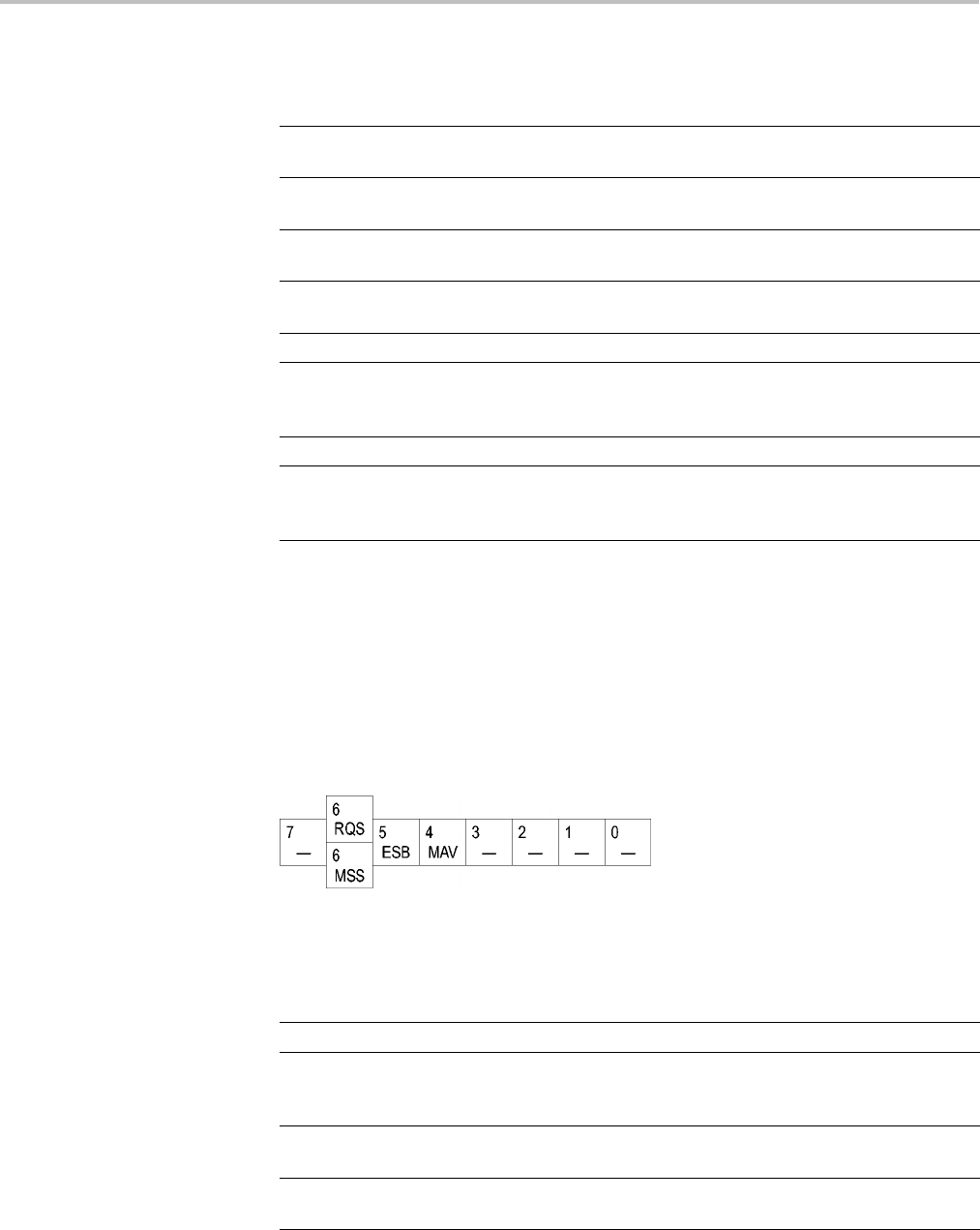
Status and Events
Table 3-1: SESR Bit Functions
Bit Function
7 (MSB) PON Power On. Shows that the oscilloscope was powered on.
On completion, the diagnostic self tests also set this bit.
6URQ User Request.Indicates that an application event has
occurred. *See note.
5CME Command Error. Shows that an error occurred while
the oscilloscope was parsing a command or query.
4 EXE Execution Error. Shows that an error executing a
command or query.
3DDE
Device Error. Shows that a device error occurred.
2QYE Query Error. Either an attempt was made to read the
Output Queue when no data was present or pending, or that
data in the Output Queue was lost.
1RQC Request Control. This is not used.
0 (LSB) OPC Operation Complete. Shows that the operation
is complete. This bit is set when all pending operations
complete following an *OPC command.
The Status Byte Register (SBR). Records whether output is available in the Output
Queue, whether the oscilloscope requests service, and whether the SESR has
recorded any events.
Use a Serial Poll or the *STB? query to read the contents of the SBR. The bits in
the SBR are set and cleared depending on the contents of the SESR, the Event
Status Enable Register (ESER), and the Output Queue. When you use a Serial
Poll to obtain the SBR, bit 6 is the RQS bit. When you use the *STB? query to
obtain the SBR, bit 6 is the MSS bit. Reading the SBR does not clear the bits.
Figure 3-2: The Status Byte Register (SBR)
Table 3-2: SBR Bit Functions
Bit Function
7(MSB) ———— Not used.
6RQS Request Service. Obtained from a serial poll. Shows
that the oscilloscope requests service from the GPIB
controller.
6MSS Master Status Summary. Obtained from *STB?
query. Summarizes the ESB and MAV bits in the SBR.
5ESB Event Status Bit. Shows that status is enabled and
present in the SESR.
3-2 MDO4000/B, MSO/DPO4000B and MDO3000 Series Oscilloscopes Programmer Manual
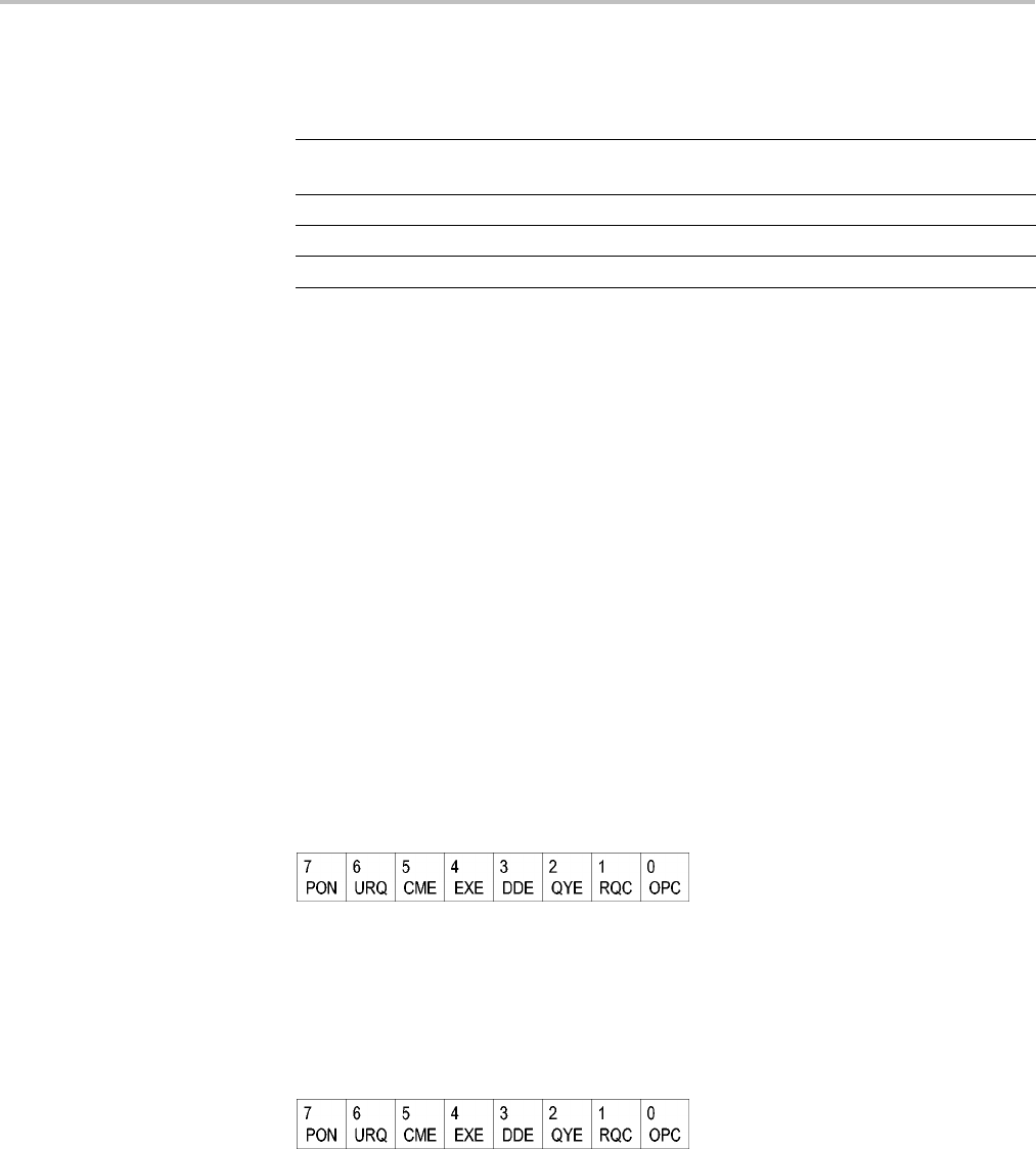
Status and Events
Table 3-2: SBR Bit Functions (cont.)
Bit Function
4MAV
Message Available. Shows that output is available
in the Output Queue.
3———— Not used.
2———— Not used.
1–0 ———— Not used.
Enable Registers DESER, ESER, and SRER allow you to select which events are reported to the
Status Registers and the Event Queue. Each Enable Register acts as a filter to a
Status Register (the DESER also acts as a filter to the Event Queue) and can
prevent information from being recorded in the register or queue.
Each bit in an Enable Register corresponds to a bit in the Status Register it
controls. In order for an event to be reported to a bit in the Status Register, the
corresponding bit in the Enable Register must be set to one. If the bit in the Enable
Register is set to zero, the event is not recorded.
Various commands set the bits in the Enable Registers. The Enable Registers and
the commands used to set them are described below.
The Device Event Status Enable Register (DESER). This register controls which
types of events are reported to the SESR and the Event Queue. The bits in the
DESER correspond to those in the SESR.
Use the DESE command to enable and disable the bits in the DESER. Use the
DESE? query to read the DESER.
Figure 3-3: The Device Event Status Enable Register (DESER)
The Event Status Enable Register (ESER). This register controls which types of
events are summarized by the Event Status Bit (ESB) in the SBR. Use the *ESE
command to set the bits in the ESER. Use the *ESE? query to read it.
Figure 3-4: The Event Status Enable Register (ESER)
The Service Request Enable Register (SRER). This register controls which bits
in the SBR generate a Service Request and are summarized by the Master Status
Summary (MSS) bit.
MDO4000/B, MSO/DPO4000B and MDO3000 Series Oscilloscopes Programmer Manual 3-3
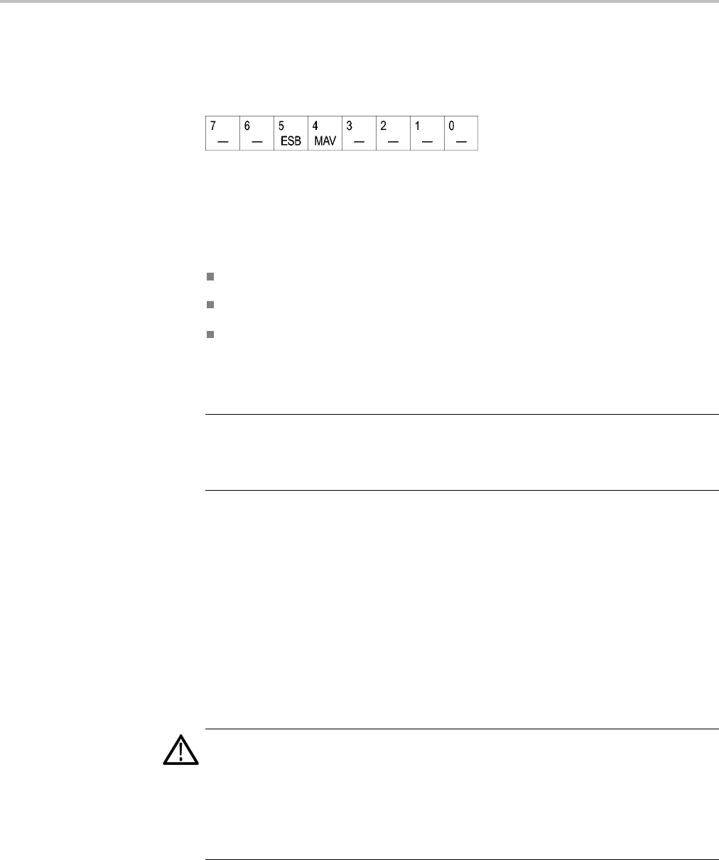
Status and Events
Use the *SRE command to set the SRER. Use the *SRE? query to read the
register. The RQS bit remains set to one until either the Status Byte Register is
read with a Serial Poll or the MSS bit changes back to a zero.
Figure 3-5: The Service Request Enable Register (SRER)
*PSC Command The *PSC command controls the Enable Registers contents at power-on. Sending
*PSC 1 sets the Enable Registers at power on as follows:
DESER 255 (equivalent to a DESe 255 command)
ESER 0 (equivalent to an *ESE 0 command)
SRER 0 (equivalent to an *SRE 0 command)
Sending *PSC 0 lets the Enable Registers maintain their values in nonvolatile
memory through a power cycle.
NOTE. To enable the PON (Power On) event to generate a Service Request, send
*PSC 0, use the DESe and *ESE commands to enable PON in the DESER and
ESER, and use the *SRE command to enable bit 5 in the SRER. Subsequent
power-on cycles will generate a Service Request.
Queues
The *PSC command controls the Enable Registers contents at power-on. Sending
*PSC 1 sets the Enable Registers at power on as follows:
Output Queue The oscilloscope stores query responses in the Output Queue and empties this
queue each time it receives a new command or query message after an <EOM>.
The controller must read a query response before it sends the next command (or
query) or it will lose responses to earlier queries.
CAUTION. When a controller sends a query, an <EOM>, and a second query,
the oscilloscope normally clears the first response and outputs the second while
reporting a Query Error (QYE bit in the ESER) to indicate the lost response. A
fast controller, however, may receive a part or all of the firstresponseaswell. To
avoid this situation, the controller should always read the response immediately
after sending any terminated query message or send a DCL (Device Clear) before
sending the second query.
3-4 MDO4000/B, MSO/DPO4000B and MDO3000 Series Oscilloscopes Programmer Manual

Status and Events
Event Queue The Event Queue storesdetailedinformationonupto33events. Ifthan32
events stack up in the Event Queue, the 32nd event is replaced by event code
350, "Queue Overflow."
Read the Event Queue with the EVENT? query (which returns only the event
number), with the EVMSG? query (which returns the event number and a text
description of the event), or with the ALLEV? query (which returns all the event
numbers along with a description of the event). Reading an event removes it
from the queue.
Before reading an event from the Event Queue, you must use the *ESR? query to
read the summary of the event from the SESR. This makes the events summarized
by the *ESR? read available to the EVENT? and EVMSG? queries, and empties
the SESR.
Reading the SESR erases any events that were summarized by previous *ESR?
reads but not read from the Event Queue. Events that follow an *ESR? read are
put in the Event Queue but are not available until *ESR? is used again.
Event Handling Sequence
The following figure shows how to use the status and event handling system. In
the explanation that follows, numbers in parentheses refer to numbers in the figure.
MDO4000/B, MSO/DPO4000B and MDO3000 Series Oscilloscopes Programmer Manual 3-5
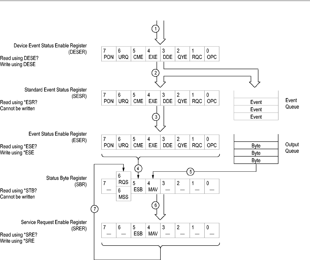
Status and Events
Figure 3-6: Status and Event Handling Process
When an event occurs, a signal is sent to the DESER (1). If that type of event
is enabled in the DESER (that is, if the bit for that event type is set to 1), the
appropriate bit in the SESR is set to one, and the event is recorded in the Event
Queue (2). If the corresponding bit in the ESER is also enabled (3), then the
ESB bit in the SBR is set to one (4).
When output is sent to the Output Queue, the MAV bit in the SBR is set to one (5).
When a bit in the SBR is set to one and the corresponding bit in the SRER
is enabled (6), the MSS bit in the SBR is set to one and a service request is
generated (7).
3-6 MDO4000/B, MSO/DPO4000B and MDO3000 Series Oscilloscopes Programmer Manual

Status and Events
Synchronization Methods
Overview Although most commands are completed almost immediately after being received
by the oscilloscope, some commands start a process that requires time. For
example, once a single sequence acquisition command is executed, depending
upon the applied signals and trigger settings, it may take an extended period
of time before the acquisition is complete. Rather than remain idle while the
operation is in process, the oscilloscope will continue processing other commands.
This means that some operations will not be completed in the order that they
were sent. Furthermore, sometimes the result of an operation depends upon the
result of an earlier operation. A first operation must complete before the next
one is processed.
In order to handle these situations, the oscilloscope status and event reporting
system allows you to synchronize the operation of the oscilloscope with your
application program, using the Operation Complete function. Note, however,
that only some operations are able to take advantage of this function; a table is
provided below of commands that support this.
The following commands are used to synchronize the oscilloscope functions
using Operation Complete. See examples of how to use these commands later
on in this section:
*OPT? — sending the *OPC command will set bit 0 of the SESR (Standard
Events Status Register). The bit will only be set high when all pending operations
that generate an OPC message have finished execution. (The SESR is queried
using *ESR?)The*OPC? query form returns 1 only when all operations have
completed, or a device clear is received.
*WAI — prevents the oscilloscope from executing further commands or queries
until all pending commands that generate an OPC message are complete.
BUSY? — returns the status of operations: 1 means there are pending operations,
0 means that all pending operations are complete.
NOTE. Some OPC operations may require an extended period of time to complete
or may never complete. For example, a single sequence acquisition may never
complete when no trigger event occurs. You should be aware of these conditions
and tailor your program accordingly by:
— setting the timeout sufficiently for the anticipated maximum time for the
operation and
— handle a timeout appropriately by querying the SESR (*ESR?) and event queue
(EVMsg? or ALLEv?).
MDO4000/B, MSO/DPO4000B and MDO3000 Series Oscilloscopes Programmer Manual 3-7

Status and Events
NOTE. The *OPC command form can also be used to cause an SRQ to be
generated upon completion of all pending operations. This requires that the
ESB (Event Status Bit, bit 5) of the SRER (Service Request Enable Regiser) is set,
and the OPC bit (bit 0) of the DESR (Device Event Status Enable Register) and
the ESER (Event Status Enable Register) are set. (The SRER is set/queried using
*SRE. The DESR is set/queried using DESE. The ESER is set/queried using *ESE.)
Only a subset of oscilloscope operations support the Operation Complete function
(OPC):
Table 3-3: Oscilloscope operations that can generate OPC
Command Conditions
ACQuire:STATE <non-zero NR1> | ON |RUN Only when in single sequence acquisition
mode
:AUTOSet < EXECute | UNDo >
CALibrate:INTERNal
CALibrate:INTERNal:STARt
CALibrate:FACtory STARt
CALibrate:FACtory CONTinue
CALibrate:FACtory PREVious
CH<x>:PRObe:AUTOZero EXECute
CH<x>:PRObe:DEGAUss EXECute
DIAg:STATE EXECute
FACtory
HARDCopy
HARDCopy START
MASK:TESt:SRQ:COMPLetion (1|ON) upon completion of test
MASK:TESt:SRQ:FAILure (1|ON) upon failure of test
:POWer:RIPPle < VERTAUTOset |
VERTDEFault >
RECAll:MASK <file>
RECAll:SETUp (<file as quoted
string>|FACtory)
RECAll:WAVEform <.ISF or .CSV file >,<
REF1|REF2|REF3|REF4 >
:RF:REFLevel AUTO
*RST
SAVe:IMAGe <file as quoted string>
SAVe:SETUp <file as quoted string>
SAVe:WAVEform < source wfm >, (<
REF1|REF2|REF3|REF4 >|< file >)
3-8 MDO4000/B, MSO/DPO4000B and MDO3000 Series Oscilloscopes Programmer Manual
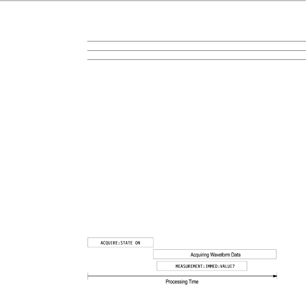
Status and Events
Table 3-3: Oscilloscope operations that can generate OPC (cont.)
Command Conditions
TEKSecure
:TRIGger:A SETLevel
Example of Acquiring
and Measuring a
Single-Sequence
Waveform
For example, a typical application might involve acquiring a single-sequence
waveform andthentakingameasurementontheacquiredwaveform.Youcould
use the following command sequence to do this:
/** Set up conditional acquisition **/
ACQUIRE:STATE OFF
SELECT:CH1 ON
HORIZONTAL:RECORDLENGTH 1000
ACQUIRE:MODE SAMPLE
ACQUIRE:STOPAFTER SEQUENCE
/** Acquire waveform data **/
ACQUIRE:STATE ON
/** Set up the measurement parameters **/
MEASUREMENT:IMMED:TYPE AMPLITUDE
MEASUREMENT:IMMED:SOURCE CH1
/** Take amplitude measurement **/
MEASUREMENT:MEAS1:VALUE?
The acquisition of the waveform requires extended processing time. It may not
finish before the oscilloscope takes an amplitude measurement (see the following
figure). This can result in an incorrect amplitude value.
Figure 3-7: Command Processing Without Using Synchronization
To ensure the oscilloscope completes waveform acquisition before taking the
measurement on the acquired data, you can synchronize the program using *WAI,
BUSY, *OPC, and *OPC?.
MDO4000/B, MSO/DPO4000B and MDO3000 Series Oscilloscopes Programmer Manual 3-9
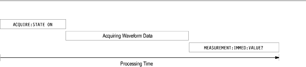
Status and Events
Figure 3-8: Processing Sequence With Synchronization
Example of Using the *OPC
Command
If the corresponding status registers are enabled, the *OPC command sets the
OPC bit in the Standard Event Status Register (SESR) when an operation is
complete. You achieve synchronization by using this command with either a
serial poll or service request handler.
Serial Poll Method: Enable the OPC bit in the Device Event Status Enable
Register (DESER) and the Event Status Enable Register (ESER) using the DESE
and *ESE commands.
When the operation is complete, the OPC bit in the Standard Event Status Register
(SESR) will be enabled and the Event Status Bit (ESB) in the Status Byte Register
will be enabled.
The same command sequence using the *OPC command for synchronization with
serial polling looks like this:
/* Set up conditional acquisition */
ACQUIRE:STATE OFF
SELECT:CH1 ON
HORIZONTAL:RECORDLENGTH 1000
ACQUIRE:MODE SAMPLE
ACQUIRE:STOPAFTER SEQUENCE
/* Enable the status registers */
DESE 1
*ESE 1
*SRE 0
/* Acquire waveform data */
ACQUIRE:STATE ON
/* Set up the measurement parameters */
MEASUREMENT:IMMED:TYPE AMPLITUDE
MEASUREMENT:IMMED:SOURCE CH1
/* Wait until the acquisition is complete before taking the
measurement.*/
*OPC
While serial poll = 0, keep looping
/* Take amplitude measurement */
MEASUREMENT:IMMED:VALUE?
This technique requires less bus trafficthandidloopingonBUSY.
3-10 MDO4000/B, MSO/DPO4000B and MDO3000 Series Oscilloscopes Programmer Manual

Status and Events
Service Request Method: Enable the OPC bit in the Device Event Status Enable
Register (DESER) and the Event Status Enable Register (ESER) using the DESE
and *ESE commands.
You can also enable service requests by setting the ESB bit in the Service Request
Enable Register (SRER) using the *SRE command. When the operation is
complete, the oscilloscope will generate a Service Request.
The same command sequence using the *OPC command for synchronization
looks like this
/* Set up conditional acquisition */
ACQUIRE:STATE OFF
SELECT:CH1 ON
HORIZONTAL:RECORDLENGTH 1000
ACQUIRE:MODE SAMPLE
ACQUIRE:STOPAFTER SEQUENCE
/* Enable the status registers */
DESE 1
*ESE 1
*SRE 32
/* Acquire waveform data */
ACQUIRE:STATE ON
/* Set up the measurement parameters */
MEASUREMENT:IMMED:TYPE AMPLITUDE
MEASUREMENT:IMMED:SOURCE CH1
/* Wait until the acquisition is complete before taking the
measurement*/
*OPC
The program can now do different tasks such as talk to other devices. The SRQ,
when it comes, interrupts those tasks and returns control to this task.
/* Take amplitude measurement */
MEASUREMENT:IMMED:VALUE?
Example of Using the
*OPC? Query
The *OPC? query places a 1 in the Output Queue once an operation that generates
an OPC message is complete. The *OPC? query does not return until all pending
OPC operations have completed. Therefore, your time-out must be set to a time at
least as long as the longest expected time for the operations to complete.
The same command sequence using the *OPC? query for synchronization looks
like this:
/* Set up single sequence acquisition */
ACQUIRE:STATE OFF
SELECT:CH1 ON
HORIZONTAL:RECORDLENGTH 1000
ACQUIRE:MODE SAMPLE
ACQUIRE:STOPAFTER SEQUENCE
MDO4000/B, MSO/DPO4000B and MDO3000 Series Oscilloscopes Programmer Manual 3-11

Status and Events
/* Acquire waveform data */
ACQUIRE:STATE ON
/* Set up the measurement parameters */
MEASUREMENT:IMMED:TYPE AMPLITUDE
MEASUREMENT:IMMED:SOURCE CH1
/* Wait until the acquisition is complete before taking the
measurement*/
*OPC?
Wait for read from Output Queue.
/* Take amplitude measurement */
MEASUREMENT:IMMED:VALUE?
This is the simplest approach. It requires no status handling or loops. However,
you must set the controller time-out for longer than the acquisition operation.
Example of Using the *WAI
Command
The *WAI command forces completion of previous commands that generate
an OPC message. No commands after the *WAI are processed before the OPC
message(s) are generated
The same command sequence using the *WAI command for synchronization
looks like this:
/* Set up conditional acquisition */
ACQUIRE:STATE OFF
SELECT:CH1 ON
HORIZONTAL:RECORDLENGTH 1000
ACQUIRE:MODE SAMPLE
ACQUIRE:STOPAFTER SEQUENCE
/* Acquire waveform data */
ACQUIRE:STATE ON
/* Set up the measurement parameters */
MEASUREMENT:IMMED:TYPE AMPLITUDE
MEASUREMENT:IMMED:SOURCE CH1
/* Wait until the acquisition is complete before taking
the measurement*/
*/
*WAI
/* Take amplitude measurement */
MEASUREMENT:IMMED:VALUE?
The controller can continue to write commands to the input buffer of the
oscilloscope, but the commands will not be processed by the oscilloscope until
all in-process OPC operations are complete. If the input buffer becomes full,
the controller will be unable to write commands to the buffer. This can cause a
time-out.
3-12 MDO4000/B, MSO/DPO4000B and MDO3000 Series Oscilloscopes Programmer Manual

Status and Events
Example of Using the
BUSY Query
The BUSY? query allows you to find out whether the oscilloscope is
busy processing a command that has an extended processing time such as
single-sequence acquisition.
The same command sequence, using the BUSY? query for synchronization, looks
like this:
/* Set up conditional acquisition */
ACQUIRE:STATE OFF
SELECT:CH1 ON
HORIZONTAL:RECORDLENGTH 1000
ACQUIRE:MODE SAMPLE
ACQUIRE:STOPAFTER SEQUENCE
/* Acquire waveform data */
ACQUIRE:STATE ON
/* Set up the measurement parameters */
MEASUREMENT:IMMED:TYPE AMPLITUDE
MEASUREMENT:IMMED:SOURCE CH1
/* Wait until the acquisition is complete before taking
the measurement */
While BUSY? keep looping
/* Take amplitude measurement */
MEASUREMENT:IMMED:VALUE?
This sequence lets you create your own wait loop rather than using the *WAI
command. The BUSY? query helps you avoid time-outs caused by writing too
many commands to the input buffer. The controller is still tied up though, and
the repeated BUSY? query will result in bus traffic.
Messages The information contained in the topics above covers all the programming
interface messages the oscilloscope generates in response to commands and
queries.
For most messages, a secondary message from the oscilloscope gives detail about
the cause of the error or the meaning of the message. This message is part of the
message string and is separated from the main message by a semicolon.
Each message is the result of an event. Each type of event sets a specific bit in the
SESR and is controlled by the equivalent bit in the DESER. Thus, each message
is associated with a specific SESR bit. In the message tables, the associated SESR
bit is specified in the table title, with exceptions noted with the error message text.
No Event The following table shows the messages when the system has no events or status
to report. These have no associated SESR bit.
MDO4000/B, MSO/DPO4000B and MDO3000 Series Oscilloscopes Programmer Manual 3-13

Status and Events
Table 3-4: No Event Messages
Code Message
0 No events to report; queue empty
1No events to report; new events pending *ESR?
Command Error The following table shows the command error messages generated by improper
syntax. Check that the command is properly formed and that it follows the rules
in the section on command Syntax.
Table 3-5: Command Error Messages (CME Bit 5)
Code Message
100 Command error
101 Invalid character
102 Syntax error
103 Invalid separator
104 Data type error
105 GET not allowed
108 Parameter not allowed
109 Missing parameter
110 Command header error
112 Program mnemonic too long
113 Undefined header
120 Numeric data error
121 Invalid character in numeric
123 Exponent too large
124 Too many digits
130 Suffixerror
131 Invalid suffix
134 Suffix too long
140 Character data error
141 Invalid character data
144 Character data too long
150 String data error
151 Invalid string data
152 String data too long
160 Block data error
161 Invalid block data
170 Command expression error
171 Invalid expression
3-14 MDO4000/B, MSO/DPO4000B and MDO3000 Series Oscilloscopes Programmer Manual

Status and Events
Execution Error The following table lists the execution errors that are detected during execution of
a command.
Table 3-6: Execution Error Messages (EXE Bit 4)
Code Message
200 Execution error
221 Settings conflict
222 Data out of range
224 Illegal parameter value
241 Hardware missing
250 Mass storage error
251 Missing mass storage
252 Missing media
253 Corrupt media
254 Media full
255 Directory full
256 File name not found
257 File name error
258 Mediaprotected
259 File name too long
270 Hardcopy error
271 Hardcopy device not responding
272 Hardcopy is busy
273 Hardcopy aborted
274Hardcopy configuration error
280Program error
282 Insufficient network printer information
283 Network printer not responding
284 Network printer server not responding
286 Program runtime error
287 Print server not found
2200 Measurement error, Measurement system error
2201 Measurement error, Zero period
2202 Measurement error, No period, second waveform
2203 Measurement error, No period, second waveform
2204 Measurement error, Low amplitude, second waveform
2205 Measurement error, Low amplitude, second waveform
2206 Measurement error, Invalid gate
2207 Measurement error, Measurement overflow
MDO4000/B, MSO/DPO4000B and MDO3000 Series Oscilloscopes Programmer Manual 3-15

Status and Events
Table 3-6: Execution Error Messages (EXE Bit 4) (cont.)
Code Message
2208 Measurement error, No backwards Mid Ref crossing
2209 Measurement error, No second Mid Ref crossing
2210 Measurement error, No Mid Ref crossing, second waveform
2211 Measurement error, No backwards Mid Ref crossing
2212 Measurement error, No negative crossing
2213 Measurement error, No positive crossing
2214 Measurement error, No crossing, target waveform
2215 Measurement error, No crossing, second waveform
2216 Measurement error, No crossing, target waveform
2217 Measurement error, Constant waveform
2219 Measurement error, No valid edge - No arm sample
2220 Measurement error, No valid edge - No arm cross
2221 Measurement error, No valid edge - No trigger cross
2222 Measurement error, No valid edge - No second cross
2223 Measurement error, Waveform mismatch
2224 Measurement error, WAIT calculating
2225 Measurement error, No waveform to measure
2226 Measurement error, Null Waveform
2227 Measurement error, Positive and Negative Clipping
2228 Measurement error, Positive Clipping
2229 Measurement error, Negative Clipping
2230 Measurement error, High Ref < Low Ref
2231 Measurement error, No statistics available
2233 Requested waveform is temporarily unavailable
2235 Math error, invalid math description
2240 Invalid password
2241 Waveform requested is invalid
2244 Source waveform is not active
2245 Saveref error, selected channel is turned off
2250 Reference error, the reference waveform file is invalid
2253 Reference error, too many points received
2254 Reference error, too few points received
2259 File too big
2270 Alias error
2271 Alias syntax error
2273 Illegal alias label
2276 Alias expansion error
3-16 MDO4000/B, MSO/DPO4000B and MDO3000 Series Oscilloscopes Programmer Manual

Status and Events
Table 3-6: Execution Error Messages (EXE Bit 4) (cont.)
Code Message
2277 Alias redefinition not allowed
2278 Alias header not found
2285 TekSecure(R) Pass
2286 TekSecure(R) Fail
2500 Setup error, file does not look like a setup file
2501 Setup warning, could not recall all values from external setup
2620 Mask error, too few points received
2760 Mark limit reached
2761 No mark present
2762 Search copy failed
Device Error The following table lists the device errors that can occur during oscilloscope
operation. These errors may indicate that the oscilloscope needs repair.
Table 3-7: Device Error Messages (DDE Bit 3)
Code Message
310 System error
311 Memory error
312 PUD memory lost
314 Save/recall memory lost
System Event The following table lists the system event messages. These messages are
generated whenever certain system conditions occur.
Table 3-8: System Event Messages
Code Message
400 Query event
401 Power on (PON bit 7 set)
402 Operation complete (OPC bit 0 set)
403 User request (URQ bit 6 set)
404 Power fail (DDE bit 3 set)
405 Request control
410 Query INTERRUPTED (QYE bit 2 set)
420 Query UNTERMINATED (QYE bit 2 set)
430 Query DEADLOCKED (QYE bit 2 set)
440 Query UNTERMINATED after indefinite response (QYE bit 2 set)
MDO4000/B, MSO/DPO4000B and MDO3000 Series Oscilloscopes Programmer Manual 3-17

Status and Events
Table 3-8: System Event Messages (cont.)
Code Message
468 Knob/Keypad value changed
472 Application variable changed
Execution Warning The following table lists warning messages that do not interrupt the flow of
command execution. They also notify you of possible unexpected results.
Table 3-9: Execution Warning Messages (EXE Bit 4)
Code Message
528 Parameter out of range
532 Curve data too long, Curve truncated
533 Curve error, Preamble values are inconsistent
540 Measurement warning, Uncertain edge
541 Measurement warning, Low signal amplitude
542 Measurement warning, Unstable histogram
543 Measurement warning, Low resolution
544 Measurement warning, Uncertain edge
545 Measurement warning, Invalid in minmax
546 Measurement warning, Need 3 edges
547 Measurement warning, Clipping positive/negative
548 Measurement warning, Clipping positive
549 Measurement warning, Clipping negative
Table 3-10: Execution Warning Messages (EXE Bit 4)
Code Message
540 Measurement warning
541 Measurement warning, Low signal amplitude
542 Measurement warning, Unstable histogram
543 Measurement warning, Low resolution
544 Measurement warning, Uncertain edge
545 Measurement warning, Invalid min max
546 Measurement warning, Need 3 edges
547 Measurement warning, Clipping positive/negative
548 Measurement warning, Clipping positive
549 Measurement warning, Clipping negative
3-18 MDO4000/B, MSO/DPO4000B and MDO3000 Series Oscilloscopes Programmer Manual

Status and Events
Internal Warning The following table shows internal errors that indicate an internal fault in the
oscilloscope.
Table 3-11: Internal Warning Messages
Code Message
630 Internal warning, 50Ωoverload
MDO4000/B, MSO/DPO4000B and MDO3000 Series Oscilloscopes Programmer Manual 3-19

Status and Events
3-20 MDO4000/B, MSO/DPO4000B and MDO3000 Series Oscilloscopes Programmer Manual

Appendices
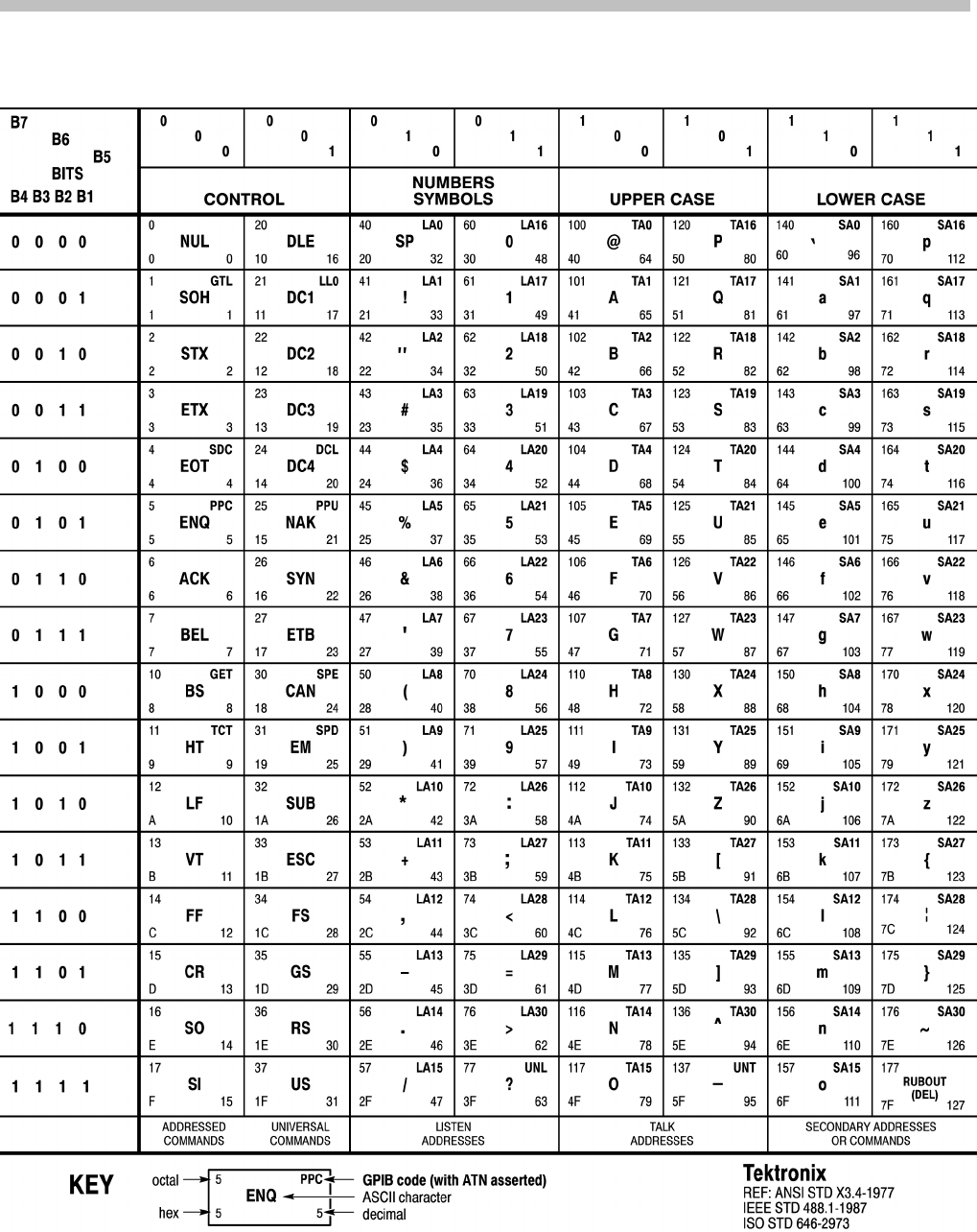
Appendix A: Character Set
MDO4000/B, MSO/DPO4000B and MDO3000 Series Oscilloscopes Programmer Manual A-1

Appendix A: Character Set
A-2 MDO4000/B, MSO/DPO4000B and MDO3000 Series Oscilloscopes Programmer Manual

Appendix B: Reserved Words
This is a list of reserved words for your instrument. Capital letters identify the
required minimum spelling.
*CAL
*CLS
*DDT
*ESE
*ESR
*IDN
*LRN
*OPC
*OPT
*PSC
*PUD
*RCL
*RST
*SAV
*SRE
*STB
*TRG
*TST
*WAI
0
1
2
3
7
8
9
A
ABORt
ABSolute
AC
ACDCRMS
ACK
ACKMISS
ACKMISSERROR
ACKnum
ACPR
ACQ
ACQCOMPLete
ACQLENGTH
ACQuire
ACRMS
ACTION
ACTIVeprinter
ACTIVity
ACTONEVent
ADD
ADDR10
ADDR7
ADDRANDDATA
ADDRess
ADDress
ADJACENTPAIRs
ADVMATH
ADVTRIG
ADVanced
AFG
ALIas
ALIas[
ALL
ALLEv
ALLFields
ALLLines
ALTERNATE
ALWAYS
AMPLitude
AMPSVIAVOLTs
AMPlitude
ANALOG
ANALOg
AND
ANY
APPKey
APPLication
APPLications
APPpwr
ARB
ARBitrary
ARB
AREa
ASCII
ASCIi
ASCii
ASSIgn
ATRIGger
AUDIO
AUDio
AUTO
AUTOContrast
AUTORange
AUTOSCale
AUTOSet
AUTOZero
AUTOmatic
AUX
AUXIN
AUXOUT
AUXOut
AUXin
AUXout
AVAILable
AVErage
Auto
B
B1
B2
B3
B4
BACKLight
BACKWards
BANDWidth
BANdwidth
BASE
BASic
BCR
BDIFFBP
BILevelcustom
BINary
BIT
BITDelay
BITOrder
BITRate
BITSTUFFing
BIT_Nr
BIT
BLAckmanharris
BLOCKHEX
BM
BMP
BN_Fmt
BOTh
BOX
BOXPcnt
BRIGHTNess
BTRIGger
BULK
BURst
BUS
BUS1
BUS2
BUS3
BUS4
BUSWAVEFORMS
BUSY
BUS
BY
BYPass
BYT_Nr
BYT_Or
Block
BlockWfmInDTO
B
C1
C2
C3
CALCmethod
CALIBRATABLe
CALibrate
CAN
CANH
CANL
CARD
CARDIac
CARea
CATalog
CENTER
CENTERFREQuency
CH1
CH2
CH3
CH4
CHANBW
CHANSPACing
CHANnel
CHannel
CHecksum
CH
CLASSALIMit
CLAss
CLEAR
CLEARMenu
CLEARSNapshot
CLEar
CLIPPing
CLOCKCoax
MDO4000/B, MSO/DPO4000B and MDO3000 Series Oscilloscopes Programmer Manual B-1

Appendix B: Reserved Words
CLOCKSymmetrical
CLOCk
CMEan
CMOS_2_5V
CMOS_3_3V
CMOS_5_0V
COLUMN
COMMAND
COMPLetion
CONDCALCmethod
CONDition
CONDuction
CONFIGuration
CONFigure
CONTROl
CONTRast
CONTRol
COPYACTive
COPy
COUNt
COUPling
CP
CPU
CR
CRC
CRC16
CRC5
CRCHeader
CRCTrailer
CREATE
CREATEmask
CRITerion
CRMs
CROSSHair
CSPLIT
CURRENTSOurce
CURRent
CURSor
CURSors
CURVe
CURrent
CURsor
CUSTOMMask
CUSTom
CWD
CYCLEcount
D
D0
D1
D10
D11
D12
D13
D14
D15
D2
D3
D4
D5
D6
D7
D8
D9
DATA
DATA0
DATA1
DATABits
DATAPacket
DATE
DATEPrint
DATa
DAll
DB
DBCA
DBM
DBMA
DBMV
DBUA
DBUV
DBUW
DC
DCREJect
DDT
DECimal
DEFLT
DEFault
DEFine
DEGAUss
DEGrees
DELEte
DELEte[
DELIMiter
DELTa
DELTatime
DELay
DELayed
DELete
DELta
DEMO
DESE
DESKew
DESTination
DESTinationaddr
DESTinationport
DESkew
DETECTionmethod
DHCPbootp
DIAg
DIFFerential
DIGITAl
DIGital
DIR
DIRection
DISPLAYSTYle
DISPlay
DISabled
DISplay
DISplaymode
DMINus
DNS
DOMAINname
DOMain
DOTsonly
DPLUs
DRAFT
DRIve
DS1
DS1A
DS1C
DS1Rate
DS2
DS2RATECoax
DS2RATESymmetrical
DS3
DS3Rate
DS4NA
DS4XNA
DSOContra
DSODouble
DSOSingle
DSOTiming
DUAL
DUty
DVM
DYNAMic
D
E
E1Coax
E1Symmetrical
E2
E3
ECL
EDECAy
EDGE
EDGE
EDGe
EEPROM
EITHer
EITher
EMAIL
EMEM
ENABle
ENAble
ENCdg
END
ENDPoint
ENERGY
ENERGYLoss
ENET
ENET100BASETX
ENET10BASET
ENGLish
ENV
ENVelope
EOF
EOFTYPE
EOP
EQual
ERISe
ERROR
ERRTYPE
ERRlog
ERRor
ESCOPEENABle
ET
ETHERNET
ETHERnet
EVEN
EVENT
EVENTS
EVENTTYPe
EVENTtable
EVMsg
EVQty
EXCURsion
EXECute
EXT
EXTVIDEO
EXTended
EXTernal
FACtor
FACtory
FAIL
FAILURES
FAILure
FAILures
FALL
FALSe
FALling
FASTAcq
FASTPHOTO
FASTer
B-2 MDO4000/B, MSO/DPO4000B and MDO3000 Series Oscilloscopes Programmer Manual

Appendix B: Reserved Words
FAStest
FCSError
FFT
FIELD
FIFty
FILEFormat
FILESystem
FILter
FINE
FIRst
FIVEdivs
FIXEDFREQValue
FIXEDFREQuency
FLATtop
FLAg
FLEXRAY
FLEXRay
FLEXray
FOCUS
FOLder
FORCEDRange
FORCe
FORMat
FORWards
FP
FPAnel
FPbinary
FRAME
FRAMEID
FRAMESync
FRAMETYPe
FRAMEType
FRAMETypeid
FRAMEtype
FRAMING
FRAMetime
FRAme
FREE
FREESpace
FREErun
FRENch
FREQREFerence
FREQRef
FREQuency
FROMADDRess
FULL
FULLSPeed
FULl
FUNCtion
FUNDamental
G703DS1
G703DS3
GAIN
GATEMid
GATESOurce
GATEWay
GATIng
GATe
GATing
GAUSsian
GENeralcall
GENerate
GERMan
GNDCPLG
GPIBUsb
GRAph
GRAticule
GRId
GROUPing
HAGAKIPCARD
HAGAKIPcard
HALFgrat
HAMming
HANDSHAKEPacket
HANDSHAKEType
HANning
HARDCopy
HARM3ALTernate
HARM5ALTernate
HARMSOURce
HARMonics
HARlt;1-400>
HAVERSINe
HBArs
HD1080I50
HD1080I60
HD1080P24
HD1080P25
HD1080P30
HD1080P50
HD1080P60
HD1080SF24
HD480P60
HD576P50
HD720P30
HD720P50
HD720P60
HD875I60
HDR
HDtv
HEADER
HEADer
HEADertime
HEIght
HERtz
HEXadecimal
HFRej
HIGH
HIGHLevel
HIGHLimit
HIGHZ
HIRes
HISTOGRAM
HIStogram
HIStory
HITS
HIVALue
HOLD
HOLDTime
HOLDoff
HORZ
HORizontal
HORizontal[
HOSTALIASNAMe
HPOS
HS
HSCAle
HST1
HST2
HST3
HST4
HST5
HST6
HSmode
HTRIGPOS
HTTPPort
HUB
HYSTeresis
I2C
I2S
ICRESTfactor
ID
IDANDDATA
IDFORmat
IDLETime
IDLEtime
IDLe
IDPrint
IDentifier
IEC
IECMAX
IMAGESize
IMAGe
IMAge
IMMed
IMPEDance
IMPedance
IN
IN2P5BY3P25
IN4BY6
IN8BY10
INDBits
INDICators
INDIvidual
INDependent
INFInite
INFMAXimum
INFMINimum
INIT
INITialize
INKSaver
INPUTPOWer
INPut
INSTR
INTENSITy
INTERLAced
INTERNal
INTERRUPT
INTERnal
INVERTed
INVert
INVerted
INrange
IO
IPADDress
IPHeader
IPv4
IRMS
ISCLOCKed
ISOALL
ISOEND
ISOMID
ISOSTART
ISOchronous
ITALian
JAPAnese
KAIser
L
L2
L4
LA1DB
LA2DB
LA3DB
LABEL
LABel
LAN
LANGuage
LANdscape
LARge
LAYout
LDIR
LEFt
MDO4000/B, MSO/DPO4000B and MDO3000 Series Oscilloscopes Programmer Manual B-3

Appendix B: Reserved Words
LENgth
LESSEQual
LESSLimit
LESSthan
LEVELPreset
LEVel
LF
LFRej
LICENSE
LIMITMask
LIMITS
LIMit
LIN
LINE
LINEAr
LINEFREQuency
LINEPeriod
LINear
LIST
LJ
LOAd
LOCation
LOCk
LOG
LOGIC
LOGIc
LOOP
LORENtz
LOW
LOWCurrent
LOWERFreq
LOWLevel
LOWLimit
LOWSPeed
LOWVoltage
LOWerthreshold
LSB
LXI
MAC
MACADDRess
MACLENgth
MAG
MAGnivu
MAIn
MAIn
MANCHester
MANual
MARK
MARKER
MARKSINCOLumn
MARgin
MASK
MASK
MATH
MATH1
MATHVAR
MATH[1]
MATLAB
MAX
MAXAmps
MAXBytedelim
MAXSAMPLERate
MAXSamplerate
MAXVolts
MAXWatts
MAXimum
ME
MEAN
MEAS
MEASUre
MEASUrement
MEAS
MEASx
MEDium
MEG
MESSage
METHod
MID
MIL
MIL1553B
MIN
MINImum
MINMax
MINUSpeak
MINimum
MISO
MISOMOSI
MIXED2
MIXed
MKDir
MM100BY150
MM54BY86
MODe
MODel
MODulation
MOREEQual
MORELimit
MOREthan
MOSI
MOUNT
MSB
M
NAK
NAME
NAMe
NANd
NDUty
NEDGECount
NEGative
NETWORKCONFig
NETWORKDRIVES
NEWpass
NEXT
NEXt
NO
NOCARE
NOISEAdd
NOISEDensity
NOISErej
NOISe
NOISeNR1
NONe
NOPARity
NOR
NORMAL
NORMal
NOTCOMPuted
NOVershoot
NPULSECount
NR1
NR1RangesL21000
NR2NR2NR2NR2
NR3
NR3NR3NR3NR3
NR3RangesD001000
NR3RangesD1e61E6
NRMAL
NR_HARMonics
NR_Pt
NTIMES
NTIMes
NTSC
NTSc
NULL
NULLFRDynamic
NULLFRStatic
NULl
NUMACQs
NUMACq
NUMAVg
NUMBUS
NUMCHANnels
NUMCYCles
NUMENTries
NUMERic
NUMEnv
NUMHORZ
NUMMEAS
NUMPoints
NUMREFS
NUMSLICEs
NUMVERT
NWIdth
NrfWfmInDTO
OBSPERiod
OBW
OCCURS
ODD
OFF
OFFSet
ON
ONCE
ONE
ONFAIL
OPTion
OR
OTHER
OUT
OUTPut
OUTrange
OUTside
OVERLoad
OWNer
PACKET
PAL
PALEtte
PAPERSize
PAPERType
PARallel
PARity
PASS
PASSFail
PASSWord
PATtern
PAUSe
PAYLength
PAYLoad
PDUty
PEAK
PEAKdetect
PEDGECount
PERCENTdown
PERCent
PERIod
PERSistence
PERcent
PHASENoise
PHASEangle
PHASe
PHOTO
PICTBridge
PID
B-4 MDO4000/B, MSO/DPO4000B and MDO3000 Series Oscilloscopes Programmer Manual

Appendix B: Reserved Words
PING
PIXel
PK2Pk
PLAIN
PLOTTYPe
PLUSpeak
PNG
POHC
POHCLIMit
POHL
POINTS
POLARCord
POLar
POLarity
PORT
PORTRait
PORTUguese
POSITION
POSition
POSitive
POVershoot
POWERFACtor
POWERFactor
POWERLEVel
POWERLoss
POWer
POWerupstatus
PPULSECount
PREAmp
PRESS
PREVIEW
PREViewstate
PREVious
PREamble
PRINT
PRINTQual
PRINTer
PRODDELta
PRODUCT
PRODUCTID
PRODuct
PROGressive
PROPDELay
PROTOCol
PROTOcol
PRObe
PT_Fmt
PT_ORder
PT_Off
PULSEWidth
PULSe
PULse
PWIdth
QString
QStringQString
QTAG
QTY
QUALifier
QUALity
Qstring
R1
R2
R3
R4
RADIUS
RADIUS
RAMP
RATDELta
RATIO
RATio
RBW
RDELta
RDSon
REACTpwr
READ
READFile
READOUT
RECAll
RECDESkew
RECLENS
RECOrdlength
RECTX
RECTY
RECTangular
REF
REF1
REF2
REF3
REF4
REFERence
REFLEvel
REFLevel
REFOut
REFS
REF
REFx
REM
REMote
REName
REPEATCount
REPEATstart
REPeat
RESERVed
RESET
RESOlution
RESPonsetime
RESPtime
RESUME
RESUlt
RESistance
RESult
RESults
RF
RF_AMPlitude
RF_AVErage
RF_BB_IQ
RF_FD
RF_FREQuency
RF_MAXHold
RF_MINHold
RF_NORMal
RF_PHASe
RF_TD
RI
RIBinary
RIGht
RIPPle
RISEFall
RISe
RISing
RJ
RMDir
RMS
ROM
ROSC
ROSc
RP
RPBinary
RS232C
RUN
RUNSTop
RUNT
RUNt
RWINClude
RX
RXDATA
RXENDPacket
RXSTArt
SAMPLERate
SAMPLEpoint
SAMple
SAVEALL
SAVEIMAGE
SAVEWFM
SAVe
SC
SCAle
SCLk
SCOPE
SCREEN
SCREen
SDAta
SE
SEARCH
SEARCHtotrigger
SECAM
SEConds
SEG
SELECTED
SELect
SELected
SEQnum
SEQuence
SERIALnumber
SERVICENAMe
SERnumber
SET
SETALLtorec
SETHold
SETLevel
SETTODEFaults
SETTime
SETUP
SETUP
SETUp
SFD
SFPbinary
SHOW
SIGNEDDECimal
SIGnal
SINC
SINE
SINGleended
SIZe
SLEEP
SLEWRate
SLICESELect
SLICETIMe
SLOT
SLOWer
SLOpe
SMAll
SMTPLOGIn
SMTPPASSWord
SMTPPort
SMTPServer
SNAPShot
SNAp
SOA
SOCKETServer
SOF
SOFFRAMENUMber
MDO4000/B, MSO/DPO4000B and MDO3000 Series Oscilloscopes Programmer Manual B-5

Appendix B: Reserved Words
SOLid
SOURCe
SOURce
SOUrce
SOUrceaddr
SOUrce
SOUrceport
SPAN
SPANRbwratio
SPANish
SPC
SPECIALPacket
SPECIALType
SPECTRUM
SPECTRUMMode
SPECTRUMTrace
SPECTRogram
SPECTral
SPI
SPLit
SPREADSheet
SPace
SQUELCH
SQUare
SRIbinary
SRPbinary
SRQ
SS
SSPLIT
STALL
STANDARDMask
STANDard
STANdard
STARTofframe
STARTup
STARTupnosync
STARt
STARtbyte
STATE
STATE
STATIstics
STATic
STATus
STAYSHigh
STAYSLow
STDdev
STOP
STOPACQ
STOPAfter
STOPOnviol
STOPOnviolation
STS1Eye
STS1Pulse
STS3
STSX3
STYle
STandard
SUBADdress
SUBNETMask
SUBSF
SUSPEND
SWITCHingloss
SWLoss
SYMmetry
SYNC
SYNCField
SYNCFrame
SYNCInterval
SourceDestination
String
TABle
TCPHeader
TDM
TEKSecure
TEMPErature
TEMPLate
TEMPerature
TERMinal
TERmination
TEST
TESTS
TESTnumber
TESt
TF
THDELta
THDF
THDR
THETA
THETA
THReshold
TIFf
TIME
TIMEOut
TIMe
TIQ
TOADDRess
TOFF
TOKENPacket
TOKENType
TOLerance
TON
TOTal
TOTaluptime
TOUSER
TOVershoot
TRACk
TRANSFER
TRANsition
TRBit
TRIGFrequency
TRIGPOS
TRIGTOSAMP
TRIGger
TRIGgered
TRIGgertosearch
TRILevelcustom
TRUEpwr
TRUe
TTL
TURN
TURNON
TWEnty
TWOfifty
TX
TXDATA
TXENDPacket
TXRX
TXSTArt
TYPe
Than
UA1DB
UA2DB
UA3DB
UNDo
UNEQual
UNIts
UNLock
UNMOUNT
UPDATERate
UPPERFreq
UPPerthreshold
USB
USBDevice
USBTMC
USBTmc
USE
USER
USERLIST
V1X
V2X
VALue
VAR
VBArs
VCEsat
VCRESTfactor
VDELTa
VENDORID
VERBose
VERTAUTOset
VERTDEFault
VERTINVert
VERTical
VERT
VIDPIC
VIDPic
VIDeo
VIOLATIONS
VISUAL
VOFFSet
VOLTAGESOurce
VOLTage
VOLts
VPOS
VRMS
VSCAle
WAKEup
WAVEFORMS
WAVEform
WAVFrm
WEIghting
WFId
WFMInpre
WFMOutpre
WFMTYPe
WHEn
WIDth
WINdow
WITHYT
WIThin
WORD
WORDSel
WRITE
WRITEFile
X
X1Y1X2Y2
XDELta
XFF
XINcr
XMAX
XMIN
XUNit
XY
XZEro
Y
YDELta
YES
YMAX
YMIN
YMUlt
YOFf
YUNIts
YUNit
B-6 MDO4000/B, MSO/DPO4000B and MDO3000 Series Oscilloscopes Programmer Manual

Appendix B: Reserved Words
YUNits
YZEro
ZERo
ZOOM
ZOOm
MDO4000/B, MSO/DPO4000B and MDO3000 Series Oscilloscopes Programmer Manual B-7

Appendix B: Reserved Words
B-8 MDO4000/B, MSO/DPO4000B and MDO3000 Series Oscilloscopes Programmer Manual

Appendix C: Factory Defaults
Default Setup
The following table lists the default values for each command.
NOTE. Find the most up-to-date default values for your instrument and software
by performing a TekSecure command, saving the instrument setup and looking
at the instrument or setup file.
Table C-1: Default Values
Item Description
ACQUIRE:FASTACQ:PALETTE TEMPERATURE
ACQUIRE:FASTACQ:STATE 0
ACQUIRE:MAGNIVU 0
ACQUIRE:MODE SAMPLE
ACQUIRE:NUMAVG 16
ACQUIRE:NUMENV INFINITE
ACQUIRE:STATE 1
ACQUIRE:STOPAFTER RUNSTOP
ACTONEVENT:ACTION:AUXOUT:STATE 0
ACTONEVENT:ACTION:EMAIL:SETUP:TOADDRESS "TestString"
ACTONEVENT:ACTION:EMAIL:STATE 0
ACTONEVENT:ACTION:PRINT:STATE 0
ACTONEVENT:ACTION:SAVEIMAGE:STATE 0
ACTONEVENT:ACTION:SAVEWFM:STATE 0
ACTONEVENT:ACTION:SRQ:STATE 0
ACTONEVENT:ACTION:STOPACQ:STATE 1
ACTONEVENT:ACTION:VISUAL:STATE 0
ACTONEVENT:EVENTTYPE NONE
ACTONEVENT:NUMACQS 1
ACTONEVENT:REPEATCOUNT 1.0000
AFG:AMPLITUDE 500.0000E-3
AFG:ARBITRARY:EMEM:POINTS:ENCDG ASCII
AFG:FREQUENCY 100.0E+3
AFG:FUNCTION SINE
AFG:HIGHLEVEL 250.0000E-3
AFG:LEVELPRESET USER
AFG:LOWLEVEL -250.0000E-3
MDO4000/B, MSO/DPO4000B and MDO3000 Series Oscilloscopes Programmer Manual C-1

Appendix C: Factory Defaults
Table C-1: Default Values (cont.)
Item Description
AFG:NOISEADD:PERCENT 0.0E+0
AFG:NOISEADD:STATE 0
AFG:OFFSET 0.0E+0
AFG:OUTPUT:LOAD:IMPEDANCE HIGHZ
AFG:PERIOD 9.9999999999916E-6
AFG:PHASE 0.0E+0
AFG:PULSE:WIDTH 1.0E-6
AFG:RAMP:SYMMETRY 50.0000
AFG:SQUARE:DUTY 50.0000
ALIAS:STATE 0
APPLICATION:TYPE POWER
AUXOUT:SOURCE ATRIGGER
BUS:B1:AUDIO:BITDELAY 1
BUS:B1:AUDIO:BITORDER MSB
BUS:B1:AUDIO:CHANNEL:SIZE 24
BUS:B1:AUDIO:CLOCK:POLARITY RISE
BUS:B1:AUDIO:CLOCK:SOURCE CH1
BUS:B1:AUDIO:DATA:POLARITY NORMAL
BUS:B1:AUDIO:DATA:SIZE 24
BUS:B1:AUDIO:DISPLAY:FORMAT SIGNEDDECIMAL
BUS:B1:AUDIO:FRAME:SIZE 8
BUS:B1:AUDIO:FRAMESYNC:POLARITY RISE
BUS:B1:AUDIO:FRAMESYNC:SOURCE CH2
BUS:B1:AUDIO:TYPE I2S
BUS:B1:AUDIO:WORDSEL:POLARITY NORMAL
BUS:B1:AUDIO:WORDSEL:SOURCE CH2
BUS:B1:CAN:BITRATE 500000
BUS:B1:CAN:PROBE CANH
BUS:B1:CAN:SAMPLEPOINT 50
BUS:B1:CAN:SOURCE CH1
BUS:B1:DISPLAY:FORMAT HEXADECIMAL
BUS:B1:DISPLAY:TYPE BUS
BUS:B1:FLEXRAY:BITRATE 10000000
BUS:B1:FLEXRAY:CHANNEL A
BUS:B1:FLEXRAY:SIGNAL BDIFFBP
BUS:B1:FLEXRAY:SOURCE CH1
BUS:B1:I2C:ADDRESS:RWINCLUDE 0
C-2 MDO4000/B, MSO/DPO4000B and MDO3000 Series Oscilloscopes Programmer Manual

Appendix C: Factory Defaults
Table C-1: Default Values (cont.)
Item Description
BUS:B1:I2C:CLOCK:SOURCE CH1
BUS:B1:I2C:DATA:SOURCE CH2
BUS:B1:LABEL "Parallel"
BUS:B1:LIN:BITRATE 19200
BUS:B1:LIN:IDFORMAT NOPARITY
BUS:B1:LIN:POLARITY NORMAL
BUS:B1:LIN:SAMPLEPOINT 50
BUS:B1:LIN:SOURCE CH1
BUS:B1:LIN:STANDARD V2X
BUS:B1:MIL1553B:POLARITY NORMAL
BUS:B1:MIL1553B:RESPONSETIME:MAXIMUM 12.0000E-6
BUS:B1:MIL1553B:RESPONSETIME:MINIMUM 4.0000E-6
BUS:B1:MIL1553B:SOURCE CH1
BUS:B1:PARALLEL:BIT0:SOURCE D0
BUS:B1:PARALLEL:BIT10:SOURCE D10
BUS:B1:PARALLEL:BIT11:SOURCE D11
BUS:B1:PARALLEL:BIT12:SOURCE D12
BUS:B1:PARALLEL:BIT13:SOURCE D13
BUS:B1:PARALLEL:BIT14:SOURCE D14
BUS:B1:PARALLEL:BIT15:SOURCE D15
BUS:B1:PARALLEL:BIT16:SOURCE CH1
BUS:B1:PARALLEL:BIT17:SOURCE CH2
BUS:B1:PARALLEL:BIT18:SOURCE CH3
BUS:B1:PARALLEL:BIT19:SOURCE CH4
BUS:B1:PARALLEL:BIT1:SOURCE D1
BUS:B1:PARALLEL:BIT2:SOURCE D2
BUS:B1:PARALLEL:BIT3:SOURCE D3
BUS:B1:PARALLEL:BIT4:SOURCE D4
BUS:B1:PARALLEL:BIT5:SOURCE D5
BUS:B1:PARALLEL:BIT6:SOURCE D6
BUS:B1:PARALLEL:BIT7:SOURCE D7
BUS:B1:PARALLEL:BIT8:SOURCE D8
BUS:B1:PARALLEL:BIT9:SOURCE D9
BUS:B1:PARALLEL:CLOCK:EDGE RISING
BUS:B1:PARALLEL:CLOCK:ISCLOCKED NO
BUS:B1:PARALLEL:CLOCK:SOURCE CH1
BUS:B1:PARALLEL:WIDTH 16
MDO4000/B, MSO/DPO4000B and MDO3000 Series Oscilloscopes Programmer Manual C-3

Appendix C: Factory Defaults
Table C-1: Default Values (cont.)
Item Description
BUS:B1:POSITION 0.0E+0
BUS:B1:RS232C:BITRATE 9600
BUS:B1:RS232C:DATABITS 8
BUS:B1:RS232C:DELIMITER LF
BUS:B1:RS232C:DISPLAYMODE FRAME
BUS:B1:RS232C:PARITY NONE
BUS:B1:RS232C:POLARITY NORMAL
BUS:B1:RS232C:RX:SOURCE OFF
BUS:B1:RS232C:TX:SOURCE CH1
BUS:B1:SPI:BITORDER MSB
BUS:B1:SPI:CLOCK:POLARITY RISE
BUS:B1:SPI:CLOCK:SOURCE CH1
BUS:B1:SPI:DATA:IN:POLARITY HIGH
BUS:B1:SPI:DATA:IN:SOURCE OFF
BUS:B1:SPI:DATA:OUT:POLARITY HIGH
BUS:B1:SPI:DATA:OUT:SOURCE CH3
BUS:B1:SPI:DATA:SIZE 8
BUS:B1:SPI:FRAMING SS
BUS:B1:SPI:IDLETIME 5.0000E-6
BUS:B1:SPI:SELECT:POLARITY LOW
BUS:B1:SPI:SELECT:SOURCE CH2
BUS:B1:STATE 0
BUS:B1:TYPE PARALLEL
BUS:B1:USB:BITRATE FULL
BUS:B1:USB:PROBE DIFFERENTIAL
BUS:B1:USB:SOURCE:DIFFERENTIAL CH1
BUS:B1:USB:SOURCE:DMINUS CH2
BUS:B1:USB:SOURCE:DPLUS CH1
BUS:B2:AUDIO:BITDELAY 1
BUS:B2:AUDIO:BITORDER MSB
BUS:B2:AUDIO:CHANNEL:SIZE 24
BUS:B2:AUDIO:CLOCK:POLARITY RISE
BUS:B2:AUDIO:CLOCK:SOURCE CH1
BUS:B2:AUDIO:DATA:POLARITY NORMAL
BUS:B2:AUDIO:DATA:SIZE 24
BUS:B2:AUDIO:DISPLAY:FORMAT SIGNEDDECIMAL
BUS:B2:AUDIO:FRAME:SIZE 8
C-4 MDO4000/B, MSO/DPO4000B and MDO3000 Series Oscilloscopes Programmer Manual

Appendix C: Factory Defaults
Table C-1: Default Values (cont.)
Item Description
BUS:B2:AUDIO:FRAMESYNC:POLARITY RISE
BUS:B2:AUDIO:FRAMESYNC:SOURCE CH2
BUS:B2:AUDIO:TYPE I2S
BUS:B2:AUDIO:WORDSEL:POLARITY NORMAL
BUS:B2:AUDIO:WORDSEL:SOURCE CH2
BUS:B2:CAN:BITRATE 500000
BUS:B2:CAN:PROBE CANH
BUS:B2:CAN:SAMPLEPOINT 50
BUS:B2:CAN:SOURCE CH1
BUS:B2:DISPLAY:FORMAT HEXADECIMAL
BUS:B2:DISPLAY:TYPE BUS
BUS:B2:FLEXRAY:BITRATE 10000000
BUS:B2:FLEXRAY:CHANNEL A
BUS:B2:FLEXRAY:SIGNAL BDIFFBP
BUS:B2:FLEXRAY:SOURCE CH1
BUS:B2:I2C:ADDRESS:RWINCLUDE 0
BUS:B2:I2C:CLOCK:SOURCE CH1
BUS:B2:I2C:DATA:SOURCE CH2
BUS:B2:LABEL "Parallel"
BUS:B2:LIN:BITRATE 19200
BUS:B2:LIN:IDFORMAT NOPARITY
BUS:B2:LIN:POLARITY NORMAL
BUS:B2:LIN:SAMPLEPOINT 50
BUS:B2:LIN:SOURCE CH1
BUS:B2:LIN:STANDARD V2X
BUS:B2:MIL1553B:POLARITY NORMAL
BUS:B2:MIL1553B:RESPONSETIME:MAXIMUM 12.0000E-6
BUS:B2:MIL1553B:RESPONSETIME:MINIMUM 4.0000E-6
BUS:B2:MIL1553B:SOURCE CH1
BUS:B2:PARALLEL:BIT0:SOURCE D0
BUS:B2:PARALLEL:BIT10:SOURCE D10
BUS:B2:PARALLEL:BIT11:SOURCE D11
BUS:B2:PARALLEL:BIT12:SOURCE D12
BUS:B2:PARALLEL:BIT13:SOURCE D13
BUS:B2:PARALLEL:BIT14:SOURCE D14
BUS:B2:PARALLEL:BIT15:SOURCE D15
BUS:B2:PARALLEL:BIT16:SOURCE CH1
MDO4000/B, MSO/DPO4000B and MDO3000 Series Oscilloscopes Programmer Manual C-5

Appendix C: Factory Defaults
Table C-1: Default Values (cont.)
Item Description
BUS:B2:PARALLEL:BIT17:SOURCE CH2
BUS:B2:PARALLEL:BIT18:SOURCE CH3
BUS:B2:PARALLEL:BIT19:SOURCE CH4
BUS:B2:PARALLEL:BIT1:SOURCE D1
BUS:B2:PARALLEL:BIT2:SOURCE D2
BUS:B2:PARALLEL:BIT3:SOURCE D3
BUS:B2:PARALLEL:BIT4:SOURCE D4
BUS:B2:PARALLEL:BIT5:SOURCE D5
BUS:B2:PARALLEL:BIT6:SOURCE D6
BUS:B2:PARALLEL:BIT7:SOURCE D7
BUS:B2:PARALLEL:BIT8:SOURCE D8
BUS:B2:PARALLEL:BIT9:SOURCE D9
BUS:B2:PARALLEL:CLOCK:EDGE RISING
BUS:B2:PARALLEL:CLOCK:ISCLOCKED NO
BUS:B2:PARALLEL:CLOCK:SOURCE CH1
BUS:B2:PARALLEL:WIDTH 16
BUS:B2:POSITION 0.0E+0
BUS:B2:RS232C:BITRATE 9600
BUS:B2:RS232C:DATABITS 8
BUS:B2:RS232C:DELIMITER LF
BUS:B2:RS232C:DISPLAYMODE FRAME
BUS:B2:RS232C:PARITY NONE
BUS:B2:RS232C:POLARITY NORMAL
BUS:B2:RS232C:RX:SOURCE OFF
BUS:B2:RS232C:TX:SOURCE CH1
BUS:B2:SPI:BITORDER MSB
BUS:B2:SPI:CLOCK:POLARITY RISE
BUS:B2:SPI:CLOCK:SOURCE CH1
BUS:B2:SPI:DATA:IN:POLARITY HIGH
BUS:B2:SPI:DATA:IN:SOURCE OFF
BUS:B2:SPI:DATA:OUT:POLARITY HIGH
BUS:B2:SPI:DATA:OUT:SOURCE CH3
BUS:B2:SPI:DATA:SIZE 8
BUS:B2:SPI:FRAMING SS
BUS:B2:SPI:IDLETIME 5.0000E-6
BUS:B2:SPI:SELECT:POLARITY LOW
BUS:B2:SPI:SELECT:SOURCE CH2
C-6 MDO4000/B, MSO/DPO4000B and MDO3000 Series Oscilloscopes Programmer Manual

Appendix C: Factory Defaults
Table C-1: Default Values (cont.)
Item Description
BUS:B2:STATE 0
BUS:B2:TYPE PARALLEL
BUS:B2:USB:BITRATE FULL
BUS:B2:USB:PROBE DIFFERENTIAL
BUS:B2:USB:SOURCE:DIFFERENTIAL CH1
BUS:B2:USB:SOURCE:DMINUS CH2
BUS:B2:USB:SOURCE:DPLUS CH1
BUS:LOWERTHRESHOLD:CH1 0.0E+0
BUS:LOWERTHRESHOLD:CH2 0.0E+0
BUS:LOWERTHRESHOLD:CH3 0.0E+0
BUS:LOWERTHRESHOLD:CH4 0.0E+0
BUS:LOWERTHRESHOLD:MATH 0.0E+0
BUS:LOWERTHRESHOLD:REF1 0.0E+0
BUS:LOWERTHRESHOLD:REF2 0.0E+0
BUS:LOWERTHRESHOLD:REF3 0.0E+0
BUS:LOWERTHRESHOLD:REF4 0.0E+0
BUS:UPPERTHRESHOLD:CH1 800.0000E-3
BUS:UPPERTHRESHOLD:CH2 800.0000E-3
BUS:UPPERTHRESHOLD:CH3 800.0000E-3
BUS:UPPERTHRESHOLD:CH4 800.0000E-3
BUS:UPPERTHRESHOLD:MATH 0.0E+0
BUS:UPPERTHRESHOLD:REF1 0.0E+0
BUS:UPPERTHRESHOLD:REF2 0.0E+0
BUS:UPPERTHRESHOLD:REF3 0.0E+0
BUS:UPPERTHRESHOLD:REF4 0.0E+0
CH1:AMPSVIAVOLTS:ENABLE 0
CH1:AMPSVIAVOLTS:FACTOR 10.0000
CH1:BANDWIDTH 1.0000E+9
CH1:COUPLING DC
CH1:DESKEW 0.0E+0
CH1:INVERT 0
CH1:LABEL ""
CH1:OFFSET 0.0E+0
CH1:POSITION 0.0E+0
CH1:PROBE:FORCEDRANGE 0.0E+0
CH1:PROBE:GAIN 1.0000
CH1:PROBE:PROPDELAY 0.0E+0
MDO4000/B, MSO/DPO4000B and MDO3000 Series Oscilloscopes Programmer Manual C-7

Appendix C: Factory Defaults
Table C-1: Default Values (cont.)
Item Description
CH1:SCALE 100.0000E-3
CH1:TERMINATION 1.0000E+6
CH1:YUNITS "V"
CH2:AMPSVIAVOLTS:ENABLE 0
CH2:AMPSVIAVOLTS:FACTOR 10.0000
CH2:BANDWIDTH 1.0000E+9
CH2:COUPLING DC
CH2:DESKEW 0.0E+0
CH2:INVERT 0
CH2:LABEL ""
CH2:OFFSET 0.0E+0
CH2:POSITION 0.0E+0
CH2:PROBE:FORCEDRANGE 0.0E+0
CH2:PROBE:GAIN 1.0000
CH2:PROBE:PROPDELAY 0.0E+0
CH2:SCALE 100.0000E-3
CH2:TERMINATION 1.0000E+6
CH2:YUNITS "V"
CH3:AMPSVIAVOLTS:ENABLE 0
CH3:AMPSVIAVOLTS:FACTOR 10.0000
CH3:BANDWIDTH 1.0000E+9
CH3:COUPLING DC
CH3:DESKEW 0.0E+0
CH3:INVERT 0
CH3:LABEL ""
CH3:OFFSET 0.0E+0
CH3:POSITION 0.0E+0
CH3:PROBE:FORCEDRANGE 0.0E+0
CH3:PROBE:GAIN 1.0000
CH3:PROBE:PROPDELAY 0.0E+0
CH3:SCALE 100.0000E-3
CH3:TERMINATION 1.0000E+6
CH3:YUNITS "V"
CH4:AMPSVIAVOLTS:ENABLE 0
CH4:AMPSVIAVOLTS:FACTOR 10.0000
CH4:BANDWIDTH 1.0000E+9
CH4:COUPLING DC
C-8 MDO4000/B, MSO/DPO4000B and MDO3000 Series Oscilloscopes Programmer Manual

Appendix C: Factory Defaults
Table C-1: Default Values (cont.)
Item Description
CH4:DESKEW 0.0E+0
CH4:INVERT 0
CH4:LABEL ""
CH4:OFFSET 0.0E+0
CH4:POSITION 0.0E+0
CH4:PROBE:FORCEDRANGE 0.0E+0
CH4:PROBE:GAIN 1.0000
CH4:PROBE:PROPDELAY 0.0E+0
CH4:SCALE 100.0000E-3
CH4:TERMINATION 1.0000E+6
CH4:YUNITS "V"
CURSOR:FUNCTION OFF
CURSOR:HBARS:POSITION1 0.0E+0
CURSOR:HBARS:POSITION2 0.0E+0
CURSOR:HBARS:UNITS BASE
CURSOR:MODE INDEPENDENT
CURSOR:SOURCE AUTO
CURSOR:VBARS:POSITION1 -12.00E-6
CURSOR:VBARS:POSITION2 12.00E-6
CURSOR:VBARS:UNITS SECONDS
CURSOR:XY:READOUT RECTANGULAR
CURSOR:XY:RECTANGULAR:X:POSITION1 0.0E+0
CURSOR:XY:RECTANGULAR:X:POSITION2 0.0E+0
CURSOR:XY:RECTANGULAR:Y:POSITION1 0.0E+0
CURSOR:XY:RECTANGULAR:Y:POSITION2 0.0E+0
D0:LABEL ""
D0:POSITION 80.0000E-3
D0:THRESHOLD 1.4000
D10:LABEL ""
D10:POSITION 80.0000E-3
D10:THRESHOLD 1.4000
D11:LABEL ""
D11:POSITION 80.0000E-3
D11:THRESHOLD 1.4000
D12:LABEL ""
D12:POSITION 80.0000E-3
D12:THRESHOLD 1.4000
MDO4000/B, MSO/DPO4000B and MDO3000 Series Oscilloscopes Programmer Manual C-9

Appendix C: Factory Defaults
Table C-1: Default Values (cont.)
Item Description
D13:LABEL ""
D13:POSITION 80.0000E-3
D13:THRESHOLD 1.4000
D14:LABEL ""
D14:POSITION 80.0000E-3
D14:THRESHOLD 1.4000
D15:LABEL ""
D15:POSITION 80.0000E-3
D15:THRESHOLD 1.4000
D1:LABEL ""
D1:POSITION 80.0000E-3
D1:THRESHOLD 1.4000
D2:LABEL ""
D2:POSITION 80.0000E-3
D2:THRESHOLD 1.4000
D3:LABEL ""
D3:POSITION 80.0000E-3
D3:THRESHOLD 1.4000
D4:LABEL ""
D4:POSITION 80.0000E-3
D4:THRESHOLD 1.4000
D5:LABEL ""
D5:POSITION 80.0000E-3
D5:THRESHOLD 1.4000
D6:LABEL ""
D6:POSITION 80.0000E-3
D6:THRESHOLD 1.4000
D7:LABEL ""
D7:POSITION 80.0000E-3
D7:THRESHOLD 1.4000
D8:LABEL ""
D8:POSITION 80.0000E-3
D8:THRESHOLD 1.4000
D9:LABEL ""
D9:POSITION 80.0000E-3
D9:THRESHOLD 1.4000
DATA:DESTINATION REF1
C-10 MDO4000/B, MSO/DPO4000B and MDO3000 Series Oscilloscopes Programmer Manual

Appendix C: Factory Defaults
Table C-1: Default Values (cont.)
Item Description
DATA:ENCDG RIBINARY
DATA:SOURCE CH1
DATA:START 1
DATA:STOP 10000
DESKEW:DISPLAY 1
DISPLAY:CLOCK 1
DISPLAY:DIGITAL:ACTIVITY 0
DISPLAY:DIGITAL:HEIGHT MEDIUM
DISPLAY:GRATICULE FULL
DISPLAY:INTENSITY:BACKLIGHT HIGH
DISPLAY:INTENSITY:BACKLIGHT:AUTODIM:ENABLE 1
DISPLAY:INTENSITY:BACKLIGHT:AUTODIM:TIME 60
DISPLAY:INTENSITY:GRATICULE 75
DISPLAY:INTENSITY:WAVEFORM 35
DISPLAY:PERSISTENCE 0.0E+0
DISPLAY:STYLE:DOTSONLY 0
DISPLAY:TRIGFREQUENCY 0
DISPLAY:XY OFF
DISPLAY:XY:WITHYT 0
DVM:AUTORANGE 0
DVM:DISPLAYSTYLE FULL
DVM:MODE OFF
DVM:SOURCE CH1
EMAIL:SETUP:FROMADDRESS "TestString"
EMAIL:SETUP:HOSTALIASNAME "TestString"
EMAIL:SETUP:SMTPLOGIN "TestString"
EMAIL:SETUP:SMTPPORT 25
EMAIL:SETUP:SMTPSERVER "TestString"
FASTACQ:STATE 0
HARDCOPY:INKSAVER 1
HARDCOPY:LAYOUT LANDSCAPE
HARDCOPY:PREVIEW 0
HEADER 0
HISTOGRAM:BOXPCNT 20.0000,20.0000,80.0000,80.0000
HISTOGRAM:DISPLAY LINEAR
HISTOGRAM:MODE OFF
HISTOGRAM:SOURCE CH1
MDO4000/B, MSO/DPO4000B and MDO3000 Series Oscilloscopes Programmer Manual C-11

Appendix C: Factory Defaults
Table C-1: Default Values (cont.)
Item Description
HORIZONTAL:DELAY:MODE 1
HORIZONTAL:DELAY:TIME 0.0E+0
HORIZONTAL:POSITION 50.0000
HORIZONTAL:RECORDLENGTH 10000
HORIZONTAL:SCALE 4.0000E-6
LOCK NONE
MARKER:M1:FREQUENCY:ABSOLUTE 0.0E+0
MARKER:M2:FREQUENCY:ABSOLUTE 0.0E+0
MARKER:MANUAL 0
MARKER:PEAK:EXCURSION 30.0000
MARKER:PEAK:MAXIMUM 5
MARKER:PEAK:STATE 1
MARKER:PEAK:THRESHOLD -50.0000
MARKER:TYPE ABSOLUTE
MASK:COPY:SOURCE NONE
MASK:DISPLAY 0
MASK:LOCK 0
MASK:MARGIN:PERCENT 0.0E+0
MASK:MARGIN:STATE 0
MASK:POLARITY POSITIVE
MASK:SOURCE CH1
MASK:STANDARD NONE
MASK:STOPONVIOLATION 0
MASK:TEMPLATE:SOURCE CH1
MASK:TEMPLATE:TOLERANCE:HORIZONTAL 200.0000E-3
MASK:TEMPLATE:TOLERANCE:VERTICAL 200.0000E-3
MASK:TEST:AUXOUT:COMPLETION 0
MASK:TEST:AUXOUT:FAILURE 0
MASK:TEST:COMPLETION:CRITERION WAVEFORM
MASK:TEST:DELAY 0.0E+0
MASK:TEST:HARDCOPY 0
MASK:TEST:REPEAT 0
MASK:TEST:SAVEIMAGE 0
MASK:TEST:SAVEWFM 0
MASK:TEST:SRQ:COMPLETION 0
MASK:TEST:SRQ:FAILURE 0
MASK:TEST:STATE 0
C-12 MDO4000/B, MSO/DPO4000B and MDO3000 Series Oscilloscopes Programmer Manual

Appendix C: Factory Defaults
Table C-1: Default Values (cont.)
Item Description
MASK:TEST:STOP:FAILURE 0
MASK:TEST:THRESHOLD 1
MASK:TEST:TIME INFINITE
MASK:TEST:WAVEFORM INFINITE
MASK:USER:AMPLITUDE 1.0000
MASK:USER:HSCALE 400.0000E-6
MASK:USER:HTRIGPOS 500.0000E-3
MASK:USER:LABEL ""
MASK:USER:RECORDLENGTH 10000
MASK:USER:SEG1:POINTS -1000.0000E-9,0.0E+0,1000.0000E-9,-1.0000,1000.0000E-9,1.000
0
MASK:USER:SEG2:POINTS 0.0E+0,0.0E+0
MASK:USER:SEG3:POINTS 0.0E+0,0.0E+0
MASK:USER:SEG4:POINTS 0.0E+0,0.0E+0
MASK:USER:SEG5:POINTS 0.0E+0,0.0E+0
MASK:USER:SEG6:POINTS 0.0E+0,0.0E+0
MASK:USER:SEG7:POINTS 0.0E+0,0.0E+0
MASK:USER:SEG8:POINTS 0.0E+0,0.0E+0
MASK:USER:TRIGTOSAMP 100.0000E-6
MASK:USER:VOFFSET 0.0E+0
MASK:USER:VPOS 0.0E+0
MASK:USER:VSCALE 100.0000E-3
MASK:USER:WIDTH 400.0000E-6
MATH:AUTOSCALE 1
MATH:DEFINE "CH1+CH2"
MATH:HORIZONTAL:POSITION 50.0000
MATH:HORIZONTAL:SCALE 4.0000E-6
MATH:HORIZONTAL:UNITS "s"
MATH:LABEL ""
MATH:SPECTRAL:MAG DB
MATH:SPECTRAL:WINDOW HANNING
MATH:TYPE DUAL
MATH:VERTICAL:POSITION 0.0E+0
MATH:VERTICAL:SCALE 100.0000E-3
MATH:VERTICAL:UNITS "V"
MATHVAR:VAR1 0.0E+0
MATHVAR:VAR2 0.0E+0
MEASUREMENT:GATING SCREEN
MDO4000/B, MSO/DPO4000B and MDO3000 Series Oscilloscopes Programmer Manual C-13

Appendix C: Factory Defaults
Table C-1: Default Values (cont.)
Item Description
MEASUREMENT:IMMED:DELAY:DIRECTION FORWARDS
MEASUREMENT:IMMED:DELAY:EDGE1 RISE
MEASUREMENT:IMMED:DELAY:EDGE2 RISE
MEASUREMENT:IMMED:SOURCE1 CH1
MEASUREMENT:IMMED:SOURCE2 CH2
MEASUREMENT:IMMED:TYPE PERIOD
MEASUREMENT:INDICATORS:STATE OFF
MEASUREMENT:MEAS1:DELAY:DIRECTION FORWARDS
MEASUREMENT:MEAS1:DELAY:EDGE1 RISE
MEASUREMENT:MEAS1:DELAY:EDGE2 RISE
MEASUREMENT:MEAS1:SOURCE1 CH1
MEASUREMENT:MEAS1:SOURCE2 CH2
MEASUREMENT:MEAS1:STATE 0
MEASUREMENT:MEAS1:TYPE PERIOD
MEASUREMENT:MEAS2:DELAY:DIRECTION FORWARDS
MEASUREMENT:MEAS2:DELAY:EDGE1 RISE
MEASUREMENT:MEAS2:DELAY:EDGE2 RISE
MEASUREMENT:MEAS2:SOURCE1 CH1
MEASUREMENT:MEAS2:SOURCE2 CH2
MEASUREMENT:MEAS2:STATE 0
MEASUREMENT:MEAS2:TYPE PERIOD
MEASUREMENT:MEAS3:DELAY:DIRECTION FORWARDS
MEASUREMENT:MEAS3:DELAY:EDGE1 RISE
MEASUREMENT:MEAS3:DELAY:EDGE2 RISE
MEASUREMENT:MEAS3:SOURCE1 CH1
MEASUREMENT:MEAS3:SOURCE2 CH2
MEASUREMENT:MEAS3:STATE 0
MEASUREMENT:MEAS3:TYPE PERIOD
MEASUREMENT:MEAS4:DELAY:DIRECTION FORWARDS
MEASUREMENT:MEAS4:DELAY:EDGE1 RISE
MEASUREMENT:MEAS4:DELAY:EDGE2 RISE
MEASUREMENT:MEAS4:SOURCE1 CH1
MEASUREMENT:MEAS4:SOURCE2 CH2
MEASUREMENT:MEAS4:STATE 0
MEASUREMENT:MEAS4:TYPE PERIOD
MEASUREMENT:METHOD AUTO
MEASUREMENT:REFLEVEL:ABSOLUTE:HIGH 0.0E+0
C-14 MDO4000/B, MSO/DPO4000B and MDO3000 Series Oscilloscopes Programmer Manual

Appendix C: Factory Defaults
Table C-1: Default Values (cont.)
Item Description
MEASUREMENT:REFLEVEL:ABSOLUTE:LOW 0.0E+0
MEASUREMENT:REFLEVEL:ABSOLUTE:MID1 0.0E+0
MEASUREMENT:REFLEVEL:ABSOLUTE:MID2 0.0E+0
MEASUREMENT:REFLEVEL:METHOD PERCENT
MEASUREMENT:REFLEVEL:PERCENT:HIGH 90.0000
MEASUREMENT:REFLEVEL:PERCENT:LOW 10.0000
MEASUREMENT:REFLEVEL:PERCENT:MID1 50.0000
MEASUREMENT:REFLEVEL:PERCENT:MID2 50.0000
MEASUREMENT:STATISTICS:MODE ALL
MEASUREMENT:STATISTICS:WEIGHTING 32
MESSAGE:BOX 167,67,167,83
MESSAGE:SHOW ""
MESSAGE:STATE 0
PICTBRIDGE:DATEPRINT DEFLT
PICTBRIDGE:IDPRINT OFF
PICTBRIDGE:IMAGESIZE DEFLT
PICTBRIDGE:PAPERSIZE DEFLT
PICTBRIDGE:PAPERTYPE DEFLT
PICTBRIDGE:PRINTQUAL DEFLT
POWER:CURRENTSOURCE CH2
POWER:DISPLAY 0
POWER:GATESOURCE NONE
POWER:GATING OFF
POWER:HARMONICS:DISPLAY:SELECT ALL
POWER:HARMONICS:DISPLAY:TYPE GRAPH
POWER:HARMONICS:FREQREF HARMSOURCE
POWER:HARMONICS:FREQREF:FIXEDFREQVALUE 60.0000
POWER:HARMONICS:IEC:CLASS A
POWER:HARMONICS:IEC:FILTER 1
POWER:HARMONICS:IEC:FUNDAMENTAL 16.0000
POWER:HARMONICS:IEC:GROUPING 1
POWER:HARMONICS:IEC:INPUTPOWER 100
POWER:HARMONICS:IEC:LINEFREQUENCY 60
POWER:HARMONICS:IEC:OBSPERIOD 10.0000
POWER:HARMONICS:IEC:POWERFACTOR 900.0000E-3
POWER:HARMONICS:MIL:FUNDAMENTAL:CALCMETHOD MEAS
POWER:HARMONICS:MIL:FUNDAMENTAL:USER:CURRENT 1.0000
MDO4000/B, MSO/DPO4000B and MDO3000 Series Oscilloscopes Programmer Manual C-15

Appendix C: Factory Defaults
Table C-1: Default Values (cont.)
Item Description
POWER:HARMONICS:MIL:LINEFREQUENCY 400
POWER:HARMONICS:MIL:POWERLEVEL LOW
POWER:HARMONICS:NR_HARMONICS 40
POWER:HARMONICS:SOURCE CURRENT
POWER:HARMONICS:STANDARD NONE
POWER:INDICATORS 0
POWER:MODULATION:SOURCE VOLTAGE
POWER:MODULATION:TYPE PWIDTH
POWER:QUALITY:DISPLAY:APPPWR 0
POWER:QUALITY:DISPLAY:FREQUENCY 0
POWER:QUALITY:DISPLAY:ICRESTFACTOR 0
POWER:QUALITY:DISPLAY:IRMS 0
POWER:QUALITY:DISPLAY:PHASEANGLE 0
POWER:QUALITY:DISPLAY:POWERFACTOR 0
POWER:QUALITY:DISPLAY:REACTPWR 0
POWER:QUALITY:DISPLAY:TRUEPWR 0
POWER:QUALITY:DISPLAY:VCRESTFACTOR 0
POWER:QUALITY:DISPLAY:VRMS 0
POWER:QUALITY:FREQREFERENCE VOLTAGE
POWER:REFLEVEL:ABSOLUTE:HIGH 0.0E+0
POWER:REFLEVEL:ABSOLUTE:LOW 0.0E+0
POWER:REFLEVEL:ABSOLUTE:MID1 0.0E+0
POWER:REFLEVEL:ABSOLUTE:MID2 0.0E+0
POWER:REFLEVEL:ABSOLUTE:MID3 50.0000
POWER:REFLEVEL:HYSTERESIS 10.0000
POWER:REFLEVEL:METHOD PERCENT
POWER:REFLEVEL:PERCENT:HIGH 90.0000
POWER:REFLEVEL:PERCENT:LOW 10.0000
POWER:REFLEVEL:PERCENT:MID1 50.0000
POWER:REFLEVEL:PERCENT:MID2 50.0000
POWER:REFLEVEL:PERCENT:MID3 50.0000
POWER:RIPPLE:SOURCE VOLTAGE
POWER:SOA:LINEAR:XMAX 500.0000
POWER:SOA:LINEAR:XMIN 0.0E+0
POWER:SOA:LINEAR:YMAX 50.0000
POWER:SOA:LINEAR:YMIN 0.0E+0
POWER:SOA:LOG:XMAX 1.0000E+3
C-16 MDO4000/B, MSO/DPO4000B and MDO3000 Series Oscilloscopes Programmer Manual

Appendix C: Factory Defaults
Table C-1: Default Values (cont.)
Item Description
POWER:SOA:LOG:XMIN 100.0000E-3
POWER:SOA:LOG:YMAX 100.0000
POWER:SOA:LOG:YMIN 100.0000E-3
POWER:SOA:MASK:DEFINE 0.0E+0,30.0000,25.0000,30.0000,300.0000,2.5000,300.0000,0.0E
+
POWER:SOA:MASK:MAXAMPS 30.0000
POWER:SOA:MASK:MAXVOLTS 300.0000
POWER:SOA:MASK:MAXWATTS 750.0000
POWER:SOA:MASK:STATE LIMITS
POWER:SOA:MASK:STOPONVIOL 0
POWER:SOA:PLOTTYPE LOG
POWER:STATISTICS:MODE ALL
POWER:STATISTICS:WEIGHTING 32
POWER:SWLOSS:CONDCALCMETHOD VOLTAGE
POWER:SWLOSS:DISPLAY ALL
POWER:SWLOSS:GATE:POLARITY RISE
POWER:SWLOSS:GATE:TURNON 1.5000
POWER:SWLOSS:RDSON 20.0000E-3
POWER:SWLOSS:REFLEVEL:ABSOLUTE:GATEMID 50.0000
POWER:SWLOSS:REFLEVEL:ABSOLUTE:LOWCURRENT 1.0000
POWER:SWLOSS:REFLEVEL:ABSOLUTE:LOWVOLTAGE 5.0000
POWER:SWLOSS:REFLEVEL:PERCENT:GATEMID 50.0000
POWER:SWLOSS:REFLEVEL:PERCENT:LOWCURRENT 5.0000
POWER:SWLOSS:REFLEVEL:PERCENT:LOWVOLTAGE 5.0000
POWER:SWLOSS:VCESAT 2.0000
POWER:TYPE NONE
POWER:VOLTAGESOURCE CH1
REF1:HORIZONTAL:DELAY:TIME 16.0000E-6
REF1:HORIZONTAL:SCALE 4.0000E-6
REF1:VERTICAL:POSITION 0.0E+0
REF1:VERTICAL:SCALE 100.0000E-3
REF2:HORIZONTAL:DELAY:TIME 16.0000E-6
REF2:HORIZONTAL:SCALE 4.0000E-6
REF2:VERTICAL:POSITION 0.0E+0
REF2:VERTICAL:SCALE 100.0000E-3
REF3:HORIZONTAL:DELAY:TIME 16.0000E-6
REF3:HORIZONTAL:SCALE 4.0000E-6
REF3:VERTICAL:POSITION 0.0E+0
MDO4000/B, MSO/DPO4000B and MDO3000 Series Oscilloscopes Programmer Manual C-17

Appendix C: Factory Defaults
Table C-1: Default Values (cont.)
Item Description
REF3:VERTICAL:SCALE 100.0000E-3
REF4:HORIZONTAL:DELAY:TIME 16.0000E-6
REF4:HORIZONTAL:SCALE 4.0000E-6
REF4:VERTICAL:POSITION 0.0E+0
REF4:VERTICAL:SCALE 100.0000E-3
RF:DETECTIONMETHOD:MODE AUTO
RF:DETECTIONMETHOD:RF_AVERAGE PLUSPEAK
RF:DETECTIONMETHOD:RF_MAXHOLD PLUSPEAK
RF:DETECTIONMETHOD:RF_MINHOLD MINUSPEAK
RF:DETECTIONMETHOD:RF_NORMAL PLUSPEAK
RF:FREQUENCY 1.50E+9
RF:MEASURE:ACPR:ADJACENTPAIRS 1
RF:MEASURE:ACPR:CHANBW 4.0000E+6
RF:MEASURE:ACPR:CHANSPACING 5.0000E+6
RF:MEASURE:CP:CHANBW 10.0000E+6
RF:MEASURE:OBW:CHANBW 10.0000E+6
RF:MEASURE:OBW:PERCENTDOWN 99.0000
RF:MEASURE:TYPE NONE
RF:POSITION 0.0E+0
RF:PROBE:FORCEDRANGE 0.0E+0
RF:PROBE:GAIN 1.0000
RF:PROBE:PREAMP:MODE AUTO
RF:RBW 3.0000E+6
RF:RBW:MODE AUTO
RF:REFLEVEL 0.0E+0
RF:RF_AVERAGE:NUMAVG 16
RF:SCALE 10.0000
RF:SPAN 3.0E+9
RF:SPANRBWRATIO 1.0000E+3
RF:SPECTROGRAM:SLICESELECT 0
RF:SPECTROGRAM:STATE 0
RF:SPECTRUMMODE FREERUN
RF:UNITS DBM
RF:WINDOW KAISER
ROSC:SOURCE INTERNAL
SAVE:ASSIGN:TYPE WAVEFORM
SAVE:IMAGE:FILEFORMAT PNG
C-18 MDO4000/B, MSO/DPO4000B and MDO3000 Series Oscilloscopes Programmer Manual

Appendix C: Factory Defaults
Table C-1: Default Values (cont.)
Item Description
SAVE:IMAGE:INKSAVER 1
SAVE:IMAGE:LAYOUT PORTRAIT
SAVE:WAVEFORM:FILEFORMAT SPREADSHEET
SAVE:WAVEFORM:FILEFORMAT:RF_BB_IQ TIQ
SAVE:WAVEFORM:GATING NONE
SEARCH:SEARCH1:STATE 0
SEARCH:SEARCH1:TRIGGER:A:BUS:B1:AUDIO:CONDITION SOF
SEARCH:SEARCH1:TRIGGER:A:BUS:B1:AUDIO:DATA:HIVALUE "XXXXXXXXXXXXXXXXXXXXXXXX"
SEARCH:SEARCH1:TRIGGER:A:BUS:B1:AUDIO:DATA:OFFSET 0
SEARCH:SEARCH1:TRIGGER:A:BUS:B1:AUDIO:DATA:QUALIFIER EQUAL
SEARCH:SEARCH1:TRIGGER:A:BUS:B1:AUDIO:DATA:VALUE "XXXXXXXXXXXXXXXXXXXXXXXX"
SEARCH:SEARCH1:TRIGGER:A:BUS:B1:AUDIO:DATA:WORD EITHER
SEARCH:SEARCH1:TRIGGER:A:BUS:B1:CAN:CONDITION SOF
SEARCH:SEARCH1:TRIGGER:A:BUS:B1:CAN:DATA:DIRECTION NOCARE
SEARCH:SEARCH1:TRIGGER:A:BUS:B1:CAN:DATA:QUALIFIER EQUAL
SEARCH:SEARCH1:TRIGGER:A:BUS:B1:CAN:DATA:SIZE 1
SEARCH:SEARCH1:TRIGGER:A:BUS:B1:CAN:DATA:VALUE "XXXXXXXX"
SEARCH:SEARCH1:TRIGGER:A:BUS:B1:CAN:FRAMETYPE DATA
SEARCH:SEARCH1:TRIGGER:A:BUS:B1:CAN:IDENTIFIER:MODE STANDARD
SEARCH:SEARCH1:TRIGGER:A:BUS:B1:CAN:IDENTIFIER:VALUE "XXXXXXXXXXX"
SEARCH:SEARCH1:TRIGGER:A:BUS:B1:FLEXRAY:CONDITION SOF
SEARCH:SEARCH1:TRIGGER:A:BUS:B1:FLEXRAY:CYCLECOUNT:HIVALUE "XXXXXX"
SEARCH:SEARCH1:TRIGGER:A:BUS:B1:FLEXRAY:CYCLECOUNT:QUALIFIER EQUAL
SEARCH:SEARCH1:TRIGGER:A:BUS:B1:FLEXRAY:CYCLECOUNT:VALUE "XXXXXX"
SEARCH:SEARCH1:TRIGGER:A:BUS:B1:FLEXRAY:DATA:HIVALUE "XXXXXXXX"
SEARCH:SEARCH1:TRIGGER:A:BUS:B1:FLEXRAY:DATA:OFFSET -1
SEARCH:SEARCH1:TRIGGER:A:BUS:B1:FLEXRAY:DATA:QUALIFIER EQUAL
SEARCH:SEARCH1:TRIGGER:A:BUS:B1:FLEXRAY:DATA:SIZE 1
SEARCH:SEARCH1:TRIGGER:A:BUS:B1:FLEXRAY:DATA:VALUE "XXXXXXXX"
SEARCH:SEARCH1:TRIGGER:A:BUS:B1:FLEXRAY:EOFTYPE STATIC
SEARCH:SEARCH1:TRIGGER:A:BUS:B1:FLEXRAY:ERRTYPE CRCHEADER
SEARCH:SEARCH1:TRIGGER:A:BUS:B1:FLEXRAY:FRAMEID:HIVALUE "XXXXXXXXXXX"
SEARCH:SEARCH1:TRIGGER:A:BUS:B1:FLEXRAY:FRAMEID:QUALIFIER EQUAL
SEARCH:SEARCH1:TRIGGER:A:BUS:B1:FLEXRAY:FRAMEID:VALUE "XXXXXXXXXXX"
SEARCH:SEARCH1:TRIGGER:A:BUS:B1:FLEXRAY:FRAMETYPE NORMAL
SEARCH:SEARCH1:TRIGGER:A:BUS:B1:FLEXRAY:HEADER:CRC "XXXXXXXXXXX"
SEARCH:SEARCH1:TRIGGER:A:BUS:B1:FLEXRAY:HEADER:CYCLECOUNT "XXXXXX"
MDO4000/B, MSO/DPO4000B and MDO3000 Series Oscilloscopes Programmer Manual C-19

Appendix C: Factory Defaults
Table C-1: Default Values (cont.)
Item Description
SEARCH:SEARCH1:TRIGGER:A:BUS:B1:FLEXRAY:HEADER:FRAMEID "XXXXXXXXXXX"
SEARCH:SEARCH1:TRIGGER:A:BUS:B1:FLEXRAY:HEADER:INDBITS "XXXXX"
SEARCH:SEARCH1:TRIGGER:A:BUS:B1:FLEXRAY:HEADER:PAYLENGTH "XXXXXXX"
SEARCH:SEARCH1:TRIGGER:A:BUS:B1:I2C:ADDRESS:MODE ADDR7
SEARCH:SEARCH1:TRIGGER:A:BUS:B1:I2C:ADDRESS:TYPE USER
SEARCH:SEARCH1:TRIGGER:A:BUS:B1:I2C:ADDRESS:VALUE "XXXXXXX"
SEARCH:SEARCH1:TRIGGER:A:BUS:B1:I2C:CONDITION START
SEARCH:SEARCH1:TRIGGER:A:BUS:B1:I2C:DATA:DIRECTION NOCARE
SEARCH:SEARCH1:TRIGGER:A:BUS:B1:I2C:DATA:SIZE 1
SEARCH:SEARCH1:TRIGGER:A:BUS:B1:I2C:DATA:VALUE "XXXXXXXX"
SEARCH:SEARCH1:TRIGGER:A:BUS:B1:LIN:CONDITION SYNCFIELD
SEARCH:SEARCH1:TRIGGER:A:BUS:B1:LIN:DATA:HIVALUE "XXXXXXXX"
SEARCH:SEARCH1:TRIGGER:A:BUS:B1:LIN:DATA:QUALIFIER EQUAL
SEARCH:SEARCH1:TRIGGER:A:BUS:B1:LIN:DATA:SIZE 1
SEARCH:SEARCH1:TRIGGER:A:BUS:B1:LIN:DATA:VALUE "XXXXXXXX"
SEARCH:SEARCH1:TRIGGER:A:BUS:B1:LIN:ERRTYPE SYNC
SEARCH:SEARCH1:TRIGGER:A:BUS:B1:LIN:IDENTIFIER:VALUE "XXXXXX"
SEARCH:SEARCH1:TRIGGER:A:BUS:B1:MIL1553B:COMMAND:ADDRESS:HIVALUE
"XXXXX"
SEARCH:SEARCH1:TRIGGER:A:BUS:B1:MIL1553B:COMMAND:ADDRESS:QUALIFIEREQUAL
SEARCH:SEARCH1:TRIGGER:A:BUS:B1:MIL1553B:COMMAND:ADDRESS:VALUE
"XXXXX"
SEARCH:SEARCH1:TRIGGER:A:BUS:B1:MIL1553B:COMMAND:COUNT "XXXXX"
SEARCH:SEARCH1:TRIGGER:A:BUS:B1:MIL1553B:COMMAND:PARITY X
SEARCH:SEARCH1:TRIGGER:A:BUS:B1:MIL1553B:COMMAND:SUBADDRESS "XXXXX"
SEARCH:SEARCH1:TRIGGER:A:BUS:B1:MIL1553B:COMMAND:TRBIT X
SEARCH:SEARCH1:TRIGGER:A:BUS:B1:MIL1553B:CONDITION SYNC
SEARCH:SEARCH1:TRIGGER:A:BUS:B1:MIL1553B:DATA:PARITY X
SEARCH:SEARCH1:TRIGGER:A:BUS:B1:MIL1553B:DATA:VALUE "XXXXXXXXXXXXXXXX"
SEARCH:SEARCH1:TRIGGER:A:BUS:B1:MIL1553B:ERRTYPE PARITY
SEARCH:SEARCH1:TRIGGER:A:BUS:B1:MIL1553B:STATUS:ADDRESS:HIVALUE"XXXXX"
SEARCH:SEARCH1:TRIGGER:A:BUS:B1:MIL1553B:STATUS:ADDRESS:QUALIFIEREQUAL
SEARCH:SEARCH1:TRIGGER:A:BUS:B1:MIL1553B:STATUS:ADDRESS:VALUE "XXXXX"
SEARCH:SEARCH1:TRIGGER:A:BUS:B1:MIL1553B:STATUS:BIT:BCR X
SEARCH:SEARCH1:TRIGGER:A:BUS:B1:MIL1553B:STATUS:BIT:BUSY X
SEARCH:SEARCH1:TRIGGER:A:BUS:B1:MIL1553B:STATUS:BIT:DBCA X
SEARCH:SEARCH1:TRIGGER:A:BUS:B1:MIL1553B:STATUS:BIT:INSTR X
SEARCH:SEARCH1:TRIGGER:A:BUS:B1:MIL1553B:STATUS:BIT:ME X
SEARCH:SEARCH1:TRIGGER:A:BUS:B1:MIL1553B:STATUS:BIT:SRQ X
C-20 MDO4000/B, MSO/DPO4000B and MDO3000 Series Oscilloscopes Programmer Manual

Appendix C: Factory Defaults
Table C-1: Default Values (cont.)
Item Description
SEARCH:SEARCH1:TRIGGER:A:BUS:B1:MIL1553B:STATUS:BIT:SUBSF X
SEARCH:SEARCH1:TRIGGER:A:BUS:B1:MIL1553B:STATUS:BIT:TF X
SEARCH:SEARCH1:TRIGGER:A:BUS:B1:MIL1553B:STATUS:PARITY X
SEARCH:SEARCH1:TRIGGER:A:BUS:B1:MIL1553B:TIME:LESSLIMIT 4.0000E-6
SEARCH:SEARCH1:TRIGGER:A:BUS:B1:MIL1553B:TIME:MORELIMIT 12.0000E-6
SEARCH:SEARCH1:TRIGGER:A:BUS:B1:MIL1553B:TIME:QUALIFIER MORETHAN
SEARCH:SEARCH1:TRIGGER:A:BUS:B1:PARALLEL:VALUE "XXXXXXXXXXXXXXXX"
SEARCH:SEARCH1:TRIGGER:A:BUS:B1:RS232C:CONDITION TXSTART
SEARCH:SEARCH1:TRIGGER:A:BUS:B1:RS232C:RX:DATA:SIZE 1
SEARCH:SEARCH1:TRIGGER:A:BUS:B1:RS232C:RX:DATA:VALUE "XXXXXXXX"
SEARCH:SEARCH1:TRIGGER:A:BUS:B1:RS232C:TX:DATA:SIZE 1
SEARCH:SEARCH1:TRIGGER:A:BUS:B1:RS232C:TX:DATA:VALUE "XXXXXXXX"
SEARCH:SEARCH1:TRIGGER:A:BUS:B1:SPI:CONDITION SS
SEARCH:SEARCH1:TRIGGER:A:BUS:B1:SPI:DATA:MISO:VALUE "XXXXXXXX"
SEARCH:SEARCH1:TRIGGER:A:BUS:B1:SPI:DATA:MOSI:VALUE "XXXXXXXX"
SEARCH:SEARCH1:TRIGGER:A:BUS:B1:SPI:DATA:SIZE 1
SEARCH:SEARCH1:TRIGGER:A:BUS:B1:USB:ADDRESS:HIVALUE "XXXXXXX"
SEARCH:SEARCH1:TRIGGER:A:BUS:B1:USB:ADDRESS:VALUE "XXXXXXX"
SEARCH:SEARCH1:TRIGGER:A:BUS:B1:USB:CONDITION SYNC
SEARCH:SEARCH1:TRIGGER:A:BUS:B1:USB:DATA:HIVALUE "XXXXXXXX"
SEARCH:SEARCH1:TRIGGER:A:BUS:B1:USB:DATA:OFFSET -1
SEARCH:SEARCH1:TRIGGER:A:BUS:B1:USB:DATA:SIZE 1
SEARCH:SEARCH1:TRIGGER:A:BUS:B1:USB:DATA:TYPE ANY
SEARCH:SEARCH1:TRIGGER:A:BUS:B1:USB:DATA:VALUE "XXXXXXXX"
SEARCH:SEARCH1:TRIGGER:A:BUS:B1:USB:ENDPOINT:VALUE "XXXX"
SEARCH:SEARCH1:TRIGGER:A:BUS:B1:USB:ERRTYPE PID
SEARCH:SEARCH1:TRIGGER:A:BUS:B1:USB:HANDSHAKETYPE ANY
SEARCH:SEARCH1:TRIGGER:A:BUS:B1:USB:QUALIFIER EQUAL
SEARCH:SEARCH1:TRIGGER:A:BUS:B1:USB:SOFFRAMENUMBER "XXXXXXXXXXX"
SEARCH:SEARCH1:TRIGGER:A:BUS:B1:USB:SPECIALTYPE ANY
SEARCH:SEARCH1:TRIGGER:A:BUS:B1:USB:TOKENTYPE ANY
SEARCH:SEARCH1:TRIGGER:A:BUS:B2:AUDIO:CONDITION SOF
SEARCH:SEARCH1:TRIGGER:A:BUS:B2:AUDIO:DATA:HIVALUE "XXXXXXXXXXXXXXXXXXXXXXXX"
SEARCH:SEARCH1:TRIGGER:A:BUS:B2:AUDIO:DATA:OFFSET 0
SEARCH:SEARCH1:TRIGGER:A:BUS:B2:AUDIO:DATA:QUALIFIER EQUAL
SEARCH:SEARCH1:TRIGGER:A:BUS:B2:AUDIO:DATA:VALUE "XXXXXXXXXXXXXXXXXXXXXXXX"
SEARCH:SEARCH1:TRIGGER:A:BUS:B2:AUDIO:DATA:WORD EITHER
MDO4000/B, MSO/DPO4000B and MDO3000 Series Oscilloscopes Programmer Manual C-21

Appendix C: Factory Defaults
Table C-1: Default Values (cont.)
Item Description
SEARCH:SEARCH1:TRIGGER:A:BUS:B2:CAN:CONDITION SOF
SEARCH:SEARCH1:TRIGGER:A:BUS:B2:CAN:DATA:DIRECTION NOCARE
SEARCH:SEARCH1:TRIGGER:A:BUS:B2:CAN:DATA:QUALIFIER EQUAL
SEARCH:SEARCH1:TRIGGER:A:BUS:B2:CAN:DATA:SIZE 1
SEARCH:SEARCH1:TRIGGER:A:BUS:B2:CAN:DATA:VALUE "XXXXXXXX"
SEARCH:SEARCH1:TRIGGER:A:BUS:B2:CAN:FRAMETYPE DATA
SEARCH:SEARCH1:TRIGGER:A:BUS:B2:CAN:IDENTIFIER:MODE STANDARD
SEARCH:SEARCH1:TRIGGER:A:BUS:B2:CAN:IDENTIFIER:VALUE "XXXXXXXXXXX"
SEARCH:SEARCH1:TRIGGER:A:BUS:B2:FLEXRAY:CONDITION SOF
SEARCH:SEARCH1:TRIGGER:A:BUS:B2:FLEXRAY:CYCLECOUNT:HIVALUE "XXXXXX"
SEARCH:SEARCH1:TRIGGER:A:BUS:B2:FLEXRAY:CYCLECOUNT:QUALIFIER EQUAL
SEARCH:SEARCH1:TRIGGER:A:BUS:B2:FLEXRAY:CYCLECOUNT:VALUE "XXXXXX"
SEARCH:SEARCH1:TRIGGER:A:BUS:B2:FLEXRAY:DATA:HIVALUE "XXXXXXXX"
SEARCH:SEARCH1:TRIGGER:A:BUS:B2:FLEXRAY:DATA:OFFSET -1
SEARCH:SEARCH1:TRIGGER:A:BUS:B2:FLEXRAY:DATA:QUALIFIER EQUAL
SEARCH:SEARCH1:TRIGGER:A:BUS:B2:FLEXRAY:DATA:SIZE 1
SEARCH:SEARCH1:TRIGGER:A:BUS:B2:FLEXRAY:DATA:VALUE "XXXXXXXX"
SEARCH:SEARCH1:TRIGGER:A:BUS:B2:FLEXRAY:EOFTYPE STATIC
SEARCH:SEARCH1:TRIGGER:A:BUS:B2:FLEXRAY:ERRTYPE CRCHEADER
SEARCH:SEARCH1:TRIGGER:A:BUS:B2:FLEXRAY:FRAMEID:HIVALUE "XXXXXXXXXXX"
SEARCH:SEARCH1:TRIGGER:A:BUS:B2:FLEXRAY:FRAMEID:QUALIFIER EQUAL
SEARCH:SEARCH1:TRIGGER:A:BUS:B2:FLEXRAY:FRAMEID:VALUE "XXXXXXXXXXX"
SEARCH:SEARCH1:TRIGGER:A:BUS:B2:FLEXRAY:FRAMETYPE NORMAL
SEARCH:SEARCH1:TRIGGER:A:BUS:B2:FLEXRAY:HEADER:CRC "XXXXXXXXXXX"
SEARCH:SEARCH1:TRIGGER:A:BUS:B2:FLEXRAY:HEADER:CYCLECOUNT "XXXXXX"
SEARCH:SEARCH1:TRIGGER:A:BUS:B2:FLEXRAY:HEADER:FRAMEID "XXXXXXXXXXX"
SEARCH:SEARCH1:TRIGGER:A:BUS:B2:FLEXRAY:HEADER:INDBITS "XXXXX"
SEARCH:SEARCH1:TRIGGER:A:BUS:B2:FLEXRAY:HEADER:PAYLENGTH "XXXXXXX"
SEARCH:SEARCH1:TRIGGER:A:BUS:B2:I2C:ADDRESS:MODE ADDR7
SEARCH:SEARCH1:TRIGGER:A:BUS:B2:I2C:ADDRESS:TYPE USER
SEARCH:SEARCH1:TRIGGER:A:BUS:B2:I2C:ADDRESS:VALUE "XXXXXXX"
SEARCH:SEARCH1:TRIGGER:A:BUS:B2:I2C:CONDITION START
SEARCH:SEARCH1:TRIGGER:A:BUS:B2:I2C:DATA:DIRECTION NOCARE
SEARCH:SEARCH1:TRIGGER:A:BUS:B2:I2C:DATA:SIZE 1
SEARCH:SEARCH1:TRIGGER:A:BUS:B2:I2C:DATA:VALUE "XXXXXXXX"
SEARCH:SEARCH1:TRIGGER:A:BUS:B2:LIN:CONDITION SYNCFIELD
SEARCH:SEARCH1:TRIGGER:A:BUS:B2:LIN:DATA:HIVALUE "XXXXXXXX"
C-22 MDO4000/B, MSO/DPO4000B and MDO3000 Series Oscilloscopes Programmer Manual

Appendix C: Factory Defaults
Table C-1: Default Values (cont.)
Item Description
SEARCH:SEARCH1:TRIGGER:A:BUS:B2:LIN:DATA:QUALIFIER EQUAL
SEARCH:SEARCH1:TRIGGER:A:BUS:B2:LIN:DATA:SIZE 1
SEARCH:SEARCH1:TRIGGER:A:BUS:B2:LIN:DATA:VALUE "XXXXXXXX"
SEARCH:SEARCH1:TRIGGER:A:BUS:B2:LIN:ERRTYPE SYNC
SEARCH:SEARCH1:TRIGGER:A:BUS:B2:LIN:IDENTIFIER:VALUE "XXXXXX"
SEARCH:SEARCH1:TRIGGER:A:BUS:B2:MIL1553B:COMMAND:ADDRESS:HIVALUE
"XXXXX"
SEARCH:SEARCH1:TRIGGER:A:BUS:B2:MIL1553B:COMMAND:ADDRESS:QUALIFIEREQUAL
SEARCH:SEARCH1:TRIGGER:A:BUS:B2:MIL1553B:COMMAND:ADDRESS:VALUE
"XXXXX"
SEARCH:SEARCH1:TRIGGER:A:BUS:B2:MIL1553B:COMMAND:COUNT "XXXXX"
SEARCH:SEARCH1:TRIGGER:A:BUS:B2:MIL1553B:COMMAND:PARITY X
SEARCH:SEARCH1:TRIGGER:A:BUS:B2:MIL1553B:COMMAND:SUBADDRESS "XXXXX"
SEARCH:SEARCH1:TRIGGER:A:BUS:B2:MIL1553B:COMMAND:TRBIT X
SEARCH:SEARCH1:TRIGGER:A:BUS:B2:MIL1553B:CONDITION SYNC
SEARCH:SEARCH1:TRIGGER:A:BUS:B2:MIL1553B:DATA:PARITY X
SEARCH:SEARCH1:TRIGGER:A:BUS:B2:MIL1553B:DATA:VALUE "XXXXXXXXXXXXXXXX"
SEARCH:SEARCH1:TRIGGER:A:BUS:B2:MIL1553B:ERRTYPE PARITY
SEARCH:SEARCH1:TRIGGER:A:BUS:B2:MIL1553B:STATUS:ADDRESS:HIVALUE"XXXXX"
SEARCH:SEARCH1:TRIGGER:A:BUS:B2:MIL1553B:STATUS:ADDRESS:QUALIFIEREQUAL
SEARCH:SEARCH1:TRIGGER:A:BUS:B2:MIL1553B:STATUS:ADDRESS:VALUE "XXXXX"
SEARCH:SEARCH1:TRIGGER:A:BUS:B2:MIL1553B:STATUS:BIT:BCR X
SEARCH:SEARCH1:TRIGGER:A:BUS:B2:MIL1553B:STATUS:BIT:BUSY X
SEARCH:SEARCH1:TRIGGER:A:BUS:B2:MIL1553B:STATUS:BIT:DBCA X
SEARCH:SEARCH1:TRIGGER:A:BUS:B2:MIL1553B:STATUS:BIT:INSTR X
SEARCH:SEARCH1:TRIGGER:A:BUS:B2:MIL1553B:STATUS:BIT:ME X
SEARCH:SEARCH1:TRIGGER:A:BUS:B2:MIL1553B:STATUS:BIT:SRQ X
SEARCH:SEARCH1:TRIGGER:A:BUS:B2:MIL1553B:STATUS:BIT:SUBSF X
SEARCH:SEARCH1:TRIGGER:A:BUS:B2:MIL1553B:STATUS:BIT:TF X
SEARCH:SEARCH1:TRIGGER:A:BUS:B2:MIL1553B:STATUS:PARITY X
SEARCH:SEARCH1:TRIGGER:A:BUS:B2:MIL1553B:TIME:LESSLIMIT 4.0000E-6
SEARCH:SEARCH1:TRIGGER:A:BUS:B2:MIL1553B:TIME:MORELIMIT 12.0000E-6
SEARCH:SEARCH1:TRIGGER:A:BUS:B2:MIL1553B:TIME:QUALIFIER MORETHAN
SEARCH:SEARCH1:TRIGGER:A:BUS:B2:PARALLEL:VALUE "XXXXXXXXXXXXXXXX"
SEARCH:SEARCH1:TRIGGER:A:BUS:B2:RS232C:CONDITION TXSTART
SEARCH:SEARCH1:TRIGGER:A:BUS:B2:RS232C:RX:DATA:SIZE 1
SEARCH:SEARCH1:TRIGGER:A:BUS:B2:RS232C:RX:DATA:VALUE "XXXXXXXX"
SEARCH:SEARCH1:TRIGGER:A:BUS:B2:RS232C:TX:DATA:SIZE 1
SEARCH:SEARCH1:TRIGGER:A:BUS:B2:RS232C:TX:DATA:VALUE "XXXXXXXX"
MDO4000/B, MSO/DPO4000B and MDO3000 Series Oscilloscopes Programmer Manual C-23

Appendix C: Factory Defaults
Table C-1: Default Values (cont.)
Item Description
SEARCH:SEARCH1:TRIGGER:A:BUS:B2:SPI:CONDITION SS
SEARCH:SEARCH1:TRIGGER:A:BUS:B2:SPI:DATA:MISO:VALUE "XXXXXXXX"
SEARCH:SEARCH1:TRIGGER:A:BUS:B2:SPI:DATA:MOSI:VALUE "XXXXXXXX"
SEARCH:SEARCH1:TRIGGER:A:BUS:B2:SPI:DATA:SIZE 1
SEARCH:SEARCH1:TRIGGER:A:BUS:B2:USB:ADDRESS:HIVALUE "XXXXXXX"
SEARCH:SEARCH1:TRIGGER:A:BUS:B2:USB:ADDRESS:VALUE "XXXXXXX"
SEARCH:SEARCH1:TRIGGER:A:BUS:B2:USB:CONDITION SYNC
SEARCH:SEARCH1:TRIGGER:A:BUS:B2:USB:DATA:HIVALUE "XXXXXXXX"
SEARCH:SEARCH1:TRIGGER:A:BUS:B2:USB:DATA:OFFSET -1
SEARCH:SEARCH1:TRIGGER:A:BUS:B2:USB:DATA:SIZE 1
SEARCH:SEARCH1:TRIGGER:A:BUS:B2:USB:DATA:TYPE ANY
SEARCH:SEARCH1:TRIGGER:A:BUS:B2:USB:DATA:VALUE "XXXXXXXX"
SEARCH:SEARCH1:TRIGGER:A:BUS:B2:USB:ENDPOINT:VALUE "XXXX"
SEARCH:SEARCH1:TRIGGER:A:BUS:B2:USB:ERRTYPE PID
SEARCH:SEARCH1:TRIGGER:A:BUS:B2:USB:HANDSHAKETYPE ANY
SEARCH:SEARCH1:TRIGGER:A:BUS:B2:USB:QUALIFIER EQUAL
SEARCH:SEARCH1:TRIGGER:A:BUS:B2:USB:SOFFRAMENUMBER "XXXXXXXXXXX"
SEARCH:SEARCH1:TRIGGER:A:BUS:B2:USB:SPECIALTYPE ANY
SEARCH:SEARCH1:TRIGGER:A:BUS:B2:USB:TOKENTYPE ANY
SEARCH:SEARCH1:TRIGGER:A:BUS:SOURCE B1
SEARCH:SEARCH1:TRIGGER:A:EDGE:SLOPE RISE
SEARCH:SEARCH1:TRIGGER:A:EDGE:SOURCE CH1
SEARCH:SEARCH1:TRIGGER:A:LEVEL 0.0E+0
SEARCH:SEARCH1:TRIGGER:A:LEVEL:CH1 0.0E+0
SEARCH:SEARCH1:TRIGGER:A:LEVEL:CH2 0.0E+0
SEARCH:SEARCH1:TRIGGER:A:LEVEL:CH3 0.0E+0
SEARCH:SEARCH1:TRIGGER:A:LEVEL:CH4 0.0E+0
SEARCH:SEARCH1:TRIGGER:A:LEVEL:MATH 0.0E+0
SEARCH:SEARCH1:TRIGGER:A:LEVEL:REF1 0.0E+0
SEARCH:SEARCH1:TRIGGER:A:LEVEL:REF2 0.0E+0
SEARCH:SEARCH1:TRIGGER:A:LEVEL:REF3 0.0E+0
SEARCH:SEARCH1:TRIGGER:A:LEVEL:REF4 0.0E+0
SEARCH:SEARCH1:TRIGGER:A:LOGIC:FUNCTION AND
SEARCH:SEARCH1:TRIGGER:A:LOGIC:INPUT:CH1 X
SEARCH:SEARCH1:TRIGGER:A:LOGIC:INPUT:CH2 X
SEARCH:SEARCH1:TRIGGER:A:LOGIC:INPUT:CH3 X
SEARCH:SEARCH1:TRIGGER:A:LOGIC:INPUT:CH4 X
C-24 MDO4000/B, MSO/DPO4000B and MDO3000 Series Oscilloscopes Programmer Manual

Appendix C: Factory Defaults
Table C-1: Default Values (cont.)
Item Description
SEARCH:SEARCH1:TRIGGER:A:LOGIC:INPUT:CLOCK:EDGE RISE
SEARCH:SEARCH1:TRIGGER:A:LOGIC:INPUT:CLOCK:SOURCE NONE
SEARCH:SEARCH1:TRIGGER:A:LOGIC:INPUT:D0 X
SEARCH:SEARCH1:TRIGGER:A:LOGIC:INPUT:D1 X
SEARCH:SEARCH1:TRIGGER:A:LOGIC:INPUT:D10 X
SEARCH:SEARCH1:TRIGGER:A:LOGIC:INPUT:D11 X
SEARCH:SEARCH1:TRIGGER:A:LOGIC:INPUT:D12 X
SEARCH:SEARCH1:TRIGGER:A:LOGIC:INPUT:D13 X
SEARCH:SEARCH1:TRIGGER:A:LOGIC:INPUT:D14 X
SEARCH:SEARCH1:TRIGGER:A:LOGIC:INPUT:D15 X
SEARCH:SEARCH1:TRIGGER:A:LOGIC:INPUT:D2 X
SEARCH:SEARCH1:TRIGGER:A:LOGIC:INPUT:D3 X
SEARCH:SEARCH1:TRIGGER:A:LOGIC:INPUT:D4 X
SEARCH:SEARCH1:TRIGGER:A:LOGIC:INPUT:D5 X
SEARCH:SEARCH1:TRIGGER:A:LOGIC:INPUT:D6 X
SEARCH:SEARCH1:TRIGGER:A:LOGIC:INPUT:D7 X
SEARCH:SEARCH1:TRIGGER:A:LOGIC:INPUT:D8 X
SEARCH:SEARCH1:TRIGGER:A:LOGIC:INPUT:D9 X
SEARCH:SEARCH1:TRIGGER:A:LOGIC:INPUT:MATH X
SEARCH:SEARCH1:TRIGGER:A:LOGIC:INPUT:REF1 X
SEARCH:SEARCH1:TRIGGER:A:LOGIC:INPUT:REF2 X
SEARCH:SEARCH1:TRIGGER:A:LOGIC:INPUT:REF3 X
SEARCH:SEARCH1:TRIGGER:A:LOGIC:INPUT:REF4 X
SEARCH:SEARCH1:TRIGGER:A:LOGIC:PATTERN:INPUT:D0 X
SEARCH:SEARCH1:TRIGGER:A:LOGIC:PATTERN:INPUT:D1 X
SEARCH:SEARCH1:TRIGGER:A:LOGIC:PATTERN:INPUT:D10 X
SEARCH:SEARCH1:TRIGGER:A:LOGIC:PATTERN:INPUT:D11 X
SEARCH:SEARCH1:TRIGGER:A:LOGIC:PATTERN:INPUT:D12 X
SEARCH:SEARCH1:TRIGGER:A:LOGIC:PATTERN:INPUT:D13 X
SEARCH:SEARCH1:TRIGGER:A:LOGIC:PATTERN:INPUT:D14 X
SEARCH:SEARCH1:TRIGGER:A:LOGIC:PATTERN:INPUT:D15 X
SEARCH:SEARCH1:TRIGGER:A:LOGIC:PATTERN:INPUT:D2 X
SEARCH:SEARCH1:TRIGGER:A:LOGIC:PATTERN:INPUT:D3 X
SEARCH:SEARCH1:TRIGGER:A:LOGIC:PATTERN:INPUT:D4 X
SEARCH:SEARCH1:TRIGGER:A:LOGIC:PATTERN:INPUT:D5 X
SEARCH:SEARCH1:TRIGGER:A:LOGIC:PATTERN:INPUT:D6 X
SEARCH:SEARCH1:TRIGGER:A:LOGIC:PATTERN:INPUT:D7 X
MDO4000/B, MSO/DPO4000B and MDO3000 Series Oscilloscopes Programmer Manual C-25

Appendix C: Factory Defaults
Table C-1: Default Values (cont.)
Item Description
SEARCH:SEARCH1:TRIGGER:A:LOGIC:PATTERN:INPUT:D8 X
SEARCH:SEARCH1:TRIGGER:A:LOGIC:PATTERN:INPUT:D9 X
SEARCH:SEARCH1:TRIGGER:A:LOGIC:PATTERN:WHEN TRUE
SEARCH:SEARCH1:TRIGGER:A:LOGIC:PATTERN:WHEN:LESSLIMIT 8.0000E-9
SEARCH:SEARCH1:TRIGGER:A:LOGIC:PATTERN:WHEN:MORELIMIT 8.0000E-9
SEARCH:SEARCH1:TRIGGER:A:LOGIC:THRESHOLD:CH1 0.0E+0
SEARCH:SEARCH1:TRIGGER:A:LOGIC:THRESHOLD:CH2 0.0E+0
SEARCH:SEARCH1:TRIGGER:A:LOGIC:THRESHOLD:CH3 0.0E+0
SEARCH:SEARCH1:TRIGGER:A:LOGIC:THRESHOLD:CH4 0.0E+0
SEARCH:SEARCH1:TRIGGER:A:LOGIC:THRESHOLD:MATH 0.0E+0
SEARCH:SEARCH1:TRIGGER:A:LOGIC:THRESHOLD:REF1 0.0E+0
SEARCH:SEARCH1:TRIGGER:A:LOGIC:THRESHOLD:REF2 0.0E+0
SEARCH:SEARCH1:TRIGGER:A:LOGIC:THRESHOLD:REF3 0.0E+0
SEARCH:SEARCH1:TRIGGER:A:LOGIC:THRESHOLD:REF4 0.0E+0
SEARCH:SEARCH1:TRIGGER:A:LOWERTHRESHOLD:CH1 0.0E+0
SEARCH:SEARCH1:TRIGGER:A:LOWERTHRESHOLD:CH2 0.0E+0
SEARCH:SEARCH1:TRIGGER:A:LOWERTHRESHOLD:CH3 0.0E+0
SEARCH:SEARCH1:TRIGGER:A:LOWERTHRESHOLD:CH4 0.0E+0
SEARCH:SEARCH1:TRIGGER:A:LOWERTHRESHOLD:MATH 0.0E+0
SEARCH:SEARCH1:TRIGGER:A:LOWERTHRESHOLD:REF1 0.0E+0
SEARCH:SEARCH1:TRIGGER:A:LOWERTHRESHOLD:REF2 0.0E+0
SEARCH:SEARCH1:TRIGGER:A:LOWERTHRESHOLD:REF3 0.0E+0
SEARCH:SEARCH1:TRIGGER:A:LOWERTHRESHOLD:REF4 0.0E+0
SEARCH:SEARCH1:TRIGGER:A:PULSEWIDTH:HIGHLIMIT 12.0000E-9
SEARCH:SEARCH1:TRIGGER:A:PULSEWIDTH:LOWLIMIT 8.0000E-9
SEARCH:SEARCH1:TRIGGER:A:PULSEWIDTH:POLARITY POSITIVE
SEARCH:SEARCH1:TRIGGER:A:PULSEWIDTH:WHEN LESSTHAN
SEARCH:SEARCH1:TRIGGER:A:PULSEWIDTH:WIDTH 8.0000E-9
SEARCH:SEARCH1:TRIGGER:A:RUNT:POLARITY POSITIVE
SEARCH:SEARCH1:TRIGGER:A:RUNT:WHEN OCCURS
SEARCH:SEARCH1:TRIGGER:A:RUNT:WIDTH 8.0000E-9
SEARCH:SEARCH1:TRIGGER:A:SETHOLD:CLOCK:EDGE RISE
SEARCH:SEARCH1:TRIGGER:A:SETHOLD:CLOCK:SOURCE CH1
SEARCH:SEARCH1:TRIGGER:A:SETHOLD:CLOCK:THRESHOLD 0.0E+0
SEARCH:SEARCH1:TRIGGER:A:SETHOLD:DATA:SOURCE NONE
SEARCH:SEARCH1:TRIGGER:A:SETHOLD:DATA:THRESHOLD 9.91E+37
SEARCH:SEARCH1:TRIGGER:A:SETHOLD:HOLDTIME 8.0000E-9
C-26 MDO4000/B, MSO/DPO4000B and MDO3000 Series Oscilloscopes Programmer Manual

Appendix C: Factory Defaults
Table C-1: Default Values (cont.)
Item Description
SEARCH:SEARCH1:TRIGGER:A:SETHOLD:SETTIME 8.0000E-9
SEARCH:SEARCH1:TRIGGER:A:SETHOLD:THRESHOLD:CH1 0.0E+0
SEARCH:SEARCH1:TRIGGER:A:SETHOLD:THRESHOLD:CH2 0.0E+0
SEARCH:SEARCH1:TRIGGER:A:SETHOLD:THRESHOLD:CH3 0.0E+0
SEARCH:SEARCH1:TRIGGER:A:SETHOLD:THRESHOLD:CH4 0.0E+0
SEARCH:SEARCH1:TRIGGER:A:SETHOLD:THRESHOLD:MATH 0.0E+0
SEARCH:SEARCH1:TRIGGER:A:SETHOLD:THRESHOLD:REF1 0.0E+0
SEARCH:SEARCH1:TRIGGER:A:SETHOLD:THRESHOLD:REF2 0.0E+0
SEARCH:SEARCH1:TRIGGER:A:SETHOLD:THRESHOLD:REF3 0.0E+0
SEARCH:SEARCH1:TRIGGER:A:SETHOLD:THRESHOLD:REF4 0.0E+0
SEARCH:SEARCH1:TRIGGER:A:TIMEOUT:POLARITY STAYSHIGH
SEARCH:SEARCH1:TRIGGER:A:TIMEOUT:TIME 8.0000E-9
SEARCH:SEARCH1:TRIGGER:A:TRANSITION:DELTATIME 8.0000E-9
SEARCH:SEARCH1:TRIGGER:A:TRANSITION:POLARITY POSITIVE
SEARCH:SEARCH1:TRIGGER:A:TRANSITION:WHEN SLOWER
SEARCH:SEARCH1:TRIGGER:A:TYPE EDGE
SEARCH:SEARCH1:TRIGGER:A:UPPERTHRESHOLD:CH1 800.0000E-3
SEARCH:SEARCH1:TRIGGER:A:UPPERTHRESHOLD:CH2 800.0000E-3
SEARCH:SEARCH1:TRIGGER:A:UPPERTHRESHOLD:CH3 800.0000E-3
SEARCH:SEARCH1:TRIGGER:A:UPPERTHRESHOLD:CH4 800.0000E-3
SEARCH:SEARCH1:TRIGGER:A:UPPERTHRESHOLD:MATH 800.0000E-3
SEARCH:SEARCH1:TRIGGER:A:UPPERTHRESHOLD:REF1 800.0000E-3
SEARCH:SEARCH1:TRIGGER:A:UPPERTHRESHOLD:REF2 800.0000E-3
SEARCH:SEARCH1:TRIGGER:A:UPPERTHRESHOLD:REF3 800.0000E-3
SEARCH:SEARCH1:TRIGGER:A:UPPERTHRESHOLD:REF4 800.0000E-3
SELECT:BUS1 0
SELECT:BUS2 0
SELECT:CH1 1
SELECT:CH2 0
SELECT:CH3 0
SELECT:CH4 0
SELECT:CONTROL CH1
SELECT:D0 0
SELECT:D1 0
SELECT:D10 0
SELECT:D11 0
SELECT:D12 0
MDO4000/B, MSO/DPO4000B and MDO3000 Series Oscilloscopes Programmer Manual C-27

Appendix C: Factory Defaults
Table C-1: Default Values (cont.)
Item Description
SELECT:D13 0
SELECT:D14 0
SELECT:D15 0
SELECT:D2 0
SELECT:D3 0
SELECT:D4 0
SELECT:D5 0
SELECT:D6 0
SELECT:D7 0
SELECT:D8 0
SELECT:D9 0
SELECT:DALL 0
SELECT:MATH 0
SELECT:REF1 0
SELECT:REF2 0
SELECT:REF3 0
SELECT:REF4 0
SELECT:RF_AVERAGE 0
SELECT:RF_MAXHOLD 0
SELECT:RF_MINHOLD 0
SELECT:RF_NORMAL 0
TRIGGER:A:BUS:B1:AUDIO:CONDITION SOF
TRIGGER:A:BUS:B1:AUDIO:DATA:HIVALUE "XXXXXXXXXXXXXXXXXXXXXXXX"
TRIGGER:A:BUS:B1:AUDIO:DATA:OFFSET 0
TRIGGER:A:BUS:B1:AUDIO:DATA:QUALIFIER EQUAL
TRIGGER:A:BUS:B1:AUDIO:DATA:VALUE "XXXXXXXXXXXXXXXXXXXXXXXX"
TRIGGER:A:BUS:B1:AUDIO:DATA:WORD EITHER
TRIGGER:A:BUS:B1:CAN:CONDITION SOF
TRIGGER:A:BUS:B1:CAN:DATA:DIRECTION NOCARE
TRIGGER:A:BUS:B1:CAN:DATA:QUALIFIER EQUAL
TRIGGER:A:BUS:B1:CAN:DATA:SIZE 1
TRIGGER:A:BUS:B1:CAN:DATA:START 0.0E+0
TRIGGER:A:BUS:B1:CAN:DATA:VALUE "XXXXXXXX"
TRIGGER:A:BUS:B1:CAN:FRAMETYPE DATA
TRIGGER:A:BUS:B1:CAN:IDENTIFIER:MODE STANDARD
TRIGGER:A:BUS:B1:CAN:IDENTIFIER:VALUE "XXXXXXXXXXX"
TRIGGER:A:BUS:B1:FLEXRAY:CONDITION SOF
C-28 MDO4000/B, MSO/DPO4000B and MDO3000 Series Oscilloscopes Programmer Manual

Appendix C: Factory Defaults
Table C-1: Default Values (cont.)
Item Description
TRIGGER:A:BUS:B1:FLEXRAY:CYCLECOUNT:HIVALUE "XXXXXX"
TRIGGER:A:BUS:B1:FLEXRAY:CYCLECOUNT:QUALIFIER EQUAL
TRIGGER:A:BUS:B1:FLEXRAY:CYCLECOUNT:VALUE "XXXXXX"
TRIGGER:A:BUS:B1:FLEXRAY:DATA:HIVALUE "XXXXXXXX"
TRIGGER:A:BUS:B1:FLEXRAY:DATA:OFFSET -1
TRIGGER:A:BUS:B1:FLEXRAY:DATA:QUALIFIER EQUAL
TRIGGER:A:BUS:B1:FLEXRAY:DATA:SIZE 1
TRIGGER:A:BUS:B1:FLEXRAY:DATA:VALUE "XXXXXXXX"
TRIGGER:A:BUS:B1:FLEXRAY:EOFTYPE STATIC
TRIGGER:A:BUS:B1:FLEXRAY:ERRTYPE CRCHEADER
TRIGGER:A:BUS:B1:FLEXRAY:FRAMEID:HIVALUE "XXXXXXXXXXX"
TRIGGER:A:BUS:B1:FLEXRAY:FRAMEID:QUALIFIER EQUAL
TRIGGER:A:BUS:B1:FLEXRAY:FRAMEID:VALUE "XXXXXXXXXXX"
TRIGGER:A:BUS:B1:FLEXRAY:FRAMETYPE NORMAL
TRIGGER:A:BUS:B1:FLEXRAY:HEADER:CRC "XXXXXXXXXXX"
TRIGGER:A:BUS:B1:FLEXRAY:HEADER:CYCLECOUNT "XXXXXX"
TRIGGER:A:BUS:B1:FLEXRAY:HEADER:FRAMEID "XXXXXXXXXXX"
TRIGGER:A:BUS:B1:FLEXRAY:HEADER:INDBITS "XXXXX"
TRIGGER:A:BUS:B1:FLEXRAY:HEADER:PAYLENGTH "XXXXXXX"
TRIGGER:A:BUS:B1:I2C:ADDRESS:MODE ADDR7
TRIGGER:A:BUS:B1:I2C:ADDRESS:TYPE USER
TRIGGER:A:BUS:B1:I2C:ADDRESS:VALUE "XXXXXXX"
TRIGGER:A:BUS:B1:I2C:CONDITION START
TRIGGER:A:BUS:B1:I2C:DATA:DIRECTION NOCARE
TRIGGER:A:BUS:B1:I2C:DATA:SIZE 1
TRIGGER:A:BUS:B1:I2C:DATA:START 0.0E+0
TRIGGER:A:BUS:B1:I2C:DATA:VALUE "XXXXXXXX"
TRIGGER:A:BUS:B1:LIN:CONDITION SYNCFIELD
TRIGGER:A:BUS:B1:LIN:DATA:HIVALUE "XXXXXXXX"
TRIGGER:A:BUS:B1:LIN:DATA:QUALIFIER EQUAL
TRIGGER:A:BUS:B1:LIN:DATA:SIZE 1
TRIGGER:A:BUS:B1:LIN:DATA:VALUE "XXXXXXXX"
TRIGGER:A:BUS:B1:LIN:ERRTYPE SYNC
TRIGGER:A:BUS:B1:LIN:IDENTIFIER:VALUE "XXXXXX"
TRIGGER:A:BUS:B1:MIL1553B:COMMAND:ADDRESS:HIVALUE "XXXXX"
TRIGGER:A:BUS:B1:MIL1553B:COMMAND:ADDRESS:QUALIFIER EQUAL
TRIGGER:A:BUS:B1:MIL1553B:COMMAND:ADDRESS:VALUE "XXXXX"
MDO4000/B, MSO/DPO4000B and MDO3000 Series Oscilloscopes Programmer Manual C-29

Appendix C: Factory Defaults
Table C-1: Default Values (cont.)
Item Description
TRIGGER:A:BUS:B1:MIL1553B:COMMAND:COUNT "XXXXX"
TRIGGER:A:BUS:B1:MIL1553B:COMMAND:PARITY X
TRIGGER:A:BUS:B1:MIL1553B:COMMAND:SUBADDRESS "XXXXX"
TRIGGER:A:BUS:B1:MIL1553B:COMMAND:TRBIT X
TRIGGER:A:BUS:B1:MIL1553B:CONDITION SYNC
TRIGGER:A:BUS:B1:MIL1553B:DATA:PARITY X
TRIGGER:A:BUS:B1:MIL1553B:DATA:VALUE "XXXXXXXXXXXXXXXX"
TRIGGER:A:BUS:B1:MIL1553B:ERRTYPE PARITY
TRIGGER:A:BUS:B1:MIL1553B:STATUS:ADDRESS:HIVALUE "XXXXX"
TRIGGER:A:BUS:B1:MIL1553B:STATUS:ADDRESS:QUALIFIER EQUAL
TRIGGER:A:BUS:B1:MIL1553B:STATUS:ADDRESS:VALUE "XXXXX"
TRIGGER:A:BUS:B1:MIL1553B:STATUS:BIT:BCR X
TRIGGER:A:BUS:B1:MIL1553B:STATUS:BIT:BUSY X
TRIGGER:A:BUS:B1:MIL1553B:STATUS:BIT:DBCA X
TRIGGER:A:BUS:B1:MIL1553B:STATUS:BIT:INSTR X
TRIGGER:A:BUS:B1:MIL1553B:STATUS:BIT:ME X
TRIGGER:A:BUS:B1:MIL1553B:STATUS:BIT:SRQ X
TRIGGER:A:BUS:B1:MIL1553B:STATUS:BIT:SUBSF X
TRIGGER:A:BUS:B1:MIL1553B:STATUS:BIT:TF X
TRIGGER:A:BUS:B1:MIL1553B:STATUS:PARITY X
TRIGGER:A:BUS:B1:MIL1553B:TIME:LESSLIMIT 4.0000E-6
TRIGGER:A:BUS:B1:MIL1553B:TIME:MORELIMIT 12.0000E-6
TRIGGER:A:BUS:B1:MIL1553B:TIME:QUALIFIER MORETHAN
TRIGGER:A:BUS:B1:PARALLEL:VALUE "XXXXXXXXXXXXXXXX"
TRIGGER:A:BUS:B1:RS232C:CONDITION TXSTART
TRIGGER:A:BUS:B1:RS232C:RX:DATA:SIZE 1
TRIGGER:A:BUS:B1:RS232C:RX:DATA:VALUE "XXXXXXXX"
TRIGGER:A:BUS:B1:RS232C:TX:DATA:SIZE 1
TRIGGER:A:BUS:B1:RS232C:TX:DATA:VALUE "XXXXXXXX"
TRIGGER:A:BUS:B1:SPI:CONDITION SS
TRIGGER:A:BUS:B1:SPI:DATA:IN:VALUE "XXXXXXXX"
TRIGGER:A:BUS:B1:SPI:DATA:OUT:VALUE "XXXXXXXX"
TRIGGER:A:BUS:B1:SPI:DATA:SIZE 1
TRIGGER:A:BUS:B1:SPI:DATA:START 0.0E+0
TRIGGER:A:BUS:B1:USB:ADDRESS:HIVALUE "XXXXXXX"
TRIGGER:A:BUS:B1:USB:ADDRESS:VALUE "XXXXXXX"
TRIGGER:A:BUS:B1:USB:CONDITION SYNC
C-30 MDO4000/B, MSO/DPO4000B and MDO3000 Series Oscilloscopes Programmer Manual

Appendix C: Factory Defaults
Table C-1: Default Values (cont.)
Item Description
TRIGGER:A:BUS:B1:USB:DATA:HIVALUE "XXXXXXXX"
TRIGGER:A:BUS:B1:USB:DATA:OFFSET -1
TRIGGER:A:BUS:B1:USB:DATA:SIZE 1
TRIGGER:A:BUS:B1:USB:DATA:TYPE ANY
TRIGGER:A:BUS:B1:USB:DATA:VALUE "XXXXXXXX"
TRIGGER:A:BUS:B1:USB:ENDPOINT:VALUE "XXXX"
TRIGGER:A:BUS:B1:USB:ERRTYPE PID
TRIGGER:A:BUS:B1:USB:HANDSHAKETYPE ANY
TRIGGER:A:BUS:B1:USB:QUALIFIER EQUAL
TRIGGER:A:BUS:B1:USB:SOFFRAMENUMBER "XXXXXXXXXXX"
TRIGGER:A:BUS:B1:USB:SPECIALTYPE ANY
TRIGGER:A:BUS:B1:USB:TOKENTYPE ANY
TRIGGER:A:BUS:B2:AUDIO:CONDITION SOF
TRIGGER:A:BUS:B2:AUDIO:DATA:HIVALUE "XXXXXXXXXXXXXXXXXXXXXXXX"
TRIGGER:A:BUS:B2:AUDIO:DATA:OFFSET 0
TRIGGER:A:BUS:B2:AUDIO:DATA:QUALIFIER EQUAL
TRIGGER:A:BUS:B2:AUDIO:DATA:VALUE "XXXXXXXXXXXXXXXXXXXXXXXX"
TRIGGER:A:BUS:B2:AUDIO:DATA:WORD EITHER
TRIGGER:A:BUS:B2:CAN:CONDITION SOF
TRIGGER:A:BUS:B2:CAN:DATA:DIRECTION NOCARE
TRIGGER:A:BUS:B2:CAN:DATA:QUALIFIER EQUAL
TRIGGER:A:BUS:B2:CAN:DATA:SIZE 1
TRIGGER:A:BUS:B2:CAN:DATA:START 0.0E+0
TRIGGER:A:BUS:B2:CAN:DATA:VALUE "XXXXXXXX"
TRIGGER:A:BUS:B2:CAN:FRAMETYPE DATA
TRIGGER:A:BUS:B2:CAN:IDENTIFIER:MODE STANDARD
TRIGGER:A:BUS:B2:CAN:IDENTIFIER:VALUE "XXXXXXXXXXX"
TRIGGER:A:BUS:B2:FLEXRAY:CONDITION SOF
TRIGGER:A:BUS:B2:FLEXRAY:CYCLECOUNT:HIVALUE "XXXXXX"
TRIGGER:A:BUS:B2:FLEXRAY:CYCLECOUNT:QUALIFIER EQUAL
TRIGGER:A:BUS:B2:FLEXRAY:CYCLECOUNT:VALUE "XXXXXX"
TRIGGER:A:BUS:B2:FLEXRAY:DATA:HIVALUE "XXXXXXXX"
TRIGGER:A:BUS:B2:FLEXRAY:DATA:OFFSET -1
TRIGGER:A:BUS:B2:FLEXRAY:DATA:QUALIFIER EQUAL
TRIGGER:A:BUS:B2:FLEXRAY:DATA:SIZE 1
TRIGGER:A:BUS:B2:FLEXRAY:DATA:VALUE "XXXXXXXX"
TRIGGER:A:BUS:B2:FLEXRAY:EOFTYPE STATIC
MDO4000/B, MSO/DPO4000B and MDO3000 Series Oscilloscopes Programmer Manual C-31

Appendix C: Factory Defaults
Table C-1: Default Values (cont.)
Item Description
TRIGGER:A:BUS:B2:FLEXRAY:ERRTYPE CRCHEADER
TRIGGER:A:BUS:B2:FLEXRAY:FRAMEID:HIVALUE "XXXXXXXXXXX"
TRIGGER:A:BUS:B2:FLEXRAY:FRAMEID:QUALIFIER EQUAL
TRIGGER:A:BUS:B2:FLEXRAY:FRAMEID:VALUE "XXXXXXXXXXX"
TRIGGER:A:BUS:B2:FLEXRAY:FRAMETYPE NORMAL
TRIGGER:A:BUS:B2:FLEXRAY:HEADER:CRC "XXXXXXXXXXX"
TRIGGER:A:BUS:B2:FLEXRAY:HEADER:CYCLECOUNT "XXXXXX"
TRIGGER:A:BUS:B2:FLEXRAY:HEADER:FRAMEID "XXXXXXXXXXX"
TRIGGER:A:BUS:B2:FLEXRAY:HEADER:INDBITS "XXXXX"
TRIGGER:A:BUS:B2:FLEXRAY:HEADER:PAYLENGTH "XXXXXXX"
TRIGGER:A:BUS:B2:I2C:ADDRESS:MODE ADDR7
TRIGGER:A:BUS:B2:I2C:ADDRESS:TYPE USER
TRIGGER:A:BUS:B2:I2C:ADDRESS:VALUE "XXXXXXX"
TRIGGER:A:BUS:B2:I2C:CONDITION START
TRIGGER:A:BUS:B2:I2C:DATA:DIRECTION NOCARE
TRIGGER:A:BUS:B2:I2C:DATA:SIZE 1
TRIGGER:A:BUS:B2:I2C:DATA:START 0.0E+0
TRIGGER:A:BUS:B2:I2C:DATA:VALUE "XXXXXXXX"
TRIGGER:A:BUS:B2:LIN:CONDITION SYNCFIELD
TRIGGER:A:BUS:B2:LIN:DATA:HIVALUE "XXXXXXXX"
TRIGGER:A:BUS:B2:LIN:DATA:QUALIFIER EQUAL
TRIGGER:A:BUS:B2:LIN:DATA:SIZE 1
TRIGGER:A:BUS:B2:LIN:DATA:VALUE "XXXXXXXX"
TRIGGER:A:BUS:B2:LIN:ERRTYPE SYNC
TRIGGER:A:BUS:B2:LIN:IDENTIFIER:VALUE "XXXXXX"
TRIGGER:A:BUS:B2:MIL1553B:COMMAND:ADDRESS:HIVALUE "XXXXX"
TRIGGER:A:BUS:B2:MIL1553B:COMMAND:ADDRESS:QUALIFIER EQUAL
TRIGGER:A:BUS:B2:MIL1553B:COMMAND:ADDRESS:VALUE "XXXXX"
TRIGGER:A:BUS:B2:MIL1553B:COMMAND:COUNT "XXXXX"
TRIGGER:A:BUS:B2:MIL1553B:COMMAND:PARITY X
TRIGGER:A:BUS:B2:MIL1553B:COMMAND:SUBADDRESS "XXXXX"
TRIGGER:A:BUS:B2:MIL1553B:COMMAND:TRBIT X
TRIGGER:A:BUS:B2:MIL1553B:CONDITION SYNC
TRIGGER:A:BUS:B2:MIL1553B:DATA:PARITY X
TRIGGER:A:BUS:B2:MIL1553B:DATA:VALUE "XXXXXXXXXXXXXXXX"
TRIGGER:A:BUS:B2:MIL1553B:ERRTYPE PARITY
TRIGGER:A:BUS:B2:MIL1553B:STATUS:ADDRESS:HIVALUE "XXXXX"
C-32 MDO4000/B, MSO/DPO4000B and MDO3000 Series Oscilloscopes Programmer Manual

Appendix C: Factory Defaults
Table C-1: Default Values (cont.)
Item Description
TRIGGER:A:BUS:B2:MIL1553B:STATUS:ADDRESS:QUALIFIER EQUAL
TRIGGER:A:BUS:B2:MIL1553B:STATUS:ADDRESS:VALUE "XXXXX"
TRIGGER:A:BUS:B2:MIL1553B:STATUS:BIT:BCR X
TRIGGER:A:BUS:B2:MIL1553B:STATUS:BIT:BUSY X
TRIGGER:A:BUS:B2:MIL1553B:STATUS:BIT:DBCA X
TRIGGER:A:BUS:B2:MIL1553B:STATUS:BIT:INSTR X
TRIGGER:A:BUS:B2:MIL1553B:STATUS:BIT:ME X
TRIGGER:A:BUS:B2:MIL1553B:STATUS:BIT:SRQ X
TRIGGER:A:BUS:B2:MIL1553B:STATUS:BIT:SUBSF X
TRIGGER:A:BUS:B2:MIL1553B:STATUS:BIT:TF X
TRIGGER:A:BUS:B2:MIL1553B:STATUS:PARITY X
TRIGGER:A:BUS:B2:MIL1553B:TIME:LESSLIMIT 4.0000E-6
TRIGGER:A:BUS:B2:MIL1553B:TIME:MORELIMIT 12.0000E-6
TRIGGER:A:BUS:B2:MIL1553B:TIME:QUALIFIER MORETHAN
TRIGGER:A:BUS:B2:PARALLEL:VALUE "XXXXXXXXXXXXXXXX"
TRIGGER:A:BUS:B2:RS232C:CONDITION TXSTART
TRIGGER:A:BUS:B2:RS232C:RX:DATA:SIZE 1
TRIGGER:A:BUS:B2:RS232C:RX:DATA:VALUE "XXXXXXXX"
TRIGGER:A:BUS:B2:RS232C:TX:DATA:SIZE 1
TRIGGER:A:BUS:B2:RS232C:TX:DATA:VALUE "XXXXXXXX"
TRIGGER:A:BUS:B2:SPI:CONDITION SS
TRIGGER:A:BUS:B2:SPI:DATA:IN:VALUE "XXXXXXXX"
TRIGGER:A:BUS:B2:SPI:DATA:OUT:VALUE "XXXXXXXX"
TRIGGER:A:BUS:B2:SPI:DATA:SIZE 1
TRIGGER:A:BUS:B2:SPI:DATA:START 0.0E+0
TRIGGER:A:BUS:B2:USB:ADDRESS:HIVALUE "XXXXXXX"
TRIGGER:A:BUS:B2:USB:ADDRESS:VALUE "XXXXXXX"
TRIGGER:A:BUS:B2:USB:CONDITION SYNC
TRIGGER:A:BUS:B2:USB:DATA:HIVALUE "XXXXXXXX"
TRIGGER:A:BUS:B2:USB:DATA:OFFSET -1
TRIGGER:A:BUS:B2:USB:DATA:SIZE 1
TRIGGER:A:BUS:B2:USB:DATA:TYPE ANY
TRIGGER:A:BUS:B2:USB:DATA:VALUE "XXXXXXXX"
TRIGGER:A:BUS:B2:USB:ENDPOINT:VALUE "XXXX"
TRIGGER:A:BUS:B2:USB:ERRTYPE PID
TRIGGER:A:BUS:B2:USB:HANDSHAKETYPE ANY
TRIGGER:A:BUS:B2:USB:QUALIFIER EQUAL
MDO4000/B, MSO/DPO4000B and MDO3000 Series Oscilloscopes Programmer Manual C-33

Appendix C: Factory Defaults
Table C-1: Default Values (cont.)
Item Description
TRIGGER:A:BUS:B2:USB:SOFFRAMENUMBER "XXXXXXXXXXX"
TRIGGER:A:BUS:B2:USB:SPECIALTYPE ANY
TRIGGER:A:BUS:B2:USB:TOKENTYPE ANY
TRIGGER:A:BUS:SOURCE B1
TRIGGER:A:EDGE:COUPLING DC
TRIGGER:A:EDGE:SLOPE RISE
TRIGGER:A:EDGE:SOURCE CH1
TRIGGER:A:HOLDOFF:TIME 20.0000E-9
TRIGGER:A:LEVEL 0.0E+0
TRIGGER:A:LEVEL:CH1 0.0E+0
TRIGGER:A:LEVEL:CH2 0.0E+0
TRIGGER:A:LEVEL:CH3 0.0E+0
TRIGGER:A:LEVEL:CH4 0.0E+0
TRIGGER:A:LEVEL:D0 1.4000
TRIGGER:A:LEVEL:D1 1.4000
TRIGGER:A:LEVEL:D10 1.4000
TRIGGER:A:LEVEL:D11 1.4000
TRIGGER:A:LEVEL:D12 1.4000
TRIGGER:A:LEVEL:D13 1.4000
TRIGGER:A:LEVEL:D14 1.4000
TRIGGER:A:LEVEL:D15 1.4000
TRIGGER:A:LEVEL:D2 1.4000
TRIGGER:A:LEVEL:D3 1.4000
TRIGGER:A:LEVEL:D4 1.4000
TRIGGER:A:LEVEL:D5 1.4000
TRIGGER:A:LEVEL:D6 1.4000
TRIGGER:A:LEVEL:D7 1.4000
TRIGGER:A:LEVEL:D8 1.4000
TRIGGER:A:LEVEL:D9 1.4000
TRIGGER:A:LOGIC:CLASS LOGIC
TRIGGER:A:LOGIC:FUNCTION AND
TRIGGER:A:LOGIC:INPUT:CH1 X
TRIGGER:A:LOGIC:INPUT:CH2 X
TRIGGER:A:LOGIC:INPUT:CH3 X
TRIGGER:A:LOGIC:INPUT:CH4 X
TRIGGER:A:LOGIC:INPUT:CLOCK:EDGE RISE
TRIGGER:A:LOGIC:INPUT:CLOCK:SOURCE NONE
C-34 MDO4000/B, MSO/DPO4000B and MDO3000 Series Oscilloscopes Programmer Manual

Appendix C: Factory Defaults
Table C-1: Default Values (cont.)
Item Description
TRIGGER:A:LOGIC:INPUT:D0 X
TRIGGER:A:LOGIC:INPUT:D1 X
TRIGGER:A:LOGIC:INPUT:D10 X
TRIGGER:A:LOGIC:INPUT:D11 X
TRIGGER:A:LOGIC:INPUT:D12 X
TRIGGER:A:LOGIC:INPUT:D13 X
TRIGGER:A:LOGIC:INPUT:D14 X
TRIGGER:A:LOGIC:INPUT:D15 X
TRIGGER:A:LOGIC:INPUT:D2 X
TRIGGER:A:LOGIC:INPUT:D3 X
TRIGGER:A:LOGIC:INPUT:D4 X
TRIGGER:A:LOGIC:INPUT:D5 X
TRIGGER:A:LOGIC:INPUT:D6 X
TRIGGER:A:LOGIC:INPUT:D7 X
TRIGGER:A:LOGIC:INPUT:D8 X
TRIGGER:A:LOGIC:INPUT:D9 X
TRIGGER:A:LOGIC:PATTERN:DELTATIME 8.0000E-9
TRIGGER:A:LOGIC:PATTERN:WHEN TRUE
TRIGGER:A:LOGIC:PATTERN:WHEN:LESSLIMIT 8.0000E-9
TRIGGER:A:LOGIC:PATTERN:WHEN:MORELIMIT 8.0000E-9
TRIGGER:A:LOGIC:THRESHOLD:CH1 0.0E+0
TRIGGER:A:LOGIC:THRESHOLD:CH2 0.0E+0
TRIGGER:A:LOGIC:THRESHOLD:CH3 0.0E+0
TRIGGER:A:LOGIC:THRESHOLD:CH4 0.0E+0
TRIGGER:A:LOGIC:THRESHOLD:D0 1.4000
TRIGGER:A:LOGIC:THRESHOLD:D1 1.4000
TRIGGER:A:LOGIC:THRESHOLD:D10 1.4000
TRIGGER:A:LOGIC:THRESHOLD:D11 1.4000
TRIGGER:A:LOGIC:THRESHOLD:D12 1.4000
TRIGGER:A:LOGIC:THRESHOLD:D13 1.4000
TRIGGER:A:LOGIC:THRESHOLD:D14 1.4000
TRIGGER:A:LOGIC:THRESHOLD:D15 1.4000
TRIGGER:A:LOGIC:THRESHOLD:D2 1.4000
TRIGGER:A:LOGIC:THRESHOLD:D3 1.4000
TRIGGER:A:LOGIC:THRESHOLD:D4 1.4000
TRIGGER:A:LOGIC:THRESHOLD:D5 1.4000
TRIGGER:A:LOGIC:THRESHOLD:D6 1.4000
MDO4000/B, MSO/DPO4000B and MDO3000 Series Oscilloscopes Programmer Manual C-35

Appendix C: Factory Defaults
Table C-1: Default Values (cont.)
Item Description
TRIGGER:A:LOGIC:THRESHOLD:D7 1.4000
TRIGGER:A:LOGIC:THRESHOLD:D8 1.4000
TRIGGER:A:LOGIC:THRESHOLD:D9 1.4000
TRIGGER:A:LOWERTHRESHOLD:CH1 0.0E+0
TRIGGER:A:LOWERTHRESHOLD:CH2 0.0E+0
TRIGGER:A:LOWERTHRESHOLD:CH3 0.0E+0
TRIGGER:A:LOWERTHRESHOLD:CH4 0.0E+0
TRIGGER:A:LOWERTHRESHOLD:D0 1.4000
TRIGGER:A:LOWERTHRESHOLD:D1 1.4000
TRIGGER:A:LOWERTHRESHOLD:D10 1.4000
TRIGGER:A:LOWERTHRESHOLD:D11 1.4000
TRIGGER:A:LOWERTHRESHOLD:D12 1.4000
TRIGGER:A:LOWERTHRESHOLD:D13 1.4000
TRIGGER:A:LOWERTHRESHOLD:D14 1.4000
TRIGGER:A:LOWERTHRESHOLD:D15 1.4000
TRIGGER:A:LOWERTHRESHOLD:D2 1.4000
TRIGGER:A:LOWERTHRESHOLD:D3 1.4000
TRIGGER:A:LOWERTHRESHOLD:D4 1.4000
TRIGGER:A:LOWERTHRESHOLD:D5 1.4000
TRIGGER:A:LOWERTHRESHOLD:D6 1.4000
TRIGGER:A:LOWERTHRESHOLD:D7 1.4000
TRIGGER:A:LOWERTHRESHOLD:D8 1.4000
TRIGGER:A:LOWERTHRESHOLD:D9 1.4000
TRIGGER:A:MODE AUTO
TRIGGER:A:PULSE:CLASS WIDTH
TRIGGER:A:PULSEWIDTH:HIGHLIMIT 12.0000E-9
TRIGGER:A:PULSEWIDTH:LOWLIMIT 8.0000E-9
TRIGGER:A:PULSEWIDTH:POLARITY POSITIVE
TRIGGER:A:PULSEWIDTH:WHEN LESSTHAN
TRIGGER:A:PULSEWIDTH:WIDTH 8.0000E-9
TRIGGER:A:RUNT:POLARITY POSITIVE
TRIGGER:A:RUNT:WHEN OCCURS
TRIGGER:A:RUNT:WIDTH 8.0000E-9
TRIGGER:A:SETHOLD:CLOCK:EDGE RISE
TRIGGER:A:SETHOLD:CLOCK:SOURCE CH1
TRIGGER:A:SETHOLD:CLOCK:THRESHOLD 0.0E+0
TRIGGER:A:SETHOLD:DATA:SOURCE NONE
C-36 MDO4000/B, MSO/DPO4000B and MDO3000 Series Oscilloscopes Programmer Manual

Appendix C: Factory Defaults
Table C-1: Default Values (cont.)
Item Description
TRIGGER:A:SETHOLD:DATA:THRESHOLD 9.91E+37
TRIGGER:A:SETHOLD:HOLDTIME 8.0000E-9
TRIGGER:A:SETHOLD:SETTIME 8.0000E-9
TRIGGER:A:SETHOLD:THRESHOLD:CH1 0.0E+0
TRIGGER:A:SETHOLD:THRESHOLD:CH2 0.0E+0
TRIGGER:A:SETHOLD:THRESHOLD:CH3 0.0E+0
TRIGGER:A:SETHOLD:THRESHOLD:CH4 0.0E+0
TRIGGER:A:SETHOLD:THRESHOLD:D0 1.4000
TRIGGER:A:SETHOLD:THRESHOLD:D1 1.4000
TRIGGER:A:SETHOLD:THRESHOLD:D10 1.4000
TRIGGER:A:SETHOLD:THRESHOLD:D11 1.4000
TRIGGER:A:SETHOLD:THRESHOLD:D12 1.4000
TRIGGER:A:SETHOLD:THRESHOLD:D13 1.4000
TRIGGER:A:SETHOLD:THRESHOLD:D14 1.4000
TRIGGER:A:SETHOLD:THRESHOLD:D15 1.4000
TRIGGER:A:SETHOLD:THRESHOLD:D2 1.4000
TRIGGER:A:SETHOLD:THRESHOLD:D3 1.4000
TRIGGER:A:SETHOLD:THRESHOLD:D4 1.4000
TRIGGER:A:SETHOLD:THRESHOLD:D5 1.4000
TRIGGER:A:SETHOLD:THRESHOLD:D6 1.4000
TRIGGER:A:SETHOLD:THRESHOLD:D7 1.4000
TRIGGER:A:SETHOLD:THRESHOLD:D8 1.4000
TRIGGER:A:SETHOLD:THRESHOLD:D9 1.4000
TRIGGER:A:TIMEOUT:POLARITY STAYSHIGH
TRIGGER:A:TIMEOUT:TIME 8.0000E-9
TRIGGER:A:TRANSITION:DELTATIME 8.0000E-9
TRIGGER:A:TRANSITION:POLARITY POSITIVE
TRIGGER:A:TRANSITION:WHEN SLOWER
TRIGGER:A:TYPE EDGE
TRIGGER:A:UPPERTHRESHOLD:CH1 800.0000E-3
TRIGGER:A:UPPERTHRESHOLD:CH2 800.0000E-3
TRIGGER:A:UPPERTHRESHOLD:CH3 800.0000E-3
TRIGGER:A:UPPERTHRESHOLD:CH4 800.0000E-3
TRIGGER:A:VIDEO:CUSTOM:FORMAT PROGRESSIVE
TRIGGER:A:VIDEO:CUSTOM:LINEPERIOD 63.5600E-6
TRIGGER:A:VIDEO:CUSTOM:SYNCINTERVAL 4.7200E-6
TRIGGER:A:VIDEO:HOLDOFF:FIELD 0.0E+0
MDO4000/B, MSO/DPO4000B and MDO3000 Series Oscilloscopes Programmer Manual C-37

Appendix C: Factory Defaults
Table C-1: Default Values (cont.)
Item Description
TRIGGER:A:VIDEO:LINE 1
TRIGGER:A:VIDEO:POLARITY POSITIVE
TRIGGER:A:VIDEO:STANDARD NTSC
TRIGGER:A:VIDEO:SYNC ALLLINES
TRIGGER:B:BY TIME
TRIGGER:B:EDGE:COUPLING DC
TRIGGER:B:EDGE:SLOPE RISE
TRIGGER:B:EDGE:SOURCE CH1
TRIGGER:B:EVENTS:COUNT 1
TRIGGER:B:LEVEL 0.0E+0
TRIGGER:B:LEVEL:CH1 0.0E+0
TRIGGER:B:LEVEL:CH2 0.0E+0
TRIGGER:B:LEVEL:CH3 0.0E+0
TRIGGER:B:LEVEL:CH4 0.0E+0
TRIGGER:B:LEVEL:D0 1.4000
TRIGGER:B:LEVEL:D1 1.4000
TRIGGER:B:LEVEL:D10 1.4000
TRIGGER:B:LEVEL:D11 1.4000
TRIGGER:B:LEVEL:D12 1.4000
TRIGGER:B:LEVEL:D13 1.4000
TRIGGER:B:LEVEL:D14 1.4000
TRIGGER:B:LEVEL:D15 1.4000
TRIGGER:B:LEVEL:D2 1.4000
TRIGGER:B:LEVEL:D3 1.4000
TRIGGER:B:LEVEL:D4 1.4000
TRIGGER:B:LEVEL:D5 1.4000
TRIGGER:B:LEVEL:D6 1.4000
TRIGGER:B:LEVEL:D7 1.4000
TRIGGER:B:LEVEL:D8 1.4000
TRIGGER:B:LEVEL:D9 1.4000
TRIGGER:B:LOWERTHRESHOLD:CH1 0.0E+0
TRIGGER:B:LOWERTHRESHOLD:CH2 0.0E+0
TRIGGER:B:LOWERTHRESHOLD:CH3 0.0E+0
TRIGGER:B:LOWERTHRESHOLD:CH4 0.0E+0
TRIGGER:B:LOWERTHRESHOLD:D0 1.4000
TRIGGER:B:LOWERTHRESHOLD:D1 1.4000
TRIGGER:B:LOWERTHRESHOLD:D10 1.4000
C-38 MDO4000/B, MSO/DPO4000B and MDO3000 Series Oscilloscopes Programmer Manual

Appendix C: Factory Defaults
Table C-1: Default Values (cont.)
Item Description
TRIGGER:B:LOWERTHRESHOLD:D11 1.4000
TRIGGER:B:LOWERTHRESHOLD:D12 1.4000
TRIGGER:B:LOWERTHRESHOLD:D13 1.4000
TRIGGER:B:LOWERTHRESHOLD:D14 1.4000
TRIGGER:B:LOWERTHRESHOLD:D15 1.4000
TRIGGER:B:LOWERTHRESHOLD:D2 1.4000
TRIGGER:B:LOWERTHRESHOLD:D3 1.4000
TRIGGER:B:LOWERTHRESHOLD:D4 1.4000
TRIGGER:B:LOWERTHRESHOLD:D5 1.4000
TRIGGER:B:LOWERTHRESHOLD:D6 1.4000
TRIGGER:B:LOWERTHRESHOLD:D7 1.4000
TRIGGER:B:LOWERTHRESHOLD:D8 1.4000
TRIGGER:B:LOWERTHRESHOLD:D9 1.4000
TRIGGER:B:STATE 0
TRIGGER:B:TIME 8.0000E-9
TRIGGER:B:TYPE EDGE
VERBOSE 1
VIDPIC:AUTOCONTRAST 1
VIDPIC:AUTOCONTRAST:UPDATERATE 20
VIDPIC:BRIGHTNESS 50
VIDPIC:CONTRAST 50
VIDPIC:DISPLAY 0
VIDPIC:FRAMETYPE ODD
VIDPIC:LOCATION:HEIGHT 254
VIDPIC:LOCATION:OFFSET 56.6000E-9
VIDPIC:LOCATION:START:LINE 17
VIDPIC:LOCATION:START:PIXEL 0.0E+0
VIDPIC:LOCATION:WIDTH 526
VIDPIC:LOCATION:X 112
VIDPIC:LOCATION:Y 73
VIDPIC:SOURCE CH1
VIDPIC:STANDARD NTSC
ZOOM:MODE 0
ZOOM:ZOOM1:POSITION 50.0000
ZOOM:ZOOM1:SCALE 4.0000E-6
ZOOM:ZOOM1:STATE 0
MDO4000/B, MSO/DPO4000B and MDO3000 Series Oscilloscopes Programmer Manual C-39

Appendix C: Factory Defaults
C-40 MDO4000/B, MSO/DPO4000B and MDO3000 Series Oscilloscopes Programmer Manual

Appendix D: Waveform Transfer (WFMOutpre and CURVe
Query) Examples
Here are several examples of command sequences using the WFMOutpre? and
CURVe? queries to transfer data from the oscilloscope to a PC, with different data
sources, including Analog, Digital, Digital Collection, and RF frequency domain
waveforms. Each command sequence example is followed by an explanation of
the returned WFMOutpre? results. The WFMOutpre? values act as settings that
apply to the CURVe query data being transferred.
NOTE. In order to guarantee that the waveform data returned from
CURVE?
queries of multiple waveforms are correlated to the same acquisition, you
should use single sequence acquisition mode to acquire the waveform data
from a single acquisition. Single sequence acquisition mode is enabled using
ACQuire:STOPAfter
SEQuence
.
Example 1: Analog Waveform (Channels 1–4)
Goal: Transfer 10,000 points of analog channel waveform data from the
oscilloscope to a PC.
Command Comment
:DATa:SOUrce CH1
:DATa:START 1
:DATa:STOP 10000
:WFMOutpre:ENCdg BINARY
:WFMOutpre:BYT_Nr 1
:HEADer 1
:WFMOutpre? Returns the following values. Each value represents the current settings that
aCURVe? query will use to format the data that will be transferred from the
oscilloscope to a PC or other device (see next table for explanations):
:WFMOUTPRE:BYT_NR 1;BIT_NR 8;ENCDG BINARY;BN_FMT
RI;BYT_OR MSB;WFID "Ch1, DC coupling, 100.0mV/div,
4.000us/div, 10000 points, Sample mode";NR_PT
10000;PT_FMT Y;PT_ORDER LINEAR;XUNIT "s";XINCR
4.0000E-9;XZERO -20.0000E-6;PT_OFF 0;YUNIT "V";YMULT
4.0000E-3;YOFF 0.0E+0;YZERO 0.0E+0
:CURVE? Returns 10,000 data points:
:CURVe #510000<10,000 binary bytes of waveform data.>
NOTE. You can also use the
WAVFrm?
query, which concatenates the
WFMOutpre?
and
CURVe?
queries.
MDO4000/B, MSO/DPO4000B and MDO3000 Series Oscilloscopes Programmer Manual D-1

Appendix D: Waveform Transfer (WFMOutpre and CURVe Query) Examples
WFMOutpre? Query results Explanation
BYT_NR 1 This value specifies the number of bytes per data point in the waveform data. To change
this value automatically, use the WFMOutpre:BYT_Nr command. Note that changing this
value automatically changes the BIT_NR value accordingly. (Thisvaluecanalsobeset
using the DATa:WIDth command.)
BIT_NR 8 This value specifies the number of bits per data point in the waveform data. To change this
value, use the WFMOutpre:BIT_Nr command. Note that changing this value automatically
changes the BYT_NR value accordingly.
ENCDG BINARY This value specifies the encoding of the waveform data. To change this value (the other
possibility is ASCii), use the WFMOutpre:ENCdg command. (This value can also be set using
the DATa:ENCdg command, which provides the ability to set the WFMOutpre:ENCdg,
WFMOutpre:BN_Fmt,: and WFMOutpre:BYT_Or values using a single command.)
BN_FMT RI This valuespecifies the binary format, which in this case is RI (signed integer). To change
this value (the other possibility is RP or positive integer), use the WFMOutpre:BN_Fmt
command. Note: this field is not applicable for ASCii encoding.
BYT_OR MSB This value specifies the byte order for the BINARY encoding, which in this case is MSB
(most significant byte first). To change this value to LSB, use the WFMOutpre:BYT_Or
command. Note: this field is not applicable for ASCii encoding.
WFID "Ch1, DC
coupling, 100.0mV/div,
4.000us/div, 10000
points, Sample mode"
This quoted string represents information about the source waveform that would be returned
by a. WFMOutpre:WFId? query.
NR_PT 10000 This value indicates the number of data points in the waveform record to be transferred
using the CURVE? query. (If you would like to determine only this value, use the
WFMOutpre:NR_Pt? query.) Note: this value is typically equal to the full record length,
but you also have the option to transfer only a portion of the record length by using the
DATa:STARt and DATa:STOP commands.
PT_FMT Y This value indicates the format of the data points in the waveform record. In this case,
the value represents YT format. This is query only – the returned values can be Y for YT
format or ENV for envelope format (min/max pairs). (If you would like to determine only this
value, use the WFMOutpre:PT_Fmt? query.)
PT_ORDER LINEAR This value is always LINear.
XUNIT “s” This value indicates the units of the x-axis of the waveform record. This is determined by the
horizontal settings for the waveform source. Typically, this value is “s”, representing seconds.
When using the math waveform as a source, the value can be “s” or “Hz”. This is query only.
(If you would like to determine only this value, use the WFMOutpre:XUNit? query.)
XINCR 4.0000E-9 This value indicates the time, in seconds, or frequency, in hertz, between data points in the
waveform record. This is query only. (If you would like to determine only this value, use
the WFMOutpre:XINcr? query.)
XZER0 -20.0000E-6 This value indicates the time, in seconds, or frequency, in hertz, of the first data point in the
waveform record. This time or frequency is relative to the time of the trigger, which is always
0. So, this XZEro time or frequency can be negative. This is query only. (If you would like to
determine only this value, use the WFMOutpre:XZEro? query.)
PT_OFF 0 This is a query provided only for compatibility with performance oscilloscopes. The
returned value is always 0. (If you would like to determine only this value, use the
WFMOutpre:PT_Off? query.)
D-2 MDO4000/B, MSO/DPO4000B and MDO3000 Series Oscilloscopes Programmer Manual

Appendix D: Waveform Transfer (WFMOutpre and CURVe Query) Examples
WFMOutpre? Query results Explanation
YUNIT “V” This value indicates the vertical units of data points in the waveform record. This can be
any of several string values, depending upon the vertical units of the source waveform –
in this case, volts. This is query only. (If you would like to determine only this value, use
the WFMOutpre:YUNit? query.)
YMULT 4.0000E-3 This value indicates the multiplying factor to convert the data point values from digitizing
levels to the units specified by the WFMOUTpre:YUNit command. This is query only. (If
youwouldli
ke to determine only this value, use the WFMOutpre:YMUlt? query.)
YOFF 0.0E+0 This value indicates the vertical position of the source waveform in digitizing levels. There
are 25 digitizing levels per vertical division. This is query only. (If you would like to determine
only this value, use the WFMOutpre:YOFf? query.)
YZERO 0.0E+0 This value indicates the vertical offset of the source waveform in units specified by the
WFMOUTpre:YUNit command. This is query only. (If you would like to determine only this
value, use the WFMOutpre:YZEro? query.)
Example 2: Digital Waveform (Channels DO-D15)
Goal: Transfer 25 points of digital channel waveform data from the oscilloscope
to a PC.
Command Comment
:DATa:SOUrce D5
:DATa:START 1
:DATa:STOP 25
:WFMOutpre:ENCdg ASCii
:WFMOutpre:BYT_Nr 1
:HEADer 1
:VERBose 1
:WFMOutpre? Returns the following values. Each value represents the current settings that
aCURVe? query will use to format the data that will be transferred from the
oscilloscope to a PC or other device (see next table for explanations):
:WFMOUTPRE:BYT_NR 1;BIT_NR 8;ENCDG ASCII;BN_FMT
RI;BYT_OR MSB;WFID "D5, unknown coupling,
100.0us/div, 10000 points, Digitalmode";NR_PT 25;PT_FMT
Y;PT_ORDER LINEAR;XUNIT "s";XINCR 100.0000E-9;XZERO
-500.0000E-6;PT_OFF 0;YUNIT "State";YMULT 1.0000;YOFF
0.0E+0;YZERO 0.0E+0
:CURVe? Returns the following values. Each value represents a data point:
:CURVe 0,1,1,1,1,1,1,1,1,1,1,1,1,1,1,1,1,0,0,0,0,0,0,0,0
NOTE. You can also use the
WAVFrm?
query, which concatenates the
WFMOutpre?
and
CURVe?
queries.
MDO4000/B, MSO/DPO4000B and MDO3000 Series Oscilloscopes Programmer Manual D-3

Appendix D: Waveform Transfer (WFMOutpre and CURVe Query) Examples
WFMOutpre? Query results Explanation
WFMOUTPRE:BYT_NR 1 This value specifies the number of bytes per data point in the waveform data. To change
this value automatically, use the WFMOutpre:BYT_Nr command. Note that changing this
value automatically changes the BIT_NR value accordingly. (This value can also be set
using the DATa:WIDth command.)
BIT_NR 8 This value specifies the number of bits per data point in the waveform data. To change this
value, use the WFMOutpre:BIT_Nr command. Note that changing this value automatically
changes the BYT_NR value accordingly.
ENCDG ASCII This value specifies the encoding of the waveform data. To change this value (the
other possibility is BINARY), use the WFMOutpre:ENCdg command. (This value can
also be set using the DATa:ENCdg command, which provides the ability to set the
WFMOutpre:ENCdg, WFMOutpre:BN_Fmt,: and WFMOutpre:BYT_Or values
using a single command.)
BN_FMT RI This value specifies the binary format, which in this case is RI (signed integer). To change
this value (the other possibility is RP or positive integer), use the WFMOutpre:BN_Fmt
command. Note: this field is not applicable for ASCii encoding.
BYT_OR MSB This value specifies the byte order for the BINARY encoding, which in this case is MSB
(most significant byte first, also known as IBM format). To change this value to LSB, use the
WFMOutpre:BYT_Or command. Note: this field is not applicable for ASCii encoding.
WFID "D5, unknown
coupling, 100.0us/div,
10000 points, Digital
mode"
This quoted string represents information about the source waveform that would be returned
by a. WFMOutpre:WFId? query. It cannot be changed.
NR_PT 25 This value indicates the number of data points in the waveform record to be transferred
using the CURVE? query. (If you would like to determine only this value, use the
WFMOutpre:NR_Pt? query.) Note: this value is typically equal to the full record length,
but you also have the option to transfer only a portion of the record length by using the
DATa:STARt and DATa:STOP commands.
PT_FMT Y This value indicates the format of the data points in the waveform record. In this case, the
value represents YT format. This is query only. (If you would like to determine only this
value, use the WFMOutpre:PT_Fmt? query.)
PT_ORDER LINEAR This value is always LINear.
XUNIT “s” This value indicates the units of the x-axis of the waveform record. This is determined by
the horizontal settings for the waveform source. Typically, this value is “s”, representing
seconds. When using the math waveform as a source, the value can be “s” or “Hz”. This
is query only. (If you would like to determine only this value, use the WFMOutpre:XUNit?
query.)
XINCR 100.0000E-9 This value indicates the time, in seconds, or frequency, in hertz, between data points in the
waveform record. This is query only. (If you would like to determine only this value, use
the WFMOutpre:XINcr? query.)
XZER0 -500.0000E-6 This value indicates the time, in seconds, or frequency, in hertz, of the first data point in the
waveform record. This time or frequency is relative to the time of the trigger, which is always
0. So, this XZEro time or frequency can be negative. This is query only. (If you would like to
determine only this value, use the WFMOutpre:XZEro? query.)
PT_OFF 0 This is a query provided only for compatibility with other Tektronix oscilloscopes. The
returned value is always 0. (If you would like to determine only this value, use the
WFMOutpre:PT_Off? query.)
D-4 MDO4000/B, MSO/DPO4000B and MDO3000 Series Oscilloscopes Programmer Manual

Appendix D: Waveform Transfer (WFMOutpre and CURVe Query) Examples
WFMOutpre? Query results Explanation
YUNIT “State” This value indicates the vertical units of data points in the waveform record. This can be
any of several string values, depending upon the vertical units of the source waveform –
in this case, State. This is query only. (If you would like to determine only this value, use
the WFMOutpre:YUNit? query.)
YMULT 1.0000 This value indicates the multiplying factor to convert the data point values from digitizing
levels to the units specified by the WFMOUTpre:YUNit command. This is query only. (If
you would like to determine only this value, use the WFMOutpre:YMUlt? query.)
YOFF 0.0E+0 This value indicates the vertical position of the source waveform in digitizing levels. There
are 25 digitizing levels per vertical division. This is query only. (If you would like to determine
only this value, use the WFMOutpre:YOFf? query.)
YZERO 0.0E+0 This value indicates the vertical offset of the source waveform in units specified by the
WFMOUTpre:YUNit command. This is query only. (If you would like to determine only
this value, use the WFMOutpre:YZEro? query.)
Example 3: The Digital Collection with 4 Bytes Per Point and MagniVu Off
Goal: Transfer 25 points of Digital Collection data from the oscilloscope to a PC
using 4 bytes per point and MagniVu off.
Command Comment
:DATa:SOUrce DIGital
:ACQuire:MAGnivu 0
:DATa:START 1
:DATa:STOP 25
:WFMOutpre:ENCdg ASCii
:WFMOutpre:BYT_Nr 4
:HEADer 1
:VERBose 1
:WFMOutpre? Returns the following values. Each value represents the current settings that
aCURVe? query will use to format the data that will be transferred from the
oscilloscope to a PC or other device (see next table for explanations):
:WFMOUTPRE:BYT_NR 4;BIT_NR 32;ENCDG ASCII;BN_FMT
RI;BYT_OR MSB;WFID "Digital, unknown coupling,
100.0us/div, 10000 points, Digital mode";NR_PT 25;PT_FMT
Y;PT_ORDER LINEAR;XUNIT "s";XINCR 100.0000E-9;XZERO
-500.0000E-6;PT_OFF 0;YUNIT "State";YMULT 1.0000;YOFF
0.0E+0;YZERO 0.0E+0
:CURVe? Returns the following values. Each value represents a data point:
:CURVe
FB386,FB366,FB3E6,FB366,FB3E6,FB32E,FB3A2,FB32E,FB3AA,FB366,
FB3EA,FB366,FB3E2,FB36,FB3E6,FB366,FB3E6,FB346,FB3C6,FB346,FB3C6,
FB34E,FB3C2,FB34E,FB3CA
MDO4000/B, MSO/DPO4000B and MDO3000 Series Oscilloscopes Programmer Manual D-5

Appendix D: Waveform Transfer (WFMOutpre and CURVe Query) Examples
NOTE. The returned hexadecimal data values for the Digital Collection are
formatted without leading zeroes. For example, a 4-byte digital collection value
of FB386 should be interpreted as 000FB386.
NOTE. You can also use the
WAVFrm?
query, which concatenates the
WFMOutpre?
and
CURVe?
queries.
WFMOutpre? Query results Explanation
WFMOUTPRE:BYT_NR 4 This value specifies the number of bytes per data point in the waveform data. To change
this value automatically, use the WFMOutpre:BYT_Nr command. Note that changing this
value automatically changes the BIT_NR value accordingly. (This value can also be set
using the DATa:WIDth command.)
BIT_NR 32 This value specifies the number of bits per data point in the waveform data. To change this
value, use the WFMOutpre:BIT_Nr command. Note that changing this value automatically
changes the BYT_NR value accordingly.
ENCDG ASCII This value specifies the encoding of the waveform data. To change this value (the
other possibility is BINARY), use the WFMOutpre:ENCdg command. (This value can
also be set using the DATa:ENCdg command, which provides the ability to set the
WFMOutpre:ENCdg, WFMOutpre:BN_Fmt,: and WFMOutpre:BYT_Or values
using a single command.)
BN_FMT RI This value specifies the binary format, which in this case is RI (signed integer). To change
this value (the other possibility is RP or positive integer), use the WFMOutpre:BN_Fmt
command. Note: this field is not applicable for ASCii encoding.
BYT_OR MSB This value specifies the byte order for the BINARY encoding, which in this case is MSB
(most significant byte first, also known as IBM format). To change this value to LSB, use the
WFMOutpre:BYT_Or command. Note: this field is not applicable for ASCii encoding.
WFID "Digital, unknown
coupling, 100.0us/div,
10000 points, Digital
mode"
This quoted string represents information about the source waveform that would be returned
by a. WFMOutpre:WFId? query. It cannot be changed.
NR_PT 25 This value indicates the number of data points in the waveform record to be transferred
using the CURVE? query. (If you would like to determine only this value, use the
WFMOutpre:NR_Pt? query.) Note: this value is typically equal to the full record length,
but you also have the option to transfer only a portion of the record length by using the
DATa:STARt and DATa:STOP commands.
PT_FMT Y This value indicates the format of the data points in the waveform record. In this case,
the value represents YT format. This is query only – the returned values can be Y for YT
format or ENV for envelope format (min/max pairs). (If you would like to determine only this
value, use the WFMOutpre:PT_Fmt? query.)
PT_ORDER LINEAR This value is always LINear.
XUNIT “s” This value indicates the units of the x-axis of the waveform record. This is determined by the
horizontal settings for the waveform source. For live channels, this value is “s”, representing
seconds. When using the math waveform as a source, the value can be “s” or “Hz”. This
is query only. (If you would like to determine only this value, use the WFMOutpre:XUNit?
query.)
D-6 MDO4000/B, MSO/DPO4000B and MDO3000 Series Oscilloscopes Programmer Manual

Appendix D: Waveform Transfer (WFMOutpre and CURVe Query) Examples
WFMOutpre? Query results Explanation
XINCR 100.0000E-9 This value indicates the time, in seconds, or frequency, in hertz, between data points in the
waveform record. This is query only. (If you would like to determine only this value, use
the WFMOutpre:XINcr? query.)
XZER0 -500.0000E-6 This value indicates the time, in seconds, or frequency, in hertz, of the first data point in the
waveform record. This time or frequency is relative to the time of the trigger, which is always
0. So, this XZEro time or frequency can be negative. This is query only. (If you would like to
determine only this value, use the WFMOutpre:XZEro? query.)
PT_OFF 0 This is a query provided only for compatibility with performance oscilloscopes. The
returned value is always 0. (If you would like to determine only this value, use the
WFMOutpre:PT_Off? query.)
YUNIT “State” This value indicates the vertical units of data points in the waveform record. This can be
any of several string values, depending upon the vertical units of the source waveform –
in this case, State. This is query only. (If you would like to determine only this value, use
the WFMOutpre:YUNit? query.)
YMULT 1.0000 This value indicates the multiplying factor to convert the data point values from digitizing
levels to the units specified by the WFMOUTpre:YUNit command. This is query only. (If
you would like to determine only this value, use the WFMOutpre:YMUlt? query.)
YOFF 0.0E+0 This value indicates the vertical position of the source waveform in digitizing levels. There
are 25 digitizing levels per vertical division. This is query only. (If you would like to determine
only this value, use the WFMOutpre:YOFf? query.)
YZERO 0.0E+0 This value indicates the vertical offset of the source waveform in units specified by the
WFMOUTpre:YUNit command. This is query only. (If you would like to determine only this
value, use the WFMOutpre:YZEro? query.)
Example 4: The Digital Collection with 8 Bytes Per Point and MagniVu Off
Goal: Transfer 25 points of Digital Collection data from the oscilloscope to a PC
using 8 bytes per point and MagniVu off.
Command Comment
:DATa:SOUrce DIGital
:ACQuire:MAGnivu 0
:DATa:START 1
:DATa:STOP 25
:WFMOutpre:ENCdg ASCii
:WFMOutpre:BYT_Nr 8
:HEADer 1
:VERBose 1
MDO4000/B, MSO/DPO4000B and MDO3000 Series Oscilloscopes Programmer Manual D-7

Appendix D: Waveform Transfer (WFMOutpre and CURVe Query) Examples
Command Comment
:WFMOutpre? Returns the following values. Each value represents the current settings that
aCURVe? query will use to format the data that will be transferred from the
oscilloscope to a PC or other device (see next table for explanations):
:WFMOUTPRE:BYT_NR 8;BIT_NR 64;ENCDG ASCII;BN_FMT
RI;BYT_OR MSB;WFID "Digital, unknown coupling,
100.0us/div, 10000 points, Digital mode";NR_PT 25;PT_FMT
Y;PT_ORDER LINEAR;XUNIT "s";XINCR 100.0000E-9;XZERO
-500.0000E-6;PT_OFF 0;YUNIT "State";YMULT 1.0000;YOFF
0.0E+0;YZERO 0.0E+0
:CURVe? Returns the following values. Each value represents a data point:
:CURVe
80000FB386,E0000FB386,80000FB3E6,80000FB3E6,80000FB3E6,
C8000FB3A6,8C000FB3A6, 8C000FB3A6,84000FB3AE,CC000FB3A6,
8C000FB3E6,8C000FB3E6,84000FB3E6,80000FB3E6,80000FB3E6,
80000FB3E6,80000FB3E6,A0000FB3C6,80000FB3C6,80000FB3C6,
80000FB3C6,88000FB3C6,8C000FB3C6, 8C000FB3C6,84000FB3CE
NOTE. The returned hexadecimal data values for the Digital Collection are
formatted without leading zeroes.
NOTE. You can also use the
WAVFrm?
query, which concatenates the
WFMOutpre?
and
CURVe?
queries.
WFMOutpre? Query results Explanation
WFMOUTPRE:BYT_NR 8 This value specifies the number of bytes per data point in the waveform data. To change
this value automatically, use the WFMOutpre:BYT_Nr command. Note that changing this
value automatically changes the BIT_NR value accordingly. (This value can also be set
using the DATa:WIDth command.)
BIT_NR 64 This value specifies the number of bits per data point in the waveform data. To change this
value, use the WFMOutpre:BIT_Nr command. Note that changing this value automatically
changes the BYT_NR value accordingly.
ENCDG ASCII This value specifies the encoding of the waveform data. To change this value (the
other possibility is BINARY), use the WFMOutpre:ENCdg command. (This value can
also be set using the DATa:ENCdg command, which provides the ability to set the
WFMOutpre:ENCdg, WFMOutpre:BN_Fmt,: and WFMOutpre:BYT_Or values
using a single command.)
BN_FMT RI This value specifies the binary format, which in this case is RI (signed integer). To change
this value (the other possibility is RP or positive integer), use the WFMOutpre:BN_Fmt
command. Note: this field is not applicable for ASCii encoding.
BYT_OR MSB This value specifies the byte order for the BINARY encoding, which in this case is MSB
(most significant byte first, also known as IBM format). To change this value to LSB, use the
WFMOutpre:BYT_Or command. Note: this field is not applicable for ASCii encoding.
D-8 MDO4000/B, MSO/DPO4000B and MDO3000 Series Oscilloscopes Programmer Manual

Appendix D: Waveform Transfer (WFMOutpre and CURVe Query) Examples
WFMOutpre? Query results Explanation
WFID "Digital, unknown
coupling, 100.0us/div,
10000 points, Digital
mode"
This quoted string represents information about the source waveform that would be returned
by a. WFMOutpre:WFId? query. It cannot be changed.
NR_PT 25 This value indicates the number of data points in the waveform record to be transferred
using the CURVE? query. (If you would like to determine only this value, use the
WFMOutpre:NR_Pt? query.) Note: this value is typically equal to the full record length,
but you also have the option to transfer only a portion of the record length by using the
DATa:STARt and DATa:STOP commands.
PT_FMT Y This value indicates the format of the data points in the waveform record. In this case,
the value represents YT format. This is query only – the returned values can be Y for YT
format or ENV for envelope format (min/max pairs). (If you would like to determine only this
value, use the WFMOutpre:PT_Fmt? query.)
PT_ORDER LINEAR This value is always LINear.
XUNIT “s” This value indicates the units of the x-axis of the waveform record. This is determined by the
horizontal settings for the waveform source. Typically, this value is “s”, representing seconds.
When using the math waveform as a source, the value can be “s” or “Hz”. This is query only.
(If you would like to determine only this value, use the WFMOutpre:XUNit? query.)
XINCR 100.0000E-9 This value indicates the time, in seconds, or frequency, in hertz, between data points in the
waveform record. This is query only. (If you would like to determine only this value, use
the WFMOutpre:XINcr? query.)
XZER0 -500.0000E-6 This value indicates the time, in seconds, or frequency, in hertz, of the first data point in the
waveform record. This time or frequency is relative to the time of the trigger, which is always
0. So, this XZEro time or frequency can be negative. This is query only. (If you would like to
determine only this value, use the WFMOutpre:XZEro? query.)
PT_OFF 0 This is a query provided only for compatibility with other Tektronix oscilloscopes. The
returned value is always 0. (If you would like to determine only this value, use the
WFMOutpre:PT_Off? query.)
YUNIT “State” This value indicates the vertical units of data points in the waveform record. This can be
any of several string values, depending upon the vertical units of the source waveform –
in this case, State. This is query only. (If you would like to determine only this value, use
the WFMOutpre:YUNit? query.)
YMULT 1.0000 This value indicates the multiplying factor to convert the data point values from digitizing
levels to the units specified by the WFMOUTpre:YUNit command. This is query only. (If
you would like to determine only this value, use the WFMOutpre:YMUlt? query.)
YOFF 0.0E+0 This value indicates the vertical position of the source waveform in digitizing levels. There
are 25 digitizing levels per vertical division. This is query only. (If you would like to determine
only this value, use the WFMOutpre:YOFf? query.)
YZERO 0.0E+0 This value indicates the vertical offset of the source waveform in units specified by the
WFMOUTpre:YUNit command. This is query only. (If you would like to determine only this
value, use the WFMOutpre:YZEro? query.)
MDO4000/B, MSO/DPO4000B and MDO3000 Series Oscilloscopes Programmer Manual D-9

Appendix D: Waveform Transfer (WFMOutpre and CURVe Query) Examples
Example 5: The Digital Collection with 4 Bytes Per Point and MagniVu On
Goal: Transfer 25 points of Digital Collection data from the oscilloscope to a PC
using 4 bytes per point and MagniVu on.
Command Comment
:DATa:SOUrce DIGital
:ACQuire:MAGnivu 1
:DATa:START 1
:DATa:STOP 25
:WFMOutpre:ENCdg ASCii
:WFMOutpre:BYT_Nr 4
:HEADer 1
:VERBose 1
:WFMOutpre? Returns the following values. Each value represents the current settings that
aCURVe? query will use to format the data that will be transferred from the
oscilloscope to a PC or other device (see next table for explanations):
:WFMOUTPRE:BYT_NR 4;BIT_NR 32;ENCDG ASCII;BN_FMT
RI;BYT_OR MSB;WFID "Digital, unknown coupling,
100.0us/div, 10000 points, Digital mode";NR_PT 25;PT_FMT
Y;PT_ORDER LINEAR;XUNIT "s";XINCR 1.2121E-9;XZERO
-6.0606E-6;PT_OFF 0;YUNIT "State";YMULT 1.0000;YOFF
0.0E+0;YZERO 0.0E+0
:CURVe? Returns the following values. Each value represents a data point:
:CURVe
FB6E6,FB666,FB6E6,FB666,FB666,FB6E6,FB666,FB6E6,FB666,
FB666, FB6E6,FB666,FB6E6,FB6E6,FB666,FB6E6,FB666,FB666,
FB6E6,FB666,FB6E6,FB6E6,FB666,FB6E6,FB666
NOTE. The returned hexadecimal data values for the Digital Collection are
formatted without leading zeroes.
NOTE. You can also use the
WAVFrm?
query, which concatenates the
WFMOutpre?
and
CURVe?
queries.
WFMOutpre? Query results Explanation
WFMOUTPRE:BYT_NR 4 This value specifies the number of bytes per data point in the waveform data. To change
this value automatically, use the WFMOutpre:BYT_Nr command. Note that changing this
value automatically changes the BIT_NR value accordingly. (This value can also be set
using the DATa:WIDth command.)
BIT_NR 32 This value specifies the number of bits per data point in the waveform data. To change this
value, use the WFMOutpre:BIT_Nrcommand. Note that changing this value automatically
changes the BYT_NR value accordingly.
D-10 MDO4000/B, MSO/DPO4000B and MDO3000 Series Oscilloscopes Programmer Manual

Appendix D: Waveform Transfer (WFMOutpre and CURVe Query) Examples
WFMOutpre? Query results Explanation
ENCDG ASCII This value specifies the encoding of the waveform data. To change this value (the
other possibility is BINARY), use the WFMOutpre:ENCdg command. (This value can
also be set using the DATa:ENCdg command, which provides the ability to set the
WFMOutpre:ENCdg, WFMOutpre:BN_Fmt,: and WFMOutpre:BYT_Or values
using a single command.)
BN_FMT RI This value specifies the binary format, which in this case is RI (signed integer). To change
this value (the other possibility is RP or positive integer), use the WFMOutpre:BN_Fmt
command. Note: this field is not applicable for ASCii encoding.
BYT_OR MSB This value specifies the byte order for the BINARY encoding, which in this case is MSB
(most significant byte first, also known as IBM format). To change this value to LSB, use the
WFMOutpre:BYT_Or command. Note: this field is not applicable for ASCii encoding.
WFID "Digital, unknown
coupling, 100.0us/div,
10000 points, Digital
mode"
This quoted string represents information about the source waveform that would be returned
by a. WFMOutpre:WFId? query. It cannot be changed.
NR_PT 25 This value indicates the number of data points in the waveform record to be transferred
using the CURVE? query. (If you would like to determine only this value, use the
WFMOutpre:NR_Pt? query.) Note: this value is typically equal to the full record length,
but you also have the option to transfer only a portion of the record length by using the
DATa:STARt and DATa:STOP commands.
PT_FMT Y This value indicates the format of the data points in the waveform record. In this case,
the value represents YT format. This is query only – the returned values can be Y for YT
format or ENV for envelope format (min/max pairs). (If you would like to determine only this
value, use the WFMOutpre:PT_Fmt? query.)
PT_ORDER LINEAR This value is always LINear.
XUNIT “s” This value indicates the units of the x-axis of the waveform record. This is determined by the
horizontal settings for the waveform source. Typically, this value is “s”, representing seconds.
When using the math waveform as a source, the value can be “s” or “Hz”. This is query only.
(If you would like to determine only this value, use the WFMOutpre:XUNit? query.)
XINCR 1.2121E-9 This value indicates the time, in seconds, or frequency, in hertz, between data points in the
waveform record. This is query only. (If you would like to determine only this value, use
the WFMOutpre:XINcr? query.)
XZER0 -6.0606E-6 This value indicates the time, in seconds, or frequency, in hertz, of the first data point in the
waveform record. This time or frequency is relative to the time of the trigger, which is always
0. So, this XZEro time or frequency can be negative. This is query only. (If you would like to
determine only this value, use the WFMOutpre:XZEro? query.)
PT_OFF 0 This is a query provided only for compatibility with performance oscilloscopes. The
returned value is always 0. (If you would like to determine only this value, use the
WFMOutpre:PT_Off? query.)
YUNIT “State” This value indicates the vertical units of data points in the waveform record. This can be
any of several string values, depending upon the vertical units of the source waveform –
in this case, State. This is query only. (If you would like to determine only this value, use
the WFMOutpre:YUNit? query.)
YMULT 1.0000 This value indicates the multiplying factor to convert the data point values from digitizing
levels to the units specified by the WFMOUTpre:YUNit command. This is query only. (If
you would like to determine only this value, use the WFMOutpre:YMUlt? query.)
MDO4000/B, MSO/DPO4000B and MDO3000 Series Oscilloscopes Programmer Manual D-11

Appendix D: Waveform Transfer (WFMOutpre and CURVe Query) Examples
WFMOutpre? Query results Explanation
YOFF 0.0E+0 This value indicates the vertical position of the source waveform in digitizing levels. There
are 25 digitizing levels per vertical division. This is query only. (If you would like to determine
only this value, use the WFMOutpre:YOFf? query.)
YZERO 0.0E+0 This value indicates the vertical offset of the source waveform in units specified by the
WFMOUTpre:YUNit command. This is query only. (If you would like to determine only this
value, use the WFMOutpre:YZEro? query.)
Example 6: The Digital Collection with 8 Bytes Per Point and MagniVu On
Goal: Transfer 25 points of Digital Collection data from the oscilloscope to a PC
using 8 bytes per point and MagniVu on.
Command Comment
:DATa:SOUrce DIGital
:ACQuire:MAGnivu 1
:DATa:START 1
:DATa:STOP 25
:WFMOutpre:ENCdg ASCii
:WFMOutpre:BYT_Nr 8
:HEADer 1
:VERBose 1
:WFMOutpre? Returns the following values. Each value represents the current settings that
aCURVe? query will use to format the data that will be transferred from the
oscilloscope to a PC or other device (see next table for explanations):
:WFMOUTPRE:BYT_NR 8;BIT_NR 64;ENCDG ASCII;BN_FMT
RI;BYT_OR MSB;WFID "Digital, unknown coupling,
100.0us/div, 10000 points, Digital mode";NR_PT 25;PT_FMT
Y;PT_ORDER LINEAR;XUNIT "s";XINCR 1.2121E-9;XZERO
-6.0606E-6;PT_OFF 0;YUNIT "State";YMULT 1.0000;YOFF
0.0E+0;YZERO 0.0E+0
:CURVe? Returns the following values. Each value represents a data point:
:CURVe
80000FB787,80000FB787,E8000FB787,8C000FB7E7,8C000FB7E7,
84000FB7EF,CC000FB7A7,8C000FB7A7,8C000FB7A7,84000FB7A7,
84000FB7A7,80000FB7A7,80000FB7A7,80000FB7A7,80000FB7A7,
80000FB7A7,80000FB7A7,80000FB7A7,C8000FB7A7,8C000FB7E7,
8C000FB7E7,84000FB7EF,CC000FB7A7,8C000FB7A7,8C000FB7A7
NOTE. The returned hexadecimal data values for the Digital Collection are
formatted without leading zeroes.
D-12 MDO4000/B, MSO/DPO4000B and MDO3000 Series Oscilloscopes Programmer Manual

Appendix D: Waveform Transfer (WFMOutpre and CURVe Query) Examples
NOTE. You can also use the
WAVFrm?
query, which concatenates the
WFMOutpre?
and
CURVe?
queries.
WFMOutpre? Query results Explanation
WFMOUTPRE:BYT_NR 8 This value specifies the number of bytes per data point in the waveform data. To change
this value automatically, use the WFMOutpre:BYT_Nr command. Note that changing this
value automatically changes the BIT_NR value accordingly. (This value can also be set
using the DATa:WIDth command.)
BIT_NR 64 This value specifies the number of bits per data point in the waveform data. To change this
value, use the WFMOutpre:BIT_Nr command. Note that changing this value automatically
changes theBYT_NR value accordingly.
ENCDG ASCII This value specifies the encoding of the waveform data. To change this value (the
other possibility is BINARY), use the WFMOutpre:ENCdg command. (This value can
also be set using the DATa:ENCdg command, which provides the ability to set the
WFMOutpre:ENCdg, WFMOutpre:BN_Fmt,: and WFMOutpre:BYT_Or values
using a single command.)
BN_FMT RIThis value specifies the binary format, which in this case is RI (signed integer). To change
this value (the other possibility is RP or positive integer), use the WFMOutpre:BN_Fmt
command. Note: this field is not applicable for ASCii encoding.
BYT_OR MSB This value specifies the byte order for the BINARY encoding, which in this case is MSB
(most significant byte first, also known as IBM format). To change this value to LSB, use the
WFMOutpre:BYT_Or command. Note: this field is not applicable for ASCii encoding.
WFID "Digital, unknown
coupling, 100.0us/div,
10000 points, Digital
mode"
This quoted string represents information about the source waveform that would be returned
by a. WFMOutpre:WFId? query. It cannot be changed.
NR_PT 25 This value indicates the number of data points in the waveform record. (If you would like to
determine only this value, use the WFMOutpre:NR_Pt? query.) Note: this value is typically
equal to the full record length, but you also have the option to transfer only a portion of the
record length by using the DATa:STARt and DATa:STOP commands.
PT_FMT Y This value indicates the format of the data points in the waveform record. In this case,
the value represents YT format. This is query only – the returned values can be Y for YT
format or ENV for envelope format (min/max pairs). (If you would like to determine only this
value, use the WFMOutpre:PT_Fmt? query.)
PT_ORDER LINEAR This value is always LINear.
XUNIT “s” This value indicates the units of the x-axis of the waveform record. This is determined by the
horizontal settings for the waveform source. Typically, this value is “s”, representing seconds.
When using the math waveform as a source, the value can be “s” or “Hz”. This is query only.
(If you would like to determine only this value, use the WFMOutpre:XUNit? query.)
XINCR 1.2121E-9 This value indicates the time, in seconds, or frequency, in hertz, between data points in the
waveform record. This is query only. (If you would like to determine only this value, use
the WFMOutpre:XINcr? query.)
XZER0 -6.0606E-6 This value indicates the time, in seconds, or frequency, in hertz, of the first data point in the
waveform record. This time or frequency is relative to the time of the trigger, which is always
0. So, this XZEro time or frequency can be negative. This is query only. (If you would like to
determine only this value, use the WFMOutpre:XZEro? query.)
MDO4000/B, MSO/DPO4000B and MDO3000 Series Oscilloscopes Programmer Manual D-13

Appendix D: Waveform Transfer (WFMOutpre and CURVe Query) Examples
WFMOutpre? Query results Explanation
PT_OFF 0 This is a query provided only for compatibility with other Tektronix oscilloscopes. The
returned value is always 0. (If you would like to determine only this value, use the
WFMOutpre:PT_Off? query.)
YUNIT “State” This value indicates the vertical units of data points in the waveform record. This can be
any of several string values, depending upon the vertical units of the source waveform –
in this case, State. This is query only. (If you would like to determine only this value, use
the WFMOutpre:YUNit? query.)
YMULT 1.0000 This value indicates the multiplying factor to convert the data point values from digitizing
levels to the units specified by the WFMOUTpre:YUNit command. This is query only. (If
you would like to determine only this value, use the WFMOutpre:YMUlt? query.)
YOFF 0.0E+0 This value indicates the vertical position of the source waveform in digitizing levels. There
are25dig
itizing levels per vertical division. This is query only. (If you would like to determine
only this value, use the WFMOutpre:YOFf? query.)
YZERO 0.0E+0 This value indicates the vertical offset of the source waveform in units specified by the
WFMOUTpre:YUNit command. This is query only. (If you would like to determine only this
value, use the WFMOutpre:YZEro? query.)
Example 7: RF Frequency Domain Waveform
Goal: Transfer 5 points of RF frequency domain data from the oscilloscope to
a PC using 4 bytes per point.
NOTE. A frequency domain waveform used in data transfer from the oscilloscope
to a PC or other device may be one of the four RF frequency domain traces or
the Spectrum Math waveform.
Command Comment
:DATa:SOUrce RF_NORMal
:DATa:STARt 495
:DATa:STOP 505
:WFMOutpre:ENCdg ASCii
:WFMOutpre:BYT_Nr 4
:HEADer 1
:VERBose 1
D-14 MDO4000/B, MSO/DPO4000B and MDO3000 Series Oscilloscopes Programmer Manual

Appendix D: Waveform Transfer (WFMOutpre and CURVe Query) Examples
Command Comment
:WFMOutpre? Returns the following values. Each value represents the current settings that
aCURVe? query will use to format the data that will be transferred from the
oscilloscope to a PC or other device (see next table for explanations):
:WFMOUTPRE:BYT_NR 4;BIT_NR 32;ENCDG ASCII;BN_FMT
FP;BYT_OR MSB;WFID "RF_NORMAL, unknown coupling,
10.00W/div, 200.0MHz/div, 1001 points, Sample mode,
Center Freq: 2.400GHz, Span: 2.000GHz, Reference
Level: 1.000mW";NR_PT 21;PT_FMT Y;PT_ORDER LINEAR;XUNIT
"Hz";XINCR 2.0000E+6;XZERO 1.4000E+9;PT_OFF 0;YUNIT
"W";YMULT 1.5625E-3;YOFF 0.0E+0;YZERO 0.0E+0;DOMAIN
FREQUENCY;WFMTYPE RF_FD;CENTERFREQUENCY 2.4000E+9;SPAN
2.0000E+9;REFLEVEL 1.0000E-3
:CURVe? Returns the following values. Each value represents a data point:
:CURVE
2.43108E-10,1.62648E-10,2.78478E-10,4.15163E-10,7.66223E-10,
7.63905E-10,3.68375E-10,3.42668E-10,3.06422E-10,1.81561E-10,
2.0223E-10,4.24327E-10,1.95298E-10,2.1304E-10,9.41791E-11,
4.56513E-10,4.33067E-10,6.57215E-11,1.65388E-10,9.09116E-10,
5.39507E-10
WFMOutpre? Query results Explanation
BYT_NR 4 This value specifies the number of bytes per data point in the waveform data. This value
is fixed for RF frequency domain traces.
BIT_NR 32 This value specifies the number of bits per data point in the waveform data. This value
is fixed for RF frequency domain traces.
ENCDG ASCII This value specifies the encoding of the waveform data. To change this value (the other
possibility for RF frequency domain traces is FPBINARY), use the WFMOutpre:ENCdg
command. This value can also be set using the DATa:ENCdg command.
BN_FMT FP This value specifies the binary format, which in this case is FP (floating point). This value is
fixed for RF frequency domain traces. Note: This field is not applicable for ASCii encoding.
BYT_OR MSB This value specifies the byte order for the BINARY encoding, which in this case is MSB
(most significant byte first, also known as IBM format). To change this value to LSB, use the
WFMOutpre:BYT_Or command. Note: This field is not applicable for ASCii encoding.
WFID "RF_NORMAL, unknown
coupling, 10.00W/div, 200.0MHz/div,
1001 points, Sample mode, Center
Freq: 2.400GHz, Span: 2.000GHz,
Reference Level: 1.000mW"
This quoted string represents information about the source waveform that would be returned
by a WFMOutpre:WFId? Query. It cannot be changed.
NR_PT 21 This value indicates the number of data points in the waveform record. (If you would like to
determine only this value, use the WFMOutpre:NR_Pt? query.) Note: This value is typically
equal to the full record length of the RF frequency domain trace, but you also have the option
to transfer only a portion of the record using the DATs:STARt and DATa:STOP commands.
PT_FMT Y This value indicates the format of the data points in the waveform record. In this case, the
value represents YF (Amplitude vs. Frequency) format. This is query only. (If you would like
to determine only this value, use the WFMOutpre:PT_Fmt? query.
PT_ORDER LINEAR . This value is always LINear
MDO4000/B, MSO/DPO4000B and MDO3000 Series Oscilloscopes Programmer Manual D-15

Appendix D: Waveform Transfer (WFMOutpre and CURVe Query) Examples
XUNIT "Hz" This value indicates the units of the x-axis of the waveform record. This value is always “Hz”
for RF frequency domain traces. This is query only. (If you would like to determine only this
value, use the WFMOutpre:XUNit? query.)
XINCR 2.0000E+6 This value indicates the frequency, in hertz, between data points in the waveform record.
This is query only. (If you would like to determine only this value, use the WFMOutpre:XINcr?
query.)
XZERO 1.4000E+9 This value indicates the frequency, in hertz, of the first data point in the waveform record.
This frequency is relative to the time of the trigger, which is always 0. This XZEro frequency
can be negative. This is query only. (If you would like to determine only this value, use
the WFMOutpre:XZEro? query.)
PT_OFF 0 This is a query provided only for compatibility with other Tektronix oscilloscopes. The
returned valueisalways0. (Ifyouwouldliketo determine only this value, use the
WFMOutpre:PT_Off? query.)
YUNIT "W" This value indicates the units of data points in the waveform record. This value depends on
the vertical units of the source waveform – in this case, watts. This is query only. (If you
would like to determine only this value, use the WFMOutpre:YUNit? query.)
YMULT 1.5625E-3 This value indicates the multiplying factor to convert the data point values to the units
specified by the:WFMOutpre:YUNit command. This is query only. (If you would like to
determine only this value, use the WFMOutpre:YMUlt? query.)
YOFF 0.0E+0 This value indicates the vertical position of the source waveform. This value is unused for
RF frequency domain traces and is always 0.
YZERO 0.0E+0 This value indicates the vertical offset of the source waveform. This value is unused for RF
frequency domain traces and is always 0.
DOMAIN FREQUENCY This value indicates the domain in which the source waveform is displayed and stored. For
RF time domain traces, the domain is Time and waveform transfer information is treated
as integer information. For RF frequency domain traces, the domain is Frequency and
waveform transfer information is treated as floating point information. This is query only. (If
you would like to determine only this value, use the WFMOutpre:DOMain? query.)
WFMTYPE RF_FD This value indicates the type of the source waveform. RF_FD indicates an RF frequency
domain trace (frequency domain waveform). This is query only. (If you would like to
determine only this value, use the WFMOutpre:WFMTYPe? query.)
CENTERFREQUENCY 2.4000E+9 This value indicates the center frequency, in hertz, of the source waveform. This is query only.
(If you would like to determine only this value, use the WFMOutpre:CENTERFREQuency?
query.)
SPAN 2.0000E+9 This value indicates the frequency span, in hertz, of the source waveform. This is query
only. (If you would like to determine only this value, use the WFMOutpre:SPAN? query.)
REFLEVEL 1.0000E-3 This value indicates the reference level, in watts, of the source waveform. This is query only.
(If you would like to determine only this value, use the WFMOutpre:REFLEvel? query.)
D-16 MDO4000/B, MSO/DPO4000B and MDO3000 Series Oscilloscopes Programmer Manual

Appendix E: Mask/Limit Command Sequence Examples
This section provides some sample mask command sequences that show you
how to accomplish a few typical tasks.
Example 1: Creating custom masks
Goal: Create a custom mask, run a test that stops on violation, and determine
the number of hits per mask segment.
Command Comment
*RST Resets the oscilloscope to the factory default settings.
:MASK:CUSTOM INIT This should display a triangle mask with one segment using the default horizontal
and vertical scope settings. (Note: the default horizontal scale is 4 µsec/div.)
You can verify that it’s a custom mask by querying:
MASK:STANDARD? Should return CUSTOM.
Next, use mask commands to specify the mask parameters:
:MASK:USER:AMPLitude 100.0000E-3
:MASK:USER:VSCALe 100.0000E-3
:MASK:USER:VPOS 0.0E+0
:MASK:USER:VOFFSet 0.0E+0
:MASK:USER:HSCALE 4.0000E-6
:MASK:USER:HTRIGPOS 500.0000E-3
:MASK:USER:WIDth 4.0000E-6
:MASK:USER:RECOrdlength 10000
:MASK:USER:TRIGTOSAMP 0.0E+0
Next, substitute a customized mask for the initial mask by creating two blue bands
across the screen, one above and one below the x-axis.
Note the dimensions of the display are 40e-6 X 10e-3 (10*horizontal_scale X
10*vertical_scale). The number of horizontal divisions is 10.
The points in these lists are presented in a counter clock-wise manner starting with
the lower # left hand corner (-20e-6, .1) for SEG1 and (-20e-6,-.2) for SEG2:
:MASK:USER:SEG1:POINTS
-20e-6,.1,20e-6,.1,20e-6,.2,-20e-6,.2
:MASK:USER:SEG2:POINTS
-20e-6,-.2,20e-6,-.2,20e-6,-.1,-20e-6,-.1
Next, force a failure. Generate 100KHz sine wave, amplitude 0.22 volt, offset 0.0.
:ACQUIRE:STATE? Should return 1, indicating that acquisitions are taking place.
:MASK:STOPONVIOLATION ON This command will cause waveform acquisitions to stop upon the first occurrence of a
waveform violation once the test starts.
:MASK:TEST:STATE ON Starts the test.
:ACQUIRE:STATE? Should now return 0, verifying that waveform acquisitions have stopped.
MDO4000/B, MSO/DPO4000B and MDO3000 Series Oscilloscopes Programmer Manual E-1

Appendix E: Mask/Limit Command Sequence Examples
Command Comment
You can use the following queries to count the hits and get other information about
the test. Total hits should equal the sum of the SEG1 and SEG2 hits.
:MASK:COUNT:HITS?
:MASK:COUNT:SEG1:HITS?
:MASK:COUNT:SEG2:HITS?
:MASK:COUNT:TOTAL?
:MASK:COUNT:VIOLATIONS?
:MASK:COUNT:WAVEFORMS?
:MASK:COUNT:VIOLATIONS? should return 1, since stoponviolation was set.
Example 2: Modifyinganexistingmask
Goal: Modify an existing standard mask, save the modified mask, then recall
the modified mask.
NOTE. This example does not apply for MDO3000 series models.
Command Comment
*RST Resets the oscilloscope to the factory default settings.
:MASK:STANDARD DS1C This command displays a standard DS1C mask.
:MASK:STANDARD? Should return DS1C.
:MASK:CUSTOM COPYACTIVE This command copies the currently displayed mask and designates it as a custom mask.
:MASK:STANDARD? Should now return CUSTOM.
You can query to find out the points of each segment:
:MASK:USER:SEG1:POINTS? Should return -155.3300E-9,420.0000E-3,-41.2100E-9,420.0000E-3,
-6.3400E-9,2.1000,-6.3400E-9,4.6200,82.4200E-9,4.6200,82.4200E-9,4.4100,
171.1800E-9,4.4100,171.1800E-9,2.1000,206.0500E-9,420.0000E-3,
320.1700E-9,420.0000E-3,320.1700E-9,6.3000,-155.3300E-9,6.3000
:MASK:USER:SEG2:POINTS? Should return -155.3300E-9,-2.1000,320.1700E-9,-2.1000,320.1700E-9,
-420.0000E-3,152.1600E-9,-420.0000E-3,152.1600E-9,2.1000,114.1200E-9,
3.9900,50.7200E-9,3.9900,12.6800E-9,2.1000,12.6800E-9,-420.0000E-3,-155.3300E-9,
-420.0000E-3
:MASK:USER:SEG3:POINTS? Should return 0.0E+0,0.0E+0 since this mask has only 2 segments.
Next, you can modify the mask.
:MASK:USER:SEG2 DELETE The bottom segment of the mask (segment 2) should disappear from the display.
:MASK:USER:SEG2:POINTS? Should now return 0.0E+0,0.0E+0.
Create a new segment 2:
:MASK:USER:SEG2:POINTS
[Enter new points for segment 2
here]
The MASK:USER:SEG2:POINTS command specifies the X-Y coordinate pairs of all points in
the specified segment, using waveform units. There can be up to 8 segments.
A new segment 2 should appear on the display.
E-2 MDO4000/B, MSO/DPO4000B and MDO3000 Series Oscilloscopes Programmer Manual

Appendix E: Mask/Limit Command Sequence Examples
Command Comment
Now, you may save your custom mask. You can save either the mask definition itself, or the
mask definition plus the rest of the scope settings. In both cases, the information is saved to
the current working directory.
:SAVE:MASK '”FOO.MSK” or SAVE:SETUP “FOO.SET'”
To recall the mask, use the commands RECAll:MASK “FOO.MSK” or RECAll:SETUP
“FOO.SET”
Example 3: Creating a limit (template) mask
Goal: Create a limit (template) mask and then, upon violation, save the waveform
data and image to a USB device or a network drive.
Command Comment
First, install a USB mass storage device into one of the available slots on the instrument or
mount a network drive. The DPO/MSO4000B series has 2 USB host ports (“E:” and “F:”) on
the front of the instrument and 2 USB host ports (“G:” and “H:”) on the rear of the instrument.
The MDO3000 series has one USB host port on the front (E:) and one on the back (F:).
Additionally, they support mounting network drives as “I:” through “Z:” (See the command
FILESystem:MOUNT:DRIve for more information).
The default working directory for file system access via the programmatic interface is “E:”.
You can create a directory on that drive if desired by using the FILESystem:MKDIR command.
For example, FILESys:MKDIR “E:/MyMaskTestWaveforms”.
Next, set the current working directory (CWD) to the drive/directory that you desire to have the
waveform file saved to. For example FILESystem:CWD “E:/MyMaskTestWaveforms”.
# Next, select the type of waveform file you desire to save: SPREADSheet or INTERNal using
the SAVe:WAVEForm:FILEFormat {SPREADSheet | INTERNal} command. See the command
SAVe:WAVEForm:FILEFormat for more information.
*RST Resets the oscilloscope to the factory default settings.
:APPLICATION:TYPE LIMITMASK This sets the application type to limit mask.
:MASK:TEMPLATE:SOURCE CH1 This command specifies the source waveform to be used to create a template mask. The
source can be either one of four channels, or one of four saved reference waveforms
Generate a 300KHz sine wave, 0.2 volt peak to peak, with no offset. Position the waveform
so that the signal is centered in the screen.
Now, create a template mask, which will be based on the settings of the
MASK:TEMPLate:SOUrce, MASK:TEMPLate:TOLerance:HORizontal, and
MASK:TEMPLate:TOLerance:VERTical commands. (If you do not specify the horizontal or
vertical tolerances, the default tolerance of one minor division will be used.)
:MASK:TEMPLATE:CREATEMASK The limit mask should appear on the screen.
:MASK:STOPONVIOLATION ON This command will stop the waveform acquisitions upon the first occurrence of a waveform
violation.
:MASK:TEST:SAVEWFM ON Once the test starts, this command will save an ISF or CSV file (depending upon the setting of
(SAVe:WAVEForm:FILEFormat) of the waveform from Channel 1 upon mask violation to a file
# in the current working directory.
MDO4000/B, MSO/DPO4000B and MDO3000 Series Oscilloscopes Programmer Manual E-3

Appendix E: Mask/Limit Command Sequence Examples
Command Comment
:MASK:TEST:SAVEIMAGE ON Once the test starts, this command will save a .PNG, .BMP or .TIF file (depending upon the
setting of SAVe:IMAGe:FILEFormat) of the waveform from Channel 1 upon mask violation to a
file in the current working directory.
:MASK:TEST:STATE 1 This starts the test.
Next, force a mask violation. Generate a 300KHz sine wave, 0.22 volt Peak to peak, 0.0 offset.
:ACQUIRE:STATE? This query should return 0, indicating that the acquisitions have stopped, because a violation
has taken place.
:FILESYSTEM:DIR? This query should show that a new waveform and a new screen image file have been saved to
the current working directory.
E-4 MDO4000/B, MSO/DPO4000B and MDO3000 Series Oscilloscopes Programmer Manual

Appendix F: Search and Trigger Command Sequence
Examples
The following are some example command sequences that show a variety of
different searches and triggers. The commands in these sequences are not
order-dependent.
To use these examples, connect channel 1, channel 2, channel 3 and channel 4 to
the probe compensation signal located on the right hand side of the front panel.
The search and trigger command group sections contain more information on
general search and trigger concepts. (See page 2-61, Search Command Group.)
(See page 2-75, Trigger Command Group.)
Example 1: Single Threshold Edge Search
Goal: Search the channel 2 waveform and place a mark at each instance where it
crosses below a threshold of 1.4 volts.
Command Comment
*RST Resets the oscilloscope. Wait for the reset to complete
(approximately 3 seconds).
:SELect:CH2 1 Turns the CH2 waveform on.
:AUTOSet EXECute Autosets the displayed waveform CH2. Wait for the autoset to
complete (approximately 3 seconds).
:SEARCH:SEARCH1:TRIGger:A:TYPe EDGE Specifies that this will be an edge search (a mark will be placed
when the source waveform passes through a specified threshold
level in the specified direction).
:SEARCH:SEARCH1:TRIGger:A:EDGE:SOUrce CH2 Specifies the CH2 waveform as the source waveform.
:SEARCH:SEARCH1:TRIGger:A:LOWerthreshold:CH2 1.4 Specifies 1.4 volts as the threshold level.
:SEARCH:SEARCH1:TRIGger:A:EDGE:SLOpe FALL Specifies the falling edge as the direction.
:SEARCH:SEARCH1:STATE 1 Turns the search on.
:SEARCH:SEARCH1:TOTal? Returns 4, indicating that CH2 fell below the 1.4 volt threshold 4
times.
:SEARCH:SEARCH1:LIST? Returns a list of the 4 marks:
CH2,11.2411,11.2411,11.2411,-1.5504E-3,
0.0E+0,0.0E+0,0.0E+0;CH2,37.0737,37.0737,37.0737,
-517.0517E-6,0.0E+0,0.0E+0,0.0E+0;CH2,62.9163,62.9163,62.9163,
516.6517E-6,0.0E+0,0.0E+0,
0.0E+0;CH2,88.7489,88.7489,88.7489,
1.5500E-3,0.0E+0,0.0E+0,0.0E+0
MDO4000/B, MSO/DPO4000B and MDO3000 Series Oscilloscopes Programmer Manual F-1

Appendix F: Search and Trigger Command Sequence Examples
Example 2: Single Threshold Edge Trigger
Goal: Trigger on the channel 2 waveform when the waveform crosses below a
threshold of 1.4 volts.
Command Comment
*RST Resets the oscilloscope. Wait for the reset to complete (approximately
3 seconds).
:SELect:CH2 1 Turns the CH2 waveform on.
:TRIGger:A:TYPe EDGE Specifies that this will be an edge trigger (trigger will occur when the
source waveform passes through a specified threshold level in the
specified direction).
:TRIGger:A:EDGE:SOUrce CH2 Specifies the CH2 waveform as the source waveform.
:TRIGger:A:LOWerthreshold:CH2 1.4 Specifies 1.4 volts as the threshold level.
:TRIGger:A:EDGE:SLOpe FALL Specifies as falling edge as the direction.
:TRIGger:STATE? Should return TRIGGER, not AUTO.
Example 3: Dual Threshold Runt Search
Goal: Search the channel 3 waveform for negative runt pulses and place a mark at
each instance when the waveform drops below an upper threshold of 1.4 volts, but
does not cross a lower threshold of -2 volts before re-crossing the upper threshold.
The pulse width must be less than 600 microseconds.
Command Comment
*RST Resets the oscilloscope. Wait for the reset to complete
(approximately 3 seconds).
:SELect:CH3 1 Turns the CH3 waveform on.
:AUTOSet EXECute Autosets the displayed waveform CH3. Wait for the autoset to
complete (approximately 3 seconds).
:SEARCH:SEARCH1:TRIGger:A:TYPe RUNT Specifies that this will be a runt search (a mark will be placed on
a pulse amplitude that crosses one threshold but fails to cross a
second threshold before re-crossing the first).
:SEARCH:SEARCH1:TRIGger:A:EDGE:SOUrce CH3 Specifies to use channel 3 as the source waveform.
:SEARCH:SEARCH1:TRIGger:A:LOWerthreshold:CH3 -2 Specifies to use -2 volts as the lower threshold.
:SEARCH:SEARCH1:TRIGger:A:UPPerthreshold: CH3 1.4 Specifies to use 1.4 volts as the upper threshold.
:SEARCH:SEARCH1:TRIGger:A:RUNT:POLarity NEGative Specifies to search for when the runt polarity is negative.
:SEARCH:SEARCH1:TRIGger:A:RUNT:WIDth 600E-6 Specifies a pulse width of 600E-6 seconds.
:SEARCH:SEARCH1:TRIGger:A:RUNT:WHEn LESSthan Specifies to search for when the pulse width is less than
600E-6 seconds.
:SEARCH:SEARCH1:STATE 1 Turns the search on.
F-2 MDO4000/B, MSO/DPO4000B and MDO3000 Series Oscilloscopes Programmer Manual

Appendix F: Search and Trigger Command Sequence Examples
Command Comment
:SEARCH:SEARCH1:TOTal? Returns 3, indicating that 3 total negative runt pulses were less than
600E-6 seconds wide
:SEARCH:SEARCH1:LIST? Returns a list of 3 marks:
CH3,11.2311,24.1624,24.1624,1.0335E3,0.0E+0,0.0E+0,0.0E+0;CH3,37.0837,
50.0150,50.0150,600.0600E9,0.0E+0,0.0E+0,0.0E+0;CH3,62.9263,75.8576,
75.8576,1.0343E-3,0.0E+0,0.0E+0,0.0E+0
NOTE. You could use a similar command sequence with a transition type search.
Example 4: Single Threshold Logic Search on Three Waveforms
Goal: Search the channel 1, 2 and 3 waveforms and place a mark at each instance
when either channel 1 is above 1.4 volts, channel 2 is above 1.5 volts, or channel
3 is above 1.3 volts.
Command Comment
*RST Resets the oscilloscope. Wait for the reset to complete
(approximately 3 seconds).
:SELect:CH1 1 Turns the CH1 waveform on.
:SELect:CH2 1 Turns the CH2 waveform on.
:SELect:CH3 1 Turns the CH3 waveform on.
:AUTOSet EXECute Autosets the displayed waveforms CH1, CH2 and CH3. Wait
for the autoset to complete (approximately 3 seconds).
:SEARCH:SEARCH1:TRIGger:A:TYPe LOGIc Specifies that this will be a logic search (a mark will be placed
when all channels transition to the specified state).
:SEARCH:SEARCH1:TRIGger:A:LOGIc:INPut:CH1 HIGH Specifies the Boolean logic criteria for channel 1; in this case,
high.
:SEARCH:SEARCH1:TRIGger:A:LOGIc:INPut:CH2 HIGH Specifies the Boolean logic criteria for channel 2; in this case,
high.
:SEARCH:SEARCH1:TRIGger:A:LOGIc:INPut:CH3 HIGH Specifies the Boolean logic criteria for channel 3; in this case,
high.
:SEARCH:SEARCH1:TRIGger:A:LOGIc:THReshold:CH1 1.4 Specifies to use 1.4 volts as the threshold for CH1.
:SEARCH:SEARCH1:TRIGger:A:LOGIc:THReshold:CH2 1.5 Specifies to use 1.5 volts as the threshold for CH2.
:SEARCH:SEARCH1:TRIGger:A:LOGIc:THReshold:CH3 1.3 Specifies to use 1.3 volts as the threshold for CH3.
:SEARCH:SEARCH1:TRIGger:A:LOGIc:PATtern:WHEn TRUE Specifies the condition for generating a logic pattern search;
in this case, true.
:SEARCH:SEARCH1:TRIGger:A:LOGIc:FUNCtion OR Specifies the logic operator for the logic search; in this case,
OR.
:SEARCH:SEARCH1:STATE 1 Turns the search on.
MDO4000/B, MSO/DPO4000B and MDO3000 Series Oscilloscopes Programmer Manual F-3

Appendix F: Search and Trigger Command Sequence Examples
Command Comment
:SEARCH:SEARCH1:TOTal? Returns 3 or 4, indicating 3 or 4 times when one of channels
1, 2 or 3 became high.
Note: Depending upon the number of transitions displayed,
you may get 3 or 4 search marks for this example. If you get
3 search marks, try adjusting the horizontal position until you
see 4 search marks.
:SEARCH:SEARCH1:LIST? Returns a list of 3 marks on 3 waveforms:
CH1,24.1600,24.1600,24.1600,1.0336E3,0.0E+0,0.0E+0,
0.0E+0;CH2,24.1600,24.1600,24.1600,1.0336E3,0.0E+0,
0.0E+0,0.0E+0;CH3,24.1600,24.1600,24.1600,1.0336E3,
0.0E+0,0.0E+0,0.0E+0;CH1,50.0000,50.0000,50.0000,0.0E+0,
0.0E+0,0.0E+0,0.0E+0;CH2,50.0000,50.0000,50.0000,
0.0E+0,0.0E+0,0.0E+0,0.0E+0;CH3,50.0000,50.0000,50.0000,0.0E+0,
0.0E+0,0.0E+0,0.0E+0;CH1,75.8300,75.8300,75.8300,
1.0332E3,0.0E+0,0.0E+0,0.0E+0;CH2,75.8300,75.8300,75.8300,1.0332E3,
0.0E+0,0.0E+0,0.0E+0;CH3,75.8300,75.8300,75.8300,1.0332E-3
,0.0E+0,0.0E+0,0.0E+0
F-4 MDO4000/B, MSO/DPO4000B and MDO3000 Series Oscilloscopes Programmer Manual

Appendix G: Application Module-enabled Commands
This table lists the commands that become available with installation of an
application module.
Application Module Commands
Aerospace Serial Triggering and Analysis Module. Enables triggering on packet-level information on
MIL-STD-1553 buses as well as analytical tools such as digital views of the signal, bus views, packet
decoding, search tools, and packet decode tables with time-stamp information.
DPO4AERO,
MDO3AERO
BUS:B<x>:MIL1553B:POLarity
BUS:B<x>:MIL1553B:RESPonsetime:MAXimum
BUS:B<x>:MIL1553B:RESPonsetime:MINimum
BUS:B<x>:MIL1553B:SOUrce
SEARCH:SEARCH<x>:TRIGger:A:BUS:B<x>:MIL1553B:COMMAND:ADDRess:HIVALue
SEARCH:SEARCH<x>:TRIGger:A:BUS:B<x>:MIL1553B:COMMAND:ADDRess:QUALifier
SEARCH:SEARCH<x>:TRIGger:A:BUS:B<x>:MIL1553B:COMMAND:ADDRess:VALue
SEARCH:SEARCH<x>:TRIGger:A:BUS:B<x>:MIL1553B:COMMAND:COUNt
SEARCH:SEARCH<x>:TRIGger:A:BUS:B<x>:MIL1553B:COMMAND:PARity
SEARCH:SEARCH<x>:TRIGger:A:BUS:B<x>:MIL1553B:COMMAND:SUBADdress
SEARCH:SEARCH<x>:TRIGger:A:BUS:B<x>:MIL1553B:COMMAND:TRBit
SEARCH:SEARCH<x>:TRIGger:A:BUS:B<x>:MIL1553B:CONDition
SEARCH:SEARCH<x>:TRIGger:A:BUS:B<x>:MIL1553B:DATa:PARity
SEARCH:SEARCH<x>:TRIGger:A:BUS:B<x>:MIL1553B:DATa:VALue
SEARCH:SEARCH<x>:TRIGger:A:BUS:B<x>:MIL1553B:ERRTYPE
SEARCH:SEARCH<x>:TRIGger:A:BUS:B<x>:MIL1553B:STATus:ADDRess:HIVALue
SEARCH:SEARCH<x>:TRIGger:A:BUS:B<x>:MIL1553B:STATus:ADDRess:VALue
SEARCH:SEARCH<x>:TRIGger:A:BUS:B<x>:MIL1553B:STATus:ADDRess:QUALifier
SEARCH:SEARCH<x>:TRIGger:A:BUS:B<x>:MIL1553B:STATus:BIT:BCR
SEARCH:SEARCH<x>:TRIGger:A:BUS:B<x>:MIL1553B:STATus:BIT:BUSY
SEARCH:SEARCH<x>:TRIGger:A:BUS:B<x>:MIL1553B:STATus:BIT:DBCA
SEARCH:SEARCH<x>:TRIGger:A:BUS:B<x>:MIL1553B:STATus:BIT:INSTR
SEARCH:SEARCH<x>:TRIGger:A:BUS:B<x>:MIL1553B:STATus:BIT:ME
SEARCH:SEARCH<x>:TRIGger:A:BUS:B<x>:MIL1553B:STATus:BIT:SRQ
SEARCH:SEARCH<x>:TRIGger:A:BUS:B<x>:MIL1553B:STATus:BIT:SUBSF
SEARCH:SEARCH<x>:TRIGger:A:BUS:B<x>:MIL1553B:STATus:BIT:TF
SEARCH:SEARCH<x>:TRIGger:A:BUS:B<x>:MIL1553B:STATus:PARity
SEARCH:SEARCH<x>:TRIGger:A:BUS:B<x>:MIL1553B:TIMe:LESSLimit
SEARCH:SEARCH<x>:TRIGger:A:BUS:B<x>:MIL1553B:TIMe:MORELimit
SEARCH:SEARCH<x>:TRIGger:A:BUS:B<x>:MIL1553B:TIMe:QUALifier
MDO4000/B, MSO/DPO4000B and MDO3000 Series Oscilloscopes Programmer Manual G-1

Appendix G: Application Module-enabled Commands
Application Module Commands
DPO4AERO,
MDO3AERO
TRIGger:A:BUS:B<x>:MIL1553B:COMMAND:ADDRess:HIVALue
TRIGger:A:BUS:B<x>:MIL1553B:COMMAND:ADDRess:QUALifier
TRIGger:A:BUS:B<x>:MIL1553B:COMMAND:ADDRess:VALue
TRIGger:A:BUS:B<x>:MIL1553B:COMMAND:COUNt
TRIGger:A:BUS:B<x>:MIL1553B:COMMAND:PARity
TRIGger:A:BUS:B<x>:MIL1553B:COMMAND:SUBADdress
TRIGger:A:BUS:B<x>:MIL1553B:COMMAND:TRBit
TRIGger:A:BUS:B<x>:MIL1553B:CONDition
TRIGger:A:BUS:B<x>:MIL1553B:DATa:PARity
TRIGger:A:BUS:B<x>:MIL1553B:DATa:VALue
TRIGger:A:BUS:B<x>:MIL1553B:ERRTYPE
TRIGger:A:BUS:B<x>:MIL1553B:STATus:ADDRess:HIVALue
TRIGger:A:BUS:B<x>:MIL1553B:STATus:ADDRess:QUALifier
TRIGger:A:BUS:B<x>:MIL1553B:STATus:ADDRess:VALue
TRIGger:A:BUS:B<x>:MIL1553B:STATus:BIT:BCR
TRIGger:A:BUS:B<x>:MIL1553B:STATus:BIT:BUSY
TRIGger:A:BUS:B<x>:MIL1553B:STATus:BIT:DBCA
TRIGger:A:BUS:B<x>:MIL1553B:STATus:BIT:INSTR
TRIGger:A:BUS:B<x>:MIL1553B:STATus:BIT:ME
TRIGger:A:BUS:B<x>:MIL1553B:STATus:BIT:SRQ
TRIGger:A:BUS:B<x>:MIL1553B:STATus:BIT:SUBSF
TRIGger:A:BUS:B<x>:MIL1553B:STATus:BIT:TF
TRIGger:A:BUS:B<x>:MIL1553B:STATus:PARity
TRIGger:A:BUS:B<x>:MIL1553B:TIMe:LESSLimit
TRIGger:A:BUS:B<x>:MIL1553B:TIMe:MORELimit
TRIGger:A:BUS:B<x>:MIL1553B:TIMe:QUALifier
G-2 MDO4000/B, MSO/DPO4000B and MDO3000 Series Oscilloscopes Programmer Manual

Appendix G: Application Module-enabled Commands
Application Module Commands
Audio Serial Triggering and Analysis Module. Enables triggering on packet-level information on I2S, LJ,
RJ, and TDM audio buses as well as analytical tools such as digital views of the signal, bus views, packet
decoding, search tools, and packet decode tables with time-stamp information.
DPO4AUDIO,
MDO3AUDIO
BUS:B<x>:AUDio:BITDelay
BUS:B<x>:AUDio:BITOrder
BUS:B<x>:AUDio:CHANnel:SIZe
BUS:B<x>:AUDio:CLOCk:POLarity
BUS:B<x>:AUDio:CLOCk:SOUrce
BUS:B<x>:AUDio:DATa:POLarity
BUS:B<x>:AUDio:DATa:SIZe
BUS:B<x>:AUDio:DATa:SOUrce
BUS:B<x>:AUDio:DISplay:FORMat
BUS:B<x>:AUDio:FRAME:SIZe
BUS:B<x>:AUDio:FRAMESync:POLarity
BUS:B<x>:AUDio:FRAMESync:SOUrce
BUS:B<x>:AUDio:TYPe
BUS:B<x>:AUDio:WORDSel:POLarity
BUS:B<x>:AUDio:WORDSel:SOUrce
SEARCH:SEARCH<x>:TRIGger:A:BUS:B<x>:AUDio:CONDition
SEARCH:SEARCH<x>:TRIGger:A:BUS:B<x>:AUDio:DATa:HIVALue
SEARCH:SEARCH<x>:TRIGger:A:BUS:B<x>:AUDio:DATa:OFFSet
SEARCH:SEARCH<x>:TRIGger:A:BUS:B<x>:AUDio:DATa:QUALifier
SEARCH:SEARCH<x>:TRIGger:A:BUS:B<x>:AUDio:DATa:VALue
SEARCH:SEARCH<x>:TRIGger:A:BUS:B<x>:AUDio:DATa:WORD
TRIGger:A:BUS:B<x>:AUDio:CONDition
TRIGger:A:BUS:B<x>:AUDio:DATa:HIVALue
TRIGger:A:BUS:B<x>:AUDio:DATa:OFFSet
TRIGger:A:BUS:B<x>:AUDio:DATa:QUALifier
TRIGger:A:BUS:B<x>:AUDio:DATa:VALue
TRIGger:A:BUS:B<x>:AUDio:DATa:WORD
MDO4000/B, MSO/DPO4000B and MDO3000 Series Oscilloscopes Programmer Manual G-3

Appendix G: Application Module-enabled Commands
Application Module Commands
Automotive Serial Triggering and Analysis Module. Enables triggering on packet-level information on CAN
and LIN buses as well as analytical tools such as digital views of the signal, bus views, packet decoding,
search tools, and packet decode tables with time-stamp information.
DPO4AUTO,
MDO3AUTO
BUS:B<x>:CAN:BITRate
BUS:B<x>:CAN:PRObe
BUS:B<x>:CAN:SAMPLEpoint
BUS:B<x>:CAN:SOUrce
BUS:B<x>:LIN:BITRate
BUS:B<x>:LIN:IDFORmat
BUS:B<x>:LIN:POLarity
BUS:B<x>:LIN:SAMPLEpoint
BUS:B<x>:LIN:SOUrce
BUS:B<x>:LIN:STANDard
SEARCH:SEARCH<x>:TRIGger:A:BUS:B<x>:CAN:CONDition
SEARCH:SEARCH<x>:TRIGger:A:BUS:B<x>:CAN:DATa:DIRection
SEARCH:SEARCH<x>:TRIGger:A:BUS:B<x>:CAN:DATa:QUALifier
SEARCH:SEARCH<x>:TRIGger:A:BUS:B<x>:CAN:DATa:SIZe
SEARCH:SEARCH<x>:TRIGger:A:BUS:B<x>:CAN:DATa:VALue
SEARCH:SEARCH<x>:TRIGger:A:BUS:B<x>:CAN:FRAMEtype
SEARCH:SEARCH<x>:TRIGger:A:BUS:B<x>:CAN{:IDentifier|:ADDRess}:MODe
SEARCH:SEARCH<x>:TRIGger:A:BUS:B<x>:CAN{:IDentifier|:ADDRess}:VALue
SEARCH:SEARCH<x>:TRIGger:A:BUS:B<x>:LIN:CONDition
SEARCH:SEARCH<x>:TRIGger:A:BUS:B<x>:LIN:DATa:HIVALue
SEARCH:SEARCH<x>:TRIGger:A:BUS:B<x>:LIN:DATa:QUALifier
SEARCH:SEARCH<x>:TRIGger:A:BUS:B<x>:LIN:DATa:SIZe
SEARCH:SEARCH<x>:TRIGger:A:BUS:B<x>:LIN:DATa:VALue
SEARCH:SEARCH<x>:TRIGger:A:BUS:B<x>:LIN:ERRTYPE
SEARCH:SEARCH<x>:TRIGger:A:BUS:B<x>:LIN:IDentifier:VALue
TRIGger:A:BUS:B<x>:CAN:CONDition
TRIGger:A:BUS:B<x>:CAN:DATa:DIRection
TRIGger:A:BUS:B<x>:CAN:DATa:QUALifier
TRIGger:A:BUS:B<x>:CAN:DATa:SIZe
TRIGger:A:BUS:B<x>:CAN:DATa:VALue
TRIGger:A:BUS:B<x>:CAN:FRAMEtype
TRIGger:A:BUS:B<x>:CAN{:IDentifier|:ADDRess}:MODe
TRIGger:A:BUS:B<x>:CAN{:IDentifier|:ADDRess}:VALue
TRIGger:A:BUS:B<x>:LIN:CONDition
TRIGger:A:BUS:B<x>:LIN:DATa:HIVALue
TRIGger:A:BUS:B<x>:LIN:DATa:QUALifier
TRIGger:A:BUS:B<x>:LIN:DATa:SIZe
TRIGger:A:BUS:B<x>:LIN:DATa:VALue
TRIGger:A:BUS:B<x>:LIN:ERRTYPE
TRIGger:A:BUS:B<x>:LIN:IDentifier:VALue
G-4 MDO4000/B, MSO/DPO4000B and MDO3000 Series Oscilloscopes Programmer Manual

Appendix G: Application Module-enabled Commands
Application Module Commands
DPO4AUTOMAX Extended Automotive Serial Triggering and Analysis Module. Enables triggering on packet-level information
on CAN, LIN, and FlexRay buses as well as analytical tools such as digital views of the signal, bus views,
packet decoding, search tools, packet decode tables with time-stamp information, and eye diagram
analysis software.
The DPO4AUTOMAX application module enables all the commands listed above for the DPO4AUTO
application module, plus the following additional commands:
BUS:B<x>:FLEXray:BITRate
BUS:B<x>:FLEXray:CHannel
BUS:B<x>:FLEXray:SIGnal
BUS:B<x>:FLEXray:SOUrce
SEARCH:SEARCH<x>:TRIGger:A:BUS:B<x>:FLEXray:CONDition
SEARCH:SEARCH<x>:TRIGger:A:BUS:B<x>:FLEXray:CYCLEcount:HIVALue
SEARCH:SEARCH<x>:TRIGger:A:BUS:B<x>:FLEXray:CYCLEcount:QUALifier
SEARCH:SEARCH<x>:TRIGger:A:BUS:B<x>:FLEXray:CYCLEcount:VALue
SEARCH:SEARCH<x>:TRIGger:A:BUS:B<x>:FLEXray:DATa:HIVALue
SEARCH:SEARCH<x>:TRIGger:A:BUS:B<x>:FLEXray:DATa:OFFSet
SEARCH:SEARCH<x>:TRIGger:A:BUS:B<x>:FLEXray:DATa:QUALifier
SEARCH:SEARCH<x>:TRIGger:A:BUS:B<x>:FLEXray:DATa:SIZe
SEARCH:SEARCH<x>:TRIGger:A:BUS:B<x>:FLEXray:DATa:VALue
SEARCH:SEARCH<x>:TRIGger:A:BUS:B<x>:FLEXray:EOFTYPE
SEARCH:SEARCH<x>:TRIGger:A:BUS:B<x>:FLEXray:ERRTYPE
SEARCH:SEARCH<x>:TRIGger:A:BUS:B<x>:FLEXray:FRAMEID:HIVALue
SEARCH:SEARCH<x>:TRIGger:A:BUS:B<x>:FLEXray:FRAMEID:QUALifier
SEARCH:SEARCH<x>:TRIGger:A:BUS:B<x>:FLEXray:FRAMEID:VALue
SEARCH:SEARCH<x>:TRIGger:A:BUS:B<x>:FLEXray:FRAMEType
SEARCH:SEARCH<x>:TRIGger:A:BUS:B<x>:FLEXray:HEADER:CRC
SEARCH:SEARCH<x>:TRIGger:A:BUS:B<x>:FLEXray:HEADER:CYCLEcount
SEARCH:SEARCH<x>:TRIGger:A:BUS:B<x>:FLEXray:HEADER:FRAMEID
SEARCH:SEARCH<x>:TRIGger:A:BUS:B<x>:FLEXray:HEADER:INDBits
SEARCH:SEARCH<x>:TRIGger:A:BUS:B<x>:FLEXray:HEADER:PAYLength
TRIGger:A:BUS:B<x>:FLEXray:CONDition
TRIGger:A:BUS:B<x>:FLEXray:CYCLEcount:HIVALue
TRIGger:A:BUS:B<x>:FLEXray:CYCLEcount:QUALifier
TRIGger:A:BUS:B<x>:FLEXray:CYCLEcount:VALue
TRIGger:A:BUS:B<x>:FLEXray:DATa:HIVALue
TRIGger:A:BUS:B<x>:FLEXray:DATa:OFFSet
TRIGger:A:BUS:B<x>:FLEXray:DATa:QUALifier
TRIGger:A:BUS:B<x>:FLEXray:DATa:SIZe
TRIGger:A:BUS:B<x>:FLEXray:DATa:VALue
TRIGger:A:BUS:B<x>:FLEXray:EOFTYPE
MDO4000/B, MSO/DPO4000B and MDO3000 Series Oscilloscopes Programmer Manual G-5

Appendix G: Application Module-enabled Commands
Application Module Commands
DPO4AUTOMAX TRIGger:A:BUS:B<x>:FLEXray:ERRTYPE
TRIGger:A:BUS:B<x>:FLEXray:FRAMEID:HIVALue
TRIGger:A:BUS:B<x>:FLEXray:FRAMEID:QUALifier
TRIGger:A:BUS:B<x>:FLEXray:FRAMEID:VALue
TRIGger:A:BUS:B<x>:FLEXray:FRAMEType
TRIGger:A:BUS:B<x>:FLEXray:HEADER:CRC
TRIGger:A:BUS:B<x>:FLEXray:HEADER:CYCLEcount
TRIGger:A:BUS:B<x>:FLEXray:HEADER:FRAMEID
TRIGger:A:BUS:B<x>:FLEXray:HEADER:INDBits
TRIGger:A:BUS:B<x>:FLEXray:HEADER:PAYLength
MDO3FLEX TRIGger:A:BUS:B<x>:FLEXray:ERRTYPE
TRIGger:A:BUS:B<x>:FLEXray:FRAMEID:HIVALue
TRIGger:A:BUS:B<x>:FLEXray:FRAMEID:QUALifier
TRIGger:A:BUS:B<x>:FLEXray:FRAMEID:VALue
TRIGger:A:BUS:B<x>:FLEXray:FRAMEType
TRIGger:A:BUS:B<x>:FLEXray:HEADER:CRC
TRIGger:A:BUS:B<x>:FLEXray:HEADER:CYCLEcount
TRIGger:A:BUS:B<x>:FLEXray:HEADER:FRAMEID
TRIGger:A:BUS:B<x>:FLEXray:HEADER:INDBits
TRIGger:A:BUS:B<x>:FLEXray:HEADER:PAYLength
DPO4COMP,
MDO3COMP
Computer Serial Triggering and Analysis Module. Enables triggering on packet-level information on
RS-232/422/485/UART buses as well as analytical tools such as digital views of the signal, bus views,
packet decoding, search tools, and packet decode tables with time-stamp information.
G-6 MDO4000/B, MSO/DPO4000B and MDO3000 Series Oscilloscopes Programmer Manual

Appendix G: Application Module-enabled Commands
Application Module Commands
BUS:B<x>:RS232C:BITRate
BUS:B<x>:RS232C:DATABits
BUS:B<x>:RS232C:DELIMiter
BUS:B<x>:RS232C:DISplaymode
BUS:B<x>:RS232C:PARity
BUS:B<x>:RS232C:POLarity
BUS:B<x>:RS232C:RX:SOUrce
BUS:B<x>:RS232C:TX:SOUrce
SEARCH:SEARCH<x>:TRIGger:A:BUS:B<x>:RS232C:CONDition
SEARCH:SEARCH<x>:TRIGger:A:BUS:B<x>:RS232C:RX:DATa:SIZe
SEARCH:SEARCH<x>:TRIGger:A:BUS:B<x>:RS232C:RX:DATa:VALue
SEARCH:SEARCH<x>:TRIGger:A:BUS:B<x>:RS232C:TX:DATa:SIZe
SEARCH:SEARCH<x>:TRIGger:A:BUS:B<x>:RS232C:TX:DATa:VALue
TRIGger:A:BUS:B<x>:RS232C:CONDition
TRIGger:A:BUS:B<x>:RS232C:RX:DATa:SIZe
TRIGger:A:BUS:B<x>:RS232C:RX:DATa:VALue
TRIGger:A:BUS:B<x>:RS232C:TX:DATa:SIZe
TRIGger:A:BUS:B<x>:RS232C:TX:DATa:VALue
MDO4000/B, MSO/DPO4000B and MDO3000 Series Oscilloscopes Programmer Manual G-7

Appendix G: Application Module-enabled Commands
Application Module Commands
DPO4EMBD,
MDO3EMBD
Embedded Serial Triggering and Analysis Module. Enables triggering on packet-level information on I2C
and SPI buses as well as analytical tools such as digital views of the signal, bus views, packet decoding,
search tools, and packet decode tables with time-stamp information.
BUS:B<x>:I2C:ADDRess:RWINClude
BUS:B<x>:I2C{:CLOCk|:SCLk}:SOUrce
BUS:B<x>:I2C{:DATa|:SDAta}:SOUrce
BUS:B<x>:SPI:BITOrder
BUS:B<x>:SPI{:CLOCk|:SCLk}:POLarity
BUS:B<x>:SPI{:CLOCk|:SCLk}:SOUrce
BUS:B<x>:SPI:DATa{:IN|:MISO}:POLarity
BUS:B<x>:SPI:DATa{:IN|:MISO}:SOUrce
BUS:B<x>:SPI:DATa{:OUT|:MOSI}:POLarity
BUS:B<x>:SPI:DATa{:OUT|:MOSI}:SOUrce
BUS:B<x>:SPI:DATa:SIZe
BUS:B<x>:SPI:FRAMING
BUS:B<x>:SPI:IDLETime
BUS:B<x>:SPI{:SELect|:SS}:POLarity
BUS:B<x>:SPI{:SELect|:SS}:SOUrce
SEARCH:SEARCH<x>:TRIGger:A:BUS:B<x>:I2C:ADDRess:MODe
SEARCH:SEARCH<x>:TRIGger:A:BUS:B<x>:I2C:ADDRess:TYPe
SEARCH:SEARCH<x>:TRIGger:A:BUS:B<x>:I2C:ADDRess:VALue
SEARCH:SEARCH<x>:TRIGger:A:BUS:B<x>:I2C:CONDition
SEARCH:SEARCH<x>:TRIGger:A:BUS:B<x>:I2C:DATa:DIRection
SEARCH:SEARCH<x>:TRIGger:A:BUS:B<x>:I2C:DATa:SIZe
SEARCH:SEARCH<x>:TRIGger:A:BUS:B<x>:I2C:DATa:VALue
SEARCH:SEARCH<x>:TRIGger:A:BUS:B<x>:SPI:CONDition
SEARCH:SEARCH<x>:TRIGger:A:BUS:B<x>:SPI:DATa{:MISO|:IN}:VALue
SEARCH:SEARCH<x>:TRIGger:A:BUS:B<x>:SPI:DATa{:MOSI|:OUT}:VALue
SEARCH:SEARCH<x>:TRIGger:A:BUS:B<x>:SPI:DATa:SIZe
TRIGger:A:BUS:B<x>:I2C:ADDRess:MODe
TRIGger:A:BUS:B<x>:I2C:ADDRess:TYPe
TRIGger:A:BUS:B<x>:I2C:ADDRess:VALue
TRIGger:A:BUS:B<x>:I2C:CONDition
TRIGger:A:BUS:B<x>:I2C:DATa:DIRection
TRIGger:A:BUS:B<x>:I2C:DATa:SIZe
TRIGger:A:BUS:B<x>:I2C:DATa:VALue
TRIGger:A:BUS:B<x>:SPI:CONDition
TRIGger:A:BUS:B<x>:SPI:DATa{:IN|:MISO}:VALue
TRIGger:A:BUS:B<x>:SPI:DATa{:OUT|:MOSI}:VALue
TRIGger:A:BUS:B<x>:SPI:DATa:SIZe
G-8 MDO4000/B, MSO/DPO4000B and MDO3000 Series Oscilloscopes Programmer Manual

Appendix G: Application Module-enabled Commands
Application Module Commands
DPO4ENET Ethernet Serial Triggering and Analysis Module. Enables triggering on packet-level information on
10BASE-T and 100BASE-TX buses as well as analytical tools such as digital views of the signal, bus views,
packet decoding, search tools, and packet decode tables with time-stamp information.
BUS:B<x>:ETHERnet:PRObe
BUS:B<x>:ETHERnet:PROTOcol
BUS:B<x>:ETHERnet:SOUrce:DIFFerential
BUS:B<x>:ETHERnet:SOUrce:DMINus
BUS:B<x>:ETHERnet:SOUrce:DPLUs
BUS:B<x>:ETHERnet:TYPe
SEARCH:SEARCH<x>:TRIGger:A:BUS:B<x>:ETHERnet:CONDition
SEARCH:SEARCH<x>:TRIGger:A:BUS:B<x>:ETHERnet:DATa:HIVALue
SEARCH:SEARCH<x>:TRIGger:A:BUS:B<x>:ETHERnet:DATa:OFFSet
SEARCH:SEARCH<x>:TRIGger:A:BUS:B<x>:ETHERnet:DATa:SIZe
SEARCH:SEARCH<x>:TRIGger:A:BUS:B<x>:ETHERnet:DATa:VALue
SEARCH:SEARCH<x>:TRIGger:A:BUS:B<x>:ETHERnet:FRAMETYPe
SEARCH:SEARCH<x>:TRIGger:A:BUS:B<x>:ETHERnet:IPHeader:DESTinationaddr:VALue
SEARCH:SEARCH<x>:TRIGger:A:BUS:B<x>:ETHERnet:IPHeader:PROTOcol:VALue
SEARCH:SEARCH<x>:TRIGger:A:BUS:B<x>:ETHERnet:IPHeader:SOUrceaddr:VALue
SEARCH:SEARCH<x>:TRIGger:A:BUS:B<x>:ETHERnet:MAC:ADDRess:DESTination:VALue
SEARCH:SEARCH<x>:TRIGger:A:BUS:B<x>:ETHERnet:MAC:ADDRess:SOUrce:VALue
SEARCH:SEARCH<x>:TRIGger:A:BUS:B<x>:ETHERnet:MAC{:LENgth|:TYPe}:HIVALue
SEARCH:SEARCH<x>:TRIGger:A:BUS:B<x>:ETHERnet:MAC{:LENgth|:TYPe}:VALue
SEARCH:SEARCH<x>:TRIGger:A:BUS:B<x>:ETHERnet:QTAG:VALue
SEARCH:SEARCH<x>:TRIGger:A:BUS:B<x>:ETHERnet:QUALifier
SEARCH:SEARCH<x>:TRIGger:A:BUS:B<x>:ETHERnet:TCPHeader:ACKnum:VALue
SEARCH:SEARCH<x>:TRIGger:A:BUS:B<x>:ETHERnet:TCPHeader:DESTinationport:VALue
SEARCH:SEARCH<x>:TRIGger:A:BUS:B<x>:ETHERnet:TCPHeader:SEQnum:VALue
SEARCH:SEARCH<x>:TRIGger:A:BUS:B<x>:ETHERnet:TCPHeader:SOUrceport:VALue
TRIGger:A:BUS:B<x>:ETHERnet:CONDition
TRIGger:A:BUS:B<x>:ETHERnet:DATa:HIVALue
TRIGger:A:BUS:B<x>:ETHERnet:DATa:OFFSet
TRIGger:A:BUS:B<x>:ETHERnet:DATa:SIZe
TRIGger:A:BUS:B<x>:ETHERnet:DATa:VALue
TRIGger:A:BUS:B<x>:ETHERnet:FRAMETYPe
TRIGger:A:BUS:B<x>:ETHERnet:IPHeader:DESTinationaddr:VALue
TRIGger:A:BUS:B<x>:ETHERnet:IPHeader:PROTOcol:VALue
TRIGger:A:BUS:B<x>:ETHERnet:IPHeader:SOUrceaddr:VALue
TRIGger:A:BUS:B<x>:ETHERnet:MAC:ADDRess:DESTination:VALue
TRIGger:A:BUS:B<x>:ETHERnet:MAC:ADDRess:SOUrce:VALue
TRIGger:A:BUS:B<x>:ETHERnet:MAC{:LENgth|:TYPe}:HIVALue
MDO4000/B, MSO/DPO4000B and MDO3000 Series Oscilloscopes Programmer Manual G-9

Appendix G: Application Module-enabled Commands
Application Module Commands
DPO4ENET TRIGger:A:BUS:B<x>:ETHERnet:MAC{:LENgth|:TYPe}:VALue
TRIGger:A:BUS:B<x>:ETHERnet:QTAG:VALue
TRIGger:A:BUS:B<x>:ETHERnet:QUALifier
TRIGger:A:BUS:B<x>:ETHERnet:TCPHeader:ACKnum:VALue
TRIGger:A:BUS:B<x>:ETHERnet:TCPHeader:DESTinationport:VALue
TRIGger:A:BUS:B<x>:ETHERnet:TCPHeader:SEQnum:VALue
TRIGger:A:BUS:B<x>:ETHERnet:TCPHeader:SOUrceport:VALue
G-10 MDO4000/B, MSO/DPO4000B and MDO3000 Series Oscilloscopes Programmer Manual

Appendix G: Application Module-enabled Commands
Application Module Commands
DPO4LMT,
MDO3LMT
Enables testing against limit masks generated from "golden" waveforms and mask testing using custom
user-defined masks.
APPLication:TYPe
MASK:COPy:SOUrce
MASK:COPy:USER
MASK:COUNt
MASK:COUNt:FAILURES?
MASK:COUNt:HITS?
MASK:COUNt:SEG<x>:HITS?
MASK:COUNt:TESTS?
MASK:COUNt:VIOLATIONS?
MASK:COUNt:WAVEFORMS?
MASK:CUSTom
MASK:DISplay
MASK:LOCk
MASK:MARgin:PERCent
MASK:SOUrce
MASK:STANdard
MASK:STOPOnviolation
MASK:TEMPLate:CREATEmask
MASK:TEMPLate:SOUrce
MASK:TEMPLate:TOLerance:HORizontal
MASK:TEMPLate:TOLerance:VERTical
MASK:TESt:AUXout:COMPLetion
MASK:TESt:AUXout:FAILure
MASK:TESt:COMPLetion:CRITerion
MASK:TESt:DELay
MASK:TESt:HARDCopy
MASK:TESt:REPeat
MASK:TESt:SAVEIMAGE
MASK:TESt:SAVEWFM
MASK:TESt:SRQ:COMPLetion
MASK:TESt:SRQ:FAILure
MASK:TESt:STATE
MASK:TESt:STATus?
MASK:TESt:STOP:FAILure
MASK:TESt:THReshold
MDO4000/B, MSO/DPO4000B and MDO3000 Series Oscilloscopes Programmer Manual G-11

Appendix G: Application Module-enabled Commands
Application Module Commands
DPO4LMT,
MDO3LMT
MASK:TESt:TIME
MASK:TESt:WAVEform
MASK:USER:AMPLitude
MASK:USER:HSCAle
MASK:USER:HTRIGPOS
MASK:USER:LABel
MASK:USER:RECOrdlength
MASK:USER{:SEG<x>|:MASK<x>}
MASK:USER{:SEG<x>|:MASK<x>}:NR_Pt?
MASK:USER{:SEG<x>|:MASK<x>}:POINTS
MASK:USER:TRIGTOSAMP
MASK:USER:VOFFSet
MASK:USER:VPOS
MASK:USER:VSCAle
MASK:USER:WIDth
RECAll:MASK
SAVe:MASK
G-12 MDO4000/B, MSO/DPO4000B and MDO3000 Series Oscilloscopes Programmer Manual

Appendix G: Application Module-enabled Commands
Application Module Commands
DPO4PWR,
MDO3PWR
Power Analysis Application Module. Enables quick and accurate analysis of power quality, switching loss,
harmonics, safe operating area (SOA), modulation, ripple, and slew rate (dI/dt, dV/dt).
APPLication:TYPe
POWer:CURRENTSOurce
POWer:QUALity:VCRESTfactor?
POWer:DISplay
POWer:GATESOurce
POWer:GATing
POWer:HARMonics:DISplay:SELect
POWer:HARMonics:DISplay:TYPe
POWer:HARMonics:FREQRef
POWer:HARMonics:FREQRef:FIXEDFREQValue
POWer:HARMonics:IEC:CLAss
POWer:HARMonics:IEC:FILter
POWer:HARMonics:IEC:FUNDamental
POWer:HARMonics:IEC:GROUPing
POWer:HARMonics:IEC:INPUTPOWer
POWer:HARMonics:IEC:LINEFREQuency
POWer:HARMonics:IEC:OBSPERiod
POWer:HARMonics:IEC:POWERFACtor
POWer:HARMonics:MIL:FUNDamental:CALCmethod
POWer:HARMonics:MIL:FUNDamental:USER:CURrent
POWer:HARMonics:MIL:LINEFREQuency
POWer:HARMonics:MIL:POWERLEVel
POWer:HARMonics:NR_HARMonics
POWer:HARMonics:RESults:HAR<1-400>:FREQuency?
POWer:HARMonics:RESults:HAR<1-400>:IECMAX?
POWer:HARMonics:RESults:HAR<1-400>:LIMit?
POWer:HARMonics:RESults:HAR<1-400>:PHASe?
POWer:HARMonics:RESults:HAR<1-400>:RMS:ABSolute?
POWer:HARMonics:RESults:HAR<1-400>:RMS:PERCent?
POWer:HARMonics:RESults:HAR<1-400>:TEST:IEC:CLASSALIMit?
POWer:HARMonics:RESults:HAR<1-400>:TEST:IEC:NORMAL?
POWer:HARMonics:RESults:HAR<1-400>:TEST:IEC:POHCLIMit?
POWer:HARMonics:RESults:HAR<1-400>:TEST:MIL:NORMAL?
POWer:HARMonics:RESults:IEC:FUNDamental?
POWer:HARMonics:RESults:IEC:HARM3ALTernate?
POWer:HARMonics:RESults:IEC:HARM5ALTernate?
MDO4000/B, MSO/DPO4000B and MDO3000 Series Oscilloscopes Programmer Manual G-13

Appendix G: Application Module-enabled Commands
Application Module Commands
DPO4PWR,
MDO3PWR
POWer:HARMonics:RESults:IEC:POHC?
POWer:HARMonics:RESults:IEC:POHL?
POWer:HARMonics:RESults:IEC:POWer?
POWer:HARMonics:RESults:IEC:POWERFactor?
POWer:HARMonics:RESults:PASSFail?
POWer:HARMonics:RESults:RMS?
POWer:HARMonics:RESults:SAVe
POWer:HARMonics:RESults:THDF?
POWer:HARMonics:RESults:THDR?
POWer:HARMonics:SOURce
POWer:HARMonics:STANDard
POWer:INDICators
POWer:MODulation:SOUrce
POWer:MODulation:TYPe
POWer:QUALity:APPpwr?
POWer:QUALity:DISplay:APPpwr
POWer:QUALity:DISplay:FREQuency
POWer:QUALity:DISplay:ICRESTfactor
POWer:QUALity:DISplay:IRMS
POWer:QUALity:DISplay:PHASEangle
POWer:QUALity:DISplay:POWERFACtor
POWer:QUALity:DISplay:REACTpwr
POWer:QUALity:DISplay:TRUEpwr
POWer:QUALity:DISplay:VCRESTfactor
POWer:QUALity:DISplay:VRMS
POWer:QUALity:FREQREFerence
POWer:QUALity:FREQuency?
POWer:QUALity:ICRESTfactor?
POWer:QUALity:IRMS?
POWer:QUALity:PHASEangle?
POWer:QUALity:POWERFACtor?
POWer:QUALity:REACTpwr?
POWer:QUALity:TRUEpwr?
POWer:QUALity:VRMS?
POWer:REFLevel:ABSolute
POWer:REFLevel:ABSolute:HIGH
POWer:REFLevel:ABSolute:LOW
POWer:REFLevel:ABSolute:MID<x>
POWer:REFLevel:HYSTeresis
G-14 MDO4000/B, MSO/DPO4000B and MDO3000 Series Oscilloscopes Programmer Manual

Appendix G: Application Module-enabled Commands
Application Module Commands
DPO4PWR,
MDO3PWR
POWer:REFLevel:METHod
POWer:REFLevel:PERCent
POWer:REFLevel:PERCent:HIGH
POWer:REFLevel:PERCent:LOW
POWer:REFLevel:PERCent:MID<x>
POWer:RIPPle
POWer:RIPPle:RESults:AMPLitude?
POWer:RIPPle:RESults:MAX?
POWer:RIPPle:RESults:MEAN?
POWer:RIPPle:RESults:MIN?
POWer:RIPPle:RESults:STDdev?
POWer:RIPPle:SOUrce
POWer:SOA:LINear:XMAX
POWer:SOA:LINear:XMIN
POWer:SOA:LINear:YMAX
POWer:SOA:LINear:YMIN
POWer:SOA:LOG:XMAX
POWer:SOA:LOG:XMIN
POWer:SOA:LOG:YMAX
POWer:SOA:LOG:YMIN
POWer:SOA:MASK:DEFine
POWer:SOA:MASK:MAXAmps
POWer:SOA:MASK:MAXVolts
POWer:SOA:MASK:MAXWatts
POWer:SOA:MASK:NR_Pt?
POWer:SOA:MASK:STATE
POWer:SOA:MASK:STOPOnviol
POWer:SOA:PLOTTYPe
POWer:SOA:RESult:FAILures:QTY?
POWer:SOA:RESult:NUMACq?
POWer:SOA:RESult:STATE?
POWer:STATIstics
POWer:STATIstics:MODe
POWer:STATIstics:WEIghting
POWer:SWLoss:CONDCALCmethod
POWer:SWLoss:CONDuction:ENERGY:MAX?
POWer:SWLoss:CONDuction:ENERGY:MEAN?
POWer:SWLoss:CONDuction:ENERGY:MIN?
POWer:SWLoss:CONDuction:POWer:MAX?
POWer:SWLoss:CONDuction:POWer:MEAN?
POWer:SWLoss:CONDuction:POWer:MIN?
MDO4000/B, MSO/DPO4000B and MDO3000 Series Oscilloscopes Programmer Manual G-15

Appendix G: Application Module-enabled Commands
Application Module Commands
DPO4PWR,
MDO3PWR
POWer:SWLoss:DISplay
POWer:SWLoss:GATe:POLarity
POWer:SWLoss:GATe:TURNON
POWer:SWLoss:NUMCYCles?
POWer:SWLoss:RDSon
POWer:SWLoss:REFLevel:ABSolute:GATEMid
POWer:SWLoss:REFLevel:ABSolute:LOWCurrent
POWer:SWLoss:REFLevel:ABSolute:LOWVoltage
POWer:SWLoss:REFLevel:PERCent:GATEMid
POWer:SWLoss:REFLevel:PERCent:LOWCurrent
POWer:SWLoss:REFLevel:PERCent:LOWVoltage
POWer:SWLoss:TOFF:ENERGY:MAX?
POWer:SWLoss:TOFF:ENERGY:MEAN?
POWer:SWLoss:TOFF:ENERGY:MIN?
POWer:SWLoss:TOFF:POWer:MAX?
POWer:SWLoss:TOFF:POWer:MEAN?
POWer:SWLoss:TOFF:POWer:MIN?
POWer:SWLoss:TON:ENERGY:MAX?
POWer:SWLoss:TON:ENERGY:MEAN?
POWer:SWLoss:TON:ENERGY:MIN?
POWer:SWLoss:TON:POWer:MAX?
POWer:SWLoss:TON:POWer:MEAN?
POWer:SWLoss:TON:POWer:MIN?
POWer:SWLoss:TOTal:ENERGY:MAX?
POWer:SWLoss:TOTal:ENERGY:MEAN?
POWer:SWLoss:TOTal:ENERGY:MIN?
POWer:SWLoss:TOTal:POWer:MAX?
POWer:SWLoss:TOTal:POWer:MEAN?
POWer:SWLoss:TOTal:POWer:MIN?
POWer:SWLoss:VCEsat
POWer:TYPe
POWer:VOLTAGESOurce
G-16 MDO4000/B, MSO/DPO4000B and MDO3000 Series Oscilloscopes Programmer Manual

Appendix G: Application Module-enabled Commands
Application Module Commands
DPO4USB,
MDO3USB
USB Serial Triggering and Analysis Module. Enables triggering on packet-level content for low-speed,
full-speed, and high-speed USB serial buses. Also enables analytical tools such as digital views of the
signal, bus views, packet decoding, search tools, and packet decode tables with time-stamp information for
low-speed, full-speed, and high-speed USB serial buses.
BUS:B<x>:USB:BITRate
BUS:B<x>:USB:PRObe
BUS:B<x>:USB:SOUrce:DIFFerential
BUS:B<x>:USB:SOUrce:DMINus
BUS:B<x>:USB:SOUrce:DPLUs
SEARCH:SEARCH<x>:TRIGger:A:BUS:B<x>:USB:ADDRess:HIVALue
SEARCH:SEARCH<x>:TRIGger:A:BUS:B<x>:USB:ADDRess:VALue
SEARCH:SEARCH<x>:TRIGger:A:BUS:B<x>:USB:CONDition
SEARCH:SEARCH<x>:TRIGger:A:BUS:B<x>:USB:DATa:HIVALue
SEARCH:SEARCH<x>:TRIGger:A:BUS:B<x>:USB:DATa:OFFSet
SEARCH:SEARCH<x>:TRIGger:A:BUS:B<x>:USB:DATa:SIZe
SEARCH:SEARCH<x>:TRIGger:A:BUS:B<x>:USB:DATa:TYPe
SEARCH:SEARCH<x>:TRIGger:A:BUS:B<x>:USB:DATa:VALue
SEARCH:SEARCH<x>:TRIGger:A:BUS:B<x>:USB:ENDPoint:VALue
SEARCH:SEARCH<x>:TRIGger:A:BUS:B<x>:USB:ERRTYPE
SEARCH:SEARCH<x>:TRIGger:A:BUS:B<x>:USB:HANDSHAKEType
SEARCH:SEARCH<x>:TRIGger:A:BUS:B<x>:USB:QUALifier
SEARCH:SEARCH<x>:TRIGger:A:BUS:B<x>:USB:SOFFRAMENUMber
SEARCH:SEARCH<x>:TRIGger:A:BUS:B<x>:USB:SPECIALType
SEARCH:SEARCH<x>:TRIGger:A:BUS:B<x>:USB:SPLit:ET:VALue
SEARCH:SEARCH<x>:TRIGger:A:BUS:B<x>:USB:SPLit:HUB:VALue
SEARCH:SEARCH<x>:TRIGger:A:BUS:B<x>:USB:SPLit:PORT:VALue
SEARCH:SEARCH<x>:TRIGger:A:BUS:B<x>:USB:SPLit:SC:VALue
SEARCH:SEARCH<x>:TRIGger:A:BUS:B<x>:USB:SPLit:SE:VALue
SEARCH:SEARCH<x>:TRIGger:A:BUS:B<x>:USB:TOKENType
TRIGger:A:BUS:B<x>:USB:ADDRess:HIVALue
TRIGger:A:BUS:B<x>:USB:ADDRess:VALue
TRIGger:A:BUS:B<x>:USB:CONDition
TRIGger:A:BUS:B<x>:USB:DATa:HIVALue
TRIGger:A:BUS:B<x>:USB:DATa:OFFSet
TRIGger:A:BUS:B<x>:USB:DATa:SIZe
TRIGger:A:BUS:B<x>:USB:DATa:TYPe
TRIGger:A:BUS:B<x>:USB:DATa:VALue
TRIGger:A:BUS:B<x>:USB:ENDPoint:VALue
TRIGger:A:BUS:B<x>:USB:ERRTYPE
TRIGger:A:BUS:B<x>:USB:HANDSHAKEType
MDO4000/B, MSO/DPO4000B and MDO3000 Series Oscilloscopes Programmer Manual G-17

Appendix G: Application Module-enabled Commands
Application Module Commands
DPO4USB,
MDO3USB
TRIGger:A:BUS:B<x>:USB:QUALifier
TRIGger:A:BUS:B<x>:USB:SOFFRAMENUMber
TRIGger:A:BUS:B<x>:USB:SPECIALType
TRIGger:A:BUS:B<x>:USB:SPLit:ET:VALue
TRIGger:A:BUS:B<x>:USB:SPLit:HUB:VALue
TRIGger:A:BUS:B<x>:USB:SPLit:PORT:VALue
TRIGger:A:BUS:B<x>:USB:SPLit:SC:VALue
TRIGger:A:BUS:B<x>:USB:SPLit:SE:VALue
TRIGger:A:BUS:B<x>:USB:TOKENType
DPO4VID HDTV and Custom (nonstandard) Video Triggering Module. Not necessary for MDO3000 series as these
features come standard.
TRIGger:A:VIDeo:CUSTom{:FORMat|:TYPe}
TRIGger:A:VIDeo:CUSTom:LINEPeriod
TRIGger:A:VIDeo:CUSTom:SYNCInterval
TRIGger:A:VIDeo:STANdard (The application module enables the arguments for HDTV and custom
(nonstandard) to be used with this command.)
MDO4TRIG Advanced RF Power Level Triggering Module. Enables the power level on the RF input to be used as a
source in the following trigger types: Pulse Width, Runt, Timeout, Logic, and Sequence.
TRIGger:A:LOGIc:CLAss *
TRIGger:A:LOGIc:INPut:CLOCk:SOUrce*
TRIGger:A:LOGIc:INPut:RF
TRIGger:A:LOGIc:THReshold:RF
TRIGger:A:LOWerthreshold:RF
TRIGger:A:PULSEWidth:SOUrce*
TRIGger:A:RUNT:SOUrce*
TRIGger:A:TIMEOut:SOUrce*
TRIGger:A:UPPerthreshold:RF
TRIGger:B:EDGE:SOUrce*
* The application module enables the RF argument for this command.
G-18 MDO4000/B, MSO/DPO4000B and MDO3000 Series Oscilloscopes Programmer Manual

Index
Symbols and Numbers
,2-596
A
ACQuire?, 2-109
ACQuire:FASTAcq, 2-109
ACQuire:FASTAcq:PALEtte, 2-110
ACQuire:FASTAcq:STATE, 2-110
ACQuire:MAGnivu, 2-111
ACQuire:MAXSamplerate?, 2-111
ACQuire:MODe, 2-112
ACQuire:NUMACq?, 2-113
ACQuire:NUMAVg, 2-113
ACQuire:NUMEnv, 2-114
ACQuire:STATE, 2-114
ACQuire:STOPAfter, 2-115
Acquisition Command Group, 2-11
ACTONEVent:ACTION:AUXOUT:STATE, 2-116
ACTONEVent:ACTION:EMAIL:SETUp:
TOADDRess, 2-116
ACTONEVent:ACTION:EMAIL:STATE, 2-117
ACTONEVent:ACTION:PRINT:STATE, 2-117
ACTONEVent:ACTION:SAVEIMAGE:
STATE, 2-118
ACTONEVent:ACTION:SAVEWFM:STATE, 2-118
ACTONEVent:ACTION:SRQ:STATE, 2-119
ACTONEVent:ACTION:STOPACQ:STATE, 2-119
ACTONEVent:ACTION:VISUAL:STATE, 2-120
ACTONEVent:EVENTTYPe, 2-120
ACTONEVent:NUMACQs, 2-121
ACTONEVent:REPEATCount, 2-121
AFG:AMPLitude, 2-122
AFG:ARBitrary:ARB<x>:DATE?, 2-123
AFG:ARBitrary:ARB<x>:LABel, 2-123
AFG:ARBitrary:ARB<x>:TIMe?, 2-124
AFG:ARBitrary:EMEM:FUNCtion?, 2-124
AFG:ARBitrary:EMEM:GENerate, 2-124
AFG:ARBitrary:EMEM:NUMPoints?, 2-125
AFG:ARBitrary:EMEM:POINTS, 2-126
AFG:ARBitrary:EMEM:POINTS:ENCdg, 2-127
AFG:FREQuency, 2-128
AFG:FUNCtion, 2-129
AFG:HIGHLevel, 2-129
AFG:LEVELPreset, 2-131
AFG:LOWLevel, 2-132
AFG:NOISEAdd:PERCent, 2-133
AFG:NOISEAdd:STATE, 2-134
AFG:OFFSet, 2-134
AFG:OUTPut:LOAd:IMPEDance, 2-136
AFG:OUTPut:STATE, 2-136
AFG:PERIod, 2-136
AFG:PHASe, 2-137
AFG:PULse:WIDth, 2-138
AFG:RAMP:SYMmetry, 2-138
AFG:SQUare:DUty, 2-138
Alias Command Group, 2-13
ALIas[:STATE], 2-141
ALIas:CATalog?, 2-139
ALIas:DEFine, 2-139
ALIas:DELEte[:NAMe], 2-140
ALIas:DELEte:ALL, 2-140
ALLEv?, 2-141
APPLication:LICENSE:SLOT<x>:LOCation?, 2-142
APPLication:LICENSE:SLOT<x>:
TRANSFER, 2-143
APPLication:LICENSE:SLOT<x>:TYPe?, 2-144
APPLication:TYPe, 2-145
AUTOSet, 2-146
AUTOSet:ENAble, 2-146
AUXin?, 2-147
AUXin:PRObe, 2-147
AUXin:PRObe:AUTOZero, 2-147
AUXin:PRObe:CALibrate:CALIBRATABLe?, 2-148
AUXin:PRObe:COMMAND, 2-148
AUXin:PRObe:DEGAUss, 2-149
AUXin:PRObe:DEGAUss:STATE?, 2-149
AUXin:PRObe:FORCEDRange, 2-150
AUXin:PRObe:GAIN, 2-150
AUXin:PRObe:ID:SERnumber?, 2-151
AUXin:PRObe:ID:TYPe?, 2-151
AUXin:PRObe:RESistance?, 2-151
AUXin:PRObe:SIGnal, 2-152
AUXin:PRObe:UNIts?, 2-152
AUXOut:SOUrce, 2-152
MDO4000/B, MSO/DPO4000B and MDO3000 Series Oscilloscopes Programmer Manual Index-1

Index
B
BUS?, 2-153
BUS:B<x>:AUDio:BITDelay, 2-153
BUS:B<x>:AUDio:BITOrder, 2-154
BUS:B<x>:AUDio:CHANnel:SIZe, 2-154
BUS:B<x>:AUDio:CLOCk:POLarity, 2-155
BUS:B<x>:AUDio:CLOCk:SOUrce, 2-156
BUS:B<x>:AUDio:DATa:POLarity, 2-156
BUS:B<x>:AUDio:DATa:SIZe, 2-157
BUS:B<x>:AUDio:DATa:SOUrce, 2-157
BUS:B<x>:AUDio:DISplay:FORMat, 2-158
BUS:B<x>:AUDio:FRAME:SIZe, 2-159
BUS:B<x>:AUDio:FRAMESync:POLarity, 2-159
BUS:B<x>:AUDio:FRAMESync:SOUrce, 2-160
BUS:B<x>:AUDio:TYPe, 2-160
BUS:B<x>:AUDio:WORDSel:POLarity, 2-161
BUS:B<x>:AUDio:WORDSel:SOUrce, 2-161
BUS:B<x>:CAN:BITRate, 2-162
BUS:B<x>:CAN:PRObe, 2-163
BUS:B<x>:CAN:SAMPLEpoint, 2-163
BUS:B<x>:CAN:SOUrce, 2-164
BUS:B<x>:DISplay:FORMat, 2-164
BUS:B<x>:DISplay:TYPe, 2-165
BUS:B<x>:ETHERnet:PRObe, 2-166
BUS:B<x>:ETHERnet:PROTOcol, 2-166
BUS:B<x>:ETHERnet:SOUrce:DIFFerential, 2-167
BUS:B<x>:ETHERnet:SOUrce:DMINus, 2-168
BUS:B<x>:ETHERnet:SOUrce:DPLUs, 2-169
BUS:B<x>:ETHERnet:TYPe, 2-169
BUS:B<x>:FLEXray:BITRate, 2-170
BUS:B<x>:FLEXray:CHannel, 2-171
BUS:B<x>:FLEXray:SIGnal, 2-171
BUS:B<x>:FLEXray:SOUrce, 2-172
BUS:B<x>:I2C{:CLOCk|:SCLk}:SOUrce, 2-173
BUS:B<x>:I2C{:DATa|:SDAta}:SOUrce, 2-173
BUS:B<x>:I2C:ADDRess:RWINClude, 2-172
BUS:B<x>:LABel, 2-174
BUS:B<x>:LIN:BITRate, 2-174
BUS:B<x>:LIN:IDFORmat, 2-175
BUS:B<x>:LIN:POLarity, 2-175
BUS:B<x>:LIN:SAMPLEpoint, 2-176
BUS:B<x>:LIN:SOUrce, 2-176
BUS:B<x>:LIN:STANDard, 2-177
BUS:B<x>:MIL1553B:POLarity, 2-178
BUS:B<x>:MIL1553B:RESPonsetime:
MAXimum, 2-178
BUS:B<x>:MIL1553B:RESPonsetime:
MINimum, 2-179
BUS:B<x>:MIL1553B:SOUrce, 2-180
BUS:B<x>:PARallel:BIT<x>:SOUrce, 2-180
BUS:B<x>:PARallel:CLOCk:EDGE, 2-181
BUS:B<x>:PARallel:CLOCk:ISCLOCKed, 2-181
BUS:B<x>:PARallel:CLOCk:SOUrce, 2-182
BUS:B<x>:PARallel:WIDth, 2-182
BUS:B<x>:POSition, 2-183
BUS:B<x>:RS232C:BITRate, 2-183
BUS:B<x>:RS232C:DATABits, 2-183
BUS:B<x>:RS232C:DELIMiter, 2-184
BUS:B<x>:RS232C:DISplaymode, 2-184
BUS:B<x>:RS232C:PARity, 2-185
BUS:B<x>:RS232C:POLarity, 2-185
BUS:B<x>:RS232C:RX:SOUrce, 2-186
BUS:B<x>:RS232C:TX:SOUrce, 2-186
BUS:B<x>:SPI{:CLOCk|:SCLk}:POLarity, 2-187
BUS:B<x>:SPI{:CLOCk|:SCLk}:SOUrce, 2-188
BUS:B<x>:SPI{:SELect|:SS}:POLarity, 2-191
BUS:B<x>:SPI{:SELect|:SS}:SOUrce, 2-192
BUS:B<x>:SPI:BITOrder, 2-187
BUS:B<x>:SPI:DATa{:IN|:MISO}:POLarity, 2-188
BUS:B<x>:SPI:DATa{:IN|:MISO}:SOUrce, 2-188
BUS:B<x>:SPI:DATa{:OUT|:MOSI}:POLarity, 2-189
BUS:B<x>:SPI:DATa{:OUT|:MOSI}:SOUrce, 2-189
BUS:B<x>:SPI:DATa:SIZe, 2-190
BUS:B<x>:SPI:FRAMING, 2-190
BUS:B<x>:SPI:IDLETime, 2-191
BUS:B<x>:STATE, 2-192
BUS:B<x>:TYPe, 2-193
BUS:B<x>:USB:BITRate, 2-193
BUS:B<x>:USB:PRObe, 2-194
BUS:B<x>:USB:SOUrce:DIFFerential, 2-194
BUS:B<x>:USB:SOUrce:DMINus, 2-195
BUS:B<x>:USB:SOUrce:DPLUs, 2-196
BUS:LOWerthreshold{:MATH|:MATH1}, 2-197
BUS:LOWerthreshold:CH<x>, 2-196
BUS:LOWerthreshold:REF<x>, 2-198
BUS:THReshold:CH<x>, 2-198
BUS:THReshold:D<x>, 2-199
BUS:UPPerthreshold{:MATH|:MATH1}, 2-200
BUS:UPPerthreshold:CH<x>, 2-199
BUS:UPPerthreshold:REF<x>, 2-200
BUSY?, 2-201
Index-2 MDO4000/B, MSO/DPO4000B and MDO3000 Series Oscilloscopes Programmer Manual

Index
C
*CAL?, 2-201
CALibrate:FACtory:STATus?, 2-202
CALibrate:FACtory:STATus:AFG?, 2-202
CALibrate:FACtory:STATus:RF?, 2-203
CALibrate:FACtory:STATus:SCOPE?, 2-203
CALibrate:INTERNal, 2-204
CALibrate:INTERNal:STARt, 2-204
CALibrate:INTERNal:STATus?, 2-205
CALibrate:INTERNal:STATus:RF?, 2-206
CALibrate:INTERNal:STATus:SCOPE?, 2-206
CALibrate:RESults?, 2-207
CALibrate:RESults:FACtory?, 2-207
CALibrate:RESults:FACtory:AFG?, 2-207
CALibrate:RESults:FACtory:RF?, 2-208
CALibrate:RESults:FACtory:SCOPE?, 2-208
CALibrate:RESults:SPC?, 2-209
CALibrate:RESults:SPC:RF?, 2-209
CALibrate:RESults:SPC:SCOPE?, 2-210
CALibrate:RF, 2-210
CALibrate:RF:STARt, 2-211
CALibrate:RF:STATus?, 2-211
Calibration and Diagnostic Command Group, 2-18
CH<x>?, 2-212
CH<x>:AMPSVIAVOLTs:ENAble, 2-212
CH<x>:AMPSVIAVOLTs:FACtor, 2-212
CH<x>:BANdwidth, 2-213
CH<x>:COUPling, 2-213
CH<x>:DESKew, 2-214
CH<x>:INVert, 2-215
CH<x>:LABel, 2-215
CH<x>:OFFSet, 2-215
CH<x>:POSition, 2-217
CH<x>:PRObe?, 2-217
CH<x>:PRObe:AUTOZero, 2-218
CH<x>:PRObe:CALibrate, 2-218
CH<x>:PRObe:CALibrate:CALIBRATABLe?, 2-219
CH<x>:PRObe:CALibrate:STATE?, 2-219
CH<x>:PRObe:COMMAND, 2-220
CH<x>:PRObe:DEGAUss, 2-220
CH<x>:PRObe:DEGAUss:STATE?, 2-221
CH<x>:PRObe:FORCEDRange, 2-221
CH<x>:PRObe:GAIN, 2-222
CH<x>:PRObe:ID?, 2-222
CH<x>:PRObe:ID:SERnumber?, 2-222
CH<x>:PRObe:ID:TYPe?, 2-223
CH<x>:PRObe:MODel, 2-223
CH<x>:PRObe:PROPDELay, 2-224
CH<x>:PRObe:RECDESkew?, 2-224
CH<x>:PRObe:RESistance?, 2-224
CH<x>:PRObe:SIGnal, 2-225
CH<x>:PRObe:UNIts?, 2-225
CH<x>:SCAle, 2-226
CH<x>:TERmination, 2-226
CH<x>:YUNits, 2-227
CLEARMenu, 2-228
*CLS, 2-228
Command Groups, 2-11
Configuration Command Group, 2-20
CONFIGuration:ADVMATH?, 2-228
CONFIGuration:AFG?, 2-229
CONFIGuration:ANALOg:BANDWidth?, 2-229
CONFIGuration:ANALOg:GNDCPLG?, 2-230
CONFIGuration:ANALOg:
MAXBANDWidth?, 2-230
CONFIGuration:ANALOg:
MAXSAMPLERate?, 2-230
CONFIGuration:ANALOg:NUMCHANnels?, 2-231
CONFIGuration:ANALOg:RECLENS?, 2-231
CONFIGuration:ANALOg:VERTINVert?, 2-231
CONFIGuration:APPLications:
CUSTOMMask?, 2-232
CONFIGuration:APPLications:LIMITMask?, 2-232
CONFIGuration:APPLications:POWer?, 2-233
CONFIGuration:APPLications:
STANDARDMask?, 2-233
CONFIGuration:APPLications:VIDPIC?, 2-234
CONFIGuration:ARB?, 2-234
CONFIGuration:AUXIN?, 2-235
CONFIGuration:BUSWAVEFORMS:AUDIO?, 2-235
CONFIGuration:BUSWAVEFORMS:CAN?, 2-236
CONFIGuration:BUSWAVEFORMS:
ETHERNET?, 2-236
CONFIGuration:BUSWAVEFORMS:
FLEXRAY?, 2-237
CONFIGuration:BUSWAVEFORMS:I2C?, 2-237
CONFIGuration:BUSWAVEFORMS:LIN?, 2-238
CONFIGuration:BUSWAVEFORMS:
MIL1553B?, 2-238
CONFIGuration:BUSWAVEFORMS:
NUMBUS?, 2-239
CONFIGuration:BUSWAVEFORMS:
PARallel?, 2-239
CONFIGuration:BUSWAVEFORMS:RS232C?, 2-240
MDO4000/B, MSO/DPO4000B and MDO3000 Series Oscilloscopes Programmer Manual Index-3

Index
CONFIGuration:BUSWAVEFORMS:SPI?, 2-240
CONFIGuration:BUSWAVEFORMS:USB?, 2-241
CONFIGuration:BUSWAVEFORMS:USB:
HS?, 2-241
CONFIGuration:DIGITAl:MAGnivu?, 2-242
CONFIGuration:DIGITAl:
MAXSAMPLERate?, 2-242
CONFIGuration:DIGITAl:NUMCHANnels?, 2-242
CONFIGuration:DVM?, 2-243
CONFIGuration:EXTVIDEO?, 2-243
CONFIGuration:HISTOGRAM?, 2-244
CONFIGuration:NETWORKDRIVES?, 2-244
CONFIGuration:NUMMEAS?, 2-244
CONFIGuration:REFS:NUMREFS?, 2-245
CONFIGuration:RF:ADVTRIG?, 2-245
CONFIGuration:RF:BANDWidth?, 2-246
CONFIGuration:RF:MAXBANDWidth?, 2-246
CONFIGuration:RF:NUMCHANnels?, 2-246
CONFIGuration:ROSC?, 2-247
Cursor Command Group, 2-23
CURSor?, 2-247
CURSor:DDT?, 2-247
CURSor:FUNCtion, 2-248
CURSor:HBArs?, 2-248
CURSor:HBArs:DELTa?, 2-249
CURSor:HBArs:POSITION<x>, 2-249
CURSor:HBArs:UNIts, 2-250
CURSor:HBArs:USE, 2-250
CURSor:MODe, 2-251
CURSor:SOUrce, 2-251
CURSor:VBArs?, 2-252
CURSor:VBArs:ALTERNATE<x>?, 2-252
CURSor:VBArs:DELTa?, 2-253
CURSor:VBArs:HPOS<x>?, 2-253
CURSor:VBArs:POSITION<x>, 2-254
CURSor:VBArs:UNIts, 2-254
CURSor:VBArs:USE, 2-255
CURSor:VBArs:VDELTa?, 2-256
CURSor:XY:POLar:RADIUS:DELta?, 2-256
CURSor:XY:POLar:RADIUS:POSITION<x>?, 2-256
CURSor:XY:POLar:RADIUS:UNIts?, 2-257
CURSor:XY:POLar:THETA:DELta?, 2-257
CURSor:XY:POLar:THETA:POSITION<x>?, 2-257
CURSor:XY:POLar:THETA:UNIts?, 2-257
CURSor:XY:PRODUCT:DELta?, 2-257
CURSor:XY:PRODUCT:POSITION<x>?, 2-258
CURSor:XY:PRODUCT:UNIts?, 2-258
CURSor:XY:RATIO:DELta?, 2-258
CURSor:XY:RATIO:POSITION<x>?, 2-258
CURSor:XY:RATIO:UNIts?, 2-259
CURSor:XY:READOUT, 2-259
CURSor:XY:RECTangular:X:DELta?, 2-259
CURSor:XY:RECTangular:X:POSITION<x>, 2-260
CURSor:XY:RECTangular:X:UNIts?, 2-260
CURSor:XY:RECTangular:Y:DELta?, 2-260
CURSor:XY:RECTangular:Y:POSITION<x>, 2-260
CURSor:XY:RECTangular:Y:UNIts?, 2-261
CURVe, 2-261
D
D<x>, 2-292
D<x>:LABel, 2-292
D<x>:POSition, 2-292
D<x>:THReshold, 2-293
DATa, 2-264
DATa:DESTination, 2-265
DATa:ENCdg, 2-266
DATa:SOUrce, 2-268
DATa:STARt, 2-269
DATa:STOP, 2-270
DATa:WIDth, 2-271
DATE, 2-272
*DDT, 2-272
DESE, 2-273
DESkew, 2-274
DESkew:DISPlay, 2-274
DIAg:LOOP:OPTion, 2-275
DIAg:LOOP:OPTion:NTIMes, 2-275
DIAg:LOOP:STOP, 2-275
DIAg:RESUlt:FLAg?, 2-276
DIAg:RESUlt:LOG?, 2-276
DIAg:SELect, 2-277
DIAg:SELect:<function>, 2-277
DIAg:STATE, 2-278
Display Command Group, 2-24
DISplay?, 2-279
DISplay:CLOCk, 2-279
DISplay:DIGital:ACTIVity, 2-279
DISplay:DIGital:HEIght, 2-280
DISplay:GRAticule, 2-280
DISplay:INTENSITy?, 2-281
DISplay:INTENSITy:BACKLight, 2-281
DISplay:INTENSITy:BACKLight:AUTODim:
ENAble, 2-282
Index-4 MDO4000/B, MSO/DPO4000B and MDO3000 Series Oscilloscopes Programmer Manual

Index
DISplay:INTENSITy:BACKLight:AUTODim:
TIMe, 2-282
DISplay:INTENSITy:GRAticule, 2-282
DISplay:INTENSITy:WAVEform, 2-283
DISplay:PERSistence, 2-283
DISplay:STYle:DOTsonly, 2-284
DISplay:TRIGFrequency, 2-284
DISplay:XY, 2-285
DISplay:XY:WITHYT, 2-285
DVM, 2-286
DVM:AUTORange, 2-286
DVM:DISPLAYSTYle, 2-287
DVM:MEASUrement:FREQuency?, 2-287
DVM:MEASUrement:HIStory:AVErage?, 2-288
DVM:MEASUrement:HIStory:MAXimum?, 2-288
DVM:MEASUrement:HIStory:MINImum?, 2-289
DVM:MEASUrement:INFMAXimum?, 2-289
DVM:MEASUrement:INFMINimum?, 2-290
DVM:MEASUrement:VALue?, 2-290
DVM:MODe, 2-290
DVM:SOUrce, 2-291
E
EMAIL:SETUp:FROMADDRess, 2-295
EMAIL:SETUp:HOSTALIASNAMe, 2-295
EMAIL:SETUp:SMTPLOGIn, 2-296
EMAIL:SETUp:SMTPPASSWord, 2-296
EMAIL:SETUp:SMTPPort, 2-297
EMAIL:SETUp:SMTPServer, 2-297
*ESE, 2-294
*ESR?, 2-294
Ethernet Command Group, 2-27
ETHERnet:DHCPbootp, 2-297
ETHERnet:DNS:IPADDress, 2-298
ETHERnet:DOMAINname, 2-298
ETHERnet:ENET:ADDress?, 2-299
ETHERnet:GATEWay:IPADDress, 2-299
ETHERnet:HTTPPort, 2-299
ETHERnet:IPADDress, 2-300
ETHERnet:LXI:LAN:PASSWord:ENABle, 2-300
ETHERnet:LXI:LAN:PASSWord:
ESCOPEENABle, 2-301
ETHERnet:LXI:LAN:RESET, 2-302
ETHERnet:LXI:LAN:SERVICENAMe, 2-302
ETHERnet:LXI:LAN:STATus?, 2-302
ETHERnet:NAME, 2-303
ETHERnet:NETWORKCONFig, 2-303
ETHERnet:PASSWord, 2-304
ETHERnet:PING, 2-304
ETHERnet:PING:STATus?, 2-305
ETHERnet:SUBNETMask, 2-305
EVENT?, 2-306
EVMsg?, 2-306
EVQty?, 2-307
F
FACtory, 2-307
File System Command Group, 2-27
FILESystem?, 2-308
FILESystem:COPy, 2-309
FILESystem:CWD, 2-309
FILESystem:DELEte, 2-310
FILESystem:DIR?, 2-311
FILESystem:FORMat, 2-311
FILESystem:FREESpace?, 2-312
FILESystem:LDIR?, 2-312
FILESystem:MKDir, 2-313
FILESystem:MOUNT:AVAILable?, 2-313
FILESystem:MOUNT:DRIve, 2-314
FILESystem:MOUNT:LIST?, 2-315
FILESystem:READFile, 2-315
FILESystem:REName, 2-316
FILESystem:RMDir, 2-316
FILESystem:UNMOUNT:DRIve, 2-317
FILESystem:WRITEFile, 2-317
FPAnel:HOLD, 2-318
FPAnel:PRESS, 2-318
FPAnel:TURN, 2-320
G
GPIBUsb:ADDress?, 2-321
GPIBUsb:ID?, 2-321
H
Hard copy Command Group, 2-28
HARDCopy, 2-321
HARDCopy:ACTIVeprinter, 2-322
HARDCopy:INKSaver, 2-323
HARDCopy:LAYout, 2-323
HARDCopy:PREVIEW, 2-324
HARDCopy:PRINTer:ADD, 2-324
HARDCopy:PRINTer:DELete, 2-325
HARDCopy:PRINTer:LIST?, 2-325
MDO4000/B, MSO/DPO4000B and MDO3000 Series Oscilloscopes Programmer Manual Index-5

Index
HARDCopy:PRINTer:REName, 2-326
HEADer|:HDR, 2-327
Histogram Command Group, 2-29
HIStogram?, 2-328
HIStogram:BOX, 2-329
HIStogram:BOXPcnt, 2-329
HIStogram:COUNt, 2-330
HIStogram:DATa?, 2-331
HIStogram:DISplay, 2-332
HIStogram:END?, 2-332
HIStogram:MODe, 2-333
HIStogram:SOUrce, 2-334
HIStogram:STARt?, 2-334
Horizontal Command Group, 2-29
HORizontal?, 2-335
HORizontal:DELay:MODe, 2-335
HORizontal:DELay:TIMe, 2-336
HORizontal:DIGital:RECOrdlength:
MAGnivu?, 2-336
HORizontal:DIGital:RECOrdlength:MAIn?, 2-337
HORizontal:DIGital:SAMPLERate:MAGnivu?, 2-337
HORizontal:DIGital:SAMPLERate:MAIn?, 2-337
HORizontal:POSition, 2-337
HORizontal:PREViewstate?, 2-338
HORizontal:RECOrdlength, 2-338
HORizontal:SCAle, 2-339
I
ID?, 2-339
*IDN?, 2-340
L
LANGuage, 2-340
LOCk, 2-341
*LRN?, 2-341
M
Mark Command Group, 2-30
MARK, 2-342
MARK:CREATE, 2-343
MARK:DELEte, 2-343
MARK:FREE?, 2-344
MARK:SAVEALL, 2-344
MARK:SELected:END?, 2-344
MARK:SELected:FOCUS?, 2-345
MARK:SELected:MARKSINCOLumn?, 2-345
MARK:SELected:OWNer?, 2-345
MARK:SELected:SOURCe?, 2-345
MARK:SELected:STARt?, 2-346
MARK:SELected:STATE?, 2-346
MARK:SELected:ZOOm:POSition?, 2-346
MARK:TOTal?, 2-346
MARK:USERLIST, 2-347
MARKER:M<x>:AMPLitude:ABSolute?, 2-349
MARKER:M<x>:AMPLitude:DELTa?, 2-350
MARKER:M<x>:FREQuency:ABSolute, 2-350
MARKER:M<x>:FREQuency:DELTa?, 2-351
MARKER:M<x>:NOISEDensity?, 2-352
MARKER:M<x>:PHASENoise?, 2-352
MARKER:MANual, 2-348
MARKER:PEAK:EXCURsion, 2-353
MARKER:PEAK:MAXimum, 2-353
MARKER:PEAK:STATE, 2-354
MARKER:PEAK:THReshold, 2-355
MARKER:REFERence, 2-355
MARKER:REFERence:AMPlitude?, 2-356
MARKER:REFERence:FREQuency?, 2-356
MARKER:TYPe, 2-357
MASK:COPy:SOUrce, 2-358
MASK:COPy:USER, 2-360
MASK:COUNt, 2-360
MASK:COUNt:FAILURES?, 2-361
MASK:COUNt:HITS?, 2-361
MASK:COUNt:SEG<x>:HITS?, 2-362
MASK:COUNt:TESTS?, 2-363
MASK:COUNt:VIOLATIONS?, 2-363
MASK:COUNt:WAVEFORMS?, 2-364
MASK:CUSTom, 2-365
MASK:DISplay, 2-365
MASK:LOCk, 2-366
MASK:MARgin:PERCent, 2-367
MASK:SOUrce, 2-368
MASK:STANdard, 2-368
MASK:STOPOnviolation, 2-370
MASK:TEMPLate:CREATEmask, 2-371
MASK:TEMPLate:SOUrce, 2-372
MASK:TEMPLate:TOLerance:HORizontal, 2-373
MASK:TEMPLate:TOLerance:VERTical, 2-374
MASK:TESt:AUXout:COMPLetion, 2-375
MASK:TESt:AUXout:FAILure, 2-375
MASK:TESt:COMPLetion:CRITerion, 2-376
MASK:TESt:DELay, 2-377
MASK:TESt:HARDCopy, 2-378
Index-6 MDO4000/B, MSO/DPO4000B and MDO3000 Series Oscilloscopes Programmer Manual

Index
MASK:TESt:REPeat, 2-379
MASK:TESt:SAVEIMAGE, 2-380
MASK:TESt:SAVEWFM, 2-380
MASK:TESt:SRQ:COMPLetion, 2-381
MASK:TESt:SRQ:FAILure, 2-382
MASK:TESt:STATE, 2-383
MASK:TESt:STATus?, 2-383
MASK:TESt:STOP:FAILure, 2-384
MASK:TESt:THReshold, 2-385
MASK:TESt:TIME, 2-386
MASK:TESt:WAVEform, 2-386
MASK:USER{:SEG<x>|:MASK<x>}, 2-391
MASK:USER{:SEG<x>|:MASK<x>}:NR_Pt?, 2-391
MASK:USER{:SEG<x>|:MASK<x>}:
POINTS, 2-392
MASK:USER:AMPLitude, 2-387
MASK:USER:HSCAle, 2-388
MASK:USER:HTRIGPOS, 2-389
MASK:USER:LABel, 2-390
MASK:USER:RECOrdlength, 2-390
MASK:USER:TRIGTOSAMP, 2-393
MASK:USER:VOFFSet, 2-394
MASK:USER:VPOS, 2-394
MASK:USER:VSCAle, 2-395
MASK:USER:WIDth, 2-396
Math Command Group, 2-35
MATH[1]?, 2-397
MATH[1]:AUTOSCale, 2-397
MATH[1]:DEFine, 2-398
MATH[1]:HORizontal:POSition, 2-404
MATH[1]:HORizontal:SCAle, 2-404
MATH[1]:HORizontal:UNIts, 2-405
MATH[1]:LABel, 2-405
MATH[1]:SPECTral:MAG, 2-405
MATH[1]:SPECTral:WINdow, 2-406
MATH[1]:TYPe, 2-407
MATH[1]:VERTical:POSition, 2-407
MATH[1]:VERTical:SCAle, 2-408
MATH[1]:VERTical:UNIts, 2-409
MATHVAR?, 2-409
M AT H VA R : VA R < x > , 2 - 4 0 9
Measurement Command Group, 2-36
MEASUrement?, 2-410
MEASUrement:CLEARSNapshot, 2-411
MEASUrement:GATing, 2-411
MEASUrement:IMMed?, 2-412
MEASUrement:IMMed:DELay?, 2-412
MEASUrement:IMMed:DELay:DIRection, 2-412
MEASUrement:IMMed:DELay:EDGE<x>, 2-413
MEASUrement:IMMed:SOUrce<x>, 2-414
MEASUrement:IMMed:TYPe, 2-414
MEASUrement:IMMed:UNIts?, 2-418
MEASUrement:IMMed:VALue?, 2-420
MEASUrement:INDICators?, 2-421
MEASUrement:INDICators:HORZ<x>?, 2-421
MEASUrement:INDICators:NUMHORZ?, 2-421
MEASUrement:INDICators:NUMVERT?, 2-422
MEASUrement:INDICators:STATE, 2-422
MEASUrement:INDICators:VERT<x>?, 2-423
MEASUrement:MEAS<x>?, 2-423
MEASUrement:MEAS<x>:COUNt?, 2-423
MEASUrement:MEAS<x>:DELay?, 2-424
MEASUrement:MEAS<x>:DELay:DIRection, 2-424
MEASUrement:MEAS<x>:DELay:EDGE<x>, 2-425
MEASUrement:MEAS<x>:MAXimum?, 2-425
MEASUrement:MEAS<x>:MEAN?, 2-426
MEASUrement:MEAS<x>:MINImum?, 2-426
MEASUrement:MEAS<x>:SOUrce<x>, 2-426
MEASUrement:MEAS<x>:STATE, 2-427
MEASUrement:MEAS<x>:STDdev?, 2-428
MEASUrement:MEAS<x>:TYPe, 2-428
MEASUrement:MEAS<x>:UNIts?, 2-432
MEASUrement:MEAS<x>:VALue?, 2-434
MEASUrement:METHod, 2-434
MEASUrement:REFLevel?, 2-435
MEASUrement:REFLevel:ABSolute:HIGH, 2-435
MEASUrement:REFLevel:ABSolute:LOW, 2-436
MEASUrement:REFLevel:ABSolute:MID<x>, 2-437
MEASUrement:REFLevel:METHod, 2-438
MEASUrement:REFLevel:PERCent:HIGH, 2-438
MEASUrement:REFLevel:PERCent:LOW, 2-439
MEASUrement:REFLevel:PERCent:MID<x>, 2-440
MEASUrement:STATIstics, 2-440
MEASUrement:STATIstics:MODe, 2-441
MEASUrement:STATIstics:WEIghting, 2-441
MESSage, 2-442
MESSage:BOX, 2-442
MESSage:CLEAR, 2-443
MESSage:SHOW, 2-443
MESSage:STATE, 2-446
Miscellaneous Command Group, 2-38
N
NEWpass, 2-447
MDO4000/B, MSO/DPO4000B and MDO3000 Series Oscilloscopes Programmer Manual Index-7

Index
O
*OPC, 2-447
*OPT?, 2-448
P
PASSWord, 2-448
PAUSe, 2-449
PICTBridge:DATEPrint, 2-449
PICTBridge:DEFault, 2-450
PICTBridge:IDPrint, 2-450
PICTBridge:IMAGESize, 2-451
PICTBridge:PAPERSize, 2-452
PICTBridge:PAPERType, 2-453
PICTBridge:PRINTQual, 2-454
POWer:CURRENTSOurce, 2-454
POWer:DISplay, 2-455
POWer:GATESOurce, 2-455
POWer:GATing, 2-456
POWer:HARMonics:DISplay:SELect, 2-457
POWer:HARMonics:DISplay:TYPe, 2-457
POWer:HARMonics:FREQRef, 2-458
POWer:HARMonics:FREQRef:
FIXEDFREQValue, 2-458
POWer:HARMonics:IEC:CLAss, 2-459
POWer:HARMonics:IEC:FILter, 2-460
POWer:HARMonics:IEC:FUNDamental, 2-460
POWer:HARMonics:IEC:GROUPing, 2-461
POWer:HARMonics:IEC:INPUTPOWer, 2-461
POWer:HARMonics:IEC:LINEFREQuency, 2-462
POWer:HARMonics:IEC:OBSPERiod, 2-462
POWer:HARMonics:IEC:POWERFACtor, 2-463
POWer:HARMonics:MIL:FUNDamental:
CALCmethod, 2-463
POWer:HARMonics:MIL:FUNDamental:USER:
CURrent, 2-464
POWer:HARMonics:MIL:LINEFREQuency, 2-464
POWer:HARMonics:MIL:POWERLEVel, 2-465
POWer:HARMonics:NR_HARMonics, 2-466
POWer:HARMonics:RESults:HAR<1-400>:
FREQuency?, 2-466
POWer:HARMonics:RESults:HAR<1-400>:
IECMAX?, 2-467
POWer:HARMonics:RESults:HAR<1-400>:
LIMit?, 2-467
POWer:HARMonics:RESults:HAR<1-400>:
PHASe?, 2-468
POWer:HARMonics:RESults:HAR<1-400>:RMS:
ABSolute?, 2-468
POWer:HARMonics:RESults:HAR<1-400>:RMS:
PERCent?, 2-468
POWer:HARMonics:RESults:HAR<1-400>:TEST:
IEC:CLASSALIMit?, 2-469
POWer:HARMonics:RESults:HAR<1-400>:TEST:
IEC:NORMAL?, 2-469
POWer:HARMonics:RESults:HAR<1-400>:TEST:
IEC:POHCLIMit?, 2-470
POWer:HARMonics:RESults:HAR<1-400>:TEST:
MIL:NORMAL?, 2-470
POWer:HARMonics:RESults:IEC:
FUNDamental?, 2-471
POWer:HARMonics:RESults:IEC:
HARM3ALTernate?, 2-471
POWer:HARMonics:RESults:IEC:
HARM5ALTernate?, 2-471
POWer:HARMonics:RESults:IEC:POHC?, 2-472
POWer:HARMonics:RESults:IEC:POHL?, 2-472
POWer:HARMonics:RESults:IEC:POWer?, 2-473
POWer:HARMonics:RESults:IEC:
POWERFactor?, 2-473
POWer:HARMonics:RESults:PASSFail?, 2-474
POWer:HARMonics:RESults:RMS?, 2-474
POWer:HARMonics:RESults:SAVe, 2-474
POWer:HARMonics:RESults:THDF?, 2-475
POWer:HARMonics:RESults:THDR?, 2-475
POWer:HARMonics:SOURce, 2-475
POWer:HARMonics:STANDard, 2-476
POWer:INDICators, 2-477
POWer:MODulation:SOUrce, 2-477
POWer:MODulation:TYPe, 2-478
POWer:QUALity:APPpwr?, 2-479
POWer:QUALity:DISplay:APPpwr, 2-479
POWer:QUALity:DISplay:FREQuency, 2-480
POWer:QUALity:DISplay:ICRESTfactor, 2-480
POWer:QUALity:DISplay:IRMS, 2-481
POWer:QUALity:DISplay:PHASEangle, 2-481
POWer:QUALity:DISplay:POWERFACtor, 2-482
POWer:QUALity:DISplay:REACTpwr, 2-482
POWer:QUALity:DISplay:TRUEpwr, 2-483
POWer:QUALity:DISplay:VCRESTfactor, 2-483
POWer:QUALity:DISplay:VRMS, 2-484
POWer:QUALity:FREQREFerence, 2-484
POWer:QUALity:FREQuency?, 2-485
POWer:QUALity:ICRESTfactor?, 2-485
Index-8 MDO4000/B, MSO/DPO4000B and MDO3000 Series Oscilloscopes Programmer Manual

Index
POWer:QUALity:IRMS?, 2-486
POWer:QUALity:PHASEangle?, 2-486
POWer:QUALity:POWERFACtor?, 2-487
POWer:QUALity:REACTpwr?, 2-487
POWer:QUALity:TRUEpwr?, 2-487
POWer:QUALity:VCRESTfactor?, 2-488
POWer:QUALity:VRMS?, 2-488
POWer:REFLevel:ABSolute, 2-489
POWer:REFLevel:ABSolute:HIGH, 2-489
POWer:REFLevel:ABSolute:LOW, 2-490
POWer:REFLevel:ABSolute:MID<x>, 2-490
POWer:REFLevel:HYSTeresis, 2-491
POWer:REFLevel:METHod, 2-491
POWer:REFLevel:PERCent, 2-492
POWer:REFLevel:PERCent:HIGH, 2-492
POWer:REFLevel:PERCent:LOW, 2-493
POWer:REFLevel:PERCent:MID<x>, 2-494
POWer:RIPPle, 2-494
POWer:RIPPle:RESults:AMPLitude?, 2-495
POWer:RIPPle:RESults:MAX?, 2-495
POWer:RIPPle:RESults:MEAN?, 2-495
POWer:RIPPle:RESults:MIN?, 2-496
POWer:RIPPle:RESults:STDdev?, 2-496
POWer:RIPPle:SOUrce, 2-497
POWer:SOA:LINear:XMAX, 2-497
POWer:SOA:LINear:XMIN, 2-498
POWer:SOA:LINear:YMAX, 2-498
POWer:SOA:LINear:YMIN, 2-499
POWer:SOA:LOG:XMAX, 2-499
POWer:SOA:LOG:XMIN, 2-500
POWer:SOA:LOG:YMAX, 2-500
POWer:SOA:LOG:YMIN, 2-501
POWer:SOA:MASK:DEFine, 2-501
POWer:SOA:MASK:MAXAmps, 2-502
POWer:SOA:MASK:MAXVolts, 2-502
POWer:SOA:MASK:MAXWatts, 2-503
POWer:SOA:MASK:NR_Pt?, 2-503
POWer:SOA:MASK:STATE, 2-504
POWer:SOA:MASK:STOPOnviol, 2-504
POWer:SOA:PLOTTYPe, 2-505
POWer:SOA:RESult:FAILures:QTY?, 2-505
POWer:SOA:RESult:NUMACq?, 2-506
POWer:SOA:RESult:STATE?, 2-506
POWer:STATIstics, 2-507
POWer:STATIstics:MODe, 2-507
POWer:STATIstics:WEIghting, 2-508
POWer:SWLoss:CONDCALCmethod, 2-508
POWer:SWLoss:CONDuction:ENERGY:
MAX?, 2-509
POWer:SWLoss:CONDuction:ENERGY:
MEAN?, 2-509
POWer:SWLoss:CONDuction:ENERGY:
MIN?, 2-510
POWer:SWLoss:CONDuction:POWer:MAX?, 2-510
POWer:SWLoss:CONDuction:POWer:MEAN?, 2-510
POWer:SWLoss:CONDuction:POWer:MIN?, 2-511
POWer:SWLoss:DISplay, 2-511
POWer:SWLoss:GATe:POLarity, 2-512
POWer:SWLoss:GATe:TURNON, 2-512
POWer:SWLoss:NUMCYCles?, 2-513
POWer:SWLoss:RDSon, 2-513
POWer:SWLoss:REFLevel:ABSolute:
GATEMid, 2-514
POWer:SWLoss:REFLevel:ABSolute:
LOWCurrent, 2-514
POWer:SWLoss:REFLevel:ABSolute:
LOWVoltage, 2-515
POWer:SWLoss:REFLevel:PERCent:
GATEMid, 2-515
POWer:SWLoss:REFLevel:PERCent:
LOWCurrent, 2-516
POWer:SWLoss:REFLevel:PERCent:
LOWVoltage, 2-517
POWer:SWLoss:TOFF:ENERGY:MAX?, 2-517
POWer:SWLoss:TOFF:ENERGY:MEAN?, 2-518
POWer:SWLoss:TOFF:ENERGY:MIN?, 2-518
POWer:SWLoss:TOFF:POWer:MAX?, 2-518
POWer:SWLoss:TOFF:POWer:MEAN?, 2-519
POWer:SWLoss:TOFF:POWer:MIN?, 2-519
POWer:SWLoss:TON:ENERGY:MAX?, 2-520
POWer:SWLoss:TON:ENERGY:MEAN?, 2-520
POWer:SWLoss:TON:ENERGY:MIN?, 2-520
POWer:SWLoss:TON:POWer:MAX?, 2-521
POWer:SWLoss:TON:POWer:MEAN?, 2-521
POWer:SWLoss:TON:POWer:MIN?, 2-522
POWer:SWLoss:TOTal:ENERGY:MAX?, 2-522
POWer:SWLoss:TOTal:ENERGY:MEAN?, 2-522
POWer:SWLoss:TOTal:ENERGY:MIN?, 2-523
POWer:SWLoss:TOTal:POWer:MAX?, 2-523
POWer:SWLoss:TOTal:POWer:MEAN?, 2-524
POWer:SWLoss:TOTal:POWer:MIN?, 2-524
POWer:SWLoss:VCEsat, 2-524
POWer:TYPe, 2-525
POWer:VOLTAGESOurce, 2-526
MDO4000/B, MSO/DPO4000B and MDO3000 Series Oscilloscopes Programmer Manual Index-9

Index
*PSC, 2-527
*PUD, 2-527
R
*RCL, 2-528
RECAll:MASK, 2-528
RECAll:SETUp, 2-529
RECAll:SETUp:DEMO<x>, 2-530
RECAll:WA
VEform, 2-530
REF<x>?, 2-531
REF<x>:DATE?, 2-532
REF<x>:HORizontal:DELay:TIMe, 2-532
REF<x>:HORizontal:SCAle, 2-532
REF<x>:LABel, 2-533
REF<x>:TIMe?, 2-533
REF<x>:VERTical:POSition, 2-533
REF<x>:VERTical:SCAle, 2-534
REM, 2-535
RF:CLIPPing?, 2-535
RF:DETECTionmethod:MODe, 2-535
RF:DETECTionmethod:RF_AVErage, 2-536
RF:DETECTionmethod:RF_MAXHold, 2-537
RF:DETECTionmethod:RF_MINHold, 2-538
RF:DETECTionmethod:RF_NORMal, 2-539
RF:FREQuency, 2-540
RF:LABel, 2-540
RF:MEASUre:ACPR:ADJACENTPAIRs, 2-541
RF:MEASUre:ACPR:CHANBW, 2-542
RF:MEASUre:ACPR:CHANSPACing, 2-543
RF:MEASUre:ACPR:LA1DB?, 2-543
RF:MEASUre:ACPR:LA2DB?, 2-544
RF:MEASUre:ACPR:LA3DB?, 2-545
RF:MEASUre:ACPR:POWer?, 2-545
RF:MEASUre:ACPR:UA1DB?, 2-546
RF:MEASUre:ACPR:UA2DB?, 2-547
RF:MEASUre:ACPR:UA3DB?, 2-547
RF:MEASUre:CP:CHANBW, 2-548
RF:MEASUre:CP:POWer?, 2-548
RF:MEASUre:OBW:CHANBW, 2-549
RF:MEASUre:OBW:LOWERFreq?, 2-549
RF:MEASUre:OBW:PERCENTdown, 2-550
RF:MEASUre:OBW:POWer?, 2-550
RF:MEASUre:OBW:UPPERFreq?, 2-551
RF:MEASUre:TYPe, 2-551
RF:POSition, 2-552
RF:PRObe:AUTOZero, 2-553
RF:PRObe:CALibrate, 2-553
RF:PRObe:CALibrate:CALIBRATABLe?, 2-554
RF:PRObe:CALibrate:STATE?, 2-554
RF:PRObe:COMMAND, 2-555
RF:PRObe:DEGAUss, 2-555
RF:PRObe:DEGAUss:STATE?, 2-556
RF:PRObe:FORCEDRange, 2-556
RF:PRObe:GAIN, 2-557
RF:PRObe:ID:SERnumber?, 2-557
RF:PRObe:ID:TYPe?, 2-558
RF:PRObe:PREAmp:MODe, 2-558
RF:PRObe:PREAmp:STATus?, 2-559
RF:PRObe:RESistance?, 2-560
RF:PRObe:SIGnal, 2-560
RF:PRObe:UNIts?, 2-561
RF:RBW, 2-561
RF:RBW:MODe, 2-562
RF:REFLevel, 2-562
RF:RF_AMPlitude:LABel, 2-563
RF:RF_AMPlitude:VERTical:POSition, 2-563
RF:RF_AMPlitude:VERTical:SCAle, 2-564
RF:RF_AVErage:COUNt?, 2-564
RF:RF_AVErage:NUMAVg, 2-565
RF:RF_FREQuency:LABel, 2-565
RF:RF_FREQuency:VERTical:POSition, 2-566
RF:RF_FREQuency:VERTical:SCAle, 2-567
RF:RF_PHASe:LABel, 2-567
RF:RF_PHASe:REFERence:DEGrees, 2-568
RF:RF_PHASe:VERTical:POSition, 2-568
RF:RF_PHASe:VERTical:SCAle, 2-569
RF:RF_PHASe:WRAP:DEGrees, 2-569
RF:RF_PHASe:WRAP:STATE, 2-570
RF:RF_V_TIMe:BANDWidth, 2-570
RF:SCAle, 2-570
RF:SPAN, 2-571
RF:SPANRbwratio, 2-572
RF:SPECTRogram, 2-572
RF:SPECTRogram:NUMSLICEs?, 2-573
RF:SPECTRogram:SLICESELect, 2-573
RF:SPECTRogram:SLICETIMe?, 2-574
RF:SPECTRogram:STATE, 2-575
RF:SPECTRogram:TIMe?, 2-575
RF:SPECTRUMMode, 2-576
RF:SPECTRUMTrace, 2-576
RF:SQUELCH:STATE, 2-577
RF:SQUELCH:THReshold, 2-577
RF:STARt, 2-578
RF:STOP, 2-578
Index-10 MDO4000/B, MSO/DPO4000B and MDO3000 Series Oscilloscopes Programmer Manual

Index
RF:UNIts, 2-579
RF:WINdow, 2-580
ROSc:SOUrce, 2-581
ROSc:STATE?, 2-581
*RST, 2-582
S
*SAV, 2-583
Save and Recall Command Group, 2-58
SAVe:ASSIgn:TYPe, 2-583
SAVe:EVENTtable:{BUS<x>|B<x>}, 2-583
SAVe:IMAGe, 2-584
SAVe:IMAGe:FILEFormat, 2-585
SAVe:IMAGe:INKSaver, 2-585
SAVe:IMAGe:LAYout, 2-586
SAVe:MASK, 2-586
SAVe:SETUp, 2-587
SAVe:WAVEform, 2-588
SAVe:WAVEform:FILEFormat, 2-594
SAVe:WAVEform:FILEFormat:RF_BB_IQ, 2-595
SAVe:WAVEform:GATIng, 2-595
Search Commands Group, 2-61
SEARCH?, 2-596
SEARCH:SEARCH<x>:COPy, 2-597
SEARCH:SEARCH<x>:LIST?, 2-597
SEARCH:SEARCH<x>:STATE, 2-598
SEARCH:SEARCH<x>:TOTal?, 2-599
SEARCH:SEARCH<x>:TRIGger:A{:TRANsition|:
RISEFall}:DELTatime, 2-728
SEARCH:SEARCH<x>:TRIGger:A{:TRANsition|:
RISEFall}:POLarity, 2-728
SEARCH:SEARCH<x>:TRIGger:A{:TRANsition|:
RISEFall}:SOUrce, 2-729
SEARCH:SEARCH<x>:TRIGger:A{:TRANsition|:
RISEFall}:WHEn, 2-729
SEARCH:SEARCH<x>:TRIGger:A:BUS?, 2-599
SEARCH:SEARCH<x>:TRIGger:A:BUS:B<x>:
AUDio:CONDition, 2-601
SEARCH:SEARCH<x>:TRIGger:A:BUS:B<x>:
AUDio:DATa:HIVALue, 2-601
SEARCH:SEARCH<x>:TRIGger:A:BUS:B<x>:
AUDio:DATa:OFFSet, 2-602
SEARCH:SEARCH<x>:TRIGger:A:BUS:B<x>:
AUDio:DATa:QUALifier, 2-602
SEARCH:SEARCH<x>:TRIGger:A:BUS:B<x>:
AUDio:DATa:VALue, 2-603
SEARCH:SEARCH<x>:TRIGger:A:BUS:B<x>:
AUDio:DATa:WORD, 2-604
SEARCH:SEARCH<x>:TRIGger:A:BUS:B<x>:
CAN{:IDentifier|:ADDRess}:MODe, 2-608
SEARCH:SEARCH<x>:TRIGger:A:BUS:B<x>:
CAN{:IDentifier|:ADDRess}:VALue, 2-609
SEARCH:SEARCH<x>:TRIGger:A:BUS:B<x>:
CAN:CONDition, 2-604
SEARCH:SEARCH<x>:TRIGger:A:BUS:B<x>:
CAN:DATa:DIRection, 2-605
SEARCH:SEARCH<x>:TRIGger:A:BUS:B<x>:
CAN:DATa:QUALifier, 2-606
SEARCH:SEARCH<x>:TRIGger:A:BUS:B<x>:
CAN:DATa:SIZe, 2-606
SEARCH:SEARCH<x>:TRIGger:A:BUS:B<x>:
CAN:DATa:VALue, 2-607
SEARCH:SEARCH<x>:TRIGger:A:BUS:B<x>:
CAN:FRAMEtype, 2-608
SEARCH:SEARCH<x>:TRIGger:A:BUS:B<x>:
ETHERnet:CONDition, 2-609
SEARCH:SEARCH<x>:TRIGger:A:BUS:B<x>:
ETHERnet:DATa:HIVALue, 2-610
SEARCH:SEARCH<x>:TRIGger:A:BUS:B<x>:
ETHERnet:DATa:OFFSet, 2-611
SEARCH:SEARCH<x>:TRIGger:A:BUS:B<x>:
ETHERnet:DATa:SIZe, 2-612
SEARCH:SEARCH<x>:TRIGger:A:BUS:B<x>:
ETHERnet:DATa:VALue, 2-613
SEARCH:SEARCH<x>:TRIGger:A:BUS:B<x>:
ETHERnet:FRAMETYPe, 2-614
SEARCH:SEARCH<x>:TRIGger:A:BUS:B<x>:
ETHERnet:IPHeader:DESTinationaddr:
VA L u e , 2 - 6 1 6
SEARCH:SEARCH<x>:TRIGger:A:BUS:B<x>:
ETHERnet:IPHeader:PROTOcol:VALue, 2-615
SEARCH:SEARCH<x>:TRIGger:A:BUS:B<x>:
ETHERnet:IPHeader:SOUrceaddr:VALue, 2-615
SEARCH:SEARCH<x>:TRIGger:A:BUS:
B<x>:ETHERnet:MAC{:LENgth|:TYPe}:
HIVALue, 2-620
SEARCH:SEARCH<x>:TRIGger:A:BUS:
B<x>:ETHERnet:MAC{:LENgth|:TYPe}:
VA L u e , 2 - 6 1 9
SEARCH:SEARCH<x>:TRIGger:A:BUS:B<x>:
ETHERnet:MAC:ADDRess:DESTination:
VA L u e , 2 - 6 1 8
MDO4000/B, MSO/DPO4000B and MDO3000 Series Oscilloscopes Programmer Manual Index-11

Index
SEARCH:SEARCH<x>:TRIGger:A:BUS:
B<x>:ETHERnet:MAC:ADDRess:SOUrce:
VALue, 2-617
SEARCH:SEARCH<x>:TRIGger:A:BUS:B<x>:
ETHERnet:QTAG:VALue, 2-621
SEARCH:SEARCH<x>:TRIGger:A:BUS:B<x>:
ETHERnet:QUALifier, 2-622
SEARCH:SEARCH<x>:TRIGger:A:BUS:B<x>:
ETHERnet:TCPHeader:ACKnum:VALue, 2-622
SEARCH:SEARCH<x>:TRIGger:A:BUS:B<x>:
ETHERnet:TCPHeader:DESTinationport:
VALue, 2-624
SEARCH:SEARCH<x>:TRIGger:A:BUS:B<x>:
ETHERnet:TCPHeader:SEQnum:VALue, 2-623
SEARCH:SEARCH<x>:TRIGger:A:BUS:
B<x>:ETHERnet:TCPHeader:SOUrceport:
VALue, 2-625
SEARCH:SEARCH<x>:TRIGger:A:BUS:B<x>:
FLEXray:CONDition, 2-626
SEARCH:SEARCH<x>:TRIGger:A:BUS:B<x>:
FLEXray:CYCLEcount:HIVALue, 2-627
SEARCH:SEARCH<x>:TRIGger:A:BUS:B<x>:
FLEXray:CYCLEcount:QUALifier, 2-628
SEARCH:SEARCH<x>:TRIGger:A:BUS:B<x>:
FLEXray:CYCLEcount:VALue, 2-629
SEARCH:SEARCH<x>:TRIGger:A:BUS:B<x>:
FLEXray:DATa:HIVALue, 2-630
SEARCH:SEARCH<x>:TRIGger:A:BUS:B<x>:
FLEXray:DATa:OFFSet, 2-630
SEARCH:SEARCH<x>:TRIGger:A:BUS:B<x>:
FLEXray:DATa:QUALifier, 2-631
SEARCH:SEARCH<x>:TRIGger:A:BUS:B<x>:
FLEXray:DATa:SIZe, 2-632
SEARCH:SEARCH<x>:TRIGger:A:BUS:B<x>:
FLEXray:DATa:VALue, 2-633
SEARCH:SEARCH<x>:TRIGger:A:BUS:B<x>:
FLEXray:EOFTYPE, 2-633
SEARCH:SEARCH<x>:TRIGger:A:BUS:B<x>:
FLEXray:ERRTYPE, 2-634
SEARCH:SEARCH<x>:TRIGger:A:BUS:B<x>:
FLEXray:FRAMEID:HIVALue, 2-635
SEARCH:SEARCH<x>:TRIGger:A:BUS:B<x>:
FLEXray:FRAMEID:QUALifier, 2-636
SEARCH:SEARCH<x>:TRIGger:A:BUS:B<x>:
FLEXray:FRAMEID:VALue, 2-637
SEARCH:SEARCH<x>:TRIGger:A:BUS:B<x>:
FLEXray:FRAMEType, 2-637
SEARCH:SEARCH<x>:TRIGger:A:BUS:B<x>:
FLEXray:HEADER:CRC, 2-638
SEARCH:SEARCH<x>:TRIGger:A:BUS:B<x>:
FLEXray:HEADER:CYCLEcount, 2-639
SEARCH:SEARCH<x>:TRIGger:A:BUS:B<x>:
FLEXray:HEADER:FRAMEID, 2-639
SEARCH:SEARCH<x>:TRIGger:A:BUS:B<x>:
FLEXray:HEADER:INDBits, 2-640
SEARCH:SEARCH<x>:TRIGger:A:BUS:B<x>:
FLEXray:HEADER:PAYLength, 2-641
SEARCH:SEARCH<x>:TRIGger:A:BUS:B<x>:I2C:
ADDRess:MODe, 2-642
SEARCH:SEARCH<x>:TRIGger:A:BUS:B<x>:I2C:
ADDRess:TYPe, 2-642
SEARCH:SEARCH<x>:TRIGger:A:BUS:B<x>:I2C:
ADDRess:VALue, 2-643
SEARCH:SEARCH<x>:TRIGger:A:BUS:B<x>:I2C:
CONDition, 2-643
SEARCH:SEARCH<x>:TRIGger:A:BUS:B<x>:I2C:
DATa:DIRection, 2-644
SEARCH:SEARCH<x>:TRIGger:A:BUS:B<x>:I2C:
DATa:SIZe, 2-645
SEARCH:SEARCH<x>:TRIGger:A:BUS:B<x>:I2C:
DATa:VALue, 2-645
SEARCH:SEARCH<x>:TRIGger:A:BUS:B<x>:LIN:
CONDition, 2-646
SEARCH:SEARCH<x>:TRIGger:A:BUS:B<x>:LIN:
DATa:HIVALue, 2-646
SEARCH:SEARCH<x>:TRIGger:A:BUS:B<x>:LIN:
DATa:QUALifier, 2-647
SEARCH:SEARCH<x>:TRIGger:A:BUS:B<x>:LIN:
DATa:SIZe, 2-648
SEARCH:SEARCH<x>:TRIGger:A:BUS:B<x>:LIN:
DATa:VALue, 2-649
SEARCH:SEARCH<x>:TRIGger:A:BUS:B<x>:LIN:
ERRTYPE, 2-649
SEARCH:SEARCH<x>:TRIGger:A:BUS:B<x>:LIN:
IDentifier:VALue, 2-650
SEARCH:SEARCH<x>:TRIGger:A:BUS:
B<x>:MIL1553B:COMMAND:ADDRess:
HIVALue, 2-651
SEARCH:SEARCH<x>:TRIGger:A:BUS:
B<x>:MIL1553B:COMMAND:ADDRess:
QUALifier, 2-653
SEARCH:SEARCH<x>:TRIGger:A:BUS:
B<x>:MIL1553B:COMMAND:ADDRess:
VA L u e , 2 - 6 5 2
Index-12 MDO4000/B, MSO/DPO4000B and MDO3000 Series Oscilloscopes Programmer Manual

Index
SEARCH:SEARCH<x>:TRIGger:A:BUS:B<x>:
MIL1553B:COMMAND:COUNt, 2-654
SEARCH:SEARCH<x>:TRIGger:A:BUS:B<x>:
MIL1553B:COMMAND:PARity, 2-655
SEARCH:SEARCH<x>:TRIGger:A:BUS:B<x>:
MIL1553B:COMMAND:SUBADdress, 2-655
SEARCH:SEARCH<x>:TRIGger:A:BUS:B<x>:
MIL1553B:COMMAND:TRBit, 2-656
SEARCH:SEARCH<x>:TRIGger:A:BUS:B<x>:
MIL1553B:CONDition, 2-657
SEARCH:SEARCH<x>:TRIGger:A:BUS:B<x>:
MIL1553B:DATa:PARity, 2-659
SEARCH:SEARCH<x>:TRIGger:A:BUS:B<x>:
MIL1553B:DATa:VALue, 2-660
SEARCH:SEARCH<x>:TRIGger:A:BUS:B<x>:
MIL1553B:ERRTYPE, 2-661
SEARCH:SEARCH<x>:TRIGger:A:BUS:B<x>:
MIL1553B:STATus:ADDRess:HIVALue, 2-662
SEARCH:SEARCH<x>:TRIGger:A:BUS:B<x>:
MIL1553B:STATus:ADDRess:QUALifier, 2-663
SEARCH:SEARCH<x>:TRIGger:A:BUS:B<x>:
MIL1553B:STATus:ADDRess:VALue, 2-664
SEARCH:SEARCH<x>:TRIGger:A:BUS:B<x>:
MIL1553B:STATus:BIT:BCR, 2-665
SEARCH:SEARCH<x>:TRIGger:A:BUS:B<x>:
MIL1553B:STATus:BIT:BUSY, 2-666
SEARCH:SEARCH<x>:TRIGger:A:BUS:B<x>:
MIL1553B:STATus:BIT:DBCA, 2-667
SEARCH:SEARCH<x>:TRIGger:A:BUS:B<x>:
MIL1553B:STATus:BIT:INSTR, 2-668
SEARCH:SEARCH<x>:TRIGger:A:BUS:B<x>:
MIL1553B:STATus:BIT:ME, 2-669
SEARCH:SEARCH<x>:TRIGger:A:BUS:B<x>:
MIL1553B:STATus:BIT:SRQ, 2-670
SEARCH:SEARCH<x>:TRIGger:A:BUS:B<x>:
MIL1553B:STATus:BIT:SUBSF, 2-670
SEARCH:SEARCH<x>:TRIGger:A:BUS:B<x>:
MIL1553B:STATus:BIT:TF, 2-671
SEARCH:SEARCH<x>:TRIGger:A:BUS:B<x>:
MIL1553B:STATus:PARity, 2-672
SEARCH:SEARCH<x>:TRIGger:A:BUS:B<x>:
MIL1553B:TIMe:LESSLimit, 2-673
SEARCH:SEARCH<x>:TRIGger:A:BUS:B<x>:
MIL1553B:TIMe:MORELimit, 2-674
SEARCH:SEARCH<x>:TRIGger:A:BUS:B<x>:
MIL1553B:TIMe:QUALifier, 2-675
SEARCH:SEARCH<x>:TRIGger:A:BUS:B<x>:
PARallel:VALue, 2-676
SEARCH:SEARCH<x>:TRIGger:A:BUS:B<x>:
RS232C:CONDition, 2-676
SEARCH:SEARCH<x>:TRIGger:A:BUS:B<x>:
RS232C:RX:DATa:SIZe, 2-677
SEARCH:SEARCH<x>:TRIGger:A:BUS:B<x>:
RS232C:RX:DATa:VALue, 2-677
SEARCH:SEARCH<x>:TRIGger:A:BUS:B<x>:
RS232C:TX:DATa:SIZe, 2-678
SEARCH:SEARCH<x>:TRIGger:A:BUS:B<x>:
RS232C:TX:DATa:VALue, 2-678
SEARCH:SEARCH<x>:TRIGger:A:BUS:B<x>:SPI:
CONDition, 2-679
SEARCH:SEARCH<x>:TRIGger:A:BUS:B<x>:SPI:
DATa{:MISO|:IN}:VALue, 2-679
SEARCH:SEARCH<x>:TRIGger:A:BUS:B<x>:SPI:
DATa{:MOSI|:OUT}:VALue, 2-680
SEARCH:SEARCH<x>:TRIGger:A:BUS:B<x>:SPI:
DATa:SIZe, 2-680
SEARCH:SEARCH<x>:TRIGger:A:BUS:B<x>:
USB:ADDRess:HIVALue, 2-681
SEARCH:SEARCH<x>:TRIGger:A:BUS:B<x>:
USB:ADDRess:VALue, 2-682
SEARCH:SEARCH<x>:TRIGger:A:BUS:B<x>:
USB:CONDition, 2-682
SEARCH:SEARCH<x>:TRIGger:A:BUS:B<x>:
USB:DATa:HIVALue, 2-683
SEARCH:SEARCH<x>:TRIGger:A:BUS:B<x>:
USB:DATa:OFFSet, 2-684
SEARCH:SEARCH<x>:TRIGger:A:BUS:B<x>:
USB:DATa:SIZe, 2-685
SEARCH:SEARCH<x>:TRIGger:A:BUS:B<x>:
USB:DATa:TYPe, 2-685
SEARCH:SEARCH<x>:TRIGger:A:BUS:B<x>:
USB:DATa:VALue, 2-686
SEARCH:SEARCH<x>:TRIGger:A:BUS:B<x>:
USB:ENDPoint:VALue, 2-687
SEARCH:SEARCH<x>:TRIGger:A:BUS:B<x>:
USB:ERRTYPE, 2-687
SEARCH:SEARCH<x>:TRIGger:A:BUS:B<x>:
USB:HANDSHAKEType, 2-688
SEARCH:SEARCH<x>:TRIGger:A:BUS:B<x>:
USB:QUALifier, 2-689
SEARCH:SEARCH<x>:TRIGger:A:BUS:B<x>:
USB:SOFFRAMENUMber, 2-690
MDO4000/B, MSO/DPO4000B and MDO3000 Series Oscilloscopes Programmer Manual Index-13

Index
SEARCH:SEARCH<x>:TRIGger:A:BUS:B<x>:
USB:SPECIALType, 2-691
SEARCH:SEARCH<x>:TRIGger:A:BUS:B<x>:
USB:SPLit:ET:VALue, 2-692
SEARCH:SEARCH<x>:TRIGger:A:BUS:B<x>:
USB:SPLit:HUB:VALue, 2-693
SEARCH:SEARCH<x>:TRIGger:A:BUS:B<x>:
USB:SPLit:PORT:VALue, 2-693
SEARCH:SEARCH<x>:TRIGger:A:BUS:B<x>:
USB:SPLit:SC:VALue, 2-694
SEARCH:SEARCH<x>:TRIGger:A:BUS:B<x>:
USB:SPLit:SE:VALue, 2-695
SEARCH:SEARCH<x>:TRIGger:A:BUS:B<x>:
USB:TOKENType, 2-696
SEARCH:SEARCH<x>:TRIGger:A:BUS:
SOUrce, 2-697
SEARCH:SEARCH<x>:TRIGger:A:EDGE:
SLOpe, 2-697
SEARCH:SEARCH<x>:TRIGger:A:EDGE:
SOUrce, 2-698
SEARCH:SEARCH<x>:TRIGger:A:LEVel:
CH<x>, 2-698
SEARCH:SEARCH<x>:TRIGger:A:LEVel:
MATH, 2-699
SEARCH:SEARCH<x>:TRIGger:A:LEVel:
REF<x>, 2-699
SEARCH:SEARCH<x>:TRIGger:A:LEVel:
RF_AMPlitude, 2-699
SEARCH:SEARCH<x>:TRIGger:A:LEVel:
RF_FREQuency, 2-700
SEARCH:SEARCH<x>:TRIGger:A:LEVel:
RF_PHASe, 2-700
SEARCH:SEARCH<x>:TRIGger:A:LOGIc:
FUNCtion, 2-701
SEARCH:SEARCH<x>:TRIGger:A:LOGIc:INPut:
CH<x>, 2-701
SEARCH:SEARCH<x>:TRIGger:A:LOGIc:INPut:
CLOCk:EDGE, 2-702
SEARCH:SEARCH<x>:TRIGger:A:LOGIc:INPut:
CLOCk:SOUrce, 2-702
SEARCH:SEARCH<x>:TRIGger:A:LOGIc:INPut:
D<x>, 2-703
SEARCH:SEARCH<x>:TRIGger:A:LOGIc:INPut:
MATH, 2-703
SEARCH:SEARCH<x>:TRIGger:A:LOGIc:INPut:
REF<x>, 2-704
SEARCH:SEARCH<x>:TRIGger:A:LOGIc:INPut:
RF_AMPlitude, 2-704
SEARCH:SEARCH<x>:TRIGger:A:LOGIc:INPut:
RF_FREQuency, 2-705
SEARCH:SEARCH<x>:TRIGger:A:LOGIc:INPut:
RF_PHASe, 2-706
SEARCH:SEARCH<x>:TRIGger:A:LOGIc:PATtern:
INPut:CH<x>, 2-706
SEARCH:SEARCH<x>:TRIGger:A:LOGIc:PATtern:
WHEn, 2-707
SEARCH:SEARCH<x>:TRIGger:A:LOGIc:PATtern:
WHEn:LESSLimit, 2-708
SEARCH:SEARCH<x>:TRIGger:A:LOGIc:PATtern:
WHEn:MORELimit, 2-708
SEARCH:SEARCH<x>:TRIGger:A:LOGIc:
THReshold:CH<x>, 2-708
SEARCH:SEARCH<x>:TRIGger:A:LOGIc:
THReshold:MATH, 2-709
SEARCH:SEARCH<x>:TRIGger:A:LOGIc:
THReshold:REF<x>, 2-709
SEARCH:SEARCH<x>:TRIGger:A:LOGIc:
THReshold:RF_AMPlitude, 2-709
SEARCH:SEARCH<x>:TRIGger:A:LOGIc:
THReshold:RF_FREQuency, 2-710
SEARCH:SEARCH<x>:TRIGger:A:LOGIc:
THReshold:RF_PHASe, 2-711
SEARCH:SEARCH<x>:TRIGger:A:
LOWerthreshold:CH<x>, 2-712
SEARCH:SEARCH<x>:TRIGger:A:
LOWerthreshold:MATH, 2-712
SEARCH:SEARCH<x>:TRIGger:A:
LOWerthreshold:REF<x>, 2-713
SEARCH:SEARCH<x>:TRIGger:A:
LOWerthreshold:RF_AMPlitude, 2-713
SEARCH:SEARCH<x>:TRIGger:A:
LOWerthreshold:RF_FREQuency, 2-714
SEARCH:SEARCH<x>:TRIGger:A:
LOWerthreshold:RF_PHASe, 2-715
SEARCH:SEARCH<x>:TRIGger:A:PULSEWidth:
HIGHLimit, 2-716
SEARCH:SEARCH<x>:TRIGger:A:PULSEWidth:
LOWLimit, 2-716
SEARCH:SEARCH<x>:TRIGger:A:PULSEWidth:
POLarity, 2-717
SEARCH:SEARCH<x>:TRIGger:A:PULSEWidth:
SOUrce, 2-717
Index-14 MDO4000/B, MSO/DPO4000B and MDO3000 Series Oscilloscopes Programmer Manual

Index
SEARCH:SEARCH<x>:TRIGger:A:PULSEWidth:
WHEn, 2-718
SEARCH:SEARCH<x>:TRIGger:A:PULSEWidth:
WIDth, 2-719
SEARCH:SEARCH<x>:TRIGger:A:RUNT:
POLarity, 2-720
SEARCH:SEARCH<x>:TRIGger:A:RUNT:
SOUrce, 2-720
SEARCH:SEARCH<x>:TRIGger:A:RUNT:
WHEn, 2-721
SEARCH:SEARCH<x>:TRIGger:A:RUNT:
WIDth, 2-721
SEARCH:SEARCH<x>:TRIGger:A:SETHold:
CLOCk:EDGE, 2-722
SEARCH:SEARCH<x>:TRIGger:A:SETHold:
CLOCk:SOUrce, 2-722
SEARCH:SEARCH<x>:TRIGger:A:SETHold:
CLOCk:THReshold, 2-723
SEARCH:SEARCH<x>:TRIGger:A:SETHold:DATa:
SOUrce, 2-723
SEARCH:SEARCH<x>:TRIGger:A:SETHold:DATa:
THReshold, 2-724
SEARCH:SEARCH<x>:TRIGger:A:SETHold:
HOLDTime, 2-724
SEARCH:SEARCH<x>:TRIGger:A:SETHold:
SETTime, 2-725
SEARCH:SEARCH<x>:TRIGger:A:SETHold:
THReshold{:MATH|:MATH1}, 2-725
SEARCH:SEARCH<x>:TRIGger:A:SETHold:
THReshold:REF<x>, 2-725
SEARCH:SEARCH<x>:TRIGger:A:TIMEOut:
POLarity, 2-726
SEARCH:SEARCH<x>:TRIGger:A:TIMEOut:
SOUrce, 2-726
SEARCH:SEARCH<x>:TRIGger:A:TIMEOut:
TIMe, 2-727
SEARCH:SEARCH<x>:TRIGger:A:TYPe, 2-730
SEARCH:SEARCH<x>:TRIGger:A:UPPerthreshold:
CH<x>, 2-731
SEARCH:SEARCH<x>:TRIGger:A:UPPerthreshold:
MATH, 2-731
SEARCH:SEARCH<x>:TRIGger:A:UPPerthreshold:
REF<x>, 2-732
SEARCH:SEARCH<x>:TRIGger:A:UPPerthreshold:
RF_AMPlitude, 2-732
SEARCH:SEARCH<x>:TRIGger:A:UPPerthreshold:
RF_FREQuency, 2-733
SEARCH:SEARCH<x>:TRIGger:A:UPPerthreshold:
RF_PHASe, 2-733
SEARCH:SPECTral:LIST?, 2-734
SELect?, 2-735
SELect:{BUS<x>|B<x>}, 2-735
SELect{:MATH|:MATH1}, 2-738
SELect:CH<x>, 2-736
SELect:CONTROl, 2-736
SELect:D<x>, 2-738
SELect:DAll, 2-737
SELect:REF<x>, 2-739
SELect:RF_AMPlitude, 2-739
SELect:RF_AVErage, 2-740
SELect:RF_FREQuency, 2-740
SELect:RF_MAXHold, 2-741
SELect:RF_MINHold, 2-741
SELect:RF_NORMal, 2-741
SELect:RF_PHASe, 2-742
SET?, 2-742
SETUP<x>:DATE?, 2-743
SETUP<x>:LABEL, 2-744
SETUP<x>:TIME?, 2-744
SOCKETServer:ENAble, 2-744
SOCKETServer:PORT, 2-745
SOCKETServer:PROTOCol, 2-746
*SRE, 2-747
Status and Error Command Group, 2-74
*STB?, 2-747
T
TEKSecure, 2-748
TIMe, 2-749
TOTaluptime?, 2-749
*TRG, 2-750
Trigger Command Group, 2-75
TRIGger, 2-750
TRIGger:A, 2-750
TRIGger:A{:TRANsition|:RISEFall}?, 2-878
TRIGger:A{:TRANsition|:RISEFall}:
DELTatime, 2-878
TRIGger:A{:TRANsition|:RISEFall}:POLarity, 2-878
TRIGger:A{:TRANsition|:RISEFall}:SOUrce, 2-879
TRIGger:A{:TRANsition|:RISEFall}:WHEn, 2-879
TRIGger:A:BANDWidth:RF:HIGH?, 2-752
TRIGger:A:BANDWidth:RF:LOW?, 2-752
TRIGger:A:BUS, 2-752
TRIGger:A:BUS:B<x>:AUDio:CONDition, 2-754
MDO4000/B, MSO/DPO4000B and MDO3000 Series Oscilloscopes Programmer Manual Index-15

Index
TRIGger:A:BUS:B<x>:AUDio:DATa:
HIVALue, 2-754
TRIGger:A:BUS:B<x>:AUDio:DATa:OFFSet, 2-755
TRIGger:A:BUS:B<x>:AUDio:DATa:
QUALifier, 2-755
TRIGger:A:BUS:B<x>:AUDio:DATa:VALue, 2-756
TRIGger:A:BUS:B<x>:AUDio:DATa:WORD, 2-756
TRIGger:A:BUS:B<x>:CAN{:IDentifier|:ADDRess}:
MODe, 2-761
TRIGger:A:BUS:B<x>:CAN{:IDentifier|:ADDRess}:
VALue, 2-761
TRIGger:A:BUS:B<x>:CAN:CONDition, 2-757
TRIGger:A:BUS:B<x>:CAN:DATa:DIRection, 2-758
TRIGger:A:BUS:B<x>:CAN:DATa:QUALifier, 2-758
TRIGger:A:BUS:B<x>:CAN:DATa:SIZe, 2-759
TRIGger:A:BUS:B<x>:CAN:DATa:VALue, 2-760
TRIGger:A:BUS:B<x>:CAN:FRAMEtype, 2-760
TRIGger:A:BUS:B<x>:ETHERnet:
CONDition, 2-762
TRIGger:A:BUS:B<x>:ETHERnet:DATa:
HIVALue, 2-763
TRIGger:A:BUS:B<x>:ETHERnet:DATa:
OFFSet, 2-764
TRIGger:A:BUS:B<x>:ETHERnet:DATa:SIZe, 2-765
TRIGger:A:BUS:B<x>:ETHERnet:DATa:
VALue, 2-765
TRIGger:A:BUS:B<x>:ETHERnet:
FRAMETYPe, 2-766
TRIGger:A:BUS:B<x>:ETHERnet:IPHeader:
DESTinationaddr:VALue, 2-767
TRIGger:A:BUS:B<x>:ETHERnet:IPHeader:
PROTOcol:VALue, 2-768
TRIGger:A:BUS:B<x>:ETHERnet:IPHeader:
SOUrceaddr:VALue, 2-769
TRIGger:A:BUS:B<x>:ETHERnet:MAC{:LENgth|:
TYPe}:HIVALue, 2-771
TRIGger:A:BUS:B<x>:ETHERnet:MAC{:LENgth|:
TYPe}:VALue, 2-772
TRIGger:A:BUS:B<x>:ETHERnet:MAC:ADDRess:
DESTination:VALue, 2-769
TRIGger:A:BUS:B<x>:ETHERnet:MAC:ADDRess:
SOUrce:VALue, 2-770
TRIGger:A:BUS:B<x>:ETHERnet:QTAG:
VALue, 2-773
TRIGger:A:BUS:B<x>:ETHERnet:QUALifier, 2-773
TRIGger:A:BUS:B<x>:ETHERnet:TCPHeader:
ACKnum:VALue, 2-774
TRIGger:A:BUS:B<x>:ETHERnet:TCPHeader:
DESTinationport:VALue, 2-775
TRIGger:A:BUS:B<x>:ETHERnet:TCPHeader:
SEQnum:VALue, 2-776
TRIGger:A:BUS:B<x>:ETHERnet:TCPHeader:
SOUrceport:VALue, 2-776
TRIGger:A:BUS:B<x>:FLEXray:CONDition, 2-777
TRIGger:A:BUS:B<x>:FLEXray:CYCLEcount:
HIVALue, 2-778
TRIGger:A:BUS:B<x>:FLEXray:CYCLEcount:
QUALifier, 2-779
TRIGger:A:BUS:B<x>:FLEXray:CYCLEcount:
VA L u e , 2 - 780
TRIGger:A:BUS:B<x>:FLEXray:DATa:
HIVALue, 2-780
TRIGger:A:BUS:B<x>:FLEXray:DATa:
OFFSet, 2-781
TRIGger:A:BUS:B<x>:FLEXray:DATa:
QUALifier, 2-782
TRIGger:A:BUS:B<x>:FLEXray:DATa:SIZe, 2-782
TRIGger:A:BUS:B<x>:FLEXray:DATa:
VA L u e , 2 - 7 8 3
TRIGger:A:BUS:B<x>:FLEXray:EOFTYPE, 2-784
TRIGger:A:BUS:B<x>:FLEXray:ERRTYPE, 2-784
TRIGger:A:BUS:B<x>:FLEXray:FRAMEID:
HIVALue, 2-785
TRIGger:A:BUS:B<x>:FLEXray:FRAMEID:
QUALifier, 2-786
TRIGger:A:BUS:B<x>:FLEXray:FRAMEID:
VA L u e , 2 - 7 8 7
TRIGger:A:BUS:B<x>:FLEXray:
FRAMEType, 2-787
TRIGger:A:BUS:B<x>:FLEXray:HEADER:
CRC, 2-788
TRIGger:A:BUS:B<x>:FLEXray:HEADER:
CYCLEcount, 2-789
TRIGger:A:BUS:B<x>:FLEXray:HEADER:
FRAMEID, 2-789
TRIGger:A:BUS:B<x>:FLEXray:HEADER:
INDBits, 2-790
TRIGger:A:BUS:B<x>:FLEXray:HEADER:
PAYLength, 2-791
TRIGger:A:BUS:B<x>:I2C:ADDRess:MODe, 2-791
TRIGger:A:BUS:B<x>:I2C:ADDRess:TYPe, 2-792
TRIGger:A:BUS:B<x>:I2C:ADDRess:VALue, 2-792
TRIGger:A:BUS:B<x>:I2C:CONDition, 2-793
TRIGger:A:BUS:B<x>:I2C:DATa:DIRection, 2-794
Index-16 MDO4000/B, MSO/DPO4000B and MDO3000 Series Oscilloscopes Programmer Manual

Index
TRIGger:A:BUS:B<x>:I2C:DATa:SIZe, 2-794
TRIGger:A:BUS:B<x>:I2C:DATa:VALue, 2-795
TRIGger:A:BUS:B<x>:LIN:CONDition, 2-795
TRIGger:A:BUS:B<x>:LIN:DATa:HIVALue, 2-796
TRIGger:A:BUS:B<x>:LIN:DATa:QUALifier, 2-797
TRIGger:A:BUS:B<x>:LIN:DATa:SIZe, 2-797
TRIGger:A:BUS:B<x>:LIN:DATa:VALue, 2-798
TRIGger:A:BUS:B<x>:LIN:ERRTYPE, 2-799
TRIGger:A:BUS:B<x>:LIN:IDentifier:VALue, 2-799
TRIGger:A:BUS:B<x>:MIL1553B:COMMAND:
ADDRess:HIVALue, 2-800
TRIGger:A:BUS:B<x>:MIL1553B:COMMAND:
ADDRess:QUALifier, 2-801
TRIGger:A:BUS:B<x>:MIL1553B:COMMAND:
ADDRess:VALue, 2-802
TRIGger:A:BUS:B<x>:MIL1553B:COMMAND:
COUNt, 2-803
TRIGger:A:BUS:B<x>:MIL1553B:COMMAND:
PARity, 2-803
TRIGger:A:BUS:B<x>:MIL1553B:COMMAND:
SUBADdress, 2-804
TRIGger:A:BUS:B<x>:MIL1553B:COMMAND:
TRBit, 2-805
TRIGger:A:BUS:B<x>:MIL1553B:
CONDition, 2-806
TRIGger:A:BUS:B<x>:MIL1553B:DATa:
PARity, 2-808
TRIGger:A:BUS:B<x>:MIL1553B:DATa:
VALue, 2-809
TRIGger:A:BUS:B<x>:MIL1553B:ERRTYPE, 2-809
TRIGger:A:BUS:B<x>:MIL1553B:STATus:
ADDRess:HIVALue, 2-810
TRIGger:A:BUS:B<x>:MIL1553B:STATus:
ADDRess:QUALifier, 2-811
TRIGger:A:BUS:B<x>:MIL1553B:STATus:
ADDRess:VALue, 2-812
TRIGger:A:BUS:B<x>:MIL1553B:STATus:BIT:
BCR, 2-813
TRIGger:A:BUS:B<x>:MIL1553B:STATus:BIT:
BUSY, 2-814
TRIGger:A:BUS:B<x>:MIL1553B:STATus:BIT:
DBCA, 2-815
TRIGger:A:BUS:B<x>:MIL1553B:STATus:BIT:
INSTR, 2-816
TRIGger:A:BUS:B<x>:MIL1553B:STATus:BIT:
ME, 2-816
TRIGger:A:BUS:B<x>:MIL1553B:STATus:BIT:
SRQ, 2-817
TRIGger:A:BUS:B<x>:MIL1553B:STATus:BIT:
SUBSF, 2-818
TRIGger:A:BUS:B<x>:MIL1553B:STATus:BIT:
TF, 2-819
TRIGger:A:BUS:B<x>:MIL1553B:STATus:
PARity, 2-820
TRIGger:A:BUS:B<x>:MIL1553B:TIMe:
LESSLimit, 2-821
TRIGger:A:BUS:B<x>:MIL1553B:TIMe:
MORELimit, 2-822
TRIGger:A:BUS:B<x>:MIL1553B:TIMe:
QUALifier, 2-822
TRIGger:A:BUS:B<x>:PARallel:VALue, 2-823
TRIGger:A:BUS:B<x>:RS232C:CONDition, 2-824
TRIGger:A:BUS:B<x>:RS232C:RX:DATa:
SIZe, 2-824
TRIGger:A:BUS:B<x>:RS232C:RX:DATa:
VA L u e , 2 - 8 2 5
TRIGger:A:BUS:B<x>:RS232C:TX:DATa:
SIZe, 2-825
TRIGger:A:BUS:B<x>:RS232C:TX:DATa:
VA L u e , 2 - 8 2 6
TRIGger:A:BUS:B<x>:SPI:CONDition, 2-826
TRIGger:A:BUS:B<x>:SPI:DATa{:IN|:MISO}:
VA L u e , 2 - 8 2 7
TRIGger:A:BUS:B<x>:SPI:DATa{:OUT|:MOSI}:
VA L u e , 2 - 8 2 7
TRIGger:A:BUS:B<x>:SPI:DATa:SIZe, 2-828
TRIGger:A:BUS:B<x>:USB:ADDRess:
HIVALue, 2-828
TRIGger:A:BUS:B<x>:USB:ADDRess:
VA L u e , 2 - 8 2 9
TRIGger:A:BUS:B<x>:USB:CONDition, 2-830
TRIGger:A:BUS:B<x>:USB:DATa:HIVALue, 2-830
TRIGger:A:BUS:B<x>:USB:DATa:OFFSet, 2-831
TRIGger:A:BUS:B<x>:USB:DATa:SIZe, 2-832
TRIGger:A:BUS:B<x>:USB:DATa:TYPe, 2-832
TRIGger:A:BUS:B<x>:USB:DATa:VALue, 2-833
TRIGger:A:BUS:B<x>:USB:ENDPoint:
VA L u e , 2 - 8 3 4
TRIGger:A:BUS:B<x>:USB:ERRTYPE, 2-835
TRIGger:A:BUS:B<x>:USB:
HANDSHAKEType, 2-835
TRIGger:A:BUS:B<x>:USB:QUALifier, 2-836
MDO4000/B, MSO/DPO4000B and MDO3000 Series Oscilloscopes Programmer Manual Index-17

Index
TRIGger:A:BUS:B<x>:USB:
SOFFRAMENUMber, 2-837
TRIGger:A:BUS:B<x>:USB:SPECIALType, 2-838
TRIGger:A:BUS:B<x>:USB:SPLit:ET:VALue, 2-838
TRIGger:A:BUS:B<x>:USB:SPLit:HUB:
VALue, 2-839
TRIGger:A:BUS:B<x>:USB:SPLit:PORT:
VALue, 2-840
TRIGger:A:BUS:B<x>:USB:SPLit:SC:VALue, 2-840
TRIGger:A:BUS:B<x>:USB:SPLit:SE:VALue, 2-841
TRIGger:A:BUS:B<x>:USB:TOKENType, 2-843
TRIGger:A:BUS:SOUrce, 2-843
TRIGger:A:EDGE?, 2-844
TRIGger:A:EDGE:COUPling, 2-845
TRIGger:A:EDGE:SLOpe, 2-846
TRIGger:A:EDGE:SOUrce, 2-846
TRIGger:A:HOLDoff?, 2-847
TRIGger:A:HOLDoff:TIMe, 2-848
TRIGger:A:LEVel:AUXin, 2-848
TRIGger:A:LEVel:CH<x>, 2-849
TRIGger:A:LEVel:D<x>, 2-849
TRIGger:A:LOGIc?, 2-850
TRIGger:A:LOGIc:CLAss, 2-850
TRIGger:A:LOGIc:FUNCtion, 2-851
TRIGger:A:LOGIc:INPut?, 2-852
TRIGger:A:LOGIc:INPut:CH<x>, 2-852
TRIGger:A:LOGIc:INPut:CLOCk:EDGE, 2-853
TRIGger:A:LOGIc:INPut:CLOCk:SOUrce, 2-853
TRIGger:A:LOGIc:INPut:D<x>, 2-854
TRIGger:A:LOGIc:INPut:RF, 2-854
TRIGger:A:LOGIc:PATtern?, 2-855
TRIGger:A:LOGIc:PATtern:DELTatime, 2-855
TRIGger:A:LOGIc:PATtern:WHEn, 2-856
TRIGger:A:LOGIc:THReshold:CH<x>, 2-857
TRIGger:A:LOGIc:THReshold:D<x>, 2-857
TRIGger:A:LOGIc:THReshold:RF, 2-858
TRIGger:A:LOWerthreshold{:AUX|:EXT}, 2-858
TRIGger:A:LOWerthreshold:CH<x>, 2-859
TRIGger:A:LOWerthreshold:D<x>, 2-859
TRIGger:A:LOWerthreshold:RF, 2-860
TRIGger:A:MODe, 2-861
TRIGger:A:PULse:CLAss, 2-861
TRIGger:A:PULSEWidth:HIGHLimit, 2-862
TRIGger:A:PULSEWidth:LOWLimit, 2-863
TRIGger:A:PULSEWidth:POLarity, 2-863
TRIGger:A:PULSEWidth:SOUrce, 2-864
TRIGger:A:PULSEWidth:WHEn, 2-864
TRIGger:A:PULSEWidth:WIDth, 2-866
TRIGger:A:RUNT?, 2-866
TRIGger:A:RUNT:POLarity, 2-866
TRIGger:A:RUNT:SOUrce, 2-867
TRIGger:A:RUNT:WHEn, 2-868
TRIGger:A:RUNT:WIDth, 2-868
TRIGger:A:SETHold?, 2-869
TRIGger:A:SETHold:CLOCk?, 2-869
TRIGger:A:SETHold:CLOCk:EDGE, 2-870
TRIGger:A:SETHold:CLOCk:SOUrce, 2-870
TRIGger:A:SETHold:CLOCk:THReshold, 2-871
TRIGger:A:SETHold:DATa?, 2-871
TRIGger:A:SETHold:DATa:SOUrce, 2-872
TRIGger:A:SETHold:DATa:THReshold, 2-873
TRIGger:A:SETHold:HOLDTime, 2-873
TRIGger:A:SETHold:SETTime, 2-874
TRIGger:A:SETHold:THReshold:CH<x>, 2-874
TRIGger:A:SETHold:THReshold:D<x>, 2-875
TRIGger:A:TIMEOut:POLarity, 2-875
TRIGger:A:TIMEOut:SOUrce, 2-876
TRIGger:A:TIMEOut:TIMe, 2-877
TRIGger:A:TYPe, 2-880
TRIGger:A:UPPerthreshold:CH<x>, 2-881
TRIGger:A:UPPerthreshold:RF, 2-882
TRIGger:A:VIDeo?, 2-883
TRIGger:A:VIDeo{:SYNC|:FIELD}, 2-890
TRIGger:A:VIDeo:CUSTom{:FORMat|:
TYPe}, 2-883
TRIGger:A:VIDeo:CUSTom:LINEPeriod, 2-884
TRIGger:A:VIDeo:CUSTom:SYNCInterval, 2-884
TRIGger:A:VIDeo:HOLDoff:FIELD, 2-885
TRIGger:A:VIDeo:LINE, 2-886
TRIGger:A:VIDeo:POLarity, 2-887
TRIGger:A:VIDeo:SOUrce, 2-887
TRIGger:A:VIDeo:STANdard, 2-888
TRIGger:B, 2-890
TRIGger:B:BY, 2-891
TRIGger:B:EDGE?, 2-891
TRIGger:B:EDGE:COUPling, 2-892
TRIGger:B:EDGE:SLOpe, 2-892
TRIGger:B:EDGE:SOUrce, 2-893
TRIGger:B:EVENTS?, 2-894
TRIGger:B:EVENTS:COUNt, 2-894
TRIGger:B:LEVel, 2-895
TRIGger:B:LEVel:CH<x>, 2-895
TRIGger:B:LEVel:D<x>, 2-896
TRIGger:B:LOWerthreshold:CH<x>, 2-896
Index-18 MDO4000/B, MSO/DPO4000B and MDO3000 Series Oscilloscopes Programmer Manual

Index
TRIGger:B:LOWerthreshold:D<x>, 2-897
TRIGger:B:STATE, 2-897
TRIGger:B:TIMe, 2-898
TRIGger:B:TYPe, 2-898
TRIGger:EXTernal?, 2-899
TRIGger:EXTernal:PRObe, 2-899
TRIGger:EXTernal:YUNIts?, 2-899
TRIGger:FREQuency?, 2-900
TRIGger:STATE?, 2-900
*TST?, 2-901
U
UNLock, 2-901
USBDevice:CONFigure, 2-902
USBTMC?,2-902
USBTMC:PRODUCTID:DECimal?, 2-902
USBTMC:PRODUCTID:HEXadecimal?, 2-903
USBTMC:SERIALnumber?, 2-903
USBTMC:VENDORID:DECimal?, 2-904
USBTMC:VENDORID:HEXadecimal?, 2-904
V
VERBose, 2-905
Vertical Command Group, 2-90
VIDPic:AUTOContrast, 2-906
VIDPic:AUTOContrast:UPDATERate, 2-906
VIDPic:BRIGHTNess, 2-907
VIDPic:CONTRast, 2-907
VIDPic:DISplay, 2-907
VIDPic:FRAMETYPe, 2-908
VIDPic:LOCation:HEIght, 2-908
VIDPic:LOCation:OFFSet, 2-909
VIDPic:LOCation:STARt:LINE, 2-909
VIDPic:LOCation:STARt:PIXel, 2-910
VIDPic:LOCation:WIDth, 2-910
VIDPic:LOCation:X, 2-911
VIDPic:LOCation:Y, 2-911
VIDPic:SOUrce, 2-912
VIDPic:STANdard, 2-912
W
*WAI, 2-913
Waveform Transfer Command Group, 2-102
WAVF rm ? , 2 - 913
WFMInpre?, 2-914
WFMInpre:BIT_Nr, 2-915
WFMInpre:BN_Fmt, 2-915
WFMInpre:BYT_Nr, 2-916
WFMInpre:BYT_Or, 2-917
WFMInpre:CENTERFREQuency, 2-917
WFMInpre:DOMain, 2-918
WFMInpre:ENCdg, 2-919
WFMInpre:NR_Pt, 2-919
WFMInpre:PT_Fmt, 2-920
WFMInpre:PT_Off, 2-921
WFMInpre:REFLevel, 2-921
WFMInpre:SPAN, 2-922
WFMInpre:WFMTYPe, 2-922
WFMInpre:XINcr, 2-923
WFMInpre:XUNit, 2-924
WFMInpre:XZEro, 2-924
WFMInpre:YMUlt, 2-925
WFMInpre:YOFf, 2-926
WFMInpre:YUNit, 2-927
WFMInpre:YZEro, 2-928
WFMOutpre?, 2-929
WFMOutpre:BIT_Nr, 2-930
WFMOutpre:BN_Fmt, 2-931
WFMOutpre:BYT_Nr, 2-931
WFMOutpre:BYT_Or, 2-932
WFMOutpre:CENTERFREQuency?, 2-933
WFMOutpre:DOMain?, 2-933
WFMOutpre:ENCdg, 2-934
WFMOutpre:NR_Pt?, 2-935
WFMOutpre:PT_Fmt?, 2-935
WFMOutpre:PT_Off?, 2-936
WFMOutpre:PT_ORder?, 2-937
WFMOutpre:REFLEvel?, 2-937
WFMOutpre:SPAN?, 2-937
WFMOutpre:WFId?, 2-938
WFMOutpre:WFMTYPe?, 2-939
WFMOutpre:XINcr?, 2-940
WFMOutpre:XUNit?, 2-940
WFMOutpre:XZEro?, 2-941
WFMOutpre:YMUlt?, 2-941
WFMOutpre:YOFf?, 2-942
WFMOutpre:YUNit?, 2-943
WFMOutpre:YZEro?, 2-943
Z
Zoom Command Group, 2-108
ZOOm?, 2-944
ZOOm{:MODe|:STATE}, 2-944
MDO4000/B, MSO/DPO4000B and MDO3000 Series Oscilloscopes Programmer Manual Index-19

