MMA 00038 01 TM8000/TM8000 CCDI Protocol Manual V3.01/MMA TM8000 May 2006
User Manual: Pdf TM8000/TM8000 CCDI Protocol Manual v3.01/MMA-00038-01 TM8000 CCDI Protocol Manual May 2006
Open the PDF directly: View PDF ![]() .
.
Page Count: 54
- Computer-Controlled Data Interface (CCDI) Protocol Manual
- Contents
- Preface
- 1 Introduction
- 2 Flow Control
- 3 Transparent Mode
- 4 Command Mode
- Tait General Software Licence Agreement

TM8100 mobiles
TM8200 mobiles
Computer-Controlled
Data Interface (CCDI)
Protocol Manual
MMA-00038-01
Issue 1
May 2006

2TM8100/TM8200 Computer-Controlled Data Interface (CCDI) Protocol Manual
© Tait Electronics Limited May 2006
Contact Information
Tait Radio Communications
Corporate Head Office
Tait Electronics Limited
P.O. Box 1645
Christchurch
New Zealand
For the address and telephone number of regional
offices, refer to the TaitWorld website:
Website: http://www.taitworld.com
Technical Support
For assistance with specific technical issues, contact
Technical Support:
E-mail: support@taitworld.com
Website: http://support.taitworld.com
Copyright and Trademarks
All information contained in this manual is the property
of Tait Electronics Limited. All rights reserved.
This manual may not, in whole or in part, be copied,
photocopied, reproduced, translated, stored, or reduced
to any electronic medium or machine-readable form,
without prior written permission from Tait Electronics
Limited.
The word TAIT and the TAIT logo are trademarks of
Tait Electronics Limited.
All trade names referenced are the service mark,
trademark or registered trademark of the respective
manufacturers.
Disclaimer
There are no warranties extended or granted by this
manual. Tait Electronics Limited accepts no
responsibility for damage arising from use of the
information contained in the manual or of the
equipment and software it describes. It is the
responsibility of the user to ensure that use of such
information, equipment and software complies with the
laws, rules and regulations of the applicable
jurisdictions.
Enquiries and Comments
If you have any enquiries regarding this manual, or any
comments, suggestions and notifications of errors,
please contact Technical Support.
Updates of Manual and Equipment
In the interests of improving the performance, reliability
or servicing of the equipment, Tait Electronics Limited
reserves the right to update the equipment or this
manual or both without prior notice.
Intellectual Property Rights
This product may be protected by one or more patents
of Tait Electronics Limited together with their
international equivalents, pending patent applications
and registered trade marks: NZ338097, NZ508054,
NZ508340, NZ508806, NZ508807, NZ509242,
NZ509640, NZ509959, NZ510496, NZ511155,
NZ511421, NZ516280/519742, NZ519118,
NZ519344, NZ520650/537902, NZ521450,
NZ524509, NZ524537, NZ524630, NZ530819,
NZ534475, NZ534692, NZ535471, NZ536945,
NZ537434, NZ534369, NZ522236, NZ524378,
AU2003281447, AU2002235062, AU2004216984,
CA2439018, EU03784706.8, EU02701829.0,
EU04714053.8, GB23865476, GB2386010,
GB0516094.0, GB0516092.4, US09/847322, US60/
613748, US60/539617, US10/520827, US10/468740,
US5,745,840, US10/520827.
To Our European Customers
Tait Electronics Limited is an
environmentally responsible company
which supports waste minimization and
material recovery. The European Union’s
Waste Electrical and Electronic Equipment
Directive requires that this product be disposed of
separately from the general waste stream when its
service life is over. Please be environmentally
responsible and dispose through the original supplier,
your local municipal waste “separate collection” service,
or contact Tait Electronics Limited.

TM8100/TM8200 Computer-Controlled Data Interface (CCDI) Protocol Manual 3
© Tait Electronics LimitedMay 2006
Contents
Preface . . . . . . . . . . . . . . . . . . . . . . . . . . . . . . . . . . . . . . . . . . . . . . . . . . . . . 5
Scope of Manual . . . . . . . . . . . . . . . . . . . . . . . . . . . . . . . . . . . . . . . . . . . . . . . . . . . .5
Associated Documentation . . . . . . . . . . . . . . . . . . . . . . . . . . . . . . . . . . . . . . . . . . . . .5
Publication Record . . . . . . . . . . . . . . . . . . . . . . . . . . . . . . . . . . . . . . . . . . . . . . . . . .5
Alert Notices . . . . . . . . . . . . . . . . . . . . . . . . . . . . . . . . . . . . . . . . . . . . . . . . . . . . . . .6
Abbreviations. . . . . . . . . . . . . . . . . . . . . . . . . . . . . . . . . . . . . . . . . . . . . . . . . . . . . . .7
1 Introduction . . . . . . . . . . . . . . . . . . . . . . . . . . . . . . . . . . . . . . . . . . . . . . . 9
1.1 Compatibility. . . . . . . . . . . . . . . . . . . . . . . . . . . . . . . . . . . . . . . . . . . . . . . . . . 10
1.2 Serial Ports. . . . . . . . . . . . . . . . . . . . . . . . . . . . . . . . . . . . . . . . . . . . . . . . . . . . 10
1.3 Before Operating . . . . . . . . . . . . . . . . . . . . . . . . . . . . . . . . . . . . . . . . . . . . . . . 14
1.4 Limitations. . . . . . . . . . . . . . . . . . . . . . . . . . . . . . . . . . . . . . . . . . . . . . . . . . . . 14
1.5 Programming . . . . . . . . . . . . . . . . . . . . . . . . . . . . . . . . . . . . . . . . . . . . . . . . . . 14
2 Flow Control . . . . . . . . . . . . . . . . . . . . . . . . . . . . . . . . . . . . . . . . . . . . . 15
2.1 XON/XOFF Software Flow Control . . . . . . . . . . . . . . . . . . . . . . . . . . . . . . . . 15
2.2 Hardware Flow Control . . . . . . . . . . . . . . . . . . . . . . . . . . . . . . . . . . . . . . . . . . 16
3 Transparent Mode . . . . . . . . . . . . . . . . . . . . . . . . . . . . . . . . . . . . . . . . . . 17
3.1 Entering Transparent Mode. . . . . . . . . . . . . . . . . . . . . . . . . . . . . . . . . . . . . . . . 17
3.2 Exiting Transparent Mode. . . . . . . . . . . . . . . . . . . . . . . . . . . . . . . . . . . . . . . . . 18
3.3 Transparent Mode Format. . . . . . . . . . . . . . . . . . . . . . . . . . . . . . . . . . . . . . . . . 18
4 Command Mode . . . . . . . . . . . . . . . . . . . . . . . . . . . . . . . . . . . . . . . . . . . 21
4.1 Entering Command Mode . . . . . . . . . . . . . . . . . . . . . . . . . . . . . . . . . . . . . . . . 21
4.2 CCDI Command Format . . . . . . . . . . . . . . . . . . . . . . . . . . . . . . . . . . . . . . . . . 22
4.3 Restrictions . . . . . . . . . . . . . . . . . . . . . . . . . . . . . . . . . . . . . . . . . . . . . . . . . . . 22
4.4 Calculating the CCDI [CHECKSUM] . . . . . . . . . . . . . . . . . . . . . . . . . . . . . . . 22
4.5 Commands to the Radio. . . . . . . . . . . . . . . . . . . . . . . . . . . . . . . . . . . . . . . . . . 24
4.6 Messages from the Radio . . . . . . . . . . . . . . . . . . . . . . . . . . . . . . . . . . . . . . . . . 40
Tait General Software Licence Agreement . . . . . . . . . . . . . . . . . . . . . . . . . . . . 53
TM8100/TM8200 Computer-Controlled Data Interface (CCDI) Protocol Manual 4
© Tait Electronics LimitedMay 2006

TM8100/TM8200 Computer-Controlled Data Interface (CCDI) Protocol Manual 5
© Tait Electronics Limited May 2006
Preface
Scope of Manual
This manual contains reference information about the CCDI protocol for
the TM8100 and TM8200 mobile radios. It applies to CCDI version 3.00
and later.
Associated Documentation
The following associated documentation is available for this product:
■MMA-00002-xx TM8100 User’s Guide
■MMA-00003-xx TM8200 User’s Guide
■MMA-00028-xx TM8100/TM8200 Installation Guide
■MMA-00005-xx TM8100/TM8200 Service Manual
■MMA-00011-xx TM8100/TM8200 3DK Hardware Developer’s Kit
Application Manual
■MMA-00013-xx TM8000 3DK Application Board Service Manual
■MMA-00014-xx TM8000 3DK Application Board Software Manual
The characters xx represent the issue number of the documentation.
Technical notes are published from time to time to describe applications for
Tait products, to provide technical details not included in manuals, and to
offer solutions for any problems that arise.1
■Technical Note TN-855-AN TM8000 and TB7100 Data Modem
Facilities
■Technical Note TN-919-AN Configuring the TM8100 for Data
Operation
Publication Record
1. Technical notes are available in PDF format from the Tait support website. Consult your nearest
Tait Dealer or Customer Service Organization for more information.
Issue Publication Date Description
1 March 2006 First issue

6TM8100/TM8200 Computer-Controlled Data Interface (CCDI) Protocol Manual
© Tait Electronics Limited May 2006
Alert Notices
Within this manual, four types of alerts are given to the reader: warning,
caution, important and note. The following paragraphs illustrate each type
of alert and its associated symbol.
Warning!! This alert is used when there is a potential risk
of death or serious injury.
Caution This alert is used when there is the risk of minor or
moderate injury to people.
Important This alert is used to warn about the risk of equipment dam-
age or malfunction.
Note This alert is used to highlight information that is required to
ensure that procedures are performed correctly.

TM8100/TM8200 Computer-Controlled Data Interface (CCDI) Protocol Manual 7
© Tait Electronics Limited May 2006
Abbreviations
Abbreviation Description
3DK Third-Party Developer’s Kit
ASCII American Standard Code for Information Interchange
AVL Automatic Vehicle Location
CCDI Computer Controlled Data Interface
CCI Computer Controlled Interface. An earlier T2000 data
interface.
CDP Conventional Data Protocol. A Tait over-air protocol.
CRC Cyclic Redundancy Check
CTCSS Continuous Tone Coded Squelch System
CTS Clear to Send
DCE Data Circuit-Terminating Equipment
DCS Data Carrier System
DTE Data Terminal Equipment
DTMF Dual Tone Multi-Frequency
FEC Forward Error Correction
FFSK Fast Frequency Shift Keying
GFI General Format Information for an SDM
GPIO General Purpose Input/Output
IPN Internal Part Number
LED Light-Emitting Diode
MSD Most Significant Digit
NMEA National Marine Electronics Association standard. Combined
electrical and data specification for communication between
marine electronics and GPS receivers.
PC Personal Computer
PTT Press To Talk
RMC Recommended Minimum sentence C. NMEA GPS message
type for the minimum recommended transmit/GPS data.
RTS Request to Send
Rx Receive
RXD Receive Data
SDM Short Data Message
SFI Specific Format Information for an SDM
THSD Tait High Speed Data
TOP Tait Orca Portable
Tx Transmit
TXD Transmit Data
UART Universal Asynchronous Receiver-Transmitter
XON Transmitter On
XOFF Transmitter Off
8TM8100/TM8200 Computer-Controlled Data Interface (CCDI) Protocol Manual
© Tait Electronics Limited May 2006
TM8100/TM8200 Computer-Controlled Data Interface (CCDI) Protocol Manual Introduction 9
© Tait Electronics Limited May 2006
1Introduction
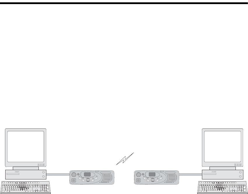
The Computer Controlled Data Interface (CCDI) protocol is a Tait
proprietary command protocol embedded in the TM8100 and TM8200
radios, and used for communicating with the radio via asynchronous serial
ports and over-air.
The radio is the DCE and is connected directly to the DTE, usually a PC,
via the serial port.
Two modes of operation are available:
■Command mode
■Transparent mode
When in Command mode, commands and response messages are passed
between the PC and the radio using the CCDI protocol. CCDI commands
can also be used to obtain GPS data and NMEA messages from the radio.
Refer to “QUERY” and “SEND_ADAPTABLE_SDM”. The baud rate is
set to 1200, 2400, 4800, 9600, 14400, 19200, 28800 or 115200 (TM8200
only) baud, using the programming application.
When in Transparent mode, communication between the PC and the radio
is set to 1200, 2400, 4800, 9600, 14400, 19200, 28800 or 115200 (TM8200
only) baud, using the programming application.
The over-air data rate is 1200 or 2400 bps for FFSK data,
12 kbps for Tait High Speed Data (THSD) narrow band and wide band, and
can be set to 19200 bps for THSD wide band.
F3
F4
F2
FI
TM8000 radio
PC Serial Port
PC running
terminal application
TM8000 radio
PC Serial Port
F3
F4
F2
FI
PC running
terminal application

10 Introduction TM8100/TM8200 Computer-Controlled Data Interface (CCDI) Protocol Manual
© Tait Electronics Limited May 2006
1.1 Compatibility
This manual supports CCDI version 3.xx and later.
The radio programming software used should be the latest released version
for both the TM8100 and TM8200 radios. Refer to the
TaitWorld website http://www.taitworld.com for the latest versions of
programming software.
1.2 Serial Ports
There are three ports available for CCDI asynchronous serial
communication with the TM8100 or TM8200. The microphone and
auxiliary ports are accessed externally, and the internal options connector is
internal to the radio.
Only one of these ports can be used for CCDI transmission and reception
at any time. The port is selected in the Data form of the programming
application, Serial Communications tab. Select “Mic”, “Aux” or “Internal
Connector”.
■Mic: the radio will transmit and receive data via the MIC_TXD and
MIC_RXD lines on the microphone connector. Refer to “Microphone
Connector” for signal details.
■Aux: the radio will transmit and receive data via the AUX_TXD and
AUX_RXD lines on the auxiliary connector. Refer to “Auxiliary
Connector” for signal details.
■Internal Connector: the radio will transmit and receive data via the
IOP_TXD and IOP_RXD lines on the internal options connector.
This connector is used to fit an internal options board into the radio.
Refer to the TM8100/TM8200 3DK Hardware Developer’s Kit
Application Manual for more details.
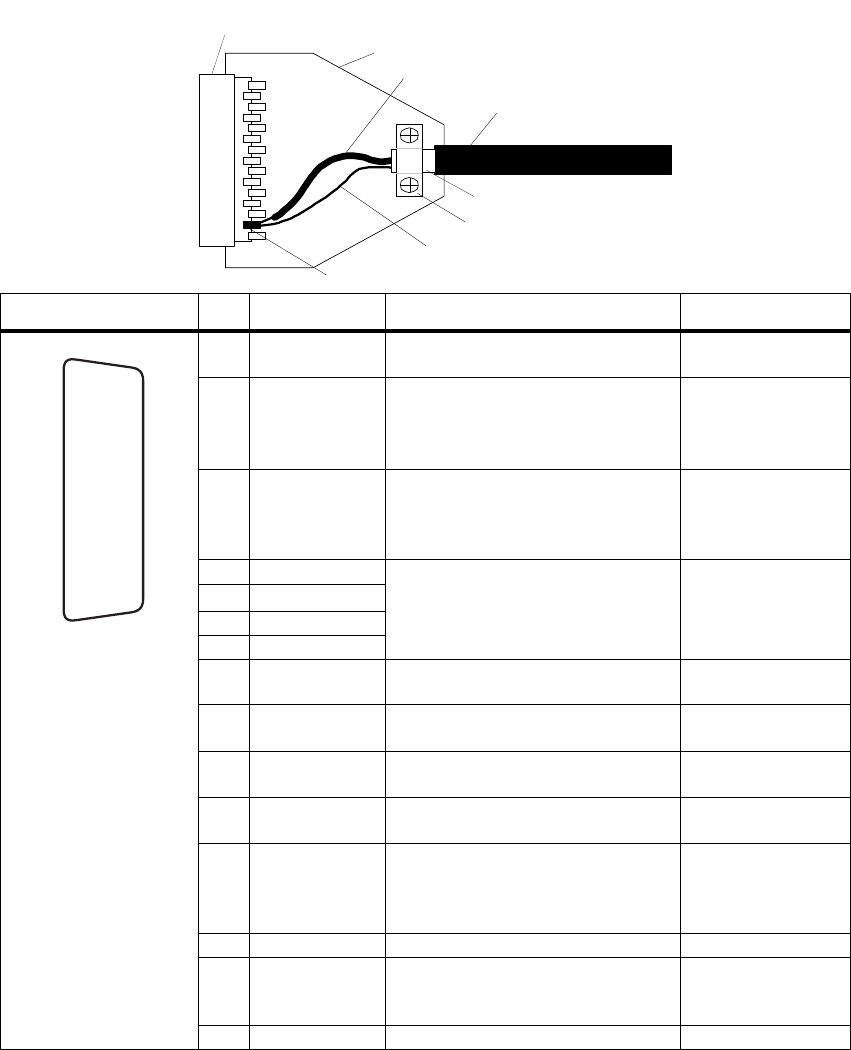
1.2.1 Auxiliary Connector
The auxiliary connector is the standard interface for external devices that are
typically connected to a radio. The auxiliary connector is a 15-way standard-
density D-range socket. The auxiliary connector provides a serial port, three
programmable input lines, four programmable digital I/O lines, RSSI and
audio I/O. The AUX_TXD and AUX_RXD lines are used to transmit and
receive data from the radio.
The GPI and GPIO lines can be programmed for flow control. Refer to
“Hardware Flow Control” on page 16
.
Note The space for a mating plug is limited to 41mm in width and
18mm in height. Although most plugs will fit this space, it is rec-
ommended that you test the plug to be used before manufacturing
a cable.
TM8100/TM8200 Computer-Controlled Data Interface (CCDI) Protocol Manual Introduction 11
© Tait Electronics Limited May 2006
If the auxiliary cable is longer than 1 metre, it is recommended that the cable
and connector backshell be shielded. The diagram shows the recommended
shielding arrangement. The earth braid wire (bare copper) and aluminium
foil should only be earthed at the radio end of the cable.
Refer to the TM8100/TM8200 3DK Hardware Developer’s Kit
Application Manual for more details about the auxiliary connector.
cable insulation
aluminium foil
earth braid wire
signal earth wire
analo
g
ue
g
round pin
metal backshell
metal D-range shroud in
contact with backshell
metal cable clamp
Pinout Pin Signal name Description Signal type
12 AUX_GPI1 General purpose digital input.
Programmable function. Digital. 3V3 CMOS.
5
AUX_GPI2 General purpose digital input.
Programmable function.
With LK3 fitted, GPI2 is an
emergency power sense input.
Digital. 3V3 CMOS.
4 AUX_GPI3 General purpose digital input.
Programmable function.
With LK2 fitted, GPI3 is a power
sense input.
Digital. 3V3 CMOS.
10 AUX_GPIO4 Programmable function and
direction.
Pads available to fit a higher power
driver transistor on GPIO4 line.
Digital.
3V3 CMOS input.
Open collector
output with pullup.
2 AUX_GPIO5
9 AUX_GPIO6
1 AUX_GPIO7
11 AUX_TXD Asynchronous serial port -
Transmit data Digital. 3V3 CMOS.
3 AUX_RXD Asynchronous serial port -
Receive data Digital. 3V3 CMOS.
7 AUD_TAP_IN Programmable tap point into the Rx
or Tx audio chain. DC-coupled. Analogue.
13 AUD_TAP_OUT Programmable tap point out of the
Rx or Tx audio chain. DC-coupled. Analogue.
14 AUX_MIC_AUD Auxiliary microphone input.
Electret microphone biasing
provided. Dynamic microphones are
not supported.
Analogue.
6 RSSI Analogue RSSI output. Analogue.
8 +13V8_SW Switched 13.8V supply. Supply is
switched off when radio body is
switched off.
Power.
15 AGND Analogue ground Ground.
rear view
J
B
C
D
E
F
G
H
I
1)
1!
1@
1#
1$
1%

12 Introduction TM8100/TM8200 Computer-Controlled Data Interface (CCDI) Protocol Manual
© Tait Electronics Limited May 2006
1.2.2 Microphone Connector
The microphone connector on the control head is an RJ-45 socket.
When the control head is connected to the control-head connector of the
radio body using the loom provided, the microphone connector uses the
following eight control-head connector signals:
The MIC_TXD and MIC_RXD lines are used to transmit and receive data
from the radio.
Refer to the TM8100/TM8200 3DK Hardware Developer’s Kit
Application Manual for more details about the microphone connector.
1.2.3 Data Characteristics
Pinout Pin Signal name Description Signal type
1 MIC_RX_AUD Receive audio output. Analogue
2 +13V8_SW Power supply output. Switched off
when radio body is switched off. Power
3 MIC_TXD Asynchronous serial port -
Transmit data. 3.3V CMOS
4 MIC_PTT PTT input from microphone.
Also carries hookswitch signal. Digital
5 MIC_AUD Fist microphone audio input. Analogue
6 AGND Analog ground. Analogue ground
7 MIC_RXD Asynchronous serial port -
Receive data. 3.3V CMOS
8 MIC_GPIO1 General purpose digital input/
output. Open collector out
3.3V CMOS in
B
I
front view
Parameter
Standard
Comments
min. typ. max. unit
s
Serial port
Baud rate: 1200, 2400, 4800, 9600,
14400, 19200, 28800, 115200 bit/s All UART parameters are
fixed and common to all
UARTs except for the
baud rate which is
configurable and
different for different
modes/applications
Data bits: 8
Start bit: 1
Stop bit: 1
Parity: None
Flow control:
Software
Hardware XON/XOFF
RTS/CTS Requires two GPIO lines
to be programmed as
flow control

TM8100/TM8200 Computer-Controlled Data Interface (CCDI) Protocol Manual Introduction 13
© Tait Electronics Limited May 2006
1.2.4 Logic Level Compatibility
The following table show the compatibility of the radio’s digital I/O used
for CCDI with common industry logic standards.
Digital Input
Compatibility and
Tolerance
Digital Output
Compatibility
1.2.5 GPS Port
The GPS receiver/antenna is also connected to an asynchronous serial port
and must be different to the CCDI UART Port. The GPS receiver/antenna
is set in the Data form of the programming application, GPS tab, and can be
set to Mic, Aux or Internal Options.
If set to Aux, the GPS receiver will send NMEA messages to the radio via
the AUX_RXD line on the auxiliary connector.
If set to Internal Options, the GPS receiver will send NMEA messages to
the radio via the IOP_RXD line on the internal options connector.
Digital Input
Line
Logic standard input compatibility and tolerance
3.3V CMOS 5V CMOS 5V TTL RS-232
AUX_RXD Yes Yes Yes Yes
IOP_RXD Yes Yes Yes Noa
a. Level compatible but not tolerant. Inputs can be made RS-232 tolerant by using 3.3kΩ series
resistance inserted at the radio end.
CH_RXD
MIC_RXD
PRG_RXD
Yes Yes Yes Yes
Digital Output
Line
Logic standard input compatibility and tolerance
3.3V CMOS 5V CMOS 5V TTL RS-232
AUX_TXD Yes No Yes No
IOP_TXD Yes Noa
a. These outputs can be made 5V CMOS compatible using a 3.3kΩ pull-up resistor to 5V that is
provided by the device being driven.
Yes No
CH_TXD
MIC_TXD
PRG_TXD
Yes No Yes No

14 Introduction TM8100/TM8200 Computer-Controlled Data Interface (CCDI) Protocol Manual
© Tait Electronics Limited May 2006
1.3 Before Operating
Before using CCDI, the following is useful to check.
■The radio must be correctly programmed for use with the CCDI
protocol. See “Radio Programming” on page 21 for configuration
information.
■At power on, the radio will select its default channel. To change the
channel, select the channel using the normal radio interface or using the
CCDI Go_to_Channel command. Refer to “GO_TO_CHANNEL”
on page 31.
■The radio will power on into the mode selected in the ‘Powerup State’
field in the Data form.
■Power, Tx and Rx LED indicators are helpful for establishing proper
operation. The radio speaker can be used to listen to data coming in.
■Data flow is controlled either by the customer’s embedded computer
system or by a PC running a data-sending application such as
Hyperterminal.
1.4 Limitations
Important Some data applications require extended transmission
times. This may be for larger file transfers or for real-time
telemetry information. This may put undue stress on the
radio transmitter and care must be taken to control trans-
mission times using flow control. Refer to “Hardware Flow
Control” on page 16.
1.5 Programming
For information on the parameters in the Data form of the programming
application, refer to:
■the Help of the programming application.
■Technical Note TN-919-AN Configuring the TM8100 for Data
Operation.

TM8100/TM8200 Computer-Controlled Data Interface (CCDI) Protocol Manual Flow Control 15
© Tait Electronics Limited May 2006
2 Flow Control
Flow control is a method of controlling the data so that a faster DTE-DCE
baud rate can be used to that of the over the air baud rate. This allows the
radio (DCE) to inform the DTE that its buffer is becoming full and that the
DTE needs to wait before sending more data to the radio.
Flow control should only be needed when the amount of data to send is
larger than the radios buffer (512 bytes for TM8100, 600 bytes for
TM8200).
Note Some older versions of the firmware have a buffer size of 128
bytes.
Available options: None, Hardware Software
2.1 XON/XOFF Software Flow Control
When the serial communications are set-up for software flow control, the
radio will use programmable bytes for XOFF and XON.
Important When using XON/XOFF software handshaking, the data
stream (or the data file) must not include the programmed
XON and XOFF characters. It is recommended that only
ASCII text be used with software flow control.
The XOFF character is sent when there is less than 35 bytes of empty space
in the buffer.
The XON character is sent when XOFF had previously been sent and there
is now less than 10 bytes of data in the buffer.

16 Flow Control TM8100/TM8200 Computer-Controlled Data Interface (CCDI) Protocol Manual
© Tait Electronics Limited May 2006
2.2 Hardware Flow Control
When the serial communications are set-up for hardware flow control, two
of the programmable I/O lines are enabled for RTS and CTS. Hardware
flow control is not available for the mic port.
2.2.1 RTS
Important The RTS line has been implemented as a “Ready to
Receive” line as per RS-232-E.
When the RTS line is inactive the radio will not output any serial data.
It will buffer any data and output it when the line is activated.
Important: The RTS line does not stop the radio from receiving data
across the air so leaving this line inactive for any length of time could cause
the buffer to overflow and for data to be lost.
2.2.2 CTS
The CTS line is deactivated when there is less than 35 bytes of empty space
in the buffer.
The CTS line is activated when the CTS line had previously been
deactivated and there is now less than 10 bytes of data in the buffer.

TM8100/TM8200 Computer-Controlled Data Interface (CCDI) Protocol Manual Transparent Mode 17
© Tait Electronics Limited May 2006
3 Transparent Mode
In Transparent mode, the radio acts as a modem, automatically transmitting
in FFSK or THSD format the serial data received from the PC. In this mode,
the baud rate between the PC (DTE) and the radio (DCE) can be set to
either 1200, 2400, 4800, 9600, 14400, 19200, 28800 or 115200 (TM8200
only) baud using the programming application. The over-air data rate is
1200 or 2400 bps for FFSK data, 12 kbps for Tait High Speed Data (THSD)
narrow band and 19200 bps for THSD wide band. The serial data input
buffer is 512 bytes for the TM8100 and 128 bytes for the TM8200, to
adequately cope with the data flow.
Communication in Transparent mode is free-format, with the protocol
determined entirely by the PC and the modem. It is transparent to the
CCDI, allowing the PC to send and receive data without passing through
the CCDI. CTCSS and DCS subaudible signalling is available in FFSK
Transparent mode.
If an SDM is received in Transparent mode, it is tested for SDM validity by
checking the leading ‘s’, the checksum, the SDM identity and the size. If it
is found to be a valid SDM, it is saved in the SDM buffer for later retrieval.
3.1 Entering Transparent Mode
Transparent mode can be set as the default mode at power on by selecting
FFSK or THSD Transparent Mode in the ‘Powerup State’ field in the
programming application. Refer to “Radio Programming” on page 21.
To change to Transparent mode while operating in Command mode, the
PC must send a TRANSPARENT command to the radio. E.g. t01zB1
sends a TRANSPARENT command, requesting that the radio be put into
Transparent mode. The escape character specified here is “z” (ASCII code
= $7A). Once acknowledged, any further data is linked directly to the radio
in Transparent mode.
If the radio default is set to Transparent mode at power on, the default escape
character is “+”.
18 Transparent Mode TM8100/TM8200 Computer-Controlled Data Interface (CCDI) Protocol Manual
© Tait Electronics Limited May 2006
3.2 Exiting Transparent Mode
To change to Command mode while operating in Transparent mode, send
the escape sequence. The escape sequence consists of a 2 second idle time,
followed by three escape characters (sent within 2 seconds), followed by a
further 2 second idle time i.e. [2 second idle] +++ [2 second idle].
In Transparent mode, when the escape sequence is detected in the data
stream, the radio is forced back to Command mode.
3.3 Transparent Mode Format
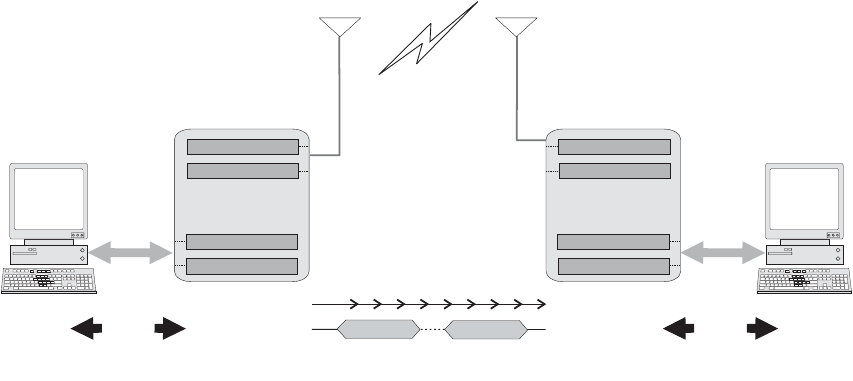
3.3.1 Transparent Mode Packetisation
Transparent mode data is packetised into data blocks before it is sent over-
air. The start and stop bits are removed and a header is sent at the start of
each data block.
FFSK-OUT
SER-OUT
FFSK-IN
SER-IN
Lead-In
Delay Lead-Out
Delay
time...
processing...
data block 1 data block n
over-air
TM8000 radio
PC data
RS232
FFSK-OUT
SER-OUT
FFSK-IN
SER-IN
processing...
TM8000 radio
data
RS232 PC
Flow
Control
Flow
Control
no Flow Control
TM8100/TM8200 Computer-Controlled Data Interface (CCDI) Protocol Manual Transparent Mode 19
© Tait Electronics Limited May 2006
3.3.2 FFSK Transmission Format
The Transparent Mode transmission format is as follows:
Singe Data Block:
Multiple Data Blocks:
3.3.3 THSD Transmission Format
For more information, refer to Technical Note TN-855-AN TM8000 and
TB7100 Data Modem Facilities.
3.3.4 Effective Over-Air Data Rate
The effective over-the-air data rate is lower than the set data rate.
For more information, refer to Technical Note TN-855-AN TM8000 and
TB7100 Data Modem Facilities.
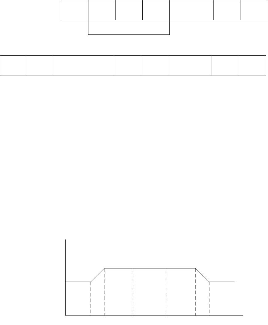
3.3.5 Lead-In Delay
The Lead-In Delay begins after the transmitter key-up time. It gives the
receiver(s) at the other end time to open before data is sent.
When data is detected at the radio’s input buffer, the following occurs:
■The transmitter keys up.
■A carrier is sent from the transmitter. When the carrier reaches its full
potential, the Lead-In Delay begins.
Lead-In
Delay preamble
2 bytes sync
2 bytes size
2 bytes FFSK data block
max 46 bytes CRC
2 bytes Lead-Out
Delay
HEADER
Lead-In
Delay HEADER
6 bytes FFSK data block . . . .
max 46 bytes CRC
2 bytes HEADER
6 bytes FFSK data block
max 46 bytes CRC
2 bytes Lead-Out
Delay
Tx
key-up
time
Lead In
Delay data Lead Out
Delay Tx
key-down
Tx
20 Transparent Mode TM8100/TM8200 Computer-Controlled Data Interface (CCDI) Protocol Manual
© Tait Electronics Limited May 2006
■If the receiving base station is set to Repeater mode, the carrier is
detected and Rx Gate becomes active (opens), which in turn makes the
PTT line active.
■The active PTT line keys up the transmitter.
This sequence is repeated with as many base stations as are in the chain.
The optimum length of the Lead-In Delay should be set keeping in mind
the number of Base Stations that need to be activated before any data is sent.
The Lead-In Delay must also allow for subaudible signalling decoding, if it
is enabled, when used in conjunction with FFSK data.

TM8100/TM8200 Computer-Controlled Data Interface (CCDI) Protocol Manual Command Mode 21
© Tait Electronics Limited May 2006
4 Command Mode
Command mode uses the Tait proprietary Computer Controlled Data
Interface (CCDI), a command protocol embedded in the radio firmware.
It is accessed using the serial port lines from the PC. In this mode, the baud
rate between the computer equipment (DTE) and the radio (DCE) can be
set to either 1200, 2400, 4800, 9600, 14400, 19200, 28800 or 115200
(TM82000 only) baud using the programming application
In Command mode, the PC sends command sequences to the radio and
waits for a prompt before beginning the next transaction. Some commands
require the radio to send a CCDI message in response. Messages sent to the
radio will always be responded to by the prompt.
Unsolicited messages such as PROGRESS or ERROR messages are sent by
the radio if there is a significant change in its state that the PC should be
aware of. When errors are detected, an unsolicited ERROR message is sent
by the radio to the PC. The radio cannot send messages that require a reply.
The SEND_SDM, SEND_ADAPTABLE_SDM and GET_SDM
commands require that SDMs are sent and received as over-air FFSK data
by the radio while in Command mode. If an SDM is received from the
over-air interface while the radio is in Command mode, the SDM data is
buffered and both an ‘FFSK Data Received’ PROGRESS message and a
‘SDM Received’ RING messages are generated by the radio to indicate that
SDM data has been received.
4.1 Entering Command Mode
Command mode can be set as the default mode at power on by selecting
‘Command Mode’ in the ‘Powerup State’ field in the programming
application. Refer to “Programming” on page 14.
To change to Command mode while operating in Transparent mode, send
the escape sequence. The escape sequence consists of a 2 second idle time,
followed by three escape characters (sent within 2 seconds), followed by a
further 2 second idle time i.e. [2 second idle] +++ [2 second idle].
In Transparent mode, when the escape sequence is detected in the data
stream, the radio is forced back to Command mode.
22 Command Mode TM8100/TM8200 Computer-Controlled Data Interface (CCDI) Protocol Manual
© Tait Electronics Limited May 2006
4.2 CCDI Command Format
All CCDI message packets take the general form:
[IDENT] [SIZE] [PARAMETERS] [CHECKSUM] <CR>
■[IDENT] = The message identifier. Identifiers are single ASCII
characters (lower-case alphabetical) which categorise the message type.
■[SIZE] = The number of characters which make up the
[PARAMETERS] field. [SIZE] is an 8-bit number expressed in ASCII
hex notation (two characters).
■[PARAMETERS] = An optional field, depending upon the command.
Parameter values are generally character strings unless explicitly stated
otherwise. Parameter type is dependent upon the command, and often
has multiple parts.
■[CHECKSUM] = An 8-bit checksum of the [IDENT], [SIZE] and
[PARAMETERS] fields. Expressed in two character ASCII hex
notation.
■<CR> = The carriage return (0Dh) packet terminator.
4.3 Restrictions
■All characters in a message are printable ASCII.
■Where numeric values are represented in ASCII hex notation (two
characters per byte), characters A to F are upper case.
■The minimum length of a command packet is 5 characters. For example
q002F is the QUERY command where [SIZE] = 00 as there is no
[PARAMETERS] field required.
■The maximum length of the [PARAMETERS] field is 255 characters.
The maximum length of the command packet is therefore 260
characters.
4.4 Calculating the CCDI [CHECKSUM]
[CHECKSUM] is calculated by applying the following algorithm:
1. Take the modulo-2 sum of all message bytes preceding
[CHECKSUM].
2. Retain bits 0 to 7, discarding any higher order bits resulting from the
summation.
3. Form the two’s complement of the remainder.
4. Convert the binary number into two ASCII hex digits, MSD first.
TM8100/TM8200 Computer-Controlled Data Interface (CCDI) Protocol Manual Command Mode 23
© Tait Electronics Limited May 2006
4.4.1 Checksum Example
s0D050800TESTHi!DA
1. Take the modulo-2 sum of all message bytes preceding
[CHECKSUM].
■s = 73h, 0 = 30h, D = 44h etc. therefore the modulo-2 sum is:
73 + 30 + 44 + 30 + 35 + 30 + 38 + 30 + 30 + 54 + 45 + 53 +
54 + 48 + 69 + 21 = 426h
2. Retain bits 0 to 7, discarding any higher order bits resulting from the
summation.
26h
3. Form the two’s complement of the remainder.
26h = 0010 0110
two’s complement = 1101 1010
4. Convert the binary number into two ASCII hex digits, MSD first.
1101 1010 = DA
4.4.2 Checksum Software Application
A software application is available from Tait Technical Support which will
calculate the checksum for any given command and parameters.
Please contact Technical Support (refer to “Tait Contact Information” on
page 2).

24 Command Mode TM8100/TM8200 Computer-Controlled Data Interface (CCDI) Protocol Manual
© Tait Electronics Limited May 2006
4.5 Commands to the Radio
The following commands are available to send from the PC to control the
radio.
In all cases, if a command is received without error by the radio and all
parameters are valid, the command is executed.
The prompt character ‘.’ is returned to the PC immediately after receiving a
command, to signify that another may begin. If an error arises, the PC is
notified with an appropriate ERROR response.
Command Command Function Compatibility
CANCEL c abort current activities conventional
DIAL d initiate a call conventional
FUNCTION f controls various hardware
and miscellaneous radio
functions
dependent on
function
GO_TO_CHANNEL g sets the radio to a
particular channel conventional
QUERY q requests information from
the radio dependent on
function
SEND_ADAPTABLE_SDM a send a Short Data
Message (SDM) conventional
SEND_SDM s send a Short Data
Message (SDM) conventional
TRANSPARENT (FFSK
and THSD) t change to transparent
mode (FFSK and THSD) conventional

TM8100/TM8200 Computer-Controlled Data Interface (CCDI) Protocol Manual Command Mode 25
© Tait Electronics Limited May 2006
4.5.1 CANCEL
The CANCEL command tells the PC to abort the current action that the
radio is performing. It has the following format:
c [SIZE] [CANCEL_TYPE] [CHECKSUM]
■‘c’ is sent as a single ASCII character and represents the CANCEL
command.
■[CANCEL_TYPE] is a single ASCII character representing the
cancelling type.
Note If no [CANCEL_TYPE] is sent, then the CANCEL command
will default to CANCEL_TYPE = 0.
Examples of CANCEL commands are:
c0100C a command to cancel the existing call.
c003D also a command to cancel the existing call.
c0110B a command to delete the currently held SDM.
[CANCEL_TYPE] Function
0
(cancel call) Cancel Call
In conventional mode, Cancel can do the following:
■clear down a Selcall call, including retries
■cancel deferred calling
■take the radio out of emergency operation if in Emergency
Tx/Rx cycles by resetting the radio
In trunked mode, Cancel can do the following:
■act as though the front panel ‘Cancel’ key has been
pressed.
1
(delete SDM) Delete SDM data of the last received SDM (if any). Available in
conventional mode only.

26 Command Mode TM8100/TM8200 Computer-Controlled Data Interface (CCDI) Protocol Manual
© Tait Electronics Limited May 2006
4.5.2 DIAL
The DIAL command allows access to the full conventional mode dialling
capability of the radio. Selcall and DTMF sequences can be dialled on the
current channel. An TM8200 trunked radio must change to a conventional
channel using a function key before executing this command. The function
key is set to “Switch Mode” in the MPT Key Settings form of the TM8200
programming application.
The DIAL command has the format:
d [SIZE] [DTYPE] [NUMBER_STR] [CHECKSUM]
■‘d’ is sent as a single ASCII character and represents the DIAL command.
■[DTYPE] is a single ASCII character representing the type of dialling
required.
■[NUMBER_STR] represents the dialled sequence. The range of allowed
characters depends upon the value of [DTYPE].
Note The DIAL command initiates the calling process only. The call
may take some time to get through, especially if the channel is
busy or the system heavily loaded. The receiver will return a
prompt as soon as the DIAL command is accepted, but the PC
may have to wait for a PROGRESS message advising successful
call set-up before proceeding.
Examples of DIAL commands are:
d0601234507 a command to initiate Selcall dialling of the number
1 2 3 4 5.
d0611234506 a command to initiate DTMF dialling of the number
1 2 3 4 5.
[DTYPE] [NUMBER_STR]
0
(Selcall) 0...9, A...F, -, V (maximum of 32 digits).
Selcall strings usually use the digits 0 to 9 as some of the tones A to
F have special meaning, e.g. A = Group; C = Reset; E = Repeat.
Selcall calls are made within the bounds of the following
parameters, as programmed into the radio: tone period, tone set
and Lead-In Delay, etc.
1
(DTMF
conventional)
0...9, A...D, *, #,-(maximum of 32 digits)
DTMF calls are made within the bounds of the following
parameters, as programmed into the radio, e.g. key-up delay, tone
period and inter-tone gap.
2
(DTMF
trunked)
0...9, A...D, *, #,-(maximum of 32 digits)
DTMF calls are made within the bounds of the following
parameters, as programmed into the radio, e.g. key-up delay, tone
period and inter-tone gap.

TM8100/TM8200 Computer-Controlled Data Interface (CCDI) Protocol Manual Command Mode 27
© Tait Electronics Limited May 2006
4.5.3 FUNCTION
The FUNCTION command provides access to various hardware and
miscellaneous functions. It has the following format:
f [SIZE] [FUNCTION] [SUBFUNCTION] [QUALIFIER]
[CHECKSUM]
■‘f’ is sent as a single ASCII character and represents the FUNCTION
command.
■[FUNCTION] is a single ASCII characters representing the required
function category.
■[SUBFUNCTION] is up to two ASCII characters and is used to extend
the range of the [FUNCTION] parameter.
■[QUALIFIER] is an ASCII character string representing the action to be
taken, depending on the value of [FUNCTION] and
[SUBFUNCTION].
[FUNCTION] [SUBFUNCTION] [QUALIFIER] Action
0
(functions) 0 none Switch to CCR mode.
1 0 Disable CCDI volume control.
1 Enable CCDI volume control (refer to
SUBFUNCTION=2).
2 0-25 Set volume level. 0=off, 1-25=loudness.
3 0 Disable selcall output RING messages.
1 Enable selcall output RING messages.
4 0 Disable PROGRESS output messages.
1 Enable PROGRESS output messages.
5 0 Disable PROGRESS output messages (default).
1 Enable PROGRESS output messages (unsolicited).
Refer to “PROGRESS” on page 45, [PTYPE] = 21
User Initiated Channel Change.
2 Report current channel (solicited).
1
(SDM control) 0 0 Disable SDM output on reception.
1 Enable SDM output on reception, QUERY
command not required.
1 0 Disable SDM caller ID encode.
1 Enable SDM caller ID encode. The caller ID is sent
as a separate SDM before sending the SDM itself.
2 0 Disable SDM caller ID decode.
1 Enable SDM caller ID decode. The caller ID SDM is
decoded before the incoming SDM.

28 Command Mode TM8100/TM8200 Computer-Controlled Data Interface (CCDI) Protocol Manual
© Tait Electronics Limited May 2006
2
(emergency mode) 2 0 Activate non-stealth emergency mode.
1 Activate stealth emergency mode.
2 Deactivate emergency mode.
3
(simulate key
presses)
none 000-009 PTT keypress length, 0=constantly off, 1-8=x/8
seconds on, 9=constantly on.
010-019 Hookswitch keypress length, 0=constantly off,
1-8=x/8 seconds on, 9=constantly on.
020-029 ‘On/off’ keypress length, 0=constantly off,
1-8=x/8 seconds on, 9=constantly on.
030-039 ‘Up’ keypress length, 0=constantly off,
1-8=x/8 seconds on, 9=constantly on.
040-049 ‘Down’ keypress length, 0=constantly off,
1-8=x/8 seconds on, 9=constantly on.
050-059 ‘FN1’ keypress length, 0=constantly off,
1-8=x/8 seconds on, 9=constantly on.
060-069 ‘FN2’ keypress length, 0=constantly off,
1-8=x/8 seconds on, 9=constantly on.
070-079 ‘FN3’ keypress length, 0=constantly off,
1-8=x/8 seconds on, 9=constantly on.
080-089 ‘FN4’ keypress length, 0=constantly off,
1-8=x/8 seconds on, 9=constantly on.
4
(user controls) none 0 Disable all user controls, display and indicators.The
radio indicates “CCDI BUSY”.
1 Disable user input only. Display and indicators still
operational. Any attempted user input will result in
the invalid keypress tone.
2 Enable all user controls except when CCDI
commands are being processed. During this time
the radio indicates “CCDI BUSY”.
Set as default at power on.
5
(Rx audio mute
control)
none 0 Cancel CCDI request for Rx audio mute.
1 Mute Rx audio. Can only be overridden by Squelch
Override. Conventional mode only.
[FUNCTION] [SUBFUNCTION] [QUALIFIER] Action

TM8100/TM8200 Computer-Controlled Data Interface (CCDI) Protocol Manual Command Mode 29
© Tait Electronics Limited May 2006
Examples of FUNCTION commands are:
ff0241D3 a command to disable user input command.
f0250D3 a command to mute the receiver audio.
f0271D0 a command to validate subaudible signalling.
f0281CF a command to activate Monitor function.
f0291CE a command to activate the transmitter.
f0290CF a command to deactivate the transmitter following an “activate
transmitter” command.
F0200D8 enter CCR Mode.
f03011A5 enable volume control.
f03010A6 disable volume control.
f03020A5 set volume level off.
f0402256D set volume level to the maximum of ‘25’.
f03025A0 set volume level to ‘5’.
f03031A3 enable Selcall output.
7
(subaudible
signalling)
none 0 Deactivate validation of CTCSS and DCS
subaudible signalling. Incoming data will be
processed regardless of the subaudible signalling.
The default radio setting at power on depends on
the ‘Ignore DCS/CTCSS’ option set in the Data
form of the programming application.
1 Activate validation of CTCSS and DCS subaudible
signalling. Incoming FFSK data will only be
processed if the subaudible signalling matches.
Only effective if current channel is programmed for
subaudible signalling.
Conventional or traffic channel mode only.
8
(monitor) none 0 Deactivate monitor function.
1 Activate monitor function. Conventional mode
only.
9
(Rx/Tx) none 0 Forces radio into a Rx state.
Conventional or traffic channel mode only.
1 Forces radio into a Tx state. Note that the Rx CCDI
command is required to take the radio out of Tx
mode when this mode is activated. The Tx will not
terminate on expiry of the Tx timer.
Conventional or traffic channel mode only.
[FUNCTION] [SUBFUNCTION] [QUALIFIER] Action
30 Command Mode TM8100/TM8200 Computer-Controlled Data Interface (CCDI) Protocol Manual
© Tait Electronics Limited May 2006
f03030A4 disable Selcall output.
f03041A2 enable progress message output.
f03040A3 disable progress message output.
f03101A5 enable output SDM on reception.
f03100A6 disable output SDM on reception.
f03111A4 enable caller ID encoder.
f03110A5 disable caller ID encoder.
f03121A3 enable caller ID decoder.
f03120A4 disable caller ID decoder.

TM8100/TM8200 Computer-Controlled Data Interface (CCDI) Protocol Manual Command Mode 31
© Tait Electronics Limited May 2006
4.5.4 GO_TO_CHANNEL
The GO_TO_CHANNEL command tells the radio to change to another
conventional mode channel. The specified channel can be assigned to a
scan/vote group in the radio. A trunked radio must change to a conventional
channel before executing this command.
The GO_TO_CHANNEL command has the following format:
g [SIZE] [ZONE] [CHANNEL_NO] [CHECKSUM]
■‘g’ is sent as a single ASCII character and represents the
GO_TO_CHANNEL command.
■[ZONE] is a two-character string representing the new zone.
■[CHANNEL_NO] is a maximum of four characters representing the
new channel number. The range of allowed characters is 0 to 9. and must
be a valid channel for the radio. If used with the [ZONE] parameter, this
will always be a four-character string.
Note If the radio is using a scan/vote group when it receives this com-
mand, it will retune to the specified channel.
Note If the radio is in emergency mode then no channel change will
occur, and a ‘not ready’ error message is returned.
Examples of GO_TO_CHANNEL commands are:
g0223D2 go to channel 23.
g0414995E go to channel 1499.
g060100120F go to zone 1, channel 12.

32 Command Mode TM8100/TM8200 Computer-Controlled Data Interface (CCDI) Protocol Manual
© Tait Electronics Limited May 2006
4.5.5 QUERY
The QUERY command requests information from the radio. It has the
following format:
q [SIZE] [QUERY_TYPE] [DATA] [CHECKSUM]
■‘q’ is sent as a single ASCII character and represents the QUERY
command.
■[QUERY_TYPE] is a single ASCII character representing the query
type required.
■[DATA] is a number with up to three-digits which identifies the CCTM
command which is sent.
Note If no [QUERY_TYPE] is sent, then the QUERY command will
default to [QUERY_TYPE] = 0.
Examples of QUERY commands are:
q010FE a command requesting a MODEL message.
q002F also a command requesting a MODEL message.
[QUERY_TYPE] [DATA] Function
0
(model and CCDI
version)
none Query the radio model and CCDI version. Data is
returned as a MODEL message.
1
(query SDM) none The buffered SDM data is returned to the PC as a
GET_SDM message. The SDM buffer is then cleared.
Available in conventional mode only.
3
(version) none Query the radio version information. The data is
returned to the PC as a RADIO_VERSION message.
Refer to “RADIO_VERSIONS”.
4
(serial number) none Query the serial number. Refer to “RADIO_SERIAL”.
5
(CCTM) 047 PA temperature. Returned to the PC as a
CCTM_QUERY_RESULT message. Refer to
“CCTM_QUERY_RESULTS”.
063 Averaged RSSI level. Returned to the PC as a
CCTM_QUERY_RESULT message.
064 Raw RSSI level. Returned to the PC as a
CCTM_QUERY_RESULT message.
318 Forward power. Returned to the PC as a
CCTM_QUERY_RESULT message.
319 Reverse power. Returned to the PC as a
CCTM_QUERY_RESULT message.
6
(GPS) none Query GPS. GPS data is returned packetised as though
the TM8100/TM8200 is a polling radio.

TM8100/TM8200 Computer-Controlled Data Interface (CCDI) Protocol Manual Command Mode 33
© Tait Electronics Limited May 2006
q011FD a command requesting a GET_SDM message.
q013FB query the software version.
4.5.6 SEND_ADAPTABLE_SDM
The SEND_ADAPTABLE_SDM command requests the radio to send a
fixed format ASCII Short Data Message (SDM). An SDM can be received
when the radio is in Command and Transparent modes.
The SEND_ADAPTABLE_SDM command has the format:
a [SIZE] [LEAD_IN_DELAY] [GFI] [SFI] [DATA_MESSAGE_ID]
[MESSAGE] [CHECKSUM]
After an SDM is sent, if the ‘SDM Auto Acknowledge’ field is set in the
programming application, the radio waits for an acknowledgement before it
generates a PROGRESS message. The PROGRESS message is either type
1D0 ‘SDM auto-acknowledge not received’ or 1D1 ‘SDM auto-
acknowledge received’. Refer to “PROGRESS” on page 45.
Note that the delay before the acknowledgement is sent and how long the
radio waits is also set in the programming application.
In Command mode, when any SDM is received, whether valid or not, the
radio sends an ‘FFSK Data Received’ PROGRESS message to the PC. If
the SDM is valid with a [MESSAGE] component, the radio also sends an
‘SDM Call’ RING message to the PC. RING will be type ‘Data Call’.
When in either Command or Transparent mode, when a valid SDM is
received the radio beeps.
Note The radio can not receive any further SDMs if one is already
stored in the buffer. The buffer must be cleared using a CANCEL
command.
■‘a’ is sent as a single ASCII character and represents the
SEND_ADAPTABLE_SDM command.
■[LEAD_IN_DELAY] is two ASCII hex characters representing the delay
after the radio transmitter keys-up and the start of data transmission. The
range is 00 to FFh.
The actual delay is calculated by multiplying the number by 20 ms. This
corresponds to a Lead-In Delay between 00 ms and 5.1 seconds, in steps
of 20 ms. A minimum of at least 20 ms of Lead-In Delay is required for
the radio.
■[GFI] is a single ASCII character giving the General Format Information
(GFI) of the SDM.

34 Command Mode TM8100/TM8200 Computer-Controlled Data Interface (CCDI) Protocol Manual
© Tait Electronics Limited May 2006
Valid GFI values are:
■[SFI] is two ASCII characters giving the Specific Format Information
(SFI) of the SDM.
Valid SFI values are:
The following table shows valid GFI/SFI combinations. All other GFI/SFI
field values which are not shown in the table are available for future formats.
GFI Description Comment
0As per “s” format (i.e. Text) Default for “s” command (ASCII SDM)
1Binary Binary SDM
2Text ASCII SDM
3 - 7 Spare Available for future GFIs
SFI Description Comment
00 Default Value Default Value
01 GPS_0 GPS related, CDP only.
02 Text Text
03 CCR SDM is directed to the CCR module. Refer to CCR
SDM (TM8100 only).
04 Extended SDM Up to 128 bytes, split into multiple SDMs. Refer to
Extended SDM (TM8100 only).
05 Extended SDM
Continuation Continuation of an Extended SDM
06 NMEA Request Request for radio to return a specified NMEA
string. Refer to NMEA Request SDM.
07 - 31 Spare Available for future SFIs

TM8100/TM8200 Computer-Controlled Data Interface (CCDI) Protocol Manual Command Mode 35
© Tait Electronics Limited May 2006
■[DATA_MESSAGE_ID] is an 8-character string representing the SDM
data identity of the radio to which the SDM is being sent. It can be any
alphanumeric characters. “*” is the wildcard for any character. e.g.
12**5678. The first four bytes are generally the fleet identity, the second
four the radio identity.
When a radio receives a SDM message, the data identity is checked
against the ‘Unit Data Identity’ set in the Data form of the programming
application. Refer to “Radio Programming” on page 21. If the data
identity matches, the received SDM data is stored and the radio sends a
response. If the data identity does not match then the SDM data is
ignored.
■[MESSAGE] is optional and contains up to 32 characters of SDM text.
Either standard 8-bit ASCII range or binary can be sent, depending on
the GFI.
An example of a SEND_ADAPTABLE_SDM command is:
a0FFF20012345678Hi4A
This message transmits text data message ID
“12345678” and SDM data “Hi” with 5.1s
lead-in delay through the current channel.
Extended SDM
(TM8100 only) An adaptable SDM with a SFI of 04 can have up to 128 bytes of data. This
is split up into multiple SDMs where the following SDMs will have a SFI of
05. The SDM can be either Text or Binary.
CCR SDM
(TM8100 only) An adaptable SDM with a GFI of 2 and a SFI of 03 is passed to the CCR
module, in radios that support CCR and are currently in CCR mode. The
data part of the SDM is stripped out of the SDM and passed to the CCR
module as a CCR command.
The SDM can only be text as CCR commands are in ASCII.
GFI SFI Description Comment
000 As per “s” command (Text) General ASCII SDM
100 Binary General binary SDM
200 Text General ASCII SDM
101 GPS_0 GPS-related binary, non-CCDI2
compatible format
202 Text General ASCII SDM
203 CCR SDM for CCR control
104/05 Binary Binary SDM up to 128 bytes
204/05 Text ASCII SDM up to 128 bytes
206 NMEA Request Requests an NMEA string to be
returned as a Text SDM
36 Command Mode TM8100/TM8200 Computer-Controlled Data Interface (CCDI) Protocol Manual
© Tait Electronics Limited May 2006
An example of a CCR SDM is:
a130520312345678M01D0E36
transmits data message ID “12345678” and the CCR
command “M01D0E” with 100 ms lead in delay through the
current channel.
NMEA Request SDM An adaptable SDM with a GFI of 2 and a SFI of 06 requests the receiving
radio to return an Extended SDM, with the next NMEA message received
of the requested type. The SDM may only be Text as NMEA messages are
in ASCII.
The message of the SDM can contain a radio ID return address.
The format for the message is:
[MESSAGE]=[NMEA_ADDRESS_FIELD][,][RADIO_ID]
■[NMEA_ADDRESS_FIELD] is a five character NMEA address field
such as “GPRMC”.
■[,] is a delimiter to separate the address field from the radio id. This
should only be added if there are more fields in the message.
■[RADIO_ID] is the radio ID that the NMEA message is to be returned
to. If not in the message then the message shall be returned to the default
GPS dispatcher.
Example of NMEA request SDM are:
a120520612345678GPRMC22
This message transmits data message to ID “12345678” and a
request for the next “GPRMC” message to be returned to the
default GPS dispatcher with 100 ms Lead-In Delay through the
current channel.
a1B0520612345678GPGGA,8765432155
transmits data message to ID “12345678” and a request for the
next “GPGGA” message to be returned to the radio
“87654321” with 100 ms Lead-In Delay through the current
channel.

TM8100/TM8200 Computer-Controlled Data Interface (CCDI) Protocol Manual Command Mode 37
© Tait Electronics Limited May 2006
4.5.7 SEND_SDM
The SEND_SDM command tells the radio to send a Short Data Message
(SDM) but the “SEND_ADAPTABLE_SDM” is normally used instead.
An SDM can be received when the radio is in Command mode.
The SEND_SDM command has the format:
s [SIZE] [LEAD_IN_DELAY] [DATA_MESSAGE_ID]
[MESSAGE] [CHECKSUM]
After an SDM is sent, if the ‘SDM Auto Acknowledge’ field is set in the
programming application, the radio waits for an acknowledgement before it
generates a PROGRESS message. The PROGRESS message is either type
1D0 ‘SDM auto-acknowledge not received’ or 1D1 ‘SDM auto-
acknowledge received’. Refer to “PROGRESS” on page 45.
Note that the delay before the acknowledgement is sent and how long the
radio waits is also set in the programming application.
In Command mode, when any SDM is received, whether valid or not, the
radio sends an ‘FFSK Data Received’ PROGRESS message to the PC.
If the SDM is valid with a [MESSAGE] component, the radio also sends an
‘SDM Call’ RING message to the PC. If no [MESSAGE] component is
received, RING will be type ‘Data Call’.
The radio can be programmed to issue three beeps when in Command
mode a valid SDM is received.
Note The radio can not receive any further SDMs if one is already
stored in the buffer. The buffer must be cleared using a CANCEL
command.
■‘s’ is sent as a single ASCII character and represents the SEND_SDM
command.
■[LEAD_IN_DELAY] is two ASCII hex characters representing the delay
after the radio transmitter keys-up and the start of data transmission,
while the radio is in Command mode.
The range is 00 to FFh. The actual delay is calculated by multiplying the
number by 20ms. This corresponds to a Lead-In Delay between 00ms
and 5.1s, in steps of 20ms. A minimum of at least 20ms of Lead-In Delay
is required for the radio.
■[DATA_MESSAGE_ID] is an 8-character string representing the SDM
data identity of the radio to which the SDM is being sent. It can be any
alphanumeric characters. “*” is the wildcard for any character, e.g.
12**5678. The first four bytes are generally the fleet identity, the second
four the radio identity.
When a radio receives a SDM message, the data identity is checked
against the ‘Unit Data Identity’ set in the Data form of the programming
application. Refer to “Radio Programming” on page 21. If the data
identity matches, the received SDM data is stored and the radio sends a
response. If the data identity does not match then the SDM data is
ignored.
38 Command Mode TM8100/TM8200 Computer-Controlled Data Interface (CCDI) Protocol Manual
© Tait Electronics Limited May 2006
■[MESSAGE] is optional. The field is limited to 32 hex characters in
standard ASCII range 20h to 2Fh. Characters between 00 and FFh can
be sent but characters above 7Fh can not be displayed.
Examples of SEND_SDM commands are:
s0A051234567813
transmits data identity “12345678” with 100ms
lead-in delay through current channel.
s0CFF12345678Hi39
transmits data identity “12345678” and SDM
data “Hi” with 5.1s lead-in delay through current channel.

TM8100/TM8200 Computer-Controlled Data Interface (CCDI) Protocol Manual Command Mode 39
© Tait Electronics Limited May 2006
4.5.8 TRANSPARENT (FFSK and THSD)
The TRANSPARENT command changes the radio to Transparent mode
and sends the escape character required to change it back to Command
mode. Refer to “Transparent Mode” on page 17 for details about
Transparent mode.
The TRANSPARENT command has the following format:
t [SIZE] [ESC_CHAR] [MODE] [CHECKSUM]
■‘t’ is sent as a single ASCII character and represents the
TRANSPARENT command.
■[ESC_CHAR] is a single ASCII character representing the escape
character. The escape sequence is three consecutive escape characters
sent within two seconds, with two seconds of idle time each side. When
the escape sequence is sent to the radio, it is forced into Command mode.
See “Entering Transparent Mode” on page 17 for details.
■[MODE] is a single ASCII character representing the modulation
scheme. If [MODE] is left blank then the modulation scheme is assumed
to be FFSK.
Note When data is transmitted in Transparent mode it has the Lead-In
Delay set in the Data form of the programming application.
Examples of TRANSPARENT commands are:
t01zB1 a command requesting that the radio be put into Transparent
mode. The escape character specified here is “z”
(ASCII code = $7A).
t02z080 enter FFSK transparent mode, with the escape character set to
‘z’.
t02yH69 enter THSD transparent mode, with the escape character set to
‘y’.
[MODE] Function
0
(FFSK mode) The radio will use FFSK modulation when in transparent mode.
H
(THSD mode) The radio will use Tait High Speed Data (THSD) modulation
when in transparent mode.

40 Command Mode TM8100/TM8200 Computer-Controlled Data Interface (CCDI) Protocol Manual
© Tait Electronics Limited May 2006
4.6 Messages from the Radio
The following messages are sent from the radio to the PC. Some are solicited
by commands from the PC, while others are unsolicited and are sent because
of changes within the radio.
The prompt character ‘.’ is returned to the PC immediately after receiving a
command to signify that another may begin. If the command initiates a
return message, then when the return message has been sent the radio sends
another prompt.
If the radio sends an unsolicited message, it sends a prompt after the message.
Command Character Function Compatibility
CCTM_QUERY_RESULTS j Results from a CCTM
QUERY command trunked and
conventional
ERROR e Transaction processing
error trunked and
conventional
GET_SDM s Get SDM data trunked and
conventional
MODEL x MAP27 message trunked
MODEL m Identify radio type trunked and
conventional
PROGRESS p Call progress report trunked and
conventional
RADIO_SERIAL n Radio serial number trunked and
conventional
RADIO_VERSIONS v Version numbers of
software components trunked and
conventional
RING r Incoming call alert trunked and
conventional
TRANSACTION OK . Transaction processed
OK trunked and
conventional

TM8100/TM8200 Computer-Controlled Data Interface (CCDI) Protocol Manual Command Mode 41
© Tait Electronics Limited May 2006
4.6.1 CCTM_QUERY_RESULTS
Solicited
The CCTM_QUERY_RESULTS message is issued as a result of the
QUERY CCTM command. For more information on the QUERY
command, refer to “QUERY” on page 32.
[j [SIZE] [CCTM_COMMAND] [CCTM_RESULT]
[CHECKSUM]
■‘j’ is sent as a single ASCII character and represents the
CCTM_QUERY_RESULTS command.
■[CCTM_COMMAND] is a three digit character string representing a
decimal number in the range of 000 to 999, which identifies the CCTM
command requested.
■[CCTM_RESULT] is a variable length character string representing the
CCTM value requested.
Note If the CCTM command gives multiple results then a separate
query result will be given for each one.
Examples of CCTM_QUERY_RESULTS messages are:
q0450475B This command queries the PA temperature.
Typical responses could be:
j050472331 where temp is 23 degrees, or
j06047481F8 where the millivolt value is 481.
QUERY CCTM Command Returns...
047
(Read PA Temperature Level) TM8100:
Temperature in °C (–1200 to 1200) [CR]
ADC value in mV (0 to 1200)
TM8200:
ADC value in mV (0 to 1200)
With:
(Temperature in °C) = (ADC value)/(–1.98)+230
063
(Read averaged RSSI level) int value of averaged RSSI in 0.1dB
064
Read raw RSSI level) int16 value of instantaneous RSSI in 0.1dB
318
(Report forward Power) uint 16 value of the forward power (0 to 1200mV)
319
(Report reverse power) uint 16 value of the reverse power (0 to 1200mV)

42 Command Mode TM8100/TM8200 Computer-Controlled Data Interface (CCDI) Protocol Manual
© Tait Electronics Limited May 2006
4.6.2 ERROR
Solicited and unsolicited.
The ERROR message advises the PC that the radio has detected an error
condition and cannot proceed with the current transaction. In some cases,
an exception condition in the radio may cause an ERROR message to be
sent to the PC independently of any control transactions. This is a system
error, which is an unsolicited message.
The ERROR message has the following format:
e [SIZE] [ETYPE] [ERRNUM] [CHECKSUM]
■‘e’ is sent as a single ASCII character and represents the ERROR
command.
■[ETYPE] is a single character representing the error category.
■[ERRNUM] is two ASCII hex characters which identify the specific
error condition.
An example of an ERROR response message is:
e03003A5 This message indicates that the parameters of the currently
received message are incorrect.
[ETYPE] [ERRNUM] Error
0
(Transaction
Error)
01 Unsupported Command
Unsupported command errors can arise when the PC
expects a later version of CCDI than is attached and
attempts to use a command which is not recognised by
the radio.
02 Checksum Error
A checksum error indicates that the checksum calculated
by the radio did not match the one received in the
command packet.
03 Parameter Error
Parameter errors encompass values out of range or
missing fields.
05 TM8000 Not Ready Error
TM8000 not ready error occurs when another new
message is receiving from PC even before a prompt
character “.” is sent from radio.
06 Command Error
The command has not been accepted as the radio is not
configured to accept this command or execution of the
command will interfere with current radio operation.
Example: An SDM was sent but Scams are not enabled in
the programming application.
1
(System
Error)
Fatal system error - contact Tait Technical Support

TM8100/TM8200 Computer-Controlled Data Interface (CCDI) Protocol Manual Command Mode 43
© Tait Electronics Limited May 2006
4.6.3 GET_SDM
Solicited.
The GET_SDM message is sent to the PC in response to a QUERY
command. It sends the SDM data buffered by the radio and has the
following format:
s [SIZE] [SDM_DATA] [CHECKSUM]
■‘s’ is sent as a single ASCII character and represents the GET_SDM
command.
■[SDM_DATA] is a optional string of up to 32 character.
Note If no [SDM_DATA] is sent, then the GET_SDM command will
default to [SDM_DATA] = 0.
If there is buffered SDM data in the radio, the SDM data will be
sent to the PC.
Examples of GET_SDM response messages are:
s002D This message indicates that the radio has no SDM data
available.
s02Hi7A This message indicates that the radio has a valid SDM data
“Hi”.

44 Command Mode TM8100/TM8200 Computer-Controlled Data Interface (CCDI) Protocol Manual
© Tait Electronics Limited May 2006
4.6.4 MODEL
Solicited.
The MODEL message is sent to the PC in response to a QUERY
command. It identifies the type of radio and the version of CCDI software
operating in the radio. It has the following format:
m [SIZE] [RUTYPE] [RUMODEL] [RUTIER] [VERSION]
[CHECKSUM]
■‘m’ is sent as a single ASCII character and represents the MODEL
command.
■[RUTYPE] is a single character representing the type of radio.
■[RUMODEL] is a single character representing the model of the radio.
■[RUTIER] is a single character representing the tier of the radio.
■[VERSION] CCDI software version. A character string, in the format
of XX.XX, identifying the capabilities of the radio operating in CCDI
mode.
Character Function
1 Conventional radio
2 Reserved for Trunked radio
3 North American Signalling Conventional radio
4 Dual mode radio
Character Function
1 Tait Orca Portable (TOP) conventional unit
2 TM8200 mobile
3 TM8100 mobile
Character TM8100/TM8200 mobiles Tait Orca portables
1 TM8105, TM8115, all TM8200 models Conventional Tait Orca Elan
2 TM8110 Tait Orca Excel
3 Tait Orca Eclipse
4 Tait Orca 5010/5011
5 reserved
6 Tait Orca 5020/5021
7 Tait Radio Modem (TRM)
8 Tait Orca 5015

TM8100/TM8200 Computer-Controlled Data Interface (CCDI) Protocol Manual Command Mode 45
© Tait Electronics Limited May 2006
An example of the MODEL response message is:
m0813102.03A3
This message is sent is response to a QUERY q002F
command. It indicates that the radio is a Conventional,
TM8105/TM8115 radio with a small display, and the
CCDI version is 02.03.
4.6.5 PROGRESS
Unsolicited.
The PROGRESS message advises the PC of the radio status when some
significant change of state in the radio occurs (typically during call
processing). PROGRESS messages are not sent by the radio while the radio
is in Transparent mode.
p [SIZE] [PTYPE] [PARA1] [PARA2] [CHECKSUM]
■‘p’ is sent as a single ASCII character and represents the PROGRESS
command.
■[PTYPE] is two ASCII hex characters which identify the progress
message category.
[PTYPE] [PARA1] Function
00 none Call Answered
A standard Selcall or Type 99 call has been answered. This
message will be sent when the call has been answered either
by the PC or manually by the user.
01 none Deferred Calling
Deferred calling is in progress. This message will be sent every
three seconds while the radio is still waiting to make the
deferred call.
02 none Tx Inhibited
Transmission has been inhibited. This message will be sent
whenever transmission is requested but is inhibited.
03 none Emergency Mode Initiated
The radio has been put into emergency mode. This message
will be sent when the radio’s emergency mode switch is
activated.
04 none Emergency Mode Terminated
The radio is no longer in emergency mode. This message will
be sent when the radio receives a “reset” to take it out of
emergency mode. The reset can be a Remote Monitor Reset
(enabled in programming application), a power off and on, or
a CANCEL command.
05 none Receiver Busy
The receiver has detected an RF signal on the current channel.
This message will be sent when the current channel becomes
busy.

46 Command Mode TM8100/TM8200 Computer-Controlled Data Interface (CCDI) Protocol Manual
© Tait Electronics Limited May 2006
06 none Receiver Not Busy
The receiver no longer detects an RF signal on the current
channel. This message will be sent when the current channel
becomes not busy.
07 none PTT Mic Activated
The PTT has been pressed. This message will be sent
whenever the PTT is pressed in an attempt to transmit.
08 none PTT Mic Deactivated
The PTT has been released. This message will be sent
whenever the PTT is released after attempting to transmit.
16 none Selcall Retry
17 none Radio Stunned
18 none Radio Revived
19 none FFSK Data Received
Indicates to that the radio has received valid FFSK data in
Command mode, and will be sent to the PC when
Transparent mode is next entered.
Note that if FFSK data is received in Transparent mode, it will
be sent directly to the PC without sending this progress
message.
1C Selcall Auto-acknowledge
Indicates whether an auto-acknowledge was received from
the last Selcall call.
Note that this progress message will only be generated if the
radio has been programmed to transmit Selcall Auto
Acknowledge in the programming application.
0 no acknowledge received.
1 acknowledge received.
1D SDM Auto-acknowledge
Indicates whether an Auto Acknowledge was received from
the last SDM call.
Note that this progress message will only be generated if the
radio has been programmed to transmit SDM Auto
Acknowledge in the programming application.
0 no acknowledge received.
1 acknowledge received.
1E SDM GPS Data Received
1 Data received.
[PTYPE] [PARA1] Function

TM8100/TM8200 Computer-Controlled Data Interface (CCDI) Protocol Manual Command Mode 47
© Tait Electronics Limited May 2006
■[PARA2] is appended if [PARA1] is=21. It is either a variable length
field of up to 4-digits which indicates the channel or scan/vote group ID,
or a fixed length field of 6-digits which indicate zone and the channel or
scan/vote group ID.
An example of a PROGRESS response message is:
p0202CC This message sends the progress message to say that Tx has
been inhibited.
1F Radio Restarted
Indicates when the radio has been restarted.
0 radio will restart in Command mode.
1 radio will restart in FFSK Transparent mode.
2 radio will restart in THSD Transparent mode.
20 Single In-band Tone Received
21 User Initiated Channel Change
Indicates the details of the current channel
0 Single channel.
1 Scan/vote group of channels.
2 A channel captured within a scan/vote group.
3 Temporary channel e.g. one used for GPS.
9 The channel is not available or invalid.
[PTYPE] [PARA1] Function
48 Command Mode TM8100/TM8200 Computer-Controlled Data Interface (CCDI) Protocol Manual
© Tait Electronics Limited May 2006
4.6.6 RADIO_SERIAL
Solicited.
The RADIO_SERIAL message is sent to the PC in response to a QUERY
command. It conveys the serial number of the radio.
n [SIZE] [SERIAL_NUMBER] [CHECKSUM]
■‘n’ is sent as a single ASCII character and represents the
RADIO_SERIAL command.
■[SERIAL_NUMBER] is a string identifying the serial number in the
radio.
An example of the RADIO_SERIAL response message is:
n08190011898D This message indicates that the RU has serial number
19001189.

TM8100/TM8200 Computer-Controlled Data Interface (CCDI) Protocol Manual Command Mode 49
© Tait Electronics Limited May 2006
4.6.7 RADIO_VERSIONS
Solicited.
The RADIO_VERSION message is sent to the PC in response to a
QUERY command. It conveys the versions of the various software and
hardware components in the radio.
v [SIZE] [RECORD NUMBER] [VERSION] [CHECKSUM]
■‘v’ is sent as a single ASCII character and represents the VERSION
command
■[RECORD NUMBER] is two ASCII characters identifying the record
number.
■[VERSION] is a variable length string identifying the version number of
each hardware and software component in the radio. Multiple
RADIO_VERSION messages are returned in response to a QUERY
command. The messages can be distinguished using the record number.
An example of the RADIO_VERSION response message is:
v1200TMAB12-H500_010115
This message indicates that the RU has a model name of
TMAB12-H500_0101.
Record Number Radio
00 Model Name
01 Software Version
02 Database Versions
03 FPGA Version

50 Command Mode TM8100/TM8200 Computer-Controlled Data Interface (CCDI) Protocol Manual
© Tait Electronics Limited May 2006
4.6.8 RING
Unsolicited.
The RING message advises the PC that an incoming call has been received.
It has the following format:
r [SIZE] [PARAMETERS] [RCATEGORY] [TYPE1] [TYPE2]
[TYPE3] [TYPE4] [STATUS] [CALLER_ID] [CHECKSUM]
■‘r’ is sent as a single ASCII character representing the RING command.
■[RCATEGORY] is a single character representing the category of the
incoming call.
■The RING type is a four character string qualifying the type of call
received.
■[STATUS] is a two digit string representing the received status for status
calls. If a [STATUS] value is not received, then [STATUS] will be “FF”.
■[CALLER_ID] is a caller’s ID which is optional and of variable length.
If the ID is different to the radio’s ID, the destination ID is placed in front
of the caller ID, separated by a “-”. This required Selcall output to be
enabled using the FUNCTION command. Refer to “FUNCTION”,
[FUNCTION]=0, [SUBFUNCTION]=3.
Note By checking [SIZE] in RING message, PC will be able to know
if the whole [CALLER_ID] part is missed or not.
Character Function
0 Selcall
1 Undefined
2 Type 99
Type Character Function
[TYPE1] 0 Voice Call received
1 reserved for Trunked non-prescribed data call
2 Status Call received
3 Interrogation Call received
4SDM received
5 Data Call received
6 Remote Monitor Call received
[TYPE2] 0 Normal Priority Call received
1 Emergency Priority Call received
[TYPE3] 0 Individual Call received
1 Group Call received
2 Super Group call received
[TYPE4] 0 reserved
TM8100/TM8200 Computer-Controlled Data Interface (CCDI) Protocol Manual Command Mode 51
© Tait Electronics Limited May 2006
An example of a RING response message is:
r0714000FFA6 This message indicates that the received call is an
SDM call.
4.6.9 TRANSACTION OK
The Transaction OK response is a single ASCII full stop character (2Eh).
This message is sent when the radio receives a command from the PC and
confirms that the command has been received.
52 Command Mode TM8100/TM8200 Computer-Controlled Data Interface (CCDI) Protocol Manual
© Tait Electronics Limited May 2006

TM8100/TM8200 Computer-Controlled Data Interface (CCDI) Protocol Manual 53
© Tait Electronics Limited May 2006
Tait General Software Licence Agreement
This legal document is an Agreement between
you (the “Licensee”) and Tait Electronics
Limited (“Tait”). By using any of the Software
or Firmware items prior-installed in the
related Tait product, included on CD or
downloaded from the Tait website,
(hereinafter referred to as “the Software or
Firmware”) you agree to be bound by the
terms of this Agreement. If you do not agree
to the terms of this Agreement, do not install
and use any of the Software or Firmware.
If you install and use any of the Software or
Firmware that will be deemed to be
acceptance of the terms of this
licence agreement.
The terms of this Agreement shall apply
subject only to any express written terms of
agreement to the contrary between Tait and
the Licensee.
Licence
TAIT GRANTS TO YOU AS LICENSEE THE NON-
EXCLUSIVE RIGHT TO USE THE SOFTWARE OR
FIRMWARE ON A SINGLE MACHINE PROVIDED
YOU MAY ONLY:
1. COPY THE SOFTWARE OR FIRMWARE INTO
ANY MACHINE READABLE OR PRINTED FORM
FOR BACKUP PURPOSES IN SUPPORT OF YOUR
USE OF THE PROGRAM ON THE SINGLE MACHINE
(CERTAIN PROGRAMS, HOWEVER, MAY INCLUDE
MECHANISMS TO LIMIT OR INHIBIT COPYING,
THEY ARE MARKED “COPY PROTECTED”),
PROVIDED THE COPYRIGHT NOTICE MUST BE
REPRODUCED AND INCLUDED ON ANY SUCH
COPY OF THE SOFTWARE OR FIRMWARE;
AND / OR
2. MERGE IT INTO ANOTHER PROGRAM FOR
YOUR USE ON THE SINGLE MACHINE (ANY
PORTION OF ANY SOFTWARE OR FIRMWARE
MERGED INTO ANOTHER PROGRAM WILL
CONTINUE TO BE SUBJECT TO THE TERMS AND
CONDITIONS OF THIS AGREEMENT).
THE LICENSEE MAY NOT DUPLICATE, MODIFY,
REVERSE COMPILE OR REVERSE ASSEMBLE ANY
SOFTWARE OR FIRMWARE IN WHOLE OR PART.
Important Notice
THE SOFTWARE OR FIRMWARE MAY CONTAIN
OPEN SOURCE SOFTWARE COMPONENTS
(“OPEN SOURCE COMPONENTS”). OPEN SOURCE
COMPONENTS ARE EXCLUDED FROM THE TERMS
OF THIS AGREEMENT EXCEPT AS EXPRESSLY
STATED IN THIS AGREEMENT AND ARE COVERED
BY THE TERMS OF THEIR RESPECTIVE LICENCES
WHICH MAY EXCLUDE OR LIMIT ANY
WARRANTY FROM OR LIABILITY OF THE
DEVELOPERS AND/OR COPYRIGHT HOLDERS OF
THE OPEN SOURCE COMPONENT FOR THE
PERFORMANCE OF THOSE OPEN SOURCE
COMPONENTS. YOU AGREE TO BE BOUND BY
THE TERMS AND CONDITIONS OF EACH SUCH
LICENCE. FOR MORE INFORMATION SEE:
http://support.taitworld.com/go/opensource
Title to Software
THIS AGREEMENT DOES NOT CONSTITUTE A
CONTRACT OF SALE IN RELATION TO THE
SOFTWARE OR FIRMWARE SUPPLIED TO THE
LICENSEE. NOT WITHSTANDING THE LICENSEE
MAY OWN THE MAGNETIC OR OTHER PHYSICAL
MEDIA ON WHICH THE SOFTWARE OR
FIRMWARE WAS ORIGINALLY SUPPLIED, OR HAS
SUBSEQUENTLY BEEN RECORDED OR FIXED, IT IS
A FUNDAMENTAL TERM OF THIS AGREEMENT
THAT AT ALL TIMES TITLE AND OWNERSHIP OF
THE SOFTWARE OR FIRMWARE, WHETHER ON
THE ORIGINAL MEDIA OR OTHERWISE, SHALL
REMAIN VESTED IN TAIT OR THIRD PARTIES
WHO HAVE GRANTED LICENCES TO TAIT.
Term and Termination
THIS LICENCE SHALL BE EFFECTIVE UNTIL
TERMINATED IN ACCORDANCE WITH THE
PROVISIONS OF THIS AGREEMENT. THE LICENSEE
MAY TERMINATE THIS LICENCE AT ANY TIME BY
DESTROYING ALL COPIES OF THE SOFTWARE OR
FIRMWARE AND ASSOCIATED WRITTEN
MATERIALS. THIS LICENCE WILL BE TERMINATED
AUTOMATICALLY AND WITHOUT NOTICE FROM
TAIT IN THE EVENT THAT THE LICENSEE FAILS TO
COMPLY WITH ANY TERM OR CONDITION OF
THIS AGREEMENT. THE LICENSEE AGREES TO
DESTROY ALL COPIES OF THE SOFTWARE OR
FIRMWARE AND ASSOCIATED WRITTEN
MATERIALS IN THE EVENT OF
SUCH TERMINATION.
54 TM8100/TM8200 Computer-Controlled Data Interface (CCDI) Protocol Manual
© Tait Electronics Limited May 2006
Limited Warranty
THE SOFTWARE OR FIRMWARE (INCLUDING
OPEN SOURCE COMPONENTS) IS SUPPLIED BY
TAIT AND ACCEPTED BY THE LICENSEE “AS IS”
WITHOUT WARRANTY OF ANY KIND EITHER
EXPRESSED OR IMPLIED, INCLUDING BUT NOT
BEING LIMITED TO ANY IMPLIED WARRANTIES AS
TO MERCHANTABILITY OR FITNESS FOR ANY
PARTICULAR PURPOSE. THE LICENSEE
ACKNOWLEDGES THAT THE SOFTWARE OR
FIRMWARE (INCLUDING OPEN SOURCE
COMPONENTS) IS USED BY IT IN BUSINESS AND
ACCORDINGLY TO THE MAXIMUM EXTENT
PERMITTED BY LAW NO TERMS OR WARRANTIES
WHICH ARE IMPLIED BY LEGISLATION SHALL
APPLY TO THIS AGREEMENT. TAIT DOES NOT
WARRANT THAT THE FUNCTIONS CONTAINED
IN THE SOFTWARE OR FIRMWARE (INCLUDING
OPEN SOURCE COMPONENTS) WILL MEET THE
LICENSEE’S REQUIREMENTS OR THAT THE
OPERATION OF THE SOFTWARE OR FIRMWARE
(INCLUDING OPEN SOURCE COMPONENTS) WILL
BE UNINTERRUPTED OR ERROR FREE.
Exclusion of Liability
IN NO CIRCUMSTANCES SHALL TAIT BE UNDER
ANY LIABILITY TO THE LICENSEE, OR ANY
OTHER PERSON WHATSOEVER, WHETHER IN
TORT (INCLUDING NEGLIGENCE), CONTRACT
(EXCEPT AS EXPRESSLY PROVIDED IN THIS
AGREEMENT), EQUITY, UNDER ANY STATUTE,
OR OTHERWISE AT LAW FOR ANY LOSSES OR
DAMAGES WHETHER GENERAL, SPECIAL,
EXEMPLARY, PUNITIVE, DIRECT, INDIRECT OR
CONSEQUENTIAL ARISING OUT OF OR IN
CONNECTION WITH ANY USE OR INABILITY OF
USING THE SOFTWARE OR FIRMWARE
(INCLUDING OPEN SOURCE COMPONENTS).
THE LICENSEE’S SOLE REMEDY AGAINST TAIT
WILL BE LIMITED TO BREACH OF CONTRACT
AND TAIT’S SOLE AND TOTAL LIABILITY FOR ANY
SUCH CLAIM SHALL BE LIMITED AT THE OPTION
OF TAIT TO THE REPAIR OR REPLACEMENT OF
THE SOFTWARE OR FIRMWARE OR THE REFUND
OF THE PURCHASE PRICE OF THE SOFTWARE
OR FIRMWARE.
General
THE LICENSEE CONFIRMS THAT IT SHALL
COMPLY WITH THE PROVISIONS OF LAW IN
RELATION TO THE SOFTWARE OR FIRMWARE.
Law and Jurisdiction
THIS AGREEMENT SHALL BE SUBJECT TO AND
CONSTRUED IN ACCORDANCE WITH
NEW ZEALAND LAW AND DISPUTES BETWEEN
THE PARTIES CONCERNING THE PROVISIONS
HEREOF SHALL BE DETERMINED BY THE NEW
ZEALAND COURTS OF LAW. PROVIDED HOWEVER
TAIT MAY AT ITS ELECTION BRING PROCEEDINGS
FOR BREACH OF THE TERMS HEREOF OR FOR
THE ENFORCEMENT OF ANY JUDGEMENT IN
RELATION TO A BREACH OF THE TERMS HEREOF
IN ANY JURISDICTION TAIT CONSIDERS FIT FOR
THE PURPOSE OF ENSURING COMPLIANCE WITH
THE TERMS HEREOF OR OBTAINING RELIEF FOR
BREACH OF THE TERMS HEREOF.
No Dealings
THE LICENSEE MAY NOT SUBLICENSE, ASSIGN OR
TRANSFER THE LICENCE OR THE PROGRAM
EXCEPT AS EXPRESSLY PROVIDED IN THIS
AGREEMENT. ANY ATTEMPT OTHERWISE TO
SUBLICENSE, ASSIGN OR TRANSFER ANY OF THE
RIGHTS, DUTIES OR OBLIGATIONS HEREUNDER
IS VOID.
No Other Terms
THE LICENSEE ACKNOWLEDGES THAT IT HAS
READ THIS AGREEMENT, UNDERSTANDS IT AND
AGREES TO BE BOUND BY ITS TERMS AND
CONDITIONS. THE LICENSEE FURTHER AGREES
THAT SUBJECT ONLY TO ANY EXPRESS WRITTEN
TERMS OF AGREEMENT TO THE CONTRARY
BETWEEN TAIT AND THE LICENSEE THIS IS THE
COMPLETE AND EXCLUSIVE STATEMENT OF THE
AGREEMENT BETWEEN IT AND TAIT IN
RELATION TO THE SOFTWARE OR FIRMWARE
WHICH SUPERSEDES ANY PROPOSAL OR PRIOR
AGREEMENT, ORAL OR WRITTEN AND ANY
OTHER COMMUNICATIONS BETWEEN THE
LICENSEE AND TAIT RELATING TO THE
SOFTWARE OR FIRMWARE.
