MPLAB XC8 C Compiler User's Guide User
User Manual: Pdf
Open the PDF directly: View PDF ![]() .
.
Page Count: 580 [warning: Documents this large are best viewed by clicking the View PDF Link!]
- MPLAB XC8 C Compiler User's Guide
- Table of Contents
- Preface
- Chapter 1. Compiler Overview
- Chapter 2. Common C Interface
- 2.1 Introduction
- 2.2 Background – The Desire for Portable Code
- 2.3 Using the CCI
- 2.4 ANSI Standard Refinement
- 2.4.1 Source File Encoding
- 2.4.2 The Prototype for main
- 2.4.3 Header File Specification
- 2.4.4 Include Search Paths
- 2.4.5 The Number of Significant Initial Characters in an Identifier
- 2.4.6 Sizes of Types
- 2.4.7 Plain char Types
- 2.4.8 Signed Integer Representation
- 2.4.9 Integer Conversion
- 2.4.10 Bitwise Operations on Signed Values
- 2.4.11 Right-shifting Signed Values
- 2.4.12 Conversion of Union Member Accessed Using Member With Different Type
- 2.4.13 Default Bit-field int Type
- 2.4.14 Bit-fields Straddling a Storage Unit Boundary
- 2.4.15 The Allocation Order of Bit-fields
- 2.4.16 The NULL Macro
- 2.4.17 Floating-point Sizes
- 2.5 ANSI Standard Extensions
- 2.5.1.1 Example
- 2.5.1.2 Differences
- 2.5.1.3 Migration to the CCI
- 2.5.2.1 Example
- 2.5.2.2 Differences
- 2.5.2.3 Migration to the CCI
- 2.5.2.4 Caveats
- 2.5.3.1 Example
- 2.5.3.2 Differences
- 2.5.3.3 Migration to the CCI
- 2.5.3.4 Caveats
- 2.5.4.1 Example
- 2.5.4.2 Differences
- 2.5.4.3 Migration to the CCI
- 2.5.4.4 Caveats
- 2.5.5.1 Example
- 2.5.5.2 Differences
- 2.5.5.3 Migration to the CCI
- 2.5.5.4 Caveats
- 2.5.6.1 Example
- 2.5.6.2 Differences
- 2.5.6.3 Migration to the CCI
- 2.5.6.4 Caveats
- 2.5.7.1 Example
- 2.5.7.2 Differences
- 2.5.7.3 Migration to the CCI
- 2.5.7.4 Caveats
- 2.5.8.1 Example
- 2.5.8.2 Differences
- 2.5.8.3 Migration to the CCI
- 2.5.8.4 Caveats
- 2.5.9.1 Example
- 2.5.9.2 Differences
- 2.5.9.3 Migration to the CCI
- 2.5.9.4 Caveats
- 2.5.10.1 Example
- 2.5.10.2 Differences
- 2.5.10.3 Migration to the CCI
- 2.5.10.4 Caveats
- 2.5.11.1 Example
- 2.5.11.2 Differences
- 2.5.11.3 Migration to the CCI
- 2.5.11.4 Caveats
- 2.5.12.1 Example
- 2.5.12.2 Differences
- 2.5.12.3 Migration to the CCI
- 2.5.12.4 Caveats
- 2.5.13.1 Example
- 2.5.13.2 Differences
- 2.5.13.3 Migration to the CCI
- 2.5.13.4 Caveats
- 2.5.14.1 Example
- 2.5.14.2 Differences
- 2.5.14.3 Migration to the CCI
- 2.5.14.4 Caveats
- 2.5.15.1 Example
- 2.5.15.2 Differences
- 2.5.15.3 Migration to the CCI
- 2.5.15.4 Caveats
- 2.5.16.1 Example
- 2.5.16.2 Differences
- 2.5.16.3 Migration to the CCI
- 2.5.16.4 Caveats
- 2.6 Compiler Features
- Chapter 3. How To’s
- 3.1 Introduction
- 3.2 Installing and Activating the Compiler
- 3.3 Invoking the Compiler
- 3.3.1 How Do I Compile From Within MPLAB X IDE?
- 3.3.2 How Do I Compile on the Command-line?
- 3.3.3 How Do I Compile Using a Make Utility?
- 3.3.4 How Can I Select Which Compiler I Want to Build With?
- 3.3.5 How Can I Change the Compiler's Operating Mode?
- 3.3.6 How Do I Build Libraries?
- 3.3.7 How Do I Know What Compiler Options Are Available and What They Do?
- 3.3.8 How Do I Know What the Build Options in MPLAB X IDE Do?
- 3.3.9 What is Different About an MPLAB X IDE Debug Build?
- 3.4 Writing Source Code
- 3.5 Getting My Application to Do What I Want
- 3.5.1 What Can Cause Glitches on Output Ports?
- 3.5.2 How Do I Link Bootloaders and Downloadable Applications?
- 3.5.3 What Do I Need to Do When Compiling to Use a Debugger?
- 3.5.4 How Can I Have Code Executed Straight After Reset?
- 3.5.5 How Do I Share Data Between Interrupt and Main-line Code?
- 3.5.6 How Can I Prevent Misuse of My Code?
- 3.5.7 How Do I Use Printf to Send Text to a Peripheral?
- 3.5.8 How Do I Calibrate the Oscillator on My Device?
- 3.5.9 How Do I Place Variables in the PIC18 Device’s External Program Memory?
- 3.5.10 How Can I Implement a Delay in My Code?
- 3.5.11 How Can I Rotate a Variable?
- 3.5.12 How Can I Stop Variables Being Cleared at Startup?
- 3.6 Understanding the Compilation Process
- 3.6.1 What’s the Difference Between the Free, Standard and PRO Modes?
- 3.6.2 How Can I Make My Code Smaller?
- 3.6.3 How Can I Reduce RAM Usage?
- 3.6.4 How Can I Make My Code Faster?
- 3.6.5 How Can I Speed Up Programming Times
- 3.6.6 How Does the Compiler Place Everything in Memory?
- 3.6.7 How Can I Make My Interrupt Routine Faster?
- 3.6.8 How Big Can C Variables Be?
- 3.6.9 How Do I Utilize All the RAM Banks on My Device?
- 3.6.10 How Do I Utilize the Linear Memory on Enhanced Mid-range PIC Devices?
- 3.6.11 What Devices are Supported by the Compiler?
- 3.6.12 How Do I Know What Code the Compiler Is Producing?
- 3.6.13 How Can I Tell How Big a Function Is?
- 3.6.14 How Do I Know What Resources Are Being Used by Each Function?
- 3.6.15 How Do I Find Out Where Variables and Functions Have Been Positioned?
- 3.6.16 Why Are Some Objects Positioned Into Memory That I Reserved?
- 3.6.17 How Do I Know How Much Memory Is Still Available?
- 3.6.18 How Do I Use Library Files in My Project?
- 3.6.19 What Optimizations Are Employed by the Compiler?
- 3.6.20 Why Do I Get Out-of-memory Errors When I Select a Debugger?
- 3.6.21 How Do I Know Which Stack Model the Compiler Has Assigned to a Function?
- 3.6.22 How Do I Know What Value Has Been Programmed in the Configuration Bits or ID Location?
- 3.7 Fixing Code That Does Not Work
- 3.7.1 How Do I Find Out What an Warning/error Message Means?
- 3.7.2 How Do I Find the Code that Caused Compiler Errors or Warnings in My Program?
- 3.7.3 How Can I Stop Spurious Warnings From Being Produced?
- 3.7.4 Why Can’t I Even Blink an LED?
- 3.7.5 How Do I Know If the Hardware Stack Has Overflowed?
- 3.7.6 How Do I Fix a “Can’t find space...” Error?
- 3.7.7 How Do I Fix a “Can’t generate code...” Error?
- 3.7.8 How Do I Fix a Fixup Overflow Error?
- 3.7.9 What Can Cause Corrupted Variables and Code Failure When Using Interrupts?
- Chapter 4. XC8 Command-line Driver
- 4.1 Introduction
- 4.2 Invoking the Compiler
- 4.3 The Compilation Sequence
- 4.4 Runtime Files
- 4.5 Compiler Output
- 4.6 Compiler Messages
- 4.7 MPLAB XC8 Driver Options
- 4.8 Option Descriptions
- Table 4-6: Driver Options
- 4.8.1 -C: Compile to Object File
- 4.8.2 -D: Define Macro
- 4.8.3 -E: Redirect Compiler Errors to a File
- 4.8.4 -I: Include Search Path
- 4.8.5 -L: Scan Library
- 4.8.6 -L-: Adjust Linker Options Directly
- 4.8.7 -M: Generate Map File
- 4.8.8 -N: Identifier Length
- 4.8.9 -O: Specify Output File
- 4.8.10 -P: Preprocess Assembly Files
- 4.8.11 -Q: Quiet Mode
- 4.8.12 -S: Compile to Assembler Code
- 4.8.13 -U: Undefine a Macro
- 4.8.14 -V: Verbose Compile
- 4.8.15 --ADDRQUAL: Set Compiler Response to Memory Qualifiers
- 4.8.16 --ASMLIST: Generate Assembler List Files
- 4.8.17 --CHECKSUM: Calculate a Checksum
- 4.8.18 --CHIP: Define Device
- 4.8.19 --CHIPINFO: Display List of Supported Devices
- 4.8.20 --CLIST: Generate C Listing File
- 4.8.21 --CODEOFFSET: Offset Program Code to Address
- 4.8.22 --DEBUGGER: Select Debugger Type
- 4.8.23 --DOUBLE: Select Kind of Double Types
- 4.8.24 --ECHO: Echo Command Line Before Processing
- 4.8.25 --EMI: Select External Memory Interface Operating Mode
- 4.8.26 --ERRATA: Specify Errata Workarounds
- 4.8.27 --ERRFORMAT: Define Format for Compiler Messages
- 4.8.28 --ERRORS: Maximum Number of Errors
- 4.8.29 --EXT: Specify C Language Extensions
- 4.8.30 --FILL: Fill Unused Program Memory
- 4.8.31 --FLOAT: Select Kind of Float Types
- 4.8.32 --GETOPTION: Get Command-line Options
- 4.8.33 --HELP: Display Help
- 4.8.34 --HTML: Generate HTML Diagnostic Files
- 4.8.35 --LANG: Specify the Language for Messages
- 4.8.36 --MEMMAP: Display Memory Map
- 4.8.37 --MODE: Choose Compiler Operating Mode
- 4.8.38 --MSGDISABLE: Disable Warning Messages
- 4.8.39 --MSGFORMAT: Set Advisory Message Format
- 4.8.40 --NODEL: Do Not Remove Temporary Files
- 4.8.41 --OBJDIR: Specify a Directory for Intermediate Files
- 4.8.42 --OPT: Invoke Compiler Optimizations
- 4.8.43 --OUTDIR: Specify a Directory for Output Files
- 4.8.44 --OUTPUT= type: Specify Output File Type
- 4.8.45 --PARSER: Specify Parser Mode
- 4.8.46 --PASS1: Compile to P-code
- 4.8.47 --PRE: Produce Preprocessed Source Code
- 4.8.48 --PROTO: Generate Prototypes
- 4.8.49 --RAM: Adjust RAM Ranges
- 4.8.50 --ROM: Adjust ROM Ranges
- 4.8.51 --RUNTIME: Specify Runtime Environment
- 4.8.52 --SCANDEP: Scan for Dependencies
- 4.8.53 --SERIAL: Store a Value at this Program Memory Address
- 4.8.54 --SETOPTION: Set the Command-line Options for Application
- 4.8.55 --SHROUD: Obfuscate P-code Files
- 4.8.56 --STACK: Specify Data Stack Type For Entire Program
- 4.8.57 --STRICT: Strict ANSI Conformance
- 4.8.58 --SUMMARY: Select Memory Summary Output Type
- 4.8.59 --TIME: Report Time Taken For Each Phase of Build Process
- 4.8.60 --VER: Display the Compiler’s Version Information
- 4.8.61 --WARN: Set Warning Level
- 4.8.62 --WARNFORMAT: Set Warning Message Format
- 4.9 MPLAB X Option Equivalents
- Chapter 5. C Language Features
- 5.1 Introduction
- 5.2 ANSI C Standard Issues
- 5.3 Device-Related Features
- 5.3.1 Device Support
- 5.3.2 Instruction Set Support
- 5.3.3 Device Header Files
- 5.3.4 Stacks
- 5.3.5 Configuration Bit Access
- 5.3.6 Using SFRs From C Code
- 5.3.7 ID Locations
- 5.3.8 Bit Instructions
- 5.3.9 Hardware Multiply Instructions
- 5.3.10 Baseline PIC MCU Special Instructions
- 5.3.11 Oscillator Calibration Constants
- 5.3.12 REAL ICE Support
- 5.3.13 Function profiling
- 5.4 Supported Data Types and Variables
- 5.5 Memory Allocation and Access
- 5.6 Operators and Statements
- 5.7 Register Usage
- 5.8 Functions
- 5.9 Interrupts
- 5.10 Main, Runtime Startup and Reset
- 5.11 Library Routines
- 5.12 Mixing C and Assembly Code
- 5.13 Optimizations
- 5.14 Preprocessing
- 5.14.1 C Language Comments
- 5.14.2 Preprocessor Directives
- 5.14.3 Predefined Macros
- 5.14.4 Pragma Directives
- Table 5-16: Pragma directives
- 5.14.4.1 The #pragma addrqual Directive
- 5.14.4.2 The #pragma config Directive
- 5.14.4.3 The #pragma inline Directive
- 5.14.4.4 The #pragma Intrinsic Directive
- 5.14.4.5 The #pragma interrupt_level Directive
- 5.14.4.6 The #pragma pack Directive
- 5.14.4.7 The #pragma printf_check Directive
- 5.14.4.8 The #pragma psect Directive
- 5.14.4.9 The #pragma regsused Directive
- 5.14.4.10 The #pragma switch Directive
- 5.14.4.11 The #pragma warning Directive
- 5.15 Linking Programs
- 5.15.1 Program Sections
- 5.15.2 Compiler-Generated Psects
- 5.15.3 Default Linker Classes
- 5.15.4 Changing and Linking the Allocated Section
- 5.15.5 Replacing Library Modules
- 5.15.6 Signature Checking
- 5.15.7 Linker-Defined Symbols
- Chapter 6. Macro Assembler
- 6.1 Introduction
- 6.2 Assembler Usage
- 6.3 Options
- Table 6-1: ASPIC Command-line Options
- 6.3.1 -A: Generate Assembly File
- 6.3.2 -C: Specify Chip Info File
- 6.3.3 -E: Specify Error Format/File
- 6.3.4 -F: Specify Page Length
- 6.3.5 -H: Print Hexadecimal Constant
- 6.3.6 -I: List Macro Expansions
- 6.3.7 -L: Generate an Assembly Listing
- 6.3.8 -O: Optimize Assembly
- 6.3.9 -O: Specify Output File
- 6.3.10 -T: Specify Listing Page Width
- 6.3.11 -V: Produce Assembly Debug Information
- 6.3.12 -VER: Specify Version Information
- 6.3.13 -X: Strip Local Symbols
- 6.3.14 --CHIP: Specify Device Name
- 6.3.15 --DISL: Disable Messages
- 6.3.16 --EDF: Set Message File Path
- 6.3.17 --EMAX: Specify Maximum Number of Errors
- 6.3.18 --OPT: Specify Optimization Type
- 6.3.19 --VER: Print Version Number
- 6.4 MPLAB XC8 Assembly Language
- 6.4.1 Assembly Instruction Deviations
- 6.4.2 Statement Formats
- 6.4.3 Characters
- 6.4.4 Comments
- 6.4.5 Constants
- 6.4.6 Identifiers
- 6.4.7 Expressions
- 6.4.8 Program Sections
- 6.4.9 Assembler Directives
- Table 6-5: ASPIC Assembler Directives
- 6.4.9.1 GLOBAL
- 6.4.9.2 END
- 6.4.9.3 PSECT
- 6.4.9.4 ORG
- 6.4.9.5 EQU
- 6.4.9.6 SET
- 6.4.9.7 DB
- 6.4.9.8 DW
- 6.4.9.9 DDW
- 6.4.9.10 DS
- 6.4.9.11 DABS
- 6.4.9.12 IF, ELSIF, ELSE and ENDIF
- 6.4.9.13 MACRO and ENDM
- 6.4.9.14 LOCAL
- 6.4.9.15 ALIGN
- 6.4.9.16 REPT
- 6.4.9.17 IRP and IRPC
- 6.4.9.18 BANKSEL
- 6.4.9.19 PAGESEL
- 6.4.9.20 PROCESSOR
- 6.4.9.21 SIGNAT
- 6.4.10 Assembler Controls
- 6.5 Assembly-Level Optimizations
- 6.6 Assembly List Files
- Chapter 7. Linker
- Chapter 8. Utilities
- 8.1 Introduction
- 8.2 Librarian
- 8.3 HEXMATE
- 8.3.1 HEXMATE Command Line Options
- Table 8-3: HEXMATE Command-line Options
- 8.3.1.1 specifications,filename.HEX
- 8.3.1.2 + Prefix
- 8.3.1.3 -ADDRESSING
- 8.3.1.4 -BREAK
- 8.3.1.5 -CK
- 8.3.1.6 -FILL
- 8.3.1.7 -FIND
- 8.3.1.8 -FIND...,DELETE
- 8.3.1.9 -FIND...,REPLACE
- 8.3.1.10 -FORMAT
- 8.3.1.11 -HELP
- 8.3.1.12 -LOGFILE
- 8.3.1.13 -MASK
- 8.3.1.14 -Ofile
- 8.3.1.15 -SERIAL
- 8.3.1.16 -SIZE
- 8.3.1.17 -STRING
- 8.3.1.18 -STRPACK
- 8.3.1 HEXMATE Command Line Options
- Appendix A. Library Functions
- A.1 Introduction
- __builtin_software_breakpoint
- __CONFIG (Baseline & Mid-Range Devices)
- __CONFIG (PIC18)
- __Debug_break
- __DELAY_MS, __DELAY_US, __delaywdt_us, __delaywdt_Ms
- __EEPROM_DATA
- __IDLOC
- __IDLOC7
- _DELAY() , _delaywdt
- __OSCCAL_VAL
- _DELAY3()
- ABS
- ACOS
- ASCTIME
- ASIN
- ASSERT
- ATAN
- ATAN2
- ATOF
- ATOI
- ATOL
- BSEARCH
- CEIL
- CGETS
- CLRWDT
- COS
- COSH, SINH, TANH
- CPUTS
- CTIME
- DI, EI
- DIV
- EEPROM routines
- EVAL_POLY
- EXP
- FABS
- FLASH Routines
- FLOOR
- FMOD
- FREXP
- FTOA
- GETCH
- GETCHE
- GETCHAR
- GETS
- GET_CAL_DATA
- GMTIME
- ISALNUM, ISALPHA, ISDIGIT, ISLOWER, et. al.
- ISDIG
- ITOA
- LABS
- LDEXP
- LDIV
- LOCALTIME
- LOG, LOG10
- LONGJMP
- LTOA
- MEMCHR
- MEMCMP
- MEMCPY
- MEMMOVE
- MEMSET
- MKTIME
- MODF
- NOP
- POW
- PRINTF, VPRINTF
- PUTCH
- PUTCHAR
- PUTS
- QSORT
- RAND
- ROUND
- SETJMP
- SIN
- SLEEP
- SPRINTF
- SQRT
- SRAND
- STRCAT
- STRCHR, STRICHR
- STRCMP, STRICMP
- STRCPY
- STRCSPN
- STRLEN
- STRNCAT
- STRNCMP, STRNICMP
- STRNCPY
- STRPBRK
- STRRCHR, STRRICHR
- STRSPN
- STRSTR, STRISTR
- STRTOD
- STRTOL
- STRTOK
- TAN
- TIME
- TOLOWER, TOUPPER, TOASCII
- TRUNC
- UDIV
- ULDIV
- UTOA
- VA_START, VA_ARG, VA_END
- XTOI
- Appendix B. Embedded Compiler Compatibility Mode
- Appendix C. Error and Warning Messages
- C.1 Introduction
- Messages 1-249
- (1) too many errors (*) (all applications)
- (2) error/warning (*) generated, but no description available (all applications)
- (3) malformed error information on line *, in file * (all applications)
- (100) unterminated #if[n][def] block from line * (Preprocessor)
- (101) #* cannot follow #else (Preprocessor)
- (102) #* must be in an #if (Preprocessor)
- (103) #error: * (Preprocessor)
- (104) preprocessor #assert failure (Preprocessor)
- (105) no #asm before #endasm (Preprocessor)
- (106) nested #asm directives (Preprocessor)
- (107) illegal # directive "*" (Preprocessor, Parser)
- (108) #if[n][def] without an argument (Preprocessor)
- (109) #include syntax error (Preprocessor)
- (110) too many file arguments; usage: cpp [input [output]] (Preprocessor)
- (111) redefining preprocessor macro "*" (Preprocessor)
- (112) #define syntax error (Preprocessor)
- (113) unterminated string in preprocessor macro body (Preprocessor, Assembler)
- (114) illegal #undef argument (Preprocessor)
- (115) recursive preprocessor macro definition of "*" defined by "*" (Preprocessor)
- (116) end of file within preprocessor macro argument from line * (Preprocessor)
- (117) misplaced constant in #if (Preprocessor)
- (118) stack overflow processing #if expression (Preprocessor)
- (119) invalid expression in #if line (Preprocessor)
- (120) operator "*" in incorrect context (Preprocessor)
- (121) expression stack overflow at operator "*" (Preprocessor)
- (122) unbalanced parenthesis at operator "*" (Preprocessor)
- (123) misplaced "?" or ":"; previous operator is "*" (Preprocessor)
- (124) illegal character "*" in #if (Preprocessor)
- (125) illegal character (* decimal) in #if (Preprocessor)
- (126) strings can’t be used in #if (Preprocessor)
- (127) bad syntax for defined() in #[el]if (Preprocessor)
- (128) illegal operator in #if (Preprocessor)
- (129) unexpected "\" in #if (Preprocessor)
- (130) unknown type "*" in #[el]if sizeof() (Preprocessor)
- (131) illegal type combination in #[el]if sizeof() (Preprocessor)
- (132) no type specified in #[el]if sizeof() (Preprocessor)
- (133) unknown type code (0x*) in #[el]if sizeof() (Preprocessor)
- (134) syntax error in #[el]if sizeof() (Preprocessor)
- (135) unknown operator (*) in #if (Preprocessor)
- (137) strange character "*" after ## (Preprocessor)
- (138) strange character (*) after ## (Preprocessor)
- (139) end of file in comment (Preprocessor)
- (140) can’t open * file "*": * (Driver, Preprocessor, Code Generator, Assembler)
- (141) can’t open * file "*": * (Any)
- (144) too many nested #if blocks (Preprocessor)
- (146) #include filename too long (Preprocessor)
- (147) too many #include directories specified (Preprocessor)
- (148) too many arguments for preprocessor macro (Preprocessor)
- (149) preprocessor macro work area overflow (Preprocessor)
- (150) illegal "__" preprocessor macro "*" (Preprocessor)
- (151) too many arguments in preprocessor macro expansion (Preprocessor)
- (152) bad dp/nargs in openpar(): c = * (Preprocessor)
- (153) out of space in preprocessor macro * argument expansion (Preprocessor)
- (155) work buffer overflow concatenating "*" (Preprocessor)
- (156) work buffer "*" overflow (Preprocessor)
- (157) can’t allocate * bytes of memory (Code Generator, Assembler)
- (158) invalid disable in preprocessor macro "*" (Preprocessor)
- (159) too many calls to unget() (Preprocessor)
- (161) control line "*" within preprocessor macro expansion (Preprocessor)
- (162) #warning: * (Preprocessor, Driver)
- (163) unexpected text in control line ignored (Preprocessor)
- (164) #include filename "*" was converted to lower case (Preprocessor)
- (165) #include filename "*" does not match actual name (check upper/lower case) (Preprocessor)
- (166) too few values specified with option "*" (Preprocessor)
- (167) too many values specified with -S option; "*" unused Preprocessor)
- (168) unknown option "*" (Any)
- (169) strange character (*) after ## (Preprocessor)
- (170) symbol "*" in undef was never defined (Preprocessor)
- (171) wrong number of preprocessor macro arguments for "*" (* instead of *) (Preprocessor)
- (172) formal parameter expected after # (Preprocessor)
- (173) undefined symbol "*" in #if, 0 used (Preprocessor)
- (174) multi-byte constant "*" isn’t portable (Preprocessor)
- (175) division by zero in #if; zero result assumed (Preprocessor)
- (176) missing newline (Preprocessor)
- (177) symbol "*" in -U option was never defined (Preprocessor)
- (179) nested comments (Preprocessor)
- (180) unterminated comment in included file (Preprocessor)
- (181) non-scalar types can’t be converted to other types (Parser)
- (182) illegal conversion between types (Parser)
- (183) function or function pointer required (Parser)
- (184) calling an interrupt function is illegal (Parser)
- (185) function does not take arguments (Parser, Code Generator)
- (186) too many function arguments (Parser)
- (187) too few function arguments (Parser)
- (188) constant expression required (Parser)
- (189) illegal type for array dimension (Parser)
- (190) illegal type for index expression (Parser)
- (191) cast type must be scalar or void (Parser)
- (192) undefined identifier "*" (Parser)
- (193) not a variable identifier "*" (Parser)
- (194) ")" expected (Parser)
- (195) expression syntax (Parser)
- (196) struct/union required (Parser)
- (197) struct/union member expected (Parser)
- (198) undefined struct/union "*" (Parser)
- (199) logical type required (Parser)
- (200) taking the address of a register variable is illegal (Parser)
- (201) taking the address of this object is illegal (Parser)
- (202) only lvalues can be assigned to or modified (Parser)
- (203) illegal operation on bit variable (Parser)
- (204) void function can’t return a value (Parser)
- (205) integral type required (Parser)
- (206) illegal use of void expression (Parser)
- (207) simple type required for "*" (Parser)
- (208) operands of "*" not same type (Parser)
- (209) type conflict (Parser)
- (210) bad size list (Parser)
- (211) taking sizeof bit is illegal (Parser)
- (212) missing number after pragma "pack" (Parser)
- (214) missing number after pragma "interrupt_level" (Parser)
- (215) missing argument to pragma "switch" (Parser)
- (216) missing argument to pragma "psect" (Parser)
- (218) missing name after pragma "inline" (Parser)
- (219) missing name after pragma "printf_check" (Parser)
- (220) exponent expected (Parser)
- (221) hexadecimal digit expected (Parser)
- (222) binary digit expected (Parser)
- (223) digit out of range (Parser, Assembler)
- (224) illegal "#" directive (Parser)
- (225) missing character in character constant (Parser)
- (226) char const too long (Parser)
- (227) "." expected after ".." (Parser)
- (228) illegal character (*) (Parser)
- (229) unknown qualifier "*" given to -A (Parser)
- (230) missing argument to -A (Parser)
- (231) unknown qualifier "*" given to -I (Parser)
- (232) missing argument to -I (Parser)
- (233) bad -Q option "*" (Parser)
- (234) close error (Parser)
- (236) simple integer expression required (Parser)
- (237) function "*" redefined (Parser)
- (238) illegal initialization (Parser)
- (239) identifier "*" redefined (from line *) (Parser)
- (240) too many initializers (Parser)
- (241) initialization syntax (Parser)
- (242) illegal type for switch expression (Parser)
- (243) inappropriate break/continue (Parser)
- (244) "default" case redefined (Parser)
- (245) "default" case not in switch (Parser)
- (246) case label not in switch (Parser)
- (247) duplicate label "*" (Parser)
- (248) inappropriate "else" (Parser)
- (249) probable missing "}" in previous block (Parser)
- Messages 250-499
- (251) array dimension redeclared (Parser)
- (252) argument * conflicts with prototype (Parser)
- (253) argument list conflicts with prototype (Parser)
- (254) undefined *: "*" (Parser)
- (255) not a member of the struct/union "*" (Parser)
- (256) too much indirection (Parser)
- (257) only "register" storage class allowed (Parser)
- (258) duplicate qualifier (Parser)
- (259) can’t be qualified both far and near (Parser)
- (260) undefined enum tag "*" (Parser)
- (261) struct/union member "*" redefined (Parser)
- (262) struct/union "*" redefined (Parser)
- (263) members can’t be functions (Parser)
- (264) bad bitfield type (Parser)
- (265) integer constant expected (Parser)
- (266) storage class illegal (Parser)
- (267) bad storage class (Code Generator)
- (268) inconsistent storage class (Parser)
- (269) inconsistent type (Parser)
- (270) variable can’t have storage class "register" (Parser)
- (271) type can’t be long (Parser)
- (272) type can’t be short (Parser)
- (273) type can’t be both signed and unsigned (Parser)
- (274) type can’t be unsigned (Parser)
- (275) "..." illegal in non-prototype argument list (Parser)
- (276) type specifier required for prototyped argument (Parser)
- (277) can’t mix prototyped and non-prototyped arguments (Parser)
- (278) argument "*" redeclared (Parser)
- (279) initialization of function arguments is illegal (Parser)
- (280) arrays of functions are illegal (Parser)
- (281) functions can’t return functions (Parser)
- (282) functions can’t return arrays (Parser)
- (283) dimension required (Parser)
- (284) invalid dimension (Parser)
- (285) no identifier in declaration (Parser)
- (286) declarator too complex (Parser)
- (287) arrays of bits or pointers to bit are illegal (Parser)
- (288) only functions can be void (Parser)
- (289) only functions can be qualified "interrupt" (Parser)
- (290) illegal function qualifier(s) (Parser)
- (291) K&R identifier "*" not an argument (Parser)
- (292) function parameter cannot be a function (Parser)
- (293) bad size in index_type() (Parser)
- (294) can’t allocate * bytes of memory (Code Generator, Hexmate)
- (295) expression too complex (Parser)
- (296) out of memory (Objtohex)
- (297) bad argument (*) to tysize() (Parser)
- (298) end of file in #asm (Preprocessor)
- (300) unexpected end of file (Parser)
- (301) end of file on string file (Parser)
- (302) can’t reopen "*": * (Parser)
- (303) can’t allocate * bytes of memory (line *) (Parser)
- (306) can’t allocate * bytes of memory for * (Code Generator)
- (307) too many qualifier names (Parser)
- (308) too many case labels in switch (Code Generator)
- (309) too many symbols (Assembler)
- (310) "]" expected (Parser)
- (311) closing quote expected (Parser)
- (312) "*" expected (Parser)
- (313) function body expected (Parser)
- (314) ";" expected (Parser)
- (315) "{" expected (Parser)
- (316) "}" expected (Parser)
- (317) "(" expected (Parser)
- (318) string expected (Parser)
- (319) while expected (Parser)
- (320) ":" expected (Parser)
- (321) label identifier expected (Parser)
- (322) enum tag or "{" expected (Parser)
- (323) struct/union tag or "{" expected (Parser)
- (324) too many arguments for printf-style format string (Parser)
- (325) error in printf-style format string (Parser)
- (326) long int argument required in printf-style format string (Parser)
- (327) long long int argument required in printf-style format string (Parser)
- (328) int argument required in printf-style format string (Parser)
- (329) double argument required in printf-style format string (Parser)
- (330) pointer to * argument required in printf-style format string (Parser)
- (331) too few arguments for printf-style format string (Parser)
- (332) "interrupt_level" should be 0 to 7 (Parser)
- (333) unrecognized qualifier name after "strings" (Parser)
- (334) unrecognized qualifier name after "printf_check" (Parser)
- (335) unknown pragma "*" (Parser)
- (336) string concatenation across lines (Parser)
- (337) line does not have a newline on the end (Parser)
- (338) can’t create * file "*" (Any)
- (339) initializer in extern declaration (Parser)
- (340) string not terminated by null character (Parser)
- (343) implicit return at end of non-void function (Parser)
- (344) non-void function returns no value (Parser)
- (345) unreachable code (Parser)
- (346) declaration of "*" hides outer declaration (Parser)
- (347) external declaration inside function (Parser)
- (348) auto variable "*" should not be qualified (Parser)
- (349) non-prototyped function declaration for "*" (Parser)
- (350) unused * "*" (from line *) (Parser)
- (352) float parameter coerced to double (Parser)
- (353) sizeof external array "*" is zero (Parser)
- (354) possible pointer truncation (Parser)
- (355) implicit signed to unsigned conversion (Parser)
- (356) implicit conversion of float to integer (Parser)
- (357) illegal conversion of integer to pointer (Parser)
- (358) illegal conversion of pointer to integer (Parser)
- (359) illegal conversion between pointer types (Parser)
- (360) array index out of bounds (Parser)
- (361) function declared implicit int (Parser)
- (362) redundant "&" applied to array (Parser)
- (363) redundant "&" or "*" applied to function address (Parser)
- (364) attempt to modify object qualified * (Parser)
- (365) pointer to non-static object returned (Parser)
- (366) operands of "*" not same pointer type (Parser)
- (367) identifier is already extern; can’t be static (Parser)
- (368) array dimension on "*[]" ignored (Preprocessor)
- (369) signed bitfields not supported (Parser)
- (370) illegal basic type; int assumed (Parser)
- (371) missing basic type; int assumed (Parser)
- (372) "," expected (Parser)
- (373) implicit signed to unsigned conversion (Parser)
- (374) missing basic type; int assumed (Parser)
- (375) unknown FNREC type "*" (Linker)
- (376) bad non-zero node in call graph (Linker)
- (378) can’t create * file "*" (Hexmate)
- (379) bad record type "*" (Linker)
- (380) unknown record type (*) (Linker)
- (381) record "*" too long (*) (Linker)
- (382) incomplete record: type = *, length = * (Dump, Xstrip)
- (383) text record has length (*) too small (Linker)
- (384) assertion failed: file *, line *, expression * (Linker, Parser)
- (387) illegal or too many -G options (Linker)
- (388) duplicate -M option (Linker)
- (389) illegal or too many -O options (Linker)
- (390) missing argument to -P (Linker)
- (391) missing argument to -Q (Linker)
- (392) missing argument to -U (Linker)
- (393) missing argument to -W (Linker)
- (394) duplicate -D or -H option (Linker)
- (395) missing argument to -J (Linker)
- (397) usage: hlink [-options] files.obj files.lib (Linker)
- (398) output file can’t be also an input file (Linker)
- (400) bad object code format (Linker)
- (402) bad argument to -F (Objtohex)
- (403) bad -E option: "*" (Objtohex)
- (404) bad maximum length value to -<digits> (Objtohex)
- (405) bad record size rounding value to -<digits> (Objtohex)
- (406) bad argument to -A (Objtohex)
- (407) bad argument to -U (Objtohex)
- (408) bad argument to -B (Objtohex)
- (409) bad argument to -P (Objtohex)
- (410) bad combination of options (Objtohex)
- (412) text does not start at 0 (Objtohex)
- (413) write error on "*" (Assembler, Linker, Cromwell)
- (414) read error on "*" (Linker)
- (415) text offset too low in COFF file (Objtohex)
- (416) bad character (*) in extended TEKHEX line (Objtohex)
- (417) seek error in "*" (Linker)
- (418) image too big (Objtohex)
- (419) object file is not absolute (Objtohex)
- (420) too many relocation items (Objtohex)
- (421) too many segments (Objtohex)
- (422) no end record (Linker)
- (423) illegal record type (Linker)
- (424) record too long (Objtohex)
- (425) incomplete record (Objtohex, Libr)
- (427) syntax error in checksum list (Objtohex)
- (428) too many segment fixups (Objtohex)
- (429) bad segment fixups (Objtohex)
- (430) bad checksum specification (Objtohex)
- (431) bad argument to -E (Objtoexe)
- (432) usage: objtohex [-ssymfile] [object-file [exe-file]] (Objtohex)
- (434) too many symbols (*) (Linker)
- (435) bad segment selector "*" (Linker)
- (436) psect "*" re-orged (Linker)
- (437) missing "=" in class spec (Linker)
- (438) bad size in -S option (Linker)
- (439) bad -D spec: "*" (Linker)
- (440) bad delta value in -D spec (Linker)
- (441) bad -A spec: "*" (Linker)
- (442) missing address in -A spec (Linker)
- (443) bad low address "*" in -A spec (Linker)
- (444) expected "-" in -A spec (Linker)
- (445) bad high address "*" in -A spec (Linker)
- (446) bad overrun address "*" in -A spec (Linker)
- (447) bad load address "*" in -A spec (Linker)
- (448) bad repeat count "*" in -A spec (Linker)
- (449) syntax error in -A spec: * (Linker)
- (450) psect "*" was never defined (Linker)
- (451) bad psect origin format in -P option (Linker)
- (452) bad "+" (minimum address) format in -P option (Linker)
- (453) missing number after "%" in -P option (Linker)
- (454) link and load address can’t both be set to "." in -P option (Linker)
- (455) psect "*" not relocated on 0x* byte boundary (Linker)
- (456) psect "*" not loaded on 0x* boundary (Linker)
- (459) remove failed, error: *, * (xstrip)
- (460) rename failed, error: *, * (xstrip)
- (461) can’t create * file "*" (Assembler, Code Generator)
- (464) missing key in avmap file (Linker)
- (465) undefined symbol "*" in FNBREAK record (Linker)
- (466) undefined symbol "*" in FNINDIR record (Linker)
- (467) undefined symbol "*" in FNADDR record (Linker)
- (468) undefined symbol "*" in FNCALL record (Linker)
- (469) undefined symbol "*" in FNROOT record (Linker)
- (470) undefined symbol "*" in FNSIZE record (Linker)
- (471) recursive function calls: (Linker)
- (472) non-reentrant function "*" appears in multiple call graphs: rooted at "*" and "*" (Linker)
- (473) function "*" is not called from specified interrupt_level (Linker)
- (474) no psect specified for function variable/argument allocation (Linker)
- (475) conflicting FNCONF records (Linker)
- (476) fixup overflow referencing * * (location 0x* (0x*+*), size *, value 0x*) (Linker)
- (477) fixup overflow in expression (location 0x* (0x*+*), size *, value 0x*) (Linker)
- (478) * range check failed (location 0x* (0x*+*), value 0x* > limit 0x*) (Linker)
- (479) circular indirect definition of symbol "*" (Linker)
- (480) function signatures do not match: * (*): 0x*/0x* (Linker)
- (481) common symbol "*" psect conflict (Linker)
- (482) symbol "*" is defined more than once in "*" (Assembler)
- (483) symbol "*" can’t be global (Linker)
- (484) psect "*" can’t be in classes "*" and "*" (Linker)
- (485) unknown "with" psect referenced by psect "*" (Linker)
- (486) psect "*" selector value redefined (Linker)
- (487) psect "*" type redefined: */* (Linker)
- (488) psect "*" memory space redefined: */* (Linker)
- (489) psect "*" memory delta redefined: */* (Linker)
- (490) class "*" memory space redefined: */* (Linker)
- (491) can’t find 0x* words for psect "*" in segment "*" (Linker)
- (492) attempt to position absolute psect "*" is illegal (Linker)
- (493) origin of psect "*" is defined more than once (Linker)
- (494) bad -P format "*/*" (Linker)
- (495) use of both "with=" and "INCLASS/INCLASS" allocation is illegal (Linker)
- (497) psect "*" exceeds max size: *h > *h (Linker)
- (498) psect "*" exceeds address limit: *h > *h (Linker)
- (499) undefined symbol: (Assembler, Linker)
- Messages 500-749
- (500) undefined symbols: (Linker)
- (501) program entry point is defined more than once (Linker)
- (502) incomplete * record body: length = * (Linker)
- (503) ident records do not match (Linker)
- (504) object code version is greater than *.* (Linker)
- (505) no end record found inobject file (Linker)
- (506) object file record too long: *+* (Linker)
- (507) unexpected end of file in object file (Linker)
- (508) relocation offset (*) out of range 0..*-*-1 (Linker)
- (509) illegal relocation size: * (Linker)
- (510) complex relocation not supported for -R or -L options (Linker)
- (511) bad complex range check (Linker)
- (512) unknown complex operator 0x* (Linker)
- (513) bad complex relocation (Linker)
- (514) illegal relocation type: * (Linker)
- (515) unknown symbol type * (Linker)
- (516) text record has bad length: *-*-(*+1) < 0 (Linker)
- (520) function "*" is never called (Linker)
- (521) call depth exceeded by function "*" (Linker)
- (522) library "*" is badly ordered (Linker)
- (523) argument to -W option (*) illegal and ignored (Linker)
- (524) unable to open list file "*": * (Linker)
- (525) too many address (memory) spaces; space (*) ignored (Linker)
- (526) psect "*" not specified in -P option (first appears in "*") (Linker)
- (528) no start record; entry point defaults to zero (Linker)
- (529) usage: objtohex [-Ssymfile] [object-file [HEX-file]] (Objtohex)
- (593) can’t find 0x* words (0x* withtotal) for psect "*" in segment "*" (Linker)
- (594) undefined symbol: (Linker)
- (595) undefined symbols: (Linker)
- (596) segment "*" (*-*) overlaps segment "*" (*-*) (Linker)
- (599) No psect classes given for COFF write (Cromwell)
- (600) No chip arch given for COFF write (Cromwell)
- (601) Unknown chip arch "*" for COFF write (Cromwell)
- (602) null file format name (Cromwell)
- (603) ambiguous file format name "*" (Cromwell)
- (604) unknown file format name "*" (Cromwell)
- (605) did not recognize format of input file (Cromwell)
- (606) inconsistent symbol tables (Cromwell)
- (607) inconsistent line number tables (Cromwell)
- (608) bad path specification (Cromwell)
- (609) missing device spec after -P (Cromwell)
- (610) missing psect classes after -N (Cromwell)
- (611) too many input files (Cromwell)
- (612) too many output files (Cromwell)
- (613) no output file format specified (Cromwell)
- (614) no input files specified (Cromwell)
- (616) option -Cbaseaddr is illegal with options -R or -L (Linker)
- (618) error reading COD file data (Cromwell)
- (619) I/O error reading symbol table (Cromwell)
- (620) filename index out of range in line number record (Cromwell)
- (621) error writing ELF/DWARF section "*" on "*" (Cromwell)
- (622) too many type entries (Cromwell)
- (623) bad class in type hashing (Cromwell)
- (624) bad class in type compare (Cromwell)
- (625) too many files in COFF file (Cromwell)
- (626) string lookup failed in COFF: get_string() (Cromwell)
- (627) missing "*" in SDB file "*" line * column * (Cromwell)
- (629) bad storage class "*" in SDB file "*" line * column * (Cromwell)
- (630) invalid syntax for prefix list in SDB file "*" (Cromwell)
- (631) syntax error at token "*" in SDB file "*" line * column * (Cromwell)
- (632) can’t handle address size (*) (Cromwell)
- (633) unknown symbol class (*) (Cromwell)
- (634) error dumping "*" (Cromwell)
- (635) invalid HEX file "*" on line * (Cromwell)
- (636) checksum error in Intel HEX file "*" on line * (Cromwell, Hexmate)
- (637) unknown prefix "*" in SDB file "*" (Cromwell)
- (638) version mismatch: 0x* expected (Cromwell)
- (639) zero bit width in Microchip optional header (Cromwell)
- (668) prefix list did not match any SDB types (Cromwell)
- (669) prefix list matched more than one SDB type (Cromwell)
- (670) bad argument to -T (Clist)
- (671) argument to -T should be in range 1 to 64 (Clist)
- (673) missing filename after * option (Objtohex)
- (674) too many references to "*" (Cref)
- (677) set_fact_bit on pic17! (Code Generator)
- (678) case 55 on pic17! (Code Generator)
- (679) unknown extraspecial: * (Code Generator)
- (680) bad format for -P option (Code Generator)
- (681) bad common spec in -P option (Code Generator)
- (682) this architecture is not supported by the PICC™ Lite compiler (Code Generator)
- (683) bank 1 variables are not supported by the PICC Lite compiler (Code Generator)
- (684) bank 2 and 3 variables are not supported by the PICC Lite compiler (Code Generator)
- (685) bad putwsize() (Code Generator)
- (686) bad switch size (*) (Code Generator)
- (687) bad pushreg "*" (Code Generator)
- (688) bad popreg "*" (Code Generator)
- (689) unknown predicate "*" (Code Generator)
- (690) interrupt function requires address (Code Generator)
- (691) interrupt functions not implemented for 12 bit PIC MCU (Code Generator)
- (692) interrupt function "*" can only have one interrupt level (Code Generator)
- (693) interrupt level can only be 0 (default) or 1 (Code Generator)
- (694) no interrupt strategy available (Code Generator)
- (695) duplicate case label (*) (Code Generator)
- (696) out-of-range case label (*) (Code Generator)
- (697) non-constant case label (Code Generator)
- (698) bit variables must be global or static (Code Generator)
- (699) no case labels in switch (Code Generator)
- (700) truncation of enumerated value (Code Generator)
- (701) unreasonable matching depth (Code Generator)
- (702) regused(): bad arg to G (Code Generator)
- (703) bad GN (Code Generator)
- (704) bad RET_MASK (Code Generator)
- (705) bad which (*) after I (Code Generator)
- (706) bad which in expand() (Code Generator)
- (707) bad SX (Code Generator)
- (708) bad mod "+" for how = "*" (Code Generator)
- (709) metaregister "*" can’t be used directly (Code Generator)
- (710) bad U usage (Code Generator)
- (711) bad how in expand() (Code Generator)
- (712) can’t generate code for this expression (Code Generator)
- (713) bad initialization list (Code Generator)
- (714) bad intermediate code (Code Generator)
- (715) bad pragma "*" (Code Generator)
- (716) bad argument to -M option "*" (Code Generator)
- (718) incompatible intermediate code version; should be *.* (Code Generator)
- (720) multiple free: * (Code Generator)
- (721) element count must be constant expression (Code Generator)
- (722) bad variable syntax in intermediate code (Code Generator)
- (723) function definitions nested too deep (Code Generator)
- (724) bad op (*) in revlog() (Code Generator)
- (726) bad op "*" in uconval() (Code Generator)
- (727) bad op "*" in bconfloat() (Code Generator)
- (728) bad op "*" in confloat() (Code Generator)
- (729) bad op "*" in conval() (Code Generator)
- (730) bad op "*" ( Code Generator)
- (731) expression error with reserved word (Code Generator)
- (732) initialization of bit types is illegal (Code Generator)
- (733) bad string "*" in pragma "psect" (Code Generator)
- (734) too many "psect" pragmas (Code Generator)
- (735) bad string "*" in pragma "stack_size" (Code Generator)
- (737) unknown argument "*" to pragma "switch" (Code Generator)
- (739) error closing output file (Code Generator)
- (740) zero dimension array is illegal (Code Generator)
- (741) bitfield too large (* bits) (Code Generator)
- (742) function "*" argument evaluation overlapped (Linker)
- (743) divide by zero (Code Generator)
- (744) static object "*" has zero size (Code Generator)
- (745) nodecount = * (Code Generator)
- (746) object "*" qualified const, but not initialized (Code Generator)
- (747) unrecognized option "*" to -Z (Code Generator)
- (748) variable "*" can be used before set (Code Generator)
- (749) unknown register name "*" used with pragma (Linker)
- Messages 750-999
- (750) constant operand to || or && (Code Generator)
- (751) arithmetic overflow in constant expression (Code Generator)
- (752) conversion to shorter data type (Code Generator)
- (753) undefined shift (* bits) (Code Generator)
- (754) bitfield comparison out of range (Code Generator)
- (755) divide by zero (Code Generator)
- (757) constant conditional branch (Code Generator)
- (758) constant conditional branch: possible use of "=" instead of "==" (Code Generator)
- (759) expression generates no code (Code Generator)
- (760) portion of expression has no effect (Code Generator)
- (761) sizeof yields 0 (Code Generator)
- (762) constant truncated when assigned to bitfield (Code Generator)
- (763) constant left operand to "? :" operator (Code Generator)
- (764) mismatched comparison (Code Generator)
- (765) degenerate unsigned comparison (Code Generator)
- (766) degenerate signed comparison (Code Generator)
- (767) constant truncated to bitfield width (Code Generator)
- (768) constant relational expression (Code Generator)
- (769) no space for macro definition (Assembler)
- (772) include files nested too deep (Assembler)
- (773) macro expansions nested too deep (Assembler)
- (774) too many macro parameters (Assembler)
- (776) can’t allocate space for object "*" (offs: *) (Assembler)
- (777) can’t allocate space for opnd structure within object "*", (offs: *) (Assembler)
- (780) too many psects defined (Assembler)
- (781) can’t enter abs psect (Assembler)
- (782) REMSYM error (Assembler)
- (783) "with" psects are cyclic (Assembler)
- (784) overfreed (Assembler)
- (785) too many temporary labels (Assembler)
- (787) can’t handle "v_rtype" of * in copyexpr (Assembler)
- (788) invalid character "*" in number (Assembler)
- (790) end of file inside conditional (Assembler)
- (793) unterminated macro argument (Assembler)
- (794) invalid number syntax (Assembler)
- (796) use of LOCAL outside macros is illegal (Assembler)
- (797) syntax error in LOCAL argument (Assembler)
- (798) macro argument cannot appear after LOCAL (Assembler)
- (799) REPT argument must be >= 0 (Assembler)
- (800) undefined symbol "*" (Assembler)
- (801) range check too complex (Assembler)
- (802) invalid address after END directive (Assembler)
- (803) undefined temporary label (Assembler)
- (804) write error on object file (Assembler)
- (806) attempted to get an undefined object (*) (Assembler)
- (807) attempted to set an undefined object (*) (Assembler)
- (808) bad size in add_reloc() (Assembler)
- (809) unknown addressing mode (*) (Assembler)
- (811) "cnt" too large (*) in display() (Assembler)
- (814) device type not defined (Assembler)
- (815) syntax error in chipinfo file at line * (Assembler)
- (816) duplicate ARCH specification in chipinfo file "*" at line * (Assembler, Driver)
- (817) unknown architecture in chipinfo file at line * (Assembler, Driver)
- (818) duplicate BANKS for "*" in chipinfo file at line * (Assembler)
- (819) duplicate ZEROREG for "*" in chipinfo file at line * (Assembler)
- (820) duplicate SPAREBIT for "*" in chipinfo file at line * (Assembler)
- (821) duplicate INTSAVE for "*" in chipinfo file at line * (Assembler)
- (822) duplicate ROMSIZE for "*" in chipinfo file at line * (Assembler)
- (823) duplicate START for "*" in chipinfo file at line * (Assembler)
- (824) duplicate LIB for "*" in chipinfo file at line * (Assembler)
- (825) too many RAMBANK lines in chipinfo file for "*" (Assembler)
- (826) inverted ram bank in chipinfo file at line * (Assembler, Driver)
- (827) too many COMMON lines in chipinfo file for "*" (Assembler)
- (828) inverted common bank in chipinfo file at line * (Assembler, Driver)
- (829) unrecognized line in chipinfo file at line * (Assembler)
- (830) missing ARCH specification for "*" in chipinfo file (Assembler)
- (832) empty chip info file "*" (Assembler)
- (833) no valid entries in chipinfo file (Assembler)
- (834) page width must be >= 60 (Assembler)
- (835) form length must be >= 15 (Assembler)
- (836) no file arguments (Assembler)
- (839) relocation too complex (Assembler)
- (840) phase error (Assembler)
- (841) bad source/destination for movfp/movpf instruction (Assembler)
- (842) bad bit number (Assembler)
- (843) a macro name can’t also be an EQU/SET symbol (Assembler)
- (844) lexical error (Assembler)
- (845) symbol "*" defined more than once (Assembler)
- (846) relocation error (Assembler)
- (847) operand error (Assembler)
- (848) symbol has been declared EXTERN (Assembler)
- (849) illegal instruction for this device (Assembler)
- (850) PAGESEL not usable with this device (Assembler)
- (851) illegal destination (Assembler)
- (852) radix must be from 2 - 16 (Assembler)
- (853) invalid size for FNSIZE directive (Assembler)
- (855) ORG argument must be a positive constant (Assembler)
- (856) ALIGN argument must be a positive constant (Assembler)
- (857) psect cannot be local and global (Linker)
- (859) argument to C option must specify a positive constant (Assembler)
- (860) page width must be >= 49 (Assembler)
- (861) argument to N option must specify a positive constant (Assembler)
- (862) symbol is not external (Assembler)
- (863) symbol can’t be both extern and public (Assembler)
- (864) argument to "size" psect flag must specify a positive constant (Assembler)
- (865) psect flag "size" redefined (Assembler)
- (866) argument to "reloc" psect flag must specify a positive constant (Assembler)
- (867) psect flag "reloc" redefined (Assembler)
- (868) argument to "delta" psect flag must specify a positive constant (Assembler)
- (869) psect flag "delta" redefined (Assembler)
- (870) argument to "pad" psect flag must specify a positive constant (Assembler)
- (871) argument to "space" psect flag must specify a positive constant (Assembler)
- (872) psect flag "space" redefined (Assembler)
- (873) a psect can only be in one class (Assembler)
- (874) a psect can only have one "with" option (Assembler)
- (875) bad character constant in expression (Assembler)
- (876) syntax error (Assembler)
- (877) yacc stack overflow (Assembler)
- (878) -S option used: "*" ignored (Driver)
- (880) invalid number of parameters. Use "* –HELP" for help (Driver)
- (881) setup succeeded (Driver)
- (883) setup failed (Driver)
- (884) please ensure you have write permissions to the configuration file (Driver)
- (889) this * compiler has expired (Driver)
- (890) contact Microchip to purchase and re-activate this compiler (Driver)
- (891) can’t open psect usage map file "*": * (Driver)
- (892) can’t open memory usage map file "*": * (Driver)
- (893) can’t open HEX usage map file "*": * (Driver)
- (894) unknown source file type "*" (Driver)
- (895) can’t request and specify options in the one command (Driver)
- (896) no memory ranges specified for data space (Driver)
- (897) no memory ranges specified for program space (Driver)
- (899) can’t open option file "*" for application "*": * (Driver)
- (900) exec failed: * (Driver)
- (902) no chip name specified; use "* –CHIPINFO" to see available chip names (Driver)
- (904) illegal format specified in "*" option (Driver)
- (905) illegal application specified in "*" option (Driver)
- (907) unknown memory space tag "*" in "*" option specification (Driver)
- (908) exit status = * (Driver)
- (913) "*" option can cause compiler errors in some standard header files (Driver)
- (915) no room for arguments (Preprocessor, Parser, Code Generator, Linker, Objtohex)
- (917) argument too long (Preprocessor, Parser)
- (918) *: no match (Preprocessor, Parser)
- (919) * in chipinfo file "*" at line * (Driver)
- (920) empty chipinfo file (Driver, Assembler)
- (922) chip "*" not present in chipinfo file "*" (Driver)
- (923) unknown suboption "*" (Driver)
- (924) missing argument to "*" option (Driver)
- (925) extraneous argument to "*" option (Driver)
- (926) duplicate "*" option (Driver)
- (928) bad "*" option value (Driver, Assembler)
- (929) bad "*" option ranges (Driver)
- (930) bad "*" option specification (Driver)
- (931) command file not specified (Driver)
- (939) no file arguments (Driver)
- (940) *-bit checksum * placed at * (Objtohex)
- (941) bad "*" assignment; USAGE: ** (Hexmate)
- (942) unexpected character on line * of file "*" (Hexmate)
- (944) data conflict at address *h between * and * (Hexmate)
- (945) checksum range (*h to *h) contained an indeterminate value (Hexmate)
- (948) checksum result width must be between 1 and 4 bytes (Hexmate)
- (949) start of checksum range must be less than end of range (Hexmate)
- (951) start of fill range must be less than end of range (Hexmate)
- (953) unknown -HELP sub-option: * (Hexmate)
- (956) -SERIAL value must be between 1 and * bytes long (Hexmate)
- (958) too many input files specified; * file maximum (Hexmate)
- (960) unexpected record type (*) on line * of "*" (Hexmate)
- (962) forced data conflict at address *h between * and * (Hexmate)
- (963) checksum range includes voids or unspecified memory locations (Hexmate)
- (964) unpaired nibble in -FILL value will be truncated (Hexmate)
- (965) -STRPACK option not yet implemented, option will be ignored (Hexmate)
- (966) no END record for HEX file "*" (Hexmate)
- (967) unused function definition "*" (from line *) (Parser)
- (968) unterminated string (Assembler)
- (969) end of string in format specifier (Parser)
- (970) character not valid at this point in format specifier (Parser)
- (971) type modifiers not valid with this format (Parser)
- (972) only modifiers "h" and "l" valid with this format (Parser)
- (973) only modifier "l" valid with this format (Parser)
- (974) type modifier already specified (Parser)
- (975) invalid format specifier or type modifier (Parser)
- (976) field width not valid at this point (Parser)
- (978) this identifier is already an enum tag (Parser)
- (979) this identifier is already a struct tag (Parser)
- (980) this identifier is already a union tag (Parser)
- (981) pointer required (Parser)
- (982) unknown op "*" in nxtuse() (Assembler)
- (983) storage class redeclared (Parser)
- (984) type redeclared (Parser)
- (985) qualifiers redeclared (Parser)
- (986) enum member redeclared (Parser)
- (987) arguments redeclared (Parser)
- (988) number of arguments redeclared (Parser)
- (989) module has code below file base of *h (Linker)
- (990) modulus by zero in #if; zero result assumed (Preprocessor)
- (991) integer expression required (Parser)
- (992) can’t find op (Assembler)
- (993) some command-line options are disabled (Driver)
- (994) some command-line options are disabled and compilation is delayed (Driver)
- (995) some command-line options are disabled, code size is limited to 16kB, compilation is delayed (Driver)
- Messages 1000-1249
- (1015) missing "*" specification in chipinfo file "*" at line * (Driver)
- (1016) missing argument* to "*" specification in chipinfo file "*" at line * (Driver)
- (1017) extraneous argument* to "*" specification in chipinfo file "*" at line * (Driver)
- (1018) illegal number of "*" specification* (* found; * expected) in chipinfo file "*" at line * (Driver)
- (1019) duplicate "*" specification in chipinfo file "*" at line * (Driver)
- (1020) unknown attribute "*" in chipinfo file "*" at line * (Driver)
- (1021) syntax error reading "*" value in chipinfo file "*" at line * (Driver)
- (1022) syntax error reading "*" range in chipinfo file "*" at line * (Driver)
- (1024) syntax error in chipinfo file "*" at line * (Driver)
- (1025) unknown architecture in chipinfo file "*" at line * (Driver)
- (1026) missing architecture in chipinfo file "*" at line * (Assembler)
- (1027) activation was successful (Driver)
- (1028) activation was not successful - error code (*) (Driver)
- (1029) compiler not installed correctly - error code (*) (Driver)
- (1030) Hexmate - Intel HEX editing utility (Build 1.%i) (Hexmate)
- (1031) USAGE: * [input1.HEX] [input2.HEX]... [inputN.HEX] [options] (Hexmate)
- (1032) use –HELP=<option> for usage of these command line options (Hexmate)
- (1033) available command-line options: (Hexmate)
- (1034) type "*" for available options (Hexmate)
- (1035) bad argument count (*) (Parser)
- (1036) bad "*" optional header length (0x* expected) (Cromwell)
- (1037) short read on * (Cromwell)
- (1038) string table length too short (Cromwell)
- (1039) inconsistent symbol count (Cromwell)
- (1040) bad checksum: record 0x*, checksum 0x* (Cromwell)
- (1041) short record (Cromwell)
- (1042) unknown * record type 0x* (Cromwell)
- (1043) unknown optional header (Cromwell)
- (1044) end of file encountered (Cromwell, Linker)
- (1045) short read on block of * bytes (Cromwell)
- (1046) short string read (Cromwell)
- (1047) bad type byte for UBROF file (Cromwell)
- (1048) bad time/date stamp (Cromwell)
- (1049) wrong CRC on 0x* bytes; should be * (Cromwell)
- (1050) bad date in 0x52 record (Cromwell)
- (1051) bad date in 0x01 record (Cromwell)
- (1052) unknown record type (Cromwell)
- (1053) additional RAM ranges larger than bank size (Driver)
- (1054) additional RAM range out of bounds (Driver)
- (1055) RAM range out of bounds (*) (Driver)
- (1056) unknown chip architecture (Driver)
- (1057) fast double option only available on 17 series processors (Driver)
- (1058) assertion (Code Generator)
- (1059) rewrite loop (Code Generator)
- (1081) static initialization of persistent variable "*" (Parser, Code Generator)
- (1082) size of initialized array element is zero (Code Generator)
- (1088) function pointer "*" is used but never assigned a value (Code Generator)
- (1089) recursive function call to "*" (Code Generator)
- (1090) variable "*" is not used (Code Generator)
- (1091) main function "*" not defined (Code Generator)
- (1094) bad derived type (Code Generator)
- (1095) bad call to typeSub() (Code Generator)
- (1096) type should be unqualified (Code Generator)
- (1097) unknown type string "*" (Code Generator)
- (1098) conflicting declarations for variable "*" (*:*) (Parser, Code Generator)
- (1104) unqualified error (Code Generator)
- (1118) bad string "*" in getexpr(J) (Code Generator)
- (1119) bad string "*" in getexpr(LRN) (Code Generator)
- (1121) expression error (Code Generator)
- (1137) match() error: * (Code Generator)
- (1157) W register must be W9 (Assembler)
- (1159) W register must be W11 (Assembler)
- (1178) the "*" option has been removed and has no effect (Driver)
- (1179) interrupt level for function "*" cannot exceed * (Code Generator)
- (1180) directory "*" does not exist (Driver)
- (1182) near variables must be global or static (Code Generator)
- (1183) invalid version number (Activation)
- (1184) activation limit reached (Activation)
- (1185) invalid serial number (Activation)
- (1186) license has expired (Driver)
- (1187) invalid activation request ( Driver)
- (1188) network error * (Activation)
- (1190) FAE license only - not for use in commercial applications (Driver)
- (1191) licensed for educational use only (Driver)
- (1192) licensed for evaluation purposes only (Driver)
- (1193) this license will expire on * (Driver)
- (1195) invalid syntax for "*" option (Driver)
- (1198) too many "*" specifications; * maximum (Hexmate)
- (1199) compiler has not been activated (Driver)
- (1200) Found %0*lXh at address *h (Hexmate)
- (1201) all FIND/REPLACE code specifications must be of equal width (Hexmate)
- (1202) unknown format requested in -FORMAT: * (Hexmate)
- (1203) unpaired nibble in * value will be truncated (Hexmate)
- (1204) * value must be between 1 and * bytes long (Hexmate)
- (1205) using the configuration file *; you can override this with the environment variable HTC_XML (Driver)
- (1207) some of the command line options you are using are now obsolete (Driver)
- (1208) use –help option or refer to the user manual for option details (Driver)
- (1209) An old MPLAB tool suite plug-in was detected. (Driver)
- (1210) Visit the Microchip website (www.microchip.com) for a possible upgrade (Driver)
- (1212) Found * (%0*lXh) at address *h (Hexmate)
- (1213) duplicate ARCH for * in chipinfo file at line * (Assembler, Driver)
- (1218) can’t create cross reference file * (Assembler)
- (1228) unable to locate installation directory (Driver)
- (1230) dereferencing uninitialized pointer "*" (Code Generator)
- (1235) unknown keyword * (Driver)
- (1236) invalid argument to *: * (Driver)
- (1237) endpoint 0 is pre-defined (Driver)
- (1238) FNALIGN failure on * ( Linker)
- (1239) pointer * has no valid targets (Code Generator)
- (1240) unknown checksum algorithm type (%i) (Driver)
- (1241) bad start address in * (Driver)
- (1242) bad end address in * (Driver)
- (1243) bad destination address in * (Driver)
- (1245) value greater than zero required for * (Hexmate)
- (1246) no RAM defined for variable placement (Code Generator)
- (1247) no access RAM defined for variable placement (Code Generator)
- (1248) symbol (*) encountered with undefined type size (Code Generator)
- Messages 1250-1499
- (1250) could not find space (* byte*) for variable * (Code Generator)
- (1253) could not find space (* byte*) for auto/param block (Code Generator)
- (1254) could not find space (* byte*) for data block (Code Generator)
- (1255) conflicting paths for output directory (Driver)
- (1256) undefined symbol "*" treated as HEX constant (Assembler)
- (1257) local variable "*" is used but never given a value (Code Generator)
- (1258) possible stack overflow when calling function "*" (Code Generator)
- (1259) can’t optimize for both speed and space (Driver)
- (1260) macro "*" redefined (Assembler)
- (1261) string constant required (Assembler)
- (1262) object "*" lies outside available * space (Code Generator)
- (1264) unsafe pointer conversion (Code Generator)
- (1267) fixup overflow referencing * into * bytes at 0x* (Linker)
- (1268) fixup overflow storing 0x* in * bytes at * (Linker)
- See error message 477 for more information.
- (1273) Omniscient Code Generation not available in Free mode (Driver)
- (1275) only functions can be qualified "*" (Parser)
- (1276) buffer overflow in DWARF location list (Cromwell)
- (1278) omitting "*" which does not have a location (Cromwell)
- (1284) malformed mapfile while generating summary: CLASS expected but not found (Driver)
- (1285) malformed mapfile while generating summary: no name at position * (Driver)
- (1286) malformed mapfile while generating summary: no link address at position * ( Driver)
- (1287) malformed mapfile while generating summary: no load address at position * (Driver)
- (1288) malformed mapfile while generating summary: no length at position * (Driver)
- (1289) line range limit exceeded, debugging can be affected (Cromwell)
- (1290) buffer overflow in DWARF debugging information entry (Cromwell)
- (1291) bad ELF string table index (Cromwell)
- (1292) malformed define in .SDB file * (Cromwell)
- (1293) couldn’t find type for "*" in DWARF debugging information entry (Cromwell)
- (1294) there is only one day left until this license expires (Driver)
- (1295) there are * days left until this license will expire (Driver)
- (1296) source file "*" conflicts with "*" (Driver)
- (1297) option * not available in Free mode (Driver)
- (1298) use of * outside macros is illegal (Assembler)
- (1299) non-standard modifier "*" - use "*" instead (Parser)
- (1300) maximum number of program classes reached. List can be truncated (Cromwell)
- (1301) invalid ELF section header. Skipping (Cromwell)
- (1302) could not find valid ELF output extension for this device (Cromwell)
- (1303) invalid variable location detected: * - * (Cromwell)
- (1304) unknown register name: "*" (Cromwell)
- (1305) inconsistent storage class for variable: "*" (Cromwell)
- (1306) inconsistent size (* vs *) for variable: "*" (Cromwell)
- (1307) psect * truncated to * bytes (Driver)
- (1308) missing/conflicting interrupts sub-option, defaulting to "*" (Driver)
- (1309) ignoring invalid runtime * sub-option (*) using default (Driver)
- (1310) specified speed (*Hz) exceeds max operating frequency (*Hz), defaulting to *Hz (Driver)
- (1311) missing configuration setting for config word *, using default (Driver)
- (1312) conflicting runtime perform sub-option and configuration word settings, assuming *Hz (Driver)
- (1313) * sub-options ("*") ignored (Driver)
- (1314) illegal action in memory allocation (Code Generator)
- (1315) undefined or empty class used to link psect * (Linker)
- (1316) attribute "*" ignored (Parser)
- (1317) missing argument to attribute "*" (Parser)
- (1318) invalid argument to attribute "*" (Parser)
- (1319) invalid type "*" for attribute "*" (Parser)
- (1320) attribute "*" already exists (Parser)
- (1321) bad attribute -T option "%s" (Parser)
- (1322) unknown qualifier "%s" given to -T (Parser)
- (1323) attribute expected (Parser)
- (1324) qualifier "*" ignored (Parser)
- (1325) no such CP* register: ($*), select (*) (Code Generator)
- (1326) "*" qualified variable (*) missing address (Code Generator)
- (1327) interrupt function "*" redefined by "*" (Code Generator)
- (1328) coprocessor * registers can’t be accessed from * code (Code Generator)
- (1329) can only modify RAM type interrupt vectors (Code Generator)
- (1330) only functions or function pointers can have an instruction set architecture qualifier (Code Generator)
- (1331) interrupt functions cannot be qualified "*" (Code Generator)
- (1332) invalid qualifier (*) and type combination on "*" (Code Generator)
- (1333) can’t extend instruction (Assembler)
- (1334) invalid * register operand (Assembler)
- (1335) instruction "*" is deprecated (Assembler)
- (1336) a psect can belong to only one ISA (Assembler)
- (1337) instruction/macro "*" is not part of psect ISA (Assembler)
- (1338) operand must be a * bit value (Assembler)
- (1339) operand must be a * bit * value (Assembler)
- (1340) operand must be >= * and <= * (Assembler)
- (1341) pos+size must be > 0 and <= 32 (Assembler)
- (1342) whitespace after "\" (Preprocessor)
- (1343) hexfile data at address 0x* (0x*) overwritten with 0x* (Objtohex)
- (1346) can’t find 0x* words for psect "*" in segment "*" (largest unused contiguous range 0x%lX) (Linker)
- (1347) can’t find 0x* words (0x* withtotal) for psect "*" in segment "*" (largest unused contiguous range 0x%lX) (Linker)
- (1348) enum tag "*" redefined (from *:*) (Parser)
- (1350) pointer operands to "-" must reference the same array (Code Generator)
- (1352) truncation of operand value (0x*) to * bits (Assembler)
- (1354) ignoring configuration setting for unimplemented word * (Driver)
- (1355) in-line delay argument too large (Code Generator)
- (1356) fixup overflow referencing * * (0x*) into * byte* at 0x*/0x* -> 0x* (*** */0x*) (Linker)
- (1357) fixup overflow storing 0x* in * byte* at 0x*/0x* -> 0x* (*** */0x*) (Linker)
- (1358) no space for * temps (*) (Code Generator)
- (1359) no space for * parameters (Code Generator)
- (1360) no space for auto/param * (Code Generator)
- (1361) syntax error in configuration argument (Parser)
- (1362) configuration setting *=* redefined (Code Generator)
- (1363) unknown configuration setting (* = *) used (Driver)
- (1364) can’t open configuration registers data file * (Driver)
- (1365) missing argument to pragma "varlocate" (Parser)
- (1366) syntax error in pragma "varlocate" (Parser)
- (1367) end of file in _asm (Parser)
- (1368) assembler message: * (Assembler)
- (1369) can’t open proc file * (Driver)
- (1370) peripheral library support is not available for the * (Driver)
- (1371) float type can’t be bigger than double type; double has been changed to * bits (Driver)
- (1372) interrupt level cannot be greater than * (Code Generator)
- (1374) the compiler feature "*" is no longer supported, * (Driver)
- (1375) multiple interrupt functions (* and *) defined for device with only one interrupt vector (Code Generator)
- (1376) initial value (*) too large for bitfield width (*) (Code Generator)
- (1377) no suitable strategy for this switch (Code Generator)
- (1378) syntax error in pragma "*" (Parser)
- (1379) no suitable strategy for this switch (Code Generator)
- (1380) unable to use switch strategy "*" (Code Generator)
- (1381) invalid case label range (Parser)
- (1385) * "*" is deprecated (declared at *:*) (Parser)
- (1386) unable to determine the semantics of the configuration setting "*" for register "*" (Parser, Code Generator)
- (1387) in-line delay argument must be constant (Code Generator)
- (1388) configuration setting/register of "*" with 0x* will be truncated by 0x* (Parser, Code Generator)
- (1389) attempt to reprogram configuration * "*" with * (is *) (Parser, Code Generator)
- (1390) identifier specifies insignificant characters beyond maximum identifier length (Parser)
- (1391) constant object size of * exceeds the maximum of * for this chip (Code Generator)
- (1392) function "*" is called indirectly from both mainline and interrupt code (Code Generator)
- (1393) possible hardware stack overflow detected, estimated stack depth: * (Code Generator)
- (1394) attempting to create memory range ( * - * ) larger than page size, * (Driver)
- (1395) notable code sequence candidate suitable for compiler validation suite detected (*) (Code Generator)
- (1396) "*" positioned in the * memory region (0x* - 0x*) reserved by the compiler (Code Generator)
- (1397) unable to implement non-stack call to "*"; possible hardware stack overflow (Code Generator)
- (1401) eeprom qualified variables can’t be accessed from both interrupt and mainline code (Code Generator)
- (1402) a pointer to eeprom can’t also point to other data types (Code Generator)
- (1403) pragma "*" ignored (Parser)
- (1404) unsupported: * (Parser)
- (1405) storage class specifier "*" ignored (Parser)
- (1406) auto eeprom variables are not supported (Code Generator)
- (1407) bit eeprom variables are not supported (Code Generator)
- (1408) ignoring initialization of far variables (Code Generator)
- (1409) warning number used with pragma "warning" is invalid (Parser)
- (1410) can’t assign the result of an invalid function pointer (Code Generator)
- (1411) Additional ROM range out of bounds (Driver)
- (1412) missing argument to pragma "warning disable" (Parser)
- (1413) "*" is positioned at address 0x0 and has had its address taken; pointer comparisons can be invalid (Code Generator)
- (1414) option * is defunct and has no effect (Driver)
- (1415) argument to "merge" psect flag must be 0 or 1 (Assembler)
- (1416) psect flag "merge" redefined (Assembler)
- (1417) argument to "split" psect flag must be 0 or 1 (Assembler)
- (1418) Attempt to read "control" qualified object which is Write-Only (Code Generator)
- (1419) using the configuration file *; you can override this with the environment variable XC_XML (Driver)
- (1420) ignoring suboption "*" (Driver)
- (1421) the qualifier __xdata is not supported by this architecture (Parser)
- (1422) the qualifier __ydata is not supported by this architecture (Parser)
- (1423) case ranges are not supported (Driver)
- (1424) short long integer types are not supported (Parser)
- (1425) __pack qualifier only applies to structures and structure members (Parser)
- (1426) 24-bit floating point types are not supported; * have been changed to 32-bits (Driver)
- (1427) machine-dependent path specified in name of included file, use -I instead (Preprocessor)
- (1429) attribute "*" is not understood by the compiler; this attribute will be ignored (Parser)
- (1430) section redefined from "*" to "*" (Parser)
- (1431) only variable and function definitions at file-scope can be located using __section() (Parser)
- (1432) "*" is not a valid section name (Parser)
- (1433) function "*" could not be inlined (Assembler)
- (1434) missing name after pragma "intrinsic" (Parser)
- (1435) variable "*" is incompatible with other objects in section "*" (Code Generator)
- (1436) "*" is not a valid nibble, use hexadecimal digits only (Parser)
- (1437) error reading CMF (*:*): * (Cromwell)
- (1438) pragma "*" options ignored (Parser)
- (1439) message: * (Parser)
- (1440) big-endian storage is not supported by this compiler (Parser)
- (1441) use __at() instead of '@' and ensure the address is applicable (Parser)
- (1442) type used in definition is incomplete (Parser)
- (1443) unknown --EXT sub-option "*" (Driver)
- (1444) respecified C extension from "*" to "*" (Driver)
- (1445) #advisory: * (Preprocessor)
- (1446) #info: * (Preprocessor)
- (1447) extra -L option (-L*) ignored (Preprocessor)
- (1448) no dependency file type specified with -L option (Preprocessor)
- (1449) unknown dependency file type (*) (Preprocessor)
- (1450) invalid --*-spaces argument (*) (Cromwell)
- (1451) no * spaces have been defined (Cromwell)
- (1452) one or more spaces are defined as data and code (Cromwell)
- (1453) stack size specified for non-existent * interrupt (Driver)
- (1454) stack size specified (*) is greater than available (*) (Driver)
- (1455) unrecognized stack size "*" in "*" (Driver)
- (1456) too many stack size specifiers (Driver)
- 1457 local variable "*" cannot be made absolute (Code Generator)
- 1458 Omniscient Code Generation not available in Standard mode (Driver)
- 1459 peripheral library support is missing for the * (Driver)
- 1460 function-level profiling is not available for the selected chip (Driver)
- 1461 insufficient h/w stack to profile function "*" (Code Generator)
- 1462 reentrant data stack model option conflicts with stack management option and will be ignored (Code Generator)
- 1463 reentrant data stack model not supported on this device, using compiled stack for data (Code Generator)
- 1464 number of arguments passed to function "*" does not match function's prototype (Code Generator)
- 1465 the stack frame size for function "*" (* bytes) has exceeded the maximum allowable (* bytes) (Code Generator)
- 1466 registers * unavailable for code generation of this expression (Code Generator)
- 1467 read-only target "*" may be indirectly written via pointer (Code Generator)
- 1468 unknown ELF/DWARF specification (*) in --output option (Driver)
- 1469 function specifier "reentrant/software" used with "*" ignored (Code Generator)
- (0) delete what ? (Libr)
- (0) incomplete ident record (Libr)
- (0) incomplete symbol record (Libr)
- (0) library file names should have.lib extension: * (Libr)
- (0) module * defines no symbols (Libr)
- (0) replace what ? ( Libr)
- Appendix D. Implementation-Defined Behavior
- D.1 Introduction
- D.2 Translation (G.3.1)
- D.3 Environment (G.3.2)
- D.4 Identifiers (G.3.3)
- D.4.1 The number of significant initial characters (beyond 31) in an identifier without external linkage (6.1.2)
- D.4.2 The number of significant initial characters (beyond 6) in an identifier with external linkage (6.1.2)
- D.4.3 Whether case distinctions are significant in an identifier with external linkage (6.1.2)
- D.5 Characters (G.3.4)
- D.5.1 The members of the source and execution character sets, except as explicitly specified in the Standard (5.2.1)
- D.5.2 The shift states used for the encoding of multibyte characters (5.2.1.2)
- D.5.3 The number of bits in a character in the execution character set (5.2.4.2.1)
- D.5.4 The mapping of members of the source character set (in character and string literals) to members of the execution character set (6.1.3.4)
- D.5.5 The value of an integer character constant that contains a character or escape sequence not represented in the basic execution character set or the extended character set for a wide character constant (6.1.3.4)
- D.5.6 The value of an integer character constant that contains more than one character, or a wide character constant that contains more than one multibyte character (3.1.3.4)
- D.5.7 Whether a plain char has the same range of values as signed char or unsigned char (6.2.1.1)
- D.6 Integers (G.3.5)
- D.6.1 The representations and sets of values of the various types of integers (6.1.2.5)
- D.6.2 The result of converting an integer to a shorter signed integer, or the result of converting an unsigned integer to a signed integer of equal length, if the value cannot be represented (6.2.1.2)
- D.6.3 The results of bitwise operations on signed integers (6.3)
- D.6.4 The sign of the remainder on integer division (6.3.5)
- D.6.5 The result of a right shift of a negative-valued signed integral type (6.3.7)
- D.7 Floating-Point (G.3.6)
- D.7.1 The representations and sets of values of the various types of floating-point numbers (6.1.2.5)
- D.7.2 The direction of truncation when an integral number is converted to a floating-point number that cannot exactly represent the original value (6.2.1.3)
- D.7.3 The direction of truncation or rounding when a floating-point number is converted to a narrower floating-point number (6.2.1.4)
- D.8 Arrays and Pointers (G.3.7)
- D.8.1 The type of integer required to hold the maximum size of an array; that is, the type of the sizeof operator, size_t (6.3.3.4, 7.1.1)
- D.8.2 The result of casting a pointer to an integer, or vice versa (6.3.4)
- D.8.3 The type of integer required to hold the difference between two s to members of the same array, ptrdiff_t (6.3.6, 7.1.1)
- D.9 Registers (G.3.8)
- D.10 Structures, Unions, Enumerations, and Bit-Fields (G.3.9)
- D.10.1 A member of a union object is accessed using a member of a different type (6.3.2.3)
- D.10.2 The padding and alignment of members of structures (6.5.2.1)
- D.10.3 Whether a plain int bit-field is treated as a signed int bit-field or as an unsigned int bit-field (6.5.2.1)
- D.10.4 The order of allocation of bit-fields within an int (6.5.2.1)
- D.10.5 Whether a bit-field can straddle a storage-unit boundary (6.5.2.1)
- D.10.6 The integer type chosen to represent the values of an enumeration type (6.5.2.2)
- D.11 Qualifiers (G.3.10)
- D.12 Declarators (G.3.11)
- D.13 Statements (G.3.12)
- D.14 Preprocessing Directives (G.3.13)
- D.14.1 Whether the value of a single-character character constant in a constant expression that controls conditional inclusion matches the value of the same character constant in the execution character set (6.8.1)
- D.14.2 Whether such a character constant can have a negative value (6.8.1)
- D.14.3 The method for locating includable source files (6.8.2)
- D.14.4 The support of quoted names for includable source files (6.8.2)
- D.14.5 The mapping of source file character sequences (6.8.2)
- D.14.6 The behavior on each recognized #pragma directive (6.8.6)
- D.14.7 The definitions for __DATE__ and __TIME__ when, respectively, the date and time of translation are not available (6.8.8)
- D.15 Library Functions (G.3.14)
- D.15.1 The null constant to which the macro NULL expands (7.1.6)
- D.15.2 The diagnostic printed by, and the termination behavior of, the assert function (7.2)
- D.15.3 The sets of characters tested for by the isalnum, isalpha, iscntrl, islower, isprint, and isupper functions (7.3.1)
- D.15.4 The values returned by the mathematics functions on domain errors (7.5.1)
- D.15.5 Whether the mathematics functions set the integer expression errno to the value of the macro ERANGE on underflow range errors (7.5.1)
- D.15.6 Whether a domain error occurs, or a zero is returned, when the fmod function has a second argument of zero (7.5.6.4)
- D.15.7 The set of signals for the signal function (7.7.1.1)
- D.15.8 The output for %p conversion in the fprintf function (7.9.6.1)
- D.15.9 The local time zone and Daylight Saving Time (7.12.1)
- Corporate Office
- Atlanta
- Austin, TX
- Boston
- Chicago
- Cleveland
- Fax: 216-447-0643
- Dallas
- Detroit
- Houston, TX
- Indianapolis
- New York, NY
- San Jose, CA
- Canada - Toronto
- Fax: 852-2401-3431
- Australia - Sydney
- China - Beijing
- China - Shanghai
- India - Bangalore
- Korea - Daegu
- Korea - Seoul
- Singapore
- Taiwan - Taipei
- Fax: 43-7242-2244-393
- Denmark - Copenhagen
- France - Paris
- Germany - Dusseldorf
- Germany - Pforzheim
- Italy - Milan
- Italy - Venice
- Spain - Madrid
- Worldwide Sales and Service
- Glossary
- Index
- Worldwide Sales and Service

2012-2013 Microchip Technology Inc. DS50002053D
MPLAB® XC8 C Compiler
User’s Guide
DS50002053D-page 2 2012-2013 Microchip Technology Inc.
Information contained in this publication regarding device
applications and the like is provided only for your convenience
and can be superseded by updates. It is your responsibility to
ensure that your application meets with your specifications.
MICROCHIP MAKES NO REPRESENTATIONS OR
WARRANTIES OF ANY KIND WHETHER EXPRESS OR
IMPLIED, WRITTEN OR ORAL, STATUTORY OR
OTHERWISE, RELATED TO THE INFORMATION,
INCLUDING BUT NOT LIMITED TO ITS CONDITION,
QUALITY, PERFORMANCE, MERCHANTABILITY OR
FITNESS FOR PURPOSE. Microchip disclaims all liability
arising from this information and its use. Use of Microchip
devices in life support and/or safety applications is entirely at
the buyer’s risk, and the buyer agrees to defend, indemnify and
hold harmless Microchip from any and all damages, claims,
suits, or expenses resulting from such use. No licenses are
conveyed, implicitly or otherwise, under any Microchip
intellectual property rights.
Note the following details of the code protection feature on Microchip devices:
• Microchip products meet the specification contained in their particular Microchip Data Sheet.
• Microchip believes that its family of products is one of the most secure families of its kind on the market today, when used in the
intended manner and under normal conditions.
• There are dishonest and possibly illegal methods used to breach the code protection feature. All of these methods, to our
knowledge, require using the Microchip products in a manner outside the operating specifications contained in Microchip’s Data
Sheets. Most likely, the person doing so is engaged in theft of intellectual property.
• Microchip is willing to work with the customer who is concerned about the integrity of their code.
• Neither Microchip nor any other semiconductor manufacturer can guarantee the security of their code. Code protection does not
mean that we are guaranteeing the product as “unbreakable.”
Code protection is constantly evolving. We at Microchip are committed to continuously improving the code protection features of our
products. Attempts to break Microchip’s code protection feature can be a violation of the Digital Millennium Copyright Act. If such acts
allow unauthorized access to your software or other copyrighted work, you can have a right to sue for relief under that Act.
Microchip received ISO/TS-16949:2009 certification for its worldwide
headquarters, design and wafer fabrication facilities in Chandler and
Tempe, Arizona; Gresham, Oregon and design centers in California
and India. The Company’s quality system processes and procedures
are for its PIC® MCUs and dsPIC® DSCs, KEELOQ® code hopping
devices, Serial EEPROMs, microperipherals, nonvolatile memory and
analog products. In addition, Microchip’s quality system for the design
and manufacture of development systems is ISO 9001:2000 certified.
QUALITY MANAGEMENT S
YSTEM
CERTIFIED BY DNV
== ISO/TS 16949 ==
Trademarks
The Microchip name and logo, the Microchip logo, dsPIC,
FlashFlex, KEELOQ, KEELOQ logo, MPLAB, PIC, PICmicro,
PICSTART, PIC32 logo, rfPIC, SST, SST Logo, SuperFlash
and UNI/O are registered trademarks of Microchip Technology
Incorporated in the U.S.A. and other countries.
FilterLab, Hampshire, HI-TECH C, Linear Active Thermistor,
MTP, SEEVAL and The Embedded Control Solutions
Company are registered trademarks of Microchip Technology
Incorporated in the U.S.A.
Silicon Storage Technology is a registered trademark of
Microchip Technology Inc. in other countries.
Analog-for-the-Digital Age, Application Maestro, BodyCom,
chipKIT, chipKIT logo, CodeGuard, dsPICDEM,
dsPICDEM.net, dsPICworks, dsSPEAK, ECAN,
ECONOMONITOR, FanSense, HI-TIDE, In-Circuit Serial
Programming, ICSP, Mindi, MiWi, MPASM, MPF, MPLAB
Certified logo, MPLIB, MPLINK, mTouch, Omniscient Code
Generation, PICC, PICC-18, PICDEM, PICDEM.net, PICkit,
PICtail, REAL ICE, rfLAB, Select Mode, SQI, Serial Quad I/O,
Total Endurance, TSHARC, UniWinDriver, WiperLock, ZENA
and Z-Scale are trademarks of Microchip Technology
Incorporated in the U.S.A. and other countries.
SQTP is a service mark of Microchip Technology Incorporated
in the U.S.A.
GestIC and ULPP are registered trademarks of Microchip
Technology Germany II GmbH & Co. KG, a subsidiary of
Microchip Technology Inc., in other countries.
All other trademarks mentioned herein are property of their
respective companies.
© 2012-2013, Microchip Technology Incorporated, Printed in
the U.S.A., All Rights Reserved.
Printed on recycled paper.
ISBN: 978-1-62077-723-7

2012-2013 Microchip Technology Inc. DS50002053D-page 3
MPLAB® XC8 C COMPILER
USER’S GUIDE
Table of Contents
Preface ........................................................................................................................... 7
Chapter 1. Compiler Overview
1.1 Introduction ................................................................................................... 13
1.2 Compiler Description and Documentation .................................................... 13
1.3 Device Description ....................................................................................... 14
Chapter 2. Common C Interface
2.1 Introduction ................................................................................................... 15
2.2 Background – The Desire for Portable Code ............................................... 15
2.3 Using the CCI ............................................................................................... 18
2.4 ANSI Standard Refinement .......................................................................... 19
2.5 ANSI Standard Extensions ........................................................................... 27
2.6 Compiler Features ........................................................................................ 41
Chapter 3. How To’s
3.1 Introduction ................................................................................................... 43
3.2 Installing and Activating the Compiler .......................................................... 43
3.3 Invoking the Compiler ................................................................................... 45
3.4 Writing Source Code .................................................................................... 48
3.5 Getting My Application to Do What I Want ................................................... 59
3.6 Understanding the Compilation Process ...................................................... 64
3.7 Fixing Code That Does Not Work ................................................................. 72
Chapter 4. XC8 Command-line Driver
4.1 Introduction ................................................................................................... 77
4.2 Invoking the Compiler ................................................................................... 78
4.3 The Compilation Sequence .......................................................................... 81
4.4 Runtime Files ............................................................................................... 87
4.5 Compiler Output ........................................................................................... 89
4.6 Compiler Messages ...................................................................................... 91
4.7 MPLAB XC8 Driver Options ......................................................................... 96
4.8 Option Descriptions ...................................................................................... 97
4.9 MPLAB X Option Equivalents ..................................................................... 127
Chapter 5. C Language Features
5.1 Introduction ................................................................................................. 135
5.2 ANSI C Standard Issues ............................................................................ 135
5.3 Device-Related Features ............................................................................ 137
5.4 Supported Data Types and Variables ........................................................ 147
5.5 Memory Allocation and Access .................................................................. 168
5.6 Operators and Statements ......................................................................... 186

MPLAB® XC8 C Compiler User’s Guide
DS50002053D-page 4 2012-2013 Microchip Technology Inc.
5.7 Register Usage ........................................................................................... 188
5.8 Functions .................................................................................................... 189
5.9 Interrupts .................................................................................................... 198
5.10 Main, Runtime Startup and Reset ............................................................ 204
5.11 Library Routines ....................................................................................... 208
5.12 Mixing C and Assembly Code .................................................................. 210
5.13 Optimizations ............................................................................................ 219
5.14 Preprocessing .......................................................................................... 222
5.15 Linking Programs ..................................................................................... 234
Chapter 6. Macro Assembler
6.1 Introduction ................................................................................................. 255
6.2 Assembler Usage ....................................................................................... 255
6.3 Options ....................................................................................................... 256
6.4 MPLAB XC8 Assembly Language .............................................................. 260
6.5 Assembly-Level Optimizations ................................................................... 286
6.6 Assembly List Files ..................................................................................... 287
Chapter 7. Linker
7.1 Introduction ................................................................................................. 297
7.2 Operation .................................................................................................... 297
7.3 Relocation and Psects ................................................................................ 306
7.4 Map Files .................................................................................................... 307
Chapter 8. Utilities
8.1 Introduction ................................................................................................. 313
8.2 Librarian ..................................................................................................... 314
8.3 HEXMATE .................................................................................................. 317
Appendix A. Library Functions
A.1 Introduction ................................................................................................ 327
Appendix B. Embedded Compiler Compatibility Mode
B.1 Introduction ................................................................................................ 421
B.2 Compiling in Compatibility Mode ................................................................ 421
B.3 Syntax Compatibility .................................................................................. 422
B.4 Data Type .................................................................................................. 423
B.5 Operator ..................................................................................................... 423
B.6 Extended Keywords ................................................................................... 424
B.7 Intrinsic Functions ...................................................................................... 425
B.8 Pragmas ..................................................................................................... 426
Appendix C. Error and Warning Messages
C.1 Introduction ................................................................................................ 427
Appendix D. Implementation-Defined Behavior
D.1 Introduction ................................................................................................ 541
D.2 Translation (G.3.1) ..................................................................................... 541
D.3 Environment (G.3.2) .................................................................................. 541
D.4 Identifiers (G.3.3) ....................................................................................... 542

2012-2013 Microchip Technology Inc. DS50002053D-page 5
D.5 Characters (G.3.4) ..................................................................................... 542
D.6 Integers (G.3.5) .......................................................................................... 543
D.7 Floating-Point (G.3.6) ................................................................................ 544
D.8 Arrays and Pointers (G.3.7) ....................................................................... 544
D.9 Registers (G.3.8) ....................................................................................... 544
D.10 Structures, Unions, Enumerations, and Bit-Fields (G.3.9) ....................... 545
D.11 Qualifiers (G.3.10) ................................................................................... 545
D.12 Declarators (G.3.11) ................................................................................ 545
D.13 Statements (G.3.12) ................................................................................ 545
D.14 Preprocessing Directives (G.3.13) ........................................................... 546
D.15 Library Functions (G.3.14) ....................................................................... 547
Glossary .....................................................................................................................549
Index ........................................................................................................................... 569
Worldwide Sales and Service .................................................................................. 580

MPLAB® XC8 C Compiler User’s Guide
DS50002053D-page 6 2012-2013 Microchip Technology Inc.
NOTES:

MPLAB® XC8 C COMPILER
USER’S GUIDE
2012-2013 Microchip Technology Inc. DS50002053D-page 7
Preface
INTRODUCTION
This chapter contains general information that will be useful to know before using the
MPLAB® XC8 C Compiler User’s Guide. Items discussed in this chapter include:
• Document Layout
• Conventions Used in this Guide
• Recommended Reading
• Recommended Reading
• The Microchip Web Site
• Development Systems Customer Change Notification Service
• Customer Support
• Document Revision History
DOCUMENT LAYOUT
The MPLAB XC8 C Compiler User’s Guide is organized as follows:
•Chapter 1. Compiler Overview
•Chapter 2. Common C Interface
•Chapter 3. How To’s
•Chapter 4. XC8 Command-line Driver
•Chapter 5. C Language Features
•Chapter 6. Macro Assembler
•Chapter 7. Linker
•Chapter 8. Utilities
•Appendix A. Library Functions
•Appendix B. Embedded Compiler Compatibility Mode
•Appendix C. Error and Warning Messages
•Appendix D. Implementation-Defined Behavior
•Glossary
•Index
NOTICE TO CUSTOMERS
All documentation becomes dated, and this manual is no exception. Microchip tools and
documentation are constantly evolving to meet customer needs, so some actual dialogs
and/or tool descriptions can differ from those in this document. Please refer to our web site
(www.microchip.com) to obtain the latest documentation available.
Documents are identified with a “DS” number. This number is located on the bottom of each
page, in front of the page number. The numbering convention for the DS number is
“DSXXXXXA”, where “XXXXX” is the document number and “A” is the revision level of the
document.
For the most up-to-date information on development tools, see the MPLAB® IDE online help.
Select the Help menu, and then Topics to open a list of available online help files.
MPLAB® XC8 C Compiler User’s Guide
DS50002053D-page 8 2012-2013 Microchip Technology Inc.
CONVENTIONS USED IN THIS GUIDE
This manual uses the following documentation conventions:
DOCUMENTATION CONVENTIONS
Description Represents Examples
Arial font:
Italic characters Referenced books MPLAB® IDE User’s Guide
Emphasized text ...is the only compiler...
Initial caps A window the Output window
A dialog the Settings dialog
A menu selection select Enable Programmer
Quotes A field name in a window or
dialog
“Save project before build”
Underlined, italic text with
right angle bracket
A menu path File>Save
Bold characters A dialog button Click OK
A tab Click the Power tab
N‘Rnnnn A number in verilog format,
where N is the total number of
digits, R is the radix and n is a
digit.
4‘b0010, 2‘hF1
Text in angle brackets < > A key on the keyboard Press <Enter>, <F1>
Courier New font:
Plain Courier New Sample source code #define START
Filenames autoexec.bat
File paths c:\mcc18\h
Keywords _asm, _endasm, static
Command-line options -Opa+, -Opa-
Bit values 0, 1
Constants 0xFF, ‘A’
Italic Courier New A variable argument file.o, where file can be
any valid filename
Square brackets [ ] Optional arguments mcc18 [options] file
[options]
Curly brackets and pipe
character: { | }
Choice of mutually exclusive
arguments; an OR selection
errorlevel {0|1}
Ellipses... Replaces repeated text var_name [,
var_name...]
Represents code supplied by
user
void main (void)
{ ...
}

Preface
2012-2013 Microchip Technology Inc. DS50002053D-page 9
RECOMMENDED READING
This user’s guide describes how to use MPLAB XC8 C Compiler. Other useful docu-
ments are listed below. The following Microchip documents are available and
recommended as supplemental reference resources.
Readme for MPLAB XC8 C Compiler
For the latest information on using MPLAB XC8 C Compiler, read MPLAB® XC8 C
Compiler Release Notes (a PDF file) in the Docs subdirectory of the compiler’s instal-
lation directory. The release notes contain update information and known issues that
cannot be included in this user’s guide.
Readme Files
For the latest information on using other tools, read the tool-specific Readme files in
the Readmes subdirectory of the MPLAB IDE installation directory. The Readme files
contain update information and known issues that cannot be included in this user’s
guide.
THE MICROCHIP WEB SITE
Microchip provides online support via our web site at www.microchip.com. This web
site is used as a means to make files and information easily available to customers.
Accessible by using your favorite Internet browser, the web site contains the following
information:
•Product Support – Data sheets and errata, application notes and sample
programs, design resources, user’s guides and hardware support documents,
latest software releases and archived software
•General Technical Support – Frequently Asked Questions (FAQs), technical
support requests, online discussion groups, Microchip consultant program
member listing
•Business of Microchip – Product selector and ordering guides, latest Microchip
press releases, listing of seminars and events, listings of Microchip sales offices,
distributors and factory representatives

MPLAB® XC8 C Compiler User’s Guide
DS50002053D-page 10 2012-2013 Microchip Technology Inc.
DEVELOPMENT SYSTEMS CUSTOMER CHANGE NOTIFICATION SERVICE
Microchip’s customer notification service helps keep customers current on Microchip
products. Subscribers will receive e-mail notification whenever there are changes,
updates, revisions or errata that are related to a specified product family or
development tool of interest.
To register, access the Microchip web site at www.microchip.com, click on Customer
Change Notification and follow the registration instructions.
The Development Systems product group categories are:
•Compilers – The latest information on Microchip C compilers, assemblers, linkers
and other language tools. These include all MPLAB C compilers; all MPLAB
assemblers (including MPASM™ assembler); all MPLAB linkers (including
MPLINK™ object linker); and all MPLAB librarians (including MPLIB™ object
librarian).
•Emulators – The latest information on Microchip in-circuit emulators.This
includes the MPLAB REAL ICE™ and MPLAB ICE 2000 in-circuit emulators.
•In-Circuit Debuggers – The latest information on the Microchip in-circuit
debuggers. This includes MPLAB ICD 3 in-circuit debuggers and PICkit™ 3
debug express.
•MPLAB® IDE – The latest information on Microchip MPLAB IDE, the Windows®
Integrated Development Environment for development systems tools. This list is
focused on the MPLAB IDE, MPLAB IDE Project Manager, MPLAB Editor and
MPLAB SIM simulator, as well as general editing and debugging features.
•Programmers – The latest information on Microchip programmers. These include
production programmers such as MPLAB REAL ICE in-circuit emulator, MPLAB
ICD 3 in-circuit debugger and MPLAB PM3 device programmers. Also included
are nonproduction development programmers such as PICSTART® Plus and
PICkit 2 and 3.
CUSTOMER SUPPORT
Users of Microchip products can receive assistance through several channels:
• Distributor or Representative
• Local Sales Office
• Field Application Engineer (FAE)
• Technical Support
Customers should contact their distributor, representative or field application engineer
(FAE) for support. Local sales offices are also available to help customers. A listing of
sales offices and locations is included in the back of this document.
Technical support is available through the web site at:
http://www.microchip.com/support

Preface
2012-2013 Microchip Technology Inc. DS50002053D-page 11
DOCUMENT REVISION HISTORY
Revision D (Dec 2013)
• Added new information relating to the software stack and function reentrancy.
• Added information relating to code profiling features offered by the compiler.
• Removed information pertaining to MPLAB IDE v8.
• Added new “How To’s”
• Removed sections on OBJTOHEX and CROMWELL.
• Added additional information relating to assembly code formats and operators.
• Corrected Fletcher algorithms used by HEXMATE.
• Added new driver options and updated existing option descriptions.
• Added and updated macros, built-ins and functions in Library Function chapter.
• Updated compiler warning and error messages.
Revision C (May 2013)
• Added Embedded Compiler Compatibility Mode chapter.
• Added information relating to new ELF/DWARF debugging files.
• Added new driver options and updated existing option descriptions.
• Updated MPLAB X IDE option dialog descriptions relating to compiler options.
• Expanded information relating to the available optimizations.
• Added code to illustrate checksum algorithms used by HEXMATE.
• Updated compiler warning and error messages.
• Updated information relating to list and map file contents.
• Added information about multiplication routines.
• Expanded information about eeprom variables and bit objects.
• Expanded information relating to the configuration pragma.
• Added information and examples using the __section() specifier.
• Expanded and extended information relating to assembly code deviations and
assembler directives.
Revision B (July 2012)
• Added How To’s chapter.
• Expanded section relating to PIC18 erratas.
• Updated the section relating to compiler optimization settings.
• Updated MPLAB v8 and MPLAB X IDE project option dialogs.
• Added sections describing PIC18 far qualifier and in-line function qualifier.
• Expanded section describing the operation of the main() function
• Expanded information about equivalent assembly symbols for Baseline parts.
• Updated the table of predefined macro symbols.
• Added section on #pragma addrqual
• Added sections to do with in-lining functions
• Updated diagrams and text associated with call graphs in the list file
• Updated library function section to be consistent with packaged libraries
• Added new compiler warnings and errors.
• Added new chapter describing the Common C Interface Standard (CCI)
Revision A (February 2012)
Initial release of this document.

MPLAB® XC8 C Compiler User’s Guide
DS50002053D-page 12 2012-2013 Microchip Technology Inc.
NOTES:

MPLAB® XC8 C COMPILER
USER’S GUIDE
2012-2013 Microchip Technology Inc. DS50002053D-page 13
Chapter 1. Compiler Overview
1.1 INTRODUCTION
This chapter is an overview of the MPLAB® XC8 C Compiler, including these topics.
• Compiler Description and Documentation
• Device Description
1.2 COMPILER DESCRIPTION AND DOCUMENTATION
The MPLAB XC8 C Compiler is a free-standing, optimizing ISO C90 (popularly known
as ANSI C) compiler. It supports all 8-bit PIC® microcontrollers: PIC10, PIC12, PIC16
and PIC18 series devices, as well as the PIC14000 device.
The compiler is available for several popular operating systems, including 32- and
64-bit Windows® (excluding Windows Server), Linux® and Mac OS® X.
The compiler is available in three operating modes: Free, Standard or PRO. The Stan-
dard and PRO operating modes are licensed modes and require a serial number to
enable them. Free mode is available for unlicensed customers. The basic compiler
operation, supported devices and available memory are identical across all modes.
The modes only differ in the level of optimization employed by the compiler.
1.2.1 Conventions
Throughout this manual, the term “compiler” is used. It can refer to all, or a subset of,
the collection of applications that comprise the MPLAB XC8 C Compiler. When it is not
important to identify which application performed an action, it will be attributed to “the
compiler”.
Likewise, “compiler” is often used to refer to the command-line driver. Although specif-
ically, the driver for the MPLAB XC8 C Compiler package is called xc8. The driver and
its options are discussed in Section 4.7 “MPLAB XC8 Driver Options”. Accordingly,
“compiler options” commonly relates to command-line driver options.
In a similar fashion, “compilation” refers to all or a selection of steps involved in
generating source code into an executable binary image.

MPLAB® XC8 C Compiler User’s Guide
DS50002053D-page 14 2012-2013 Microchip Technology Inc.
1.3 DEVICE DESCRIPTION
This compiler supports 8-bit Microchip PIC devices with baseline, mid-range,
Enhanced mid-range, and PIC18 cores. The following descriptions indicate the
distinctions within those device cores:
The baseline core uses a 12-bit-wide instruction set and is available in PIC10, PIC12
and PIC16 part numbers.
The enhanced baseline core also use a 12-bit instruction set, but this set includes addi-
tional instructions. Some of the enhanced baseline chips support interrupts and the
additional instructions used by interrupts. These devices are available in PIC12 and
PIC16 part numbers.
The mid-range core uses a 14-bit-wide instruction set that includes more instructions
than the baseline core. It has larger data memory banks and program memory pages,
as well. It is available in PIC12, PIC14 and PIC16 part numbers.
The Enhanced mid-range core also uses a 14-bit-wide instruction set but incorporates
additional instructions and features. There are both PIC12 and PIC16 part numbers
that are based on the Enhanced mid-range core.
The PIC18 core instruction set is 16 bits wide and features additional instructions and
an expanded register set. PIC18 core devices have part numbers that begin with
PIC18.
The compiler takes advantage of the target device’s instruction set, addressing modes,
memory, and registers whenever possible.
See Section 4.8.19 “--CHIPINFO: Display List of Supported Devices” for
information on finding the full list of devices that are supported by the compiler.

MPLAB® XC8 C COMPILER
USER’S GUIDE
2012-2013 Microchip Technology Inc. DS50002053D-page 15
Chapter 2. Common C Interface
2.1 INTRODUCTION
The Common C Interface (CCI) is available with all MPLAB XC C compilers and is
designed to enhance code portability between these compilers. For example,
CCI-conforming code would make it easier to port from a PIC18 MCU using the MPLAB
XC8 C compiler to a PIC24 MCU using the MPLAB XC16 C compiler.
The CCI assumes that your source code already conforms to the ANSI Standard. If you
intend to use the CCI, it is your responsibility to write code that conforms. Legacy proj-
ects will need to be migrated to achieve conformance. A compiler option must also be
set to ensure that the operation of the compiler is consistent with the interface when the
project is built.
The following topics are examined in this chapter of the MPLAB XC8 C Compiler User’s
Guide:
• Background – The Desire for Portable Code
• Using the CCI
• ANSI Standard Refinement
• ANSI Standard Extensions
• Compiler Features
2.2 BACKGROUND – THE DESIRE FOR PORTABLE CODE
All programmers want to write portable source code.
Portability means that the same source code can be compiled and run in a different
execution environment than that for which it was written. Rarely can code be one hun-
dred percent portable, but the more tolerant it is to change, the less time and effort it
takes to have it running in a new environment.
Embedded engineers typically think of code portability as being across target devices,
but this is only part of the situation. The same code could be compiled for the same
target but with a different compiler. Differences between those compilers might lead to
the code failing at compile time or runtime, so this must be considered as well.
You can only write code for one target device and only use one brand of compiler, but
if there is no regulation of the compiler’s operation, simply updating your compiler
version can change your code’s behavior.
Code must be portable across targets, tools, and time to be truly flexible.
Clearly, this portability cannot be achieved by the programmer alone, since the com-
piler vendors can base their products on different technologies, implement different fea-
tures and code syntax, or improve the way their product works. Many a great compiler
optimization has broken many an unsuspecting project.
Standards for the C language have been developed to ensure that change is managed
and code is more portable. The American National Standards Institute (ANSI) pub-
lishes standards for many disciplines, including programming languages. The ANSI C
Standard is a universally adopted standard for the C programming language.
MPLAB® XC8 C Compiler User’s Guide
DS50002053D-page 16 2012-2013 Microchip Technology Inc.
2.2.1 The ANSI Standard
The ANSI C Standard has to reconcile two opposing goals: freedom for compilers ven-
dors to target new devices and improve code generation, with the known functional
operation of source code for programmers. If both goals can be met, source code can
be made portable.
The standard is implemented as a set of rules which detail not only the syntax that a
conforming C program must follow, but the semantic rules by which that program will
be interpreted. Thus, for a compiler to conform to the standard, it must ensure that a
conforming C program functions as described by the standard.
The standard describes implementation, the set of tools, and the runtime environment
on which the code will run. If any of these change, e.g., you build for, and run on, a dif-
ferent target device, or if you update the version of the compiler you use to build, then
you are using a different implementation.
The standard uses the term behavior to mean the external appearance or action of the
program. It has nothing to do with how a program is encoded.
Since the standard is trying to achieve goals that could be construed as conflicting,
some specifications appear somewhat vague. For example, the standard states that an
int type must be able to hold at least a 16-bit value, but it does not go as far as saying
what the size of an int actually is; and the action of right-shifting a signed integer can
produce different results on different implementations; yet, these different results are
still ANSI C compliant.
If the standard is too strict, device architectures cannot allow the compiler to conform.1
But, if it is too weak, programmers would see wildly differing results within different
compilers and architectures, and the standard would lose its effectiveness.
The standard organizes source code whose behavior is not fully defined into groups
that include the following behaviors:
Implementation-defined behavior
This is unspecified behavior in which each implementation documents how the choice
is made.
Unspecified behavior
The standard provides two or more possibilities and imposes no further requirements
on which possibility is chosen in any particular instance.
Undefined behavior
This is behavior for which the standard imposes no requirements.
Code that strictly conforms to the standard does not produce output that is dependent
on any unspecified, undefined, or implementation-defined behavior. The size of an
int, which was used as an example earlier, falls into the category of behavior that is
defined by implementation. That is to say, the size of an int is defined by which com-
piler is being used, how that compiler is being used, and the device that is being
targeted.
All the MPLAB XC compilers conform to the ANS X3.159-1989 Standard for program-
ming languages (with the exception of the MPLAB XC8 compiler’s inability to allow
recursion, as mentioned in the footnote). This is commonly called the C89 Standard.
Some features from the later standard, C99, are also supported.
1. For example, the mid-range PIC® microcontrollers do not have a data stack. Because a compiler
targeting this device cannot implement recursion, it (strictly speaking) cannot conform to the ANSI
C Standard. This example illustrates a situation in which the standard is too strict for mid-range
devices and tools.

Common C Interface
2012-2013 Microchip Technology Inc. DS50002053D-page 17
For freestanding implementations (or for what we typically call embedded applications),
the standard allows non-standard extensions to the language, but obviously does not
enforce how they are specified or how they work. When working so closely to the
device hardware, a programmer needs a means of specifying device setup and inter-
rupts, as well as utilizing the often complex world of small-device memory
architectures. This cannot be offered by the standard in a consistent way.
While the ANSI C Standard provides a mutual understanding for programmers and
compiler vendors, programmers need to consider the implementation-defined behavior
of their tools and the probability that they may need to use extensions to the C language
that are non-standard. Both of these circumstances can have an impact on code
portability.
2.2.2 The Common C Interface
The Common C Interface (CCI) supplements the ANSI C Standard and makes it easier
for programmers to achieve consistent outcomes on all Microchip devices when using
any of the MPLAB XC C compilers.
It delivers the following improvements, all designed with portability in mind.
Refinement of the ANSI C Standard
The CCI documents specific behavior for some code in which actions are implemen-
tation-defined behavior under the ANSI C Standard. For example, the result of
right-shifting a signed integer is fully defined by the CCI. Note that many
implementation-defined items that closely couple with device characteristics, such as
the size of an int, are not defined by the CCI.
Consistent syntax for non-standard extensions
The CCI non-standard extensions are mostly implemented using keywords with a uni-
form syntax. They replace keywords, macros and attributes that are the native com-
piler implementation. The interpretation of the keyword can differ across each com-
piler, and any arguments to the keywords can be device specific.
Coding guidelines
The CCI can indicate advice on how code should be written so that it can be ported
to other devices or compilers. While you may choose not to follow the advice, it will
not conform to the CCI.
MPLAB® XC8 C Compiler User’s Guide
DS50002053D-page 18 2012-2013 Microchip Technology Inc.
2.3 USING THE CCI
The CCI allows enhanced portability by refining implementation-defined behavior and
standardizing the syntax for extensions to the language.
The CCI is something you choose to follow and put into effect, thus it is relevant for new
projects, although you can choose to modify existing projects so they conform.
For your project to conform to the CCI, you must do the following things.
Enable the CCI
Select the MPLAB IDE widget Use CCI Syntax in your project, or use the
command-line option that is equivalent.
Include <xc.h> in every module
Some CCI features are only enabled if this header is seen by the compiler.
Ensure ANSI compliance
Code that does not conform to the ANSI C Standard does not confirm to the CCI.
Observe refinements to ANSI by the CCI
Some ANSI implementation-defined behavior is defined explicitly by the CCI.
Use the CCI extensions to the language
Use the CCI extensions rather than the native language extensions
The next sections detail specific items associated with the CCI. These items are seg-
regated into those that refine the standard, those that deal with the ANSI C Standard
extensions, and other miscellaneous compiler options and usage. Guidelines are
indicated with these items.
If any implementation-defined behavior or any non-standard extension is not discussed
in this document, then it is not part of the CCI. For example, GCC case ranges, label
addresses, and 24-bit short long types are not part of the CCI. Programs which use
these features do not conform to the CCI. The compiler may issue a warning or error
to indicate a non-CCI feature has been used and the CCI is enabled.

Common C Interface
2012-2013 Microchip Technology Inc. DS50002053D-page 19
2.4 ANSI STANDARD REFINEMENT
The following topics describe how the CCI refines the implementation-defined
behaviors outlined in the ANSI C Standard.
2.4.1 Source File Encoding
Under the CCI, a source file must be written using characters from the 7-bit ASCII set.
Lines can be terminated using a line feed ('\n') or carriage return ('\r') that is immediately
followed by a line feed. Escaped characters can be used in character constants or
string literals to represent extended characters that are not in the basic character set.
2.4.1.1 EXAMPLE
The following shows a string constant being defined that uses escaped characters.
const char myName[] = "Bj\370rk\n";
2.4.1.2 DIFFERENCES
All compilers have used this character set.
2.4.1.3 MIGRATION TO THE CCI
No action required.
2.4.2 The Prototype for main
The prototype for the main() function is:
int main(void);
2.4.2.1 EXAMPLE
The following shows an example of how main() might be defined:
int main(void)
{
while(1)
process();
}
2.4.2.2 DIFFERENCES
The 8-bit compilers used a void return type for this function.
2.4.2.3 MIGRATION TO THE CCI
Each program has one definition for the main() function. Confirm the return type for
main() in all projects previously compiled for 8-bit targets.
2.4.3 Header File Specification
Header file specifications that use directory separators do not conform to the CCI.
2.4.3.1 EXAMPLE
The following example shows two conforming include directives.
#include <usb_main.h>
#include "global.h"

MPLAB® XC8 C Compiler User’s Guide
DS50002053D-page 20 2012-2013 Microchip Technology Inc.
2.4.3.2 DIFFERENCES
Header file specifications that use directory separators have been allowed in previous
versions of all compilers. Compatibility problems arose when Windows-style separa-
tors “\” were used and the code was compiled under other host operating systems.
Under the CCI, no directory separators should be used.
2.4.3.3 MIGRATION TO THE CCI
Any #include directives that use directory separators in the header file specifications
should be changed. Remove all but the header file name in the directive. Add the direc-
tory path to the compiler’s include search path or MPLAB IDE equivalent. This will force
the compiler to search the directories specified with this option.
For example, the following code:
#include <inc/lcd.h>
should be changed to:
#include <lcd.h>
and the path to the inc directory added to the compiler’s header search path in your
MPLAB IDE project properties, or on the command-line as follows:
-Ilcd
2.4.4 Include Search Paths
When you include a header file under the CCI, the file should be discoverable in the
paths searched by the compiler that are detailed below.
Header files specified in angle bracket delimiters < > should be discoverable in the
search paths that are specified by -I options (or the equivalent MPLAB IDE option), or
in the standard compiler include directories. The -I options are searched in the
order in which they are specified.
Header files specified in quote characters " " should be discoverable in the current
working directory or in the same directories that are searched when the header files are
specified in angle bracket delimiters (as above). In the case of an MPLAB X project, the
current working directory is the directory in which the C source file is located. If unsuc-
cessful, the search paths should be to the same directories searched when the header
file is specified in angle bracket delimiters.
Any other options to specify search paths for header files do not conform to the CCI.
2.4.4.1 EXAMPLE
If including a header file, as in the following directive:
#include "myGlobals.h"
The header file should be locatable in the current working directory, or the paths spec-
ified by any -I options, or the standard compiler directories. A header file being located
elsewhere does not conform to the CCI.
2.4.4.2 DIFFERENCES
The compiler operation under the CCI is not changed. This is purely a coding guideline.
2.4.4.3 MIGRATION TO THE CCI
Remove any option that specifies header file search paths other than the -I option (or
the equivalent MPLAB IDE option), and use the -I option in place of this. Ensure the
header file can be found in the directories specified in this section.

Common C Interface
2012-2013 Microchip Technology Inc. DS50002053D-page 21
2.4.5 The Number of Significant Initial Characters in an Identifier
At least the first 255 characters in an identifier (internal and external) are significant.
This extends upon the requirement of the ANSI C Standard that states a lower number
of significant characters are used to identify an object.
2.4.5.1 EXAMPLE
The following example shows two poorly named variables, but names which are
considered unique under the CCI.
int stateOfPortBWhenTheOperatorHasSelectedAutomaticModeAndMotorIsRunningFast;
int stateOfPortBWhenTheOperatorHasSelectedAutomaticModeAndMotorIsRunningSlow;
2.4.5.2 DIFFERENCES
Former 8-bit compilers used 31 significant characters by default, but an option allowed
this to be extended.
The 16- and 32-bit compilers did not impose a limit on the number of significant
characters.
2.4.5.3 MIGRATION TO THE CCI
No action required. You can take advantage of the less restrictive naming scheme.
2.4.6 Sizes of Types
The sizes of the basic C types, e.g., char, int and long, are not fully defined by the
CCI. These types, by design, reflect the size of registers and other architectural fea-
tures in the target device. They allow the device to efficiently access objects of this type.
The ANSI C Standard does, however, indicate minimum requirements for these types,
as specified in <limits.h>.
If you need fixed-size types in your project, use the types defined in <stdint.h>, e.g.,
uint8_t or int16_t. These types are consistently defined across all XC compilers,
even outside of the CCI.
Essentially, the C language offers a choice of two groups of types: those that offer sizes
and formats that are tailored to the device you are using, or those that have a fixed size,
regardless of the target.
2.4.6.1 EXAMPLE
The following example shows the definition of a variable, native, whose size will allow
efficient access on the target device; and a variable, fixed, whose size is clearly indi-
cated and remains fixed, even though it may not allow efficient access on every device.
int native;
int16_t fixed;
2.4.6.2 DIFFERENCES
This is consistent with previous types implemented by the compiler.
2.4.6.3 MIGRATION TO THE CCI
If you require a C type that has a fixed size, regardless of the target device, use one of
the types defined by <stdint.h>.

MPLAB® XC8 C Compiler User’s Guide
DS50002053D-page 22 2012-2013 Microchip Technology Inc.
2.4.7 Plain char Types
The type of a plain char is unsigned char. It is generally recommended that all
definitions for the char type explicitly state the signedness of the object.
2.4.7.1 EXAMPLE
The following example
char foobar;
defines an unsigned char object called foobar.
2.4.7.2 DIFFERENCES
The 8-bit compilers have always treated plain char as an unsigned type.
The 16- and 32-bit compilers used signed char as the default plain char type. The
-funsigned-char option on those compilers changed the default type to be
unsigned char.
2.4.7.3 MIGRATION TO THE CCI
Any definition of an object defined as a plain char and using the 16- or 32-bit compilers
needs review. Any plain char that was intended to be a signed quantity should be
replaced with an explicit definition, for example.
signed char foobar;
You can use the -funsigned-char option on MPLAB XC16 and XC32 to change the
type of plain char, but since this option is not supported on MPLAB XC8, the code is
not strictly conforming.
2.4.8 Signed Integer Representation
The value of a signed integer is determined by taking the two’s complement of the
integer.
2.4.8.1 EXAMPLE
The following shows a variable, test, that is assigned the value -28 decimal.
signed char test = 0xE4;
2.4.8.2 DIFFERENCES
All compilers have represented signed integers in the way described in this section.
2.4.8.3 MIGRATION TO THE CCI
No action required.
2.4.9 Integer Conversion
When converting an integer type to a signed integer of insufficient size, the original
value is truncated from the most-significant bit to accommodate the target size.
2.4.9.1 EXAMPLE
The following shows an assignment of a value that is truncated.
signed char destination;
unsigned int source = 0x12FE;
destination = source;
Under the CCI, the value of destination after the alignment is -2 (i.e., the bit pattern
0xFE).

Common C Interface
2012-2013 Microchip Technology Inc. DS50002053D-page 23
2.4.9.2 DIFFERENCES
All compilers have performed integer conversion in an identical fashion to that
described in this section.
2.4.9.3 MIGRATION TO THE CCI
No action required.
2.4.10 Bitwise Operations on Signed Values
Bitwise operations on signed values act on the two’s complement representation,
including the sign bit. See also Section 2.4.11 “Right-shifting Signed Values”.
2.4.10.1 EXAMPLE
The following shows an example of a negative quantity involved in a bitwise AND
operation.
signed char output, input = -13;
output = input & 0x7E;
Under the CCI, the value of output after the assignment is 0x72.
2.4.10.2 DIFFERENCES
All compilers have performed bitwise operations in an identical fashion to that
described in this section.
2.4.10.3 MIGRATION TO THE CCI
No action required.
2.4.11 Right-shifting Signed Values
Right-shifting a signed value will involve sign extension. This will preserve the sign of
the original value.
2.4.11.1 EXAMPLE
The following shows an example of a negative quantity involved in a bitwise AND
operation.
signed char input, output = -13;
output = input >> 3;
Under the CCI, the value of output after the assignment is -2 (i.e., the bit pattern
0xFE).
2.4.11.2 DIFFERENCES
All compilers have performed right-shifting as described in this section.
2.4.11.3 MIGRATION TO THE CCI
No action required.

MPLAB® XC8 C Compiler User’s Guide
DS50002053D-page 24 2012-2013 Microchip Technology Inc.
2.4.12 Conversion of Union Member Accessed Using Member With
Different Type
If a union defines several members of different types and you use one member identi-
fier to try to access the contents of another (whether any conversion is applied to the
result) is implementation-defined behavior in the standard. In the CCI, no conversion is
applied and the bytes of the union object are interpreted as an object of the type of the
member being accessed, without regard for alignment or other possible invalid
conditions.
2.4.12.1 EXAMPLE
The following shows an example of a union defining several members.
union {
signed char code;
unsigned int data;
float offset;
} foobar;
Code that attempts to extract offset by reading data is not guaranteed to read the
correct value.
float result;
result = foobbar.data;
2.4.12.2 DIFFERENCES
All compilers have not converted union members accessed via other members.
2.4.12.3 MIGRATION TO THE CCI
No action required.
2.4.13 Default Bit-field int Type
The type of a bit-field specified as a plain int is identical to that of one defined using
unsigned int. This is quite different from other objects where the types int, signed
and signed int are synonymous. It is recommended that the signedness of the
bit-field be explicitly stated in all bit-field definitions.
2.4.13.1 EXAMPLE
The following shows an example of a structure tag containing bit-fields that are
unsigned integers and with the size specified.
struct OUTPUTS {
int direction :1;
int parity :3;
int value :4;
};
2.4.13.2 DIFFERENCES
The 8-bit compilers have previously issued a warning if type int was used for bit-fields,
but would implement the bit-field with an unsigned int type.
The 16- and 32-bit compilers have implemented bit-fields defined using int as having
a signed int type, unless the option -funsigned-bitfields was specified.

Common C Interface
2012-2013 Microchip Technology Inc. DS50002053D-page 25
2.4.13.3 MIGRATION TO THE CCI
Any code that defines a bit-field with the plain int type should be reviewed. If the inten-
tion was for these to be signed quantities, then the type of these should be changed to
signed int. For example, in the following example:
struct WAYPT {
int log :3;
int direction :4;
};
the bit-field type should be changed to signed int, as in:
struct WAYPT {
signed int log :3;
signed int direction :4;
};
2.4.14 Bit-fields Straddling a Storage Unit Boundary
The standard indicates that implementations can determine whether bit-fields cross a
storage unit boundary. In the CCI, bit-fields do not straddle a storage unit boundary; a
new storage unit is allocated to the structure, and padding bits fill the gap.
Note that the size of a storage unit differs with each compiler, as this is based on the
size of the base data type (e.g., int) from which the bit-field type is derived. On 8-bit
compilers this unit is 8-bits in size; for 16-bit compilers, it is 16 bits; and for 32-bit
compilers, it is 32 bits in size.
2.4.14.1 EXAMPLE
The following shows a structure containing bit-fields being defined.
struct {
unsigned first : 6;
unsigned second :6;
} order;
Under the CCI and using MPLAB XC8, the storage allocation unit is byte sized. The
bit-field, second, is allocated a new storage unit since there are only 2 bits remaining
in the first storage unit in which first is allocated. The size of this structure, order,
is 2 bytes.
2.4.14.2 DIFFERENCES
This allocation is identical with that used by all previous compilers.
2.4.14.3 MIGRATION TO THE CCI
No action required.
2.4.15 The Allocation Order of Bit-fields
The memory ordering of bit-fields into their storage unit is not specified by the ANSI C
Standard. In the CCI, the first bit defined is the least significant bit of the storage unit in
which it is allocated.

MPLAB® XC8 C Compiler User’s Guide
DS50002053D-page 26 2012-2013 Microchip Technology Inc.
2.4.15.1 EXAMPLE
The following shows a structure containing bit-fields being defined.
struct {
unsigned lo : 1;
unsigned mid :6;
unsigned hi : 1;
} foo;
The bit-field lo is assigned the least significant bit of the storage unit assigned to the
structure foo. The bit-field mid is assigned the next 6 least significant bits; and hi, the
most significant bit of that same storage unit byte.
2.4.15.2 DIFFERENCES
This is identical with the previous operation of all compilers.
2.4.15.3 MIGRATION TO THE CCI
No action required.
2.4.16 The NULL Macro
The NULL macro is defined in <stddef.h>; however, its definition is
implementation-defined behavior. Under the CCI, the definition of NULL is the expres-
sion (0).
2.4.16.1 EXAMPLE
The following shows a pointer being assigned a null pointer constant via the NULL
macro.
int * ip = NULL;
The value of NULL, (0), is implicitly converted to the destination type.
2.4.16.2 DIFFERENCES
The 32-bit compilers previously assigned NULL the expression ((void *)0).
2.4.16.3 MIGRATION TO THE CCI
No action required.
2.4.17 Floating-point Sizes
Under the CCI, floating-point types must not be smaller than 32 bits in size.
2.4.17.1 EXAMPLE
The following shows the definition for outY, which is at least 32-bit in size.
float outY;
2.4.17.2 DIFFERENCES
The 8-bit compilers have allowed the use of 24-bit float and double types.
2.4.17.3 MIGRATION TO THE CCI
When using 8-bit compilers, the float and double type will automatically be made
32 bits in size once the CCI mode is enabled. Review any source code that may have
assumed a float or double type and may have been 24 bits in size.
No migration is required for other compilers.

Common C Interface
2012-2013 Microchip Technology Inc. DS50002053D-page 27
2.5 ANSI STANDARD EXTENSIONS
The following topics describe how the CCI provides device-specific extensions to the
standard.
2.5.1 Generic Header File
A single header file <xc.h> must be used to declare all compiler- and device-specific
types and SFRs. You must include this file into every module to conform with the CCI.
Some CCI definitions depend on this header being seen.
2.5.1.1 EXAMPLE
The following shows this header file being included, thus allowing conformance with the
CCI, as well as allowing access to SFRs.
#include <xc.h>
2.5.1.2 DIFFERENCES
Some 8-bit compilers used <htc.h> as the equivalent header. Previous versions of
the 16- and 32-bit compilers used a variety of headers to do the same job.
2.5.1.3 MIGRATION TO THE CCI
Change:
#include <htc.h>
previously used in 8-bit compiler code, or family-specific header files, e.g., from:
#include <p32xxxx.h>
#include <p30fxxxx.h>
#include <p33Fxxxx.h>
#include <p24Fxxxx.h>
#include "p30f6014.h"
to:
#include <xc.h>
2.5.2 Absolute Addressing
Variables and functions can be placed at an absolute address by using the __at()
construct. Stack-based (auto and parameter) variables cannot use the __at()
specifier.
2.5.2.1 EXAMPLE
The following shows two variables and a function being made absolute.
int scanMode __at(0x200);
const char keys[] __at(123) = { ’r’, ’s’, ’u’, ’d’};
int modify(int x) __at(0x1000) {
return x * 2 + 3;
}
2.5.2.2 DIFFERENCES
The 8-bit compilers have used an @ symbol to specify an absolute address.
The 16- and 32-bit compilers have used the address attribute to specify an object’s
address.
2.5.2.3 MIGRATION TO THE CCI
Avoid making objects and functions absolute if possible.

MPLAB® XC8 C Compiler User’s Guide
DS50002053D-page 28 2012-2013 Microchip Technology Inc.
In MPLAB XC8, change absolute object definitions, e.g., from:
int scanMode @ 0x200;
to:
int scanMode __at(0x200);
In MPLAB XC16 and XC32, change code, e.g., from:
int scanMode __attribute__(address(0x200)));
to:
int scanMode __at(0x200);
2.5.2.4 CAVEATS
If the __at() and __section() specifiers are both applied to an object when using
MPLAB XC8, the __section() specifier is currently ignored.
2.5.3 Far Objects and Functions
The __far qualifier can be used to indicate that variables or functions are located in
‘far memory’. Exactly what constitutes far memory is dependent on the target device,
but it is typically memory that requires more complex code to access. Expressions
involving far-qualified objects usually generate slower and larger code.
Use the native keywords discussed in the Differences section to look up information on
the semantics of this qualifier.
Some devices may not have such memory implemented; in which case, use of this
qualifier is ignored. Stack-based (auto and parameter) variables cannot use the
__far specifier.
2.5.3.1 EXAMPLE
The following shows a variable and function qualified using __far.
__far int serialNo;
__far int ext_getCond(int selector);
2.5.3.2 DIFFERENCES
The 8-bit compilers have used the qualifier far to indicate this meaning. Functions
could not be qualified as far.
The 16-bit compilers have used the far attribute with both variables and functions.
The 32-bit compilers have used the far attribute with functions, only.

Common C Interface
2012-2013 Microchip Technology Inc. DS50002053D-page 29
2.5.3.3 MIGRATION TO THE CCI
For 8-bit compilers, change any occurrence of the far qualifier, e.g., from:
far char template[20];
to:
__far, i.e., __far char template[20];
In the 16- and 32-bit compilers, change any occurrence of the far attribute, e.g., from:
void bar(void) __attribute__ ((far));
int tblIdx __attribute__ ((far));
to:
void __far bar(void);
int __far tblIdx;
2.5.3.4 CAVEATS
None.
2.5.4 Near Objects
The __near qualifier can be used to indicate that variables or functions are located in
‘near memory’. Exactly what constitutes near memory is dependent on the target
device, but it is typically memory that can be accessed with less complex code. Expres-
sions involving near-qualified objects generally are faster and result in smaller code.
Use the native keywords discussed in the Differences section to look up information on
the semantics of this qualifier.
Some devices may not have such memory implemented; in which case, use of this
qualifier is ignored. Stack-based (auto and parameter) variables cannot use the
__near specifier.
2.5.4.1 EXAMPLE
The following shows a variable and function qualified using __near.
__near int serialNo;
__near int ext_getCond(int selector);
2.5.4.2 DIFFERENCES
The 8-bit compilers have used the qualifier near to indicate this meaning. Functions
could not be qualified as near.
The 16-bit compilers have used the near attribute with both variables and functions.
The 32-bit compilers have used the near attribute for functions, only.

MPLAB® XC8 C Compiler User’s Guide
DS50002053D-page 30 2012-2013 Microchip Technology Inc.
2.5.4.3 MIGRATION TO THE CCI
For 8-bit compilers, change any occurrence of the near qualifier, e.g., from:
near char template[20];
to:
__near, i.e., __near char template[20];
In 16- and 32-bit compilers, change any occurrence of the near attribute, e.g., from:
void bar(void) __attribute__ ((near));
int tblIdx __attribute__ ((near));
to:
void __near bar(void);
int __near tblIdx;
2.5.4.4 CAVEATS
None.
2.5.5 Persistent Objects
The __persistent qualifier can be used to indicate that variables should not be
cleared by the runtime startup code.
Use the native keywords discussed in the Differences section to look up information on
the semantics of this qualifier.
2.5.5.1 EXAMPLE
The following shows a variable qualified using __persistent.
__persistent int serialNo;
2.5.5.2 DIFFERENCES
The 8-bit compilers have used the qualifier, persistent, to indicate this meaning.
The 16- and 32-bit compilers have used the persistent attribute with variables to
indicate they were not to be cleared.
2.5.5.3 MIGRATION TO THE CCI
With 8-bit compilers, change any occurrence of the persistent qualifier, e.g., from:
persistent char template[20];
to:
__persistent, i.e., __persistent char template[20];
For the 16- and 32-bit compilers, change any occurrence of the persistent attribute,
e.g., from:
int tblIdx __attribute__ ((persistent));
to:
int __persistent tblIdx;
2.5.5.4 CAVEATS
None.

Common C Interface
2012-2013 Microchip Technology Inc. DS50002053D-page 31
2.5.6 X and Y Data Objects
The __xdata and __ydata qualifiers can be used to indicate that variables are
located in special memory regions. Exactly what constitutes X and Y memory is depen-
dent on the target device, but it is typically memory that can be accessed independently
on separate buses. Such memory is often required for some DSP instructions.
Use the native keywords discussed in the Differences section to look up information on
the semantics of these qualifiers.
Some devices may not have such memory implemented; in which case, use of these
qualifiers is ignored.
2.5.6.1 EXAMPLE
The following shows a variable qualified using __xdata, as well as another variable
qualified with __ydata.
__xdata char data[16];
__ydata char coeffs[4];
2.5.6.2 DIFFERENCES
The 16-bit compilers have used the xmemory and ymemory space attribute with
variables.
Equivalent specifiers have never been defined for any other compiler.
2.5.6.3 MIGRATION TO THE CCI
For 16-bit compilers, change any occurrence of the space attributes xmemory or
ymemory, e.g., from:
char __attribute__((space(xmemory)))template[20];
to:
__xdata, or __ydata, i.e., __xdata char template[20];
2.5.6.4 CAVEATS
None.
2.5.7 Banked Data Objects
The __bank(num) qualifier can be used to indicate that variables are located in a par-
ticular data memory bank. The number, num, represents the bank number. Exactly what
constitutes banked memory is dependent on the target device, but it is typically a sub-
division of data memory to allow for assembly instructions with a limited address width
field.
Use the native keywords discussed in the Differences section to look up information on
the semantics of these qualifiers.
Some devices may not have banked data memory implemented; in which case, use of
this qualifier is ignored. The number of data banks implemented will vary from one
device to another.
2.5.7.1 EXAMPLE
The following shows a variable qualified using __bank().
__bank(0) char start;
__bank(5) char stop;

MPLAB® XC8 C Compiler User’s Guide
DS50002053D-page 32 2012-2013 Microchip Technology Inc.
2.5.7.2 DIFFERENCES
The 8-bit compilers have used the four qualifiers bank0, bank1, bank2 and bank3 to
indicate the same, albeit more limited, memory placement.
Equivalent specifiers have never been defined for any other compiler.
2.5.7.3 MIGRATION TO THE CCI
For 8-bit compilers, change any occurrence of the bankx qualifiers, e.g., from:
bank2 int logEntry;
to:
__bank(), i.e., __bank(2) int logEntry;
2.5.7.4 CAVEATS
This feature is not yet implemented in MPLAB XC8.
2.5.8 Alignment of Objects
The __align(alignment) specifier can be used to indicate that variables must be
aligned on a memory address that is a multiple of the alignment specified. The align-
ment term must be a power of 2. Positive values request that the object’s start address
be aligned; negative values imply the object’s end address be aligned.
Use the native keywords discussed in the Differences section to look up information on
the semantics of this specifier.
2.5.8.1 EXAMPLE
The following shows variables qualified using __align() to ensure they end on an
address that is a multiple of 8, and start on an address that is a multiple of 2,
respectively.
__align(-8) int spacer;
__align(2) char coeffs[6];
2.5.8.2 DIFFERENCES
An alignment feature has never been implemented on 8-bit compilers.
The 16- and 32-bit compilers used the aligned attribute with variables.
2.5.8.3 MIGRATION TO THE CCI
For 16- and 32-bit compilers, change any occurrence of the aligned attribute, e.g.,
from:
char __attribute__((aligned(4)))mode;
to:
__align, i.e., __align(4) char mode;
2.5.8.4 CAVEATS
This feature is not yet implemented on MPLAB XC8.

Common C Interface
2012-2013 Microchip Technology Inc. DS50002053D-page 33
2.5.9 EEPROM Objects
The __eeprom qualifier can be used to indicate that variables should be positioned in
EEPROM.
Use the native keywords discussed in the Differences section to look up information on
the semantics of this qualifier.
Some devices may not implement EEPROM. Use of this qualifier for such devices
generates a warning. Stack-based (auto and parameter) variables cannot use the
__eeprom specifier.
2.5.9.1 EXAMPLE
The following shows a variable qualified using __eeprom.
__eeprom int serialNos[4];
2.5.9.2 DIFFERENCES
The 8-bit compilers have used the qualifier, eeprom, to indicate this meaning for some
devices.
The 16-bit compilers have used the space attribute to allocate variables to the memory
space used for EEPROM.
2.5.9.3 MIGRATION TO THE CCI
For 8-bit compilers, change any occurrence of the eeprom qualifier, e.g., from:
eeprom char title[20];
to:
__eeprom, i.e., __eeprom char title[20];
For 16-bit compilers, change any occurrence of the eedata space attribute, e.g.,
from:
int mainSw __attribute__ ((space(eedata)));
to:
int __eeprom mainSw;
2.5.9.4 CAVEATS
MPLAB XC8 does not implement the __eeprom qualifiers for any PIC18 devices; this
qualifier works as expected for other 8-bit devices.

MPLAB® XC8 C Compiler User’s Guide
DS50002053D-page 34 2012-2013 Microchip Technology Inc.
2.5.10 Interrupt Functions
The __interrupt(type) specifier can be used to indicate that a function is to act as
an interrupt service routine. The type is a comma-separated list of keywords that indi-
cate information about the interrupt function.
The current interrupt types are:
<empty>
Implement the default interrupt function
low_priority
The interrupt function corresponds to the low priority interrupt source
(MPLAB XC8 – PIC18 only)
high_priority
The interrupt function corresponds to the high priority interrupt source (MPLAB XC8)
save(symbol-list)
Save on entry and restore on exit the listed symbols (XC16)
irq(irqid)
Specify the interrupt vector associated with this interrupt (XC16)
altirq(altirqid)
Specify the alternate interrupt vector associated with this interrupt (XC16)
preprologue(asm)
Specify assembly code to be executed before any compiler-generated interrupt code
(XC16)
shadow
Allow the ISR to utilize the shadow registers for context switching (XC16)
auto_psv
The ISR will set the PSVPAG register and restore it on exit (XC16)
no_auto_psv
The ISR will not set the PSVPAG register (XC16)
Use the native keywords discussed in the Differences section to look up information on
the semantics of this specifier.
Some devices may not implement interrupts. Use of this qualifier for such devices
generates a warning. If the argument to the __interrupt specifier does not make
sense for the target device, a warning or error is issued by the compiler.
2.5.10.1 EXAMPLE
The following shows a function qualified using __interrupt.
__interrupt(low_priority) void getData(void) {
if (TMR0IE && TMR0IF) {
TMR0IF=0;
++tick_count;
}
}

Common C Interface
2012-2013 Microchip Technology Inc. DS50002053D-page 35
2.5.10.2 DIFFERENCES
The 8-bit compilers have used the interrupt and low_priority qualifiers to
indicate this meaning for some devices. Interrupt routines were, by default, high priority.
The 16- and 32-bit compilers have used the interrupt attribute to define interrupt
functions.
2.5.10.3 MIGRATION TO THE CCI
For 8-bit compilers, change any occurrence of the interrupt qualifier, e.g., from:
void interrupt myIsr(void)
void interrupt low_priority myLoIsr(void)
to the following, respectively:
void __interrupt(high_priority) myIsr(void)
void __interrupt(low_priority) myLoIsr(void)
For 16-bit compilers, change any occurrence of the interrupt attribute, e.g., from:
void __attribute__((interrupt,auto_psv,(irq(52)))) myIsr(void);
to:
void __interrupt(auto_psv,(irq(52)))) myIsr(void);
For 32-bit compilers, the __interrupt() keyword takes two parameters, the vector
number and the (optional) IPL value. Change code that uses the interrupt attribute,
similar to these examples:
void __attribute__((vector(0), interrupt(IPL7AUTO), nomips16))
myisr0_7A(void) {}
void __attribute__((vector(1), interrupt(IPL6SRS), nomips16))
myisr1_6SRS(void) {}
/* Determine IPL and context-saving mode at runtime */
void __attribute__((vector(2), interrupt(), nomips16))
myisr2_RUNTIME(void) {}
to:
void __interrupt(0,IPL7AUTO) myisr0_7A(void) {}
void __interrupt(1,IPL6SRS) myisr1_6SRS(void) {}
/* Determine IPL and context-saving mode at runtime */
void __interrupt(2) myisr2_RUNTIME(void) {}
2.5.10.4 CAVEATS
None.

MPLAB® XC8 C Compiler User’s Guide
DS50002053D-page 36 2012-2013 Microchip Technology Inc.
2.5.11 Packing Objects
The __pack specifier can be used to indicate that structures should not use memory
gaps to align structure members, or that individual structure members should not be
aligned.
Use the native keywords discussed in the Differences section to look up information on
the semantics of this specifier.
Some compilers cannot pad structures with alignment gaps for some devices, and use
of this specifier for such devices is ignored.
2.5.11.1 EXAMPLE
The following shows a structure qualified using __pack, as well as a structure where
one member has been explicitly packed.
__pack struct DATAPOINT {
unsigned char type;
int value;
} x-point;
struct LINETYPE {
unsigned char type;
__pack int start;
long total;
} line;
2.5.11.2 DIFFERENCES
The __pack specifier is a new CCI specifier that is available with MPLAB XC8. This
specifier has no apparent effect since the device memory is byte addressable for all
data objects.
The 16- and 32-bit compilers have used the packed attribute to indicate that a
structure member was not aligned with a memory gap.
2.5.11.3 MIGRATION TO THE CCI
No migration is required for MPLAB XC8.
For 16- and 32-bit compilers, change any occurrence of the packed attribute, e.g.,
from:
struct DOT
{
char a;
int x[2] __attribute__ ((packed));
};
to:
struct DOT
{
char a;
__pack int x[2];
};
Alternatively, you can pack the entire structure, if required.
2.5.11.4 CAVEATS
None.

Common C Interface
2012-2013 Microchip Technology Inc. DS50002053D-page 37
2.5.12 Indicating Antiquated Objects
The __deprecate specifier can be used to indicate that an object has limited longev-
ity and should not be used in new designs. It is commonly used by the compiler vendor
to indicate that compiler extensions or features can become obsolete, or that better fea-
tures have been developed and should be used in preference.
Use the native keywords discussed in the Differences section to look up information on
the semantics of this specifier.
2.5.12.1 EXAMPLE
The following shows a function that uses the __deprecate keyword.
void __deprecate getValue(int mode)
{
//...
}
2.5.12.2 DIFFERENCES
No deprecate feature was implemented on 8-bit compilers.
The 16- and 32-bit compilers have used the deprecated attribute (note the different
spelling) to indicate that objects should be avoided, if possible.
2.5.12.3 MIGRATION TO THE CCI
For 16- and 32-bit compilers, change any occurrence of the deprecated attribute,
e.g., from:
int __attribute__(deprecated) intMask;
to:
int __deprecate intMask;
2.5.12.4 CAVEATS
None.
2.5.13 Assigning Objects to Sections
The __section() specifier can be used to indicate that an object should be located
in the named section (or psect, using the MPLAB XC8 terminology). This is typically
used when the object has special and unique linking requirements that cannot be
addressed by existing compiler features.
Use the native keywords discussed in the Differences section to look up information on
the semantics of this specifier.
2.5.13.1 EXAMPLE
The following shows a variable which uses the __section keyword.
int __section("comSec") commonFlag;

MPLAB® XC8 C Compiler User’s Guide
DS50002053D-page 38 2012-2013 Microchip Technology Inc.
2.5.13.2 DIFFERENCES
The 8-bit compilers have used the #pragma psect directive to redirect objects to a
new section, or psect. The operation of the __section() specifier differs from this
pragma in several ways, as described below.
Unlike with the pragma, the new psect created with __section() does not inherit the
flags of the psect in which the object would normally have been allocated. This means
that the new psect can be linked in any memory area, including any data bank. The
compiler also makes no assumptions about the location of the object in the new sec-
tion. Objects redirected to new psects using the pragma must always be linked in the
same memory area, albeit at any address in that area.
The __section() specifier allows objects that are initialized to be placed in a different
psect. Initialization of the object is still performed, even in the new psect. This requires
the automatic allocation of an additional psect (its name is the same as the new psect,
prefixed with the letter i), that will contain the initial values. The pragma cannot be used
with objects that are initialized.
Objects allocated a different psect with __section()are cleared by the runtime
startup code, unlike objects that use the pragma.
You must reserve memory, and locate via a linker option, for any new psect created with
a __section() specifier in the current MPLAB XC8 compiler implementation.
The 16- and 32-bit compilers have used the section attribute to indicate a different
destination section name. The __section() specifier works in a similar way to the
attribute.
2.5.13.3 MIGRATION TO THE CCI
For MPLAB XC8, change any occurrence of the #pragma psect directive, such as:
#pragma psect text%%u=myText
int getMode(int target) {
//...
}
to the __section() specifier, as in:
int __section ("myText") getMode(int target) {
//...
}
For 16- and 32-bit compilers, change any occurrence of the section attribute, e.g.,
from:
int __attribute__((section("myVars"))) intMask;
to:
int __section("myVars") intMask;
2.5.13.4 CAVEATS
None.
2.5.14 Specifying Configuration Bits
The #pragma config directive can be used to program the Configuration bits for a
device. The pragma has the form:
#pragma config setting = state|value
where setting is a configuration setting descriptor (e.g., WDT), state is a descriptive
value (e.g., ON) and value is a numerical value.
Use the native keywords discussed in the Differences section to look up information on
the semantics of this directive.
Common C Interface
2012-2013 Microchip Technology Inc. DS50002053D-page 39
2.5.14.1 EXAMPLE
The following shows Configuration bits being specified using this pragma.
#pragma config WDT=ON, WDTPS = 0x1A
2.5.14.2 DIFFERENCES
The 8-bit compilers have used the __CONFIG() macro for some targets that did not
already have support for the #pragma config.
The 16-bit compilers have used a number of macros to specify the configuration set-
tings.
The 32-bit compilers supported the use of #pragma config.
2.5.14.3 MIGRATION TO THE CCI
For the 8-bit compilers, change any occurrence of the __CONFIG() macro, e.g.,
__CONFIG(WDTEN & XT & DPROT)
to the #pragma config directive, e.g.,
#pragma config WDTE=ON, FOSC=XT, CPD=ON
No migration is required if the #pragma config was already used.
For the 16-bit compilers, change any occurrence of the _FOSC() or _FBORPOR()
macros attribute, e.g., from:
_FOSC(CSW_FSCM_ON & EC_PLL16);
to:
#pragma config FCKSMEM = CSW_ON_FSCM_ON, FPR = ECIO_PLL16
No migration is required for 32-bit code.
2.5.14.4 CAVEATS
None.
2.5.15 Manifest Macros
The CCI defines the general form for macros that manifest the compiler and target
device characteristics. These macros can be used to conditionally compile alternate
source code based on the compiler or the target device.
The macros and macro families are details in Table 2-1.
TABLE 2-1: MANIFEST MACROS DEFINED BY THE CCI
Name Meaning if defined Example
__XC__ Compiled with an MPLAB XC compiler __XC__
__CCI__ Compiler is CCI compliant and CCI enforce-
ment is enabled __CCI__
__XC##__ The specific XC compiler used (## can be 8,
16 or 32)__XC8__
__DEVICEFAMILY__ The family of the selected target device __dsPIC30F__
__DEVICENAME__ The selected target device name __18F452__

MPLAB® XC8 C Compiler User’s Guide
DS50002053D-page 40 2012-2013 Microchip Technology Inc.
2.5.15.1 EXAMPLE
The following shows code that is conditionally compiled dependent on the device hav-
ing EEPROM memory.
#ifdef __XC16__
void __interrupt(__auto_psv__) myIsr(void)
#else
void __interrupt(low_priority) myIsr(void)
#endif
2.5.15.2 DIFFERENCES
Some of these CCI macros are new (for example __CCI__), and others have different
names to previous symbols with identical meaning (e.g., __18F452 is now
__18F452__).
2.5.15.3 MIGRATION TO THE CCI
Any code that uses compiler-defined macros needs review. Old macros will continue to
work as expected, but they are not compliant with the CCI.
2.5.15.4 CAVEATS
None.
2.5.16 In-line Assembly
The asm() statement can be used to insert assembly code in-line with C code. The
argument is a C string literal that represents a single assembly instruction. Obviously,
the instructions contained in the argument are device specific.
Use the native keywords discussed in the Differences section to look up information on
the semantics of this statement.
2.5.16.1 EXAMPLE
The following shows a MOVLW instruction being inserted in-line.
asm("MOVLW _foobar");
2.5.16.2 DIFFERENCES
The 8-bit compilers have used either the asm() or #asm ... #endasm constructs to
insert in-line assembly code.
This is the same syntax used by the 16- and 32-bit compilers.
2.5.16.3 MIGRATION TO THE CCI
For 8-bit compilers, change any instance of #asm ... #endasm, so that each instruction
in the #asm block is placed in its own asm() statement, e.g., from:
#asm
MOVLW 20
MOVWF _i
CLRF Ii+1
#endasm
to:
asm("MOVLW20");
asm("MOVWF _i");
asm("CLRFIi+1");
No migration is required for the 16- or 32-bit compilers.

Common C Interface
2012-2013 Microchip Technology Inc. DS50002053D-page 41
2.5.16.4 CAVEATS
None.
2.6 COMPILER FEATURES
The following item details the compiler options used to control the CCI.
2.6.1 Enabling the CCI
It is assumed that you are using the MPLAB X IDE to build projects that use the CCI.
The widget in the MPLAB X IDE Project Properties to enable CCI conformance is Use
CCI Syntax in the Compiler category.
If you are not using this IDE, then the command-line options are --EXT=cci for
MPLAB XC8 or -mcci for MPLAB XC16 and XC32.
2.6.1.1 DIFFERENCES
This option has never been implemented previously.
2.6.1.2 MIGRATION TO THE CCI
Enable the option.
2.6.1.3 CAVEATS
None.

MPLAB® XC8 C Compiler User’s Guide
DS50002053D-page 42 2012-2013 Microchip Technology Inc.
NOTES:

MPLAB® XC8 C COMPILER
USER’S GUIDE
2012-2013 Microchip Technology Inc. DS50002053D-page 43
Chapter 3. How To’s
3.1 INTRODUCTION
This section contains help and references for situations that are frequently encountered
when building projects for Microchip 8-bit devices. Click the links at the beginning of
each section to assist in finding the topic relevant to your question. Some topics are
indexed in multiple sections.
Start here:
•Installing and Activating the Compiler
•Invoking the Compiler
•Writing Source Code
•Getting My Application to Do What I Want
•Understanding the Compilation Process
•Fixing Code That Does Not Work
3.2 INSTALLING AND ACTIVATING THE COMPILER
This section details questions that might arise when installing or activating the compiler.
•How Do I Install and Activate My Compiler?
•How Can I Tell if the Compiler has Activated Successfully?
•Can I Install More Than One Version of the Same Compiler?
3.2.1 How Do I Install and Activate My Compiler?
Installation of the compiler and activation of the license are performed simultaneously
by the XC compiler installer. The guide Installing and Licensing MPLAB XC C Compil-
ers (DS52059) is available on www.microchip.com. It provides details on single-user
and network licenses, as well as how to activate a compiler for evaluation purposes.
3.2.2 How Can I Tell if the Compiler has Activated Successfully?
If you think the compiler cannot have installed correctly or is not working, it is best to
verify its operation outside of MPLAB IDE to isolate possible problems. Try running the
compiler from the command line to check for correct operation. You do not have to
actually compile code.
From your terminal or DOS-prompt, run the compiler driver xc8 (see
Section 4.2 “Invoking the Compiler”) with the option --VER. This option instructs the
compiler to print version information and exit. Under Windows, for example, type the
following line (replacing the path information with a path that is relevant to your instal-
lation).
"C:\Program Files\Microchip\xc8\v1.00\bin\xc8" --ver
The compiler should run, print an informative banner and quit.
The operating mode is printed by the compiler each time you build. Note that if it is not
activated properly, the compiler will continue to operate, but only in the Free mode. If
an error is displayed, or the compiler indicates Free mode, your activation was not
successful.

MPLAB® XC8 C Compiler User’s Guide
DS50002053D-page 44 2012-2013 Microchip Technology Inc.
3.2.3 Can I Install More Than One Version of the Same Compiler?
Yes, the compilers and installation process has been designed to allow you to have
more than one version of the same compiler installed, and you can easily move
between the versions by changing options in MPLAB IDE; see Section 3.3.4 “How
Can I Select Which Compiler I Want to Build With?”.
Compilers should be installed into a directory whose name is related to the compiler
version. This is reflected in the default directory specified by the installer. For example,
the 1.00 and 1.10 MPLAB XC8 compilers would typically be placed in separate
directories.
C:\Program Files\Microchip\xc8\v1.00\
C:\Program Files\Microchip\xc8\v1.10\

How To’s
2012-2013 Microchip Technology Inc. DS50002053D-page 45
3.3 INVOKING THE COMPILER
This section discusses how the compiler is run, on the command-line or from the
MPLAB IDE. It includes information about how to get the compiler to do what you want
it to do, in terms of options and the build process itself.
• How Do I Compile From Within MPLAB X IDE?
•How Do I Compile on the Command-line?
•How Do I Compile Using a Make Utility?
•How Can I Select Which Compiler I Want to Build With?
•How Can I Change the Compiler's Operating Mode?
•How Do I Build Libraries?
•How Do I Know What Compiler Options Are Available and What They Do?
•How Do I Know What the Build Options in MPLAB X IDE Do?
•What is Different About an MPLAB X IDE Debug Build?
See, also, the following linked information in other sections.
•What Do I Need to Do When Compiling to Use a Debugger?
•How Do I Use Library Files in My Project?
•How Do I Stop the Compiler From Using Certain Memory Locations?
•What Optimizations Are Employed by the Compiler?
3.3.1 How Do I Compile From Within MPLAB X IDE?
MPLAB X IDE user’s guide and online help provide directions for setting up a project
in the MPLAB X integrated development environment.
If you have one or more MPLAB XC8 compilers installed, you select the compiler you
wish to use in the Configuration category in the Project Properties dialog. The options
for that compiler are then shown in the XC8 Compiler and XC8 Linker categories. Note
that each of these compiler categories have several Option categories.
3.3.2 How Do I Compile on the Command-line?
The compiler driver is called xc8 for all 8-bit PIC devices; e.g., in Windows, it is named
xc8.exe. This application should be invoked for all aspects of compilation. It is located
in the bin directory of the compiler distribution. Avoid running the individual compiler
applications (such as the assembler or linker) explicitly. You can compile and link in the
one command, even if your project is spread among multiple source files.
The driver is introduced in Section 4.2 “Invoking the Compiler”. See
Section 3.3.4 “How Can I Select Which Compiler I Want to Build With?”, to ensure
you are running the correct driver if you have more than one installed. The com-
mand-line options to the driver are detailed in Section 4.7 “MPLAB XC8 Driver
Options”. The files that can be passed to the driver are listed and described in
Section 4.2.3 “Input File Types”.
3.3.3 How Do I Compile Using a Make Utility?
When compiling using a make utility (such as make), the compilation is usually per-
formed as a two-step process: first generating the intermediate files, then the final com-
pilation and link step to produce one binary output. This is described in
Section 4.3.3 “Multi-Step Compilation”.
The MPLAB XC8 compiler uses a unique technology called OCG that uses an interme-
diate file format that is different than traditional compilers (including XC16 and XC32).
The intermediate file format used by XC8 is a p-code file (.p1 extension), not an object
file. Generating object files as an intermediate file for multi-step compilation defeats
many of the advantages of this technology.

MPLAB® XC8 C Compiler User’s Guide
DS50002053D-page 46 2012-2013 Microchip Technology Inc.
3.3.4 How Can I Select Which Compiler I Want to Build With?
The compilation and installation process has been designed to allow you to have more
than one compiler installed at the same time. You can create a project in MPLAB X IDE
and then build this project with different compilers by simply changing a setting in the
project properties.
To select which compiler is actually used when building a project under MPLAB X IDE,
go to the Project Properties dialog. Select the Configuration category in the Project
Properties dialog (Conf: [default]). A list of MPLAB XC8 compilers is shown in the
Compiler Toolchain, on the far right. Select the compiler that you require.
Once selected, the controls for that compiler are then shown by selecting the MPLAB
XC8 global options, MPLAB XC8 Compiler and MPLAB XC8 Linker categories. These
reveal a pane of options on the right. Note that each category has several panes which
can be selected from a pull-down menu that is near the top of the pane.
3.3.5 How Can I Change the Compiler's Operating Mode?
The compiler’s operating mode (Free, Standard or PRO, see Section 1.2 “Compiler
Description and Documentation”) can be specified as a command line option when
building on the command line; see Section 4.8.37 “--MODE: Choose Compiler Oper-
ating Mode”. If you are building under MPLAB X IDE, there is a Project Properties
selector in the XC8 Compiler category, under the Optimizations option selector; see
Section 4.9.1 “Global Category”.
You can only select modes that your license entitles you to use. The Free mode is
always available; Standard or PRO can be selected if you have purchased a license for
those modes.
3.3.6 How Do I Build Libraries?
Note that XC8 uses a different code generation framework (OCG) that uses additional
library files to those used by traditional compilers (including XC16 and XC32). See
Section 4.3.1 “The Compiler Applications”, for general information on the library
types available and how they fit into the compilation process.
When you have functions and data that are commonly used in applications, you can
either make all the C source and header files available so that other developers can
copy these into their projects. Alternatively you can bundle these source files up into a
library which, along with the accompanying header files, can be linked into a project.
Libraries are more convenient because there are fewer files to deal with. Compiling
code from a library can also be fractionally faster. However, libraries do need to be
maintained. XC8 must use LPP libraries for library routines written in C; the old-style
LIB libraries are used for library routines written in assembly source. It is recommended
that even these libraries be rebuilt if your project is moving to a new compiler version.
Using the compiler driver, libraries can be built by listing all of the files that are to be
included into the library on the command line. None of these files should contain a
main() function, nor settings for Configuration bits or any other such data. Use the
--OUTPUT=lpp option; see Section 4.8.44 “--OUTPUT= type: Specify Output File
Type”, to indicate that a library file is required. For example:
XC8 --chip=16f877a --output=lpp lcd.c utils.c io.c
creates a library file called lcd.lpp. You can specify another name using the -O
option; see Section 4.8.9 “-O: Specify Output File”, or just rename the file.
How To’s
2012-2013 Microchip Technology Inc. DS50002053D-page 47
To build a library in MPLAB X IDE, create a regular project.1 Add your source files in
the usual way. Add in the option --OUTPUT=lpp to the Additional Options field in the
MPLAB XC8 Linker category. Click Build. The IDE will issue a warning about the HEX
file being missing, but this can be ignored. The library output can be found in the
dist/default/production folder of the project directory.
3.3.7 How Do I Know What Compiler Options Are Available and What
They Do?
A list of all compiler options can be obtained by using the --HELP option on the com-
mand line; see Section 4.8.33 “--HELP: Display Help”. If you give the --HELP option
an argument, being an option name, it will give specific information on that option, for
example --HELP=runtime.
Alternatively, all options are all listed in Section 4.8 “Option Descriptions” in this
user’s guide. If you are compiling in MPLAB X IDE, see Section 4.9 “MPLAB X
Option Equivalents”.
3.3.8 How Do I Know What the Build Options in MPLAB X IDE Do?
Each of the widgets and controls, in the MPLAB X IDE Project Properties, map directly
to one command-line driver option or suboption, in most instances.
Section 4.8 “Option Descriptions” in this user’s guide lists all command-line driver
options and includes cross references, where appropriate, to corresponding sections
that relate to accessing those options from the IDE. (see Section 4.9 “MPLAB X
Option Equivalents”).
3.3.9 What is Different About an MPLAB X IDE Debug Build?
In MPLAB X, there are distinct build buttons and menu items to build (production) a
project and to debug a project.
While there are many differences between the builds in the IDE – in the XC8 compiler,
there is very little that is different between the two types of build. The main difference
is the setting of a preprocessor macro called __DEBUG, which is assigned 1 when a
performing a debug build. This macro is not defined for production builds.
You can make code in your source conditional on this macro using #ifdef directives,
etc., (see Section 5.14.2 “Preprocessor Directives”); so that you can have your pro-
gram behave differently when you are still in a development cycle. Some compiler
errors are easier to track down after performing a debug build.
In MPLAB X IDE, memory is reserved for your debugger (if selected) only when you
perform a debug build. See Section 3.5.3 “What Do I Need to Do When Compiling
to Use a Debugger?” for more information.
1. At present, the IDE library projects are incompatible with MPLAB XC8.

MPLAB® XC8 C Compiler User’s Guide
DS50002053D-page 48 2012-2013 Microchip Technology Inc.
3.4 WRITING SOURCE CODE
This section presents issues that pertain to the source code you write. It has been
subdivided into the sections listed below.
•C Language Specifics
•Device-Specific Features
•Memory Allocation
•Variables
•Functions
•Interrupts
•Assembly Code
3.4.1 C Language Specifics
This section discusses source code issues that directly relate to the C language itself,
but are commonly asked.
•When Should I Cast Expressions?
•Can Implicit Type Conversions Change the Expected Results of My Expressions?
•How Do I Enter Non-English Characters Into My Program?
•How Can I Use a Variable Defined in Another Source File?
3.4.1.1 WHEN SHOULD I CAST EXPRESSIONS?
Expressions can be explicitly case using the cast operator -- a type in round brackets,
e.g., (int). In all cases, conversion of one type to another must be done with caution
and only when absolutely necessary.
Consider the example:
unsigned long l;
unsigned int i;
i = l;
Here, a long type is being assigned to an int type, and the assignment will truncate
the value in l. The compiler will automatically perform a type conversion from the type
of the expression on the right of the assignment operator (long) to the type of the
lvalue on the left of the operator (int).This is called an implicit type conversion. The
compiler typically produces a warning concerning the potential loss of data by the trun-
cation.
A cast to type int is not required and should not be used in the above example if a
long to int conversion was intended. The compiler knows the types of both operands
and performs the conversion accordingly. If you did use a cast, there is the potential for
mistakes if the code is later changed. For example, if you had:
i = (int)l;
the code works the same way; but if, in future, the type of i is changed to a long, for
example, then you must remember to adjust the cast, or remove it, otherwise the con-
tents of l will continue to be truncated by the assignment, which cannot be correct.
Most importantly, the warning issued by the compiler will not be produced if the cast is
in place.

How To’s
2012-2013 Microchip Technology Inc. DS50002053D-page 49
Only use a cast in situations where the types used by the compiler are not the types
that you require. For example, consider the result of a division assigned to a floating
point variable:
int i, j;
float fl;
fl = i/j;
In this case, integer division is performed, then the rounded integer result is converted
to a float format. So, if i contained 7 and j contained 2, the division yields 3 and this
is implicitly converted to a float type (3.0) and then assigned to fl. If you wanted the
division to be performed in a float format, then a cast is necessary:
fl = (float)i/j;
(Casting either i or j forces the compiler to encode a floating-point division.) The
result assigned to fl now is 3.5.
An explicit cast can suppress warnings that might otherwise have been produced. This
can also be the source of many problems. The more warnings the compiler produces,
the better chance you have of finding potential bugs in your code.
3.4.1.2 CAN IMPLICIT TYPE CONVERSIONS CHANGE THE EXPECTED
RESULTS OF MY EXPRESSIONS?
Yes! The compiler will always use integral promotion and there is no way to disable this;
see Section 5.6.1 “Integral Promotion”. In addition, the types of operands to binary
operators are usually changed so that they have a common type, as specified by the C
Standard. Changing the type of an operand can change the value of the final expres-
sion, so it is very important that you understand the type C Standard conversion rules
that apply when dealing with binary operators. You can manually change the type of an
operand by casting; see Section 3.4.1.1 “When Should I Cast Expressions?”.
3.4.1.3 HOW DO I ENTER NON-ENGLISH CHARACTERS INTO MY PROGRAM?
The ANSI standard and HI-TECH C do not support extended characters set in charac-
ter and string literals in the source character set. See Section 5.4.6 “Constant Types
and Formats”, to see how these characters can be entered using escape sequences.
3.4.1.4 HOW CAN I USE A VARIABLE DEFINED IN ANOTHER SOURCE FILE?
Provided the variable defined in the other source file is not static (see
Section 5.5.2.1.1 “Static Variables”) or auto (see Section 5.5.2.2 “Auto Variable
Allocation and access”), then adding a declaration for that variable into the current
file will allow you to access it. A declaration consists of the keyword extern in addition
to the type and the name of the variable, as specified in its definition, e.g.,
extern int systemStatus;
This is part of the C language. Your favorite C textbook will give you more information.
The position of the declaration in the current file determines the scope of the variable.
That is, if you place the declaration inside a function, it will limit the scope of the variable
to that function. If you place it outside of a function, it allows access to the variable in
all functions for the remainder of the current file.
Often, declarations are placed in header files and then they are #included into the C
source code; see Section 5.14.2 “Preprocessor Directives”.

MPLAB® XC8 C Compiler User’s Guide
DS50002053D-page 50 2012-2013 Microchip Technology Inc.
3.4.2 Device-Specific Features
This section discusses the code that needs to be written to set up or control a feature
that is specific to Microchip PIC devices.
•How Do I Set the Configuration Bits?
•How Do I Use the PIC Device’s ID Locations?
•How Do I Determine the Cause of Reset on Mid-range Parts?
•How Do I Access SFRs?
•How Do I Stop the Compiler From Using Certain Memory Locations?
See, also, the following linked information in other sections.
•What Do I Need to Do When Compiling to Use a Debugger?
3.4.2.1 HOW DO I SET THE CONFIGURATION BITS?
These should be set in your code using either a macro or a pragma. Earlier versions of
MPLAB IDE allowed you to set these bits in a dialog, but MPLAB X IDE requires that
they be specified in your source code. See Section 5.3.5 “Configuration Bit
Access”, for details about how these are set.
3.4.2.2 HOW DO I USE THE PIC DEVICE’S ID LOCATIONS?
There is a supplied macro or pragma that allows these values to be programmed; see
Section 5.3.7 “ID Locations”.
3.4.2.3 HOW DO I DETERMINE THE CAUSE OF RESET ON MID-RANGE
PARTS?
The TO and PD bits in the STATUS register allow you to determine the cause of a
Reset. However, these bits are quickly overwritten by the runtime startup code that is
executed before main is executed; see Section 5.10.1 “Runtime Startup Code”. You
can have the STATUS register saved into a location that is later accessible from C
code, so that the cause of Reset can be determined by the application after it is running
again; see Section “If the software stack is being used by the program, the stack
pointer (FSR1) is also initialized by the runtime startup code. See
Section 5.5.2.2.2 “Software Stack Operation”.”.
3.4.2.4 HOW DO I ACCESS SFRS?
The compiler ships with header files; see Section 5.3.3 “Device Header Files”, that
define the variables that are mapped over the top of memory-mapped SFRs. Since
these are C variables, they can be used like any other C variables and no new syntax
is required to access these registers.
Bits within SFRs can also be accessed. Individual bit-wide variables are defined that
are mapped over the bits in the SFR. Bit-fields are also available in structures that map
over the SFR as a whole. You can use either in your code; see Section 5.3.6 “Using
SFRs From C Code”.
The name assigned to the variable is usually the same as the name specified in the
device data sheet. See Section 3.4.2.5 “How Do I Find The Names Used to
Represent SFRs and Bits?”, if these names are not recognized.

How To’s
2012-2013 Microchip Technology Inc. DS50002053D-page 51
3.4.2.5 HOW DO I FIND THE NAMES USED TO REPRESENT SFRS AND BITS?
Special function registers and the bits within them are accessed via special variables
that map over the register; see Section 3.4.2.4 “How Do I Access SFRs?”. However,
the names of these variables sometimes differ from those indicated in the data sheet
for the device you are using.
If required, you can examine the <xc.h> header file to find the device-specific header
file that is relevant for your device. This file will define the variables that allow access
to these special variables. However, an easier way to find these variable names is to
look in any of the preprocessed files left behind from a previous compilation. Provided
the corresponding source file included <xc.h>, the preprocessed file will show the
definitions for all the SFR variables and bits for your target device.
If you are compiling under MPLAB X IDE, the preprocessed file(s) are left under the
build/default/production directory of your project for regular builds, or under
build/default/debug for debug builds. They are typically left in the source file
directory if you are compiling on the command line. These files have a .pre extension.
3.4.3 Memory Allocation
Here are questions relating to how your source code affects memory allocation.
•How Do I Position Variables at an Address I Nominate?
•How Do I Position Functions at an Address I Nominate?
•How Do I Place Variables in Program Memory?
•How Do I Stop the Compiler From Using Certain Memory Locations?
See, also, the following linked information in other sections.
•Why Are Some Objects Positioned Into Memory That I Reserved?
3.4.3.1 HOW DO I POSITION VARIABLES AT AN ADDRESS I NOMINATE?
The easiest way to do this is to make the variable absolute by using the @ address
construct, see Section 5.5.4 “Absolute Variables”. This means that the address you
specify is used in preference to the variable’s symbol in generated code. Since you
nominate the address, you have full control over where objects are positioned. But, you
must also ensure that absolute variables do not overlap. Variables placed in the middle
of banks can cause havoc with the allocation of other variables and lead to “Can’t find
space” errors; see Section 3.7.6 “How Do I Fix a “Can’t find space...” Error?”. See
also, Section 5.5.2.2.4 “Changing the Default Auto Variable Allocation”, for infor-
mation on moving auto variables; Section 5.5.2.1.3 “Changing the Default
Non-Auto Variable Allocation”, for moving non-auto variables; and
Section 5.5.3.2 “Changing the Default Allocation”, for moving program-space
variables.
3.4.3.2 HOW DO I POSITION FUNCTIONS AT AN ADDRESS I NOMINATE?
The easiest way to do this is to make the functions absolute by using the @ address
construct, see Section 5.8.4 “Changing the Default Function Allocation”. This
means that the address you specify is used in preference to the function’s symbol in
generated code. Since you nominate the address, you have full control over where
functions are positioned, but must also ensure that absolute functions do not overlap.
Functions placed in the middle of pages can cause havoc with the allocation of other
functions and lead to "Can’t find space" errors, see Section 3.7.6 “How Do I Fix a
“Can’t find space...” Error?”.

MPLAB® XC8 C Compiler User’s Guide
DS50002053D-page 52 2012-2013 Microchip Technology Inc.
3.4.3.3 HOW DO I PLACE VARIABLES IN PROGRAM MEMORY?
The const qualifier implies that the qualified variable is read-only. As a consequence
of this, any variables (except for auto variables or function parameters) that are
qualified const are placed in program memory, thus freeing valuable data RAM. See
Section 5.5.3 “Variables in Program Space”, for more information. Variables that are
qualified const can also be made absolute, so that they can be positioned at an
address you nominate; see Section 5.5.4.2 “Absolute Objects in Program
Memory”.
3.4.3.4 HOW DO I STOP THE COMPILER FROM USING CERTAIN MEMORY
LOCATIONS?
Memory can be reserved when you build. The --RAM and --ROM options allow you to
adjust the ranges of data and program memory, respectively, when you build; see
Section 4.8.49 “--RAM: Adjust RAM Ranges”, and Section 4.8.50 “--ROM: Adjust
ROM Ranges”. By default, all the available on-chip memory is available for use.
However, these options allow you to reserve parts of this memory.
3.4.4 Variables
This sections examines questions that relate to the definition and usage of variables
and types within a program.
•Why Are My Floating-point Results Not Quite What I Am Expecting?
•How Can I Access Individual Bits of a Variable?
•How Long Can I Make My Variable and Macro Names?
See, also, the following linked information in other sections.
•How Do I Share Data Between Interrupt and Main-line Code?
•How Do I Position Variables at an Address I Nominate?
•How Do I Place Variables in Program Memory?
•How Do I Place Variables in the PIC18 Device’s External Program Memory?
•How Can I Rotate a Variable?
•How Do I Utilize All the RAM Banks on My Device?
•How Do I Utilize the Linear Memory on Enhanced Mid-range PIC Devices?
•How Do I Find Out Where Variables and Functions Have Been Positioned?
3.4.4.1 WHY ARE MY FLOATING-POINT RESULTS NOT QUITE WHAT I AM
EXPECTING?
First, if you are watching floating-point variables in MPLAB X IDE, make sure that their
type and size agree with the way in which they are defined. For 24-bit floating point vari-
ables (whether they have type float or double), ensure that in MPLAB X IDE the
Display Column Value As popup menu to IEEE Float (24 bit). If the variable is a 32-bit
floating point object, set the types to IEEE Float.
The size of the floating point type can be adjusted for both float and double types;
see Section 4.8.31 “--FLOAT: Select Kind of Float Types”, and
Section 4.8.23 “--DOUBLE: Select Kind of Double Types”.
Since floating-point variables only have a finite number of bits to represent the values
they are assigned, they will hold an approximation of their assigned value; see
Section 5.4.3 “Floating-Point Data Types”. A floating-point variable can only hold
one of a set of discrete real number values. If you attempt to assign a value that is not
in this set, it is rounded to the nearest value. The more bits used by the mantissa in the
floating-point variable, the more values can be exactly represented in the set, and the
average error due to the rounding is reduced.

How To’s
2012-2013 Microchip Technology Inc. DS50002053D-page 53
Whenever floating-point arithmetic is performed, rounding also occurs. This can also
lead to results that do not appear to be correct.
3.4.4.2 HOW CAN I ACCESS INDIVIDUAL BITS OF A VARIABLE?
There are several ways of doing this. The simplest and most portable way is to define
an integer variable and use macros to read, set, or clear the bits within the variable
using a mask value and logical operations, such as the following.
#define testbit(var, bit) ((var) & (1 <<(bit)))
#define setbit(var, bit) ((var) |= (1 << (bit)))
#define clrbit(var, bit) ((var) &= ~(1 << (bit)))
These, respectively, test to see if bit number, bit, in the integer, var, is set; set the
corresponding bit in var; and clear the corresponding bit in var. Alternatively, a
union of an integer variable and a structure with bit-fields (see
Section 5.4.4.2 “Bit-Fields in Structures”) can be defined, e.g.,
union both {
unsigned char byte;
struct {
unsigned b0:1, b1:1, b2:1, b3:1, b4:1, b5:1, b6:1, b7:1;
} bitv;
} var;
This allows you to access byte as a whole (using var.byte), or any bit within that
variable independently (using var.bitv.b0 through var.bitv.b7).
Note that the compiler does support bit variables (see Section 5.4.2.1 “Bit Data Types
and Variables”), as well as bit-fields in structures.
3.4.4.3 HOW LONG CAN I MAKE MY VARIABLE AND MACRO NAMES?
The C Standard indicates that a only a specific number of initial characters in an iden-
tifier are significant, but it does not actually state what this number is and it varies from
compiler to compiler. For XC8, the first 255 characters are significant, but this can be
reduced using the -N option; see Section 4.8.8 “-N: Identifier Length”. The fewer
characters there are in your variable names, the more portable your code. Using the
-N option allows the compiler to check that your identifiers conform to a specific length.
This option affects variable and function names, as well as preprocessor macro names.
If two identifiers only differ in the non-significant part of the name, they are considered
to represent the same object, which will almost certainly lead to code failure.
3.4.5 Functions
This section examines questions that relate to functions.
•What is the Optimum Size For Functions?
•How Do I Stop An Unused Function Being Removed?
•How Do I Make a Function Inline?
See, also, the following linked information in other sections.
•How Can I Tell How Big a Function Is?
•How Do I Position Functions at an Address I Nominate?
•How Do I Know What Resources Are Being Used by Each Function?
•How Do I Find Out Where Variables and Functions Have Been Positioned?
•How Do I Use Interrupts in C?

MPLAB® XC8 C Compiler User’s Guide
DS50002053D-page 54 2012-2013 Microchip Technology Inc.
3.4.5.1 WHAT IS THE OPTIMUM SIZE FOR FUNCTIONS?
Generally speaking, the source code for functions should be kept small, as this aids in
readability and debugging. It is much easier to describe and debug the operation of a
function that performs a small number of tasks. And, they typically have fewer side
effects, which can be the source of coding errors.
In the embedded programming world, a large number of small functions, and the calls
necessary to execute them, can result in excessive memory and stack usage, so a
compromise is often necessary.
The PIC10/12/16 devices use pages in the program memory as the location where the
function code is stored and executed. Although the compiler will allow, and can encode,
functions whose size (the size of the assembly code they generate) exceeds that of a
program memory page, functions of such a size should be avoided and split into
smaller routines where possible. The assembly call and jump sequences to locations
in other pages are much longer than those made to destinations in the same page. If a
function is so large as to cross a page boundary, then loops (or other code constructs
that require jumps within that function) can use the longer form of jump on each
iteration; see Section 5.8.3 “Allocation of Executable Code”.
PIC18 devices are less affected by internal memory paging and the instruction set
allows for calls and jumps to any destination with no penalty. But you should still
endeavor to keep functions as small as possible.
With all devices, the smaller the function, the easier it is for the linker to allocate them
to memory without errors.
3.4.5.2 HOW DO I STOP AN UNUSED FUNCTION BEING REMOVED?
If a C function’s symbol is referenced in hand-written assembly code, the function will
never be removed, even if it is not called or never had its address taken in C code.
Create an assembly source file and add this file to your project. You only have to
reference the symbol in this file; so, the file can contain the following
GLOBAL _myFunc
where myFunc is the C name of the function in question (note the leading underscore
in the assembly name, see Section 5.12.3.1 “Equivalent Assembly Symbols”). This
is sufficient to prevent the function removal optimization from being performed.
3.4.5.3 HOW DO I MAKE A FUNCTION INLINE?
You can ask the compiler to inline a function by using the inline specifier (see
Section 5.8.1.2 “Inline Specifier”) or #pragma inline. This is only a suggestion to
the compiler and cannot always be obeyed. Do not confuse this specifier/pragma with
the intrinsic pragma1 (see Section 5.14.4.4 “The #pragma Intrinsic Directive”),
which is for functions that have no corresponding source code and which will be
specifically expanded by the code generator during compilation.
1. This specifier was originally named in-line but was changed to avoid confusion.

How To’s
2012-2013 Microchip Technology Inc. DS50002053D-page 55
3.4.6 Interrupts
Interrupt and interrupt service routine questions are discussed in this section.
•How Do I Use Interrupts in C?
See, also, the following linked information in other sections.
•How Can I Make My Interrupt Routine Faster?
•How Do I Share Data Between Interrupt and Main-line Code?
3.4.6.1 HOW DO I USE INTERRUPTS IN C?
First, be aware of what sort of interrupt hardware is available on your target device.
Baseline PIC devices do not implement interrupts at all; mid-range devices utilize a sin-
gle interrupt vector, and PIC18 devices implement two separate interrupt vector
locations and use a simple priority scheme.
In C source code, a function can be written to act as the interrupt service routine by
using the interrupt qualifier; see Section 5.9.1 “Writing an Interrupt Service
Routine”. Such functions save/restore program context before/after executing the
function body code and a different return instruction is used; see
Section 5.9.4 “Context Switching”. There must be no more than one interrupt func-
tion for each interrupt vector implemented on the target device.
Aside from the interrupt qualifier, the function prototype must specify no parameters
and a void return type. If you wish to implement the low priority interrupt function on
PIC18 devices, use the low_priority keyword as well as the interrupt qualifier.
Code inside the interrupt function can do anything you like, but see
Section 3.6.7 “How Can I Make My Interrupt Routine Faster?” for suggestions to
enhance real-time performance.
Prior to any interrupt occurring, your program must ensure that peripherals are
correctly configured and that interrupts are enabled; see Section 5.9.5 “Enabling
Interrupts”. On PIC18 devices, you must specify the priority of interrupt sources by
writing the appropriate SFRs.

MPLAB® XC8 C Compiler User’s Guide
DS50002053D-page 56 2012-2013 Microchip Technology Inc.
3.4.7 Assembly Code
This section examines questions that arise when writing assembly code as part of a C
project.
•How Should I Combine Assembly and C Code?
•What Do I Need Other than Instructions in an Assembly Source File?
•How Do I Access C Objects from Assembly Code?
•How Can I Access SFRs from Within Assembly Code?
•What Things Must I Manage When Writing Assembly Code?
3.4.7.1 HOW SHOULD I COMBINE ASSEMBLY AND C CODE?
Ideally, any hand-written assembly should be written as separate routines that can be
called. This offers some degree of protection from interaction between compiler-gener-
ated and hand-written assembly code. Such code can be placed into a separate
assembly module that can be added to your project; see Section 5.12.1 “Integrating
Assembly Language Modules”.
If necessary, assembly code can be added in-line with C code using either of two meth-
ods; see Section 5.12.2 “#asm, #endasm and asm()”. The code added in-line should
ideally be limited to instructions such as NOP, SLEEP or CLRWDT. Macros are already
provided which in-line all these instructions; see Appendix A. “Library Functions”.
More complex in-line assembly that changes register contents and the device state can
cause code failure if precautions are not taken and should be used with caution. See
Section 5.7 “Register Usage” for those registers used by the compiler.
3.4.7.2 WHAT DO I NEED OTHER THAN INSTRUCTIONS IN AN ASSEMBLY
SOURCE FILE?
Assembly code typically needs assembler directives as well as the instructions them-
selves. The operation of all the directives are described in the subsections of
Section 6.4.9 “Assembler Directives”. Common directives required are mentioned
below.
All assembly code must be placed in a psect so it can be manipulated as a whole by
the linker and placed in memory. See Section 5.15.1 “Program Sections” for general
information on psects; see Section 6.4.9.3 “PSECT” for information on the directive
used to create and specify psects.
The other commonly used directive is GLOBAL, defined in Section 6.4.9.1 “GLOBAL”
which is used to make symbols accessible across multiple source files.
3.4.7.3 HOW DO I ACCESS C OBJECTS FROM ASSEMBLY CODE?
Most C objects are accessible from assembly code. There is a mapping between the
symbols used in the C source and those used in the assembly code generated from
this source. Your assembly should access the assembly-equivalent symbols which are
detailed in Section 5.12.3 “Interaction between Assembly and C Code”.
Instruct the assembler that the symbol is defined elsewhere by using the GLOBAL
assembler directive; see Section 6.4.9.1 “GLOBAL”. This is the assembly equivalent
of a C declaration, although no type information is present. This directive is not needed
and should not be used if the symbol is defined in the same module as your assembly
code.
Any C variable accessed from assembly code will be treated as if it were qualified
volatile; see Section 5.4.7.2 “Volatile Type Qualifier”. Specifically specifying the
volatile qualifier in C code is preferred as it makes it clear that external code can
access the object.

How To’s
2012-2013 Microchip Technology Inc. DS50002053D-page 57
3.4.7.4 HOW CAN I ACCESS SFRS FROM WITHIN ASSEMBLY CODE?
The safest way to gain access to SFRs in assembly code is to have symbols defined
in your assembly code that equate to the corresponding SFR address. Header files are
provided with the compiler so that you do not need to define these yourselves, and they
are detailed in Section 5.12.3.2 “Accessing Registers from Assembly Code”.
There is no guarantee that you will be able to access symbols generated by the com-
pilation of C code, even code that accesses the SFR you require.
3.4.7.5 WHAT THINGS MUST I MANAGE WHEN WRITING ASSEMBLY CODE?
If you are hand-writing assembly code there are several things that you must take con-
trol of.
• Whenever you access a RAM variable, you must ensure that the bank of the vari-
able is selected before you read or write the location. This is done by one or more
assembly instructions. The exact code is based on the device you are using and
the location of the variable. Bank selection is not be required if the object is in
common memory, (which is called the access bank on PIC18 devices) or if you
are using an instruction that takes a full address (such as the MOVFF instruction on
PIC18 devices). Check your device data sheet to see the memory architecture of
your device, and the instructions and registers which control bank selection. Fail-
ure to select the correct bank will lead to code failure.
The BANKSEL pseudo instruction can be used to simplify this process; see
Section 6.4.1.2 “Bank and Page Selection”.
• You must ensure that the address of the RAM variable you are accessing has
been masked so that only the bank offset is being used as the instruction’s file
register operand. This should not be done if you are using an instruction that takes
a full address (such as the MOVFF instruction on PIC18 devices). Check your
device data sheet to see what address operand instructions requires. Failure to
mask an address can lead to a fixup error (see Section 3.7.8 “How Do I Fix a
Fixup Overflow Error?”) or code failure.
The BANKMASK macro can truncate the address for you; see
Section 5.12.3.2 “Accessing Registers from Assembly Code”.
• Before you call or jump to any routine, you must ensure that you have selected
the program memory page of this routine using the appropriate instructions. You
can either use the PAGESEL pseudo instruction; see Section 6.4.1.2 “Bank and
Page Selection”, or the FCALL or LJMP pseudo instructions (not required on
PIC18 devices); see Section 6.4.1.7 “Long Jumps and Calls” which will
automatically add page selection instructions, if required.
• You must ensure that any RAM used for storage has memory reserved. If you are
only accessing variables defined in C code, then reservation is already done by
the compiler. You must reserve memory for any variables you only use in the
assembly code using an appropriate directive such as DS or DABS; see
Section 6.4.9.10 “DS” or Section 6.4.9.11 “DABS”. It is often easier to define
objects in C code rather than in assembly.

MPLAB® XC8 C Compiler User’s Guide
DS50002053D-page 58 2012-2013 Microchip Technology Inc.
• You must place any assembly code you write in a psect (see
Section 6.4.9.3 “PSECT”, for the directive to do this and
Section 5.15.1 “Program Sections”, for general information about psects). A
psect you define can need flags (options) to be specified. Pay particular note to
the delta, space and class flags (see Section 6.4.9.3.4 “Delta”, and
Section 6.4.9.3.15 “Space” and Section 6.4.9.3.3 “Class”). If these are not set
correctly, compile errors or code failure will almost certainly result. If the psect
specifies a class and you are happy with it being placed anywhere in the memory
range defined by that class (see Section 7.2.1 “-Aclass =low-high,...”), it does
not need any additional options to be linked; otherwise, you will need to link the
psect using a linker option (see Section 7.2.19 “-Pspec” for the usual way to link
psects and Section 4.8.6 “-L-: Adjust Linker Options Directly” which indicates
how you can specify this option without running the linker directly).
Assembly code that is placed in-line with C code will be placed in the same psect
as the compiler-generated assembly and you should not place this into a separate
psect.
• You must ensure that any registers you write to in assembly code are not already
in used by compiler-generated code. If you write assembly in a separate module,
then this is less of an issue as the compiler will, by default, assume that all regis-
ters are used by these routines (see Section 5.7 “Register Usage”). No
assumptions are made for in-line assembly (see Section 5.12.2 “#asm,
#endasm and asm()”) and you must be careful to save and restore any
resources that you use (write) and which are already in use by the surrounding
compiler-generated code.

How To’s
2012-2013 Microchip Technology Inc. DS50002053D-page 59
3.5 GETTING MY APPLICATION TO DO WHAT I WANT
This section provides programming techniques, applications and examples. It also
examines questions that relate to making an application perform a specific task.
•What Can Cause Glitches on Output Ports?
•How Do I Link Bootloaders and Downloadable Applications?
•What Do I Need to Do When Compiling to Use a Debugger?
•How Can I Have Code Executed Straight After Reset?
•How Do I Share Data Between Interrupt and Main-line Code?
•How Can I Prevent Misuse of My Code?
•How Do I Use Printf to Send Text to a Peripheral?
•How Do I Calibrate the Oscillator on My Device?
•How Do I Place Variables in the PIC18 Device’s External Program Memory?
•How Can I Implement a Delay in My Code?
•How Can I Rotate a Variable?
•How Can I Stop Variables Being Cleared at Startup?
3.5.1 What Can Cause Glitches on Output Ports?
In most cases, this is caused by using ordinary variables to access port bits or the entire
port itself. These variables should be qualified volatile.
The value stored in a variable mapped over a port (hence the actual value written to
the port) directly translates to an electrical signal. It is vital that the values held by these
variables only change when the code intends them to, and that they change from their
current state to their new value in a single transition. See Section 5.4.7.2 “Volatile
Type Qualifier”. The compiler attempts to write to volatile variables in one operation.
3.5.2 How Do I Link Bootloaders and Downloadable Applications?
Exactly how this is done depends on the device you are using and your project require-
ments, but the general approach when compiling applications that use a bootloader is
to allocate discrete program memory space to the bootloader and application so they
have their own dedicated memory. In this way the operation of one cannot affect the
other. This will require that either the bootloader or the application is offset in memory.
That is, the Reset and interrupt location are offset from address 0 and all program code
is offset by the same amount.
On PIC18 devices, typically the application code is offset, and the bootloader is linked
with no offset so that it populates the Reset and interrupt code locations. The boot-
loader Reset and interrupt code merely contains code which redirects control to the real
Reset and interrupt code defined by the application and which is offset.
On mid-range devices, this is not normally possible to perform when interrupts are
being used. Consider offsetting all of the bootloader with the exception of the code
associated with Reset, which must always be defined by the bootloader. The applica-
tion code can define the code linked at the interrupt location. The bootloader will need
to remap any application code that attempts to overwrite the Reset code defined by the
bootloader.
The option --CODEOFFSET, (see Section 4.8.21 “--CODEOFFSET: Offset Program
Code to Address”), allows the program code (Reset and vectors included) to be
moved by a specified amount. The option also restricts the program from using any pro-
gram memory from address 0 (Reset vector) to the offset address. Always check the
map file; see Section 7.4.2 “Contents”, to ensure that nothing remains in reserved
areas.

MPLAB® XC8 C Compiler User’s Guide
DS50002053D-page 60 2012-2013 Microchip Technology Inc.
The contents of the HEX file for the bootloader can be merged with the code of the
application by adding the HEX file as a project file, either on the command line, or in
MPLAB IDE. This results in a single HEX file that contains the bootloader and applica-
tion code in the one image. HEX files are merged by the HEXMATE application; see
Section 8.3 “HEXMATE”. Check for warnings from this application about overlap,
which can indicate that memory is in use by both bootloader and the downloadable
application.
3.5.3 What Do I Need to Do When Compiling to Use a Debugger?
You can use debuggers, such as ICD3 or REALICE, to debug code built with the
MPLAB XC8 compiler. These debuggers use some of the data and program memory
of the device for its own use, so it is important that your code does not also use these
resources.
There is a command-line option; see Section 4.8.22 “--DEBUGGER: Select
Debugger Type”, that can be used to tell the compiler which debugger is to be used.
The compiler can then reserve the memory used by the debugger so that your code will
not be located in these locations.
In the MPLAB X IDE, the appropriate debugger option is specified if you perform a
debug build. It will not be specified if you perform a regular Build Project or Clean and
Build.
Since some device memory is being used up by the debugger, there is less available
for your program and it is possible that your code or data might not fit in the device when
a debugger is selected.
Note that which specific memory locations used by the debuggers is an attribute of
MPLAB IDE, not the device. If you move a project to a new version of the IDE, the
resources required can change. For this reason, you should not manually reserve
memory for the debugger, or make any assumptions in your code as to what memory
is used. A summary of the debugger requirements is available in the MPLAB IDE help
files.
To verify that the resources reserved by the compiler match those required by the
debugger, do the following. Compile your code with and without the debugger selected
and keep a copy of the map file produced for both builds. Compare the linker options
in the map files and look for changes in the -A options; see Section 7.2.1 “-Aclass
=low-high,...”. For example, the memory defined for the CODE class with no debugger
might be specified by this option:
-ACODE=00h-0FFh,0100h-07FFh,0800h-0FFFhx3
and with the ICD3 selected as the debugger, it becomes:
-ACODE=00h-0FFh,0100h-07FFh,0800h-0FFFhx2,01800h-01EFFh
This shows that a memory range from 1F00 to 1FFF has been removed by the compiler
and cannot be used by your program. See also Section 3.6.16 “Why Are Some
Objects Positioned Into Memory That I Reserved?”.
3.5.4 How Can I Have Code Executed Straight After Reset?
A special hook has been provided so you can easily add special “powerup” assembly
code which will be linked to the Reset vector; see Section 5.10.2 “The Powerup Rou-
tine”. This code will be executed before the runtime startup code is executed, which in
turn is executed before the main function; see Section 5.10 “Main, Runtime Startup
and Reset”.

How To’s
2012-2013 Microchip Technology Inc. DS50002053D-page 61
3.5.5 How Do I Share Data Between Interrupt and Main-line Code?
Variables accessed from both interrupt and main-line code can easily become cor-
rupted or mis-read by the program. The volatile qualifier (see
Section 5.4.7.2 “Volatile Type Qualifier”) tells the compiler to avoid performing opti-
mizations on such variables. This will fix some of the issues associated with this prob-
lem.
The other issues relates to whether the compiler/device can access the data atomically.
With 8-bit PIC devices, this is rarely the case. An atomic access is one where the entire
variable is accessed in only one instruction. Such access is uninterruptable. You can
determine if a variable is being accessed atomically by looking at the assembly code
the compiler produces in the assembly list file; see Section 6.6 “Assembly List
Files”. If the variable is accessed in one instruction, it is atomic. Since the way vari-
ables are accessed can vary from statement to statement it is usually best to avoid
these issues entirely by disabling interrupts prior to the variable being accessed in
main-line code, then re-enable the interrupts afterwards; see Section 5.9.5 “Enabling
Interrupts”.
3.5.6 How Can I Prevent Misuse of My Code?
First, many devices with flash program memory allow all or part of this memory to be
write protected. The device Configuration bits need to be set correctly for this to take
place; see Section 5.3.5 “Configuration Bit Access” and your device data sheet.
Second, you can prevent third-party code being programmed at unused locations in the
program memory by filling these locations with a value rather than leaving them in their
default unprogrammed state. You can chose a fill value that corresponds to an instruc-
tion or set all the bits so as the values cannot be further modified. (Consider what will
happen if you program somehow reaches and starts executing from these filled values.
What instruction will be executed?)
The compiler’s HEXMATE utility (see Section 8.3 “HEXMATE”) has the capability to
fill unused locations and this operation can be requested using a command-line driver
option; see Section 4.8.30 “--FILL: Fill Unused Program Memory”. As HEXMATE
only works with HEX files, this feature is only available when producing HEX/COF file
outputs (as opposed to binary, for example), which is the default operation.
And last, if you wish to make your library files or intermediate p-code files available to
others but do not want the original source code to be viewable, then you can obfuscate
the files using the --SHROUD option; see Section 4.8.55 “--SHROUD: Obfuscate
P-code Files”

MPLAB® XC8 C Compiler User’s Guide
DS50002053D-page 62 2012-2013 Microchip Technology Inc.
3.5.7 How Do I Use Printf to Send Text to a Peripheral?
The printf function does two things: it formats text based on the format string and
placeholders you specify, and sends (prints) this formatted text to a destination (or
stream); see Appendix A. “Library Functions”. The printf function performs all the
formatting; then it calls a helper function, called putch, to send each byte of the for-
matted text. By customizing the putch function you can have printf send data to any
peripheral or location; see Section 5.11.1 “The printf Routine”. You can choose the
printf output go to an LCD, SPI module or USART, for example.
A stub for the putch function can be found in the compiler’s sources directory. Copy
it into your project then modify it to send the single byte parameter passed to it to the
required destination. Before you can use printf, peripherals that you use will need to
be initialized in the usual way. Here is an example of putch for a USART on a mid-range
device.
void putch(char data) {
while( ! TXIF) // check buffer
continue; // wait till ready
TXREG = data; // send data
}
You can get printf to send to one of several destinations by using a global variable
to indicate your choice. Have the putch function send the byte to one of several des-
tinations based on the contents of this variable.
3.5.8 How Do I Calibrate the Oscillator on My Device?
Some devices allow for calibration of their internal oscillators; see your device data
sheet. The runtime startup code generated by the compiler, (see
Section 5.10.1 “Runtime Startup Code”), will by default provide code that performs
oscillator calibration. This can be disabled, if required, using an option; see
Section 4.8.51 “--RUNTIME: Specify Runtime Environment”.
3.5.9 How Do I Place Variables in the PIC18 Device’s External
Program Memory?
If all you mean to do is place read-only variables in program memory, qualify them as
const; see Section 5.5.3 “Variables in Program Space”. If you intend the variables
to be located in the external program memory then use the far qualifier and specify
the memory using the --RAM option; see Section 4.8.49 “--RAM: Adjust RAM
Ranges”. The compiler will allow far-qualified variables to be modified. Note that the
time to access these variables will be longer than for variables in the internal data mem-
ory. The access mode to external memory can be specified with an option; see
Section 4.8.25 “--EMI: Select External Memory Interface Operating Mode”.

How To’s
2012-2013 Microchip Technology Inc. DS50002053D-page 63
3.5.10 How Can I Implement a Delay in My Code?
If an accurate delay is required, or if there are other tasks that can be performed during
the delay, then using a timer to generate an interrupt is the best way to proceed.
If these are not issues in your code, then you can use the compiler’s in-built delay
pseudo-functions: _delay, __delay_ms or __delay_us; see Appendix A. “Library
Functions”. These all expand into in-line assembly instructions or a (nested) loop of
instructions which will consume the specified number of cycles or time. The delay argu-
ment must be a constant and less than approximately 179,200 for PIC18 devices and
approximately 50,659,000 for other devices.
Note that these code sequences will only use the NOP instruction and/or instructions
which form a loop. The alternate PIC18-only versions of these pseudo-functions, e.g.,
_delaywdt, can use the CLRWDT instruction as well. See also, Appendix A. “Library
Functions”.
3.5.11 How Can I Rotate a Variable?
The C language does not have a rotate operator, but rotations can be performed using
the shift and bitwise OR operators. Since the PIC devices have a rotate instruction, the
compiler will look for code expressions that implement rotates (using shifts and ORs)
and use the rotate instruction in the generated output wherever possible; see
Section 5.6.2 “Rotation”.
3.5.12 How Can I Stop Variables Being Cleared at Startup?
Use the persistent qualifier (see Section 5.4.8.1 “Persistent Type Qualifier”),
which will place the variables in a different psect that is not cleared by the runtime
startup code.

MPLAB® XC8 C Compiler User’s Guide
DS50002053D-page 64 2012-2013 Microchip Technology Inc.
3.6 UNDERSTANDING THE COMPILATION PROCESS
This section tells you how to find out what the compiler did during the build process,
how it encoded output code, where it placed objects, etc. It also discusses the features
that are supported by the compiler.
•What’s the Difference Between the Free, Standard and PRO Modes?
•How Can I Make My Code Smaller?
•How Can I Reduce RAM Usage?
•How Can I Make My Code Faster?
•How Can I Speed Up Programming Times
• How Does the Compiler Place Everything in Memory?
•How Can I Make My Interrupt Routine Faster?
•How Big Can C Variables Be?
•How Do I Utilize All the RAM Banks on My Device?
•How Do I Utilize the Linear Memory on Enhanced Mid-range PIC Devices?
•What Devices are Supported by the Compiler?
•How Do I Know What Code the Compiler Is Producing?
•How Can I Tell How Big a Function Is?
•How Do I Know What Resources Are Being Used by Each Function?
•How Do I Find Out Where Variables and Functions Have Been Positioned?
•Why Are Some Objects Positioned Into Memory That I Reserved?
•How Do I Know How Much Memory Is Still Available?
•How Do I Use Library Files in My Project?
•What Optimizations Are Employed by the Compiler?
•Why Do I Get Out-of-memory Errors When I Select a Debugger?
•How Do I Know Which Stack Model the Compiler Has Assigned to a Function?
•How Do I Know What Value Has Been Programmed in the Configuration Bits or ID
Location?
See, also, the following linked information in other sections.
•How Do I Find Out What an Warning/error Message Means?
•What is Different About an MPLAB X IDE Debug Build?
•How Do I Stop An Unused Function Being Removed?
•How Do I Build Libraries?
3.6.1 What’s the Difference Between the Free, Standard and PRO
Modes?
These modes (see Section 1.2 “Compiler Description and Documentation”)
mainly differ in the optimizations that are performed when compiling. Compilers oper-
ating in Free (formerly called Lite) and Standard mode can compile for all the same
devices as supported by the Pro mode. The code compiled in Free and Standard mode
can use all the available memory for the selected device. What will be different is the
size and speed of the generated compiler output. Free mode output will be much less
efficient when compared to that produced in Standard mode, which in turn will be less
efficient than that produce when in Pro mode.
All these modes use the OCG compiler framework, so the entire C program is compiled
in one step and the source code does not need many non-standard extensions.

How To’s
2012-2013 Microchip Technology Inc. DS50002053D-page 65
There are a small number of command-line options disabled in Free mode, but these
do not relate to code features; merely how the compiler can be executed. Most
customers never need to use these options. The options are --GETOPTION (see
Section 4.8.32 “--GETOPTION: Get Command-line Options”) and --SETOPTION
(see Section 4.8.54 “--SETOPTION: Set the Command-line Options for
Application”).
3.6.2 How Can I Make My Code Smaller?
There are a number of ways that this can be done, but results vary from one project to
the next. Use the assembly list file, (see Section 6.6 “Assembly List Files”), to
observe the assembly code produced by the compiler to verify that the following tips
are relevant to your code.
Use the smallest data types possible as less code is needed to access these. (This also
reduces RAM usage.) Note that a bit type and non-standard 24-bit integer type
(short long) exists for this compiler. Avoid multi-bit bit-fields whenever possible. The
code used to access these can be very large. See Section 5.4 “Supported Data
Types and Variables”, for all data types and sizes.
There are two sizes of floating-point type, as well, and these are discussed in the same
section. Avoid floating-point if at all possible. Consider writing fixed-point arithmetic
code.
Use unsigned types, if possible, instead of signed types; particularly if they are used in
expressions with a mix of types and sizes. Try to avoid an operator acting on operands
with mixed sizes whenever possible.
Whenever you have a loop or condition code, use a “strong” stop condition, i.e., the fol-
lowing:
for(i=0; i!=10; i++)
is preferable to:
for(i=0; i<10; i++)
A check for equality (== or !=) is usually more efficient to implement than the weaker
< comparison.
In some situations, using a loop counter that decrements to zero is more efficient than
one that starts at zero and counts up by the same number of iterations. This is more
likely to be the case if the loop index is a byte-wide type. So you might be able to rewrite
the above as:
for(i=10; i!=0; i--)
There might be a small advantage in changing the order of function parameters so that
the first parameter is byte sized. A register is used if the first parameter is byte-sized.
For example consider:
char calc(char mode, int value);
over
char calc(int value, char mode);
Ensure that all optimizations are enabled; see Section 4.8.42 “--OPT: Invoke Com-
piler Optimizations”. Be aware of what optimizations the compiler performs (see
Section 5.13 “Optimizations”, and Section 6.5 “Assembly-Level Optimizations”)
so you can take advantage of them and don’t waste your time manually performing opti-
mizations in C code that the compiler already handles, e.g., don’t turn a multiply-by-4
operation into a shift-by-2 operation as this sort of optimization is already detected.

MPLAB® XC8 C Compiler User’s Guide
DS50002053D-page 66 2012-2013 Microchip Technology Inc.
3.6.3 How Can I Reduce RAM Usage?
Use the smallest data types possible. (This also reduces code size as less code is
needed to access these.) Note that a bit type and non-standard 24-bit integer type
(short long) exists for this compiler. See Section 5.4 “Supported Data Types and
Variables” for all data types and sizes. There are two sizes of floating-point type, as
well, and these are discussed in the same section.
Consider using auto variables over global or static variables as there is the poten-
tial that these can share memory allocated to other auto variables that are not active
at the same time. Memory allocation of auto variables is made on a compiled stack,
described in Section 5.5.2.2 “Auto Variable Allocation and access”.
Rather than pass large objects to, or from, functions, pass pointers which reference
these objects. This is particularly true when larger structures are being passed, but
there might be RAM savings to be made even when passing long variables.
Objects that do not need to change throughout the program can be located in program
memory using the const qualifier; see Section 5.4.7.1 “Const Type Qualifier”, and
Section 5.5.3 “Variables in Program Space”. This frees up precious RAM, but slows
execution.
Ensure that all optimizations are enabled; see Section 4.8.42 “--OPT: Invoke Com-
piler Optimizations”. Be aware of which optimizations the compiler performs (see
Section 5.13 “Optimizations”), so that you can take advantage of them and don’t
waste your time manually performing optimizations in C code that the compiler already
handles.
3.6.4 How Can I Make My Code Faster?
To a large degree, smaller code is faster code, so efforts to reduce code size often
decrease execution time; see Section 3.6.2 “How Can I Make My Code Smaller?”.
See also, Section 3.6.7 “How Can I Make My Interrupt Routine Faster?”. However,
there are ways some sequences can be sped up at the expense of increased code size.
One of the compiler optimization settings is for speed (the alternate setting is for
space), so ensure this is selected; see Section 4.8.42 “--OPT: Invoke Compiler
Optimizations”. This will use alternate output in some instances that is faster, but
larger.
Some library multiplication routines operate faster when one of their operands is a
smaller value. See Section 5.3.9 “Hardware Multiply Instructions” for more
information on how to take advantage of this.
Generally, the biggest gains to be made in terms of speed of execution come from the
algorithm used in a project. Identify which sections of your program need to be fast.
Look for loops that might be linearly searching arrays and choose an alternate search
method such as a hash table and function. Where results are being recalculated, con-
sider if they can be cached.
3.6.5 How Can I Speed Up Programming Times
The linker may build up some program output at low addresses in the HEX file, working
their way to higher address; and some output at high address, working their way down
in memory. This does not affect code operation and makes linking easier, but it can pro-
duce a HEX file covering the entire device memory space. Programming this HEX file
into the device may take a long time.
To reduce programming times in this situation, instruct the linker to not use all the
device’s program memory. Use the --ROM option to reserve the upper part of program
memory, see Section 4.8.50 “--ROM: Adjust ROM Ranges”.

How To’s
2012-2013 Microchip Technology Inc. DS50002053D-page 67
3.6.6 How Does the Compiler Place Everything in Memory?
In most situations, assembly instructions and directives associated with both code and
data are grouped into sections, called psects, and these are then positioned into con-
tainers which represent the device memory. An introductory explanation into this pro-
cess is given in Section 5.15.1 “Program Sections”. The exception is for absolute
variables (see Section 5.5.4 “Absolute Variables”), which are placed at a specific
address when they are defined and which are not placed in a psect.
3.6.7 How Can I Make My Interrupt Routine Faster?
Consider suggestions made in Section 3.6.2 “How Can I Make My Code Smaller?”
(code size) for any interrupt code. Smaller code is often faster code.
In addition to the code you write in the ISR there is the code the compiler produces to
switch context. This is executed immediately after an interrupt occurs and immediately
before the interrupt returns, so must be included in the time taken to process an inter-
rupt; see Section 5.9.4 “Context Switching”. This code is optimal in that only regis-
ters used in the ISR will be saved by this code. Thus, the less registers used in your
ISR will mean potentially less context switch code to be executed.
Mid-range devices have only a few registers that are used by the compiler, and there
is little context switch code. Even fewer registers are considered for saving when com-
piling for enhanced mid-range device. PIC18 devices will benefit most from the above
suggestion as they use a larger set of registers in generated code; see
Section 5.7 “Register Usage”.
Generally simpler code will require less resources than more complicated expressions.
Use the assembly list file to see which registers are being used by the compiler in the
interrupt code; see Section 6.6 “Assembly List Files”.
Consider having the ISR simply set a flag and return. The flag can then be checked in
main-line code to handle the interrupt. This has the advantage of moving the compli-
cated interrupt-processing code out of the ISR so that it no longer contributes to its reg-
ister usage. Always use the volatile qualifier (see Section 5.4.7.2 “Volatile Type
Qualifier”for variables shared by the interrupt and main-line code; see
Section 3.5.5 “How Do I Share Data Between Interrupt and Main-line Code?”.
3.6.8 How Big Can C Variables Be?
This question specifically relates to the size of individual C objects, such as arrays or
structures. The total size of all variables is another matter.
To answer this question you need to know in which memory space the variable will be
located. Objects qualified const will be located in program memory; other objects will
be placed in data memory. Program memory object sizes are discussed in
Section 5.5.3.1 “Size Limitations of Const Variables”. Objects in data memory are
broadly grouped into autos and non-autos and the size limitations of these objects,
respectively, are discussed in Section 5.5.2.2.2 “Software Stack Operation” and
Section 5.5.2.1.2 “Non-Auto Variable Size Limits”.
3.6.9 How Do I Utilize All the RAM Banks on My Device?
The compiler will automatically use all the available RAM banks on the device you are
programming. It is only if you wish to alter the default memory allocation that you need
take any action. Special bank qualifiers; see
Section “--RAM=default,+20000-2FFFF.”, and an option (see
Section 4.8.15 “--ADDRQUAL: Set Compiler Response to Memory Qualifiers”) to
indicate how these qualifiers are interpreted are used to manually allocate variables.
Note that there is no guarantee that all the memory on a device can be utilized as data
and code is packed in sections, or psects.

MPLAB® XC8 C Compiler User’s Guide
DS50002053D-page 68 2012-2013 Microchip Technology Inc.
3.6.10 How Do I Utilize the Linear Memory on Enhanced Mid-range PIC
Devices?
The linear addressing mode is a means of accessing the banked data memory as one
contiguous and linear block; see Section 5.5.1 “Address Spaces”. Use of the linear
memory is fully automatic. Objects that are larger than a data bank can be defined in
the usual way and will be accessed using the linear addressing mode; see
Section 5.5.2.2.2 “Software Stack Operation”, and Section 5.5.2.1.2 “Non-Auto
Variable Size Limits”. If you define absolute objects at a particular location in memory,
you can use a linear address, if you prefer, or the regular banked address; see
Section 5.5.4.1 “Absolute Variables in Data Memory”.
3.6.11 What Devices are Supported by the Compiler?
Support for new devices usually takes place with each compiler release. To find
whether a device is supported by your compiler, you can do several things; see also,
Section 5.3.1 “Device Support”.
• HTML listings are provided in the compiler’s docs directory. Open these in your
favorite web browser. They are called pic_chipinfo.html and
pic18_chipinfo.html.
• Run the compiler driver on the command line (see Section 4.2 “Invoking the
Compiler”) with the --CHIPINFO option; see Section 4.8.19 “--CHIPINFO: Dis-
play List of Supported Devices”. A full list of all devices is printed to the screen.
3.6.12 How Do I Know What Code the Compiler Is Producing?
The assembly list file (see Section 6.6 “Assembly List Files”) shows the assembly
output for almost the entire program, including library routines linked in to your pro-
gram, as well a large amount of the runtime startup code; see
Section 5.10.1 “Runtime Startup Code”. The list file is produced by default if you are
using MPLAB IDE. If you are using the command-line, the option --ASMLIST will pro-
duce this file for you; see Section 4.8.16 “--ASMLIST: Generate Assembler List
Files”. The assembly list file will have a .lst extension.
The list file shows assembly instructions, some assembly directives and information
about the program, such as the call graph (see Section 6.6.6 “Call Graph”), pointer
reference graph (see Section 6.6.5 “Pointer Reference Graph”), and information for
every function. Not all assembly directives are shown in the list file if the assembly
optimizers are enabled (they are produced in the intermediate assembly file).
Temporarily disable the assembly optimizers (see Section 4.8.42 “--OPT: Invoke
Compiler Optimizations”), if you wish to see all the assembly directives produced by
the compiler.
3.6.13 How Can I Tell How Big a Function Is?
This size of a function (the amount of assembly code generated for that function) can
be determined from the assembly list file; see Section 6.6 “Assembly List Files”, or
a ‘funclist’ file generated by the compiler. Recent compilers define a symbol whose
assigned value is equal to the size of the function. The symbol has the form
__size_of_func, where func is the name of the function. The units of this symbol
will be the same as the addressability of the program memory for the particular device:
words for PIC10/12/16 and bytes for PIC18. You can also search for the labels that
mark the beginning and end of the function. The function starts at the label _func:,
where func is the name of the function, and ends just prior to the label
__end_of_func. For example, the function main can have associated symbols
__size_of_main, _main and __end_of_main. These will be found in the symbol
table at the end of the assembly list file.

How To’s
2012-2013 Microchip Technology Inc. DS50002053D-page 69
The list of functions, memory location, and size is available in a file called funclist.
Each function will have a line similar to the following.
_main: CODE, 2012 0 30
This indicates that generated assembly code associated with the function, main, was
placed in the CODE linker class (see Section 6.4.9.3.3 “Class”), was located at
address 2012 (decimal), in address space number 0 (see
Section 6.4.9.3.15 “Space”), and was 30 (again decimal) words/bytes long. An
introduction to psects is given in Section 5.15.1 “Program Sections”.
3.6.14 How Do I Know What Resources Are Being Used by Each
Function?
In the assembly list file there is information printed for every C function, including library
functions; see Section 6.6 “Assembly List Files”. This information indicates what
registers the function used, what functions it calls (this is also found in the call graph;
see Section 6.6.6 “Call Graph”), and how many bytes of data memory it requires.
Note that auto, parameter and temporary variables used by a function can overlap with
those from other functions as these are placed in a compiled stack by the compiler; see
Section 5.5.2.2.1 “Compiled Stack Operation”.
3.6.15 How Do I Find Out Where Variables and Functions Have Been
Positioned?
You can determine where variables and functions have been positioned from either the
assembly list file, see Section 6.6 “Assembly List Files”; or the map file, see
Section 7.4 “Map Files”. Only global symbols are shown in the map file; all symbols
(including locals) are listed in the assembly list file, but only for the code represented
by that list file. (Each assembly module has its own list file.)
There is a mapping between C identifiers and the symbols used in assembly code,
which are the symbols shown in both of these files; see Section 5.12.3.1 “Equivalent
Assembly Symbols”. The symbol associated with a variable is assigned the address
of the lowest byte of the variable; for functions it is the address of the first instruction
generated for that function.
3.6.16 Why Are Some Objects Positioned Into Memory That I
Reserved?
The memory reservation options (see Section 3.4.3.4 “How Do I Stop the Compiler
From Using Certain Memory Locations?”) will adjust the range of addresses asso-
ciated with classes used by the linker. Most variables and function are placed into
psects (see Section 5.15.1 “Program Sections”) that are linked anywhere inside
these class ranges and so are affected by these reservation options.
Some psects are explicitly placed at an address rather than being linked anywhere in
an address range, e.g., the psect that holds the code to be executed at Reset is always
linked to address 0 because that is where the Reset location is defined to be for 8-bit
devices. Such a psect will not be affected by the --ROM option, even if you use it to
reserve memory address 0. Psects that hold code associated with Reset and interrupts
can be shifted using the --CODEOFFSET option; see Section 4.8.20 “--CLIST:
Generate C Listing File”.
Check the assembly list file (see Section 6.6 “Assembly List Files”) to determine the
names of psects that hold objects and code. Check the linker options in the map file;
see Section 7.4 “Map Files”, to see if psects have been linked explicitly or if they are
linked anywhere in a class. See also, the linker options -p (Section 7.2.19 “-Pspec”)
and -A (Section 7.2.1 “-Aclass =low-high,...”).

MPLAB® XC8 C Compiler User’s Guide
DS50002053D-page 70 2012-2013 Microchip Technology Inc.
3.6.17 How Do I Know How Much Memory Is Still Available?
Although the memory summary printed by the compiler after compilation, (see
Section 4.8.58 “--SUMMARY: Select Memory Summary Output Type” options), or
the memory gauge available in MPLAB IDE both indicate the amount of memory used
and the amount still available, neither of these features indicate whether this memory
is one contiguous block or broken into many small chunks. Small blocks of free memory
cannot be used for larger objects and so out-of-memory errors can be produced even
though the total amount of memory free is apparently sufficient for the objects to be
positioned. (See Section 3.7.6 “How Do I Fix a “Can’t find space...” Error?”.)
The “UNUSED ADDRESS RANGES” section (see Section 7.4.2.5 “Unused Address
Ranges”) in the map file indicates exactly what memory is still available in each linker
class. It also indicated the largest contiguous block in that class if there are memory
bank or page divisions.
3.6.18 How Do I Use Library Files in My Project?
See Section 3.3.6 “How Do I Build Libraries?” for information on how you build your
own library files. The compiler will automatically include any applicable standard library
into the build process when you compile, so you never need to control these files.
To use one or more library files that were built by yourself or a colleague, include them
in the list of files being compiled on the command line. The library files can be specified
in any position in the file list relative to the source files, but if there is more than one
library file, they will be searched in the order specified in the command line. The LPP
libraries do not need to be specified if you are compiling to an intermediate file, i.e.,
using the --PASS1 option (see Section 4.8.45 “--PARSER: Specify Parser Mode”).
For example:
xc8 --chip=16f1937 main.c int.c lcd.lpp
If you are using MPLAB X IDE to build a project, add the library file(s) to the Libraries
folder that will shown in your project, in the order in which they should be searched. The
IDE will ensure that they are passed to the compiler at the appropriate point in the build
sequence.
3.6.19 What Optimizations Are Employed by the Compiler?
Optimizations are employed at both the C and assembly level of compilation. This is
described in Section 5.13 “Optimizations” and Section 6.5 “Assembly-Level Opti-
mizations”, respectively. The options that control optimization are described in
Section 4.8.42 “--OPT: Invoke Compiler Optimizations”.
3.6.20 Why Do I Get Out-of-memory Errors When I Select a Debugger?
If you use a hardware tool debugger, such as the REAL ICE or ICD3, these require
memory for the on-board debug executive. When you select a debugger using the com-
piler’s --DEBUGGER option (Section 4.8.22 “--DEBUGGER: Select Debugger
Type”), or the IDE equivalent, the memory required for debugging is removed from that
available to your project. See Section 3.5.3 “What Do I Need to Do When Compiling
to Use a Debugger?”

How To’s
2012-2013 Microchip Technology Inc. DS50002053D-page 71
3.6.21 How Do I Know Which Stack Model the Compiler Has Assigned
to a Function?
Look in the function information section in the assembly list file, see
Section 6.6.3 “Function Information”. The last line of this block will indicate whether
the function uses a reentrant or non-reentrant model.
3.6.22 How Do I Know What Value Has Been Programmed in the
Configuration Bits or ID Location?
Check the file startup.as. This contains the output of the #pragma config direc-
tive. You will see the numerical value programmed to the appropriate locations. In the
following example, the configuration value programmed is 0xFFBF. A breakdown of
what this value means is also printed.
; Config register CONFIG @ 0x2007
; BOREN = OFF, BOR disabled
; ...
; PWRTE = 0x1, unprogrammed default
psect config
org 0x0
dw 0xFFBF

MPLAB® XC8 C Compiler User’s Guide
DS50002053D-page 72 2012-2013 Microchip Technology Inc.
3.7 FIXING CODE THAT DOES NOT WORK
This section examines issues relating to projects that do not build due to compiler
errors, or those that build, but do not work as expected.
•How Do I Find Out What an Warning/error Message Means?
•How Do I Find the Code that Caused Compiler Errors or Warnings in My
Program?
•How Can I Stop Spurious Warnings From Being Produced?
•Why Can’t I Even Blink an LED?
•How Do I Know If the Hardware Stack Has Overflowed?
•How Do I Fix a “Can’t find space...” Error?
•How Do I Fix a “Can’t generate code...” Error?
•How Do I Fix a Fixup Overflow Error?
•What Can Cause Corrupted Variables and Code Failure When Using Interrupts?
3.7.1 How Do I Find Out What an Warning/error Message Means?
Each warning or error message has a description, and possibly sample code that might
trigger such an error, listed in the messages chapter, see Appendix C. “Error and
Warning Messages”. The compiler prints with each message a unique ID number in
brackets. Use this number to look up the message in the manual. This number also
allows you to control message behavior using options and pragmas, see
Section 4.6.5 “Changing Message Behavior”.
3.7.2 How Do I Find the Code that Caused Compiler Errors or
Warnings in My Program?
In most instances, where the error is a syntax error relating to the source code, the
message produced by the compiler indicates the offending line of code, see
Section 4.6 “Compiler Messages”. If you are compiling in MPLAB IDE, then you can
double-click the message and have the editor take you to the offending line. But
identifying the offending code is not always so easy.
In some instances, the error is reported on the line of code following the line that needs
attention. This is because a C statement is allowed to extend over multiple lines of the
source file. It is possible that the compiler cannot be able to determine that there is an
error until it has started to scan to statement following. So in the following code
input = PORTB // oops - forgot the semicolon
if(input>6)
// ...
The missing semicolon on the assignment statement will be flagged on the following
line that contains the if() statement.
In other cases, the error might come from the assembler, not the code generator. If the
assembly code was derived from a C source file then the compiler will try to indicate
the line in the C source file that corresponds to the assembly that is at fault. If the
source being compiled is an assembly module, the error directly indicates the line of
assembly that triggered the error. In either case, remember that the information in the
error relates to some problem is the assembly code, not the C code.
Finally, there are errors that do not relate to any particular line of code at all. An error
in a compiler option or a linker error are examples of these. If the program defines too
many variables, there is no one particular line of code that is at fault; the program as a
whole uses too much data. Note that the name and line number of the last processed
file and source can be printed in some situations even though that code is not the direct
source of the error.

How To’s
2012-2013 Microchip Technology Inc. DS50002053D-page 73
To determine the application that generated the error or warning, take a note of its
unique number printed in the message, see Section 4.6.1 “Messaging Overview”,
and check the message section of the manual, see Appendix C. “Error and Warning
Messages”. At the top of each message description, on the right in brackets, is the
name of the application that produced this message. Knowing the application that pro-
duced the error makes it easier to track down the problem. The compiler application
names are indicated in Section 4.3 “The Compilation Sequence”. If you need to see
the assembly code generated by the compiler, look in the assembly list file, see
Section 6.6 “Assembly List Files”. For information on where the linker attempted to
position objects, see the map file discussed in Section 7.4 “Map Files”.
3.7.3 How Can I Stop Spurious Warnings From Being Produced?
Warnings indicate situations that could possibly lead to code failure. In many situations
the code is valid and the warning is superfluous. Always check your code to confirm
that it is not a possible source of error and in cases where this is so, there are several
ways that warnings can be hidden.
• The warning level threshold can be adjusted so that only warnings of a certain
importance are printed, see Section 4.6.5.1 “Disabling Messages”
• All warnings with a specified ID can be inhibited
• In some situations, a pragma can be used to inhibit a warning with a specified ID
for certain lines of source code, see Section 5.14.4.11 “The #pragma warning
Directive”.
3.7.4 Why Can’t I Even Blink an LED?
Even if you have set up the TRIS register and written a value to the port, there are
several things that can prevent such a seemingly simple program from working.
• Make sure that the device’s Configuration registers are set up correctly, see
Section 5.3.5 “Configuration Bit Access”. Make sure that you explicitly specify
every bit in these registers and don’t just leave them in their default state. All the
configuration features are described in your device data sheet. If the Configura-
tion bits that specify the oscillator source are wrong, for example, the device clock
cannot even be running.
• If the internal oscillator is being used, in addition to Configuration bits there can be
SFRs you need to initialize to set the oscillator frequency and modes, see
Section 5.3.6 “Using SFRs From C Code” and your device data sheet.
• Either turn off the Watch Dog Timer in the Configuration bits or clear the Watch
Dog Timer in your code (see Section Appendix A. “Library Functions”) so that
the device does not reset. If the device is resetting, it can never reach the lines of
code in your program that blink the LED. Turn off any other features that can
cause device Reset until your test program is working.
• The device pins used by the port bits are often multiplexed with other peripherals.
A pin might be connected to a bit in a port, or it might be an analog input, or it
might the output of a comparator, for example. If the pin connected to your LED is
not internally connected to the port you are using, then your LED will never oper-
ate as expected. The port function tables shown in your device data sheets will
show other uses for each pin that will help you identify peripherals to investigate.

MPLAB® XC8 C Compiler User’s Guide
DS50002053D-page 74 2012-2013 Microchip Technology Inc.
• Make sure you do not have a “read-modify-write” problem. If the device you are
using does not have a separate “latch” register (as is the case with mid-range PIC
devices) this problem can occur, particularly if the port outputs are driving large
loads, such as an LED. You can see that setting one bit turns off another or other
unusual events. Create your own latch by using a temporary variable. Rather than
read and write the port directly, make modifications to the latch variable. After
modifications are complete, copy the latch as a whole to the port. This means you
are never reading the port to modify it. Check the device literature for more
detailed information.
3.7.5 How Do I Know If the Hardware Stack Has Overflowed?
The 8-bit PIC devices have a limited hardware stack that is only used for function (and
interrupt function) return addresses, see Section 5.3.4 “Stacks”. If the nesting of func-
tion calls and interrupts is too deep, the stack will overflow (wraps around and over-
writes previous entries). Code will then fail at a later point — sometimes much later in
the call sequence — when it accesses the corrupted return address.
The compiler attempts to track stack depth and, when required, swap to a method of
calling that does not need the hardware stack (PIC10/12/16 devices only). You have
some degree of control over what happens when the stack depth has apparently over-
flowed, see Section 4.8.51 “--RUNTIME: Specify Runtime Environment” and the
stackcall suboption.
A call graph shows the call hierarchy and depth that the compiler has determined. This
graph is shown in the assembly list file. To understand the information in this graph, see
Section 6.6.6 “Call Graph”.
Since the runtime behavior of the program cannot be determined by the compiler, it can
only assume the worst case and can report that overflow is possible even though it is
not. However, no overflow should go undetected if the program is written entirely in C.
Assembly code that uses the stack is not considered by the compiler and this must be
taken into account.
3.7.6 How Do I Fix a “Can’t find space...” Error?
There are a number of different variants of this message, but all essentially imply a sim-
ilar situation. They all relate to there being no free space large enough to place a block
of data or instructions. Due to memory paging, banking or other fragmentation, this
message can be issued when seemingly there is enough memory remaining. See
Appendix C. “Error and Warning Messages” for more information on your particular
error number.
3.7.7 How Do I Fix a “Can’t generate code...” Error?
This is a catch-all message which is generated if the compiler has exhausted all possi-
ble means of compiling a C expression, see Appendix C. “Error and Warning Mes-
sages”. It does not usually indicate a fault in your code. The inability to compile the
code can be a deficiency in the compiler, or an expression that requires more registers
or resources than are available at that point in the code. This is more likely to occur on
baseline devices. In any case, simplifying the offending expression, or splitting a state-
ment into several smaller statements, usually allows the compilation to continue. You
can need to use another variable to hold the intermediate results of complicated
expressions.

How To’s
2012-2013 Microchip Technology Inc. DS50002053D-page 75
3.7.8 How Do I Fix a Fixup Overflow Error?
Fixup – the process of replacing a symbolic reference with an actual address – can
overflow if the address assigned to the symbol is too large to fit in the address field of
the assembly instruction. Most 8-bit PIC assembly instructions specify a file address
that is an offset into the currently selected memory bank. If a full unmasked address is
specified with these instructions, the linker will be unable to encode the large address
value into the instruction and this error will be generated. For example, a mid-range
device instruction only allows for file addresses in the range of 0 to 0x7F. However, if
such a device has 4 data banks of RAM, the address of variables can range from 0 to
0x1FF.
If the symbol of a variable that will be located at address 1D0, for example, is specified
with one of these instructions, when the symbol is replaced with its final value, this
value will not fit in the address field of the instruction.
In most cases, these errors are caused by hand-written assembly code. When writing
assembly, it is the programmer’s responsibility to add instructions to select the destina-
tion bank and then mask the address being used in the instruction, see
Section 3.4.7.5 “What Things Must I Manage When Writing Assembly Code?”. It
is important to remember that this is an issue with an assembly instruction and you
need to find the instruction at fault before you can proceed. See the relevant error num-
ber in Appendix C. “Error and Warning Messages” for specific details on to how to
track down the offending instruction.
3.7.9 What Can Cause Corrupted Variables and Code Failure When
Using Interrupts?
This is usually caused by having variables used by both interrupt and main-line code.
If the compiler optimizes access to a variable or access is interrupted by an interrupt
routine, then corruption can occur. See Section 3.5.5 “How Do I Share Data Between
Interrupt and Main-line Code?” for more information.

MPLAB® XC8 C Compiler User’s Guide
DS50002053D-page 76 2012-2013 Microchip Technology Inc.
NOTES:

MPLAB® XC8 C COMPILER
USER’S GUIDE
2012-2013 Microchip Technology Inc. DS50002053D-page 77
Chapter 4. XC8 Command-line Driver
4.1 INTRODUCTION
The name of the command-line driver is xc8. MPLAB XC8 can be invoked to perform
all aspects of compilation, including C code generation, assembly, and link steps. Even
if an IDE is used to assist with compilation, the IDE will ultimately call xc8.
Although the internal compiler applications can be called explicitly from the command
line, the xc8 driver is the recommended way to use the compiler as it hides the com-
plexity of all the internal applications used and provides a consistent interface for all
compilation steps.
This chapter describes the steps that the driver takes during compilation, the files that
the driver can accept and produce, as well as the command-line options that control
the compiler’s operation. The relationship between these command-line options and
the controls in the MPLAB IDE Build Options dialog is also described.
The following topics are examined in this chapter of the MPLAB XC8 C Compiler User’s
Guide:
• Invoking the Compiler
• The Compilation Sequence
• Runtime Files
• Compiler Output
• Compiler Messages
• MPLAB XC8 Driver Options
• MPLAB X Option Equivalents
MPLAB® XC8 C Compiler User’s Guide
DS50002053D-page 78 2012-2013 Microchip Technology Inc.
4.2 INVOKING THE COMPILER
This section explains how to invoke xc8 on the command line, as well as the files that
it can read.
4.2.1 Driver Command-line Format
The xc8 driver has the following basic command format:
xc8 [options] files [libraries]
Throughout this manual, it is assumed that the compiler applications are in the con-
sole’s search path or that the full path is specified when executing an application. The
compiler’s location can be added to the search path when installing the compiler by
selecting the Add to environment checkbox at the appropriate time during the
installation.
It is customary to declare options (identified by a leading dash “-” or double dash “–”)
before the files’ names. However, this is not mandatory.
The formats of the options are supplied in Section 4.7 “MPLAB XC8 Driver Options”,
along with corresponding descriptions of the options.
The files can be an assortment of C and assembler source files, and precompiled
intermediate files, such as relocatable object (.obj) files or p-code (.p1) files. While
the order in which the files are listed is not important, it can affect the order in which
code or data appears in memory, and can affect the name of some of the output files.
Libraries is a list of user-defined object code or p-code library files that will be
searched by the code generator (in the case of p-code libraries) or the linker (for object
code libraries), in addition to the standard C libraries. The order of these files will deter-
mine the order in which they are searched. It is customary to insert the Libraries list
after the list of source file names. However, this is not mandatory.
If you are building code using a make system, familiarity with the unique intermediate
p-code file format, as described in Section 4.3.3 “Multi-Step Compilation”, is
recommended. Object files are seldom used with the MPLAB XC8 C Compiler, unless
assembly source modules are in the project.
4.2.1.1 LONG COMMAND LINES
The xc8 driver is capable of processing command lines exceeding any operating sys-
tem limitation if the driver is passed options via a command file. The command file is
specified by the @ symbol, which should be immediately followed (i.e., no intermediate
space character) by the name of the file containing the command-line arguments that
are intended for the driver.
Each command-line argument must be separated by one or more spaces and can
extended to several lines by using a space and backslash character to separate lines.
The file can contain blank lines, which are simply skipped by the driver.
The use of a command file means that compiler options and source code filenames can
be permanently stored for future reference without the complexity of creating a make
utility.
In the following example, a command file xyz.xc8 was constructed in a text editor to
contain both the options and the file names that are required to compile a project.
--chip=16F877A -m \
--opt=all -g \
main.c isr.c
After it is saved, the compiler can be invoked with the following command:
xc8 @xyz.xc8

XC8 Command-line Driver
2012-2013 Microchip Technology Inc. DS50002053D-page 79
4.2.2 Environment Variables
When hosted on a Windows environment, the compiler uses the registry to store infor-
mation relating to the compiler installation directory and activation details, along with
other configuration settings. That information is required whether the compiler is run on
the command line or from within an IDE.
Under Linux® and Mac OS® X environments, the registry is replaced by an XML file that
stores the same information.
On non-Windows hosts, the compiler searches for the XML file in the following ways:
1. The compiler looks for the presence of an environment variable called XC_XML.
If present, this variable should contain the full path to the XML file (including the
file’s name).
2. If this variable is not defined, the compiler then searches for an environment vari-
able called HOME. This variable typically contains the path to the user’s home
directory. The compiler looks for the XML with a name .xc.xml in the directory
indicated by the HOME variable.
3. If the HOME environment variable is not defined, the compiler tries to open the file
/etc/xc.xml.
4. If none of these methods finds the XML file, an error is generated.
When running the compiler on the command line, you can wish to set the PATH envi-
ronment variable. This allows you to run the compiler driver without specifying the full
compiler path with the driver name. Note that the directories specified by the PATH vari-
able are only used to locate the compiler driver. Once the driver is running, it uses the
registry or XML file, described above, to locate the internal compiler applications, such
as the parser, assembler and linker, etc. The directories specified in the PATH variable
do not override the information contained in the registry or XML file. The MPLAB IDE
allows the compiler to be selected via a dialog and execution of the compiler does not
depend on the PATH variable.
MPLAB® XC8 C Compiler User’s Guide
DS50002053D-page 80 2012-2013 Microchip Technology Inc.
4.2.3 Input File Types
xc8 distinguishes source files, intermediate files, and library files solely by the file type,
or extension. Recognized file types are listed in Table 4-1. Alphabetic case of the
extension is not important from the compiler’s point of view, but most operating system
shells are case sensitive.
This means, for example, that a C source file must have a .c extension. Assembler
files can use either .as or .asm extensions.
There are no compiler restrictions imposed on the names of source files, but be aware
of case, name-length, and other restrictions that are imposed by your operating sys-
tem. If you are using an IDE, avoid assembly source files whose base name is the
same as the base name of any project in which the file is used. This can result in the
source file being overwritten by a temporary file during the build process.
The terms “source file” and “module” are often used when talking about computer
programs. They are often used interchangeably, but they refer to the source code at
different points in the compilation sequence.
A source file is a file that contains all or part of a program. They can contain C code, as
well as preprocessor directives and commands. Source files are initially passed to the
preprocessor by the driver.
A module is the output of the preprocessor, for a given source file, after inclusion of any
header files (or other source files) which are specified by #include preprocessor
directives. All preprocessor directives and commands (with the exception of some com-
mands for debugging) have been removed from these files. These modules are then
passed to the remainder of the compiler applications. Thus, a module can be the amal-
gamation of several source and header files. A module is also often referred to as a
translation unit. These terms can also be applied to assembly files, as they can include
other header and source files.
TABLE 4-1: xc8 INPUT FILE TYPES
File Type Meaning
.c C source file
.p1 p-code file
.lpp p-code library file
.as or .asm Assembler source file
.obj Relocatable object code file
.lib Relocatable object library file
.hex Intel HEX file
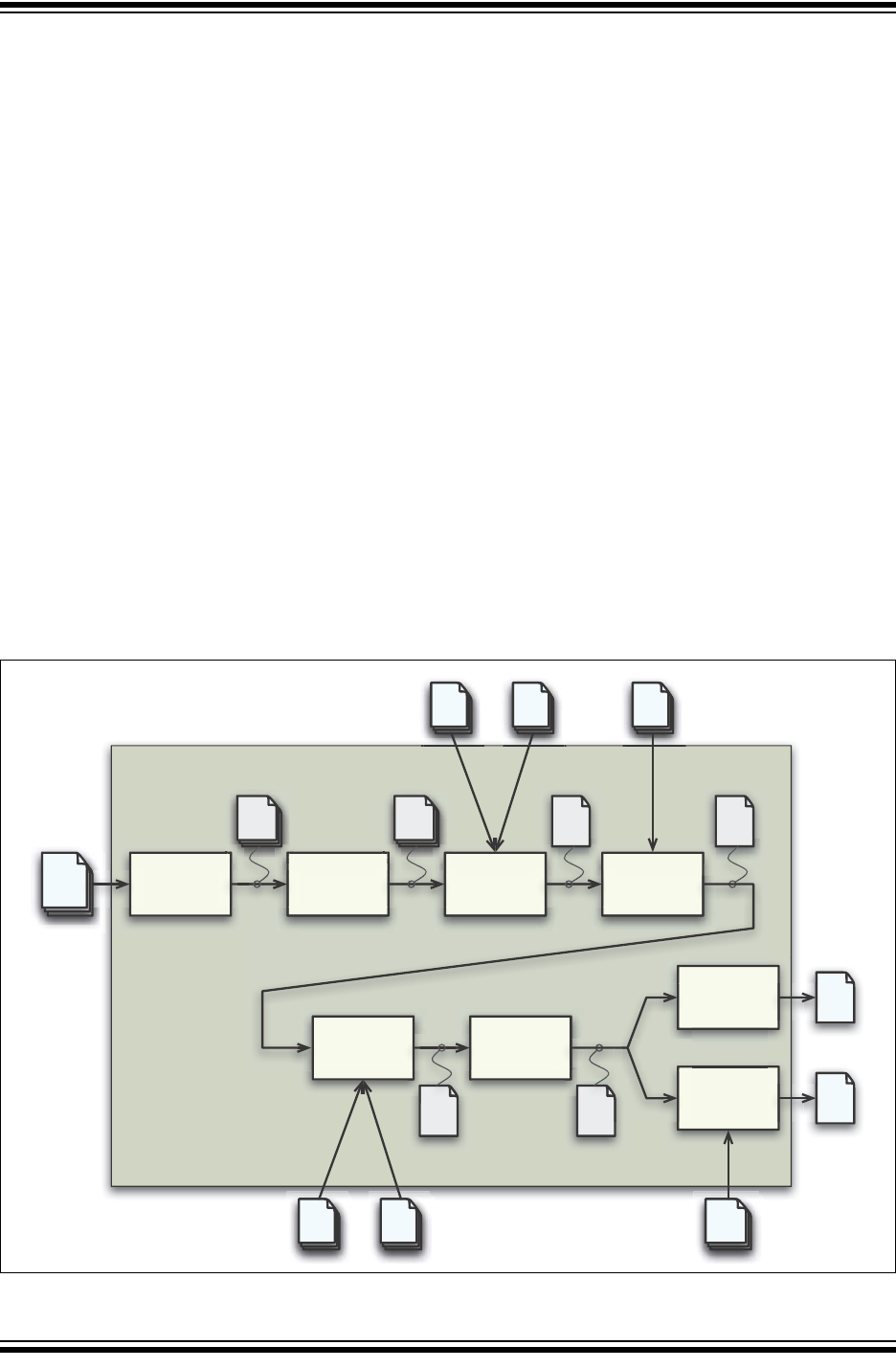
XC8 Command-line Driver
2012-2013 Microchip Technology Inc. DS50002053D-page 81
4.3 THE COMPILATION SEQUENCE
When you compile a project, many internal applications are called to do the work. This
section looks at when these internal applications are executed, and how this relates to
the build process of multiple source files. This section should be of particular interest if
you are using a make system to build projects.
4.3.1 The Compiler Applications
The main internal compiler applications and files are illustrated in Figure 4-1.
You can consider the large underlying box to represent the whole compiler, which is
controlled by the command line driver, xc8. You can be satisfied just knowing that C
source files (shown on the far left) are passed to the compiler and the resulting output
files (shown here as a HEX and COFF debug file on the far right) are produced; how-
ever, internally there are many applications and temporary files being produced. An
understanding of the internal operation of the compiler, while not necessary, does
assist with using the tool.
To simplify the compiler design, some of the internal applications come in a PIC18 and
PIC10/12/16 variant. The appropriate application is executed based on the target
device. In fact, the xc8 driver delegates the build commands to one of two com-
mand-line drivers: PICC or PICC18. This operation is transparent and xc8 can be
considered as “the driver” which does all the work.
The driver will call the required compiler applications. These applications are shown as
the smaller boxed inside the large driver box. The temporary file produced by each
application can also be seen in this diagram.
FIGURE 4-1: COMPILER APPLICATIONS AND FILES
.as
preprocessor
parser code
generator assembler
.c
.pre .p1 .obj
processed
files (module) p-code
files assembly file
relocatable
object file
C source
files
o
r p
linker objtohex
cromwell
hexmate
p
arse
r
code
generato
r
assem
bl
er
link
er
o
bjtohex
cromwe
ll
.obj
absolute
object file
.hex
hex file
.cof
debug file
.hex
hex file
.c
.
h
Command-line driver
.lpp
p-code
libraries .as
assembly
source
files
.obj
relocatable
object files .hex
hex
files
.lib object
libraries
.p1 p-code
files
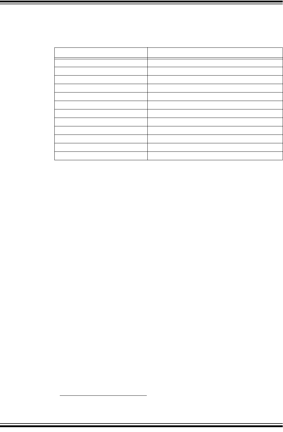
MPLAB® XC8 C Compiler User’s Guide
DS50002053D-page 82 2012-2013 Microchip Technology Inc.
Table 4-2 lists the compiler applications. The names shown are the names of the exe-
cutables, which can be found in the bin directory under the compiler’s installation
directory.
For example, C source files (.c files) are first passed to the C preprocessor, CPP. The
output of this application is .pre files. These files are then passed to the parser appli-
cation, P1, which produces a p-code file output with extension .p1. The applications
are executed in the order specified and temporary files are used to pass the output of
one application to the next.
The compiler can accept more than just C source files. Table 4-1 lists all the possible
input file types, and these files can be seen in this diagram, on the top and bottom,
being passed to different compilation applications. They are processed by these
applications and then the application output joins the normal flow indicated in the
diagram.
For example, assembly source files are passed straight to the assembler application1
and are not processed at all by the code generator. The output of the assembler (an
object file with .obj extension) is passed to the linker in the usual way. You can see
that any p-code files (.p1 extension) or p-code libraries (.lpp extension) that are
supplied on the command line are initially passed to the code generator.
Other examples of input files include object files (.obj extension) and object libraries
(.lib extension), both of which are passed initially to the linker, and even HEX files
(.hex extension), which are passed to one of the utility applications, called HEXMATE,
which is run right at the end of the compilation sequence.
Some of the temporary files shown in this diagram are actually preserved and can be
inspected after compilation has concluded. There are also driver options to request that
the compilation sequence stop after a particular application and the output of that
application becomes the final output.
TABLE 4-2: COMPILER APPLICATION NAMES
Name Description
xc8 (calls PICC or PICC18) Command line driver; the interface to the compiler
CLIST Text file formatter
CPP The C preprocessor
P1 C code parser
CGPIC or CGPIC18 Code generator (based on the target device)
ASPIC or ASPIC18 Assembler (based on the target device)
HLINK Linker
OBJTOHEX Conversion utility to create HEX files
CROMWELL Debug file converter
HEXMATE HEX file utility
LIBR Librarian
DUMP Object file viewer
1. Assembly file will be preprocessed before being passed to the assembler if the -P option is
selected.
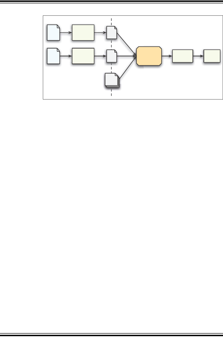
XC8 Command-line Driver
2012-2013 Microchip Technology Inc. DS50002053D-page 83
FIGURE 4-2: MULTI-FILE COMPILATION
4.3.2 Single-Step Compilation
Figure 4-1 showed us the files that are generated by each application and the order in
which these applications are executed. However this does not indicate how these
applications are executed when there is more than one source file being compiled.
Consider the case when there are two C source files that form a complete project and
that are to be compiled, as is the case shown in Figure 4-2. If these files are called
main.c and io.c, these could be compiled with a single command, such as:
xc8 --chip=16F877A main.c io.c
This command will compile the two source files all the way to the final output, but
internally we can consider this compilation as consisting of two stages.
The first stage involves processing of each source file separately, and generating some
sort of intermediate file for each source file. The second stage involves combining all
these intermediate files and further processing to form the final output. An intermediate
file is a particular temporary file that is produced and marks the midpoint between the
first and second stage of compilation.
The intermediate file used by xc8 is the p-code (.p1 extension) file output by the
parser, so there will be one p-code file produced for each C source file. As indicated in
the diagram, CPP and then P1 are executed to form this intermediate file. (For clarity,
the CPP and P1 applications have been represented by the same block in the diagram.)
In the second stage, the code generator reads in all the intermediate p-code files and
produces a single assembly file output, which is then passed to the subsequent
applications that produce the final output.
The desirable attribute of this method of compilation is that the code generator, which
is the main application that transforms from the C to the assembly domain, sees the
entire project source code via the intermediate files.
Traditional compilers have always used intermediate files that are object files output by
the assembler. These intermediate object files are then combined by the linker and fur-
ther processed to form the final output. This method of compilation is shown in
Figure 4-3. It shows that the code generator is executed once for each source file. So,
the code generator can only analyze that part of the project that is contained in the
source file that is currently being compiled. The MPLAB XC16 and XC32 compilers
work in this fashion.
Using object files as the intermediate file format with MPLAB XC8 C Compiler will
defeat many features the compiler uses to optimize code. Always use p-code files as
the intermediate file format if you are using a make system to build projects.
C file
C file
library
files
preprocess
&
parse
p-
code
code
generation
preprocess
&
parse
p-
code linkassemble
First stage of compilation Second stage of compilation
Intermediate files
MPLAB® XC8 C Compiler User’s Guide
DS50002053D-page 84 2012-2013 Microchip Technology Inc.
FIGURE 4-3: THE TRADITIONAL COMPILATION SEQUENCE
When compiling files of mixed types, this can still be achieved with just one invocation
of the compiler driver. As discussed in Section 4.3 “The Compilation Sequence”, the
driver will pass each input file to the appropriate compiler application.
For example, the files, main.c, io.c, mdef.as and c_sb.lpp are to be compiled.
To perform this in a single step, the following command line could be used.
xc8 --chip=16F877A main.c io.c mdef.as c_sb.lpp
As shown in Figure 4-1 and Figure 4-2, the two C files (main.c and io.c) will be com-
piled to intermediate p-code files; these, along with the p-code library file (c_sb.lpp)
will be passed to the code generator. The output of the code generator, as well as the
assembly source file (mdef.as), will be passed to the assembler.
The driver will recompile all source files, regardless of whether they have changed
since the last build. IDEs (such as MPLAB® IDE) and make utilities must be employed
to achieve incremental builds. See also, Section 4.3.3 “Multi-Step Compilation”.
Unless otherwise specified, a HEX file and Microchip COFF file are produced as the
final output. All intermediate files remain after compilation has completed, but most
other temporary files are deleted, unless you use the --NODEL option (see
Section 4.8.40 “--NODEL: Do Not Remove Temporary Files”) which preserves all
generated files except the run-time start-up file. Note that some generated files can be
in a different directory than your project source files. See Section 4.8.43 “--OUTDIR:
Specify a Directory for Output Files”, and Section 4.8.41 “--OBJDIR: Specify a
Directory for Intermediate Files”, which can both control the destination for some
output files.
C file
C file
library
files
preprocess
&
parse
.obj
files
preprocess
&
parse
.obj
files link
assemble
First stage of compilation Second stage
of compilation
Intermediate files
code
generation
code
generation assemble

XC8 Command-line Driver
2012-2013 Microchip Technology Inc. DS50002053D-page 85
4.3.3 Multi-Step Compilation
Make utilities and IDEs, such as MPLAB IDE, allow for an incremental build of projects
that contain multiple source files. When building a project, they take note of which
source files have changed since the last build and use this information to speed up
compilation.
For example, if compiling two source files, but only one has changed since the last
build, the intermediate file corresponding to the unchanged source file need not be
regenerated.
MPLAB IDE is aware of the different compilation sequence employed by xc8 and takes
care of this for you. From MPLAB IDE you can select an incremental build (Build Project
icon), or fully rebuild a project (Clean and Build Project icon).
If the compiler is being invoked using a make utility, the make file will need to be con-
figured to recognized the different intermediate file format and the options used to gen-
erate the intermediate files. Make utilities typically call the compiler multiple times: once
for each source file to generate an intermediate file, and once to perform the second
stage compilation.
You can also wish to generate intermediate files to construct your own library files.
However, xc8 is capable of constructing libraries in a single step, so this is typically not
necessary. See Section 4.8.44 “--OUTPUT= type: Specify Output File Type”, for
more information on library creation.
The option --PASS1 (see Section 4.8.45 “--PARSER: Specify Parser Mode”) is
used to tell the compiler that compilation should stop after the parser has executed.
This will leave the p-code intermediate file behind on successful completion.
For example, the files main.c and io.c are to be compiled using a make utility. The
command lines that the make utility should use to compile these files might be
something like:
xc8 --chip=16F877A --pass1 main.c
xc8 --chip=16F877A --pass1 io.c
xc8 --chip=16F877A main.p1 io.p1
If is important to note that the code generator needs to compile all p-code or p-code
library files associated with the project in the one step. When using the --PASS1 option
the code generator is not being invoked, so the above command lines do not violate
this requirement.
Using object files as the intermediate file format with MPLAB XC8 C Compiler will
defeat many features the compiler uses to optimize code. Always use p-code files as
the intermediate file format if you are using a make system to build projects.
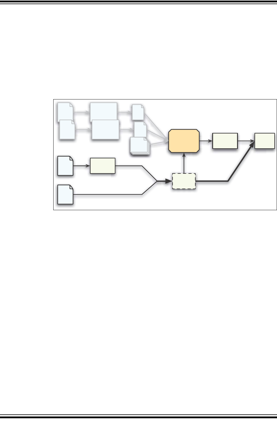
MPLAB® XC8 C Compiler User’s Guide
DS50002053D-page 86 2012-2013 Microchip Technology Inc.
4.3.4 Compilation of Assembly Source
Since the code generator performs many tasks that were traditionally performed by the
linker, there could be complications when assembly source is present in a project.
Assembly files are traditionally processed after C code, but it is necessary to have this
performed first so that specific information contained in the assembly code can be
conveyed to the code generator.
The specific information passed to the code generator is discussed in more detail in
Section 5.12.3 “Interaction between Assembly and C Code”.
When assembly source is present, the order of compilation is as shown in Figure 4-4.
FIGURE 4-4: COMPILATION SEQUENCE WITH ASSEMBLY FILES
First, any assembly source files are assembled to form object files. These files, along
with any other objects files that are part of the project, are scanned by the
command-line driver and the information is passed to the code generator; where it
subsequently builds the C files, as has been described earlier.
4.3.4.1 INTERMEDIATE FILES AND ASSEMBLY SOURCE
The intermediate file format associated with assembly source files is the same as that
used in traditional compilers; i.e., an object file (.obj extension). Assembly files are
never passed to the code generator and so the code generator technology does not
alter the way these files are compiled.
The -C option (see Section 4.8.1 “-C: Compile to Object File”) is used to generate
object files and to halt compilation after the assembly step.
4.3.5 Printf Check
An extra execution of the code generator is performed prior to the actual code genera-
tion phase. This pass is part of the process by which the printf library function is
customized; see Section 5.11.1 “The printf Routine”, for more details.
This pass is only associated with scanning the C source code for printf placeholder
usage and you will see the code generator being executed if you select the verbose
option when you build; see Section 4.8.14 “-V: Verbose Compile”.
C file
C file
library
files
preprocess
&
parse
p-
code
code
generation assemble
preprocess
&
parse
p-
code
ASM
file
OBJ
file
link
assemble
driver

XC8 Command-line Driver
2012-2013 Microchip Technology Inc. DS50002053D-page 87
4.4 RUNTIME FILES
In addition to the C and assembly source files specified on the command line, there are
also compiler-generated source files and pre-compiled library files which might be
compiled into the project by the driver. These files contain:
• C Standard library routines
• Implicitly called arithmetic routines
• User-defined library routines
• The runtime startup code
• The powerup routine
• The printf routine.
Strictly speaking, the powerup routine is neither a compiler-generated source, nor a
library routine. It is fully defined by the user. Because it is very closely associated with
the runtime startup module, it is discussed with the other runtime files in the following
sections.
4.4.1 Library Files
The names of the C standard library files appropriate for the selected target device, and
other driver options, are determined by the driver and passed to the code generator and
linker. You do not need to include library files into your project manually. P-code librar-
ies (.lpp libraries) are used by the code generator, and object code libraries (.lib
files) are used by the linker. Most library routines are derived from p-code libraries.
By default, xc8 will search the lib directory under the compiler installation directory
for library files that are required during compilation.
4.4.1.1 STANDARD LIBRARIES
The C standard libraries contain a standardized collection of functions, such as string,
math and input/output routines. The range of these functions is described in
Appendix A. “Library Functions”. Although it is considered a library function, the
printf function’s code is not found in these library files. C source code for this func-
tion is generated from a special C template file that is customized after analysis of the
user’s C code. See “PRINTF, VPRINTF”, for more information on using the printf
library function, and Section 5.11.1 “The printf Routine”, for information on how the
printf function is customized when you build a project.
The libraries also contain C routines that are implicitly called by the output code of the
code generator. These are routines that perform tasks such as floating-point opera-
tions, integer division and type conversions, and that cannot directly correspond to a C
function call in the source code.
The library name format is family-type-options.lpp, where the following apply.
•family can be pic18 for PIC18 devices, or pic for all other 8-bit PIC devices
•type indicates the sort of library functionality provided and can be stdlib for the
standard library functions, or trace, etc.
•options indicates hyphen-separated names to indicate variants of the library to
accommodate different compiler options or modes, e.g., htc for HI-TECH C
compatibility, d32 for 32-bit doubles, etc.
For example, the standard library for baseline and midrange devices using 24-bit
double types is pic-stdlib-d24.lpp.
All the libraries are present in the lib directory of the compiler installation. Search this
directory for the full list of all libraries supplied.

MPLAB® XC8 C Compiler User’s Guide
DS50002053D-page 88 2012-2013 Microchip Technology Inc.
4.4.1.2 USER-DEFINED LIBRARIES
User-defined libraries can be created and linked in with programs as required. Library
files are easier to manage and can result in faster compilation times, but must be com-
patible with the target device and options for a particular project. Several versions of a
library might need to be created to allow it to be used for different projects.
Libraries can be created manually using the compiler and the librarian, LIBR. See
Section 8.2 “Librarian” for more information on the librarian and creating library files
using this application. Alternatively, library files can be created directly from the
compiler by specifying a library output using the --OUTPUT option; see
Section 4.8.44 “--OUTPUT= type: Specify Output File Type”.
User-created libraries that should be searched when building a project can be listed on
the command line along with the source files.
As with Standard C library functions, any functions contained in user-defined libraries
should have a declaration added to a header file. It is common practice to create one
or more header files that are packaged with the library file. These header files are then
included into source code when required.
Library files specified on the command line are initially scanned for unresolved sym-
bols; so, these files can redefine anything that is defined in the C standard libraries. See
also, Section 5.15.4 “Changing and Linking the Allocated Section”.
4.4.2 Startup and Initialization
A C program requires certain objects to be initialized and the device to be in a particular
state before it can begin execution of its function main. It is the job of the runtime
startup code to perform these tasks. Section 5.10.1 “Runtime Startup Code” details
the specific actions taken by this code and how it interacts with programs you write.
Rather than the traditional method of linking in a generic, precompiled routine, the
MPLAB XC8 C Compiler determines what runtime startup code is required from the
user’s program and then generates this code each time you build.
Both the driver and code generator are involved in generating the runtime startup code.
The driver creates the code that handles device setup. This code is placed into a sep-
arate assembly startup module. The code generator produces code that initializes the
C environment, such as clearing uninitialized C variables and copying initialized C
variables. This code is output along with the rest of the C program.
The runtime startup code is regenerated every time you build a project. The file created
by the driver can be deleted after compilation, and this operation can be controlled with
the keep suboption to the --RUNTIME option. The default operation of the driver is to
keep the startup module; however, if using MPLAB IDE to build, the file will be deleted
unless you indicate otherwise in the Project Properties dialog.
If the startup module is kept, it will be called startup.as and will be located in the
current working directory. If you are using an IDE to perform the compilation, the
destination directory can be dictated by the IDE itself. MPLAB X IDE stores this file in
the dist/default/production directory in your project directory.
Generation of the runtime startup code is an automatic process that does not require
any user interaction; however, some aspects of the runtime code can be controlled, if
required, using the --RUNTIME option. Section 4.8.51 “--RUNTIME: Specify Run-
time Environment” describes the use of this option. See Section 5.10.1 “Runtime
Startup Code”, which describes the functional aspects of the code contained in this
module and its effect on program operation.
The runtime startup code is executed before main. However, if you require any special
initialization to be performed immediately after Reset, you should use the powerup
feature described later in Section 5.10.2 “The Powerup Routine”.
XC8 Command-line Driver
2012-2013 Microchip Technology Inc. DS50002053D-page 89
4.5 COMPILER OUTPUT
There are many files created by the compiler during the compilation. A large number of
these are intermediate files. Some are deleted after compilation is complete, but many
remain and are used for programming the device, or for debugging purposes.
4.5.1 Output Files
The names of many output files use the same base name as the source file from which
they were derived. For example, the source file input.c will create a p-code file called
input.p1.
Some of the output files contain project-wide information and are not directly associ-
ated with any one particular input file, e.g., the map file. If the names of these output
files are not specified by a compiler option, their base name is derived from the first C
source file listed on the command line. If there are no files of this type specified, the
name is based on the first input file (regardless of type) on the command line.
If you are using an IDE, such as MPLAB X IDE, to specify options to the compiler, there
is typically a project file that is created for each application. The name of this project is
used as the base name for project-wide output files, unless otherwise specified by the
user. However, check the manual for the IDE you are using, for more details.
The compiler is directly able to produce a number of the output file formats that are
used by the 8-bit PIC development tools.
The default behavior of xc8 is to produce a Microchip format COFF and Intel HEX out-
put. Unless changed by a driver option, the base names of these files will be the project
name. The default output file types can be controlled by compiler options, e.g., the
--OUTPUT option. The extensions used by these files are fixed and are listed together
with this option’s description in Section 4.8.44 “--OUTPUT= type: Specify Output
File Type”.
The COFF file is used by debuggers to obtain debugging information about the project.
The compiler can produce ELF/DWARF debugger files, although these are not com-
patible with MPLAB IDE v8 and early versions of MPLAB X IDE. You must specifically
select ELF output for these files to be produced. ELF/DWARF files allow for more accu-
rate debugging. Use of these files correct several COFF-related issues that prevent
you from correctly viewing objects, in particular pointer variables, in the IDE. Ensure the
IDE version you are using supports ELF before selecting this option.
Table 4-16 shows all output format options available with xc8 using the --OUTPUT
option. The File Type column lists the filename extension that is used for the output file.
4.5.1.1 SYMBOL FILES
By default, xc8 creates symbol files that are used to generate the debug output files,
such as COFF and ELF files. These files include a SYM file (.sym extension) and a
CMF file (.cmf extension), and both are produced by the linker. In addition, there is a
SDB file (.sdb extension) produced by the code generator.
The SDB file contains type information, and the SYM and CMF files contain address
information. The SDB and SYM/CMF files, in addition to the HEX file, are combined by
the CROMWELL application to produce the output debug files, such as the COFF file.
The CMF file largely replaces the older SYM file format. They contain similar informa-
tion, but CMF files are more detailed and enable more accurate debug files to be
generated.
Note: Throughout this manual, the term project name will refer to either the name
of the project created in the IDE, or the base name (file name without
extension) of the first C source file specified on the command line.

MPLAB® XC8 C Compiler User’s Guide
DS50002053D-page 90 2012-2013 Microchip Technology Inc.
4.5.2 Diagnostic Files
Two valuable files produced by the compiler are the assembly list file, produced by the
assembler, and the map file, produced by the linker.
The compiler options --ASMLIST (see Section 4.8.15 “--ADDRQUAL: Set Compiler
Response to Memory Qualifiers”) generates a list file, and the -M option (see
Section 4.8.7 “-M: Generate Map File”) specifies generation of a map file.
The assembly list file contains the mapping between the original source code and the
generated assembly code. It is useful for information such as how C source was
encoded, or how assembly source can have been optimized. It is essential when con-
firming if compiler-produced code that accesses objects is atomic, and shows the
psects in which all objects and code are placed. For an introductory guide to psects,
see Section 5.15.1 “Program Sections”. Also, see Section 6.5 “Assembly-Level
Optimizations”, for more information on the contents of this file.
There is one list file produced for the entire C program, including C library files. It is
assigned the project name and the extension .lst. One additional list file is produced
for each assembly source file compiled in the project.
The map file shows information relating to where objects were positioned in memory. It
is useful for confirming if user-defined linker options were correctly processed, and for
determining the exact placement of objects and functions. It also shows all the unused
memory areas in a device and memory fragmentation. See Section 7.4 “Map Files”,
for complete information on the contents of this file.
There is one map file produced when you build a project, assuming the linker was
executed and ran to completion. The file is assigned the project name and a .map
extension.

XC8 Command-line Driver
2012-2013 Microchip Technology Inc. DS50002053D-page 91
4.6 COMPILER MESSAGES
All compiler applications, including the command-line driver, xc8, use textual mes-
sages to report feedback during the compilation process. A centralized messaging sys-
tem is used to produce the messages, which allows consistency during all stages of the
compilation process. The messaging system is described in this section and a com-
plete list of all warning and error messages can be found in Appendix C. “Error and
Warning Messages”.
4.6.1 Messaging Overview
A message is referenced by a unique number that is passed to the messaging system
by the compiler application that needs to convey the information. The message string
corresponding to this number is obtained from Message Description Files (MDF), which
are stored in the dat directory in the compiler’s installation directory.
When a message is requested by a compiler application, its number is looked up in the
MDF that corresponds to the currently selected language. The language of messages
can be altered as discussed in Section 4.6.2 “Message Language”.
Once found, the alert system can read the message type and the string to be displayed
from the MDF. Several different message types are described in
Section 4.6.3 “Message Type”; and the type can be overridden by the user, as
described in that same section.
The user is also able to set a threshold for warning message importance, so that only
those that the user considers significant will be displayed. In addition, messages with
a particular number can be disabled. A pragma can also be used to disable a particular
message number within specific lines of code. These methods are explained in
Section 4.6.5.1 “Disabling Messages”.
Provided the message is enabled and it is not a warning message whose level is below
the current warning threshold, the message string will be displayed.
In addition to the actual message string, there are several other pieces of information
that can be displayed, such as the message number, the name of the file for which the
message is applicable, the file’s line number and the application that issued the
message, etc.
If a message is an error, a counter is incremented. After a specific amount of errors has
been reached, compilation of the current module will cease. The default number of
errors that will cause this termination can be adjusted by using the --ERRORS option;
see Section 4.8.28 “--ERRORS: Maximum Number of Errors”. This counter is reset
for each internal compiler application, thus specifying a maximum of five errors will
allow up to five errors from the parser, five from the code generator, five from the linker,
five from the driver, etc.
Although the information in the MDF can be modified with any text editor, this is not rec-
ommended. Message behavior should only be altered using the options and pragmas
described in the following sections.
MPLAB® XC8 C Compiler User’s Guide
DS50002053D-page 92 2012-2013 Microchip Technology Inc.
4.6.2 Message Language
The xc8 driver supports more than one language for displayed messages. There is one
MDF for each language supported.
Under Windows®, the default language can be specified when installing the compiler.
The default language can be changed on the command line using the --LANG option;
see Section 4.8.35 “--LANG: Specify the Language for Messages”. Alternatively, it
can be changed permanently by using the --LANG option together with the --SETUP
option which will store the default language in either the registry, under Windows, or in
the XML configuration file on other systems. On subsequent builds, the default
language used will be that specified.
Table 4-3 shows the MDF applicable for the currently supported languages.
If a language other than English is selected, and the message cannot be found in the
appropriate non-English MDF, the alert system tries to find the message in the English
MDF. If an English message string is not present, a message is displayed that is similar
to this one:
error/warning (*) generated, but no description available
where * indicates the message number that was generated that will be printed;
otherwise, the message in the requested language will be displayed.
4.6.3 Message Type
There are four types of messages. These are described below along with the com-
piler’s behavior when encountering a message of each type.
Advisory Messages convey information regarding a situation the compiler has en-
countered or some action the compiler is about to take. The information is
being displayed “for your interest”, and typically requires no action to be
taken. Compilation will continue as normal after such a message is issued.
Warning Messages indicate source code or some other situation that can be com-
piled, but is unusual and can lead to a runtime failure of the code. The code
or situation that triggered the warning should be investigated; however, com-
pilation of the current module will continue, as will compilation of any
remaining modules.
Error Messages indicate source code that is illegal or that compilation of this code
cannot take place. Compilation will be attempted for the remaining source
code in the current module, but no additional modules will be compiled and
the compilation process will then conclude.
Fatal Error Messages indicate a situation in which the compilation cannot proceed
and requires that the compilation process to stop immediately.
TABLE 4-3: SUPPORTED LANGUAGES
Language MDF name
English en_msgs.txt
German de_msgs.txt
French fr_msgs.txt
XC8 Command-line Driver
2012-2013 Microchip Technology Inc. DS50002053D-page 93
4.6.4 Message Format
By default, messages are printed in a human-readable format. This format can vary
from one compiler application to another, since each application reports information
about different file formats.
Some applications (for example, the parser) are typically able to pinpoint the area of
interest down to a position on a particular line of C source code, whereas other appli-
cations, such as the linker, can at best only indicate a module name and record number,
which is less directly associated with any particular line of code. Some messages relate
to issues in driver options that are in no way associated with any source code.
There are several ways of changing the format in which message are displayed, which
are discussed below.
The driver option -E (with or without a filename) alters the format of all displayed mes-
sages. See Section 4.8.3 “-E: Redirect Compiler Errors to a File”, for details. Using
this option produces messages that are better suited to machine parsing, and are less
user-friendly. Typically, each message is displayed on a single line. The general form
of messages produced when using the -E option is:
filename line: (message number) message string (type)
The -E option also has another effect. When used, the driver first checks to see if spe-
cial environment variables have been set. If so, the format dictated by these variables
is used as a template for all messages that will be produced by all compiler
applications. The names of these environment variables are given in Table 4-4.
The value of these environment variables are strings that are used as templates for the
message format. Printf-like placeholders can be placed within the string to allow the
message format to be customized. The placeholders, and what they represent, are
presented in Table 4-5.
If these options are used in a DOS batch file, two percent characters will need to be
used to specify the placeholders, as DOS interprets a single percent character as an
argument and will not pass this on to the compiler. For example:
SET HTC_ERR_FORMAT="file %%f: line %%l"
TABLE 4-4: MESSAGING ENVIRONMENT VARIABLES
Variable Effect
HTC_MSG_FORMAT All advisory messages
HTC_WARN_FORMAT All warning messages
HTC_ERR_FORMAT All error and fatal error messages
TABLE 4-5: MESSAGING PLACEHOLDERS
Placeholder Replacement
%a Application name
%c Column number
%f Filename
%l Line number
%n Message number
%s Message string (from MDF)

MPLAB® XC8 C Compiler User’s Guide
DS50002053D-page 94 2012-2013 Microchip Technology Inc.
Environment variables, in turn, can be overridden by the driver options: --MSGFORMAT,
--WARNFORMAT and --ERRFORMAT; see Section 4.8.27 “--ERRFORMAT: Define
Format for Compiler Messages”. These options take a string as their argument. The
option strings are formatted, and can use the same placeholders as their variable
counterparts.
For example, a project is compiled, but, as shown, produces a warning from the parser
and an error from the linker (numbered 362 and 492, respectively).
main.c: main()
17: ip = &b;
^ (362) redundant "&" applied to array (warning)
(492) attempt to position absolute psect "text" is illegal
Notice that the parser message format identifies the particular line and position of the
offending source code.
If the -E option is now used and the compiler issues the same messages, the compiler
will output:
main.c: 12: (362) redundant "&" applied to array (warning)
(492) attempt to position absolute psect "text" is illegal (error)
The user now uses the --WARNFORMAT in the following fashion:
--WARNFORMAT="%a %n %l %f %s"
When recompiled, the following output will be displayed:
parser 362 12 main.c redundant "&" applied to array
(492) attempt to position absolute psect "text" is illegal (error)
Notice that the format of the warning was changed, but that of the error message was
not. The warning format now follows the specification of the environment variable. The
application name (parser) was substituted for the %a placeholder, the message
number (362) substituted the %n placeholder, etc.
4.6.5 Changing Message Behavior
Both the attributes of individual messages and general settings for the messaging sys-
tem can be modified during compilation. There are both driver options and C pragmas
that can be used to achieve this.
4.6.5.1 DISABLING MESSAGES
Each warning message has a default number indicating a level of importance. This
number is specified in the MDF and ranges from -9 to 9. The higher the number, the
more important the warning.
Warning messages can be disabled by adjusting the warning level threshold using the
--WARN driver option; see Section 4.8.61 “--WARN: Set Warning Level”. Any
warnings whose level is below that of the current threshold are not displayed.
The default threshold is 0 which implies that only warnings with a warning level of 0 or
higher will be displayed by default. The information in this option is propagated to all
compiler applications, so its effect will be observed during all stages of the compilation
process.
Warnings can also be disabled by using the --MSGDISABLE option; see
Section 4.8.38 “--MSGDISABLE: Disable Warning Messages”. This option takes a
comma-separated list of warning numbers. The warnings corresponding to the num-
bers listed are disabled and will never be issued, regardless of the current warning level
threshold. If the special message number 0 is specified, then all warning messages are
disabled.
XC8 Command-line Driver
2012-2013 Microchip Technology Inc. DS50002053D-page 95
Some warning messages can also be disabled by using the warning pragma. This
pragma will only affect warnings that are produced by either the parser or the code gen-
erator; i.e., errors directly associated with C code. See Section 5.14.4.11 “The
#pragma warning Directive” for more information on this pragma.
Error messages can also be disabled; however, a more verbose form of the above
command is required to confirm the action. To specify an error message number in the
--MSGDISABLE command, each error number must be followed by :off to ensure
that it is disabled. For example:
--MSGDISABLE=1257,195:off,194:off
will disable warning 1257, and errors 195 and 194.
4.6.5.2 CHANGING MESSAGE TYPES
It is also possible to change the type of some messages. This can only be done for
messages generated by the parser or code generator. See Section 5.14.4.11 “The
#pragma warning Directive”, for more information on this pragma.
Note: Disabling error or warning messages in no way fixes the condition that
triggered the message. Always use extreme caution when exercising these
options.

MPLAB® XC8 C Compiler User’s Guide
DS50002053D-page 96 2012-2013 Microchip Technology Inc.
4.7 MPLAB XC8 DRIVER OPTIONS
This section looks at the general form of xc8 command-line options and what action
the compiler will perform if no option is specified for a certain feature.
4.7.1 General Option Formats
All single letter options are identified by a leading dash character, “-”, for example: -C.
Some single letter options specify an additional data field that follows the option name
immediately and without any whitespace, for example: -Ddebug. In this manual,
options are written in upper case and suboptions are written in lower case.
Multi-letter, or word, options have two leading dash characters, for example:
--ASMLIST. (Because of the double dash, the driver can determine that the option
--DOUBLE, for example, is not a -D option followed by the argument OUBLE.)
Some of these word options use suboptions which typically appear as a comma-sepa-
rated list following an equal character, =, for example: --OUTPUT=hex,cof. The exact
formats of the options vary. The options and formats are described in detail in the
following sections.
Some commonly used suboptions include default, which represent the default spec-
ification that would be used if this option was absent altogether; all, which indicates
that all the available suboptions should be enabled as if they had each been listed; and
none, which indicates that all suboptions should be disabled. For example:
--OPT=none
will turn off all optimizers.
Some suboptions can be prefixed with a plus character, +, to indicate that they are in
addition to the other suboptions present; or a minus character “-”, to indicate that they
should be excluded. For example:
--OPT=default,-asm
indicates that the default optimization be used, but that the assembler optimizer should
be disabled. If the first character after the equal sign is + or -, then the default keyword
is implied. For example:
--OPT=-asm
is the same as the previous example.
See the –-HELP option, Section 4.8.33 “--HELP: Display Help”, for more information
about options and suboptions.
4.7.2 Default Options
If you run the compiler driver from the command line and do not specify the option for
a feature, it will default to a certain state. You can also specify the default suboption
(to double-dash options) that will also invoke the default behavior. You can check what
the default behavior is by using the --HELP=option on the command line; see
Section 4.8.33 “--HELP: Display Help”.
If you are compiling from within the MPLAB X IDE, it will, by default, issue explicit
options to the compiler (unless changed in the Project Properties dialog), and these
options can be different to those that are the default on the command line. For example,
unless you specify the --ASMLIST option on the command line, the default operation
of the compiler is not to produce an assembly list file. But, if you are compiling from
within the MPLAB X IDE, the default operation (this, in fact, cannot be disabled) is to
always produce an assembly list file.
If you are compiling the same project from the command line and from the MPLAB X
IDE, always check that all options are explicitly specified.
XC8 Command-line Driver
2012-2013 Microchip Technology Inc. DS50002053D-page 97
4.8 OPTION DESCRIPTIONS
Most aspects of the compilation can be controlled using the command-line driver, xc8.
The driver will configure and execute all required applications, such as the code
generator, assembler and linker.
xc8 recognizes the compiler options which are tabled below and are explained in detail
in the sections following. The case of the options is not important; however, command
shells in most operating systems are case sensitive when it comes to the names of
files.
TABLE 4-6: DRIVER OPTIONS
Option Meaning
-C Compile to object file and stop
-Dmacro Define preprocessor macro symbol
-Efilename Redirect compile errors
-G[filename]Generate symbolic debug information
-Ipath Specify include path
-Largument Set linker option
-M[filename]Generate map file
-Nnumber Specify identifier length
-Ofile Specify output filename and type
-P Preprocess assembly source
-Q Quiet mode
-S Compile to assembly file and stop
-Umacro Undefine preprocessor macro symbol
-V Verbose mode
--ADDRQUAL=qualifier Specify address space qualifier handling
--ASMLIST Generate assembly list file
--CHAR=type Default character type (defunct)
--CHECKSUM=specification Calculate a checksum and store the result in program
memory
--CHIP=device Select target device
--CHIPINFO Print device information
--CODEOFFSET=value Specify ROM offset address
--DEBUGGER=type Set debugger environment
--DOUBLE=size Size of double type
--ECHO Echo command line
--EMI=mode Select external memory interface operating mode
--ERRATA=type Specify errata workarounds
--ERRFORMAT=format Set error format
--ERRORS=number Set maximum number of errors
--EXT=extensions Specify C language extensions
--FILL=specification Specify a ROM-fill value for unused memory
--FLOAT=size Size of float type
--GETOPTION=argument Get advanced options
--HELP=option Help
--HTML=file Generate HTML debug files
--LANG=language Specify language
--MEMMAP=mapfile Display memory map
MPLAB® XC8 C Compiler User’s Guide
DS50002053D-page 98 2012-2013 Microchip Technology Inc.
4.8.1 -C: Compile to Object File
The -C option is used to halt compilation after executing the assembler, leaving a relo-
catable object file as the output. It is frequently used when compiling assembly source
files using a make utility. It cannot be used unless all C source files are present on the
command line. Use --PASS1 to generate intermediate files from C source, see
Section 4.8.45 “--PARSER: Specify Parser Mode”.
See Section 4.3.3 “Multi-Step Compilation”, for more information on generating and
using intermediate files.
--MODE=mode Choose operating mode
--MSGDISABLE=list Disable warning messages
--MSGFORMAT=specification Set advisory message format
--NODEL Do not remove temporary files
--NOEXEC Do not execute compiler applications
--OBJDIR=path Set object files directory
--OPT=optimizations Control optimization
--OUTDIR=path Set output directory
--OUTPUT=path Set output formats
--PARSER=mode Specify parser mode
--PASS1 Produce intermediate p-code file and stop
--PRE Produce preprocessed source files and stop
--PROTO Generate function prototypes
--RAM=ranges Adjust RAM ranges
--ROM=ranges Adjust ROM ranges
--RUNTIME=options Specify runtime options
--SCANDEP Scan for dependencies
--SERIAL=specification Insert a hexadecimal code or serial number
--SETOPTION=argument Set advanced options
--SETUP=specification Setup the compiler
--SHROUD Shroud (obfuscate) generated p-code files
--STACK=type[:sizes]Specify data stack type and sizes
--STRICT Use strict ANSI keywords
--SUMMARY=type Summary options
--TIME Report compilation times
--VER Show version information
--WARN=number Set warning threshold level
--WARNFORMAT=specification Set warning format
TABLE 4-6: DRIVER OPTIONS (CONTINUED)
Option Meaning

XC8 Command-line Driver
2012-2013 Microchip Technology Inc. DS50002053D-page 99
4.8.2 -D: Define Macro
The -D option is used to define a preprocessor macro on the command line, exactly as
if it had been defined using a #define directive in the source code. This option can
take one of two forms, -Dmacro which is equivalent to:
#define macro 1
placed at the top of each module compiled using this option, or -Dmacro= text which
is equivalent to:
#define macro text
where text is the textual substitution required. Thus, the command:
xc8 --CHIP=16F877AA -Ddebug -Dbuffers=10 test.c
will compile test.c with macros defined exactly as if the C source code had included
the directives:
#define debug 1
#define buffers 10
Defining macros as C string literals requires bypassing any interpretation issues in the
operating system that is being used. To pass the C string, "hello world", (including
the quote characters) in the Windows environment, use: "-DMY_STRING=\\\"hello
world\\\"" (you must include the quote characters around the entire option, as there
is a space character in the macro definition). Under Linux or Mac OS X, use:
-DMY_STRING=\"hello\ world\".
See Section 4.9 “MPLAB X Option Equivalents”, for use of this option in MPLAB
IDE.
4.8.3 -E: Redirect Compiler Errors to a File
This option has two purposes. The first is to change the format of displayed messages.
The second is to optionally allow messages to be directed to a file, as some editors do
not allow the standard command line redirection facilities to be used when invoking the
compiler.
The general form of messages produced with the -E option in force is:
filename line_number: (message number) message string (type)
If a filename is specified immediately after -E, it is treated as the name of a file to which
all messages (errors, warnings, etc.) will be printed. For example, to compile x.c and
redirect all errors to x.err, use the command:
xc8 --CHIP=16F877AA -Ex.err x.c
The -E option also allows errors to be appended to an existing file by specifying an
addition character, +, at the start of the error filename, for example:
xc8 --CHIP=16F877AA -E+x.err y.c
If you wish to compile several files and combine all of the errors generated into a single
text file, use the -E option to create the file then use -E+ when compiling all the other
source files. For example, to compile a number of files with all errors combined into a
file called project.err, you could use the - E option as follows:
xc8 --CHIP=16F877AA -Eproject.err -O --PASS1 main.c
xc8 --CHIP=16F877AA -E+project.err -O --PASS1 part1.c
xc8 --CHIP=16F877AA -E+project.err -C asmcode.as
Section 4.6 “Compiler Messages” has more information regarding this option as well
as an overview of the messaging system and other related driver options.

MPLAB® XC8 C Compiler User’s Guide
DS50002053D-page 100 2012-2013 Microchip Technology Inc.
4.8.4 -I: Include Search Path
Use -I to specify an additional directory to search for header files which have been
included using the #include directive. The directory can either be an absolute or rel-
ative path. The -I option can be used more than once if multiple directories are to be
searched.
The compiler’s include directory containing all standard header files is always
searched, even if no -I option is present. If header filenames are specified using quote
characters rather than angle brackets, as in #include "lcd.h", then the current
working directory is searched in addition to the compiler’s include directory. Note that
if compiling within MPLAB IDE, the search path is relative to the output directory, not
the project directory.
These default search paths are searched after any user-specified directories have
been searched. For example, the following code:
xc8 --CHIP=16F877AA -C -Ic:\include -Id:\myapp\include test.c
will search the directories c:\include and d:\myapp\include for any header files
included into the source code, then search the default include directory.
Under Windows OS, be aware that use of the directory backslash character may unin-
tentionally form an escape sequence. For example, to specify an include file path that
ends with a directory separator character and which is quoted, use -I"E:\\" instead
of -I"E:\", to avoid the escape sequence \". Note that MPLAB X IDE will quote any
include file path you specify in the project properties.
This option has no effect for files that are included into assembly source using the
assembly INCLUDE directive. See Section 6.4.10.4 “INCLUDE”, for details.
See Section 4.9 “MPLAB X Option Equivalents”, for use of this option in MPLAB
IDE.
4.8.5 -L: Scan Library
The -L option is used to specify additional libraries that are to be scanned by the linker.
Libraries specified using the -L option are scanned before the standard C library, allow-
ing additional versions of standard library functions to be accessed.
The argument to -L is a library keyword to which the prefix pic; numbers representing
the device range, number of ROM pages and the number of RAM banks; and the suffix
.lib are added.
In this way, the option -Ll, when compiling for a 16F877A, will, for example, scan the
library pic42c-l.lib and the option -Lxx will scan a library called
pic42c-xx.lib.
All libraries must be located in the lib directory of the compiler installation directory.
As indicated, the argument to the -L option is not a complete library filename. If you
wish the linker to scan libraries whose names do not follow the naming convention pre-
viously mentioned or whose locations are not in the lib subdirectory, simply include
the libraries’ names on the command line along with your source files, or add these to
your project.

XC8 Command-line Driver
2012-2013 Microchip Technology Inc. DS50002053D-page 101
4.8.6 -L-: Adjust Linker Options Directly
The -L driver option can be used to specify an option that will be passed directly to the
linker. If -L is followed immediately by text starting with a dash character “-”, the text
will be passed directly to the linker without being interpreted by the xc8 command-line
driver. In the event that the -L option is not followed immediately by a dash character,
it is assumed the option is the library scan option; see Section 4.8.5 “-L: Scan
Library” for more information.
For example, if the option -L-N is specified, the -N option will be passed on to the linker
without any subsequent interpretation by the driver. The linker will then process this
option, when, and if, it is invoked, and perform the appropriate operation.
Take care with command-line options. The linker cannot interpret command-line driver
options; similarly, the driver cannot interpret linker options. In most situations, it is
always the command-line driver, xc8, that is being executed. If you need to add alter-
nate linker settings in the Linker category of the Project Properties dialog, you must add
driver options (not linker options). These driver options will be used by the driver to gen-
erate the appropriate linker options during the linking process. The -L option is a
means of allowing a linker option to be specified via a driver option.
The -L option is especially useful when linking code which contains non-standard pro-
gram sections (or psects), as can be the case if the program contains hand-written
assembly code which contains user-defined psects (see 6.4.9.3 “PSECT”, and
Section 5.15.1 “Program Sections”), or C code which uses the #pragma psect
directive (see 5.14.4.8 “The #pragma psect Directive”). Without this -L option, it
would be necessary to invoke the linker manually to allow the linker options to be
adjusted.
This option can also be used to replace default linker options. If the string starting from
the first character after the -L option, up to the first equal character, “=”, matches a
psect or class name in the default options, then (the reference to the psect or class
name in the default option, and the remainder of that option, are deleted) that default
linker option is replaced by the option specified by the -L. For example, if a default
linker option was:
-preset_vec=00h,intentry,init,end_init
the driver option -L-pinit=100h would result in the following options being passed
to the linker: -pinit=100h -preset_vec=00h. Note that the end_init linker
option has been removed entirely. If there are no characters following the first equal
character in the -L option, then no replacement will be made for the default linker
options that will be deleted. For example, the driver option -L-pinit= will adjust the
default options passed to the linker, as above; but, the -pinit linker option would be
removed entirely.
No warning is generated if such a default linker option cannot be found. The default
option that you are deleting or replacing must contain an equal character.

MPLAB® XC8 C Compiler User’s Guide
DS50002053D-page 102 2012-2013 Microchip Technology Inc.
4.8.7 -M: Generate Map File
The -M option is used to request the generation of a map file. The map file is generated
by the linker and includes detailed information about where objects are located in
memory. See Section 7.4 “Map Files” for information regarding the content of these
files.
If no filename is specified with the option, then the name of the map file will have the
project name (see Section 4.3 “The Compilation Sequence”), with the extension
.map.
This option is on by default when compiling from within MPLAB X IDE and using the
Universal Toolsuite.
4.8.8 -N: Identifier Length
This option allows the significant C identifier length (used by functions and variables)
to be decreased from the default value of 255. Valid sizes for this option are from 32 to
255. The option has no effect for all other values.
This option also controls the significant length of identifiers used by the preprocessor,
such as macro names. The default length is also 255, and can be adjusted to a
minimum of 31.
If the --STRICT option is used, the default significant identifier length is reduced to 31.
Code that uses a longer identifier length will be less portable.
See Section 4.9 “MPLAB X Option Equivalents”, for use of this option in MPLAB
IDE.
4.8.9 -O: Specify Output File
This option allows the base name of the output file(s) to be specified. If no -O option is
given, the base name of output file(s) will be the same as the project name, see
Section 4.3 “The Compilation Sequence”. The files whose names are affected by
this option are those files that are not directly associated with any particular source file,
such as the HEX file, MAP file and SYM file.
The -O option can also change the directory in which the output file is located by includ-
ing the required path before the filename. This will then also specify the output directory
for any files produced by the linker or subsequently run applications. Any relative paths
specified are with respect to the current working directory.
For example, if the option -Oc:\project\output\first is used, the MAP and
HEX file, etc., will use the base name first, and will be placed in the directory
c:\project\output.
Any extension supplied with the filename will be ignored.
If a path is specified with the option that enables MAP file creation, -M, (see
Section 4.8.7 “-M: Generate Map File”), this overrides any name or path information
provided by -O.
To change the directory in which all output and intermediate files are written, use the
--OUTDIR option; see Section Section 4.8.43 “--OUTDIR: Specify a Directory for
Output Files”. Note that if -O specifies a path that is inconsistent with the path
specified in the --OUTDIR option, it will result in an error.

XC8 Command-line Driver
2012-2013 Microchip Technology Inc. DS50002053D-page 103
4.8.10 -P: Preprocess Assembly Files
The -P option causes assembler source files to be preprocessed before they are
assembled, thus allowing the use of preprocessor directives, such as #include, and
C-style comments with assembler code.
By default, assembler files are not preprocessed.
See Section 4.9 “MPLAB X Option Equivalents”, for use of this option in MPLAB
IDE.
4.8.11 -Q: Quiet Mode
This option places the compiler in a quiet mode that suppresses the Microchip
Technology Incorporated copyright notice from being displayed.
4.8.12 -S: Compile to Assembler Code
The -S option stops compilation after generating an assembly output file. One
assembly file will be generated for all the C source code, including p-code library code.
The command:
xc8 --CHIP=16F877A -S test.c
will produce an assembly file called test.as, which contains the assembly code gen-
erated from test.c. The generated file is valid assembly code that could be passed
to xc8 as a source file, however this should only be done for exploratory reasons. To
take advantage of the benefits of the compilation technology in the compiler, it must
compile and link all the C source code in a single step. See the --PASS1 option
(Section 4.8.45 “--PARSER: Specify Parser Mode”) to generate intermediate files if
you wish to compile code using a two-step process or use intermediate files.
This option is useful for checking assembly code output by the compiler. The file pro-
duced by this option differs to that produced by the --ASMLIST option (see
Section 4.8.15 “--ADDRQUAL: Set Compiler Response to Memory Qualifiers”) in
that it does not contain op-codes or addresses and it can be used as a source file in
subsequent compilations. The assembly list file is more human readable, but is not a
valid assembly source file.
4.8.13 -U: Undefine a Macro
The -U option, the inverse of the -D option, is used to undefine predefined macros.
This option takes the form -Umacro, where macro is the name of the macro to be
undefined
The option, -Udraft, for example, is equivalent to:
#undef draft
placed at the top of each module compiled using this option.
See Section 4.9 “MPLAB X Option Equivalents”, for use of this option in MPLAB
IDE.

MPLAB® XC8 C Compiler User’s Guide
DS50002053D-page 104 2012-2013 Microchip Technology Inc.
4.8.14 -V: Verbose Compile
The -V option specifies verbose compilation. When used, the compiler will display the
command lines used to invoke each of the compiler applications described in
Section 4.3 “The Compilation Sequence”.
The name of the compiler application being executed will be displayed, plus all the
command-line arguments to this application. This option is useful for confirming options
and files names passed to the compiler applications.
If this option is used twice (-V -V), it will display the full path to each compiler applica-
tion as well as the full command-line arguments. This would be useful to ensure that
the correct compiler installation is being executed, if there is more than one compiler
installed.
See Section 4.9 “MPLAB X Option Equivalents”, for use of this option in MPLAB
IDE.
4.8.15 --ADDRQUAL: Set Compiler Response to Memory Qualifiers
The --ADDRQUAL option indicates the compiler’s response to non-standard memory
qualifiers in C source code.
By default, these qualifiers are ignored; i.e., they are accepted without error, but have
no effect. Using this option allows these qualifiers to be interpreted differently by the
compiler.
The near qualifier is affected by this option. On PIC18 devices, this option also affects
the far qualifier; and for other 8-bit devices, the bankx qualifiers (bank0, bank1,
bank2, etc.) are affected.
The suboptions are detailed in Table 4-7.
For example, when using the option --ADDRQUAL=request the compiler will try to
honor any non-standard qualifiers, but silently ignore them if they cannot be met.
See Section 4.9 “MPLAB X Option Equivalents”, for use of this option in MPLAB
IDE.
TABLE 4-7: COMPILER RESPONSES TO MEMORY QUALIFIERS
Selection Response
require The qualifiers will be honored. If they cannot be met, an error will be
issued.
request The qualifiers will be honored, if possible. No error will be generated if they
cannot be followed.
ignore The qualifiers will be ignored and code compiled as if they were not used.
reject If the qualifiers are encountered, an error will be immediately generated.

XC8 Command-line Driver
2012-2013 Microchip Technology Inc. DS50002053D-page 105
4.8.16 --ASMLIST: Generate Assembler List Files
The --ASMLIST option tells xc8 to generate assembler listing files for the C and
assembly source modules being compiled. One assembly list file is produced for the
entire C program, including code from the C library functions.
Additionally, one assembly list file is produced for each assembly source file in the
project, including the runtime startup code. For more information, see
Section 4.4.2 “Startup and Initialization”.
Assembly list files use a .lst extension and, due to the additional information placed
in these files, cannot be used as assembly source files.
In the case of listings for C source code, the list file shows both the original C code and
the corresponding assembly code generated by the compiler. See
Section 6.5 “Assembly-Level Optimizations”, for full information regarding the
content of these files.
The same information is shown in the list files for assembly source code.
This option is on by default when compiling under MPLAB IDE.
MPLAB® XC8 C Compiler User’s Guide
DS50002053D-page 106 2012-2013 Microchip Technology Inc.
4.8.17 --CHECKSUM: Calculate a Checksum
This option will perform a checksum over the address range specified and store the
result at the destination address specified. The general form of this option is as follows.
-CHECKSUM=start-end@destination[,offset=][,width=w][,code=c][,algorithm=a]
Additional specifications are appended as a comma-separated list to this option. Such
specifications are:
width=n selects the width of the checksum result in bytes for non-Fletcher algo-
rithms. A negative width will store the result in little-endian byte order. Result
widths from one to four bytes are permitted.
offset=nnnn specifies an initial value or offset to be added to this checksum.
algorithm=n selects one of the checksum algorithms implemented in HEXMATE. The
selectable algorithms are described in Table 8-4.
code=nn is a hexadecimal code that will trail each byte in the checksum result. This
can allow each byte of the checksum result to be embedded within an
instruction.
The start, end and destination attributes are, by default, hexadecimal constants.
If an accompanying --FILL option has not been specified, unused locations within the
specified address range will be filled with FFFh for baseline devices, 3FFFh for
mid-range devices, or FFFF for PIC18 devices. This is to remove any unknown values
from the equation and ensure the accuracy of the checksum result.
For example:
--checksum=800-fff@20,width=1,algorithm=2
will calculate a 1 byte checksum from address 0x800 to 0xfff and store this at address
0x20. A 16-bit addition algorithm will be used. See Table 4-8, for the available
algorithms.
The checksum calculations are performed by the HEXMATE application. The informa-
tion in this driver option is passed to the HEXMATE application when it is executed.
4.8.18 --CHIP: Define Device
This option must be used to specify the target device, or device, for the compilation.
This is the only compiler option that is mandatory when compiling code.
To see a list of supported devices that can be used with this option, use the
--CHIPINFO option described in Section 4.8.19 “--CHIPINFO: Display List of Sup-
ported Devices”.
TABLE 4-8: CHECKSUM ALGORITHM SELECTION
Selector Algorithm description
-4 Subtraction of 32 bit values from initial value
-3 Subtraction of 24 bit values from initial value
-2 Subtraction of 16 bit values from initial value
-1 Subtraction of 8 bit values from initial value
1Addition of 8 bit values from initial value
2Addition of 16 bit values from initial value
3Addition of 24 bit values from initial value
4Addition of 32 bit values from initial value
7Fletcher’s checksum (8 bit calculation, 2-byte result width)
8Fletcher’s checksum (16 bit calculation, 4-byte result width)

XC8 Command-line Driver
2012-2013 Microchip Technology Inc. DS50002053D-page 107
4.8.19 --CHIPINFO: Display List of Supported Devices
The --CHIPINFO option displays a list of devices the compiler supports. The names
listed are those chips that are defined in the chipinfo file and which can be used with
the --CHIP option.
Compiler execution will terminate after this list has been printed.
4.8.20 --CLIST: Generate C Listing File
Use of this option will generate a C listing file for each C source file specified on the
command line.
The listing files produced consist of the original C source code prepended with a line
number. Do not confuse these files with assembly list files; see
Section 4.8.16 “--ASMLIST: Generate Assembler List Files”.
4.8.21 --CODEOFFSET: Offset Program Code to Address
In some circumstances, such as bootloaders, it is necessary to shift the program image
to an alternative address. This option is used to specify a base address for the program
code image and to reserve memory from address 0 to that specified in the option.
When using this option, all code psects (including Reset and interrupt vectors and con-
stant data) will be adjusted to the address specified. The address is assumed to be a
hexadecimal constant. A leading 0x, or a trailing h hexadecimal specifier can be used,
but is not necessary.
This option differs from the --ROM option in that it will move the code associated with
the Reset and interrupt vectors. That cannot be done using the --ROM option; see
Section 4.8.50 “--ROM: Adjust ROM Ranges”.
For example, if the option --CODEOFFSET=600 is specified, the Reset vector will be
moved from address 0 to address 0x600; the interrupt vector will be moved from
address 4 to 0x604, in the case of mid-range PIC devices, or to the addresses 0x608
and 0x618 for PIC18 devices. No code will be placed between address 0 and 0x600.
As the Reset and interrupt vector locations are fixed by the PIC device, it is the pro-
grammer’s responsibility to ensure code that can redirect control to the offset Reset
and interrupt routines is written and located at the original locations.
See Section 4.9 “MPLAB X Option Equivalents”, for use of this option in MPLAB
IDE.
MPLAB® XC8 C Compiler User’s Guide
DS50002053D-page 108 2012-2013 Microchip Technology Inc.
4.8.22 --DEBUGGER: Select Debugger Type
This option is intended for use for compatibility with development tools that can act as
a debugger. xc8 supports several debuggers and using this option will configure the
compiler to conform to the requirements of that selected. The possible selections for
this option are defined in Table 4-9.
For example:
xc8 --CHIP=16F877AA --DEBUGGER=icd2 main.c
Choosing the correct debugger is important as they can use memory resources that
could otherwise be used by the project if this option is omitted. Such a conflict would
lead to runtime failure.
If the debugging features of the development tool are not to be used (for example, if the
MPLAB ICD 3 is only being used as a programmer), then the debugger option can be
set to none, because memory resources are not being used by the tool.
MPLAB X IDE will automatically apply this option for debug builds once you have
indicated the hardware tool in the Project Preferences.
4.8.23 --DOUBLE: Select Kind of Double Types
This option allows the kind of double-precision floating-point types to be selected. By
default, the compiler will choose the truncated IEEE754 24-bit implementation for
double types. With this option, it can be changed to the full 32-bit IEEE754
implementation.
See Section 4.9 “MPLAB X Option Equivalents”, for use of this option in MPLAB
IDE.
4.8.24 --ECHO: Echo Command Line Before Processing
Use of this option will result in the driver command line being echoed to the stdout
stream before compilation commences. Each token of the command line will be printed
on a separate line and they will appear in the order in which they are placed on the
command line.
TABLE 4-9: SELECTABLE DEBUGGERS
Suboption Debugger selected
none No debugger (default)
icd2 MPLAB® ICD 2
icd3 MPLAB ICD 3
pickit2 PICkit™ 2
pickit3 PICkit 3
realice MPLAB REAL ICE™ in-circuit emulator
XC8 Command-line Driver
2012-2013 Microchip Technology Inc. DS50002053D-page 109
4.8.25 --EMI: Select External Memory Interface Operating Mode
The external memory interface available on some PIC18 devices can be operated in
several modes. The interface can operate in 16-bit modes; Word-write and Byte-select
modes or in an 8-bit mode: Byte-write mode. These modes are represented by those
specified in Table 4-10.
The selected mode will affect the code generated when writing to the external data
interface. In word write mode, dummy reads and writes can be added to ensure that an
even number of bytes are always written. In Byte-select or Byte-write modes, dummy
reads and writes are not generated and can result in more efficient code.
Note that this option does not pre-configure the device for operation in the selected
mode. See your device data sheet for the registers and settings that are used to
configure the device’s external interface mode.
See Section 4.9 “MPLAB X Option Equivalents”, for use of this option in MPLAB
IDE.
TABLE 4-10: EXTERNAL MEMORY INTERFACE MODES
Mode Operation
wordwrite 16-bit Word-write mode (default)
byteselect 16-bit Byte-select mode
bytewrite 8-bit Byte-write mode
MPLAB® XC8 C Compiler User’s Guide
DS50002053D-page 110 2012-2013 Microchip Technology Inc.
4.8.26 --ERRATA: Specify Errata Workarounds
This option allows specification of software workarounds to documented silicon errata
issues. A default set of errata issues apply to each device, but this set can be adjusted
by using this option and the arguments presented in Table 4-11.
At present, workarounds are mainly employed for PIC18 devices, but the clocksw
errata is only applicable for some enhanced mid-range devices.
To disable all software workarounds, use the following.
--ERRATA=none
To apply the default set of workarounds, but to specifically disable the jump across
4000 errata, for example, use the following.
--ERRATA=default,-4000
A preprocessor macro ERRATA_TYPES (see Section 5.14.3 “Predefined Macros”) is
set to a value to indicate the errata applied. Each errata listed in Table 4-11 represents
a bit position in the macro’s value, with the topmost errata in the table being the least
significant. The bit position is indicated in the table and is set if the corresponding errata
is applied. That is, if the 4000, reset and bsr15 errata were applied, the value
assigned to the ERRATA_TYPES macro would be 0x31.
See Section 4.9 “MPLAB X Option Equivalents”, for use of this option in MPLAB
IDE.
TABLE 4-11: ERRATA WORKAROUNDS
Symbol Bit
pos. Workaround
4000 0 Program memory accesses/jumps across 4000h address boundary
fastints 1 Fast interrupt shadow registers corruption
lfsr 2 Broken LFSR instruction
minus40 3 Program memory reads at -40 degrees
reset 4 GOTO instruction cannot exist at Reset vector
bsr15 5 Flag problems when BSR holds value 15
daw 6 Broken DAW instruction
eedatard 7 Read EEDAT in immediate instruction after RD set
eeadr 8 Don't set RD bit immediately after loading EEADR
ee_lvd 9 LVD must stabilize before writing EEPROM
fl_lvd 10 LVD must stabilize before writing Flash
tblwtint 11 Clear interrupt registers before tblwt instruction
fw4000 12 Flash write exe must act on opposite side of 4000h boundary
resetram 13 RAM contents can corrupt if async. Reset occurs during write access
fetch 14 Corruptible instruction fetch. – apply FFFFh (NOP) at required locations
clocksw 15 Code corruption if switching to external oscillator clock source – apply
switch to HFINTOSC high-power mode first
XC8 Command-line Driver
2012-2013 Microchip Technology Inc. DS50002053D-page 111
4.8.27 --ERRFORMAT: Define Format for Compiler Messages
If the --ERRFORMAT option is not used, the default behavior of the compiler is to dis-
play any errors in a “human readable” form. This standard format is perfectly accept-
able to a person reading the error output, but is not generally usable with environments
that support compiler error handling.
This option allows the exact format of printed error messages to be specified using spe-
cial placeholders embedded within a message template. See Section 4.6 “Compiler
Messages” for full details of the messaging system employed by xc8, and the
placeholders which can be used with this option.
This section is also applicable to the --WARNFORMAT and --MSGFORMAT options,
which adjust the format of warning and advisory messages, respectively.
If you are compiling using MPLAB IDE, the format of the compiler messages is auto-
matically configured to what the IDE expects. It recommended that you do not adjust
the message formats if compiling using this IDE.
4.8.28 --ERRORS: Maximum Number of Errors
This option sets the maximum number of errors each compiler application, as well as
the driver, will display before execution is terminated. By default, up to 20 error
messages will be displayed by each application.
See Section 4.6 “Compiler Messages” for full details of the messaging system
employed by xc8.
4.8.29 --EXT: Specify C Language Extensions
The compiler can accept several different sets of non-standard C language extensions.
The suboption to --EXT indicates the set and these are shown in Table 4-12.
Enabling the cci suboption requests the compiler to check all source code and com-
piler options for compliance with the Common C Interface (CCI). Code that complies
with this interface is portable across all MPLAB XC compilers. Code or options that do
not conform to the CCI will be flagged by compiler warnings. See Chapter
2. “Common C Interface”, for information on the features that are covered by this
interface.
The iar suboption enables conformance with the non-standard extensions supported
by the IAR C/C++ Compiler™ for ARM. This is discussed further in
Appendix B. “Embedded Compiler Compatibility Mode”.
TABLE 4-12: ACCEPTABLE C LANGUAGE EXTENSIONS
Suboption Meaning
xc8 The native XC8 extensions (default)
cci A common C interface acceptable by all MPLAB XC compilers
iar Extensions defined by the IAR C/C++ Compiler for ARM

MPLAB® XC8 C Compiler User’s Guide
DS50002053D-page 112 2012-2013 Microchip Technology Inc.
4.8.30 --FILL: Fill Unused Program Memory
This option allows specification of a hexadecimal opcode that can be used to fill all
unused program memory locations. This option utilizes the features of the HEXMATE
application, so it is only available when producing a HEX output file, which is the default
operation.
This driver feature allows you to compile and fill unused locations in one step. If you
prefer not to use the driver option and you prefer to fill unused locations after compila-
tion, then you need to use the HEXMATE application. Note that the corresponding option
in HEXMATE is -FILL (one leading dash) as opposed to the drivers --FILL option.
Note, also, that the unused tag that can be specified with the driver option does not
exist in the HEXMATE options.
The usage of the driver option is:
--FILL=[const_width:]fill_expr[@address[:end_address]]
where:
•const_width has the form wn and signifies the width (n bytes) of each constant
in fill_expr. If const_width is not specified, the default value is the native
width of the architecture. That is, --FILL=w1:1 with fill every byte with the value
0x01.
•fill_expr can use the syntax (where const and increment are n-byte
constants):
-const fill memory with a repeating constant; i.e., --FILL=0xBEEF becomes
0xBEEF, 0xBEEF, 0xBEEF, 0xBEEF
-const+=increment fill memory with an incrementing constant; i.e.,
--fill=0xBEEF+=1 becomes 0xBEEF, 0xBEF0, 0xBEF1, 0xBEF2
-const-=increment fill memory with a decrementing constant; i.e.,
--fill=0xBEEF-=0x10 becomes 0xBEEF, 0xBEDF, 0xBECF, 0xBEBF
-const,const,...,const fill memory with a list of repeating constants; i.e.,
--FILL=0xDEAD,0xBEEF becomes 0xDEAD,0xBEEF,0xDEAD,0xBEEF
• The options following fill_expr result in the following behavior:
-@unused (or nothing) fill all unused memory with fill_expr; i.e.,
--FILL=0xBEEF@unused fills all unused memory with 0xBEEF. The driver
will expand this to the appropriate ranges and pass these to HEXMATE.
-@address fill a specific address with fill_expr; i.e.,
--FILL=0xBEEF@0x1000 puts 0xBEEF at address 1000h
-@address:end_address fill a range of memory with fill_expr; i.e.,
--FILL=0xBEEF@0:0xFF puts 0xBEEF in unused addresses between 0 and
255
All constants can be expressed in (unsigned) binary, octal, decimal or hexadecimal, as
per normal C syntax. For example, 1234 is a decimal value, 0xFF00 is hexadecimal,
and FF00 is illegal.
See Section 4.9 “MPLAB X Option Equivalents”, or Section 4.9 “MPLAB X Option
Equivalents”, for information on using this option in MPLAB IDE.
XC8 Command-line Driver
2012-2013 Microchip Technology Inc. DS50002053D-page 113
4.8.31 --FLOAT: Select Kind of Float Types
This option allows the size of float types to be selected. The types available to be
selected are given in Table 4-13.
See also, the --DOUBLE option in Section 4.8.23 “--DOUBLE: Select Kind of Dou-
ble Types”.
See Section 4.9 “MPLAB X Option Equivalents”, for use of this option in MPLAB
IDE.
4.8.32 --GETOPTION: Get Command-line Options
This option is used to retrieve the command line options that are used for named com-
piler application. The options are then saved into the given file. This option is not
required for most projects, and is disabled when the compiler is operating in Free mode
(see Section 4.8.37 “--MODE: Choose Compiler Operating Mode”).
The options take an application name and a filename to store the options, for example:
--GETOPTION=hlink,options.txt
4.8.33 --HELP: Display Help
This option displays information on the xc8 compiler options. The option --HELP will
display all options available. To find out more about a particular option, use the option’s
name as a parameter. For example:
xc8 --help=warn
will display more detailed information about the --WARN option, the available
suboptions, and which suboptions are enabled by default.
4.8.34 --HTML: Generate HTML Diagnostic Files
This option will generate a series of HTML files that can be used to explore the compi-
lation results of the latest build. The files are stored in a directory called html, located
in the output directory. The top-level file (which can be opened with your favorite web
browser) is called index.html.
Use this option at all stages of compilation to ensure files associated with all
compilation stages are generated.
The index page is a graphical representation of the compilation process. Each file icon
is clickable and will open to show the contents of that file. This is available for all inter-
mediate files, and even binary files will open in a human-readable form. Each applica-
tion icon can also be clicked to show a page that contains information about the
application’s options and build results.
The list of all preprocessor macros (preprocessor icon) and a graphical memory usage
map (Linker icon) provide information that is not otherwise readily accessible.
See Section 4.9 “MPLAB X Option Equivalents”, for use of this option in MPLAB
IDE.
TABLE 4-13: FLOATING-POINT SELECTIONS
Suboption Effect
double Size of float matches size of double type
24 24-bit float (default)
32 32-bit float (IEEE754 format)
MPLAB® XC8 C Compiler User’s Guide
DS50002053D-page 114 2012-2013 Microchip Technology Inc.
4.8.35 --LANG: Specify the Language for Messages
This option allows the compiler to be configured to produce error, warning and some
advisory messages in languages other than English.
English is the default language unless this has been changed at installation, or by the
use of the --SETUP option. Some messages are only ever printed in English regard-
less of the language specified with this option. For more information, see
Section 4.6.2 “Message Language”.
Table 4-14 shows those languages currently supported.
4.8.36 --MEMMAP: Display Memory Map
This option will display a memory map for the map file specified with this option. The
information printed is controlled by the --SUMMARY option, see
Section 4.8.58 “--SUMMARY: Select Memory Summary Output Type”, for exam-
ple:
xc8 --memmap=size.map --summary=psect,class,file
This option is seldom required, but would be useful if the linker is being driven explicitly;
i.e., instead of in the normal way through the command-line driver. This command
would display the memory summary that is normally produced at the end of compilation
by the driver.
4.8.37 --MODE: Choose Compiler Operating Mode
This option selects the basic operating mode of the compiler. The available types are
pro, std, and free. For legacy projects, the mode lite is accepted to mean the Free
operating mode.
A compiler operating in PRO mode uses full optimization and produces the smallest
code size. Standard mode uses limited optimizations, and Free mode only uses a min-
imum optimization level and will produce relatively large code. See
Section 5.13 “Optimizations” and Section 6.5 “Assembly-Level Optimizations”,
for more information on which optimizations are available in each mode.
Only those modes permitted by the compiler license status will be accepted. For exam-
ple if you have purchased a Standard compiler license, that compiler can be run in
Standard or Free mode, but not the PRO mode.
See Section 4.9 “MPLAB X Option Equivalents” for use of this option in MPLAB
IDE.
TABLE 4-14: SUPPORTED LANGUAGES
Suboption Language
en, english English (default)
fr, french, francais French
de, german, deutsch German

XC8 Command-line Driver
2012-2013 Microchip Technology Inc. DS50002053D-page 115
4.8.38 --MSGDISABLE: Disable Warning Messages
This option allows error, warning or advisory messages to be disabled during compila-
tion of a project.
The option is passed a comma-separated list of message numbers that are to be dis-
abled. If the number of an error message is specified in this list, it must be followed by
:off; otherwise, it will be ignored. If the message list is specified as 0, then all warn-
ings are disabled.
For full information on the compiler’s messaging system and use of this option; see
Section 4.6 “Compiler Messages”, and; see Section 4.6.5 “Changing Message
Behavior”, for other ways to disable messages.
4.8.39 --MSGFORMAT: Set Advisory Message Format
This option sets the format of advisory messages produced by the compiler. Warning
and error messages are controlled separately by other options. See
Section 4.8.27 “--ERRFORMAT: Define Format for Compiler Messages” and
Section 4.8.62 “--WARNFORMAT: Set Warning Message Format” for information
on changing the format of these sorts of messages.
See Section 4.6 “Compiler Messages” for full information on the compiler’s messag-
ing system.
If you are compiling using MPLAB IDE, the format of the compiler messages is auto-
matically configured to what the IDE expects. It recommended that you do not adjust
the message formats if compiling using this IDE.
4.8.40 --NODEL: Do Not Remove Temporary Files
Specifying --NODEL when building will instruct xc8 not to remove the intermediate and
temporary files that were created during the build process.
4.8.41 --OBJDIR: Specify a Directory for Intermediate Files
This option allows a directory to be nominated in xc8 to locate its intermediate files. If
this option is omitted, intermediate files will be created in the current working directory.
This option will not set the location of output files, instead use --OUTDIR. See
Section 4.8.43 “--OUTDIR: Specify a Directory for Output Files” and
Section 4.8.9 “-O: Specify Output File” for more information.
MPLAB® XC8 C Compiler User’s Guide
DS50002053D-page 116 2012-2013 Microchip Technology Inc.
4.8.42 --OPT: Invoke Compiler Optimizations
The --OPT option allows control of all the compiler optimizers. If this option is not spec-
ified, or it is specified as --OPT=all, the space and asm optimizations are enabled
(see below). Optimizations can be disabled by using --OPT=none, or individual opti-
mizers can be controlled, for example: --OPT=asm will only enable some assembler
optimizations.
Table 4-15 lists the available optimization types.
Note that different suboptions control assembler optimizations of assembly source files
and intermediate assembly files produced from C source code.
The speed and space suboptions are contradictory. Space optimizations are the
default. If speed and space suboptions are both specified, then speed optimizations
takes precedence. If all optimizations are requested, the space optimization is
enabled. These optimizations affect procedural abstraction, which is performed by the
assembler, and other optimizations at the code generation stage.
The asmfile selection optimizes assembly source files, which are otherwise not opti-
mized by the compiler. By contrast, the asm control allows for optimization of assembly
code that was derived from C code, an optimization that is enabled by default.
Some compiler optimizations can affect the ability to debug code. Enabling the debug
suboption can restrict some optimizations that would otherwise take place, and which
would affect debugging.
See Section 4.9 “MPLAB X Option Equivalents” for use of this option in MPLAB
IDE.
TABLE 4-15: OPTIMIZATION OPTIONS
Option name Function
asm Select optimizations of assembly code derived from C source (default)
asmfile Select optimizations of assembly source files
debug Favor accurate debugging over optimization
speed Favor optimizations that result in faster code
space Favor optimizations that result in smaller code (default)
all Enable all compiler optimizations
none Do not use any compiler optimizations
XC8 Command-line Driver
2012-2013 Microchip Technology Inc. DS50002053D-page 117
4.8.43 --OUTDIR: Specify a Directory for Output Files
This option allows a directory to be nominated for xc8 to locate its output files. If this
option is omitted, output files will be created in the current working directory. See also
Section 4.8.41 “--OBJDIR: Specify a Directory for Intermediate Files” and
Section 4.8.9 “-O: Specify Output File” for more information.
4.8.44 --OUTPUT= type: Specify Output File Type
This option allows the type of the output file(s) to be specified. If no --OUTPUT option
is specified, the output file’s name will be the same as the project name (see
Section 4.3 “The Compilation Sequence”).
The available output file formats are shown in Table 4-16. More than one output format
can be specified by supplying a comma-separated list of tags. Not all formats are
supported by Microchip development tools.
For debugging, the ELF/DWARF format is preferred, but this format is not supported by
MPLAB IDE v8 or early versions of MPLAB X IDE. Before selecting the ELF file output,
ensure your IDE version has support for this format. Microchip COFF is the default
debugging file output.
Output file types that specify library formats stop the compilation process before the
final stages of compilation are executed. So, specifying an output file format list that
contains, for example: lib or all, will prevent the other formats from being created.
So, for example:
xc8 --CHIP=16F877AA --OUTPUT=lpp lcd_init.c lcd_data.c lcd_msgs.c
will compile the three names files into an LPP (p-code) library.
TABLE 4-16: OUTPUT FILE FORMATS
Type tag File format
lib Object library file (for assembly source)
lpp P-code library file (for C source)
intel, inhx32 Intel HEX (default)
inhx032 Intel Hex with initialization of upper extended linear address to
zero
tek Tektronix Hex
aahex American Automation symbolic HEX file
mot, motorola, s19 Motorola S19 HEX file
bin, binary Binary file
mcof, mcoff, mpcoff Microchip COFF (default)
elf ELF/DWARF file

MPLAB® XC8 C Compiler User’s Guide
DS50002053D-page 118 2012-2013 Microchip Technology Inc.
4.8.45 --PARSER: Specify Parser Mode
This option controls which symbols are stripped from intermediate (p-code) files pro-
duced by the parser. The default is to remove unused symbols, which can also be
specified using the --PARSER=lean mode. The rich mode will not remove any
symbols.
Note that the rich mode will generate larger intermediate files and will considerably
slow down the compilation, particularly if there are many SFRs defined for a device.
PIC18 devices typically have a large number of SFRs. Use the rich setting if you have
in-line assembly code that accesses symbols that are not referenced by C code other-
wise undefined symbol errors can be produced by the assembler application.
4.8.46 --PASS1: Compile to P-code
The --PASS1 option is used to generate p-code intermediate files (.p1 files) from the
parser, and then stop compilation. Such files need to be generated if creating p-code
library files, however the compiler is able to generate library files in one step, if required.
See Section 4.8.44 “--OUTPUT= type: Specify Output File Type” for specifying a
library output file type.)
4.8.47 --PRE: Produce Preprocessed Source Code
The --PRE option is used to generate preprocessed C source files (also called mod-
ules or translation units) with an extension .pre. This can be useful to ensure that pre-
processor macros have expanded to what you think they should. Use of this option can
also create C source files that do not require any separate header files. If the .pre files
are renamed to .c files, they can be passed to the compiler for subsequent processing.
This is useful when sending files to a colleague or to obtain technical support without
sending all the header files, which can reside in many directories.
If you wish to see the preprocessed source for the printf() family of functions, do
not use this option. The source for this function is customized by the compiler, but only
after the code generator has scanned the project for printf() usage. Thus, as the
–-PRE option stops compilation after the preprocessor stage, the code generator will
not execute and no printf() code will be processed. If this option is omitted, the
preprocessed source for printf() will be automatically retained in the file
doprnt.pre.

XC8 Command-line Driver
2012-2013 Microchip Technology Inc. DS50002053D-page 119
4.8.48 --PROTO: Generate Prototypes
The --PROTO option is used to generate .pro files containing both ANSI C and K&R
style function declarations for all functions within the specified source files. Each .pro
file produced will have the same base name as the corresponding source file. Proto-
type files contain both ANSI C-style prototypes and old-style C function declarations
within conditional compilation blocks.
The extern declarations from each .pro file should be edited into a global header file,
which can then be included into all the C source files in the project. The .pro files can
also contain static declarations for functions that are local to a source file. These
static declarations should be edited into the start of the source file.
To demonstrate the operation of the --PROTO option, enter the following source code
as file test.c:
#include <stdio.h>
add(arg1, arg2)
int * arg1;
int * arg2;
{
return *arg1 + *arg2;
}
void printlist(int * list, int count)
{
while (count--)
printf("d " *list++);
putchar(’\n’);
}
If compiled with the command:
xc8 --CHIP=16F877AA --PROTO test.c
xc8 will produce test.pro containing the following declarations, which can then be
edited as necessary:
/* Prototypes from test.c */
/* extern functions - include these in a header file */
#if PROTOTYPES
extern int add(int *, int *);
extern void printlist(int *, int);
#else /* PROTOTYPES */
extern int add();
extern void printlist();
#endif /* PROTOTYPES */

MPLAB® XC8 C Compiler User’s Guide
DS50002053D-page 120 2012-2013 Microchip Technology Inc.
4.8.49 --RAM: Adjust RAM Ranges
This option is used to adjust the default RAM, which is specified for the target device.
The default memory will include all the on-chip RAM specified for the target
PIC10/12/16 device, thus this option only needs be used if there are special memory
requirements. Typically this option is used to reserve memory (reduce the amount of
memory available). Specifying additional memory that is not in the target device will
typically result in a successful compilation, but can lead to code failures at runtime.
The default RAM memory for each target device is specified in the chipinfo file,
picc.ini.
Strictly speaking, this option specifies the areas of memory that can be used by writable
(RAM-based) objects; but, not necessarily those areas of memory that contain physical
RAM. The output that will be placed in the ranges specified by this option are typically
variables that a program defines.
For example, to specify an additional range of memory to that already present on-chip,
use:
--RAM=default,+100-1ff
This will add the range from 100h to 1ffh to the on-chip memory. To only use an external
range and ignore any on-chip memory, use:
--RAM=0-ff
This option can also be used to reserve memory ranges already defined as on-chip
memory in the chipinfo file. To do this, supply a range prefixed with a minus character,
-, for example:
--RAM=default,-100-103
will use all the defined on-chip memory, but not use the addresses in the range from
100h to 103h for allocation of RAM objects.
This option is also used to specify RAM for far objects on PIC18 devices. These
objects are stored in the PIC18 extended memory. Any additional memory specified
with this option whose address is above the on-chip program memory is assumed to
be extended memory implemented as RAM.
For example, to indicate that RAM has been implemented in the extended memory
space at addresses 0x20000 to 0x20fff, use the following option.
--RAM=default,+20000-20fff
This option will adjust the memory ranges used by linker classes; see
Section 7.2.1 “-Aclass =low-high,...”; so, any object that is in a psect is placed in this
class. Any objects contained in a psect that are explicitly placed at a memory address
by the linker (see Section 7.2.19 “-Pspec”) i.e., are not placed into a memory class,
are not affected by the option. For an introductory guide to psects, see
Section 5.15.1 “Program Sections”.
See Section 4.9 “MPLAB X Option Equivalents” for use of this option in MPLAB
IDE.

XC8 Command-line Driver
2012-2013 Microchip Technology Inc. DS50002053D-page 121
4.8.50 --ROM: Adjust ROM Ranges
This option is used to change the default ROM that is specified for the target device.
The default memory will include all the on-chip ROM specified for the target
PIC10/12/16 device, thus this option only needs to be used if there are special memory
requirements. Typically this option is used to reserve memory (reduce the amount of
memory available). Specifying additional memory that is not in the target device will
typically result in a successful compilation, but can lead to code failures at runtime.
The default ROM memory for each target device is specified in the chipinfo file,
picc.ini.
Strictly speaking, this option specifies the areas of memory that can be used by
read-only (ROM-based) objects; but, not necessarily those areas of memory that con-
tain physical ROM. When producing code that can be downloaded into a system via a
bootloader, the destination memory can be some sort of (volatile) RAM. The output that
will be placed in the ranges specified by this option are typically executable code and
any data variables that are qualified as const.
For example, to specify an additional range of memory to that on-chip, use:
--ROM=default,+100-2ff
This will add the range from 100h to 2ffh to the on-chip memory. To only use an external
range and ignore any on-chip memory, use:
--ROM=100-2ff
This option can also be used to reserve memory ranges already defined as on-chip
memory in the chip configuration file. To do this supply a range prefixed with a minus
character, -, for example:
--ROM=default,-100-1ff
will use all the defined on-chip memory, but not use the addresses in the range from
100h to 1ffh for allocation of ROM objects.
This option will adjust the memory ranges used by linker classes, see
Section 7.2.1 “-Aclass =low-high,...”; so, any object that is in a psect is placed in this
class. Any objects which are contained in a psect that are explicitly placed at a memory
address by the linker (see Section 7.2.19 “-Pspec”), i.e., are not placed into a mem-
ory class, are not affected by the option. For an introductory guide to psects, see
Section 5.15.1 “Program Sections”.
Note that some psects must be linked above a threshold address, most notably some
psects that hold const data. Using this option to remove the upper memory ranges can
make it impossible to place these psects.
See Section 4.9 “MPLAB X Option Equivalents” for use of this option in MPLAB
IDE.
MPLAB® XC8 C Compiler User’s Guide
DS50002053D-page 122 2012-2013 Microchip Technology Inc.
4.8.51 --RUNTIME: Specify Runtime Environment
The --RUNTIME option is used to control what is included as part of the runtime envi-
ronment. The runtime environment encapsulates any code that is present at runtime
that has not been defined by the user, instead supplied by the compiler, typically as
library code or compiler-generated source files.
All required runtime features are enabled by default and this option is not required for
normal compilation.
Note that the code that clears or initializes variables, which is included by default, will
clobber the contents of the STATUS register. For mid-range and baseline devices, if
you need to check the cause of Reset using the TO or PD bits in this register, then you
must enable the resetbits suboption as well. See Section 5.10.1.4 “STATUS Reg-
ister Preservation”, for how this feature is used. The usable suboptions include those
shown in Table 4-17.
See Section 4.9 “MPLAB X Option Equivalents”, for use of this option in MPLAB IDE.
TABLE 4-17: RUNTIME ENVIRONMENT SUBOPTIONS
Suboption Controls On (+) Implies Default
State
init the code present in the main program
module that copies the ROM-image of
initial values to RAM variables
The ROM image is copied into RAM and
initialized variables will contain their initial
value at main().
On
clib the inclusion of library files into the output
code by the linker.
Library files are linked into the output. On
clear the code present in the main program
module that clears uninitialized variables Uninitialized variables are cleared and will
contain 0 at main().On
config programming the device with default
config bytes
Configuration bits not specified will be
assigned a default value. (PIC18 only) Off
download conditioning of the Intel HEX file for use
with bootloaders
Data records in the Intel HEX file are padded
out to 16-byte lengths and will align on 16-byte
boundaries. Startup code will not assume
Reset values in certain registers.
Off
flp additional code to provide function pro
filing
Diagnostic code will be embedded into the
output to allow function profiling. Off
no_startup whether the startup module is linked in
with user-defined code
Startup module will not be linked in. Off
osccal initialize the oscillator with the oscillator
constant Oscillator will be calibrated (PIC10/12/16
only). On
oscval:
value
set the internal clock oscillator calibration
value
Oscillator will be calibrated with value sup-
plied (PIC10/12/16 only). n/a
keep whether the startup module source file
(startup.as) is deleted after compilation
The startup module is not deleted. On
plib whether the peripheral library is linked in. The peripheral library will be linked in to the
build (PIC18 only). On
resetbits Preserve Power-down and Time-out
STATUS bits at start up STATUS bits are preserved (PIC10/12/16
only). Off
stackcall Allow function calls to use a table look-up
method after the hardware stack has
filled. (Ignored if reentrant or hybrid
function model is used, or if function uses
the reentrant specifier.)
Functions called via CALL instruction while
the stack was not exhausted, then called via a
look-up table (PIC10/12/16 devices only). Off

XC8 Command-line Driver
2012-2013 Microchip Technology Inc. DS50002053D-page 123
4.8.52 --SCANDEP: Scan for Dependencies
When this option is used, .dep and .d dependency files are generated. The depen-
dency file lists those files on which the source file is Dependant. Dependencies result
when one file is #included into another. The .d file format is used by GCC-based
compilers and it contains the same information as the .dep file.
Compilation will stop after the preprocessing stage if this option is used.
4.8.53 --SERIAL: Store a Value at this Program Memory Address
This option allows a hexadecimal code to be stored at a particular address in program
memory. A typical task for this option might be to position a serial number in program
memory.
The byte-width of data to store is determined by the byte-width of the hexcode param-
eter in the option. For example, to store a one-byte value, 0, at program memory
address 1000h, use --SERIAL=00@1000. To store the same value as a four byte
quantity use --SERIAL=00000000@1000.
This option is functionally identical to the corresponding HEXMATE option. For more
detailed information and advanced controls that can be used with this option, refer to
Section 8.3.1.15 “-SERIAL”.
The driver will also define a label at the location where the value was stored, and which
can be referenced from C code as _serial0. To enable access to this symbol,
remember to declare it, for example:
extern const int _serial0;
See Section 4.9 “MPLAB X Option Equivalents”, for use of this option in MPLAB
IDE.
4.8.54 --SETOPTION: Set the Command-line Options for Application
This option is used to supply alternative command line options for the named
application when compiling. The general form of this option is shown below.
--SETOPTION=app,file
where the app component specifies the application that will receive the new options,
and the file component specifies the name of the file that contains the additional
options that will be passed to the application. This option is not required for most
projects.
If specifying more than one option to a component, each option must be entered on a
new line in the option file. This option can also be used to remove an application from
the build sequence. If the file parameter is specified as off, execution of the named
application will be skipped. In most cases, this is not desirable as almost all applications
are critical to the success of the build process. Disabling a critical application will result
in catastrophic failure. However, it is permissible to skip a non-critical application such
as CLIST or HEXMATE, if the final results are not relying on their function.
MPLAB® XC8 C Compiler User’s Guide
DS50002053D-page 124 2012-2013 Microchip Technology Inc.
4.8.55 --SHROUD: Obfuscate P-code Files
This option should be used in situations where either p-code files or p-code libraries
are to be distributed and are built from confidential source code.
C comments, which are normally included into these files, as well as line numbers and
variable names will be removed, or obfuscated, so that the original source code cannot
be reconstructed from the distributed files.
4.8.56 --STACK: Specify Data Stack Type For Entire Program
This option allows selection of the stack type to be used by a program’s stack-based
(auto and parameter) variables. The data stacks available are called a compiled stack
and a software stack, and they are described in Section 5.3.4.2 “Data Stacks”. The
stack types that can be used with this option are described in Table 4-18.
Suboptions that specify reentrancy only affect target devices that support a software
stack. Functions encoded for baseline and mid-range devices always use the compiled
stack. In addition, not all functions can use a software stack. Interrupt functions must
use the compiled stack, but functions they call may use the software stack.
The hybrid setting forces the compiler to consider both a compiled and software stack
for the program’s stack-based variables. The software stack will only be used if the
functions and device supports reentrancy. This mode allows for reentrancy, when
required, but takes advantage of the efficiency of the compiled stack for the majority of
the program’s functions. A function is compiled to use the software stack if it is called
reentrantly in the program; otherwise, it will use a compiled stack.
Any of these option settings can be overridden for individual functions by using function
specifiers, described in Section 5.8.1.3 “Reentrant and nonreentrant Specifiers”.
In addition to the stack type, this option can be used to specify the maximum size of
memory reserved by the compiler for the software stack. This option configuration only
affects the software stack; there are no controls for the size of the compiled stack.
Distinct memory areas are allocated for the software stack used by main-line code and
each interrupt function. In essence there are separate stacks for each interrupt and
main-line code, but this is transparent at the program level. The compiler automatically
manages the allocation of memory to each stack.
TABLE 4-18: --STACK SUBOPTIONS
Stack types Default Allocation for Stack-based Variables
compiled or nonreentrant Use the compiled stack for all functions; functions are
non-reentrant (default).
software or reentrant Use the software stack for eligible functions and devices;
such functions are reentrant.
hybrid Use the compiled stack for functions not called reentrantly;
use the software stack for all other eligible functions and
devices; functions are only reentrant if required.
Note: Use the software (reentrant) setting with caution. The maximum run-
time size of the software stack is not accurately known at compile time, so
the compiler cannot warn of memory overwrites. The stack can overflow
and corrupt objects or data memory used by something outside the pro-
gram (such as hardware or another independently-compiled applications).
When all functions are forced to use the software stack, the stack size will
increase substantially.
XC8 Command-line Driver
2012-2013 Microchip Technology Inc. DS50002053D-page 125
You can manually specify the maximum space allocated for each stack by following the
stack type with a colon-separated list of decimal values, each value being the maximum
size, in bytes, of the memory to be reserved. The sizes specified correspond to the
main-line code, the lowest priority interrupt through the highest priority interrupt. (PIC18
devices have two separate interrupts; other devices have only one.) Alternatively, you
can explicitly state you have no size preference by using a size of auto or leave the
numeric field blank. For PIC18 devices, the following example:
--STACK=reentrant:auto:30:50
will arrange the stack starting locations so that the low-priority interrupt stack can grow
to, at most, 30 bytes (before overflow); the high-priority interrupt stack can grow to, at
most, 50 bytes (before overflow); and the main-line code stack can consume the
remainder of the free memory that can be allocated to the stack (before overflow).
If you do specify the stack sizes using this option, each size must be specified numer-
ically or you can use the auto token. Do not leave a size field empty. If you try to use
this option to allocate more stack memory than is available, a warning is issued and
only the available memory will be utilized.
4.8.57 --STRICT: Strict ANSI Conformance
The --STRICT option is used to enable strict ANSI C conformance of all special,
non-standard keywords.
The MPLAB XC8 C compiler supports various special keywords (for example the
persistent type qualifier). If the --STRICT option is used, these keywords are
changed to include two underscore characters at the beginning of the keyword (for
example, __persistent) so as to strictly conform to the ANSI standard. Thus if you
use this option, you will need to use the qualifier __persistent in your code, not
persistent.
Be warned that use of this option can cause problems with some standard header files
(e.g., <xc.h>) as they contain special keywords.
See Section 4.9 “MPLAB X Option Equivalents”, for use of this option in MPLAB
IDE.
4.8.58 --SUMMARY: Select Memory Summary Output Type
Use this option to select the type of memory summary that is displayed after compila-
tion. By default, or if the mem suboption is selected, a memory summary is shown. This
shows the total memory usage for all memory spaces.
A psect summary can be shown by enabling the psect suboption. This shows individ-
ual psects, after they have been grouped by the linker, and the memory ranges they
cover. Table 4-19 shows what summary types are available. The output printed when
compiling normally corresponds to the mem setting.
See Section 4.9 “MPLAB X Option Equivalents” for use of this option in MPLAB
IDE.
TABLE 4-19: MEMORY SUMMARY SUBOPTIONS
Suboption Controls
psect A summary of psect names and the addresses where they were
linked will be shown.
mem A concise summary of memory used will be shown. (default)
class A summary of all classes in each memory space will be shown.
hex A summary of addresses and HEX files that make up the final out-
put file will be shown.
file Summary information will be shown on screen and saved to a file.

MPLAB® XC8 C Compiler User’s Guide
DS50002053D-page 126 2012-2013 Microchip Technology Inc.
4.8.59 --TIME: Report Time Taken For Each Phase of Build Process
Adding the --TIME option when building generates a summary that shows how much
time it took for each stage of the build process to complete.
4.8.60 --VER: Display the Compiler’s Version Information
The --VER option will display what version of the compiler is running and then exit the
compiler.
4.8.61 --WARN: Set Warning Level
The --WARN option is used to set the compiler warning level threshold. Allowable warn-
ing levels range from -9 to 9. The warning level determines how pedantic the compiler
is about dubious type conversions and constructs. Each compiler warning has a des-
ignated warning level; the higher the warning level, the more important the warning
message. If the warning message’s warning level exceeds the set threshold, the warn-
ing is printed by the compiler. The default warning level threshold is 0 and will allow all
normal warning messages.
Use this option with care as some warning messages indicate code that is likely to fail
during execution, or compromise portability.
Warning message can be individually disabled with the --MSGDISABLE option, see
Section 4.8.38 “--MSGDISABLE: Disable Warning Messages”. See also
Section 4.6 “Compiler Messages” for full information on the compiler’s messaging
system.
See Section 4.9 “MPLAB X Option Equivalents” for use of this option in MPLAB
IDE.
4.8.62 --WARNFORMAT: Set Warning Message Format
This option sets the format of warning messages produced by the compiler. See
Section 4.8.27 “--ERRFORMAT: Define Format for Compiler Messages” for more
information on this option. For full information on the compiler’s messaging system, see
Section 4.6 “Compiler Messages”.
If you are compiling using MPLAB IDE, the format of the compiler messages is auto-
matically configured to what the IDE expects. It recommended that you do not adjust
the message formats if compiling using this IDE.
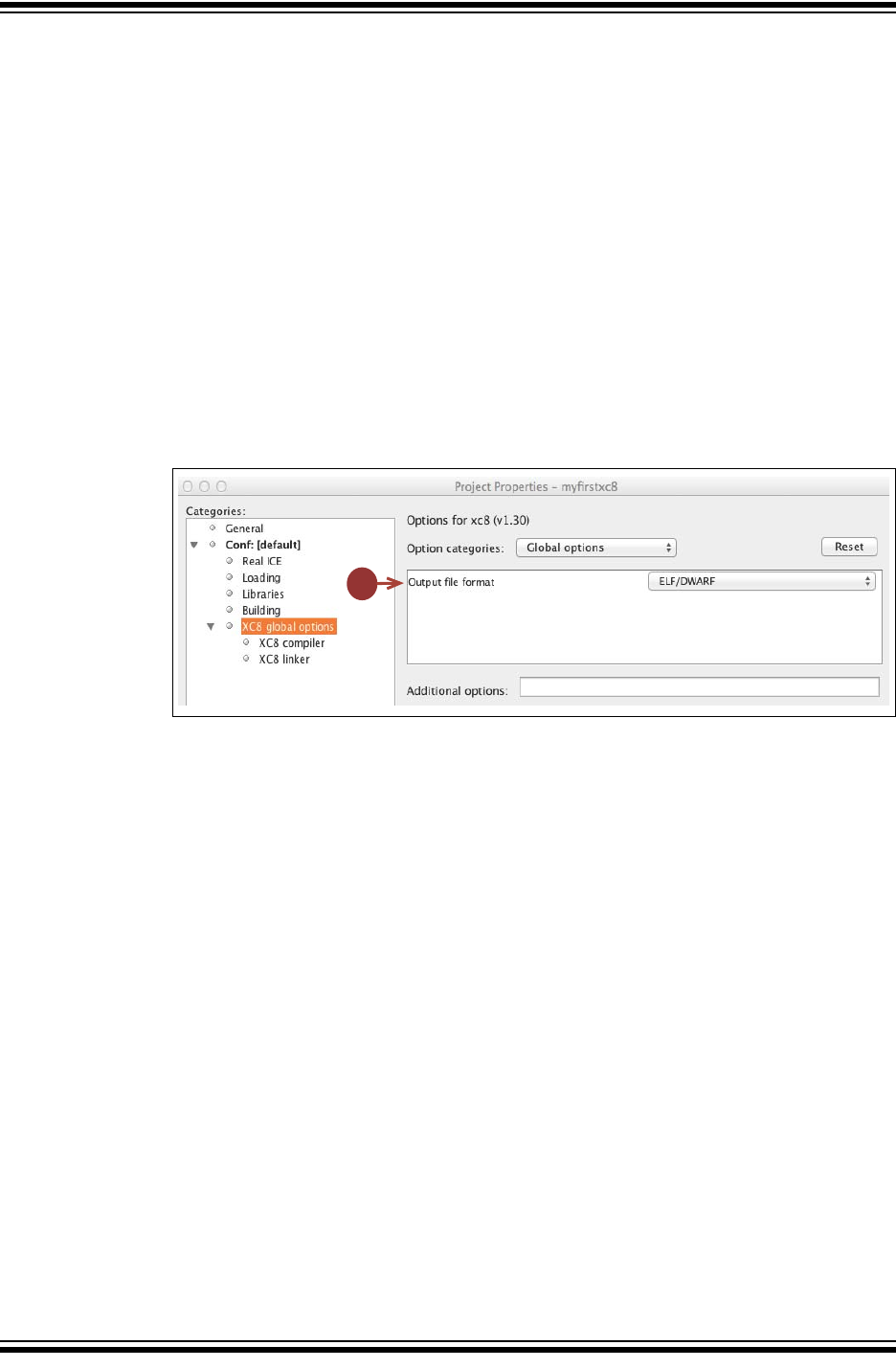
XC8 Command-line Driver
2012-2013 Microchip Technology Inc. DS50002053D-page 127
4.9 MPLAB X OPTION EQUIVALENTS
When compiling under the MPLAB X IDE, it is still the compiler’s command-line driver
that is being executed and compiling the program. The MPLAB XC8 compiler plugins
control the MPLAB X IDE Properties dialog that is used to access the compiler options,
however these graphical controls ultimately adjust the command-line options passed
to the command-line driver when compiling. You can see the command-line options
being used when building in MPLAB X IDE in the Output window.
The following dialogs and descriptions identify the mapping between the MPLAB X IDE
dialog controls and command-line options. Click any option to see online help and
examples shown in the Option Description field in the lower part of the Project
Properties dialog.
4.9.1 Global Category
The options in the panel in this category control the final output of the compiler.
See Figure 4-5 in conjunction with the following command-line option equivalent.
FIGURE 4-5: GLOBAL OPTIONS
Output file format
This selector specifies the output source-level debug format that will be used by
debuggers; see Section 4.8.44 “--OUTPUT= type: Specify Output File Type”.
4.9.2 Compiler Category
The panels in this category control aspects of compilation of C source.
4.9.2.1 PREPROCESSING AND MESSAGES
These options relate to the C preprocessor and messages produced by the compiler;
see Section 4.6 “Compiler Messages” for more information.
See Figure 4-6 in conjunction with the following command-line option equivalents.
1
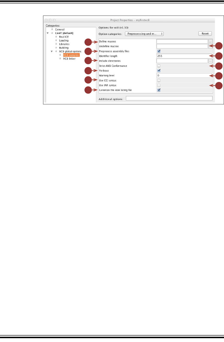
MPLAB® XC8 C Compiler User’s Guide
DS50002053D-page 128 2012-2013 Microchip Technology Inc.
FIGURE 4-6: PREPROCESSING AND MESSAGES OPTIONS
1. Define macros
The button and field on this line can be used to define preprocessor macros; see
Section 4.8.2 “-D: Define Macro”.
2. Undefine macros
The button and field on this line can be used to undefine preprocessor macros;
see Section 4.8.13 “-U: Undefine a Macro”.
3. Preprocess assembly files
This checkbox controls whether assembly source files are scanned by the pre-
processor; see Section 4.8.10 “-P: Preprocess Assembly Files”.
4. Identifier length
Not implemented; see Section 4.8.8 “-N: Identifier Length”.
5. Include directories
This selection uses the buttons and fields grouped in the bracket to specify
include (header) file search directories; see Section 4.8.4 “-I: Include Search
Path”.
6. Strict ANSI Conformance
This forces the compiler to reject any non-standard keywords; see
Section 4.8.56 “--STACK: Specify Data Stack Type For Entire Program”.
7. Verbose
This checkbox controls whether the full command lines for the compiler applica-
tions are displayed when building; see Section 4.8.14 “-V: Verbose Compile”.
8. Warning level
This selector allows the warning level print threshold to be set; see
Section 4.8.61 “--WARN: Set Warning Level”.
9. Use CCI Syntax
This option indicates that the compiler should use the Common C Interface
compiler extensions; see Section 4.8.29 “--EXT: Specify C Language
Extensions”, and Chapter 2. “Common C Interface”, for more information.
1
2
3
4
5
6
7
8
10
9
11
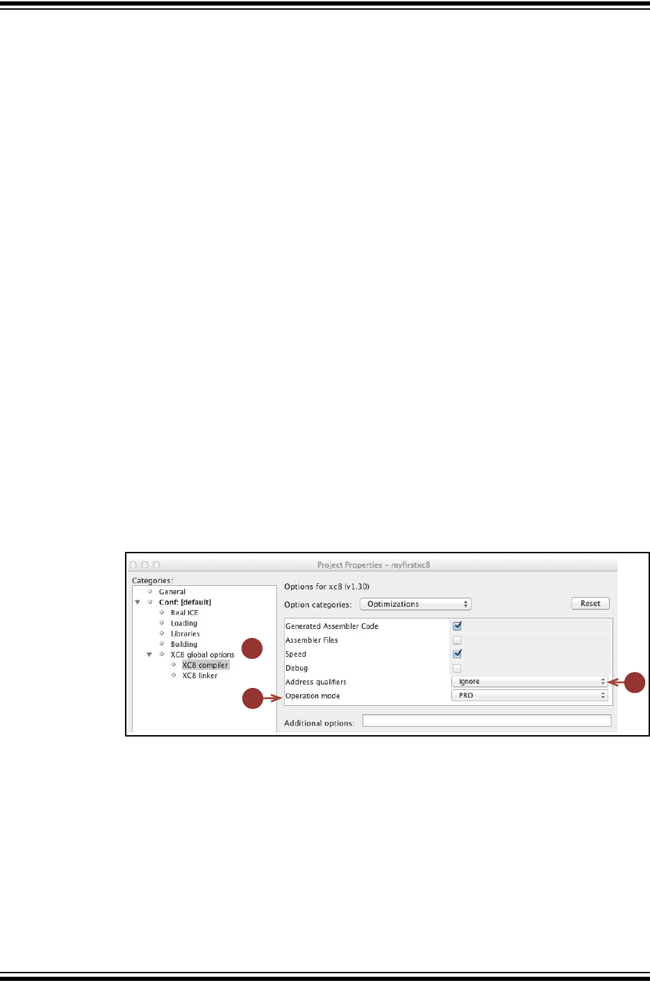
XC8 Command-line Driver
2012-2013 Microchip Technology Inc. DS50002053D-page 129
10. Use IAR Syntax
This option indicates that the compiler should use the IAR compiler extensions;
see Section 4.8.29 “--EXT: Specify C Language Extensions” for more
information.
11. Generate the ASM listing file
This option indicates that the compiler should generate an assembly listing file.
This file should be used to examine the assembly code produced by the
compiler; see Section 4.8.16 “--ASMLIST: Generate Assembler List Files”.
4.9.2.2 OPTIMIZATIONS
These options, shown in Figure 4-7, relate to optimizations performed by the compiler,
1. Optimization controls
These controls adjust the optimizations employed by the compiler (see
Section 4.8.42 “--OPT: Invoke Compiler Optimizations”). The Optimization
set widget, if present, is not used; and, you can choose any setting for this. Select
the custom options below (--OPT suboptions: asm, asmfile, speed/space
and debug). The Speed checkbox indicates your preference for any applicable
optimizations to be focused on speed or space.
2. Address qualifiers
This selector allows the user to select the behavior of the address qualifiers; see
Section 4.8.15 “--ADDRQUAL: Set Compiler Response to Memory
Qualifiers”.
3. Operation mode
This selector allows the user to force another available operating mode (free,
std, or pro) other than the default; see Section 4.8.37 “--MODE: Choose
Compiler Operating Mode”. The operating mode will affect OCG-optimizations
FIGURE 4-7: OPTIMIZATIONS OPTIONS
1
2
3
{
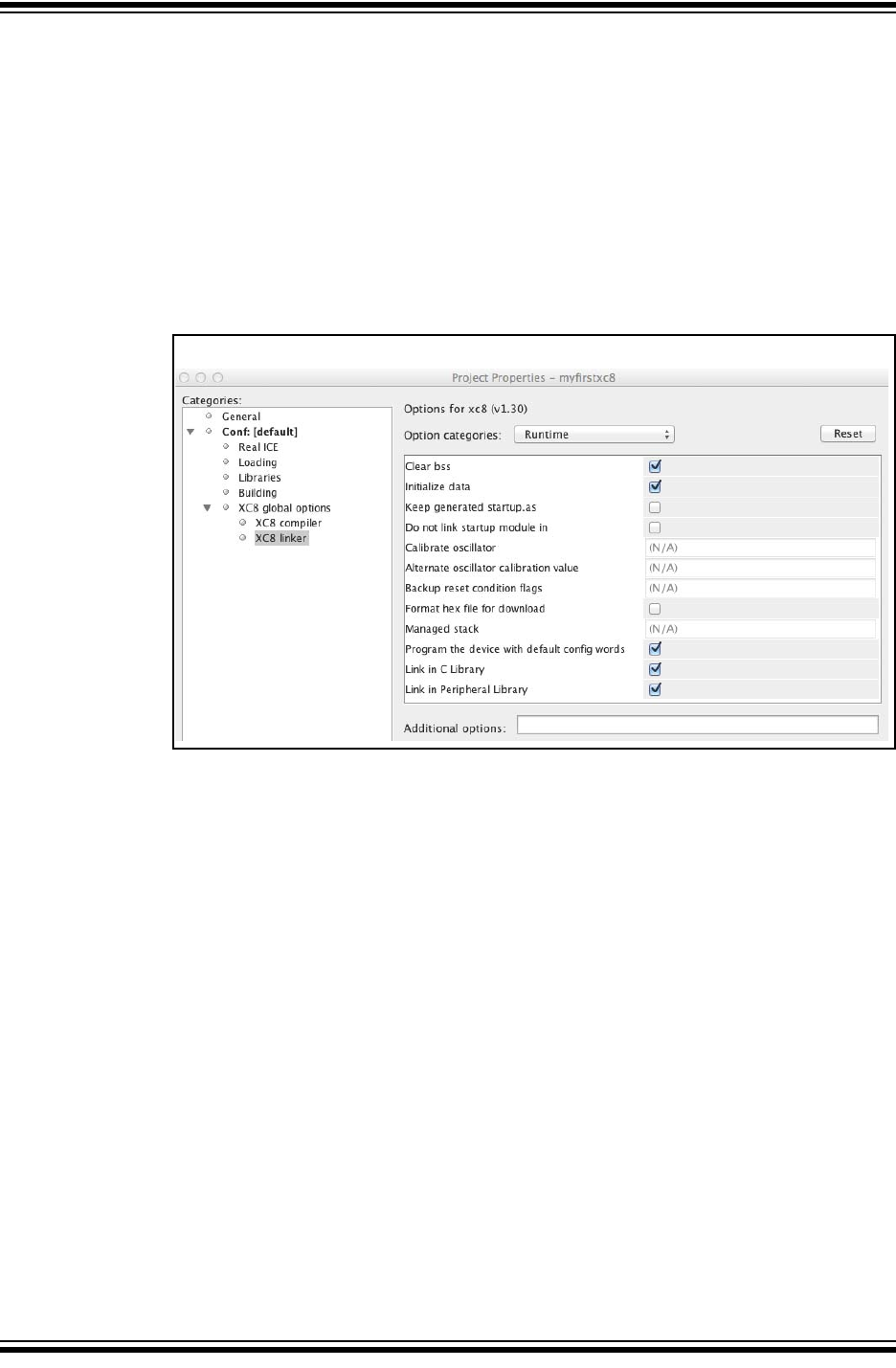
MPLAB® XC8 C Compiler User’s Guide
DS50002053D-page 130 2012-2013 Microchip Technology Inc.
4.9.3 Linker Category
The options in this dialog control the aspects of the second stage of compilation
including code generation and linking.
4.9.3.1 RUNTIME
All the widgets in Figure 4-8 correspond to suboptions of the --RUNTIME option, see
Section 4.8.51 “--RUNTIME: Specify Runtime Environment”. Respectively, these
map to the clear, init, keep, no_startup, osccal, oscval, resetbits,
download, stackcall, config, clib and plib suboptions of the --RUNTIME
option.
FIGURE 4-8: RUNTIME OPTIONS
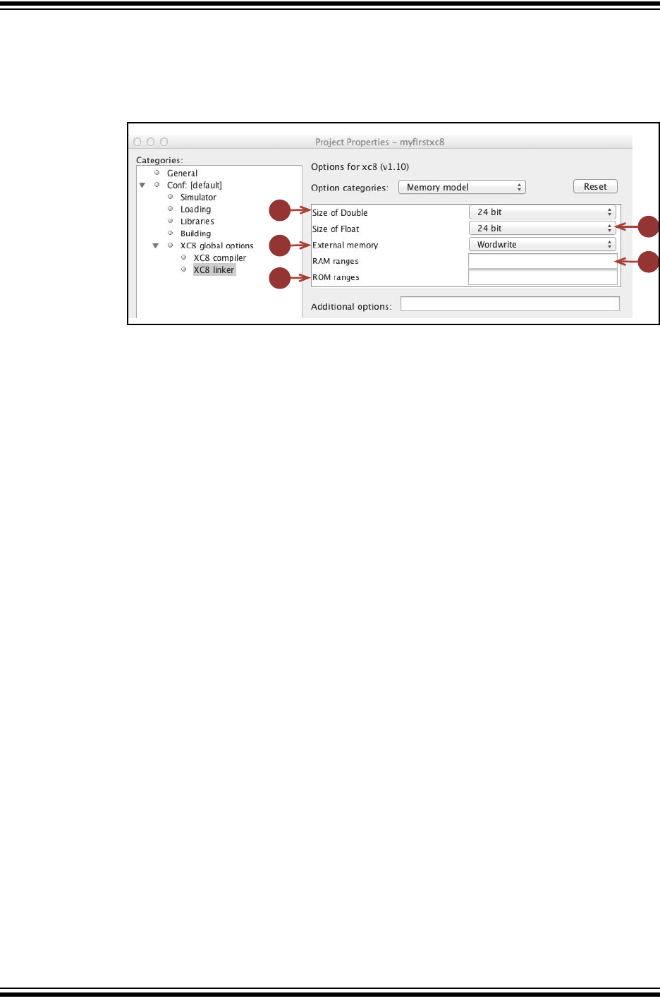
XC8 Command-line Driver
2012-2013 Microchip Technology Inc. DS50002053D-page 131
4.9.3.2 MEMORY MODEL
The panel in this category, shown in Figure 4-9, controls settings that apply to the entire
project.
FIGURE 4-9: MEMORY MODEL OPTIONS
1. Size of Double
This selector allows the size of the double type to be selected; see
Section 4.8.23 “--DOUBLE: Select Kind of Double Types”.
2. Size of Float
This selector allows the size of the float type to be selected; see
Section 4.8.31 “--FLOAT: Select Kind of Float Types”.
3. External memory
This option allows specification of how external memory access is performed.
This only affects those devices that can access external memory; see
Section 4.8.25 “--EMI: Select External Memory Interface Operating Mode”.
4. RAM ranges
This field allows the default RAM (data space) memory used to be adjusted; see
Section 4.8.49 “--RAM: Adjust RAM Ranges”.
5. ROM ranges
This field allows the default ROM (program memory space) memory used to be
adjusted; see Section 4.8.50 “--ROM: Adjust ROM Ranges”.
1
2
3
4
5
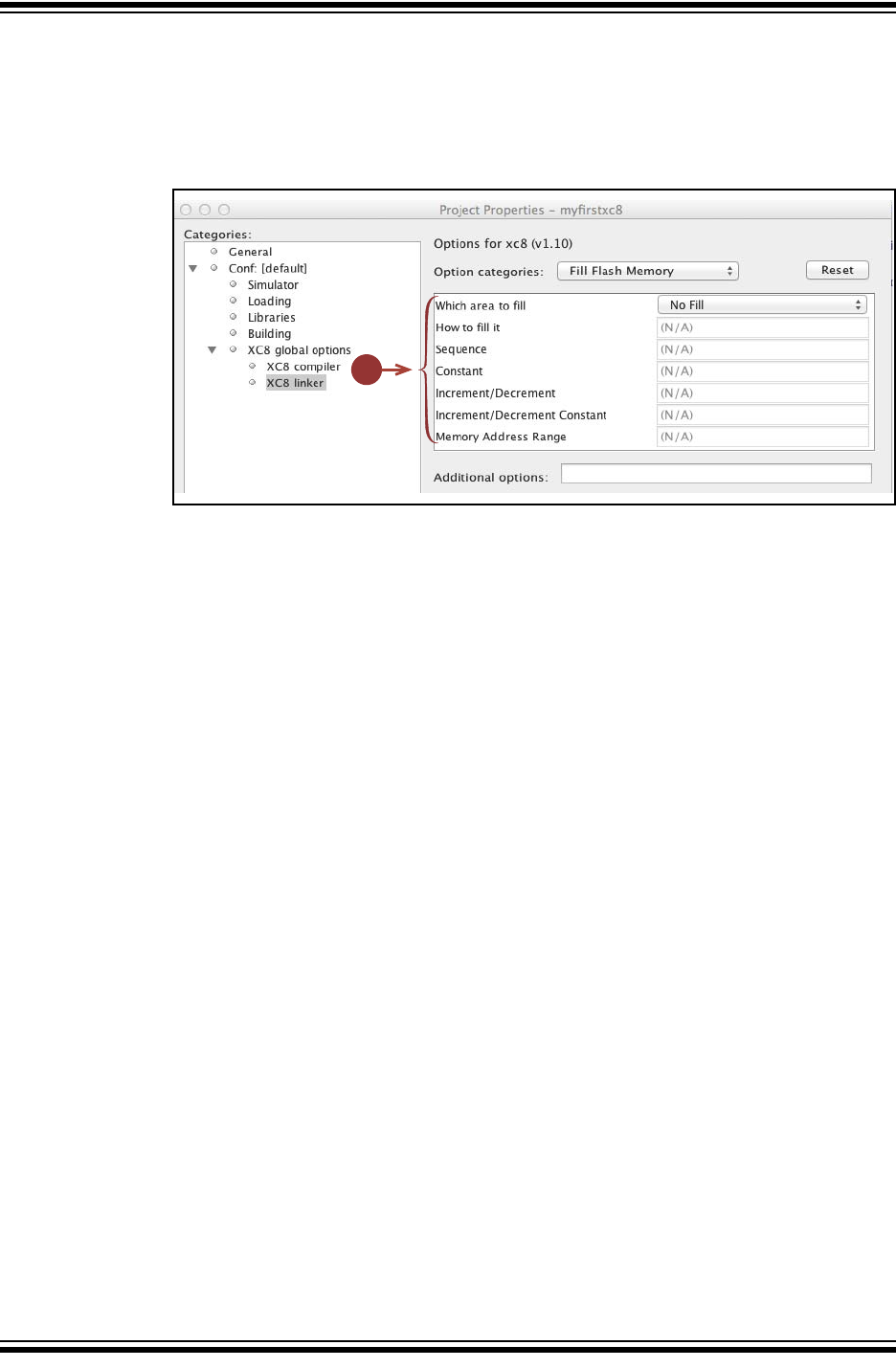
MPLAB® XC8 C Compiler User’s Guide
DS50002053D-page 132 2012-2013 Microchip Technology Inc.
4.9.3.3 FILL FLASH MEMORY
All the controls shown in Figure 4-10 relate to options associated with filling unused
program memory. See Section 4.8.30 “--FILL: Fill Unused Program Memory”, for
more information on the different fields.
FIGURE 4-10: FILL FLASH MEMORY OPTIONS
1
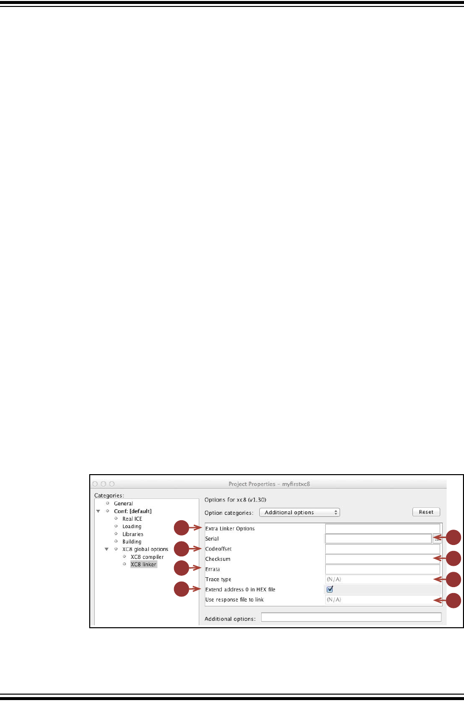
XC8 Command-line Driver
2012-2013 Microchip Technology Inc. DS50002053D-page 133
4.9.3.4 ADDITIONAL
The options shown in Figure 4-11 relate to miscellaneous options.
1. Extra linker options
This field allows you to enter additional options to the linker. Enter the entire -L-
option in this field, for example -L-pmytest=300h. See Section 4.8.6 “-L-:
Adjust Linker Options Directly”.
2. Serial
This option allows you to specify a string that can be inserted into your output
HEX file. See Section 4.8.53 “--SERIAL: Store a Value at this Program Mem-
ory Address”, for details.
3. Codeoffset
This field allows an offset for the program to be specified; see
Section 4.8.20 “--CLIST: Generate C Listing File”.
4. Checksum
This field allows the checksum specification to be specified; see
Section 4.8.17 “--CHECKSUM: Calculate a Checksum”.
5. Errata
This allows customization of the errata workarounds applied by the compiler; see
Section 4.8.26 “--ERRATA: Specify Errata Workarounds”.
6. Trace type
Not implemented. Native trace supported.
7. Extend address 0 in HEX file
This option specifies that the Intel HEX file should have initialization to zero of
the upper address; see Section 4.8.44 “--OUTPUT= type: Specify Output File
Type”.
8. Use response file to link
This option allows a file name to be specified. The file must contain
command-line options which are then used by MPLAB XC8 during the link step
and in preference to the other link-step settings in the project properties; see
Section 4.2.1.1 “Long Command Lines”. This option is only relevant when
running MPLAB X IDE under Windows.
FIGURE 4-11: ADDITIONAL OPTIONS
1
2
3
4
5
6
7
8
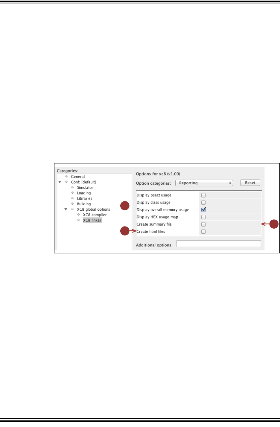
MPLAB® XC8 C Compiler User’s Guide
DS50002053D-page 134 2012-2013 Microchip Technology Inc.
4.9.3.5 REPORTING
These options, shown in Figure 4-12 relate to information produced during and after
compilation.
1. Display memory usage after compilation
These checkboxes allow you to specify what information is displayed after
compilation. The correspond to the psect, class, mem and hex suboptions to
the --SUMMARY option; see Section 4.8.58 “--SUMMARY: Select Memory
Summary Output Type”.
2. Create summary file
Selecting this checkbox will send the information you have selected above to a
file, as well as to the standard output. This corresponds to the file suboption to
the --SUMMARY option; see Section 4.8.58 “--SUMMARY: Select Memory
Summary Output Type”.
3. Create html files
This will create HTML files summarizing the previous build; see
Section 4.8.34 “--HTML: Generate HTML Diagnostic Files”.
FIGURE 4-12: REPORTING OPTIONS
1
2
3
{

MPLAB® XC8 C COMPILER
USER’S GUIDE
2012-2013 Microchip Technology Inc. DS50002053D-page 135
Chapter 5. C Language Features
5.1 INTRODUCTION
MPLAB XC8 C Compiler supports a number of special features and extensions to the
C language which are designed to ease the task of producing ROM-based applications
for 8-bit PIC devices. This chapter documents the special language features which are
specific to these devices.
• ANSI C Standard Issues
• Device-Related Features
• Supported Data Types and Variables
• Memory Allocation and Access
• Operators and Statements
• Register Usage
• Functions
• Interrupts
• Main, Runtime Startup and Reset
• Library Routines
• Mixing C and Assembly Code
• Optimizations
• Preprocessing
• Linking Programs
5.2 ANSI C STANDARD ISSUES
This compiler conforms to the ISO/IEC 9899:1990 Standard for programming lan-
guages. This is commonly called the C90 Standard. It is referred to as the ANSI C
Standard in this manual.
Some violations to the ANSI C Standard are indicated below in
Section 5.2.1 “Divergence from the ANSI C Standard”. Some features from the
later standard C99 are also supported.
5.2.1 Divergence from the ANSI C Standard
The C language implemented on MPLAB XC8 C Compiler can diverge from the ANSI
C Standard in several areas.
Due to limited memory and no hardware implementation of a data stack, recursion is
not supported and functions are not reentrant on baseline and some mid-range
devices. Functions can be encoded reentrantly for enhanced mid-range and PIC18
devices. See Section 5.3.4 “Stacks” for more information on the stack models used
by the compiler for each device family.
For those devices that do not support reentrancy, the compiler can make functions
called from main-line and interrupt code appear to be reentrant via a duplication
feature. See Section 5.9.6 “Function Duplication”.

MPLAB® XC8 C Compiler User’s Guide
DS50002053D-page 136 2012-2013 Microchip Technology Inc.
You cannot reliably use the C sizeof operator with pointer types; however, this oper-
ator may be used with pointer variable identifiers. This is a result of the dynamic size
of pointers assigned by the compiler. So for the following code:
char * cp;
size_t size;
size = sizeof(char *);
size = sizeof(cp);
size in the first example will be assigned the maximum size a pointer can be for the
particular target device you have chosen. In the second example, size will be
assigned the actual size of the pointer variable, cp.
5.2.2 Implementation-Defined behavior
Certain features of the ANSI C standard have implementation-defined behavior. This
means that the exact behavior of some C code can vary from compiler to compiler. The
exact behavior of the compiler is detailed throughout this manual, and is fully
summarized in Appendix D. “Implementation-Defined Behavior”.
5.2.3 Common C Interface Standard
This compiler conforms to the Microchip XC compiler Common C Interface standard
(CCI). This is a further refinement of the ANSI standard that attempts to standardize
implementation-defined behavior and non-standard extensions across the entire
MPLAB XC compiler family. It is described in Chapter 2. “Common C Interface”.
If you choose to write code which conforms to this standard, a compiler option (see
Section 4.8.29 “--EXT: Specify C Language Extensions”) should be enabled. This
will to indicate that the compiler should enforce conformance. Alternatively, you can
continue to write code using the non-standard ANSI extensions provided by the com-
piler.

C Language Features
2012-2013 Microchip Technology Inc. DS50002053D-page 137
5.3 DEVICE-RELATED FEATURES
MPLAB XC8 has several features which relate directly to the 8-bit PIC architectures
and instruction sets. These are detailed in the following sections.
5.3.1 Device Support
MPLAB XC8 C Compiler aims to support all 8-bit PIC devices. However, new devices
in these families are frequently released. There are several ways you can check
whether the compiler you are using supports a particular device.
From the command line, run the compiler you wish to use and pass it the option
--CHIPINFO (See Section 4.8.19 “--CHIPINFO: Display List of Supported
Devices”). A list of all devices will be printed.
If you use the -V option in addition to the --CHIPINFO option, more detailed
information my be shown about each device.
You can also see the supported devices in your favorite web browser. Open the files
pic_chipinfo.html for a list of all supported baseline or mid-range device, or
pic18_chipinfo.html for all PIC18 devices. Both these files are located in the
DOCS directory under your compiler’s installation directory.
5.3.2 Instruction Set Support
The compiler support all instruction sets for PIC10/12/16 devices as well as the stan-
dard (legacy) PIC18 instruction set. The extended instruction mode available on some
PIC18 devices is not currently supported. Ensure you set the Configuration bits to use
the PIC18 legacy instruction mode when appropriate.
5.3.3 Device Header Files
There is one header file that is typically included into each C source file you write. The
file is <xc.h> and is a generic header file that will include other device- and architec-
ture-specific header files when you build your project.
Inclusion of this file will allow access to SFRs via special variables, as well as macros
which allow special memory access or inclusion of special instructions, like CLRWDT.
Legacy projects can continue to use the <htc.h> header file.
Avoid including chip-specific header files into your code as this will reduce portability.
The header files shipped with the compiler are specific to that compiler version. Future
compiler versions can ship with modified header files. If you copy compiler header files
into your project, particularly if you modify these files, be aware that they cannot be
compatible with future versions of the compiler.
For information about assembly include files (.inc), see
Section 5.12.3.2 “Accessing Registers from Assembly Code”.

MPLAB® XC8 C Compiler User’s Guide
DS50002053D-page 138 2012-2013 Microchip Technology Inc.
5.3.4 Stacks
Stacks are used for two different purposes by programs running on 8-bit devices: one
stack is for storing function return addresses, and one or two other stacks are used for
data allocation.
5.3.4.1 FUNCTION RETURN ADDRESS STACK
The 8-bit PIC devices use what is referred to in this user’s guide as a hardware stack.
This stack is limited in depth and cannot be manipulated directly. It is only used for
function return addresses and cannot be used for program data.
You must ensure that the maximum hardware stack depth is not exceeded; otherwise,
code can fail. Nesting function calls too deeply will overflow the stack. It is important to
take into account implicitly called library functions and interrupts, which also use levels
of the stack. The compiler can be made to manage stack usage for some devices using
the stackcall suboption to the --RUNTIME compiler option, see
Section 4.8.51 “--RUNTIME: Specify Runtime Environment”. This enables an alter-
nate means of calling functions to prevent stack overflow.
A call graph is provided by the code generator in the assembler list file, see
Section 6.6.6 “Call Graph”. This will indicate the stack levels at each function call and
can be used as a guide to stack depth. The code generator can also produce warnings
if the maximum stack depth is exceeded.
The warnings and call graphs are guides to stack usage. Optimizations and the use of
interrupts can decrease or increase the program’s stack depth over that determined by
the compiler.
5.3.4.2 DATA STACKS
The compiler can implement two types of data stack: a compiled stack and a software
stack. Both these stacks are for storing stack-based variables, such as a function’s
auto, parameter, and temporary variables.
Either one or both of these types of stacks may be used by a program. Compiler
options, specifiers, and how the functions are called will dictate which stacks are used.
See Section 5.5.2.2 “Auto Variable Allocation and access”, for more information on
how the compiler allocates a function’s stack-based objects.
A compiled stack is a static allocation of memory for stack-based objects that can be
built up in multiple data banks. See Section 5.5.2.2.1 “Compiled Stack Operation”,
for information about how objects are allocated to this stack. Objects in the stack are in
fixed locations and can be accessed using an identifier (hence it is a static allocation).
Thus, there is no stack pointer. The size of the compiled stack is known at compile time,
and so available space can be confirmed by the compiler. The compiled stack is allo-
cated to psects that use the basename cstack; for example, cstackCOMMON,
cstackBANK0. See Section 5.15.2 “Compiler-Generated Psects”, for more
information on the naming convention for compiler-generated psects.
By contrast, the software stack has a size that is dynamic and varies as the program is
executed. The maximum size of the stack is not exactly known at compile time and the
compiler typically reserves as much space as possible for the stack to grow during pro-
gram execution. The stack is always allocated a single memory range, which may cross
bank boundaries, but within this range it may be segregated into one area for main-line
code and an area for each interrupt routine, if required. A stack pointer is used to
indicate the current position in the stack. This pointer is permanently allocated to FSR1.
A psect is used as a placeholder to reserve the memory used by the stack. This psect
is called stack.

C Language Features
2012-2013 Microchip Technology Inc. DS50002053D-page 139
5.3.5 Configuration Bit Access
The PIC devices have several locations which contain the Configuration bits or fuses.
These bits specify fundamental device operation, such as the oscillator mode, watch-
dog timer, programming mode and code protection. Failure to correctly set these bits
can result in code failure, or a non-running device.
These bits can be set using a configuration pragma. The pragma has the following
forms.
#pragma config setting = state|value
#pragma config register = value
where setting is a configuration setting descriptor, e.g., WDT, and state is a textual
description of the desired state, e.g., OFF. The value field is a numerical value that can
be used in preference to a descriptor.
Consider the following examples.
#pragma config WDT = ON // turn on watchdog timer
#pragma config WDTPS = 0x1A // specify the timer postscale value
One pragma can be used to program several settings by separating each setting-value
pair with a comma. For example, the above could be specified with one pragma, as in
the following.
#pragma config WDT=ON, WDTPS = 0x1A
The setting-value pairs can also be quoted to ensure that the preprocessor does not
perform substitution of these tokens, for example:
#pragma config "BOREN=OFF"
Without the quotes and with the preprocessor macro OFF defined, for example, substi-
tution within the pragma would take place. You should never assume that the OFF and
ON tokens used in configuration macros equate to 0 and 1, respectively, as that is often
not the case.
Rather than specify individual settings, the entire register can be programmed with one
numerical value, for example:
#pragma config CONFIG1L = 0x8F
The upper and lower half of each register must be programmed separately.
The settings and values associated with each device can be determined from an HTML
guide. Open the file pic_chipinfo.html or pic18_chipinfo.html, which are
located in the DOCS directory of your compiler installation. Click the link to your target
device, and the page will show you the settings and values that are appropriate with
this pragma. Check your device data sheet for more information.

MPLAB® XC8 C Compiler User’s Guide
DS50002053D-page 140 2012-2013 Microchip Technology Inc.
5.3.5.1 CONFIGURATION BIT LEGACY SUPPORT
You can continue to use the configuration macros for legacy projects, but use the
pragma for new projects.
The compiler supports the __CONFIG and __PROG_CONFIG macros, which allow con-
figuration bit symbols or a Configuration Word value, respectively, to be specified, for
example:
#include <xc.h>
__CONFIG(WDTDIS & HS & UNPROTECT);
For PIC10/12/16 devices that have more than one Configuration Word, each subse-
quent invocation of __CONFIG() will modify the next Configuration Word in sequence.
When using the legacy macros for these devices, the order of the macros must match
the order of the Configuration Words. Typically this might look like:
#include <xc.h>
__CONFIG(WDTDIS & XT & UNPROTECT); // Program config. word 1
__CONFIG(FCMEN);
The __CONFIG macro used for PIC18 devices takes an additional argument being the
number of the Configuration Word location. For example:
__CONFIG(2, BW8 & PWRTDIS & WDTPS1 & WDTEN); // specify symbols
If you want to use a literal value to program the entire Configuration Word, you must
use the __PROG_CONFIG macro. For PIC10/12/16 devices, that might appear as fol-
lows:
__PROG_CONFIG(0xFFFA);
and with PIC18 devices, you must again specify the word being programmed, as in the
following:
__PROG_CONFIG(1, 0xFE57); // specify a literal constant value
You cannot use the setting symbols in the __PROG_CONFIG macro, nor can you use a
literal value in the __CONFIG macro.
The configuration locations do not need to be programmed in order, except as noted
above for multi-word PIC10/12/16 devices using the legacy macros.
To use the legacy macros, ensure you include <xc.h> in your source file. Symbols for
the macros can be found in the .cfgmap files contained in the dat/cfgmap directory
of your compiler installation.
5.3.5.2 CONFIGURATION CONSIDERATIONS
Neither the config pragma nor the __CONFIG macro produce executable code. They
should both be placed outside function definitions so as not to interfere with the
operation of the function’s code.
MPLAB X IDE does not allow the Configuration bits to be adjusted. They must be
specified in your source code using the pragma (or legacy macro).
All the bits in the Configuration Words should be programmed to prevent erratic pro-
gram behavior. Do not leave them in their default/unprogrammed state. Not all Config-
uration bits have a default state of logic high; some have a logic low default state.
Consult your device data sheet for more information.

C Language Features
2012-2013 Microchip Technology Inc. DS50002053D-page 141
5.3.6 Using SFRs From C Code
The Special Function Registers (SFRs) are registers which control aspects of the MCU
operation or that of peripheral modules on the device. Most of these registers are mem-
ory mapped, which means that they appear at, and can be accessed using, specific
addresses in the device’s data memory space. Individual bits within some registers
control independent features. Some registers are read-only; some are write-only. See
your device data sheet for more information.
Memory-mapped SFRs are accessed by special C variables that are placed at the
address of the register. (Variables that are placed at specific addresses are called
absolute variables and are described in Section 5.5.4 “Absolute Variables”.) These
variables can be accessed like any ordinary C variable so that no special syntax is
required to access SFRs.
The SFR variables are predefined in header files and are accessible once you have
included the <xc.h> header file (see Section 5.3.3 “Device Header Files”) into your
source code. Both bit variables and structures with bit-fields are defined, so you can
use either of them in your source code to access bits within a register.
The names given to the C variables that map over registers and bits within those reg-
isters are based on the names specified in the device data sheet. However, as there
can be duplication of some bit names within registers, there can be differences in the
nomenclature.
The names of the structures that hold the bit-fields will typically be those of the corre-
sponding register followed by bits. For example, the following shows code that
includes the generic header file, clears PORTA as a whole, sets bit 0 of PORTA using
a bit variable and sets bit 2 of PORTA using the structure/bit-field definitions.
#include <xc.h>
void main(void)
{
PORTA = 0x00;
RA0 = 1;
PORTAbits.RA2 = 1;
}
To confirm the names that are relevant for the device you are using, check the
device-specific header file that <xc.h> will include for the definitions of each variable.
These files will be located in the include directory of the compiler and will have a
name that represents the device. There is a one-to-one correlation between device and
header file name that will be included by <xc.h>, e.g., when compiling for a
PIC16LF1826 device, <xc.h> will include the header file <pic16lf1826.h>.
Remember that you do not need to include this chip-specific file into your source code;
it is automatically included by <xc.h>.
Care should be taken when accessing some SFRs from C code or from assembly
in-line with C code. Some registers are used by the compiler to hold intermediate val-
ues of calculations, and writing to these registers directly can result in code failure. The
compiler does not detect when SFRs have changed as a result of C or assembly code
that writes to them directly. The list of registers used by the compiler and further
information can be found in Section 5.7 “Register Usage”.
SFRs associated with peripherals are not used by the compiler to hold intermediate
results and can be changed as you require. Always ensure that you confirm the
operation of peripheral modules from the device data sheet.

MPLAB® XC8 C Compiler User’s Guide
DS50002053D-page 142 2012-2013 Microchip Technology Inc.
5.3.6.1 SPECIAL BASELINE/MID-RANGE REGISTER ISSUES
Some SFRs are not memory mapped, do not have a corresponding variable defined in
the device specific header file, and cannot be directly accessed from C code.
For example, the W register is not memory mapped on baseline devices. Some devices
use OPTION and TRIS registers, that are only accessible via special instructions and
that are also not memory mapped. See Section 5.3.9 “Hardware Multiply Instruc-
tions” on how these registers are accessed by the compiler.
5.3.6.2 SPECIAL PIC18 REGISTER ISSUES
Some of the SFRs associated with the PIC18 can be grouped to form multi-byte values,
e.g., the TMRxH and TMRxL register combined form a 16-bit timer count value.
Depending on the device and mode of operation, there can be hardware requirements
to read these registers in certain ways, e.g., often the TMRxL register must be read
before trying to read the TMRxH register to obtain a valid 16-bit result.
Although it is possible to define a word-sized C variable to map over such registers, i.e.,
an int variable TMRx that maps over both TMRxL and TMRxH, the order in which the
compiler would read the bytes of such an object will vary from expression to expres-
sion. Some expressions require that the Most Significant Byte (MSB) is read first;
others start with the Least Significant Byte (LSB) first.
It is recommended that the existing SFR definitions in the chip header files be used.
Each byte of the SFR should be accessed directly, and in the required order, as dictated
by the device data sheet. This results in a much higher degree of portability.
The following code copies the two timer registers into a C unsigned variable count
for subsequent use.
count = TMR0L;
count += TMR0H << 8;
Macros are also provided to perform reading and writing of the more common timer reg-
isters. See the macros READTIMERx and WRITETIMERx in Appendix A. “Library
Functions”. These guarantee the correct byte order is used.
5.3.7 ID Locations
The 8-bit PIC devices have locations outside the addressable memory area that can be
used for storing program information, such as an ID number. The config pragma is
also used to place data into these locations by using a special register name. The
pragma is used as follows.
#pragma config IDLOCx = value
where x is the number (position) of the ID location, and value is the nibble or byte
which is to be positioned into that ID location. If value is larger than the maximum
value allowable for each location on the target device, the value will be truncated and
a warning message issued. The size of each ID location varies from device to device.
See your device data sheet for more information.
For example:
#pragma config IDLOC0 = 1
#pragma config IDLOC1 = 4
will attempt fill the first two ID locations with 1 and 4. One pragma can be used to pro-
gram several locations by separating each register-value pair with a comma. For
example, the above could also be specified as shown below.
#pragma config IDLOC0 = 1, IDLOC1 = 4
The config pragma does not produce executable code and so should ideally be placed
outside function definitions.

C Language Features
2012-2013 Microchip Technology Inc. DS50002053D-page 143
5.3.7.1 ID LOCATION LEGACY SUPPORT
The compiler also has legacy support for the __IDLOC macro. The macro is used in a
manner similar to:
#include <xc.h>
__IDLOC(x);
where x is a list of hexadecimal digits, which are positioned into the ID locations. Do
not use the usual 0x hexadecimal radix specifier with these values. If an invalid char-
acter is encountered, the value 0 will be programmed into the corresponding location.
Only the lower four bits of each ID location are programmed, so the following:
__IDLOC(15F0);
will attempt to fill ID locations with the hexadecimal values: 1, 5, F and 0.
To use this macro, ensure you include <xc.h> in your source file.
The __IDLOC macro does not produce executable code and so should ideally be
placed outside function definitions.
Some devices permit programming up to seven bits within each ID location. The
__IDLOC() macro is not suitable for such devices and the __IDLOC7(a,b,c,d)
macro should be used instead. The parameters a to d must be constants which repre-
sent the values to be programmed. The values can be entered in either decimal or
hexadecimal format, such as:
__IDLOC7(0x7f,1,70,0x5a);
It is not appropriate to use the __IDLOC7() macro on a device that does not permit
seven-bit programming of ID locations. The __IDLOC7 macro does not produce exe-
cutable code and so should ideally be placed outside function definitions.
5.3.8 Bit Instructions
Wherever possible, the MPLAB XC8 C Compiler will attempt to use bit instructions,
even on non-bit integer values. For example, when using a bitwise operator and a mask
to alter a bit within an integral type, the compiler will check the mask value to determine
if a bit instruction can achieve the same functionality.
unsigned int foo;
foo |= 0x40;
will produce the instruction:
BSF _foo,6
To set or clear individual bits within integral type, the following macros could be used:
#define bitset(var, bitno) ((var) |= 1UL << (bitno))
#define bitclr(var, bitno) ((var) &= ~(1UL << (bitno)))
To perform the same operation on foo as above, the bitset macro could be
employed as follows:
bitset(foo,6);

MPLAB® XC8 C Compiler User’s Guide
DS50002053D-page 144 2012-2013 Microchip Technology Inc.
5.3.9 Hardware Multiply Instructions
The PIC18 instruction set includes several 8-by-8-bit hardware multiple instructions,
and these are used by the compiler in some situations. Non-PIC18 targets always use
an iterative library routine for multiplication operations.
The hardware multiply instructions are used for all 8-bit (char) multiplications by the
compiler.
A special form of the int (16-bit) multiplication library routine (__wmul) has been
employed to decompose the 16-bit operation into the addition of several 8-bit multipli-
cation results. Thus, the benefits of hardware multiplication are also utilized for 16-bit
multiplication expressions.
A similar algorithm has not been implemented for long, 32-bit, multiplies (__lmul) as
the decomposition overhead outweighs the advantage of the hardware multiply
instruction.
For all devices, when the hardware multiply instructions are not available, a library rou-
tine consisting of an iterative algorithm is called to perform the multiply. The smaller the
first argument to these routines (i.e., the smaller the left operand to the * operator), the
faster the routine will run. For example, for the code:
x = 10;
y = 200;
result = x * y; // first multiply
result = y * x; // second multiply
the variable result will be assigned the same value in both statements, but the first
multiplication expression will be performed faster than the second.
5.3.10 Baseline PIC MCU Special Instructions
The Baseline devices have some registers which are not in the normal SFR space and
cannot be accessed using an ordinary file instruction. These are the OPTION and TRIS
registers.
Both registers are write-only and cannot be used in expression that read their value.
They can only be accessed using special instructions which the compiler will use
automatically.
The definition of the variables that map to these registers make use of the control
qualifier. This qualifier informs the compiler that the registers are outside of the normal
address space and that a different access method is required. You should not use this
qualifiers for any other registers.
When you write to either of these SFR variables, the compiler will use the appropriate
instruction to load the value. So, for example, to load the TRIS register, the following
code:
TRIS = 0xFF;
can be encoded by the compiler as:
MOVLW 0ffh
TRIS
Those PIC devices which have more than one output port can have definitions for
objects: TRISA, TRISB and TRISC, depending on the exact number of ports available.
This objects are used in the same manner as described above.
C Language Features
2012-2013 Microchip Technology Inc. DS50002053D-page 145
5.3.11 Oscillator Calibration Constants
Some Baseline and Mid-range devices come with an oscillator calibration constant
which is pre-programmed into the device’s program memory. This constant can be read
from program memory and written to the OSCCAL register to calibrate the internal RC
oscillator.
On some Baseline PIC devices, the calibration constant is stored as a MOVLW instruc-
tion at the top of program memory, e.g., the PIC10F509 device. On Reset, the program
counter is made to point to this instruction and it is executed first before the program
counter wraps around to 0x0000, which is the effective Reset vector for the device. The
default runtime startup routine (see Section 5.10.1 “Runtime Startup Code”) will
automatically include code to load the OSCCAL register with the value contained in the
W register after Reset on such devices. No other code is required.
For other chips, such as PIC12F629 device, the oscillator constant is also stored at the
top of program memory, but as a RETLW instruction. The compiler’s startup code will
automatically generate code to retrieve this value and perform the configuration.
At runtime, the calibration value stored as a RETLW instruction can be read using the
‘function’ __osccal_val(),as a label is assigned the RETLW instruction address. A
prototype for the function is provided in <xc.h>. For example:
calVal = __osccal_val();
Loading of the calibration value can be turned off via the osccal suboption to the
--RUNTIME option (see Section 4.8.51 “--RUNTIME: Specify Runtime Environ-
ment”).
At runtime, this calibration value can be read using the macro
_READ_OSCCAL_DATA(). To be able to use this macro, make sure that <xc.h> is
included into the relevant modules of your program. This macro returns the calibration
constant which can then be stored into the OSCCAL register, as follows:
OSCCAL = _READ_OSCCAL_DATA();
Note: The location which stores the calibration constant is never code protected
and will be lost if you reprogram the device. Thus, if you are using a win-
dowed or Flash device, the calibration constant must be saved from the last
ROM location before it is erased. The constant must then be reprogrammed
at the same location along with the new program and data.
If you are using an in-circuit emulator (ICE), the location used by the cali-
bration RETLW instruction cannot be programmed. Calling the
_READ_OSCCAL_DATA() macro will not work and will almost certainly not
return correctly. If you wish to test code that includes this macro on an ICE,
you will have to program a RETLW instruction at the appropriate location in
program memory. Remember to remove this instruction when programming
the actual part so you do not destroy the calibration value.

MPLAB® XC8 C Compiler User’s Guide
DS50002053D-page 146 2012-2013 Microchip Technology Inc.
5.3.12 REAL ICE Support
The compiler supports log and trace functions (instrumented trace) when using the
Microchip REAL ICE debugger. See the REAL ICE documentation for more information
on the instrumented trace features.
Only native trace is currently supported by the compiler. Not all devices support instru-
mented trace, and the IDE you are using also needs to have instrumented trace
support for your target device, as well.
The log and trace macro calls need to be added by hand to your source code in MPLAB
IDE. They have the following form.
__TRACE(id);
__LOG(id, expression);
MPLAB X IDE will automatically substitute an appropriate value for id when you com-
pile; however, you can specify these by hand if required. The trace id should be a con-
stant in the range of 0x40 to 0x7F, and the log id is a constant in the range of 0x0 to
0x7F. Each macro should be given a unique number so that it can be properly identified.
The same valid number can be used for both trace and log macros.
The expression can be any integer or 32-bit floating point expression. Typically, this
expression is simply a variable name so the variable’s contents are logged.
Macros should be placed in the C source code at the desired locations. They will trigger
information to be sent to the debugger and IDE when they are executed. Adding trace
and log macros will increase the size of your code as they contribute to the program
image that is downloaded to the device.
Here is an example of these macros that you might add.
inpStatus = readUser();
if(inpStatus == 0) {
__TRACE(id);
recovery();
}
__LOG(id, inpStatus);
5.3.13 Function profiling
The compiler can generate function registration code for the MPLAB REAL ICE debug-
ger to provide function profiling. The flp suboption to the --RUNTIME option (see
Section 4.8.51 “--RUNTIME: Specify Runtime Environment”) enables this feature.
To obtain profiling results, you must also use a Power Monitor Board and MPLAB X IDE
and power monitor plugin that support code profiling for the MPLAB XC8 C Compiler.
When enabled, the compiler inserts assembly code into the prologue and epilogue of
each function. This code communicates runtime information to the debugger to signal
when a function is being entered and when it exits. This information, along with further
measurements made by a Microchip Power Monitor Board, can determine how much
energy each function is using. This feature is transparent, but note the following points
when profiling is enabled:
• The program will increase in size and run slower due to the profiling code
• One extra level of hardware stack is used
• Some additional RAM memory is consumed
• Inlining of functions will not take place for any profiled function
If a function cannot be profiled (due to hardware stack constraints) but is qualified
inline, the compiler might inline the function. See Section 5.8.1.2 “Inline Specifier”
for more information on inlining functions.
C Language Features
2012-2013 Microchip Technology Inc. DS50002053D-page 147
5.4 SUPPORTED DATA TYPES AND VARIABLES
5.4.1 Identifiers
A C variable identifier (the following is also true for function identifiers) is a sequence
of letters and digits, where the underscore character “_” counts as a letter. Identifiers
cannot start with a digit. Although they can start with an underscore, such identifiers are
reserved for the compiler’s use and should not be defined by your programs. Such is
not the case for assembly domain identifiers, which often begin with an underscore,
see Section 5.12.3.1 “Equivalent Assembly Symbols”.
Identifiers are case sensitive, so main is different to Main.
Not every character is significant in an identifier. The maximum number of significant
characters can be set using an option, see Section 4.8.8 “-N: Identifier Length”. If
two identifiers differ only after the maximum number of significant characters, then the
compiler will consider them to be the same symbol.
5.4.2 Integer Data Types
The MPLAB XC8 compiler supports integer data types with 1, 2, 3 and 4 byte sizes as
well as a single bit type. Table 5-1 shows the data types and their corresponding size
and arithmetic type. The default type for each type is underlined.
The bit and short long types are non-standard types available in this implementa-
tion. The long long types are C99 Standard types, but this implementation limits their
size to only 32 bits.
All integer values are represented in little endian format with the Least Significant bit
(LSb) at the lower address.
If no signedness is specified in the type, then the type will be signed except for the
char types which are always unsigned. The bit type is always unsigned and the
concept of a signed bit is meaningless.
Signed values are stored as a two’s complement integer value.
The range of values capable of being held by these types is summarized in Table 5-2
The symbols in this table are preprocessor macros which are available after including
<limits.h> in your source code.
TABLE 5-1: INTEGER DATA TYPES
Type Size (bits) Arithmetic Type
bit 1 Unsigned integer
signed char 8 Signed integer
unsigned char 8 Unsigned integer
signed short 16 Signed integer
unsigned short 16 Unsigned integer
signed int 16 Signed integer
unsigned int 16 Unsigned integer
signed short long 24 Signed integer
unsigned short long 24 Unsigned integer
signed long 32 Signed integer
unsigned long 32 Unsigned integer
signed long long 32 Signed integer
unsigned long long 32 Unsigned integer
MPLAB® XC8 C Compiler User’s Guide
DS50002053D-page 148 2012-2013 Microchip Technology Inc.
As the size of data types are not fully specified by the ANSI Standard, these macros
allow for more portable code which can check the limits of the range of values held by
the type on this implementation.
The macros associated with the short long type are non-standard macros available
in this implementation; those associated with the long long types are defined by the
C99 Standard.
Macros are also available in <stdint.h> which define values associated with
fixed-width types.
When specifying a signed or unsigned short int, short long int, long int
or long long int type, the keyword int can be omitted. Thus a variable declared
as short will contain a signed short int and a variable declared as unsigned
short will contain an unsigned short int.
It is a common misconception that the C char types are intended purely for ASCII char-
acter manipulation. However, the C language makes no guarantee that the default
character representation is even ASCII. (This implementation does use ASCII as the
character representation.)
The char types are the smallest of the multi-bit integer sizes, and behave in all
respects like integers. The reason for the name “char” is historical and does not mean
that char can only be used to represent characters. It is possible to freely mix char
values with values of other types in C expressions. With the MPLAB XC8 C Compiler,
the char types are used for a number of purposes – as 8-bit integers, as storage for
ASCII characters, and for access to I/O locations.
TABLE 5-2: RANGES OF INTEGER TYPE VALUES
Symbol Meaning Value
CHAR_BIT bits per char 8
CHAR_MAX max. value of a char 127
CHAR_MIN min. value of a char -128
SCHAR_MAX max. value of a signed char 127
SCHAR_MIN min. value of a signed char -128
UCHAR_MAX max. value of an unsigned char 255
SHRT_MAX max. value of a short 32767
SHRT_MIN min. value of a short -32768
USHRT_MAX max. value of an unsigned short 65535
INT_MAX max. value of an int 32767
INT_MIN min. value of a int -32768
UINT_MAX max. value of an unsigned int 65535
SHRTLONG_MAX max. value of a short long 8388607
SHRTLONG_MIN min. value of a short long -8388608
USHRTLONG_MAX max. value of an unsigned short
long
16777215
LONG_MAX max. value of a long 2147483647
LONG_MIN min. value of a long -2147483648
ULONG_MAX max. value of an unsigned long 4294967295
LLONG_MAX max. value of a long long 2147483647
LLONG_MIN min. value of a long long -2147483648
ULLONG_MAX max. value of an unsigned long
long 4294967295

C Language Features
2012-2013 Microchip Technology Inc. DS50002053D-page 149
5.4.2.1 BIT DATA TYPES AND VARIABLES
The MPLAB XC8 C Compiler supports bit integral types which can hold the values 0
or 1. Single bit variables can be declared using the keyword bit (or __bit), for
example:
bit init_flag;
You can also use the These variables cannot be auto or parameters to a function, but
can be qualified static, allowing them to be defined locally within a function. For
example:
int func(void) {
static bit flame_on;
// ...
}
A function can return a bit object by using the bit keyword in the function’s prototype
in the usual way. The 1 or 0 value will be returned in the carry flag in the STATUS reg-
ister.
The bit variables behave in most respects like normal unsigned char variables, but
they can only contain the values 0 and 1, and therefore provide a convenient and effi-
cient method of storing flags. Eight bit objects are packed into each byte of memory
storage, so they don’t consume large amounts of internal RAM.
Operations on bit objects are performed using the single bit instructions (bsf and
bcf) wherever possible, thus the generated code to access bit objects is very
efficient.
It is not possible to declare a pointer to bit types or assign the address of a bit object
to any pointer. Nor is it possible to statically initialize bit variables so they must be
assigned any non-zero starting value (i.e., 1) in the code itself. Bit objects will be
cleared on startup, unless the bit is qualified persistent.
When assigning a larger integral type to a bit variable, only the LSb is used. For
example, if the bit variable bitvar was assigned as in the following:
int data = 0x54;
bit bitvar;
bitvar = data;
it will be cleared by the assignment since the LSb of data is zero. This sets the bit
type apart from the C99 Standard __Bool, which is a boolean type, not a 1-bit wide
integer. The __Bool type is not supported on the MPLAB XC8 compiler. If you want to
set a bit variable to be 0 or 1 depending on whether the larger integral type is zero
(false) or non-zero (true), use the form:
bitvar = (data != 0);
The psects in which bit objects are allocated storage are declared using the bit
PSECT directive flag, see Section 6.4.9.3 “PSECT”. All addresses assigned to bit
objects and psects will be bit addresses. For absolute bit variables (see
Section 5.5.4 “Absolute Variables”), the address specified in code must be a bit
address. Take care when comparing these addresses to byte addresses used by all
other variables.
If the xc8 flag --STRICT is used, the bit keyword becomes unavailable, but you can
use the __bit keyword.
MPLAB® XC8 C Compiler User’s Guide
DS50002053D-page 150 2012-2013 Microchip Technology Inc.
5.4.3 Floating-Point Data Types
The MPLAB XC8 compiler supports 24- and 32-bit floating-point types. Floating point
is implemented using either a IEEE 754 32-bit format, or a modified (truncated) 24-bit
form of this. Table 5-3 shows the data types and their corresponding size and arithmetic
type.
For both float and double values, the 24-bit format is the default. The options
--FLOAT=24 and --DOUBLE=24 can also be used to specify this explicitly. The 32-bit
format is used for double values if the --DOUBLE=32 option is used and for float
values if --FLOAT=32 is used.
Variables can be declared using the float and double keywords, respectively, to
hold values of these types. Floating-point types are always signed and the unsigned
keyword is illegal when specifying a floating-point type. Types declared as long
double will use the same format as types declared as double. All floating-point
values are represented in little endian format with the LSb at the lower address.
This format is described in Table 5-4, where:
• Sign is the sign bit which indicates if the number is positive or negative
• The exponent is 8 bits which is stored as excess 127 (i.e., an exponent of 0 is
stored as 127).
• Mantissa is the mantissa, which is to the right of the radix point. There is an
implied bit to the left of the radix point which is always 1 except for a zero value,
where the implied bit is zero. A zero value is indicated by a zero exponent.
The value of this number is (-1)sign x 2(exponent-127) x 1. mantissa.
Here are some examples of the IEEE 754 32-bit formats shown in Table 5-5. Note that
the Most Significant Bit (MSb) of the mantissa column (i.e., the bit to the left of the radix
point) is the implied bit, which is assumed to be 1 unless the exponent is zero (in which
case the float is zero).
Use the following process to manually calculate the 32-bit example in Table 5-5.
TABLE 5-3: FLOATING-POINT DATA TYPES
Type Size (bits) Arithmetic Type
float 24 or 32 Real
double 24 or 32 Real
long double same as double Real
TABLE 5-4: FLOATING-POINT FORMATS
Format Sign Biased exponent Mantissa
IEEE 754 32-bit x xxxx xxxx xxx xxxx xxxx xxxx xxxx xxxx
modified IEEE 754
24-bit x xxxx xxxx xxx xxxx xxxx xxxx
TABLE 5-5: FLOATING-POINT FORMAT EXAMPLE IEEE 754
Format Number Biased exponent 1.mantissa Decimal
32-bit 7DA6B69Bh
11111011b 1.0100110101101101
0011011b
2.77000e+37
(251) (1.302447676659) —
24-bit 42123Ah
10000100b 1.001001000111010b 36.557
(132) (1.142395019531) —

C Language Features
2012-2013 Microchip Technology Inc. DS50002053D-page 151
The sign bit is zero; the biased exponent is 251, so the exponent is 251-127=124. Take
the binary number to the right of the decimal point in the mantissa. Convert this to dec-
imal and divide it by 223 where 23 is the number of bits taken up by the mantissa, to
give 0.302447676659. Add 1 to this fraction. The floating-point number is then given
by:
-1021241.302447676659
which becomes:
12.126764793256e+371.302447676659
which is approximately equal to:
2.77000e+37
Binary floating-point values are sometimes misunderstood. It is important to remember
that not every floating-point value can be represented by a finite sized floating-point
number. The size of the exponent in the number dictates the range of values that the
number can hold, and the size of the mantissa relates to the spacing of each value that
can be represented exactly. Thus the 24-bit format allows for values with approximately
the same range of values representable by the 32-bit format, but the values that can be
exactly represented by this format are more widely spaced.
So, for example, if you are using a 24-bit wide floating-point type, it can exactly store
the value 95000.0. However, the next highest number it can represent is 95002.0 and
it is impossible to represent any value in between these two in such a type as it will be
rounded. This implies that C code which compares floating-point type cannot behave
as expected. For example:
volatile float myFloat;
myFloat = 95002.0;
if(myFloat == 95001.0) // value will be rounded
PORTA++; // this line will be executed!
in which the result of the if() expression will be true, even though it appears the two
values being compared are different.
Compare this to a 32-bit floating-point type, which has a higher precision. It also can
exactly store 95000.0 as a value. The next highest value which can be represented is
(approximately) 95000.00781.
The characteristics of the floating-point formats are summarized in Table 5-6. The sym-
bols in this table are preprocessor macros which are available after including
<float.h> in your source code.
Two sets of macros are available for float and double types, where XXX represents
FLT and DBL, respectively. So, for example, FLT_MAX represents the maximum float-
ing-point value of the float type. It can have two values depending on whether float
is a 24 or 32 bit wide format. DBL_MAX represents the same values for the double
type.
MPLAB® XC8 C Compiler User’s Guide
DS50002053D-page 152 2012-2013 Microchip Technology Inc.
As the size and format of floating-point data types are not fully specified by the ANSI
Standard, these macros allow for more portable code which can check the limits of the
range of values held by the type on this implementation.
5.4.4 Structures and Unions
MPLAB XC8 C Compiler supports struct and union types. Structures and unions
only differ in the memory offset applied to each member.
These types will be at least 1 byte wide. The members of structures and unions cannot
be objects of type bit, but bit-fields are fully supported.
Structures and unions can be passed freely as function arguments and function return
values. Pointers to structures and unions are fully supported.
5.4.4.1 STRUCTURE AND UNION QUALIFIERS
The compiler supports the use of type qualifiers on structures. When a qualifier is
applied to a structure, all of its members will inherit this qualification. In the following
example the structure is qualified const.
const struct {
int number;
int *ptr;
} record = { 0x55, &i };
In this case, the entire structure will be placed into the program space and each mem-
ber will be read-only. Remember that all members are usually initialized if a structure
is const as they cannot be initialized at runtime.
If the members of the structure were individually qualified const, but the structure was
not, then the structure would be positioned into RAM, but each member would be
read-only. Compare the following structure with the above.
struct {
const int number;
int * const ptr;
} record = { 0x55, &i };
TABLE 5-6: RANGES OF FLOATING-POINT TYPE VALUES
Symbol Meaning 24-bit Value 32-bit Value
XXX_RADIX Radix of exponent representation 2 2
XXX_ROUNDS Rounding mode for addition 0 0
XXX_MIN_EXP Min. n such that FLT_RADIXn-1 is
a normalized float value
-125 -125
XXX_MIN_10_EXP Min. n such that 10n is a
normalized float value -37 -37
XXX_MAX_EXP Max. n such that FLT_RADIXn-1
is a normalized float value
128 128
XXX_MAX_10_EXP Max. n such that 10n is a
normalized float value
38 38
XXX_MANT_DIG Number of FLT_RADIX mantissa
digits 16 24
XXX_EPSILON The smallest number which
added to 1.0 does not yield 1.0
3.05176e-05 1.19209e-07
C Language Features
2012-2013 Microchip Technology Inc. DS50002053D-page 153
5.4.4.2 BIT-FIELDS IN STRUCTURES
MPLAB XC8 C Compiler fully supports bit-fields in structures.
Bit-fields are always allocated within 8-bit words, even though it is usual to use the type
unsigned int in the definition.
The first bit defined will be the LSb of the word in which it will be stored. When a bit-field
is declared, it is allocated within the current 8-bit unit if it will fit; otherwise, a new byte
is allocated within the structure. Bit-fields can never cross the boundary between 8-bit
allocation units. For example, the declaration:
struct {
unsigned lo : 1;
unsigned dummy : 6;
unsigned hi : 1;
} foo;
will produce a structure occupying 1 byte. If foo was ultimately linked at address 10H,
the field lo will be bit 0 of address 10H; hi will be bit 7 of address 10H. The LSb of
dummy will be bit 1 of address 10H and the MSb of dummy will be bit 6 of address 10h.
Unnamed bit-fields can be declared to pad out unused space between active bits in
control registers. For example, if dummy is never referenced, the structure above could
have been declared as:
struct {
unsigned lo : 1;
unsigned : 6;
unsigned hi : 1;
} foo;
A structure with bit-fields can be initialized by supplying a comma-separated list of initial
values for each field. For example:
struct {
unsigned lo : 1;
unsigned mid : 6;
unsigned hi : 1;
} foo = {1, 8, 0};
Structures with unnamed bit-fields can be initialized. No initial value should be supplied
for the unnamed members, for example:
struct {
unsigned lo : 1;
unsigned : 6;
unsigned hi : 1;
} foo = {1, 0};
will initialize the members lo and hi correctly.
A bit-field that has a size of 0 is a special case. The Standard indicates that no further
bit-field is to be packed into the allocation unit in which the previous bit-field, if any, was
placed.
Note: Accessing bit-fields larger than a single bit can be very inefficient. If code
size and execution speed are critical, consider using a char type or a char
structure member, instead. Be aware that some SFRs are defined as
bit-fields. Most are single bits, but some can be multi-bit objects.

MPLAB® XC8 C Compiler User’s Guide
DS50002053D-page 154 2012-2013 Microchip Technology Inc.
5.4.4.3 ANONYMOUS UNIONS
The MPLAB XC8 compiler supports anonymous unions. These are unions with no
identifier and whose members can be accessed without referencing the enclosing
union. These unions can be used when placing inside structures. For example:
struct {
union {
int x;
double y;
};
} aaa;
void main(void)
{
aaa.x = 99;
// ...}
Here, the union is not named and its members accessed as if they are part of the struc-
ture.
Anonymous unions are not part of the ISO C90 C Standard. Their use limits the
portability of any code, and they are not recommended
5.4.5 Pointer Types
There are two basic pointer types supported by the MPLAB XC8 C Compiler: data
pointers and function pointers. Data pointers hold the addresses of variables which can
be indirectly read, and possible indirectly written, by the program. Function pointers
hold the address of an executable function which can be called indirectly via the pointer.
To conserve memory requirements and reduce execution time, pointers are made dif-
ferent sizes and formats. The MPLAB XC8 C Compiler uses sophisticated algorithms
to track the assignment of addresses to all pointers, and, as a result, non-standard
qualifiers are not required when defining pointer variables. The standard qualifiers
const and volatile can still be used and have their usual meaning. Despite this, the
size of each pointer is optimal for its intended usage in the program.
5.4.5.1 COMBINING TYPE QUALIFIERS AND POINTERS
It is helpful to first review the ANSI C standard conventions for definitions of pointer
types.
Pointers can be qualified like any other C object, but care must be taken when doing
so as there are two quantities associated with pointers. The first is the actual pointer
itself, which is treated like any ordinary C variable and has memory reserved for it. The
second is the target, or targets, that the pointer references, or to which the pointer
points. The general form of a pointer definition looks like the following:
target_type_&_qualifiers * pointer’s_qualifiers pointer’s_name;
Any qualifiers to the right of the * (i.e., next to the pointer’s name) relate to the pointer
variable itself. The type and any qualifiers to the left of the * relate to the pointer’s tar-
gets. This makes sense since it is also the * operator that dereferences a pointer, which
allows you to get from the pointer variable to its current target.
Here are three examples of pointer definitions using the volatile qualifier. The fields
in the definitions have been highlighted with spacing:
volatile int * vip ;
int * volatile ivp ;
volatile int * volatile vivp ;
C Language Features
2012-2013 Microchip Technology Inc. DS50002053D-page 155
The first example is a pointer called vip. It contains the address of int objects that
are qualified volatile. The pointer itself — the variable that holds the address — is
not volatile; however, the objects that are accessed when the pointer is derefer-
enced are treated as being volatile. In other words, the target objects accessible via
the pointer can be externally modified.
The second example is a pointer called ivp which also contains the address of int
objects. In this example, the pointer itself is volatile, that is, the address the pointer
contains can be externally modified; however, the objects that can be accessed when
dereferencing the pointer are not volatile.
The last example is of a pointer called vivp which is itself qualified volatile, and
which also holds the address of volatile objects.
Bear in mind that one pointer can be assigned the addresses of many objects; for
example, a pointer that is a parameter to a function is assigned a new object address
every time the function is called. The definition of the pointer must be valid for every
target address assigned.
5.4.5.2 DATA POINTERS
The MPLAB XC8 compiler monitors and records all assignments of addresses to each
data pointer the program contains. This includes assignment of the addresses of
objects to pointers; assignment of one pointer to another; initialization of pointers when
they are defined; and takes into account when pointers are ordinary variables and func-
tion parameters, and when pointers are used to access basic objects, or structures or
arrays.
The size and format of the address held by each pointer is based on this information.
When more than one address is assigned to a pointer at different places in the code, a
set of all possible targets the pointer can address is maintained. This information is spe-
cific to each pointer defined in the program, thus two pointers with the same C type can
hold addresses of different sizes and formats due to the way the pointers were used in
the program.
The compiler tracks the memory location of all targets, as well as the size of all targets
to determine the size and scope of a pointer. The size of a target is important as well,
particularly with arrays or structures. It must be possible to increment a pointer so it can
access all the elements of an array, for example.
There are several pointer classifications used with the MPLAB XC8 C Compiler, such
as those indicated below.
For baseline and mid-range devices:
• An 8-bit pointer capable of accessing common memory and two consecutive
banks, e.g., banks 0 and 1, or banks 7 and 8, etc.
• A 16-bit pointer capable of accessing the entire data memory space
• An 8-bit pointer capable of accessing up to 256 bytes of program space data
• A 16-bit pointer capable of accessing up to 64 Kbytes of program space data
• A 16-bit mixed target space pointer capable of accessing the entire data space
memory and up to 64 Kbytes of program space data
For PIC18 devices:
• An 8-bit pointer capable of accessing the access bank
• A 16-bit pointer capable of accessing the entire data memory space
Note: Care must be taken when describing pointers. Is a “const pointer” a pointer
that points to const objects, or a pointer that is const itself? You can talk
about “pointers to const” and “const pointers” to help clarify the definition,
but such terms cannot be universally understood.

MPLAB® XC8 C Compiler User’s Guide
DS50002053D-page 156 2012-2013 Microchip Technology Inc.
• An 8-bit pointer capable of accessing up to 256 bytes of program space data
• A 16-bit pointer capable of accessing up to 64 Kbytes of program space data
• A 24-bit pointer capable of accessing the entire program space
• A 16-bit mixed target space pointer capable of accessing the entire data space
memory and up to 64 Kbytes of program space data
• A 24-bit mixed target space pointer capable of accessing the entire data space
memory and the entire program space
Each data pointer will be allocated one of the available classifications after preliminary
scans of the source code. There is no mechanism by which the programmer can spec-
ify the style of pointer required (other than by the assignments to the pointer). The C
code must convey the required information to the compiler.
Information about the pointers and their targets are shown in the pointer reference
graph, which is described in Section 6.6.5 “Pointer Reference Graph”. This graph is
printed in the assembly list file, which is controlled by the option described in
Section 4.8.16 “--ASMLIST: Generate Assembler List Files”.
Consider the following mid-range device program in the early stages of development.
It consists of the following code:
int i, j;
int getValue(const int * ip) {
return *ip;
}
void main(void) {
j = getValue(&i);
// ... code that uses j
}
A pointer, ip, is a parameter to the function getValue(). The pointer target type uses
the qualifier const because we do not want the pointer to be used to write to any
objects whose addresses are passed to the function. The const qualification serves
no other purpose and does not alter the format of the pointer variable.
If the compiler allocates the variable i (defined in main()) to bank 0 data memory, it
will also be noted that the pointer ip (parameter to getValue()) only points to one
object that resides in bank 0 of the data memory. In this case, the pointer, ip, is made
an 8-bit wide data pointer. The generated code that dereferences ip in getValue()
will be generated assuming that the address can only be to an object in bank 0.
As the program is developed, another variable, x, is defined and (unknown to the pro-
grammer) is allocated space in bank 2 data memory. The main() function now looks
like:
int i, j; // allocated to bank 0 in this example
int x; // allocated to bank 2 in this example
int getValue(const int * ip) {
return *ip;
}
void main(void) {
j = getValue(&i);
// ... code that uses j
j = getValue(&x);
// ... code that uses j
}

C Language Features
2012-2013 Microchip Technology Inc. DS50002053D-page 157
The pointer, ip, now has targets that are in bank 0 and in bank 2.To be able to accom-
modate this situation, the pointer is made 16 bits wide, and the code used to derefer-
ence the pointer will change accordingly. This takes place without any modification to
the source code.
One positive aspect of tracking pointer targets is less of a dependence on pointer qual-
ifiers. The standard qualifiers const and volatile must still be used in pointer defi-
nitions to indicate a read-only or externally-modifiable target object, respectively.
However, this is in strict accordance with the ANSI C standard. Non-standard qualifiers,
like near and bank2, are not required to indicate pointer targets, have no effect, and
should be avoided. Omitting these qualifiers will result in more portable and readable
code, and reduce the chance of extraneous warnings being issued by the compiler.
5.4.5.2.1 Pointers to Both Memory Spaces
When a pointer is assigned the address of one or more objects that have been allo-
cated memory in the data space, and also assigned the address of one or more const
objects, the pointer will fall into one of the mixed target space pointers listed in
Section 5.4.5.2 “Data Pointers”, and the address will be encoded so that the target
memory space can be determined at runtime. The encoding of these pointer types are
as follows.
For the Baseline/Mid-range 16-bit mixed target space pointer, the MSb of the address
(i.e., bit number 15) indicates the memory space that the address references. If this bit
is set, it indicates that the address is of something in program memory; clear indicates
an object in the data memory. The remainder of this address represents the full address
in the indicated memory space.
For the PIC18 16-bit mixed target space pointer, any address above the highest data
space address is that of an object in the program space memory; otherwise, the
address is of a data space memory object.
For the PIC18 24-bit mixed target space pointer, bit number 21 indicates the memory
space that the address references. If this bit is set, it indicates that the address is of an
object residing in data memory; if it is clear, it indicates an object in the program mem-
ory. The remainder of this address represents the full address in the indicated memory
space. Note that for efficiency reasons, the meaning of the memory space bit is the
opposite to that for baseline and mid-range devices.
To extend the mid-range device example given in Section 5.4.5.2 “Data Pointers”,
the code is now developed further. The function getValue() is now called with the
address of an object that resides in the program memory, as shown.
int i, j; // allocated to bank 0 in this example
int x; // allocated to bank 2 in this example
const int type = 0x3456;
int getValue(const int * ip) {
return *ip;
}
void main(void) {
j = getValue(&i);
// ... code that uses j
j = getValue(&x);
// ... code that uses j
j = getValue(&type);
// ... code that uses j
}

MPLAB® XC8 C Compiler User’s Guide
DS50002053D-page 158 2012-2013 Microchip Technology Inc.
Again, the targets to the pointer, ip, are determined, and now the pointer is made of
the class that can access both data and program memory. The generated code to
dereference the pointer will be such that it can determine the required memory space
from the address, and access either space accordingly. Again, this takes place without
any change in the definition of the pointer.
If assembly code references a C pointer, the compiler will force that pointer to become
a 16-bit mixed target space pointer, in the case of baseline or mid-range programs, or
a 24-bit mixed target space pointer, for PIC18 programs. These pointer types have
unrestricted access to all memory areas and will operate correctly, even if assignments
(of a correctly formatted address) are made to the pointer in the assembly code.
5.4.5.3 FUNCTION POINTERS
The MPLAB XC8 compiler fully supports pointers to functions, which allows functions
to be called indirectly. These are often used to call one of several function addresses
stored in a user-defined C array, which acts like a lookup table.
For baseline and mid-range devices, function pointers are always one byte in size and
hold an offset into a jump table that is output by the compiler. This jump table contains
jumps to the destination functions.
For PIC18 devices, function pointers are either 16 or 24 bits wide. The pointer size is
purely based on the amount of program memory available on the target device.
As with data pointers, the target assigned to function pointers is tracked. This is an eas-
ier process to undertake compared to that associated with data pointers as all function
instructions must reside in program memory. The pointer reference graph (described in
Section 6.6.5 “Pointer Reference Graph”) will show function pointers, in addition to
data pointers, as well as all their targets. The targets will be names of functions that
could possibly be called via the pointer.
One notable runtime feature for baseline and mid-range devices is that a function
pointer which contains null (the value 0) and is used to call a function indirectly will
cause the code to become stuck in a loop which branches to itself. This endless loop
can be used to detect this erroneous situation. Typically calling a function via a null
function would result in the code crashing or some other unexpected behavior. The
label to which the endless loop will jump is called fpbase.
5.4.5.4 SPECIAL POINTER TARGETS
Pointers and integers are not interchangeable. Assigning an integer constant to a
pointer will generate a warning to this effect. For example:
const char * cp = 0x123; // the compiler will flag this as bad code
There is no information in the integer constant, 0x123, relating to the type, size or mem-
ory location of the destination. There is a very good chance of code failure if pointers
are assigned integer addresses and dereferenced, particularly for PIC devices that
have more than one memory space. Is 0x123 an address in data memory or program
memory? How big is the object found at address 0x123?
Always take the address of a C object when assigning an address to a pointer. If there
is no C object defined at the destination address, then define or declare an object at
this address which can be used for this purpose. Make sure the size of the object
matches the range of the memory locations that are to be accessed by the pointer.

C Language Features
2012-2013 Microchip Technology Inc. DS50002053D-page 159
For example, a checksum for 1000 memory locations starting at address 0x900 in pro-
gram memory is to be generated. A pointer is used to read this data. You can be
tempted to write code such as:
const char * cp;
cp = 0x900; // what resides at 0x900???
and increment the pointer over the data.
However, a much better solution is this:
const char * cp;
const char inputData[1000] @ 0x900;
cp = &inputData;
// cp is incremented over inputData and used to read values there
In this case, the compiler can determine the size of the target and the memory space.
The array size and type indicates the size of the pointer target, the const qualifier on
the object (not the pointer) indicates the target is located in program memory space.
Note that the const array does not need initial values to be specified in this instance,
see Section 5.4.7.1 “Const Type Qualifier” and can reside over the top of other
objects at these addresses.
If the pointer has to access objects in data memory, you need to define a different object
to act as a dummy target. For example, if the checksum was to be calculated over 10
bytes starting at address 0x90 in data memory, the following code could be used.
const char * cp;
extern char inputData[10] @ 0x90;
cp = &inputData;
// cp is incremented over inputData and used to read values there
No memory is consumed by the extern declaration, and this can be mapped over the
top of existing objects.
User-defined absolute objects will not be cleared by the runtime startup code and can
be placed over the top of other absolute variables.
Take care when comparing (subtracting) pointers. For example:
if(cp1 == cp2)
; // take appropriate action
The ANSI C standard only allows pointer comparisons when the two pointer targets are
the same object. One exception is that the address can extend to one element past the
end of an array.
Comparisons of pointers to integer constants are even more risky, for example:
if(cp1 == 0x246)
; // take appropriate action
Never compare pointers with integer constants.
A null pointer is the one instance where a constant value can be assigned to a pointer
and this is handled correctly by the compiler. A null pointer is numerically equal to 0
(zero), but this is a special case imposed by the ANSI C standard. Comparisons with
the macro NULL are also allowed.
If null is the only value assigned to a pointer, the pointer will be made as small as
possible.
MPLAB® XC8 C Compiler User’s Guide
DS50002053D-page 160 2012-2013 Microchip Technology Inc.
5.4.6 Constant Types and Formats
A constant is used to represent an immediate value in the source code, as opposed to
a variable that could hold the same value. For example 123 is a constant.
Like any value, a constant must have a C type. In addition to a constant’s type, the
actual value can be specified in one of several formats.
5.4.6.1 INTEGRAL CONSTANTS
The format of integral constants specifies their radix. MPLAB XC8 supports the ANSI
standard radix specifiers, as well as ones which enables binary constants to be
specified in C code.
The formats used to specify the radices are given in Table 5-7. The letters used to spec-
ify binary or hexadecimal radices are case insensitive, as are the letters used to specify
the hexadecimal digits.
Any integral constant will have a type of int, long int or long long int, so that
the type can hold the value without overflow. Constants specified in octal or hexadeci-
mal can also be assigned a type of unsigned int, unsigned long int or
unsigned long long int if the signed counterparts are too small to hold the value.
The default types of constants can be changed by the addition of a suffix after the digits;
e.g., 23U, where U is the suffix. Table 5-8 shows the possible combination of suffixes
and the types that are considered when assigning a type. So, for example, if the suffix
l is specified and the value is a decimal constant, the compiler will assign the type
long int, if that type will hold the constant; otherwise, it will assigned long long
int. If the constant was specified as an octal or hexadecimal constant, then unsigned
types are also considered.
TABLE 5-7: RADIX FORMATS
Radix Format Example
binary 0b number or 0B number 0b10011010
octal 0 number 0763
decimal number 129
hexadecimal 0x number or 0X number 0x2F
TABLE 5-8: SUFFIXES AND ASSIGNED TYPES
Suffix Decimal Octal or Hexadecimal
u or U unsigned int
unsigned long int
unsigned long long int
unsigned int
unsigned long int
unsigned long long int
l or L long int
long long int
long int
unsigned long int
long long int
unsigned long long int
u or U, and l or L unsigned long int
unsigned long long int
unsigned long int
unsigned long long int
ll or LL long long int long long int
unsigned long long int
u or U, and ll or LL unsigned long long int unsigned long long int

C Language Features
2012-2013 Microchip Technology Inc. DS50002053D-page 161
Here is an example of code that can fail because the default type assigned to a
constant is not appropriate:
unsigned long int result;
unsigned char shifter;
void main(void)
{
shifter = 20;
result = 1 << shifter;
// code that uses result
}
The constant 1 (one) will be assigned an int type, hence the result of the shift opera-
tion will be an int. Even though this result is assigned to the long variable, result,
it can never become larger than the size of an int, regardless of how much the con-
stant is shifted. In this case, the value 1 shifted left 20 bits will yield the result 0, not
0x100000.
The following uses a suffix to change the type of the constant, hence ensure the shift
result has an unsigned long type.
result = 1UL << shifter;
5.4.6.2 FLOATING-POINT CONSTANT
Floating-point constants have double type unless suffixed by f or F, in which case it
is a float constant. The suffixes l or L specify a long double type which is
considered an identical type to double by MPLAB XC8.
5.4.6.3 CHARACTER AND STRING CONSTANTS
Character constants are enclosed by single quote characters, ’, for example ’a’. A
character constant has int type, although this can be later optimized to a char type
by the compiler.
To comply with the ANSI C standard, the compiler does not support the extended char-
acter set in characters or character arrays. Instead, they need to be escaped using the
backslash character, as in the following example.
const char name[] = "Bj\370rk";
printf("%s's Resum\351", name); \\ prints "Bjørk's Resumé"
Multi-byte character constants are not supported by this implementation.
String constants, or string literals, are enclosed by double quote characters “, for exam-
ple “hello world”. The type of string constants is const char * and the character
that make up the string are stored in the program memory, as are all objects qualified
const.
A common warning relates to assigning a string literal to a pointer that does not specify
a const target, for example:
char * cp = "hello world\n";
The string characters cannot be modified, but this type of pointer allows writes to take
place, hence the warning. To prevent yourself from trying to overwrite the string,
qualifier the pointer target as follows. See also Section 5.4.5.1 “Combining Type
Qualifiers and Pointers”.
const char * cp = "hello world\n";

MPLAB® XC8 C Compiler User’s Guide
DS50002053D-page 162 2012-2013 Microchip Technology Inc.
Defining and initializing an array (i.e., not a pointer) with a string is an exception. For
example:
char ca[]= "hello world\n";
will actually copy the string characters into the RAM array, rather than assign the
address of the characters to a pointer, as in the previous examples. The string literal
remains read-only, but the array is both readable and writable.
The MPLAB XC8 compiler will use the same storage location and label for strings that
have identical character sequences, except where the strings are used to initialize an
array residing in the data space. For example, in the code snippet
if(strncmp(scp, "hello", 6) == 0)
fred = 0;
if(strcmp(scp, "world") == 0)
fred--;
if(strcmp(scp, "hello world") == 0)
fred++;
the characters in the string “world” and the last 6 characters of the string “hello
world” (the last character is the null terminator character) would be represented by
the same characters in memory. The string “hello” would not overlap with the same
characters in the string “hello world” as they differ in terms of the placement of the
null character.
Two adjacent string constants (i.e., two strings separated only by white space) are
concatenated by the compiler. Thus:
const char * cp = "hello" "world";
will assign the pointer with the address of the string “hello world “.

C Language Features
2012-2013 Microchip Technology Inc. DS50002053D-page 163
5.4.7 Standard Type Qualifiers
Type qualifiers provide additional information regarding how an object can be used.
The MPLAB XC8 compiler supports both ANSI C qualifiers and additional special qual-
ifiers which are useful for embedded applications and which take advantage of the 8-bit
PIC MCU architecture.
5.4.7.1 CONST TYPE QUALIFIER
MPLAB XC8 supports the use of the ANSI type qualifiers const and volatile.
The const type qualifier is used to tell the compiler that an object is read only and will
not be modified. If any attempt is made to modify an object declared const, the com-
piler will issue a warning or error.
User-defined objects declared const are placed in a special psect linked into the pro-
gram space. Objects qualified const can be absolute. The @ address construct is
used to place the object at the specified address in program memory, as in the following
example which places the object tableDef at address 0x100.
const int tableDef[] @ 0x100 = { 0, 1, 2, 3, 4};
Usually a const object must be initialized when it is declared, as it cannot be assigned
a value at any point at runtime. For example:
const int version = 3;
will define version as being an int variable that will be placed in the program mem-
ory, will always contain the value 3, and which can never be modified by the program.
However, uninitialized const objects can be defined and are useful if you need to place
an object in program memory over the top of other objects at a particular location. Usu-
ally uninitialized const objects will be defined as absolute, as in the following example.
const char checksumRange[0x100] @ 0x800;
will define the object checksumRange as a 0x100 byte array of characters located at
address 0x800 in program memory. This definition will not place any data in the HEX
file.

MPLAB® XC8 C Compiler User’s Guide
DS50002053D-page 164 2012-2013 Microchip Technology Inc.
5.4.7.2 VOLATILE TYPE QUALIFIER
The volatile type qualifier is used to tell the compiler that an object cannot be guar-
anteed to retain its value between successive accesses. This prevents the optimizer
from eliminating apparently redundant references to objects declared volatile
because it can alter the behavior of the program to do so.
Any SFR which can be modified by hardware or which drives hardware is qualified as
volatile, and any variables which can be modified by interrupt routines should use
this qualifier as well. For example:
volatile static unsigned int TACTL @ 0x160;
The volatile qualifier does not guarantee that any access will be atomic, which is
often not the case with the 8-bit PIC MCU architecture. All these devices can only
access a maximum of 1 byte of data per instruction.
The code produced by the compiler to access volatile objects can be different to
that to access ordinary variables, and typically the code will be longer and slower for
volatile objects, so only use this qualifier if it is necessary. However, failure to use
this qualifier when it is required can lead to code failure.
Another use of the volatile keyword is to prevent variables being removed if they
are not used in the C source. If a non-volatile variable is never used, or used in a
way that has no effect on the program’s function, then it can be removed before code
is generated by the compiler.
A C statement that consists only of a volatile variable’s name will produce code that
reads the variable’s memory location and discards the result. For example the entire
statement:
PORTB;
will produce assembly code the reads PORTB, but does nothing with this value. This is
useful for some peripheral registers that require reading to reset the state of interrupt
flags. Normally such a statement is not encoded as it has no effect.
Some variables are treated as being volatile even though they cannot be qualified
in the source code. See Section 5.12.3.4 “Undefined Symbols” if you have assem-
bly code in your project.

C Language Features
2012-2013 Microchip Technology Inc. DS50002053D-page 165
5.4.8 Special Type Qualifiers
The MPLAB XC8 C Compiler supports special type qualifiers to allow the user to control
placement of static and extern class variables into particular address spaces.
5.4.8.1 PERSISTENT TYPE QUALIFIER
By default, any C variables that are not explicitly initialized are cleared on startup. This
is consistent with the definition of the C language. However, there are occasions where
it is desired for some data to be preserved across a Reset.
The persistent type qualifier (or __persistent) is used to qualify variables that
should not be cleared by the runtime startup code.
In addition, any persistent variables will be stored in a different area of memory to
other variables. Different psects are used to hold these objects. See
5.15.2 “Compiler-Generated Psects” for more information.
This type qualifier cannot be used on variables of class auto; however, statically
defined local variables can be qualified persistent. For example, you should write:
void test(void)
{
static persistent int intvar; /* must be static */
// ...
}
If the xc8 option, --STRICT is used, you cannot use the persistent qualifier, but
you can continue to use __persistent.
5.4.8.2 NEAR TYPE QUALIFIER
Some of the 8-bit PIC architectures implement data memory which can be always
accessed regardless of the currently selected bank. This common memory can be
used to reduce code size and execution times as the bank selection instructions that
are normally required to access data in banked memory are not required when access-
ing the common memory. PIC18 devices refer to this memory as the access bank mem-
ory. Mid-range and baseline devices have very small amounts of this memory, if it is
present at all. PIC18 devices have substantially more common memory, but the amount
differs between devices. See your device data sheet for more information.
The near type qualifier (or __near) can be used to place global variables in common
memory. This qualifier cannot be used with auto or static local objects.
The compiler automatically uses the common memory for frequently accessed
user-defined variables so this qualifier would only be needed for special memory place-
ment of objects, for example if C variables are accessed in hand-written assembly code
that assumes that they are located in this memory.
This qualifier is controlled by the compiler option --ADDRQUAL, which determines its
effect, see Section 4.8.15 “--ADDRQUAL: Set Compiler Response to Memory
Qualifiers”. Based on this option’s settings, this qualifier can be binding or ignored
(which is the default operation). Qualifiers which are ignored will not produce an error
or warning, but will have no effect.
Here is an example of an unsigned char object qualified as near:
near unsigned char fred;
Note that the compiler can store some temporary objects in the common memory, so
not all of this space can be available for user-defined variables.
If the xc8 option, --STRICT is used, the near qualifier is no longer available, but you
can continue to use __near.

MPLAB® XC8 C Compiler User’s Guide
DS50002053D-page 166 2012-2013 Microchip Technology Inc.
5.4.8.3 FAR TYPE QUALIFIER
The far type qualifier (or __far) is used to place global variables into the program
memory space for those PIC18 devices that can support external memory. It will be
ignored when compiling for PIC10/12/16 targets. This qualifier cannot be used with
auto or static local objects.
The compiler assumes that far variables will be located in RAM that is implemented
in the external memory space.
Access of far variables are less efficient than that of internal variables and will result
in larger, slower code.
This qualifier is controlled by the compiler option --ADDRQUAL, which determines its
effect on PIC18 devices, see Section 4.8.15 “--ADDRQUAL: Set Compiler
Response to Memory Qualifiers”. Based on this option’s settings, this qualifier can
be binding or ignored (which is the default operation). Qualifiers which are ignored will
not produce an error or warning, but will have no effect.
Here is an example of an unsigned int object placed into the device’s external
program memory space:
far unsigned int farvar;
If the --STRICT is used, you can only use the __far form of the qualifier.
Note that not all PIC18 devices support external memory in their program memory
space and, thus, the far qualifier is not applicable to all PIC18 devices. On supported
devices, the address range where the additional memory will be mapped must first be
specified with the --RAM option, Section 4.8.49 “--RAM: Adjust RAM Ranges”. For
example, to map additional data memory from 20000h to 2FFFFh use
--RAM=default,+20000-2FFFF.
5.4.8.4 BANK0, BANK1, BANK2 AND BANK3 TYPE QUALIFIERS
The bank0, bank1, bank2 and bank3 type qualifiers are recognized by the compiler
and allow some degree of control of the placement of objects in the device’s data mem-
ory banks. When compiling for PIC18 targets, these qualifiers are only accepted for
portability and have no effect on variable placement; on other devices they can be used
to define C objects that are assumed to be located in certain memory banks by
hand-written assembly code. The compiler automatically allocates variables to all data
banks, so these qualifiers are not normally needed.
Although a few devices implement more than 4 banks of data RAM, bank qualifiers to
allow placement into these upper banks are not currently available.
These qualifiers are controlled by the compiler option --ADDRQUAL, which determines
their effect, see Section 4.8.15 “--ADDRQUAL: Set Compiler Response to Memory
Qualifiers”. Based on this option’s settings, these qualifiers can be binding or ignored
(which is the default operation). Qualifiers which are ignored will not produce an error
or warning, but will have no effect.
Objects qualified with any of these qualifiers cannot be auto or parameters to a func-
tion, but can be qualified static, allowing them to be defined locally within a function,
as in:
void myFunc(void) {
static bank1 unsigned char play_mode;
If the xc8 option, --STRICT is used, these qualifiers are changed to 0, 1, 2 and 3.

C Language Features
2012-2013 Microchip Technology Inc. DS50002053D-page 167
5.4.8.5 EEPROM TYPE QUALIFIER
The eeprom type qualifier (or __eeprom) is recognized by the compiler for baseline
and mid-range devices only and indicates that objects should be placed in the
EEPROM memory. Not all devices implement EEPROM memory. Check your device
data sheet for more information.
Objects qualified with this qualifier cannot be auto or parameters to a function, but can
be qualified static, allowing them to be defined locally within a function, as in:
void myFunc(void) {
static eeprom unsigned char inputData[3];
See Section 5.5.5 “Variables in EEPROM” for more information on these variables
and other ways of accessing the EEPROM.
If the --STRICT option is used, only the __eeprom form of this qualifier is available.

MPLAB® XC8 C Compiler User’s Guide
DS50002053D-page 168 2012-2013 Microchip Technology Inc.
5.5 MEMORY ALLOCATION AND ACCESS
There are two broad groups of RAM-based variables: auto/parameter variables, which
are allocated to some form of stack, and global/static variables, which are positioned
freely throughout the data memory space at static locations. The memory allocation of
these two groups is discussed separately in the following sections.
5.5.1 Address Spaces
All 8-bit PIC devices have a Harvard architecture, which has a separate data memory
(RAM) and program memory space (often flash). Some devices also implement
EEPROM.
The data memory uses banking to increase the amount of available memory (referred
to in the data sheets as the general purpose register file) without having to increase the
assembly instruction width. One bank is “selected” by setting one or more bits in an
SFR. (Consult your device data sheet for the exact operation of the device you are
using.) Most instructions which access a data address use only the offset into the cur-
rently selected bank to access data. The exception is the PIC18 instruction MOVFF,
which takes a full banked address and operates independently of the selected bank.
Some devices only have one bank but many have more than one.
Both the general purpose RAM and SFRs both share the same data space and can
appear in all available memory banks. PIC18 devices have all SFRs in the one data
bank, but mid-range and baseline devices have SFRs at the lower addresses of each
bank. Due to the location of SFRs in these devices, the general purpose memory
becomes fragmented and this limits the size of most C objects.
The Enhanced mid-range devices overcome this fragmentation by allowing a linear
addressing mode, which allows the general purpose memory to be accessed as one
contiguous chunk. Thus, when compiling for these devices, the maximum allowable
size of objects typically increases. Objects defined when using PIC18 devices can also
typically use the entire data memory. See Section 5.5.2.2.2 “Software Stack
Operation” and Section 5.5.2.1.2 “Non-Auto Variable Size Limits”.
Many devices have several bytes which can be accessed regardless of which bank is
currently selected. This memory is called common memory. The PIC18 data sheets
refer to the bank in which this memory is stored as the access bank, and hence it is
often referred to as the access bank memory. Since no code is required to select a bank
before accessing these locations, access to objects in this memory is typically faster
and produces smaller code. The compiler always tries to use this memory if possible.
The program memory space is primarily for executable code, but data can also be
located here. There are several ways the different device families locate and read data
from this memory, but all objects located here will be read-only.
C Language Features
2012-2013 Microchip Technology Inc. DS50002053D-page 169
5.5.2 Variables in Data Space Memory
Most variables are ultimately positioned into the data space memory. The exceptions
are non-auto variables which are qualified as const, which are placed in the program
memory space, or eeprom qualified variables.
Due to the fundamentally different way in which auto variables and non-auto vari-
ables are allocated memory, they are discussed separately. To use the C language ter-
minology, these two groups of variables are those with automatic storage duration and
those with permanent storage duration, respectively.
5.5.2.1 NON-AUTO VARIABLE ALLOCATION
Non-auto variables (those with permanent storage duration) are located by the com-
piler into any of the available data banks. This is done in a two-stage process: placing
each variable into an appropriate psect and later linking that psect into a predetermined
bank. See Section 5.15.1 “Program Sections” for an introductory guide to psects.
Thus, during compilation, the code generator can determine which bank will hold each
variable and encode the output accordingly, but it will not know the exact location within
that bank.
The compiler will attempt to locate all variables in one bank (i.e., place all variables in
the psect destined for this bank), but if this fills (i.e., if the compiler detects that the psect
has become too large for the free space in a bank), variables will be located in other
banks via different psects. Qualifiers are not required to have these variables placed in
banks other than bank 0 but can be used if you want to force a variable to a particular
bank. See “--RAM=default,+20000-2FFFF.” and Section 4.8.15 “--ADDRQUAL: Set
Compiler Response to Memory Qualifiers” for more information on how to do this.
If common memory is available on the target device, this will also be considered for
variables. This memory can be limited in size and can be reserved for special use, so
only a few variables can be allocated to it.
Note: The terms “local” and “global” are commonly used to describe variables, but
are not ones defined by the language Standard. The term “local variable” is
often taken to mean a variable which has scope inside a function, and
“global variable” is one which has scope throughout the entire program.
However, the C language has three common scopes: block, file (i.e., inter-
nal linkage) and program (i.e., external linkage), so using only two terms to
describe these can be confusing. For example, a static variable defined
outside a function has scope only in that file, so it is not globally accessible,
but it can be accessed by more than one function inside that file, so it is not
local to any one function, either.

MPLAB® XC8 C Compiler User’s Guide
DS50002053D-page 170 2012-2013 Microchip Technology Inc.
The compiler considers three categories of non-auto variables, which all relate to the
value the variable should contain by the time the program begins. Each variable cate-
gory has a corresponding psect which is used to hold the output code which reserves
memory for each variable. The base name of each psect category is tabulated below.
A full list of all psect names are in Section 5.15.2 “Compiler-Generated Psects”.
nv These psects are used to store variables qualified persistent, whose val-
ues should not be altered by the runtime startup code. They are not cleared
or otherwise modified at startup.
bss These psects contain any uninitialized variables, which are not assigned a
value when they are defined, or variables which should be cleared by the
runtime startup code.
data These psects contain the RAM image of any initialized variables, which are
assigned a non-zero initial value when they are defined and which must have
a value copied to them by the runtime startup code.
As described in Section 5.10 “Main, Runtime Startup and Reset”, the base name of
data space psects is always used in conjunction with a linker class name to indicate the
RAM bank in which the psect will be positioned. This section also lists other variants of
these psects and indicates where these psect must be linked. See also
Section 5.15.2 “Compiler-Generated Psects” for more information on how initial
values are assigned to the variables.
Note that the data psect used to hold initialized variables is the psect that holds the
RAM variables themselves. There is a corresponding psect (called idata) that is
placed into program memory (so it is non-volatile) and which is used to hold the initial
values that are copied to the RAM variables by the runtime startup code.
All non-auto variables, except for static variables, discussed in
Section 5.5.2.1.1 “Static Variables”, always use their lexical name with a leading
underscore character as the assembly identifier used for this object. See
Section 5.12.3.1 “Equivalent Assembly Symbols” for more information on the
mapping between C- and assembly-domain symbols.
5.5.2.1.1 Static Variables
All static variables have permanent storage duration, even those defined inside a
function which are “local static” variables. Local static variables only have scope in
the function or block in which they are defined, but unlike auto variables, their memory
is reserved for the entire duration of the program. Thus they are allocated memory like
other non-auto variables.
Static variables can be accessed by other functions via pointers since they have
permanent duration.
Variables which are static are guaranteed to retain their value between calls to a
function, unless explicitly modified via a pointer.
Variables which are static and which are initialized only have their initial value
assigned once during the program’s execution. Thus, they can be preferable over ini-
tialized auto objects which are assigned a value every time the block in they are
defined begins execution. Any initialized static variables are initialized in the same
way as other non-auto initialized objects by the runtime startup code, see
Section 4.4.2 “Startup and Initialization”.
The assembly symbols used to access static objects in assembly code are discussed
in Section 5.12.3.1 “Equivalent Assembly Symbols”.

C Language Features
2012-2013 Microchip Technology Inc. DS50002053D-page 171
5.5.2.1.2 Non-Auto Variable Size Limits
Arrays of any type (including arrays of aggregate types) are fully supported by the com-
piler. So too are the structure and union aggregate types, see 5.4.4 “Structures and
Unions”. These objects can often become large in size and can affect memory
allocation.
When compiling for enhanced mid-range PIC devices, the size of an object (array or
aggregate object) is typically limited only by the total available data memory. Single
objects that will not fit into any of the available general purpose RAM ranges will be
allocated memory in several RAM banks and accessed using the device’s linear GPR
(general purpose RAM).
Note that the special function registers (which reside in the data memory space) or
memory reservations in general purpose RAM can prevent objects from being allo-
cated contiguous memory in the one bank. In this case objects that are smaller than
the size of a RAM bank can also be allocated across multi-banks. The generated code
to access multi-bank objects will always be slower and the associated code size will be
larger than for objects fully contained within a single RAM bank.
When compiling for PIC18 devices, the size of an object is also typically limited only by
the data memory available. Objects can span several data banks.
On baseline and other mid-range devices, arrays and structures are limited to the max-
imum size of the available GPR memory in each RAM bank, not the total amount of
memory remaining. An error will result if an array is defined which is larger than this
size.
With any device, reserving memory in general purpose RAM (see
Section 4.8.49 “--RAM: Adjust RAM Ranges”), or defining absolute variables in the
middle of data banks (see Section 5.5.4 “Absolute Variables”), further restricts the
contiguous memory in the data banks and can reduce the maximum size of objects you
can define.
5.5.2.1.3 Changing the Default Non-Auto Variable Allocation
There are several ways in which non-auto variables can be located in locations other
than those chosen by the compiler.
Variables can be placed in other memory spaces by the use of qualifiers. For example
if you wish to place variables in the program memory space, then the const specifier
should be used (see Section 5.4.7.1 “Const Type Qualifier”). The eeprom qualifier
(see 5.4.8.5 “Eeprom Type Qualifier”) can be used to allocate variables to the
EEPROM, if such memory exists on your target device.
If you wish to prevent variables from using one or more data memory locations so that
these locations can be used for some other purpose, you are best reserving the mem-
ory using the memory adjust options. See Section 4.8.49 “--RAM: Adjust RAM
Ranges” for information on how to do this.
If only a few non-auto variables are to be located at specific addresses in data space
memory, then the variables can be made absolute. This allows individual variables to
be explicitly positioned in memory at an absolute address. Absolute variables are
described in Section 5.5.4 “Absolute Variables”. Once variables are made absolute,
their address is hard coded in generated output code, they are no longer placed in a
psect and do not follow the normal memory allocation procedure.
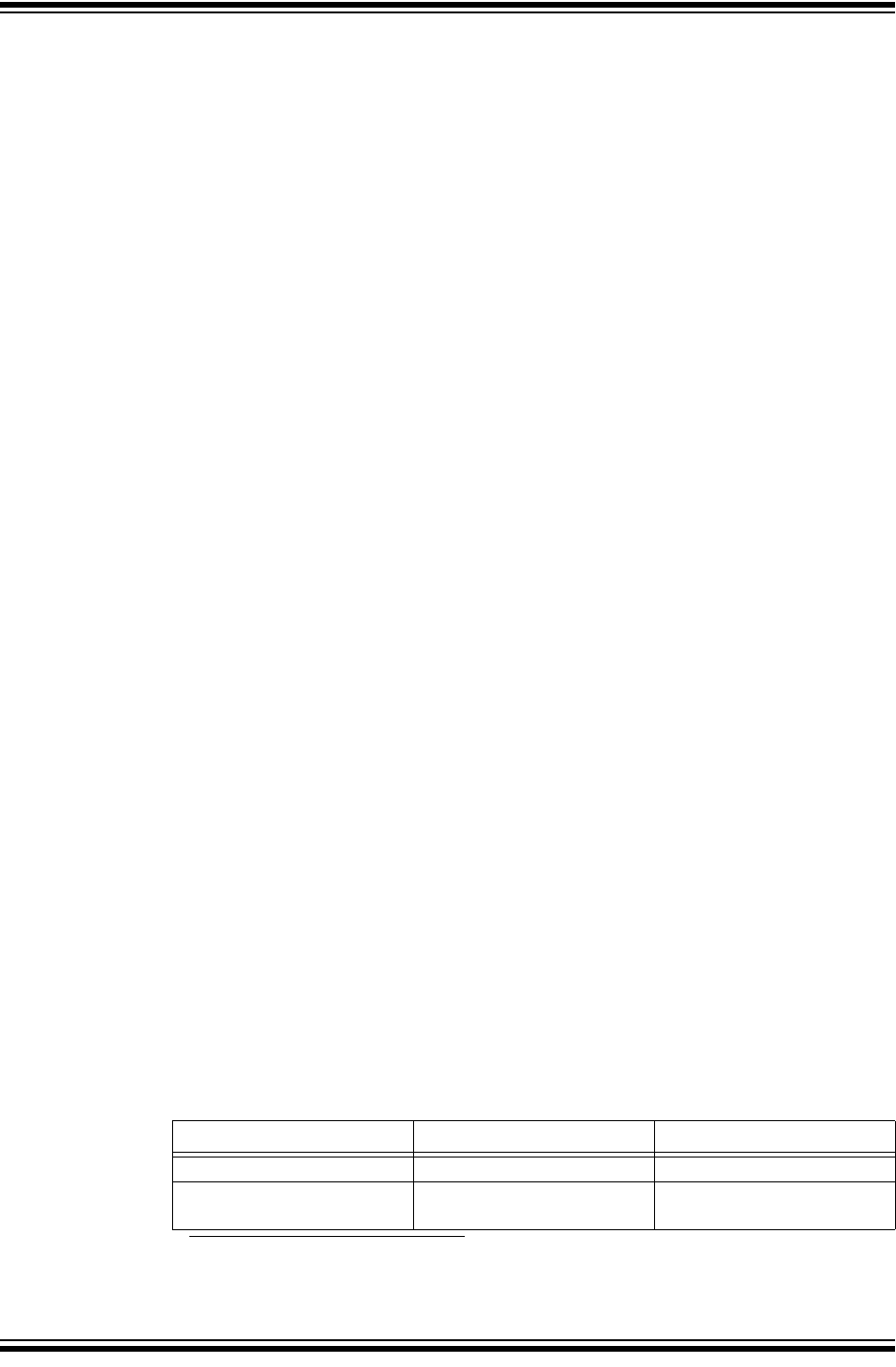
MPLAB® XC8 C Compiler User’s Guide
DS50002053D-page 172 2012-2013 Microchip Technology Inc.
The psects in which the different categories of non-auto variables (the nv, bss and
data psects described in Section 5.5.2.1 “Non-Auto Variable Allocation”) can be
shifted as a whole by changing the default linker options. So, for example, you could
move all the persistent variables. However, typically these psects can only be moved
within the data bank in which they were allocated by default. See Section 5.10 “Main,
Runtime Startup and Reset”, for more information on changing the default linker
options for psects. The code generator makes assumptions as to the location of these
psects and if you move them to a location that breaks these assumptions, code can fail.
Non-auto can also be placed at specific positions by using the psect pragma, see
Section 5.14.4.8 “The #pragma psect Directive”. The decision whether variables
should be positioned this way or using absolute variables should be based on the
location requirements.
5.5.2.2 AUTO VARIABLE ALLOCATION AND ACCESS
This section discusses allocation of auto variables (those with automatic storage dura-
tion) to a data stack. This also includes function parameter variables, which behave like
auto variables, in terms of their storage duration and scope. Temporary variables
defined by the compiler also fall into this group. They are identical to auto variables,
except they are defined by the compiler and, hence, have no C name. Together, these
objects are often called stack-based objects.
The auto (short for automatic) variables are the default type of local variable. Unless
explicitly declared to be static, a local variable will be made auto. The auto key-
word can be used if desired.
The auto variables, as their name suggests, automatically come into existence when
a function is executed, then disappear once the function returns. Since they are not in
existence for the entire duration of the program, there is the possibility to reclaim mem-
ory they use when the variables are not in existence and allocate it to other variables
in the program.
Typically such variables are stored on some sort of a dynamic data stack where mem-
ory can be easily allocated and deallocated by each function. This is not possible on all
8-bit devices supported by MPLAB XC8. Nor is it the most efficient means of storing
objects.
MPLAB XC8 has two methods of implementing data stacks for stack-based variables:
a compiled stack and a software stack1. Section 5.3.4 “Stacks” describes all the
stacks used by MPLAB XC8 and the 8-bit PIC devices.
Each C function is compiled to use exactly one of these stacks. The stack used affects
whether a function allows reentrancy. If a function is encoded to place its stack-based
objects on the software stack, it is said to be using a reentrant function model. A
function uses a non-reentrant function model if it places its stack-based objects on the
compiled stack. This information is summarized in Table 5-9 along with the devices that
support each model. The function model directly implies the stack used by a function.
See subsections below for specific details on how the compiled stack and software
stack operate.
1. What is referred to as a software stack in this user’s guide is the typical dynamic stack arrangement
employed by most computers and is ordinary data memory accessed by some sort of push and pop
instructions, and a stack pointer register.
TABLE 5-9: FUNCTION MODELS IMPLEMENTATION
Function Model Data stack used Supported device families
Non-reentrant Compiled stack All devices
Reentrant Software stack Enhanced mid-range and
PIC18 devices

C Language Features
2012-2013 Microchip Technology Inc. DS50002053D-page 173
When compiling for those devices that do not support the reentrant function model, all
functions are encoded to use the compiler stack, and these functions are
non-reentrant.
For the enhanced mid-range and PIC18 devices, by default the compiler will use the
non-reentrant model for all functions. Alternatively the user can dictate which functions
are to be compiled reentrantly (and those which are not) by using compiler options or
function specifiers. There is also a hybrid stack mode which allows the compiler to
choose which functions need to be compiled using a reentrant model and which can
use the non-reentrant model. The hybrid mode allows the program to use recursion but
still take advantage of the more efficient compiled stack.
The --STACK option (see Section 4.8.56 “--STACK: Specify Data Stack Type For
Entire Program”) can be used to change the compiler’s default behavior when assign-
ing function models. Set the --STACK option to software so the compiler will always
choose the reentrant model (software stack) for each function. If the --STACK option
is set to compiled or this option is omitted, all functions are encoded to use the
non-reentrant (compiled stack) function model. Set this option to hybrid for hybrid
stack mode and to allow the compiler to decide how each function should be encoded.
In hybrid mode the compiler will choose a function model based on how the function is
called in the program. If the function is not reentrantly called, then it will be encoded to
use the non-reentrant model and the compiled stack. If the function appears in more
than one call graph (i.e., it is called from main-line and interrupt code), or it appears in
a loop in a call graph (i.e., it is called recursively), then the compiler will use the
reentrant model.
The --STACK option’s software and compiled settings changes the function model
for all functions. You can change the function model for individual functions by using
function specifiers when you define the function.
Use either the compiled or nonreentrant specifier (identical meanings) to indicate
that the specified function must use the compiled stack, without affecting any other
function. Alternatively, use either the software or reentrant specifier to indicate a
function must be encoded to use the software stack.
The function specifiers have precedence over the --STACK option setting. If, for exam-
ple, the option --STACK=compiled has been used, but one function uses the
software (or reentrant) specifier, then the specified function will use the software
stack and all the remaining functions will use the compiled stack. These functions
specifiers also override any choice made by the compiler in hybrid mode.
If a function has been specified as compiled (or nonreentrant), or the
--STACK=compiled option has been issued, and that function appears in more than
one call graph in the program, then the usual function duplication feature automatically
comes into effect. See Section 5.9.6 “Function Duplication”, for more information on
how this is performed. Duplicating a non-reentrant function allows it to be called from
multiple call graphs, but cannot be used if the function is called recursively.
The auto variables defined in a function will not necessarily be allocated memory in
the order declared, in contrast to parameters which are always allocated memory
based on their lexical order. In fact, auto variables for one function can be allocated in
many RAM banks.
The standard qualifiers: const and volatile can both be used with auto variables
and these do not affect how they are positioned in memory. This implies that a local
const-qualified object is still an auto object and, as such, will be allocated memory in
the compiled stack in the data space memory, not in the program memory like with
non-auto const objects.
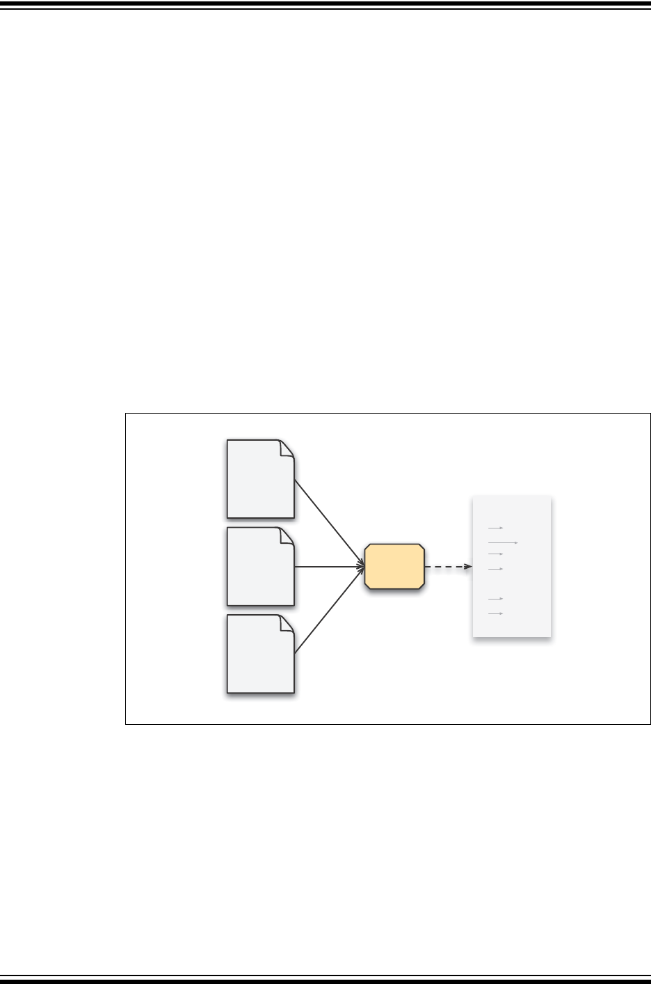
MPLAB® XC8 C Compiler User’s Guide
DS50002053D-page 174 2012-2013 Microchip Technology Inc.
The compiler will try to locate the stack in one data bank, but if this fills (i.e., if the com-
piler detects that the stack psect has become too large), it can build up the stack into
several components (each with their own psect) and link each in a different bank.
Each auto object is referenced in assembly code using a special symbol defined by
the code generator. If accessing auto variables defined in C source code, you must use
these symbols, which are discussed in Section 5.12.3 “Interaction between
Assembly and C Code”.
5.5.2.2.1 Compiled Stack Operation
A compiled stack consists of fixed memory areas that are usable by each function’s
stack-based variables. When a compiled stack is used, functions are not re-entrant
since stack-based variables in each function will use the same fixed area of memory
every time the function is invoked.
Fundamental to the generation of the compiled stack is the call graph, which defines a
tree-like hierarchy of function calls, i.e it shows what functions can be called by each
function.
There will be one graph produced for each root function. A root function is typically not
called, but which is executed via other means and contains a program entry point. The
function main() is an example of a root function that will be in every project. Interrupt
functions which are executed when a hardware interrupt occurs, are another example.
FIGURE 5-1: FORMATION OF CALL GRAPH
Figure 5-1 shows sections of a program being analyzed by the code generator to form
a call graph. In the original source code, the function main() calls F1(), F2() and
F3(). F1() calls F4(), but the other two functions make no calls. The call graph for
main() indicates these calls. The symbols F1, F2 and F3 are all indented one level
under main. F4 is indented one level under F1.
Analysis of program
main
F1
F4
F2
F3
isr
F5
F6
Call graph
code
generator
main {
F1(…);
F2(…);
F3(…);
}
F1 {
F4(…);
}
isr {
F5(…);
F6(…);
}
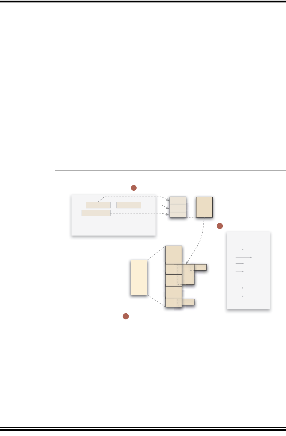
C Language Features
2012-2013 Microchip Technology Inc. DS50002053D-page 175
This is a static call graph which shows all possible calls. If the exact code for function
F1() looked like:
int F1(void) {
if(PORTA == 44)
return F4();
return 55;
}
the function F4() will always appear in the call graph, even though it is conditionally
executed in the actual source code. Thus, the call graph indicates all functions that
might be called.
In the diagram, there is also an interrupt function, isr(), and it too has a separate
graph generated.
The term main-line code is often used, and refers to any code that is executed as a
result of the main() function being executed. In the above figure, F1(), F2(), F3()
and F4() are only ever called by main-line code.
The term interrupt code refers to any code that is executed as a result of an interrupt
being generated, in the above figure, F5() and F6() are called by interrupt code.
Figure 5-2 graphically shows an example of how the compiled stack is formed.
FIGURE 5-2: FORMATION OF THE COMPILED STACK
Each function in the program is allocated a block of memory for its parameter, auto
and temporary variables. Each block is referred to as an auto-parameter block (APB).
The figure shows the APB being formed for function F2(), which has two parameters,
a and b, and one auto variable, c.
The parameters to the function are first grouped in an order strictly determined by the
lexical order in which they appear in the source code. These are then followed by any
auto objects; however, the auto objects can be placed in any order. So we see
memory for a is followed by that for b and lastly c.
F3
F6
F2
compiled
stack
main
F1
F4
isr
F5
F2(int a , int b ) {
;
}
F2
char c
int a int b a
b
b
c
Formation of auto-parameter block (APB)
for function F2
Overlap of non-concurrently active APBs
to form compiled stack
Analysis of call graph
main
F1
F4
F2
F3
isr
F5
F6
1
2
3
3
2
1
F
4
F
2
6
F
5

MPLAB® XC8 C Compiler User’s Guide
DS50002053D-page 176 2012-2013 Microchip Technology Inc.
Once these variables have been grouped, the exact location of each object is not
important at this point and we can represent this memory by one block — the APB for
this function.
The APBs are formed for all functions in the program. Then, by analyzing the call graph,
these blocks are assigned positions, or base values, in the compiled stack.
Memory can be saved if the following point is observed: If two functions are never
active at the same time, then their APBs can be overlapped.
In the example shown in the figure, F4() and F1() are active at the same time, in fact
F1() calls F4(). However, F2(), F3() and F1() are never active at the same time;
F1() must return before F2() or F3() can be called by main(). The function main()
will always be active and so its APB can never overlap with that of another function.
In the compiled stack, you can see that the APB for main() is allocated unique mem-
ory. The blocks for F1(), F2() and F3() are all placed on top of each other and the
same base value in the compiled stack; however, the memory taken up by the APBs
for F1() and F4() are unique and do not overlap.
Our example also has an interrupt function, isr(), and its call graph is used to assem-
ble the APBs for any interrupt code in the same way. Being the root of a graph, isr()
will always be allocated unique memory, and the APBs for interrupt functions will be
allocated memory following.
The end result is a block of memory which forms the compiled stack. This block can
then be placed into the device’s memory by the linker.
Once auto variables have been allocated a relative position in the compiled stack, the
stack itself is then allocated memory in the data space. This is done is a similar fashion
to the way other variables are assigned memory: a psect is used to hold the stack and
this psect is placed into the available data memory by the linker. The psect base name
used to hold the compiled stack is called cstack, and, like with other psects, the base
name is always used in conjunction with a linker class name to indicate the RAM bank
in which the psect will be positioned. See Section 5.15.2 “Compiler-Generated
Psects” for the limitations associated with where this psect can be linked.
For devices with more than one bank of data memory, the compiled stack can be built
up into components, each located in a different memory bank. The compiler will try to
allocate the compiled stack in one bank, but if this fills, it will consider other banks. The
process of building these components of the stack is the same, but each function can
have more than one APB and these will be allocated to one of the stack components
based on the remaining memory in the component’s destination bank.
Human readable symbols are defined by the code generator which can be used to
access auto and parameter variables in the compiled stack from assembly code, if
required. See Section 5.12.3 “Interaction between Assembly and C Code” for full
information between C domain and assembly domain symbols.
5.5.2.2.2 Software Stack Operation
Functions using a software stack (reentrant model) dynamically allocate memory for
their stack-based variables in a region of memory specifically reserved for this software
stack.
Allocation starts at one end of this reserved area, and the stack memory grows as new
function instances come into existence. When a function using the reentrant model
exits, any stack memory it used is freed and made available for other functions. The
stack grows up in memory, toward larger addresses.
Main-line code and each interrupt routine use unique areas in the stack space. The
maximum size allocated to each area can be specified using the --STACK option, see
Section 4.8.56 “--STACK: Specify Data Stack Type For Entire Program”.

C Language Features
2012-2013 Microchip Technology Inc. DS50002053D-page 177
MPLAB XC8 designates a register, known as the stack pointer, which always holds the
address of the next free location in the software stack. The register used by the stack
pointer is FSR1 for both enhanced mid-range and PIC18 devices. The address held by
the stack pointer is increased when variables are allocated (pushed) to the stack; it is
decreased when a function returns and variables are removed (popped) from the stack.
Note that if there are any functions in the program that are reentrantly encoded, the
FSR1 register is reserved for the stack pointer for the entire program’s duration, even
when executing code associated with non-reentrant functions. With this register
unavailable for use with general statements, the code generated may be less efficient
or "Can’t generate code" errors may result.
The stack pointer is reloaded when an interrupt occurs so it accesses the interrupt func-
tion’s unique stack area. It is restored by the interrupt context switch code when the
interrupt routine is complete.
There is no register assigned to hold a frame pointer. All access of stack-based objects
must use an address that is an offset from the stack pointer.
When a function is called, any arguments to that function are pushed onto the stack by
the calling function, in a reverse order to that in which the corresponding parameters
appear in the function’s prototype. If required, the called function will increase the value
stored in the stack pointer to allocate storage for any auto or temporary variables it
needs to allocate.
If the reentrant function returns a value on the stack (this might happen for return values
larger than 4 bytes in size), the calling function will adjust the stack to remove the return
value.
Recall that a function’s return address is not stored on this stack. It is automatically
stored on the hardware stack by the device, see Section 5.3.4.1 “Function Return
Address Stack”.
The compiler can detect if the software stack memory requirements for each function
will exceed set limits. These limits are 256 bytes for PIC18 devices and typically 31
bytes for enhanced mid-range devices. Note that the compiler cannot detect for over-
flow of the memory reserved for the stack as a whole. There is no runtime check made
for software stack overflows. If the software stack overflows, data corruption and code
failure might result.
5.5.2.2.3 Size Limits of Auto Variables
The compiled stack is built up as one contiguous block which can be placed into one
of the available data banks. However, if the stack becomes too large for this space, it
can be assembled into several blocks, with each block being positioned in a different
bank of memory. Thus the total size of the stack is roughly limited only by the available
memory on the device.
Unlike with non-auto variables, it is not efficient to access auto variables within the
compiled stack using the linear memory of enhanced mid-range devices. For all
devices, including PIC18 and Enhanced mid-range PIC MCUs, each component of the
compiled stack must fit entirely within one bank of data memory on the target device
(however, you can have more than one component, each allocated to a different bank).
This limits the size of objects within the stack to the maximum free space of the bank
in which it is allocated. The more auto variables in the stack; the more restrictive the
space is to large objects. Recall that SFRs on mid-range devices are usually present
in each data bank, so the maximum amount of GPR available in each bank is typically
less than the bank size for these devices.

MPLAB® XC8 C Compiler User’s Guide
DS50002053D-page 178 2012-2013 Microchip Technology Inc.
The software stack is always allocated one block of memory. This memory may cross
bank boundaries. The size is typically limited by the amount of free data space
remaining. An auto object placed on the software stack may be any size, providing it
fits in the allocated stack space. It may be allocated memory that crosses a bank
boundary and will always be accessed via the stack pointer, FSR1.
If a program requires large objects that should not be accessible to the entire program,
consider leaving them as local objects, but using the static specifier. Such variables
are still local to a function, but are no longer auto and have fewer size limitations. They
are allocated memory as described in Section 5.5.2.1 “Non-Auto Variable
Allocation”.
5.5.2.2.4 Changing the Default Auto Variable Allocation
As auto variables are placed in a stack, there is no means to move individual vari-
ables. They cannot be made absolute, nor can they be moved using the #pragma
psect directive.
The psects in which the auto variables reside can be shifted as a whole by changing
the default linker options. However, these psects can only be moved within the data
bank in which they were allocated by default. See Section 5.10 “Main, Runtime
Startup and Reset” for more information on changing the default linker options for
psects. The code generate makes assumptions as to the location of these psects and
if you move them to a location that breaks these assumptions, code can fail.
5.5.3 Variables in Program Space
The only variables that are placed into program memory are those that are not auto
and which have been qualified const. Any auto variables qualified const are placed
in the compiled stack along with other auto variables, and all components of the com-
piled stack will only ever be located in the data space memory.
Any const-qualified (auto or non-auto) variable will always be read-only and any
attempt to write to these in your source code will result in an error being issued by the
compiler.
On some 8-bit PIC devices, the program space is not directly readable by the device.
For these devices, the compiler stores data in the program memory by means of RETLW
instructions which can be called, and which will return a byte of data in the W register.
The compiler will generate the code necessary to make it appear that program memory
is being read directly.
Enhanced mid-range PIC devices can directly read their program memory, although
the compiler will still usually store data as RETLW instructions. This way the compiler
can either produce code that can call these instructions to obtain the program memory
data as with the ordinary mid-range devices, or directly read the operand to the instruc-
tion (the LSB of the RETLW instruction). The most efficient access method can be
selected by the compiler when the data needs to be read.

C Language Features
2012-2013 Microchip Technology Inc. DS50002053D-page 179
Data can be stored as individual bytes in the program memory of PIC18 devices. This
can be read using table read instructions.
On all devices, accessing data located in program memory is much slower than
accessing objects in the data memory. The code associated with the access is also
larger.
A const object is usually defined with initial values, as the program cannot write to
these objects at runtime. However, this is not a requirement. An uninitialized const
object can be defined to define a symbol, or label, but not make a contribution to the
output file. Uninitialized const objects are often made absolute, see
Section 5.5.4 “Absolute Variables”. Here are examples of const object definitions.
const char IOtype = ’A’; // initialized const object
const char buffer[10]; // I just define a label
The data held by non-auto const variables is placed in one of several psects, based
on the target device. See Section 5.15.2 “Compiler-Generated Psects” for the
limitations associated with where these psects can be linked.
See Section 5.12.3 “Interaction between Assembly and C Code” for the equivalent
assembly symbols that are used to represent const-qualified variables in program
memory.
5.5.3.1 SIZE LIMITATIONS OF CONST VARIABLES
Arrays of any type (including arrays of aggregate types) can be qualified const and
placed in the program memory. So too can structure and union aggregate types, see
5.4.4 “Structures and Unions”. These objects can often become large in size and can
affect memory allocation.
For baseline PIC devices, the maximum size of a single const object is 255 bytes.
However, you can define as many const objects as required provided the total size
does not exceed the available program memory size of the device. Note that as well as
other program code, there is also code required to be able to access const-qualified
data in the program memory space. Thus, you can need additional program memory
space over the size of the object itself. This additional code to access the const data
is only included once, regardless of the amount or number of const-qualified objects.
For all other 8-bit devices, the maximum size of a const-qualified object is limited only
by the available program memory. These devices also use additional code that
accesses the const data. PIC18 devices need additional code each time an object is
accessed, but this is typically small. The mid-range devices include a larger routine, but
this code is also only included once, regardless of the amount or number of
const-qualified objects.

MPLAB® XC8 C Compiler User’s Guide
DS50002053D-page 180 2012-2013 Microchip Technology Inc.
5.5.3.2 CHANGING THE DEFAULT ALLOCATION
If you only intend to prevent all variables from using one or more program memory loca-
tions so that you can use those locations for some other purpose, you are best reserv-
ing the memory using the memory adjust options. See Section 4.8.50 “--ROM: Adjust
ROM Ranges” for information on how to do this.
If only a few non-auto const variables are to be located at specific addresses in pro-
gram space memory, then the variables can be made absolute. This allows individual
variables to be explicitly positioned in memory at an absolute address. Absolute vari-
ables are described in Section 5.5.4 “Absolute Variables”. Once variables are made
absolute, their address is hard coded in generated output code, they are no longer
placed in a psect and do not follow the normal memory allocation procedure.
The psects in which the different categories of non-auto const variables can be
shifted as a whole by changing the default linker options. However, there are limitations
in where these psects can be moved to. See Section 5.10 “Main, Runtime Startup
and Reset” for more information on changing the default linker options for these
psects.
Variables in program memory can also be placed at specific positions by using the
psect pragma, see Section 5.14.4.8 “The #pragma psect Directive”. The decision
whether variables should be positioned this way or using absolute variables should be
based on the location requirements.
C Language Features
2012-2013 Microchip Technology Inc. DS50002053D-page 181
5.5.4 Absolute Variables
Most variables can be located at an absolute address by following its declaration with
the construct @ address, where address is the location in memory where the
variable is to be positioned. Such a variable is known as an absolute variable.
5.5.4.1 ABSOLUTE VARIABLES IN DATA MEMORY
Absolute variables are primarily intended for equating the address of a C identifier with
a special function register, but can be used to place ordinary variables at an absolute
address in data memory.
For example:
volatile unsigned char Portvar @ 0x06;
will declare a variable called Portvar located at 06h in the data memory. The compiler
will reserve storage for this object (if the address falls into general-purpose RAM) and
will equate the variable’s identifier to that address.
The auto variables cannot be made absolute as they are located in a stack. Nor can
you make static local objects absolute. The compiler does not make any checks for
overlap of absolute variables with other absolute variables, so this must be considered
when choosing the variable locations. There is no harm in defining more than one
absolute variable to live at the same address if this is what you require. The compiler
will not locate ordinary variables over the top of absolutes, so there is no overlap
between these objects.
When defining absolute bit variables (see Section 5.4.2.1 “Bit Data Types and Vari-
ables”), the address specified must be a bit address. A bit address is obtained by mul-
tiplying the desired byte address by 8, then adding the bit offset within that bit. So, for
example, to place a bit variable called mode at bit position #2 at byte address 0x50,
use the following:
bit mode @ 0x282;
If you wish to place a bit variable over an existing object (typically this will be an SFR
variable or another absolute variable) then you can use the symbol of that object, as in
the following example which places flag at bit position #3 in the char variable
MOT_STATUS:
bit flag @ ((unsigned) &MOT_STATUS)*8 + 3;
When compiling for an enhanced mid-range PIC device, the memory allocated for
some objects can be spread over multiple RAM banks. Such objects will only ever be
accessed indirectly in assembly code, and will use the linear GPR memory imple-
mented on these devices. A linear address (which can be mapped back to the ordinary
banked address) will be used with these objects internally by the compiler.
Note: Defining absolute objects can fragment memory and can make it impossi-
ble for the linker to position other objects. Avoid absolute objects if at all
possible. If absolute objects must be defined, try to place them at either end
of a memory bank or page so that the remaining free memory is not
fragmented into smaller chunks.

MPLAB® XC8 C Compiler User’s Guide
DS50002053D-page 182 2012-2013 Microchip Technology Inc.
The address specified for absolute objects on these devices can either be the tradi-
tional banked memory address or the linear address. As the linear addresses start
above the largest banked address, it is clear which address is intended. In the following
example:
int inputBuffer[100] @ 0x2000;
it is clear that inputBuffer should placed at address 0x2000 in the linear address
space, which is address 0x20 in bank 0 RAM in the traditional banked address space.
See the device data sheet for exact details regarding your selected device.
Absolute variables in RAM cannot be initialized when they are defined. Define the
absolute variables, then assign them a value at a suitable point in your main-line code.
5.5.4.2 ABSOLUTE OBJECTS IN PROGRAM MEMORY
Non-auto objects qualified const can also be made absolute in the same way,
however, the address will indicate an address in program memory. For example:
const int settings[] @ 0x200 = { 1, 5, 10, 50, 100 };
will place the array settings at address 0x200 in the program memory.
Both initialized and uninitialized const objects can be made absolute. That latter is
useful when you only need to define a label in program memory without making a
contribution to the output file.
Variables can also be placed at specific positions by using the psect pragma, see
Section 5.14.4.8 “The #pragma psect Directive”. The decision whether variables
should be positioned this way or using absolute variables should be based on the loca-
tion requirements. Using absolute variables is the easiest method, but only allows
placement at an address which must be known prior to compilation. The psect
pragma is more complex, but offers all the flexibility of the linker to position the new
psect into memory. You can, for example, specify that variables reside at a fixed
address, or that they be placed after other psects, or that the they be placed anywhere
in a compiler-defined or user-defined range of address.

C Language Features
2012-2013 Microchip Technology Inc. DS50002053D-page 183
5.5.5 Variables in EEPROM
For devices with on-chip EEPROM, the compiler offers several methods of accessing
this memory. You can defined named variables in this memory space, or use
block-access routines to read or write EEPROM. The EEPROM access methods are
described in the following sections.
5.5.5.1 EEPROM VARIABLES
When compiling for baseline and mid-range parts, the eeprom qualifier allows you to
create named C variables that reside in the EEPROM space. See
Section 5.4.8.5 “Eeprom Type Qualifier”.
Variables qualified eeprom are cleared or initialized, just like ordinary RAM-based vari-
ables; however, the initialization process is not carried out by the runtime startup code.
Initial values are placed into the HEX file and are burnt into the EEPROM when you
program the device. Thus, if you modify the EEPROM during program execution and
then reset the device, these variables will not contain the initial values specified in your
code at startup up.
The following example defines two arrays in EEPROM.
eeprom char regNumber[10] = "A93213";
eeprom int lastValues[3];
For both these objects, initial values will be placed into psects and will appear in the
HEX file. Zeros will be used as the initial values for lastValues.
The generated code to access eeprom-qualified variables will be much longer and
slower than code to access RAM-based variables. You should avoid using
eeprom-qualified variables in complicated expressions. Consider copying values from
the EEPROM to regular RAM-based variables and using these in your code.
5.5.5.2 EEPROM INITIALIZATION
For those devices that support external programming of their EEPROM data area, the
__EEPROM_DATA() macro can be used to place initial values into the HEX file ready
for programming. The macro is used as follows.
#include <xc.h>
__EEPROM_DATA(0, 1, 2, 3, 4, 5, 6, 7);
The macro has eight parameters, representing eight data values. Each value should be
a byte in size. Unused values should be specified with zero.
The __EEPROM_DATA() macro expands into in-line assembly code. If expressions are
used to evaluate the macro arguments, ensure that any operators or tokens in these
expressions are written in assembly code (see Section 6.4 “MPLAB XC8 Assembly
Language”).
The macro can be called multiple times to define the required amount of EEPROM
data. It is recommended that the macro be placed outside any function definition.
This macro cannot used to write to EEPROM locations during runtime; it is used for
pre-loading EEPROM contents at program time only.
The values defined by this macro share the EEPROM space with any eeprom-qualified
variables. The macro cannot be used to initialize eeprom-qualified variables. The psect
used by this macro to hold the data values is different to those used by eeprom-qual-
ified variables. The link order of these psects can be adjusted, if required (see
Section 4.8.6 “-L-: Adjust Linker Options Directly”).
For convenience, the macro _EEPROMSIZE represents the number of bytes of
EEPROM available on the target device.

MPLAB® XC8 C Compiler User’s Guide
DS50002053D-page 184 2012-2013 Microchip Technology Inc.
5.5.5.3 EEPROM ACCESS FUNCTIONS
The library functions eeprom_read() and eeprom_write(), can be called to read
from, and write to, the EEPROM during program execution. On PIC18 devices, these
functions are derived from the peripheral library. The prototypes for these functions are
as below.
#include <xc.h>
unsigned char eeprom_read(unsigned char address);
void eeprom_write(unsigned char address, unsigned char value);
These functions test and wait for any concurrent writes to EEPROM to conclude before
performing the required operation. The eeprom_write() function will initiate the pro-
cess of writing to EEPROM and this process will not have completed by the time that
eeprom_write() returns. The new data written to EEPROM will become valid at a
later time. See your device data sheet for exact information about EEPROM on your
target device.
It can also be convenient to use the preprocessor symbol, _EEPROMSIZE, in conjunc-
tion with some of these access methods. This symbol defines the number of EEPROM
bytes available for the selected chip.
5.5.5.4 EEPROM ACCESS MACROS
Macro version of the EEPROM functions are also provided. The PIC18 version of these
macros purely call the function equivalents. Those for other 8-bit PIC devices perform
similar operations to their function counterparts, with the exception of some timing
issues described below. Use the macro forms of these routines for faster execution and
to save a level of stack, but note that their repeated use will increase code size.
The usage of these macros for all devices is as follows.
EEPROM_READ(address)
EEPROM_WRITE(address, value)
The EEPROM_READ macro returns the byte read.
In the case of the baseline and mid-range macro EEPROM_READ(), there is another
very important difference from the function version to note. Unlike eeprom_read(),
this macro does not wait for any concurrent EEPROM writes to complete before pro-
ceeding to select and read EEPROM. If it cannot be guaranteed that all writes to
EEPROM have completed at the time of calling EEPROM_READ(), the appropriate flag
should be polled prior to executing EEPROM_READ().
For example:
xc.h // wait for end-of-write before EEPROM_READ
while(WR)
continue; // read from EEPROM at address
value = EEPROM_READ(address);

C Language Features
2012-2013 Microchip Technology Inc. DS50002053D-page 185
5.5.6 Variables in Registers
Allocating variables to registers, rather than to a memory location, can make code more
efficient. With MPLAB XC8, there is no direct control of placement of variables in reg-
isters. The register keyword (which can only be used with auto variables) is silently
ignored and has no effect on memory allocation of variables.
There are very few registers available for caching of variables on PIC baseline and
mid-range devices, and as these registers must be frequently used by generated code
for other purposes, there is little advantage in using them. The cost involved in loading
variables into registers would far outweigh any advantage of accessing the register. At
present, code compiled for PIC18 devices also does not utilize registers other than that
described below.
Some arguments are passed to functions in the W register rather than in a memory
location; however, these values will typically be stored back to memory by code inside
the function so that W can be used by code associated with that function. See
Section 5.8.5 “Function Size Limits” for more information as to which parameter
variables can use registers.
5.5.7 Dynamic Memory Allocation
Dynamic memory allocation, (heap-based allocation using malloc, etc.) is not sup-
ported on any 8-bit device. This is due to the limited amount of data memory, and that
this memory is banked. The wasteful nature of dynamic memory allocation does not
suit itself to the 8-bit PIC device architectures.
5.5.8 Memory Models
MPLAB XC8 C Compiler does not use fixed memory models to alter allocation of vari-
ables to memory. Memory allocation is fully automatic and there are no memory model
controls.

MPLAB® XC8 C Compiler User’s Guide
DS50002053D-page 186 2012-2013 Microchip Technology Inc.
5.6 OPERATORS AND STATEMENTS
The MPLAB XC8 C Compiler supports all the ANSI operators. The exact results of
some of these are implementation defined. Implementation-defined behavior is fully
documented in Appendix D. “Implementation-Defined Behavior”. The following
sections illustrate code operations that are often misunderstood as well as additional
operations that the compiler is capable of performing.
5.6.1 Integral Promotion
When there is more than one operand to an operator, they typically must be of exactly
the same type. The compiler will automatically convert the operands, if necessary, so
they do have the same type. The conversion is to a “larger” type so there is no loss of
information; however, the change in type can cause different code behavior to what is
sometimes expected. These form the standard type conversions.
Prior to these type conversions, some operands are unconditionally converted to a
larger type, even if both operands to an operator have the same type. This conversion
is called integral promotion and is part of Standard C behavior. The compiler performs
these integral promotions where required, and there are no options that can control or
disable this operation. If you are not aware that the type has changed, the results of
some expressions are not what would normally be expected.
Integral promotion is the implicit conversion of enumerated types, signed or
unsigned varieties of char, short int or bit-field types to either signed int or
unsigned int. If the result of the conversion can be represented by an signed int,
then that is the destination type, otherwise the conversion is to unsigned int.
Consider the following example.
unsigned char count, a=0, b=50;
if(a - b < 10)
count++;
The unsigned char result of a - b is 206 (which is not less than 10), but both a and
b are converted to signed int via integral promotion before the subtraction takes
place. The result of the subtraction with these data types is -50 (which is less than 10)
and hence the body of the if() statement is executed.
If the result of the subtraction is to be an unsigned quantity, then apply a cast. For
example:
if((unsigned int)(a - b) < 10)
count++;
The comparison is then done using unsigned int, in this case, and the body of the
if() would not be executed.
Another problem that frequently occurs is with the bitwise complement operator, ~. This
operator toggles each bit within a value. Consider the following code.
unsigned char count, c;
c = 0x55;
if( ~c == 0xAA)
count++;
If c contains the value 0x55, it often assumed that ~c will produce 0xAA; however, the
result is 0xFFAA and so the comparison in the above example would fail. The compiler
can be able to issue a mismatched comparison error to this effect in some
circumstances. Again, a cast could be used to change this behavior.

C Language Features
2012-2013 Microchip Technology Inc. DS50002053D-page 187
The consequence of integral promotion as illustrated above is that operations are not
performed with char -type operands, but with int -type operands. However, there are
circumstances when the result of an operation is identical regardless of whether the
operands are of type char or int. In these cases, the compiler will not perform the
integral promotion so as to increase the code efficiency. Consider this example.
unsigned char a, b, c;
a = b + c;
Strictly speaking, this statement requires that the values of b and c should be promoted
to unsigned int, the addition performed, the result of the addition cast to the type of
a, and then the assignment can take place. Even if the result of the unsigned int
addition of the promoted values of b and c was different to the result of the unsigned
char addition of these values without promotion, after the unsigned int result was
converted back to unsigned char, the final result would be the same. If an 8-bit
addition is more efficient than a 16-bit addition, the compiler will encode the former.
If, in the above example, the type of a was unsigned int, then integral promotion
would have to be performed to comply with the ANSI C standard.
5.6.2 Rotation
The C language does not specify a rotate operator; however, it does allow shifts. The
compiler will detect expressions that implement rotate operations using shift and logical
operators and compile them efficiently.
For the following code:
c = (c << 1) | (c >> 7);
if c is unsigned and non-volatile, the compiler will detect that the intended
operation is a rotate left of 1 bit and will encode the output using the PIC MCU rotate
instructions. A rotate left of 2 bits would be implemented with code like:
c = (c << 2) | (c >> 6);
This code optimization will also work for integral types larger than a char. If the opti-
mization cannot be applied, or this code is ported to another compiler, the rotate will be
implemented, but typically with shifts and a bitwise OR operation.
5.6.3 Switch Statements
The compiler can encode switch statements using one of several strategies. By
default, the compiler chooses a strategy based on the case values that are used inside
the switch statement. Each switch statement is assigned its strategy independently.
The type of strategy can be indicated by using the #pragma switch directive. See
Section 5.14.4.10 “The #pragma switch Directive”, which also lists the available
strategy types. There can be more than one strategy associated with each type.
There is information printed in the assembly list file for each switch statement detail-
ing the value being switched and the case values listed. See Section 6.6.4 “Switch
Statement Information”.
MPLAB® XC8 C Compiler User’s Guide
DS50002053D-page 188 2012-2013 Microchip Technology Inc.
5.7 REGISTER USAGE
The assembly generated from C source code by the compiler will use certain registers
in the PIC MCU register set. Most importantly, the compiler assumes that nothing other
than code it generates can alter the contents of these registers.
So, if compiler-generated assembly code loads a register with a value and no subse-
quent code requires this register, the compiler will assume that the contents of the
register are still valid later in the output sequence.
If any of the applicable registers listed are used by interrupt code, they will be saved
and restored when an interrupt occurs, either in hardware or software. See
Section 5.9.4 “Context Switching”.
The registers that are special and which are used by the compiler are listed in
Table 5-10
The xtemp registers are variables that the compiler treats as registers, These are
saved like any other register if they are used in interrupt code.
The state of these registers must never be changed directly by C code, or by any
assembly code in-line with C code. The following example shows a C statement and
in-line assembly that violates these rules and changes the ZERO bit in the STATUS
register.
#include <xc.h>
void getInput(void)
{
ZERO = 0x1; // do not write using C code
c = read();
#asm
bcf ZERO ; do not write using inline assembly code
#endasm
process(c);
}
MPLAB XC8 is unable to interpret the register usage of in-line assembly code that is
encountered in C code. Nor does it associate a variable mapped over an SFR to the
actual register itself. Writing to an SFR register using either of these two methods will
not flag the register as having changed and can lead to code failure.
TABLE 5-10: REGISTERS USED BY THE COMPILER
Applicable devices Register name
All 8-bit devices W
All 8-bit devices STATUS
All mid-range devices PCLATH
All PIC18 devices PCLATH, PCLATU
Enhanced mid-range and PIC18 devices BSR
Non-enhanced mid-range devices FSR
Enhanced mid-range and PIC18 devices FSR0L, FSR0H, FSR1L, FSR1H
All PIC18 devices FSR2L, FSR2H
All PIC18 devices TBLPTRL, TBLPTRH, TBLPTRU,
TABLAT
All PIC18 devices PRODL, PRODH
Enhanced mid-range and PIC18 devices btemp, wtemp, ttemp, ltemp

C Language Features
2012-2013 Microchip Technology Inc. DS50002053D-page 189
5.8 FUNCTIONS
Functions are written in the usual way, in accordance with C language. Implementation
and special features associated with functions are discussed in following sections.
5.8.1 Function Specifiers
Functions can, in the usual way, use the standard specifier static. A function defined
using the static specifier only affects the scope of the function; i.e., limits the places
in the source code where the function can be called. Functions that are static can
only be directly called from code in the file in which the function is defined. The equiv-
alent symbol used in assembly code to represent the function can change if the func-
tion is static, see 5.12.3 “Interaction between Assembly and C Code”. This
specifier does not change the way the function is encoded. Non-standard qualifiers are
discussed below.
5.8.1.1 INTERRUPT SPECIFIER
The interrupt specifier indicates that the function is an interrupt service routine and
that it is to be encoded specially to suit this task. Interrupt functions are described in
detail in 5.9.1 “Writing an Interrupt Service Routine”.
5.8.1.2 INLINE SPECIFIER
The inline function specifier is a recommendation that calls to the specified function
be as fast as possible. The compiler can be able to inline the body of the function spec-
ified if certain conditions are met.
The following is an example of a function which has been made a candidate for inlining.
inline int combine(int x, int y) {
return 2*x-y;
}
All function calls to any function that was inlined by the compiler will be encoded as if
the call was replaced with the body of the called function. This is performed at the
assembly code level. Inlining will only take place if the assembly optimizers are
enabled. The function itself can still be encoded by the compiler even if it is inlined.
If inlining takes place, this will increase the program’s execution speed, since the call
and return sequences associated with the call will be eliminated. It will also reduce the
hardware stack usage as no call instruction is actually executed. Any stack reduction
is not reflected in the call graphs shown in the assembly list file as this file is generated
before inlining takes place.
If inlining takes place, code size can be reduced if the assembly code associated with
the body of the inlined function is very small and the function itself is not output. Code
size will increase if the body of the inlined function is larger than the call/return
sequence it replaces and that function is called more than once. You should only con-
sider this specifier for functions which generate small amounts of assembly code. Note
that the amount of C code in the body of a function is not a good indicator of the size
of the assembly code which it generates (see Section 3.6.13 “How Can I Tell How
Big a Function Is?”).
A function cannot be inlined if it itself contains in-line assembly. If the assembly for the
function contains certain assembly sequences, this can also prevent inlining of the
function. A warning will be generated if the function references static objects, to
comply with the ANSI Standard. A warning is also issued if it is not inlined successfully.
Your code should not make any assumption about whether inlining was successful and
which assembly code associated with the function is being executed. This specifier per-
forms the same task as the #pragma inline directive, see Section 5.14.4.4 “The
#pragma Intrinsic Directive”.
MPLAB® XC8 C Compiler User’s Guide
DS50002053D-page 190 2012-2013 Microchip Technology Inc.
5.8.1.3 REENTRANT AND NONREENTRANT SPECIFIERS
The reentrant and nonreentrant function specifiers indicate the function model
(stack) that should be used for that function’s stack-based variables (auto, parameter,
and temporary variables), as shown in Table 5-11. The aliases software and
compiled, respectively, can also be used. If the --STRICT option has been enabled
(see Section 4.8.57 “--STRICT: Strict ANSI Conformance”) these specifiers must
use two leading underscore characters, (e.g., __reentrant).
You would only use these specifiers if the default allocation of a function’s stack-based
variables is unacceptable. These specifiers override any setting indicated using the
--STACK option, see Section 4.8.56 “--STACK: Specify Data Stack Type For Entire
Program”. If no specifier or --STACK option has been used, all functions are encoded
as non-reentrant and use the compiled stack.
The following shows an example of a function that will always be encoded as reentrant.
reentrant int setWriteMode(int mode)
{
if(mode != 3)
mode = 0;
return mode;
}
The reentrant specifier only has an effect if the target device supports a software
stack. In addition, not all functions allow reentrancy. Interrupt functions and main()
must always use the compiled stack, but functions they call may use the software stack.
Functions encoded for baseline and mid-range devices always use the non-reentrant
model and the compiled stack.
Repeated use of the software (reentrant) specifier will increase substantially the
size of the software stack leading to possible overflow. The size of the software stack
is not accurately known at compile time, so the compiler cannot issue a warning if it is
likely to overwrite memory used for some other purpose. The stack may overwrite other
sections of the program in data memory, or memory used by something outside the
program, such as hardware or another independently-compiled application.
See Section 5.3.4.2 “Data Stacks” for device specific information relating to the data
stacks available on each device.
TABLE 5-11: STACK RELATED FUNCTION SPECIFIERS
Specifier Allocation for Stack-based variables
compiled, nonreentrant Always use the compiled stack; functions are non-reentrant.
software, reentrant Use the software stack, if available; functions are reentrant.

C Language Features
2012-2013 Microchip Technology Inc. DS50002053D-page 191
5.8.2 External Functions
If a call to a function that is defined outside the program C source code is required (it
can be part of code compiled separately, e.g., the bootloader, or in assembly code), you
will need to provide a declaration of the function so that the compiler knows how to
encode the call.
If this function takes arguments or returns a value, the compiler can use a symbol to
represent the memory locations used to store these values, see
Section 5.8.6 “Function Parameters” and Section 5.8.6.2 “Software Stack Param-
eters” to determine if a register or memory locations are used in this transfer. Usually,
the compiler defines this symbol when it encodes the C function, but if the function is
external and not encoded by the compiler, then the symbol value must be manually
defined. If an argument or return value is used and this will be stored in memory, the
corresponding symbol must be defined by your code and assigned the value of the
appropriate memory location.
The value can be determined from the map file of the external build, which compiled
the function, or from the assembly code. If the function was written in C, look for the
symbol ?_funcName, where funcName is the name of the function. It can be defined
in the program which makes the call via a simple EQU directive in assembler. For
example, the following snippet of code could be placed in the C source:
#asm
GLOBAL ?_extReadFn
?_extReadFn EQU 0x20
#endasm
Alternatively, the assembly code could be contained directly in an assembly module.
This defines the base address of the parameter area for an extern function extReadFn
to be 0x20.
If this symbol is not defined, the compiler will issue an undefined symbol error. This
error can be used to verify the name being used by the compiler to encode the call, if
required.
It is not recommended to call the function indirectly by casting an integer to a function
pointer, but in such a circumstance, the compiler will use the value of the constant in
the symbol name, for example calling a function at address 0x200 will require the defi-
nition of the symbol ?0x200 to be the location of the parameter/return value location for
the function. For example:
#asm
GLOBAL ?0x200
?0x200 EQU 0x55
#endasm
Note that the return value of a function (if used) shares the same locations assigned to
any parameters to that function and both use the same symbol.

MPLAB® XC8 C Compiler User’s Guide
DS50002053D-page 192 2012-2013 Microchip Technology Inc.
5.8.3 Allocation of Executable Code
Code associated with functions is always placed in the program memory of the target
device.
On baseline and mid-range devices, the program memory is paged (compare: banking
used in the data memory space). This memory is still sequential (addresses are con-
tiguous across a page boundary), but the paging means that any call or jump from code
in one page to a label in another must use a longer sequence of instructions to accom-
plish this. See your device data sheet for more information on the program memory and
instruction set.
PIC18 devices do not implement any program memory paging. The CALL and GOTO
instruction are two-word instructions and their destinations are not limited. The relative
branch instructions have a limited range, but this is not based on any paging boundar-
ies.
The generated code associated with each function is initially placed in its own psect by
the compiler, see Section 5.15.1 “Program Sections”. These psects have names
such as textn, where n is a number, e.g., text98. However, psects can be merged
later in the compilation process so that more than one function can contribute to a
psect.
When the program memory is paged, functions within the same psect can use a shorter
form of call and jump to labels so it is advantageous to merge the code for as many
functions into the same psect. These text psects are linked anywhere in the program
memory (see 5.10 “Main, Runtime Startup and Reset”).
If the size of a psect that holds the code associated with a function exceeds the size of
a page, it can be split by the assembler optimizer. A split psect will have a name of the
form textn_split_s. So, for example, if the text102 psect exceeds the size of a
page, it can be split into a text102_split_1 and a text102_split_2 psect. This
process is fully automatic, but you should be aware that if the code associated with a
function does become larger than one page in size, the efficiency of that code can drop
fractionally due to any longer jump and call instruction sequences being used to trans-
fer control to code in other pages.
The base name of each psect category is tabulated below. A full list of all pro-
gram-memory psects psect names are listed in Section 5.15.2.1 “Program Space
Psects”.
maintext The generated code associated with the special function, main, is placed
in this psect. Some optimizations and features are not applied to this psect.
textn These psects (where n is a decimal number) contain all other executable code
that does not require a special link location.

C Language Features
2012-2013 Microchip Technology Inc. DS50002053D-page 193
5.8.4 Changing the Default Function Allocation
You can change the default memory allocation of functions several ways.
If you intend only to prevent functions from using one or more program memory loca-
tions so that you can use those locations for some other purpose, you are best
reserving the memory using the memory adjust options. See Section 4.8.50 “--ROM:
Adjust ROM Ranges”, for information on how to do this.
The assembly code associated with a C function can be placed at an absolute address.
This can be accomplished by using an @ address construct in a similar fashion to
that used with absolute variables. Such functions are called absolute functions.
The following example of an absolute function will place the function at address 400h:
int mach_status(int mode) @ 0x400
{
/* function body */
}
If you check the assembly list file you will see the function label and the first assembly
instruction associated with the function located at 0x400. You can use either the
assembly list file (see 6.5 “Assembly-Level Optimizations”) or the map file (see
7.4 “Map Files”) to confirm that the function was moved as you expect.
If this construct is used with interrupt functions it will only affect the position of the code
associated with the interrupt function body. The interrupt context switch code that pre-
cedes the function code will not be relocated, as it must be linked to the interrupt vector.
See also Section 4.8.20 “--CLIST: Generate C Listing File”, for information on how
to move Reset and interrupt vector locations – which can be useful for designing
applications such as bootloaders.
Unlike absolute variables, the generated code associated with absolute functions is still
placed in a psect, but the psect is dedicated to that function only. The psect name has
the form below. A full list of all psect names are listed in Section 5.10 “Main, Runtime
Startup and Reset”.
xxx_text Defines the psect for a function that has been made absolute; i.e., placed
at an address. xxx will be the assembly symbol associated with the function.
For example if the function rv() is made absolute, code associated with it
will appear in the psect called _rv_text.
Functions can be allocated to a user-defined psect using the __section() specifier
(see Section 5.15.4 “Changing and Linking the Allocated Section”). This new
psect can then be linked at the required location. As with absolute functions, this spec-
ifier will only affect the position of the code associated with the interrupt function body.
The interrupt entry code will still be located in the default psect and be linked at the
usual interrupt vector address.
Functions can also be placed at specific positions by using the psect pragma, see
Section 5.14.4.8 “The #pragma psect Directive”, although using the __section()
directive is an easier option. The decision whether functions should be positioned by
using the pragma, specifier, or by making them absolute should be based on the
location requirements.
Using absolute functions is the easiest method, but only allows placement at an
address that must be known prior to compilation. The __section() specifier offers all
the flexibility of the linker to position the new psect into memory. For example, you can
specify that functions reside at a fixed address, or that they be placed after other
psects, or that the they be placed anywhere in a compiler-defined or user-defined range
of addresses.
MPLAB® XC8 C Compiler User’s Guide
DS50002053D-page 194 2012-2013 Microchip Technology Inc.
5.8.5 Function Size Limits
For all devices, the code generated for a function is only limited only by the available
program memory. Functions can become larger than one page in size on paged
devices; however, these functions cannot be as efficient due to longer call sequences
to jump to and call destinations in other pages. See 5.8.3 “Allocation of Executable
Code” for more details.
5.8.6 Function Parameters
MPLAB XC8 uses a fixed convention to pass arguments to a function. The method
used to pass the arguments depends on the size and number of arguments involved,
and on which stack model is used with the function.
5.8.6.1 COMPILED STACK PARAMETERS
For functions using the non-reentrant model, the compiler will either pass arguments in
the W register, or in the called function’s parameter memory. If the first parameter is one
byte in size, it is passed in the W register. All other parameters are passed in the
parameter memory. This applies to basic types and to aggregate types, like structures.
The parameters are grouped along with the function’s auto variables in the parameter
memory and are placed in the compiled stack. See Section 5.5.2.2.1 “Compiled
Stack Operation”, for detailed information on the compiled stack. The parameter vari-
ables will be referenced as an offset from the symbol ?_function, where function
is the name of the function in which the parameter is defined (i.e., the function that is
to be called).
Unlike auto variables, parameter variables are allocated memory strictly in the order
in which they appear in the function’s prototype. This means that the parameters will
always be placed in the same memory bank. The auto variables for a function can be
allocated across multiple banks and in any order.
The parameters for variadic functions that take a variable argument list (defined using
an ellipsis in the prototype and which are called non-prototyped parameters) are placed
in the parameter memory, along with named parameters.
Take, for example, the following ANSI-style function.
void test(char a, int b);
The function test() will receive the parameter b in its function auto-parameter block
and a in the W register. A call to this function:
test(xyz, 8);
would generate code similar to:
MOVLW 08h ; move literal 0x8 into...
MOVWF ?_test ; the auto-parameter memory
CLRF ?_test+1 ; locations for the 16-bit parameter
MOVF _xyz,w ; move xyz into the W register
CALL (_test)
In this example, the parameter b is held in the memory locations ?_test (LSB) and
?_test+1 (MSB).
Note: The names “argument” and “parameter” are often used interchangeably,
but typically an argument is the actual value that is passed to the function
and a parameter is the variable defined by the function to store the
argument.

C Language Features
2012-2013 Microchip Technology Inc. DS50002053D-page 195
The exact code used to call a function, or the code used to access a parameters from
within a function, can always be examined in the assembly list file. See
Section 4.8.16 “--ASMLIST: Generate Assembler List Files” for the option that
generates this file. This is useful if you are writing an assembly routine that must call a
function with parameters, or accept arguments when it is called. The above example
does not consider data memory banking or program memory paging, which can require
additional instructions.
5.8.6.2 SOFTWARE STACK PARAMETERS
When a function uses the reentrant model, most arguments to that function will be
passed on the software stack. Parameters placed on the software stack are pushed in
the reverse order to which they were defined in the called function’s prototype. This is
unlike auto variables, which may be allocated memory in any order.
The W register is sometimes used for the first function argument if it is byte-sized and
the function uses the reentrant model. This will only take place for enhanced mid-range
devices and provided the function is not variadic and returns a value in btemp registers
(see Section 5.8.7.2 “Software Stack Return Values”Section 5.8.7.2 “Software
Stack Return Values”). The W register is never used by reentrant function arguments
when compiling for PIC18 devices.
For variadic functions, which take a variable argument list (defined using an ellipsis in
the prototype), the unprototyped parameters are placed on the software stack, before
the named parameters. After all the function’s arguments have been pushed, the total
size of the non-prototyped parameters is pushed on to the stack (except if this function
has a return value which is returned on the stack). A maximum of 256 bytes of
non-prototyped parameters are permitted per function.
Recall that the function return address is not stored on this data stack. It is automati-
cally stored on the hardware stack by the device, see Section 5.3.4.1 “Function
Return Address Stack”.
As there is no frame pointer, accessing function parameters, or other stack-based
objects, is not recommended in hand-written assembly code.

MPLAB® XC8 C Compiler User’s Guide
DS50002053D-page 196 2012-2013 Microchip Technology Inc.
5.8.7 Function Return Values
Values returned from functions are loaded into a register or placed on the stack used
by that function. The mechanism will depend on the function model used by the
function.
5.8.7.1 COMPILED STACK RETURN VALUES
For functions that use the non-reentrant model, return values are passed to the calling
function using the W register, or the function’s parameter memory. Re-using the memory
used by the parameters (which is no longer needed when the function is ready to
return) can reduce the code and data requirements for functions.
Eight-bit values are returned from a function in the W register. Values larger than a byte
are returned in the function’s parameter memory area, with the least significant word
(lsw) in the lowest memory location.
For example, the function:
int return_16(void)
{
return 0x1234;
}
will exit with the code similar to:
MOVLW 34h
MOVWF (?_return_16)
MOVLW 12h
MOVWF (?_return_16)+1
RETURN
For PIC18 targets returning values greater than 4 bytes in size, the address of the
parameter area is also placed in the FSR0 register.
Functions that return a bit do so using the carry bit of the STATUS register.
5.8.7.2 SOFTWARE STACK RETURN VALUES
Functions that use the reentrant model will pass values back to the calling function via
btemp variables, provided the value is 4 bytes or less in size. The W register will be
used to return byte-sized values for enhanced mid-range device functions that are not
variadic. For objects larger than 4 bytes in size, they are returned on the stack.
Reentrant PIC18 functions that return a bit do so using bit #0 in btemp0; other
devices use the carry bit in the STATUS register.
As there is no frame pointer, accessing the return value location, or other stack-based
objects, is not recommended in hand-written assembly code.

C Language Features
2012-2013 Microchip Technology Inc. DS50002053D-page 197
5.8.8 Calling Functions
All 8-bit devices use a hardware stack for function return addresses. The depth of this
stack varies from device to device.
Typically, CALL assembly instructions are used to transfer control to a C function when
it is called. Each function calls uses one level of stack. This stack level is freed after the
called routine executes a RETURN instruction. The stack usage grows if a called func-
tion calls another before returning. If the hardware stack overflows, function return
addresses will be destroyed and the code will eventually fail.
The stackcall suboption to the --RUNTIME option controls how the compiler
behaves when the compiler detects that the hardware stack is about to overflow due to
too many nested calls. See Section 4.8.51 “--RUNTIME: Specify Runtime
Environment” for details on this option. If this suboption is disabled (the default state),
where the depth of the stack will be exceeded by a call, the compiler will issue a
warning to indicate that this is the case. For PIC18 devices, this is the only way in which
calls are made, but for other 8-bit devices, the compiler can swap to an alternate way
of making calls, as detailed below.
If the stackcall suboption is enabled, the compiler will, instead of issuing a warning,
automatically swap to using a method that involves the use of a lookup table and which
does not require use of the hardware stack. This feature is not available for PIC18
devices.
When the lookup method is being employed, a function is reached by a jump (not a call)
directly to its address. Before this is done the address of a special “return” instruction
(implemented as a jump instruction) is stored in a temporary location inside the called
function. This return instruction will be able to return control back to the calling function.
This means of calling functions allows functions to be nested deeply without overflow-
ing the limited stack available on baseline and mid-range devices; however, it does
come at the expense of memory and program speed.
5.8.8.1 BANK SELECTION WITHIN FUNCTIONS
A function can, and can, return with any RAM bank selected. See
Section 5.5.1 “Address Spaces” for more information on RAM banks.
The compiler tracks the bank selections made in the generated code associated with
each function, even across function calls to other functions. If the bank that is selected
when a function returns can be determined, the compiler will use this information to try
to remove redundant bank selection instructions which might otherwise be inserted into
the generated code.
The compiler will not be able to track the bank selected by routines written in assembly,
even if they are called from C code. The compiler will make no assumptions about the
selected bank when such routines return.
The “Tracked objects” section associated with each function and which is shown in the
assembly list file relates to this bank tracking mechanism. See 6.5 “Assembly-Level
Optimizations” for more information of the content of these files.
MPLAB® XC8 C Compiler User’s Guide
DS50002053D-page 198 2012-2013 Microchip Technology Inc.
5.9 INTERRUPTS
The MPLAB XC8 compiler incorporates features allowing interrupts to be fully handled
from C code. Interrupt functions are often called Interrupt Service Routines, or ISRs.
There is only one interrupt vector on mid-range and Enhanced mid-range devices.
Regardless of the source of the interrupt, the device will vector to one specific location
in program memory and execution continues from that address. This address is a attri-
bute of the device and cannot be changed.
Each mid-range device interrupt source typically has a control flag in an SFR which can
disable that interrupt source. In addition there is a global interrupt enable flag that can
disable all interrupts sources and ensure that an interrupt can never occur. There is no
priority of interrupt sources. Check your device data sheet for full information how your
device handles interrupts.
PIC18 devices have two separate interrupt vectors and a priority scheme to dictate
which interrupt code is executed. The two interrupts are designated as low and high
priority. Peripherals are associated one of the interrupt priorities (vectors) through set-
tings in the peripheral’s SFRs.
Interrupt functions always use the non-reentrant function model. These functions
ignore any option or function specifier that might otherwise specify reentrancy.
Individual interrupt sources can be disabled via a control flag in an SFR associated with
that interrupt source. In addition to the global interrupt enable flag, there are other flags
that can disable each interrupt priority.
Interrupt code is the name given to any code that executes as a result of an interrupt
occurring, including functions called from the ISR and library code. Interrupt code com-
pletes at the point where the corresponding return from interrupt instruction is exe-
cuted. This contrasts with main-line code, which, for a freestanding application, is
usually the main part of the program that executes after Reset.
5.9.1 Writing an Interrupt Service Routine
The function qualifier interrupt (or __interrupt) can be applied to a C function
definition so that it will be executed once the interrupt occurs. The compiler will process
the interrupt function differently to any other functions, generating code to save and
restore any registers used and return using a special instruction.
If the xc8 option --STRICT is used, you must use the __interrupt form of the key-
word.
An interrupt function must be declared as type void interrupt and cannot have
parameters. This is the only function prototype that makes sense for an interrupt func-
tion since they are never directly called in the source code.
On PIC18 devices, interrupt functions default to being high priority. To create a low-pri-
ority interrupt function, use the qualifier low_priority in addition to interrupt in
the function definition.
Interrupt functions must not be called directly from C code (due to the different return
instruction that is used), but they themselves can call other functions, both user-defined
and library functions.
There can be many sources of interrupt that share the same interrupt vector, but there
is only ever one interrupt function associated with each vector. The interrupt function
must then contain code to determine the source of the interrupt before proceeding. An
error will result if there are more interrupt functions than interrupt vectors in a program.
Note: Baseline devices do not utilize interrupts and so the following sections are
only applicable for mid-range, Enhanced mid-range and PIC18 devices.

C Language Features
2012-2013 Microchip Technology Inc. DS50002053D-page 199
An example of an interrupt function is shown here.
int tick_count;
void interrupt tc_int(void)
{
if (TMR0IE && TMR0IF) {
TMR0IF=0;
++tick_count;
return;
}
// process other interrupt sources here, if required
}
Code generated by the compiler will be placed at the interrupt vector address which will
execute this function after any context switch that is required.
Notice that the code in the interrupt function checks for the source of the interrupt, in
this case a timer, by looking at the interrupt enable bit (TMR0IE) and the interrupt flag
bit (TMR0IF). Checking the interrupt enable flag is required since interrupt flags asso-
ciated with a peripheral can be asserted even if the peripheral is not configured to
generate an interrupt.
The following is an example of a low priority interrupt function that could be written for
PIC18 devices.
void interrupt low_priority tc_clr(void) {
if (TMR1IE && TMR1IF) {
TMR1IF=0;
tick_count = 0;
return;
}
// process any other low priority sources here
}
5.9.2 Changing the Default Interrupt Function Allocation
Moving the code associated with interrupt functions is more difficult than that for
ordinary functions, as an interrupt routine has an entry point strictly defined by the
device.
If you require the interrupt functions and the code associated with their entry points to
be moved up in memory, then use the --CODEOFFSET option, see
Section 4.8.21 “--CODEOFFSET: Offset Program Code to Address”. You might do
this, for example, if you are writing a bootloader or bootloader application that must be
remapped in memory.
You can use the __section() specifier (see Section 5.15.4 “Changing and Link-
ing the Allocated Section”) if you want to move the bulk of the interrupt code, but
leave the interrupt entry point at the default interrupt vector location. A jump instruction
will be placed in the interrupt psect that will jump to the remainder of the interrupt code,
which is placed in the user-defined psect indicated in this specifier.
5.9.3 Specifying the Interrupt Vector
The interrupt function(s) cannot be changed at runtime. That is, you cannot have alter-
nate interrupt functions and select which will be active during program execution. An
error will result if there are more interrupt functions than interrupt vectors in a program.
MPLAB® XC8 C Compiler User’s Guide
DS50002053D-page 200 2012-2013 Microchip Technology Inc.
5.9.4 Context Switching
5.9.4.1 CONTEXT SAVING ON INTERRUPTS
Some registers are automatically saved by the hardware when an interrupt occurs. Any
registers or compiler temporary objects used by the interrupt function, other than those
saved by the hardware, must be saved in code generated by the compiler. This is the
context save, or context switch code.
See Section 5.7 “Register Usage” for the registers that must be saved and restored
either by hardware or software when an interrupt occurs.
Enhanced mid-range PIC devices save the W, STATUS, BSR and FSRx registers in
hardware (using special shadow registers) and hence these registers do not need to
be saved by software. The only register that can need to be saved is BTEMP11, a com-
piler temporary location that acts like a pseudo register. This makes interrupt functions
on Enhanced mid-range PIC devices very fast and efficient.
Other mid-range PIC processors only save the entire PC (excluding the PCLATH reg-
ister) when an interrupt occurs. The W, STATUS, FSR and PCLATH registers and the
BTEMP1 pseudo register must be saved by code produced by the compiler, if required.
By default, the PIC18 high-priority interrupt function will utilize its internal shadow reg-
ister to save the W, STATUS and BSR registers. All other used registers are saved in
software. Note that for some older devices, the compiler will not use the shadow regis-
ters if compiling for the MPLAB ICD debugger, as the debugger itself utilizes these
shadow registers. Some errata workarounds also prevent the use of the shadow
registers see Section 4.8.26 “--ERRATA: Specify Errata Workarounds”.
For the low priority PIC18 interrupts, or when the shadow registers cannot be used, all
registers that has been used by the interrupt code will be saved by software.
The compiler determines exactly which registers and objects are used by an interrupt
function, or any of the functions that it calls (based on the call graph generated by the
compiler), and saves these appropriately.
Assembly code placed in-line within the interrupt function is not scanned for register
usage. Thus, if you include in-line assembly code into an interrupt function, you can
have to add extra assembly code to save and restore any registers or locations used.
The same is true for any assembly routines called by the interrupt code.
If the W register is to be saved by the compiler, it can be stored to memory reserved in
the common RAM. If the device for which the code is written does not have common
memory, a byte is reserved in all RAM banks for the storage location for W register.
Most registers to be saved are allocated memory in the interrupt function’s auto area.
They can be treated like any other auto variable and use the same assembly symbols.
On mid-range devices, the W register is stored in BTEMP0, a pseudo register, see
Section 5.7 “Register Usage”.
If the software stack is in use, the context switch code will also initialize the stack
pointer register so it is accessing the area of the stack reserved for the interrupt. See
Section 5.5.2.2.2 “Software Stack Operation”, for more information on the software
stack.
1. The BTEMP register is a memory location allocated by the compiler, but it is treated like a register for
code generation purposes. It is not used by all devices.
C Language Features
2012-2013 Microchip Technology Inc. DS50002053D-page 201
5.9.4.2 CONTEXT RESTORATION
Any objects saved by software are automatically restored by software before the inter-
rupt function returns. The order of restoration is the reverse to that used when context
is saved.
If the software stack is in use, the context restoration code will also restore the stack
pointer register so that it is accessing the area of the stack used before the interrupt
occurred. See Section 5.5.2.2.2 “Software Stack Operation”, for more information
on the software stack.
5.9.5 Enabling Interrupts
Two macros are available, once you have included <xc.h>, which control the masking
of all available interrupts. These macros are ei(), which enable or unmask all
interrupts, and di(), which disable or mask all interrupts.
On all devices, they affect the GIE bit in the INTCON register. These macros should be
used once the appropriate interrupt enable bits for the interrupts that are required in a
program have been enabled.
For example:
ADIE = 1; // A/D interrupts will be used
PEIE = 1; // all peripheral interrupts are enabled
ei(); // enable all interrupts
// ...
di(); // disable all interrupts
Note: Never re-enable interrupts inside the interrupt function itself. Interrupts are
automatically re-enabled by hardware on execution of the RETFIE instruc-
tion. Re-enabling interrupts inside an interrupt function can result in code
failure.

MPLAB® XC8 C Compiler User’s Guide
DS50002053D-page 202 2012-2013 Microchip Technology Inc.
5.9.6 Function Duplication
It is assumed by the compiler that an interrupt can occur at any time. Functions
encoded to use the compiled stack are not reentrant (see
Section 5.5.2.2.1 “Compiled Stack Operation”), so, if such a function is called by an
interrupt function and by main-line code, this could lead to code failure.
MPLAB XC8 has a feature which will duplicate the output associated with any function
that uses the non-reentrant function model and which is called from more than one call
graph. There is one call graph associated with main-line code, and one for each
interrupt function, if defined. This allows reentrancy, but recursion is still not
possible even if the function is duplicated.
Although the compiler can compile functions using a reentrant model, this feature is not
available with all devices; it can also be disabled using the --STACK option or the
nonreentrant specifier. See Section 5.5.2.2 “Auto Variable Allocation and
access”, for information on which function model is chosen for a function.
Main-line code will call the original function’s output, and the interrupt will call the dupli-
cated function’s output. The duplication takes place only in the called function’s output;
there is no duplication of the C source code itself. The duplicated code and data uses
different symbols and are allocated different memory, so are fully independent.
This is similar to the process you would need to undertake if this feature was not imple-
mented in the compiler: the C function could be duplicated by hand, given different
names and one called from main-line code; the other from the interrupt function. How-
ever, you would have to maintain both functions, and the code would need to be
reverted if it was ported to a compiler which did support reentrancy.
The compiler-generated duplicate will have unique identifiers for the assembly symbols
used within it. The identifiers consists of the same name used in the original output pre-
fixed with i1. Duplicated PIC18 functions use the prefixes i1 and i2 for the low- and
high-priority interrupts, respectively.
The output of the function called from main-line code will not use any prefixes and the
assembly names will be those normally used.
To illustrate, in a program the function main calls a function called input. This function
is also called by an interrupt function.
Examination of the assembly list file will show assembly code for both the original and
duplicate function outputs. The output corresponding to the C function input() will
use the assembly label _input. The corresponding label used by the duplicate func-
tion will be i1_input. If the original function makes reference to a temporary variable,
the generated output will use the symbol ??_input, compared to ??i1_input for the
duplicate output. Even local labels within the function output will be duplicated in the
same way. The call graph, in the assembly list file, will show the calls made to both of
these functions as if they were independently written. These symbols will also be seen
in the map file symbol table.
This feature allows the programmer to use the same source code with compilers that
use either reentrant or non-reentrant models. It does not handle cases where functions
are called recursively.
Code associated with library functions are duplicated in the same way. This also
applies to implicitly called library routines, such as those that perform division or
floating-point operations associated with C operators.
5.9.6.1 DISABLING DUPLICATION
The automatic duplication of the function can be inhibited by the use of a special
pragma.

C Language Features
2012-2013 Microchip Technology Inc. DS50002053D-page 203
This should only be done if the source code guarantees that an interrupt cannot occur
while the function is being called from any main-line code. Typically this would be
achieved by disabling interrupts before calling the function. It is not sufficient to disable
the interrupts inside the function after it has been called; if an interrupt occurs when
executing the function, the code can fail. See Section 5.9.5 “Enabling Interrupts” for
more information on how interrupts can be disabled.
The pragma is:
#pragma interrupt_level 1
The pragma should be placed before the definition of the function that is not to be dupli-
cated. The pragma will only affect the first function whose definition follows.
For example, if the function read is only ever called from main-line code when the
interrupts are disabled, then duplication of the function can be prevented if it is also
called from an interrupt function as follows.
#pragma interrupt_level 1
int read(char device)
{
// ...
}
In main-line code, this function would typically be called as follows:
di(); // turn off interrupts
read(IN_CH1);
ei(); // re-enable interrupts
The level value specified indicates for which interrupt the function will not be duplicated.
For mid-range devices, the level should always be 1; for PIC18 devices it can be 1 or
2 for the low- or high-priority interrupt functions, respectively. To disable duplication for
both interrupt priorities, use the pragma twice to specify both levels 1 and 2. The fol-
lowing function will not be duplicated if it is also called from the low- and high-priority
interrupt functions.
#pragma interrupt_level 1
#pragma interrupt_level 2
int timestwo(int a) {
return a * 2;
}
MPLAB® XC8 C Compiler User’s Guide
DS50002053D-page 204 2012-2013 Microchip Technology Inc.
5.10 MAIN, RUNTIME STARTUP AND RESET
The identifier main is special. You must always have one and only one function called
main() in your programs. This is the first function to execute in your program.
Code associated with main(); however, is not the first code to execute after Reset.
Additional code provided by the compiler, and known as the runtime startup code, is
executed first and is responsible for transferring control to the main() function. The
actions and control of this code is described in the following sections.
The compiler inserts special code at the end of main() which is executed if this func-
tion ends, i.e., a return statement inside main() is executed, or code execution
reaches the main()’s terminating right brace. This special code causes execution to
jump to address 0, the Reset vector for all 8-bit PIC devices. This essentially performs
a software Reset. Note that the state of registers after a software Reset can be different
to that after a hardware Reset.
It is recommended that the main() function does not end. Add a loop construct (such
as a while(1)) that will never terminate either around your code in main() or at the
end of your code, so that execution of the function will never terminate. For example,
void main(void)
{
// your code goes here
// finished that, now just wait for interrupts
while(1)
continue;
}
5.10.1 Runtime Startup Code
A C program requires certain objects to be initialized and the device to be in a particular
state before it can begin execution of its function main(). It is the job of the runtime
startup code to perform these tasks, specifically (and in no particular order):
• Initialization of global variables assigned a value when defined
• Clearing of non-initialized global variables
• General setup of registers or device state
Rather than the traditional method of linking in a generic, precompiled routine, MPLAB
XC8 uses a more efficient method which actually determines what runtime startup code
is required from the user’s program. Details of the files used and how the process can
be controlled are described in Section 4.4.2 “Startup and Initialization”. The follow-
ing sections detail exactly what the runtime startup code actually does.
The runtime startup code is executed before main(), but If you require any special ini-
tialization to be performed immediately after Reset, you should use powerup feature
described later in Section 5.10.2 “The Powerup Routine”.
The following table lists the significant assembly labels used by the startup and
powerup code.
TABLE 5-12: SIGNIFICANT ASSEMBLY LABELS
Label Location
reset_vec At the Reset vector location (0x0)
powerup The beginning of the powerup routine, if used
start The beginning of the runtime startup code, in
startup.as
start_initialization The beginning of the C initialization startup code, in the C
output code.
C Language Features
2012-2013 Microchip Technology Inc. DS50002053D-page 205
5.10.1.1 INITIALIZATION OF OBJECTS
One task of the runtime startup code is to ensure that any initialized variables contain
their initial value before the program begins execution. Initialized variables are those
which are not auto objects and which are assigned an initial value in their definition,
for example input in the following example.
int input = 88;
void main(void) { ...
Such initialized objects have two components: their initial value (0x0088 in the above
example) stored in program memory (i.e., placed in the HEX file), and space for the
variable reserved in RAM it will reside and be accessed during program execution
(runtime).
The psects used for storing these components are described in
Section 5.15.2 “Compiler-Generated Psects”.
The runtime startup code will copy all the blocks of initial values from program memory
to RAM so that the variables will contain the correct values before main() is executed.
This action can be omitted by disabling the init suboption of --RUNTIME. For exam-
ple:
--RUNTIME=default,-init
With this part of the runtime startup code absent, the contents of initialized variables
will be unpredictable when the program begins execution. Code relying on variables
containing their initial value will fail.
Since auto objects are dynamically created, they require code to be positioned in the
function in which they are defined to perform their initialization. It is possible that the
initial value of an auto object can change on each instance of the function and so the
initial values cannot be stored in program memory and copied. As a result, initialized
auto objects are not considered by the runtime startup code but are instead initialized
by assembly code in each function output.
Variables whose contents should be preserved over a Reset, or even power off, should
be qualified with the persistent qualifier, see Section 5.4.8.1 “Persistent Type
Qualifier”. Such variables are linked at a different area of memory and are not altered
by the runtime startup code in any way.
If objects are initialized, the runtime startup code which performs this will destroy the
contents of the STATUS register. With some devices, the TO and PD bits in this register
are required to determine the cause of Reset. You can choose to have a copy of this
register taken so that it can later be examined. See Section 5.10.1.4 “STATUS
Register Preservation”, for more information.
Note: Initialized auto variables can impact on code performance, particularly if
the objects are large in size. Consider using global or static objects
instead.

MPLAB® XC8 C Compiler User’s Guide
DS50002053D-page 206 2012-2013 Microchip Technology Inc.
5.10.1.2 CLEARING OBJECTS
Those non-auto objects which are not initialized must be cleared before execution of
the program begins. This task is also performed by the runtime startup code.
Uninitialized variables are those which are not auto objects and which are not
assigned a value in their definition, for example output in the following example.
int output;
void main(void) {...
Such uninitialized objects will only require space to be reserved in RAM where they will
reside and be accessed during program execution (runtime).
The psects used for storing these components are described in
Section 5.15.2 “Compiler-Generated Psects” and typically have a name based on
the initialism “bss” (Block Started by Symbol).
The runtime startup code will clear all the memory location occupied by uninitialized
variables so they will contain zero before main() is executed.
Variables whose contents should be preserved over a Reset should be qualified with
persistent. See Section 5.4.8.1 “Persistent Type Qualifier” for more information.
Such variables are linked at a different area of memory and are not altered by the
runtime startup code in any way.
If objects are initialized, the runtime startup code that performs this will destroy the con-
tents of the STATUS register. With some devices, the TO and PD bits in this register
are required to determine the cause of Reset. You can choose to have a copy of this
register taken so that it can later be examined. See Section “If the software stack is
being used by the program, the stack pointer (FSR1) is also initialized by the run-
time startup code. See Section 5.5.2.2.2 “Software Stack Operation”.” for more
information.
5.10.1.3 SETUP OF DEVICE STATE
Some PIC devices come with an oscillator calibration constant which is pre-pro-
grammed into the device’s program memory. This constant can be written to the OSC-
CAL register to calibrate the internal RC oscillator, if required.
Code is automatically placed in the runtime startup code to load this calibration value,
see Section 5.3.11 “Oscillator Calibration Constants”.
If the software stack is being used by the program, the stack pointer (FSR1) is also
initialized by the runtime startup code. See Section 5.5.2.2.2 “Software Stack
Operation”.

C Language Features
2012-2013 Microchip Technology Inc. DS50002053D-page 207
5.10.1.4 STATUS REGISTER PRESERVATION
The resetbits suboption of the --RUNTIME option (see 4.8.51 “--RUNTIME: Spec-
ify Runtime Environment”) preserves some of the bits in the STATUS register before
being clobbered by the remainder of the runtime startup code. The state of these bits
can be examined after recovering from a Reset condition to determine the cause of the
Reset.
The entire STATUS register is saved to an assembly variable ___resetbits. This
variable can be accessed from C code using the declaration:
extern unsigned char __resetbits;
The compiler defines the assembly symbols ___powerdown and ___timeout to rep-
resent the bit address of the Power-down and Time-out bits within the STATUS register
and can be used if required. These can be accessed from C code using the
declarations:
extern bit __powerdown;
extern bit __timeout;
In the above symbols, note that the C variables use two leading underscore characters,
and the assembly equivalent symbols use three. See Section 5.12.3.1 “Equivalent
Assembly Symbols” for more details of the mapping.
See Section 4.9 “MPLAB X Option Equivalents” for use of this option in MPLAB
IDE.
5.10.2 The Powerup Routine
Some hardware configurations require special initialization, often within the first few
instruction cycles after Reset. To achieve this there is a hook to the Reset vector pro-
vided via the powerup routine.
This routine can be supplied in a user-defined assembler module that will be executed
immediately after Reset. A template powerup routine is provided in the file
powerup.as which is located in the sources directory of your compiler distribution.
Refer to comments in this file for more details.
The file should be copied to your working directory, modified and included into your
project as a source file. No special linker options or other code is required. The compiler
will detect if you have defined a powerup routine and will automatically use it, provided
the code in this routine is contained in a psect called powerup.
For correct operation (when using the default compiler-generated runtime startup
code), the code must end with a GOTO instruction to the label called start. As with all
user-defined assembly code, any code inside this file must take into consideration pro-
gram memory paging and/or data memory banking, as well as any applicable errata
issues for the device you are using. The program’s entry point is already defined by the
runtime startup code, so this should not be specified in the powerup routine with the
END directive (if used). See Section 6.4.9.2 “END” for more information on this
assembler directive.

MPLAB® XC8 C Compiler User’s Guide
DS50002053D-page 208 2012-2013 Microchip Technology Inc.
5.11 LIBRARY ROUTINES
5.11.0.1 USING LIBRARY ROUTINES
Library functions (and any associated variables) will be automatically linked into a pro-
gram once they have been referenced in your source code. The use of a function from
one library file will not include any other functions from that library. Only used library
functions will be linked into the program output and consume memory.
Your program will require declarations for any functions or symbols used from libraries.
These are contained in the standard C header (.h) files. Header files are not library
files and the two files types should not be confused. Library files contain precompiled
code, typically functions and variable definitions; the header files provide declarations
(as opposed to definitions) for functions, variables and types in the library files, as well
as other preprocessor macros.
In the following example, the definition for sqrt is not contained in source code, so the
compiler searches the libraries to find a definition there. Once found, it links in the
function for sqrt into your program.
#include <math.h> // declare function prototype for sqrt
void main(void)
{
double i;
// sqrt referenced; sqrt will be linked in from library file
i = sqrt(23.5);
}
5.11.1 The printf Routine
The code associated with the printf function is not precompiled into the library files.
The printf() function is generated from a special C template file that is customized
after analysis of the user’s C code. See “PRINTF, VPRINTF” for more information on
using the printf library function.
The template file is found in the lib directory of the compiler distribution and is called
doprnt.c. It contains a minimal implementation of the printf() function, but with
the more advanced features included as conditional code which can be utilized via
preprocessor macros that are defined when it (along with your code) is compiled.
The parser and code generator analyze the C source code, searching for calls to the
printf function. For all calls, the placeholders that were specified in the printf()
format strings are collated to produce a list of the desired functionality of the final func-
tion. The doprnt.c file is then preprocessed with the those macros specified by the
preliminary analysis, thus creating a custom printf() function for the project being
compiled. After parsing, the p-code output derived from doprnt.c is then combined
with the remainder of the C program in the final code generation step.
For example, if a program contains one call to printf(), which looks like:
printf(”input is: %d”);
The compiler will note that only the %d placeholder is used and the doprnt.c module
that is linked into the program will only contain code that handles printing of decimal
integers.
Consider now that the code is changed and another call to printf() is added. The
new call looks like:
printf(”output is %6d”);
Now the compiler will detect that additional code to handle printing decimal integers to
a specific width must be enabled as well.

C Language Features
2012-2013 Microchip Technology Inc. DS50002053D-page 209
As more features of printf() are detected, the size of the code generated for the
printf() function will increase.
If the format string in a call to printf() is not a string literal as above, but is rather a
pointer to a string, then the compiler will not be able to reliably predict the printf()
usage, and so it forces a more complete version of printf() to be generated.
However, even without being able to scan printf() placeholders, the compiler can
still make certain assumptions regarding the usage of the function. In particular, the
compiler can look at the number and type of the additional arguments to printf()
(those following the format string expression) to determine which placeholders could
be valid. This enables the size and complexity of the generated printf() routine to
be kept to a minimum even in this case.
For example, if printf() was called as follows:
printf(myFormatString, 4, 6);
the compiler could determine that, for example, no floating-point placeholders are
required and omit these from being included in the printf() function output. As the
arguments after the format string are non-prototyped parameters, their type must
match that of the placeholders.
No aspect of this operation is user-controllable (other than by adjusting the calls to
printf() ); however, the actual printf() code used by a program can be observed.
If compiling a program using printf(), the driver will leave behind the pre-processed
version of doprnt.c. This module, called doprnt.pre in your working directory, will
show the C code that will actually be contained in the printf routine. As this code has
been pre-processed, indentation and comments will have been stripped out as part of
the normal actions taken by the C pre-processor.
MPLAB® XC8 C Compiler User’s Guide
DS50002053D-page 210 2012-2013 Microchip Technology Inc.
5.12 MIXING C AND ASSEMBLY CODE
Assembly language code can be mixed with C code using two different techniques:
writing assembly code and placing it into a separate assembler module, or including it
as in-line assembly in a C module.
5.12.1 Integrating Assembly Language Modules
Entire functions can be coded in assembly language as separate .as or .asm source
files included into your project. They will be assembled and combined into the output
image using the linker.
By default, such modules are not optimized by the assembler optimizer. Optimization
can be enabled by using the --OPT option, see Section 4.8.42 “--OPT: Invoke Com-
piler Optimizations”.
The following are guidelines that must be adhered to when writing a C-callable assem-
bly routine.
• Select, or define, a suitable psect for the executable assembly code (See
Section 5.15.1 “Program Sections” for an introductory guide to these.)
• Select a name (label) for the routine using a leading underscore character
• Ensure that the routine’s label is globally accessible from other modules
• Select an appropriate C-equivalent prototype for the routine on which argument
passing can be modeled
• Limit arguments and return values to single byte-sized objects (Assembly routines
cannot define variables that reside in the compiled stack. Use global variables for
additional arguments.)
• Optionally, use a signature value to enable type checking when the function is
called
• Use bank selection instructions and mask addresses of any variable symbols
The following example goes through these steps for a mid-range device. The process
is the same for other devices. A mapping is performed on the names of all C functions
and non-static global variables. See Section 5.12.3 “Interaction between
Assembly and C Code” for a complete description of mappings between C and
assembly identifiers.
An assembly routine is required which can add an 8-bit quantity passed to the routine
with the contents of PORTB and return this as an 8-bit quantity.
Most compiler-generated executable code is placed in psects called textn, where n is
a number. (see Section 5.15.2 “Compiler-Generated Psects”). We will create our
own text psect based on the psect the compiler uses. Check the assembly list file to
see how the text psects normally appear for assembly generated from C code. You can
see a psect, such as the following, generated by the code generator when compiling
for baseline or mid-range devices.
PSECT text0,local,class=CODE,delta=2
Note: The more assembly code a project contains, the more difficult and time con-
suming will be its maintenance. As the project is developed, the compiler
can perform different optimizations as these are based on the entire pro-
gram. Assembly code can need revision if the compiler is updated due to
differences in the way the updated compiler can work. These factors do not
affect code written in C.
If assembly must be added, it is preferable to write this as a self-contained
routine in a separate assembly module, rather than in-lining it in C code.

C Language Features
2012-2013 Microchip Technology Inc. DS50002053D-page 211
See Section 6.4.9.3 “PSECT” for detailed information on the flags used with the
PSECT assembler directive. This psect is called text0. It is flagged local, which
means that it is distinct from other psects with the same name. This flag is not important
in this example and can be omitted, if required. It lives in the CODE class. This flag is
important as it means it will be automatically placed in the area of memory set aside for
code. With this flag in place, you do not need to adjust the default linker options to have
the psect correctly placed in memory. The last option, the delta value, is also very
important. This indicates that the memory space in which the psect will be placed is
word addressable (value of 2). The PIC10/12/16 program memory space is word
addressable; the data space is byte addressable.
For PIC18 devices, program memory is byte addressable, but instructions must be
word-aligned, so you will see code such as the following.
PSECT text0,local,class=CODE,reloc=2
In this case, the delta value is 1 (which is the default setting), but the reloc (align-
ment) flag is set to 2, to ensure that the section starts on a word-aligned address.
We simply need to choose a different name, so we might choose the name mytext,
as the psect name in which we will place out routine, so we have for our mid-range
example:
PSECT mytext,local,class=CODE,delta=2
Let’s assume we would like to call this routine add in the C domain. In assembly
domain we must choose the name _add as this then maps to the C identifier add. If we
had chosen add as the assembly routine, then it could never be called from C code.
The name of the assembly routine is the label that we will place at the beginning of the
assembly code. The label we would use would look like this.
_add:
We need to be able to call this from other modules, so make this label globally acces-
sible, by using the GLOBAL assembler directive (Section 6.4.9.1 “GLOBAL”).
GLOBAL _add
By compiling a dummy C function with a similar prototype to this assembly routine, we
can determine the signature value. The C-equivalent prototype to this routine would
look like:
unsigned char add(unsigned char);
Check the assembly list file for the signature value of such a function. You will need to
turn the assembler optimizer off for this step, as the optimizer removes these values
from the assembly list file. Signature values are not mandatory, but allow for additional
type checking to be made by the linker. We determine that the following SIGNAT direc-
tive (Section 6.4.9.21 “SIGNAT”) can be used.
SIGNAT _add,4217
The W register will be used for passing in the argument. See Section 5.8.6 “Function
Parameters”, for the convention used to pass parameters.

MPLAB® XC8 C Compiler User’s Guide
DS50002053D-page 212 2012-2013 Microchip Technology Inc.
Here is an example of the complete routine for a mid-range device which could be
placed into an assembly file and added to your project. The GLOBAL and SIGNAT direc-
tives do not generator code, and hence do not need to be inside the mytext psect,
although you can place them there if you prefer. The BANKSEL directive and BANKMASK
macro have been used to ensure that the correct bank was selected and that all
addresses are masked to the appropriate size.
#include <xc.inc>
GLOBAL _add ; make _add globally accessible
SIGNAT _add,4217 ; tell the linker how it should be called
; everything following will be placed into the mytext psect
PSECT mytext,local,class=CODE,delta=2
; our routine to add to ints and return the result
_add:
; W is loaded by the calling function;
BANKSEL (PORTB) ; select the bank of this object
ADDWF BANKMASK(PORTB),w ; add parameter to port
; the result is already in the required location (W)so we can
; just return immediately
RETURN
To compile this, the assembly file must be preprocessed as we have used the C pre-
processor #include directive. See Section 4.8.10 “-P: Preprocess Assembly
Files”.
To call an assembly routine from C code, a declaration for the routine must be provided.
This ensures that the compiler knows how to encode the function call in terms of
parameters and return values.
Here is a C code snippet that declares the operation of the assembler routine, then calls
the routine.
// declare the assembly routine so it can be correctly called
extern unsigned char add(unsigned char a);
void main(void) {
volatile unsigned char result;
result = add(5); // call the assembly routine
}
5.12.2 #asm, #endasm and asm()
Assembly instructions can also be directly embedded in-line into C code using the
directives #asm, #endasm or the statement asm();.
The #asm and #endasm directives are used to start and end a block of assembly
instructions which are to be embedded into the assembly output of the code generator.
The #asm block is not syntactically part of the C program, and thus it does not obey
normal C flow-of-control rules. This means that you should not use this form of in-line
assembly inside or near C constructs like if(), while() , and for() statements.
However, this is the easiest means of adding multiple assembly instructions. The #asm
and #endasm directives should appear on lines separate from the assembly code and
each other.

C Language Features
2012-2013 Microchip Technology Inc. DS50002053D-page 213
The asm(); statement is used to embed assembler instructions in-line with C code.
This form looks and behaves like a C statement. The instructions are placed in a string
inside what look like function call brackets, although no call takes place. Typically one
instruction is placed in the string, but you can specify more than one assembly instruc-
tion by separating the instructions with a \n character, (e.g., asm(“MOVLW
55\nMOVWF _x”);) Code will be more readable if you one place one instruction in
each statement and use multiple statements.
You can use the asm() form of in-line assembly at any point in the C source code as
it will correctly interact with all C flow-of-control structures.
The following example shows both methods used:
unsigned int var;
void main(void)
{
var = 1;
#asm // like this...
BCF 0,3
BANKSEL(_var)
RLF (_var)&07fh
RLF (_var+1)&07fh
#endasm
// do it again the other way...
asm(“BCF 0,3”);
asm(“BANKSEL _var”);
asm(“RLF (_var)&07fh”);
asm(“RLF (_var+1)&07fh”);
}
In-line assembly code is never optimized by the assembler optimizer.
When using in-line assembler code, great care must be taken to avoid interacting with
compiler-generated code. The code generator cannot scan the assembler code for reg-
ister usage and so will remain unaware if registers are clobbered or used by the assem-
bly code.
The registers used by the compiler are explained in Section 5.7 “Register Usage”. If
you are in doubt as to which registers are being used in surrounding code, compile your
program with the --ASMLIST option (see Section 4.8.15 “--ADDRQUAL: Set Com-
piler Response to Memory Qualifiers”) and examine the assembler code generated
by the compiler. Remember that as the rest of the program changes, the registers and
code strategy used by the compiler will change as well.
If a C function is called from main-line and interrupt code, it can be duplicated, see
Section 5.9.6 “Function Duplication”. Although a special prefix is used to ensure
that labels generated by the compiler are not duplicated, this does not apply to labels
defined in hand-written, in-line assembly code in C functions. Thus, you should not
define assembly labels in in-line assembly if the containing function might be
duplicated.

MPLAB® XC8 C Compiler User’s Guide
DS50002053D-page 214 2012-2013 Microchip Technology Inc.
5.12.3 Interaction between Assembly and C Code
MPLAB XC8 C Compiler incorporates several features designed to allow C code to
obey requirements of user-defined assembly code. There are also precautions that
must be followed to ensure that assembly code does not interfere with the assembly
generated from C code.
The command-line driver ensures that all user-defined assembly files have been pro-
cessed first, before compilation of C source files begin. The driver is able to read and
analyze certain information in the relocatable object files and pass this information to
the code generator. This information is used to ensure the code generator takes into
account requirement of the assembly code. See Section 4.3.4 “Compilation of
Assembly Source” for further information on the compile sequence.
5.12.3.1 EQUIVALENT ASSEMBLY SYMBOLS
Most C symbols map to an corresponding assembly equivalent.
This mapping is such that an “ordinary” symbol defined in the assembly domain cannot
interfere with an “ordinary” symbol in the C domain. So for example, if the symbol main
is defined in the assembly domain, it is quite distinct to the main symbol used in C code
and they refer to different locations.
The name of a C function maps to an assembly label that will have the same name, but
with an underscore prepended. So the function main() will define an assembly label
_main.
Baseline PIC devices can use alternate assembly domain symbols for functions. The
destinations of call instructions on these devices are limited to the first half of a program
memory page. The compiler, thus, encodes functions in two parts, as illustrated in the
following example of a C function, add(), compiled for a baseline device.
entry__add:
LJMP _add
The label entry__add is the function’s entry point and will always be located in a spe-
cial psect linked in the first half of a program memory page. The code associated with
this label is simply a long jump (see Section 6.4.1.7 “Long Jumps and Calls”) to the
actual function body located elsewhere and identified by the label _add.
If you plan to call routines from assembly code, you must be aware of this limitation in
the device and the way the compiler works around it for C functions. Hand-written
assembly code should always call the entry__funcName label rather than the usual
assembly-equivalent function label.
If a C function is qualified static, and there is more than one static function in the
program with exactly the same name, the name of the first function will map to the usual
assembly symbol and the subsequent functions will map to a special symbol with the
form: fileName@functionName, where fileName is the name of the file that
contains the function, and functionName is the name of the function.
For example, a program contains the definition for two static functions, both called
add. One lives in the file main.c and the other in lcd.c. The first function will
generate an assembly label _add. The second will generate the label lcd@add.
The name of a non-auto C variable also maps to an assembler label that will have the
same name, but with an underscore prepended. So the variable result will define an
assembly label: _result.

C Language Features
2012-2013 Microchip Technology Inc. DS50002053D-page 215
If the C variable is qualified static, there, again, is a chance that there could be more
than one variable in the program with exactly the same C name. The same rules apply
to non-local static variables as to static functions. The name of the first variable
will map to a symbol prepended with an underscore; the subsequent symbols will have
the form: fileName@variableName, where fileName is the name of the file that
contains the variable, and variableName is the name of the variable.
For example a program contains the definition for two static variables, both called
result. One lives in the file main.c and the other in lcd.c. The first function will
generate an assembly label _result. The second will generate the label
lcd@result.
If there is more than one local static variable (i.e., it is defined inside a function defi-
nition) then all the variables will have an assembly name of the form:
functionName@variableName. So, if there is a static variable called output in
the function read, and another static variable with the same name defined in the
function update, then in assembly the symbols can be accessed using the symbols
read@output and update@output, respectively.
If there is more than one static function with the same name, and they contain defi-
nitions for static variables of the same name, then the assembly symbol used for
these variables will be of the form: fileName@functionName@variableName.
Having two static variables or functions with the same name is legal, but not
recommended as is easy to write code that accesses the wrong variable or calls the
wrong function.
Functions that use the reentrant model do not define any symbols that allow you to
access auto and parameter variables. You should not attempt to access these in
assembly code. Special symbols for auto and parameter variables are defined,
however, by functions that use the non-reentrant model. These symbols are described
in the following paragraphs.
To allow easy access to parameter and auto variables on the compiled stack, special
equates are defined which map a unique symbol to each variable. The symbol has the
form: functionName@variableName. Thus, if the function main defines an auto
variable called foobar, the symbol main@foobar can be used in assembly code to
access this C variable.
Function parameters use the same symbol mapping as auto variables. If a function
called read has a parameter called channel, then the assembly symbol for that
parameter is read@channel.
Function return values have no C identifier associated with them. The return value for
a function shares the same memory as that function’s parameter variables, if they are
present. The assembly symbol used for return values has the form ?_funcName,
where funcName is the name of the function returning the value. Thus, if a function,
getPort returns a value, it will be located the address held by the assembly symbol
?_getPort. If this return value is more than one byte in size, then an offset is added
to the symbol to access each byte, e.g., ?_getPort+1.
If the compiler creates temporary variables to hold intermediate results, these will
behave like auto variables. As there is no corresponding C variable, the assembly
symbol is based on the symbol that represents the auto block for the function plus an
offset. That symbol is ??_funcName, where funcName is the function in which the
symbol is being used. So for example, if the function main uses temporary variables,
they will be accessed as an offset from the symbol ??_main.

MPLAB® XC8 C Compiler User’s Guide
DS50002053D-page 216 2012-2013 Microchip Technology Inc.
5.12.3.2 ACCESSING REGISTERS FROM ASSEMBLY CODE
If writing separate assembly modules, SFR definitions will not automatically be acces-
sible. The assembly header file <xc.inc> can be used to gain access to these register
definitions. Do not use this file for assembly in-line with C code as it will clash with
definitions in <xc.h>.
Include the file using the assembler’s INCLUDE directive, (see
Section 6.4.10.4 “INCLUDE”) or use the C preprocessor’s #include directive. If you
are using the latter method, make sure you compile with the -P driver option to
preprocess assembly files, see Section 4.8.10 “-P: Preprocess Assembly Files”.
The symbols for registers in this header file look similar to the identifiers used in the C
domain when including <xc.h>, e.g., PORTA, EECON1, etc. They are different symbols
in different domains, but will map to the same memory location.
Bits within registers are defined as the registerName,bitNumber. So for example,
RA0 is defined as PORTA,0.
Here is an example of a mid-range assembly module that uses SFRs.
#include <xc.inc>
GLOBAL _setports
PSECT text,class=CODE,local,delta=2
_setports:
MOVLW 0xAA
BANKSEL (PORTA)
MOVWF BANKMASK(PORTA)
BANKSEL (PORTB)
BSF RB1
If you wish to access register definitions from assembly that is in-line with C code,
ensure that the <xc.h> header is included into the C module. Information included by
this header will define in-line assembly symbols as well as the usual symbols
accessible from C code.
The symbols used for register names will be the same as those defined by <xc.inc>.
So for example, the example given previously could be rewritten as in-line assembly as
follows.
#asm
MOVLW 0xAA
BANKSEL (PORTA)
MOVWF BANKMASK(PORTA)
BANKSEL (PORTB)
BSF RB1
#endasm
Care must be taken to ensure that you do not destroy the contents of registers that are
holding intermediate values of calculations. Some registers are used by the compiler
and writing to these registers directly can result in code failure. The code generator
does not detect when SFRs have changed as a result of assembly code that writes to
them. The list of registers used by the compiler and further information can be found in
Section 5.7 “Register Usage”.

C Language Features
2012-2013 Microchip Technology Inc. DS50002053D-page 217
5.12.3.3 ABSOLUTE PSECTS
Some of the information that is extracted from the initial compilation of assembly code,
see Section 4.3.4 “Compilation of Assembly Source”, relates to absolute psects,
specifically psects defined using the abs and ovrld, PSECT flags, see
Section 6.4.9.3 “PSECT” for information on this directive.
MPLAB XC8 is able to determine the address bounds of absolute psects and uses this
information to ensure that the code produced from C source by the code generator
does not use memory required by the assembly code. The code generator will reserve
any memory used by the assembly code prior to compiling C source.
Here is an example of how this works. An assembly code files defines a table that must
be located at address 0x110 in the data space. The assembly file contains:
PSECT lkuptbl,class=RAM,space=1,abs,ovrld
ORG 110h
lookup:
DS 20h
An absolute psect always starts at address 0. For such psects, you can specify a
non-zero starting address by using the ORG directive. See Section 6.4.9.4 “ORG” for
important information on this directive.
When the project is compiled, this file is assembled and the resulting relocatable object
file scanned for absolute psects. As this psect is flagged as being abs and ovrld, the
bounds and space of the psect will be noted — in this case, a memory range from
address 0x110 to 0x12F in memory space 1 is noted as being used. This information is
passed to the code generator to ensure that this address range is not used by the
assembly generated from the C code.
The linker handles all of the allocation into program memory, and so for hand-written
assembly, only the psects located in data memory need be defined in this way.

MPLAB® XC8 C Compiler User’s Guide
DS50002053D-page 218 2012-2013 Microchip Technology Inc.
5.12.3.4 UNDEFINED SYMBOLS
If a variable needs to be accessible from both assembly and C source code, it can be
defined in assembly code, if required, but it is easier to do so in C source code.
A problem could occur if there is a variable defined in C source, but is only ever refer-
enced in the assembly code. In this case, the code generator would remove the vari-
able believing it is unused. The linker would be unable to resolve the symbol referenced
by the assembly code and an error will result.
To work around this issue, MPLAB XC8 also searches assembly-derived object files for
symbols which are undefined. see Section 4.3.4 “Compilation of Assembly
Source”. These will be symbols that are used, but not defined, in assembly code. The
code generator is informed of these symbols, and if they are encountered in the C code,
the variable is automatically marked as being volatile. This action has the same effect
as qualifying the variable volatile in the source code, see Section 5.4.7.2 “Volatile
Type Qualifier”.
Variables qualified as volatile will never be removed by the code generator, even if
they appear to be unused throughout the program.
For example, if a C program defines a global variable as follows:
int input;
but this variable is only ever used in assembly code. The assembly module(s) can
simply declare this symbol using the GLOBAL assembler directive, and then use it. The
following PIC18 example illustrates the assembly code accessing this variable.
GLOBAL _input, _raster
PSECT text,local,class=CODE,reloc=2
_raster:
MOVF _input,w
The compiler knows of the mapping between the C symbol input, and the corre-
sponding assembly symbol _input (see Section 5.12.3 “Interaction between
Assembly and C Code”). In this instance the C variable input will not be removed
and be treated as if it was qualified volatile.
C Language Features
2012-2013 Microchip Technology Inc. DS50002053D-page 219
5.13 OPTIMIZATIONS
The optimizations in the HI-TECH C compiler can be broadly grouped into C-level opti-
mizations performed on the source code before conversion into assembly, and
assembly-level optimizations performed on the assembly code generated by the
compiler.
The C-level optimizations are performed early during the code generation phase and
so have flow-on benefits: performing one optimizations can mean that another can then
be applied.
As these optimizations are applied before the debug information has been produced,
there is typically little impact on source-level debugging of programs.
Some of these optimizations are integral to the code generation process and so cannot
be disabled via an option. Suggestions as to how specific optimizations can be
defeated are given in the sections below.
In Standard mode, and particularly Free mode, some of these optimizations are dis-
abled. (Hence if you want to disable as many optimizations as possible, run the com-
piler in the Free operating mode.) Even if they are enabled, optimizations can only be
applied if very specific conditions are met. As a result, you might find that some lines
of code are optimized, but others are not.
The compiler operating mode determines the available optimizations, which are listed
in Table 5-13.
Assembly-level optimizations are described in Section 6.5 “Assembly-Level
Optimizations”.
TABLE 5-13: OPERATING MODE OPTIMIZATION SETS
Mode Optimization sets available
Free • Basic code generator optimizations
STD • Basic code generator optimizations
• Whole program assembly optimizations
PRO • Basic code generator optimizations
• Whole program assembly optimizations
• Procedural abstraction (assembly optimization)
• OCG C-level optimizations

MPLAB® XC8 C Compiler User’s Guide
DS50002053D-page 220 2012-2013 Microchip Technology Inc.
The basic code generator optimizations consist of the following.
Whole-program analysis for object allocation into data banks without having to
use non-standard keywords or compiler directives.
Simplification and folding of constant expressions to simplify expressions.
Expression tree optimizations to ensure efficient assembly generation.
The main OCG C-level optimizations, which simplify C expressions or code produced
from C expressions, are listed below. These are applied across the entire program, not
just on a module-by-module basis.
Tracking of the current data bank is performed by the compiler as it generated as-
sembly code. This allows the compiler to reduce the number of bank-selec-
tion instructions generated.
Strength reductions and expression transformations are applied to all expression
trees before code is generated. This involves replacing expressions with
equivalent but less costly operations.
Unused variables in a program are removed. This applies to local as well as global
variables. Variables removed will not have memory reserved for them, will
not appear in any list or map file, and will not be present in debug information,
and so will not be observable in the debugger. A warning is produced if an
unused variable is encountered.
Objects qualified volatile will never be removed, see
Section 5.4.7.2 “Volatile Type Qualifier”. Taking the address of a variable
or referencing its assembly-domain symbol in hand-written assembly code
also constitutes use of the variable.
Redundant assignments to variables not subsequently used are removed, unless
the variable is volatile. The assignment statement is completely re-
moved, as if it was never present in the original source code. No code will be
produced for it, and you will not be able to set a breakpoint on that line in the
debugger.
Unused functions in a program are removed. A function is considered unused if it is
not called, directly or indirectly, nor has had its address taken. The entire
function is removed, as if it was never present in the original source code. No
code will be produced for it and you will not be able to set a breakpoint on
any line in the function in the debugger.
Referencing a function’s assembly-domain symbol in a separate hand-writ-
ten assembly module will prevent it being removed. The assembly code
need only use the symbol in the GLOBAL directive.
Unused return expressions in a function are removed. The return value is consid-
ered unused if the result of all calls to that function discard the return value.
The code associated with calculation of the return value will be removed, and
the function will be encoded as if its return type was void.
Propagation of constants is performed where the numerical contents of a variable
can be determined. Variables which are not volatile and whose value can be
exactly determined are replaced with the numerical value. Uninitialized
global variables are assumed to contain zero prior to any assignment to
them.

C Language Features
2012-2013 Microchip Technology Inc. DS50002053D-page 221
Variables assigned a value before being read are not cleared or initialized by the
runtime startup code. Only non-auto variables are considered and if they
are assigned a value before other code can read their value, they are treated
as being persistent, see Section 5.4.8.1 “Persistent Type Qualifier”.
All persistent objects are not cleared by the runtime startup code, so this
optimization will speed execution of the program startup.
Pointer sizes are optimized to suit the target objects they can access. The compiler
tracks all assignments to pointer variables and keeps a list of targets each
pointer can access. As the memory space of each target is known, the size
and dereference method used can be customized for each pointer.
Dereferencing pointers with only target can be replaced with direct access of the
target object. This applies to data and function pointers.
Unreachable code is removed. C Statements that cannot be reached are removed
before they generate assembly code. This allows subsequent optimizations
to be applied at the C level.
As C-level optimizations are performed before debug information is produced, they
tend to have less impact on debugging information. However, if a variable is located in
a register, IDEs, such as MPLAB IDE, can indicate incorrect values in their Watch view.
Try to use the ELF/DWARF debug file format to minimize such occurrences. Check the
assembly list file to see if registers are used in the routine being debugged.
The assembly-level optimizations are described in Section 6.5 “Assembly-Level
Optimizations”.
MPLAB® XC8 C Compiler User’s Guide
DS50002053D-page 222 2012-2013 Microchip Technology Inc.
5.14 PREPROCESSING
All C source files are preprocessed before compilation. The preprocessed file is not
deleted after compilation. It will have a .pre extension and the same base name as
the source file from which it is derived.
The --PRE option can be used to preprocess and then stop the compilation. See
Section 4.8.47 “--PRE: Produce Preprocessed Source Code”.
Assembler files can also be preprocessed if the -P driver option is issued. See
Section 4.8.10 “-P: Preprocess Assembly Files”.
5.14.1 C Language Comments
The MPLAB XC8 C compiler supports standard C comments, as well as C++ style com-
ments. Both types are illustrated in the following table.
5.14.2 Preprocessor Directives
HI-TECH C accepts several specialized preprocessor directives, in addition to the
standard directives. All of these are listed in Table 5-14 on the next page.
Macro expansion using arguments can use the # character to convert an argument to
a string, and the ## sequence to concatenate arguments. If two expressions are being
concatenated, consider using two macros in case either expression requires
substitution itself; so, for example
#define __paste1(a,b) a##b
#define __paste(a,b) __paste1(a,b)
lets you use the paste macro to concatenate two expressions that themselves can
require further expansion. Remember also that once a macro identifier has been
expanded, it will not be expanded again if it appears after concatenation.
Comment Syntax Description Example
/* */ Standard C code comment.
Used for one or more lines. /* This is line 1
This is line 2 */
// C++ code comment. Used for
one line only. // This is line 1
// This is line 2
C Language Features
2012-2013 Microchip Technology Inc. DS50002053D-page 223
The type and conversion of numeric values in the preprocessor domain is the same as
in the C domain. Preprocessor values do not have a type, but acquire one as soon as
they are converted by the preprocessor. Expressions can overflow their allocated type
in the same way that C expressions can overflow.
Overflow can be avoided by using a constant suffix. For example, an L after the number
indicates it should be interpreted as a long once converted.
So, for example
#define MAX 1000*1000
and
#define MAX 1000*1000L
TABLE 5-14: PREPROCESSOR DIRECTIVES
Directive Meaning Example
#preprocessor null directive, do nothing #
#advisory generate an advisory message #advisory TODO: I need to
finish this
#assert generate error if condition false #assert SIZE > 10
#asm signifies the beginning of in-line
assembly
#asm MOVLW FFh
#endasm
#define define preprocessor macro #define SIZE 5
#define FLAG
#define add(a,b) ((a)+(b))
#elif short for #else #if see #ifdef
#else conditionally include source lines see #if
#endasm terminate in-line assembly see #asm
#endif terminate conditional source inclusion see #if
#error generate an error message #error Size too big
#if include source lines if constant
expression true
#if SIZE < 10
c = process(10)
#else
skip();
#endif
#ifdef include source lines if preprocessor
symbol defined
#ifdef FLAG
do_loop();
#elif SIZE == 5
skip_loop();
#endif
#ifndef include source lines if preprocessor
symbol not defined
#ifndef FLAG
jump();
#endif
#include include text file into source #include <stdio.h>
#include “project.h”
#info alias for #advisory (see above) #info I wrote this bit
#line specify line number and filename for
listing
#line 3 final
#nn (where nn is a number) short for
#line nn
#20
#pragma compiler specific options Refer to Section “Each symbol, if
defined, is equated to 1 (unless
otherwise stated).”
#undef undefines preprocessor symbol #undef FLAG
#warning generate a warning message #warning Length not set
MPLAB® XC8 C Compiler User’s Guide
DS50002053D-page 224 2012-2013 Microchip Technology Inc.
will define the values 0x4240 and 0xF4240, respectively.
5.14.3 Predefined Macros
The compiler drivers define certain symbols to the preprocessor, allowing conditional
compilation based on chip type, etc. The symbols listed in Table 5-15 show the more
common symbols defined by the drivers.
Each symbol, if defined, is equated to 1 (unless otherwise stated).
TABLE 5-15: PREDEFINED MACROS
Symbol When set Usage
__CHIPNAME and
__CHIPNAME__
when chip selected to indicate the specific chip type selected, e.g.,
__16F877
__DATABANK if eeprom or flash memory
implemented identifies which bank the EEDATA/PMDATA register is
found
__DATE__ always to indicate the current date, e.g., can 21 2004
__FILE__ always to indicate this source file being preprocessed.
__FLASHTYPE if flash memory is implemented to indicate the type of flash memory employed by the
target device, see _PROGMEM below.
__LINE__ always to indicate this source line number.
__J_PART if PIC® 18 J device indicates device a ‘J’ series part
__MPLAB_ICDX__ if compiling for MPLAB® ICD or
MPLAB ICD 2/3 debugger
(where X is empty, 2 or 3
Assigned 1 to indicate that the code is generated for
use with the Microchip MPLAB ICD,ICD 2 or ICD 3.
__MPLAB_PICKITX__ if compiling for MPLAB
PICkit™ 2/3
Assigned 1 to indicate that the code is generated for
use with the Microchip MPLAB PICKIT 2 or PICKIT 3.
__MPLAB_REALICE__ if compiling for MPLAB REAL
ICE™
Assigned 1 to indicate that the code is generated for
use with the Microchip MPLAB REAL ICE.
__PICCPRO__ and
__PICC__
if any non-PIC18 device to indicate the target device is any PIC10/12/14/16
__PICC18__ if not in C18 compatibility mode to indicate non-C18 compatibility mode operation
__RESETBITS_ADDR if --RUNTIME option request
STATUS register save
indicates the address at which the STATUS register
will be saved
__TIME__ always to indicate the current time, e.g., 08:06:31.
__XC always indicates MPLAB XC compiler for Microchip in use
__XC8 always indicates MPLAB XC compiler for Microchip 8-bit
devices in use
__XC8_VERSION always to indicate the compiler’s version number multiplied
by 1000, e.g., v1.00 will be represented by 1000
_CHIPNAME when chip selected to indicate the specific chip type selected, e.g.,
_16F877
_BANKBITS_ always assigned 0, 1 or 2 to indicate 1, 2 or 4 available banks
or RAM
_BANKCOUNT_ always to indicate the number of banks of data memory
implemented
_COMMON_ if common RAM present to indicate whether device has common RAM area
_EEPROMSIZE always to indicate how many bytes of EEPROM are available
_ERRATA_TYPES always indicates the errata workarounds being applied, see
--ERRATA option Section 4.8.26
_FAMILY_FAMILY_ (1) if PIC18 device indicates PIC18 family
C Language Features
2012-2013 Microchip Technology Inc. DS50002053D-page 225
Note 1: To determine the family macro relevant to your device, look for the FAMILY field in the picc-18.ini file
in the compiler's DAT directory.
_FLASH_ERASE_SIZE always size of flash erase block
_FLASH_WRITE_SIZE Always size of flash write block
_GPRBITS_ always assigned 0, 1 or 2 to indicate 1, 2 or 4 available banks
or general purpose RAM.
_HAS_OSCVAL_ if the target device has an oscil-
lator calibration register to indicate target device can require oscillator
calibration
_HTC_EDITION_ always indicates which of PRO, Standard or Free compiler is
in use
Values of 2, 1 or 0 are assigned, respectively.
_HTC_VER_MAJOR_
_HTC_VER_MINOR_
always to indicate the whole or decimal component,
respectively, of the compiler’s version number
_HTC_VER_PATCH_
_HTC_VER_PLVL_
always to indicate the patch level of the compiler’s version
number
_MPC_ always indicates compiling for Microchip PIC MCU family
_OMNI_CODE_ always indicates compiling using an OCG compiler
_PIC12 if baseline (12-bit instruction)
device
to indicate selected device is a baseline PIC devices
_PIC12E if enhanced baseline (12-bit
instruction) device to indicate selected device is an enhanced baseline
PIC devices
_PIC14 if mid-range (14-bit instruction)
device
to indicate selected device is a mid-range PIC devices
_PIC14E if Enhanced mid-range (14-bit
instruction) device
to indicate selected device is an Enhanced mid-range
PIC devices
_PIC18 if PIC18 (16-bit instruction)
device to indicate selected device is an PIC18 devices
_PROGMEM_ if compiling for mid-range
device with flash memory
to indicate the type of flash memory employed by the
target device
values 0xFF (unknown), 0xF0 (none), 0 (read-only), 1
(word write with auto erase), 2 (block write with auto
erase), 3 (block write with manual erase)
_RAMSIZE if PIC18 device to indicate how many bytes of data memory are
available
_ROMSIZE always to indicate how much program memory is available
(byte units for PIC18 devices; words for other devices)
EEPROMSIZE always to indicate how many bytes of EEPROM are available
ERRATA_4000_BOUNDARY if the ERRATA_4000 applies to indicate that the 4000 word boundary errata is
applied
HI_TECH_C always to indicate that the C language variety is HI-TECH C
compatible
__TRADITIONAL18__ if PIC18 device to indicate the non-extended instruction set is
selected
__STRICT if the --STRICT option is
enabled
to indicate that strict ANSI compliance of keywords is
in force
MPLAB_ICD if compiling for MPLAB ICD or
MPLAB ICD 2/3 debugger
Assigned 1 to indicate that the code is generated for
use with the Microchip MPLAB ICD 1.
Assigned 2 for MPLAB ICD 2; 3 for MPLAB ICD 3.
TABLE 5-15: PREDEFINED MACROS (CONTINUED)
Symbol When set Usage
MPLAB® XC8 C Compiler User’s Guide
DS50002053D-page 226 2012-2013 Microchip Technology Inc.
5.14.4 Pragma Directives
There are certain compile-time directives that can be used to modify the behavior of the
compiler. These are implemented through the use of the ANSI standard #pragma
facility. The format of a pragma is:
#pragma keyword options
where keyword is one of a set of keywords, some of which are followed by certain
options. A list of the keywords is given in Table 5-16. Those keywords not discussed
elsewhere are detailed below.
5.14.4.1 THE #PRAGMA ADDRQUAL DIRECTIVE
This directive allows you to control the compiler’s response to non-standard memory
qualifiers. This pragma is an in-code equivalent to the --ADDRQUAL option and both
use the same arguments, see Section 4.8.15 “--ADDRQUAL: Set Compiler
Response to Memory Qualifiers”.
The pragma has effect over the entire C program and should be issued once, if
required. If the pragma is issued more than once, the last pragma determines the com-
piler’s response.
For example:
#pragma addrqual=require
bank2 int foobar;
5.14.4.2 THE #PRAGMA CONFIG DIRECTIVE
This directive allows the device Configuration bits to be specified for PIC18 target
devices. See Section 5.3.5 “Configuration Bit Access” for full details.
TABLE 5-16: PRAGMA DIRECTIVES
Directive Meaning Example
addrqual specify action of qualifiers #pragma addrqual=require
config specify configuration bits #pragma config WDT=ON
inline inline function if possible #pragma inline(getPort)
intrinsic specify function is inline #pragma intrinsic(_delay)
interrupt_level allow call from interrupt and
main-line code
#pragma interrupt_level 1
pack specify structure packing #pragma pack 1
printf_check enable printf-style format
string checking
#pragma
printf_check(printf) const
psect rename compiler-gener-
ated psect
#pragma psect
nvBANK0=my_nvram
regsused specify registers used by
function
#pragma regsused myFunc
wreg,fsr
switch specify code generation for
switch statements
#pragma switch direct
warning control messaging
parameters
#pragma warning disable
299,407
C Language Features
2012-2013 Microchip Technology Inc. DS50002053D-page 227
5.14.4.3 THE #PRAGMA INLINE DIRECTIVE
The #pragma inline directive indicates to the compiler that calls to the specified
function should be as fast as possible. This pragma has the same effect as using the
inline function specifier.
5.14.4.4 THE #PRAGMA INTRINSIC DIRECTIVE
The #pragma intrinsic directive is used to indicate to the compiler that a function
will be inlined intrinsically by the compiler. The directive is only usable with special func-
tions that the code generator will expand internally, e.g the _delay function. Such
functions do not have corresponding source code and are handled specially by the
compiler.
5.14.4.5 THE #PRAGMA INTERRUPT_LEVEL DIRECTIVE
The #pragma interrupt_level directive can be used to prevent function duplica-
tion of functions called from main-line and interrupt code. See
Section 5.9.6.1 “Disabling Duplication” for more information.
5.14.4.6 THE #PRAGMA PACK DIRECTIVE
All 8-bit PIC devices can only perform byte accesses to memory and so do not require
any alignment of memory objects within structures. This pragma will have no effect
when used.
5.14.4.7 THE #PRAGMA PRINTF_CHECK DIRECTIVE
Certain library functions accept a format string followed by a variable number of argu-
ments in the manner of printf(). Although the format string is interpreted at runtime,
it can be compile-time checked for consistency with the remaining arguments.
This directive enables this checking for the named function, for example the system
header file <stdio.h> includes the directive:
#pragma printf_check(printf) const
to enable this checking for printf(). You can also use this for any user-defined
function that accepts printf -style format strings.
The qualifier following the function name is to allow automatic conversion of pointers in
variable argument lists. The above example would cast any pointers to strings in RAM
to be pointers of the type (const char *)
Note that the warning level must be set to -1 or below for this option to have any visible
effect. See Section 4.8.61 “--WARN: Set Warning Level”.
Note: Use of this pragma with a user-defined function does not mean that function
will be inlined and an error will result. See the inline function specifier for
that operation, in Section 5.8.1.2 “Inline Specifier”.

MPLAB® XC8 C Compiler User’s Guide
DS50002053D-page 228 2012-2013 Microchip Technology Inc.
5.14.4.8 THE #PRAGMA PSECT DIRECTIVE
The #pragma psect can be used to redirect objects and functions to a new psect. It
is recommended you consider instead the __section() specifier (see
Section 5.15.4 “Changing and Linking the Allocated Section”), which cannot only
perform the same task, but which allows a greater flexibility in where the new sections
can be linked. The main difference between the specifier and the pragma is that the
pragma preserves flags associated with the standard psect, whereas the specifier does
not.
Normally the object code generated by the compiler is broken into the standard psects.
This is described in 5.15.2 “Compiler-Generated Psects”. For an introductory guide
to psects, see Section 5.15.1 “Program Sections”. This is fine for most applications,
but sometimes it is necessary to redirect variables or code into different psects when a
special memory configuration is desired.
Some compiler-generated psects that contain code and data can be redirected using a
#pragma psect directive. The general form of this pragma looks like:
#pragma psect standardPsect=newPsect
and instructs the code generator that anything that would normally appear in the stan-
dard psect standardPsect, will now appear in a new psect called newPsect. This
psect will be identical to standardPsect in terms of its flags and attributes; however,
it will have a unique name. Thus, you can explicitly position this new psect without
affecting the placement of anything in the original psect.
If the name of the standard psect that is being redirected contains a counter (e.g.,
text0, text1, text2, etc.), the placeholder %%u should be used in the name of the
psect at the position of the counter, e.g., text%%u. This will match any psect, regard-
less of the counter value. For example, to remap a C function, you could use:
#pragma psect text%%u=lookupfunc
int lookup(char ind)
{
...
Standard psects that make reference to a bank number are not using a counter and do
not need the placeholder to match. For example, to redirect an uninitialized variable
from bank 1 memory, use:
#pragma psect bssBANK1=sharedObj
int foobar;
This pragma should not be used for any of the data psects (data or idata) that hold
initialized variables. These psects must be assembled in a particular order and the use
of this pragma to redirect some of their content will destroy this order. Use of this
pragma with RAM-based psects that are intended to be linked into a particular RAM
bank is acceptable, but the new psect must be linked into the same bank. Linking the
new psect to a different bank can lead to code failure.
This pragma affects the entire module in which it is located, regardless of the position
of the pragma in the file. Any given psect should only be redirected once in a particular
module. That is, you cannot redirect the standard psect for some of the module, then
swap back to using the standard psect for the remainder of the source code. The
pragma should typically be placed at the top of the source file. It is recommended that
the code or variables to be separated be placed in a source file all to themselves so
they are easily distinguished.

C Language Features
2012-2013 Microchip Technology Inc. DS50002053D-page 229
To determine the psect in which the function or object is normally located, define the
function or object in the usual way and without this pragma. Now check the assembly
list file (see 6.5 “Assembly-Level Optimizations”) to determine the psect in which the
function or object is normally positioned. Note that the location of objects and functions
can vary with the target device and compiler options selected.
Check either the assembly list file or the map file with the pragma in place to ensure
that the mapping has worked as expected and that the function or variable has been
linked at the address specified.
Consider this crude program that consists of several functions.
#include <xc.h>
void init(void)
{
}
int getInput(void)
{
return PORTA;
}
int masher(int val)
{
return val;
}
void main(void)
{
int input;
init();
while(1) {
input = getInput();
masher(input);
}
}

MPLAB® XC8 C Compiler User’s Guide
DS50002053D-page 230 2012-2013 Microchip Technology Inc.
The programmer decides that the function masher() is to be linked at a particular
address and they do not want to make the function absolute. The programmer first
compiles they code and checked either the assembly list file or map file to find the psect
in which masher is normally found. For example, the map file shows the symbol asso-
ciated with the function and the psect in which it is located.
Symbol Table
_getInput text13 07E5
_init text12 07E4
_main maintext 07ED
_masher text14 07E8
...
So it is allocated to a textn psect. The source code for the masher() function is
removed from this source file and placed in is own file. The psect pragma is then
applied so that this new file contains the following.
#pragma psect text%%u=myMasherPsect
int masher(int val)
{
return val;
}
After recompiling, the function is now located in its own psect. The updated map file
now shows the following. Note that its address has not changed.
Symbol Table
_getInput text13 07E5
_init text12 07E4
_main maintext 07ED
_masher myMasherPsect 07E8
...
The programmer now uses the driver option -L-pmyMasherPsect=1000h to locate
this psect at the desired location. After recompiling, the map file now shows the follow-
ing. Note that the addresses of other functions have not been affected by the pragma
in this example.
Symbol Table
_getInput text13 07E5
_init text12 07E4
_main maintext 07ED
_masher myMasherPsect 1000
...
Variables can also be placed at specific positions by making them absolute, see
Section 5.5.4 “Absolute Variables”. The same is also true for functions. See
5.8.4 “Changing the Default Function Allocation”. The decision whether functions
or variables should be positioned using absolutes or via the psect pragma should be
based on the location requirements.
Using absolute functions and variables is the easiest method, but only allows place-
ment at an address which must be known prior to compilation. The psect pragma is
more complex, but offers all the flexibility of the linker to position the new psect into
memory. For example, you can specify that functions or variables reside at a fixed
address, or that they be placed after other psects, or that the psect be placed anywhere
in a compiler-defined or user-defined range of address. See Chapter 7. “Linker” for
the features and options available when linking. See also 4.8.6 “-L-: Adjust Linker
Options Directly” for information on controlling the linker from the driver or in MPLAB
IDE.
C Language Features
2012-2013 Microchip Technology Inc. DS50002053D-page 231
5.14.4.9 THE #PRAGMA REGSUSED DIRECTIVE
The #pragma regsused directive allows the programmer to indicate register usage
for functions that will not be “seen” by the code generator, for example if they were writ-
ten in assembly code. It has no effect when used with functions defined in C code, but
in these cases the register usage of these functions can be accurately determined by
the compiler and the pragma is not required.
The compiler will determine only those registers and objects which need to be saved
for an interrupt function defined and use of this pragma allows the code generator
to also determine register usage for routines written in assembly code.
The general form of the pragma is:
#pragma regsused routineName registerList
where routineName is the C equivalent name of the function or routine whose regis-
ter usage is being defined, and registerList is a space-separated list of registers
names, as shown in Table 5-10.
Those registers not listed are assumed to be unused by the function or routine. The
code generator can use any of these registers to hold values across a function call.
Hence, if the routine does in fact use these registers, unreliable program execution can
eventuate.
The register names are not case sensitive and a warning will be produced if the register
name is not recognized. A blank list indicates that the specified function or routine uses
no registers. If this pragma is not used, the compiler will assume that the external func-
tion uses all registers.
For example, a routine called _search is written in PIC18 assembly code. In the C
source, we can write:
extern void search(void);
#pragma regsused search wreg status fsr0
to indicate that this routine used the W register, STATUS and FSR0. Here, FSR0
expands to both FSR0L and FSR0H. These could be listed individually, if required.
5.14.4.10 THE #PRAGMA SWITCH DIRECTIVE
Normally, the compiler chooses how switch statements will be encoded to produce
the smallest possible code size. The #pragma switch directive can be used to force
the compiler to use a different coding strategy.
The general form of the switch pragma is:
#pragma switch switchType
where switch_type is one of the available switch types (the only switch type currently
implemented for PIC18 devices is space) listed in Table 5-17.
TABLE 5-17: SWITCH TYPES
Switch Type Description
speed use the fastest switch method
space use the smallest code size method
time use a fixed delay switch method
auto use smallest code size method (default)
direct (deprecated) use a fixed delay switch method
simple (deprecated) sequential xor method

MPLAB® XC8 C Compiler User’s Guide
DS50002053D-page 232 2012-2013 Microchip Technology Inc.
Specifying the time option to the #pragma switch directive forces the compiler to
generate a table look-up style switch method. The time taken to execute each case
is the same, so this is useful where timing is an issue, e.g., state machines.
This pragma affects all subsequent code.
The auto option can be used to revert to the default behavior.
There is information printed in the assembly list file for each switch statement show-
ing the chosen strategy, see Section 6.6.4 “Switch Statement Information”.
5.14.4.11 THE #PRAGMA WARNING DIRECTIVE
This pragma allows control over some of the compiler’s messages, such as warnings
and errors. For full information on the massaging system employed by the compiler,
see Section 4.6 “Compiler Messages”.
5.14.4.11.1 The Warning Disable Pragma
Some warning messages can be disabled by using the warning disable pragma.
This pragma will only affect warnings that are produced by the parser or the code gen-
erator; i.e., errors directly associated with C code. The position of the pragma is only
significant for the parser; i.e., a parser warning number can be disabled for one section
of the code to target specific instances of the warning. Specific instances of a warning
produced by the code generator cannot be individually controlled and the pragma will
remain in force during compilation of the entire module.
The state of those warnings which have been disabled can preserved and recalled
using the warning push and warning pop pragmas. Pushes and pops can be
nested to allow a large degree of control over the message behavior.
The following example shows the warning associated with assigning the address of a
const object to a pointer to non-const objects. Such code normally produces warning
number 359.
int readp(int * ip) {
return *ip;
}
const int i = 'd';
void main(void) {
unsigned char c;
#pragma warning disable 359
readp(&i);
#pragma warning enable 359
}
This same affect would be observed using the following code.
#pragma warning push
#pragma warning disable 359
readp(&i);
#pragma warning pop
Here the state of the messaging system is saved by the warning push pragma.
Warning 359 is disabled, then after the source code which triggers the warning, the
state of the messaging system is retrieved by using the warning pop pragma.

C Language Features
2012-2013 Microchip Technology Inc. DS50002053D-page 233
5.14.4.11.2 The Warning Error/Warning Pragma
It is also possible to change the type of some messages.
This is only possible by the use of the warning pragma and only affects messages
generated by the parser or code generator. The position of the pragma is only signifi-
cant for the parser; i.e., a parser message number can have its type changed for one
section of the code to target specific instances of the message. Specific instances of a
message produced by the code generator cannot be individually controlled and the
pragma will remain in force during compilation of the entire module.
The following example shows the warning produced in the previous example being
converted to an error for the instance in the function main().
void main(void) {
unsigned char c;
#pragma warning error 359
readp(&i);
}
Compilation of this code would result in an error, not the usual warning. The error will
force compilation to cease after the current module has concluded, or immediately if
the maximum error count has been reached.

MPLAB® XC8 C Compiler User’s Guide
DS50002053D-page 234 2012-2013 Microchip Technology Inc.
5.15 LINKING PROGRAMS
The compiler will automatically invoke the linker unless the compiler has been
requested to stop after producing an intermediate file.
The linker will run with options that are obtained from the command-line driver. These
options specify the memory of the device and how the psects should be placed in the
memory. No linker scripts are used.
The linker options passed to the linker can be adjusted by the user, but this is only
required in special circumstances. See Section 4.8.6 “-L-: Adjust Linker Options
Directly” for more information.)
The linker creates a map file which details the memory assigned to psects and some
objects within the code. The map file is the best place to look for memory information.
See Section 7.4 “Map Files” for a detailed explanation of the detailed information in
this file.
5.15.1 Program Sections
There is a lot of confusion as to what psects (program sections) actually are and even
more confusion as to how they are placed in memory. The following aside takes the
form of an analogy and examples, and serves as an introduction to how compilers must
generate code and have it allocated into memory. Such an understanding is vital for
assembly programmers and understanding “Can’t find space” error messages issued
by the linker. Like all analogies, it can be misleading and can only be taken so far, but
it relates the main principles of code generation, the linker and sections back to some-
thing that you should understand.
By the end of this section, you should have a better understanding of:
• Why assembly code has to be packed and manipulated in sections
• Why the linker packs sections into classes rather than the device memory
• Why a “Can’t find space” error message can be issued even though there is plenty
of space left in a device’s memory
5.15.1.1 AN ANALOGY
Our analogy is based around a company which sells components. Customers through-
out the world place orders for these components. The consignments are sent from a
central warehouse in shipping containers to a regional office and then delivered to the
customer.
In the warehouse, a robot assembles each order. The required components are col-
lected and placed in a box of sufficient size. The box is labeled then placed on a con-
veyor belt. The label on the box indicates the destination city and country, as well as
any special packing instructions.
At the other end of the conveyor belt, a packing machine reads the labels on the boxes
and sorts them by destination city. Thus, all the boxes destined for the same city are
collated into one holding bay.
Once the day’s order are all processed, the collated boxes in each holding bay are first
wrapped in plastic to keep them together. These bundles are then placed into a ship-
ping container bound for that country. As there might be more than one destination city
in the same country, there could be many bundles placed in the same container.
And so ends another productive day in the warehouse.
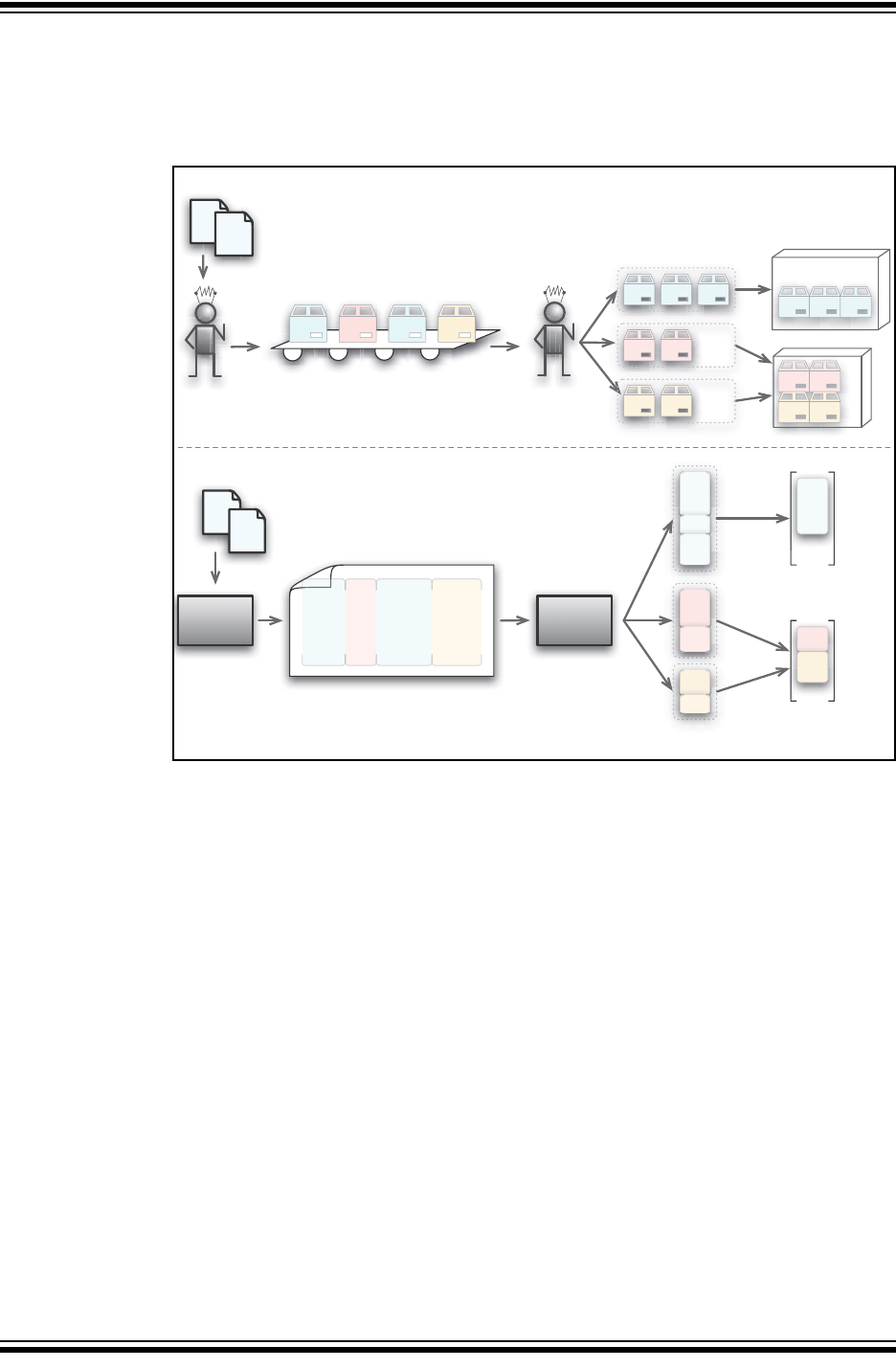
C Language Features
2012-2013 Microchip Technology Inc. DS50002053D-page 235
5.15.1.2 THE COMPILER EQUIVALENT
Let’s now look at the similarities and differences between this situation and the
compilation process. Both these processes are compared in Figure 5-3.
FIGURE 5-3: THE WAREHOUSE AND COMPILER SIDE BY SIDE
In this analogy, the warehouse is likened to the compiler. The robot is akin to the com-
piler’s code generator application, which turns the C code into assembly code, and the
packing machine, the linker, which is responsible for arranging how everything will
appear in memory.
The packing machine is not actually delivering the bundles of boxes; it is just putting
them into containers in the warehouse. In the same way, the linker is not actually plac-
ing sections in the device’s memory; it is arranging them in conceptual containers. This
analogy is not concerned with what happens outside the warehouse, nor after the
compilation process – that is another story.
The following sections detail points relevant at different stages of the process.
5.15.1.2.1 Orders and Source Code
Both the warehouse and compiler take descriptions of something and use this to pro-
duce the final product: The warehouse receives orders, and assembles the compo-
nents to fulfill that order; the compiler reads (variable and function) definitions in a C
program and generates the assembly code to implement each definition.
An order from a customer can be for any number of components. In the same way, each
C definition can require few or many assembly instructions or directives to be
produced.
Orders arrive at the warehouse randomly, but the components are always shipped to
one of several countries. Source code (variables and functions) can also be written in
any order, but the compiled code is always allocated to one of several memory areas.
‧‧‧
if(in > 4)
scale = 0;
‧‧‧
code
generator
int result;
float scale;
int
getDat(void) {
...
ORDER 1
3 x TSC235
2 x RC123a
ORDER 2
1 x TSD87
2 x XAM99
10 x TD66
RP
linker
PSECT text,class=CODE
movlw (?_barrr2)&0ffh
movwf fsr0
movlw (?_srv)&0ffh
movwf (??_main+0+0)
movf fsr0,w
movwf (??_main+0+0+1)
movlw 12
movwf (??_main+0+0+2)
u60:
movf (??_main+0+0),w
PSECT bssBANK0,class=BANK0,space=1
global __pbssCOMMON
__pbssCOMMON:
_c:
ds 1
_more:
ds 8
PSECT cstackBANK0,class=BANK0,space=1
global __pcstackBANK0
__pcstackBANK0:
global ?___ftge
?___ftge: ;@ 0x0
global ?___ftmul
?___ftmul: ;@ 0x0
global ?_frexp
?_frexp: ;@ 0x0
global ___ftmul@f1
___ftmul@f1: ; 3 bytes @ 0x0
PSECT text,class=CODE
fcall _srv
movlw (?_barrr2)&0ffh
movwf fsr0
movlw (?_srv)&0ffh
movwf (??_main+0+0)
movf fsr0,w
movwf (??_main+0+0+1)
movlw 12
movwf (??_main+0+0+2)
u60:
movf (??_main+0+0),w
movwf fsr0
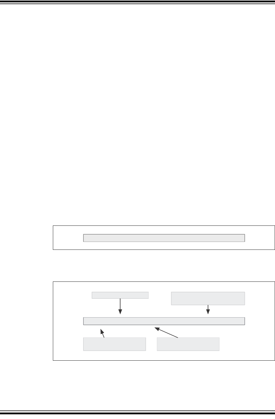
MPLAB® XC8 C Compiler User’s Guide
DS50002053D-page 236 2012-2013 Microchip Technology Inc.
5.15.1.2.2 Boxes, Labels and Sections
In our analogy, the components for each order are placed in a box. In the same way,
the assembly output generated is also placed into boxes, called program sections (or
psects, for short).
There are several reasons why code is placed in a section.
• The generated assembly code is more manageable.
• The ordering of the code sequence within the section is preserved.
• The ordering of sections with the same name are preserved.
• Code is easily sorted based on where it needs to reside in memory.
• Only one command is required to locate an entire section into memory.
Any code sequence that must be contiguous is placed in the one section. The output
of the compiler will typically appear in many different sections, but all sections with the
same name will collate in the order in which they are produced.
The compiler has a list of section names and chooses a section based on the code it
is generating, see 5.15.2 “Compiler-Generated Psects”.
A section is not a physical box, but rather a special directive is used in the assembly
code to define the start of each section. The directive signifies the end of the previous
box and the start of a new box. A section can hold any amount of assembly code and
can even be empty.
Both the warehouse boxes and compiler sections are labeled and in both instances,
the label indicates a destination rather than the contents. In Figure 5-3 color is used to
identify the destination city of a box, or the name of a section.
Figure 5-4 shows what a typical box label might look like. The packing machine in the
warehouse is only concerned with packing boxes in containers and so, other than the
city and country, the customer’s actual address is not important here.
FIGURE 5-4: A TYPICAL BOX LABEL
Figure 5-5 shows an example of the assembly directive that is used to start a new sec-
tion. The city name is now a section name and the destination country a linker class.
FIGURE 5-5: THE SECTION DIRECTIVE AS A BOX LABEL
BOX paris,country=FRANCE,fragile
PSECT bss0,class=BANK0,space=1,reloc=4
close the previous box,
start a new box
the name of this box
the container this box
must be packed in
special packing instructions
for this box
C Language Features
2012-2013 Microchip Technology Inc. DS50002053D-page 237
5.15.1.2.3 Down the Conveyor Belt and Object files
Once the robot has assembled an order and placed the components in a box, the con-
tents of the box are no longer relevant, and the remaining activities in the warehouse
only deal with boxes.
It is a similar situation in the compiler: Once assembly code has been placed into a sec-
tion, the instructions are no longer relevant during the link process. The linker only
handles sections and is oblivious to each section’s contents.1
5.15.1.2.4 Sorting Boxes and Sections
In the warehouse, all the boxes are sorted by destination city. After the day’s orders are
processed, all these similar boxes are wrapped so they can be easily kept together.
The concept is the same in the compiler domain: Sections are sorted based on the sec-
tion’s name, and are merged into one larger section by the linker. The order in which
the sections come together strictly follows the order in which they are produced.
5.15.1.2.5 Loading the Containers and Classes
In the warehouse, the bundled boxes are loaded into the shipping containers. One or
more shipping containers will be provided for each country. If there are orders for more
than one city in the same country, then the bundled boxes for those cities can share the
same container (as long as there is room).
The linker does a similar thing: It arranges the collated sections in the classes. Typi-
cally, several sections are placed in each class. The classes represent the device mem-
ory, but might take into account addressing modes or banking/paging restrictions
present in the target device. Classes are often smaller than the memory space in which
they are theoretically located.
Think of a large cargo ship. Although the ship can be very long, the biggest object it can
hold is determined by the size of the shipping containers it transports. The shipping
company cannot be able to carry an item due to size constraints even though the item
is a fraction the size of the vessel.
5.15.1.3 SECTIONS AT WORK
Now that we have a basic understanding of the concepts, let’s work through a simple
example to help see how these work when compiling.
An engineer has written a program. Exactly what it does or how it is written is not
important. The target device has only one bank of RAM and one page of flash.
In our very simplified example, the compiler will choose from the sections listed in
Table 5-18. This table also shows the linker class associated with each section and the
memory location in the device the class represents.
1. Inside the compiler, there are actually a few steps between the code generator and linker. Assembly
code is passed first to the assembler; however, the object files produced, which are passed to the linker,
preserve all the sections and can be ignored in this exercise.
The assembler optimizer can alter assembly instructions, but this is only after reading and interpreting
the code – something the linker cannot do. Modified code is still functionally identical to the original.
Other optimizations can further merge or split sections, but this is not important to a basic understanding
of the concepts.
TABLE 5-18: SECTION NAMES FOR OUR SIMPLE EXAMPLE
Section name Contents Linker class Memory location
text Executable code CODE Flash
bss0 Variables that need to be cleared BANK0 RAM
data0 Variables that need to be initialized BANK0 RAM
idata Initialized variable’s values CODE Flash

MPLAB® XC8 C Compiler User’s Guide
DS50002053D-page 238 2012-2013 Microchip Technology Inc.
The code generator starts to read the program description in C and produces the
assembly code required to implement this on the target device.
The first thing the code generator encounters is the C definition for a variable with no
initial value. All variables like this will be kept together so that clearing them at startup
will be easier and more efficient. The code generator outputs the directive that starts a
new section. Its internal table of section names indicates that bss0 is the appropriate
choice and that this section is placed in the BANK0 class. The directive looks like this.
PSECT bss0,class=BANK0
Code follows this directive to define the variable: It merely consists of a label and
another directive to reserve the required amount of memory. Altogether, this might look
like:
PSECT bss0,class=BANK0
myVariable:
DS 2 ; reserve 2 bytes for this object
The code generator continues and sees yet another uninitialized variable. As this vari-
able will also use the same section, the code generator can keep adding to the current
section and so immediately outputs another label and directive to reserve memory for
the second variable.
Now a function definition is encountered in the C source. The code generator sees that
output now needs to be placed in the text section and outputs the following directive.
PSECT text,class=CODE
This directive ends the bss0 section and starts the text section. Any code following
will be contained in the text section. Code associated with the function is generated
and placed into this section.
Moving on, the code generator encounters a variable which is initialized with a value.
These variables will have their initial values stored in flash and copied as a block into
the RAM space allocated to them. By using one section for the RAM image and another
for the initial values, the compiler can ensure that all the initial values will align after link-
ing, as the sections will be collated in order.
The compiler first outputs the directive for the section with the name data0. It then out-
puts a label and directive to reserve memory for the variable in RAM. It next changes
to the idata section which will hold all the initial values. Code is output that will place
the initial value in this section. Notice that the code associated with initialized variables
is output into two separate sections.
PSECT data0,class=BANK0
_StartCount:
DS 2 ; space in RAM for the variable
PSECT idata,class=CODE
DB 012h ;initial values places as bytes
DB 034h ; which will be copied to RAM later
The code generator reads yet another initialized variable. It selects the data0 section,
outputs the label and memory reservation directive, then selects the idata section and
stores the initial value.
This process continues until all the program has been generated. The output is passed
to the linker (via the assembler) which then looks for the sections it contains.
The linker sorts each section as it is encountered. All text sections are collated, as
well as the bss0, data0 and idata sections. The order in which they will be assem-
bled will match the order in which they are passed to the linker, which in turn will be the
order in which they were produced by the code generator. There is now one collated
text, bss0, data0 and idata section.
C Language Features
2012-2013 Microchip Technology Inc. DS50002053D-page 239
These sections are now located in memory. The linker is passed options (from the com-
piler driver) which define the linker classes and the memory ranges they represent, see
Section 7.2.1 “-Aclass =low-high,...”1. For our device, the linker options might look
like this.
-ACODE=0-7ffh
-ABANK0=20h-6fh
So for example, the BANK0 class covers memory from 20h to 6fh. You can see all the
options passed to the linker in the map file, see Section 7.4 “Map Files”.
The linker “fits” each section into the memory associated with the class it is associated
with. It might, for example, place the text section at address 0 in the CODE class, then
immediately follow it with the idata section at address 374h, for example. The bss0
and data0 sections will similarly be placed in the BANK0 class.
All the sections are now allocated an address within a class. The addresses of symbols
can now be determined and ultimately a hex file is produced. The compiler’s job is over.
5.15.1.4 MORE ADVANCED TOPICS
Let’s look at more complex issues with linking now that we understand the basics.
5.15.1.4.1 Allocation at Specific Locations
We have seen in the preceding analogy that the linker places sections in their corre-
sponding class when it comes time to determine where they will live in memory. This is
how most sections are linked, but there are some exceptions. Code to be executed on
Reset or an interrupt are examples. They cannot just be placed anywhere in a class;
they must be located at specific addresses. So how are these positioned by the linker?
Any code that is to be linked at a particular address is placed in a section in the usual
way. These sections will even have a class associated with them, but allocation any-
where in this class can be overridden by a special linker option which tells the linker to
place the section at a specific address. In terms of our previous analogy, think of the
special linker options as being explicit instructions given to the packing machine as to
where in a container to place the box. We will see in the next example the linker options
to place a section explicitly.
-preset_vec=0h
-pint_text=04h
Note that if a section is linked in this way, the linker will follow these instructions strictly.
It will warn if it is asked to place a section over the top of another, but since there is no
container, which essentially represents a memory range, the linker cannot check for
sections extending past the device’s memory limits.
5.15.1.4.2 Where Classes and Containers Differ
Containers and linker classes differ in one important aspect: Linker classes are
conceptual and merely represent the memory of a device; they are not physical
storage.
The compiler can, and often does, use more than one class to represent the same
memory range. This is illustrated in Section 5.15.1.5 “More Advanced Sections at
Work” where the example uses CODE and CONST classes for flash memory. Although
classes can cover the same range, typically the size of the containers vary. This allows
code with different restrictions and requirements to be accommodated.
1. Remember these are linker options and you cannot pass these straight to the compiler driver. You
can, however, encapsulate these options in the driver’s -L- options, see Section 4.8.6 “-L-: Adjust
Linker Options Directly”.
MPLAB® XC8 C Compiler User’s Guide
DS50002053D-page 240 2012-2013 Microchip Technology Inc.
When the memory ranges of classes overlap, allocating to one will also mark as being
used memory from the other. In fact, when any memory is allocated by the linker by
whatever means, it checks each class to see if it covers this memory and marks it as
being used. This is quite a difference concept to physical containers.
5.15.1.4.3 Multi-bin containers
Linker classes usually define one memory range, but there are instances where a class
defines multiple memory ranges. You can think of this as several separate containers,
but all with identical shipping destinations. Memory ranges in the class do not need to
be contiguous.
The compiler typically uses a multi-range class to represent program memory that is
paged. The boundaries in the memory ranges coincide with the page boundaries. This
prevents sections from crossing a page boundary.
The compiler could use a similar class for banked RAM, but code can be considerably
reduced in size if the destination bank of each variable is known by the code generator.
You will usually see a separate class defined for each bank, and dedicated sections
that are associated with these classes. The code generator will allocate a bank for each
variable and choose a section destined for the class that represents that bank.
5.15.1.5 MORE ADVANCED SECTIONS AT WORK
Let’s build on the previous example. Our target device now has two banks of RAM and
two pages of flash, and Table 5-19 shows the extended list of sections the compiler now
uses. These sections reference new classes, also shown in the table.
The compiler operates as it did in the previous example, selecting and producing a
section directive prior to generating the assembly code associated with the C source
currently being compiled.
TABLE 5-19: SECTION NAMES FOR OUR EXTENDED EXAMPLE
Section name Contents Linker class Memory location
textn Executable code CODE Flash
bss0 Variables that need to be cleared BANK0 RAM
bss1 Variables that need to be cleared BANK1 RAM
data0 Variables that need to be initialized BANK0 RAM
idata Initialized variable’s values CODE Flash
reset_vec Code associated with Reset CODE Flash
const Read-only variables CONST Flash
init Runtime startup code CODE Flash
int_text Interrupt function code CODE Flash

C Language Features
2012-2013 Microchip Technology Inc. DS50002053D-page 241
The assembly code associated with ordinary functions is still placed in a “text” section,
but as there are now two pages of flash, we have to ensure that both pages can be
used. If each function was placed into the same section, they will be merged by the
linker and that section would grow until it is too large to fit into either page. To ensure
that all the “text” sections do not merge, each function is placed in its own unique num-
bered section: text0, text1, text2, etc. As these sections do not have the same
name, they will not be merged by the linker.
The linker option to define the CODE class might now look like:
-ACODE=0-7ffhx2
which tells the linker that CODE represents two pages of memory: one from 0 to 7ffh and
another from 800h to fffh.
This specification indicates that there is some sort of memory boundary that occurs at
address 800h (the devices internal memory page) and is very different to a class defi-
nition that reads -ACODE=0-fffh, which covers the same memory range, but which
does not have the boundary. The linker will try allocating each textx section to one
page (class memory range); if it does not fit, it will try the other.
If an interrupt function is encountered, the int_text section is selected for this code.
As this is separate to the sections used to hold ordinary functions, it can be linked
explicitly at the interrupt vector location. Assuming that the interrupt vector is at address
4, the linker option to locate this section might look like the following, see
Section 7.2.19 “-Pspec”.
-pint_text=4h
For simplicity in this example, initialized variables are treated as they were in the pre-
vious example, even though there are now two RAM banks; i.e., they are always
allocated in the first bank of RAM.
In the previous example we ignored the code that would have copied the initial values
from flash into RAM. This code is executed after Reset and before the function main,
and forms part of the runtime startup code. It reads each initial value from flash and
writes this to the corresponding variable in the RAM space. Provided the order in which
the variables are allocated memory in RAM matches the order their initial values are
allocated in flash, a single loop can be used to perform the copy. Even though the vari-
ables might be defined at many places in the source code, the order in memory of each
variable and value will be preserved since the compiler uses sections to hold the code
associated with each.
This runtime startup code is output into a section called init. Code which jumps to the
runtime startup codes is placed in the reset_vec section, which is linked to the Reset
location. By linking these sections in the same page, the jump from one section to
another will be shorter and faster. The linker options to make this happen might look
like:
-preset_vec=0
-pinit=int_text
which says that the Reset vector code is linked to address 0 (which is the Reset vector
location) and that the init section, which contains the runtime startup code, should be
linked immediately after the interrupt code in the int_text section. If the int_text
section is empty; i.e., there is no interrupt code defined in the program, then init will
be placed at address 4.

MPLAB® XC8 C Compiler User’s Guide
DS50002053D-page 242 2012-2013 Microchip Technology Inc.
Previously all uninitialized variables were placed in the bss0 section. Now the code
generator first checks that there will actually be enough room in bank 0 memory before
doing so. If not, it chooses the bss1 section that will ultimately be linked into bank 1
memory. The code generator keeps track of any object allocated to RAM so it can main-
tain the amount of free memory in each RAM bank. For these variables, the linker allo-
cates the sections to memory, but it is the code generator that decides which section
will be used by each variable. Thus, both applications play a part in the memory
allocation process.
In this example, we also consider const variables which are stored in flash, not RAM.
Each byte of data is encapsulated in a RETLW instruction that return the byte in the W
register. Code is needed to access each byte of a variable or array. One way of doing
this is a “computed goto” which involves loading the W register with an offset into the
block of data and adding this to the PC.(The Microchip application note AN556 has
examples of how this can be done for several devices.) A computed goto requires that
the destination address (the result of adding W and PC) must not cross over a 256 word
boundary (i.e., the addresses 100h, 200h, 300h, etc.). This requirement can be met
using sections and a class.
In this example a new class, called CONST, is created and defined as follows
-ACONST=0-0ffhx16
which is to say that CONST is a container 100h long, but there are 16 of them one after
the other in memory, so 0-ffh is one container, 100-1ffh is another, etc. We have the
compiler place all the RETLW instructions and the computed goto code into the const
section, which are linked into this class. The section can be located in any of the 16
containers, but must fit entirely within one.
In this example, the compiler only allows one block of const data. It could be made to
allow many by having each block of const data in a unique numbered section as we
did for the text sections (e.g., const1, const2, etc.). Thus each sections could remain
independent and be allocated to any memory bin of the CONST class.
5.15.1.6 EXPLAINING COMMON LINKER ERRORS AND PROBLEMS
We can also use our knowledge to help explain some common linker problems and
error messages.
5.15.1.6.1 Not Finding Space
A common linker error is, “can’t find x words for psect ‘abc’ in class ‘XYZ’,” which we
can now think of as, “can’t find 3 cubic feet for the boxes ‘paris’, in container ‘FRANCE’.”
The most obvious reason for this error is that the containers have been steadily filling
and have finally run out of free space, i.e., the total amount of code or data you need
to store exceeds the amount of memory on the device.
Another reason is that a box is larger than the container(s) in which it has to be placed.
If this is the case, the section will never fit, even if the entire memory space is empty.
This situation might occur when defining a very large C function, RAM or const array
resulting in an abnormally large section. Other possible sources include large switch
statements or even a switch with too many case labels.

C Language Features
2012-2013 Microchip Technology Inc. DS50002053D-page 243
The hold of a ship or aircraft might be a very large space, but freight is always packed
into shipping containers and it is the size of the shipping container that dictates the
maximum size of a object that can be transported. In the same way, the total amount
of memory on a target device is irrelevant if sections must first be allocated to a class.
Classes can seem restrictive, but without them, code will typically be less efficient or
can simply fail to work altogether. The computed goto is a good example. If the table of
instructions in a computed goto crosses a 100h boundary, it will fail due to the limited
jump range of the instruction set.
This space error can also occur if there are many free spaces remaining in containers,
but none are large enough to hold the section. This can be confusing since the total
amount of free space can be larger than the section to be placed. In the same way that
boxes cannot be removed from a bundle or unpacked, if a section does not fit into any
remaining space, it cannot be split by the linker and an error will result. The error
message indicates that largest free space that is still available.
In the same way that the label on a box can indicate special packing instructions, e.g.,
“fragile – pack at the top of the container”, or “this way up”, etc, a section can also indi-
cate special memory allocation instructions. One of the most common requirements is
that a section must start on an address boundary, see the reloc PSECT flag in
Section 6.4.9.3.13 “Reloc”. If a section has to fit into a class, but also has to be
aligned on an address, this makes it much more difficult to locate and increases the
chance that this error is produced. This is also the case if other sections or objects have
been placed in the middle of a container, as we saw in Section 5.15.1.4.1 “Allocation
at Specific Locations”.
5.15.1.6.2 Not Being Shipped in the Right Container
Clearly, boxes will not be delivered correctly if they are placed in the wrong container.
So too, code cannot run if it is placed in the wrong class or address. The compiler will
always ensure that code and data is allocated correctly, but it is possible to manually
change linker options.
The code generator assumes that sections will be located in certain memory areas and
the code it generates can rely on this being the case. Typically, sections placed in RAM
must remain in the bank in which they were originally destined. Sections containing
executable code possibly more forgiving, but some have very specific requirements.
Remember, the linker will allow any allocation you indicate; it has no way of checking
if what you tell it is correct. Always take care if you override linker options and reposition
a section. Section 5.15.2 “Compiler-Generated Psects” lists the common sections
used by the compiler. it also indicates restrictions on how these sections can be linked.
5.15.1.6.3 Doing Things by Hand
So far we have discussed assembly code produced by the code generator and how it
is linked into memory; now, we consider hand-written assembly.
Imagine that in the warehouse an order is not processed by the robot, but by a human
worker. The components ordered are assembled by hand, packed in a box by hand and
then placed on the conveyor belt along with those boxes packed by the robot. This is
quite similar to when there is hand-written assembly code in a project: the linker is
passed a number of sections, some created by the code generator and some by a
human.
Mistakes can be made by the warehouse worker or the assembly programmer. In the
warehouse, the worker might not use a box and place the components loose on the
conveyor belt, or a box might be used but it is not labeled, or it might be labeled incor-
rectly. In the compiler’s domain, assembly code can be written without a section, or it
is in a section but with the wrong (or no) class, or the section can have incorrect
allocation instructions.

MPLAB® XC8 C Compiler User’s Guide
DS50002053D-page 244 2012-2013 Microchip Technology Inc.
If assembly code is not in a section, the compiler will actually place it into a default sec-
tion. But since there are no specific instructions as to what to do with this section, it
could be linked anywhere. Such sections are like boxes labeled “ship to anywhere you
want”. As a rule of thumb, put all assembly code inside a section, but some directives
(e.g., GLOBAL or EQU) do not generate code and can be placed anywhere.
The easiest way to write and locate hand-written assembly code is to associate the
section you create with an existing linker class that represents a suitable memory area.
This means the default linker options do not need to be altered.
The association is made using the class flag of the PSECT directive, see
Section 6.4.9.3.3 “Class”. If a section is to be placed at an explicit address rather than
having it placed anywhere in a class, the class flag should still be used. A list of linker
classes and the memory they represent is given in Section 5.15.3 “Default Linker
Classes”.
Even if you place your code into a section and use an appropriate class, other flags can
be necessary to correctly link the code. The most important section flags are the
delta, see Section 6.4.9.3.4 “Delta”, reloc, see Section 6.4.9.3.13 “Reloc” and
space, see 6.4.9.3.15 “Space” flags. If these are incorrectly specified, the code not
be positioned correctly and will almost certainly fail.
5.15.2 Compiler-Generated Psects
The code generator places code and data into psects (program sections) with standard
names, which are subsequent positioned by the default linker options. The linker does
not treat these compiler-generated psects any differently to a psect that has been
defined by yourself. A psect can be created in assembly code by using the PSECT
assembler directive (see Section 6.4.9.3 “PSECT”). The code generator uses this
directive to direct assembly code it produces into the appropriate psect. For an intro-
ductory guide to psects, see Section 5.15.1 “Program Sections”.
Some psects, in particular the data memory psects, use special naming conventions.
For example, take the bss psect. The name bss is historical. It holds uninitialized vari-
ables. However, there can be some uninitialized variables that will need to be located
in bank 0 data memory; others can need to be located in bank 1 memory. As these two
groups of variables will need to be placed into different memory banks, they will need
to be in separate psects so they can be independently controlled by the linker. In addi-
tion, the uninitialized variables that are bit variables need to be treated specially so
they need their own psect. So there are a number of different psects that all use the
same base name, but which have prefixes and suffixes to make them unique.
The general form of these psect names is:
[bit]psectBaseNameCLASS[div]
where psectBaseName is the base name of the psect, such as bss or data. The
CLASS is a name derived from the linker class (see Section 7.2.1 “-Aclass
=low-high,...”) in which the psect will be linked, e.g., BANK0. The prefix bit is used if
the psect holds bit variables. So there can be psects like: bssBANK0, bssBANK1 and
bitbssBANK0 defined by the compiler to hold the uninitialized variables.
Note that eeprom-qualified variables can define psects called bssEEDATA or
dataEEDATA, for example, in the same way. Any psect using the class suffix EEDATA
is placed in the HEX file and is burnt into the EEPROM space when you program the
device.

C Language Features
2012-2013 Microchip Technology Inc. DS50002053D-page 245
If locations in a bank are reserved or are taken up by absolute objects for example, a
psect cannot be formed over the entire bank. Instead, a separate psect will be used to
represent the free memory on either side of the used memory. The letters l (elle) and
h are used as the div field in the psect name to indicate if it is the lower or higher
division. Thus you might see bssBANK0l and bssBANK0h psects if a split took place.
If you are unsure which psect holds an object or code in your project, check the
assembly list file (see Section 6.6.1 “General Format”)
The contents of these psects are described below, listed by psect base name.
5.15.2.1 PROGRAM SPACE PSECTS
checksum – this is a psect that is used to mark the position of a checksum that has
been requested using the --CHECKSUM option.
See Section 4.8.16 “--ASMLIST: Generate Assembler List Files” for
more information.
The checksum value is added after the linker has executed so you will
not see the contents of this psect in the assembly list file, nor specific
information in the map file. Linking this psect at a non-default location
will have no effect on where the checksum is stored, although the map
file will indicate it located at the new address.
Do not change the default linker options relating to this psect.
cinit – used by the C initialization runtime startup code.
Code in this psect is output by the code generator along with the gen-
erated code for the C program and does not appear in the runtime start-
up assembly module.
This psect can be linked anywhere within a program memory page, pro-
vided it does not interfere with the requirements of other psects.
config – used to store the Configuration Words.
This psect must be stored in a special location in the HEX file.
Do not change the default linker options relating to this psect.
const – these PIC18-only psects hold objects that are declared const and
string literals which are not modifiable.
It is used when the total amount of const data in a program exceeds
64k.
This psect can be linked anywhere within a program memory page, pro-
vided it does not interfere with the requirements of other psects.
eeprom (PIC18: eeprom_data) – used to store initial values in the EEPROM
memory.
Do not change the default linker options relating to this psect.
idata – these psects contain the ROM image of any initialized variables.
These psects are copied into the data psects at startup. In this case, the
class name is used to describe the class of the corresponding
RAM-based data psect. These psects will be stored in program memo-
ry, not the data memory space.
These psects are implicitly linked to a location that is anywhere within
the CODE linker class.
The linker options can be changed allowing this psect to be placed at
any address within a program memory page, provided it does not inter-
fere with the requirements of other psects.
idloc – used to store the ID location words.
This psect must be stored in a special location in the HEX file.
Do not change the default linker options relating to this psect.

MPLAB® XC8 C Compiler User’s Guide
DS50002053D-page 246 2012-2013 Microchip Technology Inc.
init – used by assembly code in the runtime startup assembly module.
The code in this and the cinit define the runtime startup code. PIC18
devices also use an end_init psect, which contains the code which
transfers control to the main function.
If no interrupt code is defined code from the Reset vector can “fall
through” into this psect.
It is recommended that the default linker options relating to this psect
are not changed in case this situation is in effect.
intcode, intcodelo – are the psects which contains the executable code for the
high-priority (default) and low-priority interrupt service routines, respec-
tively. These psects are linked to interrupt vector at address 0x8 and
0x18, respectively.
Do not change the default linker options relating to these psects. See
Section 4.8.20 “--CLIST: Generate C Listing File” if you want to
move code when using a bootloader.
intentry – contains the entry code for the interrupt service routine which is linked
to the interrupt vector.
This code saves the necessary registers and jumps to the main interrupt
code in the case of mid-range devices; for enhanced mid-range devices
this psect will contain the interrupt function body. (PIC18 devices use
the intcode psects.)
This psect must be linked at the interrupt vector. Do not change the de-
fault linker options relating to this psect. See the --CODEOFFSET option
Section 4.8.20 “--CLIST: Generate C Listing File” if you want to
move code when using a bootloader.
jmp_tab – only used for the baseline processors, this is a psect used to store jump
addresses and function return values.
Do not change the default linker options relating to this psect.
maintext – this psect will contain the assembly code for the main() function.
The code for main() is segregated as it contains the program entry
point.
Do not change the default linker options relating to this psect as the run-
time startup code can “fall through” into this psect which requires that it
be linked immediately after this code.
mediumconst – these PIC18-only psects hold objects that are declared const and
string literals which are not modifiable. Used when the total amount of
const data in a program exceeds 255 bytes, but does not exceed 64k.
This psect can be linked anywhere in the lower 64k of program memory,
provided it does not interfere with the requirements of other psects.
For PIC18 devices, the location of the psect must be above the highest
RAM address.
powerup – contains executable code for a user-supplied powerup routine.
Do not change the default linker options relating to this psect.
reset_vec – this psect contains code associated with the Reset vector.
Do not change the default linker options relating to this psect as it must
be linked to the Reset vector location of the target device. See the
--CODEOFFSET option Section 4.8.20 “--CLIST: Generate C Listing
File”, if you want to move code when using a bootloader.

C Language Features
2012-2013 Microchip Technology Inc. DS50002053D-page 247
reset_wrap – for baseline PIC devices, this psect contains code which is executed
after the device PC has wrapped around to address 0x0 from the oscil-
lator calibration location at the top of program memory.
Do not change the default linker options relating to this psect as it must
be linked to the Reset vector location of the target device.
smallconst – these psects hold objects that are declared const and string literals
which are not modifiable.
Used when the total amount of const data in a program is less than
255 bytes.
This psect can be linked anywhere in the program memory, provided it
does not cross a 0x100 boundary and it does not interfere with the re-
quirements of other psects. For PIC18 devices, the location of the psect
must be above the highest RAM address.
strings –the strings psect is used for const objects.
It also includes all unnamed string literals. This psect is linked into
ROM, since the contents do not need to be modified.
This psect can be linked anywhere in the program memory, provided it
does not cross a 0x100 boundary or interfere with the requirements of
other psects.
stringtext – the stringtext psect is used for const objects when compiling for
baseline devices.
This psect is linked into ROM, since the contents do not need to be
modified.
This psect must be linked within the first half of each program memory
page.
textn – these psects (where n is a decimal number) contain all other executable
code that does not require a special link location.
These psects can be linked anywhere in the program memory, provided
they does not interfere with the requirements of other psects.
xxx_text – defines the psect for a function that has been made absolute; i.e.,
placed at an address. xxx will be the assembly symbol associated with
the function.
For example if the function rv() is made absolute, code associated
with it will appear in the psect called _rv_text.
As these psects are already placed at the address indicated in the C
source code, the linker options that position them should not be
changed.
xxx_const – defines the psect for const object that has been made absolute; i.e.,
placed at an address. xxx will be the assembly symbol associated with
the object.
For example, if the array nba is made absolute, values stored in this ar-
ray will appear in the psect called _nba_const.
As these psects are already placed at the address indicated in the C
source code, the linker options that position them should not be
changed.

MPLAB® XC8 C Compiler User’s Guide
DS50002053D-page 248 2012-2013 Microchip Technology Inc.
5.15.2.2 DATA SPACE PSECTS
nv – these psects are used to store variables qualified persistent.
They are not cleared or otherwise modified at startup.
These psects can be linked anywhere in their targeted memory bank
and should not overlap any common (unbanked memory) that the de-
vice supports if it is a banked psect.
bss – these psects contain any uninitialized variables.
These psects can be linked anywhere in their targeted memory bank
and should not overlap any common (unbanked memory) that the de-
vice supports if it is a banked psect.
data – these psects contain the RAM image of any initialized variables.
These psects can be linked anywhere in their targeted memory bank
and should not overlap any common (unbanked memory) that the de-
vice supports if it is a banked psect.
cstack – these psects contain the compiled stack.
On the stack are auto and parameter variables for the entire program.
See Section 5.5.2.2.1 “Compiled Stack Operation”, for information
on the compiled stack.
These psects can be linked anywhere in their targeted memory bank
and should not overlap any common (unbanked memory) that the de-
vice supports if it is a banked psect.
stack – this psect is used as a placeholder for the software stack.
This stack is dynamic and its size is not known by the compiler. As de-
scribed in 5.3.4.2 “Data Stacks” this psect is typically allocated the re-
mainder of the free data space so that the stack may grow as large as
possible.
This psect may be linked anywhere in the data memory, but adjusting
the default linker options for this psect may limit the size of the software
stack. Any overflow of the software stack may cause code failure.

C Language Features
2012-2013 Microchip Technology Inc. DS50002053D-page 249
5.15.3 Default Linker Classes
The linker uses classes to represent memory ranges. For an introductory guide to
psects and linker classes, see Section 5.15.1 “Program Sections”.
The classes are defined by linker options, see Section 7.2.1 “-Aclass =low-high,...”
passed to the linker by the compiler driver. Psects are typically allocated space in the
class they are associated with. The association is made using the class flag of the
PSECT directive, see Section 6.4.9.3.3 “Class”. Alternatively, a psect can be explicitly
placed into a class using a linker option, see Section 7.2.19 “-Pspec”.
Classes can represent a single memory range, or multiple ranges. Even if two ranges
are contiguous, the address where one range ends and the other begins forms a
boundary and psects placed in the class can never cross such boundaries. You will see
classes that cover the same addresses, but will be divided into different ranges and
have different boundaries. This is to accommodate psects whose contents were com-
piled under assumptions about where they would be located in memory.
Memory allocated from one class will also be reserved from other classes that specify
the same memory. To the linker, there is no significance to a class name or the memory
it defines.
Memory will be subtracted from these classes if using the --ROM or --RAM options, see
Section 4.8.50 “--ROM: Adjust ROM Ranges” and Section 4.8.49 “--RAM: Adjust
RAM Ranges”, to reserve memory. When specifying a debugger, such as an ICD, see
Section 4.8.22 “--DEBUGGER: Select Debugger Type”, memory can also be
removed from the ranges associated with some classes so that this memory is not used
by your program.
Although you can manually adjust the ranges associated with a class, this is not rec-
ommended. Never change or remove address boundaries specified by a class
definition option.
Below are the linker classes that can be defined by the compiler. Not all classes can be
present for each device.

MPLAB® XC8 C Compiler User’s Guide
DS50002053D-page 250 2012-2013 Microchip Technology Inc.
5.15.3.1 PROGRAM MEMORY CLASSES
CODE —consists of ranges that map to the pages on the target device.
Thus, it is typically used for psects containing executable code.
On baseline devices, it can only be used by code that is accessed via a
jump table.
ENTRY —is used mainly by baseline devices for psects containing executable
code that is accessed via a CALL instruction (calls can only be to the
first half of a page).
The class is defined in such a way that it is the size of a page, but psects
it holds will be positioned so that they start in the first half of the page.
This class is also used in mid-range devices and will consist of many
ranges, each 0x100 words long and aligned on a 0x100 boundary.
Thus, it is useful for psects whose contents cannot span a 0x100 word
boundary.
STRING —consists of ranges that are 0x100 words long and aligned on a 0x100
boundary.
Thus, it is useful for psects whose contents cannot span a 0x100 word
boundary.
STRCODE —defines a single memory range that covers the entire program memory.
It is useful for psects whose content can appear in any page and can
cross page boundaries.
CONST —consists of ranges that are 0x100 words long and aligned on a 0x100
boundary.
Thus, it is useful for psects whose contents cannot span a 0x100 word
boundary.
5.15.3.2 DATA MEMORY CLASSES
RAM —consist of ranges that cover all the general purpose RAM memory of the
target device, but excluding any common (unbanked) memory.
Thus, it is useful for psects that must be placed in general-purpose
banked RAM, but can be placed in any bank.
BIGRAM —consists of a single memory range that is designed to cover the linear
data memory of enhanced mid-range devices, or the entire available
memory space of PIC18 devices.
It is suitable for any psect whose contents are accessed using linear
addressing or which does not need to be contained in a single data
bank.
ABS1 —consist of ranges that cover all the general purpose RAM memory of the
target device, including any common (unbanked) memory.
Thus, it is useful for psects that must be placed in general purpose
RAM, but can be placed in any bank or the common memory,
BANKx (where x is a bank number) — each consist of a single range that covers the
general purpose RAM in that bank, but excluding any common
(unbanked) memory.
COMMON —consists of a single memory range that covers the common (unbanked)
RAM, if present.
SFRx (where x is a bank number) — each consists of a single range that covers the
SFR memory in that bank.
These classes would not typically be used by programmers as they do
not represent general purpose RAM.

C Language Features
2012-2013 Microchip Technology Inc. DS50002053D-page 251
5.15.3.3 MISCELLANEOUS CLASSES
CONFIG —consists of a single range that covers the memory reserved for config-
uration bit data in the hex file.
This class would not typically be used by programmers as it does not
represent general purpose RAM.
IDLOC —consists of a single range that covers the memory reserved for ID loca-
tion data in the hex file.
This class would not typically be used by programmers as it does not
represent general purpose RAM.
EEDATA —consists of a single range that covers the EEPROM memory of the tar-
get device, if present.
This class would typically be used for psects that contain data that is to
be programmed into the EEPROM.
5.15.4 Changing and Linking the Allocated Section
Section 5.15.2 “Compiler-Generated Psects” lists the default sections the compiler
uses to hold objects and code. You can change the default section of a function or vari-
able several ways. This is typically done when the object has special and unique linking
requirements that cannot be addressed by existing compiler features.
Both the __section() specifier1 or the #pragma psect (Section 5.14.4.8 “The
#pragma psect Directive”) allow you to have a variable or function redirected into a
user-define psect (section). There are several differences in their operation which are
described below.
Use of the pragma will create a user-defined psect with identical psect flags to the orig-
inal (standard) psect referenced in the directive. A consequence of this is this the psect
created using the pragma must be linked into the same memory space as that which
would hold the original psect; in particular, the psect must be linked into the same data
bank, for the case of RAM-based psects. The compiler assumes this is the case. So,
for example, you cannot use the pragma to place a variable normally linked into bank
0 data memory into a user-defined psect and then link that psect into bank 2.
New psects created by the specifier will have no flags associated with them. In addition,
the compiler will not make assumptions about the final location of the new psect. Thus,
for example, you can define a variable, redirect it into a user-defined psect using the
__section() specifier and link the psect into any data bank. Note, however, that the
code used to access the relocated variable can be less efficient than the code used to
access variable without the specifier.
Regardless of which method you use to place an object or function into a unique psect,
the name of this psect must be a valid identifier in the assembler’s name space, i.e., it
cannot have a name which is the same as that of an assembler directive, control, or
directive flag.
Variables that use the __section() specifier will be cleared or initialized (based on
how they are defined) in the usual way by the runtime startup code (see
Section 4.4.2 “Startup and Initialization”). For the case of initialized variables, the
compiler will automatic allocation an additional psect (whose name will be the same as
the new psect prefixed with the letter i), which will contain the initial values. You can
need to link this psect explicitly.
1.This specifier is part of the CCI (see Chapter 2. “Common C Interface”), but is also available as part
of the native MPLAB XC8 syntax.

MPLAB® XC8 C Compiler User’s Guide
DS50002053D-page 252 2012-2013 Microchip Technology Inc.
Variables placed in a new section using the pragma will not be cleared or initialized. In
fact, initialized variables must never be redirected to a new psect using the pragma.
The following are examples of a variable and function allocated to a non-default sec-
tion.
int __section("myData") foobar;
int __section("myCode") helper(int mode) {
/* ... */ }
You must reserve memory, and locate via an explicit linker option, any new psect cre-
ated with a __section() specifier. So, for example, if you wanted to place the sec-
tions created in the above example, you could use the following driver options:
-L-pmyData=0200h
-L-AMYCODE=50h-3ffh
-L-pmyCode=MYCODE
which will place the section myData at address 0x200, and the section myCode any-
where in the range 0x50 to 0x3ff represented by the linker class. See
Section 7.2 “Operation” for linker options that can be passed using the -L- driver
option (Section 4.8.6 “-L-: Adjust Linker Options Directly”).
Since user-defined psects created using the pragma inherit the flags of the original
psect, they will typically be linked into their original linker class without the need of an
explicit linker option. However, if you do link them explicitly, ensure that you follow the
original psect linking guidelines indicated in Section 5.15.2 “Compiler-Generated
Psects”.
5.15.5 Replacing Library Modules
The MPLAB XC8 C compiler comes with a librarian, LIBR, which allows you to unpack
a library file and replace modules with your own modified versions. See
Section 8.2 “Librarian”. However, you can easily replace a library module that is
linked into your program without having to do this.
If you add a source file to your project and it contains the definition for a routine with
the same name as a library routine, then the library routine will be replaced by your
routine. This is due to the way the compiler scans source and library files.
When trying to resolve a symbol (a function name, or variable name, for example) the
compiler first scans all the source modules for the definition. Only if it cannot resolve
the symbol in these files does it then search the library files.
If the symbol is defined in a source file, the compiler will never actually search the librar-
ies for this symbol. No error will result if the symbol was present in both your source
code and the library files. This cannot be true if a symbol is defined twice in source files
and an error can result if there is a conflict in the definitions.
All library source code is written in C, and the p-code library files that contain these
library routines are actually passed to the code generator, not the linker, but both these
applications work in the way described above in resolving library symbols.
You cannot replace a C library function with an equivalent written in assembly code
using the above method. If this is required, you will need to use the librarian to edit or
create a new library file.

C Language Features
2012-2013 Microchip Technology Inc. DS50002053D-page 253
5.15.6 Signature Checking
The compiler automatically produces signatures for all functions. A signature is a 16-bit
value computed from a combination of the function’s return data type, the number of its
parameters and other information affecting the calling sequence for the function. This
signature is generated and placed the object code whenever a function is referenced
or defined.
At link time, the linker will report any mismatch of signatures, which will indicate a dis-
crepancy between how the function is defined. MPLAB XC8 is only likely to issue a mis-
match error from the linker when the routine is either a precompiled object file or an
assembly routine. Other function mismatches are reported by the code generator.
It is sometimes necessary to write assembly language routines which are called from
C using an extern declaration. Such assembly language functions should include a
signature which is compatible with the C prototype used to call them. The simplest
method of determining the correct signature for a function is to write a dummy C func-
tion with the same prototype and check the assembly list file using the --ASMLIST
option (see Section 4.8.15 “--ADDRQUAL: Set Compiler Response to Memory
Qualifiers”).
For example, suppose you have an assembly language routine called _widget which
takes a char argument and returns a char. The prototype used to call this function
from C would be:
extern char widget(char);
Where a call to _widget is made in the C code, the signature for a function with one
char argument and a char return value would be generated. In order to match the
correct signature, the source code for widget needs to contain an assembler SIGNAT
directive which defines the same signature value. To determine the correct value, you
would write the following code into a dummy file:
char widget(char arg1)
{
}
The resultant assembler code seen in the assembly list file includes the following line:
SIGNAT _widget,4217
The SIGNAT directive tells the assembler to include a record in the .obj file which
associates the signature value 4217 with symbol _widget. The value 4217 is the
correct signature for a function with one char argument and a char return value.
If this directive is copied into the assembly source file which contains the _widget
code, it will associate the correct signature with the function and the linker will be able
to check for correct argument passing.
If a C source file contains the declaration:
extern char widget(long);
then a different signature will be generated and the linker will report a signature
mis-match which will alert you to the possible existence of incompatible calling
conventions.

MPLAB® XC8 C Compiler User’s Guide
DS50002053D-page 254 2012-2013 Microchip Technology Inc.
5.15.7 Linker-Defined Symbols
The linker defines some special symbols that can be used to determine where some
psects where linked in memory. These symbols can be used in code, if required.
The link address of a psect can be obtained from the value of a global symbol with
name __Lname (two leading underscores) where name is the name of the psect. For
example, __LbssBANK0 is the low bound of the bssBANK0 psect.
The highest address of a psect (i.e., the link address plus the size) is represented by
the symbol __Hname.
If the psect has different load and link addresses, the load start address is represented
by the symbol __Bname.
Not all psects are assigned these symbols, in particular those that are not placed in
memory by a -P linker option. See Section 7.2.19 “-Pspec”. Psect names can change
from one device to another.
Assembly code can use these symbol by globally declaring them, for example:
GLOBAL __Lidata
and C code could use them by declaring a symbol such as the following.
extern char * _Lidata;
Note that there is only one leading underscore in the C domain, see
Section 5.12.3.1 “Equivalent Assembly Symbols”. As the symbol represents an
address, a pointer is the typical type choice.

MPLAB® XC8 C COMPILER
USER’S GUIDE
2012-2013 Microchip Technology Inc. DS50002053D-page 255
Chapter 6. Macro Assembler
6.1 INTRODUCTION
Two macro assemblers are included with the MPLAB XC8 C Compiler to assemble
source files for all 8-bit PIC devices. The operation and assembler directives are almost
identical for both assemblers. The appropriate assembler application is invoked when
you use the compiler driver to build projects.
This chapter describes the usage of the assembler and the directives (assembler
pseudo-ops and controls) accepted by the assembler in the source files.
Although the term “assembler” is almost universally used to describe the tool that con-
verts human-readable mnemonics into machine code, both “assembler” and “assem-
bly” are used to describe the source code which such a tool reads. The latter is more
common and is used in this manual to describe the language. Thus you will see the
terms assembly language (or just assembly), assembly listing and other assembly
terms, but also, assembler options, assembler directive and assembler optimizer.
The following topics are examined in this chapter of the user’s guide:
• Assembler Usage
• Options
• MPLAB XC8 Assembly Language
• Assembly-Level Optimizations
• Assembly List Files
6.2 ASSEMBLER USAGE
The assembler is called ASPIC18 for PIC18 devices and ASPIC for all other 8-bit
devices. It is available to run on Windows, Linux and Mac OS X systems. Note that the
assembler will not produce any messages unless there are errors or warnings – there
are no “assembly completed” messages.
Typically the command-line driver, xc8, is used to invoke the assembler as it can be
passed assembler source files as input; however, the options for the assembler are
supplied here for instances where the assembler is being called directly, or when they
are specified using the command-line driver option --SETOPTION, see
Section 4.8.54 “--SETOPTION: Set the Command-line Options for Application”.
The usage of the assembler is similar under all of available operating systems. All com-
mand-line options are recognized in either upper or lower case. The basic command
format is shown:
ASPIC [ options ] files
files is a space-separated list of one or more assembler source files. Where more
than one source file is specified, the assembler treats them as a single module; i.e., a
single assembly will be performed on the concatenation of all the source files specified.
The files must be specified in full, no default extensions or suffixes are assumed.
options is an optional space-separated list of assembler options, each with a dash –
as the first character in the case of single letter options, or double dashes in the case
of multi-letter options. The assembler options must be specified on the command line
before any files.
MPLAB® XC8 C Compiler User’s Guide
DS50002053D-page 256 2012-2013 Microchip Technology Inc.
6.3 OPTIONS
The command line options recognized by ASPIC are given in Table 6-1, and a full
description of each option followings.
6.3.1 -A: Generate Assembly File
An assembler file will be produced if this option is used rather than the usual object file
format. This is useful when checking the optimized assembler produced using the -O
optimization option.
By default the output file will an extension .opt, unless the -Ooutfile output option
is used to specify another name.
6.3.2 -C: Specify Chip Info File
Specify the chipinfo file to use. The chipinfo file is called picc.ini and can be found
in the dat directory in the compiler’s installation directory. This file specifies information
about the currently selected device.
TABLE 6-1: ASPIC COMMAND-LINE OPTIONS
Option Meaning Default
-A produce assembler output produce object code
-Cchipinfo define the chipinfo file dat\picc[18].ini
-E[file | digit]set error destination/format
-Flength specify listing page length 66
-H output HEX values for constants decimal values
-I list macro expansions don’t list macros
-L[listfile ] produce listing no listing
-N disable merging optimizations merging optimizations enabled
-O perform optimization no optimization
-Ooutfile specify object name srcfile.obj
-R specify non-standard ROM
-Twidth specify listing page width 80
-V produce line number info no line numbers
-VER=version specify full version information
for list file title
-Wlevel set warning level threshold 0
-X no local symbols in OBJ file
--CHIP=device specify device name
--DISL=list specify disabled messages no message disabled
--EDF=path specify message file location
--EMAX=number specify maximum number of
errors
10
--OPT=optimization specify optimization type
--VER print version number and stop

Macro Assembler
2012-2013 Microchip Technology Inc. DS50002053D-page 257
6.3.3 -E: Specify Error Format/File
The default format for an error message is in the form:
filename: line: message
where the error of type message occurred on line line of the file filename.
The -E option with no argument will make the assembler use an alternate format for
error and warning messages.
Specifying a filename as argument will force the assembler to direct error and warning
messages to a file with the name specified.
6.3.4 -F: Specify Page Length
By default, the assembly listing format is pageless; i.e., the assembler listing output is
continuous. The output can be formatted into pages of varying lengths. Each page will
begin with a header and title, if specified.
The -F option allows a page length to be specified. A zero value of length implies
pageless output. The length is specified in a number of lines.
6.3.5 -H: Print Hexadecimal Constant
This option specifies that output constants should be shown as hexadecimal values
rather than decimal values. This option affects both the assembly list file, as well as
assembly output, when requested.
6.3.6 -I: List Macro Expansions
This option forces listing of macro expansions and unassembled conditionals which
would otherwise be suppressed by a NOLIST assembler control, see
Section 6.4.10 “Assembler Controls”. The -L option is still necessary to produce an
actual listing output.
6.3.7 -L: Generate an Assembly Listing
This option requests the generation of an assembly listing file. If listfile is specified
then the listing will be written to that file, otherwise it will be written to the standard
output.
This option is applied if compiling using xc8, the command-line driver and the
--ASMLIST driver option, see Section 4.8.15 “--ADDRQUAL: Set Compiler
Response to Memory Qualifiers”.
6.3.8 -O: Optimize Assembly
This requests the assembler to perform optimization on the assembly code. Note that
the use of this option slows the assembly process down, as the assembler must make
an additional pass over the input code.
Debug information for assembler code generated from C source code can become
unreliable in debuggers when this option is used.
This option can be applied if compiling using xc8, the command-line driver and the
--OPT driver option, see Section 4.8.42 “--OPT: Invoke Compiler Optimizations”.
6.3.9 -O: Specify Output File
By default the assembler determines the name of the object file to be created by strip-
ping any suffix or extension from the first source filename and appending .obj. The
-O option allows the user to override the default filename and specify a new name for
the object file.

MPLAB® XC8 C Compiler User’s Guide
DS50002053D-page 258 2012-2013 Microchip Technology Inc.
6.3.10 -T: Specify Listing Page Width
This option allows specification of the assembly list file page width, in characters.
width should be a decimal number greater than 41. The default width is 80 characters.
6.3.11 -V: Produce Assembly Debug Information
This option will include line number and filename information in the object file produced
by the assembler. Such information can be used by debuggers.
Note that the line numbers will correspond with assembler code lines in the assembler
file. This option should not be used when assembling an assembly file produced by the
code generator. In that case, debug information should relate back to the original C
source, not the intermediate assembly code.
6.3.12 -VER: Specify Version Information
This option allows the full version information, including optional text to indicate beta
builds or release candidate builds, to be passed to the assembler. This information is
only used in the title of the assembly list file and is not reflected in the output to the
--VER option.
6.3.13 -X: Strip Local Symbols
The object file created by the assembler contains symbol information, including local
symbols; i.e., symbols that are neither public nor external. The -X option will prevent
the local symbols from being included in the object file, thereby reducing the file size.
6.3.14 --CHIP: Specify Device Name
This option defines the device that is being used. The device type can also be indicated
by use of the device directive in the assembler source file, see
Section 6.4.9.20 “PROCESSOR”. You can also add your own processors to the
compiler via the compiler’s chipinfo file.
This option is applied if compiling using xc8, the command-line driver and the --CHIP
driver option, see Section 4.8.18 “--CHIP: Define Device”.
6.3.15 --DISL: Disable Messages
This option is mainly used by the command-line driver, xc8, to disable particular
message numbers. It takes a comma-separate list of message numbers that will be
disabled during compilation.
This option is applied if compiling using xc8, the command-line driver and the
--MSGDISABLE driver option, see Section 4.8.38 “--MSGDISABLE: Disable
Warning Messages”.
See Section 4.6 “Compiler Messages” for full information about the compiler’s
messaging system.
6.3.16 --EDF: Set Message File Path
This option is mainly used by the command-line driver, xc8, to specify the path of the
message description file. The default file is located in the dat directory in the compiler’s
installation directory.
See Section 4.6 “Compiler Messages”, for full information about the compiler’s
messaging system.

Macro Assembler
2012-2013 Microchip Technology Inc. DS50002053D-page 259
6.3.17 --EMAX: Specify Maximum Number of Errors
This option is mainly used by the command-line driver, xc8, to specify the maximum
number of errors that can be encountered before the assembler terminates. The default
number is 10 errors.
This option is applied if compiling using xc8, the command-line driver and the
--ERRORS driver option, see Section 4.8.28 “--ERRORS: Maximum Number of
Errors”.
See Section 4.6 “Compiler Messages”, for full information about the compiler’s
messaging system.
6.3.18 --OPT: Specify Optimization Type
This option complements the assembler -O option and indicates specific information
about optimizations required. The suboptions: speed, space and debug can be spec-
ified to indicate preferences related to procedural abstraction.
Abstraction is enabled when the space option is set, and disabled when speed is set.
The debug suboption limits the application of some optimizations which otherwise can
severely corrupt debug information used by debuggers.
6.3.19 --VER: Print Version Number
This option prints information relating to the version and build of the assembler appli-
cation. The assembler will terminate after processing this option, even if other options
and files are present on the command line.

MPLAB® XC8 C Compiler User’s Guide
DS50002053D-page 260 2012-2013 Microchip Technology Inc.
6.4 MPLAB XC8 ASSEMBLY LANGUAGE
The source language accepted by the macro assembler, ASPIC, is described below.
All opcode mnemonics and operand syntax are specific to the target device. Although
the PIC17 family instruction set is supported at the assembler level, the code generator
cannot produce code for these devices so no C projects can target these devices.
Additional mnemonics and assembler directives are documented in this section.
The same assembler application is used for compiler-generated intermediate
assembly and hand-written assembly source code.
6.4.1 Assembly Instruction Deviations
The MPLAB XC8 assembler uses a slightly modified form of assembly language to that
specified by the Microchip data sheets. The following information details changes to the
instruction format, and pseudo instructions that can be used in addition to the device
instruction set.
These deviations can be used in assembly code in-line with C code or in hand-written
assembly modules.
6.4.1.1 DESTINATION LOCATION
Certain PIC instructions use the operands “,0” or “,1” to specify the destination for the
result of that operation. ASPIC uses the more-readable operands “,w” and “,f” to
specify the destination register.
The W register is selected as the destination when using the “,w” operand, and the file
register is selected when using the “,f” operand or if no destination operand is
specified. The case of the letter in the destination operand in not important. For
example:
MOVF _foo,w
ADDWF _foo,f ;the ,f destination is optional
The numerical destination operands cannot be used with ASPIC.
The assembler also uses the destination select operand “,b” to indicate that PIC18
instructions should use the bank select register (BSR) when accessing the specified
file register address. The “,c” operand indicates that the address is in the common
memory, which is known as the access bank on PIC18 devices. Alternatively, an oper-
and can be preceded by the characters “c:” to indicate that the address resides in com-
mon memory. These operands and prefix affect the RAM access bit in the instruction.
For example:
ADDWF _foo,c
BTFSC c:_foo,3
If the instruction does not specify a destination select operand, or the common memory
prefix, the instruction will used banked access. These operands and prefix are not
applicable with operands to the MOVFF instruction, which takes two untruncated
addresses and which always works independently of the BSR.
If an instruction address is absolute and the address is within the access bank, the
common memory destination selectors “,c” or “c:” are not required. The assembler
will determine from the address that access bank memory is being accessed.

Macro Assembler
2012-2013 Microchip Technology Inc. DS50002053D-page 261
For example, the following instructions show the W register being moved to first, an
absolute location; and, then, to an address represented by an identifier. The op codes
for these instructions, assuming that the address assigned to _foo is 0x516 and to
_bar is 0x55, are shown below.
6EE5 MOVWF 0FE5h ;write to access bank location 0xFE5
6E55 MOVWF _bar,c ;write to access bank location 0x55
0105 BANKSEL(_foo) ;set up BSR to access _foo
6F16 MOVWF BANKMASK(_foo),b ;write to _foo (banked)
6F16 MOVWF BANKMASK(_foo) ;defaults to banked access
Notice that the first two instructions have the RAM access bit (bit 8 of the op-code)
cleared, but that the bit is set in the last two instructions.
6.4.1.2 BANK AND PAGE SELECTION
The BANKSEL pseudo instruction can be used to generate instructions to select the
bank of the operand specified. The operand should be the symbol or address of an
object that resides in the data memory.
Depending on the target device, the generated code will either contain one or more bit
instructions to set/clear bits in the appropriate register, or use a MOVLB instruction (in
the case of enhanced mid-range or PIC18 devices). As this pseudo instruction can
expand to more than one instruction on mid-range or baseline parts, it should not
immediately follow a BTFSX instruction on those devices.
For example:
MOVLW 20
BANKSEL(_foobar) ;select bank for next file instruction
MOVWF BANKMASK(_foobar) ;write data and mask address
In the same way, the PAGESEL pseudo instruction can be used to generate code to
select the page of the address operand. For the current page, you can use the location
counter, $, as the operand.
Depending on the target device, the generated code will either contain one or more
instructions to set/clear bits in the appropriate register, or use a MOVLP instruction in
the case of enhanced mid-range PIC devices. As the directive could expand to more
than one instruction, it should not immediately follow a BTFSX instruction.
For example:
FCALL _getInput
PAGESEL $ ;select this page
This directive is accepted when compiling for PIC18 targets but has no effect and does
not generate any code. Support is purely to allow easy migration across the 8-bit
devices.

MPLAB® XC8 C Compiler User’s Guide
DS50002053D-page 262 2012-2013 Microchip Technology Inc.
6.4.1.3 ADDRESS MASKING
A macro, BANKMASK(), can be used with an identifier; so, it is usable as an operand
to instructions that expect a file register address. The macro does this by ANDing out
the bank information using a suitable mask. It is available once you include the
<xc.inc> file. An example of this macro is given in Section 6.4.1.2 “Bank and Page
Selection”.
All MPLAB XC8 assembly identifiers represent a full address. This address includes
the bank information for the object it represents. Virtually all instructions in the 8-bit PIC
instruction sets that take a file register operand expect this operand value to be an off-
set into the currently selected bank. As the device families have different bank sizes,
the width of this offset is different for each family. Use of this macro increases assembly
code portability across Microchip devices, since it adjusts the mask to suit the bank size
of the target device.
Do not use this macro with either operand to the PIC18’s MOVFF instruction, which
requires two full, banked addresses to be specified, or with any other instruction that
expects a full address.
6.4.1.4 MOVFW PSEUDO INSTRUCTION
The MOVFW pseudo instruction implemented by MPLAB C18 is not implemented in
MPLAB XC8. You will need to use the standard PIC instruction that performs an iden-
tical function. Note that the MPLAB C18 instruction:
MOVFW foobar
maps directly to the standard PIC instruction:
MOVF foobar,w
6.4.1.5 MOVIW/MOVWI INSTRUCTIONS
Both the MOVIW and MOVWI instructions have operands which differ in syntax to that
indicated in the data sheet. These instructions are only available with enhanced
mid-range devices.
The indexed Indirect operands to these instructions have the FSR offset specified first
in square brackets, followed by the FSR name, for example:
MOVIW [6]FSR0
MOVWI [0x10]FSR1
The pre/post increment/decrement form of these instructions use the name of the FSR
register, not the indirection register (INDF), for example:
MOVIW ++FSR0
MOVWI FSR1++
MOVWI FSR0--
6.4.1.6 INTERRUPT RETURN MODE
The RETFIE PIC18 instruction can be followed by “f” (no comma) to indicate that the
shadow registers should be retrieved and copied to their corresponding registers on
execution. Without this modifier, the registers are not updated from the shadow
registers. This replaces the “0” and “1” operands indicated in the device data sheet.
The following examples show both forms and the opcodes they generate.
0011 RETFIE f ;shadow registers copied
0010 RETFIE ;return without copy
The baseline and mid-range devices do not allow such a syntax.

Macro Assembler
2012-2013 Microchip Technology Inc. DS50002053D-page 263
6.4.1.7 LONG JUMPS AND CALLS
The assembler recognizes several mnemonics that expand into regular PIC MCU
assembly instructions. The mnemonics are FCALL and LJMP. On baseline and
mid-range parts, these instructions expand into regular CALL and GOTO instructions
respectively, but also ensure the instructions necessary to set the bits in PCLATH (for
mid-range devices) or STATUS (for baseline devices) will be generated when the des-
tination is in another page of program memory. Whether the page selection instructions
are generated, and exactly where they will be located, is dependent on the surrounding
source code. Page selection instructions can appear immediately before the call or
jump, or be generated as part of, and immediately after, a previous FCALL/LJMP
instruction.
On PIC18 devices, these mnemonics are present purely for compatibility with smaller
8-bit devices and are always expanded as regular PIC18 CALL and GOTO instructions.
These additional mnemonics should be used where possible as they make assembly
code independent of the final position of the routines that are to be executed. If the call
or jump is determined to be within the current page, the additional code to set the
PCLATH bits can be optimized away. Note that assembly code that is added in-line with
C code is never optimized and assembly modules require a specific option to enable
optimization, see Section 4.8.42 “--OPT: Invoke Compiler Optimizations”. Unopti-
mized FCALL and LJMP instruction will always generate page selection code.
The following mid-range PIC example shows an FCALL instruction in the assembly list
file. You can see that the FCALL instruction has expanded to five instructions. In this
example, there are two bit instructions that set/clear bits in the PCLATH register. Bits
are also set/cleared in this register after the call to reselect the page that was selected
before the FCALL.
13 0079 3021 movlw 33
14 007A 120A 158A 2000 fcall _phantom
120A 118A
15 007F 3400 retlw 0
Since FCALL and LJMP instructions can expand into more than one instruction, they
should never be preceded by an instruction that can skip, e.g., a BTFSC instruction.
The FCALL and LJMP instructions assume that the psect that contains them is smaller
than a page. Do not use these instructions to transfer control to a label in the current
psect if it is larger than a page. The default linker options will not permit code psects to
be larger than a page.
On PIC18 devices, the regular CALL instruction can be followed by a “,f” to indicate
that the W, STATUS and BSR registers should be pushed to their respective shadow
registers. This replaces the “,1” syntax indicated on the device data sheet.
MPLAB® XC8 C Compiler User’s Guide
DS50002053D-page 264 2012-2013 Microchip Technology Inc.
6.4.1.8 RELATIVE BRANCHES
The PIC18 devices implement conditional relative branch instructions, e.g., BZ, BNZ.
These instructions have a limited jump range compared to the GOTO instruction.
Note that in some instance, the assembler can change a relative branch instruction to
be a relative branch with the opposite condition over a GOTO instruction. For example:
BZ error
;next
can become:
BNZ l18
GOTO error
l18:
;next
This is functionally identical and is performed so that the conditional branch can use
the same destination range as the GOTO instruction.
6.4.2 Statement Formats
Legal statement formats are shown in Table 6-2: "ASPIC Statement Formats".
The label field is optional and, if present, should contain one identifier. A label can
appear on a line of its own, or precede a mnemonic as shown in the second format.
The third format is only legal with certain assembler directives, such as MACRO, SET
and EQU. The name field is mandatory and should contain one identifier.
If the assembly file is first processed by the C preprocessor, see Section 4.8.10 “-P:
Preprocess Assembly Files”, then it can also contain lines that form valid preproces-
sor directives. See Section 5.14.1 “C Language Comments”, for more information
on the format for these directives.
There is no limitation on what column or part of the line in which any part of the
statement should appear.
6.4.3 Characters
The character set used is standard 7 bit ASCII. Alphabetic case is significant for
identifiers, but not mnemonics and reserved words. Tabs are treated as equivalent to
spaces.
6.4.3.1 DELIMITERS
All numbers and identifiers must be delimited by white space, non-alphanumeric
characters or the end of a line.
TABLE 6-2: ASPIC STATEMENT FORMATS
Format # Field1 Field2 Field3 Field4
Format 1 label:
Format 2 label: mnemonic operands ; comment
Format 3 name pseudo-op operands ; comment
Format 4 ; comment
only
Format 5 empty line

Macro Assembler
2012-2013 Microchip Technology Inc. DS50002053D-page 265
6.4.3.2 SPECIAL CHARACTERS
There are a few characters that are special in certain contexts. Within a macro body,
the character & is used for token concatenation. To use the bitwise & operator within a
macro body, escape it by using && instead. In a macro argument list, the angle brackets
< and > are used to quote macro arguments.
6.4.4 Comments
An assembly comment is initiated with a semicolon that is not part of a string or
character constant.
If the assembly file is first processed by the C preprocessor, see Section 4.8.10 “-P:
Preprocess Assembly Files”, then the file can also contain C or C++ style comments
using the standard /* ... */ and // syntax.
6.4.4.1 SPECIAL COMMENT STRINGS
Several comment strings are appended to compiler-generated assembly instructions
by the code generator. These comments are typically used by the assembler optimizer.
The comment string ;volatile is used to indicate that the memory location being
accessed in the instruction is associated with a variable that was declared as
volatile in the C source code. Accesses to this location which appear to be
redundant will not be removed by the assembler optimizer if this string is present.
This comment string can also be used in hand-written assembly source to achieve the
same effect for locations defined and accessed in assembly code.
The comment string ;wreg free is placed on some CALL instructions. The string indi-
cates that the W register was not loaded with a function parameter; i.e., it is not in use.
If this string is present, optimizations can be made to assembler instructions before the
function call, which loads the W register redundantly.
MPLAB® XC8 C Compiler User’s Guide
DS50002053D-page 266 2012-2013 Microchip Technology Inc.
6.4.5 Constants
6.4.5.1 NUMERIC CONSTANTS
The assembler performs all arithmetic with signed 32-bit precision.
The default radix for all numbers is 10. Other radices can be specified by a trailing base
specifier, as given in Table 6-3.
Hexadecimal numbers must have a leading digit (e.g., 0ffffh) to differentiate them from
identifiers. Hexadecimal digits are accepted in either upper or lower case.
Note that a binary constant must have an upper case B following it, as a lower case b
is used for temporary (numeric) label backward references.
In expressions, real numbers are accepted in the usual format, and are interpreted as
IEEE 32-bit format.
6.4.5.2 CHARACTER CONSTANTS AND STRINGS
A character constant is a single character enclosed in single quotes ’.
Multi-character constants, or strings, are a sequence of characters, not including car-
riage return or newline characters, enclosed within matching quotes. Either single
quotes ’ or double quotes " can be used, but the opening and closing quotes must be
the same.
6.4.6 Identifiers
Assembly identifiers are user-defined symbols representing memory locations or num-
bers. A symbol can contain any number of characters drawn from the alphabetics,
numerics, and the special characters: dollar, $; question mark, ?; and underscore, _.
The first character of an identifier cannot be numeric. The case of alphabetics is signif-
icant, e.g., Fred is not the same symbol as fred. Some examples of identifiers are
shown here:
An_identifier
an_identifier
an_identifier1
$
?$_12345
An identifier cannot be one of the assembler directives, keywords, or psect flags.
An identifier that begins with at least one underscore character can be accessed from
C code. Care must be taken with such symbols that they do not interact with C code
identifiers. Identifiers that do not begin with an underscore can only be accessed from
the assembly domain. See Section 5.12.3.1 “Equivalent Assembly Symbols” for
the mapping between the C and assembly domains.
TABLE 6-3: ASPIC NUMBERS AND BASES
Radix Format
Binary Digits 0 and 1 followed by B
Octal Digits 0 to 7 followed by O, Q, o or q
Decimal Digits 0 to 9 followed by D, d or nothing
Hexadecimal Digits 0 to 9, A to F preceded by 0x or followed by H or h

Macro Assembler
2012-2013 Microchip Technology Inc. DS50002053D-page 267
6.4.6.1 SIGNIFICANCE OF IDENTIFIERS
Users of other assemblers that attempt to implement forms of data typing for identifiers
should note that this assembler attaches no significance to any symbol, and places no
restrictions or expectations on the usage of a symbol.
The names of psects (program sections) and ordinary symbols occupy separate,
overlapping name spaces, but other than this, the assembler does not care whether a
symbol is used to represent bytes, words or sports cars. No special syntax is needed
or provided to define the addresses of bits or any other data type, nor will the assembler
issue any warnings if a symbol is used in more than one context. The instruction and
addressing mode syntax provide all the information necessary for the assembler to
generate correct code.
6.4.6.2 ASSEMBLER-GENERATED IDENTIFIERS
Where a LOCAL directive is used in a macro block, the assembler will generate a
unique symbol to replace each specified identifier in each expansion of that macro.
These unique symbols will have the form ??nnnn where nnnn is a 4-digit number. The
user should avoid defining symbols with the same form.
6.4.6.3 LOCATION COUNTER
The current location within the active program section is accessible via the symbol $.
This symbol expands to the address of the currently executing instruction (which is dif-
ferent to the address contained in the program counter (PC) register when executing
this instruction). Thus:
GOTO $ ;endless loop
will represent code that will jump to itself and form an endless loop. By using this
symbol and an offset, a relative jump destination can be specified.
Any address offset added to $ has the native addressability of the target device. So, for
baseline and mid-range devices, the offset is the number of instructions away from the
current location, as these devices have word-addressable program memory. For PIC18
instructions, which use byte addressable program memory, the offset to this symbol
represents the number of bytes from the current location. As PIC18 instructions must
be word aligned, the offset to the location counter should be a multiple of 2. All offsets
are rounded down to the nearest multiple of 2. For example:
GOTO $+2 ;skip...
MOVLW 8 ;to here for PIC18 devices, or
MOVWF _foo ;to here for baseline and mid-range devices
will skip the MOVLW instruction on baseline or mid-range devices. On PIC18 devices,
GOTO $+2 will jump to the following instruction; i.e., act like a NOP instruction.
6.4.6.4 REGISTER SYMBOLS
Code in assembly modules can gain access to the special function registers by includ-
ing pre-defined assembly header files. The appropriate file can be included by add the
line:
#include <xc.inc>
to the assembler source file. Note that the file must be included using a C pre-processor
directive and hence the option to preprocess assembly files must be enabled when
compiling, see Section 4.8.10 “-P: Preprocess Assembly Files”. This header file
contains appropriate commands to ensure that the header file specific for the target
device is included into the source file.
These header files contain EQU declarations for all byte or multi-byte sized registers
and #define macros for named bits within byte registers.

MPLAB® XC8 C Compiler User’s Guide
DS50002053D-page 268 2012-2013 Microchip Technology Inc.
6.4.6.5 SYMBOLIC LABELS
A label is a symbolic alias that is assigned a value that is equal to the current address
within the current psect. Labels are not assigned a value until link time.
A label definition consists of any valid assembly identifier followed by a colon, :. The
definition can appear on a line by itself or it can be positioned before a statement. Here
are two examples of legitimate labels interspersed with assembly code.
frank:
MOVLW 1
GOTO fin
simon44: CLRF _input
Here, the label frank will ultimately be assigned the address of the MOVLW instruction,
and simon44 the address of the CLRF instruction. Regardless of how they are defined,
the assembler list file produced by the assembler will always show labels on a line by
themselves.
Note that the colon following the label is mandatory for PIC18 assembly, but is recom-
mended in assembly for all other devices. Symbols that are not interpreted as instruc-
tions are assumed to be labels. Mistyped assembly instructions can sometimes be
treated as labels without an error message being issued. Thus the code:
mistake:
MOVLW 23h
MOVWF 37h
REUTRN ; oops
defines a symbol called REUTRN, which was intended to be the RETURN instruction.
This cannot occur with PIC18 assembly code, as the colon following a label is
mandatory; the compiler would report an error when reached the line containing
REUTRN.
Labels can be used (and are preferred) in assembly code, rather than using an abso-
lute address with other instructions. In this way, they can be used as the target location
for jump-type instructions or to load an address into a register.
Like variables, labels have scope. By default, they can be used anywhere in the module
in which they are defined. They can be used by code located before their definition. To
make a label accessible in other modules, use the GLOBAL directive. See
Section 6.4.9.1 “GLOBAL” for more information.
Macro Assembler
2012-2013 Microchip Technology Inc. DS50002053D-page 269
6.4.7 Expressions
The operands to instructions and directives are comprised of expressions. Expressions
can be made up of numbers, identifiers, strings and operators.
Operators can be unary (one operand, e.g., not) or binary (two operands, e.g., +). The
operators allowable in expressions are listed in Table 6-4.
The usual rules governing the syntax of expressions apply.
The operators listed can all be freely combined in both constant and relocatable
expressions. The linker permits relocation of complex expressions, so the results of
expressions involving relocatable identifiers cannot be resolved until link time.
TABLE 6-4: ASPIC OPERATORS
Operator Purpose Example
*multiplication MOVLW 4*33,w
+addition BRA $+1
-subtraction DB 5-2
/division MOVLW 100/4
= or eq equality IF inp eq 66
> or gt signed greater than IF inp > 40
>= or ge signed greater than or equal to IF inp ge 66
< or lt signed less than IF inp < 40
<= or le signed less than or equal to IF inp le 66
<> or ne signed not equal to IF inp <> 40
low low byte of operand MOVLW low(inp)
high high byte of operand MOVLW high(1008h)
highword high 16 bits of operand DW highword(inp)
mod modulus MOVLW 77mod4
& or and bitwise AND CLRF inp&0ffh
^ bitwise XOR (exclusive or) MOVF inp^80,w
|bitwise OR MOVF inp|1,w
not bitwise complement MOVLW not 055h,w
<< or shl shift left DB inp>>8
>> or shr shift right MOVLW inp shr 2,w
rol rotate left DB inp rol 1
ror rotate right DB inp ror 1
float24 24-bit version of real operand DW float24(3.3)
nul tests if macro argument is null

MPLAB® XC8 C Compiler User’s Guide
DS50002053D-page 270 2012-2013 Microchip Technology Inc.
6.4.8 Program Sections
Program sections, or psects, are simply a section of code or data. They are a way of
grouping together parts of a program (via the psect’s name) even though the source
code cannot be physically adjacent in the source file, or even where spread over
several modules. For an introductory guide to psects, see Section 5.15.1 “Program
Sections”.
A psect is identified by a name and has several attributes. The PSECT assembler direc-
tive is used to define a psect. It takes as arguments a name and an optional
comma-separated list of flags. See Section 5.15.2 “Compiler-Generated Psects” for
a list of all psects that the code generator defines. Chapter 7. “Linker” has more infor-
mation on the operation of the linker and on options that can be used to control psect
placement in memory.
The assembler associates no significance to the name of a psect. The linker, also, is
not aware of which psects are compiler-generated or which are user-defined. Unless
defined as abs (absolute), psects are relocatable.
Code or data that is not explicitly placed into a psect will become part of the default
(unnamed) psect.
When writing assembly code, you can use the existing compiler-generated psects,
described in Section 5.15.2 “Compiler-Generated Psects”, or create your own. You
will not need to adjust the linker options if you are using compiler-generated psects. If
you create your own psects, try to associate them with an existing linker class (see
Section 5.15.3 “Default Linker Classes” and Section 6.4.9.3.3 “Class”) otherwise
you can need to specify linker options for them to be allocated correctly.
Note, that the length and placement of psects is important. It is easier to write code if
all executable code is located in psects that do not cross any device pages boundaries;
so, too, if data psects do not cross bank boundaries. The location of psects (where they
are linked) must match the assembly code that accesses the psect contents.
Macro Assembler
2012-2013 Microchip Technology Inc. DS50002053D-page 271
6.4.9 Assembler Directives
Assembler directives, or pseudo-ops, are used in a similar way to instruction mnemon-
ics. With the exception of PAGESEL and BANKSEL, these directives do not generate
instructions. The DB, DW and DDW directives place data bytes into the current psect. The
directives are listed in Table 6-5, and are detailed below in the following sections.
TABLE 6-5: ASPIC ASSEMBLER DIRECTIVES
Directive Purpose
GLOBAL make symbols accessible to other modules or allow reference to other
modules’ symbols
END end assembly
PSECT declare or resume program section
ORG set location counter within current psect
EQU define symbol value
SET define or re-define symbol value
DB define constant byte(s)
DW define constant word(s)
DDW define double-width constant word(s) (pic18 devices only)
DS reserve storage
DABS define absolute storage
IF conditional assembly
ELSIF alternate conditional assembly
ELSE alternate conditional assembly
ENDIF end conditional assembly
FNCALL inform the linker that one function calls another
FNROOT inform the linker that a function is the “root” of a call graph
MACRO macro definition
ENDM end macro definition
LOCAL define local tabs
ALIGN align output to the specified boundary
BANKSEL generate code to select bank of operand
PAGESEL generate set/clear instruction to set PCLATH bits for this page
PROCESSOR define the particular chip for which this file is to be assembled.
REPT repeat a block of code n times
IRP repeat a block of code with a list
IRPC repeat a block of code with a character list
SIGNAT define function signature

MPLAB® XC8 C Compiler User’s Guide
DS50002053D-page 272 2012-2013 Microchip Technology Inc.
6.4.9.1 GLOBAL
The GLOBAL directive declares a list of comma-separated symbols. If the symbols are
defined within the current module, they are made public. If the symbols are not defined
in the current module, they are made references to public symbols defined in external
modules. Thus to use the same symbol in two modules the GLOBAL directive must be
used at least twice: once in the module that defines the symbol to make that symbol
public, and again in the module that uses the symbol to link in with the external
definition.
For example:
GLOBAL lab1,lab2,lab3
6.4.9.2 END
The END directive is optional, but if present should be at the very end of the program.
It will terminate the assembly and not even blank lines should follow this directive.
If an expression is supplied as an argument, that expression will be used to define the
entry point of the program. This is stored in a start record in the object file produced by
the assembler. Whether this is of any use will depend on the linker.
The default runtime startup code that is defined by the compiler will contain an END
directive with a start address. As only one start address can be specified for each proj-
ect, you generally do not need to define this address – you can use the END directive
with no entry point in any file.
For example:
END start_label ;defines the entry point
or
END ;do not define entry point
Macro Assembler
2012-2013 Microchip Technology Inc. DS50002053D-page 273
6.4.9.3 PSECT
The PSECT directive declares or resumes a program section. For an introductory guide
to psects, see Section 5.15.1 “Program Sections”.
The directive takes as argument a name and, optionally, a comma-separated list of
flags. The allowed flags specify attributes of the psect. They are listed in Table 6-6.
The psect name is in a separate name space to ordinary assembly symbols, so a psect
can use the same identifier as an ordinary assembly identifier. However, a psect name
cannot be one of the assembler directives, keywords, or psect flags.
Once a psect has been declared, it can be resumed later by another PSECT directive;
however, the flags need not be repeated and will be propagated from the earlier decla-
ration. If two PSECT directives are encountered with contradicting flags, then an error
is generated.
Some examples of the use of the PSECT directive follow:
PSECT fred
PSECT bill,size=100h,global
PSECT joh,abs,ovrld,class=CODE,delta=2
6.4.9.3.1 Abs
The abs flag defines the current psect as being absolute; i.e., it is to start at location 0.
This does not mean that this module’s contribution to the psect will start at 0, since
other modules can contribute to the same psect. See also Section 6.4.9.3.11 “Ovrld”.
An abs-flagged psect is not relocatable and an error will result if a linker option is
issued that attempts to place such a psect at any location.
6.4.9.3.2 Bit
The bit flag specifies that a psect holds objects that are 1 bit long. Such psects will
have a scale value of 8 to indicate that there are 8 addressable units to each byte of
storage and all addresses associated with this psect will be bit address, not byte
addresses. The scale value is indicated in the map file; see Section 7.4 “Map Files”.
TABLE 6-6: PSECT FLAGS
Flag Meaning
abs psect is absolute
bit psect holds bit objects
class=name specify class name for psect
delta=size size of an addressing unit
global psect is global (default)
inline psect contents (function) can be inlined when called
keep psect will not be deleted after inlining
limit=address upper address limit of psect
local psect is not global
merge=allow allow or prevent merging of this psect
ovrld psect will overlap same psect in other modules
pure psect is to be read-only
reloc=boundary start psect on specified boundary
size=max maximum size of psect
space=area represents area in which psect will reside
split=allow allow or prevent splitting of this psect
with=psect place psect in the same page as specified psect

MPLAB® XC8 C Compiler User’s Guide
DS50002053D-page 274 2012-2013 Microchip Technology Inc.
6.4.9.3.3 Class
The class flag specifies a corresponding linker class name for this psect. A class is a
range of addresses in which psects can be placed.
Class names are used to allow local psects to be located at link time, since they cannot
always be referred to by their own name in a -P linker option (as would be the case if
there are more than one local psect with the same name).
Class names are also useful where psects need only be positioned anywhere within a
range of addresses rather than at a specific address. The association of a class with a
psect that you have defined typically means that you do not need to supply a custom
linker option to place it in memory.
See Section 7.2.1 “-Aclass =low-high,...” for information on how linker classes are
defined.
6.4.9.3.4 Delta
The delta flag defines the size of the addressable unit. In other words, the number of
data bytes that are associated with each address.
With PIC mid-range and baseline devices, the program memory space is word
addressable; so, psects in this space must use a delta of 2. That is to say, each address
in program memory requires 2 bytes of data in the HEX file to define their contents. So,
addresses in the HEX file will not match addresses in the program memory.
The data memory space on these devices is byte addressable; so, psects in this space
must use a delta of 1. This is the default delta value.
All memory spaces on PIC18 devices are byte addressable; so, a delta of 1 (the
default) should be used for all psects on these devices.
The redefinition of a psect with conflicting delta values can lead to phase errors being
issued by the assembler.
6.4.9.3.5 Global
A psect defined as global will be combined with other global psects with the same
name at link time. Psects are grouped from all modules being linked.
Psects are considered global by default, unless the local flag is used.
6.4.9.3.6 Inline
The inline flag is used by the code generator to tell the assembler that the contents
of a psect can be inlined. If this operation is performed, the contents of the inline
psect will be copied and used to replace calls to the function defined in the psect.
6.4.9.3.7 Keep
Psects that are candidates for inlining (see Section 6.4.9.3.6 “Inline”) can be deleted
after the inlining takes place. This flag ensures that the psect is not deleted after any
inlining by the assembler optimizer.
6.4.9.3.8 Limit
The limit flag specifies a limit on the highest address to which a psect can extend. If
this limit is exceeded when it is positioned in memory, an error will be generated.
6.4.9.3.9 Local
A psect defined as local will not be combined with other local psects from other
modules at link time, even if there are others with the same name. Where there are two
local psects in the one module, they reference the same psect. A local psect can-
not have the same name as any global psect, even one in another module.
Macro Assembler
2012-2013 Microchip Technology Inc. DS50002053D-page 275
6.4.9.3.10 Merge
This flag can be assigned 0 or 1, or not specified. When assigned 0, the psect will never
be merged by the assembly optimizer during optimizations. If assigned the value 1, the
psect can be merged if other psect attributes allow it and the optimizer can see an
advantage doing so. If this flag is not specified, then merging will not take place.
Typically, merging is only performed on code-based psects (text psects).
6.4.9.3.11 Ovrld
A psect defined as ovrld will have the contribution from each module overlaid, rather
than concatenated at link time. This flag in combination with the abs flag (see
Section 6.4.9.3.1 “Abs”) defines a truly absolute psect; i.e., a psect within which any
symbols defined are absolute.
6.4.9.3.12 Pure
The pure flag instructs the linker that this psect will not be modified at runtime. So, for
example, be placed in ROM. This flag is of limited usefulness since it depends on the
linker and target system enforcing it.
6.4.9.3.13 Reloc
The reloc flag allows specification of a requirement for alignment of the psect on a
particular boundary. For example the flag reloc=100h would specify that this psect
must start on an address that is a multiple of 100h.
PIC18 instructions must be word aligned, so a reloc value of 2 must be used for any
psect that contains executable code. All other sections, and all sections for all other
devices, can use the default reloc value of 1.
6.4.9.3.14 Size
The size flag allows a maximum size to be specified for the psect, e.g., size=100h.
This will be checked by the linker after psects have been combined from all modules.
6.4.9.3.15 Space
The space flag is used to differentiate areas of memory that have overlapping
addresses, but are distinct. Psects that are positioned in program memory and data
memory have a different space value to indicate that the program space address 0, for
example, is a different location to the data memory address 0.
The memory spaces associated with the space flag numbers are shown in Table 6-7.
Devices that have a banked data space do not use different space values to identify
each bank. A full address that includes the bank number is used for objects in this
space. So, each location can be uniquely identified. For example, a device with a bank
size of 0x80 bytes will use address 0 to 0x7F to represent objects in bank 0, and then
addresses 0x80 to 0xFF to represent objects in bank 1, etc.
TABLE 6-7: SPACE FLAG NUMBERS
Space Flag Number Memory Space
0 Program memory
1Data memory
2 Reserved
3 EEPROM
MPLAB® XC8 C Compiler User’s Guide
DS50002053D-page 276 2012-2013 Microchip Technology Inc.
6.4.9.3.16 Split
This flag can be assigned 0 or 1, or not specified. When assigned 0, the psect will never
be split by the assembly optimizer during optimizations. If assigned the value 1, the
psect can be split if other psect attributes allow it and the psect is too large to fit in avail-
able memory. If this flag is not specified, then the splitability of this psect is based on
whether the psect can be merged, see Section 6.4.9.3.10 “Merge”.
6.4.9.3.17 With
The with flag allows a psect to be placed in the same page with another psect. For
example the flag with=text will specify that this psect should be placed in the same
page as the text psect.
The term withtotal refers to the sum of the size of each psect that is placed “with” other
psects.
6.4.9.4 ORG
The ORG directive changes the value of the location counter within the current psect.
This means that the addresses set with ORG are relative to the base address of the
psect, which is not determined until link time.
The argument to ORG must be either an absolute value, or a value referencing the cur-
rent psect. In either case, the current location counter is set to the value determined by
the argument. It is not possible to move the location counter backward. For example:
ORG 100h
will move the location counter to the beginning of the current psect plus 100h. The
actual location will not be known until link time.
In order to use the ORG directive to set the location counter to an absolute value, the
directive must be used from within an absolute, overlaid psect. For example:
PSECT absdata,abs,ovrld
ORG 50h
;this is guaranteed to reside at address 50h
6.4.9.5 EQU
This pseudo-op defines a symbol and equates its value to an expression. For example
thomas EQU 123h
The identifier thomas will be given the value 123h. EQU is legal only when the symbol
has not previously been defined. See also, Section 6.4.9.6 “SET”, which allows for
redefinition of values.
This directive performs a similar function to the preprocessor’s #define directive, see
Section 5.14.1 “C Language Comments”.
Note: The much-abused ORG directive does not move the location counter to the
absolute address you specify. Only if the psect in which this directive is
placed is absolute and overlaid will the location counter be moved to the
address specified. To place objects at a particular address, place them in a
psect of their own and link this at the required address using the linkers -P
option, see Section 7.2.19 “-Pspec”. The ORG directive is not commonly
required in programs.

Macro Assembler
2012-2013 Microchip Technology Inc. DS50002053D-page 277
6.4.9.6 SET
This pseudo-op is equivalent to EQU (Section 6.4.9.5 “EQU”) except that allows a
symbol to be re-defined without error. For example:
thomas SET 0h
This directive performs a similar function to the preprocessor’s #define directive, see
Section 5.14.1 “C Language Comments”.
6.4.9.7 DB
The DB directive is used to initialize storage as bytes. The argument is a comma-sep-
arated list of expressions, each of which will be assembled into one byte and
assembled into consecutive memory locations.
Examples:
alabel: DB ’X’,1,2,3,4,
If the size of an address unit in the program memory is 2 bytes, as it will be for baseline
and mid-range devices (see Section 6.4.9.3.4 “Delta”), the DB pseudo-op will initialize
a word with the upper byte set to zero. So, the above example will define bytes padded
to the following words.
0058 0001 0002 0003 0004
However, on PIC18 devices (PSECT directive’s delta flag should be 1), no padding
will occur and the following data will appear in the HEX file.
58 01 02 03 04
6.4.9.8 DW
The DW directive operates in a similar fashion to DB, except that it assembles
expressions into 16-bit words. Example:
DW -1, 3664h, ’A’
6.4.9.9 DDW
The DDW directive operates in a similar fashion to DW, except that it assembles
expressions into double-width (32-bit) words. Example:
DDW ’d’, 12345678h, 0
6.4.9.10 DS
This directive reserves, but does not initialize, memory locations. The single argument
is the number of bytes to be reserved.
This directive is typically used to reserve memory location for RAM-based objects in
the data memory. If used in a psect linked into the program memory, it will move the
location counter, but not place anything in the HEX file output. Note that because the
size of an address unit in the program memory is 2 bytes (see
Section 6.4.9.3.4 “Delta”), the DS pseudo-op will actually reserve an entire word.
A variable is typically defined by using a label and then the DS directive to reserve
locations at the label location.
Examples:
alabel: DS 23 ;Reserve 23 bytes of memory
xlabel: DS 2+3 ;Reserve 5 bytes of memory

MPLAB® XC8 C Compiler User’s Guide
DS50002053D-page 278 2012-2013 Microchip Technology Inc.
6.4.9.11 DABS
This directive allows one or more bytes of memory to be reserved at the specified
address. The general form of the directive is:
DABS memorySpace, address, bytes[ ,symbol]
where memorySpace is a number representing the memory space in which the reser-
vation will take place, address is the address at which the reservation will take place,
and bytes is the number of bytes that is to be reserved. The symbol is optional and
refers to the name of the object at the address.
Use of symbol in the directive will aid debugging. The symbol is automatically made
globally accessible and is equated to the address specified in the directive. So, for
example, the following directive uses a symbol:
DABS 1,0x100,4,foo
that is identical to the following directives:
GLOBAL foo
foo EQU 0x100
DABS 1,0x100,4
This directive differs to the DS directive in that it can be used to reserve memory at any
location, not just within the current psect. Indeed, these directives can be placed any-
where in the assembly code and do not contribute to the currently selected psect in any
way.
The memory space number is the same as the number specified with the space flag
option to psects (see Section 6.4.9.3.15 “Space”).
The code generator issues a DABS directive for every user-defined absolute C variable,
or for any variables that have been allocated an address by the code generator.
The linker reads this DABS-related information from object files and ensures that the
reserved addresses are not used for other memory placement.
6.4.9.12 IF, ELSIF, ELSE AND ENDIF
These directives implement conditional assembly. The argument to IF and ELSIF
should be an absolute expression. If it is non-zero, then the code following it up to the
next matching ELSE, ELSIF or ENDIF will be assembled. If the expression is zero, then
the code up to the next matching ELSE or ENDIF will not be output.
At an ELSE, the sense of the conditional compilation will be inverted, while an ENDIF
will terminate the conditional assembly block.
These directives do not implement a runtime conditional statement in the same way
that the C statement if() does; they are only evaluated at compile time. In addition,
assembly code in both true and false cases is always scanned and interpreted, but the
machine code corresponding to instructions is output only if the condition matches.
This implies that assembler directives (e.g., EQU) will be processed regardless of the
state of the condition expression, and so, should not be used inside an IF construct.

Macro Assembler
2012-2013 Microchip Technology Inc. DS50002053D-page 279
For example:
IF ABC
GOTO aardvark
ELSIF DEF
GOTO denver
ELSE
GOTO grapes
ENDIF
In this example, if ABC is non-zero, the first GOTO instruction will be assembled but not
the second or third. If ABC is zero and DEF is non-zero, the second GOTO instruction will
be assembled but the first and third will not. If both ABC and DEF are zero, the third
GOTO instruction will be assembled. Note in the above example, only one GOTO instruc-
tion will appear in the output; which one will be determined by the values assigned to
ABC and DEF.
Conditional assembly blocks can be nested.
6.4.9.13 MACRO AND ENDM
These directives provide for the definition of assembly macros, optionally with argu-
ments. See Section 6.4.9.5 “EQU” for simple association of a value with an identifier,
or Section 5.14.1 “C Language Comments” for the preprocessor’s #define macro
directive, which can also work with arguments.
The MACRO directive should be preceded by the macro name and optionally followed
by a comma-separated list of formal arguments. When the macro is used, the macro
name should be used in the same manner as a machine opcode, followed by a list of
arguments to be substituted for the formal parameters.
For example:
;macro: movlf
;args: arg1 - the literal value to load
; arg2 - the NAME of the source variable
;descr: Move a literal value into a nominated file register
movlf MACRO arg1,arg2
MOVLW arg1
MOVWF arg2 mod 080h
ENDM
When used, this macro will expand to the 2 instructions in the body of the macro, with
the formal parameters substituted by the arguments. Thus:
movlf 2,tempvar
expands to:
MOVLW 2
MOVWF tempvar mod 080h
The & character can be used to permit the concatenation of macro arguments with
other text, but is removed in the actual expansion. For example:
loadPort MACRO port, value
MOVLW value
MOVWF PORT&port
ENDM
will load PORTA if port is A when called, etc. The special meaning of the & token in
macros implies that you can not use the bitwise AND operator, (also represented by
&), in assembly macros; use the and form of this operator instead.
A comment can be suppressed within the expansion of a macro (thus saving space in
the macro storage) by opening the comment with a double semicolon, ;;.

MPLAB® XC8 C Compiler User’s Guide
DS50002053D-page 280 2012-2013 Microchip Technology Inc.
When invoking a macro, the argument list must be comma-separated. If it is desired to
include a comma (or other delimiter such as a space) in an argument then angle
brackets < and > can be used to quote
If an argument is preceded by a percent sign, %, that argument will be evaluated as an
expression and passed as a decimal number, rather than as a string. This is useful if
evaluation of the argument inside the macro body would yield a different result.
The nul operator can be used within a macro to test a macro argument, for example:
IF nul arg3 ; argument was not supplied.
...
ELSE ; argument was supplied
...
ENDIF
See Section 6.4.9.14 “LOCAL” for use of unique local labels within macros.
By default, the assembly list file will show macro in an unexpanded format; i.e., as the
macro was invoked. Expansion of the macro in the listing file can be shown by using
the EXPAND assembler control; see Section 6.4.10.3 “EXPAND”.
6.4.9.14 LOCAL
The LOCAL directive allows unique labels to be defined for each expansion of a given
macro. Any symbols listed after the LOCAL directive will have a unique assembler
generated symbol substituted for them when the macro is expanded. For example:
down MACRO count
LOCAL more
more: DECFSZ count
GOTO more
ENDM
when expanded, will include a unique assembler generated label in place of more. For
example:
down foobar
expands to:
??0001 DECFSZ foobar
GOTO ??0001
If invoked a second time, the label more would expand to ??0002, and multiply defined
symbol errors will be averted.
6.4.9.15 ALIGN
The ALIGN directive aligns whatever is following, data storage or code etc., to the spec-
ified offset boundary within the current psect. The boundary is specified as a number
of bytes following the directive.
For example, to align output to a 2-byte (even) address within a psect, the following
could be used.
ALIGN 2
Note that what follows will only begin on an even absolute address if the psect begins
on an even address; i.e., alignment is done within the current psect. See
Section 6.4.9.3.13 “Reloc” for psect alignment.
The ALIGN directive can also be used to ensure that a psect’s length is a multiple of a
certain number. For example, if the above ALIGN directive was placed at the end of a
psect, the psect would have a length that was always an even number of bytes long.

Macro Assembler
2012-2013 Microchip Technology Inc. DS50002053D-page 281
6.4.9.16 REPT
The REPT directive temporarily defines an unnamed macro, then expands it a number
of times as determined by its argument.
For example:
REPT 3
ADDWF fred,w
ENDM
will expand to:
ADDWF fred,w
ADDWF fred,w
ADDWF fred,w
See also, Section 6.4.9.17 “IRP and IRPC”.
6.4.9.17 IRP AND IRPC
The IRP and IRPC directives operate in a similar way to REPT; however, instead of
repeating the block a fixed number of times, it is repeated once for each member of an
argument list.
In the case of IRP, the list is a conventional macro argument list. In the case or IRPC,
it is each character in one argument. For each repetition, the argument is substituted
for one formal parameter.
For example:
IRP number,4865h,6C6Ch,6F00h
DW number
ENDM
would expand to:
DW 4865h
DW 6C6Ch
DW 6F00h
Note that you can use local labels and angle brackets in the same manner as with
conventional macros.
The IRPC directive is similar, except it substitutes one character at a time from a string
of non-space characters.
For example:
IRPC char,ABC
DB ’char’
ENDM
will expand to:
DB ’A’
DB ’B’
DB ’C’
6.4.9.18 BANKSEL
This directive can be used to generate code to select the bank of the operand. The
operand should be the symbol or address of an object that resides in the data memory.
See Section 6.4.1.2 “Bank and Page Selection”.
6.4.9.19 PAGESEL
This directive can be used to generate code to select the page of the address operand.
See Section 6.4.1.2 “Bank and Page Selection”.

MPLAB® XC8 C Compiler User’s Guide
DS50002053D-page 282 2012-2013 Microchip Technology Inc.
6.4.9.20 PROCESSOR
The output of the assembler can vary, depending on the target device. The device
name is typically set using the --CHIP option to the command-line driver xc8, see
Section 4.8.18 “--CHIP: Define Device”, or using the assembler’s --CHIP option,
see Section 6.3.14 “--CHIP: Specify Device Name”. However, it can also be set with
this directive, for example:
PROCESSOR 16F877
This directive will override any device selected by any command-line option.
6.4.9.21 SIGNAT
This directive is used to associate a 16-bit signature value with a label. At link time, the
linker checks that all signatures defined for a particular label are the same. The linker
will produce an error if they are not. The SIGNAT directive is used by HI-TECH C to
enforce link time checking of C function prototypes and calling conventions.
Use the SIGNAT directive if you want to write assembly language routines that are
called from C. For example:
SIGNAT _fred,8192
associates the signature value 8192 with the symbol _fred. If a different signature
value for _fred is present in any object file, the linker will report an error.
The easiest way to determine the correct signature value for a routine is to write a C
routine with the same prototype as the assembly routine and check the signature value
determined by the code generator. This will be shown in the assembly list file; see
Section 4.8.15 “--ADDRQUAL: Set Compiler Response to Memory Qualifiers”,
and Section 6.5 “Assembly-Level Optimizations”.
Macro Assembler
2012-2013 Microchip Technology Inc. DS50002053D-page 283
6.4.10 Assembler Controls
Assembler controls can be included in the assembler source to control assembler oper-
ation. These keywords have no significance anywhere else in the program. The control
is invoked by the directive OPT, followed by the control name. Some keywords are
followed by one or more arguments. For example:
OPT EXPAND
A list of keywords is given in Table 6-8, and each is described further below.
Note 1: The default options are listed with an asterisk (*)
6.4.10.1 ASMOPT_OFF AND ASMOPT_ON
These controls allow the assembler optimizer to be selectively disabled for sections of
assembly code. No code is modified after an ASMOPT_OFF control until a subsequent
ASMOPT_ON control is encountered.
6.4.10.2 COND
Any conditional code is included in the listing output. See also, the NOCOND control in
Section 6.4.10.6 “NOCOND”.
6.4.10.3 EXPAND
When EXPAND is in effect, the code generated by macro expansions appears in the list-
ing output. See also, the NOEXPAND control in Section 6.4.10.7 “NOEXPAND”.
TABLE 6-8: ASPIC ASSEMBLER CONTROLS
Control Meaning Format
ASMOPT_ON,
ASMOPT_OFF
start and stop assembly optimizations OPT ASMOPT_OFF
;protected code
OPT ASMOPT_ON
COND*,
NOCOND
include/do not include conditional code
in the listing
OPT COND
EXPAND,
NOEXPAND
expand/do not expand macros in the
listing output
OPT EXPAND
INCLUDE textually include another source file OPT INCLUDE < pathname >
LIST*,
NOLIST
define options for listing output/disable
listing output
OPT LIST [< listopt >, ...,
< listopt >]
PAGE start a new page in the listing output OPT PAGE
SPACE add blank lines to listing OPT SPACE 3
SUBTITLE specify the subtitle of the program OPT SUBTITLE “< subtitle >”
TITLE specify the title of the program OPT TITLE “< title >”
MPLAB® XC8 C Compiler User’s Guide
DS50002053D-page 284 2012-2013 Microchip Technology Inc.
6.4.10.4 INCLUDE
This control causes the file specified by pathname to be textually included at that point
in the assembly file. The INCLUDE control must be the last control keyword on the line,
for example:
OPT INCLUDE "options.h"
The driver does not pass any search paths to the assembler, so if the include file is not
located in the working directory, the pathname must specify the exact location.
See also, the driver option -P in (Section 4.8.10 “-P: Preprocess Assembly Files”)
that forces the C preprocessor to preprocess the assembly file, thus allowing use of
preprocessor directives, such as #include (see Section 5.14.1 “C Language
Comments”).
6.4.10.5 LIST
If, previously, the listing was turned off using the NOLIST control, the LIST control
automatically turns listing on.
Alternatively, the LIST control can include options to control the assembly and the
listing. The options are listed in Table 6-9.
See also, the NOLIST control in Section 6.4.10.8 “NOLIST”.
6.4.10.6 NOCOND
Using this control will prevent conditional code from being included in the assembly list
file output. See also, the COND control in Section 6.4.10.2 “COND”.
6.4.10.7 NOEXPAND
The NOEXPAND control disables macro expansion in the assembly list file. The macro
call will be listed instead. See the EXPAND control in Section 6.4.10.3 “EXPAND”.
Assembly macros are discussed in Section 6.4.9.13 “MACRO and ENDM”.
6.4.10.8 NOLIST
This control turns the listing output off from a precise point forward. See also, the LIST
control in Section 6.4.10.5 “LIST”.
6.4.10.9 PAGE
The PAGE control causes a new page to be started in the listing output. A Control-L
(form feed) character will also cause a new page when it is encountered in the source.
6.4.10.10 SPACE
The SPACE control places a number of blank lines in the listing output, as specified by
its parameter.
TABLE 6-9: LIST CONTROL OPTIONS
List Option Default Description
c= nnn 80 Set the page (i.e., column) width.
n= nnn 59 Set the page length.
t= ON|OFF OFF Truncate listing output lines. The default wraps lines.
p=< device >n/a Set the device type.
r=< radix >HEX Set the default radix to HEX, dec or oct.
x= ON|OFF OFF Turn macro expansion on or off.

Macro Assembler
2012-2013 Microchip Technology Inc. DS50002053D-page 285
6.4.10.11 SUBTITLE
The SUBTITLE control defines a subtitle to appear at the top of every listing page, but
under the title. The string should be enclosed in single or double quotes. See also, the
TITLE control in Section 6.4.10.12 “TITLE”.
6.4.10.12 TITLE
This control keyword defines a title to appear at the top of every listing page. The string
should be enclosed in single or double quotes. See also, the SUBTITLE control in
Section 6.4.10.11 “SUBTITLE”.

MPLAB® XC8 C Compiler User’s Guide
DS50002053D-page 286 2012-2013 Microchip Technology Inc.
6.5 ASSEMBLY-LEVEL OPTIMIZATIONS
The assembler performs optimizations on assembly code, in addition to those
optimizations performed by the code generator directly on the C code; see
Section 5.13 “Optimizations”.
The xc8 driver, by default, instructs the assembler to optimize assembly code that is
generated from C code, but to refrain from performing optimizations on hand-written
assembly source modules. The latter code can be optimized if required; see
Section 4.8.42 “--OPT: Invoke Compiler Optimizations”. Assembly added in-line
(see Section 5.12.2 “#asm, #endasm and asm()”) with C code is never optimized.
The optimizations that can be performed by the assembler include the following. Note,
however, that these optimizations are skipped if the compiler is operating in Free mode.
Procedural abstraction is only employed by compilers operating in PRO mode. The
compiler operating mode selection is made by an option, see
Section 4.8.37 “--MODE: Choose Compiler Operating Mode”.
Assembly-level optimizations include:
• In-lining of small routines –
is done so that a call to the routine is not required. Only very small routines (typically
a few instructions) will be changed so that code size is not impacted. This will speed
code execution without a significant increase in code size.
• Procedural abstraction –
is performed on assembly code sequences that appear more than once. This is
essentially a reverse in-lining process. The code sequences are abstracted into call-
able routines that use a label, PLx, where x is a number. A call to this routine will
replace every instance of the original code sequence. This optimization reduces
code size considerably, with a small impact on code speed. It can, however,
adversely impact debugging.
• Jump-to-jump type optimizations –
are made primarily to tidy the output related to conditional code sequences that fol-
low a generic template. Jump-to-jump can leave jump instructions that jump to other
jump instructions.
• Unreachable code –
is removed. Code can become orphaned by other optimizations and cannot be
reached during normal execution, e.g., instructions after a return instruction. The
presence of any label is considered a possible entry point, and code following a
label is always considered reachable.
• Peephole optimizations –
are performed on every instruction. These optimizations consider the state of execu-
tion at, and immediately around, each instruction – hence the name. They either
alter or delete one or more instructions at each step. For example, if W is known to
contain the value 0, and an instruction moves W to an address (MOVWF), this might
be replaceable with a CLRF instruction.
• Psect merging –
can be performed to allow other optimizations to take place. Code within the same
psect is guaranteed to be located in the same program memory page. So, calls and
jumps within the psect do not need to have the page selection bits set before exe-
cuting. Code using the LJMP and FCALL instructions will benefit from this
optimization, see Section 6.4.1 “Assembly Instruction Deviations”.
Assembly optimizations can often interfere with debugging in some tools, such as
MPLAB IDE. It can be necessary to disable them when debugging code, if that is pos-
sible. See Section 4.8.42 “--OPT: Invoke Compiler Optimizations”, for more details.
The assembler optimizations can drastically reduce code size. However, they typically
have little effect on RAM usage.

Macro Assembler
2012-2013 Microchip Technology Inc. DS50002053D-page 287
6.6 ASSEMBLY LIST FILES
The assembler will produce an assembly list file if instructed. The xc8 driver option
--ASMLIST is typically used to request generation of such a file, see
Section 4.8.16 “--ASMLIST: Generate Assembler List Files”.
The assembly list file shows the assembly output produced by the compiler for both C
and assembly source code. If the assembler optimizers are enabled, the assembly
output can be different than assembly source code. So, it is still useful for assembly
programming.
The list file is in a human-readable form and cannot be go any farther in the compilation
sequence. It differs from an assembly output file in that it contains address and op-code
data. In addition, the assembler optimizer simplifies some expressions and removes
some assembler directives from the listing file for clarity, although these directives are
included in the true assembly output files. If you are using the assembly list file to look
at the code produced by the compiler, you might wish to turn off the assembler opti-
mizer so that all the compiler-generated directives are shown in the list file. Re-enable
the optimizer when continuing development. Section 4.8.42 “--OPT: Invoke Compiler
Optimizations” gives more information on controlling the optimizers.
Provided that the link stage has successfully concluded, the listing file is updated by
the linker so that it contains absolute addresses and symbol values. Thus, you can use
the assembler list file to determine the position and exact op codes of instructions.
Tick marks “'” in the assembly listing, next to addresses or opcodes, indicate that the
linker did not update the list file, most likely due to a compiler error, or a compiler option
that stopped compilation before the link stage. For example, in the following listing:
85 000A' 027F subwf 127,w
86 000B' 1D03 skipz
87 000C' 2800' goto u15
These marks indicate that addresses are just address offsets into their enclosing psect,
and that opcodes have not been fixed up. Any address field in the opcode that has not
been fixed up is shown with a value of 0.
There is a single assembly list file produced by the assembler for each assembly file
passed to it. So, there is a single file produced for all the C source code in a project,
including p-code based library code. The file also contains some of the C initialization
that forms part of the runtime startup code. There is also a single file produced for each
assembly source file. Typically, there is at least one assembly file in each project. It
contains some of the runtime startup file and is typically named startup.as.
MPLAB® XC8 C Compiler User’s Guide
DS50002053D-page 288 2012-2013 Microchip Technology Inc.
6.6.1 General Format
The format of the main listing is in the form shown in Figure 6-1.
The line numbers purely relate to the assembly list file and are not associated with the
lines numbers in the C or assembly source files. Any assembly that begins with a semi-
colon indicates it is a comment added by the code generator. Such comments contain
either the original source code, which corresponds to the generated assembly, or is a
comment inserted by the code generator to explain some action taken.
Before the output for each function, there is detailed information regarding that function
summarized by the code generator. This information relates to register usage, local
variable information, functions called, and the calling function.
FIGURE 6-1: GENERAL FORM OF ASSEMBLY LISTING FILE
6.6.2 Psect Information
The assembly list file can be used to determine the name of the psect in which a data
object or section of code has been placed by the compiler. For labels (symbols), check
the symbol table at the end of the file. It indicates the name of the psect in which it
resides, as well as the address associated with the symbol.
For other code, find the code in the list file. You can usually search for the C statement
associated with the code. Look for the first PSECT assembler directive above this code.
This name associated with this directive is the psect in which the code is placed, see
Section 6.4.9.3 “PSECT”.
6.6.3 Function Information
For each C function, printed before the function’s assembly label (search for the func-
tion’s name that is immediately followed by a colon :), is general information relating
to the resources used by that function. A typical printout is shown in Figure
6-2: “Function Information”. Most of the information is self-explanatory, but special
comments follow.
The locations shown use the format offset[space]. For example, a location of
42[BANK0] means that the variable was located in the bank 0 memory space and that
it appears at an offset of 42 bytes into the compiled stack component in this space, see
Section 5.5.2.2.1 “Compiled Stack Operation”.
Whenever pointer variables are shown, they are often accompanied by the targets that
the pointer can reference, these targets appear after the arrow ->. See, also,
Section 6.6.5 “Pointer Reference Graph”. The auto and parameter section of this
information is especially useful because the size of pointers is dynamic; see
Section 5.4.5 “Pointer Types”. This information shows the actual number of bytes
assigned to each pointer variable.
768 ;sp2_inpADC.c: 119: void ADC_start(unsigned char chan)
769 ;sp2_inpADC.c: 120: {
770 0243 _ADC_start:
771 ; Regs used in _ADC_start: [reg0,reg3]
772 0243 00A3 movwf ADC_start@chan
773 ;sp2_inpADC.c: 121: chan &= 0x07;
774 0244 3007 movlw 7
775 0245 05A3 andwf ADC_start@chan
776 ;sp2_inpADC.c: 128: }
777 0252 0008 instruction
778 ; ========= function _ADC_start ends ========
1
2
3
4
5
]
========
3]
3]
line number
1
2
3
4
5
address
op code
source comment
assembly
Macro Assembler
2012-2013 Microchip Technology Inc. DS50002053D-page 289
The tracked objects are generally not used. It indicates the known state of the currently
selected RAM bank on entry to the function and at its exit points. It also indicates the
bank selection bits that did, or did not, change in the function.
The hardware stack information shows how many stack levels were taken up by this
function alone, and the total levels used by this function and any functions it calls.
Functions that use a non-reentrant model are those that allocate auto and parameter
variables to a compiled stack and which are, hence, not reentrant. If a function is
marked as being reentrant, it allocates stack-based variables to the software stack and
can be reentrantly called.
FIGURE 6-2: FUNCTION INFORMATION
4064 ;; *************** function _render *****************
4065 ;; Defined at:
4066 ;; line 29 in file "draw.c"
4067 ;; Parameters: Size Location Type
4068 ;; None
4069 ;; Auto vars: Size Location Type
4070 ;; lll 4 42[BANK0 ] long
4071 ;; x 2 46[BANK0 ] volatile int
4072 ;; cp 1 41[BANK0 ] PTR unsigned char
4073 ;; -> inputData(2),
4074 ;; Return value: Size Location Type
4075 ;; None void
4076 ;; Registers used:
4077 ;; wreg, fsr0l, fsr0h, status,2, status,0, pclath, cstack
4078 ;; Tracked objects:
4079 ;; On entry : 17F/0
4080 ;; On exit : 0/0
4081 ;; Unchanged: FFE00/0
4082 ;; Data sizes: COMMON BANK0 BANK1 BANK2
4083 ;; Params: 0 0 0 0
4084 ;; Locals: 0 7 0 0
4085 ;; Temps: 0 5 0 0
4086 ;; Totals: 0 12 0 0
4087 ;;Total ram usage: 12 bytes
4088 ;; Hardware stack levels used: 1
4089 ;; Hardware stack levels required when called: 4
4090 ;; This function calls:
4091 ;; _lrv
4092 ;; ___altofl
4093 ;; ___awdiv
4094 ;; ___awmod
4095 ;; This function is called by:
4096 ;; _main
4097 ;; This function uses a non-reentrant model
1
2
3
4
5
6
7
8
9
10
11
12
0
0
1
when called: 4
r
ant model
0 0
0 0
r
function's name
1
2
3
4
5
6
7
8
9
10
11
12
file name and line number of definition
size, location and type of parameters
size, location and type of auto variables
size, location and type of return value
registers that the function code used
selected GPR bank on entry and exit
RAM memory summary for entire function
hardware stack requirements
functions called by this function
which functions call this function
how the function was encoded
MPLAB® XC8 C Compiler User’s Guide
DS50002053D-page 290 2012-2013 Microchip Technology Inc.
6.6.4 Switch Statement Information
Along with the generated code for each switch statement is information about how
that statement was encoded. There are several strategies the compiler can use for
switch statements. The compiler determines the appropriate strategy, see
Section 5.6.3 “Switch Statements”, or you can indicate a preference for a particular
type of strategy using a pragma, see Section 5.14.4.10 “The #pragma switch
Directive”. The information printed will look similar to that shown in Figure 6-3.
FIGURE 6-3: SWITCH STATEMENT INFORMATION
6.6.5 Pointer Reference Graph
Other important information contained in the assembly list file is the pointer reference
graph (look for pointer list with targets: in the list file). This is a list of each pointer con-
tained in the program and each target the pointer can reference through the program.
The size and type of each target is indicated, as well as the size and type of the pointer
variable itself.
For example, the following shows a pointer called task_tmr in the C code. It is local
to the function timer_intr(). It is also a pointer to an unsigned int, and it is one
byte wide. There is only one target to this pointer and it is the member timer_count
in the structure called task. This target variable resides in the BANK0 class and is two
bytes wide.
timer_intr@task_tmr PTR unsigned int size(1); Largest target is 2
-> task.timer_count(BANK0[2]),
The pointer reference graph shows both pointers to data objects and pointers to
functions.
206 ; Switch size 1, requested type "space"
207 ; Number of cases is 4, Range of values is 0 to 254
208 ; switch strategies available:
209 ; Name Instructions Cycles
210 ; simple_byte 13 7 (average)
211 ; jumptable 260 6 (fixed)
212 ; rangetable 259 6 (fixed)
213 ; spacedrange 516 9 (fixed)
214 ; locatedrange 255 3 (fixed)
215 ; Chosen strategy is simple_byte
1
2
3
41
2
3
4
egy is simple_byte
1
2
3
4
e
egy is simple_byte
size of the switched value
number and range of the case values
all switch strategies and their attributes
the strategy choosen for this switch
statement

Macro Assembler
2012-2013 Microchip Technology Inc. DS50002053D-page 291
6.6.6 Call Graph
The other important information in the assembly list file is the call graph. This is pro-
duced for all 8-bit devices, which can use a compiled stack to facilitate stack-based
variables (function parameters, auto and temporary variables). See
Section 5.5.2.2.1 “Compiled Stack Operation”, for more detailed information on
compiled stack operation.
Call graph tables, showing call information on a function-by-function basis, are pre-
sented in the map file, followed by more traditional call graphs for the entire program.
The call graphs are built by the code generator, and are used to allow overlapping of
functions’ auto-parameter blocks (APBs) in the compiled stack. The call graphs are not
used when functions use the software stack (see Section 5.5.2.2.2 “Software Stack
Operation”). You can obtain the following information from studying the call graph.
• The functions in the program that are “root” nodes marking the top of a call tree,
and that are called spontaneously
• The functions that the linker deemed were called, or can have been called, during
program execution (and those which were called indirectly via a pointer)
• The program’s hierarchy of function calls
• The size of the auto and parameter areas within each function’s APB
• The offset of each function’s APB within the compiled stack
• The estimated call tree depth.
These features are discussed in sections that follow.
MPLAB® XC8 C Compiler User’s Guide
DS50002053D-page 292 2012-2013 Microchip Technology Inc.
6.6.6.1 CALL GRAPH TABLES
A typical call graph table can look like the extract shown in Figure 6-4. Look for Call
Graph Tables: in the list file.
FIGURE 6-4: CALL GRAPH FORM
The graph table starts with the function main(). Note that the function name will
always be shown in the assembly form, thus the function main() appears as the sym-
bol _main. main() is always a root of a call tree. Interrupt functions will form separate
trees.
All the functions that main() calls, or can call, are shown below the function name in
the Calls column. So in this example, main() calls aOut() and initSPI(). These
have been grouped in the orange box in the figure. If a star (*) appears next to the func-
tion’s name, this implies the function has been called indirectly via a pointer. A func-
tion’s inclusion into the call graph does not imply the function was actually called, but
there is a possibility that the function was called. For example, code such as:
int test(int a) {
if(a)
foo();
else
bar();
}
will list foo() and bar() under test(), as either can be called. If a is always true,
then the function bar() will never be called, even though it appears in the call graph.
In addition to the called functions, information relating to the memory allocated in the
compiled stack for main() is shown. This memory will be used for the stack-based
variables that are defined in main(), as well as a temporary location for the function’s
return value, if appropriate.
Call Graph Tables:
---------------------------------------------------------------------------------
(Depth) Function Calls Base Space Used Autos Params Refs
---------------------------------------------------------------------------------
(0) _main 12 12 0 34134
43 BANK0 5 5 0
0 BANK1 7 7 0
_aOut
_initSPI
---------------------------------------------------------------------------------
(1) _aOut 2 0 2 68
2 BANK0 2 0 2
_SPI
_GetDACValue (ARG)
---------------------------------------------------------------------------------
(1) _initSPI 0 0 0 0
---------------------------------------------------------------------------------
(2) _SPI 2 2 0 23
0 BANK0 2 2 0
...
Estimated maximum stack depth 6
---------------------------------------------------------------------------------
(
0
)
_ma
i
n 12 12 0 34134
4
3
BANK
0
5
5
0
0 BANK1 7 7 0
_aOut
_
i
n
i
tSPI

Macro Assembler
2012-2013 Microchip Technology Inc. DS50002053D-page 293
In the orange box for main() you can see that it defines 12 auto and temporary vari-
able (under the Autos column). It defines no parameters – main() never has parame-
ters – under the Params column. There is a total of 34134 references in the assembly
code to local objects in main(), shown under the Refs column. The Used column indi-
cates the total number of bytes of local storage, i.e., the sum of the Autos and Params
columns.
Rather than the compiled stack being one block of memory in one memory space, it
can be broken up into multiple blocks placed in different memory spaces to utilize all of
the available memory on the target device. This breakdown is shown under the memory
summary line for each function. In this example, it shows that 5 bytes of auto objects
for main() are placed in the bank 0 component of the compiled stack (Space column),
at an offset of 43 (Base column) into this stack. It also shows that 7 bytes of auto
objects were placed in the bank 1 data component of the compiled stack at an offset of
0. The name listed under the Space column, is the same name as the linker class which
will hold this section of the stack.
Below the information for main() (outside the orange box) you will see the same infor-
mation repeated for the functions that main() called, i.e., aOut()and initSPI().
For clarity, only the first few functions of this program are shown in the figure.
Before the name of each function, and in brackets, is the call stack depth for that par-
ticular function. A function can be called from many places in a program, and it can
have a different stack depth in the call graph at each call. The maximum call depth is
always shown for a function, regardless of its position in the call table. The main()
function will always have a depth of 0. The starting call depth for interrupt functions
assumes a worst case and will start at the start depth of the previous tree plus one.
After each tree in the call graph, there is an indication of the maximum stack depth that
might be realized by that tree. This stack depth is not printed if any functions in the
graph use the software stack. (In that case, a single stack depth estimate is printed for
the entire program at the end of the graphs.) In the example shown, the estimated max-
imum stack depth is 6. Check the associated data sheet for the depth of your device’s
hardware stack (see Section 5.3.4 “Stacks”). The stack depth indicated can be used
as a guide to the stack usage of the program. No definitive value can be given for the
program’s total stack usage for several reasons:
• Certain parts of the call tree can never be reached, reducing that tree’s stack
usage.
• The exact contribution of interrupt (or other) trees to the main() tree cannot be
determined as the point in main’s call tree at which the interrupt (or other function
invocation) will occur cannot be known;
• The assembler optimizer can have replaced function calls with jumps to functions,
reducing that tree’s stack usage.
• The assembler’s procedural abstraction optimizations can have added in calls to
abstracted routines. (Checks are made to ensure this does not exceed the
maximum stack depth.)
The compiler can be configured to manage the hardware stack for PIC10/12/16
devices only, see Section 4.8.51 “--RUNTIME: Specify Runtime Environment”.
When this mode is selected, the compiler will convert calls to jumps if it thinks the max-
imum stack depth of the device is being exceeded. The stack depth estimate listed in
the call table will reflect the stack savings made by this feature. Thus, the stack depth
and call depth cannot be the same. Note that main() is jumped to by the runtime
startup, not called; so, main() itself does not consume a level of stack. See also
Section 5.10.1 “Runtime Startup Code”.
MPLAB® XC8 C Compiler User’s Guide
DS50002053D-page 294 2012-2013 Microchip Technology Inc.
The code generator produces a warning if the maximum stack depth appears to have
been exceeded and the stack is not being managed by the compiler. For the above
reasons, this warning, too, is intended to be a only a guide to potential stack problems.
6.6.6.2 CALL GRAPH CRITICAL PATHS
Immediately prior to the call graph tables in the list file are the critical paths for memory
usage identified in the call graphs. A critical path is printed for each memory space and
for each call graph. Look for a line similar to Critical Paths under _main in BANK0,
which, for this example, indicates the critical path for the main function (the root of one
call graph) in bank 0 memory. There will be one call graph for the function main and
another for each interrupt function. Each of these will appear for every memory space
the device defines.
A critical path here represents the biggest range of APBs stacked together in a contig-
uous block. Essentially, it identifies those functions whose APBs are contributing to the
program’s memory usage in that particular memory space. If you can reduce the mem-
ory usage of these functions in the corresponding memory space, then you will affect
the program’s total memory usage in that memory space.
This information can be presented as follows.
3793 ;; Critical Paths under _main in BANK0
3794 ;;
3795 ;; _main->_foobar
3796 ;; _foobar->___flsub
3797 ;; ___flsub->___fladd
In this example, it shows that of all the call graph paths starting from the function main,
the path in which main calls foobar, which calls flsub, which calls fladd, is using
the largest block of memory in bank 0 RAM. The exact memory usage of each function
is shown in the call graph tables.
The memory used by functions that are not in the critical path will overlap entirely with
that in the critical path. Reducing the memory usage of these will have no impact on
the memory usage of the entire program.
6.6.6.3 CALL GRAPH GRAPHS
Following the call tables are the call graphs, which show the full call tree for main()
and any interrupt functions. This is a subset of the information presented in the call
tables, and it is shown in a different form. The call graphs will look similar to the one
shown in Figure 6-5.
FIGURE 6-5: CALL GRAPH GRAPHS
Call Graph Graphs:
_main (ROOT)
_initSPI
_aOut
_SPI
_GetDACValue
___ftadd
___ftpack
___ftmul (ARG)
...

Macro Assembler
2012-2013 Microchip Technology Inc. DS50002053D-page 295
Indentation is used to indicate the call depth. In the diagram, you can see that main()
calls aOut(), which in turn calls GetDACValue(), which in turn calls the library
function __ftadd(), etc. If a star (*) appears next to the function’s name, this implies
that the function has been called indirectly via a pointer.
6.6.6.4 ARG NODES
In both the call trees and the call graph itself, you can see functions listed with the anno-
tation (ARG) after its name. This implies that the call to that function at that point in the
call graph is made to obtain an argument to another function. For example, in the fol-
lowing code snippet, the function input() is called to obtain an argument value to the
function process().
result = process(input(0x7));
For such code, if it were to appear inside the main() function, the call graph would
contain the following.
_main (ROOT)
_input
_process
_input (ARG)
This indicates that main() calls input() and main() also calls process(), but
input() is also called as an argument expression to process().
These argument nodes in the graph do not contribute to the overall stack depth usage
of the program, but they are important for the creation of the compiled stack. The call
depth stack usage of the tree indicated above would only be 1, not 2, even though the
argument node function is at an indicated depth of 2. This is because there is no actual
reentrancy in terms of an actual call and a return address being stored on the hardware
stack.
The compiler must ensure that the parameter area for a function and any of its ‘argu-
ment functions’ must be at unique addresses in the compiled stack to avoid data cor-
ruption. Note that a function’s return value is also stored in its parameter area; so, that
needs to be considered by the compiler even if there are no parameters. A function’s
parameters become ‘active’ before the function is actually called (when the arguments
are passed) and its return value location remains ‘active’ after the function has returned
(while that return value is being processed).
In terms of data allocation, the compiler assumes a function has been ‘called’ the
moment that any of its parameters have been loaded and is still considered ‘called’ up
until its return value is no longer required. Thus, the definition for ‘reentrancy’ is much
broader when considering data allocation than it is when considering stack call depth.
6.6.7 Symbol Table
At the bottom of each assembly list file is a symbol table. This differs from the symbol
table presented in the map file (see Section 7.4.2.6 “Symbol Table”) in two ways:
• It lists only those symbols associated with the assembly module from which the
list file is produced (as opposed to the entire program); and
• It lists local as well as global symbols associated with that module.
Each symbol is listed along with the address is has been assigned.

MPLAB® XC8 C Compiler User’s Guide
DS50002053D-page 296 2012-2013 Microchip Technology Inc.
NOTES:

MPLAB® XC8 C COMPILER
USER’S GUIDE
2012-2013 Microchip Technology Inc. DS50002053D-page 297
Chapter 7. Linker
7.1 INTRODUCTION
This chapter describes the theory behind, and the usage of, the linker.
The application name of the linker is HLINK. In most instances it will not be necessary
to invoke the linker directly, as the compiler driver, xc8, will automatically execute the
linker with all the necessary arguments. Using the linker directly is not simple, and
should be attempted only by those with a sound knowledge of the compiler, and linking
in general. The compiler often makes assumptions about the way in which the program
will be linked. If the psects are not linked correctly, code failure can result.
If it is absolutely necessary to use the linker directly, the best way to start is to copy the
linker arguments constructed by the compiler driver, and modify them as is appropriate.
This ensures that the necessary startup module and arguments are present.
The following topics are examined in this chapter of the MPLAB XC8 C Compiler User’s
Guide:
• Operation
• Relocation and Psects
•Map Files
7.2 OPERATION
A command to the linker takes the following form:
hlink [options] files
The options are zero or more linker options, each of which modifies the behavior of
the linker in some way. The files is one or more object files, and zero or more object
code library names (.lib extension).
Note that P-code libraries (.lpp extension) are always passed to the code generator
application. They cannot be passed to the linker.
MPLAB® XC8 C Compiler User’s Guide
DS50002053D-page 298 2012-2013 Microchip Technology Inc.
The options recognized by the linker are listed in Table 7-1 and discussed in the
following paragraphs.
TABLE 7-1: LINKER COMMAND-LINE OPTIONS
Option Effect
-8 use 8086 style segment:offset address form
-Aclass=low-high ,... specify address ranges for a class
-Cxcall graph options
-Cpsect=class specify a class name for a global psect
-Cbaseaddr produce binary output file based at baseaddr
-Dclass=delta specify a class delta value
-Dsymfile produce old-style symbol file
-Eerrfile write error messages to errfile
-F produce .obj file with only symbol records
-G spec specify calculation for segment selectors
-H symfile generate symbol file
-H+ symfile generate enhanced symbol file
-I ignore undefined symbols
-J num set maximum number of errors before aborting
-K prevent overlaying function parameter and auto areas
-L preserve relocation items in .obj file
-LM preserve segment relocation items in .obj file
-N sort symbol table in map file by address order
-Nc sort symbol table in map file by class address order
-Ns sort symbol table in map file by space address order
-Mmapfile generate a link map in the named file
-Ooutfile specify name of output file
-Pspec specify psect addresses and ordering
-Qprocessor specify the device type (for cosmetic reasons only)
-S inhibit listing of symbols in symbol file
-Sclass=limit[,bound] specify address limit, and start boundary for a class of
psects
-Usymbol pre-enter symbol in table as undefined
-Vavmap use file avmap to generate an Avocet format symbol file
-Wwarnlev set warning level (-9 to 9)
-Wwidth set map file width (>=10)
-X remove any local symbols from the symbol file
-Z remove trivial local symbols from the symbol file
--DISL=list specify disabled messages
--EDF=path specify message file location
--EMAX=number specify maximum number of errors
--NORLF do not relocate list file
--VER print version number and stop

Linker
2012-2013 Microchip Technology Inc. DS50002053D-page 299
If the standard input is a file, then this file is assumed to contain the command-line
argument. Lines can be broken by leaving a backslash \ at the end of the preceding
line. In this fashion, HLINK commands of almost unlimited length can be issued. For
example, a link command file called x.lnk and containing the following text:
-Z -OX.OBJ -MX.MAP \
-Ptext=0,data=0/,bss,nvram=bss/. \
X.OBJ Y.OBJ Z.OBJ
can be passed to the linker by one of the following:
hlink @x.lnk
hlink < x.lnk
Several linker options require memory addresses or sizes to be specified. The syntax
for all of these is similar. By default, the number is interpreted as a decimal value. To
force interpretation as a HEX number, a trailing H, or h, should be added. For example,
765FH will be treated as a HEX number.
7.2.1 -Aclass =low-high,...
Normally psects are linked according to the information given to a -P option (see
Section 7.2.19 “-Pspec”). But, sometimes it is desirable to have a class of psects
linked into more than one non-contiguous address range. This option allows a number
of address ranges to be specified as a class. For example:
-ACODE=1020h-7FFEh,8000h-BFFEh
specifies that psects in the class CODE are to be linked into the given address ranges,
unless they are specifically linked otherwise.
Where there are a number of identical, contiguous address ranges, they can be
specified with a repeat count following an x character. For example:
-ACODE=0-0FFFFhx16
specifies that there are 16 contiguous ranges, each 64k bytes in size, starting from
address zero. Even though the ranges are contiguous, no psect will straddle a 64k
boundary, thus this can result in different psect placement to the case where the option
-ACODE=0-0FFFFFh
had been specified, which does not include boundaries on 64k multiples.
The -A option does not specify the memory space associated with the address. Once
a psect is allocated to a class, the space value of the psect is then assigned to the
class, see Section 6.4.9.3.15 “Space”.
7.2.2 -Cx
This option is now obsolete.
7.2.3 -Cpsect=class
This option allows a psect to be associated with a specific class. Normally, this is not
required on the command line because psect classes are specified in object files. See
Section 6.4.9.3.3 “Class”.
7.2.4 -Dclass=delta
This option allows the delta value for psects that are members of the specified class to
be defined. The delta value should be a number. It represents the number of bytes per
addressable unit of objects within the psects. Most psects do not need this option as
they are defined with a delta value. See Section 6.4.9.3.4 “Delta”.

MPLAB® XC8 C Compiler User’s Guide
DS50002053D-page 300 2012-2013 Microchip Technology Inc.
7.2.5 -Dsymfile
Use this option to produce an old-style symbol file. An old-style symbol file is an ASCII
file, where each line has the link address of the symbol followed by the symbol name.
7.2.6 -Eerrfile
Error messages from the linker are written to the standard error stream. Under DOS,
there is no convenient way to redirect this to a file (the compiler drivers will redirect
standard errors, if standard output is redirected). This option makes the linker write all
error messages to the specified file instead of the screen, which is the default standard
error destination.
7.2.7 -F
Normally the linker will produce an object file that contains both program code and data
bytes, and symbol information. Sometimes you want to produce a symbol-only object
file that can be used again in a subsequent linker run to supply symbol values. The -F
option suppresses data and code bytes from the output file, leaving only the symbol
records.
This option can be used when part of one project (i.e., a separate build) is to be shared
with another, as might be the case with a bootloader and application. The files for one
project are compiled using this linker option to produce a symbol-only object file. That
file is then linked with the files for the other project.
7.2.8 -Gspec
When linking programs using segmented, or bank-switched psects, there are two ways
the linker can assign segment addresses, or selectors, to each segment. A segment is
defined as a contiguous group of psects where each psect in sequence has both its link
and load addresses concatenated with the previous psect in the group. The segment
address or selector for the segment is the value derived when a segment type
relocation is processed by the linker.
By default the segment selector is generated by dividing the base load address of the
segment by the relocation quantum of the segment, which is based on the reloc= flag
value given to psects at the assembler level, see Section 6.4.9.3.13 “Reloc”. The -G
option allows an alternate method for calculating the segment selector. The argument
to -G is a string similar to:
A /10h-4h
where A represents the load address of the segment and / represents division. This
means “Take the load address of the psect, divide by 10 HEX, then subtract 4”. This
form can be modified by substituting N for A, * for / (to represent multiplication), and
adding, rather than subtracting, a constant. The token N is replaced by the ordinal
number of the segment, which is allocated by the linker. For example:
N*8+4
means “take the segment number, multiply by 8, then add 4”. The result is the segment
selector. This particular example would allocate segment selectors in the sequence 4,
12, 20, ... for the number of segments defined.
The selector of each psect is shown in the map file. See Section 7.4.2.2 “Psect
Information Listed by Module”.
7.2.9 -Hsymfile
This option instructs the linker to generate a symbol file. The optional argument
symfile specifies the name of the file to receive the data. The default file name is
l.sym.

Linker
2012-2013 Microchip Technology Inc. DS50002053D-page 301
7.2.10 -H+symfile
This option will instruct the linker to generate an enhanced symbol file, which provides,
in addition to the standard symbol file, class names associated with each symbol and
a segments section which lists each class name and the range of memory it occupies.
This format is recommended if the code is to be run in conjunction with a debugger. The
optional argument symfile specifies a file to receive the symbol file. The default file
name is l.sym.
7.2.11 -I
Usually, failure to resolve a reference to an undefined symbol is a fatal error. Using this
option causes undefined symbols to be treated as warnings, instead.
7.2.12 -Jerrcount
The linker will stop processing object files after a certain number of errors (other than
warnings). The default number is 10, but the -J option allows this to be altered.
7.2.13 -K
This option should not be used. It is for older compilers that use a compiled stack. In
those cases, the linker tries to overlay function auto and parameter blocks to reduce
the total amount of RAM required. For debugging purposes, that feature can be dis-
abled with this option. However, doing so will increase the data memory requirements.
This option has no effect when compiled stack allocation is performed by the code gen-
erator. This is the case for OCG (PRO-Standard-Free mode) compilers, and this option
should not be used.
7.2.14 -L
When the linker produces an output file it does not usually preserve any relocation
information, since the file is now absolute. In some circumstances a further “relocation”
of the program is done at load time. The -L option generates, in the output file, one null
relocation record for each relocation record in the input.
7.2.15 -LM
Similar to the above option, this preserves relocation records in the output file, but only
segment relocations.
7.2.16 -Mmapfile
This option causes the linker to generate a link map in the named file, or on the stan-
dard output, if the file name is omitted. The format of the map file is illustrated in
Section 7.4 “Map Files”.
7.2.17 -N, -Ns and-Nc
By default the symbol table in the map file is sorted by name. The -N option causes it
to be sorted numerically, based on the value of the symbol. The -Ns and -Nc options
work similarly except that the symbols are grouped by either their space value, or class.
7.2.18 -Ooutfile
This option allows specification of an output file name for the linker. The default output
file name is l.obj. Use of this option overrides that default.

MPLAB® XC8 C Compiler User’s Guide
DS50002053D-page 302 2012-2013 Microchip Technology Inc.
7.2.19 -Pspec
Psects are linked together and assigned addresses based on information supplied to
the linker via -P options. The argument to the -P option consists basically of comma
-separated sequences thus:
-Ppsect =lnkaddr+min/ldaddr+min,psect=lnkaddr/ldaddr,...
There are several variations, but essentially each psect is listed with its desired link and
load addresses, and a minimum value. All values can be omitted, in which case a
default will apply, depending on previous values.
If present, the minimum value, min, is preceded by a + sign. It sets a minimum value
for the link or load address. The address will be calculated as described below, but if it
is less than the minimum then it will be set equal to the minimum.
The link and load addresses are either numbers, or the names of other psects, classes,
or special tokens.
If the link address is a negative number, the psect is linked in reverse order with the top
of the psect appearing at the specified address minus one. Psects following a negative
address will be placed before the first psect in memory.
If a psect’s link address is omitted, it will be derived from the top of the previous psect.
For example, in the following:
-Ptext=100h,data,bss
the text psect is linked at 100h (its load address defaults to the same). The data
psect will be linked (and loaded) at an address which is 100 HEX plus the length of the
text psect, rounded up as necessary if the data psect has a reloc value associated
with it (see Section 6.4.9.3.13 “Reloc”). Similarly, the bss psect will concatenate with
the data psect. Again:
-Ptext=-100h,data,bss
will link in ascending order bss, data then text with the top of the text psect
appearing at address 0ffh.
If the load address is omitted entirely, it defaults to the same as the link address. If the
slash / character is supplied, but no address is supplied after it, the load address will
concatenate with the previous psect. For example:
-Ptext=0,data=0/,bss
will cause both text and data to have a link address of zero; text will have a load
address of zero, and data will have a load address starting after the end of text. The
bss psect will concatenate with data in terms of both link and load addresses.
The load address can be replaced with a dot character, “.”. This tells the linker to set
the load address of this psect to the same as its link address. The link or load address
can also be the name of another (previously linked) psect. This will explicitly
concatenate the current psect with the previously specified psect, for example:
-Ptext=0,data=8000h/,bss/. -Pnvram=bss,heap
This example shows text at zero, data linked at 8000h but loaded after text; bss
is linked and loaded at 8000h plus the size of data, and nvram and heap are concat-
enated with bss. Note here the use of two -P options. Multiple -P options are
processed in order.
If -A options (see Section 7.2.1 “-Aclass =low-high,...”) have been used to specify
address ranges for a class then this class name can be used in place of a link or load
address, and space will be found in one of the address ranges. For example:
-ACODE=8000h-BFFEh,E000h-FFFEh
-Pdata=C000h/CODE

Linker
2012-2013 Microchip Technology Inc. DS50002053D-page 303
This will link data at C000h, but find space to load it in the address ranges associated
with the CODE class. If no sufficiently large space is available in this class, an error will
result. Note that in this case the data psect will still be assembled into one contiguous
block, whereas other psects in the class CODE will be distributed into the address
ranges wherever they will fit. This means that if there are two or more psects in class
CODE, they can be intermixed in the address ranges.
Any psects allocated by a -P option will have their load address range subtracted from
the address ranges associate with classes in the same memory space. This allows a
range to be specified with the -A option without knowing in advance how much of the
lower part of the range, for example, will be required for other psects.
The final link and load address of psects are shown in the map file. See
Section 7.4.2.2 “Psect Information Listed by Module”.
7.2.20 -Qprocessor
This option allows a device type to be specified. This is purely for information placed in
the map file. The argument to this option is a string describing the device. There are no
behavioral changes attributable to the device type.
7.2.21 -S
This option prevents symbol information relating from being included in the symbol file
produced by the linker. Segment information is still included.
7.2.22 -Sclass =limit[,bound]
A class of psects can have an upper address limit associated with it. The following
example places a limit on the maximum address of the CODE class of psects to one less
than 400h.
-SCODE=400h
Note that to set an upper limit to a psect, this must be set in assembler code using the
psect limit flag, see Section 6.4.9.3.8 “Limit”).
If the bound (boundary) argument is used, the class of psects will start on a multiple of
the bound address. This example below places the FARCODE class of psects at a
multiple of 1000h, but with an upper address limit of 6000h.
-SFARCODE=6000h,1000h
7.2.23 -Usymbol
This option will enter the specified symbol into the linker’s symbol table as an undefined
symbol. This is useful for linking entirely from libraries, or for linking a module from a
library where the ordering has been arranged so that by default a later module will be
linked.
7.2.24 -Vavmap
To produce an Avocet format symbol file, the linker needs to be given a map file to allow
it to map psect names to Avocet memory identifiers. The avmap file will normally be
supplied with the compiler, or created automatically by the compiler driver as required.
7.2.25 -Wnum
The -W option can be used to set the warning level, in the range -9 to 9, or the width of
the map file, for values of num >= 10.
-W9 will suppress all warning messages. -W0 is the default. Setting the warning level
to -9 (-W-9) will give the most comprehensive warning messages.

MPLAB® XC8 C Compiler User’s Guide
DS50002053D-page 304 2012-2013 Microchip Technology Inc.
7.2.26 -X
Local symbols can be suppressed from a symbol file with this option. Global symbols
will always appear in the symbol file.
7.2.27 -Z
Some local symbols are compiler generated and not of interest in debugging. This
option will suppress from the symbol file all local symbols that have the form of a single
alphabetic character, followed by a digit string. The set of letters that can start a trivial
symbol is currently “klfLSu“. The -Z option will strip any local symbols starting with
one of these letters, and followed by a digit string.
7.2.28 --DISL=message numbers Disable Messages
This option is mainly used by the command-line driver, xc8, to disable particular
message numbers. It takes a comma-separate list of message numbers that will be
disabled during compilation.
This option is applied if compiling using xc8, the command-line driver and the
--MSGDISABLE driver option, see Section 4.8.38 “--MSGDISABLE: Disable
Warning Messages”.
See Section 4.6 “Compiler Messages” for full information about the compiler’s
messaging system.
7.2.29 --EDF=message file: Set Message File Path
This option is mainly used by the command-line driver, xc8, to specify the path of the
message description file. The default file is located in the dat directory in the compiler’s
installation directory.
See Section 4.6 “Compiler Messages” for full information about the compiler’s
messaging system.
7.2.30 --EMAX=number: Specify Maximum Number of Errors
This option is mainly used by the command-line driver, xc8, to specify the maximum
number of errors that can be encountered before the assembler terminates. The default
number is 10 errors.
This option is applied if compiling using xc8, the command-line driver and the
--ERRORS driver option, see Section 4.8.28 “--ERRORS: Maximum Number of
Errors”.
See Section 4.6 “Compiler Messages” for full information about the compiler’s
messaging system.
7.2.31 --NORLF: Do Not Relocate List File
Use of this option prevents the linker applying fixups to the assembly list file produced
by the assembler. This option is normally using by the command line driver, xc8, when
performing pre-link stages, but is omitted when performing the final link step so that the
list file shows the final absolute addresses.
If you are attempting to resolve fixup errors, this option should be disabled so as to fixup
the assembly list file and allow absolute addresses to be calculated for this file. If the
compiler driver detects the presence of a preprocessor macro __DEBUG which is
equated to 1, then this option will be disabled when building. This macro is set when
choosing a Debug build in MPLAB IDE, so always have this selected if you encounter
such errors.

Linker
2012-2013 Microchip Technology Inc. DS50002053D-page 305
7.2.32 --VER: Print Version Number
This option printed information relating to the version and build of the linker. The linker
will terminate after processing this option, even if other options and files are present on
the command line.

MPLAB® XC8 C Compiler User’s Guide
DS50002053D-page 306 2012-2013 Microchip Technology Inc.
7.3 RELOCATION AND PSECTS
This section looks at the input files that the linker has to work with.
The linker can read both relocatable object files and object-file libraries (.lib exten-
sion). The library files are a collection of object files packaged into a single unit. So,
essentially, we only need consider the format of object files.
Each object file consists of a number of records. Each record has a type that indicates
what sort of information it holds. Some record types hold general information about the
target device and its configuration, other records types can hold data; and others,
program debugging information, for example.
A lot of the information in object files relates to psects. Psects are an assembly domain
construct and are essentially a block of something, either instructions or data. Every-
thing that contributes to the program is located in a psect. See
Section 6.4.8 “Program Sections”, for an introductory guide. There is a particular
record type that is used to hold the data in psects. The bulk of each object file consists
of psect records containing the executable code and variables etc.
We are now in a position to look at the fundamental tasks the linker performs, which
are:
• combining all the relocatable object files into one
• relocation of psects contained in the object files into memory
• fixup of symbolic references in the psects
There are at least two object files that are passed to the linker. One is produced from
all the C code in the project, including C library code. There is only one of these files
since the code generator compiles and combines all the C code of the program and
produces just the one assembly output. The other file passed to the linker will be the
object code produced from the runtime startup code, see Section 4.4.2 “Startup and
Initialization”.
If there are assembly source files in the project, then there will also be one object file
produced for each source file, and these will be passed to the linker. Existing object
files, or object file libraries can also be specified in a project; and if present, these will
also be passed to the linker.
The output of the linker is also an object file, but there is only a single file produced.
The file is absolute, since relocation will have been performed by the linker. The output
file consists of the information from all input object files, merged together.
Relocation consists of placing the psect data into the memory of the target device.
The target device memory specification is passed to the linker by the way of linker
options. These options are generated by the command-line driver, xc8. There are no
linker scripts or means of specifying options in any source file. The default linker
options rarely need adjusting. But, they can be changed, if required, with caution, using
the driver option -L-, see Section 4.8.6 “-L-: Adjust Linker Options Directly”.
When the psects are placed at actual memory locations, symbolic references made in
the psects data can be replaced with absolute values. This is a process called fixup.
For each psect record in the object file, there is a corresponding relocation record that
indicates which bytes (or bits) in the psect record need to be adjusted once relocation
is complete. The relocation records also specify how the values are to be determined.
A linker fixup overflow error can occur if the value determined by the linker is too large
to fit in the “hole” reserved for the value in the psect. See (477) fixup overflow in
expression (location 0x* (0x*+*), size *, value 0x*) (Linker) for information on finding
the cause of these errors.

Linker
2012-2013 Microchip Technology Inc. DS50002053D-page 307
7.4 MAP FILES
The map file contains information relating to the relocation of psects and the addresses
assigned to symbols within those psects.
7.4.1 Generation
If compilation is being performed via MPLAB IDE, a map file is generated by default. If
you are using the driver from the command line, you need to use the -M option to
request that the map file be produced, see Section 7.2.16 “-Mmapfile”. Map files
have the extension .map.
Map files are produced by the linker. If the compilation process is stopped before the
linker is executed, then no map file is produced. The linker produces a map file, even
if it encounters errors. The file, then, helps you track down the cause of the errors. How-
ever, if the linker ultimately reports too many errors, the linker did not run to com-
pletion, the map file was not created. You can use the --ERRORS option (see
Section 4.8.28 “--ERRORS: Maximum Number of Errors”) on the command line to
increase the number of errors encountered before the linker exits.
7.4.2 Contents
The sections in the map file, in order of appearance, are as follows.
• the compiler name and version number
• a copy of the command line used to invoke the linker
• the version number of the object code in the first file linked
• the machine type
• a psect summary sorted by the psect’s parent object file
• a psect summary sorted by the psect’s CLASS
• a segment summary
• unused address ranges summary
• the symbol table
• information summary for each function
• information summary for each module
Portions of an example map file, along with explanatory text, are shown in the following
sections.
7.4.2.1 GENERAL INFORMATION
At the top of the map file is general information relating to the execution of the linker.
When analyzing a program, always confirm the compiler version number shown in the
map file if you have more than one compiler version installed to ensure the desired
compiler is being executed.
The device selected with the --CHIP option (Section 4.8.18 “--CHIP: Define
Device”), or the one selected in your IDE, should appear after the Machine type entry.
The object code version relates to the file format used by relocatable object files pro-
duced by the assembler. Unless either the assembler or linker have been updated
independently, this should not be of concern.

MPLAB® XC8 C Compiler User’s Guide
DS50002053D-page 308 2012-2013 Microchip Technology Inc.
A typical map file can begin something like the following. This example has been cut
down for clarity.
--edf=/home/jeff/Microchip/XC8/1.00/dat/en_msgs.txt -cs -h+main.sym -z \
-Q16F946 -ol.obj -Mmain.map -ver=XC8 -ACONST=00h-0FFhx32 \
-ACODE=00h-07FFhx4 -ASTRCODE=00h-01FFFh -AENTRY=00h-0FFhx32 \
-ASTRING=00h-0FFhx32 -ACOMMON=070h-07Fh -ABANK0=020h-06Fh \
-ABANK1=0A0h-0EFh -ABANK2=0120h-016Fh -ABANK3=01A0h-01EFh \
-ARAM=020h-06Fh,0A0h-0EFh,0120h-016Fh,01A0h-01EFh \
-AABS1=020h-07Fh,0A0h-0EFh,0120h-016Fh,01A0h-01EFh -ASFR0=00h-01Fh \
-ASFR1=080h-09Fh -ASFR2=0100h-011Fh -ASFR3=0180h-019Fh \
-preset_vec=00h,intentry,init,end_init -ppowerup=CODE -pfunctab=CODE \
-ACONFIG=02007h-02007h -pconfig=CONFIG -DCONFIG=2 -AIDLOC=02000h-02003h \
-pidloc=IDLOC -DIDLOC=2 -AEEDATA=00h-0FFh/02100h -peeprom_data=EEDATA \
-DEEDATA=2 -DCODE=2 -DSTRCODE=2 -DSTRING=2 -DCONST=2 -DENTRY=2 -k \
startup.obj main.obj
Object code version is 3.10
Machine type is 16F946
The Linker command line shows all the command-line options and files that were
passed to the linker for the last build. Remember, these are linker options, not
command-line driver options.
The linker options are necessarily complex. Fortunately, they rarely need adjusting
from their default settings. They are formed by the command-line driver, xc8, based on
the selected target device and the specified driver options. You can often confirm that
driver options were valid by looking at the linker options in the map file. For example, if
you ask the driver to reserve an area of memory, you should see a change in the linker
options used.
If the default linker options must be changed, this can be done indirectly through the
driver using the driver -L- option, see Section 4.8.6 “-L-: Adjust Linker Options
Directly”. If you use this option, always confirm the change appears correctly in the
map file.
7.4.2.2 PSECT INFORMATION LISTED BY MODULE
The next section in the map file lists those modules that have made a contribution to
the output, and information regarding the psects that these modules have defined. See
Section 5.15.1 “Program Sections” for an introductory explanation of psects.
This section is heralded by the line that contains the headings:
Name Link Load Length Selector Space Scale
Under this on the far left is a list of object files. These object files include both files gen-
erated from source modules and those that were extracted from object library files
(.lib extension). In the latter case, the name of the library file is printed before the
object file list. Note that since the code generator combines all C source files (and
p-code libraries), there is be one object file representing the entire C part of the pro-
gram. The object file corresponding to the runtime startup code is normally present in
this list.
The information in this section of the map file can be used to confirm that a module is
making a contribution to the output file and to determine the exact psects that each
module defines.
Shown are all the psects (under the Name column) that were linked into the program
from each object file, and information about that psect.
The linker deals with two kinds of addresses: link and load. Generally speaking, the link
address of a psect is the address by which it is accessed at runtime.

Linker
2012-2013 Microchip Technology Inc. DS50002053D-page 309
The load address, which is often the same as the link address, is the address at which
the psect starts within the output file (HEX or binary file etc.). If a psect is used to hold
bits, the load address is irrelevant and is, instead, used to hold the link address (in bit
units) converted into a byte address.
The Length of the psect is shown in the units that are used by that psect.
The Selector is less commonly used and is of no concern when compiling for PIC
devices.
The Space field is important as it indicates the memory space in which the psect was
placed. For Harvard architecture machines, with separate memory spaces (such as the
PIC10/12/16 devices), this field must be used in conjunction with the address to specify
an exact storage location. A space of 0 indicates the program memory, and a space of
1 indicates the data memory. See Section 6.4.9.3.15 “Space”.
The Scale of a psect indicates the number of address units per byte. This remains blank
if the scale is 1, and shows 8 for psects that hold bit objects. The load address of psects
that hold bits is used to display the link address converted into units of bytes, rather
than the load address. See Section 6.4.9.3.2 “Bit”.
For example, the following appears in a map file.
Name Link Load Length Selector Space Scale
ext.obj text 3A 3A 22 30 0
bss 4B 4B 10 4B 1
rbit 50 A 2 0 1 8
This indicates that one of the files that the linker processed was called ext.obj. (This
can have been derived from C code or a source file called ext.as.)
This object file contained a text psect, as well as psects called bss and rbit.
The psect text was linked at address 3A and bss at address 4B. At first glance, this
seems to be a problem, given that text is 22 words long. However, they are in different
memory areas, as indicated by the space flag (0 for text and 1 for bss), and so they
do not occupy the same memory.
The psect rbit contains bit objects, and this can be confirmed by looking at the scale
value, which is 8. Again, at first glance it seems that there could be an issue with rbit
linked over the top of bss. Their space flags are the same, but since rbit contains bit
objects, its link address is in units of bits. The load address field of rbit psect displays
the link address converted to byte units, i.e., 50h/8 => Ah.
Underneath the object file list there can be a label COMMON. This shows the contribu-
tion to the program from program-wide psects, in particular that used by the compiled
stack.

MPLAB® XC8 C Compiler User’s Guide
DS50002053D-page 310 2012-2013 Microchip Technology Inc.
7.4.2.3 PSECT INFORMATION LISTED BY CLASS
The next section in the map file shows the same psect information but grouped by the
psects’ class.
This section is heralded by the line that contains the headings:
TOTAL Name Link Load Length
Under this are the class names followed by those psects which belong to this class, see
Section 6.4.9.3.3 “Class”. These psects are the same as those listed by module in the
above section; there is no new information contained in this section, just a different
presentation.
7.4.2.4 SEGMENT LISTING
The class listing in the map file is followed by a listing of segments. Typically this sec-
tion of the map file can be ignored by the user.
A segment is a conceptual grouping of contiguous psects in the same memory space,
and is used by the linker as an aid in psect placement. There is no segment assembler
directive and segments cannot be controlled in any way.
This section is heralded by the line that contains the headings:
SEGMENTS Name Load Length Top Selector Space Class
The name of a segment is derived from the psect in the contiguous group with the low-
est link address. This can lead to confusion with the psect with the same name. Do not
read psect information from this section of the map file.
Again, this section of the map file can be ignored.
7.4.2.5 UNUSED ADDRESS RANGES
The last of the memory summaries show the memory that has not been allocated, and
is unused. The linker is aware of any memory allocated by the code generator (for
absolute variables), and so this free space is accurate.
This section follows the heading:
UNUSED ADDRESS RANGES
and is followed by a list of classes and the memory that is still available in each class.
If there is more than one memory range available in a class, each range is printed on
a separate line. Any paging boundaries located within a class are not displayed. But,
the column Largest block shows the largest contiguous free space (which takes into
account any paging in the memory range). If you are looking to see why psects cannot
be placed into memory (e.g., cant-find-space type errors) then this is important infor-
mation to study.
Note that the memory associated with a class can overlap that in others, thus the total
free space is not simply the addition of all the unused ranges.

Linker
2012-2013 Microchip Technology Inc. DS50002053D-page 311
7.4.2.6 SYMBOL TABLE
The next section in the map file lists the global symbols that the program defines. This
section has the heading:
Symbol Table
and is followed by two columns in which the symbols are alphabetically listed. As
always with the linker, any C derived symbol is shown with its assembler equivalent
symbol name. See Section 5.12.3 “Interaction between Assembly and C Code”.
The symbols listed in this table are:
• Global assembly labels
•Global EQU /SET assembler directive labels
• Linker-defined symbols
Assembly symbols are made global via the GLOBAL assembler directive, see
Section 6.4.9.1 “GLOBAL” for more information.
Linker-defined symbols act like EQU directives. However, they are defined by the linker
during the link process, and no definition for them appears in any source or
intermediate file. See Section 5.15.7 “Linker-Defined Symbols”.
Each symbol is shown with the psect in which they are placed, and the value (usually
an address) that the symbol has been assigned. There is no information encoded into
a symbol to indicate whether it represents code or data, nor in which memory space it
resides.
If the psect of a symbol is shown as (abs), this implies that the symbol is not directly
associated with a psect. Such is the case for absolute C variables, or any symbols that
are defined using an EQU directive in assembly.
Note that a symbol table is also shown in each assembler list file. (See
Section 4.8.15 “--ADDRQUAL: Set Compiler Response to Memory Qualifiers” for
information on generating these files.) These differ to that shown in the map file as they
also list local symbols, and they only show symbols defined in the corresponding mod-
ule.
7.4.2.7 FUNCTION INFORMATION
Following the symbol table is information relating to each function in the program. This
information, and its presentation, is identical to the function information displayed in the
assembly list file. However, the information from all functions is collated in the one loca-
tion. See Section 6.6.3 “Function Information” for detailed descriptions of this
information.

MPLAB® XC8 C Compiler User’s Guide
DS50002053D-page 312 2012-2013 Microchip Technology Inc.
7.4.2.8 MODULE INFORMATION
The final section in the map file shows code usage summaries for each module. Each
module in the program will show information similar to the following.
Module Function Class Link Load Size
main.c
init CODE 07D8 0000 1
main CODE 07E5 0000 13
getInput CODE 07D9 0000 4
main.c estimated size: 18
The module name is listed (main.c in the above example). The special module name
shared is used for data objects allocated to program memory and to code that is not
specific to any particular module.
Next, the functions defined by each module are listed. Both user-defined and library
functions are shown.
The code for each function is placed in a psect. The class in which that psect is located
is listed in this section (see Section 5.15.3 “Default Linker Classes”), along with the
psect’s link address, load address and its size. The units of the size are the native
addressing unit of the device, i.e., bytes for PIC18 devices and Words for other 8-bit
devices.
After the function list is an estimated size for the program memory component of that
module.

MPLAB® XC8 C COMPILER
USER’S GUIDE
2012-2013 Microchip Technology Inc. DS50002053D-page 313
Chapter 8. Utilities
8.1 INTRODUCTION
This chapter discusses some of the utility applications that are bundled with the
compiler.
The applications discussed in this chapter are those more commonly used, but you do
not typically need to execute them directly. Most of their features are invoked indirectly
by the command line driver that is based on the command-line arguments or MPLAB
X IDE project property selections.
The following applications are described in this chapter of the MPLAB XC8 C Compiler
User’s Guide:
• Librarian
•HEXMATE
MPLAB® XC8 C Compiler User’s Guide
DS50002053D-page 314 2012-2013 Microchip Technology Inc.
8.2 LIBRARIAN
The librarian program, LIBR, has the function of combining several files into a single
file known as a library. The reasons you might want to use a library in a project are:
• there will be fewer files to link
• the file content will be accessed faster
• libraries uses less disk space
The librarian can build p-code libraries (.lpp extension) from p-code files (.p1 exten-
sion), or object code libraries (.lib extension) from object files (.obj extension).
P-code libraries should be only created if all the library source code is written in C.
Object code libraries should be used for assembly code that is to be built into a library.
With both library types, only those modules required by a program will be extracted and
included in the program output.
8.2.1 The Library Format
The modules in a library are simply concatenated, but a directory of the modules and
symbols in the library is maintained at the beginning of a library file. Since this directory
is smaller than the sum of the modules, on the first pass the linker can perform faster
searches by just reading the directory, and not all the modules. On the second pass, it
needs to read only those modules which are required, seeking them over the others.
This all minimizes disk I/O when linking.
It should be noted that the library format is not a general purpose archiving mechanism
as is used by some other compiler systems. This has the advantage that the format can
be optimized toward speeding up the linkage process.
8.2.2 Using the Librarian
Library files can be built directly using the command-line driver; see
Section 4.8.44 “--OUTPUT= type: Specify Output File Type”. In this case, the driver
will invoke LIBR with the appropriate options saving you from having to use the librar-
ian directly. You might wish to perform this step manually, or you might need to look at
the contents of library files, for example. This section shows how the librarian can be
executed from the command-line. The librarian cannot be called from IDEs, such as
MPLAB IDE.
The librarian program is called LIBR, and the formats of commands to it are as follows:
LIBR [options] k file.lpp [file1.p1 file2.p1...]
LIBR [options] k file.lib [file1.obj file2.obj ...]
options is zero or more librarian options that affect the output of the program. These
are listed in Table 8-1.
TABLE 8-1: LIBRARIAN COMMAND-LINE OPTIONS
Option Effect
-P width Specify page width
-W Suppress non-fatal errors
Utilities
2012-2013 Microchip Technology Inc. DS50002053D-page 315
A key letter, k, denotes the command requested of the librarian (replacing, extracting,
or deleting modules, listing modules or symbols). These commands are listed in
Table 8-2.
The first file name listed after the key is the name of the library file to be used. The
following files, if required, are the modules of the library that is required by the
command specified.
If you are building a p-code library, the modules listed must be p-code files. If you are
building an object file library, the modules listed must be object files.
When replacing or extracting modules, the names of the modules to be replaced or
extracted must be specified. If no names are supplied, all the modules in the library will
be replaced or extracted respectively.
Adding a file to a library is performed by requesting the librarian to replace it in the
library. Since it is not present, the module will be appended to the library. If the r key is
used and the library does not exist, it will be created.
When using the d key letter, the named modules will be deleted from the library. In this
instance, it is an error not to give any module names.
The m and s key letters will list the named modules and, in the case of the s key letter,
the global symbols defined or referenced within. A D or U letter is used to indicate
whether each symbol is defined in the module, or referenced but undefined. As with the
r and x key letters, an empty list of modules means all the modules in the library.
The o key takes a list of module names and re-orders the matching modules in the
library file so that they have the same order as the one listed on the command line.
Modules that are not listed are left in their existing order, and will appear after the
re-ordered modules.
8.2.2.1 EXAMPLES
Here are some examples of usage of the librarian. The following command:
LIBR s pic-stdlib-d24.lpp ctime.p1
lists the global symbols in the modules ctime.p1, as shown here:
ctime.p1 D _moninit
D _localtime
D _gmtime
D _asctime
D _ctime
The D letter before each symbol indicates that these symbols are defined by the
module.
Using the command above without specifying the module name will list all the symbols
defined (or undefined) in the library.
The following command deletes the object modules a.obj, b.obj and c.obj from
the library lcd.lib:
LIBR d lcd.lib a.obj b.obj c.obj
TABLE 8-2: LIBRARIAN KEY LETTER COMMANDS
Key Meaning
r Replace modules
d Delete modules
x Extract modules
m List modules
s List modules with symbols
o Re-order modules

MPLAB® XC8 C Compiler User’s Guide
DS50002053D-page 316 2012-2013 Microchip Technology Inc.
8.2.3 Supplying Arguments
Since it is often necessary to supply many object file arguments to LIBR, arguments
will be read from standard input if no command-line arguments are given. If the
standard input is attached to the console, LIBR will prompt for input.
Multiple line input can be given by using a backslash as a continuation character on the
end of a line. If standard input is redirected from a file, LIBR will take input from the file,
without prompting. For example:
libr
libr> r file.lib 1.obj 2.obj 3.obj \
libr> 4.obj 5.obj 6.obj
will perform much the same as if the object files had been typed on the command line.
The libr> prompts were printed by LIBR itself, the remainder of the text was typed
as input.
libr <lib.cmd
LIBR will read input from lib.cmd, and execute the command found therein. This
allows a virtually unlimited length command to be given to LIBR.
8.2.4 Ordering of Libraries
The librarian creates libraries with the modules in the order in which they were given
on the command line. When updating a library the order of the modules is preserved.
Any new modules added to a library after it has been created will be appended to the
end.
The ordering of the modules in a library is significant to the linker. If a library contains
a module that references a symbol defined in another module in the same library, the
module defining the symbol should come after the module referencing the symbol.
8.2.5 Error Messages
LIBR issues various error messages, most of which represent a fatal error. However,
some of those messages represent harmless occurrences, which will, nonetheless, be
reported. That is, unless the -W option was used. In that case, all warning messages
are suppressed.

Utilities
2012-2013 Microchip Technology Inc. DS50002053D-page 317
8.3 HEXMATE
The HEXMATE utility is a program designed to manipulate Intel HEX files. HEXMATE is
a post-link stage utility that is automatically invoked by the compiler driver, and that pro-
vides the facility to:
• Calculate and store variable-length checksum values
• Fill unused memory locations with known data sequences
• Merge multiple Intel HEX files into one output file
• Convert INHX32 files to other INHX formats (e.g., INHX8M)
• Detect specific or partial opcode sequences within a HEX file
• Find/replace specific or partial opcode sequences
• Provide a map of addresses used in a HEX file
• Change or fix the length of data records in a HEX file
• Validate checksums within Intel HEX files.
Typical applications for HEXMATE might include:
• Merging a bootloader or debug module into a main application at build time
• Calculating a checksum over a range of program memory and storing its value in
program memory or EEPROM
• Filling unused memory locations with an instruction to send the PC to a known
location if it gets lost
• Storage of a serial number at a fixed address
• Storage of a string (e.g., time stamp) at a fixed address
• Store initial values at a particular memory address (e.g., initialize EEPROM)
• Detecting usage of a buggy/restricted instruction
• Adjusting HEX file to meet requirements of particular bootloaders
8.3.1 HEXMATE Command Line Options
HEXMATE is automatically called by the command line driver, xc8. This is primarily to
merge HEX files in with the output generated by the source files. However, there are
some xc8 options which map directly to HEXMATE options. So, other functionality can
be requested without running HEXMATE on the command line explicitly. For other func-
tionality, the following sections detail the options that are available when running this
application.
If HEXMATE is to be run directly, its usage is:
HEXMATE [specs,]file1.HEX [[specs,]file2.HEX ...
[specs,]fileN.HEX] [options]
where file1.HEX through to fileN.HEX form a list of input Intel HEX files to merge
using HEXMATE.
MPLAB® XC8 C Compiler User’s Guide
DS50002053D-page 318 2012-2013 Microchip Technology Inc.
If only one HEX file is specified, no merging takes place, but other functionality is
specified by additional options. Table 8-3 lists the command line options that HEXMATE
accepts.
If you are using the driver, xc8, to compile your project (or the IDE), a log file is
produced by default. It will have the project’s name and the extension .hxl.
The input parameters to HEXMATE are now discussed in detail. Note that any integral
values supplied to the HEXMATE options should be entered as hexadecimal values
without leading 0x or trailing h characters. Note also, that any address fields specified
in these options are to be entered as byte addresses, unless specified otherwise in the
-ADDRESSING option.
TABLE 8-3: HEXMATE COMMAND-LINE OPTIONS
Option Effect
-ADDRESSING Set address fields in all HEXMATE options to use word addressing
or other
-BREAK Break continuous data so that a new record begins at a set address.
-CK Calculate and store a checksum value.
-FILL Program unused locations with a known value.
-FIND Search and notify if a particular code sequence is detected.
-FIND...,DELETE Remove the code sequence if it is detected (use with caution).
-FIND...,REPLACE Replace the code sequence with a new code sequence.
-FORMAT Specify maximum data record length or select INHX variant.
-HELP Show all options or display help message for specific option.
-LOGFILE Save HEXMATE analysis of output and various results to a file.
-Ofile Specify the name of the output file.
-SERIAL Store a serial number or code sequence at a fixed address.
-SIZE Report the number of bytes of data contained in the resultant HEX
image.
-STRING Store an ASCII string at a fixed address.
-STRPACK Store an ASCII string at a fixed address using string packing.
-W Adjust warning sensitivity.
+Prefix to any option to overwrite other data in its address range, if
necessary.

Utilities
2012-2013 Microchip Technology Inc. DS50002053D-page 319
8.3.1.1 SPECIFICATIONS,FILENAME.HEX
Intel HEX files that can be processed by HEXMATE should be in either INHX32 or
INHX8M format. Additional specifications can be applied to each HEX file to put
restrictions or conditions on how this file should be processed.
If any specifications are used, they must precede the filename. The list of specifications
will then be separated from the filename by a comma.
A range restriction can be applied with the specification rStart-End. A range
restriction will cause only the address data falling within this range to be used. For
example:
r100-1FF,myfile.hex
will use myfile.hex as input, but only process data which is addressed within the
range 100h-1FFh (inclusive) from that file.
An address shift can be applied with the specification sOffset. If an address shift is
used, data read from this HEX file will be shifted (by the offset specified) to a new
address when generating the output. The offset can be either positive or negative. For
example:
r100-1FFs2000,myfile.HEX
will shift the block of data from 100h-1FFh to the new address range 2100h-21FFh.
Be careful when shifting sections of executable code. Program code should only be
shifted if it is position independent.
8.3.1.2 + PREFIX
When the + operator precedes an argument or input file, the data obtained from that
source will be forced into the output file and will overwrite another other data existing
at that address range. For example:
+input.HEX +-STRING@1000=”My string”
Ordinarily, HEXMATE will issue an error if two sources try to store differing data at the
same location. Using the + operator informs HEXMATE that if more than one data
source tries to store data to the same address, the one specified with a + prefix will take
priority.
8.3.1.3 -ADDRESSING
By default, all address arguments in HEXMATE options expect that values will be
entered as byte addresses. In some device architectures, the native addressing format
can be something other than byte addressing. In these cases, it would be much simpler
to be able to enter address-components in the device’s native format. To facilitate this,
the -ADDRESSING option is used.
This option takes one parameter that configures the number of bytes contained per
address location. If, for example, a device’s program memory naturally used a 16-bit (2
byte) word-addressing format, the option -ADDRESSING=2 will configure HEXMATE to
interpret all command line address fields as word addresses. The affect of this setting
is global and all HEXMATE options will now interpret addresses according to this setting.
This option will allow specification of addressing modes from one byte per address to
four bytes per address.
8.3.1.4 -BREAK
This option takes a comma-separated list of addresses. If any of these addresses are
encountered in the HEX file, the current data record will conclude and a new data
record will recommence from the nominated address. This can be useful to use new
data records to force a distinction between functionally different areas of program
space. Some HEX file readers depend on this.
MPLAB® XC8 C Compiler User’s Guide
DS50002053D-page 320 2012-2013 Microchip Technology Inc.
8.3.1.5 -CK
The -CK option is for calculating a checksum. The usage of this option is:
-CK=start-end@destination [+offset][wWidth][tCode][gAlogithm]
where:
•start and end specify the address range over which the checksum will be
calculated.
•destination is the address where the checksum result will be stored. This
value cannot be within the range of calculation.
•offset is an optional initial value to add to the checksum result.
•Width is optional and specifies the byte-width of the checksum result. Results
can be calculated for byte-widths of 1 to 4 bytes. If a positive width is requested,
the result will be stored in big-endian byte order. A negative width will cause the
result to be stored in little-endian byte order. If the width is left unspecified, the
result will be 2 bytes wide and stored in little-endian byte order. This width
argument is not used if you have selected any Fletcher algorithm.
•Code is a hexadecimal code that will trail each byte in the checksum result. This
can allow each byte of the checksum result to be embedded within an instruction.
•Algorithm is an integer to select which HEXMATE algorithm to use to calculate
the checksum result. A list of selectable algorithms is provided in Table 8-4. If
unspecified, the default checksum algorithm used is 8-bit addition (1).
A typical example of the use of the checksum option is:
-CK=0-1FFF@2FFE+2100w2
This will calculate a checksum over the range 0-1FFFh and program the checksum
result at address 2FFEh. The checksum value will be offset by 2100h. The result will
be two bytes wide.
The code used to generate the Fletcher checksums, for both 8- and 16-bit forms, is indi-
cated in the functions below. Note that different implementations of the algorithm can
yield different results.
TABLE 8-4: HEXMATE CHECKSUM ALGORITHM SELECTION
Selector Algorithm description
-4 subtraction of 32 bit values from initial value
-3 subtraction of 24 bit values from initial value
-2 subtraction of 16 bit values from initial value
-1 subtraction of 8 bit values from initial value
1addition of 8 bit values from initial value
2addition of 16 bit values from initial value
3addition of 24 bit values from initial value
4addition of 32 bit values from initial value
7Fletcher’s checksum (8 bit calculation, 2-byte result width)
8Fletcher’s checksum (16 bit calculation, 4-byte result width)

Utilities
2012-2013 Microchip Technology Inc. DS50002053D-page 321
// data: bytes to process
// len: number of bytes to process
unsigned long
fletcher8(unsigned char *data, unsigned long len)
{
unsigned long sum = 0, sumB = 0;
unsigned int crcLoop = 0;
do {
sum += *data;
sumB += sum;
if((++crcLoop == 256)){
sum = (sum & 0xFF) + ((sum>>8)&0xFF);
sumB = (sumB & 0xFF) + ((sumB>>8)&0xFF);
crcLoop = 0;
}
data++;
} while (--len);
if(crcLoop){
sum = (sum & 0xFF) + ((sum>>8)&0xFF);
sumB = (sumB & 0xFF) + ((sumB>>8)&0xFF);
}
sum = (sum & 0xFF) + ((sum>>8)&0xFF);
sumB = (sumB & 0xFF) + ((sumB>>8)&0xFF);
sumB <<= 8;
sum = (sum & 0xFF) | sumB;
return sum & 0xFFFF;
}
// data: bytes to process
// len: number of bytes to process
// addr: address of starting byte of *data
unsigned long
fletcher16(unsigned char*data, unsigned long addr, unsigned long len){
unsigned long sum = 0, sumB = 0;
unsigned int crcLoop = 0;
do {
addr %= 2;
sum += (*data << (addr*8));
if(addr){
// Do this only every second byte
sumB += sum;
if(++crcLoop == 256){
sum = (sum & 0xFFFF) + ((sum>>16)&0xFFFF);
sumB = (sumB & 0xFFFF) + ((sumB>>16)&0xFFFF);
crcLoop = 0;
}
}
data++;
addr++;
} while (--len);
if(crcLoop){
sum = (sum & 0xFFFF) + ((sum>>16)&0xFFFF);
sumB = (sumB & 0xFFFF) + ((sumB>>16)&0xFFFF);
}
// Repeat this just in case there was an overflow in the last
addition

MPLAB® XC8 C Compiler User’s Guide
DS50002053D-page 322 2012-2013 Microchip Technology Inc.
sum = (sum & 0xFFFF) + ((sum>>16)&0xFFFF);
sumB = (sumB & 0xFFFF) + ((sumB>>16)&0xFFFF);
sumB <<= 16;
sum = (sum & 0xFFFF) | sumB;
return sum;
}
8.3.1.6 -FILL
The -FILL option is used for filling unused memory locations with a known value. The
usage of this option is:
-FILL=[const_width:]fill_expr[@address[:end_address]]
where:
•const_width has the form wn and signifies the width (n bytes) of each constant
in fill_expr. If const_width is not specified, the default value is the native
width of the architecture. That is, -FILL=w1:1 with fill every byte with the value
0x01.
•fill_expr can use the syntax (where const and increment are n-byte
constants):
-const fill memory with a repeating constant; i.e., -FILL=0xBEEF becomes
0xBEEF, 0xBEEF, 0xBEEF, 0xBEEF
-const+=increment fill memory with an incrementing constant; i.e.,
-FILL=0xBEEF+=1 becomes 0xBEEF, 0xBEF0, 0xBEF1, 0xBEF2
-const-=increment fill memory with a decrementing constant; i.e.,
-FILL=0xBEEF-=0x10 becomes 0xBEEF, 0xBEDF, 0xBECF, 0xBEBF
-const,const,...,const fill memory with a list of repeating constants; i.e.,
-FILL=0xDEAD,0xBEEF becomes 0xDEAD,0xBEEF,0xDEAD,0xBEEF
• The options following fill_expr result in the following behavior:
-@address fill a specific address with fill_expr; i.e.,
-FILL=0xBEEF@0x1000 puts 0xBEEF at address 1000h
-@address:end_address fill a range of memory with fill_expr; i.e.,
-FILL=0xBEEF@0:0xFF puts 0xBEEF in unused addresses between 0 and
255
All constants can be expressed in (unsigned) binary, octal, decimal or hexadecimal, as
per normal C syntax, for example, 1234 is a decimal value, 0xFF00 is hexadecimal and
FF00 is illegal.

Utilities
2012-2013 Microchip Technology Inc. DS50002053D-page 323
8.3.1.7 -FIND
This option is used to detect and log occurrences of an opcode or partial code
sequence. The usage of this option is:
-FIND=Findcode [mMask]@Start-End [/Align][w][t”Title”]
where:
•Findcode is the hexadecimal code sequence to search for and is entered in little
endian byte order.
•Mask is optional. It specifies a bit mask applied over the Findcode value to allow
a less restrictive search. It is entered in little endian byte order.
•Start and End limit the address range to search.
•Align is optional. It specifies that a code sequence can only match if it begins on
an address that is a multiple of this value.
•w, if present, will cause HEXMATE to issue a warning whenever the code sequence
is detected.
•Title is optional. It allows a title to be given to this code sequence. Defining a
title will make log-reports and messages more descriptive and more readable. A
title will not affect the actual search results.
Here are some examples.
The option -FIND=3412@0-7FFF/2w will detect the code sequence 1234h when
aligned on a 2 (two) byte address boundary, between 0h and 7FFFh. w indicates that
a warning will be issued each time this sequence is found.
In this next example, -FIND=3412M0F00@0-7FFF/2wt”ADDXY”, the option is the
same as in last example but the code sequence being matched is masked with 000Fh,
so HEXMATE will search for any of the opcodes 123xh, where x is any digit. If a
byte-mask is used, is must be of equal byte-width to the opcode it is applied to. Any
messaging or reports generated by HEXMATE will refer to this opcode by the name,
ADDXY, as this was the title defined for this search.
If HEXMATE is generating a log file, it will contain the results of all searches. -FIND
accepts whole bytes of HEX data from 1 to 8 bytes in length. Optionally, -FIND can be
used in conjunction with REPLACE or DELETE (as described below).
8.3.1.8 -FIND...,DELETE
If the DELETE form of the -FIND option is used, any matching sequences will be
removed. This function should be used with extreme caution and is not normally
recommended for removal of executable code.
8.3.1.9 -FIND...,REPLACE
If the REPLACE form of the -FIND option is used, any matching sequences will be
replaced, or partially replaced, with new codes. The usage for this sub-option is:
-FIND...,REPLACE=Code [mMask]
where:
•Code is a little endian hexadecimal code to replace the sequences that match the
-FIND criteria.
•Mask is an optional bit mask to specify which bits within Code will replace the
code sequence that has been matched. This can be useful if, for example, it is
only necessary to modify 4 bits within a 16-bit instruction. The remaining 12 bits
can masked and left unchanged.
MPLAB® XC8 C Compiler User’s Guide
DS50002053D-page 324 2012-2013 Microchip Technology Inc.
8.3.1.10 -FORMAT
The -FORMAT option can be used to specify a particular variant of INHX format or
adjust maximum record length. The usage of this option is:
-FORMAT=Type [,Length]
where:
•Type specifies a particular INHX format to generate.
•Length is optional and sets the maximum number of bytes per data record. A
valid length is between 1 and 16, with 16 being the default.
Consider the case of a bootloader trying to download an INHX32 file, which fails
because it cannot process the extended address records that are part of the INHX32
standard. You know that this bootloader can only program data addressed within the
range 0 to 64k, and that any data in the HEX file outside of this range can be safely
disregarded. In this case, by generating the HEX file in INHX8M format the operation
might succeed. The HEXMATE option to do this would be -FORMAT=INHX8M.
Now, consider if the same bootloader also required every data record to contain exactly
8 bytes of data. This is possible by combining the -FORMAT with -FILL options. Appro-
priate use of -FILL can ensure that there are no gaps in the data for the address range
being programmed. This will satisfy the minimum data length requirement. To set the
maximum length of data records to 8 bytes, just modify the previous option to become
-FORMAT=INHX8M,8.
The possible types that are supported by this option are listed in Table 8-5. Note that
INHX032 is not an actual INHX format. Selection of this type generates an INHX32 file,
but will also initialize the upper address information to zero. This is a requirement of
some device programmers.
8.3.1.11 -HELP
Using -HELP will list all HEXMATE options. Entering another HEXMATE option as a
parameter of -HELP will show a detailed help message for the given option. For
example:
-HELP=string
will show additional help for the -STRING HEXMATE option.
8.3.1.12 -LOGFILE
The -LOGFILE option saves HEX file statistics to the named file. For example:
-LOGFILE=output.hxl
will analyze the HEX file that HEXMATE is generating, and save a report to a file named
output.hxl.
TABLE 8-5: INHX TYPES USED IN -FORMAT OPTION
Type Description
INHX8M cannot program addresses beyond 64K
INHX32 can program addresses beyond 64K with extended linear address records
INHX032 INHX32 with initialization of upper address to zero

Utilities
2012-2013 Microchip Technology Inc. DS50002053D-page 325
8.3.1.13 -MASK
Use this option to logically AND a memory range with a particular bitmask. This is used
to ensure that the unimplemented bits in program words (if any) are left blank. The
usage of this option is as follows:
-MASK=hexcode@start-end
where hexcode is a hexadecimal value that will be ANDed with data within the start
to end address range. Multibyte mask values can be entered in little endian byte order.
8.3.1.14 -OFILE
The generated Intel HEX output will be created in this file. For example:
-Oprogram.hex
will save the resultant output to program.hex. The output file can take the same name
as one of its input files; but, by doing so, it will replace the input file entirely.
8.3.1.15 -SERIAL
This option will store a particular HEX value at a fixed address. The usage of this option
is:
-SERIAL=Code [+/-Increment]@Address [+/-Interval][rRepetitions]
where:
•Code is a hexadecimal value to store and is entered in little-endian byte order.
•Increment is optional and allows the value of Code to change by this value with
each repetition (if requested).
•Address is the location to store this code, or the first repetition thereof.
•Interval is optional and specifies the address shift per repetition of this code.
•Repetitions is optional and specifies the number of times to repeat this code.
For example:
-SERIAL=000001@EFFE
will store HEX code 00001h to address EFFEh.
Another example:
-SERIAL=0000+2@1000+10r5
will store 5 codes, beginning with value 0000 at address 1000h. Subsequent codes
will appear at address intervals of +10h and the code value will change in increments
of +2h.
8.3.1.16 -SIZE
Using the -SIZE option will report the number of bytes of data within the resultant HEX
image to standard output. The size will also be recorded in the log file if one has been
requested.

MPLAB® XC8 C Compiler User’s Guide
DS50002053D-page 326 2012-2013 Microchip Technology Inc.
8.3.1.17 -STRING
The -STRING option will embed an ASCII string at a fixed address. The usage of this
option is:
-STRING@Address [tCode]=”Text”
where:
•Address is the location to store this string.
•Code is optional and allows a byte sequence to trail each byte in the string. This
can allow the bytes of the string to be encoded within an instruction.
•Text is the string to convert to ASCII and embed.
For example:
-STRING@1000=”My favorite string”
will store the ASCII data for the string, My favorite string (including the null
character terminator), at address 1000h.
And again:
-STRING@1000t34=”My favorite string”
will store the same string, with every byte in the string being trailed with the HEX code
34h.
8.3.1.18 -STRPACK
This option performs the same function as -STRING, but with two important differ-
ences. First, only the lower seven bits from each character are stored. Pairs of 7-bit
characters are then concatenated and stored as a 14-bit word rather than in separate
bytes. This is known as string packing. This is usually only useful for devices where pro-
gram space is addressed as 14-bit words (PIC10/12/16 devices). The second
difference is that -STRING’s t specifier is not applicable with the -STRPACK option.

MPLAB® XC8 C COMPILER
USER’S GUIDE
2012-2013 Microchip Technology Inc. DS50002053D-page 327
Appendix A. Library Functions
A.1 INTRODUCTION
The functions and preprocessor macros within the standard compiler library are
alphabetically listed in this chapter.
The synopsis indicates the header file in which a declaration or definition for function
or macro is found. It also shows the function prototype for functions, or the equivalent
prototype for macros.
Note that where printf() is shown in example code, this assumes that the putch()
function has been defined to suit the peripheral that will act as the stdout stream.
Initialization of that peripheral must also be performed before you attempt to print.
__BUILTIN_SOFTWARE_BREAKPOINT
Synopsis
#include <xc.h>
void __builtin_software_breakpoint(void);
Description
This builtin unconditionally inserts code into the program output which triggers a
software breakpoint when the code is executed using a debugger.
The software breakpoint code is only generated for mid-range and PIC18 devices.
Baseline devices do not support software breakpoints in this way, and the builtin will be
ignored if used with these devices.
Example
#include <xc.h>
int
main (void)
{
__builtin_software_breakpoint(); // stop here to begin
...
See also
__debug_break()

MPLAB® XC8 C Compiler User’s Guide
DS50002053D-page 328 2012-2013 Microchip Technology Inc.
__CONFIG (BASELINE & MID-RANGE DEVICES)
Synopsis
#include <xc.h>
__CONFIG(data)
Description
This macro is provided for legacy support only. Use the #pragma config for new
projects.
This macro is used to program the Configuration fuses that set the device’s operating
modes.
The macro assumes the argument is a16-bit value, which will be used to program the
Configuration bits.
16-bit masks have been defined to describe each programmable attribute available on
each device. These masks can be found in the chip-specific header files included via
<xc.h>.
Multiple attributes can be selected by ANDing them together.
Example
#include <xc.h>
__CONFIG(RC & UNPROTECT)
void
main (void)
{
}
See also
__EEPROM_DATA(), __IDLOC(), __IDLOC7(), CONFIG() (PIC18),
#pragma config

Library Functions
2012-2013 Microchip Technology Inc. DS50002053D-page 329
__CONFIG (PIC18)
Synopsis
#include <xc.h>
__CONFIG(num, data)
Description
This macro is provided for legacy support only. Use the #pragma config for new
projects.
This macro is used to program the Configuration fuses that set the device’s operating
modes.
The macro accepts the number corresponding to the Configuration register it is to
program, then the 16-bit value it is to update it with.
16-bit masks have been defined to describe each programmable attribute available on
each device. These masks can be found in the chip-specific header files included via
<xc.h>.
Multiple attributes can be selected by ANDing them together.
Example
#include <xc.h>
__CONFIG(1,RC & OSCEN)
__CONFIG(2,WDTPS16 & BORV45)
__CONFIG(4, DEBUGEN)
void
main (void)
{
}
See also
__EEPROM_DATA(), __IDLOC(), __IDLOC7(), CONFIG()
(baseline & mid-range devices), #pragma config

MPLAB® XC8 C Compiler User’s Guide
DS50002053D-page 330 2012-2013 Microchip Technology Inc.
__DEBUG_BREAK
Synopsis
#include <xc.h>
void __debug_break(void);
Description
This macro conditionally inserts code into the program output which triggers a software
breakpoint when the code is executed using a debugger. The code is only generated
for debug builds (see Section 3.3.9 “What is Different About an MPLAB X IDE
Debug Build?”) and is omitted for production builds.
The software breakpoint code is only generated for mid-range and PIC18 devices.
Baseline devices do not support software breakpoints in this way, and the macro will
be ignored if used with these devices.
Example
#include <xc.h>
int
main (void)
{
__debug_break(); // stop here to begin
...
See also
__builtin_software_breakpoint()
__DELAY_MS, __DELAY_US, __DELAYWDT_US, __DELAYWDT_MS
Synopsis
__delay_ms(x) // request a delay in milliseconds
__delay_us(x) // request a delay in microseconds
__delaywdt_ms(x) // request a delay in milliseconds
__delaywdt_us(x) // request a delay in microseconds
Description
It is often more convenient to request a delay in time-based terms, rather than in cycle
counts. The macros __delay_ms(x) and __delay_us(x) are provided to meet this
need. These macros convert the time-based request into instruction cycles that can be
used with _delay(n). In order to achieve this, these macros require the prior defini-
tion of preprocessor symbol _XTAL_FREQ, which indicates the system frequency. This
symbol should equate to the oscillator frequency (in hertz) used by the system.
On PIC18 devices only, you can use the alternate WDT-form of these functions, which
uses the CLRWDT instruction as part of the delay code. See the _delay function.
The macro argument must be a constant expression. An error will result if these macros
are used without defining the oscillator frequency symbol, the delay period requested
is too large, or the delay period is not a constant.
See also
_delay()

Library Functions
2012-2013 Microchip Technology Inc. DS50002053D-page 331
__EEPROM_DATA
Synopsis
#include <xc.h>
__EEPROM_DATA(a,b,c,d,e,f,g,h)
Description
This macro is used to store initial values in the device’s EEPROM registers at the time
of programming.
The macro must be given blocks of 8 bytes to write each time it is called, and can be
called repeatedly to store multiple blocks.
__EEPROM_DATA() will begin writing to EEPROM address zero, and auto-increments
the address written to by 8 each time it is used.
Example
#include <xc.h>
__EEPROM_DATA(0x00,0x01,0x02,0x03,0x04,0x05,0x06,0x07)
__EEPROM_DATA(0x08,0x09,0x0A,0x0B,0x0C,0x0D,0x0E,0x0F)
void
main (void)
{
}
See also
__CONFIG()

MPLAB® XC8 C Compiler User’s Guide
DS50002053D-page 332 2012-2013 Microchip Technology Inc.
__IDLOC
Synopsis
#include <xc.h>
__IDLOC(x)
Description
This macro is provided for legacy support only. Use the #pragma config for new
projects.
This macro places data into the device’s special locations, outside of addressable
memory, that is reserved for ID. This would be useful for storage of serial numbers, etc.
The macro will attempt to write 4 nibbles of data to the 4 locations reserved for ID
purposes.
Example
#include <xc.h>
/* will store 1, 5, F and 0 in the ID registers */
__IDLOC(15F0);
void
main (void)
{
}
See also
__IDLOC7(), __CONFIG()

Library Functions
2012-2013 Microchip Technology Inc. DS50002053D-page 333
__IDLOC7
Synopsis
#include <xc.h>
__IDLOC7(a,b,c,d)
Description
This macro is provided for legacy support only. Use the #pragma config for new
projects.
This macro places data into the device’s special locations, outside of addressable
memory, that is reserved for ID. This would be useful for storage of serial numbers, etc.
The macro will attempt to write 7 bits of data to each of the 4 locations reserved for ID
purposes.
Example
#include <xc.h>
/* will store 7Fh, 70, 1 and 5Ah in the ID registers */
__IDLOC(0x7F,70,1,0x5A);
void
main (void)
{
}
Note
Not all devices permit 7-bit programming of the ID locations. Refer to the device data
sheet to see whether this macro can be used on your particular device.
See also
__IDLOC(), __CONFIG()

MPLAB® XC8 C Compiler User’s Guide
DS50002053D-page 334 2012-2013 Microchip Technology Inc.
_DELAY() , _DELAYWDT
Synopsis
#include <xc.h>
void _delay(unsigned long cycles);
void _delaywdt(unsigned long cycles);
Description
This is an in-line function that is expanded by the code generator. When called, this rou-
tine expands to an in-line assembly delay sequence. The sequence will consist of code
that delays for the number of instruction cycles that is specified as the argument. The
argument must be a constant expression.
The _delay in-line function can use loops and the NOP instruction to implement the
delay. On PIC18 devices only, the _delaywdt in-line function performs the same task,
but can use the CLRWDT instruction, as well as loops to achieve the specified delay.
An error will result if the delay period requested is not a constant expression or is too
large (approximately 179,200 for PIC18 devices, and 50,659,000 instructions for other
8-bit PIC devices). For very large delays, call this function multiple times.
Example
#include <xc.h>
void
main (void)
{
control |= 0x80;
_delay(10); // delay for 10 cycles
control &= 0x7F;
}
See Also
_delay3(), __delay_us(), __delay_ms()

Library Functions
2012-2013 Microchip Technology Inc. DS50002053D-page 335
__OSCCAL_VAL
Synopsis
#include <xc.h>
unsigned char __osccal_val(void);
Description
This is a pseudo-function that is defined by the code generator to be a label only. The
label’s value is equated to the address of the RETLW instruction, which encapsulates
the oscillator configuration value. This function is only available for those devices that
are shipped with such a value stored in program memory.
Calls to the function will return the device’s oscillator configuration value, which can
then be used in any expression, if required.
Note that this function is automatically called by the runtime start-up code (unless you
have explicitly disabled this option, see Section 4.8.51 “--RUNTIME: Specify Run-
time Environment”) and you do not need to call it to calibrate the internal oscillator.
Example
#include <xc.h>
void
main (void)
{
unsigned char c;
c = __osccal_val();
}

MPLAB® XC8 C Compiler User’s Guide
DS50002053D-page 336 2012-2013 Microchip Technology Inc.
_DELAY3()
Synopsis
#include <xc.h>
void _delay3(unsigned char cycles);
Description
This is an in-line function that is expanded by the code generator. When called, this rou-
tine expands to an in-line assembly delay sequence.The sequence will consist of code
that delays for 3 times the number of cycles that is specified as argument. The
argument can be a byte-sized constant or variable.
Example
#include <xc.h>
void
main (void)
{
control |= 0x80;
_delay3(10); // delay for 30 cycles
control &= 0x7F;
}
See Also
_delay
ABS
Synopsis
#include <stdlib.h>
int abs (int j)
Description
The abs() function returns the absolute value of j.
Example
#include <stdio.h>
#include <stdlib.h>
void
main (void)
{
int a = -5;
printf(“The absolute value of %d is %d\n”, a, abs(a));
}
See Also
labs(), fabs()
Return Value
The absolute value of j.

Library Functions
2012-2013 Microchip Technology Inc. DS50002053D-page 337
ACOS
Synopsis
#include <math.h>
double acos (double f)
Description
The acos() function implements the inverse of cos(); i.e., it is passed a value in the
range -1 to +1, and returns an angle in radians thats cosine is equal to that value.
Example
#include <math.h>
#include <stdio.h>
/* Print acos() values for -1 to 1 in degrees. */
void
main (void)
{
float i, a;
for(i = -1.0; i < 1.0 ; i += 0.1) {
a = acos(i)*180.0/3.141592;
printf(“acos(%f) = %f degrees\n”, i, a);
}
}
See Also
sin(), cos(), tan(), asin(), atan(), atan2()
Return Value
An angle in radians, in the range 0 to

MPLAB® XC8 C Compiler User’s Guide
DS50002053D-page 338 2012-2013 Microchip Technology Inc.
ASCTIME
Synopsis
#include <time.h>
char * asctime (struct tm * t)
Description
The asctime() function takes the time broken down into the struct tm structure,
pointed to by its argument, and returns a 26 character string describing the current date
and time in the format:
Sun Sep 16 01:03:52 1973\n\0
Note the newline at the end of the string. The width of each field in the string is fixed.
The example gets the current time, converts it to a struct tm with localtime(), it
then converts this to ASCII and prints it. The time() function will need to be provided
by the user (see time() for details).
Example
#include <stdio.h>
#include <time.h>
void
main (void)
{
time_t clock;
struct tm * tp;
time(&clock);
tp = localtime(&clock);
printf(“%s”, asctime(tp));
}
See Also
ctime(), gmtime(), localtime(), time()
Return Value
A pointer to the string.
Note
The example will require the user to provide the time() routine as it cannot be
supplied with the compiler. See time() for more details.

Library Functions
2012-2013 Microchip Technology Inc. DS50002053D-page 339
ASIN
Synopsis
#include <math.h>
double asin (double f)
Description
The asin() function implements the converse of sin(); i.e., it is passed a value in the
range -1 to +1, and returns an angle in radians whose sine is equal to that value.
Example
#include <math.h>
#include <stdio.h>
void
main (void)
{
float i, a;
for(i = -1.0; i < 1.0 ; i += 0.1) {
a = asin(i)*180.0/3.141592;
printf(“asin(%f) = %f degrees\n”, i, a);
}
}
See Also
sin(), cos(), tan(), acos(), atan(), atan2()
Return Value
An angle in radians, in the range -/2 – /2.

MPLAB® XC8 C Compiler User’s Guide
DS50002053D-page 340 2012-2013 Microchip Technology Inc.
ASSERT
Synopsis
#include <assert.h>
void assert (int e)
Description
This macro is used for debugging purposes; the basic method of usage is to place
assertions liberally throughout your code at points where correct operation of the code
depends upon certain conditions being true initially. An assert() routine can be used
to ensure at runtime that an assumption holds true. For example, the following
statement asserts that tp is not equal to NULL:
assert(tp);
If at runtime the expression evaluates to false, the program will abort with a message
identifying the source file and line number of the assertion, and the expression used as
an argument to it. A fuller discussion of the uses of assert() is impossible in limited
space, but it is closely linked to methods of proving program correctness.
The assert() macro depends on the implementation of the function _fassert().
By default this prints information using printf(). This routine should be inspected to
ensure it meets your application needs. Include the source file containing this function,
even if you do not modify it, into your project and then rebuild. The _fassert()
function is not built into any library file.
Example
#include <assert.h>
void
ptrfunc (struct xyz * tp)
{
assert(tp != 0);
}
Note
The underlying routine _fassert(...) will need to be implemented by the user.

Library Functions
2012-2013 Microchip Technology Inc. DS50002053D-page 341
ATAN
Synopsis
#include <math.h>
double atan (double x)
Description
This function returns the arc tangent of its argument; i.e., it returns an angle ‘e’ in the
range -/2 – /2.
Example
#include <stdio.h>
#include <math.h>
void
main (void)
{
printf(“atan(%f) is %f\n”, 1.5, atan(1.5));
}
See Also
sin(), cos(), tan(), asin(), acos(), atan2()
Return Value
The arc tangent of its argument.
ATAN2
Synopsis
#include <math.h>
double atan2 (double x, double x)
Description
This function returns the arc tangent of y/x.
Example
#include <stdio.h>
#include <math.h>
void
main (void)
{
printf(“atan2(%f, %f) is %f\n”, 10.0, -10.0, atan2(10.0,
-10.0));
}
See Also
sin(), cos(), tan(), asin(), acos(), atan()
Return Value
The arc tangent of y/x.

MPLAB® XC8 C Compiler User’s Guide
DS50002053D-page 342 2012-2013 Microchip Technology Inc.
ATOF
Synopsis
#include <stdlib.h>
double atof (const char * s)
Description
The atof() function scans the character string passed to it, skipping leading blanks. It
then converts an ASCII representation of a number to a double. The number can be in
decimal, normal floating point or scientific notation.
Example
#include <stdlib.h>
#include <stdio.h>
void
main (void)
{
char buf[80];
double i;
gets(buf);
i = atof(buf);
printf(“Read %s: converted to %f\n”, buf, i);
}
See Also
atoi(), atol(), strtod()
Return Value
A double precision floating-point number. If no number is found in the string, 0.0 will be
returned.

Library Functions
2012-2013 Microchip Technology Inc. DS50002053D-page 343
ATOI
Synopsis
#include <stdlib.h>
int atoi (const char * s)
Description
The atoi() function scans the character string passed to it, skipping leading blanks
and reading an optional sign. It then converts an ASCII representation of a decimal
number to an integer.
Example
#include <stdlib.h>
#include <stdio.h>
void
main (void)
{
char buf[80];
int i;
gets(buf);
i = atoi(buf);
printf(“Read %s: converted to %d\n”, buf, i);
}
See Also
xtoi(), atof(), atol()
Return Value
A signed integer. If no number is found in the string, 0 will be returned.

MPLAB® XC8 C Compiler User’s Guide
DS50002053D-page 344 2012-2013 Microchip Technology Inc.
ATOL
Synopsis
#include <stdlib.h>
long atol (const char * s)
Description
The atol() function scans the character string passed to it, skipping leading blanks. It
then converts an ASCII representation of a decimal number to a long integer.
Example
#include <stdlib.h>
#include <stdio.h>
void
main (void)
{
char buf[80];
long i;
gets(buf);
i = atol(buf);
printf(“Read %s: converted to %ld\n”, buf, i);
}
See Also
atoi(), atof()
Return Value
A long integer. If no number is found in the string, 0 will be returned.

Library Functions
2012-2013 Microchip Technology Inc. DS50002053D-page 345
BSEARCH
Synopsis
#include <stdlib.h>
void * bsearch (const void * key, void * base, size_t n_memb,
size_t size, int (*compar)(const void *, const void *))
Description
The bsearch() function searches a sorted array for an element matching a particular
key. It uses a binary search algorithm, calling the function pointed to by compar to
compare elements in the array.
Example
#include <stdlib.h>
#include <stdio.h>
#include <string.h>
struct value {
char name[10];
int value;
} values[] = {
{ "foobar", 66 };
{ "casbar", 87 };
{ "crossbar", 105 };
};
int
val_cmp (const void * p1, const void * p2)
{
return strcmp(((const struct value *)p1)->name,
((const struct value *)p2)->name);
}
void
main (void)
{
int i = sizeof(values)/sizeof(struct value);
struct value * vp;
qsort(values, i, sizeof values[0], val_cmp);
vp = bsearch(“fred”, values, i, sizeof values[0], val_cmp);
if(!vp)
printf(“Item ’fred’ was not found\n”);
else
printf(“Item ’fred’ has value %d\n”, vp->value);
}
See Also
qsort()
Return Value
A pointer to the matched array element (if there is more than one matching element,
any of these can be returned). If no match is found, a null is returned.

MPLAB® XC8 C Compiler User’s Guide
DS50002053D-page 346 2012-2013 Microchip Technology Inc.
Note
The comparison function must have the correct prototype.

Library Functions
2012-2013 Microchip Technology Inc. DS50002053D-page 347
CEIL
Synopsis
#include <math.h>
double ceil (double f)
Description
This routine returns the smallest whole number not less than f.
Example
#include <stdio.h>
#include <math.h>
#include <stdlib.h>
void
main (void)
{
double j;
j = 2.345 * rand()
printf(“The ceiling of %f is %f\n”, j, ceil(j));
}

MPLAB® XC8 C Compiler User’s Guide
DS50002053D-page 348 2012-2013 Microchip Technology Inc.
CGETS
Synopsis
#include <conio.h>
char * cgets (char * s)
Description
The cgets() function will read one line of input from the console into the buffer passed
as an argument. It does so by repeated calls to getche(). As characters are read,
they are buffered, with backspace deleting the previously typed character, and ctrl-U
deleting the entire line typed so far. Other characters are placed in the buffer, with a
carriage return or line feed (newline) terminating the function. The collected string is
null terminated.
Example
#include <conio.h>
#include <string.h>
char buffer[80];
void
main (void)
{
for(;;) {
cgets(buffer);
if(strcmp(buffer, “exit” == 0)
break;
cputs(“Type ’exit’ to finish\n”);
}
}
See Also
getch(), getche(), putch(), cputs()
Return Value
The return value is the character passed as the sole argument.

Library Functions
2012-2013 Microchip Technology Inc. DS50002053D-page 349
CLRWDT
Synopsis
#include <xc.h>
CLRWDT();
Description
This macro is used to clear the device’s internal watchdog timer.
Example
#include <xc.h>
void
main (void)
{
WDTCON=1;
/* enable the WDT */
CLRWDT();
}
COS
Synopsis
#include <math.h>
double cos (double f)
Description
This function yields the cosine of its argument, which is an angle in radians. The cosine
is calculated by expansion of a polynomial series approximation.
Example
#include <math.h>
#include <stdio.h>
#define C 3.141592/180.0
void
main (void)
{
double i;
for(i = 0 ; i <= 180.0 ; i += 10)
printf(“sin(%3.0f) = %f, cos = %f\n”, i, sin(i*C),
cos(i*C));
}
See Also
sin(), tan(), asin(), acos(), atan(), atan2()
Return Value
A double in the range -1 to +1.

MPLAB® XC8 C Compiler User’s Guide
DS50002053D-page 350 2012-2013 Microchip Technology Inc.
COSH, SINH, TANH
Synopsis
#include <math.h>
double cosh (double f)
double sinh (double f)
double tanh (double f)
Description
These functions are the implement hyperbolic equivalents of the trigonometric
functions; cos(), sin() and tan().
Example
#include <stdio.h>
#include <math.h>
void
main (void)
{
printf(“%f\n”, cosh(1.5));
printf(“%f\n”, sinh(1.5));
printf(“%f\n”, tanh(1.5));
}
Return Value
The function cosh() returns the hyperbolic cosine value.
The function sinh() returns the hyperbolic sine value.
The function tanh() returns the hyperbolic tangent value.

Library Functions
2012-2013 Microchip Technology Inc. DS50002053D-page 351
CPUTS
Synopsis
#include <conio.h>
void cputs (const char * s)
Description
The cputs() function writes its argument string to the console, outputting carriage
returns before each newline in the string. It calls putch() repeatedly. On a hosted sys-
tem cputs() differs from puts() in that it writes to the console directly, rather than
using file I/O. In an embedded system cputs() and puts() are equivalent.
Example
#include <conio.h>
#include <string.h>
char buffer[80];
void
main (void)
{
for(;;) {
cgets(buffer);
if(strcmp(buffer, “exit” == 0)
break;
cputs(“Type ’exit’ to finish\n”;
}
}
See Also
cputs(), puts(), putch()

MPLAB® XC8 C Compiler User’s Guide
DS50002053D-page 352 2012-2013 Microchip Technology Inc.
CTIME
Synopsis
#include <time.h>
char * ctime (time_t * t)
Description
The ctime() function converts the time in seconds pointed to by its argument to a
string of the same form as described for asctime(). Thus the example program prints
the current time and date.
Example
#include <stdio.h>
#include <time.h>
void
main (void)
{
time_t clock;
time(&clock);
printf(“%s”, ctime(&clock));
}
See Also
gmtime(), localtime(), asctime(), time()
Return Value
A pointer to the string.
Note
The example will require the user to provide the time() routine as one cannot be
supplied with the compiler. See time() for more detail.

Library Functions
2012-2013 Microchip Technology Inc. DS50002053D-page 353
DI, EI
Synopsis
#include <xc.h>
void ei (void)
void di (void)
Description
The di() and ei() routines disable and re-enable interrupts respectively. These are
implemented as macros. The example shows the use of ei() and di() around access
to a long variable that is modified during an interrupt. If this was not done, it would be
possible to return an incorrect value, if the interrupt occurred between accesses to
successive words of the count value.
The ei() macro should never be called in an interrupt function, and there is no need
to call di() in an interrupt function.
Example
#include <xc.h>
long count;
void
interrupt tick (void)
{
count++;
}
long
getticks (void)
{
long val; /* Disable interrupts around access
to count, to ensure consistency.*/
di();
val = count;
ei();
return val;
}

MPLAB® XC8 C Compiler User’s Guide
DS50002053D-page 354 2012-2013 Microchip Technology Inc.
DIV
Synopsis
#include <stdlib.h>
div_t div (int numer, int denom)
Description
The div() function computes the quotient and remainder of the numerator divided by
the denominator.
Example
#include <stdlib.h>
#include <stdio.h>
void
main (void)
{
div_t x;
x = div(12345, 66);
printf(“quotient = %d, remainder = %d\n”, x.quot, x.rem);
}
See Also
udiv(), ldiv(), uldiv()
Return Value
Returns the quotient and remainder into the div_t structure.

Library Functions
2012-2013 Microchip Technology Inc. DS50002053D-page 355
EEPROM ROUTINES
Description
These functions are now supplied in the PIC18 peripheral library. See the peripheral
library documentation (docs directory) for full information on this library function.
EVAL_POLY
Synopsis
#include <math.h>
double eval_poly (double x, const double * d, int n)
Description
The eval_poly() function evaluates a polynomial, whose coefficients are contained in
the array d, at x, for example:
y = x*x*d2 + x*d1 + d0.
The order of the polynomial is passed in n.
Example
#include <stdio.h>
#include <math.h>
void
main (void)
{
double x, y;
double d[3] = {1.1, 3.5, 2.7};
x = 2.2;
y = eval_poly(x, d, 2);
printf(“The polynomial evaluated at %f is %f\n”, x, y);
}
Return Value
A double value, being the polynomial evaluated at x.

MPLAB® XC8 C Compiler User’s Guide
DS50002053D-page 356 2012-2013 Microchip Technology Inc.
EXP
Synopsis
#include <math.h>
double exp (double f)
Description
The exp() routine returns the exponential function of its argument; i.e., ‘e’ to the power
of ‘f’.
Example
#include <math.h>
#include <stdio.h>
void
main (void)
{
double f;
for(f = 0.0 ; f <= 5 ; f += 1.0)
printf(“e to %1.0f = %f\n”, f, exp(f));
}
See Also
log(), log10(), pow()
FABS
Synopsis
#include <math.h>
double fabs (double f)
Description
This routine returns the absolute value of its double argument.
Example
#include <stdio.h>
#include <math.h>
void
main (void)
{
printf("%f %f\n", fabs(1.5), fabs(-1.5));
}
See Also
abs(), labs()

Library Functions
2012-2013 Microchip Technology Inc. DS50002053D-page 357
FLASH ROUTINES
Description
These functions are now supplied in the PIC18 peripheral library. See the peripheral
library documentation (docs directory) for full information on this library function.
FLOOR
Synopsis
#include <math.h>
double floor (double f)
Description
This routine returns the largest whole number not greater than f.
Example
#include <stdio.h>
#include <math.h>
void
main (void)
{
printf("%f\n", floor( 1.5 ));
printf("%f\n", floor( -1.5));
}
FMOD
Synopsis
#include <math.h>
double fmod (double x, double y)
Description
The function fmod returns the remainder of x/y as a floating-point quantity.
Example
#include <math.h>
void
main (void)
{
double rem, x;
x = 12.34;
rem = fmod(x, 2.1);
}
Return Value
The floating-point remainder of x/y.

MPLAB® XC8 C Compiler User’s Guide
DS50002053D-page 358 2012-2013 Microchip Technology Inc.
FREXP
Synopsis
#include <math.h>
double frexp (double f, int * p)
Description
The frexp() function breaks a floating-point number into a normalized fraction and an
integral power of 2. The integer is stored into the int object pointed to by p. Its return
value x is in the interval (0.5, 1.0) or zero, and f equals x times 2 raised to the power
stored in *p. If f is zero, both parts of the result are zero.
Example
#include <math.h>
#include <stdio.h>
void
main (void)
{
double f;
int i;
f = frexp(23456.34, &i);
printf("23456.34 = %f * 2^%d\n", f, i);
}
See Also
ldexp()

Library Functions
2012-2013 Microchip Technology Inc. DS50002053D-page 359
FTOA
Synopsis
#include <stdlib.h>
char * ftoa (float f, int * status)
Description
The function ftoa converts the contents of f into a string which is stored into a buffer
which is then return.
Example
#include <stdlib.h>
#include <stdio.h>
void
main (void)
{
char * buf;
float input = 12.34;
int status;
buf = ftoa(input, &status);
printf("The buffer holds %s\n", buf);
}
See Also
strtol(), itoa(), utoa(), ultoa()
Return Value
This routine returns a reference to the buffer into which the result is written.

MPLAB® XC8 C Compiler User’s Guide
DS50002053D-page 360 2012-2013 Microchip Technology Inc.
GETCH
Synopsis
#include <conio.h>
char getch (void)
Description
The getch() function is provided as an empty stub which can be completed as each
project requires. Typically this function will read one byte of data from a peripheral that
is associated with stdin, and return this value.
Example
#include <conio.h>
char result;
void
main (void)
{
result = getch();
}
See Also
getche(), getchar()
GETCHE
Synopsis
#include <conio.h>
char getche (void)
Description
The getche() function is provided as an empty stub which can be completed as each
project requires. Typically this function will read one byte of data from a peripheral that
is associated with stdin, and return this value. Unlike getch(), it echoes this character
received.
Example
#include <conio.h>
char result;
void
main (void)
{
result = getche();
}
See Also
getch(), getchar()

Library Functions
2012-2013 Microchip Technology Inc. DS50002053D-page 361
GETCHAR
Synopsis
#include <stdio.h>
int getchar (void)
Description
The getchar() routine usually reads from stdin, but is implemented as a call to
getche().
Example
#include <stdio.h>
void
main (void)
{
int c;
while((c = getchar()) != EOF)
putchar(c);
}
See Also
getc(), getche()
Note
This routine calls getche().

MPLAB® XC8 C Compiler User’s Guide
DS50002053D-page 362 2012-2013 Microchip Technology Inc.
GETS
Synopsis
#include <stdio.h>
char * gets (char * s)
Description
The gets() function reads a line from standard input into the buffer at s, deleting the
newline (compare: fgets()). The buffer is null terminated. In an embedded system,
gets() is equivalent to cgets(), and results in getche() being called repeatedly to
get characters. Editing (with backspace) is available.
Example
#include <stdio.h>
void
main (void)
{
char buf[80];
printf("Type a line: ");
if(gets(buf))
puts(buf);
}
See Also
fgets(), freopen(), puts()
Return Value
It returns its argument, or NULL on end-of-file.

Library Functions
2012-2013 Microchip Technology Inc. DS50002053D-page 363
GET_CAL_DATA
Synopsis
#include <xc.h>
double get_cal_data (const unsigned char * code_ptr)
Description
This function returns the 32-bit floating-point calibration data from the PIC MCU 14000
calibration space. Only use this function to access KREF, KBG, VHTHERM and KTC (that
is, the 32-bit floating-point parameters). FOSC and TWDT can be accessed directly as
they are bytes.
Example
#include <xc.h>
void
main (void)
{
double x;
unsigned char y;
/* Get the slope reference ratio. */
x = get_cal_data(KREF);
/* Get the WDT time-out. */
y = TWDT;
}
Return Value
The value of the calibration parameter
Note
This function can only be used on the PIC14000.

MPLAB® XC8 C Compiler User’s Guide
DS50002053D-page 364 2012-2013 Microchip Technology Inc.
GMTIME
Synopsis
#include <time.h>
struct tm * gmtime (time_t * t)
Description
This function converts the time pointed to by t which is in seconds since 00:00:00 on
Jan 1, 1970, into a broken down time stored in a structure as defined in time.h. The
structure is defined in the ‘Data Types’ section.
Example
#include <stdio.h>
#include <time.h>
void
main (void)
{
time_t clock;
struct tm * tp;
time(&clock);
tp = gmtime(&clock);
printf("It’s %d in London\n", tp->tm_year+1900);
}
See Also
ctime(), asctime(), time(), localtime()
Return Value
Returns a structure of type tm.
Note
The example will require the user to provide the time() routine as one cannot be
supplied with the compiler. See time() for more detail.

Library Functions
2012-2013 Microchip Technology Inc. DS50002053D-page 365
ISALNUM, ISALPHA, ISDIGIT, ISLOWER, ET. AL.
Synopsis
#include <ctype.h>
int isalnum (char c)
int isalpha (char c)
int isascii (char c)
int iscntrl (char c)
int isdigit (char c)
int islower (char c)
int isprint (char c)
int isgraph (char c)
int ispunct (char c)
int isspace (char c)
int isupper (char c)
int isxdigit(char c)
Description
These macros, defined in ctype.h, test the supplied character for membership in one
of several overlapping groups of characters. Note that all except isascii() are
defined for c, if isascii(c) is true or if c = EOF.
isalnum(c) c is in 0-9 or a-z or A-Z
isalpha(c) c is in A-Z or a-z
isascii(c) c is a 7 bit ASCII character
iscntrl(c) c is a control character
isdigit(c) c is a decimal digit
islower(c) c is in a-z
isprint(c) c is a printing char
isgraph(c) c is a non-space printable character
ispunct(c) c is not alphanumeric
isspace(c) c is a space, tab or newline
isupper(c) c is in A-Z
isxdigit(c) c is in 0-9 or a-f or A-F
Example
#include <ctype.h>
#include <stdio.h>
void
main (void)
{
char buf[80];
int i;
gets(buf);
i = 0;
while(isalnum(buf[i]))
i++;
buf[i] = 0;
printf("’%s’ is the word\n", buf);
}
See Also
toupper(), tolower(), toascii()

MPLAB® XC8 C Compiler User’s Guide
DS50002053D-page 366 2012-2013 Microchip Technology Inc.
ISDIG
Synopsis
#include <ctype.h>
int isdig (int c)
Description
The isdig() function tests the input character c to see if is a decimal digit (0 – 9) and
returns true is this is the case; false otherwise.
Example
#include <ctype.h>
void
main (void)
{
char buf[] = "1998a";
if(isdig(buf[0]))
printf(" type detected\n");
}
See Also
isdigit() (listed under isalnum())
Return Value
Zero if the character is a decimal digit; a non-zero value otherwise.
ITOA
Synopsis
#include <stdlib.h>
char * itoa (char * buf, int val, int base)
Description
The function itoa converts the contents of val into a string which is stored into buf.
The conversion is performed according to the radix specified in base. buf is assumed
to reference a buffer which has sufficient space allocated to it.
Example
#include <stdlib.h>
#include <stdio.h>
void
main (void)
{
char buf[10];
itoa(buf, 1234, 16);
printf("The buffer holds %s\n", buf);
}
See Also
strtol(), utoa(), ltoa(), ultoa()

Library Functions
2012-2013 Microchip Technology Inc. DS50002053D-page 367
Return Value
This routine returns a copy of the buffer into which the result is written.

MPLAB® XC8 C Compiler User’s Guide
DS50002053D-page 368 2012-2013 Microchip Technology Inc.
LABS
Synopsis
#include <stdlib.h>
int labs (long int j)
Description
The labs() function returns the absolute value of long value j.
Example
#include <stdio.h>
#include <stdlib.h>
void
main (void)
{
long int a = -5;
printf("The absolute value of %ld is %ld\n", a, labs(a));
}
See Also
abs()
Return Value
The absolute value of j.
LDEXP
Synopsis
#include <math.h>
double ldexp (double f, int i)
Description
The ldexp() function performs the inverse of frexp() operation; the integer i is
added to the exponent of the floating-point f and the resultant returned.
Example
#include <math.h>
#include <stdio.h>
void
main (void)
{
double f;
f = ldexp(1.0, 10);
printf("1.0 * 2^10 = %f\n", f);
}
See Also
frexp()

Library Functions
2012-2013 Microchip Technology Inc. DS50002053D-page 369
Return Value
The return value is the integer i added to the exponent of the floating-point value f.

MPLAB® XC8 C Compiler User’s Guide
DS50002053D-page 370 2012-2013 Microchip Technology Inc.
LDIV
Synopsis
#include <stdlib.h>
ldiv_t ldiv (long number, long denom)
Description
The ldiv() routine divides the numerator by the denominator, computing the quotient
and the remainder. The sign of the quotient is the same as that of the mathematical
quotient. Its absolute value is the largest integer which is less than the absolute value
of the mathematical quotient.
The ldiv() function is similar to the div() function, the difference being that the
arguments and the members of the returned structure are all of type long int.
Example
#include <stdlib.h>
#include <stdio.h>
void
main (void)
{
ldiv_t lt;
lt = ldiv(1234567, 12345);
printf("Quotient = %ld, remainder = %ld\n", lt.quot,
lt.rem);
}
See Also
div(), uldiv(), udiv()
Return Value
Returns a structure of type ldiv_t

Library Functions
2012-2013 Microchip Technology Inc. DS50002053D-page 371
LOCALTIME
Synopsis
#include <time.h>
struct tm * localtime (time_t * t)
Description
The localtime() function converts the time pointed to by t which is in seconds since
00:00:00 on Jan 1, 1970, into a broken down time stored in a structure as defined in
time.h. The routine localtime() takes into account the contents of the global integer
time_zone. This should contain the number of minutes that the local time zone is
westward of Greenwich. On systems where it is not possible to predetermine this value,
localtime() will return the same result as gmtime().
Example
#include <stdio.h>
#include <time.h>
char * wday[] = {
"Sunday", "Monday", "Tuesday", "Wednesday",
"Thursday", "Friday", "Saturday"
};
void
main (void)
{
time_t clock;
struct tm * tp;
time(&clock);
tp = localtime(&clock);
printf("Today is %s\n", wday[tp->tm_wday]);
}
See Also
ctime(), asctime(), time()
Return Value
Returns a structure of type tm.
Note
The example will require the user to provide the time() routine as one cannot be
supplied with the compiler. See time() for more detail.

MPLAB® XC8 C Compiler User’s Guide
DS50002053D-page 372 2012-2013 Microchip Technology Inc.
LOG, LOG10
Synopsis
#include <math.h>
double log (double f)
double log10 (double f)
Description
The log() function returns the natural logarithm of f. The function log10() returns the
logarithm to base 10 of f.
Example
#include <math.h>
#include <stdio.h>
void
main (void)
{
double f;
for(f = 1.0 ; f <= 10.0 ; f += 1.0)
printf("log(%1.0f) = %f\n", f, log(f));
}
See Also
exp(), pow()
Return Value
Zero if the argument is negative.

Library Functions
2012-2013 Microchip Technology Inc. DS50002053D-page 373
LONGJMP
Synopsis
#include <setjmp.h>
void longjmp (jmp_buf buf, int val)
Description
The longjmp() function, in conjunction with setjmp(), provides a mechanism for
non-local goto’s. To use this facility, setjmp() should be called with a jmp_buf
argument in some outer level function. The call from setjmp() will return 0.
To return to this level of execution, longjmp() can be called with the same jmp_buf
argument from an inner level of execution. However, the function that called setjmp()
must still be active when longjmp() is called. Breach of this rule will cause errors, due
to the use of a stack containing invalid data. The val argument to longjmp() will be
the value apparently returned from the setjmp(). This should normally be non-zero,
to distinguish it from the genuine setjmp() call.
Example
#include <stdio.h>
#include <setjmp.h>
#include <stdlib.h>
jmp_buf jb;
void
inner (void)
{
longjmp(jb, 5);
}
void
main (void)
{
int i;
if(i = setjmp(jb)) {
printf("setjmp returned %d\n" i);
exit(0);
}
printf("setjmp returned 0 - good\n");
printf("calling inner...\n");
inner();
printf("inner returned - bad!\n");
}
See Also
setjmp()
Return Value
The longjmp() routine never returns.
Note
The function which called setjmp() must still be active when longjmp() is called.
Breach of this rule will cause disaster, due to the use of a stack containing invalid data.

MPLAB® XC8 C Compiler User’s Guide
DS50002053D-page 374 2012-2013 Microchip Technology Inc.
LTOA
Synopsis
#include <stdlib.h>
char * ltoa (char * buf, long val, int base)
Description
The function ltoa converts the contents of val into a string which is stored into buf.
The conversion is performed according to the radix specified in base. buf is assumed
to reference a buffer which has sufficient space allocated to it.
Example
#include <stdlib.h>
#include <stdio.h>
void
main (void)
{
char buf[10];
ltoa(buf, 12345678L, 16);
printf("The buffer holds %s\n", buf);
}
See Also
strtol(), itoa(), utoa(), ultoa()
Return Value
This routine returns a copy of the buffer into which the result is written.

Library Functions
2012-2013 Microchip Technology Inc. DS50002053D-page 375
MEMCHR
Synopsis
#include <string.h>
void * memchr (const void * block, int val, size_t length)
Description
The memchr() function is similar to strchr() except that instead of searching null-ter-
minated strings, it searches a block of memory specified by length for a particular byte.
Its arguments are a pointer to the memory to be searched, the value of the byte to be
searched for, and the length of the block. A pointer to the first occurrence of that byte
in the block is returned.
Example
#include <string.h>
#include <stdio.h>
unsigned int ary[] = {1, 5, 0x6789, 0x23};
void
main (void)
{
char * cp;
cp = memchr(ary, 0x89, sizeof ary);
if(!cp)
printf("Not found\n");
else
printf("Found at offset %u\n", cp - (char *)ary);
}
See Also
strchr()
Return Value
A pointer to the first byte matching the argument if one exists; NULL otherwise.

MPLAB® XC8 C Compiler User’s Guide
DS50002053D-page 376 2012-2013 Microchip Technology Inc.
MEMCMP
Synopsis
#include <string.h>
int memcmp (const void * s1, const void * s2, size_t n)
Description
The memcmp() function compares two blocks of memory, of length n, and returns a
signed value similar to strncmp(). Unlike strncmp() the comparison does not stop
on a null character.
Example
#include <stdio.h>
#include <string.h>
void
main (void)
{
int buf[10], cow[10], i;
buf[0] = 1;
buf[2] = 4;
cow[0] = 1;
cow[2] = 5;
buf[1] = 3;
cow[1] = 3;
i = memcmp(buf, cow, 3*sizeof(int));
if(i < 0)
printf("Less than\n");
else if(i > 0)
printf("Greater than\n");
else
printf("Equal\n");
}
See Also
strncpy(), strncmp(), strchr(), memset(), memchr()
Return Value
Returns negative one, zero or one, depending on whether s1 points to string which is
less than, equal to or greater than the string pointed to by s2 in the collating sequence.

Library Functions
2012-2013 Microchip Technology Inc. DS50002053D-page 377
MEMCPY
Synopsis
#include <string.h>
void * memcpy (void * d, const void * s, size_t n)
Description
The memcpy() function copies n bytes of memory starting from the location pointed to
by s to the block of memory pointed to by d. The result of copying overlapping blocks
is undefined. The memcpy() function differs from strcpy() in that it copies a specified
number of bytes, rather than all bytes up to a null terminator.
Example
#include <string.h>
#include <stdio.h>
void
main (void)
{
char buf[80];
memset(buf, 0, sizeof buf);
memcpy(buf, "A partial string", 10);
printf("buf = ’%s’\n", buf);
}
See Also
strncpy(), strncmp(), strchr(), memset()
Return Value
The memcpy() routine returns its first argument.

MPLAB® XC8 C Compiler User’s Guide
DS50002053D-page 378 2012-2013 Microchip Technology Inc.
MEMMOVE
Synopsis
#include <string.h>
void * memmove (void * s1, const void * s2, size_t n)
Description
The memmove() function is similar to the function memcpy() except copying of
overlapping blocks is handled correctly. That is, it will copy forwards or backwards as
appropriate to correctly copy one block to another that overlaps it.
See Also
strncpy(), strncmp(), strchr(), memcpy()
Return Value
The function memmove() returns its first argument.
MEMSET
Synopsis
#include <string.h>
void * memset (void * s, int c, size_t n)
Description
The memset() function fills n bytes of memory starting at the location pointed to by s
with the byte c.
Example
#include <string.h>
#include <stdio.h>
void
main (void)
{
char abuf[20];
strcpy(abuf, "This is a string";
memset(abuf, ’x’, 5);
printf("buf = ’%s’\n", abuf);
}
See Also
strncpy(), strncmp(), strchr(), memcpy(), memchr()

Library Functions
2012-2013 Microchip Technology Inc. DS50002053D-page 379
MKTIME
Synopsis
#include <time.h>
time_t mktime (struct tm * tmptr)
Description
The mktime() function converts and returns the local calendar time referenced by the
tm structure tmptr into a time being the number of seconds passed since Jan 1, 1970,
or returns -1 if the time cannot be represented.
Example
#include <time.h>
#include <stdio.h>
void
main (void)
{
struct tm birthday;
birthday.tm_year = 83; // the 5th of can 1983
birthday.tm_mon = 5;
birthday.tm_mday = 5;
birthday.tm_hour = birthday.tm_min = birthday.tm_sec = 0;
printf("you were born approximately %ld seconds after the
unix epoch\n",
mktime(&birthday));
}
See Also
ctime(), asctime()
Return Value
The time contained in the tm structure represented as the number of seconds since the
1970 Epoch, or -1 if this time cannot be represented.

MPLAB® XC8 C Compiler User’s Guide
DS50002053D-page 380 2012-2013 Microchip Technology Inc.
MODF
Synopsis
#include <math.h>
double modf (double value, double * iptr)
Description
The modf() function splits the argument value into integral and fractional parts, each
having the same sign as value. For example, -3.17 would be split into the integral part
(-3) and the fractional part (-0.17).
The integral part is stored as a double in the object pointed to by iptr.
Example
#include <math.h>
#include <stdio.h>
void
main (void)
{
double i_val, f_val;
f_val = modf( -3.17, &i_val);
}
Return Value
The signed fractional part of value.
NOP
Synopsis
#include <xc.h>
NOP();
Description
Execute NOP instruction here. This is often useful to fine tune delays or create a handle
for breakpoints. The NOP instruction is sometimes required during some sensitive
sequences in hardware.
Example
#include <xc.h>
void
crude_delay(unsigned char x) {
while(x--){
NOP(); /* Do nothing for 3 cycles */
NOP();
NOP();
}
}

Library Functions
2012-2013 Microchip Technology Inc. DS50002053D-page 381
POW
Synopsis
#include <math.h>
double pow (double f, double p)
Description
The pow() function raises its first argument, f, to the power p.
Example
#include <math.h>
#include <stdio.h>
void
main (void)
{
double f;
for(f = 1.0 ; f <= 10.0 ; f += 1.0)
printf("pow(2, %1.0f) = %f\n", f, pow(2, f));
}
See Also
log(), log10(), exp()
Return Value
f to the power of p.

MPLAB® XC8 C Compiler User’s Guide
DS50002053D-page 382 2012-2013 Microchip Technology Inc.
PRINTF, VPRINTF
Synopsis
#include <stdio.h>
int printf (const char * fmt, ...)
#include <stdio.h>
#include <stdarg.h>
int vprintf (const char * fmt, va_list va_arg)
Description
The printf() function is a formatted output routine, operating on stdout. It relies on
the putch() function to determine the destination of stdout. The putch() function
must be written as part of each project, as well as code to initialize any peripherals used
by this routine. A stub for putch can be found in the sources directory of the compiler.
A typical putch routine to send one byte to the USART can need to be written similar
to the following.
void putch(char data) {
while( ! TXIF)
continue;
TXREG = data;
}
Include the source file for putch into your project once it is complete.
The printf() routine is passed a format string, followed by a list of zero or more argu-
ments. In the format string are conversion specifications, each of which is used to print
out one of the argument list values.
Each conversion specification is of the form %fm.nc where the percent symbol % intro-
duces a conversion, followed by zero or more flags, f, (in any order), and followed by
an optional width specification m. The n specification is an optional precision
specification (introduced by the dot) and c is a letter specifying the type of the
conversion.
The flags may consist of the following.
•A minus sign (’-’), which indicates left rather than right adjustment of the con-
verted value in the field. Where the field width is larger than required for the
conversion, blank padding is performed at the left or right as specified.
• A plus sign (’+’), which indicates that the sign of the converted value will always
be printed, even if the value is positive.
• A space (’ ’), which will prefix a space to the converted result if it does not contain
a sign (hence this has no effect if the + flag is specified) or if a signed conversion
results in no characters.
• The digit zero (’0’), which indicates that any padding will be performed with zeros
rather than blanks. This flag is ignored if the ’-’ flag has been specified.
• A hash character (’#’), which indicates that an alternate format is to be used. The
nature of the alternate format is discussed below. Not all formats have alternates.
In those cases, the presence of the hash character has no effect.
If the character * is used in place of a decimal constant, e.g., in the format %*d, then
one integer argument will be taken from the list to provide that value.

Library Functions
2012-2013 Microchip Technology Inc. DS50002053D-page 383
The types of conversion are:
fFloating point - m is the total width and n is the number of digits after the decimal
point. If n is omitted it defaults to 6. If the precision is zero, the decimal point will be
omitted unless the alternate format is specified.
ePrint the corresponding argument in scientific notation. Otherwise similar to f.
gUse e or f format, whichever gives maximum precision in minimum width. If the
alternate format is not specified, any trailing zeros after the decimal point will be
removed, and if no digits remain after the decimal point, it will also be removed.
o x X u d Integer conversion - in radices 8, 16, 16, 10 and 10 respectively. The con-
version is signed in the case of d, unsigned otherwise. The precision value is the total
number of digits to print, and can be used to force leading zeros. For example, %8.4x
will print at least 4 HEX digits in an 8 wide field. Preceding the key letter with an l indi-
cates that the value argument is a long integer. The letter X prints out hexadecimal
numbers using the upper case letters A-F rather than a- f as would be printed when
using x. When the alternate format is specified, a leading zero will be supplied for the
octal format, and a leading 0x or 0X for the HEX format.
sPrint a string - the value argument is assumed to be a character. At most n
characters from the string will be printed, in a field m characters wide.
cThe argument is assumed to be a single character and is printed literally.
Any other characters used as conversion specifications will be printed. Thus % will
produce a single percent sign.
The vprintf() function is similar to printf() but takes a variable argument list
rather than a list of arguments. See the description of va_start() for more informa-
tion on variable argument lists. An example of using vprintf() follows.

MPLAB® XC8 C Compiler User’s Guide
DS50002053D-page 384 2012-2013 Microchip Technology Inc.
Example
printf("Total = %4d%", 23);
yields ’Total = 23%’
printf("Size is %lx", size);
where size is a long, prints size as hexadecimal.
printf("Name = %.8s", "a1234567890");
yields ‘Name = a1234567’
printf("xx%*d", 3, 4);
yields ‘xx 4’
/* vprintf example */
#include <stdio.h>
int
error (char * s, ...)
{
va_list ap;
va_start(ap, s);
printf("Error: ");
vprintf(s, ap);
putchar(’\n’);
va_end(ap);
}
void
main (void)
{
int i;
i = 3;
error("testing 1 2 %d", i);
}
See Also
sprintf()
Return Value
The printf() and vprintf() functions return the number of characters written to
stdout.

Library Functions
2012-2013 Microchip Technology Inc. DS50002053D-page 385
PUTCH
Synopsis
#include <conio.h>
void putch (char c)
Description
The putch() function is provided as an empty stub which can be completed as each
project requires. Typically this function will accept one byte of data and send this to a
peripheral which is associated with stdout.
Example
#include <conio.h>
char * x = "This is a string";
void
main (void)
{
char * cp;
cp = x;
while(*x)
putch(*x++);
putch(’\n’);
}
See Also
printf(), putchar()

MPLAB® XC8 C Compiler User’s Guide
DS50002053D-page 386 2012-2013 Microchip Technology Inc.
PUTCHAR
Synopsis
#include <stdio.h>
int putchar (int c)
Description
The putchar() function calls putch() to print one character to stdout, and is defined
in stdio.h.
Example
#include <stdio.h>
char * x = "This is a string";
void
main (void)
{
char * cp;
cp = x;
while(*x)
putchar(*x++);
putchar(’\n’);
}
See Also
putc(), getc(), freopen(), fclose()
Return Value
The character passed as argument, or EOF if an error occurred.

Library Functions
2012-2013 Microchip Technology Inc. DS50002053D-page 387
PUTS
Synopsis
#include <stdio.h>
int puts (const char * s)
Description
The puts() function writes the string s to the stdout stream, appending a newline. The
null character terminating the string is not copied.
Example
#include <stdio.h>
void
main (void)
{
puts("Hello, world!");
}
See Also
fputs(), gets(), freopen(), fclose()
Return Value
EOF is returned on error; zero otherwise.

MPLAB® XC8 C Compiler User’s Guide
DS50002053D-page 388 2012-2013 Microchip Technology Inc.
QSORT
Synopsis
#include <stdlib.h>
void qsort (void * base, size_t nel, size_t width,
int (*func)(const void *, const void *))
Description
The qsort() function is an implementation of the quicksort algorithm. It sorts an array
of nel items, each of length width bytes, located contiguously in memory at base. The
argument func is a pointer to a function used by qsort() to compare items. It calls
func with s to two items to be compared. If the first item is considered to be greater
than, equal to or less than the second then func should return a value greater than
zero, equal to zero or less than zero respectively.
Example
#include <stdio.h>
#include <stdlib.h>
int array[] = {
567, 23, 456, 1024, 17, 567, 66
};
int
sortem (const void * p1, const void * p2)
{
return *(int *)p1 - *(int *)p2;
}
void
main (void)
{
register int i;
qsort(aray, sizeof array/sizeof array[0],
sizeof array[0], sortem);
for(i = 0 ; i != sizeof array/sizeof array[0] ; i++)
printf("%d\t", array[i]);
putchar(’\n’);
}
Note
The function parameter must be a pointer to a function of type similar to:
int func (const void *, const void *)
For example, it must accept two const void * parameters, and must be prototyped.

Library Functions
2012-2013 Microchip Technology Inc. DS50002053D-page 389
RAND
Synopsis
#include <stdlib.h>
int rand (void)
Description
The rand() function is a pseudo-random number generator. It returns an integer in the
range 0 to 32767, which changes in a pseudo-random fashion on each call. The algo-
rithm will produce a deterministic sequence if started from the same point. The starting
point is set using the srand() call. The example shows use of the time() function to
generate a different starting point for the sequence each time.
Example
#include <stdlib.h>
#include <stdio.h>
#include <time.h>
void
main (void)
{
time_t toc;
int i;
time(&toc);
srand((int)toc);
for(i = 0 ; i != 10 ; i++)
printf("%d\t", rand());
putchar(’\n’);
}
See Also
srand()
Note
The example will require the user to provide the time() routine as one cannot be
supplied with the compiler. See time() for more detail.

MPLAB® XC8 C Compiler User’s Guide
DS50002053D-page 390 2012-2013 Microchip Technology Inc.
ROUND
Synopsis
#include <math.h>
double round (double x)
Description
The round function round the argument to the nearest integer value, but in
floating-point format. Values midway between integer values are rounded up.
Example
#include <math.h>
void
main (void)
{
double input, rounded;
input = 1234.5678;
rounded = round(input);
}
See Also
trunc()

Library Functions
2012-2013 Microchip Technology Inc. DS50002053D-page 391
SETJMP
Synopsis
#include <setjmp.h>
int setjmp (jmp_buf buf)
Description
The setjmp() function is used with longjmp() for non-local goto’s. See longjmp()
for further information.
Example
#include <stdio.h>
#include <setjmp.h>
#include <stdlib.h>
jmp_buf jb;
void
inner (void)
{
longjmp(jb, 5);
}
void
main (void)
{
int i;
if(i = setjmp(jb)) {
printf("setjmp returned %d\n", i);
exit(0);
}
printf("setjmp returned 0 - good\n");
printf("calling inner...\n");
inner();
printf("inner returned - bad!\n");
}
See Also
longjmp()
Return Value
The setjmp() function returns zero after the real call, and non-zero if it apparently
returns after a call to longjmp().

MPLAB® XC8 C Compiler User’s Guide
DS50002053D-page 392 2012-2013 Microchip Technology Inc.
SIN
Synopsis
#include <math.h>
double sin (double f)
Description
This function returns the sine function of its argument.
Example
#include <math.h>
#include <stdio.h>
#define C 3.141592/180.0
void
main (void)
{
double i;
for(i = 0 ; i <= 180.0 ; i += 10)
printf("sin(%3.0f) = %f\n", i, sin(i*C));
printf("cos(%3.0f) = %f\n", i, cos(i*C));
}
See Also
cos(), tan(), asin(), acos(), atan(), atan2()
Return Value
Sine vale of f.

Library Functions
2012-2013 Microchip Technology Inc. DS50002053D-page 393
SLEEP
Synopsis
#include <xc.h>
SLEEP();
Description
This macro is used to put the device into a low-power standby mode.
Example
#include <xc.h>
extern void init(void);
void
main (void)
{
init(); /* enable peripherals/interrupts */
while(1)
SLEEP(); /* save power while nothing happening */
}
SPRINTF
Synopsis
#include <stdio.h>
int sprintf (char * buf, const char * fmt, ...)
Description
The sprintf() function operates in a similar fashion to printf(), except that instead
of placing the converted output on the stdout stream, the characters are placed in the
buffer at buf. The resultant string will be null terminated, and the number of characters
in the buffer will be returned.
See Also
printf()
Return Value
This routine return the number of characters placed into the buffer.

MPLAB® XC8 C Compiler User’s Guide
DS50002053D-page 394 2012-2013 Microchip Technology Inc.
SQRT
Synopsis
#include <math.h>
double sqrt (double f)
Description
The function sqrt(), implements a square root routine using Newton’s approximation.
Example
#include <math.h>
#include <stdio.h>
void
main (void)
{
double i;
for(i = 0 ; i <= 20.0 ; i += 1.0)
printf("square root of %.1f = %f\n", i, sqrt(i));
}
See Also
exp()
Return Value
Returns the value of the square root.
Note
A domain error occurs if the argument is negative and errno will be set to EDOM.

Library Functions
2012-2013 Microchip Technology Inc. DS50002053D-page 395
SRAND
Synopsis
#include <stdlib.h>
void srand (unsigned int seed)
Description
The srand() function initializes the random number generator accessed by rand()
with the given seed. This provides a mechanism for varying the starting point of the
pseudo-random sequence yielded by rand().
Example
#include <stdlib.h>
#include <stdio.h>
#include <time.h>
void
main (void)
{
time_t toc;
int i;
time(&toc);
srand((int)toc);
for(i = 0 ; i != 10 ; i++)
printf("%d\t", rand());
putchar(’\n’);
}
See Also
rand()

MPLAB® XC8 C Compiler User’s Guide
DS50002053D-page 396 2012-2013 Microchip Technology Inc.
STRCAT
Synopsis
#include <string.h>
char * strcat (char * s1, const char * s2)
Description
This function appends (concatenates) string s2 to the end of string s1. The result will
be null terminated. The argument s1 must point to a character array big enough to hold
the resultant string.
Example
#include <string.h>
#include <stdio.h>
void
main (void)
{
char buffer[256];
char * s1, * s2;
strcpy(buffer, "Start of line");
s1 = buffer;
s2 = "... end of line";
strcat(s1, s2);
printf("Length = %d\n", strlen(buffer));
printf("string = \"%s\"\n", buffer);
}
See Also
strcpy(), strcmp(), strncat(), strlen()
Return Value
The value of s1 is returned.

Library Functions
2012-2013 Microchip Technology Inc. DS50002053D-page 397
STRCHR, STRICHR
Synopsis
#include <string.h>
char * strchr (const char * s, int c)
char * strichr (const char * s, int c)
Description
The strchr() function searches the string s for an occurrence of the character c. If
one is found, a pointer to that character is returned, otherwise null is returned.
The strichr() function is the case-insensitive version of this function.
Example
#include <strings.h>
#include <stdio.h>
void
main (void)
{
static char temp[] = "Here it is...";
char c = ’s’;
if(strchr(temp, c))
printf("Character %c was found in string\n", c);
else
printf("No character was found in string");
}
See Also
strrchr(), strlen(), strcmp()
Return Value
A pointer to the first match found, or NULL if the character does not exist in the string.
Note
Although the function takes an integer argument for the character, only the lower 8 bits
of the value are used.

MPLAB® XC8 C Compiler User’s Guide
DS50002053D-page 398 2012-2013 Microchip Technology Inc.
STRCMP, STRICMP
Synopsis
#include <string.h>
int strcmp (const char * s1, const char * s2)
int stricmp (const char * s1, const char * s2)
Description
The strcmp() function compares its two, null terminated, string arguments and returns
a signed integer to indicate whether s1 is less than, equal to or greater than s2. The
comparison is done with the standard collating sequence, which is that of the ASCII
character set.
The stricmp() function is the case-insensitive version of this function.
Example
#include <string.h>
#include <stdio.h>
void
main (void)
{
int i;
if((i = strcmp("ABC", "ABc")) < 0)
printf("ABC is less than ABc\n");
else if(i > 0)
printf("ABC is greater than ABc\n");
else
printf("ABC is equal to ABc\n");
}
See Also
strlen(), strncmp(), strcpy(), strcat()
Return Value
A signed integer less than, equal to or greater than zero.
Note
Other C implementations can use a different collating sequence; the return value is
negative, zero, or positive; i.e., do not test explicitly for negative one (-1) or one (1).

Library Functions
2012-2013 Microchip Technology Inc. DS50002053D-page 399
STRCPY
Synopsis
#include <string.h>
char * strcpy (char * s1, const char * s2)
Description
This function copies a null terminated string s2 to a character array pointed to by s1.
The destination array must be large enough to hold the entire string, including the null
terminator.
Example
#include <string.h>
#include <stdio.h>
void
main (void)
{
char buffer[256];
char * s1, * s2;
strcpy(buffer, "Start of line");
s1 = buffer;
s2 = "... end of line";
strcat(s1, s2);
printf("Length = %d\n", strlen(buffer));
printf("string = \"%s\"\n", buffer);
}
See Also
strncpy(), strlen(), strcat(), strlen()
Return Value
The destination buffer s1 is returned.

MPLAB® XC8 C Compiler User’s Guide
DS50002053D-page 400 2012-2013 Microchip Technology Inc.
STRCSPN
Synopsis
#include <string.h>
size_t strcspn (const char * s1, const char * s2)
Description
The strcspn() function returns the length of the initial segment of the string pointed to
by s1 which consists of characters NOT from the string pointed to by s2.
Example
#include <stdio.h>
#include <string.h>
void
main (void)
{
static char set[] = "xyz";
printf("%d\n", strcspn("abcdevwxyz", set));
printf("%d\n", strcspn("xxxbcadefs", set));
printf("%d\n", strcspn("1234567890", set));
}
See Also
strspn()
Return Value
Returns the length of the segment.

Library Functions
2012-2013 Microchip Technology Inc. DS50002053D-page 401
STRLEN
Synopsis
#include <string.h>
size_t strlen (const char * s)
Description
The strlen() function returns the number of characters in the string s, not including
the null terminator.
Example
#include <string.h>
#include <stdio.h>
void
main (void)
{
char buffer[256];
char * s1, * s2;
strcpy(buffer, "Start of line");
s1 = buffer;
s2 = "... end of line";
strcat(s1, s2);
printf("Length = %d\n", strlen(buffer));
printf("string = \"%s\"\n", buffer);
}
Return Value
The number of characters preceding the null terminator.

MPLAB® XC8 C Compiler User’s Guide
DS50002053D-page 402 2012-2013 Microchip Technology Inc.
STRNCAT
Synopsis
#include <string.h>
char * strncat (char * s1, const char * s2, size_t n)
Description
This function appends (concatenates) string s2 to the end of string s1. At most n char-
acters will be copied, and the result will be null terminated. s1 must point to a character
array big enough to hold the resultant string.
Example
#include <string.h>
#include <stdio.h>
void
main (void)
{
char buffer[256];
char * s1, * s2;
strcpy(buffer, "Start of line");
s1 = buffer;
s2 = "... end of line";
strncat(s1, s2, 5);
printf("Length = %d\n", strlen(buffer));
printf("string = \"%s\"\n", buffer);
}
See Also
strcpy(), strcmp(), strcat(), strlen()
Return Value
The value of s1 is returned.

Library Functions
2012-2013 Microchip Technology Inc. DS50002053D-page 403
STRNCMP, STRNICMP
Synopsis
#include <string.h>
int strncmp (const char * s1, const char * s2, size_t n)
int strnicmp (const char * s1, const char * s2, size_t n)
Description
The strncmp() function compares its two, null terminated, string arguments, up to a
maximum of n characters, and returns a signed integer to indicate whether s1 is less
than, equal to or greater than s2. The comparison is done with the standard collating
sequence, which is that of the ASCII character set.
The strnicmp() function is the case-insensitive version of this function.
Example
#include <stdio.h>
#include <string.h>
void
main (void)
{
int i;
i = strncmp("abcxyz", "abcxyz", 6);
if(i == 0)
printf("The strings are equal\n");
else if(i > 0)
printf("String 2 less than string 1\n");
else
printf("String 2 is greater than string 1\n");
}
See Also
strlen(), strcmp(), strcpy(), strcat()
Return Value
A signed integer less than, equal to or greater than zero.
Note
Other C implementations can use a different collating sequence; the return value is
negative, zero, or positive; i.e., do not test explicitly for negative one (-1) or one (1).

MPLAB® XC8 C Compiler User’s Guide
DS50002053D-page 404 2012-2013 Microchip Technology Inc.
STRNCPY
Synopsis
#include <string.h>
char * strncpy (char * s1, const char * s2, size_t n)
Description
This function copies a null terminated string s2 to a character array pointed to by s1. At
most n characters are copied. If string s2 is longer than n then the destination string will
not be null terminated. The destination array must be large enough to hold the entire
string, including the null terminator.
Example
#include <string.h>
#include <stdio.h>
void
main (void)
{
char buffer[256];
char * s1, * s2;
strncpy(buffer, "Start of line", 6);
s1 = buffer;
s2 = "... end of line";
strcat(s1, s2);
printf("Length = %d\n", strlen(buffer));
printf("string = \"%s\"\n", buffer);
}
See Also
strcpy(), strcat(), strlen(), strcmp()
Return Value
The destination buffer s1 is returned.

Library Functions
2012-2013 Microchip Technology Inc. DS50002053D-page 405
STRPBRK
Synopsis
#include <string.h>
char * strpbrk (const char * s1, const char * s2)
Description
The strpbrk() function returns a pointer to the first occurrence in string s1 of any
character from string s2, or a null if no character from s2 exists in s1.
Example
#include <stdio.h>
#include <string.h>
void
main (void)
{
char * str = "This is a string.";
while(str != NULL) {
printf("%s\n", str);
str = strpbrk(str+1, "aeiou");
}
}
Return Value
to the first matching character, or NULL if no character found.

MPLAB® XC8 C Compiler User’s Guide
DS50002053D-page 406 2012-2013 Microchip Technology Inc.
STRRCHR, STRRICHR
Synopsis
#include <string.h>
char * strrchr (char * s, int c)
char * strrichr (char * s, int c)
Description
The strrchr() function is similar to the strchr() function, but searches from the end
of the string rather than the beginning; i.e., it locates the last occurrence of the charac-
ter c in the null terminated string s. If successful it returns a pointer to that occurrence,
otherwise it returns NULL.
The strrichr() function is the case-insensitive version of this function.
Example
#include <stdio.h>
#include <string.h>
void
main (void)
{
char * str = "This is a string.";
while(str != NULL) {
printf("%s\n", str);
str = strrchr(str+1, ’s’);
}
}
See Also
strchr(), strlen(), strcmp(), strcpy(), strcat()
Return Value
A pointer to the character, or NULL if none is found.

Library Functions
2012-2013 Microchip Technology Inc. DS50002053D-page 407
STRSPN
Synopsis
#include <string.h>
size_t strspn (const char * s1, const char * s2)
Description
The strspn() function returns the length of the initial segment of the string pointed to
by s1 which consists entirely of characters from the string pointed to by s2.
Example
#include <stdio.h>
#include <string.h>
void
main (void)
{
printf("%d\n", strspn("This is a string", "This"));
printf("%d\n", strspn("This is a string", "this"));
}
See Also
strcspn()
Return Value
The length of the segment.
STRSTR, STRISTR
Synopsis
#include <string.h>
char * strstr (const char * s1, const char * s2)
char * stristr (const char * s1, const char * s2)
Description
The strstr() function locates the first occurrence of the sequence of characters in the
string pointed to by s2 in the string pointed to by s1.
The stristr() routine is the case-insensitive version of this function.
Example
#include <stdio.h>
#include <string.h>
void
main (void)
{
printf("%d\n", strstr("This is a string", "str"));
}
Return Value
to the located string or a null if the string was not found.

MPLAB® XC8 C Compiler User’s Guide
DS50002053D-page 408 2012-2013 Microchip Technology Inc.
STRTOD
Synopsis
#include <stdlib.h>
double strtod (const char * s, const char ** res)
Description
Parse the string s converting it to a double floating-point type. This function converts
the first occurrence of a substring of the input that is made up of characters of the
expected form after skipping leading white-space characters. If res is not NULL, it will
be made to point to the first character after the converted sub-string.
Example
#include <stdio.h>
#include <strlib.h>
void
main (void)
{
char buf[] = "35.7 23.27";
char * end;
double in1, in2;
in1 = strtod(buf, &end);
in2 = strtod(end, NULL);
printf("in comps: %f, %f\n", in1, in2);
}
See Also
atof()
Return Value
Returns a double representing the floating-point value of the converted input string.

Library Functions
2012-2013 Microchip Technology Inc. DS50002053D-page 409
STRTOL
Synopsis
#include <stdlib.h>
double strtol (const char * s, const char ** res, int base)
Description
Parse the string s converting it to a long integer type. This function converts the first
occurrence of a substring of the input that is made up of characters of the expected
form after skipping leading white-space characters. The radix of the input is determined
from base. If this is zero, then the radix defaults to base 10. If res is not NULL, it will be
made to point to the first character after the converted sub-string.
Example
#include <stdio.h>
#include <strlib.h>
void
main (void)
{
char buf[] = "0X299 0x792";
char * end;
long in1, in2;
in1 = strtol(buf, &end, 16);
in2 = strtol(end, NULL, 16);
printf("in (decimal): %ld, %ld\n", in1, in2);
}
See Also
strtod()
Return Value
Returns a long int representing the value of the converted input string using the
specified base.

MPLAB® XC8 C Compiler User’s Guide
DS50002053D-page 410 2012-2013 Microchip Technology Inc.
STRTOK
Synopsis
#include <string.h>
char * strtok (char * s1, const char * s2)
Description
A number of calls to strtok() breaks the string s1 (which consists of a sequence of
zero or more text tokens separated by one or more characters from the separator string
s2) into its separate tokens.
The first call must have the string s1. This call returns a pointer to the first character of
the first token, or NULL if no tokens were found. The inter-token separator character is
overwritten by a null character, which terminates the current token.
For subsequent calls to strtok(), s1 should be set to a NULL. These calls start search-
ing from the end of the last token found, and again return a pointer to the first character
of the next token, or NULL if no further tokens were found.
Example
#include <stdio.h>
#include <string.h>
void
main (void)
{
char * ptr;
char buf[] = "This is a string of words.";
char * sep_tok = ",?! "
ptr = strtok(buf, sep_tok);
while(ptr != NULL) {
printf("%s\n", ptr);
ptr = strtok(NULL, sep_tok);
}
}
Return Value
Returns a pointer to the first character of a token, or a null if no token was found.
Note
The separator string s2 can be different from call to call.

Library Functions
2012-2013 Microchip Technology Inc. DS50002053D-page 411
TAN
Synopsis
#include <math.h>
double tan (double f)
Description
The tan() function calculates the tangent of f.
Example
#include <math.h>
#include <stdio.h>
#define C 3.141592/180.0
void
main (void)
{
double i;
for(i = 0 ; i <= 180.0 ; i += 10)
printf("tan(%3.0f) = %f\n", i, tan(i*C));
}
See Also
sin(), cos(), asin(), acos(), atan(), atan2()
Return Value
The tangent of f.

MPLAB® XC8 C Compiler User’s Guide
DS50002053D-page 412 2012-2013 Microchip Technology Inc.
TIME
Synopsis
#include <time.h>
time_t time (time_t * t)
Description
This function is not provided as it is dependent on the target system supplying the cur-
rent time. This function will be user implemented. When implemented, this function
should return the current time in seconds since 00:00:00 on Jan 1, 1970. If the argu-
ment t is not equal to NULL, the same value is stored into the object pointed to by t.
Example
#include <stdio.h>
#include <time.h>
void
main (void)
{
time_t clock;
time(&clock);
printf("%s", ctime(&clock));
}
See Also
ctime(), gmtime(), localtime(), asctime()
Return Value
This routine, when implemented, will return the current time (in seconds) since
00:00:00 on Jan 1, 1970.
Note
The time() routine is not supplied, if required the user will have to implement this
routine to the specifications outlined above.

Library Functions
2012-2013 Microchip Technology Inc. DS50002053D-page 413
TOLOWER, TOUPPER, TOASCII
Synopsis
#include <ctype.h>
char toupper (int c)
char tolower (int c)
char toascii (int c)
Description
The toupper() function converts its lower case alphabetic argument to upper case, the
tolower() routine performs the reverse conversion and the toascii() macro returns
a result that is guaranteed in the range 0-0177. The functions toupper() and
tolower() return their arguments if it is not an alphabetic character.
Example
#include <stdio.h>
#include <ctype.h>
#include <string.h>
void
main (void)
{
char * array1 = "aBcDE";
int i;
for(i=0;i < strlen(array1); ++i) {
printf("%c", tolower(array1[i]));
}
printf("n");
}
See Also
islower(), isupper(), isascii(), et. al.

MPLAB® XC8 C Compiler User’s Guide
DS50002053D-page 414 2012-2013 Microchip Technology Inc.
TRUNC
Synopsis
#include <math.h>
double trunc (double x)
Description
The trunc function rounds the argument to the nearest integer value, in floating-point
format, that is not larger in magnitude than the argument.
Example
#include <math.h>
void
main (void)
{
double input, rounded;
input = 1234.5678;
rounded = trunc(input);
}
See Also
round()
UDIV
Synopsis
#include <stdlib.h>
int udiv (unsigned num, unsigned denom)
Description
The udiv() function calculate the quotient and remainder of the division of number
and denom, storing the results into a udiv_t structure which is returned.
Example
#include <stdlib.h>
void
main (void)
{
udiv_t result;
unsigned num = 1234, den = 7;
result = udiv(num, den);
}
See Also
uldiv(), div(), ldiv()
Return Value
Returns the quotient and remainder as a udiv_t structure.

Library Functions
2012-2013 Microchip Technology Inc. DS50002053D-page 415
ULDIV
Synopsis
#include <stdlib.h>
int uldiv (unsigned long num, unsigned long denom)
Description
The uldiv() function calculate the quotient and remainder of the division of number
and denom, storing the results into a uldiv_t structure which is returned.
Example
#include <stdlib.h>
void
main (void)
{
uldiv_t result;
unsigned long num = 1234, den = 7;
result = uldiv(num, den);
}
See Also
ldiv(), udiv(), div()
Return Value
Returns the quotient and remainder as a uldiv_t structure.

MPLAB® XC8 C Compiler User’s Guide
DS50002053D-page 416 2012-2013 Microchip Technology Inc.
UTOA
Synopsis
#include <stdlib.h>
char * utoa (char * buf, unsigned val, int base)
Description
The function utoa() converts the unsigned contents of val into a string which is stored
into buf. The conversion is performed according to the radix specified in base. buf is
assumed to reference a buffer which has sufficient space allocated to it.
Example
#include <stdlib.h>
#include <stdio.h>
void
main (void)
{
char buf[10];
utoa(buf, 1234, 16);
printf("The buffer holds %s\n", buf);
}
See Also
strtol(), itoa(), ltoa(), ultoa()
Return Value
This routine returns a copy of the buffer into which the result is written.

Library Functions
2012-2013 Microchip Technology Inc. DS50002053D-page 417
VA_START, VA_ARG, VA_END
Synopsis
#include <stdarg.h>
void va_start (va_list ap, parmN)
type va_arg (ap, type)
void va_end (va_list ap)
Description
These macros are provided to give access in a portable way to parameters to a function
represented in a prototype by the ellipsis symbol (...), where type and number of
arguments supplied to the function are not known at compile time.
The right most parameter to the function (shown as parmN) plays an important role in
these macros, as it is the starting point for access to further parameters. In a function
taking variable numbers of arguments, a variable of type va_list should be declared,
then the macro va_start() invoked with that variable and the name of parmN. This will
initialize the variable to allow subsequent calls of the macro va_arg() to access suc-
cessive parameters.
Each call to va_arg() requires two arguments; the variable previously defined and a
type name which is the type that the next parameter is expected to be. Note that any
arguments thus accessed will have been widened by the default conventions to int,
unsigned int or double. For example, if a character argument has been passed, it
should be accessed by va_arg(ap, int) since the char will have been widened to
int.
An example is given below of a function taking one integer parameter, followed by a
number of other parameters. In this example the function expects the subsequent
parameters to be s to char, but note that the compiler is not aware of this, and it is the
programmers responsibility to ensure that correct arguments are supplied.
Example
#include <stdio.h>
#include <stdarg.h>
void
pf (int a, ...)
{
va_list ap;
va_start(ap, a);
while(a--)
puts(va_arg(ap, char *));
va_end(ap);
}
void
main (void)
{
pf(3, "Line 1", "Line 2", "Line 3");
}

MPLAB® XC8 C Compiler User’s Guide
DS50002053D-page 418 2012-2013 Microchip Technology Inc.
XTOI
Synopsis
#include <stdlib.h>
unsigned xtoi (const char * s)
Description
The xtoi() function scans the character string passed to it, skipping leading blanks
reading an optional sign, and converts an ASCII representation of a hexadecimal
number to an integer.
Example
#include <stdlib.h>
#include <stdio.h>
void
main (void)
{
char buf[80];
int i;
gets(buf);
i = xtoi(buf);
printf("Read %s: converted to %x\n", buf, i);
}
See Also
atoi()
Return Value
An unsigned integer. If no number is found in the string, zero will be returned.

Library Functions
2012-2013 Microchip Technology Inc. DS50002053D-page 419
NOTES:

MPLAB® XC8 C Compiler User’s Guide
DS50002053D-page 420 2012-2013 Microchip Technology Inc.
MPLAB® XC8 C COMPILER
USER’S GUIDE
2012-2013 Microchip Technology Inc. DS50002053D-page 421
Appendix B. Embedded Compiler Compatibility Mode
B.1 INTRODUCTION
All three MPLAB XC C compilers can be placed into a compatibility mode. In this mode,
they are syntactically compatible with the non-standard C language extensions used by
other non-Microchip embedded compiler vendors. This compatibility allows C source
code written for other compilers to be compiled with minimum modification when using
the MPLAB XC compilers.
Since very different device architectures can be targeted by other compilers, the
semantics of the non-standard extensions can be different to that in the MPLAB XC
compilers. This document indicates when the original C code can need to be reviewed.
The compatibility features offered by the MPLAB C compilers are discussed in the
following topics:
• Compiling in Compatibility Mode
• Syntax Compatibility
• Data Type
• Operator
• Extended Keywords
• All assembly code specified by this construct is device-specific and will need
review when porting to any Microchip device.
•Pragmas
B.2 COMPILING IN COMPATIBILITY MODE
An option is used to enable vendor-specific syntax compatibility. When using MPLAB
XC8, this option is --ext=vendor; when using MPLAB XC16 or MPLAB XC32, the
option is -mext=vendor. The argument vendor is a key that is used to represent the
syntax. See Table B-1 for a list of all keys usable with the MPLAB XC compilers.
The Common C Interface (CCI) is a language standard that is common to all Microchip
MPLAB XC compilers. The non-standard extensions associated with this syntax are
already described in Chapter 2. “Common C Interface” and are not repeated here.
TABLE B-1: VENDOR KEYS
Vendor
key Syntax XC8
Support XC16
Support XC32
Support
cci Common C Interface Yes Yes Yes
iar IAR C/C++ CompilerTM for ARM Yes Yes Yes
MPLAB® XC8 C Compiler User’s Guide
DS50002053D-page 422 2012-2013 Microchip Technology Inc.
B.3 SYNTAX COMPATIBILITY
The goal of this syntax compatibility feature is to ease the migration process when
porting source code from other C compilers to the native MPLAB XC compiler syntax.
Many non-standard extensions are not required when compiling for Microchip devices
and, for these, there are no equivalent extensions offered by MPLAB XC compilers.
These extensions are then simply ignored by the MPLAB XC compilers, although a
warning message is usually produced to ensure you are aware of the different compiler
behavior. You should confirm that your project will still operate correctly with these fea-
tures disabled.
Other non-standard extensions are not compatible with Microchip devices. Errors will
be generated by the MPLAB XC compiler if these extensions are not removed from the
source code. You should review the ramifications of removing the extension and decide
whether changes are required to other source code in your project.
Table B-2 indicates the various levels of compatibility used in the tables that are pre-
sented throughout this guide.
Note that even if a C feature is supported by an MPLAB XC compiler, addresses, reg-
ister names, assembly instructions, or any other device-specific argument is unlikely to
be valid when compiling for a Microchip device. Always review code which uses these
items in conjunction with the data sheet of your target Microchip device.
TABLE B-2: LEVEL OF SUPPORT INDICATORS
Level Explanation
support The syntax is accepted in the specified compatibility mode, and its
meaning will mimic its meaning when it is used with the original compiler.
support (no args) In the case of pragmas, the base pragma is supported in the specified
compatibility mode, but the arguments are ignored.
native support The syntax is equivalent to that which is already accepted by the MPLAB
XC compiler, and the semantics are compatible. You can use this feature
without a vendor compatibility mode having been enabled.
ignore The syntax is accepted in the specified compatibility mode, but the implied
action is not required or performed. The extension is ignored and a warning
will be issued by the compiler.
error The syntax is not accepted in the specified compatibility mode. An error will
be issued and compilation will be terminated.
Embedded Compiler Compatibility Mode
2012-2013 Microchip Technology Inc. DS50002053D-page 423
B.4 DATA TYPE
Some compilers allow use of the boolean type, bool, as well as associated values
true and false, as specified by the C99 ANSI Standard. This type and these values
can be used by all MPLAB XC compilers when in compatibility mode1, as shown in
Table B-3.
As indicated by the ANSI Standard, the <stdbool.h> header must be included for this
feature to work as expected when it is used with MPLAB XC compilers.
Do not confuse the boolean type, bool, and the integer type, bit, implemented by
MPLAB XC8.
B.5 OPERATOR
The @ operator can be used with other compilers to indicate the desired memory loca-
tion of an object. As Table B-4 indicates, support for this syntax in MPLAB C is limited
to MPLAB XC8 only.
Any address specified with another device is unlikely to be correct on a new architec-
ture. Review the address in conjunction with the data sheet for your target Microchip
device.
Using @ in a compatibility mode with MPLAB XC8 will work correctly, but will generate
a warning. To prevent this warning from appearing again, use the reviewed address
with the MPLAB C __at() specifier instead.
For MPLAB XC16 and XC32, consider using the address attribute.
1. Not all C99 features have been adopted by all Microchip MPLAB XC compilers.
TABLE B-3: SUPPORT FOR C99 BOOL TYPE
IAR Compatibility Mode
Type MPLAB XC8 MPLAB XC16 MPLAB XC32
bool support support support
TABLE B-4: SUPPORT FOR NON-STANDARD OPERATOR
IAR Compatibility Mode
Operator MPLAB XC8 MPLAB XC16 MPLAB XC32
@native support error error
MPLAB® XC8 C Compiler User’s Guide
DS50002053D-page 424 2012-2013 Microchip Technology Inc.
B.6 EXTENDED KEYWORDS
Non-standard extensions often specify how objects are defined or accessed. Keywords
are usually used to indicate the feature. The non-standard C keywords corresponding
to other compilers are listed in Table B-5, as well as the level of compatibility offered by
MPLAB XC compilers. The table notes offer more information about some extensions.
Note 1: All assembly code specified by this construct is device-specific and will need review
when porting to any Microchip device.
2: The keyword, asm, is supported natively by MPLAB XC8, but this compiler only sup-
ports the __asm keyword in IAR compatibility mode.
3: This is the default (and only) endianism used by all MPLAB XC compilers.
4: When used with MPLAB XC32, this must be used with the __longcall__ macro
for full compatibility.
5: Although this keyword is ignored, by default, all structures are packed when using
MPLAB XC8, so there is no loss of functionality.
TABLE B-5: SUPPORT FOR NON-STANDARD KEYWORDS
IAR Compatibility Mode
Keyword MPLAB XC8 MPLAB XC16 MPLAB XC32
__section_begin ignore support support
__section_end ignore support support
__section_size ignore support support
__segment_begin ignore support support
__segment_end ignore support support
__segment_size ignore support support
__sfb ignore support support
__sfe ignore support support
__sfs ignore support support
__asm or asm(1) support(2) native support native support
__arm ignore ignore ignore
__big_endian error error error
__fiq support error error
__intrinsic ignore ignore ignore
__interwork ignore ignore ignore
__irq support error error
__little_endian(3) ignore ignore ignore
__nested ignore ignore ignore
__no_init support support support
__noreturn ignore support support
__ramfunc ignore ignore support(4)
__packed ignore(5) support support
__root ignore support support
__swi ignore ignore ignore
__task ignore support support
__weak ignore support support
__thumb ignore ignore ignore
__farfunc ignore ignore ignore
__huge ignore ignore ignore
__nearfunc ignore ignore ignore
__inline support native support native support
Embedded Compiler Compatibility Mode
2012-2013 Microchip Technology Inc. DS50002053D-page 425
B.7 INTRINSIC FUNCTIONS
Intrinsic functions can be used to perform common tasks in the source code. The
MPLAB XC compilers’ support for the intrinsic functions offered by other compilers is
shown in Table B-6.
Note 1: These intrinsic functions map to macros which disable or enable the global interrupt
enable bit on 8-bit PIC® devices.
The header file <xc.h> must be included for supported functions to operate correctly.
TABLE B-6: SUPPORT FOR NON-STANDARD INTRINSIC FUNCTIONS
IAR Compatibility Mode
Function MPLAB XC8 MPLAB XC16 MPLAB XC32
__disable_fiq1support ignore ignore
__disable_interrupt support support support
__disable_irq1support ignore ignore
__enable_fiq1support ignore ignore
__enable_interrupt support support support
__enable_irq1support ignore ignore
__get_interrupt_state ignore support support
__set_interrupt_state ignore support support
MPLAB® XC8 C Compiler User’s Guide
DS50002053D-page 426 2012-2013 Microchip Technology Inc.
B.8 PRAGMAS
Pragmas can be used by a compiler to control code generation. Any compiler will
ignore an unknown pragma, but many pragmas implemented by another compiler have
also been implemented by the MPLAB XC compilers in compatibility mode. Table B-7
shows the pragmas and the level of support when using each of the MPLAB XC
compilers.
Many of these pragmas take arguments. Even if a pragma is supported by an MPLAB
XC compiler, this support cannot apply to all of the pragma’s arguments. This is
indicated in the table.
TABLE B-7: SUPPORT FOR NON-STANDARD PRAGMAS
IAR Compatibility Mode
Pragma MPLAB XC8 MPLAB XC16 MPLAB XC32
bitfields ignore ignore ignore
data_alignment ignore support support
diag_default ignore ignore ignore
diag_error ignore ignore ignore
diag_remark ignore ignore ignore
diag_suppress ignore ignore ignore
diag_warning ignore ignore ignore
include_alias ignore ignore ignore
inline support (no args) support (no args) support (no args)
language ignore ignore ignore
location ignore support support
message support native support native support
object_attribute ignore ignore ignore
optimize ignore native support native support
pack ignore native support native support
__printf_args support support support
required ignore support support
rtmodel ignore ignore ignore
__scanf__args ignore support support
section ignore support support
segment ignore support support
swi_number ignore ignore ignore
type_attribute ignore ignore ignore
weak ignore native support native support
MPLAB® XC8 C COMPILER
USER’S GUIDE
2012-2013 Microchip Technology Inc. DS50002053D-page 427
Appendix C. Error and Warning Messages
C.1 INTRODUCTION
This chapter lists the MPLAB XC8 C Compiler error, warning, and advisory messages
with an explanation of each message. This is the complete and historical message set
covering all former HI-TECH C compilers and all compiler versions. Not all messages
shown here will be relevant for the compiler version you are using.
Most messages have been assigned a unique number that appears in brackets before
each message description. It is also printed by the compiler when the message is
issued. The messages shown here are sorted by their number. Un-numbered
messages appear toward the end and are sorted alphabetically.
The name of the application(s) that could have produced the messages are listed in
brackets opposite the error message. In some cases examples of code or options that
could trigger the error are given. The use of * in the error message is used to represent
a string that the compiler will substitute that is specific to that particular error.
Note that one problem in your C or assembler source code can trigger more than one
error message. You should attempt to resolve errors or warnings in the order in which
they are produced.
MESSAGES 1-249
(1) too many errors (*) (all applications)
The executing compiler application has encountered too many errors and will exit
immediately. Other uncompiled source files will be processed, but the compiler appli-
cations that would normally be executed in due course will not be run. The number of
errors that can be accepted is controlled using the --ERRORS option, See
Section 4.8.28 “--ERRORS: Maximum Number of Errors”.
(2) error/warning (*) generated, but no description available (all
applications)
The executing compiler application has emitted a message (advisory/warning/error),
but there is no description available in the message description file (MDF) to print. This
could be because the MDF is out-of-date, or the message issue has not been
translated into the selected language.
(3) malformed error information on line *, in file * (all applications)
The compiler has attempted to load the messages for the selected language, but the
message description file (MDF) was corrupted and could not be read correctly.
(100) unterminated #if[n][def] block from line * (Preprocessor)
A #if or similar block was not terminated with a matching #endif, for example:
#if INPUT /* error flagged here */
void main(void)
{
run();
} /* no #endif was found in this module */

MPLAB® XC8 C Compiler User’s Guide
DS50002053D-page 428 2012-2013 Microchip Technology Inc.
(101) #* cannot follow #else (Preprocessor)
A #else or #elif has been used in the same conditional block as a #else. These
can only follow a #if, for example:
#ifdef FOO
result = foo;
#else
result = bar;
#elif defined(NEXT) /* the #else above terminated the #if */
result = next(0);
#endif
(102) #* must be in an #if (Preprocessor)
The #elif, #else or #endif directive must be preceded by a matching #if line. If
there is an apparently corresponding #if line, check for things like extra #endifs, or
improperly terminated comments, for example:
#ifdef FOO
result = foo;
#endif
result = bar;
#elif defined(NEXT) /* the #endif above terminated the #if */
result = next(0);
#endif
(103) #error: * (Preprocessor)
This is a programmer generated error; there is a directive causing a deliberate error.
This is normally used to check compile time defines, etc. Remove the directive to
remove the error, but first determine why the directive is there.
(104) preprocessor #assert failure (Preprocessor)
The argument to a preprocessor #assert directive has evaluated to zero. This is a
programmer induced error.
#assert SIZE == 4 /* size should never be 4 */
(105) no #asm before #endasm (Preprocessor)
A #endasm operator has been encountered, but there was no previous matching
#asm, for example:
void cleardog(void)
{
clrwdt
#endasm /* in-line assembler ends here,
only where did it begin? */
}
(106) nested #asm directives (Preprocessor)
It is not legal to nest #asm directives. Check for a missing or misspelled #endasm
directive, for example:
#asm
MOVE r0, #0aah
#asm ; previous #asm must be closed before opening another
SLEEP
#endasm

Error and Warning Messages
2012-2013 Microchip Technology Inc. DS50002053D-page 429
(107) illegal # directive "*" (Preprocessor, Parser)
The compiler does not understand the # directive. It is probably a misspelling of a
pre-device # directive, for example:
#indef DEBUG /* oops -- that should be #undef DEBUG */
(108) #if[n][def] without an argument (Preprocessor)
The preprocessor directives #if, #ifdef, and #ifndef must have an argument. The
argument to #if should be an expression, while the argument to #ifdef or #ifndef
should be a single name, for example:
#if /* oops -- no argument to check */
output = 10;
#else
output = 20;
#endif
(109) #include syntax error (Preprocessor)
The syntax of the filename argument to #include is invalid. The argument to
#include must be a valid file name, either enclosed in double quotes "" or angle
brackets < >. Spaces should not be included, and the closing quote or bracket must
be present. There should be nothing else on the line other than comments, for example:
#include stdio.h /* oops -- should be: #include <stdio.h> */
(110) too many file arguments; usage: cpp [input [output]]
(Preprocessor)
CPP should be invoked with at most two file arguments. Contact Microchip Technical
Support if the preprocessor is being executed by a compiler driver.
(111) redefining preprocessor macro "*" (Preprocessor)
The macro specified is being redefined to something different than the original defini-
tion. If you want to deliberately redefine a macro, use #undef first to remove the orig-
inal definition, for example:
#define ONE 1
/* elsewhere: */
/* Is this correct? It will overwrite the first definition. */
#define ONE one
(112) #define syntax error (Preprocessor)
A macro definition has a syntax error. This could be due to a macro or formal parameter
name that does not start with a letter or a missing closing parenthesis, ), for example:
#define FOO(a, 2b) bar(a, 2b) /* 2b is not to be! */
(113) unterminated string in preprocessor macro body (Preprocessor,
Assembler)
A macro definition contains a string that lacks a closing quote.
(114) illegal #undef argument (Preprocessor)
The argument to #undef must be a valid name. It must start with a letter, for example:
#undef 6YYY /* this isn’t a valid symbol name */

MPLAB® XC8 C Compiler User’s Guide
DS50002053D-page 430 2012-2013 Microchip Technology Inc.
(115) recursive preprocessor macro definition of "*" defined by "*"
(Preprocessor)
The named macro has been defined in such a manner that expanding it causes a
recursive expansion of itself.
(116) end of file within preprocessor macro argument from line *
(Preprocessor)
A macro argument has not been terminated. This probably means the closing paren-
thesis has been omitted from a macro invocation. The line number given is the line
where the macro argument started, for example:
#define FUNC(a, b) func(a+b)
FUNC(5, 6; /* oops -- where is the closing bracket? */
(117) misplaced constant in #if (Preprocessor)
A constant in a #if expression should only occur in syntactically correct places. This
error is probably caused by omission of an operator, for example:
#if FOO BAR /* oops -- did you mean: #if FOO == BAR ? */
(118) stack overflow processing #if expression (Preprocessor)
The preprocessor filled up its expression evaluation stack in a #if expression. Simplify
the expression – it probably contains too many parenthesized subexpressions.
(119) invalid expression in #if line (Preprocessor)
This is an internal compiler error. Contact Microchip Technical Support with details.
(120) operator "*" in incorrect context (Preprocessor)
An operator has been encountered in a #if expression that is incorrectly placed (two
binary operators are not separated by a value), for example:
#if FOO * % BAR == 4 /* what is "* %" ? */
#define BIG
#endif
(121) expression stack overflow at operator "*" (Preprocessor)
Expressions in #if lines are evaluated using a stack with a size of 128. It is possible
for very complex expressions to overflow this. Simplify the expression.
(122) unbalanced parenthesis at operator "*" (Preprocessor)
The evaluation of a #if expression found mismatched parentheses. Check the expres-
sion for correct parenthesizing, for example:
#if ((A) + (B) /* oops -- a missing ), I think */
#define ADDED
#endif
(123) misplaced "?" or ":"; previous operator is "*" (Preprocessor)
A colon operator has been encountered in a #if expression that does not match up
with a corresponding ? operator, for example:
#if XXX : YYY /* did you mean: #if COND ? XXX : YYY */

Error and Warning Messages
2012-2013 Microchip Technology Inc. DS50002053D-page 431
(124) illegal character "*" in #if (Preprocessor)
There is a character in a #if expression that should not be there. Valid characters are
the letters, digits, and those comprising the acceptable operators, for example:
#if YYY /* what are these characters doing here? */
int m;
#endif
(125) illegal character (* decimal) in #if (Preprocessor)
There is a non-printable character in a #if expression that should not be there. Valid
characters are the letters, digits, and those comprising the acceptable operators, for
example:
#if ^S YYY /* what is this control characters doing here? */
int m;
#endif
(126) strings can’t be used in #if (Preprocessor)
The preprocessor does not allow the use of strings in #if expressions, for example:
/* no string operations allowed by the preprocessor */
#if MESSAGE > "hello"
#define DEBUG
#endif
(127) bad syntax for defined() in #[el]if (Preprocessor)
The defined() pseudo-function in a preprocessor expression requires its argument
to be a single name. The name must start with a letter and should be enclosed in
parentheses, for example:
/* oops -- defined expects a name, not an expression */
#if defined(a&b)
input = read();
#endif
(128) illegal operator in #if (Preprocessor)
A #if expression has an illegal operator. Check for correct syntax, for example:
#if FOO = 6 /* oops -- should that be: #if FOO == 5 ? */
(129) unexpected "\" in #if (Preprocessor)
The backslash is incorrect in the #if statement, for example:
#if FOO == \34
#define BIG
#endif
(130) unknown type "*" in #[el]if sizeof() (Preprocessor)
An unknown type was used in a preprocessor sizeof(). The preprocessor can only
evaluate sizeof() with basic types, or pointers to basic types, for example:
#if sizeof(unt) == 2 /* should be: #if sizeof(int) == 2 */
i = 0xFFFF;
#endif

MPLAB® XC8 C Compiler User’s Guide
DS50002053D-page 432 2012-2013 Microchip Technology Inc.
(131) illegal type combination in #[el]if sizeof() (Preprocessor)
The preprocessor found an illegal type combination in the argument to sizeof() in a
#if expression, for example:
/* To sign, or not to sign, that is the error. */
#if sizeof(signed unsigned int) == 2
i = 0xFFFF;
#endif
(132) no type specified in #[el]if sizeof() (Preprocessor)
Sizeof() was used in a preprocessor #if expression, but no type was specified. The
argument to sizeof() in a preprocessor expression must be a valid simple type, or
pointer to a simple type, for example:
#if sizeof() /* oops -- size of what? */
i = 0;
#endif
(133) unknown type code (0x*) in #[el]if sizeof() (Preprocessor)
The preprocessor has made an internal error in evaluating a sizeof() expression.
Check for a malformed type specifier. This is an internal error. Contact Microchip
Technical Support with details.
(134) syntax error in #[el]if sizeof() (Preprocessor)
The preprocessor found a syntax error in the argument to sizeof in a #if expression.
Probable causes are mismatched parentheses and similar things, for example:
#if sizeof(int == 2) // oops - should be: #if sizeof(int) == 2
i = 0xFFFF;
#endif
(135) unknown operator (*) in #if (Preprocessor)
The preprocessor has tried to evaluate an expression with an operator it does not
understand. This is an internal error. Contact Microchip Technical Support with details.
(137) strange character "*" after ## (Preprocessor)
A character has been seen after the token catenation operator ## that is neither a letter
nor a digit. Because the result of this operator must be a legal token, the operands must
be tokens containing only letters and digits, for example:
/* the ’ character will not lead to a valid token */
#define cc(a, b) a ## ’b
(138) strange character (*) after ## (Preprocessor)
An unprintable character has been seen after the token catenation operator ## that is
neither a letter nor a digit. Because the result of this operator must be a legal token, the
operands must be tokens containing only letters and digits, for example:
/* the ’ character will not lead to a valid token */
#define cc(a, b) a ## ’b
(139) end of file in comment (Preprocessor)
End of file was encountered inside a comment. Check for a missing closing comment
flag, for example:
/* Here the comment begins. I’m not sure where I end, though
}

Error and Warning Messages
2012-2013 Microchip Technology Inc. DS50002053D-page 433
(140) can’t open * file "*": * (Driver, Preprocessor, Code Generator,
Assembler)
The command file specified could not be opened for reading. Confirm the spelling and
path of the file specified on the command line, for example:
xc8 @communds
should that be:
xc8 @commands
(141) can’t open * file "*": * (Any)
An output file could not be created. Confirm the spelling and path of the file specified
on the command line.
(144) too many nested #if blocks (Preprocessor)
#if, #ifdef, etc., blocks can only be nested to a maximum of 32.
(146) #include filename too long (Preprocessor)
A filename constructed while looking for an include file has exceeded the length of an
internal buffer. Because this buffer is 4096 bytes long, this is unlikely to happen.
(147) too many #include directories specified (Preprocessor)
A maximum of 7 directories can be specified for the preprocessor to search for include
files. The number of directories specified with the driver is too many.
(148) too many arguments for preprocessor macro (Preprocessor)
A macro can only have up to 31 parameters, per the C Standard.
(149) preprocessor macro work area overflow (Preprocessor)
The total length of a macro expansion has exceeded the size of an internal table. This
table is normally 32768 bytes long. Thus any macro expansion must not expand to a
total of more than 32K bytes.
(150) illegal "__" preprocessor macro "*" (Preprocessor)
This is an internal compiler error. Contact Microchip Technical Support with details.
(151) too many arguments in preprocessor macro expansion
(Preprocessor)
There were too many arguments supplied in a macro invocation. The maximum
number allowed is 31.
(152) bad dp/nargs in openpar(): c = * (Preprocessor)
This is an internal compiler error. Contact Microchip Technical Support with details.
(153) out of space in preprocessor macro * argument expansion
(Preprocessor)
A macro argument has exceeded the length of an internal buffer. This buffer is normally
4096 bytes long.
(155) work buffer overflow concatenating "*" (Preprocessor)
This is an internal compiler error. Contact Microchip Technical Support with details.

MPLAB® XC8 C Compiler User’s Guide
DS50002053D-page 434 2012-2013 Microchip Technology Inc.
(156) work buffer "*" overflow (Preprocessor)
This is an internal compiler error. Contact Microchip Technical Support with details.
(157) can’t allocate * bytes of memory (Code Generator, Assembler)
This is an internal compiler error. Contact Microchip Technical Support with details.
(158) invalid disable in preprocessor macro "*" (Preprocessor)
This is an internal compiler error. Contact Microchip Technical Support with details.
(159) too many calls to unget() (Preprocessor)
This is an internal compiler error. Contact Microchip Technical Support with details.
(161) control line "*" within preprocessor macro expansion
(Preprocessor)
A preprocessor control line (one starting with a #) has been encountered while
expanding a macro. This should not happen.
(162) #warning: * (Preprocessor, Driver)
This warning is either the result of user-defined #warning preprocessor directive, or
the driver encountered a problem reading the map file. If the latter, contact Microchip
Technical Support with details
(163) unexpected text in control line ignored (Preprocessor)
This warning occurs when extra characters appear on the end of a control line. The
extra text will be ignored, but a warning is issued. It is preferable (and in accordance
with Standard C) to enclose the text as a comment, for example:
#if defined(END)
#define NEXT
#endif END /* END would be better in a comment here */
(164) #include filename "*" was converted to lower case (Preprocessor)
The #include file name had to be converted to lowercase before it could be opened,
for example:
#include <STDIO.H> /* oops -- should be: #include <stdio.h> */
(165) #include filename "*" does not match actual name (check
upper/lower case) (Preprocessor)
In Windows versions this means the file to be included actually exists and is spelled the
same way as the #include filename; however, the case of each does not exactly
match. For example, specifying #include "code.c" will include Code.c, if it is
found. In Linux versions this warning could occur if the file wasn’t found.
(166) too few values specified with option "*" (Preprocessor)
The list of values to the preprocessor (CPP) -S option is incomplete. This should not
happen if the preprocessor is being invoked by the compiler driver. The values passed
to this option represent the sizes of char, short, int, long, float and double
types.
(167) too many values specified with -S option; "*" unused
Preprocessor)
There were too many values supplied to the -S preprocessor option. See message 166.

Error and Warning Messages
2012-2013 Microchip Technology Inc. DS50002053D-page 435
(168) unknown option "*" (Any)
The option given to the component which caused the error is not recognized.
(169) strange character (*) after ## (Preprocessor)
There is an unexpected character after #.
(170) symbol "*" in undef was never defined (Preprocessor)
The symbol supplied as argument to #undef was not already defined. This warning
can be disabled with some compilers. This warning can be avoided with code like:
#ifdef SYM
#undef SYM /* only undefine if defined */
#endif
(171) wrong number of preprocessor macro arguments for "*" (* instead
of *) (Preprocessor)
A macro has been invoked with the wrong number of arguments, for example:
#define ADD(a, b) (a+b)
ADD(1, 2, 3) /* oops -- only two arguments required */
(172) formal parameter expected after # (Preprocessor)
The stringization operator # (not to be confused with the leading # used for
preprocessor control lines) must be followed by a formal macro parameter, for
example:
#define str(x) #y /* oops -- did you mean x instead of y? */
If you need to stringize a token, you will need to define a special macro to do it, for
example:
#define __mkstr__(x) #x
then use __mkstr__(token) wherever you need to convert a token into a string.
(173) undefined symbol "*" in #if, 0 used (Preprocessor)
A symbol on a #if expression was not a defined preprocessor macro. For the
purposes of this expression, its value has been taken as zero. This warning can be
disabled with some compilers. Example:
#if FOO+BAR /* e.g. FOO was never #defined */
#define GOOD
#endif
(174) multi-byte constant "*" isn’t portable (Preprocessor)
Multi-byte constants are not portable; and, in fact, will be rejected by later passes of the
compiler, for example:
#if CHAR == ’ab’
#define MULTI
#endif
(175) division by zero in #if; zero result assumed (Preprocessor)
Inside a #if expression, there is a division by zero which has been treated as yielding
zero, for example:
#if foo/0 /* divide by 0: was this what you were intending? */
int a;
#endif

MPLAB® XC8 C Compiler User’s Guide
DS50002053D-page 436 2012-2013 Microchip Technology Inc.
(176) missing newline (Preprocessor)
A new line is missing at the end of the line. Each line, including the last line, must have
a new line at the end. This problem is normally introduced by editors.
(177) symbol "*" in -U option was never defined (Preprocessor)
A macro name specified in a -U option to the preprocessor was not initially defined, and
thus cannot be undefined.
(179) nested comments (Preprocessor)
This warning is issued when nested comments are found. A nested comment can indi-
cate that a previous closing comment marker is missing or malformed, for example:
output = 0; /* a comment that was left unterminated
flag = TRUE; /* next comment:
hey, where did this line go? */
(180) unterminated comment in included file (Preprocessor)
Comments begun inside an included file must end inside the included file.
(181) non-scalar types can’t be converted to other types (Parser)
You cannot convert a structure, union, or array to another type, for example:
struct TEST test;
struct TEST * sp;
sp = test; /* oops -- did you mean: sp = &test; ? */
(182) illegal conversion between types (Parser)
This expression implies a conversion between incompatible types, i.e., a conversion of
a structure type into an integer, for example:
struct LAYOUT layout;
int i;
layout = i; /* int cannot be converted to struct */
Note that even if a structure only contains an int , for example, it cannot be assigned
to an int variable, and vice versa.
(183) function or function pointer required (Parser)
Only a function or function pointer can be the subject of a function call, for example:
int a, b, c, d;
a = b(c+d); /* b is not a function --
did you mean a = b*(c+d) ? */
(184) calling an interrupt function is illegal (Parser)
A function-qualified interrupt cannot be called from other functions. It can only be
called by a hardware (or software) interrupt. This is because an interrupt function
has special function entry and exit code that is appropriate only for calling from an inter-
rupt. An interrupt function can call other non-interrupt functions.

Error and Warning Messages
2012-2013 Microchip Technology Inc. DS50002053D-page 437
(185) function does not take arguments (Parser, Code Generator)
This function has no parameters, but it is called here with one or more arguments, for
example:
int get_value(void);
void main(void)
{
int input;
input = get_value(6); /* oops --
parameter should not be here */
}
(186) too many function arguments (Parser)
This function does not accept as many arguments as there are here.
void add(int a, int b);
add(5, 7, input); /* call has too many arguments */
(187) too few function arguments (Parser)
This function requires more arguments than are provided in this call, for example:
void add(int a, int b);
add(5); /* this call needs more arguments */
(188) constant expression required (Parser)
In this context an expression is required that can be evaluated to a constant at compile
time, for example:
int a;
switch(input) {
case a: /* oops!
cannot use variable as part of a case label */
input++;
}
(189) illegal type for array dimension (Parser)
An array dimension must be either an integral type or an enumerated value.
int array[12.5]; /* oops -- twelve and a half elements, eh? */
(190) illegal type for index expression (Parser)
An index expression must be either integral or an enumerated value, for example:
int i, array[10];
i = array[3.5]; /* oops --
exactly which element do you mean? */
(191) cast type must be scalar or void (Parser)
A typecast (an abstract type declarator enclosed in parentheses) must denote a type
which is either scalar (i.e., not an array or a structure) or the type void, for example:
lip = (long [])input; /* oops -- possibly: lip = (long *)input */
(192) undefined identifier "*" (Parser)
This symbol has been used in the program, but has not been defined or declared.
Check for spelling errors if you think it has been defined.

MPLAB® XC8 C Compiler User’s Guide
DS50002053D-page 438 2012-2013 Microchip Technology Inc.
(193) not a variable identifier "*" (Parser)
This identifier is not a variable; it can be some other kind of object, i.e., a label.
(194) ")" expected (Parser)
A closing parenthesis, ), was expected here. This can indicate you have left out this
character in an expression, or you have some other syntax error. The error is flagged
on the line at which the code first starts to make no sense. This can be a statement
following the incomplete expression, for example:
if(a == b /* the closing parenthesis is missing here */
b = 0; /* the error is flagged here */
(195) expression syntax (Parser)
This expression is badly formed and cannot be parsed by the compiler, for example:
a /=% b; /* oops -- possibly that should be: a /= b; */
(196) struct/union required (Parser)
A structure or union identifier is required before a dot "." , for example:
int a;
a.b = 9; /* oops -- a is not a structure */
(197) struct/union member expected (Parser)
A structure or union member name must follow a dot "." or an arrow ("->").
(198) undefined struct/union "*" (Parser)
The specified structure or union tag is undefined, for example:
struct WHAT what; /* a definition for WHAT was never seen */
(199) logical type required (Parser)
The expression used as an operand to if, while statements or to boolean operators
like ! and && must be a scalar integral type, for example:
struct FORMAT format;
if(format) /* this operand must be a scaler type */
format.a = 0;
(200) taking the address of a register variable is illegal (Parser)
A variable declared register cannot have storage allocated for it in memory, and thus it
is illegal to attempt to take the address of it by applying the & operator, for example:
int * proc(register int in)
{
int * ip = ∈
/* oops -- in cannot have an address to take */
return ip;
}
(201) taking the address of this object is illegal (Parser)
The expression which was the operand of the & operator is not one that denotes mem-
ory storage (“an lvalue”) and therefore its address cannot be defined, for example:
ip = &8; /* oops -- you cannot take the address of a literal */

Error and Warning Messages
2012-2013 Microchip Technology Inc. DS50002053D-page 439
(202) only lvalues can be assigned to or modified (Parser)
Only an lvalue (i.e., an identifier or expression directly denoting addressable storage)
can be assigned to or otherwise modified, for example:
int array[10];
int * ip;
char c;
array = ip; /* array is not a variable,
it cannot be written to */
A typecast does not yield an lvalue, for example:
/* the contents of c cast to int
is only a intermediate value */
(int)c = 1;
However, you can write this using pointers:
*(int *)&c = 1
(203) illegal operation on bit variable (Parser)
Not all operations on bit variables are supported. This operation is one of those, for
example:
bit b;
int * ip;
ip = &b; /* oops --
cannot take the address of a bit object */
(204) void function can’t return a value (Parser)
A void function cannot return a value. Any return statement should not be followed
by an expression, for example:
void run(void)
{
step();
return 1;
/* either run should not be void, or remove the 1 */
}
(205) integral type required (Parser)
This operator requires operands that are of integral type only.
(206) illegal use of void expression (Parser)
A void expression has no value and therefore you cannot use it anywhere an
expression with a value is required, i.e., as an operand to an arithmetic operator.
(207) simple type required for "*" (Parser)
A simple type (i.e., not an array or structure) is required as an operand to this operator.
(208) operands of "*" not same type (Parser)
The operands of this operator are of different pointers, for example:
int * ip;
char * cp, * cp2;
cp = flag ? ip : cp2;
/* result of ? : will be int * or char * */
Possibly, you meant something like:
cp = flag ? (char *)ip : cp2;

MPLAB® XC8 C Compiler User’s Guide
DS50002053D-page 440 2012-2013 Microchip Technology Inc.
(209) type conflict (Parser)
The operands of this operator are of incompatible types.
(210) bad size list (Parser)
This is an internal compiler error. Contact Microchip Technical Support with details.
(211) taking sizeof bit is illegal (Parser)
It is illegal to use the sizeof operator with the C bit type. When used against a type,
the sizeof operator gives the number of bytes required to store an object that type.
Therefore its usage with the bit type make no sense and it is an illegal operation.
(212) missing number after pragma "pack" (Parser)
The pragma pack requires a decimal number as argument. This specifies the align-
ment of each member within the structure. Use this with caution as some processors
enforce alignment and will not operate correctly if word fetches are made on odd
boundaries, for example:
#pragma pack /* what is the alignment value */
Possibly, you meant something like:
#pragma pack 2
(214) missing number after pragma "interrupt_level" (Parser)
The pragma interrupt_level requires an argument to indicate the interrupt level.
It will be the value 1 for mid-range devices, or 1 or 2 or PIC18 devices.
(215) missing argument to pragma "switch" (Parser)
The pragma switch requires an argument of auto, direct or simple, for example:
#pragma switch /* oops -- this requires a switch mode */
Possibly, you meant something like:
#pragma switch simple
(216) missing argument to pragma "psect" (Parser)
The pragma psect requires an argument of the form oldname = newname where old-
name is an existing psect name known to the compiler, and newname is the desired
new name, for example:
#pragma psect /* oops -- this requires an psect to redirect */
Possibly, you meant something like:
#pragma psect text=specialtext
(218) missing name after pragma "inline" (Parser)
The inline pragma expects the name of a function to follow. The function name must
be recognized by the code generator for it to be expanded; other functions are not
altered, for example:
#pragma inline /* what is the function name? */
Possibly, you meant something like:
#pragma inline memcpy

Error and Warning Messages
2012-2013 Microchip Technology Inc. DS50002053D-page 441
(219) missing name after pragma "printf_check" (Parser)
The printf_check pragma expects the name of a function to follow. This specifies
printf-style format string checking for the function, for example:
#pragma printf_check /* what function is to be checked? */
Possibly, you meant something like:
#pragma printf_check sprintf
Pragmas for all the standard printf-like function are already contained in <stdio.h>.
(220) exponent expected (Parser)
A floating-point constant must have at least one digit after the e or E, for example:
float f;
f = 1.234e; /* oops -- what is the exponent? */
(221) hexadecimal digit expected (Parser)
After 0x should follow at least one of the HEX digits 0-9 and A-F or a-f, for example:
a = 0xg6; /* oops -- was that meant to be a = 0xf6 ? */
(222) binary digit expected (Parser)
A binary digit was expected following the 0b format specifier, for example:
i = 0bf000; /* oops -- f000 is not a base two value */
(223) digit out of range (Parser, Assembler)
A digit in this number is out of range of the radix for the number, i.e., using the digit 8
in an octal number, or HEX digits A-F in a decimal number. An octal number is denoted
by the digit string commencing with a zero, while a HEX number starts with “0X” or “0x”.
For example:
int a = 058;
/* leading 0 implies octal which has digits 0 - 7 */
(224) illegal "#" directive (Parser)
An illegal # preprocessor has been detected. Likely, a directive has been misspelled in
your code somewhere.
(225) missing character in character constant (Parser)
The character inside the single quotes is missing, for example:
char c = "; /* the character value of what? */
(226) char const too long (Parser)
A character constant enclosed in single quotes cannot contain more than one
character, for example:
c = ’12’; /* oops -- only one character can be specified */
(227) "." expected after ".." (Parser)
The only context in which two successive dots can appear is as part of the ellipsis sym-
bol, which must have 3 dots. (An ellipsis is used in function prototypes to indicate a
variable number of parameters.)
Either .. was meant to be an ellipsis symbol which would require you to add an extra
dot, or it was meant to be a structure member operator which would require you to
remove one dot.

MPLAB® XC8 C Compiler User’s Guide
DS50002053D-page 442 2012-2013 Microchip Technology Inc.
(228) illegal character (*) (Parser)
This character is illegal in the C code. Valid characters are the letters, digits and those
comprising the acceptable operators, for example:
c = a; /* oops -- did you mean c = ’a’; ? */
(229) unknown qualifier "*" given to -A (Parser)
This is an internal compiler error. Contact Microchip Technical Support with details.
(230) missing argument to -A (Parser)
This is an internal compiler error. Contact Microchip Technical Support with details.
(231) unknown qualifier "*" given to -I (Parser)
This is an internal compiler error. Contact Microchip Technical Support with details.
(232) missing argument to -I (Parser)
This is an internal compiler error. Contact Microchip Technical Support with details.
(233) bad -Q option "*" (Parser)
This is an internal compiler error. Contact Microchip Technical Support with details.
(234) close error (Parser)
This is an internal compiler error. Contact Microchip Technical Support with details.
(236) simple integer expression required (Parser)
A simple integral expression is required after the operator @, used to associate an
absolute address with a variable, for example:
int address;
char LOCK @ address;
(237) function "*" redefined (Parser)
More than one definition for a function has been encountered in this module. Function
overloading is illegal, for example:
int twice(int a)
{
return a*2;
}
/* only one prototype & definition of rv can exist */
long twice(long a)
{
return a*2;
}
(238) illegal initialization (Parser)
You cannot initialize a typedef declaration, because it does not reserve any storage
that can be initialized, for example:
/* oops -- uint is a type, not a variable */
typedef unsigned int uint = 99;

Error and Warning Messages
2012-2013 Microchip Technology Inc. DS50002053D-page 443
(239) identifier "*" redefined (from line *) (Parser)
This identifier has already been defined in the same scope. It cannot be defined again,
for example:
int a; /* a filescope variable called "a" */
int a; /* attempting to define another of the same name */
Note that variables with the same name, but defined with different scopes, are legal;
but; not recommended.
(240) too many initializers (Parser)
There are too many initializers for this object. Check the number of initializers against
the object definition (array or structure), for example:
/* three elements, but four initializers */
int ivals[3] = { 2, 4, 6, 8};
(241) initialization syntax (Parser)
The initialization of this object is syntactically incorrect. Check for the correct placement
and number of braces and commas, for example:
int iarray[10] = {{’a’, ’b’, ’c’};
/* oops -- one two many {s */
(242) illegal type for switch expression (Parser)
A switch operation must have an expression that is either an integral type or an
enumerated value, e.g:
double d;
switch(d) { /* oops -- this must be integral */
case ’1.0’:
d = 0;
}
(243) inappropriate break/continue (Parser)
A break or continue statement has been found that is not enclosed in an appropriate
control structure. A continue can only be used inside a while, for, or do while
loop, while break can only be used inside those loops or a switch statement, for
example:
switch(input) {
case 0:
if(output == 0)
input = 0xff;
} /* oops! this should not be here; it closed the switch */
break; /* this should be inside the switch */
(244) "default" case redefined (Parser)
Only one default label is allowed to be in a switch statement. You have more than
one, for example:
switch(a) {
default: /* if this is the default case... */
b = 9;
break;
default: /* then what is this? */
b = 10;
break;

MPLAB® XC8 C Compiler User’s Guide
DS50002053D-page 444 2012-2013 Microchip Technology Inc.
(245) "default" case not in switch (Parser)
A label has been encountered called default, but it is not enclosed by a switch
statement. A default label is only legal inside the body of a switch statement.
If there is a switch statement before this default label, there could be one too many
closing braces in the switch code. That would prematurely terminate the switch
statement. See message 246.
(246) case label not in switch (Parser)
A case label has been encountered, but there is no enclosing switch statement. A
case label can only appear inside the body of a switch statement.
If there is a switch statement before this case label, there might be one too many
closing braces in the switch code. That would prematurely terminate the switch
statement, for example:
switch(input) {
case ’0’:
count++;
break;
case ’1’:
if(count>MAX)
count= 0;
} /* oops -- this shouldn’t be here */
break;
case ’2’: /* error flagged here */
(247) duplicate label "*" (Parser)
The same name is used for a label more than once in this function. Note that the scope
of labels is the entire function, not just the block that encloses a label, for example:
start:
if(a > 256)
goto end;
start: /* error flagged here */
if(a == 0)
goto start; /* which start label do I jump to? */
(248) inappropriate "else" (Parser)
An else keyword has been encountered that cannot be associated with an if
statement. This can mean there is a missing brace or other syntactic error, for example:
/* here is a comment which I have forgotten to close...
if(a > b) {
c = 0;
/* ... that will be closed here, thus removing the "if" */
else /* my "if" has been lost */
c = 0xff;

Error and Warning Messages
2012-2013 Microchip Technology Inc. DS50002053D-page 445
(249) probable missing "}" in previous block (Parser)
The compiler has encountered what looks like a function or other declaration, but the
preceding function was ended with a closing brace. This probably means that a closing
brace has been omitted from somewhere in the previous function, although it might not
be the last one, for example:
void set(char a)
{
PORTA = a;
/* the closing brace was left out here */
void clear(void) /* error flagged here */
{
PORTA = 0;
}
MESSAGES 250-499
(251) array dimension redeclared (Parser)
An array dimension has been declared as a different non-zero value from its previous
declaration. It is acceptable to redeclare the size of an array that was previously
declared with a zero dimension; but, not otherwise, for example:
extern int array[5];
int array[10]; /* oops -- has it 5 or 10 elements? */
(252) argument * conflicts with prototype (Parser)
The argument specified (argument 0 is the left most argument) of this function definition
does not agree with a previous prototype for this function, for example:
/* this is supposedly calc’s prototype */
extern int calc(int, int);
int calc(int a, long int b) /* hmmm -- which is right? */
{ /* error flagged here */
return sin(b/a);
}
(253) argument list conflicts with prototype (Parser)
The argument list in a function definition is not the same as a previous prototype for
that function. Check that the number and types of the arguments are all the same.
extern int calc(int); /* this is supposedly calc’s prototype */
int calc(int a, int b) /* hmmm -- which is right? */
{ /* error flagged here */
return a + b;
}

MPLAB® XC8 C Compiler User’s Guide
DS50002053D-page 446 2012-2013 Microchip Technology Inc.
(254) undefined *: "*" (Parser)
This is an internal compiler error. Contact Microchip Technical Support with details.
(255) not a member of the struct/union "*" (Parser)
This identifier is not a member of the structure or union type with which it used here, for
example:
struct {
int a, b, c;
} data;
if(data.d) /* oops --
there is no member d in this structure */
return;
(256) too much indirection (Parser)
A pointer declaration can only have 16 levels of indirection.
(257) only "register" storage class allowed (Parser)
The only storage class allowed for a function parameter is register, for example:
void process(static int input)
(258) duplicate qualifier (Parser)
There are two occurrences of the same qualifier in this type specification. This can
occur either directly or through the use of a typedef. Remove the redundant qualifier.
For example:
typedef volatile int vint;
/* oops -- this results in two volatile qualifiers */
volatile vint very_vol;
(259) can’t be qualified both far and near (Parser)
It is illegal to qualify a type as both far and near, for example:
far near int spooky; /* oops -- choose far or near, not both */
(260) undefined enum tag "*" (Parser)
This enum tag has not been defined, for example:
enum WHAT what; /* a definition for WHAT was never seen */
(261) struct/union member "*" redefined (Parser)
This name of this member of the struct or union has already been used in this struct
or union, for example:
struct {
int a;
int b;
int a; /* oops -- a different name is required here */
} input;

Error and Warning Messages
2012-2013 Microchip Technology Inc. DS50002053D-page 447
(262) struct/union "*" redefined (Parser)
A structure or union has been defined more than once, for example:
struct {
int a;
} ms;
struct {
int a;
} ms; /* was this meant to be the same name as above? */
(263) members can’t be functions (Parser)
A member of a structure or a union cannot be a function. It could be a pointer to a
function, for example:
struct {
int a;
int get(int); /* should be a pointer: int (*get)(int); */
} object;
(264) bad bitfield type (Parser)
A bit-field can only have a type of int (or unsigned), for example:
struct FREG {
char b0:1; /* these must be part of an int, not char */
char :6;
char b7:1;
} freg;
(265) integer constant expected (Parser)
A colon appearing after a member name in a structure declaration indicates that the
member is a bit-field. An integral constant must appear after the colon to define the
number of bits in the bit-field, for example:
struct {
unsigned first: /* oops -- should be: unsigned first; */
unsigned second;
} my_struct;
If this was meant to be a structure with bit-fields, then the following illustrates an
example:
struct {
unsigned first : 4; /* 4 bits wide */
unsigned second: 4; /* another 4 bits */
} my_struct;
(266) storage class illegal (Parser)
A structure or union member cannot be given a storage class. Its storage class is deter-
mined by the storage class of the structure, for example:
struct {
/* no additional qualifiers can be present with members */
static int first;
} ;

MPLAB® XC8 C Compiler User’s Guide
DS50002053D-page 448 2012-2013 Microchip Technology Inc.
(267) bad storage class (Code Generator)
The code generator has encountered a variable definition whose storage class is
invalid, for example:
auto int foo; /* auto not permitted with global variables */
int power(static int a) /* parameters cannot be static */
{
return foo * a;
}
(268) inconsistent storage class (Parser)
A declaration has conflicting storage classes. Only one storage class should appear in
a declaration, for example:
extern static int where; /* so is it static or extern? */
(269) inconsistent type (Parser)
Only one basic type can appear in a declaration, for example:
int float if; /* is it int or float? */
(270) variable can’t have storage class "register" (Parser)
Only function parameters or auto variables can be declared using the register
qualifier, for example:
register int gi; /* this cannot be qualified register */
int process(register int input) /* this is okay */
{
return input + gi;
}
(271) type can’t be long (Parser)
Only int and float can be qualified with long.
long char lc; /* what? */
(272) type can’t be short (Parser)
Only int can be modified with short, for example:
short float sf; /* what? */
(273) type can’t be both signed and unsigned (Parser)
The type modifiers signed and unsigned cannot be used together in the same
declaration, as they have opposite meaning, for example:
signed unsigned int confused; /* which is it? */
(274) type can’t be unsigned (Parser)
A floating-point type cannot be made unsigned, for example:
unsigned float uf; /* what? */

Error and Warning Messages
2012-2013 Microchip Technology Inc. DS50002053D-page 449
(275) "..." illegal in non-prototype argument list (Parser)
The ellipsis symbol can only appear as the last item in a prototyped argument list. It
cannot appear on its own, nor can it appear after argument names that do not have
types; i.e., K&R-style non-prototype function definitions. For example:
/* K&R-style non-prototyped function definition */
int kandr(a, b, ...)
int a, b;
{
(276) type specifier required for prototyped argument (Parser)
A type specifier is required for a prototyped argument. It is not acceptable to just have
an identifier.
(277) can’t mix prototyped and non-prototyped arguments (Parser)
A function declaration can only have all prototyped arguments (i.e., with types inside
the parentheses) or all K&R style arguments (i.e., only names inside the parentheses
and the argument types in a declaration list before the start of the function body), for
example:
int plus(int a, b) /* oops -- a is prototyped, b is not */
int b;
{
return a + b;
}
(278) argument "*" redeclared (Parser)
The specified argument is declared more than once in the same argument list, for
example:
/* cannot have two parameters called "a" */
int calc(int a, int a)
(279) initialization of function arguments is illegal (Parser)
A function argument cannot have an initializer in a declaration. The initialization of the
argument happens when the function is called and a value is provided for the argument
by the calling function, for example:
/* oops -- a is initialized when proc is called */
extern int proc(int a = 9);
(280) arrays of functions are illegal (Parser)
You cannot define an array of functions. You can, however, define an array of pointers
to functions, for example:
int * farray[](); /* oops -- should be: int (* farray[])(); */
(281) functions can’t return functions (Parser)
A function cannot return a function. It can return a function pointer. A function returning
a pointer to a function could be declared like this: int (* (name()))(). Note the many
parentheses that are necessary to make the parts of the declaration bind correctly.
(282) functions can’t return arrays (Parser)
A function can return only a scalar (simple) type or a structure. It cannot return an array.

MPLAB® XC8 C Compiler User’s Guide
DS50002053D-page 450 2012-2013 Microchip Technology Inc.
(283) dimension required (Parser)
Only the most significant (i.e., the first) dimension in a multi-dimension array cannot be
assigned a value. All succeeding dimensions must be present as a constant
expression, for example:
/* This should be, for example: int arr[][7] */
int get_element(int arr[2][])
{
return array[1][6];
}
(284) invalid dimension (Parser)
The array dimension specified is not valid. It must be larger than 0.
int array[0]; // oops -- you cannot have an array of size 0
(285) no identifier in declaration (Parser)
The identifier is missing in this declaration. This error can also occur when the compiler
has been confused by such things as missing closing braces, for example:
void interrupt(void) /* what is the name of this function? */
{
}
(286) declarator too complex (Parser)
This declarator is too complex for the compiler to handle. Examine the declaration and
find a way to simplify it. If the compiler finds it too complex, so will anybody maintaining
the code.
(287) arrays of bits or pointers to bit are illegal (Parser)
It is not legal to have an array of bits, or a pointer to bit variable, for example:
bit barray[10]; /* wrong -- no bit arrays */
bit * bp; /* wrong -- no pointers to bit variables */
(288) only functions can be void (Parser)
A variable cannot be void. Only a function can be void, for example:
int a;
void b; /* this makes no sense */
(289) only functions can be qualified "interrupt" (Parser)
The qualifier interrupt cannot be applied to anything except a function, for example:
/* variables cannot be qualified interrupt */
interrupt int input;
(290) illegal function qualifier(s) (Parser)
A qualifier has been applied to a function which makes no sense in this context. Some
qualifier only make sense when used with an lvalue, i.e., const or volatile. This
can indicate that you have forgotten a star * that is indicating that the function should
return a pointer to a qualified object, for example:
const char ccrv(void) /* const * char ccrv(void) perhaps? */
{ /* error flagged here */
return ccip;
}

Error and Warning Messages
2012-2013 Microchip Technology Inc. DS50002053D-page 451
(291) K&R identifier "*" not an argument (Parser)
This identifier, that has appeared in a K&R style argument declarator, is not listed inside
the parentheses after the function name, for example:
int process(input)
int unput; /* oops -- that should be int input; */
{
}
(292) function parameter cannot be a function (Parser)
A function parameter cannot be a function. It can be a pointer to a function, so perhaps
a "*" has been omitted from the declaration.
(293) bad size in index_type() (Parser)
This is an internal compiler error. Contact Microchip Technical Support with details.
(294) can’t allocate * bytes of memory (Code Generator, Hexmate)
This is an internal compiler error. Contact Microchip Technical Support with details.
(295) expression too complex (Parser)
This expression has caused overflow of the compiler’s internal stack and should be
rearranged or split into two expressions.
(296) out of memory (Objtohex)
This could be an internal compiler error. Contact Microchip Technical Support with
details.
(297) bad argument (*) to tysize() (Parser)
This is an internal compiler error. Contact Microchip Technical Support with details.
(298) end of file in #asm (Preprocessor)
An end of file has been encountered inside a #asm block. This probably means the
#endasm is missing or misspelled, for example:
#asm
MOV r0, #55
MOV [r1], r0
} /* oops -- where is the #endasm */
(300) unexpected end of file (Parser)
An end-of-file in a C module was encountered unexpectedly, for example:
void main(void)
{
init();
run(); /* is that it? What about the close brace */
(301) end of file on string file (Parser)
This is an internal compiler error. Contact Microchip Technical Support with details.
(302) can’t reopen "*": * (Parser)
This is an internal compiler error. Contact Microchip Technical Support with details.

MPLAB® XC8 C Compiler User’s Guide
DS50002053D-page 452 2012-2013 Microchip Technology Inc.
(303) can’t allocate * bytes of memory (line *) (Parser)
The parser was unable to allocate memory for the longest string encountered, as it
attempts to sort and merge strings. Try reducing the number or length of strings in this
module.
(306) can’t allocate * bytes of memory for * (Code Generator)
This is an internal compiler error. Contact Microchip Technical Support with details.
(307) too many qualifier names (Parser)
This is an internal compiler error. Contact Microchip Technical Support with details.
(308) too many case labels in switch (Code Generator)
There are too many case labels in this switch statement. The maximum allowable
number of case labels in any one switch statement is 511.
(309) too many symbols (Assembler)
There are too many symbols for the assembler’s symbol table. Reduce the number of
symbols in your program.
(310) "]" expected (Parser)
A closing square bracket was expected in an array declaration or an expression using
an array index, for example:
process(carray[idx); /* oops --
should be: process(carray[idx]); */
(311) closing quote expected (Parser)
A closing quote was expected for the indicated string.
(312) "*" expected (Parser)
The indicated token was expected by the parser.
(313) function body expected (Parser)
Where a function declaration is encountered with K&R style arguments (i.e., argument
names; but, no types inside the parentheses) a function body is expected to follow, for
example:
/* the function block must follow, not a semicolon */
int get_value(a, b);
(314) ";" expected (Parser)
A semicolon is missing from a statement. A close brace or keyword was found following
a statement with no terminating semicolon , for example:
while(a) {
b = a-- /* oops -- where is the semicolon? */
} /* error is flagged here */
Note: Omitting a semicolon from statements not preceding a close brace or keyword
typically results in some other error being issued for the following code which the parser
assumes to be part of the original statement.

Error and Warning Messages
2012-2013 Microchip Technology Inc. DS50002053D-page 453
(315) "{" expected (Parser)
An opening brace was expected here. This error can be the result of a function
definition missing the opening brace, for example:
/* oops! no opening brace after the prototype */
void process(char c)
return max(c, 10) * 2; /* error flagged here */
}
(316) "}" expected (Parser)
A closing brace was expected here. This error can be the result of a initialized array
missing the closing brace, for example:
char carray[4] = { 1, 2, 3, 4; /* oops -- no closing brace */
(317) "(" expected (Parser)
An opening parenthesis , (, was expected here. This must be the first token after a
while , for , if , do or asm keyword, for example:
if a == b /* should be: if(a == b) */
b = 0;
(318) string expected (Parser)
The operand to an asm statement must be a string enclosed in parentheses, for
example:
asm(nop); /* that should be asm("nop");
(319) while expected (Parser)
The keyword while is expected at the end of a do statement, for example:
do {
func(i++);
} /* do the block while what condition is true? */
if(i > 5) /* error flagged here */
end();
(320) ":" expected (Parser)
A colon is missing after a case label, or after the keyword default. This often occurs
when a semicolon is accidentally typed instead of a colon, for example:
switch(input) {
case 0; /* oops -- that should have been: case 0: */
state = NEW;
(321) label identifier expected (Parser)
An identifier denoting a label must appear after goto, for example:
if(a)
goto 20;
/* this is not BASIC -- a valid C label must follow a goto */
(322) enum tag or "{" expected (Parser)
After the keyword enum, must come either an identifier that is, or will be, defined as an
enum tag, or an opening brace, for example:
enum 1, 2; /* should be, for example: enum {one=1, two }; */

MPLAB® XC8 C Compiler User’s Guide
DS50002053D-page 454 2012-2013 Microchip Technology Inc.
(323) struct/union tag or "{" expected (Parser)
An identifier denoting a structure or union or an opening brace must follow a struct
or union keyword, for example:
struct int a; /* this is not how you define a structure */
You might mean something like:
struct {
int a;
} my_struct;
(324) too many arguments for printf-style format string (Parser)
There are too many arguments for this format string. This is harmless, but can
represent an incorrect format string, for example:
/* oops -- missed a placeholder? */
printf("%d - %d", low, high, median);
(325) error in printf-style format string (Parser)
There is an error in the format string here. The string has been interpreted as a
printf() style format string, and it is not syntactically correct. If not corrected, this will
cause unexpected behavior at runtime, for example:
printf("%l", lll); /* oops -- possibly: printf("%ld", lll); */
(326) long int argument required in printf-style format string (Parser)
A long argument is required for this format specifier. Check the number and order of
format specifiers and corresponding arguments, for example:
printf("%lx", 2); // possibly you meant: printf("%lx", 2L);
(327) long long int argument required in printf-style format string
(Parser)
A long long argument is required for this format specifier. Check the number and
order of format specifiers and corresponding arguments, for example:
printf("%llx", 2); // possibly you meant: printf("%llx", 2LL);
Note that MPLAB XC8 does not provide direct support for a long long integer type.
(328) int argument required in printf-style format string (Parser)
An integral argument is required for this printf-style format specifier. Check the number
and order of format specifiers and corresponding arguments, for example:
printf("%d", 1.23); /* wrong number or wrong placeholder */
(329) double argument required in printf-style format string (Parser)
The printf format specifier corresponding to this argument is %f or similar, and requires
a floating-point expression. Check for missing or extra format specifiers or arguments
to printf.
printf("%f", 44); /* should be: printf("%f", 44.0); */
(330) pointer to * argument required in printf-style format string (Parser)
A pointer argument is required for this format specifier. Check the number and order of
format specifiers and corresponding arguments.

Error and Warning Messages
2012-2013 Microchip Technology Inc. DS50002053D-page 455
(331) too few arguments for printf-style format string (Parser)
There are too few arguments for this format string. This would result in a garbage value
being printed or converted at runtime, for example:
printf("%d - %d", low);
/* oops! where is the other value to print? */
(332) "interrupt_level" should be 0 to 7 (Parser)
The pragma interrupt_level must have an argument from 0 to 7; however,
mid-range devices only use level 1. PIC18 devices can use levels 1 or 2. For example:
#pragma interrupt_level 9 /* oops -- the level is too high */
void interrupt isr(void)
{
/* isr code goes here */
}
(333) unrecognized qualifier name after "strings" (Parser)
The pragma strings was passed a qualifier that was not identified, for example:
/* oops -- should that be #pragma strings const ? */
#pragma strings cinst
(334) unrecognized qualifier name after "printf_check" (Parser)
The #pragma printf_check was passed a qualifier that could not be identified, for
example:
/* oops -- should that be const not cinst? */
#pragma printf_check(printf) cinst
(335) unknown pragma "*" (Parser)
An unknown pragma directive was encountered, for example:
#pragma rugsused myFunc w /* I think you meant regsused */
(336) string concatenation across lines (Parser)
Strings on two lines will be concatenated. Check that this is the desired result, for
example:
char * cp = "hi"
"there"; /* this is okay,
but is it what you had intended? */
(337) line does not have a newline on the end (Parser)
The last line in the file is missing the newline (operating system dependent character)
from the end. Some editors will create such files, which can cause problems for include
files. The ANSI C standard requires all source files to consist of complete lines only.
(338) can’t create * file "*" (Any)
The application tried to create or open the named file, but it could not be created. Check
that all file path names are correct.

MPLAB® XC8 C Compiler User’s Guide
DS50002053D-page 456 2012-2013 Microchip Technology Inc.
(339) initializer in extern declaration (Parser)
A declaration containing the keyword extern has an initializer. This overrides the
extern storage class, because to initialize an object it is necessary to define (i.e.,
allocate storage for) it, for example:
extern int other = 99; /* if it’s extern and not allocated
storage, how can it be initialized? */
(340) string not terminated by null character (Parser)
A char array is being initialized with a string literal larger than the array. Hence there is
insufficient space in the array to safely append a null terminating character, for
example:
char foo[5] = "12345"; /* the string stored in foo won’t have
a null terminating, i.e.
foo = [’1’, ’2’, ’3’, ’4’, ’5’] */
(343) implicit return at end of non-void function (Parser)
A function that has been declared to return a value has an execution path that will allow
it to reach the end of the function body, thus returning without a value. Either insert a
return statement with a value, or if the function is not to return a value, declare it
void, for example:
int mydiv(double a, int b)
{
if(b != 0)
return a/b; /* what about when b is 0? */
} /* warning flagged here */
(344) non-void function returns no value (Parser)
A function that is declared as returning a value has a return statement that does not
specify a return value, for example:
int get_value(void)
{
if(flag)
return val++;
return;
/* what is the return value in this instance? */
}
(345) unreachable code (Parser)
This section of code will never be executed, because there is no execution path by
which it could be reached, for example:
while(1) /* how does this loop finish? */
process();
flag = FINISHED; /* how do we get here? */

Error and Warning Messages
2012-2013 Microchip Technology Inc. DS50002053D-page 457
(346) declaration of "*" hides outer declaration (Parser)
An object has been declared that has the same name as an outer declaration (i.e., one
outside and preceding the current function or block). This is legal, but can lead to
accidental use of one variable when the outer one was intended, for example:
int input; /* input has filescope */
void process(int a)
{
int input; /* local blockscope input */
a = input; /* this will use the local variable.
Is this right? */
(347) external declaration inside function (Parser)
A function contains an extern declaration. This is legal but is invariably not desirable
as it restricts the scope of the function declaration to the function body. This means that
if the compiler encounters another declaration, use, or definition of the extern object
later in the same file, it will no longer have the earlier declaration and thus will be unable
to check that the declarations are consistent. This can lead to strange behavior of your
program or signature errors at link time. It will also hide any previous declarations of
the same thing, again subverting the compiler’s type checking. As a general rule,
always declare extern variables and functions outside any other functions. For
example:
int process(int a)
{
/* this would be better outside the function */
extern int away;
return away + a;
}
(348) auto variable "*" should not be qualified (Parser)
An auto variable should not have qualifiers such as near or far associated with it. Its
storage class is implicitly defined by the stack organization. An auto variable can be
qualified with static, but it is then no longer auto.
(349) non-prototyped function declaration for "*" (Parser)
A function has been declared using old-style (K&R) arguments. It is preferable to use
prototype declarations for all functions, for example:
int process(input)
int input; /* warning flagged here */
{
}
This would be better written:
int process(int input)
{
}
(350) unused * "*" (from line *) (Parser)
The indicated object was never used in the function or module being compiled. Either
this object is redundant, or the code that was meant to use it was excluded from com-
pilation or misspelled the name of the object. Note that the symbols rcsid and
sccsid are never reported as being unused.

MPLAB® XC8 C Compiler User’s Guide
DS50002053D-page 458 2012-2013 Microchip Technology Inc.
(352) float parameter coerced to double (Parser)
Where a non-prototyped function has a parameter declared as float, the compiler
converts this to a double float. This is because the default C type conversion con-
ventions provide that when a floating-point number is passed to a non-prototyped func-
tion, it is converted to double. It is important that the function declaration be consistent
with this convention, for example:
double inc_flt(f) /* f will be converted to double */
float f; /* warning flagged here */
{
return f * 2;
}
(353) sizeof external array "*" is zero (Parser)
The size of an external array evaluates to zero. This is probably due to the array not
having an explicit dimension in the extern declaration.
(354) possible pointer truncation (Parser)
A pointer qualified far has been assigned to a default pointer, or a pointer qualified near,
or a default pointer has been assigned to a pointer qualified near. This can result in
truncation of the pointer and loss of information, depending on the memory model in
use.
(355) implicit signed to unsigned conversion (Parser)
A signed number is being assigned or otherwise converted to a larger unsigned
type. Under the ANSI C “value preserving” rules, this will result in the signed value
being first sign-extended to a signed number the size of the target type, then con-
verted to unsigned (which involves no change in bit pattern). Thus, an unexpected
sign extension can occur. To ensure this does not happen, first convert the signed value
to an unsigned equivalent, for example:
signed char sc;
unsigned int ui;
ui = sc; /* if sc contains 0xff,
ui will contain 0xffff for example */
will perform a sign extension of the char variable to the longer type. If you do not want
this to take place, use a cast, for example:
ui = (unsigned char)sc;
(356) implicit conversion of float to integer (Parser)
A floating-point value has been assigned or otherwise converted to an integral type.
This could result in truncation of the floating-point value. A typecast will make this
warning go away.
double dd;
int i;
i = dd; /* is this really what you meant? */
If you do intend to use an expression like this, then indicate that this is so by a cast:
i = (int)dd;

Error and Warning Messages
2012-2013 Microchip Technology Inc. DS50002053D-page 459
(357) illegal conversion of integer to pointer (Parser)
An integer has been assigned to, or otherwise converted to, a pointer type. This will
usually mean that you have used the wrong variable. But, if this is genuinely what you
want to do, use a typecast to inform the compiler that you want the conversion and the
warning will be suppressed. This can also mean that you have forgotten the & address
operator, for example:
int * ip;
int i;
ip = i; /* oops -- did you mean ip = &i ? */
If you do intend to use an expression like this, then indicate that this is so by a cast:
ip = (int *)i;
(358) illegal conversion of pointer to integer (Parser)
A pointer has been assigned to, or otherwise converted to, a integral type. This will usu-
ally mean that you have used the wrong variable. But, if this is genuinely what you want
to do, use a typecast to inform the compiler that you want the conversion and the warn-
ing will be suppressed. This can also mean that you have forgotten the * dereference
operator, for example:
int * ip;
int i;
i = ip; /* oops -- did you mean i = *ip ? */
If you do intend to use an expression like this, indicate your intention by a cast:
i = (int)ip;
(359) illegal conversion between pointer types (Parser)
A pointer of one type (i.e., pointing to a particular kind of object) has been converted
into a pointer of a different type. This usually means that you have used the wrong vari-
able, but if this is genuinely what you want to do, use a typecast to inform the compiler
that you want the conversion and the warning will be suppressed, for example:
long input;
char * cp;
cp = &input; /* is this correct? */
This is a common way of accessing bytes within a multi-byte variable. To indicate that
this is the intended operation of the program, use a cast:
cp = (char *)&input; /* that’s better */
This warning can also occur when converting between pointers to objects that have the
same type, but which have different qualifiers, for example:
char * cp;
/* yes, but what sort of characters? */
cp = "I am a string of characters";
If the default type for string literals is const char *, then this warning is quite valid.
This should be written:
const char * cp;
cp = "I am a string of characters"; /* that’s better */
Omitting a qualifier from a pointer type is often disastrous, and almost certainly not what
you intend.

MPLAB® XC8 C Compiler User’s Guide
DS50002053D-page 460 2012-2013 Microchip Technology Inc.
(360) array index out of bounds (Parser)
An array is being indexed with a constant value that is less than zero, or greater than
or equal to the number of elements in the array. This warning will not be issued when
accessing an array element via a pointer variable, for example:
int i, * ip, input[10];
i = input[-2]; /* oops -- this element doesn’t exist */
ip = &input[5];
i = ip[-2]; /* this is okay */
(361) function declared implicit int (Parser)
When the compiler encounters a function call of a function whose name is presently
undefined, the compiler will automatically declare the function to be of type int, with
unspecified (K&R style) parameters. If a definition of the function is subsequently
encountered, it is possible that its type and arguments will be different from the earlier
implicit declaration, causing a compiler error. The solution is to ensure that all functions
are defined (or at least declared) before use, preferably with prototyped parameters. If
it is necessary to make a forward declaration of a function, it should be preceded with
the keywords extern or static, as appropriate. For example:
/* I can prevent an error arising from calls below */
extern void set(long a, int b);
void main(void)
{
/* at this point, a prototype for set() has already been seen */
set(10L, 6);
}
(362) redundant "&" applied to array (Parser)
The address operator & has been applied to an array. Because using the name of an
array gives its address anyway, this is unnecessary and has been ignored, for example:
int array[5];
int * ip;
/* array is a constant, not a variable; the & is redundant. */
ip = &array;
(363) redundant "&" or "*" applied to function address (Parser)
The address operator “&” has been applied to a function. Because using the name of
a function gives its address anyway, this is unnecessary and has been ignored, for
example:
extern void foo(void);
void main(void)
{
void(*bar)(void);
/* both assignments are equivalent */
bar = &foo;
bar = foo; /* the & is redundant */
}
(364) attempt to modify object qualified * (Parser)
Objects declared const or code cannot be assigned to or modified in any other way
by your program. The effect of attempting to modify such an object is compiler specific.
const int out = 1234; /* "out" is read only */
out = 0; /* oops --
writing to a read-only object */

Error and Warning Messages
2012-2013 Microchip Technology Inc. DS50002053D-page 461
(365) pointer to non-static object returned (Parser)
This function returns a pointer to a non-static (e.g., auto) variable. This is likely to
be an error, because the storage associated with automatic variables becomes invalid
when the function returns, for example:
char * get_addr(void)
{
char c;
/* returning this is dangerous;
the pointer could be dereferenced */
return &c;
}
(366) operands of "*" not same pointer type (Parser)
The operands of this operator are of different pointer types. This probably means you
have used the wrong pointer, but if the code is actually what you intended, use a
typecast to suppress the error message.
(367) identifier is already extern; can’t be static (Parser)
This function was already declared extern, possibly through an implicit declaration. It
has now been redeclared static, but this redeclaration is invalid.
void main(void)
{
/* at this point the compiler assumes set is extern... */
set(10L, 6);
}
/* now it finds out otherwise */
static void set(long a, int b)
{
PORTA = a + b;
}
(368) array dimension on "*[]" ignored (Preprocessor)
An array dimension on a function parameter has been ignored because the argument
is actually converted to a pointer when passed. Thus arrays of any size can be passed.
Either remove the dimension from the parameter, or define the parameter using pointer
syntax, for example:
/* param should be: "int array[]" or "int *" */
int get_first(int array[10])
{ /* warning flagged here */
return array[0];
}
(369) signed bitfields not supported (Parser)
Only unsigned bit-fields are supported. If a bit-field is declared to be type int, the
compiler still treats it as unsigned, for example:
struct {
signed int sign: 1; /* oops -- this must be unsigned */
signed int value: 7;
} ;

MPLAB® XC8 C Compiler User’s Guide
DS50002053D-page 462 2012-2013 Microchip Technology Inc.
(370) illegal basic type; int assumed (Parser)
The basic type of a cast to a qualified basic type could not be recognized and the basic
type was assumed to be int, for example:
/* here ling is assumed to be int */
unsigned char bar = (unsigned ling) ’a’;
(371) missing basic type; int assumed (Parser)
This declaration does not include a basic type, so int has been assumed. This decla-
ration is not illegal, but it is preferable to include a basic type to make it clear what is
intended, for example:
char c;
i; /* don’t let the compiler make assumptions, use : int i */
func(); /* ditto, use: extern int func(int); */
(372) "," expected (Parser)
A comma was expected here. This could mean you have left out the comma between
two identifiers in a declaration list. It can also mean that the immediately preceding type
name is misspelled, and has been interpreted as an identifier, for example:
unsigned char a;
/* thinks: chat & b are unsigned, but where is the comma? */
unsigned chat b;
(373) implicit signed to unsigned conversion (Parser)
An unsigned type was expected where a signed type was given and was implicitly
cast to unsigned, for example:
unsigned int foo = -1;
/* the above initialization is implicitly treated as:
unsigned int foo = (unsigned) -1; */
(374) missing basic type; int assumed (Parser)
The basic type of a cast to a qualified basic type was missing and assumed to be int.,
for example:
int i = (signed) 2; /* (signed) assumed to be (signed int) */
(375) unknown FNREC type "*" (Linker)
This is an internal compiler error. Contact Microchip Technical Support with details.
(376) bad non-zero node in call graph (Linker)
The linker has encountered a top level node in the call graph that is referenced from
lower down in the call graph. This probably means the program has indirect recursion,
which is not allowed when using a compiled stack.
(378) can’t create * file "*" (Hexmate)
This type of file could not be created. Is the file, or a file by this name, already in use?
(379) bad record type "*" (Linker)
This is an internal compiler error. Ensure that the object file is a valid object file. Contact
Microchip Technical Support with details.
(380) unknown record type (*) (Linker)
This is an internal compiler error. Contact Microchip Technical Support with details.

Error and Warning Messages
2012-2013 Microchip Technology Inc. DS50002053D-page 463
(381) record "*" too long (*) (Linker)
This is an internal compiler error. Contact Microchip Technical Support with details.
(382) incomplete record: type = *, length = * (Dump, Xstrip)
This message is produced by the DUMP or XSTRIP utilities and indicates that the
object file is not a valid object file, or that it has been truncated. Contact Microchip
Technical Support with details.
(383) text record has length (*) too small (Linker)
This is an internal compiler error. Contact Microchip Technical Support with details.
(384) assertion failed: file *, line *, expression * (Linker, Parser)
This is an internal compiler error. Contact Microchip Technical Support with details.
(387) illegal or too many -G options (Linker)
There has been more than one linker -g option, or the -g option did not have any
arguments following. The arguments specify how the segment addresses are
calculated.
(388) duplicate -M option (Linker)
The map file name has been specified to the linker for a second time. This should not
occur if you are using a compiler driver. If invoking the linker manually, ensure that only
one instance of this option is present on the command line. See Section 4.8.7 “-M:
Generate Map File” for information on the correct syntax for this option.
(389) illegal or too many -O options (Linker)
This linker -o flag is illegal, or another -o option has been encountered. A -o option
to the linker must be immediately followed by a filename with no intervening space.
(390) missing argument to -P (Linker)
There have been too many -p options passed to the linker, or a -p option was not fol-
lowed by any arguments. The arguments of separate -p options can be combined and
separated by commas.
(391) missing argument to -Q (Linker)
The -Q linker option requires the machine type for an argument.
(392) missing argument to -U (Linker)
The -U (undefine) option needs an argument.
(393) missing argument to -W (Linker)
The -W option (listing width) needs a numeric argument.
(394) duplicate -D or -H option (Linker)
The symbol file name has been specified to the linker for a second time. This should
not occur if you are using a compiler driver. If invoking the linker manually, ensure that
only one instance of either of these options is present on the command line.
(395) missing argument to -J (Linker)
The maximum number of errors before aborting must be specified following the -j
linker option.

MPLAB® XC8 C Compiler User’s Guide
DS50002053D-page 464 2012-2013 Microchip Technology Inc.
(397) usage: hlink [-options] files.obj files.lib (Linker)
Improper usage of the command-line linker. If you are invoking the linker directly, refer
to Section Section 7.2 “Operation” for more details. Otherwise, this could be an inter-
nal compiler error and you should contact Microchip Technical Support with details.
(398) output file can’t be also an input file (Linker)
The linker has detected an attempt to write its output file over one of its input files. This
cannot be done, because it needs to simultaneously read and write input and output
files.
(400) bad object code format (Linker)
This is an internal compiler error. The object code format of an object file is invalid.
Ensure it is a valid object file. Contact Microchip Technical Support with details.
(402) bad argument to -F (Objtohex)
The -F option for objtohex has been supplied an invalid argument. If you are invok-
ing this command-line tool directly, refer to Section 8.3 “HEXMATE” for more details.
Otherwise, this could be an internal compiler error and you should contact Microchip
Technical Support with details.
(403) bad -E option: "*" (Objtohex)
This is an internal compiler error. Contact Microchip Technical Support with details.
(404) bad maximum length value to -<digits> (Objtohex)
The first value to the OBJTOHEX -n,m HEX length/rounding option is invalid.
(405) bad record size rounding value to -<digits> (Objtohex)
The second value to the OBJTOHEX -n,m HEX length/rounding option is invalid.
(406) bad argument to -A (Objtohex)
This is an internal compiler error. Contact Microchip Technical Support with details.
(407) bad argument to -U (Objtohex)
This is an internal compiler error. Contact Microchip Technical Support with details.
(408) bad argument to -B (Objtohex)
This option requires an integer argument in either base 8, 10, or 16. If you are invoking
objtohex directly, then see Section 8.3 “HEXMATE” for more details. Otherwise this
could be an internal compiler error and you should contact Microchip Technical Support
with details.
(409) bad argument to -P (Objtohex)
This option requires an integer argument in either base 8, 10, or 16. If you are invoking
objtohex directly, see Section 8.3 “HEXMATE” for more details. This could be an
internal compiler error and you should contact Microchip Technical Support with details.
(410) bad combination of options (Objtohex)
The combination of options supplied to OBJTOHEX is invalid.
(412) text does not start at 0 (Objtohex)
Code in some things must start at zero. Here it doesn’t.

Error and Warning Messages
2012-2013 Microchip Technology Inc. DS50002053D-page 465
(413) write error on "*" (Assembler, Linker, Cromwell)
A write error occurred on the named file. This probably means you have run out of disk
space.
(414) read error on "*" (Linker)
The linker encountered an error trying to read this file.
(415) text offset too low in COFF file (Objtohex)
This is an internal compiler error. Contact Microchip Technical Support with details.
(416) bad character (*) in extended TEKHEX line (Objtohex)
This is an internal compiler error. Contact Microchip Technical Support with details.
(417) seek error in "*" (Linker)
This is an internal compiler error. Contact Microchip Technical Support with details.
(418) image too big (Objtohex)
This is an internal compiler error. Contact Microchip Technical Support with details.
(419) object file is not absolute (Objtohex)
The object file passed to OBJTOHEX has relocation items in it. This can indicate it is the
wrong object file, or that the linker or OBJTOHEX have been given invalid options. The
object output files from the assembler are relocatable, not absolute. The object file
output of the linker is absolute.
(420) too many relocation items (Objtohex)
This is an internal compiler error. Contact Microchip Technical Support with details.
(421) too many segments (Objtohex)
This is an internal compiler error. Contact Microchip Technical Support with details.
(422) no end record (Linker)
This object file has no end record. This probably means it is not an object file. Contact
Microchip Technical Support if the object file was generated by the compiler.
(423) illegal record type (Linker)
There is an error in an object file. This is either an invalid object file, or an internal error
in the linker. Contact Microchip Technical Support with details if the object file was
created by the compiler.
(424) record too long (Objtohex)
This is an internal compiler error. Contact Microchip Technical Support with details.
(425) incomplete record (Objtohex, Libr)
The object file passed to OBJTOHEX or the librarian is corrupted. Contact Microchip
Technical Support with details.
(427) syntax error in checksum list (Objtohex)
There is a syntax error in a checksum list read by OBJTOHEX. The checksum list is
read from standard input in response to an option.

MPLAB® XC8 C Compiler User’s Guide
DS50002053D-page 466 2012-2013 Microchip Technology Inc.
(428) too many segment fixups (Objtohex)
This is an internal compiler error. Contact Microchip Technical Support with details.
(429) bad segment fixups (Objtohex)
This is an internal compiler error. Contact Microchip Technical Support with details.
(430) bad checksum specification (Objtohex)
A checksum list supplied to OBJTOHEX is syntactically incorrect.
(431) bad argument to -E (Objtoexe)
This option requires an integer argument in either base 8, 10, or 16. If you are invoking
objtoexe directly then check this argument. Otherwise, this can be an internal
compiler error and you should contact Microchip Technical Support with details.
(432) usage: objtohex [-ssymfile] [object-file [exe-file]] (Objtohex)
Improper usage of the command-line tool objtohex. If you are invoking objtohex
directly, refer to Section 8.3 “HEXMATE” for more details. Otherwise this can be an
internal compiler error and you should contact Microchip Technical Support with details.
(434) too many symbols (*) (Linker)
There are too many symbols in the symbol table, which has a limit of * symbols.
Change some global symbols to local symbols to reduce the number of symbols.
(435) bad segment selector "*" (Linker)
The segment specification option (-G) to the linker is invalid, for example:
-GA/f0+10
Did you forget the radix?
-GA/f0h+10
(436) psect "*" re-orged (Linker)
This psect has had its start address specified more than once.
(437) missing "=" in class spec (Linker)
A class spec needs an = sign, e.g., -Ctext=ROM. See Section 7.2.3 “-Cpsect=class”
for more information.
(438) bad size in -S option (Linker)
The address given in a -S specification is invalid, it should be a valid number, in deci-
mal, octal, or hexadecimal radix. The radix is specified by a trailing O, for octal, or H for
HEX. A leading 0x can also be used for hexadecimal. Case in not important for any
number or radix. Decimal is the default, for example:
-SCODE=f000
Did you forget the radix?
-SCODE=f000h

Error and Warning Messages
2012-2013 Microchip Technology Inc. DS50002053D-page 467
(439) bad -D spec: "*" (Linker)
The format of a -D specification, giving a delta value to a class, is invalid, for example:
-DCODE
What is the delta value for this class? Possibly, you meant something like:
-DCODE=2
(440) bad delta value in -D spec (Linker)
The delta value supplied to a -D specification is invalid. This value should an integer of
base 8, 10, or 16.
(441) bad -A spec: "*" (Linker)
The format of a -A specification, giving address ranges to the linker, is invalid, for
example:
-ACODE
What is the range for this class? Possibly, you meant:
-ACODE=0h-1fffh
(442) missing address in -A spec (Linker)
The format of a -A specification, giving address ranges to the linker, is invalid, for
example:
-ACODE=
What is the range for this class? Possibly, you meant:
-ACODE=0h-1fffh
(443) bad low address "*" in -A spec (Linker)
The low address given in a -A specification is invalid: it should be a valid number, in
decimal, octal, or hexadecimal radix. The radix is specified by a trailing O (for octal) or
H for HEX. A leading 0x can also be used for hexadecimal. Case in not important for
any number or radix. Decimal is default, for example:
-ACODE=1fff-3fffh
Did you forget the radix?
-ACODE=1fffh-3fffh
(444) expected "-" in -A spec (Linker)
There should be a minus sign, -, between the high and low addresses in a -A linker
option, for example:
-AROM=1000h
Possibly, you meant:
-AROM=1000h-1fffh
(445) bad high address "*" in -A spec (Linker)
The high address given in a -A specification is invalid: it should be a valid number, in
decimal, octal, or hexadecimal radix. The radix is specified by a trailing O, for octal, or
H for HEX. A leading 0x can also be used for hexadecimal. Case in not important for
any number or radix. Decimal is the default, for example:
-ACODE=0h-ffff
Did you forget the radix?
-ACODE=0h-ffffh

MPLAB® XC8 C Compiler User’s Guide
DS50002053D-page 468 2012-2013 Microchip Technology Inc.
See Section 7.2.1 “-Aclass =low-high,...” for more information.
(446) bad overrun address "*" in -A spec (Linker)
The overrun address given in a -A specification is invalid: it should be a valid number,
in decimal, octal, or hexadecimal radix. The radix is specified by a trailing O (for octal)
or H for HEX. A leading 0x can also be used for hexadecimal. Case in not important for
any number or radix. Decimal is default, for example:
-AENTRY=0-0FFh-1FF
Did you forget the radix?
-AENTRY=0-0FFh-1FFh
(447) bad load address "*" in -A spec (Linker)
The load address given in a -A specification is invalid: it should be a valid number, in
decimal, octal, or hexadecimal radix. The radix is specified by a trailing O (for octal) or
H for HEX. A leading 0x can also be used for hexadecimal. Case in not important for
any number or radix. Decimal is default, for example:
-ACODE=0h-3fffh/a000
Did you forget the radix?
-ACODE=0h-3fffh/a000h
(448) bad repeat count "*" in -A spec (Linker)
The repeat count given in a -A specification is invalid, for example:
-AENTRY=0-0FFhxf
Did you forget the radix?
-AENTRY=0-0FFhxfh
(449) syntax error in -A spec: * (Linker)
The -A spec is invalid. A valid -A spec should be something like:
-AROM=1000h-1FFFh
(450) psect "*" was never defined (Linker)
This psect has been listed in a -P option, but is not defined in any module within the
program.
(451) bad psect origin format in -P option (Linker)
The origin format in a -p option is not a validly formed decimal, octal, or HEX number,
nor is it the name of an existing psect. A HEX number must have a trailing H, for
example:
-pbss=f000
Did you forget the radix?
-pbss=f000h
(452) bad "+" (minimum address) format in -P option (Linker)
The minimum address specification in the linker’s -p option is badly formatted, for
example:
-pbss=data+f000
Did you forget the radix?
-pbss=data+f000h

Error and Warning Messages
2012-2013 Microchip Technology Inc. DS50002053D-page 469
(453) missing number after "%" in -P option (Linker)
The % operator in a -p option (for rounding boundaries) must have a number after it.
(454) link and load address can’t both be set to "." in -P option (Linker)
The link and load address of a psect have both been specified with a dot character.
Only one of these addresses can be specified in this manner, for example:
-Pmypsect=1000h/.
-Pmypsect=./1000h
Both of these options are valid and equivalent. However, the following usage is
ambiguous:
-Pmypsect=./.
What is the link or load address of this psect?
(455) psect "*" not relocated on 0x* byte boundary (Linker)
This psect is not relocated on the required boundary. Check the relocatability of the
psect and correct the -p option. if necessary.
(456) psect "*" not loaded on 0x* boundary (Linker)
This psect has a relocatability requirement that is not met by the load address given in
a -p option. For example, if a psect must be on a 4K byte boundary, you could not start
it at 100H.
(459) remove failed, error: *, * (xstrip)
The creation of the output file failed when removing an intermediate file.
(460) rename failed, error: *, * (xstrip)
The creation of the output file failed when renaming an intermediate file.
(461) can’t create * file "*" (Assembler, Code Generator)
This is an internal compiler error. Contact Microchip Technical Support with details.
(464) missing key in avmap file (Linker)
This is an internal compiler error. Contact Microchip Technical Support with details.
(465) undefined symbol "*" in FNBREAK record (Linker)
The linker has found an undefined symbol in the FNBREAK record for a non-reentrant
function. Contact Microchip Technical Support if this is not handwritten assembler
code.
(466) undefined symbol "*" in FNINDIR record (Linker)
The linker has found an undefined symbol in the FNINDIR record for a non-reentrant
function. Contact Microchip Technical Support if this is not handwritten assembler
code.
(467) undefined symbol "*" in FNADDR record (Linker)
The linker has found an undefined symbol in the FNADDR record for a non-reentrant
function. Contact Microchip Technical Support if this is not handwritten assembler
code.

MPLAB® XC8 C Compiler User’s Guide
DS50002053D-page 470 2012-2013 Microchip Technology Inc.
(468) undefined symbol "*" in FNCALL record (Linker)
The linker has found an undefined symbol in the FNCALL record for a non-reentrant
function. Contact Microchip Technical Support if this is not handwritten assembler
code.
(469) undefined symbol "*" in FNROOT record (Linker)
The linker has found an undefined symbol in the FNROOT record for a non-reentrant
function. Contact Microchip Technical Support if this is not handwritten assembler
code.
(470) undefined symbol "*" in FNSIZE record (Linker)
The linker has found an undefined symbol in the FNSIZE record for a non-reentrant
function. Contact Microchip Technical Support if this is not handwritten assembler
code.
(471) recursive function calls: (Linker)
These functions (or function) call each other recursively. One or more of these functions
has statically allocated local variables (compiled stack). Either use the reentrant
keyword (if supported with this compiler) or recode to avoid recursion, for example:
int test(int a)
{
if(a == 5) {
/* recursion cannot be supported by some compilers */
return test(a++);
}
return 0;
}
(472) non-reentrant function "*" appears in multiple call graphs: rooted
at "*" and "*"
(Linker)
This function can be called from both main-line code and interrupt code. Use the
reentrant keyword, if this compiler supports it, or recode to avoid using local vari-
ables or parameters, or duplicate the function, for example:
void interrupt my_isr(void)
{
scan(6); /* scan is called from an interrupt function */
}
void process(int a)
{
scan(a); /* scan is also called from main-line code */
}

Error and Warning Messages
2012-2013 Microchip Technology Inc. DS50002053D-page 471
(473) function "*" is not called from specified interrupt_level (Linker)
The indicated function is never called from an interrupt function of the same interrupt
level, for example:
#pragma interrupt_level 1
void foo(void)
{
...
}
#pragma interrupt_level 1
void interrupt bar(void)
{
// this function never calls foo()
}
(474) no psect specified for function variable/argument allocation
(Linker)
The FNCONF assembler directive which specifies to the linker information regarding the
auto/parameter block was never seen. This is supplied in the standard runtime files if
necessary. This error can imply that the correct run-time startup module was not linked.
Ensure you have used the FNCONF directive if the runtime startup module is hand-writ-
ten.
(475) conflicting FNCONF records (Linker)
The linker has seen two conflicting FNCONF directives. This directive should be speci-
fied only once, and is included in the standard runtime startup code which is normally
linked into every program.
(476) fixup overflow referencing * * (location 0x* (0x*+*), size *, value 0x*)
(Linker)
The linker was asked to relocate (fixup) an item that would not fit back into the space
after relocation. See the following error message (477) for more information.

MPLAB® XC8 C Compiler User’s Guide
DS50002053D-page 472 2012-2013 Microchip Technology Inc.
(477) fixup overflow in expression (location 0x* (0x*+*), size *, value 0x*)
(Linker)
Fixup is the process conducted by the linker of replacing symbolic references to vari-
ables etc, in an assembler instruction with an absolute value. This takes place after
positioning the psects (program sections or blocks) into the available memory on the
target device. Fixup overflow is when the value determined for a symbol is too large to
fit within the allocated space within the assembler instruction. For example, if an
assembler instruction has an 8-bit field to hold an address and the linker determines
that the symbol that has been used to represent this address has the value 0x110, then
clearly this value cannot be inserted into the instruction.
The causes for this can be many, but hand-written assembler code is always the first
suspect. Badly written C code can also generate assembler that ultimately generates
fixup overflow errors. Consider the following error message.
main.obj: 8: Fixup overflow in expression (loc 0x7FD (0x7FC+1),
size 1, value 0x1FC)
This indicates that the file causing the problem was main.obj. This would be typically
be the output of compiling main.c or main.as. This tells you the file in which you
should be looking. The next number (8 in this example) is the record number in the
object file that was causing the problem. If you use the DUMP utility to examine the
object file, you can identify the record; however, you do not normally need to do this.
The location (loc) of the instruction (0x7FD), the size (in bytes) of the field in the
instruction for the value (1), and the value (0x1FC) which is the actual value that the
symbol represents, is typically the only information needed to track down the cause of
this error. Note that a size which is not a multiple of 8 bits will be rounded up to the near-
est byte size, i.e., a 7 bit space in an instruction will be shown as 1 byte.
Generate an assembler list file for the appropriate module. Look for the address
specified in the error message.
7 07FC 0E21 MOVLW 33
807FD 6FFC MOVWF _foo
9 07FE 0012 RETURN
and to confirm, look for the symbol referenced in the assembler instruction at this
address in the symbol table at the bottom of the same file.
Symbol Table Fri Aug 12 13:17:37 2004
_foo 01FC _main 07FF
In this example, the instruction causing the problem takes an 8-bit offset into a bank of
memory, but clearly the address 0x1FC exceeds this size. Possibly, the instruction
should have been written as:
MOVWF (_foo&0ffh)
which masks out the top bits of the address containing the bank information.
If the assembler instruction that caused this error was generated by the compiler, in the
assembler list file look back up the file from the instruction at fault to determine which
C statement has generated this instruction. You will then need to examine the C code
for possible errors. incorrectly qualified pointers are an common trigger.
(478) * range check failed (location 0x* (0x*+*), value 0x* > limit 0x*)
(Linker)
This is an internal compiler error. Contact Microchip Technical Support with details.
(479) circular indirect definition of symbol "*" (Linker)
The specified symbol has been equated to an external symbol which, in turn, has been
equated to the first symbol.

Error and Warning Messages
2012-2013 Microchip Technology Inc. DS50002053D-page 473
(480) function signatures do not match: * (*): 0x*/0x* (Linker)
The specified function has different signatures in different modules. This means it has
been declared differently; i.e., it can have been prototyped in one module and not
another. Check what declarations for the function are visible in the two modules
specified and make sure they are compatible, for example:
extern int get_value(int in);
/* and in another module: */
/* this is different to the declaration */
int get_value(int in, char type)
{
(481) common symbol "*" psect conflict (Linker)
A common symbol has been defined to be in more than one psect.
(482) symbol "*" is defined more than once in "*" (Assembler)
This symbol has been defined in more than one place. The assembler will issue this
error if a symbol is defined more than once in the same module, for example:
_next:
MOVE r0, #55
MOVE [r1], r0
_next: ; oops -- choose a different name
The linker will issue this warning if the symbol (C or assembler) was defined multiple
times in different modules. The names of the modules are given in the error message.
Note that C identifiers often have an underscore prepended to their name after
compilation.
(483) symbol "*" can’t be global (Linker)
This is an internal compiler error. Contact Microchip Technical Support with details.
(484) psect "*" can’t be in classes "*" and "*" (Linker)
A psect cannot be in more than one class. This is either due to assembler modules with
conflicting class= options to the PSECT directive, or use of the -C option to the linker,
for example:
psect final,class=CODE
finish:
/* elsewhere: */
psect final,class=ENTRY
(485) unknown "with" psect referenced by psect "*" (Linker)
The specified psect has been placed with a psect using the psect with flag. The psect
it has been placed with does not exist, for example:
psect starttext,class=CODE,with=rext
; was that meant to be with text?
(486) psect "*" selector value redefined (Linker)
The selector value for this psect has been defined more than once.
(487) psect "*" type redefined: */* (Linker)
This psect has had its type defined differently by different modules. This probably
means you are trying to link incompatible object modules, i.e., linking 386 flat model
code with 8086 real mode code.

MPLAB® XC8 C Compiler User’s Guide
DS50002053D-page 474 2012-2013 Microchip Technology Inc.
(488) psect "*" memory space redefined: */* (Linker)
A global psect has been defined in two different memory spaces. Either rename one of
the psects or, if they are the same psect, place them in the same memory space using
the space psect flag, for example:
psect spdata,class=RAM,space=0
ds 6
; elsewhere:
psect spdata,class=RAM,space=1
(489) psect "*" memory delta redefined: */* (Linker)
A global psect has been defined with two different delta values, for example:
psect final,class=CODE,delta=2
finish:
; elsewhere:
psect final,class=CODE,delta=1
(490) class "*" memory space redefined: */* (Linker)
A class has been defined in two different memory spaces. Either rename one of the
classes or, if they are the same class, place them in the same memory space.
(491) can’t find 0x* words for psect "*" in segment "*" (Linker)
One of the main tasks the linker performs is positioning the blocks (or psects) of code
and data that is generated from the program into the memory available for the target
device. This error indicates that the linker was unable to find an area of free memory
large enough to accommodate one of the psects. The error message indicates the
name of the psect that the linker was attempting to position and the segment name
which is typically the name of a class which is defined with a linker -A option.
Section 5.15.2 “Compiler-Generated Psects” lists each compiler-generated psect
and what it contains. Typically psect names which are, or include, text relate to pro-
gram code. Names such as bss or data refer to variable blocks. This error can be due
to two reasons.
First, the size of the program or the program’s data has exceeded the total amount of
space on the selected device. In other words, some part of your device’s memory has
completely filled. If this is the case, then the size of the specified psect must be
reduced.
The second cause of this message is when the total amount of memory needed by the
psect being positioned is sufficient, but that this memory is fragmented in such a way
that the largest contiguous block is too small to accommodate the psect. The linker is
unable to split psects in this situation. That is, the linker cannot place part of a psect at
one location and part somewhere else. Thus, the linker must be able to find a contigu-
ous block of memory large enough for every psect. If this is the cause of the error, then
the psect must be split into smaller psects if possible.
To find out what memory is still available, generate and look in the map file, see
Section 4.8.7 “-M: Generate Map File” for information on how to generate a map file.
Search for the string UNUSED ADDRESS RANGES. Under this heading, look for the
name of the segment specified in the error message. If the name is not present, then
all the memory available for this psect has been allocated. If it is present, there will be
one address range specified under this segment for each free block of memory. Deter-
mine the size of each block and compare this with the number of words specified in the
error message.

Error and Warning Messages
2012-2013 Microchip Technology Inc. DS50002053D-page 475
Psects containing code can be reduced by using all the compiler’s optimizations, or
restructuring the program. If a code psect must be split into two or more small psects,
this requires splitting a function into two or more smaller functions (which can call each
other). These functions can need to be placed in new modules.
Psects containing data can be reduced when invoking the compiler optimizations, but
the effect is less dramatic. The program can need to be rewritten so that it needs less
variables. If the default linker options must be changed, this can be done indirectly
through the driver using the driver -L- option, see Section 4.8.6 “-L-: Adjust Linker
Options Directly”. Section 4.8.7 “-M: Generate Map File” has information on inter-
preting the map file’s call graph if the compiler you are using uses a compiled stack. (If
the string Call graph: is not present in the map file, then the compiled code uses a
hardware stack.) If a data psect needs to be split into smaller psects, the definitions for
variables will need to be moved to new modules or more evenly spread in the existing
modules. Memory allocation for auto variables is entirely handled by the compiler.
Other than reducing the number of these variables used, the programmer has little con-
trol over their operation. This applies whether the compiled code uses a hardware or
compiled stack.
For example, after receiving the message:
Can’t find 0x34 words (0x34 withtotal) for psect text
in segment CODE (error)
look in the map file for the ranges of unused memory.
UNUSED ADDRESS RANGES
CODE 00000244-0000025F
00001000-0000102f
RAM 00300014-00301FFB
In the CODE segment, there is 0x1c (0x25f-0x244+1) bytes of space available in one
block and 0x30 available in another block. Neither of these are large enough to accom-
modate the psect text which is 0x34 bytes long. Notice, however, that the total amount
of memory available is larger than 0x34 bytes.
(492) attempt to position absolute psect "*" is illegal (Linker)
This psect is absolute and should not have an address specified in a -P option. Either
remove the abs psect flag, or remove the -P linker option.
(493) origin of psect "*" is defined more than once (Linker)
The origin of this psect is defined more than once. There is most likely more than one
-p linker option specifying this psect.
(494) bad -P format "*/*" (Linker)
The -P option given to the linker is malformed. This option specifies placement of a
psect, for example:
-Ptext=10g0h
Possibly, you meant:
-Ptext=10f0h
(495) use of both "with=" and "INCLASS/INCLASS" allocation is illegal
(Linker)
It is not legal to specify both the link and location of a psect as within a class, when that
psect was also defined using a with psect flag.

MPLAB® XC8 C Compiler User’s Guide
DS50002053D-page 476 2012-2013 Microchip Technology Inc.
(497) psect "*" exceeds max size: *h > *h (Linker)
The psect has more bytes in it than the maximum allowed as specified using the size
psect flag.
(498) psect "*" exceeds address limit: *h > *h (Linker)
The maximum address of the psect exceeds the limit placed on it using the limit
psect flag. Either the psect needs to be linked at a different location or there is too much
code/data in the psect.
(499) undefined symbol: (Assembler, Linker)
The symbol following is undefined at link time. This could be due to spelling error, or
failure to link an appropriate module.
MESSAGES 500-749
(500) undefined symbols: (Linker)
A list of symbols follows that were undefined at link time. These errors could be due to
spelling error, or failure to link an appropriate module.
(501) program entry point is defined more than once (Linker)
There is more than one entry point defined in the object files given the linker. End entry
point is specified after the END directive. The runtime startup code defines the entry
point, for example:
powerup:
goto start
END powerup ; end of file and define entry point
; other files that use END should not define another entry point
(502) incomplete * record body: length = * (Linker)
An object file contained a record with an illegal size. This probably means the file is
truncated or not an object file. Contact Microchip Technical Support with details.
(503) ident records do not match (Linker)
The object files passed to the linker do not have matching ident records. This means
they are for different device types.
(504) object code version is greater than *.* (Linker)
The object code version of an object module is higher than the highest version the
linker is known to work with. Check that you are using the correct linker. Contact
Microchip Technical Support if you have not patched the linker.
(505) no end record found inobject file (Linker)
An object file did not contain an end record. This probably means the file is corrupted
or not an object file. Contact Microchip Technical Support if the object file was
generated by the compiler.
(506) object file record too long: *+* (Linker)
This is an internal compiler error. Contact Microchip Technical Support with details.
(507) unexpected end of file in object file (Linker)
This is an internal compiler error. Contact Microchip Technical Support with details.

Error and Warning Messages
2012-2013 Microchip Technology Inc. DS50002053D-page 477
(508) relocation offset (*) out of range 0..*-*-1 (Linker)
This is an internal compiler error. Contact Microchip Technical Support with details.
(509) illegal relocation size: * (Linker)
There is an error in the object code format read by the linker. This either means you are
using a linker that is out of date, or that there is an internal error in the assembler or
linker. Contact Microchip Technical Support with details if the object file was created by
the compiler.
(510) complex relocation not supported for -R or -L options (Linker)
The linker was given a -R or -L option with file that contain complex relocation.
(511) bad complex range check (Linker)
This is an internal compiler error. Contact Microchip Technical Support with details.
(512) unknown complex operator 0x* (Linker)
This is an internal compiler error. Contact Microchip Technical Support with details.
(513) bad complex relocation (Linker)
The linker has been asked to perform complex relocation that is not syntactically
correct. Probably means an object file is corrupted.
(514) illegal relocation type: * (Linker)
An object file contained a relocation record with an illegal relocation type. This probably
means the file is corrupted or not an object file. Contact Microchip Technical Support
with details if the object file was created by the compiler.
(515) unknown symbol type * (Linker)
This is an internal compiler error. Contact Microchip Technical Support with details.
(516) text record has bad length: *-*-(*+1) < 0 (Linker)
This is an internal compiler error. Contact Microchip Technical Support with details.
(520) function "*" is never called (Linker)
This function is never called. This cannot represent a problem, but space could be
saved by removing it. If you believe this function should be called, check your source
code. Some assembler library routines are never called, although they are actually exe-
cute. In this case, the routines are linked in a special sequence so that program
execution falls through from one routine to the next.
(521) call depth exceeded by function "*" (Linker)
The call graph shows that functions are nested to a depth greater than specified.
(522) library "*" is badly ordered (Linker)
This library is badly ordered. It will still link correctly, but it will link faster if better
ordered.
(523) argument to -W option (*) illegal and ignored (Linker)
The argument to the linker option -w is out of range. This option controls two features.
For warning levels, the range is -9 to 9. For the map file width, the range is greater than
or equal to 10.

MPLAB® XC8 C Compiler User’s Guide
DS50002053D-page 478 2012-2013 Microchip Technology Inc.
(524) unable to open list file "*": * (Linker)
The named list file could not be opened. The linker would be trying to fixup the list file
so that it will contain absolute addresses. Ensure that an assembler list file was gener-
ated during the compilation stage. Alternatively, remove the assembler list file
generation option from the link step.
(525) too many address (memory) spaces; space (*) ignored (Linker)
The limit to the number of address spaces (specified with the PSECT assembler
directive) is currently 16.
(526) psect "*" not specified in -P option (first appears in "*") (Linker)
This psect was not specified in a -P or -A option to the linker. It has been linked at the
end of the program, which is probably not where you wanted it.
(528) no start record; entry point defaults to zero (Linker)
None of the object files passed to the linker contained a start record. The start address
of the program has been set to zero. This can be harmless, but it is recommended that
you define a start address in your startup module by using the END directive.
(529) usage: objtohex [-Ssymfile] [object-file [HEX-file]] (Objtohex)
Improper usage of the command-line tool objtohex. If you are invoking objtohex
directly then refer to Section 8.3 “HEXMATE” for more details. Otherwise, this can be
an internal compiler error and you should contact Microchip Technical Support with
details.
(593) can’t find 0x* words (0x* withtotal) for psect "*" in segment "*"
(Linker)
See message (491).
(594) undefined symbol: (Linker)
The symbol following is undefined at link time. This could be due to spelling error, or
failure to link an appropriate module.
(595) undefined symbols: (Linker)
A list of symbols follows that were undefined at link time. These errors could be due to
spelling error, or failure to link an appropriate module.
(596) segment "*" (*-*) overlaps segment "*" (*-*) (Linker)
The named segments have overlapping code or data. Check the addresses being
assigned by the -P linker option.
(599) No psect classes given for COFF write (Cromwell)
CROMWELL requires that the program memory psect classes be specified to produce a
COFF file. Ensure that you are using the -N option.
(600) No chip arch given for COFF write (Cromwell)
CROMWELL requires that the chip architecture be specified to produce a COFF file.
Ensure that you are using the -P option.

Error and Warning Messages
2012-2013 Microchip Technology Inc. DS50002053D-page 479
(601) Unknown chip arch "*" for COFF write (Cromwell)
The chip architecture specified for producing a COFF file isn’t recognized by
CROMWELL. Ensure that you are using the -P option, and that the architecture is
correctly specified.
(602) null file format name (Cromwell)
The -I or -O option to CROMWELL must specify a file format.
(603) ambiguous file format name "*" (Cromwell)
The input or output format specified to CROMWELL is ambiguous. These formats are
specified with the -i key and -o key options respectively.
(604) unknown file format name "*" (Cromwell)
The output format specified to CROMWELL is unknown, for example:
cromwell -m -P16F877 main.HEX main.sym -ocot
and output file type of cot, did you mean cof?
(605) did not recognize format of input file (Cromwell)
The input file to CROMWELL is required to be COD, Intel HEX, Motorola HEX, COFF,
OMF51, P&E or HI-TECH.
(606) inconsistent symbol tables (Cromwell)
This is an internal compiler error. Contact Microchip Technical Support with details.
(607) inconsistent line number tables (Cromwell)
This is an internal compiler error. Contact Microchip Technical Support with details.
(608) bad path specification (Cromwell)
This is an internal compiler error. Contact Microchip Technical Support with details.
(609) missing device spec after -P (Cromwell)
The -p option to CROMWELL must specify a device name.
(610) missing psect classes after -N (Cromwell)
CROMWELL requires that the -N option be given a list of the names of psect classes.
(611) too many input files (Cromwell)
To many input files have been specified to be converted by CROMWELL.
(612) too many output files (Cromwell)
To many output file formats have been specified to CROMWELL.
(613) no output file format specified (Cromwell)
The output format must be specified to CROMWELL.
(614) no input files specified (Cromwell)
CROMWELL must have an input file to convert.

MPLAB® XC8 C Compiler User’s Guide
DS50002053D-page 480 2012-2013 Microchip Technology Inc.
(616) option -Cbaseaddr is illegal with options -R or -L (Linker)
The linker option -Cbaseaddr cannot be used in conjunction with either the -R or -L
linker options.
(618) error reading COD file data (Cromwell)
An error occurred reading the input COD file. Confirm the spelling and path of the file
specified on the command line.
(619) I/O error reading symbol table (Cromwell)
The COD file has an invalid format in the specified record.
(620) filename index out of range in line number record (Cromwell)
The COD file has an invalid value in the specified record.
(621) error writing ELF/DWARF section "*" on "*" (Cromwell)
An error occurred writing the indicated section to the given file. Confirm the spelling and
path of the file specified on the command line.
(622) too many type entries (Cromwell)
This is an internal compiler error. Contact Microchip Technical Support with details.
(623) bad class in type hashing (Cromwell)
This is an internal compiler error. Contact Microchip Technical Support with details.
(624) bad class in type compare (Cromwell)
This is an internal compiler error. Contact Microchip Technical Support with details.
(625) too many files in COFF file (Cromwell)
This is an internal compiler error. Contact Microchip Technical Support with details.
(626) string lookup failed in COFF: get_string() (Cromwell)
This is an internal compiler error. Contact Microchip Technical Support with details.
(627) missing "*" in SDB file "*" line * column * (Cromwell)
This is an internal compiler error. Contact Microchip Technical Support with details.
(629) bad storage class "*" in SDB file "*" line * column * (Cromwell)
This is an internal compiler error. Contact Microchip Technical Support with details.
(630) invalid syntax for prefix list in SDB file "*" (Cromwell)
This is an internal compiler error. Contact Microchip Technical Support with details.
(631) syntax error at token "*" in SDB file "*" line * column * (Cromwell)
This is an internal compiler error. Contact Microchip Technical Support with details.
(632) can’t handle address size (*) (Cromwell)
This is an internal compiler error. Contact Microchip Technical Support with details.

Error and Warning Messages
2012-2013 Microchip Technology Inc. DS50002053D-page 481
(633) unknown symbol class (*) (Cromwell)
CROMWELL has encountered a symbol class in the symbol table of a COFF, Microchip
COFF, or ICOFF file which it cannot identify.
(634) error dumping "*" (Cromwell)
Either the input file to CROMWELL is of an unsupported type or that file cannot be
dumped to the screen.
(635) invalid HEX file "*" on line * (Cromwell)
The specified HEX file contains an invalid line. Contact Microchip Technical Support if
the HEX file was generated by the compiler.
(636) checksum error in Intel HEX file "*" on line * (Cromwell, Hexmate)
A checksum error was found at the specified line in the specified Intel HEX file. The
HEX file can be corrupt.
(637) unknown prefix "*" in SDB file "*" (Cromwell)
This is an internal compiler warning. Contact Microchip Technical Support with details.
(638) version mismatch: 0x* expected (Cromwell)
The input Microchip COFF file wasn’t produced using CROMWELL.
(639) zero bit width in Microchip optional header (Cromwell)
The optional header in the input Microchip COFF file indicates that the program or data
memory spaces are zero bits wide.
(668) prefix list did not match any SDB types (Cromwell)
This is an internal compiler error. Contact Microchip Technical Support with details.
(669) prefix list matched more than one SDB type (Cromwell)
This is an internal compiler error. Contact Microchip Technical Support with details.
(670) bad argument to -T (Clist)
The argument to the -T option to specify tab size was not present or correctly formed.
The option expects a decimal integer argument.
(671) argument to -T should be in range 1 to 64 (Clist)
The argument to the -T option to specify tab size was not in the expected range. The
option expects a decimal integer argument ranging from 1 to 64 inclusive.
(673) missing filename after * option (Objtohex)
The indicated option requires a valid file name. Ensure that the filename argument sup-
plied to this option exists and is spelt correctly.
(674) too many references to "*" (Cref)
This is an internal compiler error. Contact Microchip Technical Support with details.
(677) set_fact_bit on pic17! (Code Generator)
This is an internal compiler error. Contact Microchip Technical Support with details.

MPLAB® XC8 C Compiler User’s Guide
DS50002053D-page 482 2012-2013 Microchip Technology Inc.
(678) case 55 on pic17! (Code Generator)
This is an internal compiler error. Contact Microchip Technical Support with details.
(679) unknown extraspecial: * (Code Generator)
This is an internal compiler error. Contact Microchip Technical Support with details.
(680) bad format for -P option (Code Generator)
This is an internal compiler error. Contact Microchip Technical Support with details.
(681) bad common spec in -P option (Code Generator)
This is an internal compiler error. Contact Microchip Technical Support with details.
(682) this architecture is not supported by the PICC™ Lite compiler
(Code Generator)
A target device other than baseline, mid-range or highend was specified. This compiler
only supports devices from these architecture families.
(683) bank 1 variables are not supported by the PICC Lite compiler
(Code Generator)
A variable with an absolute address located in bank 1 was detected. This compiler does
not support code generation of variables in this bank.
(684) bank 2 and 3 variables are not supported by the PICC Lite compiler
(Code Generator)
A variable with an absolute address located in bank 2 or 3 was detected. This compiler
does not support code generation of variables in these banks.
(685) bad putwsize() (Code Generator)
This is an internal compiler error. Contact Microchip Technical Support with details.
(686) bad switch size (*) (Code Generator)
This is an internal compiler error. Contact Microchip Technical Support with details.
(687) bad pushreg "*" (Code Generator)
This is an internal compiler error. Contact Microchip Technical Support with details.
(688) bad popreg "*" (Code Generator)
This is an internal compiler error. Contact Microchip Technical Support with details.
(689) unknown predicate "*" (Code Generator)
This is an internal compiler error. Contact Microchip Technical Support with details.
(690) interrupt function requires address (Code Generator)
The high end PIC devices support multiple interrupts. An @ address is required with the
interrupt definition to indicate with which vector this routine is associated, for example:
void interrupt isr(void) @ 0x10
{
/* isr code goes here */
}
This construct is not required for mid-range PIC devices.

Error and Warning Messages
2012-2013 Microchip Technology Inc. DS50002053D-page 483
(691) interrupt functions not implemented for 12 bit PIC MCU (Code
Generator)
The 12-bit range of PIC MCU processors do not support interrupts.
(692) interrupt function "*" can only have one interrupt level (Code
Generator)
Only one interrupt level can be associated with an interrupt function. Check to
ensure that only one interrupt_level pragma has been used with the function
specified. This pragma can be used more than once on main-line functions that are
called from interrupt functions. For example:
#pragma interrupt_level 0
#pragma interrupt_level 1 /* which is it to be: 0 or 1? */
void interrupt isr(void)
{
(693) interrupt level can only be 0 (default) or 1 (Code Generator)
The only possible interrupt levels are 0 or 1. Check to ensure that all
interrupt_level pragmas use these levels.
#pragma interrupt_level 2 /* oops -- only 0 or 1 */
void interrupt isr(void)
{
/* isr code goes here */
}
(694) no interrupt strategy available (Code Generator)
The device does not support saving and subsequent restoring of registers during an
interrupt service routine.
(695) duplicate case label (*) (Code Generator)
There are two case labels with the same value in this switch statement, for example:
switch(in) {
case ’0’: /* if this is case ’0’... */
b++;
break;
case ’0’: /* then what is this case? */
b--;
break;
}
(696) out-of-range case label (*) (Code Generator)
This case label is not a value that the controlling expression can yield, and thus this
label will never be selected.
(697) non-constant case label (Code Generator)
A case label in this switch statement has a value which is not a constant.

MPLAB® XC8 C Compiler User’s Guide
DS50002053D-page 484 2012-2013 Microchip Technology Inc.
(698) bit variables must be global or static (Code Generator)
A bit variable cannot be of type auto. If you require a bit variable with scope local
to a block of code or function, qualify it static, for example:
bit proc(int a)
{
bit bb; /* oops -- this should be: static bit bb; */
bb = (a > 66);
return bb;
}
(699) no case labels in switch (Code Generator)
There are no case labels in this switch statement, for example:
switch(input) {
} /* there is nothing to match the value of input */
(700) truncation of enumerated value (Code Generator)
An enumerated value larger than the maximum value supported by this compiler was
detected and has been truncated, for example:
enum { ZERO, ONE, BIG=0x99999999 } test_case;
(701) unreasonable matching depth (Code Generator)
This is an internal compiler error. Contact Microchip Technical Support with details.
(702) regused(): bad arg to G (Code Generator)
This is an internal compiler error. Contact Microchip Technical Support with details.
(703) bad GN (Code Generator)
This is an internal compiler error. Contact Microchip Technical Support with details.
(704) bad RET_MASK (Code Generator)
This is an internal compiler error. Contact Microchip Technical Support with details.
(705) bad which (*) after I (Code Generator)
This is an internal compiler error. Contact Microchip Technical Support with details.
(706) bad which in expand() (Code Generator)
This is an internal compiler error. Contact Microchip Technical Support with details.
(707) bad SX (Code Generator)
This is an internal compiler error. Contact Microchip Technical Support with details.
(708) bad mod "+" for how = "*" (Code Generator)
This is an internal compiler error. Contact Microchip Technical Support with details.
(709) metaregister "*" can’t be used directly (Code Generator)
This is an internal compiler error. Contact Microchip Technical Support with details.
(710) bad U usage (Code Generator)
This is an internal compiler error. Contact Microchip Technical Support with details.

Error and Warning Messages
2012-2013 Microchip Technology Inc. DS50002053D-page 485
(711) bad how in expand() (Code Generator)
This is an internal compiler error. Contact Microchip Technical Support with details.
(712) can’t generate code for this expression (Code Generator)
This error indicates that a C expression is too difficult for the code generator to actually
compile. For successful code generation, the code generator must know how to com-
pile an expression and there must be enough resources (i.e., registers or temporary
memory locations) available. Simplifying the expression, i.e., using a temporary vari-
able to hold an intermediate result, can work around this message. Contact Microchip
Technical Support with details of this message.
This error can also be issued if the code being compiled is unusual. For example, code
which writes to a const-qualified object is illegal and will result in warning messages,
but the code generator can unsuccessfully try to produce code to perform the write.
(713) bad initialization list (Code Generator)
This is an internal compiler error. Contact Microchip Technical Support with details.
(714) bad intermediate code (Code Generator)
This is an internal compiler error. Contact Microchip Technical Support with details.
(715) bad pragma "*" (Code Generator)
The code generator has been passed a pragma directive that it does not understand.
This implies that the pragma you have used is not implemented for the target device.
(716) bad argument to -M option "*" (Code Generator)
The code generator has been passed a -M option that it does not understand. This
should not happen if it is being invoked by a standard compiler driver.
(718) incompatible intermediate code version; should be *.* (Code
Generator)
The intermediate code file produced by P1 is not the correct version for use with this
code generator. This is either that incompatible versions of one or more compilers have
been installed in the same directory, or a temporary file error has occurred leading to
corruption of a temporary file. Check the setting of the TEMP environment variable. If
it refers to a long path name, change it to something shorter. Contact Microchip
Technical Support with details if required.
(720) multiple free: * (Code Generator)
This is an internal compiler error. Contact Microchip Technical Support with details.
(721) element count must be constant expression (Code Generator)
This is an internal compiler error. Contact Microchip Technical Support with details.
(722) bad variable syntax in intermediate code (Code Generator)
This is an internal compiler error. Contact Microchip Technical Support with details.
(723) function definitions nested too deep (Code Generator)
This error is unlikely to happen with C code, because C cannot have nested functions!
Contact Microchip Technical Support with details.

MPLAB® XC8 C Compiler User’s Guide
DS50002053D-page 486 2012-2013 Microchip Technology Inc.
(724) bad op (*) in revlog() (Code Generator)
This is an internal compiler error. Contact Microchip Technical Support with details.
(726) bad op "*" in uconval() (Code Generator)
This is an internal compiler error. Contact Microchip Technical Support with details.
(727) bad op "*" in bconfloat() (Code Generator)
This is an internal code generator error. Contact Microchip Technical Support with
details.
(728) bad op "*" in confloat() (Code Generator)
This is an internal compiler error. Contact Microchip Technical Support with details.
(729) bad op "*" in conval() (Code Generator)
This is an internal compiler error. Contact Microchip Technical Support with details.
(730) bad op "*" (Code Generator)
This is an internal compiler error. Contact Microchip Technical Support with details.
(731) expression error with reserved word (Code Generator)
This is an internal compiler error. Contact Microchip Technical Support with details.
(732) initialization of bit types is illegal (Code Generator)
Variables of type bit cannot be initialized, for example:
bit b1 = 1; /* oops!
b1 must be assigned after its definition */
(733) bad string "*" in pragma "psect" (Code Generator)
The code generator has been passed a pragma psect directive that has a badly
formed string, for example:
#pragma psect text /* redirect text psect into what? */
Possibly, you meant something like:
#pragma psect text=special_text
(734) too many "psect" pragmas (Code Generator)
Too many #pragma psect directives have been used.
(735) bad string "*" in pragma "stack_size" (Code Generator)
The argument to the stack_size pragma is malformed. This pragma must be followed
by a number representing the maximum allowed stack size.
(737) unknown argument "*" to pragma "switch" (Code Generator)
The #pragma switch directive has been used with an invalid switch code generation
method. Possible arguments are: auto , simple and direct.
(739) error closing output file (Code Generator)
The compiler detected an error when closing a file. Contact Microchip Technical
Support with details.

Error and Warning Messages
2012-2013 Microchip Technology Inc. DS50002053D-page 487
(740) zero dimension array is illegal (Code Generator)
The code generator has been passed a declaration that results in an array having a
zero dimension.
(741) bitfield too large (* bits) (Code Generator)
The maximum number of bits in a bit-field is 8, the same size as the storage unit width.
struct {
unsigned flag : 1;
unsigned value : 12; /* oops -- that’s larger than 8 bits wide */
unsigned cont : 6;
} object;
(742) function "*" argument evaluation overlapped (Linker)
A function call involves arguments which overlap between two functions. This could
occur with a call like:
void fn1(void)
{
fn3( 7, fn2(3), fn2(9)); /* Offending call */
}
char fn2(char fred)
{
return fred + fn3(5,1,0);
}
char fn3(char one, char two, char three)
{
return one+two+three;
}
where fn1 is calling fn3 , and two arguments are evaluated by calling fn2 , which in
turn calls fn3. The program structure should be modified to prevent this type of call
sequence.
(743) divide by zero (Code Generator)
An expression involving a division by zero has been detected in your code.
(744) static object "*" has zero size (Code Generator)
A static object has been declared, but has a size of zero.
(745) nodecount = * (Code Generator)
This is an internal compiler error. Contact Microchip Technical Support with details.
(746) object "*" qualified const, but not initialized (Code Generator)
An object has been qualified as const, but there is no initial value supplied at the defi-
nition. As this object cannot be written by the C program, this can imply the initial value
was accidentally omitted.
(747) unrecognized option "*" to -Z (Code Generator)
This is an internal compiler error. Contact Microchip Technical Support with details.

MPLAB® XC8 C Compiler User’s Guide
DS50002053D-page 488 2012-2013 Microchip Technology Inc.
(748) variable "*" can be used before set (Code Generator)
This variable can be used before it has been assigned a value. Because it is an auto
variable, this will result in it having a random value, for example:
void main(void)
{
int a;
if(a) /* oops -- a has never been assigned a value */
process();
}
(749) unknown register name "*" used with pragma (Linker)
This is an internal compiler error. Contact Microchip Technical Support with details.
MESSAGES 750-999
(750) constant operand to || or && (Code Generator)
One operand to the logical operators || or && is a constant. Check the expression for
missing or badly placed parentheses. This message can also occur if the global opti-
mizer is enabled and one of the operands is an auto or static local variable whose
value has been tracked by the code generator, for example:
{
int a;
a = 6;
if(a || b) /* a is 6, therefore this is always true */
b++;
(751) arithmetic overflow in constant expression (Code Generator)
A constant expression has been evaluated by the code generator that has resulted in
a value that is too big for the type of the expression. The most common code to trigger
this warning is assignments to signed data types. For example:
signed char c;
c = 0xFF;
As a signed 8-bit quantity, c can only be assigned values -128 to 127. The constant
is equal to 255 and is outside this range. If you mean to set all bits in this variable, then
use either of:
c = ~0x0;
c = -1;
which sets all the bits in the variable, regardless of variable size, and without warning.
This warning can also be triggered by intermediate values overflowing. For example:
unsigned int i; /* assume ints are 16 bits wide */
i = 240 * 137; /* this should be okay, right? */
A quick check with your calculator reveals that 240 * 137 is 32880 which can easily be
stored in an unsigned int, but a warning is produced. Why? Because 240 and 137
and both signed int values. Therefore the result of the multiplication must also be
a signed int value, but a signed int cannot hold the value 32880. (Both operands
are constant values so the code generator can evaluate this expression at compile
time, but it must do so following all the ANSI C rules.) The following code forces the
multiplication to be performed with an unsigned result:
i = 240u * 137; /* force at least one operand
to be unsigned */

Error and Warning Messages
2012-2013 Microchip Technology Inc. DS50002053D-page 489
(752) conversion to shorter data type (Code Generator)
Truncation can occur in this expression as the lvalue is of shorter type than the
rvalue, for example:
char a;
int b, c;
a = b + c; /* int to char conversion
can result in truncation */
(753) undefined shift (* bits) (Code Generator)
An attempt has been made to shift a value by a number of bits equal to or greater than
the number of bits in the data type. This will produce an undefined result on many pro-
cessors. This is non-portable code and is flagged as having undefined results by the C
Standard, for example:
int input;
input <<= 33; /* oops -- that shifts the entire value out */
(754) bitfield comparison out of range (Code Generator)
This is the result of comparing a bit-field with a value when the value is out of range of
the bit-field. That is, comparing a 2-bit bit-field to the value 5 will never be true as a 2-bit
bit-field has a range from 0 to 3. For example:
struct {
unsigned mask : 2; /* mask can hold values 0 to 3 */
} value;
int compare(void)
{
return (value.mask == 6); /* test can
}
(755) divide by zero (Code Generator)
A constant expression that was being evaluated involved a division by zero, for exam-
ple:
a /= 0; /* divide by 0: was this what you were intending */

MPLAB® XC8 C Compiler User’s Guide
DS50002053D-page 490 2012-2013 Microchip Technology Inc.
(757) constant conditional branch (Code Generator)
A conditional branch (generated by an if, for, while statement etc.) always follows
the same path. This will be some sort of comparison involving a variable and a constant
expression. For the code generator to issue this message, the variable must have local
scope (either auto or static local) and the global optimizer must be enabled, possi-
bly at higher level than 1, and the warning level threshold can need to be lower than
the default level of 0.
The global optimizer keeps track of the contents of local variables for as long as is pos-
sible during a function. For C code that compares these variables to constants, the
result of the comparison can be deduced at compile time and the output code hard
coded to avoid the comparison, for example:
{
int a, b;
a = 5;
/* this can never be false;
always perform the true statement */
if(a == 5)
b = 6;
will produce code that sets a to 5, then immediately sets b to 6.
No code will be produced for the comparison if(a == 5). If a was a global variable,
it can be that other functions (particularly interrupt functions) can modify it and so
tracking the variable cannot be performed.
This warning can indicate more than an optimization made by the compiler. It can indi-
cate an expression with missing or badly placed parentheses, causing the evaluation
to yield a value different to what you expected.
This warning can also be issued because you have written something like while(1).
To produce an infinite loop, use for(;;).
A similar situation arises with for loops, for example:
{
int a, b;
/* this loop must iterate at least once */
for(a=0; a!=10; a++)
b = func(a);
In this case the code generator can again pick up that a is assigned the value 0, then
immediately checked to see if it is equal to 10. Because a is modified during the for
loop, the comparison code cannot be removed, but the code generator will adjust the
code so that the comparison is not performed on the first pass of the loop; only on the
subsequent passes. This cannot reduce code size, but it will speed program execution.

Error and Warning Messages
2012-2013 Microchip Technology Inc. DS50002053D-page 491
(758) constant conditional branch: possible use of "=" instead of "=="
(Code Generator)
There is an expression inside an if or other conditional construct, where a constant is
being assigned to a variable. This can mean you have inadvertently used an assign-
ment = instead of a compare ==, for example:
int a, b;
/* this can never be false;
always perform the true statement */
if(a = 4)
b = 6;
will assign the value 4 to a, then , as the value of the assignment is always true, the
comparison can be omitted and the assignment to b always made. Did you mean:
/* this can never be false;
always perform the true statement */
if(a == 4)
b = 6;
which checks to see if a is equal to 4.
(759) expression generates no code (Code Generator)
This expression generates no output code. Check for things like leaving off the
parentheses in a function call, for example:
int fred;
fred; /* this is valid, but has no effect at all */
Some devices require that special function register need to be read to clear hardware
flags. To accommodate this, in some instances the code generator does produce code
for a statement which only consists of a variable ID. This can happen for variables
which are qualified as volatile. Typically the output code will read the variable, but
not do anything with the value read.
(760) portion of expression has no effect (Code Generator)
Part of this expression has no side effects, and no effect on the value of the expression,
for example:
int a, b, c;
a = b,c; /* "b" has no effect,
was that meant to be a comma? */
(761) sizeof yields 0 (Code Generator)
The code generator has taken the size of an object and found it to be zero. This almost
certainly indicates an error in your declaration of a pointer; i.e., you can have declared
a pointer to a zero length array. In general, pointers to arrays are of little use. If you
require a pointer to an array of objects of unknown length, you only need a pointer to a
single object that can then be indexed or incremented.
(762) constant truncated when assigned to bitfield (Code Generator)
A constant value is too large for a bitfield structure member to which it is being
assigned, for example:
struct INPUT {
unsigned a : 3;
unsigned b : 5;
} input_grp;
input_grp.a = 0x12; /* oops -- 0x12 cannot fit into a 3-bit wide
object */

MPLAB® XC8 C Compiler User’s Guide
DS50002053D-page 492 2012-2013 Microchip Technology Inc.
(763) constant left operand to "? :" operator (Code Generator)
The left operand to a conditional operator ? is constant, thus the result of the tertiary
operator ?: will always be the same, for example:
a = 8 ? b : c; /* this is the same as saying a = b; */
(764) mismatched comparison (Code Generator)
A comparison is being made between a variable or expression and a constant value
which is not in the range of possible values for that expression, for example:
unsigned char c;
if(c > 300) /* oops -- how can this be true? */
close();
(765) degenerate unsigned comparison (Code Generator)
There is a comparison of an unsigned value with zero, which will always be true or
false, for example:
unsigned char c;
if(c >= 0)
will always be true, because an unsigned value can never be less than zero.
(766) degenerate signed comparison (Code Generator)
There is a comparison of a signed value with the most negative value possible for this
type, such that the comparison will always be true or false, for example:
char c;
if(c >= -128)
will always be true, because an 8 bit signed char has a maximum negative value of
-128.
(767) constant truncated to bitfield width (Code Generator)
A constant value is too large for a bit-field structure member on which it is operating,
for example:
struct INPUT {
unsigned a : 3;
unsigned b : 5;
} input_grp;
input_grp.a |= 0x13; /* oops -- 0x13 to large for 3-bit wide object
*/
(768) constant relational expression (Code Generator)
There is a relational expression that will always be true or false. This, for example, can
be the result of comparing an unsigned number with a negative value; or comparing
a variable with a value greater than the largest number it can represent, for example:
unsigned int a;
if(a == -10) /* if a is unsigned, how can it be -10? */
b = 9;
(769) no space for macro definition (Assembler)
The assembler has run out of memory.
(772) include files nested too deep (Assembler)
Macro expansions and include file handling have filled up the assembler’s internal
stack. The maximum number of open macros and include files is 30.

Error and Warning Messages
2012-2013 Microchip Technology Inc. DS50002053D-page 493
(773) macro expansions nested too deep (Assembler)
Macro expansions in the assembler are nested too deep. The limit is 30 macros and
include files nested at one time.
(774) too many macro parameters (Assembler)
There are too many macro parameters on this macro definition.
(776) can’t allocate space for object "*" (offs: *) (Assembler)
The assembler has run out of memory.
(777) can’t allocate space for opnd structure within object "*", (offs: *)
(Assembler)
The assembler has run out of memory.
(780) too many psects defined (Assembler)
There are too many psects defined! Boy, what a program!
(781) can’t enter abs psect (Assembler)
This is an internal compiler error. Contact Microchip Technical Support with details.
(782) REMSYM error (Assembler)
This is an internal compiler error. Contact Microchip Technical Support with details.
(783) "with" psects are cyclic (Assembler)
If Psect A is to be placed “with” Psect B, and Psect B is to be placed “with” Psect A,
there is no hierarchy. The with flag is an attribute of a psect and indicates that this
psect must be placed in the same memory page as the specified psect.
Remove a with flag from one of the psect declarations. Such an assembler
declaration can look like:
psect my_text,local,class=CODE,with=basecode
which will define a psect called my_text and place this in the same page as the psect
basecode.
(784) overfreed (Assembler)
This is an internal compiler error. Contact Microchip Technical Support with details.
(785) too many temporary labels (Assembler)
There are too many temporary labels in this assembler file. The assembler allows a
maximum of 2000 temporary labels.
(787) can’t handle "v_rtype" of * in copyexpr (Assembler)
This is an internal compiler error. Contact Microchip Technical Support with details.
(788) invalid character "*" in number (Assembler)
A number contained a character that was not part of the range 0-9 or 0-F.
(790) end of file inside conditional (Assembler)
END-of-FILE was encountered while scanning for an “endif” to match a previous “if”.

MPLAB® XC8 C Compiler User’s Guide
DS50002053D-page 494 2012-2013 Microchip Technology Inc.
(793) unterminated macro argument (Assembler)
An argument to a macro is not terminated. Note that angle brackets (“< >”) are used to
quote macro arguments.
(794) invalid number syntax (Assembler)
The syntax of a number is invalid. This, for example, can be use of 8 or 9 in an octal
number, or other malformed numbers.
(796) use of LOCAL outside macros is illegal (Assembler)
The LOCAL directive is only legal inside macros. It defines local labels that will be
unique for each invocation of the macro.
(797) syntax error in LOCAL argument (Assembler)
A symbol defined using the LOCAL assembler directive in an assembler macro is syn-
tactically incorrect. Ensure that all symbols and all other assembler identifiers conform
with the assembly language of the target device.
(798) macro argument cannot appear after LOCAL (Assembler)
The list of labels after the directive LOCAL cannot include any of the formal parameters
to the macro, for example:
mmm MACRO a1
MOVE r0, #a1
LOCAL a1 ; oops --
; the macro parameter cannot be used with local
ENDM
(799) REPT argument must be >= 0 (Assembler)
The argument to a REPT directive must be greater than zero, for example:
REPT -2 ; -2 copies of this code? */
MOVE r0, [r1]++
ENDM
(800) undefined symbol "*" (Assembler)
The named symbol is not defined in this module, and has not been specified GLOBAL.
(801) range check too complex (Assembler)
This is an internal compiler error. Contact Microchip Technical Support with details.
(802) invalid address after END directive (Assembler)
The start address of the program which is specified after the assembler END directive
must be a label in the current file.
(803) undefined temporary label (Assembler)
A temporary label has been referenced that is not defined. Note that a temporary label
must have a number >= 0.
(804) write error on object file (Assembler)
The assembler failed to write to an object file. This can be an internal compiler error.
Contact Microchip Technical Support with details.

Error and Warning Messages
2012-2013 Microchip Technology Inc. DS50002053D-page 495
(806) attempted to get an undefined object (*) (Assembler)
This is an internal compiler error. Contact Microchip Technical Support with details.
(807) attempted to set an undefined object (*) (Assembler)
This is an internal compiler error. Contact Microchip Technical Support with details.
(808) bad size in add_reloc() (Assembler)
This is an internal compiler error. Contact Microchip Technical Support with details.
(809) unknown addressing mode (*) (Assembler)
An unknown addressing mode was used in the assembly file.
(811) "cnt" too large (*) in display() (Assembler)
This is an internal compiler error. Contact Microchip Technical Support with details.
(814) device type not defined (Assembler)
The device must be defined either from the command line (eg. -16c84), via the device
assembler directive, or via the LIST assembler directive.
(815) syntax error in chipinfo file at line * (Assembler)
The chipinfo file contains non-standard syntax at the specified line.
(816) duplicate ARCH specification in chipinfo file "*" at line *
(Assembler, Driver)
The chipinfo file has a device section with multiple ARCH values. Only one ARCH value
is allowed. If you have not manually edited the chip info file, contact Microchip Technical
Support with details.
(817) unknown architecture in chipinfo file at line * (Assembler, Driver)
An chip architecture (family) that is unknown was encountered when reading the chip
INI file.
(818) duplicate BANKS for "*" in chipinfo file at line * (Assembler)
The chipinfo file has a device section with multiple BANKS values. Only one BANKS
value is allowed. If you have not manually edited the chip info file, contact Microchip
Technical Support with details.
(819) duplicate ZEROREG for "*" in chipinfo file at line * (Assembler)
The chipinfo file has a device section with multiple ZEROREG values. Only one
ZEROREG value is allowed. If you have not manually edited the chip info file, contact
Microchip Technical Support with details.
(820) duplicate SPAREBIT for "*" in chipinfo file at line * (Assembler)
The chipinfo file has a device section with multiple SPAREBIT values. Only one
SPAREBIT value is allowed. If you have not manually edited the chip info file, contact
Microchip Technical Support with details.
(821) duplicate INTSAVE for "*" in chipinfo file at line * (Assembler)
The chipinfo file has a device section with multiple INTSAVE values. Only one
INTSAVE value is allowed. If you have not manually edited the chip info file, contact
Microchip Technical Support with details.

MPLAB® XC8 C Compiler User’s Guide
DS50002053D-page 496 2012-2013 Microchip Technology Inc.
(822) duplicate ROMSIZE for "*" in chipinfo file at line * (Assembler)
The chipinfo file has a device section with multiple ROMSIZE values. Only one
ROMSIZE value is allowed. If you have not manually edited the chip info file, contact
Microchip Technical Support with details.
(823) duplicate START for "*" in chipinfo file at line * (Assembler)
The chipinfo file has a device section with multiple START values. Only one START
value is allowed. If you have not manually edited the chip info file, contact Microchip
Technical Support with details.
(824) duplicate LIB for "*" in chipinfo file at line * (Assembler)
The chipinfo file has a device section with multiple LIB values. Only one LIB value is
allowed. If you have not manually edited the chip info file, contact Microchip Technical
Support with details.
(825) too many RAMBANK lines in chipinfo file for "*" (Assembler)
The chipinfo file contains a device section with too many RAMBANK fields. Reduce the
number of values.
(826) inverted ram bank in chipinfo file at line * (Assembler, Driver)
The second HEX number specified in the RAM field in the chipinfo file must be greater
in value than the first.
(827) too many COMMON lines in chipinfo file for "*" (Assembler)
There are too many lines specifying common (access bank) memory in the chip
configuration file.
(828) inverted common bank in chipinfo file at line * (Assembler, Driver)
The second HEX number specified in the COMMON field in the chipinfo file must be
greater in value than the first. Contact Microchip Technical Support if you have not
modified the chipinfo INI file.
(829) unrecognized line in chipinfo file at line * (Assembler)
The chipinfo file contains a device section with an unrecognized line. Contact Microchip
Technical Support if the INI has not been edited.
(830) missing ARCH specification for "*" in chipinfo file (Assembler)
The chipinfo file has a device section without an ARCH values. The architecture of the
device must be specified. Contact Microchip Technical Support if the chipinfo file has
not been modified.
(832) empty chip info file "*" (Assembler)
The chipinfo file contains no data. If you have not manually edited the chip info file, con-
tact Microchip Technical Support with details.
(833) no valid entries in chipinfo file (Assembler)
The chipinfo file contains no valid device descriptions.

Error and Warning Messages
2012-2013 Microchip Technology Inc. DS50002053D-page 497
(834) page width must be >= 60 (Assembler)
The listing page width must be at least 60 characters. Any less will not allow a properly
formatted listing to be produced, for example:
LIST C=10 ; the page width will need to be wider than this
(835) form length must be >= 15 (Assembler)
The form length specified using the -F length option must be at least 15 lines. Setting
this length to zero is allowed and turns off paging altogether. The default value is zero
(pageless).
(836) no file arguments (Assembler)
The assembler has been invoked without any file arguments. It cannot assemble
anything.
(839) relocation too complex (Assembler)
The complex relocation in this expression is too big to be inserted into the object file.
(840) phase error (Assembler)
The assembler has calculated a different value for a symbol on two different passes.
This is probably due to bizarre use of macros or conditional assembly.
(841) bad source/destination for movfp/movpf instruction (Assembler)
The absolute address specified with the MOVFP/MOVPF instruction is too large.
(842) bad bit number (Assembler)
A bit number must be an absolute expression in the range 0-7.
(843) a macro name can’t also be an EQU/SET symbol (Assembler)
An EQU or SET symbol has been found with the same name as a macro. This is not
allowed. For example:
getval MACRO
MOV r0, r1
ENDM
getval EQU 55h ; oops -- choose a different name to the macro
(844) lexical error (Assembler)
An unrecognized character or token has been seen in the input.
(845) symbol "*" defined more than once (Assembler)
This symbol has been defined in more than one place. The assembler will issue this
error if a symbol is defined more than once in the same module, for example:
_next:
MOVE r0, #55
MOVE [r1], r0
_next: ; oops -- choose a different name
The linker will issue this warning if the symbol (C or assembler) was defined multiple
times in different modules. The names of the modules are given in the error message.
Note that C identifiers often have an underscore prepended to their name after
compilation.

MPLAB® XC8 C Compiler User’s Guide
DS50002053D-page 498 2012-2013 Microchip Technology Inc.
(846) relocation error (Assembler)
It is not possible to add together two relocatable quantities. A constant can be added
to a relocatable value, and two relocatable addresses in the same psect can be sub-
tracted. An absolute value must be used in various places where the assembler must
know a value at assembly time.
(847) operand error (Assembler)
The operand to this opcode is invalid. Check your assembler reference manual for the
proper form of operands for this instruction.
(848) symbol has been declared EXTERN (Assembler)
An assembly label uses the same name as a symbol that has already been declared
as EXTERN.
(849) illegal instruction for this device (Assembler)
The instruction is not supported by this device.
(850) PAGESEL not usable with this device (Assembler)
The PAGESEL pseudo-instruction is not usable with the device selected.
(851) illegal destination (Assembler)
The destination (either ,f or ,w ) is not correct for this instruction.
(852) radix must be from 2 - 16 (Assembler)
The radix specified using the RADIX assembler directive must be in the range from 2
(binary) to 16 (hexadecimal).
(853) invalid size for FNSIZE directive (Assembler)
The assembler FNSIZE assembler directive arguments must be positive constants.
(855) ORG argument must be a positive constant (Assembler)
An argument to the ORG assembler directive must be a positive constant or a symbol
which has been equated to a positive constant, for example:
ORG -10 /* this must a positive offset to the current psect */
(856) ALIGN argument must be a positive constant (Assembler)
The align assembler directive requires a non-zero positive integer argument.
(857) psect cannot be local and global (Linker)
A local psect cannot have the same name as a global psect, for example:
psect text,class=CODE ; text is implicitly global
MOVE r0, r1
; elsewhere:
psect text,local,class=CODE
MOVE r2, r4
The global flag is the default for a psect if its scope is not explicitly stated.

Error and Warning Messages
2012-2013 Microchip Technology Inc. DS50002053D-page 499
(859) argument to C option must specify a positive constant(Assembler)
The parameter to the LIST assembler control’s C= option (which sets the column width
of the listing output) must be a positive decimal constant number, for example:
LIST C=a0h ; constant must be decimal and positive,
try: LIST C=80
(860) page width must be >= 49 (Assembler)
The page width suboption to the LIST assembler directive must specify a width of at
least 49.
(861) argument to N option must specify a positive constant(Assembler)
The parameter to the LIST assembler control’s N option (which sets the page length
for the listing output) must be a positive constant number, for example:
LIST N=-3 ; page length must be positive
(862) symbol is not external (Assembler)
A symbol has been declared as EXTRN but is also defined in the current module.
(863) symbol can’t be both extern and public (Assembler)
If the symbol is declared as extern, it is to be imported. If it is declared as public, it is to
be exported from the current module. It is not possible for a symbol to be both.
(864) argument to "size" psect flag must specify a positive constant
(Assembler)
The parameter to the PSECT assembler directive’s size option must be a positive con-
stant number, for example:
PSECT text,class=CODE,size=-200 ; a negative size?
(865) psect flag "size" redefined (Assembler)
The size flag to the PSECT assembler directive is different from a previous PSECT
directive, for example:
psect spdata,class=RAM,size=400
; elsewhere:
psect spdata,class=RAM,size=500
(866) argument to "reloc" psect flag must specify a positive constant
(Assembler)
The parameter to the PSECT assembler directive’s reloc option must be a positive
constant number, for example:
psect test,class=CODE,reloc=-4 ; the reloc must be positive
(867) psect flag "reloc" redefined (Assembler)
The reloc flag to the PSECT assembler directive is different from a previous PSECT
directive, for example:
psect spdata,class=RAM,reloc=4
; elsewhere:
psect spdata,class=RAM,reloc=8

MPLAB® XC8 C Compiler User’s Guide
DS50002053D-page 500 2012-2013 Microchip Technology Inc.
(868) argument to "delta" psect flag must specify a positive constant
(Assembler)
The parameter to the PSECT assembler directive’s DELTA option must be a positive
constant number, for example:
PSECT text,class=CODE,delta=-2 ; negative delta value doesn’t make
sense
(869) psect flag "delta" redefined (Assembler)
The ’DELTA’ option of a psect has been redefined more than once in the same module.
(870) argument to "pad" psect flag must specify a positive constant
(Assembler)
The parameter to the PSECT assembler directive’s ’PAD’ option must be a non-zero
positive integer.
(871) argument to "space" psect flag must specify a positive constant
(Assembler)
The parameter to the PSECT assembler directive’s space option must be a positive
constant number, for example:
PSECT text,class=CODE,space=-1 ; space values start at zero
(872) psect flag "space" redefined (Assembler)
The space flag to the PSECT assembler directive is different from a previous PSECT
directive, for example:
psect spdata,class=RAM,space=0
; elsewhere:
psect spdata,class=RAM,space=1
(873) a psect can only be in one class (Assembler)
You cannot assign a psect to more than one class. The psect was defined differently at
this point than when it was defined elsewhere. A psect’s class is specified via a flag as
in the following:
psect text,class=CODE
Look for other psect definitions that specify a different class name.
(874) a psect can only have one "with" option (Assembler)
A psect can only be placed with one other psect. A psect’s with option is specified via
a flag as in the following:
psect bss,with=data
Look for other psect definitions that specify a different with psect name.
(875) bad character constant in expression (Assembler)
The character constant was expected to consist of only one character, but was found
to be greater than one character or none at all. An assembler specific example:
MOV r0, #’12’ ; ’12’ specifies two characters
(876) syntax error (Assembler)
A syntax error has been detected. This could be caused a number of things.

Error and Warning Messages
2012-2013 Microchip Technology Inc. DS50002053D-page 501
(877) yacc stack overflow (Assembler)
This is an internal compiler error. Contact Microchip Technical Support with details.
(878) -S option used: "*" ignored (Driver)
The indicated assembly file has been supplied to the driver in conjunction with the -S
option. The driver really has nothing to do because the file is already an assembly file.
(880) invalid number of parameters. Use "* –HELP" for help (Driver)
Improper command-line usage of the of the compiler’s driver.
(881) setup succeeded (Driver)
The compiler has been successfully setup using the --setup driver option.
(883) setup failed (Driver)
The compiler was not successfully setup using the --setup driver option. Ensure that
the directory argument to this option is spelled correctly, is syntactically correct for your
host operating system and it exists.
(884) please ensure you have write permissions to the configuration file
(Driver)
The compiler was not successfully setup using the --setup driver option because the
driver was unable to access the XML configuration file. Ensure that you have write per-
mission to this file. The driver will search the following configuration files in order:
• the file specified by the environment variable XC_XML
•the file /etc/xc.xml if the directory ’/etc ’ is writable and there is no .xc.xml
file in your home directory
• the file .xc.xml file in your home directory
If none of the files can be located, then the above error will occur.
(889) this * compiler has expired (Driver)
The demo period for this compiler has concluded.
(890) contact Microchip to purchase and re-activate this compiler
(Driver)
The evaluation period of this demo installation of the compiler has expired. You will
need to purchase the compiler to re-activate it. If, however, you sincerely believe the
evaluation period has ended prematurely, contact Microchip technical support.
(891) can’t open psect usage map file "*": * (Driver)
The driver was unable to open the indicated file. The psect usage map file is generated
by the driver when the driver option --summary=file is used. Ensure that the file is
not open in another application.
(892) can’t open memory usage map file "*": * (Driver)
The driver was unable to open the indicated file. The memory usage map file is gener-
ated by the driver when the driver option --summary=file is used. Ensure that the
file is not open in another application.

MPLAB® XC8 C Compiler User’s Guide
DS50002053D-page 502 2012-2013 Microchip Technology Inc.
(893) can’t open HEX usage map file "*": * (Driver)
The driver was unable to open the indicated file. The HEX usage map file is generated
by the driver when the driver option --summary=file is used. Ensure that the file is
not open in another application.
(894) unknown source file type "*" (Driver)
The extension of the indicated input file could not be determined. Only files with the
extensions as, c, obj, usb, p1, lib or HEX are identified by the driver.
(895) can’t request and specify options in the one command (Driver)
The usage of the driver options --getoption and --setoption is mutually
exclusive.
(896) no memory ranges specified for data space (Driver)
No on-chip or external memory ranges have been specified for the data space memory
for the device specified.
(897) no memory ranges specified for program space (Driver)
No on-chip or external memory ranges have been specified for the program space
memory for the device specified.
(899) can’t open option file "*" for application "*": * (Driver)
An option file specified by a --getoption or --setoption driver option could not
be opened. If you are using the --setoption option ensure that the name of the file
is spelt correctly and that it exists. If you are using the --getoption option ensure
that this file can be created at the given location or that it is not in use by any other
application.
(900) exec failed: * (Driver)
The subcomponent listed failed to execute. Does the file exist? Try re-installing the
compiler.
(902) no chip name specified; use "* –CHIPINFO" to see available chip
names (Driver)
The driver was invoked without selecting what chip to build for. Running the driver with
the –CHIPINFO option will display a list of all chips that could be selected to build for.
(904) illegal format specified in "*" option (Driver)
The usage of this option was incorrect. Confirm correct usage with –HELP or refer to
the part of the manual that discusses this option.
(905) illegal application specified in "*" option (Driver)
The application given to this option is not understood or does not belong to the
compiler.
(907) unknown memory space tag "*" in "*" option specification (Driver)
A parameter to this memory option was a string but did not match any valid tags. Refer
to the section of this manual that describes this option to see what tags (if any) are valid
for this device.

Error and Warning Messages
2012-2013 Microchip Technology Inc. DS50002053D-page 503
(908) exit status = * (Driver)
One of the subcomponents being executed encountered a problem and returned an
error code. Other messages should have been reported by the subcomponent to
explain the problem that was encountered.
(913) "*" option can cause compiler errors in some standard header files
(Driver)
Using this option will invalidate some of the qualifiers used in the standard header files,
resulting in errors. This issue and its solution are detailed in the section of this manual
that specifically discusses this option.
(915) no room for arguments (Preprocessor, Parser, Code Generator,
Linker, Objtohex)
The code generator could not allocate any more memory.
(917) argument too long (Preprocessor, Parser)
This is an internal compiler error. Contact Microchip Technical Support with details.
(918) *: no match (Preprocessor, Parser)
This is an internal compiler error. Contact Microchip Technical Support with details.
(919) * in chipinfo file "*" at line * (Driver)
The specified parameter in the chip configuration file is illegal.
(920) empty chipinfo file (Driver, Assembler)
The chip configuration file was able to be opened but it was empty. Try re-installing the
compiler.
(922) chip "*" not present in chipinfo file "*" (Driver)
The chip selected does not appear in the compiler’s chip configuration file. Contact
Microchip to see whether support for this device is available or it is necessary to
upgrade the version of your compiler.
(923) unknown suboption "*" (Driver)
This option can take suboptions, but this suboption is not understood. This can just be
a simple spelling error. If not, –HELP to look up what suboptions are permitted here.
(924) missing argument to "*" option (Driver)
This option expects more data but none was given. Check the usage of this option.
(925) extraneous argument to "*" option (Driver)
This option does not accept additional data, yet additional data was given. Check the
usage of this option.
(926) duplicate "*" option (Driver)
This option can only appear once, but appeared more than once.
(928) bad "*" option value (Driver, Assembler)
The indicated option was expecting a valid hexadecimal integer argument.

MPLAB® XC8 C Compiler User’s Guide
DS50002053D-page 504 2012-2013 Microchip Technology Inc.
(929) bad "*" option ranges (Driver)
This option was expecting a parameter in a range format
(start_of_range-end_of_range), but the parameter did not conform to this syntax.
(930) bad "*" option specification (Driver)
The parameters to this option were not specified correctly. Run the driver with –HELP
or refer to the driver’s chapter in this manual to verify the correct usage of this option.
(931) command file not specified (Driver)
Command file to this application, expected to be found after ’@’ or ’<’ on the com-
mand line was not found.
(939) no file arguments (Driver)
The driver has been invoked with no input files listed on its command line. If you are
getting this message while building through a third party IDE, perhaps the IDE could
not verify the source files to compile or object files to link and withheld them from the
command line.
(940) *-bit checksum * placed at * (Objtohex)
Presenting the result of the requested checksum calculation.
(941) bad "*" assignment; USAGE: ** (Hexmate)
An option to HEXMATE was incorrectly used or incomplete. Follow the usage supplied
by the message and ensure that the option has been formed correctly and completely.
(942) unexpected character on line * of file "*" (Hexmate)
File contains a character that was not valid for this type of file, the file can be corrupt.
For example, an Intel HEX file is expected to contain only ASCII representations of
hexadecimal digits, colons (:) and line formatting. The presence of any other characters
will result in this error.
(944) data conflict at address *h between * and * (Hexmate)
Sources to Hexmate request differing data to be stored to the same address. To force
one data source to override the other, use the ’+’ specifier. If the two named sources of
conflict are the same source, then the source can contain an error.
(945) checksum range (*h to *h) contained an indeterminate value
(Hexmate)
The range for this checksum calculation contained a value that could not be resolved.
This can happen if the checksum result was to be stored within the address range of
the checksum calculation.
(948) checksum result width must be between 1 and 4 bytes (Hexmate)
The requested checksum byte size is illegal. Checksum results must be within 1 to 4
bytes wide. Check the parameters to the -CKSUM option.
(949) start of checksum range must be less than end of range (Hexmate)
The -CKSUM option has been given a range where the start is greater than the end.
The parameters can be incomplete or entered in the wrong order.

Error and Warning Messages
2012-2013 Microchip Technology Inc. DS50002053D-page 505
(951) start of fill range must be less than end of range (Hexmate)
The -FILL option has been given a range where the start is greater than the end. The
parameters can be incomplete or entered in the wrong order.
(953) unknown -HELP sub-option: * (Hexmate)
Invalid sub-option passed to -HELP. Check the spelling of the sub-option or use -HELP
with no sub-option to list all options.
(956) -SERIAL value must be between 1 and * bytes long (Hexmate)
The serial number being stored was out of range. Ensure that the serial number can be
stored in the number of bytes permissible by this option.
(958) too many input files specified; * file maximum (Hexmate)
Too many file arguments have been used. Try merging these files in several stages
rather than in one command.
(960) unexpected record type (*) on line * of "*" (Hexmate)
Intel HEX file contained an invalid record type. Consult the Intel HEX format
specification for valid record types.
(962) forced data conflict at address *h between * and * (Hexmate)
Sources to HEXMATE force differing data to be stored to the same address. More than
one source using the ‘+’ specifier store data at the same address. The actual data
stored there cannot be what you expect.
(963) checksum range includes voids or unspecified memory locations
(Hexmate)
Checksum range had gaps in data content. The runtime calculated checksum is likely
to differ from the compile-time checksum due to gaps/unused byes within the address
range that the checksum is calculated over. Filling unused locations with a known value
will correct this.
(964) unpaired nibble in -FILL value will be truncated (Hexmate)
The hexadecimal code given to the FILL option contained an incomplete byte. The
incomplete byte (nibble) will be disregarded.
(965) -STRPACK option not yet implemented, option will be ignored
(Hexmate)
This option currently is not available and will be ignored.
(966) no END record for HEX file "*" (Hexmate)
Intel HEX file did not contain a record of type END. The HEX file can be incomplete.
(967) unused function definition "*" (from line *) (Parser)
The indicated static function was never called in the module being compiled. Being
static, the function cannot be called from other modules so this warning implies the
function is never used. Either the function is redundant, or the code that was meant to
call it was excluded from compilation or misspelled the name of the function.
(968) unterminated string (Assembler)
A string constant appears not to have a closing quote.

MPLAB® XC8 C Compiler User’s Guide
DS50002053D-page 506 2012-2013 Microchip Technology Inc.
(969) end of string in format specifier (Parser)
The format specifier for the printf() style function is malformed.
(970) character not valid at this point in format specifier (Parser)
The printf() style format specifier has an illegal character.
(971) type modifiers not valid with this format (Parser)
Type modifiers cannot be used with this format.
(972) only modifiers "h" and "l" valid with this format (Parser)
Only modifiers h (short ) and l (long ) are legal with this printf format specifier.
(973) only modifier "l" valid with this format (Parser)
The only modifier that is legal with this format is l (for long).
(974) type modifier already specified (Parser)
This type modifier has already be specified in this type.
(975) invalid format specifier or type modifier (Parser)
The format specifier or modifier in the printf-style string is illegal for this particular
format.
(976) field width not valid at this point (Parser)
A field width cannot appear at this point in a printf() type format specifier.
(978) this identifier is already an enum tag (Parser)
This identifier following a struct or union keyword is already the tag for an
enumerated type, and thus should only follow the keyword enum, for example:
enum IN {ONE=1, TWO};
struct IN { /* oops -- IN is already defined */
int a, b;
};
(979) this identifier is already a struct tag (Parser)
This identifier following a union or enum keyword is already the tag for a structure, and
thus should only follow the keyword struct, for example:
struct IN {
int a, b;
};
enum IN {ONE=1, TWO}; /* oops -- IN is already defined */
(980) this identifier is already a union tag (Parser)
This identifier following a struct or enum keyword is already the tag for a union, and
thus should only follow the keyword union, for example:
union IN {
int a, b;
};
enum IN {ONE=1, TWO}; /* oops -- IN is already defined */

Error and Warning Messages
2012-2013 Microchip Technology Inc. DS50002053D-page 507
(981) pointer required (Parser)
A pointer is required here, for example:
struct DATA data;
data->a = 9; /* data is a structure,
not a pointer to a structure */
(982) unknown op "*" in nxtuse() (Assembler)
This is an internal compiler error. Contact Microchip Technical Support with details.
(983) storage class redeclared (Parser)
A variable previously declared as being static , has now be redeclared as extern.
(984) type redeclared (Parser)
The type of this function or object has been redeclared. This can occur because of two
incompatible declarations, or because an implicit declaration is followed by an incom-
patible declaration, for example:
int a;
char a; /* oops -- what is the correct type? */
(985) qualifiers redeclared (Parser)
This function or variable has different qualifiers in different declarations.
(986) enum member redeclared (Parser)
A member of an enumeration is defined twice or more with differing values. Does the
member appear twice in the same list or does the name of the member appear in more
than one enum list?
(987) arguments redeclared (Parser)
The data types of the parameters passed to this function do not match its prototype.
(988) number of arguments redeclared (Parser)
The number of arguments in this function declaration does not agree with a previous
declaration of the same function.
(989) module has code below file base of *h (Linker)
This module has code below the address given, but the -C option has been used to
specify that a binary output file is to be created that is mapped to this address. This
would mean code from this module would have to be placed before the beginning of
the file! Check for missing psect directives in assembler files.
(990) modulus by zero in #if; zero result assumed (Preprocessor)
A modulus operation in a #if expression has a zero divisor. The result has been
assumed to be zero, for example:
#define ZERO 0
#if FOO%ZERO /* this will have an assumed result of 0 */
#define INTERESTING
#endif

MPLAB® XC8 C Compiler User’s Guide
DS50002053D-page 508 2012-2013 Microchip Technology Inc.
(991) integer expression required (Parser)
In an enum declaration, values can be assigned to the members, but the expression
must evaluate to a constant of type int, for example:
enum {one = 1, two, about_three = 3.12};
/* no non-int values allowed */
(992) can’t find op (Assembler)
This is an internal compiler error. Contact Microchip Technical Support with details.
(993) some command-line options are disabled (Driver)
The compiler is operating in demo mode. Some command-line options are disabled.
(994) some command-line options are disabled and compilation is
delayed (Driver)
The compiler is operating in demo mode. Some command-line options are disabled,
the compilation speed will be slower.
(995) some command-line options are disabled, code size is limited to
16kB, compilation is delayed (Driver)
The compiler is operating in demo mode. Some command-line options are disabled;
the compilation speed will be slower, and the maximum allowed code size is limited to
16 KB.
MESSAGES 1000-1249
(1015) missing "*" specification in chipinfo file "*" at line * (Driver)
This attribute was expected to appear at least once but was not defined for this chip.
(1016) missing argument* to "*" specification in chipinfo file "*" at line *
(Driver)
This value of this attribute is blank in the chip configuration file.
(1017) extraneous argument* to "*" specification in chipinfo file "*" at
line * (Driver)
There are too many attributes for the listed specification in the chip configuration file.
(1018) illegal number of "*" specification* (* found; * expected) in
chipinfo file "*" at line * (Driver)
This attribute was expected to appear a certain number of times; but, it did not appear
for this chip.
(1019) duplicate "*" specification in chipinfo file "*" at line * (Driver)
This attribute can only be defined once but has been defined more than once for this
chip.
(1020) unknown attribute "*" in chipinfo file "*" at line * (Driver)
The chip configuration file contains an attribute that is not understood by this version of
the compiler. Has the chip configuration file or the driver been replaced with an equiv-
alent component from another version of this compiler?

Error and Warning Messages
2012-2013 Microchip Technology Inc. DS50002053D-page 509
(1021) syntax error reading "*" value in chipinfo file "*" at line * (Driver)
The chip configuration file incorrectly defines the specified value for this device. If you
are modifying this file yourself, take care and refer to the comments at the beginning of
this file for a description on what type of values are expected here.
(1022) syntax error reading "*" range in chipinfo file "*" at line * (Driver)
The chip configuration file incorrectly defines the specified range for this device. If you
are modifying this file yourself, take care and refer to the comments at the beginning of
this file for a description on what type of values are expected here.
(1024) syntax error in chipinfo file "*" at line * (Driver)
The chip configuration file contains a syntax error at the line specified.
(1025) unknown architecture in chipinfo file "*" at line * (Driver)
The attribute at the line indicated defines an architecture that is unknown to this com-
piler.
(1026) missing architecture in chipinfo file "*" at line * (Assembler)
The chipinfo file has a device section without an ARCH values. The architecture of the
device must be specified. Contact Microchip Technical Support if the chipinfo file has
not been modified.
(1027) activation was successful (Driver)
The compiler was successfully activated.
(1028) activation was not successful - error code (*) (Driver)
The compiler did not activated successfully.
(1029) compiler not installed correctly - error code (*) (Driver)
This compiler has failed to find any activation information and cannot proceed to exe-
cute. The compiler can have been installed incorrectly or incompletely. The error code
quoted can help diagnose the reason for this failure. You can be asked for this failure
code if contacting Microchip for assistance with this problem.
(1030) Hexmate - Intel HEX editing utility (Build 1.%i) (Hexmate)
Indicating the version number of the HEXMATE being executed.
(1031) USAGE: * [input1.HEX] [input2.HEX]... [inputN.HEX] [options]
(Hexmate)
The suggested usage of HEXMATE.
(1032) use –HELP=<option> for usage of these command line options
(Hexmate)
More detailed information is available for a specific option by passing that option to the
HELP option.
(1033) available command-line options: (Hexmate)
This is a simple heading that appears before the list of available options for this
application.

MPLAB® XC8 C Compiler User’s Guide
DS50002053D-page 510 2012-2013 Microchip Technology Inc.
(1034) type "*" for available options (Hexmate)
It looks like you need help. This advisory suggests how to get more information about
the options available to this application or the usage of these options.
(1035) bad argument count (*) (Parser)
The number of arguments to a function is unreasonable. This is an internal compiler
error. Contact Microchip Technical Support with details.
(1036) bad "*" optional header length (0x* expected) (Cromwell)
The length of the optional header in this COFF file was of an incorrect length.
(1037) short read on * (Cromwell)
When reading the type of data indicated in this message, it terminated before reaching
its specified length.
(1038) string table length too short (Cromwell)
The specified length of the COFF string table is less than the minimum.
(1039) inconsistent symbol count (Cromwell)
The number of symbols in the symbol table has exceeded the number indicated in the
COFF header.
(1040) bad checksum: record 0x*, checksum 0x* (Cromwell)
A record of the type specified failed to match its own checksum value.
(1041) short record (Cromwell)
While reading a file, one of the file’s records ended short of its specified length.
(1042) unknown * record type 0x* (Cromwell)
The type indicator of this record did not match any valid types for this file format.
(1043) unknown optional header (Cromwell)
When reading this Microchip COFF file, the optional header within the file header was
of an incorrect length.
(1044) end of file encountered (Cromwell, Linker)
The end of the file was found while more data was expected. Has this input file been
truncated?
(1045) short read on block of * bytes (Cromwell)
A while reading a block of byte data from a UBROF record, the block ended before the
expected length.
(1046) short string read (Cromwell)
A while reading a string from a UBROF record, the string ended before the specified
length.
(1047) bad type byte for UBROF file (Cromwell)
This UBROF file did not begin with the correct record.

Error and Warning Messages
2012-2013 Microchip Technology Inc. DS50002053D-page 511
(1048) bad time/date stamp (Cromwell)
This UBROF file has a bad time/date stamp.
(1049) wrong CRC on 0x* bytes; should be * (Cromwell)
An end record has a mismatching CRC value in this UBROF file.
(1050) bad date in 0x52 record (Cromwell)
A debug record has a bad date component in this UBROF file.
(1051) bad date in 0x01 record (Cromwell)
A start of program record or segment record has a bad date component in this UBROF
file.
(1052) unknown record type (Cromwell)
A record type could not be determined when reading this UBROF file.
(1053) additional RAM ranges larger than bank size (Driver)
A block of additional RAM being requested exceeds the size of a bank. Try breaking
the block into multiple ranges that do not cross bank boundaries.
(1054) additional RAM range out of bounds (Driver)
The RAM memory range as defined through custom RAM configuration is out of range.
(1055) RAM range out of bounds (*) (Driver)
The RAM memory range as defined in the chip configuration file or through custom
configuration is out of range.
(1056) unknown chip architecture (Driver)
The compiler is attempting to compile for a device of an architecture that is either
unsupported or disabled.
(1057) fast double option only available on 17 series processors (Driver)
The fast double library cannot be selected for this device. These routines are only avail-
able for PIC17 devices.
(1058) assertion (Code Generator)
This is an internal compiler error. Contact Microchip Technical Support with details.
(1059) rewrite loop (Code Generator)
This is an internal compiler error. Contact Microchip Technical Support with details.
(1081) static initialization of persistent variable "*" (Parser, Code
Generator)
A persistent variable has been assigned an initial value. This is somewhat contradictory
as the initial value will be assigned to the variable during execution of the compiler’s
startup code; however, the persistent qualifier requests that this variable shall be
unchanged by the compiler’s startup code.
(1082) size of initialized array element is zero (Code Generator)
This is an internal compiler error. Contact Microchip Technical Support with details.

MPLAB® XC8 C Compiler User’s Guide
DS50002053D-page 512 2012-2013 Microchip Technology Inc.
(1088) function pointer "*" is used but never assigned a value (Code
Generator)
A function call involving a function pointer was made, but the pointer was never
assigned a target address, for example:
void (*fp)(int);
fp(23); /* oops -- what function does fp point to? */
(1089) recursive function call to "*" (Code Generator)
A recursive call to the specified function has been found. The call can be direct or indi-
rect (using function pointers) and can be either a function calling itself, or calling
another function whose call graph includes the function under consideration.
(1090) variable "*" is not used (Code Generator)
This variable is declared but has not been used by the program. Consider removing it
from the program.
(1091) main function "*" not defined (Code Generator)
The main function has not been defined. Every C program must have a function called
main.
(1094) bad derived type (Code Generator)
This is an internal compiler error. Contact Microchip Technical Support with details.
(1095) bad call to typeSub() (Code Generator)
This is an internal compiler error. Contact Microchip Technical Support with details.
(1096) type should be unqualified (Code Generator)
This is an internal compiler error. Contact Microchip Technical Support with details.
(1097) unknown type string "*" (Code Generator)
This is an internal compiler error. Contact Microchip Technical Support with details.
(1098) conflicting declarations for variable "*" (*:*) (Parser, Code
Generator)
Differing type information has been detected in the declarations for a variable, or
between a declaration and the definition of a variable, for example:
extern long int test;
int test; /* oops -- which is right? int or long int ? */
(1104) unqualified error (Code Generator)
This is an internal compiler error. Contact Microchip Technical Support with details.
(1118) bad string "*" in getexpr(J) (Code Generator)
This is an internal compiler error. Contact Microchip Technical Support with details.
(1119) bad string "*" in getexpr(LRN) (Code Generator)
This is an internal compiler error. Contact Microchip Technical Support with details.
(1121) expression error (Code Generator)
This is an internal compiler error. Contact Microchip Technical Support with details.

Error and Warning Messages
2012-2013 Microchip Technology Inc. DS50002053D-page 513
(1137) match() error: * (Code Generator)
This is an internal compiler error. Contact Microchip Technical Support with details.
(1157) W register must be W9 (Assembler)
The working register required here has to be W9, but an other working register was
selected.
(1159) W register must be W11 (Assembler)
The working register required here has to be W11, but an other working register was
selected.
(1178) the "*" option has been removed and has no effect (Driver)
This option no longer exists in this version of the compiler and has been ignored. Use
the compiler’s –help option or refer to the manual to find a replacement option.
(1179) interrupt level for function "*" cannot exceed * (Code Generator)
The interrupt level for the function specified is too high. Each interrupt function is
assigned a unique interrupt level. This level is considered when analyzing the call
graph and reentrantly called functions. If using the interrupt_level pragma, check
the value specified.
(1180) directory "*" does not exist (Driver)
The directory specified in the setup option does not exist. Create the directory and try
again.
(1182) near variables must be global or static (Code Generator)
A variable qualified as near must also be qualified with static or made global. An auto
variable cannot be qualified as near.
(1183) invalid version number (Activation)
During activation, no matching version number was found on the Microchip activation
server database for the serial number specified.
(1184) activation limit reached (Activation)
The number of activations of the serial number specified has exceeded the maximum
number allowed for the license.
(1185) invalid serial number (Activation)
During activation, no matching serial number was found on the Microchip activation
server database.
(1186) license has expired (Driver)
The time-limited license for this compiler has expired.
(1187) invalid activation request (Driver)
The compiler has not been correctly activated.
(1188) network error * (Activation)
The compiler activation software was unable to connect to the Microchip activation
server via the network.

MPLAB® XC8 C Compiler User’s Guide
DS50002053D-page 514 2012-2013 Microchip Technology Inc.
(1190) FAE license only - not for use in commercial applications (Driver)
Indicates that this compiler has been activated with an FAE license. This license does
not permit the product to be used for the development of commercial applications.
(1191) licensed for educational use only (Driver)
Indicates that this compiler has been activated with an education license. The educa-
tional license is only available to educational facilities and does not permit the product
to be used for the development of commercial applications.
(1192) licensed for evaluation purposes only (Driver)
Indicates that this compiler has been activated with an evaluation license.
(1193) this license will expire on * (Driver)
The compiler has been installed as a time-limited trial. This trial will end on the date
specified.
(1195) invalid syntax for "*" option (Driver)
A command line option that accepts additional parameters was given inappropriate
data or insufficient data. For example, an option can expect two parameters with both
being integers. Passing a string as one of these parameters or supplying only one
parameter could result in this error.
(1198) too many "*" specifications; * maximum (Hexmate)
This option has been specified too many times. If possible, try performing these oper-
ations over several command lines.
(1199) compiler has not been activated (Driver)
The trial period for this compiler has expired. The compiler is now inoperable until acti-
vated with a valid serial number. Contact Microchip to purchase this software and
obtain a serial number.
(1200) Found %0*lXh at address *h (Hexmate)
The code sequence specified in a -FIND option has been found at this address.
(1201) all FIND/REPLACE code specifications must be of equal width
(Hexmate)
All find, replace and mask attributes in this option must be of the same byte width.
Check the parameters supplied to this option. For example, finding 1234h (2 bytes)
masked with FFh (1 byte) results in an error; but, masking with 00FFh (2 bytes) works.
(1202) unknown format requested in -FORMAT: * (Hexmate)
An unknown or unsupported INHX format has been requested. Refer to documentation
for supported INHX formats.
(1203) unpaired nibble in * value will be truncated (Hexmate)
Data to this option was not entered as whole bytes. Perhaps the data was incomplete
or a leading zero was omitted. For example, the value Fh contains only four bits of sig-
nificant data and is not a whole byte. The value 0Fh contains eight bits of significant
data and is a whole byte.

Error and Warning Messages
2012-2013 Microchip Technology Inc. DS50002053D-page 515
(1204) * value must be between 1 and * bytes long (Hexmate)
An illegal length of data was given to this option. The value provided to this option
exceeds the maximum or minimum bounds required by this option.
(1205) using the configuration file *; you can override this with the
environment variable HTC_XML (Driver)
This is the compiler configuration file selected during compiler setup. This can be
changed via the HTC_XML environment variable. This file is used to determine where
the compiler has been installed.
(1207) some of the command line options you are using are now
obsolete (Driver)
Some of the command line options passed to the driver have now been discontinued
in this version of the compiler; however, during a grace period these old options will still
be processed by the driver.
(1208) use –help option or refer to the user manual for option details
(Driver)
An obsolete option was detected. Use –help or refer to the manual to find a replace-
ment option that will not result in this advisory message.
(1209) An old MPLAB tool suite plug-in was detected. (Driver)
The options passed to the driver resemble those that the Microchip MPLAB IDE would
pass to a previous version of this compiler. Some of these options are now obsolete;
however, they were still interpreted. It is recommended that you install an updated
Microchip options plug-in for the MPLAB IDE.
(1210) Visit the Microchip website (www.microchip.com) for a possible
upgrade (Driver)
Visit our website to see if an upgrade is available to address the issue(s) listed in the
previous compiler message. Navigate to the MPLAB XC8 C Compiler page and look
for a version upgrade downloadable file. If your version is current, contact Microchip
Technical Support for further information.
(1212) Found * (%0*lXh) at address *h (Hexmate)
The code sequence specified in a -FIND option has been found at this address.
(1213) duplicate ARCH for * in chipinfo file at line * (Assembler, Driver)
The chipinfo file has a device section with multiple ARCH values. Only one ARCH value
is allowed. If you have not manually edited the chip info file, contact Microchip Technical
Support with details.
(1218) can’t create cross reference file * (Assembler)
The assembler attempted to create a cross reference file; but, it could not be created.
Check that the file’s path name is correct.
(1228) unable to locate installation directory (Driver)
The compiler cannot determine the directory where it has been installed.

MPLAB® XC8 C Compiler User’s Guide
DS50002053D-page 516 2012-2013 Microchip Technology Inc.
(1230) dereferencing uninitialized pointer "*" (Code Generator)
A pointer that has not yet been assigned a value has been dereferenced. This can
result in erroneous behavior at runtime.
(1235) unknown keyword * (Driver)
The token contained in the USB descriptor file was not recognized.
(1236) invalid argument to *: * (Driver)
An option that can take additional parameters was given an invalid parameter value.
Check the usage of the option or the syntax or range of the expected parameter.
(1237) endpoint 0 is pre-defined (Driver)
An attempt has been made to define endpoint 0 in a USB file.
(1238) FNALIGN failure on * (Linker)
Two functions have their auto/parameter blocks aligned using the FNALIGN directive,
but one function calls the other, which implies that must not be aligned. This will occur
if a function pointer is assigned the address of each function, but one function calls the
other. For example:
int one(int a) { return a; }
int two(int a) { return two(a)+2; } /* ! */
int (*ip)(int);
ip = one;
ip(23);
ip = two; /* ip references one and two; two calls one */
ip(67);
(1239) pointer * has no valid targets (Code Generator)
A function call involving a function pointer was made, but the pointer was never
assigned a target address, for example:
void (*fp)(int);
fp(23); /* oops -- what function does fp point to? */
(1240) unknown checksum algorithm type (%i) (Driver)
The error file specified after the -Efile or -E+file options could not be opened.
Check to ensure that the file or directory is valid and that has read only access.
(1241) bad start address in * (Driver)
The start of range address for the --CHECKSUM option could not be read. This value
must be a hexadecimal number.
(1242) bad end address in * (Driver)
The end of range address for the --CHECKSUM option could not be read. This value
must be a hexadecimal number.
(1243) bad destination address in * (Driver)
The destination address for the --CHECKSUM option could not be read. This value must
be a hexadecimal number.
(1245) value greater than zero required for * (Hexmate)
The align operand to the HEXMATE -FIND option must be positive.

Error and Warning Messages
2012-2013 Microchip Technology Inc. DS50002053D-page 517
(1246) no RAM defined for variable placement (Code Generator)
No memory has been specified to cover the banked RAM memory.
(1247) no access RAM defined for variable placement (Code Generator)
No memory has been specified to cover the access bank memory.
(1248) symbol (*) encountered with undefined type size (Code
Generator)
The code generator was asked to position a variable, but the size of the variable is not
known. This is an internal compiler error. Contact Microchip Technical Support with
details.
MESSAGES 1250-1499
(1250) could not find space (* byte*) for variable * (Code Generator)
The code generator could not find space in the banked RAM for the variable specified.
(1253) could not find space (* byte*) for auto/param block (Code
Generator)
The code generator could not find space in RAM for the psect that holds auto and
parameter variables.
(1254) could not find space (* byte*) for data block (Code Generator)
The code generator could not find space in RAM for the data psect that holds initialized
variables.
(1255) conflicting paths for output directory (Driver)
The compiler has been given contradictory paths for the output directory via any of the
-O or --OUTDIR options, for example:
--outdir=../../ -o../main.HEX
(1256) undefined symbol "*" treated as HEX constant (Assembler)
A token which could either be interpreted as a symbol or a hexadecimal value does not
match any previously defined symbol and so will be interpreted as the latter. Use a
leading zero to avoid the ambiguity, or use an alternate radix specifier such as 0x. For
example:
MOV a, F7h ; is this the symbol F7h, or the HEX number 0xF7?
(1257) local variable "*" is used but never given a value (Code
Generator)
An auto variable has been defined and used in an expression, but it has not been
assigned a value in the C code before its first use. Auto variables are not cleared on
startup and their initial value is undefined. For example:
void main(void) {
double src, out;
out = sin(src); /* oops -- what value was in src? */

MPLAB® XC8 C Compiler User’s Guide
DS50002053D-page 518 2012-2013 Microchip Technology Inc.
(1258) possible stack overflow when calling function "*" (Code
Generator)
The call tree analysis by the code generator indicates that the hardware stack can over-
flow. This should be treated as a guide only. Interrupts, the assembler optimizer and the
program structure can affect the stack usage. The stack usage is based on the C pro-
gram and does not include any call tree derived from assembly code.
(1259) can’t optimize for both speed and space (Driver)
The driver has been given contradictory options of compile for speed and compile for
space, for example:
--opt=speed,space
(1260) macro "*" redefined (Assembler)
More than one definition for a macro with the same name has been encountered, for
example:
MACRO fin
ret
ENDM
MACRO fin ; oops -- was this meant to be a different macro?
reti
ENDM
(1261) string constant required (Assembler)
A string argument is required with the DS or DSU directive, for example:
DS ONE ; oops -- did you mean DS "ONE"?
(1262) object "*" lies outside available * space (Code Generator)
An absolute variable was positioned at a memory location which is not within the mem-
ory defined for the target device, for example:
int data @ 0x800 /* oops -- is this the correct address? */
(1264) unsafe pointer conversion (Code Generator)
A pointer to one kind of structure has been converted to another kind of structure and
the structures do not have a similar definition, for example:
struct ONE {
unsigned a;
long b; /* ! */
} one;
struct TWO {
unsigned a;
unsigned b; /* ! */
} two;
struct ONE * oneptr;
oneptr = & two; /* oops --
was ONE meant to be same struct as TWO? */
(1267) fixup overflow referencing * into * bytes at 0x* (Linker)
See error message 477 for more information.

Error and Warning Messages
2012-2013 Microchip Technology Inc. DS50002053D-page 519
(1268) fixup overflow storing 0x* in * bytes at * (Linker)
See error message 477 for more information.
(1273) Omniscient Code Generation not available in Free mode (Driver)
This message advises that advanced features of the compiler are not be enabled in this
Free mode compiler.
(1275) only functions can be qualified "*" (Parser)
A qualifier which only makes sense when used in a function definition has been used
with a variable definition.
interrupt int dacResult; /* oops --
the interrupt qualifier can only be used with functions */
(1276) buffer overflow in DWARF location list (Cromwell)
A buffer associated with the ELF/DWARF debug file has overflowed. Contact Microchip
Technical Support with details.
(1278) omitting "*" which does not have a location (Cromwell)
A variable has no storage location listed and will be omitted from the debug output.
Contact Microchip Technical Support with details.
(1284) malformed mapfile while generating summary: CLASS expected
but not found (Driver)
The map file being read to produce a memory summary is malformed. Either the file
has been edited or corrupted, or this is a compiler error – contact Microchip Technical
Support with details.
(1285) malformed mapfile while generating summary: no name at
position * (Driver)
The map file being read to produce a memory summary is malformed. Either the file
has been edited or corrupted, or this is a compiler error – contact Microchip Technical
Support with details.
(1286) malformed mapfile while generating summary: no link address at
position * (Driver)
The map file being read to produce a memory summary is malformed. Either the file
has been edited or corrupted, or this is a compiler error – contact Microchip Technical
Support with details.
(1287) malformed mapfile while generating summary: no load address at
position * (Driver)
The map file being read to produce a memory summary is malformed. Either the file
has been edited or corrupted, or this is a compiler error – contact Microchip Technical
Support with details.
(1288) malformed mapfile while generating summary: no length at
position * (Driver)
The map file being read to produce a memory summary is malformed. Either the file
has been edited or corrupted, or this is a compiler error – contact Microchip Technical
Support with details.

MPLAB® XC8 C Compiler User’s Guide
DS50002053D-page 520 2012-2013 Microchip Technology Inc.
(1289) line range limit exceeded, debugging can be affected (Cromwell)
A C statement has produced assembly code output whose length exceeds a preset
limit. This means that debug information produced by CROMWELL cannot be accurate.
This warning does not indicate any potential code failure.
(1290) buffer overflow in DWARF debugging information entry
(Cromwell)
A buffer associated with the ELF/DWARF debug file has overflowed. Contact Microchip
Technical Support with details.
(1291) bad ELF string table index (Cromwell)
An ELF file passed to CROMWELL is malformed and cannot be used.
(1292) malformed define in .SDB file * (Cromwell)
The named SDB file passed to CROMWELL is malformed and cannot be used.
(1293) couldn’t find type for "*" in DWARF debugging information entry
(Cromwell)
The type of symbol could not be determined from the SDB file passed to CROMWELL.
Either the file has been edited or corrupted, or this is a compiler error – contact
Microchip Technical Support with details.
(1294) there is only one day left until this license expires (Driver)
The compiler is running as a demo and will be unable to run in PRO mode after the
evaluation license has expired in less than one day’s time. After expiration, the compiler
can be operated in Free mode indefinitely, but will produce a larger output binary.
(1295) there are * days left until this license will expire (Driver)
The compiler is running as a demo and will be unable to run in PRO mode after the
evaluation license has expired in the indicated time. After expiration, the compiler can
be operated in Free mode indefinitely, but will produce a larger output binary.
(1296) source file "*" conflicts with "*" (Driver)
The compiler has encountered more than one source file with the same basename.
This can only be the case if the files are contained in different directories. As the com-
piler and IDEs based the names of intermediate files on the basenames of source files,
and intermediate files are always stored in the same location, this situation is illegal.
Ensure the basename of all source files are unique.
(1297) option * not available in Free mode (Driver)
Some options are not available when the compiler operates in Free mode. The options
disabled are typically related to how the compiler is executed, e.g., --GETOPTION and
--SETOPTION, and do not control compiler features related to code generation.
(1298) use of * outside macros is illegal (Assembler)
Some assembler directives, e.g., EXITM, can only be used inside macro definitions.
(1299) non-standard modifier "*" - use "*" instead (Parser)
A printf placeholder modifier has been used which is non-standard. Use the indi-
cated modifier instead. For example, the standard hh modifier should be used in
preference to b to indicate that the value should be printed as a char type.

Error and Warning Messages
2012-2013 Microchip Technology Inc. DS50002053D-page 521
(1300) maximum number of program classes reached. List can be
truncated (Cromwell)
CROMWELL is passed a list of class names on the command line. If the number of class
names passed in is too large, not all will be used and debugging information can be
affected.
(1301) invalid ELF section header. Skipping (Cromwell)
CROMWELL found an invalid section in an ELF section header. This section will be
skipped.
(1302) could not find valid ELF output extension for this device
(Cromwell)
The extension could not be for the target device family.
(1303) invalid variable location detected: * - * (Cromwell)
A symbol location could not be determined from the SDB file.
(1304) unknown register name: "*" (Cromwell)
The location for the indicated symbol in the SDB file was a register, but the register
name was not recognized.
(1305) inconsistent storage class for variable: "*" (Cromwell)
The storage class for the indicated symbol in the SDB file was not recognized.
(1306) inconsistent size (* vs *) for variable: "*" (Cromwell)
The size of the symbol indicated in the SDB file does not match the size of its type.
(1307) psect * truncated to * bytes (Driver)
The psect representing either the stack or heap could not be made as large as
requested and will be truncated to fit the available memory space.
(1308) missing/conflicting interrupts sub-option, defaulting to "*"(Driver)
The suboptions to the --INTERRUPT option are missing or malformed, for example:
--INTERRUPTS=single,multi
Oops, did you mean single-vector or multi-vector interrupts?
(1309) ignoring invalid runtime * sub-option (*) using default (Driver)
The indicated suboption to the --RUNTIME option is malformed, for example:
--RUNTIME=default,speed:0y1234
Oops, that should be 0x1234.
(1310) specified speed (*Hz) exceeds max operating frequency (*Hz),
defaulting to *Hz (Driver)
The frequency specified to the perform suboption to --RUNTIME option is too large
for the selected device.
--RUNTIME=default,speed:0xffffffff
Oops, that value is too large.

MPLAB® XC8 C Compiler User’s Guide
DS50002053D-page 522 2012-2013 Microchip Technology Inc.
(1311) missing configuration setting for config word *, using default
(Driver)
The configuration settings for the indicated word have not be supplied in the source
code and a default value will be used.
(1312) conflicting runtime perform sub-option and configuration word
settings, assuming *Hz (Driver)
The configuration settings and the value specified with the perform suboption of the
--RUNTIME options conflict and a default frequency has been selected.
(1313) * sub-options ("*") ignored (Driver)
The argument to a suboption is not required and will be ignored.
--OUTPUT=intel:8
Oops, the :8 is not required
(1314) illegal action in memory allocation (Code Generator)
This is an internal error. Contact Microchip Technical Support with details.
(1315) undefined or empty class used to link psect * (Linker)
The linker was asked to place a psect within the range of addresses specified by a
class, but the class was either never defined, or contains no memory ranges.
(1316) attribute "*" ignored (Parser)
An attribute has been encountered that is valid, but which is not implemented by the
parser. It will be ignored by the parser and the attribute will have no effect. Contact
Microchip Technical Support with details.
(1317) missing argument to attribute "*" (Parser)
An attribute has been encountered that requires an argument, but this is not present.
Contact Microchip Technical Support with details.
(1318) invalid argument to attribute "*" (Parser)
An argument to an attribute has been encountered, but it is malformed. Contact Micro-
chip Technical Support with details.
(1319) invalid type "*" for attribute "*" (Parser)
This indicated a bad option passed to the parser. Contact Microchip Technical Support
with details.
(1320) attribute "*" already exists (Parser)
This indicated the same attribute option being passed to the parser more than once.
Contact Microchip Technical Support with details.
(1321) bad attribute -T option "%s" (Parser)
The attribute option passed to the parser is malformed. Contact Microchip Technical
Support with details.
(1322) unknown qualifier "%s" given to -T (Parser)
The qualifier specified in an attribute option is not known. Contact Microchip Technical
Support with details.

Error and Warning Messages
2012-2013 Microchip Technology Inc. DS50002053D-page 523
(1323) attribute expected (Parser)
The __attribute__ directive was used but did not specify an attribute type.
int rv (int a) __attribute__(()) /* oops -- what is the attribute? */
(1324) qualifier "*" ignored (Parser)
Some qualifiers are valid, but cannot be implemented on some compilers or target
devices. This warning indicates that the qualifier will be ignored.
(1325) no such CP* register: ($*), select (*) (Code Generator)
A variable has been qualifier as cp0, but no corresponding co-device register exists at
the address specified with the variable.
cp0 volatile unsigned int mycpvar @ 0x7000; /* oops --
did you mean 0x700, try... */
cp0 volatile unsigned int mycpvar @ __REGADDR(7, 0);
(1326) "*" qualified variable (*) missing address (Code Generator)
A variable has been qualifier as cp0, but the co-device register address was not spec-
ified.
cp0 volatile unsigned int mycpvar; /* oops -- what address ? */
(1327) interrupt function "*" redefined by "*" (Code Generator)
An interrupt function has been written that is linked to a vector location that already has
an interrupt function linked to it.
void interrupt timer1_isr(void) @ TIMER_1_VCTR { ... }
void interrupt timer2_isr(void) @ TIMER_1_VCTR { ... } /* oops --
did you mean that to be TIMER_2_VCTR */
(1328) coprocessor * registers can’t be accessed from * code (Code
Generator)
Code in the indicated instruction set has illegally attempted to access the coprocessor
registers. Ensure the correct instruction set is used to encode the enclosing function.
(1329) can only modify RAM type interrupt vectors (Code Generator)
The SETVECTOR() macro has been used to attempt to change the interrupt vector
table, but this table is in ROM and cannot be changed at runtime.
(1330) only functions or function pointers can have an instruction set
architecture qualifier (Code Generator)
An instruction set qualifier has been used with something that does not represent exe-
cutable code.
mips16e int input; /* oops -- you cannot qualify a variable with an
instruction set type */
(1331) interrupt functions cannot be qualified "*" (Code Generator)
A illegal function qualifier has been used with an interrupt function.
mips16e void interrupt tisr(void) @ CORE_TIMER_VCTR; /* oops --
you cannot use mips16e with interrupt functions */

MPLAB® XC8 C Compiler User’s Guide
DS50002053D-page 524 2012-2013 Microchip Technology Inc.
(1332) invalid qualifier (*) and type combination on "*" (Code Generator)
Some qualified variables must have a specific type or size. A combination has been
detected that is not allowed.
volatile cp0 int mycpvar @ __REGADDR(7,0); /* oops --
you must use unsigned types with the cp0 qualifier */
(1333) can’t extend instruction (Assembler)
An attempt was made to extend a MIPS16E instruction where the instruction is
non-extensible. This is an internal error. Contact Microchip Technical Support with
details.
(1334) invalid * register operand (Assembler)
An illegal register was used with an assembly instruction. Either this is an internal error
or caused by hand-written assembly code.
psect my_text,isa=mips16e,reloc=4
move t0,t1 /* oops -- these registers cannot be used in the
16-bit instruction set */
(1335) instruction "*" is deprecated (Assembler)
An assembly instruction was used that is deprecated.
beql t0,t1,12 /* oops -- this instruction is no longer supported */
(1336) a psect can belong to only one ISA (Assembler)
Psects that have a flag that defines the allowed instruction set architecture. A psect has
been defined whose ISA flag conflicts with that of another definition for the same psect.
mytext,global,isa=mips32r2,reloc=4,delta=1
mytext,global,isa=mips16e,reloc=4,delta=1 /* oops --
is this the right psect name or the wrong ISA value */
(1337) instruction/macro "*" is not part of psect ISA (Assembler)
An instruction from one instruction set architecture has been found in a psect whose
ISA flag specifies a different architecture type.
psect my_text,isa=mips16e,reloc=4
mtc0 t0,t1 /* oops -- this is a 32-bit instruction */
(1338) operand must be a * bit value (Assembler)
The constant operand to an instruction is too large to fit in the instruction field width.
psect my_text,isa=mips32r2,reloc=4
li t0,0x123456789 /* oops -- this constant is too large */
(1339) operand must be a * bit * value (Assembler)
The constant operand to an instruction is too large to fit in the instruction field width and
must have the indicated type.
addiu a3, a3, 0x123456 /* oops --
the constant operand to this MIPS16E instruction is too large */
(1340) operand must be >= * and <= * (Assembler)
The operand must be within the specified range.
ext t0,t1,50,3 /* oops -- third operand is too large */

Error and Warning Messages
2012-2013 Microchip Technology Inc. DS50002053D-page 525
(1341) pos+size must be > 0 and <= 32 (Assembler)
The size and position operands to bit-field instruction must total a value within the spec-
ified range.
ext t0,t1,50,3 /* oops -- 50 + 3 is too large */
(1342) whitespace after "\" (Preprocessor)
Whitespace characters have been found between a backslash and newline characters
and will be ignored.
(1343) hexfile data at address 0x* (0x*) overwritten with 0x* (Objtohex)
The indicated address is about to be overwritten by additional data. This would indicate
more than one section of code contributing to the same address.
(1346) can’t find 0x* words for psect "*" in segment "*" (largest unused
contiguous range 0x%lX) (Linker)
See also message (491). The new form of message also indicates the largest free
block that the linker could find. Unless there is a single space large enough to accom-
modate the psect, the linker will issue this message. Often when there is banking or
paging involved the largest free space is much smaller than the total amount of space
remaining,
(1347) can’t find 0x* words (0x* withtotal) for psect "*" in segment "*"
(largest unused contiguous range 0x%lX) (Linker)
See also message (593). The new form of message also indicates the largest free
block that the linker could find. Unless there is a single space large enough to accom-
modate the psect, the linker will issue this message. Often when there is banking or
paging involved the largest free space is much smaller than the total amount of space
remaining,
(1348) enum tag "*" redefined (from *:*) (Parser)
More than one enum tag with the same name has been defined, The previous definition
is indicated in the message.
enum VALS { ONE=1, TWO, THREE };
enum VALS { NINE=9, TEN }; /* oops -- is INPUT the right tag name? */
(1350) pointer operands to "-" must reference the same array (Code
Generator)
If two addresses are subtracted, the addresses must be of the same object to be ANSI
compliant.
int * ip;
int fred, buf[20];
ip = &buf[0] - &fred; /* oops --
second operand must be an address of a "buf" element */
(1352) truncation of operand value (0x*) to * bits (Assembler)
The operand to an assembler instruction was too large and was truncated.
movlw 0x321 ; oops -- is this the right value?

MPLAB® XC8 C Compiler User’s Guide
DS50002053D-page 526 2012-2013 Microchip Technology Inc.
(1354) ignoring configuration setting for unimplemented word * (Driver)
A Configuration Word setting was specified for a Word that does not exist on the target
device.
__CONFIG(3, 0x1234); /* config word 3 does not exist on an 18C801 */
(1355) in-line delay argument too large (Code Generator)
The in-line delay sequence _delay has been used, but the number of instruction
cycles requested is too large. Use this routine multiple times to achieve the desired
delay length.
#include <xc.h>
void main(void) {
delay(0x400000); /* oops -- cannot delay by this number of cycles */
}
(1356) fixup overflow referencing * * (0x*) into * byte* at 0x*/0x* -> 0x*
(*** */0x*) (Linker)
See also message (477). This form of the message precalculates the address of the
offending instruction taking into account the delta value of the psect which contains the
instruction.
(1357) fixup overflow storing 0x* in * byte* at 0x*/0x* -> 0x* (*** */0x*)
(Linker)
See also message (477). This form of the message precalculates the address of the
offending instruction taking into account the delta value of the psect which contains the
instruction.
(1358) no space for * temps (*) (Code Generator)
The code generator was unable to find a space large enough to hold the temporary
variables (scratch variables) for this program.
(1359) no space for * parameters (Code Generator)
The code generator was unable to find a space large enough to hold the parameter
variables for a particular function.
(1360) no space for auto/param * (Code Generator)
The code generator was unable to find a space large enough to hold the auto variables
for a particular function. Some parameters passed in registers can need to be allocated
space in this auto area as well.
(1361) syntax error in configuration argument (Parser)
The argument to #pragma config was malformed.
#pragma config WDT /* oops -- is WDT on or off? */
(1362) configuration setting *=* redefined (Code Generator)
The same config pragma setting have been issued more than once with different val-
ues.
#pragma config WDT=OFF
#pragma config WDT=ON /* oops -- is WDT on or off? */

Error and Warning Messages
2012-2013 Microchip Technology Inc. DS50002053D-page 527
(1363) unknown configuration setting (* = *) used (Driver)
The configuration value and setting is not known for the target device.
#pragma config WDR=ON /* oops -- did you mean WDT? */
(1364) can’t open configuration registers data file * (Driver)
The file containing value Configuration settings could not be found.
(1365) missing argument to pragma "varlocate" (Parser)
The argument to #pragma varlocate was malformed.
#pragma varlocate /* oops -- what do you want to locate & where? */
(1366) syntax error in pragma "varlocate" (Parser)
The argument to #pragma varlocate was malformed.
#pragma varlocate fred /* oops -- which bank for fred? */
(1367) end of file in _asm (Parser)
An end-of-file marker was encountered inside a _asm _endasm block.
(1368) assembler message: * (Assembler)
Displayed is an assembler advisory message produced by the MESSG directive con-
tained in the assembler source.
(1369) can’t open proc file * (Driver)
The proc file for the selected device could not be opened.
(1370) peripheral library support is not available for the * (Driver)
The peripheral library is not available for the selected device.
(1371) float type can’t be bigger than double type; double has been
changed to * bits (Driver)
Use of the --float and --double options has result in the size of the double type
being smaller than that of the float type. This is not permitted by the C Standard. The
double type size has been increased to be that indicated.
(1372) interrupt level cannot be greater than * (Code Generator)
The specific interrupt_level is too high for the device selected.
#pragma interrupt_level 4
// oops - there aren't that many interrupts on this device
(1374) the compiler feature "*" is no longer supported, * (Driver)
The feature indicated is no longer supported by the compiler.

MPLAB® XC8 C Compiler User’s Guide
DS50002053D-page 528 2012-2013 Microchip Technology Inc.
(1375) multiple interrupt functions (* and *) defined for device with only
one interrupt vector (Code Generator)
The named functions have both been qualified interrupt, but the target device only sup-
ports one interrupt vector and hence one interrupt function.
interrupt void isr_lo(void) {
// ...
}
interrupt void isr_hi(void) { // oops, cannot define two ISRs
// ...
}
(1376) initial value (*) too large for bitfield width (*) (Code Generator)
A structure with bit-fields has been defined an initialized with values. The value indi-
cated it too large to fit in the corresponding bit-field width.
struct {
unsigned flag :1;
unsigned mode :3;
} foobar = { 1, 100 }; // oops, 100 is too large for a 3 bit object
(1377) no suitable strategy for this switch (Code Generator)
The compiler was unable to determine the switch strategy to use to encode a C switch
statement based on the code and your selection using the #pragma switch directive.
You can need to choose a different strategy.
(1378) syntax error in pragma "*" (Parser)
The arguments to the indicated pragma are not valid.
#pragma addrqual ingore // oops -- did you mean ignore?
(1379) no suitable strategy for this switch (Code Generator)
The compiler encodes switch() statements according to one of a number of strate-
gies. The specific number and values of the case values, and the switch expression,
as well as the switch pragma determine the strategy chosen. This error indicates that
no strategy was available to encode the switch() statement. Contact Microchip sup-
port with program details.
(1380) unable to use switch strategy "*" (Code Generator)
The compiler encodes switch() statements according to one of a number of strate-
gies. The specific number and values of the case values, and the switch expression,
as well as the switch pragma, determine the strategy chosen. This error indicates that
the strategy that was requested cannot be used to encode the switch() statement.
Contact Microchip support with program details.
(1381) invalid case label range (Parser)
The values supplied for the case range are not correct. They must form an ascending
range and be integer constants.
case 0 ... -2: // oops -- do you mean -2 ... 0 ?
(1385) * "*" is deprecated (declared at *:*) (Parser)
Code is using a variable or function that was marked as being deprecated using an
attribute.
char __attribute__((deprecated)) foobar;
foobar = 9; // oops -- this variable is near end-of-life

Error and Warning Messages
2012-2013 Microchip Technology Inc. DS50002053D-page 529
(1386) unable to determine the semantics of the configuration setting "*"
for register "*" (Parser, Code Generator)
The numerical value supplied to a configuration bit setting has no direct association
setting specified in the data sheet. The compiler will attempt to honor your request, but
check your device data sheet.
#pragma config OSC=11
// oops -- there is no direct association for that value on an 18F2520
// either use OSC=3 or OSC=RC
(1387) in-line delay argument must be constant (Code Generator)
The __delay in-line function can only take a constant expression as its argument.
int delay_val = 99;
__delay(delay_val); // oops, argument must be a constant expression
(1388) configuration setting/register of "*" with 0x* will be truncated by
0x* (Parser, Code Generator)
A Configuration bit has been programmed with a value that is either too large for the
setting, or is not one of the prescribed values.
#pragma config WDTPS=138 // oops -- do you mean 128?
(1389) attempt to reprogram configuration * "*" with * (is *) (Parser, Code
Generator)
A Configuration bit that was already programmed has been programmed again with a
conflicting setting to the original.
#pragma config WDT=ON
#pragma config WDT=OFF // oops -- watchdog on or off?
(1390) identifier specifies insignificant characters beyond maximum
identifier length (Parser)
An identifier that has been used is so long that it exceeds the set identifier length. This
can mean that long identifiers cannot be correctly identified and the code will fail. The
maximum identifier length can be adjusted using the -N option.
int theValueOfThePortAfterTheModeBitsHaveBeenSet;
// oops, make your symbol shorter or increase the maximum
// identifier length
(1391) constant object size of * exceeds the maximum of * for this chip
(Code Generator)
The const object defined is too large for the target device.
const int array[200] = { ... }; // oops -- not on a Baseline part!
(1392) function "*" is called indirectly from both mainline and interrupt
code (Code Generator)
A function has been called by main-line (non-interrupt) and interrupt code. If this warn-
ing is issued, it highlights that such code currently violates a compiler limitation for the
selected device.

MPLAB® XC8 C Compiler User’s Guide
DS50002053D-page 530 2012-2013 Microchip Technology Inc.
(1393) possible hardware stack overflow detected, estimated stack
depth: * (Code Generator)
The compiler has detected that the call graph for a program could be using more stack
space that allocated on the target device. If this is the case, the code can fail. The com-
piler can only make assumption regarding the stack usage, when interrupts are
involved, and these lead to a worst-case estimate of stack usage. Confirm the function
call nesting if this warning is issued.
(1394) attempting to create memory range ( * - * ) larger than page size, *
(Driver)
The compiler driver has detected that the memory settings include a program memory
“page” that is larger than the page size for the device. This would mostly likely be the
case if the --ROM option is used to change the default memory settings. Consult your
device data sheet to determine the page size of the device you are using and to ensure
that any contiguous memory range you specify using the --ROM option has a boundary
that corresponds to the device page boundaries.
--ROM=100-1fff
The above might need to be paged. If the page size is 800h, the above could specified
as
--ROM=100-7ff,800-fff,1000-17ff,1800-1fff
(1395) notable code sequence candidate suitable for compiler validation
suite detected (*) (Code Generator)
The compiler has in-built checks that can determine if combinations of internal code
templates have been encountered. Where unique combinations are uncovered when
compiling code, this message is issued. This message is not an error or warning, and
its presence does not indicate possible code failure, but if you are willing to participate,
the code you are compiling can be sent to Support to assist with the compiler testing
process.
(1396) "*" positioned in the * memory region (0x* - 0x*) reserved by the
compiler (Code Generator)
Some memory regions are reserved for use by the compiler. These regions are not nor-
mally used to allocate variables defined in your code. However, by making variables
absolute, it is possible to place variables in these regions and avoid errors that would
normally be issued by the linker. (Absolute variables can be placed at any location,
even on top of other objects.) This warning from the code generator indicates that an
absolute has been detected that will be located at memory that the compiler will be
reserving. You must locate the absolute variable at a different location. This message
will commonly be issued when placing variables in the common memory space.
char shared @ 0x7; // oops, this memory is required by the compiler
(1397) unable to implement non-stack call to "*"; possible hardware
stack overflow (Code Generator)
The compiler must encode a C function call without using a CALL assembly instruction
and the hardware stack (i.e., use a lookup table), but is unable to. A call instruction
might be required if the function is called indirectly via a pointer, but if the hardware
stack is already full, an additional call will cause a stack overflow.

Error and Warning Messages
2012-2013 Microchip Technology Inc. DS50002053D-page 531
(1401) eeprom qualified variables can’t be accessed from both interrupt
and mainline code (Code Generator)
All eeprom variables are accessed via routines that are not reentrant. Code might fail
if an attempt is made to access eeprom-qualified variables from interrupt and main-line
code. Avoid accessing eeprom variables in interrupt functions.
(1402) a pointer to eeprom can’t also point to other data types (Code
Generator)
A pointer cannot have targets in both the EEPROM space and ordinary data space.
(1403) pragma "*" ignored (Parser)
The pragma you have specified has no effect and will be ignored by the compiler. This
message can only be issued in C18 compatibility mode.
#pragma varlocate "mySection" fred // oops -- not accepted
(1404) unsupported: * (Parser)
The unsupported __attribute__ has been used to indicate that some code
feature is not supported.
The message printed will indicate the feature that is not supported and which should
be avoided.
(1405) storage class specifier "*" ignored (Parser)
The storage class you have specified is not required and will be ignored by the
compiler. This message can only be issued in C18 compatibility mode.
int procInput(auto int inValue) // oops -- no need for auto
{ ...
(1406) auto eeprom variables are not supported (Code Generator)
Variables qualified as eeprom cannot be auto. You can define static local objects
qualified as eeprom, if required.
void main(void) {
eeprom int mode; // oops -- make this static or global
(1407) bit eeprom variables are not supported (Code Generator)
Variables qualified as eeprom cannot have type bit.
eeprom bit myEEbit; // oops -- you cannot define bits in EEPROM
(1408) ignoring initialization of far variables (Code Generator)
Variables qualified as far cannot be assigned an initial value. Assign the value later in
the code.
far int chan = 0x1234; // oops -- you cannot assign a value here
(1409) warning number used with pragma "warning" is invalid (Parser)
The message number used with the warning pragma is below zero or larger than the
highest message number available.
#pragma warning disable 1316 13350 // oops -- possibly number 1335?

MPLAB® XC8 C Compiler User’s Guide
DS50002053D-page 532 2012-2013 Microchip Technology Inc.
(1410) can’t assign the result of an invalid function pointer (Code
Generator)
The compiler will allow some functions to be called via a constant cast to be a function
pointer, but not all. The address specified is not valid for this device.
foobar += ((int (*)(int))0x0)(77);
// oops -- you cannot call a function with a NULL pointer
(1411) Additional ROM range out of bounds (Driver)
Program memory specified with the --ROM option is outside of the on-chip, or external,
memory range supported by this device.
--ROM=default,+2000-2ffff
Oops -- memory too high, should that be 2fff?
(1412) missing argument to pragma "warning disable" (Parser)
Following the #pragma warning disable should be a comma-separated list of
message numbers to disable.
#pragma warning disable // oops -- what messages are to be disabled?
Try something like the following.
#pragma warning disable 1362
(1413) "*" is positioned at address 0x0 and has had its address taken;
pointer comparisons can be invalid (Code Generator)
An absolute object placed at address 0 has had its address taken. By definition, this is
a NULL pointer and code which checks for NULL (i.e., checks to see if the address is
valid) can fail.
int foobar @ 0x00;
int * ip;
void
main(void)
{
ip = &foobar; // oops -- 0 is not a valid address
(1414) option * is defunct and has no effect (Driver)
The option used is now longer supported. It will be ignored.
xc8 --chip=18f452 --cp=24 main.c
Oops -- the --cp option is no longer required.
(1415) argument to "merge" psect flag must be 0 or 1 (Assembler)
This psect flag must be assigned a 0 or 1.
PSECT myTxt,class=CODE,merge=true ; oops -- I think you mean merge=1
(1416) psect flag "merge" redefined (Assembler)
A psect with a name seen before specifies a different merge flag value to that
previously seen.
psect mytext,class=CODE,merge=1
; and later
psect mytext,class=CODE,merge=0
Oops, can mytext be merged or not?

Error and Warning Messages
2012-2013 Microchip Technology Inc. DS50002053D-page 533
(1417) argument to "split" psect flag must be 0 or 1 (Assembler)
This psect flag must be assigned a 0 or 1.
psect mytext,class=CODE,split=5
Oops, the split flag argument must be 0 or 1.
(1418) Attempt to read "control" qualified object which is Write-Only
(Code Generator)
An attempt was made to read a write-only register.
state = OPTION; // oops -- you cannot read this register
(1419) using the configuration file *; you can override this with the
environment variable XC_XML (Driver)
This is the compiler configuration file that is selected during compiler setup. This can
be changed via the XC_XML environment variable. This file is used to determine where
the compiler has been installed. See also, message 1205.
(1420) ignoring suboption "*" (Driver)
The suboption you have specified is not valid in this implementation and will be ignored.
--RUNTIME=default,+ramtest
oops -- what is ramtest?
(1421) the qualifier __xdata is not supported by this architecture(Parser)
The qualifier you have specified is not valid in this implementation and will be ignored.
__xdata int coeff[2]; // that has no meaning for this target
(1422) the qualifier __ydata is not supported by this architecture(Parser)
The qualifier you have specified is not valid in this implementation and will be ignored.
__ydata int coeff[2]; // that has no meaning for this target
(1423) case ranges are not supported (Driver)
The use of GCC-style numerical ranges in case values does not conform to the CCI
Standard. Use individual case labels and values to conform.
switch(input) {
case 0 ... 5: // oops -- ranges of values are not supported
low();
(1424) short long integer types are not supported (Parser)
The use of the short long type does not conform to the CCI Standard. Use the
corresponding long type instead.
short long typeMod; // oops -- not a valid type for CCI
(1425) __pack qualifier only applies to structures and structure members
(Parser)
The qualifier you have specified only makes sense when used with structures or
structure members. It will be ignored.
__pack int c; // oops -- there aren’t inter-member spaces to pack in
an int

MPLAB® XC8 C Compiler User’s Guide
DS50002053D-page 534 2012-2013 Microchip Technology Inc.
(1426) 24-bit floating point types are not supported; * have been changed
to 32-bits (Driver)
Floating-point types must be 32-bits wide to conform to the CCI Standard. These types
will be compiled as 32-bit wide quantities.
--DOUBLE=24
oops -- you cannot set this double size
(1427) machine-dependent path specified in name of included file, use -I
instead (Preprocessor)
To conform to the CCI Standard, header file specifications must not contain directory
separators.
#inlcude <inc\lcd.h> // oops -- do not indicate directories here
Remove the path information and use the -I option to indicate this, for example:
#include <lcd.h>
and issue the -Ilcd option.
(1429) attribute "*" is not understood by the compiler; this attribute will
be ignored (Parser)
The indicated attribute you have used is not valid with this implementation. It will be
ignored.
int x __attribute__ ((deprecate)) = 0;
oops -- did you mean deprecated?
(1430) section redefined from "*" to "*" (Parser)
You have attempted to place an object in more than one section.
int __section("foo") __section("bar") myvar; // oops -- which section
should it be in?
(1431) only variable and function definitions at file-scope can be located
using __section() (Parser)
You cannot attempt to locate local objects using the __section() specifier.
int main(void) {
int __section("myData") counter; // oops -- you cannot specify a
section for autos
(1432) "*" is not a valid section name (Parser)
The section name specified with __section() is not a valid section name. The section
name must conform to normal C identifier rules.
int __section("28data") counter; // oops -- name cannot start
with digits
(1433) function "*" could not be inlined (Assembler)
The specified function could not be made in-line. The function will called in the usual
way.
int inline getData(int port) // sorry -- no luck inlining this
{ //...

Error and Warning Messages
2012-2013 Microchip Technology Inc. DS50002053D-page 535
(1434) missing name after pragma "intrinsic" (Parser)
The intrinsic pragma needs a function name. This pragma is not needed in most
situations. If you mean to in-line a function, see the inline keyword or pragma.
#pragma intrinsic // oops -- what function is intrinsically called?
(1435) variable "*" is incompatible with other objects in section "*"(Code
Generator)
You cannot place variables that have differing startup initializations into the same psect.
That is, variables that are cleared at startup and variables that are assigned an initial
non-zero value must be in different psects. Similarly, bit objects cannot be mixed with
byte objects, like char or int.
int __section("myData") input; // okay
int __section("myData") output; // okay
int __section("myData") lvl = 0x12; // oops -- not with uninitialized
bit __section("myData") mode; // oops again -- no bits with bytes
// each different object to their own new section
(1436) "*" is not a valid nibble, use hexadecimal digits only (Parser)
When using __IDLOC(), the argument must only consist of hexadecimal digits with
no radix specifiers or other characters. Any character which is not a hexadecimal digit
will be programmed as a 0 in the corresponding location.
__IDLOC(0x51); // oops -- you cannot use the 0x radix modifier
(1437) error reading CMF (*:*): * (Cromwell)
The CMF file being read by Cromwell is invalid. Unless you have modified or generated
this file, this is an internal error. Contact Microchip Technical Support with details.
(1438) pragma "*" options ignored (Parser)
You have used unsupported options with a pragma. The options will be ignored.
#pragma inline=forced // oops -- no options allowed with this pragma
(1439) message: * (Parser)
This is a programmer generated message; there is a pragma directive causing this
advisory to be printed. This is only printed when using IAR C extensions.
#pragma message "this is a message from your programmer"
(1440) big-endian storage is not supported by this compiler (Parser)
You have specified the __big_endian IAR extension for a variable. The big-endian
storage format is not supported by this compiler. Remove the specification and ensure
that other code does not rely on this endianism.
__big_endian int volume; // oops -- this won’t be big endian
(1441) use __at() instead of '@' and ensure the address is applicable
(Parser)
You have used the @ address specifier when using the IAR C extensions. Any
address specified is unlikely to be correct on a new architecture. Review the address
in conjunction with your device data sheet. To prevent this warning from appearing
again, use the reviewed address with the __at() specifier instead.

MPLAB® XC8 C Compiler User’s Guide
DS50002053D-page 536 2012-2013 Microchip Technology Inc.
(1442) type used in definition is incomplete (Parser)
When defining objects, the type must be complete. If you attempt to define an object
using an incomplete type, this message is issued.
typedef struct foo foo_t;
foo_t x; // oops -- you cannot use foo_t until it is fully defined
struct foo {
int i;
};
(1443) unknown --EXT sub-option "*" (Driver)
The suboption to the --EXT option is not valid.
xc8 --chip=18f8585 x.c --ext=arm --ext=cci
Oops -- valid choices are iar, cci and xc8
(1444) respecified C extension from "*" to "*" (Driver)
The --EXT option has been used more than once, with conflicting arguments. The last
use of the option will dictate the C extensions accepted by the compiler.
xc8 --chip=18f8585 x.c --ext=iar --ext=cci
Oops -- which C extension do you mean?
(1445) #advisory: * (Preprocessor)
This is a programmer generated message; there is a directive causing this advisory to
be printed.
#advisory "please listen to this good advice"
(1446) #info: * (Preprocessor)
This is a programmer generated message; there is a directive causing this advisory to
be printed. It is identical to #advisory messages (1445).
#info "the following is for your information only"
(1447) extra -L option (-L*) ignored (Preprocessor)
This error relates to a duplicate -L option being passed to the preprocessor. Unless
you are explicitly running this application, consider this an internal error. Contact
Microchip Technical Support with details.
(1448) no dependency file type specified with -L option (Preprocessor)
This error relates to a malformed -L option being passed to the preprocessor. Unless
you are explicitly running this application, consider this an internal error. Contact
Microchip Technical Support with details.
(1449) unknown dependency file type (*) (Preprocessor)
This error relates to a unknown dependency file format being passed to the preproces-
sor. Unless you are explicitly running this application, consider this an internal error.
Contact Microchip Technical Support with details.

Error and Warning Messages
2012-2013 Microchip Technology Inc. DS50002053D-page 537
(1450) invalid --*-spaces argument (*) (Cromwell)
The option passed to Cromwell does not relate to a valid memory space. The space
arguments must be a valid number that represents the space.
--data-spaces=a
Oops — a is not a valid data space number.
(1451) no * spaces have been defined (Cromwell)
Cromwell must be passed information that indicates the type for each numbered mem-
ory space. This is down via the --code-spaces and --data-spaces options.
Unless you are explicitly running this application, consider this an internal error.
Contact Microchip Technical Support with details.
(1452) one or more spaces are defined as data and code (Cromwell)
The options passed to Cromwell indicate memory space is both in the code and data
space. Unless you are explicitly running this application, consider this an internal error.
Contact Microchip Technical Support with details.
--code-space=1,2 --data-space=1
Oops — is space 1 code or data?
(1453) stack size specified for non-existent * interrupt (Driver)
The --STACK option has been used to specify the maximum sizes for each stack. A
size has been used for each interrupt, but the compiler cannot see the corresponding
interrupt function definition, which means the stack space can never be used. Ensure
that you create the interrupt function for each interrupt the device supports.
--STACK=reentrant:20:20:auto
Oops, you have asked for two interrupt stacks, but the compiler cannot see both
interrupt function definitions.
(1454) stack size specified (*) is greater than available (*) (Driver)
The --STACK option has been used to specify the maximum sizes for each stack, but
the total amount of memory requested exceeds the amount of memory available.
--STACK=software:1000:1000:20000
Oops, that is too much stack space for a small device.
(1455) unrecognized stack size "*" in "*" (Driver)
The --STACK option has been used to specify the maximum sizes for each stack, but
one or more of the sizes are not a valid value. Use only decimal values in this option,
or the token auto, for a default size.
--STACK=software:30:all:default
Oops, only use decimal numbers or auto.
(1456) too many stack size specifiers (Driver)
Too many software stack maximum sizes have been specified in the --STACK option.
The maximum stack sizes are optional. If used, specify one size for each interrupt and
one for main-line code.
--STACK=reentrant:20:20:auto
Oops, too many sizes for a device with only one interrupt.

MPLAB® XC8 C Compiler User’s Guide
DS50002053D-page 538 2012-2013 Microchip Technology Inc.
1457 local variable "*" cannot be made absolute (Code Generator)
You cannot specify the address of any local variable, whether it be an auto, parameter,
or static local object.
int pushState(int a) {
int cnt __at(0x100); // oops -- you cannot specify an address ...
1458 Omniscient Code Generation not available in
Standard mode (Driver)
This message warns you that not all optimizations are enabled in the Standard
operating mode.
1459 peripheral library support is missing for the * (Driver)
The peripheral libraries do not have code present for the device you have selected.
Disable the option that links in the peripheral library.
1460 function-level profiling is not available for the selected chip(Driver)
Function profiling is only available for PIC18 or enhanced mid-range devices. If you are
not using such a device, do not attempt to use function profiling.
1461 insufficient h/w stack to profile function "*" (Code Generator)
Function profiling requires a level of hardware stack. The entire stack has been used
by this program so not all functions can be profiled. The indicated function will not have
profiling code embedded into it, and it will not contribute to the profiling information
displayed by MPLAB X IDE.
1462 reentrant data stack model option conflicts with stack management
option and will be ignored (Code Generator)
The managed stack option allows conversion of function calls that would exceed the
hardware stack depth to calls that will use a lookup table. This option cannot be
enabled if the reentrant function model is also enabled. If you attempt to use both the
managed stack and reentrant function model options, this message will be generated.
Code will be compiled with the stack management option disabled. Either disable the
reentrant function model or the managed stack option.
1463 reentrant data stack model not supported on this device, using
compiled stack for data (Code Generator)
The target device does not support reentrant functions. The program will be compiled
so that stack-based data is placed on a compiled stack.
1464 number of arguments passed to function "*" does not match
function's prototype (Code Generator)
A function was called with arguments, but the definition of the function had an empty
parameter list (as opposed to a parameter list of void).
int test(); // oops--this should define the parameters
...
test(12, input);

Error and Warning Messages
2012-2013 Microchip Technology Inc. DS50002053D-page 539
1465 the stack frame size for function "*" (* bytes) has exceeded the
maximum allowable (* bytes) (Code Generator)
The compiler has been able to determine that the software stack requirements for the
named function’s auto, parameter, and temporary variables exceed the maximum
allowable. The limits are 31 for enhanced mid-range devices and 255 for PIC18
devices. Reduce the size or number of these variables. Consider static local objects
instead of auto objects.
reentrant int addOffset(int offset) {
int report[400]; // oops--this will never fit on the software stack
1466 registers * unavailable for code generation of this expression
(Code Generator)
The compiler has been unable to generate code for this statement. This is essentially
a "can’t generate code" error message (message 712), but the reason for this inability
to compile relates to there not being enough register available. See message 712 for
suggested workarounds.
1467 read-only target "*" may be indirectly written via pointer
(Code Generator)
A pointer to a non-const qualified type is being used to write a value, but the compiler
knows that this pointer has targets (the first of which is indicated) that have been
qualified const. This could lead to code failure of other error messages being
generated.
void keepTotal(char * cp) {
*cp += total;
}
char c;
const char name[] = "blender";
keepTotal(&c);
keepTotal(&name[2]); // oops--will write a read-only object
1468 unknown ELF/DWARF specification (*) in --output option (Driver)
The ELF suboption uses flags that are unknown.
—output=elf:3
Oops, there is no elf flag of 3.
This ELF suboption and its flags are usually issued by the MPLAB X IDE plugin.
Contact Microchip Technical Support with details of the compiler and IDE if this error is
issued.
1469 function specifier "reentrant/software" used with "*" ignored
(Code Generator)
The reentrant (or software) specifier was used with a function (indicated) that can-
not be encoded to use the software stack. The specifier will be ignored and the function
will use the compiled stack.
reentrant int main(void) // oops-main cannot be reentrant
...

MPLAB® XC8 C Compiler User’s Guide
DS50002053D-page 540 2012-2013 Microchip Technology Inc.
(0) delete what ? (Libr)
The Librarian requires one or more modules to be listed for deletion when using the d
key, for example:
libr d c:\ht-pic\lib\pic704-c.lib
does not indicate which modules to delete. try something like:
libr d c:\ht-pic\lib\pic704-c.lib wdiv.obj
(0) incomplete ident record (Libr)
The IDENT record in the object file was incomplete. Contact Microchip Technical
Support with details.
(0) incomplete symbol record (Libr)
The SYM record in the object file was incomplete. Contact Microchip Technical Support
with details.
(0) library file names should have.lib extension: * (Libr)
Use the .lib extension when specifying a library filename.
(0) module * defines no symbols (Libr)
No symbols were found in the module’s object file. This can be what was intended, or
it can mean that part of the code was inadvertently removed or commented.
(0) replace what ? (Libr)
The Librarian requires one or more modules to be listed for replacement when using
the r key, for example:
libr r lcd.lib
This command needs the name of a module (.obj file) after the library name.

MPLAB® XC8 C COMPILER
USER’S GUIDE
2012-2013 Microchip Technology Inc. DS50002053D-page 541
Appendix D. Implementation-Defined Behavior
D.1 INTRODUCTION
This section discusses implementation-defined behavior for this implementa-
tion of the MPLAB XC8 C Compiler. The exact behavior of some C code can
vary from compiler to compiler, and the ANSI standard for C requires that ven-
dors document the specifics of implementation-defined features of the
language.
The number in brackets after each item refers to the section number in the
Standard to which the item relates.
D.2 TRANSLATION (G.3.1)
D.2.1 How a diagnostic is identified (5.1.1.3)
The format of diagnostics is fully controllable by the user. By default, when
compiling on the command-line the following formats are used. Always indi-
cated in the display is a unique message ID number. The string (warning)
is only displayed if the message is a warning.
filename: function()
linenumber:source line
^ (ID) message (warning)
or
filename: linenumber: (ID) message (warning)
where filename is the name of the file that contains the code (or empty if no
particular file is relevant); linenumber is the line number of the code (or 0 if
no line number is relevant); ID is a unique number that identifies the message;
and message is the diagnostic message itself.
D.3 ENVIRONMENT (G.3.2)
D.3.1 The semantics of arguments to main (5.1.2.2.1)
The function main has no arguments, nor return value. It follows the prototype:
void main(void);

MPLAB® XC8 C Compiler User’s Guide
DS50002053D-page 542 2012-2013 Microchip Technology Inc.
D.4 IDENTIFIERS (G.3.3)
D.4.1 The number of significant initial characters (beyond 31) in an
identifier without external linkage (6.1.2)
By default, the first 31 characters are significant. This can be adjusted up to
255 by the user.
D.4.2 The number of significant initial characters (beyond 6) in an
identifier with external linkage (6.1.2)
By default, the first 31 characters are significant. This can be adjusted up to
255 by the user.
D.4.3 Whether case distinctions are significant in an identifier with
external linkage (6.1.2)
All characters in all identifiers are case sensitive.
D.5 CHARACTERS (G.3.4)
D.5.1 The members of the source and execution character sets, except
as explicitly specified in the Standard (5.2.1)
Both sets are identical to the ASCII character set.
D.5.2 The shift states used for the encoding of multibyte characters
(5.2.1.2)
There are no shift states.
D.5.3 The number of bits in a character in the execution character set
(5.2.4.2.1)
There are 8 bits in a character.
D.5.4 The mapping of members of the source character set (in
character and string literals) to members of the execution
character set (6.1.3.4)
The mapping is the identity function.
D.5.5 The value of an integer character constant that contains a
character or escape sequence not represented in the basic
execution character set or the extended character set for a wide
character constant (6.1.3.4)
It is the numerical value of the rightmost character.
D.5.6 The value of an integer character constant that contains more
than one character, or a wide character constant that contains
more than one multibyte character (3.1.3.4)
Not supported.
D.5.7 Whether a plain char has the same range of values as signed
char or unsigned char (6.2.1.1)
A plain char is treated as an unsigned char.
Implementation-Defined Behavior
2012-2013 Microchip Technology Inc. DS50002053D-page 543
D.6 INTEGERS (G.3.5)
D.6.1 The representations and sets of values of the various types of
integers (6.1.2.5)
See Section 5.4.2 “Integer Data Types”.
D.6.2 The result of converting an integer to a shorter signed integer, or
the result of converting an unsigned integer to a signed integer
of equal length, if the value cannot be represented (6.2.1.2)
The low-order bits of the original value are copied to the signed integer; or, all
the low-order bits of the original value are copied to the signed integer.
D.6.3 The results of bitwise operations on signed integers (6.3)
The bitwise operations act as if the operand was unsigned.
D.6.4 The sign of the remainder on integer division (6.3.5)
The remainder has the same sign as the dividend. Table D-1 shows the
expected sign of the result of division for all combinations of dividend and
divisor signs.
In the case where the second operand is zero (division by zero), the result will
always be zero.
D.6.5 The result of a right shift of a negative-valued signed integral
type (6.3.7)
The right shift operator sign extends signed values. Thus, an object with the
signed int value 0x0124 shifted right one bit will yield the value 0x0092 and
the value 0x8024 shifted right one bit will yield the value 0xC012.
Right shifts of unsigned integral values always clear the MSb of the result.
Left shifts (<< operator), signed or unsigned, always clear the LSb of the
result.
TABLE D-1: INTEGRAL DIVISION
Dividend Divisor Quotient Remainder
+ + + +
- + - -
+ - - +
- - + -

MPLAB® XC8 C Compiler User’s Guide
DS50002053D-page 544 2012-2013 Microchip Technology Inc.
D.7 FLOATING-POINT (G.3.6)
D.7.1 The representations and sets of values of the various types of
floating-point numbers (6.1.2.5)
See Section 5.4.3 “Floating-Point Data Types”.
D.7.2 The direction of truncation when an integral number is converted
to a floating-point number that cannot exactly represent the
original value (6.2.1.3)
The integer value is rounded to the nearest floating-point value that can be
represented.
D.7.3 The direction of truncation or rounding when a floating-point
number is converted to a narrower floating-point number (6.2.1.4)
The floating-point number is truncated to the smaller floating-point number.
D.8 ARRAYS AND POINTERS (G.3.7)
D.8.1 The type of integer required to hold the maximum size of an
array; that is, the type of the sizeof operator, size_t (6.3.3.4, 7.1.1)
The type of size_t is unsigned int.
D.8.2 The result of casting a pointer to an integer, or vice versa (6.3.4)
When casting an integer to a pointer variable, if the pointer variable throughout
the entire program is only assigned the addresses of objects in data memory
or is only assigned the addresses of objects in program memory, the integer
address is copied without modification into the pointer variable. If a pointer
variable throughout the entire program is assigned addresses of objects in
data memory and also addresses of objects in program memory, then the MSb
of the integer will be set if it is cast to a pointer to const type; otherwise the
MSb is not set. The remaining bits of the integer are assigned to the pointer
variable without modification.
When casting a pointer to an integer, the value held by the pointer is assigned
to the integer without modification. The usual integer truncation applies if the
integer is larger than the size of the pointer.
D.8.3 The type of integer required to hold the difference between two s
to members of the same array, ptrdiff_t (6.3.6, 7.1.1)
The type of ptrdiff_t is unsigned int.
D.9 REGISTERS (G.3.8)
D.9.1 The extent to which objects can actually be placed in registers by
use of the register storage-class specifier (6.5.1)
This specifier has no effect.

Implementation-Defined Behavior
2012-2013 Microchip Technology Inc. DS50002053D-page 545
D.10 STRUCTURES, UNIONS, ENUMERATIONS, AND BIT-FIELDS (G.3.9)
D.10.1 A member of a union object is accessed using a member of a
different type (6.3.2.3)
The value stored in the union member is accessed and interpreted according
to the type of the member by which it is accessed.
D.10.2 The padding and alignment of members of structures (6.5.2.1)
No padding or alignment is imposed on structure members.
D.10.3 Whether a plain int bit-field is treated as a signed int bit-field or
as an unsigned int bit-field (6.5.2.1)
It is treated as an unsigned int. Signed bit-fields are not supported.
D.10.4 The order of allocation of bit-fields within an int (6.5.2.1)
The first bit-field defined in a structure is allocated the LSb position in the
storage unit. Subsequent bit-fields are allocated higher-order bits.
D.10.5 Whether a bit-field can straddle a storage-unit boundary (6.5.2.1)
A bit-field cannot straddle a storage unit. Any bit-field that would straddle a
storage unit will be allocated to the LSb position in a new storage unit.
D.10.6 The integer type chosen to represent the values of an
enumeration type (6.5.2.2)
The type chosen to represent an enumerated type depends on the enumer-
ated values. A signed type is chosen if any value is negative; unsigned other-
wise. If a char type is sufficient to hold the range of values, then this type is
chosen; otherwise, an int type is chosen. Enumerated values must fit within
an int type and will be truncated if this is not the case.
D.11 QUALIFIERS (G.3.10)
D.11.1 What constitutes an access to an object that has
volatile-qualified type (6.5.5.3)
Each reference to the name of a volatile-qualified object constitutes one
access to the object.
D.12 DECLARATORS (G.3.11)
D.12.1 The maximum number of declarators that can modify an
arithmetic, structure, or union type (6.5.4)
No limit is imposed by the compiler.
D.13 STATEMENTS (G.3.12)
D.13.1 The maximum number of case values in a switch statement
(6.6.4.2)
There is no practical limit to the number of case values inside a switch
statement.

MPLAB® XC8 C Compiler User’s Guide
DS50002053D-page 546 2012-2013 Microchip Technology Inc.
D.14 PREPROCESSING DIRECTIVES (G.3.13)
D.14.1 Whether the value of a single-character character constant in a
constant expression that controls conditional inclusion matches
the value of the same character constant in the execution
character set (6.8.1)
The character constant evaluates to the same value in both environments.
D.14.2 Whether such a character constant can have a negative value
(6.8.1)
It cannot be negative.
D.14.3 The method for locating includable source files (6.8.2)
For files specified in angle brackets, < >, the search first takes place in the
directories specified by -I options, then in the standard compiler directory
(this is the directory include found in the compiler install location).
For files specified in quotes, " ", the compiler searches the current working
directory first, then directories specified by -I options, then in the standard
compiler directory.
If the first character of the filename is a /, then it is assumed that a full or rel-
ative path to the file is specified. On Windows compilers, a path is also speci-
fied by either \ or a DOS drive letter followed by a colon, e.g., C:, appearing
first in the filename.
D.14.4 The support of quoted names for includable source files (6.8.2)
Quoted names are supported.
D.14.5 The mapping of source file character sequences (6.8.2)
Source file characters are mapped to their corresponding ASCII values.
D.14.6 The behavior on each recognized #pragma directive (6.8.6)
See Section “Each symbol, if defined, is equated to 1 (unless otherwise
stated).”.
D.14.7 The definitions for __DATE__ and __TIME__ when, respectively,
the date and time of translation are not available (6.8.8)
These macros are always available from the environment.

Implementation-Defined Behavior
2012-2013 Microchip Technology Inc. DS50002053D-page 547
D.15 LIBRARY FUNCTIONS (G.3.14)
D.15.1 The null constant to which the macro NULL expands (7.1.6)
The macro NULL expands to 0.
D.15.2 The diagnostic printed by, and the termination behavior of, the
assert function (7.2)
The function prints to stderr "Assertion failed: %s line %d:
\"%s\"\n" where the placeholders are replaced with the filename, line
number, and message string, respectively. The program does not terminate.
D.15.3 The sets of characters tested for by the isalnum, isalpha, iscntrl,
islower, isprint, and isupper functions (7.3.1)
isalnum: ASCII characters a-z, A-Z, 0-9
isalpha: ASCII characters a-z, A-Z
iscntrl: ASCII values less than 32
islower: ASCII characters a-z
isprint: ASCII values between 32 and 126, inclusive
isupper: ASCII characters A-Z
D.15.4 The values returned by the mathematics functions on domain
errors (7.5.1)
acos(x) |x|>1.0 pi/2
asin(x) |x|>1.0 0.0
atan2(x,y) x=0,y=0 0.0
log(x) x<0 0.0
pow(0,0) 0.0
pow(0, y) y<0 0.0
pow(x,y) x<0 y is non-integral 0.0
sqrt(x) x<0 0.0
fmod(x, 0) x
D.15.5 Whether the mathematics functions set the integer expression
errno to the value of the macro ERANGE on underflow range
errors (7.5.1)
The exp(), frexp() and log() functions set errno to ERANGE on under-
flow.
D.15.6 Whether a domain error occurs, or a zero is returned, when the
fmod function has a second argument of zero (7.5.6.4)
It returns the first argument and no domain error is produced.
D.15.7 The set of signals for the signal function (7.7.1.1)
The signal() function is not implemented
D.15.8 The output for %p conversion in the fprintf function (7.9.6.1)
The address is printed as an unsigned long.

MPLAB® XC8 C Compiler User’s Guide
DS50002053D-page 548 2012-2013 Microchip Technology Inc.
D.15.9 The local time zone and Daylight Saving Time (7.12.1)
Default time zone is GMT. Can be specified by setting the variable
time_zone. Daylight saving is not implemented.

MPLAB® XC8 C COMPILER
USER’S GUIDE
2012-2013 Microchip Technology Inc. DS50002053D-page 549
Glossary
A
Absolute Section
A GCC compiler section with a fixed (absolute) address that cannot be changed by the
linker.
Absolute Variable/Function
A variable or function placed at an absolute address using the OCG compiler’s @
address syntax.
Access Memory
PIC18 Only – Special registers on PIC18 devices that allow access regardless of the
setting of the Bank Select Register (BSR).
Access Entry Points
Access entry points provide a way to transfer control across segments to a function
which cannot be defined at link time. They support the separate linking of boot and
secure application segments.
Address
Value that identifies a location in memory.
Alphabetic Character
Alphabetic characters are those characters that are letters of the Arabic alphabet
(a,b,…,z,A,B, …,Z).
Alphanumeric
Alphanumeric characters are comprised of alphabetic characters and decimal digits
(0,1, …, 9).
ANDed Breakpoints
Set up an ANDed condition for breaking, i.e., breakpoint 1 AND breakpoint 2 must
occur at the same time before a program halt. This can only be accomplished if a data
breakpoint and a program memory breakpoint occur at the same time.
Anonymous Structure
16-bit C Compiler – An unnamed structure.
PIC18 C Compiler – An unnamed structure that is a member of a C union. The mem-
bers of an anonymous structure can be accessed as if they were members of the
enclosing union. For example, in the following code, hi and lo are members of an
anonymous structure inside the union caster.
union castaway {
int intval;
struct {
char lo; //accessible as caster.lo
char hi; //accessible as caster.hi
};
} caster;

MPLAB® XC8 C Compiler User’s Guide
DS50002053D-page 550 2012-2013 Microchip Technology Inc.
ANSI
American National Standards Institute is an organization responsible for formulating
and approving standards in the United States.
Application
A set of software and hardware that can be controlled by a PIC microcontroller.
Archive/Archiver
An archive/library is a collection of relocatable object modules. It is created by assem-
bling multiple source files to object files, and then using the archiver/librarian to com-
bine the object files into one archive/library file. An archive/library can be linked with
object modules and other archives/libraries to create executable code.
ASCII
American Standard Code for Information Interchange is a character set encoding that
uses 7 binary digits to represent each character. It includes upper and lower case
letters, digits, symbols and control characters.
Assembly/Assembler
Assembly is a programming language that describes binary machine code in a sym-
bolic form. An assembler is a language tool that translates assembly language source
code into machine code.
Assigned Section
A GCC compiler section which has been assigned to a target memory block in the linker
command file.
Asynchronously
Multiple events that do not occur at the same time. This is generally used to refer to
interrupts that can occur at any time during processor execution.
Asynchronous Stimulus
Data generated to simulate external inputs to a simulator device.
Attribute
GCC characteristics of variables or functions in a C program which are used to describe
machine-specific properties.
Attribute, Section
GCC characteristics of sections, such as “executable”, “readonly”, or “data” that can be
specified as flags in the assembler .section directive.
B
Binary
The base two numbering system that uses the digits 0-1. The rightmost digit counts
ones, the next counts multiples of 2, then 22 = 4, etc.
Breakpoint
Hardware Breakpoint: An event whose execution will cause a halt.
Software Breakpoint: An address where execution of the firmware will halt. Usually
achieved by a special break instruction.
Build
Compile and link all the source files for an application.

Glossary
2012-2013 Microchip Technology Inc. DS50002053D-page 551
C
C\C++
C is a general-purpose programming language which features economy of expression,
modern control flow and data structures, and a rich set of operators. C++ is the
object-oriented version of C.
Calibration Memory
A special function register or registers used to hold values for calibration of a PIC micro-
controller on-board RC oscillator or other device peripherals.
Central Processing Unit
The part of a device that is responsible for fetching the correct instruction for execution,
decoding that instruction, and then executing that instruction. When necessary, it works
in conjunction with the arithmetic logic unit (ALU) to complete the execution of the
instruction. It controls the program memory address bus, the data memory address
bus, and accesses to the stack.
Clean
Clean removes all intermediary project files, such as object, hex and debug files, for
the active project. These files are recreated from other files when a project is built.
COFF
Common Object File Format. An object file of this format contains machine code,
debugging and other information.
Command Line Interface
A means of communication between a program and its user based solely on textual
input and output.
Compiled Stack
A region of memory managed by the compiler in which variables are statically allocated
space. It replaces a software or hardware stack when such mechanisms cannot be effi-
ciently implemented on the target device.
Compiler
A program that translates a source file written in a high-level language into machine
code.
Conditional Assembly
Assembly language code that is included or omitted based on the assembly-time value
of a specified expression.
Conditional Compilation
The act of compiling a program fragment only if a certain constant expression, specified
by a preprocessor directive, is true.
Configuration Bits
Special-purpose bits programmed to set PIC microcontroller modes of operation. A
Configuration bit can or cannot be preprogrammed.
Control Directives
Directives in assembly language code that cause code to be included or omitted based
on the assembly-time value of a specified expression.
CPU
See Central Processing Unit.

MPLAB® XC8 C Compiler User’s Guide
DS50002053D-page 552 2012-2013 Microchip Technology Inc.
Cross Reference File
A file that references a table of symbols and a list of files that references the symbol. If
the symbol is defined, the first file listed is the location of the definition. The remaining
files contain references to the symbol.
D
Data Directives
Data directives are those that control the assembler’s allocation of program or data
memory and provide a way to refer to data items symbolically; that is, by meaningful
names.
Data Memory
On Microchip MCU and DSC devices, data memory (RAM) is comprised of General
Purpose Registers (GPRs) and Special Function Registers (SFRs). Some devices also
have EEPROM data memory.
Data Monitor and Control Interface (DMCI)
The Data Monitor and Control Interface, or DMCI, is a tool in MPLAB X IDE. The inter-
face provides dynamic input control of application variables in projects. Applica-
tion-generated data can be viewed graphically using any of 4 dynamically-assignable
graph windows.
Debug/Debugger
See ICE/ICD.
Debugging Information
Compiler and assembler options that, when selected, provide varying degrees of infor-
mation used to debug application code. See compiler or assembler documentation for
details on selecting debug options.
Deprecated Features
Features that are still supported for legacy reasons, but will eventually be phased out
and no longer used.
Device Programmer
A tool used to program electrically programmable semiconductor devices such as
microcontrollers.
Digital Signal Controller
A A digital signal controller (DSC) is a microcontroller device with digital signal process-
ing capability, i.e., Microchip dsPIC DSC devices.
Digital Signal Processing\Digital Signal Processor
Digital signal processing (DSP) is the computer manipulation of digital signals, com-
monly analog signals (sound or image) which have been converted to digital form (sam-
pled). A digital signal processor is a microprocessor that is designed for use in digital
signal processing.
Directives
Statements in source code that provide control of the language tool’s operation.
Download
Download is the process of sending data from a host to another device, such as an
emulator, programmer or target board.
DWARF
Debug With Arbitrary Record Format. DWARF is a debug information format for ELF
files.

Glossary
2012-2013 Microchip Technology Inc. DS50002053D-page 553
E
EEPROM
Electrically Erasable Programmable Read Only Memory. A special type of PROM that
can be erased electrically. Data is written or erased one byte at a time. EEPROM
retains its contents even when power is turned off.
ELF
Executable and Linking Format. An object file of this format contains machine code.
Debugging and other information is specified in with DWARF. ELF/DWARF provide
better debugging of optimized code than COFF.
Emulation/Emulator
See ICE/ICD.
Endianness
The ordering of bytes in a multi-byte object.
Environment
MPLAB PM3 – A folder containing files on how to program a device. This folder can be
transferred to a SD/MMC card.
Epilogue
A portion of compiler-generated code that is responsible for deallocating stack space,
restoring registers and performing any other machine-specific requirement specified in
the runtime model. This code executes after any user code for a given function,
immediately prior to the function return.
EPROM
Erasable Programmable Read Only Memory. A programmable read-only memory that
can be erased usually by exposure to ultraviolet radiation.
Error/Error File
An error reports a problem that makes it impossible to continue processing your pro-
gram. When possible, an error identifies the source file name and line number where
the problem is apparent. An error file contains error messages and diagnostics gener-
ated by a language tool.
Event
A description of a bus cycle which can include address, data, pass count, external
input, cycle type (fetch, R/W), and time stamp. Events are used to describe triggers,
breakpoints and interrupts.
Executable Code
Software that is ready to be loaded for execution.
Export
Send data out of the MPLAB IDE in a standardized format.
Expressions
Combinations of constants and/or symbols separated by arithmetic or logical
operators.
Extended Microcontroller Mode
In extended microcontroller mode, on-chip program memory as well as external mem-
ory is available. Execution automatically switches to external if the program memory
address is greater than the internal memory space of the PIC18 device.

MPLAB® XC8 C Compiler User’s Guide
DS50002053D-page 554 2012-2013 Microchip Technology Inc.
Extended Mode (PIC18 MCUs)
In Extended mode, the compiler will utilize the extended instructions (i.e., ADDFSR,
ADDULNK, CALLW, MOVSF, MOVSS, PUSHL, SUBFSR and SUBULNK) and the indexed
with literal offset addressing.
External Label
A label that has external linkage.
External Linkage
A function or variable has external linkage if it can be referenced from outside the
module in which it is defined.
External Symbol
A symbol for an identifier which has external linkage. This can be a reference or a
definition.
External Symbol Resolution
A process performed by the linker in which external symbol definitions from all input
modules are collected in an attempt to resolve all external symbol references. Any
external symbol references which do not have a corresponding definition cause a linker
error to be reported.
External Input Line
An external input signal logic probe line (TRIGIN) for setting an event based upon
external signals.
External RAM
Off-chip Read/Write memory.
F
Fatal Error
An error that will halt compilation immediately. No further messages will be produced.
File Registers
On-chip data memory, including General Purpose Registers (GPRs) and Special
Function Registers (SFRs).
Filter
Determine by selection what data is included/excluded in a trace display or data file.
Fixup
The process of replacing object file symbolic references with absolute addresses after
relocation by the linker.
Flash
A type of EEPROM where data is written or erased in blocks instead of bytes.
FNOP
Forced No Operation. A forced NOP cycle is the second cycle of a two-cycle instruc-
tion. Because the PIC microcontroller architecture is pipelined, it prefetches the next
instruction in the physical address space while it is executing the current instruction.
However, if the current instruction changes the program counter, this prefetched
instruction is explicitly ignored, causing a forced NOP cycle.
Frame Pointer
A pointer that references the location on the stack that separates the stack-based
arguments from the stack-based local variables. Provides a convenient base from
which to access local variables and other values for the current function.

Glossary
2012-2013 Microchip Technology Inc. DS50002053D-page 555
Free-Standing
An implementation that accepts any strictly conforming program that does not use
complex types and in which the use of the features specified in the library clause (ANSI
‘89 standard clause 7) is confined to the contents of the standard headers <float.h>,
<iso646.h>, <limits.h>, <stdarg.h>, <stdbool.h>, <stddef.h> and
<stdint.h>.
G
GPR
General Purpose Register. The portion of device data memory (RAM) available for
general use.
H
Halt
A stop of program execution. Executing Halt is the same as stopping at a breakpoint.
Heap
An area of memory used for dynamic memory allocation where blocks of memory are
allocated and freed in an arbitrary order determined at runtime.
Hex Code\Hex File
Hex code is executable instructions stored in a hexadecimal format code. Hex code is
contained in a hex file.
Hexadecimal
The base 16 numbering system that uses the digits 0-9 plus the letters A-F (or a-f). The
digits A-F represent hexadecimal digits with values of (decimal) 10 to 15. The rightmost
digit counts ones, the next counts multiples of 16, then 162 = 256, etc.
High Level Language
A language for writing programs that is further removed from the processor than
assembly.
I
ICE/ICD
In-Circuit Emulator/In-Circuit Debugger: A hardware tool that debugs and programs a
target device. An emulator has more features than an debugger, such as trace.
In-Circuit Emulation/In-Circuit Debug: The act of emulating or debugging with an in-cir-
cuit emulator or debugger.
-ICE/-ICD: A device (MCU or DSC) with on-board in-circuit emulation or debug circuitry.
This device is always mounted on a header board and used to debug with an in-circuit
emulator or debugger.
ICSP
In-Circuit Serial Programming. A method of programming Microchip embedded
devices using serial communication and a minimum number of device pins.
IDE
Integrated Development Environment, as in MPLAB IDE.
Identifier
A function or variable name.
IEEE
Institute of Electrical and Electronics Engineers.

MPLAB® XC8 C Compiler User’s Guide
DS50002053D-page 556 2012-2013 Microchip Technology Inc.
Import
Bring data into the MPLAB IDE from an outside source, such as from a hex file.
Initialized Data
Data which is defined with an initial value. In C,
int myVar=5;
defines a variable which will reside in an initialized data section.
Instruction Set
The collection of machine language instructions that a particular processor
understands.
Instructions
A sequence of bits that tells a central processing unit to perform a particular operation
and can contain data to be used in the operation.
Internal Linkage
A function or variable has internal linkage if it cannot be accessed from outside the
module in which it is defined.
International Organization for Standardization
An organization that sets standards in many businesses and technologies, including
computing and communications. Also known as ISO.
Interrupt
A signal to the CPU that suspends the execution of a running application and transfers
control to an Interrupt Service Routine (ISR) so that the event can be processed. Upon
completion of the ISR, normal execution of the application resumes.
Interrupt Handler
A routine that processes special code when an interrupt occurs.
Interrupt Service Request (IRQ)
An event which causes the processor to temporarily suspend normal instruction exe-
cution and to start executing an interrupt handler routine. Some processors have
several interrupt request events allowing different priority interrupts.
Interrupt Service Routine (ISR)
Language tools – A function that handles an interrupt.
MPLAB IDE – User-generated code that is entered when an interrupt occurs. The loca-
tion of the code in program memory will usually depend on the type of interrupt that has
occurred.
Interrupt Vector
Address of an interrupt service routine or interrupt handler.
L
L-value
An expression that refers to an object that can be examined and/or modified. An l-value
expression is used on the left-hand side of an assignment.
Latency
The time between an event and its response.
Library/Librarian
See Archive/Archiver.

Glossary
2012-2013 Microchip Technology Inc. DS50002053D-page 557
Linker
A language tool that combines object files and libraries to create executable code,
resolving references from one module to another.
Linker Script Files
Linker script files are the command files of a linker. They define linker options and
describe available memory on the target platform.
Listing Directives
Listing directives are those directives that control the assembler listing file format. They
allow the specification of titles, pagination and other listing control.
Listing File
A listing file is an ASCII text file that shows the machine code generated for each C
source statement, assembly instruction, assembler directive, or macro encountered in
a source file.
Little Endian
A data ordering scheme for multibyte data whereby the LSb is stored at the lower
addresses.
Local Label
A local label is one that is defined inside a macro with the LOCAL directive. These
labels are particular to a given instance of a macro’s instantiation. In other words, the
symbols and labels that are declared as local are no longer accessible after the ENDM
macro is encountered.
Logic Probes
Up to 14 logic probes can be connected to some Microchip emulators. The logic probes
provide external trace inputs, trigger output signal, +5V, and a common ground.
Loop-Back Test Board
Used to test the functionality of the MPLAB REAL ICE in-circuit emulator.
LVDS
Low Voltage Differential Signaling. A low noise, low-power, low amplitude method for
high-speed (gigabits per second) data transmission over copper wire.
With standard I/O signaling, data storage is contingent upon the actual voltage level.
Voltage level can be affected by wire length (longer wires increase resistance, which
lowers voltage). But with LVDS, data storage is distinguished only by positive and neg-
ative voltage values, not the voltage level. Therefore, data can travel over greater
lengths of wire while maintaining a clear and consistent data stream.
Source: http://www.webopedia.com/TERM/L/LVDS.html.
M
Machine Code
The representation of a computer program that is actually read and interpreted by the
processor. A program in binary machine code consists of a sequence of machine
instructions (possibly interspersed with data). The collection of all possible instructions
for a particular processor is known as its “instruction set”.
Machine Language
A set of instructions for a specific central processing unit, designed to be usable by a
processor without being translated.

MPLAB® XC8 C Compiler User’s Guide
DS50002053D-page 558 2012-2013 Microchip Technology Inc.
Macro
Macro instruction. An instruction that represents a sequence of instructions in abbrevi-
ated form.
Macro Directives
Directives that control the execution and data allocation within macro body definitions.
Makefile
Export to a file the instructions to Make the project. Use this file to Make your project
outside of MPLAB IDE, i.e., with a make.
Make Project
A command that rebuilds an application, recompiling only those source files that have
changed since the last complete compilation.
MCU
Microcontroller Unit. An abbreviation for microcontroller. Also uC.
Memory Model
For C compilers, a representation of the memory available to the application. For the
PIC18 C compiler, a description that specifies the size of pointers that point to program
memory.
Message
Text displayed to alert you to potential problems in language tool operation. A message
will not stop operation.
Microcontroller
A highly integrated chip that contains a CPU, RAM, program memory, I/O ports and
timers.
Microcontroller Mode
One of the possible program memory configurations of PIC18 microcontrollers. In
microcontroller mode, only internal execution is allowed. Thus, only the on-chip pro-
gram memory is available in microcontroller mode.
Microprocessor Mode
One of the possible program memory configurations of PIC18 microcontrollers. In
microprocessor mode, the on-chip program memory is not used. The entire program
memory is mapped externally.
Mnemonics
Text instructions that can be translated directly into machine code. Also referred to as
opcodes.
Module
The preprocessed output of a source file after preprocessor directives have been exe-
cuted. Also known as a translation unit.
MPASM™ Assembler
Microchip Technology’s relocatable macro assembler for PIC microcontroller devices,
KeeLoq® devices and Microchip memory devices.
MPLAB Language Tool for Device
Microchip’s C compilers, assemblers and linkers for specified devices. Select the type
of language tool based on the device you will be using for your application, e.g., if you
will be creating C code on a PIC18 MCU, select the MPLAB C Compiler for PIC18
MCUs.

Glossary
2012-2013 Microchip Technology Inc. DS50002053D-page 559
MPLAB ICD
Microchip’s in-circuit debuggers that works with MPLAB IDE. See ICE/ICD.
MPLAB IDE
Microchip’s Integrated Development Environment. MPLAB IDE comes with an editor,
project manager and simulator.
MPLAB PM3
A device programmer from Microchip. Programs PIC18 microcontrollers and dsPIC
digital signal controllers. Can be used with MPLAB IDE or stand-alone. Replaces
PRO MATE II.
MPLAB REAL ICE™ In-Circuit Emulator
Microchip’s next-generation in-circuit emulators that works with MPLAB IDE. See
ICE/ICD.
MPLAB SIM
Microchip’s simulator that works with MPLAB IDE in support of PIC MCU and dsPIC
DSC devices.
MPLIB™ Object Librarian
Microchip’s librarian that can work with MPLAB IDE. MPLIB librarian is an object librar-
ian for use with COFF object modules created using either MPASM assembler (mpasm
or mpasmwin v2.0) or MPLAB C18 C compiler.
MPLINK™ Object Linker
MPLINK linker is an object linker for the Microchip MPASM assembler and the Micro-
chip C18 C compiler. MPLINK linker also can be used with the Microchip MPLIB librar-
ian. MPLINK linker is designed to be used with MPLAB IDE, though it does not have to
be.
MRU
Most Recently Used. Refers to files and windows available to be selected from MPLAB
IDE main pull down menus.
N
Native Data Size
For Native trace, the size of the variable used in a Watch window must be of the same
size as the selected device’s data memory: bytes for PIC18 devices and words for
16-bit devices.
Nesting Depth
The maximum level to which macros can include other macros.
Node
MPLAB IDE project component.
Non-Extended Mode (PIC18 MCUs)
In Non-Extended mode, the compiler will not utilize the extended instructions nor the
indexed with literal offset addressing.
Non Real Time
Refers to the processor at a breakpoint or executing single-step instructions or MPLAB
IDE being run in simulator mode.
Non-Volatile Storage
A storage device whose contents are preserved when its power is off.
MPLAB® XC8 C Compiler User’s Guide
DS50002053D-page 560 2012-2013 Microchip Technology Inc.
NOP
No Operation. An instruction that has no effect when executed except to advance the
program counter.
O
Object Code/Object File
Object code is the machine code generated by an assembler or compiler. An object file
is a file containing machine code and, possibly, debug information. It can be immedi-
ately executable or it can be relocatable, requiring linking with other object files, e.g.,
libraries, to produce a complete executable program.
Object File Directives
Directives that are used only when creating an object file.
Octal
The base 8 number system that only uses the digits 0-7. The rightmost digit counts
ones, the next digit counts multiples of 8, then 82 = 64, etc.
Off-Chip Memory
Off-chip memory refers to the memory selection option for the PIC18 device where
memory can reside on the target board, or where all program memory can be supplied
by the emulator. The Memory tab accessed from Options>Development Mode pro-
vides the Off-Chip Memory selection dialog box.
Opcodes
Operational Codes. See Mnemonics.
Operators
Symbols, like the plus sign ‘+’ and the minus sign ‘-’, that are used when forming
well-defined expressions. Each operator has an assigned precedence that is used to
determine order of evaluation.
OTP
One Time Programmable. EPROM devices that are not in windowed packages. Since
EPROM needs ultraviolet light to erase its memory, only windowed devices are eras-
able.
P
Pass Counter
A counter that decrements each time an event (such as the execution of an instruction
at a particular address) occurs. When the pass count value reaches zero, the event is
satisfied. You can assign the Pass Counter to break and trace logic, and to any
sequential event in the complex trigger dialog.
PC
Personal Computer or Program Counter.
PC Host
Any PC running a supported Windows operating system.
Persistent Data
Data that is never cleared or initialized. Its intended use is so that an application can
preserve data across a device Reset.
Phantom Byte
An unimplemented byte in the dsPIC architecture that is used when treating the 24-bit
instruction word as if it were a 32-bit instruction word. Phantom bytes appear in dsPIC
hex files.

Glossary
2012-2013 Microchip Technology Inc. DS50002053D-page 561
PIC MCUs
PIC microcontrollers (MCUs) refers to all Microchip microcontroller families.
PICkit 2 and 3
Microchip’s developmental device programmers with debug capability through Debug
Express. See the Readme files for each tool to see which devices are supported.
Plug-ins
The MPLAB IDE has both built-in components and plug-in modules to configure the
system for a variety of software and hardware tools. Several plug-in tools can be found
under the Tools menu.
Pod
The enclosure for an in-circuit emulator or debugger. Other names are “Puck”, if the
enclosure is round, and “Probe”, not be confused with logic probes.
Power-on-Reset Emulation
A software randomization process that writes random values in data RAM areas to
simulate uninitialized values in RAM upon initial power application.
Pragma
A directive that has meaning to a specific compiler. Often a pragma is used to convey
implementation-defined information to the compiler. MPLAB C30 uses attributes to
convey this information.
Precedence
Rules that define the order of evaluation in expressions.
Production Programmer
A production programmer is a programming tool that has resources designed in to pro-
gram devices rapidly. It has the capability to program at various voltage levels and com-
pletely adheres to the programming specification. Programming a device as fast as
possible is of prime importance in a production environment where time is of the
essence as the application circuit moves through the assembly line.
Profile
For MPLAB SIM simulator, a summary listing of executed stimulus by register.
Program Counter
The location that contains the address of the instruction that is currently executing.
Program Counter Unit
16-bit assembler – A conceptual representation of the layout of program memory. The
program counter increments by 2 for each instruction word. In an executable section,
2 program counter units are equivalent to 3 bytes. In a read-only section, 2 program
counter units are equivalent to 2 bytes.
Program Memory
MPLAB IDE – The memory area in a device where instructions are stored. Also, the
memory in the emulator or simulator containing the downloaded target application firm-
ware.
16-bit assembler/compiler – The memory area in a device where instructions are
stored.
Project
A project contains the files needed to build an application (source code, linker script
files, etc.) along with their associations to various build tools and build options.

MPLAB® XC8 C Compiler User’s Guide
DS50002053D-page 562 2012-2013 Microchip Technology Inc.
Prologue
A portion of compiler-generated code that is responsible for allocating stack space, pre-
serving registers and performing any other machine-specific requirement specified in
the runtime model. This code executes before any user code for a given function.
Prototype System
A term referring to a user’s target application, or target board.
Psect
The OCG equivalent of a GCC section, short for program section. A block of code or
data which is treated as a whole by the linker.
PWM Signals
Pulse Width Modulation Signals. Certain PIC MCU devices have a PWM peripheral.
Q
Qualifier
An address or an address range used by the Pass Counter or as an event before
another operation in a complex trigger.
R
Radix
The number base, hex, or decimal, used in specifying an address.
RAM
Random Access Memory (Data Memory). Memory in which information can be
accessed in any order.
Raw Data
The binary representation of code or data associated with a section.
Read Only Memory
Memory hardware that allows fast access to permanently stored data but prevents
addition to or modification of the data.
Real Time
When an in-circuit emulator or debugger is released from the halt state, the processor
runs in Real Time mode and behaves exactly as the normal chip would behave. In Real
Time mode, the real time trace buffer of an emulator is enabled and constantly captures
all selected cycles, and all break logic is enabled. In an in-circuit emulator or debugger,
the processor executes in real time until a valid breakpoint causes a halt, or until the
user halts the execution.
In the simulator, real time simply means execution of the microcontroller instructions as
fast as they can be simulated by the host CPU.
Recursive Calls
A function that calls itself, either directly or indirectly.
Recursion
The concept that a function or macro, having been defined, can call itself. Great care
should be taken when writing recursive macros; it is easy to get caught in an infinite
loop where there will be no exit from the recursion.
Reentrant
A function that can have multiple, simultaneously active instances. This can happen
due to either direct or indirect recursion or through execution during interrupt
processing.

Glossary
2012-2013 Microchip Technology Inc. DS50002053D-page 563
Relaxation
The process of converting an instruction to an identical, but smaller instruction. This is
useful for saving on code size. MPLAB ASM30 currently knows how to RELAX a CALL
instruction into an RCALL instruction. This is done when the symbol that is being called
is within +/- 32k instruction words from the current instruction.
Relocatable
An object whose address has not been assigned to a fixed location in memory.
Relocatable Section
16-bit assembler – A section whose address is not fixed (absolute). The linker assigns
addresses to relocatable sections through a process called relocation.
Relocation
A process performed by the linker in which absolute addresses are assigned to relo-
catable sections and all symbols in the relocatable sections are updated to their new
addresses.
ROM
Read Only Memory (Program Memory). Memory that cannot be modified.
Run
The command that releases the emulator from halt, allowing it to run the application
code and change or respond to I/O in real time.
Run-time Model
Describes the use of target architecture resources.
Runtime Watch
A Watch window where the variables change in as the application is run. See individual
tool documentation to determine how to set up a runtime watch. Not all tools support
runtime watches.
S
Scenario
For MPLAB SIM simulator, a particular setup for stimulus control.
Section
The GCC equivalent of an OCG psect. A block of code or data which is treated as a
whole by the linker.
Section Attribute
A GCC characteristic ascribed to a section (e.g., an access section).
Sequenced Breakpoints
Breakpoints that occur in a sequence. Sequence execution of breakpoints is
bottom-up; the last breakpoint in the sequence occurs first.
Serialized Quick Turn Programming
Serialization allows you to program a serial number into each microcontroller device
that the Device Programmer programs. This number can be used as an entry code,
password or ID number.
Shell
The MPASM assembler shell is a prompted input interface to the macro assembler.
There are two MPASM assembler shells: one for the DOS version and one for the
Windows version.

MPLAB® XC8 C Compiler User’s Guide
DS50002053D-page 564 2012-2013 Microchip Technology Inc.
Simulator
A software program that models the operation of devices.
Single Step
This command steps though code, one instruction at a time. After each instruction,
MPLAB IDE updates register windows, watch variables, and status displays so you can
analyze and debug instruction execution. You can also single step C compiler source
code, but instead of executing single instructions, MPLAB IDE will execute all assembly
level instructions generated by the line of the high level C statement.
Skew
The information associated with the execution of an instruction appears on the proces-
sor bus at different times. For example, the executed opcodes appears on the bus as
a fetch during the execution of the previous instruction, the source data address and
value and the destination data address appear when the opcodes is actually executed,
and the destination data value appears when the next instruction is executed. The trace
buffer captures the information that is on the bus at one instance. Therefore, one trace
buffer entry will contain execution information for three instructions. The number of cap-
tured cycles from one piece of information to another for a single instruction execution
is referred to as the skew.
Skid
When a hardware breakpoint is used to halt the processor, one or more additional
instructions can be executed before the processor halts. The number of extra
instructions executed after the intended breakpoint is referred to as the skid.
Source Code
The form in which a computer program is written by the programmer. Source code is
written in a formal programming language which can be translated into machine code
or executed by an interpreter.
Source File
An ASCII text file containing source code.
Special Function Registers (SFRs)
The portion of data memory (RAM) dedicated to registers that control I/O processor
functions, I/O status, timers or other modes or peripherals.
SQTP
See Serialized Quick Turn Programming.
Stack, Hardware
Locations in PIC microcontroller where the return address is stored when a function call
is made.
Stack, Software
Memory used by an application for storing return addresses, function parameters, and
local variables. This memory is dynamically allocated at runtime by instructions in the
program. It allows for reentrant function calls.
Stack, Compiled
A region of memory managed and allocated by the compiler in which variables are stat-
ically assigned space. It replaces a software stack when such mechanisms cannot be
efficiently implemented on the target device. It precludes reentrancy.
MPLAB Starter Kit for Device
Microchip’s starter kits contains everything needed to begin exploring the specified
device. View a working application and then debug and program you own changes.

Glossary
2012-2013 Microchip Technology Inc. DS50002053D-page 565
Static RAM or SRAM
Static Random Access Memory. Program memory you can read/write on the target
board that does not need refreshing frequently.
Status Bar
The Status Bar is located on the bottom of the MPLAB IDE window and indicates such
current information as cursor position, development mode and device, and active tool
bar.
Step Into
This command is the same as Single Step. Step Into (as opposed to Step Over) follows
a CALL instruction into a subroutine.
Step Over
Step Over allows you to debug code without stepping into subroutines. When stepping
over a CALL instruction, the next breakpoint will be set at the instruction after the CALL.
If for some reason the subroutine gets into an endless loop or does not return properly,
the next breakpoint will never be reached. The Step Over command is the same as
Single Step except for its handling of CALL instructions.
Step Out
Step Out allows you to step out of a subroutine which you are currently stepping
through. This command executes the rest of the code in the subroutine and then stops
execution at the return address to the subroutine.
Stimulus
Input to the simulator, i.e., data generated to exercise the response of simulation to
external signals. Often the data is put into the form of a list of actions in a text file.
Stimulus can be asynchronous, synchronous (pin), clocked and register.
Stopwatch
A counter for measuring execution cycles.
Storage Class
Determines the lifetime of the memory associated with the identified object.
Storage Qualifier
Indicates special properties of the objects being declared (e.g., const).
Symbol
A symbol is a general purpose mechanism for describing the various pieces which
comprise a program. These pieces include function names, variable names, section
names, file names, struct/enum/union tag names, etc. Symbols in MPLAB IDE refer
mainly to variable names, function names and assembly labels. The value of a symbol
after linking is its value in memory.
Symbol, Absolute
Represents an immediate value such as a definition through the assembly .equ
directive.
System Window Control
The system window control is located in the upper left corner of windows and some dia-
logs. Clicking on this control usually pops up a menu that has the items “Minimize,”
“Maximize,” and “Close.”
T
Target
Refers to user hardware.

MPLAB® XC8 C Compiler User’s Guide
DS50002053D-page 566 2012-2013 Microchip Technology Inc.
Target Application
Software residing on the target board.
Target Board
The circuitry and programmable device that makes up the target application.
Target Processor
The microcontroller device on the target application board.
Template
Lines of text that you build for inserting into your files at a later time. The MPLAB Editor
stores templates in template files.
Tool Bar
A row or column of icons that you can click on to execute MPLAB IDE functions.
Trace
An emulator or simulator function that logs program execution. The emulator logs pro-
gram execution into its trace buffer which is uploaded to MPLAB IDE’s trace window.
Trace Memory
Trace memory contained within the emulator. Trace memory is sometimes called the
trace buffer.
Trace Macro
A macro that will provide trace information from emulator data. Since this is a software
trace, the macro must be added to code, the code must be recompiled or reassembled,
and the target device must be programmed with this code before trace will work.
Trigger Output
Trigger output refers to an emulator output signal that can be generated at any address
or address range, and is independent of the trace and breakpoint settings. Any number
of trigger output points can be set.
Trigraphs
Three-character sequences, all starting with ??, that are defined by ISO C as
replacements for single characters.
U
Unassigned Section
A section which has not been assigned to a specific target memory block in the linker
command file. The linker must find a target memory block in which to allocate an
unassigned section.
Uninitialized Data
Data which is defined without an initial value. In C,
int myVar;
defines a variable which will reside in an uninitialized data section.
Upload
The Upload function transfers data from a tool, such as an emulator or programmer, to
the host PC or from the target board to the emulator.
USB
Universal Serial Bus. An external peripheral interface standard for communication
between a computer and external peripherals over a cable using bi-serial transmission.
USB 1.0/1.1 supports data transfer rates of 12 Mbps. Also referred to as high-speed
USB, USB 2.0 supports data rates up to 480 Mbps.

Glossary
2012-2013 Microchip Technology Inc. DS50002053D-page 567
V
Vector
The memory locations that an application will jump to when either a Reset or interrupt
occurs.
Volatile
A variable qualifier which prevents the compiler applying optimizations that affect how
the variable is accessed in memory.
W
Warning
MPLAB IDE – An alert that is provided to warn you of a situation that would cause phys-
ical damage to a device, software file, or equipment.
16-bit assembler/compiler – Warnings report conditions that can indicate a problem,
but do not halt processing. In MPLAB C30, warning messages report the source file
name and line number, but include the text ‘warning:’ to distinguish them from error
messages.
Watch Variable
A variable that you can monitor during a debugging session in a Watch window.
Watch Window
Watch windows contain a list of watch variables that are updated at each breakpoint.
Watchdog Timer (WDT)
A timer on a PIC microcontroller that resets the processor after a selectable length of
time. The WDT is enabled or disabled and set up using Configuration bits.
Workbook
For MPLAB SIM stimulator, a setup for generation of SCL stimulus.

MPLAB® XC8 C Compiler User’s Guide
DS50002053D-page 568 2012-2013 Microchip Technology Inc.
NOTES:

MPLAB® XC8 C COMPILER
USER’S GUIDE
2012-2013 Microchip Technology Inc. DS50002053D-page 569
Index
Symbols
_ assembly label character .............................214, 266
__align qualifier........................................................ 32
__bank qualifier........................................................ 31
__Bool type ............................................................ 149
__builtin_software_breakpoint builtin..................... 327
__Bxxxx type symbols ........................................... 254
__CONFIG macro ...........................................328, 329
__DATABANK macro............................................. 224
__DATE__ macro .................................................. 224
__DEBUG macro ................................................... 304
__debug_break macro ........................................... 330
__delay_ms macro................................................. 330
__delay_us macro.................................................. 330
__deprecate qualifier ............................................... 37
__eeprom qualifier ................................................... 33
__EEPROM_DATA macro..............................183, 331
__far qualifier ........................................................... 28
__FILE__ macro .................................................... 224
__FLASHTYPE macro ........................................... 224
__Hxxxx type symbols ........................................... 254
__IDLOC macro ..............................................143, 332
__IDLOC7 macro ............................................143, 333
__interrupt qualifier .................................................. 34
__J_PART macro................................................... 224
__LINE__ macro .................................................... 224
__LOG macro (REAL ICE)..................................... 146
__Lxxxx type symbols............................................ 254
__MPLAB_ICD__ macro........................................ 225
__MPLAB_ICDx__ macro...................................... 224
__MPLAB_PICKITx__ macro................................. 224
__MPLAB_REALICE__ macro............................... 224
__near qualifier ........................................................ 29
__pack qualifier........................................................ 36
__persisten qualifier................................................. 30
__PICC__ macro ................................................... 224
__PICC18__ macro ............................................... 224
__PICCPRO__ macro............................................ 224
__powerdown variable........................................... 207
__resetbits variable................................................ 207
__RESETBITS_ADDR macro................................ 224
__section qualifier .................................................... 37
__serial0 label........................................................ 123
__TIME__ macro ................................................... 224
__timeout variable.................................................. 207
__TRACE macro (REAL ICE) ................................ 146
__TRADITIONAL18__ macro ................................ 225
__XC macro........................................................... 224
__XC8 macro ......................................................... 224
__XC8_VERSION macro....................................... 224
__xdata qualifier....................................................... 31
__ydata qualifier....................................................... 31
_16Fxxx type macros............................................. 224
_BANKBITS_ macro .............................................. 224
_BANKCOUNT macro............................................ 224
_COMMON_ macro ............................................... 224
_delay function..................................63, 227, 334, 336
_EEPROMSIZE macro............................184, 224, 225
_ERRATA_TYPES macro...................................... 224
_FLASH_ERASE_SIZE macro .............................. 225
_FLASH_WRITE_SIZE macro............................... 225
_GPRBITS_ macro ................................................ 225
_HAS_OSCVAL macro .......................................... 225
_HTC_EDITION_ macro ........................................ 225
_HTC_VER_MAJOR_ macro................................. 225
_HTC_VER_MINOR_ macro ................................. 225
_HTC_VER_PATCH_ macro ................................. 225
_HTC_VER_PLVL_ macro..................................... 225
_MPC_ macro ........................................................ 225
_OMNI_CODE_ macro .......................................... 225
_PIC12 macro ........................................................ 225
_PIC12E macro...................................................... 225
_PIC14 macro ........................................................ 225
_PIC14E macro...................................................... 225
_PIC18 macro ........................................................ 225
_PROGMEM_ macro ............................................. 225
_RAMSIZE macro .................................................. 225
_READ_OSCCAL_DATA macro............................ 145
_ROMSIZE macro.................................................. 225
;; macro comment suppress character................... 279
? assembly label character .................................... 266
??nnnn type symbols ..................................... 267, 280
. (dot) linker load address character....................... 302
.as files, see assembly files
.asm files, see assembly files
.cmd files, see command files
.cmf files, see symbol files
.cof files, see COFF files
.d files, see dependency files
.dep files, see dependency files
.elf files, see ELF files
.h files, see header files
.hxl files, see hexmate log files
.lib files, see libraries
.lpp files, see libraries, p-code
.lst files, see assembly list files
.map files, see map files
.p1 files, see p-code files
.pre files, see preprocessed files
.pro files, see prototype files
.sdb files, see debug information
.sym files, see symbol files

MPLAB® XC8 C Compiler User’s Guide
DS50002053D-page 570 2012-2013 Microchip Technology Inc.
xxxx@yyyy type symbols ....................................... 215
@ address construct, see absolute variables/functions
@ command file specifier................................. 78, 299
/ psect address symbol........................................... 302
\ command file character.......................................... 78
& macro concatenation character................... 265, 279
&& bitwise AND operator........................................ 265
# preprocessor operator......................................... 222
## preprocessor operator....................................... 222
#asm directive ........................................................ 212
#define directive ....................................................... 99
#endasm directive.................................................. 212
#include directive ......................................80, 100, 123
#pragma
addrqual .......................................................... 226
inline................................................................ 227
interrupt_level ................................................. 227
intrinsic............................................................ 227
printf_check..................................................... 227
psect ............................................................... 228
regsused ......................................................... 231
switch .............................................................. 231
#undef directive...................................................... 103
% macro argument prefix ....................................... 280
% message format placeholder character................ 93
%%u psect pragma placeholder............................. 228
- suboption ............................................................... 96
+ suboption............................................................... 96
<> macro argument characters ...................... 265, 280
$ assembly label character..................................... 266
$ location counter symbol....................................... 267
Numerics
0b binary radix specifier ......................................... 160
A
abs function............................................................ 336
abs PSECT flag.............................................. 217, 273
ABS1 class............................................................. 250
absolute functions .....................................27, 193, 230
absolute object files................................................ 301
absolute psects .......................................217, 273, 275
absolute variables ............. 27, 141, 180, 181–182, 278
acos function .......................................................... 337
activation, see compiler installation & activation
addressable unit, see delta PSECT flag
addrqual pragma directive...................................... 226
advisory messages........................................... 92, 115
alignment
of HEX file records .......................................... 122
of psects, see reloc PSECT flag
all suboption ............................................................. 96
anonymous unions................................................. 154
ANSI C standard ...................................................... 16
conformance ........................................... 125, 135
divergence ...................................................... 135
implementation-defined behaviour...136, 541–548
APB ........................................................................ 175
arrays ..................................................................... 171
and pointer sizes............................................. 155
as dummy pointer targets ............................... 159
maximum size of .............................................171
ASCII characters ............................................ 148, 264
extended .........................................................161
asctime function .....................................................338
asin function ...........................................................339
asm C statement .............................................. 40, 212
ASMOPT control ....................................................283
aspic.h header file ..................................................216
assembler application..................................... 255–286
disabling messages.........................................258
maximum number of errors .............................259
usage ..............................................................255
assembler controls ............................................283–??
assembler directives....................................... 271–282
assembler macros..................................................279
disabling in listing............................................284
expanding in listings................................ 257, 283
repeat with argument ...................................... 281
repeating .........................................................281
suppressing comments ...................................279
unnamed .........................................................281
assembler optimizations.........................................286
assembler optimizer
and list files .....................................................287
enabling........................................... 116, 257, 283
selectively disabling ........................................ 283
stack depth considerations..............................293
assembler options .......................................... 256–259
assembler-generated symbols ............................... 267
assembly code
called by C ......................................................210
generating from C ...........................................103
interaction with C.............................................214
mixing with C............................................. 56, 210
optimizations ...................................................116
preprocessing.......................................... 103, 222
stack overflow ...................................................74
writing.......................................................... 56–58
assembly constants................................................ 266
assembly files................................................... 80, 210
assembly language
absolute variables ........................................... 278
accessing C objects ........................................214
character set ...................................................264
comments................................................ 264, 265
common errors ............................................ 58, 75
conditional.......................................................278
data types........................................................267
delimiters......................................................... 264
differences in...................................................260
expressions .....................................................269
include files .....................................................284
initializing locations .........................................277
label scope .............................................. 268, 272
labels....................................................... 264, 268
line numbers....................................................258
location counter...............................................267
operators.........................................................269
pseudo-ops .....................................................271
registers ............................................ 58, 216, 267

Index
2012-2013 Microchip Technology Inc. DS50002053D-page 571
relative jumps.................................................. 267
repeating instructions...................................... 281
reserving memory ....................................217, 278
statement formats ........................................... 264
strings ............................................................. 266
volatile objects ................................................ 265
assembly list files ................ 68, 90, 105, 257, 287–294
blank lines....................................................... 284
content ............................................................ 287
excluding conditional code.............................. 284
format...............................................257, 258, 284
hexadecimal constants ................................... 257
including conditional code............................... 283
macros .............................................257, 283, 284
new page ........................................................ 284
titles and subtitles ........................................... 285
assembly source files............................................... 80
assembly variables
C equivalent.................................................... 214
defining ........................................................... 277
global .............................................................. 272
identifiers ........................................................ 266
initialized ......................................................... 277
reserving memory ........................................... 277
type ................................................................. 267
assert function........................................................ 340
atan function .......................................................... 341
atan2 function ........................................................ 341
atof function ........................................................... 342
atoi function............................................................ 343
atol function............................................................ 344
auto variables..........................................169, 172, 291
assembly symbols .......................................... 174
compiled stack................................................ 174
initilization ....................................................... 205
memory allocation....................................172–176
size limits ........................................................ 177
software stack................................................. 176
auto-parameter block............................................. 175
B
banked memory ........................................67, 168, 275
linear addressing ...............................68, 171, 181
qualifiers for .................................................... 166
selection in assembly code........57, 212, 261, 281
BANKMASK macro...........................................57, 212
BANKSEL directive ...........................................57, 212
BANKx class .......................................................... 250
bankx qualifiers ...................................................... 166
base specifier, see radix specifier
base value.............................................................. 176
biased exponent..................................................... 151
big endian format ................................................... 320
BIGRAM class........................................................ 250
bin directory ............................................................. 82
binary constants
assembly......................................................... 266
C code ............................................................ 160
bit access of variables.............................................. 53
bit data types...................................................147, 149
bit instructions .................................................143, 149
bit PSECT flag........................................................ 273
bitclr macro............................................................. 143
bit-fields......................................... 24, 25, 53, 153–154
bitset macro............................................................ 143
bitwise complement operator ................................. 186
blinking an LED........................................................ 73
bootloaders .......................................59, 121, 122, 324
bsearch function..................................................... 345
bss psect .................................................170, 206, 248
btemp variables.............................................. 188, 200
building projects ....................................................... 85
byte addressible memory ....................................... 274
C
C identifiers ............................................................ 147
C standard libraries...................................87, 327–419
call depth, see stack depth
call graph................................. 138, 174, 202, 291–294
casting.............................................................. 48, 186
CCI................................................................. 111, 136
ceil function ............................................................ 347
cgets function......................................................... 348
char data types................................................. 22, 148
character constants
assembly......................................................... 266
in C.................................................................. 161
checksum psect ..................................................... 245
checksums ..................................................... 106, 320
chipinfo file ..............................................120, 121, 256
cinit psect ............................................................... 245
class PSECT flag ................................................... 274
classes
linker ............................................................... 249
classes, see linker classes
clearing variables ................................................... 206
CLRWDT instruction ................................................ 63
CLRWDT macro..................................................... 349
CODE class............................................................ 250
COFF files .............................................................. 117
command files .................................................. 78, 316
linker ............................................................... 299
command-line driver, see driver
commands, see building projects, command-line
common C interface, see CCI
COMMON class ..................................................... 250
common memory ....................................165, 168, 200
compilation
assembly files ................................................... 86
incremental builds............................................. 85
make files, see make files
mixed file types ................................................. 84
sequence .................................................... 81–85
time ................................................................. 126
to assembly file ............................................... 103
to intermediate file........................................... 118
to object file....................................................... 98
to preprocessed file......................................... 118
compiled specifier .................................................. 190
compiled stack ........................................138, 174–176
base value....................................................... 176
compiler applications................................................ 81

MPLAB® XC8 C Compiler User’s Guide
DS50002053D-page 572 2012-2013 Microchip Technology Inc.
compiler errors
format................................................................ 93
list of........................................................ 427–540
compiler installation & activation .........................43–??
compiler operating mode.............................13, 64, 114
compiler options, see driver options
compiler selection..................................................... 46
compiler-generated code.......................................... 68
compiler-generated psects......................228, 244–248
COND control......................................................... 283
conditional assembly.............................................. 278
CONFIG class ........................................................ 251
config pragma ........................................................ 139
config psect ............................................................ 245
configuration bits.................................................... 139
CONST class.......................................................... 250
const objects
initialization ..................................................... 163
storage location............................................... 178
const psect ............................................................. 245
const qualifier................................................. 163, 179
constants
assembly......................................................... 266
C specifiers .....................................................160
character ......................................................... 161
string, see string literals .................................. 161
context switch code..................... 55, 67, 193, 200, 231
control qualifier....................................................... 144
conversion between types...................................... 186
copyright notice ...................................................... 103
cos function ............................................................ 349
cosh function .......................................................... 350
cputs function......................................................... 351
CROMWELL application .......................................... 89
cstack psect ................................................... 138, 248
ctime function......................................................... 352
Customer Notification Service.................................. 10
Customer Support .................................................... 10
D
DABS directive....................................................... 278
dat directory ............................................................. 91
data memory ................... 168, 169, 181, 248, 274, 275
data pointers ..........................................................155
data psect................................................170, 228, 248
data stack....................................................... 138, 172
data types
assembly......................................................... 267
floating point............................................ 150–152
integer ..................................................... 147–149
size of.................................................21, 147, 151
DB directive............................................................ 277
DDW directive ........................................................ 277
debug information
assembler ....................................................... 258
optimizers and................................................. 257
debuggers ........................................................ 60, 108
default psect........................................................... 270
default suboption...................................................... 96
delay routine..................................................... 63, 330
delta PSECT flag.....................................211, 274, 299
dependency files .................................................... 123
destination operands..............................................260
device family macro................................................224
device macros ........................................................224
device selection.............................................. 106, 303
device support.......................................... 68, 107, 137
DI macro.................................................................353
diagnostic files..........................................................90
directives, see assembler directives
disabling interrupts ........................................... 61, 201
div function .............................................................354
divide by zero .........................................................543
Documentation
Conventions ........................................................ 8
Layout .................................................................7
doprnt.c source file.................................................208
doprnt.pre file ................................................. 118, 209
double data type............................................. 108, 150
driver ................................................................ 77–126
command file.....................................................78
command format ...............................................78
help on options................................................ 113
input files...........................................................78
long command lines .......................................... 78
single step compilation......................................84
driver option
-.........................................................................96
+ ........................................................................96
ADDRQUAL .................................... 104, 165, 166
all.......................................................................96
ASMLIST............................90, 103, 105, 257, 287
C........................................................................98
CCI.................................................................... 41
CHECKSUM.................................................... 106
CHIP................................................ 106, 258, 307
CHIPINFO ................................................. 68, 107
CLIST.............................................................. 107
CODEOFFSET.......................................... 59, 107
D................................................................ 99, 103
DEBUGGER....................................................108
default ...............................................................96
DOUBLE ................................................. 108, 150
E.................................................................. 93, 99
ECHO..............................................................108
EMI..................................................................109
ERRATA..........................................................110
ERRFORMAT ........................................... 94, 111
ERRORS....................................91, 111, 259, 307
EXT ......................................................... 111, 421
FILL......................................................... 106, 112
FLOAT.............................................................113
GETOPTION...................................................113
HELP...............................................................113
HTML .............................................................. 113
I .......................................................................100
L ......................................................................100
L (linker options).............................. 101, 306, 308
LANG ........................................................ 92, 114
M ....................................................... 90, 102, 307
MEMMAP........................................................ 114

Index
2012-2013 Microchip Technology Inc. DS50002053D-page 573
MODE ............................................................. 114
MSGDISABLE ...................................94, 115, 258
MSGFORMAT ...................................94, 111, 115
N ................................................................53, 102
NODEL ......................................................84, 115
none.................................................................. 96
O ..................................................................... 102
OBJDIR........................................................... 115
OPT .........................................................116, 257
OUTDIR ...................................................115, 117
OUTPUT ....................................................89, 117
P ......................................................103, 216, 222
PARSER ......................................................... 118
PASS1 ............................................................ 118
PRE .........................................................118, 222
PROTO ........................................................... 119
Q ..................................................................... 103
RAM................................................................ 120
ROM ............................................................... 121
RUNTIME ..................................88, 122, 145, 197
S ..................................................................... 103
SCANDEP ...................................................... 123
SERIAL........................................................... 123
SETOPTION ................................................... 255
SETUP.......................................................92, 114
SHROUD ........................................................ 124
STACK............................................................ 124
STRICT........................................................... 125
SUMMARY ..................................................... 125
TIME ............................................................... 126
U ..................................................................... 103
V ..................................................................... 104
WARN........................................................94, 126
WARNFORMAT.................................94, 111, 126
driver options ........................................47, 78, 96–126
DS directive............................................................ 277
DW directive........................................................... 277
DWARF files, see ELF files
dynamic memory allocation.................................... 185
E
EEDATA class ....................................................... 251
EEPROM
data................................................................. 183
EEPROM memory
initializing ........................................................ 183
reading............................................................ 184
writing ............................................................. 184
eeprom psect ......................................................... 245
eeprom qualifier ..............................................167, 183
eeprom_data psect ................................................ 245
eeprom_read function .....................................184, 355
eeprom_write function.....................................184, 355
EI macro................................................................. 353
ELF files................................................................. 117
ELSE directive ....................................................... 278
ELSIF directive....................................................... 278
enabling interrupts ................................................. 201
END directive ......................................................... 272
endianism........................................................147, 150
ENDIF directive...................................................... 278
ENDM directive ...................................................... 279
ENTRY class.......................................................... 250
entry point .............................................................. 272
entry__ type symbols ............................................. 214
environment variables .............................................. 79
EQU directive ..........................................264, 267, 276
equating assembly symbols ................................... 276
errata...................................................................... 110
ERRATA_4000_BOUNDARY macro ..................... 225
ERRATA_TYPES macro........................................ 110
error counter............................................................. 91
error files ................................................................ 300
error messages .............................................72, 91–95
format........................................................ 93, 111
language ......................................................... 114
list of........................................................ 427–540
location.............................................................. 72
maximum number of ....................................... 111
eval_poly function .................................................. 355
exp function............................................................ 356
EXPAND control............................................. 280, 283
exponent ................................................................ 150
extended character set........................................... 161
extended instruction set ......................................... 137
extensions................................................................ 80
external functions................................................... 191
external memory .................................................... 166
F
F constant suffix..................................................... 161
fabs function........................................................... 356
far qualifier ............................................................. 166
fatal error messages ................................................ 92
fcall pseudo instruction..................................... 57, 263
file extensions .......................................................... 80
file types
assembly listing, see assembly list files
command ...........................................78, 299, 316
dependency .................................................... 123
input .................................................................. 78
intermediate .................................................... 115
intermediate, see intermediate files
library, see libraries
object, see object files
preprocessed .................................................. 118
prototype......................................................... 119
symbol............................................................. 300
filling unused memory ...............................61, 106, 112
fixup overflow errors..................................75, 304, 306
flash functions ........................................................ 357
Fletcher’s checksum algorithm....................... 106, 320
float data type................................................. 113, 150
floating-point constant suffixes............................... 161
floating-point rounding.............................................. 52
floating-point types..........................108, 113, 150–152
biased exponent.............................................. 151
exponent ......................................................... 151
rounding.......................................................... 151
floor function........................................................... 357
fmod function.......................................................... 357
fpbase symbol........................................................ 158

MPLAB® XC8 C Compiler User’s Guide
DS50002053D-page 574 2012-2013 Microchip Technology Inc.
frexp function..........................................................358
ftoa function............................................................ 359
function
calling convention ........................................... 197
duplication............................................... 202–203
parameters...............................172, 194, 195, 210
pointers ........................................................... 158
prototypes ............................................... 253, 282
return bank...................................................... 197
return values ................................................... 196
signatures ............................................... 253, 282
size limits ........................................................ 194
specifiers......................................................... 189
stack usage.....................................................197
functions
absolute .............................................27, 193, 230
creating prototypes ......................................... 119
external ........................................................... 191
inline................................................................ 189
interrupt, see interrupt functions
location of.......................................................... 69
placing at specific addresses.......................... 228
reentrant.......................................................... 190
size of.......................................................... 54, 68
static................................................................ 189
written in assembler........................................ 210
G
get_cal_data function............................................. 363
getch function......................................................... 360
getchar function...................................................... 361
getche function....................................................... 360
gets function........................................................... 362
glitches on ports ....................................................... 59
GLOBAL directive .............................56, 211, 268, 272
global PSECT flag.................................................. 274
gmtime function...................................................... 364
H
hardware errata...................................................... 110
hardware multiply instructions................................ 144
hardware stack....................................................... 138
header file
search path ....................................................... 20
header files....................................................... 19, 208
device...................................................... 137, 141
search path ..................................................... 100
help! ................................................................. 43, 113
hex files.......................................................80, 82, 317
address alignment........................................... 122
addresses ....................................................... 274
data record.............................................. 122, 319
embedding serial numbers.............................. 325
embedding strings........................................... 326
extended address record ................................ 324
filling unused memory ..................................... 112
format.............................................................. 324
merging ..................................................... 60, 317
multiple............................................................ 300
record length ........................................... 122, 324
renaming ......................................................... 102
statistics ..........................................................324
hexadecimal constants
assembly................................................. 257, 266
C code.............................................................160
HEXMATE application...................................... 82, 317
hexmate log files ............................................ 318, 324
HEXMATE options ......................................... 319–326
HI_TECH_C macro ................................................225
HLINK application...................................................297
HTC_ERR_FORMAT environment variable.............93
HTC_MSG_FORMAT environment variable ............ 93
HTC_WARN_FORMAT environment variable ......... 93
HTML files .............................................................. 113
I
i1 symbol prefix ...................................................... 202
IAR compatibility............................................. 421–426
IAR extensions .......................................................111
ICD, see debuggers
ID Locations ........................................................... 142
idata psect...................................................... 228, 245
identifiers
assembly.........................................................266
C......................................................................147
unique length of................................... 21, 53, 102
IDLOC class ...........................................................251
idloc psect ..............................................................245
IEEE floating-point format, see floating-point types150
IF directive..............................................................278
implementation-defined behaviour ......... 136, 541–548
INCLUDE control....................................................284
include files, see header files
incremental builds ....................................................85
INHX32 hex files............................................. 319, 324
INHX8M hex files............................................ 319, 324
init psect ................................................................. 246
initialized variables ......................................... 122, 205
inline functions........................................................189
inline pragma directive ...........................................227
inline PSECT flag ................................................... 274
input files ..................................................................78
installation, see compiler installation & activation
instruction set .........................................................137
instrumented trace..................................................146
int types ..................................................................147
intcode psect ..........................................................246
integer constants....................................................160
integer suffixes ....................................................... 160
integral promotion...................................................186
Intel HEX files, see hex files
intentry psect ..........................................................246
intermediate files ...........................78, 81, 82, 115, 118
assembly...........................................................86
Internet Address .........................................................9
interrupt
sources............................................................198
vectors..................................................... 107, 198
interrupt functions...................................................198
context switching............................. 200, 201, 231
moving..................................................... 107, 193
optimizations .....................................................67

Index
2012-2013 Microchip Technology Inc. DS50002053D-page 575
interrupt qualifier .................................................... 198
interrupt_level pragma directive............................. 227
interrupts.................................................................. 55
context switching .................................55, 67, 193
disabling.....................................................61, 201
enabling .......................................................... 201
intrinsic pragma directive ....................................... 227
IRP directive........................................................... 281
IRPC directive ........................................................ 281
isalnum function..................................................... 365
isalpha function ...................................................... 365
isatty function ......................................................... 366
isdigit function ........................................................ 365
islower function ...................................................... 365
itoa function............................................................ 366
J
jmp_tab psect......................................................... 246
K
keep PSECT flag ................................................... 274
keywords, see qualifiers
L
L constant suffix..................................................... 160
l.obj file................................................................... 301
labels, assembly .............................................264, 268
labs function........................................................... 368
language support ..................................................... 92
ldexp function......................................................... 368
ldiv function ............................................................ 370
LED, blinking............................................................ 73
lib directory................................................87, 100, 208
LIBR application, see librarian
librarian .............................................88, 252, 314–316
libraries .................................................................... 87
adding files to.................................................. 315
creating......................................................46, 315
deleting modules from .................................... 315
excluding from project..................................... 122
format of.......................................................... 314
linking.......................................................297, 303
listing modules & symbols in........................... 315
module order................................................... 316
obfuscating ..................................................... 124
object ......................................... 82, 306, 308, 314
p-code..................................................82, 87, 314
replacing modules in..................................88, 252
scanning additional......................................... 100
search order...................................................... 78
user-defined...................................................... 88
library functions...............................................327–419
limit PSECT flag..............................................274, 303
limits.h header file.................................................. 147
linear data memory ...................................68, 168, 181
link addresses ........................................................ 302
linker classes .......................... 120, 121, 249, 274, 302
address limit.................................................... 303
address ranges ............................................... 299
adjusting ..................................................120, 121
boundary argument......................................... 303
linker options...................................297, 297–305, 308
adjusting.......................................................... 101
viewing............................................................ 308
linker scripts ........................................................... 234
linker-defined symbols ........................................... 254
linking projects ....................................................... 234
LIST control............................................................ 284
LITE mode, see compiler operating mode
little endian format...................................147, 150, 320
ljmp pseudo instruction .................................... 57, 263
load addresses....................................................... 302
LOCAL directive..................................................... 267
local PSECT flag.................................................... 274
localtime function ................................................... 371
location counter.............................................. 267, 276
log function............................................................. 372
log10 function......................................................... 372
long double types................................................... 150
long int types.......................................................... 147
longjmp function..................................................... 373
ltemp variables....................................................... 188
ltoa function............................................................ 374
M
macro concatenation.............................................. 222
MACRO directive ........................................... 264, 279
main function...............................................19, 88, 204
main-line code................................................ 175, 198
maintext psect................................................ 192, 246
make files......................................................78, 83, 85
mantissa................................................................. 150
map files............................................90, 301, 307–311
maximum (unique) identifier length........................ 102
MDF ......................................................................... 91
mediumconst psect ................................................ 246
memchr function..................................................... 375
memcmp function................................................... 376
memcpy function.................................................... 377
memmove function................................................. 378
memory
banks, see banked memory
common ...........................................165, 168, 200
data .................................. 168, 181, 248, 274, 275
linear data ....................................................... 168
pages ................................. 54, 261, 263, 276, 281
remaining .......................................................... 70
reserving .............................. 52, 69, 107, 120, 121
specifying ranges............................................ 299
summary ................................................... 70, 125
unbanked ........................................................ 168
unused ............................................................ 112
memory allocation.................................................. 168
data memory ................................................... 169
dynamic........................................................... 185
function code................................................... 192
non-auto variables .......................................... 169
program memory............................................. 178
static variables ................................................ 170
memory models...................................................... 185
memset function..................................................... 378
merge PSECT flag ......................................... 275, 276

MPLAB® XC8 C Compiler User’s Guide
DS50002053D-page 576 2012-2013 Microchip Technology Inc.
merging hex files.................................................... 319
message description files......................................... 91
messages........................................................... 91–95
advisory..................................................... 92, 115
disabling.......................................91, 94, 115, 232
error, see error messages
fatal error........................................................... 92
format................................................................ 93
ID number ......................................................... 91
language ................................................... 92, 114
list of........................................................ 427–540
meaning ............................................................ 72
placeholders in.................................................. 93
types of ............................................................. 92
warning level of ................................................. 94
warning, see warning messages
messaging system.............................................. 91–95
appending messages to file .............................. 99
default langauge ............................................... 92
default warning level ......................................... 94
environment variables....................................... 93
message count.................................................. 91
redirecting messages to file .............................. 99
supported languages ........................................ 92
Microchip COF file.................................................. 117
Microchip Internet Web Site ....................................... 9
mktime function ...................................................... 379
modf function..........................................................380
modules.................................................................... 80
generating ....................................................... 118
MOVFW instruction ................................................ 262
MPLAB IDE
build options.............................................. 47, 101
compiler operating mode .................................. 46
compiler selection ............................................. 46
debug builds.................................................... 304
search path ..................................................... 100
MPLAB X IDE
build options.................................................... 127
multi-byte SFRs...................................................... 142
multiply instructions................................................ 144
N
native trace............................................................. 146
near qualifier .......................................................... 165
NOCOND control.................................................... 284
NOEXPAND control ............................................... 284
NOLIST control .............................................. 257, 284
none suboption......................................................... 96
nonreentrant specifier ............................................ 190
non-volatile RAM.................................................... 164
NOP macro ............................................................ 380
NULL macro ............................................................. 26
null macro operator ................................................ 280
NULL pointers ................................................ 158, 159
nv psect.......................................................... 170, 248
O
object code version number................................... 307
object file libraries................................................... 306
object files .....................................82, 86, 98, 257, 314
absolute...........................................................301
contents...........................................................306
relocatable.......................................................306
symbol only .....................................................300
OBJTOHEX application..........................................317
operator, cast ...........................................................48
OPT control directive.............................................. 283
optimizations .......................................... 114, 116, 219
assembler................................................ 116, 259
causing corruption.............................................61
code size...........................................................65
data size............................................................66
debugging ............................................... 116, 259
faster code ........................................................66
interrupt functions.............................................. 67
speed vs space ...............................................116
option instruction ....................................................144
options, see driver options
ORG directive................................................. 217, 276
oscillator calibration constants ................. 62, 145, 206
preserving .......................................................145
output file format
binary ..............................................................117
library ..............................................................117
specifying ........................................................117
output files...................................................... 102, 117
directory ..........................................................117
names of ...........................................................89
renaming .........................................................102
specifying name of ..........................................102
overlaid memory areas...........................................301
overlaid psects ....................................................... 275
ovrld PSECT flag............................................ 217, 275
P
PAGE control..........................................................284
paged memory ..........................54, 261, 263, 276, 281
selection in assembly code ...............................57
PAGESEL directive .................................. 57, 261, 281
parameters, see function, parameters
PATH environment variable .....................................79
p-code files............................................78, 82, 83, 118
obfuscating......................................................124
p-code libraries, see libraries, p-code
persistent qualifier .................................. 165, 205, 206
phase errors ........................................................... 274
picc.ini file....................................................... 120, 121
pointer
comparisons....................................................159
definitions........................................................154
encoding..........................................................157
qualifiers..........................................................154
targets .............................................................155
types................................................................154
pointer reference graph .................................. 156, 290
pointers......................................................154–??, 168
assigning dummy targets ................................158
assigning integers ...........................................158
data .................................................................155
function............................................................158

Index
2012-2013 Microchip Technology Inc. DS50002053D-page 577
pow function........................................................... 381
powerup label......................................................... 204
powerup psect.................................................207, 246
powerup routine ........................................88, 204, 207
powerup.as ............................................................ 207
pragma directives................................................... 226
preprocessed files.....................................82, 118, 222
preprocessing ........................................................ 222
assembler files................................................ 103
preprocessor
macro concatenation ...................................... 222
search path ..................................................... 100
type conversions............................................. 223
preprocessor directives...................................222–224
in assembly files ......................................103, 264
preprocessor macros
containing strings.............................................. 99
defining ............................................................. 99
predefined..................................................39, 224
undefining ....................................................... 103
unique length of .............................................. 102
printf function ................................ 62, 86, 87, 208, 382
format checking .............................................. 227
preprocessing ................................................. 118
printf_check pragma directive ................................ 227
PRO mode, see compiler operating mode
PROCESSOR directive.......................................... 258
processor selection.........................................106, 303
program counter..................................................... 267
program entry point................................................ 207
program memory.............................................178, 274
absolute variables....................................163, 182
project name ............................................................ 89
projects .................................................................... 85
assembly files ................................................... 86
prototype files......................................................... 119
psect
absolute .......................................................... 217
bss ...................................................170, 206, 248
checksum........................................................ 245
cinit ................................................................. 245
config .............................................................. 245
const ............................................................... 245
cstack.............................................................. 248
data..........................................................170, 248
default ............................................................. 270
eeprom............................................................ 245
eeprom_data................................................... 245
grouping.......................................................... 274
idata................................................................ 245
idloc ................................................................ 245
init ................................................................... 246
intcode ............................................................ 246
intentry ............................................................ 246
jmp_tab........................................................... 246
maintext ...................................................192, 246
mediumconst .................................................. 246
powerup ...................................................207, 246
reset_vec ........................................................ 246
reset_wrap ...................................................... 247
smallconst....................................................... 247
stack................................................................ 248
strings ............................................................. 247
stringtext ......................................................... 247
textn .........................................192, 210, 228, 247
xxx_text................................................... 193, 247
psect association.................................................... 274
PSECT directive............................................... 58, 273
PSECT flags................................................... 273–276
psect pragma directive ........................................... 228
psects..................................................................... 306
absolute .................................................. 273, 275
alignment of, see reloc PSECT flag
class........................................................ 299, 303
compiler-generated................................. 244–248
delta value....................................................... 299
function ........................................................... 192
linking.............................................................. 306
listing............................................................... 125
maximum address........................................... 274
maximum size................................................. 275
overlaid ........................................................... 275
page boundaries and ...................................... 276
placing in memory................................... 274, 302
placing with others .......................................... 276
specifying address ranges .............................. 302
specifying addresses .............................. 299, 302
splitting............................................................ 192
pseudo-ops, see assembler directives
pure PSECT flag .................................................... 275
putch function........................................................... 62
putchar function.............................................. 385, 386
puts function........................................................... 387
Q
qsort function.......................................................... 388
qualifer
far.................................................................... 166
qualifier................................................................... 167
__align .............................................................. 32
__bank .............................................................. 31
__deprecate...................................................... 37
__eeprom.......................................................... 33
__far.................................................................. 28
__interrupt......................................................... 34
__near............................................................... 29
__pack .............................................................. 36
__persistent ...................................................... 30
__section........................................................... 37
__xdata ............................................................. 31
__ydata ............................................................. 31
auto................................................................. 172
bankx .............................................................. 166
const ....................................................... 163, 179
control ............................................................. 144
eeprom............................................................ 167
interrupt........................................................... 198
near................................................................. 165
persistent .........................................165, 205, 206
special............................................................. 165
volatile.................................. 59, 61, 164, 218, 265

MPLAB® XC8 C Compiler User’s Guide
DS50002053D-page 578 2012-2013 Microchip Technology Inc.
qualifiers......................................................... 163–166
and auto variables........................................... 172
and structures ................................................. 152
disabling non-ANSI C...................................... 125
quiet mode ............................................................. 103
R
radix specifiers
assembly......................................................... 266
C code............................................................. 160
RAM banks, see banked memory
RAM class.............................................................. 250
rand function ..........................................................389
reading timer registers............................................ 142
Reading, Recommended............................................ 9
Readme...................................................................... 9
read-modify-write problems...................................... 74
read-only variables................................................. 163
REAL ICE debugger............................................... 146
REALICE, see debuggers
rebuilding projects.................................................... 85
reentrant functions ..................................174, 190, 202
reentrant specifier .................................................. 190
registers
allocation to..................................................... 185
in assembly code ............................................ 267
special function ............................................... 267
temporary........................................................ 188
used by functions...................................... 69, 188
registry ..................................................................... 79
regsused pragma directive..................................... 231
relative jump........................................................... 267
reloc PSECT flag............................................ 243, 275
relocatable object files............................................ 306
replacing library modules ....................................... 252
REPT directive ....................................................... 281
reserving memory..............................69, 107, 120, 121
reset ....................................................................... 165
code executed after .....................60, 88, 204, 207
determining cause........................................... 207
vector .............................................................. 107
reset_vec label ....................................................... 204
reset_vec psect ...................................................... 246
reset_wrap psect.................................................... 247
RETLW instruction ................................................. 178
return values, see function, return values
rotate operator.................................................. 63, 187
round function ........................................................ 390
runtime environment............................................... 122
runtime startup code .........................88, 204, 246, 306
assembly listing............................................... 105
preserving variables........................................ 165
variable initialization........................................ 205
runtime startup module........................................... 122
S
safeguarding code............................................ 61, 124
scale value ............................................................. 273
search path, see header files
sections, see psects
segment selector.................................................... 300
serial numbers................................................ 123, 325
embedding ......................................................325
SET directive.................................................. 264, 277
setjmp function .......................................................391
SFRs ......................................................................141
accessing in assembly ....................................216
SFRx class .............................................................250
shadow registers .................................................... 200
shift operator ..........................................................543
short int types.........................................................147
sign bit ....................................................................150
SIGNAT directive.................................... 211, 253, 282
signatures....................................................... 253, 282
silicon errata...........................................................110
sin function .............................................................392
single step compilation ....................................... 83, 84
sinh function ...........................................................350
size limits..................................................................67
auto variables..................................................177
const variables ................................................179
non-auto variables...........................................171
size of types ........................................... 108, 147, 151
size PSECT flag .....................................................275
SLEEP macro.........................................................393
smallconst psect.....................................................247
software breakpoint........................................ 327, 330
software specifier ...................................................190
software stack ................................................ 138, 176
source files ............................................................... 80
sources directory....................................................207
SPACE control ....................................................... 284
space PSECT flag..................................................275
special function registers, see SFRs
special type qualifiers.............................................165
sports cars.............................................................. 267
sqrt function............................................................ 394
srand function.........................................................395
stack.......................................................................138
data ......................................................... 138, 172
depth ............................................................... 293
overflow..................................................... 74, 138
stack pointer ...........................................................177
stack psect ..................................................... 138, 248
standard library files
start label........................................................ 204, 207
start record .............................................................272
start_initialization....................................................204
startup module.................................................. 88, 122
startup.as, see startup module
static functions................................................ 189, 214
static variables........................................ 170, 205, 215
STATUS register, preserving .................................207
STD mode, see compiler operating mode
storage duration .....................................................169
STRCODE class.....................................................250
string (strxxx) functions .................................. 396–410
STRING class......................................................... 250
string literals ...........................................................161
assembly.........................................................266
concatenation..................................................162

Index
2012-2013 Microchip Technology Inc. DS50002053D-page 579
packing ........................................................... 326
storage location .......................................162, 326
type of............................................................. 161
strings psect........................................................... 247
stringtext psect....................................................... 247
struct types, see structures
structure bit-fields................................................... 153
structure qualifiers.................................................. 152
structures ............................................................... 152
bit-fields in..................................................53, 153
maximum size of............................................. 171
SUBTITLE control .................................................. 285
supported devices, see device, support
switch pragma directive.......................................... 231
switch statement .................................................... 231
switch statements .................................................. 187
symbol files .............................................300, 301, 303
symbol tables ......................................................... 303
sorting ............................................................. 301
symbol-only object file............................................ 300
symbols
assembler-generated...................................... 267
linker defined .................................................. 254
undefined ........................................................ 303
T
tan function ............................................................ 411
tanh function .......................................................... 350
target device, see device, selection
temporary registers ................................................ 188
temporary variables ............................................... 172
textn psect....................................... 192, 210, 228, 247
time function........................................................... 412
time to build............................................................ 126
TITLE control ......................................................... 285
toascii function ....................................................... 413
tolower function...................................................... 413
toupper function ..................................................... 413
trace features ......................................................... 146
tracked objects....................................................... 197
translation units.................................................80, 118
tris instruction......................................................... 144
trunc function ......................................................... 414
ttemp variables....................................................... 188
type conversions...............................................48, 186
types, see data types
U
U constant suffix .................................................... 160
unamed bit-fields.................................................... 153
unbanked memory, see memory, common
undefined symbols................................................. 218
adding ............................................................. 303
undefining macros.................................................. 103
ungetc function................................................414, 415
uninitilized variables............................................... 206
unions
anonymous ..................................................... 154
qualifiers ......................................................... 152
unnamed psect ...................................................... 270
unnamed structure members ................................. 153
unused memory ....................................................... 70
filling................................................................ 106
unused variables.................................................... 218
removing ......................................................... 164
USB........................................................................ 566
utoa function........................................................... 416
V
va_arg function....................................................... 417
va_end function...................................................... 417
va_start function..................................................... 417
variable names, see identifiers
variables
absolute .................................................... 27, 181
accessing from assembler .............................. 214
auto................................................................. 172
in assembly..................................................... 277
in program memory............................52, 178–180
in registers ...................................................... 185
initialization ..................................................... 205
location of.......................................................... 69
maximum size of............................................... 67
placing at specific addresses.......................... 228
sizes........................................................ 147, 151
static................................................................ 170
storage duration.............................................. 169
verbose output ....................................................... 104
version number ...................................................... 126
volatile qualifier ........................... 59, 61, 164, 218, 265
vprintf function........................................................ 382
W
warning level ............................................................ 94
setting ............................................................. 303
warning messages ............................................. 72, 92
disabling.................................................. 115, 232
format.............................................................. 126
level displayed ................................................ 126
location.............................................................. 72
suppressing............................................... 73, 303
threshold level................................................. 126
Warranty Registration ................................................ 9
watch dog timer........................................................ 73
Watchdog Timer..................................................... 567
windows registry....................................................... 79
with PSECT flag ..................................................... 276
withtotal.................................................................. 276
word addressible memory...................................... 274
word boundaries..................................................... 275
wtemp variables ..................................................... 188
WWW Address........................................................... 9
X
XC_XML environment variable ................................ 79
xc.h header file....................................................... 137
xc.xml XML file ......................................................... 79
XC8 application ........................................................ 78
XML files .................................................................. 79
xtoi function............................................................ 418

DS50002053D-page 580 2012-2013 Microchip Technology Inc.
AMERICAS
Corporate Office
2355 West Chandler Blvd.
Chandler, AZ 85224-6199
Tel: 480-792-7200
Fax: 480-792-7277
Technical Support:
http://www.microchip.com/
support
Web Address:
www.microchip.com
Atlanta
Duluth, GA
Tel: 678-957-9614
Fax: 678-957-1455
Austin, TX
Tel: 512-257-3370
Boston
Westborough, MA
Tel: 774-760-0087
Fax: 774-760-0088
Chicago
Itasca, IL
Tel: 630-285-0071
Fax: 630-285-0075
Cleveland
Independence, OH
Tel: 216-447-0464
Fax: 216-447-0643
Dallas
Addison, TX
Tel: 972-818-7423
Fax: 972-818-2924
Detroit
Novi, MI
Tel: 248-848-4000
Houston, TX
Tel: 281-894-5983
Indianapolis
Noblesville, IN
Tel: 317-773-8323
Fax: 317-773-5453
Los Angeles
Mission Viejo, CA
Tel: 949-462-9523
Fax: 949-462-9608
New York, NY
Tel: 631-435-6000
San Jose, CA
Tel: 408-735-9110
Canada - Toronto
Tel: 905-673-0699
Fax: 905-673-6509
ASIA/PACIFIC
Asia Pacific Office
Suites 3707-14, 37th Floor
Tower 6, The Gateway
Harbour City, Kowloon
Hong Kong
Tel: 852-2401-1200
Fax: 852-2401-3431
Australia - Sydney
Tel: 61-2-9868-6733
Fax: 61-2-9868-6755
China - Beijing
Tel: 86-10-8569-7000
Fax: 86-10-8528-2104
China - Chengdu
Tel: 86-28-8665-5511
Fax: 86-28-8665-7889
China - Chongqing
Tel: 86-23-8980-9588
Fax: 86-23-8980-9500
China - Hangzhou
Tel: 86-571-2819-3187
Fax: 86-571-2819-3189
China - Hong Kong SAR
Tel: 852-2943-5100
Fax: 852-2401-3431
China - Nanjing
Tel: 86-25-8473-2460
Fax: 86-25-8473-2470
China - Qingdao
Tel: 86-532-8502-7355
Fax: 86-532-8502-7205
China - Shanghai
Tel: 86-21-5407-5533
Fax: 86-21-5407-5066
China - Shenyang
Tel: 86-24-2334-2829
Fax: 86-24-2334-2393
China - Shenzhen
Tel: 86-755-8864-2200
Fax: 86-755-8203-1760
China - Wuhan
Tel: 86-27-5980-5300
Fax: 86-27-5980-5118
China - Xian
Tel: 86-29-8833-7252
Fax: 86-29-8833-7256
China - Xiamen
Tel: 86-592-2388138
Fax: 86-592-2388130
China - Zhuhai
Tel: 86-756-3210040
Fax: 86-756-3210049
ASIA/PACIFIC
India - Bangalore
Tel: 91-80-3090-4444
Fax: 91-80-3090-4123
India - New Delhi
Tel: 91-11-4160-8631
Fax: 91-11-4160-8632
India - Pune
Tel: 91-20-3019-1500
Japan - Osaka
Tel: 81-6-6152-7160
Fax: 81-6-6152-9310
Japan - Tokyo
Tel: 81-3-6880- 3770
Fax: 81-3-6880-3771
Korea - Daegu
Tel: 82-53-744-4301
Fax: 82-53-744-4302
Korea - Seoul
Tel: 82-2-554-7200
Fax: 82-2-558-5932 or
82-2-558-5934
Malaysia - Kuala Lumpur
Tel: 60-3-6201-9857
Fax: 60-3-6201-9859
Malaysia - Penang
Tel: 60-4-227-8870
Fax: 60-4-227-4068
Philippines - Manila
Tel: 63-2-634-9065
Fax: 63-2-634-9069
Singapore
Tel: 65-6334-8870
Fax: 65-6334-8850
Taiwan - Hsin Chu
Tel: 886-3-5778-366
Fax: 886-3-5770-955
Taiwan - Kaohsiung
Tel: 886-7-213-7830
Taiwan - Taipei
Tel: 886-2-2508-8600
Fax: 886-2-2508-0102
Thailand - Bangkok
Tel: 66-2-694-1351
Fax: 66-2-694-1350
EUROPE
Austria - Wels
Tel: 43-7242-2244-39
Fax: 43-7242-2244-393
Denmark - Copenhagen
Tel: 45-4450-2828
Fax: 45-4485-2829
France - Paris
Tel: 33-1-69-53-63-20
Fax: 33-1-69-30-90-79
Germany - Dusseldorf
Tel: 49-2129-3766400
Germany - Munich
Tel: 49-89-627-144-0
Fax: 49-89-627-144-44
Germany - Pforzheim
Tel: 49-7231-424750
Italy - Milan
Tel: 39-0331-742611
Fax: 39-0331-466781
Italy - Venice
Tel: 39-049-7625286
Netherlands - Drunen
Tel: 31-416-690399
Fax: 31-416-690340
Poland - Warsaw
Tel: 48-22-3325737
Spain - Madrid
Tel: 34-91-708-08-90
Fax: 34-91-708-08-91
Sweden - Stockholm
Tel: 46-8-5090-4654
UK - Wokingham
Tel: 44-118-921-5800
Fax: 44-118-921-5820
Worldwide Sales and Service
10/28/13
