MT D21E User Guide
User Manual: Pdf
Open the PDF directly: View PDF ![]() .
.
Page Count: 39
- Overview
- MT-D21E Hardware
- MattairTech Arduino SAMD Core
- SAM-BA USB CDC Bootloader (Arduino Compatible)
- USB Mass Storage Bootloader
- Schematic
- Fuse and Lock Settings
- Blink Demo
- Troubleshooting / FAQ
- Support Information
- Legal
- Appendix A: Precautions
- Appendix B: Other MattairTech Products

MT-D21E User Guide
Table of Contents
Table of Contents
Overview........................................................................................................................4
Introduction.......................................................................................................................................4
Board Features.................................................................................................................................5
ATSAMD21ExxA Features................................................................................................................6
MT-D21E Hardware.......................................................................................................7
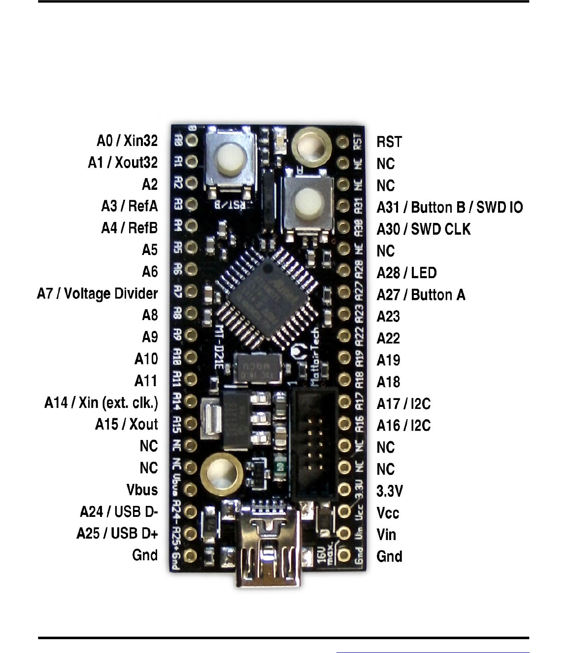
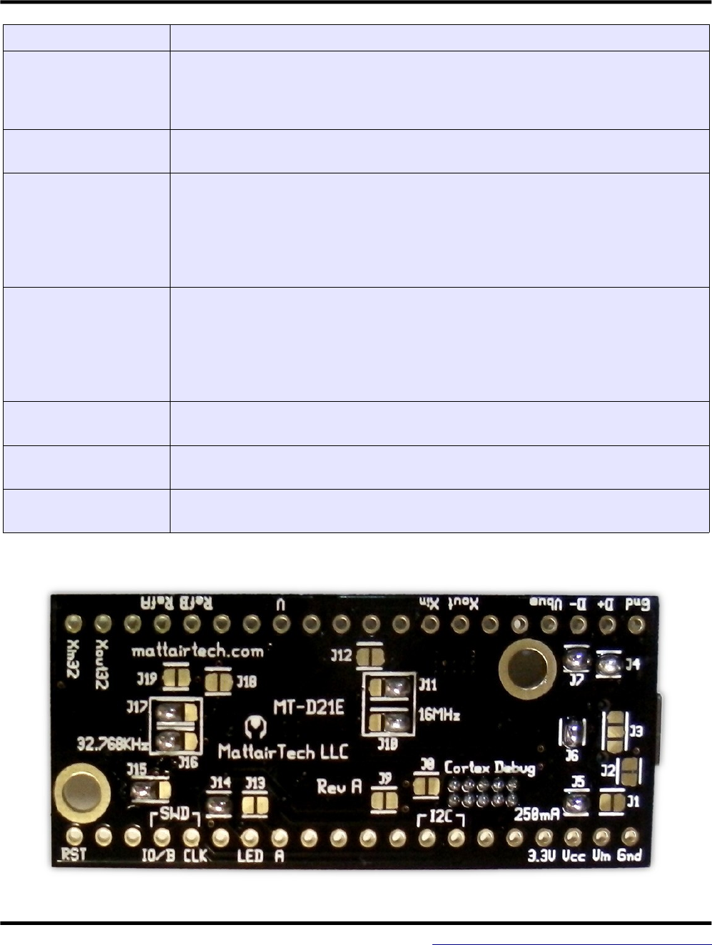
Top View / Pinout..............................................................................................................................7
Main Header Pins (Power)................................................................................................................8
Main Header Pins (Signal)................................................................................................................9
Solder Jumpers...............................................................................................................................11
MattairTech Arduino SAMD Core..............................................................................13
What's New (1.6.6-mt1, November 24, 2015)..................................................................................13
Summary.........................................................................................................................................14
Special Notes..................................................................................................................................15
Pin Configurations...........................................................................................................................16
Pin Capabilities...............................................................................................................................17
MT-D21E and MT-D11 Board Configuration...................................................................................18
Serial Monitor..................................................................................................................................19
Code Size and RAM Usage (1.6.5-mt2)..........................................................................................19
Detailed Memory Usage Output After Compilation..............................................................................20
Installation.......................................................................................................................................21
Driver Installation..................................................................................................................................21
SAMD Core Installation........................................................................................................................22
New PinDescription Table...............................................................................................................22
Possible Future Additions................................................................................................................24
ChangeLog.....................................................................................................................................24
SAM-BA USB CDC Bootloader (Arduino Compatible)............................................26
Bootloader Firmware Installation.....................................................................................................27
Bootloader Installation Using the Arduino IDE................................................................................27
Bootloader Installation Using Another Tool (ie: Atmel Studio, openocd)........................................27
Using Bossac Standalone...............................................................................................................28
USB Mass Storage Bootloader..................................................................................29
Schematic....................................................................................................................31
Fuse and Lock Settings.............................................................................................32
Blink Demo..................................................................................................................32
Troubleshooting / FAQ...............................................................................................33
Support Information..................................................................................................33
Legal.............................................................................................................................34
Appendix A: Precautions...........................................................................................38
Appendix B: Other MattairTech Products................................................................39
July 11, 2016 2 http://www.mattairtech.com/

MT-D21E User Guide
Overview
Overview
Introduction
The MT-D21E is a development board for the 32-pin Atmel SAM D21E ARM Cortex M0+ USB
microcontroller. It can be powered from USB or from the Vin pin. Two schottky diodes facilitate simple
switching (and reverse-polarity protection) between the two power sources. This voltage is regulated
to 3.3V by the onboard 250mA, extremely low quiescent current (2uA) LDO regulator that supports up
to 16V DC input voltage. Overcurrent protection is provided by a 180mA hold (400mA trip) PTC
resettable fuse. Also mounted is a mini USB connector, blue LED, 16MHz crystal, 32.768KHz crystal,
and two buttons. A USB CDC bootloader (Atmel SAM-BA) can be pre-installed for device
programming without an external programmer. It is compatible with Arduino, and core files are
provided to support Arduino 1.6.5+. A USB Mass Storage Class bootloader can optionally be installed
for device programming (see caveats). The Cortex debug header (10-pin, 50-mil) can be used with an
external debugger/programmer. The board has 40 main dual inline header pins with 100 mil pin
spacing and 700 mil row spacing which allows for mounting on a breadboard or perfboard. There are 2
3mm mounting holes. The PCB measures approx. 2.1” x 0.9” x 0.062” (52mm x 23mm x 1.6mm).
July 11, 2016 4 http://www.mattairtech.com/

MT-D21E User Guide
Board Features
●Atmel SAM D21E 32-pin ARM Cortex M0+ microcontroller
●ATSAMD21E17A (128KB) or ATSAMD21E18A (256KB)
●Up to 48MHz
●128KB or 256KB in-system self-programmable Flash
●16KB or 32KB SRAM Memory
●Onboard 3.3V, 250mA LDO regulator
●up to 16V DC input
●extremely low quiescent current (2.0uA typical)
●low dropout (525mV typical @ 250mA, 725mV max. @ 250mA)
●0.4% output tolerance typical
●Over-current and over-temperature protection
●Simple power source switching
●2 schottky barrier diodes (Vbus and Vin)
●Low voltage drop
●Reverse-polarity protection
●PTC resettable fuse (180mA hold / 400mA trip)
●Cortex Debug Header (10-pin, 50-mil)
●Can be used for device programming and debugging
●16MHz crystal (can use PLL for up to 48MHz cpu clock)
●32.768KHz crystal
●Blue Status LED (can be disconnected)
●Button A for general use (pin A27) with debouncing
●Button B configurable for reset or general use (pin A31) with debouncing
●Two 4.7Kohm resistors can be connected to pins A16 and A17 for use with I2C
●USB SAM-BA (CDC) bootloader (optional)
●Arduino compatible (use the Arduino IDE to upload)
●Bossa command line utility (Windows, Linux, limited OS X)
●Arduino 1.6.5+ compatible core (1.6.6 support now available)
●USB Mass Storage Device (MSD) bootloader (optional, see caveats)
●Mini USB connector
●ESD protection on USB D+ and D- lines
●USB pins routed to header pins (for panel-mount USB connector)
●Powered by USB or external power source (up to 16V) on Vin
●Ferrite bead and 2 capacitors on analog supply
●Two capacitors each can be enabled for pins A3 and/or A4 for use with external references
●19 solder jumpers on PCB bottom for configuration flexibility
●All PORT pins routed to headers
●2 main headers are on 0.1” spacing (breadboard/perfboard mounting)
●Two 3mm mounting holes (~5mm pad)
●High-quality PCB with gold-plated finish
●Measures approx. 2.1” x 0.9” (52mm x 23mm) and 0.062” (1.6mm) thick.
July 11, 2016 5 http://www.mattairtech.com/

MT-D21E User Guide
ATSAMD21ExxA Features
●Processor
●ARM Cortex-M0+ CPU running at up to 48MHz
●Single-cycle hardware multiplier
●Micro Trace Bu$er
●Memories
●32/64/128/256KB in-system self-programmable Flash
●4/8/16/32KB SRAM Memory
●System
●Power-on reset (POR) and brown-out detection (BOD)
●Internal and external clock options with 48MHz Digital Frequency Locked Loop (DFLL48M) and 48MHz to
96MHz Fractional Digital Phase Locked Loop (FDPLL96M)
●External Interrupt Controller (EIC) / One non-maskable interrupt
●16 external interrupts
●Two-pin Serial Wire Debug (SWD) programming, test and debugging interface
●Low Power
●Idle and standby sleep modes
●SleepWalking peripherals
●Peripherals
●12-channel Direct Memory Access Controller (DMAC)
●12-channel Event System
●Up to ve 16-bit Timer/Counters (TC), congurable as either:
●One 16-bit TC with compare/capture channels
●One 8-bit TC with compare/capture channels
●One 32-bit TC with compare/capture channels, by using two TCs
●Three 24-bit Timer/Counters for Control (TCC), with extended functions:
●Up to four compare channels with optional complementary output
●Generation of synchronized pulse width modulation (PWM) pattern across port pins
●Deterministic fault protection, fast decay and con>gurable dead-time (complementary outputs)
●Dithering that increase resolution with up to 5 bit and reduce quantization error
●32-bit Real Time Counter (RTC) with clock/calendar function
●Watchdog Timer (WDT)
●CRC-32 generator
●One full-speed (12Mbps) Universal Serial Bus (USB) 2.0 interface
●Embedded host and device function
●Eight endpoints
●Up to six Serial Communication Interfaces (SERCOM), each congurable to operate as either:
●USART with full-duplex and single-wire half-duplex con>guration
●I2C up to 3.4MHz
●SPI
●LIN slave
●One two-channel Inter-IC Sound (I2S) interface
●One 12-bit, 350ksps Analog-to-Digital Converter (ADC) with up to 20 channels
●Di$erential and single-ended input
●1/2x to 16x programmable gain stage
●Automatic o$set and gain error compensation
●Oversampling and decimation in hardware to support 13-, 14-, 15- or 16-bit resolution
●10-bit, 350ksps Digital-to-Analog Converter (DAC)
●Two Analog Comparators (AC) with window compare function
●Peripheral Touch Controller (PTC)
●I/O
●Up to 52 programmable I/O pins
July 11, 2016 6 http://www.mattairtech.com/
MT-D21E User Guide
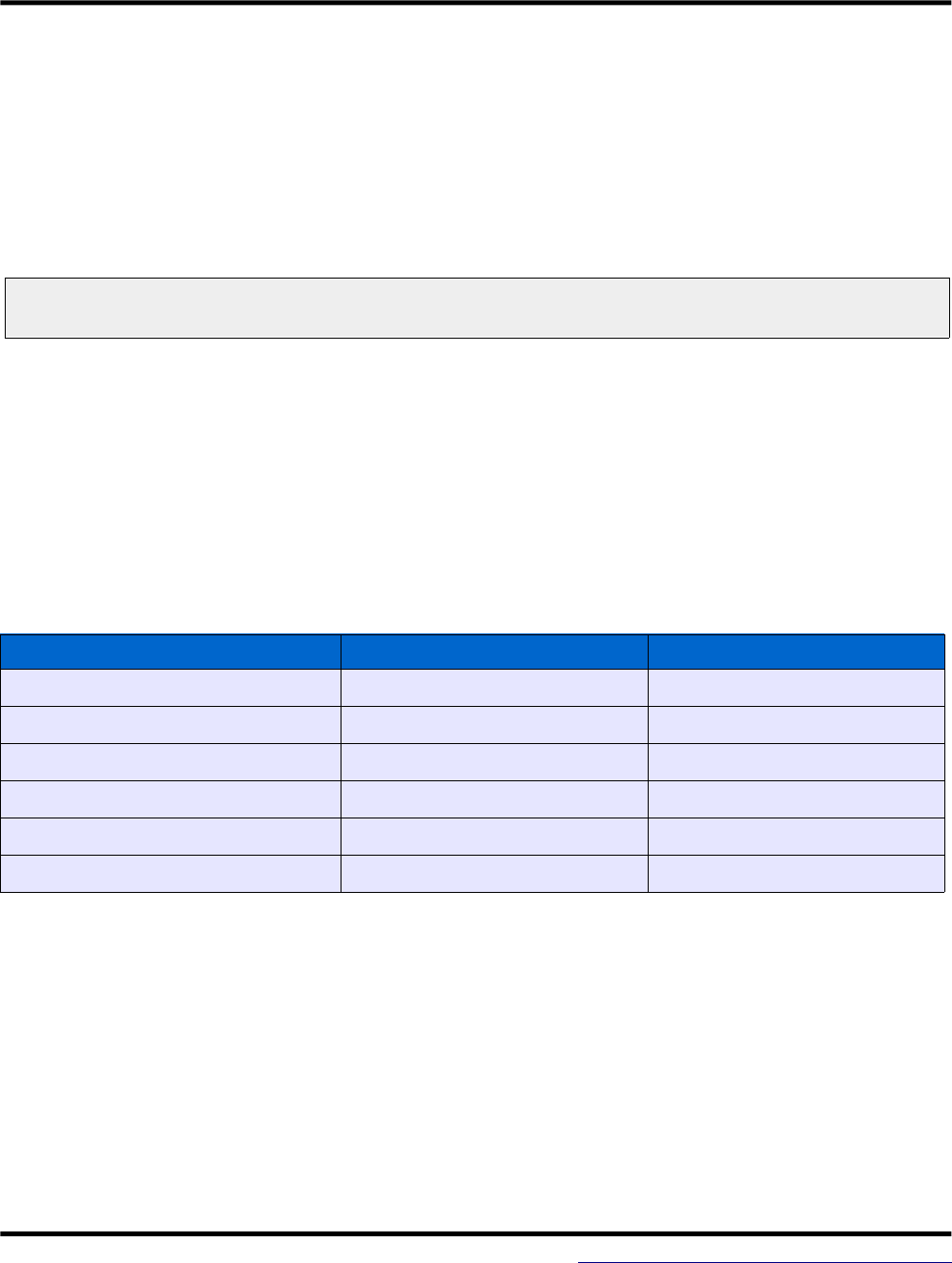
============================= MattairTech MT-D21E (ATsamd21eXXa) ========================
Other INT PWM Digital Analog Digital PWM INT Other
=========================================================================================
-------------------
Xin32 | A0 RST | Reset
Xout32 | A1 NC |
DAC 2 2(ADC0) | A2 NC |
REF 3 3(ADC1) | A3 A31 | 31 31(TCC11) 31(INT11) SWDIO*
4(INT4) 4 4(ADC4) | A4 A30 | 30 30(TCC10) 30(INT10) SWDCLK
5(INT5) 5 5(ADC5) | A5 NC |
6 6(ADC6) | A6 A28 | 28 28(INT8) LED
VDIV 7 7(ADC7) | A7 A27 | 27 27(INT15) BTNA
8(INTNMI) 8(TCC00) 8 8(ADC16) | A8 A23 | 23 23(TC41) 23(INT7) SS
9(INT9) 9(TCC01) 9 9(ADC17) | A9 A22 | 22 22(TC40) 22(INT6) MISO
TX1 10(TCC02) 10 10(ADC18)| A10 A19 | 19 19(INT3) SCK
RX1 11(TCC03) 11 11(ADC19)| A11 A18 | 18 18(INT2) MOSI
TX2 14(INT14) 14(TC30) 14 | A14 A17 | 17 17(TCC21) 17(INT1) SCL
RX2 15(TC31) 15 | A15 A16 | 16 16(TCC20) 16(INT0) SDA
| NC NC |
| NC NC |
| Vbus 3.3V| * Button B available on 31
USB D- | A24- _____ Vcc |
USB D+ | A25+ | | Vin |
| Gnd | USB | Gnd |
-------------------
Main Header Pins (Power)
Pin Description
Gnd (2) Ground
Vbus Vbus is connected directly to the Vbus pin (5V) of the USB connector. It is routed
through a schottky diode and through J6 to the regulator input circuitry, which includes
a 4.7uF capacitor. Vbus voltage can be measured on pin A1 by connecting J12 and
setting J3 toward the Vbus side of the board. J12 will complete the circuit for a resistor
divider consisting of a 200Kohm (top) and a 20Kohm resistor (bottom), and J3
connects to Vbus. The resistor divider will pull pin A7 to near ground level when Vbus
is disconnected. Because of a small leakage current from the schottky diode, a small
voltage should be interpreted as USB disconnected.
Vin Vin is the external power input pin. Up to 16V can be connected. It is routed through a
schottky diode to the regulator input circuitry, which includes a 4.7uF, 25V capacitor.
The schottky diode can be shorted with J1, eliminating the voltage drop across the
diode, which can be useful for battery applications. Note that when the diode is
shorted, reverse-polarity protection is disabled, and J6 should be disconnected to
prevent Vbus current from flowing into Vin. Vin voltage can be measured on pin A1 by
connecting J12 and setting J3 toward the Vin side of the board. J12 will complete the
circuit for a resistor divider consisting of a 200Kohm (top) and a 20Kohm resistor
(bottom), and J3 connects to Vbus. The resistor divider will pull pin A7 to near ground
level when Vbus is disconnected. Because of a small leakage current from the
schottky diode, a small voltage should be interpreted as Vin disconnected.
July 11, 2016 8 http://www.mattairtech.com/
MT-D21E User Guide
Vcc This pin is connected to the Vcc and VccAna (through a ferrite bead) pins on the
microcontroller, the Cortex debug header Vcc pin, the reset pullup, and the TWI pullup
resistors. Vcc is connected to 3.3V through J5, which in turn is connected to the
output of the onboard regulator. The Vcc pin can also be used as an input. Disconnect
J5 to supply power from an external source to the Vcc pin.
3.3V 3.3V is connected to the output of the onboard 3.3V regulator. There is a 10uF
capacitor on the output. 3.3V is normally connected to Vcc through J5.
CAUTION
Higher regulator input voltages mean larger voltage drops and thus higher
thermal dissipation for a given amount of current. Be sure to limit current
consumption to prevent excessive heat when using higher voltages and/or
currents. The regulator will enter thermal shutdown if it gets too hot. All
capacitors are X7R, X7S, or NP0, so they can deal with the higher
temperatures of the regulator. Note that the PTC fuse is located near the
regulator, so high temperatures will lower the PTC trip and hold currents.
Main Header Pins (Signal)
Pin Description
A0, A1 (Xin32, Xout32) These can be used for analog or digital functions. Alternatively, jumpers
J16 and J17 can be set to route A0 and A1 to the 32.768KHz crystal.
A2, A5, A6 These can be used for analog or digital functions. Pin A2 can be used as a
DAC output.
A3, A4 These can be used for analog or digital functions. Alternatively, jumpers
J19 and/or J18 can be set to enable both a 100nF capacitor and a 1uF
capacitor so that the pin can be used with an external voltage reference.
A7 / Voltage Divider This can be used for analog or digital functions. Additionally, this pin can
be connected to the voltage divider for measurement of Vin or Vbus by
setting J3 and J12 appropriately.
A8 - A11 These can be used for analog or digital functions.
A14, A15 (Xin, Xout) These can be used for digital functions. Pin A14 can be used with an
external clock. Alternatively, jumpers J10 and J11 can be set to route A15
and A14 to the 16MHz crystal.
A24-, A25+
(USB D- and D+)
These can be used for digital functions. By default, these pins are also
connected to pins D- and D+ of the USB connector through jumpers J7
and J4. These header pins, along with the adjacent Vbus and Ground pins
can be used for a panel-mount USB connector.
July 11, 2016 9 http://www.mattairtech.com/

MT-D21E User Guide
A16, A17 (I2C) These can be used for digital functions. Additionally, jumpers J8 and J9
can be enabled, which will connect two 4.7Kohm pullup resistors for use
with I2C.
A18, A19, A22, A23 These can be used for digital functions.
A27 / Button A This can be used for digital functions. By default, this pin is connected to
Button A through jumper J13. This button is debounced using a 249ohm
resistor and a 100nF capacitor. The pin is brought to ground when the
button is pressed. The button is used for bootloader entry (optional) or can
be for general purpose use.
A28 / LED This can be used for digital functions. By default, this pin is connected to a
blue LED through jumper J14 and a 499ohm resistor. The LED circuit
should consume around 1mA. Drive the pin high to turn on the LED.
A30 / SWD CLK This can be used for digital functions. Additionally, this pin is connected to
the Cortex debug header where it is used as SWD CLK.
A31 / Button B / SWD
IO
This can be used for digital functions. Additionally, the pin is routed to the
Cortex debug header where it is used as SWD IO. Alternatively, this pin
can be connected to Button B through jumper J15 (note that this button
can also be used for RST). This button is debounced using a 249ohm
resistor and a 100nF capacitor. The pin is brought to ground when the
button is pressed. The button can be can be for general purpose use.
RST RST connects to the reset pin of the microcontroller, to Button B through
jumper J15 ( note that this button can also be for general purpose use; see
A31 above), and to the Cortex debug header. A 10K pullup resistor is
connected as well.
NC These pins are not connected to anything. There are 7 pins marked NC.
Cortex Debug Header This 10-pin, 50-mil header can be connected to an external
programmer/debugger.
July 11, 2016 10 http://www.mattairtech.com/
MT-D21E User Guide
Solder Jumpers
Jumper Description
J1: Vin diode disable Vin is the external power input pin. Up to 16V can be connected. It is routed through
a schottky diode to the regulator input circuitry. The schottky diode can be shorted
by closing J1, eliminating the voltage drop across the diode, which can be useful for
battery applications. Note that when the diode is shorted, reverse-polarity protection
is disabled, and J6 should be opened to prevent Vbus current from flowing into Vin.
J2: USB Shield Ground Jumper J2 can be closed to connect the USB shield to ground. The USB
specification calls for the USB shield to be connected to ground on the host side
only. However, some prefer to have it grounded. Bear in mind that the USB shield
will then act as an antenna. To avoid this, an 0603 component and an 0402 (ie:
1Mohm resistor and 4.5nF capacitor) may be soldered on the pads.
J3: Voltage divider
input
Vin or Vbus voltage can be measured on pin A7 by closing J12 and setting J3
toward either the Vin (for Vin measurement) or the Vbus (for Vbus measurement)
side of the board (refer to printing on top side of pcb). J12 will complete the circuit
for a resistor divider consisting of a 200Kohm (top) and a 20Kohm resistor (bottom),
and J3 connects to Vin or Vbus. The resistor divider will pull pin A7 to near ground
level when Vbus is disconnected. Because of a small leakage current from the
schottky diode, a small voltage should be interpreted as Vin/Vbus disconnected.
J4: USB D+ / Pin A25 Microcontroller pins A24 and A25 are connected to header pins A24- and A25+. By
default, these pins are also connected to pins D- and D+ of the USB connector
through jumpers J7 and J4. The header pins, along with the adjacent Vbus and
Ground pins can be used for a panel-mount USB connector.
J5: Vcc – 3.3V This connects the 3.3V regulator output rail to Vcc. Open J5 if supplying a regulated
voltage (3.6V or less) externally on the Vcc pin.
J6: Vbus Power This routes Vbus to the regulator input circuitry. There are two schottky diodes, one
for Vin and one for Vbus. They facilitate automatic power switching between these
two sources. If only external power will be used (Vin), open J6. This will prevent
Vbus power from being used when a USB cable is plugged in for communications.
J7: USB D- / Pin A24 See J4.
J8: I2C pullup resistor Close J8 to connect pin A16 through a 4.7Kohm resistor to Vcc for use with I2C.
J9: I2C pullup resistor Close J9 to connect pin A17 through a 4.7Kohm resistor to Vcc for use with I2C.
J10: 16MHz crystal
selection
J10 and J11 determine whether microcontroller pins A15 and A14 connect to
header pins A15 and A14 or to the 16MHz crystal. When the SAM-BA bootloader is
installed, the header pins are connected. If the MSD bootloader or no bootloader
are installed, the alternate position is used by default(16MHz crystal connected).
Note that the MSD bootloader does not use an external crystal, as it uses USB
clock recovery (DFLL tuned using the USB SOF signal).
J11: 16MHz crystal
selection
See J10. The image below shows connection to the header pins.
J12: Voltage divider See J3.
July 11, 2016 11 http://www.mattairtech.com/
MT-D21E User Guide
enable
J13: Button A enable This jumper connects to Button A to pin A27. This button is debounced using a
249ohm resistor and a 100nF capacitor. The pin is brought to ground when the
button is pressed. The button is used for bootloader entry (optional) or can be for
general purpose use.
J14: LED enable This jumper connects pin A28 to a blue LED through a 499ohm resistor. The LED
circuit should consume around 1mA. Drive the pin high to turn on the LED.
J15: Button B function
selection
This jumper connects button B to either the RST pin, which is the default as shown
in the image below, or to pin A31 for general purpose use. This button is debounced
using a 249ohm resistor and a 100nF capacitor. The pin is brought to ground when
the button is pressed. Note that pin A31 is also used by the Cortex debug header
(SWD IO). The button can be completely disconnected by removing solder from all
three pads.
J16: 32.768KHz crystal
selection
J16 and J17 determine whether microcontroller pins A0 and A1 connect to header
pins A0 and A1 or to the 32.768KHz crystal. When the SAM-BA bootloader is
installed, they are routed to the crystal. If the MSD bootloader or no bootloader is
installed, they are routed to the header pins by default. Note that the MSD
bootloader does not use an external crystal, as it uses USB clock recovery (DFLL
tuned using the USB SOF signal).
J17: 32.768KHz crystal
selection
See J16.
J18: VREF capacitors When using pin A4 as VREF, close J18 to enable both a 100nF capacitor and a 1uF
capacitor from A4 to ground.
J19: VREF capacitors When using pin A3 as VREF, close J19 to enable both a 100nF capacitor and a 1uF
capacitor from A3 to ground.
Image note: The solder jumper configuration shows BOTH crystals disconnected.
July 11, 2016 12 http://www.mattairtech.com/
MT-D21E User Guide
MattairTech Arduino SAMD Core
MattairTech Arduino SAMD Core
Please visit https://github.com/mattairtech/ArduinoCore-samd for updated documentation and
information on the new 1.6.7-beta release with support for OS X and many updates.
This is a fork from arduino/ArduinoCore-samd on GitHub. This will be used to maintain Arduino
support for SAMD boards including the MattairTech MT-D21E and the MT-D11 (see
https://www.mattairtech.com/). It primarily adds support for new devices as well as a more flexible pin
configuration / mapping system. It also adds some size optimizations, including the ability to select any
combination of CDC, HID, or UART through the menu (~7.5KB for blink sketch with CDC+HID+UART,
~2.5KB without USB or UART).
This core is intended to be installed using Boards Manager (see below). To update from a previous
version, click on MattairTech SAMD Boards in Boards Manager, then click Update.
What's New (1.6.6-mt1, November 24, 2015)
●New documentation section 'Special Notes'. Please read!
●Updated ASCII pinouts to be more readable and less ambiguous.
●Updated the Signed driver for Windows (extras directory).
adds CDC/MIDI/HID, CDC/MSD/HID, and CDC/MSD/MIDI/HID composite USB
devices.
Of the above, currently only CDC/MIDI/HID is usable (see MIDIUSB library).
●Merged in changes from upstream past SAMD CORE 1.6.2 release
Added SPI.transfer16(..) method
Bugfix: added missing Serial.begin(baud, config) method. Thanks @tuxedo0801
the pin mode is changed to INPUT mode, arduino/ArduinoCore-samd#28
HardwareSerial BUG Rx pin floating input, arduino/ArduinoCore-samd#48
Send a ZLP if data size is multiple of EPX_SIZE for USB sends, arduino/ArduinoCore-
samd#63
Print not aborting on write failure, changelog update
Tone fix for arduino/ArduinoCore-samd#59 and optimizations
Fix warnings about deprecated recipe.ar.pattern
●Merged in changes from upstream SAMD CORE 1.6.2 2015.11.03
Fixed bug in delay calculations
Fixed deadlock conditions in Wire. Thanks Erin Tomson
Print not aborting on write() failure. Thanks @stickbreaker
SPI can now be configured in variants. Thanks @aethaniel
Implemented Wire.end
Implemented Wire.setClock. Thanks @PaoloP74
July 11, 2016 13 http://www.mattairtech.com/

MT-D21E User Guide
Wire: allow scanning bus via beginTransmission-endTransmission
USB Device: big refactoring and bug fix
USB Device: added PluggableUSB interface
Summary
Feature MT-D21E MT-D11
Microcontroller ATSAMD21ExxA, 32-Bit ARM Cortex M0+ ATSAMD11D14AM, 32-Bit ARM
Cortex M0+
Clock Speed 48 MHz 48 MHz
Flash Memory 256 KB (D21E18A) / 128 KB (D21E17A) /
64 KB (D21E16A) / 32 KB (D21E15A)
16 KB (4KB used by USB SAM-
BA bootloader)
SRAM 32 KB (D21E18A) / 16 KB (D21E17A) / 8
KB (D21E16A) / 4 KB (D21E15A) 4 KB
EEPROM None (emulation may be available in the
future)
None (emulation may be available
in the future)
Digital Pins 22 17
Analog Input Pins 10, 12-bit ADC channels 10, 12-bit ADC channels
Analog Output Pins 1, 10-bit DAC 1, 10-bit DAC
PWM Output Pins 12 8
External Interrupts 15 (1 NMI) 9 (1 NMI)
USB Device and Host (CDC and HID) Device and Host (CDC and HID)
UART (Serial) 2 1
SPI 1 1
I2C (TWI) 1 1
Operating Voltage 3.3V (Do not connect voltages higher than
3.3V!) 3.3V (Do not connect voltages
higher than 3.3V!)
DC Current per I/O
Pin 7 mA 7 mA
July 11, 2016 14 http://www.mattairtech.com/

MT-D21E User Guide
Special Notes
●Boards Manager must be opened twice to see some updates
●Errors when compiling, uploading, or burning the bootloader
Be sure to install the Arduino samd core before installing the MattairTech samd
core. If you have problems upgrading the IDE to 1.6.6, you may need to uninstall
both the Arduino and MattairTech cores, then re-install in the proper order. Use
Arduino core 1.6.2 or above.
●Tools->Communications menu
Currently, the Tools->Communications menu must be used to select the
communications configuration. This configuration must match the included
libraries. For example, when including the HID and Keyboard libraries, you must
select an option that includes HID (ie: CDC_HID_UART). This menu is currently
needed to select the USB PID that matches the USB device configuration
(needed for Windows). This may become automatic in a future release.
➢Be sure that the Tools->Communications menu matches the sketch and
libraries you are compiling.
➢Different combinations of USB devices will result in different COM port
assingments in Windows.
●Incude platform specific libraries
You may need to manually include platform specific libraries such as SPI.h,
Wire.h, and HID.h.
●Differences from Arduino in versioning
The MattairTech ArduinoCore-samd version currently tracks the IDE version. In
some cases, it may indicate the minimum IDE version. This is the case for both
1.6.5-mtX and 1.6.6-mtX (which corresponds to SAMD CORE 1.6.2). 1.6.6-mt1
corresponds to Arduino SAMD CORE 1.6.2 plus some pull requests.
July 11, 2016 15 http://www.mattairtech.com/

MT-D21E User Guide
Pin Configurations
Most pins have multiple configurations available (even analog pins). For example, pin A10 on the MT-
D21E can be an analog input, a PWM output, Digital I/O, or the TX pin of 'Serial1'. These always
reference the pin number printed on the board but without the 'A' (with the usable pins starting at 2).
DO NOT connect voltages higher than 3.3V!
SAMD21 (MT-D21E)
============================= MattairTech MT-D21E (ATsamd21eXXa) ========================
Other INT PWM Digital Analog Digital PWM INT Other
=========================================================================================
-------------------
Xin32 | A0 RST | Reset
Xout32 | A1 NC |
DAC 2 2(ADC0) | A2 NC |
REF 3 3(ADC1) | A3 A31 | 31 31(TCC11) 31(INT11) SWDIO*
4(INT4) 4 4(ADC4) | A4 A30 | 30 30(TCC10) 30(INT10) SWDCLK
5(INT5) 5 5(ADC5) | A5 NC |
6 6(ADC6) | A6 A28 | 28 28(INT8) LED
VDIV 7 7(ADC7) | A7 A27 | 27 27(INT15) BTNA
8(INTNMI) 8(TCC00) 8 8(ADC16) | A8 A23 | 23 23(TC41) 23(INT7) SS
9(INT9) 9(TCC01) 9 9(ADC17) | A9 A22 | 22 22(TC40) 22(INT6) MISO
TX1 10(TCC02) 10 10(ADC18)| A10 A19 | 19 19(INT3) SCK
RX1 11(TCC03) 11 11(ADC19)| A11 A18 | 18 18(INT2) MOSI
TX2 14(INT14) 14(TC30) 14 | A14 A17 | 17 17(TCC21) 17(INT1) SCL
RX2 15(TC31) 15 | A15 A16 | 16 16(TCC20) 16(INT0) SDA
| NC NC |
| NC NC |
| Vbus 3.3V| * Button B available on 31
USB D- | A24- _____ Vcc |
USB D+ | A25+ | | Vin |
| Gnd | USB | Gnd |
-------------------
SAMD11 (MT-D11)
=========================== MattairTech MT-D11 (ATsamd11D14AM) ==========================
Other INT PWM Digital Analog Digital PWM INT Other
=========================================================================================
-------------------
DAC 2 2(ADC0) | A2 | USB | Gnd |
REF 3 3(ADC1) | A3 | | Vcc |
4(INT4) 4(TCC00) 4 4(ADC2) | A4 ----- A31 | 31 31(TC21) 31(INT3) RX/SWDIO
5(INT5) 5(TCC01) 5 5(ADC3) | A5 A30 | 30 30(TC20) TX/SWDCLK
6(TCC02) 6 6(ADC4) | A6 A27 | 27 27(INT7)
7(TCC03) 7 7(ADC5) | A7 A23 | 23 SCL
MOSI 10(INT2) 10 10(ADC8) | A10 A22 | 22 22(INT6) SDA
SCK 11 11(ADC9) | A11 A17 | 17 17(TC11)
MISO 14(INTNMI) 14 14(ADC6) | A14 A16 | 16 16(TC10) 16(INT0) LED
BTN/SS 15(INT1) 15 15(ADC7) | A15 RST | Reset
-------------------
All pins operate at 3.3 volts. DO NOT connect voltages higher than 3.3V!
July 11, 2016 16 http://www.mattairtech.com/

MT-D21E User Guide
Pin Capabilities
●Digital: All pins can be used for general purpose I/O
●Supports INPUT, OUTPUT, INPUT_PULLUP, and INPUT_PULLDOWN.
●Each pin can source or sink a maximum of 7 mA (when PER_ATTR_DRIVE_STRONG
is set for the pin).
●Internal pull-up and pull-down resistors of 20-60 Kohms (40Kohm typ., disconnected by
default).
●Use the pinMode(), digitalWrite(), and digitalRead() functions.
●Analog Inputs: 10 pins can be configured as ADC analog inputs.
●These are available using the analogRead() function.
●All pins can be used for GPIO and some pins can be used for other digital functions (ie.
pwm or serial).
●Each pin provides 10 bits of resolution (1024 values) by default.
●12-bit resolution supported by using the analogReadResolution() function.
●Each pin measures from ground to 3.3 volts.
●The upper end of the measurement range can be changed using the AREF pin and the
analogReference() function.
●DAC: One analog output is available on pin 2.
●Provides a 10-bit voltage output with the analogWrite() function.
●PWM: 12 pins (MT-D21E) or 8 pins (MT-D11) can be configured as PWM outputs.
●Available using the analogWrite() function.
●Each pin provides 8 bits of resolution (256 values) by default.
●12-bit resolution supported by using the analogWriteResolution() function.
●External Interrupts: 15 pins (MT-D21E) or 9 pins (MT-D11) can be configured with
external interrupts.
●Available using the attachInterrupt() function.
●Serial: 2 pairs of pins (MT-D21E) or 1 pair (MT-D11) can be configured for TTL serial I/O.
●MT-D21E: Serial1: pin 11 (RX) and pin 10 (TX). Serial2: pin 15 (RX) and pin 14 (TX).
●MT-D11: Serial1: pin 31 (RX) and pin 30 (TX).
●SPI: 3 or 4 pins can be configured for SPI I/O (SPI).
●MT-D21E: Pin 18 (MOSI), pin 19 (SCK), pin 22 (MISO), and optionally pin 23 (SS, not
currently used).
●MT-D11: Pin 10 (MOSI), pin 11 (SCK), pin 14 (MISO), and optionally pin 15 (SS, not
currently used).
●SPI communication using the SPI library.
●Note that the SPI library will set SS as an output.
●On the MT-D11, the button must be configured as reset (default) when using SPI.
●TWI (I2C): 2 pins can be configured for TWI I/O (Wire).
●MT-D21E: Pin 16 (SDA) and pin 17 (SCL).
●MT-D11: Pin 22 (SDA) and pin 23 (SCL).
●TWI communication using the Wire library.
●LED: One pin can be configured to light the onboard LED (LED_BUILTIN).
July 11, 2016 17 http://www.mattairtech.com/

MT-D21E User Guide
●Pin 28 (MT-D21E) or pin 16 (MT-D11). Bring the pin HIGH to turn the LED on. The
pullup is disabled on this pin.
●Button: One pin can be configured to read the onboard Button A (BUTTON_BUILTIN).
●Pin 27 (MT-D21E) or pin 15 (MT-D11). Pressing the button will bring the pin LOW. The
pullup must be enabled first.
●If the debouncing capacitor is connected, delay reading the pin at least 6ms after
turning on the pullup.
●AREF: One pin can be configured as an AREF analog input.
●The upper end of the analog measurement range can be changed using the
analogReference() function.
●Reset: Bring this line LOW to reset the microcontroller.
MT-D21E and MT-D11 Board Configuration
●The 32.768KHz crystal is used by the Arduino core, so it MUST be connected via the
solder jumpers.
●Note that the sketch may still run without the crystal attached, but the clock speed will
be very inaccurate.
●The 16MHz crystal is not used. It should be disconnected via the solder jumpers.
●The I2C (TWI) pullup resistors should be enabled via the solder jumpers.
●The LED should be enabled via the solder jumper.
●Button A should be connected via the solder jumper. The debouncing capacitor should
also be connected.
●Button B (MT-D21E only) is connected to the Reset pin by default, but can be
connected to pin 31 via the solder jumper.
●A reference voltage can be connected to AREF. In this case, the capacitors should be
enabled via the solder jumper.
●On the MT-D11, BTN is shared with SPI SS, so the button must be configured as reset
(default) when using SPI.
July 11, 2016 18 http://www.mattairtech.com/
MT-D21E User Guide
Serial Monitor
To print to the Serial Monitor over USB, use 'Serial'. Serial points to SerialUSB (Serial1 and
Serial2 are UARTs). Unlike most Arduino boards (ie. Uno), SAMD boards do not
automatically reset when the serial monitor is opened. To see what your sketch outputs to the
serial monitor from the beginning, the sketch must wait for the SerialUSB port to open first.
Add the following to setup():
while (!Serial) ;
Remember that if the sketch needs to run without SerialUSB connected, another approach
must be used. You can also reset the board manually with the Reset button if you wish to
restart your sketch. However, pressing the Reset button will reset the SAMD chip, which in
turn will reset USB communication. This interruption means that if the serial monitor is open, it
will be necessary to close and re-open it to restart communication.
Code Size and RAM Usage (1.6.5-mt2)
Sketch and Configuration MT-D21E (Code + RAM) MT-D11 (Code + RAM)
Blink (CDC + HID + UART) 7564 + 1524 7452 + 1424
Blink (CDC + UART) 6588 + 1496 6484 + 1396
Blink (CDC Only) 5248 + 1304 5192 + 1300
Blink (UART Only) 3828 + 336 3716 + 236
Blink (No USB or UART) 2472 + 144 2416 + 140
Datalogger (No USB or UART) 10340 + 948 10260 + 944
●180 bytes of flash can be saved on the MT-D11 by using PIN_MAP_COMPACT (see 'New
PinDescription Table' below).
●Datalogger compiled without USB or UART support, but with SPI and SD (with FAT filesystem)
support. Serial output was disabled.
●Note that USB CDC is required for auto-reset into the bootloader to work (otherwise, manually
press reset twice in quick succession).
●USB uses primarily 3 buffers totaling 1024 bytes. The UART uses a 96 byte buffer. The
banzai() function (used for auto-reset) resides in RAM and uses 72 bytes.
●Any combination of CDC, HID, or UART can be used (or no combination),
by using the Tools->Communication menu.
July 11, 2016 19 http://www.mattairtech.com/

MT-D21E User Guide
Detailed Memory Usage Output After Compilation
The flash used message at the end of compilation is not correct. The number shown
represents the .text segment only. However, Flash usage = .text + .data segments (RAM
usage = .data + .bss segments). In this release, two programs are run at the end of
compilation to provide more detailed memory usage. To enable this output, go to File-
>Preferences and beside "Show verbose output during:", check "compilation".
Just above the normal flash usage message, is the output from the size utility. However, this
output is also incorrect, as it shows .text+.data in the .text field, but 0 in the .data field.
However, the .text field does show the total flash used. The .data field can be determined by
subtracting the value from the normal flash usage message (.text) from the value in the .text
field (.text+.data). The .bss field is correct.
Above the size utility output is the output from the nm utility. The values on the left are in
bytes. The letters stand for: T(t)=.text, D(d)=.data, B(b)=.bss, and everything else (ie: W)
resides in flash (in most cases).
July 11, 2016 20 http://www.mattairtech.com/

MT-D21E User Guide
Installation
Driver Installation
Windows
There are currently four USB composite device combinations that include CDC as well as a
CDC only device. Drivers are required for each of these five devices. The CDC only driver is
required by the bootloader. The drivers are signed and support both 32 and 64 bit versions of
Windows XP (SP3), Vista, 7, 8, and 10.
1. If you do not already have the SAM-BA bootloader installed, see below.
2. Download https://www.mattairtech.com/software/MattairTech_CDC_Driver_Signed.zip and
unzip into any folder.
3. Plug in the board while holding down button A to enter the bootloader. The LED should light.
4. Windows will detect the board. Point the installer to the folder from above to install the
bootloader driver.
5. If you don't intend on using Arduino, you can skip the rest of this list. See Using Bossac
Standalone below.
6. If you do not already have the test firmware installed, see Using Bossac Standalone below.
7. Press the reset button to run the test firmware (blink sketch with CDC-HID).
8. Windows will detect the board. Point the installer to the folder from above to install the sketch
driver.
9. Continue with SAMD Core Installation below.
Linux
1. No driver installation is needed.
2. On some distros, you may need to add your user to the same group as the port (ie: dialout)
and/or set udev rules.
3. You MAY have to install and use Arduino as the root user in order to get reliable access to the
serial port.
●This is true even when group permissions are set correctly, and it may fail after
previously working.
●You can also create/modify a udev rule to set permissions on the port so everyone can
read / write.
4. Continue with SAMD Core Installation below.
OS X
1. As of this writing, only the 256 KB chip variants work with the OS X version of the upload tool,
bossac.
2. First, you will need to open boards.txt and change mattairtech_mt_d21e_bl8k.upload.tool to
July 11, 2016 21 http://www.mattairtech.com/
MT-D21E User Guide
equal arduino:bossac.
3. Open platform.txt and change tools.bossac.path to equal{runtime.tools.bossac-1.6.1-
arduino.path}.
4. No driver installation is needed. You may get a dialog box asking if you wish to open the
“Network Preferences”:
●Click the "Network Preferences..." button, then click "Apply".
●The board will show up as “Not Configured”, but it will work fine.
5. Continue with SAMD Core Installation below.
SAMD Core Installation
To update from a previous version, click on MattairTech SAMD Boards in Boards
Manager, then click Update.
Boards Manager may require opening twice (with possibly a delay in between) to see
some updates.
1. The MattairTech SAMD Core requires Arduino 1.6.6+ (1.6.5-mtX required IDE 1.6.5).
2. In the Arduino IDE, click File->Preferences.
3. Click the button next to Additional Boards Manager URLs.
4. Add https://www.mattairtech.com/software/arduino/package_MattairTech_index.json.
5. Save preferences, then open the Boards Manager.
6. Install the Arduino SAMD Boards package. Use version 1.6.2 or higher with 1.6.6-mtX.
7. Install the MattairTech SAMD Boards package (1.6.6-mtX).
8. Close Boards Manager, then click Tools->Board->MattairTech MT-D21E (or MT-D11).
9. Select the processor with the now visible Tools->Processor menu.
10.If you do not already have the bootloader or blink sketch installed, see SAM-BA USB CDC
Bootloader below.
11.Plug in the board. The blink sketch should be running.
12.Click Tools->Port and choose the COM port.
13.You can now upload your own sketch.
New PinDescription Table
/* The PinDescription table describes how each of the pins can be used by the Arduino
* core. Each pin can have multiple functions (ie: ADC input, digital output, PWM,
* communications, etc.), and the PinDescription table configures which functions can
* be used for each pin. This table is mainly accessed by the pinPeripheral function in
* wiring_private.c, which is used to attach a pin to a particular peripheral function.
* The communications drivers (ie: SPI, I2C, and UART), analogRead(), analogWrite(),
* analogReference(), attachInterrupt(), and pinMode() all call pinPeripheral() to
* verify that the pin can perform the function requested, and to configure the pin for
* that function. Most of the contents of pinMode() are now in pinPeripheral().
*
July 11, 2016 22 http://www.mattairtech.com/

MT-D21E User Guide
* There are two ways that pins can be mapped. The first is to map pins contiguously
* (no PIO_NOT_A_PIN entries) in the table. This results in the least amount of space
* used by the table. A second method, used by default by the MT-D21E and MT-D11, maps
* Arduino pin numbers to the actual port pin number (ie: Arduino pin 28 = Port A28).
* This only works when there is one port. Because not all port pins are available,
* PIO_NOT_A_PIN entries must be added for these pins and more FLASH space is consumed.
* For an example of both types, see variant.cpp from the MT-D11 variant.
*
* Explanation of PinDescription table:
*
* Port This is the port (ie: PORTA).
* Pin This is the pin (bit) within the port. Valid values are 0-31.
* PinType This indicates what peripheral function the pin can be
* attached to. In most cases, this is PIO_MULTI, which means
* that the pin can be anything listed in the PinAttribute field.
* It can also be set to a specific peripheral. In this case, any
* attempt to configure the pin (using pinPeripheral or pinMode)
* as anything else will fail (and pinPeripheral will return -1).
* This can be used to prevent accidental re-configuration of a
* pin that is configured for only one function (ie: USB D- and
* D+ pins). If a pin is not used or does not exist,
* PIO_NOT_A_PIN must be entered in this field. See WVariant.h
* for valid entries. These entries are also used as a parameter
* to pinPeripheral() with the exception of PIO_NOT_A_PIN and
* PIO_MULTI. The pinMode function now calls pinPeripheral() with
* the desired mode. Note that this field is not used to select
* between the two peripherals possible with each of the SERCOM
* and TIMER functions. PeripheralAttribute is now used for this.
* PeripheralAttribute This is an 8-bit bitfield used for various peripheral
* configuration. It is primarily used to select between the two
* peripherals possible with each of the SERCOM and TIMER
* functions. TIMER pins are individual, while SERCOM uses a
* group of two to four pins. This group of pins can span both
* peripherals. For example, pin 19 (SPI1 SCK) on the MT-D21E
* uses PER_ATTR_SERCOM_ALT while pin 22 (SPI1 MISO) uses
* PER_ATTR_SERCOM_STD. Both TIMER and SERCOM can exist for each
* pin. This bitfield is also used to set the pin drive strength.
* In the future, other attributes (like input buffer
* configuration) may be added. See WVariant.h for valid entries.
* PinAttribute This is a 32-bit bitfield used to list all of the valid
* peripheral functions that a pin can attach to. This includes
* GPIO functions like PIN_ATTR_OUTPUT. Certain attributes are
* shorthand for a combination of other attributes.
* PIN_ATTR_DIGITAL includes all of the GPIO functions, while
* PIN_ATTR_TIMER includes both PIN_ATTR_TIMER_PWM and
* PIN_ATTR_TIMER_CAPTURE (capture is not used yet).
* PIN_ATTR_ANALOG is an alias to PIN_ATTR_ANALOG_ADC. There is
* only one DAC channel, so PIN_ATTR_DAC appears only once. This
* bitfield is useful for limiting a pin to only input related
* functions or output functions. This allows a pin to have a
* more flexible configuration, while restricting the direction
* (ie: to avoid contention). See WVariant.h for valid entries.
* TCChannel This is the TC(C) channel (if any) assigned to the pin. Some
* TC channels are available on multiple pins (ie: TCC0/WO[0] is
* available on pin A4 or pin A8 on the MT-D21E). In general,
* only one pin should be configured (in the pinDescription
* table) per TC channel. See WVariant.h for valid entries.
* The tone library uses TC5 (MT-D21E) or TC2 (MT-D11).
* ADCChannelNumber This is the ADC channel (if any) assigned to the pin. See
* WVariant.h for valid entries.
July 11, 2016 23 http://www.mattairtech.com/

MT-D21E User Guide
* ExtInt This is the interrupt (if any) assigned to the pin. Some
* interrupt numbers are available on multiple pins (ie:
* EIC/EXTINT[2] is available on pin A2 or pin A18 on the
* MT-D21E). In general, only one pin should be configured (in
* the pinDescription table) per interrupt number. Thus, if an
* interrupt was needed on pin 2, EXTERNAL_INT_2 can be moved
* from pin 18. See WVariant.h for valid entries.
*/
Possible Future Additions
●USB Host mode CDC ACM
●Features for lower power consumption (library?)
●Enhanced SD card library
●Optional use of single on-board LED as USB activity LED
●Replace pulse with timer capture
●MSC (Mass Storage) USB Device Class
●Polyphonic tone
●Better OS X support
●Libraries for some hardware I plan on using:
➢TFT LCD Motor controller
➢IR decoder
➢I2S DAC/AMP and I2S MEMS microphone
➢Battery management IC
➢XBee/Xbee Pro devices
➢RS485
●Several I2C (Wire) sensor devices:
➢Accelerometer/gyro/magnetometer
➢Barometer/altimeter
➢Humidity/temperature
➢Light/color sensor
ChangeLog
●1.6.6-mt1:
➢See 'What's New' above.
●1.6.5-mt2:
➢Added support for the MT-D11 (ATSAMD11D14AM).
➢Reduced code size (see 'Code Size and RAM Usage' below).
➢Any combination of CDC, HID, or UART can be used (or no combination), by
July 11, 2016 24 http://www.mattairtech.com/

MT-D21E User Guide
using the Tools->Communication menu.
➢Note that switching between CDC and CDC+HID will require re-selecting the
COM port.
➢More detailed memory usage at end of compilation (see below).
➢Merged in upstream updates. Fixed Wire interrupt.
➢Tested all ADC, DAC, external interrupts, PWM outputs, serial, SPI, and Wire
instances/pins.
●1.6.5-mt1:
➢Initial release
July 11, 2016 25 http://www.mattairtech.com/

MT-D21E User Guide
SAM-BA USB CDC Bootloader (Arduino Compatible)
SAM-BA USB CDC Bootloader (Arduino Compatible)
The SAM-BA bootloader has both a CDC USB interface, and a UART interface (MT-D21E:
TX: pin 10, RX: pin 11). It is compatible with the Arduino IDE (Zero compatible), or it can be
used with the Bossac tool standalone. Under Arduino, auto-reset is supported (automatically
runs the bootloader while the sketch is running) as well as automatic return from reset. The
SAM-BA bootloader described here adds to the Arduino version, which in turn is based on the
bootloader from Atmel. The Arduino version added several features, including three new
commands (Arduino Extended Capabilities) that increase upload speed. The bootloader
normally requires 8 KB FLASH, however, a 4 KB version can be used for the D11 chips.
Bossac is a command line utility for uploading firmware to SAM-BA bootloaders. It runs on
Windows. Linux, and OS X. It is used by Arduino to upload firmware to SAM and SAMD
boards. The version Bossac described here adds to the Arduino version
(https://github.com/shumatech/BOSSA, Arduino branch), which in turn is a fork from the
original Bossa (http://www.shumatech.com/web/products/bossa). It adds support for more
SAMD chips (both D21 and D11).
Note that only the Arduino or Mattairtech versions of bossac are currently supported for
SAMD chips. Neither the stock bossac (or Bossa) nor the Atmel SAM-BA upload tool will
work.
Arduino Extended Capabilities:
●X: Erase the flash memory starting from ADDR to the end of flash.
●Y: Write the content of a buffer in SRAM into flash memory.
●Z: Calculate the CRC for a given area of memory.
The bootloader can be started by:
●Tapping reset twice in quick succession (BOOT_DOUBLE_TAP).
●Holding down button A (BOOT_LOAD_PIN) while powering up.
●Clicking 'Upload Sketch' in the Arduino IDE, which will automatically start the bootloader.
●If the application (sketch) area is blank, the bootloader will run.
Otherwise, it jumps to application and starts execution from there. The LED will light during
bootloader execution. Note that the 4KB bootloader does not support the Arduino Extended
Capabilities or BOOT_DOUBLE_TAP. However, BOOT_DOUBLE_TAP does fit into the
SAMD11 4KB bootloader.
When the Arduino IDE initiates the bootloader, the following procedure is used:
1. The IDE opens and closes the USB serial port at a baud rate of 1200bps. This triggers a “soft
erase” procedure.
2. The first row of application section flash memory is erased by the MCU. If it is interrupted for
July 11, 2016 26 http://www.mattairtech.com/

MT-D21E User Guide
any reason, the erase procedure will likely fail.
3. The board is reset. The bootloader (which always runs first) detects the blank flah row, so
bootloader operation resumes.
4. Opening and closing the port at a baud rate other than 1200bps will not erase or reset the
SAMD.
Bootloader Firmware Installation
Bootloader Installation Using the Arduino IDE
1. If you do not already have the MattairTech SAMD core installed, see SAMD Core Installation
above.
2. Plug an Atmel ICE into USB, then connect it to the powered SAMD board. A green LED should
light on the Atmel ICE.
3. Click Tools->Programmer->Atmel ICE.
4. Click Tools->Board->MattairTech MT-D21E (or MT-D11).
5. Click Tools->Burn Bootloader. Ignore any messages about not supporting shutdown or reset.
6. Continue with driver installation above.
Bootloader Installation Using Another Tool (ie: Atmel Studio, openocd)
1. Download the bootloader from https://www.mattairtech.com/software/arduino/SAM-BA-
bootloaders-zero-mattairtech.zip.
2. Unzip to any directory. Be sure that a bootloader is available for your particular chip.
3. Follow the procedures for your upload tool to upload the firmware.
●Perform a chip erase first. Be sure no BOOTPROT bits are set.
●Install the binary file to 0x00000000 of the FLASH.
●You can optionally set the BOOTPROT bits to 8KB (or 4KB for the MT-D11). The
Arduino installation method does not set these.
●You can optionally set the EEPROM bits or anything else. The Arduino installation
method uses factory defaults.
4. Continue with driver installation above.
July 11, 2016 27 http://www.mattairtech.com/
MT-D21E User Guide
Using Bossac Standalone
When using Bossac standalone, you will need to ensure that your application starts at
0x00002000 for 8 KB bootloaders, and 0x00001000 for 4 KB bootloaders. This is because the
bootloader resides at 0x00000000. This can be accomplished by passing the following flag to
the linker (typically LDFLAGS in your makefile; adjust for your bootloader size):
-Wl,--section-start=.text=0x2000
You may also use a linker script. See the MattairTech SAMD package for examples. Be sure
to generate and use a binary file. Many makefiles are set up to generate an elf, hex, and bin
already.
Download Bossac from:
●https://www.mattairtech.com/software/arduino/bossac-1.5-arduino-mattairtech-1-mingw32.zip
(Windows 32 bit and 64 bit)
●https://www.mattairtech.com/software/arduino/bossac-1.5-arduino-mattairtech-1-x86_64-linux-
gnu.tar.bz2 (Linux 64 bit)
●https://www.mattairtech.com/software/arduino/bossac-1.5-arduino-mattairtech-1-i686-linux-
gnu.tar.bz2 (Linux 32 bit)
●Use the bossac command from the Arduino SAMD package for OS X support. Only the 256 KB
chip versions are supported
As an example, bossac will be used to upload the test firmware (blink sketch):
1. Download firmware from https://www.mattairtech.com/software/SAM-BA-bootloader-test-
firmware.zip and unzip.
2. If you have not already installed the bootloader driver, see Driver Installation above.
3. Be sure there is a binary that matches your chip. On the command line (change the binary to
match yours):
4. On Linux --port might be /dev/ttyACM0. If the device is not found, remove the --port argument
for auto-detection.
bossac.exe -d --port=COM5 -U true -i -e -w -v Blink_Demo_ATSAMD21E18A.bin -R
1. See http://manpages.ubuntu.com/manpages/vivid/man1/bossac.1.html for details.
2. Continue with the CDC-HID driver installation above (optional).
July 11, 2016 28 http://www.mattairtech.com/
MT-D21E User Guide
USB Mass Storage Bootloader
USB Mass Storage Bootloader
Source code and binaries available at https://github.com/mattairtech/SAMD-MSD-Bootloader.
A USB Mass Storage Class device (MSC or MSD) bootloader can be optionally installed. This
will allow programming of the FLASH without an external programmer. Additionally, no special
software is required on the host computer. The bootloader occupies the first 16KB of FLASH, leaving
the rest for the user firmware. The BOOTPROT fuse bits (2:0) are set 0x01, which will protect the first
16KB of FLASH from internal or external programming (from 0x00000000 to 0x00004000). Note that
the MSD bootloader does not use an external crystal, as it uses USB clock recovery (DFLL tuned
using the USB SOF signal).
Special Requirements when Compiling Software
●Because the user firmware will begin executing at FLASH byte address 0x00004000, you must
pass the following flag to the linker (typically LDFLAGS in your makefile):
-Wl,--section-start=.text=0x4000
●Be sure to generate a binary file. Most makefiles are set up to generate an elf, hex, and bin
already. You will need the bin file.
●You will need to rename the binary file to FLASH.BIN.
Entering the bootloader and programming the firmware
●Enter the bootloader by pressing button A while powering up the board from USB. Or, hold
button A while pressing and releasing button B (if configured as RST). Button A must be
connected to pin A27 via solder jumper J13 (this will already be soldered if you ordered the
bootloader option). Note that when no user firmware is installed, the bootloader will not
automatically run, so you must always use the bootloader button. When the bootloader is run
for the first time, the host operating system may take a small amount of time to install drivers.
Drivers are already included with the OS, so there is nothing more to download. Once loaded,
the LED will begin blinking at 2Hz.
●Mount the “FLASH disk” if it is not mounted automatically. The only file on the entire volume
will be FLASH.BIN. This file represents the entire FLASH contents and will always exist. The
file date will always be the same upon mounting (2/14/1989). You can read this file simply by
copying it to your hard drive. It will include the installed firmware plus 0xFF for the remainder of
the file (up to the end of the FLASH).
●Program the FLASH by copying your new FLASH.BIN over the existing copy on the “FLASH
disk”. On Windows, you can do this with a file manager. On OS-X (and possibly Linux), you will
need to use the cp command, which should already be present. Open up a console (Terminal
on OS-X) and type (adjust for your system):
cp FLASH.BIN '/run/media/cygnus/MT-D21E MSD'
July 11, 2016 29 http://www.mattairtech.com/

MT-D21E User Guide
●Be sure to unmount the volume before running your new firmware, so that any disk caches are
flushed.
●To run your firmware, simply reset or cycle power without pressing button A.
●Technical notes: The startup portion of the bootloader will run prior to executing your firmware.
This startup code will enable the button A pullup resistor, wait 8ms for the debouncing
capacitor to charge, then test the state of the button. If it is not pressed, the user firmware will
be executed as follows:
●The stack pointer location will be rebased to 0x00004000
●The interrupt vector table will be rebased to (0x00004000 &
SCB_VTOR_TBLOFF_Msk)
●A jump will be perfomed to the user firmware reset vector.
July 11, 2016 30 http://www.mattairtech.com/

MT-D21E User Guide
Fuse and Lock Settings
Fuse and Lock Settings
With SAM-BA (CDC) Bootloader
Both the bootloader and the blink sketch were pre-installed by using the Arduino IDE. Neither the
region lock bits or the security bit is set. The fuses are left at default settings.
With Mass Storage Bootloader
The Mass Storage Bootloader was pre-installed with the following commands (ATSAMD21E17A
shown):
atprogram -t atmelice -i SWD -d atsamd21e17a -cl 500khz program -c --verify -f
c:\msd_bootloader_128_flash.hex
atprogram -t atmelice -i SWD -d atsamd21e17a -cl 500khz write -fs -o 0x00804000 --values f9
Neither the region lock bits or the security bit is set. The three BOOTPROT fuse bits (2:0) are set to
0x01 (16KB). The blink program (compiled with an offset of 0x00004000) was then installed using the
Mass Storage Bootloader.
Without Bootloader
The Blink program was pre-installed with the following commands (ATSAMD21E17A shown):
atprogram -t atmelice -i SWD -d atsamd21e17a -cl 500khz program -c --verify -f
c:\MT_D21E_Blink_128_no_offset_flash.hex
Neither the region lock bits or the security bit is set. The fuses are left at default settings.
Blink Demo
Blink Demo
With SAM-BA (CDC) Bootloader
The blink sketch comes pre-installed using the Arduino IDE.
With MSD Bootloader or Without Bootloader
A demo program comes pre-installed. It simply blinks the LED at 1Hz using an internal clock source.
The hex files can be found on the MT-D21E product page at https://www.mattairtech.com/. The blink
demo was compiled using the Atmel Standalone Toolchain for Linux. It makes use of Atmel Software
Framework (ASF) so it is rather large for a blink program. I can send the source upon request. I will
post source if I ever recompile a simpler version that does not depend on ASF.
July 11, 2016 32 http://www.mattairtech.com/
MT-D21E User Guide
Troubleshooting / FAQ
Troubleshooting / FAQ
●On October 6, 2014, the old PTC fuse was replaced with a 180mA hold (400mA trip) 16V PTC
fuse.
●Prior to November 16, 2014, the 16MHz crystal (18pF) was -20C - 70C and the capacitors
were 27pF. The new crystal (12pF) is -40C – 85C and the new capacitors are 13pF.
●Prior to January 31, 2016, there was a documentation error regarding J16 and J17, the solder
jumpers associated with the 32.768KHz crystal. The image of the PCB bottom shows BOTH
crystals disconnected (pins routed to the main headers). The text incorrectly indicated that J16
and J17 were set such that the 32.768KHz crystal was connected. I wrote the text with the
intent to use an image with the 32.768KHz connected (SAM-BA bootloader configuration), but I
used the wrong image. Note that if the 32.768KHz crystal is disconnected, the crystal oscillator
circuitry may still run at around 32KHz, but it will be unreliable and very inaccurate (USB may
work intermittently).
Support Information
Support Information
Please check the MattairTech website (http://www.MattairTech.com/) for firmware and software
updates. Email me if you have any feature requests, suggestions, or if you have found a bug. If you
need support, please contact me (email is best). You can also find support information at the
MattairTech website. A support forum is planned. Support for Atmel ARM in general can be found at
http://www.at91.com/.
Justin Mattair
MattairTech LLC
PO Box 1079
Heppner, OR 97836 USA
541-626-1531
justin@mattair.net
http://www.mattairtech.com/
July 11, 2016 33 http://www.mattairtech.com/

MT-D21E User Guide
Legal
Legal
Copyright / Licenses
Arduino core files:
This core has been developed by Arduino LLC in collaboration with Atmel.
This fork developed by Justin Mattair of MattairTech LLC.
Copyright (c) 2015 Arduino LLC. All right reserved.
This library is free software; you can redistribute it and/or
modify it under the terms of the GNU Lesser General Public
License as published by the Free Software Foundation; either
version 2.1 of the License, or (at your option) any later version.
This library is distributed in the hope that it will be useful,
but WITHOUT ANY WARRANTY; without even the implied warranty of
MERCHANTABILITY or FITNESS FOR A PARTICULAR PURPOSE.
See the GNU Lesser General Public License for more details.
You should have received a copy of the GNU Lesser General Public
License along with this library; if not, write to the Free Software
Foundation, Inc., 51 Franklin St, Fifth Floor, Boston, MA 02110-1301 USA
Bootloader files:
Portions of this code are copyright (c) 2009-2015 Justin Mattair (www.mattairtech.com)
Portions of this code are copyright © 2003-2014, Atmel Corporation (http://www.atmel.com/):
/**
* \file
*
* \brief User Interface
*
* Copyright (c) 2014 Atmel Corporation. All rights reserved.
*
* \asf_license_start
*
* \page License
*
* Redistribution and use in source and binary forms, with or without
* modification, are permitted provided that the following conditions are met:
*
* 1. Redistributions of source code must retain the above copyright notice,
* this list of conditions and the following disclaimer.
*
* 2. Redistributions in binary form must reproduce the above copyright notice,
* this list of conditions and the following disclaimer in the documentation
* and/or other materials provided with the distribution.
*
July 11, 2016 34 http://www.mattairtech.com/

MT-D21E User Guide
* 3. The name of Atmel may not be used to endorse or promote products derived
* from this software without specific prior written permission.
*
* 4. This software may only be redistributed and used in connection with an
* Atmel microcontroller product.
*
* THIS SOFTWARE IS PROVIDED BY ATMEL "AS IS" AND ANY EXPRESS OR IMPLIED
* WARRANTIES, INCLUDING, BUT NOT LIMITED TO, THE IMPLIED WARRANTIES OF
* MERCHANTABILITY, FITNESS FOR A PARTICULAR PURPOSE AND NON-INFRINGEMENT ARE
* EXPRESSLY AND SPECIFICALLY DISCLAIMED. IN NO EVENT SHALL ATMEL BE LIABLE FOR
* ANY DIRECT, INDIRECT, INCIDENTAL, SPECIAL, EXEMPLARY, OR CONSEQUENTIAL
* DAMAGES (INCLUDING, BUT NOT LIMITED TO, PROCUREMENT OF SUBSTITUTE GOODS
* OR SERVICES; LOSS OF USE, DATA, OR PROFITS; OR BUSINESS INTERRUPTION)
* HOWEVER CAUSED AND ON ANY THEORY OF LIABILITY, WHETHER IN CONTRACT,
* STRICT LIABILITY, OR TORT (INCLUDING NEGLIGENCE OR OTHERWISE) ARISING IN
* ANY WAY OUT OF THE USE OF THIS SOFTWARE, EVEN IF ADVISED OF THE
* POSSIBILITY OF SUCH DAMAGE.
*
* \asf_license_stop
*
*/
Portions of this code are Copyright (C) 2009-2012 ARM Limited. All rights reserved.
* @note
* Copyright (C) 2009-2012 ARM Limited. All rights reserved.
*
* @par
* ARM Limited (ARM) is supplying this software for use with Cortex-M
* processor based microcontrollers. This file can be freely distributed
* within development tools that are supporting such ARM based processors.
*
* @par
* THIS SOFTWARE IS PROVIDED "AS IS". NO WARRANTIES, WHETHER EXPRESS, IMPLIED
* OR STATUTORY, INCLUDING, BUT NOT LIMITED TO, IMPLIED WARRANTIES OF
* MERCHANTABILITY AND FITNESS FOR A PARTICULAR PURPOSE APPLY TO THIS SOFTWARE.
* ARM SHALL NOT, IN ANY CIRCUMSTANCES, BE LIABLE FOR SPECIAL, INCIDENTAL, OR
* CONSEQUENTIAL DAMAGES, FOR ANY REASON WHATSOEVER.
Portions of this code are copyright © 2003-2014, Dean Camera (www.fourwalledcubicle.com)
Specifically, the virtual FAT implementation from his MSD bootloader is used in the MT-D21E bootloader:
/*
LUFA Library
Copyright (C) Dean Camera, 2014.
dean [at] fourwalledcubicle [dot] com
www.lufa-lib.org
*/
/*
Copyright 2014 Dean Camera (dean [at] fourwalledcubicle [dot] com)
Permission to use, copy, modify, distribute, and sell this
software and its documentation for any purpose is hereby granted
without fee, provided that the above copyright notice appear in
all copies and that both that the copyright notice and this
permission notice and warranty disclaimer appear in supporting
documentation, and that the name of the author not be used in
advertising or publicity pertaining to distribution of the
software without specific, written prior permission.
The author disclaims all warranties with regard to this
software, including all implied warranties of merchantability
July 11, 2016 35 http://www.mattairtech.com/

MT-D21E User Guide
and fitness. In no event shall the author be liable for any
special, indirect or consequential damages or any damages
whatsoever resulting from loss of use, data or profits, whether
in an action of contract, negligence or other tortious action,
arising out of or in connection with the use or performance of
this software.
*/
Portions of this code are Copyright (C) 2009-2012 ARM Limited. All rights reserved.
* @note
* Copyright (C) 2009-2012 ARM Limited. All rights reserved.
*
* @par
* ARM Limited (ARM) is supplying this software for use with Cortex-M
* processor based microcontrollers. This file can be freely distributed
* within development tools that are supporting such ARM based processors.
*
* @par
* THIS SOFTWARE IS PROVIDED "AS IS". NO WARRANTIES, WHETHER EXPRESS, IMPLIED
* OR STATUTORY, INCLUDING, BUT NOT LIMITED TO, IMPLIED WARRANTIES OF
* MERCHANTABILITY AND FITNESS FOR A PARTICULAR PURPOSE APPLY TO THIS SOFTWARE.
* ARM SHALL NOT, IN ANY CIRCUMSTANCES, BE LIABLE FOR SPECIAL, INCIDENTAL, OR
* CONSEQUENTIAL DAMAGES, FOR ANY REASON WHATSOEVER.
ATSAMD21E Features (page 5) taken from Atmel datasheet.
July 11, 2016 36 http://www.mattairtech.com/

MT-D21E User Guide
Software Warranty Disclaimer
The author disclaim all warranties with regard to this software, including all implied warranties of
merchantability and fitness. In no event shall the author be liable for any special, indirect or
consequential damages or any damages whatsoever resulting from loss of use, data or profits, whether in
an action of contract, negligence or other tortious action, arising out of or in connection with the
use or performance of this software.
Hardware Disclaimer
This development board/kit is intended for use for FURTHER ENGINEERING, DEVELOPMENT, DEMONSTRATION, OR
EVALUATION PURPOSES ONLY. It is not a finished product, and may not (yet) comply with some or any
technical or legal requirements that are applicable to finished products, including, without
limitation, directives regarding electromagnetic compatibility, recycling (WEEE), FCC, CE, or UL
(except as may be otherwise noted on the board/kit). MattairTech LLC supplied this board/kit AS IS,
without any warranties, with all faults, at the buyer's and further users' sole risk. The user assumes
all responsibility and liability for proper and safe handling of the goods. Further, the user
indemnifies MattairTech LLC from all claims arising from the handling or use of the goods. Due to the
open construction of the product, it is the user's responsibility to take any and all appropriate
precautions with regard to electrostatic discharge and any other technical or legal concerns.
The product described in this document is subject to continuous development and improvements. All
particulars of the product and its use contained in this document are given by MattairTech LLC in good
faith. However all warranties implied or expressed including but not limited to implied warranties of
merchantability or fitness for particular purpose are excluded.
This document is intended only to assist the reader in the use of the product. MattairTech LLC shall
not be liable for any loss or damage arising from the use of any information in this document or any
error or omission in such information or any incorrect use of the product.
July 11, 2016 37 http://www.mattairtech.com/
MT-D21E User Guide
Appendix A: Precautions
Appendix A: Precautions
CAUTION
Do not change power configuration, or solder any jumper while
unit is powered. Do not short Vin, Vbus, 3.3V, or ground to each
other (ie: solder jumpers on bottom shorting on clipped lead).
CAUTION
Higher regulator input voltages mean larger voltage drops and
thus higher thermal dissipation for a given amount of current.
Be sure to limit current consumption to prevent excessive heat
when using higher voltages and/or currents. The regulator will
enter thermal shutdown if it gets too hot. All capacitors are X7R,
X7S, or NP0, so they can deal with the higher temperatures of the
regulator. Note that the PTC fuse is located near the regulator, so
high temperatures will lower the PTC trip and hold currents.
CAUTION
Normally, power is supplied from Vin or Vbus.
However, it is possible to disconnect the regulator and supply an
externally regulated voltage on the 3.3V and/or Vcc pins. When doing
this, care must be taken to limit inrush current on these pins due to the
low ESR of the ceramic capacitors. Failure to do so may cause
damaging inductive voltage spikes due to any wire inductance (ie:
benchtop power supply leads). Inrush current is normally controlled by
the PTC fuse, which has a small series resistance.
CAUTION
The MT-D21E contains static sensitive components.
Use the usual ESD procedures when handling.
July 11, 2016 38 http://www.mattairtech.com/
MT-D21E User Guide
Appendix B: Other MattairTech Products
Appendix B: Other MattairTech Products
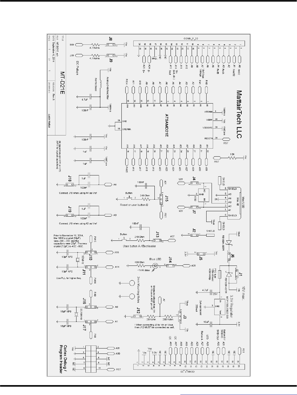
MT-D11 USB ARM Cortex M0+ board
●
●ATSAMD11D14AM (24-pin)
●16KB FLASH, 4KB SRAM
●Onboard 3.3V, 250mA LDO regulator (2uA quiescent)
●16MHz and 32.768KHz crystals
●USB connector (power by USB or external up to 16V)
●Blue LED, 10-pin Cortex header, button, I2C pullups
●USB CDC Bootloader (no programmer required)
●Arduino 1.6.5+ support (core and bootloader)
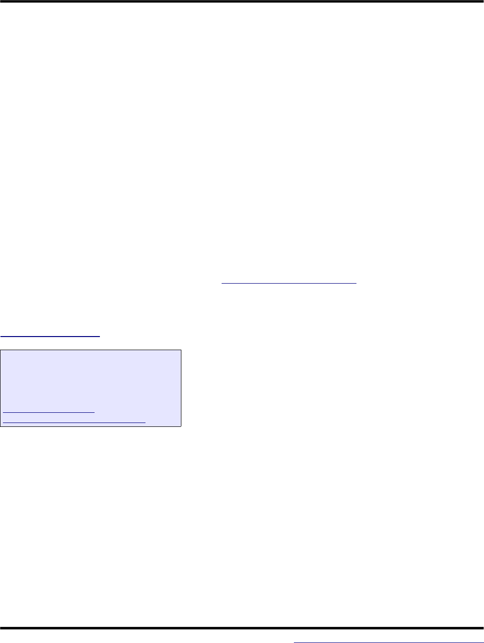
MT-DB-X3 USB AVR XMEGA board
●
●XMEGA A3U, A3BU, C3, and D3 (64-pin)
●32KB - 384KB FLASH, 4KB – 32KB SRAM
●3.3V 250mA regulator (2uA quiescent current)
●Optional 5V 500mA regulator (23uA quiescent current)
●Optional auto-direction sensing level shifter
●16MHz and 32.768KHz crystals, optional coin cell holder
●LED, boot jumper, PDI header, button, TWI pullups
●USB DFU bootloader preinstalled (except D variant)
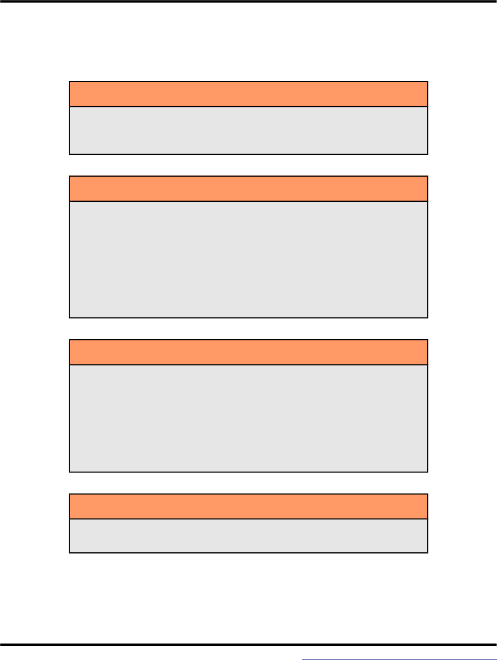
MT-DB-X4 USB AVR XMEGA board
●
●ATxmega128A4U USB XMEGA AVR
●128KB FLASH, 8KB SRAM, 2KB EEPROM
●3.3V LDO regulator (low quiescent current)
●16MHz and 32.768KHz crystals
●LED, boot jumper, PDI header
●Reset button, mounting holes
●USB DFU bootloader preinstalled
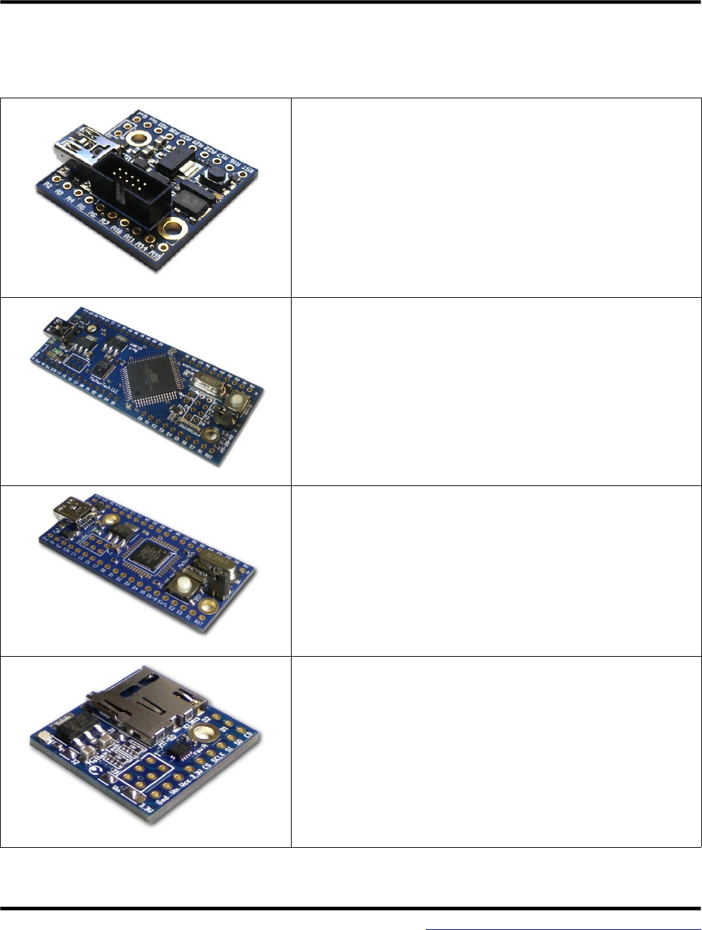
MT-SD MicroSD Card Slot
●
●MicroSD card slot with push-in/push-out
●Onboard 3.3V, 250mA LDO regulator
●Very low quiescent current
●Can use 3.3V for external devices
●Vcc to 3.3V level translator onboard (Vcc can be from
3.3V to 5.5V)
●100Kohm pull resistors
●All MicroSD pins routed to headers
July 11, 2016 39 http://www.mattairtech.com/
