MY18 C Cab Operators Manual
User Manual: Pdf 2018 Mercedes-Benz C-Cabriolet Owners Manual PDF | SERVICE MANUAL OWNERS
Open the PDF directly: View PDF ![]() .
.
Page Count: 350 [warning: Documents this large are best viewed by clicking the View PDF Link!]
C-Class
Cabriolet
Operator's Manual
Mercedes-Benz
Your Operator's Manual
Digital form inside the vehicle
Familiarize yourself with the contents of the Operator's Manual directly via your
vehicle's multimedia system (Menu item "Vehicle").
Booklet inside the vehicle
In addition to the vehicle's Operator's Manual, you can obtain the complete multi-
media system Supplement from your authorized Mercedes-Benz Center.
Digital form via the Internet
You can find the Operator's Manual on the Mercedes-Benz homepage.
Digital form as an App
The Mercedes-Benz Guides App is available for free on the Apple®App store or Google
Play.
Apple® iOS Android™
Order no. P205 0847 13 Part no. 205 584 31 12 Edition A 2018
É2055843112*ËÍ
2055843112
C-Class Cabriolet Operator's Manual

Publication details
Internet
Further information about Mercedes-Benz vehi-
cles and about Daimler AG can be found on the
following websites:
http://www.mbusa.com (USA only)
http://www.mercedes-benz.ca (Canada only)
Editorial office
Daimler AG: not to be reprinted, translated or
otherwise reproduced, in whole or in part, with-
out written permission from Daimler AG.
Vehicle manufacturer
Daimler AG
Mercedesstrae 137
70327 Stuttgart
Germany
Symbols
Registered trademarks:
RBluetooth®is a registered trademark of Blue-
tooth SIG Inc.
RDTS™ is a registered trademark of DTS, Inc.
RDolby®and MLP™ are registered trademarks
of DOLBY Laboratories.
RBabySmart™, ESP®and PRE-SAFE®are reg-
istered trademarks of Daimler AG.
RHomeLink®is a registered trademark of John-
son Controls.
RiPod®and iTunes®are registered trademarks
of Apple Inc.
RBurmester®is a registered trademark of
Burmester Audiosysteme GmbH.
RMicrosoft®and Windows media®are regis-
tered trademarks of Microsoft Corporation.
RSIRIUS®is a registered trademark of Sirius
XM Radio Inc.
RHD Radio™ is a registered trademark of iBiq-
uity Digital Corporation.
RGracenote®is a registered trademark of
Gracenote, Inc.
RZAGAT Survey®and related brands are regis-
tered trademarks of Zagat Survey, LLC.
In this Operator's Manual you will find the fol-
lowing symbols:
GWARNING
Warning notes make you aware of dangers
which could pose a threat to your health or
life, or to the health and life of others.
HEnvironmental note
Environmental notes provide you with infor-
mation on environmentally aware actions or
disposal.
!Notes on material damage alert you to dan-
gers that could lead to damage to your vehi-
cle.
iPractical tips or further information that
could be helpful to you.
XThis symbol indicates an
instruction that must be fol-
lowed.
XSeveral of these symbols in
succession indicate an
instruction with several
steps.
(Y
page)
This symbol tells you where
you can find more informa-
tion about a topic.
YY This symbol indicates a
warning or an instruction
that is continued on the next
page.
Dis‐
play
This text indicates a mes-
sage on the multifunction
display/multimedia display.
As at 03.11.2016

Welcome to the world of Mercedes-Benz
We urge you to read this Operator's Manual
carefully and familiarize yourself with the vehi-
cle before driving. For your own safety and a
longer vehicle life, follow the instructions and
warning notices in this Operator's Manual.
Ignoring them could result in damage to the
vehicle or personal injury to you or others.
Vehicle damage caused by failure to follow
instructions is not covered by the Mercedes-
Benz Limited Warranty.
The equipment or product designation of your
vehicle may vary depending on:
RModel
ROrder
RCountry specification
RAvailability
Mercedes-Benz therefore reserves the right to
introduce changes in the following areas:
RDesign
REquipment
RTechnical features
The equipment in your vehicle may therefore
differ from that shown in the descriptions and
illustrations.
The following are integral components of the
vehicle:
RDigital Operator's Manual
RPrinted Operator's Manual
RMaintenance Booklet
REquipment-dependent supplements
Keep these documents in the vehicle at all
times. If you sell the vehicle, always pass all
documents on to the new owner.
Please note that the Mercedes-Benz Guides app
may not yet be available in your country.
Mercedes-Benz USA, LLC
Mercedes-Benz Canada, Inc.
A Daimler Company
2055843112 É2055843112*ËÍ

Index ....................................................... 4
Digital Operator's Manual .................. 26
Introduction ...........................................26
Operation ............................................... 26
Introduction ......................................... 27
Protecting the environment ...................27
Genuine Mercedes-Benz parts ...............27
Operator's Manual ................................. 28
Service and vehicle operation ................28
Operating safety .................................... 30
QR codes for the rescue card ................32
Data stored in the vehicle ...................... 32
Information on copyright ....................... 34
At a glance ........................................... 35
Cockpit .................................................. 35
Instrument cluster ................................. 36
Multifunction steering wheel ................. 37
Center console ...................................... 38
Overhead control panel .........................41
Door control panel ................................. 42
Safety ................................................... 43
Panic alarm ............................................ 43
Occupant safety .................................... 43
Children in the vehicle ........................... 59
Pets in the vehicle ................................. 64
Driving safety systems ........................... 64
Protection against theft .........................74
Opening and closing ........................... 76
SmartKey ............................................... 76
Doors ..................................................... 81
Trunk ..................................................... 83
Side windows ......................................... 85
Soft top .................................................88
Seats, steering wheel and mirrors .... 94
Correct driver's seat position ................94
Seats ..................................................... 94
Steering wheel ..................................... 100
Mirrors ................................................. 103
Memory function ................................. 105
Lights and windshield wipers .......... 107
Exterior lighting ................................... 107
Interior lighting .................................... 110
Replacing bulbs ................................... 111
Windshield wipers ................................ 111
Climate control ................................. 115
Overview of climate control systems ... 115
Operating the climate control sys-
tems .................................................... 116
Air vents .............................................. 120
Driving and parking .......................... 122
Notes on breaking-in a new vehicle ..... 122
Driving ................................................. 122
DYNAMIC SELECT switch .................... 130
Automatic transmission ....................... 132
Refueling ............................................. 141
Parking ................................................ 143
Driving tips .......................................... 146
Driving systems ................................... 151
On-board computer and displays .... 192
Important safety notes ........................ 192
Displays and operation ........................ 192
Menus and submenus ......................... 196
Display messages ................................ 211
Warning and indicator lamps in the
instrument cluster ............................... 241
Multimedia system ........................... 253
General notes ...................................... 253
Important safety notes ........................ 253
Function restrictions ............................ 253
Operating system ................................ 254
Stowage and features ...................... 263
Stowage areas ..................................... 263
Features .............................................. 267
Maintenance and care ...................... 281
Engine compartment ........................... 281
2Contents

ASSYST PLUS ...................................... 285
Care ..................................................... 286
Breakdown assistance ..................... 295
Where will I find...? .............................. 295
Flat tire ................................................ 296
Battery (vehicle) .................................. 301
Jump-starting ....................................... 304
Towing and tow-starting ...................... 306
Fuses ................................................... 309
Wheels and tires ............................... 312
Important safety notes ........................ 312
Operation ............................................ 312
Winter operation .................................. 314
Tire pressure ....................................... 315
Loading the vehicle .............................. 322
All about wheels and tires ...................325
Changing a wheel ................................ 331
Wheel/tire combination ......................336
Technical data ................................... 338
Information regarding technical data ... 338
Vehicle electronics .............................. 338
Identification plates .............................339
Service products and filling capaci-
ties ...................................................... 340
Vehicle data ......................................... 345
Contents 3

1, 2, 3 ...
4ETS (Electronic Traction System)
see ETS/4ETS (Electronic Trac-
tion System)
4MATIC (permanent four-wheel
drive) .................................................. 166
12 V socket
see Socket (12 V)
360° camera
Cleaning .........................................292
Display in the multimedia system .. 178
Function/notes .............................176
A
ABS (Anti-lock Braking System)
Display message ............................ 213
Function/notes ................................ 64
Warning lamp ................................. 244
Acceleration
see Kickdown
Accident
Automatic measures after an acci-
dent ................................................. 59
Accident warning
see Driving safety system
Activating media mode
General notes ................................ 261
Activating/deactivating cooling
with air dehumidification ................. 117
Active Blind Spot Assist
Activating/deactivating (on-
board computer) ............................ 205
Display message ............................ 230
Function/notes .............................186
Active Brake Assist
Activating or deactivating .............. 204
Display message ............................ 218
Function/notes ................................ 65
Active Brake Assist with cross-
traffic function
Activating or deactivating .............. 205
Display message ............................ 219
Function/notes ................................ 71
Important safety notes .................... 72
Warning lamp ................................. 250
Active Lane Keeping Assist
Activating/deactivating (on-
board computer) ............................ 205
Display message ............................ 229
Function/information .................... 189
Active light function
Display message ............................ 224
Active Service System PLUS
see ASSYST PLUS
ADAPTIVE BRAKE ................................. 71
Adaptive Brake Assist
Function/notes ................................ 67
Adaptive Damping System
Function/notes ............................. 165
Adaptive Damping System with
continuous damping adjustment
(ADS PLUS) ........................................ 164
Adaptive Highbeam Assist
Display message ............................ 224
Function/notes ............................. 109
Switching on/off ........................... 110
Additional speedometer ................... 207
Additives (engine oil) ........................ 343
Address book
see also Digital Operator's Man-
ual .................................................. 253
Adjusting the volume
Multimedia system ........................ 254
After-sales service center
see ASSYST PLUS
Air bags
Deployment ..................................... 56
Display message ............................ 222
Front air bag (driver, front
passenger) ....................................... 50
Head bag ......................................... 51
Important safety notes .................... 49
Introduction ..................................... 48
Knee bag .......................................... 50
Occupant Classification System
(OCS) ............................................... 51
PASSENGER AIR BAG indicator
lamps ............................................... 44
Side impact air bag .......................... 50
Air vents
Important safety notes .................. 120
Rear ............................................... 120
Setting ........................................... 120
4Index

Setting the blower output of the
AIRSCARF vents ............................. 121
Setting the center air vents ........... 120
Setting the side air vents ............... 120
Switching AIRSCARF on/off .......... 100
Air-conditioning system
see Climate control
Airbag
Warning lamp ................................. 247
AIRCAP
Cleaning instructions ..................... 289
Extending/retracting ....................... 91
Important safety notes .................... 91
AIRMATIC
Display message ............................ 228
Function/notes ............................. 163
Setting the normal vehicle level ..... 164
Setting the raised vehicle level ...... 164
AIRSCARF
Switching on/off ........................... 100
AIRSCARF vents
Setting the blower output .............. 121
Alarm
ATA (Anti-Theft Alarm system) ......... 74
Switching off (ATA) .......................... 74
Switching the function on/off
(ATA) ................................................ 74
Alarm system
see ATA (Anti-Theft Alarm system)
All-wheel drive
see 4MATIC (permanent four-
wheel drive)
AMG
Adaptive sport suspension sys-
tem ................................................ 165
Performance Seat ............................ 98
Switchable performance exhaust
system ........................................... 129
AMG menu (on-board computer) ..... 208
Animals
see Pets in the vehicle
Anti-lock braking system
see ABS (Anti-lock Braking System)
Anti-skid chains
see Snow chains
Anti-Theft Alarm system
see ATA (Anti-Theft Alarm system)
AppCode
see QR code
Armrest
Stowage compartment .................. 264
Ashtray ............................................... 269
Assistance display (on-board com-
puter) .................................................. 203
Assistance menu (on-board com-
puter) .................................................. 204
Assistance system
see Driving systems
ASSYST PLUS
Displaying a service message ........ 285
Driving abroad ............................... 286
Hiding a service message .............. 285
Resetting the service interval dis-
play ................................................ 286
Service message ............................ 285
Special service requirements ......... 286
ATA (Anti-Theft Alarm system)
Activating/deactivating ................... 74
Function ........................................... 74
Switching off the alarm .................... 74
ATTENTION ASSIST
Activating/deactivating ................. 205
Display message ............................ 228
Displaying level .............................. 181
Function/notes ............................. 180
Authorized Mercedes-Benz Center
see Qualified specialist workshop
Authorized workshop
see Qualified specialist workshop
AUTO lights
Display message ............................ 224
see Lights
Automatic car wash (care) ............... 286
Automatic engine start (ECO start/
stop function) .................................... 128
Automatic engine switch-off (ECO
start/stop function) .......................... 127
Automatic headlamp mode .............. 107
Automatic transmission
Accelerator pedal position ............. 135
Changing gear ............................... 135
DIRECT SELECT lever ..................... 133
Display message ............................ 236
Double-clutch function .................. 135
Index 5

Drive program ................................ 136
Drive program display .................... 134
Driving tips .................................... 135
DYNAMIC SELECT switch .............. 130
Emergency running mode .............. 141
Engaging drive position .................. 134
Engaging neutral ............................ 133
Engaging park position automati-
cally ............................................... 133
Engaging reverse gear ................... 133
Engaging the park position ............ 133
Gearshift recommendation ............ 140
Gliding mode ................................. 136
Kickdown ....................................... 136
Manual shifting .............................. 138
Oil temperature (on-board com-
puter, Mercedes-AMG vehicles) ..... 208
Overview ........................................ 132
Permanent setting ......................... 139
Problem (malfunction) ................... 141
Pulling away ................................... 126
Starting the engine ........................ 125
Steering wheel paddle shifters ...... 138
Transmission position display
(DIRECT SELECT lever) ................... 134
Transmission positions .................. 135
Automatic transmission emer-
gency mode ....................................... 141
B
Back button ....................................... 254
Backup lamp
Display message ............................ 224
BAS (Brake Assist System) ................. 65
Basic settings
see Settings
Battery (SmartKey)
Checking .......................................... 79
Important safety notes .................... 78
Replacing ......................................... 79
Battery (vehicle)
Charging ........................................ 303
Display message ............................ 226
Important safety notes .................. 301
Jump starting ................................. 304
Belt
see Seat belts
Belt warning ......................................... 48
Blind Spot Assist
Activating/deactivating (on-
board computer) ............................ 205
Display message ............................ 230
Notes/function .............................. 182
see Active Blind Spot Assist
Blower
see Climate control
Bluetooth®
Connecting a different mobile
phone ............................................ 261
Searching for a mobile phone ........ 260
see also Digital Operator's Man-
ual .................................................. 253
Telephony ...................................... 260
Brake
Active Brake Assist with cross-
traffic function ................................. 71
Brake Assist
see BAS (Brake Assist System)
Brake assistance
see BAS (Brake Assist System)
Brake fluid
Display message ............................ 218
Notes ............................................. 343
Brake force distribution
see EBD (electronic brake force
distribution)
Brake linings
Display message ............................ 218
Brakes
ABS .................................................. 64
Adaptive Brake Assist ...................... 67
BAS .................................................. 65
Brake fluid (notes) ......................... 343
Display message ............................ 213
EBD .................................................. 71
High-performance brake system .... 150
Hill start assist ............................... 127
HOLD function ............................... 161
Important safety notes .................. 148
Maintenance .................................. 149
Parking brake ................................ 145
Riding tips ...................................... 148
Warning lamp ................................. 243
Breakdown
Where will I find...? ........................ 295
6Index

see Flat tire
see Towing away
Brightness control (instrument
cluster lighting) ................................... 35
Buttons on the steering wheel ......... 193
C
California
Important notice for retail cus-
tomers and lessees .......................... 28
Calling up a malfunction
see Display messages
Calling up the climate control bar
Multimedia system ........................ 258
Calling up the climate control
menu
Multimedia system ........................ 258
Camera
see 360° camera
see Rear view camera
Car
see Vehicle
Car wash
see Care
Care
360° camera ................................. 292
AIRCAP .......................................... 289
Car wash ........................................286
Carpets .......................................... 294
Display ...........................................293
Exhaust pipe .................................. 292
Exterior lights ................................ 291
General notes ................................ 286
Interior ...........................................293
Matte finish ................................... 289
Paint .............................................. 288
Plastic trim ....................................293
Power washer ................................ 288
Rear view camera .......................... 292
Roof lining ...................................... 294
Seat belt ........................................ 294
Seat cover ..................................... 294
Selector lever ................................ 293
Sensors ......................................... 292
Soft top .......................................... 289
Steering wheel ............................... 293
Trim pieces .................................... 293
Washing by hand ........................... 287
Wheels ........................................... 291
Wind deflector ............................... 289
Wind screen ................................... 290
Windows ........................................ 291
Wiper blades .................................. 291
Wooden trim .................................. 293
Cargo tie down rings ......................... 266
CD
see also Digital Operator's Man-
ual .................................................. 253
CD player (on-board computer) ........ 201
Center console
Lower section .................................. 39
Lower section (Mercedes-AMG
vehicles) .......................................... 40
Upper section .................................. 38
Central locking
Locking/unlocking (SmartKey) ........ 76
Change of address .............................. 29
Change of ownership .......................... 29
Changing the media source ............. 200
Charge-air pressure (on-board
computer, Mercedes-AMG vehi-
cles) .................................................... 208
Child
Restraint system .............................. 60
Child seat
Forward-facing restraint system ...... 63
LATCH-type (ISOFIX) child seat
anchors ............................................ 61
On the front-passenger seat ............ 63
Rearward-facing restraint system .... 63
Top Tether ....................................... 62
Children
Special seat belt retractor ............... 60
Children in the vehicle
Important safety notes .................... 59
Cigarette lighter ................................ 270
Cleaning
Mirror turn signal ........................... 292
Climate control
Control panel for dual-zone auto-
matic climate control ..................... 115
Controlling automatically ............... 117
Cooling with air dehumidification .. 117
Index 7

Coolingwith air dehumidification
(multimedia system) ...................... 258
Defrosting the windows .................119
Defrosting the windshield .............. 118
ECO start/stop function ................ 116
General notes ................................ 115
Indicator lamp ................................ 117
Ionization ....................................... 120
Ionization (multimedia system) ...... 258
Notes on using the automatic cli-
mate control .................................. 116
Overview ........................................ 257
Overview of systems ......................115
Problem with the rear window
defroster ........................................ 119
Problems with cooling with air
dehumidification ............................ 117
Refrigerant ..................................... 344
Refrigerant filling capacity ............. 345
Setting the air distribution ............. 118
Setting the air vents ......................120
Setting the airflow ......................... 118
Setting the climate mode (multi-
media system) ............................... 258
Setting the temperature ................ 118
Switching air-recirculation mode
on/off ............................................ 120
Switching on/off ........................... 116
Switching the rear window
defroster on/off ............................ 119
Switching the synchronization
function on and off ........................ 118
Synchronization function (multi-
media system) ............................... 258
Climate control settings
Multimedia system ........................ 257
Climate control system
Climate control .............................. 116
Cockpit
Overview .......................................... 35
Code for Apps
see QR code
COMAND display
Cleaning ......................................... 293
Combination switch .......................... 108
Connecting a USB device
see also Digital Operator's Man-
ual ..................................................253
Consumption statistics (on-board
computer) .......................................... 197
Controller ...........................................254
Controlling the speed
see Distance Pilot DISTRONIC
Convenience opening feature ............ 90
Coolant (engine)
Checking the level ......................... 284
Display message ............................ 225
Filling capacity ............................... 344
Important safety notes .................. 343
Temperature display in the instru-
ment cluster .................................. 193
Warning lamp ................................. 248
Cooling
see Climate control
Copyright ............................................. 34
Cornering light function
Display message ............................ 224
Function/notes .............................109
Crosswind Assist ................................. 71
Cruise control
Cruise control lever ....................... 152
Deactivating ................................... 153
Display message ............................ 232
Driving system ............................... 151
Function/notes .............................151
General notes ................................ 151
Important safety notes .................. 151
Setting a speed .............................. 152
Storing and maintaining current
speed ............................................. 152
Storing the current speed or call-
ing up the last stored speed .......... 152
Cup holder
Center console .............................. 268
Important safety notes .................. 267
Rear compartment ......................... 268
Customer Assistance Center
(CAC) ..................................................... 31
Customer Relations Department ....... 31
D
Dashboard
see Instrument cluster
Dashboard lighting
see Instrument cluster lighting
8Index

Data
see Technicaldata
Datacarrier
Selecting ........................................ 201
Daytime runninglampmode
see Daytime running lamps
Daytime runninglamps
Displaymessage ............................ 224
Function/notes .............................107
Switching on/off (on-board com-
puter) ............................................. 207
Diagnostics connection ......................31
Digital Operator's Manual
Help .................................................26
Introduction .....................................26
Digital speedometer .........................197
DIRECT SELECT lever
Automatic transmission ................. 133
Display
see Display messages
see Warning and indicator lamps
Display messages
ASSYST PLUS ................................ 285
Calling up (on-board computer) ..... 212
Driving systems .............................228
Engine ............................................ 225
General notes ................................ 211
Hiding (on-board computer) ........... 211
Introduction ................................... 211
Lights ............................................. 224
Safety systems .............................. 213
SmartKey ....................................... 240
Tires ............................................... 234
Vehicle ...........................................236
Distance control
see Driving system
Distance Pilot DISTRONIC
Activating ....................................... 155
Activation conditions ..................... 155
Cruise control lever ....................... 155
Display Message ............................ 231
Displays in the instrument cluster .. 157
Driving tips ....................................159
Driving with Distance Pilot
DISTRONIC ....................................156
Function/notes .............................153
Important safety notes .................. 154
Setting a speed .............................. 157
Setting the specified minimum
distance ......................................... 157
Stopping ........................................ 156
Switching off .................................. 158
with Steering Pilot ......................... 159
Distance recorder .............................196
Distance warning (warning lamp) .... 250
Distance warning function
Function/notes ................................ 66
Distance warning system
see Active Brake Assist
Doors
Automatic locking (switch) ...............82
Central locking/unlocking
(SmartKey) .......................................76
Control panel ...................................42
Display message ............................ 238
Emergency locking ........................... 83
Emergency unlocking ....................... 83
Important safety notes .................... 81
Opening (from inside) ...................... 81
Drinking and driving ......................... 147
Drive program
Automatic transmission ................. 136
SETUP (on-board computer,
Mercedes-AMG vehicles) ............... 209
Drive programs
Display (DIRECT SELECT lever) ...... 134
DYNAMIC SELECT switch .............. 130
Driver's door
see Doors
Driver's seat
see Seat
Driving abroad
Mercedes-Benz Service ................. 286
Driving Assistance PLUS package ... 186
Driving on flooded roads .................. 150
Driving safety system
Active Brake Assist .......................... 65
Crosswind Assist ............................. 71
Driving safety systems
ABS (Anti-lock Braking System) ....... 64
Active Brake Assist with cross-
traffic function ................................. 71
ADAPTIVE BRAKE ............................. 71
Adaptive Brake Assist ...................... 67
BAS (Brake Assist System) .............. 65
Index 9

Distance warning function ............... 66
EBD (electronic brake force distri-
bution) ............................................. 71
ESP®(Electronic Stability Pro-
gram) ............................................... 67
Important safety information ........... 64
Overview .......................................... 64
STEER CONTROL ............................. 74
Driving system
Distance Pilot DISTRONIC ............. 153
Distance Pilot DISTRONIC with
Steering Pilot ................................. 159
Parking assist PARKTRONIC .......... 170
Parking Pilot .................................. 166
RACE START (Mercedes-AMG
vehicles) ........................................ 162
Driving systems
360°camera .................................. 176
Active Blind Spot Assist ................. 186
Active Lane Keeping Assist ............ 189
AIRMATIC ...................................... 163
AMG adaptive sport suspension
system ........................................... 165
ATTENTION ASSIST ........................ 180
Blind Spot Assist ............................ 182
Cruise control ................................ 151
Display message ............................ 228
Driving Assistance Plus package ... 186
HOLD function ............................... 161
Lane Keeping Assist ...................... 184
Lane Tracking package .................. 182
Rear view camera .......................... 173
Traffic Sign Assist .......................... 182
Driving tips
AMG ceramic brakes ..................... 150
Automatic transmission ................. 135
Brakes ........................................... 148
Break-in period .............................. 122
Distance Pilot DISTRONIC ............. 159
Downhill gradient ........................... 148
Drinking and driving ....................... 147
Driving in winter ............................. 151
Driving on flooded roads ................ 150
Driving on wet roads ...................... 150
Exhaust check ............................... 147
Fuel ................................................ 147
General .......................................... 146
Hydroplaning ................................. 150
Icy road surfaces ........................... 151
Important safety notes .................. 122
Limited braking efficiency on sal-
ted roads ....................................... 149
Snow chains .................................. 315
Subjecting brakes to a load ........... 149
The first 1000 miles (1500 km) ..... 122
Wet road surface ........................... 149
DVD video
Operating (on-board computer) ..... 201
see also Digital Operator's Man-
ual .................................................. 253
DYNAMIC SELECT switch
Automatic transmission ................. 130
Climate control (dual-zone auto-
matic climate control) .................... 116
E
EASY-ENTRY feature
Function/notes ............................. 101
EASY-ENTRY system ............................ 97
EASY-EXIT feature
Function/notes ............................. 101
EBD (electronic brake force distri-
bution)
Display message ............................ 215
Function/notes ................................ 71
ECO display
Function/notes ............................. 147
On-board computer ....................... 197
ECO start/stop function
Automatic engine start .................. 128
Automatic engine switch-off .......... 127
Deactivating/activating ................. 128
General information ....................... 127
Important safety notes .................. 127
Introduction ................................... 127
Electronic brake force distribution
see EBD (electronic brake force
distribution)
Electronic Stability Program
see ESP®(Electronic Stability Program)
Emergency
Automatic measures after an acci-
dent ................................................. 59
Emergency braking
see BAS (Brake Assist System)
10 Index

Emergency release
Driver's door .................................... 83
Trunk ...............................................85
Vehicle .............................................83
Emergency Tensioning Devices
Activation .........................................56
Emissions control
Service and warranty information .... 28
Engine
Check Engine warning lamp ...........247
Display message ............................ 225
ECO start/stop function ................ 127
Engine number ............................... 340
Irregular running ............................ 129
Jump-starting ................................. 304
Starting (important safety notes) ... 125
Starting problems .......................... 129
Starting the engine with the
SmartKey ....................................... 125
Starting via smartphone ................ 126
Starting with the Start/Stop but-
ton ................................................. 125
Switching off .................................. 144
Tow-starting (vehicle) ..................... 309
Engine electronics
Problem (malfunction) ................... 129
Engine jump starting
see Jump starting (engine)
Engine oil
Adding ...........................................283
Additives ........................................ 343
Checking the oil level ..................... 282
Checking the oil level using the
dipstick .......................................... 283
Display message ............................ 227
Filling capacity ............................... 343
General notes ................................ 342
Notes about oil grades ................... 342
Notes on oil level/consumption .... 282
Temperature (on-board computer,
Mercedes-AMG vehicles) ...............208
Engine oil additives
see Additives (engine oil)
Entering an address
see also Digital Operator's Man-
ual ..................................................253
ESC (Electronic Stability Control)
see ESP®(Electronic Stability Program)
ESP®(Electronic Stability Pro-
gram)
AMG menu (on-board computer) ... 209
Characteristics ................................. 68
Crosswind Assist .............................71
Deactivating/activating (button
in Mercedes-AMG vehicles) .............69
Deactivating/activating (notes,
except Mercedes-AMG vehicles) ...... 68
Deactivating/activating (on-
board computer, except
Mercedes-AMG vehicles) ............... 204
Display message ............................ 213
Function/notes ................................ 67
General notes .................................. 67
Important safety information ........... 68
Trailer stabilization ........................... 70
Warning lamp ................................. 244
ETS/4ETS (Electronic Traction Sys-
tem) ...................................................... 68
Exhaust
see Exhaust pipe
Exhaust check ................................... 147
Exhaust pipe
Cleaning ......................................... 292
Exterior lighting
Cleaning ......................................... 291
Setting options .............................. 107
see Lights
Exterior mirrors
Adjusting ....................................... 103
Dipping (automatic) ....................... 104
Folding in/out (automatically) ....... 104
Folding in/out (electrically) ........... 103
Out of position (troubleshooting) ... 104
Setting ........................................... 103
Storing settings (memory func-
tion) ............................................... 106
Storing the parking position .......... 104
Eyeglasses compartment ................. 264
F
Favorites
Overview ........................................ 256
Features ............................................. 267
Filler cap
see Refueling
Index 11

Flat tire
Changing a wheel/mounting the
spare wheel ...................................331
MOExtended tires .......................... 297
Preparing the vehicle ..................... 296
TIREFIT kit ...................................... 298
Floormats ...........................................280
Folding wind screen
Cleaning ......................................... 290
Installing .......................................... 92
Removing ......................................... 92
Frequencies
Mobile phone ................................. 338
Two-way radio ................................ 338
Front-passenger seat
see Seat
Fuel
Additives ........................................ 342
Consumption statistics .................. 197
Displaying the current consump-
tion ................................................ 197
Displaying the range ......................197
Driving tips ....................................147
Fuel gauge ....................................... 36
Grade (gasoline) ............................ 341
Important safety notes .................. 341
Problem (malfunction) ................... 143
Refueling ........................................ 141
Tank content/reserve fuel ............. 341
Fuel filler flap
Closing ...........................................143
Fuel level
Calling up the range (on-board
computer) ...................................... 197
Fuel tank
Capacity ........................................ 341
Problem (malfunction) ................... 143
Fuses
Allocation chart .............................311
Before changing .............................309
Dashboard fuse box ....................... 310
Fuse box in the engine compart-
ment .............................................. 310
Fuse box in the front-passenger
footwell .......................................... 310
Fuse box in the trunk ..................... 311
Important safety notes .................. 309
G
G-Meter (on-board computer,
Mercedes-AMG vehicles) .................. 208
Garage door opener
Clearing the memory ..................... 280
General notes ................................ 277
Important safety notes .................. 278
Opening/closing the garage door .. 280
Problems when programming ........279
Programming (button in the rear-
view mirror) ................................... 278
Synchronizing the rolling code ....... 279
Gear indicator (on-board com-
puter, Mercedes-AMG vehicles) ....... 208
Genuine parts ...................................... 27
Glove box ...........................................264
Google™ Local Search
see also Digital Operator's Man-
ual ..................................................253
H
Handbrake
see Parking brake
Handling control system
see ESP®(Electronic Stability Program)
Handwriting recognition
Switching text reader function
on/off ............................................ 256
Touchpad ....................................... 255
Hazard warning lamps ......................109
Head bags
Display message ............................ 221
Operation ......................................... 51
Head level heating (AIRSCARF) ........100
Head restraints
Adjusting (electrically) ..................... 97
Adjusting the fore-and-aft posi-
tion manually ................................... 96
General notes .................................. 96
Important safety notes .................... 96
Installing/removing (rear) ................ 97
Head-up display
Adjusting the brightness ................ 206
Displays and operating .................. 195
Function/notes .............................195
Important safety notes .................. 195
12 Index

Selecting displays .......................... 206
Setting the position ....................... 206
Storing settings (memory func-
tion) ............................................... 106
Switching on or off ......................... 195
Headlamps
Display message ............................ 224
Fogging up ..................................... 110
see Automatic headlamp mode
Heating
see Climate control
High beam flasher ............................. 108
High-beam headlamps
Adaptive Highbeam Assist ............. 109
Display message ............................ 224
Switching on/off ........................... 108
Hill start assist .................................. 127
HOLD function
Activating ....................................... 162
Activation conditions ..................... 161
Deactivating ................................... 162
Display message ............................ 231
Function/notes ............................. 161
General notes ................................ 161
Home address
see also Digital Operator's Man-
ual .................................................. 253
Hood
Closing ........................................... 282
Display message ............................ 238
Important safety notes .................. 281
Opening ......................................... 281
Horn ...................................................... 35
HUD
see Head-up display
Hydroplaning ..................................... 150
I
Ignition key
see SmartKey
Ignition lock
see Key positions
Immobilizer .......................................... 74
Indicator lamps
see Warning and indicator lamps
Indicators
see Turn signals
Insect protection on the radiator .... 282
Inspection
see ASSYST PLUS
Instrument cluster
Overview .......................................... 36
Warning and indicator lamps ........... 36
Instrument cluster lighting .............. 192
Interior lighting
Automatic control .......................... 111
Control ........................................... 111
Overview ........................................ 110
Reading lamp ................................. 110
iPod®
see also Digital Operator's Man-
ual .................................................. 253
J
Jack
Using ............................................. 333
Jump starting (engine) ...................... 304
K
Key positions
SmartKey ....................................... 123
Start/Stop button .......................... 124
KEYLESS-GO
Activating ......................................... 77
Deactivation ..................................... 77
Locking ............................................ 77
Removing the Start/Stop button ... 124
Start function ................................... 77
Unlocking ......................................... 77
Kickdown
Driving tips .................................... 136
Manual gearshifting ....................... 141
Knee bag .............................................. 50
L
Lamps
see Warning and indicator lamps
Lane Change Assist
see Active Blind Spot Assist
Lane detection (automatic)
see Lane Keeping Assist
Lane Keeping Assist
Activating/deactivating ................. 185
Index 13

Activating/deactivating (on-
board computer) ............................ 205
Display message ............................ 229
Function/information .................... 184
see Active Lane Keeping Assist
Lane Tracking package ..................... 182
Lap time (RACETIMER) ...................... 210
LATCH-type (ISOFIX) child seat
anchors ................................................ 61
License plate lamp (display mes-
sage) ................................................... 224
Light function, active
Display message ............................ 224
Light switch
Operation ....................................... 107
Lights
Adaptive Highbeam Assist ............. 109
Automatic headlamp mode ............ 107
Cornering light function ................. 109
Fogged up headlamps .................... 110
General notes ................................ 107
Hazard warning lamps ...................109
High beam flasher .......................... 108
High-beam headlamps ................... 108
Light switch ................................... 107
Low-beam headlamps .................... 108
Parking lamps ................................ 108
Rear fog lamp ................................ 108
Setting exterior lighting ................. 107
Standing lamps .............................. 108
Switching the daytime running
lamps on/off (on-board com-
puter) ............................................. 207
Turn signals ................................... 108
see Interior lighting
see Replacing bulbs
Loading guidelines ............................ 263
Locking
see Central locking
Locking (doors)
Automatic ........................................ 82
Emergency locking ........................... 83
From inside (central locking but-
ton) ..................................................82
Locking centrally
see Central locking
Low-beam headlamps
Display message ............................ 224
Switching on/off ...........................108
Lubricant additives
see Additives (engine oil)
Luggage cover
see Trunk partition
Lumbar support
Adjusting the 4-way lumbar sup-
port ..................................................98
M
M+S tires ............................................ 314
Malfunction message
see Display messages
Matte finish (cleaning instruc-
tions) .................................................. 289
mbrace
Call priority ....................................274
Display message ............................ 218
Downloading destinations
(COMAND) ..................................... 274
Downloading routes ....................... 277
Emergency call .............................. 272
General notes ................................ 271
Geo fencing ................................... 277
Info call button .............................. 273
Locating a stolen vehicle ...............276
Remote fault diagnosis .................. 276
Remote vehicle locking .................. 275
Roadside assistance button ........... 273
Search & Send ............................... 275
Self-test ......................................... 271
Speed alert .................................... 277
System .......................................... 271
Triggering the vehicle alarm ........... 277
Vehicle remote unlocking .............. 275
Mechanical key
Function/notes ................................ 78
General notes .................................. 78
Inserting .......................................... 78
Locking vehicle ................................ 83
Removing ......................................... 78
Unlocking the driver's door .............. 83
Media Interface
see Digital Operator's Manual
Memory card (audio) ......................... 201
14 Index

Memory function
Seats, steering wheel, exterior
mirrors ........................................... 105
Mercedes-Benz Intelligent Drive
360°camera .................................. 176
Active Blind Spot Assist ................. 186
Active Lane Keeping Assist ............ 189
ATTENTION ASSIST ........................ 180
Blind Spot Assist ............................ 182
Distance Pilot DISTRONIC ............. 153
Distance Pilot DISTRONIC with
Steering Pilot ................................. 159
General notes ................................ 151
Lane Keeping Assist ...................... 184
Parking Assist PARKTRONIC .......... 170
Parking Pilot .................................. 166
PRE-SAFE®(anticipatory occu-
pant protection) ...............................58
PRE-SAFE®PLUS (anticipatory
occupant protection PLUS) .............. 58
Rear view camera .......................... 173
Traffic Sign Assist .......................... 182
Message memory (on-board com-
puter) .................................................. 212
Messages
see Display messages
see Warning and indicator lamps
Mirror turn signal
Cleaning ......................................... 292
Mirrors
see Exterior mirrors
see Vanity mirror (in the sun visor)
Mobile phone
Connecting (Bluetooth®inter-
face) ..............................................260
Connecting another mobile
phone ............................................ 261
Frequencies ................................... 338
Installation ..................................... 338
Menu (on-board computer) ............ 202
Transmission output (maximum) .... 338
Model type
see Vehicle identification plate
Modifying the programming
(SmartKey) ...........................................78
MOExtended tires .............................. 297
Mounting wheels
Lowering the vehicle ...................... 336
Mounting a new wheel ................... 335
Preparing the vehicle .....................332
Raising the vehicle ......................... 333
Removing a wheel .......................... 335
Securing the vehicle against roll-
ing away ........................................ 332
MP3
Operation ....................................... 201
see also Digital Operator's Man-
ual ..................................................253
Multifunction display
Function/notes .............................194
Multifunction steering wheel
Operating the on-board computer .. 193
Overview .......................................... 37
Multimedia system
Switching on and off ......................254
Music files
see also Digital Operator's Man-
ual ..................................................253
N
Navigation
Displaying (on-board computer) ..... 198
Menu (on-board computer) ............ 198
see also Digital Operator's Man-
ual ..................................................253
Notes on breaking-in a new vehi-
cle ....................................................... 122
O
Occupant Classification System
(OCS)
Conditions ....................................... 51
Faults ............................................... 55
Operation ......................................... 52
System self-test ............................... 54
Occupant safety
Air bags ...........................................48
Automatic measures after an acci-
dent ................................................. 59
Belt warning ..................................... 48
Children in the vehicle ..................... 59
Important safety notes .................... 43
Index 15

Introduction to the restraint sys-
tem .................................................. 43
Occupant Classification System
(OCS) ............................................... 51
PASSENGER AIR BAG indicator
lamps ............................................... 44
Pets in the vehicle ........................... 64
PRE-SAFE®(anticipatory occu-
pant protection) ............................... 58
PRE-SAFE®PLUS (anticipatory
occupant protection PLUS) .............. 58
Restraint system warning lamp ........ 44
Seat belt .......................................... 44
OCS
Conditions ....................................... 51
Faults ............................................... 55
Operation .........................................52
System self-test ............................... 54
Odometer ........................................... 196
Oil
see Engine oil
On-board computer
AMG menu ..................................... 208
Assistance graphic menu ............... 203
Assistance menu ........................... 204
Display messages .......................... 211
Displaying a service message ........ 285
Displays and operation .................. 192
Distance Pilot DISTRONIC ............. 158
Factory settings ............................. 207
G-Meter ......................................... 208
Head-up display ............................. 195
Important safety notes .................. 192
Instrument cluster menu ............... 207
Lights menu ................................... 207
Media menu ................................... 200
Menu overview .............................. 196
Message memory .......................... 212
Navigation menu ............................ 198
RACETIMER ................................... 210
Radio menu ................................... 200
Service menu ................................. 203
Settings menu ............................... 203
Standard display ............................ 196
Telephone menu ............................ 202
Trip menu ...................................... 196
Video DVD operation ..................... 201
On-board diagnostic interface
see Diagnostics connection
Operating safety
Declaration of conformity ................ 30
Important safety notes .................... 30
Operating system
see On-board computer
Operation
Digital Operator's Manual ................ 26
Operator's Manual
Overview .......................................... 28
Vehicle equipment ........................... 28
Outside temperature display ........... 193
Overhead control panel ...................... 41
P
Paddle shifters
see Steering wheel paddle shifters
Paint code number ............................ 339
Paintwork (cleaning instructions) ... 288
Panic alarm .......................................... 43
Parcel net ........................................... 267
Parking
Important safety notes .................. 143
Parking brake ................................ 145
Parking position for the exterior
mirror on the front-passenger
side ................................................ 104
Rear view camera .......................... 173
Switching off the engine ................ 144
see Parking Assist PARKTRONIC
Parking aid
see 360° camera
see Exterior mirrors
see Parking Assist PARKTRONIC
see Parking Pilot
see Rear view camera
Parking Assist
Display message ............................ 230
Parking Assist PARKTRONIC
Deactivating/activating ................. 172
Driving system ............................... 170
Function/notes ............................. 170
Important safety notes .................. 170
Problems (malfunctions) ................ 172
Sensor range ................................. 170
Warning display ............................. 171
16 Index

Parking assistance
see Parking Assist PARKTRONIC
Parking brake
Applying automatically ...................145
Applying or releasing manually ...... 145
Display message ............................ 215
Electric parking brake .................... 145
Emergency braking ........................ 146
General notes ................................ 145
Releasing automatically ................. 146
Warning lamp ................................. 247
Parking lamps
Switching on/off ........................... 108
Parking Pilot
Canceling ....................................... 170
Detecting parking spaces .............. 167
Exiting a parking space .................. 169
Function/notes .............................166
Important safety notes .................. 166
Parking .......................................... 168
PASSENGER AIR BAG
Display message ............................ 222
Indicator lamps ................................ 44
Problems (malfunction) .................. 222
Pedestrian protection
see Hood
Permanent all-wheel drive
see 4MATIC (permanent four-
wheel drive)
Pets in the vehicle ............................... 64
Phone book
see also Digital Operator's Man-
ual ..................................................253
Plastic trim (cleaning instruc-
tions) ..................................................293
Power washers .................................. 288
Power windows
see Side windows
PRE-SAFE®(anticipatory occupant
protection)
Display message ............................ 219
Operation ......................................... 58
PRE-SAFE®PLUS (anticipatory
occupant protection PLUS)
Operation ......................................... 58
Program
see Drive programs
Protection against theft
ATA (Anti-Theft Alarm system) ......... 74
Immobilizer ...................................... 74
Protection of the environment
General notes .................................. 27
Pulling away
Automatic transmission ................. 126
General notes ................................ 126
Hill start assist ............................... 127
Q
QR code
Mercedes-Benz Guide App ................. 1
Rescue card ..................................... 32
Qualified specialist workshop ........... 31
Quick access for audio and tele-
phone
Changing the station/music
track .............................................. 256
R
RACE START (Mercedes-AMG vehi-
cles) .................................................... 162
RACE TIMER (on-board computer,
Mercedes-AMG vehicles) .................. 210
Radar sensor system
Display message ............................ 220
Radiator cover ................................... 282
Radio
Selecting a station ......................... 200
Radio mode
see also Digital Operator's Man-
ual .................................................. 253
Radio-wave reception/transmis-
sion in the vehicle
Declaration of conformity ................ 30
Reading lamp ..................................... 110
Rear compartment
Setting the air vents ...................... 120
Rear fog lamp
Display message ............................ 224
Switching on/off ........................... 108
Rear seat (folding the backrest for-
wards/back) ...................................... 265
Rear view camera
"Reverse parking" function ............ 175
Index 17

Cleaning instructions .....................292
Display in the multimedia system .. 173
General notes ................................ 173
Object detection (function/
notes) ............................................ 176
Switching on/off ........................... 173
Wide-angle function ....................... 176
Rear window defroster
Problem (malfunction) ................... 119
Switching on/off ........................... 119
Rear-view mirror
Dipping (automatic) ....................... 104
Recuperation display ........................ 197
Reflective safety jacket .................... 295
Refrigerant (air-conditioning sys-
tem)
Important safety notes .................. 344
Refueling
Fuel gauge ....................................... 36
Important safety notes .................. 141
Refueling process .......................... 142
see Fuel
Remote control
Garage door opener ....................... 277
Programming (garage door
opener) .......................................... 278
Replacing bulbs
General notes ................................ 111
Reporting safety defects .................... 31
Rescue card ......................................... 32
Reserve (fuel tank)
see Fuel
Reserve fuel
Display message ............................ 227
Warning lamp ................................. 247
Restraint system
Display message ............................ 220
Introduction ..................................... 43
Warning lamp ................................. 247
Warning lamp (function) ................... 44
Reversing feature
Side windows ................................... 85
Roadside Assistance (breakdown) .... 29
Roll away protection
see HOLD function
Roll bar
Display message ............................ 221
Operation ......................................... 55
Roof
Overview .......................................... 88
see Soft top
Roof lining and carpets (cleaning
guidelines) ......................................... 294
Route guidance
see also Digital Operator's Man-
ual .................................................. 253
Route guidance active ...................... 198
S
Safety
Children in the vehicle ..................... 59
see Occupant safety
see Operating safety
Safety system
see Driving safety systems
SD card
Inserting/removing ........................ 261
Selecting ........................................ 201
SD memory card
see also Digital Operator's Man-
ual .................................................. 253
Search & Send
see also Digital Operator's Man-
ual .................................................. 253
Seat
Correct driver's seat position ........... 94
Seat belts
Adjusting the driver's and front-
passenger seat belt ......................... 48
Cleaning ......................................... 294
Correct usage .................................. 46
Fastening ......................................... 47
Important safety guidelines ............. 45
Introduction ..................................... 44
Releasing ......................................... 48
Warning lamp ................................. 241
Warning lamp (function) ................... 48
Seat function
see Seat
Seats
Adjusting (AMG Performance
Seat) ................................................ 98
Adjusting (electrically) ..................... 96
18 Index

Adjusting the 4-way lumbar sup-
port .................................................. 98
Adjusting the head restraint ............ 96
Calling up a stored setting (mem-
ory function) .................................. 106
Cleaning the cover ......................... 294
Folding the backrest (rear com-
partment) forwards/back .............. 265
Folding the backrests forward/
back ................................................. 97
Important safety notes .................... 94
Seat backrest display message ..... 238
Seat heating .................................... 99
Seat heating problem .................... 100
Seat ventilation ................................ 99
Seat ventilation problem ................ 100
Storing settings (memory func-
tion) ............................................... 106
Switching AIRSCARF on/off .......... 100
Securing a load
see Securing cargo
Securing cargo .................................. 266
Selecting a gear
see Automatic transmission
Selector lever
Cleaning ......................................... 293
see Automatic transmission
Sensors (cleaning instructions) ....... 292
Service center
see Qualified specialist workshop
Service Center
see Qualified specialist workshop
Service menu (on-board com-
puter) .................................................. 203
Service message
see ASSYST PLUS
Service products
Brake fluid ..................................... 343
Coolant (engine) ............................ 343
Engine oil ....................................... 342
Fuel ................................................ 340
Important safety notes .................. 340
Refrigerant (air-conditioning sys-
tem) ............................................... 344
Washer fluid ................................... 344
Setting the date/time format
see also Digital Operator's Man-
ual .................................................. 253
Setting the language
see also Digital Operator's Man-
ual .................................................. 253
Setting the time
see also Digital Operator's Man-
ual .................................................. 253
Settings
Factory (on-board computer) ......... 207
On-board computer ....................... 203
SETUP (on-board computer,
Mercedes-AMG vehicles) .................. 209
Side impact air bag ............................. 50
Side marker lamp (display mes-
sage) ................................................... 224
Side windows
Cleaning ......................................... 291
Important safety information ........... 85
Opening/closing .............................. 86
Opening/closing (all) ....................... 86
Problem (malfunction) ..................... 87
Resetting ......................................... 87
Reversing feature ............................. 85
SIRIUS services
see also Digital Operator's Man-
ual .................................................. 253
SmartKey
Changing the battery ....................... 79
Changing the programming ............. 78
Checking the battery ....................... 79
Display message ............................ 240
Door central locking/unlocking ....... 76
Important safety notes .................... 76
KEYLESS-GO start function .............. 77
Loss ................................................. 80
Mechanical key ................................ 78
Opening/closing soft top ................. 90
Overview .......................................... 76
Positions (ignition lock) ................. 123
Problem (malfunction) ..................... 80
Starting the engine ........................ 125
Smartphone
Starting the engine ........................ 126
SMS
see also Digital Operator's Man-
ual .................................................. 253
Snow chains ...................................... 315
Socket (12 V)
Center console .............................. 270
Index 19

General notes ................................ 270
Rear compartment .........................270
Soft top
AIRCAP ............................................ 91
Cleaning ......................................... 289
Display message ............................ 239
Important safety notes .................... 88
Opening/closing (SmartKey) ........... 90
Opening/closing (with soft-top
switch) ............................................. 89
Problem (malfunction) ..................... 93
Relocking ......................................... 90
wind screen ..................................... 91
Soft-top switch ....................................89
Sound
Switching on/off ........................... 254
Special seat belt retractor .................. 60
Specialist workshop ............................31
Speed, controlling
see Cruise control
Speedometer
Activating/deactivating the addi-
tional speedometer ........................ 207
Digital ............................................ 197
In the Instrument cluster ................. 36
Segments ...................................... 192
Selecting the display unit ............... 207
SPORT handling mode
Deactivating/activating
(Mercedes-AMG vehicles) ................69
Warning lamp ................................. 246
Sports exhaust system
AMG ............................................... 129
Standing lamps
Display message ............................224
Switching on/off ........................... 108
Start button
Display message ............................ 241
Start/Stop button
Key positions ................................. 124
Starting the engine ........................ 125
Start/stop function
see ECO start/stop function
Starting (engine) ................................ 125
Starting the engine
see Starting (engine)
STEER CONTROL .................................. 74
Steering
Display message ............................ 238
Warning lamps ............................... 252
Steering assistant STEER CON-
TROL
see STEER CONTROL
Steering Pilot
Display message ............................ 232
with Distance Pilot DISTRONIC ...... 159
Steering wheel
Adjusting (electrically) ................... 101
Button overview ............................... 37
Buttons (on-board computer) ......... 193
Cleaning ......................................... 293
EASY ENTRY/EXIT feature ............. 101
Important safety notes .................. 100
Storing settings (memory func-
tion) ............................................... 106
Steering wheel heating
Problem (malfunction) ................... 101
Switching on/off ........................... 101
Steering wheel paddle shifters ........138
Stopwatch (RACETIMER) ................... 210
Stowage areas ................................... 263
Stowage compartments
Armrest (under) .............................264
Center console .............................. 264
Cup holders ................................... 267
Door ............................................... 265
Eyeglasses compartment ...............264
Glove box ....................................... 264
Important safety information ......... 263
Map pockets .................................. 265
Stowage net ................................... 265
see Stowage areas
Stowage net ....................................... 265
Stowage well beneath the trunk
floor .................................................... 267
Summer opening
see Convenience opening feature
Summer tires
In winter ........................................ 314
Sun visor ............................................ 268
Suspension setting
AIRMATIC ...................................... 164
AMG adaptive sport suspension
system ...........................................165
20 Index

Suspension tuning
SETUP (on-board computer,
Mercedes-AMG vehicles) ............... 209
Switching air-recirculation mode
on/off .................................................120
Switching on media mode
Via the device list .......................... 261
T
Tachometer ........................................ 193
Tail lamps
Display message ............................ 224
Tank
see Fuel tank
Tank content
Fuel gauge ....................................... 36
Technical data
Capacities ...................................... 340
Information .................................... 338
Vehicle data ................................... 345
Telephone
Accepting a call (multifunction
steering wheel) .............................. 202
Authorizing a mobile phone (con-
necting) ......................................... 260
Connecting a mobile phone (gen-
eral information) ............................ 260
Display message ............................ 239
Introduction ................................... 202
Menu (on-board computer) ............ 202
Number from the phone book ........ 202
Redialing ........................................ 203
Rejecting/ending a call ................. 202
see also Digital Operator's Man-
ual .................................................. 253
Switching between mobile
phones ........................................... 261
see Mobile phone
Temperature
Coolant (display in the instrument
cluster) .......................................... 193
Engine oil (on-board computer,
Mercedes-AMG vehicles) ............... 208
Outside temperature ...................... 193
Setting (climate control) ................ 118
Transmission oil (on-board com-
puter, Mercedes-AMG vehicles) ..... 208
Through-loading feature ................... 265
Timing (RACETIMER) ......................... 210
Tire pressure
Calling up (on-board computer) ..... 319
Checking manually ........................ 318
Display message ............................ 234
Maximum ....................................... 318
Not reached (TIREFIT) .................... 299
Notes ............................................. 316
Reached (TIREFIT) .......................... 300
Recommended ............................... 315
Using the TIREFIT kit ...................... 298
Tire pressure loss warning system
General notes ................................ 318
Important safety notes .................. 318
Restarting ...................................... 319
Tire pressure monitor
Checking the tire pressure elec-
tronically ........................................ 321
Function/notes ............................. 319
General notes ................................ 319
Important safety notes .................. 319
Radio type approval for the tire
pressure monitor ........................... 322
Restarting ...................................... 321
Warning lamp ................................. 251
Warning message .......................... 321
Tire pressure sensors
Display message ............................ 235
Tire-change tool kit ........................... 296
TIREFIT kit
Important safety notes .................. 298
Storage location ............................ 296
Tire pressure not reached .............. 299
Tire pressure reached .................... 300
Using ............................................. 298
Tires
Aspect ratio (definition) ................. 331
Average weight of the vehicle
occupants (definition) .................... 329
Bar (definition) ............................... 329
Changing a wheel .......................... 331
Characteristics .............................. 329
Checking ........................................ 313
Curb weight (definition) ................. 330
Definition of terms ......................... 329
Direction of rotation ...................... 332
Display message ............................ 234
Index 21

Distribution of the vehicle occu-
pants (definition) ............................ 331
DOT (Department of Transporta-
tion) (definition) ............................. 329
DOT, Tire Identification Number
(TIN) ............................................... 329
GAWR (Gross Axle Weight Rating)
(definition) .....................................330
GVW (Gross Vehicle Weight) (def-
inition) ...........................................330
GVWR (Gross Vehicle Weight Rat-
ing) (definition) .............................. 330
Important safety notes .................. 312
Increased vehicle weight due to
optional equipment (definition) ...... 330
Information on driving .................... 312
Kilopascal (kPa) (definition) ........... 330
Labeling (overview) ........................ 326
Load bearing index (definition) ...... 331
Load index ..................................... 328
Load index (definition) ................... 330
Maximum load on a tire (defini-
tion) ............................................... 330
Maximum loaded vehicle weight
(definition) ..................................... 330
Maximum permissible tire pres-
sure (definition) ............................. 330
Maximum tire load ......................... 328
Maximum tire load (definition) ....... 330
MOExtended tires .......................... 314
Optional equipment weight (defi-
nition) ............................................ 331
PSI (pounds per square inch) (def-
inition) ........................................... 331
Replacing ....................................... 331
Service life ..................................... 313
Sidewall (definition) ....................... 331
Snow chains .................................. 315
Speed rating (definition) ................ 330
Storing ........................................... 332
Structure and characteristics
(definition) ..................................... 329
Summer tires in winter .................. 314
Temperature .................................. 326
TIN (Tire Identification Number)
(definition) ..................................... 331
Tire bead (definition) ...................... 331
Tire pressure (definition) ................ 331
Tire pressures (recommended) ...... 330
Tire size (data) ............................... 336
Tire size designation, load-bearing
capacity, speed rating .................... 326
Tire tread ....................................... 313
Tire tread (definition) ..................... 331
Total load limit (definition) ............. 331
Traction ......................................... 325
Traction (definition) ....................... 331
Tread wear ..................................... 325
Uniform Tire Quality Grading
Standards ...................................... 325
Uniform Tire Quality Grading
Standards (definition) .................... 330
Wear indicator (definition) ............. 331
Wheel and tire combination ........... 336
Wheel rim (definition) .................... 330
see Flat tire
Top Tether ............................................ 62
Touchpad
Changing the station/music
track .............................................. 256
Character suggestions ................... 255
Deleting characters ....................... 255
Entering a space ............................ 255
Entering characters ....................... 255
Gesture control .............................. 255
Handwriting recognition ................ 255
Operating the touchpad ................. 255
Overview ........................................ 255
Quick access for Audio .................. 256
Switching ....................................... 255
Switching input line ....................... 255
Tow-starting
Emergency engine starting ............ 309
Important safety notes .................. 306
Towing a trailer
ESP®(Electronic Stability Pro-
gram) ............................................... 70
Towing away
Important safety guidelines ........... 306
Installing the towing eye ................ 307
Notes for 4MATIC vehicles ............ 309
Removing the towing eye ............... 307
Transporting the vehicle ................ 308
With both axles on the ground ....... 308
With the rear axle raised ................ 307
Towing eye ......................................... 296
22 Index

Traction system
see ETS/4ETS (Electronic Trac-
tion System)
Traffic reports
see also Digital Operator's Man-
ual .................................................. 253
Traffic Sign Assist
Activating/deactivating the warn-
ing function .................................... 204
Display message ............................ 231
Function/notes ............................. 182
Important safety notes .................. 182
Instrument cluster display ............. 182
Transfer case ..................................... 141
Transmission
Display message ............................ 237
see Automatic transmission
Transmission oil
Temperature (on-board computer,
Mercedes-AMG vehicles) ............... 208
Transmission position display ......... 134
Transporting the vehicle .................. 308
Trim pieces (cleaning instruc-
tions) .................................................. 293
Trip computer (on-board com-
puter) .................................................. 197
Trip odometer
Calling up ....................................... 196
Resetting (on-board computer) ...... 198
Trunk
Important safety notes .................... 83
Locking separately ........................... 84
Opening (automatically from
inside) .............................................. 84
Opening (automatically from out-
side) ................................................. 84
Opening/closing (manually from
outside) ............................................ 83
Trunk lid
Display message ............................ 238
Opening dimensions ...................... 345
Trunk partition
Display message ............................ 239
General notes .................................. 90
Opening/closing .............................. 90
Turn signals
Display message ............................ 224
Switching on/off ........................... 108
Two-way radio
Frequencies ................................... 338
Installation ..................................... 338
Transmission output (maximum) .... 338
Type identification plate
see Vehicle identification plate
U
Unlocking
Emergency unlocking ....................... 83
From inside the vehicle (central
unlocking button) ............................. 82
USB devices
Connecting to the Media Inter-
face ............................................... 262
V
Vanity mirror (in the sun visor) ........ 269
Vehicle
Correct use ...................................... 31
Data acquisition ............................... 32
Display message ............................ 236
Electronics ..................................... 338
Equipment ....................................... 28
Individual settings .......................... 203
Limited Warranty ............................. 32
Loading .......................................... 322
Locking (in an emergency) ............... 83
Locking (SmartKey) .......................... 76
Lowering ........................................ 336
Maintenance .................................... 29
Operating safety .............................. 30
Operation outside the USA/
Canada ............................................ 29
Parking .......................................... 143
Parking for a long period ................ 146
Pulling away ................................... 126
Raising ........................................... 333
Reporting problems ......................... 31
Securing from rolling away ............ 332
Technical data ............................... 338
Towing away .................................. 306
Transporting .................................. 308
Unlocking (in an emergency) ........... 83
Unlocking (SmartKey) ...................... 76
Vehicle data ................................... 345
Index 23

Vehicle battery
see Battery (vehicle)
Vehicle dimensions ........................... 345
Vehicle emergency locking ................ 83
Vehicle identification number
see VIN
Vehicle identification plate .............. 339
Vehicle level
AIRMATIC ...................................... 164
Display message ............................ 228
Video
Operating the DVD ......................... 201
see also Digital Operator's Man-
ual .................................................. 253
VIN
Seat ............................................... 340
Type plate ...................................... 339
W
Warning and indicator lamps
ABS ................................................ 244
Active Brake Assist ........................ 250
Airbag ............................................ 247
Brakes ........................................... 243
Coolant .......................................... 248
Distance warning ........................... 250
Engine diagnostics ......................... 247
ESP®.............................................. 244
ESP®OFF ....................................... 246
Fuel tank ........................................ 247
General notes ................................ 241
Overview .......................................... 36
Parking brake ................................ 247
PASSENGER AIR BAG ...................... 44
Reserve fuel ................................... 247
Restraint system ............................ 247
Seat belt ........................................ 241
SPORT handling mode ................... 246
Steering ......................................... 252
Tire pressure monitor .................... 251
Warranty .............................................. 28
Washer fluid
Display message ............................ 239
Weather display (COMAND)
see also Digital Operator's Man-
ual .................................................. 253
Wheel and tire combinations
Tires ............................................... 336
Wheel bolt tightening torque ........... 336
Wheel chock ...................................... 332
Wheels
Changing a wheel .......................... 331
Checking ........................................ 313
Cleaning ......................................... 291
Important safety notes .................. 312
Information on driving .................... 312
Interchanging/changing ................ 331
Mounting a new wheel ................... 335
Mounting a wheel .......................... 332
Removing a wheel .......................... 335
Snow chains .................................. 315
Storing ........................................... 332
Tightening torque ........................... 336
Wheel size/tire size ....................... 336
Wind deflector (cleaning instruc-
tions) .................................................. 289
Wind screen ......................................... 91
Wind screen (cleaning instruc-
tions) .................................................. 290
Windows
see Side windows
Windshield
Defrosting ...................................... 118
Windshield washer fluid
see Windshield washer system
Windshield washer system
Adding washer fluid ....................... 285
Important safety notes .................. 344
Windshield wipers
Problem (malfunction) ................... 114
Replacing the wiper blades ............ 112
Switching on/off ........................... 111
Winter driving
Important safety notes .................. 314
Slippery road surfaces ................... 151
Snow chains .................................. 315
Winter operation
Radiator cover ............................... 282
Summer tires ................................. 314
Winter tires
M+S tires ....................................... 314
Wiper arm
Moving to a vertical position .......... 112
24 Index

Wiper blades
Cleaning ......................................... 291
Important safety notes .................. 112
Replacing ....................................... 112
Without changing gears
Display message ............................ 237
Wooden trim (cleaning instruc-
tions) .................................................. 293
Workshop
see Qualified specialist workshop
Index 25
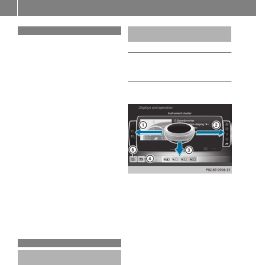
Introduction
The printedOperator's Manual providesinfor-
mation about thesafeoperation of your vehicle.
The Digital Operator's Manual providescompre-
hensiveand specifically adapted information on
your vehicle's equipmentand multimedia sys-
tem. You can call up theDigital Operator's Man-
ual via themultimedia system.
iYou will notincur any costswhen calling up
theDigital Operator's Manual. The Digital
Operator's Manual works without connecting
to theInternet.
Thereare three ways to access thetopicsof the
Digital Operator's Manual:
RVisualsearch
The visual search allows you to exploreyour
vehicle"virtually". Starting from either the
vehicleexteriorviewor interiorview, you can
access manyof thedifferenttopicscovered
by theDigital Operator's Manual. To access
thevehicleinteriorsection,select the"Vehi-
cle interior" view.
RKeywordsearch
The keyword search allows you to search for a
keyword by enteringcharacters.
RContents
You can select individual sectionsin thecon-
tents.
iThe Digital Operator's Manual is deactiva-
tedfor safetyreasonswhile driving.
Operation
Calling up the Digital Operator's Man-
ual
XPress theØbuttonon thecenter console.
The overview relating to thevehicleappears.
XSelectthe"Operator's Manual" menuitem by
turning3or pressing7thecontroller.
XConfirm7themessage about thewarning
and safetynotes.
The menufor theDigital Operator's Manual
appears.
Operating the Digital Operator's Man-
ual
General notes
Pleaseobservetheinformation about theoper-
ation of thecontroller (Ypage 254).
Content pages
The contentpages can be accessed by meansof
avisual search, a keyword search or usingthe
contents.
XTo scroll forward/back:turn3thecon-
troller.
XTo displayin full-screen or animation: slide
8thecontroller to theleft:.
XTo select information textor savebook-
marks: slide 9thecontroller to the
right ;.
XTo select alink:slide 6thecontroller
down =.
XTo exit acontent page: select the%
symbol ?.
XTo call up themenuof theDigital Opera-
tor's Manual: select Þsymbol A.
XTo switch functions to themultimedia
system using thebuttonson thecenter
console: press the$,%,Õor Ø
button.
The selected menuappears. The Digital Oper-
ator's Manual remainsopen in theback-
ground.
26 Digital Operator's Manual

Protecting the environment
General notes
HEnvironmental note
Daimler's declared policy is one of compre-
hensive environmental protection.
The objectives are for the natural resources
that form the basis of our existence on this
planet to be used sparingly and in a manner
that takes the requirements of both nature
and humanity into account.
You too can help to protect the environment
by operating your vehicle in an environmen-
tally responsible manner.
Fuel consumption and the rate of engine,
transmission, brake and tire wear are affected
by these factors:
Roperating conditions of your vehicle
Ryour personal driving style
You can influence both factors. You should
bear the following in mind:
Operating conditions:
Ravoid short trips as these increase fuel con-
sumption.
Ralways make sure that the tire pressures
are correct.
Rdo not carry any unnecessary weight.
Rremove roof racks once you no longer need
them.
Ra regularly serviced vehicle will contribute
to environmental protection. You should
therefore adhere to the service intervals.
Ralways have service work carried out at a
qualified specialist workshop.
Personal driving style:
Rdo not depress the accelerator pedal when
starting the engine.
Rdo not warm up the engine when the vehicle
is stationary.
Rdrive carefully and maintain a safe distance
from the vehicle in front.
Ravoid frequent, sudden acceleration and
braking.
Rchange gear in good time and use each gear
only up to Ôof its maximum engine speed.
Rswitch off the engine in stationary traffic.
Rkeep an eye on the vehicle's fuel consump-
tion.
Environmental concerns and recom-
mendations
Wherever the Operator's Manual requires you to
dispose of materials, first try to regenerate or re-
use them. Observe the relevant environmental
rules and regulations when disposing of materi-
als. In this way you will help to protect the envi-
ronment.
Genuine Mercedes-Benz parts
HEnvironmental note
Daimler AG also supplies reconditioned major
assemblies and parts which are of the same
quality as new parts. They are covered by the
same Limited Warranty entitlements as new
parts.
!Air bags and Emergency Tensioning Devi-
ces, as well as control units and sensors for
these restraint systems, may be installed in
the following areas of your vehicle:
Rdoors
Rdoor pillars
Rdoor sills
Rseats
Rcockpit
Rinstrument cluster
Rcenter console
Do not install accessories such as audio sys-
tems in these areas. Do not carry out repairs
or welding. You could impair the operating
efficiency of the restraint systems.
Have aftermarket accessories installed at a
qualified specialist workshop.
You could jeopardize the operating safety of
your vehicle if you use parts, tires and wheels as
well as accessories relevant to safety which
have not been approved by Mercedes-Benz. This
could lead to malfunctions in safety-relevant
Genuine Mercedes-Benz parts 27
Introduction
Z

systems, e.g. the brake system. Use only genu-
ine Mercedes-Benz parts or parts of equal qual-
ity. Only use tires, wheels and accessories that
have been specifically approved for your vehi-
cle.
Genuine Mercedes-Benz parts are subject to
strict quality control. Every part has been spe-
cifically developed, manufactured or selected
for and adapted to Mercedes-Benz vehicles.
Therefore, only genuine Mercedes-Benz parts
should be used.
More than 300,000 different genuine
Mercedes-Benz parts are available for
Mercedes-Benz models.
All authorized Mercedes-Benz Centers maintain
a supply of genuine Mercedes-Benz parts for
necessary service and repair work. In addition,
strategically located parts delivery centers pro-
vide quick and reliable parts service.
Always specify the vehicle identification number
(VIN) when ordering genuine Mercedes-Benz
parts (Ypage 339).
Operator's Manual
Vehicle equipment
iThis Operator's Manual describes all models
and all standard and optional equipment of
your vehicle available at the time of publica-
tion of the Operator's Manual. Country-spe-
cific differences are possible. Bear in mind
that your vehicle may not feature all functions
described here. This also applies to safety-
relevant systems and functions. The equip-
ment in your vehicle may therefore differ from
that shown in the descriptions and illustra-
tions.
The original purchase agreement lists all sys-
tems installed in your vehicle.
Should you have any questions concerning
equipment and operation, please consult an
authorized Mercedes-Benz Center.
The Operator's Manual and Maintenance Book-
let are important documents and should be kept
in the vehicle.
Service and vehicle operation
Warranty
The Limited Warranty for your vehicle applies in
accordance with the warranty terms and condi-
tions in the Service and Warranty Information
booklet.
Your authorized Mercedes-Benz Center will
replace and repair all factory-installed parts in
accordance with the following warranty terms
and conditions:
RNew Vehicle Limited Warranty
REmission System Warranty
REmission Performance Warranty
RCalifornia, Connecticut, Maine, Massachu-
setts, New York, Pennsylvania, Rhode Island
and Vermont Emission Control System War-
ranty
RState warranty enforcement laws (lemon
laws)
Replacement parts and accessories are covered
by the Mercedes-Benz Parts and Accessories
warranties. These are available at any author-
ized Mercedes-Benz Center.
iShould you lose your Service and Warranty
Information booklet, have an authorized
Mercedes-Benz Center arrange for a replace-
ment. The new Service and Warranty Infor-
mation booklet will be posted to you.
Information for customers in Califor-
nia
Under California law you may be entitled to a
replacement of your vehicle or a refund of the
purchase price or lease price, if after a reason-
able number of repair attempts Mercedes-Benz
USA, LLC and/or its authorized repair or service
facilities fail to fix one or more substantial
defects or malfunctions in the vehicle that are
covered by its express warranty.
During the period of 18 months from original
delivery of the vehicle or the accumulation of
18,000 miles (approximately 29,000 km) on the
odometer of the vehicle, whichever occurs first,
a reasonable number of repair attempts is pre-
sumed for a retail buyer or lessee if one or more
of the following occurs:
(1) the substantial defect or malfunction can
result in death or serious injuries for the
28 Service and vehicle operation
Introduction

vehicle occupants while driving and this
defect has already been repaired at least
twice and Mercedes-Benz, LLC has been
informed in writing of the necessity of a
repair.
(2) the defect or malfunction, though less seri-
ous than (1) above, has already been
repaired at least four times and Mercedes-
Benz has been informed in writing of the
necessity of a repair.
(3) the vehicle cannot be used for longer than
30 calendar days because of repair work
resulting from this or other substantial
defects or malfunctions.
Please send your written notice to:
Mercedes-Benz USA, LLC
Customer Assistance Center
3 Mercedes Drive
Montvale, NJ 07645-0350
Maintenance
Always bring the Maintenance Booklet with you
when taking the vehicle to an authorized
Mercedes-Benz Center. Your customer service
advisor will enter every service into your Main-
tenance Booklet on your behalf.
Roadside Assistance
The Mercedes-Benz Roadside Assistance Pro-
gram offers technical help in the event of a
breakdown. Calls to the toll-free Roadside Assis-
tance Hotline are answered by our agents 24
hours a day, 365 days a year.
1-800-FOR-MERCedes (1-800-367-6372)
(USA)
1-800-387-0100 (Canada)
For additional information, refer to the
Mercedes-Benz Roadside Assistance Program
brochure (USA) or the "Roadside Assistance"
section in the Service and Warranty Booklet
(Canada). You will find both in the vehicle docu-
ment wallet.
Change of address or change of own-
ership
In the event of a change of address, please send
us the "Notification of Address Change" in the
Service and Warranty Booklet or simply call the
Mercedes-Benz Customer Assistance Center
(USA) at the hotline number
1-800-FOR-MERCedes (1-800-367-6372) or
Customer Service Center (Canada) at
1-800-387-0100. This will assist us in contact-
ing you in a timely manner should the need arise.
If you sell your Mercedes, please leave all liter-
ature in the vehicle so that it is available to the
next owner.
If you have purchased a used car, please send us
the "Notification of Used Car Purchase" in the
Service and Warranty Booklet or simply call the
Mercedes-Benz Customer Assistance Center
(USA) at the hotline number
1-800-FOR-MERCedes (1-800-367-6372) or
Customer Service (Canada) at 1-800-387-0100.
Vehicle operation outside the USA
and Canada
When you are abroad with your vehicle, observe
the following points:
RService facilities or replacement parts may
not be readily available.
RLead-free fuel for vehicles with a catalytic
converter may not be available. Leaded fuel
can cause damage to the catalytic converter.
RThe fuel may have a considerably lower
octane number. Unsuitable fuel can cause
engine damage.
Some Mercedes-Benz models are available for
delivery in Europe through our European Deliv-
ery Program. For details, consult an authorized
Mercedes-Benz Center or write to one of the
following addresses.
In the USA
Mercedes-Benz USA, LLC
European Delivery Department
One Mercedes Drive
Montvale, NJ 07645-0350
In Canada
Mercedes-Benz Canada, Inc.
European Delivery Department
98 Vanderhoof Avenue
Toronto, Ontario M4G 4C9
Service and vehicle operation 29
Introduction
Z

Operating safety
Important safety notes
GWARNING
If you do not have the prescribed service/
maintenance work or any required repairs
carried out, this can result in malfunctions or
system failures. There is a risk of an accident.
Always have the prescribed service/mainte-
nance work as well as any required repairs
carried out at a qualified specialist workshop.
GWARNING
Flammable material such as leaves, grass or
twigs may ignite if they come into contact with
hot parts of the exhaust system. There is a risk
of fire.
When driving off road or on unpaved roads,
check the vehicle's underside regularly. In
particular, remove parts of plants or other
flammable materials which have become
trapped. In the case of damage, contact a
qualified specialist workshop.
GWARNING
Modifications to electronic components, their
software as well as wiring can impair their
function and/or the function of other net-
worked components. In particular, systems
relevant to safety could also be affected. As a
result, these may no longer function as inten-
ded and/or jeopardize the operating safety of
the vehicle. There is an increased risk of an
accident and injury.
Never tamper with the wiring as well as elec-
tronic components or their software. You
should have all work to electrical and elec-
tronic equipment carried out at a qualified
specialist workshop.
!There is a risk of damage to the vehicle if:
Rthe vehicle becomes stuck, e.g. on a high
curb or an unpaved road
Ryou drive too fast over an obstacle, e.g. a
curb, a speed bump or a pothole in the road
Ra heavy object strikes the underbody or
parts of the chassis
In situations like this, the body, the under-
body, chassis parts, wheels or tires could be
damaged without the damage being visible.
Components damaged in this way can unex-
pectedly fail or, in the case of an accident, no
longer withstand the loads they are designed
to.
If the underbody paneling is damaged, com-
bustible materials such as leaves, grass or
twigs can gather between the underbody and
the underbody paneling. If these materials
come in contact with hot parts of the exhaust
system, they can catch fire.
In such situations, have the vehicle checked
and repaired immediately at a qualified spe-
cialist workshop. If on continuing your jour-
ney you notice that driving safety is impaired,
pull over and stop the vehicle immediately,
paying attention to road and traffic condi-
tions. In such cases, consult a qualified spe-
cialist workshop.
Declaration of conformity for wireless
vehicle components
USA: "The wireless devices of this vehicle com-
ply with Part 15 of the FCC Rules. Operation is
subject to the two following two conditions: 1)
These devices may not cause harmful interfer-
ence, and 2) These devices must accept any
interference received, including interference
that may cause undesired operation. Changes
or modifications not expressly approved by the
party responsible for compliance could void the
user’s authority to operate the equipment."
Canada: "The wireless devices of this vehicle
comply with Industry Canada license-exempt
RSS standard(s). Operation is subject to the fol-
lowing two conditions: (1) These devices may
not cause interference, and (2) These devices
must accept any interference, including inter-
ference that may cause undesired operation of
the device."
30 Operating safety
Introduction

Diagnostics connection
The diagnosticsconnection is only intended for
theconnection of diagnostic equipmentat a
qualified specialistworkshop.
GWARNING
If you connectequipmentto adiagnostics
connection in thevehicle, it may affectthe
operation of vehicle systems.As aresult,the
operatingsafetyof thevehicle could be affec-
ted. There is ariskof an accident.
Only connectequipmentto adiagnosticscon-
nection in thevehicle, whichis approved for
your vehicle by Mercedes-Benz.
GWARNING
Objects in thedriver's footwell can restrictthe
pedaltravelor obstruct adepressed pedal.
The operatingand road safetyof thevehicle is
jeopardized. There is ariskof an accident.
Makesurethat all objects in thevehicle are
stowed correctly, and that they cannotenter
thedriver's footwell. Install thefloormats
securely and as specifiedin order to ensure
sufficientclearanceforthepedals. Do notuse
loose floormatsand do notplacefloormatson
topof oneanother.
!If theengineis switched offand equipment
on thediagnosticsconnection is used,the
starter battery may discharge.
Connectingequipmentto thediagnosticscon-
nection can lead to emissionsmonitoringinfor-
mation beingreset,forexample. Thismay lead
to thevehicle failingto meettherequirements of
thenext emissionstest duringthemain inspec-
tion.
Qualified specialist workshop
An authorized Mercedes-BenzCenteris aquali-
fiedspecialistworkshop.It has thenecessary
specialistknowledge,tools and qualificationsto
correctlycarry out theworkrequiredon your
vehicle. Thisis especially thecaseforworkrel-
evant to safety.
Observethenotesin theMaintenance Booklet.
Always havethefollowingworkcarriedout at an
authorized Mercedes-BenzCenter:
Rworkrelevant to safety
Rserviceand maintenance work
Rrepair work
Ralterations, installation workand modifica-
tions
Rworkon electronic components
Correct use
If you removeany warningstickers,you or oth-
ers could fail to recognizecertain dangers.
Leave warningstickers in position.
Observethefollowinginformation when driving
your vehicle:
Rthesafetynotesin this manual
Rtechnical dataforthevehicle
Rtraffic rulesand regulations
Rlaws and safetystandardspertainingto motor
vehicles
Problemswithyourvehicle
If you should experience aproblem withyour
vehicle, particularly onethat you believe may
affectitssafeoperation,we urgeyou to contact
an authorized Mercedes-BenzCenterimmedi-
ately to havetheproblem diagnosed and recti-
fied. If theproblem is notresolved to your sat-
isfaction,please discusstheproblem again with
an authorized Mercedes-BenzCenteror,if nec-
essary, contact us at oneof thefollowing
addresses.
In theUSA
Customer AssistanceCenter
Mercedes-BenzUSA, LLC
3Mercedes Drive
Montvale, NJ 07645-0350
In Canada
Customer RelationsDepartment
Mercedes-BenzCanada, Inc.
98 VanderhoofAvenue
Toronto,Ontario M4G4C9
Reporting safetydefects
USAonly:
Operating safety 31
Introduction
Z

The following text is reproduced as required of
all manufacturers under Title 49, Code of U.S.
Federal Regulations, Part 575 pursuant to the
National Traffic and Motor Vehicle Safety Act of
1966.
If you believe that your vehicle has a defect
which could cause a crash or could cause injury
or death, you should immediately inform the
National Highway Traffic Safety Administration
(NHTSA) in addition to notifying Mercedes-Benz
USA, LLC.
If NHTSA receives similar complaints, it may
open an investigation, and if it finds that a safety
defect exists in a group of vehicles, it may order
a recall and remedy campaign. However, NHTSA
cannot become involved in individual problems
between you, your dealer, or Mercedes-Benz
USA, LLC.
To contact NHTSA, you may call the Vehicle
Safety Hotline toll-free at 1-888-327-4236
(TTY: 1-800-424-9153); go to http://
www.safercar.gov; or write to: Administrator,
NHTSA, 400 Seventh Street, SW., Washington,
DC 20590.
You can also obtain other information about
motor vehicle safety from
http://www.safercar.gov
Limited Warranty
!Follow the instructions in this manual about
the proper operation of your vehicle as well as
about possible vehicle damage. Damage to
your vehicle that arises from culpable contra-
ventions against these instructions is not cov-
ered either by the Mercedes-Benz Limited
Warranty or by the New or Used-Vehicle War-
ranty.
QR codes for the rescue card
The QR codes are secured in the fuel filler flap
and on the opposite side on the B-pillar. In the
event of an accident, rescue services can use
the QR code to quickly find the appropriate res-
cue card for your vehicle. The current rescue
card contains the most important information
about your vehicle in a compact form, e.g. the
routing of the electric cables.
You can find more information under
www.mercedes-benz.de/qr-code.
Data stored in the vehicle
Data storage
A wide range of electronic components in your
vehicle contain data memories.
These data memories temporarily or perma-
nently store technical information about:
Rthe vehicle's operating state
Rincidents
Rmalfunctions
In general, this technical information docu-
ments the state of a component, a module, a
system or the surroundings.
These include, for example:
Roperating conditions of system components,
e.g. fluid levels
Rthe vehicle's status messages and those of its
individual components, e.g. number of wheel
revolutions/speed, deceleration in move-
ment, lateral acceleration, accelerator pedal
position
Rmalfunctions and defects in important system
components, e.g. lights, brakes
Rvehicle reactions and operating conditions in
special driving situations, e.g. air bag deploy-
ment, intervention of stability control sys-
tems
Rambient conditions, e.g. outside temperature
This data is of an exclusively technical nature
and can be used to:
Rassist in recognizing and rectifying malfunc-
tions and defects
Ranalyze vehicle functions, e.g. after an acci-
dent
Roptimize vehicle functions
The data cannot be used to trace the vehicle's
movements.
When your vehicle is serviced, technical infor-
mation can be read from the event data memory
and malfunction data memory.
Services include, for example:
Rrepair services
Rservice processes
Rwarranties
Rquality assurance
The vehicle is read out by employees of the ser-
vice network (including the manufacturer) using
special diagnostic testers. More detailed infor-
mation is obtained from it, if required.
32 Data stored in the vehicle
Introduction

After a malfunction has been rectified, the infor-
mation is deleted from the malfunction memory
or is continually overwritten.
When operating the vehicle, situations are con-
ceivable in which this technical data, in connec-
tion with other information (if necessary, under
consultation with an authorized expert), could
be traced to a person.
Examples include:
Raccident reports
Rdamage to the vehicle
Rwitness statements
Further additional functions that have been con-
tractually agreed upon with the customer allow
certain vehicle data to be conveyed by the vehi-
cle as well. The additional functions include, for
example, vehicle location in case of an emer-
gency.
COMAND/mbrace
If the vehicle is equipped with COMAND or
mbrace, additional data about the vehicle's
operation, the use of the vehicle in certain sit-
uations, and the location of the vehicle may be
compiled through COMAND or the mbrace sys-
tem.
For additional information please refer to the
COMAND User Manual or the Digital Operator's
Manual and/or the mbrace Terms and Condi-
tions.
Event data recorders
This vehicle is equipped with an event data
recorder (EDR). This vehicle is equipped with an
event data recorder (EDR). The main purpose of
an EDR is to record, in certain crash or near
crash-like situations, such as an air bag deploy-
ment or hitting a road obstacle, data that will
assist in understanding how a vehicle's systems
performed. The EDR is designed to record data
related to vehicle dynamics and safety systems
for a short period of time, typically 30 seconds
or less.
The EDR in this vehicle is designed to record
such data as:
RHow various systems in your vehicle were
operating
RWhether or not the driver and passenger
safety belts were buckled/fastened
RHow far (if at all) the driver was depressing the
accelerator and/or brake pedal and
RHow fast the vehicle was traveling
These data can help provide a better under-
standing of the circumstances in which crashes
and injuries occur. NOTE: EDR data are recorded
by your vehicle only if a non-trivial crash situa-
tion occurs; no data are recorded by the EDR
under normal driving conditions and no personal
data (e.g. name, gender, age and crash location)
are recorded. However, other parties, such as
law enforcement could combine the EDR data
with the type of personally identifying data rou-
tinely acquired during a crash investigation.
Access to the vehicle and/or the EDR is needed
to read data that is recorded by an EDR, and
special equipment is required. In addition to the
vehicle manufacturer, other parties that have
the special equipment, such as law enforce-
ment, can read the information by accessing the
vehicle or the EDR.
EDR data may be used in civil and criminal mat-
ters as a tool in accident reconstruction, acci-
dent claims and vehicle safety. Since the Crash
Data Retrieval CDR tool that is used to extract
data from the EDR is commercially available,
Mercedes-Benz USA, LLC ("MBUSA") expressly
disclaims any and all liability arising from the
extraction of this information by unauthorized
Mercedes-Benz personnel.
MBUSA will not share EDR data with others
without the consent of the vehicle owners or, if
the vehicle is leased, without the consent of the
lessee. Exceptions to this representation
include responses to subpoenas by law enforce-
ment; by federal, state or local government; in
connection with or arising out of litigation involv-
ing MBUSA or its subsidiaries and affiliates; or,
as required by law.
Warning: The EDR is a component of the
Restraint System Module. Tampering with, alter-
ing, modifying or removing the EDR component
may result in a malfunction of the Restraint Sys-
tem Module and other systems.
State laws or regulations regarding EDRs that
conflict with federal regulation are pre-empted.
This means that in the event of such conflict, the
federal regulation governs. As of February 2013,
13 states have enacted laws relating to EDRs.
Data stored in the vehicle 33
Introduction
Z

Information on copyright
Free and open-source software
Information on license for free and open-source
software used in your vehiclecan be foundon
thedatacarrier in your vehicledocumentwallet
and,includingupdates, on thefollowingweb-
site:
http://www.mercedes-benz.com/opensource
Registered trademarks
Registered trademarks:
RBluetooth®is aregisteredtrademark of Blue-
toothSIGInc.
RDTS™ is aregisteredtrademark of DTS, Inc.
RDolby®and MLP™are registeredtrademarks
of DOLBYLaboratories.
RBabySmart™, ESP®and PRE-SAFE®are reg-
isteredtrademarksof Daimler AG.
RHomeLink®is aregisteredtrademark of John-
son Controls.
RiPod®and iTunes®are registeredtrademarks
of Apple Inc.
RBurmester®is aregisteredtrademark of
BurmesterAudiosysteme GmbH.
RMicrosoft®and Windows media®are regis-
tered trademarksof Microsoft Corporation.
RSIRIUS®is aregisteredtrademark of Sirius
XM Radio Inc.
RHD Radio™ is aregisteredtrademark of iBiq-
uityDigital Corporation.
RGracenote®is aregisteredtrademark of
Gracenote, Inc.
RZAGATSurvey®and relatedbrands are regis-
tered trademarksof Zagat Survey, LLC.
34 Information on copyright
Introduction
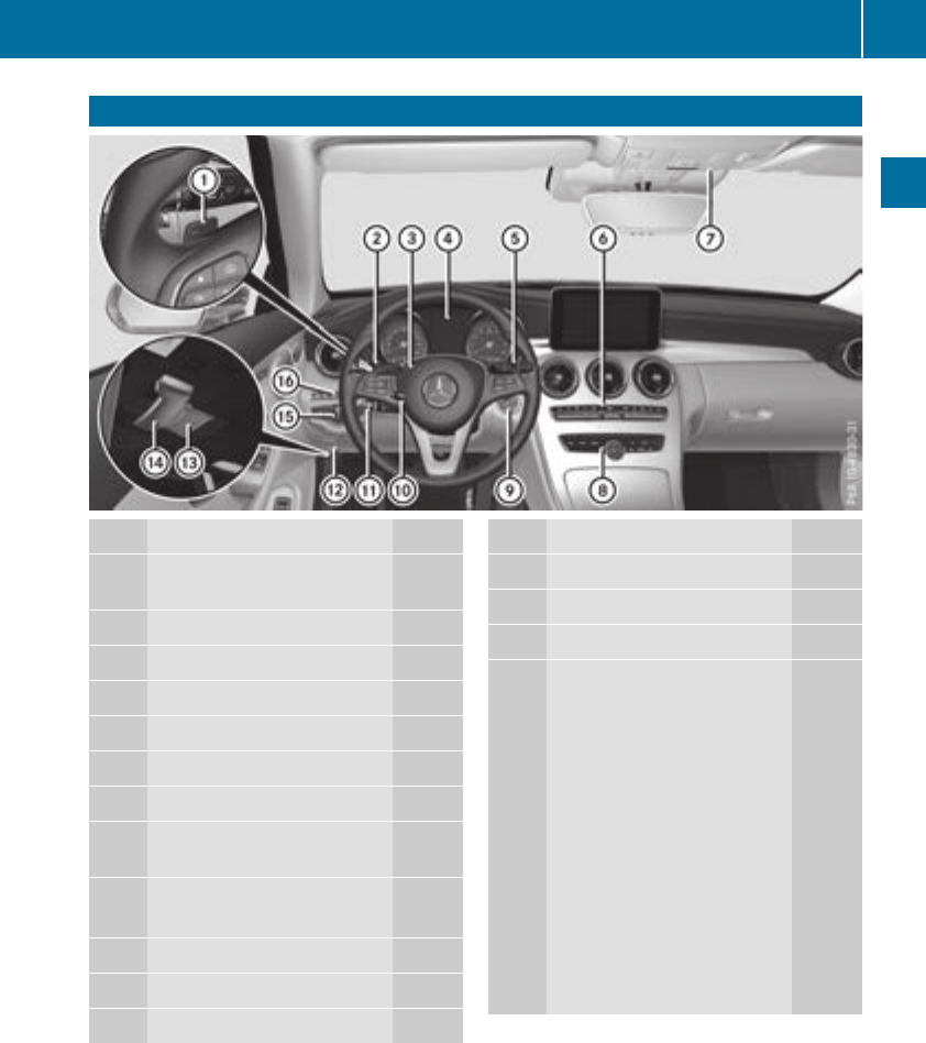
Cockpit
Function Page
:Steering wheel paddle shift-
ers 138
;Combination switch 108
=Horn
?Instrument cluster 36
ADIRECT SELECT lever 133
BClimate control systems 115
COverhead control panel 41
DControl panel for multimedia
system and vehicle functions 38
EIgnition lock 123
Start/Stop button 124
FAdjusts the steering wheel 100
GCruise control lever 152
HElectric parking brake 145
Function Page
IDiagnostics connection 31
JOpens the hood 281
KLight switch 107
LControl panel for:
YActivating Distance
Pilot DISTRONIC with Steer-
ing Pilot 159
ÇSwitching on Active
Lane Keeping Assist 189
cDeactivating Parking
Assist PARKTRONIC 172
ÔSwitching on the 360°
camera 176
Switching on the head-up
display 195
Vehicles without a driver
assistance system: map/
coin holder
Cockpit 35
At a glance
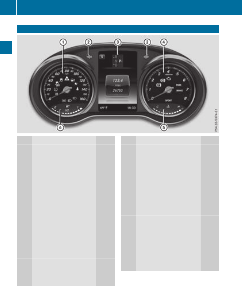
Instrument cluster
Function Page
:Speedometer withsegments 192
Warning and indicator lamps:
åESP®OFF244
÷ESP®244
·Distancewarning 250
ÐPowersteering assis-
tance malfunctioning 252
6Restraintsystem 44
üSeat belt notfastened241
KHigh-beam headlamps 108
LLow-beam headlamps 108
TParking lamps108
RRear fog lamp 108
hTirepressuremonitor 251
;#! Turn signals 108
=Multifunction display 194
?Tachometer 193
Warning and indicator lamps:
!Electric parking brake
(yellow) 247
Function Page
!ABSmalfunctioning 244
;CheckEngine247
Electric parking brake
applied(red) 247
FUSAonly
!Canadaonly
Brakes(red) 243
$USAonly
JCanadaonly
MSPORT handlingmode
(Mercedes-AMGvehicles) 246
ACoolanttemperature gauge 193
Warning and indicator lamps:
?Coolanttoohot/cold 248
BFuellevel indicator
Warning and indicator lamps:
8Reserve fuel withfuel
filler flap location indicator
(right-hand side)247
iInformation on displayingtheoutside tem-
peraturein themultifunction display can be
foundunder "Outside temperature display"
(Ypage 193).
36 Instrument cluster
At a glance
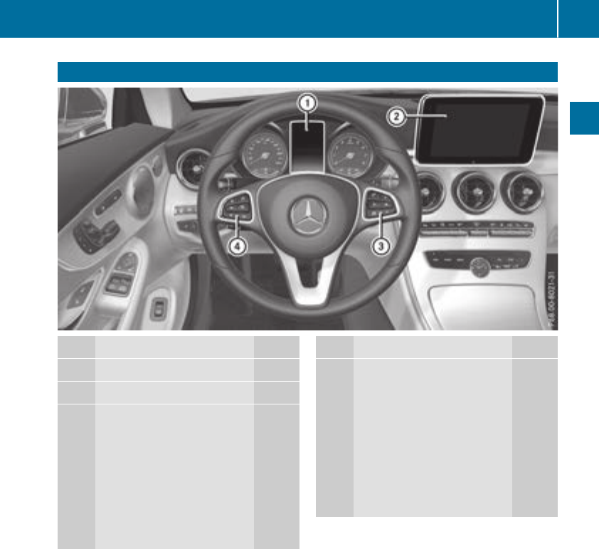
Multifunction steering wheel
Function Page
:Multifunction display 194
;Multimedia system display
=~Rejects or ends a call
6Makes or accepts a call
Further telephone functions 202
WXAdjusts volume
8Mute
óSwitches on voice-
operated control for naviga-
tion or the Voice Control Sys-
tem
Function Page
?òOpens the menu list
9:Selects a menu
aConfirms the selection
%Back
Operates the on-board com-
puter 193
ñSwitches on voice-
operated control for naviga-
tion or the Voice Control Sys-
tem
iVehicles with Audio 20 multimedia sys-
tem: you can find further information
Ron the multimedia system in the Digital
Operator's Manual
Ron voice-controlled navigation in the man-
ufacturer's operating instructions
iVehicles with COMAND multimedia sys-
tem: you can find further information
Ron the multimedia system in the Digital
Operator's Manual
Ron the single DVD drive in the Digital Oper-
ator's Manual
Ron the Voice Control System in the sepa-
rate operating instructions
Multifunction steering wheel 37
At a glance
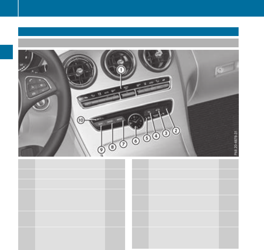
Center console
Center console, upper section
Function Page
:Climate control systems 115
;£Hazard warning lamps 109
=ØVehicle functions/
system settings button (see
Digital Operator's Manual)
?%Telephone button (see
Digital Operator's Manual)
APASSENGER AIRBAG indica-
tor lamps 44
ATA indicator lamp 74
Function Page
BAnalog clock
CÕMedia button (see Dig-
ital Operator's Manual)
D$Radio button (see Digi-
tal Operator's Manual)
EØNavigation button (see
Digital Operator's Manual)
FþInserts or ejects a CD
or DVD (see Digital Opera-
tor's Manual)
38 Center console
At a glance
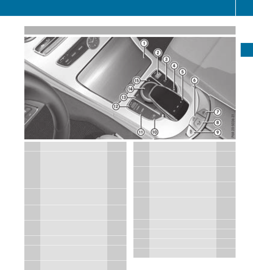
Center console, lower section (except Mercedes-AMG vehicles)
Function Page
:Stowage compartment 263
Ashtray 269
Cigarette lighter 270
Socket 270
Cup holder 267
;Adjusts the volume 254
Switches the sound on or off 254
=ÜSwitches the multime-
dia system on/off 254
?Moves the seat-belt extender
forward 47
ATouchpad 255
BOpens and closes the soft
top 88
CAIRCAP 91
Function Page
DOpens stowage compart-
ment with Media Interface 263
EOpening and closing the side
windows 85
FèECO start/stop func-
tion 127
GÉSets the vehicle level 163
cDeactivates Parking
Assist PARKTRONIC 172
HDYNAMIC SELECT switch 130
I%Back button 254
JController 254
KgFavorites button 256
Center console 39
At a glance
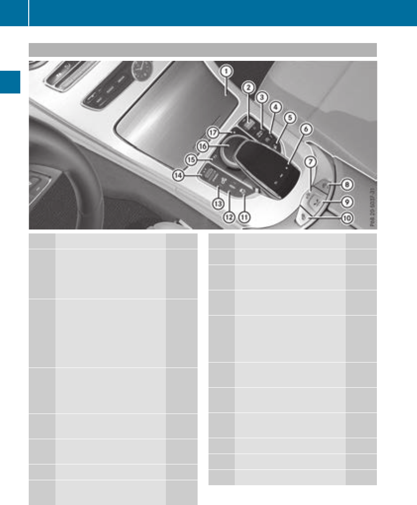
Center console, lower section (Mercedes-AMG vehicles)
Function Page
:Ashtray 269
Cigarette lighter 270
Socket 270
Cup holder 267
;Adjusts the volume 254
Switches the sound on or off 254
Vehicles with AMG Perform-
ance exhaust system:
ÜSwitches the multime-
dia system on/off 254
=AMG performance exhaust
system can be selected 129
ÜSwitches the multime-
dia system on/off 254
?èECO start/stop func-
tion 127
AMoves the seat-belt extender
forward 47
BTouchpad 255
COpens and closes the soft
top 88
Function Page
DAIRCAP 91
EOpens stowage compart-
ment with Media Interface 263
FOpening and closing the side
windows 85
GåActivates/deactivates
ESP®69
MActivates/deactivates
SPORT handling mode 69
HàAMG RIDE CONTROL
(suspension tuning) 165
IManual gearshifting (perma-
nent setting) 138
JDYNAMIC SELECT switch
(selects the drive program) 130
K%Back button 254
LController 254
MgFavorites button 256
40 Center console
At a glance
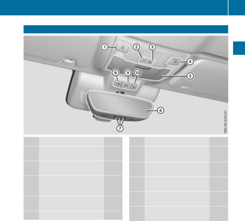
Overhead control panel
Function Page
:pSwitches the left-hand
reading lamp on/off 110
;cSwitches the front inte-
rior lighting on/off 111
=|Switches the automatic
interior lighting control
on/off 111
?pSwitches the right-
hand reading lamp on/off 110
AEyeglasses compartment 264
Function Page
BRear-view mirror
Automatic anti-glare 104
CButtons for the garage door
opener 278
DFBreakdown assistance
call button (mbrace system) 273
EGSOS button (mbrace
system) 272
FïInfo call button
(mbrace system) 273
Overhead control panel 41
At a glance
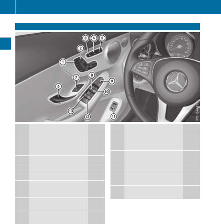
Door controlpanel
Function Page
:r45=
Stores settings for the seat,
exterior mirrors and steering
column 105
;Adjusts the seats electrically 96
=cSeat heating 99
?sSeat ventilation 99
AÒAIRSCARF 100
BOpens the door 81
C%&Unlocks/locks
the vehicle 82
DWOpens/closes the left
side window 85
Function Page
E7Zª\
Adjusts and folds the exterior
mirrors in/out electrically 103
FWOpens/closes the right
side window 85
GpOpens the trunk lid 84
HWOpens/closes the rear
right side window 85
IWOpens/closes the rear
left side window 85
42 Door control panel
At a glance
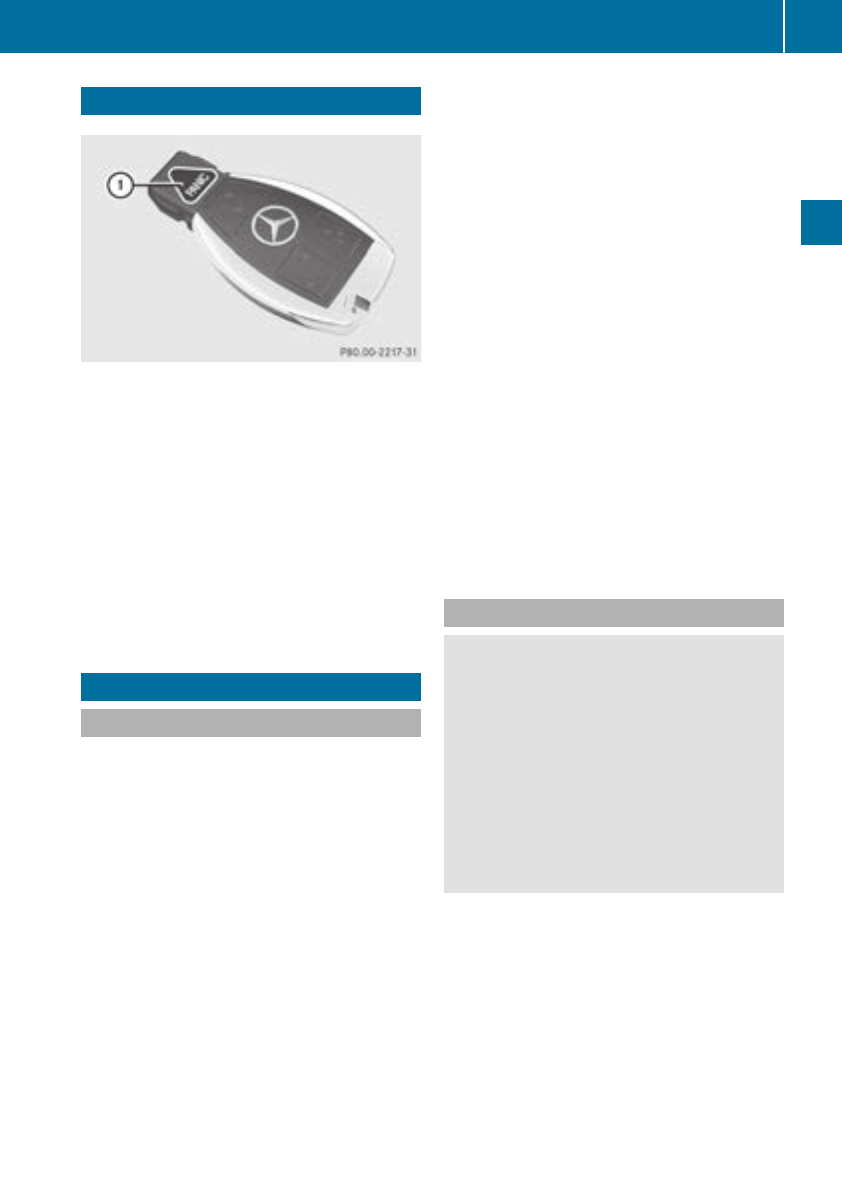
Panic alarm
XTo arm: press and hold !button :for
approximately one second.
A visual and audible alarm is triggered if the
alarm system is armed.
XTo disarm: press !button :again.
or
XInsert the SmartKey into the ignition lock.
or
XVehicles with KEYLESS-GO start function
or KEYLESS-GO: press the Start/Stop but-
ton.
The SmartKey must be in the vehicle.
Occupant safety
Introduction to the restraint system
The restraint system can reduce the risk of vehi-
cle occupants coming into contact with parts of
the vehicle's interior in the event of an accident.
The restraint system can also reduce the forces
to which vehicle occupants are subjected during
an accident.
The restraint system comprises:
RSeat belt system
RAir bags
RChild restraint system
RChild seat securing systems
The components of the restraint system work in
conjunction with each other. They can only
deploy their protective function if, at all times, all
vehicle occupants:
Rhave fastened their seat belts correctly
(Ypage 46)
Rhave the seat and head restraint adjusted
properly (Ypage 94)
As the driver, you also have to make sure that
the steering wheel is adjusted correctly.
Observe the information relating to the correct
driver's seat position (Ypage 94).
You also have to make sure that an air bag can
inflate properly if deployed (Ypage 49).
An air bag supplements a correctly worn seat
belt. As an additional safety device, the air bag
increases the level of protection for vehicle
occupants in the event of an accident. For exam-
ple, if, in the event of an accident, the protection
offered by the seat belt is sufficient, the air bags
are not deployed. When an accident occurs, only
the air bags that increase protection in that par-
ticular accident situation are deployed. How-
ever, seat belts and air bags generally do not
protect against objects penetrating the vehicle
from the outside.
Information on restraint system operation can
be found under "Triggering of the Emergency
Tensioning Devices and air bags" (Ypage 56).
See "Children in the vehicle" for information on
children traveling with you in the vehicle as well
as on child restraint systems (Ypage 59).
Important safety notes
GWARNING
Modifications to the restraint system may
cause it to no longer work as intended. The
restraint system may then not perform its
intended protective function and may fail in an
accident or trigger unexpectedly, for example.
This poses an increased risk of injury or even
fatal injury.
Never modify parts of the restraint system.
Never tamper with the wiring, the electronic
components or their software.
If it is necessary to modify components of the
restraint system to accommodate a person with
disabilities, contact an authorized Mercedes-
Benz Center for details. USA only: for further
information contact our Customer Assistance
Center at 1-800-FOR-MERCedes
(1‑800‑367‑6372).
Mercedes-Benz recommends that you only use
driving aids which have been approved specifi-
cally for your vehicle by Mercedes-Benz.
Occupant safety 43
Safety
Z
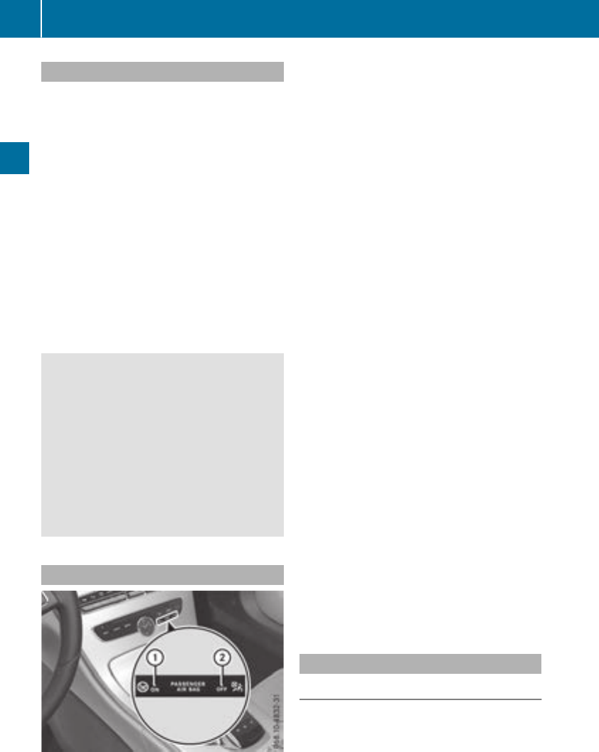
Restraint system warning lamp
The functions of the restraint system are
checked after the ignition is switched on and at
regular intervals while the engine is running.
Therefore, malfunctions can be detected in
good time.
The 6restraint system warning lamp on the
instrument cluster lights up when the ignition is
switched on. It goes out no later than a few sec-
onds after the vehicle is started. The compo-
nents of the restraint system are in operational
readiness.
A malfunction has occurred if the 6restraint
system warning lamp:
Rdoes not light up after the ignition is switched
on
Rdoes not go out after a few seconds with the
engine running
Rlights up again while the engine is running
GWARNING
If the restraint system is malfunctioning,
restraint system components may be trig-
gered unintentionally or may not deploy as
intended during an accident. This can affect
for example the Emergency Tensioning
Device or the air bag. This poses an increased
risk of injury or even fatal injury.
Have the restraint system checked and
repaired in a qualified specialist workshop as
soon as possible.
PASSENGER AIR BAG indicator lamp
PASSENGER AIR BAG ON indicator lamp :and
PASSENGER AIR BAG OFF indicator lamp ;are
part of the Occupant Classification System
(OCS).
The indicator lamps display the status of the
front-passenger front air bag.
RPASSENGER AIR BAG ON lights up for 60 sec-
onds, subsequently both indicator lamps are
off (PASSENGER AIR BAG ON and OFF): the
front-passenger front air bag is able to deploy
in the event of an accident.
RPASSENGER AIR BAG OFF lights up: the front-
passenger front air bag is deactivated. It will
then not be deployed in the event of an acci-
dent.
If the PASSENGER AIR BAG ON indicator lamp is
off, only the PASSENGER AIR BAG OFF indicator
lamp shows the status of the front-passenger
front air bag. The PASSENGER AIR BAG OFF
indicator lamp may be lit continuously or be off.
Depending on the person in the front-passenger
seat, the front-passenger front air bag must
either be deactivated or enabled; see the fol-
lowing points. You must make sure of this both
before and during a journey.
RChildren in a child restraint system:
whether the front-passenger front air bag is
enabled or deactivated depends on the instal-
led child restraint system, and the age and
size of the child. Therefore, be sure to observe
the notes on the "Occupant Classification
System (OCS)" (Ypage 51) and on "Chil-
dren in the vehicle" (Ypage 59). There you
will also find instructions on rearward and
forward-facing child restraint systems on the
front-passenger seat.
RAll other persons: depending on the classi-
fication of the person in the front-passenger
seat, the front-passenger front air bag is ena-
bled or deactivated (Ypage 51). Be sure to
observe the notes on "Seat
belts“ (Ypage 44) and "Air bags"
(Ypage 48). There you can also find infor-
mation on the correct seat position.
Seat belts
Introduction
Seat belts are the most effective means of
restricting the movement of vehicle occupants
in the event of an accident or the vehicle rolling
over. This reduces the risk of vehicle occupants
coming into contact with parts of the vehicle
interior or being ejected from the vehicle. Fur-
thermore, the seat belt helps to keep the vehicle
44 Occupant safety
Safety

occupant in the best position in relation to the
air bag.
The seat belt system comprises:
RSeat belts
REmergency Tensioning Devices and seat belt
force limiters
If the seat belt is pulled out of the belt outlet
quickly or with a jerky movement, the belt
retractor locks. The belt strap cannot be extrac-
ted any further.
The Emergency Tensioning Device tightens the
seat belt in an accident, pulling the belt close
against the body. However it does not pull the
vehicle occupant back in the direction of the
backrest.
The Emergency Tensioning Device does not cor-
rect an incorrect seat position or the routing of
an incorrectly fastened seat belt.
When triggered, a seat belt force limiter helps to
reduce the force exerted by the seat belt on the
vehicle occupant.
The seat belt force limiters for the front seats are
synchronized with the front air bags, which
absorb part of the deceleration force. This can
reduce the force exerted on the vehicle occu-
pants during an accident.
!If the front-passenger seat is not occupied,
do not engage the seat belt tongue in the
buckle on the front-passenger seat. Other-
wise, the Emergency Tensioning Device and
side impact air bag could be triggered in the
event of an accident and would need to be
replaced.
Important safety notes
The use of seat belts and child restraint systems
is required by law in:
Rall 50 states
Rthe U.S. territories
Rthe District of Columbia
Rall Canadian provinces
Even where this is not required by law, all vehicle
occupants should correctly fasten their seat
belts before starting the journey.
GWARNING
If the seat belt is not worn correctly, it cannot
perform its intended protective function. An
incorrectly fastened seat belt can also cause
injuries, for example, in the event of an acci-
dent or when braking or changing direction
abruptly. This poses an increased risk of injury
or even fatal injury.
Always ensure that all vehicle occupants have
their seat belts fastened correctly and are sit-
ting properly.
The components of the restraint system work in
conjunction with each other. They can only
deploy their protective function if, at all times, all
vehicle occupants:
Rhave fastened their seat belts correctly
(Ypage 46)
Rhave the seat and head restraint adjusted
properly (Ypage 94)
GWARNING
The seat belt does not offer the intended level
of protection if you have not moved the back-
rest to an almost vertical position. When brak-
ing or in the event of an accident, you could
slide underneath the seat belt and sustain
abdomen or neck injuries, for example. This
poses an increased risk of injury or even fatal
injury.
Adjust the seat properly before beginning
your journey. Always ensure that the backrest
is in an almost vertical position and that the
shoulder section of your seat belt is routed
across the center of your shoulder.
GWARNING
Persons less than 5 ft (1.50 m) tall cannot
wear the seat belt correctly without an addi-
tional and suitable restraint system. If the
seat belt is not worn correctly, it cannot per-
form its intended protective function. An
incorrectly fastened seat belt can also cause
injuries, for example, in the event of an acci-
dent or when braking or changing direction
abruptly. This poses an increased risk of injury
or even fatal injury.
For this reason, always secure persons under
5 ft (1.50 m) tall in suitable additional restraint
systems.
Occupant safety 45
Safety
Z

If a child younger than twelve years old and
under 5 ft (1.50 m) in height is traveling in the
vehicle:
Ralways secure the child in a child restraint
system suitable for this Mercedes-Benz vehi-
cle. The child restraint system must be appro-
priate to the age, weight and size of the child
Ralways observe the instructions and safety
notes on "Children in the vehicle"
(Ypage 59) in addition to the child restraint
system manufacturer's installation and oper-
ating instructions
Ralways observe the instructions and safety
notes on the "Occupant classification system
(OCS)" (Ypage 51)
GWARNING
The seat belts may not perform their intended
protective function if:
Rthey are damaged, modified, extremely
dirty, bleached or dyed
Rthe seat belt buckle is damaged or
extremely dirty
Rthe Emergency Tensioning Devices, belt
anchorages or inertia reels have been modi-
fied.
Seat belts may be damaged in an accident,
although the damage may not be visible, e.g.
due to splinters of glass. Modified or damaged
seat belts may tear or fail, e.g. in an accident.
Modified Emergency Tensioning Devices
could accidentally trigger or fail to deploy
when necessary. This poses an increased risk
of injury or even fatal injury.
Never modify the seat belts, Emergency Ten-
sioning Devices, belt anchorages and inertia
reels. Make sure that the seat belts are
undamaged, not worn out and clean. Follow-
ing an accident, have the seat belts checked
immediately at a qualified specialist work-
shop.
Only use seat belts that have been approved for
your vehicle by Mercedes-Benz.
AMG Performance seat: this seat is designed
for the standard three-point seat belt. If you
install another multi-point seat belt, e.g. sport or
racing seat belts, the restraint system cannot
provide the best level of protection.
GWARNING
If you feed seat belts through the opening in
the seat backrest, the seat backrest may be
damaged or may even break in the event of an
accident. This poses an increased risk of
injury or even fatal injury.
Only use the standard three-point seat belt.
Never modify the seat belt system.
Proper use of the seat belts
Observe the safety notes on the seat belt
(Ypage 45).
All vehicle occupants must be wearing the seat
belt correctly before beginning the journey. Also
make sure that all vehicle occupants are always
wearing the seat belt correctly while the vehicle
is in motion.
When fastening the seat belt, always make sure
that:
Rthe seat belt buckle tongue is inserted only
into the belt buckle belonging to that seat
Rthe seat belt is pulled tight across your body
Avoid wearing bulky clothing, e.g. a winter
coat.
Rthe seat belt is not twisted
Only then can the forces which occur be dis-
tributed over the area of the belt.
Rthe shoulder section of the belt is routed
across the center of your shoulder
The shoulder section of the seat belt should
not touch your neck or be routed under your
arm or behind your back.
Rthe lap belt is taut and passes across your lap
as low down as possible
The lap belt must always be routed across
your hip joints and not across your abdomen.
This applies particularly to pregnant women.
If necessary, push the lap belt down to your
hip joint and pull it tight using the shoulder
section of the belt.
Rthe seat belt is not routed across sharp, poin-
ted or fragile objects
If you have such items located on or in your
clothing, e.g. pens, keys or eyeglasses, store
these in a suitable place.
Ronly one person is using a seat belt
Infants and children must never travel sitting
on the lap of a vehicle occupant. In the event
46 Occupant safety
Safety
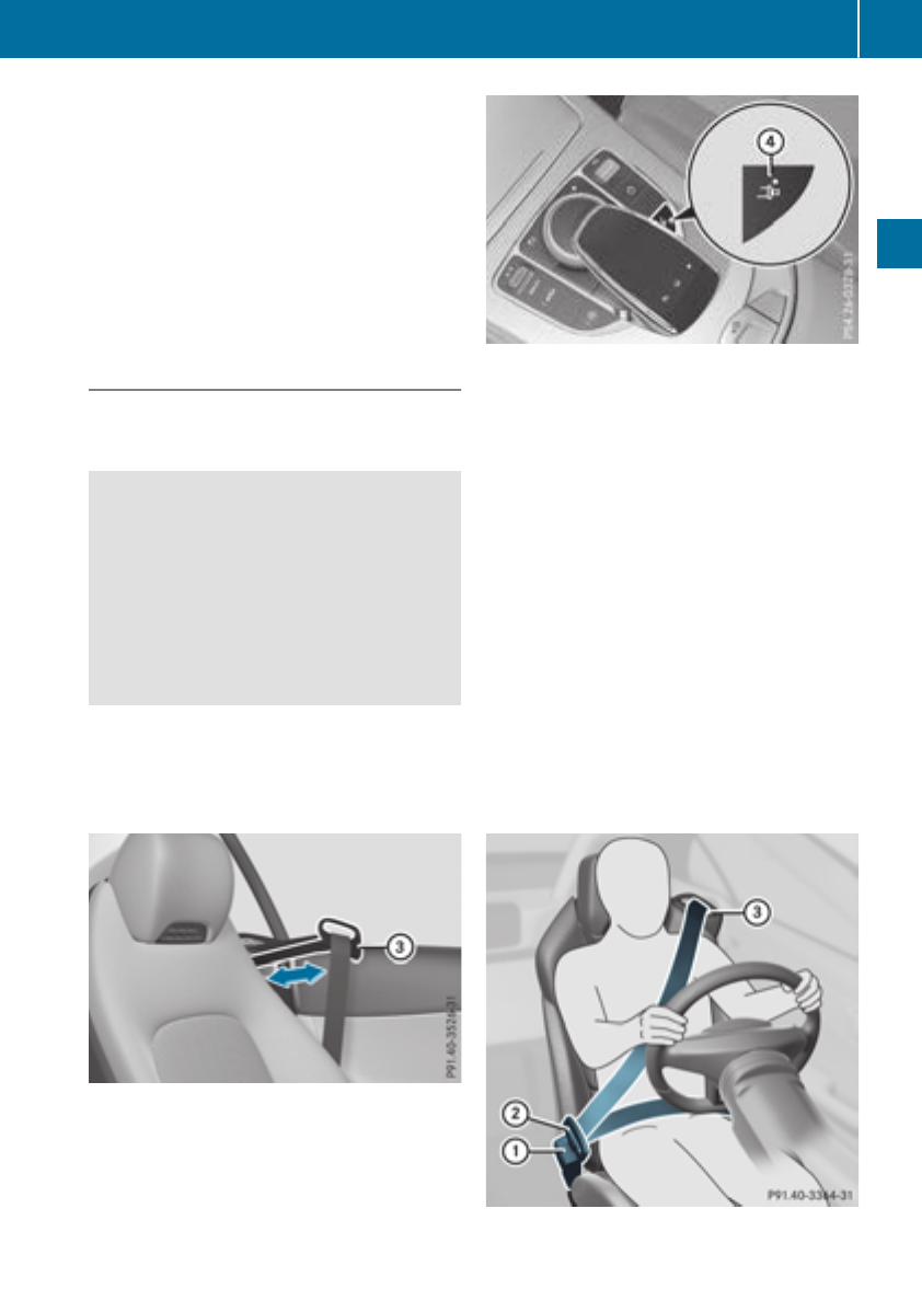
of an accident, they could be crushed
between the vehicle occupant and seat belt.
Robjects are never secured with a seat belt if
the seat belt is also being used by one of the
vehicle's occupants
Also ensure that there are never objects
between a person and the seat, e.g. cushions.
Seat belts are only intended to secure and
restrain vehicle occupants. Always observe the
"Loading guidelines" for securing objects, lug-
gage or loads (Ypage 263).
Fastening seat belts
Observe the safety notes on the seat belt
(Ypage 45) and the notes on correct use of seat
belts (Ypage 46).
GWARNING
If the seat-belt extender is extended during
the journey, the seat belt is not fitted properly
on the body. The seat belt can then no longer
perform its intended protective function. This
poses an increased risk of injury or even fatal
injury.
Always make sure that the seat-belt extender
is retracted during a journey.
If the seat-belt extender does not retract auto-
matically, you can return it manually. Press the
seat-belt extender back to the stop before start-
ing the vehicle to do so. Returning the seat-belt
extender requires force.
The seat-belt extender for the driver and front
passenger helps you fasten your seat belt. Seat-
belt extender =is extended when the respec-
tive door is closed.
You can also extend seat-belt extender =with
seat-belt extender button ?.
XTurn the SmartKey to position 1or 2in the
ignition lock.
XPress seat-belt extender button ?.
Seat-belt extender =extends.
Seat-belt extender =is retracted again if:
Rthe belt tongue is engaged in the seat belt
buckle
Rthe belt tongue is not engaged in the seat belt
buckle within 60 seconds
In this case, you can extend seat-belt
extender =again. Press seat-belt extender
button ?again.
Rthe respective door is opened
Ryou release the seat backrest and fold it
forward
Rthe front-passenger seat remains unoccupied
If you then press seat-belt extender but-
ton ?, seat-belt extender =will not extend.
Basic illustration
Occupant safety 47
Safety
Z

XAdjust the seat (Ypage 94).
The seat backrest must be in an almost
upright position.
XPull the seat belt smoothly out of seat-belt
extender =and engage belt tongue ;into
belt buckle :.
The seat belt on the driver’s seat and the
front-passenger seat may be tightened auto-
matically, see "Belt adjustment"
(Ypage 48).
XIf necessary, pull up on the shoulder section
of the seat belt to tighten the belt across your
body.
All seat belts except the driver's seat belt are
equipped with a special seat belt retractor to
securely fasten child restraint systems in the
vehicle. Further information can be found under
"Special seat belt retractor" (Ypage 60).
Releasing seat belts
!Make sure that the seat belt is fully rolled up.
Otherwise, the seat belt or belt tongue will be
trapped in the door or in the seat mechanism.
This could damage the door, the door trim
panel and the seat belt. Damaged seat belts
can no longer fulfill their protective function
and must be replaced. Visit a qualified spe-
cialist workshop.
XPress the release button in the belt buckle,
hold the belt tongue firmly and guide the belt
back.
Seat belt adjustment
The belt adjustment is a convenience function
integrated into PRE-SAFE®. With this function,
the driver's and front-passenger seat belts are
adjusted to the upper body of the vehicle occu-
pant.
The seat belt strap will slightly tighten if:
Rthe belt tongue is inserted into the buckle and
Rthe ignition is switched on
The seat belt adjustment will apply a certain
tightening force if any slack is detected between
the vehicle occupant and the seat belt. Do not
grab hold of the seat belt.
You can switch the seat belt adjustment on and
off using the multimedia system. Information on
switching the seat belt adjustment on and off
can be found in the Digital Operating Instruc-
tions.
Belt warning for the driver and front
passenger
The 7seat belt warning lamp in the instru-
ment cluster is a reminder that all vehicle occu-
pants must wear their seat belts. It may light up
continuously or flash. In addition, there may be
a warning tone.
Regardless of whether the driver's seat belt has
already been fastened, the 7seat belt warn-
ing lamp lights up for six seconds each time the
engine is started. If the doors are closed and the
driver's or front-passenger seat belt has not
been fastened, the 7seat belt warning lamp
lights up again after the six seconds. As soon as
the driver's and front-passenger seat belts are
fastened or a door is opened again, the 7
seat belt warning lamp goes out.
If the driver's seat belt is not fastened after the
engine is started, an additional warning tone will
sound. The warning tone switches off after six
seconds or once the driver's seat belt is fas-
tened.
If the vehicle's speed exceeds 15 mph
(25 km/h) once and the driver's and front-
passenger seat belts are not fastened, a warning
tone sounds. A warning tone also sounds with
increasing intensity for 60 seconds or until the
driver or front passenger have fastened their
seat belts.
If the driver or front passenger unfasten their
seat belts during the journey, the seat belt warn-
ing is activated again.
Air bags
Introduction
The installation point of an air bag can be rec-
ognized by the AIRBAG marking.
An air bag complements the correctly fastened
seat belt. It is no substitute for the seat belt. The
air bag provides additional protection in appli-
cable accident situations.
Not all air bags are deployed in an accident. The
different air bag systems function independ-
ently from one another (Ypage 56).
However, no system available today can com-
pletely eliminate injuries and fatalities.
It is also not possible to rule out a risk of injury
caused by an air bag due to the high speed at
which the air bag must be deployed.
48 Occupant safety
Safety

Important safety notes
GWARNING
If you do notsit in thecorrectseat position,
theair bag cannotprotect as intended and
could evencauseadditional injury when
deployed. This poses an increased riskof
injury or evenfatal injury.
To avoidhazardous situations, always make
surethat all of thevehicle's occupants:
Rhave fastenedtheir seat beltscorrectly,
includingpregnant women
Rare sitting correctlyand maintainthegreat-
est possible distanceto theair bags
Rfollow thefollowinginstructions
Always makesurethat there are no objects
between theair bag and thevehicle's occu-
pants.
RAdjusttheseatsproperly before beginning
your journey. Always makesurethat theseat
is in an almost upright position.The center of
thehead restraintmust support thehead at
about eye level.
RMovethedriver'sand front-passenger seats
as far backas possible.The driver'sseat posi-
tion must allow thevehicleto be driven safely.
ROnly hold thesteering wheelon theoutside.
This allows theair bag to be fully deployed.
RAlways lean against thebackrest while driv-
ing.Do notlean forward or lean against the
door or side window. You may otherwise be in
thedeploymentarea of theair bags.
RAlways keep your feetin thefootwell in front
of theseat.Do notput your feeton thedash-
board, for example. Your feetmay otherwise
be in thedeploymentarea of theair bag.
RForthis reason,always secure personsless
than 5ft (1.50m) tall in suitable restraint sys-
tems. Up to this height, the seat belt cannot
be worn correctly.
If a child is traveling in your vehicle, also
observe the following notes:
RAlways secure children under twelve years of
age and less than 5 ft (1.50 m) tall in suitable
child restraint systems.
RChild restraint systems should be installed on
the rear seats.
ROnly secure a child in a rearward-facing child
restraint system on the front-passenger seat
when the front-passenger front air bag is
deactivated. If the PASSENGER AIR BAG OFF
indicator lamp is permanently lit, the front-
passenger front air bag is deactivated
(Ypage 44).
RAlways observe the instructions and safety
notes on the "Occupant Classification System
(OCS)" (Ypage 51) and on "Children in the
vehicle" (Ypage 59)in addition to the child
restraint system manufacturer's installation
and operating instructions.
Objects in the vehicle interior may prevent
an air bag from functioning correctly. Before
starting your journey and to avoid risks resulting
from the speed of the air bag as it deploys, make
sure that:
Rthere are no people, animals or objects
between the vehicle occupants and an air bag
Rthere are no objects between the seat, door
and B-pillar
Rthere are no hard objects, e.g. coat hangers,
hanging on the grab handles or coat hooks
Rno accessories, such as cup holders, are
attached to the vehicle within the deployment
area of an air bag, e.g. to doors, side windows,
rear side trim or side walls
Rno heavy, sharp-edged or fragile objects are in
the pockets of your clothing. Store such
objects in a suitable place
GWARNING
If you modify the air bag cover or affix objects
such as stickers to it, the air bag can no longer
function correctly. There is an increased risk
of injury.
Never modify an air bag cover or affix objects
to it.
GWARNING
Sensors to control the air bags are located in
the doors. Modifications or work not per-
formed correctly to the doors or door panel-
ing, as well as damaged doors, can lead to the
function of the sensors being impaired. The air
bags might therefore not function properly
anymore. Consequently, the air bags cannot
protect vehicle occupants as they are
Occupant safety 49
Safety
Z
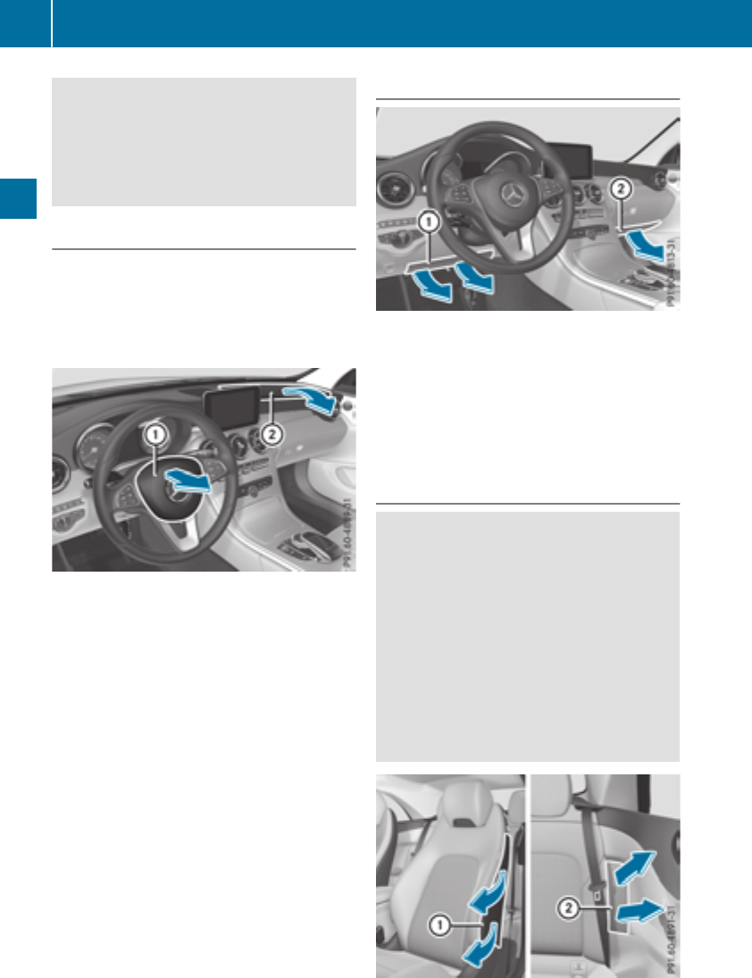
designed to do. There is an increased risk of
injury.
Never modify the doors or parts of the doors.
Always have work on the doors or door pan-
eling carried out at a qualified specialist work-
shop.
Front air bags
!Do not place heavy objects on the front-
passenger seat. This could cause the system
to identify the seat as being occupied. In the
event of an accident, the restraint systems on
the front-passenger side may be triggered
and have to be replaced.
Driver's air bag :deploys in front of the steer-
ing wheel. Front-passenger front air bag ;
deploys in front of and above the glove box.
When deployed, the front air bags offer addi-
tional head and thorax protection for the occu-
pants in the front seats.
The PASSENGER AIR BAG OFF indicator lamp
informs you about the status of the front-
passenger front air bag (Ypage 44).
The front-passenger front air bag will only
deploy if:
Rthe system, based on the OCS weight sensor
readings, detects that the front-passenger
seat is occupied (Ypage 51). The
PASSENGER AIR BAG OFF indicator lamp is
not lit (Ypage 52)
Rthe restraint system control unit predicts a
high accident severity
Knee bags
Driver's knee bag :deploys underneath the
steering column and front-passenger knee
bag ;underneath the glove box. The driver's
and front-passenger knee bags are triggered
together with the front air bags.
The driver's and front-passenger knee bags
offer additional thigh, knee and lower leg pro-
tection for the occupants in the front seats.
Side impact air bags
GWARNING
Unsuitable seat covers can obstruct or pre-
vent deployment of the air bags integrated
into the seats. Consequently, the air bags
cannot protect vehicle occupants as they are
designed to do. In addition, the operation of
the occupant classification system (OCS)
could be adversely affected. This poses an
increased risk of injury or even fatal injury.
You should only use seat covers that have
been approved for the respective seat by
Mercedes-Benz.
50 Occupant safety
Safety
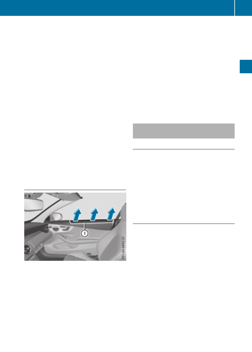
Front side impact air bags :and rear side
impact air bags ;deploy next to the outer bol-
ster of the seat backrest.
When deployed, the side impact air bag offers
additional thorax protection. However, it does
not protect the:
RHead
RNeck
RArms
If the restraint system control unit detects a side
impact, the side impact air bag is deployed on
the side on which the impact occurs.
The side impact air bag on the front-passenger
side deploys under the following conditions:
Rthe OCS system detects that the front-
passenger seat is occupied or
Rthe seat belt buckle tongue is engaged in the
belt buckle of the front-passenger seat
If the belt tongue is engaged in the belt buckle,
the side impact air bag on the front-passenger
side deploys if an appropriate accident situation
occurs. In this case, deployment is independent
of whether the front-passenger seat is occupied
or not.
Head air bags
Head bags :deploy in the area of the side win-
dows at the front.
When deployed, the head bag enhances the
level of protection for the head. However, it does
not protect the:
Rchest
Rarms
If the restraint system control unit detects a side
impact, the head bag is deployed on the side on
which the impact occurs.
If the system determines that they can offer
additional protection to that provided by the
seat belt, a head bag may be deployed in other
accident situations (Ypage 56).
The head bag on the front-passenger side
deploys under the following conditions:
Rthe OCS system detects that the front-
passenger seat is occupied or
Rthe seat belt buckle tongue is engaged in the
belt buckle of the front-passenger seat
If the belt tongue is engaged in the belt buckle,
the head bag on the front-passenger side
deploys if an appropriate accident situation
occurs. In this case, deployment is independent
of whether the front-passenger seat is occupied
or not.
Occupant Classification System
(OCS)
Introduction
The Occupant Classification System (OCS) cat-
egorizes the person in the front-passenger seat.
Depending on that result, the front-passenger
front air bag and front-passenger knee bag are
either enabled or deactivated.
The system does not deactivate:
Rthe side impact air bag
Rthe headbag
Rthe Emergency Tensioning Devices
Requirements
To be classified correctly, the front passenger
must sit:
Rwith the seat belt fastened correctly
Rin an almost upright position with their back
against the seat backrest
Rwith their feet resting on the floor, if possible
If the front passenger does not observe these
conditions, OCS may produce a false classifica-
tion, e.g. because the front passenger:
Rtransfers their weight by supporting them-
selves on a vehicle armrest
Rsits in such a way that their weight is raised
from the seat cushion
If it is absolutely necessary to install a child
restraint system on the front-passenger seat, be
sure to observe the correct positioning of the
child restraint system. Never place objects
under or behind the child restraint system, e.g. a
Occupant safety 51
Safety
Z
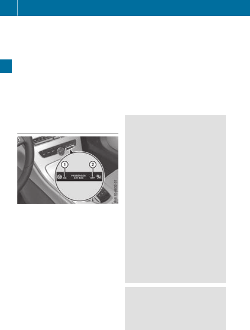
cushion. Fully retract the seat cushion length.
The entire base of the child restraint system
must always rest on the seat cushion of the
front-passenger seat. The backrest of the
forward-facing child restraint system must lie as
flat as possible against the backrest of the front-
passenger seat.
The child restraint system must not touch the
roof or be subjected to a load by the head
restraint. Adjust the angle of the seat backrest
and the head restraint position accordingly.
Only then can OCS be guaranteed to function
correctly. Always observe the child restraint sys-
tem manufacturer's installation and operating
instructions.
Occupant Classification System opera-
tion (OCS)
:PASSENGER AIR BAG ON indicator lamp
;PASSENGER AIR BAG OFF indicator lamp
The indicator lamps inform you whether the
front-passenger front air bag is deactivated or
enabled.
XPress the Start/Stop button once or twice, or
turn the SmartKey to position 1or 2in the
ignition lock.
The system carries out self-diagnostics.
The PASSENGER AIR BAG OFF and PASSENGER
AIR BAG ON indicator lamps must light up simul-
taneously for approximately six seconds.
The indicator lamps display the status of the
front-passenger front air bag.
RPASSENGER AIR BAG ON lights up for 60 sec-
onds, subsequently both indicator lamps are
off (PASSENGER AIR BAG ON and OFF): the
front-passenger front air bag is able to deploy
in the event of an accident.
RPASSENGER AIR BAG OFF lights up: the front-
passenger front air bag is deactivated. It will
then not be deployed in the event of an acci-
dent.
If the PASSENGER AIR BAG ON indicator lamp is
off, only the PASSENGER AIR BAG OFF indicator
lamp shows the status of the front-passenger
front air bag. The PASSENGER AIR BAG OFF
indicator lamp may be lit continuously or be off.
If the status of the front-passenger front air bag
changes while the vehicle is in motion, an air bag
display message appears in the instrument clus-
ter (Ypage 222). When the front-passenger
seat is occupied, always pay attention to the
PASSENGER AIR BAG OFF indicator lamp. Be
aware of the status of the front-passenger front
air bag both before and during the journey.
GWARNING
If the PASSENGER AIR BAG OFF indicator
lamp is lit, the front-passenger front air bag is
disabled. It will not be deployed in the event of
an accident and cannot perform its intended
protective function. A person in the front-
passenger seat could then, for example, come
into contact with the vehicle's interior, espe-
cially if the person is sitting too close to the
dashboard. This poses an increased risk of
injury or even fatal injury.
When the front-passenger seat is occupied,
always ensure that:
Rthe classification of the person in the front-
passenger seat is correct and the front-
passenger front air bag is enabled or disa-
bled in accordance with the person in the
front-passenger seat
Rthe front-passenger seat has been moved
back as far back as possible.
Rthe person is seated correctly.
Make sure, both before and during the jour-
ney, that the status of the front-passenger
front air bag is correct.
GWARNING
If you secure a child in a rearward-facing child
restraint system on the front-passenger seat
and the PASSENGER AIR BAG OFF indicator
lamp is off, the front-passenger front air bag
may deploy in the event of an accident. The
52 Occupant safety
Safety

child could be struck by the air bag. This poses
an increased risk of injury or even fatal injury.
Make sure that the front-passenger front air
bag has been disabled. The PASSENGER AIR
BAG OFF indicator lamp must be lit.
If the PASSENGER AIR BAG OFF indicator lamp
stays off, do not install a rearward-facing child
restraint system on the front-passenger seat.
You can find more information on OCS under
"Problems with the Occupant Classification Sys-
tem" (Ypage 55).
GWARNING
If you secure a child in a forward-facing child
restraint system on the front-passenger seat
and you position the front-passenger seat too
close to the dashboard, in the event of an
accident, the child could:
Rcome into contact with the vehicle's inte-
rior if the PASSENGER AIR BAG OFF indi-
cator lamp is lit, for example
Rbe struck by the air bag if the PASSENGER
AIR BAG OFF indicator lamp is off
This poses an increased risk of injury or even
fatal injury.
Always move the front-passenger seat as far
back as possible and fully retract the seat
cushion length. Always make sure that the
shoulder belt strap is correctly routed from
the vehicle belt outlet to the shoulder belt
guide on the child restraint system. The shoul-
der belt strap must be routed forwards and
downwards from the vehicle belt outlet. If
necessary, adjust the vehicle belt outlet and
the front-passenger seat accordingly. Always
observe the child restraint system manufac-
turer's installation instructions.
If OCS determines that:
Rthe front-passenger seat is unoccupied, the
PASSENGER AIR BAG OFF indicator lamp
lights up after the system self-test and
remains lit. This indicates that the front-
passenger front air bag is deactivated.
Rthe front-passenger seat is occupied by a
child of up to twelve months old, in a standard
child restraint system, the PASSENGER AIR
BAG OFF indicator lamp lights up after the
system self-test and remains lit. This indi-
cates that the front-passenger front air bag is
deactivated.
But even in the case of a twelve-month-old
child, in a standard child restraint system, the
PASSENGER AIR BAG OFF indicator lamp can
go out after the system self-test. This indi-
cates that the front-passenger front air bag is
activated. The result of the classification is
dependent on, among other factors, the child
restraint system and the child's stature. It is
recommended that you install the child
restraint system on a suitable rear seat.
Rthe front-passenger seat is occupied by a per-
son with a smaller build (e.g. a teenager or
small adult), the PASSENGER AIR BAG OFF
indicator lamp lights up and remains lit after
the system self-test depending on the result
of the classification or, alternatively, goes out.
-if the PASSENGER AIR BAG OFF indicator
lamp is off, move the front-passenger seat
as far back as possible. Alternatively, a per-
son of smaller stature can sit on a rear seat.
-if the PASSENGER AIR BAG OFF indicator
lamp is lit, a person of smaller stature
should not use the front-passenger seat.
Rthe front-passenger seat is occupied by an
adult or a person of adult stature, the
PASSENGER AIR BAG OFF indicator lamp
goes out after the system self-test. This indi-
cates that the front-passenger front air bag is
activated.
If children are traveling in the vehicle, be sure to
observe the notes on "Children in the vehicle"
(Ypage 59).
When the Occupant Classification System
(OCS) is malfunctioning, the red 6restraint
system warning lamp on the instrument cluster
and the PASSENGER AIR BAG OFF indicator
lamp light up simultaneously. The front-
passenger front air bag is deactivated in this
case and does not deploy during an accident.
Have the Occupant Classification System (OCS)
checked and repaired immediately at a qualified
specialist workshop. Mercedes-Benz recom-
mends that you use an authorized Mercedes-
Benz Center for this purpose.
If the front-passenger seat, the seat cover or the
seat cushion are damaged, have the necessary
repair work carried out at a qualified specialist
workshop. Mercedes-Benz recommends that
you use an authorized Mercedes-Benz Center
for this purpose.
Occupant safety 53
Safety
Z

For safety reasons, Mercedes-Benz recom-
mends that you only use seat accessories that
have been approved by Mercedes-Benz.
If the driver's air bag deploys, this does not
mean that the front-passenger front air bag will
also deploy. The Occupant Classification Sys-
tem (OCS) categorizes the occupant on the
front-passenger seat. Depending on that result,
the front-passenger front air bag is either ena-
bled or deactivated.
System self-test
GDANGER
If both the PASSENGER AIR BAG OFF and
PASSENGER AIR BAG ON indicator lamps do
not light up during the system self-test, the
system is malfunctioning. The front-
passenger front air bag might be triggered
unintentionally or might not be triggered at all
in the event of an accident with high deceler-
ation. This poses an increased risk of injury or
even fatal injury.
In this case the front-passenger seat may not
be used. Do not install a child restraint system
on the front-passenger seat. Have the Occu-
pant Classification System (OCS) checked
and repaired immediately at a qualified spe-
cialist workshop.
GWARNING
If the PASSENGER AIR BAG OFF indicator
lamp remains lit after the system self-test, the
front-passenger front air bag is disabled. It will
not be deployed in the event of an accident. In
this case, the front-passenger front air bag
cannot perform its intended protective func-
tion, e.g. when a person is seated in the front-
passenger seat.
That person could, for example, come into
contact with the vehicle's interior, especially
if the person is sitting too close to the dash-
board. This poses an increased risk of injury or
even fatal injury.
When the front-passenger seat is occupied,
always ensure that:
Rthe classification of the person in the front-
passenger seat is correct and the front-
passenger front air bag is enabled or disa-
bled in accordance with the person in the
front-passenger seat
Rthe person is seated properly with a cor-
rectly fastened seatbelt
Rthe front-passenger seat has been moved
as far back as possible
If the PASSENGER AIR BAG OFF indicator
lamp remains lit when it should not, the front-
passenger seat may not be used. Do not
install a child restraint system on the front-
passenger seat. Have the Occupant Classifi-
cation System (OCS) checked and repaired
immediately at a qualified specialist work-
shop.
GWARNING
Objects between the seat surface and the
child restraint system could affect OCS oper-
ation. This could result in the front-passenger
air bag not functioning as intended during an
accident. This poses an increased risk of
injury or even fatal injury.
Do not place any objects between the seat
surface and the child restraint system. The
entire base of the child restraint system must
always rest on the seat cushion of the front-
passenger seat. The backrest of the forward-
facing child restraint system must, as far as
possible, be resting on the backrest of the
front-passenger seat. Always comply with the
child restraint system manufacturer's instal-
lation instructions.
After the system self-test, the PASSENGER AIR
BAG OFF or PASSENGER AIR BAG ON indicator
lamp displays the status of the front-passenger
front air bag (Ypage 52). If the front-passenger
front air bag is enabled, the PASSENGER AIR
BAG ON indicator lamp lights up for 60 seconds
and then goes out.
If the PASSENGER AIR BAG ON indicator lamp is
off, only the PASSENGER AIR BAG OFF indicator
lamp shows the status of the front-passenger
54 Occupant safety
Safety

front air bag. The PASSENGER AIR BAG OFF
indicator lamp may be lit continuously or be off.
For more information about the OCS, see "Prob-
lems with the Occupant Classification System"
(Ypage 55).
Problems with the Occupant Classification System (OCS)
Be sure to observe the notes on "System self-test" (Ypage 54).
Problem Possible causes/consequences and MSolutions
The PASSENGER AIR
BAG OFF indicator lamp
lights up and remains lit,
even though the front-
passenger seat is occu-
pied by an adult or a per-
son of a stature corre-
sponding to that of an
adult.
The classification of the person on the front-passenger seat is incor-
rect.
XMake sure the conditions for a correct classification of the person
on the front-passenger seat are met (Ypage 51).
XIf the PASSENGER AIR BAG OFF indicator lamp remains lit, the front-
passenger seat may not be used.
XHave OCS checked as soon as possible at an authorized Mercedes-
Benz Center.
The PASSENGER AIR
BAG OFF indicator lamp
does not light up and/or
does not stay on.
The front-passenger seat
is:
Runoccupied
Roccupied with the
weight of a child up to
twelve months old in a
child restraint system
OCS is malfunctioning.
XMake sure there is nothing between the seat cushion and the child
seat.
XMake sure that the entire base of the child restraint system rests on
the seat cushion of the front-passenger seat. The backrest of the
forward-facing child restraint system must lie as flat as possible
against the backrest of the front-passenger seat. If necessary,
adjust the position of the front-passenger seat.
XMake sure that the seat cushion length is fully retracted.
XWhen installing the child restraint system, make sure that the seat
belt is tight. Do not pull the seat belt tight using the front-passenger
seat adjustment. This could result in the seat belt and the child
restraint system being pulled too tightly.
XCheck for correct installation of the child restraint system.
Make sure that the head restraint does not apply a load to the child
restraint system. If necessary, adjust the head restraint accord-
ingly.
XMake sure that no objects are applying additional weight onto the
seat.
XIf the PASSENGER AIR BAG OFF indicator lamp remains off and/or
the PASSENGER AIR BAG ON indicator lamp lights up, do not install
a child restraint system on the front-passenger seat. It is recom-
mended that you install the child restraint system on a suitable rear
seat.
XHave OCS checked as soon as possible at an authorized Mercedes-
Benz Center.
Roll bar
GDANGER
If the roll bar has developed a malfunction, it
may not function, e.g. in the event of an acci-
dent. The roll bars may then not protect the
vehicle occupants as intended. This poses an
increased risk of injury or even fatal injury.
Occupant safety 55
Safety
Z
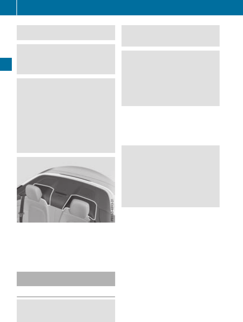
Have roll bars checked immediately at a quali-
fied specialist workshop.
GWARNING
Risk of injury if the roll bar is triggered.
Ensure that the movement area of the roll bars
behind the rear head restraints is kept clear.
GWARNING
If you place objects or clothing on the roll bar
covers, these could impair roll bar extension.
The roll bars may then not protect the vehicle
occupants as intended. In addition, objects
could endanger the vehicle occupants when
the roll bar is extending. This poses an
increased risk of injury or even fatal injury.
Ensure that the movement area of the roll bar
covers is kept clear. Always stow all objects in
the vehicle correctly.
The roll bars are under the covers behind the
rear head restraints. They extend if systems
detect that the vehicle is in danger of rollover.
Once the roll bars are extended, an open soft top
can no longer be closed. In this case, visit the
nearest qualified specialist workshop.
Deployment of Emergency Tensioning
Devices and air bags
Important safety notes
GWARNING
The air bag parts are hot after an air bag has
been deployed. There is a risk of injury.
Do not touch the air bag parts. Have a
deployed air bag replaced at a qualified spe-
cialist workshop as soon as possible.
GWARNING
A deployed air bag no longer offers any pro-
tection and cannot provide the intended pro-
tection in an accident. There is an increased
risk of injury.
Have the vehicle towed to a qualified special-
ist workshop in order to have a deployed air
bag replaced.
It is important for your safety and that of your
passenger to have deployed air bags replaced
and to have any malfunctioning air bags
repaired. This will help to make sure the air bags
continue to perform their protective function for
the vehicle occupants in the event of a crash.
GWARNING
Emergency Tensioning Devices that have
deployed pyrotechnically are no longer opera-
tional and are unable to perform their inten-
ded protective function. This poses an
increased risk of injury or even fatal injury.
Have pyrotechnically triggered Emergency
Tensioning Devices replaced immediately at a
qualified specialist workshop.
An electric motor is used by PRE-SAFE®to trig-
ger the tightening of the seat belt in hazardous
situations. This procedure is reversible.
If Emergency Tensioning Devices are triggered
or air bags are deployed, you will hear a bang,
and some powder may also be released. The
6restraint system warning lamp lights up.
Only in rare cases will the bang affect your hear-
ing. The powder that is released generally does
not constitute a health hazard, but it may cause
short-term breathing difficulties in people with
asthma or other respiratory problems. Provided
it is safe to do so, you should leave the vehicle
immediately or open the window in order to pre-
vent breathing difficulties.
Air bags and pyrotechnic Emergency Tensioning
Devices (ETDs) contain perchlorate material,
which may require special handling and regard
for the environment. National guidelines must
be observed during disposal. In California, see
56 Occupant safety
Safety

www.dtsc.ca.gov/HazardousWaste/
Perchlorate/index.cfm.
Method of operation
During thefirst stage of acollision,therestraint
system control unitevaluatesimportant physi-
cal datarelating to vehicledeceleration or accel-
eration,suchas:
Rduration
Rdirection
Rintensity
Based on theevaluation of this data, the
restraintsystem control unittriggers theEmer-
gency Tensioning Devices during afrontal or
rear collision.
An Emergency Tensioning Devicecan only be
triggered,if:
Rtheignition is switched on
Rthecomponentsof therestraintsystem are
operational. You can findfurther information
under "Restraintsystem warning lamp"
(Ypage 44)
Rtheseat belt buckletongue has engagedin
thebelt buckleof therespective frontseat
The Emergency Tensioning Devices in therear
compartmentare triggered independentlyof the
lockstatus of theseat belts.
If therestraintsystem control unitdetects a
moresevere accident, further componentsof
therestraintsystem are activated independ-
entlyof eachother in certain frontal collision
situations:
RFrontair bags as well as driver's and front-
passenger knee bags
RHeadbag, if thesystem determinesthat
deployment can offer additional protection to
that provided by theseat belt
The front-passenger frontair bag is activated or
deactivated depending on theperson on the
front-passenger seat.The front-passenger front
air bag can only deploy in an accidentif the
PASSENGER AIRBAGOFFindicator lamp is off.
Observetheinformation on thePASSENGER AIR
BAGindicator lamps (Ypage 44).
Your vehiclehas two-stagefrontair bags.In the
first deployment stage, thefrontair bag is filled
withpropellantgas. The frontair bag is fully
deployed withthemaximum amount of propel-
lantgas if aseconddeployment threshold is
reached within afew milliseconds.
The activation threshold of theEmergency Ten-
sioning Devices and theair bags is determined
by evaluating therateof vehicledeceleration or
acceleration whichoccursat various points in
thevehicle. This process is pre-emptive in
nature. Deploymentshould takeplacein good
time at thestart of thecollision.
The rateof vehicledeceleration or acceleration
and thedirection of theforce are essentially
determinedby:
Rthedistribution of forcesduring thecollision
Rthecollision angle
Rthedeformation characteristics of thevehicle
Rthecharacteristics of theobjectwithwhich
thevehiclehas collided
Factors whichcan only be seenand measured
after acollision has occurred do notplay adeci-
siverolein thedeployment of an air bag. Nor do
they providean indication of air bag deploy-
ment.
The vehiclecan be deformed considerably, with-
out an air bag beingdeployed. This is thecaseif
only partswhichare relativelyeasilydeformed
are affectedand therateof deceleration is not
high.Conversely, air bags may be deployed even
though thevehiclesuffersonly minor deforma-
tion.This is thecaseif, for example, veryrigid
vehiclepartssuchas longitudinal body mem-
bersare hit,and sufficientdeceleration occurs
as aresult.
If therestraintsystem control unitdetects aside
impact or if thevehiclerolls over, theapplicable
componentsof therestraintsystem are activa-
tedindependentlyof eachother depending on
theapparenttypeof accident.
RSideimpact air bags on theside of impact,
independentlyof theEmergency Tensioning
Deviceand theuse of theseat belt on the
driver's seat and in therear compartment
seats
The side impact air bag on thefront-
passenger side deploys under thefollowing
conditions:
-theOCS system detects that thefront-
passenger seat is occupied or
-theseat belt buckletongue is engagedin
thebelt buckleof thefront-passenger seat
RHeadbag on theside of impact,independ-
entlyof theuse of theseat belt and inde-
pendentlyof whether thefront-passenger
seat is occupied
Occupant safety 57
Safety
Z

REmergency Tensioning Devices, if the system
determines that deployment can offer addi-
tional protection in this situation
RHead bags on the driver's and front-
passenger side in certain situations when the
vehicle rolls over, if the system determines
that deployment can offer additional protec-
tion to that provided by the seat belt
iNot all air bags are deployed in an accident.
The different air bag systems work independ-
ently of each other.
How the air bag system works is determined
by the severity of the accident detected,
especially the vehicle deceleration or accel-
eration and the apparent type of accident:
RFrontal collision
RSide impact
RRollover
PRE-SAFE®(anticipatory occupant
protection system)
Introduction
In certain hazardous situations, PRE-SAFE®
takes pre-emptive measures to protect the vehi-
cle occupants.
Important safety notes
!Make sure that there are no objects in the
footwell or behind the seats. There is a danger
that the seats and/or objects could be dam-
aged when PRE-SAFE®is activated.
Despite your vehicle being equipped with the
PRE-SAFE®system, the possibility of personal
injuries occurring as a result of an accident can-
not be eliminated. Always adapt your driving
style to suit the prevailing road and weather
conditions and maintain a safe distance from
the vehicle in front. Drive carefully.
Function
PRE-SAFE®intervenes:
Rin emergency braking situations, e.g. when
BAS is activated
Rin critical driving situations, e.g. when physi-
cal limits are exceeded and the vehicle under-
steers or oversteers severely
Rvehicles with the Driving Assistance package:
when a driver assistance system intervenes
powerfully or the radar sensor system detects
an imminent danger of collision in certain sit-
uations
PRE-SAFE®takes the following measures
depending on the hazardous situation detected:
Rthe front seat belts are pre-tensioned.
Rif the vehicle skids, the front side windows are
closed.
Rvehicles with the memory function for the
front-passenger seat: the front-passenger
seat is adjusted if it is in an unfavorable posi-
tion.
If the hazardous situation passes without result-
ing in an accident, PRE-SAFE®slackens the belt
pre-tensioning. All settings made by PRE-SAFE®
can then be reversed.
If the seat belt pre-tensioning is not reduced:
XMove the seat backrest or seat back slightly
when the vehicle is stationary.
The seat belt pre-tensioning is reduced and
the locking mechanism is released.
The seat-belt adjustment is an integral part of
the PRE-SAFE®convenience function. Informa-
tion about the convenience function can be
found under "Belt adjustment" (Ypage 48).
PRE-SAFE®PLUS (anticipatory occu-
pant protection system PLUS)
Introduction
PRE-SAFE®PLUS is only available in vehicles
with the Driving Assistance package.
Using the radar sensor system, PRE-SAFE®
PLUS is able to detect that a head-on or rear-end
collision is imminent. In certain hazardous sit-
uations, PRE-SAFE®PLUS takes pre-emptive
measures to protect the vehicle occupants.
58 Occupant safety
Safety

Important safety notes
The intervention of PRE-SAFE®PLUScannot
preventan imminent collision.
The driver is notwarned about theintervention
of PRE-SAFE®PLUS.
PRE-SAFE®PLUSdoes notinterveneif thevehi-
cle is backingup.
When driving,or when parking or exiting apark-
ing spacewithassistancefrom Parking Pilot,
PRE-SAFE®PLUSwill notapply thebrakes.
Function
PRE-SAFE®PLUSintervenes in certain situa-
tionsif theradar sensor system detects an
imminent head-on or rear-end collision.
PRE-SAFE®PLUStakes thefollowingmeasures
depending on thehazardous situation detected:
Rif theradar sensor system detects that a
head-on collision is imminent,theseat belts
are pre-tensioned.
Rif theradar sensor system detects that arear-
endcollision is imminent:
-thebrakepressureis increased if thedriver
appliesthebrakes when thevehicleis sta-
tionary.
-theseat beltsare pre-tensioned.
The PRE-SAFE®PLUSbraking application is can-
celed:
Rif theacceleratorpedal is depressed when a
gear is engaged
Rif theriskof acollision passes or is no longer
detected
Rif DistancePilot DISTRONICindicates an
intention to pull away
If thehazardous situation passes without result-
ing in an accident, theoriginal settingsare
restored.
Automatic measures after an acci-
dent
Immediately after an accident, thefollowing
measures are implemented, depending on the
typeand severityof theimpact:
Rthehazard warning lampsare switched on
Rtheemergencylighting is activated
Rthevehicledoorsare unlocked
Rthefrontside windows are lowered
Rvehicles with a memory function:theelectri-
callyadjustable steering wheelis raised when
thedriver'sdoor is opened
Rtheengineis switched off and thefuel supply
is cut off
Rvehicles withmbrace:automatic emergency
call
Children in the vehicle
Important safety notes
Accidentstatistics showthat children secured
in therear seatsare safer than children secured
in thefront-passenger seat.Forthis reason,
Mercedes-Benzstrongly advises that you install
achild restraintsystem on arear seat.Children
are generally betterprotected there.
If achild younger than twelve years old and
under 5ft (1.50 m) in height is traveling in the
vehicle:
Ralways secure thechild in achild restraint
system suitable for Mercedes-Benzvehicles.
The child restraintsystem must be appropri-
ate to theage, weightand sizeof thechild
Rbe sureto observetheinstructionsand safety
notesin this section in addition to thechild
restraintsystem manufacturer'sinstallation
instructions
Rbe sureto observetheinstructionsand safety
noteson the"Occupant classification system
(OCS)" (Ypage 51)
GWARNING
If you leavechildren unsupervised in thevehi-
cle,they could set it in motion by, for example:
Rrelease theparking brake.
Rshifttheautomatic transmission out of the
parking position P.
Rstart theengine.
In addition,they may operate vehicleequip-
mentand become trapped.Thereis ariskof
an accidentand injury.
When leaving thevehicle, always takethe
SmartKey withyou and lockthevehicle. Never
leavechildren unsupervised in thevehicle.
Children in the vehicle 59
Safety
Z

GWARNING
If persons, particularly children are subjected
to prolonged exposure to extreme heat or
cold, there is a risk of injury, possibly even
fatal. Never leave children unattended in the
vehicle.
GWARNING
If the child restraint system is subjected to
direct sunlight, parts may get very hot. Chil-
dren may burn themselves on these parts,
particularly on the metal parts of the child
restraint system. There is a risk of injury.
If you leave the vehicle, taking the child with
you, always ensure that the child restraint
system is not exposed to direct sunlight. Pro-
tect it with a blanket, for example. If the child
restraint system has been exposed to direct
sunlight, let it cool down before securing the
child in it. Never leave children unattended in
the vehicle.
Always ensure that all vehicle occupants have
their seat belts fastened correctly and are sitting
properly. Particular attention must be paid to
children.
Observe the safety notes on the seat belt
(Ypage 45) and the notes on correct use of seat
belts (Ypage 46).
A booster seat may be necessary to achieve
proper seat belt positioning for children over
41 lbs (18 kg) until they reach a height where a
three-point seat belt can be properly fastened
without a booster seat.
Special seatbelt retractor
GWARNING
If the seat belt is released while driving, the
child restraint system will no longer be
secured properly. The special seat belt retrac-
tor is disabled and the inertia real draws in a
portion of the seat belt. The seat belt cannot
be immediately refastened. There is an
increased risk of injury, possibly even fatal.
Stop the vehicle immediately, paying atten-
tion to road and traffic conditions. Reactivate
the special seat belt retractor and secure the
child restraint system properly.
All seat belts in the vehicle, except the driver's
seat belt, are equipped with a special seat belt
retractor. When activated, the special seat belt
retractor ensures that the seat belt cannot
slacken once the child seat is secured.
Installing a child restraint system:
XMake sure you observe the child restraint
system manufacturer's installation instruc-
tions.
XPull the front seat belt smoothly out of the
seat-belt extender and the rear seat belt out
of the belt sash guide.
XEngage seat belt tongue in belt buckle.
Activating the special seat belt retractor:
XPull the seat belt out fully and let the inertia
reel retract it again.
While the seat belt is retracting, you should
hear a ratcheting sound. The special seat belt
retractor is enabled.
XPush the child restraint system down so that
the seat belt is tight and does not loosen.
Removing the child restraint system and deac-
tivating the special seat belt retractor:
XMake sure you observe the child restraint
system manufacturer's installation instruc-
tions.
XPress the release button of the seat belt
buckle, hold the seat belt tongue and route it
to the seat belt extender in front or the belt
sash guide in the rear compartment.
The special seat belt retractor is deactivated.
Child restraint system
The use of seat belts and child restraint systems
is required by law in:
Rall 50 states
Rthe U.S. territories
Rthe District of Columbia
Rall Canadian provinces
You can obtain further information about the
correct child restraint system from any author-
ized Mercedes-Benz Center.
60 Children in the vehicle
Safety

GWARNING
If the child restraint system is installed incor-
rectly on a suitable seat, it cannot protect as
intended. The child cannot then be restrained
in the event of an accident, heavy braking or
sudden changes of direction. There is an
increased risk of injury, possibly even fatal.
Make sure that you observe the child restraint
system manufacturer's installation instruc-
tions and the notes on use. Please ensure,
that the base of the child restraint system is
always resting completely on the seat cush-
ion. Never place objects, e.g. cushions, under
or behind the child restraint system. Only use
child restraint systems with the original cover
designed for them. Only replace damaged
covers with genuine covers.
GWARNING
If the child restraint system is installed incor-
rectly or is not secured, it can come loose in
the event of an accident, heavy braking or a
sudden change in direction. The child
restraint system could be thrown about, strik-
ing vehicle occupants. There is an increased
risk of injury, possibly even fatal.
Always install child restraint systems prop-
erly, even if they are not being used. Make
sure that you observe the child restraint sys-
tem manufacturer's installation instructions.
You will find further information on stowing
objects, luggage or loads under "Loading guide-
lines" (Ypage 263).
GWARNING
Child restraint systems or their securing sys-
tems which have been damaged or subjected
to a load in an accident can no longer protect
as intended. The child cannot then be
restrained in the event of an accident, heavy
braking or sudden changes of direction. There
is an increased risk of injury, possibly even
fatal.
Replace child restraint systems which have
been damaged or subjected to a load in an
accident as soon as possible. Have the secur-
ing systems on the child restraint system
checked at a qualified specialist workshop,
before you install a child restraint system
again.
The securing systems of child restraint systems
are:
Rthe seat belt system
Rthe LATCH-type (ISOFIX) securing rings
Rthe Top Tether anchorages
If it is absolutely necessary to carry a child on
the front-passenger seat, be sure to observe the
information on the "Occupant Classification
System (OCS)" (Ypage 51). There you will also
find information on deactivating the front-
passenger front air bag.
All child restraint systems must meet the fol-
lowing standards:
RU.S. Federal Motor Vehicle Safety Standards
213 and 225
RCanadian Motor Vehicle Safety Standards
213 and 210.2
Confirmation that the child restraint system cor-
responds to the standards can be found on an
instruction label on the child restraint system.
This confirmation can also be found in the instal-
lation instructions that are included with the
child restraint system.
Observe the warning labels in the vehicle inte-
rior and on the child restraint system.
LATCH-type (ISOFIX) child seat secur-
ing system
GWARNING
LATCH-type (ISOFIX) child restraint systems
do not offer sufficient protection for children
whose weight combined with the child
restraint system is greater than 65 lbs (29 kg)
and who are secured using the safety belt
integrated in the child restraint system. In the
event of an accident, a child might not be
restrained correctly. This poses an increased
risk of injury or even fatal injury.
If the child and the child restraint system
together weigh more than 65 lbs (29 kg), only
use LATCH-type (ISOFIX) child restraint sys-
tems with which the child is also secured with
Children in the vehicle 61
Safety
Z
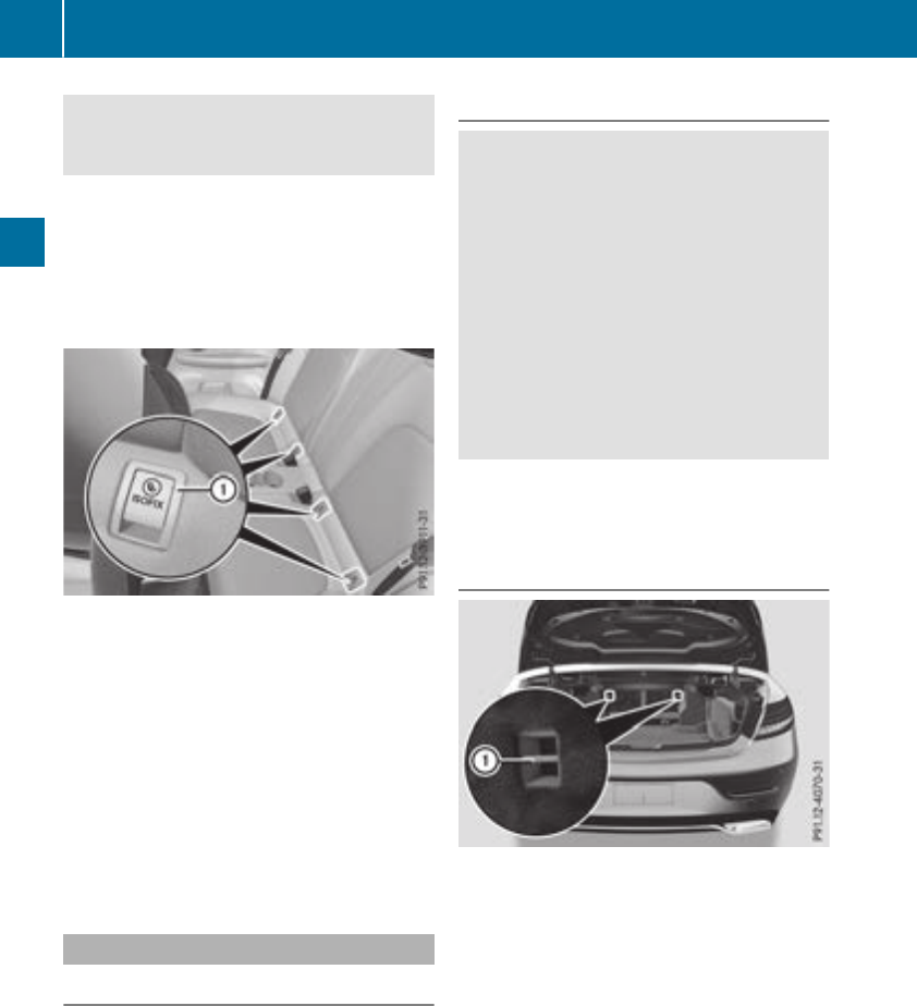
the vehicle seat belt. Also secure the child
restraint system with the Top Tether belt, if
available.
Always comply with the manufacturer's instal-
lation and operating instructions for the child
restraint system used.
Before every trip, make sure that the LATCH-
type (ISOFIX) child restraint system is engaged
correctly in both LATCH-type (ISOFIX) securing
rings
XInstall the LATCH-type (ISOFIX) child restraint
system on both LATCH-type (ISOFIX) securing
rings :.
ISOFIX is a standardized securing system for
specially designed child restraint systems on
the rear seats. LATCH-type (ISOFIX) securing
rings for two LATCH-type (ISOFIX) child restraint
systems are installed on the left and right of the
rear seats.
Non-LATCH-type (ISOFIX) child seats may also
be used and can be installed using the vehicle's
seat belt system. Install the child seat according
to the manufacturer's instructions.
Top Tether
Introduction
Top Tether provides an additional connection
between the LATCH-type (ISOFIX) child restraint
system secured with a LATCH-type (ISOFIX) sys-
tem and the vehicle. This helps reduce the risk of
injury even further. If the child restraint system
is equipped with a Top Tether belt, this should
always be used.
Important safety notes
GWARNING
If the rear seat backrests are not locked, they
could fold forwards in the event of an acci-
dent, heavy braking or sudden changes of
direction. As a result, child restraint systems
cannot perform their intended protective
function. Rear seat backrests that are not
locked can also cause additional injuries, e.g.
in the event of an accident. This poses an
increased risk of injury or even fatal injury.
Always lock rear seat backrests after instal-
ling a Top Tether belt. Observe the lock veri-
fication indicator.
If the rear seat backrest is not engaged and
locked, this will be shown in the multifunction
display in the instrument cluster.
Top Tether anchorages
Top Tether anchorage points :are located on
the rear side of the backrests on both outer rear
seats.
XPut the LATCH-type (ISOFIX) child restraint
system with Top Tether on the rear seat.
Always comply with the child restraint system
manufacturer's installation instructions when
doing so.
62 Children in the vehicle
Safety
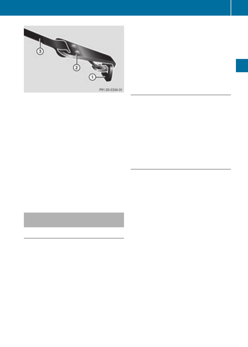
XFold the rear seat backrest forwards
(Ypage 265).
XHook Top Tether hook ;on Top Tether
anchorage :.
XFold back the rear seat backrest
(Ypage 265).
XMake sure that the Top Tether belt =is not
twisted and that the rear seat backrest is
locked.
XSecure the child restraint system with LATCH-
type (ISOFIX) (Ypage 61).
XTension Top Tether belt =from the trunk.
XMake sure there is sufficient belt strap avail-
able to tighten it.
XAlways comply with the child restraint system
manufacturer's installation instructions when
doing so.
Child restraint system on the front-
passenger seat
General notes
Accident statistics show that children secured
in the rear seats are safer than children secured
in the front-passenger seat. For this reason,
Mercedes-Benz strongly advises that you install
the child restraint system on a rear seat.
If it is absolutely necessary to install a child
restraint system on the front-passenger seat,
always observe the instructions and safety
notes on the "Occupant Classification System
(OCS)" (Ypage 51).
You can thus avoid the risks that could arise as
a result of:
Ran incorrectly categorized person in the front-
passenger seat
Rthe unintentional deactivation of the front-
passenger front air bag
Rthe unsuitable positioning of the child
restraint system, e.g. too close to the dash-
board
Rearward-facing child restraint system
If it is absolutely necessary to install a rearward-
facing child restraint system on the front-
passenger seat, always make sure that the
front-passenger front air bag is deactivated.
Only if the PASSENGER AIR BAG OFF indicator
lamp is permanently lit (Ypage 44)is the front-
passenger front air bag deactivated.
Always observe the child restraint system man-
ufacturer's installation and operating instruc-
tions.
Forward-facing child restraint system
If it is absolutely necessary to install a forward-
facing child restraint system on the front-
passenger seat, always move the front-
passenger seat as far back as possible. Fully
retract the seat cushion length. The entire base
of the child restraint system must always rest on
the seat cushion of the front-passenger seat.
The backrest of the child restraint system must
lie as flat as possible against the backrest of the
front-passenger seat. The child restraint system
must not touch the roof or be subjected to a load
by the head restraint. Adjust the angle of the
seat backrest and the head restraint position
accordingly. Always make sure that the shoul-
der belt strap is correctly routed from the vehi-
cle belt outlet to the shoulder belt guide on the
child restraint system. The shoulder belt strap
must be routed forward and down from the vehi-
cle belt outlet. If necessary, adjust the vehicle
belt outlet and the front-passenger seat accord-
ingly.
Always observe the child restraint system man-
ufacturer's installation and operating instruc-
tions.
Children in the vehicle 63
Safety
Z

Pets in the vehicle
GWARNING
If you leave animals unattended or unsecured
in the vehicle, they could press buttons or
switches, for example.
As a result, they could:
Ractivate vehicle equipment and become
trapped, for example
Ractivate or deactivate systems, thereby
endangering other road users
Unsecured animals could also be flung around
the vehicle in the event of an accident or sud-
den steering or braking, thereby injuring vehi-
cle occupants. There is a risk of an accident
and injury.
Never leave animals unattended in the vehi-
cle. Always secure animals properly during
the journey, e.g. use a suitable animal trans-
port box.
Driving safety systems
Overview of driving safety systems
In this section, you will find information about
the following driving safety systems:
RABS (Anti-lock Braking System)
(Ypage 64)
RBAS (Brake Assist System) (Ypage 65)
RActive Brake Assist (Ypage 65)
RESP®(Electronic Stability Program)
(Ypage 67)
REBD (Electronic Brake force Distribution)
(Ypage 71)
RADAPTIVE BRAKE (Ypage 71)
RActive Brake Assist with cross-traffic function
(Ypage 71)
RSTEER CONTROL (Ypage 74)
Important safety notes
If you fail to adapt your driving style or if you are
inattentive, the driving safety systems can nei-
ther reduce the risk of an accident nor override
the laws of physics. Driving safety systems are
merely aids designed to assist driving. You are
responsible for maintaining the distance to the
vehicle in front, for vehicle speed, for braking in
good time, and for staying in lane. Always adapt
your driving style to suit the prevailing road and
weather conditions and maintain a safe distance
from the vehicle in front. Drive carefully.
The driving safety systems described only work
as effectively as possible when there is ade-
quate contact between the tires and the road
surface. Pay particular attention to the informa-
tion regarding tires, recommended minimum
tire tread depths etc. in the "Wheels and tires"
section (Ypage 312).
In wintry driving conditions, always use winter
tires (M+S tires) and if necessary, snow chains.
Only in this way will the driving safety systems
described in this section work as effectively as
possible.
ABS (Anti-lock Braking System)
General information
ABS regulates brake pressure in such a way that
the wheels do not lock when you brake. This
allows you to continue steering the vehicle when
braking.
The !ABS warning lamp in the instrument
cluster lights up when the ignition is switched
on. It goes out when the engine is running.
ABS works from a speed of about 5 mph
(8 km/h), regardless of road-surface conditions.
ABS works on slippery surfaces, even when you
only brake gently.
Important safety notes
iObserve the "Important safety notes" sec-
tion (Ypage 64).
GWARNING
If ABS is faulty, the wheels could lock when
braking. The steerability and braking charac-
teristics may be severely impaired. Addition-
ally, further driving safety systems are deac-
tivated. There is an increased danger of skid-
ding and accidents.
Drive on carefully. Have ABS checked imme-
diately at a qualified specialist workshop.
64 Driving safety systems
Safety

When ABS is malfunctioning, other systems,
including driving safety systems, will also
become inoperative. Observe the information
on the ABS warning lamp (Ypage 244) and dis-
play messages which may be shown in the
instrument cluster (Ypage 213).
Braking
XIf ABS intervenes: continue to depress the
brake pedal vigorously until the braking sit-
uation is over.
XTo make a full brake application: depress
the brake pedal with full force.
If ABS intervenes when braking, you will feel a
pulsing in the brake pedal.
The pulsating brake pedal can be an indication
of hazardous road conditions, and functions as a
reminder to take extra care while driving.
BAS (Brake Assist System)
General information
BAS operates in emergency braking situations.
If you depress the brake pedal quickly, BAS
automatically boosts the braking force, thus
shortening the stopping distance.
Important safety notes
iObserve the "Important safety notes" sec-
tion (Ypage 64).
GWARNING
If BAS is malfunctioning, the braking distance
in an emergency braking situation is
increased. There is a risk of an accident.
In an emergency braking situation, depress
the brake pedal with full force. ABS prevents
the wheels from locking.
Braking
XKeep the brake pedal firmly depressed until
the emergency braking situation is over.
ABS prevents the wheels from locking.
The brakes will function as usual once you
release the brake pedal. BAS is deactivated.
Active Brake Assist
General information
iObserve the "Important safety notes" sec-
tion (Ypage 64).
Active Brake Assist consists of a distance warn-
ing function with an autonomous braking func-
tion and Adaptive Brake Assist.
Active Brake Assist can help you to minimize the
risk of a collision with the vehicle traveling in
front or reduce the effects of such a collision.
If Active Brake Assist detects that there is a risk
of collision, you will be warned visually and
acoustically. If you do not react to the visual and
audible collision warning, autonomous braking
can be initiated in critical situations. If you apply
the brake yourself in a critical situation, Adap-
tive Brake Assist of the Active Brake Assist sys-
tem supports you.
Important safety notes
In particular, the detection of obstacles can be
impaired if:
Rthere is dirt on the sensors or anything else
covering the sensors
Rthere is snow or heavy rain
Rthere is interference by other radar sources
Rthere are strong radar reflections, for exam-
ple in parking garages
Ra narrow vehicle is traveling in front, e.g. a
motorbike
Ra vehicle is traveling in front on a different line
Ryou are driving a new vehicle or servicing on
the Active Brake Assist system has just been
carried out
Observe the important safety notes in the
"Breaking-in notes" section (Ypage 122).
Following damage to the front end of the vehicle,
have the configuration and operation of the
radar sensor checked at a qualified specialist
workshop. This also applies to collisions at slow
speeds where there is no visible damage to the
front of the vehicle.
Activating/deactivating
Active Brake Assist is automatically active after
switching on the ignition.
You can activate or deactivate Active Brake
Assist (Ypage 204) in the on-board computer.
Driving safety systems 65
Safety
Z

When deactivated, the distance warning func-
tion and the autonomous braking function are
also deactivated.
If Active Brake Assist is deactivated, the æ
symbol appears on the assistant display.
Distance warning function
General information
The distance warning function can help you to
minimize the risk of a front-end collision with a
vehicle ahead or reduce the effects of such a
collision. If the distance warning function
detects that there is a risk of a collision, you will
be warned visually and acoustically.
Important safety notes
iObserve the "Important safety notes" sec-
tion for driving safety systems (Ypage 64).
GWARNING
The distance warning function does not react:
Rto people or animals
Rto oncoming vehicles
Rto crossing traffic
Rwhen cornering
The distance warning function may not give
warnings in all critical situations. There is a
risk of an accident.
Always pay careful attention to the traffic sit-
uation and be ready to brake.
Always adapt your speed to suit the prevailing
road and traffic conditions.
GWARNING
The distance warning function cannot always
clearly identify objects and complex traffic
situations.
In such cases, the distance warning function
may:
Rgive an unnecessary warning
Rnot give a warning
There is a risk of an accident.
Always pay careful attention to the traffic sit-
uation and do not rely solely on the distance
warning function.
Function
Starting at a speed of approximately 4 mph
(7 km/h), the distance warning function warns
you if you are rapidly approaching a vehicle in
front. An intermittent warning tone will then
sound, and the ·distance warning lamp will
light up in the instrument cluster.
XBrake immediately in order to increase the
distance from the vehicle in front.
or
XTake evasive action, provided it is safe to do
so.
Due to the nature of the system, particularly
complicated but non-critical driving conditions
may also cause the system to display a warning.
With the help of the radar sensor system, the
distance warning function can detect obstacles
that are in the path of your vehicle for an exten-
ded period of time.
Up to a speed of approximately 44 mph
(70 km/h), the distance warning function can
also react to stationary obstacles, such as stop-
ped or parked vehicles.
Autonomous braking function
If the driver does not react to the distance warn-
ing signal in a critical situation, Active Brake
Assist can assist the driver with the autonomous
braking function.
Vehicles without Distance Pilot DISTRONIC:
the autonomous braking function is available in
the following speed ranges:
R4–65 mph (7–105 km/h) for moving objects
R4–31 mph (7–50 km/h) for stationary objects
Vehicles with Distance Pilot DISTRONIC: the
autonomous braking function is available in the
following speed ranges:
R4–124 mph (7–200 km/h) for moving objects
R4–31 mph (7–50 km/h) for stationary objects
Due to the nature of the system, particularly
complicated but non-critical driving conditions
may also cause the Autonomous Braking Func-
tion to intervene.
If the autonomous braking function requires a
particularly high braking force, preventative
passenger protection measures (PRE-SAFE®)
are activated simultaneously (Ypage 58).
66 Driving safety systems
Safety

Adaptive Brake Assist
Generalinformation
iObservethe"Importantsafetynotes" sec-
tion (Ypage 64).
Withthehelp of adaptive Brake Assist, thedis-
tance warning signal can detectobstacles that
are in thepathof your vehiclefor an extended
period of time.
If adaptive Brake Assistdetects ariskof colli-
sion withthevehiclein front, it calculates the
braking force necessaryto avoid a collision.If
you apply thebrakes forcefully, adaptive Brake
Assistwill automatically increasethebraking
force to alevel suitable for thetraffic conditions.
Adaptive Brake Assistprovides braking assis-
tance in hazardous situationsat speeds above
4mph (7 km/h). It uses radar sensor technology
to assess thetraffic situation.
Up to aspeedof approximately 155mph
(250km/h), Adaptive Brake Assistis capable of
reacting to moving objects that havealready
been detectedas suchat least once overthe
period of observation.
Up to aspeedof approximately 44 mph
(70 km/h), Adaptive Brake Assistreacts to sta-
tionary obstacles.
If adaptive Brake Assistdemandsparticularly
high braking force,preventative passenger pro-
tection measures (PRE-SAFE®)are activated
simultaneously (Ypage 58).
XKeepthebrakepedal depressed until the
emergencybraking situation is over.
ABSprevents thewheels from locking.
The brakes will worknormally again if:
Ryou release thebrakepedal.
Rthere is no longer any danger of acollision.
Rno obstacle is detectedin frontof your vehi-
cle.
Adaptive Brake Assistis then deactivated.
Important safety notes
iObservethe"Importantsafetynotes" sec-
tion for drivingsafetysystems (Ypage 64).
GWARNING
Adaptive Brake Assistcannotalways clearly
identify objects and complex traffic situa-
tions.
In suchcases, Adaptive Brake Assistcan:
Rinterveneunnecessarily
Rnotintervene
There is ariskof an accident.
Always pay careful attention to thetraffic sit-
uation and be readyto brake. Terminate the
intervention in anon-critical drivingsituation.
GWARNING
Adaptive Brake Assistdoes notreact:
Rto people or animals
Rto oncomingvehicles
Rto crossing traffic
Rwhen cornering
As aresult,theAdaptive Brake Assistmay not
intervenein all critical conditions. There is a
riskof an accident.
Always pay careful attention to thetraffic sit-
uation and be readyto brake.
Always adapt your speedto suit theprevailing
road and traffic conditions.
Due to thenature of thesystem, particularly
complicated but non-critical drivingconditions
may also causeBrake Assistto intervene.
If adaptive Brake Assistis notavailable due to a
malfunction in theradar sensor system, the
brakesystem remainsavailable withfull brake
boosting effectand BAS.
ESP®(Electronic Stability Program)
General notes
iObservethe"Importantsafetynotes" sec-
tion (Ypage 64).
ESP®monitors drivingstabilityand traction,i.e.
powertransmission between thetires and the
road surface.
If ESP®detects that thevehicleis deviating from
thedirection desired by thedriver,oneor more
wheels are braked to stabilizethevehicle. The
engineoutput is also modifiedto keep thevehi-
cle on thedesired coursewithin physical limits.
ESP®assiststhedriver when pullingaway on
Driving safety systems 67
Safety
Z

wet or slippery roads. ESP®can also stabilize
the vehicle during braking.
ETS/4ETS (Electronic Traction System)
iObserve the "Important safety notes" sec-
tion (Ypage 64).
ETS traction control is part of ESP®. On vehicles
with 4MATIC, 4ETS is part of ESP®.
Traction control brakes the drive wheels indi-
vidually if they spin. This enables you to pull
away and accelerate on slippery surfaces, for
example if the road surface is slippery on one
side. In addition, more drive torque is transfer-
red to the wheel or wheels with traction.
Traction control remains active, even if you
deactivate ESP®.
Important safety notes
iObserve the "Important safety notes" sec-
tion (Ypage 64).
GWARNING
If ESP®is malfunctioning, ESP®is unable to
stabilize the vehicle. Additionally, further driv-
ing safety systems are deactivated. This
increases the risk of skidding and an accident.
Drive on carefully. Have ESP®checked at a
qualified specialist workshop.
When towing the vehicle with the rear axle
raised, observe the notes on ESP®
(Ypage 307).
If the åESP®OFF warning lamp lights up
continuously, ESP®is deactivated.
If the ÷ESP®warning lamp lights up contin-
uously, ESP®is not available due to a malfunc-
tion.
Observe the information on warning lamps
(Ypage 244) and display messages which may
be shown in the instrument cluster
(Ypage 213).
Only use wheels with the recommended tire
sizes. Only then will ESP®function properly.
Characteristics of ESP®
General information
If the ÷ESP®warning lamp goes out before
beginning the journey, ESP®is automatically
active.
If ESP®intervenes, the ÷ESP®warning lamp
flashes in the instrument cluster.
If ESP®intervenes:
XDo not deactivate ESP®under any circum-
stances.
XOnly depress the accelerator pedal as far as
necessary when pulling away.
XAdapt your driving style to suit the prevailing
road and weather conditions.
ECO start/stop function
The ECO start/stop function switches the
engine off automatically when the vehicle stops
moving. The engine starts automatically when
the driver wants to pull away again. ESP®
remains in its previously selected status, e.g. if
ESP®was deactivated before the engine was
automatically switched off.
Deactivating/activating ESP®(except
Mercedes‑AMG vehicles)
Important safety notes
iObserve the "Important safety notes" sec-
tion (Ypage 64).
You can select between the following states of
ESP®:
RESP®is activated.
RESP®is deactivated.
GWARNING
If you deactivate ESP®, ESP®no longer sta-
bilizes the vehicle. There is an increased risk
of skidding and an accident.
Only deactivate ESP®in the situations descri-
bed in the following.
It may be best to deactivate ESP®in the follow-
ing situations:
Rwhen using snow chains
Rin deep snow
Ron sand or gravel
68 Driving safety systems
Safety

Spinning the wheels results in a cutting action
which provides better grip.
iActivate ESP®as soon as the situations
described above no longer apply. ESP®will
otherwise not be able to stabilize the vehicle if
the vehicle starts to skid or a wheel starts to
spin.
!Avoid spinning the driven wheels for an
extended period with ESP®deactivated. You
could otherwise damage the drivetrain.
Deactivating/activating ESP®
You can deactivate or activate ESP®via the on-
board computer (Ypage 204).
ESP®deactivated:
The åESP®OFF warning lamp in the instru-
ment cluster lights up.
ESP®activated:
The åESP®OFF warning lamp in the instru-
ment cluster goes out.
Characteristics when ESP®is deactivated
If ESP®is deactivated and one or more wheels
start to spin, the ÷ESP®warning lamp in the
instrument cluster flashes. In such situations,
ESP®will not stabilize the vehicle.
If you deactivate ESP®:
RESP®no longer improves driving stability.
REngine torque is no longer limited and the
drive wheels are able to spin.
RTraction control is still activated.
RActive Brake Assist is no longer available; nor
is it activated if you brake firmly with assis-
tance from ESP®.
RPRE-SAFE®is no longer available, nor is it
activated if you brake firmly and ESP®inter-
venes.
RPRE-SAFE®Brake is no longer available, it is
also not activated if you brake firmly and ESP®
intervenes.
RESP®still provides support when you brake
firmly.
Deactivating/activating ESP®
(Mercedes‑AMG vehicles)
Important safety notes
iObserve the "Important safety notes" sec-
tion (Ypage 64).
You can select between the following states of
ESP®:
RESP®is activated.
RSPORT handling mode is activated.
RESP®is deactivated.
GWARNING
When SPORT handling mode is activated,
there is a greater risk of skidding and acci-
dents.
Only activate SPORT handling mode in the sit-
uations described in the following.
GWARNING
If you deactivate ESP®, ESP®no longer sta-
bilizes the vehicle. There is an increased risk
of skidding and an accident.
Only deactivate ESP®in the situations descri-
bed in the following.
!Avoid spinning the driven wheels for an
extended period with ESP®deactivated. You
could otherwise damage the drivetrain.
In the following situations, it may be better to
activate SPORT handling mode or deactivate
ESP®:
Rwhen using snow chains
Rin deep snow
Ron sand or gravel
Ron specially designated roads when the vehi-
cle's own oversteering and understeering
characteristics are desired
Spinning the wheels results in a cutting action
which provides better grip.
Driving in SPORT handling mode or without
ESP®requires an extremely qualified and expe-
rienced driver.
iActivate ESP®as soon as the situations
described above no longer apply. ESP®will
otherwise not be able to stabilize the vehicle if
Driving safety systems 69
Safety
Z
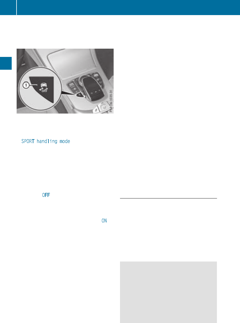
the vehicle starts to skid or a wheel starts to
spin.
Deactivating/activating ESP®
XTo activate SPORT handling mode: briefly
press button :.
The MSPORT handling mode warning
lamp in the instrument cluster lights up. The
SPORT handling mode message appears on
the multifunction display.
XTo deactivate SPORT handling mode:
briefly press button :.
The MSPORT handling mode warning
lamp in the instrument cluster goes out.
XTo deactivate ESP®:press button :until
the åESP®OFF warning lamp lights up in
the instrument cluster.
The ÷OFF message appears on the mul-
tifunction display.
XTo activate ESP®:briefly press button :.
The åESP®OFF warning lamp in the
instrument cluster goes out. The ÷ON
message appears on the multifunction dis-
play.
Characteristics of activated SPORT han-
dling mode
If SPORT handling mode is activated and one or
more wheels start to spin, the ÷ESP®warn-
ing lamp in the instrument cluster flashes. ESP®
only stabilizes the vehicle to a limited degree.
When SPORT handling mode is activated:
RESP®only improves driving stability to a limi-
ted degree.
RTraction control is still activated.
REngine torque is no longer limited and the
drive wheels are able to spin.
RESP®still provides support when you brake
firmly.
Characteristics when ESP®is deactivated
If ESP®is deactivated and one or more wheels
start to spin, the ÷ESP®warning lamp in the
instrument cluster does not flash. In such situa-
tions, ESP®will not stabilize the vehicle.
If you deactivate ESP®:
RESP®no longer improves driving stability.
REngine torque is no longer limited and the
drive wheels are able to spin.
RTraction control is still activated.
RActive Brake Assist is no longer available; nor
is it activated if you brake firmly with assis-
tance from ESP®.
RPRE-SAFE®is no longer available, nor is it
activated if you brake firmly and ESP®inter-
venes.
RPRE-SAFE®Brake is no longer available, it is
also not activated if you brake firmly and ESP®
intervenes.
RESP®still provides support when you brake
firmly.
ESP®trailer stabilization
General information
ESP®trailer stabilization is not available in
Mercedes-AMG vehicles.
If your vehicle/trailer combination begins to
swerve, ESP®assists you in this situation. ESP®
slows the vehicle down by braking and limiting
the engine output until the vehicle/trailer com-
bination has stabilized.
Important safety notes
GWARNING
If road and weather conditions are poor,
trailer stabilization will not be able to prevent
the vehicle/trailer combination from swerv-
ing. Trailers with a high center of gravity can
tip over before ESP®can detect this. There is
a risk of an accident.
Always adapt your driving style to the prevail-
ing road and weather conditions.
70 Driving safetysystems
Safety

If your vehicle with trailer (vehicle/trailer com-
bination) begins to lurch, you can only stabilize
the vehicle/trailer combination by depressing
the brake firmly.
ESP®trailer stabilization is active above speeds
of approximately 40 mph (65 km/h).
ESP®trailer stabilization does not work if ESP®
is deactivated or malfunctioning.
Crosswind Assist
General information
Strong crosswind gusts can impair the ability of
your vehicle to drive straight ahead. The cross-
wind driving assistance function integrated in
ESP®noticeably reduces these impairments.
ESP®intervenes automatically according to the
direction and intensity of the crosswinds affect-
ing your vehicle.
ESP®intervenes with stabilizing braking to
assist you in keeping the vehicle in the lane.
Crosswind Assist is active at vehicle speeds
above 50 mph (80 km/h) when driving straight
ahead or cornering gently.
Important safety notes
Crosswind Assist does not work if ESP®is
switched off or deactivated because of a mal-
function.
EBD (electronic brake force distribu-
tion)
General information
EBD monitors and controls the brake pressure
on the rear wheels to improve driving stability
while braking.
Important safety notes
iObserve the "Important safety notes" sec-
tion (Ypage 64).
GWARNING
If EBD is malfunctioning, the rear wheels can
lock, e.g. under full braking. This increases the
risk of skidding and an accident.
You should therefore adapt your driving style
to the different handling characteristics. Have
the brake system checked at a qualified spe-
cialist workshop.
Observe information regarding indicator and
warning lamps (Ypage 244) as well as display
messages (Ypage 215).
ADAPTIVE BRAKE
ADAPTIVE BRAKE enhances braking safety and
offers increased braking comfort. In addition to
the braking function, ADAPTIVE BRAKE also has
the HOLD function (Ypage 161) and hill start
assist (Ypage 127).
Active Brake Assist with cross-traffic
function
General information
iObserve the important safety notes in the
"Driving safety systems" section (Ypage 64).
Active Brake Assist with cross-traffic function
can help you to minimize the risk of a collision
with a vehicle in front or a pedestrian and reduce
the effects of such a collision. If the Active Brake
Assist with cross-traffic function detects a risk
of collision, you will be warned visually and
acoustically and, if necessary, your brake appli-
cation will be assisted according to the situa-
tion. If you do not react, the system can also
react by braking automatically. In the event of a
detected risk of collision due to crossing traffic,
you will also be visually and acoustically warned
as well as assisted by the brake boosting effect
according to the situation.
Active Brake Assist with cross-traffic function is
only available in vehicles with the Driving Assis-
tance Plus package.
For Active Brake Assist with cross-traffic func-
tion to assist you when driving, the radar sensor
system and the camera system must be opera-
tional.
If the radar sensor system or the camera system
is malfunctioning, Active Brake Assist with
cross-traffic function is restricted or no longer
available. The brake system is still available with
complete brake boosting effect and BAS.
The radar sensor system and camera system
help Active Brake Assist with cross-traffic func-
Driving safety systems 71
Safety
Z

tion to detect obstacles that are in the path of
your vehicle for an extended period of time.
In addition, pedestrians in the path of your vehi-
cle can be detected.
Active Brake Assist with cross-traffic function
detects pedestrians using typical characteris-
tics such as body contours and the posture of a
person standing upright.
iObserve the restrictions described in the
"Important safety notes" section
(Ypage 72).
Important safety notes
GWARNING
Active Brake Assist with cross-traffic function
will initially brake your vehicle by a partial
application of the brakes if a danger of colli-
sion is detected. There may be a collision
unless you brake yourself. Even after subse-
quent full application of the brakes a collision
cannot always be avoided, particularly when
approaching at too high a speed. There is a
risk of an accident.
Always apply the brakes yourself and try to
take evasive action, provided it is safe to do
so.
In the event of a partial application of the brakes,
the vehicle is braked with up to 50% of the full
braking pressure.
GWARNING
Active Brake Assist with cross-traffic function
cannot always clearly identify objects and
complex traffic situations.
In such cases, Active Brake Assist with cross-
traffic function might:
Rissue an unnecessary warning or engage
Rneither give a warning nor intervene
There is a risk of an accident.
Always pay particular attention to the traffic
situation and be prepared to brake, especially
if Active Brake Assist with cross-traffic func-
tion alerts you. Terminate the intervention in a
non-critical driving situation.
GWARNING
Active Brake Assist with cross-traffic function
cannot always clearly identify people, partic-
ularly if they are moving. Active Brake Assist
with cross-traffic function cannot intervene in
these cases. There is a risk of an accident.
Always pay particular attention to the traffic
situation and be prepared to brake, especially
if Active Brake Assist with cross-traffic func-
tion alerts you.
In order to maintain the appropriate distance to
the vehicle in front and thus prevent a collision,
you must apply the brakes yourself.
GWARNING
Active Brake Assist with cross-traffic function
does not react:
Rto small people, e.g. children
Rto animals
Rto oncoming vehicles
Rwhen cornering
As a result, Active Brake Assist with cross-
traffic function may not warn you or engage in
all critical situations. There is a risk of an acci-
dent.
Always pay careful attention to the traffic sit-
uation and be ready to brake.
In the event of snowfall or heavy rain, the rec-
ognition can be impaired.
Recognition by the radar sensor system is also
impaired if:
Rthere is dirt on the sensors or anything else
covering the sensors
Rthere is interference by other radar sources
Rthere are strong radar reflections, for exam-
ple in parking garages
Ra narrow vehicle is traveling in front, e.g. a
motorbike
Ra vehicle is traveling in front on a different line
Rvehicles moving quickly into the radar sensor
system detection range
72 Driving safetysystems
Safety

Recognition by thecamera system is also
impairedin theevent of:
Rdirt on thecamera or if thecamera is covered
Rglareon thecamera system, e.g. from thesun
beinglow in thesky
Rdarkness
Ror if:
-pedestriansmovequickly, e.g. intothepath
of thevehicle
-thecamera system no longer recognizes a
pedestrian as aperson due to special cloth-
ing or other objects
-apedestrian is concealed by other objects
-thetypical outlineof apedestrian is not
distinguishable from thebackground
Followingdamageto thefrontendof thevehicle,
havetheconfiguration and operation of the
radar sensorscheckedat aqualified specialist
workshop. This also appliesto collisionsat slow
speeds wherethere is no visible damageto the
frontof thevehicle.
Followingdamageto thewindshield, havethe
configuration and operation of thecamera sys-
temcheckedat aqualified specialist workshop.
Function
XTo activate or deactivate: activateor deac-
tivateActive Brake Assist withcross-traffic
function usingtheon-board computer
(Ypage 205).
If Active Brake Assist withcross-traffic func-
tion is deactivated, theæsymbol appears
on themultifunction display.
Starting at aspeedof around 4 mph (7 km/h),
this function warnsyou if you are rapidly
approaching a vehiclein front. An intermittent
warning tone will then soundand the·dis-
tance warning lamp will lightup in theinstru-
mentcluster.
XBrake immediately to defuse thesituation.
or
XTakeevasive action providedit is safeto do
so.
Active Brake Assist withcross-traffic function
can also brakethevehicleautomatically under
thefollowingconditions:
Rthedriver and frontpassenger havetheir seat
beltsfastened
Rthevehiclespeedis between approximately
4mph (7 km/h) and 124 mph (200 km/h)
Up to a speed of approximately 44 mph
(70 km/h), Active Brake Assist with cross-traffic
function may react to:
Rstationary objects in the path of your vehicle,
e.g. stopped or parked vehicles
Rpedestrians in the path of your vehicle
iIf there is an increased risk of a collision,
preventive passenger protection measures
(PRE-SAFE®) are triggered (Ypage 58).
If the risk of collision with the vehicle in front
remains and you do not brake, take evasive
action or accelerate significantly, the vehicle
may perform automatic emergency braking, up
to the point of full brake application. Automatic
emergency braking is not performed until imme-
diately prior to an imminent accident.
If you apply the brake yourself in a critical sit-
uation or during autonomous braking, situation-
dependent braking assistance is implemented.
If necessary, this increases the brake pressure
up to full brake application.
To avoid a collision, Active Brake Assist with
cross-traffic function calculates the brake force
necessary if:
Ryou approach an obstacle, and
RActive Brake Assist with cross-traffic function
has detected a risk of a collision
When driving at a speed under 20 mph
(30 km/h): if you depress the brake pedal,
Active Brake Assist with cross-traffic function is
activated. The increase in brake pressure from
Active Brake Assist with cross-traffic function is
carried out at the last possible moment.
When driving at a speed above 20 mph
(30 km/h): if you depress the brake pedal
sharply, Active Brake Assist with cross-traffic
function automatically increases the brake pres-
sure to a degree suited to the traffic situation.
Active Brake Assist with cross-traffic function
provides braking assistance in hazardous situa-
tions with vehicles in front within a speed range
between 4 mph (7 km/h) and 155 mph
(250 km/h).
Driving safety systems 73
Safety
Z
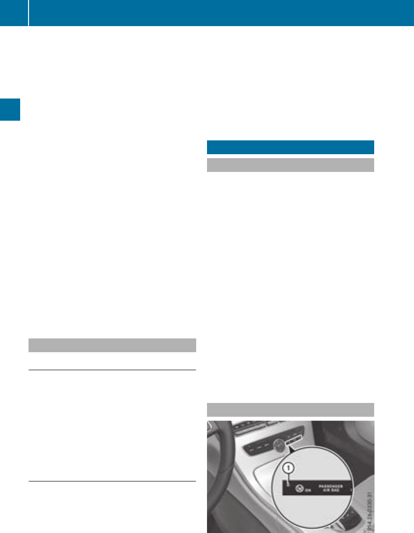
Up to a speed of approximately 44 mph
(70 km/h) the Active Brake Assist with cross-
traffic function assists you with braking in haz-
ardous situations with:
Rstationary obstacles in the path of the vehicle,
e.g. stopped or parked vehicles
Rstationary pedestrians in the path of the vehi-
cle
Robstacles crossing your path that move in the
detection range of the sensors and are detec-
ted
XKeep the brake pedal depressed until the
emergency braking situation is over.
ABS prevents the wheels from locking.
You can prevent the intervention of Active Brake
Assist with cross-traffic function at any time by:
Rdepressing the accelerator pedal further.
Ractivating kickdown.
Rreleasing the brake pedal
The braking application of Active Brake Assist
with cross-traffic function is ended automati-
cally if:
Ryou maneuver to avoid the obstacle.
Rthere is no longer a risk of collision.
Ran obstacle is no longer detected in front of
your vehicle.
STEER CONTROL
General information
STEER CONTROL helps you by transmitting a
noticeable steering force to the steering wheel
in the direction required for vehicle stabilization.
This steering assistance is provided in particular
if:
Rboth right wheels or both left wheels are on a
wet or slippery road surface when you brake
Rthe vehicle begins to skid
Important safety notes
iObserve the "Important safety notes" sec-
tion (Ypage 64).
No steering support is provided from STEER
CONTROL, if:
RESP®is deactivated
RESP®is malfunctioning
Rthe steering is malfunctioning
If ESP®is malfunctioning, you will be assisted
further by the electrical power steering.
Protection against theft
Immobilizer
The immobilizer prevents your vehicle from
being started without the correct SmartKey.
XTo activate with the SmartKey: remove the
SmartKey from the ignition lock.
XTo activate with KEYLESS-GO start-func-
tion or KEYLESS-GO: switch the ignition off
and open the driver's door.
XTo deactivate: switch on the ignition.
When leaving the vehicle, always take the
SmartKey with you and lock the vehicle. Anyone
can start the engine if a valid SmartKey has been
left inside the vehicle.
iThe immobilizer is always deactivated when
you start the engine.
In the event that the engine cannot be started
(yet the vehicle's battery is charged), the sys-
tem is not operational. Contact an authorized
Mercedes-Benz Center or call
1-800-FOR-MERCedes (in the USA) or
1-800-387-0100 (in Canada).
ATA (anti-theft alarm system)
74 Protection against theft
Safety

XTo arm: lock the vehicle with the SmartKey or
KEYLESS-GO.
Indicator lamp :flashes. The alarm system
is armed after approximately ten seconds.
XTo disarm: unlock the vehicle with the Smart-
Key or KEYLESS-GO.
or
XInsert the SmartKey into the ignition lock.
or
XVehicles with KEYLESS-GO start function
or KEYLESS-GO: press the Start/Stop but-
ton.
The SmartKey must be in the vehicle.
A visual and audible alarm is triggered if the
alarm system is armed and you open:
Ra door
Rthe vehicle with the mechanical key
Rthe trunk lid
Rthe hood
Rthe stowage compartment/telephone com-
partment under the armrest in vehicles with
automatic transmission
XTo stop the alarm with the SmartKey:
press the %or &button on the Smart-
Key.
The alarm is stopped.
or
XVehicles with KEYLESS-GO start-function
or KEYLESS-GO: remove the Start/Stop but-
ton from the ignition lock (Ypage 124).
XInsert the SmartKey into the ignition lock.
The alarm is stopped.
XTo stop the alarm using KEYLESS-GO:
grasp the outside door handle. The SmartKey
must be outside the vehicle.
The alarm is stopped.
or
XPress the Start/Stop button on the dash-
board. The SmartKey must be inside the vehi-
cle.
The alarm is stopped.
The alarm is not switched off, even if you close
the open door that triggered it, for example.
iIf the alarm continues for more than
30 seconds, the mbrace emergency call sys-
tem automatically notifies the Customer
Assistance Center. This is done either by text
message or data connection.
The emergency call system sends a message
or establishes a data connection provided
that:
Ryou have subscribed to the mbrace service.
Rthe mbrace service has been activated
properly.
Rthe necessary mobile phone network is
available.
Protection against theft 75
Safety
Z
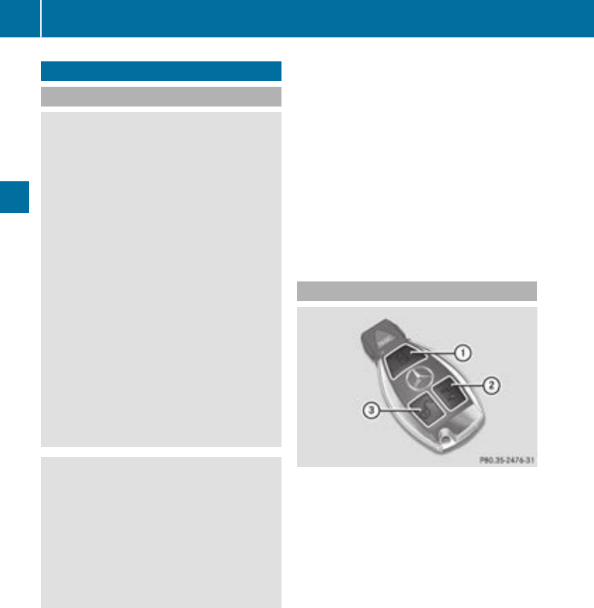
SmartKey
Important safety notes
GWARNING
If children are left unsupervised in the vehicle,
they could:
Ropen the doors, thus endangering other
people or road users.
Rget out and disrupt traffic.
Roperate the vehicle's equipment.
Additionally, children could set the vehicle in
motion if, for example, they:
Rrelease the parking brake.
Rshifting the automatic transmission out of
park position P
RStart the engine.
There is a risk of an accident and injury.
When leaving the vehicle, always take the
SmartKey with you and lock the vehicle. Never
leave children or animals unattended in the
vehicle. Always keep the SmartKey out of
reach of children.
GWARNING
If you attach heavy or large objects to the
SmartKey, the SmartKey could be uninten-
tionally turned in the ignition lock. This could
cause the engine to be switched off. There is a
risk of an accident.
Do not attach any heavy or large objects to the
SmartKey. Remove any bulky key rings before
inserting the SmartKey into the ignition lock.
!Keep the SmartKey away from strong mag-
netic fields. Otherwise, the remote control
function could be affected.
Strong magnetic fields can occur in the vicin-
ity of powerful electrical installations.
Do not keep the SmartKey:
Rwith electronic devices, e.g. a mobile phone
or another SmartKey.
Rwith metallic objects, e.g. coins or metal foil.
Rinside metallic objects, e.g. a metal case.
This can affect the functionality of the Smart-
Key.
Vehicles with KEYLESS-GO start function: do
not keep the SmartKey in the cargo compart-
ment. Otherwise, the SmartKey may not be
detected, e.g. when starting the engine using
the Start/Stop button.
A brief radio connection between the vehicle
and the SmartKey determines whether a valid
SmartKey is in, or in the direct vicinity of, the
vehicle. This occurs, for example:
Rwhen starting the engine
Rwhile driving
Rwhen the external door handles are touched
Rduring convenience closing
SmartKey functions
:&Locks the vehicle
;FOpens the trunk lid
=%Unlocks the vehicle
XTo unlock centrally: press the %button.
If you do not open the vehicle within approx-
imately 40 seconds of unlocking:
Rthe vehicle is locked again.
Rprotection against theft is reactivated.
XTo lock centrally: press the &button.
The SmartKey centrally locks and unlocks the
following components:
Rthe doors
Rthe trunk lid
Rthe glove box
Rthe fuel filler flap
The turn signals flash once when unlocking and
three times when locking.
You can also set an audible signal to confirm
that the vehicle has been locked. The audible
signal can be activated and deactivated via the
76 SmartKey
Opening and closing
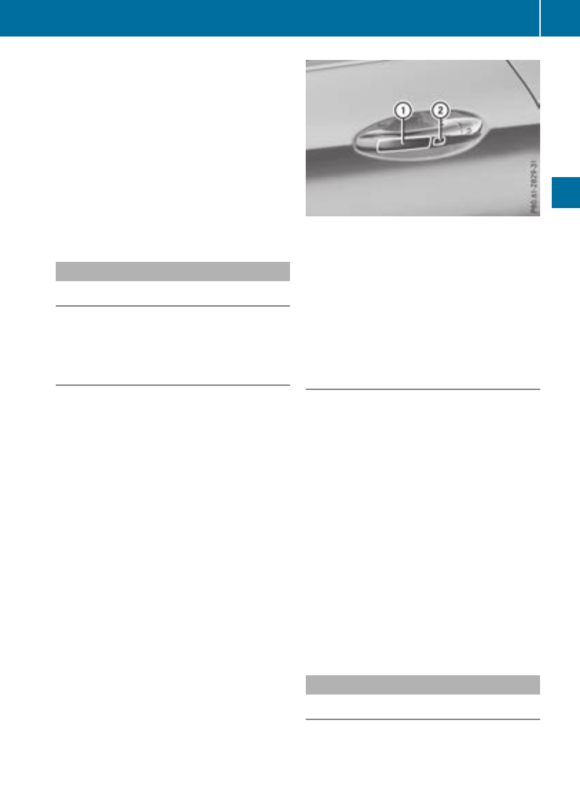
multimedia system; see the Digital Operator's
Manual.
You will receive visual and acoustic locking con-
firmation if all components were able to be
locked.
When the locator lighting is activated via the
multimedia system, it lights up when it is dark
after the vehicle is unlocked with the SmartKey;
see the Digital Operator's Manual.
XTo open the trunk lid automatically from
outside the vehicle: press and hold the F
button until the trunk lid opens.
KEYLESS-GO
General notes
Bear in mind that the engine can be started by
any of the vehicle occupants if there is a Smart-
Key in the vehicle (Ypage 125).
Locking/unlocking centrally
You can start, lock or unlock the vehicle using
KEYLESS-GO. To do this, you only need carry the
SmartKey with you. You can combine the func-
tions of KEYLESS-GO with those of a conven-
tional SmartKey. Unlock the vehicle by using
KEYLESS-GO, for instance, and lock it using the
&button on the SmartKey.
The driver's door and the door at which the han-
dle is used, must both be closed. The SmartKey
must be outside the vehicle. When locking or
unlocking with KEYLESS-GO, the distance
between the SmartKey and the corresponding
door handle must not be greater than 3 ft (1 m).
A brief radio connection between the vehicle
and the SmartKey determines whether a valid
SmartKey is in, or in the direct vicinity of, the
vehicle. This occurs, for example:
Rwhen starting the engine
Rwhile driving
Rwhen the external door handles are touched
Rduring convenience closing
XTo unlock the vehicle: touch the inner sur-
face of the door handle.
XTo lock the vehicle: touch sensor surface :
or ;.
Make sure that you do not touch the inner
surface of the door handle.
XConvenience closing feature: touch
recessed sensor surface ;for an extended
period.
Deactivating and activating
If you do not intend to use a SmartKey for an
extended period of time, you can deactivate the
KEYLESS-GO function of the SmartKey. The
SmartKey will then use very little power, thereby
conserving battery power. For the purposes of
activation/deactivation, the vehicle must not be
nearby.
XTo deactivate: press the &button on the
SmartKey twice in rapid succession.
The battery check lamp (Ypage 79) of the
SmartKey flashes twice briefly and lights up
once, then KEYLESS-GO is deactivated.
XTo activate: press any button on the Smart-
Key.
or
XInsert the SmartKey into the ignition lock.
KEYLESS-GO and all of its associated features
are available again.
KEYLESS-GO start function
General notes
Bear in mind that the engine can be started by
any of the vehicle occupants if there is a Smart-
Key in the vehicle (Ypage 125).
SmartKey 77
Opening and closing
Z
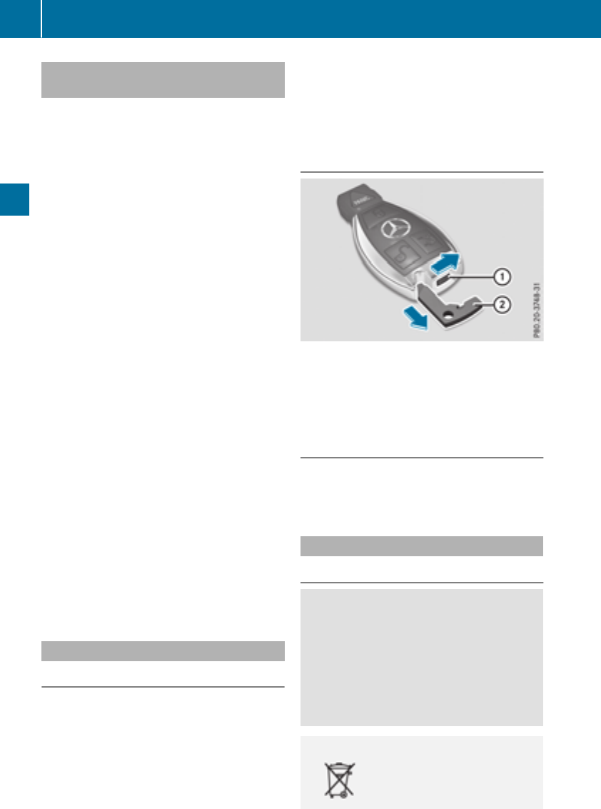
Changing the settings of the locking
system
You can change the settings of the locking sys-
tem. This means that only the driver's door and
the fuel filler flap are unlocked when the vehicle
is unlocked. This is useful if you frequently travel
alone.
XTo change the setting: press and hold down
the %and &buttons simultaneously
for approximately six seconds until the bat-
tery check lamp (Ypage 79) flashes twice.
If the setting of the locking system is changed
within the signal range of the vehicle, pressing
the &or %button:
Rlocks or
Runlocks the vehicle
The SmartKey now functions as follows:
XTo unlock: press the %button once.
XTo unlock centrally: press the %button
twice.
XTo lock: press the &button.
XTo restore the factory settings: press and
hold the %and &buttons simultane-
ously for approximately six seconds until the
battery check lamp (Ypage 79) flashes
twice.
The KEYLESS-GO functions can be changed as
follows:
XTo unlock the driver's door: touch the inner
surface of the door handle on the driver's
door.
XTo unlock centrally: touch the inner surface
of the front-passenger door handle.
XTo lock centrally: touch the outer sensor
surface on one of the door handles.
Mechanical key
General notes
If the vehicle can no longer be locked or
unlocked with the SmartKey or KEYLESS-GO,
use the mechanical key.
If you use the mechanical key to unlock and
open the driver's door, the anti-theft alarm sys-
tem will be triggered. Switch off the alarm
(Ypage 74).
If you unlock the vehicle using the mechanical
key, the fuel filler flap will not be unlocked auto-
matically.
XTo unlock the fuel filler flap: insert the
SmartKey into the ignition lock.
Removing the mechanical key
XPush release catch :in the direction of the
arrow and at the same time remove mechan-
ical key ;from the SmartKey.
Further information on locking/unlocking the
driver's door (Ypage 83).
Inserting the mechanical key
XPush mechanical key ;completely into the
SmartKey until it engages and release
catch :is back in its basic position.
SmartKey battery
Important safety notes
GWARNING
Batteries contain toxic and corrosive substan-
ces. If batteries are swallowed, it can result in
severe health problems. There is a risk of fatal
injury.
Keep batteries out of the reach of children. If
a battery is swallowed, seek medical attention
immediately.
HEnvironmental note
Batteries contain dangerous
substances. It is against the
law to dispose of them with
78 SmartKey
Opening and closing
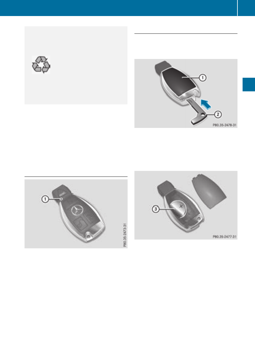
the household rubbish. They
must be collected separately
and recycled to protect the
environment.
Dispose of batteries in an
environmentally friendly
manner. Take discharged
batteries to a qualified spe-
cialist workshop or a special
collection point for used bat-
teries.
The SmartKey batteries contain perchlorate
material, which may require special handling
and regard for the environment. National guide-
lines must be observed during disposal. In Cal-
ifornia, see www.dtsc.ca.gov/
HazardousWaste/Perchlorate/index.cfm.
Mercedes-Benz recommends that you have the
batteries replaced at a qualified specialist work-
shop.
Checking the battery
XPress the &or %button.
The battery is working properly if battery
check lamp :lights up briefly.
The battery is discharged if battery check
lamp :does not light up briefly.
XChange the battery (Ypage 79).
If the SmartKey battery is checked within the
signal reception range of the vehicle, pressing
the &or %button:
Rlocks or
Runlocks the vehicle
iYou can get a battery at any qualified spe-
cialist workshop.
Replacing the battery
You require a CR 2025 3 V cell battery.
XTake the mechanical key out of the SmartKey
(Ypage 78).
XPress mechanical key ;into the SmartKey
opening in the direction of the arrow until bat-
tery compartment cover :opens. Do not
hold battery compartment cover :closed
while doing so.
XRemove battery compartment cover :.
XRepeatedly tap the SmartKey against your
palm until battery =falls out.
XInsert the new battery with the positive ter-
minal facing upwards. Use a lint-free cloth to
do so.
XMake sure that the surface of the battery is
free of lint, grease and other contaminants.
XInsert the front tabs of battery compartment
cover :into the housing first and then press
to close it.
XInsert mechanical key ;into the SmartKey
(Ypage 78).
XCheck the function of all SmartKey buttons on
the vehicle.
SmartKey 79
Opening and closing
Z

Problems with the SmartKey
Problem Possible causes/consequences and MSolutions
You can no longer lock or
unlock the vehicle using
the SmartKey.
The SmartKey battery is discharged or nearly discharged.
XCheck the SmartKey battery (Ypage 79) and replace it if necessary
(Ypage 79).
If this does not work:
XLock or unlock the vehicle using the mechanical key (Ypage 83).
There is interference from a powerful source of radio waves.
XLock or unlock the vehicle using the mechanical key (Ypage 83).
The SmartKey is faulty.
XLock or unlock the vehicle using the mechanical key (Ypage 83).
XHave the SmartKey checked at a qualified specialist workshop.
You can no longer lock or
unlock the vehicle using
KEYLESS-GO.
KEYLESS-GO was deactivated.
XReactivate KEYLESS-GO (Ypage 77).
The SmartKey battery is discharged or nearly discharged.
XCheck the SmartKey battery (Ypage 79) and replace it if necessary
(Ypage 79).
If this does not work:
XLock or unlock the vehicle using the mechanical key (Ypage 83).
There is interference from a powerful source of radio waves.
XLock or unlock the vehicle using the mechanical key (Ypage 83).
KEYLESS-GO is malfunctioning.
XLock/unlock the vehicle using the remote control function of the
SmartKey.
XHave the vehicle and SmartKey checked at a qualified specialist
workshop.
If the vehicle can also not be locked/unlocked using the remote con-
trol function:
XLock or unlock the vehicle using the mechanical key (Ypage 83).
XHave the vehicle and SmartKey checked at a qualified specialist
workshop.
The engine cannot be
started using the Smart-
Key.
The on-board voltage is too low.
XSwitch off non-essential consumers, e.g. seat heating or interior
lighting, and try to start the engine again.
If this does not work:
XCheck the starter battery and charge it if necessary (Ypage 303).
or
XJump-start the vehicle (Ypage 304).
or
XConsult a qualified specialist workshop.
80 SmartKey
Opening and closing

Problem Possible causes/consequences and MSolutions
The engine cannot be
started using the Start/
Stop button. The Smart-
Key is in the vehicle.
The vehicle is locked.
XUnlock the vehicle and try to start the vehicle again.
The SmartKey battery is discharged or nearly discharged.
XCheck the SmartKey battery (Ypage 79) and replace it if necessary
(Ypage 79).
If this does not work:
XStart your vehicle with the SmartKey in the ignition lock.
There is interference from a powerful source of radio waves.
XStart your vehicle with the SmartKey in the ignition lock.
You have lost a Smart-
Key.
XHave the SmartKey deactivated at a qualified specialist workshop.
XReport the loss immediately to the vehicle insurers.
XIf necessary, have the locks changed as well.
You have lost the
mechanical key.
XReport the loss immediately to the vehicle insurers.
XIf necessary, have the locks changed as well.
Doors
Important safety notes
GWARNING
If children are left unsupervised in the vehicle,
they could:
Ropen the doors, thus endangering other
people or road users.
Rget out and disrupt traffic.
Roperate the vehicle's equipment.
Additionally, children could set the vehicle in
motion if, for example, they:
Rrelease the parking brake.
Rshifting the automatic transmission out of
park position P
RStart the engine.
There is a risk of an accident and injury.
When leaving the vehicle, always take the
SmartKey with you and lock the vehicle. Never
leave children or animals unattended in the
vehicle. Always keep the SmartKey out of
reach of children.
Unlocking and opening doors from
the inside
When a door is opened, the side window on that
side opens slightly. When the door is closed, the
side window closes again.
!The side windows will not open/close if the
battery is discharged or if the side windows
have iced up. It will then not be possible to
close the door. Do not attempt to force the
door closed. You could otherwise damage the
door or the side window.
You can open a door from inside the vehicle
even if it has been locked. If the vehicle has been
locked with the SmartKey or with KEYLESS-GO,
opening a door from the inside will trigger the
anti-theft alarm system. Switch off the alarm
(Ypage 74).
Doors 81
Opening and closing
Z
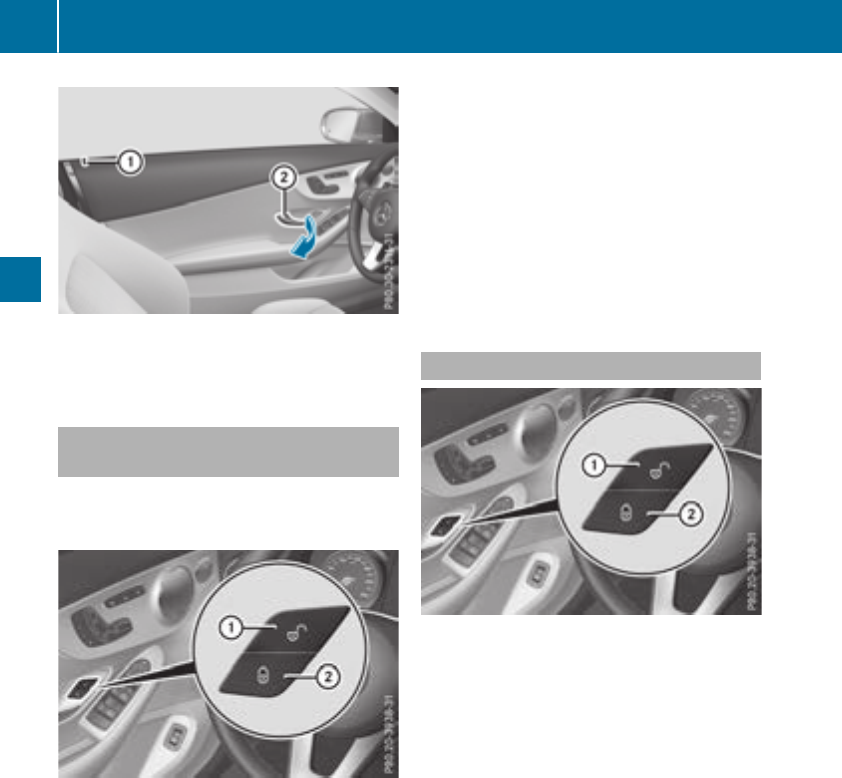
XPull door handle ;.
If the door is locked, locking knob :pops up.
The door is unlocked and opens.
Centrally locking and unlocking the
vehicle from the inside
You can centrally lock and unlock the vehicle
from the inside. The switches are on the driver’s
door.
XTo unlock: press button :.
XTo lock: press button ;.
When the front-passenger door is closed, the
vehicle is locked.
This does not lock or unlock the fuel filler flap or
the glove box.
You cannot unlock the vehicle centrally from the
inside if the vehicle has been locked with the
SmartKey or KEYLESS-GO.
The doors can be opened from the inside.
If the vehicle has been locked with the SmartKey
or with KEYLESS-GO, opening a door from the
inside will trigger the anti-theft alarm system.
Switch off the alarm (Ypage 74).
If a locked door is opened from the inside, the
previous unlock status of the vehicle will be
taken into consideration if:
Rthe vehicle was locked using the locking but-
ton for the central locking, or
Rthe vehicle was locked automatically
The vehicle will be fully unlocked if it had previ-
ously been fully unlocked. If only the driver's
door had been previously unlocked, only the
door which has been opened from the inside is
unlocked.
Automatic locking feature
XTo deactivate: press and hold button :for
approximately five seconds until a tone
sounds.
XTo activate: press and hold button ;for
approximately five seconds until a tone
sounds.
If you press one of the two buttons and do not
hear a tone, the relevant setting has already
been selected.
The vehicle is locked automatically when the
ignition is switched on and the wheels are turn-
ing.
You could therefore be locked out if:
Rthe vehicle is being pushed
Rthe vehicle is being towed
Rthe vehicle is being tested on a dynamometer.
You can activate and deactivate the automatic
locking mechanism via the multimedia system
(see the Digital Operator's Manual).
82 Doors
Opening and closing
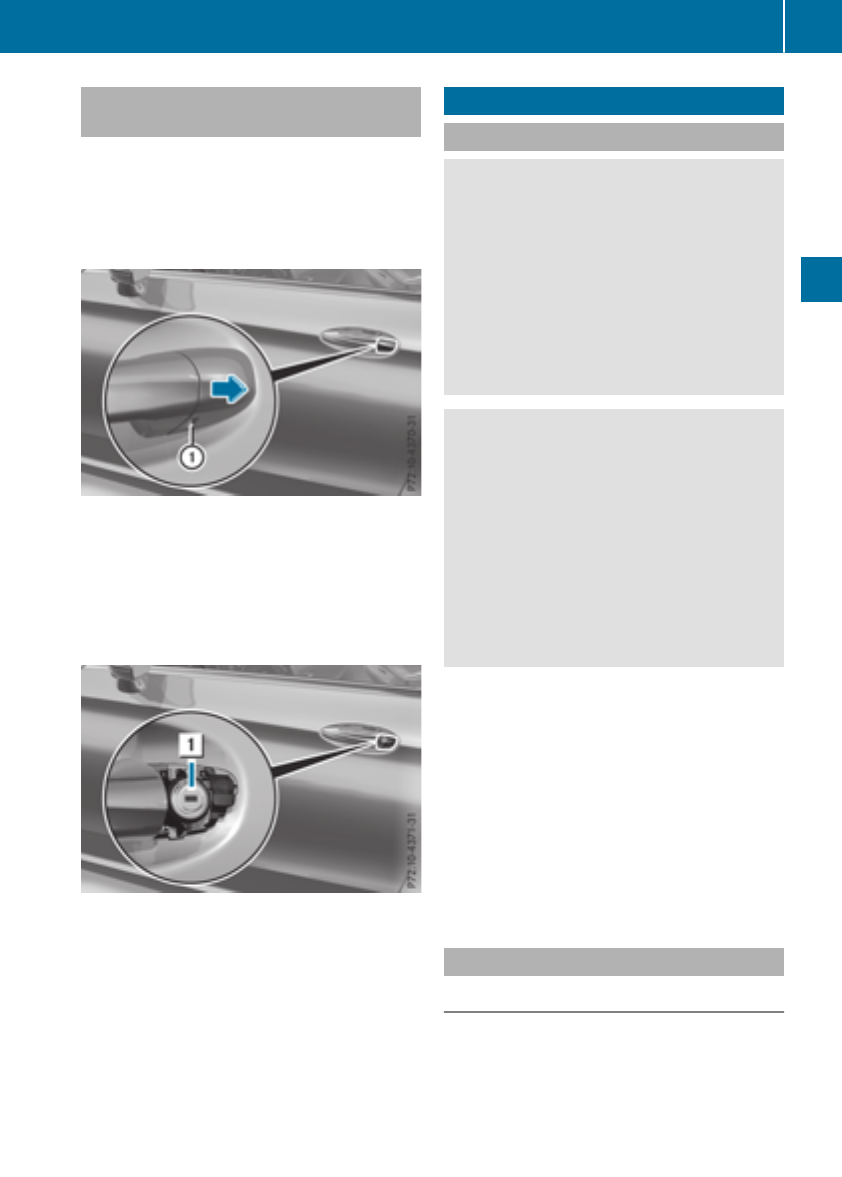
Locking/unlocking the driver's door
with the mechanical key
iIf you want to centrally lock the vehicle using
the mechanical key, begin by pressing the
locking button for the interior locking mech-
anism while the driver's door is open. Then
lock the driver's door using the mechanical
key.
XInsert the mechanical key into opening :in
the protective cap.
XPull and hold the door handle.
XPull the protective cap on the mechanical key
as straight as possible away from the vehicle
until it releases.
XRelease the door handle.
XTo lock: turn the mechanical key clockwise as
far as it will go to position 1.
XTo unlock: turn the mechanical key counter-
clockwise as far as it will go to position 1.
If you use the mechanical key to unlock and
open the driver's door, the anti-theft alarm sys-
tem will be triggered. Switch off the alarm
(Ypage 74).
Trunk
Important safety notes
GWARNING
Combustion engines emit poisonous exhaust
gases such as carbon monoxide. Exhaust
gases can enter the vehicle interior if the
trunk lid is open when the engine is running,
especially if the vehicle is in motion. There is a
risk of poisoning.
Always switch off the engine before opening
the trunk lid. Never drive with the trunk lid
open.
GWARNING
If objects, luggage or loads are not secured or
not secured sufficiently, they could slip, tip
over or be flung around and thereby hit vehicle
occupants. There is a risk of injury, particu-
larly in the event of sudden braking or a sud-
den change in direction.
Always store objects so that they cannot be
flung around. Secure objects, luggage or
loads against slipping or tipping before the
journey.
!The trunk lid swings upwards when opened.
Therefore, make sure that there is sufficient
clearance above the trunk lid.
The opening dimensions of the trunk lid can be
found in the "Vehicle data" section
(Ypage 345).
Do not leave the SmartKey in the trunk. You
could otherwise lock yourself out.
You should preferably place luggage or loads in
the trunk. Observe the loading guidelines
(Ypage 263).
Opening and closing manually
Opening
XPress the Fbutton on the SmartKey.
The trunk lid opens.
Trunk 83
Opening and closing
Z
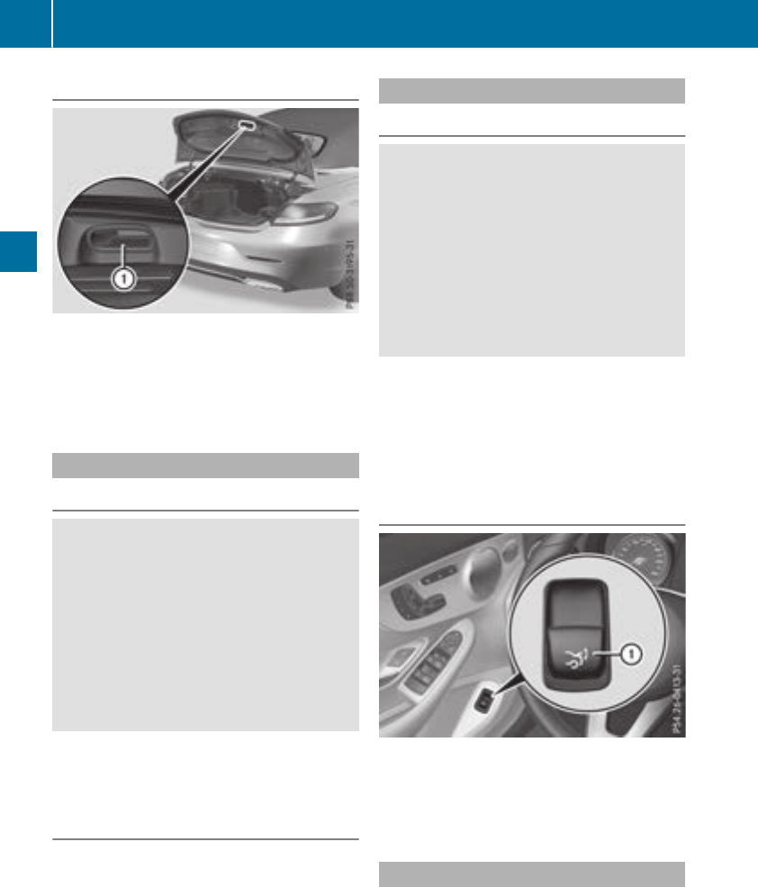
Closing
XPull the trunk lid down using recess :and
push it closed.
XLock the vehicle if necessary with the &
button on the SmartKey or with KEYLESS-GO
(Ypage 77).
Opening automatically from outside
Important safety notes
GWARNING
Combustion engines emit poisonous exhaust
gases such as carbon monoxide. Exhaust
gases can enter the vehicle interior if the
trunk lid is open when the engine is running,
especially if the vehicle is in motion. There is a
risk of poisoning.
Always switch off the engine before opening
the trunk lid. Never drive with the trunk lid
open.
The opening dimensions of the trunk lid can be
found in the "Vehicle data" section
(Ypage 345).
Opening automatically
You can open the trunk lid automatically using
the SmartKey.
XPress and hold the Fbutton on the Smart-
Key until the trunk lid opens.
Opening automatically from inside
Important safety notes
GWARNING
Combustion engines emit poisonous exhaust
gases such as carbon monoxide. Exhaust
gases can enter the vehicle interior if the
trunk lid is open when the engine is running,
especially if the vehicle is in motion. There is a
risk of poisoning.
Always switch off the engine before opening
the trunk lid. Never drive with the trunk lid
open.
!The trunk lid swings upwards when opened.
Therefore, make sure that there is sufficient
clearance above the trunk lid.
The opening dimensions of the trunk lid can be
found in the "Vehicle data" section
(Ypage 345).
Opening
You can open the trunk lid from the driver's seat
when the vehicle is stationary and unlocked.
XPull remote operating switch :for the trunk
lid until the trunk lid opens.
Locking the trunk separately
You can lock the trunk separately. If you then
unlock the vehicle centrally, the trunk remains
locked and cannot be opened.
84 Trunk
Opening and closing
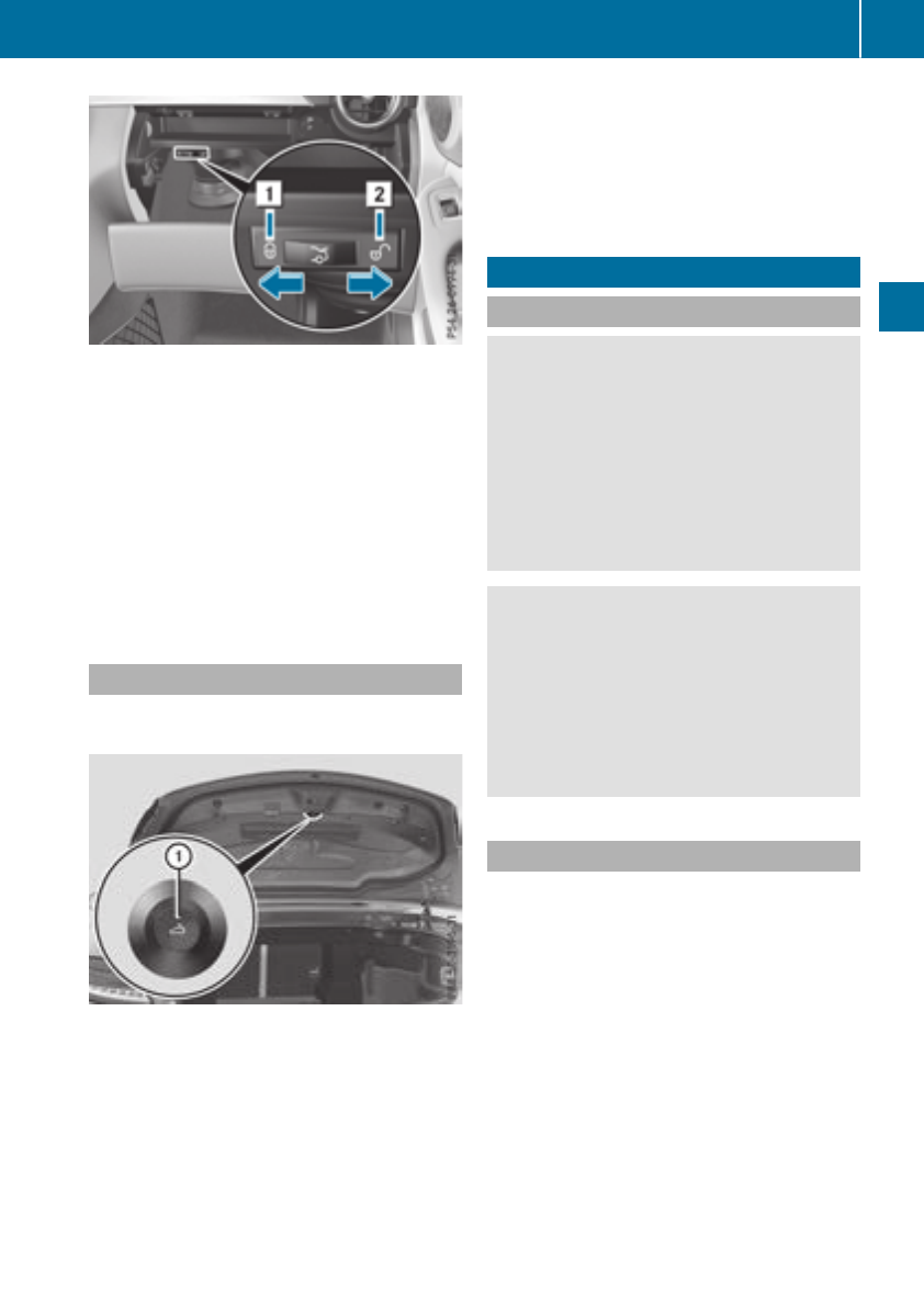
XTo activate: close the trunk lid.
XOpen the glove box.
XSlide the switch to position 1.
If the vehicle is unlocked centrally, the trunk
remains locked.
iYou can also lock the glove box
(Ypage 264).
XTo deactivate: open the glove box.
XSlide the switch to position 2.
If the vehicle is unlocked centrally, the trunk
will also be unlocked.
Emergency release for the trunk
You can unlock the trunk lid from the inside with
the emergency release button.
XPress emergency release button :briefly.
The trunk lid unlocks and opens.
The trunk lid can be unlocked with the trunk lid
emergency release when the vehicle is station-
ary or while driving.
The trunk lid emergency release does not unlock
the trunk lid if the battery is disconnected or
discharged.
Trunk lid emergency release light:
Remergency release button :flashes for
30 minutes after the trunk lid is opened
Remergency release button :flashes for
60 minutes after the trunk lid is closed
Side windows
Important safety notes
GWARNING
While opening the side windows, body parts
could become trapped between the side win-
dow and the door frame as the side window
moves. There is a risk of injury.
Make sure that nobody touches the side win-
dow during the opening procedure. If some-
body becomes trapped, release the switch or
pull the switch to close the side window again.
GWARNING
While closing the side windows, body parts in
the closing area could become trapped. There
is a risk of injury.
When closing make sure that no parts of the
body are in the closing area. If somebody
becomes trapped, release the switch or press
the switch to open the side window again.
Side window reversing feature
The side windows are equipped with an auto-
matic reversing feature. If a solid object blocks
or restricts a side window from traveling
upwards during the automatic closing process,
the side window opens again automatically. Dur-
ing the manual closing process, the side window
only opens again automatically after the corre-
sponding switch is released. The automatic
reversing feature is only an aid and is no substi-
tute for your attention when closing a side win-
dow.
Side windows 85
Opening and closing
Z
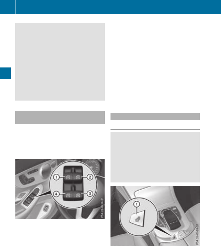
GWARNING
The reversing feature does not react:
Rto soft, light and thin objects, e.g. small fin-
gers
Rwhile resetting
This means that the reversing feature cannot
prevent someone being trapped in these sit-
uations. There is a risk of injury.
Make sure that no body parts are in close
proximity during the closing procedure. If
someone becomes trapped, press the switch
to open the side window again.
Opening and closing the side win-
dows
The switches for the side windows are located
on the driver's door. There is also a switch for
the front-passenger side window on the front-
passenger door.
The switches on the driver's door take prece-
dence.
:Front left
;Front right
=Rear right
?Rear left
XTurn the SmartKey to position 1or 2in the
ignition lock.
XTo open manually: press and hold the cor-
responding switch.
XTo open fully: press the switch beyond the
pressure point and release it.
Automatic operation is started.
XTo close manually: pull the corresponding
switch and hold it.
XTo close fully: pull the switch beyond the
pressure point and release it.
Automatic operation is started.
XTo interrupt automatic operation: press/
pull the corresponding switch again.
If you press the switch beyond the pressure
point and release, automatic operation is star-
ted in the corresponding direction. You can stop
automatic operation by pressing/pulling the
switch again.
You can continue to operate the side windows
after you switch off the engine or remove the
SmartKey. This function is available for up to five
minutes or until the driver's or front-passenger
door is opened.
Opening and closing all side windows
Using the switch on the center console
GWARNING
While closing the side windows, body parts in
the closing area could become trapped. There
is a risk of injury.
When closing make sure that no parts of the
body are in the closing area. If somebody
becomes trapped, release the switch or press
the switch to open the side window again.
You can use button :to open or close all side
windows simultaneously.
XTurn the SmartKey to position 1or 2in the
ignition lock.
XTo open all side windows: press and hold
button :to the point of resistance.
86 Side windows
Opening and closing
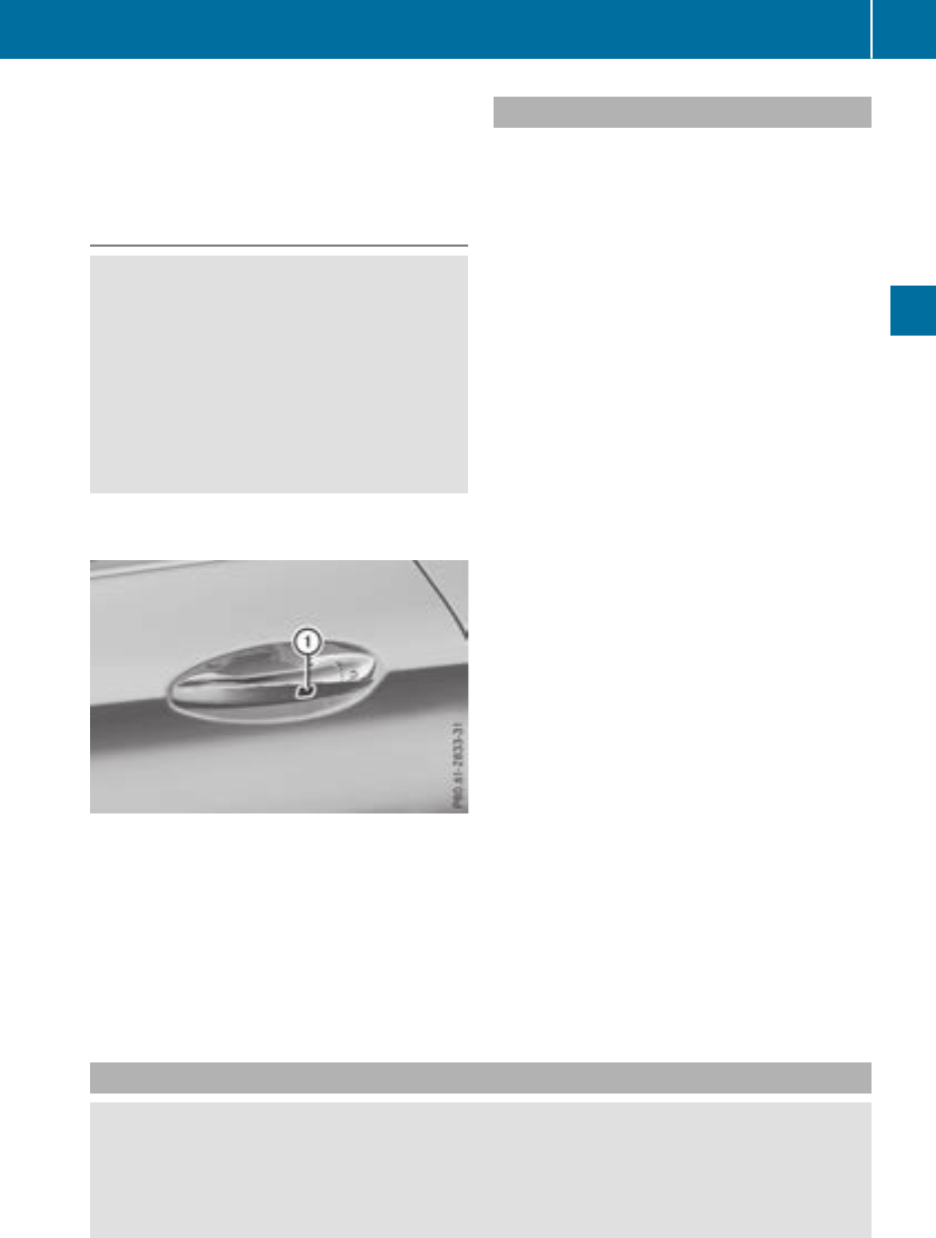
XTo open all side windows fully: press
switch :beyond the pressure point.
XTo close all side windows: pull and hold
button :.
Using KEYLESS-GO
GWARNING
When using the convenience closing feature,
parts of the body could be trapped in the clos-
ing area when a side window is being closed.
There is a risk of injury.
Observe the complete closing procedure
when the convenience closing feature is oper-
ating. Make sure that no body parts are in
close proximity during the closing procedure.
The SmartKey must be outside the vehicle. All
the doors must be closed.
XConvenience closing feature: touch
recessed sensor surface :on the door han-
dle until the side windows are fully closed.
iMake sure you only touch recessed sensor
surface :.
XTo interrupt convenience closing: release
recessed sensor surface :on the door han-
dle.
Resetting the side windows
If a side window can no longer be closed fully,
you must reset it.
XClose all the doors.
XTurn the SmartKey to position 1or 2in the
ignition lock.
XClose the soft top (Ypage 89).
XPull the corresponding switch on the door
control panel until the side window is com-
pletely closed (Ypage 86).
XHold the switch for an additional second.
If the side window opens again slightly:
XImmediately pull the corresponding switch on
the door control panel until the side window is
completely closed (Ypage 86).
XHold the switch for an additional second.
XIf the respective side window remains closed
after the button is released, then it has been
set correctly. If this is not the case, repeat the
steps above.
Problems with the side windows
GWARNING
If you close a side window again immediately after it has been blocked or reset, the side window
closes with increased or maximum force. The reversing feature is then not active. Parts of the
body could be trapped in the closing area in the process. This poses an increased risk of injury or
even fatal injury.
Side windows 87
Opening and closing
Z

Make sure that no parts of the body are in the closing area. To stop the closing process, release
the switch or push the switch again to reopen the side window.
Problem Possible causes/consequences and MSolutions
A side window cannot be
closed because it is
blocked by objects, e.g.
leaves in the window
guide.
XRemove the objects.
XClose the side window.
A side window cannot be
closed and you cannot
see the cause.
If a side window is obstructed during closing and reopens again
slightly:
XImmediately after the window blocks, pull the corresponding switch
again until the side window has closed.
The side window is closed with increased force.
If a side window is obstructed again during closing and reopens again
slightly:
XImmediately after the window blocks, pull the corresponding switch
again until the side window has closed.
The side windows are closed without the automatic reversing fea-
ture.
Soft top
Important safety notes
GWARNING
If you do not fully open/close the soft top, the
soft-top hydraulics depressurize after a short
time. This causes the soft top to lower unex-
pectedly and may cause you or others to be
trapped. There is a risk of injury.
Always open or close the soft top completely.
!Never sit on the soft-top compartment
cover or stow heavy objects there. You will
otherwise damage the soft top and soft-top
compartment cover of the vehicle.
!When opening and closing the soft top,
make sure that:
Rthere is sufficient clearance above it, as the
soft top swings upwards.
Rthe trunk is only loaded to below the trunk
partition.
Rthe trunk partition is not pushed up by the
load.
Rthe trunk lid is closed.
Rthere are no objects on the soft-top com-
partment cover
Rthe fabric is not dirty, wet or frozen.
You could otherwise damage the soft top,
trunk and other parts of the vehicle.
Take the height of the vehicle into account when
opening and closing the soft top (Ypage 345).
Make sure that the soft top is dry and clean
before opening it. Otherwise, water or dirt could
enter the vehicle interior or trunk.
You can open or close the soft top:
Rwhen the vehicle is stationary or
Rwhen you are not exceeding a speed of
30 mph (50 km/h) (Max. 35 mph (60 km/h),
to avoid interrupting the closing process while
slightly exceeding the speed limit).
If there is a strong head wind, it may not be pos-
sible to close the soft top fully. In this case,
reduce speed or stop in order to close the soft
top fully.
For safety reasons, Mercedes-Benz recom-
mends that you only open or close the soft top
when the vehicle is stationary.
88 Soft top
Opening and closing
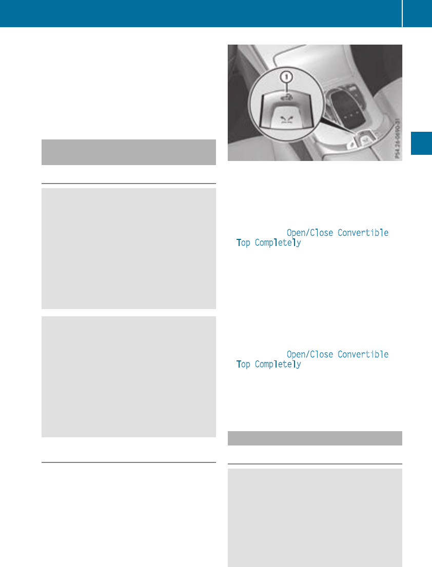
If the soft top does not open or close fully, the
soft-top hydraulics are depressurized and the
soft top is lowered:
Rafter approximately 7 minutes when the igni-
tion is switched on
Rafter about
20 seconds if the ignition is switched off
Opening/closing with the soft top
switch
Important safety notes
GWARNING
When opening or closing the soft top, there is
a risk that parts of the body could become
trapped by moving parts such as the roof
mechanism, the trunk lid, or the side win-
dows. There is a risk of injury.
When opening or closing the roof, make sure
that no parts of the body are in the vicinity of
moving parts. Release the switch if somebody
becomes trapped.
GWARNING
If the vehicle speed exceeds 35 mph
(60 km/h), the soft top stops during the open-
ing or closing process. This impairs your view
to the rear. There is a risk of an accident.
Reduce your speed to below 35 mph
(60 km/h) or stop the vehicle in accordance
with the traffic conditions. Press or pull the
soft-top switch again in order to open or close
the soft top fully.
Opening and closing
XMake sure that the trunk partition is closed
(Ypage 90).
XClose the trunk lid.
XTurn the SmartKey to position 2in the igni-
tion lock.
XWhen the vehicle is stationary, depress the
brake pedal and keep it depressed.
XTo open: pull and hold soft top switch :until
the entire soft top is stowed away in the trunk.
The multifunction display shows the opening
process of the soft top.
If, when opening, you drive at speeds above
35 mph (60 km/h), the opening process is
stopped. The Open/Close Convertible
Top Completely message is shown in the
multifunction display. In order to open the
soft top fully, reduce your speed again to
below 35 mph (60 km/h) and pull the soft-top
switch again.
XTo close: pull and hold soft top switch :until
the soft top is completely closed.
The multifunction display shows the closing
process of the soft top.
If, when closing, you drive at speeds above
35 mph (60 km/h), the closing process is
stopped. The Open/Close Convertible
Top Completely message is shown on the
multifunction display. In order to close the
soft top fully, reduce your speed again to
below 35 mph (60 km/h) and press the soft-
top switch again.
Opening/closing using the SmartKey
Important safety notes
GWARNING
When opening or closing the soft top, there is
a risk that parts of the body could become
trapped by moving parts such as the roof
mechanism, the trunk lid, or the side win-
dows. There is a risk of injury.
When opening or closing the roof, make sure
that no parts of the body are in the vicinity of
Soft top 89
Opening and closing
Z
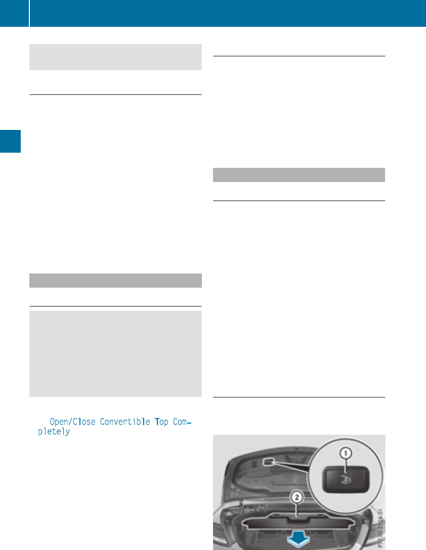
moving parts. Release the switch if somebody
becomes trapped.
Opening and closing
The SmartKey must be in close proximity to the
vehicle.
XClose the trunk partition (Ypage 90).
Otherwise only the side windows open.
XTo open: press and hold the %button in
the SmartKey until the soft top is completely
open.
The multifunction display shows the opening
process of the soft top. The seat ventilation is
switched on.
XTo close: press and hold the &button in
the SmartKey until the soft top is completely
closed.
The multifunction display shows the closing
process of the soft top.
Relocking the soft top
Important safety notes
GWARNING
If you do not fully open/close the soft top, the
soft-top hydraulics depressurize after a short
time. This causes the soft top to lower unex-
pectedly and may cause you or others to be
trapped. There is a risk of injury.
Always open or close the soft top completely.
The soft top is not locked if:
RtheOpen/Close Convertible Top Com‐
pletely message is shown in the multifunc-
tion display
Ryou hear a warning tone for up to ten seconds
when pulling away or while driving
Locking
You can lock the soft top again if it is not locked
fully.
XPull over and stop the vehicle safely as soon
as possible, paying attention to road and traf-
fic conditions.
XTurn the SmartKey to position 2in the igni-
tion lock.
XPress the soft-top switch (Ypage 89).
Trunk partition
General notes
The trunk partition can be used to cover luggage
and loads in the trunk.
The soft top can be opened only when the man-
ual trunk partition is closed. In vehicles with a
partially electrical trunk partition, this automat-
ically closes when the soft top is opened.
!In order to avoid damaging the soft top or
stowed loads, please adhere to the following
while the soft top is open:
Rwhen the trunk partition is open, do not
place any objects in or behind the net on
the side that are too long. These objects
could obstruct the trunk partition or cause
damage to the open soft top.
Rmake sure that the cargo does not push the
trunk partition upwards.
Opening and closing
Depending on the vehicle equipment, your vehi-
cle is installed with a partially electrical or a
manual trunk partition.
90 Soft top
Opening and closing
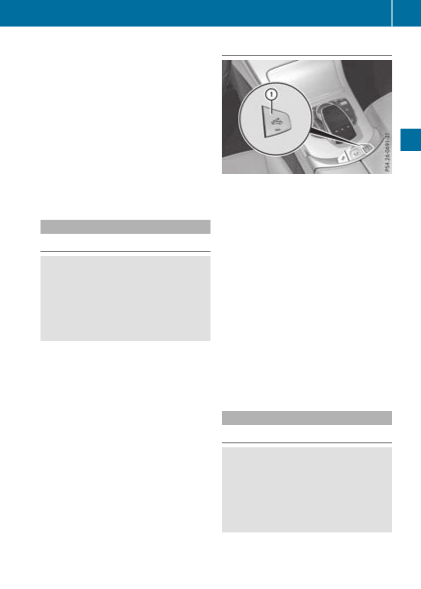
To open:
XAll vehicles: push trunk partition ;using
the handle against the direction of the arrow
to its upper end position.
To close:
XVehicles with a partially electrical trunk
partition: press button :.
Trunk partition ;closes automatically.
iIf the system fails, the partially electrical
trunk partition can be closed manually.
XVehicles with a manual trunk partition:
pull trunk partition ;by the handle in the
direction of the arrow until it rests on the
sides of the trunk.
AIRCAP
Important safety notes
GWARNING
When retracting the AIRCAP, persons could
become caught in the moving mechanism.
There is a risk of injury.
Ensure that persons do not hold onto the
upper frame of the windshield and do not
touch the AIRCAP wind deflector.
With AIRCAP, four people can travel comfortably
with the soft top open. AIRCAP reduces the draft
for the driver and passengers in both the front
and the rear compartment in a vehicle with the
soft top down.
In particularly turbulent air, e.g. when following
a vehicle or in a crosswind, AIRCAP's effect may
be reduced.
AIRCAP has the following components:
Ra wind deflector above the windshield
Ra wind screen behind the two rear-seat head
restraints
When AIRCAP has been activated, the wind
screen extends up between the two rear-seat
head restraints. At the same time, the wind
deflector extends out along the front wind-
shield.
AIRCAP can be activated or deactivated up to
speeds of approximately 100 mph (160 km/h).
Activating and deactivating AIRCAP
XTurn the SmartKey to position 2in the igni-
tion lock.
XTo activate: pull switch :.
The wind screen behind the rear-seat headr-
ests and the wind deflector in the roof frame
extend simultaneously. The indicator lamp in
switch :lights up.
XTo deactivate: press switch :.
The wind screen behind the rear-seat headr-
ests and the wind deflector in the roof frame
retract simultaneously. The indicator lamp in
switch :goes out.
If you park your vehicle with the soft top down
and remove the SmartKey, the wind deflector
and the wind screen retract automatically.
When you restart your engine after having been
parked, the wind deflector and the wind screen
extend again automatically.
AIRCAP cannot be extended or retracted if the
vehicle speed exceeds approximately 100 mph
(160 km/h).
Folding wind screen
Important safety notes
GWARNING
If you use the wind screen in darkness or in
other conditions offering poor visibility, your
view to the rear is further impaired. There is a
risk of an accident.
Only use the wind screen when visibility con-
ditions are good.
Soft top 91
Opening and closing
Z
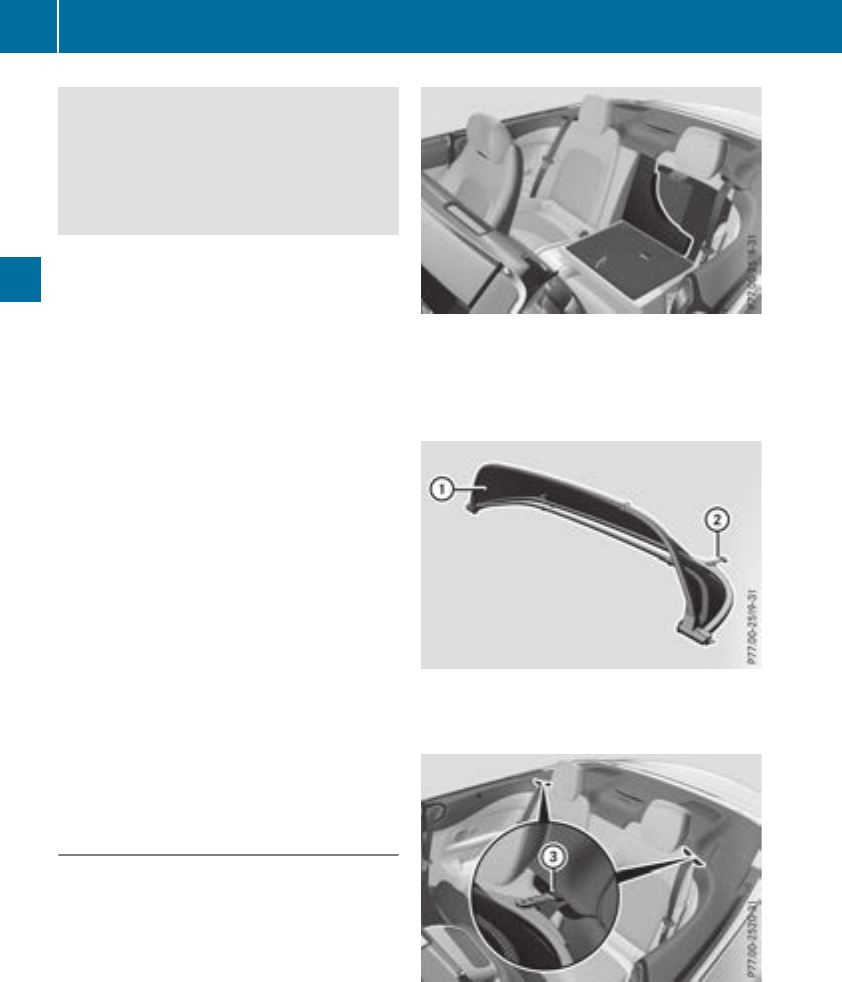
GWARNING
If the wind screen is incorrectly installed, it
could detach itself during a journey and
endanger other road users. There is a risk of
an accident and injury.
Install the wind screen as described.
!Install or remove the wind screen only when
the soft top is open. You could otherwise
damage the wind screen or the vehicle inte-
rior.
!Observe the backrest position of the front
seats if the wind screen is installed, since the
backrest could collide with the wind screen
here.
!Mercedes-Benz recommends that you only
use wind screens which have been tested and
approved for Mercedes-Benz vehicles. This
helps to prevent damage to the vehicle.
The folding wind screen protects against wind
when driving with the soft top open. It is secured
above the rear bench seats. For this reason, only
the driver and the front passenger can travel in
the vehicle when the folding wind screen is
installed.
The folding wind screen can be installed or
removed from the driver's side or passenger
side.
For operations involving the folding wind screen,
it is preferable to be positioned on the side of the
vehicle facing away from the traffic, after stop-
ping the vehicle in accordance with the traffic
conditions.
Installing/removing the folding wind
screen
Installing
The folding wind screen is stowed in a bag. The
bag is attached with a lashing strap to the
through-loading facility behind the rear seats.
If you wish to use the through-loading facility,
loosen the lashing strap attached to the
through-loading facility and stow the folding
wind screen in the trunk. Use the lashing strap
to fasten the bag to one of the luggage hooks in
the trunk.
XOpen all side windows and the soft top.
XFold the rear seats forward (Ypage 265) and
remove the bag containing the folding wind
screen.
XRemove the folding wind screen from the bag.
XFold out folding wind screen :as shown.
XFold out the two brackets ;to the left and
right.
XAlign brackets ;of folding wind screen :
with both rear fixtures =on the vehicle.
92 Soft top
Opening and closing
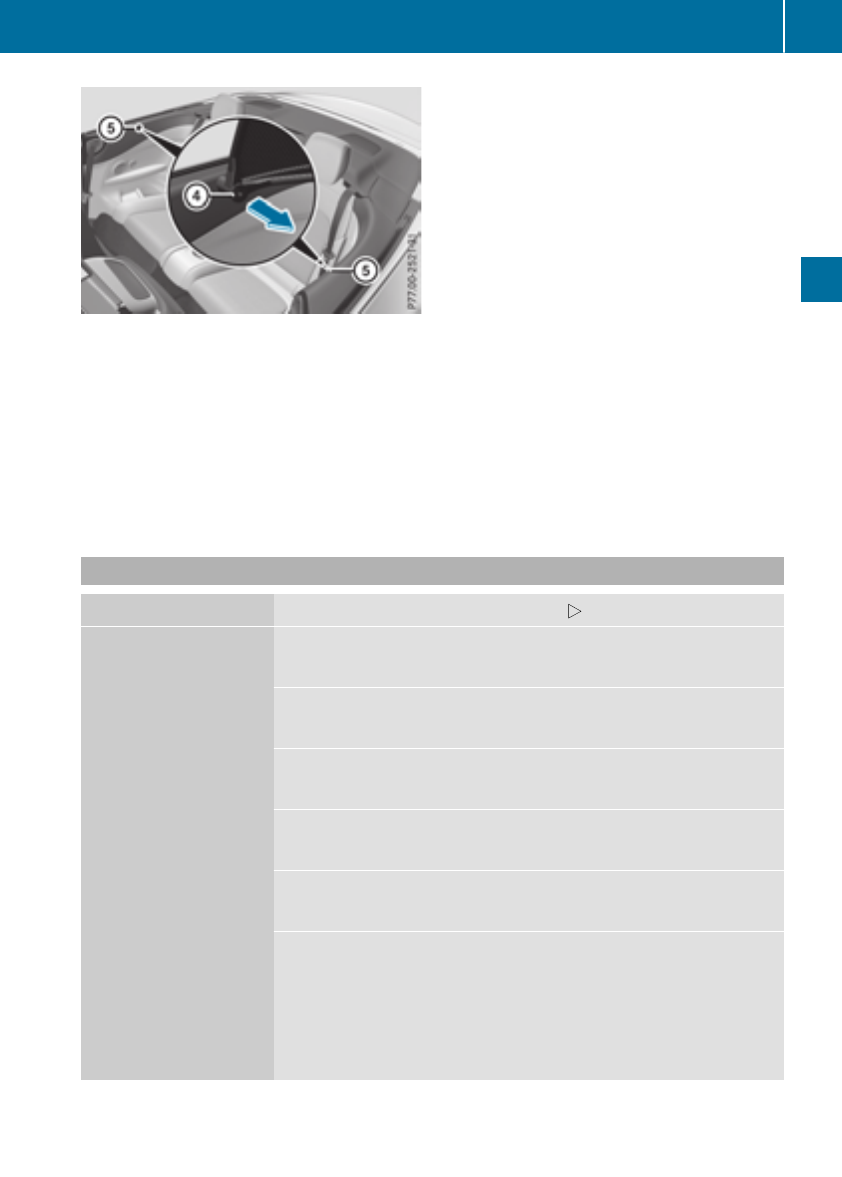
Perform the following steps in sequence on both
sides of the vehicle:
XPull the handle ?in the direction of the
arrow.
XAlign folding wind screen :with side fixture
Aon the vehicle from above and insert.
XPush handle ?on folding wind screen :
back as far as it will go.
Folding wind screen :is locked.
Removing
XPull handles ?on the left and right one after
the other and slide folding wind screen :out
of fixture Afrom above.
Folding wind screen :is unlocked.
XPull folding wind screen :out of both rear
fixtures =.
XFold in both brackets ;on folding wind
screen :.
XFold folding wind screen :together and
stow it in the bag.
XUse the lashing strap to attach the bag con-
taining the folding wind screen to the through-
loading facility behind the rear seats.
Problems with the soft top
Problem Possible causes/consequences and MSolutions
The soft top will not open
or close.
The ignition is not switched on.
XMake sure that the SmartKey is in position 2in the ignition lock.
The trunk lid is open.
XClose the trunk lid (Ypage 83).
The trunk partition is not closed.
XClose the trunk partition (Ypage 90).
The roll bars have been deployed.
XVisit a qualified specialist workshop.
The soft-top mechanism or control system is defective.
XVisit a qualified specialist workshop.
The soft top has been opened and closed several times in a row. The
soft-top drive has been deactivated automatically for safety reasons.
You can open and close the soft top again after approximately ten
minutes.
XSwitch off the ignition and turn it back on.
XRepeat the opening or closing procedure.
Soft top 93
Opening and closing
Z
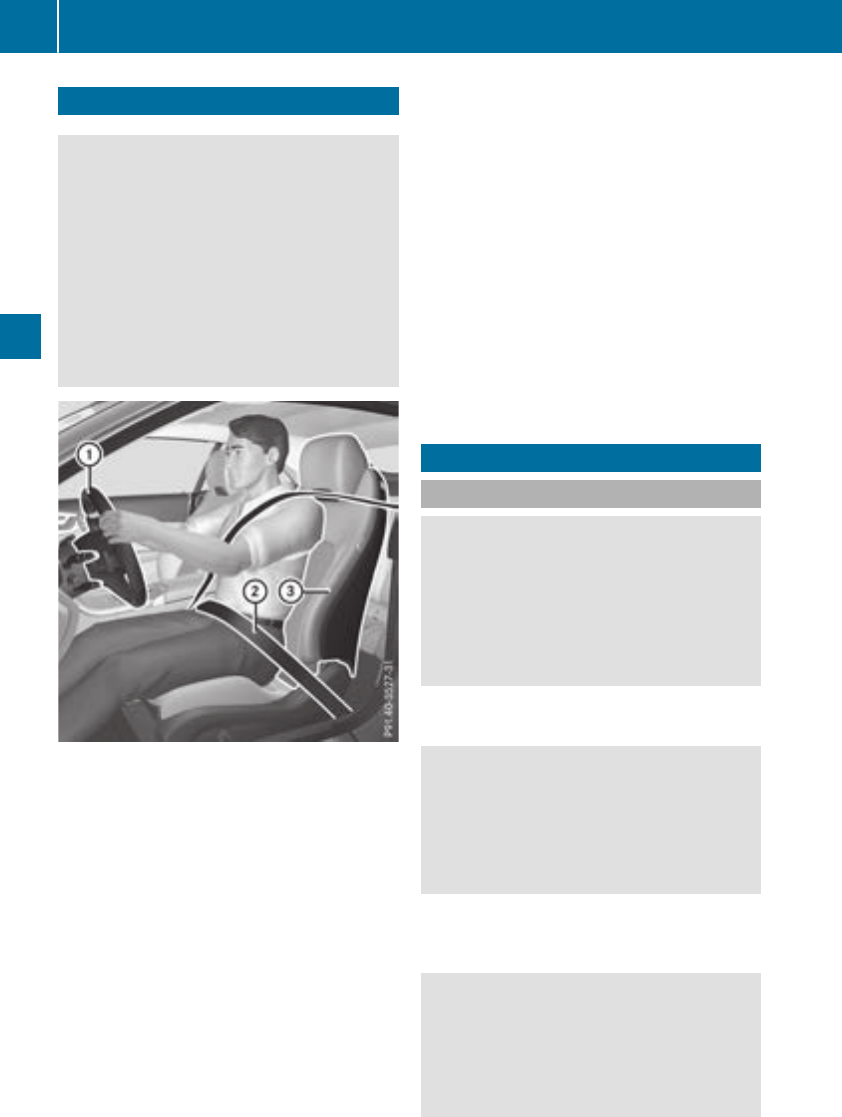
Correct driver's seat position
GWARNING
You could lose control of your vehicle if you do
the following while driving:
Radjust the driver's seat, head restraint,
steering wheel or mirrors
Rfasten the seat belt
There is a risk of an accident.
Adjust the driver's seat, head restraint, steer-
ing wheel and mirror and fasten your seat belt
before starting the engine.
Observe the following when adjusting steering
wheel :, seat belt ;and driver's seat =:
Ryou are as far away from the driver's air bag as
possible
Ryou are sitting in a normal upright position
Ryour thighs are slightly supported by the seat
cushion
Ryour legs are not entirely stretched and you
can depress the pedals properly
Rthe back of your head is supported at eye level
by the center of the head restraint
Ryou can hold the steering wheel with your
arms slightly bent
Ryou can move your legs freely
Ryou can see all the displays in the instrument
cluster clearly
Ryou should have a good overview of traffic
conditions
Rthe seat belt is pulled snugly against the body
and is routed across the center of your shoul-
der and across your hips in the pelvic area
Further related subjects:
RAdjusting the seats electrically (Ypage 96).
RAdjusting the steering wheel electrically
(Ypage 101).
RFastening the seat belt correctly (Ypage 47).
RAdjusting the rear-view mirror and exterior
mirrors (Ypage 103).
RStoring the seat, steering wheel, exterior mir-
ror and head-up display settings with the
memory function (Ypage 106).
Seats
Important safety notes
GWARNING
Children could become trapped if they adjust
the seats, particularly when unattended.
There is a risk of injury.
When leaving the vehicle, always take the
SmartKey with you and lock the vehicle. Never
leave children unsupervised in the vehicle.
The seats can still be adjusted when there is no
SmartKey in the ignition lock.
GWARNING
When you adjust a seat, you or other vehicle
occupants could become trapped, e.g. on the
seat guide rail. There is a risk of injury.
Make sure when adjusting a seat that no one
has any body parts in the sweep of the seat.
Observe the safety notes on "Air bags"
(Ypage 49) and "Children in the Vehicle"
(Ypage 59).
GWARNING
If the head restraints are not installed or not
adjusted correctly, they cannot provide pro-
tection as intended. There is an increased risk
of injury in the head and neck area, e.g. in the
event of an accident or when braking.
94 Seats
Seats, steering wheel and mirrors

Always drive with the head restraints instal-
led. Before driving off, make sure for every
vehicle occupant that the center of the head
restraint supports the back of the head at
about eye level.
Do not rotate the head restraints of the front and
rear seats. Otherwise, you cannot adjust the
height and angle of the head restraints cor-
rectly.
Using the fore-and-aft adjustment, adjust the
head restraint so that it is as close as possible to
your head.
GWARNING
If the driver's seat is not engaged, it could
move unexpectedly while the vehicle is in
motion. This could cause you to lose control of
the vehicle. There is a risk of an accident.
Always make sure that the driver's seat is
engaged before starting the vehicle.
GWARNING
You could lose control of your vehicle if you do
the following while driving:
Radjust the driver's seat, head restraint,
steering wheel or mirrors
Rfasten the seat belt
There is a risk of an accident.
Adjust the driver's seat, head restraint, steer-
ing wheel and mirror and fasten your seat belt
before starting the engine.
GWARNING
If you adjust the seat height carelessly, you or
other vehicle occupants could be trapped and
thereby injured. Children in particular could
accidentally press the electrical seat adjust-
ment buttons and become trapped. There is a
risk of injury.
While moving the seats, make sure that your
hands or other body parts do not get under the
lever assembly of the seat adjustment sys-
tem.
GWARNING
The seat belt does not offer the intended level
of protection if you have not moved the back-
rest to an almost vertical position. When brak-
ing or in the event of an accident, you could
slide underneath the seat belt and sustain
abdomen or neck injuries, for example. This
poses an increased risk of injury or even fatal
injury.
Adjust the seat properly before beginning
your journey. Always ensure that the backrest
is in an almost vertical position and that the
shoulder section of your seat belt is routed
across the center of your shoulder.
!To avoid damage to the seats and the seat
heating, observe the following information:
Rkeep liquids from spilling on the seats. If
liquid is spilled on the seats, dry them as
soon as possible.
Rif the seat covers are damp or wet, do not
switch on the seat heating. The seat heat-
ing should also not be used to dry the seats.
Rclean the seat covers as recommended;
see "Interior care".
Rdo not transport heavy loads on the seats.
Do not place sharp objects on the seat
cushions, e.g. knives, nails or tools. The
seats should only be occupied by passen-
gers, if possible.
Rwhen the seat heating is in operation, do
not cover the seats with insulating materi-
als, e.g. blankets, coats, bags, seat covers,
child seats or booster seats.
!Make sure that there are no objects in the
footwell under or behind the seats when mov-
ing the seats back. There is a risk that the
seats and/or the objects could be damaged.
iFor more information, contact a qualified
specialist workshop.
iRelated topic:
RRear bench seat through-loading feature
(Ypage 265)
Seats 95
Seats, steering wheel and mirrors
Z
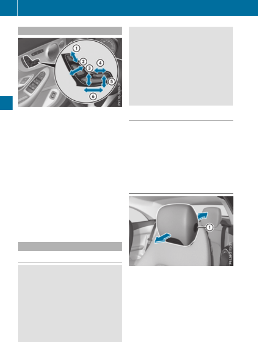
Adjusting the seats electrically
:Headrestraintheight
;Backrest angle
=Seat height
?Seat cushion length
ASeat cushion angle
BSeat fore-and-aftadjustment
iFurther relatedsubjects:
RYou can store theseat settingsusingthe
memory function (Ypage 106).
RIf PRE-SAFE®is triggered,thefront-
passenger seat will be moved to abetter
position if it was previously in an unfavora-
ble position (Ypage 58).
RWhen theseat is moved forward or back,
theheadrestis moved up or down auto-
matically.
Vehicles withAMGPerformance seat:theheight
of thehead restraints cannotbe adjusted.
Adjusting the head restraints
Important safety notes
GWARNING
You could lose control of your vehicleif you do
thefollowingwhile driving:
Radjust thedriver's seat,head restraint,
steering wheelor mirrors
Rfastentheseat belt
There is ariskof an accident.
Adjustthedriver's seat,head restraint, steer-
ing wheeland mirror and fastenyour seat belt
before starting theengine.
GWARNING
If thehead restraints are notinstalled or not
adjusted correctly, they cannotprovidepro-
tection as intended. There is an increased risk
of injury in thehead and neck area, e.g. in the
event of an accidentor when braking.
Always drive withthehead restraints instal-
led. Beforedrivingoff,makesurefor every
vehicleoccupant that thecenter of thehead
restraintsupportsthebackof thehead at
about eye level.
General notes
Pay attention to theimportant safetynotes
(Ypage 94).
Do notrotate thehead restraints of thefrontand
rear seats. Otherwise,you cannotadjust the
height and angle of thehead restraints to the
correctposition.
The rear seat head restraints are notheight-
adjustable.
Adjusting the head restraint fore-and-
aft position manually
Withthis function you can adjust thedistance
between thehead restraintand thebackof the
seat occupant's head.
XTo moveforward: pull thehead restraint
forward in thedirection of thearrow until it
engagesin thedesired position.
XTo moveback:press and hold therelease
catch :.
XPush thehead restraintback.
96 Seats
Seats, steering wheel and mirrors
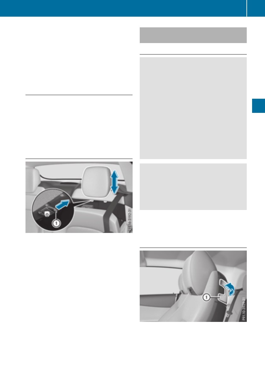
XReleasetherelease buttononce thehead
restraintis in thedesired position.
XEnsurethat thehead restrainthas engaged
properly.
Using thefore-and-aftadjustment, adjust the
head restraintso that it is as close as possibleto
your head.
Adjusting the height of the head
restraints electrically
XTo adjust theheadrestraintheight:slide
theswitch for thehead restraintadjustment
(Ypage 96) up or down in thedirection of the
arrow.
Vehicles withAMGPerformance seat:theheight
of thehead restraints cannotbe adjusted.
Installing and removing rear head
restraints
XReleasetherear seat backrest and foldit
slightly forward (Ypage 265).
XTo remove: press thecatch :in thedirec-
tion of thearrow and keep depressed.
XRemove thehead restraintfrom theguides
and release thecatch :.
XTo install:insert thehead restraintintothe
guide so that thenotches on thebar appear
on theleft-handside when viewed in the
direction of travel.
XPush thehead restraintall theway down until
it engages.
XEnsurethat thehead restrainthas engaged
properly.
XFold backtherear backrest until it engages.
Folding the front seat backrests
forward/back
Important safety notes
GWARNING
The seat belt does notoffer theintended level
of protection if you havenotmoved theback-
restto an almost vertical position.When brak-
ing or in theevent of an accident, you could
slideunderneaththeseat belt and sustain
abdomen or neck injuries, for example. This
poses an increased riskof injury or evenfatal
injury.
Adjusttheseat properly before beginning
your journey. Always ensurethat thebackrest
is in an almost vertical position and that the
shoulder section of your seat belt is routed
across thecenter of your shoulder.
GWARNING
When you adjust aseat,you or other vehicle
occupantscould become trapped,e.g. on the
seat guide rail. There is ariskof injury.
Makesurewhen adjusting aseat that no one
has any body partsin thesweepof theseat.
Observethesafetynoteson "Airbags"
(Ypage 49)and "Children in thevehicle"
(Ypage 59).
Folding the seat backrest forward
EASY-ENTRY System:theseat moves forwards
as soonas you foldthebackrest forwards and
pull theseat forwards horizontally. This makes it
easierfor passengersto get intoand out of the
rear compartment.
Seats 97
Seats, steering wheel and mirrors
Z
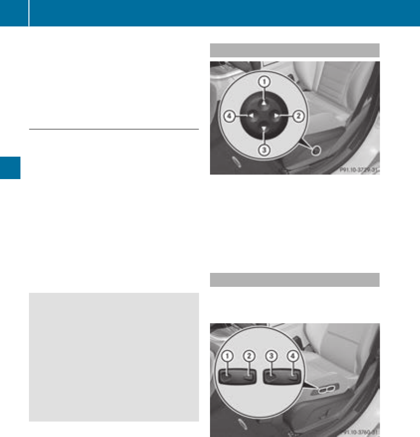
The head restraint also lowers on vehicles with
electric seat adjustment.
XPull the seat release handle :and fold the
backrest forwards as far as it will go.
The seat moves automatically to the foremost
position.
Folding the seat backrest back
XSwing back the seat backrest.
If the rear seat backrest is not engaged, this
will be shown in the multifunction display in
the instrument cluster. A warning tone also
sounds.
The seat moves automatically to the stored
position.
If the previous position can no longer be set, e.g.
because of luggage in the rear-compartment
footwell or after occupants have entered the
rear-compartment:
XPull seat release handle :again and return
the seat backrest to an upright position.
The seat locks in the new seat fore-and-aft
adjustment position.
GWARNING
If the backrest is not engaged, it could fold
forwards during a braking maneuver or in the
event of an accident, for example. The seat
backrest will then push the vehicle occupant
against the seat belt. The seat belt can no
longer offer the intended level of protection
and could even cause injuries. There is an
increased risk of injury.
Before each journey, make sure that the back-
rest engages fully as described.
Adjusting the 4-way lumbar support
:Raises the backrest contour
;Softens the backrest contour
=Lowers the backrest contour
?Hardens the backrest contour
You can adjust the contour of the front seat
backrests individually to provide optimum sup-
port for your back.
Adjusting the AMG Performance Seat
To adjust the contour of the seat and for
improved lateral support, you can individually
adjust the front seats.
Adjusting the side bolsters of the seat cush-
ion
XTo set narrower: press button :.
XTo set wider: press button ;.
To adjust the side bolsters of the seat back-
rest
XTo set narrower: press button =.
XTo set wider: press button ?.
98 Seats
Seats, steering wheel and mirrors
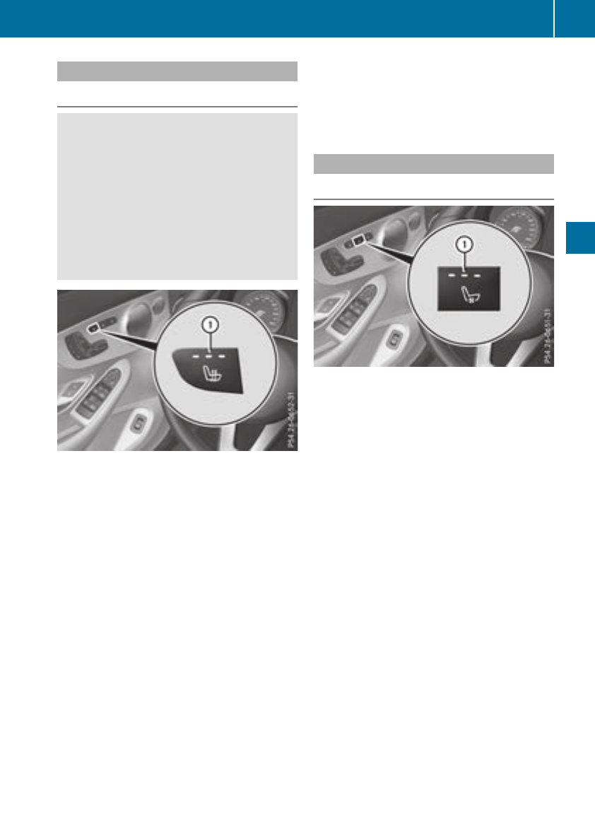
Switching the seat heating on/off
Switching on/off
GWARNING
Repeatedly switching on the seat heating can
cause the seat cushion and backrest pads to
become very hot. The health of persons with
limited temperature sensitivity or a limited
ability to react to high temperatures may be
affected or they may even suffer burn-like
injuries. There is a risk of injury.
Therefore, do not switch the seat heating on
repeatedly.
The three red indicator lamps in the button indi-
cate the heating level you have selected.
The system automatically switches down from
level 3to level 2after approximately eight
minutes.
The system automatically switches down from
level 2to level 1after approximately ten
minutes.
The system automatically switches off approx-
imately 20 minutes after it is set to level 1.
XTurn the SmartKey to position 1or 2in the
ignition lock (Ypage 123).
XTo switch on: press button :repeatedly
until the desired heating level is set.
XTo switch off: press button :repeatedly
until all the indicator lamps go out.
iIf the battery voltage is too low, the seat
heating may switch off.
iIf drive program Eis selected, the power of
the seat heating is reduced.
Switching the seat ventilation on/off
Switching on/off
The blue indicator lamps in the button indicate
the ventilation level you have selected.
XTurn the SmartKey to position 1or 2in the
ignition lock (Ypage 123).
XTo switch on: press button :repeatedly
until the desired ventilation level is set.
XTo switch off: press button :repeatedly
until all the indicator lamps go out.
iIf the battery voltage is too low, the seat
ventilation may switch off.
iYou can open the side windows and the soft
top with the SmartKey (Ypage 90). The seat
ventilation of the driver's seat automatically
switches to the highest level.
iWhen the vehicle is stationary, the fan
speed can be reduced automatically. This
reduces the noises of the seat ventilation.
Seats 99
Seats, steering wheel and mirrors
Z
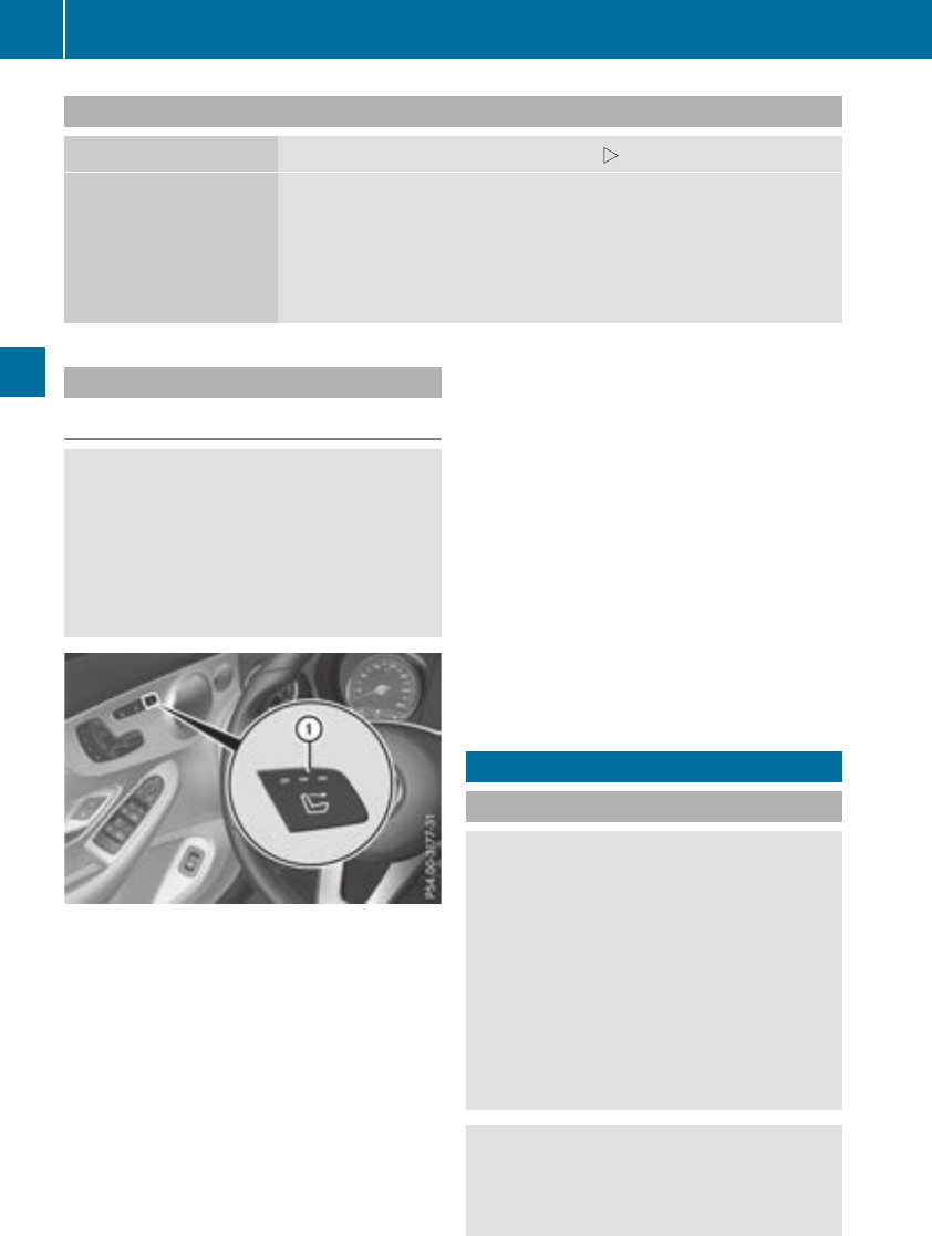
Problems with the seat heating / seat ventilation
Problem Possible causes/consequences and MSolutions
The seat heating or seat
ventilation has switched
off prematurely or can-
not be switched on.
The on-board voltage is too low because too many electrical consum-
ers are switched on.
XSwitch off electrical consumers that you do not need, such as the
rear window defroster or interior lighting.
Once the battery is sufficiently charged, the seat heating or seat
ventilation can be switched back on manually.
AIRSCARF
Switching on/off
GWARNING
When AIRSCARF is switched on, very hot air
can flow from the vents in the head restraints.
This could result in burns in the immediate
vicinity of the air vents. There is a risk of injury.
Reduce the heater output before it becomes
too hot.
The AIRSCARF function warms the head and
neck area of vehicle occupants with warm air.
The warm air flows out of the holes in the head
restraints.
The three red indicator lamps in the button indi-
cate the heating level you have selected.
XMake sure that the SmartKey is in position 1
or 2in the ignition lock.
XTo switch on: press button :.
Three red indicator lamps in the button light
up. The blower starts up after a preheating
phase of seven seconds.
XPress button :repeatedly until the desired
heating level is set.
XTo switch off: press button :repeatedly
until all the indicator lamps go out.
Adjust the height of the current of air blown out
according to your height while adjusting the
height of the head restraint.
Make sure that there are no objects covering the
intake grille on the back of the driver's seat head
restraint.
iThe blower continues running for seven sec-
onds to cool down the heating elements.
iIf the battery voltage is too low, AIRSCARF
may switch off.
Steering wheel
Important safety notes
GWARNING
You could lose control of your vehicle if you do
the following while driving:
Radjust the driver's seat, head restraint,
steering wheel or mirrors
Rfasten the seat belt
There is a risk of an accident.
Adjust the driver's seat, head restraint, steer-
ing wheel and mirror and fasten your seat belt
before starting the engine.
GWARNING
Children could injure themselves if they
adjust the steering wheel. There is a risk of
injury.
100 Steering wheel
Seats, steering wheel and mirrors
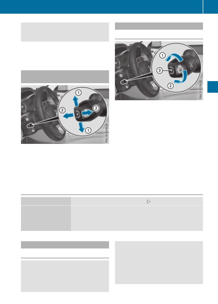
When leaving the vehicle, always take the
SmartKey with you and lock the vehicle. Never
leave children unsupervised in the vehicle.
The electrically adjustable steering wheel can
still be adjusted when there is no key in the igni-
tion lock.
Adjusts the steering wheel electri-
cally
:Adjusts the steering wheel height
;Adjusts the steering wheel position (fore-
and-aft adjustment)
iFurther related subjects:
REASY-ENTRY/EXIT feature (Ypage 101)
RStoring settings (Ypage 106)
Steering wheel heating
Switching on/off
XTurn the SmartKey to position 2in the igni-
tion lock (Ypage 123).
XTo switch on/off: turn the lever in the direc-
tion of arrow :or ;.
Indicator lamp =lights up or goes out.
If you switch off the ignition, the steering wheel
heating is deactivated.
Problems with the steering wheel heating
Problem Possible causes/consequences and MSolutions
The steering wheel heat-
ing has switched off pre-
maturely or cannot be
switched on.
The on-board voltage is too low because too many electrical consum-
ers are switched on.
XSwitch off electrical consumers that you do not need, such as the
rear window defroster or interior lighting.
EASY-ENTRY/EXIT feature
Important safety notes
GWARNING
When the EASY-ENTRY/EXIT feature adjusts
the steering wheel, you and other vehicle
occupants – particularly children – could
become trapped. There is a risk of injury.
While the EASY-ENTRY/EXIT feature is mak-
ing adjustments, make sure that no one has
any body parts in the sweep of the steering
wheel.
Move the steering wheel adjustment lever if
there is a risk of entrapment by the steering
wheel. The adjustment process is stopped.
Steering wheel 101
Seats, steering wheel and mirrors
Z

You can stop the adjustment process by press-
ing one of the memory function's position but-
tons. This function is only available on vehicles
with memory function.
GWARNING
If children activate the EASY-ENTRY/EXIT fea-
ture, they can become trapped, particularly
when unattended. There is a risk of injury.
When leaving the vehicle, always take the
SmartKey with you and lock the vehicle. Never
leave children unsupervised in the vehicle.
GWARNING
If you drive off while the EASY-ENTRY/EXIT
feature is making adjustments, you could lose
control of the vehicle. There is a risk of an
accident.
Always wait until the adjustment process is
complete before driving off.
The EASY-ENTRY/EXIT feature makes getting in
and out of your vehicle easier.
You can activate and deactivate the EASY-
ENTRY/EXIT feature using the multimedia sys-
tem (see the Digital Operator's Manual)
Position of the steering wheel when the
EASY-ENTRY/EXIT feature is active
The steering wheel swings up when you:
Rremove the SmartKey from the ignition lock
Rwith KEYLESS-GO or KEYLESS-GO start
function: open the driver's door; the voltage
supply must be switched on
Rwith the SmartKey: open the driver's door;
the SmartKey must be in position gor 1in
the ignition lock (Ypage 123)
Ropen the driver's door when the ignition is
switched off
iThe steering wheel only tilts up if the driving
position is stored after the steering column
adjustment has been adjusted (Ypage 106).
The most recent driving position of the steering
wheel is stored if:
Rthe ignition is switched off
Rthe setting is stored using the memory func-
tion (Ypage 106)
iThe steering wheel only moves up if it has
not already reached the upper steering lim-
iter.
Position of the steering wheel for driv-
ing
The steering wheel is moved to the last selected
position when:
Rthe driver's door is closed and you insert the
SmartKey into the ignition lock
Ryou close the driver's door when the ignition
is switched on
Ryou press the Start/Stop button once in vehi-
cles with KEYLESS-GO or the KEYLESS-GO
start function
iThe steering wheel only returns to the last
set position if the driving position is stored
after the seat or steering column has been
adjusted (Ypage 106).
The most recent driving position of the steering
wheel is stored if:
Rthe ignition is switched off
Rthe setting is stored using the memory func-
tion (Ypage 106)
Crash-responsive EASY-EXIT feature
If the crash-responsive EASY-EXIT feature is trig-
gered in an accident, the steering column will
move up when the driver's door is opened or the
SmartKey is removed from the ignition lock. This
makes it easier to exit the vehicle and rescue the
occupants.
The crash-responsive EASY-EXIT feature is
operational only if the EASY-EXIT/ENTRY fea-
ture is activated in the multimedia system (see
Digital Operator's Manual).
102 Steering wheel
Seats, steering wheel and mirrors
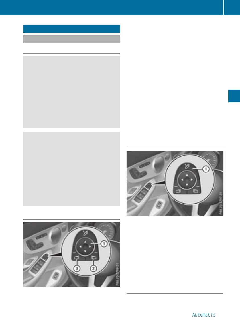
Mirrors
Exterior mirrors
Important safety notes
GWARNING
You could lose control of your vehicle if you do
the following while driving:
Radjust the driver's seat, head restraint,
steering wheel or mirrors
Rfasten the seat belt
There is a risk of an accident.
Adjust the driver's seat, head restraint, steer-
ing wheel and mirror and fasten your seat belt
before starting the engine.
GWARNING
The exterior mirror on the front-passenger
side reduces the size of the image. Visible
objects are actually closer than they appear.
This means that you could misjudge the dis-
tance from road users traveling behind, e.g.
when changing lane. There is a risk of an acci-
dent.
For this reason, always make sure of the
actual distance from the road users traveling
behind by glancing over your shoulder.
Adjusting the exterior mirrors
XTurn the SmartKey to position 1or 2in the
ignition lock (Ypage 123).
XExterior mirror on the front-passenger side:
press button ;.
Exterior mirror on the driver's side: press but-
ton =.
The indicator lamp lights up in the button that
has been pressed.
The indicator lamp goes out again after some
time. You can adjust the selected exterior
mirror using button :as long as the indicator
lamp is lit.
XPress button :up, down, or to the left or
right until you have adjusted the exterior mir-
ror to the correct position. You should have a
good overview of traffic conditions.
The convex exterior mirrors provide a larger field
of vision.
After the engine has been started, the exterior
mirrors are automatically heated if the rear win-
dow defroster is switched on and the outside
temperature is low.
Folding the exterior mirrors in or out
electrically
XTurn the SmartKey to position 1or 2in the
ignition lock (Ypage 123).
XBriefly press :.
Both exterior mirrors fold in or out.
iMake sure that the exterior mirrors are
always folded out fully while driving. They
could otherwise vibrate.
iIf you are driving faster than 30 mph
(47 km/h), you can no longer fold in the exte-
rior mirrors.
Resetting the exterior mirrors
If the battery has been disconnected or com-
pletely discharged, the exterior mirrors must be
reset. The exterior mirrors will otherwise not
fold in if you have activated the Automatic
Mirrors 103
Seats, steering wheel and mirrors
Z
Mirror Folding function in the multimedia
system.
XTurn the SmartKey to position 1or 2in the
ignition lock (Ypage 123).
XBriefly press :.
Folding the exterior mirrors in or out
automatically
When the Automatic Mirror Folding func-
tion is activated in the multimedia system (see
Digital Operator's Manual):
Rthe exterior mirrors fold in automatically as
soon as you lock the vehicle from the outside.
Rthe exterior mirrors fold out again automati-
cally as soon as you unlock the vehicle.
iIf the exterior mirrors have been folded in
manually, they do not fold out.
Exterior mirror pushed out of position
If an exterior mirror has been pushed out of
position, proceed as follows:
XVehicles without electrically folding exte-
rior mirrors: manually move the exterior mir-
ror into the correct position.
XVehicles with electrically folding exterior
mirrors: press and hold button :until you
hear a click and then the mirror engaging in
position (Ypage 103).
The mirror housing is engaged again and you
can adjust the exterior mirrors as usual
(Ypage 103).
Automatic anti-glare mirrors
GWARNING
Electrolyte may escape if the glass in an auto-
matic anti-glare mirror breaks. The electrolyte
is harmful and causes irritation. It must not
come into contact with your skin, eyes, res-
piratory organs or clothing or be swallowed.
There is a risk of injury.
If you come into contact with the electrolyte,
observe the following:
RRinse off the electrolyte from your skin
immediately with water.
RImmediately rinse the electrolyte out of
your eyes thoroughly with clean water.
RIf the electrolyte is swallowed, immediately
rinse your mouth out thoroughly. Do not
induce vomiting.
RIf electrolyte comes into contact with your
skin or hair or is swallowed, seek medical
attention immediately.
RImmediately change out of clothing which
has come into contact with electrolyte.
RIf an allergic reaction occurs, seek medical
attention immediately.
The exterior mirror on the driver's side and the
rear-view mirror automatically go into anti-glare
mode if:
Rthe ignition is switched on
Rincident light from headlamps strikes the sen-
sor in the rear-view mirror
The mirrors do not go into anti-glare mode if
reverse gear is engaged or if the interior lighting
is switched on.
Parking position for the exterior mir-
ror on the front-passenger side
Storing the parking position
You can set the front-passenger side exterior
mirror such that you can see the rear wheel on
that side as soon as you engage reverse gear.
You can store this position.
104 Mirrors
Seats, steering wheel and mirrors
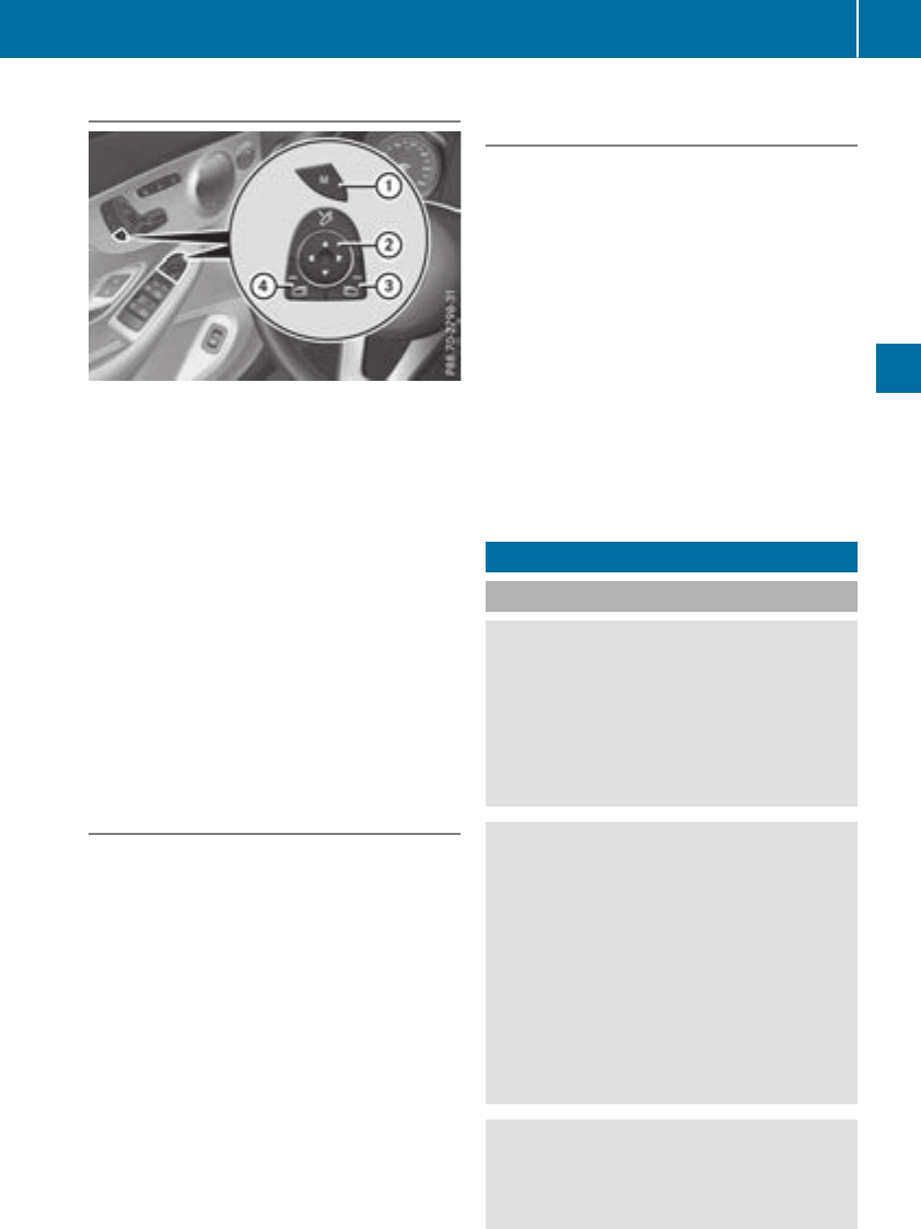
Storing using reverse gear
:Memory button M
;Button for the exterior mirror setting
=Button for the front-passenger side exterior
mirror
?Button for the driver's side exterior mirror
XStart the engine.
XPress button =.
XEngage reverse gear.
The exterior mirror on the front-passenger
side moves to the preset parking position.
XUse button ;to adjust the exterior mirror to
a position that allows you to see the rear
wheel and the curb.
The parking position is stored.
iIf you shift the transmission to another posi-
tion, the exterior mirror on the front-
passenger side returns to the driving position.
Saving using the memory button
You can store the parking position of the exte-
rior mirror on the front-passenger side using
memory button M:. The reverse gear must not
be engaged.
XTurn the SmartKey to position 2in the igni-
tion lock (Ypage 123).
XPress button =.
XUse button ;to adjust the exterior mirror to
a position that allows you to see the rear
wheel and the curb.
XPress memory button M:and one of the
arrows on button ;within three seconds.
The parking position is stored if the exterior
mirror does not move.
XIf the mirror moves out of position, repeat the
steps.
XAfter successfully storing, reset the driving
position of the exterior mirror.
Calling up a stored parking position set-
ting
XTurn the SmartKey to position 2in the igni-
tion lock (Ypage 123).
XAdjust the exterior mirror on the front-
passenger side using button =.
XEngage reverse gear.
The exterior mirror on the front-passenger
side moves to the stored parking position.
The exterior mirror on the front-passenger side
moves back to its original position:
Ras soon as you exceed a speed of 9 mph
(15 km/h)
Rabout ten seconds after you have disengaged
reverse gear
Rwhen you use button ?to select the exterior
mirror on the driver's side
Memory function
Important safety notes
GWARNING
If you use the memory function on the driver's
side while driving, you could lose control of
the vehicle as a result of the adjustments
being made. There is a risk of an accident.
Only use the memory function on the driver's
side when the vehicle is stationary.
GWARNING
When the memory function adjusts the seat or
steering wheel, you and other vehicle occu-
pants – particularly children – could become
trapped. There is a risk of injury.
While the memory function is making adjust-
ments, make sure that no one has any body
parts in the sweep of the seat or steering
wheel. If somebody becomes trapped, imme-
diately release the memory function position
button. The adjustment process is stopped.
GWARNING
Children could become trapped if they acti-
vate the memory function, particularly when
unattended. There is a risk of injury.
Memory function 105
Seats, steering wheel and mirrors
Z
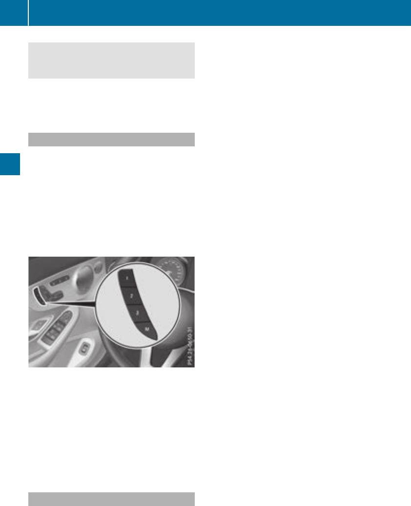
When leaving the vehicle, always take the
SmartKey with you and lock the vehicle. Never
leave children unsupervised in the vehicle.
The memory function can be used at any time,
e.g. even when the SmartKey is not in the igni-
tion lock.
Storing settings
With the memory function, you can store up to
three different settings, e.g. for three different
people.
The following settings are stored as a single
memory preset:
Rposition of the seat, backrest and head
restraint
Rdriver's side: position of the exterior mirrors
on the driver's and front-passenger sides
Rposition of the head-up display
XAdjust the seat accordingly (Ypage 96).
XOn the driver's side, adjust the steering wheel
(Ypage 101) and the exterior mirrors
(Ypage 103).
XPress memory button Mand then press one of
the memory position buttons 1,2or 3within
three seconds.
The settings are stored in the selected preset
position. A tone sounds when the settings
have been completed.
Calling up a stored setting
XPress and hold the relevant memory position
button 1,2or 3until the following compo-
nents are in the saved position:
RSeat
RSteering wheel
RExterior mirrors
iIf you release the memory position switch,
the seat, steering wheel and mirror setting
functions stop immediately. The head-up dis-
play continues to be adjusted.
106 Memory function
Seats, steering wheel and mirrors
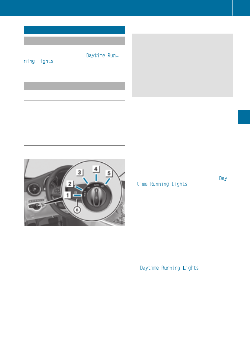
Exterior lighting
General notes
USA only: if you wish to drive during the daytime
without lights, switch off the Daytime Run‐
ning Lights function via the on-board com-
puter (Ypage 207).
Setting the exterior lighting
Setting options
Exterior lighting can be set using the:
Rlight switch (Ypage 107)
Rcombination switch (Ypage 108)
Ron-board computer (Ypage 207)
Light switch
Operation
1WLeft-hand standing lamps
2XRight-hand standing lamps
3TParking lamps, license plate and
instrument cluster lighting
4ÃAutomatic headlamp mode, controlled
by the light sensor
5LLow-beam/high-beam headlamps
BRRear fog lamp
If you hear a warning tone when you leave the
vehicle, the lights may still be switched on.
XTurn the light switch to the Ãposition.
The exterior lighting (except the parking/stand-
ing lamps) switches off automatically if you:
Rremove the SmartKey from the ignition lock
Ropen the driver's door with the SmartKey in
position u
Automatic headlamp mode
GWARNING
When the light switch is set to Ã, the low-
beam headlamps may not be switched on
automatically if there is fog, snow or other
causes of poor visibility due to the weather
conditions such as spray. There is a risk of an
accident.
In such situations, turn the light switch to
L.
The automatic headlamp feature is only an aid.
The driver is responsible for the vehicle's light-
ing at all times.
Ãis the favored light switch setting.
The light setting is automatically selected
according to the brightness of the ambient light,
but not in the event of poor visibility due to
weather conditions such as fog, snow or spray.
RWith the SmartKey in position 1in the igni-
tion lock, the parking lamps are switched on
or off automatically depending on the bright-
ness of the ambient light.
RUSA only: if you have switched on the Day‐
time Running Lights function via the on-
board computer, and the engine is running,
the daytime running lamps or the parking
lamps and low-beam headlamps are switched
on or off automatically depending on the
ambient light.
RCanada only: depending on the ambient light,
the daytime running lamps or the parking and
low-beam headlamps are switched on/off
automatically when the engine is running.
XTo switch on the automatic headlamps:
turn the light switch to the Ãposition.
USA only: The daytime running lamps improve
the visibility of your vehicle during the day. Here,
the Daytime Running Lights function must
be switched on via the on-board computer
(Ypage 207).
If the engine is running and you turn the light
switch to the Tor Lposition, the manual
settings take precedence over the daytime run-
ning lamps.
Canada only: The daytime running lamps
improve the visibility of your vehicle during the
day. The daytime running lamps function is
required by law in Canada. It cannot therefore
be deactivated.
Exterior lighting 107
Lights and windshield wipers
Z
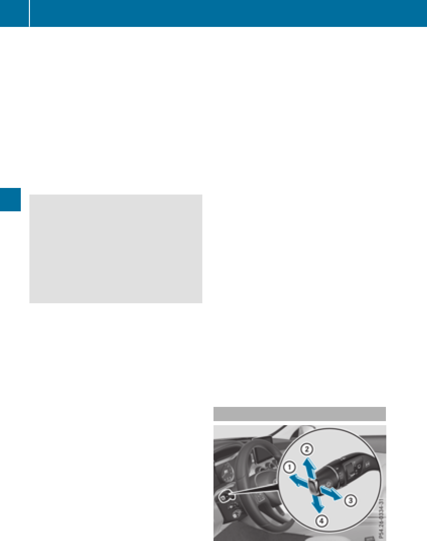
When the engine is running and the vehicle is
stationary: if you move the selector lever from a
driving position to P, the daytime running lamps
and low-beam headlamps go out after three
minutes.
When the engine is running, the vehicle is sta-
tionary and in bright ambient light: if you turn the
light switch to the Tposition, the daytime
running lamps and parking lamps switch on.
If the engine is running and you turn the light
switch to the Lposition, the manual settings
take precedence over the daytime running
lamps.
Low-beam headlamps
GWARNING
When the light switch is set to Ã, the low-
beam headlamps may not be switched on
automatically if there is fog, snow or other
causes of poor visibility due to the weather
conditions such as spray. There is a risk of an
accident.
In such situations, turn the light switch to
L.
Even if the light sensor does not detect that it is
dark, the parking lamps and low-beam head-
lamps switch on when the ignition is switched on
and the light switch is set to the Lposition.
This is a particularly useful function in the event
of rain and fog.
XTo switch on the low-beam headlamps:
turn the SmartKey to position 2in the igni-
tion lock or start the engine.
XTurn the light switch to the Lposition.
The green Lindicator lamp in the instru-
ment cluster lights up.
Rear fog lamp
The rear fog lamp improves visibility of your
vehicle for the traffic behind in the event of thick
fog. You must observe the legal requirements
for the country in which you are currently driving
when operating the rear fog lamp.
XTo switch on the rear fog lamp: turn the
SmartKey in the ignition lock to position 2or
start the engine.
XTurn the light switch to the Lor Ã
position.
XPress the Rbutton.
The yellow Rindicator lamp on the instru-
ment cluster lights up.
Parking lamps
!If the battery charge is very low, the parking
lamps or standing lamps are automatically
switched off to enable the next engine start.
Always park your vehicle safely and in a well lit
area, in accordance with the relevant legal
stipulations. Avoid using the Tparking
lamps over a period of several hours. If pos-
sible, switch on the right-hand Xor left-
hand Wstanding lamps.
XTo switch on the parking lamps: turn the
light switch to the Tposition.
The green Tindicator lamp on the instru-
ment cluster lights up.
Standing lamps
Switching on the standing lamps ensures the
corresponding side of the vehicle is illuminated.
XTo switch on the standing lamps: turn the
SmartKey to position uin the ignition lock or
remove the SmartKey.
XTurn the light switch to the W(left-hand
side of the vehicle) or X(right-hand side of
the vehicle) position.
Combination switch
:High-beam headlamps
;Turn signal, right
108 Exterior lighting
Lights and windshield wipers
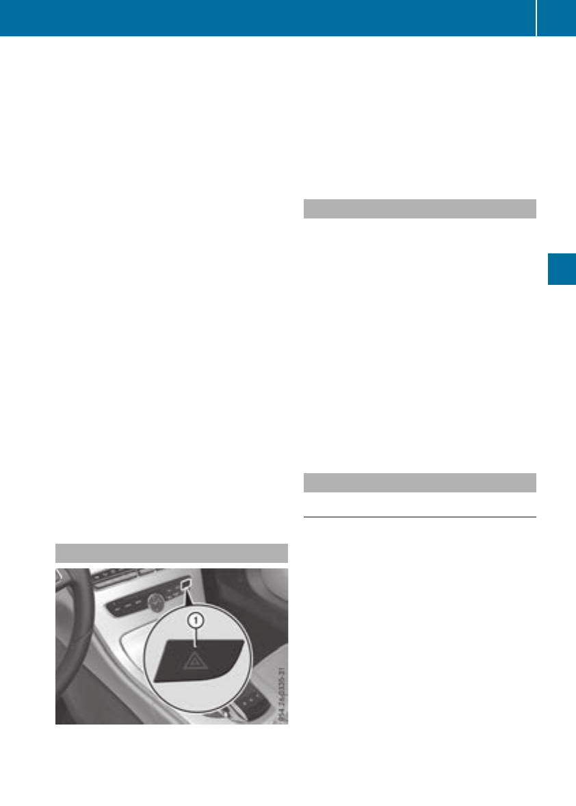
=High-beam flasher
?Turn signal, left
XTo indicate briefly: press the combination
switch briefly to the pressure point in the
direction of arrow ;or ?.
The corresponding turn signal flashes three
times.
XTo indicate: press the combination switch
beyond the pressure point in the direction of
arrow ;or ?.
XTo switch on the high-beam headlamps:
turn the light switch to the Lor Ã
position.
XPress the combination switch beyond the
pressure point in the direction of arrow :.
In the Ãposition, the high-beam head-
lamps are switched on only when it is dark and
the engine is running.
The blue Kindicator lamp on the instru-
ment cluster lights up when the high-beam
headlamps are switched on.
XTo switch off the high-beam headlamps:
move the combination switch back to its nor-
mal position.
The blue Kindicator lamp on the instru-
ment cluster goes out.
Vehicles with Adaptive Highbeam Assist:
If Adaptive Highbeam Assist is active, it auto-
matically controls activation and deactivation of
the high-beam headlamps (Ypage 109).
XHigh-beam flasher: pull the combination
switch in the direction of arrow =.
Hazard warning lamps
XTo switch the hazard warning lamps on or
off: press button :.
The turn signal lamps flash when the hazard
warning lamps are switched on. If you now
switch on a turn signal lamp using the com-
bination switch, only the turn signal lamp on
the corresponding side of the vehicle will
flash.
The hazard warning lamps switch on automati-
cally if an air bag is deployed.
The hazard warning lamps still operate if the
ignition is switched off.
Cornering light function
The cornering light function improves the illu-
mination of the road over a wide angle in the
direction you are turning, enabling better visi-
bility in tight bends, for example. It can only be
activated when the low-beam headlamps are
switched on.
Active:
Rif you are driving at speeds below 25 mph
(40 km/h) and switch on the turn signal or
turn the steering wheel
Rif you are driving at speeds between 25 mph
(40 km/h) and 45 mph (70 km/h) and turn
the steering wheel
The cornering lamp may remain lit for a short
time, but is automatically switched off after no
more than three minutes.
Adaptive Highbeam Assist
General notes
You can use this function to set the headlamps
to change between low beam and high beam
automatically. The system recognizes vehicles
with their lights on, either approaching from the
opposite direction or traveling in front of your
vehicle, and consequently switches the head-
lamps from high beam to low beam.
The system automatically adapts the low-beam
headlamp range depending on the distance to
the other vehicle. Once the system no longer
detects any other vehicles, it reactivates the
high-beam headlamps.
The system's optical sensor is located behind
the windshield near the overhead control panel.
Exterior lighting 109
Lights and windshield wipers
Z
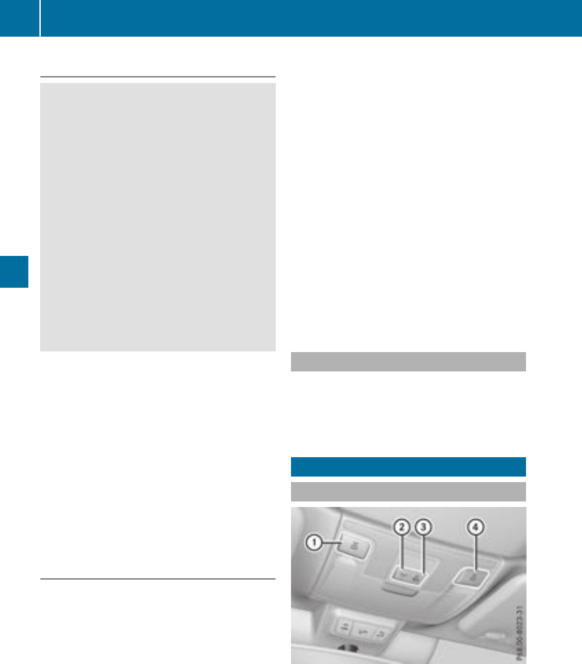
Important safety notes
GWARNING
Adaptive Highbeam Assist does notrecognize
road users:
Rwho have no lights,e.g. pedestrians
Rwho havepoor lighting,e.g. cyclists
Rwhoselighting is blocked, e.g. by abarrier
On veryrareoccasions, Adaptive Highbeam
Assist may fail to recognize other road users
that have lights,or may recognize them too
late. In this, or in similar situations, theauto-
matic high-beam headlamps will notbe deac-
tivated or will be activated regardless.Thereis
ariskof an accident.
Always carefully observethetraffic conditions
and switch off thehigh-beam headlamps in
goodtime.
Adaptive Highbeam Assist cannottakeinto
accountroad,weather or traffic conditions.
Adaptive Highbeam Assist is only an aid. You are
responsible for adjusting thevehicle's lighting
to theprevailing light, visibilityand traffic con-
ditions.
In particular, thedetection of obstacles can be
impaired if:
Rthere is poor visibility, e.g. due to fog,heavy
rain or snow
Rthere is dirt on thesensorsor anythingelse
covering thesensors
Switching Adaptive Highbeam Assist
on/off
XTo switch on: turnthelightswitch to the
Ãposition.
XPress thecombination switch forwards
beyondthepressurepoint (Ypage 108).
The _indicator lamp on themultifunction
display lights up when it is dark and thelight
sensor switches on thelow-beam headlamps.
If you are driving at speeds aboveapprox-
imately 16 mph (25 km/h):
The headlamp range is set automatically
depending on the distance between the vehi-
cle and other road users.
If you are driving at speeds above approx-
imately 19 mph (30 km/h) and no other road
users are detected:
The high-beam headlamps are switched on
automatically. The Kindicator lamp on the
instrument cluster also lights up.
If you are driving at speeds below approx-
imately 16 mph (25 km/h) or other road users
are detected or the roads are adequately lit:
The high-beam headlamps are switched off
automatically. The Kindicator lamp on the
instrument cluster goes out. The _indi-
cator lamp on the multifunction display
remains lit.
XTo switch off: move the combination switch
back to its normal position or move the light
switch to another position.
The Kindicator lamp on the instrument
cluster goes out.
Headlamps fogged up on the inside
Certain climatic and physical conditions may
cause moisture to form in the headlamp. This
moisture does not affect the functionality of the
headlamp.
Interior lighting
Overview of interior lighting
:pLeft-hand front reading lamp
;cFront interior lighting
=|Automatic interior lighting control
?pRight-hand front reading lamp
110 Interior lighting
Lights and windshield wipers
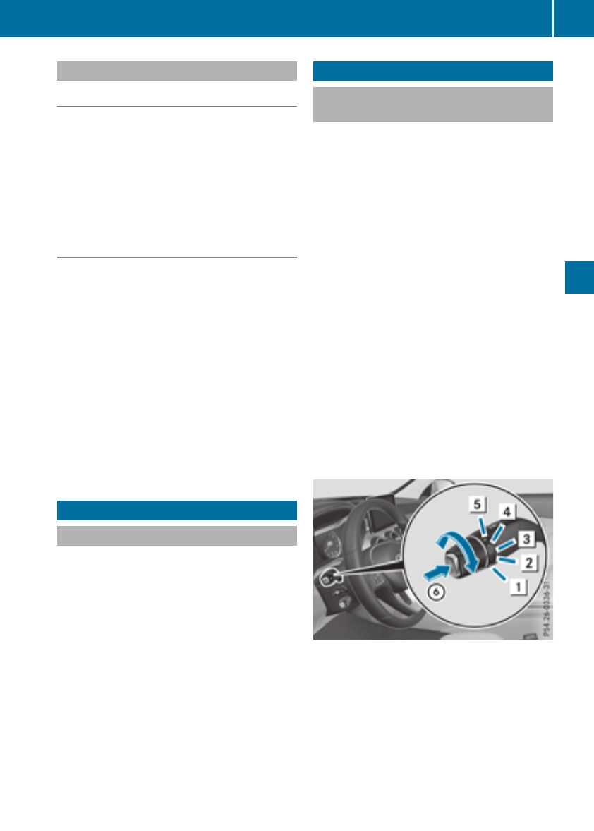
Interior lighting control
General notes
In order to preventthevehicle's battery from
discharging,theinteriorlighting functionsare
automatically deactivated after sometime
except for when theSmartKey is in position 2
in theignition lock.
The color and brightness of theambientlighting
are set usingthemultimedia system (see Digital
Operator's Manual).
Automatic interior lighting control
XTo switch on or off:press the|button.
When theautomatic interiorlighting control is
activated, thebuttonis flushwiththeover-
head control panel.
The interiorlighting automatically switches on if
you:
Runlock thevehicle
Ropen adoor
Rremove theSmartKey from theignition lock
The interiorlighting is switched on for aset time
when theSmartKey is removedfrom theignition
lock. This delayedswitch-off can be adjusted via
themultimedia system (see Digital Operator's
Manual).
Replacing bulbs
General notes
The frontand rear lightclusters of your vehicle
are equipped withLEDlightbulbs.Do not
replace theLEDlightsourcesof your vehicle
yourself.Contact a qualified specialist work-
shopwhichhas thenecessaryspecialist knowl-
edge and tools to carry out theworkrequired.
Lamps are an important aspect of vehiclesafety.
You must thereforemakesurethat these func-
tion correctlyat all times.Havetheheadlamp
setting checkedregularly.
Windshield wipers
Switching the windshield wipers
on/off
!Do notoperate thewindshield wiperswhen
thewindshield is dry, as this could damage
thewiper blades. Moreover, dust that has col-
lectedon thewindshield can scratch theglass
if wipingtakes placewhen thewindshield is
dry.
If it is necessaryto switch on thewindshield
wipersin dry weather conditions, always use
washerfluid when operating thewindshield
wipers.
!If thewindshield wipersleavesmears on the
windshield after thevehiclehas been washed
in an automatic car wash, wax or other resi-
dues may be thereason for this. Clean the
windshield usingwasherfluid after washing
thevehiclein an automatic car wash.
!Intermittent wipingwithrain sensor:due to
optical influencesand thewindshield becom-
ing dirtyin dry weather conditions, thewind-
shield wipersmay be activated inadvertently.
This could then damagethewindshield wiper
bladesor scratch thewindshield.
Forthis reason,you should always switch off
thewindshield wipersin dry weather.
1$Windshield wiper off
2ÄIntermittent wipe, normal
3ÅIntermittent wipe, frequent
4°Continuous wipe, slow
5¯Continuous wipe, fast
BíSingle wipe
îWipe withwasherfluid
XSwitchon theignition.
XTurn thecombination switch to thecorre-
sponding position.
Windshield wipers 111
Lights and windshield wipers
Z
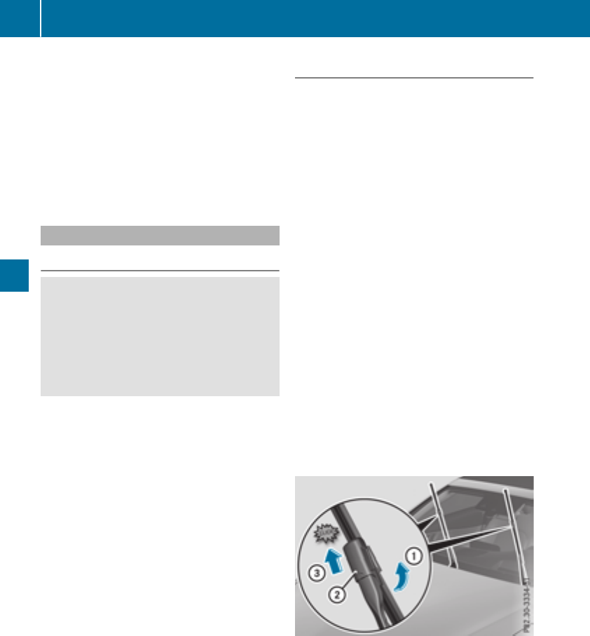
Vehicles with a rain sensor: in the Åor
Äposition, the appropriate wipe frequency
is automatically set according to the intensity of
the rain. In the Åposition, the rain sensor is
more sensitive than in the Äposition, caus-
ing the windshield wiper to wipe more fre-
quently.
If the wiper blades are worn, the windshield will
no longer be wiped properly. This could prevent
you from observing the traffic conditions.
Replacing the wiper blades
Important safety notes
GWARNING
If the windshield wipers begin to move while
you are changing the wiper blades, you could
be trapped by the wiper arm. There is a risk of
injury.
Always switch off the windshield wipers and
ignition before changing the wiper blades.
!Never open the hood if a windshield wiper
arm has been folded away from the wind-
shield.
Never fold a windshield wiper arm without a
wiper blade back onto the windshield.
Hold the windshield wiper arm firmly when
you change the wiper blade. If you release the
windshield wiper arm without a wiper blade
and it falls onto the windshield, the windshield
may be damaged by the force of the impact.
Mercedes-Benz recommends that you have
the wiper blades changed at a qualified spe-
cialist workshop.
!To avoid damaging the wiper blades, make
sure that you touch only the wiper arm of the
wiper.
Changing the windshield wiper blades
Moving the wiper arms to a vertical posi-
tion
On vehicles without KEYLESS-GO or KEY-
LESS‑GO start function:
XTurn the SmartKey to position 1or 2in the
ignition lock (Ypage 123).
XSet the windshield wipers to the °posi-
tion on the combination switch.
XWhen the wiper arms are vertical to the hood,
turn the SmartKey to position uin the igni-
tion lock and remove SmartKey.
XFold the wiper arm away from the windshield.
On vehicles with KEYLESS-GO or KEY-
LESS‑GO start function:
XSwitch off the engine.
XRemove your foot from the brake pedal.
XSet the windshield wiper to the °position
on the combination switch.
XPress the Start/Stop button repeatedly until
the windshield wiper starts.
XWhen the wiper arms are vertical to the hood,
press the Start/Stop button.
XFold the wiper arm away from the windshield.
Removing the wiper blades
XHold on to the wiper arm with one hand. With
the other hand, turn the wiper blade in the
direction of arrow :away from the wiper arm
as far as it will go.
XSlide the catch ;in the direction of arrow =
until it engages in the removal position with a
noticeable click.
112 Windshield wipers
Lights and windshield wipers
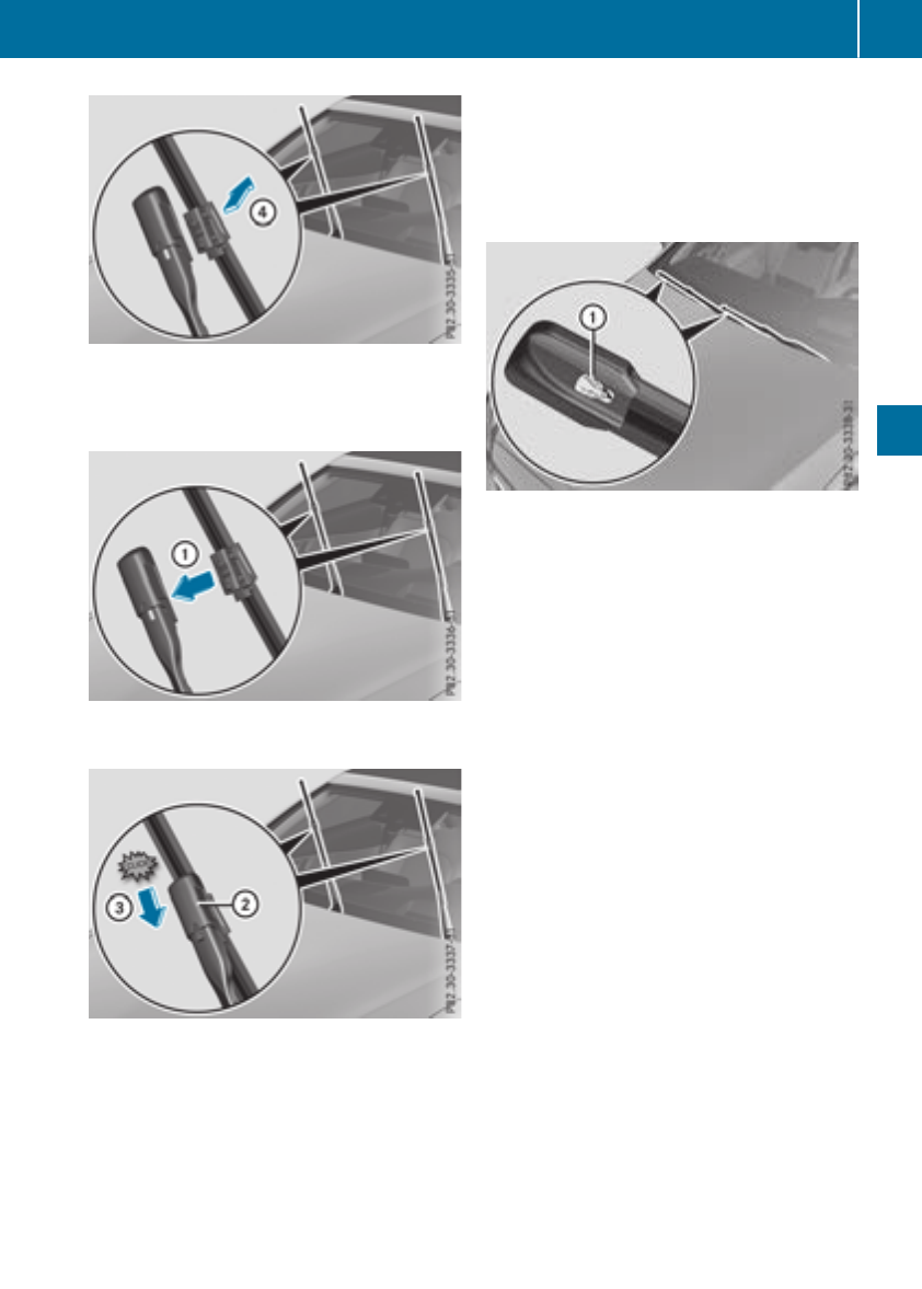
XRemove thewiper blade in thedirection of
arrow ?away from thewiper arm.
Installing thewiper blades
XInsertthenewwiper blade intothewiper arm
in thedirection of arrow :.
XSlide thecatch ;in thedirection of arrow =
until it engagesin thelockingposition with a
noticeable click.
XMakesurethat thewiper blade is seated cor-
rectly.
XFold thewiper arm backonto thewindshield.
XRemove theprotective film :from theser-
viceindicator on thetipof thewiper blade.
If thecolor of theserviceindicator changes from
blackto yellow,thewiper bladesshould be
replaced.
iThe duration of thecolor changevaries
depending on theusage conditions.
Windshield wipers 113
Lights and windshield wipers
Z

Problems with the windshield wipers
Problem Possible causes/consequences and MSolutions
The windshield wipers
are jammed.
Leaves or snow, for example, are obstructing windshield wiper move-
ment. The wiper motor has been deactivated.
XSwitch off the engine.
XRemove the SmartKey from the ignition lock.
or, on vehicles with KEYLESS-GO or KEYLESS‑GO start function:
XOpen the driver's door.
The vehicle electronics are now in position u. This means: "Key
removed".
XRemove the cause of the obstruction.
XSwitch the windshield wipers back on.
The windshield wipers
fail completely.
The windshield wiper drive is malfunctioning.
XSelect another wiper speed on the combination switch.
XHave the windshield wipers checked at a qualified specialist work-
shop.
The windshield washer
fluid from the spray noz-
zles no longer hits the
center of the windshield.
The spray nozzles are misaligned.
XHave the spray nozzles adjusted at a qualified specialist workshop.
114 Windshield wipers
Lights and windshield wipers
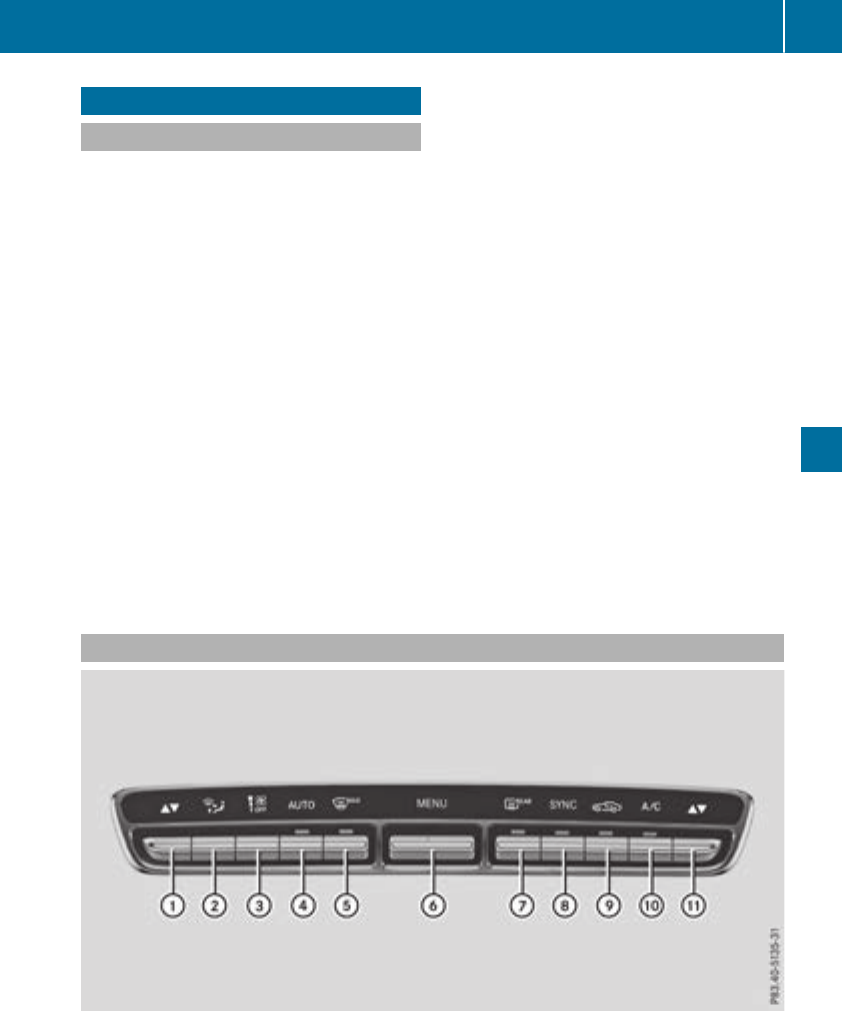
Overview of climate control systems
General notes
Observe the settings recommended on the fol-
lowing pages. The windows could otherwise fog
up.
To prevent the windows from fogging up:
Rswitch off climate control only briefly
Rswitch on air-recirculation mode only briefly
Rswitch on the cooling with air dehumidifica-
tion function
Ractivate the "Windshield defrosting" function
briefly, if required
Climate control regulates the temperature and
air humidity in the vehicle interior. The interior
filter cleans the air, thus improving the interior
climate.
The "Cooling with air dehumidification" function
is only available when the engine is running.
Optimum climate control is only achieved with
the side windows and roof closed.
If you start the engine using your smartphone,
the last selected climate control setting is reac-
tivated (Ypage 126).
The integrated filter filters out most particles of
dust and soot and completely filters out pollen.
It also reduces gaseous pollutants and odors. A
clogged filter reduces the amount of air supplied
to the vehicle interior. For this reason, you
should always observe the interval for replacing
the filter, which is specified in the Maintenance
Booklet. As it depends on environmental condi-
tions, e.g. heavy air pollution, the interval may
be shorter than stated in the Maintenance Book-
let.
iVentilate the vehicle for a brief period during
warm weather, e.g. using the convenience
opening feature (Ypage 90). This will speed
up the cooling process and the desired inte-
rior temperature will be reached more
quickly.
iIt is possible that the blower may be activa-
ted automatically 60 minutes after the Smart-
Key has been removed depending on various
factors, e.g. the outside temperature. The
vehicle is then ventilated for 30 minutes to dry
the automatic climate control.
Control panel for dual-zone automatic climate control
Example: control panel for dual-zone automatic climate control
:Sets the temperature, left (Ypage 118)
;Sets the air distribution (Ypage 118)
=Sets the airflow (Ypage 118)
Switches off climate control (Ypage 116)
Overview of climate control systems 115
Climate control

?Sets climate control to automatic (Ypage 117)
ADefrosts the windshield (Ypage 118)
BCalls up the climate control menu of the multimedia system (Ypage 258)
CSwitches the rear window defroster on/off (Ypage 119)
DActivates or deactivates synchronization (Ypage 118)
ESwitches air-recirculation mode manually on/off (Ypage 120)
FSwitches cooling with air dehumidification on/off (Ypage 117)
GSets the temperature, right (Ypage 118)
Optimum use of automatic climate
control
Optimum use of the automatic climate
control
The following contains notes and recommenda-
tions on optimum use of dual-zone automatic
climate control.
XActivate climate control using the Ã
rocker switch. The indicator lamp above the
Ãrocker switch lights up. The "Cooling
with dehumidification" function is activated in
automatic mode.
XSet the temperature to 72 ‡ (22 †).
iOnly use the "Windshield defrosting" func-
tion briefly until the windshield is clear again.
iOnly use air-recirculation mode briefly, e.g.
if there are unpleasant outside odors or when
in a tunnel. The windows could otherwise fog
up, since no fresh air is drawn into the vehicle
in air-recirculation mode.
DYNAMIC SELECT switch (except
Mercedes-AMG C 63 /C 63 S)
You can choose between various drive programs
with the DYNAMIC SELECT switch
(Ypage 130).
If you have selected drive program E:
Rwhen heating, the electrical heater booster is
deactivated and heat output is reduced as a
result
Rthe rear window defroster running time is
reduced
If you have selected drive program C,Sor S+,
the current climate settings are maintained.
ECO start/stop function
During automatic engine switch-off, the climate
control system only operates at a reduced capa-
city. If you require the full climate control output,
you can switch off the ECO start/stop function
by pressing the ECO button (Ypage 128).
Operating the climate control sys-
tems
Activating/deactivating climate con-
trol
General notes
When the climate control is switched off, the air
supply and air circulation are also switched off.
The windows could fog up. Therefore, switch off
climate control only briefly
Switch on climate control primarily using the
Ãrocker switch (Ypage 117).
Activating/deactivating
XTurn the SmartKey to position 2in the igni-
tion lock (Ypage 123).
XTo switch on: set the airflow to level 1or
higher using the Hrocker switch.
XTo switch off: set the airflow to level 0using
the Hrocker switch.
116 Operating the climate control systems
Climate control

Switching cooling with air dehumidification on/off
General notes
If you deactivate the "Cooling with air-dehumidification" function, the air inside the vehicle will not
be cooled. The air inside the vehicle will also not be dehumidified. The windows can fog up more
quickly. Therefore, only deactivate the "Cooling with air-dehumidification" function briefly.
The "Cooling with air dehumidification" function is only available when the engine is running. The air
inside the vehicle is cooled and dehumidified according to the temperature selected.
Condensation may drip from the underside of the vehicle when it is in cooling mode. This is normal
and not a sign that there is a malfunction.
Activating/deactivating
XPress the ¿rocker switch up or down.
The indicator lamp above the rocker switch lights up or goes out.
Problems with the "Cooling with air dehumidification" function
Problem Possible causes/consequences and MSolutions
The indicator lamp above
the ¿rocker switch
remains off. The cooling
with air dehumidification
function cannot be acti-
vated via the multimedia
system any longer
(Ypage 258).
Cooling with air dehumidification has been deactivated due to a mal-
function.
XVisit a qualified specialist workshop.
Setting climate control to automatic
General notes
In automatic mode, the set temperature is main-
tained automatically at a constant level. The
system automatically regulates the temperature
of the dispensed air, the airflow and the air dis-
tribution.
During automatic controlling, the "Cooling with
air dehumidification" function is activated.
The system automatically detects whether the
soft top is open or closed and automatically
adjusts the air settings depending on the soft
top status.
Automatic control
XTurn the SmartKey to position 2in the igni-
tion lock (Ypage 123).
XTo activate: press the Ãrocker switch up
or down.
The indicator lamp above the Ãrocker
switch lights up.
XSet the desired temperature using the w
rocker switch on the front control unit.
XTo switch to manual operation: press the
Hrocker switch up or down.
or
XPress the _rocker switch up or down.
The indicator lamp above the Ãrocker
switch goes out.
In automatic mode, if you adjust the airflow or
air distribution manually, the indicator lamp
above the Ãrocker switch goes out. The
function which has not been changed manually,
however, continues to be controlled automati-
cally. When the manually set function switches
Operating the climate control systems 117
Climate control

back to automatic mode, the indicator lamp
above the Ãrocker switch lights up again.
Setting the temperature
Dual-zone automatic climate control: different
temperatures can be set for the driver's and
front-passenger sides.
XTurn the SmartKey to position 2in the igni-
tion lock (Ypage 123).
XTo increase or reduce: press the w
rocker switch up or down.
Only change the temperature setting in small
increments. Start at 72 ‡ (22 †).
Setting the air distribution
Air distribution settings
¯Directs air through the defroster vents
PDirects air through the center and side air
vents
ODirects air through the footwell air vents
SDirects air through the center, side and
footwell vents
aDirects air through the defroster and
footwell vents
_Directs air through the defroster, center,
side and footwell vents
bDirects air through the defroster, center
and side air vents
WSets the air distribution to automatic
Setting
XTurn the SmartKey to position 2
(Ypage 123).
XPress the _rocker switch up or down.
The various air distribution settings appear in
the multimedia system.
Setting the airflow
XTurn the SmartKey to position 2in the igni-
tion lock (Ypage 123).
XTo increase or reduce: press the H
rocker switch up or down.
Activating or deactivating the syn-
chronization function
General notes
Climate control can be set centrally using the
synchronization function. The temperature set-
ting is adopted for the front-passenger side.
Activating/deactivating
XPress the 0rocker switch up or down.
The indicator lamp above the 0rocker
switch lights up or goes out.
or
XActivate or deactivate the "Synchronization"
function using the multimedia system
(Ypage 118).
The synchronization function deactivates if the
settings for the front-passenger side are
changed.
Defrosting the windshield
General notes
You can use this function to defrost the wind-
shield or to clear a fogged up windshield or front
side windows on the inside.
Switch off the "Windshield defrosting" function
as soon as the windshield is clear again.
Switching the "Windshield defrosting"
function on or off
XTurn the SmartKey to position 2in the igni-
tion lock (Ypage 123).
XTo switch on: press rocker switch ¬on
the front control unit up or down.
The indicator lamp above the ¬rocker
switch lights up. The current climate control
settings are deactivated.
The climate control system switches to the
following functions:
Rhigh airflow
Rhigh temperature
Rair distribution to the windshield and front
side windows
Rair-recirculation mode off
iIf necessary, the "Cooling with air dehumid-
ification" function is activated. In this case,
118 Operating the climate control systems
Climate control

the indicator lamp above the ¿rocker
switch remains switched off.
XTo switch off: press rocker switch ¬up or
down.
The indicator lamp above the ¬rocker
switch goes out. The previously selected set-
tings are restored. Air-recirculation mode
remains deactivated.
Defrosting the windows
Windows fogged up on the inside
XActivate the "Cooling with air dehumidifica-
tion" function with the ¿rocker switch.
XSwitch on automatic mode using the Ã
rocker switch.
XIf the windows continue to fog up, activate the
"Windshield defrosting" function using the
¬rocker switch.
iYou should only select this setting until the
windshield is clear again.
Windows fogged up on the outside
XActivate the windshield wipers.
XSwitch on automatic mode using the Ã
rocker switch.
iIf you clean the windows regularly, they do
not fog up so quickly.
Rear window defroster
General notes
The rear window defroster has a high current
draw. You should therefore switch it off as soon
as the rear window is clear. Otherwise, the rear
window defroster switches off automatically
after several minutes.
If the battery voltage is too low, the rear window
defroster may switch off.
Activating/deactivating
XTurn the SmartKey to position 2in the igni-
tion lock (Ypage 123).
XPress rocker switch ¤up or down.
The indicator lamp above rocker switch ¤
lights up or goes out.
Problems with the rear window defroster
Problem Possible causes/consequences and MSolutions
The rear window
defroster has deactiva-
ted prematurely or can-
not be activated.
The battery has not been sufficiently charged.
XSwitch off any consumers that are not required, e.g. reading lamps,
interior lighting or the seat heating.
When the battery is sufficiently charged, the rear window defroster
can be activated again.
Switching air-recirculation mode
on/off
General notes
You can also temporarily deactivate the flow of
fresh air manually if unpleasant odors are enter-
ing the vehicle from outside. The air already
inside the vehicle will then be recirculated.
If you switch on air-recirculation mode, the win-
dows can fog up more quickly, in particular at
low temperatures. Only use air-recirculation
mode briefly to prevent the windows from fog-
ging up.
Operating the climate control systems 119
Climate control
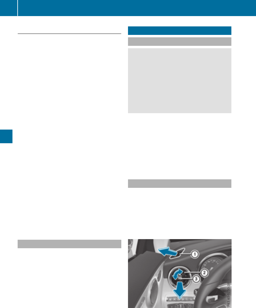
Activating/deactivating
XTurn theSmartKey to position 2in theigni-
tion lock (Ypage 123).
XTo activate: press thegrockerswitch up
or down.
The indicator lamp abovethegrocker
switch lights up.
Air-recirculation modeswitches on automati-
cally:
Rat high outside temperatures
Rin atunnel(vehicles with a navigation system
only)
The indicator lamp abovethegrocker
switch is notlit when automatic air-recirculation
modeis activated. Outside air is added after
about 30 minutes.
XTo deactivate: press thegrockerswitch
up or down.
The indicator lamp abovethegrocker
switch goesout.
Air-recirculation modedeactivates automati-
cally:
Rafter approximately fiveminutesat outside
temperatures belowapproximately 41 ‡
(5 †)
Rafter approximately five minutes if cooling
with air dehumidification is deactivated
Rafter approximately 30 minutes at outside
temperatures above approximately 41 ‡
(5 †) if the "Cooling with dehumidification"
function is activated
Ionization
Ionization is used to purify the air in the vehicle
interior and attain an improved interior climate.
The ionization of the interior air is odorless and
cannot be perceived directly in the vehicle inte-
rior.
You can switch ionization on/off using the mul-
timedia system (Ypage 258).
Ionization can only be operated when the auto-
matic climate control is switched on. The side air
vent on the driver's side must be open.
Air vents
Important safety notes
GWARNING
Very hot or very cold air can flow from the air
vents. This could result in burns or frostbite in
the immediate vicinity of the air vents. There
is a risk of injury.
Make sure that all vehicle occupants always
maintain a sufficient distance to the air out-
lets. If necessary, redirect the airflow to
another area of the vehicle interior.
In order to ensure the direct flow of fresh air
through the air vents into the vehicle interior,
please observe the following notes:
Rkeep the air inlet between the windshield and
the hood free of blockages, such as ice, snow
or leaves.
Rnever cover the air vents or air intake grilles in
the vehicle interior.
Setting the air vents
Air vents are located:
Ron the left and right-hand side of the dash-
board
Rin the middle of the dashboard
Rin the front head restraints
Rin the rear center console, depending on the
equipment installed
Side air vent (example)
:Side window defroster vent
;Side air vent, left
=Control for left side air vent
120 Air vents
Climate control
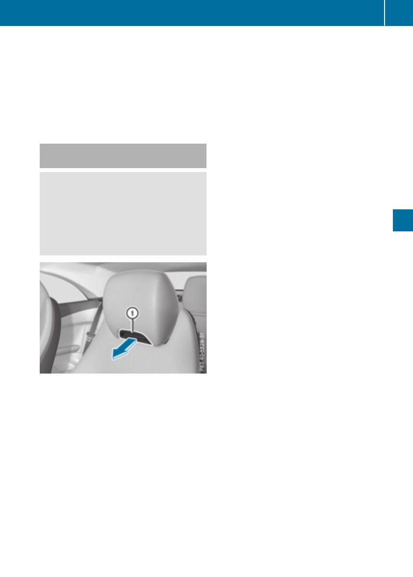
XTo open or close: turn control =to the
counter-clockwise or clockwise as far as it will
go.
XTo adjust the air direction: hold side air
vent ;by control =and move it up or down
or to the left or right.
Adjusting the rear air vents (see the Digital
Operator's Manual).
Setting the blower output of the AIR-
SCARF vents
GWARNING
When AIRSCARF is switched on, very hot air
can flow from the vents in the head restraints.
This could result in burns in the immediate
vicinity of the air vents. There is a risk of injury.
Reduce the heater output before it becomes
too hot.
You can adjust the blower output of AIRSCARF
vents :using the AIRSCARF button
(Ypage 100).
Air vents 121
Climate control
Z

Notes on breaking-in a new vehicle
Important safety notes
The sensor system of some driving and driving
safety systems adjusts automatically while a
certain distance is being driven after the vehicle
has been delivered or after repairs. Full system
effectiveness is not reached until the end of this
teach-in procedure.
New and replaced brake pads and discs only
reach their optimum braking effect after several
hundred kilometers of driving. Compensate for
this by applying greater force to the brake pedal.
The first 1000 miles (1500 km)
The more you look after the engine when it is
new, the more satisfied you will be with its per-
formance in the future.
RYou should therefore drive at varying vehicle
and engine speeds for the first 1000 miles
(1500 km).
RAvoid heavy loads, e.g. driving at full throttle,
during this period.
RWhen changing gears manually, change up in
good time, before the tachometer needle rea-
ches Ôof the way to the red area of the tach-
ometer.
RDo not manually shift to a lower gear to brake
the vehicle.
RTry to avoid depressing the accelerator pedal
beyond the pressure point (kickdown).
RAll vehicles (except Mercedes-AMG vehi-
cles): ideally, for the first 1,000 miles
(1,500 km), drive in drive program E.
Additional breaking-in notes for Mercedes-AMG
vehicles:
RDo not drive faster than 85 mph (140 km/h)
for the first 1,000 miles (1,500 km).
ROnly briefly allow the engine to reach a max-
imum engine speed of 4,500 rpm briefly.
RChange gear in good time.
RIdeally, for the first 1,000 miles (1,500 km),
drive in program C.
After 1000 miles (1500 km), you can increase
the engine speed gradually and accelerate the
vehicle to full speed.
You should also observe these notes on break-
ing in if the engine or parts of the drive train on
your vehicle have been replaced.
Always observe the maximum permissible
speed.
Locking rear axle differential
(Mercedes-AMG C 63/C 63 S)
Your vehicle is equipped with a self-locking dif-
ferential on the rear axle.
Change the oil to improve protection of the rear
axle differential:
Rafter a breaking-in period of 1,850 miles
(3,000 km)
Revery 31,000 miles (50,000 km) or 3 years
These oil changes prolong the service life of the
differential. Have the oil change carried out at a
qualified specialist workshop.
Driving
Important safety notes
GWARNING
Objects in the driver's footwell may restrict
the clearance around the pedals or block a
depressed pedal. This jeopardizes the oper-
ating and road safety of the vehicle. There is a
risk of an accident.
Stow all objects securely in the vehicle so that
they do not get into the driver's footwell.
When using floormats or carpets, make sure
that they are properly secured so that they do
not slip or obstruct the pedals. Do not place
several floormats or carpets on top of one
another.
GWARNING
Unsuitable footwear can hinder correct usage
of the pedals, e.g.:
Rshoes with thick soles
Rshoes with high heels
Rslippers
There is a risk of an accident.
Wear suitable footwear to ensure correct
usage of the pedals.
122 Driving
Driving and parking
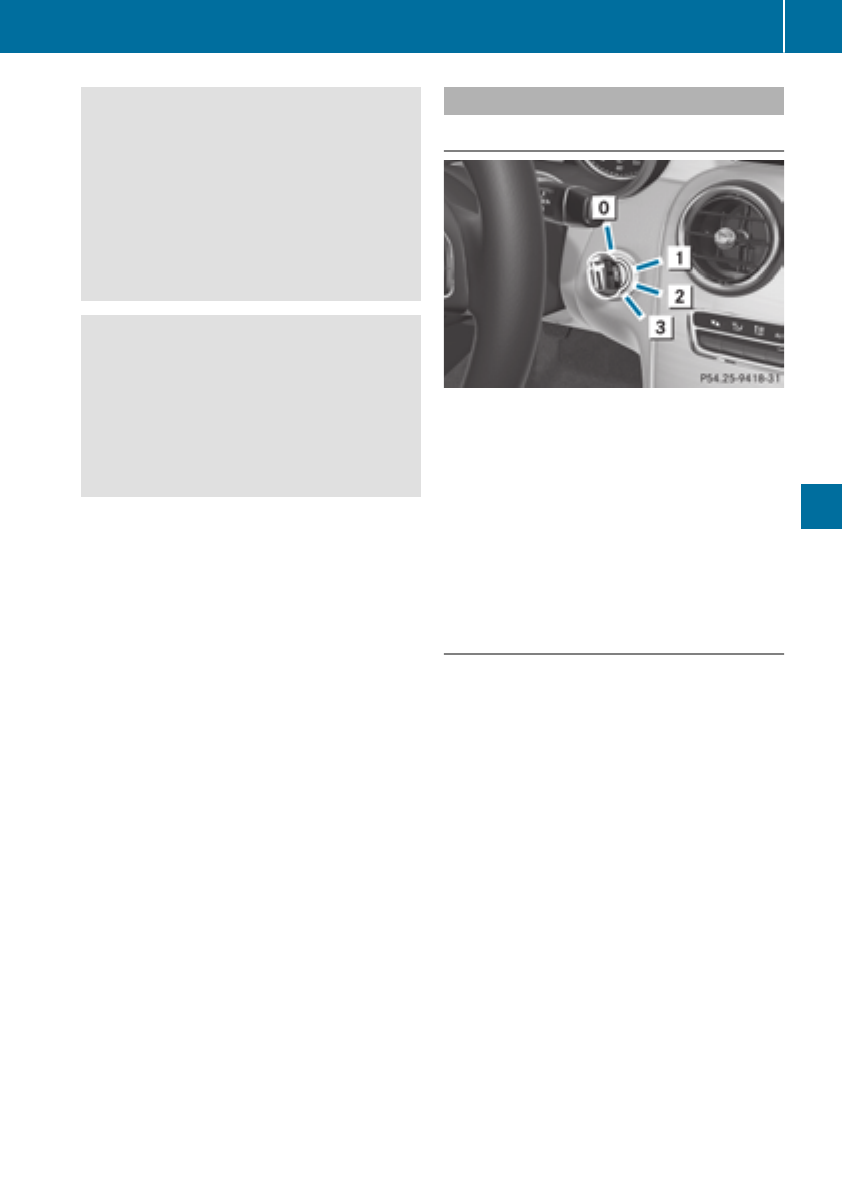
GWARNING
If you switch off the ignition while driving,
safety-relevant functions are only available
with limitations, or not at all. This could affect,
for example, the power steering and the brake
boosting effect. You will require considerably
more effort to steer and brake. There is a risk
of an accident.
Do not switch off the ignition while driving.
GWARNING
If the parking brake has not been fully
released when driving, the parking brake can:
Roverheat and cause a fire
Rlose its hold function.
There is a risk of fire and an accident. Release
the parking brake fully before driving off.
!Do not warm up the engine with the vehicle
stationary. Drive off immediately. Avoid high
engine speeds and driving at full throttle until
the engine has reached its operating temper-
ature.
Only shift the automatic transmission to the
desired drive position when the vehicle is sta-
tionary.
Where possible, avoid spinning the drive
wheels when pulling away on slippery roads.
You could otherwise damage the drive train.
!Mercedes-AMG vehicles: at low engine oil
temperatures below 68 ‡ (+20 †), the max-
imum engine speed is restricted in order to
protect the engine. To protect the engine and
maintain smooth engine operation, avoid driv-
ing at full throttle when the engine is cold.
Key positions
SmartKey
gTo remove the SmartKey
1Power supply for some consumers, such as
the windshield wipers
2Ignition (power supply for all consumers)
and drive position
3To start the engine
iThe SmartKey can be turned in the ignition
lock even if it is not the correct SmartKey for
the vehicle. The ignition is not switched on.
The engine cannot be started.
Start/Stop button
General notes
When you insert the Start/Stop button into the
ignition lock, the system needs approximately
two seconds recognition time. You can then use
the Start/Stop button.
Pressing the Start/Stop button several times in
succession corresponds to the different Smart-
Key positions in the ignition lock. This is only the
case if you are not depressing the brake pedal.
If you depress the brake pedal and press the
Start/Stop button, the engine starts immedi-
ately.
A check which periodically establishes a radio
connection between the vehicle and the Smart-
Key determines whether a valid SmartKey is in
the vehicle. This occurs, for example, when
starting the engine.
Driving 123
Driving and parking
Z
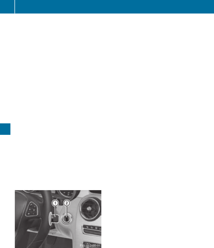
To start the vehicle without actively using the
SmartKey:
Rthe Start/Stop button must be inserted in the
ignition lock.
Rthe SmartKey must be in the vehicle.
Rthe vehicle must not be locked with the
SmartKey or KEYLESS-GO. (Ypage 77)
Do not keep the SmartKey:
Rwith electronic devices, e.g. a mobile phone
or another SmartKey.
Rwith metallic objects, e.g. coins or metal foil.
Rinside metallic objects, e.g. a metal case.
This can affect the functionality of the Smart-
Key.
If you lock the vehicle with the SmartKey remote
control or with KEYLESS-GO, after a short time:
Ryou will not be able to switch on the ignition
with the Start/Stop button.
Ryou will no longer be able to start the engine
with the Start/Stop button until the vehicle is
unlocked again.
If you lock the vehicle centrally using the button
on the front door (Ypage 82), you can continue
to start the engine with the Start/Stop button.
The engine can be switched off while the vehicle
is in motion by pressing and holding the Start/
Stop button for three seconds. This function
operates independently of the ECO start/stop
automatic engine switch-off function.
Key positions with the Start/Stop button
:Start/Stop button
;Ignition lock
As soon as the ignition is switched on, all the
indicator lamps in the instrument cluster light
up. Warning and indicator lamps: see
(Ypage 241).
If Start/Stop button :has not yet been
pressed, this corresponds to the SmartKey
being removed from the ignition.
XTo switch on the power supply: press
Start/Stop button :once.
The power supply is switched on. You can now
activate the windshield wipers, for example.
The power supply is switched off again if:
Rthe driver's door is opened and
Ryou press Start/Stop button :twice when in
this position
XTo switch on the ignition: press Start/Stop
button :twice.
The ignition is switched on.
The ignition is switched off again if:
Ryou do not start the engine from this position
within 15 minutes
Ryou press Start/Stop button :once when in
this position
The power supply is switched off again if:
Rthe driver's door is opened and
Ryou press Start/Stop button :once when in
this position
Removing the Start/Stop button
You can remove the Start/Stop button from the
ignition lock and start the vehicle as normal
using the SmartKey.
It is possible to switch between Start/Stop but-
ton mode and key operation only when the
transmission is in position j.
XRemove Start/Stop button :from ignition
lock ;.
You do not have to remove the Start/Stop but-
ton from the ignition lock when you leave the
vehicle. You should, however, always take the
SmartKey with you when leaving the vehicle. As
long as the SmartKey is in the vehicle:
Rthe vehicle can be started using the Start/
Stop button
Rthe electrically powered equipment can be
operated
124 Driving
Driving and parking

Starting the engine
Important safety notes
GWARNING
If children are left unsupervised in the vehicle,
they could:
Ropen the doors, thus endangering other
people or road users.
Rget out and disrupt traffic.
Roperate the vehicle's equipment.
Additionally, children could set the vehicle in
motion if, for example, they:
Rrelease the parking brake.
Rshifting the automatic transmission out of
park position P
RStart the engine.
There is a risk of an accident and injury.
When leaving the vehicle, always take the
SmartKey with you and lock the vehicle. Never
leave children or animals unattended in the
vehicle. Always keep the SmartKey out of
reach of children.
GWARNING
Combustion engines emit poisonous exhaust
gases such as carbon monoxide. Inhaling
these exhaust gases leads to poisoning. There
is a risk of fatal injury. Therefore never leave
the engine running in enclosed spaces with-
out sufficient ventilation.
GWARNING
Flammable materials introduced through
environmental influence or by animals can
ignite if in contact with the exhaust system or
parts of the engine that heat up. There is a risk
of fire.
Carry out regular checks to make sure that
there are no flammable foreign materials in
the engine compartment or in the exhaust
system.
General notes
The catalytic converter is preheated for up to
30 seconds after a cold start. The sound of the
engine may change during this time.
Automatic transmission
XShift the transmission to position j
(Ypage 133).
The transmission position indicator on the
multifunction display shows j
(Ypage 134).
iYou can start the engine in transmission
position jand i.
Starting procedure with the SmartKey
To start the engine using the SmartKey instead
of the Start/Stop button, pull the Start/Stop
button out of the ignition lock.
XTurn the SmartKey to position 3in the igni-
tion lock and release it as soon as the engine
is running.
If the engine will not start:
XRemove the SmartKey from the ignition lock.
XReinsert the SmartKey into the ignition lock
after a short waiting period.
XTurn the SmartKey to position 2in the igni-
tion lock (Ypage 123).
The indicator lamps in the instrument cluster
light up (Ypage 241).
XTurn the SmartKey to position 3
(Ypage 123) in the ignition lock and release it
as soon as the engine is running.
Starting procedure with the Start/Stop
button
The Start/Stop button is only available on vehi-
cles with KEYLESS-GO or the KEYLESS-GO start
function.
The Start/Stop button can be used to start the
vehicle manually without inserting the SmartKey
into the ignition lock. The Start/Stop button
must be inserted in the ignition lock and the
SmartKey must be in the vehicle. This mode for
starting the engine operates independently of
the ECO start/stop automatic engine start func-
tion.
You can start the engine if a valid SmartKey is in
the vehicle. Switch off the engine and always
Driving 125
Driving and parking
Z

take the SmartKey with you when leaving the
vehicle, even if you only leave it for a short time.
Pay attention to the important safety notes.
XDepress the brake pedal and keep it
depressed.
XPress the Start/Stop button once
(Ypage 124).
The engine starts.
Starting procedure via smartphone
Observe the important safety notes on starting
the engine (Ypage 125).
You can also start your engine via your smart-
phone from outside the vehicle. In this case, the
previously selected climate control setting is
activated. In this way you can cool or heat the
interior of the vehicle before starting the jour-
ney.
Only start the engine via your smartphone if it is
safe to start and run the engine where your vehi-
cle is parked.
Observe the legal stipulations in the area where
your vehicle is parked. Engine start via smart-
phone may be limited to certain countries or
regions.
You can execute a maximum of two consecutive
starting attempts via your smartphone. If you
press the start/stop button or insert the Smart-
Key into the ignition lock, you can carry out two
more starting attempts with your smartphone.
The engine runs for ten minutes when starting
with the smartphone.
Once you have started the engine, you can
switch the engine off via your smartphone at any
time.
You can only start the engine via your smart-
phone if:
Rthe SmartKey is in the ignition lock
Rpark position jis selected
Rthe accelerator pedal is not depressed
Rthe anti-theft alarm system is not activated
Rthe panic alarm is not activated
Rthe hazard warning lamps are switched off
Rthe hood is closed
Rthe doors are closed and locked
Rthe windows and sliding sunroof are closed
Also make sure that:
Rthe fuel tank is sufficiently filled
Rthe starter battery has been sufficiently
charged
GWARNING
Limbs could be crushed or trapped if the
engine is started unintentionally during ser-
vice or maintenance work. There is a risk of
injury.
Always secure the engine against uninten-
tional starting before carrying out mainte-
nance or repair work.
Make sure that the engine cannot be started via
your smartphone before carrying out mainte-
nance or repairs. You can prevent an engine
start via your smartphone, for example, if you:
Rswitch on the hazard warning lamps
Rdo not lock the doors
Ropen a side window
Pulling away
General notes
GWARNING
If the engine speed is above the idling speed
and you engage transmission position Dor R,
the vehicle could pull away suddenly. There is
a risk of an accident.
When engaging transmission position Dor R,
always firmly depress the brake pedal and do
not simultaneously accelerate.
Depress the accelerator carefully when pulling
away.
The vehicle locks centrally once you have pulled
away. The locking knobs in the doors drop down.
You can open the doors from the inside at any
time.
You can also deactivate the automatic locking
feature, see the Digital Operator's Manual.
It is possible to shift the transmission from posi-
tion jto the desired position only if you
depress the brake pedal. Only then is the park-
ing lock released. If you do not depress the
brake pedal, the DIRECT SELECT lever can still
126 Driving
Driving and parking
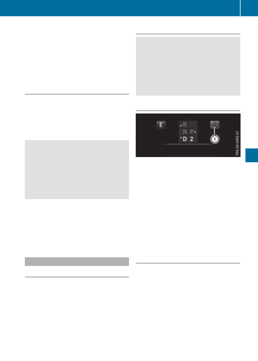
be moved but the parking lock remains
engaged.
iUpshifts take place at higher engine speeds
after a cold start. This helps the catalytic con-
verter to reach its operating temperature
more quickly.
Information on the automatic release of the
electric parking brake (Ypage 146).
Hill start assist
Hill start assist helps you when pulling away
forward or in reverse on an uphill gradient. It
holds the vehicle for a short time after you have
removed your foot from the brake pedal. This
gives you enough time to move your foot from
the brake pedal to the accelerator pedal and to
depress it before the vehicle begins to roll.
GWARNING
After a short time, hill start assist will no lon-
ger brake your vehicle and it could roll away.
There is a risk of an accident and injury.
Therefore, quickly move your foot from the
brake pedal to the accelerator pedal. Never
leave the vehicle when it is held by hill start
assist.
Hill start assist is not active if:
Ryou are pulling away on a level road or on a
downhill gradient.
Rthe transmission is in position i
Rthe electric parking brake is applied.
RESP®is malfunctioning
ECO start/stop function
Introduction
The ECO start/stop function switches the
engine off automatically if the vehicle is stopped
under certain conditions.
The engine starts automatically when the driver
wants to pull away again. The ECO start/stop
function thereby helps you to reduce the fuel
consumption and emissions of your vehicle.
Important safety notes
GWARNING
If the engine is switched off automatically and
you exit the vehicle, the engine is restarted
automatically. The vehicle may begin moving.
There is a risk of accident and injury.
If you wish to exit the vehicle, always turn off
the ignition and secure the vehicle against
rolling away.
General notes
:ECO start/stop display
The ECO start/stop function is activated when-
ever you start the engine using the SmartKey or
the Start/Stop button.
If the engine has been switched off automati-
cally by the ECO start/stop function, the è
ECO symbol is shown in the multifunction dis-
play.
Mercedes-AMG C 63 and Mercedes-AMG
C 63 S: the ECO start/stop function is auto-
matically switched on only in drive program C.
Mercedes-AMG C 43 4MATIC: the ECO start/
stop function is automatically switched on only
in drive programs S,Cand E.
Automatic engine switch-off
If the vehicle is braked to a standstill with the
transmission in hor i, the ECO start/stop
function switches off the engine automatically.
The ECO start/stop function is operational
when:
Rthe indicator lamp in the ECO button is lit
green
Rthe outside temperature and the atmospheric
air pressure is within the range that is suitable
for the system
Rthe engine is at normal operating temperature
Rthe set temperature for the vehicle interior
has been reached
Driving 127
Driving and parking
Z
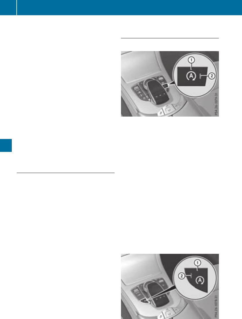
Rthe battery is sufficiently charged
Rthe system detects that the windshield is not
fogged up when the air-conditioning system is
switched on
Rthe hood is closed
Rthe driver's door is closed and the driver's
seat belt is fastened
All of the vehicle's systems remain active when
the engine is stopped automatically.
The HOLD function can also be activated if the
engine has been switched off automatically. It is
then not necessary to continue applying the
brakes during the automatic stop phase. When
you depress the accelerator pedal, the engine
starts automatically and the braking effect of
the HOLD function is deactivated.
Mercedes-AMG C 63 and Mercedes-
AMG C 63 S: the number of consecutive auto-
matic engine switch-offs is unlimited.
All other models: automatic engine switch-off
can take place a maximum of four times in a row
(initial switch-off, then three subsequent switch-
offs).
Automatic engine start
The engine starts automatically if:
Ryou switch off the ECO start/stop function by
pressing the ECO button
RMercedes-AMG vehicles: you permanently
activate manual gearshifting (Ypage 138)
Rin transmission position hor i, the brake
pedal is released and the HOLD function is not
active
Ryou depress the accelerator pedal
Ryou engage reverse gear k
Ryou move the transmission out of position j
Ryou unfasten your seat belt or open the driv-
er's door
Rthe vehicle starts to roll
Rthe brake system requires this
Rthe temperature in the vehicle interior devi-
ates from the set range
Rthe system detects moisture on the wind-
shield when the air-conditioning system is
switched on
Rthe condition of charge of the battery is too
low
Shifting the transmission to position jdoes
not start the engine.
Deactivating or activating the ECO
start/stop function
Mercedes-AMG vehicles
XTo deactivate: press ECO button :.
Indicator lamp ;goes out.
XTo activate: press ECO button :.
Indicator lamp ;lights up.
If indicator lamp ;is off, the ECO start/stop
function has been deactivated manually or as
the result of a malfunction. The engine will then
not be switched off automatically when the vehi-
cle stops.
The ECO start/stop function is deactivated, if:
RMercedes-AMG C 63 and Mercedes-AMG
C 63 S: you switch to drive program RACE
(S‑MODEL), S+ or S(Ypage 130)
RMercedes-AMG C 43 4MATIC: you switch to
drive program S+ (Ypage 130)
Ryou permanently activate manual gearshifting
(Ypage 138)
If you have permanently activated manual gear-
shifting and then press ECO button :, the ECO
start/stop function is activated.
All other models
128 Driving
Driving and parking
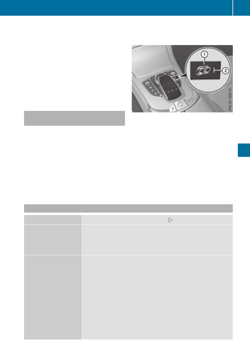
XTo deactivate: press ECO button :.
Indicator lamp ;goes out.
XTo activate: press ECO button :.
Indicator lamp ;lights up.
If indicator lamp ;is off, the ECO start/stop
function has been deactivated manually or as
the result of a malfunction. The engine will then
not be switched off automatically when the vehi-
cle stops.
Selecting drive program S+ deactivates the ECO
start/stop function. If you press ECO button :,
the ECO start/stop function is activated.
AMG performance adjustable exhaust
system (Mercedes-AMG vehicles)
The volume of the AMG Performance adjustable
exhaust system changes depending on the posi-
tion of the switchable exhaust flap. The exhaust
flap is adjusted automatically according to the
selected drive program (Ypage 130).
You can also adjust the position of the exhaust
flap and therefore the volume of the exhaust
system manually.
The automatic adjustment of the exhaust flap is
always active when you change drive program,
regardless of the manual setting.
Each time you start the engine with the Smart-
Key or the Start/Stop button, the quietest set-
ting is activated.
Setting the volume:
XPress button :.
If you select the loudest setting, indicator
lamp lights up ;.
Mercedes-AMG C 63/C 63 S: you can preset
the volume of the exhaust system for drive pro-
gram I(Individual). Information on DYNAMIC
SELECT and on configuring drive program Iwith
the multimedia system (see the Digital Opera-
tor's Manual).
Problems with the engine
Problem Possible causes/consequences and MSolutions
The engine does not
start.
The HOLD function or Distance Pilot DISTRONIC is activated.
XDeactivate the HOLD function (Ypage 162) or Distance Pilot
DISTRONIC (Ypage 158).
XTry to start the engine again (Ypage 125).
The engine does not
start. The starter motor
can be heard.
RThere is a malfunction in the engine electronics.
RThere is a malfunction in the fuel supply.
Before attempting to start the engine again:
XTurn the SmartKey back to position uin the ignition lock.
or
XPress the Start/Stop button repeatedly until all indicator lamps in
the instrument cluster go out.
XTry to start the engine again (Ypage 125). Avoid excessively long
and frequent attempts to start the engine as these will drain the
battery.
If the engine does not start after several attempts:
XConsult a qualified specialist workshop.
Driving 129
Driving and parking
Z

Problem Possible causes/consequences and MSolutions
The engine does not
start. The starter motor
can be heard. The
reserve fuel warning
lamp is lit and the fuel
gauge display is at the
reserve level.
The fuel tank is empty.
XRefuel the vehicle.
The engine does not
start. You cannot hear
the starter motor.
The on-board voltage is too low because the battery is too weak or
discharged.
XJump-start the vehicle (Ypage 304).
If the engine does not start despite attempts to jump-start it:
XConsult a qualified specialist workshop.
The starter motor was exposed to a thermal load that was too high.
XTry to start the engine again (Ypage 125).
If the engine still does not start:
XConsult a qualified specialist workshop.
The engine is not running
smoothly and is misfir-
ing.
There is a malfunction in the engine electronics or in a mechanical
component of the engine management system.
XOnly depress the accelerator pedal slightly.
Otherwise, non-combusted fuel may get into the catalytic converter
and damage it.
XHave the cause rectified immediately at a qualified specialist work-
shop.
The coolant temperature
display is pointing to the
red mark.
The coolant level is too low. The coolant is too hot and the engine is no
longer being cooled sufficiently.
XStop as soon as possible and allow the engine and the coolant to
cool down.
XCheck the coolant level (Ypage 284). Observe the warning notes
as you do so and add coolant if necessary.
DYNAMIC SELECT switch
Mercedes-AMG vehicles
General information
Use the DYNAMIC SELECT switch to select the
drive program.
Available drive programs for Mercedes-
AMG C 43 4MATIC:
S+ Sport Plus Particularly sporty driving
characteristics
SSport Sporty driving characteris-
tics
CComfort Comfortable and economi-
cal driving characteristics
EEconomy Particularly economical
driving characteristics
IIndividual Individual settings
130 DYNAMIC SELECT switch
Driving and parking
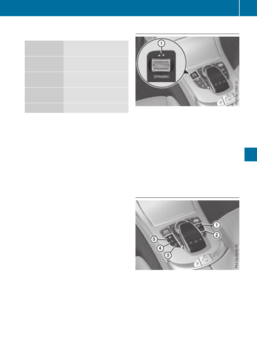
Available drive programs for Mercedes-
AMG C 63/C 63 S:
RACE
(S‑MODEL)
Driving characteristics suit-
able for a race circuit
S+ Sport Plus Particularly sporty driving
characteristics
SSport Sporty driving characteris-
tics
CComfort Comfortable and economi-
cal driving characteristics
IIndividual Individual settings
Depending on the drive program selected the
following vehicle characteristics will change:
Rthe drive (engine and transmission manage-
ment)
Rthe suspension
Rthe steering
Rthe driver assistance systems
RESP®(Mercedes-AMG C 63/C 63 S)
Rthe position of the exhaust flap (Mercedes-
AMG C 63/C 63 S)
Rthe setting of the ECO start/stop function
Rthe availability of gliding mode
Rthe climate control:
Further information for automatic drive program
characteristics (Ypage 136).
Additionally, in drive program Iyou can config-
ure the respective vehicle characteristics using
the multimedia system. You can find informa-
tion about this under "DYNAMIC SELECT" in the
vehicle's Digital Operator's Manual.
Each time you start the engine with the Smart-
Key or the Start/Stop button, drive program Cis
activated. For further information about starting
the engine, see (Ypage 125).
Selecting the drive program
XPush DYNAMIC SELECT switch :forwards
or back until the desired drive program is
selected.
The status icon of the selected drive program
is shown in the multifunction display.
In addition, the current drive program settings
are displayed briefly in the multimedia system
display.
You can also change gear yourself using the
steering wheel paddle shifters. For further infor-
mation on the manual drive program
(Ypage 138).
Additional settings
:Position of the exhaust flap (Ypage 129)
;ECO start/stop function (Ypage 127)
=ESP®(Ypage 67)
?Suspension (Ypage 164)
APermanently activates manual gearshifting
(Ypage 138)
When you press buttons :-Athe corre-
sponding setting is selected. The DYNAMIC
SELECT switch setting is overwritten.
If you switch to drive program I, all stored char-
acteristics will be accepted. This is also the case
DYNAMIC SELECT switch 131
Driving and parking
Z
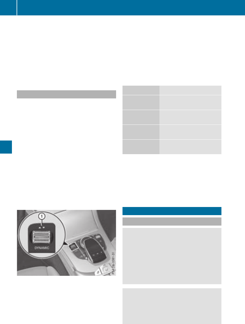
if you have previously pressed one of buttons :
-A.
iMercedes-AMG C 43 4MATIC In a few
countries, the ECO start/stop function is
deactivated at the factory due to the fuel
grade available. In this case, the ECO start/
stop function is not available in any drive pro-
gram, regardless of the display in the multi-
media system display.
All other models
Use the DYNAMIC SELECT switch to change the
drive program.
Depending on the drive program selected the
following vehicle characteristics will change:
Rthe drive (engine and transmission manage-
ment)
Rthe suspension
Rthe steering
Rthe ECO start/stop function
Rthe climate control:
-the climate control settings
-the rear window defroster operation period
-the performance of the seat heating
Each time you start the engine with the Smart-
Key or the Start/Stop button, drive program Cis
activated. For further information about starting
the engine, see (Ypage 125).
XPush DYNAMIC SELECT switch :forward or
back until the desired drive program is selec-
ted.
The status icon of the selected drive program
is shown in the multifunction display.
In addition, the current drive program settings
are displayed briefly in the multimedia system
display.
iIn a few countries, the ECO start/stop func-
tion is deactivated at the factory due to the
available fuel grade. In this case, the ECO
start/stop function is not available in any
drive program, regardless of the display in the
multimedia system display.
Available drive programs:
IIndividual Individual settings
S+ Sport Plus Particularly sporty driving
characteristics
SSport Sporty driving characteris-
tics
CComfort Comfortable and economi-
cal driving characteristics
EEconomy Particularly economical
driving characteristics
Additional information for drive programs
(Ypage 136).
You can also change gear yourself using the
steering wheel paddle shifters. For further infor-
mation on the manual drive program
(Ypage 138).
Automatic transmission
Important safety notes
GWARNING
If the engine speed is above the idling speed
and you engage transmission position Dor R,
the vehicle could pull away suddenly. There is
a risk of an accident.
When engaging transmission position Dor R,
always firmly depress the brake pedal and do
not simultaneously accelerate.
GWARNING
The automatic transmission switches to neu-
tral position Nwhen you switch off the engine.
The vehicle may roll away. There is a risk of an
accident.
132 Automatic transmission
Driving and parking
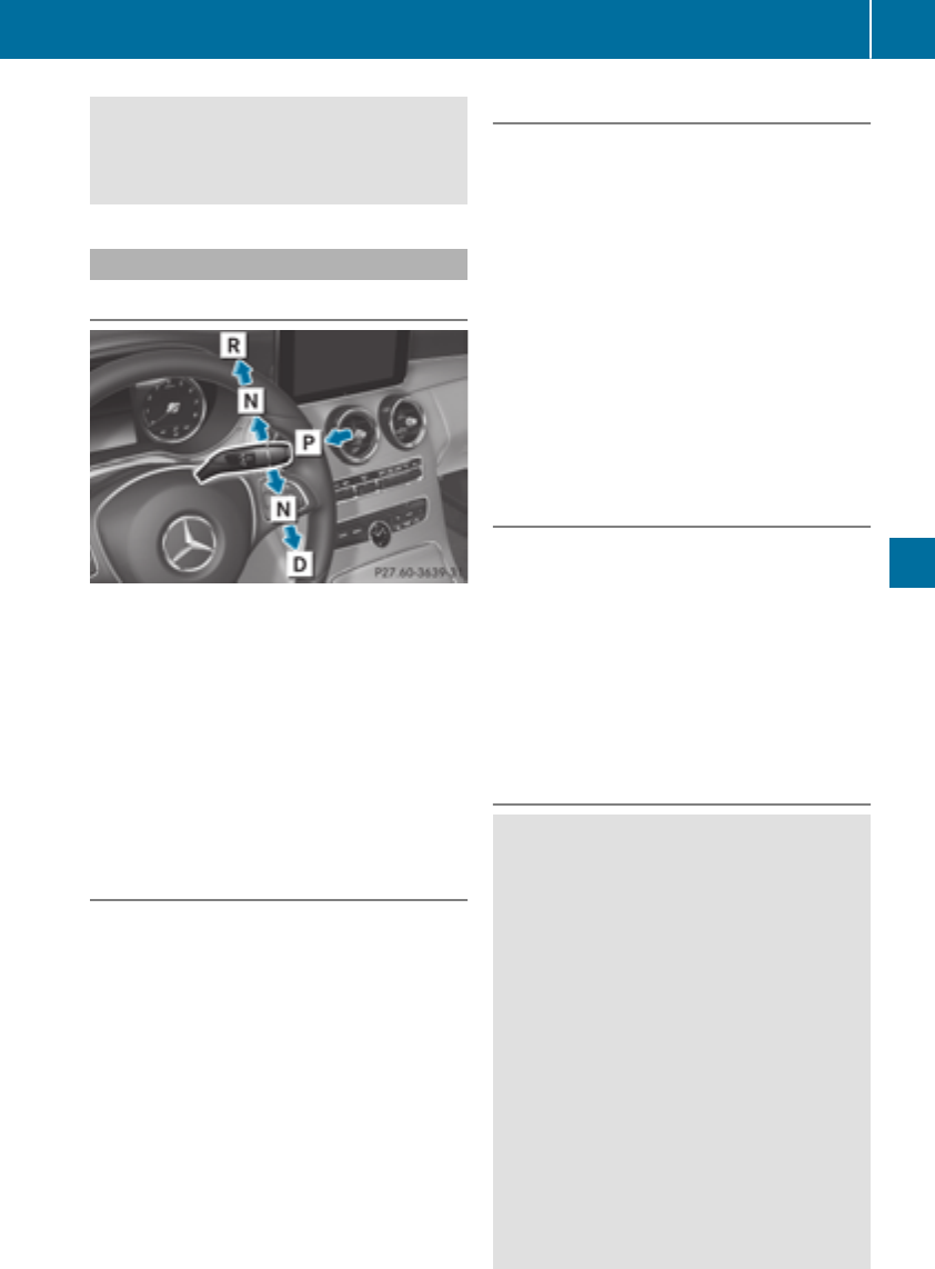
After switching off the engine, always switch
to parking position P. Prevent the parked vehi-
cle from rolling away by applying the parking
brake.
DIRECT SELECT lever
Overview of transmission positions
jPark position with parking lock
kReverse gear
iNeutral
hDrive
The DIRECT SELECT lever is on the right of the
steering column.
The DIRECT SELECT lever always returns to its
original position. The current transmission posi-
tion j,k,ior his shown on the trans-
mission position display on the multifunction
display (Ypage 134).
Selects park position
!If the engine speed is too high or the vehicle
is coasting, do not shift the automatic trans-
mission directly from hto k, from kto h
or directly to j. Otherwise, the automatic
transmission may be damaged.
XPush the DIRECT SELECT lever switch in the
direction of arrow j.
Engaging park position automatically
Park position jis automatically engaged if:
Ryou switch off the engine using the SmartKey
and remove the SmartKey
Ryou switch off the engine using the SmartKey
or using the Start/Stop button and open the
driver's door or front-passenger door
Ryou open the driver's door when the vehicle is
stationary or when driving at a very low speed
and the transmission is in position hor k
Under certain conditions, the automatic trans-
mission shifts to transmission position jauto-
matically if the HOLD function or Distance Pilot
DISTRONIC is activated. Observe the informa-
tion on the HOLD function (Ypage 162) and
Distance Pilot DISTRONIC (Ypage 156).
Engaging reverse gear
!Only move the automatic transmission to
kwhen the vehicle is stationary.
XDepress the brake pedal.
XPush the DIRECT SELECT lever up past the
first point of resistance.
The ECO start/stop function is not available
when reverse gear is engaged. Further informa-
tion on the ECO start/stop function
(Ypage 127).
Engaging neutral
GWARNING
If children are left unsupervised in the vehicle,
they could:
Ropen the doors, thus endangering other
people or road users.
Rget out and disrupt traffic.
Roperate the vehicle's equipment.
Additionally, children could set the vehicle in
motion if, for example, they:
Rrelease the parking brake.
Rshifting the automatic transmission out of
park position P
RStart the engine.
There is a risk of an accident and injury.
When leaving the vehicle, always take the
SmartKey with you and lock the vehicle. Never
Automatic transmission 133
Driving and parking
Z
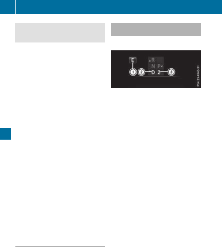
leave children or animals unattended in the
vehicle. Always keep the SmartKey out of
reach of children.
XIf the transmission is in position hor k:
push the DIRECT SELECT lever up or down to
the first point of resistance.
XIf the transmission is in position j: depress
the brake pedal and push the DIRECT SELECT
lever up or down to the first point of resist-
ance.
If you switch the engine off with the transmis-
sion in position kor h, the automatic trans-
mission shifts to iautomatically.
With the SmartKey: if you then open the driv-
er's door or the front-passenger door or remove
the SmartKey from the ignition lock, the auto-
matic transmission shifts to jautomatically.
With the Start/Stop button: if you then open
the driver's door or the front-passenger door,
the automatic transmission shifts to jauto-
matically.
If you want the automatic transmission to
remain in neutral i, e.g. when having the vehi-
cle cleaned in an automatic, tow-through car
wash:
XVehicles with KEYLESS-GO or KEYLESS-
GO start function: remove the Start/Stop
button from the ignition lock.
XInsert the SmartKey into the ignition lock.
XAll vehicles: switch the ignition on.
XDepress the brake pedal and keep it
depressed.
XEngage neutral i.
XRelease the brake pedal.
XRelease the electric parking brake.
XSwitch off the ignition and leave the SmartKey
in the ignition lock.
Engaging the drive position
XIf the transmission is in position kor i:
push the DIRECT SELECT lever down past the
first point of resistance.
XIf the transmission is in position j: depress
the brake pedal and push the DIRECT SELECT
lever down past the first point of resistance.
Transmission position and drive pro-
gram display
The current transmission position and drive pro-
gram appear in the multifunction display.
:Status symbol drive program
;Transmission position
=Gear
The arrows in the transmission position display
show how and into which transmission positions
you can shift using the DIRECT SELECT lever.
If the transmission position display in the mul-
tifunction display is not working, you should pull
away carefully to check whether the desired
transmission position is engaged. Ideally, you
should select transmission position hand
drive program E(for Mercedes-AMG vehicles:
drive program C) or S.
134 Automatic transmission
Driving and parking

Transmission positions
BPark position
This prevents the vehicle from rolling
away when stopped.
Only shift the transmission into posi-
tion j(Ypage 133) when the vehi-
cle is stationary. The parking lock
should not be used as a brake when
parking. Always apply the electronic
parking brake in addition to the park-
ing lock in order to secure the vehi-
cle.
Park position jis automatically
engaged if:
Ryou switch off the engine using the
SmartKey and remove the Smart-
Key
Ryou switch off the engine using the
SmartKey or using the Start/Stop
button and open the driver's door
or front-passenger door
Ryou open the driver's door when
the vehicle is stationary or when
driving at a very low speed and the
transmission is in position hor
k
In the event of a malfunction of the
vehicle's electronics, the transmis-
sion may lock in position j. Have
the vehicle electronics checked
immediately at a qualified specialist
workshop.
CReverse gear
You can only shift the transmission
into position kwhen the vehicle is
stationary (Ypage 133).
ANeutral
Do not shift the transmission to i
while driving. Otherwise, the auto-
matic transmission could be dam-
aged.
No power is transmitted from the
engine to the drive wheels.
Releasing the brake pedal will allow
you to move the vehicle freely, e.g. to
push it or tow it.
If ESP®is deactivated or faulty: shift
the transmission to position iif the
vehicle is in danger of skidding, e.g.
on icy roads.
If you switch the engine off with the
transmission in position kor h,
the automatic transmission shifts to
iautomatically.
!Coasting in neutral imay
cause damage to the drive train.
7Drive
The automatic transmission changes
gear automatically. All forward gears
are available.
Driving tips
Changing gear
The automatic transmission shifts through the
individual gears automatically when it is in trans-
mission position h. This automatic gear shift-
ing behavior is determined by:
Rthe selected drive program
Rthe position of the accelerator pedal
Rthe road speed
Accelerator pedal position
Your style of driving influences how the auto-
matic transmission shifts gear:
Rlittle throttle: early upshifts
Rmore throttle: late upshifts
Double-clutch function
When shifting down, the double-clutch function
is active regardless of the currently selected
drive program. The double-clutch function
Automatic transmission 135
Driving and parking
Z
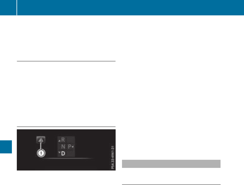
reduces load change reactions and is conducive
to a sporty driving style. The sound generated by
the double-clutch function depends on the drive
program selected.
Kickdown
Use kickdown for maximum acceleration.
XDepress the accelerator pedal beyond the
pressure point.
The automatic transmission shifts to a lower
gear depending on the engine speed.
XEase off the accelerator pedal once the
desired speed is reached.
The automatic transmission shifts back up.
Gliding mode
Gliding mode is available depending on equip-
ment.
Gliding mode is characterized by the following:
RThe combustion engine is disconnected from
the drive train.
RThe engine speed corresponds to the idling
speed.
RThe multifunction display hides the gear indi-
cator and displays transmission position h
in green (Ypage 134)
RMercedes-AMG vehicles: the multifunction
display shows status icon :for the drive
program's status icon
In drive program Eor in drive program C
(Mercedes-AMG C 63/C 63 S), you can activate
and deactivate glide mode using the ECO button
(Ypage 128).
Gliding mode can be activated under the follow-
ing conditions:
RThe speed is within a suitable range.
RThe course of the road is suitable, e.g. there
are no steep up or downhill gradients.
RYou are no longer depressing the accelerator
pedal.
Gliding mode is deactivated under the following
conditions:
RYou depress the accelerator pedal.
RYou depress the brake pedal.
RYou change the transmission position
(Ypage 133).
Ryou switch to drive program RACE
(Mercedes-AMG C 63 S), S+ or S
(Ypage 130).
Ryou activate manual gearshifting
(Ypage 138).
Ryou leave the suitable speed range.
iIf you have selected the "Eco" or "Comfort"
setting (Mercedes-AMG C 63/C 63 S) for the
drive (engine and transmission management)
in drive program I, you can also activate glide
mode. Information on DYNAMIC SELECT and
on configuring drive program Ivia the multi-
media system (see the Digital Operator's
Manual).
Drive programs
All vehicles except Mercedes-AMG
C 63/C 63 S
Drive program I (Individual)
In drive program Ithe following properties of the
drive program can be selected:
Rthe drive (engine and transmission manage-
ment)
and therefore indirectly the availability of glid-
ing mode and the properties of the driver
assistance systems
Rthe suspension
Rthe steering
Rthe availability of the ECO start/stop function
Rthe climate control:
To permanently shift the gears manually in drive
program Iusing the steering wheel paddle shift-
ers, select the M(Manual) setting for the drive
(except Mercedes-AMG C 43 4MATIC).
Information about configuring drive program I
with the multimedia system can be found under
"DYNAMIC SELECT" in the vehicle's Digital
Operator's Manual.
136 Automatic transmission
Driving and parking

Drive program S+ (SportPlus)
Drive programS+ is characterized by thefol-
lowing:
Rthevehicleexhibits particularlysportydriving
characteristics.
Rthevehiclepulls away in first gear.
Rtheautomatictransmissionshiftsup later.
thefuelconsumption possiblybeinghigher as
aresult of thelater automatictransmission
shift points.
Rthesuspensionexhibits particularlystiff
springingand dampingsettings(vehicles with
AIRMATIC).
Rglidingmodeis notavailable.
RtheECO start/stopfunction is switched off
(Ypage 127).
Drive program S(Sport)
Drive programSis characterized by thefollow-
ing:
Rthevehicleexhibits sportydrivingcharacter-
istics.
Rthevehiclepulls away in first gear.
Rtheautomatictransmissionshiftsup later.
thefuelconsumption possiblybeinghigher as
aresult of thelater automatictransmission
shift points.
Rthesuspensionexhibits hardspringingand
dampingsettings(vehicles withAIRMATIC).
Rglidingmodeis notavailable.
RtheECO start/stopfunction is switched on
(Ypage 127).
Drive program C(Comfort)
Drive programCis characterized by thefollow-
ing:
Rthevehicledeliverscomfortable, economical
handlingcharacteristics.
Rthevehiclepulls away moregentlyin forward
and reversegears, unless theaccelerator
pedalis depressed fully.
Rthevehiclehas improved drivingstability, for
exampleon slipperyroadsurfaces.
Roptimal fuelconsumption resultingfrom the
automatictransmissionshiftingup sooner.
The vehicleis driven in thelow enginespeed
range and thewheels are less likely to spin.
Rglidingmodeis notavailable.
RtheECO start/stopfunction is switched on
(Ypage 127).
Drive program E(Economy)
Drive programEis characterized by thefollow-
ing:
Rthevehicleexhibits comfortable, economical
handlingcharacteristics.
Rthevehiclepulls away moregentlyin forward
and reversegears, unless theaccelerator
pedalis depressed fully.
Rthevehiclehas improved drivingstability, for
exampleon slipperyroadsurfaces.
Roptimal fuelconsumption resultingfrom the
automatictransmissionshiftingup sooner.
The vehicleis driven in thelow enginespeed
range and thewheels are less likely to spin.
Rduring deceleration,theengineis disconnec-
tedfrom thedrive train.The vehicleuses
kineticenergyand consumes less fuel.
Rthecoolingand heatingoutput of theclimate
control system has been reduced.
Rglidingmodeis available.
RtheECO start/stopfunction is switched on
(Ypage 127).
Mercedes-AMG C63/C63 S
Drive program RACE (S‑MODEL)
The RACE drive programis characterized by the
following:
Rthevehicleexhibits drivingcharacteristics
suitable fortheracetrack.
Rall vehiclesystems are set formaximum
sportiness.
Rthegearshift recommendation gives you
information forslowly warmingup thedrive
assemblies and foradopting afuel-efficient
drivingstyle (Ypage 138). You can follow the
gearshift recommendationsat all times and
shift gear accordingly usingthesteering
wheelpaddleshifters.On thebasisof the
gearshift recommendation,usingthesteering
wheelpaddleshifters,you can optimizethe
drive train and engineoperatingmodeat any
time.
Rif you haveselected agear manually, this will
be maintaineduntil thevehiclespeed increa-
ses or decreases dramatically.
Rthevehiclepulls away in first gear.
Rtheautomatictransmissionshiftsup later.
thefuelconsumption possiblybeinghigher as
aresult of thelater automatictransmission
shift points.
Automatic transmission 137
Driving and parking
Z

Rthe suspension exhibits particularly hard
springing and damping settings.
Rgliding mode is not available.
Rthe ECO start/stop function is switched off
(Ypage 127).
Drive program S+ (Sport Plus)
Drive program S+ is characterized by the fol-
lowing:
Rthe vehicle exhibits particularly sporty driving
characteristics.
Rthe vehicle pulls away in first gear.
Rthe automatic transmission shifts up later.
the fuel consumption possibly being higher as
a result of the later automatic transmission
shift points.
Rthe suspension exhibits particularly hard
springing and damping settings.
Rgliding mode is not available.
Rthe ECO start/stop function is switched off
(Ypage 127).
Drive program S (Sport)
Drive program Sis characterized by the follow-
ing:
Rthe vehicle exhibits sporty driving character-
istics.
Rthe vehicle pulls away in first gear.
Rthe automatic transmission shifts up later.
the fuel consumption possibly being higher as
a result of the later automatic transmission
shift points.
Rthe suspension exhibits stiff springing and
damping settings.
Rgliding mode is not available.
Rthe ECO start/stop function is switched off
(Ypage 127).
Drive program C (Comfort)
Drive program Cis characterized by the follow-
ing:
Rthe vehicle delivers comfortable, economical
handling characteristics.
Rthe vehicle pulls away more gently in forward
and reverse gears, unless the accelerator
pedal is depressed fully.
Rthe vehicle has improved driving stability, for
example on slippery road surfaces.
Roptimal fuel consumption resulting from the
automatic transmission shifting up sooner.
The vehicle is driven in the low engine speed
range and the wheels are less likely to spin.
Rgliding mode is available.
Rthe ECO start/stop function is switched on
(Ypage 127).
Drive program I (Individual)
In drive program Ithe following properties of the
drive program can be selected:
Rthe drive (engine management)
Rthe transmission management
RESP®(Ypage 67)
Rthe suspension
Ractivation of the exhaust flap
To permanently shift the gears manually in drive
program Iusing the steering wheel paddle shift-
ers, select the M(Manual) setting for the trans-
mission management.
Information about configuring drive program I
with the multimedia system can be found under
"DYNAMIC SELECT" in the vehicle's Digital
Operator's Manual.
Manual gear shifting
General notes
You can change gear yourself using the steering
wheel paddle shifters. The transmission must be
in position hfor this.
Depending on which steering wheel paddle
shifter is pulled, the automatic transmission
immediately shifts into the next gear down or
up, if permitted.
To use manual shifting, you have two options:
Rtemporary setting
Rpermanent setting
If you activate manual gearshifting, the multi-
function display will show the current gear and
pinstead of transmission position h.
If you deactivate manual gearshifting, the gears
will be shifted automatically again.
138 Automatic transmission
Driving and parking
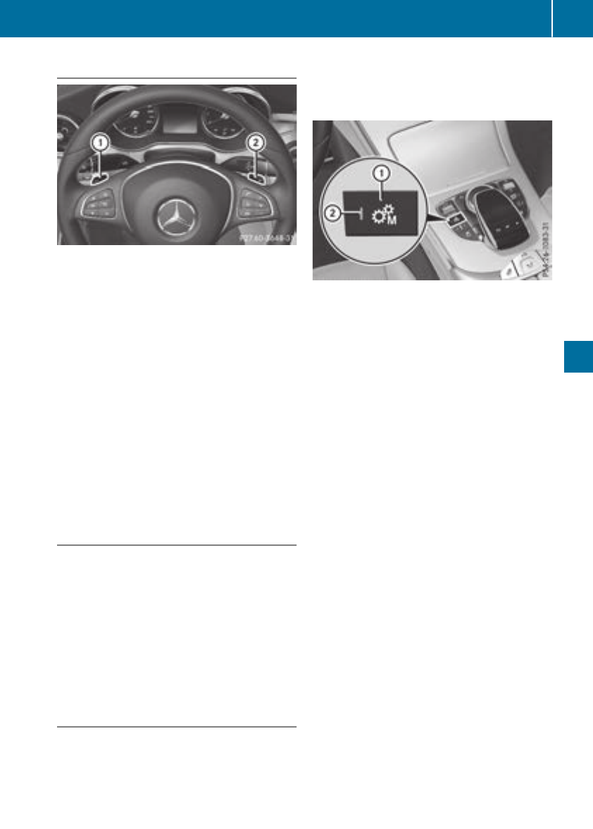
Temporary setting
XTo activate: shift the DIRECT SELECT lever to
position h.
XPull steering wheel paddle shifter :or ;.
Temporary setting will be active for a certain
amount of time. In certain conditions, the mini-
mum amount of time is extended, e.g. in the
case of lateral acceleration, overrun mode or
driving on steep terrain.
XTo deactivate: pull steering wheel paddle
shifter ;and hold it in place.
or
XUse the DIRECT SELECT lever to switch the
transmission position.
or
XUse the DYNAMIC SELECT switch to change
the drive program.
Permanent setting (except Mercedes-
AMG vehicles)
When configuring drive program I, select the M
(Manual) setting for the drive. When driving in
drive program I, you permanently shift the gears
manually using the steering wheel paddle shift-
ers.
Information about configuring drive program I
with the multimedia system can be found under
"DYNAMIC SELECT" in the vehicle's Digital
Operator's Manual.
Permanent setting (Mercedes-AMG
vehicles)
!In manual mode, the automatic transmis-
sion does not shift up automatically even
when the engine limiting speed for the current
gear is reached. When the engine limiting
speed is reached, the fuel supply is cut to
prevent the engine from overrevving. Always
make sure that the engine speed does not
reach the red area of the tachometer. There is
otherwise a risk of engine damage.
XTo activate/deactivate: shift the DIRECT
SELECT lever to position h.
XPress button :.
When the indicator lamp ;lights up, auto-
matic transmission manual mode is activated.
You then permanently shift the gears man-
ually using the steering wheel paddle shifters.
The manual mode activated with button :
remains activated when the drive program is
changed.
Mercedes-AMG C 63/C 63 S: only if the D
(Automatic) setting has been preselected for
the transmission is manual mode deactivated
when you change to drive program I.
Mercedes-AMG C 63/C 63 S: you can also
preset manual mode for drive program I. To do
so, select the M(Manual) setting when config-
uring the transmission. When driving in drive
program I, you permanently shift the gears man-
ually using the steering wheel paddle shifters.
Information about configuring drive program I
with the multimedia system can be found under
"DYNAMIC SELECT" in the vehicle's Digital
Operator's Manual.
Automatic transmission 139
Driving and parking
Z
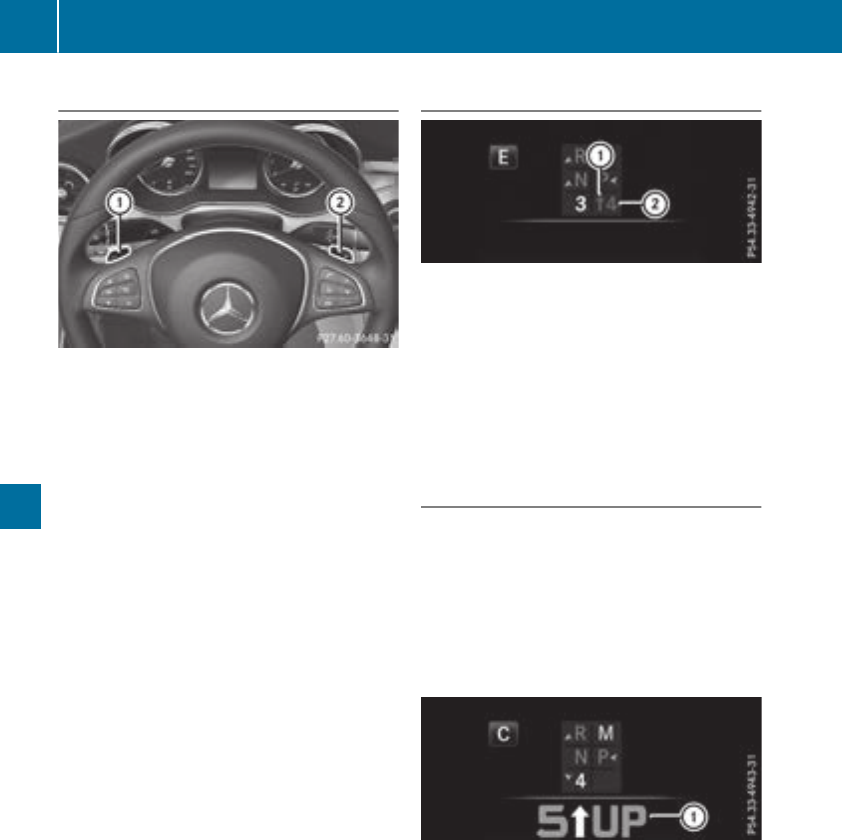
Shifting gears
XTo shift up: pull steering wheel paddle
shifter ;.
The automatic transmission shifts up to the
next gear.
If the maximum engine speed in the gear cur-
rently engaged is reached and you continue to
accelerate, the automatic transmission auto-
matically shifts up in order to prevent engine
damage (except Mercedes-AMG vehicles).
Mercedes-AMG vehicles: if the temporary
setting has been activated and you continue
to accelerate when the maximum engine
speed has been reached, the automatic trans-
mission automatically shifts up. If the perma-
nent setting is activated, the automatic trans-
mission does not shift up automatically even
when the engine limiting speed for the current
gear is reached. Observe the protection
against reaching the overrevving range on the
multifunction display. Always make sure that
the engine speed does not reach the red area
of the tachometer.
XTo shift down: pull steering wheel paddle
shifter :.
The automatic transmission shifts down to
the next gear.
Automatic down shifting occurs when coast-
ing.
If the engine exceeds the maximum engine
speed when shifting down, the automatic
transmission protects against engine damage
by not shifting down.
Shift recommendation
The gearshift recommendations assist you in
adopting an economical driving style. The rec-
ommended gear is shown in the multifunction
display.
XWhen the corresponding gearshift recom-
mendation :appears in the multifunction
display of the instrument cluster, shift to rec-
ommended gear ;.
Protection against reaching the over-
revving range (Mercedes-AMG vehicles)
!In manual mode, the automatic transmis-
sion does not shift up automatically even
when the engine limiting speed for the current
gear is reached. When the engine limiting
speed is reached, the fuel supply is cut to
prevent the engine from overrevving. Always
make sure that the engine speed does not
reach the red area of the tachometer. There is
otherwise a risk of engine damage.
Before the engine speed reaches the red area,
an upshift indicator will be shown in the multi-
function display.
XWhen message :appears in the multifunc-
tion display, pull on the right-hand steering
wheel paddle shifter.
140 Automatic transmission
Driving and parking
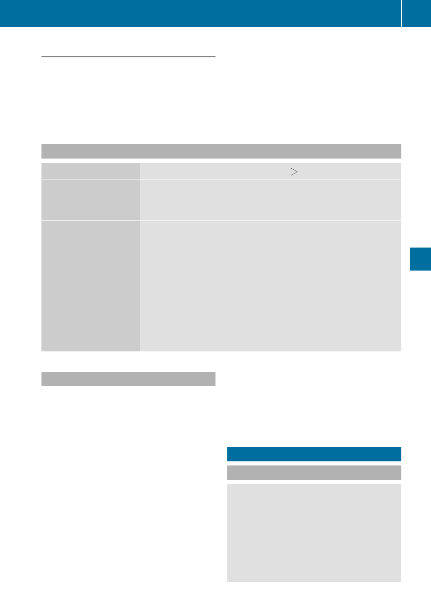
Kickdown
XFormaximum acceleration,depress the
acceleratorpedal beyondthepressurepoint.
The automatic transmission shiftsto alower
gear depending on theenginespeed.
XShift backup once thedesiredspeedis
reached.
If you apply full throttle, theautomatic trans-
mission shiftsup to thenext gear when the
maximum enginespeed is reached. This pre-
vents theenginefrom overrevving.
Mercedes-AMG vehicles: kickdown is only
possiblein thetemporarysetting.
Problems with the transmission
Problem Possible causes/consequences and MSolutions
The transmission has
problemsshifting gear.
The transmission is losing oil.
XHavethetransmission checkedat aqualified specialist workshop
immediately.
The acceleration ability
is deteriorating.
The transmission no lon-
ger changes gear.
The transmission is in emergencymode.
It is possibleto shift to agear and reversegear only.
XStop thevehicle.
XShift thetransmission to position j.
XSwitchoff theengine.
XWait at least tenseconds before restarting theengine.
XShift thetransmission to position hor k.
If his selected, thetransmission only shiftsto onegear;if kis
selected, thetransmission shiftsto reversegear.
XHavethetransmission checkedat aqualified specialist workshop
immediately.
Transfer case
This section is only valid for vehicles with4-
wheeldrive (4MATIC). Poweris always trans-
mittedto bothaxles.
!Performance testsmay only be carriedout
on a2-axledynamometer. The brakesystem
or transfer casecould otherwise be damaged.
Contact a qualified specialist workshop for a
performance test.
!Since ESP®engagesautomatically, theigni-
tion mustbe switched off (the SmartKey or
Start/Stopbuttonmustbe in position gor
1)if
Rtheelectrical parking brakeis beingtested
using a dynamometer
Rthevehicleis beingtowed withonly one
axleraised (not permittedfor vehicles with
4MATIC)
Otherwise,thebrakesystem can be dam-
aged.
!Vehicles with4MATIC mustnotbe towed
witheither thefrontor therear axleraised, as
doingso will damagethetransmission.
Refueling
Important safety notes
GWARNING
Fuelis highly flammable. If you handle fuel
incorrectly, there is ariskof fireand explo-
sion.
You mustavoid fire, open flames, creating
sparks and smoking.Switchoff theengine
and,if applicable, theauxiliary heating before
refueling.
Refueling 141
Driving and parking
Z
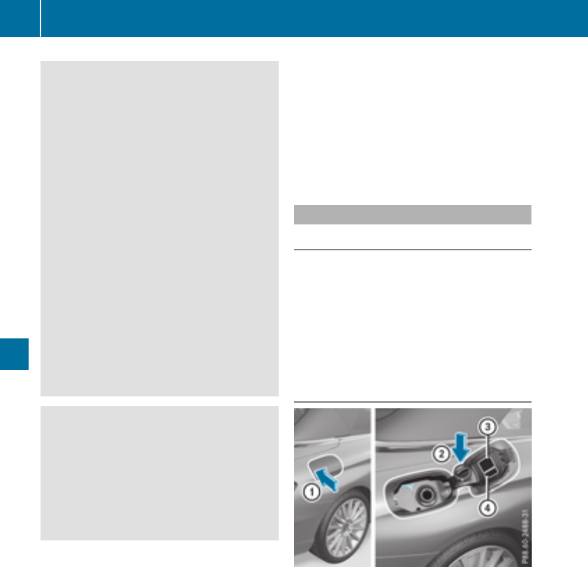
GWARNING
Fuel is poisonous and hazardous to health.
There is a risk of injury.
You must make sure that fuel does not come
into contact with your skin, eyes or clothing
and that it is not swallowed. Do not inhale fuel
vapors. Keep fuel away from children.
If you or others come into contact with fuel,
observe the following:
RWash away fuel from skin immediately
using soap and water.
RIf fuel comes into contact with your eyes,
immediately rinse them thoroughly with
clean water. Seek medical assistance with-
out delay.
RIf fuel is swallowed, seek medical assis-
tance without delay. Do not induce vomit-
ing.
RImmediately change out of clothing which
has come into contact with fuel.
GWARNING
Electrostatic buildup can create sparks and
ignite fuel vapors. There is a risk of fire and
explosion.
Always touch the vehicle body before opening
the fuel filler flap or touching the fuel pump
nozzle. Any existing electrostatic buildup is
thereby discharged.
Do not get into the vehicle again during the refu-
eling process. otherwise electrostatic charge
could build up again.
!Do not use diesel to refuel vehicles with a
gasoline engine. Do not switch on the ignition
if you accidentally refuel with the wrong fuel.
Otherwise, the fuel will enter the fuel system.
Even small amounts of the wrong fuel could
result in damage to the fuel system and the
engine. Notify a qualified specialist workshop
and have the fuel tank and fuel lines drained
completely.
!Overfilling the fuel tank could damage the
fuel system.
!Take care not to spill any fuel on painted
surfaces. You could otherwise damage the
paintwork.
!Use a filter when adding fuel from a fuel can.
The fuel lines and/or the fuel injection system
could otherwise be blocked by particles from
the fuel can.
If you overfill the fuel tank, fuel could spray out
when the fuel pump nozzle is removed.
For further information on fuel and fuel quality
(Ypage 340).
Refueling
General information
Pay attention to the important safety notes
(Ypage 141).
If you unlock/lock the vehicle from the outside,
the fuel filler flap also unlocks/locks.
The position of the 8fuel filler cap is dis-
played on the instrument cluster. The arrow next
to the filling pump indicates the side of the vehi-
cle.
Opening the fuel filler flap
:To open the fuel filler flap
;To insert the fuel filler cap
=Tire pressure table
?Instruction label for fuel type to be refueled
XSwitch off the engine.
XRemove the SmartKey from the ignition lock.
or, in vehicles with KEYLESS-GO start-function
or KEYLESS‑GO
XOpen the driver's door.
The vehicle electronics are now in setting u.
This is the same as "SmartKey removed".
XPress the fuel filler flap in the direction of
arrow :.
The fuel filler flap swings up.
142 Refueling
Driving and parking
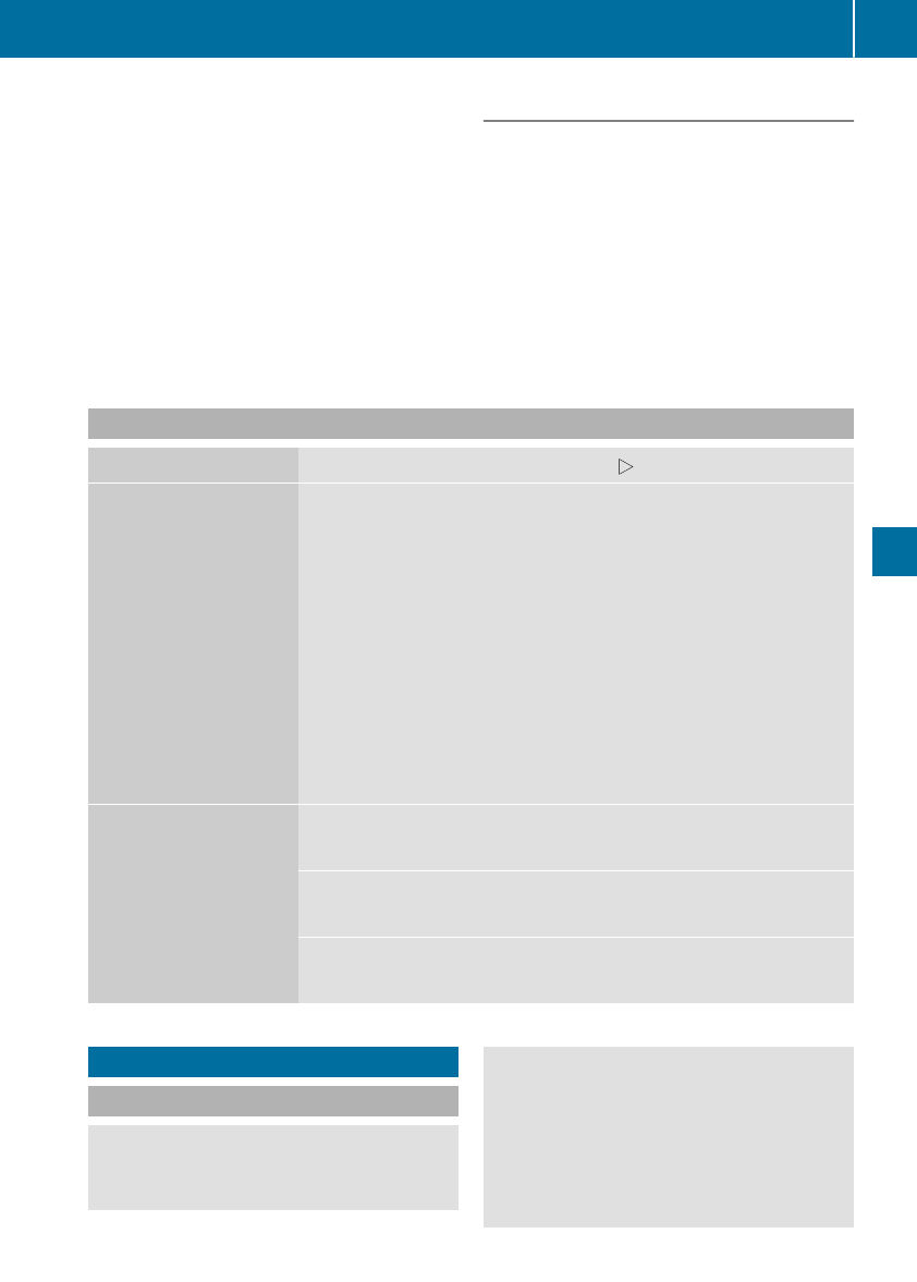
XTurn the fuel filler cap counterclockwise and
remove it.
XInsert the fuel filler cap into the holder on the
inside of fuel filler flap ;.
XCompletely insert the filler neck of the fuel
pump nozzle into the tank, hook in place and
refuel.
XOnly fill the tank until the pump nozzle
switches off.
Do not add any more fuel after the pump stops
filling for the first time. Otherwise, fuel may leak
out.
Closing the fuel filler flap
XReplace the cap on the filler neck and turn
clockwise until it engages audibly.
XClose the fuel filler flap.
Close the fuel filler flap before locking the vehi-
cle.
If you are driving with the fuel filler cap open, the
8reserve fuel warning lamp flashes. A mes-
sage appears in the multifunction display
(Ypage 227).
Problems with fuel and the fuel tank
Problem Possible causes/consequences and MSolutions
Fuel is leaking from the
vehicle. GWARNING
The fuel line or the fuel tank is faulty.
Risk of explosion or fire.
XApply the electric parking brake.
XSwitch off the engine.
XRemove the SmartKey from the ignition lock.
or, in vehicles with KEYLESS-GO start-function or KEYLESS‑GO
XOpen the driver's door.
The vehicle electronics are now in position u. This is the same as
the key having been removed.
XDo not restart the engine under any circumstances.
XConsult a qualified specialist workshop.
The fuel filler flap cannot
be opened.
The fuel filler flap is not unlocked.
XUnlock the vehicle (Ypage 76).
The SmartKey battery is discharged or nearly discharged.
XUnlock the vehicle using the mechanical key (Ypage 78).
The fuel filler flap is unlocked, but the opening mechanism is jammed.
XConsult a qualified specialist workshop.
Parking
Important safety notes
GWARNING
Flammable material such as leaves, grass or
twigs may ignite if they come into contact with
hot parts of the exhaust system or exhaust
gas flow. There is a risk of fire.
Park the vehicle so that no flammable mate-
rials come into contact with parts of the vehi-
cle which are hot. Take particular care not to
park on dry grassland or harvested grain
fields.
Parking 143
Driving and parking
Z

GWARNING
If you leave children unsupervised in the vehi-
cle, they could set it in motion by, for example:
Rrelease the parking brake.
Rshift the automatic transmission out of the
parking position P.
Rstart the engine.
In addition, they may operate vehicle equip-
ment and become trapped. There is a risk of
an accident and injury.
When leaving the vehicle, always take the
SmartKey with you and lock the vehicle. Never
leave children unsupervised in the vehicle.
!Always secure the vehicle correctly against
rolling away. Otherwise, the vehicle or its driv-
etrain could be damaged.
To ensure that the vehicle is secured against
rolling away unintentionally:
Rthe electric parking brake must be applied.
Rthe transmission must be in position jand
the SmartKey must be removed from the igni-
tion lock.
Rthe front wheels must be turned towards the
curb on steep uphill or downhill gradients.
Rthe empty vehicle must be secured at the
front axle with a wheel chock or similar, for
example, on uphill or downhill gradients.
Ron uphill or downhill gradients the laden vehi-
cle must also be secured at the rear axle, for
example with a wheel chock or similar object.
Switching off the engine
Important safety notes
GWARNING
The automatic transmission switches to neu-
tral position Nwhen you switch off the engine.
The vehicle may roll away. There is a risk of an
accident.
After switching off the engine, always switch
to parking position P. Prevent the parked vehi-
cle from rolling away by applying the parking
brake.
Vehicles with automatic transmission
XApply the electric parking brake.
XShift the transmission to position j.
XWith the SmartKey: turn the SmartKey to
position uin the ignition lock and remove it.
The immobilizer is activated.
XWith the Start/Stop button: press the
Start/Stop button (Ypage 124).
The engine stops and all the indicator lamps in
the instrument cluster go out.
When the driver's door is closed, this corre-
sponds to key position 1. When the driver's
door is open, this corresponds to key position
u, "Key removed".
If you switch the engine off with the transmis-
sion in position kor hthe automatic trans-
mission shifts to iautomatically.
With the SmartKey: if you then open the driv-
er's door or the front-passenger door or remove
the SmartKey from the ignition, the automatic
transmission shifts to jautomatically.
With the Start/Stop button: if you then open
the driver's door or the front-passenger door,
the automatic transmission shifts to jauto-
matically.
If you want the automatic transmission to
remain in neutral i, for example, when having
the vehicle cleaned in an automatic car wash
with a towing system:
XVehicles with KEYLESS-GO or KEYLESS-
GO start function: remove the Start/Stop
button from the ignition lock.
XInsert the SmartKey into the ignition lock.
XAll vehicles: switch the ignition on.
XDepress the brake pedal and keep it
depressed.
XEngage neutral i.
XRelease the brake pedal.
XRelease the electric parking brake.
XSwitch off the ignition and leave the SmartKey
in the ignition lock.
The engine can be switched off in an emergency
while the vehicle is in motion by pressing and
holding the Start/Stop button for three sec-
onds. This function operates independently of
the ECO start/stop automatic engine switch-off
function.
144 Parking
Driving and parking
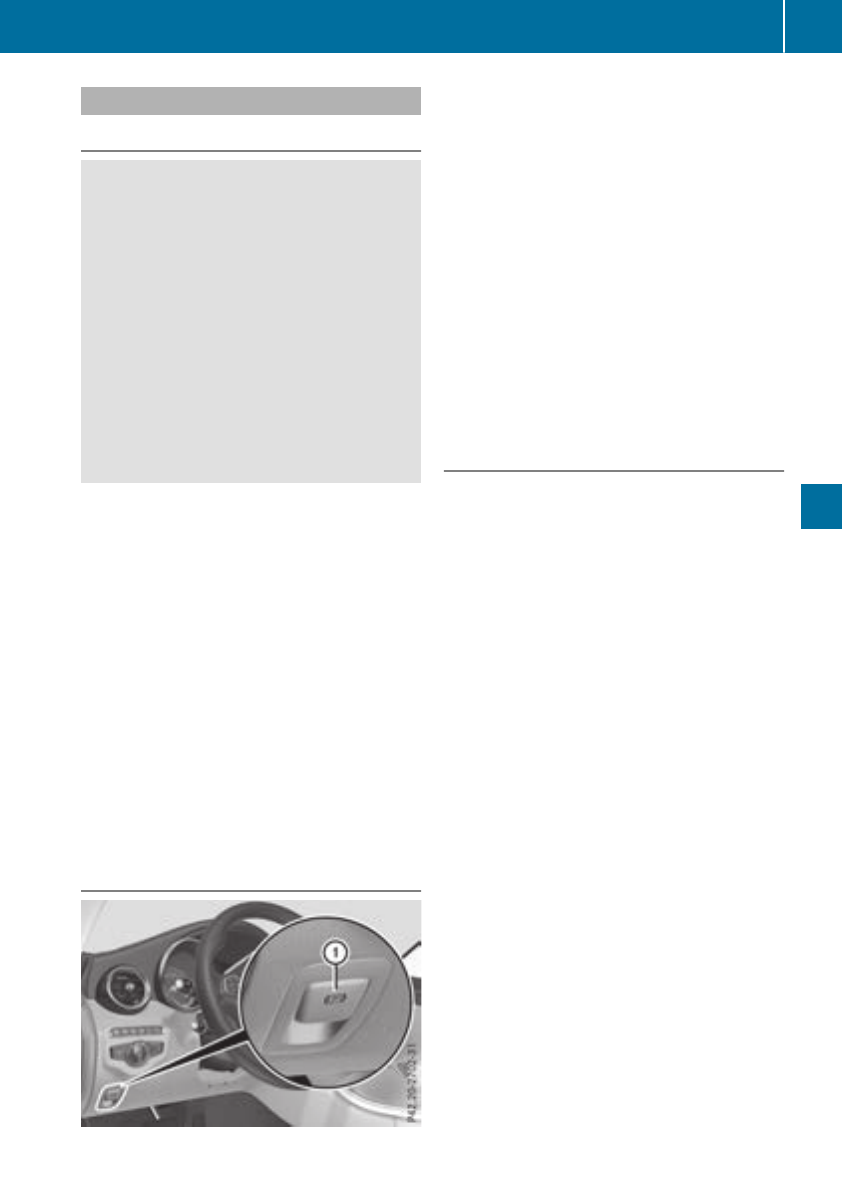
Electric parking brake
General notes
GWARNING
If you leave children unsupervised in the vehi-
cle, they could set it in motion by, for example:
Rrelease the parking brake.
Rshift the automatic transmission out of the
parking position P.
Rstart the engine.
In addition, they may operate vehicle equip-
ment and become trapped. There is a risk of
an accident and injury.
When leaving the vehicle, always take the
SmartKey with you and lock the vehicle. Never
leave children unsupervised in the vehicle.
The function of the electric parking brake is
depending on the on-board voltage. If the on-
board voltage is low or there is a malfunction in
the system, it may not be possible to apply the
released parking brake.
XIf this happens, park the vehicle on level
ground only and secure it to prevent it from
rolling away.
XShift the transmission to position j.
It may not be possible to release an applied
parking brake if the on-board voltage is low or
there is a malfunction in the system. Contact a
qualified specialist workshop.
The electric parking brake performs a function
test at regular intervals while the engine is
switched off. The sounds that can be heard while
this is occurring are normal.
Applying or releasing manually
XTo apply: push handle :.
When the electric parking brake is applied,
the red F(USA only) or !(Canada
only) indicator lamp lights up in the instru-
ment cluster.
The electric parking brake can also be applied
when the SmartKey is removed.
XTo release: pull handle :.
The red F(USA only) or !(Canada
only) indicator lamp in the instrument cluster
goes out.
The electric parking brake can only be released:
Rif the SmartKey is in position 1or 2in the
ignition lock (Ypage 123) or
Rif the ignition was switched on using the
Start/Stop button
Applying automatically
The electric parking brake is automatically
applied when the transmission is in position j
and:
Rthe engine is switched off or
Rthe driver is not wearing a seat belt and the
driver's door is opened
To prevent the electric parking brake from being
automatically applied, pull handle :.
The electric parking brake is also engaged auto-
matically if:
RDistance Pilot DISTRONIC brings the vehicle
to a standstill or
Rthe HOLD function is keeping the vehicle sta-
tionary
RParking Pilot is keeping the vehicle stationary
In addition, at least one of the following condi-
tions must be fulfilled:
Rthe engine is switched off
Rthe driver is not wearing a seat belt and the
driver's door is opened
Rthere is a system malfunction
Rthe power supply is insufficient
Rthe vehicle is stationary for a lengthy period
The red F(USA only) or !(Canada only)
indicator lamp in the instrument cluster goes
out.
The electric parking brake is not automatically
engaged if the engine is switched off by the ECO
start/stop function.
Parking 145
Driving and parking
Z

Releasing automatically
Your vehicle's electric parking brake is auto-
matically released if all of the following condi-
tions are met:
Rthe seat belt has been fastened
Rthe engine is running
Rthe transmission is in position hor kand
you accelerate.
or
you shift from transmission position jto
position hor k. On steep inclines, you have
to press the accelerator as well.
If the transmission is in position k, the trunk lid
must be closed.
If your seat belt is not fastened, the following
conditions must be fulfilled to automatically
release the electric parking brake:
Rthe driver's door is closed
RYou have shifted out of transmission position
jor you have previously driven faster than
2 mph (3 km/h).
Ensure that you do not depress the accelerator
pedal unintentionally. Otherwise, the parking
brake will be released and the vehicle will start
to move.
Emergency braking
The vehicle can also be braked during an emer-
gency by using the electric parking brake.
XWhile driving, push handle :of the electric
parking brake (Ypage 145).
The vehicle is braked as long as you keep
handle :of the electric parking brake
depressed. The longer electric parking brake
handle :is depressed, the greater the brak-
ing force.
During braking:
Ra warning tone sounds
Rthe Please Release Parking Brake mes-
sage appears
Rthe red F(USA only) or !(Canada
only) indicator lamp in the instrument cluster
flashes
When the vehicle has been braked to a stand-
still, the electric parking brake is engaged.
Parking the vehicle for a long period
If you leave the vehicle parked for longer than
four weeks, the battery may be damaged by
exhaustive discharging.
If you leave the vehicle parked for longer than six
weeks, the vehicle may suffer damage as a
result of lack of use.
XVisit a qualified specialist workshop and seek
advice.
iYou can obtain information about trickle
chargers from a qualified specialist work-
shop.
Driving tips
General driving tips
Important safety notes
GWARNING
If you switch off the ignition while driving,
safety-relevant functions are only available
with limitations, or not at all. This could affect,
for example, the power steering and the brake
boosting effect. You will require considerably
more effort to steer and brake. There is a risk
of an accident.
Do not switch off the ignition while driving.
GWARNING
If you operate mobile communication equip-
ment when driving, you may be distracted
from the traffic situation. You could also lose
control of the vehicle. There is a risk of an
accident.
Only operate this equipment when the vehicle
is stationary.
Observe the legal requirements for the country
in which you are driving. Some jurisdictions pro-
hibit the driver from using a mobile phone while
driving a vehicle.
If you make a call while driving, always use
hands-free mode. Only operate the telephone
when the traffic situation permits. If you are
unsure, pull over to a safe location and stop
before operating the telephone.
146 Driving tips
Driving and parking
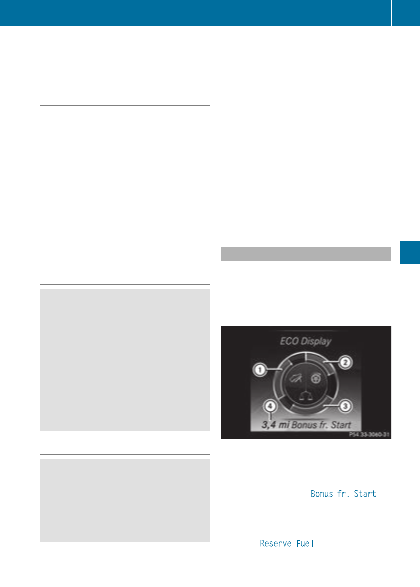
Bear in mind that at a speed of only 30 mph
(approximately 50 km/h), the vehicle covers a
distance of 44 ft (approximately 14 m) per sec-
ond.
Drive sensibly – save fuel
Observe the following tips to save fuel:
XThe tires should always be inflated to the rec-
ommended tire pressure.
XRemove unnecessary loads.
XRemove roof racks when they are not needed.
XWarm up the engine at low engine speeds.
XAvoid frequent acceleration or braking.
XHave all maintenance work carried out as
indicated by the service intervals in the Main-
tenance Booklet or by the service interval dis-
play.
Fuel consumption also increases when driving in
cold weather, in stop-start traffic and in hilly ter-
rain.
Drinking and driving
GWARNING
Drinking and driving and/or taking drugs and
driving are very dangerous combinations.
Even a small amount of alcohol or drugs can
affect your reflexes, perceptions and judg-
ment.
The possibility of a serious or even fatal acci-
dent is greatly increased when you drink or
take drugs and drive.
Do not drink or take drugs and drive or allow
anyone to drive who has been drinking or tak-
ing drugs.
Emission control
GWARNING
Combustion engines emit poisonous exhaust
gases such as carbon monoxide. Inhaling
these exhaust gases leads to poisoning. There
is a risk of fatal injury. Therefore never leave
the engine running in enclosed spaces with-
out sufficient ventilation.
Certain engine systems are designed to keep
the level of poisonous components in exhaust
fumes within legal limits.
These systems only work at peak efficiency if
they are serviced exactly in accordance with the
manufacturer's specifications. Always have
work on the engine carried out at a qualified
specialist workshop. Mercedes-Benz recom-
mends that you use an authorized Mercedes-
Benz Center for this purpose. In particular, work
relevant to safety or on safety-related systems
must be carried out at a qualified specialist
workshop.
The engine settings must not be changed under
any circumstances. Furthermore, all specific
service work must be carried out at regular
intervals and in accordance with the Mercedes-
Benz service requirements. Details can be found
in the Maintenance Booklet.
ECO display
The ECO display shows you how economical
your driving style is. The ECO display assists you
in achieving the most economical driving style
for the selected settings and prevailing condi-
tions. Your driving style can significantly influ-
ence the vehicle's consumption.
:Acceleration
;Coasting
=Constant
?Additional range achieved
Range ?is shown under Bonus fr. Start and
represents the additional range achieved since
the beginning of the journey as a result of an
adapted driving style.
If the fuel level has dropped into the reserve
range, the Reserve Fuel display message is
shown instead of range ?in the multifunction
Driving tips 147
Driving and parking
Z

display. The 8warning lamp in the instru-
ment cluster also lights up (Ypage 247).
The ECO display consists of three sections, with
an inner and outer area. The sections corre-
spond to the following three categories:
:Acceleration (evaluation of all accel-
eration processes):
Rthe outer area fills up and the inner
area lights up green: moderate
acceleration, especially at higher
speeds
Rthe outer area empties and the
inner area is gray: sporty acceler-
ation
;Coasting (evaluation of all decelera-
tion processes):
Rthe outer area fills up and the inner
area lights up green: anticipatory
driving, keeping your distance and
early release of the accelerator.
The vehicle can coast without use
of the brakes.
Rthe outer area empties and the
inner area is gray: frequent heavy
braking
=Constant (continuous evaluation
over the entire journey):
Rthe outer area fills up and the inner
area lights up green: constant
speed and avoidance of unneces-
sary acceleration and deceleration
Rthe outer area empties and the
inner area is gray: fluctuations in
speed
The three inner areas display the current driving
style and light up green as a result of a particu-
larly economical driving style. Depending on the
driving situation, up to two areas may light up
simultaneously.
At the beginning of the journey, the three outer
areas are empty and fill up as a result of eco-
nomical driving. A higher level indicates a more
economical driving style. If the three outer areas
are completely filled at the same time, the driver
has adopted the most economical driving style
for the selected settings and prevailing condi-
tions. The ECO display border lights up.
The ECO display does not indicate the actual fuel
consumption. The additionally achieved range
displayed under Bonus fr. Start does not
indicate a fixed consumption reduction.
In addition to driving style, the actual consump-
tion is affected by other factors, such as:
Rload
RTire pressure
RCold start
RChoice of route
RActive electrical consumers
These factors are not included in the ECO dis-
play.
An economical driving style specially requires
driving at moderate engine speeds.
Achieving a higher value in the categories
"Acceleration" and "Constant":
Robserve the gearshift recommendations
Rdrive using drive program E
On long journeys at a constant speed, e.g. on the
highway, only the outer area for "constant" will
change.
The ECO display summarizes the driving style
from the start of the journey to its completion.
Therefore, there are more marked changes in
the outer areas at the start of a journey. On lon-
ger journeys, there are fewer changes. For more
marked changes, perform a manual rest
(Ypage 198).
For further information on the ECO display, see
(Ypage 197).
Braking
Important safety notes
GWARNING
If you shift down on a slippery road surface in
an attempt to increase the engine's braking
effect, the drive wheels could lose their grip.
There is an increased danger of skidding and
accidents.
Do not shift down for additional engine brak-
ing on a slippery road surface.
Downhill gradients
!On long and steep gradients, you must
reduce the load on the brakes by shifting to a
lower gear in good time. This allows you to
take advantage of the engine's braking effect.
148 Driving tips
Driving and parking

This helps you to avoid overheating the
brakes and wearing them out excessively.
When you take advantage of engine braking, a
drive wheel may not turn for some time, e.g.
on a slippery road surface. This could cause
damage to the drive train. This type of damage
is not covered by the Mercedes-Benz war-
ranty.
Heavy and light loads
GWARNING
If you rest your foot on the brake pedal while
driving, the braking system can overheat. This
increases the stopping distance and can even
cause the braking system to fail. There is a
risk of an accident.
Never use the brake pedal as a footrest. Never
depress the brake pedal and the accelerator
pedal at the same time.
!Depressing the brake pedal constantly
results in excessive and premature wear to
the brake pads.
If the brakes have been subjected to a heavy
load, do not stop the vehicle immediately. Drive
on for a short while. This allows the airflow to
cool the brakes more quickly.
Wet roads
If you have driven for a long time in heavy rain
without braking, there may be a delayed reac-
tion from the brakes when braking for the first
time. This may also occur after the vehicle has
been washed or driven through deep water.
You have to depress the brake pedal more
firmly. Maintain a greater distance from the
vehicle in front.
After driving on a wet road or having the vehicle
washed, brake firmly while paying attention to
the traffic conditions. This will warm up the
brake discs, thereby drying them more quickly
and protecting them against corrosion.
Limited braking performance on salt-
treated roads
If you drive on salted roads, a layer of salt resi-
due may form on the brake discs and brake
pads. This can result in a significantly longer
braking distance.
RIn order to prevent any salt build-up, apply the
brakes occasionally while paying attention to
the traffic conditions.
RCarefully depress the brake pedal and the
beginning and end of a journey.
RMaintain a greater distance to the vehicle
ahead.
Servicing the brakes
!The brake fluid level may be too low, if:
Rif the red brake warning lamp lights up in
the instrument cluster and
Ryou hear a warning tone while the engine is
running
Observe additional warning messages in the
multifunction display.
The brake fluid level may be too low due to
brake pad wear or leaking brake lines.
Have the brake system checked immediately.
Consult a qualified specialist workshop to
arrange this.
!Vehicles with 4MATIC: function or per-
formance tests may only be carried out on a 2-
axle dynamometer. If you wish to operate the
vehicle on such a dynamometer, please con-
sult a qualified specialist workshop in
advance. You could otherwise damage the
drive train or the brake system.
!Vehicles with 4MATIC: the ESP®system
operates automatically. If the electric parking
brake is tested on a brake dynamometer, the
engine and ignition must be switched off: turn
the SmartKey in the ignition lock to position
uor 1or press the Start/Stop button
repeatedly in accordance with the given
SmartKey positions.
Braking triggered automatically by ESP®may
cause severe damage to the brake system.
All checks and maintenance work on the brake
system must be carried out at a qualified spe-
cialist workshop.
Have brake pads installed and brake fluid
replaced at a qualified specialist workshop.
If the brake system has only been subject to
moderate loads, you should test the functional-
ity of your brakes at regular intervals.
Information on BAS (Brake Assist System)
(Ypage 65) and Active Brake Assist with cross-
traffic function (Ypage 71).
Driving tips 149
Driving and parking
Z

For safety reasons, Mercedes-Benz recom-
mends only installing the following brake disks
and brake pads/linings:
Rbrake disks that have been approved by
Mercedes-Benz
Rbrake pads/linings that have been approved
by Mercedes-Benz or that are of an equivalent
standard of quality
Other brake disks or brake pads/linings can
compromise the safety of your vehicle.
Always replace all brake disks and brake pads/
linings on an axle at the same time. Always
install new brake pads/linings when replacing
brake disks.
The vehicle is equipped with lightweight brake
disks to which the wheel assembly with rim and
threaded connection is matched.
The use of brake disks other than those
approved by Mercedes-Benz can change the
track width and is subject to approval, if appli-
cable.
Shock-type loads when handling the brake
discs, such as when changing wheels, can lead
to a reduction in comfort when driving with light-
weight brake discs. Avoid shock-type loads on
the lightweight brake disks, particularly on the
brake plate.
Mercedes-Benz recommends that you only use
brake fluid that has been specially approved for
your vehicle by Mercedes-Benz, or which corre-
sponds to an equivalent quality standard. Brake
fluid which has not been approved for
Mercedes-Benz vehicles or which is not of an
equivalent quality could affect your vehicle's
operating safety.
High-performance and ceramic brakes
(Mercedes-AMG vehicles)
The AMG brake systems are designed for heavy
loads. This may lead to noise when braking. This
will depend on:
RSpeed
RBraking force
REnvironmental conditions, such as tempera-
ture and humidity
The wear of individual components of the brake
system, such as the brake pads/linings or brake
discs, depends on the individual driving style
and operating conditions.
For this reason, it is impossible to state a mile-
age that will be valid under all circumstances. An
aggressive driving style will lead to high wear.
You can obtain more information on this from a
qualified specialist workshop.
New and replaced brake pads and discs only
reach their optimum braking effect after several
hundred kilometers of driving. Compensate for
this by applying greater force to the brake pedal.
Keep this in mind, and adapt your driving and
braking accordingly during this break-in period.
Excessive heavy braking results in correspond-
ingly high brake wear. If the brake pads/linings
have reached their wear limit, the multifunction
display shows a corresponding message. Espe-
cially for high performance driving, it is impor-
tant to maintain and have the brake system
checked regularly.
Driving on wet roads
Hydroplaning
If water has accumulated to a certain depth on
the road surface, there is a danger of hydro-
planing occurring, even if:
Ryou drive at low speeds
Rthe tires have adequate tread depth
For this reason, in the event of heavy rain or in
conditions in which hydroplaning may occur,
you must drive in the following manner:
Rlower your speed
Ravoid ruts
Ravoid sudden steering movements
Rbrake carefully
Driving on flooded roads
!Bear in mind that vehicles traveling in front
or in the opposite direction create waves. This
may cause the maximum permissible water
depth to be exceeded.
Failure to observe these notes may result in
damage to the engine, electrical systems and
transmission.
If you have to drive on stretches of road on which
water has collected, please bear in mind that:
Rin the case of standing water, the water level
may be no higher than the lower edge of the
vehicle body
Ryou should drive no faster than walking pace
150 Driving tips
Driving and parking

Winter driving
GWARNING
If you shift down on a slippery road surface in
an attempt to increase the engine's braking
effect, the drive wheels could lose their grip.
There is an increased danger of skidding and
accidents.
Do not shift down for additional engine brak-
ing on a slippery road surface.
GDANGER
If the exhaust pipe is blocked or adequate
ventilation is not possible, poisonous gases
such as carbon monoxide (CO) may enter the
vehicle. This is the case, e.g. if the vehicle
becomes trapped in snow. There is a risk of
fatal injury.
If you leave the engine or the auxiliary heating
running, make sure the exhaust pipe and area
around the vehicle are clear of snow. To
ensure an adequate supply of fresh air, open a
window on the side of the vehicle that is not
facing into the wind.
Have your vehicle winter-proofed at a qualified
specialist workshop at the onset of winter.
Drive particularly carefully on slippery road sur-
faces. Avoid sudden acceleration, steering and
braking maneuvers. Do not use cruise control or
Distance Pilot DISTRONIC.
If the vehicle threatens to skid or cannot be
stopped when moving at low speed:
XShift the transmission to position i.
The outside temperature indicator is not
designed to serve as an ice-warning device and
is therefore unsuitable for that purpose.
Changes in the outside temperature are dis-
played after a short delay.
Indicated temperatures just above the freezing
point do not guarantee that the road surface is
free of ice. The road may still be icy, especially in
wooded areas or on bridges. The vehicle could
skid if you fail to adapt your driving style. Always
adapt your driving style and drive at a speed to
suit the prevailing weather conditions.
You should pay special attention to road condi-
tions when temperatures are around freezing
point.
For more information on driving with snow
chains, see (Ypage 315).
For more information on driving with summer
tires, see (Ypage 314).
Observe the notes in the "Winter operation" sec-
tion (Ypage 314).
Driving systems
Mercedes-Benz Intelligent Drive
Mercedes-Benz Intelligent Drive stands for inno-
vative driver assistance and safety systems
which enhance comfort and support the driver in
critical situations. With these intelligent co-ordi-
nated systems Mercedes-Benz has set a mile-
stone on the path towards autonomous driving.
Mercedes-Benz Intelligent Drive embraces all
elements of active and passive safety in one well
thought out system – for the safety of the vehi-
cle occupants and that of other road users.
Further information on driving safety systems
(Ypage 64).
Cruise control
General notes
Cruise control maintains a constant road speed
for you. It brakes automatically in order to avoid
exceeding the set speed. Change into a lower
gear in good time on long and steep downhill
gradients. This is especially important if the
vehicle is laden. By doing so, you will make use
of the braking effect of the engine. This relieves
the load on the brake system and prevents the
brakes from overheating and wearing too
quickly.
Use cruise control only if road and traffic con-
ditions make it appropriate to maintain a steady
speed for a prolonged period. You can store any
road speed above 20 mph (30 km/h).
Important safety notes
Cruise control can neither reduce the risk of an
accident if you fail to adapt your driving style nor
override the laws of physics. Cruise control can-
not take into account the road, traffic and
weather conditions. Cruise control is only an
aid. You are responsible for maintaining a safe
distance to the vehicle in front, for vehicle
Driving systems 151
Driving and parking
Z
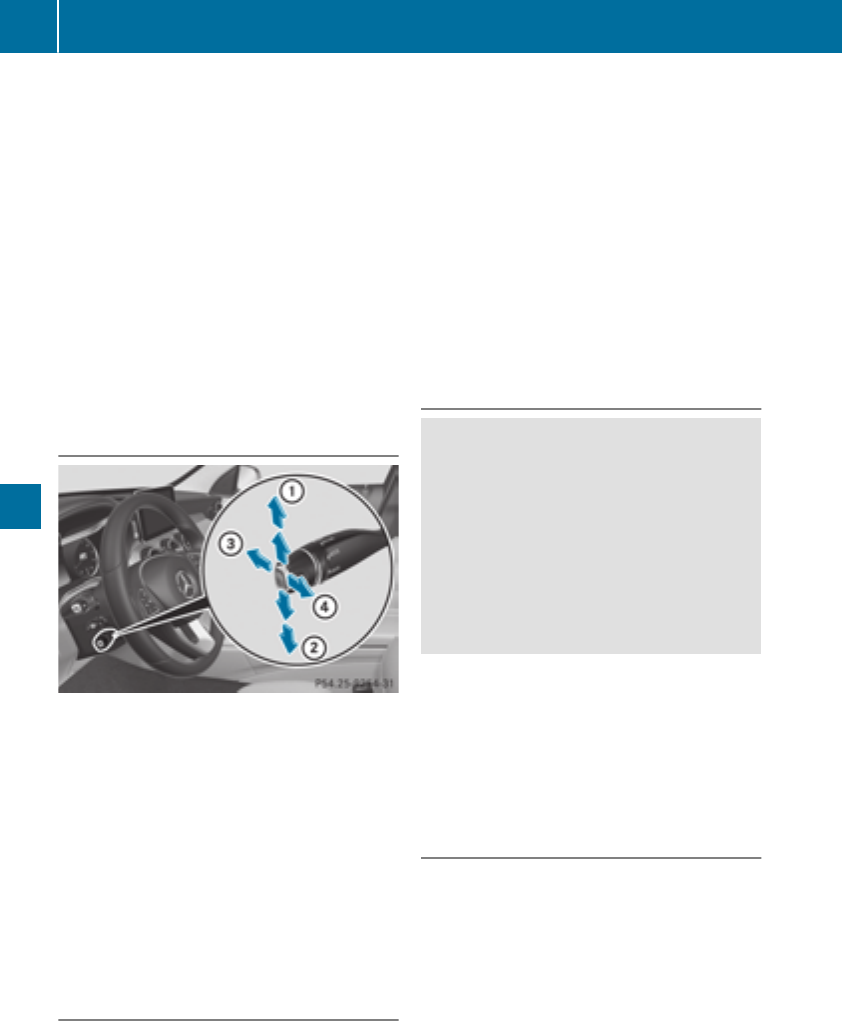
speed, for braking in good time and for staying in
lane.
Do not use cruise control:
Rin road and traffic conditions which do not
allow you to maintain a constant speed, e.g. in
heavy traffic or on winding roads
Ron slippery road surfaces. Braking or accel-
erating could cause the drive wheels to lose
traction and the vehicle could then skid
Rwhen there is poor visibility, e.g. due to fog,
heavy rain or snow
If there is a change of drivers, advise the new
driver of the speed stored.
iThe speed indicated in the speedometer
may differ slightly from the speed stored.
Cruise control lever
:Activates or increases speed
;Activates or reduces speed
=Deactivates cruise control
?Activates at the current speed/last stored
speed
When you activate cruise control, the stored
speed is shown in the multifunction display for
five seconds. The ésymbol appears on the
multifunction display.
Speedometer with segments: when cruise
control is activated, the segments from the
stored speed to the end of the scale light up.
Storing and maintaining the current
speed
You can store the current speed if you are driv-
ing faster than 20 mph (30 km/h).
XAccelerate the vehicle to the desired speed.
XBriefly press the cruise control lever up :or
down ;.
XRemove your foot from the accelerator pedal.
Cruise control is activated. The vehicle auto-
matically maintains the stored speed.
iCruise control may be unable to maintain
the stored speed on uphill gradients. The
stored speed is resumed when the gradient
evens out. Cruise control maintains the
stored speed on downhill gradients by auto-
matically applying the brakes.
Storing the current speed or calling up
the last stored speed
GWARNING
If you call up the stored speed and it is lower
than the current speed, the vehicle deceler-
ates. If you do not know the stored speed, the
vehicle could decelerate unexpectedly. There
is a risk of an accident.
Pay attention to the road and traffic condi-
tions before calling up the stored speed. If you
do not know the stored speed, store the
desired speed again.
XBriefly pull the cruise control lever towards
you ?.
XRemove your foot from the accelerator pedal.
The first time cruise control is activated, it
stores the current speed or regulates the
speed of the vehicle to the previously stored
speed.
Setting a speed
Keep in mind that it may take a brief moment
until the vehicle has accelerated or braked to
the speed set.
XPress the cruise control lever up :for a
higher speed or down ;for a lower speed.
XTo adjust the set speed in 1 mph incre-
ments (1 km/h increments): briefly press
152 Driving systems
Driving and parking
the cruise control lever up :or down ;to
the pressure point.
Every time the cruise control lever is pressed
up :or down ;the last speed stored is
increased or reduced.
XTo adjust the set speed in 5 mph incre-
ments (10 km/h increments): briefly press
the cruise control lever up :or down ;
beyond the pressure point.
Every time the cruise control lever is pressed
up :or down ;the last speed stored is
increased or reduced.
iCruise control is not deactivated if you
depress the accelerator pedal. If you acceler-
ate to overtake, cruise control adjusts the
vehicle's speed to the last speed stored after
you have finished overtaking.
Deactivating cruise control
There are several ways to deactivate cruise con-
trol:
XBriefly press the cruise control lever forward
=.
or
XBrake.
Cruise control is automatically deactivated if:
Ryou engage the electric parking brake
Ryou are driving at less than 20 mph (30 km/h)
RESP®intervenes or you deactivate ESP®
Ryou shift the transmission to position i
while driving
If cruise control is deactivated, a warning tone
sounds. You will see the Cruise Control Off
message in the multifunction display for approx-
imately five seconds. The message on the mul-
tifunction display disappears and the segments
on the speedometer go out.
iWhen you switch off the engine, the last
speed stored is cleared.
Distance Pilot DISTRONIC
General notes
Distance Pilot DISTRONIC regulates the speed
and automatically helps you maintain the dis-
tance to the vehicle detected in front. Vehicles
are detected with the aid of the radar sensor
system. Distance Pilot DISTRONIC brakes auto-
matically so that the set speed is not exceeded.
Change into a lower gear in good time on long
and steep downhill gradients. This is especially
important if the vehicle is laden. By doing so, you
will make use of the braking effect of the engine.
This relieves the load on the brake system and
prevents the brakes from overheating and wear-
ing too quickly.
If Distance Pilot DISTRONIC detects that there is
a risk of a collision, you will be warned visually
and acoustically. Without your intervention, Dis-
tance Pilot DISTRONIC cannot prevent a colli-
sion. An intermittent warning tone will then
sound and the distance warning lamp will light
up in the instrument cluster. Brake immediately
in order to increase the distance to the vehicle in
front or take evasive action provided it is safe to
do so.
Distance Pilot DISTRONIC operates in the range
between 0 mph (0 km/h) and 120 mph
(200 km/h).
Do not use Distance Pilot DISTRONIC while driv-
ing on roads with steep gradients.
Since Distance Pilot DISTRONIC transmits radar
waves, it can resemble the radar detectors of
the responsible authorities. You can refer to the
relevant chapter in the Operator's Manual if
questions are asked about this.
iUSA only: This device has been approved by
the FCC as a "Vehicular Radar System". The
radar sensor is intended for use in an auto-
motive radar system only. Removal, tamper-
ing, or altering of the device will void any war-
ranties, and is not permitted by the FCC. Do
not tamper with, alter, or use in any non-
approved way.
Any unauthorized modification to this device
could void the user's authority to operate the
equipment.
iCanada only: This device complies with
RSS-210 of Industry Canada. Operation is
subject to the following two conditions:
1. This device may not cause interference,
and
2. This device must accept any interference
received, including interference that may
cause undesired operation of the device.
Removal, tampering, or altering of the device
will void any warranties, and is not permitted.
Do not tamper with, alter, or use in any non-
approved way.
Driving systems153
Driving and parking
Z

Any unauthorized modification to this device
could void the user's authority to operate the
equipment.
Important safety notes
GWARNING
Distance Pilot DISTRONIC does not react to:
Rpeople or animals
Rstationary objects on the road, e.g. stopped
or parked vehicles
Roncoming vehicles and crossing traffic
As a result, Distance Pilot DISTRONIC may
neither give warnings nor intervene in such
situations. There is a risk of an accident.
Always pay careful attention to the traffic sit-
uation and be ready to brake.
GWARNING
Distance Pilot DISTRONIC cannot always
clearly identify other road users and complex
traffic situations.
In such cases, Distance Pilot DISTRONIC may:
Rgive an unnecessary warning and then
brake the vehicle
Rneither give a warning nor intervene
Raccelerate or brake unexpectedly
There is a risk of an accident.
Continue to drive carefully and be ready to
brake, especially if Distance Pilot DISTRONIC
warns you.
GWARNING
Distance Pilot DISTRONIC brakes your vehicle
with up to 50% of the maximum possible
deceleration. If this deceleration is not suffi-
cient, Distance Pilot DISTRONIC alerts you
with a visual and acoustic warning. There is a
risk of an accident.
Apply the brakes yourself in these situations
and try to take evasive action.
!When Distance Pilot DISTRONIC or the
HOLD function are activated, the vehicle
brakes automatically in certain situations.
To avoid damage to the vehicle, deactivate
these systems in the following or similar sit-
uations:
Rwhen towing the vehicle
Rin the car wash
Distance Pilot DISTRONIC can neither reduce
the risk of an accident if you fail to adapt your
driving style nor override the laws of physics.
Distance Pilot DISTRONIC cannot take into
account road, weather or traffic conditions. Dis-
tance Pilot DISTRONIC is only an aid. You are
responsible for maintaining a safe distance to
the vehicle in front, for vehicle speed, for brak-
ing in good time and for staying in lane.
Do not use Distance Pilot DISTRONIC:
Rin road and traffic conditions which do not
allow you to maintain a constant speed, e.g. in
heavy traffic or on winding roads
Ron slippery road surfaces. Braking or accel-
erating could cause the drive wheels to lose
traction and the vehicle could then skid
Rin poor visibility, e.g. due to fog, heavy rain or
snow
Distance Pilot DISTRONIC may not detect nar-
row vehicles driving in front, e.g. motorcycles, or
vehicles driving on a different line.
In particular, the detection of obstacles can be
impaired if:
Rthere is dirt on the sensors or anything else
covering the sensors
Rthere is snow or heavy rain
Rthere is interference by other radar sources
Rthere are strong radar reflections, for exam-
ple in parking garages
If Distance Pilot DISTRONIC no longer detects a
vehicle in front, it may unexpectedly accelerate
to the speed stored.
This speed may:
Rbe too high if you are driving in a turning lane
or an exit lane
Rbe so high in the right lane that you pass vehi-
cles driving on the left (in countries where
they drive on the right)
Rbe so high in the left lane that you pass vehi-
cles driving on the right (in countries where
they drive on the left)
If there is a change of drivers, advise the new
driver of the speed stored.
154 Driving systems
Driving and parking
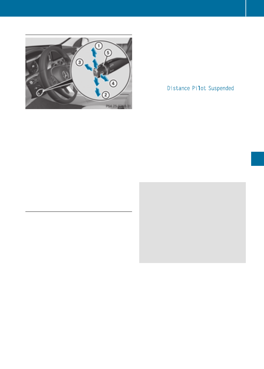
Cruise control lever
:Activates or increases speed
;Activates or reduces speed
=Deactivates Distance Pilot DISTRONIC
?Activates at the current speed/last stored
speed
ASets a specified minimum distance
When you activate Distance Pilot DISTRONIC,
the stored speed will appear on the multifunc-
tion display for five seconds.
Speedometer with segments: when Distance
Pilot DISTRONIC is activated, the segments of
the stored speed light up to the end of the scale
or to a permanently set speed limit.
Activating Distance Pilot DISTRONIC
Activation conditions
To activate Distance Pilot DISTRONIC, the fol-
lowing conditions must be fulfilled:
Rthe engine must be started. It may take up to
two minutes of driving before Distance Pilot
DISTRONIC is ready for use.
Rthe electric parking brake must be released.
RESP®must be activated, but not intervening
at present.
RParking Pilot must not be activated.
Rthe transmission must be in position h.
Rthe driver's door must be closed when you
shift the transmission from position jto h
or your seat belt must be fastened.
Rthe front-passenger door and rear doors must
be closed.
Rthe vehicle must not slide.
Activating
XBriefly pull the cruise control lever towards
you ?or push it up :or down ;.
Distance Pilot DISTRONIC is activated.
XRemove your foot from the accelerator pedal.
The vehicle adapts its speed to that of the
vehicle in front, but only up to the desired
stored speed.
If you do not fully release the accelerator
pedal, the Distance Pilot Suspended mes-
sage appears on the multifunction display.
The set distance to a slower-moving vehicle in
front will then not be maintained. You will be
driving at the speed you determine by the
position of the accelerator pedal.
You can also activate Distance Pilot DISTRONIC
when stationary. The lowest speed that can be
set is 20 mph (30 km/h).
XBriefly pull the cruise control lever towards
you ?or push it up :or down ;.
Distance Pilot DISTRONIC is activated.
Activating at the current speed/last
stored speed
GWARNING
If you call up the stored speed and it differs
from the current speed, the vehicle acceler-
ates or decelerates. If you do not know the
stored speed, the vehicle could accelerate or
brake unexpectedly. There is a risk of an acci-
dent.
Pay attention to the road and traffic condi-
tions before calling up the stored speed. If you
do not know the stored speed, store the
desired speed again.
XBriefly pull the cruise control lever towards
you ?.
XRemove your foot from the accelerator pedal.
The first time Distance Pilot DISTRONIC is
activated, it stores the current speed or reg-
ulates the speed of the vehicle to the previ-
ously stored speed.
Driving systems 155
Driving and parking
Z

DrivingwithDistance PilotDISTRONIC
Pullingawayanddriving
XTo pull awaywithDistance Pilot
DISTRONIC: removeyour foot from thebrake
pedal.
XBriefly pull thecruise controllever towards
you ?.
or
XAcceleratebriefly.
The vehicle pulls away and adaptsitsspeed to
that of thevehicle in front. If no vehicle is
detectedin front, your vehicle accelerates to
thestored speed.
The vehicle can also pull away when it is facing
an unidentifiedobstacleor is drivingon adiffer-
entlinefrom another vehicle. The vehicle then
brakesautomatically.
If DistancePilotDISTRONIC doesnotdetect a
vehicle in front, thesystemoperates likecruise
control.
If DistancePilotDISTRONIC detects that the
vehicle in fronthas slowed down,it brakesthe
vehicle. In this way, thespecifiedminimum dis-
tanceyou haveselectedis maintained.
If DistancePilotDISTRONIC detects afaster-
movingvehicle in front, it increasesthedriving
speed to theset speed.
Selecting thedrive program
DistancePilotDISTRONIC supports asporty
drivingstyle when you haveselectedtheSor S+
drive program (Ypage 136). Acceleration
behindthevehicle in frontor to theset speed is
then noticeably more dynamic.If you have
selectedtheCor Edrivingprogram, thevehicle
accelerates more gently. Thissetting is recom-
mended in stop-and-start traffic.
Changinglanes
If you changeto theovertakinglane, Distance
PilotDISTRONIC supports you if:
Ryou are drivingfasterthan 45 mph (70 km/h)
Ryou switch on theappropriateturnsignal
RDistancePilotDISTRONICdoes notcurrently
detect a danger of collision
If these conditionsare fulfilled,your vehicleis
accelerated. Acceleration will be interrupted if
changinglanes takes toolongor if thedistance
between your vehicleand thevehiclein front
becomestoosmall.
Whenyou changelanes, DistancePilot
DISTRONICmonitors theleftlane(on left-hand-
drive vehicles) or theright lane(on right-hand-
drive vehicles).
Stopping
GWARNING
If you leavethevehiclewhen it is only being
braked by DistancePilotDISTRONIC, it could
rollaway if:
Rthere is amalfunction in thesystem or in
thevoltagesupply.
RDistancePilotDISTRONICis switched off
usingthecruise control lever, e.g. by avehi-
cle occupant or from outside thevehicle
Rtheelectricalsystem in theenginecom-
partment, thebattery or thefuses are tam-
pered with.
Rthebattery is disconnected
Rthevehicleis accelerated, e.g. by avehicle
occupant.
There is ariskof an accident.
Beforeleavingthevehicle, always deactivate
DistancePilotDISTRONICand secure the
vehicleagainst rollingaway.
Further information on deactivatingDistance
PilotDISTRONIC (Ypage 158).
If DistancePilotDISTRONICdetects that the
vehiclein frontis stopping,it brakes your vehicle
to astop.
Once your vehicleis stationary, it remainssta-
tionary and you do notneed to depress the
brake.
After a time, theelectric parkingbrakesecures
thevehicleand relieves theservicebrake.
Dependingon thespecified minimum distance,
your vehiclewill come to astandstill at asuffi-
cient distancebehind thevehiclein front. The
specified minimum distanceis set usingthe
control on thecruise control lever.
156 Driving systems
Driving and parking
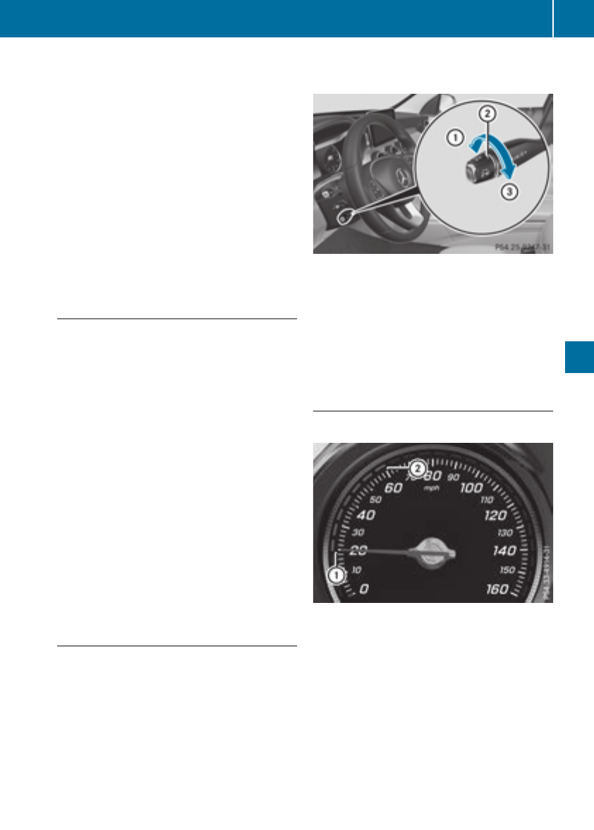
When Distance Pilot DISTRONIC is activated,
the transmission shifts automatically to position
jif:
Rthe driver's seat belt is not fastened and the
driver's door is open.
Rthe engine is switched off, unless it is auto-
matically switched off by the ECO start/stop
function.
The electric parking brake secures the vehicle
automatically if Distance Pilot DISTRONIC is
activated when the vehicle is stationary and:
Ra system malfunction occurs.
Rthe power supply is insufficient.
If a malfunction occurs, the transmission may
also be shifted to position jautomatically.
Setting a speed
XPush cruise control lever up :for a higher
speed or down ;for a lower speed.
XTo adjust the set speed in 1 mph incre-
ments (1 km/h increments): briefly push
the cruise control lever up :or down ;to
the pressure point.
Every time the cruise control lever is pressed
up :or down ;the last speed stored is
increased or reduced.
XTo adjust the set speed in 5 mph incre-
ments (10 km/h increments): briefly push
the cruise control lever up :or down ;
beyond the pressure point.
Every time the cruise control lever is pressed
up :or down ;, the last speed stored is
increased or reduced.
iIf you accelerate to overtake, Distance Pilot
DISTRONIC adjusts the vehicle's speed to the
last speed stored after you have finished over-
taking.
Setting a specified minimum distance
You can set the specified minimum distance for
Distance Pilot DISTRONIC by varying the time
span between one and two seconds. With this
function you can set the minimum distance that
Distance Pilot DISTRONIC maintains to the vehi-
cle in front, depending on vehicle speed. You
can see this distance in the multifunction dis-
play (Ypage 158).
Make sure that you maintain the minimum dis-
tance to the vehicle in front as required by law.
Adjust the distance to the vehicle in front if nec-
essary.
XTo increase: turn control ;in direction =.
Distance Pilot DISTRONIC then maintains a
greater distance between your vehicle and
the vehicle in front.
XTo decrease: turn control ;in direction :.
Distance Pilot DISTRONIC then maintains a
shorter distance between your vehicle and
the vehicle in front.
Displays in the instrument cluster
Displays in the speedometer
If Distance Pilot DISTRONIC detects a vehicle in
front, segments between speed of the vehicle in
front :and stored speed ;light up.
Vehicles with the Driving Assistance Plus
package: the segments likewise light up if a
vehicle in front is detected in the fast lane.
For design reasons, the speed displayed in the
speedometer may differ slightly from the speed
set for Distance Pilot DISTRONIC.
Driving systems 157
Driving and parking
Z
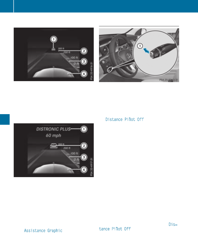
Displaysin theassistancegraphic
Display when DistancePilotDISTRONIC
is deactivated
:Vehiclein front, if detected
;Distanceindicator, currentdistanceto the
vehiclein front
=Specified minimum distanceto thevehicle
in front; adjustable
?Your vehicle
Display when DistancePilotDISTRONIC
is activated
:DistancePilotDISTRONIC active (textonly
appears when thecruise control lever is
actuated)
;Vehiclein front, if detected
=Specified minimum distanceto thevehicle
in front; adjustable
?Your vehicle
XTo call up theassistancegraphic: select
theAssistanceGraphicfunction usingthe
on-boardcomputer (Ypage 203).
The multifunction display shows thestored
speed forapproximately fiveseconds when
you activateDistancePilotDISTRONIC.
Deactivating DistancePilot DISTRONIC
There are severalways to deactivateDistance
PilotDISTRONIC:
XBriefly push cruise control lever forward:.
or
XBrake,unless thevehicleis stationary
Whenyou deactivateDistancePilotDISTRONIC,
theDistance Pilot Off message will appear
on themultifunction display forapproximately
fiveseconds.
The last speed storedremainsstoreduntil you
switch offtheengine.
DistancePilotDISTRONIC is notdeactivated if
you depress theacceleratorpedal.
DistancePilotDISTRONIC is automatically deac-
tivated if:
Ryou engage theelectric parkingbrakeor if the
vehicleis automatically secured withtheelec-
tric parkingbrake
RESP®intervenes or you deactivateESP®
Ryou shift thetransmissionto position j,k
or i
Ryou pull thecruise control lever towardsyou
in order to pull away and thefront-passenger
dooror oneof thereardoors is open
Rthevehicleslips
Ryou activateParking Pilot
If,in these cases, DistancePilotDISTRONIC is
deactivated, awarningtone sounds. The Dis‐
tance Pilot Off message will then be shown
on themultifunction display forapproximately
fiveseconds.
158 Driving systems
Driving and parking
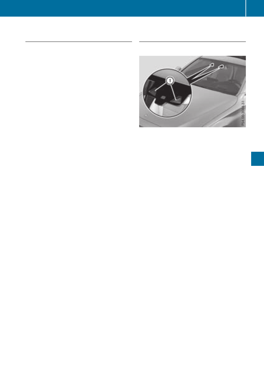
Tips for driving with Distance Pilot
DISTRONIC
Pay particular attention in the following traffic
situations:
RCornering, entering and exiting a bend: the
ability of Distance Pilot DISTRONIC to detect
vehicles during cornering is limited. Your vehi-
cle may brake unexpectedly or late.
RDriving on a different line: Distance Pilot
DISTRONIC may not detect vehicles which are
not driving in the middle of their lane. The dis-
tance to the vehicle in front will be too short.
ROther vehicles changing lanes: Distance Pilot
DISTRONIC has not detected the vehicle cut-
ting in yet. The distance to this vehicle will be
too short.
RNarrow vehicles: Distance Pilot DISTRONIC
has not yet detected the vehicle in front on
the edge of the road because of its narrow
width. The distance to the vehicle in front will
be too short.
RObstacles and stationary vehicles: Distance
Pilot DISTRONIC does not brake for obstacles
or stationary vehicles. If, for example, the
detected vehicle turns a corner and an obsta-
cle or stationary vehicle is then revealed, Dis-
tance Pilot DISTRONIC will not brake for
them.
RCrossing traffic: Distance Pilot DISTRONIC
may mistakenly detect vehicles that are
crossing your lane. Activating Distance Pilot
DISTRONIC at, for example, a traffic light with
crossing traffic, could cause your vehicle to
pull away at the wrong time.
In such situations, brake if necessary. Distance
Pilot DISTRONIC will then be deactivated.
Distance Pilot DISTRONIC with Steering
Pilot
General notes
Distance Pilot DISTRONIC with Steering Pilot
aids you in keeping the vehicle in the middle of
the lane by means of moderate steering inter-
ventions in a speed range from 0 – 125 mph
(0 - 200 km/h).
It monitors the area in front of your vehicle by
means of multifunction camera :, fixed at the
top of the windshield.
In a speed range from 0 - 37 mph (0 - 60 km/h),
Steering Pilot focuses on the vehicle in front,
taking into account lane markings, e.g. when
following vehicles in a traffic jam.
At speeds of more than 37 mph (60 km/h),
Steering Pilot focuses on clear lane markings
(left and right), focusing on the vehicle in front
only if clear lane markings are not present.
If these conditions are not present, Steering
Pilot cannot provide assistance.
Distance Pilot DISTRONIC must be active in
order for the function to be available.
Important safety notes
Distance Pilot DISTRONIC and Steering Pilot can
neither reduce the risk of an accident if you fail
to adapt your driving style nor override the laws
of physics. Distance Pilot DISTRONIC with
Steering Pilot cannot take into account road,
weather or traffic conditions. Distance Pilot
DISTRONIC with Steering Pilot is only an aid.
You are responsible for maintaining a safe dis-
tance to the vehicle in front, for vehicle speed,
for braking in good time and for staying in lane.
Distance Pilot DISTRONIC with Steering Pilot
does not detect road and traffic conditions and
does not detect all road users. If you are follow-
ing a vehicle which is driving towards the edge of
the road, your vehicle could come into contact
Driving systems159
Driving and parking
Z
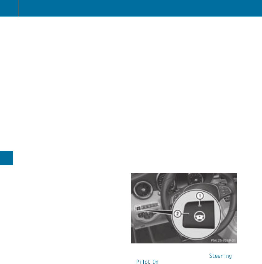
with the curb or other road boundaries. Be par-
ticularly aware of other road users, e.g. cyclists,
that are directly next to your vehicle.
Obstacles such as traffic markers on a con-
struction site that are on the lane or projecting
out into the lane are not detected.
An inappropriate steering intervention, e.g. after
intentionally driving over a lane marking, can be
corrected at any time if you steer slightly in the
opposite direction.
DISTRONIC PLUS with Steering Pilot cannot
continuously keep your vehicle in lane. In some
cases, steering intervention is not sufficient to
bring the vehicle back to the lane. In such cases,
you must steer the vehicle yourself to ensure
that it does not leave the lane.
The system may be impaired or may not function
if:
Rthere is poor visibility, e.g. due to insufficient
illumination of the road, or due to snow, rain,
fog or spray
Rthere is glare, e.g. from oncoming traffic, the
sun or reflection from other vehicles (e.g. if
the road surface is wet)
Rthe windshield is dirty, fogged up, damaged or
covered, for instance by a sticker, in the vicin-
ity of the camera
Rthere are no or several unclear lane markings
for one lane, e.g. roadworks
Rthe lane markings are worn away, dark or cov-
ered up, e.g. by dirt or snow
Rthe distance to the vehicle in front is too short
and thus the lane markings cannot be detec-
ted
Rthe lane markings change quickly, e.g. lanes
branch off, cross one another or merge
Rthe road is narrow and winding
Rthere are highly variable shade conditions on
the roadway
The system is switched to passive and no longer
assists you by performing steering interventions
if:
Ryou actively change lane
Ryou switch on the turn signal
Ryou take your hands off the steering wheel or
do not steer for a prolonged period of time
After you have finished changing lanes, Steering
Pilot is automatically active once more.
Steering Pilot cannot provide assistance:
Ron very sharp corners
Rwhen a loss of tire pressure or a defective tire
has been detected and displayed
Pay attention also to the important safety notes
on Distance Pilot DISTRONIC (Ypage 154).
The steering interventions are carried out with a
limited steering moment. The system requires
the driver to keep his hands on the steering
wheel and to steer himself.
If you do not steer yourself or if you take your
hands off the steering wheel for a prolonged
period of time, the system will first alert you with
a visual warning. A steering wheel symbol
appears in the multifunction display. If you have
still not started to steer and have not taken hold
of the steering wheel, a warning tone also
sounds to remind you to take control of the
vehicle after five seconds at the latest. Steering
Pilot is then switched to passive. Distance Pilot
DISTRONIC remains active.
Activating Steering Pilot
XPress button ;.
Indicator lamp :lights up. The Steering
Pilot On message appears on the multifunc-
tion display. Steering Pilot is activated.
160 Driving systems
Driving and parking
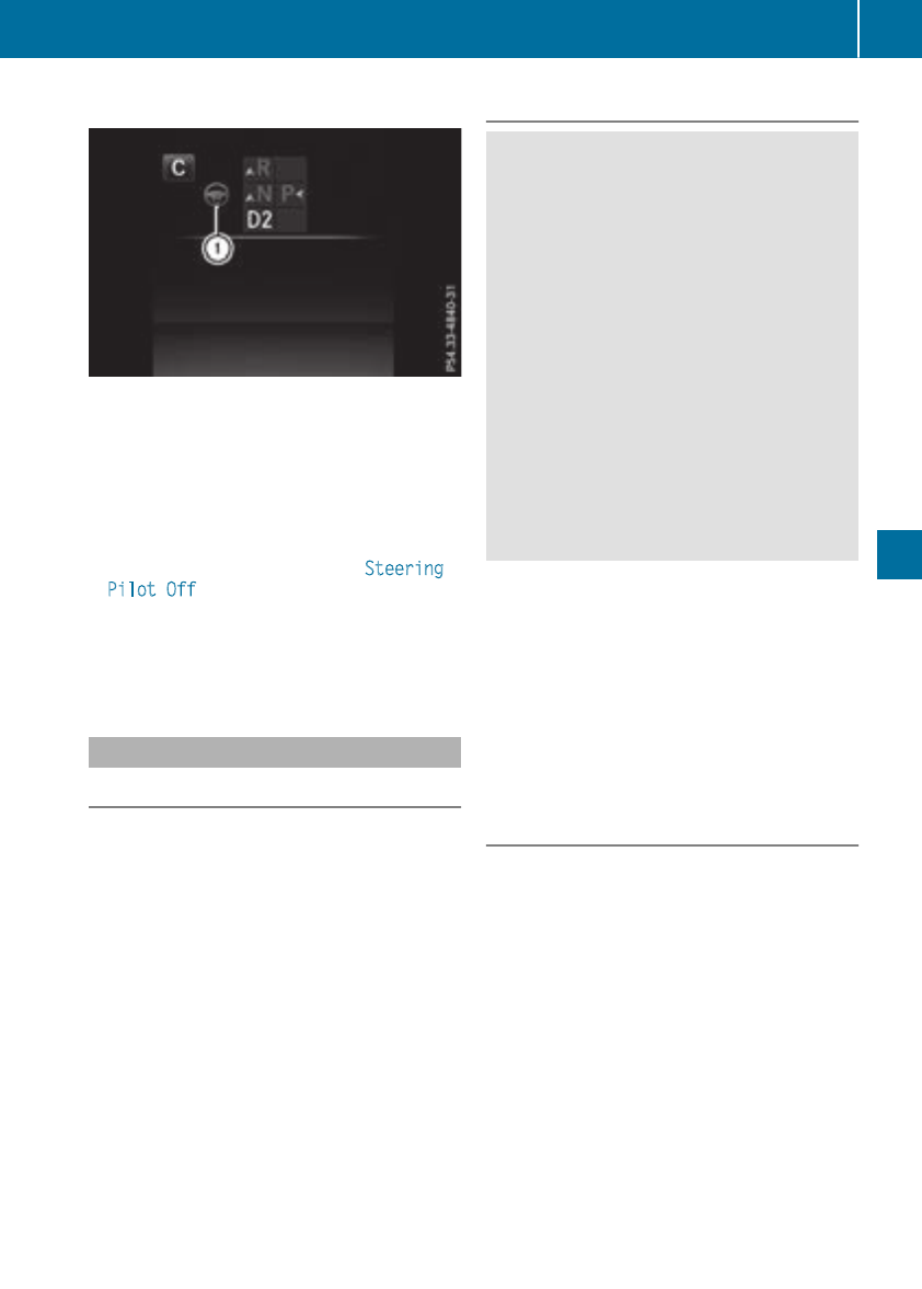
Information in the multifunction display
If Steering Pilot is activated but not ready for a
steering intervention, steering wheel symbol :
appears in gray. If the system provides you with
support by means of steering interventions,
symbol :is shown in green.
Deactivating Steering Pilot
XPress button ;.
Indicator lamp :goes out. The Steering
Pilot Off message appears on the multi-
function display. Steering pilot is deactivated.
When Distance Pilot DISTRONIC is deactivated
or not available, Steering Pilot is deactivated
automatically.
HOLD function
General notes
The HOLD function can assist the driver in the
following situations:
Rwhen pulling away, especially on steep slopes
Rwhen maneuvering on steep slopes
Rwhen waiting in traffic
The vehicle is kept stationary without the driver
having to depress the brake pedal.
The braking effect is canceled and the HOLD
function deactivated when you depress the
accelerator pedal to pull away.
Important safety notes
GWARNING
When leaving the vehicle, it can still roll away
despite being braked by the HOLD function if:
Rthere is a malfunction in the system or in
the voltage supply.
Rthe HOLD function has been deactivated by
pressing the accelerator pedal or the brake
pedal, e.g. by a vehicle occupant.
Rthe electrical system in the engine com-
partment, the battery or the fuses have
been tampered with.
Rthe battery is disconnected
There is a risk of an accident.
If you wish to exit the vehicle, always turn off
the HOLD function and secure the vehicle
against rolling away.
!When DISTRONIC PLUS or the HOLD func-
tion is activated, the vehicle brakes automat-
ically in certain situations.
To avoid damage to the vehicle, deactivate
DISTRONIC PLUS and the HOLD function in
the following or similar situations:
Rwhen towing the vehicle
Rin the car wash
Deactivating the HOLD function (Ypage 162).
Activation conditions
You can activate the HOLD function if all of the
following conditions are fulfilled:
Rthe vehicle is stationary.
Rthe engine is running or if it has been auto-
matically switched off by the ECO start/stop
function.
Rthe driver's door is closed or your seat belt is
fastened.
Rthe electric parking brake is released.
Rthe transmission is in position h,kor i.
RDISTRONIC PLUS is deactivated.
Driving systems 161
Driving and parking
Z
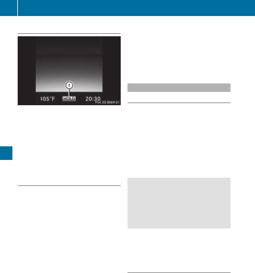
Activating the HOLD function
XMakesurethat theactivation conditionsare
met.
XDepress thebrakepedal.
XQuicklydepress thebrakepedal further
until :appearsin themultifunction display.
The HOLD function is activated. You can
release thebrakepedal.
If depressing thebrakepedal thefirst time does
notactivatetheHOLD function,wait brieflyand
then tryagain.
Deactivating the HOLD function
The HOLD function is deactivated automatically
if:
Ryou depress theacceleratorand thetrans-
mission is in position hor k
Rthetransmission is in position j
Ryou depress thebrakepedal again with a cer-
tainamount of pressureuntil display ë
disappearsfrom themultifunction display
Ryou secure thevehicleusingtheelectric park-
ing brake.
Ryou activateDISTRONICPLUS
After a time, theelectric parking brakesecures
thevehicleand relieves theservicebrake.
When theHOLD function is activated, thetrans-
mission is shiftedautomatically to position j
if:
Rthedriver's seat belt is notfastenedand the
driver's door is open.
Rtheengineis switched off,unless it is auto-
matically switched off by theECO start/stop
function.
The electric parking brakesecures thevehicle
automatically if theHOLD function is activated
when thevehicleis stationary and:
Rasystem malfunction occurs.
Rthepowersupply is insufficient.
If amalfunction occurs, thetransmission may
also be shiftedto position jautomatically.
RACE START
Important safety notes
iRACE START mustnotbe used on normal
roads. RACE START mustonly be activated
and used on dedicated road circuits, outside
of public road use.
iRACE START is only available for Mercedes-
AMGvehicles except Mercedes-AMG C 43
4MATIC.
RACE START enables optimal acceleration from
astanding start.Forthis, asuitably high-grip
road surfaceis requiredand thevehicleand tires
mustbe in goodworking order.
GWARNING
If you use RACE START,individual tires may
start to spin and thevehiclecould skid.
Dependingon theselected ESP®mode, there
is an increased riskof skiddingand having an
accident. Makesurethat no persons, animals
or obstacles are within range of thevehicle.
iObservethesafetynoteson drivingsafety
systems (Ypage 64).
Be sureto read thesafetynotesand informa-
tion on ESP®(Ypage 67).
Conditions for activation
You can activateRACE START if:
Rthedoorsare closed.
Rtheengineis runningand it has reached an
operating temperature of approximately
160 ‡ (71 †). This is thecasewhen theoil
temperature gauge in themultifunction dis-
play is shown in white.
Rthedrive program S,S+ or Race is selected.
(Ypage 130)
Rthesteering wheelis in thestraight-ahead
position.
162 Driving systems
Driving and parking
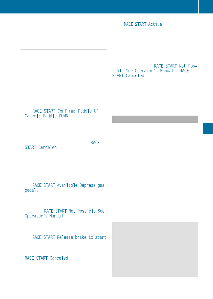
Rthe vehicle is stationary and the brake pedal is
depressed (left foot).
Rthe transmission is in position h
Activating RACE START
iWhen manual mode (Ypage 138) is active,
the transmission automatically shifts up to
RACE START in the drive program. This func-
tion supports maximum acceleration with
RACE START. After going through an acceler-
ating process once from a stationary position,
this function is automatically deactivated.
XDepress the brake pedal with your left foot
and keep it depressed.
XPull and hold both steering wheel paddle shift-
ers (Ypage 138).
The RACE START Confirm: Paddle UP
Cancel: Paddle DOWN message appears in
the multifunction display.
XRelease both steering wheel paddle shifters
(Ypage 138).
iIf the activation conditions are no longer ful-
filled, RACE START is canceled. The RACE
START Canceled message appears in the
multifunction display.
XTo cancel: pull the left steering wheel paddle
shifter (Ypage 138).
or
XTo confirm: pull the right steering wheel pad-
dle shifter (Ypage 138).
The RACE START Available Depress gas
pedal. message appears in the multifunction
display.
iIf you do not depress the accelerator pedal
fully within two seconds, RACE START is can-
celed. The RACE START Not Possible See
Operator's Manual message appears in the
multifunction display.
XDepress the accelerator pedal completely,
until the engine speed stops increasing.
The RACE START Release brake to start
message appears in the multifunction display.
iIf you do not release the brake pedal within
five seconds, RACE START is canceled. The
RACE START Canceled message appears in
the multifunction display.
XTake your foot off the brake, but keep the
accelerator pedal depressed.
The vehicle pulls away at maximum acceler-
ation.
The RACE START Active message appears in
the multifunction display.
RACE START is deactivated when the vehicle
reaches a speed of approximately 30 mph (Can-
ada: 50 km/h).
RACE START is deactivated immediately if you
release the accelerator pedal during RACE
START or if any of the activation conditions are
no longer fulfilled. The RACE START Not Pos‐
sible See Operator's Manual or RACE
START Canceled message appears in the mul-
tifunction display.
iIf RACE START is used repeatedly within a
short period of time, it is only available again
after the vehicle has been driven a certain
distance.
AIRMATIC
General notes
AIRMATIC is an air suspension with variable
damping for improved driving comfort. All-round
level control ensures the best possible suspen-
sion and constant ground clearance, even with a
laden vehicle. When you drive fast, the vehicle is
lowered automatically to improve driving safety
and to reduce fuel consumption. There is also
the option to manually adjust the vehicle level.
AIRMATIC consists of level setting, level control
and ADS PLUS (Adaptive Damping System with
continuous damping adjustment).
The vehicle level can be set using the DYNAMIC
SELECT switch (Ypage 130) or the level button
(Ypage 164). The setting always corresponds
to the last selected function.
Important safety notes
GWARNING
When the vehicle is being lowered, people
could become trapped if their limbs are
between the vehicle body and the wheels or
underneath the vehicle. There is a risk of
injury.
Make sure no one is underneath the vehicle or
in the immediate vicinity of the wheel arches
when the vehicle is being lowered.
iIf one of the doors is open, the vehicle is not
lowered.
Driving systems163
Driving and parking
Z
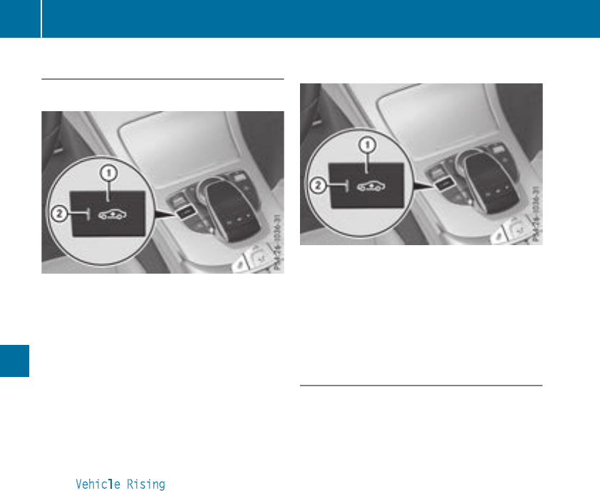
Vehicle level
Setting the raised vehicle level
It is possible to choose between the "Normal"
and "Raised" vehicle levels below a speed of
50 mph (80 km/h). Select the "Normal" setting
for normal road surfaces and "Raised" for driving
with snow chains or on particularly poor road
surfaces. Your selection remains stored even if
you remove the SmartKey from the ignition lock.
XStart the engine.
If indicator lamp ;is not lit:
XPress button :.
Indicator lamp ;lights up. The vehicle is
raised by 0.6 in (15 mm) compared to the
normal level.
The Vehicle Rising message appears on
the multifunction display.
iThe message disappears after ten seconds,
irrespective of the level reached. If necessary,
the vehicle is raised further.
The "Raised level" setting is canceled if you:
Rdrive faster than 75 mph (120 km/h).
Rdrive for approximately three minutes at a
speed over 50 mph (80 km/h).
The "Raised level" remains active when you are
not driving within these speed ranges.
Setting the normal vehicle level
XStart the engine.
If indicator lamp ;is lit:
XPress button :.
Indicator lamp ;goes out. The vehicle is
adjusted to the height of the currently selec-
ted drive program (Ypage 130).
Suspension tuning
General notes
The Adaptive Damping System with continuous
damping adjustment (ADS PLUS) automatically
controls the calibration of the dampers.
The damping is tuned individually to each wheel
and depends on:
Ryour driving style, e.g. sporty
Rthe road surface condition, e.g. bumps
Ryour individual selection, i.e. sports or com-
fort
Your selection remains stored even if you
remove the SmartKey from the ignition lock.
Sports tuning
In the S(Sport) and S+ (Sport Plus) drive pro-
grams, the firmer suspension tuning ensures
even better contact with the road. Select this
mode when employing a sporty driving style,
e.g. on winding country roads.
XSelect the Sor S+ drive program with the
DYNAMIC SELECT switch (Ypage 130).
The vehicle is lowered by 0.6 in (15 mm) com-
pared to the normal level.
Comfort tuning
In the Eand Cdrive programs, the driving char-
acteristics of your vehicle are more comforta-
ble. Therefore, select this mode if you favor a
164 Driving systems
Driving and parking
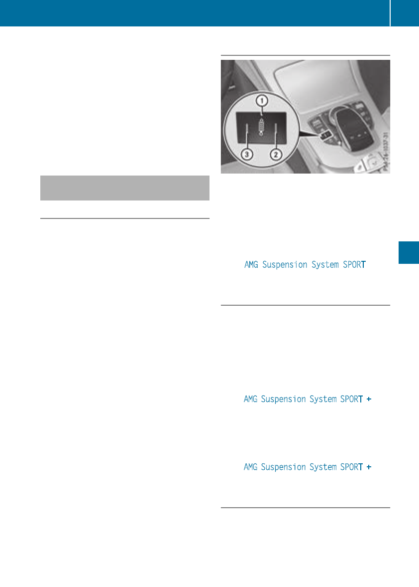
more comfortable driving style. Select comfort
mode also when driving fast on straight roads,
e.g. on straight stretches of highway.
XSelect the Eor Cdrive program with the
DYNAMIC SELECT switch (Ypage 130).
The vehicle is raised to the normal level.
When driving at speeds above 78 mph
(125 km/h), the vehicle is automatically low-
ered by 0.6 in (15 mm) in the Eand Cdrive pro-
grams. When driving at speeds below 50 mph
(80 km/h) the vehicle is raised again.
AMG adaptive sport suspension sys-
tem
General notes
The electronically controlled damping system
works continuously. This improves driving
safety and ride comfort.
The damping is tuned individually to each wheel
and depends on:
Ryour driving style, e.g. sporty
Rthe road surface condition, e.g. bumps
Ryour individual selection of Sport, Sport + or
Comfort
The suspension setting is adjusted using the
corresponding button in the center console.
iThe mode can also be set using the
DYNAMIC SELECT switch (Ypage 130).
This is only possible if:
Rusing the AMG adaptive sport suspension
system button on the center console, and
Rusing the DYNAMIC SELECT switch, the
same mode is selected for the chassis. This
is the case, for example, when both are set
to Comfort mode.
Each time you start the engine with the Smart-
Key or the Start/Stop button, Comfort mode is
activated. For further information about starting
the engine, see (Ypage 125).
Sport mode
The firmer setting of the suspension tuning in
Sport mode ensures even better contact with
the road. Select this mode when employing a
sporty driving style, e.g. on winding country
roads.
XPress button :.
Indicator lamp =lights up. You have selected
Sport mode.
The AMG Suspension System SPORT mes-
sage appears in the multifunction display.
Sport + mode
The very firm setting of the suspension setting in
Sport + mode ensures the best possible contact
with the road. Select this mode only when driv-
ing on race circuits.
If indicator lamps ;and =are off:
XPress button :twice.
Indicator lamps ;and =light up. You have
selected Sport + mode.
The AMG Suspension System SPORT + mes-
sage appears in the multifunction display.
If indicator lamp =lights up:
XPress button :once.
Second indicator lamp ;lights up. You have
selected Sport + mode.
The AMG Suspension System SPORT + mes-
sage appears in the multifunction display.
Comfort mode
In Comfort mode, the driving characteristics of
your vehicle are more comfortable. Select this
mode if you favor a comfortable driving style.
This mode is also suitable if you are driving fast
on straight roads, such as on straight stretches
of a highway.
Driving systems 165
Driving and parking
Z
XPress button :repeatedly until indicator
lamps ;and =go out.
You have selected Comfort mode.
The AMG Suspension System COMFORT mes-
sage appears in the multifunction display.
4MATIC (permanent four-wheel drive)
4MATIC ensures permanent drive for all four
wheels. Together with ESP®, it improves the
traction of your vehicle whenever a drive wheel
spins due to insufficient grip.
If you fail to adapt your driving style or if you are
inattentive, 4MATIC can neither reduce the risk
of an accident nor override the laws of physics.
4MATIC does not take into account
Rthe road and weather conditions
Rthe traffic situation
4MATIC is only an aid. You are responsible for
the distance to the vehicle in front, for vehicle
speed, for braking in good time and for staying in
your lane.
If a drive wheel spins due to insufficient grip:
ROnly depress the accelerator pedal as far as
necessary when pulling away.
RAccelerate less when driving.
!Never tow the vehicle with one axle raised.
This may damage the transfer case. Damage
of this sort is not covered by the Mercedes-
Benz Limited Warranty. All wheels must
remain either on the ground or be fully raised.
Observe the instructions for towing the vehi-
cle with all wheels in full contact with the
ground.
iIn wintry driving conditions, the maximum
effect of 4MATIC can only be achieved if you
use winter tires (M+S tires), with snow chains
if necessary.
Parking Pilot
General notes
Parking Pilot is an electronic parking aid with
ultrasound. It measures the road on both sides
of the vehicle. A parking symbol indicates a suit-
able parking space. Active steering intervention
and brake application can assist you during
parking and when exiting a parking space. You
can also still use Parking Assist PARKTRONIC
(Ypage 170).
Important safety notes
Parking Pilot is only an aid. It is not a replace-
ment for your attention to your immediate sur-
roundings. You are always responsible for safe
maneuvering, parking and exiting a parking
space. Make sure that no persons, animals or
objects are in the maneuvering range.
When Parking Assist PARKTRONIC is deactiva-
ted, Parking Pilot is also unavailable.
GWARNING
While parking or pulling out of a parking
space, the vehicle swings out and can drive
onto areas of the oncoming lane. This could
result in a collision with another road user.
There is a risk of an accident.
Pay attention to other road users. Stop the
vehicle if necessary or cancel the Parking Pilot
parking procedure.
!If unavoidable, you should drive over obsta-
cles such as curbs slowly and not at a sharp
angle. Otherwise, you may damage the
wheels or tires.
Parking Pilot may also display spaces not suita-
ble for parking, e.g.:
Rwhere parking or stopping is prohibited
Rin front of driveways or entrances and exits
Ron unsuitable surfaces
Parking tips:
ROn narrow roads, drive as close to the parking
space as possible.
RParking spaces that are littered or overgrown
might be identified or measured incorrectly.
RParking spaces that are partially occupied by
trailer drawbars might not be identified as
such or be measured incorrectly.
RSnowfall or heavy rain may lead to a parking
space being measured inaccurately.
RPay attention to the warning messages of
Parking Assist PARKTRONIC during the park-
ing procedure (Ypage 171).
RYou can intervene in the steering procedure
to correct it at any time. Parking Pilot is then
canceled.
166 Driving systems
Driving and parking
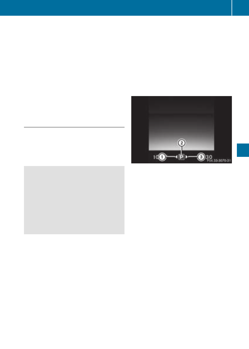
RWhen transporting a load that protrudes from
your vehicle, you should not use Parking Pilot
RNever use Parking Pilot when snow chains are
installed.
RAlways pay attention to the specified tire
pressure for your vehicle. This has a direct
influence on the parking characteristics of the
vehicle.
Use Parking Pilot for parking spaces that are:
Rparallel or at right angles to the direction of
travel
Ron straight roads, not bends
Ron the same level as the road, e.g. not on the
pavement
Detecting parking spaces
Objects located above the detection range of
Parking Pilot will not be detected when the park-
ing space is measured. These are not taken into
account when the parking procedure is calcula-
ted, e.g. overhanging loads, tail sections or load-
ing ramps of trucks.
GWARNING
If there are objects above the detection range:
RParking Pilot may steer in too early
Rthe vehicle may not stop in front of these
objects
You may cause a collision as a result. There is
a risk of an accident.
If objects are located above the detection
range, stop and deactivate Parking Pilot.
For further information on the detection range
(Ypage 170).
Parking Pilot does not assist you parking in
spaces at a right angle to the direction of travel
if:
Rtwo parking spaces are located directly next
to one another
Rthe parking space is directly next to a low
obstacle such as a low curb
Ryou forward-park
Parking Pilot does not assist you parking in
spaces parallel with or at a right angle to the
direction of travel if:
Rthe parking space is on a curb
Rthe system reads the parking space as being
blocked, for example by foliage or grass pav-
ing blocks
Rthe area is too small for the vehicle to maneu-
ver into
Rthe parking space is bordered by an obstacle,
e.g. a tree, a post or a trailer
:Detected parking space on the left
;Parking symbol
=Detected parking space on the right
Parking Pilot is activated automatically when
driving forward. The system is operational at
speeds of up to approximately 22 mph
(35 km/h). While in operation, the system inde-
pendently locates and measures parking spaces
on both sides of the vehicle.
Parking Pilot will only detect parking spaces
which are:
Rparallel or at right angles to the direction of
travel
Rthat are parallel to the direction of travel and
at least 59 in (1.5 m) wide
Rthat are parallel to the direction of travel and
at least 39.5 in (1.0 m) longer than your vehi-
cle
Rat right angles to the direction of travel and at
least 39.5 in (1.0 m) wider than your vehicle
iNote that Parking Pilot PARKTRONIC cannot
measure the depth of parking spaces if they
are at right angles to the direction of travel.
You will need to judge whether your vehicle
will fit into the parking space.
When driving at speeds below 19 mph
(30 km/h), you will see parking symbol ;as a
Driving systems 167
Driving and parking
Z
status indicator on the instrument cluster. When
a parking space has been detected, an arrow
towards the right or the left also appears. Park-
ing Pilot only displays parking spaces on the
front-passenger side as standard. Parking
spaces on the driver's side are displayed as
soon as the turn signal on the driver's side is
activated. When parking on the driver's side,
this must remain activated until you confirm the
use of Parking Pilot by pressing the abutton
on the multifunction steering wheel. The system
automatically determines whether the parking
space is parallel or at right angles to the direc-
tion of travel.
A parking space is displayed while you are driv-
ing past it, and until you are approximately 50 ft
(15 m) away from it.
Parking
GWARNING
If you leave the vehicle when it is only being
braked by Parking Pilot, it could roll away if:
Rthere is a malfunction in the system or in
the voltage supply.
Rthe electrical system in the engine com-
partment, the battery or the fuses are tam-
pered with.
Rthe battery is disconnected.
Rthe vehicle is accelerated, e.g. by a vehicle
occupant.
There is a risk of an accident.
Before leaving the vehicle, always secure it
against rolling away.
iIf Parking Assist PARKTRONIC detects
obstacles, Parking Pilot brakes automatically
whilst the vehicle is being parked. You are
responsible for braking in good time.
XStop the vehicle when the parking space sym-
bol shows the desired parking space in the
instrument cluster.
XShift the transmission to position k.
The Start Parking Pilot? Yes: OK No:
%message appears on the multifunction
display.
XTo cancel the procedure: press the %
button on the multifunction steering wheel or
pull away.
or
XParking using Parking Pilot: press button
aon the multifunction steering wheel.
The Parking Pilot Active Accelerate
and Brake Observe Surroundings mes-
sage appears on the multifunction display.
XLet go of the multifunction steering wheel.
XBack up the vehicle, being ready to brake at all
times. When backing up, drive at a speed
below approximately 6 mph (10 km/h). Oth-
erwise, Parking Pilot is canceled immediately.
Parking Pilot brakes the vehicle to a standstill
when the vehicle approaches the rear border
of the parking space.
Maneuvering may be required in tight parking
spaces.
The Parking Pilot Active Select D
Observe Surroundings message appears on
the multifunction display.
XShift the transmission to position hwhen
the vehicle is stationary.
Parking Pilot immediately steers in the other
direction.
The Parking Pilot Active Accelerate
and Brake Observe Surroundings mes-
sage appears on the multifunction display.
iYou will achieve the best results by waiting
for the steering procedure to complete before
pulling away.
XDrive forwards and be ready to brake at all
times.
Parking Pilot brakes the vehicle to a standstill
when the vehicle approaches the front border
of the parking space.
Maneuvering may be required in tight parking
spaces.
The Parking Pilot Active Select R
Observe Surroundings message appears on
the multifunction display.
As soon as the parking procedure is complete,
the Parking Pilot Finished message
appears and a warning tone sounds. The vehicle
is now parked.
The vehicle is kept stationary without the driver
having to depress the brake pedal. The braking
effect is canceled when you depress the accel-
erator pedal.
168 Driving systems
Driving and parking
Parking Pilot no longer supports you with steer-
ing interventions and brake applications. When
Parking Pilot is finished, you must steer and
brake again yourself. Parking Assist
PARKTRONIC is still available.
Parking tips:
RThe way your vehicle is positioned in the park-
ing space after parking is dependent on vari-
ous factors. These include the position and
shape of the vehicles parked in front and
behind it and the conditions of the location. It
may be the case that Parking Pilot guides you
too far into a parking space, or not far enough
into it. In some cases, it may also lead you
across or onto the curb. Cancel the parking
procedure with Parking Pilot if necessary.
RYou can also prematurely select transmission
position h. The vehicle redirects and does
not drive as far into the parking space. Should
the transmission change take place too early,
the parking procedure is canceled. A sensible
parking position can no longer be achieved
from this position.
Exiting a parking space
In order for Parking Pilot to support you when
exiting the parking space:
Rthe border of the parking space must be high
enough at the front and the rear. A curb is too
small, for example.
Rthe border of the parking space must not be
too wide. Your vehicle can be maneuvered
into a position at a maximum of 45° to the
starting position in the parking space.
Ra maneuvering distance of at least 3.3 ft
(1.0 m) must be available.
Parking Pilot can assist you with exiting a park-
ing space only if you have parked the vehicle
parallel to the direction of travel using the Park-
ing Pilot.
iIf Parking Assist PARKTRONIC detects
obstacles, Parking Pilot brakes automatically
whilst the vehicle is exiting the parking space.
You are responsible for braking in good time.
XStart the engine.
XRelease the electric parking brake.
XSwitch on the turn signal in the direction you
are pulling away.
XShift the transmission to position hor k.
The Start Parking Pilot? Yes: OK No:
%message appears on the multifunction
display.
XTo cancel the procedure: press the %
button on the multifunction steering wheel or
pull away.
or
XTo exit a parking space using Parking
Pilot: press the abutton on the multi-
function steering wheel.
The Parking Pilot Active Accelerate
and Brake Observe Surroundings mes-
sage appears on the multifunction display.
XLet go of the multifunction steering wheel.
XPull away, being ready to brake at all times. Do
not exceed a maximum speed of approx-
imately 6 mph (10 km/h) when exiting a park-
ing space. Otherwise, Parking Pilot is can-
celed immediately.
XDepending on the message or as required,
shift the transmission to position hor k.
Parking Pilot immediately steers in the other
direction. The Parking Pilot Active
Accelerate and Brake Observe Sur‐
roundings message appears on the multi-
function display.
iYou will achieve the best results by waiting
for the steering procedure to complete before
pulling away.
If you back up after activation, the steering
wheel is moved to the straight-ahead posi-
tion.
XDrive forwards and reverse as prompted by
the Parking Assist PARKTRONIC warning dis-
plays, several times if necessary.
Once you have exited the parking space com-
pletely, the steering wheel is moved to the
straight-ahead position. You hear a tone and the
Parking Pilot Finished message appears
on the multifunction display. You will then have
to steer and merge into traffic on your own.
Parking Assist PARKTRONIC is still available.
You can take over the steering before the vehi-
cle has exited the parking space completely.
This is useful if you recognize that it is already
possible to pull out of the parking space.
Driving systems 169
Driving and parking
Z
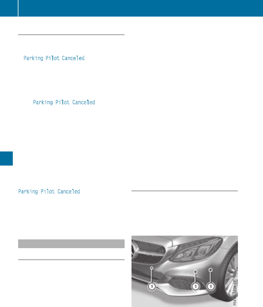
Canceling Active Parking Pilot
XStop the movement of the multifunction
steering wheel or steer yourself.
Parking Pilot is canceled immediately. The
Parking Pilot Canceled message appears
on the multifunction display.
or
XPress the Parking Assist PARKTRONIC button
(Ypage 172).
Parking Assist PARKTRONIC is switched off
and Parking Pilot is immediately canceled.
The Parking Pilot Canceled message
appears on the multifunction display.
Parking Pilot is canceled automatically when:
Rthe electric parking brake is engaged
Rtransmission position jis selected
Rparking using Parking Pilot is no longer pos-
sible
Ryou are driving faster than 6 mph (10 km/h)
Ra wheel spins, ESP®intervenes or fails. In
such cases the ÷warning lamp lights up in
the instrument cluster
A warning tone sounds. The parking symbol dis-
appears and the multifunction display shows the
Parking Pilot Canceled message.
When Parking Pilot is canceled, you must steer
and brake again yourself.
If a system malfunction occurs, the vehicle is
braked to a standstill. To drive on, depress the
accelerator again.
Parking Assist PARKTRONIC
Important safety notes
Parking Assist PARKTRONIC is an electronic
parking aid with ultrasound. It monitors the area
around your vehicle using six sensors in the
front bumper and six sensors in the rear
bumper. Parking Assist PARKTRONIC visually
and audibly indicates the distance between your
vehicle and an object.
Parking Assist PARKTRONIC is only an aid. It is
not a replacement for your attention to your
immediate surroundings. You are always
responsible for safe maneuvering, parking and
exiting a parking space. Make sure that there
are no persons, animals or objects in the maneu-
vering area while maneuvering and parking in/
leaving parking spaces.
!When parking, pay particular attention to
objects above or below the sensors, such as
flower pots or trailer drawbars. Parking Assist
PARKTRONIC does not detect such objects
when they are in the immediate vicinity of the
vehicle. You could damage the vehicle or the
objects.
The sensors may not detect snow and other
objects that absorb ultrasonic waves.
Ultrasonic sources such as an automatic car
wash, the compressed-air brakes of a truck or
a pneumatic drill could cause Parking Assist
PARKTRONIC to malfunction.
Parking Assist PARKTRONIC may not function
correctly on uneven terrain.
Parking Assist PARKTRONIC is activated auto-
matically when you:
Rswitch on the ignition
Rshift the transmission to position h,kor
i
Parking Assist PARKTRONIC is deactivated at
speeds above 11 mph (18 km/h). It is reactiva-
ted at lower speeds.
Range of the sensors
Parking Assist PARKTRONIC does not take into
account obstacles located:
Rbelow the detection range, e.g. people, ani-
mals or objects.
Rabove the detection range, e.g. overhanging
loads, tail sections or loading ramps of trucks.
:Sensors in the front bumper, left-hand side
(example)
170 Driving systems
Driving and parking
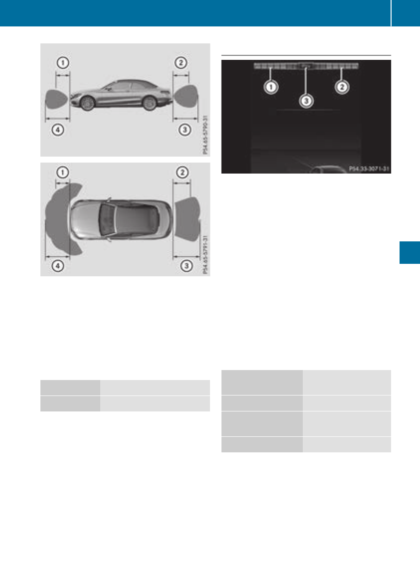
:Approx. 24 in (approx. 60 cm) (corners)
;Approx. 32 in (approx. 80 cm) (corners)
=Approx. 48 in (approx. 120 cm) (center)
?Approx. 40 in (approx. 100 cm) (center)
The sensors must be free from dirt, ice or slush.
They can otherwise not function correctly. Clean
the sensors regularly, taking care not to scratch
or damage them (Ypage 292).
Minimum distance
Center Approx. 8 in (approx. 20 cm)
Corners Approx. 6 in (approx. 15 cm)
If there is an obstacle within this range, the rel-
evant warning displays light up and a warning
tone sounds. If the distance falls below the min-
imum, the distance may no longer be shown.
Warning displays
:Segments on the left-hand side of the vehi-
cle
;Segments on the right-hand side of the vehi-
cle
=Segments showing operational readiness
The warning displays show the distance
between the sensors and the obstacle. The
warning display for the front area is in the instru-
ment cluster. The warning display for the rear
area is located on the headliner in the rear com-
partment.
The warning display for each side of the vehicle
is divided into five yellow and two red segments.
Parking Assist PARKTRONIC is operational if
operational readiness indicator =lights up.
The selected transmission position and the
direction in which the vehicle is rolling deter-
mine which warning display is active when the
engine is running.
Transmission posi-
tion
Warning display
hFront area activated
k,ior the vehicle
is rolling backwards
Rear and front areas
activated
jNo areas activated
One or more segments light up as the vehicle
approaches an obstacle, depending on the vehi-
cle's distance from the obstacle. In addition,
warning tones are issued.
When the distance to the obstacle is sufficient,
you will hear an intermittent warning tone. The
shorter the distance to the obstacle, the shorter
the frequency of the intermittent warning tones
becomes. When the minimum distance is
reached, you hear a continuous warning tone.
Driving systems 171
Driving and parking
Z
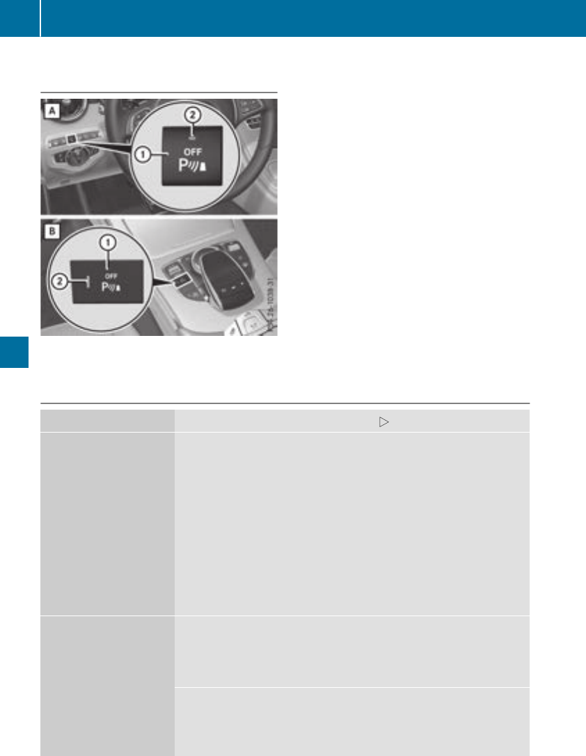
Activating/deactivating Parking Assist
PARKTRONIC
dSwitchon thedashboard
eSwitchin thecenter console
:Deactivates or activates Parking Assist
PARKTRONIC
;Indicatorlamp
If indicator lamp ;lights up, Parking Assist
PARKTRONICis deactivated. Parking Pilotis
then also deactivated.
iParking AssistPARKTRONICis automati-
callyactivated when you turntheSmartKey to
position 2in theignition lock.
Problems with Parking Assist PARKTRONIC
Problem Possible causes/consequences and MSolutions
Only thered segments in
theParking Assist
PARKTRONICwarning
displays are lit.You also
hear awarning tone for
approximately two sec-
onds.
Parking Assist
PARKTRONICis then
deactivated and theindi-
cator lamp on the
PARKTRONICbutton
lights up.
Parking AssistPARKTRONIChas malfunctioned and has been deacti-
vated.
XIf problemspersist, haveParking AssistPARKTRONICcheckedat a
qualified specialistworkshop.
Only thered segments in
theParking Assist
PARKTRONICwarning
displays are lit.Parking
AssistPARKTRONICis
then deactivated.
The Parking AssistPARKTRONICsensorsare dirty or there is inter-
ference.
XClean theParking AssistPARKTRONICsensors (Ypage 292).
XSwitchtheignition backon.
The problem may be caused by an external source of radioor ultra-
soundwaves.
XCheckto see if Parking AssistPARKTRONICworks at adifferent
location.
172 Driving systems
Driving and parking
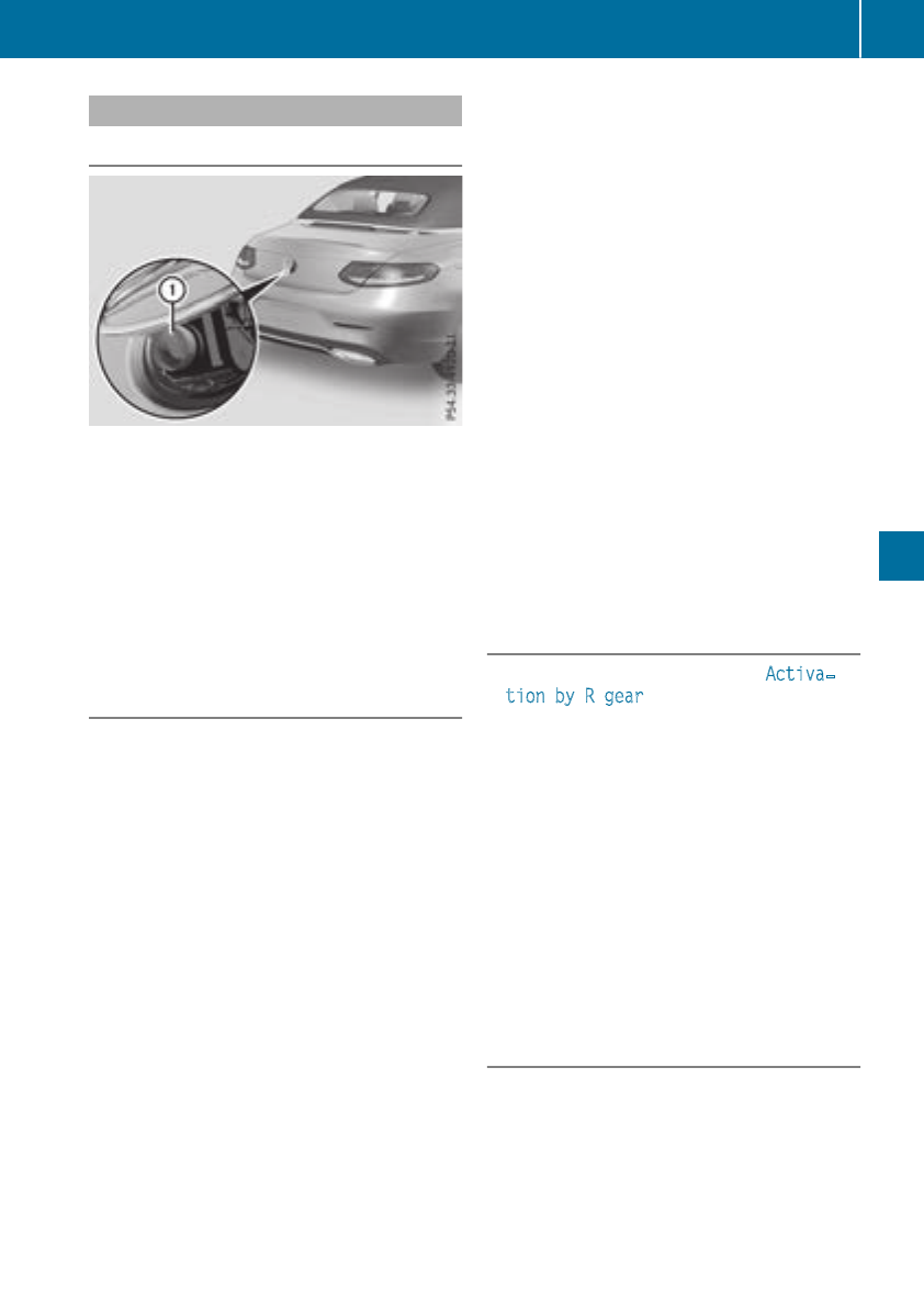
Rear view camera
General notes
Rear view camera :is an optical parking and
maneuvering aid. It shows the area behind the
vehicle with guide lines in the multimedia sys-
tem.
The area behind the vehicle is displayed as a
mirror image, as in the rear view mirror.
iThe text shown in the multimedia system
depends on the language setting. The follow-
ing are examples of rear view camera displays
in the multimedia system.
Important safety notes
The rear view camera is only an aid. It is not a
replacement for your attention to your immedi-
ate surroundings. You are always responsible
for safe maneuvering and parking. Make sure
that there are no persons, animals or objects in
the maneuvering area while maneuvering and
parking in parking spaces.
Under the following circumstances, the rear
view camera will not function, or will function in
a limited manner:
Rif the trunk lid is open
Rin heavy rain, snow or fog
Rat night or in very dark places
Rif the camera is exposed to very bright light
Rif the area is lit by fluorescent bulbs or LED
lighting (the display may flicker)
Rif there is a sudden change in temperature,
e.g. when driving into a heated garage in win-
ter
Rif the camera lens is dirty or obstructed.
Observe the notes on cleaning
(Ypage 292)
Rif the rear of your vehicle is damaged. In this
case, have the camera position and setting
checked at a qualified specialist workshop
The field of vision and other functions of the rear
view camera may be restricted due to additional
accessories on the rear of the vehicle (e.g.
license plate holder, rear bicycle rack).
The rear view camera is protected from rain-
drops and dust by means of a flap. When the rear
view camera is activated, this flap opens.
The flap closes again when:
Ryou have finished the maneuvering process
Ryou switch off the engine
Ryou open the trunk
Observe the notes on cleaning (Ypage 292).
For technical reasons, the flap may remain open
briefly after the rear view camera has been
deactivated.
Activating/deactivating the rear view
camera
XTo activate: make sure that the Activa‐
tion by R gear function is selected in the
multimedia system (see the Digital Operator's
Manual).
XEngage reverse gear.
The rear view camera flap opens. The multi-
media system shows the area behind the vehi-
cle with guide lines.
The image from the rear view camera is avail-
able throughout the maneuvering process.
XTo deactivate: shift the transmission to posi-
tion j.
or
XTo deactivate: Drive forwards at a speed
greater than 7 mph (12 km/h).
Multimedia display
The rear view camera may show a distorted view
of obstacles, show them incorrectly or not at all.
The rear view camera does not show objects in
the following positions:
Rvery close to the rear bumper
Runder the rear bumper
Driving systems 173
Driving and parking
Z
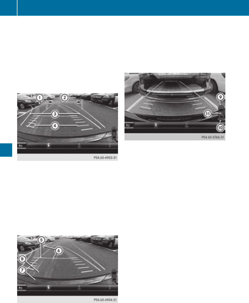
!Objects not at ground level may appear to
be further away than they actually are, e.g.:
Rthe bumper of a parked vehicle
Rthe drawbar of a trailer
Rthe ball coupling of a trailer tow hitch
Rthe rear section of an HGV
Ra slanted post
Use the guidelines only for orientation.
Approach objects no further than the bottom-
most guideline.
:Yellow guide line at a distance of approx-
imately 13 ft (4.0 m) from the rear of the
vehicle
;White guide lines without steering input,
vehicle width including the exterior mirrors
(static)
=Yellow guide lines for vehicle width including
the exterior mirrors, for current steering
input (dynamic)
?Yellow lanes marking the course the tires
will take at the current steering wheel angle
(dynamic)
AYellow guide line at a distance of approx-
imately 3 ft (1.0 m) from the rear of the vehi-
cle
BVehicle center axle (marker assistance)
CBumper
DRed guide line at a distance of approximately
12 in (0.30 m) from the rear of the vehicle
When the transmission is shifted to position k,
guide lines appear in the camera image.
The distance specifications only apply to
objects that are at ground level.
EFront warning display
FRear warning display
GAdditional vehicle icon as Parking Assist
PARKTRONIC measurement operational
readiness indicator
Vehicles with Parking Assist PARKTRONIC:
When Parking Assist PARKTRONIC is opera-
tional, vehicle icon (Ypage 171), appears on the
multimedia system display G. If the Parking
Assist PARKTRONIC warning displays are active
or light up, warning displays Eand Fare also
active or light up correspondingly on the multi-
media system display.
174 Driving systems
Driving and parking
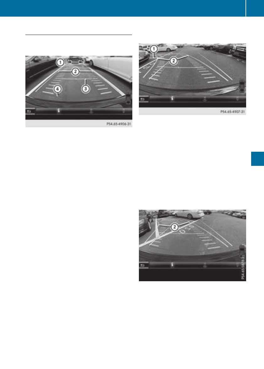
"Reverse parking" function
Backing up straight into a parking space
without steering input
:White guide line without steering input –
vehicle width including the exterior mirrors
(static)
;Yellow guide lines for vehicle width including
the exterior mirrors – dynamic for current
steering input
=Yellow guide line at a distance of approx-
imately 3 ft (1.0 m) from the rear of the vehi-
cle
?Red guide line at a distance of approximately
12 in (0.30 m) from the rear of the vehicle
XMake sure that the rear view camera is
switched on (Ypage 173).
The lane and the guide lines appear.
XWith the help of white guide line :, check
whether the vehicle will fit into the parking
space.
XUsing white guide line :as a guide, carefully
back up until you reach the end position.
Red guide line ?is then at the end of the
parking space. The vehicle is almost parallel
in the parking space.
Reverse perpendicular parking with steer-
ing input
XAfter driving past the parking space, stop the
vehicle safely.
XMake sure that the rear view camera is
switched on (Ypage 173).
The lane and the guide lines appear in the
camera image.
XWhile the vehicle is stationary, turn the steer-
ing wheel in the direction of the parking space
until yellow guide lines ;reach parking
space marking :.
Yellow guide lines ;dynamically adapt to the
current steering input.
XMaintain the steering input and reverse care-
fully.
XStop the vehicle when it is almost exactly in
front of the parking space.
Driving systems 175
Driving and parking
Z
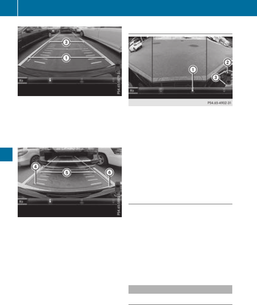
:Parking space markings
=White guide lines – for current steering input
White guide lines =should be as close to par-
allel with parking space markings :as possi-
ble.
XTurn the steering wheel to the center position
while the vehicle is stationary.
?Red guide line at a distance of approximately
12 in (0.30 m) from the rear of the vehicle
AWhite guide lines – no steering input
BEnd of parking space
XBack up carefully until you have reached the
final position.
The red guide line ?is then at the end of the
parking space B. The vehicle is almost par-
allel in the parking space.
"Wide-angle" function
:Symbol for the wide-angle view function
;Your vehicle
=Warning displays for Parking Assist
PARKTRONIC
You can also use the rear view camera to select
a wide-angle view.
When Parking Assist PARKTRONIC is opera-
tional (Ypage 171), a symbol for your own vehi-
cle appears in the multimedia system display. If
the Parking Assist PARKTRONIC warning dis-
plays are active, warning displays =light up on
the multimedia system display in yellow or red
accordingly.
Object detection
The rear view camera helps detect moving and
stationary objects. If an object (person, vehicle
or other obstacle) is detected, this object is
marked with a bar. Objects located some dis-
tance from the vehicle away are marked with a
yellow bar. If the distance to the object is very
small, the bar is displayed in red.
Object detection only works in wide-angle view.
To ensure that you can use the function, it must
be switched on in the multimedia system (see
the Digital Operator's Manual).
360° camera
General notes
The 360° camera is a system consisting of four
cameras.
176 Driving systems
Driving and parking

The system processes images from the follow-
ing cameras:
RRear view camera
RFront camera
RTwo side cameras in the exterior mirrors
The cameras cover the immediate surroundings
of the vehicle. The system supports you, for
example when parking or if vision is restricted at
an exit.
You can show images from the 360° camera in
full-screen mode or in six different split-screen
views on the multimedia system. A split-screen
view also includes a top view of the vehicle. This
view is calculated from the data supplied by the
installed cameras (virtual camera).
The six split-screen views are:
RTop view and picture from the rear view cam-
era (130° viewing angle)
RTop view and image from the front camera
(130° viewing angle without displaying the
maximum steering wheel angle)
RTop view and enlarged rear view
RTop view and enlarged front view
RTop view and images from the rear-facing side
cameras (rear wheel view)
RTop view and images from the forward-facing
side cameras (front wheel view)
When the function is active and you shift the
transmission from hor kto i, the guide
lines on the multimedia system are hidden.
When you shift between transmission positions
hand k, you see the previously selected front
or rear view.
Distances measured by Parking Assist
PARKTRONIC will also be optically displayed:
Rin split screen view as red or yellow brackets
around the vehicle icon in the top view, or
Rat the bottom right as red or yellow brackets
around the vehicle symbol in full-screen mode
The line thickness and color of the brackets
show how far the vehicle is from an object.
Ryellow brackets with thin lines: Parking Assist
PARKTRONIC is active
Ryellow brackets with normal lines: an object is
present in close range of the vehicle
Rred line: an object is present in the immediate
close range of the vehicle
Important safety notes
The 360°camera is only an aid and may show a
distorted view of obstacles, show them incor-
rectly or not at all. The 360°camera is not a
substitute for attentive driving.
You are always responsible for safe maneuver-
ing and parking. Make sure that there are no
persons, animals or objects in the maneuvering
area while maneuvering and parking in parking
spaces.
You are always responsible for safety, and must
always pay attention to your surroundings when
parking and maneuvering. This applies to the
areas behind, in front of and beside the vehicle.
You could otherwise endanger yourself and oth-
ers.
The 360° camera will not function or will func-
tion in a limited manner:
Rif the doors are open
Rif the exterior mirrors are folded in
Rif the trunk lid is open
Rin heavy rain, snow or fog
Rat night or in very dark places
Rif the cameras are exposed to very bright light
Rif the area is lit by fluorescent bulbs or LED
lighting (the display may flicker)
Rif the camera lenses fog up, e.g. when driving
into a heated garage in winter, causing a rapid
change in temperature
Rif the camera lenses are dirty or covered
Rif the vehicle components in which the cam-
eras are installed are damaged. In this case,
have the camera position and setting checked
at a qualified specialist workshop
Do not use the 360° camera in this case. You
can otherwise injure others or cause damage to
objects or the vehicle.
The guide lines in the multimedia system display
show the distances to your vehicle. The distan-
ces only apply to road level.
The camera in the rear area is protected by
means of a flap. This flap opens when the 360°
camera is activated. Observe the notes on
cleaning (Ypage 292). For technical reasons,
the flap may remain open briefly after the 360°
camera has been deactivated.
The field of vision and other functions of the
camera system may be restricted due to addi-
tional attachments (e.g. license plate holder,
rear bicycle carrier).
Driving systems 177
Driving and parking
Z
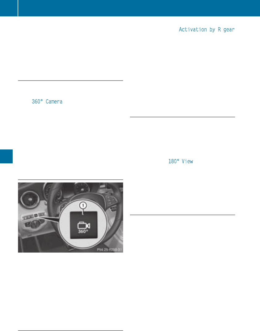
On vehicles with height-adjustable chassis,
depending on technical conditions, leaving the
standard height can result in:
Rinaccuracies in the guide lines
Rinaccuracies in the display of generated
images (top view)
Activation conditions
The image from the 360° camera appears if:
Rthe multimedia system is switched on
Rthe 360° Camera function is switched on
If you are driving faster than at a moderate
speed and you turn on the 360° camera, a warn-
ing message appears.
The warning message disappears if:
Ryou are again driving at a moderate speed The
360° camera is then activated
Rthe message is confirmed with the %but-
ton
Switching the 360° camera on and off
using the button
XTo switch on: press button :.
Depending on whether transmission position
hor kis selected, the following appears:
Ra split screen with top view and the image
from the front camera or
Ra split screen with top view and the image
from the rear view camera
XTo switch off: press button :.
Activating the 360° camera using
reverse gear
The 360° camera images can be automatically
displayed by engaging reverse gear.
XMake sure that the Activation by R gear
function is selected on the multimedia system
(see the Digital Operator's Manual).
XTo show the 360° camera image: engage
reverse gear.
The multimedia system shows the area
behind the vehicle in split-screen mode. You
see the top view of the vehicle and the image
from the rear view camera.
You cannot stop the 360° camera display if
reverse gear is engaged.
Selecting the split-screen view or full
screen mode
Switching between split screen views:
XTo switch to the line with the vehicle icons:
slide 5the controller.
XTo select a vehicle icon: turn the controller.
Switching to full screen mode:
XTurn and press 180° View with the controller.
The full screen option is only available in the fol-
lowing views:
RTop view with picture from the rear view cam-
era
RTop view with picture from the front camera
Multimedia display
Important safety notes
The camera system may show a distorted view
of obstacles, show them incorrectly or not at all.
Obstacles are not shown by the system in the
following locations:
Runder the front and rear bumpers
Rvery close to the front and rear bumpers
Rin close range above the handle on the trunk
lid
Rvery close to the exterior mirrors
Rin the transitional areas between the various
cameras in the virtual top view
!Objects not at ground level may appear to
be further away than they actually are, e.g.:
Rthe bumper of a parked vehicle
Rthe drawbar of a trailer
Rthe ball coupling of a trailer tow hitch
Rthe rear section of an HGV
Ra slanted post
178 Driving systems
Driving and parking
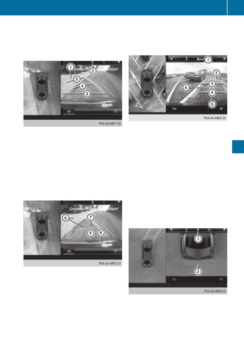
Use the guidelines only for orientation.
Approach objects no further than the bottom-
most guideline.
Top view with picture from the rear view
camera
:Yellow guide line at a distance of approx-
imately 13 ft (4.0 m) from the rear of the
vehicle
;Symbol for the split screen setting with top
view and rear view camera image
=Guide lines for the maximum steering input
?Yellow lanes marking the course the tires
will take at the current steering wheel angle
(dynamic)
AYellow guide lines for vehicle width including
the exterior mirrors – dynamic for current
steering input
BVehicle center axis (locating aids)
CYellow guide line at a distance of approx-
imately 3 ft (1.0 m) from the rear of the vehi-
cle
DBumper
ERed guide line at a distance of approximately
12 in (0.30 m) from the rear of the vehicle
When reverse gear is selected, guide lines
appear on the camera image.
The distance specifications only apply to
objects that are at ground level.
Top view with picture from the front cam-
era
:Symbol for the split screen setting with top
view and front camera image
;Yellow guide line at a distance of approx-
imately 13 ft (4.0 m) from the front of the
vehicle
=Yellow guide lines for vehicle width including
the exterior mirrors, for current steering
input (dynamic)
?Yellow lanes marking the course the tires
will take at the current steering wheel angle
(dynamic)
ARed guide line at a distance of approximately
12 in (0.30 m) from the front of the vehicle
BYellow guide line at a distance of approx-
imately 3 ft (1.0 m) from the front of the
vehicle
Top view and enlarged rear view
:Symbol for the split screen setting with top
view and rear view camera image enlarged
;Red guide line at a distance of approximately
12 in (0.30 m) from the rear of the vehicle
Driving systems 179
Driving and parking
Z
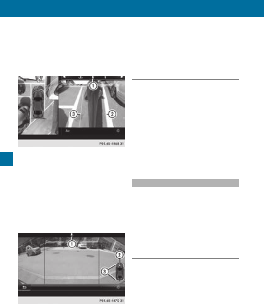
This view assists you in estimating the distance
to the vehicle behind you.
iThis setting can also be selected as an
enlarged front view.
Top view with image from the side cam-
eras
:Symbol for the top view and forward-facing
side camera setting
;Yellow guide line for the vehicle width
including the exterior mirrors (right side of
vehicle)
=Yellow guide line for the vehicle width
including the exterior mirrors (left side of
vehicle)
iYou can also select the side camera setting
for the rear-facing view.
180° view
:Symbol for the full screen setting with rear
view camera image
;Your vehicle
=Warning displays for Parking Assist
PARKTRONIC
i180° view can also be selected as front
view.
Select this view when you are driving out of an
exit and the view of crossing traffic is restricted,
for example.
If you select the %symbol in the display and
confirm with the controller, the split-screen view
appears.
Exiting 360° camera display mode
XShift the transmission to position j.
or
XDrive forwards at a speed greater than 6 mph
(10 km/h).
The 360° camera display is stopped.
The view that was active before the 360°
camera was displayed appears in the multi-
media system display. You can stop the 360°
camera from the split-screen view by select-
ing the %symbol on the display and con-
firming with the controller.
You cannot stop the 360° camera display if
transmission position kis selected.
ATTENTION ASSIST
General notes
ATTENTION ASSIST helps you during long,
monotonous journeys, such as on highways. It is
active in the 37 mph (60 km/h) to 124 mph
(200 km/h) speed range. If ATTENTION ASSIST
detects typical indicators of fatigue or increas-
ing lapses in concentration on the part of the
driver, it suggests taking a break.
Important safety notes
ATTENTION ASSIST is only an aid to the driver. It
might not always recognize fatigue or increasing
inattentiveness in time or fail to recognize them
at all. The system is not a substitute for a well-
rested and attentive driver.
The functionality of ATTENTION ASSIST is
restricted and warnings may be delayed or not
occur at all:
Rif the length of the journey is less than approx-
imately 30 minutes
Rif the road condition is poor, e.g. if the surface
is uneven or if there are potholes
Rif there is a strong side wind
180 Driving systems
Driving and parking
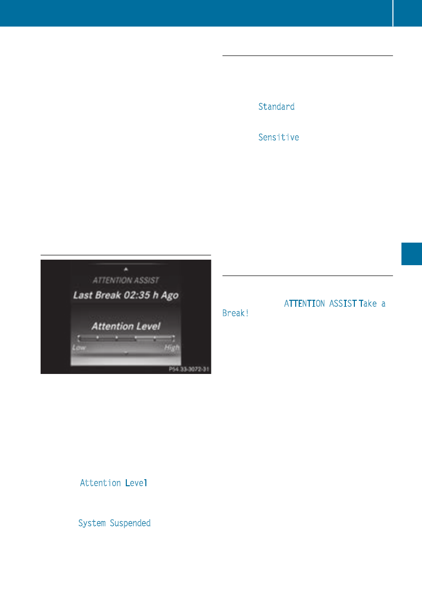
Rif you have adopted a sporty driving style with
high cornering speeds or high rates of accel-
eration
Rif you are predominantly driving at a speed
below 37 mph (60 km/h) or above 124 mph
(200 km/h)
Rif you are driving with the Steering Pilot of
Distance Pilot DISTRONIC activated
Rif the time has been set incorrectly
Rin active driving situations, such as when you
change lanes or change your speed
The ATTENTION ASSIST tiredness assessment
is deleted and restarted when continuing the
journey, if:
Ryou switch off the engine
Ryou take off your seat belt and open the driv-
er's door, e.g. for a change of drivers or to
take a break
Displaying the attention level
In the Assistance menu (Ypage 204) of the on-
board computer, you can call up the current sta-
tus information.
XSelect the Assistance display for ATTENTION
ASSIST using the on-board computer
(Ypage 203).
The following information appears:
RThe length of the journey since the last break.
Rthe attention level determined by ATTENTION
ASSIST (Attention Level), displayed in a
bar display in five levels from high to low.
Rif ATTENTION ASSIST is unable to calculate
the attention level and cannot issue a warn-
ing, the System Suspended message
appears. The bar display then changes the
display, e.g. if you are driving at a speed below
37 mph (60 km/h) or above 124 mph
(200 km/h).
Activating ATTENTION ASSIST
XActivate ATTENTION ASSIST using the on-
board computer (Ypage 205).
The system determines the attention level of
the driver depending on the setting selected:
Selection Standard: the sensitivity with which
the system determines the attention level is set
to normal.
Selection Sensitive: the sensitivity is set
higher. The attention level detected by Attention
Assist is adapted accordingly and the driver is
warned earlier.
When ATTENTION ASSIST is deactivated, the
ésymbol appears in the multifunction dis-
play in the assistance graphic display.
When ATTENTION ASSIST has been deactivated,
it is automatically reactivated after the engine
has been stopped. The sensitivity selected cor-
responds to the last selection activated (stand-
ard/sensitive).
Warning in the multifunction display
If fatigue or increasing lapses in concentration
are detected, a warning appears in the multi-
function display: ATTENTION ASSIST Take a
Break!.
In addition to the message shown in the multi-
function display, you will then hear a warning
tone.
XIf necessary, take a break.
XConfirm the message by pressing the a
button on the steering wheel.
On long journeys, take regular breaks in good
time to allow yourself to rest properly. If you do
not take a break and ATTENTION ASSIST con-
tinues to detect increasing lapses in concentra-
tion, you will be warned again after 15 minutes
at the earliest. This will only happen if ATTEN-
TION ASSIST still detects typical indicators of
fatigue or increasing lapses in concentration.
Vehicles with COMAND multimedia system:
if a warning appears in the multifunction display,
a service station search is performed in the mul-
timedia system. You can select a service station
and navigation to this service station will then
begin. This function can be activated and deac-
tivated in the COMAND multimedia system (see
the Digital Operator's Manual).
Driving systems 181
Driving and parking
Z
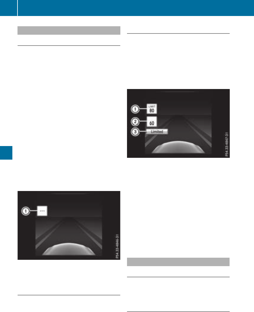
Traffic Sign Assist
General notes
Traffic Sign Assist displays the maximum speed
permitted to the driver in the instrument cluster.
The data and general traffic regulations stored in
the navigation system are used to determine the
current speed limit.
Traffic Sign Assist is a map-based system, and
for this reason, traffic signs put up temporarily
(e.g. near roadworks) are not detected. There is
also no display for changing traffic signs.
Traffic signs with a restriction indicated by an
additional sign (e.g. in wet conditions) are also
shown.
The sign indicating the end of a restriction only
appears with the restriction in the instrument
cluster when:
RThe regulation must be observed with the
restriction, or
RTraffic Sign Assist is unable to determine
whether the restriction applies
If Traffic Sign Assist is unable to determine a
maximum permitted speed from any of the avail-
able sources, no speed limit appears in the
instrument cluster either.
Traffic Sign Assist is not available in all coun-
tries. In this case, display :appears in the
assistance graphic (Ypage 203).
Important safety notes
Traffic Sign Assist is only an aid and is not always
able to correctly display speed limits. Traffic
signs always have priority over the Traffic Sign
Assist display.
The system may be either functionally impaired
or temporarily unavailable if the information in
the digital street map of the navigation system is
incorrect or out of date.
Instrument cluster display
Displaying the assistance graphic
XCall up the assistance graphic display func-
tion using the on-board computer
(Ypage 203).
Detected traffic signs appear in the instru-
ment cluster.
Speed limit with unknown restriction
:Maximum permitted speed
;Maximum permitted speed for vehicles for
which the restriction in the additional sign is
relevant
=Additional sign for unknown restriction
A maximum permitted speed of 80 mph
(80 km/h) and a speed limit of 60 mph
(60 km/h) with an unknown restriction apply.
The unit for the speed limit (km/h or mph)
depends on the country in which you are driving.
It is generally neither shown on the traffic sign
nor on the instrument cluster but must be taken
into account when observing the maximum per-
mitted speed.
Lane Tracking package
General notes
The Lane Tracking package consists of Blind
Spot Assist (Ypage 182) and Lane Keeping
Assist (Ypage 184).
Blind Spot Assist
General notes
Blind Spot Assist monitors the areas on either
side of the vehicle that are not visible to the
driver with two lateral, rear-facing radar sen-
182 Driving systems
Driving and parking
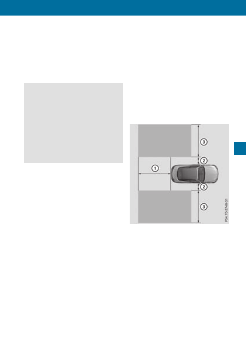
sors. A warning lamp lights up in the exterior
mirrors and draws your attention to vehicles
detected in the monitored area. If you then
switch on the corresponding turn signal to
change lane, you will also receive an optical and
audible warning.
Blind Spot Assist supports you from a speed of
approximately 20 mph (30 km/h).
Important safety notes
GWARNING
Blind Spot Assist does not react to:
Rvehicles overtaken too closely on the side,
placing them in the blind spot area
Rvehicles which approach with a large speed
differential and overtake your vehicle
As a result, Blind Spot Assist may not give
warnings in such situations. There is a risk of
an accident.
Always observe the traffic conditions care-
fully, and maintain a safe lateral distance.
Blind Spot Assist is only an aid. It may fail to
detect some vehicles and is no substitute for
attentive driving. Always ensure that there is
sufficient distance to the side for other road
users and obstacles.
iUSA only:
This device has been approved by the FCC as
a "Vehicular Radar System". The radar sensor
is intended for use in an automotive radar
system only. Removing, tampering with, or
altering the device will void any warranties,
and is not permitted by the FCC. Do not tam-
per with, alter, or use in any non-approved
way.
Any unauthorized modification to this device
could void the user’s authority to operate the
equipment.
Radar sensors
The radar sensors for Blind Spot Assist are inte-
grated into the rear bumper. Make sure that the
bumpers are free from dirt, ice or slush. The
sensors must not be covered, for example by
cycle racks or overhanging loads. Following a
severe impact or in the event of damage to the
bumpers, have the function of the radar sensors
checked at a qualified specialist workshop.
Blind Spot Assist may no longer work properly.
Monitoring area
In particular, the detection of obstacles can be
impaired if:
Rthere is dirt on the sensors or anything else
covering the sensors
Rthere is poor visibility, e.g. due to fog, heavy
rain, snow or spray
Rthere are narrow vehicles, e.g. motorcycles or
bicycles
Rthe road has very wide lanes
Rthe road has narrow lanes
Ryou are not driving in the middle of the lane
Rthere are barriers or other road boundaries
Vehicles in the monitoring range are then not
indicated.
At a distance of around 1.6 ft (0.5 m) ;from the
vehicle, Blind Spot Assist monitors the area up
to 10 ft (3 m) next to =and behind :your
vehicle, as shown in the picture.
If the lanes are narrow, vehicles driving in the
lane beyond the lane next to your vehicle may be
indicated, especially if the vehicles are not driv-
ing in the middle of their lane. This may be the
case if there are vehicles driving at the inner
edge of their lanes.
Due to the nature of the system:
Rwarnings may be issued in error when driving
close to crash barriers or similar solid lane
borders.
Rwarnings may be interrupted when driving
alongside long vehicles, e.g. trucks, for a pro-
longed time.
Driving systems 183
Driving and parking
Z
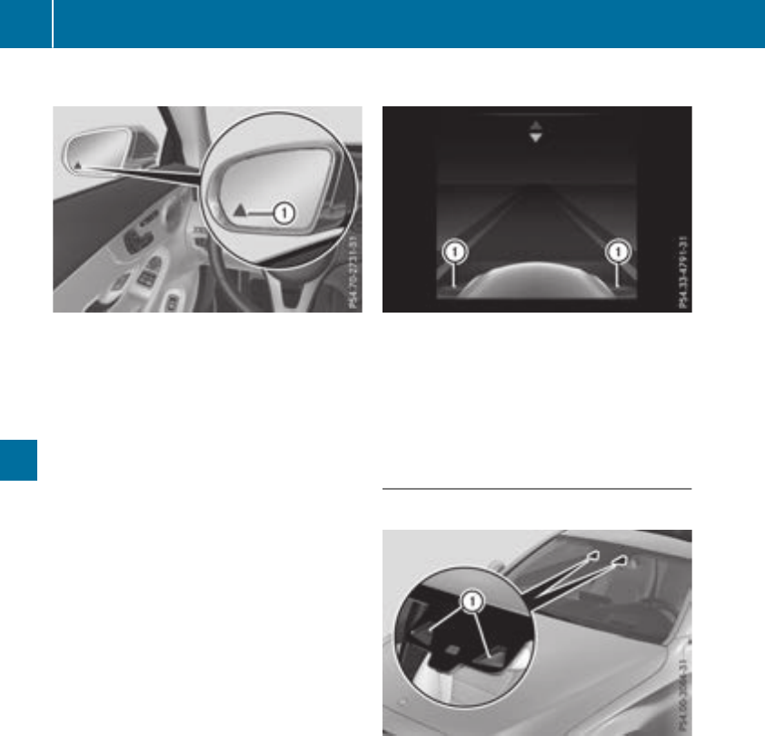
Warning lamp
:Warning lamp
Blind Spot Assist is not active at speeds below
approximately 20 mph (30 km/h). Vehicles in
the monitoring range are then not indicated.
If a vehicle is detected within the blind spot
monitoring range at speeds above 20 mph
(30 km/h), warning lamp :on the correspond-
ing side lights up red. This warning is always
emitted when a vehicle enters the blind spot
monitoring range from behind or from the side.
When you overtake a vehicle, the warning only
occurs if the difference in speed is less than
7 mph (12 km/h).
If you select the reverse gear, Blind Spot Assist
is not operational.
The brightness of the warning lamps is auto-
matically adapted to the brightness of the sur-
roundings.
Collision warning
If a vehicle is detected in the monitoring range of
Blind Spot Assist and you switch on the corre-
sponding turn signal, a double warning tone
sounds. The red warning lamp flashes on the
relevant exterior mirror. If the turn signal
remains on, detected vehicles are indicated by
the flashing of the red warning lamp on the exte-
rior mirror. There are no further warning tones.
Switching on Blind Spot Assist
XMake sure that Blind Spot Assist is activated
in the on-board computer (Ypage 205).
XTurn the SmartKey to position 2in the igni-
tion lock.
The red warning lamps on the exterior mirrors
light up until the engine is started.
Display in the assistance graphic
When Blind Spot Assist is activated, gray radar
waves propagating backwards appear next to
the vehicle in the assistance display in the mul-
tifunction display (Ypage 203). Above a speed
of 20 mph (30 km/h), the color of the radar
waves in the assistance graphic changes to
green :. Blind Spot Assist is then ready for use.
Lane Keeping Assist
General notes
Lane Keeping Assist monitors the area in front of
your vehicle by means of multifunction cam-
era :which is attached behind the top of the
windshield. Active Lane Keeping Assist detects
lane markings on the road and can warn you
before you leave your lane unintentionally.
This function is available in the range between
40 mph and 120 mph (60 km/h and 200 km/h).
A warning may be given if a front wheel passes
over a lane marking. It will warn you by means of
intermittent vibration in the steering wheel for
up to 1.5 seconds.
184 Driving systems
Driving and parking
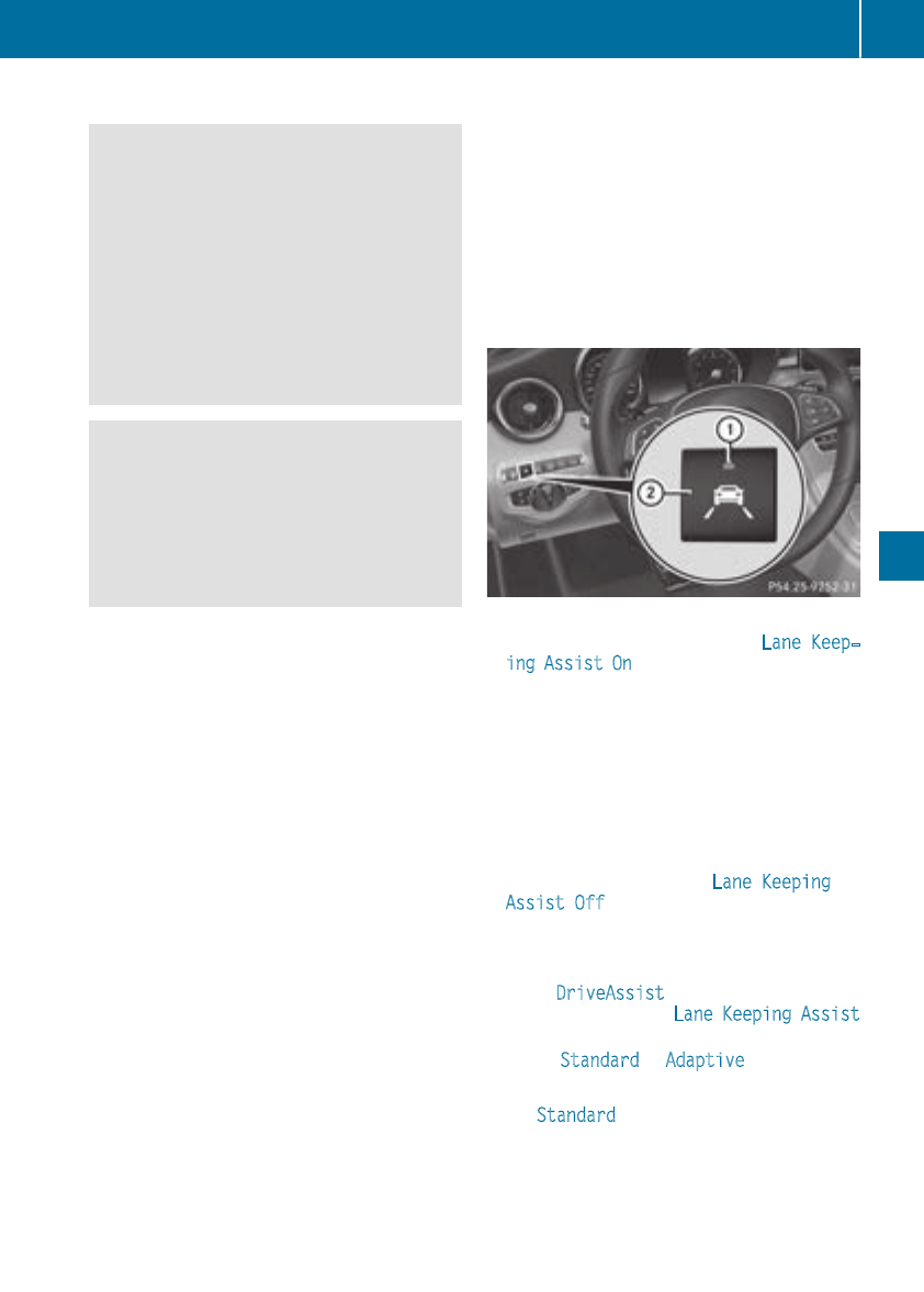
Important safety notes
GWARNING
Lane Keeping Assist cannot always clearly
detect lane markings.
In such cases, Lane Keeping Assist can:
Rgive an unnecessary warning
Rnot give a warning
There is a risk of an accident.
Always pay particular attention to the traffic
situation and keep within the lane, especially
if Lane Keeping Assist alerts you.
GWARNING
The Lane Keeping Assist warning does not
return the vehicle to the original lane. There is
a risk of an accident.
You should always steer, brake or accelerate
yourself, in particular if warned by Lane Keep-
ing Assist.
Lane Keeping Assist can neither reduce the risk
of an accidentif you fail to adapt your driving
style nor override the laws of physics. Lane
Keeping Assist cannot take into account the
road, traffic and weather conditions. Lane Keep-
ing Assist is merely an aid. You are responsible
for the distance to the vehicle in front, for vehi-
cle speed, for braking in good time and for stay-
ing in your lane.
The Lane Keeping Assist does not keep the vehi-
cle in the lane.
The system may be impaired or may not function
if:
Rthere is poor visibility, e.g. due to insufficient
illumination of the road, or due to snow, rain,
fog or spray
Rthere is glare, e.g. from oncoming traffic, the
sun or reflection from other vehicles (e.g. if
the road surface is wet)
Rthe windshield is dirty, fogged up, damaged or
covered, for instance by a sticker, in the vicin-
ity of the camera
Rthere are no, several or unclear lane markings
for a lane, e.g. in areas with road construction
work
Rthe lane markings are worn away, dark or cov-
ered up, e.g. by dirt or snow
Rthe distance to the vehicle in front is too small
and the lane markings thus cannot be detec-
ted
Rthe lane markings change quickly, e.g. lanes
branch off, cross one another or merge
Rthe road is narrow and winding
Rthere are highly variable shade conditions on
the roadway
Activating/deactivating Lane Keeping
Assist
XTo activate: press button ;.
Indicator lamp :lights up. The Lane Keep‐
ing Assist On message appears in the mul-
tifunction display. If all conditions have been
satisfied, there may be a warning.
If you drive at speeds above 40 mph
(60 km/h) and lane markings are detected,
the lines in the assistance graphics display
(Ypage 203) are shown in green. Lane Keep-
ing Assist is ready for use.
XTo deactivate: press button ;.
Indicator lamp :goes out. Lane Keeping
Assist is deactivated. The Lane Keeping
Assist Off message appears in the multi-
function display.
Selecting Standard or Adaptive setting
XIn the DriveAssist menu on the on-board
computer, select the Lane Keeping Assist
function (Ypage 205).
XSelect Standard or Adaptive.
Standard
When Standard is selected, no warning vibra-
tion occurs if:
Driving systems 185
Driving and parking
Z
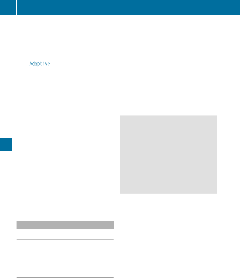
Ryou switch on theturnsignals. In this event,
thewarnings are suppressed for acertain
period of time.
Radrivingsafetysystem intervenes, e.g. ABS,
BASor ESP®.
Adaptive
WhenAdaptive is selected, no warningvibra-
tion occursif:
Ryou switch on theturnsignals. In this event,
thewarnings are suppressed for acertain
period of time.
Radrivingsafetysystem intervenes, e.g. ABS,
BASor ESP®.
Ryou accelerate hard, e.g. kickdown.
Ryou brakehard.
Ryou steer actively, e.g. swerve to avoid an
obstacle or changelanes quickly.
Ryou cut thecorner on asharpbend.
In order that you are warned only when neces-
saryand in goodtime if you cross thelanemark-
ing, thesystem recognizes certain conditions
and warnsyou accordingly.
The warningvibration occursearlier if:
Ryou approachtheouter lanemarking on a
bend.
Rtheroadhas verywide lanes, e.g. afreeway.
Rthesystem detects solidlanemarkings.
The warningvibration occurslater if:
Rtheroadhas narrow lanes
Ryou cut thecorner on abend
Driving Assistance Plus package
General notes
The DrivingAssistance Plus packageconsistsof
DistancePilotDISTRONIC (Ypage 153), Active
Blind Spot Assist (Ypage 186) and Active Lane
KeepingAssist (Ypage 189).
Active Blind Spot Assist
Generalnotes
Active Blind Spot Assistuses aradarsensor
system, pointedtoward therear of thevehicle,
to monitor thearea to thesidesof thevehicle
whichthedriver is unable to see. A warninglamp
lights up in theexteriormirrorsand drawsyour
attention to vehicles detectedin themonitored
area.If you then switch on thecorresponding
turnsignal to changelane, you will also receive
an opticaland audiblewarning. If ariskof lateral
collision is detected, corrective brakingmay
help you avoid acollision.Before a course-cor-
recting brakeapplication,Active Blind Spot
Assistevaluates thespacein thedirection of
travel and at thesidesof thevehicle. Forthis,
Active Blind Spot Assistuses theforward-facing
radarsensors.
Active Blind Spot Assistsupportsyou from a
speed of approximately 20 mph (30 km/h).
Important safety notes
Active Blind Spot Assist is only an aid and is not
a substitute for attentive driving.
GWARNING
Active Blind Spot Assist does not react to:
Rvehicles overtaken too closely on the side,
placing them in the blind spot area
Rvehicles which approach with a large speed
differential and overtake your vehicle
As a result, Active Blind Spot Assist may nei-
ther give warnings nor intervene in such sit-
uations. There is a risk of an accident.
Always observe the traffic conditions care-
fully, and maintain a safe lateral distance.
iUSA only: This device has been approved by
the FCC as a "Vehicular Radar System". The
radar sensor is intended for use in an auto-
motive radar system only. Removal, tamper-
ing, or altering of the device will void any war-
ranties, and is not permitted by the FCC. Do
not tamper with, alter, or use in any non-
approved way.
Any unauthorized modification to this device
could void the user's authority to operate the
equipment.
iCanada only: This device complies with
RSS-210 of Industry Canada. Operation is
subject to the following two conditions:
1. This device may not cause interference,
and
2. This device must accept any interference
received, including interference that may
cause undesired operation of the device.
Removal, tampering, or altering of the device
will void any warranties, and is not permitted.
186 Driving systems
Driving and parking
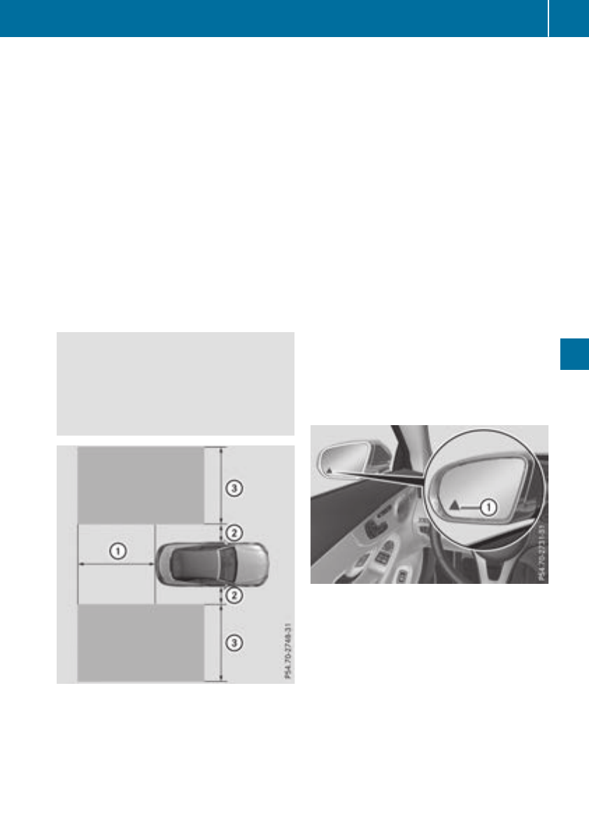
Do not tamper with, alter, or use in any non-
approved way.
Any unauthorized modification to this device
could void the user's authority to operate the
equipment.
Radar sensors
The Active Blind Spot Assist radar sensors are
integrated into the front and rear bumpers and
behind a cover in the radiator trim. Make sure
that the bumpers and the cover in the radiator
grill are free of dirt, ice or slush. The rear sensors
must not be covered, for example by cycle racks
or overhanging cargo. Following a severe impact
or in the event of damage to the bumpers, have
the function of the radar sensors checked at a
qualified specialist workshop. Active Blind Spot
Assist may otherwise no longer work properly.
Monitoring area
GWARNING
Active Blind Spot Assist does not detect all
traffic situations and road users. There is a
risk of an accident.
Always make sure that there is sufficient dis-
tance on the side for other traffic or obstacles.
At a distance of approximately 1.6 ft (0.5 m) ;
from the vehicle, Active Blind Spot Assist mon-
itors the area up to 10 ft (3 m) next to =and
behind :your vehicle, as shown in the picture.
The detection of obstacles can be impaired in
the case of:
Rthere is dirt on the sensors or anything else
covering the sensors
Rpoor visibility, e.g. due to rain, snow or spray
Vehicles in the monitoring range are then not
indicated.
Active Blind Spot Assist may not detect narrow
vehicles, such as motorcycles or bicycles, or
may only detect them too late.
If the lanes are narrow, vehicles driving in the
lane beyond the lane next to your vehicle may be
indicated, especially if the vehicles are not driv-
ing in the middle of their lane. This may be the
case if there are vehicles at the inner edge of
your lane.
Due to the nature of the system:
Rwarnings may be issued in error when driving
close to crash barriers or similar solid lane
borders.
Rwarnings may be interrupted when you are
driving alongside particularly long vehicles,
such as trucks, for a prolonged time.
Warning lamp
:Warning lamp
Active Blind Spot Assist is not operational at
speeds below approximately 20 mph (30 km/h).
Vehicles in the monitoring range are then not
indicated.
If a vehicle is detected within the blind spot
monitoring range at speeds above 20 mph
(30 km/h), warning lamp :on the correspond-
ing side lights up red. This warning is always
emitted when a vehicle enters the blind spot
monitoring range from behind or from the side.
When you overtake a vehicle, the warning only
occurs if the difference in speed is less than
7 mph (12 km/h).
Driving systems 187
Driving and parking
Z
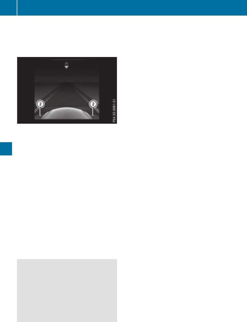
If you select the reverse gear, Active Blind Spot
Assist is not operational.
The brightness of the warning lamps is auto-
matically adapted to the brightness of the sur-
roundings.
When Active Blind Spot Assist is activated, gray
radar waves propagating backward appear next
to the vehicle in the assistance display in the
multifunction display. Above a speed of 20 mph
(30 km/h), the color of the radar waves in the
assistance display changes to green ;. Active
Blind Spot Assist is then ready for use.
Visual and acoustic collision warning
If you switch on the turn signals to change lanes
and a vehicle is detected in the side monitoring
range, you receive a visual and acoustic collision
warning. You will then hear a double warning
tone and red warning lamp :flashes. If the turn
signal remains on, detected vehicles are indica-
ted by the flashing of red warning lamp :.
There are no further warning tones.
Course-correcting brake application
If Active Blind Spot Assist detects a risk of a lat-
eral collision in the monitoring range, a course-
correcting brake application is carried out. This
is meant to assist you in avoiding a collision.
GWARNING
A course-correcting brake application cannot
always prevent a collision. There is a risk of an
accident.
Always steer, brake or accelerate yourself,
especially if Active Blind Spot Assist warns
you or makes a course-correcting brake appli-
cation. Always maintain a safe distance at the
sides.
If a course-correcting brake application occurs,
red warning lamp :flashes in the exterior mir-
ror and a double warning tone sounds. In addi-
tion, a display underlining the danger of a side
collision appears in the multifunction display.
In very rare cases, the system may make an
inappropriate brake application. A course-cor-
recting brake application may be interrupted at
any time by countersteering slightly or acceler-
ating.
The course-correcting brake application is avail-
able in the speed range between 20 mph
(30 km/h) and 120 mph (200 km/h).
Either no braking application, or a course-cor-
recting brake application adapted to the driving
situation occurs if:
Rthere are vehicles or obstacles, e.g. crash
barriers, located on both sides of your vehicle.
Ra vehicle approaches you too closely at the
side.
Ryou have adopted a sporty driving style with
high cornering speeds.
Ryou clearly brake or accelerate.
Ra driving safety system intervenes, e.g. ESP®
or PRE-SAFE®Brake.
RESP®is switched off.
Ra loss of tire pressure or a defective tire is
detected.
Switching on Active Blind Spot Assist
XMake sure that Active Blind Spot Assist is
activated in the on-board computer
(Ypage 205).
XSwitch on the ignition.
Warning lamps :in the exterior mirrors light
up red for approximately 1.5 seconds.
Gray radar waves propagating backwards
appear next to the vehicle in the assistance
graphic in the multifunction display ;.
Above a speed of 20 mph (30 km/h), the color
of the radar waves in the assistance display
changes to green ;. Active Blind Spot Assist
is then ready for use.
188 Driving systems
Driving and parking
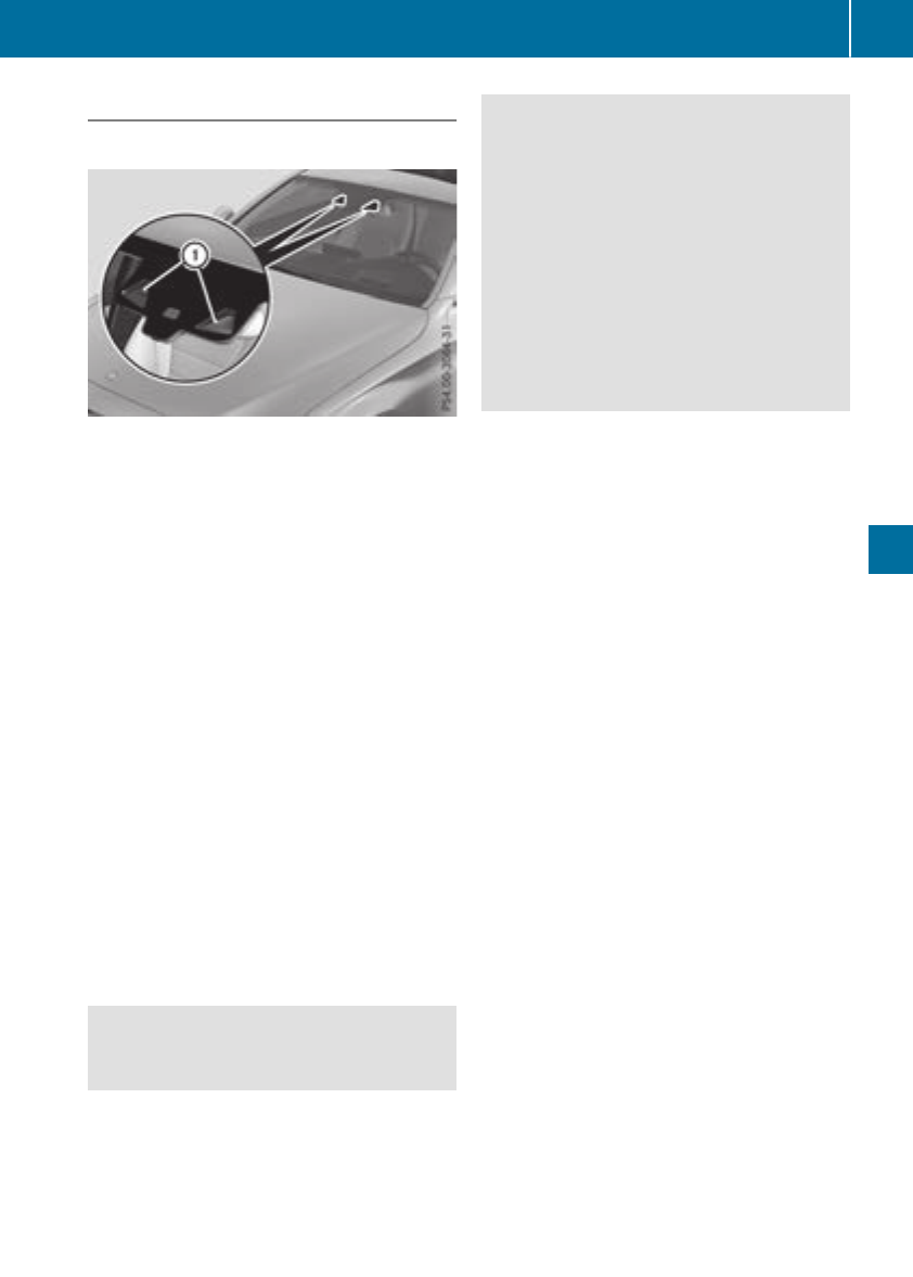
Active Lane Keeping Assist
Generalnotes
Active LaneKeepingAssistmonitors thearea in
frontof your vehicleby meansof multifunction
camera :at thetopof thewindshield. Various
differentareas to thefront, rear and side of your
vehicleare also monitoredwiththeaid of the
radar sensor system. Active LaneKeeping
Assistdetects lanemarkingson theroad and
can warn you before you leaveyour laneunin-
tentionally. If you do notreactto thewarning, a
lane-correcting application of thebrakes can
bring thevehiclebackintotheoriginal lane.
This function is available in therange between
40 mph and 120mph (60 km/h and 200km/h).
Important safety notes
If you fail to adapt your drivingstyle, Active Lane
KeepingAssistcan neither reduce theriskof an
accidentnoroverride thelaws of physics.Active
LaneKeepingAssistcannottakeaccountof
road and weather conditions. It may notrecog-
nizetraffic situations. Active LaneKeeping
Assistis only an aid. You are responsiblefor the
distanceto thevehiclein front, for vehicle
speed, for braking in goodtime and for stayingin
your lane.
Active LaneKeepingAssistcannotcontinuously
keep your vehiclein itslane.
GWARNING
Active LaneKeepingAssistcannotalways
clearly detectlanemarkings.
In suchcases, Active LaneKeepingAssist
can:
Rgivean unnecessary warning and then
make a course-correcting brakeapplication
to thevehicle
Rnotgive a warning or intervene
There is ariskof an accident.
Always pay particular attention to thetraffic
situation and keep within thelane, especially
if Active LaneKeepingAssistalerts you. Ter-
minate theintervention in anon-critical driv-
ing situation.
The system may be impairedor may notfunction
if:
Rthere is poor visibility, e.g. due to insufficient
illumination of theroad,or due to snow, rain,
fog or spray
Rthere is glare, e.g. from oncomingtraffic, the
sun or reflection from other vehicles (e.g. if
theroad surfaceis wet)
Rthewindshield is dirty, fogged up, damaged or
covered, for instance by asticker, in thevicin-
ityof thecamera
Rtheradar sensorsin thefrontor rear bumpers
or theradiatortrim are dirty, e.g. obscured by
snow
Rthere are no,several or unclear lanemarkings
for alane, e.g. in areas withroad construction
work
Rthelanemarkingsare wornaway, dark or cov-
eredup, e.g. by dirtor snow
Rthedistanceto thevehiclein frontis toosmall
and thelanemarkingsthus cannotbe detec-
ted
Rthelanemarkingschangequickly, e.g. lanes
branch off,cross oneanother or merge
Rtheroad is narrow and winding
Rthere are highly variable shadeconditionson
theroadway
If no vehicleis detectedin theadjacent laneand
brokenlanemarkingsare detected, no lane-cor-
recting brakeapplication is made.
Warning vibration in thesteering wheel
Awarning may be given if afrontwheelpasses
over a lanemarking.It will warn you by meansof
intermittent vibration in thesteering wheelfor
up to 1.5seconds.
Driving systems 189
Driving and parking
Z
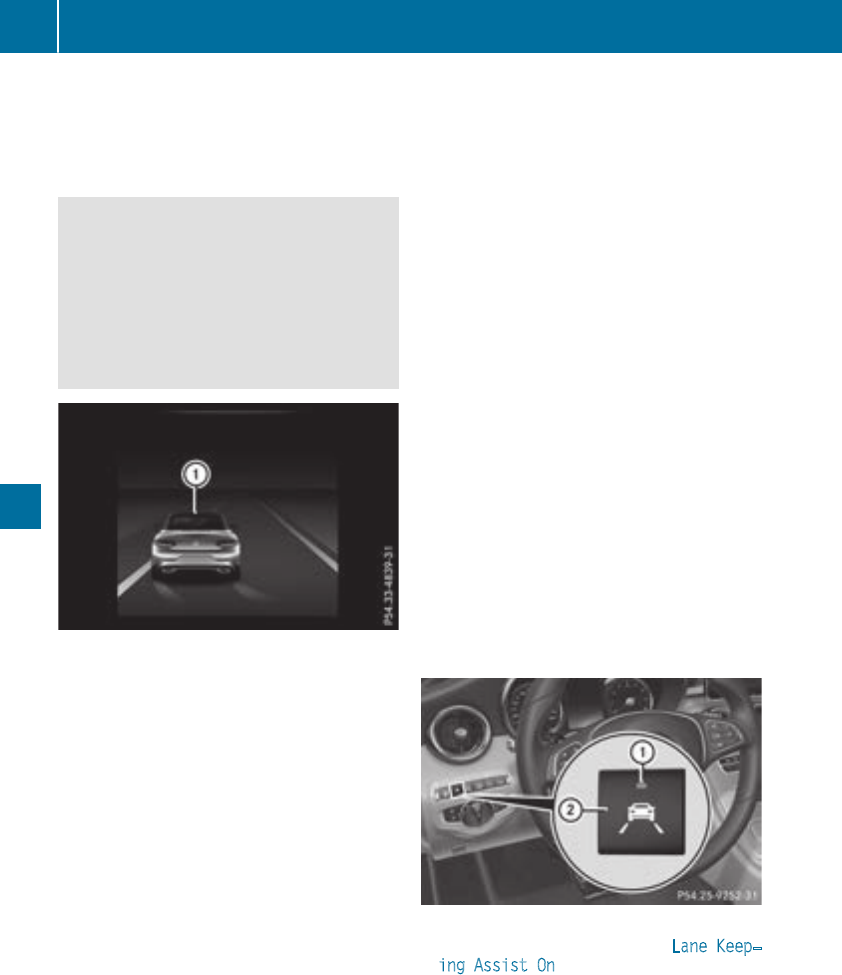
Lane-correcting brake application
If you leave your lane, under certain circumstan-
ces the vehicle will brake briefly on one side.
This is meant to assist you in bringing the vehicle
back to the original lane.
GWARNING
A lane-correcting brake application cannot
always bring the vehicle back into the original
lane. There is a risk of an accident.
Always steer, brake or accelerate yourself,
especially if Active Lane Keeping Assist warns
you or makes a lane-correcting brake appli-
cation.
If a lane-correcting brake application occurs,
display :appears in the multifunction display.
The brake application also slightly reduces vehi-
cle speed.
A lane-correcting brake application can be made
after driving over a lane marking detected as
being solid or broken. Before this, a warning
must be given by means of intermittent vibration
in the steering wheel. In addition, a lane with
lane markings on both sides must be recog-
nized.
In the case of a broken lane marking being
detected, a lane-correcting brake application
can only be made if a vehicle has been detected
in the adjacent lane. Oncoming vehicles, over-
taking vehicles and vehicles in adjacent lanes
can be detected.
A further lane-correcting brake application can
only occur after your vehicle has returned to the
original lane.
No lane-correcting brake application occurs if:
Ryou clearly and actively steer, brake or accel-
erate.
Ryou cut the corner on a sharp bend.
Ryou have switched on the turn signal.
Ra driving safety system intervenes, e.g. ESP®,
PRE-SAFE®Brake or Active Blind Spot Assist.
Ryou have adopted a sporty driving style with
high cornering speeds or high rates of accel-
eration.
RESP®is switched off.
Rthe transmission is not in position h.
Ra loss of tire pressure or a defective tire has
been detected and displayed.
Ran obstacle has been detected in the lane in
which you are driving.
Active Lane Keeping Assist may not detect other
road users or traffic situations. An inappropriate
brake application may be interrupted at any time
if you:
Rsteer slightly in the opposite direction.
Rswitch on the turn signal.
Ryou brake or accelerate significantly.
A lane-correcting brake application is interrup-
ted automatically if:
Ra driving safety system intervenes, e.g. ESP®,
PRE-SAFE®Brake or Active Blind Spot Assist.
Rlane markings are no longer detected.
Activating/deactivating Active Lane
Keeping Assist
XTo activate: press button ;.
Indicator lamp :lights up. The Lane Keep‐
ing Assist On message appears on the
multifunction display. If all conditions have
been satisfied, a warning or steering inter-
vention may be made.
If you drive at speeds above 40 mph
(60 km/h) and lane markings are detected,
the lines in the assistance graphic
190 Driving systems
Driving and parking
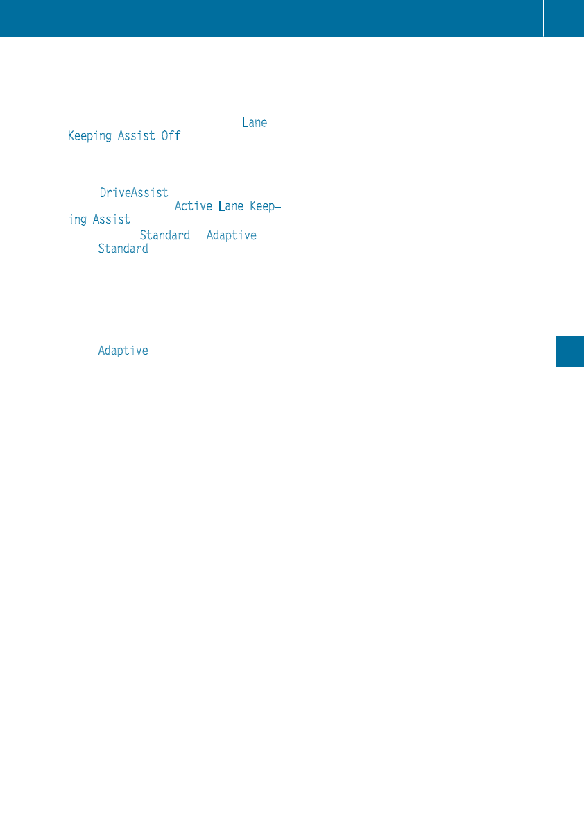
(Ypage 203) appear in green. Active Lane
Keeping Assist is ready for use.
XTo deactivate: press button ;.
Indicator lamp :goes out. The Active Lane
Keeping Assist is deactivated. The Lane
Keeping Assist Off message appears on
the multifunction display.
Selecting Standard or Adaptive setting
XIn the DriveAssist menu on the on-board
computer, select the Active Lane Keep‐
ing Assist function (Ypage 205).
XSelect setting Standard or Adaptive.
When Standard is selected, no warning vibra-
tion occurs if:
Ryou switch on the turn signals. In this case,
the warnings are suppressed for a certain
period of time.
Ra driving safety system intervenes, such as
ABS, BAS or ESP®.
When Adaptive is selected, no warning vibra-
tion occurs if:
Ryou switch on the turn signals. In this event,
the warnings are suppressed for a certain
period of time.
Ra driving safety system intervenes, e.g.
ABS, BAS or ESP®.
Ryou accelerate hard, e.g. kickdown.
Ryou brake hard.
Ryou steer actively, e.g. swerve to avoid an
obstacle or change lanes quickly.
Ryou cut the corner on a sharp bend.
In order that you are warned only when neces-
sary and in good time if you cross the lane mark-
ing, the system recognizes certain conditions
and warns you accordingly.
The warning vibration occurs earlier if:
Ryou approach the outer lane marking on a
bend.
Rthe road has very wide lanes, e.g. a freeway.
Rthe system detects solid lane markings.
The warning vibration occurs later if:
Rthe road has narrow lanes
Ryou cut the corner on a bend
Driving systems 191
Driving and parking
Z
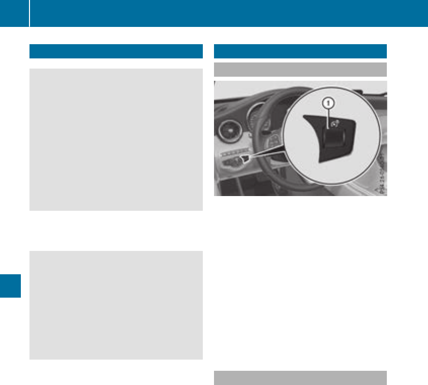
Important safety notes
GWARNING
If you operate information systems and com-
munication equipmentintegratedin thevehi-
cle when driving,you may be distractedfrom
thetraffic situation.You could also lose con-
trol of thevehicle. Thereis ariskof an acci-
dent.
Only operate this equipmentwhen thetraffic
situation permits. If you are notsurethat this
is possible,park thevehiclepayingattention
to traffic conditionsand operate theequip-
mentwhen thevehicleis stationary.
You must observethelegal requirements for the
country in whichyou are currentlydriving when
operating theon-board computer.
GWARNING
If theinstrumentclusterhas failedor mal-
functioned, you may notrecognize function
restrictionsin systems relevantto safety. The
operating safetyof your vehiclemay be
impaired.Thereis ariskof an accident.
Drive on carefully. Havethevehiclechecked
at aqualified specialist workshop immedi-
ately.
If theoperating safetyof your vehicleis
impaired,pull overas soonas it is safeto do so.
Contact a qualified specialist workshop.
The on-board computer only shows messagesor
warningsfrom certain systems in themultifunc-
tion display. You should thereforemakesure
your vehicleis operating safely at all times.
Foran overview, see theinstrumentpanel illus-
tration (Ypage 36).
Displays and operation
Instrument cluster lighting
The lighting in theinstrumentcluster, in thedis-
plays and thecontrolsin thevehicleinterior can
be adjusted usingbrightness control knob :.
XTurn brightness control knob :up or down.
If you turnthelightswitch (Ypage 107) to the
T,Ãor Lposition,thebrightness
will depend upon thebrightness of theambi-
entlight.
iThe lightsensor in theinstrumentcluster
automatically controlsthebrightness of the
multifunction display.
In daylight, thedisplays in theinstrument
clusterare illuminated. Adimming function is
notpossible in daylight.
Speedometer with segments
The speedometer is divided intosegments
depending on theequipment.
The segments in thespeedometer indicate
whichspeedrange is available.
RCruisecontrol activated (Ypage 151):
The segments lightup from thestoredspeed
to theendof thescale.
RDistancePilot DISTRONICis activated
(Ypage 155):
Oneor two segments in theset speedrange
lightup.
RDistancePilot DISTRONICdetects avehiclein
frontmoving moreslowly than thestored
speed:
The segments between thespeedof thevehi-
cle in frontand thestoredspeedlightup.
192 Displays and operation
On-board computer and displays
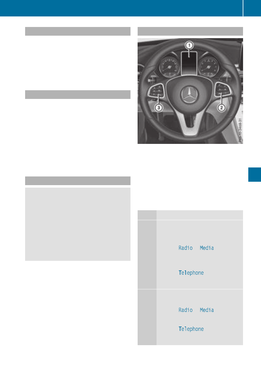
Tachometer
!Do not drive in the overrevving range, as this
could damage the engine.
The red band in the tachometer indicates the
engine's overrevving range.
The fuel supply is interrupted to protect the
engine when the red band is reached.
Outside temperature display
You should pay special attention to road condi-
tions when temperatures are around freezing
point.
Bear in mind that the outside temperature dis-
play indicates the temperature measured and
does not record the road temperature.
The outside temperature display is in the multi-
function display (Ypage 194).
Changes in the outside temperature are dis-
played after a short delay.
Coolant temperature gauge
GWARNING
Opening the hood when the engine is over-
heated or when there is a fire in the engine
compartment could expose you to hot gases
or other service products. There is a risk of
injury.
Let an overheated engine cool down before
opening the hood. If there is a fire in the
engine compartment, keep the hood closed
and contact the fire department.
!If the coolant temperature is too high, a dis-
play message is shown.
If the coolant temperature display is in the
area marked in red, do not continue driving.
Otherwise, the engine will be damaged.
The coolant temperature gauge is in the lower
section of the tachometer (Ypage 36).
Under normal operating conditions and at the
correct coolant level, the display may rise to the
red mark.
Operating the on-board computer
:Multifunction display
;Right control panel
=Left control panel
XTo activate the on-board computer: switch
on the power supply.
You can control the multifunction display and
the settings in the on-board computer using the
buttons on the multifunction steering wheel.
Left control panel
òROpens a menu list
9
:
Press briefly:
RScrolls in lists
RSelects a menu or function
RIn the Radio or Media menu:
opens a track or station list and
selects a station, an audio track or
a video scene.
RIn the Telephone menu: switches
to the phone book and selects a
name or a telephone number
9
:
Press and hold:
RScrolls quickly through all lists
RIn the Radio or Media menu:
selects a station, audio track or
video scene using rapid scrolling
RIn the Telephone menu: starts
rapid scrolling if the phone book is
open
Displays andoperation 193
On-board computer and displays
Z
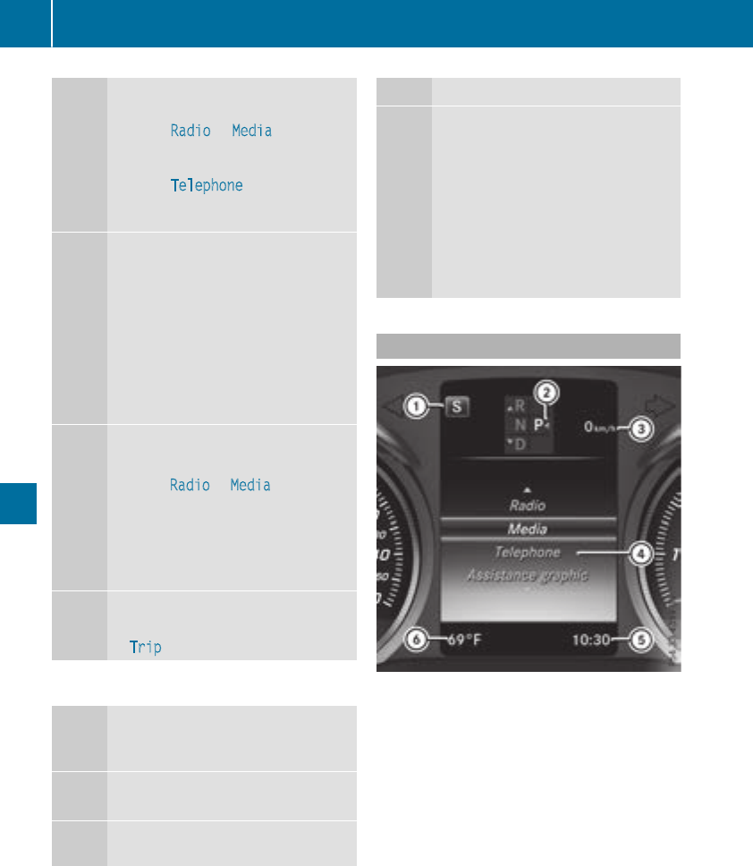
aRIn all menus: confirms the selected
entry in the list
RIn the Radio or Media menu:
opens the list of available radio
sources or media
RIn the Telephone menu: switches
to the phone book and starts dial-
ing the selected number
ñRVehicles with multimedia system
Audio 20:
Switches off voice control for nav-
igation (see the manufacturer's
operating instructions)
RVehicles with multimedia system
COMAND:
Switches off the Voice Control
System (see the separate operat-
ing instructions)
%Press briefly:
RBack
RIn the Radio or Media menu: exits
the track or station list or list of
available radio sources or media
RHides display messages
RExits the phone book/redial mem-
ory
%Press and hold:
RCalls up the standard display in the
Trip menu
Right control panel
~RRejects or ends a call
RExits the phone book/redial mem-
ory
6RMakes or accepts a call
RSwitches to the redial memory
W
X
RAdjusts the volume
8RMute
óRVehicles with multimedia system
Audio 20:
Switches on voice control for nav-
igation (see the manufacturer's
operating instructions)
RVehicles with multimedia system
COMAND:
Switches on the Voice Control Sys-
tem (see the separate operating
instructions)
Multifunction display
:Drive program (Ypage 134)
;Transmission position (Ypage 135)
=Additional speedometer
?Display
ATime
BOutside temperature (Ypage 193)
Display panel ?shows the selected menu or
submenu and display messages.
XTo open the menu list: press òon the
steering wheel.
Display panel ?appears in the menu list.
Possible displays in the multifunction dis-
play:
RZGearshift recommendation, when shifting
manually (Ypage 140)
RjParking Pilot (Ypage 166)
R¯Cruise control (Ypage 151)
194 Displays and operation
On-board computer and displays
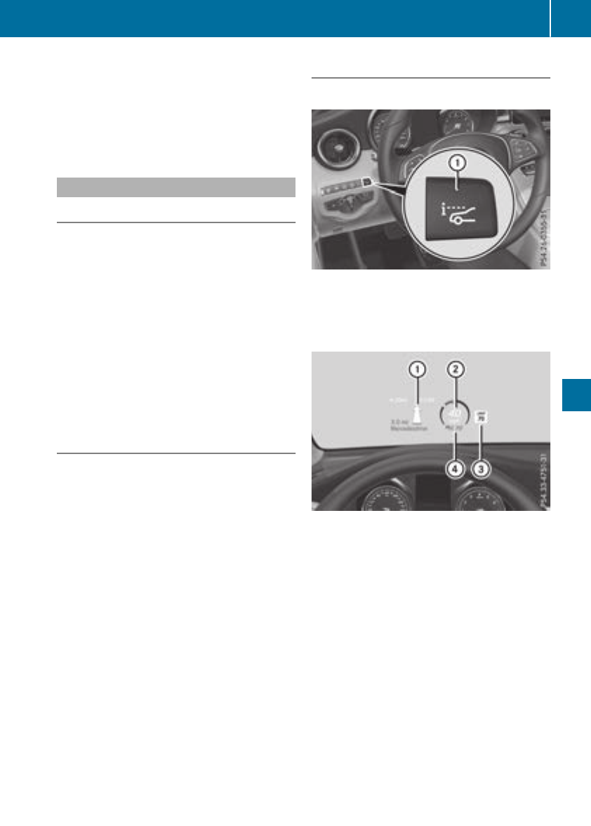
RaDistance Pilot DISTRONIC Steering Pilot
(Ypage 159)
R_Adaptive Highbeam Assist
(Ypage 109)
RèECO start/stop function (Ypage 127)
RëHOLD function (Ypage 161)
Head-up display
General notes
The head-up display projects information from
the navigation system and the driver assistance
system above the dashboard into the driver's
field of vision. The head-up display allows the
driver to see all of the information without hav-
ing to take their eyes off the road.
A requirement for the display of the contents is
that the following functions are available in the
vehicle and are switched on:
RCruise control
RDistance Pilot DISTRONIC
RTraffic Sign Assist
RNavigation
Important safety notes
The head-up display is only an aid and is not a
substitute for attentive driving.
Speed limits and overtaking restrictions are not
always correctly displayed. Traffic signs always
have priority over the Traffic Sign Assist display.
The visibility of the head-up display is influenced
by the following conditions:
Rthe driver's seat position
Rthe positioning of the display image
Rthe general ambient light
Rsunglasses with polarization filters
Rwet roads
Rblocking of sunlight by objects on the display
cover
In the event of extreme sunlight, sections of the
display may fade. This can be reversed by
switching the head-up display off and on again.
iVehicles with the head-up display are equip-
ped with a special windshield. Should repairs
be necessary, have the windshield replaced at
a qualified specialist workshop.
Displays and operation
Switching the head-up display on/off
XPress button :.
When the head-up display is switched on, the
display appears in the driver's field of vision.
Standard displays in the head-up display
:Navigation messages
;Current speed
=Detected traffic signs
?Set speed for cruise control or Distance Pilot
DISTRONIC
Displays andoperation 195
On-board computer and displays
Z
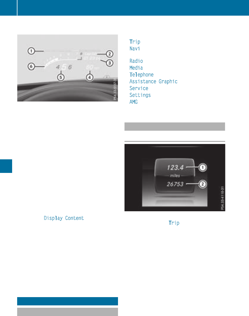
AMG displays in the head-up display
:Protection against reachingtheoverrevving
range
;RACE TIMER lap
=RACE TIMER lap time
?Currentspeed
ACurrently selected gear,gearshiftoptions
when shiftingmanually
BCurrentenginespeed
Setting options
You can adjust thefollowingsettings in the
head-up display submenu:
Radjust thepositionof thehead-up display on
thewindshield (Ypage 206)
Radjust thebrightness of thedisplays in the
head-up display (Ypage 206)
Rselect desired displays in thehead-up display
(Ypage 206)
UsingtheDisplayContentfunction,you
can,depending on your vehicle's equipment,
choosebetween four standard displays. The
selected contents then appear in thehead-up
display.
In Mercedes-AMGvehicles, you can choose
between further AMGdisplays in addition to
thestandard displays, depending on your
vehicle's equipment.
If you select adisplay withtraffic signs, detec-
tedtraffic signsfrom Traffic SignAssist
appear in thehead-up display.
Menus and submenus
Menu overview
Press theòbuttonon thesteering wheelto
open themenulist.
Operating theon-board computer (Ypage 193).
Dependingon thevehicleequipment, you can
select thefollowingmenu:
RTripmenu (Ypage 196)
RNavimenu(navigation instructions)
(Ypage 198)
RRadio menu (Ypage 200)
RMedia menu (Ypage 200)
RTelephone menu (Ypage 202)
RAssistanceGraphicmenu (Ypage 203)
RServicemenu (Ypage 203)
RSettings menu (Ypage 203)
RAMG menuin Mercedes-AMGvehicles
(Ypage 208)
Trip menu
Standard display
XPress and hold the%buttonon thesteer-
ing wheeluntil theTripmenuwithtrip odom-
eter :and odometer ;appears.
196 Menus and submenus
On-board computer and displays
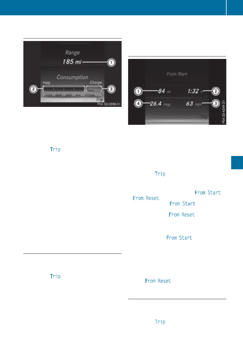
Displaying therange andcurrent fuel
consumption
:Range of thefuelsupply
;Currentfuelconsumption
=Recuperation display
XPress theòbuttonon thesteeringwheel
to openthemenulist.
XPress :or 9on thesteeringwheelto
selecttheTripmenu.
XConfirmby pressing aon thesteering
wheel.
XPress 9or :to selectthedisplay.
Approximaterange :that can be covered is
calculated accordingto your currentdriving
style and theamount of fuelin thetank.If
there is only asmall amount of fuelleftin the
fueltank, a vehicle beingrefueledC
appears instead of approximaterange :.
Recuperation display =shows you if energy
has beenrecuperated from thekineticenergy
in overrun mode and saved in thebattery.
Recuperation display =dependson the
engineinstalled and is therefore notavailable
in all vehicles.
ECO display
XPress òon thesteeringwheelto openthe
menulist.
XPress :or 9on thesteeringwheelto
selecttheTripmenu.
XConfirmby pressing aon thesteering
wheel.
XPress the:or 9buttonto selectECO
display.
If theignition remainsswitched offforlonger
than four hours, theECOdisplay will be auto-
matically reset.
Forfurther information on theECOdisplay, see
(Ypage 147).
Trip computer"From Start" or "From
Reset"
:Distance
;Driving time
=Average speed
?Average fuelconsumption
XPress theòbuttonon thesteeringwheel
to openthemenulist.
XPress :or 9on thesteeringwheelto
selecttheTripmenu.
XConfirmby pressing aon thesteering
wheel.
XPress :or 9to selectFromStart or
FromReset.
The values in theFromStart submenuare
calculated from thestart of ajourney, while
thevalues in theFromReset submenuare
calculated from thelast time thesubmenu
was reset (Ypage 198).
The trip computeris automatically reset in the
followingcases FromStart:
Rtheignition has beenswitched offformore
than four hours.
R999hourshavebeenexceeded.
R9,999 miles havebeenexceeded.
When9999 hoursor 99,999 mileshave been
exceeded, the trip computer is automatically
reset From Reset.
Digital speedometer
XPress òon the steering wheel to open the
menu list.
XPress :or 9on the steering wheel to
select the Trip menu.
Menus and submenus 197
On-board computer and displays
Z
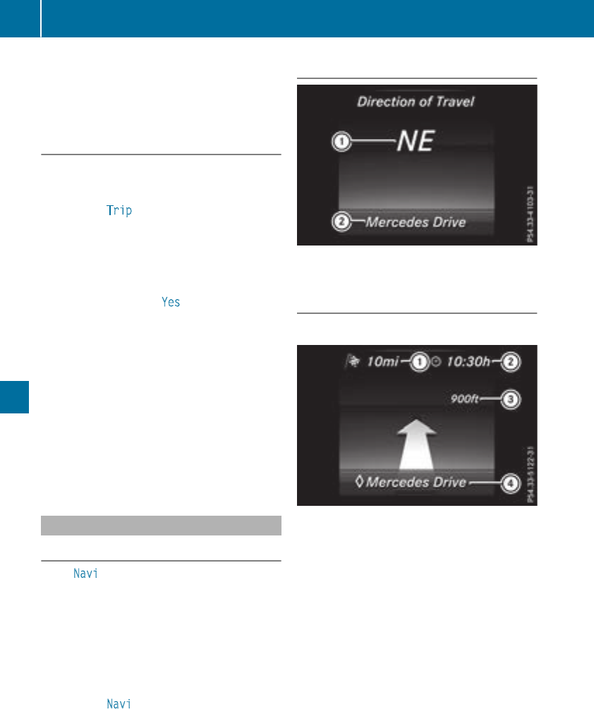
XConfirm by pressing aon the steering
wheel.
XPress the :or 9button to select the
digital speedometer.
Resetting values
XPress the òbutton on the steering wheel
to open the menu list.
XPress :or 9on the steering wheel to
select the Trip menu.
XConfirm by pressing aon the steering
wheel.
XPress the :or 9button to select the
function that you wish to reset.
XPress abriefly.
XPress :to select Yes and press ato
confirm.
You can reset the values of the following func-
tions:
RTrip odometer
R"From Start" trip computer
R"From Reset" trip computer
RECO display
If you reset the values in the ECO display, the
values in the "From Start" trip computer are
also reset. If you reset the values in the "From
Start" trip computer, the values in the ECO
display are also reset.
Navigation system menu
Displaying navigation instructions
In the Navi menu, the multifunction display
shows navigation instructions. You can find fur-
ther information on navigation instructions in
the multimedia system in the Digital Operator's
Manual.
XSwitch on the multimedia system.
XPress the òbutton on the steering wheel
to open the menu list.
XPress :or 9on the steering wheel to
select the Navi menu.
XConfirm by pressing aon the steering
wheel.
Route guidance not active
:Direction of travel
;Current road
Route guidance active
No change of direction announced
:Distance to the next destination
;Estimated arrival time
=Distance to the next change of direction
?Current road
198 Menus and submenus
On-board computer and displays
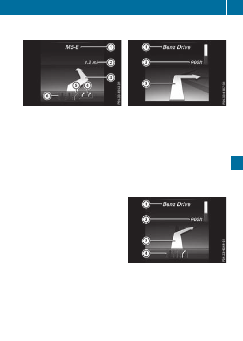
Change of direction announced with a
lane recommendation
:Target of the change of direction
;Distance to the change of direction
=Change-of-direction symbol
?Recommended lane and new lane during a
change of direction (white)
APossible lane
BLane not recommended (dark gray)
On multilane roads, new lane recommendations
can be displayed for the next change of direction
if the digital map supports this data. During the
change of direction, new lanes may be added.
Lane not recommended B: you will not be able
to complete the next change of direction if you
stay in this lane.
Possible lane A: you will only be able to com-
plete the next change of direction in this lane.
Recommended lane ?: in this lane you will be
able to complete the next change of direction
and the one after that.
Change of direction without lane recom-
mendation
:Road into which the change of direction
leads
;Distance to change of direction and visual
distance display
=Change-of-direction symbol
When a change of direction is to be made, you
will see symbol =for the change of direction
and distance graphic ;. The distance indicator
shortens towards the top of the display as you
approach the point of the announced change of
direction. The change of direction starts once
the distance display reaches zero.
Change of direction with lane recommen-
dation
:Road into which the change of direction
leads
;Distance to change of direction and visual
distance display
=Change-of-direction symbol
?Lane recommendation
Menus and submenus 199
On-board computer and displays
Z
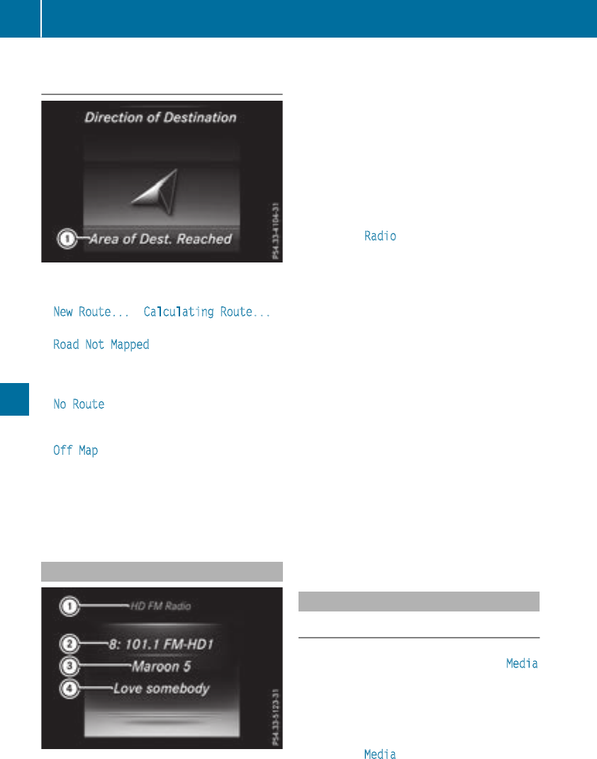
Other status indicators of the naviga-
tion system
:Additional information
Other possible additional information:
RNew Route... orCalculating Route...
A new route is calculated.
RRoad Not Mapped
The vehicle position is inside the area of the
digital map but the road is not recognized, e.g.
newly built streets, car parks or private land.
RNo Route
No route could be calculated to the selected
destination.
ROff Map
The map for the current vehicle position is not
available.
RO
You have reached the destination or an inter-
mediate destination.
Radio menu
:Waveband
;Station frequency with memory position
=Name of artist
?Name of track
The multifunction display shows station ;with
station frequency or station name. The preset
position is only displayed along with station ;if
this has been stored. You can store radio sta-
tions in the multimedia system.
XSwitch on the multimedia system.
XPress the òbutton on the steering wheel
to open the menu list.
XPress :or 9on the steering wheel to
select the Radio menu.
XConfirm by pressing aon the steering
wheel.
Currently set station ;appears in the multi-
function display.
XTo open the channel list: press the :or
9button briefly.
XTo select a station in the station list: press
the :or 9button briefly.
XTo select a station in the station list using
rapid scrolling: press and hold the :or
9button.
XTo select the waveband or station mem-
ory: press abriefly.
XPress :or 9to select the waveband or
station memory.
XPress ato confirm the selection.
iSIRIUS XM satellite radio functions like a
normal radio.
Further information about radio operation can
be found in the multimedia system in the Dig-
ital Operator's Manual.
Media menu
Changing the media source
You can change the media source and playback
mode (audio or video) at any time in the Media
menu.
XSwitch on the multimedia system.
XPress the òbutton on the steering wheel
to open the menu list.
XPress :or 9on the steering wheel to
select the Media menu.
200 Menus and submenus
On-board computer and displays
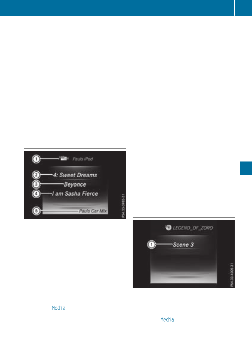
XConfirm by pressing aon the steering
wheel.
XTo open the media sources list: press a
briefly.
The list shows the following media sources,
for example:
RCD or DVD (DVD only in the COMAND mul-
timedia system)
RSD card
RMedia Register (only in the COMAND mul-
timedia system)
RUSB storage device
RBluetooth®capable audio device
Please observe further information on media
support and media operation in the multimedia
system (see the Digital Operator's Manual).
Operating an audio player or audio
media
:Media source, e.g. name of USB memory
stick
;Current title
=Name of artist
?Name of album
AFolder name
Audio data from various audio devices or media
can be played, depending on the equipment
installed in the vehicle.
XSwitch on the multimedia system.
XPress the òbutton on the steering wheel
to open the menu list.
XPress :or 9on the steering wheel to
select the Media menu.
XConfirm by pressing aon the steering
wheel.
XTo select an audio player or audio media:
press abriefly. The list containing the
media sources appears.
XPress :or 9to select the correspond-
ing audio player or media.
XPress ato confirm.
XTo open the track list: press the :or
9button briefly.
XTo select the next or previous track from
thetrack list: press the :or 9button
briefly.
XTo select a track from the track list using
rapid scrolling: press and hold :or 9
until the desired track is reached.
If you press and hold the button, the speed of
rapid scroll increases after a short time. Not
all audio drives or data carriers support this
function.
If the corresponding track information is stored
on the audio player or media, the multifunction
display shows the following:
Rtrack number
Rthe name of the track
Rthe name of the artist
Ralbum
The track information does not appear in audio
AUX mode (Auxiliary audio mode: external
audio source connected).
Video DVD operation
XSwitch on the multimedia system.
XPress the òbutton on the steering wheel
to open the menu list.
XPress :or 9on the steering wheel to
select the Media menu.
XConfirm by pressing aon the steering
wheel.
Menus and submenus 201
On-board computer and displays
Z
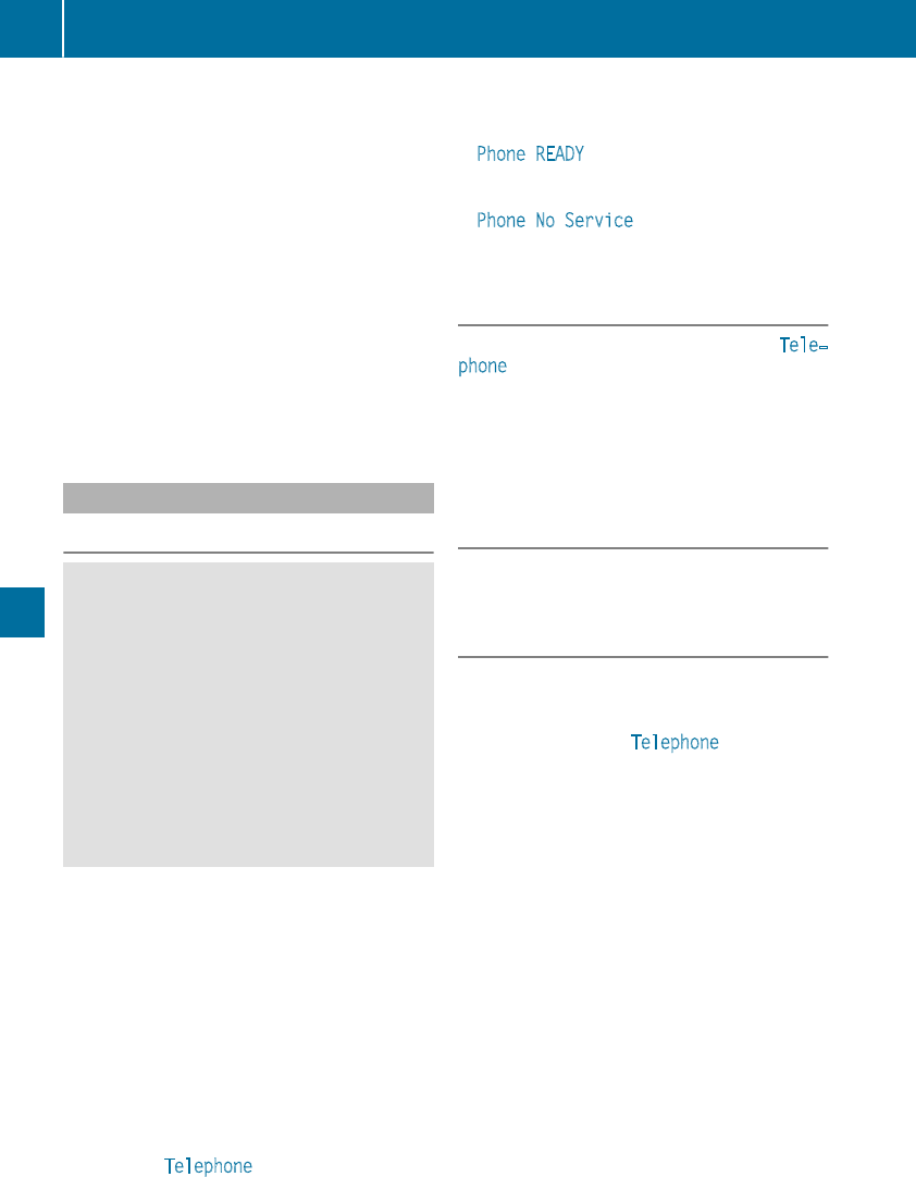
XTo select a DVD drive or DVD media: press
abriefly. The list containing the media
sources appears.
XPress :or 9to select the correspond-
ing DVD single drive or disc.
XPress ato confirm.
XTo open the scene list: press the :or
9button briefly.
XTo select the next or previous scene in the
scene list: press the :or 9button
briefly.
XTo select a scene from the scene list using
rapid scrolling: press and hold :or 9
until desired scene :is reached.
XPress ato confirm your selection.
Telephone menu
Introduction
GWARNING
If you operate information systems and com-
munication equipment integrated in the vehi-
cle when driving, you may be distracted from
the traffic situation. You could also lose con-
trol of the vehicle. There is a risk of an acci-
dent.
Only operate this equipment when the traffic
situation permits. If you are not sure that this
is possible, park the vehicle paying attention
to traffic conditions and operate the equip-
ment when the vehicle is stationary.
When telephoning, you must observe the legal
requirements for the country in which you are
currently driving.
XSwitch on the mobile phone (see the manu-
facturer’s operating instructions).
XSwitch on the multimedia system.
XEstablish a Bluetooth®connection to the mul-
timedia system (see the Digital Operator's
Manual).
XPress the òbutton on the steering wheel
to open the menu list.
XPress :or 9on the steering wheel to
select the Telephone menu.
XConfirm by pressing aon the steering
wheel.
You will see one of the following display mes-
sages in the multifunction display:
RPhone READY or the name of the network
provider: the mobile phone has found a net-
work and is ready to receive.
RPhone No Service: there is no network
available or the mobile phone is searching for
a network.
Accepting a call
If someone calls you when you are in the Tele‐
phone menu, a display message appears in the
multifunction display.
You can accept a call at any time regardless of
the menu selected.
XPress the 6button on the steering wheel
to accept an incoming call.
Rejecting or ending a call
XPress the ~button on the steering wheel
to reject or end a call.
Selecting an entry in the phone book
XPress the òbutton on the steering wheel
to open the menu list.
XPress the :or 9button on the steering
wheel to select the Telephone menu.
XConfirm by pressing aon the steering
wheel.
XPress the :or 9or abutton to
switch to the phone book.
XPress the :or 9button to select the
names one after the other.
or
XTo start rapid scrolling: press and hold :
or 9for longer than one second.
The names are displayed quickly one after the
other in the phone book.
If you press and hold the :or 9button
for longer than five seconds, the name with
the next or previous initial letter in the alpha-
bet appears.
Rapid scrolling stops when you release the
button or reach the end of the list.
XIf only one telephone number is stored for
a name: press the 6or abutton to
start dialing.
or
202 Menus and submenus
On-board computer and displays
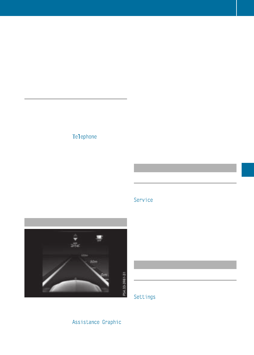
XIf there is more than one number for a
particular name: press the 6or a
button to display the numbers.
XPress the :or 9button to select the
number you want to dial.
XPress the 6or abutton to start dialing.
or
XTo exit the telephone book: press the ~
or %button briefly.
Redialing
The on-board computer saves the last names or
numbers dialed in the redial memory.
XPress the òbutton on the steering wheel
to open the menu list.
XPress the :or 9button on the steering
wheel to select the Telephone menu.
XConfirm by pressing aon the steering
wheel.
XPress the 6button to switch to the redial
memory.
XPress the :or 9button to select the
desired name or number.
XPress the 6or abutton to start dialing.
or
XTo exit the redial memory: press the ~
or %button briefly.
Assistance graphic menu
XPress the òbutton on the steering wheel
to open the menu list.
XPress the :or 9button on the steering
wheel to select the Assistance Graphic
menu.
XConfirm by pressing aon the steering
wheel.
The assistance graphic displays the status of
and information from the following driving
systems or driving safety systems:
RDistance Pilot DISTRONIC distance display
(Ypage 158)
RTraffic Sign Assist (Ypage 182)
RDistance warning function and autono-
mous brake function of Active Brake Assist
(Ypage 65)
RActive Brake Assist with cross-traffic func-
tion (Ypage 71)
RBlind Spot Assist (Ypage 182) or Active
Blind Spot Assist (Ypage 186)
RATTENTION ASSIST (Ypage 181)
RLane Keeping Assist (Ypage 184) or Active
Lane Keeping Assist (Ypage 189)
XPress :to display the ATTENTION ASSIST
assessment.
Service menu
Introduction
Depending on the equipment installed in the
vehicle, you have the following options in the
Service menu:
Rcalling up display messages in message mem-
ory (Ypage 212)
Rrestarting the tire pressure loss warning sys-
tem (Canada only) (Ypage 319).
Rchecking the tire pressure electronically
(Ypage 321).
Rcalling up the service due date (Ypage 285).
Settings menu
Introduction
Depending on the equipment installed in the
vehicle, you have the following options in the
Settings menu:
RChanging assistance settings (Ypage 204).
RChanging head-up display settings
(Ypage 206).
RChanging the light settings (Ypage 207).
Menus and submenus 203
On-board computer and displays
Z
RChanging the instrument cluster settings
(Ypage 207).
RRestoring the factory settings (Ypage 207).
Assistance submenu
Deactivating/activating ESP®
Observe the "Important safety notes" section in
the description of ESP®(Ypage 68).
GWARNING
If you deactivate ESP®, ESP®no longer sta-
bilizes the vehicle. There is an increased risk
of skidding and an accident.
Only deactivate ESP®in the situations descri-
bed in the following.
It may be best to deactivate ESP®in the follow-
ing situations:
Rwhen using snow chains
Rin deep snow
Ron sand or gravel
Deactivating/activating ESP®in Mercedes-
AMG vehicles (Ypage 69).
For further information about ESP®, see
(Ypage 67).
XStart the engine.
XPress the òbutton on the steering wheel
to open the menu list.
XPress :or 9on the steering wheel to
select the Settings menu.
XConfirm by pressing aon the steering
wheel.
XPress :or 9to select the DriveAs‐
sist submenu.
XPress ato confirm.
XSelect ESP by pressing :or 9.
XPress ato confirm.
The current selection appears.
XTo activate/deactivate: press the abut-
ton again.
If the åwarning lamp in the instrument
cluster lights up when the vehicle is ready to
drive, ESP®is deactivated.
If the ÷and åwarning lamps light up
continuously, ESP®is not available due to a mal-
function.
Observe the information on warning lamps
(Ypage 244).
Observe the information on display messages
(Ypage 213).
Traffic Sign Assist
You can activate or deactivate the warning func-
tion of Traffic Sign Assist in the Traffic Sign
Assist menu. When the function is activated,
detected traffic signs and information appear in
the multifunction display for five seconds.
XPress the òbutton on the steering wheel
to open the menu list.
XPress the :or 9button on the steering
wheel to select the Settings menu.
XConfirm by pressing aon the steering
wheel.
XPress :or 9to select the DriveAs‐
sist submenu.
XPress ato confirm.
XPress :or 9to select Traffic Sign
Assist.
XPress ato confirm.
The current selection appears.
XActivate or deactivate the warning func-
tion: press aagain.
For further information about Traffic Sign Assist,
see (Ypage 182).
Activating/deactivating Active Brake
Assist
XPress the òbutton on the steering wheel
to open the menu list.
XPress the :or 9button on the steering
wheel to select the Settings menu.
XConfirm by pressing aon the steering
wheel.
XUse :or 9to select the DriveAssist
submenu.
XPress ato confirm.
XSelect Brake Assist by pressing 9
or :.
XPress ato confirm.
The current selection appears.
XTo activate/deactivate: press aagain.
When Active Brake Assist is deactivated, the
æsymbol appears on the Assistance
Graphic menu of the multifunction display.
Further information on Active Brake Assist
(Ypage 65).
204 Menus and submenus
On-board computer and displays
Activating or deactivating Active Brake
Assist with cross-traffic function
ActiveBrake Assist withcross-traffic function is
available only in vehicles withtheDrivingAssis-
tance package.
XPress theòbuttonon thesteering wheel
to open themenulist.
XPress the:or 9buttonon thesteering
wheelto select theSettings menu.
XConfirmby pressingaon thesteering
wheel.
XUse :or 9to select theDriveAssist
submenu.
XPress ato confirm.
XSelectBrake Assist by pressing:or
9.
XPress ato confirm.
The currentselection appears.
XTo activate/deactivate: press theabut-
tonagain.
When ActiveBrake Assist withcross-traffic
function is deactivated, theæsymbol
appearson theAssistanceGraphicmenu
of themultifunction display.
Further information about ActiveBrake Assist
withcross-traffic function (Ypage 71).
Activating/deactivating Blind Spot Assist
XPress theòbuttonon thesteering wheel
to open themenulist.
XPress :or 9on thesteering wheelto
select theSettings menu.
XConfirmby pressingaon thesteering
wheel.
XPress :or 9to select theDriveAs‐
sistsubmenu.
XPress ato confirm.
XPress :or 9to select Blind Spot
Assist.
XPress ato confirm.
The currentselection appears.
XTo activate/deactivate: press theabut-
tonagain.
Forfurther information about BlindSpotAssist,
see (Ypage 182).
Forfurther information about ActiveBlindSpot
Assist,see (Ypage 186).
Setting ATTENTION ASSIST
XPress theòbuttonon thesteering wheel
to open themenulist.
XPress the:or 9buttonon thesteering
wheelto select theSettings menu.
XConfirmby pressingaon thesteering
wheel.
XUse :or 9to select theDriveAssist
submenu.
XPress ato confirm.
XSelectAttention Assist by pressing:
or 9.
XPress ato confirm.
XPress :or 9to select Off,Standard
or Sensitive.
XPress theabuttonto confirm theselec-
tion.
When ATTENTION ASSIST is deactivated, the
ésymbol appearsin theAssistance
Graphicmenuin themultifunction display.
Forfurther information about ATTENTION
ASSIST,see (Ypage 180).
Setting Lane Keeping Assist
XPress theòbuttonon thesteering wheel
to open themenulist.
XPress :or 9on thesteering wheelto
select theSettings menu.
XConfirmby pressingaon thesteering
wheel.
XPress :or 9to select theDriveAs‐
sistsubmenu.
XPress ato confirm.
XPress :or 9to select LaneKeeping
Assist.
XPress ato confirm.
The currentselection Standard or Adaptive
appears.
XTo change thesetting: press aagain.
Forfurther information about LaneKeeping
Assist,see (Ypage 184).
Forfurther information about ActiveLaneKeep-
ing Assist,see (Ypage 189).
Menus and submenus 205
On-board computer and displays
Z
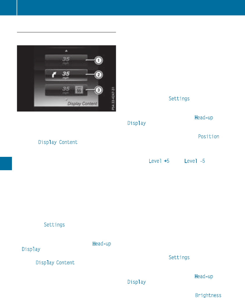
Head-up display submenu
Selecting other displays
:Vehicle speed display
;Vehicle speed and navigation instruction
display
=Vehicle speed display and Traffic Sign Assist
Using the Display Content function, you can
choose from up to four display options depend-
ing on the vehicle's equipment. The selected
contents appear in the head-up display.
In Mercedes-AMG vehicles, you can also choose
between two AMG displays. If you select an
AMG display, the head-up display shows AMG-
specific contents.
If you select a display with traffic signs, detected
traffic signs from Traffic Sign Assist appear in
the head-up display.
XPress the òbutton on the steering wheel
to open the menu list.
XPress :or 9on the steering wheel to
select the Settings menu.
XConfirm by pressing aon the steering
wheel.
XPress :or 9to select the Head-up
Display submenu.
XPress ato confirm.
XSelect Display Content by pressing :or
9.
XPress ato confirm.
A graphic selection list appears.
XPress :or 9to select the desired dis-
play.
XPress the abutton to confirm the selec-
tion.
You can find more information on the navigation
displays in the multimedia system (see Digital
Operator's Manual).
Information on displays of Traffic Sign Assist
(Ypage 182).
Setting the position
You can adjust the position of the head-up dis-
play on the windshield. You can compensate for
height differences if the seat positions are
changed, for example.
XSwitch on the head-up display (Ypage 195).
XPress the òbutton on the steering wheel
to open the menu list.
XPress the :or 9button on the steering
wheel to select the Settings menu.
XConfirm by pressing aon the steering
wheel.
XUse :or 9to select the Head-up
Display submenu.
XPress ato confirm.
XPress :or 9to select the Position
function.
XPress the abutton to save the setting.
XPress :or 9to adjust the position to a
level from Level +5 (up) to Level -5 (down).
XPress the aor %button to save the
setting.
Using the Memory function, you can save and
call up the set position of the head-up display as
a single memory preset (Ypage 105).
Setting the brightness
The brightness of the head-up display is auto-
matically adjusted to the surrounding ambient
light. You can also individually adjust the bright-
ness of the head-up display.
XSwitch on the head-up display (Ypage 195).
XPress the òbutton on the steering wheel
to open the menu list.
XPress the :or 9button on the steering
wheel to select the Settings menu.
XConfirm by pressing aon the steering
wheel.
XUse :or 9to select the Head-up
Display submenu.
XPress ato confirm.
XPress :or 9to select the Brightness
function.
XPress the abutton to save the setting.
206 Menus and submenus
On-board computer and displays
XPress the :or 9button to adjust the
brightness to a level from Level +5 (bright) to
Level -5 (dark).
XPress the aor %button to save the
setting.
Light submenu
Switching the daytime running lamps on/
off
This function is not available in Canada.
XPress òon the steering wheel to open the
menu list.
XPress :or 9on the steering wheel to
select the Settings menu.
XConfirm by pressing aon the steering
wheel.
XPress :or 9to select the Lights
submenu.
XPress ato confirm.
XUsing :or 9, select the Daytime
Running Lights function.
If the Daytime Running Lights function has
been switched on, the multifunction display
shows the cone of light and the Wsymbol
in yellow.
XPress the abutton to save the setting.
Further information on daytime running
lampsDaytime Running Lights (Ypage 107).
Instrument cluster submenu
Selecting the distance unit
The Display Unit Speed-/Odometer function
allows you to choose whether certain displays
appear in kilometers or miles in the multifunc-
tion display.
XPress the òbutton on the steering wheel
to open the menu list.
XPress the :or 9button on the steering
wheel to select the Settings menu.
XConfirm by pressing aon the steering
wheel.
XUse :or 9to select the Instrument
Cluster submenu.
XPress ato confirm.
XPress :or 9to select the Display
Unit Speed-/Odometer function.
The current setting km or Miles appears.
XPress the abutton to save the setting.
The selected unit of measurement for distance
applies to:
RDigital speedometer in the Trip menu
ROdometer and the trip odometer
RTrip computer
RCurrent consumption and the range
RRange
RNavigation instructions in the Navi menu
RCruise control
RDistance Pilot DISTRONIC with Steering Pilot
RASSYST PLUS service interval display
Switching the additional speedometer
on/off
If the additional speedometer is switched on,
the speed is shown in the status bar in the mul-
tifunction display instead of the outside tem-
perature.
The speed display is inverse to the speedome-
ter.
XPress the òbutton on the steering wheel
to open the menu list.
XPress the :or 9button on the steering
wheel to select the Settings menu.
XConfirm by pressing aon the steering
wheel.
XUse :or 9to select the Instrument
Cluster submenu.
XPress ato confirm.
XUsing :or 9, select the Additional
Speedometer [km/h] function.
The current selection appears.
XTo activate/deactivate: press the abut-
ton again.
Restoring the factory settings
XPress the òbutton on the steering wheel
to open the menu list.
XPress the :or 9button on the steering
wheel to select the Settings menu.
XConfirm by pressing aon the steering
wheel.
XUse :or 9to select the Factory
Settings submenu.
Menus and submenus 207
On-board computer and displays
Z
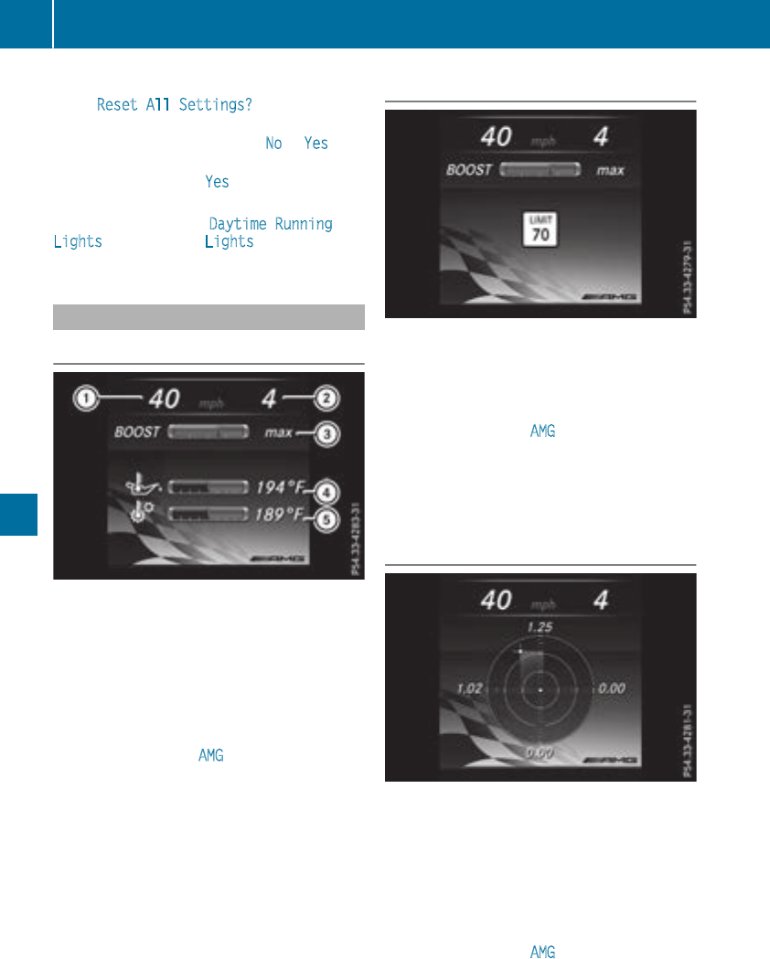
XPress ato confirm.
The Reset All Settings? function
appears.
XPress :or 9to select No or Yes.
XPress ato confirm the selection.
If you have selected Yes, the multifunction
display shows a confirmation message.
For safety reasons, the Daytime Running
Lights function in the Lights submenu is only
reset when the vehicle is stationary.
AMG menu (Mercedes-AMG vehicles)
Warm-up
:Digital speedometer
;Gear indicator
=Charge-air pressure
?Engine oil temperature
ATransmission oil temperature
XPress the òbutton on the steering wheel
to open the menu list.
XPress the :or 9button on the steering
wheel to select the AMG menu.
XConfirm by pressing aon the steering
wheel.
Engine and transmission oil tempera-
tures: when the engine and transmission are
at normal operating temperature, oil temper-
atures ?and Aare displayed in white in the
multifunction display.
If the multifunction display shows oil temper-
ature ?or Ain blue, the engine or the
transmission are not yet at normal operating
temperature. Avoid driving at full engine out-
put during this time.
Traffic Sign Assist display
XSwitch on the display function for notes and
traffic signs (Ypage 204).
XPress the òbutton on the steering wheel
to open the menu list.
XPress the :or 9button on the steering
wheel to select the AMG menu.
XConfirm by pressing aon the steering
wheel.
XPress the 9button repeatedly until the
Traffic Sign Assist display appears.
G-Meter
While the vehicle is in motion, the G-Meter
shows the forces that are exerted on the driver
both laterally and in the direction of travel.
The maximum values are indicated in red in the
guideline system.
XPress òon the steering wheel to open the
menu list.
XPress the :or 9button on the steering
wheel to select the AMG menu.
XConfirm by pressing aon the steering
wheel.
XPress the 9button repeatedly until the G-
Meter appears.
208 Menus and submenus
On-board computer and displays
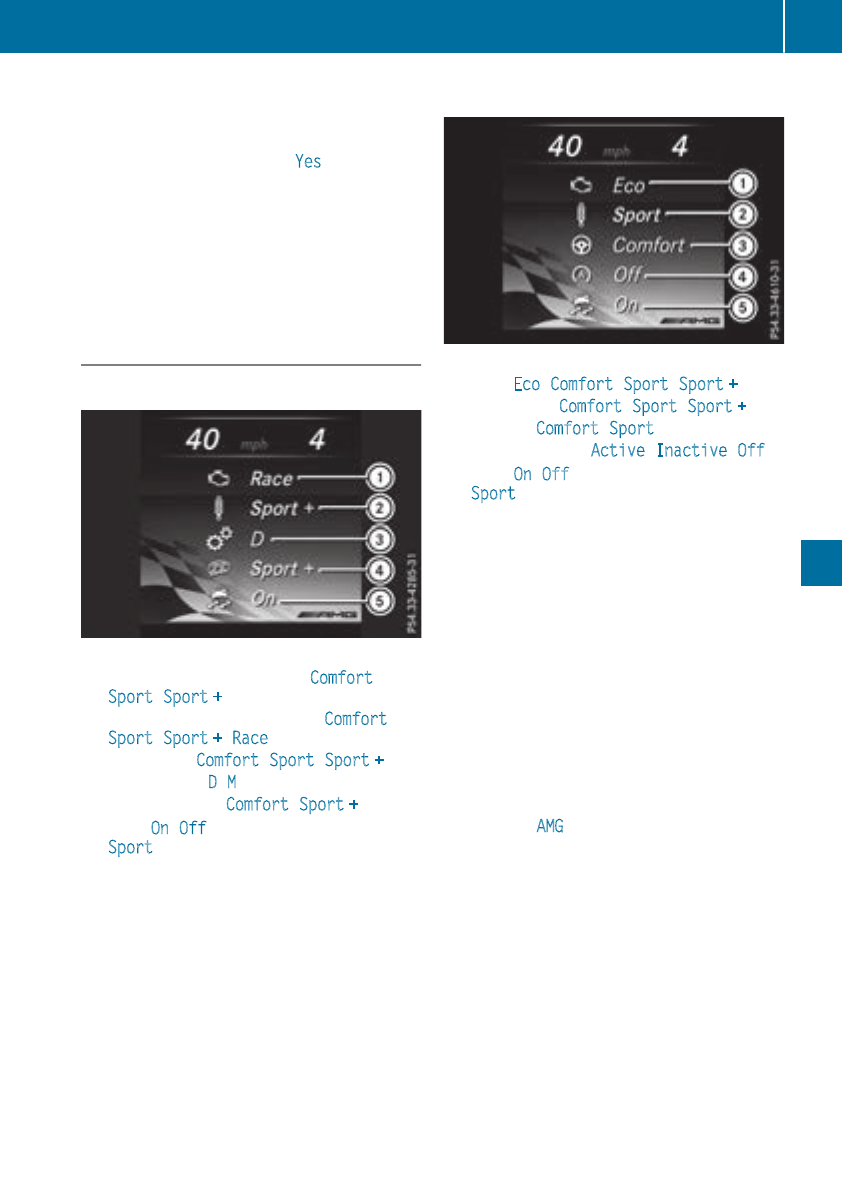
The maximum values of the G-Meter are
saved.
XTo reset the G-Meter: press aagain.
XUsing :or 9select Yes on the steer-
ing wheel.
XPress ato confirm.
The maximum values of the G-Meter are
deleted.
If the ignition remains switched off for longer
than four hours, the G-Meter will be automati-
cally reset.
SETUP
Mercedes-AMG C 63/AMG C 63 S
(Example)
:Mercedes-AMG C 63: Drive Comfort/
Sport/Sport +
Mercedes-AMG C 63 S: Drive Comfort/
Sport/Sport +/Race
;Suspension Comfort/Sport/Sport +
=Transmission D/M
?Exhaust system Comfort/Sport +
AESP®On/Off or SPORT handling mode
Sport
SETUP shows the following functions and set-
tings:
Rthe gear indicator
Rthe digital speedometer
Rthe drive system setting
Rthe suspension mode
Rthe transmission position
Rthe exhaust flap position
Rthe ESP®(Electronic Stability Program) status
Mercedes-AMG C 43 4MATIC
(Example)
:Drive Eco/Comfort/Sport/Sport +
;Suspension Comfort/Sport/Sport +
=Steering Comfort/Sport
?ECO Start/Stop Active/Inactive/Off
AESP®On/Off or SPORT handling mode
Sport
SETUP shows the following functions and set-
tings:
Rthe gear indicator
Rthe digital speedometer
Rthe drive system setting
Rthe suspension mode
Rthe steering setting
Rthe setting of the ECO start/stop function
Rthe ESP®(Electronic Stability Program) status
Select SETUP
XUse òon the steering wheel to call up the
list of menus.
XPress :or 9on the steering wheel to
select the AMG menu.
XConfirm by pressing aon the steering
wheel.
XPress 9repeatedly until SETUP appears.
Menus and submenus 209
On-board computer and displays
Z
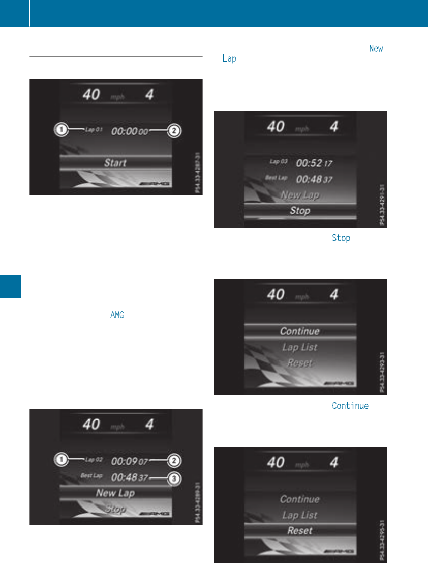
RACE TIMER
Displaying and starting RACETIMER
:Lap
;RACETIMER
The RACETIMER is only intended for use on a
closed race circuit. Do not use the function on
public roads.
You can start the RACETIMER when the engine is
running or the ignition is switched on.
XUse òon the steering wheel to call up the
list of menus.
XPress the :or 9button on the steering
wheel to select the AMG menu.
XConfirm by pressing aon the steering
wheel.
XPress :or 9repeatedly until the
RACETIMER appears.
XTo start: press the abutton to start the
RACETIMER.
Starting a new lap
:Lap
;RACETIMER
=Quickest lap time
XPress the :or 9button to select New
Lap.
XPress ato confirm.
A maximum of 32 laps may be stored.
Stopping the RACETIMER
XPress :or 9to select Stop.
XPress ato confirm.
Continuing the RACETIMER
XPress :or 9to select Continue.
XPress ato confirm.
Resetting the RACETIMER
210 Menus and submenus
On-board computer and displays
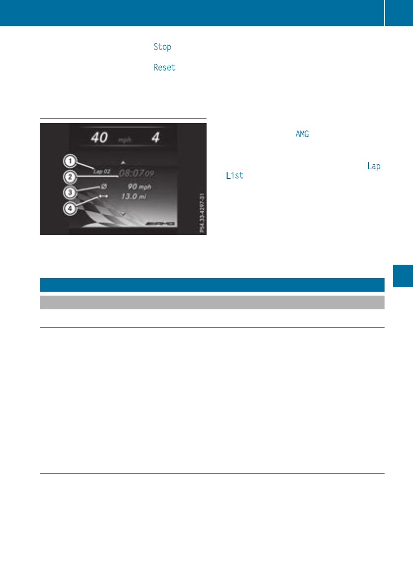
XPress :or 9to select Stop.
The RACETIMER is stopped.
XPress :or 9to select Reset.
XPress ato confirm.
All laps are deleted.
Lap statistics
:Lap
;Lap time
=Average lap speed
?Lap length
This function is only available if you have stored
at least two laps and have stopped the RACE-
TIMER.
XUse òon the steering wheel to call up the
list of menus.
XPress the :or 9button on the steering
wheel to select the AMG menu.
XConfirm by pressing aon the steering
wheel.
XPress the :or 9button to select Lap
List.
XPress ato confirm.
The lap evaluation appears.
XPress the 9or :button to select a dif-
ferent lap evaluation.
The fastest lap is indicated by flashing sym-
bol :.
Display messages
Introduction
General notes
Display messages appear in the multifunction display.
Display messages with graphic displays may be shown in simplified form in the Operator's Manual
and may therefore differ from the multifunction display.
Please respond in accordance with the display messages and follow the additional notes in this
Operator's Manual.
With certain display messages, you will also hear a warning tone.
You can hide the display messages. The display messages are then stored in the message memory.
Rectify the cause of a display message as soon as possible.
When you stop and park the vehicle, please observe the notes on:
RHOLD function (Ypage 161)
RParking (Ypage 143)
Hiding display messages
XPress the aor %button on the steering wheel.
The multifunction display hides the display message.
High-priority display messages are shown in red in the multifunction display. Some high-priority
display messages cannot be hidden.
The multifunction display shows these messages continuously until the causes for the messages
have been remedied.
Display messages 211
On-board computer and displays
Z
Message memory
The on-board computer saves certain display messages in the message memory. You can call up
the display messages:
XPress the òbutton on the steering wheel to open the menu list.
XPress :or 9on the steering wheel to select the Service menu.
XConfirm by pressing aon the steering wheel.
XPress the :or 9button to select the message memory.
If there are no display messages, the No Messages display appears in the multifunction display.
When there are display messages, the number of stored messages appears.
XPress ato confirm.
XPress the :or 9button to scroll through the display messages.
212 Display messages
On-board computer and displays
Safety systems
Display messages Possible causes/consequences and MSolutions
!÷
Currently Unavaila‐
ble See Operator's
Manual
ABS (Anti-lock Braking System) and ESP®(Electronic Stability Pro-
gram) are temporarily not available.
Other driving systems and driving safety systems may also malfunc-
tion.
In addition, the ÷and !warning lamps light up in the instru-
ment cluster.
For example, the on-board voltage may be insufficient.
GWARNING
The brake system continues to function normally, but without the
functions listed above. The wheels could therefore lock if you brake
hard, for example.
The steerability and braking characteristics may be severely affected.
The braking distance in an emergency braking situation can increase.
If ESP®is not operational, ESP®is unable to stabilize the vehicle.
There is an increased risk of skidding and an accident.
XDrive on carefully.
Carefully drive a suitable distance, making slight steering move-
ments at a speed above 12 mph (20 km/h).
If the display message disappears, the functions mentioned above
are available again.
If the multifunction display still shows the display message:
XDrive on carefully.
XVisit a qualified specialist workshop immediately.
!÷
Inoperative See
Operator's Manual
ABS and ESP®are malfunctioning.
Other driving systems and driving safety systems may also malfunc-
tion.
The $(USA only) or J(Canada only), ÷and !warning
lamps in the instrument cluster may also light up.
GWARNING
The brake system continues to function normally, but without the
functions listed above. The wheels could therefore lock if you brake
hard, for example.
The steerability and braking characteristics may be severely affected.
The braking distance in an emergency braking situation can increase.
If ESP®is not operational, ESP®is unable to stabilize the vehicle.
There is an increased risk of skidding and an accident.
XDrive on carefully.
XVisit a qualified specialist workshop immediately.
Display messages 213
On-board computer and displays
Z
Display messages Possible causes/consequences and MSolutions
÷
Inoperative See
Operator'sManual
ESP®is malfunctioning.
Other drivingsystems and drivingsafetysystems may also malfunc-
tion.
The ÷warning lamp also lights up in theinstrumentcluster.
GWARNING
The brakesystem continues to function normally, but without the
functionslisted above.
The braking distancein an emergencybraking situation can thus
increase.
If ESP®is notoperational, ESP®is unable to stabilizethevehicle.
There is an increased riskof skiddingand an accident.
XDrive on carefully.
XVisit aqualified specialist workshop immediately.
÷
Currently Unavaila‐
ble See Operator's
Manual
ESP®is temporarily unavailable.
Other drivingsystems and drivingsafetysystems may also malfunc-
tion.
The ÷warning lamp also lights up in theinstrumentcluster.
The self-diagnosis function might notbe complete, for example.
GWARNING
The brakesystem continues to function normally, but without the
functionslisted above. The wheels could thereforelockif you brake
hard, for example.
The braking distancein an emergencybraking situation can thus
increase.
If ESP®is notoperational, ESP®is unable to stabilizethevehicle.
There is an increased riskof skiddingand an accident.
XCarefully drive asuitable distance, making slight steering move-
ments at aspeed above12 mph (20 km/h).
If the display message disappears, the functions mentioned above
are available again.
If the multifunction display still shows the display message:
XDrive on carefully.
XVisit a qualified specialist workshop immediately.
214 Display messages
On-board computer and displays
Display messages Possible causes/consequences and MSolutions
T!
÷
Inoperative See
Operator'sManual
EBD(electronic brakeforce distribution), ABSand ESP®are malfunc-
tioning.
Other drivingsystems and drivingsafetysystems may also malfunc-
tion.
In addition,the÷and !warning lampslightup in theinstru-
mentclusterand awarning tone sounds.
GWARNING
The brakesystem continues to function normally, but without the
functionslisted above. The frontand rear wheels could thereforelock
if you brakehard, for example.
The steerabilityand braking characteristics may be severely affected.
The braking distancein an emergencybraking situation can increase.
If ESP®is notoperational, ESP®is unable to stabilizethevehicle.
There is an increased riskof skiddingand an accident.
XDrive on carefully.
XVisit aqualified specialist workshop immediately.
F(USA
only) !(Canada
only)
TurnOn the Igni‐
tionto Releasethe
ParkingBrake
The red F(USAonly) or !(Canada only) indicator lamp lights
up.
You attemptedto release theelectric parking brakewhile theignition
was switched off.
XSwitchon theignition.
F(USA
only) !(Canada
only)
Please ReleasePark‐
ing Brake
The red F(USAonly) or !(Canada only) indicator lamp flashes
and awarning tone sounds. Acondition for automatic release of the
electric parking brakeis notfulfilled (Ypage 146).
You are drivingwiththeelectric parking brakeapplied.
XReleasetheelectric parking brakemanually.
The red F(USAonly) or !(Canada only) indicator lamp flashes
and awarning tone sounds.
You are usingtheelectric parking brakefor emergencybraking
(Ypage 146).
F(USA
only) !(Canada
only)
ParkingBrake See
Operator'sManual
The yellow !warning lamp lights up.
The electric parking brakeis malfunctioning.
To apply:
XSwitchtheignition off.
XPress theelectric parking brakehandle for at least tenseconds.
XShift thetransmission to position j.
XConsult aqualified specialist workshop.
Display messages 215
On-board computer and displays
Z

Display messages Possible causes/consequences and MSolutions
The yellow !warning lamp and thered F(USAonly) or !
(Canada only) indicator lamp lightup.
The electric parking brakeis malfunctioning.
To release:
XSwitchoff theignition and turnit backon.
XReleasetheelectric parking brakemanually.
or
XReleasetheelectric parking brakeautomatically (Ypage 146).
If theelectric parking brakestill cannotbe released:
XDo notdrive on.
XConsult aqualified specialist workshop.
The red F(USAonly) or !(Canada only) indicator lamp flashes
and theyellow !warning lamp lights up.
The electric parking brakeis malfunctioning.
To release:
XSwitchoff theignition and turnit backon.
XReleasetheelectric parking brakemanually.
To apply:
XSwitchoff theignition and turnit backon.
XApply theelectric parking brakemanually.
If thered F(USAonly) or !(Canada only) indicator lamp con-
tinuesto flash:
XDo notdrive on.
XSecurethevehicleagainst rollingaway (Ypage 332).
XShift thetransmission to position j.
XTurn thefrontwheels towardsthecurb.
XConsult aqualified specialist workshop.
216 Display messages
On-board computer and displays

Display messages Possible causes/consequences and MSolutions
The yellow !warning lamp lights up. The red F(USAonly)
or !(Canada only) indicator lamp flashes for about tenseconds
after theelectric parking brakehas been appliedor released. It then
goesout or remainslit.
The electric parking brakeis malfunctioning.
XSwitchoff theignition and turnit backon.
XApply theelectric parking brake.
If it is notpossibleto engage theelectric parking brake:
XShift thetransmission to position j.
XVisit aqualified specialist workshop.
If it is notpossibleto release theelectric parking brakemanually:
XReleasetheelectric parking brakeautomatically (Ypage 146).
If theelectric parking brakestill cannotbe released:
XConsult aqualified specialist workshop.
The yellow !warning lamp lights up. If you manually apply or
release theelectric parking brake, thered F(USAonly) or !
(Canada only) indicator lamp flashes.
The electric parking brakeis malfunctioning.It is notpossibleto apply
theelectric parking brakemanually.
XShift thetransmission to position j,as theelectric parking brake
is notappliedautomatically.
XVisit aqualified specialist workshop.
If it is notpossibleto release theelectric parking brakemanually:
XReleasetheelectric parking brakeautomatically (Ypage 146).
F(USA
only) !(Canada
only)
ParkingBrake Inop‐
erative
The yellow !warning lamp lights up. The red F(USAonly)
or !(Canada only) indicator lamp flashes for about tenseconds
after theelectric parking brakehas been appliedor released. It then
goesout or remainslit.
The electric parking brakeis malfunctioning,e.g. because of over-
voltageor undervoltage.
XRemove thecausefor theovervoltage or undervoltage, e.g. by
charging thebattery or restarting theengine.
XEngage or release theelectric parking brake.
If it remainsimpossible to apply or release theelectric parking brake:
XSwitchoff theignition and turnit backon.
XEngage or release theelectric parking brake.
If theelectric parking brakestill cannotbe released:
XConsult aqualified specialist workshop.
If theelectric parking brakestill cannotbe applied:
XVisit aqualified specialist workshop.
Display messages 217
On-board computer and displays
Z
Display messages Possible causes/consequences and MSolutions
The yellow !warning lamp lights up and thered F(USAonly)
or !(Canada only) indicator lamp flashes.
It is notpossibleto apply theelectric parking brakemanually.
XShift thetransmission to position j.
XVisit aqualified specialist workshop.
$(USAonly)
J(Canada only)
Check Brake Fluid
Level
There is notenough brakefluid in thebrakefluid reservoir.
In addition,the$(USAonly) or J(Canada only) warning lamp
lights up in theinstrumentclusterand awarning tone sounds.
GWARNING
The braking effectmay be impaired.
There is ariskof an accident.
XPull overand stop thevehiclesafely as soonas possible, paying
attention to roadand traffic conditions. Do notcontinuedriving
under any circumstances.
XSecurethevehicleagainst rollingaway (Ypage 143).
XConsult aqualified specialist workshop.
XDo notadd brakefluid.This does notcorrectthemalfunction.
#
Check Brake Pad Wear
The brakepads/linings havereached their wear limit.
USAonly: the$red brakesystem warning lamp is lit while the
engineis running.
XVisit aqualified specialist workshop.
G
Inoperative
Oneor moremain features of thembrace system are malfunctioning.
XVisit aqualified specialist workshop.
Active Brake Assist
Functions Currently
LimitedSee Opera‐
tor's Manual
Active Brake Assistis temporarily inoperative.
Possiblecauses are:
RThe radar sensor system is temporarily inoperative, e.g. due to
electromagneticradiation emitted by nearby TV or radiostationsor
other sourcesof electromagneticradiation.
RThe system is outside theoperating temperature range.
RThe on-boardvoltageis toolow.
Whenthecauses statedaboveno longer apply, thedisplay message
disappears.
Active Brake Assistis operational again.
If thedisplay message does notdisappear:
XPull overand stop thevehiclesafely as soonas possible, paying
attention to roadand traffic conditions.
XSecurethevehicleagainst rollingaway (Ypage 143).
XRestart theengine.
218 Display messages
On-board computer and displays
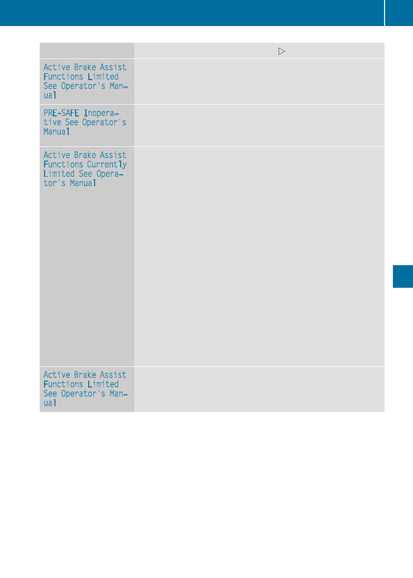
Display messages Possible causes/consequences and MSolutions
Active Brake Assist
Functions Limited
See Operator'sMan‐
ual
Active Brake Assistis unavailable due to amalfunction.Adaptive
Brake Assistmay also havefailed.
XVisit aqualified specialist workshop immediately.
PRE-SAFE Inopera‐
tiveSee Operator's
Manual
Importantfunctionsof PRE-SAFE®havefailed. Allother occupant
safetysystems,e.g. air bags,remain available.
XVisit aqualified specialist workshop immediately.
Active Brake Assist
Functions Currently
LimitedSee Opera‐
tor's Manual
Active Brake Assistwithcross-traffic function is temporarily inopera-
tive.
Possiblecauses are:
RFunction is impaireddue to heavyrain or snow.
RThe radar sensor system is temporarily inoperative, e.g. due to
electromagneticradiation emitted by nearby TV or radiostationsor
other sourcesof electromagneticradiation.
RMercedes-AMG vehicles: ESP®is deactivated
RThe system is outside theoperating temperature range.
RThe on-boardvoltageis toolow.
Whenthecauses statedaboveno longer apply, thedisplay message
disappears.
Active Brake Assistwithcross-traffic function is operational again.
If thedisplay message does notdisappear:
XPull overand stop thevehiclesafely as soonas possible, paying
attention to roadand traffic conditions.
XSecurethevehicleagainst rollingaway (Ypage 143).
XRestart theengine.
XMercedes-AMG vehicles: switch ESP®on again (Ypage 69).
Active Brake Assist
Functions Limited
See Operator'sMan‐
ual
Active Brake Assistwithcross-traffic function is unavailable due to a
malfunction.
XVisit aqualified specialist workshop immediately.
Display messages 219
On-board computer and displays
Z
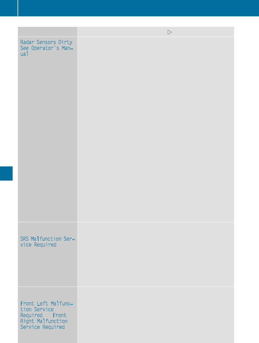
Display messages Possible causes/consequences and MSolutions
Radar SensorsDirty
See Operator'sMan‐
ual
The radar sensor system is malfunctioning.
Possiblecauses are:
RDirt on sensors
RHeavy rain or snow
RWhendrivingon inter-urban roads without traffic or infrastructure,
e.g. in desert-like areas
At least onedrivingsystem or drivingsafetysystem is malfunctioning
or is temporarily unavailable:
RActive Brake Assistwithcross-traffic function
RActive Brake Assist
RActive LaneKeepingAssist
RActive Blind Spot Assist
RDistancePilotDISTRONICwithSteering Pilot
If theradar sensor system in frontis dirty, Active Blind Spot Assistwill
notperform a course-correcting brakeapplication.
Once thecauseof theproblem is no longer present, thedrivingand
drive safetysystems will be available again.The display message dis-
appears.
If thedisplay message does notdisappear:
XPull overand stop thevehiclesafely as soonas possible, paying
attention to roadand traffic conditions.
XSecurethevehicleagainst rollingaway (Ypage 143).
XSwitchoff theengine.
XClean all sensors (Ypage 292).
XRestart theengine.
The display message disappears.
6
SRS Malfunction Ser‐
viceRequired
The restraintsystem is malfunctioning.The 6warning lamp also
lights up in theinstrumentcluster.
GWARNING
The air bags or Emergency Tensioning Devices may either be triggered
unintentionally or, in theevent of an accident, may notbe triggered.
There is an increased riskof injury.
XVisit aqualified specialist workshop immediately.
Forfurther information about therestraintsystem, see (Ypage 43).
6
Front LeftMalfunc‐
tionService
Required or Front
Right Malfunction
ServiceRequired
The restraintsystem is malfunctioning at thefronton theleftor right.
The 6warning lamp also lights up in theinstrumentcluster.
GWARNING
The air bags or Emergency Tensioning Devices may either be triggered
unintentionally or, in theevent of an accident, may notbe triggered.
There is an increased riskof injury.
XVisit aqualified specialist workshop immediately.
220 Display messages
On-board computer and displays
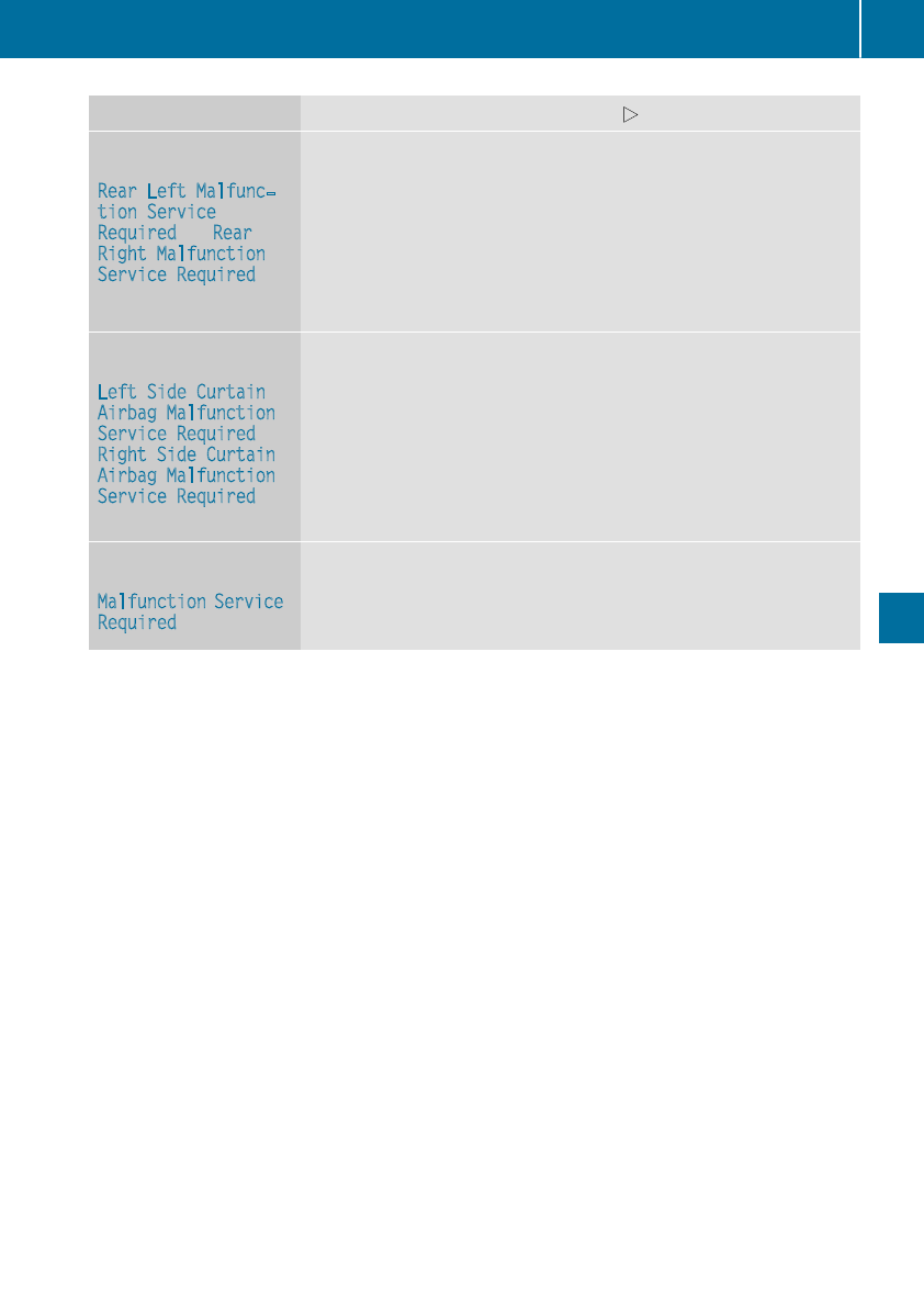
Display messages Possible causes/consequences and MSolutions
6
RearLeftMalfunc‐
tionService
Required or Rear
Right Malfunction
ServiceRequired
The rear left-handor right-hand restraintsystem is malfunctioning.
The 6warning lamp also lights up in theinstrumentcluster.
GWARNING
The air bags or Emergency Tensioning Devices may either be triggered
unintentionally or, in theevent of an accident, may notbe triggered.
There is an increased riskof injury.
XVisit aqualified specialist workshop immediately.
6
LeftSideCurtain
Airbag Malfunction
ServiceRequired or
Right SideCurtain
Airbag Malfunction
ServiceRequired
There is amalfunction in theleft-handand/orright-hand head bag.
The 6warning lamp also lights up in theinstrumentcluster.
GWARNING
The leftor right head bag may either be triggered unintentionally or, in
theevent of an accident, may notbe triggered.
There is an increased riskof injury.
XVisit aqualified specialist workshop immediately.
A
Malfunction Service
Required
GWARNING
The rollbars are defective.
XVisit aqualified specialist workshop immediately.
Display messages 221
On-board computer and displays
Z
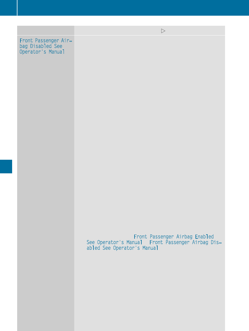
Display messages Possible causes/consequences and MSolutions
Front Passenger Air‐
bag Disabled See
Operator'sManual
The front-passenger frontair bag and front-passenger knee bag are
deactivated during thejourney although:
Ran adult
or
Raperson of thecorrespondingstatureis on thefront-passenger seat
If additional forcesare appliedto theseat,thesystem may interpret
theoccupant's weightas lower than it actually is.
GWARNING
The front-passenger air bag and front-passenger knee bag will notbe
triggered in theevent of an accident.
There is an increased riskof injury.
XPull overand stop thevehiclesafely as soonas possible, paying
attention to roadand traffic conditions.
XSecurethevehicleagainst rollingaway (Ypage 143).
XSwitchtheignition off.
XHavetheoccupant on thefront-passenger seat get out of thevehi-
cle.
XKeeptheseat unoccupied,close thefront-passenger door and
switch on theignition.
XObservethePASSENGER AIRBAGindicator lampsin thecenter
console and themultifunction display and checkthefollowing:
Seat unoccupied and ignition switched on:
Raself-diagnosis is carriedout.The PASSENGER AIRBAGOFFand
PASSENGER AIRBAGON indicator lampsmustlightup simulta-
neouslyfor approximately six seconds
RthePASSENGER AIRBAGOFFindicator lamp mustthen lightup
and remain lit after theself-diagnosis.If theindicator lamp is on,
theOCS (Occupant Classification System) has disabled thefront-
passenger frontair bag and front-passenger knee bag
(Ypage 52)
Rthedisplay messagesFront Passenger Airbag Enabled
See Operator'sManual or Front Passenger Airbag Dis‐
abled See Operator'sManual mustnotappear in themulti-
function display
XWait for aperiod of at least 60 seconds until thenecessarysystem
checks havebeen completed.
XMakesurethat thedisplay messagesdo notappear in themulti-
function display.
If these conditionsare fulfilled,thefront-passenger seat can be occu-
pied again.Whether thePASSENGER AIRBAGOFFindicator lamp
remainslit or goesout dependson how OCS classifies theoccupant.
If theconditionsare notfulfilled,thesystem is notoperating correctly.
XVisit aqualified specialist workshop immediately.
Forfurther information about theOccupant Classification System, see
(Ypage 52).
222 Display messages
On-board computer and displays
Display messages Possible causes/consequences and MSolutions
Front Passenger Air‐
bag EnabledSee
Operator'sManual
The front-passenger air bag and front-passenger knee bag are enabled
during thejourney although:
Rachild, asmall adult or an objectweighing less than thesystem's
weightthreshold is locatedon thefront-passenger seat
or
Rthefront-passenger seat is unoccupied
The system may detectobjects or forcesapplyingadditional weighton
theseat.
GWARNING
The front-passenger air bag and thefront-passenger knee bag may be
triggered unintentionally.
There is an increased riskof injury.
XPull overand stop thevehiclesafely as soonas possible, paying
attention to roadand traffic conditions.
XSecurethevehicleagainst rollingaway (Ypage 143).
XSwitchtheignition off.
XOpenthefront-passenger door.
XRemove thechild and thechild restraintsystem from thefront-
passenger seat.
XMakesurethat there are no objects on theseat addingto the
weight.
The system might otherwise detecttheadditional weightand inter-
prettheseat occupant's weightas greaterthan it actually is.
XKeeptheseat unoccupied,close thefront-passenger door and
switch on theignition.
XObservethePASSENGER AIRBAGindicator lampsin thecenter
console and themultifunction display and checkthefollowing:
Seat unoccupied and ignition switched on:
Raself-diagnosis is carriedout.The PASSENGER AIRBAGOFFand
PASSENGER AIRBAGON indicator lampsmustlightup simulta-
neouslyfor approximately six seconds
RthePASSENGER AIRBAGOFFindicator lamp mustthen lightup
and remain lit after theself-diagnosis.If theindicator lamp is on,
theOCS has disabled thefront-passenger frontair bag and front-
passenger knee bag (Ypage 52)
Rthedisplay messagesFront Passenger Airbag Enabled
See Operator'sManual or Front Passenger Airbag Dis‐
abled See Operator'sManual mustnotappear in themulti-
function display
XWait for aperiod of at least 60 seconds until thenecessarysystem
checks havebeen completed.
XMakesurethat thedisplay messagesdo notappear in themulti-
function display.
If these conditionsare fulfilled,thefront-passenger seat can be occu-
pied again.Whether thePASSENGER AIRBAGOFFindicator lamp
remainslit or goesout dependson how OCS classifies theoccupant.
If theconditionsare notfulfilled,thesystem is notoperating correctly.
Display messages 223
On-board computer and displays
Z
Display messages Possible causes/consequences and MSolutions
XVisit aqualified specialist workshop immediately.
Forfurther information about theOccupant Classification System, see
(Ypage 52).
Lights
Display messages Possible causes/consequences and MSolutions
b
Check LeftLow Beam
(Example)
The bulb in question is malfunctioning.
XVisit aqualified specialist workshop.
iLEDlightsources: thedisplay message for thecorresponding
lamp only appearswhen all theLEDs in thelamp havefailed.
b
Active Headlamps
Inoperative
The active lightfunction is malfunctioning.
XVisit aqualified specialist workshop.
b
Malfunction See
Operator’sManual
The exteriorlighting is malfunctioning.
XVisit aqualified specialist workshop.
b
AutoLampFunction
Inoperative
The lightsensor is malfunctioning.
XVisit aqualified specialist workshop.
b
Switch Off Lights
You leavethevehicleand thelights are switched on. A warning tone
also sounds.
XTurn thelightswitch to theÃposition.
b
Switch On Headlamps
You are drivingwithlow-beam headlampsswitched off.
XTurn thelightswitch to theLor Ãposition.
Adaptive Highbeam
Assist Currently
Unavailable See
Operator'sManual
Adaptive HighbeamAssistis deactivated and temporarily inoperative.
Possiblecauses are:
RThe windshield in thecamera'sfield of vision is dirty.
RVisibilityis impaireddue to heavyrain,snow or fog.
XClean thewindshield.
If thesystem detects that thecamera is fullyoperational again,the
Adaptive Highbeam Assist Now Available message is displayed.
Adaptive HighbeamAssistis operational again.
Adaptive Highbeam
Assist Inoperative
Adaptive HighbeamAssistis malfunctioning.
XVisit aqualified specialist workshop.
224 Display messages
On-board computer and displays
Engine
Display messages Possible causes/consequences and MSolutions
+
Check Coolant Level
See Operator's Man‐
ual
The coolant level is too low.
!Avoid making long journeys with too little coolant in the engine
cooling system. The engine will otherwise be damaged.
XAdd coolant, observing the warning notes before doing so
(Ypage 284).
If you have to add coolant frequently:
XContact a qualified specialist workshop and have the engine cooling
system checked.
?The fan motor is malfunctioning.
XIf the coolant temperature is below the red marking in the coolant
temperature gauge, drive to the nearest qualified specialist work-
shop.
XAvoid heavy loads on the engine as you do so, e.g. driving in moun-
tainous terrain and stop-and-go traffic.
?
Coolant Too Hot
Stop Vehicle Turn
Engine Off
The coolant is too hot.
A warning tone also sounds.
GWARNING
Do not drive when your engine is overheated. This can cause some
fluids which may have leaked into the engine compartment to catch
fire.
Steam from the overheated engine can also cause serious burns which
can occur just by opening the hood.
There is a risk of injury.
XPull over and stop the vehicle safely and switch off the engine, pay-
ing attention to road and traffic conditions.
XSecure the vehicle against rolling away (Ypage 143).
XWait until the engine has cooled down.
XMake sure that the air supply to the engine radiator is not blocked,
e.g. by snow, slush or ice.
XDo not start the engine again until the display message goes out and
the coolant temperature gauge is below the red marking. Other-
wise, the engine could be damaged.
XPay attention to the coolant temperature gauge.
If the temperature increases again:
XVisit a qualified specialist workshop immediately.
Under normal operating conditions and with the specified coolant
level, the coolant temperature gauge may rise to the red marking.
Display messages 225
On-board computer and displays
Z
Display messages Possible causes/consequences and MSolutions
#
See Operator'sMan‐
ual
The battery is notbeingcharged.
Awarning tone also sounds.
Possiblecauses are:
Radefective alternator
Ratorn poly-V-belt
Ramalfunction in theelectronics
!Do notcontinuedriving. The enginecould otherwise overheat.
XPull overand stop thevehiclesafely and switch off theengine, pay-
ing attention to roadand traffic conditions.
XSecurethevehicleagainst rollingaway (Ypage 143).
XConsult aqualified specialist workshop.
#
StopVehicleSee
Operator'sManual
The battery is no longer beingcharged and thecondition of chargeis
toolow.
Awarning tone also sounds.
XPull overand stop thevehiclesafely and switch off theengine, pay-
ing attention to roadand traffic conditions.
XSecurethevehicleagainst rollingaway (Ypage 143).
XObservetheinstructionsin the#See Operator'sManual
display message.
XConsult aqualified specialist workshop.
#
StopVehicleLeave
Engine Running
The battery condition of chargeis toolow.
XPull overand stop thevehiclesafely as soonas possible, paying
attention to roadand traffic conditions. Do notcontinuedriving
under any circumstances.
XLeavetheenginerunning.
XWait until thedisplay message disappearsbefore pullingaway.
#
Start Engine See
Operator'sManual
The engineis switched off and thecondition of chargeis toolow.
XSwitchoff electrical consumersthat you do notneed, suchas the
rear window defrosterand interior lighting.
XLeavetheenginerunningfor afew minutesor drive alongdistance.
The battery is beingcharged.
226 Display messages
On-board computer and displays
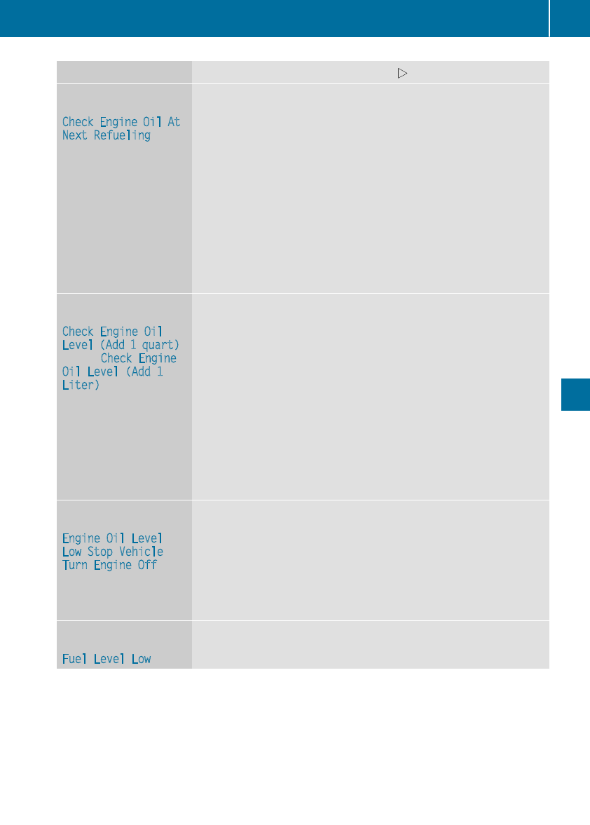
Display messages Possible causes/consequences and MSolutions
4
Check Engine Oil At
NextRefueling
The engineoil level has dropped to theminimum level.
Awarning tone also sounds.
!Avoid longjourneys withtoolittleengineoil. The enginewill oth-
erwise be damaged.
XChecktheoil level when next refueling, at thelatest (Ypage 283).
XIf necessary, add engineoil (Ypage 283).
If you have to addengineoil frequently:
XContact a qualified specialist workshop and havetheengine
checked.
Information on approvedengineoils can be obtained from aqualified
specialist workshop or on theInternet at http://bevo.mercedes-
benz.com.
4
Check Engine Oil
Level (Add 1 quart)
(USA) Check Engine
Oil Level (Add 1
Liter) (Canada)
Mercedes-AMG C 63 vehicles:
The engine oil level has dropped to the minimum level.
!Avoid long journeys with too little engine oil. The engine will oth-
erwise be damaged.
XCheck the oil level when next refueling, at the latest (Ypage 283).
XIf necessary, add engine oil (Ypage 283).
If you have to add engine oil frequently:
XContact a qualified specialist workshop and have the engine
checked.
Information on approved engine oils can be obtained from a qualified
specialist workshop or on the Internet at http://bevo.mercedes-
benz.com.
4
Engine Oil Level
Low Stop Vehicle
Turn Engine Off
Mercedes-AMG C 63 vehicles:
The engine oil level is too low. There is a risk of engine damage.
XPull over and stop the vehicle safely and switch off the engine, pay-
ing attention to road and traffic conditions.
XSecure the vehicle against rolling away (Ypage 143).
XCheck the engine oil level (Ypage 283).
XIf necessary, add engine oil (Ypage 283).
8
Fuel Level Low
The fuel level has dropped into the reserve range.
XRefuel at the nearest gas station.
Display messages 227
On-board computer and displays
Z
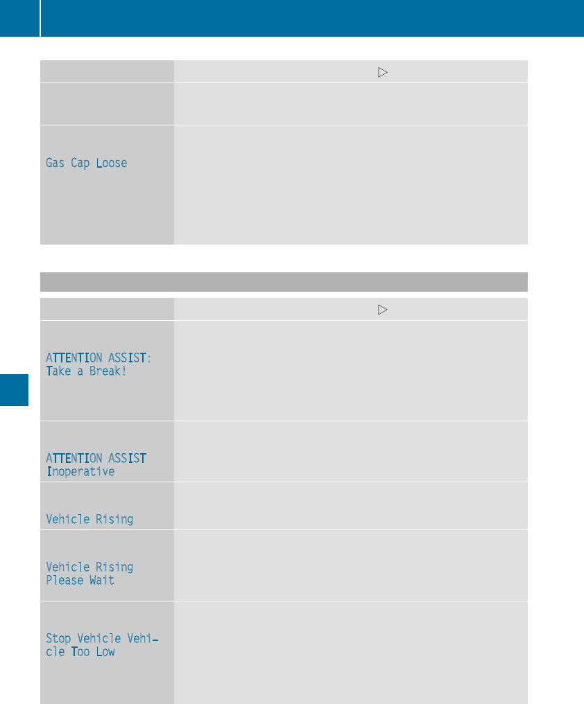
Display messages Possible causes/consequences and MSolutions
CThere is only averysmall amount of fuel in thefuel tank.
XRefuelat thenearestgas station without fail.
8
Gas Cap Loose
The fuel filler cap is notclosed correctlyor thefuel system is leaking.
XCheckthat thefuel filler cap is correctlyclosed.
If thefuel filler cap is not correctlyclosed:
XClosethefuel filler cap.
If thefuel filler cap is correctlyclosed:
XVisit aqualified specialist workshop.
Driving systems
Display messages Possible causes/consequences and MSolutions
À
ATTENTION ASSIST:
TakeaBreak!
Based on certain criteria, ATTENTION ASSIST has detectedfatigue or
alack of concentration on thepart of thedriver. A warning tone also
sounds.
XIf necessary, take a break.
During longjourneys, takeregular breaks in goodtime so you get
enough rest.
À
ATTENTION ASSIST
Inoperative
ATTENTION ASSIST is inoperative.
XVisit aqualified specialist workshop.
¨
VehicleRising
The vehicleis rising to thelevel you haveselected.
¨
VehicleRising
Please Wait
The vehiclelevel is toolow when thevehicleis stationary. Awarning
tone also sounds.
XDo notpull away.
The vehiclelevel is set when thedisplay message disappears.
¨
StopVehicleVehi‐
cle Too Low
You havepulled away while thevehiclelevel is still toolow.
AIRMATIC setsthevehicleto theselected level after ashort period.
XPull overand stop thevehiclesafely as soonas possible, paying
attention to roadand traffic conditions.
XSecurethevehicleagainst rollingaway (Ypage 143).
XWait until thedisplay message disappearsbefore pullingaway.
228 Display messages
On-board computer and displays
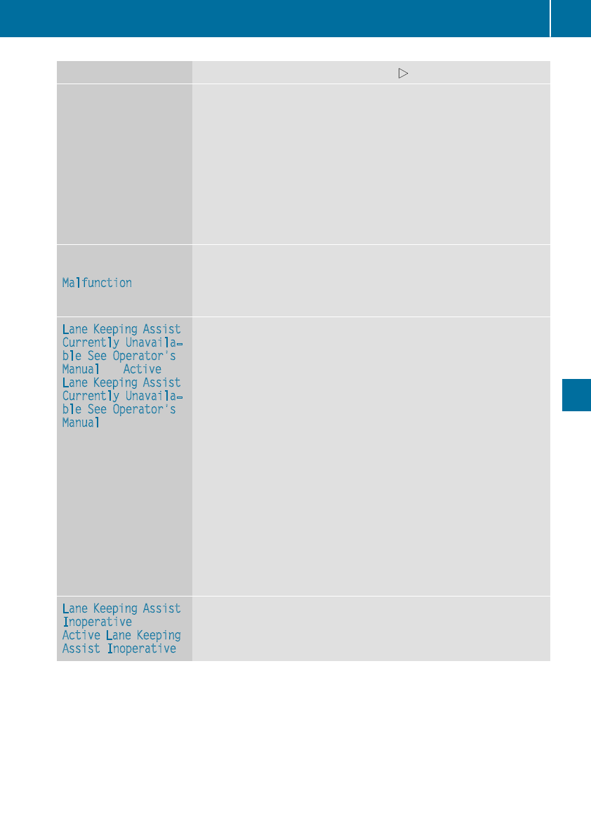
Display messages Possible causes/consequences and MSolutions
AIRMATIC is malfunctioning. A warning tone also sounds.
XDo notdrive at speeds above50 mph (80 km/h).
XMakeonly slight steering movements. Otherwise,thefrontfender
or thetires could be damaged if thesteering movement is toolarge.
XListenfor scraping sounds.
XPull overand stop thevehiclesafely, payingattention to roadand
traffic conditions, and set ahigher vehiclelevel.
Dependingon themalfunction,it may be possibleto raisethevehi-
cle.
XVisit aqualified specialist workshop.
¨
Malfunction
The AIRMATIC function is restricted. The vehicle's handlingcharac-
teristics may be affected.
XDo notdrive at speeds above50 mph (80 km/h).
XVisit aqualified specialist workshop.
LaneKeepingAssist
Currently Unavaila‐
ble See Operator's
Manual or Active
LaneKeepingAssist
Currently Unavaila‐
ble See Operator's
Manual
LaneKeepingAssistor Active LaneKeepingAssistis deactivated and
temporarily inoperative.
Possiblecauses are:
RThe windshield in thecamera'sfield of vision is dirty.
RVisibilityis impaireddue to heavyrain,snow or fog.
RThere havebeen no lanemarkingsfor an extended period
RThe lanemarkingsare wornaway, dark or covered up, e.g. by dirtor
snow.
Whenthecauses statedaboveno longer apply, thedisplay message
disappears.
LaneKeepingAssistor Active LaneKeepingAssistis operational
again.
If thedisplay message does notdisappear:
XPull overand stop thevehiclesafely as soonas possible, paying
attention to roadand traffic conditions.
XSecurethevehicleagainst rollingaway (Ypage 143).
XClean thewindshield.
LaneKeepingAssist
Inoperative or
Active LaneKeeping
Assist Inoperative
LaneKeepingAssistor Active LaneKeepingAssistis malfunctioning.
XVisit aqualified specialist workshop.
Display messages 229
On-board computer and displays
Z
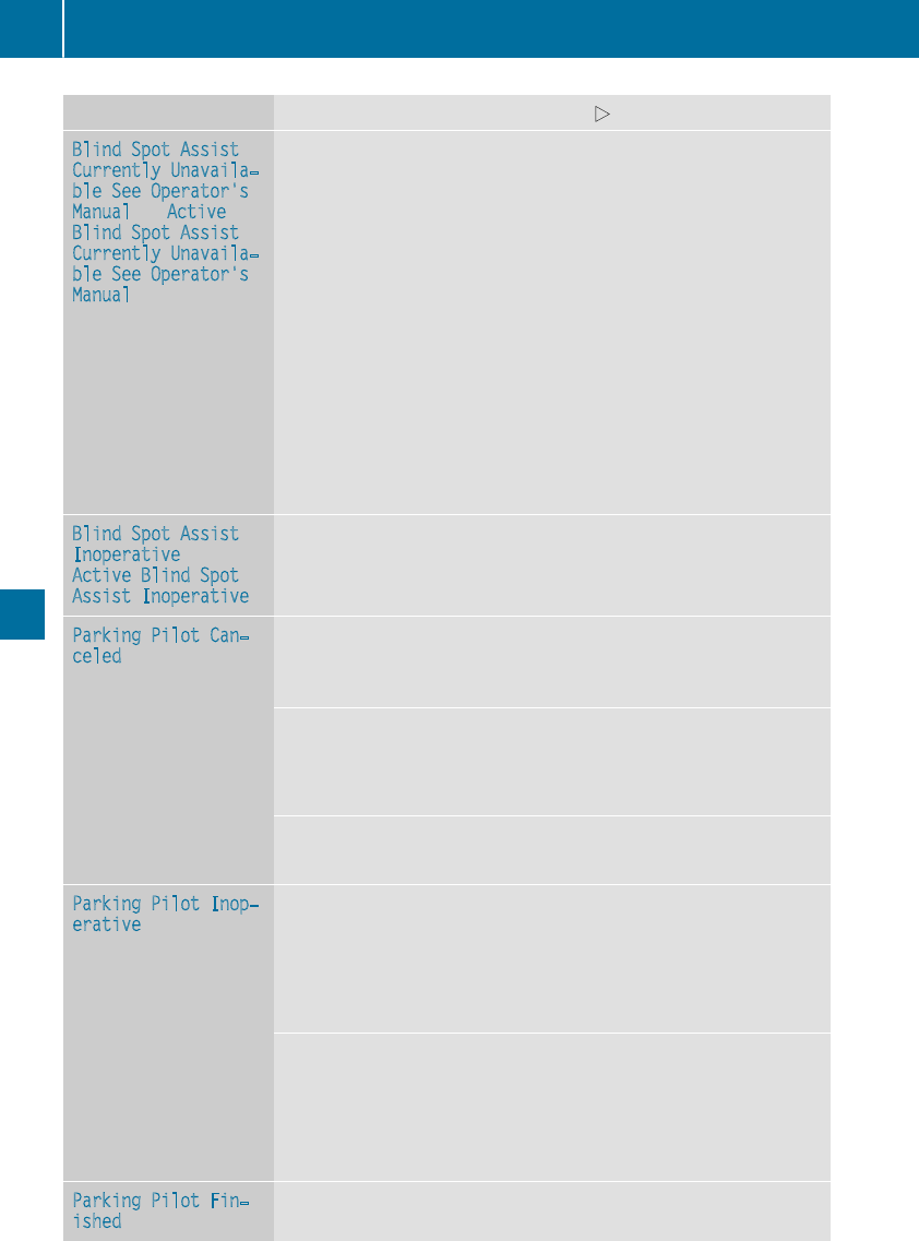
Display messages Possible causes/consequences and MSolutions
Blind SpotAssist
Currently Unavaila‐
ble See Operator's
Manual or Active
Blind SpotAssist
Currently Unavaila‐
ble See Operator's
Manual
Blind Spot Assistor Active Blind Spot Assistis temporarily inoperative.
Possiblecauses are:
RThe radar sensor system is outside theoperating temperature
range.
RThe radar sensor system is temporarily inoperative, e.g. due to
electromagneticradiation emitted by nearby TV or radiostationsor
other sourcesof electromagneticradiation.
Whenthecauses statedaboveno longer apply, thedisplay message
disappears.
Blind Spot Assistor Active Blind Spot Assistis operational again.
If thedisplay message does notdisappear:
XPull overand stop thevehiclesafely as soonas possible, paying
attention to roadand traffic conditions.
XSecurethevehicleagainst rollingaway (Ypage 143).
XRestart theengine.
Blind SpotAssist
Inoperative or
Active Blind Spot
Assist Inoperative
Blind Spot Assistor Active Blind Spot Assistis malfunctioning.
XVisit aqualified specialist workshop.
ParkingPilot Can‐
celed
The driver's door is open.
XRepeat theparking gap measurementand parking process withthe
driver's door closed.
You touched themultifunction steering wheelwhile steering inter-
vention was active.
XWhilesteering intervention is active,makesurethat themultifunc-
tion steering wheelis nottouched unintentionally.
The vehiclehas started to skid and ESP®has intervened.
XUse theParking Pilotagain later (Ypage 166).
ParkingPilot Inop‐
erative
Parking Pilotis malfunctioning or defective.
XFollow theinstructionsand helpful hints in the"Problemswith
Parking AssistPARKTRONIC" section (Ypage 172).
If themultifunction display still shows thedisplay message:
XVisit aqualified specialist workshop.
Parking Pilotis unavailable or malfunctioning.
XSwitchoff theignition and restarttheengine.
If theParking Pilotcontinues to be unavailable (the jsymbol does
notappear in themultifunction display):
XVisit aqualified specialist workshop.
ParkingPilot Fin‐
ished
The vehicleis parked. Awarning tone also sounds.
The display message disappearsautomatically.
230 Display messages
On-board computer and displays
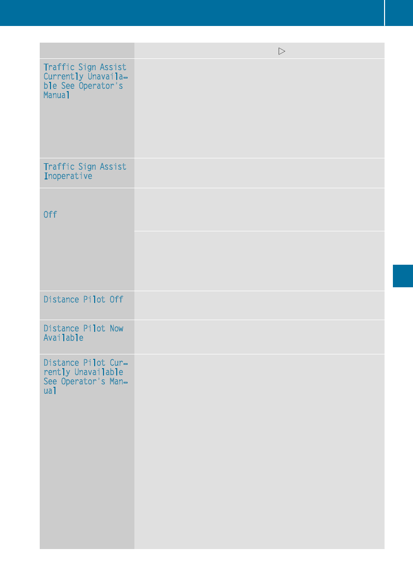
Display messages Possible causes/consequences and MSolutions
TrafficSignAssist
Currently Unavaila‐
ble See Operator's
Manual
Traffic SignAssistis temporarily inoperative.
Possiblecauses are:
RThe windshield in thecamera'sfield of vision is dirty.
RVisibilityis impaireddue to heavyrain,snow or fog.
XClean thewindshield.
If thesystem detects that thecamera is fullyoperational, thedisplay
message disappears.
Traffic SignAssistis operational again.
TrafficSignAssist
Inoperative
Traffic SignAssistis malfunctioning.
XVisit aqualified specialist workshop.
ë
Off
The HOLD function is deactivated. The vehicleis skidding.
Awarning tone also sounds.
XReactivatetheHOLD function later (Ypage 162).
The HOLD function is deactivated. Whenthebrakepedal is firmly
depressed, an activation condition is notfulfilled.
Awarning tone also sounds.
XChecktheactivation conditionsfor theHOLD function
(Ypage 161).
Distance Pilot Off DistancePilotDISTRONICis deactivated (Ypage 158).
If it was notdeactivated by thedriver, a warning tone also sounds.
Distance Pilot Now
Available
DistancePilotDISTRONICis operational again after having been tem-
porarily unavailable.You can nowreactivateDistancePilot
DISTRONIC (Ypage 155).
Distance Pilot Cur‐
rently Unavailable
See Operator'sMan‐
ual
DistancePilotDISTRONICis temporarily inoperative.
Steering Pilotis also temporarily inoperative.
Possiblecauses are:
RThe radar sensor system is temporarily inoperative, e.g. due to
electromagneticradiation emitted by nearby TV or radiostationsor
other sourcesof electromagneticradiation.
RThe system is outside theoperating temperature range.
RThe on-boardvoltageis toolow.
Awarning tone also sounds.
Whenthecauses statedaboveno longer apply, thedisplay message
disappears.
DistancePilotDISTRONICis operational again.
If thedisplay message does notdisappear:
XPull overand stop thevehiclesafely as soonas possible, paying
attention to roadand traffic conditions.
XSecurethevehicleagainst rollingaway (Ypage 143).
XRestart theengine.
Display messages 231
On-board computer and displays
Z
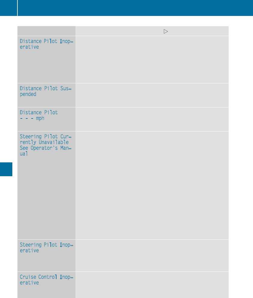
Display messages Possible causes/consequences and MSolutions
Distance Pilot Inop‐
erative
DistancePilotDISTRONICis malfunctioning.
The followingmay havealso failed:
RActive Brake Assistwithcross-traffic function
RSteering Pilot
Awarning tone also sounds.
XVisit aqualified specialist workshop.
Distance Pilot Sus‐
pended
You havedepressed theacceleratorpedal.DistancePilotDISTRONIC
is no longer controllingthespeed of thevehicle.
XRemove your footfrom theacceleratorpedal.
Distance Pilot
---mph
Acondition for activating DistancePilotDISTRONIChas notbeen met.
XChecktheactivation conditionsfor DistancePilotDISTRONIC
(Ypage 155).
Steering Pilot Cur‐
rently Unavailable
See Operator'sMan‐
ual
Steering Pilotis temporarily inoperative.
Possiblecauses are:
RThe windshield in thecamera'sfield of vision is dirty.
RVisibilityis impaireddue to heavyrain,snow or fog.
RThere havebeen no lanemarkingsfor an extended period.
RThe lanemarkingsare wornaway, dark or covered up, e.g. by dirtor
snow.
Whenthecauses statedaboveno longer apply, thedisplay message
disappears.
Steering Pilotis operational again.
If thedisplay message does notdisappear:
XPull overand stop thevehiclesafely as soonas possible, paying
attention to roadand traffic conditions.
XSecurethevehicleagainst rollingaway (Ypage 143).
XClean thewindshield.
Steering Pilot Inop‐
erative
Steering Pilotis malfunctioning.
However, theDistancePilotDISTRONICfunctionsare still available.
Awarning tone also sounds.
XVisit aqualified specialist workshop.
Cruise ControlInop‐
erative
Cruisecontrol is malfunctioning.
Awarning tone also sounds.
XVisit aqualified specialist workshop.
232 Display messages
On-board computer and displays
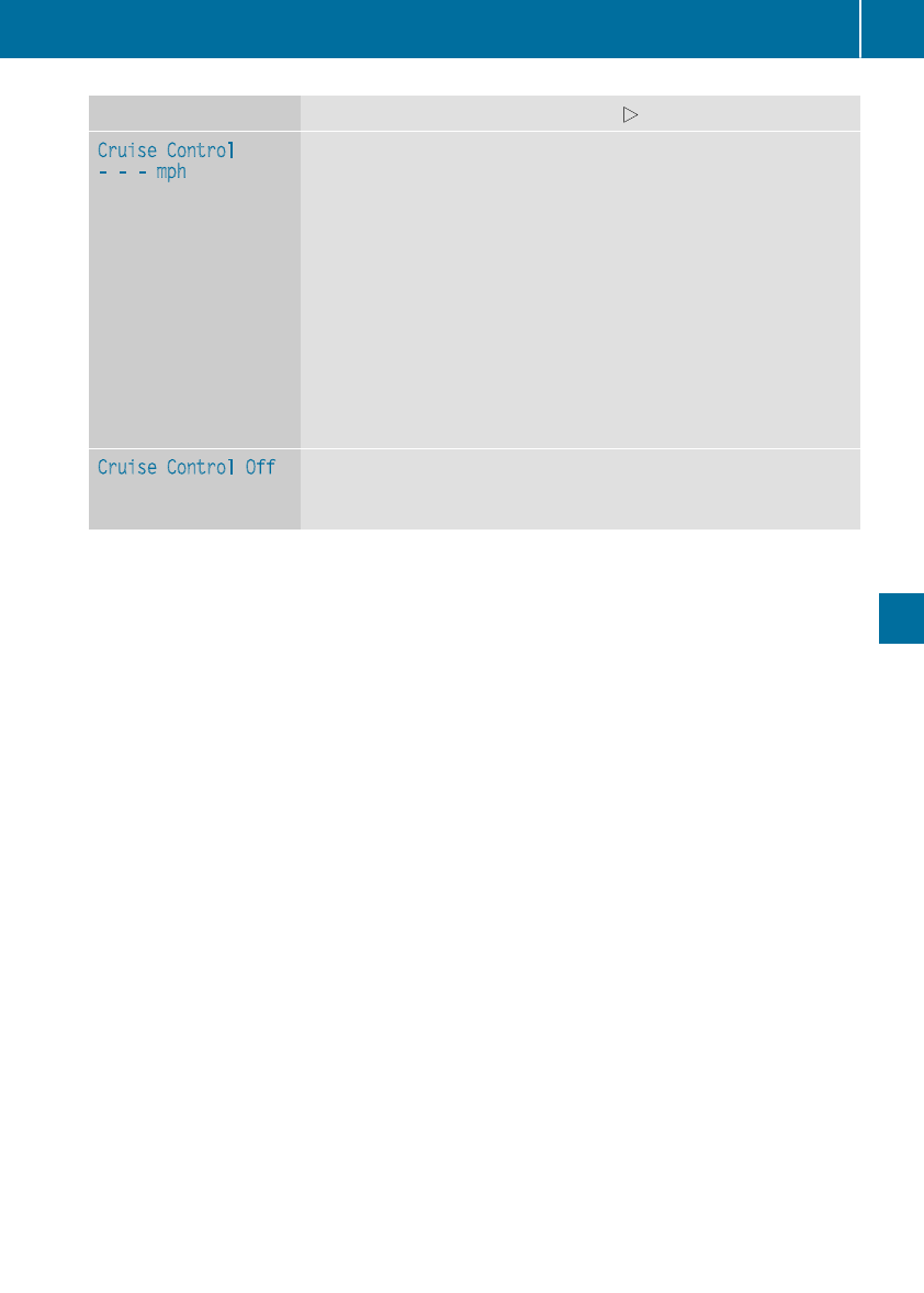
Display messages Possible causes/consequences and MSolutions
Cruise Control
---mph
RAcondition for activating cruise control has notbeen met.
You havetried to store aspeed below20 mph (30 km/h), for exam-
ple.
RESP®is deactivated. The yellowESP®OFFwarning lamp is lit.
XIf conditionspermit,drive fasterthan 20 mph (30 km/h)and store
thespeed.
or
XChecktheactivation conditionsfor cruise control (Ypage 151).
or
XReactivateESP®(Ypage 204).
or
XReactivateESP®in Mercedes-AMG vehicles (Ypage 69).
Cruise ControlOff Cruisecontrol has been deactivated.
If awarning tone also sounds, cruise control has deactivated auto-
matically (Ypage 151).
Display messages 233
On-board computer and displays
Z
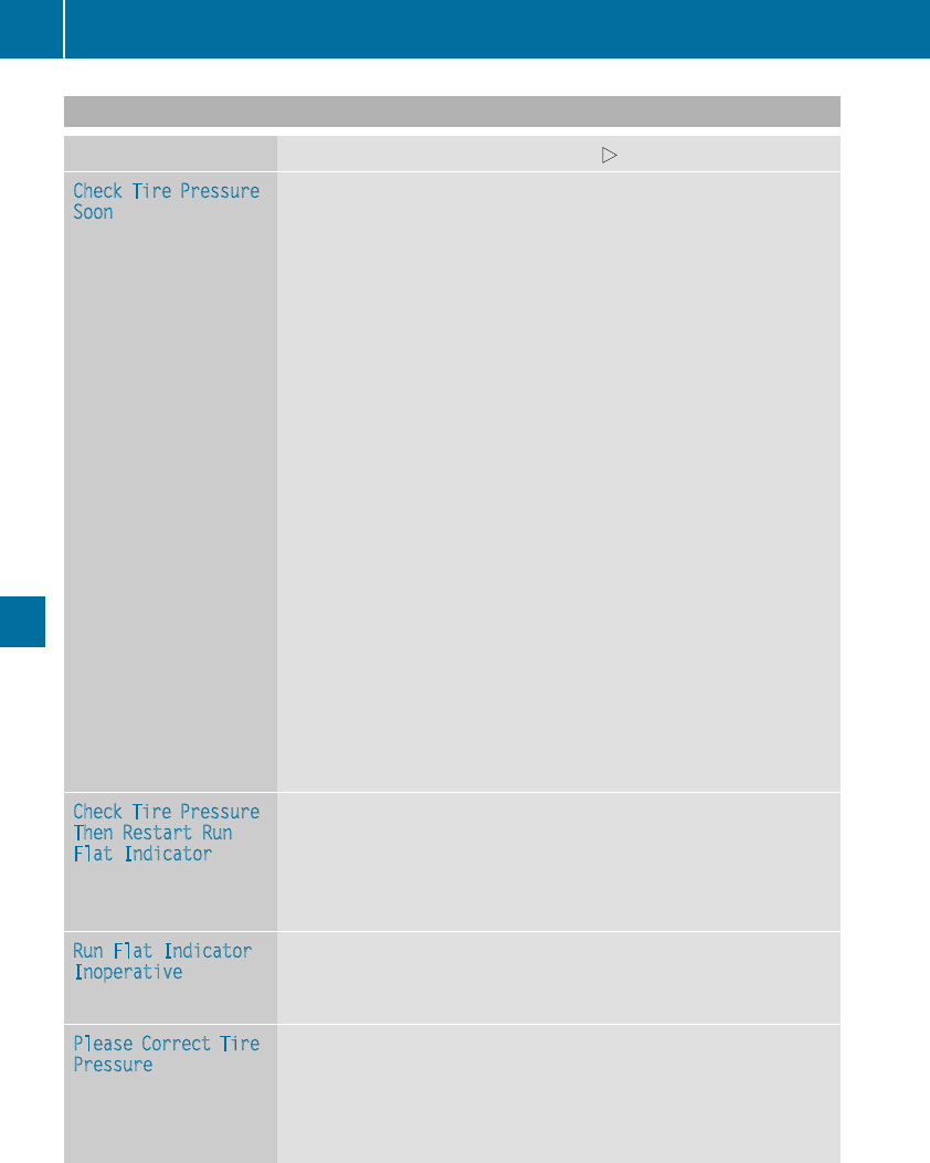
Tires
Display messages Possible causes/consequences and MSolutions
Check Tire Pressure
Soon
Canada only:
The tire pressure loss warning system has detected a significant loss
in pressure.
A warning tone also sounds.
Possible causes:
Ryou have changed the positions of the wheels and tires or installed
new wheels and tires
Rthe tire pressure in one or more tires has dropped significantly
GWARNING
Tire pressures that are too low pose the following hazards:
Rthey may burst, especially as the load and vehicle speed increase.
Rthey may wear excessively and/or unevenly, which may greatly
impair tire traction.
Rthe driving characteristics, as well as steering and braking, may be
greatly impaired.
There is a risk of an accident.
XStop the vehicle without making any sudden steering or braking
maneuvers. Pay attention to the traffic conditions as you do so.
XSecure the vehicle against rolling away (Ypage 143).
XCheck the tires and, if necessary, follow the instructions for a flat
tire (Ypage 296).
XCheck the tire pressures and, if necessary, correct the tire pressure.
XRestart the tire pressure loss warning system when the tire pres-
sure is correct (Ypage 319).
Check Tire Pressure
Then Restart Run
Flat Indicator
Canada only:
The tire pressure loss warning system generated a display message
and has not been restarted since.
XSet the correct tire pressure in all four tires.
XRestart the tire pressure loss warning system (Ypage 319).
Run Flat Indicator
Inoperative
Canada only:
The tire pressure loss warning system is faulty.
XVisit a qualified specialist workshop.
Please Correct Tire
Pressure
The tire pressure is too low in at least one of the tires, or the tire
pressure difference between the wheels is too great.
XCheck the tire pressures at the next opportunity (Ypage 321).
XIf necessary, correct the tire pressure.
XRestart the tire pressure monitor (Ypage 321).
234 Display messages
On-board computer and displays

Display messages Possible causes/consequences and MSolutions
Check Tires The tire pressurein oneor moretires has dropped significantly. The
wheelposition is displayed in themultifunction display.
Awarning tone also sounds.
GWARNING
Tirepressures that are toolow posethefollowinghazards:
Rthey may burst, especially as theload and vehiclespeed increase.
Rthey may wear excessivelyand/orunevenly, whichmay greatly
impair tire traction.
Rthedrivingcharacteristics,as well as steering and braking,may be
greatlyimpaired.
There is ariskof an accident.
XStop thevehiclewithout making any sudden steering or braking
maneuvers.Pay attention to thetraffic conditionsas you do so.
XSecurethevehicleagainst rollingaway (Ypage 143).
XCheckthetires and,if necessary, follow theinstructionsfor aflat
tire (Ypage 296).
XCheckthetire pressure (Ypage 321).
XIf necessary, correctthetire pressure.
WarningTireMal‐
function
The tire pressurein oneor moretires has dropped suddenly. The wheel
position is shown in themultifunction display.
GWARNING
Drivingwith a flat tire poses ariskof thefollowinghazards:
Raflat tire affects theabilityto steer or brakethevehicle
Ryou could lose control of thevehicle
Rcontinued drivingwith a flat tire will causeexcessive heat build-up
and possibly a fire
There is ariskof an accident.
XStop thevehiclewithout making any sudden steering or braking
maneuvers.Pay attention to thetraffic conditionsas you do so.
XSecurethevehicleagainst rollingaway (Ypage 143).
XCheckthetires and,if necessary, follow theinstructionsfor aflat
tire (Ypage 296).
TirePress. Monitor
Currently Unavaila‐
ble
Becausethere is interferencefrom astrongsource of radiowaves, no
signals from thetire pressuresensorsare detected. The tire pressure
monitor is temporarily malfunctioning.
XDrive on.
The tire pressuremonitor restarts automatically as soonas the
problem has been resolved.
TirePress.Sen‐
sor(s) Missing
There is no signal from thetire pressuresensor of oneor several tires.
The pressureof theaffectedtire is notdisplayed in themultifunction
display.
XHavethefaultytire pressuresensor replacedat aqualified special-
ist workshop.
Display messages 235
On-board computer and displays
Z
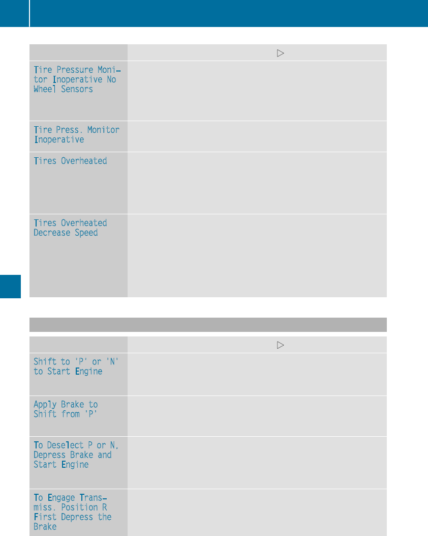
Display messages Possible causes/consequences and MSolutions
TirePressure Moni‐
tor Inoperative No
Wheel Sensors
The wheels mounteddo nothave a suitable tire pressuresensor.The
tire pressuremonitor is deactivated.
XMountwheels withsuitable tire pressuresensors.
The tire pressuremonitor is activated automatically after drivingfor
afew minutes.
TirePress. Monitor
Inoperative
The tire pressuremonitor is faulty.
XVisit aqualified specialist workshop.
Tires OverheatedThe tire temperature monitoring function is notavailable in all vehi-
cles.
At least onetire has overheated. Affectedtires are shown in red.At
temperatures close to thelimitvalue,thetires are shown in yellow.
XDrive moreslowly.
Tires Overheated
Decrease Speed
The tire temperature monitoring function is notavailable in all vehi-
cles.
At least onetire has overheated.
GWARNING
Overheated tires can burst, particularly at high speeds.
XDrive moreslowly so that thetires cool down.
Vehicle
Display messages Possible causes/consequences and MSolutions
Shift to 'P' or 'N'
to Start Engine
You haveattemptedto start theenginewiththetransmission in posi-
tion kor h.
XShift thetransmission to position jor i.
Apply Brake to
Shift from'P'
You haveattemptedto shift thetransmission to position h,kor i
without depressing thebrakepedal.
XDepress thebrakepedal.
To Deselect Por N,
DepressBrake and
Start Engine
Withtheengineswitched off,you haveattemptedto shift thetrans-
mission out of position jor iintoanother transmission position.
XDepress thebrakepedal.
XStart theengine.
To Engage Trans‐
miss. Position R
First Depressthe
Brake
You haveattemptedto shift from position hto position k.
XDepress thebrakepedal.
XShift thetransmission to position k.
236 Display messages
On-board computer and displays
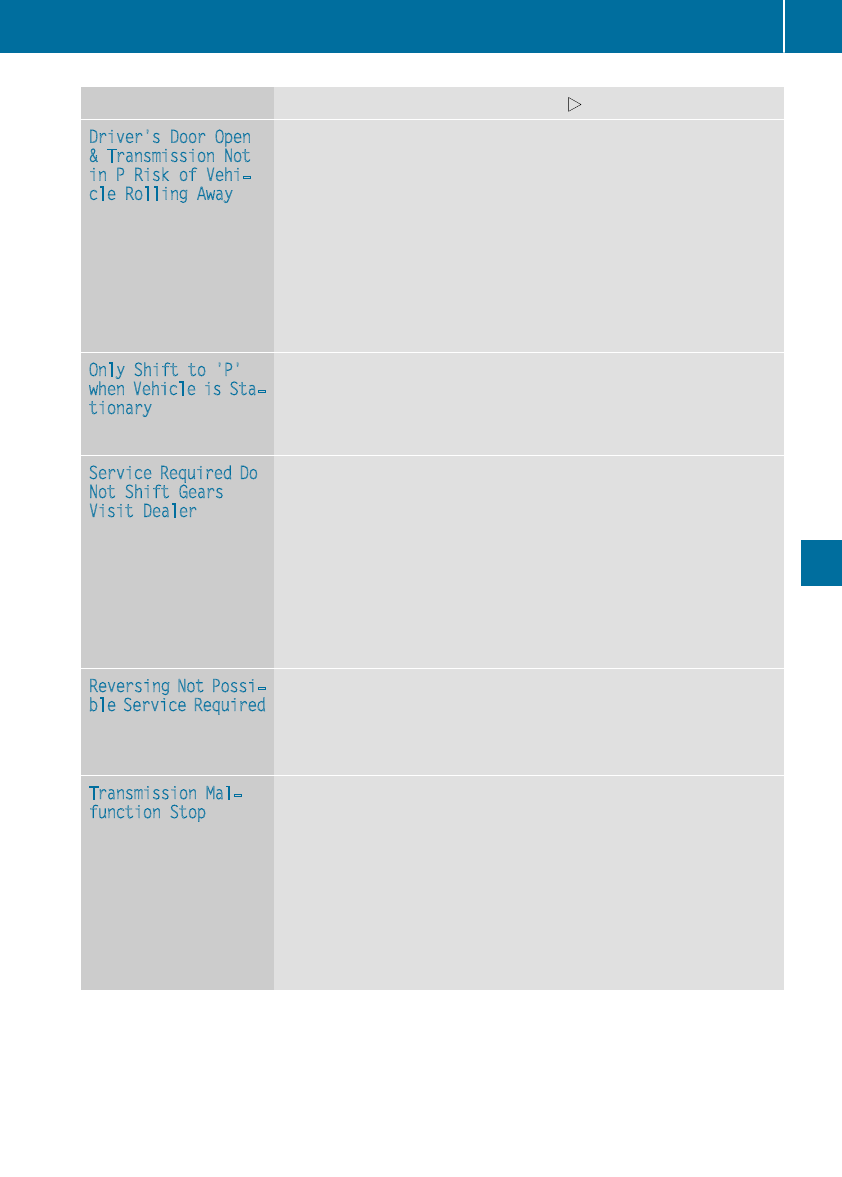
Display messages Possible causes/consequences and MSolutions
Driver's DoorOpen
&Transmission Not
in PRiskof Vehi‐
cle RollingAway
The driver's door is open or notfully closed and thetransmission is in
position k,ior h.
Awarning tone also sounds.
GWARNING
The vehiclemay rollaway.
There is ariskof an accident.
XShift thetransmission to position j.
XSecurethevehicleagainst rollingaway (Ypage 143).
XClosethedriver's door completely.
OnlyShift to 'P'
whenVehicleis Sta‐
tionary
The vehicleis moving.
XPull overand stop thevehiclesafely as soonas possible, paying
attention to roadand traffic conditions.
XShift thetransmission to position j.
ServiceRequired Do
Not Shift Gears
Visit Dealer
You cannotchangethetransmission position due to amalfunction.
Awarning tone also sounds.
If transmission position his selected:
XDrive to aqualified specialist workshop without shifting thetrans-
mission from position h.
If transmission position k,ior jis selected:
XSecurethevehicleagainst rollingaway (Ypage 143).
XNotify aqualified specialist workshop or breakdown service.
Reversing Not Possi‐
ble ServiceRequired
You cannotshift intotransmission position kdue to amalfunction.
The transmission positionsj,ior hcontinueto be available.
Awarning tone also sounds.
XVisit aqualified specialist workshop.
Transmission Mal‐
function Stop
Amalfunction has occurred in themechanical transmission compo-
nents.
Awarning tone also sounds. The transmission automatically shiftsto
position i.
XPull overand stop thevehiclesafely as soonas possible, paying
attention to roadand traffic conditions.
XShift thetransmission to position j.
XSecurethevehicleagainst rollingaway (Ypage 143).
XNotify aqualified specialist workshop or breakdown service.
Display messages 237
On-board computer and displays
Z

Display messages Possible causes/consequences and MSolutions
StopVehicleLeave
Engine RunningWait
Transmission Cool‐
ing
The transmission has overheated. Pullingaway can be temporarily
impairedor notpossible.
XPull overand stop thevehiclesafely as soonas possible, paying
attention to roadand traffic conditions. Do notcontinuedriving
under any circumstances.
XLeavetheenginerunning.
XWait until thedisplay message disappearsbefore pullingaway.
NThe trunk lid is open.
XClosethetrunk lid.
MThe hoodis open. A warning tone also sounds.
GWARNING
The open hoodmay blockyour viewwhen thevehicleis in motion.
There is ariskof an accident.
XPull overand stop thevehiclesafely as soonas possible, paying
attention to roadand traffic conditions.
XSecurethevehicleagainst rollingaway (Ypage 143).
XClosethehood.
CAt least onedoor is open. A warning tone also sounds.
XCloseall thedoors.
_
Front LeftSeat
Backrest Not Locked
or Front Right Seat
Backrest Not Locked
The driver's or frontpassenger's seat backrest is notengaged. A
warning tone also sounds.
XPush thebackrest backuntil it engages.
Ð
Power Steering Mal‐
function See Opera‐
tor's Manual
The powersteering is malfunctioning.
Awarning tone also sounds.
GWARNING
You will need to use moreforce to steer.
There is ariskof an accident.
XCheckwhether you are able to apply theextraforce required.
If you areableto steer safely:
XDrive on carefully.
XVisit aqualified specialist workshop immediately.
If you areunable to steer safely:
XDo notdrive on.
XConsult aqualified specialist workshop.
238 Display messages
On-board computer and displays
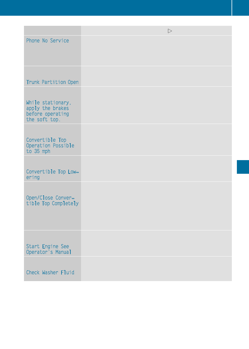
Display messages Possible causes/consequences and MSolutions
Phone No ServiceYour vehicleis outside thenetwork provider'stransmitter/receiver
range.
XWait until themobile phone operational readiness symbol appears
in themultifunction display.
J
Trunk Partition Open
The trunk partition is open.
XClosethetrunk partition (Ypage 90).
K
While stationary,
apply the brakes
before operating
the softtop.
The vehicleis stationary and you tryto open or close thesofttop.
XDepress thebrakepedal.
XPush or pull thesofttopswitch again until thesofttopis fullyopen
or closed (Ypage 89).
K
Convertible Top
Operation Possible
to 35 mph
If you drive at speeds of morethan 35 mph (60 km/h), you cannot
open or close thesofttop.
XDo notdrive at speeds above35 mph (60 km/h).
XFullyopen or close thesofttop (Ypage 89).
K
Convertible Top Low‐
ering
The softtopis notfully opened or closed.The hydraulicsare depres-
surized.
XFullyopen or close thesofttop (Ypage 89).
K
Open/CloseConver‐
tible Top Completely
The roofis notlocked.
If you drive at speeds of morethan 35 mph (60 km/h), you cannot
open or close thesofttop.
XPull overand stop thevehiclesafely as soonas possible, paying
attention to roadand traffic conditions.
XPush or pull and hold thesoft-topswitch until thesofttopis fully
open or closed (Ypage 89).
K
Start Engine See
Operator'sManual
The on-boardvoltageis toolow.
XStart theengine.
¥
Check Washer Fluid
The washer fluidlevel in thewasher fluidreservoir has dropped below
theminimum.
XAddwasher fluid (Ypage 285).
Display messages 239
On-board computer and displays
Z
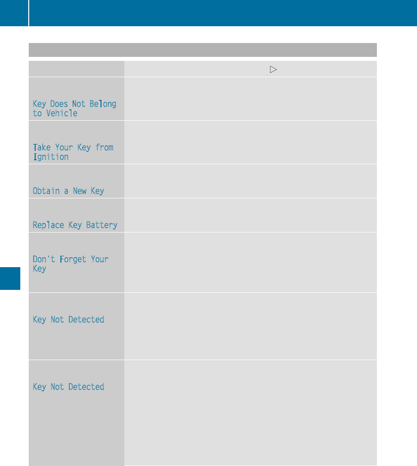
SmartKey
Display messages Possible causes/consequences and MSolutions
Â
Key Does Not Belong
to Vehicle
You have put the wrong SmartKey in the ignition lock.
XUse the correct SmartKey.
Â
Take Your Key from
Ignition
The SmartKey is in the ignition lock.
A warning tone sounds
XRemove the SmartKey.
Â
Obtain a New Key
The SmartKey needs to be replaced.
XVisit a qualified specialist workshop.
Â
Replace Key Battery
The SmartKey battery is discharged.
XChange the batteries (Ypage 79).
Â
Don't Forget Your
Key
The SmartKey is not in the ignition lock. You have opened the driver's
door with the engine switched off. A warning tone sounds
This display message is displayed for a maximum of 60 seconds and is
simply a reminder.
XTake the SmartKey with you when you leave the vehicle.
Â
Key Not Detected
(white display message)
The SmartKey is currently undetected.
XChange the location of the SmartKey in the vehicle.
If the SmartKey still cannot be detected:
XInsert the SmartKey into the ignition lock and turn it to the desired
position.
Â
Key Not Detected
(red display message)
The SmartKey is not in the vehicle.
A warning tone also sounds.
If the engine is switched off, you can no longer lock the vehicle cen-
trally or start the engine.
XPull over and stop the vehicle safely as soon as possible, paying
attention to road and traffic conditions.
XSecure the vehicle against rolling away (Ypage 143).
XLocate the SmartKey.
XPress aon the steering wheel to confirm the display message.
240 Display messages
On-board computer and displays
Display messages Possible causes/consequences and MSolutions
Becausethere is interferencefrom astrongsource of radiowaves, the
SmartKey is notdetectedwhilsttheengineis running.
Awarning tone also sounds.
XPull overand stop thevehiclesafely as soonas possible, paying
attention to roadand traffic conditions.
XSecurethevehicleagainst rollingaway (Ypage 143).
XInserttheSmartKey intotheignition lockand drive in SmartKey
mode.
Â
Remove 'Start'But‐
ton and Insert Key
The SmartKey is continually undetected.
The SmartKey detection function has atemporarymalfunction or is
faulty. Awarning tone also sounds.
XInserttheSmartKey intotheignition lockand turnit to thedesired
position.
XVisit aqualified specialist workshop.
Warning and indicator lamps in the instrument cluster
General notes
Some systems carry out aself-diagnosis when theignition is switched on.Therefore,someindicator
and warning lampsmay lightup or flashtemporarily. This behavioris non-critical.These indicator
and warning lampsonly indicate a malfunction if they lightup or flashafter starting theengineor
whilstdriving.
Safety
Seat belts
Warning/
indicator
lamp
NSignal type
Possible causes/consequences and MSolutions
üNAfterstarting theengine, thered seat belt warning lamp lights up for six sec-
onds.
The seat belt warning lamp remindsthedriver and frontpassenger to fastentheir
seat belts.
XFastenyour seat belt (Ypage 47).
üNAfterstarting theengine, thered seat belt warning lamp lights up. In addition, a
warning tone sounds for up to six seconds.
The driver's seat belt is notfastened.
XFastenyour seat belt (Ypage 47).
The warning tone ceases.
Warning and indicator lamps in the instrument cluster 241
On-board computer and displays
Z

Warning/
indicator
lamp
NSignal type
Possible causes/consequences and MSolutions
üNThe red seat belt warning lamp lights up after the engine starts, as soon as the
driver's or the front-passenger door is closed.
The driver or front passenger has not fastened their seat belt.
XFasten your seat belt (Ypage 47).
The warning lamp goes out.
There are objects on the front-passenger seat.
XRemove the objects from the front-passenger seat and stow them in a secure
place.
The warning lamp goes out.
üNThe red seat belt warning lamp flashes and an intermittent audible warning
sounds.
The driver or front passenger has not fastened their seat belt. The vehicle is being
driven faster than 15 mph (25 km/h) or has briefly been driven faster than 15 mph
(25 km/h).
XFasten your seat belt (Ypage 47).
The warning lamp goes out and the intermittent warning tone ceases.
There are objects on the front-passenger seat. The vehicle is being driven faster
than 15 mph (25 km/h) or has briefly been driven faster than 15 mph (25 km/h).
XRemove the objects from the front-passenger seat and stow them in a secure
place.
The warning lamp goes out and the intermittent warning tone ceases.
242 Warning and indicator lamps in the instrument cluster
On-board computer and displays

Safety systems
Warning/
indicator
lamp
NSignal type
Possible causes/consequences and MSolutions
$J N$(USA only), J(Canada only): the red brake system warning lamp is lit
while the engine is running.
A warning tone also sounds.
GWARNING
The brake boosting effect is malfunctioning and the braking characteristics may be
affected.
There is a risk of an accident.
XPull over and stop the vehicle safely as soon as possible, paying attention to road
and traffic conditions. Do not continue driving under any circumstances.
XSecure the vehicle against rolling away (Ypage 143).
XConsult a qualified specialist workshop.
XObserve the additional display messages in the multifunction display.
$J N$(USA only), J(Canada only): the red brake system warning lamp lights
up while the engine is running.
A warning tone also sounds.
There is not enough brake fluid in the brake fluid reservoir.
GWARNING
The braking effect may be impaired.
There is a risk of an accident.
XPull over and stop the vehicle safely as soon as possible, paying attention to road
and traffic conditions. Do not continue driving under any circumstances.
XSecure the vehicle against rolling away (Ypage 143).
XDo not add brake fluid. Adding more will not correct the malfunction.
XConsult a qualified specialist workshop.
XObserve the additional display messages in the multifunction display.
$NUSA only: the red brake system warning lamp is lit while the engine is running.
The multifunction display also shows a display message with the #symbol.
The brake pads/linings have reached their wear limit.
XVisit a qualified specialist workshop.
Warning and indicator lamps in the instrument cluster 243
On-board computer and displays
Z

Warning/
indicator
lamp
NSignal type
Possible causes/consequences and MSolutions
!NThe yellow ABS warning lamp is lit while the engine is running.
ABS (anti-lock braking system) is malfunctioning.
If there is an additional warning tone, the EBD (electronic brake force distribution)
is malfunctioning.
Other driving systems and driving safety systems may also malfunction.
GWARNING
The brake system continues to function normally, but without the functions listed
above. The front and rear wheels could therefore lock if you brake hard, for exam-
ple.
The steerability and braking characteristics may be severely affected. The braking
distance in an emergency braking situation can increase.
If ESP®is not operational, ESP®is unable to stabilize the vehicle.
There is an increased risk of skidding and an accident.
XObserve the additional display messages in the multifunction display.
XDrive on carefully.
XVisit a qualified specialist workshop immediately.
If the ABS control unit is faulty, there is also a possibility that other systems, such
as the navigation system or the automatic transmission, will not be available.
$J
÷!
N$(USA only), J(Canada only): the red brake warning lamp and the yellow
ESP®and ABS warning lamps are lit while the engine is running.
ABS and ESP®are malfunctioning.
Other driving systems and driving safety systems may also malfunction.
GWARNING
The brake system continues to function normally, but without the functions listed
above. The front and rear wheels could therefore lock if you brake hard, for exam-
ple.
The steerability and braking characteristics may be severely affected. The braking
distance in an emergency braking situation can increase.
If ESP®is not operational, ESP®is unable to stabilize the vehicle.
There is an increased risk of skidding and an accident.
XObserve the additional display messages in the multifunction display.
XDrive on carefully.
XVisit a qualified specialist workshop immediately.
244 Warning and indicator lamps in the instrument cluster
On-board computer and displays

Warning/
indicator
lamp
NSignal type
Possible causes/consequences and MSolutions
÷NThe yellow ESP®warning lamp flashes while the vehicle is in motion.
ESP®or traction control has intervened because there is a risk of skidding or at
least one wheel has started to spin.
Cruise control or Distance Pilot DISTRONIC is deactivated.
XWhen pulling away, only depress the accelerator pedal as far as necessary.
XEase off the accelerator pedal while the vehicle is in motion.
XAdapt your driving style to suit the road and weather conditions.
XDo not deactivate ESP®.
In exceptional cases, it may be better to deactivate ESP®:
Rwhen using snow chains
Rin deep snow
Ron sand or gravel
Observe the important safety notes on ESP®(Ypage 68).
÷NThe yellow ESP®warning lamp is lit while the engine is running.
ESP®is malfunctioning.
Other driving systems and driving safety systems may also malfunction.
GWARNING
The brake system continues to function normally, but without the functions listed
above.
The braking distance in an emergency braking situation can thus increase.
If ESP®is not operational, ESP®is unable to stabilize the vehicle.
There is an increased risk of skidding and an accident.
XObserve the additional display messages in the multifunction display.
XDrive on carefully.
XVisit a qualified specialist workshop immediately.
Warning and indicator lamps in the instrument cluster 245
On-board computer and displays
Z
Warning/
indicator
lamp
NSignal type
Possible causes/consequences and MSolutions
åNThe yellow ESP®OFF warning lamp is lit while the engine is running or the ECO
start/stop function is activated.
ESP®is deactivated.
GWARNING
If ESP®is switched off, ESP®is unable to stabilize the vehicle.
Further driving systems or driving safety systems are thus restricted, e.g. Active
Blind Spot Assist. The system does not perform braking actions.
There is an increased risk of skidding and an accident.
XReactivate ESP®.
In exceptional cases, it may be better to deactivate ESP®:
Rwhen using snow chains
Rin deep snow
Ron sand or gravel
Observe the important safety notes on ESP®(Ypage 68).
XAdapt your driving style to suit the road and weather conditions.
If ESP®cannot be activated:
XDrive on carefully.
XContact a qualified specialist workshop and have ESP®checked.
MNMercedes-AMG vehicles:
The yellow SPORT handling mode warning lamp is lit while the engine is running.
SPORT handling mode is activated.
GWARNING
When SPORT handling mode is switched on, ESP®is unable to stabilize the vehicle.
There is an increased risk of skidding and an accident.
XOnly activate SPORT handling mode in accordance with the conditions descri-
bed in the "Activating/deactivating ESP®" section (Ypage 69).
246 Warning and indicator lamps in the instrument cluster
On-board computer and displays
Warning/
indicator
lamp
NSignal type
Possible causes/consequences and MSolutions
F! NF(USA only), !(Canada only): the red indicator lamp for the electric
parking brake flashes or is lit and/or the yellow warning lamp for the electric
parking brake is lit.
XObserve the additional display messages in the multifunction display.
6NThe red restraint system warning lamp is lit while the engine is running.
The restraint system is malfunctioning.
GWARNING
The air bags or Emergency Tensioning Devices may either be triggered uninten-
tionally or, in the event of an accident, may not be triggered.
There is an increased risk of injury.
XObserve the additional display messages in the multifunction display.
XDrive on carefully.
XContact a qualified specialist workshop and have the restraint system checked.
For further information about the restraint system, see (Ypage 43).
Engine
Warning/
indicator
lamp
NSignal type
Possible causes/consequences and MSolutions
;NThe yellow Check Engine warning lamp lights up while the engine is running.
There may be a malfunction, for example:
Rin the engine management
Rin the fuel injection system
Rin the exhaust system
Rin the ignition system
Rin the fuel system
The emission limit values may be exceeded and the engine may be in emergency
mode.
XVisit a qualified specialist workshop immediately.
In some states, you must immediately visit a qualified specialist workshop as soon
as the yellow Check Engine warning lamp lights up. This is due to the legal require-
ments in effect in these states. If in doubt, check whether such legal regulations
apply in the state in which you are currently driving.
8NThe yellow reserve fuel warning lamp lights up while the engine is running.
The fuel level has dropped into the reserve range.
XRefuel at the nearest gas station.
Warning and indicator lamps in the instrument cluster 247
On-board computer and displays
Z
Warning/
indicator
lamp
NSignal type
Possible causes/consequences and MSolutions
8NThe yellow reserve fuel warning lamp flashes while the vehicle is in motion.
In addition, the ;Check Engine warning lamp may light up.
The fuel filler cap is not closed correctly or the fuel system is leaking.
XCheck that the fuel filler cap is correctly closed.
XIf the fuel filler cap is not correctly closed: close the fuel filler cap.
XIf the fuel filler cap is closed: visit a qualified specialist workshop.
?NThe red coolant warning lamp lights up while the engine is running and the
coolant temperature gauge is at the start of the scale.
The temperature sensor for the coolant temperature gauge is malfunctioning.
The coolant temperature is no longer being monitored. There is a risk of engine
damage if the coolant temperature is too high.
XPull over and stop the vehicle safely and switch off the engine, paying attention
to road and traffic conditions. Do not continue driving under any circumstances.
XSecure the vehicle against rolling away (Ypage 143).
XConsult a qualified specialist workshop.
248 Warning and indicator lamps in the instrument cluster
On-board computer and displays

Warning/
indicator
lamp
NSignal type
Possible causes/consequences and MSolutions
?NThe red coolant warning lamp comes on while the engine is running.
The coolant level is too low.
If the coolant level is correct, the airflow to the engine radiator may be blocked or
the electric engine radiator fan may be defective.
The coolant is too hot and the engine is no longer being cooled sufficiently.
XObserve the additional display messages in the multifunction display.
XPull over and stop the vehicle safely and switch off the engine, paying attention
to road and traffic conditions.
XSecure the vehicle against rolling away (Ypage 143).
XLeave the vehicle and keep a safe distance from the vehicle until the engine has
cooled down.
XCheck the coolant level and add coolant, observing the warning notes
(Ypage 284).
XIf you have to add coolant frequently, have the engine cooling system checked.
XMake sure that the air supply to the engine radiator is not blocked, e.g. by snow,
slush or ice.
XDo not start the engine again until the coolant temperature gauge is below the
red marking. Otherwise, the engine could be damaged.
XDrive to the nearest qualified specialist workshop.
XAvoid heavy loads on the engine as you do so, e.g. driving in mountainous terrain
and stop-and-go traffic.
?NThe red coolant warning lamp comes on while the engine is running. A warning
tone also sounds.
The coolant temperature gauge has reached the red marking. The airflow to the
engine radiator may be blocked or the coolant level may be too low.
GWARNING
The engine is not being cooled sufficiently and may be damaged.
Do not drive when your engine is overheated. This can cause some fluids which
may have leaked into the engine compartment to catch fire.
Steam from the overheated engine can also cause serious burns which can occur
just by opening the hood.
There is a risk of injury.
XObserve the additional display messages in the multifunction display.
XPull over and stop the vehicle safely and switch off the engine, paying attention
to road and traffic conditions.
XSecure the vehicle against rolling away (Ypage 143).
XLeave the vehicle and keep a safe distance from the vehicle until the engine has
cooled down.
XCheck the coolant level and add coolant, observing the warning notes
(Ypage 284).
XIf you have to add coolant frequently, have the engine cooling system checked.
XMake sure that the air supply to the engine radiator is not blocked, e.g. by snow,
slush or ice.
Warning and indicator lamps in the instrument cluster 249
On-board computer and displays
Z
Warning/
indicator
lamp
NSignal type
Possible causes/consequences and MSolutions
XIf the coolant temperature is below the red marking, drive to the nearest quali-
fied specialist workshop.
XAvoid heavy loads on the engine as you do so, e.g. driving in mountainous terrain
and stop-and-go traffic.
Driving systems
Warning/
indicator
lamp
NSignal type
Possible causes/consequences and MSolutions
·NThe red distance warning lamp lights up while the vehicle is in motion. A warning
tone also sounds.
You are approaching a vehicle, a pedestrian or a stationary obstacle in your line of
travel at too high a speed.
XBe prepared to brake immediately.
XPay careful attention to the traffic situation. You may have to brake or take
evasive action.
Further information about Active Brake Assist with cross-traffic function
(Ypage 71).
Further information on the distance warning function of Active Brake Assist
(Ypage 65).
250 Warning and indicator lamps in the instrument cluster
On-board computer and displays

Tires
Warning/
indicator
lamp
NSignal type
Possible causes/consequences and MSolutions
hNThe yellow tire pressure monitor warning lamp (pressure loss/malfunction) is lit.
The tire pressure monitor has detected a loss of pressure in at least one of the tires.
GWARNING
Tire pressures that are too low pose the following hazards:
Rthey may burst, especially as the load and vehicle speed increase
Rthey may wear excessively and/or unevenly, which may greatly impair tire trac-
tion
Rthe driving characteristics, as well as steering and braking, may be greatly
impaired
There is a risk of an accident.
XStop the vehicle without making any sudden steering or braking maneuvers. Pay
attention to the traffic conditions as you do so.
XSecure the vehicle against rolling away (Ypage 143).
XObserve the additional display messages in the multifunction display.
XCheck the tires and, if necessary, follow the instructions for a flat tire
(Ypage 296).
XCheck the tire pressure (Ypage 321).
XIf necessary, correct the tire pressure.
hNThe yellow tire pressure monitor warning lamp (pressure loss/malfunction)
flashes for approximately one minute and then remains lit.
The tire pressure monitor is malfunctioning.
GWARNING
The system is possibly unable to recognize or register low tire pressure.
There is a risk of an accident.
XObserve the additional display messages in the multifunction display.
XVisit a qualified specialist workshop immediately.
Warning and indicator lamps in the instrument cluster 251
On-board computer and displays
Z

Vehicle
Warning/
indicator
lamp
NSignal type
Possible causes/consequences and MSolutions
ÐNThe red power steering warning lamp is lit while the engine is running.
The power steering is malfunctioning.
A warning tone also sounds.
GWARNING
You will need to use more force to steer.
There is a risk of an accident.
XCheck whether you are able to apply the extra force required.
If you are able to steer safely:
XDrive on carefully.
XVisit a qualified specialist workshop immediately.
If you are unable to steer safely:
XDo not drive on.
XConsult a qualified specialist workshop.
252 Warning and indicator lamps in the instrument cluster
On-board computer and displays

General notes
The multimedia system section in this Opera-
tor's Manual describes the basic principles for
operation. More information can be found in the
Digital Operator's Manual.
Important safety notes
GWARNING
If you operate information systems and com-
munication equipment integrated in the vehi-
cle when driving, you may be distracted from
the traffic situation. You could also lose con-
trol of the vehicle. There is a risk of an acci-
dent.
Only operate this equipment when the traffic
situation permits. If you are not sure that this
is possible, park the vehicle paying attention
to traffic conditions and operate the equip-
ment when the vehicle is stationary.
You must observe the legal requirements for the
country in which you are currently driving when
operating the multimedia system.
The multimedia system calculates the route to
the destination without taking the following into
account, for example:
Rtraffic lights
Rstop and yield signs
Rparking or stopping restrictions
Rroad narrowing
Rother road and traffic rules and regulations
The multimedia system may give incorrect nav-
igation recommendations if the actual street/
traffic situation does not correspond with the
digital map's data.
For example:
Ra diverted route
Rthe road layout or the direction of a one-way
street has been changed
For this reason, you must always observe road
and traffic rules and regulations during your
journey. Road and traffic rules and regulations
always have priority over multimedia system
driving recommendations.
Navigation announcements are intended to
direct you while driving without diverting your
attention from the road and driving.
Please always use this feature instead of con-
sulting the map display for directions. Looking
at the icons or map display can distract you from
traffic conditions and driving, and increase the
risk of an accident.
This equipment complies with FCC radiation
exposure limits set forth for uncontrolled equip-
ment and meets the FCC radio frequency (RF)
Exposure Guidelines in Supplement C to OET65.
This equipment has very low levels of RF energy
that is deemed to comply without maximum
permissive exposure evaluation (MPE). How-
ever, it is recommended to install it at a distance
of at least 8 inches (approx. 20 cm) between the
radiation source and a person's body (not
including limbs such as hands, wrists, feet and
legs).
GWARNING
Modifications to electronic components, their
software as well as wiring can impair their
function and/or the function of other net-
worked components. In particular, systems
relevant to safety could also be affected. As a
result, these may no longer function as inten-
ded and/or jeopardize the operating safety of
the vehicle. There is an increased risk of an
accident and injury.
Never tamper with the wiring as well as elec-
tronic components or their software. You
should have all work to electrical and elec-
tronic equipment carried out at a qualified
specialist workshop.
Function restrictions
For safety reasons, some functions are restric-
ted or unavailable while the vehicle is in motion.
You will notice this, for example, because either
you will not be able to select certain menu items
or a message will appear to this effect.
Function restrictions 253
Multimedia system
Z

Operating system
Overview
General notes
Wearing polarized sunglasses may impair your
ability to read the display.
The display has an automatic temperature-con-
trolled switch-off feature. The brightness is
automatically reduced if the temperature is too
high. The display may temporarily switch off
completely.
Cleaning instructions
!Do not touch the display. The display has a
very sensitive high-gloss surface; there is a
risk of scratching. If you have to clean the
screen, however, use a mild cleaning agent
and a soft, lint-free cloth.
The display must be switched off and have
cooled down before you start cleaning. Do not
apply pressure to the display surface when
cleaning it, as this could cause irreversible dam-
age to the display.
Switching the multimedia system
on/off
XPress the Übutton on the center console
to the right of the controller.
XFor Mercedes-AMG vehicles with a switch-
able AMG Performance exhaust system:
press the thumbwheel which is to the right of
the controller.
Adjusts the volume
XTurn the thumbwheel to the right of the con-
troller.
The volume is adjusted:
Rfor the currently selected media source
Rduring traffic or navigation announcements
Rin hands-free mode during a phone call
Switching the sound on or off
This function is only available on the multifunc-
tion steering wheel for Mercedes-AMG vehicles
with a selectable AMG Performance exhaust
system.
XPress the thumbwheel to the right of the con-
troller.
or
XPress the 8button on the multifunction
steering wheel.
If the audio output is switched off, the status
line will show the 8symbol. If you switch
the media source or change the volume, the
sound is automatically switched on.
iNavigation announcements will be heard
even if the sound is muted.
Functions
The multimedia system has the following func-
tions:
RRadio mode
RMedia mode with media search
RSound system
RNavigation system
COMAND: navigation via the hard drive
Audio 20: navigation via SD card
RCommunication functions
RSIRIUS Weather (COMAND)
RVehicle functions with system settings
RFavorites functions
Controller
The controller in the center console lets you:
Rselect menu items on the display
Renter characters
Rselect a destination on the map
Rsave entries
The controller can be:
Rturned 3
Rslid left or right 1
Rslid forwards or back 4
Rslid diagonally 2
Rpressed briefly or pressed and held 7
Back button
You can use the %button to exit a menu or to
call up the display of the current operating
mode.
254 Operating system
Multimedia system
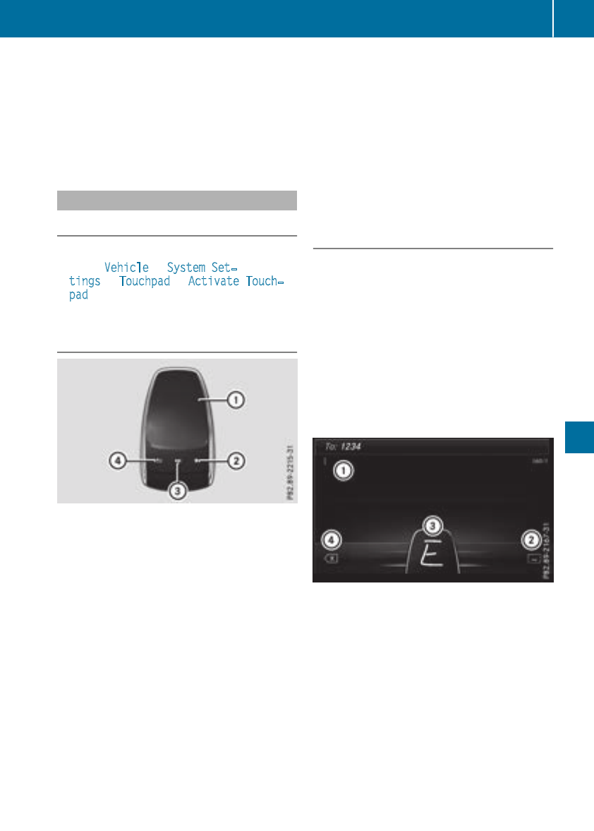
XTo exit the menu: briefly press the %
button.
The multimedia system changes to the next
higher menu level in the current operating
mode.
XTo call up the highest level menu: press the
%button for longer than two seconds.
Touchpad
Switching the touchpad on/off
Multimedia system:
XSelect VehicleQSystem Set‐
tingsQTouchpadQActivate Touch‐
pad.
The touchpad is switched on Oor off ª.
Operating the touchpad
:Touch-sensitive surface
;Favorites button
=Calls up quick access for audio
?Back button
Navigating in menus and lists can be done via
touch-sensitive surface :by swiping with
your finger.
XTo select the menu item: swipe up, down, to
the left or right.
XPress the touchpad.
XTo move the digital map: swipe in all direc-
tions.
Swiping with two fingers, e.g. using this func-
tion:
XTo show or hide the audio menu: swipe up
or down with two fingers.
XTo increase or reduce the vehicle and
sound settings: turn two fingers to the right
or left.
XTo zoom in and out of the map: move two
fingers together or apart.
Character entry with handwriting rec-
ognition
Entering characters
XUse one finger to write characters on the sur-
face.
The character is entered in the input line. If
the character that you have entered can be
interpreted in different ways, these character
suggestions are displayed.
XIf character suggestions are shown, turn and
press the controller.
XResume the character entry on the touchpad.
Handwriting recognition
Example: COMAND
:Active input line
;Inserts a space
=Character entered on the touchpad
?Deletes characters
XTo display the menu: press the touchpad.
Operating system 255
Multimedia system
Z
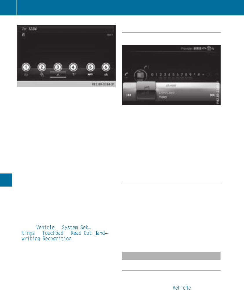
Example: COMAND
:To exit the menu
;To return to handwriting recognition
=To use the phone book or text templates
?To select the input line or changes the posi-
tion of the cursor
ATo switch the language
BTo finish character entry
XTo select the input line: select p.
XSwipe up or down.
XTo move the cursor within the input line:
select p.
XSwipe to the left or right.
XTo delete characters: swipe to the left if an
input line is selected.
XTo confirm the entry: press the touchpad.
Switching the text reader function of the
handwriting recognition on/off
Multimedia system:
XSelect VehicleQSystem Set‐
tingsQTouchpadQRead Out Hand‐
writing Recognition.
The read-aloud function is switched on Oor
off ª.
Quick access for audio
Changing the station/music track
Depending on the audio source that is currently
activated, you can use this function to select the
next station or music track.
XSwipe upwards with two fingers on the touch-
pad.
The current audio source is displayed.
XTo select the previous or next station/
music track: glide to the right or left.
The selected station/music track is played.
Switching the character entry between
touchpad and controller
Requirement: an input line for text, numbers or
characters has been selected.
XTo switch to the controller: press the con-
troller.
Character entry using the controller is active.
XTo switch to the touchpad: press the touch-
pad with your finger.
Handwriting recognition on the touchpad is
active.
Favorites
Calling up and exiting favorites
XTo call up: press the gbutton on the con-
troller or on the touchpad.
XSelect a favorite, e.g. Vehicle.
The favorites are displayed.
XTo exit: press the gbutton again.
256 Operating system
Multimedia system
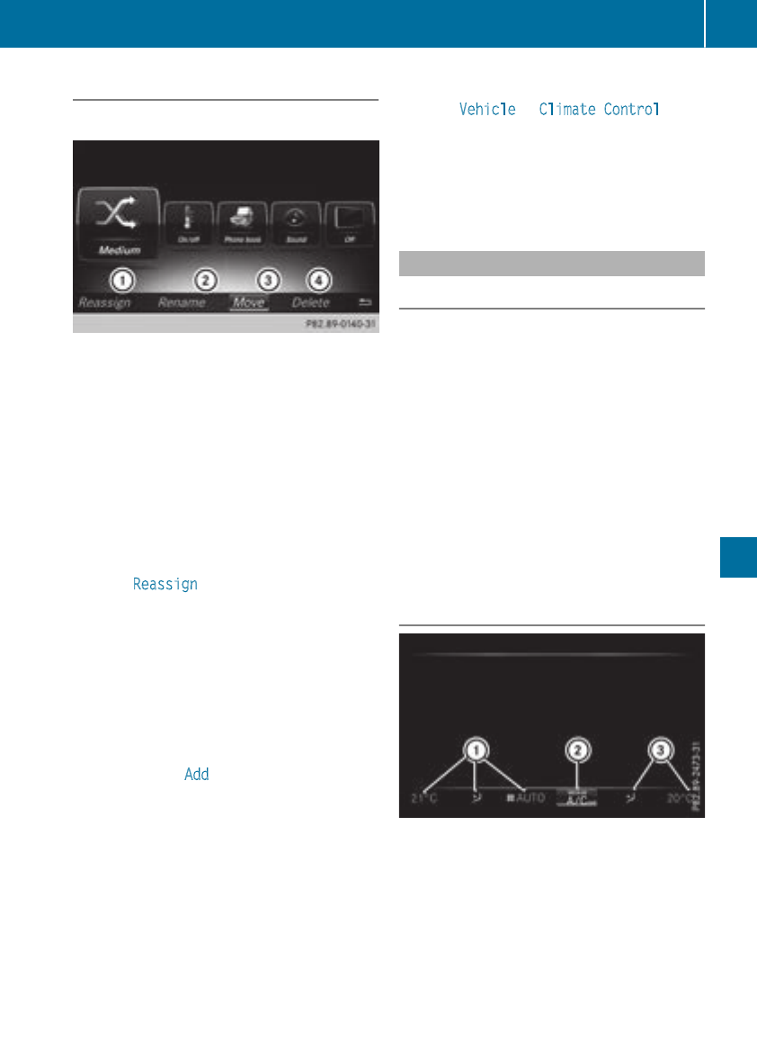
Adding favorites
Adding predefined favorites
Example: favoritesarranged in onerow
:Adds anewfavorite
;Renames aselected favorite
=Moves aselected favorite
?Deletes aselected favorite
XPress thegbutton.
The favoritesare displayed.
These are arranged in either oneor two rows,
eachwithfivetiles.
XFavorites arearranged in one row: slide
6thecontroller.
The menubar is shown.
XSelectReassign.
The categoriesare displayed.
XSelect a category.
The favoritesare displayed.
XSelect a favorite.
XAdd a favorite at thedesired position.
If afavorite has already been added at this
position,it will be overwritten.
XFavorites arearranged in one row: slide
6or 5thecontroller.
XTo select WAdd:turnand press thecon-
troller.
The categoriesand predefinedfavoritesare
displayed.
XSelect a category.
The favoritesare displayed.
XSelect a favorite.
XAdd a favorite at thedesired position.
If afavorite has already been added at this
position,it will be overwritten.
Adding yourown favorites
XSelectVehicleQClimate Control.
XPress and hold thegbuttonuntil the
favoritesare displayed.
XAdd a favorite at thedesired position.
If afavorite has already been added at this
position,it will be overwritten.
Climate control settings
General notes
You can adjust theclimatecontrol settings
usingtheclimatecontrol bar or theclimatecon-
trol menu.
Importantclimatecontrol functionscan be set
in theclimatecontrol bar:
RTemperature
RAirflow
RAir distribution
The climatecontrol bar is visible in mostdis-
plays.
You can findall available climatecontrol func-
tionsin theclimatecontrol menu. You can use
theclimatecontrol bar to switch to theclimate
control menu.
Overview
Climate control bar (COMAND)
:Adjusts temperature, air distribution on the
leftand airflow, displays thecurrentsettings
;Calls up theclimatecontrol menu, displays
thecurrentcoolingand climatemodeset-
tings
=Adjusts temperature and air distribution on
theright,displays thecurrentsettings
There may be fewer settingsor none depending
on your vehicle's equipment.
Operating system 257
Multimedia system
Z
Calling up the climate control bar
Multimedia system:
XSelect Vehicle.
The vehicle menu is displayed.
XSlide 6the controller repeatedly until the
climate control bar is activated.
Calling up the climate control menu
Multimedia system:
XSelect Vehicle.
The vehicle menu is displayed.
XSlide 6the controller repeatedly until the
climate control bar is activated.
XTo select from climate control bar ;: turn
and press the controller.
The menu for selecting the climate control
function is activated.
XTo select the climate control function: turn
and press the controller.
The selected climate control function
appears.
Settings in the climate menu
Adjusting the climate mode settings
The climate mode determines the type of air-
flow. The setting is active when the air-condi-
tioning system is set to Ã(Ypage 117).
XCall up the climate control menu
(Ypage 258).
XTo select Climate Mode: turn and press the
controller.
XTo change the setting: turn the controller.
XTo exit the menu: press the %button.
The climate mode bar displays the current air-
flow setting: DIFFUSE,MEDIUM or FOCUS.
Switching the ionization on/off
The ionization has a cleansing effect on the air in
the vehicle interior. Further information
(Ypage 120).
XCall up the climate control menu
(Ypage 258).
XTo select Ionization: turn and press the
controller.
The setting element is active.
XTo switch the ionization on or off: turn the
controller.
XTo exit the menu: press the %button.
Settings in the bottom bar of the cli-
mate control menu
Switching cooling with air dehumidifica-
tion on/off
XCall up the climate control menu
(Ypage 258).
XSlide 6the controller repeatedly until the
bottom bar is activated.
XTo select OA/C: turn and press the control-
ler.
XSwitch cooling with air dehumidification on
Oor off ª.
iThe current status of the cooling function is
displayed in the climate control bar: A/C ON
– activated, A/C OFF – deactivated.
iDeactivating the cooling with air dehumidi-
fication function reduces fuel consumption.
Synchronizing the climate control set-
tings
Use OSync (synchronization) to select the cli-
mate control setting for all zones together Oor
separately ª.
XCall up the climate control menu
(Ypage 258).
XSlide 6the controller repeatedly until the
bottom bar is activated.
XTo select OSync: turn and press the con-
troller.
XSwitch the synchronization function on Oor
off ª.
For further information on synchronizing climate
control settings, see (Ypage 118).
Navigation mode
Important safety notes
GWARNING
If you operate information systems and com-
munication equipment integrated in the vehi-
cle when driving, you may be distracted from
the traffic situation. You could also lose con-
258 Operating system
Multimedia system
trol of the vehicle. There is a risk of an acci-
dent.
Only operate this equipment when the traffic
situation permits. If you are not sure that this
is possible, park the vehicle paying attention
to traffic conditions and operate the equip-
ment when the vehicle is stationary.
You must observe the legal requirements for the
country in which you are currently driving when
operating the navigation system.
General notes
Among other things, correct functioning of the
navigation system depends on GPS reception. In
certain situations, GPS reception may be
impaired, there may be interference or there
may be no reception at all, e.g. in tunnels or
parking garages.
Audio 20 is equipped with Garmin®MAP PILOT
(see the manufacturer's operating instructions).
The Garmin®MAP PILOT operating instructions
are stored on the SD card as a PDF file. The SD
card box contains a quick guide.
The following descriptions apply to navigation
with COMAND. Further information can be
found in the Digital Operator's Manual.
Selecting a route type and route options
Multimedia system:
XSelect NaviQNavigation.
XSelect OptionsQRoute Settings.
iIf route guidance is active, first slide 6the
controller and show the menu.
XSelect a route type.
Notes for route types:
REco Route
Calculates an economic route.
RDynamic Traffic Route (only available in
the USA)
Traffic reports on the route for the route guid-
ance are taken into account.
RCalculate Alternative Routes
Different routes are being calculated. Instead
of Start, select the Continue menu item.
XTo avoid/use route options: select Avoid
Options.
XSelect a route option.
Notes for route options:
RUse Toll Roads
The route calculation includes roads which
require you to pay a usage fee (toll).
RUse Carpool Lanes (only available in the
USA)
Prerequisite: your vehicle meets the access
conditions for carpool lanes.
Carpool lanes will be included if the carpool
lanes option is activated.
Entering an address
Multimedia system:
XSelect NaviQNavigation.
XSelect DestinationQAddress Entry.
iIf route guidance is active, first slide 6the
controller and show the menu.
Enter an address, e.g. as follows:
Rcity or ZIP code, street, house number
Rcountry, city or ZIP code
Rcity or ZIP code, center
Rstreet, city or ZIP code, intersection
XSelect City.
The city in which the vehicle is currently loca-
ted (current vehicle position) is at the top.
Below this, you will see locations for which
route guidance has already been carried out.
XEnter the city.
The Gsymbol: the location is contained on
the digital map multiple times.
XTo switch to the list: slide the 5control-
ler.
XSelect the location.
If available, the ZIP code is shown. If there are
different ZIP codes available for the location,
the corresponding digits are displayed with an
X.
XEnter the street and house number.
The address is in the menu.
Further options for destination entry:
RKeyword search
The keyword search finds destinations using
fragments of words.
Rselect the last destination
Operating system 259
Multimedia system
Z
Rselect a contact
Rselect a POI
You can search for a POI by location, name or
telephone number.
Rselect destination on the map
Renter intermediate destination
You can map the route to the destination
yourself with up to four intermediate destina-
tions.
Rselect destinations from Mercedes-Benz
Apps
Rselect geo-coordinates
Calculating the route
Prerequisite: the address has been entered and
is in the menu.
XSelect Start or Continue.
The route is calculated with the selected route
type and the selected route options.
If route guidance has already been activated,
a prompt will appear asking whether you wish
to end the current route guidance.
XSelect Yes or Set as Intermediate Des‐
tination.
Yes cancels the current route guidance and
starts route calculation to the new destina-
tion.
Set as Intermediate Destination adds
the new destination in addition to the existing
destination and opens the intermediate des-
tinations list.
Connecting a mobile phone
Requirements
Note: this segment describes connecting of a
mobile phone with COMAND. To connect a
mobile phone with Audio 20 (see the Digital
Operator's Manual).
For telephony via the Bluetooth®interface, you
require a Bluetooth®-capable mobile phone. The
mobile phone must support Hands-Free Profile
1.0 or above.
Multimedia system:
XSelect VehicleQSystem Set‐
tingsQActivate Bluetooth.
XActivate Bluetooth®O.
Mobile phone:
XActivate Bluetooth®and, if necessary, Blue-
tooth®visibility for other devices (see the
manufacturer's operating instructions).
The Bluetooth®device names for all of one man-
ufacturer's products might be identical. To
make it possible to clearly identify your mobile
phone, change the device name (see the man-
ufacturer's operating instructions).
If the mobile phone supports the PBAP (Phone
Book Access Profile) and MAP (Message
Access Profile) Bluetooth®profiles, the follow-
ing information will be transmitted after you
connect:
RPhone book
RCall lists
RMessages
iFurther information on suitable mobile
phones can be obtained on the Internet at:
http://www.mercedes-benz.com/
connect
iIn the USA, you can get in touch with the
Mercedes-Benz Customer Assistance Center
on 1-800-FOR-MERCedes (1-800-367-6372).
In Canada, you can get in touch with the Cus-
tomer Relations Center on 1-800-387-0100.
Searching for and authorizing a mobile
phone
Before using your mobile phone with the multi-
media system for the first time, you will need to
search for the phone and then authorize (con-
nect) it. Depending on the mobile phone, author-
ization either takes place by means of Secure
Simple Pairing or by entering a passkey. The
multimedia system automatically makes the
procedure that is relevant for your mobile phone
available. The mobile phone is always connec-
ted automatically after authorization. Further
information on using a mobile phone with the
multimedia system (see the Digital Operator's
Manual).
If the multimedia system does not detect your
mobile phone, this may be due to particular
security settings on your mobile phone (see the
manufacturer's operating instructions).
Only one mobile phone can be connected to the
multimedia system at any one time.
Searching for a mobile phone
260 Operating system
Multimedia system
Multimedia system:
XSelect PhoneQConnect
DeviceQSearch for PhonesQStart
Search.
The available mobile phones are displayed.
Symbols in the device list
Sym-
bol
Explanation
ÏNew mobile phone found, not yet
authorized.
ÑMobile phone is authorized, but is
not connected.
#Mobile phone is authorized and
connected.
Connecting a mobile phone
Authorization using Secure Simple Pairing:
XSelect mobile phone.
A code is displayed in the multimedia system
and on the mobile phone.
XIf codes match: select Yes on the multimedia
system.
XConfirm code on the mobile phone. Depend-
ing on the mobile phone used, confirm the
connection to the multimedia system and for
the PBAP and MAP Bluetooth®profiles. The
prompt to confirm may take up to two
minutes to be displayed (see the manufactur-
er's operating instructions).
XIf the codes are different: select No on the
multimedia system.
The process is canceled.
Repeat authorization.
Authorization by entering a passkey (passcode):
XSelect Bluetooth®name of the mobile phone.
The input menu for the passkey is displayed.
XChoose a one to sixteen-digit number combi-
nation as a passkey.
XEnter the passkey on the multimedia system.
XPress ¬to confirm.
XEnter and confirm the passkey on the mobile
phone. Depending on the mobile phone used,
confirm the connection to the multimedia sys-
tem and for the PBAP and MAP Bluetooth®
profiles. The prompt to confirm may take up
to two minutes to be displayed (see the man-
ufacturer's operating instructions).
Switching between mobile phones
If you have authorized more than one mobile
phone, you can switch between the individual
phones.
Multimedia system:
XSelect PhoneQConnect Device.
XSelect a mobile phone from the device list.
Media mode
General notes
If you wish to play external media sources, the
appropriate media mode must already be turned
on. Further information on media mode (see the
Digital Operator's Manual).
The following external media sources can be
used:
RApple®devices (e.g. iPhone®)
RUSB devices (e.g. USB stick, MP3 player)
RCD
RDVD (COMAND)
RSD cards
Rvia devices connected by Bluetooth®
iInformation on the single DVD drive (see the
Digital Operator's Manual).
Activating media mode
Multimedia system:
XSelect MediaQDevices .
The available media sources will be shown.
XSelect the media source.
Playable files are played.
Inserting and removing an SD card
Important safety notes
GWARNING
SD cards are small parts. They can be swal-
lowed and cause choking. This poses an
increased risk of injury or even fatal injury.
Keep the SD card out of the reach of children.
If a SD card is swallowed, seek medical atten-
tion immediately.
Operating system 261
Multimedia system
Z
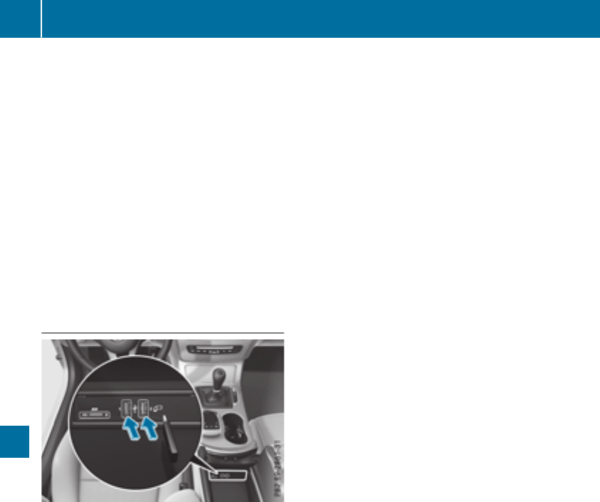
!If you are no longer using the SD card, you
should remove it and store it outside the vehi-
cle. High temperatures can damage the card.
Inserting an SD card
The SD card slot is located in the stowage com-
partment under the armrest.
XInsert the SD card into the SD card slot until
the SD card engages. The side with the con-
tacts must face down.
XSelect the media source (Ypage 261).
Removing an SD card
XPress the SD card.
The SD card is ejected.
XRemove the memory card.
Connecting USB devices
USB ports e.g. when the vehicle is equipped with a
navigation system.
There are two USB ports in the stowage space
under the armrest.
XConnect the USB device to the USB port.
XSelect the media source (Ypage 261).
262 Operating system
Multimedia system

Stowage areas
Loading guidelines
GWARNING
Combustion engines emit poisonous exhaust
gases such as carbon monoxide. Exhaust
gases can enter the vehicle interior if the
trunk lid is open when the engine is running,
especially if the vehicle is in motion. There is a
risk of poisoning.
Always switch off the engine before opening
the trunk lid. Never drive with the trunk lid
open.
GWARNING
If objects, luggage or loads are not secured or
not secured sufficiently, they could slip, tip
over or be flung around and thereby hit vehicle
occupants. There is a risk of injury, particu-
larly in the event of sudden braking or a sud-
den change in direction.
Always store objects so that they cannot be
flung around. Secure objects, luggage or
loads against slipping or tipping before the
journey.
GWARNING
The exhaust tail pipe and tail pipe trim can
become very hot. If you come into contact
with these parts of the vehicle, you could burn
yourself. There is a risk of injury.
Always be particularly careful around the
exhaust tail pipe and the tail pipe trim. Allow
these components to cool down before touch-
ing them.
The handling characteristics of a laden vehicle
are dependent on the distribution of the load
within the vehicle. For this reason, you should
observe the following notes when transporting a
load:
RNever exceed the maximum permissible
gross vehicle mass or the gross axle weight
rating for the vehicle (including occupants).
The values are specified on the vehicle iden-
tification plate on the B-pillar of the driver's
door.
RThe trunk is the preferred place to carry
objects.
RPosition heavy loads as far forwards as pos-
sible and as low down in the trunk as possible.
RThe load must not protrude above the upper
edge of the seat backrests.
RAlways place the load behind unoccupied
seats if possible.
RSecure the load with sufficiently strong and
wear-resistant tie-downs. Pad sharp edges for
protection.
Stowage spaces
Important safety notes
GWARNING
If objects in the passenger compartment are
stowed incorrectly, they can slide or be
thrown around and hit vehicle occupants. In
addition, cupholders, open stowage spaces
and mobile phone brackets cannot always
retain all objects they contain. There is a risk
of injury, particularly in the event of sudden
braking or a sudden change in direction.
RAlways stow objects so that they cannot be
thrown around in such situations.
RAlways make sure that objects do not pro-
trude from stowage spaces, parcel nets or
stowage nets.
RClose the lockable stowage spaces before
starting a journey.
RAlways stow and secure heavy, hard, poin-
ted, sharp-edged, fragile or bulky objects in
the trunk.
Observe the loading guidelines (Ypage 263).
Stowage areas 263
Stowage and features
Z
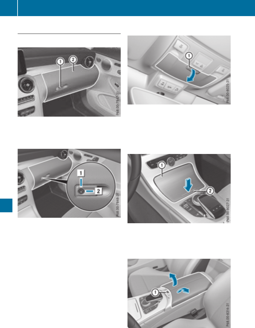
Stowage compartments in the front
Glove box
XTo open: pull handle :and open glove box
flap ;.
XTo close: fold glove box flap ;up until it
engages.
The glove box can only be locked and unlocked
using the mechanical key (Ypage 78).
XTo lock: insert the mechanical key into the
lock and turn it 90° clockwise to position 2.
XTo unlock: insert the mechanical key into the
lock and turn it 90° counter-clockwise to
position 1.
Eyeglasses compartment
XTo open: press marking :.
The eyeglasses compartment opens down.
Make sure that the eyeglasses compartment is
always closed while the vehicle is in motion.
Stowage compartment in the front center
console
XBriefly press trim ;in the direction of the
arrow.
Cover :swings up.
Stowage compartment under the armrest
XTo open: press button :at front.
The stowage space opens.
264 Stowage areas
Stowage and features
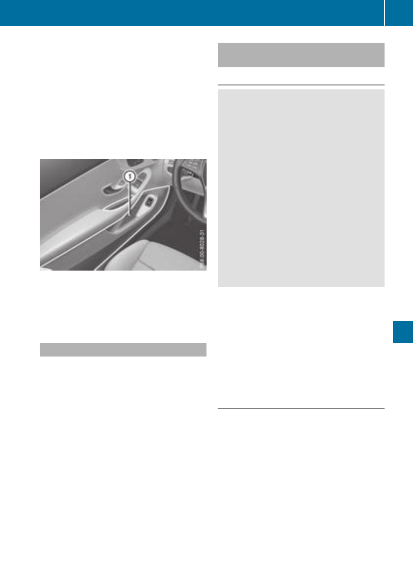
Depending on the vehicle's equipment, the fol-
lowing may be in the stowage space:
Ran SD card slot
Ra multimedia connector unit with two USB
ports, e.g. for iPod®, iPhone®or MP3 player
(see the Digital Operator's Manual)
Ra mobile phone bracket
Ra small stowage space in the upper front sec-
tion
Stowage compartment in the doors
In stowage space :in the doors, you can store
bottles with a capacity of up to 34 fl. oz. (1.0 l),
a rolled-up fluorescent jacket (driver's door) and
the vehicle document wallet (front-passenger
door).
Additional stowage space
Depending on the equipment, the following
additional stowage areas are available in the
vehicle:
Rcard and coin holder in the dashboard above
the light switch (not suitable for holding thin
objects such as shopping tokens)
Rthe open stowage compartment in the center
console
Rstowage net in the front-passenger footwell
Rparcel net on the left-hand side in the trunk
Rstowage nets on the left and right in the foot-
well of the rear bench seat
Observe the loading guidelines (Ypage 263)
and the safety notes regarding stowage spaces
(Ypage 263).
Rear bench seat through-loading fea-
ture
Important safety notes
GWARNING
If the rear bench seat/rear seat and seat
backrest are not engaged they could fold for-
wards, e.g. when braking suddenly or in the
event of an accident.
RThe vehicle occupant would thereby be
pushed into the seat belt by the rear bench
seat/rear seat or by the seat backrest. The
seat belt can no longer offer the intended
level of protection and could even cause
injuries.
RObjects or loads in the trunk cannot be
restrained by the seat backrest.
There is an increased risk of injury.
Before every trip, make sure that the seat
backrests and the rear bench seat/rear seat
are engaged.
!When folding the rear seat backrest for-
wards, ensure that there are no items lying on
the seat cushions. These items could other-
wise be damaged or could themselves dam-
age the rear seats.
Observe the loading guidelines (Ypage 263).
The left and right rear seat backrests can be fol-
ded down separately to increase the trunk capa-
city.
Folding the rear seat backrests forward
XVehicles without memory function: if neces-
sary, move the driver's or front-passenger
seat forward.
XVehicles with memory function: when one or
both parts of the rear seat backrest are folded
forward, the respective front seat moves
forward slightly, when necessary, in order to
avoid contact.
XOpen the trunk.
Stowage areas 265
Stowage and features
Z
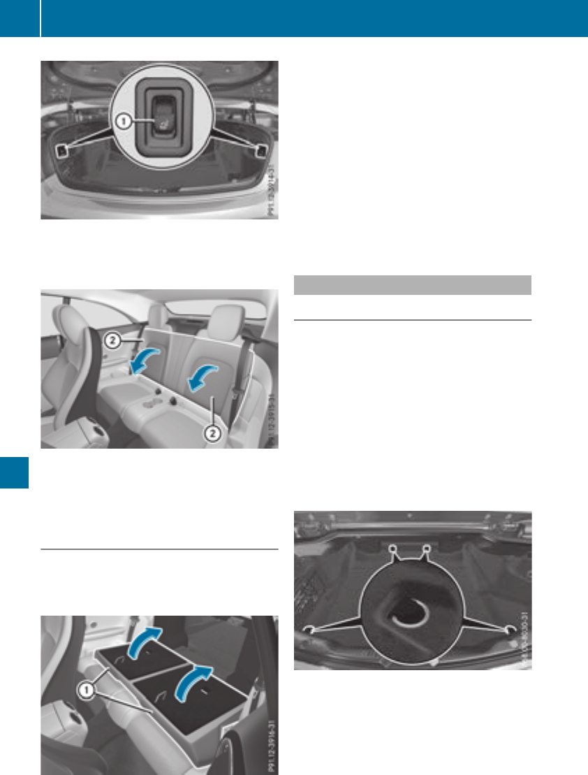
XPress the right or left button :on the rear
seat backrest.
The corresponding rear seat backrest is
released.
XFold corresponding rear seat backrest ;
forward.
XMove the driver's or front-passenger seat
back if necessary.
Folding the rear seat backrest back
!Make sure that the seat belt does not
become trapped when folding the rear seat
backrest back. Otherwise, it could be dam-
aged.
Left and right seat backrest
XMove the driver's or front-passenger seat
forward if necessary.
XFold rear seat backrest :back until it
engages.
If the rear seat backrest is not engaged and
locked, this will be shown in the multifunction
display in the instrument cluster. A warning
tone also sounds.
You should always engage the rear seat backr-
ests if you do not need the through-loading fea-
ture. This will prevent unauthorized access to
the trunk from the vehicle interior.
Securing loads
Cargo tie-down rings
Observe the following notes on securing loads:
RObserve the loading guidelines (Ypage 263).
RSecure the load using the cargo tie-down
rings.
RDistribute the load on the cargo tie-down
rings evenly.
RDo not use elastic straps or nets to secure a
load, as these are only intended as an anti-slip
protection for light loads.
RDo not route tie-downs across sharp edges or
corners.
RPad sharp edges for protection.
XFold up the cargo tie-down rings next to the
rear seat backrest and put them through the
slots in the carpet.
266 Stowage areas
Stowage and features
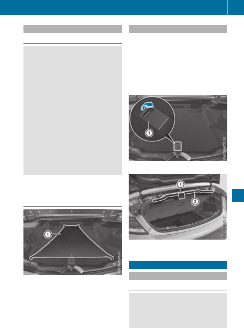
Parcel net
Important safety notes
GWARNING
If objects in the passenger compartment are
stowed incorrectly, they can slide or be
thrown around and hit vehicle occupants. In
addition, cupholders, open stowage spaces
and mobile phone brackets cannot always
retain all objects they contain. There is a risk
of injury, particularly in the event of sudden
braking or a sudden change in direction.
RAlways stow objects so that they cannot be
thrown around in such situations.
RAlways make sure that objects do not pro-
trude from stowage spaces, parcel nets or
stowage nets.
RClose the lockable stowage spaces before
starting a journey.
RAlways stow and secure heavy, hard, poin-
ted, sharp-edged, fragile or bulky objects in
the trunk.
Observe the following notes:
RObserve the loading guidelines (Ypage 263).
Attaching the parcel net
XFold up the cargo tie-down rings next to the
rear seat backrest and put them through the
slots in the carpet.
XAttach parcel net :to the front and rear
cargo tie-down rings.
Stowage well under the trunk floor
The following items are located beneath the
trunk floor, for example:
Rthe folding box
Rtire-change tool kit
RTIREFIT kit
!Unhook the handle before again before clos-
ing the trunk lid and clip it in securely to pre-
vent the handle flap from protruding. Other-
wise, you could damage the handle.
XTo open: pull handle :up.
XHook handle :into rain trough ;.
Features
Cup holder
Important safety notes
GWARNING
The cup holder cannot hold a container secure
whilst traveling. If you use a cup holder whilst
traveling, the container may be flung around
and liquid may be spilled. The vehicle occu-
Features 267
Stowage and features
Z
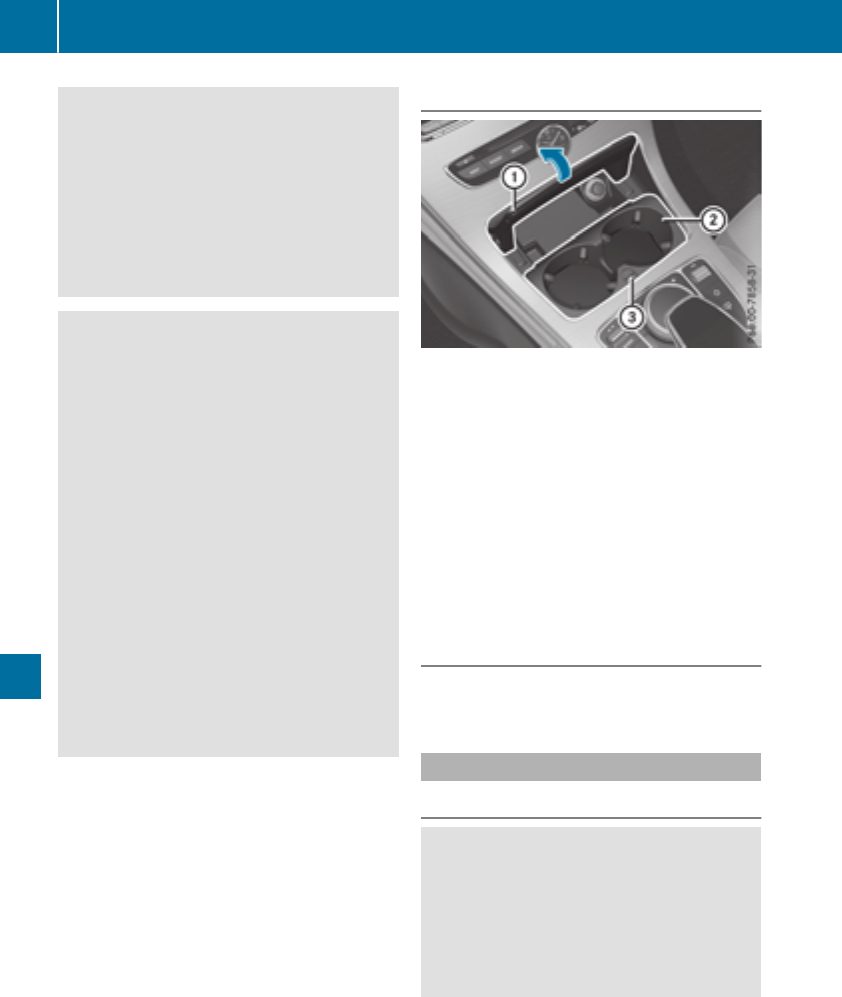
pants may come into contact with the liquid
and if it is hot, they may be scalded. You may
be distracted from the traffic conditions and
you could lose control of the vehicle. There is
a risk of an accident and injury.
Only use the cup holder when the vehicle is
stationary. Only use the cup holder for con-
tainers of the right size. Always close the con-
tainer, particularly if the liquid is hot.
GWARNING
If objects in the passenger compartment are
stowed incorrectly, they can slide or be
thrown around and hit vehicle occupants. In
addition, cupholders, open stowage spaces
and mobile phone brackets cannot always
retain all objects they contain. There is a risk
of injury, particularly in the event of sudden
braking or a sudden change in direction.
RAlways stow objects so that they cannot be
thrown around in such situations.
RAlways make sure that objects do not pro-
trude from stowage spaces, parcel nets or
stowage nets.
RClose the lockable stowage spaces before
starting a journey.
RAlways stow and secure heavy, hard, poin-
ted, sharp-edged, fragile or bulky objects in
the trunk.
!Only use the cup holders for containers of
the right size and which have lids. The drinks
could otherwise spill.
!Do not expose drinks bottles in the cup
holder in the center console to continuous,
strong and direct sunlight. The passenger
compartment in the area of the center con-
sole can otherwise be damaged by the con-
centrated and reflected sunlight.
Observe the loading guidelines (Ypage 263).
Cup holder in the front center console
If you remove the cup holder insert, you can use
the resulting compartment for stowage.
XTo open: open the stowage compartment
(Ypage 264).
XTo remove: slide catch =forward and pull
out cup holder ;.
XTo insert: insert cup holder ;and slide back
catch =.
XTo close: push cover :of the stowage com-
partment closed.
You can remove the cup holder's rubber mat for
cleaning. Clean with clear, lukewarm water only.
Cup holders in the rear compartment
The cup holder can hold two cups of up to
17 fl. oz. (0.5 l).
Sun visors
Overview
GWARNING
If the mirror cover of the vanity mirror is folded
up when the vehicle is in motion, you could be
blinded by incident light. There is a risk of an
accident.
Always keep the mirror cover folded down
while driving.
268 Features
Stowage and features
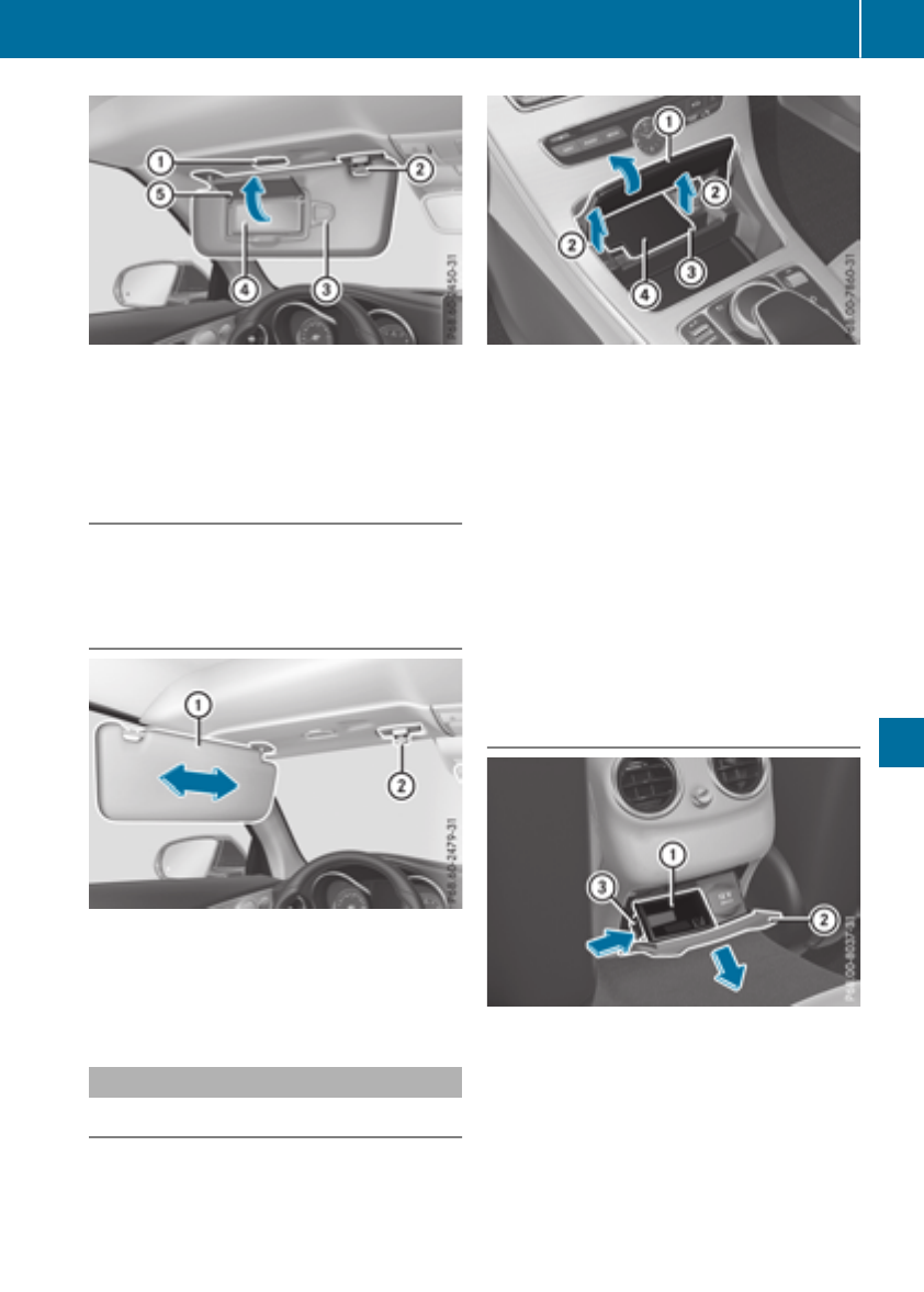
:Mirror light
;Retainer
=Retaining clip, e.g. for a car park ticket
?Vanity mirror
AMirror cover
Vanity mirror in the sun visor
Mirror light :only functions if the sun visor is
clipped into bracket ;and mirror cover Ahas
been folded up.
Glare from the side
XFold down the sun visor.
XPull sun visor :out of retainer ;.
XSwing sun visor :to the side.
XSlide sun visor :horizontally as required.
Ashtray
Front ashtray
!The stowage space under the ashtray is not
heat resistant. Before placing lit cigarettes in
the ashtray, make sure that the ashtray is
properly engaged. Otherwise, the stowage
space could be damaged.
XTo open: open the stowage compartment
(Ypage 264).
XPush the cover of the ashtray upwards at its
right side =.
XTo remove the insert: hold the sides of
insert ?, push it forward and lift it up ;and
out.
XTo install the insert: press insert ?into the
holder until it engages.
XTo close: close the cover of the ashtray.
XPush cover :of the stowage compartment
closed.
iYou can remove the ashtray insert and use
the resulting compartment for stowage.
Rear compartment ashtray
XTo open: pull cover ;out by its top edge.
XTo remove the insert: push ribbing =from
the left side and pull insert :upwards.
XTo install the insert: install insert :from
above into the holder and press down into the
holder until it engages.
Features 269
Stowage and features
Z
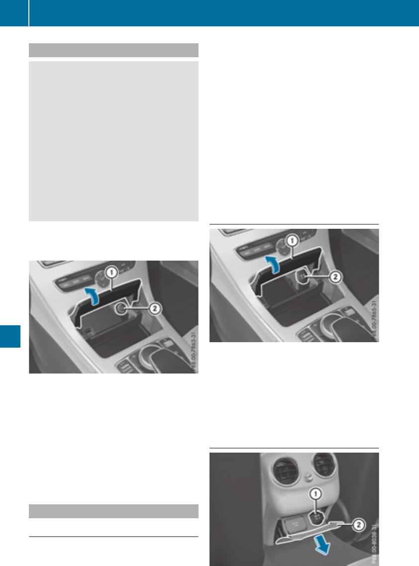
Cigarette lighter
GWARNING
You can burn yourself if you touch the hot
heating element or the socket of the cigarette
lighter.
In addition, flammable materials can ignite if:
Rthe hot cigarette lighter falls
Ra child holds the hot cigarette lighter to
objects, for example
There is a risk of fire and injury.
Always hold the cigarette lighter by the knob.
Always make sure that the cigarette lighter is
out of reach of children. Never leave children
unsupervised in the vehicle.
Your attention must always be focused on the
traffic conditions. Only use the cigarette lighter
when road and traffic conditions permit.
Cigarette lighter (example)
XTurn the SmartKey to position 2in the igni-
tion lock (Ypage 123).
XTo open: open the stowage compartment
(Ypage 264).
XPress in cigarette lighter ;.
Cigarette lighter ;will pop out automatically
when the heating element is red-hot.
XTo close: push cover :of the stowage com-
partment closed.
12 V sockets
General notes
XTurn the SmartKey to position 1in the igni-
tion lock (Ypage 123).
The sockets can be used for accessories with a
maximum draw of 180 W (15 A). Accessories
include such items as chargers for mobile
phones.
If you use the sockets for long periods when the
engine is switched off, the battery may dis-
charge.
An emergency cut-out ensures that the on-
board voltage does not drop too low. If the on-
board voltage is too low, the power to the sock-
ets is automatically cut. This ensures that there
is sufficient power to start the engine.
If you have connected a device to the 12 V
socket, leave the cover of the stowage com-
partment open. This prevents the cover from
being blocked.
Socket in the front center console
12 V socket (example)
XTo open: open the stowage compartment
(Ypage 264).
XLift up the cover of socket ;.
XTo close: push cover :of the stowage com-
partment closed.
Socket in the rear compartment center
console
270 Features
Stowage and features
XPull cover ;out by its top edge.
XLift up the cover of socket :.
mbrace
General notes
The mbrace system is only available in the USA.
You must have a license agreement to activate
the mbrace service. Make sure that your system
is activated and operational. To register, press
the ïInfo call button. If any of the steps
mentioned are not carried out, the system may
not be activated.
If you have questions about the activation, con-
tact one of the following telephone hotlines:
Mercedes-Benz Customer Assistance Center at
1-800-FOR-MERCedes (1-800-367-6372) or
1-866-990-9007
Shortly after successfully registering with the
mbrace service, a user ID and password will be
sent to you by mail. You can use this password
to log onto the mbrace area under "Owners
Online" at http://www.mbusa.com.
The system is available if:
Rit has been activated and is operational
Rthe corresponding mobile phone network is
available for transmitting data to the Cus-
tomer Center
Ra service subscription is available
Determining the location of the vehicle on a map
is only possible if:
RGPS reception is available
Rthe vehicle position can be forwarded to the
Customer Assistance Center
The mbrace system
To adjust the volume during a call, proceed as
follows:
XPress the Wor Xbutton on the multi-
function steering wheel.
or
XUse the multimedia system volume control.
The system offers various services, e.g.:
RAutomatic and manual emergency call
RRoadside Assistance call
RInfo call
You can find information and a description of all
available features under "Owners Online" at
http://www.mbusa.com.
System self-test
After you have switched on the ignition, the sys-
tem carries out a self-diagnosis.
A malfunction in the system has been detected
if one of the following occurs:
RThe indicator lamp in the SOS button does not
come on during the system self-test.
RThe indicator lamp in the FRoadside
Assistance button does not light up during
self-diagnosis of the system.
RThe indicator lamp in the ïInfo call button
does not light up during the system self-diag-
nosis
RThe indicator lamp in one or more of the fol-
lowing buttons continues to light up red after
the system self-diagnosis:
-SOS button
-FRoadside Assistance call button
-Info call buttonï
RAfter the system self-diagnosis, the Inoper‐
ative or Service Not Activated message
appears in the multifunction display.
If a malfunction is indicated as outlined above,
the system may not operate as expected. In the
event of an emergency, help will have to be
summoned by other means.
Have the system checked at the nearest
Mercedes-Benz Service Center or contact the
following service hotlines:
Mercedes-Benz Customer Assistance Center at
1-800-FOR-MERCedes (1-800-367-6372) or
1-866-990-9007
Features 271
Stowage and features
Z
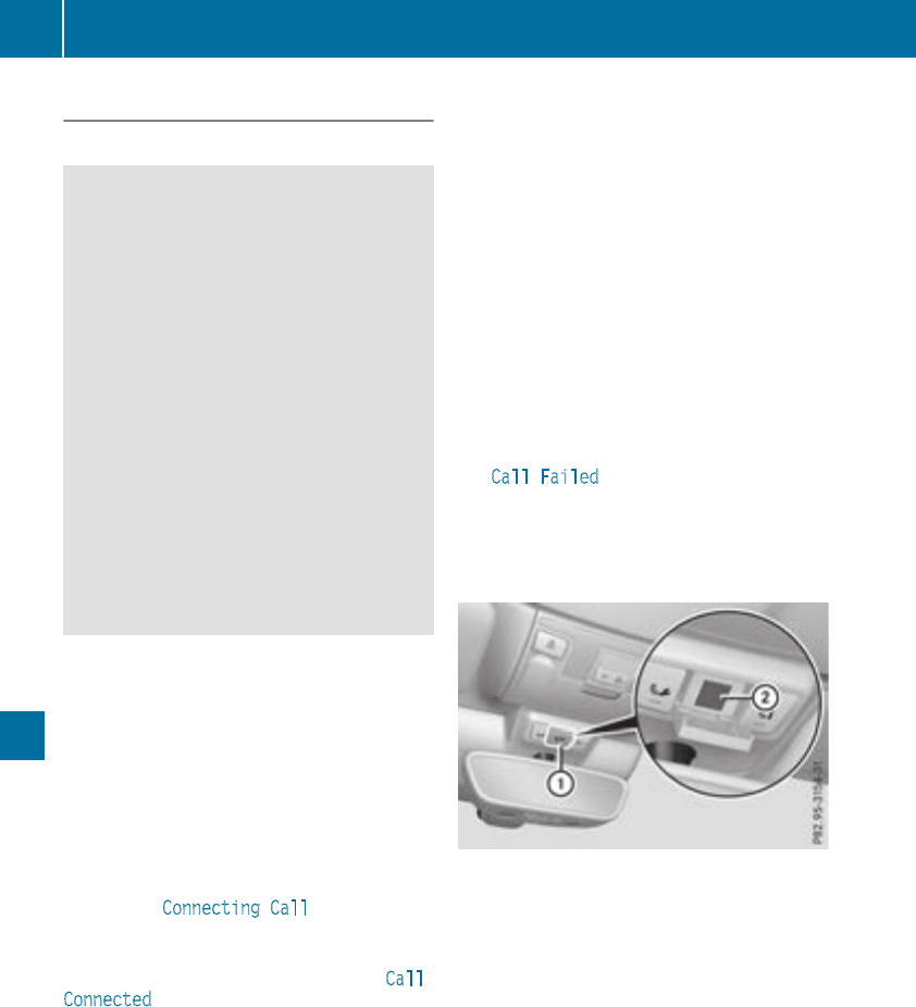
Emergency call
Important safety notes
GWARNING
It can be dangerous to remain in the vehicle,
even if you have pressed the SOS button in an
emergency if:
Ryou see smoke inside or outside of the vehi-
cle, e.g. if there is a fire after an accident
Rthe vehicle is on a dangerous section of
road
Rthe vehicle is not visible or cannot easily be
seen by other road users, particularly when
dark or in poor visibility conditions
There is a risk of an accident and injury.
Leave the vehicle immediately in this or simi-
lar situations as soon as it is safe to do so.
Move to a safe location along with other vehi-
cle occupants. In such situations, secure the
vehicle in accordance with national regula-
tions, e. g. with a warning triangle.
General notes
Observe the notes on system activation
(Ypage 271).
An emergency call is dialed automatically if an
air bag or Emergency Tensioning Device is trig-
gered. You cannot end an automatically trig-
gered emergency call yourself.
An emergency call can also be initiated man-
ually.
As soon as the emergency call has been initi-
ated, the indicator lamp in the SOS button
flashes. The Connecting Call message
appears in the multifunction display.
The audio output is muted.
Once the connection has been made, the Call
Connected message appears in the multifunc-
tion display.
All important information on the emergency is
transmitted, for example:
RCurrent location of the vehicle (as determined
by the GPS system)
RVehicle identification number
RInformation on the severity of the accident
Shortly after the emergency call has been initi-
ated, a voice connection is automatically estab-
lished between the Customer Assistance Center
and the vehicle occupants.
RIf the vehicle occupants respond, the
Mercedes-Benz Customer Assistance Center
attempts to get more information on the
emergency.
Rif there is no response from the vehicle occu-
pants, an ambulance is immediately sent to
the vehicle.
If no voice connection can be established to the
Mercedes-Benz Customer Assistance Center,
the system has been unable to initiate an emer-
gency call.
This can occur, for example, if the relevant
mobile phone network is not available. The indi-
cator lamp in the SOS button flashes continu-
ously.
The Call Failed message appears in the mul-
tifunction display and must be confirmed.
In this case, summon assistance by other
means.
Making an emergency call
XTo initiate an emergency call manually:
press cover :briefly to open.
XPress and hold the SOS button for at least one
second ;.
The indicator lamp in SOS button ;flashes
until the emergency call is concluded.
XWait for a voice connection to the Mercedes-
Benz Customer Assistance Center.
XAfter the emergency call, close cover :.
If the mobile phone network is unavailable,
mbrace will not be able to make the emergency
call. If you leave the vehicle immediately after
pressing SOS button ;, you do not know if
mbrace has successfully made the emergency
call. In this case, always summon assistance by
other means.
272 Features
Stowage and features
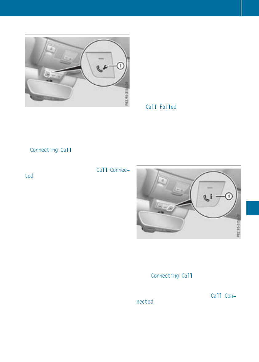
Roadside Assistance
XTo call: press Roadside Assistance but-
ton :.
This initiates a call to the Mercedes-Benz Cus-
tomer Assistance Center.
The indicator lamp in Roadside Assistance
button :flashes while the call is active. The
Connecting Call message appears in the
multifunction display. The audio output is
muted.
If a connection can be made, theCall Connec‐
ted message appears in the multifunction dis-
play.
If a mobile phone network and GPS reception
are available, the system transfers data to the
Mercedes-Benz Customer Assistance Center,
for example:
RCurrent location of the vehicle
RVehicle identification number
The multimedia system display indicates that a
call is active. During the call, you can change to
the navigation menu by pressing the NAVI but-
ton on the multimedia system, for example.
Voice output is not available in this case.
A voice connection is established between the
Mercedes-Benz Customer Assistance Center
and the vehicle occupants.
From the remote malfunction diagnosis, the
Mercedes-Benz Customer Assistance Center
can ascertain the nature of the problem
(Ypage 276).
The Mercedes-Benz Customer Assistance Cen-
ter either sends a qualified Mercedes-Benz tech-
nician or makes arrangements for your vehicle
to be transported to the nearest Mercedes-Benz
Service Center.
You may be charged for services such as repair
work and/or towing.
You can find more information in the separate
mbrace manual.
The system has not been able to initiate a Road-
side Assistance call, if:
Rthe Findicator lamp for the Roadside
Assistance call button is flashing continu-
ously.
Rno voice connection to the Mercedes-Benz
Customer Assistance Center was estab-
lished.
This can occur if the relevant mobile phone net-
work is not available, for example.
The Call Failed message appears in the mul-
tifunction display.
XTo end a call: press the ~button on the
multifunction steering wheel.
or
XPress the corresponding multimedia system
button for ending a phone call.
Info call button
XTo call: press Info call button :.
This initiates a call to the Mercedes-Benz Cus-
tomer Assistance Center.
The indicator lamp in Info call button :
flashes while the connection is being made.
The Connecting Call message appears in
the multifunction display. The audio output is
muted.
If a connection can be made, the Call Con‐
nected message appears in the multifunction
display.
If a mobile phone network and GPS reception
are available, the system transfers data to the
Mercedes-Benz Customer Assistance Center,
for example:
RCurrent location of the vehicle
RVehicle identification number
Features 273
Stowage and features
Z
The multimedia system display indicates that a
call is active. During the call, you can change to
the navigation menu by pressing the NAVI but-
ton on COMAND, for example.
Voice output is not available in this case.
A voice connection is established between the
Mercedes-Benz Customer Assistance Center
and the vehicle occupants.
You receive information about operating your
vehicle, about the nearest Mercedes-Benz Ser-
vice Center and about other products and serv-
ices from Mercedes-Benz.
You can find further information on the mbrace
system under "Owners Online" at http://
www.mbusa.com.
The system has not been able to initiate an MB
Info call, if:
Rthe indicator lamp in the ïInfo call button
is flashing continuously.
Rno voice connection to the Mercedes-Benz
Customer Assistance Center was estab-
lished.
This can occur if the relevant mobile phone net-
work is not available, for example.
The Call Failed message appears in the mul-
tifunction display.
XTo end a call: press the ~button on the
multifunction steering wheel.
or
XPress the corresponding multimedia system
button for ending a phone call.
Call priority
When service calls are active, e.g. Roadside
Assistance or Info calls, an emergency call can
still be initiated. In this case, an emergency call
will take priority and override all other active
calls.
The indicator lamp of the respective button
flashes until the call is ended.
An emergency call can only be terminated by the
Mercedes-Benz Customer Assistance Center.
All other calls can be ended by pressing:
Rthe ~button on the multifunction steering
wheel
Rthe corresponding button in the multimedia
system to end the voice call
When a call is initiated, the audio system is
muted.
The mobile phone is no longer connected to the
multimedia system.
However, if you want to use your mobile phone,
do so only when the vehicle is stationary and in
a safe location.
Downloading destinations
Downloading destinations
Downloading destinations gives you access to a
database with over 15 million points of interest
(POIs). These can be downloaded on the navi-
gation system in your vehicle. If you know the
destination, the address can be downloaded.
Alternatively, you can obtain the location of
Points of Interest (POIs)/important destinations
in the vicinity.
Furthermore, you can download routes with up
to four way points.
You are prompted to confirm route guidance to
the address entered.
XSelect Yes by turning 3or sliding 1
the controller and confirm with 7.
The system calculates the route and subse-
quently starts the route guidance with the
address entered.
If you select No the address can be stored in
the address book.
The destination download function is available
if:
Rthe vehicle is equipped with a navigation sys-
tem.
Rthe relevant mobile phone network is availa-
ble and data transfer is possible.
Route Assistance
This service is part of the mbrace PLUS Package
and cannot be purchased separately.
You can use the Route Assistance function even
if the vehicle is not equipped with a navigation
system.
Within the framework of this service, you receive
a professional and reliable form of navigation
support without having to leave your vehicle.
The customer service representative finds a
suitable route depending on your vehicle's cur-
rent position and the desired destination. You
will then be guided live through the current route
section.
274 Features
Stowage and features

Search and Send
General notes
To use "Search & Send", your vehicle must be
equipped with mbrace and a navigation system.
Additionally, an mbrace service subscription
must be completed.
"Search & Send" is a destination entry service. A
destination address which is found on Google
Maps®can be transferred via mbrace directly to
your vehicle's navigation system.
Specifying and sending the destination
address
XGo to the website http://maps.google.com
and enter a destination address into the entry
field.
XTo send the destination address to the e-
mail address of your mbrace account:
click on the corresponding button on the web-
site.
Example:
If you select 'Send to vehicle' and then
'Mercedes-Benz', the destination address will
be sent to your vehicle.
XWhen the "Send" dialog window appears:
Enter the e-mail address you specified when
setting up your mbrace account into the cor-
responding field.
XClick "Send".
Information on specific commands such as
"Address entry" or "Send" can be found on the
website.
Calling up a transmitted destination
address
XTurn the SmartKey to position 2in the ignition
lock (Ypage 123).
The transmitted destination address is loaded
into the vehicle's navigation system.
A display message appears, asking whether
navigation should be started.
XSelect Yes by turning 3or sliding 1
the controller and confirm with 7.
The system calculates the route and subse-
quently starts the route guidance with the
address entered.
If you select No the address can be stored in
the address book.
If you have sent more than one destination
address, each individual destination must be
confirmed separately.
Destination addresses are loaded in the same
order as the order in which they were sent.
If you own multiple Mercedes-Benz vehicles with
mbrace and activated mbrace accounts:
If multiple vehicles are registered under the
same e-mail address, the destination will be
sent to all the vehicles.
Vehicle remote opening
You can use the vehicle remote opening if you
have unintentionally locked your vehicle and a
replacement SmartKey is not available.
The vehicle can be opened by the Mercedes-
Benz Customer Assistance Center.
The vehicle can be immediately opened
remotely within four days of the ignition being
turned off. After this time, the remote unlocking
may be delayed by 15 to 60 minutes. After
30 days, the vehicle can no longer be opened
remotely.
The vehicle remote unlocking feature is availa-
ble if the relevant mobile phone network is avail-
able and a data connection is possible.
XContact the following service hotlines:
Mercedes-Benz Customer Assistance Center
at 1-800-FOR-MERCedes (1-800-367-6372)
or 1-866-990-9007
You will be asked for your password.
XReturn to your vehicle at the time agreed upon
with the Mercedes-Benz Customer Assis-
tance Center.
Alternatively, the vehicle can be opened via:
Rthe Internet, under the "Owners Online" sec-
tion
Rtelephone applications (e.g. for iPhone®,
Android™)
To do this, you will need your identification num-
ber and password.
Vehicle remote closing
The vehicle remote closing feature can be used
when you have forgotten to lock the vehicle and
you are no longer nearby.
The vehicle can then be locked by the Mercedes-
Benz Customer Assistance Center.
Features 275
Stowage and features
Z
The vehicle can be immediately remotely locked
within four days of the ignition being turned off.
After this time, remote closing may be delayed
by 15 to 60 minutes. After 30 days the vehicle
can no longer be locked remotely.
The vehicle remote closing feature is available if
the relevant mobile phone network is available
and a data connection is possible.
XContact the following service hotlines:
Mercedes-Benz Customer Assistance Center
at 1-800-FOR-MERCedes (1-800-367-6372)
or 1-866-990-9007
You will be asked for your password.
The next time you are inside the vehicle and you
switch on the ignition, the Doors Locked
Remotely message appears in the multifunction
display.
Alternatively, the vehicle can be locked via:
Rthe Internet, under the "Owners Online" sec-
tion
Rtelephone applications (e.g. for iPhone®,
Android™)
To do this, you will need your identification num-
ber and password.
Stolen vehicle recovery service
If your vehicle has been stolen:
XNotify the police.
The police will issue a numbered incident
report.
XThis number will be forwarded to the
Mercedes-Benz Customer Assistance Center
together with your PIN.
The Mercedes-Benz Customer Assistance
Center then tries to locate the system. The
Mercedes-Benz Customer Assistance Center
contacts you and the local law enforcement
agency if the vehicle is located.
However, only the law enforcement agency is
informed of the location of the vehicle.
If the anti-theft alarm system is activated for
longer than 30 seconds, the Mercedes-Benz
Customer Assistance Center is automatically
notified.
Vehicle Health Check
With the Vehicle Health Check, the Customer
Assistance Center can provide improved sup-
port for problems with your vehicle. During an
existing call, vehicle data is transferred to the
Customer Assistance Center.
The customer service representative can use
the received data to decide what kind of assis-
tance is required. You are then, for example,
guided to the nearest Mercedes-Benz Service
Center or a recovery vehicle is called.
If vehicle data need to be transferred during an
Info call or a Roadside Assistance call, this is
initiated by the Customer Assistance Center.
You will see the Roadside Assistance Con‐
nected message in the display. If the Vehicle
Health Check can be started, the Request for
Vehicle Diagnostics Received Start
vehicle diagnostics? message appears in
the display.
XPress the Yes button to confirm the message.
XIf the Vehicle Diagnostics Please
Start Ignition message appears: turn the
SmartKey to position 2in the ignition lock
(Ypage 123).
XIf the Please follow the instructions
received by phone and move your vehi‐
cle to a safe position. message
appears: please follow the instructions
received by phone and move your vehicle to a
safe position.
The message in the display disappears.
The vehicle operating state check begins. You
will see the Vehicle Diagnostics Active
message.
If you select Cancel, the Vehicle Health
Check is canceled completely.
When the check is complete, the Sending
vehicle diagnostics data. (Voice con‐
nection may be interrupted during
data transfer) message appears. The vehicle
data can now be sent.
XPress the OK button to confirm the message.
The voice connection with the Customer
Assistance Center is terminated.
You will see the Vehicle Diagnostics:
Transferring Data... message.
The vehicle data is sent to the Customer
Assistance Center.
Depending on what the customer service rep-
resentative agreed with you, the voice connec-
tion is re-established after the transfer is com-
plete. If necessary, you will be contacted at a
later time by another means, e.g. by e-mail or
phone.
276 Features
Stowage and features
Another function of the Vehicle Health Check is
the transfer of service data to the Customer
Assistance Center. If a service is due, the display
shows a message to this effect together with
information about any special offers at your
workshop.
This information can also be called up under
"Owners Online" at http://www.mbusa.com.
Information on the data stored in the vehicle
(Ypage 32).
Information on Roadside Assistance
(Ypage 29).
Downloading routes
Downloading routes allows you to transfer and
save predefined routes in the navigation sys-
tem.
A route can be prepared and sent by either a
customer service representative or under "Own-
ers Online" at http://www.mbusa.com.
Each route can include up to four way points.
Once a route has been received by the naviga-
tion system, you will see the Do you want to
start route guidance? Destination
Received destination has been saved
in "Previous destinations". message on
the multimedia system display.
The route is saved.
XTo start route guidance: select Yes.
An overview of the route is shown in the dis-
play.
If you select No, the saved route can be called
up later in the navigation menu.
XSelect Start.
Route guidance starts.
Downloaded and saved routes can be called up
again.
Speed alert
You can define the upper speed limit, which
must not be exceeded by the vehicle.
If this selected speed is exceeded by the vehicle,
a message will be sent to the Customer Assis-
tance Center. The Customer Assistance Center
then forwards this information to you.
You can select the way in which you receive this
information beforehand. Possible options
include text message, e-mail or an automated
call.
The data you receive contains the following
information:
Rthe location where the speed limit was excee-
ded
Rthe time at which the speed limit was excee-
ded
Rthe selected speed limit which was exceeded
Geo fencing
Geo fencing allows you to select areas which the
vehicle should not enter or leave. You will be
informed if the vehicle crosses the boundaries
of the selected areas. You can select the way in
which you receive this information beforehand.
Possible options include text message, e-mail or
an automated call.
The area can be determined as either a circle or
a polygon with a maximum of ten corners. You
can specify up to ten areas simultaneously. Dif-
ferent settings are possible for each area.
These settings can be called up under "Owners
Online" at http://www.mbusa.com.
Alternatively, you can trigger an Info call and
notify the customer service representative that
you wish to activate geo-fencing.
Currently inactive areas can be activated by text
message.
Triggering the vehicle alarm
With this function, you can trigger the vehicle's
panic alarm via text message. An alarm sounds
and the exterior lighting flashes. Depending on
the setting, the panic alarm lasts five or ten sec-
onds. Afterwards, the alarm switches off.
Garage door opener
General notes
The HomeLink®garage door opener integrated
in the rear-view mirror allows you to operate up
to three different door and gate systems.
Use the integrated garage door opener only on
garage doors that:
Rhave safety stop and reverse features and
Rmeet current U.S. federal safety standards
Once programed, the integrated garage door
opener in the rear-view mirror will assume the
function of the garage door system's remote
Features 277
Stowageand features
Z
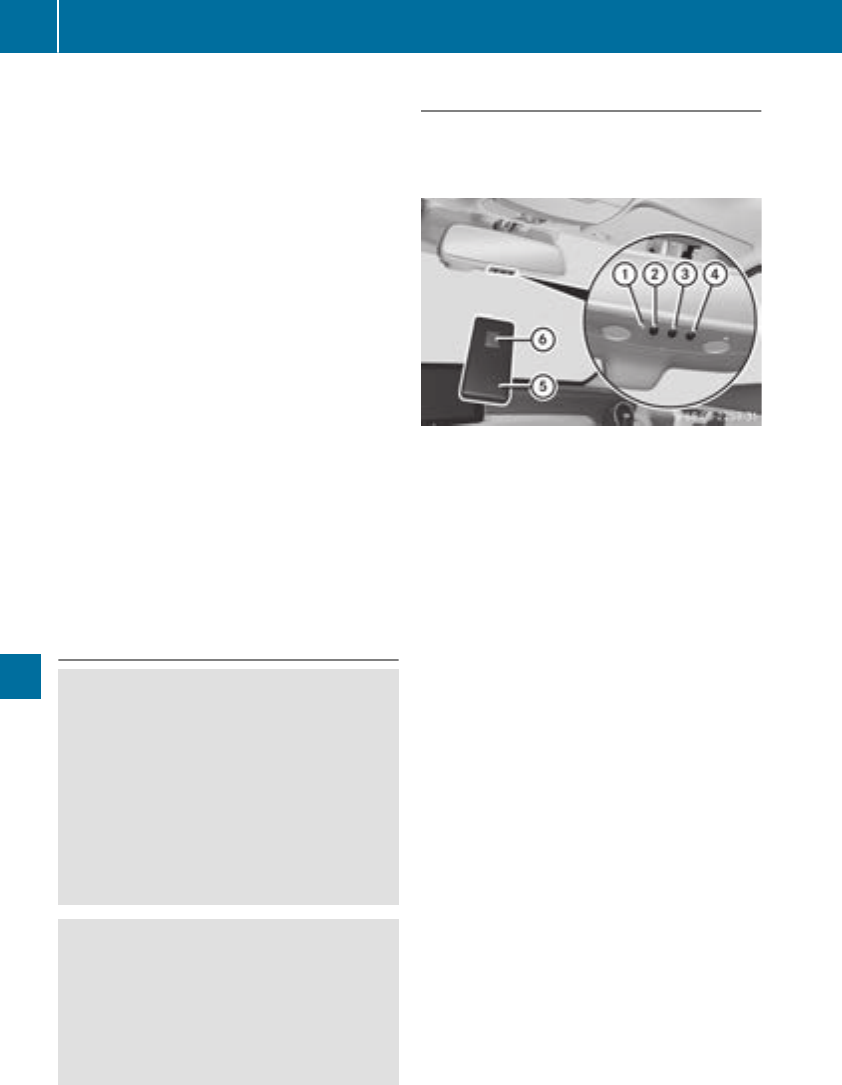
control. Please also read the operating instruc-
tions for the garage door system.
When programming a garage door opener, park
the vehicle outside the garage. Do not run the
engine while programming.
Certain garage door drives are incompatible
with the integrated garage door opener. If you
have difficulty programing the integrated garage
door opener, contact an authorized Mercedes-
Benz Center.
Alternatively, you can call the following tele-
phone assistance services:
RUSA: Mercedes-Benz Customer Assistance
Center at 1-800-FOR-MERCedes
RCanada: Customer Service at
1-800-387-0100
RHomeLink®hotline 1-800-355-3515 (free of
charge)
More information on HomeLink®and/or com-
patible products is also available online at
http://www.homelink.com.
Notes on the declaration of conformity
(Ypage 263).
USA: FCC ID: CB2HMIHL4
Canada: IC: 279B-HMIHL4
Important safety notes
GWARNING
When you operate or program the garage door
with the integrated garage door opener, per-
sons in the range of movement of the garage
door can become trapped or struck by the
garage door. There is a risk of injury.
When using the integrated garage door
opener, always make sure that nobody is
within the range of movement of the garage
door.
GWARNING
Combustion engines emit poisonous exhaust
gases such as carbon monoxide. Inhaling
these exhaust gases leads to poisoning. There
is a risk of fatal injury. Therefore never leave
the engine running in enclosed spaces with-
out sufficient ventilation.
Programming
Programming buttons
Pay attention to the "Important safety notes"
(Ypage 278).
Garage door remote control Ais not included
with the integrated garage door opener.
XTurn the SmartKey to position 2in the igni-
tion lock (Ypage 123).
XSelect one of buttons ;to ?to use to con-
trol the garage door drive.
XTo start programming mode: press and
hold one of buttons ;to ?on the integrated
garage door opener.
The garage door opener is in programming
mode. After a short time, indicator lamp :
lights up yellow.
Indicator lamp :lights up yellow as soon as
button ;,=or ?is stored for the first time.
If the selected button has already been pro-
grammed, indicator lamp :will only light up
yellow after ten seconds have elapsed.
XRelease button ;,=or ?. Indicator
lamp :flashes yellow.
XTo program the remote control: point
garage door remote control Atowards but-
tons ;to ?on the rear-view mirror at a dis-
tance of 2 to 8 in (5 to 20 cm).
XPress and hold button Bon remote control
Auntil indicator lamp :lights up green.
When indicator lamp :lights up green: pro-
gramming is finished.
When indicator lamp :flashes green: pro-
gramming was successful. The rolling code
must be synchronized (Ypage 279).
XRelease button Bon remote control Afor
the garage door drive system.
If indicator lamp :lights up red: repeat the
programing procedure for the corresponding
button on the rear-view mirror. When doing
278 Features
Stowage and features

so, vary the distance between remote control
Aand the rear-view mirror.
The required distance between remote con-
trol Aand the integrated garage door opener
depends on the garage door drive system.
Several attempts might be necessary. You
should test every position for at least
25 seconds before trying another position.
Synchronizing the rolling code
Pay attention to the "Important safety notes"
(Ypage 278).
If the garage door system uses a rolling code,
you will also have to synchronize the garage
door system with the integrated garage door
opener in the rear-view mirror. To do this you will
need to use the programming button on the door
drive control panel. The programming button
may be located in different places depending on
the manufacturer. It is usually located on the
door drive unit on the garage ceiling.
Familiarize yourself with the garage door drive
operating instructions, for example under "Pro-
gramming additional remote controls", before
carrying out the following steps.
Your vehicle must be within reach of the garage
door or gate opener drive. Make sure that nei-
ther your vehicle nor any persons/objects are
present within the sweep of the door or gate.
XTurn the SmartKey to position 2in the igni-
tion lock (Ypage 123).
XGet out of the vehicle.
XPress the programming button on the door
drive unit.
Usually, you now have 30 seconds to initiate
the next step.
XGet into the vehicle.
XPress previously programmed button ;,=
or ?on the integrated garage door opener
repeatedly and in quick succession until the
door closes.
The rolling code synchronization is then com-
plete.
Notes on programming the remote con-
trol
Canadian radio frequency laws require a "break"
(or interruption) of the transmission signals
after broadcasting for a few seconds. Therefore,
these signals may not last long enough for the
integrated garage door opener. The signal is not
recognized during programming. Comparable
with Canadian law, some U.S. garage door open-
ers also feature a "break".
Proceed as follows:
Rif you live in Canada.
Rif you have difficulties programming the
garage door opener (regardless of where you
live) when using the programming steps.
XPress and hold one of buttons ;to ?on the
integrated garage door opener.
After a short time, indicator lamp :lights up
yellow.
XRelease the button.
Indicator lamp :flashes yellow.
XPress button Bof garage door remote con-
trol Afor two seconds, then release it for two
seconds.
XPress button Bof the remote control A
again and hold for two seconds.
XRepeat this sequence on button Bof remote
control Auntil indicator lamp :lights up
green.
When indicator lamp :lights up green: pro-
gramming is finished.
When indicator lamp :flashes green: pro-
gramming was successful. The next step is to
synchronize the rolling code.
XRelease button Bof remote control Aof the
garage door drive.
If indicator lamp :lights up red: repeat the
programming process for the corresponding
button on the rear-view mirror. When doing
so, vary the distance between remote control
Aand the rear-view mirror.
The required distance between remote con-
trol Aand the integrated garage door opener
depends on the garage door drive system.
Several attempts might be necessary. You
should test every position for at least
25 seconds before trying another position.
Problems when programming
If you are experiencing problems programing
the integrated garage door opener on the rear-
view mirror, take note of the following instruc-
tions:
RCheck the transmitter frequency used by
garage door drive remote control Aand
whether it is supported. The transmitter fre-
quency can usually be found on the back of
remote control Afor the garage door drive.
Features 279
Stowage and features
Z
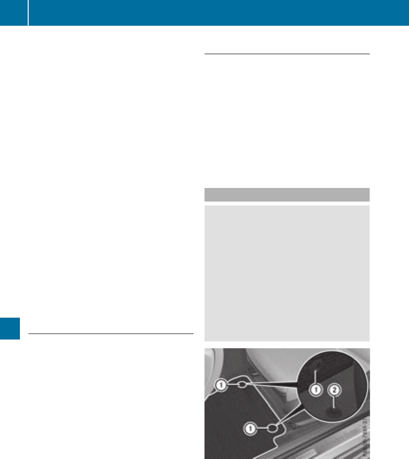
The garage door opener is compatible with
devices which operate in the frequency range
of 280 to 433 MHz.
RReplace the batteries in garage door remote
control A. This increases the likelihood that
garage door remote control Awill transmit a
strong and precise signal to the integrated
garage door opener.
RWhen programming, hold remote control A
at varying distances and angles and from but-
tons ;to ?which you are programming. Try
various angles at a distance between 2and
8 inches (5to 20 cm) or at the same angle but
at varying distances.
RIf another remote control Ais available for
the same garage door drive, repeat the same
programming steps with this remote control
A. Before performing these steps, make sure
that new batteries have been installed in
garage door drive remote control A.
RNote that some remote controls only transmit
for a limited amount of time (the indicator
lamp on the remote control goes out). Press
button Bon remote control Aagain before
transmission ends.
RAlign the antenna cable of the garage door
opener unit. This can improve signal recep-
tion/transmission.
Opening/closing the garage door
After it has been programmed, the integrated
garage door opener performs the function of the
garage door system remote control. Please also
read the operating instructions for the garage
door system.
XTurn the SmartKey to position 2in the igni-
tion lock (Ypage 123).
XPress button ;,=or ?which you pro-
grammed to operate the garage door.
Garage door system with a fixed code: indi-
cator lamp :lights up green.
Garage door system with a rolling code: indi-
cator lamp :flashes green.
The transmitter will transmit a signal as long
as the button is pressed. The transmission is
halted after a maximum of ten seconds and
indicator lamp :lights up yellow.
XPress button ;,=or ?again if necessary.
Clearing the memory
Make sure that you clear the memory of the
integrated garage door opener before selling the
vehicle.
XTurn the SmartKey to position 2in the igni-
tion lock (Ypage 123).
XPress and hold buttons ;and ?.
The indicator lamp initially lights up yellow
and then green.
XRelease buttons ;and ?.
The memory of the integrated garage door
opener in the rear-view mirror is cleared.
Floormats
GWARNING
Objects in the driver's footwell can restrict the
pedal travel or obstruct a depressed pedal.
The operating and road safety of the vehicle is
jeopardized. There is a risk of an accident.
Make sure that all objects in the vehicle are
stowed correctly, and that they cannot enter
the driver's footwell. Install the floormats
securely and as specified in order to ensure
sufficient clearance for the pedals. Do not use
loose floormats and do not place floormats on
top of one another.
XSlide the relevant seat back.
XTo install: place the floormat in the footwell.
XPress studs :onto retainers ;.
XTo remove: pull the floormat off retainers ;.
XRemove the floormat.
280 Features
Stowage and features
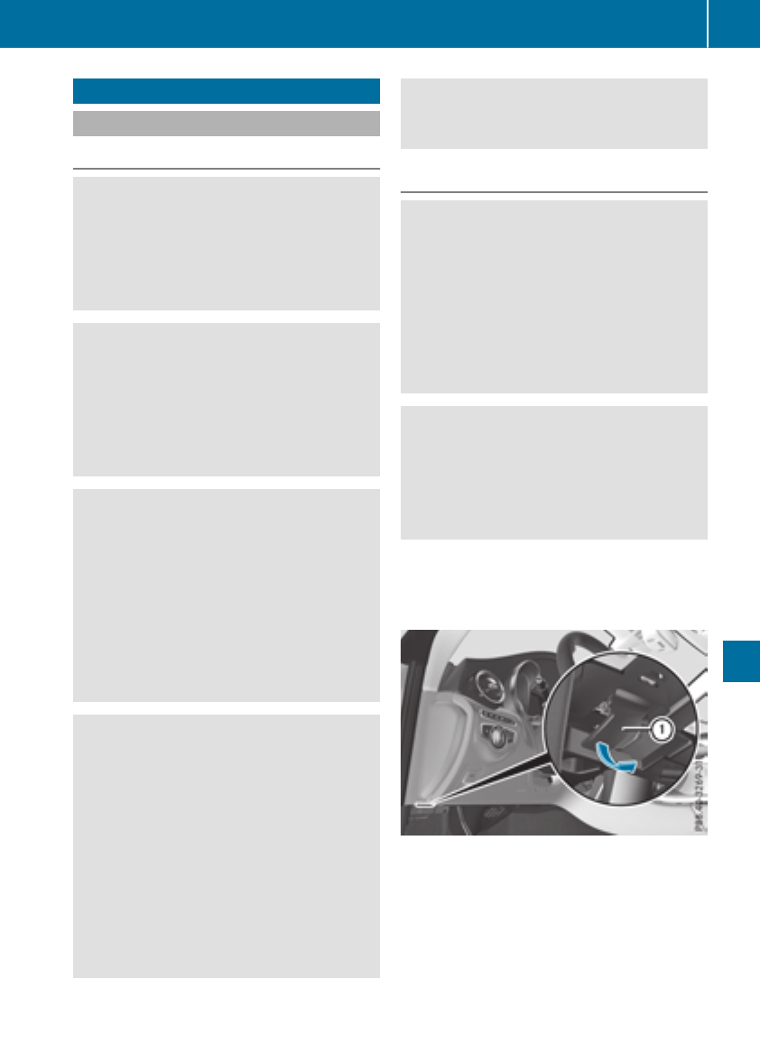
Engine compartment
Hood
Important safety notes
GWARNING
If the hood is unlatched, it may open up when
the vehicle is in motion and block your view.
There is a risk of an accident.
Never unlatch the hood while driving. Before
every trip, ensure that the hood is locked.
GWARNING
When opening and closing the hood, it may
suddenly fall into the closed position. There is
a risk of injury to persons within range of
movement of the hood.
Open and close the hood only when no one is
within its range of movement.
GWARNING
Opening the hood when the engine is over-
heated or when there is a fire in the engine
compartment could expose you to hot gases
or other service products. There is a risk of
injury.
Let an overheated engine cool down before
opening the hood. If there is a fire in the
engine compartment, keep the hood closed
and contact the fire department.
GWARNING
The engine compartment contains moving
components. Certain components, such as
the radiator fan, may continue to run or start
again suddenly when the ignition is off. There
is a risk of injury.
If you need to do any work inside the engine
compartment:
Rswitch off the ignition
Rnever reach into the area where there is a
risk of danger from moving components,
such as the fan rotation area
Rremove jewelry and watches
Rkeep items of clothing and hair, for exam-
ple, away from moving parts
Opening the hood
GWARNING
Certain components in the engine compart-
ment, such as the engine, radiator and parts
of the exhaust system, can become very hot.
Working in the engine compartment poses a
risk of injury.
Where possible, let the engine cool down and
touch only the components described in the
following.
GWARNING
When the hood is open and the windshield
wipers are set in motion, you can be injured by
the wiper linkage. There is a risk of injury.
Always switch off the windshield wipers and
the ignition before opening the hood.
!Make sure that the windshield wipers are
not folded away from the windshield. You
could otherwise damage the windshield wip-
ers or the hood.
XMake sure that the windshield wipers are
turned off.
XPull release lever :on the hood.
The hood is released.
Engine compartment 281
Maintenance and care
Z
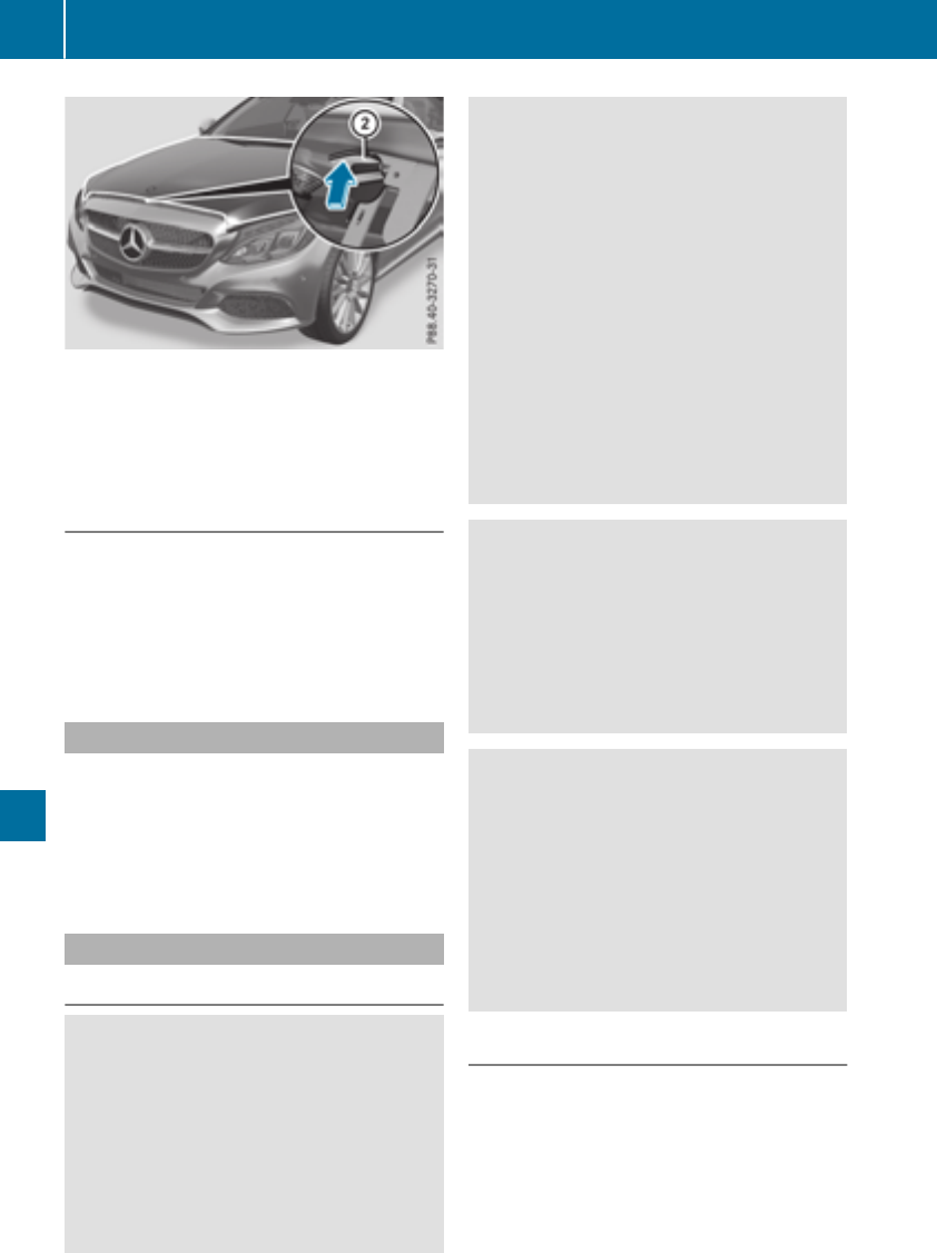
XReachintothegap, pull hoodcatch handle ;
up and lift thehood.
If you lift thehoodby approximately 15 in
(40 cm), thehoodis opened and held open
automatically by thegas-filled strut.
Closing the hood
XLowerthehoodand let it fall from aheight of
approximately 8in (20 cm).
XCheckthat thehoodhas engagedproperly.
If thehoodcan be raised slightly, it is not
properly engaged. Open it again and close it
with a littlemoreforce.
Radiator
Do notcover up theradiator, suchas with a
thermal mat or insectprotection cover.Other-
wise, thevaluesof theEuropean on-board diag-
nostics may be affected. Some of these read-
ingsare requiredby law and mustbe accurateat
all times.
Engine oil
Important safety notes
GWARNING
Certain componentsin theenginecompart-
ment, suchas theengine, radiatorand parts
of theexhaust system, can become veryhot.
Workingin theenginecompartmentposes a
riskof injury.
Wherepossible, let theenginecool down and
touch only thecomponentsdescribedin the
following.
GWARNING
The enginecompartmentcontainsmoving
components. Certain components, suchas
theradiatorfan,may continueto run or start
again suddenly when theignition is off.There
is ariskof injury.
If you need to do any workinside theengine
compartment:
Rswitch off theignition
Rnever reachintothearea wherethere is a
riskof danger from moving components,
suchas thefan rotation area
Rremove jewelryand watches
Rkeep items of clothing and hair,for exam-
ple, away from moving parts
GWARNING
If engineoil comes intocontact withhot com-
ponents in theenginecompartment, it may
ignite. There is ariskof fireand injury.
Makesurethat engineoil is notspilled next to
thefiller neck.Let theenginecool down and
thoroughly clean theengineoil off thecom-
ponents before starting theengine.
GWARNING
Opening thehoodwhen theengineis over-
heated or when there is afirein theengine
compartmentcould exposeyou to hot gases
or other serviceproducts.There is ariskof
injury.
Let an overheatedenginecool down before
opening thehood. If there is afirein the
enginecompartment, keep thehoodclosed
and contact thefiredepartment.
General notes
Dependingon your driving style, thevehicle
consumes up to 0.9US qt (0.8l) of oil per
600miles(1000 km). The oil consumption may
be higher than this when the vehicle is new or if
you frequently drive at high engine speeds.
Depending on the engine, the oil dipstick may be
in a different location.
282 Engine compartment
Maintenance and care
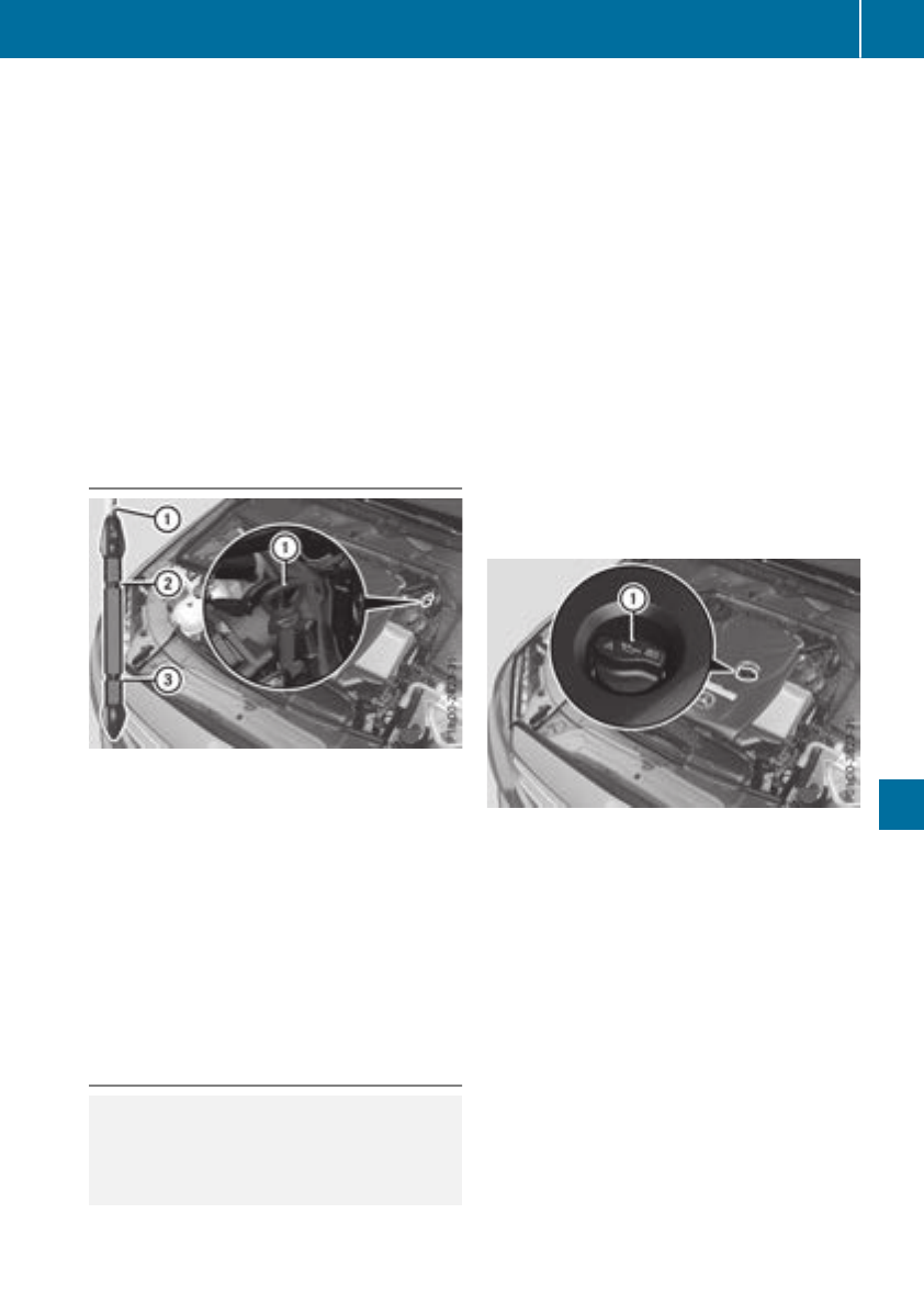
When checking the oil level:
Rpark the vehicle on a level surface
Rthe engine should be switched off for approx-
imately five minutes if the engine is at normal
operating temperature
Rall vehicles (except Mercedes‑AMG C 63
and Mercedes‑AMG C 63 S): if the engine is
not at normal operating temperature, e.g. if
the engine was started only briefly, wait
approximately 30 minutes before carrying out
the measurement
Mercedes‑AMG C 63 and Mercedes‑AMG C
63 S: the oil level must only be checked when
the engine is at normal operating temperature.
Checking the oil level using the oil dip-
stick
Check the oil level with the oil dipstick (exam-
ple)
XPull oil dipstick :out of the dipstick guide
tube.
XWipe off oil dipstick :.
XSlowly slide dipstick :into the guide tube to
the stop, and take it out again after approx-
imately three seconds.
If the level is between MIN mark =and MAX
mark ;, the oil level is correct.
XIf the oil level has dropped to MIN mark =or
below, add 1.1 US qt (1.0 l) of engine oil.
Adding engine oil
HEnvironmental note
When adding oil, take care not to spill any. If
oil enters the soil or waterways, it is harmful to
the environment.
!Use only engine oils and oil filters that are
approved for vehicles with a service system. A
list of the engine oils and oil filters that have
been tested and approved in accordance with
Mercedes-Benz Specifications for Service
Products is available at any authorized
Mercedes-Benz Center.
The following cause engine failure or damage
to the exhaust system:
RUse of engine oils and oil filters that have
not been expressly approved for the service
system
RReplacement of engine oil and oil filter after
the replacement interval specified by the
service system has expired
RUse of engine oil additives
!Do not add too much oil. adding too much
engine oil can result in damage to the engine
or to the catalytic converter. Have excess
engine oil siphoned off.
Add engine oil (example)
XTurn cap :counter-clockwise and remove it.
XAdd engine oil.
If the oil level is at or below the MIN mark on
the oil dipstick, add 1.1 US qt (1.0 l) of engine
oil.
XReplace cap :on the filler neck and tighten
clockwise.
Ensure that the cap locks into place securely.
XCheck the oil level again with the oil dipstick
(Ypage 283).
Further information on engine oil (Ypage 342).
Engine compartment 283
Maintenance and care
Z
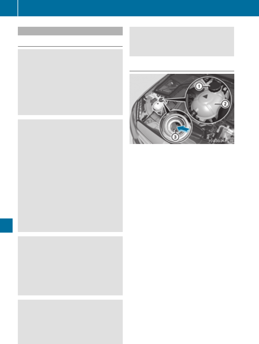
Additional service products
Important safety notes
GWARNING
Certain componentsin theenginecompart-
ment, suchas theengine, radiatorand parts
of theexhaust system, can become veryhot.
Working in theenginecompartmentposes a
riskof injury.
Wherepossible, let theenginecool down and
touch only thecomponentsdescribed in the
following.
GWARNING
The enginecompartmentcontainsmoving
components. Certain components, suchas
theradiatorfan,may continueto run or start
again suddenly when theignition is off.There
is ariskof injury.
If you need to do any workinside theengine
compartment:
Rswitch off theignition
Rnever reachintothearea wherethere is a
riskof danger from moving components,
suchas thefan rotation area
Rremove jewelryand watches
Rkeep items of clothing and hair,for exam-
ple, away from moving parts
GWARNING
The coolingsystem is pressurized, particularly
when themotor is warm.If you open thecap,
you could be scalded if hot coolantsprays out.
There is ariskof injury.
Let theenginecool down before you open the
cap.Wear gloves and eye protection.Slowly
open thecap to relievepressure.
GWARNING
Opening thehoodwhen theengineis over-
heated or when there is afirein theengine
compartmentcould exposeyou to hot gases
or other serviceproducts.There is ariskof
injury.
Let an overheatedenginecool down before
opening thehood. If there is afirein the
enginecompartment, keep thehoodclosed
and contact thefiredepartment.
Checking coolant level
Checking thecoolantlevel (example)
XPark thevehicleon alevel surface.
Only checkthecoolantlevel when thevehicle
is on alevel surfaceand theenginehas cooled
down.
XTurn theSmartKey to position 2in theigni-
tion lock (Ypage 123).
or
XPress theStart/Stopbuttontwice on vehicles
withKEYLESS-GO or theKEYLESS-GO start
function (Ypage 124).
XCheckthecoolanttemperature display in the
instrumentcluster (Ypage 36).
The coolanttemperature mustbe below
158 ‡ (70 †).
XTurn theSmartKey to position gin theigni-
tion lock (Ypage 123).
or
XPress theStart/Stopbuttononce on vehicles
withKEYLESS-GO or theKEYLESS-GO start
function (Ypage 124).
XSlowly turncap :half aturncounter-clock-
wise and allow excess pressureto escape.
XTurn cap :further counter-clockwise and
remove it.
If thecoolantis at thelevel of markerbar =
in thefiller neck when cold, there is enough
coolantin coolantexpansion tank;.
If thecoolantlevel is approximately 0.6in
(1.5cm) abovemarkerbar =in thefiller neck
when warm,there is enough coolantin expan-
sion tank;.
284 Engine compartment
Maintenance and care
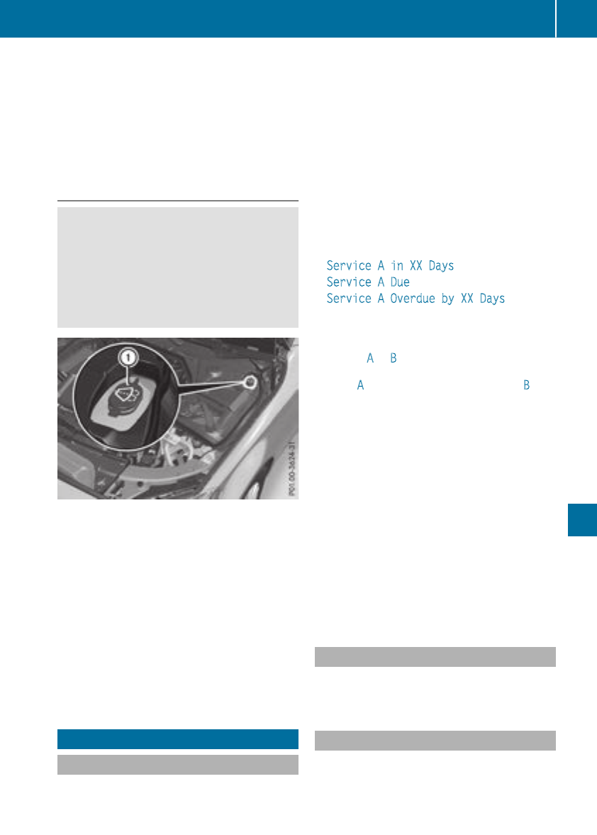
XIf necessary, add coolant that has been tested
and approved by Mercedes-Benz.
XReplace cap :and turn it clockwise as far as
it will go.
For further information on coolant, see
(Ypage 343).
Adding washer fluid to the windshield
washer system
GWARNING
Windshield washer concentrate could ignite if
it comes into contact with hot engine compo-
nents or the exhaust system. There is a risk of
fire and injury.
Make sure that no windshield washer con-
centrate is spilled next to the filler neck.
Example: adding liquid to the windshield
washer system
XTo open: pull cap :upwards by the tab and
open.
XAdd the premixed washer fluid.
XTo close: press cap :onto the filler neck
until it engages.
If the washer fluid level drops below the recom-
mended minimum fluid level of 1.1 US qt (1.0 l),
a message appears in the multifunction display
prompting you to add washer fluid (Ypage 239).
Further information on washer fluid
(Ypage 344).
ASSYST PLUS
Service message
The ASSYST PLUS service interval display
informs you of the next service due date.
Information on the type of service and service
intervals (see the separate Maintenance Book-
let).
Further information can be obtained at a quali-
fied specialist workshop, e.g. an authorized
Mercedes-Benz Center, or at
http://www.mbusa.com (USA only).
iThe ASSYST PLUS service interval display
does not show any information on the engine
oil level. Observe the notes on the engine oil
level (Ypage 282).
The multifunction display shows a service mes-
sage for several seconds, e.g.:
RService A in XX Days
RService A Due
RService A Overdue by XX Days
Depending on the operating conditions of the
vehicle, the remaining time or distance until the
next service due date is displayed.
The letter Aor B, possibly in connection with a
number or another letter, indicates the type of
service. Astands for a minor service and Bfor a
major service.
You can obtain further information from an
authorized Mercedes-Benz Center.
The ASSYST PLUS service interval display does
not take into account any periods of time during
which the battery is disconnected.
Maintaining the time-dependent service sched-
ule:
XNote down the service due date displayed in
the multifunction display before disconnect-
ing the battery.
or
XAfter reconnecting the battery, subtract the
battery disconnection periods from the ser-
vice date shown on the display.
Hiding a service message
XPress the aor %button on the steering
wheel.
Displaying service messages
XSwitch on the ignition.
XUse òon the steering wheel to call up the
list of menus.
ASSYST PLUS 285
Maintenance and care
Z
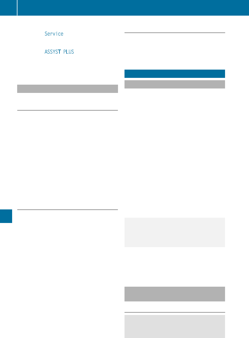
XPress 9or :on the steering wheel to
select the Service menu and confirm with
a.
XPress 9or :on the steering wheel to
select the ASSYST PLUS submenu and con-
firm with a.
The service due date appears in the multi-
function display.
Information about Service
Resetting the ASSYST PLUS service
interval display
!If the ASSYST PLUS service interval display
has been inadvertently reset, this setting can
be corrected at a qualified specialist work-
shop.
Have service work carried out as described in
the Maintenance Booklet. This may otherwise
lead to increased wear and damage to the
major assemblies or the vehicle.
A qualified specialist workshop, e.g. an author-
ized Mercedes-Benz Center, will reset the
ASSYST PLUS service interval display after the
service work has been carried out. You can also
obtain further information on maintenance
work, for example.
Special service requirements
The specified maintenance interval takes only
the normal operation of the vehicle into
account. Under arduous operating conditions or
increased load on the vehicle, maintenance
work must be carried out more frequently, for
example:
Rregular city driving with frequent intermediate
stops
Rif the vehicle is primarily used to travel short
distances
Ruse in mountainous terrain or on poor road
surfaces
Rif the engine is often left idling for long periods
Under these or similar conditions, have, for
example, the air filter, engine oil and oil filter
replaced or changed more frequently. Under
arduous operating conditions, the tires must be
checked more often. Further information can be
obtained at a qualified specialist workshop, e.g.
an authorized Mercedes-Benz Center.
Driving abroad
An extensive Mercedes-Benz Service network is
also available in other countries. You can obtain
further information from any authorized
Mercedes-Benz Center.
Care
General notes
!For cleaning your vehicle, do not use any of
the following:
Rdry, rough or hard cloths
Rabrasive cleaning agents
Rsolvents
Rcleaning agents containing solvents
Do not scrub.
Do not touch the surfaces or protective films
with hard objects, e.g. a ring or ice scraper.
You could otherwise scratch or damage the
surfaces and protective film.
!Do not park your vehicle for a long period of
time directly after cleaning, particularly after
cleaning the wheel rim with wheel cleaner.
Wheel cleaner can lead to the increased cor-
rosion of the brake discs and pads. Therefore,
drive for a few minutes after cleaning. By
heating up the brakes, the brake discs and
pads dry. The vehicle can then be parked for a
long period of time.
HEnvironmental note
Dispose of empty packaging and cleaning
cloths in an environmentally responsible man-
ner.
Regular care of your vehicle is a condition for
retaining the quality in the long term.
Use care products and cleaning agents recom-
mended and approved by Mercedes-Benz.
Washing the vehicle and cleaning the
paintwork
Automatic car wash
GWARNING
Braking efficiency is reduced after washing
the vehicle. There is a risk of an accident.
286 Care
Maintenance and care

After the vehicle has been washed, brake
carefully while paying attention to the traffic
conditions until full braking power is restored.
!When Active Brake Assist, Distance Pilot
DISTRONIC or the HOLD function is activated,
the vehicle brakes automatically in certain
situations.
To avoid damage to the vehicle, deactivate
these systems in the following or similar sit-
uations:
Rwhen towing the vehicle
Rin the car wash
!Preferably use automatic car washes with
adjustable high-pressure pre-cleaning. This
corresponds with the specification for the
Cabriolet program. In car washes that use
high water pressures, there is a risk that a
small amount of water may leak into the vehi-
cle.
!Make sure that the vehicle is not subse-
quently treated with hot wax.
!Always remove the SmartKey before wash-
ing the vehicle in a car wash. This ensures that
the wind deflector on the windshield is retrac-
ted. The wind deflector may otherwise be
damaged.
!Never clean your vehicle in a Touchless
Automatic Car Wash as these use special
cleaning agents. These cleaning agents can
damage the paintwork or plastic parts.
!Make sure that:
Rthe side windows and soft top are closed
completely
Rthe blower is switched off
Rthe windshield wiper switch is in position 0
Rthe 360° camera or the rear view camera is
deactivated
The vehicle may otherwise be damaged.
!Make sure that the automatic transmission
is in neutral position iwhen washing your
vehicle in a tow-through car wash. The vehicle
may otherwise be damaged.
ROperating with the SmartKey:
Do not remove the SmartKey from the igni-
tion lock. Do not open the driver's door
when the engine is switched off or at very
low speeds. Otherwise, when in transmis-
sion position hor k, the automatic
transmission will automatically switch to
park position jand block the wheels.
ROperating with the Start/Stop button:
Do not open the driver's door when the
engine is switched off or at very low
speeds. Otherwise, when in transmission
position hor k, the automatic transmis-
sion will automatically switch to park posi-
tion jand block the wheels.
Observe the following to make sure that the
automatic transmission stays in neutral i:
Operating with the SmartKey and Start/Stop
button:
XMake sure that the ignition is switched on.
XMake sure that the vehicle is stationary.
XDepress and hold the brake pedal.
Operating with the Start/Stop button only:
XEngage park position j.
XRelease the brake pedal.
XRemove Start/Stop button from ignition lock
(Ypage 124).
XInsert the SmartKey into the ignition lock.
XSwitch on the ignition.
XDepress and hold the brake pedal.
Operating with the SmartKey and Start/Stop
button:
XEngage neutral i.
XRelease the brake pedal.
XRelease the electric parking brake, if neces-
sary.
XSwitch off the ignition and leave the SmartKey
in the ignition lock.
You can wash the vehicle in an automatic car
wash from the very start.
If the vehicle is very dirty, pre-wash it before
cleaning it in an automatic car wash.
After using an automatic car wash, wipe off wax
from the windshield and the wiper blades. This
will prevent smears and reduce wiping noises
caused by residue on the windshield.
Washing by hand
In some countries, washing by hand is only
allowed at specially equipped washing bays.
Observe the legal requirements in each country.
Care 287
Maintenance and care
Z

XDo not use hot water and do not wash the
vehicle in direct sunlight.
XUse a soft sponge to clean.
XUse a mild cleaning agent, such as a car
shampoo approved by Mercedes-Benz.
XThoroughly hose down the vehicle with a gen-
tle jet of water.
XDo not point the water jet directly towards the
air inlet.
XUse plenty of water and rinse out the sponge
frequently.
XRinse the vehicle with clean water and dry
thoroughly with a chamois.
XDo not let the cleaning agent dry on the paint-
work.
Carefully remove all deposits of road salt as
soon as possible when driving in winter.
Power washers
GWARNING
The water jet from a circular jet nozzle (dirt
blasters) can cause invisible exterior damage
to the tires or chassis components. Compo-
nents damaged in this way may fail unexpect-
edly. There is a risk of an accident.
Do not use power washers with circular jet
nozzles to clean the vehicle. Have damaged
tires or chassis components replaced imme-
diately.
!Always maintain a distance of at least
11.8 in (30 cm) between the vehicle and the
power washer nozzle. Information about the
correct distance is available from the equip-
ment manufacturer.
Move the power washer nozzle around when
cleaning your vehicle.
Do not aim directly at any of the following:
RTires
RDoor gaps, joints etc.
RSoft top
RWind deflector net
RElectrical components
RBattery
RConnectors
RLamps
RSeals
RTrim elements
RVentilation slots
Damaged seals or electrical components can
lead to leaks or failures.
!Vehicles with decorative film: parts of your
vehicle are covered with a decorative film.
Maintain a distance of at least 27.5 in (70 cm)
between the parts of the vehicle covered with
the film and the nozzle of the high pressure
cleaner.
Information about the correct distance is
available from the equipment manufacturer.
Move the power washer nozzle around when
cleaning your vehicle.
Cleaning the paintwork
!Do not affix:
Rstickers
Rfilms
Rmagnetic plates or similar items
to painted surfaces. You could otherwise
damage the paintwork.
Scratches, corrosive deposits, areas affected by
corrosion and damage caused by inadequate
care cannot always be completely repaired. In
such cases, visit a qualified specialist workshop.
XRemove dirt immediately, where possible,
while avoiding rubbing too hard.
XSoak insect remains with insect remover and
rinse off the treated areas afterwards.
XSoak bird droppings with water and rinse off
the treated areas afterwards.
XRemove coolant, brake fluid, tree resin, oils,
fuels and greases by rubbing gently with a
cloth soaked in petroleum ether or lighter
fluid.
XUse tar remover to remove tar stains.
XUse silicone remover to remove wax.
If water no longer forms "beads" on the paint
surface, use the paint care products recommen-
ded and approved by Mercedes-Benz. This is the
case approximately every three to five months,
depending on the climate conditions and the
care product used.
The cleaning product Paint Cleaner, which has
been recommended and approved by
Mercedes-Benz, should be used when dirt has
penetrated the paint surface.
288 Care
Maintenance and care

Also use Paint Cleaner on paint that has become
dull.
Do not use these care products in the sun or on
the hood while the hood is hot.
XUse a suitable touch-up stick, e.g. MB Touch-
Up Stick, to repair slight damage to the paint-
work quickly and provisionally.
Matte finish care
!Never polish the vehicle or the light alloy
wheels. Polishing causes the finish to shine.
!The following may cause the paint to
become shiny and thus reduce the matte
effect:
Rstrong rubbing of the paintwork with
unsuitable materials
Rfrequent use of automatic car washes
Rwashing the vehicle in direct sunlight
!Never use paint cleaner, buffing or polishing
products, or gloss preserver, e.g. wax, for the
purpose of paintwork care. These products
are only suitable for high-gloss surfaces. Their
use on vehicles with matte paintwork leads to
considerable surface damage or, more spe-
cifically, to shiny, spotted areas.
Always have paintwork repairs carried out at a
qualified specialist workshop.
!Do not use wash programs with a hot wax
treatment under any circumstances.
Observe these notes if your vehicle has a clear
matte finish. This will help you to avoid damage
to the paintwork due to incorrect treatment.
These notes also apply to light alloy wheels with
a clear matte finish.
The vehicle should preferably be washed by
hand using a soft sponge, car shampoo and
plenty of water.
Use only insect remover and car shampoo from
the range of approved Mercedes-Benz care
products.
Cleaning the vehicle parts
Cleaning the soft top
!Never use any of the following to clean the
soft top:
Rgasoline
Rthinner
Rtar or stain remover
Rother organic solvents
!Remove bird droppings immediately as they
are corrosive and, therefore, can make the
soft-top fabric leak. Do not use high-pressure
cleaning equipment to clean the vehicle. Do
not use sharp-edged equipment to remove ice
and snow.
XLight soiling: you can clean the soft top while
it is dry or rinse it with clean water.
XNormal to heavy soiling: clean the soft top
with a brush and clear water. Clean stains and
other dirt with a brush and soft top cleaning
agents that have been recommended and
approved by Mercedes-Benz. Always brush
from front to back, following the grain of the
fabric.
Frequent cleaning reduces the soft top's resist-
ance to dirt.
To restore this resistance to dirt, clean the soft
top using soft top cleaning agents that have
been recommended and approved by
Mercedes-Benz.
Incorrect cleaning and care, as well as aging,
can cause the soft-top seams to leak. Have the
soft-top seams sealed at a qualified specialist
workshop, e.g. at an authorized Mercedes-Benz
Center.
Cover the soft top appropriately if you plan to
leave the vehicle outside for a long period of
time.
Cleaning AIRCAP
Cleaning the wind deflector
!Do not use high-pressure cleaning equip-
ment to clean the net.
Clean the wind deflector on the windshield with
the soft top open.
Care 289
Maintenance and care
Z
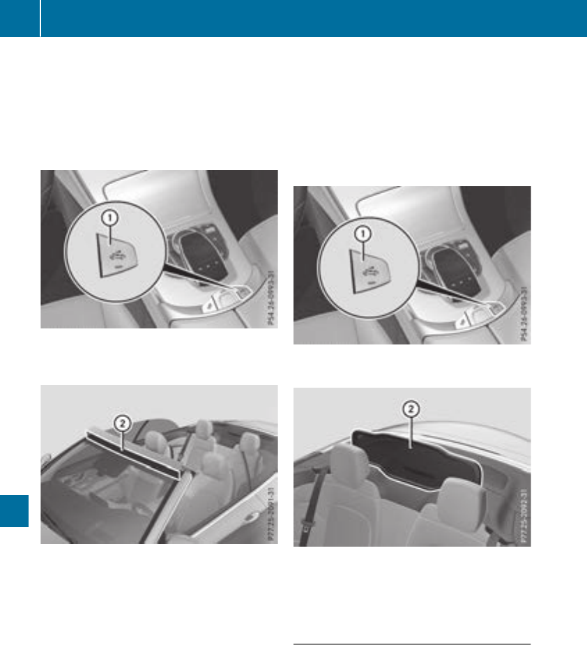
XApply the electric parking brake manually.
XTurn the SmartKey to position 2in the igni-
tion lock (Ypage 123).
or
XPress the Start/Stop button twice on vehicles
with KEYLESS-GO or the KEYLESS-GO start
function (Ypage 124).
XPress AIRCAP button :.
The wind deflector between the windshield
and the soft top is extended.
XClean net ;of the wind deflector with a soft
brush or a moist cloth.
If there is a large amount of dirt on the net:
Rclean with the care products and cleaning
agents recommended and approved by
Mercedes-Benz
Rrinse with clean water
Cleaning the AIRCAP wind screen
Clean the AIRCAP wind screen with the soft top
open.
XApply the electric parking brake manually.
XTurn the SmartKey to position 2in the igni-
tion lock (Ypage 123).
or
XPress the Start/Stop button twice on vehicles
with KEYLESS-GO or the KEYLESS-GO start
function (Ypage 124).
XOpen the soft top (Ypage 89).
XPress AIRCAP button :.
The AIRCAP wind screen moves up.
XClean net ;of the AIRCAP wind screen with
a damp cloth. Use only the care products and
cleaning agents recommended and approved
by Mercedes-Benz for this.
Cleaning the folding wind screen
!Do not use high-pressure cleaning equip-
ment to clean the net.
The folding wind screen is stowed in a bag. The
bag is secured with a securing strap to the
through-loading facility behind the rear seat.
Observe the information on the correct installa-
tion of the folding wind screen (Ypage 92).
XClean the net of the folding wind screen with
a damp cloth together with the care products
290 Care
Maintenance and care

and cleaning agents recommended and
approved by Mercedes-Benz.
Cleaning the wheels
GWARNING
The water jet from a circular jet nozzle (dirt
blasters) can cause invisible exterior damage
to the tires or chassis components. Compo-
nents damaged in this way may fail unexpect-
edly. There is a risk of an accident.
Do not use power washers with circular jet
nozzles to clean the vehicle. Have damaged
tires or chassis components replaced imme-
diately.
!Do not use acidic wheel cleaning products
to remove brake dust. This could damage
wheel bolts and brake components.
!Do not park your vehicle for a long period of
time directly after cleaning, particularly after
cleaning the wheel rim with wheel cleaner.
Wheel cleaner can lead to the increased cor-
rosion of the brake discs and pads. Therefore,
drive for a few minutes after cleaning. By
heating up the brakes, the brake discs and
pads dry. The vehicle can then be parked for a
long period of time.
Cleaning the windows
GWARNING
You could become trapped by the windshield
wipers if they start moving while cleaning the
windshield or wiper blades. There is a risk of
injury.
Always switch off the windshield wipers and
the ignition before cleaning the windshield or
wiper blades.
!Do not use dry cloths, abrasive products,
solvents or cleaning agents containing sol-
vents to clean the inside of the windows. Do
not touch the insides of the windows with
hard objects, e.g. an ice scraper or ring. There
is otherwise a risk of damaging the windows.
!Clean the water drainage channels of the
windshield and the rear window at regular
intervals. Deposits such as leaves, petals and
pollen may under certain circumstances pre-
vent water from draining away. This can lead
to corrosion damage and damage to elec-
tronic components.
XClean the inside and outside of the windows
with a damp cloth and a cleaning product that
is recommended and approved by Mercedes-
Benz.
Cleaning wiper blades
GWARNING
You could become trapped by the windshield
wipers if they start moving while cleaning the
windshield or wiper blades. There is a risk of
injury.
Always switch off the windshield wipers and
the ignition before cleaning the windshield or
wiper blades.
!Do not pull the wiper blade. Otherwise, the
wiper blade could be damaged.
!Do not clean wiper blades too often and do
not rub them too hard. Otherwise, the graph-
ite coating could be damaged. This could
cause wiper noise.
!Hold the wiper arm securely when folding
back. The windshield could be damaged if the
wiper arm smacks against it suddenly.
XFold the windshield wiper arms away from the
windshield (Ypage 112).
XCarefully clean the wiper blades with a damp
cloth.
XFold the windshield wiper arms back again
before switching on the ignition.
Cleaning the exterior lighting
!Only use cleaning agents or cleaning cloths
which are suitable for plastic light lenses.
Unsuitable cleaning agents or cleaning cloths
could scratch or damage the plastic light len-
ses.
XClean the plastic lenses of the exterior light-
ing using a wet sponge and a mild cleaning
agent, e.g. Mercedes-Benz car shampoo or
cleaning cloths.
Care 291
Maintenance and care
Z
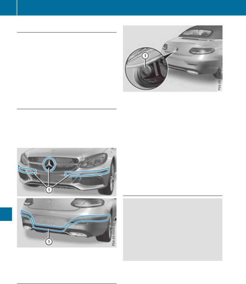
Cleaning the mirror turn signals
!Only use cleaning agents or cleaning cloths
that are suitable for plastic lenses. Unsuitable
cleaning agents or cleaning cloths could
scratch or damage the plastic lenses of the
mirror turn signals.
XClean the plastic lenses of the mirror turn sig-
nals in the exterior mirror housing using a wet
sponge and mild cleaning agent, e.g.
Mercedes-Benz car shampoo or cleaning
cloths.
Cleaning the sensors
!If you clean the sensors with a power
washer, make sure that you keep a distance
of at least 11.8 in (30 cm)betweenthe vehicle
and the power washer nozzle. Information
about the correct distance is available from
the equipment manufacturer.
XClean sensors :of the driving systems with
water, car shampoo and a soft cloth.
Cleaning the rear view camera and 360°
camera
!Do not clean the camera lens and the area
around the rear view camera or 360° camera
with a power washer.
XMake sure that the vehicle is stationary.
XTurn the SmartKey to position 1or 2in the
ignition lock (Ypage 123).
or
XPress the Start/Stop button once or twice on
vehicles with KEYLESS-GO or the KEYLESS-
GO start function (Ypage 124).
XOpen the camera cover for cleaning via the
multimedia system (see Digital Operator's
Manual).
XTo clean the camera: use clean water and a
soft cloth to clean camera lens :.
When you switch off the ignition, the camera
cover closes automatically.
Cleaning the exhaust pipes
GWARNING
The exhaust tail pipe and tail pipe trim can
become very hot. If you come into contact
with these parts of the vehicle, you could burn
yourself. There is a risk of injury.
Always be particularly careful around the
exhaust tail pipe and the tail pipe trim. Allow
these components to cool down before touch-
ing them.
!Do not clean the exhaust pipe with acid-
based cleaning agents, such as bathroom
cleaner or wheel cleaner.
!Mercedes‑AMG C 63 and Mercedes‑AMG C
63 S with black exhaust pipes: Black chrome
trims must not be polished with a chrome
polish as this will cause them to lose their
black shine. For optimal care, the faceplates
should be rubbed with a lightly oiled cloth
after every car wash. Commercially available
engine and care oils are suitable for this.
292 Care
Maintenance and care

For heavier soiling, you can apply a fine paint-
work polish with a microfiber cloth. Remove
the excess polish residue after polishing.
Impurities combined with the effects of road grit
and corrosive environmental factors may cause
flash rust to form on the surface. You can
restore the original shine of the exhaust pipe by
cleaning it regularly, especially in winter and
after washing.
XClean the exhaust pipe with a care product
tested and approved by Mercedes-Benz.
Interior care
Cleaning the display
!For cleaning, do not use any of the following:
Ralcohol-based thinner or gasoline
Rabrasive cleaning agents
Rcommercially-available household cleaning
agents
These may damage the display surface. Do
not put pressure on the display surface when
cleaning. This could lead to irreparable dam-
age to the display.
XBefore cleaning the display, make sure that it
is switched off and has cooled down.
XClean the display surface using a commer-
cially available microfiber cloth and TFT/LCD
display cleaner.
XDry the display surface using a dry microfiber
cloth.
Cleaning the plastic trim
GWARNING
Care products and cleaning agents containing
solvents cause surfaces in the cockpit to
become porous. As a result, plastic parts may
come loose in the event of air bag deploy-
ment. There is a risk of injury.
Do not use any care products and cleaning
agents to clean the cockpit.
!Never attach the following to plastic surfa-
ces:
Rstickers
Rfilms
Rperfume oil container or similar
You could otherwise damage the plastic.
!Do not allow cosmetics, insect repellent or
sunscreen to come into contact with the plas-
tic trim. This maintains the high-quality look of
the surfaces.
XWipe the plastic trim with a damp, lint-free
cloth, e.g. a microfiber cloth.
XHeavy soiling: use care and cleaning prod-
ucts recommended and approved by
Mercedes-Benz.
The surface may change color temporarily.
Wait until the surface is dry again.
Cleaning the steering wheel and selec-
tor lever
XThoroughly wipe with a damp cloth or use
leather care agents that have been recom-
mended and approved by Mercedes-Benz.
Cleaning genuine wood and trim ele-
ments
!Do not use solvent-based cleaning agents
such as tar remover, wheel cleaners, polishes
or waxes. There is otherwise a risk of damag-
ing the surface.
!Do not use chrome polish on trim pieces.
The trim pieces have a chrome look but are
mostly made of anodized aluminum and can
lose their shine if chrome polish is used. Use
a damp, lint-free cloth instead when cleaning
the trim pieces.
If the chrome-plated trim pieces are very
dirty, you can use a chrome polish. If you are
unsure as to whether the trim pieces are
chrome-plated or not, consult an authorized
Mercedes-Benz Center.
Care 293
Maintenance and care
Z

XWipe the wooden trim and trim pieces with a
damp, lint-free cloth, e.g. a microfiber cloth.
XTrim elements with piano black finish:
wipe with a soft, damp cotton cloth. Use clean
water.
XHeavy soiling: use care and cleaning prod-
ucts recommended and approved by
Mercedes-Benz.
Cleaning the seat covers
General notes
!Do not use a microfiber cloth to clean covers
made out of real leather, artificial leather or
DINAMICA. If used often, these can damage
the cover.
Note that regular care is essential to ensure that
the appearance and comfort of the covers is
retained over time.
Genuine leather seat covers
!To retain the natural appearance of the
leather, observe the following cleaning
instructions:
RClean genuine leather covers carefully with
a damp cloth and then wipe the covers
down with a dry cloth.
RMake sure that the leather does not
become soaked. It may otherwise become
rough and cracked.
ROnly use leather care agents that have
been tested and approved by Mercedes-
Benz. You can obtain these from a qualified
specialist workshop.
Leather is a natural product.
It exhibits natural surface characteristics, for
example:
Rdifferences in the texture
Rmarks caused by growth and injury
Rslight nuances of color
These are characteristics of leather and not
material defects.
Seat covers of other materials
!Observe the following when cleaning:
Rclean artificial leather covers with a cloth
moistened with a solution containing 1%
detergent (e.g. dish washing liquid).
Rclean cloth covers with a microfiber cloth
moistened with a solution containing 1%
detergent (e.g. dish washing liquid). Rub
carefully and always wipe entire seat sec-
tions to avoid leaving visible lines. Leave
the seat to dry afterwards. Cleaning results
depend on the type of dirt and how long it
has been there.
Rclean DINAMICA covers with a damp cloth.
Make sure that you wipe entire seat sec-
tions to avoid leaving visible lines.
Cleaning the seat belts
GWARNING
Seat belts can become severely weakened if
bleached or dyed. This could cause the seat
belts to tear or fail, for instance, in the event of
an accident. This poses an increased risk of
injury or fatal injury.
Never bleach or dye the seat belts.
!Do not clean the seat belts using chemical
cleaning agents. Do not dry the seat belts by
heating at temperatures above 176 ‡(80 †)
or in direct sunlight.
XUse clean, lukewarm water and soap solution.
Cleaning the headliner and carpets
XHeadliner: if it is very dirty, use a soft brush or
dry shampoo.
XCarpets: use the carpet and textile cleaning
agents recommended and approved by
Mercedes-Benz.
294 Care
Maintenance and care
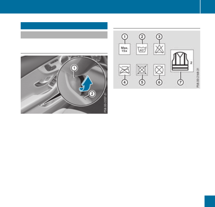
Where will I find...?
Reflective safety jacket
Removing/replacing the reflective
safety jacket
The reflective safety jackets are located in the
safety jacket compartments in the stowage
compartments.
XTo remove: pull out safety jacket bag :with
the reflective safety jacket by loop ;.
XOpen safety jacket bag :and pull out the
reflective safety jacket.
XTo stow: fold the reflective safety jacket, roll
it up and stow it in safety jacket bag :.
XSlide safety jacket bag :along the lower
edge of the armrest into the safety jacket
compartment. Meanwhile, ensure that
loop ;hangs out well within reach.
XObserve the legal requirements in each indi-
vidual country for the use of safety jackets.
iRemove a new reflective safety jacket from
its packaging material before sliding it into
the safety jacket compartment. The packag-
ing material may otherwise cause it to slip out
or make removing it difficult.
Information on reflective safety jackets
:Maximum number of washes
;Maximum wash temperature
=Do not bleach
?Do not iron
ADo not use a laundry dryer
BDo not dry-clean
CThis is a class 2 jacket
RThe safety jackets only meet the require-
ments defined by the legal standard:
-if the correct size is used
-if the reflective safety jackets are correctly
fastened
RBefore use, ensure that the reflective safety
jackets are clean and intact. The special prop-
erties may otherwise be compromised.
RThe reflective safety jackets should be stored
in their original packaging in a dry place away
from sources of heat and light.
RThe maximum number of washes specified is
not the only factor influencing the life span of
the reflective safety jackets. Their life span
also depends on use, care, storage, etc.
RThe reflective safety jackets should be dis-
posed of and replaced with new ones:
-after 15 washes, and/or
-if the reflective strips have become
scratched, and/or
-if the backing material and/or reflective
strips have become soiled and cannot be
cleaned off, and/or
-if the fluorescence has faded, for example
due to the effects of sunlight
RDispose of reflective safety jackets in an envi-
ronmentally responsible manner. To do so,
contact your local waste disposal company.
Where will I find...? 295
Breakdown assistance
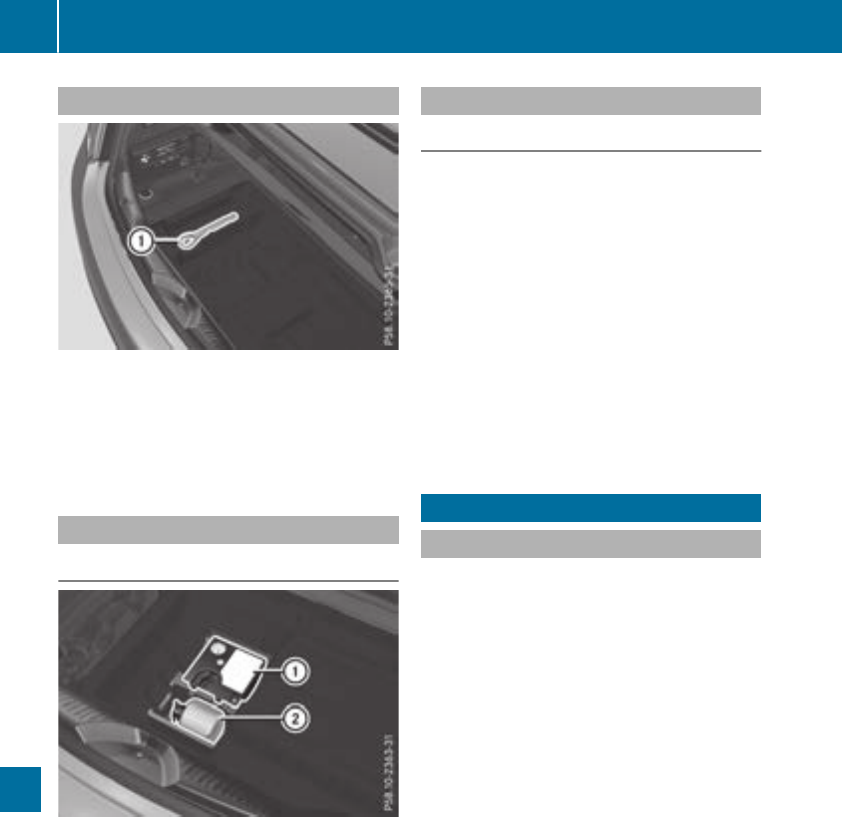
Towing eye
The towing eye is located in the stowage well
under the trunk floor.
XTo remove: open the trunk lid.
XLift the trunk floor up (Ypage 267).
XRemove towing eye :.
Vehicles with a TIREFIT kit
Removing the TIREFIT kit
:Tire inflation compressor
;Tire sealant filler bottle
The TIREFIT kit is located in the stowage well
under the trunk floor.
XTo remove: open the trunk lid.
XLift the trunk floor up (Ypage 267).
XUse the TIREFIT kit (Ypage 298).
Vehicles with a tire-change tool kit
General notes
Apart from certain country-specific variations,
the vehicles are not equipped with a tire-change
tool kit.
Some tools for changing a wheel are specific to
the vehicle. For more information on which tire
changing tools are required and approved to
perform a wheel change on your vehicle, consult
a qualified specialist workshop.
Necessary tire-changing tools can include, for
example:
RJack
RWheel chock
RLug wrench
RAlignment bolt
Flat tire
Preparing the vehicle
Your vehicle may be equipped with:
RMOExtended tires (tires with run-flat proper-
ties) (Ypage 297)
Vehicle preparation is not necessary on vehi-
cles with MOExtended tires
Ra TIREFIT kit (Ypage 296)
Vehicles equipped with MOExtended tires are
not equipped with a TIREFIT kit at the factory. It
is therefore recommended that you additionally
equip your vehicle with a TIREFIT kit if you mount
tires that do not feature run-flat properties, e.g.
winter tires. A TIREFIT kit may be obtained from
a qualified specialist workshop.
Vehicles with an mbrace system (USA only) that
are not equipped with a TIREFIT kit: in the event
of a flat tire, contact the Customer Assistance
Center of the mbrace emergency call system
(Ypage 272).
Information on changing and mounting wheels
(Ypage 332).
XStop the vehicle on solid, non-slippery and
level ground, as far away as possible from
traffic.
XSwitch on the hazard warning lamps.
XSecure the vehicle against rolling away
(Ypage 143).
296 Flat tire
Breakdown assistance

XIf possible, bring the front wheels into the
straight-ahead position.
XSwitch off the engine.
XRemove the SmartKey from the ignition lock.
or, in vehicles with KEYLESS-GO start-function
or KEYLESS‑GO
XOpen the driver's door.
The vehicle electronics are now in position
u. which is the same as the SmartKey having
been removed.
XRemove the Start/Stop button from the igni-
tion lock (Ypage 124).
XMake sure that the engine cannot be started
via your smartphone (Ypage 126).
XMake sure that the passengers are not endan-
gered as they do so. Make sure that no one is
near the danger area while a wheel is being
changed. Anyone who is not directly assisting
in the wheel change should, for example,
stand behind the barrier.
XGet out of the vehicle. Pay attention to traffic
conditions when doing so.
XClose the driver's door.
Vehicles with MOExtended tires (tires
with run-flat characteristics)
General notes
With MOExtended tires (tires with run flat char-
acteristics), you can continue to drive your vehi-
cle even if there is a total loss of pressure in one
or more tires. The affected tire must not show
any clearly visible damage.
You can recognize a MOExtended tire by the
MOExtended marking which appears on the
sidewall of the tire. You will find this marking
next to the tire size designation, the load-bear-
ing capacity and the speed index (Ypage 326).
MOExtended tires may only be used in conjunc-
tion with an active tire pressure loss warning
system or with an active tire pressure monitor.
If a pressure loss warning message appears
in the multifunction display:
Robserve the instructions in the display mes-
sages (Ypage 234)
Rcheck the tire for damage
Rif driving on, observe the following notes
The driving distance possible in run-flat mode is
approximately 50 miles (80 km) when the vehi-
cle is partially laden. When the vehicle is fully
laden it is approximately 19 miles (30 km).
In addition to the vehicle load, the driving dis-
tance possible depends upon:
Rvehicle speed
Rroad condition
Routside temperature
The driving distance possible in run-flat mode
may be reduced by extreme driving conditions
or maneuvers, or it can be increased through a
moderate style of driving.
The driving distance possible in run-flat mode is
counted from the moment the tire pressure loss
warning appears in the multifunction display.
You must not exceed a maximum permissible
speed of 50 mph (80 km/h).
When replacing one or all tires, please observe
the following specifications for your vehicle's
tires:
Rsize
Rthe type and
Rthe "MOExtended" marking
If a tire has gone flat and cannot be replaced
with a MOExtended tire, a standard tire may be
used as a temporary measure. Make sure that
you use the proper size and type (summer or
winter tires).
Vehicles equipped with MOExtended tires are
not equipped with a TIREFIT kit at the factory. It
is therefore recommended that you additionally
equip your vehicle with a TIREFIT kit if you mount
tires that do not feature run-flat properties, e.g.
winter tires. A TIREFIT kit may be obtained from
a qualified specialist workshop.
Important safety notes
GWARNING
When driving in emergency mode, the driving
characteristics deteriorate, e.g. when corner-
ing, accelerating quickly and when braking.
There is a risk of an accident.
Do not exceed the stated maximum speed.
Avoid abrupt steering and driving maneuvers,
and driving over obstacles (curbs, potholes,
off-road). This applies in particular to a laden
vehicle.
Flat tire 297
Breakdown assistance
Z

Stop driving in emergency mode if:
Ryou hear banging noises.
Rthe vehicle starts to shake.
Ryou see smoke and smell rubber.
RESP®is intervening constantly.
Rthere are tears in the sidewalls of the tire.
After driving in emergency mode, have the
wheel rims checked at a qualified specialist
workshop with regard to their further use. The
defective tire must be replaced in every case.
TIREFIT kit
Important safety notes
TIREFIT is a tire sealant.
You can use TIREFIT to seal punctures of up to
0.16 in (4 mm), particularly those in the tire
tread. You can use TIREFIT at outside tempera-
tures down to Ò4‡(Ò20 †).
GWARNING
In the following situations, the tire sealant is
unable to provide sufficient breakdown assis-
tance, as it is unable to seal the tire properly:
Rthere are cuts or punctures in the tire larger
than those mentioned above.
Rthe wheel rim is damaged.
Ryou have driven at very low tire pressures or
on a flat tire.
There is a risk of an accident.
Do not drive the vehicle. Contact a qualified
specialist workshop.
GWARNING
The tire sealant is harmful and causes irrita-
tion. It must not come into contact with your
skin, eyes or clothing or be swallowed. Do not
inhale TIREFIT fumes. Keep tire sealant away
from children. There is a risk of injury.
If you come into contact with the tire sealant,
observe the following:
RRinse off the tire sealant from your skin
immediately with water.
RIf the tire sealant comes into contact with
your eyes, immediately rinse them thor-
oughly with clean water.
RIf tire sealant is swallowed, immediately
rinse your mouth out thoroughly and drink
plenty of water. Do not induce vomiting,
and seek medical attention immediately.
RImmediately change out of clothing which
has come into contact with tire sealant.
RIf an allergic reaction occurs, seek medical
attention immediately.
!Residue from the tire sealant may come out
of the filler hose after use. This could cause
stains.
Therefore, place the filler hose in the plastic
bag which contained the TIREFIT kit.
HEnvironmental note
Have the used tire sealant bottle disposed of
professionally, e.g. at a qualified specialist
workshop.
!Do not operate the tire inflation compressor
for longer than ten minutes at a time without
a break. It may otherwise overheat.
The tire inflation compressor can be operated
again once it has cooled down.
Comply with the manufacturer’s safety instruc-
tions on the sticker on the tire inflation com-
pressor.
Using the TIREFIT kit
XDo not remove any foreign objects which have
penetrated the tire, e.g. screws or nails.
XRemove the tire sealant bottle, the accompa-
nying TIREFIT sticker and the tire inflation
compressor from the stowage well under-
neath the trunk floor (Ypage 296).
298 Flat tire
Breakdown assistance
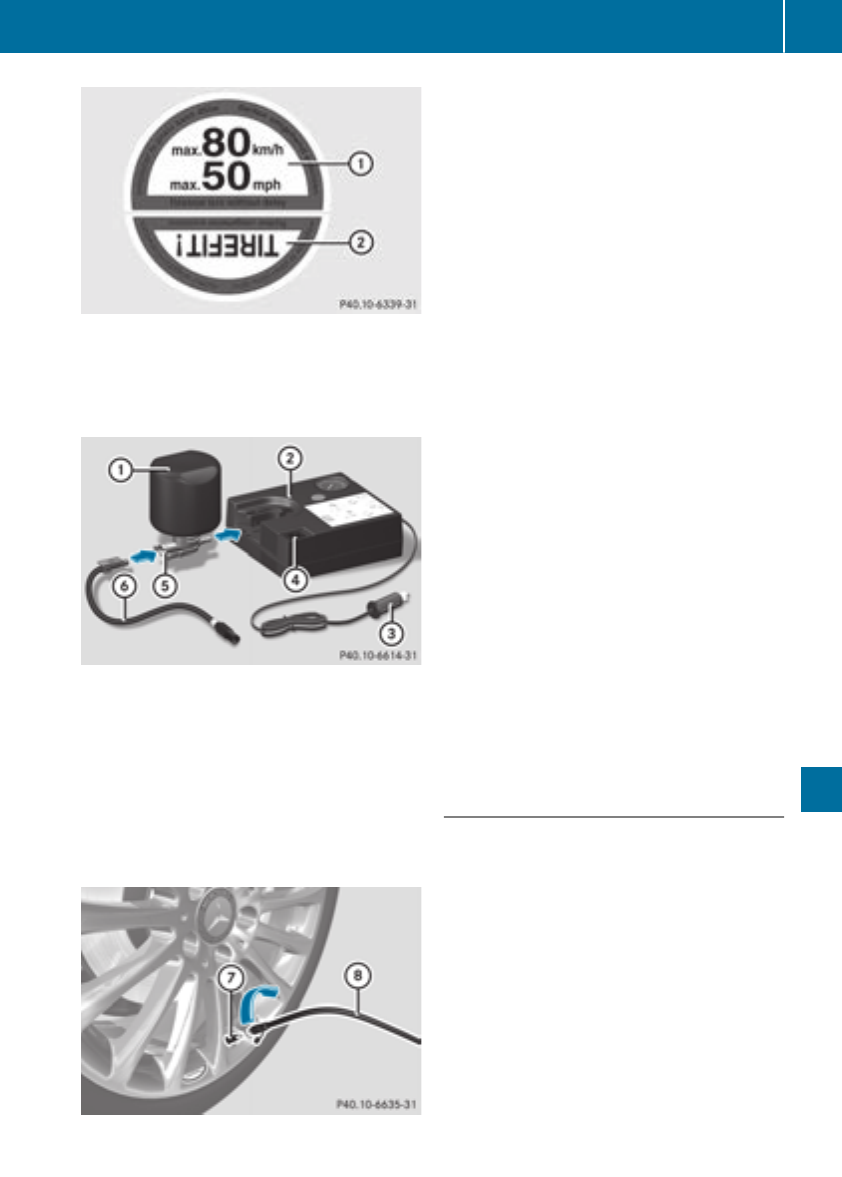
XAffix part :of the TIREFIT sticker to the
instrument cluster within the driver's field of
vision.
XAffix part ;of the TIREFIT sticker near the
valve on the wheel with the defective tire.
XRemove filler hose Band connector =from
the bottom section of tire inflation compres-
sor housing ;.
XSlide the yellow filler hose connector into the
mounting on yellow cap Aof tire sealant filler
bottle :until the connector engages.
XWith the sealing rings in front, slide yellow cap
Aof tire sealant bottle :into the mounting
of tire inflation compressor ;. The cap must
engage in both hooks.
XRemove the cap from valve Con the faulty
tire.
XScrew filler hose Donto valve C.
XInsert plug =into cigarette lighter socket
(Ypage 270) or into another 12 V socket in
your vehicle (Ypage 270).
XTurn the SmartKey to position 1in the igni-
tion lock (Ypage 123).
XPress on and off switch ?on the tire inflation
compressor to ON position.
The tire inflation compressor is switched on.
The tire is inflated.
First, tire sealant is pumped into the tire. The
pressure may briefly rise to approximately
500 kPa (5 bar/73 psi).
Do not switch off the tire inflation com-
pressor during this phase.
XLet the tire inflation compressor run for a
maximum of ten minutes. The tire should then
have attained a pressure of at least 200 kPa
(2.0 bar/29 psi).
If a pressure of 200 kPa (2.0 bar/29 psi) has
been attained after five minutes, see "Tire pres-
sure reached" (Ypage 300).
If a tire pressure of 200 kPa (2.0 bar/29 psi) has
not been attained after five minutes, see "Tire
pressure not reached" (Ypage 299).
If tire sealant has escaped, clean it off affected
areas as quickly as possible. Use plain water if
possible.
If your clothes are soiled with tire sealant, have
them cleaned with perchloroethylene at a dry
cleaner as soon as possible.
Tire pressure not reached
If a tire pressure of 200 kPa (2.0 bar/29 psi) has
not been attained after ten minutes:
XSwitch off the tire inflation compressor.
XUnscrew the filler hose from the valve of the
faulty tire.
Tire sealant may escape when the filler hose is
unscrewed.
XVery slowly drive forwards or reverse approx-
imately 30 ft (10 m).
XPump up the tire again.
After a maximum of ten minutes, the tire pres-
sure must be at least 200 kPa (2.0 bar/
29 psi).
Flat tire 299
Breakdown assistance
Z
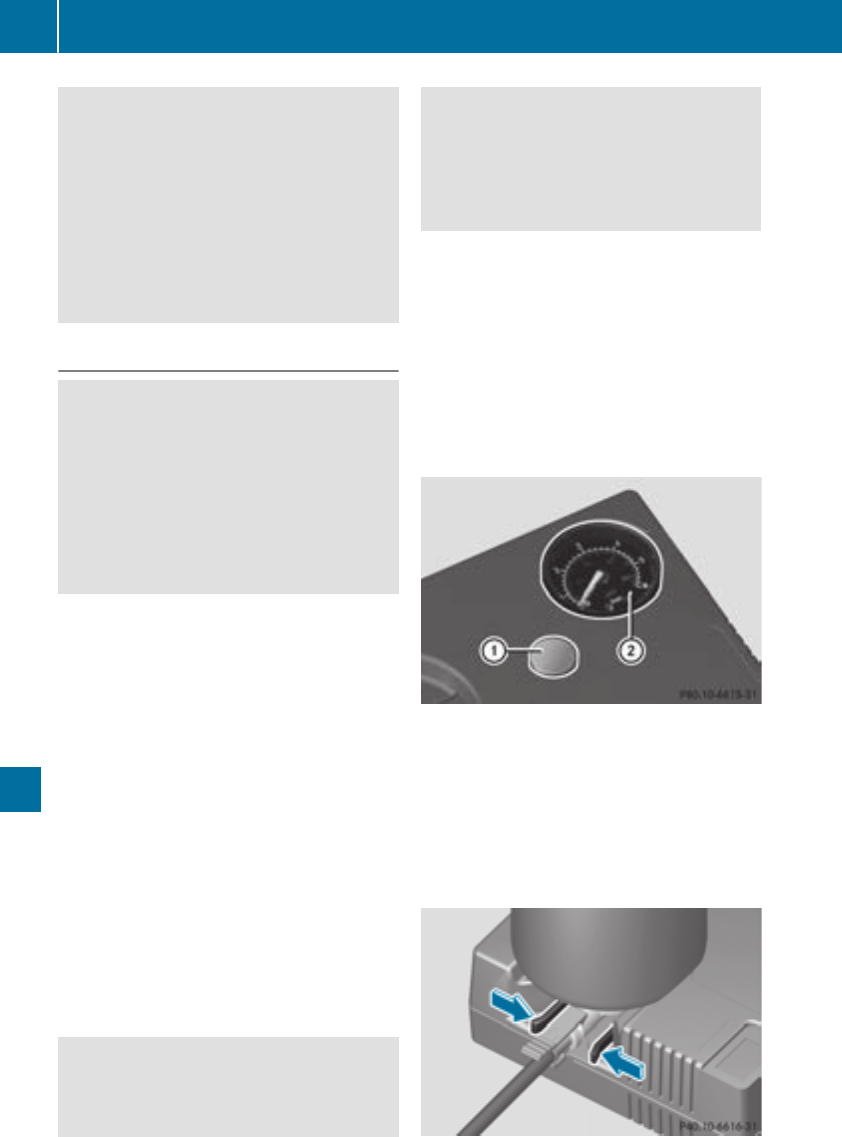
GWARNING
If the required tire pressure is not reached
after the specified time, the tire is too badly
damaged. The tire sealant cannot repair the
tire in this instance. Damaged tires and a tire
pressure that is too low can significantly
impair the vehicle's braking and driving char-
acteristics. There is a risk of accident.
Do not continue driving. Contact a qualified
specialist workshop.
Tire pressure reached
GWARNING
A tire temporarily sealed with tire sealant
impairs the driving characteristics and is not
suitable for higher speeds. There is a risk of
accident.
You should therefore adapt your driving style
accordingly and drive carefully. Do not exceed
the specified maximum speed with a tire that
has been repaired using tire sealant.
The maximum permissible speed for a tire
sealed with tire sealant is 50 mph (80 km/h).
The upper part of the TIREFIT sticker must be
affixed to the instrument cluster in the driver's
field of vision.
If a tire pressure of 200 kPa (2.0 bar/29 psi) has
been attained after ten minutes:
XSwitch off the tire inflation compressor.
XUnscrew the filler hose from the valve of the
faulty tire.
Tire sealant may escape when the filler hose is
unscrewed.
XStow the tire sealant bottle and the tire infla-
tion compressor.
XPull away immediately.
XStop after driving for approximately ten
minutes and check the tire pressure with the
tire inflation compressor.
The tire pressure must now be at least
130 kPa (1.3 bar/19 psi).
GWARNING
If the required tire pressure is not reached
after driving for a short period, the tire is too
badly damaged. The tire sealant cannot repair
the tire in this instance. Damaged tires and a
tire pressure that is too low can significantly
impair the vehicle's braking and driving char-
acteristics. There is a risk of accident.
Do not continue driving. Contact a qualified
specialist workshop.
In cases such as the one mentioned above, con-
tact an authorized Mercedes-Benz Center. Or
call 1-800-FOR-MERCedes (in the USA) or
1-800-387-0100 (in Canada).
XCorrect the tire pressure if it is still at least
130 kPa (1.3 bar/19 psi). See the Tire and
Loading Information placard on the B-pillar on
the driver's side or the tire pressure table in
the fuel filler flap for values.
XTo increase the tire pressure: switch on the
tire inflation compressor.
XTo reduce the tire pressure: depress pres-
sure release button :next to pressure
gauge ;.
XWhen the tire pressure is correct, unscrew the
filler hose from the valve of the sealed tire.
Tire sealant may escape when the filler hose is
unscrewed.
XScrew the valve cap onto the tire valve of the
sealed tire.
300 Flat tire
Breakdown assistance

XTo remove the tire sealant bottle from the tire
inflation compressor, press together the lock-
ing tabs on the yellow cap.
XPull the tire sealant bottle out of the tire infla-
tion compressor.
The filler hose remains attached to the tire
sealant bottle.
XDrive to the nearest qualified specialist work-
shop and have the tire changed there.
XHave the tire sealant bottle and the filler hose
replaced as soon as possible at a qualified
specialist workshop.
XHave the tire sealant bottle replaced every
four years at a qualified specialist workshop.
Battery (vehicle)
12 V battery – important safety notes
Special tools and expert knowledge are required
when working on the battery, e.g. removal and
installation. You should therefore have all work
involving the battery carried out at a qualified
specialist workshop.
GWARNING
Work carried out incorrectly on the battery
can lead, for example, to a short circuit and
thus damage the vehicle electronics. This can
lead to function restrictions applying to
safety-relevant systems, e.g the lighting sys-
tem, the ABS (anti-lock braking system) or the
ESP®(Electronic Stability Program). The oper-
ating safety of your vehicle may be restricted.
You could lose control of the vehicle, for
example:
Rwhen braking
Rin the event of abrupt steering maneuvers
and/or when the vehicle's speed is not
adapted to the road conditions
There is a risk of an accident.
In the event of a short circuit or a similar inci-
dent, contact a qualified specialist workshop
immediately. Do not drive any further. You
should have all work involving the battery car-
ried out at a qualified specialist workshop.
For further information about ABS and ESP®,
see (Ypage 64) and (Ypage 67).
All vehicles except vehicles with a lithium-
ion battery:
GWARNING
Electrostatic build-up can lead to the creation
of sparks, which could ignite the highly explo-
sive gases of a battery. There is a risk of an
explosion.
Before handling the battery, touch the vehicle
body to remove any existing electrostatic
build-up.
The highly flammable gas mixture forms when
charging the battery as well as when jump-start-
ing.
Always make sure that neither you nor the bat-
tery is electrostatically charged. A build-up of
electrostatic charge can be caused, for exam-
ple:
Rby wearing clothing made from synthetic
fibers
Rdue to friction between clothing and seats
Rif you push or pull the battery across the car-
pet or other synthetic materials
Rif you rub the battery with a cloth
GWARNING
During the charging process, a battery produ-
ces hydrogen gas. If a short circuit occurs or
sparks are created, the hydrogen gas can
ignite. There is a risk of an explosion.
RMake sure that the positive terminal of a
connected battery does not come into con-
tact with vehicle parts.
RNever place metal objects or tools on a bat-
tery.
RIt is important that you observe the descri-
bed order of the battery terminals when
connecting and disconnecting a battery.
RWhen jump-starting, make sure that the
battery poles with identical polarity are
connected.
Battery (vehicle) 301
Breakdown assistance
Z
RIt is particularly important to observe the
described order when connecting and dis-
connecting the jumper cables.
RNever connect or disconnect the battery
terminals while the engine is running.
GWARNING
Battery acid is caustic. There is a risk of injury.
Avoid contact with skin, eyes or clothing. Do
not inhale any battery gases. Do not lean over
the battery. Keep children away from batter-
ies. Wash away battery acid immediately with
plenty of clean water and seek medical atten-
tion.
All vehicles:
HEnvironmental note
Batteries contain dangerous
substances. It is against the
law to dispose of them with
the household rubbish. They
must be collected separately
and recycled to protect the
environment.
Dispose of batteries in an
environmentally friendly
manner. Take discharged
batteries to a qualified spe-
cialist workshop or a special
collection point for used bat-
teries.
!Have the battery checked regularly at a
qualified specialist workshop.
Observe the service intervals in the Mainte-
nance Booklet or contact a qualified specialist
workshop for more information.
!Always have work on batteries carried out at
a qualified specialist workshop.
Should it, in exceptional circumstances, be
absolutely necessary to disconnect the 12-
volt battery yourself, please observe the fol-
lowing:
RSecure the vehicle to prevent it from rolling
away.
RSwitch off the ignition.
RDisconnect the negative terminal first and
then the positive terminal.
The transmission is locked in position j
after disconnecting the battery.
After the work has been done, install the bat-
tery and replace the cover of the positive ter-
minal clamp firmly.
Comply with safety precautions and take pro-
tective measures when handling batteries.
Risk of explosion.
Fire, open flames and smoking are
prohibited when handling the bat-
tery. Avoid creating sparks.
Electrolyte or battery acid is corro-
sive. Avoid contact with skin, eyes or
clothing.
Wear suitable protective clothing,
especially gloves, apron and face-
guard.
Immediately rinse electrolyte or acid
splashes off with clean water. Con-
tact a physician if necessary.
Wear eye protection.
Keep children away.
Observe this Operator's Manual.
For safety reasons, Mercedes-Benz recom-
mends that you only use batteries which have
been tested and approved for your vehicle by
Mercedes-Benz. These batteries provide
increased impact protection to prevent vehicle
occupants from suffering acid burns should the
battery be damaged in the event of an accident.
302 Battery (vehicle)
Breakdown assistance

In order for the battery to achieve the maximum
possible service life, it must always be suffi-
ciently charged.
Like other batteries, the vehicle battery may
discharge over time if you do not use the vehicle.
In this case, have the battery disconnected at a
qualified specialist workshop. You can also
charge the battery with a charger recommended
by Mercedes-Benz. Contact a qualified special-
ist workshop for further information.
Have the battery condition of charge checked
more frequently if you use the vehicle mainly for
short trips or if you leave it standing idle for a
lengthy period. Consult a qualified specialist
workshop if you wish to leave your vehicle
parked for a long period of time.
Remove the SmartKey if you park the vehicle
and do not require any electrical consumers.
The vehicle will then use very little energy, thus
conserving battery power.
Charging the 12 V battery
Vehicles with a lithium-ion battery:
!Only use battery chargers with a maximum
charging voltage of 14.4 V.
All vehicles except vehicles with a lithium-
ion battery:
!Only use battery chargers with a maximum
charging voltage of 14.8 V.
GWARNING
During charging and jump-starting, explosive
gases can escape from the battery. There is a
risk of an explosion.
Particularly avoid fire, open flames, creating
sparks and smoking. Ensure there is sufficient
ventilation while charging and jump-starting.
Do not lean over a battery.
GWARNING
Battery acid is caustic. There is a risk of injury.
Avoid contact with skin, eyes or clothing. Do
not inhale any battery gases. Do not lean over
the battery. Keep children away from batter-
ies. Wash away battery acid immediately with
plenty of clean water and seek medical atten-
tion.
GWARNING
A discharged battery can freeze at tempera-
tures below freezing point. When jump-start-
ing the vehicle or charging the battery, gases
can escape from the battery. There is a risk of
an explosion.
Allow the frozen battery to thaw out before
charging it or jump-starting.
All vehicles:
!Only charge the battery using the jump-
starting connection point.
The jump-starting connection point is in the
engine compartment (Ypage 304).
XOpen the hood.
XConnect the battery charger to the positive
terminal and ground point in the same order
as when connecting the donor battery in the
jump-starting procedure (Ypage 304).
Keep away from fire and open flames. Do not
lean over a battery. Never charge the battery if it
is still installed in the vehicle, unless you use a
battery charger which has been tested and
approved by Mercedes-Benz. A battery charger
unit specially adapted for Mercedes-Benz vehi-
cles and tested and approved by Mercedes-
Benz is available as an accessory. It permits the
charging of the battery in its installed position.
Contact an authorized Mercedes-Benz Center
for further information and availability. Read the
battery charger's operating instructions before
charging the battery.
All vehicles except vehicles with a lithium-
ion battery: if the warning and indicator lamps
on the instrument cluster do not light up at low
temperatures, it is very likely that the dis-
charged battery has frozen. In this case you may
neither jump-start the vehicle nor charge the
battery. The service life of a thawed-out battery
may be shorter. The starting characteristics can
be impaired, particularly at low temperatures.
Have the thawed-out battery checked at a quali-
fied specialist workshop.
Vehicles with a lithium-ion battery: at low
temperatures, do not charge a battery which has
been removed using a battery charger. Allow the
battery to warm up gently first, if necessary.
Otherwise, the service life can be shortened and
the starting characteristics impaired, especially
at low temperatures.
Battery (vehicle) 303
Breakdown assistance
Z

Jump-starting
For the jump-starting procedure, use only the jump-starting connection point in the engine com-
partment, consisting of a positive terminal and a ground point.
All vehicles except vehicles with a lithium-ion battery:
GWARNING
Battery acid is caustic. There is a risk of injury.
Avoid contact with skin, eyes or clothing. Do not inhale any battery gases. Do not lean over the
battery. Keep children away from batteries. Wash away battery acid immediately with plenty of
clean water and seek medical attention.
GWARNING
During charging and jump-starting, explosive gases can escape from the battery. There is a risk
of an explosion.
Particularly avoid fire, open flames, creating sparks and smoking. Ensure there is sufficient ven-
tilation while charging and jump-starting. Do not lean over a battery.
GWARNING
During the charging process, a battery produces hydrogen gas. If a short circuit occurs or sparks
are created, the hydrogen gas can ignite. There is a risk of an explosion.
RMake sure that the positive terminal of a connected battery does not come into contact with
vehicle parts.
RNever place metal objects or tools on a battery.
RIt is important that you observe the described order of the battery terminals when connecting
and disconnecting a battery.
RWhen jump-starting, make sure that the battery poles with identical polarity are connected.
RIt is particularly important to observe the described order when connecting and disconnecting
the jumper cables.
RNever connect or disconnect the battery terminals while the engine is running.
GWARNING
A discharged battery can freeze at temperatures below freezing point. When jump-starting the
vehicle or charging the battery, gases can escape from the battery. There is a risk of an explosion.
Allow the frozen battery to thaw out before charging it or jump-starting.
If the warning and indicator lamps do not light up on the instrument cluster when temperatures are
low, it is probably because the discharged battery has frozen. In this case, you may neither charge
the battery nor jump-start the vehicle. The service life of a thawed-out battery may be shorter. The
starting characteristics can be impaired, particularly at low temperatures. Have the thawed-out
battery checked at a qualified specialist workshop.
All vehicles:
!Avoid repeated and lengthy starting attempts. Otherwise, the catalytic converter could be
damaged by the non-combusted fuel.
304 Jump-starting
Breakdown assistance
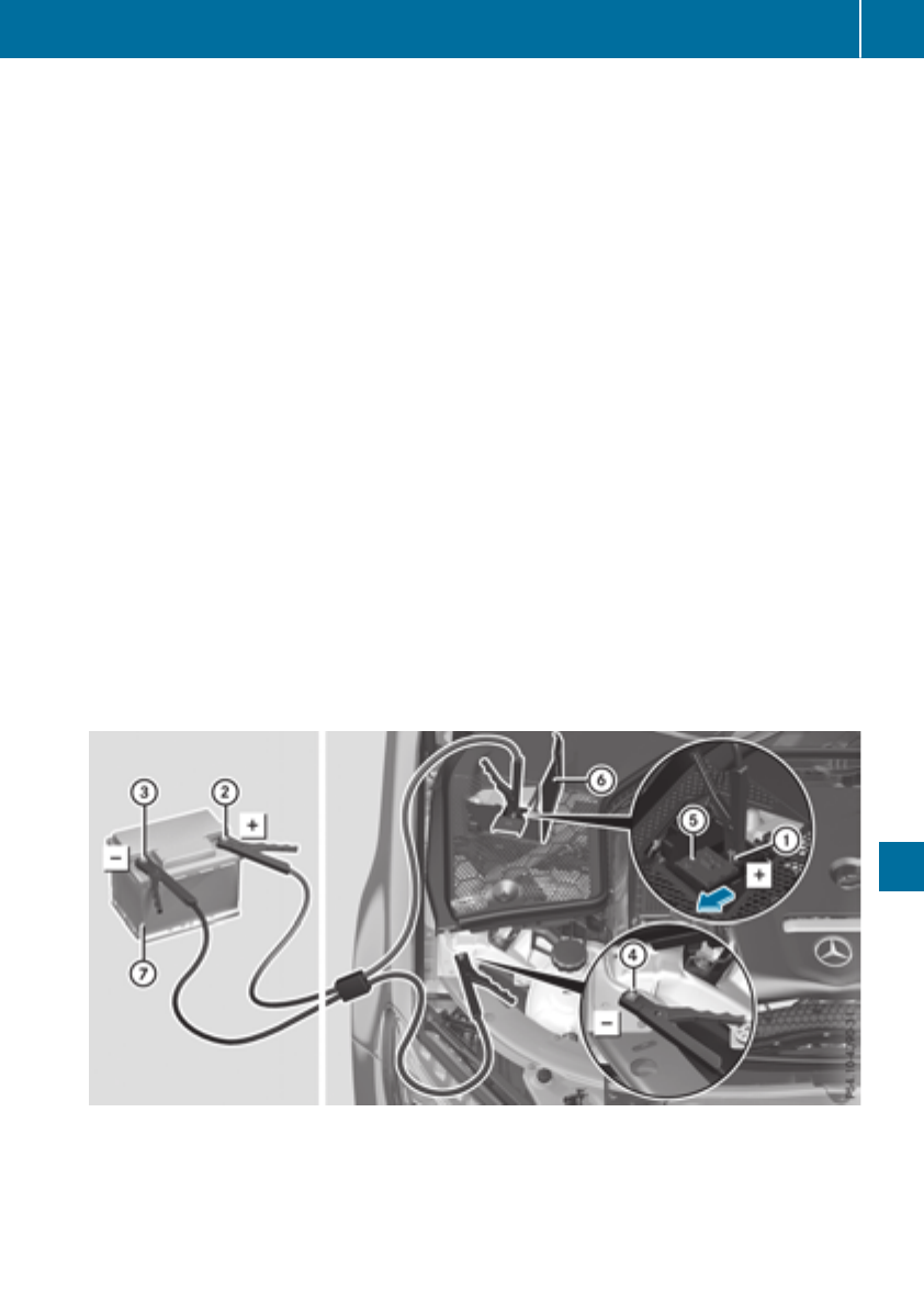
Do not start the vehicle using a rapid charging device. If your vehicle's battery is discharged, the
engine can be jump-started from another vehicle or from a second battery using jumper cables.
Observe the following points:
RThe battery is not accessible in all vehicles. If the other vehicle's battery is not accessible, jump-
start the vehicle using a second battery or a jump-starting device.
RYou may only jump-start the vehicle when the engine and exhaust system are cold.
RAll vehicles except vehicles with a lithium-ion battery: do not start the engine if the battery
is frozen. Let the battery thaw first.
RJump-starting may be performed only using batteries with a nominal voltage of 12 V.
ROnly use jumper cables which have a sufficient cross-section and insulated terminal clamps.
RIf the battery is fully discharged, leave the battery that is being used to jump-start connected for
a few minutes before attempting to start. This charges the battery slightly.
RMake sure that the two vehicles do not touch.
Make sure that:
RThe jumper cables are not damaged.
RBare parts of the terminal clamp do not come into contact with other metal parts while the jumper
cables are connected to the battery.
RThe jumper cables cannot come into contact with parts that can move when the engine is running,
such as the V-belt pulley or the fan.
XSecure the vehicle by applying the electric parking brake.
XShift the transmission to position j.
XMake sure that the ignition is switched off. All indicator lamps in the instrument cluster must be
off. When using the SmartKey, turn the SmartKey to position uin the ignition lock and remove it
(Ypage 123).
XSwitch off all electrical consumers, e.g. rear window defroster, lighting, etc.
XOpen the hood.
Position number Cidentifies the charged battery of the other vehicle or an equivalent jump-starting
device.
XLift up panel B.
XSlide cover Aof positive terminal :in the direction of the arrow.
Jump-starting 305
Breakdown assistance
Z

XConnect positive terminal :on your vehicle to positive terminal ;of donor battery Cusing the
jumper cable, Always begin with positive terminal :on your own vehicle first.
XStart the engine of the donor vehicle and run it at idling speed.
XConnect negative terminal =of donor battery Cto earth point ?of your vehicle using the
jumper cable. beginning with donor battery Cfirst.
XStart the engine.
XBefore disconnecting the jumper cables, let the engine run for several minutes.
XFirst, remove the jumper cables from ground point?and negative terminal =, then from pos-
itive clamp :and positive terminal ;. Begin each time at the contacts on your own vehicle first.
XClose cover Aof positive terminal :after removing jumper cables.
XFold panel Bshut.
XHave the battery checked at a qualified specialist workshop.
Jump-starting is not considered to be a normal operating condition.
iJumper cables and further information regarding jump-starting can be obtained at any qualified
specialist workshop.
Towing and tow-starting
Important safety notes
GWARNING
Functions relevant to safety are restricted or
no longer available if:
Rthe engine is not running.
Rthe brake system or the power steering is
malfunctioning.
Rthere is a malfunction in the voltage supply
or the vehicle's electrical system.
If your vehicle is being towed, much more
force may be necessary to steer or brake.
There is a risk of an accident.
In such cases, use a tow bar. Before towing,
make sure that the steering moves freely.
GWARNING
You can no longer steer the vehicle if the
steering wheel lock has been engaged. There
is a risk of an accident.
Always switch off the ignition when towing the
vehicle with a tow cable or a tow bar.
GWARNING
When towing or tow-starting another vehicle
and its weight is greater than the permissible
gross weight of your vehicle, the:
Rthe towing eye could detach itself
Rthe vehicle/trailer combination could roll-
over.
There is a risk of an accident.
When towing or tow-starting another vehicle,
its weight should not be greater than the per-
missible gross weight of your vehicle.
Details on the permissible gross vehicle weight
of your vehicle can be found on the vehicle iden-
tification plate (Ypage 339).
!When Active Brake Assist, Distance Pilot
DISTRONIC or the HOLD function is activated,
the vehicle brakes automatically in certain
situations.
To avoid damage to the vehicle, deactivate
these systems in the following or similar sit-
uations:
Rwhen towing the vehicle
Rin the car wash
!Make sure that the electric parking brake is
released. If the electric parking brake is faulty,
visit a qualified specialist workshop.
!Secure the tow rope or tow bar to the towing
eye only. Otherwise, the vehicle could
become damaged.
306 Towing and tow-starting
Breakdown assistance
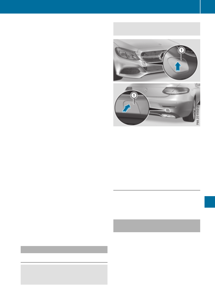
!Do not use the towing eye for recovery. This
could damage the vehicle. If in doubt, have
the vehicle recovered using a crane.
!When towing, pull away slowly and
smoothly. If the tractive power is too high, the
vehicles could be damaged.
!Shift the automatic transmission to position
iand do not open the driver's or front pas-
senger's door during towing. The automatic
transmission may otherwise shift to position
j, which could damage the transmission.
!Do not tow with sling-type equipment. This
could damage the vehicle.
!The vehicle can be towed a maximum of
30 miles (50km). The towing speed of 30 mph
(50 km/h) must not be exceeded.
If the vehicle has to be towed more than
30 miles (50km), the entire vehicle must be
raised and transported.
It is better to have the vehicle transported than
to have it towed away.
If the vehicle has suffered transmission damage,
have it transported on a transporter or trailer.
The automatic transmission must be in position
iwhen the vehicle is being towed. If the auto-
matic transmission cannot be shifted to position
i, have the vehicle transported on a trans-
porter or trailer.
The battery must be connected and charged.
Otherwise, you:
Rcannot turn the SmartKey to position 2in
the ignition lock
Rcannot release the electric parking brake
Rcannot shift the automatic transmission to
position i
Disarm the automatic locking feature before the
vehicle is towed (Ypage 82). You could other-
wise be locked out when pushing or towing the
vehicle.
Installing/removing the towing eye
Installing the towing eye
GWARNING
The exhaust tail pipe may be very hot. There is
a risk of burns when removing the rear cover.
Do not touch the exhaust pipe. Take particular
care when removing the rear cover.
The brackets for the screw-in towing eye are
located in the bumpers. They are at the rear and
at the front, under covers :.
XRemove the towing eye from the retainer
(Ypage 296).
XPress the mark on cover :inward and
remove.
XScrew in the towing eye clockwise as far as it
will go and tighten it.
Removing the towing eye
XUnscrew and remove the towing eye.
XAttach cover :to the bumper and press until
it engages.
Towing the vehicle with the rear axle
raised
Only vehicles without 4MATIC can be towed
with the rear axle raised.
!Vehicles with 4MATIC must not be towed
with either the front or the rear axle raised, as
doing so will damage the transmission.
Vehicles with 4MATIC may either be towed away
with both axles on the ground or be loaded up
and transported.
!Vehicles with automatic transmission must
not be towed with the rear axle raised. The
Towing and tow-starting 307
Breakdown assistance
Z

vehicle/trailer combination may otherwise
swerve or even roll over.
Towing a vehicle with both axles on
the ground
The automatic transmission automatically shifts
to position jwhen you open the driver's or
front-passenger door or when you remove the
SmartKey from the ignition lock. It is essential to
observe the following steps to ensure that the
automatic transmission remains in position i
during towing.
XMake sure that the vehicle is stationary.
XTurn the SmartKey to position 2in the igni-
tion lock.
XDepress and hold the brake pedal.
XShift the automatic transmission to position
N.
XLeave the SmartKey in position 2in the igni-
tion lock.
XRelease the brake pedal.
XRelease the electric parking brake.
XSwitch on the hazard warning lamps
(Ypage 109).
In order to signal a change of direction when
towing the vehicle with the hazard warning
lamps switched on, use the combination switch
as usual. In this case, only the indicator lamps
for the direction of travel flash. After resetting
the combination switch, the hazard warning
lamp starts flashing again.
Transporting the vehicle
4MATIC vehicles/vehicles with auto-
matic transmission
!When the vehicle is loaded for transport, the
front and rear axles must be stationary and on
the same transportation vehicle. Positioning
over the connection point of the transport
vehicle is not permitted. The drive train may
otherwise be damaged.
Vehicles with ADS PLUS (Adaptive
Damping System PLUS)
GWARNING
The weaker damping forces of the vehicle to
be transported can cause the vehicle/trailer
combination to swing.
As a result, when transporting vehicles with
Adaptive Damping System PLUS, the vehicle/
trailer combination may start to skid. Conse-
quently, you could lose control of the vehicle.
There is a risk of accident and injury.
When transporting, make sure that:
Rthe vehicle is has been loaded onto the
transporter correctly
Rthe vehicle is secured at all four wheels with
suitable tensioning straps
Ryou do not exceed the maximum permissi-
ble speed of 35 mph (60 km/h)
!After loading, the vehicle must be secured at
all four wheels. Otherwise, the vehicle could
be damaged.
A minimum distance of 8 in (20 cm) up and
4 in (10 cm) down must be maintained to the
transport platform.
XSecure all four wheels after loading the vehi-
cle.
All vehicles
!You may only secure the vehicle by the
wheels, not by parts of the vehicle such as
axle or steering components. Otherwise, the
vehicle could be damaged.
The towing eye can be used to pull the vehicle
onto a trailer or transporter for transporting pur-
poses.
308 Towing and tow-starting
Breakdown assistance

XTurn the SmartKey to position 2in the igni-
tion lock.
XShift the automatic transmission to position
i.
As soon as the vehicle has been loaded:
XPrevent the vehicle from rolling away by
applying the electric parking brake.
XShift the automatic transmission to position
j.
XTurn the SmartKey to position uin the igni-
tion lock and remove it.
XSecure the vehicle.
Notes on 4MATIC vehicles
!Vehicles with 4MATIC must not be towed
with either the front or the rear axle raised, as
doing so will damage the transmission.
Vehicles with 4MATIC may either be towed away
with both axles on the ground or be loaded up
and transported.
If the vehicle's transmission, front, or rear axle is
damaged, have the vehicle transported on a
truck or trailer.
In the event of damage to the electrical sys-
tem: if the battery is defective, the automatic
transmission will be locked in position P. To shift
the automatic transmission to position N, you
must provide power to the vehicle's electrical
system in the same way as when jump-starting
(Ypage 304).
Have the vehicle transported on a transporter or
trailer.
Tow-starting (emergency engine
starting)
!Vehicles with automatic transmission must
not be tow-started. You could otherwise dam-
age the automatic transmission.
iYou can find information on "Jump-starting"
under (Ypage 304).
Fuses
Important safety notes
GWARNING
If you manipulate or bridge a faulty fuse or if
you replace it with a fuse with a higher amper-
age, the electric cables could be overloaded.
This could result in a fire. There is a risk of an
accident and injury.
Always replace faulty fuses with the specified
new fuses having the correct amperage.
Blown fuses must be replaced with fuses of the
same rating, which you can recognize by the
color and value. The fuse ratings are listed in the
fuse allocation chart.
The fuse allocation chart is on the fuse box in the
trunk (Ypage 311).
If a newly inserted fuse also blows, have the
cause traced and rectified at a qualified special-
ist workshop, e.g. an authorized Mercedes-Benz
Center.
!Only use fuses that have been approved for
Mercedes-Benz vehicles and which have the
correct fuse rating for the system concerned.
Otherwise, components or systems could be
damaged.
!Make sure that no moisture can enter the
fuse box when the cover is open.
!When closing the cover, make sure that it is
lying correctly on the fuse box. Moisture seep-
ing in or dirt could otherwise impair the oper-
ation of the fuses.
The fuses in your vehicle serve to close down
faulty circuits. If a fuse blows, all the compo-
nents on the circuit and their functions stop
operating.
Before changing a fuse
Observe the important safety notes
(Ypage 309)
XSwitch off the engine.
XSwitch off all electrical consumers.
Fuses 309
Breakdown assistance
Z
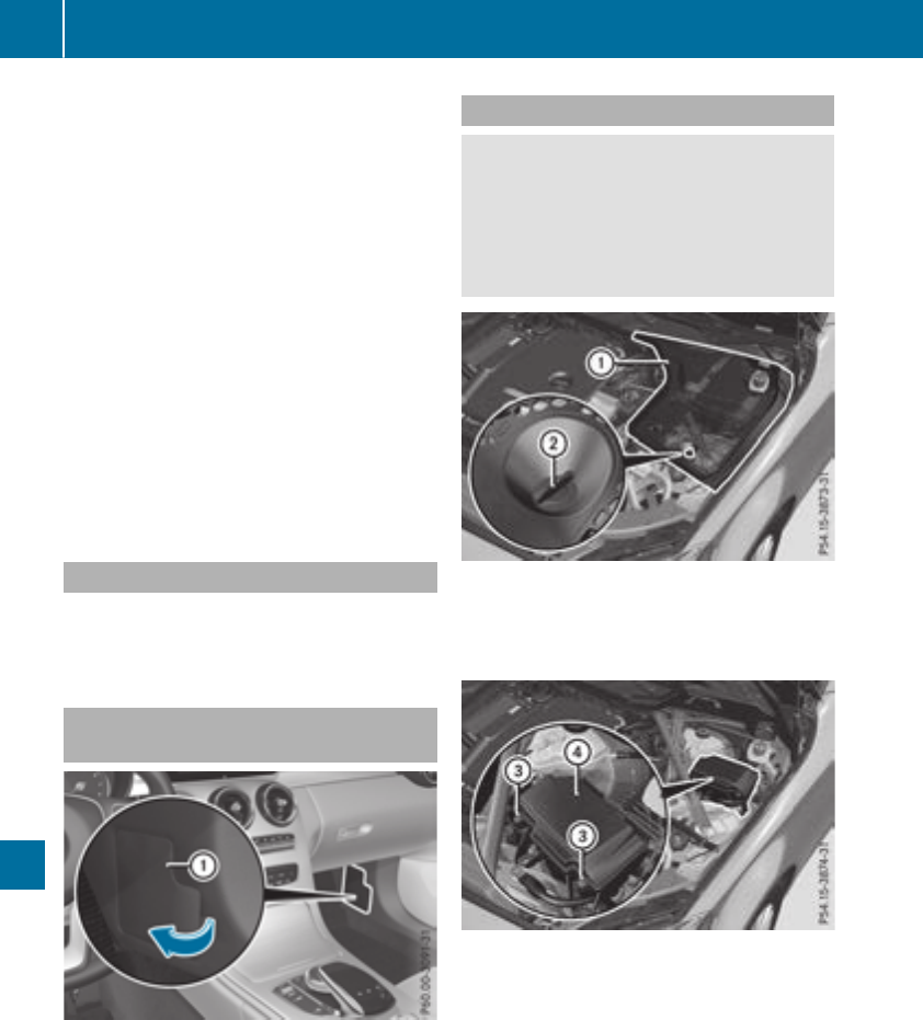
XMake sure that the ignition is switched off
(Ypage 124).
or
XWhen using the SmartKey, turn the SmartKey
to position uin the ignition lock and remove
it (Ypage 123).
XSecure the vehicle against rolling away
(Ypage 143).
All indicator lamps in the instrument cluster
must be off.
The fuses are located in various fuse boxes:
RFuse box on the driver's side of the dashboard
RFuse box in the front-passenger footwell
RFuse box in the engine compartment on the
driver's side
RFuse box under the trunk floor on the right-
hand side of the vehicle, when viewed in the
direction of travel
Dashboard fuse box
The fuse box is under a cover on the side of the
dashboard. You can obtain further information
from an authorized Mercedes-Benz Center.
Fuse box in the front-passenger foot-
well
XOpen the front-passenger door.
XTo open: fold cover :out towards the rear
and remove it.
XTo close: clip in cover :at the rear.
XFold cover :forwards until it engages.
Fuse box in the engine compartment
GWARNING
When the hood is open and the windshield
wipers are set in motion, you can be injured by
the wiper linkage. There is a risk of injury.
Always switch off the windshield wipers and
the ignition before opening the hood.
XOpen the hood (Ypage 281).
XTo open: turn fastener ;on cover :coun-
ter-clockwise as far as it will go.
XRemove fuse box cover :up.
XUse a dry cloth to remove any moisture from
the fuse box.
XLoosen screws =, fold up fuse box lid ?and
remove it.
XTo close: check whether the seal is posi-
tioned correctly in lid ?.
XInsert lid ?into the bracket at the rear of the
fuse box.
XFold down lid ?of the fuse box and tighten
screws =.
XInsert cover :and turn fastener ;clock-
wise as far as it will go.
XClose the hood.
310 Fuses
Breakdown assistance
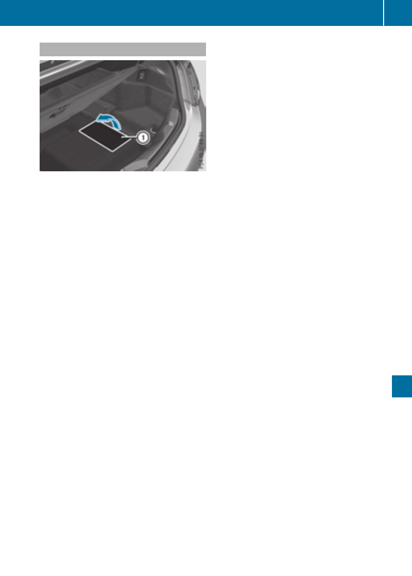
Fuse box in the trunk
Opening
XOpen thetrunk lid.
XLiftthetrunk floor up (Ypage 267).
XLiftup cover :in thetrunk recess panel in
thedirection of thearrow.
Closing
XFold cover :backin theoppositedirection
to thearrow.
Makesure that cover :is in therecess provi-
ded for it in thepanel trim.
iThe fuseallocation chart is locatedin a
recess at theside of thefusebox.You can find
thecorresponding fuserating and fusetype
on thefuseallocation chart.
Fuses 311
Breakdown assistance
Z

Important safety notes
GWARNING
If wheels and tires of thewrong sizeare used,
thewheelbrakes or suspension components
may be damaged. Thereis ariskof an acci-
dent.
Always replace wheels and tires withthose
that fulfill thespecificationsof theoriginal
part.
When replacing wheels, makesureto use the
correct:
Rdesignation
Rmodel
When replacing tires,makesureto use the
correct:
Rdesignation
Rmanufacturer
Rmodel
GWARNING
Aflat tire severely impairs thedriving,steer-
ing and braking characteristics of thevehicle.
Thereis ariskof accident.
Tires without run-flat characteristics:
Rdo notdrivewith a flat tire.
Rimmediately replace theflat tire withyour
emergencysparewheelor sparewheel, or
consult aqualified specialist workshop.
Tires withrun-flat characteristics:
Rpay attention to theinformation and warn-
ing noticeson MOExtended tires (tireswith
run-flat characteristics).
Accessories that are notapprovedfor your vehi-
cle by Mercedes-Benzor are notbeingused cor-
rectlycan impair theoperating safety.
Before purchasing and usingnon-approved
accessories, visit aqualified specialist work-
shopand inquire about:
Rsuitability
Rlegal stipulations
Rfactory recommendations
Further information regarding wheels and tires
can be foundunder "Wheel/tire combinations"
(Ypage 336).
You can ask for information regarding permitted
wheel-tire combinationsat an authorized
Mercedes-BenzCenter.
Information on tire pressurecan be found:
Ron theTireand Loading Information placard
on theB-pillar on thedriver'sside
(Ypage 322)
Rin thetire pressuretable in thefuel filler flap
(Ypage 315)
Runder "Tirepressure" (Ypage 315)
Operation
Information on driving
Checkthetire pressurewhen thevehicleis
heavily laden and adjust priorto atrip.
While driving,pay attention to vibrations, noises
and unusual handlingcharacteristics,e.g. pull-
ing to oneside.This may indicatethat the
wheels or tires are damaged. If you suspectthat
atire is defective, reduce your speedimmedi-
ately. Stop thevehicleas soonas possible to
checkthewheels and tires for damage. Hidden
tire damagecould also be causing theunusual
handlingcharacteristics.If you findno signsof
damage, havethetires and wheels checkedat a
qualified specialist workshop.
When parking your vehicle, makesurethat the
tires do notget deformed by thecurbor other
obstacles. If they cannotbe avoided, driveover
obstacles suchas curbs slowly and at an obtuse
angle. Otherwise, you may damagethewheels
or tires.
Notes on high performance tires
GWARNING
Due to thespecial tire tread in combination
withtheoptimized rubber compound,there is
an increased riskof hydroplaning and skid-
dingon damp or wet road surfaces. In addi-
tion,tire traction is significantly reducedat
low outside temperatures and low tire-oper-
ating temperatures.Thereis ariskof an acci-
dent.
312 Operation
Wheels and tires
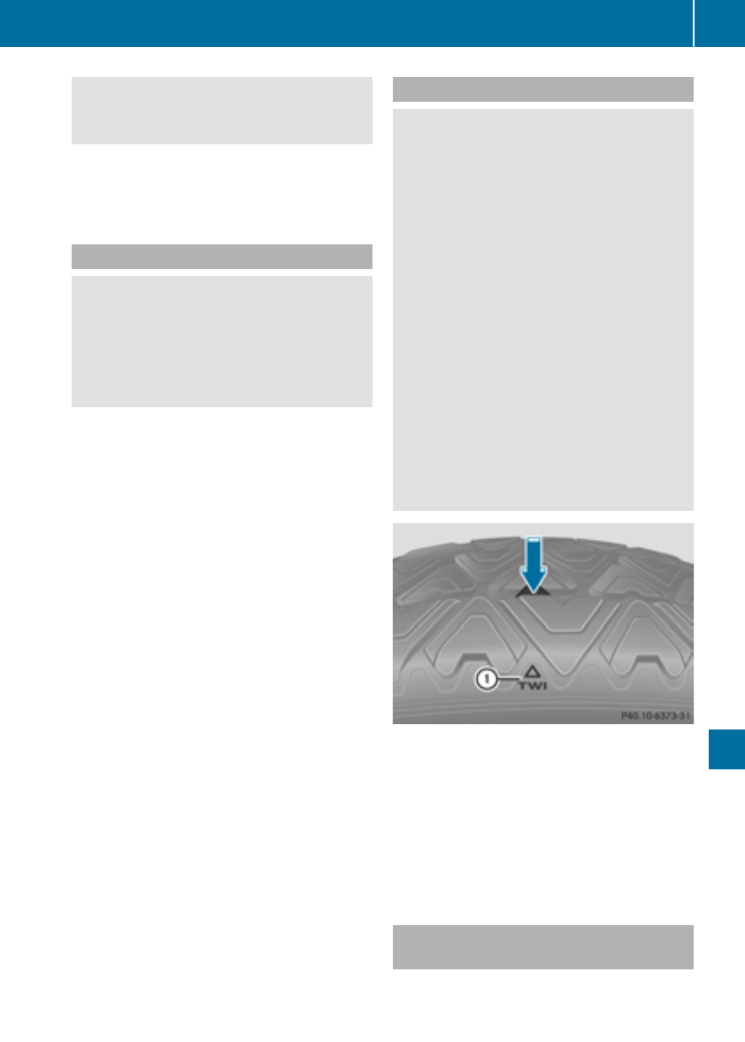
Activate ESP®and adapt your driving style. At
outside temperatures below 50 ‡(10 †), use
M+S tires.
iDifferent driving styles may lead to high tire
wear and the tires may reach the minimum
tire tread depth after only a short time.
Regular checking of wheels and tires
GWARNING
Damaged tires can cause tire inflation pres-
sure loss. As a result, you could lose control of
your vehicle. There is a risk of accident.
Check the tires regularly for signs of damage
and replace any damaged tires immediately.
Check wheels and tires for damage at least once
a month. Check wheels and tires after driving
off-road or on rough roads. Damaged wheels
can cause a loss of tire pressure.
Pay particular attention to damage such as:
RCuts in the tires
RPunctures in the tires
RTears in the tires
RBulges on tires
RDeformation or severe corrosion on wheels
Regularly check the tire tread depth and the
condition of the tread across the whole width of
the tire (Ypage 313). If necessary, turn the
front wheels to full lock in order to inspect the
inner side of the tire surface.
All wheels must have a valve cap to protect the
valve against dirt and moisture. Do not mount
anything onto the valve other than the standard
valve cap or other valve caps approved by
Mercedes-Benz for your vehicle. Do not use any
other valve caps or systems, e.g. tire pressure
monitoring systems.
Regularly check the pressure of all the tires par-
ticularly prior to long trips. Adjust the tire pres-
sure as necessary (Ypage 315).
The service life of tires depends, among other
things, on the following factors:
RDriving style
RTire pressure
RDistance covered
Notes on tire tread
GWARNING
Insufficient tire tread will reduce tire traction.
The tire is no longer able to dissipate water.
This means that on wet road surfaces, the risk
of hydroplaning increases, in particular where
speed is not adapted to suit the driving con-
ditions. There is a risk of accident.
If the tire pressure is too high or too low, tires
may exhibit different levels of wear at differ-
ent locations on the tire tread. Thus, you
should regularly check the tread depth and
the condition of the tread across the entire
width of all tires.
Minimum tire tread depth for:
RSummer tires: âin (3 mm)
RM+S tires: ãin (4 mm)
For safety reasons, replace the tires before
the legally prescribed limit for the minimum
tire tread depth is reached.
Marking :shows where the bar indicator
(arrow) for tread wear is integrated into the tire
tread.
Treadwear indicators (TWI) are required by law.
Six indicators are positioned on the tire tread.
They are visible once a tread depth of approx-
imately áin (1.6 mm) has been reached. If this
is the case, the tire is so worn that it must be
replaced.
Selecting, mounting and replacing
tires
ROnly mount tires and wheels of the same type
and make.
Operation 313
Wheels and tires
Z

Exception: it is permissible to install a differ-
ent type or make in the event of a flat tire.
Observe the "MOExtended tires (tires with
run-flat characteristics" section (Ypage 297).
ROnly mount tires of the correct size onto the
wheels.
RBreak in new tires at moderate speeds for the
first 60 miles (100 km). The new tires only
reach their full performance after this dis-
tance.
RDo not drive with tires which have too little
tread depth, as this significantly reduces the
traction on wet roads (hydroplaning).
RReplace the tires after six years at the latest,
regardless of wear.
MOExtended tires (tires with run-flat
properties)
With MOExtended tires (tires with run flat char-
acteristics), you can continue to drive your vehi-
cle even if there is a total loss of pressure in one
or more tires.
MOExtended tires may only be used in conjunc-
tion with an active tire pressure loss warning
system or with an active tire pressure monitor
and on wheels specifically tested by Mercedes-
Benz.
Notes on driving with MOExtended tires with a
flat tire (Ypage 297).
Vehicles equipped with MOExtended tires are
not equipped with a TIREFIT kit at the factory. It
is therefore recommended that you additionally
equip your vehicle with a TIREFIT kit if you mount
tires that do not feature run-flat properties, e.g.
winter tires. A TIREFIT kit can be obtained from
a qualified specialist workshop.
Winter operation
General notes
Have your vehicle winter-proofed at a qualified
specialist workshop at the onset of winter.
Observe the notes in the "Changing a wheel"
section (Ypage 331).
Driving with summer tires
At temperatures below 45 ‡ (+7 †), summer
tires lose elasticity and therefore traction and
braking power. Change the tires on your vehicle
to M+S tires. Usingsummer tires at very cold
temperatures could cause cracks to form,
thereby damaging the tires permanently.
Mercedes-Benz cannot accept responsibility for
this type of damage.
GWARNING
Damaged tires can cause tire inflation pres-
sure loss. As a result, you could lose control of
your vehicle. There is a risk of accident.
Check the tires regularly for signs of damage
and replace any damaged tires immediately.
M+S tires
GWARNING
M+S tires with a tire tread depth of less than
ãin (4 mm) are not suitable for use in winter
and do not provide sufficient traction. There is
a risk of an accident.
M+S tires with a tread depth of less than ãin
(4 mm) must be replaced immediately.
At temperatures below 45 ‡(+7 †), use winter
tires or all-season tires. Both types of tire are
identified by the M+S marking.
Only winter tires bearing the isnowflake
symbol in addition to the M+S marking provide
the best possible grip in wintry road conditions.
Only these tires will allow driving safety systems
such as ABS and ESP®to function optimally in
winter. These tires have been developed specif-
ically for driving in snow.
Use M+S tires of the same make and tread on all
wheels to maintain safe handling characteris-
tics.
Always observe the maximum permissible
speed specified for the M+S tires you have
mounted.
When you have mounted the M+S tires:
XCheck the tire pressures (Ypage 318).
XVehicles for Canada: restart the tire pres-
sure loss warning system (Ypage 319).
XRestart the tire pressure monitor
(Ypage 321).
314 Winter operation
Wheels and tires

Snow chains
GWARNING
If snow chains are installed to the front
wheels, they may drag against the vehicle
body or chassis components. This could
cause damage to the vehicle or the tires.
There is a risk of an accident.
To avoid hazardous situations:
Rnever install snow chains to the front
wheels
Ralways install snow chains in pairs to the
rear wheels.
For safety reasons, Mercedes-Benz recom-
mends that you only use snow chains that have
been specially approved for your vehicle by
Mercedes-Benz, or are of a corresponding
standard of quality. For more information,
please contact a qualified specialist workshop.
If you intend to mount snow chains, please bear
the following points in mind:
RSnow chains may not be mounted on all
wheel/tire combinations. Observe the infor-
mation regarding permitted wheel/tire com-
binations (Ypage 336).
ROnly use snow chains when driving on roads
completely covered by snow. Remove the
snow chains as soon as possible when you
come to a road that is not snow-covered.
RLocal regulations may restrict the use of snow
chains. Observe the appropriate regulations if
you wish to mount snow chains.
RDo not exceed the maximum permissible
speed of 31 mph (50 km/h).
ROn vehicles with AIRMATIC, you must drive at
raised vehicle level if snow chains have been
installed (Ypage 164).
RYou must never use Parking Pilot (Ypage 166)
when snow chains are installed.
You may wish to deactivate ESP®when pulling
away with snow chains installed:
RAll vehicles (except Mercedes‑AMG vehicles)
(Ypage 68)
RMercedes‑AMG vehicles (Ypage 69)
You can thereby allow the wheels to spin in a
controlled manner, achieving an increased driv-
ing force (cutting action).
Tire pressure
Tire pressure specifications
Important safety notes
GWARNING
Underinflated or overinflated tires pose the
following risks:
Rthe tires may burst, especially as the load
and vehicle speed increase.
Rthe tires may wear excessively and/or
unevenly, which may greatly impair tire
traction.
Rthe driving characteristics, as well as steer-
ing and braking, may be greatly impaired.
There is a risk of an accident.
Follow recommended tire inflation pressures
and check the pressure of all the tires includ-
ing the spare wheel:
Rmonthly, at least
Rif the load changes
Rbefore beginning a long journey
Runder different operating conditions, e.g.
off-road driving
If necessary, correct the tire pressure.
The data on the Tire and Loading Information
placard and tire pressure table shown here are
examples. Tire pressure specifications are vehi-
cle-specific and may deviate from the data
shown here. The tire pressure specifications
that are valid for your vehicle can be found on
the Tire and Loading Information placard and
tire pressure table on the vehicle.
General notes
The recommended tire pressures for the tires
mounted at the factory can be found on the
labels described here.
Further information on tire pressures can be
obtained at a qualified specialist workshop.
Tire pressure 315
Wheels and tires
Z
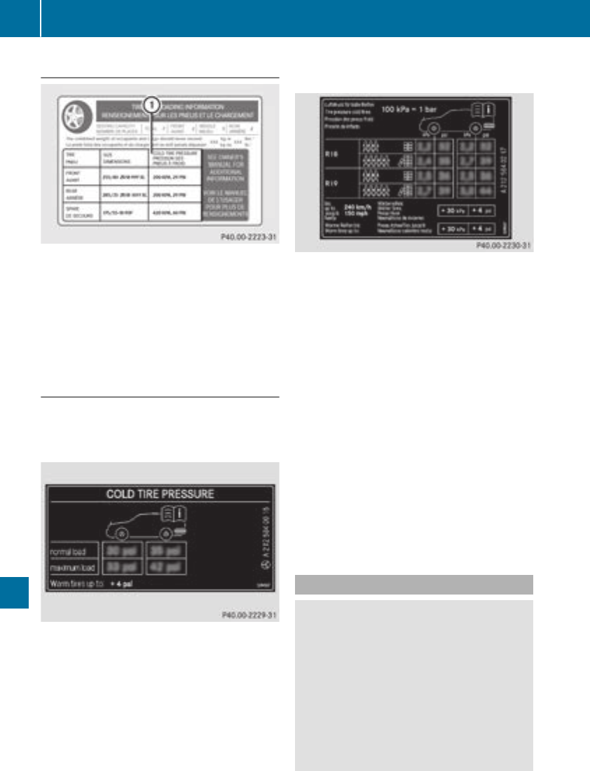
Tire and Loading Information placard
:Recommended tire pressures
The Tire and Loading Information placard is on
the B-pillar on the driver's side (Ypage 322).
The Tire and Loading Information placard con-
tains the recommended tire pressures for cold
tires. The recommended tire pressures are valid
for the maximum permissible load and up to the
maximum permissible vehicle speed.
Tire pressure table
The tire pressure table is on the inside of the fuel
filler flap. It shows the tire pressure for all tires
permitted at the factory for this vehicle; see
illustration (example).
The tire pressure table contains the recommen-
ded pressures for cold tires for various operat-
ing conditions, i.e. differing load and speed con-
ditions.
If a tire size precedes a tire pressure, the tire
pressure information following is only valid for
that tire size. If a speed range precedes the tire
pressure, the following tire pressure data
applies to only this speed range.
The load conditions "partially laden" and "fully
laden" are defined in the table for different num-
bers of occupants and amounts of luggage. The
actual number of seats may differ.
Some tire pressure tables show only the rim
diameters instead of the full tire size, e.g. R18.
Rim diameter is part of the tire size and can be
found on the tire sidewall (Ypage 326).
If the tire pressures have been set to the lower
values for lighter loads and/or lower road
speeds, the pressures should be reset to the
higher values:
Rif you want to drive with an increased load
and/or
Rif you want to drive at higher road speeds
The tire pressures for increased loads and/or
higher road speeds, shown in the tire pressure
table, may have a negative effect on driving
comfort.
If the tire pressure is not set correctly, this can
lead to an excessive build up of heat and a sud-
den loss of pressure.
For more information, contact a qualified spe-
cialist workshop.
Important notes on tire pressure
GWARNING
If the tire pressure drops repeatedly, the
wheel, valve or tire may be damaged. Tire
pressure that is too low may result in a tire
blow-out. There is a risk of an accident.
RCheck the tire for foreign objects.
RCheck whether the wheel is losing air or the
valve is leaking.
If you are unable to rectify the damage, con-
tact a qualified specialist workshop.
316 Tire pressure
Wheels and tires

GWARNING
If you fit unsuitable accessories onto tire
valves, the tire valves may be overloaded and
malfunction, which can cause tire pressure
loss. Due to their design, retrofitted tire pres-
sure monitors keep the tire valve open. This
can also result in tire pressure loss. There is a
risk of an accident.
Only screw the standard valve cap or other
valve caps approved by Mercedes-Benz for
your vehicle onto the tire valve.
Use a suitable pressure gauge to check the tire
pressure. The outer appearance of a tire does
not permit any reliable conclusion about the tire
pressure. On vehicles equipped with the elec-
tronic tire pressure monitor, the tire pressure
can be checked in the on-board computer.
The tire temperature and pressure increase
when the vehicle is in motion. This is dependent
on the driving speed and the load.
Therefore, you should only correct tire pres-
sures when the tires are cold.
The tires are cold:
Rif the vehicle has been parked with the tires
out of direct sunlight for at least three hours
and
Rif the vehicle has not been driven further than
1 mile (1.6 km)
The tire temperature changes depending on the
outside temperature, the vehicle speed and the
tire load. If the tire temperature changes by
18 ‡ (10 †), the tire pressure changes by
approximately 10 kPa (0.1 bar/1.5 psi). Take
this into account when checking the pressure of
warm tires. Only correct the tire pressure if it is
too low for the current operating conditions. If
you check the tire pressure when the tires are
warm, the resulting value will be higher than if
the tires were cold. This is normal. Do not
reduce the tire pressure to the value specified
for cold tires. The tire pressure would otherwise
be too low.
Observe the recommended tire pressures for
cold tires:
Ron the Tire and Loading Information placard
on the B-pillar on the driver's side
Rin the tire pressure table on the fuel filler flap
(Ypage 142)
Underinflated or overinflated tires
Underinflated tires
GWARNING
Tires with pressure that is too low can over-
heat and burst as a consequence. In addition,
they also suffer from excessive and/or irreg-
ular wear, which can severely impair the brak-
ing properties and the driving characteristics.
There is a risk of an accident.
Avoid tire pressures that are too low in all the
tires, including the spare wheel.
Underinflated tires may:
Roverheat, leading to tire defects
Radversely affect handling
Rwear excessively and/or unevenly
Rhave an adverse effect on fuel consumption
Overinflated tires
GWARNING
Tires with excessively high pressure can burst
because they are damaged more easily by
road debris, potholes etc. In addition, they
also suffer from irregular wear, which can
severely impair the braking properties and the
driving characteristics. There is a risk of an
accident.
Avoid tire pressures that are too high in all the
tires, including the spare wheel.
Overinflated tires may:
Rincrease the braking distance
Radversely affect handling
Rwear excessively and/or unevenly
Rhave an adverse effect on ride comfort
Rbe more susceptible to damage
Tire pressure 317
Wheels and tires
Z
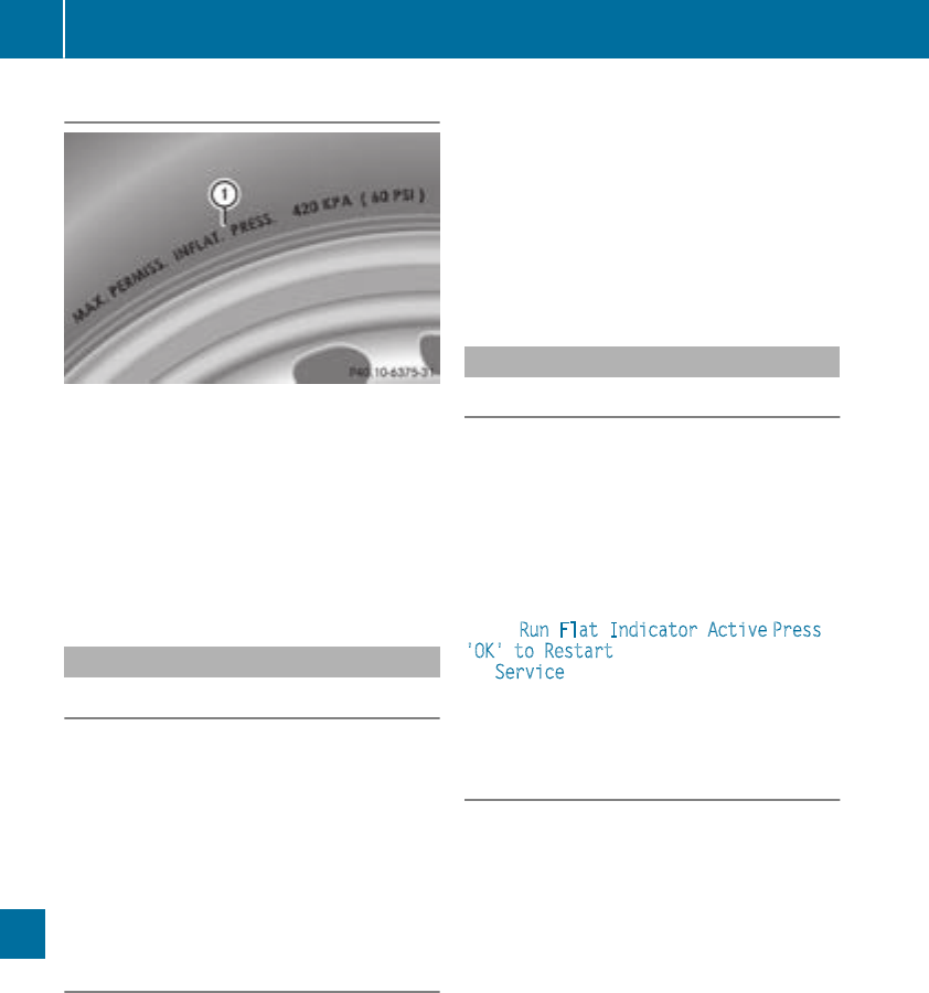
Maximum tire pressures
:Example: maximum permissible tire pres-
sure
Never exceed the maximum permissible tire
inflation pressure. Always observe the recom-
mended tire pressure for your vehicle when
adjusting the tire pressure (Ypage 315).
iThe actual values for tires are vehicle-spe-
cific and may deviate from the values in the
illustration.
Checking the tire pressures
Important safety notes
Observe the notes on tire pressure
(Ypage 315).
Information on air pressure for the tires on your
vehicle can be found:
Ron the vehicle's Tire and Loading Information
placard on the B-pillar
Rin the tire pressure table in the fuel filler flap
(Ypage 142)
Rin the "Tire pressure" section
Checking tire pressures manually
To determine and set the correct tire pressure,
proceed as follows:
XRemove the valve cap of the tire that is to be
checked.
XPress the tire pressure gauge securely onto
the valve.
XRead the tire pressure and compare it to the
recommended value on the Tire and Loading
Information placard or the tire pressure table
(Ypage 315).
XIf the tire pressure is too low, increase the tire
pressure to the recommended value.
XIf the tire pressure is too high, release air. To
do so, press down the metal pin in the valve,
using the tip of a pen for example. Then check
the tire pressure again using the tire pressure
checker.
XScrew the valve cap onto the valve.
XRepeat these steps for the other tires.
Tire pressure loss warning system
General notes
While the vehicle is in motion, the tire pressure
loss warning system monitors the set tire pres-
sure using the rotational speed of the wheels.
This enables the system to detect significant
pressure loss in a tire. If the speed of rotation of
a wheel changes as a result of a loss of pressure,
a corresponding warning message will appear in
the multifunction display.
You can recognize the tire pressure loss warning
by the Run Flat Indicator Active Press
'OK' to Restart message which appears in
the Service menu of the multifunction display.
Information on the message display can be
found in the "Restarting the tire pressure loss
warning system" section (Ypage 319).
Important safety notes
The tire pressure warning system does not warn
you of an incorrectly set tire pressure. Observe
the notes on the recommended tire pressure
(Ypage 315).
The tire pressure loss warning does not replace
the need to regularly check the tire pressure. An
even loss of pressure on several tires at the
same time cannot be detected by the tire pres-
sure loss warning system.
The tire pressure monitor is not able to warn you
of a sudden loss of pressure, e.g. if the tire is
penetrated by a foreign object. In the event of a
sudden loss of pressure, bring the vehicle to a
halt by braking carefully. Avoid abrupt steering
movements.
The function of the tire pressure loss warning
system is limited or delayed if:
Rsnow chains are mounted on your vehicle's
tires.
Rroad conditions are wintry.
318 Tire pressure
Wheels and tires
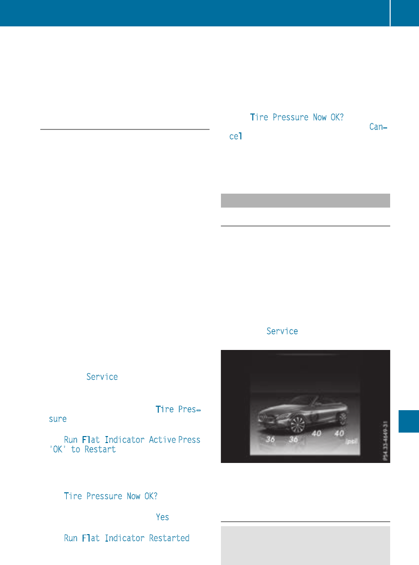
Ryou are drivingon sandor gravel.
Ryou adopt a verysportydrivingstyle (corner-
ingat high speeds or drivingwithhigh rates of
acceleration).
Ryou drive with a heavyload.
Restarting the tire pressure loss warn-
ing system
Restart thetire pressureloss warningsystem if
you have:
Rchanged thetire pressure
Rchanged thewheels or tires
Rmountednewwheels or tires
XBeforerestarting,makesurethat thetire
pressures are set properly on all fourtires for
therespective operating conditions.
The recommended tire pressurecan be found
on theTireand LoadingInformation placard
on theB-pillar.Additionally, atire pressure
table is attached to thefuel filler flap.The tire
pressureloss warningsystem can only give
reliable warnings if you haveset thecorrect
tire pressure. If an incorrecttire pressureis
set,these incorrectvalueswill be monitored.
XAlso observethenotesin thesection on tire
pressures (Ypage 315).
XMakesurethat theSmartKey is in position 2
in theignition lock (Ypage 123).
XPress òon thesteeringwheelto callup
themenulist.
XPress 9or :on thesteeringwheelto
select theServicemenu.
XConfirmby pressing aon thesteering
wheel.
XPress 9or :to select TirePres‐
sure.
XPress ato confirm.
The Run FlatIndicator Active Press
'OK'to Restartmessage is shown in the
multifunction display.
If you wish to confirmtherestart:
XPress theabutton.
The TirePressure Now OK? message is
shown on themultifunction display.
XPress 9or :to select Yes.
XPress ato confirm.
The Run FlatIndicator Restarted mes-
sage is shown on themultifunction display.
After a teach-inperiod, thetire pressureloss
warningsystem will monitor theset tire pres-
sures of all fourtires.
If you wish to cancel therestart:
XPress the%button.
or
XIf theTirePressure Now OK? message
appears,press 9or :to select Can‐
cel.
XPress ato confirm.
The tire pressurevaluesstoredat thelast
restartwill continue to be monitored.
Tire pressure monitor
General notes
If atire pressuremonitor is installed,thevehi-
cle's wheels havesensorsthat monitor thetire
pressures in all fourtires.The tire pressuremon-
itor warnsyou if thepressuredrops in oneor
moreof thetires.The tire pressuremonitor only
functionsif thecorrespondingsensorsare
installed in all wheels.
Information on tire pressures is displayed in the
multifunction display. After a few minutesof
driving, thecurrenttire pressureof eachtire is
shown in theServicemenuof themultifunction
display; see illustration (example).
Information on themessage display can be
found in the"Checking thetire pressureelec-
tronically" section (Ypage 321).
Important safety notes
GWARNING
Eachtire, includingthespare(if provided),
should be checkedat leastonce every two
Tire pressure 319
Wheels and tires
Z

weeks when cold and inflated to the pressure
recommended by the vehicle manufacturer
on the Tire and Loading Information placard
on the driver's door B-pillar or the tire pres-
sure label on the inside of the fuel filler flap. If
your vehicle has tires of a different size than
the size indicated on the Tire and Loading
Information placard or, if available, the tire
pressure label, you should determine the
proper tire pressure for those tires.
As an added safety feature, your vehicle has
been equipped with a tire pressure monitoring
system (TPMS) that illuminates a low tire pres-
sure telltale when one or more of your tires
are significantly underinflated. Accordingly,
when the low tire pressure telltale lights up,
you should stop and check your tires as soon
as possible, and inflate them to the proper
pressure. Driving on a significantly underin-
flated tire causes the tire to overheat and can
lead to tire failure.
Underinflation also reduces fuel efficiency
and tire tread life, and may affect the vehicle's
handling and stopping ability. Please note that
the TPMS is not a substitute for proper tire
maintenance, and it is the driver's responsi-
bility to maintain correct tire pressure, even if
underinflation has not reached the level to
trigger illumination of the TPMS low tire pres-
sure telltale.
Your vehicle has also been equipped with a
TPMS malfunction indicator to indicate when
the system is not operating properly. The
TPMS malfunction indicator is combined with
the low tire pressure telltale. When the sys-
tem detects a malfunction, the warning lamp
will flash for approximately a minute and then
remain continuously illuminated. This
sequence will be repeated every time the vehi-
cle is started as long as the malfunction
exists. When the malfunction indicator is illu-
minated, the system may not be able to detect
or signal low tire pressure as intended.
TPMS malfunctions may occur for a variety of
reasons, including the installation of incom-
patible replacement or alternate tires or
wheels on the vehicle that prevent the TPMS
from functioning properly. Always check the
TPMS malfunction telltale after replacing one
or more tires or wheels on your vehicle to
ensure that the replacement or alternate Tires
and wheels allow the TPMS to continue to
function properly.
It is the driver's responsibility to set the tire
pressure to that recommended for cold tires
which is suitable for the operating situation
(Ypage 315). Note that the correct tire pressure
for the current operating situation must first be
taught-in to the tire pressure monitor. If a sub-
stantial loss of pressure occurs, the warning
threshold for the warning message is aligned to
the taught-in reference values. Restart the tire
pressure monitor after adjusting the pressure of
the cold tires (Ypage 321). The current pres-
sures are saved as new reference values. As a
result, a warning message will appear if the tire
pressure drops significantly.
The tire pressure monitor does not warn you of
an incorrectly set tire pressure. Observe the
notes on the recommended tire pressure
(Ypage 315).
The tire pressure monitor is not able to warn you
of a sudden loss of pressure, e.g. if the tire is
penetrated by a foreign object. In the event of a
sudden loss of pressure, bring the vehicle to a
halt by braking carefully. Avoid abrupt steering
movements.
The tire pressure monitor has a yellow warning
lamp in the instrument cluster for indicating
pressure loss or a malfunction. Whether the
warning lamp flashes or lights up indicates
whether a tire pressure is too low or the tire
pressure monitor is malfunctioning:
Rif the warning lamp is lit continuously, the tire
pressure on one or more tires is significantly
too low. The tire pressure monitor is not mal-
functioning.
Rif the warning lamp flashes for around a
minute and then remains lit constantly, the
tire pressure monitor is malfunctioning.
In addition to the warning lamp, a message
appears in the multifunction display. Observe
the information on display messages
(Ypage 234).
It may take up to ten minutes for a malfunction
of the tire pressure monitor to be indicated. A
malfunction will be indicated by the tire pres-
sure warning lamp flashing for approximately
one minute and then remaining lit. When the
320 Tire pressure
Wheels and tires
malfunction has been rectified, the tire pressure
warning lamp goes out after a few minutes of
driving.
The tire pressure values indicated by the on-
board computer may differ from those meas-
ured at a gas station with a pressure gauge. The
tire pressures shown by the on-board computer
refer to those measured at sea level. At high
altitudes, the tire pressure values indicated by a
pressure gauge are higher than those shown by
the on-board computer. In this case, do not
reduce the tire pressures.
The operation of the tire pressure monitor can
be affected by interference from radio transmit-
ting equipment (e.g. radio headphones, two-way
radios) that may be being operated in or near the
vehicle.
Checking the tire pressure electroni-
cally
XMake sure that the SmartKey is in position 2
(Ypage 123) in the ignition lock.
XPress òon the steering wheel to call up
the menu list.
XPress 9or :on the steering wheel to
select the Service menu.
XConfirm by pressing aon the steering
wheel.
XPress 9or :to select Tire Pres‐
sure.
XPress ato confirm.
The multifunction display shows the current
tire pressure of each wheel.
If the vehicle was parked for longer than
20 minutes, the following message appears:
Tire pressure will be displayed after
driving a few minutes.
After a teach-in process, the tire pressure mon-
itor automatically detects new wheels or new
sensors. As long as a clear allocation of the tire
pressure value to the individual wheels is not
possible, the Tire Pressure Monitor Active
message is shown instead of the tire pressure
display. The tire pressures are already being
monitored.
Tire pressure monitor warning mes-
sages
If the tire pressure monitor detects a pressure
loss in one or more tires, a warning message is
shown in the multifunction display. The yellow
tire pressure warning lamp then lights up.
RIf the Please Correct Tire Pressure
message appears in the multifunction display,
the tire pressure in at least one tire is too low.
The tire pressure must be corrected when the
opportunity arises.
RIf the Check Tires message appears in the
multifunction display, the tire pressure in one
or more tires has dropped significantly. The
tires must be checked.
RIf the Warning Tire Malfunction message
appears in the multifunction display, the tire
pressure in one or more tires has dropped
suddenly. The tires must be checked.
Be sure to observe the instructions and safety
notes in the display messages in the "Tires" sec-
tion (Ypage 234).
If the wheel positions on the vehicle are rotated,
the tire pressures may be displayed for the
wrong positions for a short time. This is rectified
after a few minutes of driving, and the tire pres-
sures are displayed for the correct positions.
Restarting the tire pressure monitor
When you restart the tire pressure monitor, all
existing warning messages are deleted and the
warning lamps go out. The monitor uses the cur-
rently set tire pressures as the reference values
for monitoring. In most cases, the tire pressure
monitor will automatically detect the new refer-
ence values after you have changed the tire
pressure. However, you can also set reference
values manually as described here. The tire
pressure monitor then monitors the new tire
pressure values.
XSet the tire pressure to the value recommen-
ded for the corresponding driving situation on
the Tire and Loading Information placard on
the B-pillar on the driver's side.
You can find more tire pressures for various
operating conditions in the tire pressure table
inside the filler flap.
Observe the information on tire pressure
when doing so (Ypage 315).
XMake sure that the tire pressure is correct on
all four wheels.
Tire pressure 321
Wheels and tires
Z
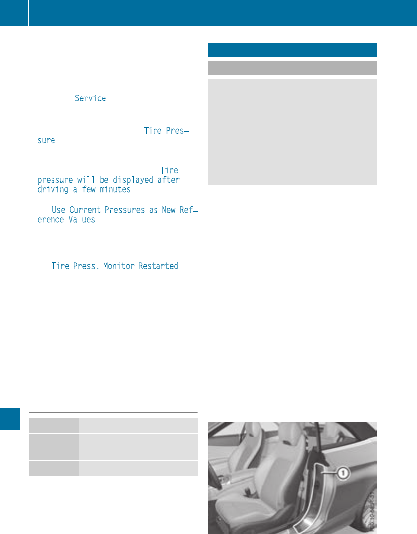
XMake sure that the SmartKey is in position 2
in the ignition lock (Ypage 123).
XPress òon the steering wheel to call up
the menu list.
XPress 9or :on the steering wheel to
select the Service menu.
XConfirm by pressing aon the steering
wheel.
XPress 9or :to select Tire Pres‐
sure.
XPress ato confirm.
The multifunction display shows the current
tire pressure of each wheel or the Tire
pressure will be displayed after
driving a few minutes message.
XPress the :button.
The Use Current Pressures as New Ref‐
erence Values message is shown on the
multifunction display.
If you wish to confirm the restart:
XPress the abutton.
The Tire Press. Monitor Restarted mes-
sage is shown on the multifunction display.
After driving for a few minutes, the system
checks whether the current tire pressures are
within the specified range. The new tire pres-
sures are then accepted as reference values
and monitored.
If you wish to cancel the restart:
XPress the %button.
The tire pressure values stored at the last
restart will continue to be monitored.
Radio type approval for the tire pres-
sure monitor
Country Radio type approval number
USA FCC ID: MRXGG4
FCC ID: MRXMC34MA4
Canada IC: 2546A-GG4
Loading the vehicle
Instruction labels for tires and loads
GWARNING
Overloaded tires can overheat, causing a
blowout. Overloaded tires can also impair the
steering and driving characteristics and lead
to brake failure. There is a risk of accident.
Observe the load rating of the tires. The load
rating must be at least half of the GAWR of
your vehicle. Never overload the tires by
exceeding the maximum load.
Two instruction labels on your vehicle show the
maximum possible load.
(1) The Tire and Loading Information placard is
on the B-pillar on the driver's side. The Tire
and Loading Information placard shows the
maximum permissible number of occu-
pants and the maximum permissible vehicle
load. It also contains details of the tire sizes
and corresponding pressures for tires
mounted at the factory.
(2) The vehicle identification plate is on the B-
pillar on the driver's side. The vehicle iden-
tification plate informs you of the gross
vehicle weight rating. It is made up of the
vehicle weight, all vehicle occupants, the
fuel and the cargo. You can also find infor-
mation about the maximum gross axle
weight rating on the front and rear axle.
The maximum gross axle weight rating is
the maximum weight that can be carried by
one axle (front or rear axle). Never exceed
the maximum load or the maximum gross
axle weight rating for the front or rear axle.
:B-pillar, driver's side
322 Loading the vehicle
Wheels and tires
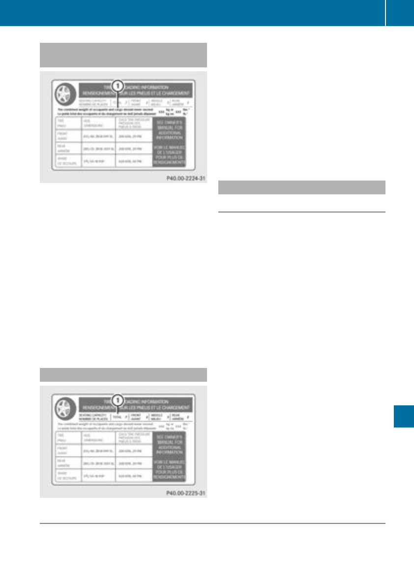
Maximum permissible gross vehicle
weight rating
XSpecification for maximum gross vehicle
weight :is listed in the Tire and Loading
Information placard: "The combined weight of
occupants and cargo should never exceed
XXX kg or XXX lbs."
The gross weight of all vehicle occupants, load
and luggage must not exceed the specified
value.
iThe specifications shown on the Tire and
Loading Information placard in the illustration
are examples. The maximum permissible
gross vehicle weight rating is vehicle-specific
and may differ from that in the illustration.
You can find the valid maximum permissible
gross vehicle weight rating for your vehicle on
the Tire and Loading Information placard.
Number of seats
Maximum number of seats :indicates the
maximum number of occupants allowed to
travel in the vehicle. This information can be
found on the Tire and Loading Information plac-
ard.
iThe specifications shown on the Tire and
Loading Information placard in the illustration
are examples. The number of seats is vehicle-
specific and can differ from the details shown.
The number of seats in your vehicle can be
found on the Tire and Loading Information
placard.
Determining the correct load limit
Step-by-step instructions
The following steps have been developed as
required of all manufacturers under Title 49,
Code of U.S. Federal Regulations, Part 575 pur-
suant to the "National Traffic and Motor Vehicle
Safety Act of 1966".
XStep 1: Locate the statement "The combined
weight of occupants and cargo should never
exceed XXX kg or XXX lbs." on your vehicle's
Tire and Loading Information placard.
XStep 2: Determine the combined weight of
the driver and passengers that will be riding in
your vehicle.
XStep 3: Subtract the combined weight of the
driver and passengers from XXX kilograms or
XXX lbs.
XStep 4: The resulting figure equals the avail-
able amount of cargo and luggage load capa-
city. For example, if the "XXX" amount equals
1400 lbs and there will be five 150-lb pas-
sengers in your vehicle, the amount of avail-
able cargo and luggage load capacity is
650 lbs (1400 - 750 (5 x 150) = 650 lbs).
XStep 5: Determine the combined weight of
luggage and cargo being loaded on the vehi-
cle. That weight may not safely exceed the
available cargo and luggage load capacity cal-
culated in step 4.
Example: steps 1 to 3
The following table shows examples on how to calculate total and cargo load capacities with varying
seating configurations and number and size of occupants. The following examples use a load limit of
Loading the vehicle 323
Wheels and tires
Z

1500 lbs (680 kg). This is for illustration purposes only. Make sure you are using the actual load
limit for your vehicle stated on your vehicle's Tire and Loading Information placard (Ypage 322).
The greater the combined weight of the occupants, the lower the maximum luggage load.
Step 1
Example 1 Example 2 Example 3
Combined maximum
weight of occupants
and load (data from the
Tire and Loading Infor-
mation placard)
1500 lbs (680 kg) 1500 lbs (680 kg) 1500 lbs (680 kg)
Step 2
Example 1 Example 2 Example 3
Number of people in
the vehicle (driver and
occupants)
5 3 1
Distribution of the
occupants
Front: 2
Rear: 3
Front: 1
Rear: 2
Front: 1
Weight of the occu-
pants
Occupant 1: 150 lbs
(68 kg)
Occupant 2: 180 lbs
(82 kg)
Occupant 3: 160 lbs
(73 kg)
Occupant 4: 140 lbs
(63 kg)
Occupant 5: 120 lbs
(54 kg)
Occupant 1: 200 lbs
(91 kg)
Occupant 2: 190 lbs
(86 kg)
Occupant 3: 150 lbs
(68 kg)
Occupant 1: 150 lbs
(68 kg)
Gross weight of all
occupants
750 lbs (340 kg) 540 lbs (245 kg) 150 lbs (68 kg)
Step 3
Example 1 Example 2 Example 3
Permissible load (maxi-
mum gross vehicle
weight rating from the
Tire and Loading Infor-
mation placard minus
the gross weight of all
occupants)
1500 lbs (680 kg) Ò
750 lbs (340 kg) =
750 lbs (340 kg)
1500 lbs (680 kg) Ò
540 lbs (245 kg)
=960 lbs (435 kg)
1500 lbs (680 kg) Ò
150 lbs (68 kg) =
1350 lbs (612 kg)
Vehicle identification plate
Even if you have calculated the total cargo care-
fully, you should still make sure that the gross
vehicle weight rating and the gross axle weight
rating are not exceeded. Details can be found on
the vehicle identification plate on the B-pillar on
the driver's side of the vehicle (Ypage 322).
324 Loading the vehicle
Wheels and tires
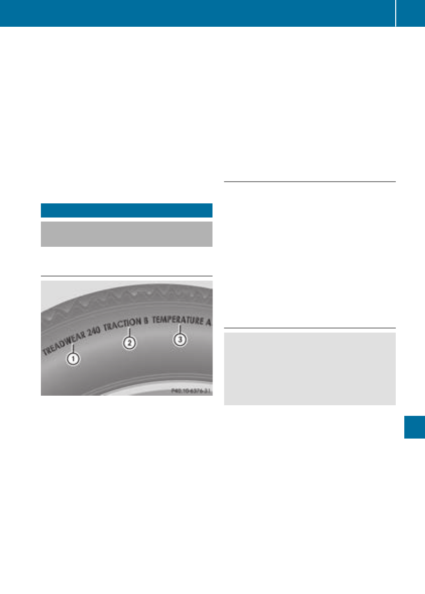
Permissible Gross Vehicle Weight Rating
(GVWR): the gross weight of the vehicle, all pas-
sengers, load and trailer load/noseweight (if
applicable) must not exceed the permissible
gross vehicle weight.
Gross Axle Weight Rating (GAWR): the maxi-
mum permissible load that can be carried by one
axle (front or rear axle).
To ensure that your vehicle does not exceed the
maximum permissible values (gross vehicle
weight and maximum gross axle weight rating),
have your loaded vehicle (including driver, occu-
pants, cargo, and full trailer load if applicable)
weighed on a suitable vehicle weighbridge.
All about wheels and tires
Uniform Tire Quality Grading Stand-
ards
Overview of Tire Quality Grading Stand-
ards
Uniform Tire Quality Grading Standards are U.S.
government specifications. Their purpose is to
provide drivers with uniform reliable information
on tire performance data. Tire manufacturers
have to grade tires using three performance fac-
tors: :tread wear grade, ;traction grade and
=temperature grade. These regulations do not
apply to Canada. Nevertheless, all tires sold in
North America are provided with the corre-
sponding quality grading markings on the side-
wall of the tire.
Quality grades can be found, where applicable,
on the tire sidewall between tread shoulder and
maximum section width.
Example:
RTreadwear grade: 200
RTraction grade: AA
RTemperature grade: A
All passenger car tires must conform to the stat-
utory safety requirements in addition to these
grades.
iThe actual values for tires are vehicle-spe-
cific and may deviate from the values in the
illustration.
Treadwear
The treadwear grade is a comparative rating
based on the wear rate of the tire when tested
under controlled conditions on a specified U.S.
government course. For example, a tire graded
150 would wear one and one-half times as well
on the government course as a tire graded 100.
The relative performance of tires depends upon
the actual conditions of their use, however, and
may depart significantly from the norm due to
variations in driving habits, service practices
and differences in road characteristics and cli-
mate.
Traction
GWARNING
The traction grade assigned to this tire is
based on straight-ahead braking traction
tests, and does not include acceleration, cor-
nering, hydroplaning, or peak traction char-
acteristics.
!Avoid wheelspin. This can lead to damage to
the drive train.
The traction grades – from highest to lowest –
are AA, A, B and C. Those grades represent the
tire's ability to stop on wet pavement as meas-
ured under controlled conditions on specified
government test surfaces of asphalt and con-
crete. A tire marked C may have poor traction
performance.
The safe speed on a wet, snow covered or icy
road is always lower than on dry road surfaces.
You should pay special attention to road condi-
tions when temperatures are around freezing
point.
Mercedes-Benz recommends a minimum tread
depth of ãin (4 mm) on all four winter tires.
All about wheels and tires 325
Wheels and tires
Z
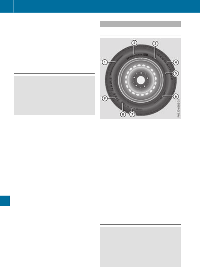
Observe the legally required minimum tire tread
depth (Ypage 313). Winter tires can reduce the
braking distance on snow-covered surfaces in
comparison with summer tires. The braking dis-
tance is still much further than on surfaces that
are not icy or covered with snow. Take appro-
priate care when driving.
Further information on winter tires (M+S tires)
(Ypage 314).
Temperature
GWARNING
The temperature grade for this tire is estab-
lished for a tire that is properly inflated and
not overloaded. Excessive speed, underinfla-
tion, or excessive loading, either separately or
in combination, can cause excessive heat
build-up and possible tire failure.
The temperature grades are A (the highest), B,
and C, representing the tire's resistance to the
generation of heat and its ability to dissipate
heat when tested under controlled conditions
on a specified indoor laboratory test wheel. Sus-
tained high temperature can cause the material
of the tire to degenerate and reduce tire life, and
excessive temperature can lead to sudden tire
failure. The grade C corresponds to a level of
performance which all passenger car tires must
meet under the Federal Motor Vehicle Safety
Standard No. 109. Grades B and A represent
higher levels of performance on the laboratory
test wheel than the minimum required by law.
Tire labeling
Overview
:Uniform Tire Quality Grading Standard
(Ypage 330)
;DOT, Tire Identification Number
(Ypage 329)
=Maximum tire load (Ypage 328)
?Maximum tire pressure (Ypage 318)
AManufacturer
BTire material (Ypage 329)
CTire size designation, load-bearing capacity
and speed rating (Ypage 326)
DLoad index (Ypage 328)
ETire name
The markings described above are on the tire in
addition to the tire name (sales designation) and
the manufacturer's name.
iTire data is vehicle-specific and may deviate
from the data in the example.
Tire size designation, load-bearing
capacity and speed rating
GWARNING
Exceeding the stated tire load-bearing capa-
city and the approved maximum speed could
lead to tire damage or the tire bursting. There
is a risk of accident.
Therefore, only use tire types and sizes
approved for your vehicle model. Observe the
326 All about wheels and tires
Wheels and tires
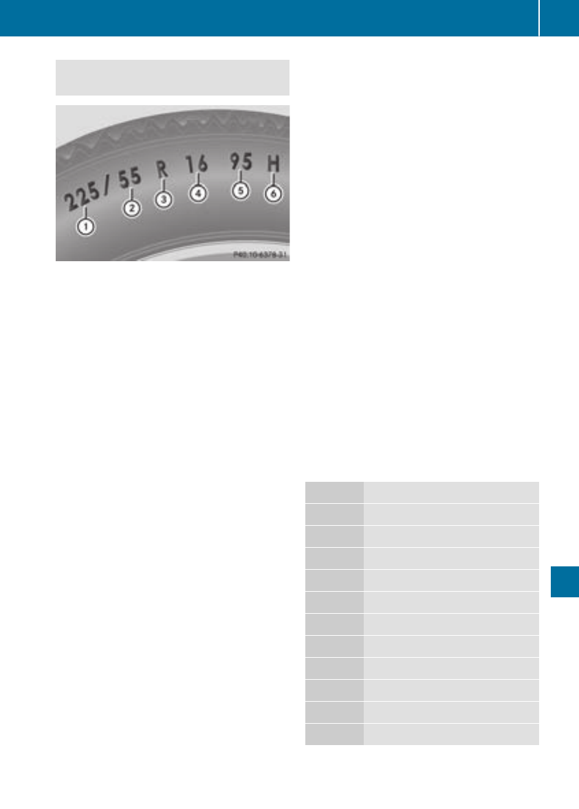
tire load rating and speed rating required for
your vehicle.
:Tire width
;Nominal aspect ratio in %
=Tire code
?Rim diameter
ALoad bearing index
BSpeed rating
General: depending on the manufacturer's
standards, the size imprinted in the tire wall may
not contain any letters or may contain one letter
that precedes the size description.
If there is no letter preceding the size descrip-
tion (as shown above): these are passenger
vehicle tires according to European manufac-
turing standards.
If "P" precedes the size description: these are
passenger vehicle tires according to U.S. man-
ufacturing standards.
If "LT" precedes the size description: these are
light truck tires according to U.S. manufacturing
standards.
If "T" precedes the size description: compact
emergency wheels with high tire pressure that
are only designed for temporary use in an emer-
gency.
Tire width: tire width :shows the nominal tire
width in millimeters.
Height-width ratio: aspect ratio ;is the size
ratio between the tire height and tire width and
is shown in percent. The aspect ratio is calcula-
ted by dividing the tire width by the tire height.
Tire code: tire code =specifies the tire type.
"R" represents radial tires; "D" represents diag-
onal tires; "B" represents diagonal radial tires.
Optionally, tires with a maximum speed of over
149 mph (240 km/h) may have "ZR" in the size
description, depending on the manufacturer
(e.g. 245/40 ZR 18).
Rim diameter: rim diameter ?is the diameter
of the bead seat, not the diameter of the rim
flange. The rim diameter is specified in
inches (in).
Load-bearing index: load-bearing index Ais a
numerical code that specifies the maximum
load-bearing capacity of a tire.
Do not overload the tires by exceeding the
specified load limit. The maximum permissible
load can be found on the vehicle's Tire and
Loading Information placard on the B-pillar on
the driver's side (Ypage 322).
Example:
Load-bearing index 91 indicates a maximum
load of 1,356 lb (615 kg) that the tires can bear.
For further information on the maximum tire
load in kilograms and lbs, see (Ypage 328).
For further information on the load bearing
index, see "Load index" (Ypage 328).
Speed rating: speed rating Bspecifies the
approved maximum speed of the tire.
iTire data is vehicle-specific and may deviate
from the data in the example.
Regardless of the speed rating, always observe
the speed limits. Drive carefully and adapt your
driving style to the traffic conditions.
Summer tires
Index Speed rating
Q up to 100 mph (160 km/h)
R up to 106 mph (170 km/h)
S up to 112 mph (180 km/h)
T up to 118 mph (190 km/h)
H up to 130 mph (210 km/h)
V up to 149 mph (240 km/h)
W up to 168 mph (270 km/h)
Y up to 186 mph (300 km/h)
ZR...Y up to 186 mph (300 km/h)
ZR...(..Y) over 186 mph (300 km/h)
ZR over 149 mph (240 km/h)
ROptionally, tires with a maximum speed of
over 149 mph (240 km/h) may have "ZR" in
All about wheels and tires 327
Wheels and tires
Z
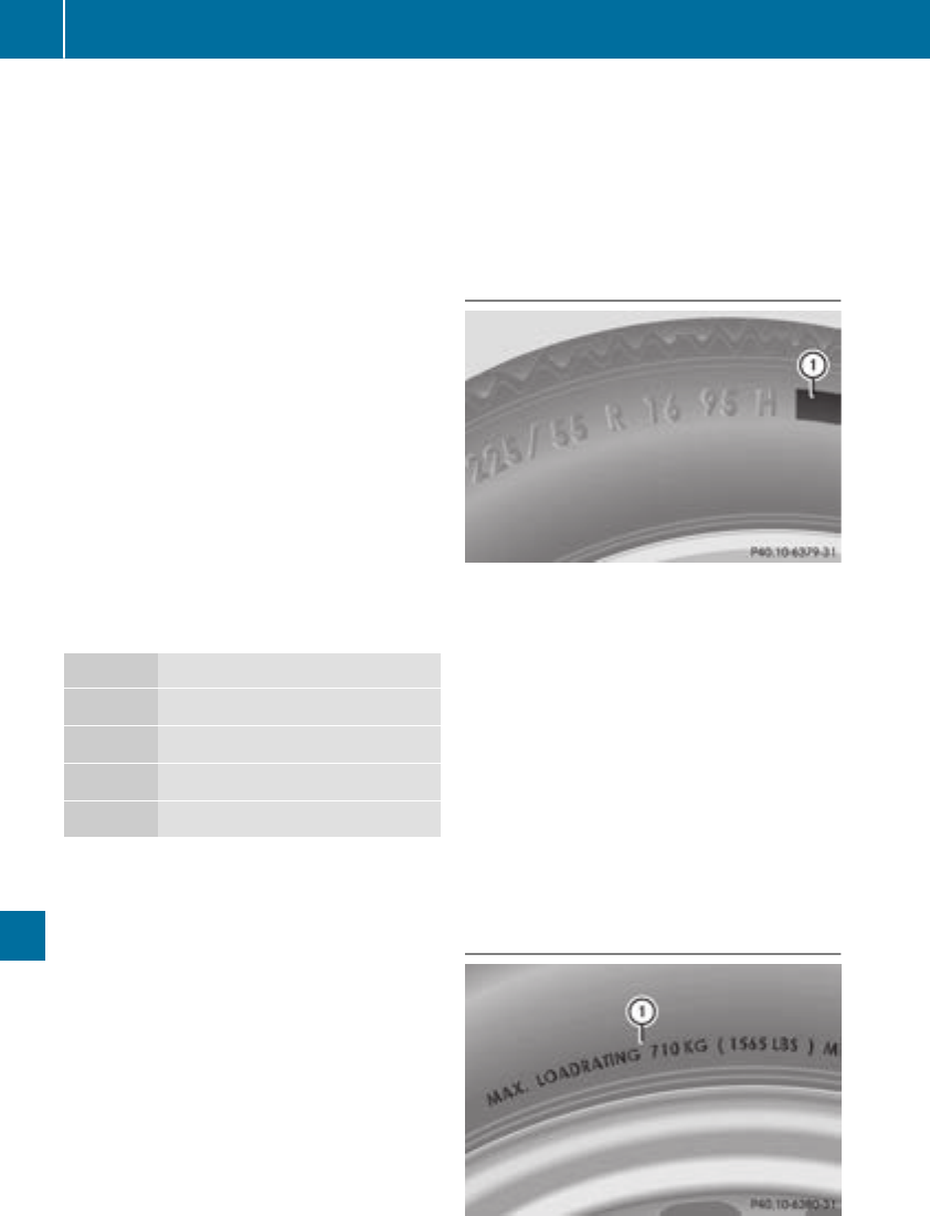
the size description, depending on the man-
ufacturer (e.g. 245/40 ZR18).
The service specification is made up of load-
bearing index Aand speed rating B.
RIf the size description of your tire includes
"ZR" and there are no service specifications,
ask the tire manufacturer in order to find out
the maximum speed.
If a service specification is available, the max-
imum speed is limited according to the speed
rating in the service specification. Example:
245/40 ZR18 97 Y. In this example, "97 Y" is
the service specification. The letter "Y" rep-
resents the speed rating. The maximum
speed of the tire is limited to 186 mph
(300 km/h).
RThe size description for all tires with maxi-
mum speeds of over 186 mph (300 km/h)
must include "ZR", and the service specifica-
tion must be given in parentheses. Example:
275/40 ZR 18 (99 Y). Speed rating "(Y)" indi-
cates that the maximum speed of the tire is
over 186 mph (300 km/h). Ask the tire man-
ufacturer about the maximum speed.
All-weather tires and winter tires
Index Speed rating
Q M+S1up to 100 mph (160 km/h)
T M+S1up to 118 mph (190 km/h)
H M+S1up to 130 mph (210 km/h)
V M+S1up to 149 mph (240 km/h)
iNot all tires with the M+S marking provide
the driving characteristics of winter tires. In
addition to the M+S marking, winter tires also
have the isnowflake symbol on the tire
wall. Tires with this marking fulfill the require-
ments of the Rubber Manufacturers Associa-
tion (RMA) and the Rubber Association of
Canada (RAC) regarding the tire traction on
snow. They have been especially developed
for driving on snow.
An electronic speed limiter prevents your vehi-
cle from exceeding a speed of 130 mph
(210 km/h).
The speed rating of tires mounted at the factory
may be higher than the maximum speed that the
electronic speed limiter permits.
Make sure that your tires have the required
speed rating, e.g. when buying new tires. You
can find information on this under "Tires"
(Ypage 336).
Further information about reading tire data can
be obtained from any qualified specialist work-
shop.
Load index
In addition to the load-bearing index, load
index :may also be imprinted on the sidewall
of the tire. You will find this after the letter that
identifies the speed rating (Ypage 326).
RIf no specification is given: no text (as in the
example above), represents a standard load
(SL) tire
RXL or Extra Load: represents a reinforced tire
RLight Load: represents a light load tire
RC, D, E: represents a load range that depends
on the maximum load that the tire can carry at
a certain pressure
iTire data is vehicle-specific and may deviate
from the data in the example.
Maximum load rating
1Or M+S ifor winter tires.
328 All about wheels and tires
Wheels and tires
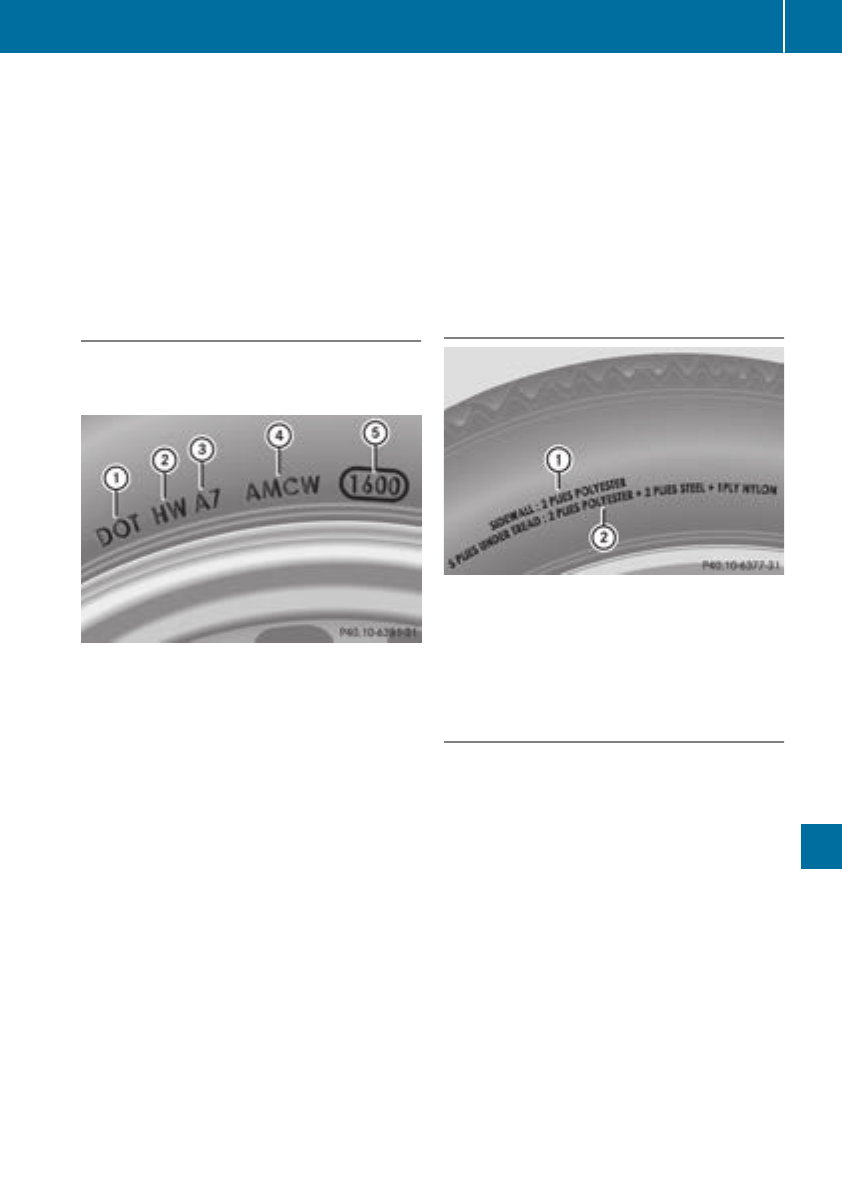
Maximum tire load :is the maximum permis-
sible weight for which the tire is approved.
Do not overload the tires by exceeding the
specified load limit. The maximum permissible
load can be found on the vehicle's Tire and
Loading Information placard on the B-pillar on
the driver's side (Ypage 322).
iThe actual values for tires are vehicle-spe-
cific and may deviate from the values in the
illustration.
DOT, Tire Identification Number (TIN)
US tire regulations stipulate that every tire man-
ufacturer or retreader must imprint a TIN in or on
the sidewall of each tire produced.
The TIN is a unique identification number. The
TIN enables the tire manufacturers or retreaders
to inform purchasers of recalls and other safety-
relevant matters. It makes it possible for the
purchaser to easily identify the affected tires.
The TIN is made up of manufacturer identifica-
tion code ;, tire size =, tire type code ?and
manufacturing date A.
DOT (Department of Transportation): tire
symbol :marks that the tire complies with the
requirements of the U.S. Department of Trans-
portation.
Manufacturer identification code: manufac-
turer identification code ;provides details on
the tire manufacturer. New tires have a code
with two symbols. Retreaded tires have a code
with four symbols.
For further information about retreaded tires,
see (Ypage 336).
Tire size: identifier =describes the tire size.
Tire type code: tire type code ?can be used by
the manufacturer as a code to describe specific
characteristics of the tire.
Date of manufacture: date of manufacture A
provides information about the age of a tire. The
first and second positions represent the week of
manufacture, starting with "01" for the first cal-
endar week. Positions three and four represent
the year of manufacture. For example, a tire that
is marked "3214" was manufactured in week 32
in 2014.
iTire data is vehicle-specific and may deviate
from the data in the example.
Tire characteristics
This information describes the type of tire cord
and the number of layers in sidewall :and
under tire tread ;.
iTire data is vehicle-specific and may deviate
from the data in the example.
Definition of terms for tires and loading
Tire ply composition and material used
Describes the number of plies or the number of
layers of rubber-coated fabric in the tire tread
and sidewall. These are made of steel, nylon,
polyester and other materials.
Bar
Metric unit for tire pressure. 14.5038 pounds
per square inch (psi) and 100 kilopascals (kPa)
are the equivalent of 1 bar.
DOT (Department of Transportation)
DOT-marked tires fulfill the requirements of the
U S Department of Transportation.
Normal occupant weight
The number of occupants for which the vehicle
is designed multiplied by 68 kilograms (150 lbs).
All about wheels and tires 329
Wheels and tires
Z

Uniform Tire Quality Grading Standards
A uniform standard to grade the quality of tires
with regards to tread quality, tire traction and
temperature characteristics. The quality grad-
ing assessment is made by the manufacturer
following specifications from the U.S. govern-
ment. The ratings are molded into the sidewall of
the tire.
Recommended tire pressures
The recommended tire pressure applies to the
tires mounted at the factory.
The Tire and Loading Information placard con-
tains the recommended tire pressures for cold
tires on a fully loaded vehicle and for the maxi-
mum permissible vehicle speed.
The tire pressure table contains the recommen-
ded pressures for cold tires for various operat-
ing conditions, i.e. differing load and speed con-
ditions.
Increased vehicle weight due to optional
equipment
The combined weight of all standard and
optional equipment available for the vehicle,
regardless of whether it is actually installed on
the vehicle or not.
Rim
This is the part of the wheel on which the tire is
mounted.
GAWR (Gross Axle Weight Rating)
The GAWR is the maximum gross axle weight
rating. The actual load on an axle must never
exceed the gross axle weight rating. The gross
axle weight rating can be found on the vehicle
identification plate on the B-pillar on the driver's
side.
Speed rating
The speed rating is part of the tire identification.
It specifies the speed range for which the tire is
approved.
GVW (Gross Vehicle Weight)
The gross vehicle weight includes the weight of
the vehicle including fuel, tools, the spare wheel,
accessories installed, occupants, luggage and
the drawbar noseweight, if applicable. The gross
vehicle weight must not exceed the gross vehi-
cle weight rating GVWR as specified on the vehi-
cle identification plate on the B-pillar on the
driver's side.
GVWR (Gross Vehicle Weight Rating)
The GVWR is the maximum permissible gross
weight of a fully loaded vehicle (the weight of the
vehicle including all accessories, occupants,
fuel, luggage and the drawbar noseweight, if
applicable). The gross vehicle weight rating is
specified on the vehicle identification plate on
the B-pillar on the driver's side.
Maximum loaded vehicle weight
The maximum weight is the sum of:
Rthe curb weight of the vehicle
Rthe weight of the accessories
Rthe load limit
Rthe weight of the factory installed optional
equipment
Kilopascal (kPa)
Metric unit for tire pressure. 6.9 kPa corre-
sponds to 1 psi. Another unit for tire pressure is
bar. 100 kilopascals (kPa) are the equivalent of
1 bar.
Load index
In addition to the load-bearing index, the load
index may also be imprinted on the sidewall of
the tire. This specifies the load-bearing capacity
more precisely.
Curb weight
The weight of a vehicle with standard equipment
including the maximum capacity of fuel, oil and
coolant. It also includes the air-conditioning sys-
tem and optional equipment if these are instal-
led in the vehicle, but does not include passen-
gers or luggage.
Maximum load rating
The maximum tire load is the maximum permis-
sible weight in kilograms or lbs for which a tire is
approved.
Maximum permissible tire pressure
Maximum permissible tire pressure for one tire.
Maximum load on one tire
Maximum load on one tire. This is calculated by
dividing the maximum axle load of one axle by
two.
330 All about wheels and tires
Wheels and tires

PSI (pounds per square inch)
A standard unit of measure for tire pressure.
Aspect ratio
Relationship between tire height and tire width
in percent.
Tire pressure
This is pressure inside the tire applying an out-
ward force to each square inch of the tire's sur-
face. The tire pressure is specified in pounds per
square inch (psi), in kilopascal (kPa) or in bar.
The tire pressure should only be corrected when
the tires are cold.
Cold tire pressure
The tires are cold:
Rif the vehicle has been parked with the tires
out of direct sunlight for at least three hours
and
Rif the vehicle has not been driven further than
1 mile (1.6 km)
Tread
The part of the tire that comes into contact with
the road.
Bead
The tire bead ensures that the tire sits securely
on the wheel. There are several steel wires in the
bead to prevent the tire from coming loose from
the wheel rim.
Sidewall
The part of the tire between the tread and the
bead.
Weight of optional extras
The combined weight of those optional extras
that weigh more than the replaced standard
parts and more than 5 lbs (2.3 kg). These
optional extras, such as high-performance
brakes, level control, a roof rack or a high-per-
formance battery, are not included in the curb
weight and the weight of the accessories.
TIN (Tire Identification Number)
This is a unique identifier which can be used by
a tire manufacturer to identify tires, for example
for a product recall, and thus identify the pur-
chasers. The TIN is made up of the manufactur-
er's identity code, tire size, tire type code and
the manufacturing date.
Load bearing index
The load bearing index (also load index) is a code
that contains the maximum load bearing capa-
city of a tire.
Traction
Traction is the result of friction between the tires
and the road surface.
Treadwear indicators
Narrow bars (tread wear bars) that are distrib-
uted over the tire tread. If the tire tread is level
with the bars, the wear limit of áin (1.6 mm)
has been reached.
Occupant distribution
The distribution of occupants in a vehicle at their
designated seating positions.
Total load limit
Nominal load and luggage load plus 68 kg
(150 lbs) multiplied by the number of seats in
the vehicle.
Changing a wheel
Flat tire
The "Breakdown assistance" section
(Ypage 296) contains information and notes on
how to deal with a flat tire. Information on driv-
ing with MOExtended tires in the event of a flat
tire can be found under "MOExtended tires (tires
with run-flat characteristics" (Ypage 297).
Rotating the wheels
GWARNING
Interchanging the front and rear wheels may
severely impair the driving characteristics if
the wheels or tires have different dimensions.
The wheel brakes or suspension components
may also be damaged. There is a risk of acci-
dent.
Rotate front and rear wheels only if the wheels
and tires are of the same dimensions.
!On vehicles equipped with a tire pressure
monitor, electronic components are located
in the wheel.
Changing a wheel 331
Wheels and tires
Z
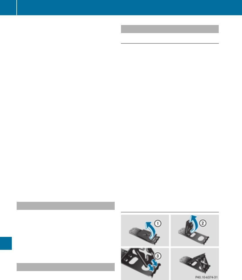
Tire-mounting tools should not be used near
the valve. This could damage the electronic
components.
Only have tires changed at a qualified spe-
cialist workshop.
Always observe the instructions and safety
notes in the "Mounting a wheel" section
(Ypage 332).
The wear patterns on the front and rear tires
differ, depending on the operating conditions.
Rotate the wheels before a clear wear pattern
has formed on the tires. Front tires typically
wear more on the shoulders and the rear tires in
the center.
On vehicles that have the same size front and
rear wheels, you can rotate the wheels accord-
ing to the intervals in the tire manufacturer's
warranty book in your vehicle documents. If no
warranty book is available, the tires should be
rotated every 3,000 to 6,000 miles (5,000 to
10,000 km). Depending on tire wear, this may
be required earlier. Do not change the direction
of wheel rotation.
Clean the contact surfaces of the wheel and the
brake disc thoroughly every time a wheel is rota-
ted. Check the tire pressure and, if necessary,
restart the tire pressure loss warning system
(Ypage 319) or the tire pressure monitor
(Ypage 321).
Direction of rotation
Tires with a specified direction of rotation have
additional benefits, e.g. if there is a risk of hydro-
planing. These advantages can only be gained if
the tires are installed corresponding to the
direction of rotation.
An arrow on the sidewall of the tire indicates its
correct direction of rotation.
Storing wheels
Store wheels that are not being used in a cool,
dry and preferably dark place. Protect the tires
from oil, grease, gasoline and diesel.
Mounting a wheel
Preparing the vehicle
XStop the vehicle on solid, non-slippery and
level ground.
XApply the electric parking brake manually.
XBring the front wheels into the straight-ahead
position.
XShift the transmission to position j.
XMake sure that the vehicle level is set to "Nor-
mal" on vehicles with AIRMATIC (Ypage 164).
XSwitch off the engine.
XVehicles without KEYLESS-GO: remove the
SmartKey from the ignition lock.
XVehicles with KEYLESS-GO start-function
or KEYLESS-GO: open the driver's door.
The vehicle electronics are now in key posi-
tion u. This is the same as the key having
been removed.
XVehicles with KEYLESS-GO start-function
or KEYLESS-GO: remove the Start/Stop but-
ton from the ignition lock (Ypage 124).
XMake sure that the engine cannot be started
via your smartphone (Ypage 126).
XIf included in the vehicle equipment, remove
the tire-change tool kit from the vehicle.
XSafeguard the vehicle against rolling away.
Securing the vehicle to prevent it from
rolling away
If your vehicle is equipped with a wheel chock, it
can be found in the tire-change tool kit
(Ypage 296).
The folding wheel chock is an additional safety
measure to prevent the vehicle from rolling
away, for example when changing a wheel.
332 Changing a wheel
Wheels and tires
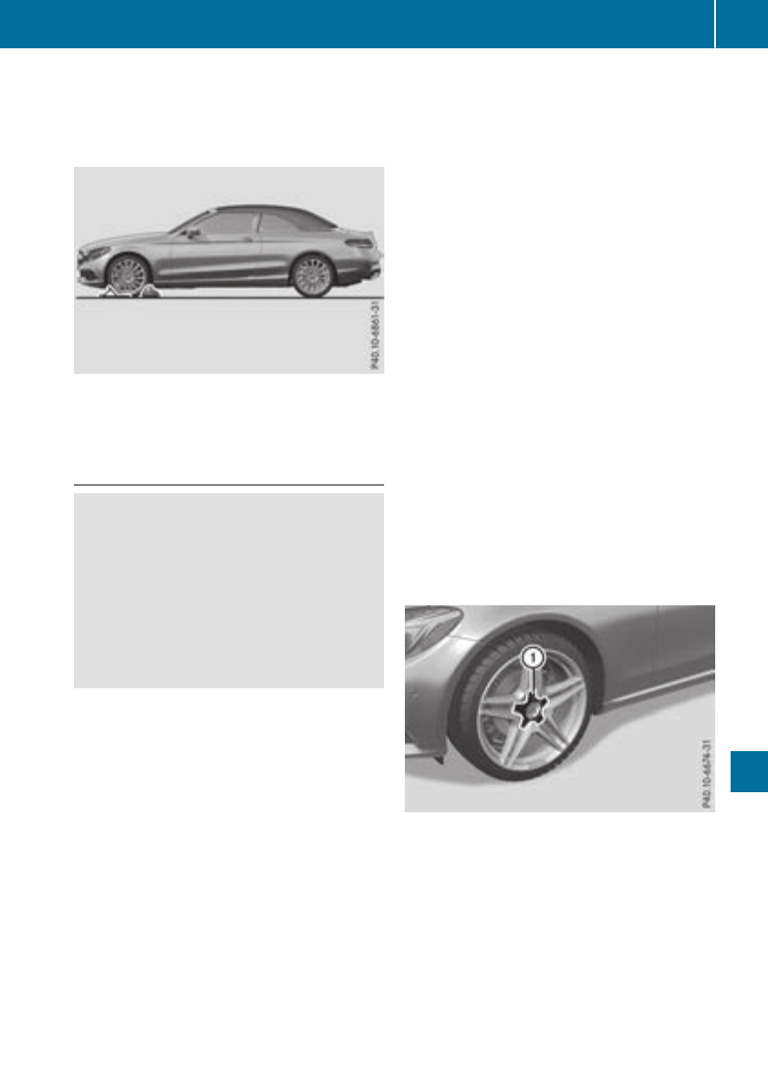
XFold both plates upwards :.
XFold out lower plate ;.
XGuide the lugs on the lower plate fully into the
openings in base plate =.
XPlace chocks or other suitable items under
the front and rear of the wheel that is diago-
nally opposite the wheel you wish to change.
Raising the vehicle
GWARNING
If you do not position the jack correctly at the
appropriate jacking point of the vehicle, the
jack could tip over with the vehicle raised.
There is a risk of injury.
Only position the jack at the appropriate jack-
ing point of the vehicle. The base of the jack
must be positioned vertically, directly under
the jacking point of the vehicle.
!Only position the jack at the appropriate
jacking point of the vehicle. Otherwise, you
could damage the vehicle.
Observe the following when raising the vehi-
cle:
RTo raise the vehicle, only use the vehicle-spe-
cific jack that has been tested and approved
by Mercedes-Benz. If used incorrectly, the
jack could tip over with the vehicle raised.
RThe jack is designed only to raise and hold the
vehicle for a short time while a wheel is being
changed. It must not be used for performing
maintenance work under the vehicle.
RAvoid changing the wheel on uphill and down-
hill slopes.
RBefore raising the vehicle, secure it from roll-
ing away by applying the parking brake and
inserting wheel chocks. Do not disengage the
parking brake while the vehicle is raised.
RThe jack must be placed on a firm, flat and
non-slip surface. On a loose surface, a large,
flat, load-bearing underlay must be used. On a
slippery surface, a non-slip underlay must be
used, e.g. rubber mats.
RDo not use wooden blocks or similar objects
as a jack underlay. Otherwise, the jack will not
be able to achieve its load-bearing capacity
due to the restricted height.
RMake sure that the distance between the
underside of the tires and the ground does not
exceed 1.2 in (3 cm).
RDo not place your hands or feet under the
raised vehicle.
RDo not lie under the vehicle.
RDo not start the engine when the vehicle is
raised.
RDo not open or close a door or the trunk lid
when the vehicle is raised.
RMake sure that no persons are present in the
vehicle when the vehicle is raised.
Vehicles with alloy wheels and hub caps: the
wheel bolts are covered by a hub cap. Before you
can unscrew the wheel bolts, you must remove
the hub cap. Two different variants can be instal-
led.
Vehicles with plastic hub cap:
XTo remove: turn the center cover of hub
cap :counter-clockwise and remove.
XTo install: before installing, ensure that hub
cap :is in the open position. To do this, turn
the center cover counter-clockwise.
XPosition hub cap :and turn the center cover
clockwise until hub cap :engages physically
and audibly.
XMake sure that hub cap :is installed
securely.
Changing a wheel 333
Wheels and tires
Z
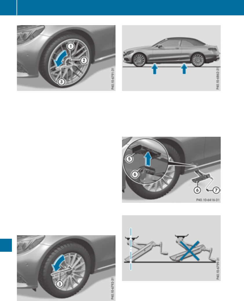
Vehicles with aluminum hub cap:
XTo remove: take socket ;and wheel wrench
=from the vehicle tool kit (Ypage 296).
XPosition socket ;on hub cap :.
XPosition lug wrench =on socket ;.
XUsing lug wrench =, turn hub cap :coun-
ter-clockwise and remove it.
XTo install: before installing, check hub cap :
and the wheel area for soiling and clean if
necessary.
XPut hub cap :in position and turn until it is in
the right position.
XPosition socket ;on hub cap :.
XAttach lug wrench =to socket ;and
tighten hub cap :.
The tightening torque must be
18 lb-ft (25 Nm).
iNote that the hub cap should be tightened
to the specified torque of 18 lb-ft (25 Nm).
Mercedes-Benz recommends that you have
the hub cap installed at a qualified specialist
workshop.
XUsing lug wrench =, loosen the bolts on the
wheel you wish to change by about one full
turn. Do not unscrew the bolts completely.
The jacking points are located just behind the
front wheel housings and just in front of the rear
wheel housings (arrows).
Mercedes-AMG vehicles and vehicles with
AMG equipment: to protect the vehicle body,
the vehicle has covers installed next to the jack-
ing points on the outer sills.
XPosition jack Bat jacking point A.
XMake sure the foot of the jack is directly
beneath the jacking point.
XTurn crank Cclockwise until jack Bsits
completely on jacking point A. The base of
the jack must lie evenly on the ground.
XTurn crank Cuntil the tire is raised a maxi-
mum of 1.2 in (3 cm) from the ground.
334 Changing a wheel
Wheels and tires
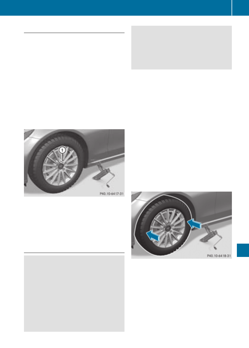
Removing a wheel
!Mercedes-AMG vehicles with ceramic-
brake disc: during removal and repositioning
of the wheel, the wheel rim can strike the
ceramic-brake disc and damage it. Therefore,
you should proceed carefully and get a sec-
ond person assist to you. Alternatively, you
can use a second alignment bolt.
!Do not place wheel bolts in sand or on a dirty
surface. The bolt and wheel hub threads could
otherwise be damaged when you screw them
in.
When mounting/removing wheels, and for as
long as the wheels are removed, avoid applying
any external force on the brake disks. This could
impair the level of comfort when braking.
XUnscrew the uppermost wheel bolt com-
pletely.
XScrew alignment bolt :into the thread
instead of the wheel bolt.
XUnscrew the remaining wheel bolts fully.
XRemove the wheel.
Mounting a new wheel
GWARNING
Oiled or greased wheel bolts or damaged
wheel bolts/hub threads can cause the wheel
bolts to come loose. As a result, you could
lose a wheel while driving. There is a risk of
accident.
Never oil or grease wheel bolts. In the event of
damage to the threads, contact a qualified
specialist workshop immediately. Have the
damaged wheel bolts or hub threads
replaced/renewed. Do not continue driving.
GWARNING
If you tighten the wheel bolts or wheel nuts
when the vehicle is raised, the jack could tip
over. There is a risk of injury.
Only tighten the wheel bolts or wheel nuts
when the vehicle is on the ground.
Always pay attention to the instructions and
safety notes in the "Changing a wheel" section
(Ypage 331).
Only use wheel bolts that have been designed
for the wheel and the vehicle. For safety rea-
sons, Mercedes-Benz recommends that you
only use wheel bolts which have been approved
for Mercedes-Benz vehicles and the respective
wheel.
!Mercedes-AMG vehicles with ceramic-
brake disc: during removal and repositioning
of the wheel, the wheel rim can strike the
ceramic-brake disc and damage it. Therefore,
you should proceed carefully and get a sec-
ond person assist to you. Alternatively, you
can use a second alignment bolt.
!To prevent damage to the paintwork, hold
the wheel securely against the wheel hub
while screwing in the first wheel bolt.
XClean the wheel and wheel hub contact sur-
faces.
XSlide the wheel to be mounted onto the align-
ment bolt and push it on.
XTighten the wheel bolts until they are finger-
tight.
XUnscrew the alignment bolt.
XTighten the last wheel bolt until it is finger-
tight.
Changing a wheel 335
Wheels and tires
Z
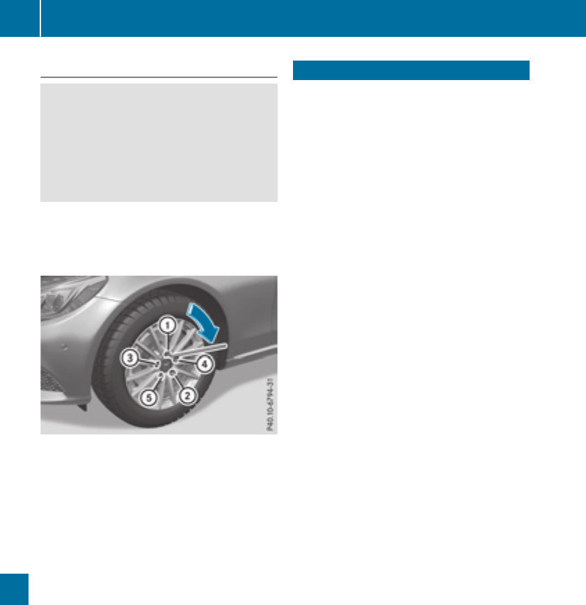
Lowering the vehicle
GWARNING
The wheels could work loose if the wheel nuts
and bolts are not tightened to the specified
tightening torque. There is a risk of accident.
Have the tightening torque immediately
checked at a qualified specialist workshop
after a wheel is changed.
XTurn the crank of the jack counter-clockwise
until the vehicle is once again standing firmly
on the ground.
XPlace the jack to one side.
XTighten the wheel bolts evenly in a crosswise
pattern in the sequence indicated (:to A).
The tightening torque must be 111 lb-ft
(150 Nm).
XTurn the jack back to its initial position.
XStow the jack and the rest of the vehicle tools
in the trunk again.
XMercedes-AMG vehicles and vehicles
with AMG equipment: insert the cover into
the outer sill.
XCheck the tire pressure of the newly mounted
wheel and adjust it if necessary.
Observe the recommended tire pressure
(Ypage 315).
When you are driving with the collapsible spare
wheel mounted, the tire pressure loss warning
system or the tire pressure monitor cannot func-
tion reliably. Only restart the tire pressure loss
warning system or tire pressure monitor when
the defective wheel has been replaced with a
new wheel.
Vehicles with a tire pressure control sys-
tem: all installed wheels must be equipped with
functioning sensors.
Wheel/tire combination
You can ask for information regarding permitted
wheel/tire combinations at an authorized
Mercedes-Benz Center.
!For safety reasons, Mercedes-Benz recom-
mends that you only use tires and wheels
which have been approved by Mercedes-Benz
specifically for your vehicle.
These tires have been specially adapted for
use with the control systems, such as ABS or
ESP®, and are marked as follows:
RMO = Mercedes-Benz Original
RMOE = Mercedes-Benz Original Extended
(tires featuring run-flat characteristics)
RMO1 = Mercedes-Benz Original (only cer-
tain AMG tires)
Mercedes-Benz Original Extended tires may
only be used on wheels that have been spe-
cifically approved by Mercedes-Benz.
Only use tires, wheels or accessories tested
and approved by Mercedes-Benz. Certain
characteristics, e.g. handling, vehicle noise
emissions or fuel consumption, may other-
wise be adversely affected. In addition, when
driving with a load, tire dimension variations
could cause the tires to come into contact
with the bodywork and axle components. This
could result in damage to the tires or the vehi-
cle.
Mercedes-Benz accepts no liability for dam-
age resulting from the use of tires, wheels or
accessories other than those tested and
approved.
Information on tires, wheels and approved
combinations can be obtained from any quali-
fied specialist workshop.
!Retreaded tires are neither tested nor rec-
ommended by Mercedes-Benz, since previ-
ous damage cannot always be detected on
retreaded tires. As a result, Mercedes-Benz
cannot guarantee vehicle safety if retreaded
tires are mounted. Do not mount used tires if
you have no information about their previous
usage.
The recommended pressures for various oper-
ating conditions can be found:
Ron the Tire and Loading Information placard
on the B-pillar on the driver's side
Rin the tire pressure table in the fuel filler flap
336 Wheel/tire combination
Wheels and tires

Observe the notes on recommended tire pres-
sures under various operating conditions
(Ypage 315).
Check tire pressures regularly, and only when
the tires are cold. Comply with the maintenance
recommendations of the tire manufacturer in
the vehicle document wallet.
Notes on the vehicle equipment – always equip
the vehicle:
Rwith tires of the same size on a given axle (left
and right)
Rwith the same type of tires at a given time
(summer tires, winter tires, MOExtended
tires)
Exception: it is permissible to install a differ-
ent type or make in the event of a flat tire.
Observe the "MOExtended tires (tires with
run-flat characteristics" section (Ypage 297).
Vehicles equipped with MOExtended tires are
not equipped with a TIREFIT kit at the factory. It
is therefore recommended that you additionally
equip your vehicle with a TIREFIT kit if you mount
tires that do not feature run-flat properties, e.g.
winter tires. A TIREFIT kit may be obtained from
a qualified specialist workshop.
Wheel/tire combination 337
Wheels and tires
Z
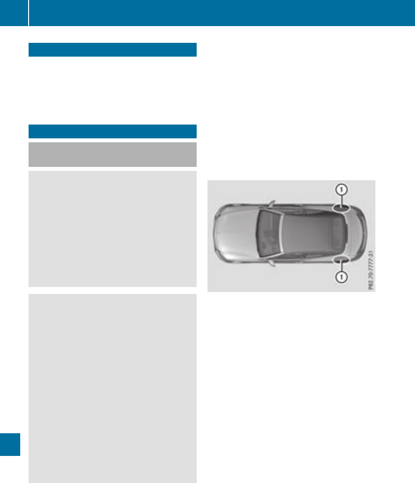
Information regarding technical data
iThe datastatedherespecifically refers to a
vehiclewithstandard equipment. Consult an
authorizedMercedes-BenzCenterfor the
datafor all vehiclevariants and trim levels.
Vehicle electronics
Installing two-way radios and mobile
phones
GWARNING
The electromagneticradiation from two-way
radios can interfere withthevehicleelectron-
ics if two-way radios are manipulated or ret-
rofittedincorrectly. This could jeopardizethe
operating safetyof thevehicle. Thereis arisk
of an accident.
You should haveall workon electrical and
electronic componentscarried out at aquali-
fiedspecialist workshop.
GWARNING
If you incorrectlyoperate two-way radios in
thevehicle, theelectromagneticradiation
may interfere withthevehicleelectronics,for
exampleif:
Rthetwo-way radiois notconnectedto an
exteriorantenna
Rtheexteriorantenna is notcorrectlymoun-
tedor is notlow-reflection
This could jeopardizetheoperating safetyof
thevehicle. Thereis ariskof an accident.
Havethelow-reflection exteriorantenna
installed at aqualified specialist workshop.
Always connecttwo-way radios to thelow-
reflection exteriorantenna when operating in
thevehicle.
!The operating permit may be invalidated if
theinstructionsfor installation and use of
two-way radios are notobserved.
In particular, thefollowingconditionsmust be
complied with:
Ronly approvedwavebands may be used.
Robservethemaximum permissible output
in these wavebands.
Ronly approvedantenna positionsmay be
used.
Excessivelevels of electromagneticradiation
may causedamageto your healthand thehealth
of others. Using an exteriorantenna takes into
accountcurrentscientific discussionsrelating
to thepossible healthhazards that may result
from electromagneticfields.
Approved antenna positions
:Rear fender
On therear fenders, it is recommended to posi-
tion theantenna on theside of thevehicleclos-
est to thecenter of theroad.
Use Technical Specification ISO/TS 21609
(Road Vehicles –"EMCguidelines for installa-
tion of aftermarket radiofrequency transmitting
equipment") when retrofitting two-way radios.
Observethelegal requirements for accessory
parts.
If your vehiclehas installationsfor two-way radio
equipment, use thepower supplyor antenna
connectionsintended for use withthebasic wir-
ing.Be sureto observethemanufacturer'sSup-
plementwhen installing.
Deviationswithrespectto frequency bands,
maximum transmission outputsor antenna
positionsmust be approvedby Mercedes-Benz.
338 Vehicle electronics
Technical data
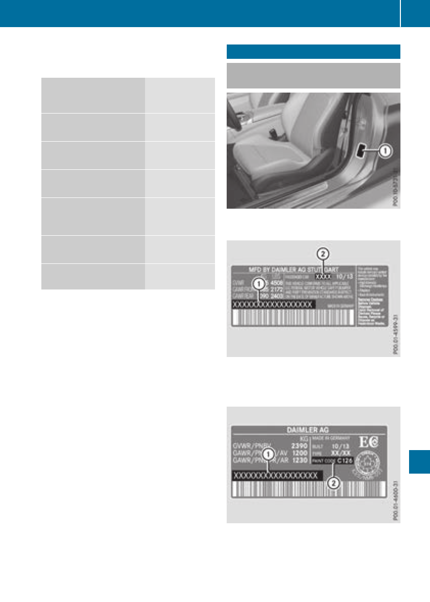
The maximum transmission output (PEAK) at the
base of the antenna must not exceed the fol-
lowing values:
Frequency band Maximum
transmission
output
Short wave
3 - 54 MHz
30 W
4 m waveband
74 - 88 MHz
15 W
2 m waveband
144 - 174 MHz
25 W
Trunked radio system/
Tetra
380 - 460 MHz
10 W
70 cm waveband
400 - 460 MHz
15 W
Mobile communications
(2G/3G/4G)
10 W
The following can be used in the vehicle without
restrictions:
RTwo-way radios with a maximum transmission
output of up to 100 mW
RTwo-way radios with transmitter frequencies
in the 380 - 410 MHz waveband and a maxi-
mum transmission output of up to 2 W
(trunked radio/Tetra)
RMobile phones (2G/3G/4G)
There is no restriction for antenna positions on
the outside of the vehicle for the following fre-
quency bands:
RTrunked radio system/Tetra
R70 cm waveband
R2G/3G/4G
Identification plates
Vehicle identification plate with vehi-
cle identification number (VIN)
XOpen the driver's door.
You will see vehicle identification plate :.
Example: vehicle identification plate (USA
only)
:VIN
;Vehicle model
Example: vehicle identification plate (Can-
ada only)
:VIN
;Paint code
Identification plates 339
Technical data
Z
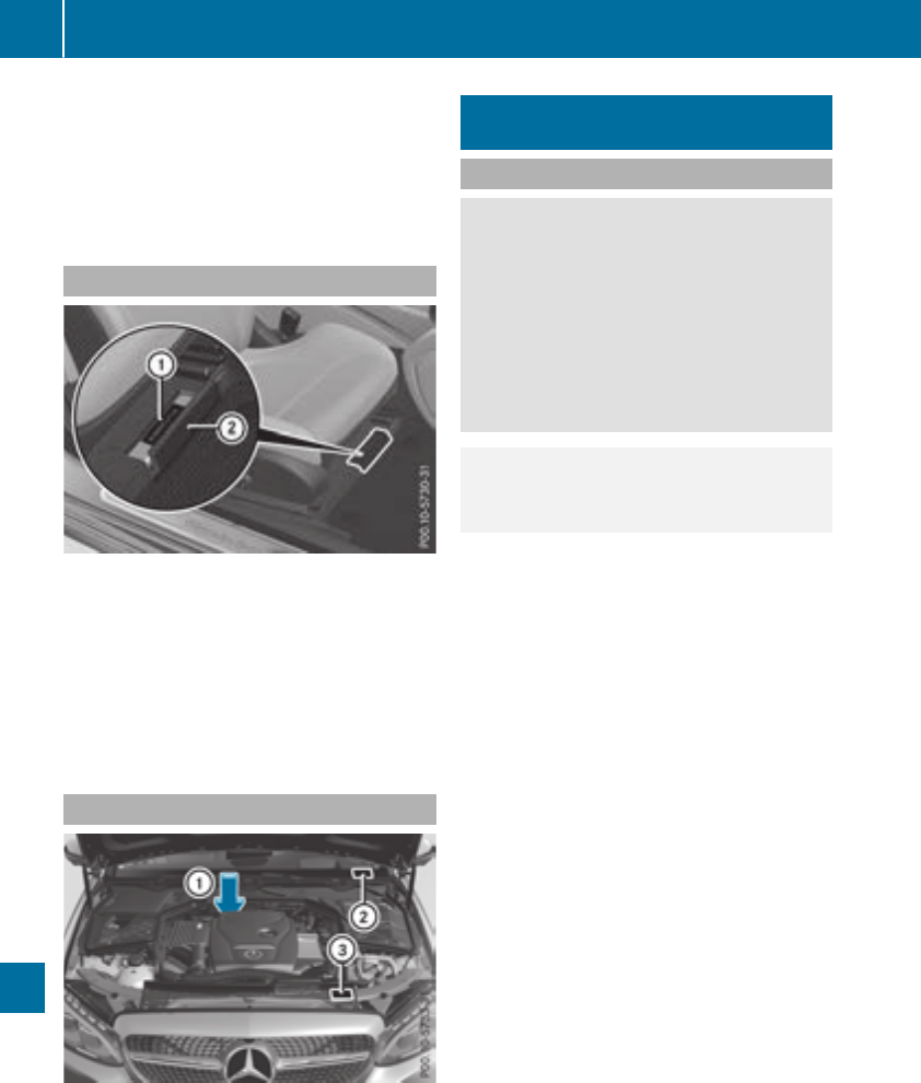
iThe data shown on the vehicle identification
plate is used only as an example. This data is
different for every vehicle and can deviate
from the data shown here. You can find the
data applicable to your vehicle on the vehicle
identification plate.
Vehicle identification number (VIN)
XSlide the right-hand front seat to its rearmost
position.
XFold floor covering ;upwards.
The VIN is visible :.
The VIN can also be found on the vehicle iden-
tification plate (Ypage 339).
The VIN can also be found at the lower edge of
the windshield (Ypage 340).
Engine number
:Engine number (stamped into the crank-
case)
;VIN (on the lower edge of the windshield)
=Emission control information plate, includ-
ing the certification of both federal and Cali-
fornian emissions standards
Service products and filling capaci-
ties
Important safety notes
GWARNING
Service products may be poisonous and haz-
ardous to health. There is a risk of injury.
Comply with instructions on the use, storage
and disposal of service products on the labels
of the respective original containers. Always
store service products sealed in their original
containers. Always keep service products out
of the reach of children.
HEnvironmental note
Dispose of service products in an environ-
mentally responsible manner.
Service products include the following:
RFuels
RLubricants (e.g. engine oil, transmission oil)
RCoolant
RBrake fluid
RWindshield washer fluid
RClimate control system refrigerant
Components and service products must match.
Only use products recommended by Mercedes-
Benz. Damage which is caused by the use of
products which have not been recommended is
not covered by the Mercedes-Benz warranty or
goodwill gestures. Products approved by
Mercedes-Benz are listed in this Operator's
Manual in the appropriate section.
Information on tested and approved products
can be obtained at a Mercedes-Benz Service
Center or on the Internet at
http://bevo.mercedes-benz.com.
You can recognize service products approved by
Mercedes-Benz by the following inscription on
the containers:
RMB-Freigabe (e.g. MB-Freigabe 229.51)
RMB-Approval (e.g. MB-Approval 229.51)
Other designations or recommendations indi-
cate a level of quality or a specification in
accordance with an MB Sheet Number (e.g. MB
229.5). They have not necessarily been
approved by Mercedes-Benz.
340 Service products and filling capacities
Technical data

Other identifications, for example:
R0 W-30
R5 W-30
R5 W-40
Fuel
Important safety notes
GWARNING
Fuel is highly flammable. If you handle fuel
incorrectly, there is a risk of fire and explo-
sion.
You must avoid fire, open flames, creating
sparks and smoking. Switch off the engine
and, if applicable, the auxiliary heating before
refueling.
GWARNING
Fuel is poisonous and hazardous to health.
There is a risk of injury.
You must make sure that fuel does not come
into contact with your skin, eyes or clothing
and that it is not swallowed. Do not inhale fuel
vapors. Keep fuel away from children.
If you or others come into contact with fuel,
observe the following:
RWash away fuel from skin immediately
using soap and water.
RIf fuel comes into contact with your eyes,
immediately rinse them thoroughly with
clean water. Seek medical assistance with-
out delay.
RIf fuel is swallowed, seek medical assis-
tance without delay. Do not induce vomit-
ing.
RImmediately change out of clothing which
has come into contact with fuel.
Tank capacity
Model Total capacity
All models 17.4 US gal
(66.0 l)
Model Of which
reserve
Mercedes-AMG C 63
Mercedes-AMG C 63 S
Approx.
2.6 US gal
(10.0 l)
Allother models Approx.
1.8 US gal (7.0 l)
Gasoline
Fuel grade
!Do not use diesel to refuel vehicles with a
gasoline engine. Do not switch on the ignition
if you accidentally refuel with the wrong fuel.
Otherwise, the fuel will enter the fuel system.
Even small amounts of the wrong fuel could
result in damage to the fuel system and the
engine. Notify a qualified specialist workshop
and have the fuel tank and fuel lines drained
completely.
!Only refuel using unleaded premium grade
gasoline with at least 91 AKI/95 RON.
iE10 fuel contains up to 10% bioethanol.
Your vehicle is E10-compatible. You can
refuel your vehicle using E10 fuel.
!Only use the fuel recommended. Operating
the vehicle with other fuels can lead to dam-
age to the fuel system, engine and exhaust
system.
!Do not use the following:
RGasoline with more than 10% ethanol
RE100 (100% ethanol)
RGasoline with methanol
RM100 (100% methanol)
RGasoline with metalliferous additives
RDiesel
Do not mix such fuels with the fuel recom-
mended for your vehicle.
!To ensure the longevity and full perform-
ance of the engine, only premium-grade
unleaded gasoline must be used.
If standard unleaded gasoline is unavailable
and you have to refuel with unleaded gasoline
of a lower grade, observe the following pre-
cautions:
ROnly fill the fuel tank to half full with regular
unleaded gasoline and fill the rest with pre-
Service products and filling capacities 341
Technical data
Z
mium-grade unleaded gasoline as soon as
possible.
RDo not drive at the maximum speed.
RAvoid sudden acceleration and engine
speeds over 3,000 rpm.
You will usually find information about the fuel
grade on the fuel pump. If you cannot find the
label on the fuel pump, ask the gas station staff.
iFor further information, consult a qualified
specialist workshop or visit
http://www.mbusa.com (USA only).
As a temporary measure, if the recommended
fuel is not available, you may also use regular
unleaded gasoline with an octane rating of
87 AKI/91 RON. This may reduce engine per-
formance and increase fuel consumption. Avoid
driving at full throttle and sudden acceleration.
Never refuel using gasoline with a lower AKI.
Information on refueling (Ypage 142).
Additives
!Operating the engine with fuel additives
added later can lead to engine failure. Do not
mix fuel additives with fuel. This does not
include additives for the removal and preven-
tion of residue buildup. gasoline must only be
mixed with additives recommended by
Mercedes-Benz. Comply with the instructions
for use on the product label. More information
about recommended additives can be
obtained from any authorized Mercedes-Benz
Center.
Mercedes-Benz recommends that you use bran-
ded fuels that have additives.
The fuel quality available in some countries may
not be sufficient. Residue could build up in the
fuel injection system as a result. In such cases,
and in consultation with an authorized
Mercedes-Benz Center, the fuel may be mixed
with the cleaning additive recommended by
Mercedes-Benz. You must observe the notes
and mixing ratios specified on the container.
Engine oil
General notes
!Do not use engine oil or an oil filter with
specifications deviating from those expressly
required for the prescribed service intervals.
Do not change the engine oil or oil filter in
order to set replacement intervals longer than
those prescribed. This could otherwise cause
damage to the engine or exhaust gas after-
treatment.
Follow the instructions on the service interval
display for changing the engine oil. This could
otherwise cause damage to the engine or
exhaust gas aftertreatment.
When handling engine oil, observe the important
safety notes on service products (Ypage 340).
The engine oils are matched to the performance
of Mercedes-Benz engines and service intervals.
You should therefore only use engine oils and oil
filters that are approved for vehicles with main-
tenance systems.
For a list of approved engine oils and oil filters,
consult an authorized Mercedes-Benz Center.
Or visit the website
http://bevo.mercedes-benz.com.
The table shows which engine oils have been
approved for your vehicle.
Model MB-Freigabe or
MB-Approval
All models 229.5, 229.6
Use only SAE 0W-40 or SAE 5W-40 engine oils
for Mercedes-AMG vehicles.
iMB approval is indicated on the oil contain-
ers.
342 Service products and filling capacities
Technical data

Filling capacities
The followingvaluesrefer to an oil change
includingtheoil filter.
Model Capacity
C300 7.4US qt (7.0 l)
C 300 4MATIC
Mercedes-AMG
C 43 4MATIC
6.9 US qt (6.5 l)
Mercedes-AMG
C 63
Mercedes-AMG
C 63 S
9.5 US qt (9.0 l)
Additives
!Do not use any additives in the engine oil.
This could damage the engine.
Brake fluid
GWARNING
The brake fluid constantly absorbs moisture
from the air. This lowers the boiling point of
the brake fluid. If the boiling point of the brake
fluid is too low, vapor pockets may form in the
brake system when the brakes are applied
hard. This would impair braking efficiency.
There is a risk of an accident.
You should have the brake fluid renewed at
the specified intervals.
When handling brake fluid, observe the impor-
tant safety notes on service products
(Ypage 340).
The brake fluid change intervals can be found in
the Maintenance Booklet.
Only use brake fluid approved by Mercedes-
Benz in accordance with MB-Freigabe or MB-
Approval 331.0.
Information about approved brake fluid can be
obtained at any qualified specialist workshop or
on the Internet at
http://bevo.mercedes-benz.com.
iHave the brake fluid regularly replaced at a
qualified specialist workshop in accordance
with the replacement intervals and the
replacement confirmed in the Maintenance
Booklet.
Coolant
Important safety notes
GWARNING
If antifreeze comes into contact with hot com-
ponents in the engine compartment, it may
ignite. There is a risk of fire and injury.
Let the engine cool down before you add anti-
freeze. Make sure that antifreeze is not spilled
next to the filler neck. Thoroughly clean the
antifreeze from components before starting
the engine.
!Only add coolant that has been premixed
with the desired antifreeze protection. You
could otherwise damage the engine.
Further information on coolants can be found
in the Mercedes-Benz Specifications for Ser-
vice Products, MB BeVo 310.1, e.g. on the
Internet at http://bevo.mercedes-benz.com.
Or contact a qualified specialist workshop.
!Always use a suitable coolant mixture, even
in countries where high temperatures prevail.
Otherwise, the engine cooling system is not
sufficiently protected from corrosion and
overheating.
iHave the coolant regularly replaced at a
qualified specialist workshop and the replace-
ment confirmed in the Maintenance Booklet.
Comply with the important safety notes for ser-
vice products when handling coolant
(Ypage 340).
The coolant is a mixture of water and anti-
freeze/corrosion inhibitor. It performs the fol-
lowing tasks:
RAnti-corrosion protection
RAntifreeze protection
RRaising the boiling point
If the coolant has antifreeze protection down to
-35 ‡ (-37 †), the boiling point of the coolant
during operation is approximately 266 ‡
(130 †).
Service products and filling capacities 343
Technical data
Z

The antifreeze concentrate/corrosion inhibitor
concentration in the engine cooling system
should:
Rbe at least 50%. This will protect the engine
cooling system against freezing down to
approximately -35 ‡ (-37 †).
Rnot exceed 55% (antifreeze protection down
to -49 ‡[-45 †]). Otherwise, heat will not be
dissipated as effectively.
Mercedes-Benz recommends an antifreeze/
corrosion inhibitor concentrate in accordance
with MB Specifications for Service Products
310.1.
iWhen the vehicle is first delivered, it is filled
with a coolant mixture that ensures adequate
antifreeze and anti-corrosion protection.
iThe coolant is checked with every mainte-
nance interval at a qualified specialist work-
shop.
Filling capacities
Model Capacity
Mercedes-AMG
C 43 4MATIC
11.5 US qt (10.9 l)
Mercedes-AMG
C 63
Mercedes-AMG
C 63 S
12.6 US qt (11.9 l)
Allother models 9.5 US qt (9.0 l)
Windshield washer system
Important safety notes
GWARNING
Windshield washer concentrate could ignite if
it comes into contact with hot engine compo-
nents or the exhaust system. There is a risk of
fire and injury.
Make sure that no windshield washer con-
centrate is spilled next to the filler neck.
!Only use washer fluid that is suitable for
plastic lamp lenses, e.g. MB SummerFit or MB
WinterFit. Unsuitable washer fluid could dam-
age the plastic lenses of the headlamps.
!Only MB SummerFit and MB WinterFit
washer fluid should be mixed together. The
spray nozzles may otherwise become
blocked.
Do not use distilled or de-ionized water. Other-
wise, the level sensor may give a false reading.
When handling washer fluid, observe the impor-
tant safety notes on service products
(Ypage 340).
At temperatures above freezing:
XFill the washer fluid reservoir with a mixture of
water and windshield washer fluid, e.g. MB
SummerFit.
Add 1 part MB SummerFit to 100 parts water.
At temperatures below freezing:
XFill the washer fluid reservoir with a mixture of
water and washer fluid, e.g. MB WinterFit.
For the correct mixing ratio refer to the infor-
mation on the antifreeze reservoir.
iAdd windshield washer fluid, e.g. MB Sum-
merFit or MB WinterFit, to the washer fluid all
year round.
Climate control system refrigerant
Important safety notes
The climate control system of your vehicle is fil-
led with refrigerant R‑134a.
The instruction label regarding the refrigerant
type used can be found on the radiator cross
member.
!Only the refrigerant R‑134a and the PAG oil
approved by Mercedes-Benz may be used.
The approved PAG oil may not be mixed with
any other PAG oil that is not approved for
R-134a refrigerant. Otherwise, the climate
control system may be damaged.
Service work, such as refilling with refrigerant or
replacing component parts, may only be carried
out by a qualified specialist workshop. All appli-
cable regulations, as well as SAE standard J639,
must be adhered to.
Always have work on the climate control system
carried out at a qualified specialist workshop.
344 Service products and filling capacities
Technical data
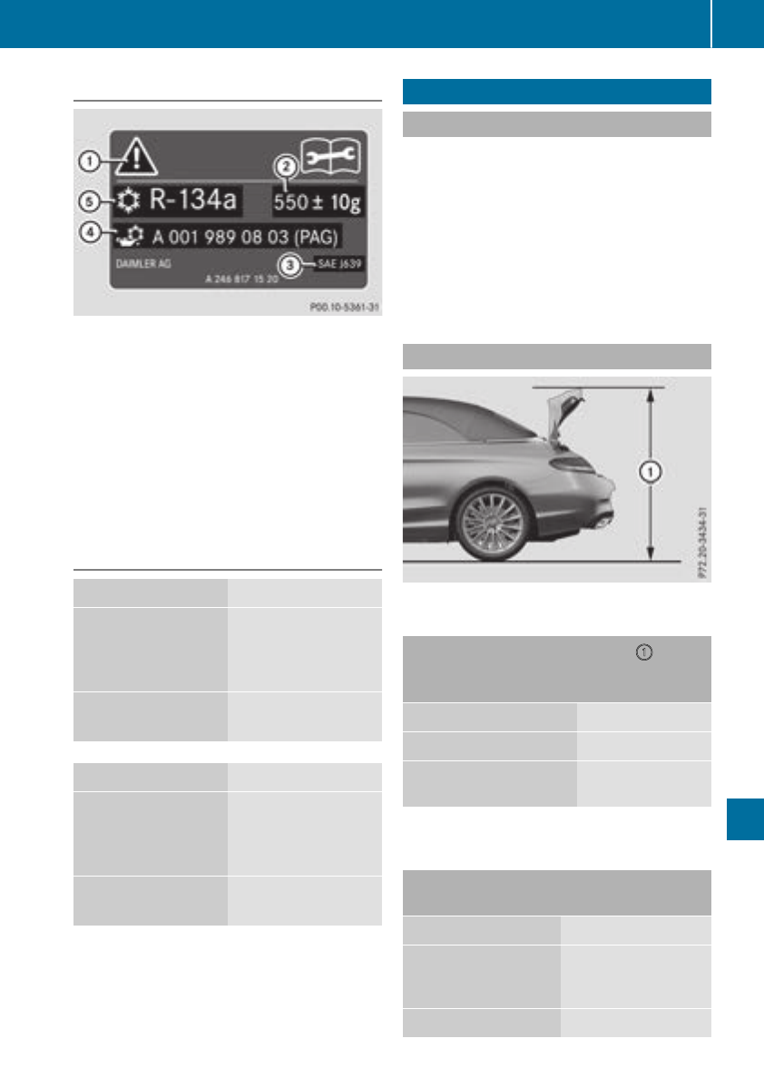
Refrigerant instruction label
Example: refrigerant instruction label
:Warning symbol
;Refrigerant filling capacity
=Applicable standards
?PAG oil part number
AType of refrigerant
Warning symbol :advises you about:
RPossible dangers
RHaving service work carried out at a qualified
specialist workshop
Filling capacities
Model Refrigerant
Mercedes-AMG
C 63
Mercedes-AMG
C 63 S
21.5 ± 0.4 oz
(610 ± 10 g)
Allother models 22.2 ± 0.4 oz
(630 ± 10 g)
Model PAG oil
Mercedes-AMG
C 63
Mercedes-AMG
C 63 S
4.2 oz
(120 g)
All other models 2.8 oz
(80 g)
Vehicle data
General notes
Please note that for the specified vehicle data:
RThe heights specified may vary as a result of:
-Tires
-Load
-Condition of the suspension
-Optional equipment
ROptional equipment reduces the maximum
payload
Dimensions and weights
Missing values were not available at time of
going to print.
Model :
Height when
opened
C 300 58.5 in (1486 mm)
C 300 4MATIC 58.9 in (1495 mm)
Mercedes-AMG vehi-
cles
Missing values were not available at time of
going to print.
Mercedes-AMG C 43
4MATIC
Vehicle length 184.9 in (4696 mm)
Vehicle width
including exterior
mirrors
79.4 in (2016 mm)
Vehicle height 55.4 in (1408 mm)
Vehicle data 345
Technical data
Z

Mercedes-AMG C 43
4MATIC
Vehicle height,
when opening/clos-
ing the roof
Wheelbase 111.8 in (2840 mm)
Turning radius 38.4 ft (11.7 m)
Mercedes-AMG C 63
Mercedes-AMG C 63
S
Vehicle length 187.0 in (4750 mm)
Vehicle width
including exterior
mirrors
79.4 in (2016 mm)
Vehicle height,
Mercedes-AMG C 63
55.2 in (1403 mm)
Vehicle height,
Mercedes-AMG C 63
S
55.3 in (1405 mm)
Vehicle height,
when opening/clos-
ing the roof
Wheelbase 111.8 in (2840 mm)
Turning radius 37.1 ft (11.3 m)
All other models
Vehicle length 184.5 in
(4686 mm)
Vehicle width including
exterior mirrors
79.4 in
(2016 mm)
Vehicle height, C 300 55.5 in
(1409 mm)
Vehicle height, C 300
4MATIC
55.7 in
(1416 mm)
Vehicle height when open-
ing/closing the roof, C 300
78.0 in
(1982 mm)
Vehicle height when open-
ing/closing the roof, C 300
4MATIC
78.2 in
(1987 mm)
All other models
Wheelbase 111.8 in
(2840 mm)
Turning circle, C 300 36.8 ft
(11.22 m)
Turning circle, C 300
4MATIC
37.6 ft
(11.45 m)
346 Vehicle data
Technical data

347

348
