MY18 CLA Operator Manual
User Manual: Pdf 2018 Mercedes-Benz CLA-Class Owners Manual PDF | SERVICE MANUAL OWNERS
Open the PDF directly: View PDF ![]() .
.
Page Count: 326 [warning: Documents this large are best viewed by clicking the View PDF Link!]
CLA
Operator's Manual
Mercedes-Benz
Order no. P117 0075 13 Part no. 117 584 2704 Edition A2018
CLA Operator's Manual
É1175842704eËÍ
1175842704

Publication details
Internet
Further information about Mercedes-Benzvehi-
cles and about Daimler AG can be found on the
following websites:
http://www.mbusa.com (USA only)
http://www.mercedes-benz.ca (Canada only)
Editorial office
Daimler AG: not to be reprinted, translated or
otherwise reproduced, in whole or in part, with-
out written permission from Daimler AG.
Vehicle manufacturer
Daimler AG
Mercedesstrae 137
70327 Stuttgart
Germany
Symbols
In this Operator's Manual you will find the fol-
lowing symbols:
GWARNING
Warning notes make you aware of dangers
which could pose athreat to your health or
life, or to the health and life of others.
HEnvironmental note
Environmental notes provide you with infor-
mation on environmentally aware actions or
disposal.
!Notes on material damage alert you to dan-
gers that could lead to damage to your vehi-
cle.
iPractical tips or further information that
could be helpful to you.
XThis symbol indicates an instruction
that must be followed.
XSeveral of these symbols in succession
indicate an instruction with several
steps.
(Y
page)
This symbol tells you where you can
find more information about atopic.
Dis‐
play
This text indicates amessage on the
multifunction display/multimedia dis-
play.
As at 20.10.2016
Welcome to the world of Mercedes-Benz
We urge you to read this Operator's Manual
carefully and familiarize yourself with the vehi-
cle before driving. For yourown safety and a
longer vehiclelife,follow the instructions and
warning notices in this Operator's Manual.
Ignoring them couldresult in damage to the
vehicleorpersonal injury to you or others.
Vehicle damage caused by failure to follow
instructions is not covered by the Mercedes-
Benz Limited Warranty.
The equipment or product designation of your
vehiclemay vary depending on:
RModel
ROrder
RCountry specification
RAvailability
Mercedes-Benz therefore reservesthe right to
introduce changes in the following areas:
RDesign
REquipment
RTechnicalfeatures
The equipment in yourvehiclemay therefore
differfrom that showninthe descriptions and
illustrations.
The following are integralcomponents of the
vehicle:
RPrinted Operator's Manual
RMaintenance Booklet
REquipment-dependent supplements
Keep these documents in the vehicleatall
times. If you sell the vehicle, alwayspassall
documents on to the new owner.
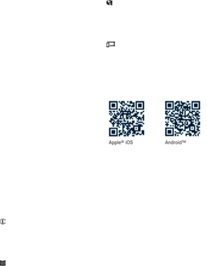
You can alsouse the Mercedes-Benz Guides
App:
Your Operator's Manual:
Digital form inside the vehicle
The DigitalOperator's Manual provides
comprehensive and specifically adapted
information on yourvehicle's equipment
and multimediasystem. It contains infor-
mative animations, individuallanguage
settings and an intuitive search function.
Booklet inside the vehicle
In addition to this manualand the afore-
mentioned digital media, you alsohave the
option to obtainacomprehensive printed
versionofthe Supplement for yourmulti-
mediasystem from yourauthorized
Mercedes-Benz Center.
Digital form via the Internet
The Operator's Manual on the Internet pro-
videseasy access to all information
regarding yourvehicleand multimediasys-
tem. It alsoprovides helpful animations,
interesting background information and a
widearrayofsearch options.
Digital form as an App
Using the Mercedes-Benz GuidesApp, you
can view all the information on yourvehicle
and multimediasystem via mobile Internet
or download it independently of network
access. Availablefor smartphones or tab-
lets.
You can alsouse the Mercedes-Benz Guides
App:
Please note that the Mercedes-Benz GuidesApp
may not yet be available in yourcountry.
Mercedes-Benz USA, LLC
Mercedes-Benz Canada,Inc.
ADaimler Company
1175842704 É1175842704eËÍ

Index ....................................................... 4
Digital Operator's Manual .................. 23
Introduction........................................... 23
Operation ............................................... 23
Introduction ......................................... 24
Protecting the environment ...................24
Genuine Mercedes-Benzparts............... 24
Operator's Manual ................................. 25
Service and vehicle operation ................25
Operating safety .................................... 27
QR codes for the rescue card ................29
Data stored in the vehicle...................... 29
Informationoncopyright ....................... 31
At aglance ........................................... 32
Cockpit.................................................. 32
Instrument cluster................................. 33
Multifunctionsteering wheel................. 34
Center console...................................... 35
Doorcontrolpanel ................................. 38
Overhead controlpanel .........................39
Safety ................................................... 40
Panic alarm ............................................ 40
Occupant safety .................................... 40
Children in the vehicle ........................... 54
Pets in the vehicle ................................. 60
Driving safety systems ........................... 61
Protection against theft .........................68
Opening and closing ........................... 70
SmartKey ............................................... 70
Doors ..................................................... 76
Trunk ..................................................... 78
Side windows ......................................... 81
Panorama roof with power tilt/sliding
panel ...................................................... 85
Seats, steering wheel and mirrors .... 90
Correct driver's seat position ................90
Seats ..................................................... 90
Steering wheel ....................................... 95
Mirrors................................................... 96
Memory function ................................... 98
Lights and windshield wipers .......... 100
Exterior lighting ................................... 100
Interior lighting .................................... 103
Replacing bulbs................................... 104
Windshield wipers ................................ 107
Climate control ................................. 110
Overview of climate control systems ... 110
Operating the climate control sys-
tems .................................................... 115
Air vents .............................................. 120
Drivingand parking .......................... 121
Notesonbreaking-in anew vehicle..... 121
Driving ................................................. 121
DYNAMIC SELECT button (all vehicles
exceptMercedes-AMGvehicles) ......... 128
DYNAMIC SELECT controller
(Mercedes-AMGvehicles) .................... 129
Automatictransmission....................... 130
Refueling ............................................. 138
Parking ................................................ 141
Driving tips.......................................... 144
Driving systems ................................... 149
On-board computer and displays .... 176
Important safety notes ........................ 176
Displays and operation ........................ 176
Menusand submenus ......................... 179
Displaymessages ................................ 190
Warning and indicator lamps in the
instrument cluster ............................... 218
Multimediasystem ........................... 229
Generalnotes ...................................... 229
Important safety notes ........................ 229
Function restrictions ............................ 229
Operating system ................................ 230
Stowageand features ...................... 237
Loading guidelines............................... 237
Stowageareas ..................................... 237
2Contents

Features.............................................. 242
Maintenanceand care ...................... 257
Engine compartment ........................... 257
ASSYST PLUS ...................................... 261
Care ..................................................... 262
Breakdown assistance ..................... 269
Where will Ifind...? .............................. 269
Flattire ................................................ 271
Battery (vehicle) .................................. 276
Jump-starting ....................................... 278
Towing and tow-starting ...................... 281
Fuses ................................................... 284
Wheels and tires ............................... 287
Important safety notes ........................ 287
Operation ............................................ 287
Winteroperation .................................. 289
Tirepressure ....................................... 290
Loading the vehicle .............................. 298
All aboutwheelsand tires................... 301
Changing awheel ................................ 307
Wheel and tire combinations ............... 312
Technical data ................................... 313
Information regarding technical data ... 313
Vehicleelectronics .............................. 313
Identification plates ............................. 314
Service products and filling capaci-
ties ...................................................... 315
Vehicledata......................................... 320
Contents 3

1, 2, 3...
4ETS (Electronic Traction System)
see ETS/4ETS (Electronic Trac-
tion System)
4MATIC
Display message ............................ 215
4MATIC (permanent four-wheel
drive) .................................................. 160
A
ABS (Anti-lock Braking System)
Display message ............................ 192
Function/notes ................................ 61
Important safety notes .................... 61
Warninglamp .................................220
Accident
Automatic measuresafter an acci-
dent ................................................. 54
Activatingmedia mode
General notes ................................ 235
Activating/deactivating cooling
with air dehumidification ................. 115
Active Brake Assist
Activating or deactivating .............. 185
Display message ............................ 197
Function/notes ................................ 62
ADAPTIVE BRAKE ................................. 68
Adaptive DampingSystem
Function/notes .............................160
Adaptive Highbeam Assist
Display message ............................ 204
Function/notes .............................102
Switching on/off ........................... 103
Additional speedometer ................... 187
Additives (engine oil) ........................ 318
Address book
see also DigitalOperator's Man-
ual..................................................229
Adjustingthe volume
Multimediasystem ........................ 230
Airbags
Deployment ..................................... 52
Display message ............................ 200
Front airbag (driver, front
passenger)....................................... 46
Important safety notes .................... 45
Introduction ..................................... 45
Knee bag .......................................... 46
Occupant Classification System
(OCS) ............................................... 47
PASSENGER AIR BAG indicator
lamps ............................................... 41
Side impact airbag .......................... 47
Windowcurtainair bag .................... 47
Airvents
Important safety notes .................. 120
Rear............................................... 120
Setting the center airvents ........... 120
Setting the sideair vents ...............120
Air-conditioningsystem
see Climate control
Alarm
ATA (Anti-Theft Alarm system) ......... 68
Switching off (ATA) .......................... 68
Switching the function on/off
(ATA) ................................................ 68
Alarm system
see ATA (Anti-Theft Alarm system)
AMG
Adaptive sport suspension sys-
tem ................................................ 159
Performance Seat ............................ 94
AMG adaptive sport suspension
system
General Information ....................... 159
AMG menu (on-board computer) ..... 188
AMG Performance exhaustsys-
tem ..................................................... 127
Anti-lockbraking system
see ABS (Anti-lock Braking System)
Anti-skid chains
see Snow chains
Anti-Theft Alarm system
see ATA (Anti-Theft Alarm system)
Ashtray ............................................... 244
Assistancedisplay (on-board com-
puter) ..................................................185
Assistancemenu (on-board com-
puter) ..................................................184
ASSYST PLUS
Displaying aservice message ........261
Driving abroad ............................... 262
Hiding aservice message .............. 261
4Index

Information aboutService .............261
Resetting the service intervaldis-
play................................................ 261
Service message ............................ 261
Specialservice requirements ......... 261
ATA (Anti-Theft Alarm system)
Activating/deactivating ................... 68
Function ...........................................68
Switching off the alarm .................... 68
ATTENTIONASSIST
Activating/deactivating ................. 185
Displaymessage ............................ 207
Function/notes............................. 171
Audiomenu(on-board computer) .... 182
Audiosystem
see separate operating instructions
Authorized Mercedes-Benz Center
see Qualifiedspecialist workshop
Authorized workshop
see Qualifiedspecialist workshop
AUTO lights
Displaymessage ............................ 204
see Lights
Automatic car wash(care) ............... 262
Automatic engine start (ECO start/
stopfunction) .................................... 126
Automatic engine switch-off (ECO
start/stopfunction) .......................... 126
Automatic headlamp mode .............. 100
Automatic transmission
Accelerator pedalposition ............. 133
Changing gear............................... 133
DIRECTSELECT lever ..................... 130
Drive program................................ 134
Drive programdisplay .................... 130
Driving tips.................................... 133
DYNAMIC SELECT button (all vehi-
clesexcept Mercedes-AMGvehi-
cles) ............................................... 128
DYNAMIC SELECT controller
(Mercedes-AMGvehicles) .............. 129
Emergency running mode.............. 138
Engaging drive position .................. 132
Engaging neutral ............................ 131
Engaging park position
(Mercedes-AMGvehicles) .............. 132
Engaging park position automati-
cally ............................................... 131
Engaging reverse gear................... 131
Engaging the park position ............ 130
Holding the vehiclestationary on
uphill gradients .............................. 134
Kickdown....................................... 134
Manualshifting .............................. 136
Oil temperature (on-board com-
puter, Mercedes-AMGvehicles) ..... 188
Overview ........................................ 130
Problem (malfunction) ................... 138
Pulling away ................................... 125
Selector lever ................................ 132
Starting the engine ........................ 124
Steering wheelpaddleshifters ...... 136
Transmission position display ........ 132
Transmission position display
(DIRECT SELECT lever) ................... 130
Transmission positions .................. 133
Automatic transmissionemer-
gencymode ....................................... 138
B
Back button ....................................... 230
Backup lamp
Displaymessage ............................ 203
BAS (Brake Assist System) ................. 61
Battery (SmartKey)
Checking .......................................... 73
Important safety notes .................... 73
Replacing ......................................... 73
Battery (vehicle)
Charging ........................................ 278
Displaymessage ............................ 206
Important safety notes .................. 276
Jump starting ................................. 278
Belt
see Seatbelts
Beltwarning ......................................... 44
Blind SpotAssist
Activating/deactivating (on-
board computer) ............................ 186
Displaymessage ............................ 208
Notes/function .............................. 172
Bluetooth®
Searching for amobilephone ........ 233
Index 5

Searching for amobilephone
(device manager)........................... 234
see also Digital Operator's Man-
ual.................................................. 229
Telephony ...................................... 233
Brake Assist
see BAS (Brake Assist System)
Brake fluid
Displaymessage ............................ 197
Notes............................................. 318
Brake forcedistribution
see EBD (electronicbrake force
distribution)
Brake lamp
Replacing bulbs............................. 106
Brake lamps
Displaymessage ............................ 202
Brakes
ABS .................................................. 61
BAS .................................................. 61
Brake fluid (notes) ......................... 318
Braking assistance appropriate to
the situation ..................................... 63
Displaymessage ............................ 192
EBD .................................................. 67
Hillstart assist............................... 125
HOLD function ............................... 157
Important safety notes .................. 146
Maintenance .................................. 147
Parking brake ................................ 142
Riding tips...................................... 146
Warning lamp ................................. 219
Brakingassistanceappropriate to
the situation
Function/notes................................ 63
Breakdown
Where will Ifind...? ........................ 269
see Flattire
see Tow-starting
see Towing away
Buttonsonthe steering wheel ......... 177
C
California
Important notice for retail cus-
tomers and lessees .......................... 25
Calling up amalfunction
see Displaymessages
Car
see Vehicle
Care
Carwash........................................ 262
Carpets .......................................... 268
Display........................................... 266
Exhaustpipe.................................. 266
Exterior lights ................................ 265
Gear or selector lever .................... 267
Interior ........................................... 266
Matte finish ................................... 264
Notes............................................. 262
Paint .............................................. 263
Plastic trim .................................... 266
Power washer................................ 263
Rear viewcamera .......................... 265
Roof lining ...................................... 268
Seatbelt........................................ 267
Seatcover..................................... 267
Sensors ......................................... 265
Steering wheel............................... 267
Trimpieces.................................... 267
Washing by hand ........................... 262
Wheels........................................... 264
Windows........................................ 264
Wiperblades.................................. 265
Woodentrim .................................. 267
Cargocompartmentenlargement ... 240
Cargotie downrings ......................... 241
CD
see also Digital Operator's Man-
ual.................................................. 229
CD player (on-board computer) ........ 183
Centerconsole
Lower section .................................. 36
Upper section .................................. 35
Central locking
Automaticlocking (on-board com-
puter) ............................................. 187
Locking/unlocking (SmartKey)........ 70
Changeofaddress .............................. 26
Changeofownership .......................... 26
Changingawheel
Wheels andtires............................ 308
6Index

Child
Restraintsystem .............................. 56
Child seat
Forward-facing restraint system ...... 59
LATCH-type (ISOFIX) child seat
anchors............................................57
On thefront-passenger seat ............ 58
Rearward-facingrestraint system .... 59
Top Tether .......................................57
Child-proof locks
Important safety notes....................59
Rear doors....................................... 60
Children
Special seat belt retractor............... 55
Children in thevehicle
Important safety notes....................54
Cigarettelighter ................................ 244
Cleaning
Mirror turnsignal ...........................265
Climate control
Air-conditioning system ................. 111
Automatic climate control (dual-
zone) .............................................. 113
Controlling automatically ...............116
Cooling with airdehumidification .. 115
Defrosting the windows ................. 118
Defrosting the windshield .............. 117
General notes ................................ 110
Indicator lamp ................................ 116
Information about using auto-
matic climate control ..................... 114
Maximum cooling .......................... 118
Notes on using the air-condition-
ing system ..................................... 112
Overview of systems ......................110
Problem with the rear window
defroster ........................................ 119
Problems with cooling with air
dehumidification ............................ 116
Refrigerant ..................................... 319
Refrigerant filling capacity ............. 320
Setting the airdistribution ............. 116
Setting the airvents ......................120
Setting the airflow ......................... 117
Setting the temperature ................ 116
Switching air-recirculation mode
on/off ............................................ 119
Switching on/off ........................... 115
Switching residualheaton/off ...... 119
Switching the rear window
defroster on/off ............................ 118
Switching the ZONE function
on/off ............................................ 117
Cockpit
Overview .......................................... 32
COMAND display
Cleaning ......................................... 266
Combination switch .......................... 101
Compass
Calibrating ..................................... 255
Calling up ....................................... 255
Magnetic fieldzone maps.............. 255
Setting ...........................................255
ConnectingaUSB device
see also DigitalOperator's Man-
ual..................................................229
Consumptionstatistics(on-board
computer) .......................................... 180
Controller ...........................................230
Convenience closing feature .............. 83
Convenience opening feature ............ 83
Coolant(engine)
Checking the level......................... 260
Display message ............................ 205
Filling capacity ............................... 319
Important safety notes .................. 318
Temperature (on-board computer,
Mercedes-AMG vehicles) ...............188
Temperature gauge ........................ 177
Warning lamp ................................. 225
Cooling
see Climate control
Copyright ............................................. 31
Corneringlight function
Display message ............................ 202
Cruisecontrol
Activationconditions ..................... 150
Cruise control lever....................... 149
Deactivating ................................... 150
Display message ............................ 210
Driving system ............................... 149
Function/notes .............................149
Important safety notes .................. 149
Setting aspeed.............................. 150
Index 7

Storing and maintaining current
speed ............................................. 150
Cup holder
Center console .............................. 243
Important safety notes .................. 242
Rear compartment ......................... 243
CustomerAssistance Center
(CAC) ..................................................... 28
CustomerRelations Department ....... 28
D
Dashboard
see Instrument cluster
Data
see Technicaldata
Daytime runninglamps
Displaymessage ............................ 204
Function/notes............................. 100
Switching on/off(on-board com-
puter) ............................................. 187
Declarations of conformity ................. 27
Diagnosticsconnection ...................... 28
Digital Operator's Manual
Help................................................. 23
Introduction ..................................... 23
Digital speedometer ......................... 181
DIRECTSELECT lever
Automatictransmission................. 130
Display messages
ASSYST PLUS................................ 261
Calling up (on-board computer) ..... 191
Driving systems ............................. 207
Engine ............................................ 205
Generalnotes ................................ 190
Hiding (on-board computer) ........... 191
Lights ............................................. 202
Safety systems .............................. 192
SmartKey ....................................... 216
Tires ............................................... 211
Vehicle........................................... 213
Distance PilotDISTRONIC
Activating ....................................... 152
Calling up aspeed ......................... 153
Cruise control lever ....................... 152
DisplayMessage ............................ 209
Displays in the instrument cluster .. 155
Driving tips.................................... 156
Function/notes............................. 151
Important safety notes .................. 151
Setting aspeed .............................. 154
Setting the specified minimum
distance ......................................... 154
Stopping ........................................ 154
Storing aspeed .............................. 153
Switching off .................................. 155
Distance recorder ............................. 180
Distance warning(warning lamp) .... 227
Distance warningfunction
Function/notes................................ 62
Warning lamp ................................. 227
Doors
Automaticlocking (on-board com-
puter) ............................................. 187
Automaticlocking (switch) ............... 77
Central locking/unlocking
(SmartKey)....................................... 70
Control panel ................................... 38
Displaymessage ............................ 216
Emergency locking ........................... 77
Emergency unlocking ....................... 77
Important safety notes .................... 76
Opening (frominside)...................... 76
Drinking and driving ......................... 144
Drive program
Automatictransmission ................. 134
Display........................................... 132
Display(DIRECT SELECT lever) ...... 130
Driver's door
see Doors
Drivingabroad
Mercedes-Benz Service ................. 262
Drivingonfloodedroads .................. 148
Drivingsafety system
Active Brake Assist .......................... 62
Braking assistance appropriate to
the situation ..................................... 63
Drivingsafety systems
ABS (Anti-lock Braking System) ....... 61
ADAPTIVEBRAKE............................. 68
BAS (Brake Assist System) .............. 61
Distance warning function ............... 62
EBD (electronicbrake force distri-
bution) ............................................. 67
8Index

ESP®(ElectronicStability Pro-
gram) ............................................... 64
Important safety information ........... 61
Overview .......................................... 61
STEER CONTROL ............................. 68
Driving system
Distance PilotDISTRONIC............. 151
DYNAMIC BODY CONTROL ............ 160
Parking assistPARKTRONIC .......... 161
Parking Pilot.................................. 164
RACESTART(Mercedes-AMG
vehicles) ........................................ 158
Start-off assist............................... 158
Drivingsystems
AMG adaptive sport suspension
system ........................................... 159
ATTENTIONASSIST ........................ 171
Blind Spot Assist ............................ 172
Cruise control ................................ 149
Displaymessage ............................ 207
HOLD function ............................... 157
Lane Keeping Assist ...................... 174
Lane Tracking package.................. 172
Rear viewcamera .......................... 167
Drivingtips
Automatictransmission................. 133
Brakes ........................................... 146
Break-in period.............................. 121
Checking brake lining thickness .... 147
Distance PilotDISTRONIC ............. 156
Downhillgradient ........................... 146
Drinking and driving ....................... 144
Driving in winter ............................. 148
Driving on floodedroads ................ 148
Driving on wetroads ...................... 148
Exhaustcheck ............................... 144
Fuel................................................ 144
General.......................................... 144
Hydroplaning ................................. 148
Icy roadsurfaces ........................... 148
Limitedbraking efficiency on sal-
ted roads ....................................... 147
Snow chains .................................. 290
The first 1000 miles (1500km) ..... 121
Wet roadsurface ........................... 146
DVD video
Operating (on-board computer) ..... 183
see also Digital Operator's Man-
ual.................................................. 229
DYNAMICSELECT button
Climate control (3-zone automatic
climate control)............................. 115
Climate control (air-conditioning
system) .......................................... 112
DYNAMICSELECT button(allvehi-
cles except Mercedes-AMG vehi-
cles) .................................................... 128
DYNAMICSELECT controller
(Mercedes-AMGvehicles) ................. 129
E
EBD (electronicbrake forcedistri-
bution)
Displaymessage ............................ 194
Function/notes................................ 67
ECOdisplay
Function/notes............................. 145
On-board computer....................... 180
ECOstart/stopfunction
Automaticengine start .................. 126
Automaticengine switch-off .......... 126
Deactivating/activating ................. 127
Generalinformation ....................... 126
Important safety notes .................. 126
Introduction ................................... 125
Electronic Stability Program
see ESP®(Electronic Stability Program)
Emergency
Automaticmeasures afteranacci-
dent ................................................. 54
Emergencyrelease
Driver's door.................................... 77
Vehicle............................................. 77
EmergencyTensioningDevices
Activation ......................................... 52
Emissionscontrol
Service and warranty information .... 25
Engine
Check Engine warning lamp ........... 224
Displaymessage ............................ 205
ECO start/stop function ................ 125
Engine number ............................... 315
Irregularrunning ............................ 127
Jump-starting ................................. 278
Index 9

Starting (important safety notes)... 123
Starting problems .......................... 127
Starting the engine with the
SmartKey ....................................... 124
Starting via smartphone ................ 124
Starting with the Start/Stopbut-
ton ................................................. 124
Switching off .................................. 141
Tow-starting (vehicle)..................... 284
Engine electronics
Problem (malfunction) ................... 127
Engine jump starting
see Jump starting (engine)
Engine oil
Adding ........................................... 259
Additives ........................................ 318
Checking the oillevel ..................... 258
Checking the oillevel using the
dipstick .......................................... 258
Displaymessage ............................ 206
Filling capacity ............................... 318
Notesabout oilgrades................... 317
Notesonoil level/consumption .... 258
Temperature (on-board computer,
Mercedes-AMGvehicles) ............... 188
Entering an address
see also Digital Operator's Man-
ual.................................................. 229
ESP®(ElectronicStability Pro-
gram)
Activating/deactivating (on-
board computer) ............................ 219
AMG menu (on-board computer) ... 188
Characteristics ................................. 65
Deactivating/activating (button
in Mercedes-AMGvehicles) ............. 66
Deactivating/activating (except
Mercedes‑AMG vehicles) ................. 65
Deactivating/activating (on-
board computer, except
Mercedes-AMGvehicles) ............... 185
Displaymessage ............................ 192
Function/notes................................ 64
Generalnotes .................................. 64
Important safety information ........... 64
Trailer stabilization ........................... 67
Warning lamp ................................. 221
ETS/4ETS (ElectronicTraction Sys-
tem) ...................................................... 64
Exhaust
see Exhaustpipe
Exhaustcheck ................................... 144
Exhaustpipe
Cleaning ......................................... 266
Exterior lighting
Cleaning ......................................... 265
see Lights
Exterior mirrors
Adjusting ......................................... 96
Dipping (automatic) ......................... 97
Folding in when locking (on-board
computer) ...................................... 188
Folding in/out (automatically)......... 97
Folding in/out (electrically) ............. 97
Outofposition (troubleshooting)..... 97
Setting ............................................. 97
Storing settings (memory func-
tion) ................................................. 99
Storing the parking position ............. 98
Eyeglassescompartment ................. 238
F
Favorites
Overview ........................................ 231
Filler cap
see Refueling
First-aidkit ......................................... 270
Flat tire
MOExtended tires.......................... 271
Preparing the vehicle..................... 271
TIREFIT kit ...................................... 272
Floormats ........................................... 256
Frequencies
Mobilephone ................................. 313
Two-way radio ................................ 313
Fuel
Additives ........................................ 317
Consumption statistics .................. 180
Displaying the current consump-
tion ................................................ 180
Displaying the range...................... 180
Driving tips.................................... 144
E10 ................................................ 316
Fuelgauge ....................................... 33
10 Index

Grade (gasoline) ............................ 316
Importantsafety notes..................316
Problem (malfunction) ...................140
Refueling ........................................ 138
Tank content/reserve fuel ............. 316
Fuelfiller flap
Opening ......................................... 139
Fuellevel
Calling up the range (on-board
computer) ...................................... 180
Fueltank
Capacity ........................................ 316
Problem (malfunction) ................... 140
Fuses
Allocation chart .............................285
Before changing .............................284
Fuse box in the engine compart-
ment .............................................. 285
Fuse box in the front-passenger
footwell .......................................... 285
Important safety notes .................. 284
G
Garage door opener
Clearing the memory ..................... 254
General notes ................................ 252
Important safety notes .................. 252
Opening/closing the garage door .. 254
Problems whenprogramming ........254
Programming (button in the rear-
view mirror) ................................... 252
Synchronizing the rolling code ....... 253
Gasoline ............................................. 316
Gear indicator (on-board com-
puter, Mercedes-AMG vehicles) ....... 188
Genuine parts ...................................... 24
Glove box ...........................................238
Google™Local Search
see also DigitalOperator's Man-
ual..................................................229
H
Handbrake
see Parking brake
HANDS-FREEACCESS.......................... 79
Hazard warning lamps
Display message ............................ 216
Switching on/off ........................... 102
Head restraints
Adjusting ......................................... 92
Adjusting (manually)........................ 93
Adjusting (rear) ................................ 93
Headlamps
Fogging up ..................................... 103
see Automatic headlamp mode
Heating
see Climate control
High beam flasher .............................101
High-beam headlamps
Adaptive Highbeam Assist ............. 102
Display message ............................ 203
Replacing bulbs .............................106
Switching on/off ........................... 101
Hill start assist .................................. 125
HOLD function
Activating ....................................... 157
Activationconditions ..................... 157
Deactivating ................................... 157
Display message ............................ 207
Function/notes .............................157
Home address
see also DigitalOperator's Man-
ual..................................................229
Hood
Closing ...........................................258
Display message ............................ 215
Important safety notes .................. 257
Opening ......................................... 257
Horn ...................................................... 32
Hydroplaning ..................................... 148
I
Ignitionlock
see Key positions
Immobilizer .......................................... 68
Indicator lamp
Replacing bulbs (rear) .................... 106
Indicator lamps
see Warning and indicator lamps
Indicators
see Turn signals
Index 11

Instrumentcluster
Overview .......................................... 33
Settings......................................... 186
Warningand indicator lamps ........... 33
Instrument cluster lighting .............. 176
Interior lighting
Control ...........................................104
Overview ........................................ 103
Reading lamp ................................. 103
iPod®
see also DigitalOperator's Man-
ual..................................................229
J
Jack
Storage location ............................ 270
Using ............................................. 309
Jump starting (engine) ......................278
K
Keypositions
Start/Stop button .......................... 122
KEYLESS-GO
Convenience closing feature ............ 83
Deactivation ..................................... 71
Locking ............................................ 71
Unlocking ......................................... 71
Kickdown
Driving tips ....................................134
Manual gearshifting ....................... 138
Kneebag .............................................. 46
L
Lamps
see Warning and indicator lamps
Lane KeepingAssist
Activating/deactivating (on-
board computer) ............................ 186
Display message ............................ 208
Function/information.................... 174
LaneTracking package ..................... 172
Lap time (RACETIMER) ...................... 189
LATCH-type (ISOFIX)child seat
anchors ................................................ 57
License plate lamp (display mes-
sage) ................................................... 203
Light sensor(display message) ....... 204
Lights
Adaptive Highbeam Assist ............. 102
Automaticheadlamp mode............ 100
Fogged up headlamps.................... 103
Hazard warning lamps ................... 102
Highbeamflasher.......................... 101
High-beam headlamps................... 101
Light switch ................................... 100
Low-beamheadlamps.................... 101
Parking lamps ................................ 101
Rear fog lamp ................................ 101
Setting exteriorlighting ................. 100
Standing lamps .............................. 101
Switching the daytime running
lamps on/off(on-board com-
puter) ............................................. 187
Turn signals................................... 101
Loadingguidelines ............................ 237
Locking
see Central locking
Locking (doors)
Automatic........................................ 77
Emergency locking ........................... 77
From inside (central locking but-
ton) .................................................. 76
Locking centrally
see Central locking
Locking verification signal (on-
board computer) ............................... 187
Low-beam headlamps
Displaymessage ............................ 202
Replacing bulbs............................. 105
Switching on/off........................... 101
Lumbar support
Adjusting the 4-waylumbarsup-
port.................................................. 93
M
M+S tires ............................................ 289
Malfunctionmessage
see Displaymessages
Matte finish(cleaning instruc-
tions) .................................................. 264
mbrace
Call priority .................................... 248
Displaymessage ............................ 197
12 Index

Downloading destinations
(COMAND) .....................................248
Downloading routes....................... 251
Emergency call .............................. 246
General notes ................................ 245
Geo fencing ................................... 251
Locating astolenvehicle ...............250
MB info call button ........................ 247
Remote fault diagnosis.................. 250
Remote vehiclelocking .................. 250
Roadsideassistance button ........... 247
Search &Send ............................... 249
Self-test ......................................... 245
Speed alert .................................... 251
System .......................................... 245
Triggering the vehiclealarm ........... 252
Vehicleremote unlocking .............. 249
Mechanical key
Function/notes................................ 72
Inserting .......................................... 72
Locking vehicle................................ 77
Removing ......................................... 72
Unlocking the driver'sdoor.............. 77
Memory card (audio) ......................... 183
Memory function ................................. 98
Messagememory (on-board com-
puter) .................................................. 191
Messages
see Displaymessages
Mirrorturn signal
Cleaning ......................................... 265
Mirrors
see Exterior mirrors
see Rear-viewmirror
see Vanity mirror (inthe sunvisor)
Mobilephone
Connecting (Bluetooth®inter-
face).............................................. 233
Connecting (device manager)........ 234
Frequencies................................... 313
Installation ..................................... 313
Menu (on-board computer) ............ 183
Transmission output(maximum) .... 313
Modifying the programming
(SmartKey) ........................................... 72
MOExtendedtires .............................. 271
Mounting wheels
Lowering the vehicle...................... 311
Mounting anew wheel................... 310
Preparing the vehicle..................... 308
Raising the vehicle......................... 309
Removing awheel .......................... 310
Securing the vehicleagainstroll-
ing away ........................................ 309
MP3
Operation ....................................... 183
see also Digital Operator's Man-
ual.................................................. 229
Multifunctiondisplay
Function/notes............................. 179
Permanent display ......................... 187
Multifunctionsteering wheel
Operating the on-board computer..177
Overview .......................................... 34
Multimedia system
Switching on and off ......................230
Music files
see also DigitalOperator's Man-
ual..................................................229
N
Navigation
Entering adestination .................... 231
Menu (on-board computer) ............ 181
see also DigitalOperator's Man-
ual..................................................229
Notes on breaking-inanew vehi-
cle ....................................................... 121
O
Occupant Classification System
(OCS)
Conditions ....................................... 48
Faults ............................................... 51
Operation ......................................... 48
System self-test ............................... 50
Occupant safety
Air bags...........................................45
Automatic measures after an acci-
dent ................................................. 54
Beltwarning ..................................... 44
Childreninthe vehicle..................... 54
Important safety notes.................... 40
Index 13

Introduction to the restraint sys-
tem .................................................. 40
Occupant Classification System
(OCS) ............................................... 47
PASSENGER AIR BAG indicator
lamps............................................... 41
Pets in the vehicle ........................... 60
Restraint system warning lamp ........ 41
Seat belt .......................................... 41
OCS
Conditions ....................................... 48
Faults ............................................... 51
Operation .........................................48
System self-test ............................... 50
Odometer ........................................... 180
On-board computer
AMG menu ..................................... 188
Assistance graphicmenu ............... 185
Assistance menu ........................... 184
Audio menu ................................... 182
Convenience submenu .................. 188
Displaymessages .......................... 190
Displaying aservice message ........ 261
Factory settings ............................. 188
Important safety notes .................. 176
Instrument cluster submenu .......... 186
Lighting submenu .......................... 187
Menu overview .............................. 179
Message memory .......................... 191
Navigation menu ............................ 181
Operation ....................................... 177
RACETIMER ................................... 189
Service menu ................................. 186
Settingsmenu ............................... 186
Standard display ............................ 180
Telephone menu ............................ 183
Tripmenu ...................................... 180
Vehiclesubmenu ........................... 187
Video DVD operation ..................... 183
Opening and closingthe side trim
panels ................................................. 106
Operatingsafety
Declaration of conformity ................ 27
Important safety notes .................... 27
Operatingsystem
see On-board computer
Operation
Digital Operator's Manual................ 23
Operator's Manual
Vehicleequipment ........................... 25
Outside temperature display ........... 176
Overhead controlpanel ...................... 39
Override feature
Rear side windows........................... 60
P
Paint code number ............................ 314
Paintwork (cleaning instructions) ... 263
Panic alarm .......................................... 40
Panorama roofwithpower tilt/
sliding panel
Important safety notes .................... 85
Operating ......................................... 86
Operating the rollersunblindsfor
the sliding sunroof........................... 87
Problem (malfunction) ..................... 89
Reversing feature ............................. 86
Parking
Important safety notes .................. 141
Parking brake ................................ 142
Parking position for the exterior
mirror on the front-passenger
side .................................................. 98
Rear viewcamera .......................... 167
Parking aid
see Exterior mirrors
see Rear viewcamera
Parking Assist PARKTRONIC
Deactivating/activating ................. 163
Driving system ............................... 161
Function/notes............................. 161
Important safety notes .................. 161
Problems (malfunctions)................ 163
Sensorrange................................. 161
Warning display ............................. 162
Parking assistance
see Parking Assist PARKTRONIC
Parking brake
Applying automatically................... 143
Applying or releasing manually ...... 142
Displaymessage ............................ 194
Electric parking brake .................... 142
Emergency braking ........................ 143
Generalnotes ................................ 142
Releasing automatically................. 143
14 Index

Warning lamp ................................. 224
Parking lamps
Switching on/off ........................... 101
Parking Pilot
Canceling ....................................... 167
Detecting parking spaces .............. 164
Display Message ............................208
Exiting aparking space .................. 166
Function/notes .............................164
Important safety notes .................. 164
Parking .......................................... 165
PASSENGERAIR BAG
Display message ............................ 200
Indicator lamps ................................ 41
Problem (malfunction) ................... 200
Pets in the vehicle ............................... 60
Phonebook
see also DigitalOperator's Man-
ual..................................................229
Plastic trim (cleaning instruc-
tions) ..................................................266
Power washers .................................. 263
Power windows
see Side windows
Protection against theft
ATA (Anti-Theft Alarm system) ......... 68
Immobilizer...................................... 68
Protection of the environment
General notes .................................. 24
Pulling away
Automatic transmission ................. 125
General notes ................................ 125
Hill start assist ............................... 125
Q
QR code
Mercedes-Benz Guide App ................. 1
Rescue card ..................................... 29
Qualifiedspecialist workshop ........... 28
R
RACESTART
Important safety notes .................. 158
RACESTART (Mercedes-AMG vehi-
cles) .................................................... 158
RACETIMER (on-board computer,
Mercedes-AMG vehicles) .................. 189
Radio
Selecting astation......................... 182
see separate operating instructions
Radio mode
see also DigitalOperator's Man-
ual..................................................229
Radio-wave reception/transmis-
sioninthe vehicle
Declarationofconformity ................ 27
Rain closing feature (panorama
roof with power tilt/sliding panel) .... 87
Readinglamp ..................................... 103
Rear compartment
Setting the airvents ......................120
Rear fog lamp
Display message ............................ 203
Replacing bulbs .............................106
Switching on/off ........................... 101
Rear lamps
see Lights
Rear seats
Folding the backrestforwards/
back ............................................... 240
Rear viewcamera
"Reverse parking" function ............ 169
Cleaning instructions ..................... 265
Display in the multimediasystem .. 168
Function/notes .............................167
General notes ................................ 167
Switching on/off ........................... 168
Rear window defroster
Problem (malfunction) ................... 119
Switching on/off ........................... 119
Rear-viewmirror
Anti-glare (manual).......................... 96
Dipping (automatic) ......................... 97
Reflectivesafety jacket .................... 269
Refrigerant (air-conditioning sys-
tem)
Important safety notes .................. 319
Refueling
Fuel gauge ....................................... 33
Important safety notes .................. 138
Refueling process.......................... 139
see Fuel
Index 15

Remote control
Garagedooropener ....................... 252
Programming (garagedoor
opener) .......................................... 252
Replacing bulbs
Brake lamp .................................... 106
High-beam headlamps................... 106
Important safety notes .................. 104
Installing/removing the cover
(front wheelarch).......................... 105
Low-beamheadlamps.................... 105
Overview of bulb types .................. 104
Rear fog lamp ................................ 106
Turn signals(front) ......................... 106
Turn signals(rear) .......................... 106
Reporting safety defects .................... 28
Rescue card ......................................... 29
Reserve (fuel tank)
see Fuel
Reserve fuel
Displaymessage ............................ 206
Warning lamp ................................. 224
see Fuel
Residual heat(climate control) ........ 119
Restraintsystem
Displaymessage ............................ 198
Introduction ..................................... 40
Warning lamp ................................. 224
Warning lamp (function) ................... 41
Reversegear(selectorlever)........... 132
Reversingfeature
Roller sunblind ................................. 87
Sidewindows................................... 82
Roadside Assistance (breakdown) .... 26
Rollersunblind
Panorama roofwithpower tilt/
sliding panel ..................................... 87
Roofcarrier ........................................ 241
Roofliningand carpets (cleaning
guidelines) ......................................... 268
Roofload(maximum) ........................ 320
Route guidance
see also Digital Operator's Man-
ual.................................................. 229
S
Safety
Childreninthe vehicle..................... 54
see Occupant safety
Safety system
see Driving safety systems
SD card
Inserting ........................................ 235
Inserting/removing ........................ 235
Removing ....................................... 235
SD memory card
see also Digital Operator's Man-
ual.................................................. 229
Search &Send
see also Digital Operator's Man-
ual.................................................. 229
Seat
Correct driver'sseatposition ........... 90
Seat belts
Adjusting the height ......................... 44
Cleaning ......................................... 267
Correct usage.................................. 43
Fastening ......................................... 44
Important safety guidelines............. 42
Introduction ..................................... 41
Releasing ......................................... 44
Warning lamp ................................. 218
Warning lamp (function) ................... 44
Seats
Adjusting (electrically) ..................... 92
Adjusting (manually) ........................ 91
Adjusting (Performance Seat) .......... 94
Adjusting the 4-waylumbarsup-
port.................................................. 93
Adjusting the headrestraint ............ 92
Cleaning the cover......................... 267
Folding the backrest(rear com-
partment) forwards/back .............. 240
Important safety notes .................... 90
Seatheating problem ...................... 95
Storing settings (memory func-
tion) ................................................. 99
Switching seatheating on/off......... 94
Securing cargo .................................. 241
Selectorlever
Cleaning ......................................... 267
Sensors (cleaning instructions) ....... 265
16 Index

Service center
see Qualified specialist workshop
Service Center
see Qualified specialist workshop
Service menu (on-board com-
puter) .................................................. 186
Service message
see ASSYST PLUS
Service products
Brake fluid .....................................318
Coolant (engine) ............................ 318
Engine oil ....................................... 317
Fuel ................................................ 315
Important safety notes .................. 315
Refrigerant (air-conditioning sys-
tem) ............................................... 319
Washer fluid ................................... 319
Settingthe air distribution ...............116
Settingthe airflow ............................ 117
Settingthe date/time format
see also DigitalOperator's Man-
ual..................................................229
Settingthe language
see also DigitalOperator's Man-
ual..................................................229
Settingthe time
see also DigitalOperator's Man-
ual..................................................229
Settings
Factory (on-board computer) ......... 188
On-board computer ....................... 186
SETUP (on-board computer,
Mercedes-AMG vehicles) .................. 188
Side impact air bag .............................47
Side marker lamp (display mes-
sage) ................................................... 204
Side windows
Cleaning ......................................... 264
Convenienceclosing feature ............ 83
Convenienceopening feature ..........83
Important safety information ........... 81
Opening/closing .............................. 82
Problem(malfunction) .....................84
Resetting......................................... 84
Reversingfeature .............................82
SIRIUS services
see also Digital Operator's Man-
ual .................................................. 229
Sliding sunroof
see Panorama roof with power
tilt/sliding panel
SmartKey
Changing the battery ....................... 73
Changing the programming .............72
Checkingthe battery .......................73
Convenience closingfeature ............ 83
Convenience opening feature .......... 83
Display message ............................ 216
Door central locking/unlocking .......70
Important safety notes .................... 70
KEYLESS-GO start function .............. 71
Loss .................................................74
Mechanical key ................................ 72
Positions (ignition lock) ................. 122
Problem (malfunction) ..................... 74
Starting the engine ........................ 124
SmartKey positions (ignition lock) .. 122
Smartphone
Starting the engine ........................ 124
SMS
see also Digital Operator's Man-
ual .................................................. 229
Snow chains ...................................... 290
Sound
Switching on/off ........................... 230
Special seat belt retractor .................. 55
Specialist workshop ............................28
Speed, controlling
see Cruise control
Speedometer
Activating/deactivating the addi-
tional speedometer ........................ 187
Digital ............................................ 181
In the Instrument cluster ................. 33
Segments...................................... 176
Selectingthe display unit ............... 186
SPORT handling mode
Deactivating/activating
(Mercedes-AMG vehicles) ................66
Warning lamp ................................. 222
Standing lamps
Display message ............................203
Switching on/off ........................... 101
Index 17

Start-off assist
Activating ....................................... 158
Important safety notes .................. 158
Start/Stop button
Removing ....................................... 123
Starting the engine ........................ 124
Start/stop function
see ECO start/stop function
Starting (engine) ................................ 123
STEER CONTROL ..................................68
Steering
Display message ............................216
Steering assistant STEERCON-
TROL
see STEER CONTROL
Steering wheel
Adjusting (manually)........................ 95
Buttonoverview ............................... 34
Buttons (on-board computer) ......... 177
Cleaning ......................................... 267
Important safety notes .................... 95
Paddle shifters ............................... 136
Steering wheelpaddle shifters ........ 136
Stopwatch (RACETIMER) ................... 189
Stowagecompartments
Armrest (front) ............................... 238
Armrest (under)............................. 239
Center console .............................. 238
Center console (rear) ..................... 239
Cupholders ................................... 242
Eyeglasses compartment ............... 238
Glove box ....................................... 238
Important safety information ......... 237
Mappockets .................................. 239
Stowagenet ................................... 239
Stowagenet ....................................... 239
Stowagewellbeneath the trunk
floor .................................................... 241
Summertires ..................................... 289
Sun visor ............................................ 243
Suspension setting
AMG adaptive sport suspension
system ........................................... 159
Switchingair-recirculationmode
on/off ................................................. 119
Switchingonmediamode
Via the device list .......................... 235
T
Tachometer ........................................ 176
Tail lamps
Displaymessage ............................ 203
see Lights
Tank
see Fueltank
Tank content
Fuelgauge ....................................... 33
Technical data
Capacities ...................................... 315
Information .................................... 313
Tires/wheels ................................. 312
Vehicledata................................... 320
Telephone
Accepting acall(multifunction
steering wheel) .............................. 184
Authorizing amobilephone (con-
necting) ......................................... 233
Authorizing amobilephone via the
device manager (connecting) ......... 234
Connecting amobilephone
(device manager)........................... 234
Connecting amobilephone (gen-
eralinformation) ............................ 233
Displaymessage ............................ 216
Introduction ................................... 183
Menu (on-board computer) ............ 183
Numberfrom the phone book........ 184
Redialing ........................................ 184
Rejecting/ending acall................. 184
see also Digital Operator's Man-
ual.................................................. 229
Temperature
Coolant .......................................... 177
Coolant (on-board computer,
Mercedes-AMGvehicles) ............... 188
Engine oil(on-board computer,
Mercedes-AMGvehicles) ............... 188
Outsidetemperature ...................... 176
Setting (climate control)................ 116
Transmission oil(on-board com-
puter, Mercedes-AMGvehicles) ..... 188
Through-loadingfeature ................... 239
Timing (RACETIMER) ......................... 189
Tire pressure
Calling up (on-board computer) ..... 294
18 Index

Checkingmanually ........................ 293
Display message ............................ 211
Maximum .......................................293
Not reached (TIREFIT) .................... 274
Notes ............................................. 292
Reached (TIREFIT) .......................... 274
Recommended ............................... 290
Tire pressure losswarning system
General notes ................................ 293
Important safety notes .................. 294
Restarting ...................................... 294
Tire pressure monitor
Checking the tire pressure elec-
tronically ........................................ 296
Function/notes .............................294
General notes ................................ 294
Important safety notes .................. 295
Radio type approval for the tire
pressure monitor ........................... 297
Restarting ...................................... 297
Warning lamp ................................. 228
Warning message .......................... 296
TIREFIT kit .......................................... 272
Important safety notes .................. 272
Storage location ............................ 271
Tire pressure not reached .............. 274
Tire pressure reached .................... 274
Tires
Aspect ratio (definition) ................. 307
Averageweight of the vehicle
occupants (definition) .................... 305
Bar (definition) ............................... 305
Changing awheel .......................... 307
Characteristics .............................. 305
Checking ........................................ 287
Curb weight (definition) ................. 306
Definition of terms ......................... 305
Direction of rotation...................... 308
Displaymessage ............................ 211
Distribution of the vehicleoccu-
pants (definition) ............................ 307
DOT (Department of Transporta-
tion) (definition) ............................. 305
DOT, Tire Identification Number
(TIN) ............................................... 305
GAWR(GrossAxle Weight Rating)
(definition) ..................................... 306
Generalnotes ................................ 312
GVW(GrossVehicleWeight) (def-
inition) ........................................... 306
GVWR (GrossVehicleWeight Rat-
ing)(definition) .............................. 306
Important safety notes .................. 287
Increased vehicleweightdue to
optionalequipment (definition) ...... 306
Information on driving .................... 287
Kilopascal(kPa)(definition) ........... 306
Labeling (overview) ........................ 302
Loadbearing index (definition) ...... 307
Loadindex ..................................... 304
Loadindex (definition) ................... 306
M+S tires....................................... 289
Maximumloadonatire (defini-
tion) ............................................... 306
Maximumloaded vehicleweight
(definition) ..................................... 306
Maximumpermissibletire pres-
sure (definition) ............................. 306
Maximumtire load ......................... 304
Maximumtire load (definition) ....... 306
MOExtended tires.......................... 289
Optionalequipment weight (defi-
nition) ............................................ 307
PSI (pounds persquare inch)(def-
inition) ........................................... 307
Replacing ....................................... 307
Service life ..................................... 288
Sidewall(definition) ....................... 307
Speed rating (definition) ................ 306
Storing ........................................... 308
Structure and characteristics
(definition) ..................................... 305
Summer tires................................. 289
Temperature .................................. 302
TIN (Tire Identification Number)
(definition) ..................................... 307
Tire bead (definition) ...................... 307
Tire pressure (definition) ................ 307
Tire pressures (recommended)...... 306
Tire size (data)............................... 312
Tire size designation, load-bearing
capacity, speed rating .................... 302
Tire tread....................................... 288
Tire tread(definition) ..................... 307
Totalloadlimit (definition) ............. 307
Traction......................................... 301
Index 19

Traction (definition)....................... 307
Tread wear .....................................301
Uniform Tire Quality Grading
Standards...................................... 301
Uniform Tire Quality Grading
Standards(definition) .................... 306
Wearindicator (definition) ............. 307
Wheelrim (definition) .................... 306
see Flat tire
Top Tether ............................................ 57
Tow-starting
Emergency engine starting ............ 284
Important safety notes .................. 281
Installing the towing eye................ 282
Removing the towing eye...............282
Towing atrailer
ESP®(ElectronicStability Pro-
gram) ............................................... 67
Towing away
Important safety guidelines ........... 281
Installing the towing eye................ 282
Notes for 4MATIC vehicles ............ 284
Removing the towing eye...............282
Transporting the vehicle ................ 283
With both axlesonthe ground ....... 283
With front axle raised ..................... 282
Towing eye ......................................... 270
Traffic reports
see also DigitalOperator's Man-
ual..................................................229
Transmission
see Automatic transmission
Transmission position display
(DIRECT SELECTlever) ......................130
Transporting the vehicle .................. 283
Trim pieces (cleaning instruc-
tions) ..................................................267
Trip computer (on-board com-
puter) ..................................................180
Trip odometer
Calling up ....................................... 180
Resetting (on-board computer) ...... 181
Trunk
Emergency release .......................... 81
Emergency release button ...............81
Important safety notes .................... 78
Opening (automaticallyfrom out-
side) .................................................79
Opening (from outside the vehi-
cle, HANDS-FREE ACCESS) .............. 79
Opening automaticallyfrom
inside ............................................... 80
Opening/closing (manually from
outside) ............................................ 78
Trunk lid
Display message ............................215
Opening dimensions ......................320
Trunk load (maximum) ......................320
Turn signals
Display message ............................ 202
Replacing bulbs (front) ................... 106
Switching on/off ........................... 101
Two-way radio
Frequencies ................................... 313
Installation..................................... 313
Transmissionoutput (maximum).... 313
Type identification plate
see Vehicle identification plate
U
Unlocking
Emergency unlocking ....................... 77
From insidethe vehicle (central
unlocking button) .............................76
Upshiftindicator (on-boardcom-
puter, Mercedes-AMG vehicles) .......188
USB devices
Connecting to the MediaInter-
face ............................................... 236
V
Vanity mirror (in the sun visor) ........244
Vehicle
Correct use ...................................... 28
Data acquisition ............................... 29
Display message ............................ 213
Equipment ....................................... 25
Individualsettings .......................... 186
Limited Warranty .............................29
Loading .......................................... 298
Locking (in an emergency) ............... 77
Locking (SmartKey) .......................... 70
20 Index

Lowering ........................................ 311
Maintenance .................................... 26
Parking for along period................ 143
Pulling away................................... 125
Raising ........................................... 309
Reporting problems ......................... 28
Securing from rolling away ............ 309
Transporting .................................. 283
Unlocking (inanemergency) ........... 77
Unlocking (SmartKey)...................... 70
Vehicledata................................... 320
Vehicledata
Roof load (maximum) ..................... 320
Trunk load (maximum) ................... 320
Vehicledimensions ........................... 320
Vehicleemergencylocking ................ 77
Vehicleidentificationnumber
see VIN
Vehicleidentificationplate .............. 314
Vehicletoolkit .................................. 270
Ventilation
Setting the vents ........................... 120
Video
Operating the DVD ......................... 183
see also Digital Operator's Man-
ual.................................................. 229
VIN
Seat............................................... 315
Type plate ...................................... 314
W
Warning and indicator lamps
ABS ................................................ 220
Active Brake Assist ........................ 227
Brakes ........................................... 219
Check Engine ................................. 224
Coolant .......................................... 225
Distance warning ........................... 227
ESP®.............................................. 221
ESP®OFF ....................................... 222
Fueltank ........................................ 224
Overview .......................................... 33
PASSENGER AIR BAG ...................... 41
Reserve fuel................................... 224
Restraint system ............................ 224
Seatbelt........................................ 218
SPORThandling mode................... 222
Tire pressure monitor .................... 228
Warning triangle ................................ 270
Warranty .............................................. 25
Washer fluid
Displaymessage ............................ 216
Weather display (COMAND)
see also Digital Operator's Man-
ual.................................................. 229
Wheel and tire combinations
Tires ............................................... 312
Wheel bolt tighteningtorque ........... 311
Wheel chock ...................................... 309
Wheels
Changing awheel .......................... 307
Checking ........................................ 287
Cleaning ......................................... 264
Important safety notes .................. 287
Information on driving .................... 287
Interchanging/changing ................ 307
Mounting anew wheel................... 310
Removing awheel .......................... 310
Storing ........................................... 308
Tightening torque ........................... 311
Wheel size/tire size ....................... 312
Wheelsand tires
Changing awheel .......................... 308
Window curtainair bag
Displaymessage ............................ 199
Operation ......................................... 47
Windows
see Sidewindows
Windshield
Defrosting ...................................... 117
Windshieldwasher system
Adding washerfluid ....................... 260
Important safety notes .................. 319
Windshieldwipers
Displaymessage ............................ 216
Problem (malfunction) ................... 109
Replacing the wiperblades............ 108
Switching on/off........................... 107
Winter driving
Slippery roadsurfaces ................... 148
Snow chains .................................. 290
Winter operation
Generalnotes ................................ 289
Winter tires
M+S tires....................................... 289
Index 21

Wiper blades
Cleaning ......................................... 265
Important safety notes .................. 108
Woodentrim (cleaning instruc-
tions) .................................................. 267
Workshop
see Qualified specialist workshop
Z
ZONE function
Switching on/off ........................... 117
22 Index
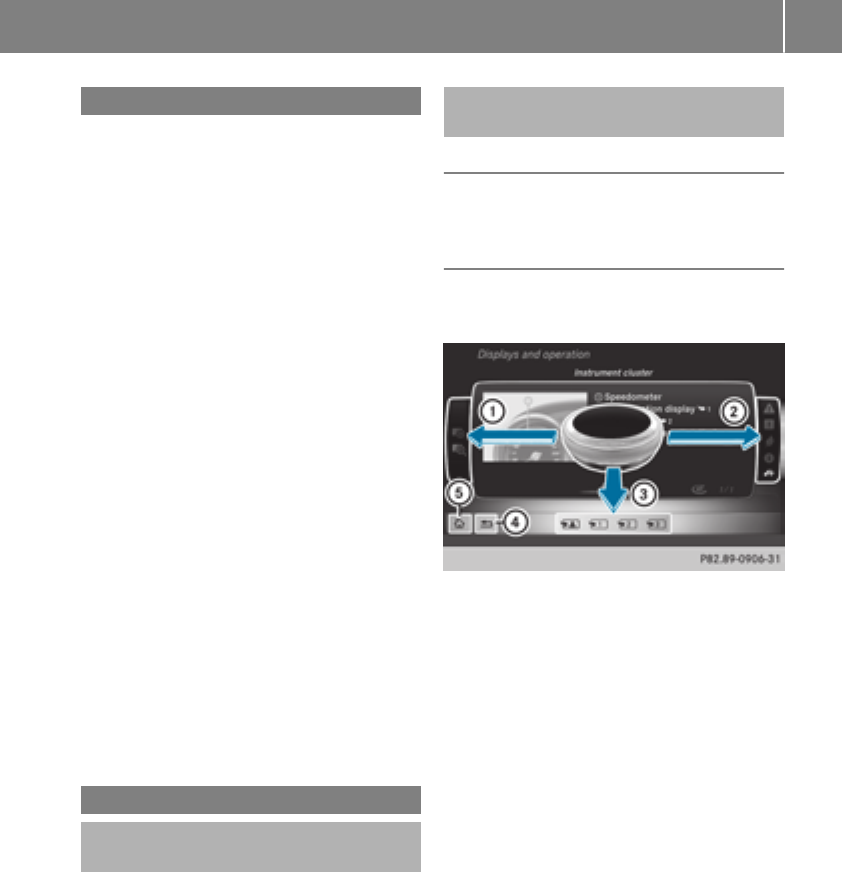
Introduction
The printedOperator's Manual providesinfor-
mation about thesafeoperation of your vehicle.
The Digital Operator's Manual providescompre-
hensiveand specifically adapted information on
your vehicle's equipmentand multimedia sys-
tem. You can call up theDigital Operator's Man-
ual via themultimedia system.
iYou will notincur any costswhen calling up
theDigital Operator's Manual. The Digital
Operator's Manual works without connecting
to theInternet.
Thereare three ways to access thetopicsofthe
Digital Operator's Manual:
RVisualsearch
The visual search allows you to exploreyour
vehicle"virtually". Starting from either the
vehicleexteriorvieworinteriorview, you can
access manyofthe differenttopicscovered
by theDigital Operator's Manual. To access
thevehicleinteriorsection,select the"Vehi-
cle interior" view.
RKeywordsearch
The keyword search allows you to search for a
keyword by enteringcharacters.
RContents
You can select individual sectionsinthe con-
tents.
iThe Digital Operator's Manual is deactiva-
tedfor safetyreasonswhile driving.
Operation
Calling up theDigital Operator's Man-
ual
XPress theØbuttoninthe center console.
The overview relating to thevehicleappears.
XSelectthe "Operator's Manual" menuitemby
turning3or pressing7thecontroller.
XConfirm7themessage about thewarning
and safetynotes.
The basic menufor theDigital Operator's
Manual appears.
Operating theDigital Operator's Man-
ual
General notes
Pleaseobservethe information about theoper-
ation of thecontroller (Ypage 230).
Content pages
The contentpages can be accessed by meansof
avisual search,akeyword search or usingthe
contents.
XTo scroll forwards/backwards: turn3
thecontroller.
XTo displayinfull-screen or animation: slide
8thecontroller to theleft:.
XTo select information texts or savebook-
marks: slide 9thecontroller to the
right ;.
XTo select alink:slide 6thecontroller
downwards =.
XTo exit acontent page: select %sym-
bol ?.
XTo call up thebasic menuofthe Digital
Operator's Manual: select Þsymbol A.
XTo switch functions to themultimedia
system using thebuttonsonthe center
console: press the$,%,Õor Ø
button.
The selected menuappears. The Digital Oper-
ator's Manual remainsopen in theback-
ground.
Digital Operator's Manual 23

Protecting the environment
General notes
HEnvironmental note
Daimler's declared policy is one of compre-
hensive environmental protection.
The objectives are for the natural resources
that form the basis of our existence on this
planet to be used sparingly and in amanner
that takes the requirements of both nature
and humanity into account.
You too can help to protect the environment
by operating your vehicle in an environmen-
tally responsible manner.
Fuel consumption and the rate of engine,
transmission, brake and tire wear are affected
by these factors:
Roperating conditionsofyour vehicle
Ryour personal driving style
You can influence both factors. You should
bear the following in mind:
Operating conditions:
Ravoid short trips as these increase fuel con-
sumption.
Ralways make sure that the tire pressures
are correct.
Rdo not carry any unnecessary weight.
Rremove roof racks once you no longer need
them.
Raregularly serviced vehicle will contribute
to environmental protection. You should
therefore adhere to the service intervals.
Ralways have service work carried out at a
qualified specialist workshop.
Personal driving style:
Rdo not depress the accelerator pedal when
startingthe engine.
Rdo not warm up the engine when the vehicle
is stationary.
Rdrive carefully and maintain asafe distance
from the vehicle in front.
Ravoid frequent, sudden acceleration and
braking.
Rchange gear in good time and use each gear
only up to Ôof its maximum engine speed.
Rswitch off the engine in stationary traffic.
Rkeep an eye on the vehicle's fuel consump-
tion.
Environmental concerns and recom-
mendations
Wherever the Operator's Manual requires you to
dispose of materials, first try to regenerate or re-
use them. Observe the relevant environmental
rules and regulations when disposing of materi-
als. In this way you will help to protect the envi-
ronment.
Genuine Mercedes-Benz parts
HEnvironmental note
Daimler AG also suppliesreconditioned major
assemblies and parts which are of the same
quality as new parts. They are covered by the
same Limited Warranty entitlements as new
parts.
!Air bags and Emergency Tensioning Devi-
ces, as well as control units and sensors for
these restraint systems, may be installed in
the following areas of your vehicle:
Rdoors
Rdoor pillars
Rdoor sills
Rseats
Rcockpit
Rinstrumentcluster
Rcenter console
Do not install accessories such as audio sys-
tems in these areas. Do not carry out repairs
or welding. You could impair the operating
efficiency of the restraint systems.
Have aftermarket accessories installed at a
qualified specialist workshop.
You could jeopardize the operating safety of
your vehicle if you use parts, tires and wheels as
well as accessories relevant to safety which
have not been approved by Mercedes-Benz. This
could lead to malfunctionsinsafety-relevant
24 Genuine Mercedes-Benz parts
Introduction

systems, e.g. the brake system. Use only genu-
ine Mercedes-Benz parts or parts of equalqual-
ity. Only use tires, wheels and accessories that
have been specifically approved for your vehi-
cle.
Genuine Mercedes-Benz parts are subject to
strict quality control. Every part has been spe-
cifically developed,manufactured or selected
for and adapted to Mercedes-Benz vehicles.
Therefore, only genuine Mercedes-Benz parts
should be used.
More than 300,000 different genuine
Mercedes-Benz parts are available for
Mercedes-Benz models.
All authorized Mercedes-Benz Centers maintain
asupply of genuine Mercedes-Benz parts for
necessary service and repair work. In addition,
strategically located parts delivery centers pro-
vide quick and reliable parts service.
Always specify the vehicle identification number
(VIN) when ordering genuine Mercedes-Benz
parts (Ypage 314).
Operator's Manual
Vehicle equipment
iThis Operator's Manual describes all models
and all standard and optional equipment of
your vehicle available at the time of this Oper-
ator's Manual going to print. Country-specific
differences are possible.Bear in mind that
your vehicle may not feature all functions
described here. This also applies to safety-
relevant systems and functions. The equip-
ment in your vehicle may therefore differ from
that shown in the descriptions and illustra-
tions.
The original purchase agreement lists all sys-
tems installed in your vehicle.
Should you have any questions concerning
equipment and operation, please consult an
authorized Mercedes-Benz Center.
The Operator's Manual and Maintenance Book-
let are important documents and should be kept
in the vehicle.
Service and vehicleoperation
Warranty
The Limited Warranty for your vehicle applies in
accordance with the warranty terms and condi-
tions in the Service and Warranty Information
booklet.
Your authorized Mercedes-Benz Center will
replace and repair all factory-installedparts in
accordance with the following warranty terms
and conditions:
RNew Vehicle Limited Warranty
REmission System Warranty
REmission Performance Warranty
RCalifornia, Connecticut,Maine, Massachu-
setts, New York, Pennsylvania, Rhode Island
and Vermont Emission Control System War-
ranty
RState warranty enforcementlaws (lemon
laws)
Replacement parts and accessories are covered
by the Mercedes-Benz Parts and Accessories
warranties. These are available at any author-
ized Mercedes-Benz Center.
iShould you lose your Service and Warranty
Information booklet, have an authorized
Mercedes-Benz Center arrange for areplace-
ment. The new Service and Warranty Infor-
mation booklet will be posted to you.
Information for customers in Califor-
nia
Under California law you may be entitled to a
replacement of your vehicle or arefund of the
purchase price or lease price, if after areason-
able number of repair attempts Mercedes-Benz
USA, LLC and/or its authorized repair or service
facilities fail to fix one or more substantial
defects or malfunctions in the vehicle that are
covered by its express warranty.
During the period of 18 months from original
delivery of the vehicle or the accumulation of
18,000 miles (approximately 29,000 km) on the
odometer of the vehicle, whichever occurs first,
areasonable number of repair attempts is pre-
sumed for aretail buyerorlessee if one or more
of the following occurs:
(1) the same substantial defect or malfunction
results in acondition that is likely to cause
Service and vehicle operation 25
Introduction
Z

death or serious bodily injury if the vehicle is
driven,that defect or malfunction has been
subjecttorepair two or more times, and you
have directly notified Mercedes-Benz USA,
LLC in writingofthe need for its repair.
(2) the same substantial defect or malfunction
of aless serious naturethan category (1)
has been subjecttorepair four or more
times and you have directly notified
Mercedes-Benz in writingofthe need for its
repair.
(3) the vehicle is out of servicebyreason of
repair of the same or differentsubstantial
defectsormalfunctionsfor acumulative
total of more than 30 calendar days.
Please send your written notice to:
Customer Assistance Center
Mercedes-Benz USA,LLC
3Mercedes Drive
Montvale, NJ 07645-0350
Maintenance
Always bring the Maintenance Booklet with you
when takingthe vehicle to an authorized
Mercedes-Benz Center.Your customer service
advisor will enter every serviceintoyour Main-
tenance Booklet on your behalf.
Roadside Assistance
The Mercedes-Benz Roadside Assistance Pro-
gram offerstechnical help in the event of a
breakdown.Calls to the toll-free Roadside Assis-
tanceHotline are answered by our agents24
hours aday, 365 days ayear.
1-800-FOR-MERCedes (1-800-367-6372)
(USA)
1-800-387-0100 (Canada)
For additional information,refer to the
Mercedes-Benz Roadside Assistance Program
brochure(USA)orthe "Roadside Assistance"
section in the Service and WarrantyBooklet
(Canada). You will find both in the vehicle docu-
ment wallet.
Change of address or change of own-
ership
In the event of achangeofaddress, please send
us the "Notification of AddressChange" in the
Service and WarrantyBooklet or simply call the
Mercedes-Benz Customer Assistance Center
(USA)atthe hotlinenumber
1-800-FOR-MERCedes (1-800-367-6372) or
Customer Service Center (Canada) at
1-800-387-0100.This will assist us in contact-
ing you in atimely manner should the need arise.
If you sell your Mercedes,please leave all liter-
ature in the vehicle so that it is available to the
nextowner.
If you have purchased aused car, please send us
the "Notification of Used Car Purchase" in the
Service and WarrantyBooklet or simply call the
Mercedes-Benz Customer Assistance Center
(USA)atthe hotlinenumber
1-800-FOR-MERCedes (1-800-367-6372) or
Customer Service (Canada) at 1-800-387-0100.
Vehicle operation outsidethe USA
and Canada
When you are abroad with your vehicle, observe
the following points:
RService facilities or replacementparts may
not be readily available.
RLead-free fuel for vehicles with acatalytic
converter may not be available. Leaded fuel
can cause damage to the catalytic converter.
RThe fuel may have aconsiderably lower
octane number. Unsuitable fuel can cause
enginedamage.
Some Mercedes-Benz models are available for
delivery in Europe through our European Deliv-
ery Program. For details, consult an authorized
Mercedes-Benz Center or write to one of the
following addresses.
In the USA
Mercedes-Benz USA,LLC
European DeliveryDepartment
One Mercedes Drive
Montvale, NJ 07645-0350
In Canada
Mercedes-Benz Canada, Inc.
European DeliveryDepartment
98 Vanderhoof Avenue
Toronto, Ontario M4G 4C9
26 Service and vehicle operation
Introduction

Operating safety
Important safetynotes
GWARNING
If you do not have the prescribed service/
maintenancework or any required repairs
carried out, this can result in malfunctions or
system failures. There is arisk of an accident.
Always have the prescribed service/mainte-
nancework as well as any required repairs
carried out at aqualified specialist workshop.
GWARNING
Flammable material such as leaves, grass or
twigs may ignite if they come into contact with
hot parts of the exhaust system. There is arisk
of fire.
When driving off road or on unpaved roads,
checkthe vehicle's underside regularly. In
particular, remove parts of plants or other
flammable materials which have become
trapped. In the case of damage, contact a
qualified specialist workshop.
GWARNING
Modifications to electronic components, their
software as well as wiring can impair their
function and/or the function of other net-
worked components. In particular, systems
relevant to safety could also be affected. As a
result, these may no longer function as inten-
ded and/or jeopardizethe operatingsafety of
the vehicle. There is an increased risk of an
accidentand injury.
Never tamper with the wiring as well as elec-
tronic componentsortheir software. You
should have all work to electrical and elec-
tronic equipment carried out at aqualified
specialist workshop.
!There is arisk of damage to the vehicle if:
Rthe vehicle becomes stuck,e.g. on ahigh
curb or an unpaved road
Ryou drive too fast over an obstacle, e.g. a
curb, aspeed bump or apothole in the road
Raheavy objectstrikes the underbody or
parts of the chassis
In situationslike this, the body, the under-
body, chassis parts, wheels or tires could be
damaged without the damage being visible.
Components damaged in this way can unex-
pectedly fail or, in the case of an accident, no
longer withstand the loads they are designed
to.
If the underbody paneling is damaged, com-
bustible materials such as leaves, grass or
twigs can gather between the underbody and
the underbody paneling. If these materials
come in contact with hot parts of the exhaust
system, they can catchfire.
In such situations, have the vehicle checked
and repaired immediately at aqualified spe-
cialist workshop. If on continuingyour jour-
ney you notice that driving safety is impaired,
pull over and stop the vehicle immediately,
paying attention to road and traffic condi-
tions. In such cases, consult aqualified spe-
cialist workshop.
Declarations of conformity
USA: "The wireless devices of this vehicle com-
ply with Part 15 of the FCC Rules. Operation is
subject to the two following two conditions:1)
These devices may not cause harmful interfer-
ence, and 2) These devices must accept any
interference received, including interference
that may cause undesired operation.Changes
or modifications not expressly approved by the
party responsible for compliancecould void the
user’s authoritytooperate the equipment."
Canada: "The wireless devices of this vehicle
comply with Industry Canada license-exempt
RSS standard(s). Operation is subject to the fol-
lowing two conditions:(1) These devices may
not cause interference, and (2) These devices
must accept any interference, including inter-
ference that may cause undesired operation of
the device."
Operating safety 27
Introduction
Z

Diagnostics connection
The diagnosticsconnectionisonlyintendedfor
theconnectionofdiagnostic equipmentata
qualified specialistworkshop.
GWARNING
If you connectequipmenttoadiagnostics
connection in thevehicle, it may affectthe
operation of vehicle systems.Asaresult,the
operatingsafetyofthe vehicle could be affec-
ted. There is ariskofanaccident.
Only connectequipmenttoadiagnosticscon-
nection in thevehicle, whichisapproved for
your vehicle by Mercedes-Benz.
GWARNING
Objects in thedriver's footwell can restrictthe
pedaltravelorobstruct adepressed pedal.
The operatingand road safetyofthe vehicle is
jeopardized. There is ariskofanaccident.
Makesurethatall objects in thevehicle are
stowed correctly, and that they cannotenter
thedriver's footwell. Install thefloormats
securely and as specifiedinorder to ensure
sufficientclearancefor thepedals. Do notuse
loose floormatsand do notplacefloormatson
topofone another.
!If theengineisswitched offand equipment
on thediagnosticsconnectionisused,the
starter battery may discharge.
Connectingequipmenttothe diagnosticscon-
nection can lead to emissionsmonitoringinfor-
mation beingreset,for example. Thismay lead
to thevehicle failingtomeetthe requirements of
thenextemissionstestduringthe main inspec-
tion.
Qualified specialist workshop
An authorized Mercedes-BenzCenterisaquali-
fiedspecialistworkshop.Ithas thenecessary
specialistknowledge,tools and qualificationsto
correctlycarry out theworkrequiredonyour
vehicle. Thisisespecially thecasefor workrel-
evant to safety.
Observethe notesinthe Maintenance Booklet.
Always havethe followingworkcarriedout at an
authorized Mercedes-BenzCenter:
Rworkrelevant to safety
Rserviceand maintenance work
Rrepair work
Ralterations, installation workand modifica-
tions
Rworkonelectronic components
Correct use
If you removeany warningstickers, you or oth-
ers could fail to recognizecertaindangers.
Leave warningstickersinposition.
Observethe followinginformation when driving
your vehicle:
Rthesafetynotes in this manual
Rtechnical datafor thevehicle
Rtraffic rulesand regulations
Rlaws and safetystandardspertainingtomotor
vehicles
Problemswithyourvehicle
If you should experience aproblem withyour
vehicle, particularly onethatyou believe may
affectits safeoperation,weurgeyou to contact
an authorized Mercedes-BenzCenterimmedi-
ately to havethe problem diagnosed and recti-
fied. If theproblem is notresolved to your sat-
isfaction,please discussthe problem again with
an authorized Mercedes-BenzCenteror, if nec-
essary, contact us at oneofthe following
addresses.
In theUSA
Customer AssistanceCenter
Mercedes-BenzUSA,LLC
3Mercedes Drive
Montvale, NJ 07645-0350
In Canada
Customer RelationsDepartment
Mercedes-BenzCanada, Inc.
98 VanderhoofAvenue
Toronto,Ontario M4G4C9
Reporting safetydefects
USAonly:
28 Operating safety
Introduction

The following text is reproduced as required of
all manufacturers under Title 49, Code of U.S.
Federal Regulations, Part 575 pursuant to the
National Traffic and Motor Vehicle Safety Act of
1966.
If you believe that your vehicle has adefect
which could cause acrash or could cause injury
or death, you should immediately inform the
National Highway Traffic Safety Administration
(NHTSA)inaddition to notifying Mercedes-Benz
USA,LLC.
If NHTSA receives similar complaints,itmay
open an investigation, and if it finds that asafety
defect exists in agroup of vehicles, it may order
arecall and remedy campaign. However, NHTSA
cannot become involved in individual problems
between you, your dealer, or Mercedes-Benz
USA,LLC.
To contact NHTSA,you may call the Vehicle
Safety Hotlinetoll-free at 1-888-327-4236
(TTY: 1-800-424-9153); go to http://
www.safercar.gov;orwrite to: Administrator,
NHTSA,400 SeventhStreet, SW., Washington,
DC 20590.
You can also obtain other information about
motor vehicle safety from
http://www.safercar.gov
Limited Warranty
!Follow the instructions in this manual about
the proper operation of your vehicle as well as
about possible vehicle damage. Damage to
your vehicle that arises from culpable contra-
ventions against these instructions is not cov-
ered either by the Mercedes-Benz Limited
Warranty or by the New or Used-Vehicle War-
ranty.
QR codes for the rescue card
The QR codes are secured in the fuel filler flap
and on the opposite side on the B-pillar. In the
event of an accident,rescue services can use
the QR code to quickly find the appropriate res-
cue card for your vehicle. The current rescue
card contains the most important information
about your vehicle in acompact form, e.g. the
routing of the electric cables.
You can find more information under
www.mercedes-benz.de/qr-code.
Data stored in the vehicle
Data storage
Awide range of electronic components in your
vehicle contain data memories.
These data memories temporarily or perma-
nently store technical information about:
Rthe vehicle's operating state
Rincidents
Rmalfunctions
In general, this technical information docu-
mentsthe state of acomponent, amodule, a
system or the surroundings.
These include, for example:
Roperating conditions of system components,
e.g. fluid levels
Rthe vehicle's status messages and those of its
individual components, e.g. number of wheel
revolutions/speed, deceleration in move-
ment,lateral acceleration, accelerator pedal
position
Rmalfunctionsand defects in important system
components, e.g. lights, brakes
Rvehicle reactionsand operating conditions in
special driving situations, e.g. air bag deploy-
ment,intervention of stability control sys-
tems
Rambient conditions, e.g. outside temperature
This data is of an exclusively technical nature
and can be used to:
Rassist in recognizing and rectifying malfunc-
tions and defects
Ranalyze vehicle functions, e.g. after an acci-
dent
Roptimize vehicle functions
The data cannot be used to trace the vehicle's
movements.
When your vehicle is serviced, technical infor-
mation can be read from the event data memory
and malfunction data memory.
Services include, for example:
Rrepair services
Rservice processes
Rwarranties
Rquality assurance
The vehicle is read out by employees of the ser-
vice network (including the manufacturer) using
special diagnostic testers. More detailed infor-
mation is obtained from it, if required.
Data stored in the vehicle 29
Introduction
Z

After amalfunctionhas been rectified, the infor-
mationisdeletedfrom the malfunctionmemory
or is continuallyoverwritten.
Whenoperating the vehicle, situations arecon-
ceivableinwhich thistechnicaldata, in connec-
tionwithotherinformation(if necessary,under
consultationwithanauthorizedexpert),could
be traced to aperson.
Examples include:
Raccident reports
Rdamage to the vehicle
Rwitness statements
Further additional functions thathavebeencon-
tractuallyagreeduponwiththe customerallow
certain vehicledatatobeconveyedbythe vehi-
cle as well.The additional functions include, for
example, vehiclelocation in caseofanemer-
gency.
COMAND/mbrace
If the vehicleisequippedwithCOMAND or
mbrace,additional data aboutthe vehicle's
operation, the useofthe vehicleincertain sit-
uations, and the location of the vehiclemay be
compiled throughCOMAND or the mbrace sys-
tem.
For additional informationpleaserefer to the
COMAND UserManualorthe DigitalOperator's
Manualand/or the mbrace Terms and Condi-
tions.
Eventdata recorders
Thisvehicleisequippedwithanevent data
recorder(EDR). Thisvehicleisequippedwithan
event data recorder(EDR). The main purpose of
an EDR is to record, in certain crash or near
crash-like situations, such as an airbag deploy-
ment or hitting aroadobstacle,datathatwill
assist in understanding how avehicle's systems
performed.The EDR is designedtorecord data
relatedtovehicledynamics and safety systems
for ashort periodoftime,typically30seconds
or less.
The EDR in thisvehicleisdesignedtorecord
such data as:
RHow various systemsinyourvehiclewere
operating
RWhether or not the driver and passenger
safety belts were buckled/fastened
RHow far (ifatall)the driver wasdepressing the
accelerator and/or brake pedaland
RHow fastthe vehiclewas traveling.
These data can helpprovideabetter under-
standing of the circumstances in which crashes
and injuriesoccur. NOTE: EDR data arerecorded
by your vehicleonlyifanon-trivialcrash situa-
tionoccurs; no data arerecordedbythe EDR
under normal driving conditions and no personal
data (e.g. name, gender, ageand crash location)
arerecorded. However, otherp
arties, such as
lawenforcement could combine the EDR data
with the typeofpersonally identifying data rou-
tinely acquired during acrash investigation.
Accesstothe vehicleand/or the EDR is needed
to readdatathatisrecordedbyanEDR, and
specialequipment is required.Inadditiontothe
vehiclemanufacturer,otherpartiesthathave
the specialequipment,suchaslaw enforce-
ment, can readthe informationbyaccessing the
vehicleorthe EDR.
EDR data maybeusedinciviland criminalmat-
ters as atool in accident reconstruction, acci-
dent claims and vehiclesafety.Since the Crash
Data RetrievalCDR tool thatisusedtoextract
data from the EDR is commercially available,
Mercedes-Benz USA, LLC ("MBUSA")expressly
disclaims any and allliability arising from the
extractionofthisinformationbyunauthorized
Mercedes-Benz personnel.
MBUSA will not share EDR data with others
withoutthe consent of the vehicleowners or, if
the vehicleisleased, withoutthe consent of the
lessee. Exceptions to thisrepresentation
includeresponses to subpoenas by lawenforce-
ment; by federal, state or local government; in
connectionwithorarisingout of litigation involv-
ing MBUSA or its subsidiariesand affiliates; or,
as required by law.
Warning:The EDR is acomponent of the
Restraint System Module. Tampering with, alter-
ing,modifying or removing the EDR component
mayresultinamalfunctionofthe Restraint Sys-
tem Moduleand othersystems.
State laws or regulations regarding EDRs that
conflict with federalregulation arepre-empted.
Thismeans thatinthe event of such conflict, the
federalregulation governs.AsofFebruary2013,
13 states have enacted laws relating to EDRs.
30 Data stored in the vehicle
Introduction

Information on copyright
General information
Information on license for free and open-source
software used in your vehicleand itselectronic
componentsisavailable on thefollowingweb-
site:
http://www.mercedes-benz.com/opensource
Registeredtrademarks
RBluetooth®is aregisteredtrademark of Blue-
toothSIG Inc.
RDTS™ is aregisteredtrademark of DTS, Inc.
RDolby®and MLP™are registeredtrademarks
of DOLBYLaboratories.
RBabySmart™, ESP®and PRE-SAFE®are reg-
isteredtrademarksofDaimler AG.
RHomeLink®is aregisteredtrademark of John-
son Controls.
RiPod®and iTunes®are registeredtrademarks
of Apple Inc.
RLogic7®is aregisteredtrademark of Harman
International Industries.
RMicrosoft®and Windows media®are regis-
tered trademarksofMicrosoft Corporation.
RSIRIUS®is aregisteredtrademark of Sirius
XM Radio Inc.
RHD Radio™ is aregisteredtrademark of iBiq-
uityDigital Corporation.
RGracenote®is aregisteredtrademark of
Gracenote, Inc.
RZAGATSurvey®and relatedbrands are regis-
tered trademarksofZagat Survey, LLC.
Information on copyright 31
Introduction
Z
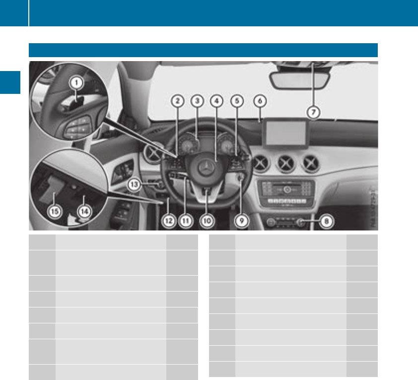
Cockpit
Function Page
:Steering wheel paddle shift-
ers 136
;Combination switch 101
=Instrumentcluster 33
?Horn
ADIRECT SELECT lever 130
BParking Assist PARKTRONIC
warning display 162
COverhead control panel 39
Function Page
DClimatecontrol systems 110
EIgnition lock 122
FAdjusts thesteering wheel 95
GCruisecontrol lever 149
HElectric parking brake 142
ILightswitch 100
JDiagnostics connection 28
KOpensthe hood 257
32 Cockpit
At aglance
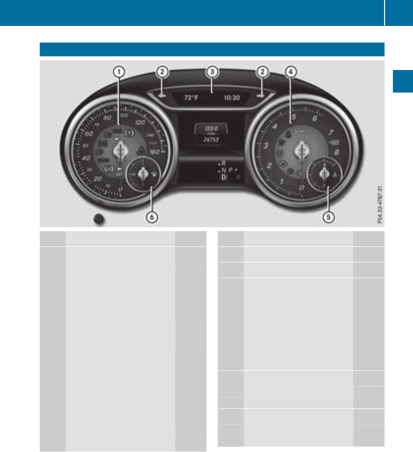
Instrumentcluster
Function Page
:Speedometer withsegments 176
Warning and indicator lamps:
LLow-beam headlamps 101
TParking lamps101
KHigh-beam headlamps 101
÷ESP®221
Electric parking brake
applied(red)
F(USAonly)
!(Canada only) 224
!Electric parking brake
(yellow) 224
·Distancewarning 227
åESP®OFF221
!ABSmalfunctioning 220
Brakes219
$(USAonly)
J(Canada only)
Function Page
;#! Turn signals 101
=Multifunction display 179
?Tachometer 176
6Restraintsystem 41
üSeat belt notfastened218
MSPORT handlingmode
(Mercedes-AMGvehicles) 222
RRear fog lamp 101
;CheckEngine224
hTirepressuremonitor 228
ACoolanttemperature gauge 177
Warning and indicator lamps:
?Coolanttoo hot/cold 225
BFuellevel indicator
Warning and indicator lamps:
æReserve fuel 224
Instrument cluster 33
At aglance
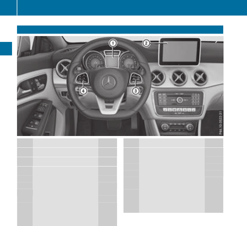
Multifunction steering wheel
Function Page
:Multifunction display 179
;Multimediasystem display
=~Rejects or ends acall
6Makes or accepts acall
Further telephone functions 183
WXAdjusts volume
8Mute
?Switchesonvoice-
operated controlfor naviga-
tionorthe Voice Control Sys-
tem
Function Page
?òOpens the menu list
9:Selects amenu
aConfirmsthe selection
%Back
Operatesthe on-board com-
puter 177
?Switches off voice-
operatedcontrol for naviga-
tion or the Voice Control Sys-
tem
iIn vehicles with multimediasystem Audio 20
youcan find further information:
Ron the multimediasystem in the Digital
Operator's Manual
Ron voice-controlled navigation in the man-
ufacturer's operating instructions
iIn vehicles with multimediasystem
COMAND youcan find further information:
Ron the multimediasystem in the Digital
Operator's Manual
Ron the DVD changer or single DVD drive in
the Digital Operator's Manual
Ron the Voice Control System in the sepa-
rate operating instructions
34 Multifunctionsteering wheel
At aglance
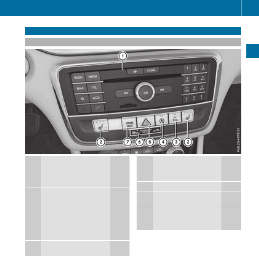
Center console
Center console, upper section
Function Page
:Multimedia system (see the
separate operatinginstruc-
tions)
;cSeat heating 94
Mercedes-AMGvehicles:
AMGadaptive sportsuspen-
sion system (leftside) 159
Mercedes-AMGvehicles:
adjuststhe exhaust flap of
theAMG performance
exhaust system (right side) 127
=cParking Assist
PARKTRONIC 163
Function Page
?èECO start/stopfunc-
tion 125
A£Hazard warning lamps 102
BPASSENGER AIRBAGindica-
torlamps 41
CDYNAMIC SELECT button 128
åMercedes-AMGvehi-
cles: ESP®66
Center console 35
At aglance
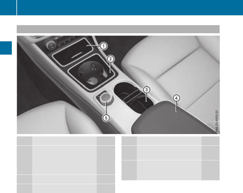
Center console, lower section
Function Page
:Ashtray 244
Cigarettelighter 244
Socket
Stowage compartment 237
;Cup holder 242
=Cup holder 242
Function Page
?Stowage compartmentwith
Media Interface 237
AMultimedia system control-
ler (see theseparate operat-
ing instructions)
36 Center console
At aglance
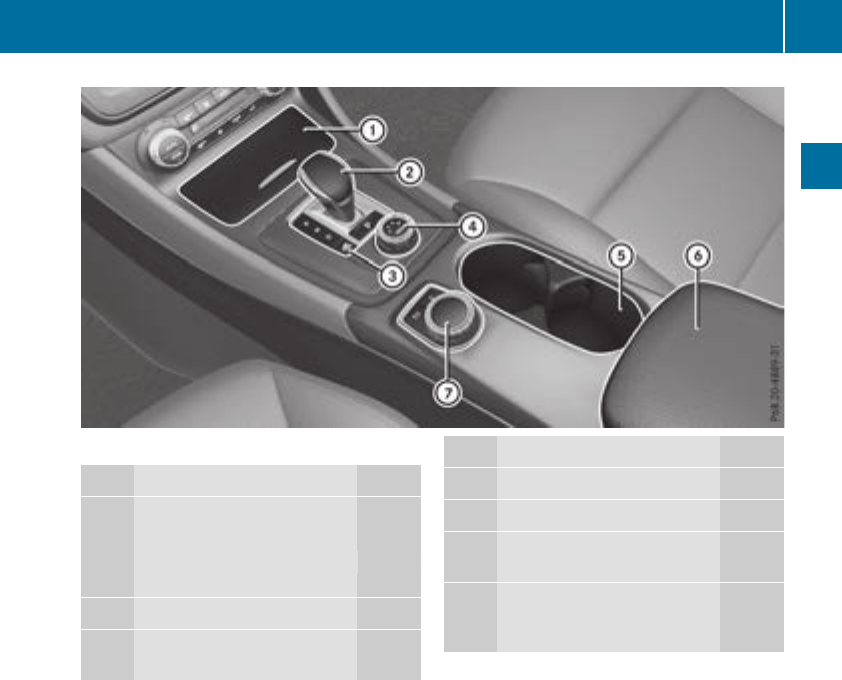
iMercedes-AMG vehicles
Function Page
:Ashtray 244
Cigarette lighter 244
Socket
Stowage compartment 237
;Selector lever 132
=Manual gearshifting (perma-
nent setting) 136
Function Page
?DYNAMIC SELECT controller 129
ACup holder 242
BStowage compartmentwith
Media Interface 237
CMultimedia system control-
ler (see the separate operat-
ing instructions)
Center console 37
At aglance
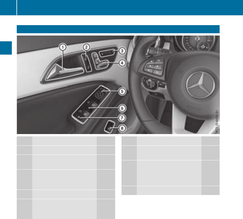
Door controlpanel
Function Page
:Opens thedoor76
;%&Unlocks/locks
the vehicle 76
=r45= Saves
the seat and exterior mirror
settings 98
?Adjusts the seats electrically 92
A7Zö\
Adjusts and folds the exterior
mirrors in/out electrically 96
Function Page
BWOpens/closes the side
windows 82
CnActivates/deactivates
the override feature for the
side windows in the rear
compartment 60
DqOpens the trunk 80
38 Door control panel
At aglance
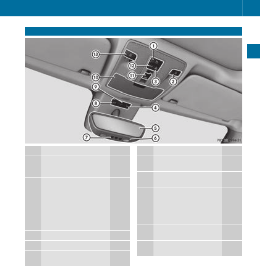
Overheadcontrol panel
Function Page
:uSwitches the rear com-
partmentinterior lighting
on/off 103
;pSwitches the right-
hand reading lamp on/off 103
=|Switches the frontinte-
rior lighting/automatic inte-
rior lighting control off 103
?ïMB Infocall button
(mbrace system) 247
ARear-view mirror 97
BSetsthe compass 255
CButtons for the garage door
opener 252
Function Page
DFBreakdown assistance
call button (mbrace system) 247
EGSOS button (mbrace
system) 246
FEyeglasses compartment 238
G3Opens/closes the pan-
orama roof with power tilt/
sliding panel with roller sun-
blinds 86
HcSwitches the frontinte-
rior lighting on 103
IpSwitches the left-hand
reading lamp on/off 103
Overheadcontrol panel 39
At aglance
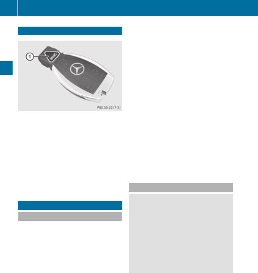
Panic alarm
XTo activate: press and hold the
!button :for approx. one second.
Avisual and audible alarm is triggered if the
alarm system is armed.
XTo deactivate: press !button :again.
or
XInsert the SmartKey into the ignition lock.
or, in vehicles with KEYLESS-GO start-function
or KEYLESS‑GO
XPress the Start/Stop button.
The SmartKey must be in the vehicle.
Occupant safety
Introduction to the restraint system
The restraint system can reduce the risk of vehi-
cle occupants coming into contact with parts of
the vehicle's interior in the event of an accident.
The restraint system can also reduce the forces
to which vehicle occupants are subjected during
an accident.
The restraint system comprises:
RSeat belt system
RAir bags
RChild restraint system
RChild seat securing systems
The components of the restraint system work in
conjunction with each other. They can only
deploy their protective function if, at all times, all
vehicle occupants:
Rhave fastened their seat belts correctly
(Ypage 43)
Rhave the seat and head restraint adjusted
properly (Ypage 90)
As the driver, you also have to make sure that
the steering wheel is adjusted correctly.
Observe the information relating to the correct
driver's seat position (Ypage 90).
You also have to make sure that an air bag can
inflate properly if deployed(
Ypage 45).
An air bag supplements acorrectly worn seat
belt. As an additional safety device, the air bag
increases the level of protection for vehicle
occupants in the event of an accident. For exam-
ple, if, in the event of an accident, the protection
offered by the seat belt is sufficient, the air bags
are not deployed. When an accident occurs, only
the air bags that increase protection in that par-
ticular accident situation are deployed. How-
ever, seat belts and air bags generally do not
protect against objectspenetrating the vehicle
from the outside.
Information on restraint system operation can
be found under "Triggering of the Emergency
Tensioning Devices and air bags" (Ypage 52).
See "Children in the vehicle" for information on
children traveling with you in the vehicle as well
as on child restraint systems (Ypage 54).
Important safety notes
GWARNING
Modifications to the restraint system may
cause it to no longer work as intended. The
restraint system may then not perform its
intended protective function and may fail in an
accident or trigger unexpectedly, for example.
This poses an increased risk of injury or even
fatal injury.
Never modify parts of the restraint system.
Never tamper with the wiring, the electronic
components or their software.
If it is necessary to modify components of the
restraint system to accommodate aperson with
disabilities, contact an authorized Mercedes-
Benz Center for details. USA only: for further
information contact our Customer Assistance
Center at 1-800-FOR-MERCedes
(1‑800‑367‑6372).
Mercedes-Benz recommends that you only use
driving aids which have been approved specifi-
cally for your vehicle by Mercedes-Benz.
40 Occupant safety
Safety
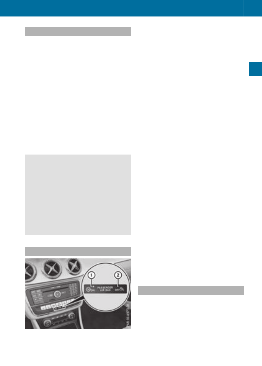
Restraint system warninglamp
The functions of the restraint system are
checkedafterthe ignition is switched on and at
regular intervalswhile the engine is running.
Therefore, malfunctions can be detected in
goodtime.
The 6restraint system warning lamp on the
instrument cluster lights up when the ignition is
switched on. It goesout no later than afew sec-
onds afterthe vehicleisstarted. The compo-
nents of the restraint system are in operational
readiness.
Amalfunction hasoccurred if the 6restraint
system warning lamp:
Rdoesnot light up afterthe ignition is switched
on
Rdoesnot go outafterafew seconds with the
engine running
Rlights up againwhile the engine is running
GWARNING
If the restraint system is malfunctioning,
restraint system components may be trig-
gered unintentionally or may not deployas
intended during an accident. Thiscan affect
for examplethe Emergency Tensioning
Device or the airbag.Thisposes an increased
riskofinjury or evenfatalinjury.
Have the restraint system checkedand
repaired in aqualified specialist workshopas
soonaspossible.
PASSENGER AIRBAG indicator lamp
PASSENGER AIR BAG ON indicator lamp :and
PASSENGER AIR BAG OFF indicator lamp ;are
part of the Occupant Classification System
(OCS).
The indicator lamps display the statusofthe
front-passenger front airbag.
RPASSENGER AIR BAG ON lights up for 60 sec-
onds,subsequently both indicator lamps are
off (PASSENGER AIR BAG ON and OFF):the
front-passenger front airbag is able to deploy
in the event of an accident.
RPASSENGER AIR BAG OFF lights up:the front-
passenger front airbag is deactivated. It will
then not be deployedinthe event of an acci-
dent.
If the PASSENGER AIR BAG ON indicator lamp is
off, only the PASSENGER AIR BAG OFF indicator
lamp shows the statusofthe front-passenger
front airbag.The PASSENGER AIR BAG OFF
indicator lamp may be litcontinuously or be off.
Depending on the person in the front-passenger
seat, the front-passenger front airbag must
either be deactivated or enabled; see the fol-
lowing points. Youmustmake sure of this both
before and during ajourney.
RChildreninachild restraintsystem:
whetherthe front-passenger front airbag is
enabled or deactivated depends on the instal-
ledchild restraint system, and the ageand
size of the child.Therefore, be sure to observe
the notes on the "Occupant Classification
System (OCS)" (Ypage 47)and on "Chil-
dreninthe vehicle" (Ypage 54). There you
will also find instructions on rearward and
forward-facing child restraint systems on the
front-passenger seat.
RAllotherpersons: depending on the classi-
fication of the person in the front-passenger
seat, the front-passenger front airbag is ena-
bled or deactivated (Ypage 47). Be sure to
observe the notes on "Seat
belts“ (Ypage 41)and "Airbags"
(Ypage 45). There youcan also find infor-
mation on the correct seatposition.
Seat belts
Introduction
Seatbelts are the most effective means of
restricting the movement of vehicleoccupants
in the event of an accident or the vehiclerolling
over. Thisreducesthe riskofvehicleoccupants
coming into contact with parts of the vehicle
interiororbeing ejectedfrom the vehicle. Fur-
thermore,the seatbelthelps to keep the vehicle
Occupantsafety 41
Safety
Z

occupant in the best position in relation to the
air bag.
The seat belt system comprises:
RSeat belts
REmergency TensioningDevices for the front
seat belts and the outer seat belts in the rear
RSeat belt force limiters for the front seat belts
and the outer seat belts in the rear
If the seat belt is pulled out of the belt outlet
quickly or with ajerkymovement,the belt
retractor locks. The belt strap cannot be extrac-
ted any further.
The Emergency TensioningDevice tightensthe
seat belt in an accident,pulling the belt close
against the body. However it does not pull the
vehicle occupant back in the direction of the
backrest.
The Emergency TensioningDevice does not cor-
rect an incorrect seat position or the routing of
an incorrectly fastened seat belt.
When triggered, aseat belt force limiter helps to
reduce the force exerted by the seat belt on the
vehicle occupant.
The seat belt force limiters for the front seats are
synchronized with the front air bags, which
absorb part of the deceleration force. This can
reduce the force exerted on the vehicle occu-
pants during an accident.
!If the front-passenger seat is not occupied,
do not engage the seat belt tongue in the
buckle on the front-passenger seat. Other-
wise, the Emergency TensioningDevice and
side impact air bag could be triggered in the
event of an accident and would need to be
replaced.
Important safety notes
The use of seat belts and child restraint systems
is required by law in:
Rall 50 states
Rthe U.S. territories
Rthe District of Columbia
Rall Canadian provinces
Even where this is not required by law, all vehicle
occupantsshould correctly fasten their seat
belts before starting the journey.
GWARNING
If the seat belt is not worn correctly, it cannot
perform its intended protective function. An
incorrectly fastened seat belt can also cause
injuries, for example, in the event of an acci-
dent or when braking or changing direction
abruptly. This poses an increased risk of injury
or even fatal injury.
Always ensure that all vehicle occupantshave
their seat belts fastened correctly and are sit-
ting properly.
The components of the restraint system work in
conjunction with each other. They can only
deploy their protective function if, at all times, all
vehicle occupants:
Rhave fastened their seat belts correctly
(Ypage 43)
Rhave the seat and head restraint adjusted
properly (Ypage 90)
GWARNING
The seat belt does not offer the intended level
of protection if you have not moved the back-
rest to an almost vertical position. When brak-
ing or in the event of an accident,you could
slide underneath the seat belt and sustain
abdomen or neck injuries, for example. This
poses an increased risk of injury or even fatal
injury.
Adjust the seat properly before beginning
your journey. Always ensure that the backrest
is in an almost vertical position and that the
shoulder section of your seat belt is routed
across the center of your shoulder.
GWARNING
Persons less than 5ft(1.50 m) tall cannot
wear the seat belt correctly without an addi-
tional and suitable restraint system. If the
seat belt is not worn correctly, it cannot per-
form its intended protective function. An
incorrectly fastened seat belt can also cause
injuries, for example, in the event of an acci-
dent or when braking or changing direction
abruptly. This poses an increased risk of injury
or even fatal injury.
For this reason, alwayssecure persons under
5ft(1.50 m) tall in suitable additional restraint
systems.
42 Occupant safety
Safety

If achild younger than twelve years old and
under 5ft(1.50m)inheight is travelinginthe
vehicle:
Ralways securethe child in achild restraint
system suitable for this Mercedes-Benzvehi-
cle. The child restraint system must be appro-
priatetothe age, weight and size of the child
Ralways observe the instructions and safety
notes on "Children in the vehicle"
(Ypage 54) in addition to the child restraint
system manufacturer'sinstallation and oper-
atinginstructions
Ralways observe the instructions and safety
notes on the "Occupant classification system
(OCS)" (Ypage 47)
GWARNING
The seat belts may not perform their intended
protective function if:
Rtheyare damaged, modified, extremely
dirty, bleachedordyed
Rthe seat belt buckle is damaged or
extremely dirty
Rthe Emergency TensioningDevices, belt
anchoragesorinertia reels have been modi-
fied.
Seat belts may be damaged in an accident,
althoughthe damage may not be visible, e.g.
due to splinters of glass. Modifiedordamaged
seat belts may tear or fail, e.g. in an accident.
ModifiedEmergency TensioningDevices
could accidentally trigger or fail to deploy
when necessary. This poses an increased risk
of injury or even fatal injury.
Never modifythe seat belts,Emergency Ten-
sioning Devices, belt anchoragesand inertia
reels. Make sure that the seat belts are
undamaged, not worn out and clean.Follow-
ing an accident,have the seat belts checked
immediately at aqualified specialist work-
shop.
Only use seat belts that have been approved for
your vehicle by Mercedes-Benz.
Sports seat or AMG Performance seat: this
seat is designed for the standard three-point
seat belt. If you install another multi-point seat
belt, e.g. sport or racingseat belts,the restraint
system cannot provide the best level of protec-
tion.
GWARNING
If you feed seat belts through the opening in
the seat backrest,the seat backrest may be
damaged or may even break in the eventofan
accident.This poses an increased risk of
injury or even fatal injury.
Only use the standard three-point seat belt.
Never modifythe seat belt system.
Proper use of theseat belts
Observe the safetynotes on the seat belt
(Ypage 42).
All vehicle occupantsmust be wearingthe seat
belt correctly beforebeginningthe journey. Also
make sure that all vehicle occupantsare always
wearing the seat belt correctly while the vehicle
is in motion.
When fasteningthe seat belt, always make sure
that:
Rthe seat belt buckle tongue is inserted only
intothe belt buckle belonging to that seat
Rthe seat belt is pulled tightacross your body
Avoid wearing bulky clothing,e.g. awinter
coat.
Rthe seat belt is not twisted
Only thencan the forces which occur be dis-
tributed over the area of the belt.
Rthe shoulder section of the belt is routed
across the center of your shoulder
The shoulder section of the seat belt should
not touchyour neckorberouted under your
arm or behindyour back.Where possible,
adjust the seat belt to the appropriate height.
Rthe lap belt is taut and passes across your lap
as low down as possible
The lap belt must always be routed across
your hip joints and not across your abdomen.
This applies particularly to pregnant women.
If necessary, push the lap belt down to your
hip jointand pull it tightusing the shoulder
section of the belt.
Rthe seat belt is not routed across sharp, poin-
ted or fragile objects
If you have such itemslocated on or in your
clothing,e.g. pens,keys or eyeglasses,store
these in asuitable place.
Ronly one personisusing aseat belt
Occupant safety 43
Safety
Z
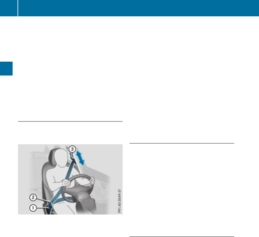
Infants and childrenmust never travel sitting
on the lap of avehicle occupant. In the event
of an accident, they could be crushed
between the vehicle occupant and seat belt.
Robjects are never secured with aseat belt if
the seat belt is also being used by one of the
vehicle's occupants
Also ensure that there are never objects
between aperson and the seat, e.g. cushions.
Seat belts are only intended to secure and
restrain vehicle occupants. Alwaysobserve the
"Loading guidelines" for securing objects, lug-
gage or loads(
Ypage 237).
Fastening and adjusting the seat belts
Observe the safety notes on the seat belt
(Ypage 42) and the notes on correct use of seat
belts (Ypage 43).
Basic illustration
XAdjust the seat (Ypage 90).
The seat backrest must be in an almost
upright position.
XPullthe seat belt smoothly from the belt out-
let.
XEngage seat belt tongue ;in belt buckle :.
XIf necessary,pulluponthe shoulder section
of the seat belt to tighten the belt across your
body.
The shoulder section of the seat belt must
always be routed across the center of the shoul-
der. Adjust the belt outlet if necessary.
XTo raise: slidethe belt outlet up.
The belt outlet willengage in variousposi-
tions.
XTo lower: hold belt outlet release =and slide
the belt outlet down.
XLet go of belt outlet release =in the desired
positionand make sure that the belt outlet
engages.
All seat belts except the driver's seat belt are
equipped with aspecialseat belt retractor to
securelyfasten child restraint systems in the
vehicle.Further information can be found under
"Specialseat belt retractor" (Ypage 55).
Releasing seat belts
!Make sure that the seat belt is fullyrolledup.
Otherwise,the seat belt or belt tongue willbe
trapped in the door or in the seat mechanism.
This could damage the door, the door trim
panel and the seat belt. Damaged seat belts
can no longer fulfill their protective function
and must be replaced. Visit aqualifiedspe-
cialist workshop.
XPress the release button in the belt buckle,
hold the belt tongue firmly and guide the belt
back.
Belt warning for the driver and front
passenger
The 7seat belt warning lamp in the instru-
ment cluster is areminder that all vehicle occu-
pants must weartheir seat belts. It may light up
continuously or flash. In addition, there may be
awarning tone.
Regardless of whether the driver's seat belt has
already been fastened, the 7seat belt warn-
ing lamp lights up for six seconds each time the
engine is started. If the front doors are closed
and the driver's or front-passenger seat belt has
not been fastened, the 7seat belt warning
lamp lights up again after the six seconds. As
soon as the driver's and front-passenger seat
belts are fastened or afront door is opened
again, the 7seat belt warning lamp goes out.
If the driver's seat belt is not fastened after the
engine is started, an additional warning tone will
sound. The warning tone switches off after six
44 Occupant safety
Safety

seconds or once the driver's seat belt is fas-
tened.
If the vehicle's speed exceeds 15 mph
(25 km/h) once and the driver's and front-
passenger seat belts are not fastened, awarning
tone sounds. Awarning tone also sounds with
increasing intensityfor 60 seconds or until the
driver or front passenger have fastened their
seat belts.
If the driver or front passenger unfasten their
seat belts during the journey, the seat belt warn-
ing is activated again.
Air bags
Introduction
The installation point of an air bag can be rec-
ognized by the AIRBAG marking.
An air bag complements the correctly fastened
seat belt. It is no substitute for the seat belt. The
air bag provides additional protection in appli-
cable accident situations.
Not all air bags are deployed in an accident. The
different air bag systems function independ-
ently from one another (Ypage 52).
However, no system available today can com-
pletely eliminate injuries and fatalities.
It is also not possible to rule out arisk of injury
caused by an air bag due to the high speed at
which the air bag must be deployed.
Important safety notes
GWARNING
If you do not sit in the correct seat position,
the air bag cannot protect as intended and
could even cause additional injury when
deployed. This poses an increased risk of
injury or even fatal injury.
To avoid hazardous situations, always make
sure that all of the vehicle's occupants:
Rhave fastened their seat belts correctly,
including pregnant women
Rare sitting correctly and maintain the great-
est possible distance to the air bags
Rfollow the following instructions
Always make sure that there are no objects
between the air bag and the vehicle's occu-
pants.
RAdjust the seats properly before beginning
your journey. Always make sure that the seat
is in an almost upright position. The center of
the head restraint must support the head at
about eye level.
RMove the driver's and front-passenger seats
as far back as possible.The driver's seat posi-
tion must allow the vehicle to be driven safely.
ROnly hold the steering wheel on the outside.
This allowsthe air bag to be fully deployed.
RAlways lean against the backrest while driv-
ing. Do not lean forward or lean against the
door or side window. You may otherwise be in
the deployment area of the air bags.
RAlways keep your feet in the footwell in front
of the seat. Do not put your feet on the dash-
board, for example. Your feet may otherwise
be in the deployment area of the air bag.
RFor this reason, always secure persons less
than 5ft(1.50 m) tall in suitable restraint sys-
tems. Up to this height, the seat belt cannot
be worn correctly.
If achild is traveling in your vehicle,also
observe the following notes:
RAlways secure children under twelve years of
age and less than 5ft(1.50 m) tallinsuitable
child restraint systems.
RChildrestraint systems shouldbeinstalledon
the rearseats.
ROnlysecureachild in arearward-facing child
restraint systemonthe front-passengerseat
when the front-passengerfront airbag is
deactivated.Ifthe PASSENGER AIR BAG OFF
indicator lamp is permanentlylit,the front-
passengerfront airbag is deactivated
(Ypage 41).
RAlwaysobserve the instructions and safety
notesonthe "Occupant Classification System
(OCS)"(
Ypage 47) and on "Children in the
vehicle" (Ypage 54)inadditiontothe child
restraint systemmanufacturer's installation
and operating instructions.
Occupant safety 45
Safety
Z
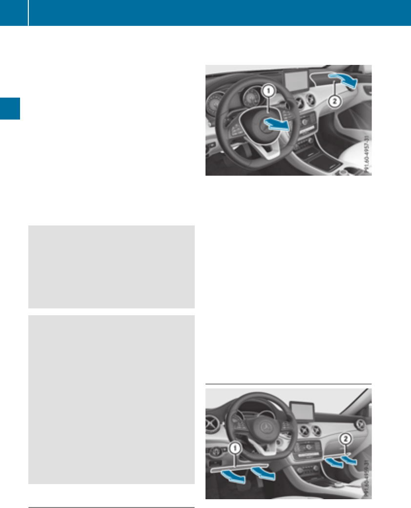
Objects in the vehicle interior may prevent
an air bag from functioning correctly. Before
starting your journey and to avoid risks resulting
from the speed of the air bag as it deploys, make
sure that:
Rthere are no people, animals or objects
between the vehicle occupantsand an air bag
Rthere are no objectsbetween the seat, door
and B-pillar
Rthere are no hard objects, e.g. coat hangers,
hanging on the grab handles or coat hooks
Rno accessories, such as cup holders, are
attached to the vehicle within the deployment
area of an air bag, e.g. to doors, side windows,
rear side trim or side walls
Rno heavy, sharp-edged or fragile objectsare in
the pocketsofyour clothing. Store such
objectsinasuitable place
GWARNING
If you modify the air bag cover or affix objects
such as stickers to it, the air bag can no longer
function correctly. There is an increased risk
of injury.
Never modify an air bag cover or affix objects
to it.
GWARNING
Sensors to control the air bags are located in
the doors. Modificationsorwork not per-
formed correctly to the doors or door panel-
ing, as well as damaged doors, can lead to the
function of the sensorsbeing impaired. The air
bags might therefore not function properly
anymore. Consequently, the air bags cannot
protectvehicle occupantsasthey are
designed to do. There is an increased risk of
injury.
Never modify the doors or parts of the doors.
Always have work on the doors or door pan-
eling carried out at aqualified specialist work-
shop.
Front air bags
!Do not place heavy objectsonthe front-
passenger seat. This could cause the system
to identifythe seat as being occupied. In the
event of an accident,the restraint systems on
the front-passenger side may be triggered
and have to be replaced.
Driver's air bag :deploys in frontofthe steer-
ing wheel. Front-passenger frontair bag ;
deploys in frontofand above the glove box.
When deployed, the frontair bags offer addi-
tional head and thorax protection for the occu-
pants in the frontseats.
The PASSENGER AIR BAG OFF indicatorlamp
informsyou about the status of the front-
passenger frontair bag (Ypage 41).
The front-passenger frontair bag will only
deploy if:
Rthe system, based on the OCS weight sensor
readings, detectsthat the front-passenger
seat is occupied (Ypage 47). The
PASSENGER AIR BAG OFF indicatorlamp is
not lit (Ypage 48)
Rthe restraint system control unit predictsa
high accident severity
Knee bags
Driver's knee bag :deploys under the steering
column and front-passenger knee bag ;under
the glove box. The driver's and front-passenger
knee bags are triggered together with the front
air bags.
46 Occupant safety
Safety
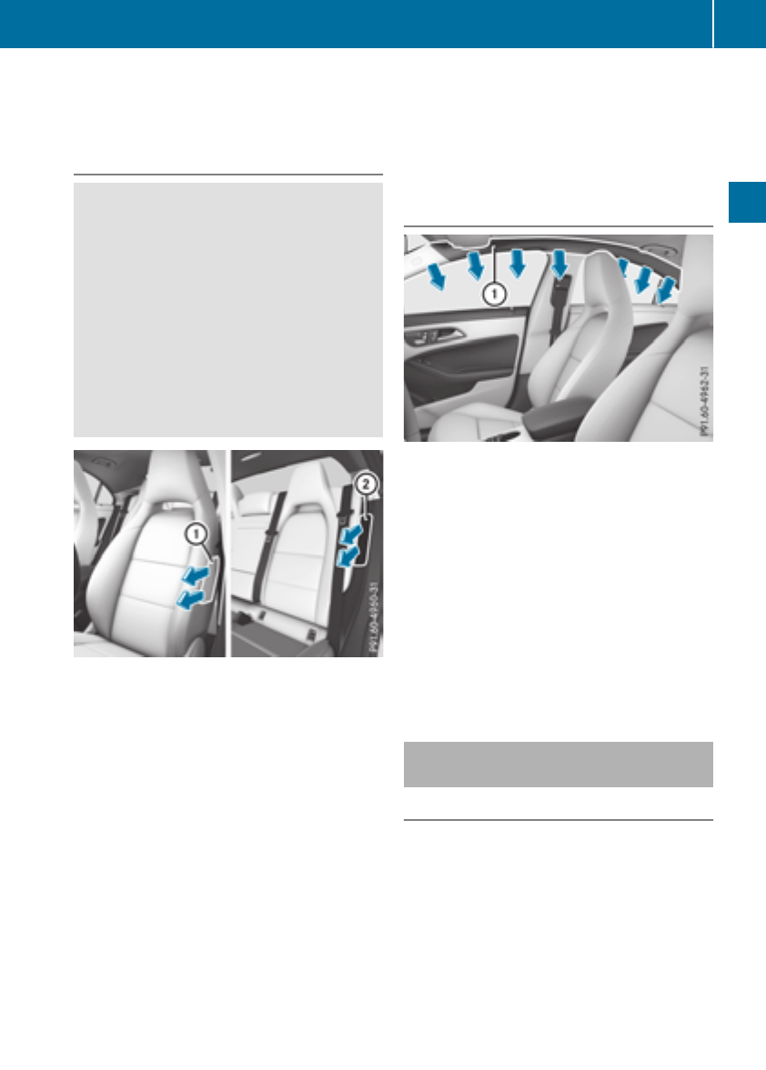
The driver's and front-passenger knee bags
offer additional thigh, knee and lower leg pro-
tection for the occupantsinthe front seats.
Side impact air bags
GWARNING
Unsuitable seat covers can obstruct or pre-
vent deployment of the air bags integrated
into the seats. Consequently, the air bags
cannot protectvehicle occupantsasthey are
designed to do. In addition, the operation of
the occupant classification system (OCS)
could be adversely affected. This poses an
increased risk of injury or even fatal injury.
You should only use seat covers that have
been approved for the respective seat by
Mercedes-Benz.
Frontside impact air bags :and rear side
impact air bags ;deploy next to the outer bol-
ster of the seat backrest.
When deployed, the side impact air bag offers
additional thorax protection. It also offers addi-
tional pelvis protection for occupantsinthe
front seats. However, it does not protectthe:
RHead
RNeck
RArms
If the restraint system control unit detectsaside
impact, the side impact air bag is deployed on
the side on which the impact occurs.
The side impact air bag on the front-passenger
side deploys under the following conditions:
Rthe OCS system detectsthat the front-
passenger seat is occupied or
Rthe seat belt buckle tongue is engaged in the
belt buckle of the front-passenger seat
If the belt tongue is engaged in the belt buckle,
the side impact air bag on the front-passenger
side deploys if an appropriate accident situation
occurs. In this case, deployment is independent
of whether the front-passenger seat is occupied
or not.
Window curtain air bags
Window curtain air bags :are integrated into
the side of the roof frame and deployed in the
area from the A-pillar to the C-pillar.
When deployed, the window curtain air bag
enhances the level of protection for the head.
However, it does not protectthe chest or arms.
If the restraint system control unit detectsaside
impact, the window curtain air bag is deployed
on the side on which the impact occurs.
If the system determines that they can offer
additional protection to that provided by the
seat belt, awindow curtain air bag may be
deployed in other accident situations
(Ypage 52).
Occupant Classification System
(OCS)
Introduction
The Occupant Classification System (OCS) cat-
egorizes the person in the front-passenger seat.
Dependingonthat result, the front-passenger
front air bag and front-passenger knee bag are
either enabled or deactivated.
The system does not deactivate:
Rthe side impact air bag
Rthe window curtain air bag
Rthe Emergency TensioningDevices
Occupant safety 47
Safety
Z
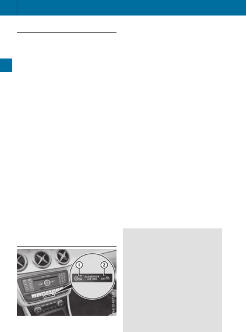
Requirements
To be classifiedcorrectly,the front passenger
mustsit:
Rwith the seatbeltfastened correctly
Rin an almost upright position with theirback
against the seatbackrest
Rwith theirfeetresting on the floor, if possible
If the front passenger doesnot observe these
conditions,OCS may produce afalse classifica-
tion, e.g. because the front passenger:
Rtransfers theirweightbysupporting them-
selves on avehiclearmrest
Rsits in such away that theirweightisraised
from the seatcushion
If it is absolutely necessary to install achild
restraint system on the front-passenger seat, be
sure to observe the correct positioning of the
child restraint system. Neverplace objects
under or behind the child restraint system, e.g. a
cushion. The entirebaseofthe child restraint
system mustalwaysrestonthe seatcushionof
the front-passenger seat. The backrest of the
forward-facing child restraint system mustlie as
flataspossible against the backrest of the front-
passenger seat.
The child restraint system mustnot touch the
rooforbesubjectedtoaloadbythe head
restraint. Adjust the angle of the seatbackrest
and the headrestraint position accordingly.
Only then can OCSbeguaranteed to function
correctly.Alwaysobserve the child restraint sys-
tem manufacturer'sinstallation and operating
instructions.
OperationofOccupant Classification
System (OCS)
:PASSENGER AIR BAG ON indicator lamp
;PASSENGER AIR BAG OFF indicator lamp
The indicator lamps inform youwhetherthe
front-passenger front airbag is deactivated or
enabled.
XPress the Start/Stopbutton once or twice, or
turn the SmartKey to position 1or 2in the
ignition lock.
The system carriesout self-diagnostics.
The PASSENGER AIR BAG OFF and PASSENGER
AIR BAG ON indicator lamps mustlight up simul-
taneously for approximately six seconds.
The indicator lamps display the statusofthe
front-passenger front airbag.
RPASSENGER AIR BAG ON lights up for 60 sec-
onds,subsequently both indicator lamps are
off (PASSENGER AIR BAG ON and OFF):the
front-passenger front airbag is able to deploy
in the event of an accident.
RPASSENGER AIR BAG OFF lights up:the front-
passenger front airbag is deactivated. It will
then not be deployedinthe event of an acci-
dent.
If the PASSENGER AIR BAG ON indicator lamp is
off, only the PASSENGER AIR BAG OFF indicator
lamp shows the statusofthe front-passenger
front airbag.The PASSENGER AIR BAG OFF
indicator lamp may be litcontinuously or be off.
If the statusofthe front-passenger front airbag
changes whilethe vehicleisinmotion, an airbag
display message appears in the instrument clus-
ter (Ypage 200). Whenthe front-passenger
seatisoccupied, always payattention to the
PASSENGER AIR BAG OFF indicator lamp. Be
aware of the statusofthe front-passenger front
airbag both before and during the journey.
GWARNING
If the PASSENGER AIR BAG OFF indicator
lamp is lit, the front-passenger front airbag is
disabled. It will not be deployedinthe event of
an accident and cannotperform its intended
protectivefunction. Aperson in the front-
passenger seatcould then, for example, come
into contact with the vehicle's interior, espe-
ciallyifthe person is sitting too close to the
dashboard. Thisposes an increased riskof
injury or evenfatalinjury.
Whenthe front-passenger seatisoccupied,
always ensure that:
Rthe classification of the person in the front-
passenger seatiscorrect and the front-
48 Occupantsafety
Safety

passenger frontair bag is enabled or disa-
bled in accordance with the person in the
front-passenger seat
Rthe front-passenger seat has been moved
back as far back as possible.
Rthe person is seated correctly.
Make sure, both before and during the jour-
ney, that the status of the front-passenger
frontair bag is correct.
GWARNING
If you secure achild in arearward-facing child
restraint system on the front-passenger seat
and the PASSENGER AIR BAGOFF indicator
lamp is off, the front-passenger frontair bag
can deploy in the event of an accident. The
child could be struck by the air bag. This poses
an increased risk of injury or even fatal injury.
Make sure that the front-passenger frontair
bag has been deactivated. The PASSENGER
AIR BAGOFF indicator lamp must be lit.
NEVER use arearward-facing child restraint
on aseat protected by an ACTIVE FRONT AIR-
BAGinfrontofit; DEATH or SERIOUS INJURY
to the child can occur.
If the PASSENGER AIR BAGOFF indicator lamp
stays off, do not install arearward-facing child
restraint system on the front-passenger seat.
You can find more information on OCS under
"Problems with the Occupant Classification Sys-
tem" (Ypage 51).
GWARNING
If you secure achild in aforward-facingchild
restraint system on the front-passenger seat
and you position the front-passenger seat too
close to the dashboard, in the event of an
accident, the child could:
Rcome intocontact with the vehicle's inte-
rior if the PASSENGER AIR BAGOFF indi-
cator lamp is lit, for example
Rbe struck by the air bag if the PASSENGER
AIR BAGOFF indicator lamp is off
This poses an increased risk of injury or even
fatal injury.
Always move the front-passenger seat as far
back as possible and fully retract the seat
cushion length. Always make sure that the
shoulder belt strap is correctly routed from
the vehicle belt sash guide to the shoulder
belt guide on the child restraint system. The
shoulder belt strap must be routed forwards
and downwards from the vehicle belt sash
guide. If necessary, adjust the vehicle belt
sash guide and the front-passenger seat
accordingly. Always observe the child
restraint system manufacturer's installation
instructions.
If OCS determines that:
RThe front-passenger seat is unoccupied, the
PASSENGER AIR BAGOFF indicator lamp
lights up after the system self-test and
remains lit. This indicates that the front-
passenger frontair bag is deactivated.
RThe front-passenger seat is occupied by a
child of up to twelve months old, in astandard
child restraint system, the PASSENGER AIR
BAGOFF indicator lamp lights up after the
system self-test and remains lit. This indi-
cates that the front-passenger frontair bag is
deactivated.
But even in the case of atwelve-month-old
child, in astandard child restraint system, the
PASSENGER AIR BAGOFF indicator lamp can
go out after the system self-test. This indi-
cates that the front-passenger frontair bag is
activated. The result of the classification is
dependenton, among other factors, the child
restraint system and the child's stature. It is
recommended that you install the child
restraint system on asuitable rear seat.
RThe front-passenger seat is occupied by a
person of smaller stature (e.g. ateenager or
small adult), the PASSENGER AIR BAGOFF
indicator lamp lights up and remains lit after
the system self-test dependingonthe result
of the classification or, alternatively, goes out.
-If the PASSENGER AIR BAGOFF indicator
lamp is off, move the front-passenger seat
Occupant safety 49
Safety
Z

as far back as possible. Alternatively, aper-
son of smaller staturecan sit on arear seat.
-If thePASSENGER AIRBAG OFFindicator
lamp is lit,aperson of smaller stature
shouldnot use thefront-passenger seat.
RThe front-passenger seat is occupied by an
adult or aperson of adult stature, the
PASSENGER AIRBAG OFFindicator lamp
goes out after thesystem self-test.This indi-
cates that thefront-passenger frontair bag is
activated.
If childrenare travelinginthe vehicle,besure to
observethe noteson"Children in thevehicle"
(Ypage 54).
When theOccupantClassification System
(OCS)ismalfunctioning, thered 6restraint
system warning lamp on theinstrumentcluster
and thePASSENGER AIRBAG OFFindicator
lamp light up simultaneously. The front-
passenger frontair bag is deactivatedinthis
caseand does notdeployduringanaccident.
Havethe OccupantClassification System (OCS)
checked and repaired immediately at aqualified
specialist workshop.Mercedes-Benzrecom-
mends that you use an authorized Mercedes-
BenzCenter for this purpose.
If thefront-passenger seat,the seat cover or the
seat cushion are damaged, have thenecessary
repairwork carried out at aqualified specialist
workshop.Mercedes-Benzrecommendsthat
you use an authorized Mercedes-BenzCenter
for this purpose.
For safety reasons, Mercedes-Benzrecom-
mends that you only use seat accessories that
have been approved by Mercedes-Benz.
If thedriver'sair bag deploys, this does not
mean that thefront-passenger frontair bag will
also deploy. The OccupantClassification Sys-
tem(OCS)categorizesthe occupant on the
front-passenger seat.Dependingonthatresult,
thefront-passenger frontair bag is either ena-
bled or deactivated.
System self-test
GDANGER
If boththe PASSENGER AIRBAG OFFand
PASSENGER AIRBAG ON indicator lamps do
notlight up duringthe system self-test,the
system is malfunctioning. The front-
passenger frontair bag mightbetriggered
unintentionally or mightnot be triggered at all
in theeventofanaccidentwith high deceler-
ation. This posesanincreased risk of injury or
even fatal injury.
In this casethe front-passenger seat may not
be used. Do notinstall achild restraint system
on thefront-passenger seat.Havethe Occu-
pant Classification System (OCS)checked
and repaired immediately at aqualified spe-
cialistworkshop.
GWARNING
If thePASSENGER AIRBAG OFFindicator
lamp remains lit after thesystem self-test,the
front-passenger frontair bag is disabled. It will
notbedeployed in theeventofanaccident. In
this case, thefront-passenger frontair bag
cannotperform its intended protective func-
tion, e.g.when aperson is seated in thefront-
passenger seat.
That person could, for example, comeinto
contactwith thevehicle's interior, especially
if theperson is sittingtoo close to thedash-
board.This posesanincreased risk of injury or
even fatal injury.
When thefront-passenger seat is occupied,
always ensure that:
Rtheclassification of theperson in thefront-
passenger seat is correctand thefront-
passenger frontair bag is enabled or disa-
bled in accordance with theperson in the
front-passenger seat
Rtheperson is seated properly with acor-
rectly fastenedseatbelt
Rthefront-passenger seat has been moved
as far back as possible
If thePASSENGER AIRBAG OFFindicator
lamp remains lit when it shouldnot,the front-
passenger seat may notbeused. Do not
install achild restraint system on thefront-
passenger seat.Havethe OccupantClassifi-
cation System (OCS)checked and repaired
immediately at aqualified specialist work-
shop.
50 Occupant safety
Safety

GWARNING
Objects between the seat surface and the
child restraint system couldaffect OCS oper-
ation. This couldresult in the front-passenger
air bag not functioning as intended during an
accident. This poses an increased risk of
injury or even fatal injury.
Do not place any objects between the seat
surface and the child restraint system. The
entire base of the child restraint system must
alwaysrest on the seat cushion of the front-
passenger seat. The backrest of the forward-
facing child restraint system must, as far as
possible,beresting on the backrest of the
front-passengerseat. Always comply with the
child restraint system manufacturer's instal-
lation instructions.
After the system self-test, the PASSENGER AIR
BAG OFF or PASSENGER AIR BAG ON indicator
lamp displaysthe status of the front-passenger
front air bag (Ypage48). If the front-passenger
front air bag is enabled, the PASSENGER AIR
BAG ON indicator lamp lights up for 60 seconds
and then goes out.
If the PASSENGER AIR BAG ON indicator lamp is
off, only the PASSENGER AIR BAG OFF indicator
lamp showsthe status of the front-passenger
front air bag.The PASSENGER AIR BAG OFF
indicator lamp may be lit continuously or be off.
For more information about the OCS, see "Prob-
lems with the Occupant Classification System"
(Ypage51).
Problems with the Occupant ClassificationSystem (OCS)
Be sure to observe the notes on "System self-test" (Ypage50).
Occupant safety 51
Safety
Z

Problem Possible causes/consequences and MSolutions
The PASSENGER AIR
BAG OFF indicator lamp
lights up and remains lit,
even though the front-
passenger seat is occu-
pied by an adult or aper-
son of astature corre-
sponding to that of an
adult.
The classification of the person on the front-passenger seat is incor-
rect.
XMake sure the conditionsfor acorrect classification of the person
on the front-passenger seat are met (Ypage 48).
XIf the PASSENGER AIR BAG OFF indicator lamp remains lit, the front-
passenger seat may not be used.
XHave OCS checked as soon as possible at an authorized Mercedes-
Benz Center.
The PASSENGER AIR
BAG OFF indicator lamp
does not light up and/or
does not stay on.
The front-passenger seat
is:
Runoccupied
Roccupied with the
weight of achild up to
twelve months old in a
child restraint system
OCS is malfunctioning.
XMake sure there is nothingbetween the seat cushion and the child
seat.
XMake sure that the entire base of the child restraint system rests on
the seat cushion of the front-passenger seat. The backrest of the
forward-facing child restraint system must lie as flat as possible
against the backrest of the front-passenger seat. If necessary,
adjust the position of the front-passenger seat.
XMake sure that the seat cushion length is fully retracted.
XWhen installing the child restraint system, make sure that the seat
belt is tight. Do not pull the seat belt tight using the front-passenger
seat adjustment.This could result in the seat belt and the child
restraint system being pulled too tightly.
XCheck for correct installation of the child restraint system.
Make sure that the head restraint does not apply aload to the child
restraint system. If necessary, adjust the head restraint accord-
ingly.
XMake sure that no objectsare applying additional weight onto the
seat.
XIf the PASSENGER AIR BAG OFF indicator lamp remains off and/or
the PASSENGER AIR BAG ON indicator lamp lights up, do not install
achild restraint system on the front-passenger seat. It is recom-
mended that you install the child restraint system on asuitable rear
seat.
XHave OCS checked as soon as possible at an authorized Mercedes-
Benz Center.
Deployment of Emergency Tensioning
Devices and air bags
Important safety notes
GWARNING
The air bag parts are hot after an air bag has
been deployed. There is arisk of injury.
Do not touch the air bag parts. Have a
deployedair bag replaced at aqualified spe-
cialist workshop as soon as possible.
GWARNING
Adeployedair bag no longer offers any pro-
tection and cannot provide the intended pro-
tection in an accident. There is an increased
risk of injury.
Have the vehicle towed to aqualified special-
ist workshop in order to have adeployedair
bag replaced.
It is important for your safety and that of your
passenger to have deployedair bags replaced
52 Occupant safety
Safety

and to have any malfunctioningair bags
repaired. This will help to makesure theair bags
continue to perform their protective function for
thevehicle occupantsinthe eventofacrash.
GWARNING
EmergencyTensioning Devices that have
deployed pyrotechnically are no longer opera-
tional and are unabletoperform their inten-
ded protective function.This posesan
increased risk of injury or even fatal injury.
Havepyrotechnically triggered Emergency
Tensioning Devices replaced immediately at a
qualified specialist workshop.
If EmergencyTensioning Devices are triggered
or air bags are deployed, you will hear abang,
and asmall amountofpowder may also be
released. The 6restraint system warning
lamp lightsup.
Only in rarecases will thebang affect your hear-
ing.The powder that is released generally does
notconstituteahealthhazard, but it may cause
short-term breathingdifficulties in peoplewith
asthma or other respiratory problems.Provided
it is safe to do so, you shouldleave thevehicle
immediately or open thewindow in ordertopre-
ventbreathingdifficulties.
Air bags and pyrotechnic EmergencyTensioning
Devices (ETDs)contain perchlorate material,
whichmay require special handlingand regard
for theenvironment. National guidelines must
be observed duringdisposal. In California, see
www.dtsc.ca.gov/HazardousWaste/
Perchlorate/index.cfm.
Method of operation
During thefirst stage of acollision,the restraint
system control unit evaluates important physi-
cal datarelating to vehicle decelerationoraccel-
eration,suchas:
Rduration
Rdirection
Rintensity
Based on theevaluation of this data, the
restraint system control unit triggersthe Emer-
gency Tensioning Devices duringafrontal or
rear collision.
An EmergencyTensioning Devicecan only be
triggered, if:
Rtheignition is switched on
Rthecomponentsofthe restraint system are
operational. You can findfurther information
under"Restraintsystem warning lamp"
(Ypage 41)
Rtheseat belt buckle tongue has engaged in
thebelt buckle of therespectivefront seat
The EmergencyTensioning Devices in therear
compartmentare triggered independently of the
lockstatus of theseat belts.
If therestraint system control unit detectsa
moresevere accident, further componentsof
therestraint system are activated independ-
ently of each other in certain frontal collision
situations:
RFrontair bags as well as driver'sand front-
passenger knee bags
RWindow curtain air bag, if thesystem deter-
mines that deploymentcan offer additional
protection to that provided by theseat belt
The front-passenger frontair bag is activated or
deactivateddependingont
he person on the
front-passenger seat.The front-passenger front
air bag can only deployinanaccidentifthe
PASSENGER AIRBAG OFFindicator lamp is off.
Observethe informationonthe PASSENGER AIR
BAGindicator lamps (Ypage 41).
Your vehicle has two-stagefront air bags. In the
first deploymentstage, thefront air bag is filled
with propellantgas. The frontair bag is fully
deployed with themaximum amountofpropel-
lant gas if aseconddeploymentthreshold is
reached within afew milliseconds.
The activation threshold of theEmergencyTen-
sioning Devices and theair bags is determined
by evaluating therateofvehicle decelerationor
accelerationwhichoccurs at various points in
thevehicle.This process is pre-emptive in
nature. Deployment shouldtakeplace in good
timeatthe start of thecollision.
The rateofvehicle decelerationoracceleration
and thedirection of theforce are essentially
determinedby:
Rthedistribution of forces duringthe collision
Rthecollision angle
Rthedeformationcharacteristics of thevehicle
Rthecharacteristics of theobject with which
thevehicle has collided
Factors whichcan only be seen and measured
after acollision has occurreddonot play adeci-
Occupant safety 53
Safety
Z

sive role in the deployment of an air bag. Nor do
they provide an indication of air bag deploy-
ment.
The vehicle can be deformed considerably, with-
out an air bag being deployed. This is the case if
only parts which are relatively easilydeformed
are affected and the rate of deceleration is not
high. Conversely, air bags may be deployed even
though the vehicle suffers only minor deforma-
tion. This is the case if, for example, very rigid
vehicle parts such as longitudinal body mem-
bers are hit, and sufficient deceleration occurs
as aresult.
If the restraint system control unit detects aside
impact or if the vehicle rolls over, the applicable
componentsofthe restraint system are activa-
ted independently of each other depending on
the apparent type of accident.
RSide impact air bags on the side where the
impact takes place, independently of the
EmergencyTensioning Device and the use of
the seat belt on the driver's seat and outer
seats in the second row
The side impact air bag on the front-
passenger side deploysunder the following
conditions:
-the OCS system detects that the front-
passenger seat is occupied or
-the seat belt buckle tongue is engaged in
the belt buckle of the front-passenger seat
RWindow curtain air bag on the side of impact,
independently of the use of the seat belt and
independently of whether the front-
passenger seat is occupied
REmergencyTensioning Devices, if the system
determines that deployment can offer addi-
tional protection in this situation
RWindow curtain air bags on the driver's and
front-passenger side in certain situations
when the vehicle rolls over, if the system
determines that deployment can offer addi-
tional protection to that provided by the seat
belt
iNot all air bags are deployed in an accident.
The different air bag systems work independ-
ently of each other.
How the air bag system works is determined
by the severity of the accident detected,
especially the vehicle deceleration or accel-
eration and the apparent type of accident:
RFrontal collision
RSide impact
RRollover
Automatic measures after an acci-
dent
Immediately after an accident, the following
measures are implemented, depending on the
type and severity of the impact:
Rthe hazard warning lamps are activated
Rthe emergency lighting is activated
Rthe vehicle doors are unlocked
Rthe front side windows are lowered
Rthe engine is switched off and the fuel supply
is cut off
Rvehicles with mbrace: automatic emergency
call
Children in the vehicle
Important safety notes
Accident statistics show that children secured
in the rear seats are safer than children secured
in the front-passenger seat. For this reason,
Mercedes-Benz strongly advises that you install
achild restraint system on arear seat. Children
are generally better protected there.
If achild younger than twelve years old and
under 5ft(1.50 m) in height is traveling in the
vehicle:
Ralways secure the child in achild restraint
system suitable for Mercedes-Benz vehicles.
The child restraint system must be appropri-
ate to the age, weight and size of the child
Rbe sure to observe the instructions and safety
notes in this section in addition to the child
restraint system manufacturer's installation
instructions
Rbe sure to observe the instructions and safety
notes on the "Occupant classification system
(OCS)" (Ypage 47)
54 Children in the vehicle
Safety

GWARNING
If you leave children unsupervised in the vehi-
cle, they couldset it in motion by, for example:
Rrelease the parking brake.
Rshift the automatic transmission out of the
parking position P.
Rstart the engine.
In addition, they may operate vehicleequip-
ment and become trapped. There is arisk of
an accident and injury.
When leaving the vehicle, alwaystake the
SmartKey with you and lock the vehicle. Never
leave children unsupervised in the vehicle.
GWARNING
If persons, particularlychildren are subjected
to prolonged exposure to extreme heator
cold, there is arisk of injury,possibly even
fatal.Never leave children unattended in the
vehicle.
GWARNING
If the child restraint system is subjected to
direct sunlight, parts may get very hot. Chil-
dren may burn themselves on these parts,
particularlyonthe metal parts of the child
restraint system. There is arisk of injury.
If you leave the vehicle, taking the child with
you,alwaysensure that the child restraint
system is not exposedtodirect sunlight. Pro-
tect it with ablanket, for example. If the child
restraint system has been exposedtodirect
sunlight, let it cool downbefore securing the
child in it. Never leave children unattended in
the vehicle.
Always ensure that all vehicleoccupants have
their seat belts fastened correctly and are sitting
properly.Particular attention must be paidto
children.
Observe the safety notes on the seat belt
(Ypage42) and the notes on correct use of seat
belts (Ypage43).
Abooster seat may be necessary to achieve
properseat beltpositioning for children over
41 lbs (18 kg)until they reach aheight where a
three-point seat beltcan be properly fastened
without abooster seat.
Special seatbelt retractor
GWARNING
If the seat beltisreleased while driving, the
child restraint system willnolonger be
securedproperly.The special seat beltretrac-
tor is disabledand the inertia real drawsina
portion of the seat belt. The seat beltcannot
be immediatelyrefastened. There is an
increased risk of injury,possibly even fatal.
Stop the vehicleimmediately, paying atten-
tion to road and traffic conditions. Reactivate
the special seat beltretractor and secure the
child restraint system properly.
All seat belts in the vehicle, except the driver's
seat belt, are equipped with aspecial seat belt
retractor. When activated, the special seat belt
retractor ensuresthat the seat beltcannot
slacken once the child seat is secured.
Installing achild restraint system:
XMake sure you observe the child restraint
system manufacturer's installation instruc-
tions.
XPullthe seat beltsmoothly from the beltout-
let.
XEngage seat belttongue in beltbuckle.
Activating the special seat beltretractor:
XPullthe seat beltout fullyand let the inertia
reel retract it again.
Whilethe seat beltisretracting, you should
hear aratcheting sound.The special seat belt
retractor is enabled.
XPush the child restraint system downsothat
the seat beltistight and does not loosen.
Removing the child restraint system and deac-
tivating the special seat beltretractor:
XMake sure you observe the child restraint
system manufacturer's installation instruc-
tions.
XPress the release button of the seat belt
buckle and guide the seat belttongue back
towardsthe beltsash guide.
The special seat beltretractor is deactivated.
Children in the vehicle 55
Safety
Z

Child restraint system
The use of seat beltsand child restraint systems
is required by law in:
Rall 50 states
RtheU.S.territories
RtheDistrict of Columbia
Rall Canadian provinces
If you install arearward-facing child restraint
system on thecenterrear seat,the rear arm rest
must be folded back as far as possible.
You can obtain further informationabout the
correctchild restraint system from any author-
izedMercedes-BenzCenter.
GWARNING
If thechild restraint system is installed incor-
rectly on asuitable seat,itcannotprotect as
intended. The child cannotthenberestrained
in theevent of an accident, heavybraking or
suddenchanges of direction.Thereisan
increased riskofinjury, possibly evenfatal.
Makesure that you observethe child restraint
system manufacturer'sinstallationinstruc-
tions and thenotes on use. Pleaseensure,
that thebase of thechild restraint system is
always restingcompletely on theseat cush-
ion.Never placeobjects, e.g.cushions, under
or behindthe child restraint system. Only use
child restraint systems withthe original cover
designedfor them. Only replace damaged
covers withgenuine covers.
GWARNING
If thechild restraint system is installed incor-
rectly or is notsecured, it can comeloosein
theevent of an accident, heavybraking or a
suddenchangeindirection.The child
restraint system couldbethrown about,strik-
ing vehicle occupants. Thereisanincreased
riskofinjury, possibly evenfatal.
Always install child restraint systems prop-
erly, eveniftheyare notbeingused. Make
sure that you observethe child restraint sys-
temmanufacturer'sinstallationinstructions.
You will findfurther informationonstowing
objects, luggageorloads under"Loading guide-
lines" (Ypage 237).
GWARNING
Child restraint systems or their securingsys-
tems whichhave been damaged or subjected
to aload in an accidentcan no longer protect
as intended. The child cannotthenbe
restrainedinthe event of an accident, heavy
braking or suddenchanges of direction.There
is an increased riskofinjury, possibly even
fatal.
Replacechild restraint systems whichhave
been damaged or subjected to aload in an
accidentassoon as possible. Havethe secur-
ing systems on thechild restraint system
checked at aqualified specialist workshop,
before you install achild restraint system
again.
The securingsystems of child restraint systems
are:
Rtheseat belt system
RtheLATCH-type (ISOFIX) securingrings
RtheTop Tether anchorages
If it is absolutely necessary to carry achild on
thefront-passenger seat,besure to observethe
informationonthe "OccupantClassification
System(OCS)" (Ypage 47).Thereyou will also
findinformationondeactivatingthe front-
passenger frontair bag.
All child restraint systems must meetthe fol-
lowingstandards:
RU.S. Federal Motor Vehicle SafetyStandards
213and 225
RCanadian Motor Vehicle SafetyStandards
213and 210.2
Confirmation that thechild restraint system cor-
responds to thestandards can be foundonan
instruction label on thechild restraint system.
This confirmation can also be foundinthe instal-
lation instructionsthatare included withthe
child restraint system.
Observethe warning labels in thevehicle inte-
rior and on thechild restraint system.
56 Children in thevehicle
Safety
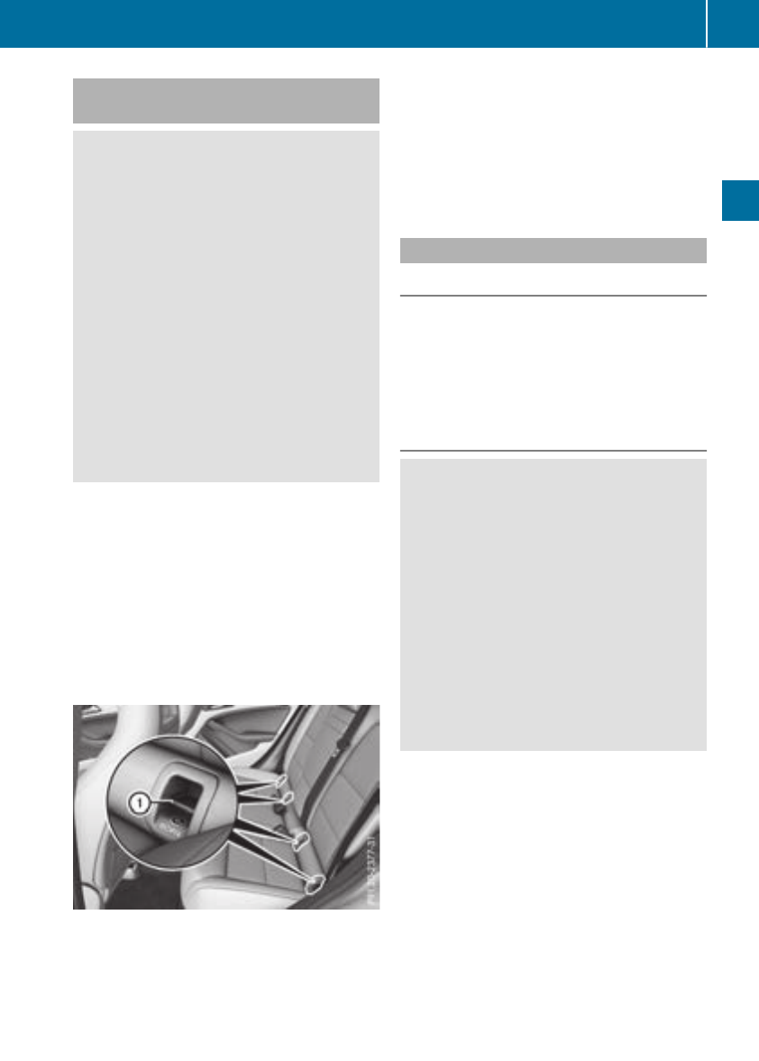
LATCH-type(ISOFIX) child seat secur-
ing system
GWARNING
LATCH-type (ISOFIX) child restraint systems
do not offer sufficient protection for children
whose weight combinedwith thechild
restraint system is greater than 65 lbs (29 kg)
and who are secured usingthe safety belt
integrated in thechild restraint system. In the
eventofanaccident, achild mightnot be
restrained correctly. This poses an increased
risk of injury or even fatal injury.
If thechild and thechild restraint system
together weigh morethan65lbs (29 kg), only
use LATCH-type (ISOFIX) child restraint sys-
temswith whichthe child is also secured with
thevehicle seat belt.Alsosecure thechild
restraint system with theTop Tether belt,if
available.
Always comply with themanufacturer'sinstal-
lationand operatinginstructionsfor thechild
restraint system used.
Before everytrip, makesure that theLATCH-
type (ISOFIX) child restraint system is engaged
correctly in bothLATCH-type (ISOFIX) securing
rings
!When installing thechild restraint system,
makesure that theseat belt for themiddle
seat does not get trapped. The seat belt could
otherwise be damaged.
XInstall theLATCH-type (ISOFIX) child restraint
system on bothLATCH-type (ISOFIX) securing
rings :.
ISOFIXisastandardized securingsystem for
specially designed child restraint systems on
therear seats. LATCH-type (ISOFIX) securing
rings for two LATCH-type (ISOFIX) child restraint
systems are installedonthe left and rightofthe
rear seats.
Non-LATCH-type (ISOFIX) child seatsmay also
be used and can be installedusingthe vehicle's
seat belt system. Install thechild seat according
to themanufacturer'sinstructions.
Top Tether
Introduction
Top Tether provides an additional connection
between thechild restraint system secured with
aLATCH-type (ISOFIX) system and thevehicle.
This helps reducethe risk of injury even further.
If thechild restraint system is equipped with a
Top Tether belt,thisshould always be used.
Important safety notes
GWARNING
If therear seat backrests are not locked,they
could fold forwards in theeventofanacci-
dent, heavy braking or sudden changes of
direction. As aresult, child restraint systems
cannot perform their intended protective
function.Rear seat backrests that are not
locked can also cause additional injuries,e.g.
in theeventofanaccident. This poses an
increased risk of injury or even fatal injury.
Always lock rear seat backrests after instal-
ling aTop Tether belt.Observe thelockveri-
ficationindicator. Adjust therear seat backr-
estssothattheyare in an uprightposition.
If therear backrestisnot engaged and locked,
thered lock verificationindicator will be visible
(Ypage 240).
Children in thevehicle 57
Safety
Z
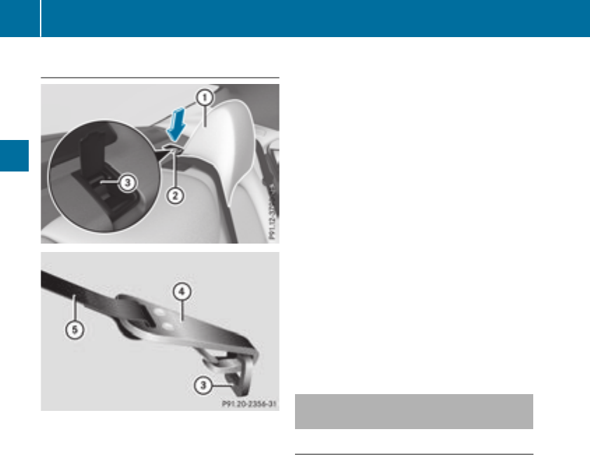
Top Tether anchorages
The TopTetheranchorage points areinstalledin
the rearcompartment behind the head
restraints on the parcel shelf.
XPress down the rearofcover ;in the direc-
tionofthe arrow.
Cover ;is raised slightlyatthe front.
XFoldcover ;up.
Vehicleswithadjustableheadrestraints:
XMoveheadrestraint :up.
XRoute TopTetherbeltAunder head
restraint :between the two head restraint
bars.
Vehicleswithout adjustableheadrestraints:
XTop Tether belt with onebeltstrap: route
TopTetherbeltAcentrallyoverhead
restraint :.
or
XTop Tether belt with two belt straps: route
one TopTetherbeltAto the left and one to
the right past the side of head restraint :.
Allvehicles:
XInstall the LATCH-type (ISOFIX)child restraint
system with TopTether. Alwayscomply with
the child restraint system manufacturer's
installationinstructions when doing so.
XHookTop Tetherhook ?of TopTetherbelt
Ainto TopTetheranchorage =.
Make sure that:
RTopTetherhook ?is hooked into Top
Tetheranchorage =as shown.
RTopTetherbeltAis not twisted.
RTopTetherbeltAis routed between the
rearseatbackrestand the cargo compart-
ment coverifthe cargo compartment cover
is installed.
XTension TopTetherbeltA.Alwayscomply
with the child restraint system manufactur-
er'sinstallationinstructions when doing so.
Vehicleswithadjustableheadrestraints:
XIf necessary,moveheadrestraint :back
down againslightly.Makesurethatyou do
not interfere with the correct routing of Top
TetherbeltA.
Childrestraintsystem on the front-
passengerseat
General notes
Accident statistics showthatchildren secured
in the rearseats aresafer thanchildren secured
in the front-passengerseat. For thisreason,
Mercedes-Benz stronglyadvises thatyou install
the child restraint system on arearseat.
If it is absolutely necessary to installachild
restraint system on the front-passengerseat,
always observe the instructions and safety
notesonthe "Occupant Classification System
(OCS)"(
Ypage 47).
Youcan thusavoid the risks thatcould ariseas
aresultof:
Ran incorrectly categorizedpersoninthe front-
passengerseat
Rthe unintentionaldeactivationofthe front-
passengerfront airbag
Rthe unsuitable positioning of the child
restraint system,e.g.too close to the dash-
board
58 Children in the vehicle
Safety

Rearward-facingchild restraint system
If it is absolutely necessary to install arearward-
facing child restraint system on the front-
passenger seat, always make sure that the
front-passenger front airbag is deactivated.
Only if the PASSENGER AIR BAG OFF indicator
lamp is permanently lit(
Ypage 41)isthe front-
passenger front airbag deactivated.
Alwaysobserve the child restraint system man-
ufacturer's installation and operating instruc-
tions.
Forward-facing child restraint system
If it is absolutely necessary to install aforward-
facing child restraint system on the front-
passenger seat, always move the front-
passenger seatasfar back as possible.Fully
retract the seatcushionlength. The entirebase
of the child restraint system mustalwaysreston
the seatcushionofthe front-passenger seat.
The backrest of the child restraint system must
lieasflataspossible against the backrest of the
front-passenger seat. The child restraint system
mustnot touch the rooforbesubjectedtoaload
by the headrestraint. Adjust the angle of the
seatbackrest and the headrestraint position
accordingly.Alwaysmake sure that the shoul-
der beltstrapiscorrectly routed from the vehi-
cle beltoutlet to the shoulder beltguide on the
child restraint system. The shoulder beltstrap
mustberouted forward and downfrom the vehi-
cle beltoutlet. If necessary, adjust the vehicle
beltoutlet and the front-passenger seataccord-
ingly.
Alwaysobserve the child restraint system man-
ufacturer's installation and operating instruc-
tions.
Child-proof locks
Important safety notes
GWARNING
If children are traveling in the vehicle, they
could:
Ropendoors, thusendangering otherpeople
or roadusers
Rexitthe vehicleand be caught by oncoming
traffic
Roperate vehicleequipment and become
trapped
There is ariskofanaccident and injury.
Alwaysactivate the child-proof locks and
overridefeature if children are traveling in the
vehicle. Whenleaving the vehicle, always take
the key with youand lock the vehicle. Never
leave children unattendedinthe vehicle.
Overridefeature for:
Rthe reardoors (Ypage 60)
Rthe rearsidewindows(Ypage 60)
GWARNING
If youleave children unsupervised in the vehi-
cle,they could set it in motion by,for example:
Rrelease the parking brake.
Rshift the automatic transmissionout of the
parking position P.
Rstartthe engine.
In addition, they may operate vehicleequip-
ment and become trapped.There is ariskof
an accident and injury.
Whenleaving the vehicle, always take the
SmartKey with youand lock the vehicle. Never
leave children unsupervised in the vehicle.
GWARNING
If persons,particularly children are subjected
to prolonged exposure to extreme heator
cold, there is ariskofinjury, possibly even
fatal. Neverleave children unattendedinthe
vehicle.
Childreninthe vehicle 59
Safety
Z
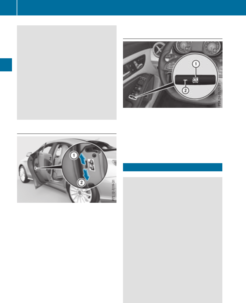
GWARNING
If the child restraint system is subjected to
direct sunlight, parts may get very hot. Chil-
dren may burn themselves on these parts,
particularlyonthe metal parts of the child
restraint system. There is arisk of injury.
If you leave the vehicle, taking the child with
you,alwaysensure that the child restraint
system is not exposedtodirect sunlight. Pro-
tect it with ablanket, for example. If the child
restraint system has been exposedtodirect
sunlight, let it cool downbefore securing the
child in it. Never leave children unattended in
the vehicle.
Child-proof locks for the rear doors
You secure each door individually with the child-
proof locks on the rear doors. Adoor secured
with achild-proof lock cannot be opened from
insidethe vehicle. When the vehicleisunlocked,
the door can be opened from the outside.
XTo activate: press the child-proof lock lever
up in the direction of arrow :.
XMake sure that the child-proof locks are work-
ing properly.
XTo deactivate: press the child-proof lock
leverdowninthe direction of arrow ;.
Override feature for the rear side win-
dows
XTo activate/deactivate: press button :.
If indicator lamp ;is lit, operation of the rear
side windows is disabled. Operation is only
possible using the switches in the driver's
door. If indicator lamp ;is off, operation is
possible using the switches in the rear com-
partment.
Pets in the vehicle
GWARNING
If you leave animals unattended or unsecured
in the vehicle, they couldpress buttons or
switches, for example.
As aresult, they could:
Ractivate vehicleequipment and become
trapped, for example
Ractivate or deactivate systems,thereby
endangering other road users
Unsecuredanimals couldalsobeflung around
the vehicleinthe event of an accident or sud-
den steering or braking, thereby injuring vehi-
cle occupants. There is arisk of an accident
and injury.
Never leave animals unattended in the vehi-
cle. Always secure animals properly during
the journey,e.g. use asuitable animaltrans-
port box.
60 Pets in the vehicle
Safety

Drivingsafetysystems
Overview of drivingsafetysystems
In this section,you will findinformation about
thefollowingdrivingsafetysystems:
RABS(Anti-lock BrakingSystem)
(Ypage 61)
RBAS(BrakeAssist System) (Ypage 61)
RActive BrakeAssist(Ypage 62)
RESP®(Electronic Stability Program)
(Ypage 64)
REBD(ElectronicBrakeforce Distribution)
(Ypage 67)
RADAPTIVEBRAKE (Ypage 68)
RSTEERCONTROL (Ypage 68)
Important safetynotes
If you fail to adapt your drivingstyle or if you are
inattentive,the drivingsafetysystems can nei-
ther reduce theriskofanaccidentnor override
thelaws of physics. Driving safetysystems are
merely aids designed to assist driving. You are
responsible formaintainingthe distancetothe
vehicle in front, forvehicle speed, forbraking in
goodtime, and forstayinginlane. Always adapt
your drivingstyle to suit theprevailingroadand
weather conditionsand maintain asafedistance
from thevehicle in front. Drive carefully.
The drivingsafetysystems described only work
as effectively as possible when there is ade-
quatecontactbetween thetires and theroad
surface. Please pay special attention to the
notesontires,recommended minimum tire
tread depths, etc. (Ypage 288).
In wintrydrivingconditions, always use winter
tires (M+Stires)and if necessary,snow chains.
Onlyinthisway will the driving safety systems
describedinthissection work as effectively as
possible.
ABS (Anti-lock BrakingSystem)
General information
ABS regulatesbrake pressure in such away that
the wheels do not lock when youbrake. This
allows youtocontinue steering the vehiclewhen
braking.
The !ABS warning lamp in the instrument
cluster lights up when the ignition is switched
on. It goesout when the engine is running.
ABS works from aspeed of about5mph
(8 km/h), regardless of road-surface conditions.
ABS works on slippery surfaces, evenwhenyou
onlybrake gently.
Important safety notes
iObserve the "Important safety notes"sec-
tion(
Ypage 61).
GWARNING
If ABS is faulty,the wheels could lock when
braking.The steerability and braking charac-
teristicsmay be severely impaired.Addition-
ally,further driving safety systemsare deac-
tivated.There is an increased danger of skid-
ding and accidents.
Driveoncarefully. HaveABS checked imme-
diately at aqualified specialist workshop.
WhenABS is malfunctioning,othersystems,
including driving safety systems, will also
become inoperative. Observe the information
on the ABS warning lamp (Ypage 220)and dis-
play messages which maybeshown in the
instrument cluster (Ypage 192).
Braking
XIf ABS intervenes: continue to depress the
brake pedalvigorously untilthe braking sit-
uationisover.
XTo make afullbrake application: depress
the brake pedalwithfullforce.
If ABS interveneswhenbraking,you will feela
pulsing in the brake pedal.
The pulsating brake pedalcan be an indication
of hazardousroadconditions, and functions as a
reminder to take extra carewhile driving.
BAS (BrakeAssistSystem)
General information
BAS operates in emergency braking situations.
If youdepress the brake pedalquickly, BAS
automaticallyboosts the braking force,thus
shortening the stopping distance.
Driving safety systems 61
Safety
Z

Important safety notes
iObservethe "Importantsafetynotes"sec-
tion (Ypage 61).
GWARNING
If BASismalfunctioning,the braking distance
in an emergencybraking situation is
increased. Thereisariskofanaccident.
In an emergencybraking situation,depress
thebrakepedal withfull force.ABS prevents
thewheels from locking.
Braking
XKeepthe brakepedal firmly depressed until
theemergencybraking situation is over.
ABSprevents thewheels from locking.
The brakes will function as usual once you
release thebrakepedal.BAS is deactivated.
Active BrakeAssist
General information
iObservethe "Importantsafetynotes"sec-
tion (Ypage 61).
Active Brake Assist consistsofadistancewarn-
ing function withanautonomous braking func-
tion and situation-dependentbraking assis-
tance
Active Brake Assist can help you to minimizethe
riskofacollision withthe vehicletraveling in
frontorreduce theeffects of suchacollision.
If Active Brake Assist detects that there is arisk
of collision,you will be warned visually and
acoustically. If you do notreacttothe visual and
audible collision warning,autonomous braking
can be initiatedincritical situations. If you apply
thebrakeyourself in acritical situation,Adap-
tive Brake Assist supportsyou withsituation-
dependentbraking assistance.
Important safety notes
Detection of hazardous situationscan be par-
ticularly impaired if:
Rthere is dirt on thesensorsoranythingelse
covering thesensors
Rthere is snow or heavyrain
Rthere is interferencebyother radar sources
Rthere are strongradar reflections, for exam-
ple in parking garages
Ranarrow vehicleistraveling in front, e.g. a
motorbike
Ravehicleistraveling in frontonadifferentline
Ryou are driving anew vehicleorservicing on
theActiveBrake Assist system has justbeen
carriedout
Observethe important safetynotes in the
"Breaking-in notes" section (Ypage 121).
Followingdamagetothe frontend of thevehicle,
havethe configuration and operation of the
radar sensor checkedataqualified specialist
workshop. This also appliestocollisionsatlow
speeds wherenovisible damagetothe frontof
thevehicleisapparent.
Activating/deactivating
Active Brake Assist is active after every ignition
cycle.
You can activateordeactivateActiveBrake
Assist (Ypage 185) in theon-board computer.
When deactivated, thedistancewarning func-
tion and theautonomous braking function are
also deactivated.
If Active Brake Assist is deactivated, theæ
symbol appearsinthe assistancegraphic dis-
play.
Distance warning function
Generalinformation
The distancewarning function can help you to
minimizethe riskofafront-end collision witha
vehicleahead or reduce theeffects of sucha
collision.Ifthe distancewarning function
detects that there is ariskofacollision,you will
be warned visually and acoustically.
Important safety notes
iObservethe "Importantsafetynotes"sec-
tion for driving safetysystems (Ypage 61).
GWARNING
The distancewarning function does notreact:
Rto people or animals
Rto oncomingvehicles
Rto crossing traffic
Rwhen cornering
62 Driving safety systems
Safety

The distance warning function may not give
warnings in all critical situations. There is a
risk of an accident.
Always pay careful attention to the traffic sit-
uation and be ready to brake.
Always adapt your speed to suit the prevailing
road and traffic conditions.
GWARNING
The distance warning function cannot always
clearly identify objectsand complex traffic
situations.
In such cases, the distance warning function
may:
Rgive an unnecessary warning
Rnot give awarning
There is arisk of an accident.
Always pay careful attention to the traffic sit-
uation and do not rely solely on the distance
warning function.
Function
Starting at aspeed of approximately 4mph
(7 km/h), the distance warning function warns
you if you rapidly approach avehicle in front.An
intermittent warning tonewill then sound, and
the ·distance warning lamp will light up in
the instrument cluster.
XBrake immediately in order to increase the
distance from the vehicle in front.
or
XTake evasive action, provided it is safe to do
so.
Due to the nature of the system, particularly
complicated but non-critical driving conditions
may also cause the system to display awarning.
With the help of the radar sensor system, the
distance warning function can detect obstacles
that are in the path of your vehicle for an exten-
ded period of time.
Up to aspeed of approximately 44 mph
(70 km/h), the distance warning function can
also react to stationary obstacles, such as stop-
ped or parked vehicles.
Autonomous braking function
If the driver does not react to the distance warn-
ing signal in acritical situation, Active Brake
Assist can assist the driver with the autonomous
braking function.
The autonomous braking function:
Rgives the driver more time to react to critical
driving situations
Rcan help the driver to avoid an accident or
Rreduces the effectsofanaccident
Vehicles without Distance Pilot DISTRONIC:
the autonomous braking function is available in
the following speed ranges:
R4-65mph (7 -105 km/h) for moving objects
R4-31mph (7 -50km/h)for stationary
objects
Vehicles with Distance Pilot DISTRONIC: the
autonomous braking function is available in the
following speedranges:
R4-124 mph (7 -200 km/h)for moving
objects
R4-31mph (7 -50km/h)for stationary
objects
Due to the nature of the system,particularly
complicated but non-critical driving conditions
may alsocausethe AutonomousBraking Func-
tion to intervene.
Situation-dependent braking assis-
tance
General information
iObservethe "Important safety notes" sec-
tion (Ypage61).
With the help of the radarsensor system,Adap-
tive Brake Assist can detect obstacles that are in
the path of yourvehiclefor an extended period
of time.
If Adaptive Brake Assist detects arisk of colli-
sion with the vehicleinfront, it calculatesthe
brake pressure necessary to avoidacollision. If
you apply the brakes forcefully,situation-
dependent braking assistance adapts to the sit-
uation and automatically increases the brake
pressure to adegreeappropriate to the traffic
situation.
Situation-dependent braking assistance pro-
videsbraking assistance in hazardoussituations
at speeds above 4mph (7 km/h).Itusesradar
Driving safety systems 63
Safety
Z

sensor technology to assess the traffic situa-
tion.
Situation-dependent braking assistance is capa-
ble of reacting to moving objects that have
alreadybeen detected as such at least once
over the period of observation, up to vehicle
speeds of around 155 mph (250 km/h).
Situation-dependent braking assistance can
also detect stationary objects, up to vehicle
speeds of around 44 mph (70 km/h).
XKeep the brake pedal depressed until the
emergency braking situation is over.
ABS prevents the wheels from locking.
The brakes will work normally againif:
Ryou release the brake pedal.
Rthere is no longer any danger of acollision.
Rno obstacle is detected in front of your vehi-
cle.
Situation-dependent braking assistance is then
deactivated.
Important safety notes
iObserve the "Important safety notes" sec-
tion for driving safety systems (Ypage 61).
GWARNING
Adaptive Brake Assist does not react:
Rto people or animals
Rto oncoming vehicles
Rto crossing traffic
Rwhen cornering
As aresult, Adaptive Brake Assist may not
intervene in all critical conditions. There is a
risk of an accident.
Always pay careful attention to the traffic sit-
uation and be ready to brake.
GWARNING
Adaptive Brake Assist cannot always clearly
identify objects and complex traffic situa-
tions.
In such cases, Adaptive Brake Assist might:
Rintervene unnecessarily
Rnot intervene
There is arisk of an accident.
Always pay careful attention to the traffic sit-
uation and be ready to brake. Terminate the
intervention in anon-critical driving situation.
Due to the nature of the system, complex but
non-critical driving conditions may also cause
Active Brake Assist to intervene.
Even if Active Brake Assist is not available due to
amalfunction in the radar sensor system, the
brake system is still available with full brake
boosting effect and BAS.
ESP®(Electronic Stability Program)
General notes
iObserve the "Important safety notes" sec-
tion (Ypage 61).
ESP®monitors driving stability and traction,i.e.
power transmission between the tires and the
road surface.
If ESP®detects that the vehicle is deviating from
the direction desired by the driver, one or more
wheels are braked to stabilize the vehicle. The
engine output is also modified to keep the vehi-
cle on the desired course within physical limits.
ESP®assists the driver when pulling awayon
wet or slippery roads. ESP®can also stabilize
the vehicle during braking.
ETS/4ETS (Electronic Traction System)
iObserve the "Important safety notes" sec-
tion (Ypage 61).
ETS traction control is part of ESP®.Onvehicles
with 4MATIC, 4ETS is part of ESP®.
Traction control brakes the drive wheels indi-
vidually if they spin. This enables you to pull
awayand accelerate on slippery surfaces, for
example if the road surface is slippery on one
side. In addition, more drive torque is transfer-
red to the wheel or wheels with traction.
Traction control remains active, even if you
deactivate ESP®.
Important safety notes
iObserve the "Important safety notes" sec-
tion (Ypage 61).
64 Driving safety systems
Safety

GWARNING
If ESP®is malfunctioning, ESP®is unable to
stabilize the vehicle. Additionally, further driv-
ing safety systems are deactivated. This
increases the risk of skidding and an accident.
Drive on carefully.Have ESP®checked at a
qualified specialist workshop.
Vehicles without 4MATIC: when towing your
vehiclewith the front axle raised, it is important
that you observe the notes on ESP®
(Ypage282).
If the åESP®OFF warning lamp lights up
continuously,ESP®is deactivated.
If the ÷ESP®warning lamp and the å
warning lamp are lit continuously,ESP®is not
available due to amalfunction.
Observe the information on warning lamps
(Ypage221) and display messages which may
be showninthe instrument cluster
(Ypage192).
Only use wheels with the recommendedtire
sizes. Only then willESP®function properly.
Characteristics of ESP®
General information
If the ÷ESP®warning lamp goes out before
beginning the journey,ESP®is automatically
active.
If ESP®intervenes, the ÷ESP®warning lamp
flashes in the instrument cluster.
If ESP®intervenes:
XDo not deactivate ESP®under any circum-
stances.
XOnly depress the accelerator pedalasfar as
necessary when pulling away.
XAdapt yourdriving style to suitthe prevailing
road and weather conditions.
ECOstart/stop function
The ECO start/stop function switches the
engine off automatically when the vehiclestops
moving. The engine starts automatically when
the driverwants to pullawayagain. ESP®
remains in its previouslyselected status. Exam-
ple: if ESP®was deactivated before the engine
was switched off, ESP®remains deactivated
when the engine is switched on again.
Deactivating/activating ESP®(except
Mercedes‑AMG vehicles)
Important safety notes
iObserve the "Important safety notes" sec-
tion (Ypage61).
You can select between the following states of
ESP®:
RESP®is activated.
RESP®is deactivated.
GWARNING
If you deactivate ESP®,ESP®no longer sta-
bilizes the vehicle. There is an increased risk
of skidding and an accident.
Only deactivate ESP®in the situations descri-
bed in the following.
The spinning of the wheels results in acutting
action for better traction on loosesurfaces.
It may be best to deactivate ESP®in the follow-
ing situations:
Rwhen using snow chains
Rin deep snow
Ron sand or gravel
iActivate ESP®as soon as the situations
described above no longer apply.ESP®will
otherwise not be abletostabilize the vehicleif
the vehiclestarts to skid or awheelstarts to
spin.
!Avoid spinning the drivenwheels for an
extended period with ESP®deactivated. You
couldotherwise damage the drivetrain.
Deactivating/activating ESP®
You can deactivate or activate ESP®via the on-
board computer (Ypage185).
ESP®deactivated:
The åESP®OFF warning lamp in the instru-
ment cluster lights up.
ESP®activated:
The åESP®OFF warning lamp in the instru-
ment cluster goes out.
Driving safety systems 65
Safety
Z
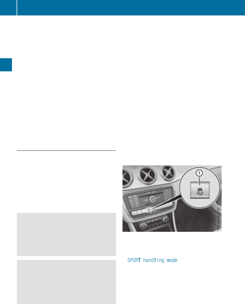
Characteristics when ESP®is deactivated
If ESP®is deactivatedand oneormorewheels
start to spin,the ÷ESP®warning lamp in the
instrumentclusterflashes. In suchsituations,
ESP®will notstabilizethe vehicle.
If you deactivate ESP®:
RESP®no longer improvesdriving stability.
REnginetorque is no longer limited and the
drivewheels are able to spin.
RTractioncontrol is still activated.
RActiveBrake Assist is no longer available; nor
is it activated if you brakefirmly with assis-
tance from ESP®.
RSTEER CONTROL is no longer active.
RESP®still provides support when you brake
firmly.
Deactivating/activatingESP®
(Mercedes‑AMGvehicles)
Important safety notes
iObservethe "Important safety notes" sec-
tion(
Ypage 61).
You can selectbetween thefollowingstatesof
ESP®:
RESP®is activated.
RSPORT handlingmode is activated.
RESP®is deactivated.
GWARNING
When SPORT handlingmode is activated,
there is agreaterrisk of skiddingand acci-
dents.
Only activateSPORT handlingmode in thesit-
uations describedinthe following.
GWARNING
If you deactivate ESP®,ESP®no longer sta-
bilizes thevehicle.Thereisanincreased risk
of skiddingand an accident.
Only deactivate ESP®in thesituations descri-
bed in thefollowing.
In thefollowingsituations,itmay be betterto
activateSPORT handlingmode or deactivate
ESP®:
Rwhen usingsnowchains
Rindeep snow
Ron sandorgravel
Ron specially designated roads when thevehi-
cle's own oversteering and understeering
characteristics are desired
DrivinginSPORT handlingmode or without
ESP®requires an extremely qualified and expe-
rienced driver.
iActivate ESP®as soon as thesituations
describedabovenolonger apply. ESP®will
otherwise notbeable to stabilizethe vehicle if
thevehicle startstoskidorawheel startsto
spin.
!Avoid spinningthe driven wheels for an
extended period with ESP®deactivated. You
couldotherwise damage thedrivetrain.
Deactivating/activatingESP®
XTo activate SPORThandling mode: briefly
pressbutton :.
The MSPORT handlingmode warning
lamp in theinstrumentclusterlightsup. The
SPORT handling mode message appearsin
themultifunction display.
XTo deactivateSPORThandling mode:
briefly pressbutton :.
The MSPORT handlingmode warning
lamp in theinstrumentclustergoes out.
66 Driving safety systems
Safety

XTo deactivate ESP®:press button :until
the åESP®OFF warning lamp lights up in
the instrument cluster.
The ÷OFF message appears in the multi-
functiondisplay.
XTo activate ESP®:brieflypress button :.
The åESP®OFF warning lamp in the
instrument cluster goesout.The ÷ESP®
ON message appears in the multifunctiondis-
play.
CharacteristicsofactivatedSPORT han-
dling mode
If SPORThandling modeisactivatedand one or
more wheels start to spin, the ÷ESP®warn-
ing lamp in the instrument cluster flashes. ESP®
onlystabilizes the vehicletoalimiteddegree.
WhenSPORThandling modeisactivated:
RESP®onlyimprovesdriving stability to alimi-
ted degree.
RTractioncontrolisstillactivated.
RThe engine's torque is onlyrestrictedtoa
limiteddegreeand the drive wheels may start
to spin.
The spinning of the wheels results in acutting
action for better tractiononloose surfaces.
RESP®stillprovides support when youbrake
firmly.
CharacteristicswhenESP®is deactivated
If ESP®is deactivatedand one or more wheels
start to spin, the ÷ESP®warning lamp in the
instrument cluster does not flash. In such situa-
tions, ESP®will not stabilize the vehicle.
If youdeactivate ESP®:
RESP®no longer improvesdriving stability.
REngine torque is no longer limitedand the
drive wheels are able to spin.
The spinning of the wheels results in acutting
action for better tractiononloose surfaces.
RTractioncontrolisstillactivated.
RActive Brake Assist is no longer available;nor
is it activatedifyou brake firmly with assis-
tance from ESP®.
RESP®stillprovides support when youbrake
firmly.
ESP®trailer stabilization
General information
If your vehicle/trailer combinationbeginsto
swerve,ESP®assists youinthissituation. ESP®
slowsthe vehicledownbybraking and limiting
the engine outputuntilthe vehicle/trailer com-
bination hasstabilized.
Important safety notes
GWARNING
If roadand weather conditions are poor,
trailerstabilization will not be able to prevent
the vehicle/trailer combinationfrom swerv-
ing.Trailers with ahighcenterofgravity can
tip overbefore ESP®can detect this. There is
ariskofanaccident.
Alwaysadapt your driving style to the prevail-
ing roadand weather conditions.
If your vehiclewithtrailer(vehicle/trailer com-
bination) begins to lurch, youcan onlystabilize
the vehicle/trailer combinationbydepressing
the brake firmly.
ESP®trailerstabilization is active above speeds
of about65km/h.
ESP®trailerstabilization does not work if ESP®
is deactivatedordisabledbecause of amalfunc-
tion.
EBD (electronicbrake forcedistribu-
tion)
General information
EBD monitors and controls the brake pressure
on the rearwheelstoimprove driving stability
whilebraking.
Important safety notes
iObserve the "Important safety notes"sec-
tion(
Ypage 61).
GWARNING
If EBD is malfunctioning,the rearwheelscan
lock, e.g.under fullbraking.Thisincreases the
riskofskidding and an accident.
Driving safety systems 67
Safety
Z
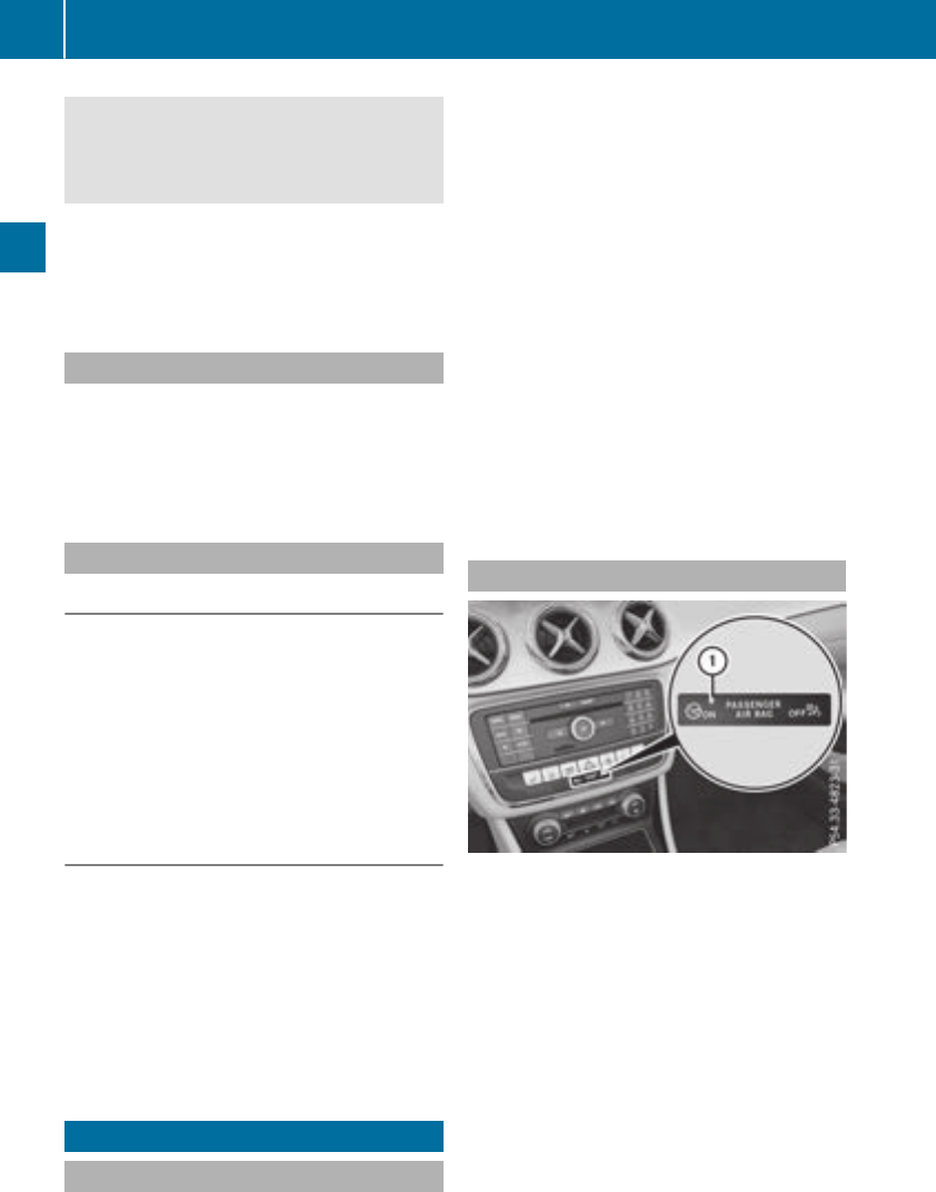
You should therefore adapt your drivingstyle
to the differenthandlingcharacteristics. Have
the brakesystemchecked at aqualified spe-
cialist workshop.
Please observethe information on warningand
indicator lamps (Ypage 220)
(Ypage 220) as well as on display messages
(Ypage 194).
ADAPTIVE BRAKE
ADAPTIVE BRAKE enhances braking safetyand
offers increased braking comfort.Inaddition to
the braking function,ADAPTIVE BRAKE also has
the HOLDfunction (Ypage 157) and hill start
assist (Ypage 125).
STEER CONTROL
Generalinformation
STEER CONTROL helps you by transmitting a
noticeable steeringforcetothe steeringwheel
in the direction required for vehicle stabilization.
This steeringassistanceisprovided in particular
if:
Rboth right wheels or both left wheels are on a
wet or slippery road surfacewhen you brake
Rthe vehicle begins to skid
Important safetynotes
iObserve the "Importantsafetynotes" sec-
tion (Ypage 61).
No steeringassistanceisprovided from STEER
CONTROL, if:
RESP®is malfunctioning
Rthe steeringismalfunctioning
If ESP®is malfunctioning, you will be assisted
further by the electrical power steering.
Protection against theft
Immobilizer
The immobilizer preventsyour vehicle from
being started without the correctSmartKey.
XTo activatewith theSmartKey: remove the
SmartKey from the ignition lock.
XTo activatewith KEYLESS-GO start-func-
tion or KEYLESS-GO: switchthe ignition off
and open the driver's door.
XTo deactivate: switchonthe ignition.
When leaving the vehicle, always takethe
SmartKey with you and lock the vehicle. Anyone
can startthe engineifavalid SmartKey has been
left inside the vehicle.
iThe immobilizer is always deactivatedwhen
you startthe engine.
In the eventthat the enginecannot be started
(yet the vehicle's battery is charged), the sys-
tem is not operational. Contact an authorized
Mercedes-BenzCenter or call
1-800-FOR-MERCedes (in the USA)or
1-800-387-0100(in Canada).
ATA (anti-theft alarmsystem)
XTo arm: lock the vehicle with the SmartKeyor
KEYLESS-GO.
Indicator lamp :flashes. The alarm system
is armed after approximately 15 seconds.
XTo disarm: unlock the vehicle with the Smart-
Key or KEYLESS-GO.
or
XInsert the SmartKeyintothe ignition lock.
Avisual and audible alarm is triggered if the
alarm system is armed and you open:
Radoor
Rthe vehicle with the mechanical key
Rthe trunklid
Rthe hood
68 Protection against theft
Safety

XTo turn the alarm off with the SmartKey:
press the %or &button on the Smart-
Key.
The alarm is stopped.
or
XVehicles with KEYLESS-GO start-function
or KEYLESS-GO: remove the Start/Stop but-
ton from the ignition lock (Ypage 122).
XInsert the SmartKey into the ignition lock.
The alarm is stopped.
XTo stopthe alarm using KEYLESS-GO:
grasp the outsidedoorhandle. The SmartKey
must be outsidethe vehicle.
The alarm is stopped.
or
XPress the Start/Stop button on the dash-
board.The SmartKey must be insidethe vehi-
cle.
The alarm is stopped.
The alarm is not switched off, evenifyou close
the open door thattriggered it, for example.
iIf the alarm continuesfor more than
30 seconds,the mbrace emergency callsys-
tem automaticallynotifiesthe Customer
Assistance Center. Thisisdoneeither by text
message or data connection.
The emergency callsystem sendsthe mes-
sage or data provided that:
Ryouhavesubscribed to the mbrace service.
Rthe mbrace service hasbeenactivated
properly.
Rthe necessary mobilephone network is
available.
Protectionagainsttheft 69
Safety
Z
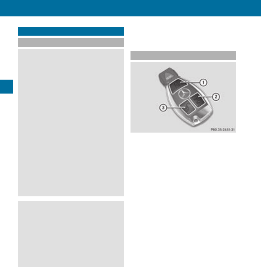
SmartKey
Important safety notes
GWARNING
If children are left unsupervised in the vehicle,
they could:
Ropen the doors, thus endangering other
people or road users.
Rget out and disrupt traffic.
Roperate the vehicle's equipment.
Additionally, children could set the vehicle in
motion if, for example, they:
Rrelease the parking brake.
Rshifting the automatic transmission out of
park position P
RStart the engine.
There is arisk of an accident and injury.
When leaving the vehicle, always take the
SmartKey with you and lock the vehicle. Never
leave children or animals unattended in the
vehicle. Always keep the SmartKey out of
reach of children.
GWARNING
If you attach heavy or large objectstothe
SmartKey, the SmartKey could be uninten-
tionally turned in the ignition lock. This could
cause the engine to be switched off. There is a
risk of an accident.
Do not attach any heavy or large objectstothe
SmartKey. Remove any bulky key rings before
insertingthe SmartKey into the ignition lock.
!Keep the SmartKey away from strongmag-
netic fields. Otherwise, the remote control
function could be affected.
Strong magnetic fields can occur in the vicin-
ity of powerful electrical installations.
Do not keep the SmartKey:
Rwith electronic devices, e.g. amobile phone
or another SmartKey.
Rwith metallic objects, e.g. coins or metal foil.
Rinside metallic objects, e.g. ametal case
Vehicles with KEYLESS-GO startfunction: do
not keep the SmartKey in the trunk.Otherwise,
the SmartKey may not be detected, e.g. when
startingthe engine using the Start/Stop button.
SmartKey functions
:&To lock the vehicle
;FTo open the trunk lid
=%To unlock the vehicle
If you do not open the vehicle within approx-
imately 40 seconds of unlocking:
Rthe vehicle is locked again.
Ranti-theft protection is reactivated.
XTo lock: press the &button.
The SmartKey centrally locks/unlocks:
Rthe doors
Rthe trunk lid
Rthe fuel filler flap
The turn signals flash once when unlocking and
three times when locking.
When the locator lighting is activated via the
multimedia system, it lights up when it is dark
after the vehicle is unlocked with the remote
control (see the separate operating instruc-
tions).
You can also set an audible signal to confirm
that the vehicle has been locked. The audible
signal can be activated and deactivated using
the on-board computer (Ypage 187).
XTo open the trunk lid automatically: press
and hold the Fbutton until the trunk lid
opens (Ypage 79).
70 SmartKey
Opening and closing
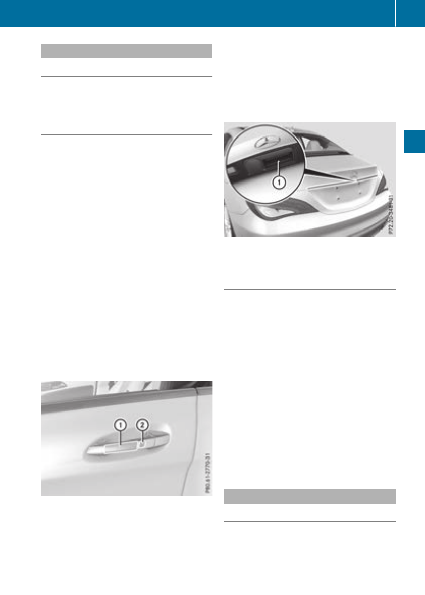
KEYLESS-GO
Generalnotes
Bear in mindthatthe enginecan be started by
any of thevehicleoccupantsifthere is aSmart-
Key in thevehicle.
Lockingand unlocking
You can start,lockorunlockthe vehicleusing
KEYLESS-GO.Todothis, you only need carry the
SmartKey withyou. You can combine thefunc-
tionsofKEYLESS-GO withthose of aconven-
tional SmartKey. Unlockthe vehiclebyusing
KEYLESS-GO,for instance,and lockitusingthe
&buttononthe SmartKey.
The driver's door and thedoor at whichthe han-
dle is used,mustbothbeclosed. The SmartKey
mustbeoutside thevehicle. Whenlocking or
unlocking withKEYLESS-GO,the distance
between theSmartKey and thecorresponding
door handle mustnot be greaterthanthree feet
(onemeter).
Acheck whichperiodically establishes aradio
connection between thevehicleand theSmart-
Key determineswhether avalid SmartKey is in
thevehicle. This occurs, for example:
Rwhen starting theengine
Rwhile driving
Rwhen usingHANDS-FREEACCESS
Rwhen theexternal door handles are touched
Rduring convenience closing
XTo unlock thevehicle: touch theinner sur-
faceofthe door handle.
XTo lock thevehicle: touch sensor surface:
or ;.
Makesurethatyou do nottouch theinner
surfaceofthe door handle.
XConvenienceclosingfeature: touch
recessed sensor surface;for an extended
period.
Further information on theconvenience clos-
ing feature (Ypage 83).
XTo unlock thetrunk lid:pull trunk lid han-
dle :.
Deactivating and activating
If you do notintendtouse thevehiclefor alon-
ger period of time, you can deactivateKEYLESS-
GO. The SmartKey will then use verylittlepower,
thereby conserving battery power. Forthe pur-
poses of activation/deactivation,the vehicle
mustnot be nearby.
XTo deactivate: press the&buttononthe
SmartKey twice in rapidsuccession.
The battery checklamp of theSmartKey
flashes twice brieflyand lights up once,then
KEYLESS-GO is deactivated (Ypage 73).
XTo activate: press any buttononthe Smart-
Key.
or
XInsertthe SmartKey intothe ignition lock.
KEYLESS-GO and all of itsassociated features
are available again.
KEYLESS-GO startfunction
Generalnotes
Bear in mindthatthe enginecan be started by
any of thevehicleoccupantsifthere is aSmart-
Key in thevehicle.
SmartKey 71
Opening and closing
Z
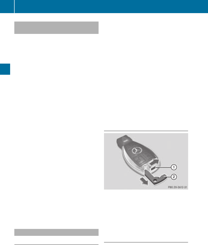
Changing thesettings of thelocking
system
You can changethe settings of thelockingsys-
tem. This meansthatonlythe driver'sdoor and
thefuel fillerflap are unlocked when thevehicle
is unlocked. This is useful if you frequently travel
on your own.
XTo change thesetting: pressand hold the
%and &buttons simultaneouslyfor
approximately six seconds until thebattery
indicator lamp flashes twice (Ypage 73).
If thesettingofthe lockingsystem is changed
within thesignal range of thevehicle,pressing
the &or %button:
Rlocks or
Runlocksthe vehicle
The SmartKey nowfunctionsasfollows:
XTo unlock: pressthe %buttononce.
XTo unlock centrally: pressthe %button
twice.
XTo lock centrally: pressthe &button.
The KEYLESS-GO function is changed as fol-
lows:
XTo unlock thedriver's door: touch theinner
surface of thedoor handle on thedriver's
door.
XTo unlock centrally: touch theinner surface
of thedoor handle on thefront-passenger
door or therear door.
XTo lock centrally: touch theouter sensor
surface on oneofthe door handles.
XTo restorethe factorysettings: pressand
hold the %and &buttons simultane-
ously for approximately six seconds until the
battery check lamp flashes twice
(Ypage 73).
Mechanicalkey
General notes
If thevehicle can no longer be lockedor
unlocked withthe SmartKey or KEYLESS-GO,
use themechanical key.
If you use themechanical keytounlock and
open thedriver'sdoor or thetrunk lid, theanti-
theft alarm system will be triggered (Ypage 68).
Thereare several ways to turnoff thealarm:
XTo deactivatethe alarm with thekey: press
the %or &buttononthe key.
or
XInsertthe SmartKey intothe ignition lock.
or
XTo deactivatethe alarm with KEYLESS-GO:
pressthe Start/Stopbuttoninthe ignition
lock. The SmartKey must be in thevehicle.
or
XLockorunlock thevehicle usingKEYLESS-
GO. The SmartKey must be outside thevehi-
cle.
If you unlock thevehicle usingthe mechanical
key, thefuel fillerflap will notbeunlocked auto-
matically.
XTo unlock thefuelfillerflap: insert the
SmartKey intothe ignition lock.
Removing themechanicalkey
XPush release catch :in thedirection of the
arrow and at thesame timeremove mechan-
ical key ;from theSmartKey.
For further informationabout:
RUnlockingthe driver'sdoor (Ypage 77)
RUnlockingthe trunk (Ypage 81)
RLockingthe vehicle (Ypage 77)
Insertingthe mechanicalkey
XPush mechanical key ;completely intothe
SmartKey until it engages and release
catch :is back in its basic position.
72 SmartKey
Opening and closing
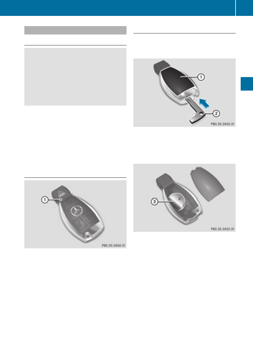
SmartKey battery
Important safety notes
GWARNING
Batteries contain toxic and corrosive substan-
ces. If batteries are swallowed, it can result in
severe health problems. There is arisk of fatal
injury.
Keep batteries out of the reach of children. If
abattery is swallowed, seek medical attention
immediately.
The SmartKey batteries contain perchlorate
material, which may require special handling
and regard for the environment. National guide-
lines must be observed during disposal. In Cal-
ifornia, see www.dtsc.ca.gov/
HazardousWaste/Perchlorate/index.cfm.
Mercedes-Benz recommends that you have the
battery replaced at aqualified specialist work-
shop.
Checking the battery
XPress the &or %button.
The battery is working properly if battery
check lamp :lights up briefly.
The battery is discharged if battery check
lamp :does not light up briefly.
XChange the battery (Ypage 73).
iIf the SmartKey battery is checked within
the signal reception range of the vehicle,
pressing the &or %button:
Rlocks or
Runlocks the vehicle
iYou can get abattery at any qualified spe-
cialist workshop.
Replacing the battery
You require aCR2025 3Vcell battery.
XTake the mechanical key out of the SmartKey
(Ypage 72).
XPress mechanical key ;into the opening in
the SmartKey in the direction of the arrow
until battery tray cover :opens. When doing
so, do not hold cover :shut.
XRemove battery tray cover :.
XRepeatedly tap the SmartKey against your
palm until battery =falls out.
XInsert the new battery with the positive ter-
minal facing upwards. Use alint-free cloth to
do so.
XMake sure that the surface of the battery is
free of lint, grease and other contaminants.
XInsert the front tabs of battery tray cover :
and then press to close it.
XInsert mechanical key into the SmartKey
(Ypage 72).
XCheck the function of all SmartKey buttons on
the vehicle.
SmartKey 73
Opening and closing
Z

Problems with the SmartKey
Problem Possible causes/consequences and MSolutions
You cannot lock or
unlock the vehicle using
the SmartKey.
The SmartKey battery is discharged or nearly discharged.
XVehicles without KEYLESS-GO or KEYLESS-GO startfunction:
try again to lock/unlock the vehicle using the remote control func-
tion of the SmartKey. Point the tip of the SmartKey at the driver's
door handle from close range and press the %or &button.
If this does not work:
XCheck the SmartKey battery (Ypage 73) and replace it if necessary
(Ypage 73).
XUnlock (Ypage 77) or lock (Ypage 77) the vehicle using the
mechanical key.
There is interference from apowerful source of radio waves.
XVehicles without KEYLESS-GO or KEYLESS-GO startfunction:
try again to lock/unlock the vehicle using the remote control func-
tion of the SmartKey. Point the tip of the SmartKey at the driver's
door handle from close range and press the %or &button.
If this does not work:
XUnlock (Ypage 77) or lock (Ypage 77) the vehicle using the
mechanical key.
The SmartKey is faulty.
XUnlock (Ypage 77) or lock (Ypage 77) the vehicle using the
mechanical key.
XHave the SmartKey checked at aqualified specialist workshop.
You can no longer lock or
unlock the vehicle using
KEYLESS-GO.
The SmartKey battery is discharged or nearly discharged.
XCheck the SmartKey battery (Ypage 73) and replace it if necessary
(Ypage 73).
If this does not work:
XUnlock (Ypage 77) or lock (Ypage 77) the vehicle using the
mechanical key.
There is interference from apowerful source of radio waves.
XUnlock (Ypage 77) or lock (Ypage 77) the vehicle using the
mechanical key.
74 SmartKey
Opening and closing

Problem Possible causes/consequences and MSolutions
KEYLESS-GO is malfunctioning.
XLock/unlock the vehicle using the remote control function of the
SmartKey.
XHave the vehicle and SmartKey checked at aqualified specialist
workshop.
If the vehicle can also not be locked/unlocked using the remote con-
trol function:
XUnlock (Ypage 77) or lock (Ypage 77) the vehicle using the
mechanical key.
XHave the vehicle and SmartKey checked at aqualified specialist
workshop.
The engine cannot be
started using the Smart-
Key.
The on-board voltage is too low.
XSwitch off non-essential consumers, e.g. seat heating or interior
lighting, and try to start the engine again.
If this does not work:
XCheck the starter battery and charge it if necessary (Ypage 278).
or
XJump-start the vehicle (Ypage 278).
or
XConsult aqualified specialist workshop.
The engine cannot be
started using the Start/
Stop button. The Smart-
Key is in the vehicle.
The vehicle is locked.
XUnlock the vehicle and try to start the vehicle again.
The SmartKey battery is discharged or nearly discharged.
XCheck the SmartKey battery (Ypage 73) and replace it if necessary
(Ypage 73).
If this does not work:
XStart your vehicle with the SmartKey in the ignition lock.
There is interference from apowerful source of radio waves.
XStart your vehicle with the SmartKey in the ignition lock.
You have lost aSmart-
Key.
XHave the SmartKey deactivated at aqualified specialist workshop.
XReport the loss immediately to the vehicle insurers.
XIf necessary, have the locks changed as well.
You have lost the
mechanical key.
XReport the loss immediately to the vehicle insurers.
XIf necessary, have the locks changed as well.
SmartKey 75
Opening and closing
Z
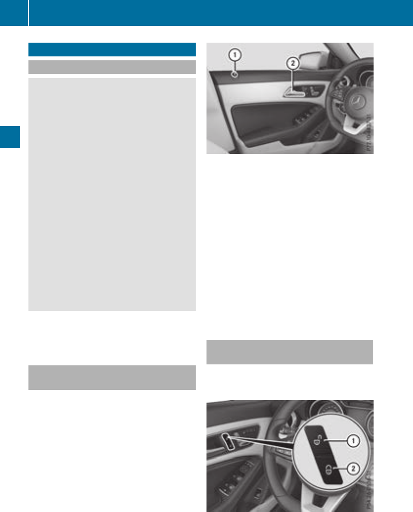
Doors
Important safetynotes
GWARNING
If children are leftunsupervised in thevehicle,
they could:
Ropenthe doors,thusendangeringother
people or road users.
Rget out and disrupttraffic.
Roperatethe vehicle'sequipment.
Additionally, children could set thevehicle in
motion if, forexample, they:
Rrelease theparking brake.
Rshiftingthe automatic transmissionout of
parkposition P
RStart theengine.
There is ariskofanaccidentand injury.
Whenleavingthe vehicle, always take the
SmartKey withyou and lockthe vehicle. Never
leavechildren or animals unattended in the
vehicle. Always keep theSmartKey out of
reach of children.
You should preferably placeluggage or loadsin
thecargo compartment. Observethe loading
guidelines (Ypage 237).
Unlockingand opening doors from
theinside
!The sidewindows will notopen/close if the
battery is discharged or if thesidewindows
haveicedup. It will then notbepossible to
close thedoor. Do notattempttoforce the
doorclosed. You could otherwise damage the
doororthe sidewindow.
Whenadoorisopened, thesidewindow on that
sideopens slightly. Whenthe doorisclosed, the
sidewindow closesagain.
XTo unlock andopenafront door: pull door
handle ;.
If thedoorislocked, locking knob :popsup.
The doorisunlockedand opens.
XTo unlock areardoor: pull up locking
knob :.
The doorisunlockedand can be opened.
XTo openareardoor: pull doorhandle ;.
You can openadoorfrominsidethe vehicle
evenifithas beenlocked. You can only openthe
reardoors from insidethe vehicle if they are not
securedbythe child-proof locks (Ypage 60).
If thevehicle has previously beenlockedwith
theSmartKey from theoutside, opening adoor
from theinsidewill trigger theanti-theftalarm
system. Switchoff thealarm(
Ypage 68).
Centrally locking andunlocking the
vehicle from theinside
You can centrallylockorunlockthe vehicle from
theinside. Thiscan be useful if you wish to lock
thevehicle beforepulling away, forexample.
XTo unlock:press button:.
XTo lock:press button;.
If all thedoors and thetrunk lid are closed, the
vehicle locks.
76 Doors
Opening andclosing
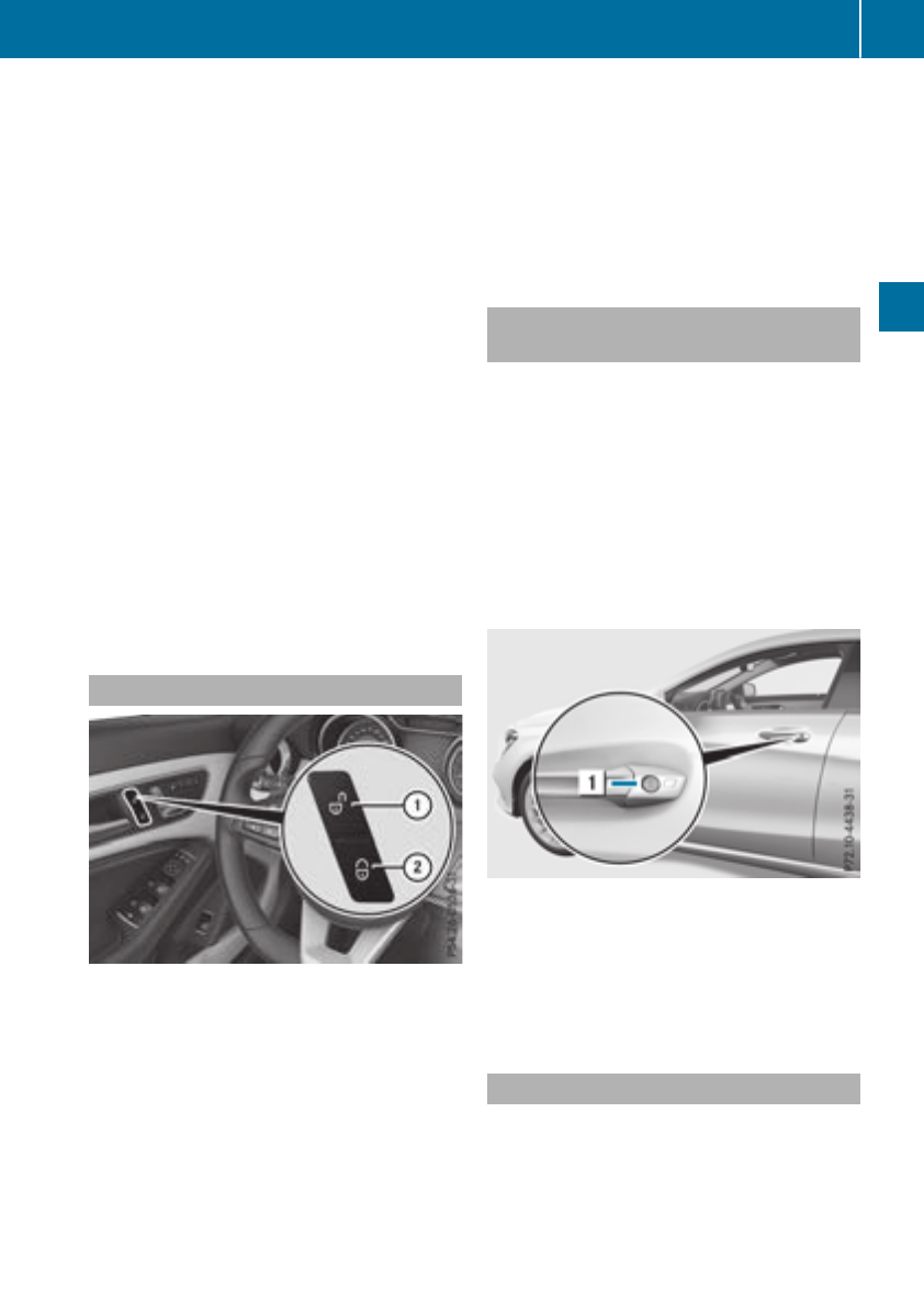
Meanwhile, the fuel filler flap will not be locked
or unlocked.
You cannot unlock the vehicle centrally from the
inside if the vehicle has been locked with the
SmartKey or KEYLESS-GO.
You can open adoor from inside the vehicle
even if it has been locked. You can open the rear
doors from inside the vehicle unless they are
secured by the child-proof lock (Ypage 60).
If the vehicle has previously been locked with
the SmartKey from the outside, opening adoor
from the inside will trigger the anti-theft alarm
system. Switch off the alarm (Ypage 68).
If alocked door is opened from the inside, the
previous unlock status of the vehicle will be
taken into consideration if:
Rthe vehicle was locked using the locking but-
ton for the central locking, or
Rif the vehicle was locked automatically
The vehicle will be fully unlocked if it had previ-
ously been fully unlocked. If only the driver's
door had been previously unlocked, only the
door which has been opened from the inside is
unlocked.
Automatic lockingfeature
XTo deactivate: press and hold button :for
approximately five seconds until atone
sounds.
XTo activate: press and hold button ;for
approximately five seconds until atone
sounds.
If you press one of the two buttons and do not
hear atone, the relevant settinghas already
been selected.
The vehicle is locked automatically when the
ignition is switched on and the wheels are turn-
ing.
You could therefore lock yourself out if:
Rthe vehicle is being pushed
Rthe vehicle is being towed
Rthe vehicle is on aroller dynamometer
You can also switch the automatic locking func-
tion on and off using the on-board computer
(Ypage 187).
Unlocking the driver's door (mechan-
ical key)
If the vehicle can no longer be locked or
unlocked with the SmartKey or KEYLESS-GO,
use the mechanical key.
If you use the mechanical key to unlock and
open the driver's door, the anti-theft alarm sys-
tem will be triggered. Switch off the alarm
(Ypage 68).
XTake the mechanical key out of the SmartKey
(Ypage 72).
XInsert the mechanical key into the lock of the
driver's door as far as it will go.
XTurn the mechanical key counter-clockwise
as far as it will go to position 1.
The door is unlocked.
XTurn the mechanical key back and remove it.
XInsert mechanical key into the SmartKey
(Ypage 72).
Locking the vehicle (mechanical key)
If the vehicle can no longer be locked with the
SmartKey or KEYLESS-GO, use the mechanical
key.
XOpen the driver's door.
XClose the front-passenger door, the rear
doors and the trunk lid.
Doors 77
Opening and closing
Z
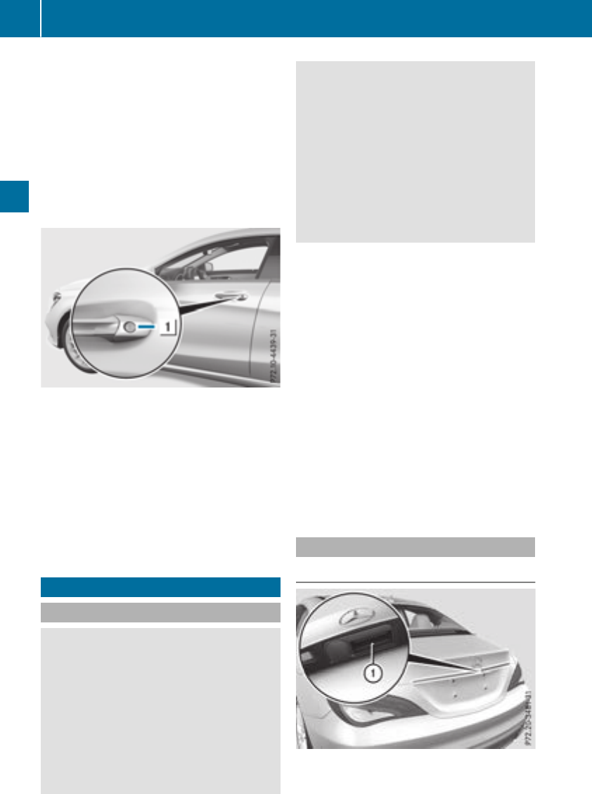
XPress the lockingbutton on the driver’s door
(Ypage 76).
XCheck whether the lockingknobs on the
front-passenger door and the rear doors are
still visible. Press down the lockingknobs by
hand, if necessary.
XClose the driver's door.
XTake the mechanical key out of the SmartKey
(Ypage 72).
XInsert the mechanical key into the lock of the
driver's door as far as it will go.
XTurn the mechanical key clockwise as far as it
will go to position 1.
XTurn the mechanical key back and remove it.
XMake sure that the doors and the trunk lid are
locked.
XInsert mechanical key into the SmartKey
(Ypage 72).
iIf you lock the vehicle as described above,
the fuel filler flap is not locked. The anti-theft
alarm system is not armed.
Trunk
Important safety notes
GWARNING
Combustion engines emit poisonous exhaust
gases such as carbon monoxide. Exhaust
gases can enter the vehicle interior if the
trunk lid is open when the engine is running,
especially if the vehicle is in motion.There is a
risk of poisoning.
Always switch off the engine before opening
the trunk lid. Never drive with the trunk lid
open.
GWARNING
If objects, luggage or loads are not secured or
not secured sufficiently, they could slip, tip
over or be flung around and thereby hit vehicle
occupants. There is arisk of injury, particu-
larly in the event of sudden braking or asud-
den change in direction.
Always store objectssothat they cannot be
flung around. Secure objects, luggage or
loads against slipping or tipping before the
journey.
!The trunk lid swings upwards when opened.
Therefore, make sure that there is sufficient
clearance above the trunk lid.
The opening dimensions of the trunk lid can be
found in the "Vehicle data" section
(Ypage 320).
You should preferably place luggage or loads in
the trunk.Observe the loading guidelines
(Ypage 237).
Do not leave the SmartKey in the trunk.You
could otherwise lock yourself out.
The trunk lid can be:
Ropened and closed manually from outside
Ropened automatically from outside
Ropened automatically from inside
Rreleased with the emergencyrelease from the
inside
Opening/closing from outside
Opening
XPress the %button on the SmartKey.
XPull handle :.
XRaise the trunk lid.
78 Trunk
Opening and closing
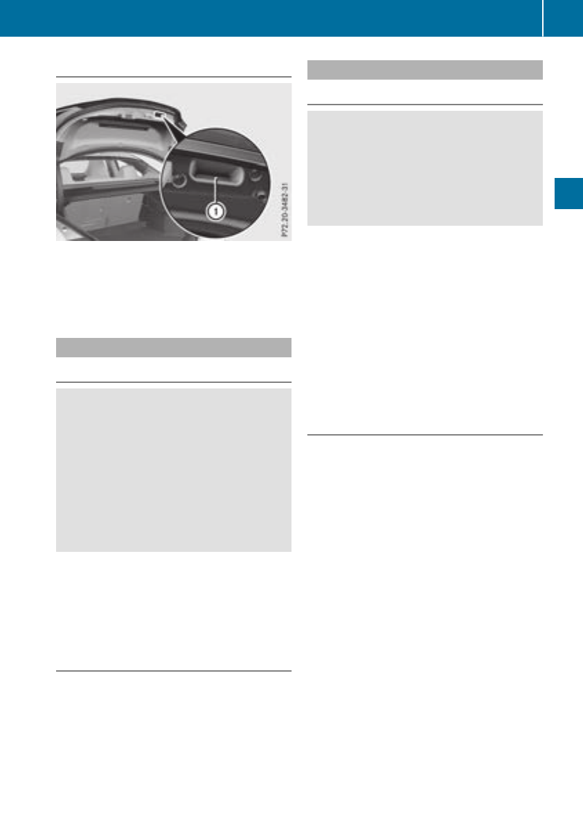
Closing
XPull down thetrunk lid usinghandle :.
XLet thetrunk lid dropintothe lock.
XIf necessary, lockthe vehicle withthe &
buttononthe SmartKey or withKEYLESS-GO.
Opening automatically from outside
Important safety notes
GWARNING
Combustion engines emit poisonous exhaust
gases suchascarbon monoxide. Exhaust
gases can enterthe vehicle interiorifthe
trunk lid is open when theengineisrunning,
especiallyifthe vehicle is in motion.Thereisa
riskofpoisoning.
Always switch off theenginebefore opening
thetrunk lid. Never drivewiththe trunk lid
open.
!The trunk lid swings upwardswhen opened.
Therefore, makesure that there is sufficient
clearance abovethe trunk lid.
iThe opening dimensionsofthe trunk lid can
be foundunder"Vehicle data" (Ypage 320).
Opening automatically
You can open thetrunk lid automaticallyusing
theSmartKey or thehandle in thetrunk lid.
XPress and hold the Fbuttononthe Smart-
Key until thetrunk lid opens.
or
XIf thetrunk lid is unlocked, pull thetrunk lid
handle and let it go again immediately.
HANDS-FREE ACCESS
Important safety notes
GWARNING
The vehicle's exhaust system may be veryhot.
You couldburn yourself by touching the
exhaust system if you use HANDS-FREE
ACCESS.Thereisariskofinjury. Always
ensure that you only makethe kickingmove-
mentwithin thedetection range of sensors.
!If theSmartKey is within therear detection
range of KEYLESS-GO,the followingsitua-
tions,for example,couldlead to theuninten-
tional opening of thetrunk:
Rusingacar wash
Rusingapower washer
Makesure that theSmartKey is at least 10 ft
(3 m) away from thevehicle.
iYou can also deactivate KEYLESS-GO.Fur-
ther informationondeactivatingand activat-
ing KEYLESS-GO (Ypage 71).
General notes
WithKEYLESS-GO and HANDS-FREEACCESS,
you can open thetrunk lid without usingyour
hands. This is useful if you have your hands full.
To do this, makeakickingmovement underthe
bumperwithyour foot.
Observethe followingpoints:
RCarryyour KEYLESS-GO keyabout your per-
son.The KEYLESS-GO keymust be in therear
detection range of thevehicle.
RWhen making thekickingmovement,make
sure that you are standing firmly on the
ground and that there is sufficient clearance
to therear of thevehicle.You couldotherwise
lose your balance, for example on ice.
Trunk 79
Opening and closing
Z
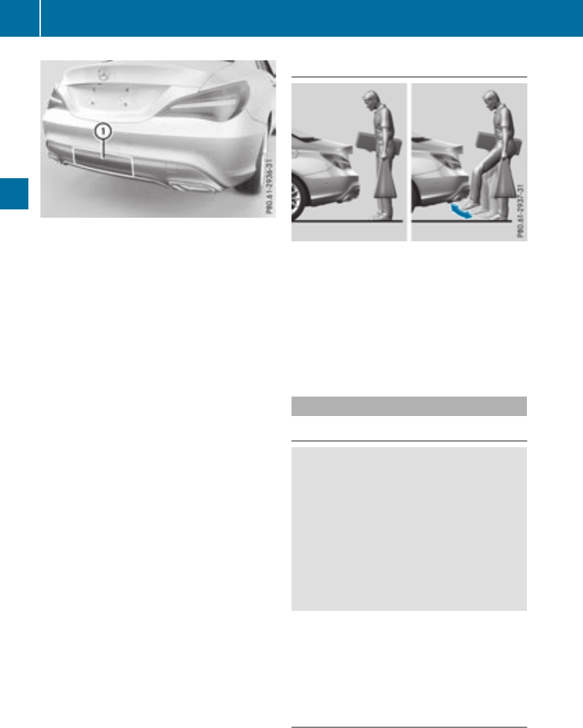
RAlwaysensure thatyou onlymakethe kicking
movement withinthe detection range of sen-
sors :.
RStand at least12in(30 cm)awayfrom the
rearareawhile doing so.
RDo not come into contact with the bumper
whilemaking the kicking movement. Other-
wise, the sensors maynot functioncorrectly.
RHANDS-FREE ACCESS does not functiondur-
ing engine start.
RDirt caused by roadsaltaround sensors :
mayrestrict functionality.
Using the HANDS-FREE ACCESS with apros-
theticleg mayrestrict functionality.
RIf aKEYLESS-GO key is withinthe reardetec-
tionrange of KEYLESS-GO,HANDS-FREE
ACCESS could be triggered.The trunklid
could thusbeopenedunintentionally, for
example, when you:
-set something down or lift something up
behind the vehicle.
-polish the rearofthe vehicle.
Do not carry the KEYLESS-GO key aboutyour
personinthesesituations or in situations sim-
ilar to these. Thiswillprevent the uninten-
tional opening of the trunklid.
Operation
XTo open: kick into sensor detection range :
belowthe bumperwithyourfoot.
XIf the trunk liddoesnot openafterseveral
attempts: wait at leastten secondsthen
move your legunder the bumperonce again.
If youholdyourfootunder the bumperfor too
long, the trunklid does not open. Repeat the leg
movement more quicklyifthisoccurs.
Opening automaticallyfrom inside
Important safety notes
GWARNING
Combustion enginesemitpoisonousexhaust
gases such as carbonmonoxide. Exhaust
gases can enterthe vehicleinteriorifthe
trunklid is open when the engine is running,
especially if the vehicleisinmotion. There is a
riskofpoisoning.
Alwaysswitch off the engine before opening
the trunklid.Never drive with the trunklid
open.
!The trunklid swingsupwards when opened.
Therefore,makesurethatthereissufficient
clearance above the trunklid.
The opening dimensions of the trunklid can be
found under "Vehicle data" (Ypage 320).
Opening
Youcan open the trunklid from the driver's seat
when the vehicleisstationaryand unlocked.
80 Trunk
Opening and closing
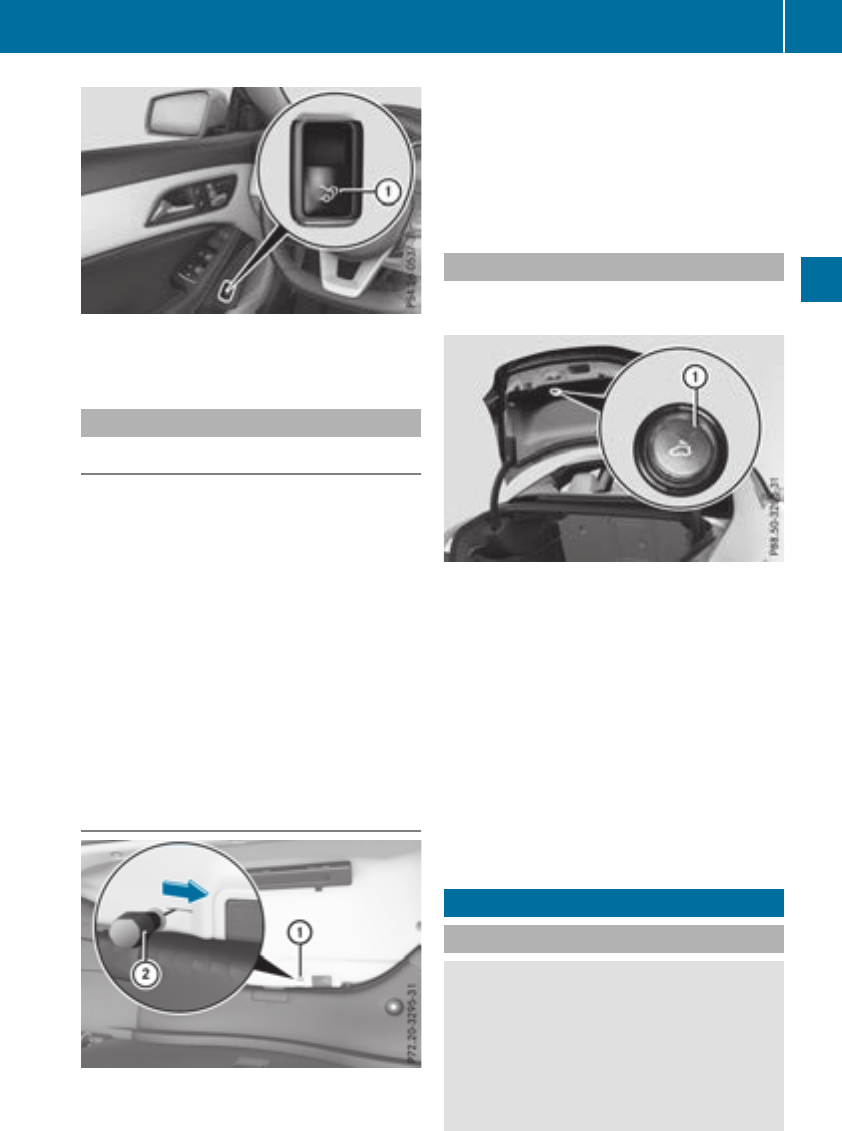
XTo open: pull remote operating switch :for
the trunk liduntilthe trunk lidopens.
Emergencyreleasefor the trunk
General notes
!The trunk lidswingsupwards when opened.
Therefore, make sure thatthereissufficient
clearance above the trunk lid.
The opening dimensions of the trunk lidcan be
found in the "Vehicle data" section
(Ypage 320).
If the trunk lidcan no longer be unlocked:
Rusing the SmartKey,or
Rusing the remote operating switch in the door
controlpanel:
Use the emergency release on the insideofthe
trunk lid.
Youcan reach the emergency release via the
trunk.
Opening
XFoldthe rearseatbackrestforwards
(Ypage 240).
XInsert asuitabletool ;,e.g.ascrewdriver,
into opening :in the paneling.
The trunk lidisreleased.
XOpenthe trunk lid.
Emergencyreleasebutton
Youcan open the trunk lidfrom insidethe vehi-
cle with the emergency release button.
XPress emergency release button :briefly.
The trunk lidunlocks and opens.
The trunk lidcan be unlockedand openedwith
the trunk lidemergency release when the vehi-
cle is stationary or whiledriving.
The trunk lidemergency release does not open
the trunk lidifthe battery is disconnected or
discharged.
Trunk lidemergency release light:
REmergency release button :flashesfor
30 minutes afterthe trunk lidisopened.
REmergency release button :flashesfor
60 minutes afterthe trunk lidisclosed.
Side windows
Important safety notes
GWARNING
While opening the side windows,bodyparts
could become trappedbetween the side win-
dowand the door frame as the side window
moves. There is ariskofinjury.
Make sure thatnobodytouchesthe side win-
dowduring the opening procedure. If some-
Side windows 81
Opening and closing
Z
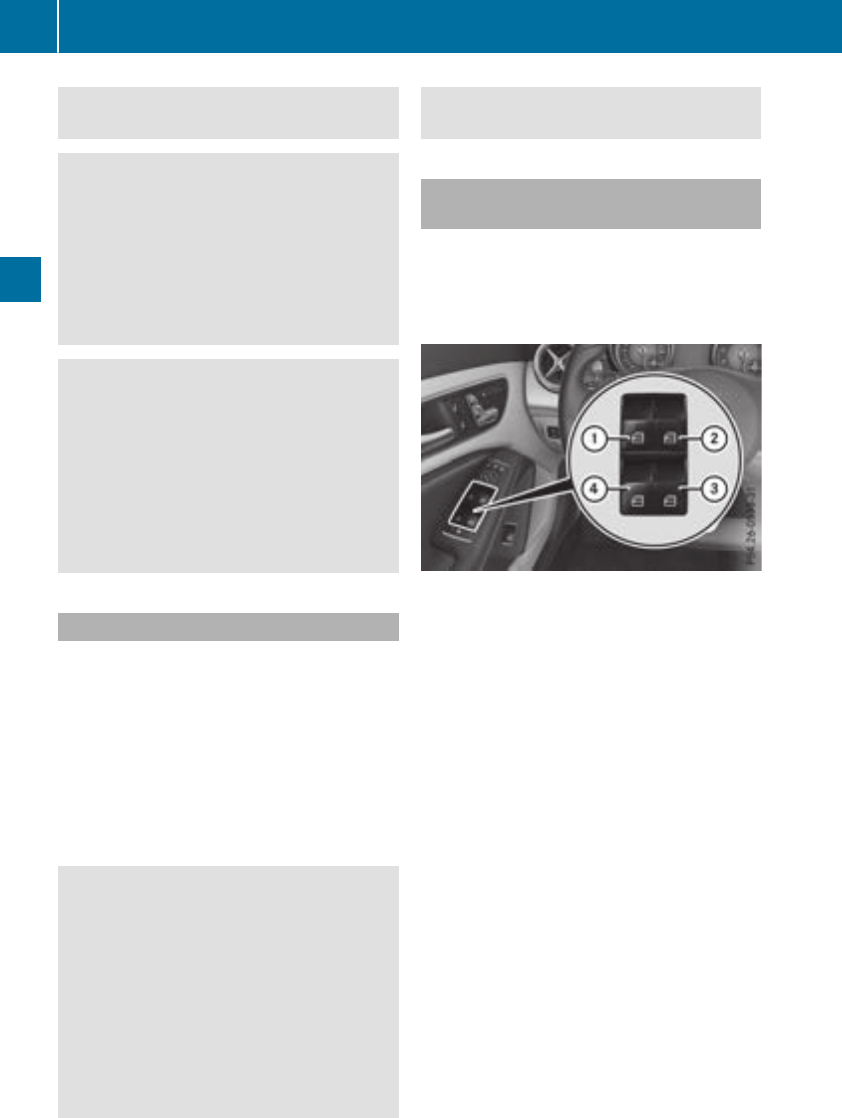
body becomes trapped, release the switch or
pull the switch to close the side window again.
GWARNING
While closingthe side windows, body parts in
the closingarea could become trapped. There
is arisk of injury.
When closingmake sure that no parts of the
body are in the closingarea. If somebody
becomes trapped, release the switch or press
the switch to open the side window again.
GWARNING
If children operate the side windows they
could become trapped, particularly if they are
left unsupervised. There is arisk of injury.
Activatethe override feature for the rear side
windows. When leaving the vehicle, always
take the SmartKey with you and lock the vehi-
cle. Never leave children unsupervised in the
vehicle.
Side window reversing feature
The side windows are equipped with an auto-
matic reversing feature. If asolid objectblocks
or restrictsaside window from traveling
upwards during the automatic closingprocess,
the side window opens again automatically. Dur-
ing the manual closingprocess, the side window
only opens again automatically after the corre-
spondingswitch is released. The automatic
reversing feature is only an aid and is no substi-
tute for your attention when closingaside win-
dow.
GWARNING
The reversing feature does not react:
Rto soft,light and thin objects, e.g. small fin-
gers
Rwhile resetting
This means that the reversing feature cannot
preventsomeonebeing trapped in these sit-
uations. There is arisk of injury.
Make sure that no body parts are in close
proximity during the closingprocedure. If
someonebecomes trapped, press the switch
to open the side window again.
Opening and closing the side win-
dows
The switches for all side windows are located on
the driver'sdoor. There is also aswitch on each
door for the correspondingside window.
The switches on the driver'sdoor take prece-
dence.
:Frontleft
;Frontright
=Rear right
?Rear left
XTurn the SmartKey to position 1or 2in the
ignition lock (Ypage 122).
XTo open manually: press and hold the cor-
responding switch.
XTo open fully: press the switch beyond the
pressure point and release it.
Automatic operation is started.
XTo close manually: pull the corresponding
switch and hold it.
XTo close fully: pull the switch beyond the
pressure point and release it.
Automatic operation is started.
XTo interrupt automatic operation: press/
pull the correspondingswitch again.
iIf you press/pull the switch beyond the
point of resistance, automatic operation is
started in the correspondingdirection. You
can stop automatic operation by pressing/
pulling the switch again.
iYou can continue to operate the side win-
dows after you switch off the engineor
removethe SmartKey. This function remains
82 Side windows
Opening and closing

active for fiveminutesoruntil thedriver'sor
front-passenger door is opened.
iWhen theoverride feature for theside win-
dows is activated (Ypage 60),the side win-
dows cannotbeoperatedfromthe rear.
Convenience opening
Vehicles with KEYLESS-GO, theKEYLESS-
GO startfunction, Exclusive package or
AMG Exclusive package: you can ventilate the
vehicle before you start driving.
The SmartKey can also be used to carry out the
followingfunctionssimultaneously:
Runlock thevehicle
Ropen theside windows
Ropen thepanoramaroofwith power tilt/slid-
ing paneland theroller sunblind
The convenience opening feature can only be
operatedusingthe SmartKey.
The "convenience opening"feature is also avail-
able when thevehicle is unlocked.
XVehicles with Exclusive package or AMG
Exclusive package but without KEYLESS-
GO and theKEYLESS-GO startfunction: for
thefollowingoperations,pointthe tip of the
SmartKey at thedoor handle on thedriver's
door.The SmartKey must be close to thedriv-
er'sdoor handle.
iVehicles with KEYLESS-GO or theKEY-
LESS-GO startfunction: theSmartKey must
be in close proximitytothe vehicle.
XPressand hold the %button until theside
windows and thepanoramasunroofare in the
desired position.
If theroller sunblindofthe panoramaroof
with power tilt/slidingpanelisclosed, the
roller sunblindisopened first.
XPressand hold the %button once more
until thepanoramaroofwith power tilt/slid-
ing panelreaches thedesired position.
XTo interruptconvenience opening: release
the %button.
Convenience closing feature
Important safety notes
GWARNING
When theconvenience closingfeature is oper-
ating, partsofthe body couldbecome trapped
in theclosingarea of theside window and the
slidingsunroof. Thereisarisk of injury.
Observethe completeclosingprocedure
when theconvenience closingfeature is oper-
ating. Makesure that no body partsare in
close proximityduringthe closingprocedure.
Vehicles with KEYLESS-GO, theKEYLESS-
GO startfunction, Exclusive Package or
AMG Exclusive Package: at thesame timeyou
can:
Rlockthe vehicle
Rclose theside windows
Rclose thepanoramaroofwith power tilt/slid-
ing panel
On vehicleswith apanoramaroofwith power
tilt/slidingpanel, you can then close theroller
sunblind.
iNotes on theautomatic reversing feature
for:
Rtheside window (Ypage 82)
Rthepanoramaroofwith power tilt/sliding
panel(
Ypage 86)
Rtheroller sunblind(Ypage 87)
Using theSmartKey
XVehicles with Exclusive package or AMG
Exclusive package but without KEYLESS-
GO and theKEYLESS-GO startfunction: for
thefollowingoperations,pointthe tip of the
SmartKey at thedoor handle on thedriver's
door.The SmartKey must be close to thedriv-
er'sdoor handle.
iVehicles with KEYLESS-GO or theKEY-
LESS-GO startfunction: theSmartKey must
be in close proximitytothe vehicle.
XPressand hold the &button until theside
windows and thepanoramaroofwith power
tilt/slidingpanelare fully closed.
XMakesure that all theside windows and the
panoramaroofwith power tilt/slidingpanel
are closed.
Sidewindows 83
Opening and closing
Z
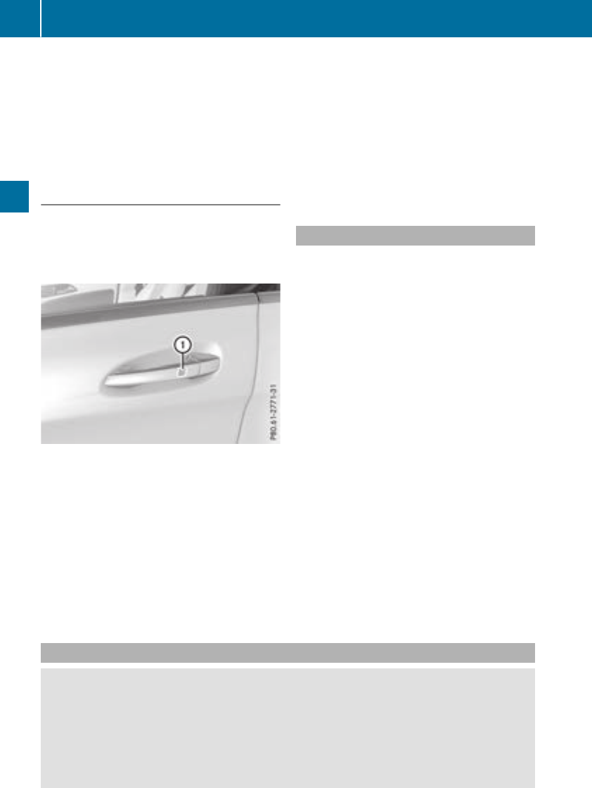
On vehicles with apanorama roof with power
tilt/sliding panel:
XPress and hold the &button againuntil the
roller sunblind of the panorama roof with
power tilt/sliding panel closes.
XTo interruptconvenienceclosing: release
the &button.
Using KEYLESS-GO
The driver's door and the door at which the han-
dle is used, must both be closed. The SmartKey
must be outside the vehicle. The gap between
the SmartKey and the corresponding door han-
dle should not be greater than 3ft(1m).
XTouch recessed sensor surface :on the
door handle until the side windows and the
panorama roof with power tilt/sliding panel
are fully closed.
iMake sure you only touch recessed sensor
surface :.
XMake sure that all the side windows are
closed.
XMake sure that all the side windows and the
panorama roof with power tilt/sliding panel
are closed.
On vehicles with apanorama roof with power
tilt/sliding panel:
XTouch recessed sensor surface :on the
door handle againuntil the roller sunblind of
the panorama roof with power tilt/sliding
panel closes.
XTo interruptconvenienceclosing: release
recessed sensor surface :on the door han-
dle.
Resetting the side windows
If aside window can no longer be closed fully,
you must reset it.
XClose all the doors.
XTurn the SmartKey to position 1or 2in the
ignition lock (Ypage 122).
XPull the corresponding switch on the door
control panel until the side window is com-
pletely closed (Ypage 82).
XHold the switch for an additional second.
If the side window opens againslightly:
XImmediately pull the corresponding switch on
the door control panel until the side window is
completely closed (Ypage 82).
XHold the switch for an additional second.
XIf the respective side window remains closed
after the button is released,then it has been
set correctly. If this is not the case, repeat the
steps above.
Problems with the side windows
GWARNING
If you close aside window againimmediately after it has been blocked or reset, the side window
closes with increased or maximum force. The reversing feature is then not active. Parts of the
body could be trapped in the closing area in the process. This poses an increased risk of injury or
even fatal injury.
Make sure that no parts of the body are in the closing area. To stop the closing process, release
the switch or push the switch againtoreopen the side window.
84 Side windows
Opening and closing

Problem Possible causes/consequences and MSolutions
Aside window cannot be
closed because it is
blocked by objects, e.g.
leaves in the window
guide.
XRemove the objects.
XClose the side window.
Aside window cannot be
closed and you cannot
see the cause.
If aside window is obstructed during closing and reopens again
slightly:
XImmediately after the window blocks, pull the correspondingswitch
again until the side window has closed.
The side window is closed with increased force.
If aside window is obstructed again during closing and reopens again
slightly:
XImmediately after the window blocks, pull the correspondingswitch
again until the side window has closed.
The side window is closed without the automatic reversing feature.
Panoramaroof with power tilt/sliding
panel
Important safety notes
In the following section, the term "sliding sun-
roof" refers to the panorama roof with power
tilt/sliding panel.
GWARNING
While opening and closing the sliding sunroof,
body parts in close proximity could become
trapped. There is arisk of injury.
Make sure that no body parts are in close
proximity during the opening and closing pro-
cedures.
If somebody becomes trapped:
Rrelease the switch immediately, or
Rduring automatic operation, push the
switch briefly in any direction
The opening or closing procedure will be stop-
ped.
GWARNING
If children operate the sliding sunroof they
could become trapped, particularly if they are
left unsupervised. There is arisk of injury.
When leaving the vehicle, always take the
SmartKey with you and lock the vehicle. Never
leave children unsupervised in the vehicle.
GWARNING
At high speeds the raised sliding sunroof auto-
matically lowers slightly at the rear. This could
trap you or other persons. There is arisk of
injury. Make sure that nobody reaches into
the sweep of the sliding sunroof whilst the
vehicle is in motion.
If somebody becomes trapped, immediately
pull back the sliding sunroof switch. The slid-
ing sunroof lifts during opening.
!Only open the sliding sunroof if it is free of
snow and ice. Otherwise, malfunctions may
occur.
Do not allow anything to protrude from the
sliding sunroof. Otherwise, the seals could be
damaged.
!The weather can change abruptly. It could
start to rain or snow. Make sure that the slid-
ing sunroof is closed when you leave the vehi-
cle. The vehicle electronics can be damaged if
water enters the vehicle interior.
iResonance noises can occur in addition to
the usual airflow noises when the sliding sun-
roof is open. They are caused by minor pres-
Panoramaroof with power tilt/sliding panel 85
Opening and closing
Z
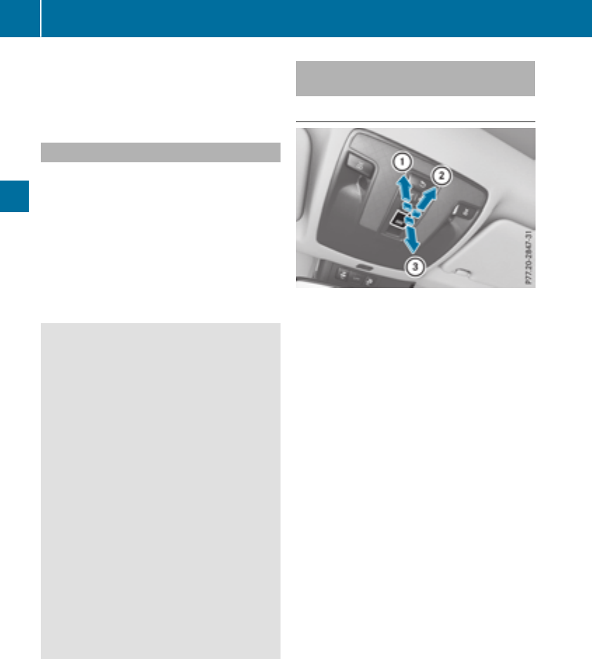
sure fluctuations in the vehicle interior.
Change the position of the sliding sunroof or
open aside window slightly to reduce or elim-
inate these noises.
Sliding sunroof reversing feature
In the following section, the term "sliding sun-
roof" refers to the panorama roof with power
tilt/sliding panel.
The sliding sunroof is equipped with an auto-
matic reversing feature. If asolid object blocks
or restrictsthe sliding sunroof during the closing
process, the sliding sunroof opens againauto-
matically.However, the automatic reversing
feature is only an aid and does not relieve you of
the responsibility of paying attention when clos-
ing the sliding sunroof.
GWARNING
The reversing feature does not react:
Rto soft, light and thin objects, e.g. small fin-
gers
Rover the last 1/6 in (4 mm) of the closing
movement
Rduring resetting
Rwhen closing the sliding sunroof againman-
ually immediately after automatic reversing
This means that the reversing feature cannot
prevent someone being trapped in these sit-
uations. There is arisk of injury.
Make sure that no body parts are in close
proximity during the closing procedure.
If somebody becomes trapped:
Rrelease the switch immediately,or
Rpress the switch in any direction during the
automatic closing process
The closing process is stopped.
Operating the panoramaroof with
power tilt/sliding panel
Opening and closing
:To raise
;To open
=To close/lower
The panorama roof with power tilt/sliding panel
can only be operated when the roller sunblind is
open.
XTurn the SmartKey to position 1or 2in the
ignition lock (Ypage 122).
XPress or pull the 3switch in the corre-
sponding direction.
If you press/pull the 3switch beyond the
point of resistance, automatic operation is star-
ted in the corresponding direction. You can stop
automatic operation by pressing/pulling the
switch again.
After opening the sliding sunroof, the roller sun-
blind closes slightly automatically. This reduces
drafts in the vehicle interior.
If the sliding sunroof is raised at the rear, it low-
ers slightly automatically at higher speeds. The
noise level in the vehicle interior is reduced as a
result.
At low speeds it raises againautomatically.
You can also temporarily deactivate automatic
lowering. To do so, press the 3switch. The
sliding sunroof raises againautomatically.
You can continue to operate the sliding sunroof
after switching off the engine or removing the
SmartKey from the ignition lock. This function
remains active for five minutes or until you open
afront door.
The sliding sunroof cannot be opened if aroof
carrier is installed. In order to allow ventilation
of the vehicle interior, you can raise the sliding
sunroof.
86 Panoramaroof with power tilt/sliding panel
Opening and closing

If contact is made with aroof carrier approved
by Mercedes-Benz, the sliding sunroof lowers
slightly but remains raisedatthe rear.
Rain-closing feature
The rain-closing feature is only available for vehi-
cles with arain sensor.
When the SmartKey is in position gin the igni-
tion lock or is removed, the sliding sunroof
closes automatically:
Rif it starts to rain.
Rat extreme outsidetemperatures.
Rafter six hours.
Rif there is amalfunction in the powersupply.
The panorama roof with powertilt/sliding panel
remains raisedatthe rear in order to allow ven-
tilation of the vehicle interior.
If the panorama roof with powertilt/sliding
panel is obstructed whilebeing closed by the
rain-closing feature, it opens again slightly. The
rain-closing feature is then deactivated.
The panorama roof with powertilt/sliding panel
does not close if:
Rit is raisedatthe rear.
Rit is blocked.
Rno rain is falling on the area of the windshield
being monitored by the rain sensor. If the
vehicle,for example,isunder abridge or in a
carport, the field of the sensor may be cov-
ered.
Operating the rollersunblind for the
panorama roof with powertilt/sliding
panel
Important safety notes
GWARNING
Parts of the body could become trapped
betweenthe rollersunblind and frame or slid-
ing sunroof during automatic opening or clos-
ing. There is arisk of injury.
When opening or closing, make sure that no
body parts are in the sweep of the rollersun-
blind.
If somebodybecomes trapped:
Rrelease the switch immediately,or
Rduring automatic operation, push the
switch brieflyinany direction
The opening or closing procedure willbestop-
ped.
The rollersunblind shields the vehicle interior
from sunlight. The rollersunblind can only be
opened and closed when the panorama roof
with powertilt/sliding panel is closed.
Rollersunblind reversingfeature
The rollersunblind is equipped with an auto-
matic reversing feature. If asolid object blocks
or restricts the rollersunblind during the closing
process, the rollersunblind opens again auto-
matically. The automatic reversing feature is
only an aid and is not asubstitute for youratten-
tiveness when closing the rollersunblind.
GWARNING
The reversing feature does not react:
Rto soft, lightand thin objects, e.g. small fin-
gers
Rwhen closing the rollersunblind again man-
ually immediately after automatic reversal
This means that the reversing feature cannot
prevent someone being trapped in these sit-
uations. There is arisk of injury.
When closing the rollersunblind, make sure
that no body parts are in the sweep area.
If somebodybecomes trapped:
Rrelease the switch immediately,or
Rpress the switch in any direction during the
automatic closing process
The closing process is stopped.
Panorama roof with powertilt/sliding panel 87
Opening and closing
Z
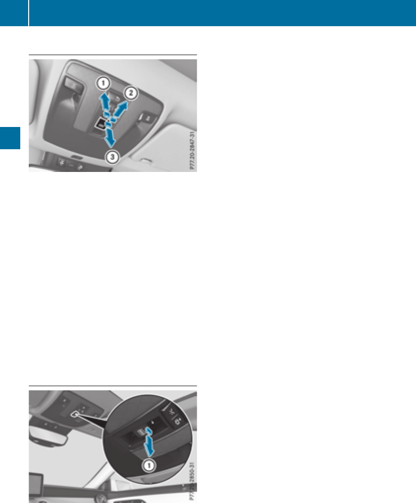
Opening and closing
:To open
;To open
=To close
XTurn the SmartKey to position 1or 2in the
ignition lock (Ypage 122).
XPress or pull the 3switch in the corre-
spondingdirection.
If you press/pull the 3switch beyond the
point of resistance, automatic operation is star-
ted in the correspondingdirection. You can stop
automatic operation by pressing/pulling the
switch again.
After opening the panorama roof with power
tilt/sliding panel, the roller sunblind automati-
cally closes slightly. This reduces drafts in the
vehicle interior.
Resetting the panorama roof with
power tilt/sliding panel or the roller
sunblind
Reset the panorama roof with power tilt/sliding
panel or the roller sunblind if the panorama roof
with power tilt/sliding panel or the roller sun-
blind does not move smoothly.
XTurn the SmartKey to position 1or 2in the
ignition lock (Ypage 122).
XPull the 3switch repeatedly to the point of
resistance in the direction of arrow :until
the panorama roof with power tilt/sliding
panel is fully closed.
XKeep the 3switch pulled for an additional
second.
XPull the 3switch repeatedly to the point of
resistance in the direction of arrow :until
the roller sunblind is fully closed.
XKeep the 3switch pulled for an additional
second.
XMake sure that the panorama roof with power
tilt/sliding panel and the roller sunblind can
be fully opened and closed again.
XIf this is not the case, repeat the steps above.
88 Panorama roof with power tilt/sliding panel
Opening and closing

Problems with the panorama roof with power tilt/sliding panel
GWARNING
If you do not reset the sliding sunroof after amalfunction or voltage supply interruption, then the
backing up function will malfunction or not work. The sliding sunroof closes with increased or
maximum force. Parts of the body could be trapped in the closing area in the process. This poses
an increased risk of injury or even fatal injury.
In such or similar situations always make sure that no parts of the body are in the closing area.
Always reset the sliding sunroof after amalfunction or voltage supply interruption.
!If the sliding sunroof still cannot be opened or closed as aresult of amalfunction,contact a
qualified specialist workshop.
Problem Possible causes/consequences and MSolutions
The panorama roof with
power tilt/sliding panel
cannot be closed and
you cannot see the
cause.
If the panorama roof with power tilt/sliding panel is obstructed during
closing and reopens again slightly:
XImmediately after it blocks, pull the 3switch down again to the
point of resistance until the panorama roof with power tilt/sliding
panel is closed.
The panorama roof with power tilt/sliding panel is closed with more
force.
If the panorama roof with power tilt/sliding panel is obstructed again
during closing and reopens again slightly:
XImmediately after it blocks, pull the 3switch down again to the
point of resistance until the panorama roof with power tilt/sliding
panel is closed.
The panorama roof with power tilt/sliding panel is closed without
the automatic reversing feature.
Panoramaroof with power tilt/sliding panel 89
Opening and closing
Z
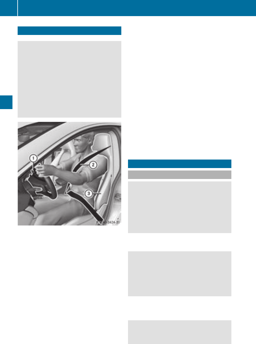
Correct driver's seat position
GWARNING
You couldlose control of your vehicle if you do
thefollowingwhile driving:
Radjust thedriver'sseat,head restraint,
steering wheel or mirrors
Rfasten theseat belt
Thereisariskofanaccident.
Adjust thedriver'sseat,head restraint,steer-
ing wheel and mirror and fasten your seat belt
before starting theengine.
Observethe followingwhen adjusting steering
wheel :,seat belt ;and driver'sseat =:
Ryou are as far away from thedriver'sair bag as
possible
Ryou are sittinginanormalupright position
Ryour thighs are slightly supported by theseat
cushion
Ryour legs are notentirely stretched and you
can depress thepedals properly
Rtheback of your head is supported at eye level
by thecenterofthe head restraint
Ryou can hold thesteering wheel withyour
armsslightly bent
Ryou can moveyour legs freely
Ryou can see all thedisplays in theinstrument
clusterclearly
Ryou should have agood overview of traffic
conditions
Rtheseat belt is pulled snugly against thebody
and is routed across thecenterofyour shoul-
der and across your hips in thepelvic area
Further related subjects:
RAdjustingthe seatsmanually (Ypage 91)
RAdjustingthe seatselectrically
(Ypage 92)
RAdjustingthe steering wheel manually
(Ypage 95)
RFasteningthe seat belt correctly
(Ypage 44)
RAdjustingthe rear-view mirror and exterior
mirrors(
Ypage 96)
RVehicles with amemory function: saving
theseat,steering wheel and exterior mirror
settings usingthe memory function
(Ypage 99)
Seats
Important safety notes
GWARNING
Children couldbecome trapped if they adjust
theseats, particularly when unattended.
Thereisariskofinjury.
When leaving thevehicle,always takethe
SmartKey withyou and lockthe vehicle.Never
leave childrenunsupervised in thevehicle.
The seatscan still be adjusted when there is no
SmartKey in theignition lock.
GWARNING
When you adjust aseat,you or other vehicle
occupants couldbecome trapped, e.g.onthe
seat guide rail. Thereisariskofinjury.
Makesure when adjusting aseat that no one
has any body partsinthe sweep of theseat.
Observethe safety noteson"Air bags"
(Ypage 45)and "Children in thevehicle"
(Ypage 54).
GWARNING
If thedriver'sseat is notengaged,itcould
moveunexpectedly while thevehicle is in
90 Seats
Seats, steeringwheel and mirrors
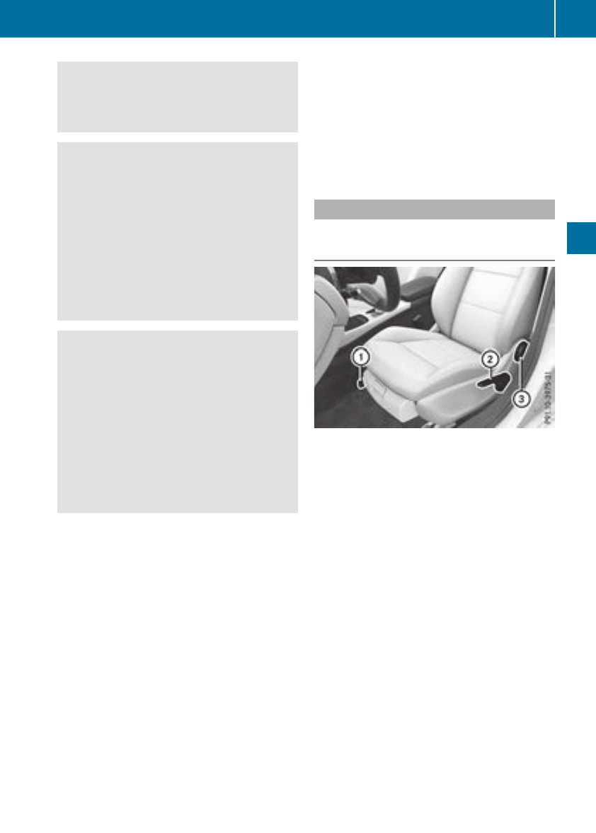
motion. This could cause you to lose control of
the vehicle. There is arisk of an accident.
Always make sure that the driver'sseat is
engagedbefore starting the vehicle.
GWARNING
You could lose control of yourvehicleifyou do
the following while driving:
Radjust the driver'sseat, head restraint,
steering wheelormirrors
Rfasten the seat belt
There is arisk of an accident.
Adjust the driver'sseat, head restraint, steer-
ing wheeland mirror and fasten yourseat belt
before starting the engine.
GWARNING
If you adjust the seat height carelessly,you or
other vehicleoccupants could be trappedand
thereby injured. Children in particular could
accidentally press the electricalseat adjust-
ment buttons and become trapped. There is a
risk of injury.
Whilemoving the seats, make sure that your
hands or other body parts do not get under the
lever assembly of the seat adjustment sys-
tem.
!To avoiddamage to the seats and the seat
heating, observe the following information:
Rkeep liquidsfrom spilling on the seats. If
liquid is spilled on the seats, dry them as
soon as possible.
Rif the seat covers are damp or wet, do not
switch on the seat heating. The seat heat-
ing should alsonot be used to dry the seats.
Rclean the seat covers as recommended;
see the "Interior care" section.
Rdo not transport heavy loads on the seats.
Do not place sharp objects on the seat
cushions, e.g. knives, nailsortools. The
seats should only be occupied by passen-
gers, if possible.
Rwhen the seat heating is in operation, do
not cover the seats with insulating materi-
als,e.g. blankets, coats, bags,seat covers,
child seats or booster seats.
!Make sure that there are no objects in the
footwellunder or behind the seats when mov-
ing the seats back. There is arisk that the
seats and/or the objects could be damaged.
iFurther related subjects:
Rcargo compartment enlargement (folding
down the rear seats) (Ypage 240)
Adjusting the seats manually
Vehicles without the seating comfort
package
Seat fore-and-aft adjustment:
XLift handle :and slidethe seat forwards or
backwards.
XRelease lever :again.
Make sure that you hear the seat engage in
position.
Backrest angle:
XRelieve the pressure on the backrest.
XTurn handwheel =forwards or backwards.
Seat height:
XPullhandle ;upwards or push it down
repeatedly until the seat has reachedthe
desired height.
Seats 91
Seats, steering wheel and mirrors
Z
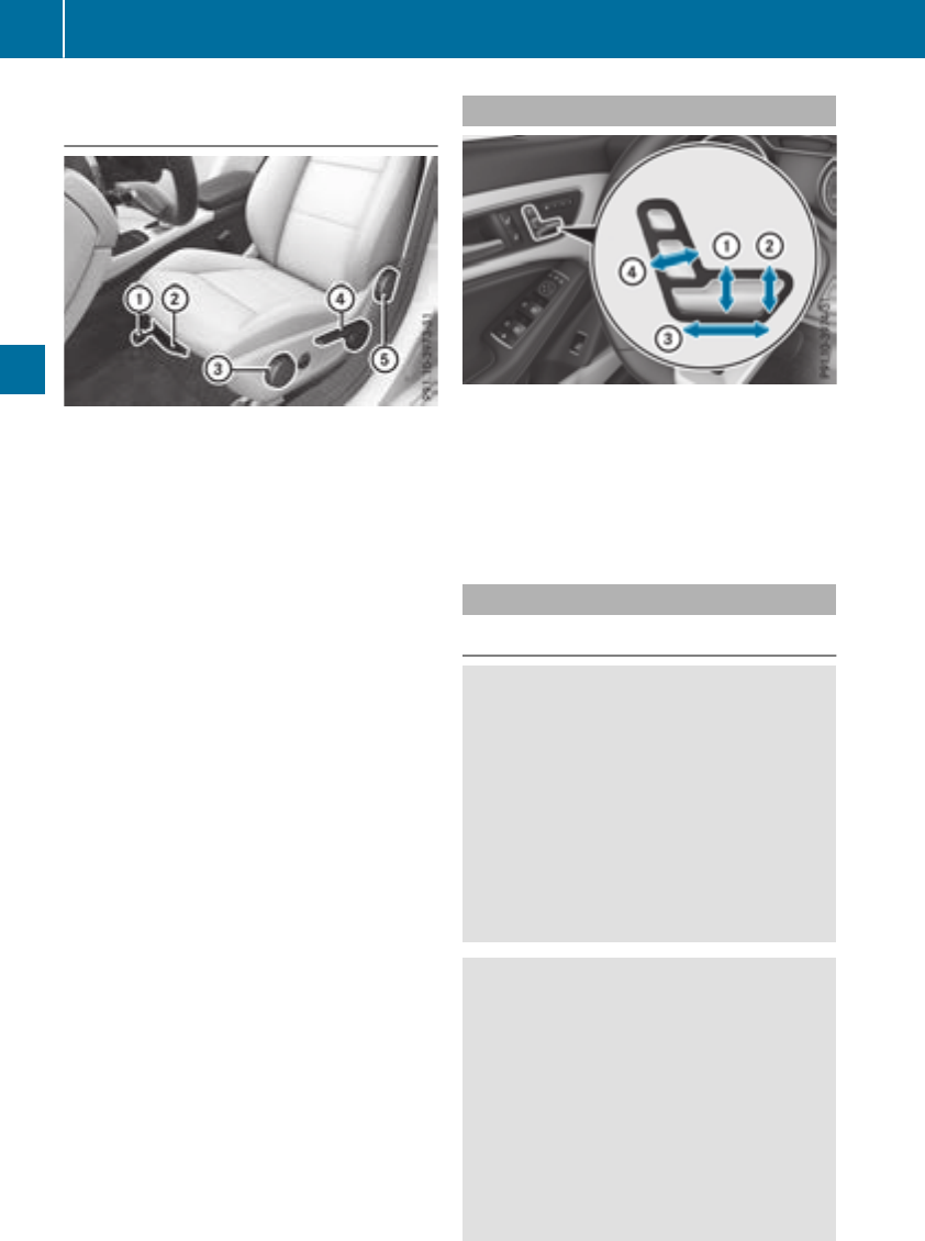
Vehicles with the seatingcomfort pack-
age
Seatfore-and-aft adjustment:
XLifthandle :and slidethe seatforwardsor
rearwards.
XReleaselever :again.
Make sure thatyou hearthe seatengage in
position.
Backrest angle:
XRelieve the pressure on the backrest.
XTurn handwheel Aforwardsorbackwards.
Seatheight:
XPull handle ?upwards or push it down
repeatedly untilthe seathas reachedthe
desired height.
Seatcushion angle:
XAdjust the angle so thatyourthighs are lightly
supported.
XTurn handwheel =forwardsorbackwards.
Seatcushion length:
XLifthandle ;and slidethe front part of the
seatcushion forwardsorbackwards.
XReleaselever ;again.
The seatcushion engages.
Adjustingthe seats electrically
:Seatheight
;Seatcushion angle
=Seatfore-and-aft adjustment
?Backrest angle
iYoucan storethe seatsettings using the
memory function(
Ypage 99).
Adjustingthe headrestraints
Important safety notes
GWARNING
Youcould lose controlofyourvehicleifyou do
the following whiledriving:
Radjustthe driver'sseat, headrestraint,
steering wheelormirrors
Rfasten the seatbelt
There is ariskofanaccident.
Adjust the driver'sseat, headrestraint, steer-
ing wheeland mirror and fasten your seatbelt
before starting the engine.
GWARNING
If the headrestraints are not installedornot
adjusted correctly, they cannotprovidepro-
tection as intended. There is an increased risk
of injury in the headand neck area, e.g.inthe
event of an accident or when braking.
Alwaysdrive with the headrestraints instal-
led. Before driving off, make sure for every
vehicleoccupant thatthe centerofthe head
restraint supports the back of the headat
abouteye level.
92 Seats
Seats, steering wheel andmirrors
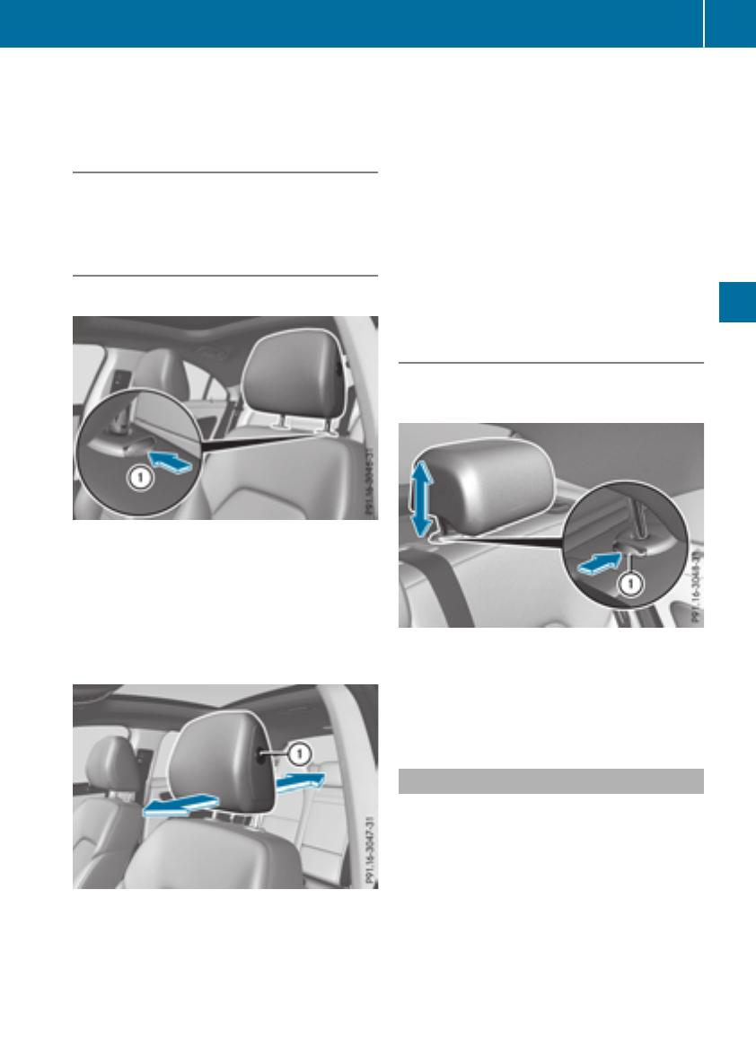
Using the fore-and-aft adjustment, adjust the
head restraint so that it is as close as possible to
your head.
General notes
For vehicles with sports seats you cannot adjust
the front head restraints or the outer rear head
restraints.
Adjusting the head restraints manually
Adjusting the head restraint height
XTo raise: pull the head restraint up to the
desired position.
XTo lower: press release catch :in the direc-
tion of the arrow and push the head restraint
down to the desired position.
Adjusting the fore/aft position of the
head restraint
With this function you can adjust the distance
between the head restraint and the back of the
seat occupant's head.
XTo move forwards: pull the head restraint
forwards in the direction of the arrow until it
engages.
There are several notches.
XTo move backwards: press and hold release
button :and push the head restraint back-
wards.
XWhen the head restraint is in the desired posi-
tion, release the button and make sure that
the head restraint is engaged in position.
Rear seat head restraints
Adjusting the rear seat head restraint
height
XTo raise: pull the head restraint up to the
desired position.
XTo lower: press release catch :and push
the head restraint down until it is in the
desired position.
Adjusting the 4-way lumbar support
You can adjust the contour of the front seat
backrests individually to provide optimum sup-
port for your back.
Seats 93
Seats, steering wheeland mirrors
Z
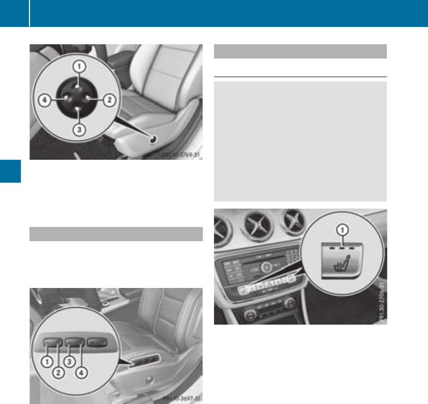
:Raises thebackrest contour
;Softensthe backrest contour
=Lowers thebackrest contour
?Hardensthe backrest contour
AMG Performance seat
Vehicles with electricallyadjustableseats:
to adjust thecontourofthe seat and for
improvedlateral support,you can individually
adjust thefront seats.
Adjusting thesidebolsters of theseatcush-
ion
XTo set thesidebolsters of theseatcush-
ion narrower: press button:.
XTo set thesidebolsters of theseatcush-
ion wider: press button;.
Adjusting thesidebolsters of theseatback-
rest
XTo set thesidebolsters of theseatback-
restnarrower: press button=.
XTo set thesidebolsters of theseatback-
restwider: press button?.
Switchingthe seatheating on/off
Switchingon/off
GWARNING
Repeatedly switching on theseat heating can
causethe seat cushion and backrest pads to
become veryhot.The healthofpersonswith
limitedtemperature sensitivityoralimited
abilitytoreacttohigh temperatures may be
affectedortheymay evensuffer burn-like
injuries. There is ariskofinjury.
Therefore,donot switch theseat heating on
repeatedly.
The three red indicator lampsinthe buttonindi-
catethe heating level you haveselected.
The system automatically switches down from
level 3to level 2after approximately eight
minutes.
The system automatically switches down from
level 2to level 1after approximately ten
minutes.
The system automatically switches off approx-
imately 20 minutesafter it is set to level 1.
XTurn theSmartKey to position 1or 2in the
ignition lock(
Ypage 122).
XTo switch on: press button:repeatedly
until thedesired heating level is set.
XTo switch off:press button:repeatedly
until all theindicator lampsgoout.
iIf thebattery voltageistoo low, theseat
heating may switch off.
94 Seats
Seats,steering wheel and mirrors
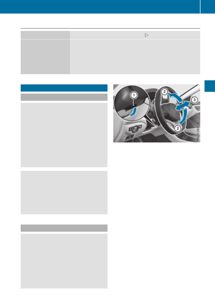
Problems with the seat heating
Problem Possible causes/consequences and MSolutions
The seat heating has
switched off prematurely
or cannot be switched
on.
The on-board voltage is too low because too many electrical consum-
ers are switched on.
XSwitch off electrical consumers that you do not need, such as the
rear window defroster or interior lighting.
Once the battery is sufficiently charged, the seat heating will switch
back on automatically.
Steering wheel
Important safety notes
GWARNING
You could lose control of your vehicle if you do
the following while driving:
Radjust the driver's seat, head restraint,
steering wheel or mirrors
Rfasten the seat belt
There is arisk of an accident.
Adjust the driver's seat, head restraint,steer-
ing wheel and mirror and fasten your seat belt
before startingthe engine.
GWARNING
Children could injure themselves if they
adjust the steering wheel. There is arisk of
injury.
When leaving the vehicle, always take the
SmartKey with you and lock the vehicle. Never
leave children unsupervised in the vehicle.
Adjusting the steering wheel
GWARNING
If the steering wheel is unlocked while the
vehicle is in motion, it could change position
unexpectedly. This could cause you to lose
control of the vehicle. There is arisk of an
accident.
Before startingoff, make sure the steering
wheel is locked. Never unlock the steering
wheel while the vehicle is in motion.
:Release lever
;Adjuststhe steering wheel height
=Adjuststhe steering wheel position (fore-
and-aft adjustment)
XPush release lever :down completely.
The steering column is unlocked.
XAdjust the steering wheel to the desired posi-
tion.
XPush release lever :up completely.
The steering column is locked.
XCheck if the steering column is locked. When
doing so, try to push the steering wheel up or
down or try to move it in the fore-and-aft
direction.
Steering wheel 95
Seats, steering wheeland mirrors
Z
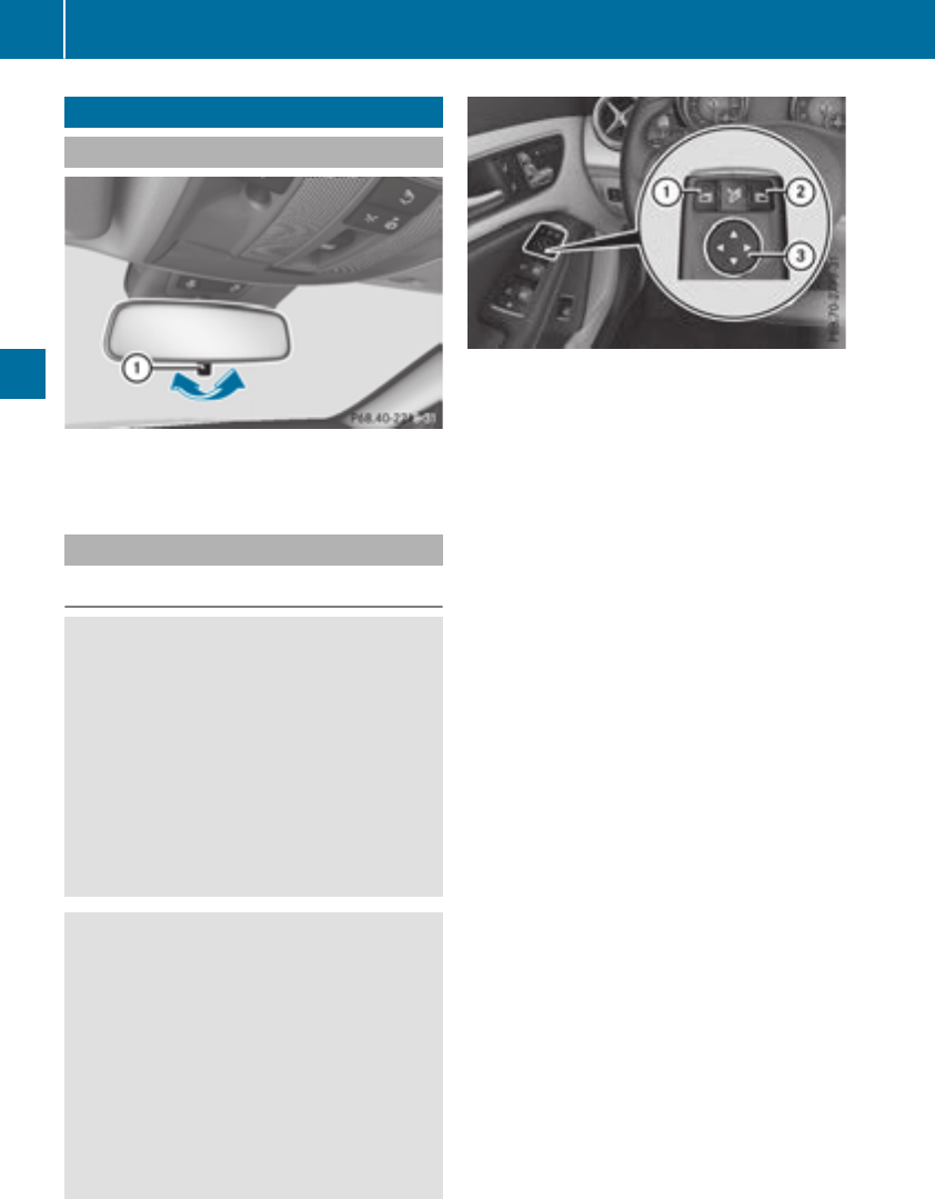
Mirrors
Rear-view mirror
XAnti-glare mode: flick anti-glare lever :for-
wards or back.
Exterior mirrors
Adjusting the exterior mirrors
GWARNING
You couldlose control of yourvehicleifyou do
the following while driving:
Radjust the driver's seat, headrestraint,
steering wheelormirrors
Rfasten the seat belt
There is arisk of an accident.
Adjust the driver's seat, headrestraint, steer-
ing wheeland mirror and fasten yourseat belt
before starting the engine.
GWARNING
The exterior mirror on the front-passenger
side reduces the size of the image. Visible
objects are actually closer than they appear.
This means that you couldmisjudge the dis-
tance from road users traveling behind, e.g.
when changing lane.There is arisk of an acci-
dent.
For this reason, alwaysmake sure of the
actualdistance from the road users traveling
behind by glancing over yourshoulder.
XTurn the SmartKey to position 1or 2in the
ignitionlock (Ypage122).
XExterior mirror on the front-passenger side:
press button ;.
Exterior mirror on the driver's side:press but-
ton :.
The indicator lamp in the corresponding but-
ton lights up in red.
The indicator lamp goes out again after some
time. You can adjust the selected exterior
mirror using button =as long as the indicator
lamp is lit.
XPress button =up, down, or to the right or
left until you have adjusted the exterior mirror
to the correct position. You should have a
good overview of traffic conditions.
The convex exterior mirrors provide alarger field
of vision.
After the engine has been started, the exterior
mirrors are automatically heated at low outside
temperatures. Heating takes amaximumoften
minutes.
iYou can alsoheatupthe exterior mirrors
manually by switching on the rear window
defroster.
96 Mirrors
Seats, steering wheel and mirrors
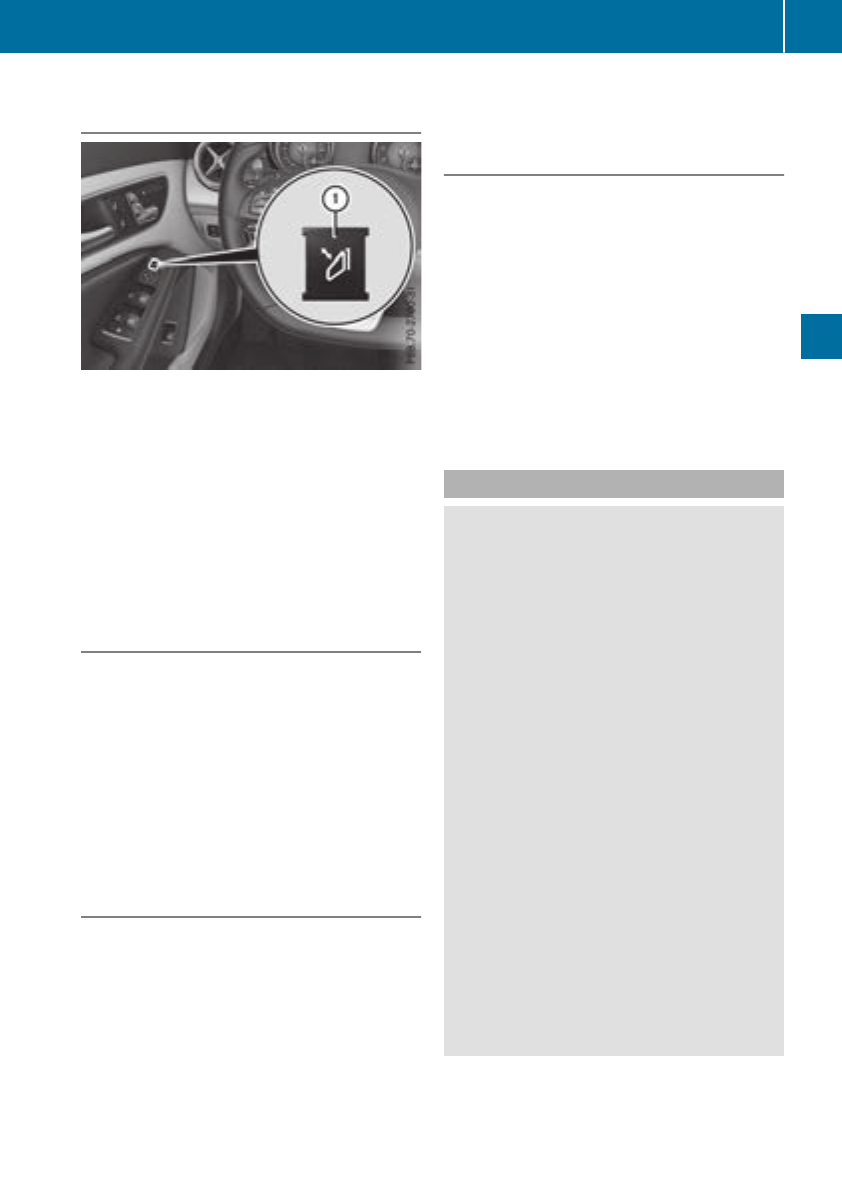
Folding theexterior mirrors in or out
electrically
XTurn theSmartKey to position 1or 2in the
ignition lock(
Ypage 122).
XBriefly press :.
Both exteriormirrorsfoldinorout.
iMakesure that theexteriormirrorsare
always folded out fully while driving.They
could otherwise vibrate.
iIf you are driving fasterthan30mph
(47 km/h), you can no longer foldinthe exte-
riormirrors.
Resetting theexterior mirrors
If thebattery has been disconnected or com-
pletely discharged, theexteriormirrorsmust be
reset.The exteriormirrorswill otherwise not
foldinwhen you select the"Fold in mirrorswhen
locking" function in theon-board computer
(Ypage 188).
XTurn theSmartKey to position 1in theigni-
tion lock(
Ypage 122).
XBriefly press :.
Folding theexterior mirrors in or out
automatically
If the"Fold in mirrorswhen locking" function is
activated in theon-board computer
(Ypage 188):
Rtheexteriormirrorsfoldinautomatically as
soonasyou lockthe vehiclefromthe outside.
Rtheexteriormirrorsfoldout again automati-
callyassoonasyou unlock thevehicleand
then open thedriver'sorfront-passenger
door.
iIf theexteriormirrorshave been folded in
manually, they do notfoldout.
Exterior mirror pushed out of position
If an exteriormirror has been pushed out of
position,proceedasfollows:
XVehicles without electricallyfolding exte-
rior mirrors:movethe exteriormirror into
thecorrect position manually.
XVehicles with electricallyfolding exterior
mirrors:press and hold mirror-foldingbutton
(Ypage 97)until youhearthe mirror click into
place.
The mirror housing is engaged againand you
can adjustthe exteriormirrors as usual
(Ypage 96).
Automaticanti-glare mirrors
GWARNING
Electrolyte mayescape if the glassinanauto-
matic anti-glare mirror breaks.The electrolyte
is harmfuland causes irritation. It must not
come into contact with your skin, eyes, res-
piratory organs or clothing or be swallowed.
There is ariskofinjury.
If youcome into contact with the electrolyte,
observe the following:
RRinse off the electrolyte from your skin
immediatelywithwater.
RImmediately rinsethe electrolyte outof
your eyes thoroughlywithclean water.
RIf the electrolyte is swallowed, immediately
rinseyourmouth outthoroughly. Do not
induce vomiting.
RIf electrolyte comesinto contact with your
skinorhairorisswallowed, seekmedical
attentionimmediately.
RImmediately change outofclothing which
hascome into contact with electrolyte.
RIf an allergicreactionoccurs, seekmedical
attentionimmediately.
The "Automatic anti-glare mirrors"functionis
onlyavailable if the vehicleisequippedwiththe
"Mirrors package".
Mirrors 97
Seats, steering wheel andmirrors
Z
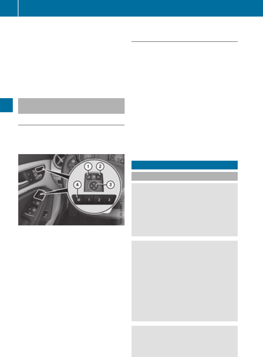
The rear-view mirror and the exterior mirror on
the driver's side automatically go into anti-glare
mode if:
Rthe ignition is switched on and
Rincident light from headlamps strikes the sen-
sor in the rear-view mirror
The mirrors do not go into anti-glare mode if
reverse gear is engaged or if the interior lighting
is switched on.
Parking position for the exterior mir-
ror on the front-passenger side
Setting and storing the parking position
You can set the front-passenger side exterior
mirror such that you can see the rear wheel on
that side as soon as you engage reverse gear.
You can store this position.
:Button for the driver's side exterior mirror
;Button for the front-passenger side exterior
mirror
=Button for the exterior mirror setting
?Memory button M
XMake sure that the vehicle is stationary.
XTurn the SmartKey to position 2in the igni-
tion lock (Ypage 122).
XPress button ;.
XEngage reverse gear.
The exterior mirror on the front-passenger
side moves to the default parking position.
XUse button =to adjust the exterior mirror to
aposition that allows you to see the rear
wheel and the curb.
The parking position is stored.
iIf you shift the transmission to another posi-
tion, the front-passenger side exterior mirror
returnstothe driving position.
Calling up astored parking position set-
ting
XTurn the SmartKey to position 2in the igni-
tion lock (Ypage 122).
XAdjust the front-passenger side exterior mir-
ror using the corresponding button
(Ypage 96).
XEngage reverse gear.
The exterior mirror on the front-passenger
side moves to the stored parking position.
The exterior mirror on the front-passenger side
moves back to its original position:
Ras soon as you exceed aspeed of 9mph
(15 km/h)
Rabout ten seconds after you have disengaged
reverse gear
Rwhen you use button :to select the exterior
mirror on the driver's side
Memory function
Important safety notes
GWARNING
If you use the memory function on the driver's
side while driving, you could lose control of
the vehicle as aresult of the adjustments
being made. There is arisk of an accident.
Only use the memory function on the driver's
side when the vehicle is stationary.
GWARNING
When the memory function adjusts the seat,
you and other vehicle occupants–particularly
children –could become trapped. There is a
risk of injury.
While the memory function is making adjust-
ments, make sure that no one has any body
parts in the sweep of the seat. If somebody
becomes trapped, immediately release the
memory function position button.The adjust-
ment process is stopped.
GWARNING
Children could become trapped if they acti-
vate the memory function, particularly when
unattended. There is arisk of injury.
98 Memory function
Seats, steering wheel and mirrors
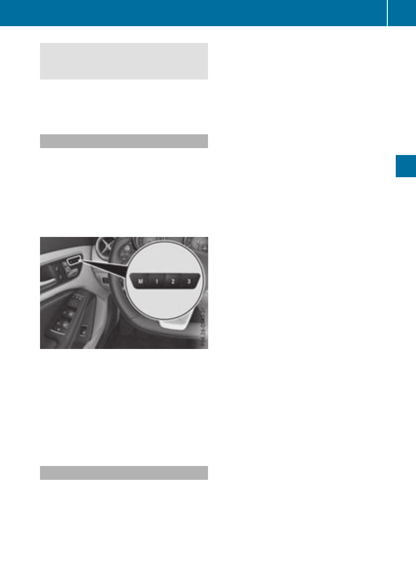
When leaving the vehicle, alwaystake the
SmartKey with you and lock the vehicle. Never
leave children unsupervised in the vehicle.
The memory function can be used at any time,
e.g. even when the SmartKey is not in the igni-
tion lock.
Storing settings
With the memory function, you can store up to
three differentsettings, e.g. for three different
people.
The following settings are stored as asingle
memory preset:
Rseat and backrestposition
Rdriver's side: position of the exterior mirrors
on the driver's and front-passenger sides
XAdjust the seat (Ypage 92).
XAdjust the exterior mirror on the driver's side
(Ypage 96).
XBriefly press the Mmemory button and then
press preset position button 1,2or 3within
three seconds.
The settings are stored in the selected preset
position. Atonesounds when the settings
have been completed.
Calling up astored setting
XPress and hold the relevant preset position
button 1,2or 3until the seat and exterior
mirrors are in the stored position.
iThe setting procedure is interrupted as soon
as you release the storage position button.
Memoryfunction 99
Seats, steering wheel and mirrors
Z
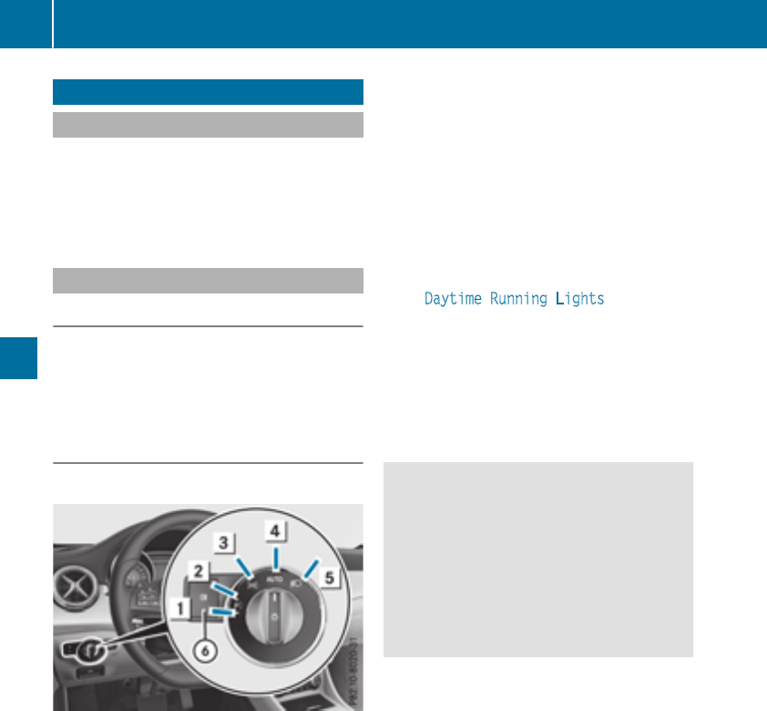
Exteriorlighting
General notes
For reasonsofsafety, Mercedes-Benzrecom-
mends that you drivewith thelightsswitched on
even duringthe daytime. In somecountries,
operationofthe headlamps varies due to legal
requirementsand self-imposedobligations.
Settingthe exteriorlighting
Settingoptions
Exterior lighting can be set usingthe:
Rlight switch
Rcombinationswitch (Ypage 101)
Ron-board computer(Ypage 187)
Light switch
Operation
1WLeft-handstanding lamps
2XRight-hand standing lamps
3TParking lamps,licenseplateand
instrumentclusterlighting
4ÃAutomatic headlampmode, controlled
by thelight sensor
5LLow-beam/high-beam headlamps
BRRear fog lamp
If you hear awarning tone when you leave the
vehicle,the lightsmay still be switched on.
XTurn thelight switch to the Ãposition.
The exteriorlighting (exceptthe parking/stand-
ing lamps)switches off automaticallyifyou:
Rremove theSmartKey from theignition lock
Ropen thedriver'sdoor with theSmartKey in
position g
Automatic headlamp mode
Ãis thepreferred light switch position:
RThe light settingisautomaticallyselected
according to thebrightnessofthe ambient
light (exception: poor visibilitydue to weather
conditionssuchasfog,snoworspray).
RWiththe SmartKey in position 1in theigni-
tionlock: theparking lamps are switched on
or off automaticallydependingonthe bright-
nessofthe ambient light.
RWiththe engine running: if you have activated
the DaytimeRunningLights function via
theon-board computer, thedaytime running
lamps or theparking lamps and thelow-beam
headlamps are switched on or off automati-
cally dependingonthe brightnessofthe ambi-
ent light.
XTo switch on theautomatic headlamp
mode: turnthe light switch to the Ãposi-
tion.
GWARNING
When thelight switch is set to Ã,the low-
beam headlamps may notbeswitched on
automaticallyifthere is fog,snoworother
causes of poor visibilitydue to theweather
conditionssuchasspray. Thereisarisk of an
accident.
In suchsituations,turnthe light switch to
L.
The automatic headlampfeature is only an aid.
The driver is responsible for thevehicle's light-
ing at all times.
Canada only:
The daytime runninglamps improve thevisibility
of your vehicle duringthe day. The daytime run-
ninglamps function is required by law in Can-
ada. It cannottherefore be deactivated.
When theengine is runningand thevehicle is
stationary: if you shiftthe automatic transmis-
sion from adriving position to position jthe
daytime runninglamps or low-beam headlamps
go out after 3minutes.
When theengine is running, thevehicle is sta-
tionaryand in bright ambient light:ifyou turnthe
light switch to the Tposition,the daytime
runninglamps and parking lamps turnon.
If theengine is runningand you turnthe light
switch to the Lposition,the manual settings
100 Exterior lighting
Lightsand windshield wipers
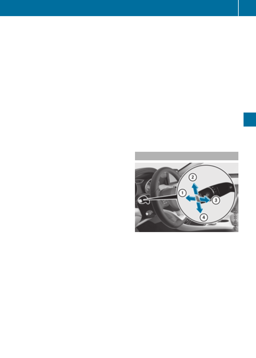
take precedence overthe daytime running
lamps.
USAonly:
The daytime running lamps improve the visibility
of your vehicleduringthe day. To do this, the
daytime running lamps functionmustbe
switched on using the on-board computer
(Ypage 187).
If the engine is running and youturnthe light
switch to the Tor Lposition, the manual
settingstake precedence overthe daytime run-
ning lamps.
Low-beam headlamps
Even if the light sensordoesnot detect thatitis
dark, the parking lamps and low-beamhead-
lamps switch on when the ignition is switched on
and the light switch is settothe Lposition.
Thisisaparticularly usefulfunctioninthe event
of rain and fog.
XTo switchonthe low-beam headlamps:
turnthe SmartKeytoposition 2in the igni-
tionlockorstart the engine.
XTurn the light switch to L.
The green Lindicator lamp in the instru-
ment clusterlights up.
Rearfog lamp
The rearfog lamp improves visibility of your
vehiclefor the trafficbehindinthe event of thick
fog.Pleasetake note of the country-specific
regulations for the useofrearfog lamps.
XTo switchonthe rear foglamp: turnthe
SmartKeyinthe ignition lock to position 2or
start the engine.
XTurn the light switch to Lor Ã.
XPress the Rbutton.
The yellow Rindicator lamp in the instru-
ment clusterlights up.
XTo switchoff the rear foglamp: press the
Rbutton.
The yellow Rindicator lamp in the instru-
ment clustergoesout.
iWhen the rearfog lamp is switched on, the
centerbrake lamp in the taillampswitches off
duetoalegal requirement.
Parkinglamps
!If the battery charge is verylow,the parking
lamps or standing lamps areautomatically
switched off to enablethe next engine start.
Alwaysparkyourvehiclesafelyand in awelllit
area,inaccordance with the relevant legal
stipulations. Avoidusing the Tparking
lamps overaperiodofseveral hours. If pos-
sible, switch on the right-hand Xor left-
hand Wstanding lamps.
XTo switchon: turnthe light switch to T.
Thegreen Tindicator lamp in the instru-
ment clusterlights up.
Standinglamps
Switching on the standing lamps ensures the
corresponding side of the vehicleisilluminated.
XTo switchonthe standinglamps: the
SmartKeyisnot in the ignition lock or it is in
position gin the ignition lock.
XTurn the light switch to W(left-hand side of
the vehicle) or X(right-hand side of the
vehicle).
Combination switch
XTo indicate briefly: press the combination
switch brieflytothe pressure point in the
directionofarrow ;or ?.
Thecorresponding turnsignalflashesthree
times.
XTo indicate: press the combinationswitch
beyond the pressure point in the directionof
arrow ;or ?.
XTo switchonthe high-beam headlamps:
turnthe light switch to Lor Ã.
XPress the combinationswitch beyond the
pressure point in the directionofarrow :.
Thehigh-beam headlamps onlyswitch on in
the Ãpositionifthe low-beamheadlamps
areon.
TheblueKindicator lamp in the instru-
ment clusterlights up when the high-beam
headlamps areswitched on.
Exterior lighting 101
Lights and windshield wipers
Z
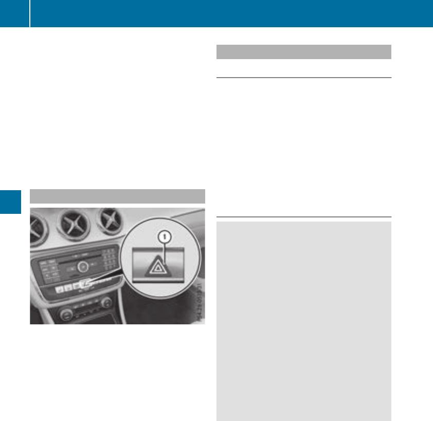
XTo switchoff the high-beam headlamps:
move the combinationswitch back to its nor-
malposition.
The blue Kindicator lamp in the instru-
ment cluster goesout.
Vehicles with Adaptive Highbeam Assist:
when Adaptive Highbeam Assist is active, it
controls activation and deactivation of the
high-beamheadlamps (Ypage 102).
XTo switchonthe high-beam flasher: pull
the combinationswitch in the direction of
arrow =.
Hazard warning lamps
XTo switchonthe hazard warning lamps:
press button :.
All turn signals flash. If younow switch on a
turn signalusing the combinationswitch,only
the turn signallamponthe corresponding
side of the vehiclewillflash.
XTo switchoff the hazard warning lamps:
press button :.
The hazard warning lamps automaticallyswitch
on if:
Ran airbag is deployed or
Rthe vehicledecelerates rapidly from aspeed
of above 45 mph (70 km/h)and comestoa
standstill
The hazard warning lamps switch off automati-
cally if the vehiclereachesaspeed of above
6mph (10 km/h)again afterafullbrake appli-
cation.
The hazard warning lamps stilloperate if the
ignition is switched off.
AdaptiveHighbeam Assist
General notes
Youcan usethisfunctiontoset the headlamps
to change between lowbeamand high beam
automatically. The system recognizes vehicles
with theirlights on, either approaching from the
opposite direction or traveling in front of your
vehicle, and consequentlyswitches the head-
lamps from high beam to lowbeam. Once the
system no longer detects any othervehicles, it
reactivates the high-beamheadlamps.
The system's opticalsensor is locatedbehind
the windshield nearthe overhead controlpanel.
Important safety notes
GWARNING
Adaptive Highbeam Assist does not recognize
roadusers:
Rwhohavenolights,e.g.pedestrians
Rwhohavepoorlighting, e.g.cyclists
Rwhose lighting is blocked, e.g.byabarrier
On very rareoccasions, Adaptive Highbeam
Assist mayfailtorecognize otherroadusers
thathavelights,ormay recognize them too
late. In this, or in similar situations, the auto-
matic high-beamheadlamps will not be deac-
tivated or will be activatedregardless. There is
ariskofanaccident.
Alwayscarefullyobserve the traffic conditions
and switch off the high-beamheadlamps in
goodtime.
Adaptive Highbeam Assist cannottake into
account road, weather or traffic conditions.
Adaptive Highbeam Assist is onlyanaid.You are
responsiblefor adjusting the vehicle's lighting
to the prevailing light, visibility and traffic con-
ditions.
In particular, the detection of obstaclescan be
restrictedifthereis:
Rpoor visibility,e.g.due to fog,heavy rainor
snow
Rdirt on the sensors or the sensors are
obscured
102 Exterior lighting
Lights and windshield wipers
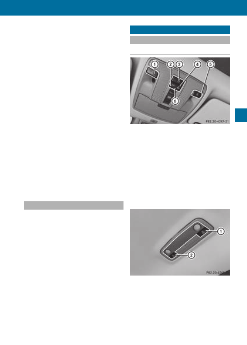
Switching Adaptive Highbeam Assist
on/off
XTo switch on: turn the light switch to Ã.
XPress the combination switch beyond the
pressure point in the direction of arrow :.
The _indicator lamp in the multifunction
display lights up when it is dark and the light
sensor activates the low-beam headlamps.
If you are driving at speeds above approx-
imately 19 mph (30 km/h)and no other road
users are detected:
The high-beam headlamps are switched on
automatically. The Kindicator lamp in the
instrumentcluster also lights up.
If you are driving at speeds below approx-
imately 16 mph (25 km/h) or other road users
have been detected or the roads are ade-
quately lit:
The high-beam headlamps are switched off
automatically. The Kindicator lamp in the
instrumentcluster goes out. The _indi-
cator lamp in the multifunction display
remains lit.
XTo switch off: move the combination switch
back to its normal position.
The _indicator lamp in the multifunction
display goes out.
Headlamps fogged up on the inside
Certain climatic and physical conditionsmay
cause moisture to form in the headlamp. This
moisture does not affect the functionality of the
headlamp.
Interior lighting
Overview of interior lighting
Front overhead control panel
:pSwitches the left-hand front reading
lamp on or off
;cSwitches the front interior lighting on
=vSwitches the rear interior lighting on or
off
?|Switches the front interior lighting/
automatic interior lighting control off
ApSwitches the right-handfront reading
lamp on or off
BSwitches the automatic interior lighting con-
trol on
Rear compartment control panel
:pSwitches the left-hand reading lamp
on/off
;pSwitches the right-handreading lamp
on/off
Interior lighting 103
Lights and windshieldwipers
Z

Interior lighting control
General notes
In order to preventthe vehicle's battery from
discharging,the interiorlighting functionsare
automatically deactivated after sometime
except when theSmartKey is in position 2in
theignition lock.
The color and brightness for theambientlighting
may be set via themultimedia system; see the
separateoperating instructions.
Automaticinterior lighting control
XTo switch on: set theswitch to center posi-
tion B.
XTo switch off:set theswitch to the|
position.
The interiorlighting automatically switches on if
you:
Runlock thevehicle
Ropen adoor
Rremove theSmartKey from theignition lock
The interiorlightisactivated for ashort while
when theSmartKey is removedfromthe ignition
lock. This delayedswitch-off can be adjusted via
themultimedia system; see theseparateoper-
ating instructions.
Replacingbulbs
Important safety notes
GWARNING
Bulbs, lampsand connectors can get veryhot
when operating.Ifyou changeabulb, you
could burn yourself on these components.
Thereisariskofinjury.
Allow these componentstocooldown before
changing abulb.
Do notuse abulb if it has been dropped or if its
glass tubehas been scratched.
The bulb may explodeif:
Ryou touch it
Rit is hot
Ryou dropit
Ryou scratch it
Use bulbs only in closed lampsthathavebeen
designed for this purpose.Onlyinstallspare
bulbs of thesametypeand thespecifiedvolt-
age.
Marksonthe glass tubereduce theservicelife
of thebulbs.Donot touch theglass tubewith
your bare hands. If necessary, clean theglass
tubewhen cold withalcohol or spirit and rub it
off withalint-free cloth.
Protect bulbs from moisture during operation.
Do notallow bulbs to come intocontactwith
liquids.
Replaceonlythe bulbs listed (Ypage 104).
Havethe bulbs that you cannotchangeyourself
replacedataqualified specialist workshop.
If you require assistancereplacing bulbs,con-
sult aqualified specialist workshop.
If thenew bulb still does notlightup, consult a
qualified specialist workshop.
Headlamps and lights are an important aspect of
vehiclesafety. You must thereforemakesure
that these function correctlyatall times.Have
theheadlamp setting checkedregularly.
Vehicles with LED headlamps: thefront and
rear lamp clusters of your vehicleare equipped
withLED bulbs.Donot replace thebulbs your-
self.Contactaqualified specialist workshop
withthe necessaryspecialist knowledge and
tools to carry out theworkrequired.
Overview of bulbtypes
You can replace thefollowingbulbs.The bulb
typecan be foundinthe legend.
104 Replacingbulbs
Lightsand windshield wipers
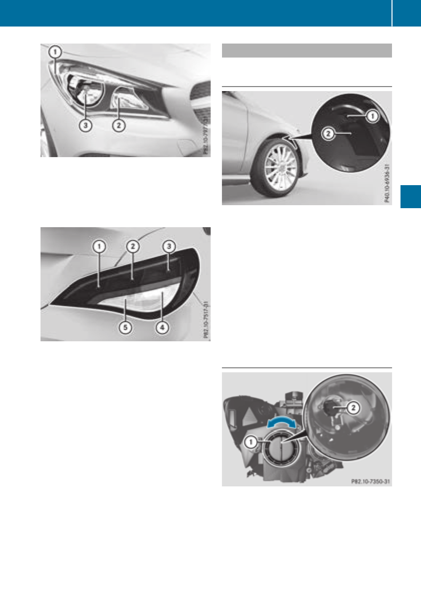
Vehicles with halogenheadlamps
:Turn signal lamp: PY 21 W
;High-beam headlamps/daytime running
lamps/parking lamps/standing lamps:
H15 55 W/15 W
=Low-beam headlamp: H7 55 W
Tail lamps (vehicles with halogenheadlamps)
:Rearfog lamp: P21W
;Brake lamp: W16W
=Brake lamp: W16W
?Turn signal lamp: PY 21 W
ABackup lamp: W16W
Replacing front bulbs
Removing and installingthe coverinthe
front wheelhousing
You must remove the cover of the front wheel
housing before you can change the front turn
signal lamp.
XTo remove: switch off the lights.
XTurn the front wheelsinwards.
XTurn rotary knob :through 90°.
Cover ;is released.
XPush cover ;down.
XTo install: push cover ;up.
XTurn rotary knob :through 90°.
Cover ;is locked.
Low-beam headlamps (halogenhead-
lamps)
XRemove the cover in the front wheel housing
(Ypage 105).
XTurn housing cover :counter-clockwise and
remove it.
XTurn bulb holder ;counter-clockwise and
pull out.
XPull the bulb out of bulb holder ;.
Replacing bulbs 105
Lights and windshieldwipers
Z
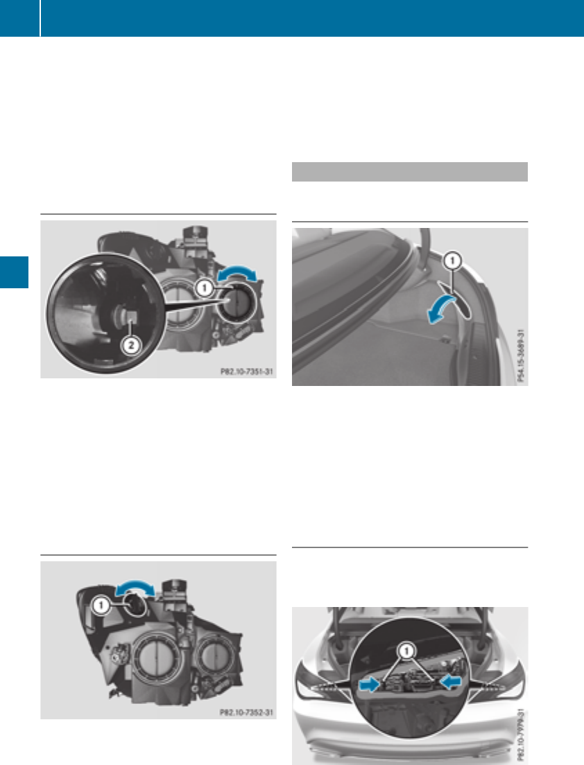
XInsert the new bulbinto bulbholder ;.
XInsert bulbholder ;and turn it clockwise.
XPress on housing cover :and turn it to the
right.
XReplace the cover in the front wheel housing
(Ypage 105).
High-beam headlamps/daytime run-
ning lamps/parking lamps and stand-
ing lamps (halogen headlamps)
XSwitch off the lights.
XOpen the hood.
XTurn housing cover :counter-clockwise and
remove it.
XTurn bulbholder ;counter-clockwise and
pullout.
XInsert the new bulband engage it to the stop.
XPress on housing cover :and turn it to the
right.
Turn signals (halogen headlamps)
XSwitch off the lights.
XOpen the hood.
XTurn bulbholder :counter-clockwise and
pullout.
XTurn the bulbcounter-clockwise and pullit
out of bulbholder :.
XInsert the new bulbinto bulbholder :.
XInsert bulbholder :and turn it clockwise
until it engages.
Replacing rear bulbs
Openingand closing the side trim pan-
els
View of right-hand side trim panel
You must open the side trim panel in the trunk
before you can replace the bulbs in the tail
lamps.
XTo open: release right or left side trim
panel :at the top and fold it down in the
direction of the arrow.
XTo close: insert side panel :.
Tail lamps
XSwitch off the lights.
XOpen the trunk.
XOpen the side trim panel (Ypage 106).
106 Replacing bulbs
Lights and windshield wipers
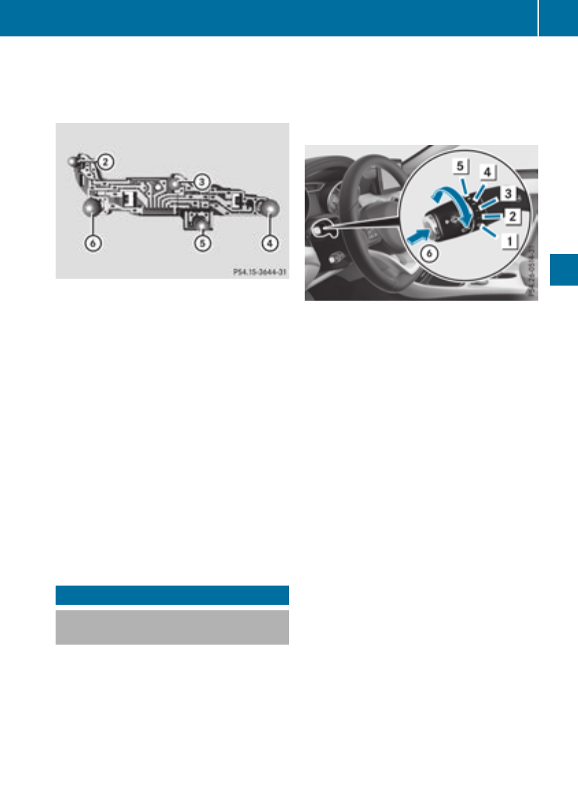
XPress retainingclips :at the same time in
the direction of the arrows.
XCarefully remove the bulb holder together
with the connected plug and the bulbs.
Bulb holder
;Brake lamp
=Brake lamp
?Rear fog lamp
ABackup lamp
BTurn signals
XBrake lamp and backup lamp: remove the
corresponding bulb from the bulb holder.
XInsert the new bulb into the bulb holder.
XRear fog lamp and turnsignal: press the
bulb gently into the bulb holder, turn it coun-
ter-clockwise and remove it from the bulb
holder.
XInsert the new bulb into the bulb holder and
turn it clockwise.
XReinsert the bulb holder and engage on
retainingclips :.
XClose the side trim panel (Ypage 106).
Windshield wipers
Switching the windshield wipers
on/off
!Do not operate the windshield wipers when
the windshield is dry, as this could damage
the wiper blades. Moreover, dust that has col-
lected on the windshield can scratch the glass
if wiping takes place when the windshield is
dry.
If it is necessary to switch on the windshield
wipers in dry weather conditions, alwaysuse
washer fluid when operating the windshield
wipers.
!If the windshield wipers leave smears on the
windshield after the vehicle has been washed
in an automatic car wash, wax or other resi-
dues may be the reason for this. Clean the
windshield using washer fluid after washing
the vehicle in an automatic car wash.
Combination switch
1$Windshield wiper off
2ÄIntermittent wipe, low (rain sensor set
to low sensitivity)
3ÅIntermittent wipe, high (rain sensor
set to high sensitivity)
4°Continuous wipe, slow
5¯Continuous wipe, fast
BíSingle wipe/îWipes the wind-
shield using washer fluid
XSwitchonthe ignition.
XTurn the combination switch to the corre-
sponding position.
!Vehicles with arain sensor: if the windshield
becomes dirty in dry weather conditions, the
windshield wipers may be activated inadver-
tently. This could then damage the windshield
wiper blades or scratch the windshield.
For this reason, you should alwaysswitch off
the windshield wipers in dry weather.
Vehicles with arain sensor: in the Äor Å
position, the appropriate wiping frequency is
automatically set accordingtothe intensity of
the rain. In the Åposition, the rain sensor is
more sensitive than in the Äposition, caus-
ing the windshield wiper to wipe more fre-
quently.
If the wiper blades are worn, the windshield will
no longer be wiped properly. This could prevent
you from observing the traffic conditions.
Windshield wipers 107
Lights and windshield wipers
Z
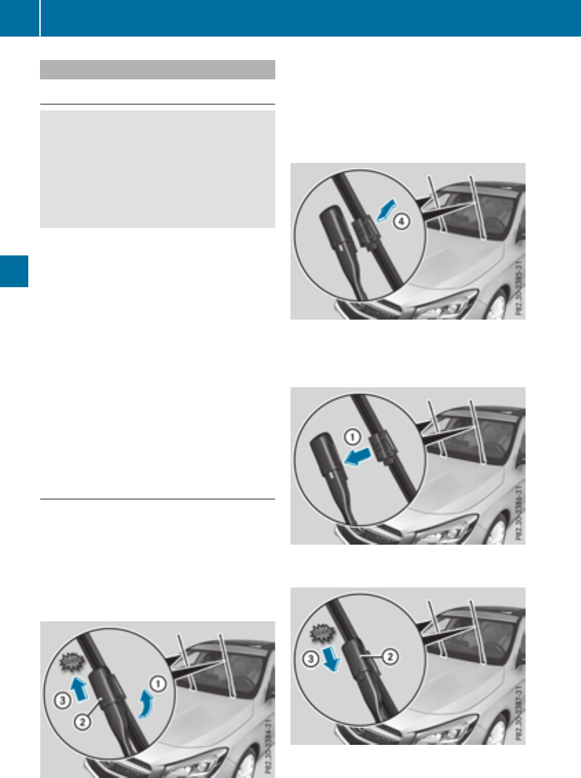
Replacing the wiper blades
Important safety notes
GWARNING
If the windshield wipersbegin to move while
youare changing the wiper blades, youcould
be trapped by the wiper arm.There is ariskof
injury.
Alwaysswitch off the windshield wipersand
ignition before changing the wiper blades.
!To avoid damaging the wiper blades, make
sure that youtouch only the wiper arm of the
wiper.
!Neveropenthe hoodifawindshield wiper
arm hasbeenfolded away from the wind-
shield.
Neverfoldawindshield wiper arm withouta
wiper bladebackonto the windshield.
Holdthe windshield wiper arm firmly when
youchange the wiper blade. If yourelease the
windshield wiper arm withoutawiper blade
and it falls onto the windshield,the windshield
may be damaged by the force of the impact.
Mercedes-Benz recommendsthat youhave
the wiper blades changed at aqualified spe-
cialist workshop.
Changingthe windshield wiper blades
Removingthe wiper blades
XVehicles without KEYLESS-GO or KEY-
LESS-GOstart function: remove the Smart-
Key from the ignition lock.
XVehicles with KEYLESS-GO or KEYLESS-
GO start function: switch off the engine.
XFoldthe wiper arm away from the windshield.
XHoldontothe wiper arm with one hand. With
the otherhand, turn wiper bladeindirection
of arrow :away from the wiper arm as far as
it will go.
XSlide catch ;in the direction of arrow =
untilitengages in the removal position with a
noticeable click.
XRemove the wiper bladeinthe direction of
arrow ?away from the wiper arm.
Installing the wiper blades
XInsert the new wiper bladeinto the wiper arm
in the direction of arrow :.
108 Windshieldwipers
Lights and windshield wipers
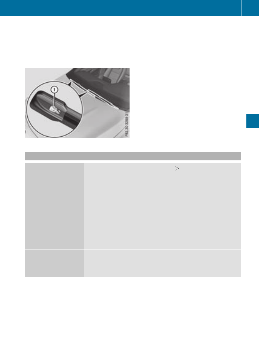
XSlide catch ;in the direction of arrow =
untilitengages in the locking position with a
noticeable click.
XMake sure that the wiper bladeisseated cor-
rectly.
XFoldthe wiper arm back onto the windshield.
XRemove protectivefilm :of the service indi-
catoronthe tip of the wiper blade.
If the color of the service indicator changes from
black to yellow,the wiper blades shouldbe
replaced.
iThe duration of the color change varies
depending on the usageconditions.
Problems with the windshield wipers
Problem Possiblecauses/consequencesand MSolutions
The windshield wipers
are jammed.
Leaves or snow,for example, may be obstructing the windshield wiper
movement. The wiper motor hasbeendeactivated.
XFor safety reasons,you shouldremove the SmartKey from the igni-
tion lock.
XRemove the cause of the obstruction.
XSwitch the windshield wipersbackon.
The windshield wipers
failcompletely.
The windshield wiper drive is malfunctioning.
XSelect another wiper speed on the combination switch.
XHave the windshield wiperscheckedataqualified specialist work-
shop.
The windshield washer
fluid from the spray noz-
zles no longer hits the
center of the windshield.
The spray nozzlesare misaligned.
XHave the spray nozzlesadjustedataqualified specialist workshop.
Windshieldwipers 109
Lights and windshield wipers
Z

Overview of climatecontrol systems
General notes
Observe the settings recommended on the fol-
lowing pages. The windows could otherwise fog
up.
To preventthe windows from fogging up:
Rswitch off climate control only briefly
Rswitch on air-recirculation mode only briefly
Rswitch on the cooling with air dehumidifica-
tion function
Rswitch on the defrost windshield function
briefly, if required
The air-conditioningsystem or dual-zoneauto-
matic climate control regulates the temperature
and the humidity of the vehicle interior and fil-
ters undesirable substances from the air.
The air-conditioningsystem or dual-zoneauto-
matic climate control can only be operated
when the engineisrunning. Optimum operation
is only achieved with the side windows and pan-
orama roof with power tilt/sliding panel closed.
If you start the engine using your smartphone,
the last selected climate control setting is reac-
tivated (Ypage 83).
The residual heat function can only be activated
or deactivated with the ignition switched off
(Ypage 119).
Always keep the ventilation flaps behind the
side trim panel in the cargo compartment clear
(Ypage 106). Otherwise the vehicle will not be
ventilated correctly.
iVentilate the vehicle for abrief period during
warm weather, e.g. using the convenience
opening feature (Ypage 83). This will speed
up the cooling process and the desired inte-
rior temperature will be reached more
quickly.
iThe integrated filter filters out most parti-
cles of dust and soot and completely filters
out pollen. It also reduces gaseous pollutants
and odors. Aclogged filter reduces the
amount of air supplied to the vehicle interior.
For this reason, you should alwaysobserve
the interval for replacing the filter, which is
specified in the Maintenance Booklet. As it
depends on environmental conditions,e.g.
heavy air pollution, the interval may be
shorter than stated in the Maintenance Book-
let.
iIt is possible that under certain circumstan-
ces the residual heat function may be activa-
ted automatically an hour after the SmartKey
has been removed in order to dry the auto-
matic climate control. The vehicle is then ven-
tilated for 30 minutes.
110 Overview of climatecontrol systems
Climatecontrol
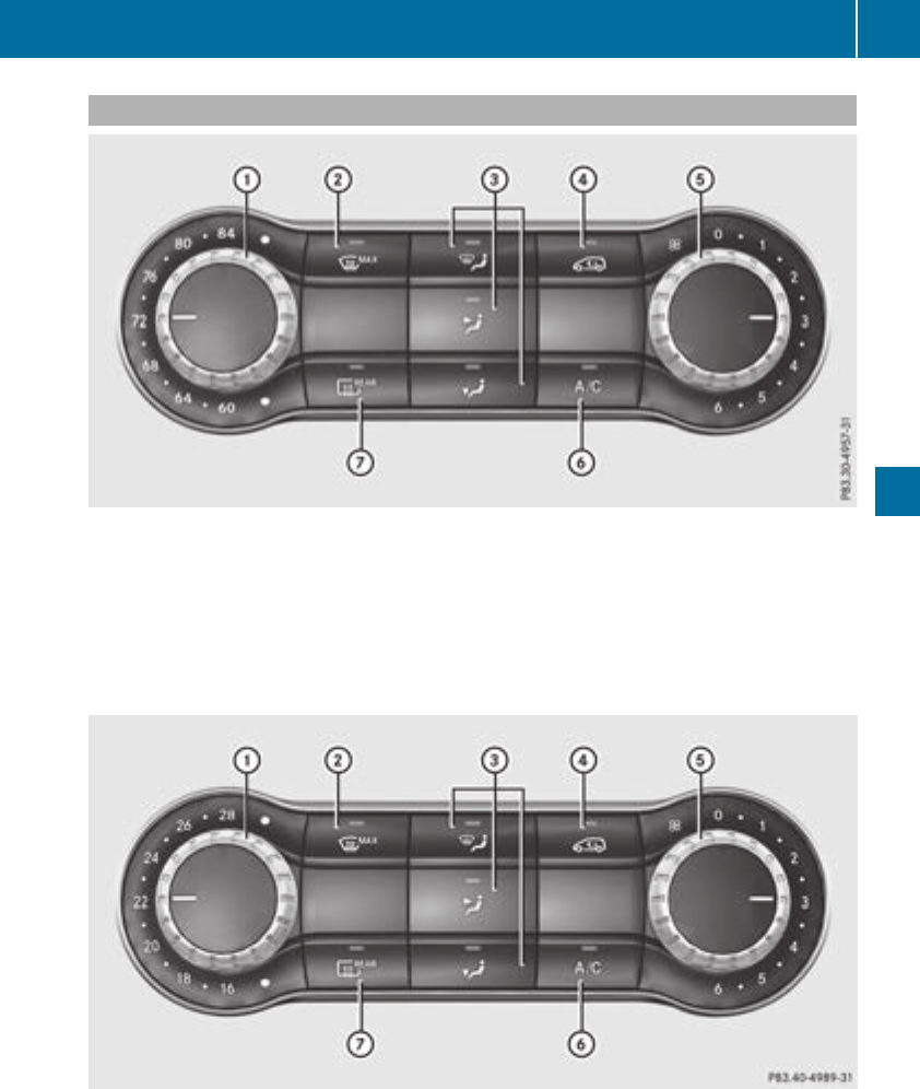
Air-conditioningsystem control panel
USAonly
:Sets thetemperature (Ypage 116)
;Defroststhe windshield (Ypage 117)
=Sets theair distribution (Ypage 116)
?Switches air-recirculation modeon/off(Ypage 119)
ASets theairflow (Ypage 117)
BSwitches coolingwithair dehumidification on/off (Ypage 115)
CSwitches therear window defrosteron/off(Ypage 118)
Canada only
:Sets thetemperature (Ypage 116)
;Defroststhe windshield (Ypage 117)
=Sets theair distribution (Ypage 116)
?Switches air-recirculation modeon/off(Ypage 119)
ASets theairflow (Ypage 117)
Overview of climatecontrolsystems 111
Climatecontrol

BSwitches cooling with airdehumidification on/off (Ypage 115)
CSwitches the rearwindow defrosteron/off (Ypage 118)
Notesonusing the air-conditioning
system
Air-conditioning system
Below,you can find anumber of notes and rec-
ommendations to helpyou usethe air-condi-
tioning system optimally.
RSwitch on the air-conditioning system by turn-
ing control knob Aclockwise to the desired
position (except position 0).
RSet the temperature to 72 ‡(22 †).
RRecommendation for avoiding misted
windows at lowexteriortemperatures or
in rain: switch on the ¿cooling with dehu-
midification function (Ypage 115).
Set airdistribution to ¯and if possible
switch off Pand O(Ypage 116).
Deactivate air-recirculation mode e
(Ypage 119).
Set airflowcontrol Ato asetting between 3
and 6(Ypage 117).
RRecommendation for rapid coolingor
heating of the vehicle interior: brieflyset
airflowcontrol Ato asetting between 3and
6(Ypage 117).
RRecommendation for aconstantvehicle
interior temperature: set airflowcontrol A
to asetting between 1and 3(Ypage 117).
RRecommendation for air distributionin
winter: select the Oand ¯settings
(Ypage 116).
Recommendation for air distributionin
summer: select the Por Pand ¯
settings (Ypage 116).
ROnly usethe "Windshielddefrosting" function
brieflyuntilthe windshield is clear again.
ROnly useair-recirculation modebriefly, e.g. if
there are unpleasant outsideodors or when in
atunnel.T
he windowscould otherwise fog up,
since no freshair is drawn into the vehiclein
air-recirculation mode.
RIf youchange the settings of the climate con-
trol system, the climate statusdisplay
appears for approximately three seconds at
the bottomofthe screen in the multimedia
system display;see separate operating
instructions.You will see the current settings
of the various climate control functions.
DYNAMICSELECT button(except
Mercedes-AMG vehicles)
You can choose between various drive programs
with the DYNAMIC SELECT button
(Ypage 128).
If youhaveselected drive program E:
Rwhen heating, the electrical heater booster is
deactivated and in the warming-up phase
heatoutputisreduced
Rthe rearwindow defrosterrunning time is
reduced
Depending on the configuration, climate set-
tings may also be influenced in the drive pro-
gram I.
If youhaveselected drive program Cor S,cli-
mate settings are not influenced.
ECOstart/stop function
During automatic engine switch-off, the climate
control system only operatesatareducedcapa-
city.Ifyou require the fullclimate control output,
youcan switch off the ECO start/stop function
by pressing the ECO button (Ypage 127).
112 Overviewofclimate control systems
Climate control
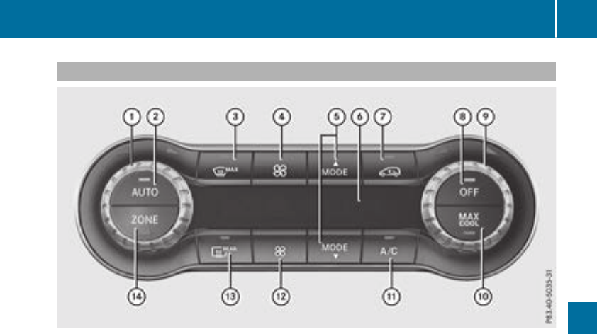
Control panel for dual-zone automatic climatecontrol
USAonly
:Setsthe temperature, left (Ypage 116)
;Setsclimate control to automatic (Ypage 116)
=Defroststhe windshield (Ypage 117)
?Increases theairflow (Ypage 117)
ASetsthe air distribution (Ypage 116)
BDisplay
CSwitches air-recirculation modeon/off(Ypage 119)
DActivates/deactivatesclimate control (Ypage 115)
ESetsthe temperature, right(Ypage 116)
FActivatesordeactivatesmaximum cooling(Ypage 118)
GSwitches coolingwithair dehumidification on/off(Ypage 115)
HReduces theairflow (Ypage 117)
ISwitches therear window defrosteron/off(Ypage 118)
JSwitches theZONE function on/off(Ypage 117)
Overview of climatecontrol systems 113
Climate control
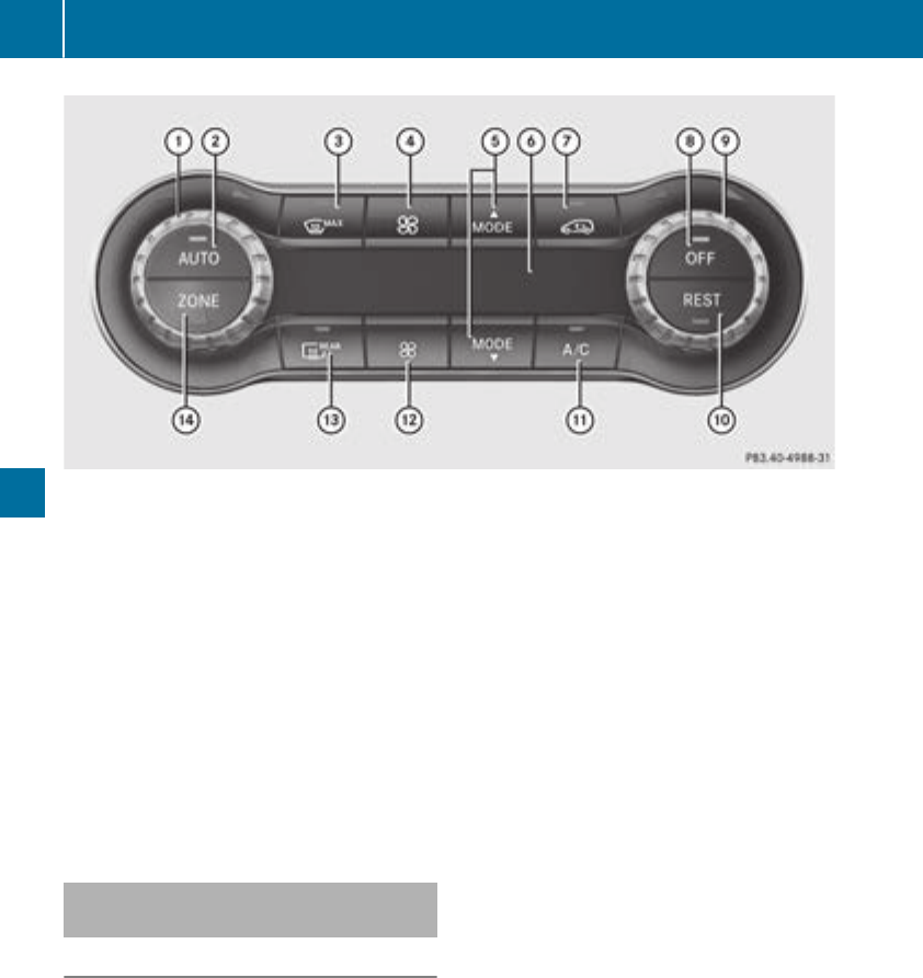
Canada only
:Setsthe temperature, left (Ypage 116)
;Setsclimate control to automatic (Ypage 116)
=Defroststhe windshield (Ypage 117)
?Increases theairflow (Ypage 117)
ASetsthe air distribution (Ypage 116)
BDisplay
CSwitches air-recirculationmode on/off(Ypage 119)
DActivates/deactivatesclimate control (Ypage 115)
ESetsthe temperature, right(Ypage 116)
FSwitches theresidual heat on or off (Ypage 119)
GSwitches cooling with air dehumidification on/off(Ypage 115)
HReduces theairflow (Ypage 117)
ISwitches therear window defroster on/off(Ypage 118)
JSwitches theZONE function on/off(Ypage 117)
Optimumuse of dual-zone automatic
climatecontrol
Climatecontrol system
The followingcontainsinstructionsand recom-
mendationstoenable you to get themostout of
your dual-zone automatic climate control.
RActivate climate control usingthe Ãand
¿buttons. The indicator lamps in the
Ãand ¿buttonslight up.
RSet thetemperatureto72‡(22 †).
ROnly use the"Windshield defrosting"function
briefly until thewindshield is clear again.
ROnly use air-recirculationmode briefly, e.g.if
there are unpleasantoutside odorsorwhen in
atunnel.The windows couldotherwise fog up,
since no fresh air is drawn intothe vehicle in
air-recirculationmode.
RUse theZONE function to adopt thetemper-
aturesettings on thedriver'sside for the
front-passenger side as well. The indicator
lamp in the ábutton goes out.
RUse theresidual heat function if you want to
heat or ventilate thevehicle interiorwhen the
ignition is switched off.The residual heat
function can only be activated or deactivated
with theignition switched off.
RIf you changethe settings of theclimate con-
trol system, theclimate status display
appearsfor approximately three seconds at
thebottomofthe screen in themultimedia
system display; see separate operating
114 Overview of climate control systems
Climate control
instructions.You will see the current settings
of the various climatecontrol functions.
DYNAMIC SELECT button (except
Mercedes-AMGvehicles)
You can choose betweenvarious drive programs
with the DYNAMICSELECTbutton
(Ypage 128).
If you have selected drive program E:
Rwhen heating, the electrical heaterbooster is
deactivatedand in the warming-up phase
heat output is reduced
Rthe rear window defroster running timeis
reduced
Dependingonthe configuration, climateset-
tings may also be influenced in the drive pro-
gram I.
If you have selected drive program Cor S,cli-
mate settings are not influenced.
ECO start/stop function
Duringautomatic engineswitch-off, the climate
control system only operates at areduced capa-
city. If you require the full climatecontrol output,
you can switchoff the ECO start/stopfunction
by pressing the ECO button (Ypage 127).
Operating theclimate control sys-
tems
Activating/deactivating climate con-
trol
General notes
When the climatecontrol is switched off,the air
supply and air circulation are also switched off.
The windows could fog up. Therefore, switchoff
climatecontrol only briefly
Air-conditioning system
XTurn the SmartKey to position 2in the igni-
tion lock (Ypage 122).
XTo switch on: turn control Aclockwise to
the desiredposition (except position 0)
(Ypage 111).
XTo switch off: turn control Acounter-clock-
wise to position 0(Ypage 111).
Dual-zone automatic climate control
XTurn the SmartKey to position 2in the igni-
tion lock (Ypage 122).
XTo activate: press the Ãbutton.
The indicator lamp in the Ãbutton lights
up. Airflow and air distribution are set to auto-
matic mode.
or
XPress the ^button.
The indicator lamp in the ^button goes
out. The previously selected settings are
restored.
XTo deactivate: press the ^button.
The indicator lamp in the ^button lights
up.
iDual-zoneautomatic climatecontrol: switch
on climatecontrol primarily using the Ã
button.
Switchingcooling with air dehumidi-
fication on/off
General notes
If you deactivatethe "Cooling with air-dehumid-
ification" function,the air insidethe vehicle will
not be cooled. The air insidethe vehicle will also
not be dehumidified. The windows can fog up
more quickly. Therefore, only deactivatethe
"Cooling with air-dehumidification" function
briefly.
The "Cooling with air dehumidification" function
is only available when the engineisrunning. The
air insidethe vehicle is cooledand dehumidified
accordingtothe temperature selected.
Condensationmay drip fromthe underside of
the vehicle when it is in coolingmode. This is
normal and not asign that there is amalfunc-
tion.
Activating/deactivating
XPress the ¿button.
The indicator lamp in the ¿button lights
up or goes out.
The indicator lamp in the button indicates that
the respective function is activated. The
"Cooling with air dehumidification" function
has adelayed switch-off feature.
Operating theclimate control systems 115
Climate control

Problems with the "Cooling with air dehumidification" function
Problem Possible causes/consequences and MSolutions
The indicator lamp in the
¿button flashes
three times or remains
off. The "Cooling with air
dehumidification" func-
tion cannot be switched
on.
Cooling with air dehumidification has been deactivated due to amal-
function.
XVisit aqualified specialist workshop.
Setting climate control to automatic
General notes
The automatic climate control function is only
available in conjunction with dual-zone auto-
matic climate control.
In automatic mode, the set temperature is main-
tained automatically at aconstant level. The
system automatically regulates the temperature
of the dispensed air, the airflow and the air dis-
tribution.
The "Cooling with air dehumidification" function
is activated automatically in automatic mode.
Setting climate control to automatic
XTurn the SmartKey to position 2in the ignition
lock (Ypage 122).
XSet the desired temperature.
XTo activate: press the Ãbutton.
The indicator lamp in the Ãbutton lights
up. Automatic air distribution and airflow are
activated.
XTo switch to manualmode: press the É
or Ëbutton.
or
XPress the Kor Ibutton.
The indicator lamp in the Ãbutton goes
out. Automatic air distribution and airflow are
deactivated.
Setting the temperature
Air-conditioning system
You can set the temperature for the entire vehi-
cle. The set temperature is automatically main-
tained at aconstant level.
XTurn the SmartKey to position 2in the ignition
lock (Ypage 122).
XTo increase or reduce: turn control :coun-
ter-clockwise or clockwise (Ypage 111). Only
change the temperature settinginsmall
increments. Start at 72 ‡(22 †).
Dual-zone automatic climate control
Differenttemperatures can be set for the driv-
er's and front-passenger sides. The set temper-
ature is automatically maintained at aconstant
level.
XTurn the SmartKey to position 2in the ignition
lock (Ypage 122).
XTo increase or decrease: turn control :or
Ecounter-clockwise or clockwise
(Ypage 113). Only change the temperature
settinginsmall increments. Start at 72 ‡
(22 †).
Setting the air distribution
Air-conditioning system
Air distribution settings
¯Directsair through the defroster vents
PDirectsair through the center and side air
vents
ODirectsair through the footwell air vents
116 Operating the climate control systems
Climatecontrol

iYou can also activate several air distribution
settings simultaneously. To do this,press
multiple air distribution buttons.The air is
thendirected through various vents.
iRegardless of the air distribution setting,
airflow is always directed through the side air
vents. The side air vents can only be closedif
the adjusters are turned clockwise until they
engage.
Setting theair distribution
XTurn the SmartKey to position 2in the igni-
tion lock (Ypage 122).
XPress one or more of the P,O,¯
buttons.
The corresponding indicator lamp lightsup
briefly.
Dual-zone automatic climate control
Air distribution settings
¯Directsair through the defrostervents
PDirectsair through the center and side air
vents
ODirectsair through the footwell air vents
SDirectsair through the center,side and
footwell vents
bDirectsair through the defroster, center
and side air vents
aDirectsair through the defrosterand
footwell vents
_Directsair through the defroster, center,
side and footwell vents
iRegardless of the air distribution setting,
airflow is always directed through the side air
vents. The side air vents can only be closedif
the adjusters are turned clockwise until they
engage.
Setting theair distribution
XTurn the SmartKey to position 2in the igni-
tion lock (Ypage 122).
XPress the Éor Ëbutton repeatedly
until the desired symbol appears in the dis-
play.
Setting theairflow
Air-conditioning system
XTurn the SmartKey to position 2in the igni-
tion lock (Ypage 122).
XTo increase or reduce: turn control Acoun-
ter-clockwise or clockwise (Ypage 111).
Dual-zone automatic climate control
XTurn the SmartKey to position 2in the igni-
tion lock (Ypage 122).
XTo increase or reduce: press the Kor
Ibutton.
Switching theZONEfunction on/off
This function is only available with dual-zone
automatic climatecontrol.
XTo activate: press the ábutton.
The indicator lamp in the ábutton lights
up.
The temperature settingfor the driver's side
is not adoptedfor the front-passenger side.
XTo deactivate: press the ábutton.
The indicator lamp in the ábutton goes
out.
The temperature settingfor the driver's side
is adoptedfor the front-passenger side.
Defrosting thewindshield
Generalnotes
You can use this function to defrost the wind-
shield or to clear afoggedupwindshield and
side windows.
iYou should only selectthe "Windshield
defrosting" function until the windshield is
clear again.
Switching the"Windshield defrosting"
function on or off
XTurn the SmartKey to position 2in the igni-
tion lock (Ypage 122).
XTo activate: press the ¬button.
The indicator lamp in the ¬button lights
up.
Operating theclimatecontrol systems 117
Climatecontrol

The climate control system switches to the
following functions:
Rhigh airflow
Rhigh temperature
Rair distribution to the windshield and front
side windows
Rair-recirculation mode off
iThe "Windshield defrosting" function auto-
matically sets the blower level to the optimum
defrosting effect.Asaresult, the airflow may
increase or decrease automatically after the
¬button is pressed.
iYou can adjust the blower level manually
while the "Windshield defrosting" function is
in operation:
RAir-conditioning system: turn airflow con-
trol Acounter-clockwise or clockwise
(Ypage 111).
RDual-zoneautomatic climate control: press
the óor ôbutton.
XTo deactivate: press the ¬button.
The indicator lamp in the ¬button goes
out. The previously selected settings are
restored. Air-recirculation mode remains
deactivated.
or
XDual-zoneclimate control: press the Ã
button.
The indicator lamp in the ¬button goes
out. Airflow and air distribution are set to
automatic mode.
or
XAir-conditioning system: turn temperature
control :counter-clockwise or clockwise
(Ypage 111).
Dual-zoneautomatic climate control: turn
temperature control :or Ecounter-clock-
wise or clockwise (Ypage 113).
MAX COOL maximum cooling
The MAX COOL function is only availableinvehi-
cles for the USA.
MAX COOL is only operational when the engine
is running.
XTo activate: press the Ùbutton.
The indicator lamp in the button lights up.
XTo deactivate: press the Ùbutton.
The indicator lamp goes out. The previously
selected settings are restored.
When you activate MAX COOL, climate control
switches to the following functions:
Rmaximum cooling
Rmaximum airflow
Rair-recirculation mode on
Defrosting the windows
Windows fogged up on the inside
Air-conditioning system
XActivate the ¿"Cooling with air dehumid-
ification" function.
XIf the windows continue to fog up, activate the
¬"Windshield defrosting" function.
iYou should only select this setting until the
windshield is clear again.
Dual-zone automatic climate control
XActivate the ¿"Cooling with air dehumid-
ification" function.
XActivate automatic mode Ã.
XIf the windows continue to fog up, activate the
¬"Windshield defrosting" function.
iYou should only select this setting until the
windshield is clear again.
Windows fogged up on the outside
XActivate the windshield wipers.
XSet the air distribution to Por O.
iYou should only select this setting until the
windshield is clear again.
Rear window defroster
General notes
The rear window defroster has ahigh current
draw. You should thereforeswitch it off as soon
as the rear window is clear. Otherwise, the rear
window defroster switches off automatically
after several minutes.
118 Operating the climate control systems
Climate control
If the battery voltage is too low, the rear window
defroster may switch off.
Activating/deactivating
XTurn the SmartKey to position 2in the igni-
tion lock (Ypage 122).
XPress the ¤button.
The indicator lamp in the ¤button lights
up or goes out.
Problems with the rear window defroster
Problem Possible causes/consequences and MSolutions
The rear window
defroster has deactiva-
ted prematurely or can-
not be activated.
The battery has not been sufficiently charged.
XSwitch off any consumers that are not required, e.g. reading lamps,
interior lighting or the seat heating.
When the battery is sufficiently charged, the rear window defroster
can be activated again.
Switching air-recirculationmode
on/off
General notes
You can deactivate the flow of fresh air if
unpleasant odors are entering the vehicle from
outside. The air already inside the vehicle will
then be recirculated.
If you switch on air-recirculation mode, the win-
dows can fog up more quickly, in particular at
low temperatures. Only use air-recirculation
mode brieflytoprevent the windowsfrom fog-
ging up.
The operation of air-recirculation mode is the
same for all control panels.
Activating/deactivating
XTurn the SmartKey to position 2in the igni-
tion lock (Ypage 122).
XTo activate: press the ebutton.
The indicator lamp in the ebutton lights
up.
Air-recirculation mode switches on automati-
cally:
Rat high outsidetemperatures
Rat high levelsofpollution
When air-recirculation mode is activated auto-
matically, the indicator lamp in the ebutton
is not lit. Outside air is addedafter about
30 minutes.
XTo deactivate: press the ebutton.
The indicator lamp in the ebutton goes
out.
iAir-recirculation mode deactivates auto-
matically:
Rafter approximately five minutes at outside
temperaturesbelowapproximately 45 ‡
(7 †)
Rafter approximately five minutes if the
"Cooling with air dehumidification" func-
tion is deactivated
Rafter approximately 30 minutes at outside
temperaturesabove approximately 45 ‡
(7 †) if the "Cooling with dehumidification"
function is activated
Switching the residual heat on or off
General notes
The residual heat function is only available in
vehiclesfor Canada with dual-zone automatic
climate control.
It is possible to make use of the residual heat of
the engine to continue heating the vehicle for
approximately 30 minutes after the engine has
been switched off. The heating time depends on
the set interior temperature.
iThe blower willrun at alow speed regardless
of the airflow setting.
Operating the climatecontrol systems 119
Climate control
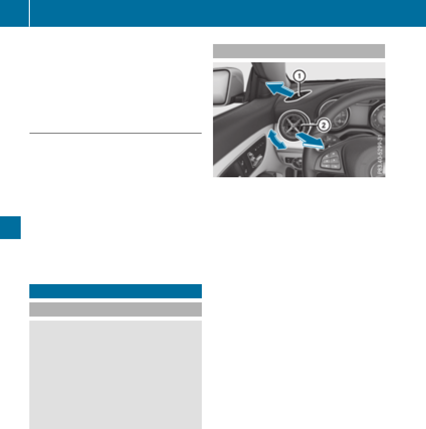
iIf you activate the residual heat function at
high temperatures, only the ventilation willbe
activated. The blower runs at mediumspeed.
iYou cannot use the ventilation to cool the
vehicle interior to atemperature lowerthan
the outsidetemperature.
Activating/deactivating
XTurn the SmartKey to position gin the igni-
tion lock or remove it (Ypage 122).
XPress the Ìbutton.
The indicator lamp in the Ìbutton lights
up or goes out.
The indicator lamp in the button indicates that
the respective function is activated.
iResidualheat is deactivated automatically:
Rafter approximately 30 minutes
Rwhen the ignition is switched on
Rif the battery voltage drops
Air vents
Important safety notes
GWARNING
Very hot or very cold air can flow from the air
vents. This could resultinburns or frostbite in
the immediate vicinity of the air vents. There
is arisk of injury.
Make sure that all vehicle occupants always
maintain asufficient distance to the air out-
lets. If necessary,redirect the airflow to
another area of the vehicle interior.
In order to ensure the direct flow of fresh air
through the air vents into the vehicle interior,
please observe the following notes:
Rkeep the air inlet between the windshield and
the hood free of blockages, such as ice, snow
or leaves.
Rnever cover the air vents or air intake grilles in
the vehicle interior.
iFor optimal climate control in the vehicle,
open the air vents completely and set the
adjusters to the central position.
Setting the air vents
:Side window defroster vent
;Side air vent
XTo open aside air vent: turn the adjuster in
side air vent ;to the left.
XTo close aside air vent: turn the adjuster in
side air vent ;clockwise as far as it willgo.
iThe center and rear air vents are adjusted in
the same way.
120 Airvents
Climate control

Notesonbreaking-in anew vehicle
Important safety notes
Thesensorsystemofsomedriving and driving
safety systems adjusts automaticallywhile a
certaindistance is being driven after the vehicle
hasbeendeliveredorafter repairs. Full system
effectiveness is not reacheduntilthe end of this
teach-inprocedure.
New and replaced brake pads and discs only
reach their optimum braking effect after several
hundred kilometers of driving. Compensate for
thisbyapplyinggreaterforce to the brake pedal.
The first 1000 miles (1500km)
Themoreyou look after the engine when it is
new,the moresatisfied youwillbewithits per-
formance in the future.
RYoushouldtherefore drive at varying vehicle
and engine speeds for the first 1000 miles
(1500 km).
RAvoidheavy loads, e.g.driving at full throttle,
during thisperiod.
RChangegearingoodtime, beforethe tach-
ometer needleisÔof the waytothe red area
of the tachometer.
RDo not manuallyshift to alower gear to brake
the vehicle.
RTry to avoiddepressing the accelerator pedal
beyond the point of resistance(kickdown).
RIdeally,for the first 1000 miles(1500 km),
driveinprogram E.
Additional breaking-in notesfor Mercedes-AMG
vehicles:
RDo notdrivefaster than 85 mph (140km/h)
for thefirst 1,000 miles (1,500 km).
ROnly allow theengine to reachamaximum
engine speedof4,500 rpm briefly.
RChange gear in good time.
After1,000 miles (1,500 km), you can increase
theengine speedgradually and bringthe vehicle
to full speed.
You shouldalso observethese notesonbreak-
ing-in if theengine or partsofthe drivetrain on
your vehicle have been replaced.
Always observethe maximum permissible
speed.
Driving
Important safety notes
GWARNING
Objectsinthe driver'sfootwell can restrict the
pedal travel or obstructadepressedpedal.
The operatingand road safety of thevehicle is
jeopardized. Thereisarisk of an accident.
Makesure that all objectsinthe vehicle are
stowed correctly, and that they cannotenter
thedriver'sfootwell. Install thefloormats
securely and as specified in ordertoensure
sufficient clearance for thepedals.Donot use
loosefloormats and do notplace floormats on
topofone another.
GWARNING
Unsuitable footwear can hinder correctusage
of thepedals,e.g.:
Rshoeswith thick soles
Rshoeswith high heels
Rslippers
Thereisarisk of an accident.
Wear suitable footwear to ensure correct
usage of thepedals.
GWARNING
If you switch off theignition while driving,
safety-relevantfunctionsare only available
with limitations,ornot at all. This couldaffect,
for example, thepower steering and thebrake
boostingeffect.You will require considerably
moreeffort to steer and brake. Thereisarisk
of an accident.
Do notswitch off theignition while driving.
GWARNING
If theparking brakehas notbeen fully
released when driving,the parking brakecan:
Roverheat and causeafire
Rlose its hold function.
Thereisarisk of fireand an accident. Release
theparking brakefully before driving off.
Driving 121
Driving and parking
Z
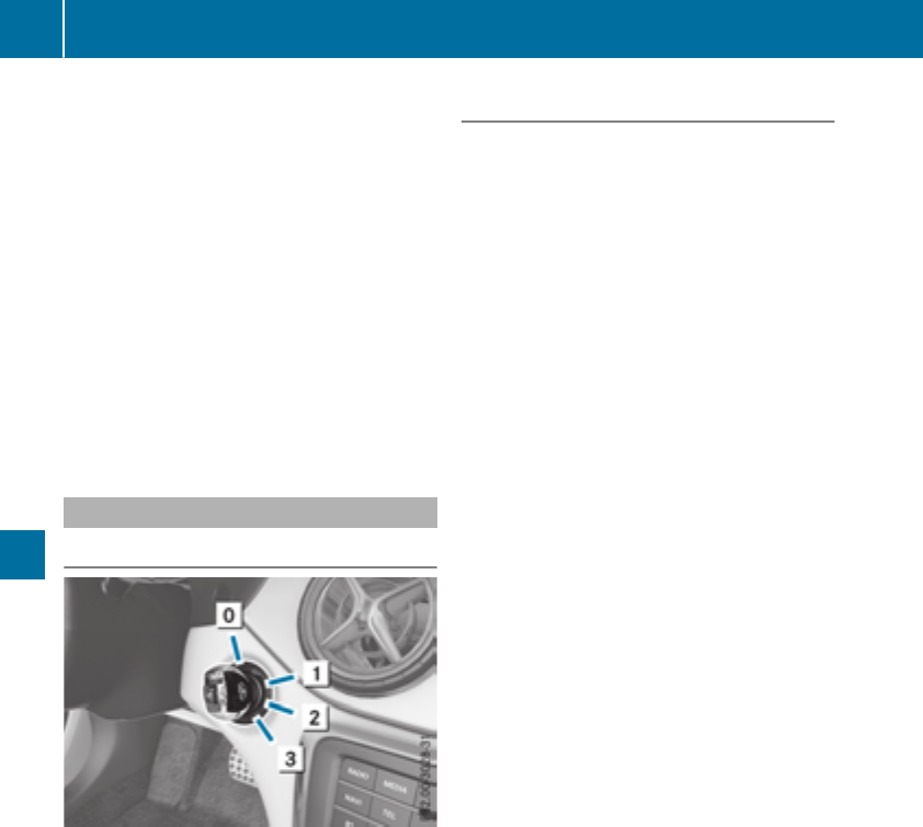
!Do not warm up the engine with the vehicle
stationary. Drive off immediately.Avoid high
engine speeds and driving at full throttle until
the engine has reached its operating temper-
ature.
Only shift the automatic transmission to the
desired drive position when the vehicle is sta-
tionary.
Where possible,avoid spinning the drive
wheels when pulling awayonslippery roads.
You could otherwise damage the drive train.
!Mercedes-AMG vehicles: avoid full-load
operation and engine speeds greater than
5000 rpm when the engine is cold. This helps
to protect the engine and avoids uncomfort-
able driving.
Key positions
SmartKey
gTo remove the SmartKey
(shift the transmission to position j)
1Power supplyfor some consumers, such as
the windshieldwipers
2Ignition (power supplyfor all consumers)
and drive position
3To start the engine
iThe SmartKey can be turned in the ignition
lock even if it is not the correct SmartKey for
the vehicle. The ignition is not switched on.
The engine cannot be started.
Start/Stop button
General notes
Vehicles with KEYLESS-GO are equipped with
SmartKeys featuring the integrated KEYLESS-
GO function and adetachable Start/Stop but-
ton.
Acheck which periodically establishes aradio
connection between the vehicle and the Smart-
Key determines whether avalid SmartKey is in
the vehicle. This occurs, for example, when
starting the engine.
When you insert the Start/Stop button into the
ignition lock, the system needs approximately
two seconds recognition time. You can then use
the Start/Stop button.
Pressing the Start/Stop button several times in
succession corresponds to the different Smart-
Key positions in the ignition lock. This is only the
case if you are not depressing the brake pedal.
If you depress the brake pedal and press the
Start/Stop button, the engine starts immedi-
ately.
To start the vehicle without actively using the
SmartKey:
Rthe Start/Stop button must be inserted in the
ignition lock
Rthe SmartKey must be in the vehicle
Rthe vehicle must not be locked with the
SmartKey or KEYLESS-GO (Ypage 71)
Do not keep the KEYLESS-GO key:
Rwith electronic devices, e.g. amobile phone
or another SmartKey.
Rwith metallic objects, e.g. coins or metal foil.
Rinside metallic objects, e.g. ametal case.
This can affect the functionality of KEYLESS-GO.
If you lock the vehicle with the SmartKey remote
control or with KEYLESS-GO, after ashort time:
Ryou will not be able to switch on the ignition
with the Start/Stop button.
Ryou will no longer be able to start the engine
with the Start/Stop button until the vehicle is
unlocked again.
If you lock the vehicle centrally using the button
on the front door (Ypage 76), you can continue
to start the engine with the Start/Stop button.
The engine can be switched off while the vehicle
is in motion by pressing and holding the Start/
Stop button for three seconds. This function
122 Driving
Driving and parking
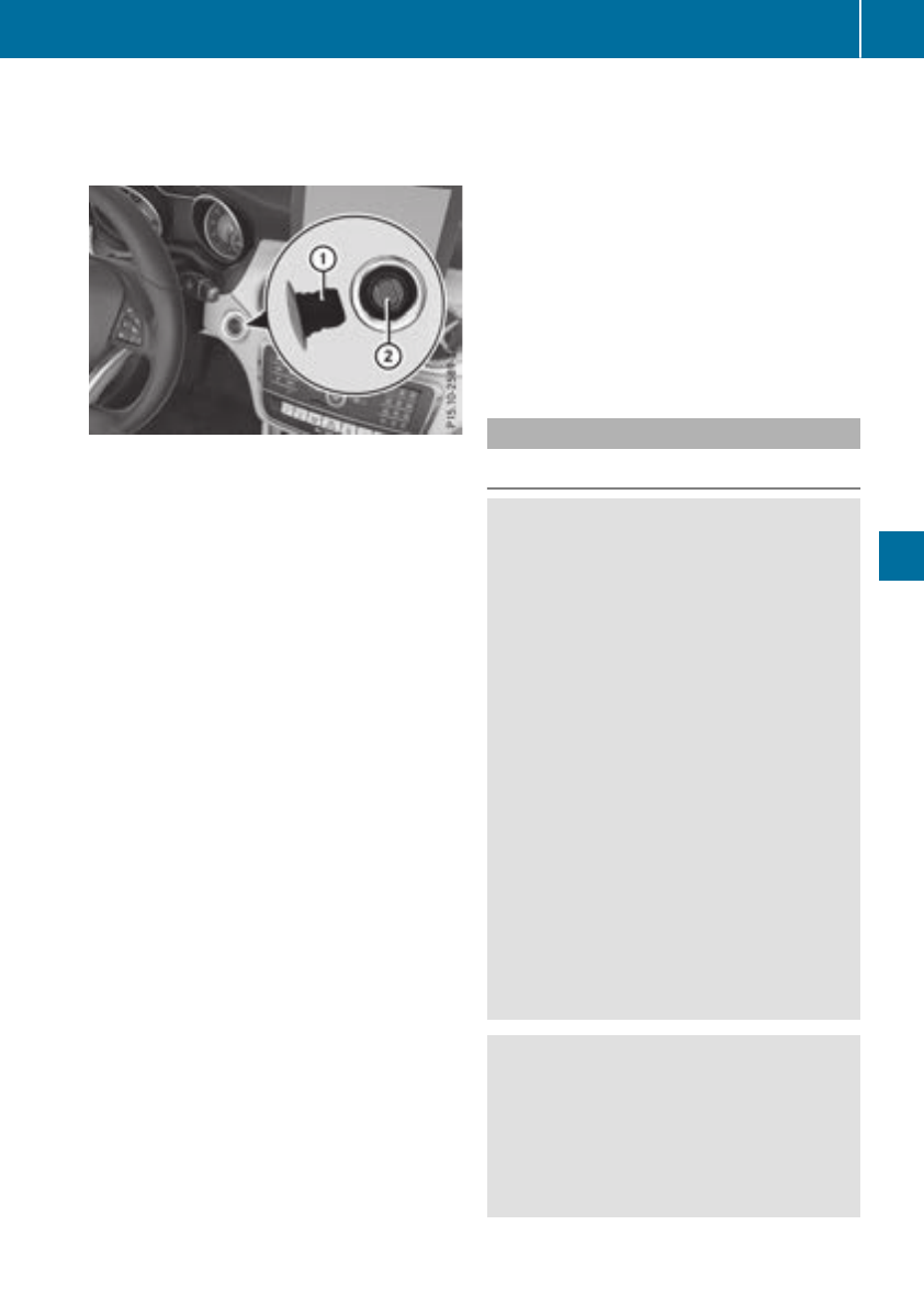
operates independently of the ECO start/stop
automatic engine switch-off function.
Key positions with the Start/Stop button
:Start/Stop button
;Ignition lock
As soon as the ignition is switched on, all the
indicator lamps in the instrument cluster light
up.
For further information on situations in which an
indicator lamp either fails to go out after the
engine is started or lights up while driving,
please refer to "Warning and indicator lamps in
the instrument cluster" (Ypage 219).
If Start/Stop button :has not yet been
pressed, this is the same as the SmartKey being
removed from the ignition.
XTo switch on the power supply: press
Start/Stop button :once.
The power supply is switched on. You can now
activate the windshield wipers, for example.
The power supply is switched off again if:
Rthe driver's door is opened and
Ryou press Start/Stop button :twice when in
this position
XTo switch on the ignition: press Start/Stop
button :twice.
The ignition is switched on.
If you press Start/Stop button :once when
in this position, the ignition is switched off
again.
Removing the Start/Stop button
You can remove the Start/Stop button from the
ignition lock and start the vehicle as normal
using the SmartKey.
You can only switch between Start/Stop button
mode and SmartKey operation when the vehicle
is stationary.
You must also engage park position j.
XRemove Start/Stop button :from ignition
lock ;.
You do not have to remove the Start/Stop but-
ton from the ignition lock when you leave the
vehicle. You should, however, alwaystake the
SmartKey with you when leaving the vehicle. As
long as the SmartKey is in the vehicle:
Rthe vehicle can be started using the Start/
Stop button
Rthe electrically powered equipment can be
operated
Starting the engine
Important safety notes
GWARNING
If children are left unsupervised in the vehicle,
they could:
Ropen the doors, thus endangering other
people or road users.
Rget out and disrupt traffic.
Roperate the vehicle's equipment.
Additionally, children could set the vehicle in
motion if, for example, they:
Rrelease the parking brake.
Rshifting the automatic transmission out of
park position P
RStart the engine.
There is arisk of an accident and injury.
When leaving the vehicle, alwaystake the
SmartKey with you and lock the vehicle. Never
leave children or animals unattended in the
vehicle. Always keep the SmartKey out of
reach of children.
GWARNING
Combustion engines emit poisonous exhaust
gases such as carbon monoxide. Inhaling
these exhaust gases leads to poisoning. There
is arisk of fatal injury. Therefore never leave
the engine runninginenclosed spaces with-
out sufficient ventilation.
Driving 123
Driving and parking
Z

GWARNING
Flammable materials introduced through
environmental influence or by animals can
ignite if in contact with the exhaust system or
parts of the engine that heatup. There is arisk
of fire.
Carry out regular checks to make sure that
there are no flammable foreignmaterials in
the engine compartment or in the exhaust
system.
General notes
During acold start, the engine runs at higher
speeds to enablethe catalytic converter to
reach its operating temperature. The sound of
the engine may change during this time.
Automatic transmission
XShift the transmission to position j
(Ypage130).
The transmission position display in the mul-
tifunction display shows P(Ypage130).
iYou can start the engine in transmission
position jand i.
Starting procedure with the SmartKey
To start the engine using the SmartKey instead
of the Start/Stop button, pullthe Start/Stop
button out of the ignitionlock.
XTurn the SmartKey to position 3in the igni-
tion lock (Ypage122) and release it as soon
as the engine is running.
Starting procedure with the Start/Stop
button
The Start/Stop button can be used to start the
vehiclemanually without inserting the SmartKey
into the ignitionlock. The Start/Stop button
must be inserted in the ignitionlock and the
SmartKey must be in the vehicle. This mode for
starting the engine operates independently of
the ECO start/stop automatic engine start func-
tion.
You can start the engine if avalidSmartKey is in
the vehicle. Switch off the engine and always
take the SmartKey with you when leaving the
vehicle, even if you only leave it for ashort time.
Pay attention to the important safety notes.
XDepress the brake pedaland keep it
depressed.
XPress the Start/Stop button once
(Ypage122).
The engine starts.
Starting procedure via smartphone
Observe the important safety notes on starting
the engine (Ypage123).
You can alsostart yourengine via yoursmart-
phone from outside the vehicle. In this case, the
previouslyselected climate control setting is
activated. In this way you can cool or heat the
interior of the vehiclebefore starting the jour-
ney.
Only start the engine via yoursmartphone if it is
safe to start and run the engine where yourvehi-
cle is parked.
Observe the legalstipulations in the area where
yourvehicleisparked.Engine start via smart-
phone may be limited to certain countries or
regions.
You can execute amaximumoftwo consecutive
starting attempts via yoursmartphone. If you
insert the SmartKey into the ignitionlock, you
can carry out two more starting attempts.
Once you have started the engine, you can
switch the engine off via yoursmartphone at any
time.
You can only start the engine via yoursmart-
phone if:
Rthe SmartKey is in the ignitionlock
Rpark position jis selected
Rthe accelerator pedalisnot depressed
Rthe anti-theft alarm system is not activated
Rthe panicalarm is not activated
Rthe hazard warning lampsare switched off
Rthe hood is closed
Rthe doors are closed and locked
Rthe windows and sliding sunroof are closed
Also make sure that:
Rthe fuel tank is sufficiently filled
Rthe starter battery is sufficiently charged
GWARNING
Limbs couldbecrushedortrappedifthe
engine is started unintentionally during ser-
124 Driving
Driving and parking

vice or maintenance work. There is arisk of
injury.
Always secure the engine against uninten-
tional starting before carrying out mainte-
nance or repair work.
Make sure that the engine cannot be started via
yoursmartphone before carrying out mainte-
nance or repairs. You can prevent an engine
start via yoursmartphone, for example, if you:
Rswitch on the hazard warning lamps
Rdo not lock the doors
Ropen the hood
Pulling away
General notes
GWARNING
If the engine speedisabove the idling speed
and you engage transmission position Dor R,
the vehiclecould pullawaysuddenly.There is
arisk of an accident.
When engaging transmission position Dor R,
alwaysfirmly depress the brake pedaland do
not simultaneously accelerate.
Depress the accelerator carefully when pulling
away.
The vehiclelocks centrally once you have pulled
away. The locking knobs in the doors drop down.
You can open the doors from the insideatany
time.
You can alsodeactivate the automatic locking
feature (Ypage187).
It is possible to shift the transmission from posi-
tion jto the desired position only if you
depress the brake pedal. Only then can the
parking lock be deactivated.
All vehicles (except Mercedes-AMG vehi-
cles): if you do not depress the brake pedal, the
DIRECT SELECT lever can still be moved but the
parking lock remains engaged.
Mercedes-AMG vehicles: if you do not depress
the brake pedal, the selector lever can still be
moved but the parking lock remains engaged.
At transmission fluidtemperatures below Ò4‡
(Ò20†), you can only shift out of position jinto
another transmission position when the engine
is running.
iUpshifts take place at higherengine speeds
after acold start. This helpsthe catalytic con-
verter to reach its operating temperature
more quickly.
Information on the automatic release of the
electric parking brake (Ypage143).
Hill start assist
Hill start assist helpsyou when pulling away
forward or in reverse on an uphill gradient. It
holdsthe vehiclefor ashort time after you have
removed yourfoot from the brake pedal. This
gives you enoughtime to move yourfoot from
the brake pedaltothe accelerator pedaland to
depress it before the vehiclebegins to roll.
GWARNING
After ashort time, hill start assist willnolon-
ger brake yourvehicleand it couldroll away.
There is arisk of an accident and injury.
Therefore, quickly move yourfoot from the
brake pedaltothe accelerator pedal. Never
leave the vehiclewhen it is held by hill start
assist.
Hill start assist is not active if:
Ryou are pulling awayonalevel road or on a
downhill gradient.
Rthe transmission is in position i.
Rthe electric parking brake is applied.
RESP®is malfunctioning.
Further information on holding the vehiclesta-
tionary on uphill gradients (Ypage134).
ECOstart/stop function
Introduction
The ECO start/stop function switches the
engine off automatically if the vehicleisstopped
under certain conditions.
The engine starts automatically when the driver
wants to pullawayagain. The ECO start/stop
function thereby helpsyou to reduce the fuel
consumptionand emissions of yourvehicle.
Driving 125
Driving and parking
Z
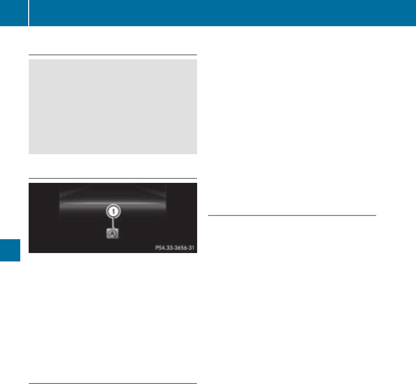
Important safety notes
GWARNING
If theengineisswitched off automatically and
you exit thevehicle, theengineisrestarted
automatically. The vehiclemay beginmoving.
Thereisariskofaccidentand injury.
If you wish to exit thevehicle, always turnoff
theignition and secure thevehicleagainst
rollingaway.
General notes
:ECO start/stopdisplay
The ECO start/stopfunction is activated when-
everyou start theengineusingthe SmartKey or
theStart/Stopbutton.
If theenginehas been switched off automati-
callybythe ECO start/stopfunction,the è
ECO symbol is shown in themultifunction dis-
play.
Mercedes-AMGvehicles: theECO start/stop
function is only available in driveprogram C.
Automaticengineswitch-off
If thevehicleisbraked to astandstill in Dor N,
theECO start/stopfunction switches off the
engineautomatically.
The ECO start/stopfunction is operational
when:
Rtheindicator lamp in theECO buttonislit
green.
Rtheoutside temperature is within therange
that is suitable for thesystem.
Rtheengineisatnormaloperating tempera-
ture.
Rtheset temperature for thevehicleinterior
has been reached.
Rthebattery is sufficientlycharged.
Rthesystem detects that thewindshield is not
fogged up when theair-conditioning system is
switched on.
Rthehoodisclosed.
Rthedriver'sdoor is closed and thedriver's
seat belt is fastened.
All of thevehicle's systems remain active when
theengineisstoppedautomatically.
The HOLD function can also be activated if the
enginehas been switched off automatically. It is
then notnecessarytocontinue applyingthe
brakes during theautomatic stop phase. When
you depress theacceleratorpedal,the engine
startsautomatically and thebraking effectof
theHOLDfunction is deactivated.
Automatic engineswitch-off can takeplacea
maximum of four times in arow (initial stop, then
three subsequentstops).
Automaticenginestart
The enginestartsautomatically if:
Ryou switch off theECO start/stopfunction by
pressingthe ECO button
Rin transmission position Dor Nthebrake
pedal is releasedand theHOLDfunction is not
active
Ryou depress theacceleratorpedal
Ryou engage reversegear R
Ryou movethe transmission out of position P
Ryou unfasten your seat belt or open thedriv-
er'sdoor
Rthevehiclestartstoroll
Rthebrakesystem requiresthis
Rthetemperature in thevehicleinterior devi-
atesfromthe set range
Rthesystem detects moisture on thewind-
shield when theair-conditioning system is
switched on
Rthebattery's condition of charge is toolow
Shifting thetransmission to position Pdoes not
start theengine.
126 Driving
Driving and parking
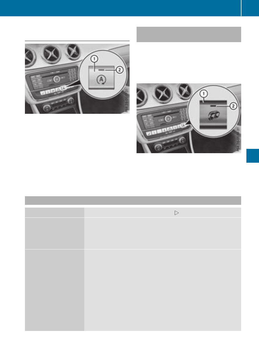
Deactivating or activating theECO
start/stop function
XTo deactivate:press ECObutton:.
Indicator lamp ;goesout.
XTo activate:press ECObutton:.
Indicator lamp ;lights up.
If indicator lamp ;is off, theECO start/stop
function has beendeactivated manually or as
theresult of amalfunction.The enginewill then
notbeswitched offautomatically when thevehi-
clestops.
AMG Performance exhaust system
(Mercedes-AMG vehicles)
You can choosebetween differentAMG Per-
formanceexhaustsystem volumesusingthe
position of theexhaustflap.
Each time you start theenginewiththe Smart-
Key or theStart/Stopbutton, thequietest set-
ting is activated.
Settingthe volume:
XPress button:.
If you selectthe loudest setting,indicator
lamp ;lights up.
Problemswiththe engine
Problem Possible causes/consequences andMSolutions
The enginedoesnot
start.
The HOLD function or DistancePilotDISTRONIC is activated.
XDeactivatethe HOLD function (Ypage 157) or DistancePilot
DISTRONIC (Ypage 155).
XTrytostart theengineagain.
The enginedoesnot
start.The starter motor
can be heard.
RThere is amalfunction in theengineelectronics.
RThere is amalfunction in thefuelsupply.
Before attemptingtostart theengineagain:
XTurnthe SmartKey backtoposition gin theignition lock.
or
XPress theStart/Stopbuttonrepeatedly until all indicator lampsin
theinstrument cluster go out.
XTrytostart theengineagain.Avoid excessivelylongand frequent
attemptstostart theengineasthese will drain thebattery.
If theenginedoesnot start after severalattempts:
XConsult aqualified specialistworkshop.
Driving 127
Driving andparking
Z
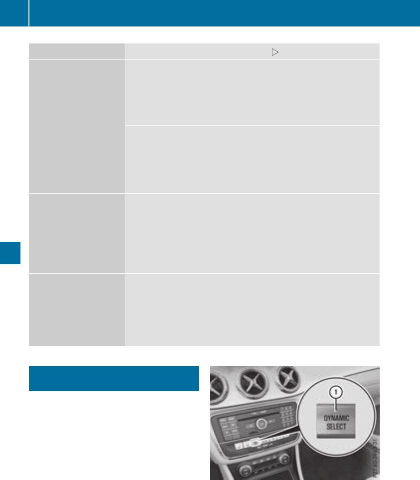
Problem Possible causes/consequences and MSolutions
The engine does not
start. You cannot hear
the starter motor.
The on-board voltage is too low because the battery is too weak or
discharged.
XJump-start the vehicle (Ypage 278).
If the engine does not start despite attemptstojump-start it:
XConsult aqualified specialist workshop.
The starter motor was exposed to athermal load that was too high.
XAllow the starter motor to cool down for approximately two minutes.
XTry to start the engine again.
If the engine still does not start:
XConsult aqualified specialist workshop.
The engine is not running
smoothly and is misfir-
ing.
There is amalfunction in the engine electronics or in amechanical
componentofthe engine management system.
XOnly depress the accelerator pedal slightly.
Otherwise, non-combusted fuel may get into the catalytic converter
and damage it.
XHave the cause rectified immediately at aqualified specialist work-
shop.
The coolant temperature
gauge shows avalue
above 248 ‡(120 †).
The coolant warning
lamp may also be on and
awarning tone may
sound.
The coolant level is too low. The coolant is too hot and the engine is no
longer being cooled sufficiently.
XStop as soon as possible and allow the engine and the coolant to
cool down.
XCheck the coolant level (Ypage 260). Observe the warning notes
as you do so and add coolant if necessary.
DYNAMIC SELECTbutton (all vehicles
except Mercedes-AMG vehicles)
Use the DYNAMIC SELECT button to change the
drive program. Depending on the drive program
selected the following vehicle characteristics
will change:
Rthe drive (engine and transmission manage-
ment)
Rthe suspension (vehicles with damping sys-
tem or AMG adaptive sport suspension sys-
tem)
Rthe steering
Rthe availability of the ECO start/stop function
Rthe climate control:
Each time you start the engine with the Smart-
Key or the Start/Stop button, drive program Cis
activated. For further information about starting
the engine, see (Ypage 125).
XPress DYNAMIC SELECT button :as many
times as necessary until the desired drive
program is selected.
The selected drive program appears in the
multifunction display.After five seconds the
display goes out and the status icon of the
selected drive program appears.
128 DYNAMIC SELECT button (all vehicles except Mercedes-AMG vehicles)
Driving and parking
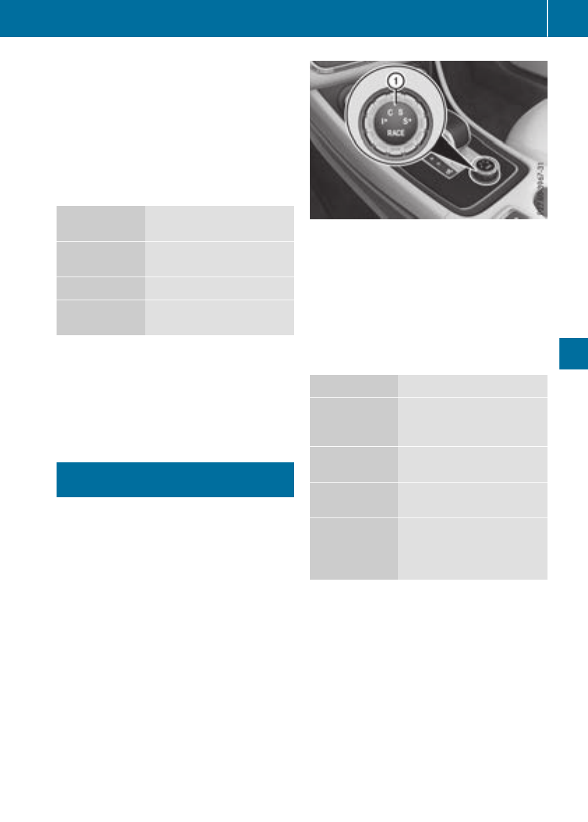
In addition, the current drive program settings
are displayedbrieflyinthe multimedia system
display.
iIn afew countries, the ECO start/stop func-
tion is deactivated at the factory due to the
available fuel grade.Inthis case, the ECO
start/stop function is not available in any
drive program, regardless of the display in the
multimedia system display.
Available drive programs:
CComfort Comfortable and economi-
cal driving characteristics
SSport Sporty driving characteris-
tics
IIndividual Individual settings
EEconomy Particularly economical
driving characteristics
Additional information for drive programs
(Ypage 134).
You can also change gear yourself using the
steering wheel paddle shifters. For further infor-
mation on the manualdrive program
(Ypage 136).
DYNAMIC SELECT controller
(Mercedes-AMG vehicles)
Use the DYNAMIC SELECT controller to change
the drive program. Depending on the drive pro-
gram selected the following vehicle character-
istics willchange:
Rthe drive
Rthe transmission management
RESP®
Rthe suspension (vehicles with AMG adaptive
sport suspension system)
Rthe availability of the ECO start/stop function
Rthe availability of gliding mode
Each time you start the engine with the Smart-
Key or the Start/Stop button, drive program Cis
activated. For further information aboutstarting
the engine, see (Ypage 125).
XTurn DYNAMIC SELECT controller :as many
times as necessary until the desireddrive
program is selected.
The selected drive program appears in the
multifunction display. After five seconds the
display goes out and the status icon of the
selected drive program appears.
The drive program indicator on DYNAMIC
SELECT controller :lights up in red.
Available drive programs:
IIndividual Individual settings
CComfort Comfort-oriented, opti-
mum-economy engine and
transmission settings
SSport Sporty engine and trans-
missionsettings
S+ Sport Plus Particularly sporty trans-
missionsettings
Race Maximumsportiness and
engine and transmission
settings suitable for the
racetrack
Additional information for drive programs
(Ypage 134).
You can also change gear yourself using the
steering wheel paddle shifters. For further infor-
mation on the manualdrive program
(Ypage 136).
DYNAMIC SELECTcontroller(Mercedes-AMG vehicles) 129
Driving and parking
Z
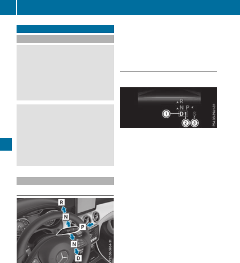
Automatictransmission
Important safety notes
GWARNING
If theenginespeedisabovethe idlingspeed
and you engage transmission position Dor R,
thevehiclecould pull away suddenly. There is
ariskofanaccident.
When engagingtransmission position Dor R,
always firmly depress thebrakepedal and do
notsimultaneously accelerate.
GWARNING
The automatic transmission switches to neu-
tral position Nwhen you switch off theengine.
The vehiclemay rollaway. There is ariskofan
accident.
Afterswitching off theengine, always switch
to parking position P.Preventthe parked vehi-
cle from rollingaway by applyingthe parking
brake.
DIRECT SELECT lever
Overview of transmission positions
jPark position withparking lock
kReverse gear
iNeutral
hDrive
All vehicles (exceptMercedes-AMG vehi-
cles): theDIRECT SELECT lever is on theright of
thesteering column.
Forinformation on theselector lever in
Mercedes-AMGvehicles (Ypage 132).
The DIRECT SELECT lever always returnstoits
original position.The currenttransmission posi-
tion j,k,ior his shown in thetransmis-
sion position display in themultifunction display
(Ypage 130).
Transmission position and drive pro-
gram display
The currenttransmission position and drive pro-
gram appear in themultifunction display.
:Transmission position
;Gear
=Drive program display
The arrows in thetransmission position display
showhow and intowhichtransmission positions
you can shiftusingthe DIRECT SELECT lever.
If thetransmission position display in themul-
tifunction display is notworking,you should pull
away carefully to checkwhether thedesired
transmission position is engaged. Ideally, you
should select transmission position hand
drive program Eor S.
Engaging park position P
!If theenginespeedistoo high or thevehicle
is coasting,donot shiftthe automatic trans-
mission directlyfromhto k,fromkto h
or directlytoj.Otherwise,the automatic
transmission may be damaged.
XPush theDIRECT SELECT lever switch in the
direction of arrow j.
Transmission position display jis shown in
themultifunction display.
When you haveengagedpark position j,make
surethatthe transmission position display
shows jin themultifunction display.
You can only engage park position jwhen the
vehicleisstationary.
Depressing thebrakeand pushing theDIRECT
SELECT lever up or down disengages thepark-
ing lock. The transmission is in neutral i.
130 Automatic transmission
Driving andparking

At transmission fluid temperaturesbelow Ò4‡
(Ò20†),you can onlyshift outofparkposition
jinto another transmission positionwhenthe
engine is running.
In order to shift from park position jdirectly
into kor h:
Rdepress the brake pedaland
Rpush the DIRECT SELECTlever up or down
past the first point of resistance
Engagingpark position Pautomatically
Park position jis automaticallyengaged if:
Ryouswitch off the engine using the SmartKey
and remove the SmartKey
Ryouswitch off the engine using the SmartKey
or using the Start/Stop button and open the
driver's door or front-passenger door
Ryouopenthe driver's door when the vehicleis
stationaryorwhendriving at averylow speed
and the transmission is in position hor k
Undercertain conditions, the automatic trans-
mission shifts to transmission position jauto-
maticallyifthe HOLD functionorDistance Pilot
DISTRONICisactivated.Observethe informa-
tiononthe HOLD function(
Ypage 157)and
Distance PilotDISTRONIC(
Ypage 154).
EngagingreversegearR
!Onlymove the automatic transmission to
kwhen the vehicleisstationary.
XDepressthe brake and keepitpressed.
XPush the DIRECT SELECTlever up past the
first point of resistance.
The ECO start/stopfunctionisnot available
when reversegearisengaged.Further informa-
tiononthe ECO start/stopfunction
(Ypage 126).
Shiftingtoneutral N
GWARNING
If children areleftunsupervised in the vehicle,
they could:
Ropen the doors,thusendangering other
people or roadusers.
Rget outand disrupt traffic.
Roperate the vehicle's equipment.
Additionally, children could set the vehiclein
motion if, for example, they:
Rrelease the parking brake.
Rshifting the automatic transmission outof
park position P
RStartthe engine.
There is ariskofanaccident and injury.
Whenleaving the vehicle, always take the
SmartKeywithyou and lock the vehicle. Never
leavechildren or animals unattended in the
vehicle. Alwayskeepthe SmartKeyout of
reach of children.
XIf the transmission is in position hor k:
push the DIRECT SELECTlever up or down to
the first point of resistance.
XIf the transmission is in position j:depress
the brake pedaland push the DIRECT SELECT
lever up or down to the first point of resist-
ance.
If youswitch the engine off with the transmis-
sion in position kor h,the automatic trans-
mission shifts to iautomatically.
With the SmartKey: if youthen open the driv-
er'sdoororthe front-passenger door or remove
the SmartKeyfrom the ignition, the automatic
transmission shifts to jautomatically.
With the Start/Stopbutton: if youthen open
the driver's door or the front-passenger door,
the automatic transmission shifts to jauto-
matically.
If youwantthe automatic transmission to
remaininneutral i,e.g.w
henhaving the vehi-
cle cleanedinanautomatic car wash with a
towing system:
XVehicles with the Start-Stop button:
remove the Start-Stop button from the igni-
tionlock.
XInsert the SmartKeyinto the ignition lock.
XAllvehicles: switch the ignition on.
XDepressthe brake pedaland keepit
depressed.
XEngage neutral i.
XReleasethe brake pedal.
XReleasethe electricparking brake.
XSwitch off the ignition and leavethe SmartKey
in the ignition lock.
Automatictransmission 131
Driving andparking
Z
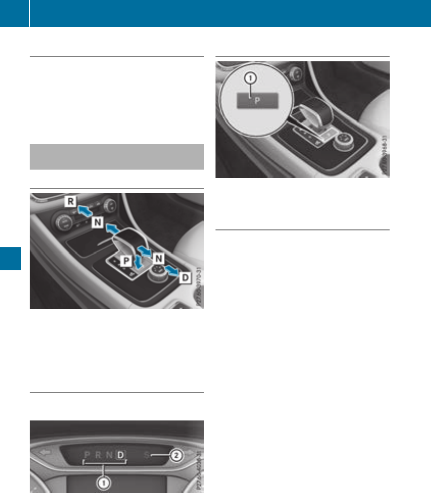
Engaging drive position D
XIf thetransmission is in position kor i:
push theDIRECT SELECT leverdown past the
first pointofresistance.
XIf thetransmission is in position j:depress
thebrakepedal and push theDIRECT SELECT
leverdown past thefirst pointofresistance.
Selector lever (Mercedes-AMG vehi-
cles)
Overview of transmission positions
jPark position with parking lock
kReverse gear
iNeutral
hDrive
Transmission position and drive pro-
gram display
The currenttransmission position and drivepro-
gram appear in themultifunction display.
:Transmission position display
;Drive program display
If thetransmission position display in themul-
tifunctiondisplay is notworking,you shouldpull
away carefully to check whether thedesired
transmission position is engaged. Ideally, you
should selecttransmission position hand
driveprogram Cor S.
Engaging park position P
XWhen thevehicle is stationary, pressbut-
ton :.
Engaging reversegear R
!Only movethe automatic transmission to
kwhen thevehicle is stationary.
XDepressthe brakeand keep it pressed.
XPush theselectorleverforwards past thefirst
pointofresistance.
132 Automatic transmission
Driving and parking

Transmission positions
BPark position
Thisprevents the vehiclefromrolling
away when stopped.
Onlyshift the transmission to posi-
tion jwhen the vehicleisstation-
ary. The parkinglockshouldnot be
used as abrake when parking.
Alwaysapply the electronic parking
brake in additiontothe parkinglock
in order to securethe vehicle.
In the event of amalfunctionofthe
vehicle's electronics,the transmis-
sion maylockinposition j.Have
the vehicleelectronics checked
immediatelyataqualified specialist
workshop.
Park position jis automatically
engaged if:
Ryouswitch off the engine using the
SmartKeyand remove the Smart-
Key
Ryouswitch off the engine using the
SmartKeyorusing the Start/Stop
button and open the driver's door
or front-passengerdoor
Ryouopenthe driver's door when
the vehicleisstationaryorwhen
drivingataverylow speedand the
transmission is in position hor
k
CReversegear
Onlyshift the transmission into posi-
tion kwhen the vehicleisstation-
ary.
ANeutral
Do not shift the transmission to i
whiledriving. The automatic trans-
mission could otherwisebedam-
aged.
No poweristransmitted fromthe
engine to the drive wheels.
Releasing the brakes will allowyou to
movethe vehiclefreely, e.g.topush
it or tow it.
If ESP®is deactivated or faulty: shift
the transmission to position iif the
vehicleisindangerofskidding,e.g.
on icy roads.
If youswitch the engine off with the
transmission in position kor h,
the automatic transmission shifts to
iautomatically.
!Coasting in neutral imay
cause damage to the drive train.
7Drive
The automatic transmission changes
gear automatically. All forward gears
areavailable.
Driving tips
Changinggear
The automatic transmission shifts throughthe
individual gearsautomaticallywhenitisintrans-
mission position h.Thisautomatic gear shift-
ing behaviorisdeterminedby:
Rthe selecteddrive program
Rthe positionofthe accelerator pedal
Rthe roadspeed
Accelerator pedalposition
Your style of drivinginfluences how the auto-
matic transmission shifts gear:
Rlittle throttle:early upshifts
Rmorethrottle:lateupshifts
Automatictransmission 133
Driving andparking
Z
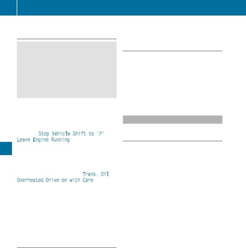
Holding the vehicle stationary on uphill
gradients
GWARNING
If the clutch overheats, the electronic man-
agement system is automatically deactivated.
This interrupts the power transmission. The
vehiclemay,for example, roll backwards on
gradients. There is arisk of an accident.
Never hold the vehiclestationary on uphill
gradients by depressing the accelerator.
The clutch may overheat if you hold the vehicle
stationary on uphill gradients by depressing the
accelerator pedal. If the clutch overheats, a
warning tone sounds.
All vehicles(except Mercedes-AMG vehi-
cles): the Stop Vehicle Shift to 'P'
Leave Engine Running display message
appears in the multifunction display.You will
only be abletocontinue yourjourney once the
clutch has cooleddownand the display mes-
sage in the multifunction display has disap-
peared.
Mercedes-AMG vehicles: the Trans. Oil
Overheated Drive on with Care display
message appears in the multifunction display.
Do not hold the vehiclestationary on uphill gra-
dients by depressing the accelerator pedal.
Instead, only ever hold the vehiclestationary on
uphill gradients by:
Rdepressing the brake pedal
Ractivating the HOLD function
Rengaging the electric parking brake
Kickdown
Use kickdown for maximumacceleration.
XDepress the accelerator pedalbeyond the
pressure point.
The automatic transmission shifts to alower
geardepending on the engine speed.
XEase off the accelerator pedalonce the
desired speedisreached.
The automatic transmission shifts back up.
Mercedes-AMG vehicles: it is only possible to
use kickdown in the automatic drive program
and the temporary manualdrive program M.
When manualdrive program Mis permanently
activated, kickdown is not possible.
For further information on kickdown in manual
drive program M(Ypage138).
Rocking the vehicle free
Shifting back and forth between transmission
positions hand kcan help to free up the
vehicleifitgets stuck in mud or snow. The vehi-
cle's engine management system limits the
speedtoamaximumof5mph (9 km/h) when
shifting back and forth. To shift repeatedly
between transmission positions hand k,
move the DIRECT SELECT leverupand down
pastthe point of resistance.
Drive programs
Allvehicles(except Mercedes-AMG
vehicles)
Drive program C(Comfort)
Drive program Cis characterized by the follow-
ing:
Rthe vehicledelivers comfortable, economical
handling characteristics.
Rthe vehiclepulls awaymore gently in forward
and reverse gears, unless the accelerator
pedalisdepressed fully.
Rthe vehiclehas improved driving stability,for
exampleonslippery road surfaces.
Roptimalfuel consumption resulting from the
automatic transmission shifting up sooner.
The vehicleisdriveninthe low engine speed
range and the wheels are less likelytospin.
Drive program S(Sport)
Drive program Sis characterized by the follow-
ing:
Rsporty engine settings.
Rthe automatic transmission shifts up later.
The fuel consumption possibly being higher
as aresult of the later automatic transmission
shift points.
134 Automatic transmission
Driving and parking

Drive program I(Individual)
In drive programIthefollowing properties of the
drive programcan be selected:
Rthedrive (engineand transmissionmanage-
ment)
Rthesuspension(vehicles withdampingsys-
temorAMG adaptive sport suspensionsys-
tem)
Rthesteering
Rtheavailabilityofthe ECO start/stopfunction
Rtheclimatecontrol
Information about configuringdrive programI
withthe multimedia system can be found in the
Digital Operator'sManual.
iTo permanentlyselect thegearsindrive
programIusingthe steeringwheelpaddle
shifters,select theM(manual) setting forthe
drive.
Drive program E(Economy)
Drive programEis characterized by thefollow-
ing:
Rcomfort-oriented enginesettings.
Roptimal fuelconsumption resultingfromthe
automatictransmissionshiftingupsooner.
Rthevehiclepulls away moregentlyinforward
and reversegears, unless theaccelerator
pedalisdepressed fully.
Rthevehiclehas improved drivingstability, for
exampleonslipperyroadsurfaces.
Rtheautomatictransmissionshiftingup
sooner. This resultsinthe vehiclebeingdriven
at lowerenginespeeds and thew
heels being
less likely to spin.
Rglidingmodeisactivated automatically when
engine-internal conditionsare fulfilled and
theacceleratorisnot depressed. At thesame
time thetransmission’s clutchopens and the
vehiclerolls freely usingits kineticenergy. As
aresult great distances can be completed
without theenginebrakeand fuelconsump-
tion reduced.
iThe availabilityofglidingmodedependson
various factors,includingthe following:
Rtheengineand transmissiontemperature
Rthedownhill gradient
Rthevehiclespeed
Rperformingregular adaptation functions
Whenyou depress thebrakepedal, gliding
modeisdeactivated, dependingonpedal
pressure.
Whenyou activatecruise control or Distance
PilotDISTRONIC, glidingmodeisnot availa-
ble.
Mercedes-AMG vehicles
Drive program I(Individual)
In drive programIthefollowing properties of the
drive programcan be selected:
Rthedrive (enginemanagement)
Rthetransmissionmanagement
Rthesuspension(vehicles withAMG adaptive
sport suspensionsystem)
RESP®
Information about configuringdrive programI
withthe multimedia system can be found in the
Digital Operator'sManual.
Drive program C(Comfort)
Drive programCis characterized by thefollow-
ing:
Rthevehicledeliverscomfortable, economical
handlingcharacteristics.
Rthevehiclepulls away moregentlyinforward
and reversegears, unless theaccelerator
pedalisdepressed fully.
Rthevehiclehas improved drivingstability, for
exampleonslipperyroadsurfaces.
Roptimal fuelconsumption resultingfromthe
automatictransmissionshiftingupsooner.
The vehicleisdriven in thelow enginespeed
range and thewheels are less likely to spin.
Rglidingmodeisavailable.
RtheECO start/stopfunction is available.
Drive program S(Sport)
Drive programSis characterized by thefollow-
ing:
Rthevehicleexhibits sportydrivingcharacter-
istics.
Rtheautomatictransmissionshiftsuplater.
The fuelconsumption possiblybeinghigher
as aresult of thelater automatictransmission
shift points.
Rthesuspensionexhibits stiff springingand
dampingsettings(vehicles withAIR adaptive
sport suspensionsystem).
Automatic transmission 135
Driving andparking
Z
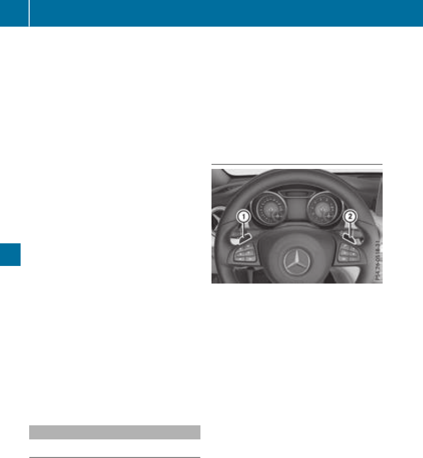
Rgliding mode is not available.
Rthe ECO start/stop function is not available.
Drive program S+ (Sport Plus)
Drive program S+ is characterized by the fol-
lowing:
Rthe vehicle exhibits particularly sporty driving
characteristics.
Rthe automatic transmission shifts up later.
Rthe fuel consumption possibly being higher as
aresult of the later automatic transmission
shift points.
Rthe suspension exhibits particularly stiff
springing and damping settings (vehicles with
AMG adaptive sport suspension system).
Rgliding mode is not available.
Rthe ECO start/stop function is not available.
Drive program RACE (vehicleswith AMG
adaptive sport suspension system)
The RACE drive program is characterized by the
following:
Rthe vehicle exhibits driving characteristics
suitable for the racetrack.
Rall vehicle systems are set for maximum
sportiness.
Rthe automatic transmission shifts up later.
Rthe fuel consumption possibly being higher as
aresult of the later automatic transmission
shift points.
Rthe suspension exhibits particularly hard
springing and damping settings.
Rgliding mode is not available.
Rthe ECO start/stop function is not available.
Manual gear shifting
General notes
You can change gear yourself using the steering
wheel paddle shifters. The transmission must be
in position hto do this.
Depending on which steering wheel paddle
shifter is pulled, the automatic transmission
immediately shifts into the next gear down or
up, if permitted.
Mercedes-AMG vehicles: to use manual shift-
ing, you have two options:
Rtemporary setting
Rpermanent setting
If you activate manual gearshifting, the multi-
function display will show the current gear
instead of transmission position h.
If manual gearshifting is deactivated, the gears
will be selected automatically.
Temporarysetting
XTo activate: shift the DIRECT SELECT lever to
position h.
XPull steering wheel paddle shifter :or ;.
Temporary setting will be active for acertain
amount of time. Under certain conditions the
minimum amount of time is extended, e.g. in the
case of lateral acceleration, during an overrun
phase or when driving on steep terrain.
XTo deactivate: pull steering wheel paddle
shifter ;and hold it in place.
or
XUse the DIRECT SELECT lever to switch the
transmission position.
or
XAll vehicles (except Mercedes-AMG vehicles):
use the DYNAMICSELECT button to change
the drive program.
Mercedes-AMG vehicles: use the DYNAMIC
SELECT controller to change the drive pro-
gram.
136 Automatic transmission
Driving and parking
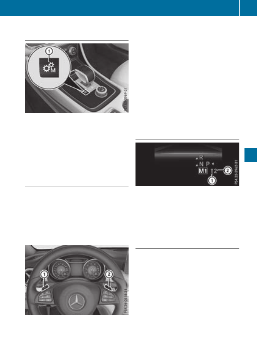
Permanent setting (Mercedes-AMG
vehicles)
XTo activate: shift the selector lever to h.
XPress button :.
XTo deactivate: press button :.
or
XIf position D(automatic transmission) is
selected for the transmission in drive pro-
gram I:shift to drive program Iwith the
DYNAMICSELECT controller.
Shifting gears
!Mercedes-AMG vehicles: the automatic
transmission does not shift up automatically
even when the engine limiting speed for the
current gear is reached. When the engine lim-
iting speed is reached, the fuel supply is cut to
prevent the engine from overrevving. Always
make sure that the engine speed does not
reach the red area of the tachometer. There is
otherwise arisk of engine damage.
XTo shift up: pull steering wheel paddle
shifter ;.
The automatic transmission shifts up to the
next gear.
All vehicles (except Mercedes-AMG vehi-
cles): if the maximum engine speed on the
currently engaged gear is reached and you
continue to accelerate, the automatic trans-
mission automatically shifts up in order to
prevent engine damage.
XTo shift down: pull steering wheel paddle
shifter :.
The automatic transmission shifts down to
the next gear.
Automatic down shifting occurs when coast-
ing.
If the engine exceeds the maximum engine
speed when shifting down, the automatic
transmission protectsagainst engine damage
by not shifting down.
Shift recommendation
The gearshift recommendations assist you in
adopting an economical driving style. The rec-
ommended gear is shown in the multifunction
display.
XShift to recommended gear ;according to
gearshift recommendation :when shown in
the multifunction display.
Upshifting (Mercedes-AMG vehicles)
!In manual mode, the automatic transmis-
sion does not shift up automatically even
when the engine limiting speed for the current
gear is reached. When the engine limiting
speed is reached, the fuel supply is cut to
prevent the engine from overrevving. Always
make sure that the engine speed does not
reach the red area of the tachometer. There is
otherwise arisk of engine damage.
Automatic transmission 137
Driving and parking
Z
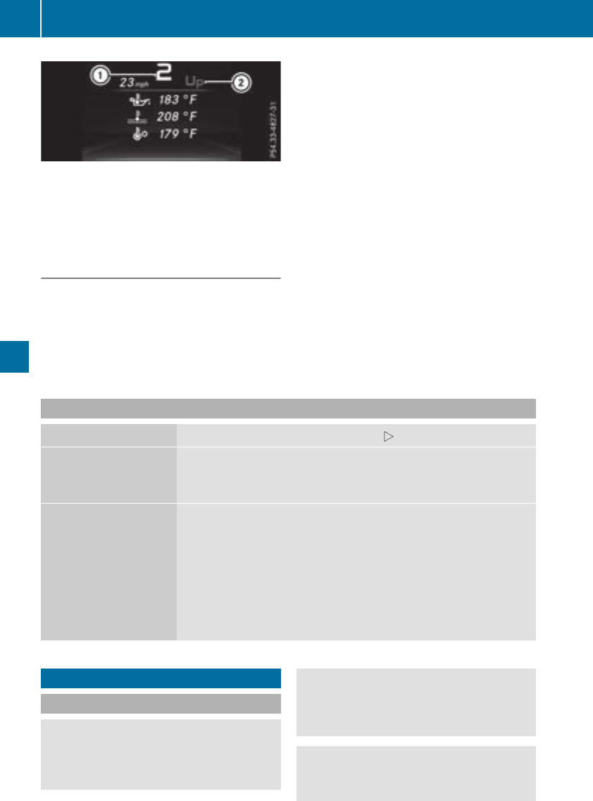
Beforethe engine speed reaches the red area,
an upshift indicator will be showninthe multi-
function display.
XShift to recommendedgear :whenmes-
sage ;is showninthe multifunction display.
Kickdown
XFor maximum acceleration, depress the
accelerator pedal beyond the pressure point.
The automatic transmission shifts to alower
geardepending on the engine speed.
XShift back up once the desiredspeed is
reached.
During kickdown, youcannot shift gears using
the steering wheel paddleshifters.
If youapply fullthrottle,the automatic trans-
missionshifts up to the next gearwhenthe
maximum engine speed is reached.Thispre-
vents the engine from overrevving.
Mercedes-AMG vehicles: it is only possible to
use kickdown in temporary manual drive pro-
gram M.Whenmanual drive program Mis per-
manently activated, kickdown is not possible.
Problems with the transmission
Problem Possible causes/consequencesand MSolutions
The transmission has
problemsshifting gear.
The transmission is losing oil.
XHave the transmission checkedataqualified specialist workshop
immediately.
The acceleration ability
is deteriorating.
The transmission no lon-
ger shifts into allofthe
gears.
Reversegearcan no lon-
ger be engaged.
The transmission is in emergency mode.
XStop the vehicle.
XShift the transmission to position j.
XSwitch off the engine.
XWait at least ten seconds before restarting the engine.
XShift the transmission to position h.
XHave the transmission checkedataqualified specialist workshop
immediately.
Refueling
Important safety notes
GWARNING
Fuelishighly flammable. If youhandle fuel
incorrectly,there is ariskoffire and explo-
sion.
You mustavoid fire,openflames, creating
sparks and smoking. Switch off the engine
and,ifapplicable, the auxiliary heating before
refueling.
GWARNING
Fuelispoisonousand hazardoustohealth.
There is arisk of injury.
138 Refueling
Drivingand parking
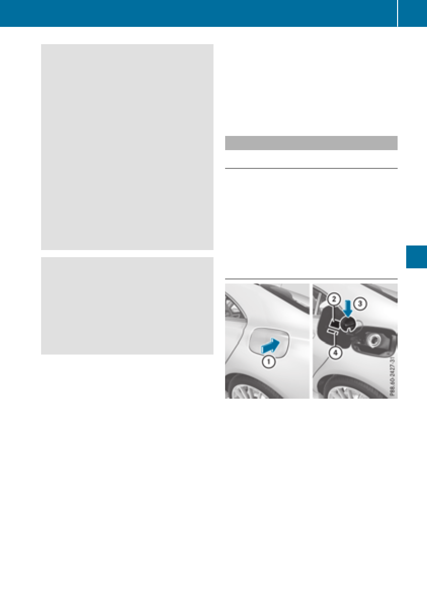
You must make sure that fuel does not come
intocontactwith your skin,eyes or clothing
and that it is not swallowed. Do not inhale fuel
vapors.Keep fuel away from children.
If you or others comeintocontactwith fuel,
observethe following:
RWash away fuel from skin immediately
using soap and water.
RIf fuel comes intocontactwith your eyes,
immediately rinse themthoroughly with
clean water. Seek medical assistancewith-
out delay.
RIf fuel is swallowed, seek medical assis-
tance without delay. Do not inducevomit-
ing.
RImmediately change out of clothing which
has comeintocontactwith fuel.
GWARNING
Electrostatic buildup can create sparksand
ignitefuel vapors.There is arisk of fire and
explosion.
Always touchthe vehicle body beforeopening
the fuel filler flap or touching the fuel pump
nozzle. Anyexisting electrostatic buildup is
thereby discharged.
!Do not use diesel to refuel vehicles with a
gasolineengine. Do not switchonthe ignition
if you accidentally refuel with the wrongfuel.
Otherwise, the fuel will enter the fuel system.
Even small amountsofthe wrongfuel could
result in damage to the fuel systemand the
engine. Notify aqualified specialistworkshop
and have the fuel tankand fuel lines drained
completely.
!Overfilling the fuel tankcould damage the
fuel system.
!Take care not to spill any fuel on painted
surfaces. You could otherwise damage the
paintwork.
!Use afilter when adding fuel from afuel can.
The fuel lines and/or the fuel injection system
could otherwise be blocked by particles from
the fuel can.
Do not get intothe vehicle again during the refu-
eling process. Otherwise, electrostatic charge
could build up again.
If you overfill the fuel tank, fuel could spray out
when the fuel pump nozzle is removed.
For further information on fuel and fuel quality
(Ypage 315).
Refueling
Generalinformation
Pay attention to the importantsafetynotes
(Ypage 138).
The fuel filler flap is unlocked/locked automat-
ically when you unlock/lock the vehicle with the
SmartKey.
The position of the fuel filler cap is displayed
æin the instrumentcluster. The arrow on the
filling pump indicates the side of the vehicle.
Opening thefuel filler flap
:To open the fuel filler flap
;Tire pressure table
=To insertthe fuel filler cap
?Instruction label for fuel type to be refueled
XSwitch off the engine.
XRemove the SmartKey from the ignition lock.
or, in vehicles with KEYLESS-GO start-function
or KEYLESS‑GO
XOpen the driver's door.
The vehicle electronics are now in position
g.This is the same as the SmartKey being
removed from the ignition.
XPress the fuel filler flap in the direction of
arrow :.
The fuel filler flap swings up.
Refueling 139
Driving and parking
Z

XTurn the fuel filler cap counterclockwise and
remove it.
XInsert the fuel filler cap into the holder on the
inside of fuel filler flap =.
XCompletely insert the filler neck of the fuel
pump nozzle into the tank,hook in place and
refuel.
XOnly fill the tank until the pump nozzle
switches off.
Do not add any more fuel after the pump stops
filling for the first time. Otherwise, fuel may leak
out.
Closing the fuel filler flap
XReplace the cap on the filler neck and turn
clockwise until it engages audibly.
XClose the fuel filler flap.
Close the fuel filler flap before lockingthe vehi-
cle.
If you are driving with the fuel filler cap open, the
8reserve fuel warning lamp flashes. Ames-
sage appears in the multifunction display
(Ypage 206).
In addition, the ;Check Engine warning
lamp may light up (Ypage 224).
For further information on warning and indicator
lamps in the instrument cluster, see
(Ypage 224).
Problems with fuel and the fuel tank
Problem Possible causes/consequences and MSolutions
Fuel is leaking from the
vehicle.
The fuel line or the fuel tank is faulty.
GWARNING
Risk of explosion or fire.
XApply the electric parking brake.
XSwitch off the engine.
XRemove the SmartKey from the ignition lock.
or, in vehicles with KEYLESS-GO start-function or KEYLESS‑GO
XOpen the driver's door.
The vehicle electronics are now in position g.This is the same as
the SmartKey being removed from the ignition.
XDo not restart the engine under any circumstances.
XConsult aqualified specialist workshop.
The fuel filler flap cannot
be opened.
The fuel filler flap is not unlocked.
XUnlock the vehicle (Ypage 70).
The SmartKey battery is discharged or nearly discharged.
XUnlock the vehicle using the mechanical key (Ypage 77).
The fuel filler flap is unlocked, but the opening mechanism is jammed.
XConsult aqualified specialist workshop.
140 Refueling
Driving and parking
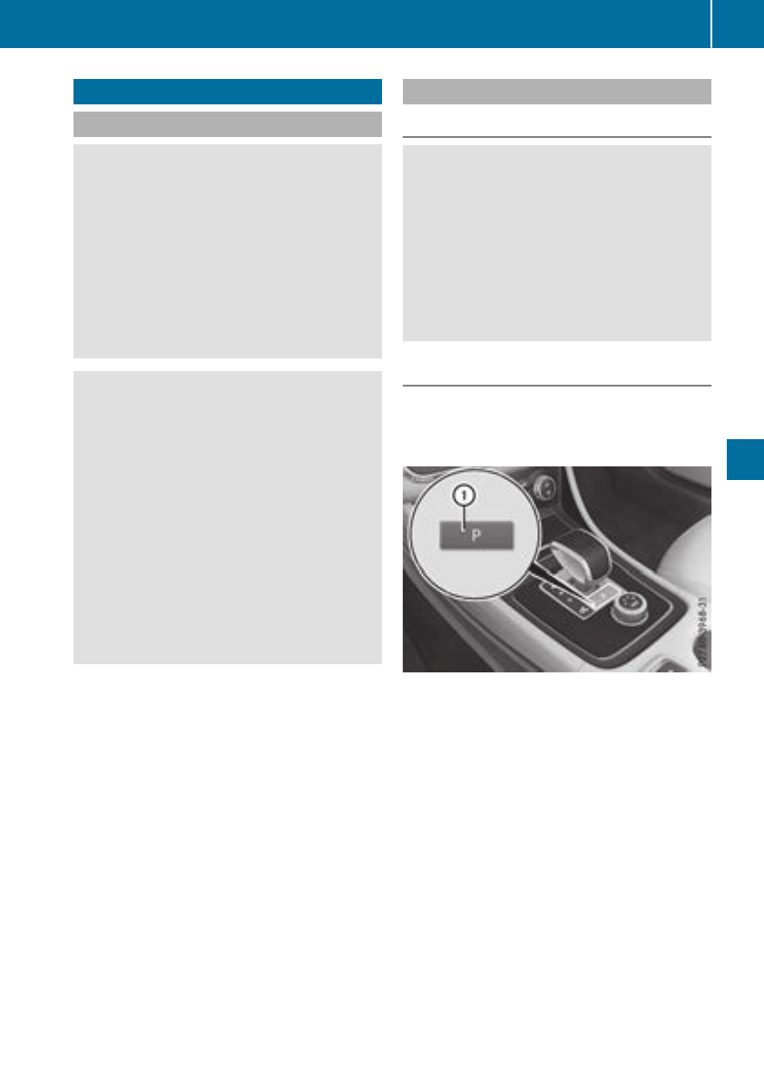
Parking
Important safety notes
GWARNING
Flammable material such as leaves, grass or
twigs may ignite if they come into contact with
hot parts of the exhaust system or exhaust
gas flow. There is arisk of fire.
Park the vehicle so that no flammable mate-
rials come into contact with parts of the vehi-
cle which are hot. Take particular care not to
park on dry grassland or harvested grain
fields.
GWARNING
If you leave children unsupervised in the vehi-
cle, they could set it in motion by, for example:
Rrelease the parking brake.
Rshift the automatic transmission out of the
parking position P.
Rstart the engine.
In addition, they may operate vehicle equip-
ment and become trapped. There is arisk of
an accident and injury.
When leaving the vehicle, always take the
SmartKey with you and lock the vehicle. Never
leave children unsupervised in the vehicle.
!Always secure the vehicle correctly against
rolling away.Otherwise, the vehicle or its driv-
etrain could be damaged.
To ensure that the vehicle is secured against
rolling away unintentionally:
Rthe electric parking brake must be applied.
Rthe transmission must be in position jand
the transmission position display must show
jin the multifunction display.
Rthe SmartKey must be removed from the igni-
tion lock.
Ron uphill or downhill gradients, the front
wheels must be turned towards the curb.
Switching off the engine
Important safety notes
GWARNING
The automatic transmission switches to neu-
tral position Nwhen you switch off the engine.
The vehicle may roll away.There is arisk of an
accident.
After switching off the engine, always switch
to parking position P.Prevent the parked vehi-
cle from rolling away by applying the parking
brake.
Automatic transmission
XApply the electric parking brake.
XAll vehicles (except Mercedes-AMG vehi-
cles): shift the transmission to position j.
XMercedes-AMG vehicles: press button :.
XWith the SmartKey : turn the SmartKey to
position gin the ignition lock and remove it.
The immobilizer is activated.
XWith the Start/Stop button: press the
Start/Stop button (Ypage 122).
The engine stops and all the indicator lamps in
the instrumentcluster go out.
If the driver's door is closed, this is the same
as key position 1.Ifthe driver's door is open,
this is the same as key position g,i.e. the
SmartKey having been removed.
If you switch the engine off with the transmis-
sion in position kor h,the automatic trans-
mission shifts to iautomatically.
With the SmartKey: if you then open the driv-
er's door or the front-passenger door or remove
Parking 141
Driving and parking
Z
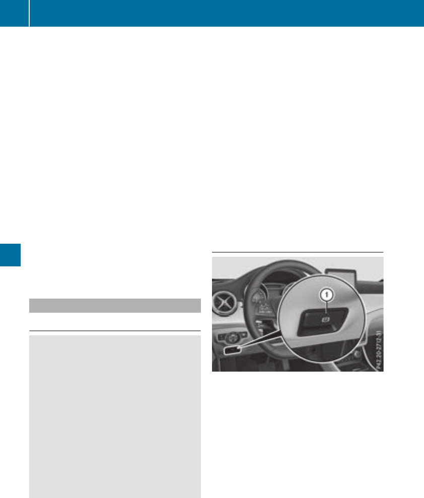
the SmartKeyfromthe ignition, the automatic
transmission shifts to jautomatically.
With the Start/Stopbutton: if youthenopen
the driver's door or the front-passengerdoor,
the automatic transmission shifts to jauto-
matically.
If youwantthe automatic transmission to
remaininneutral i,e.g.whenhavingthe vehi-
cle cleanedinanautomatic car wash with a
towing system:
XVehicleswiththe Start-Stopbutton:
remove the Start-Stop button fromthe igni-
tionlock.
XInsert the SmartKeyinto the ignition lock.
XAllvehicles: switch the ignition on.
XDepressthe brake pedaland keepit
depressed.
XEngage neutral i.
XReleasethe brake pedal.
XReleasethe electricparking brake.
XSwitch off the ignition and leavethe SmartKey
in the ignition lock.
Electric parking brake
General notes
GWARNING
If youleave children unsupervised in the vehi-
cle,theycould setitinmotion by,for example:
Rrelease the parking brake.
Rshift the automatic transmission outofthe
parking position P.
Rstart the engine.
In addition, theymay operate vehicleequip-
ment and become trapped.There is ariskof
an accident and injury.
When leaving the vehicle, always take the
SmartKeywithyou and lock the vehicle. Never
leavechildren unsupervised in the vehicle.
The functionofthe electric parking brake is
dependent on the on-board voltage. If the on-
boardvoltageislow or there is amalfunctionin
the system, it maynot be possibletoapply the
releasedparking brake.
XIf thisisthe case, onlyparkthe vehicleon
level ground and secureittoprevent it rolling
away.
XShift the automatic transmission to position
j.
It maynot be possibletorelease an applied
parking brake if the on-board voltageislow or
there is amalfunctioninthe system. Contact a
qualified specialistworkshop.
The electric parking brake performs afunction
testatregular intervals whilethe engine is
switched off.The soundsthatcan be heardwhile
thisisoccurring arenormal.
Applyingorreleasing manually
XTo engage: push handle :.
When the electric parking brake is applied,
the red F(USA only) or !(Canada
only) indicator lamp lights up in the instru-
ment cluster.
Theelectric parking brake can also be applied
when the SmartKeyisremoved.
XTo release: pull handle :.
The red F(USA only) or !(Canada
only) indicator lamp in the instrument cluster
goes out.
Theelectric parking brake can onlybe
released:
Rif the SmartKeyisinposition 1or 2in
the ignition lock (Ypage 122)or
Rif the ignition wasswitched on using the
Start/Stop button
142 Parking
Driving andparking
Applyingautomatically
The electric parking brakeisautomatically
appliedwhen thetransmission is in position j
and:
Rtheengineisswitched off or
Rthedriver is notwearing aseat belt and the
driver's door is opened
To preventthe electric parking brakefrombeing
automatically applied, pull handle :.
The electric parking brakeisalso engagedauto-
matically if:
RDistancePilotDISTRONICbringsthe vehicle
to astandstill or
RtheHOLDfunction is keepingthe vehiclesta-
tionary
RParking Pilotiskeepingthe vehiclestationary
In addition,atleast oneofthe followingcondi-
tionsmustbefulfilled:
Rtheengineisswitched off
Rthedriver is notwearing aseat belt and the
driver's door is opened
Rthere is asystem malfunction
Rthepowersupply is insufficient
Rthevehicleisstationary for alengthy period
The red F(USAonly) or !(Canada only)
indicator lamp in theinstrumentclustergoes
out.
The electric parking brakeisnot automatically
engagedifthe engineisswitched off by theECO
start/stopfunction.
Releasing automatically
Your vehicle's electric parking brakeisauto-
matically releasedifall of thefollowingcondi-
tionsare met:
Rtheengineisrunning
Rthetransmission is in position hor kand
you depress theacceleratorpedal or shift
from position jto hor k
Rtheseat belt has been fastened
if thetransmission is in position k,the trunk lid
mustbeclosed.
If your seat belt is notfastened, thefollowing
conditionsmustbefulfilled to automatically
release theelectric parking brake:
Rthedriver's door is closed
Ryou are shifting from transmission position
jor havepreviously driven at speeds
greaterthan2mph (3 km/h)
Ensure thatyou do not depress the accelerator
pedalunintentionally. Otherwise, the parking
brake will be released and the vehiclewillstart
to move.
Emergencybraking
The vehiclecan also be braked duringanemer-
gency by using the electricparkingbrake.
XWhiledriving, push handle :of the electric
parkingbrake (Ypage 142).
The vehicleisbraked as long as youkeep
handle :of the electricparkingbrake
pressed. The longerthe electricparkingbrake
handle :is depressed, the greaterthe brak-
ing force.
During braking:
Rawarning tone sounds
Rthe ReleaseParkingBrake message
appears
Rthe red F(USA only) or !(Canada
only) indicator lamp in the instrument cluster
flashes
When the vehiclehas been braked to astand-
still,the electricparkingbrake is engaged.
Parking the vehicle foralongperiod
If youleave the vehicleparked for longerthan
fourweeks,the battery maybedamaged by
exhaustive discharging.
If youleave the vehicleparked for longerthansix
weeks,the vehiclemay sufferdamageasa
resultoflackofuse.
XVisitaqualified specialistworkshop and seek
advice.
iYoucan obtaininformationabout trickle
chargers fromaqualified specialistwork-
shop.
Parking 143
Driving andparking
Z

Drivingtips
General notes
Important safetynotes
GWARNING
If you switch offthe ignition whiledriving,
safety-relevant functionsare only available
withlimitations, or notatall. Thiscould affect,
forexample, thepowersteeringand thebrake
boostingeffect. You will require considerably
more effort to steer and brake.There is arisk
of an accident.
Do notswitch offthe ignition whiledriving.
GWARNING
If you operatemobile communication equip-
mentwhen driving, you may be distracted
from thetraffic situation.You could also lose
controlofthe vehicle. There is ariskofan
accident.
Only operatethisequipmentwhen thevehicle
is stationary.
Observethe legalrequirements forthe country
in whichyou are driving. Some jurisdictionspro-
hibitthe driver from usingamobile phone while
drivingavehicle.
If you makeacallwhiledriving, always use
hands-free mode. Only operatethe telephone
when thetraffic situation permits. If you are
unsure,pull over to asafelocation and stop
beforeoperatingthe telephone.
Bear in mindthatataspeed of only 30 mph
(approximately 50 km/h), thevehicle coversa
distanceof44ft(approximately 14 m) per sec-
ond.
Drive sensibly –save fuel
Observe the following tips to save fuel:
RThe tires should always be inflated to the rec-
ommended tire pressure.
RRemove unnecessary loads.
RRemove roof rackswhen they are not needed.
RWarm up the engineatlow enginespeeds.
RAvoid frequentacceleration or braking.
RHave all maintenancework carried out as
indicated by the serviceintervals in the Main-
tenance Booklet or by the serviceinterval dis-
play.
Fuel consumption also increases when driving in
cold weather, in stop-start traffic and in hilly ter-
rain.
Drinking and driving
GWARNING
Drinkingand driving and/or takingdrugs and
driving are very dangerous combinations.
Even asmall amount of alcohol or drugs can
affect your reflexes, perceptions and judg-
ment.
The possibility of aserious or even fatal acci-
dent is greatly increased when you drink or
take drugs and drive.
Do not drink or take drugs and drive or allow
anyone to drive who has been drinking or tak-
ing drugs.
Emission control
GWARNING
Combustion engines emit poisonous exhaust
gases such as carbon monoxide. Inhaling
these exhaust gases leads to poisoning. There
is arisk of fatal injury. Thereforenever leave
the enginerunning in enclosed spaces with-
out sufficientventilation.
Certain enginesystems are designed to keep
the level of poisonous componentsinexhaust
fumes within legal limits.
These systems only work at peak efficiency if
they are serviced exactly in accordance with the
manufacturer's specifications.Always have
work on the enginecarried out at aqualified
specialist workshop. Mercedes-Benz recom-
mends that you use an authorized Mercedes-
BenzCenter for this purpose. In particular, work
relevant to safety or on safety-related systems
must be carried out at aqualified specialist
workshop.
The enginesettings must not be changed under
any circumstances. Furthermore, all specific
servicework must be carried out at regular
intervals and in accordance with the Mercedes-
Benzservicerequirements. Details can be found
in the Maintenance Booklet.
144 Driving tips
Driving and parking
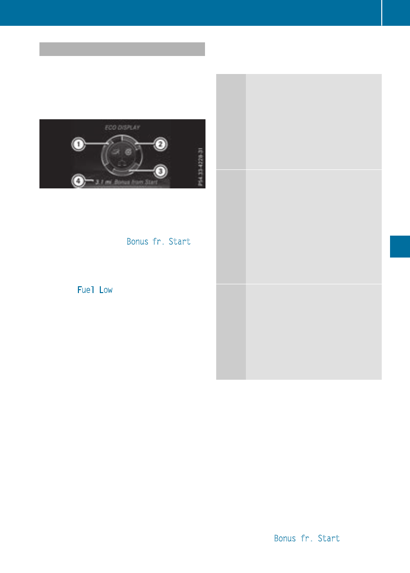
ECO display
The ECO display showsyou how economical
your driving style is. The ECO display assists you
in achievingthe mosteconomical driving style
for theselectedsettings and prevailingcondi-
tions.Your driving style can significantly influ-
encethe vehicle's consumption.
:Acceleration
;Coasting
=Constant
?Additional range achieved
Range ?is shownunder Bonus fr. Start and
represents theadditional range achievedsince
thebeginningofthe journey as aresult of an
adapted driving style.
If thefuel levelhas dropped intothe reserve
range, the FuelLow message is showninthe
multifunction display instead of range ?.The
8warning lamp in theinstrumentcluster
also lightsup(
Ypage 224).
The ECO display consistsofthree sections,with
an inner and outer area. The sections corre-
spondtothe followingthree categories:
:Acceleration (evaluationofthe
accelerationprocesses):
Rtheouter area fills up and theinner
area lightsupgreen: moderate
acceleration, especiallyathigher
speeds
Rtheouter area empties and the
inner area is gray: sporty acceler-
ation
;Coasting (evaluationofall decelera-
tionprocesses):
Rtheouter area fills up and theinner
area lightsupgreen: anticipatory
driving,keepingyour distanceand
early release of theaccelerator.
The vehicle can coastwithout use
of thebrakes.
Rtheouter area empties and the
inner area is gray: frequentheavy
braking
=Constant (continuous evaluation
overthe entire journey):
Rtheouter area fills up and theinner
area lightsupgreen: constant
speedand avoidanceofunneces-
sary accelerationand deceleration
Rtheouter area empties and the
inner area is gray: fluctuationsin
speed
The three inner areas display thecurrentdriving
style and light up green as aresult of aparticu-
larly economical driving style. Dependingonthe
driving situation, up to two areas may light up
simultaneously.
At thebeginningofthe journey, thethree outer
areas are emptyand fill up as aresult of eco-
nomical driving.Ahigher levelindicates amore
economical driving style. If thethree outer areas
are completely filledatthe same time, thedriver
has adopted themosteconomical driving style
for theselectedsettings and prevailingcondi-
tions.The ECO display border lightsup.
The ECO display does notindicatethe actual fuel
consumption. The additionally achievedrange
displayed under Bonus fr. Start does not
indicateafixed consumptionreduction.
Driving tips 145
Driving and parking
Z

In addition to driving style, the actual consump-
tion is affected by other factors, such as:
RLoad
RTire pressure
RCold start
RChoice of route
RActive electrical consumers
These factors are not includedinthe ECO dis-
play.
An economical driving style specially requires
driving at moderate engine speeds.
Achieving ahigher valueinthe categories
"Acceleration" and "Constant":
Robserve the gearshift recommendations.
Rdrive the vehicle in drive program Cor E
(vehicles with aDYNAMIC SELECT button).
On long journeys at aconstant speed,e.g. on the
highway, only the outer area for "constant" will
change.
The ECO display summarizes the driving style
from the start of the journey to its completion.
Therefore, there are more marked changes in
the outer areasatthe start of ajourney. On lon-
ger journeys, there are fewer changes. For more
marked changes, perform amanualrest
(Ypage 181).
For more information on the ECO display, see
(Ypage 180).
Braking
Important safety notes
GWARNING
If you shift down on aslippery road surface in
an attempt to increase the engine's braking
effect, the drive wheelscould lose their grip.
There is an increased danger of skidding and
accidents.
Do not shift down for additional engine brak-
ing on aslippery road surface.
Downhill gradients
!On long and steep gradients, you must
reduce the load on the brakes by shifting to a
lowergear in good time. This allows you to
take advantage of engine braking. For this you
must first activate manualgearshifting. This
helps you to avoid overheating the brakes and
wearing them out excessively.
When you take advantage of engine braking, it
is possible that adrive wheel willnot rotate for
some time, e.g. on aslippery road surface.
This could cause damage to the drive train.
This type of damage is not covered by the
Mercedes-Benz warranty.
Briefly depressing the accelerator pedalon
downhill gradients whilethe manualdrive pro-
gram Mis temporarilyactivated: the automatic
transmission may switch to the last active auto-
matic drive program Eor S.The automatic trans-
missionmay shift to ahighergear. This can
reduce the engine's braking effect.
Heavy and light loads
GWARNING
If you rest yourfoot on the brake pedalwhile
driving, the braking system can overheat. This
increases the stopping distance and can even
cause the braking system to fail.There is a
risk of an accident.
Never use the brake pedalasafootrest. Never
depressthe brake pedaland the accelerator
pedalatthe same time.
!Depressing the brake pedalconstantly
results in excessive and premature wearto
the brake pads.
If the brakes have been subjected to aheavy
load,donot stop the vehicle immediately.Drive
on for ashort while. This allows the airflow to
cool the brakes more quickly.
Wet roads
If you have driven for along time in heavy rain
withoutbraking, there may be adelayed reac-
tion from the brakes when braking for the first
time. This may also occur after the vehicle has
been washed or driven through deep water.
You have to depressthe brake pedalmore
firmly.Maintainagreater distance from the
vehicle in front.
After driving on awet road or having the vehicle
washed, brake firmly whilepaying attention to
the traffic conditions. This willwarm up the
brake discs, thereby drying them more quickly
and protecting them against corrosion.
146 Driving tips
Driving and parking
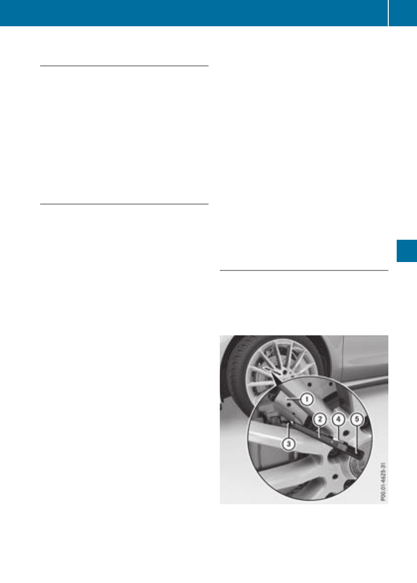
Limited braking performance on salt-
treated roads
If you driveonsalted roads,alayer of salt resi-
due may formonthe brakediscsand brake
pads. This can result in asignificantly longer
braking distance.
RIn ordertoprevent any salt build-up, apply the
brakes occasionally while paying attention to
thetraffic conditions.
RCarefully depress thebrakepedal and the
beginningand end of ajourney.
RMaintain agreater distancetothe vehicle
ahead.
Servicing thebrakes
!The brakefluid level may be toolow, if:
Rif thered brakewarning lamp lightsupin
theinstrumentcluster and
Ryou hear awarning tone while theengine is
running
Observe additional warning messages in the
multifunction display.
The brakefluid level may be toolow due to
brakepad wear or leaking brakelines.
Havethe brakesystem checked immediately.
Consult aqualifiedspecialist workshop to
arrange this.
!Afunction or performancetestshould only
be carried out on a2-axle dynamometer. If
you wish to operate thevehicle on such a
dynamometer, please consult aqualifiedspe-
cialistworkshop in advance. You could oth-
erwisedamage thedrivetrain or thebrake
system.
!As theESP®system operates automatically,
theengine and theignitionmust be switched
off (theSmartKey must be in position uor
1in theignitionlock), if theelectric parking
brakeistested on abraking dynamometer
(maximum 10 seconds).
Brakingtriggered automatically by ESP®may
cause severe damage to thebrakesystem.
All checksand maintenancework on thebrake
system must be carried out at aqualifiedspe-
cialistworkshop.
Havebrakepads installedand brakefluid
replaced at aqualifiedspecialist workshop.
If thebrakesystem has onlybeen subject to
moderateloads, you should testthe functional-
ity of your brakes at regular intervals.
You can findadescription of Brake Assist (BAS)
on (Ypage 61).
Mercedes-Benzrecommendsthatyou onlyhave
brakepads/linings installedonyour vehicle
whichhave been approved for Mercedes-Benz
vehiclesorwhichcorrespondtoanequivalent
qualitystandard. Brake pads/linings whichhave
not been approved for Mercedes-Benzvehicles
or whichare not of an equivalent qualitycould
affect your vehicle's operatingsafety.
Mercedes-Benzrecommendsthatyou onlyuse
brakefluid that has been specially approved for
your vehicle by Mercedes-Benz, or whichcorre-
sponds to an equivalent qualitystandard. Brake
fluid whichhas not been approved for
Mercedes-Benzvehiclesorwhichisnot of an
equivalent qualitycould affect your vehicle's
operatingsafety.
Checkingbrake lining thickness
You can measure thebreak pad/liningthick-
nessusingatestgage. Color-coding(green or
red) on thetestgage allows you to determine
whether thebrakepad/liningthicknessisstill
sufficient.The testgage is in thevehicle docu-
mentwallet in theglovebox.
Front wheel
Driving tips 147
Driving and parking
Z
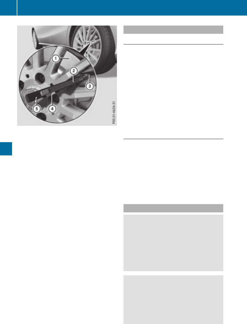
Rear wheel
XBring thevehicleand wheels intoasuitable
position so that you can attach test gage A.
XSecurethe vehicleagainst rollingaway
(Ypage 141).
XEngage park position P.
XSwitchoff theengine.
XPlacetestgage Abetween thewheel's
spokesonbrakepad/lining =.
XHold test gage Averticallyonbrakedisc :
and slidemeasuringpin ;onto brake
disc :.
XCheckwhichcolor field ?thearrow on
measuringpin ;is pointing to.
Green: thebrakepad/lining thickness is suf-
ficient.
Red:thebrakepad/lining thickness is not
sufficient. Havethe brakepads/lining
checkedataqualified specialist workshop.
To avoidaninaccuratemeasurement:
Rmakesureyou position thewheels suitably
Rdo notput themeasuringpin on arecess in
thebrakedisc
Driving on wet roads
Hydroplaning
If water has accumulated to acertaindepthon
theroad surface, there is adanger of hydro-
planing occurring, evenif:
Ryou driveatlow speeds
Rthetires haveadequatetread depth
Forthisreason,inthe event of heavyrain or in
conditionsinwhichhydroplaning may occur,
you mustdriveinthe followingmanner:
Rlower your speed
Ravoidruts
Ravoidsuddensteering movements
Rbrakecarefully
Driving on flooded roads
!Do notdrivethroughflooded areas.Check
thedepthofany water before driving through
it.Drive slowly throughstanding water. Oth-
erwise, water may enterthe vehicleinterior or
theenginecompartment. This can damage
theelectronic componentsinthe engineor
theautomatic transmission.Water can also
be drawn in by theengine's air suction nozzles
and this can causeenginedamage.
Winter driving
GWARNING
If you shiftdown on aslipperyroad surfacein
an attempttoincreasethe engine's braking
effect, thedrivewheels could lose their grip.
There is an increased danger of skiddingand
accidents.
Do notshiftdown for additional enginebrak-
ing on aslipperyroad surface.
GDANGER
If theexhaust pipe is blockedoradequate
ventilation is notpossible, poisonous gases
suchascarbon monoxide (CO) may enterthe
vehicle. This is thecase, e.g. if thevehicle
becomestrapped in snow. There is ariskof
fatal injury.
148 Driving tips
Driving and parking
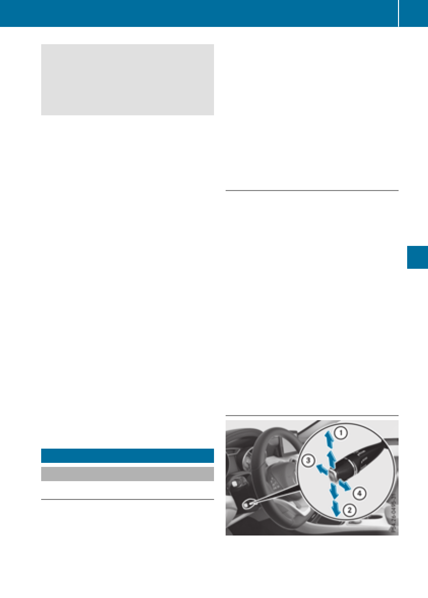
If you leave the engine or the auxiliary heating
running, make sure the exhaust pipe and area
around the vehicle are clear of snow. To
ensure an adequate supply of fresh air, open a
window on the side of the vehicle that is not
facing into the wind.
Have yourvehicle winter-proofed at aqualified
specialist workshop at the onset of winter.
Drive particularly carefully on slippery road sur-
faces. Avoid sudden acceleration, steering and
braking maneuvers. Do not use cruise control or
Distance PilotDISTRONIC.
If the vehicle threatens to skid or cannot be
stopped when moving at low speed:
XShift the transmission to position N.
XTry to bring the vehicle under control using
corrective steering.
The outsidetemperature indicator is not
designed to serve as an ice-warning device and
is therefore unsuitable for that purpose.
Changes in the outsidetemperature are dis-
played after ashort delay.
Indicated temperaturesjust above the freezing
point do not guarantee that the road surface is
free of ice. The road may still be icy, especially in
woodedareasoronbridges.
You shouldpay specialattention to road condi-
tions when temperaturesare around freezing
point.
For more information on driving with snow
chains, see (Ypage 290).
For more information on driving with summer
tires, see (Ypage 289).
Observe the notes in the "Winter operation" sec-
tion (Ypage 289).
Drivingsystems
Cruise control
General notes
Cruise control maintains aconstant road speed
for you.Itbrakes automatically in order to avoid
exceeding the set speed.Onlong and steep
downhill gradients, especially if the vehicle is
laden, you must select alow gear in good time.
You need to shift manually using the steering
wheel paddle shifters beforehand. By doing so,
you willmake use of the braking effect of the
engine. This relieves the load on the brake sys-
tem and prevents the brakes from overheating
and wearing too quickly.
When the engine is running, you can use the
cruise control lever to limitthe speed to any
speed between20mph (30 km/h)and the tech-
nicallypermitted maximum speed of the vehicle.
Use cruise control only if road and traffic con-
ditions make it appropriate to maintain asteady
speed for aprolongedperiod.
The speed indicated in the speedometer may
differ slightly from the speed stored.
Important safety notes
If you fail to adapt yourdriving style, cruise con-
trol can neither reduce the risk of an accident
nor override the lawsofphysics. Cruise control
cannot take into account the road, traffic and
weather conditions. Cruise control is only an
aid.You are responsible for the distance to the
vehicle in front, for vehicle speed,for braking in
good time and for staying in yourlane.
Do not use cruise control:
Rin road and traffic conditions which do not
allow you to maintain aconstant speed,e.g. in
heavy traffic or on winding roads
Ron slippery road surfaces.Braking or accel-
erating could cause the drive wheelstolose
traction and the vehicle could then skid
Rin poor visibility, e.g. due to fog, heavy rain or
snow
If there is achange of drivers, advise the new
driver of the speed stored.
Cruise control lever
:Activates or increases speed
;Activates or reduces speed
Driving systems 149
Driving and parking
Z

=Deactivatescruisecontrol
?Activatesatthe current speed/laststored
speed
When youactivate cruisecontrol, the stored
speedisshown in the multifunctiondisplay for
fiveseconds.
Activationconditions
To activate cruisecontrol, allofthe following
activationconditions must be fulfilled:
Rthe electricparkingbrake must be released.
RESP®must be active, butnot intervening.
Rthe transmission must be in position h.
Storing, maintainingand callingupa
speed
Storingand maintainingthe current
speed
Youcan storethe current speedifyou aredriv-
ing faster than20mph (30 km/h).
XAccelerate the vehicletothe desired speed.
XBrieflypress the cruisecontrollever up :or
down ;.
XRemoveyourfootfromthe accelerator pedal.
Cruise controlisactivated.The vehicleauto-
maticallymaintains the stored speed.
iCruise controlmay be unabletomaintain
the stored speedonuphillgradients.The
stored speedisresumed when the gradient
evens out. Cruise controlmaintains the
stored speedondownhillgradients by auto-
maticallyapplyingthe brakes.
Storingthe currentspeed or callingupthe
laststored speed
GWARNING
If youcallupthe stored speedand it differs
fromthe current speed, the vehicleacceler-
atesordecelerates. If youdonot know the
stored speed, the vehiclecould accelerate or
brake unexpectedly.There is ariskofanacci-
dent.
Payattentiontothe roadand trafficcondi-
tions beforecalling up the stored speed. If you
do not know the stored speed, storethe
desired speedagain.
XBrieflypullthe cruisecontrollever towards
you ?.
XRemoveyourfootfromthe accelerator pedal.
The first time cruisecontrolisactivated,it
stores the current speedorregulatesthe
speedofthe vehicletothe previously stored
speed.
Settingaspeed
Keepinmindthatitmay take abrief moment
untilthe vehiclehas accelerated or braked to
the speedset.
XTo adjustthe setspeed in 5mph incre-
ments (10km/h increments): briefly press
the cruise control lever up :past the pres-
sure point for ahigher speed, or down ;for
alower speed.
XTo adjust the set speed in 1mph incre-
ments (1 km/h increments): briefly press
the cruise control lever up :to the pressure
point for ahigher speed, or down ;for a
lower speed.
iCruise control is not deactivated if you
depress the accelerator pedal. For example, if
you acceleratebriefly to overtake, cruise con-
trol adjusts the vehicle's speed to the last
speed stored after you have finished overtak-
ing.
Deactivating cruise control
There are several ways to deactivate cruise con-
trol:
XBriefly press the cruise control lever forwards
=.
or
XBrake.
Cruise control is automatically deactivated if:
Rthe vehicle is secured with the electric park-
ing brake
Ryou are driving at less than 20 mph (30km/h)
RESP®intervenes or youdeactivate ESP®
Ryoushift the transmission to position i
whiledriving
If cruisecontrolisdeactivated,you will hear a
warning tone.You will see the Cruise Con‐
trolOff message in the multifunctiondisplay
for approximately fiveseconds.
150 Driving systems
Driving andparking

iWhen you switch off the engine, the last
speed stored is cleared.
Distance Pilot DISTRONIC
General notes
Distance Pilot DISTRONIC regulates the speed
and automatically helps you maintain the dis-
tancetothe vehicle detected in front. Vehicles
are detected with the aid of the radar sensor
system. Distance Pilot DISTRONIC brakes auto-
matically to avoid exceedingthe set speed or to
maintain the designated distancefrom the vehi-
cle in front.
If Distance Pilot DISTRONIC detectsthat there is
arisk of acollision, you will be warned visually
and acoustically. Without your intervention, Dis-
tancePilot DISTRONIC cannot prevent acolli-
sion. An intermittent warning tonewill then
sound and the distancewarning lamp will light
up in the instrument cluster. Brake immediately
in order to increase the distancetothe vehicle in
frontortake evasive action provided it is safe to
do so.
Distance Pilot DISTRONIC operates in the range
between 0mph (0 km/h) and 120 mph
(200 km/h).
Change into alower gear in good time on long
and steep downhill gradients.This is especially
importantifthe vehicle is laden. By doing so, you
will make use of the braking effect of the engine.
This relieves the load on the brake system and
preventsthe brakes from overheatingand wear-
ing too quickly.
Do not use Distance Pilot DISTRONIC on roads
with steep gradients.
For Distance Pilot DISTRONIC to assist you
when driving, the radar sensor system must be
operational.
SinceDistance Pilot DISTRONIC transmits radar
waves, it can resemble the radar detectors of
the responsible authorities. You can refer to the
relevant chapter in the Operator'sManual if
questions are asked about this.
iUSA only: This device has been approved by
the FCC as a"Vehicular Radar System". The
radar sensor is intended for use in an auto-
motive radar system only. Removal, tamper-
ing, or altering of the device will void any war-
ranties, and is not permitted by the FCC. Do
not tamper with, alter, or use in any non-
approved way.
Anyunauthorized modification to this device
could void the user's authority to operate the
equipment.
iCanada only: This device complies with
RSS-210 of Industry Canada. Operation is
subject to the following two conditions:
1. This device may not cause interference,
and
2. This device must accept any interference
received, including interference that may
cause undesired operation of the device.
Removal, tampering, or altering of the device
will void any warranties, and is not permitted.
Do not tamper with, alter, or use in any non-
approved way.
Anyunauthorized modification to this device
could void the user's authority to operate the
equipment.
Important safety notes
GWARNING
Distance Pilot DISTRONIC does not react to:
Rpeople or animals
Rstationary objectsonthe road, e.g. stopped
or parked vehicles
Roncoming vehicles and crossingtraffic
As aresult, Distance Pilot DISTRONIC may
neither give warnings nor intervene in such
situations. There is arisk of an accident.
Always pay careful attention to the traffic sit-
uation and be ready to brake.
GWARNING
Distance Pilot DISTRONIC cannot always
clearly identifyother road users and complex
traffic situations.
In such cases, Distance Pilot DISTRONIC may:
Rgive an unnecessary warning and then
brake the vehicle
Rneither give awarning nor intervene
Raccelerateorbrake unexpectedly
There is arisk of an accident.
Driving systems 151
Driving and parking
Z
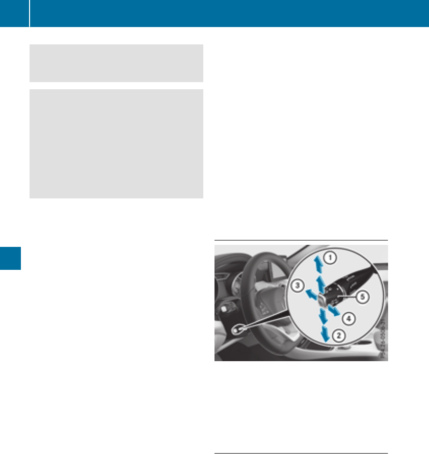
Continue to drivecarefullyand be readyto
brake, especiallyifDistance Pilot DISTRONIC
warnsyou.
GWARNING
Distance Pilot DISTRONICbrakes your vehicle
withupto50% of themaximum possible
deceleration. If this decelerationisnot suffi-
cient,Distance Pilot DISTRONICalertsyou
withavisual and acoustic warning.Thereisa
riskofanaccident.
Apply thebrakes yourself in these situations
and trytotakeevasive action.
!When Distance Pilot DISTRONICorthe
HOLD function is activated, thevehicle
brakes automaticallyincertain situations.
To avoid damagetothe vehicle,deactivate
Distance Pilot DISTRONICand theHOLD
function in thefollowingorsimilar situations:
Rwhen towing thevehicle
Rin thecar wash
If you fail to adapt your driving style, Distance
Pilot DISTRONICcan neither reduce theriskof
an accidentnor override thelaws of physics.
Distance Pilot DISTRONICcannottakeinto
accountroad,weather or traffic conditions.Dis-
tance Pilot DISTRONICisonlyanaid. You are
responsible for thedistancetothe vehicle in
front, for vehicle speed, for braking in good time
and for staying in your lane.
Do notuse Distance Pilot DISTRONIC:
Rin road and traffic conditions whichdonot
allow you to maintain aconstant speed, e.g.in
heavytraffic or on winding roads
Ron slippery road surfaces.Brakingoraccel-
erating could causethe drivewheelstolose
traction and thevehicle could then skid
Rwhen there is poor visibility, e.g.due to fog,
heavyrain or snow
Distance Pilot DISTRONICmay notdetect nar-
row vehiclesdriving in front, e.g.motorcycles, or
vehiclesdriving on adifferent line.
In particular,the detection of obstaclescan be
impaired if:
Rthere is dirt on thesensorsoranythingelse
covering thesensors
Rthere is snow or heavyrain
Rthere is interferencebyother radar sources
Rthere are strongradar reflections,for exam-
ple, in parking garages
If Distance Pilot DISTRONICnolonger detectsa
vehicle in front, it may unexpectedly accelerate
to thespeedstored.
This speedmay:
Rbe toohigh if you are driving in afilter lane or
an exit lane
Rbe so high when driving in theright-handlane
that you overtake vehiclesinthe left-hand
lane
Rbe so high in theleft lane that you pass vehi-
clesdriving in therightlane
If there is achangeofdrivers,advisethe new
driver of thespeedstored.
Cruise control lever
:Storesthe currentspeedorahigher speed
;Storesthe currentspeedoralower speed
=Deactivates Distance Pilot DISTRONIC
?Storesthe currentspeedorcalls up thelast
storedspeed
ASetsaspecifiedminimum distance
Activating Distance Pilot DISTRONIC
Activation conditions
!When Distance Pilot DISTRONICorthe
HOLD function is activated, thevehicle
brakes automaticallyincertain situations.
To avoid damagetothe vehicle,deactivate
Distance Pilot DISTRONICand theHOLD
function in thefollowingorsimilar situations:
Rwhen towing thevehicle
Rin thecar wash
152 Driving systems
Driving and parking
To activate Distance Pilot DISTRONIC, the fol-
lowing conditions must be fulfilled:
Rthe engine must be started. It may take up to
two minutes of driving before Distance Pilot
DISTRONIC is ready for use.
Rthe electric parking brake must be released.
RESP®must be active, but not intervening.
RParking Pilot must not be activated.
Rthe transmission must be in position h.
Rthe driver's door must be closed when you
shift from jto hor your seat belt must be
fastened.
Rthe front-passenger door must be closed.
Rthe vehicle must not skid.
Activating
XBriefly pull the cruise control lever towards
you ?,up:or down ;.
Distance Pilot DISTRONIC is activated.
XKeep the cruise control lever pressed up :or
down ;until the desired speed is set.
XRemove your foot from the accelerator pedal.
Your vehicle adapts its speed to that of the
vehicle in front,but only up to the desired
stored speed.
iIf you do not fully release the accelerator
pedal, the Distance Pilot Suspended mes-
sage appears in the multifunction display.The
set distance to aslower-movingvehicle in
front will then not be maintained. You will be
driving at the speed you determinebythe
position of the accelerator pedal.
You can also activate Distance Pilot DISTRONIC
when stationary. The lowest speed that can be
set is 20 mph (30km/h).
DrivingwithDistance PilotDISTRONIC
Activating at thecurrent speed/last
stored speed
GWARNING
If you callupthe stored speed and it differs
from thecurrentspeed, thevehicle acceler-
ates or decelerates. If you do notknowthe
stored speed, thevehicle could accelerateor
brake unexpectedly. There is ariskofanacci-
dent.
Pay attention to theroadand traffic condi-
tionsbeforecallingupthe stored speed. If you
do notknowthe stored speed, storethe
desiredspeed again.
XBriefly pull thecruise controllever towards
you ?.
XRemoveyour foot from theaccelerator pedal.
The first time DistancePilotDISTRONIC is
activated, it stores thecurrentspeed or reg-
ulates thespeed of thevehicle to theprevi-
ouslystoredspeed.
Pullingawayand driving
XIf you wanttopullawaywithDistance
PilotDISTRONIC: removeyour foot from the
brake pedal.
XBriefly pull thecruise controllever towards
you ?.
or
XIf Distance PilotDISTRONICisactivated:
acceleratebriefly.
Your vehicle pulls away and adaptsits speed
to that of thevehicle in front. If no vehicle is
detectedinfront,your vehicle accelerates to
theset speed.
The vehicle can also pull away when it is facing
an unidentifiedobstacleorisdrivingonadiffer-
entlinefromanother vehicle. The vehicle then
brakesautomatically. Be ready to brake at all
times.
If there is no vehicle in front, DistancePilot
DISTRONIC operates in thesameway as cruise
control.
If DistancePilotDISTRONIC detects aslower-
movingvehicle in front, it brakesyour vehicle. In
this way, thedistanceyou haveselectedismain-
tained.
If DistancePilotDISTRONIC detects afaster-
movingvehicle in front, it increasesthe driving
speed. However, thevehicle is only accelerated
up to thespeed you havestored.
iDistancePilotDISTRONIC is deactivated
when you depress thebrake,exceptwhen the
vehicle is stationary.
Selecting thedrive program
DistancePilotDISTRONIC supports asporty
drivingstyle when you selectthe S+ drive pro-
gram (Ypage 134) or themanual drive program
(Ypage 136). Acceleration behindthe vehicle in
frontortothe set speed is then noticeably more
dynamic.Ifyou haveselectedthe E(Mercedes-
AMGvehicles:C)drive program, thevehicle
Driving systems 153
Driving andparking
Z

acceleratesmoregently. This settingisrecom-
mended in stop-and-start traffic.
Changing lanes
If when driving on multilane roads you wish to
changetothe overtakinglane,Distance Pilot
DISTRONIC supportsyou if:
Ryou are driving faster than 45 mph (70 km/h)
RDistance PilotDISTRONICismaintaining the
distance to avehicleinfront
Ryouswitch on the appropriate turnsignal
RDistance PilotDISTRONICdoesnot currently
detect adangerofcollision
If these conditions arefulfilled,yourvehicleis
accelerated.Accelerationwillbeinterruptedif
changing lanes takestoo long or if the distance
between your vehicleand the vehicleinfront
becomestoo small.
Stopping
If Distance PilotDISTRONICdetects thatthe
vehicleinfront is stopping, it brakes your vehicle
untilitisstationary.
Once your vehicleisstationary, it remains sta-
tionaryand youdonot needtodepress the
brake.
iAfter atime,the electricparkingbrake
secures the vehicleand relieves the service
brake.
iDepending on the specifiedminimumdis-
tance,yourvehiclewillcome to astandstillat
asufficient distance behind the vehiclein
front. The specifiedminimumdistance is set
using the controlonthe cruisecontrollever.
When Distance PilotDISTRONICisactivated,
the transmission is shifted automaticallyto
position jif:
Rthe driver's seatbeltisnot fastened and the
driver's door is open.
Rthe engine is switched off,unless it is auto-
maticallyswitched off by the ECO start/stop
function.
The electricparkingbrake secures the vehicle
automaticallyifDistance PilotDISTRONICis
activated when the vehicleisstationaryand:
Rasystem malfunctionoccurs.
Rthe powersupplyisinsufficient.
If amalfunctionoccurs, the transmission may
also shift to position jautomatically.
Settingaspeed
Keepinmindthatitmay take abrief moment
untilthe vehiclehas accelerated or braked to
the speedset.
XPress the cruisecontrollever up :for a
higherspeed or down ;for alower speed.
XTo adjustthe setspeed in 1mph incre-
ments (1 km/hincrements): brieflypress
the cruisecontrollever up :or down ;to
the pressure point.
The last stored speedincreases or decreases
in 1mph (1 km/h)increments.
XTo adjustthe setspeed in 5mph incre-
ments (10km/h increments): briefly press
the cruise control lever up :or down ;
beyond the pressure point.
The last stored speed increases or decreases
in 5mph (10 km/h) increments.
iDistance Pilot DISTRONIC is not deactivated
if you depress the accelerator pedal. If you
acceleratetoovertake, Distance Pilot
DISTRONIC adjusts the vehicle's speed to the
last speed stored after you have finished over-
taking.
Setting aspecified minimum distance
You can set the specified minimum distancefor
Distance Pilot DISTRONIC by varying the time
span between one and two seconds. With this
function you can set the minimum distancethat
Distance Pilot DISTRONIC maintains to the vehi-
cle in front, dependentonvehicle speed. You
can see this distanceinthe multifunction dis-
play (Ypage 161).
The specified minimum distancecan be
changed while Distance Pilot DISTRONIC is
switched on or off.
iMake sure that you maintain the minimum
distancetothe vehicle in frontasrequired by
law. Adjust the distancetothe vehicle in front
if necessary.
154 Driving systems
Driving and parking
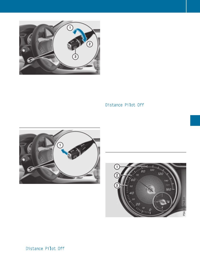
XTo increase: turn control =in direction ;.
Distance PilotDISTRONIC then maintains a
greaterdistance between your vehicleand
the vehicleinfront.
XTo decrease: turn control =in direction :.
Distance PilotDISTRONIC then maintains a
shorter distance between your vehicleand
the vehicleinfront.
Deactivating Distance PilotDISTRONIC
There are severalwaystodeactivate Distance
PilotDISTRONIC:
XBriefly press the cruisecontrollever for-
wards :.
or
XBrake, unless the vehicleisstationary
XBriefly press the cruisecontrollever for-
wards :.
or
XBrake, unless the vehicleisstationary
Whenyou deactivate Distance PilotDISTRONIC,
the Distance Pilot Off message appears in
the multifunctiondisplay for approximatelyfive
seconds.
iThe last speed stored remains stored until
youswitch off the engine. Distance Pilot
DISTRONIC is not deactivatedifyou depress
the acceleratorpedal.
Distance PilotDISTRONIC is automaticallydeac-
tivated if:
Ryouengage the electricparking brake or if the
vehicleisautomaticallysecured with the elec-
tric parking brake
RESP®intervenesoryou deactivate ESP®
Rthe transmission is in position j,kor i
Ryoupullthe cruisecontrollever towardsyou
in order to pull away and the front-passenger
door or one of the reardoors is open
Rthe vehicleisskidding
Ryouswitch on Parking Pilot
If Distance PilotDISTRONIC is automatically
deactivated, youwillhearawarning tone. The
Distance Pilot Off message appears in the
multifunctiondisplay for approximatelyfivesec-
onds.
Distance PilotDISTRONIC is also automatically
deactivatedwhenyou activate DSR. The Ã
DSR symbolappears in the multifunctiondis-
play.
Distance PilotDISTRONICdisplaysin
the instrument cluster
Displays in the speedometer
WhenDistance PilotDISTRONIC PLUSisactiva-
ted and thereare no vehicles detectedinfront,
one or two segments ;in the set speed range
light up.
If Distance PilotDISTRONIC detects avehiclein
front, segments ;between speed of the vehi-
cle in front =and stored speed :light up.
iFor design reasons,the speed displayed in
the speedometer maydiffer slightlyfrom the
speed set for Distance PilotDISTRONIC.
Driving systems 155
Driving andparking
Z
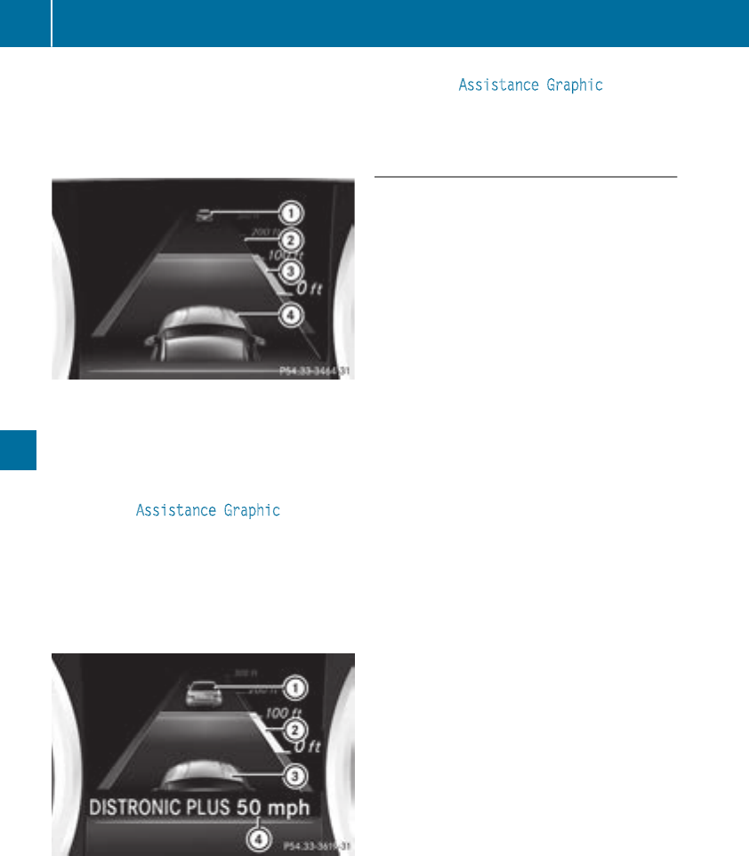
Display when DistancePilot DISTRONIC is
deactivated
In theAssistance menu(Ypage 184) of theon-
boardcomputer, you can select theassistance
display.
:Vehicleinfront,ifdetected
;Distanceindicator, currentdistancetothe
vehicleinfront
=Specified minimum distancetothe vehicle
in front; adjustable
?Your vehicle
XSelectthe AssistanceGraphicfunction
usingthe on-boardcomputer (Ypage 185).
Display when DistancePilot DISTRONIC is
activated
You will initially see thestoredspeed forabout
fiveseconds when you activateDistance Pilot
DISTRONIC.
:Vehicleinfront,ifdetected
;Specified minimum distancetothe vehicle
in front; adjustable
=Your vehicle
?DistancePilotDISTRONIC active (textonly
appears when thecruise control lever is
actuated)
XSelectthe AssistanceGraphicfunction
usingthe on-boardcomputer (Ypage 185).
Tips for drivingwithDistancePilot
DISTRONIC
General notes
Pay particular attention in thefollowing traffic
situations:
RCornering, enteringand exitingabend: the
abilityofDistance PilotDISTRONIC to detect
vehicles during cornering is limited. Your vehi-
cle may brakeunexpectedly or late.
RDriving on adifferentline: DistancePilot
DISTRONIC may notdetectvehicles whichare
notdrivinginthe middle of their lane. The dis-
tance to thevehicleinfront will be tooshort.
ROther vehicles changinglanes: DistancePilot
DISTRONIC has notdetectedthe vehiclecut-
ting in yet.The distancetothisvehiclewill be
tooshort.
RNarrow vehicles: DistancePilotDISTRONIC
has notyet detectedthe vehicleinfront on
theedgeofthe roadbecause of itsnarrow
width. The distancetothe vehicleinfront will
be tooshort.
RObstacles and stationary vehicles: Distance
PilotDISTRONIC doesnot brakefor obstacles
or stationary vehicles. If,for example, the
detectedvehicleturns acorner and an obsta-
cle or stationary vehicleisthenrevealed,Dis-
tance PilotDISTRONIC will notbrakefor
them.
RDistancePilotDISTRONIC may mistakenly
detectvehicles that are crossingyour lane. If
you activateDistance PilotDISTRONIC in the
following situations, thevehiclecould pull
away unintentionally:
-At traffic lights withcrossingtraffic, for
example.
-Withavehicleahead on theother side of an
intersection and theHOLDfunction active.
In suchsituations, brakeifnecessary. Distance
PilotDISTRONIC will then be deactivated.
156 Driving systems
Driving andparking
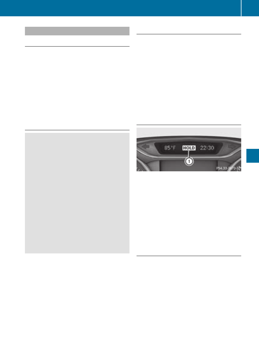
HOLD function
General notes
The HOLD function can assist the driverinthe
following situations:
Rwhen pulling away, especially on steep slopes
Rwhen maneuvering on steep slopes
Rwhen waiting in traffic
The vehicleiskept stationary without the driver
having to depress the brake pedal.
The braking effect is canceledand the HOLD
function deactivated when you depress the
accelerator pedaltopullaway.
Important safety notes
GWARNING
When leaving the vehicle, it can still roll away
despite being braked by the HOLD function if:
Rthere is amalfunction in the system or in
the voltagesupply.
Rthe HOLD function has been deactivated by
pressing the accelerator pedalorthe brake
pedal, e.g. by avehicleoccupant.
Rthe electrical system in the engine com-
partment, the battery or the fuseshave
been tamperedwith.
Rthe battery is disconnected
There is arisk of an accident.
If you wishtoexit the vehicle, alwaysturn off
the HOLD function and secure the vehicle
against rolling away.
!When Distance Pilot DISTRONIC or the
HOLD function is activated, the vehicle
brakes automatically in certain situations.
To avoiddamage to the vehicle, deactivate
Distance Pilot DISTRONIC and the HOLD
function in the following or similar situations:
Rwhen towing the vehicle
Rin the car wash
Deactivating the HOLD function (Ypage157).
Activation conditions
You can activate the HOLD function if:
Rthe vehicleisstationary
Rthe engine is running or if it has been auto-
matically switched off by the ECO start/stop
function
Rthe driver's door is closed or yourseat beltis
fastened
Rthe electric parking brake is released
RDistance Pilot DISTRONIC is deactivated
Rthe transmission is in position h,kor i
on vehicles with automatic transmission
Activating the HOLD function
XMake sure that the activation conditions are
met.
XDepress the brake pedal.
XQuickly depress the brake pedalfurther
until :appears in the multifunction display.
The HOLD function is activated. You can
release the brake pedal.
iIf depressing the brake pedalthe first time
does not activate the HOLD function, wait
briefly and then try again.
Deactivatingthe HOLD function
The HOLD function is deactivated automatically
if:
Ryou accelerate. On vehicles with automatic
transmission: only when the transmission is in
position hor k.
Rthe transmission is in position jon vehicles
with automatic transmission.
Ryou depress the brake pedalagain with acer-
tain amount of pressure until :disappears
from the multifunction display.
Ryou activate Distance Pilot DISTRONIC.
Ryou secure the vehicleusing the electric park-
ing brake.
Driving systems 157
Driving and parking
Z

iAfter atime,the electricparking brake
secures the vehicleand relieves the service
brake.
Whenthe HOLD functionisactivated,the trans-
mission is automaticallyshifted to position j
if:
Rthe driver's seatbeltisnot fastenedand the
driver's door is open.
Rthe engine is switched off, unless it is auto-
maticallyswitched off by the ECO start/stop
function.
The electricparking brake secures the vehicle
automaticallyifthe HOLD functionisactivated
when the vehicleisstationaryand:
Rasystem malfunctionoccurs.
Rthe powersupplyisinsufficient.
Start-off Assist (except Mercedes-
AMGvehicles)
Important safety notes
GWARNING
If youuse start-off assist, individual wheels
maystart to spinand the vehiclemay skid. If
ESP®is deactivated,thereisagreaterdanger
of skidding and having an accident. Make sure
thatnopersons or obstaclesare in the vicinity
of the vehicle.
Start-off assist enables optimumacceleration
from astandstill.For this, asuitablyhigh-grip
roadsurface is required,along with the tiresand
vehiclebeing in properoperating condition.
Do not activate start-off assist on public roads.
Observethe safety notes on driving safety sys-
tems (Ypage 61).
Be sure to readthe safety notes and information
on ESP®(Ypage 64).
Activatingstart-off assist
XDeactivate ESP®(Ypage 185).
XTurn the steering wheeltothe straight-ahead
position.
XDepressthe brake pedalhardwithyourleft
footand keepitdepressed.
XShift the transmission to position D.
XUse the DYNAMIC SELECTbutton to select
the Sdrive program(
Ypage 128).
XQuickly depress the accelerator pedalfully.
XTake your footoff the brake, butkeepthe
accelerator pedaldepressed.
The vehiclepulls away at maximumacceler-
ation.
iActivate ESP®as soonasthe acceleration
processhas ended.ESP®will otherwise not
be able to stabilize the vehicleifthe vehicle
starts to skidorawheel starts to spin.
Canceling start-off assist
XRemove your footfrom the accelerator pedal.
XReactivate ESP®.
RACESTART (Mercedes-AMGvehi-
cles)
Important safety notes
iRACESTARTmustnot be used on normal
roads. RACESTARTmustonlybeactivated
and used on dedicatedroadcircuits, outside
of public roaduse.
iRACESTARTisonlyavailable in
Mercedes‑AMGvehicles.
GWARNING
If youuse RACESTART, individual tiresmay
start to spinand the vehiclecould skid.
Depending on the selectedESP®mode, there
is an increased riskofskidding and having an
accident. Make sure thatnopersons, animals
or obstaclesare withinrange of the vehicle.
RACESTARTenables optimalaccelerationfrom
astanding start. For this, asuitablyhigh-grip
roadsurface is required and the vehicleand tires
must be in goodworking order.
iObservethe safety notes on driving safety
systems(
Ypage 61).
Be sure to readthe safety notes and informa-
tiononESP®(Ypage 64).
158 Driving systems
Driving andparking
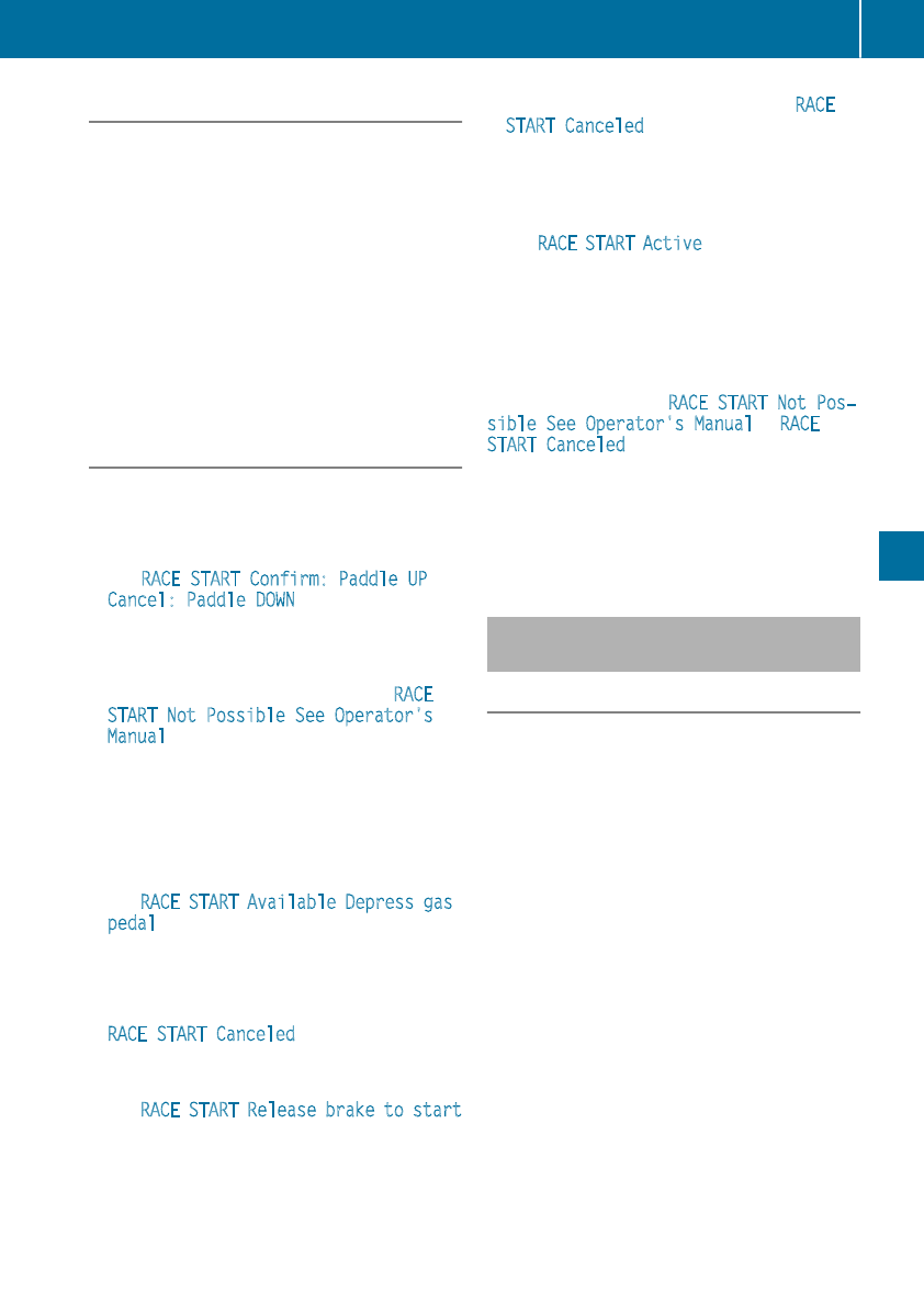
Conditions for activation
You can activateRACE START if:
Rthedoors, hood and thetrunk lid are closed.
Rtheengineisrunningand thetransmission,
all-wheel driveclutch and theengineare at
operatingtemperature.
Rthesteering wheel is in thestraight-ahead
position.
Rthevehicle is stationaryand thebrakepedal is
depressed (leftfoot).
Rthetransmission is in position h.
Rdriveprogram S,S+ or RACE is selected
(Ypage 129)
Activating RACE START
XDepressthe brakepedal withyour left foot
and keep it depressed.
XPull and hold bothsteering wheel paddle shift-
ers.
XThe RACESTART Confirm: Paddle UP
Cancel:Paddle DOWN message appearsin
themultifunction display.
XRelease bothsteering wheel paddle shifters.
iIf theactivation conditionsare no longer ful-
filled, RACE START is canceled. The RACE
START Not Possible See Operator's
Manual message appearsinthe multifunction
display.
XTo cancel: pull theleft steering wheel paddle
shifter(
Ypage 136).
or
XTo confirm: pull therightsteering wheel pad-
dle shifter(
Ypage 136).
The RACE START Available Depress gas
pedal message appearsinthe multifunction
display.
iIf you do notdepress theacceleratorpedal
within afew seconds, RACE START is can-
celed. The multifunction display shows the
RACESTART Canceled message.
XFully depress theacceleratorpedal.
The enginespeedisincreased.
The RACE START Release brake to start
message appearsinthe multifunction display.
iIf you do notrelease thebrakepedal within
ashort time, RACE START will be canceled.
The multifunction display shows the RACE
START Canceled message.
XTakeyour footoff thebrake, but keep the
acceleratorpedal depressed.
The vehicle pulls away at maximum acceler-
ation.
The RACE START Active message appearsin
themultifunction display.
RACE START is deactivatedwhen thevehicle
reaches aspeedofapproximately 50 km/h.
RACE START is deactivatedimmediately if you
release theacceleratorpedal duringRACE
START or if any of theactivation conditionsare
no longer fulfilled. The RACESTART Not Pos‐
sible See Operator'sManual or RACE
START Canceled message appearsinthe mul-
tifunctiondisplay.
iIf RACE START is used repeatedly within a
short period of time, it is only available again
after thevehicle has been driven acertain
distance.
AMG adaptivesport suspension sys-
tem
General notes
The electronicallycontrolled damping system
workscontinuously. This improvesdriving
safety and ride comfort.
The damping is tuned individually to each wheel
and depends on:
Ryour driving style, e.g.sporty
Rtheroad surface condition,e.g.bumps
Ryour individualselectionofSport or Comfort
The suspension settingisadjusted usingthe
correspondingbuttoninthe centerconsole.
iThe modecan also be set usingthe AMG
DYNAMIC SELECT controller (Ypage 129).
Eachtimeyou start theenginewiththe Smart-
Key or theStart/Stopbutton, Comfort modeis
activated. For further informationabout starting
theengine, see (Ypage 125).
Driving systems 159
Driving and parking
Z
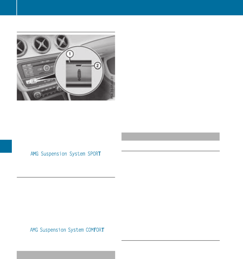
Sport mode
The firmer settingofthe suspension tuning in
Sport mode ensures even better contact with
the road. Select this mode when employing a
sporty driving style, e.g. on winding country
roads.
XPress button :.
Indicator lamp ;lights up. You have selected
Sport mode.
The AMG Suspension System SPORT mes-
sage appears in the multifunction display.
Comfort mode
In Comfort mode, the driving characteristics of
your vehicle are more comfortable. Select this
mode if you favor amore comfortable driving
style, but also when driving fast on straight
roads, e.g. highways.
XPress button :again so that indicator
lamp ;goes out.
You have selected Comfort mode.
The AMG Suspension System COMFORT mes-
sage appears in the multifunction display.
4MATIC
!Never tow the vehicle with one axle raised.
This may damage the differential. Damage of
this sort is not covered by the Mercedes-Benz
Limited Warranty. All wheels must remain
either on the ground or be fully raised.
Observe the instructions for towing the vehi-
cle with all wheels in full contact with the
ground.
4MATIC, together with ESP®,improves the trac-
tion of your vehicle whenever adrive wheel
spins due to insufficient grip.
If you fail to adapt your driving style, 4MATIC can
neither reduce the risk of accident nor override
the laws of physics. 4MATIC cannot take
account of road, weather and traffic conditions.
4MATIC is only an aid. You are responsible for
the distance to the vehicle in front,for vehicle
speed, for braking in good time and for staying in
your lane.
If adrive wheel spins due to insufficient grip:
ROnly depress the accelerator pedal as far as
necessary when pulling away.
RAccelerate less when driving.
iIn wintry driving conditions, the maximum
effect of 4MATIC can only be achieved if you
use winter tires (M+S tires), with snow chains
if necessary.
DYNAMIC BODY CONTROL
General notes
DYNAMICBODY CONTROL offers improved
driving comfort and continuously controls the
calibration of the dampers. The
damping characteristics adapt to the current
operating and driving situation.
The damping is tuned individually to each wheel
and depends on:
Ryour driving style, e.g. sporty
Rthe road surface conditions
Rthe drive program selected
The drive program can be set using the
DYNAMICSELECT button (Ypage 128).
Selecting Comfort mode
In the Comfort drive program, the driving char-
acteristicsofyour vehicle are more comforta-
ble. Therefore, select this drive program if you
prefer amore comfortable driving style. Also
select the Comfort drive program when driving
fast on straight roads, e.g. on straight stretches
of highway.
XPress DYNAMICSELECT button (Ypage 128)
as many times as necessary until the Com-
fort drive program is selected.
160 Driving systems
Driving and parking
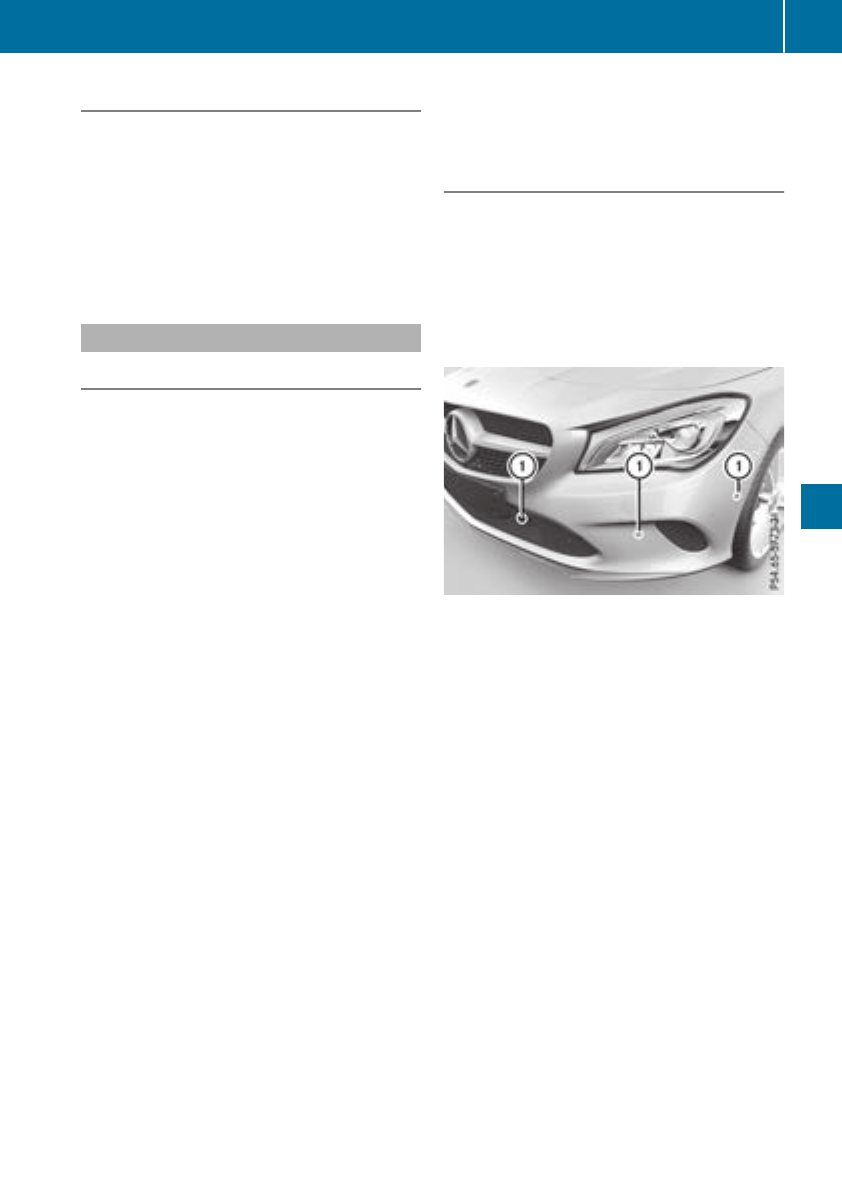
Selecting Sport mode
The firmer settingofthe suspension tuning in
the Sport drive program ensures even better
contact with the road. Select this drive program
when employing asporty driving style, e.g. on
winding countryroads.
XPress DYNAMICSELECT button (Ypage 128)
as many times as necessary until the Sport
drive program is selected.
Parking Assist PARKTRONIC
Important safety notes
Parking Assist PARKTRONIC is an electronic
parking aid with ultrasound. It monitorsthe area
around your vehicle using six sensors in the
front bumper and six sensors in the rear
bumper. Parking Assist PARKTRONIC visually
and audibly indicates the distance between your
vehicle and an object.
Parking Assist PARKTRONIC is only an aid. It is
not areplacement for your attention to your
immediate surroundings. You are always
responsible for safe maneuvering, parking and
exiting aparking space. Make sure that there
are no persons, animals or objectsinthe maneu-
vering area while maneuvering and parking in/
leaving parking spaces.
!When parking, pay particular attention to
objectsabove or below the sensors, such as
flower pots or trailer drawbars. Parking Assist
PARKTRONIC does not detect such objects
when they are in the immediate vicinity of the
vehicle. You could damage the vehicle or the
objects.
The sensors may not detect snow and other
objectsthat absorb ultrasonic waves.
Ultrasonic sources such as an automatic car
wash, the compressed-air brakes of atruck or
apneumatic drill could cause Parking Assist
PARKTRONIC to malfunction.
Parking Assist PARKTRONIC may not function
correctly on uneven terrain.
Parking Assist PARKTRONIC is activated auto-
matically when you:
Rswitch on the ignition
Rshift the transmission to position h,kor
i
Rrelease the electric parking brake
Parking Assist PARKTRONIC is deactivated at
speeds above 11 mph (18 km/h). It is reactiva-
ted at lower speeds.
Range of the sensors
General notes
Parking Assist PARKTRONIC does not take into
account obstacles located:
Rbelow the detection range, e.g. people, ani-
mals or objects.
Rabove the detection range, e.g. overhanging
loads, tail sectionsorloading ramps of trucks.
:Sensors in the front bumper, left-hand side
(example)
The sensors must be free from dirt, ice or slush.
They can otherwise not function correctly. Clean
the sensors regularly,taking care not to scratch
or damage them (Ypage 265).
Driving systems 161
Driving and parking
Z
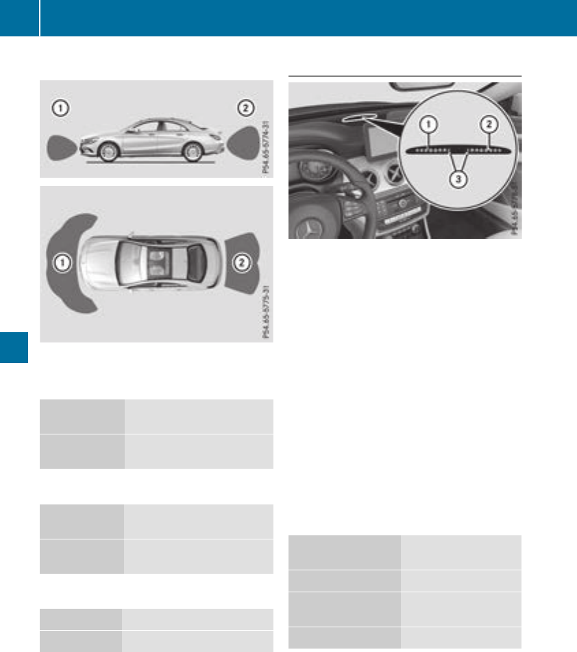
Range
:Detection rangeoffront sensors
;Detection rangeofrearsensors
Front sensors
Center Approx. 40 in (approx.
100 cm)
Corners Approx. 24 in (approx.
60 cm)
Rear sensors
Center Approx. 48 in (approx.
120 cm)
Corners Approx. 32 in (approx.
80 cm)
Minimum distance
Center Approx. 8in(approx. 20 cm)
Corners Approx. 6in(approx. 15 cm)
If there is an obstaclewithin this range, the rel-
evant warning displayslight up and awarning
tone sounds. If the distance falls below the min-
imum, the distance may no longer be shown.
Warning displays
:Segments on the left-hand sideofthe vehi-
cle
;Segments on the right-hand sideofthe vehi-
cle
=Segments showing operationalreadiness
The warning displaysshowthe distance
between the sensors and the obstacle. The
warning display for the front areaislocated on
the dashboard above the center airvents. The
warning display for the rearareaislocated on
the headliner in the rearcompartment.
The warning display for each sideofthe vehicle
is divided into five yellow and two red segments.
Parking Assist PARKTRONIC is operationalifyel-
low segments showing operationalreadiness =
light up.
The gearlever position or the transmissionposi-
tion of the automatic transmissionand the
direction in which the vehicle is rolling deter-
mine which warning display is active whenthe
engine is running.
Transmission posi-
tion
Warning display
hFront areaactivated
k,ior the vehicle
is rolling backwards
Rear and front areas
activated
jNo areas activated
One or more segments light up as the vehicle
approaches an obstacle, depending on the vehi-
cle's distance from the obstacle. In addition,
warning tones are issued.
Whenthe distance to the obstacleissufficient,
youwillhearanintermittent warning tone. The
shorter the distance to the obstacle, the shorter
the frequency of the intermittent warning tones
162 Drivingsystems
Drivingand parking
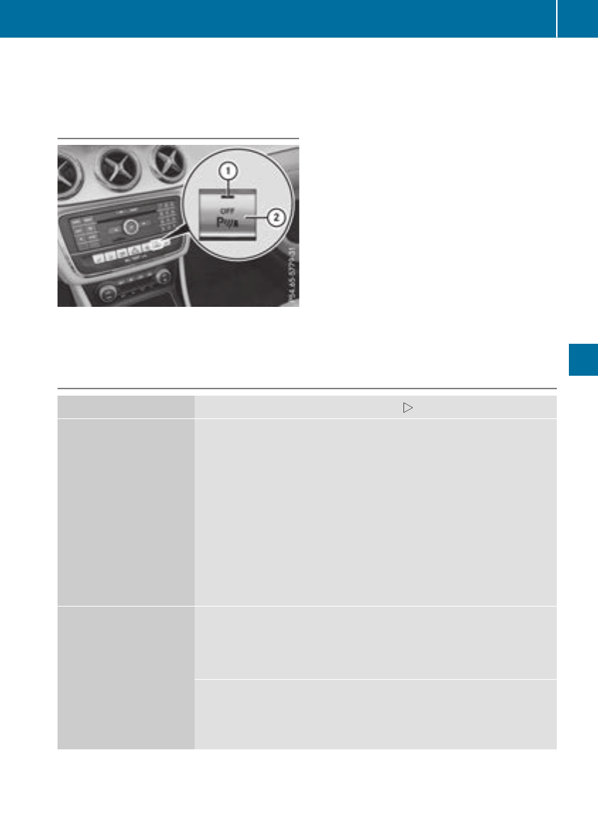
becomes.When the minimum distance is
reached, you hear acontinuous warning tone.
Deactivating or activating Parking
Assist PARKTRONIC
:Indicator lamp
;Deactivates or activates ParkingAssist
PARKTRONIC
If indicator lamp :is lit, ParkingAssist
PARKTRONICisdeactivated.
iParkingAssist PARKTRONICisautomati-
cally activated when you turn the SmartKey to
position 2in the ignition lock.
Problems with Parking Assist PARKTRONIC
Problem Possible causes/consequences and MSolutions
Only the red segments in
the ParkingAssist
PARKTRONICwarning
displays are lit. You also
hear awarning tonefor
approximately two sec-
onds.
ParkingAssist
PARKTRONICisthen
deactivated and the indi-
cator lamp on the
PARKTRONICbutton
lights up.
ParkingAssist PARKTRONIChas malfunctioned and has been deacti-
vated.
XIf problems persist,have ParkingAssist PARKTRONICchecked at a
qualified specialist workshop.
Only the red segments in
the ParkingAssist
PARKTRONICwarning
displays are lit. Parking
Assist PARKTRONICis
then deactivated.
The ParkingAssist PARKTRONICsensorsare dirty or thereisinter-
ference.
XClean the ParkingAssist PARKTRONICsensors(Ypage 265).
XSwitchthe ignition back on.
The problem may be caused by an external source of radio or ultra-
sound waves.
XCheck to see if ParkingAssist PARKTRONICworks at adifferent
location.
Driving systems 163
Driving and parking
Z

Parking Pilot
General notes
Parking Pilot is an electronic parking aid with
ultrasound. It measures the road on both sides
of the vehicle. Aparking symbol indicates asuit-
able parking space. Active steering intervention
and brake application can assist you during
parking and when exiting aparking space. Park-
ing Assist PARKTRONIC is also available
(Ypage 161).
Important safety notes
Parking Pilot is only an aid. It is not areplace-
ment for your attention to your immediate sur-
roundings. You are always responsible for safe
maneuvering, parking and exiting aparking
space. Make sure that no persons, animals or
objectsare in the maneuvering range.
When Parking Assist PARKTRONIC is deactiva-
ted, Parking Pilot is also unavailable.
GWARNING
While parking or pulling out of aparking
space, the vehicle swings out and can drive
onto areas of the oncominglane. This could
result in acollision with another road user.
There is arisk of an accident.
Pay attention to other road users. Stop the
vehicle if necessary or cancel the Parking Pilot
parking procedure.
!If unavoidable,you should drive over obsta-
cles such as curbs slowly and not at asharp
angle. Otherwise, you may damage the
wheels or tires.
Parking Pilot may also display spaces not suita-
ble for parking, e.g.:
Rwhere parking or stopping is prohibited
Rin front of driveways or entrances and exits
Ron unsuitable surfaces
Parking tips:
ROn narrow roads, drive as close to the parking
space as possible.
RParking spaces that are littered or overgrown
might be identified or measured incorrectly.
RParking spaces that are partially occupied by
trailer drawbars might not be identified as
such or be measured incorrectly.
RSnowfall or heavy rain may lead to aparking
space being measured inaccurately.
RPay attention to the warning messages of
Parking Pilot PARKTRONIC during the parking
procedure (Ypage 162).
RYou can intervene to correct the steering pro-
cedure at any time. Parking Pilot will then be
canceled.
RWhen transporting aload that protrudes from
your vehicle, you must not use Parking Pilot.
RNever use Parking Pilot when snow chains are
mounted.
RMake sure that the tire pressures are always
correct.This has adirect influence on the
parking characteristics of the vehicle.
Use Parking Pilot for parking spaces that are:
Rthat are paralleloratright-angles to the direc-
tion of travel
Ron straight roads, not bends
Ron the same level as the road, e.g. not on the
pavement
Detecting parking spaces
Objectslocated above the detection range of
Parking Pilot will not be detected when the park-
ing space is measured. These are not taken into
account when the parking procedure is calcula-
ted, e.g. overhanging loads, truck overhangs or
loading ramps. Parking Pilot may therefore
guide you into the parking space too early.
Parking Pilot does not assist you parking in
spaces perpendicular to the direction of travel if:
Rtwo parking spaces are located directly next
to one another
Rthe parking space is directly next to alow
obstacle such as alow curb
Ryou forward-park
Parking Pilot does not assist you parking in
spaces parallelorperpendicular to the direction
of travel if:
Rthe parking space is on acurb
Rthe system reads the parking space as being
blocked, for example by foliage or grass pav-
ing blocks
Rthe area is too small for the vehicle to maneu-
ver into
Rthe parking space is bordered by an obstacle,
e.g. atree, apost or atrailer
For further information on the detection range
(Ypage 161).
164 Driving systems
Driving and parking
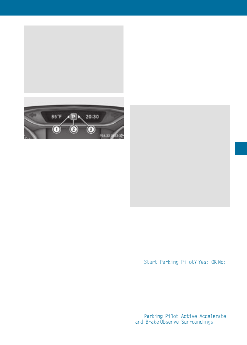
GWARNING
If there are objects above the detection range:
RParking Pilot may steer in too early
Rthe vehiclemay not stop in front of these
objects
You may causeacollision as aresult. There is
arisk of an accident.
If objects are located above the detection
range, stop and deactivate Parking Pilot.
:Detected parking space on the left
;Parking symbol
=Detected parking space on the right
Parking Pilot is activated automatically when
driving forward. The system is operational at
speeds of up to approximately 22 mph
(35 km/h).Whileinoperation, the system inde-
pendently locates and measures parking spaces
on both sidesofthe vehicle.
Parking Pilot willonly detect parking spaces:
Rthat are paralleloratright-angles to the direc-
tion of travel
Rthat are paralleltothe direction of travel and
at least 59 in (1.5 m) wide
Rthat are paralleltothe direction of travel and
at least 39.5 in (1.0 m) longer than your vehi-
cle
Rat right angles to the direction of travel and at
least 39.5in(1.0m)wider than your vehicle
iNotethat Parking Pilot cannot measure the
lengthofaparking space if it is at right angles
to the direction of travel. You will need to
judge whether your vehicle will fit intothe
parking space.
When drivingatspeeds below 19 mph
(30 km/h), you will see parking symbol ;as a
status indicator in the instrumentcluster. When
aparking space has been detected, an arrow
towards the right or the left also appears. Park-
ing Pilot only displays parking spaces on the
front-passengerside as standard. Parking
spaces on the driver's side are displayed as
soon as the turn signal on the driver's side is
activated. When parking on the driver's side,
this must remain activated until you confirm the
use of Parking Pilot by pressing the abutton
on the multifunction steeringwheel. The system
automatically determines whether the parking
space is parallel or at right-angles to the direc-
tion of travel.
Aparking space is displayed while you are driv-
ing past it, and until you are approximately 50 ft
(15 m) away fromit.
Parking
GWARNING
If you leave the vehicle when it is only being
braked by Parking Pilot,itcould roll away if:
Rthere is amalfunction in the system or in
the voltage supply.
Rthe electrical system in the enginecom-
partment, the battery or the fuses are tam-
pered with.
Rthe battery is disconnected.
Rthe vehicle is accelerated, e.g. by avehicle
occupant.
There is arisk of an accident.
Before leavingthe vehicle, always secureit
against rollingaway.
iIf Parking Assist PARKTRONIC detects
obstacles, Parking Pilot brakes automatically
whilst the vehicle is being parked. You are
responsible for braking in good time.
XStop the vehicle when the parking space sym-
bol shows the desiredparking space in the
instrumentcluster.
XShiftthe transmission to position k.
The StartParking Pilot? Yes: OK No:
%message appears in the multifunction
display.
XTo cancel theprocedure: press the %
button on the multifunction steeringwheel or
pull away.
or
XTo park using Parking Pilot: press the a
button on the multifunction steeringwheel.
The Parking PilotActive Accelerate
and Brake Observe Surroundings mes-
sage appears in the multifunction display.
Driving systems 165
Driving and parking
Z
XLet go of the multifunction steering wheel.
XBack up the vehicle,being ready to brake at all
times. When backing up, drive at aspeed
belowapproximately 6mph (10 km/h). Oth-
erwise, Parking Pilotiscanceled immediately.
Parking Pilotbrakes the vehicle to astandstill
when the vehicle approaches the rear border
of the parking space.
Maneuvering may be required in tight parking
spaces.
The Parking Pilot Active Select D
Observe Surroundings messageappears in
the multifunction display.
XShift the transmission to position hwhile
the vehicle is stationary.
Parking Pilotimmediately steers in the other
direction.
The Parking Pilot Active Accelerate
and Brake Observe Surroundings mes-
sage appears in the multifunction display.
iYou willachieve the best results by waiting
for the steering procedure to complete before
pulling away.
XDrive forwardsand be ready to brake at all
times.
Parking Pilotbrakes the vehicle to astandstill
when the vehicle approaches the front border
of the parking space.
Maneuvering may be required in tight parking
spaces.
The Parking Pilot Active Select R
Observe Surroundings messageappears in
the multifunction display.
As soon as the parking procedure is complete,
the Parking Pilot Finished message
appears and awarning tone sounds. The vehicle
is now parked.
The vehicle is kept stationary withoutthe driver
having to depressthe brake pedal. The braking
effect is canceled when you depressthe accel-
erator pedal.
Parking Pilotnolonger supports you with steer-
ing interventions and brake applications. When
Parking Pilotisfinished,you must steer and
brake again yourself. Parking Assist
PARKTRONIC is still available.
Parking tips:
RThe way yourvehicle is positioned in the park-
ing space after parking is dependent on vari-
ous factors. These include the positionand
shape of the vehiclesparked in front and
behind it and the conditions of the location. It
may be the case that Parking Pilotguides you
too far into aparking space, or not far enough
into it. In some cases, it may also leadyou
across or onto the curb. If necessary,you
shouldcancel the parking procedure with
Parking Pilot.
RYou can also preselect transmission position
h.The vehicle redirects and does not drive
as far into the parking space. Should the
transmission change take place too early, the
parking procedure is canceled. Asensible
parking positioncan no longer be achieved
from this position.
Exitingaparking space
In order for Parking Pilottosupport you when
exiting the parking space:
Ryou need to have parked using Parking Pilot.
Rthe border of the parking space must be high
enough at the front and the rear. Acurb stone
is too small,for example.
Rthe border of the parking space must not be
too wide, as the positionofthe vehicle must
not exceed an angle of 45° to the starting
positionasitismaneuvered into the parking
space.
Ramaneuvering distance of at least 3.3 ft
(1.0 m) must be available.
Parking Pilotcan assist you with exiting apark-
ing space only if you have parked the vehicle
parallel to the direction of travel using Parking
Pilot.
iIf Parking Assist PARKTRONIC detects
obstacles, Parking Pilotbrakes automatically
whilst the vehicle is exiting the parking space.
You are responsible for braking in good time.
XStart the engine.
XRelease the electric parking brake.
XSwitch on the turn signal in the direction you
willdrive out of the parking space.
XShift the transmission to position hor k.
The Start Parking Pilot? Yes: OK No:
%messageappears in the multifunction
display.
XTo cancel the procedure: press the %
button on the multifunction steering wheelor
pullaway.
or
166 Driving systems
Driving and parking
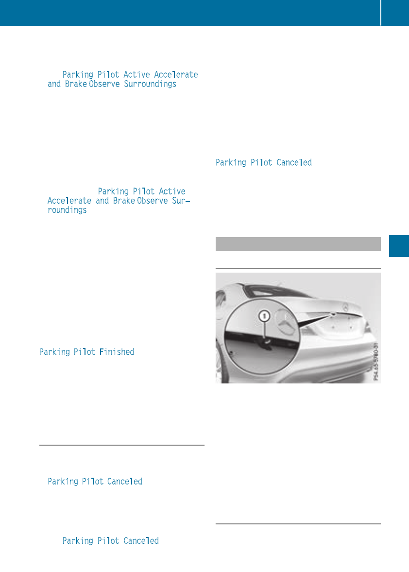
XTo exit aparking spaceusing Parking
Pilot: press the abutton on the multi-
functionsteering wheel.
The ParkingPilot Active Accelerate
and Brake ObserveSurroundings mes-
sage appears in the multifunctiondisplay.
XLet go of the multifunctionsteering wheel.
XPull away,being ready to brake at alltimes. Do
not exceed amaximumspeed of approx-
imately6mph (10 km/h)whenexiting apark-
ing space. Otherwise, Parking Pilotiscan-
celed immediately.
XDepending on the message or as required,
shift the transmission to position hor k.
Parking Pilotimmediatelysteers in the other
direction. The ParkingPilot Active
Accelerateand Brake ObserveSur‐
roundings message appears in the multi-
functiondisplay.
iYouwillachieve the best results by waiting
for the steering proceduretocomplete before
pulling away.
If youbackupafteractivation, the steering
wheelismovedtothe straight-aheadposi-
tion.
XDriveforwardsand reverse as promptedby
the Parking Assist PARKTRONIC warning dis-
plays, severaltimesifnecessary.
Once youhaveexited the parking space com-
pletely, the steering wheelismovedtothe
straight-aheadposition. Youhearatone and the
Parking Pilot Finished message appears in
the multifunctiondisplay.You will then have to
steerand merge into traffic on your own. Park-
ing Assist PARKTRONIC is stillavailable.You can
take overthe steering before the vehiclehas
exited the parking space completely. Thisis
useful, for examplewhenyou recognize thatitis
already possibletopullout of the parking space.
Canceling Parking Pilot
XStop the movement of the multifunction
steering wheelorsteeryourself.
Parking Pilotiscanceledimmediately. The
Parking Pilot Canceled message appears
in the multifunctiondisplay.
or
XPress the PARKTRONIC button (Ypage 163).
Parking Assist PARKTRONIC is switched off
and Parking Pilotisimmediatelycanceled.
The ParkingPilot Canceled message
appears in the multifunctiondisplay.
Parking Pilotiscanceledautomaticallywhen:
Rthe electricparking brake is engaged
Rtransmission position jis selected
Rparking using Parking Pilotisnolonger pos-
sible
Ryouare driving faster than6mph (10 km/h)
Rawheel spins, ESP®intervenesorfails.In
such cases the ÷warning lamp lights up in
the instrument cluster
Awarning tone sounds. The parking symboldis-
appears and the multifunctiondisplay shows the
ParkingPilot Canceled message.
WhenParking Pilotiscanceled, youmuststeer
and brake againyourself.
If asystem malfunctionoccurs, the vehicleis
braked to astandstill.Todrive on, depress the
acceleratoragain.
Rear view camera
General notes
Rear viewcamera :is an opticalparking and
maneuvering aid. It shows the areabehindyour
vehiclewithguide lines in the multimedia sys-
tem display.
The areabehindthe vehicleisdisplayed as a
mirror image, as in the rearviewmirror.
Observe the notes on cleaning (Ypage 265).
iThe text shown in the multimedia system
display depends on the languagesetting. The
following are examples of rearviewcamera
messages in the multimedia system display.
Important safety notes
The rearviewcamera is onlyanaid.Itisnot a
replacement for your attentiontoyourimmedi-
ate surroundings. Youare always responsible
Driving systems 167
Driving andparking
Z
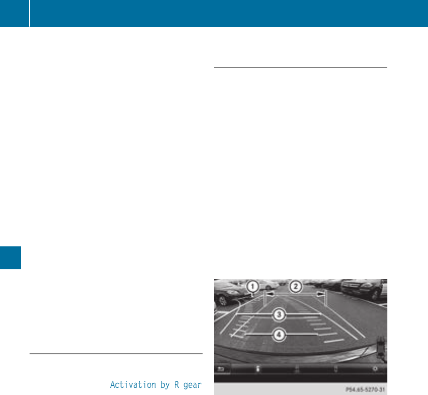
for safe maneuvering and parking. Make sure
that there are no persons, animals or objects in
the maneuvering area while maneuvering and
parking in parking spaces.
Under the following circumstances, the rear
view camera willnot function, or willfunction in
alimited manner:
Rif the trunk lid is open
Rin heavy rain, snow or fog
Rat night or in very dark places
Rif the camera is exposedtovery bright light
Rif the area is lit by fluorescent bulbs or LED
lighting (the display may flicker)
Rif there is asudden change in temperature,
e.g. when driving into aheated garage in win-
ter
Rif the camera lens is dirty or obstructed.
Observe the notes on cleaning
(Ypage265)
Rif the rear of yourvehicleisdamaged. In this
case, have the camera position and setting
checked at aqualified specialist workshop
The fieldofvision and other functions of the rear
view camera may be restricted due to additional
accessories on the rear of the vehicle(e.g.
license plate holder, rear bicycle rack).
Activating/deactivating the rear view
camera
XTo activate: make sure that the SmartKey is
in position 2in the ignition lock.
XMake sure that the Activation by Rgear
function is selected in the multimediasystem;
see the DigitalOperator's Manual.
XEngage reverse gear.
The area behind the vehicleisshownwith
guide lines in the multimediasystem display.
The image from the rear view camera is avail-
ablethroughoutthe maneuvering process.
To deactivate: the rear view camera deacti-
vates if you shift the transmission to jor after
driving forwards ashort distance.
Messages in the multimedia system dis-
play
The rear view camera may show adistorted view
of obstacles, show them incorrectly or not at all.
The rear view camera does not show objects in
the following positions:
Rvery close to the rear bumper
Runder the rear bumper
Rin close range above the handleonthe trunk
lid
!Objects not at ground levelmay appear to
be further away than they actually are, e.g.:
Rthe bumper of aparked vehicle
Rthe drawbar of atrailer
Rthe ballcoupling of atrailer tow hitch
Rthe rear section of an HGV
Raslanted post
Use the guidelines only for orientation.
Approach objects no further than the bottom-
most guideline.
:Yellow guide line at adistance of approx-
imately 13 ft (4.0 m) from the rear of the
vehicle
;White guide line without steering input–
vehiclewidth including the exterior mirrors
(static)
=Yellow guide line for the vehiclewidth
including the exterior mirrors, for current
steering wheelangle (dynamic)
?Yellow lane marking the course the tires will
take at the current steering wheelangle
(dynamic)
168 Driving systems
Driving and parking
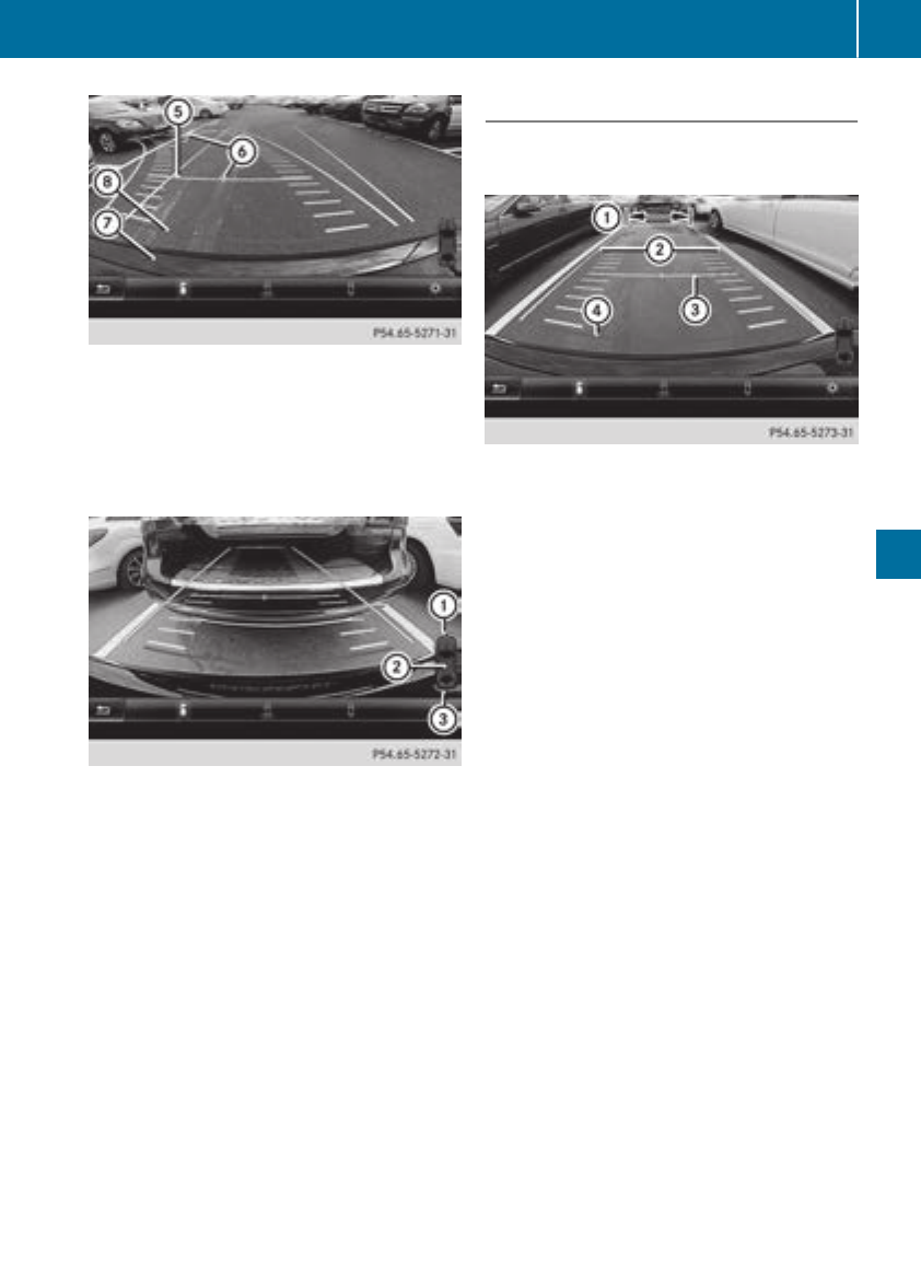
AYellow guide line at adistance of approx-
imately 3ft(1.0m)from the rear of the vehi-
cle
BVehicle center axle (marker assistance)
CBumper
DRed guide line at adistance of approximately
12 in (0.30m)from the rear of the vehicle
:Front warningdisplay
;Additional measurement operational readi-
ness indicator for Parking Assist
PARKTRONIC
=Rear warningdisplay
When Parking Assist PARKTRONIC is opera-
tional (Ypage 162),additional measurement
operational readiness indicator ;appears in
the multimedia systemdisplay. If the Parking
Assist PARKTRONIC warningdisplays are active
or light up, warningdisplays :and =are also
active or light up correspondingly in the multi-
media systemdisplay.
"Reverse parking" function
Backing up straight into aparkingspace
withoutsteering input
:Whiteguide line without steeringinput –
vehicle width including the exterior mirrors
(static)
;Yellow guide line for the vehicle width
including the exterior mirrors, for current
steeringwheel angle (dynamic)
=Yellow guide line at adistance of approx-
imately 3ft(1.0m)from the rear of the vehi-
cle
?Red guide line at adistance of approximately
12 in (0.30 m) from the rear of the vehicle
XMake sure that the rear view camerais
switched on (Ypage 168).
The lane and the guide lines are shown.
XWith the help of white guide line :,check
whether the vehicle will fit intothe parking
space.
XUsingwhite guide line :as aguide, carefully
back up until you reach the end position.
Red guide line ?is thenatthe end of the
parking space. The vehicle is almost parallel
in the parking space.
Driving systems 169
Driving and parking
Z
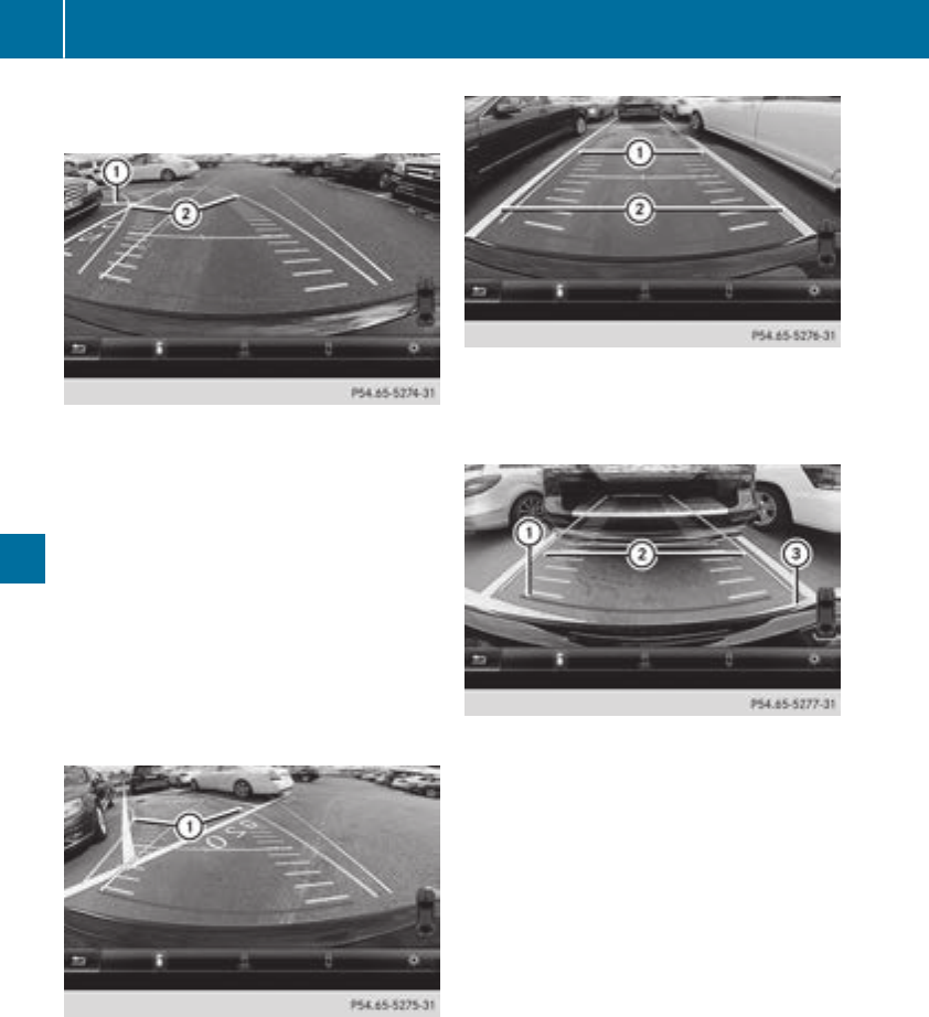
Reverse perpendicular parkingwithsteer-
inginput
:Parking space marking
;Yellow guidelinefor the vehicle width
including the exterior mirrors, for current
steering wheel angle (dynamic)
XDrive past the parking space and bring the
vehicle to astandstill.
XMake sure that the rearviewcamera is
switched on (Ypage 168).
The lane and the guidelines are shown.
XWhile the vehicle is at astandstill, turn the
steering wheel in the direction of the parking
space untilyellowguide line ;reaches park-
ing space marking :.
XMaintain the steering input and reverse care-
fully.
:Yellow guidelinefor the vehicle width
including the exterior mirrors, for current
steering wheel angle (dynamic)
XStop the vehicle whenitisalmost exactly in
front of the parking space.
The white lane shouldbeasclose to parallel
with the parking space marking as possible.
:White guidelinefor current steering input
;Parking space marking
XTurn the steering wheel to the center position
while the vehicle is stationary.
:Redguide line at adistance of approximately
12 in (0.30 m) from the rearofthe vehicle
;White guidelinewithoutsteering input
=End of parking space
XBackupcarefullyuntilyou have reachedthe
final position.
Redguide line :is thenatend of parking
space =.The vehicleisalmostparallelinthe
parking space.
170 Driving systems
Driving andparking
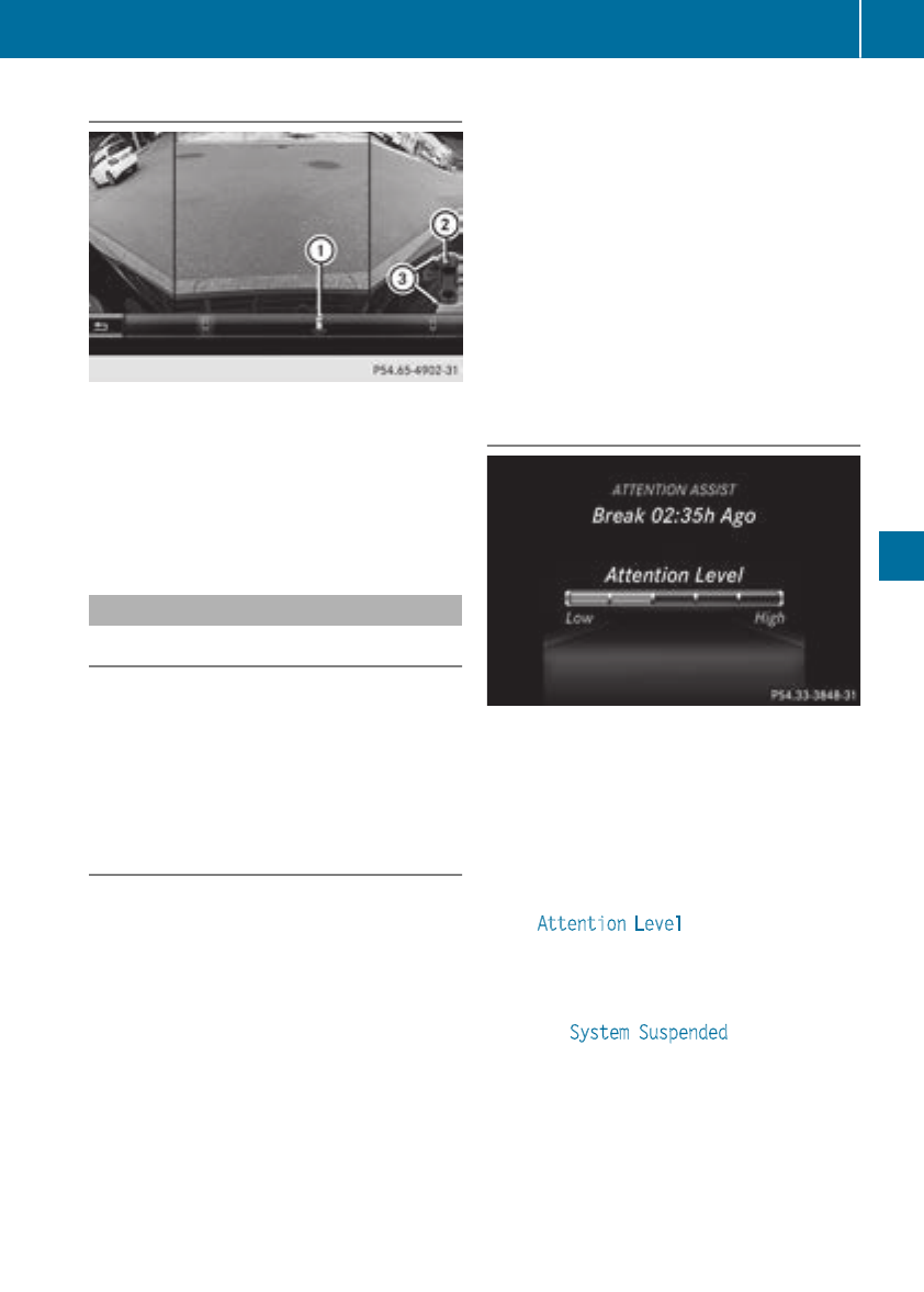
Wide-angle function
:Symbolfor the wide-angleview function
;Yourvehicle
=Parking Assist PARKTRONIC warning dis-
plays
Select this view when you are driving out of an
exit and the view of crossing traffic is restricted,
for example.
ATTENTION ASSIST
General notes
ATTENTION ASSIST helpsyou during long,
monotonous journeys, such as on highways. It is
active in the 37 mph (60 km/h) to 125 mph
(200 km/h) range. If ATTENTION ASSIST
detects typical indicators of fatigueorincreas-
ing lapses in concentration on the part of the
driver, it suggests taking abreak.
Important safety notes
ATTENTION ASSIST is only an aid to the driver. It
might not alwaysrecognize fatigueorincreasing
inattentivenessintime or fail to recognize them
at all.The systemisnot asubstitute for awell-
rested and attentive driver.
The functionality of ATTENTION ASSIST is
restricted and warnings may be delayed or not
occur at all:
Rif the length of the journey is less than approx-
imately 30 minutes
Rif the road conditionispoor, e.g. if the surface
is uneven or if there are potholes
Rif there is astrong side wind
Rif you have adopted asporty driving style with
high cornering speeds or high rates of accel-
eration
Rif you are predominantly driving slower than
37 mph (60 km/h) or faster than 125 mph
(200 km/h)
Rif the time has been set incorrectly
Rin active driving situations, such as whenyou
change lanesorchange yourspeed
ATTENTION ASSIST is reset whenyou continue
yourjourney and starts assessing yourtiredness
again if:
Ryou switch off the engine
Ryou take off yourseatbeltand open the driv-
er's door, e.g. for achange of drivers or to
take abreak
Displaying the attention level
You can have current status information dis-
played in the assistance menu (Ypage184) of
the on-board computer.
XSelect the Assistance display for Attention
Assist using the on-board computer
(Ypage185).
The following information is displayed:
RThe length of the journey since the lastbreak.
RThe Attention Level determined by ATTEN-
TION ASSIST, displayed in abar display in five
levels from high to low.
RIf ATTENTION ASSIST is unable to calculate
the attention leveland cannot outputawarn-
ing, the System Suspended message
appears.The bar display then changes the
display,such as whenyou are driving at a
speedbelow 37 mph (60 km/h)orabove
125 mph (200 km/h).
Driving systems 171
Driving and parking
Z
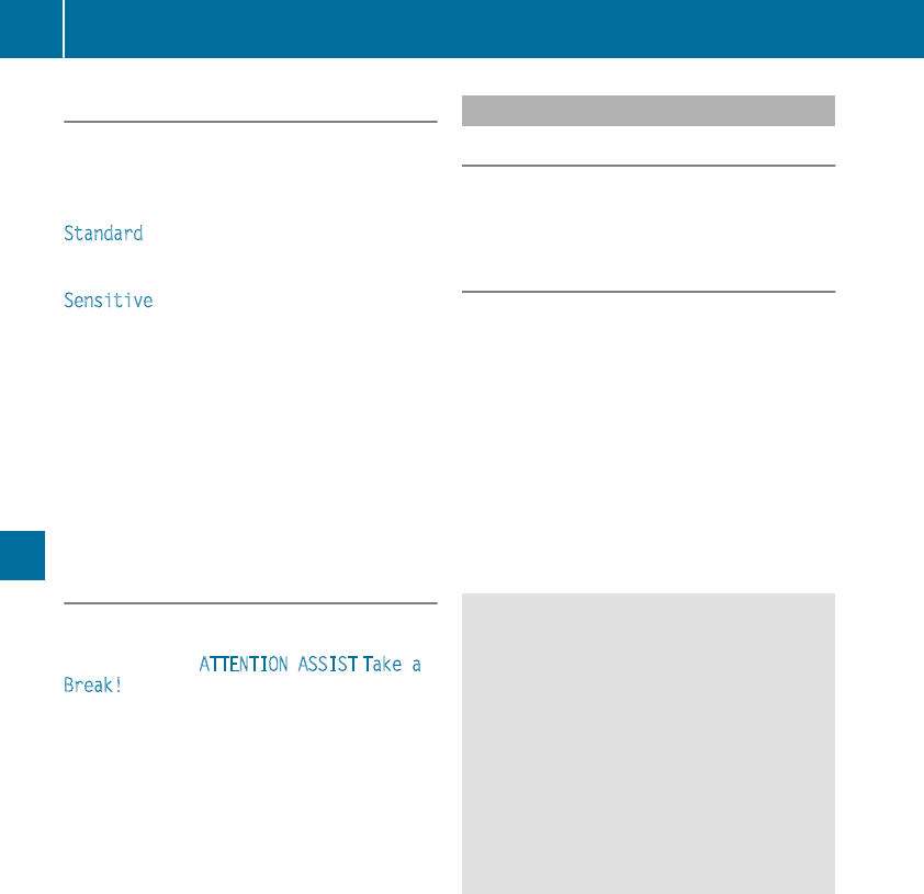
Activating ATTENTION ASSIST
XActivateATTENTION ASSIST usingthe on-
boardcomputer (Ypage 185).
The system determinesthe attention level of
thedriver depending on thesetting selected:
Standard selected: thesensitivitywithwhich
thesystem determinesthe attention level is set
to normal.
Sensitive selected: thesensitivityisset
higher. The attention level detectedbyAttention
Assistisadapted accordingly and thedriver is
warned earlier.
When ATTENTION ASSIST is deactivated, the
ésymbol appearsinthe multifunction dis-
play in theassistancegraphic display.
When ATTENTION ASSIST has been deactivated,
it is automatically reactivated after theengine
has been stopped. The sensitivityselected cor-
responds to thelast selection activated (stand-
ard/sensitive).
Warning in themultifunction display
If fatigue or increasing lapsesinconcentration
are detected, awarning appearsinthe multi-
function display: ATTENTION ASSIST Takea
Break!.
In addition to themessage shown in themulti-
function display, you will then hear awarning
tone.
XIf necessary, takeabreak.
XConfirmthe message by pressing thea
buttononthe steering wheel.
On longjourneys, takeregular breaks in good
time to allow yourself to restproperly. If you do
nottakeabreak and ATTENTION ASSIST still
detects increasing lapsesinconcentration, you
will be warned again after 15 minutesatthe
earliest.This will only happen if ATTEN-
TIONASSISTstill detects typical indicators of
fatigue or increasing lapsesinconcentration.
Vehicles withthe COMAND multimediasys-
tem:if awarning is output in themultifunction
display, aservicestation search is performed in
themultimedia system. You can select aservice
station and navigation to this servicestation will
then begin. This function can be activated or
deactivated in themultimedia system; see the
Digital Operator'sManual.
LaneTracking package
Generalnotes
The LaneTracking packageconsists of Blind
Spot Assist(
Ypage 172) and LaneKeeping
Assist(
Ypage 174).
Blind Spot Assist
Generalnotes
Blind Spot Assistmonitors theareas on either
side of thevehiclethatare notvisible to the
driver withtwo lateral,rear-facingradar sen-
sors. Awarning display in theexteriormirrors
drawsyour attention to vehicles detectedinthe
monitoredarea. If you then switch on thecor-
respondingturnsignal to changelane, you will
also receiveanoptical and audible warning.
Blind Spot Assistsupportsyou from aspeedof
approximately 20 mph (30 km/h).
Important safety notes
GWARNING
Blind Spot Assistdoes notreactto:
Rvehicles overtakentoo closely on theside,
placing them in theblindspotarea
Rvehicles whichapproachwithalargespeed
differential and overtake your vehicle
As aresult,Blind Spot Assistmay notgive
warningsinsuchsituations. There is ariskof
an accident.
Always observethe traffic conditionscare-
fully, and maintainasafelateral distance.
Blind Spot Assistisonlyanaid. It may fail to
detectsomevehicles and is no substitutefor
attentive driving. Always ensurethatthere is
sufficientdistancetothe side for other road
usersand obstacles.
iUSAonly:
This device has been approvedbythe FCC as
a"Vehicular Radar System". The radar sensor
is intended for use in an automotive radar
system only. Removing, tampering with, or
altering thedevice will voidany warranties,
and is notpermittedbythe FCC. Do nottam-
per with, alter, or use in any non-approved
way.
172 Driving systems
Driving and parking
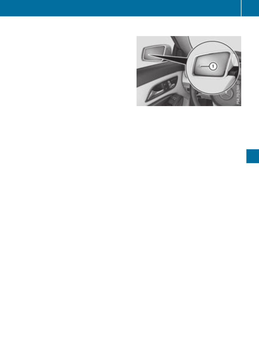
Any unauthorized modification to thisdevice
could voidthe user’sauthority to operate the
equipment.
Radar sensors
The radarsensors for Blind SpotAssist areinte-
grated into the rearbumper. Make sure thatthe
bumpers arefreefrom dirt, ice or slush. The
sensors must not be covered,for exampleby
cycle racks or overhanging loads. Following a
severe impact or in the event of damage to the
bumpers, have the functionofthe radarsensors
checked at aqualified specialist workshop.
Blind SpotAssist maynolongerworkproperly.
Monitoringrangeofthe sensors
In particular, the detection of obstaclescan be
impaired if:
Rthereisdirtonthe sensors or anything else
covering the sensors
Rthereispoorvisibility,e.g.due to fog,heavy
rain or snow
Ranarrow vehicletraveling in front, e.g.a
motorbike or bicycle
Rthe roadhas verywidelanes
Rthe roadhas narrow lanes
Ryouare not driving in the middleofthe lane
Rthereare barriers or otherroadboundaries
Vehicles in the monitoring range arethen not
indicated.
Blind SpotAssist monitors the area up to 10 ft
(3 m) behind your vehicleand directlynext to it.
If the lanes arenarrow,vehicles driving in the
lane beyond the lane next to your vehiclemay be
indicated,especially if the vehicles arenot driv-
ing in the middleoftheirlane. Thismay be the
caseifthe vehicles aredriving on the innerside
of theirlane.
Due to the nature of the system:
Rwarningsmay be issued in error when driving
close to crash barriers or similar solid lane
borders.
Rwarningsmay be interruptedwhenyou are
driving alongsideparticularly long vehicles,
such as trucks, for aprolongedtime.
Warning display
:Warning display
Blind SpotAssist is not active at speedsbelow
approximately20mph (30 km/h). Vehicles in
the monitoring range arethen not indicated.
WhenBlind SpotAssist is activated,indicator
lamp :in the exteriormirrors lights up yellow
at speedsofupto20mph (30 km/h). At speeds
above 20 mph (30 km/h), the indicator lamp
goesout and Blind SpotAssist is operational.
If avehicleisdetectedwithinthe blind spot
monitoring range at speedsabove 20 mph
(30 km/h), warning lamp :on the correspond-
ing side lights up red.Thiswarning is always
emitted when avehicleenters the blind spot
monitoring range from behind or from the side.
Whenyou overtake avehicle, the warning only
occurs if the difference in speed is less than
7mph (12 km/h).
The yellow indicator lamp goesout if reverse
gear is engaged.Inthisevent, Blind SpotAssist
is no longeractive.
The brightness of the indicator/warning lamps
is adjusted automaticallyaccording to the ambi-
ent light.
Collisionwarning
If avehicleisdetectedinthe monitoring range of
Blind SpotAssist and youswitch on the corre-
sponding turn signal, adouble warning tone
sounds. Redwarning lamp :flashes. If the turn
signalremains on, vehicles detectedare indica-
ted by the flashing of red warning lamp :.
There arenofurtherwarning tones.
Driving systems 173
Driving andparking
Z
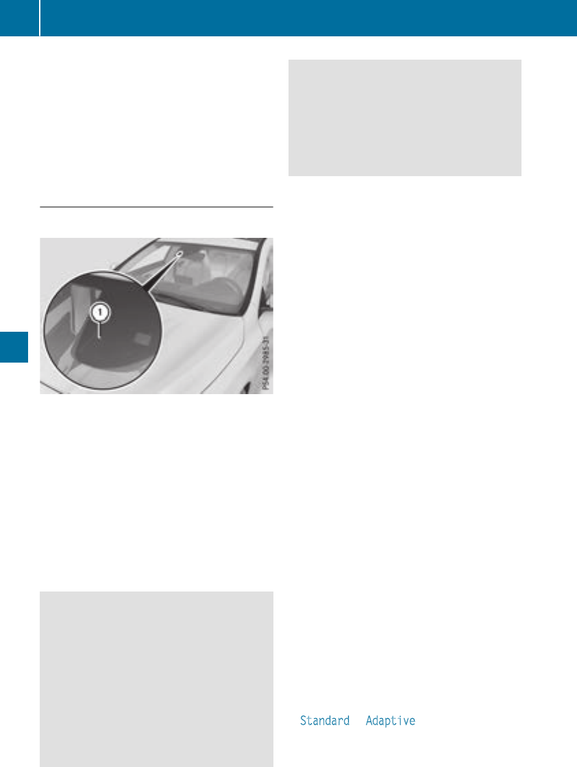
Switching on Blind Spot Assist
XMake sure that Blind Spot Assist is activated
in the on-board computer (Ypage 186).
XTurn the SmartKey to position 2in the igni-
tion lock.
Warning lamps :in the exterior mirrors light
up red for approximately 1.5 seconds and
then turn yellow.
Lane Keeping Assist
General notes
Lane Keeping Assist monitorsthe area in front of
your vehicle by means of multifunction cam-
era :which is attached behind the top of the
windshield. Lane Keeping Assist detectslane
markings on the road and can warn you before
you leave your lane unintentionally.
This function is available in the range between
40 mph and 120 mph (60 km/h and 200 km/h).
Awarning may be given if afront wheel passes
over alane marking. It will warn you by means of
intermittent vibration in the steering wheel for
up to 1.5 seconds.
Important safety notes
GWARNING
Lane Keeping Assist cannot always clearly
detect lane markings.
In such cases, Lane Keeping Assist can:
Rgive an unnecessary warning
Rnot give awarning
There is arisk of an accident.
Always pay particular attention to the traffic
situation and keep within the lane, especially
if Lane Keeping Assist alerts you.
GWARNING
The Lane Keeping Assist warning does not
return the vehicle to the original lane. There is
arisk of an accident.
You should always steer, brake or accelerate
yourself, in particular if warned by Lane Keep-
ing Assist.
If you fail to adapt your driving style, Lane Keep-
ing Assist can neither reduce the risk of an acci-
dent nor override the laws of physics. Lane
Keeping Assist cannot take into account the
road, traffic and weather conditions. Lane Keep-
ing Assist is merely an aid. You are responsible
for the distance to the vehicle in front,for vehi-
cle speed, for braking in good time and for stay-
ing in your lane.
The Lane Keeping Assist does not keep the vehi-
cle in the lane.
The system may be impaired or may not function
if:
Rthere is poor visibility, e.g. due to insufficient
illumination of the road, or due to snow, rain,
fog or spray
Rthere is glare, e.g. from oncomingtraffic, the
sun or reflection from other vehicles (e.g. if
the road surface is wet)
Rthe windshield is dirty, fogged up, damaged or
covered, for instancebyasticker, in the vicin-
ity of the camera
Rthere are no or several unclear lane markings
for one lane, e.g. roadworks
Rthe lane markings are worn away,dark or cov-
ered up, e.g. by dirt or snow
Rthe distance to the vehicle in front is too short
and thus the lane markings cannot be detec-
ted
Rthe lane markings change quickly, e.g. lanes
branch off, cross one another or merge
Rthe road is narrow and winding
Rthere are highly variable shade conditionson
the roadway
Switching on Lane Keeping Assist
XSwitch on Active Lane Keeping Assist using
the on-board computer; to do so, select
Standard or Adaptive (Ypage 174).
If you drive at speeds above 40 mph
(60 km/h) and lane markings are detected,
the lines in the assistance graphic are shown
174 Driving systems
Driving and parking

in green (Ypage 185). Lane KeepingAssist is
ready for use.
If Standard is selected, no warningvibration
occurs if:
Ryou have switched on the turn signal. In this
event, the warnings are suppressed for acer-
tain period of time.
Radrivingsafetysystem intervenes,e.g. ABS,
BASorESP®.
When Adaptive is selected, no warningvibra-
tion occurs if:
Ryou have switched on the turn signal. In this
event, the warnings are suppressed for acer-
tain period of time.
Radrivingsafetysystem intervenes,e.g. ABS,
BASorESP®.
Ryou acceleratehard, e.g. kickdown.
Ryou brakehard.
Ryou steer actively, e.g. swervetoavoid an
obstacle or change lanes quickly.
Ryou cut the corner on asharp bend.
In order that you are warnedonly when neces-
sary and in good timeifyou cross the lane mark-
ing, the system detectscertain conditionsand
warns you accordingly.
The warningvibration occurs earlier if:
Ryou approachthe outer lane marking on a
bend
Rthe road has very wide lanes, e.g. afreeway
Rthe system detectssolid lane markings
The warningvibration occurs later if:
Rthe road has narrow lanes.
Ryou cut the corner on abend
Driving systems 175
Driving and parking
Z

Important safety notes
GWARNING
If you operate information systems and com-
munication equipmentintegratedinthe vehi-
cle when driving,you may be distractedfrom
thetraffic situation.You could also lose con-
trol of thevehicle. Thereisariskofanacci-
dent.
Only operate this equipmentwhen thetraffic
situation permits. If you are notsurethatthis
is possible,park thevehiclepayingattention
to traffic conditionsand operate theequip-
mentwhen thevehicleisstationary.
You must observethe legal requirements for the
country in whichyou are currentlydriving when
operating theon-board computer.
GWARNING
If theinstrumentclusterhas failedormal-
functioned, you may notrecognize function
restrictionsinsystems relevanttosafety. The
operating safetyofyour vehiclemay be
impaired.Thereisariskofanaccident.
Drive on carefully. Havethe vehiclechecked
at aqualified specialist workshop immedi-
ately.
The on-board computer only shows messagesor
warningsfromcertainsystems in themultifunc-
tion display. You should thereforemakesure
your vehicleisoperating safely at all times.
If theoperating safetyofyour vehicleis
impaired,pull overassoonasitissafetodoso.
Contactaqualified specialist workshop.
Foranoverview, see theinstrumentpanel illus-
tration (Ypage 33).
Displaysand operation
Instrumentcluster lighting
The lightsensor in theinstrumentclusterauto-
matically controlsthe brightness of themulti-
function display. In daylight, thedisplays in the
instrumentclusterare notilluminated.
The lighting in theinstrumentcluster, in thedis-
plays and thecontrols in thevehicleinterior can
be adjusted usingthe brightness control knob.
The brightness control knob is locatedonthe
bottomleftofthe instrumentcluster
(Ypage 33).
XTurn thebrightness control knob clockwise or
counter-clockwise.
If thelightswitch is set to theÃ,Tor
Lposition,the brightness is dependent
upon thebrightness of theambientlight.
Speedometer with segments
The speedometer is divided intosegments on
vehicles withDistance Pilot DISTRONIC.
The segments in thespeedometer indicate
whichspeedrange is available.
RDistancePilot DISTRONICisactivated
(Ypage 151):
Oneortwo segments in theset speedrange
lightup.
RDistancePilot DISTRONICdetects avehiclein
frontmoving moreslowly than thestored
speed:
The segments between thespeedofthe vehi-
cle in frontand thestoredspeedlightup.
Tachometer
!Do notdriveinthe overrevving range, as this
could damagethe engine.
The red bandinthe tachometer indicates the
engine's overrevving range.
The engineislimitedwithin arange to protect
theenginewhen thered bandisreached.
Outsidetemperaturedisplay
You should pay special attention to road condi-
tionswhen temperatures are aroundfreezing
point.
Bearinmindthatthe outside temperature dis-
play indicates thetemperature measured and
does notrecord theroad temperature.
The outside temperature display is in themulti-
function display (Ypage 179).
176 Displaysand operation
On-boardcomputer and displays
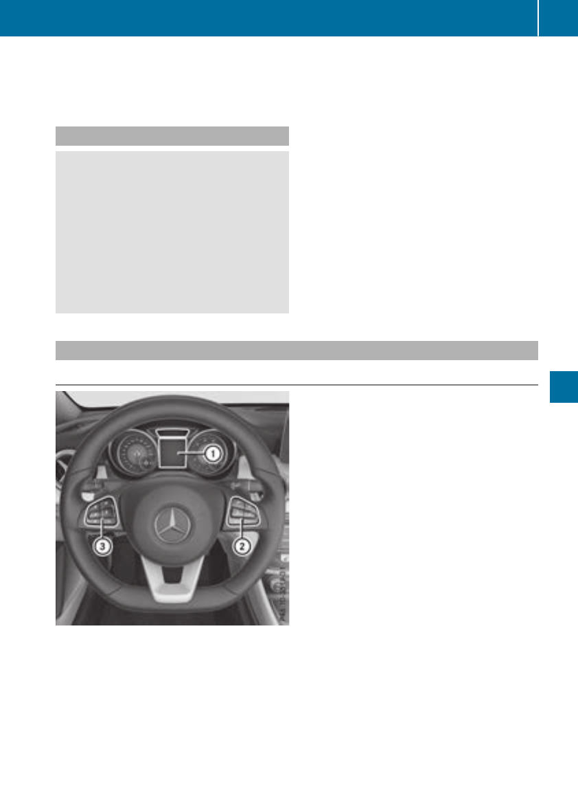
There is ashort delay before achange in outside
temperature appears in the multifunction dis-
play.
Coolant temperature gauge
GWARNING
Opening the hood when the engine is over-
heated or when there is afire in the engine
compartment could expose you to hot gases
or other service products. There is arisk of
injury.
Let an overheated engine cool down before
opening the hood. If there is afire in the
engine compartment,keep the hood closed
and contact the fire department.
!Adisplay message is shown if the coolant
temperature is too high.
If the coolant temperature is over 248 ‡
(120 †), do not continue driving. The engine
will otherwise be damaged.
The coolant temperature gage is in the instru-
ment cluster on the right-hand side (Ypage 33).
The Hmarking in the coolant temperature gauge
corresponds to acoolant temperature of
approximately 248 ‡(120 †).
Under normal operating conditions and at the
correctcoolant level, the coolant temperature
gauge may rise to the Hmarking.
Operating the on-board computer
Overview
:Multifunction display
;Right control panel
=Left control panel
XTo activatethe on-board computer: turn the SmartKey to position 1in the ignition lock.
You can control the multifunction display and the settings in the on-board computer using the
buttonsonthe multifunction steeringwheel.
Displays and operation 177
On-board computer and displays
Z
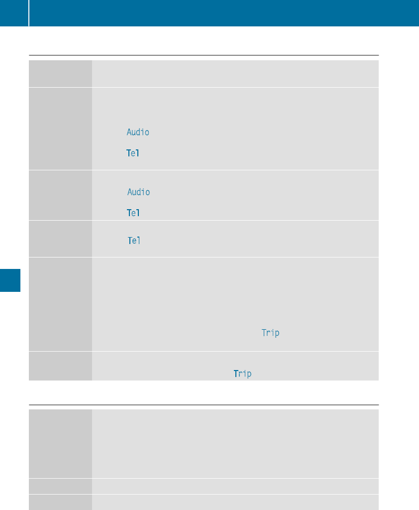
Left control panel
=
;
RCalls up themenuand menubar
9
:
Press briefly:
RScrolls in lists
RSelectsasubmenu or function
RIn the Audio menu: selects theprevious or nextstation, when thepreset list
or stationlist is active, or an audio track or video scene
RIn the Tel (telephone) menu: switchestothe phonebook and selects aname
or telephonenumber
9
:
Press and hold:
RIn the Audio menu: selects apreset list or astationlist in thedesired fre-
quency range, or an audio track or video scene usingrapid scrolling
RIn the Tel (Telephone) menu: startsrapid scrollingifthe phonebook is open
aRConfirmsthe selectionordisplay message
RIn the Tel (Telephone) menu: switchestothe telephonebook and starts
dialingthe selected number
%Press briefly:
RBack
RVehicles with Audio 20:switchesoff voice-operated control for navigation
(see themanufacturer'soperatinginstructions)
RVehicles with COMAND:switchesoff theVoiceControl System (see thesep-
arateoperatinginstructions)
RHidesdisplay messages or calls up thelast Trip menufunction used
RExits thetelephonebook/redial memory
%Press and hold:
RCalls up thestandarddisplay in the Trip menu
Rightcontrol panel
óRVehicles with Audio 20:
Switchesonvoice-operated control for navigation (see themanufacturer's
operatinginstructions)
RVehicles with COMAND:
Switchesoff theVoiceControl System (see theseparate operatinginstruc-
tions)
8RMute
WX RAdjusts the volume
178 Displays and operation
On-board computer and displays
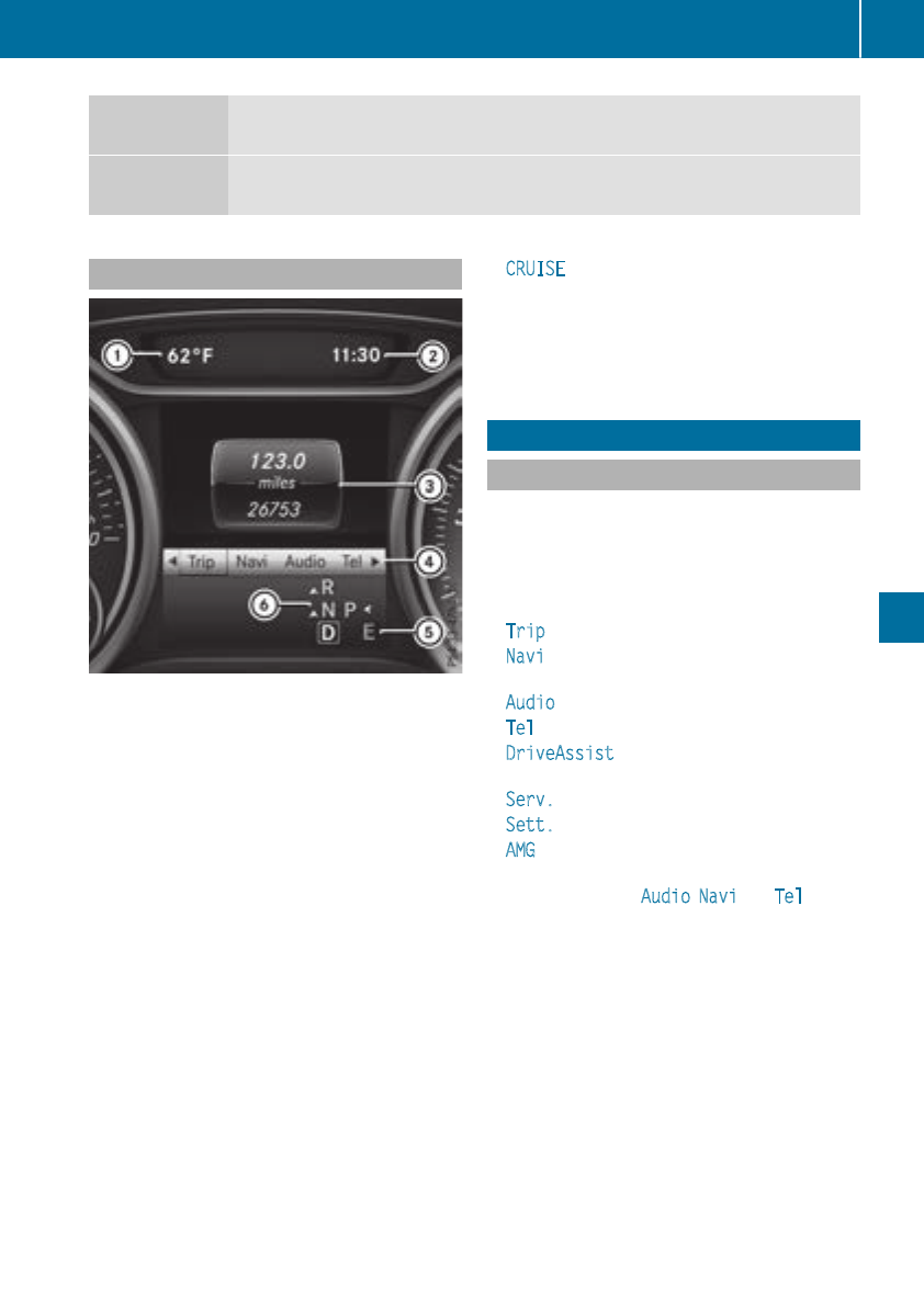
~RRejects or ends acall
RExitsthe telephonebook/redial memory
6RMakes or acceptsacall
RSwitches to theredial memory
Multifunction display
:Permanentdisplay: outside temperature or
speed(
Ypage 187)
;Time
=Textfield
?Menubar
ADrive program (Ypage 130)
BTransmissionposition (Ypage 132)
In Mercedes-AMGvehicles, theindicators in the
lower and upper part of themultifunction display
differ from thedisplays shown here.
XTo displaymenubar ?:press the=
or ;buttononthe steering wheel.
If you do notpress thebuttons any longer,
menubar ?is fadedout after afew seconds.
Textfield =shows theselected menuorsub-
menuaswell as display messages.
iSetthe time usingthe multimedia system
(see theseparateoperating instructions).
Thefollowing messages mayappearinthe
multifunction display:
RZGearshiftrecommendation,when shifting
manually (Ypage 136)
RjParking Pilot (Ypage 164)
RCRUISE Cruisecontrol(Ypage 149)
R_Adaptive Highbeam Assist
(Ypage 102)
RèECO start/stopfunction (Ypage 126)
RëHOLD function (Ypage 157)
Menusand submenus
Menu overview
Using the=or ;buttononthe steering
wheel, open themenubar.
Operating theon-board computer (Ypage 177).
Dependingonthe equipmentinstalled in the
vehicle, you can call up thefollowingmenus:
RTripmenu(Ypage 180)
RNavimenu(navigation instructions)
(Ypage 181)
RAudio menu(Ypage 182)
RTel menu(telephone) (Ypage 183)
RDriveAssist menu(assistance)
(Ypage 184)
RServ. menu(Ypage 186)
RSett. menu(settings) (Ypage 186)
RAMG menu(Mercedes-AMGvehicles)
(Ypage 188)
The displays for theAudio,Naviand Tel menus
may differ slightly from those in your vehicle.
The examples given in this Operator's Manual
apply to vehicles equipped withCOMAND.
Menusand submenus 179
On-boardcomputer and displays
Z
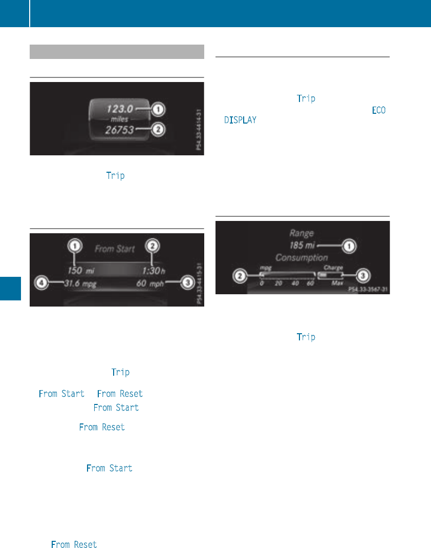
Trip menu
Standard display
XPress and holdthe %button on the steer-
ing wheeluntilthe Trip menu with trip odom-
eter :and odometer ;appears.
Trip computer"From Start" or "From
Reset"
:Distance
;Driving time
=Averagespeed
?Averagefuelconsumption
XPress the =or ;button on the steering
wheeltoselect the Trip menu.
XPress the 9or :button to select
FromStart or FromReset.
The values in the From Start submenu arecal-
culatedfromthe start of ajourney whilst the
values in the FromReset submenu arecalcu-
lated fromthe last time the submenu wasreset
(Ypage 181).
In the following cases, the trip computerisauto-
maticallyreset FromStart:
Rthe ignition hasbeenswitched off for more
thanfourhours.
R999 hours have been exceeded.
R9,999 miles have been exceeded.
When 9,999 hours or 99,999 miles have been
exceeded,the trip computerisautomatically
reset FromReset.
ECOdisplay
The ECO displayisnot availableinMercedes-
AMG vehicles.
XPress the =or ;button on the steering
wheeltoselect the Trip menu.
XPress the 9or :button to select ECO
DISPLAY.
If the ignition remains switched off for longer
thanfourhours, the ECO displaywillbeauto-
maticallyreset.
For moreinformationonthe ECO display, see
(Ypage 145).
Displaying the rangeand currentfuel
consumption
Mercedes-AMG vehicles: the menu onlyshows
range :.
XPress the =or ;button on the steering
wheeltoselect the Trip menu.
XPress 9or :to select the displaywith
approximate range :and current fuel con-
sumption ;.
Approximate range :thatcan be covered is
calculatedaccording to your current driving
style and the amount of fuel in the tank. If
there is onlyasmall amount of fuel left in the
fuel tank, avehiclebeing refueled C
appearsinsteadofapproximate range :.
Recuperationdisplay =shows youifenergy
hasbeenrecuperated fromthe kinetic energy
in overrunmodeand saved in the battery.
Recuperationdisplay =depends on the
engine installedand is therefore not available
in allvehicles.
180 Menus and submenus
On-board computer and displays
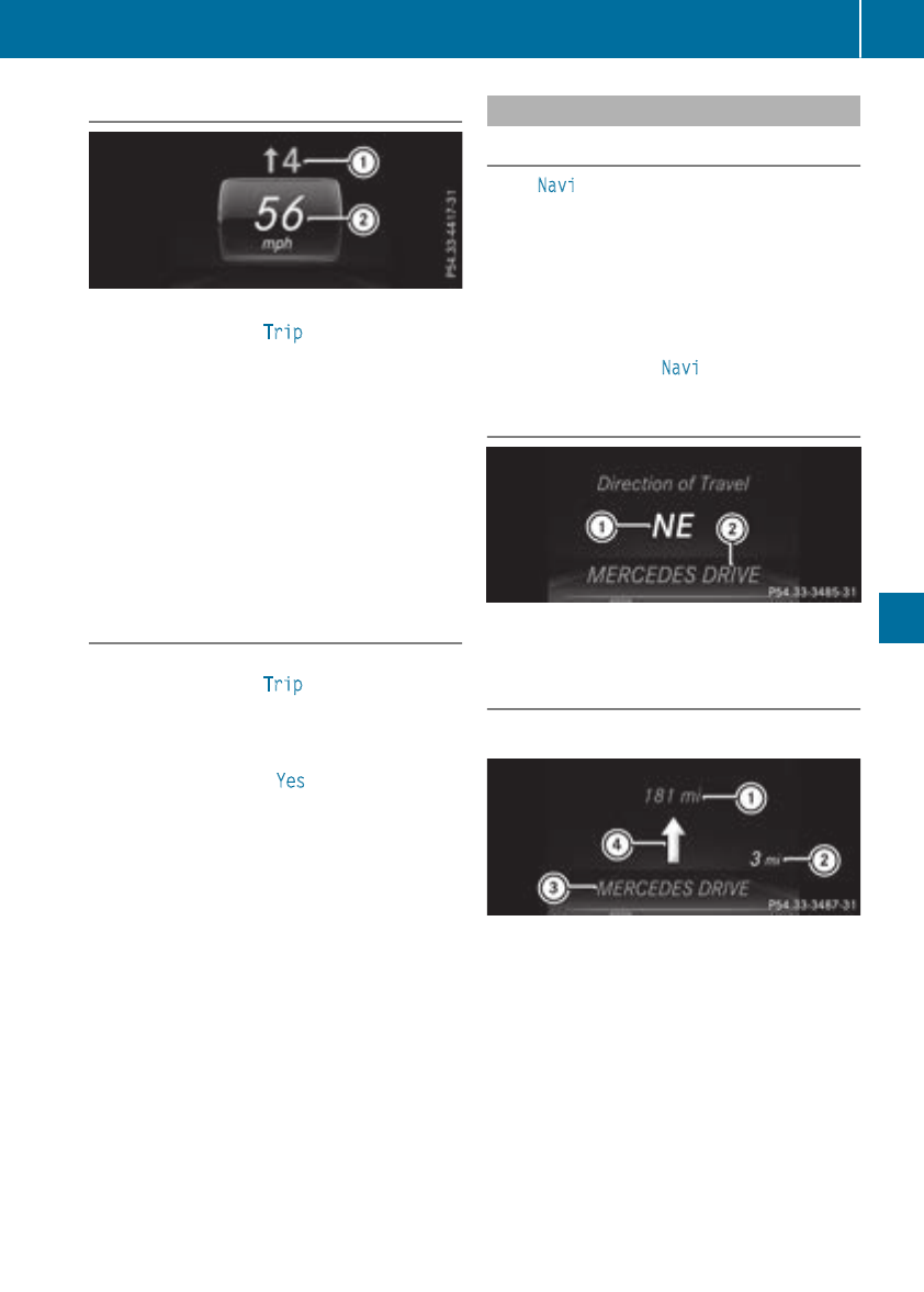
Digital speedometer
XPress the=or ;buttononthe steering
wheeltoselectthe Tripmenu.
XPress the9or :buttontoselectthe
digitalspeedometer ;.
Agear shift recommendation :Zcan also
follow.
Observethe information on gearshift recom-
mendation :when shiftingmanually
(Ypage 136).
Mercedes-AMG vehicles:agearshift recom-
mendation is shown in thestatusbar of the
multifunction display and notinthe digital
speedometer display.
Resetting values
XPress the=or ;buttononthe steering
wheeltoselectthe Tripmenu.
XPress the9or :buttontoselectthe
function that you wish to reset.
XPress ato confirm.
XPress :to selectYes and press ato
confirm.
You can reset thevalues of thefollowingfunc-
tions:
RTrip odometer
R"From Start"tripcomputer
R"From Reset" trip computer
RECOdisplay
If you reset thevalues in theECO display, the
values in the"From Start"tripcomputerare also
reset.Ifyou reset thevalues in the"From Start"
trip computer, thevalues in theECO display are
also reset.
Navigation systemmenu
Displaying navigation instructions
In theNavimenu, themultifunction display
shows navigation instructions.
You can findfurther information on navigation in
theseparatemultimedia system operating
instructions.
XSwitchonthe multimedia system (seesepa-
rateoperatinginstructions).
XPress the=or ;buttononthe steering
wheeltoselectthe Navimenu.
Route guidance not active
:Direction of travel
;Currentroad
Route guidance active
No change of direction announced
:Distancetodestination
;Distancetothe next changeofdirection
=Currentroad
?"Follow theroad's course" symbol
Menus andsubmenus 181
On-board computerand displays
Z
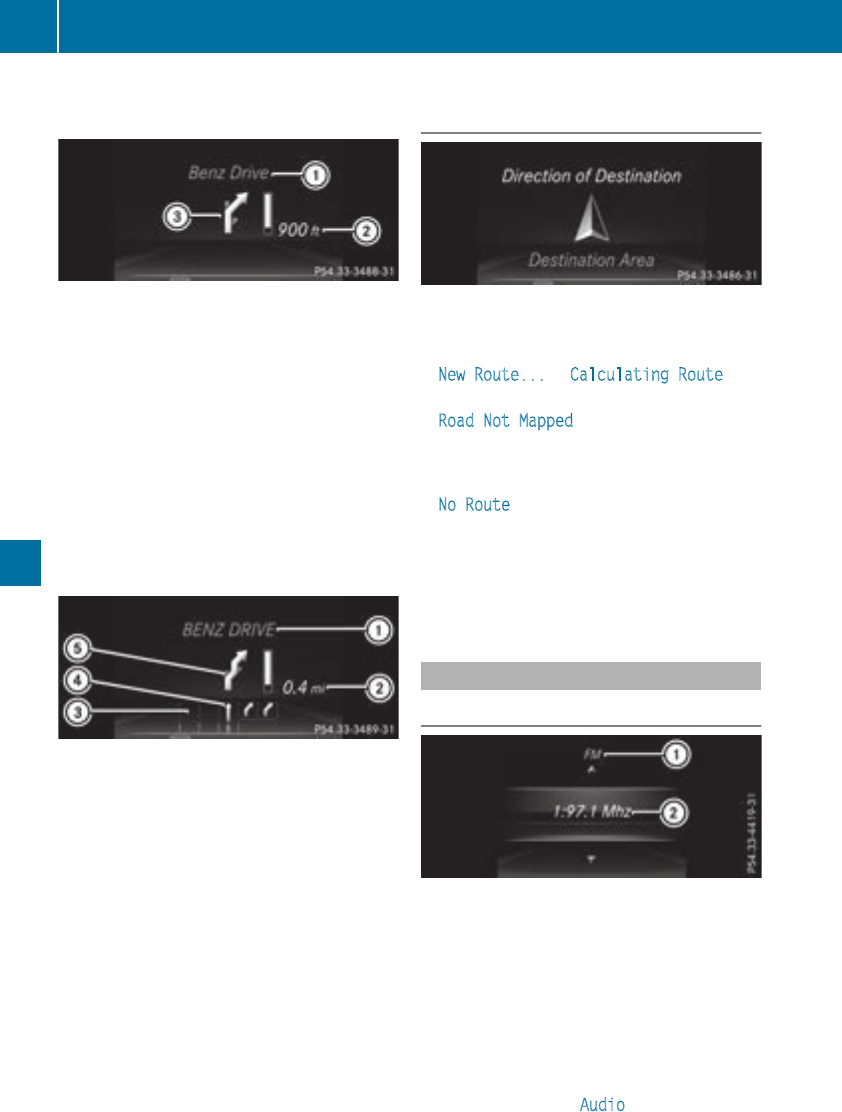
Change of direction without lane recom-
mendation
:Road intowhichthe change of direction
leads
;Distance to change of direction and visual
distancedisplay
=Change-of-direction symbol
When achange of direction is to be made, you
will see symbol =for thechange of direction
and distancegraphic ;.The distanceindicator
shortens towards thetop of thedisplay as you
approach thepointofthe announced change of
direction.The change of direction startsonce
thedistancedisplay reaches zero.
Change of direction announced with a
lane recommendation
:Road intowhichthe change of direction
leads
;Distance to change of direction and visual
distancedisplay
=Lanes notrecommended
?Recommendedlane and new lane duringa
change of direction
AChange-of-direction symbol
On multilane roads,new lane recommendations
can be displayedfor thenextchange of direction
if thedigital map supportsthisdata. During the
change of direction,new lanesmay be added.
Lanenot recommended =:you will notbeable
to completethe nextchange of direction if you
stay in this lane.
Recommendedlane and new lane duringa
change of direction ?:inthislane you will be
able to completethe nexttwo changes of direc-
tionwithout changinglane.
Other status indicators of thenaviga-
tion system
The navigation system displays additional infor-
mation and thevehicle status.
Possible displays:
RNew Route... or Calculating Route
Anew routeiscalculated.
RRoadNot Mapped
The vehicle position is inside thearea of the
digital map but theroad is notrecognized, e.g.
newly built streets, car parksorprivate land.
RNo Route
No routecouldbecalculatedtothe selected
destination.
RO
You have reached thedestination or an inter-
mediate destination.
Audio menu
Selecting aradio station
:Activestationlist
;Stationfrequency with memory position
The multifunction display showsstation ;with
stationfrequency or stationname. The preset
position is only displayedalongwith station ;if
this has been stored.
XSwitch on themultimedia system and select
Radio (see theseparate operatinginstruc-
tions).
XPressthe =or ;button on thesteering
wheel to selectthe Audio menu.
182 Menusand submenus
On-boardcomputer and displays
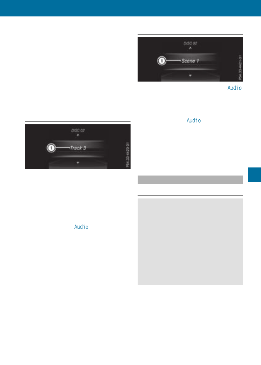
XTo select apreset list or station list: press
and brieflyholdthe 9or :button until
the preset list or stationlistinthe desired
frequency rangeisshown.
XTo select astation: brieflypress 9
or :.
iSIRIUS XM satellite radio functions like a
normalradio.
Youcan find further informationonoperation
in the "Satellite radio"section of the separate
multimedia system operating instructions.
Operatinganaudioplayer or audio
media
:Current title
Audio data from various audiodevicesormedia
can be played,depending on the equipment
installedinthe vehicle.
XSwitch on the multimedia system and then
audioCDorMP3 mode(seethe separate
operating instructions).
XPress the =or ;button on the steering
wheeltoselect the Audio menu.
XTo select the next/previous track: briefly
press the 9or :button.
XTo select atrack from the track list (rapid
scrolling): press and holdthe 9or :
button untildesired trackappears.
If youpress and hold 9or :,the rapid
scrolling speed is increased.Not allaudio
drives or data carriers support thisfunction.
If trackinformationisstored on the audiodevice
or medium, the multifunctiondisplay will show
the numberand titleofthe track.
VideoDVD operation
Youcan onlyoperate DVD videos in the Audio
menu in vehicles with COMAND.
XSwitch on COMAND and select video DVD
(seethe separate operating instructions).
XPress the =or ;button on the steering
wheeltoselect the Audio menu.
XTo select the next or previous scene:
brieflypress the 9or :button.
XTo select ascene from the scenelist
(rapidscrolling): press and holdthe 9
or :button untildesired scene :
appears.
Telephone menu
Introduction
GWARNING
If youoperate informationsystemsand com-
municationequipment integrated in the vehi-
cle when driving,you maybedistracted from
the traffic situation. Youcould also lose con-
trol of the vehicle. There is ariskofanacci-
dent.
Onlyoperate thisequipment when the traffic
situationpermits. If youare not sure thatthis
is possible, park the vehiclepayingattention
to traffic conditions and operate the equip-
ment when the vehicleisstationary.
Whentelephoning, youmustobserve the legal
requirements for the country in which youare
currentlydriving.
XSwitch on the mobilephone (seethe manu-
facturer’soperating instructions).
XSwitch on the multimedia system (seesepa-
rate operating instructions).
Menus and submenus 183
On-board computer and displays
Z
XEstablishaBluetooth®connectiontothe mul-
timediasystem;see the separate operating
instructions.
XPress the =or ;button on the steering
wheeltoselect the Tel menu.
Youwillsee one of the following displaymes-
sagesinthe multifunctiondisplay:
RTelephone READY or the nameofthe net-
work provider: the mobilephone hasfound a
network and is ready to receive.
RTelephone No service:there is no network
availableorthe mobilephone is searching for
anetwork.
Acceptingacall
If someone calls youwhenyou areinthe Tel
menu,adisplay message appearsinthe multi-
functiondisplay.
Youcan acceptacallatany time,evenifyou are
not in the Tel menu.
XPress the 6button on the steeringwheel
to acceptanincomingcall.
Rejecting or endingacall
Youcan end or reject acallanytime,evenifyou
arenot in the Tel menu.
XPress the ~button on the steeringwheel
to reject or end acall.
Selecting an entry in the phone book
XPress the =or ;button on the steering
wheeltoselect the Tel menu.
XPress the 9,:or abutton to
switch to the phone book.
XAuthorize access to the phone book on the
phone.
XPress the 9or :button to select the
desired name.
or
XTo beginrapid scrolling: press and holdthe
9or :button for longerthanone sec-
ond.
Rapidscrolling stopswhenyou release the
button or reach the end of the list.
XIf only onetelephonenumber is stored for
aname: press the 6or abutton to
start dialing.
or
XIf there is more than onenumber fora
particular name: press the 6or a
button to displaythe numbers.
XPress the 9or :button to select the
numberyou want to dial.
XPress the 6or abutton to start dialing.
or
XIf youdonot want to make acall: press the
~or %button.
Redialing
The on-board computersaves the last names or
numbers dialed in the redialmemory.
XPress the =or ;button on the steering
wheeltoselect the Tel menu.
XPress the 6button to switch to the redial
memory.
XPress the 9or :button to select the
desired nameornumber.
XPress the 6or abutton to start dialing.
or
XIf youdonot want to make the call: press
the ~or %button.
Assistance menu
Introduction
Depending on the equipment installedinthe
vehicle, youhavethe following options in the
DriveAssist menu:
RDisplaying the assistance graphic
(Ypage 185)
RDeactivating/activating ESP®(except
Mercedes‑AMG vehicles) (Ypage 185)
RActivating/deactivating ActiveBrake Assist
(Ypage 185)
RActivating/deactivating ATTENTION ASSIST
(Ypage 185)
RActivating/deactivating Blind SpotAssist
(Ypage 186)
RActivating/deactivating Lane Keeping Assist
(Ypage 186)
184 Menus and submenus
On-board computer and displays
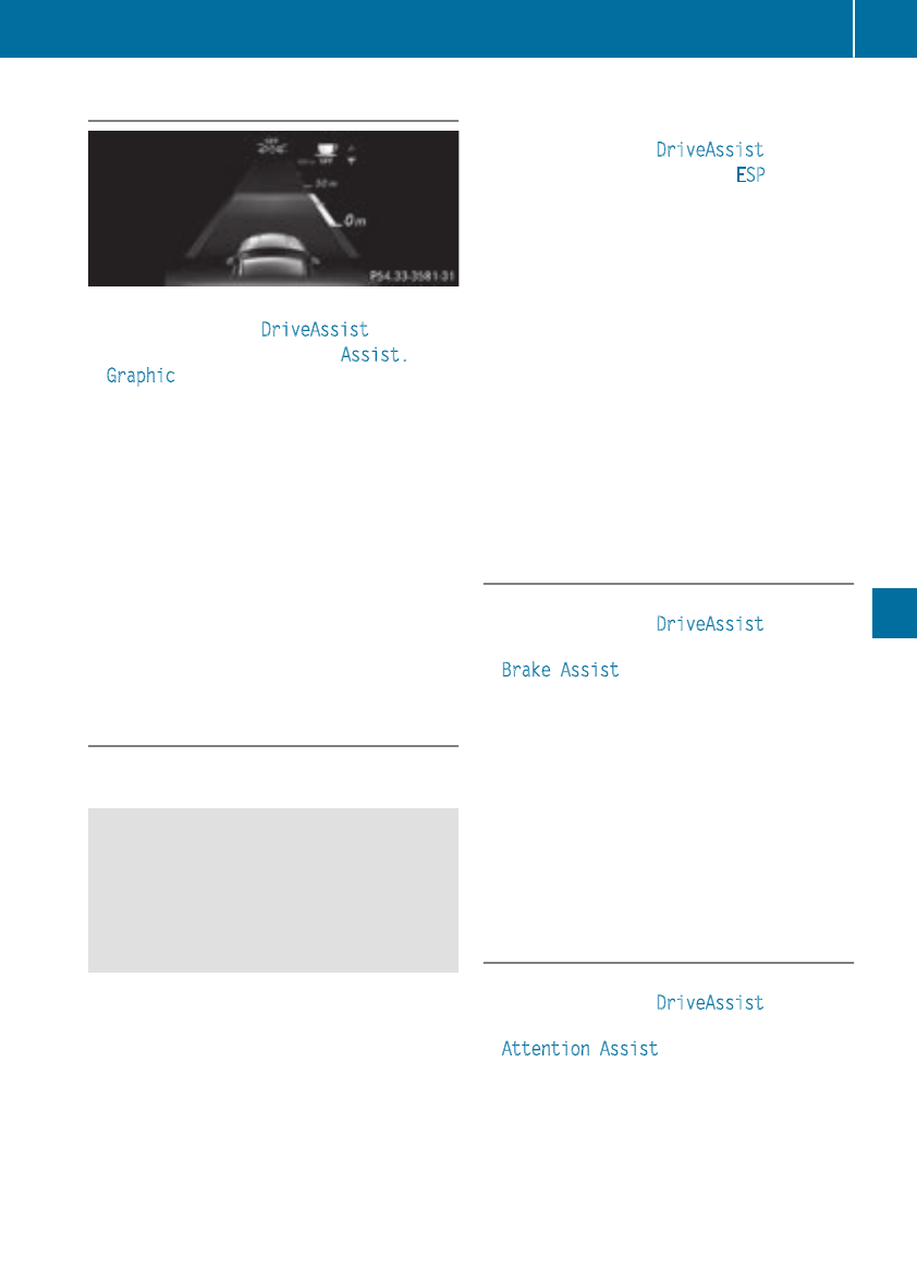
Displaying theassistance graphic
XPress the=or ;buttononthe steering
wheeltoselectthe DriveAssist menu.
XPress 9or :to selectAssist.
Graphic.
XPress ato confirm.
The multifunction display shows theDistance
PilotDISTRONIC distancedisplay in theassis-
tancegraphicdisplay.
The assistancegraphicdisplays thestatusof
and information from thefollowingdriving
systems or drivingsafetysystems:
RDistancePilotDISTRONIC (Ypage 151)
RActive BrakeAssist(Ypage 62)
RATTENTION ASSIST (Ypage 171)
RLaneKeepingAssist(Ypage 174)
XPress :to display theATTENTION ASSIST
assessment.
Deactivating/activating ESP®
Observethe important safetynotes on ESP®
(Ypage 64).
GWARNING
If you deactivateESP®,ESP®no longer sta-
bilizes thevehicle. There is an increasedrisk
of skidding and an accident.
Only deactivateESP®in thesituationsdescri-
bed in thefollowing.
It may be besttodeactivateESP®in thefollow-
ingsituations:
Rwhen usingsnowchains
Rin deepsnow
Ron sandorgravel
Deactivating/activatingESP®in Mercedes-
AMGvehicles (Ypage 66).
Forfurther information about ESP®,see
(Ypage 64).
XStart theengine.
XPress the=or ;buttononthe steering
wheeltoselectthe DriveAssist menu.
XPress 9or :to selectESP.
XPress ato confirm.
The currentselection appears.
XTo activate/deactivate:press theabut-
tonagain.
ESP®is deactivated if theåwarninglamp
in theinstrument cluster lights up continu-
ouslywhen theengineisrunning.
If the÷and åwarninglampslightup
continuously, ESP®is notavailable due to amal-
function.
Observethe information on warninglamps
(Ypage 221).
Observethe information on display messages
(Ypage 192).
Activating/deactivating Active Brake
Assist
XPress the=or ;buttononthe steering
wheeltoselectthe DriveAssist menu.
XPress the9or :buttontoselect
Brake Assist.
XPress ato confirm.
The currentselection appears.
XTo activate/deactivate:press theabut-
tonagain.
WhenActiveBrake Assistisdeactivated, the
æsymbol appears in themultifunction dis-
play in theassistancegraphicdisplay.
Further information on Active BrakeAssist
(Ypage 62).
Activating/deactivating ATTENTION
ASSIST
XPress the=or ;buttononthe steering
wheeltoselectthe DriveAssist menu.
XPress the9or :buttontoselect
Attention Assist.
XPress ato confirm.
The currentselection appears.
XPress ato confirm.
Menus andsubmenus 185
On-board computerand displays
Z
XPress the :or 9button to set Off,
Standard or Sensitive.
XPress the abutton to save the setting.
When ATTENTION ASSIST is deactivated, the
ésymbol appears in the multifunction dis-
play in the assistancegraphics display.
For further information about ATTENTION
ASSIST, see (Ypage 171).
Activating/deactivating Blind Spot
Assist
XPress the =or ;button on the steering
wheel to select the DriveAssist menu.
XPress the 9or :button to select
Blind Spot Assist.
XPress ato confirm.
The currentselection appears.
XTo activate/deactivate: press the abut-
ton again.
For further information about Blind Spot Assist,
see (Ypage 172).
Activating/deactivating Lane Keeping
Assist
XPress the =or ;button on the steering
wheel to select the DriveAssist menu.
XPress the 9or :button to select
Lane Keeping Assist.
XPress ato confirm.
The currentselection appears.
XPress aagain to confirm.
XPress the :or 9button to set Off,
Standard or Adaptive.
XPress the abutton to save the setting.
When Lane Keeping Assist is activated, the
multifunction display shows the lane mark-
ings as bright lines in the assistancegraphic.
For further information about Lane Keeping
Assist,see (Ypage 174).
Service menu
Dependingonthe equipment installed in the
vehicle, you have the following options in the
Serv. menu:
RCalling up display messages in message
memory (Ypage 191)
RRestartingthe tire pressure loss warning sys-
tem (Canada only) (Ypage 294)
RChecking the tire pressure electronically
(USA only) (Ypage 294)
RCalling up the service due date
(Ypage 261)
Settings menu
Introduction
Dependingonthe equipment installed in the
vehicle, you have the following options in the
Sett. menu:
RChanging the instrument cluster settings
RChanging the light settings
RChanging the vehicle settings
RChanging the conveniencesettings
RRestoring the factorysettings
Instrument cluster
Selecting the distance unit
The Display Unit Speed-/Odometer: func-
tion allows you to choose whether certain dis-
plays appear in kilometersormiles in the mul-
tifunction display.
XPress the =or ;button on the steering
wheel to select the Sett. menu.
XPress the :or 9button to select the
Instrument Cluster submenu.
XPress ato confirm.
XPress the :or 9button to select the
Display Unit Speed-/Odometer function.
You will see the selected setting: km or miles.
XPress the abutton to save the setting.
The selected unit of measurement for distance
applies to:
RDigital speedometer in the Trip menu
ROdometer and the trip odometer
RTrip computer
RCurrent fuel consumption and approximate
range
RNavigation instructionsinthe Navi menu
RCruise control
186 Menus and submenus
On-board computer and displays
RDistance PilotDISTRONIC
RASSYST PLUSserviceintervaldisplay
Switchingthe additional speedometer
on/off
If the additional speedometerisswitched on,
the speedisshown in the status barinthe mul-
tifunctiondisplay insteadofthe outside tem-
perature.
The speeddisplay is inversetothe speedome-
ter.
XPress the =or ;button on the steering
wheeltoselect the Sett. menu.
XPress the :or 9button to select the
InstrumentCluster submenu.
XPress ato confirm.
XPress the :or 9button to select the
Speedometer [km/h] or Speedometer
[mph] function.
Youwillsee the selectedsetting: On or Off.
XPress the abutton to save the setting.
Selecting permanent display
The Permanent Display: functionallowsyou
to choose whether the multifunctiondisplay
always shows the outside temperatureorthe
speed.
The speeddisplay is inversetothe speedome-
ter.
XPress the =or ;button on the steering
wheeltoselect the Sett. menu.
XPress the :or 9button to select the
Instr. Cluster submenu.
XPress ato confirm.
XPress the :or 9button to select the
Permanent Display: function.
The current setting, OutsideTemperature
or Speedometer [km/h]/Speedometer
[mph],appears.
XPress the abutton to save the setting.
Lights
Switchingthe daytime runninglamps on/
off
Thisfunctionisnot availableinCanada.
XPress the =or ;button on the steering
wheeltoselect the Sett. menu.
XPress the :or 9button to select the
Light submenu.
XPress ato confirm.
XPress the :or 9button to select the
DaytimeRunningLights function.
If the Daytime Running Lights functionhas
been switched on, the multifunctiondisplay
shows the cone of light and the Wsymbol
in orange.
XPress the abutton to save the setting.
Furtherinformationondaytime running lamps
(Ypage 100).
Vehicle
Activating/deactivating the automatic
doorlocking mechanism
XPress the =or ;button on the steering
wheeltoselect the Sett. menu.
XPress the :or 9button to select the
Vehicle submenu.
XPress ato confirm.
XPress the :or 9button to select the
Automatic DoorLock function.
If the Automatic DoorLock functionis
switched on, the multifunctiondisplay shows
the doors in orange.
XPress the abutton to save the setting.
If youactivate the Automatic Door Lock func-
tion, the vehicleiscentrallylocked above a
speedofaround 9mph (15 km/h).
For furtherinformationonthe automatic locking
feature, see (Ypage 77).
Activating/deactivating the acoustic
lockingverificationsignal
If youswitch on the Acoustic Lock function, an
acoustic signalsounds when youlockthe vehi-
cle.
XPress the =or ;button on the steering
wheeltoselect the Sett. menu.
XPress the :or 9button to select the
Vehicle submenu.
XPress ato confirm.
XPress the :or 9button to select the
Acoustic Lock function.
If the Acoustic Lock functionisactivated,
the multifunctiondisplay shows the &
symbolinorange.
XPress the abutton to save the setting.
Menus and submenus 187
On-board computer and displays
Z
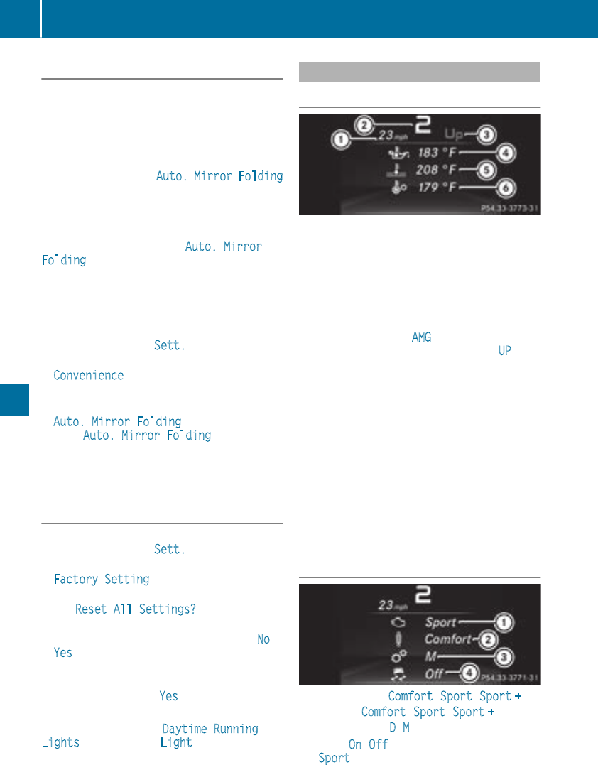
Comfort
Switching thefold-in mirrorswhen lock-
ing feature on/off
This function is only available in Canada.
This function is only available when thevehicle is
equipped withthe electrical fold-in function.
When you activatethe Auto. Mirror Folding
function,the exterior mirrorsare folded in when
thevehicle is locked. If you unlock thevehicle
and then open thedriver'sorfront-passenger
door,the exterior mirrorsfold out again.
If you have switched on the Auto. Mirror
Folding function and you fold in theexterior
mirrorsusingthe buttononthe door
(Ypage 97), they will notfold out automatically.
The exterior mirrorscan then only be folded out
usingthe buttononthe door.
XPress the =or ;buttononthe steering
wheel to selectthe Sett. menu.
XPress the :or 9buttontoselectthe
Convenience submenu.
XPress ato confirm.
XPress the :or 9buttontoselectthe
Auto. Mirror Folding function.
If the Auto. Mirror Folding function is
switched on,the multifunction display shows
theexterior mirror in orange.
XPress the abuttontosave thesetting.
Restoring thefactorysettings
XPress the =or ;buttononthe steering
wheel to selectthe Sett. menu.
XPress the :or 9buttontoselectthe
FactorySetting submenu.
XPress ato confirm.
The Reset All Settings? function
appears.
XPress the :or 9buttontoselect No or
Yes.
XPress the abuttontoconfirmthe selec-
tion.
If you have selected Yes,the multifunction
display shows aconfirmation message.
For safety reasons, the DaytimeRunning
Lights function in the Light submenuisonly
reset if thevehicle is stationary.
AMG menu(Mercedes-AMGvehicles)
Warm-up
:Digital speedometer
;Gear indicator
=Upshift indicator
?Engineoil temperature
ACoolanttemperature
BTransmissionfluid temperature
XPress the =or ;buttononthe steering
wheel to select the AMG menu.
Upshiftindicator: upshift indicator UP =
indicates that theenginehas reached the
overrevving range when in themanual drive
program.
Engine and transmission oil temperature:
when theengineand transmission are at nor-
mal operatingtemperature, oil tempera-
ture ?and Bare displayed in whiteinthe
multifunction display.
If themultifunction display shows oil temper-
ature ?or Bin blue, theengineorthe
transmission are notyet at normal operating
temperature. Avoid driving at full engineout-
put duringthistime.
SETUP
:Drive system Comfort/Sport/Sport +
;Chassis Comfort/Sport/Sport +
=Transmission D/M
?ESP®On/Off or SPORT handlingmode
Sport
188 Menusand submenus
On-boardcomputer and displays
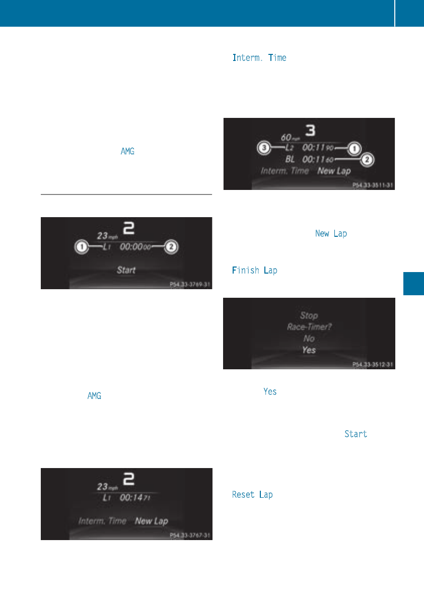
SETUP displaysthe following information and
functions:
Rthe digital speedometer
Rthe gearindicator
Rthe drive system setting
Rthe suspensionmode
Rthe transmissionposition
Rthe ESP®(ElectronicStability Program) status
XPress the =or ;button on the steering
wheel to select the AMG menu.
XPress 9repeatedlyuntilSETUP appears.
RACETIMER
Displaying and startingRACETIMER
:Lap
;RACETIMER
The RACETIMER is only intended for useona
closed race circuit. Do not usethe function on
public roads.
You can startthe RACETIMER when the engine
is running or if the SmartKey is in position 2in
the ignition lock.
XPress =or ;on the steering wheel to
select the AMG menu.
XPress the 9button repeatedlyuntilthe
RACETIMER appears.
XTo start: press the abutton to startthe
RACETIMER.
Displaying the intermediate time
XPress the =or ;button to select
Interm. Time.
XPress ato confirm.
The intermediate time appears for five sec-
onds.
Startinganew lap
:RACETIMER
;Fastest laptime (best lap)
=Lap
XPress ato confirm New Lap.
iIt is possible to store amaximum of sixteen
laps. The 16th lapcan only be completed with
Finish Lap.
Stopping the RACETIMER
XPress the %button on the steering wheel.
XConfirm Yes with a.
The RACETIMER interrupts timing if youstop the
vehicleand turn the SmartKey to position 1in
the ignition lock. If youturn the SmartKey to
position 3and then press aStart to con-
firm,timing is continued.
Resetting the current lap
XStop the RACETIMER.
XPress the =or ;button to select
ResetLap.
XPress ato resetthe laptime to "0".
Menus and submenus 189
On-board computer and displays
Z
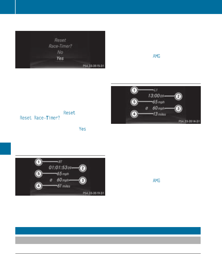
Deleting all laps
If you switch offthe engine, theRACE TIMER is
reset to "0" after 30 seconds. Alllaps are
deleted.
You cannotdelete individual storedlaps.Ifyou
havestopped16laps,the currentlap doesnot
havetobereset.
XResetthe currentlap.
XPress ato confirm Reset.
Reset Race-Timer? appears in themulti-
function display.
XPress the:buttontoselect Yes and press
theabuttontoconfirm.
Alllaps are deleted.
Overall statistics
:RACETIMER overall evaluation
;Total time driven
=Average speed
?Distancecovered
AMaximum speed
This function is shown if you havestoredatleast
onelap and stoppedthe RACETIMER.
XPress the=or ;buttononthe steering
wheeltoselect theAMG menu.
XPress the9buttonrepeatedly until the
overall evaluation appears.
Lap statistics
:Lap
;Lap time
=Average lap speed
?Lap length
ATop speed during lap
This function is only available if you havestored
at leasttwo laps and havestoppedthe RACE-
TIMER.
XPress the=or ;buttononthe steering
wheeltoselect theAMG menu.
XPress 9repeatedly until alap evaluation
appears.
Eachlap appears in aseparatesubmenu. The
fastest lap is indicatedbyflashingsymbol :.
XPress the9or :buttontoselect adif-
ferentlap evaluation.
Display messages
Introduction
General notes
Displaymessagesappear in themultifunction display.
Displaymessageswithgraphic displays may be shown in simplified form in theOperator'sManual
and may therefore differ from themultifunction display.
Pleaserespondinaccordancewiththe display messagesand follow theadditional notesinthis
Operator'sManual.
Certain display messagesare accompanied by an audiblewarningtoneoracontinuous tone.
190 Display messages
On-boardcomputer anddisplays

When the ignition is switched off, all display messages are deleted, apart from some high-priority
display messages. Oncethe causes of the high-prioritydisplay messages have been rectified, the
corresponding display messages are also deleted.
When you stop and park the vehicle, please observe the notes on:
RHOLD function (Ypage 157)
RParking (Ypage 141)
Hiding displaymessages
XPress the aor %button on the steeringwheel.
The multifunction display hides the display message.
The multifunction display shows high-prioritydisplay messages in red. Some high-prioritydisplay
messages cannot be hidden.
The multifunction display shows these messages continuously until the causes for the messages
have been remedied.
Message memory
The on-board computer saves certain display messages in the message memory.You can call up
the display messages:
XPress the =or ;button on the steeringwheel to select the Serv. menu.
If there are display messages, the multifunction display shows 2Messages,for example.
XPress the 9or :button to select the entry, e.g. 2Messages.
XPress ato confirm.
XPress the 9or :button to scroll through the display messages.
Display messages 191
On-boardcomputer and displays
Z
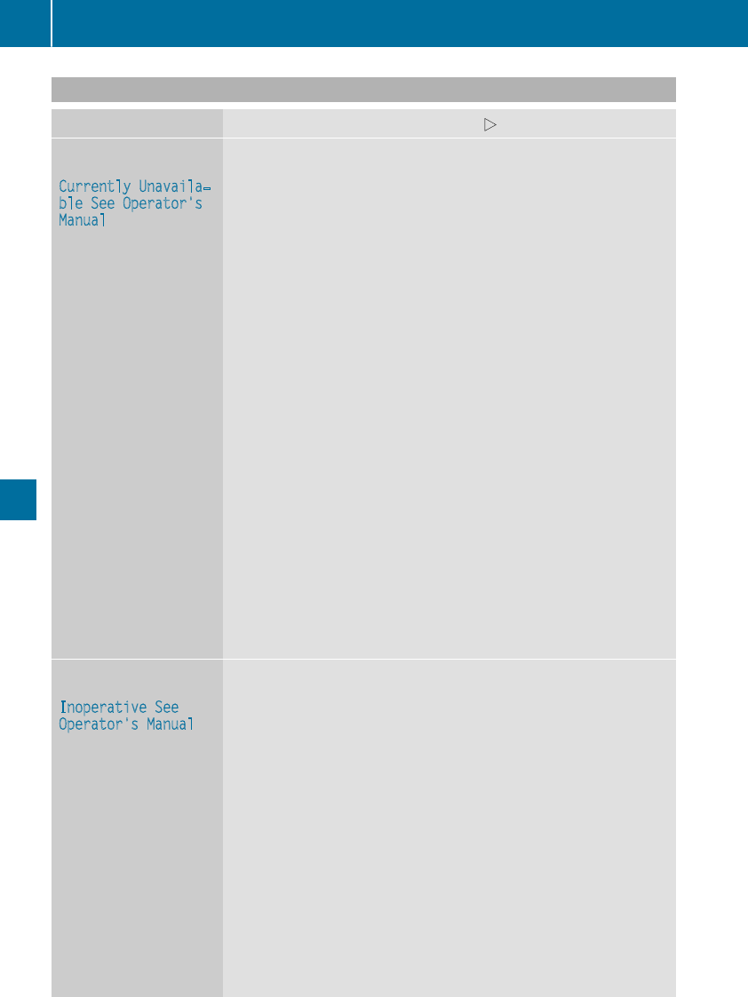
Safety systems
Display messages Possible causes/consequences and MSolutions
!÷
Currently Unavaila‐
ble See Operator's
Manual
ABS (Anti-lock Braking System), BAS (Brake Assist), ESP®(Electronic
Stability Program), the HOLD function and hill start assist are tempo-
rarily unavailable.
Active Brake Assist may have also failed.
In addition, the !,÷and åwarning lamps may light up in
the instrument cluster.
ATTENTION ASSIST is deactivated.
Possible causes are:
RSelf-diagnosis is not yet complete
RThe on-board voltage may be insufficient
GWARNING
The brake system continues to function normally, but without the
functions listed above. The wheels could therefore lock if you brake
hard, for example.
The steerability and braking characteristics may be severely affected.
The braking distance in an emergency braking situation can increase.
If ESP®is not operational, ESP®is unable to stabilize the vehicle.
There is an increased risk of skidding and an accident.
XCarefully drive ashort distance on asuitablestretchofroad, making
slight steering movements at aspeed above 12 mph (20 km/h).
If the displaymessage disappears, the functions mentioned above
are available again.
If the multifunction displaystill shows the displaymessage:
XDrive on carefully.
XVisit aqualified specialist workshop immediately.
!÷
Inoperative See
Operator's Manual
ABS, BAS, ESP®,the HOLD function and hill start assist are not avail-
able due to amalfunction.
Active Brake Assist may have also failed.
The !,÷,åand $(USA only) or J(Canadaonly)
warning lamps in the instrument cluster may also light up.
ATTENTION ASSIST is deactivated.
GWARNING
The brake system continues to function normally, but without the
functions listed above. The wheels could therefore lock if you brake
hard, for example.
The steerability and braking characteristics may be severely affected.
The braking distance in an emergency braking situation can increase.
If ESP®is not operational, ESP®is unable to stabilize the vehicle.
There is an increased risk of skidding and an accident.
XDrive on carefully.
XVisit aqualified specialist workshop immediately.
192 Display messages
On-board computer and displays
Display messages Possible causes/consequences and MSolutions
÷
Currently Unavaila‐
ble See Operator's
Manual
ESP®,BAS,the HOLD function and hill start assist are temporarily
unavailable.
Active Brake Assistmay havealso failed.
In addition,the ÷and åwarning lampsmay lightupinthe
instrumentcluster.
ATTENTION ASSIST is deactivated.
The self-diagnosis function might notbecomplete, for example.
GWARNING
The brakesystem continues to function normally, but without the
functionslisted above.
The braking distanceinanemergencybraking situation can thus
increase.
If ESP®is notoperational, ESP®is unable to stabilizethe vehicle.
There is an increased riskofskiddingand an accident.
XCarefully drive asuitable distance, making slight steering move-
ments at aspeed above12mph (20 km/h).
If the display messagedisappears, the functions mentioned above
are available again.
If the multifunction display still shows the display message:
XDrive on carefully.
XVisit aqualifiedspecialist workshop immediately.
÷
Currently Unavaila‐
ble See Operator's
Manual
ESP®,BAS, the HOLD function and hill start assist are unavailable due
to amalfunction.
Active Brake Assist may have also failed.
In addition, the ÷and åwarning lampsmay lightupinthe
instrument cluster.
ATTENTION ASSISTisdeactivated.
GWARNING
The brake system continues to function normally,but withoutthe
functions listed above.
The braking distance in an emergency braking situation can thus
increase.
If ESP®is not operational, ESP®is unabletostabilize the vehicle.
There is an increased risk of skidding and an accident.
XDrive on carefully.
XVisit aqualifiedspecialist workshop immediately.
Display messages 193
On-board computer and displays
Z
Display messages Possible causes/consequences and MSolutions
T!
÷
Inoperative See
Operator'sManual
EBD(electronic brakeforce distribution), ABS, BAS, ESP®,the HOLD
function and hill start assist are notavailable due to amalfunction.
Active Brake Assistmay havealso failed.
Awarning tone sounds.
In addition,the ÷,åand !warning lampsmay lightupin
theinstrumentcluster.
GWARNING
The brakesystem continues to function normally, but without the
functionslisted above. The frontand rear wheels could thereforelock
if you brakehard, for example.
The steerabilityand braking characteristics may be severely affected.
The braking distanceinanemergencybraking situation can increase.
If ESP®is notoperational, ESP®is unable to stabilizethe vehicle.
There is an increased riskofskiddingand an accident.
XDrive on carefully.
XVisit aqualified specialist workshop immediately.
F(USA
only) !(Canada
only)
TurnOnthe Igni‐
tionto Releasethe
ParkingBrake
The red F(USAonly) or !(Canada only) indicator lamp lights
up.
You attemptedtorelease theelectric parking brakewhile theignition
was switched off.
XSmartKey:turnthe SmartKey to position 1in theignition lock.
XKEYLESS-GO: switch on theignition.
F(USA
only) !(Canada
only)
Please ReleasePark‐
ing Brake
The red F(USAonly) or !(Canada only) indicator lamp flashes
and awarning tone sounds. Acondition for automatic release of the
electric parking brakeisnot fulfilled (Ypage 143).
You are drivingwiththe electric parking brakeapplied.
XReleasethe electric parking brakemanually.
The red F(USAonly) or !(Canada only) indicator lamp flashes
and awarning tone sounds.
You are usingthe electric parking brakefor emergencybraking
(Ypage 83).
F(USA
only) !(Canada
only)
ParkingBrake See
Operator'sManual
The yellow !warning lamp lights up.
The electric parking brakeismalfunctioning.
To apply:
XSwitchthe ignition off.
XPress theelectric parking brakehandle for at least tenseconds.
XShift thetransmission to position B.
XConsult aqualified specialist workshop.
194 Display messages
On-boardcomputer anddisplays

Display messages Possible causes/consequences and MSolutions
The yellow !warning lamp and thered F(USAonly) or !
(Canada only) indicator lamp lightup.
The electric parking brakeismalfunctioning.
To release:
XSwitchoff theignition and turnitbackon.
XReleasethe electric parking brakemanually.
or
XReleasethe electric parking brakeautomatically (Ypage 142).
If theelectric parking brakestill cannotbereleased:
XDo notdrive on.
XConsult aqualified specialist workshop.
The red F(USAonly) or !(Canada only) indicator lamp flashes
and theyellow !warning lamp lights up.
The electric parking brakeismalfunctioning.
To release:
XSwitchoff theignition and turnitbackon.
XReleasethe electric parking brakemanually.
To apply:
XSwitchoff theignition and turnitbackon.
XApply theelectric parking brakemanually.
If thered F(USAonly) or !(Canada only) indicator lamp con-
tinuestoflash:
XDo notdrive on.
XSecurethe vehicleagainst rollingaway (Ypage 309).
XShift thetransmission to position B.
XTurn thefront wheels towardsthe curb.
XConsult aqualified specialist workshop.
Display messages 195
On-boardcomputer anddisplays
Z

Display messages Possible causes/consequences and MSolutions
The yellow !warning lamp lights up. The red F(USAonly)
or !(Canada only) indicator lamp flashes for about tenseconds
after theelectric parking brakehas been appliedorreleased. It then
goesout or remainslit.
The electric parking brakeismalfunctioning.
XSwitchoff theignition and turnitbackon.
XApply theelectric parking brake.
If it is notpossibletoengage theelectric parking brake:
XShift thetransmission to position B.
XVisit aqualified specialist workshop.
If it is notpossibletorelease theelectric parking brakemanually:
XReleasethe electric parking brakeautomatically (Ypage 142).
If theelectric parking brakestill cannotbereleased:
XConsult aqualified specialist workshop.
The yellow !warning lamp lights up. If you manually apply or
release theelectric parking brake, thered F(USAonly) or !
(Canada only) indicator lamp flashes.
The electric parking brakeismalfunctioning.Itisnot possibletoapply
theelectric parking brakemanually.
XShift thetransmission to position B,asthe electric parking
brakeisnot appliedautomatically.
XVisit aqualified specialist workshop.
F(USA
only) !(Canada
only)
ParkingBrake Inop‐
erative
The yellow !warning lamp lights up. The red F(USAonly)
or !(Canada only) indicator lamp flashes for about tenseconds
after theelectric parking brakehas been appliedorreleased. It then
goesout or remainslit.
The electric parking brakeismalfunctioning,e.g.because of over-
voltageorundervoltage.
XRemove thecausefor theovervoltage or undervoltage, e.g. by
charging thebattery or restarting theengine.
XEngage or release theelectric parking brake.
If it remainsimpossible to apply or release theelectric parking brake:
XSwitchoff theignition and turnitbackon.
XEngage or release theelectric parking brake.
If theelectric parking brakestill cannotbereleased:
XConsult aqualified specialist workshop.
If theelectric parking brakestill cannotbeapplied:
XVisit aqualified specialist workshop.
196 Display messages
On-boardcomputer anddisplays
Display messages Possible causes/consequences and MSolutions
The yellow !warning lamp lights up and thered F(USAonly)
or !(Canada only) indicator lamp flashes.
It is notpossibletoapply theelectric parking brakemanually.
XShift thetransmission to position B.
XVisit aqualified specialist workshop.
$(USAonly)
J(Canada only)
Check Brake Fluid
Level
There is notenough brakefluidinthe brakefluid reservoir.
Awarning tone sounds. The $(USAonly) or J(Canada only)
warning lampsinthe instrumentclustermay also lightup.
GWARNING
The braking effectmay be impaired.
There is ariskofanaccident.
XPull overand stop thevehiclesafely as soonaspossible, paying
attention to roadand traffic conditions. Do notcontinue driving
under any circumstances.
XSecurethe vehicleagainst rollingaway (Ypage 141).
XConsult aqualified specialist workshop.
XDo notadd brakefluid.This does notcorrect themalfunction.
#
Check Brake Pad Wear
The brakepads/linings havereached their wear limit.
XVisit aqualified specialist workshop.
G
Inoperative
Oneormoremain features of thembrace system are malfunctioning.
XVisit aqualified specialist workshop.
Active Brake Assist
Functions Currently
LimitedSee Opera‐
tor's Manual
Active Brake Assististemporarily inoperative.
Possiblecauses are:
RThe radar sensor system is temporarily inoperative, e.g. due to
electromagneticradiation emitted by nearby TV or radiostationsor
other sourcesofelectromagneticradiation.
RThe system is outside theoperating temperature range.
RThe on-boardvoltageistoo low.
Whenthe causes statedabovenolonger apply, thedisplay message
disappears.
Active Brake Assistisoperational again.
If thedisplay message does notdisappear:
XPull overand stop thevehiclesafely as soonaspossible, paying
attention to roadand traffic conditions.
XSecurethe vehicleagainst rollingaway (Ypage 141).
XRestart theengine.
Active Brake
Assist:System Inop‐
erative
Active Brake Assistisunavailable due to amalfunction.Situation-
dependentbraking assistancemay also havefailed.
XVisit aqualified specialist workshop immediately.
Display messages 197
On-boardcomputer anddisplays
Z
Display messages Possible causes/consequences and MSolutions
Radar SensorsDirty
See Operator'sMan‐
ual
The radar sensor system is malfunctioning.
Possiblecauses are:
RDirt on sensors
RHeavy rain or snow
RWhendrivingoninter-urban roads without traffic or infrastructure,
e.g. in desert-like areas
At least onedrivingsystem or drivingsafetysystem is malfunctioning
or is temporarily unavailable:
RActive Brake Assist
RDistancePilotDISTRONIC
Awarning tone also sounds.
Once thecauseofthe problem is no longer present, thedrivingand
drive safetysystems will be available again.The display message dis-
appears.
If thedisplay message does notdisappear:
XPull overand stop thevehiclesafely as soonaspossible, paying
attention to roadand traffic conditions.
XSecurethe vehicleagainst rollingaway (Ypage 141).
XSwitchoff theengine.
XClean all sensors(Ypage 265).
XRestart theengine.
The display message disappears.
6
SRS Malfunction Ser‐
viceRequired
The restraintsystem is malfunctioning.The 6warning lamp also
lights up in theinstrumentcluster.
GWARNING
The air bags or Emergency Tensioning Devices may either be triggered
unintentionally or, in theevent of an accident, may notbetriggered.
There is an increased riskofinjury.
XVisit aqualified specialist workshop immediately.
Forfurther information about therestraintsystem, see (Ypage 40).
6
Front LeftMalfunc‐
tionService
Required or Front
Right Malfunction
ServiceRequired
The restraintsystem is malfunctioning at thefront on theleftorright.
The 6warning lamp also lights up in theinstrumentcluster.
GWARNING
The air bags or Emergency Tensioning Devices may either be triggered
unintentionally or, in theevent of an accident, may notbetriggered.
There is an increased riskofinjury.
XVisit aqualified specialist workshop immediately.
198 Display messages
On-boardcomputer anddisplays
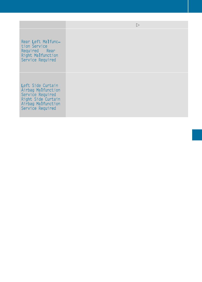
Display messages Possible causes/consequences and MSolutions
6
RearLeftMalfunc‐
tionService
Required or Rear
Right Malfunction
ServiceRequired
The rear left-handorright-hand restraintsystem is malfunctioning.
The 6warning lamp also lights up in theinstrumentcluster.
GWARNING
The air bags or Emergency Tensioning Devices may either be triggered
unintentionally or, in theevent of an accident, may notbetriggered.
There is an increased riskofinjury.
XVisit aqualified specialist workshop immediately.
6
LeftSideCurtain
Airbag Malfunction
ServiceRequired or
Right SideCurtain
Airbag Malfunction
ServiceRequired
The left-handorright-hand window curtainair bag is malfunctioning.
The 6warning lamp also lights up in theinstrumentcluster.
GWARNING
The leftorright window curtainair bag may either be triggered unin-
tentionally or, in theevent of an accident, may notbetriggered.
There is an increased riskofinjury.
XVisit aqualified specialist workshop immediately.
Display messages 199
On-boardcomputer anddisplays
Z
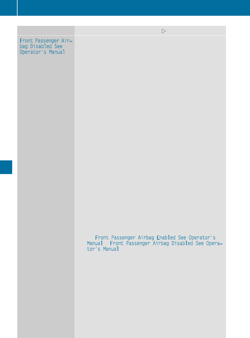
Display messages Possible causes/consequences and MSolutions
Front Passenger Air‐
bag Disabled See
Operator'sManual
The front-passenger air bag and front-passenger knee bag are deac-
tivated during thejourney, although:
Ran adult
or
Raperson of thecorrespondingstatureisonthe front-passenger seat
If additional forcesare appliedtothe seat,the system may interpret
theoccupant's weightaslower than it actually is.
GWARNING
The front-passenger frontair bag and frontpassenger knee bag may
notbetriggered in theevent of an accident.
There is an increased riskofinjury.
XPull overand stop thevehiclesafely as soonaspossible, paying
attention to roadand traffic conditions.
XSecurethe vehicleagainst rollingaway (Ypage 141).
XSwitchthe ignition off.
XHavethe occupant on thefront-passenger seat get out of thevehi-
cle.
XKeepthe seat unoccupied,close thefront-passenger door and
switch on theignition.
XObservethe PASSENGER AIRBAG indicator lampsinthe center
console and themultifunction display and checkthe following:
Seat unoccupied and ignition switched on:
Raself-diagnosis is carriedout.The PASSENGER AIRBAG OFFand
PASSENGER AIRBAG ON indicator lampsmustlightupsimulta-
neouslyfor approximately six seconds
RthePASSENGER AIRBAG OFFindicator lamp mustthenlightup
and remain lit after theself-diagnosis.Ifthe indicator lamp is on,
OCS (Occupant Classification System) has deactivated thefront-
passenger frontair bag and front-passenger knee bag
(Ypage 48)
RtheFront Passenger Airbag EnabledSee Operator's
Manual or Front Passenger Airbag Disabled See Opera‐
tor's Manual display messagesmustnot be shown in themul-
tifunction display
XWait for aperiod of at least 60 seconds until thenecessarysystem
checks havebeen completed.
XMakesurethatthe display messagesdonot appear in themulti-
function display.
If these conditionsare fulfilled,the front-passenger seat can be occu-
pied again.Whether thePASSENGER AIRBAG OFForONindicator
lamp remainslit or goesout dependsonhow OCS classifies theoccu-
pant.
If theconditionsare notfulfilled,the system is notoperating correctly.
XVisit aqualified specialist workshop immediately.
Forfurther information about theOccupant Classification System, see
(Ypage 48).
200 Display messages
On-boardcomputer anddisplays
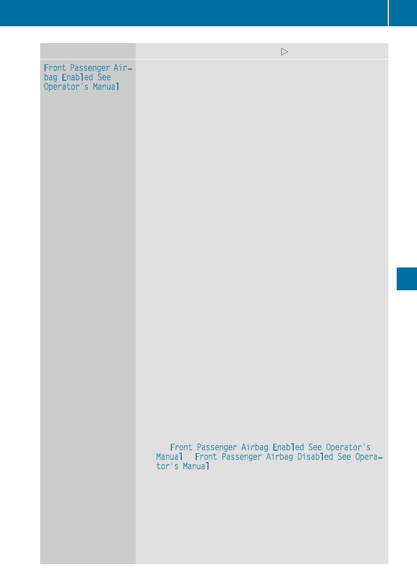
Display messages Possible causes/consequences and MSolutions
Front Passenger Air‐
bag EnabledSee
Operator'sManual
The front-passenger air bag and front-passenger knee bag are enabled
during thejourney, eventhough:
Rachild, asmall adult or an objectweighing less than thesystem's
weightthreshold is locatedonthe front-passenger seat
or
Rthefront-passenger seat is unoccupied
The system may detectobjects or forcesapplyingadditional weighton
theseat.
GWARNING
The front-passenger frontair bag and front-passenger knee bag may
be triggered unintentionally.
There is an increased riskofinjury.
XPull overand stop thevehiclesafely as soonaspossible, paying
attention to roadand traffic conditions.
XSecurethe vehicleagainst rollingaway (Ypage 141).
XSwitchthe ignition off.
XOpenthe front-passenger door.
XRemove thechild and thechild restraintsystem from thefront-
passenger seat.
XMakesurethatthere are no objects on theseat addingtothe
weight.
The system might otherwise detectthe additional weightand inter-
pretthe seat occupant's weightasgreaterthanitactually is.
XKeepthe seat unoccupied,close thefront-passenger door and
switch on theignition.
XObservethe PASSENGER AIRBAG indicator lampsinthe center
console and themultifunction display and checkthe following:
Seat unoccupied and ignition switched on:
Raself-diagnosis is carriedout.The PASSENGER AIRBAG OFFand
PASSENGER AIRBAG ON indicator lampsmustlightupsimulta-
neouslyfor approximately six seconds
RthePASSENGER AIRBAG OFFindicator lamp mustthenlightup
and remain lit after theself-diagnosis.Ifthe indicator lamp is on,
OCS has deactivated thefront-passenger frontair bag and front-
passenger knee bag (Ypage 48)
RtheFront Passenger Airbag EnabledSee Operator's
Manual or Front Passenger Airbag Disabled See Opera‐
tor's Manual display messagesmustnot be shown in themul-
tifunction display
XWait for aperiod of at least 60 seconds until thenecessarysystem
checks havebeen completed.
XMakesurethatthe display messagesdonot appear in themulti-
function display.
If these conditionsare fulfilled,the front-passenger seat can be occu-
pied again.Whether thePASSENGER AIRBAG OFForONindicator
lamp remainslit or goesout dependsonhow OCS classifies theoccu-
pant.
Display messages 201
On-boardcomputer anddisplays
Z
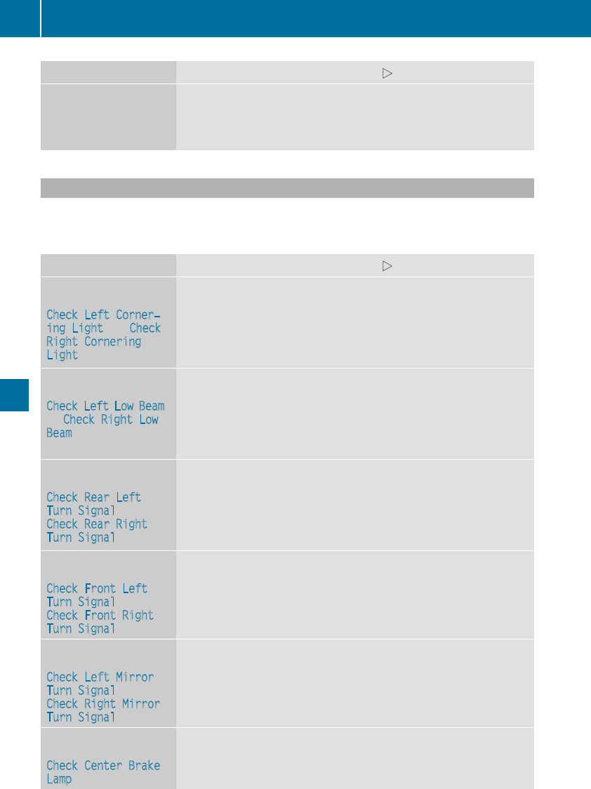
Display messages Possible causes/consequences and MSolutions
If theconditionsare notfulfilled,the system is notoperating correctly.
XVisit aqualified specialist workshop immediately.
Forfurther information about theOccupant Classification System, see
(Ypage 48).
Lights
iVehicles withLED bulbs in thelightclusters:
The display message for thecorrespondinglamp only appearswhen all of theLEDsinthe lamp
havefailed.
Display messages Possible causes/consequences and MSolutions
b
Check LeftCorner‐
ing Light or Check
Right Cornering
Light
The leftorright-hand cornering lightisdefective.
XCheckwhether you are permittedtoreplace thebulb yourself
(Ypage 104).
or
XVisit aqualified specialist workshop.
b
Check LeftLow Beam
or Check Right Low
Beam
The leftorright-hand low-beam headlamp is defective.
XCheckwhether you are permittedtoreplace thebulb yourself
(Ypage 104).
or
XVisit aqualified specialist workshop.
b
Check RearLeft
TurnSignal or
Check RearRight
TurnSignal
The rear left-handorrear right-hand turnsignal is defective.
XCheckwhether you are permittedtoreplace thebulb yourself
(Ypage 104).
or
XVisit aqualified specialist workshop.
b
Check Front Left
TurnSignal or
Check Front Right
TurnSignal
The frontleft-handorfront right-hand turnsignal is defective.
XCheckwhether you are permittedtoreplace thebulb yourself
(Ypage 104).
or
XVisit aqualified specialist workshop.
b
Check LeftMirror
TurnSignal or
Check Right Mirror
TurnSignal
The turnsignal in theleft-handorright-hand exteriormirror is defec-
tive.
XVisit aqualified specialist workshop.
b
Check Center Brake
Lamp
The high-mountedbrakelamp is faulty.
XVisit aqualified specialist workshop.
202 Display messages
On-boardcomputer anddisplays
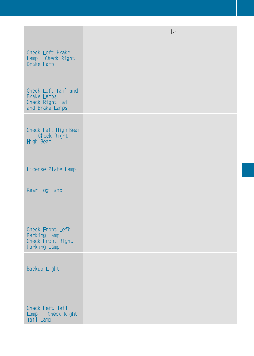
Display messages Possible causes/consequences and MSolutions
b
Check LeftBrake
Lampor Check Right
Brake Lamp
The leftorright-hand brakelamp is defective.
XCheckwhether you are permittedtoreplace thebulb yourself
(Ypage 104).
or
XVisit aqualified specialist workshop.
b
Check LeftTailand
Brake Lamps or
Check Right Tail
and Brake Lamps
The leftorright-hand taillamp/brake lamp is defective.
XCheckwhether you are permittedtoreplace thebulb yourself
(Ypage 104).
or
XVisit aqualified specialist workshop.
b
Check LeftHighBeam
or Check Right
HighBeam
The leftorright-hand high beam is defective.
XCheckwhether you are permittedtoreplace thebulb yourself
(Ypage 104).
or
XVisit aqualified specialist workshop.
b
LicensePlate Lamp
The leftorright-hand license platelamp is faulty.
XVisit aqualified specialist workshop.
b
RearFog Lamp
The rear fog lamp is faulty.
XCheckwhether you are permittedtoreplace thebulb yourself
(Ypage 104).
or
XVisit aqualified specialist workshop.
b
Check Front Left
ParkingLampor
Check Front Right
ParkingLamp
The frontleftorfront right parking or standing lamp is defective.
XCheckwhether you are permittedtoreplace thebulb yourself
(Ypage 104).
or
XVisit aqualified specialist workshop.
b
Backup Light
The backup lamp is defective.
XCheckwhether you are permittedtoreplace thebulb yourself
(Ypage 104).
or
XVisit aqualified specialist workshop.
b
Check LeftTail
Lampor Check Right
TailLamp
The leftorright-hand taillamp is defective.
XVisit aqualified specialist workshop.
Display messages 203
On-boardcomputer anddisplays
Z
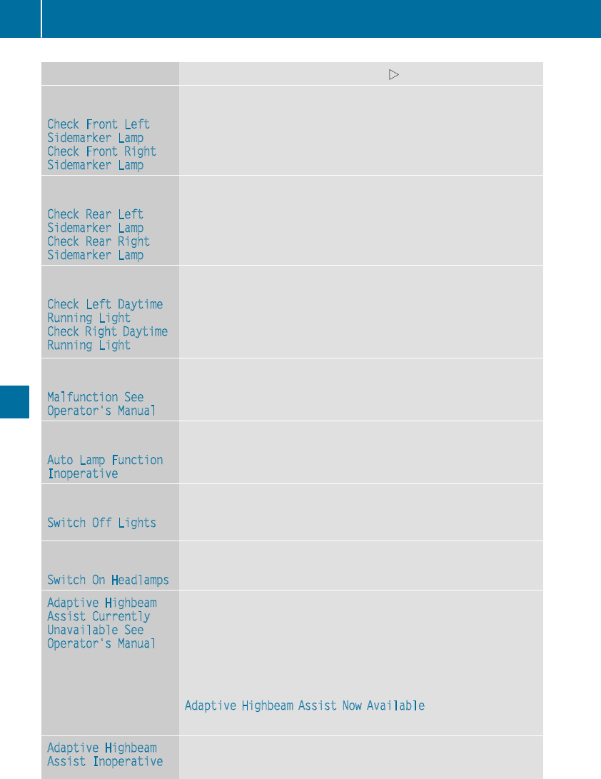
Display messages Possible causes/consequences and MSolutions
b
Check Front Left
SidemarkerLampor
Check Front Right
SidemarkerLamp
The frontleft-handorfront right-hand side markerlamp is faulty.
XVisit aqualified specialist workshop.
b
Check RearLeft
SidemarkerLampor
Check RearRight
SidemarkerLamp
The rear left-handorrear right-hand side markerlamp is faulty.
XVisit aqualified specialist workshop.
b
Check LeftDaytime
RunningLight or
Check Right Daytime
RunningLight
The leftorright-hand daytime runninglamp is faulty.
XCheckwhether you are permittedtoreplace thebulb yourself
(Ypage 104).
or
XVisit aqualified specialist workshop.
b
Malfunction See
Operator'sManual
The exteriorlighting is malfunctioning.
XVisit aqualified specialist workshop.
b
AutoLampFunction
Inoperative
The lightsensor is defective.
XVisit aqualified specialist workshop.
b
Switch Off Lights
The lights are still switched on when you leavethe vehicle. Awarning
tone also sounds.
XTurn thelightswitch to theÃposition.
b
Switch On Headlamps
You are drivingwithlow-beam headlampsswitched off.
XTurn thelightswitch to theLor Ãposition.
Adaptive Highbeam
Assist Currently
Unavailable See
Operator'sManual
Adaptive HighbeamAssistisdeactivated and temporarily inoperative.
Possiblecauses are:
RThe windshield in thecamera'sfield of vision is dirty.
RVisibilityisimpaireddue to heavyrain,snoworfog.
XClean thewindshield.
If thesystem detects that thecamera is fullyoperational again,the
Adaptive Highbeam Assist Now Available message is displayed.
Adaptive HighbeamAssistisoperational again.
Adaptive Highbeam
Assist Inoperative
Adaptive HighbeamAssistisfaulty.
XVisit aqualified specialist workshop.
204 Display messages
On-boardcomputer anddisplays
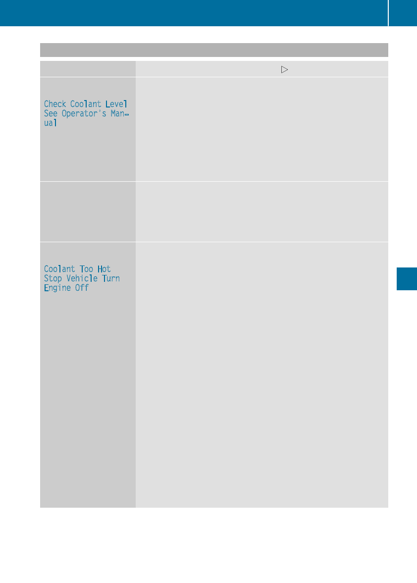
Engine
Display messages Possible causes/consequences and MSolutions
+
Check Coolant Level
See Operator'sMan‐
ual
The coolant levelistoo low.
!Avoid making longjourneys with toolittle coolant in theengine
cooling system. The engine will otherwise be damaged.
XAdd coolant,observing thewarning notesbefore doingso
(Ypage 260).
If you have to addcoolantfrequently:
XContactaqualified specialist workshop and have theengine cooling
system checked.
?The fan motor is malfunctioning.
XAt coolant temperatures below 248‡(120 †), drive to the nearest
qualified specialist workshop.
XAvoid heavy loads on the engine as you do so, e.g. driving in moun-
tainousterrainand stop-and-go traffic.
?
CoolantToo Hot
Stop VehicleTurn
Engine Off
The coolant is too hot.
Awarning tone also sounds.
GWARNING
Do not drive whenyourengine is overheated. This can cause some
fluids which may have leaked into the engine compartment to catch
fire.
Steam from the overheated engine can also cause serious burns which
can occur just by opening the hood.
There is arisk of injury.
XPullover and stop the vehicle safely and switch off the engine, pay-
ing attention to road and traffic conditions.
XSecure the vehicle against rolling away (Ypage141).
XWaituntil the engine has cooleddown.
XMake sure that the airsupply to the engine radiator is not blocked,
e.g. by snow, slush or ice.
XDo not start the engine again until the displaymessage goes out and
the coolant temperature is below 248 ‡(120 †). Otherwise, the
engine couldbedamaged.
XPay attention to the coolant temperature gauge.
If the temperature increasesagain:
XVisitaqualified specialist workshop immediately.
Under normal operating conditions and with the specified coolant
level, the coolant temperature may rise to 248 ‡(120 †).
Display messages 205
On-board computer and displays
Z
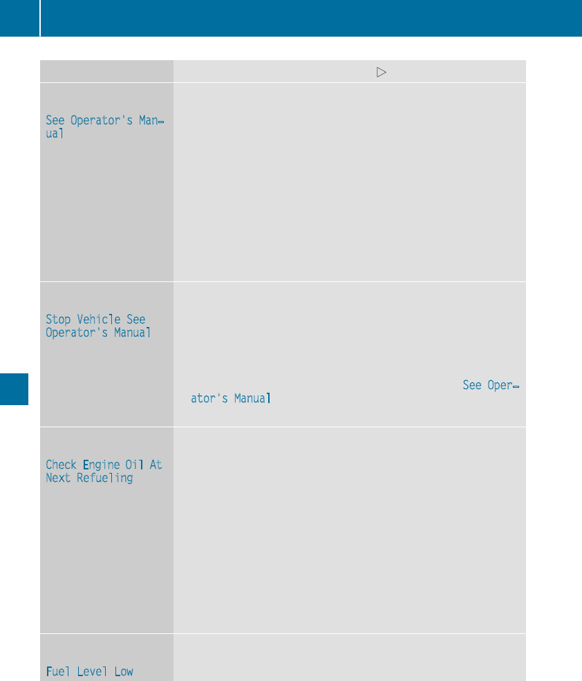
Display messages Possible causes/consequences and MSolutions
#
See Operator'sMan‐
ual
The battery is notbeingcharged.
Awarning tone also sounds.
Possiblecauses are:
Radefective alternator
Ratornpoly-V-belt
Ramalfunction in theelectronics
!Do notcontinue driving. The enginecould otherwise overheat.
XPull overand stop thevehiclesafely and switch off theengine, pay-
ing attention to roadand traffic conditions.
XSecurethe vehicleagainst rollingaway (Ypage 141).
XConsult aqualified specialist workshop.
#
StopVehicleSee
Operator'sManual
The battery is no longer beingcharged and thecondition of chargeis
toolow.
Awarning tone also sounds.
XPull overand stop thevehiclesafely and switch off theengine, pay-
ing attention to roadand traffic conditions.
XSecurethe vehicleagainst rollingaway (Ypage 141).
XObservethe instructionsinthe display message #See Oper‐
ator's Manual.
XConsult aqualified specialist workshop.
4
Check Engine Oil At
NextRefueling
The engineoil level has dropped to theminimum level.
Awarning tone also sounds.
!Avoid longjourneys withtoo littleengineoil. The enginewill oth-
erwise be damaged.
XCheckthe oil level when next refueling, at thelatest (Ypage 258).
XIf necessary, add engineoil (Ypage 259).
If theengineoil needstoppingupmoreoften:
XContactaqualified specialist workshop and havethe engine
checked.
Information on approvedengineoils can be obtained from any quali-
fiedspecialist workshop or on theInternetathttp://bevo.mercedes-
benz.com.
æ
FuelLevel Low
The fuel level has dropped intothe reserverange.
XRefuelatthe nearestgas station.
206 Display messages
On-boardcomputer anddisplays
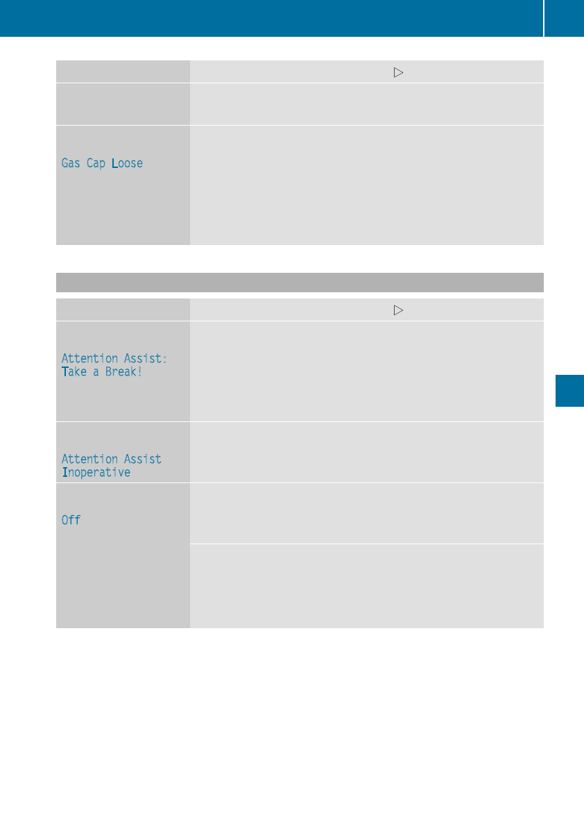
Display messages Possible causes/consequences and MSolutions
çThere is only averysmall amount of fuel in thefuel tank.
XRefuelatthe nearestgas station without fail.
æ
Gas Cap Loose
The fuel filler cap is notclosed correctlyorthe fuel system is leaking.
XCheckthatthe fuel filler cap is correctlyclosed.
If thefuelfiller cap is not correctlyclosed:
XClosethe fuel filler cap.
If thefuelfiller cap is correctlyclosed:
XVisit aqualified specialist workshop.
Driving systems
Display messages Possible causes/consequences and MSolutions
À
Attention Assist:
TakeaBreak!
Based on certain criteria, ATTENTION ASSIST has detectedfatigue or
alack of concentration on thepart of thedriver.Awarning tone also
sounds.
XIf necessary, takeabreak.
During longjourneys, takeregular breaks in goodtimesoyou get
enough rest.
À
Attention Assist
Inoperative
ATTENTION ASSIST is inoperative.
XVisit aqualified specialist workshop.
ë
Off
The HOLD function is deactivated. The vehicleisskidding.
Awarning tone also sounds.
XReactivatethe HOLD function later (Ypage 157).
The HOLD function is deactivated. Whenthe brakepedal is firmly
depressed, an activation condition is notfulfilled.
Awarning tone also sounds.
XCheckthe activation conditionsfor theHOLDfunction
(Ypage 157).
Display messages 207
On-boardcomputer anddisplays
Z
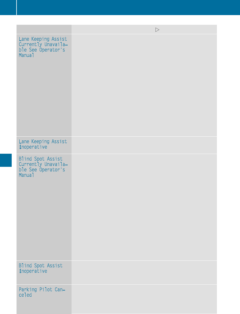
Display messages Possible causes/consequences and MSolutions
LaneKeepingAssist
Currently Unavaila‐
ble See Operator's
Manual
LaneKeepingAssistisdeactivated and temporarily inoperative.
Possiblecauses are:
RThe windshield in thecamera'sfield of vision is dirty.
RVisibilityisimpaireddue to heavyrain,snoworfog.
RThere havebeen no lanemarkingsfor an extended period
RThe lanemarkingsare wornaway, dark or covered up, e.g. by dirtor
snow
Whenthe causes statedabovenolonger apply, thedisplay message
disappears.
LaneKeepingAssistisoperational again.
If thedisplay message does notdisappear:
XPull overand stop thevehiclesafely as soonaspossible, paying
attention to roadand traffic conditions.
XSecurethe vehicleagainst rollingaway (Ypage 141).
XClean thewindshield.
LaneKeepingAssist
Inoperative
LaneKeepingAssistisfaulty.
XVisit aqualified specialist workshop.
Blind SpotAssist
Currently Unavaila‐
ble See Operator's
Manual
Blind Spot Assististemporarily inoperative.
Possiblecauses are:
RThe radar sensor system is temporarily inoperative, e.g. due to
electromagneticradiation emitted by nearby TV or radiostationsor
other sourcesofelectromagneticradiation.
RThe radar sensor system is outside theoperating temperature
range.
The yellow 9indicator lampsalso lightupinthe exteriormirrors.
Whenthe causes statedabovenolonger apply, thedisplay message
disappears.
Blind Spot Assistisoperational again.
If thedisplay message does notdisappear:
XPull overand stop thevehiclesafely as soonaspossible, paying
attention to roadand traffic conditions.
XSecurethe vehicleagainst rollingaway (Ypage 141).
XRestart theengine.
Blind SpotAssist
Inoperative
Blind Spot Assistisfaulty.
The yellow 9indicator lampsalso lightupinthe exteriormirrors.
XVisit aqualified specialist workshop.
ParkingPilot Can‐
celed
The driver's door is open and thedriver's seat belt has notbeen fas-
tened.
XRepeat theparking process withthe seat belt fastenedand the
driver's door closed.
208 Display messages
On-boardcomputer anddisplays
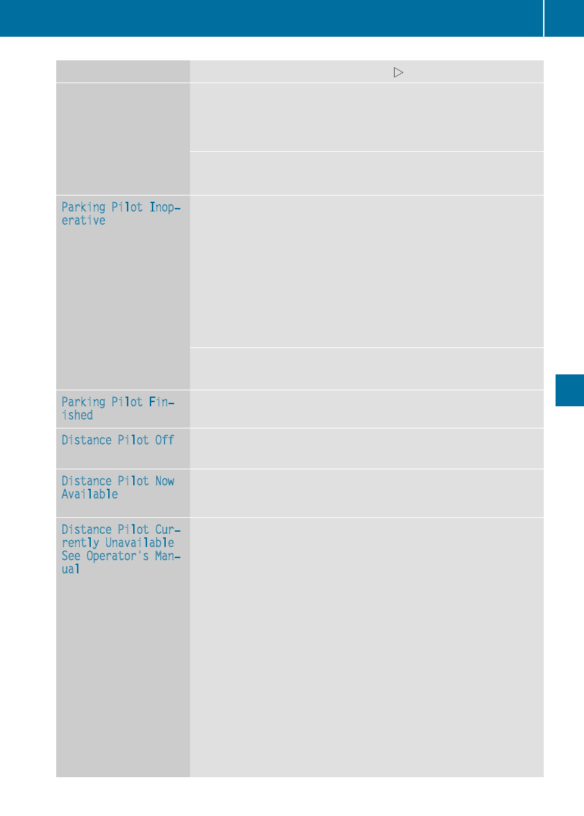
Display messages Possible causes/consequences and MSolutions
You haveinadvertentlytouched themultifunction steering wheelwhile
steering intervention was active.
XWhilesteering intervention is active,makesurethatthe multifunc-
tion steering wheelisnot touched unintentionally.
The vehiclehas started to skid and ESP®has intervened.
XUse Parking Pilotagain later (Ypage 164).
ParkingPilot Inop‐
erative
You havejustcarriedout alargenumber of turningorparking maneu-
vers.
Parking Pilotwill become available again after approximately ten
minutes(
Ypage 164).
XPull overand stop thevehiclesafely as soonaspossible, paying
attention to roadand traffic conditions.
XSwitchoff and restartthe engine.
If themultifunction display still shows thedisplay message:
XVisit aqualified specialist workshop.
Parking AssistPARKTRONICismalfunctioning.
XVisit aqualified specialist workshop.
ParkingPilot Fin‐
ished
The vehicleisparked. Awarning tone also sounds.
The display message disappearsautomatically.
Distance Pilot Off DistancePilotDISTRONICisdeactivated (Ypage 155).
If it was notdeactivated by thedriver,awarning tone also sounds.
Distance Pilot Now
Available
DistancePilotDISTRONICisoperational again after having been tem-
porarily unavailable.You can nowreactivateDistance Pilot
DISTRONIC(
Ypage 152).
Distance Pilot Cur‐
rently Unavailable
See Operator'sMan‐
ual
DistancePilotDISTRONICistemporarily inoperative.
Possiblecauses are:
RThe radar sensor system is temporarily inoperative, e.g. due to
electromagneticradiation emitted by nearby TV or radiostationsor
other sourcesofelectromagneticradiation.
RThe system is outside theoperating temperature range.
RThe on-boardvoltageistoo low.
Awarning tone also sounds.
Whenthe causes statedabovenolonger apply, thedisplay message
disappears.
DistancePilotDISTRONICisoperational again.
If thedisplay message does notdisappear:
XPull overand stop thevehiclesafely as soonaspossible, paying
attention to roadand traffic conditions.
XSecurethe vehicleagainst rollingaway (Ypage 141).
XRestart theengine.
Display messages 209
On-boardcomputer anddisplays
Z
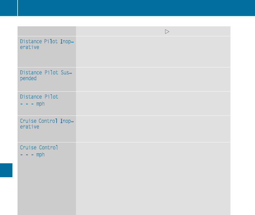
Display messages Possible causes/consequences and MSolutions
Distance Pilot Inop‐
erative
DistancePilotDISTRONICismalfunctioning.Situation-dependent
braking assistancemay also havefailed.
Awarning tone also sounds.
XVisit aqualified specialist workshop.
Distance Pilot Sus‐
pended
You havedepressed theacceleratorpedal.Distance PilotDISTRONIC
is no longer controllingthe speed of thevehicle.
XRemove your footfromthe acceleratorpedal.
Distance Pilot
---mph
Acondition for activating DistancePilotDISTRONIChas notbeen met.
XCheckthe activation conditionsfor DistancePilotDISTRONIC
(Ypage 152).
Cruise ControlInop‐
erative
Cruisecontrolismalfunctioning.
Awarning tone also sounds.
XVisit aqualified specialist workshop.
Cruise Control
---mph
RAcondition for activating cruise control has notbeen fulfilled.
You havetried to store aspeed below20mph (30 km/h), for exam-
ple.
RESP®is deactivated. The yellow ESP®OFFwarning lamp is lit.
XIf conditionspermit,drive fasterthan20mph (30 km/h)and store
thespeed.
or
XCheckthe activation conditionsfor cruise control (Ypage 150).
or
XReactivateESP®(Ypage 185).
210 Display messages
On-boardcomputer anddisplays
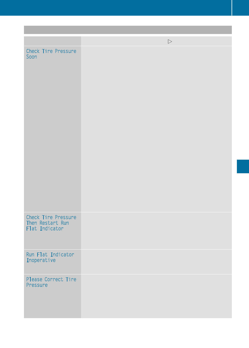
Tires
Display messages Possible causes/consequencesand MSolutions
Check Tire Pressure
Soon
Canadaonly:
The tire pressure loss warning system hasdetectedasignificant loss
in pressure.
Awarning tone also sounds.
Possiblecauses:
Ryouhavechangedthe positions of the wheels and tiresorinstalled
new wheels and tires
Rthe tire pressure in one or moretireshas dropped
GWARNING
Tire pressures thatare too lowposethe following hazards:
Rtheymay burst, especially as the load and vehiclespeed increase.
Rtheymay wear excessivelyand/or unevenly, which maygreatly
impairtire traction.
Rthe drivingcharacteristics, as well as steeringand braking,may be
greatlyimpaired.
There is ariskofanaccident.
XStop the vehiclewithoutmaking any sudden steeringorbraking
maneuvers. Payattentiontothe trafficconditions as youdoso.
XSecure the vehicleagainst rolling away (Ypage 141).
XCheck the tiresand,ifnecessary,followthe instructions for aflat
tire (Ypage 271).
XCheck the tire pressures and,ifnecessary,correct the tire pressure.
XRestart the tire pressure loss warning system when the tire pres-
sure is correct (Ypage 294).
Check Tire Pressure
ThenRestartRun
FlatIndicator
Canadaonly:
The tire pressure loss warning system generated adisplay message
and hasnot been restarted since.
XSet the correct tire pressure in allfourtires.
XRestart the tire pressure loss warning system (Ypage 294).
Run FlatIndicator
Inoperative
Canadaonly:
The tire pressure loss warning system is faulty.
XVisitaqualified specialistworkshop.
Please Correct Tire
Pressure
USA only:
The tire pressure is too lowinatleast one of the tires, or the tire
pressure differencebetween the wheels is too great.
XCheck the tire pressures at the next opportunity (Ypage 294).
XIf necessary,correct the tire pressure.
XRestart the tire pressure monitor (Ypage 297).
Displaymessages 211
On-boardcomputer anddisplays
Z

Display messages Possible causes/consequences and MSolutions
Check Tires USAonly:
The tire pressureinone or moretires has dropped significantly. The
wheelposition appearsinthe multifunction display.
Awarning tone also sounds.
GWARNING
Tirepressures that are toolow posethe followinghazards:
Rthey may burst, especially as theload and vehiclespeed increase.
Rthey may wear excessivelyand/orunevenly, whichmay greatly
impair tire traction.
Rthedrivingcharacteristics,aswell as steering and braking,may be
greatlyimpaired.
There is ariskofanaccident.
XStop thevehiclewithout making any sudden steering or braking
maneuvers.Pay attention to thetraffic conditionsasyou do so.
XSecurethe vehicleagainst rollingaway (Ypage 141).
XCheckthe tires and,ifnecessary, follow theinstructionsfor aflat
tire (Ypage 271).
XCheckthe tire pressure(Ypage 294).
XIf necessary, correctthe tire pressure.
WarningTireMal‐
function
USAonly:
The tire pressureinone or moretires has dropped suddenly. The wheel
position appearsinthe multifunction display.
GWARNING
Drivingwithaflat tire poses ariskofthe followinghazards:
Raflat tire affects theabilitytosteer or brakethe vehicle
Ryou could lose control of thevehicle
Rcontinued drivingwithaflat tire will causeexcessive heat build-up
and possiblyafire
There is ariskofanaccident.
XStop thevehiclewithout making any sudden steering or braking
maneuvers.Pay attention to thetraffic conditionsasyou do so.
XSecurethe vehicleagainst rollingaway (Ypage 141).
XCheckthe tires and,ifnecessary, follow theinstructionsfor aflat
tire (Ypage 271).
TirePress. Monitor
Currently Unavaila‐
ble
USAonly:
Becausethere is interferencefromastrongsource of radiowaves, no
signals from thetirepressuresensorsare detected. The tire pressure
monitor is temporarily malfunctioning.
XDrive on.
The tire pressuremonitor restarts automatically as soonasthe
problem has been resolved.
212 Display messages
On-boardcomputer anddisplays
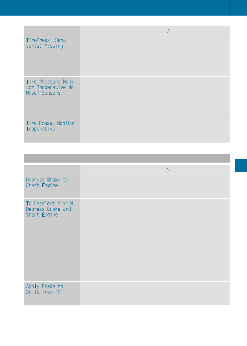
Display messages Possible causes/consequences and MSolutions
TirePress.Sen‐
sor(s) Missing
USAonly:
There is no signal from thetirepressuresensor of oneorseveral tires.
The pressureofthe affectedtiredoes notappear in themultifunction
display.
XHavethe faultytirepressuresensor replacedataqualified special-
ist workshop.
TirePressure Moni‐
tor Inoperative No
Wheel Sensors
USAonly:
The wheels mounteddonot haveasuitable tire pressuresensor.The
tire pressuremonitor is deactivated.
XMountwheels withsuitable tire pressuresensors.
The tire pressuremonitor is activated automatically after drivingfor
afew minutes.
TirePress. Monitor
Inoperative
USAonly:
The tire pressuremonitor is faulty.
XVisit aqualified specialist workshop.
Vehicle
Display messages Possible causes/consequences and MSolutions
DepressBrake to
Start Engine
You haveattemptedtostart theenginewiththe transmission in posi-
tion Nwithout depressing thebrakepedal.
XDepress thebrakepedal.
To Deselect Por N,
DepressBrake and
Start Engine
You haveattemptedtoshift thetransmission to position Ror Dwith-
out starting theengine.
XStart theengine.
XDepress thebrakepedal.
iIt is only possibletoshift thetransmission from position Pto the
desiredposition if you depress thebrakepedal.Onlythencan the
parking lockbedeactivated. If you do notdepress thebrakepedal,
theDIRECT SELECT lever can still be moved but theparking lock
remainsengaged.
iAt transmission fluid temperatures belowÒ4‡(Ò20 †) you can
only shift out of position Pintoanother transmission position when
theengineisrunning.
Apply Brake to
Shift from'P'
You haveattemptedtoshift thetransmission to position R,Nor D
without depressing thebrakepedal.
XDepress thebrakepedal.
Display messages 213
On-boardcomputer anddisplays
Z
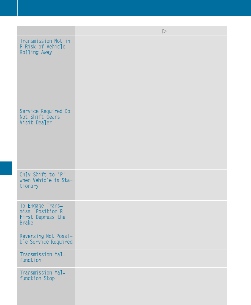
Display messages Possible causes/consequences and MSolutions
Transmission Not in
PRiskofVehicle
RollingAway
The driver's door is open or notfullyclosed and thetransmission is in
position R,Nor D.
Awarning tone also sounds.
GWARNING
The vehiclemay rollaway.
There is ariskofanaccident.
XShift thetransmission to position P.
XSecurethe vehicleagainst rollingaway (Ypage 141).
XClosethe driver's door completely.
ServiceRequired Do
Not Shift Gears
Visit Dealer
You cannotchangethe transmission position due to amalfunction.
Awarning tone also sounds.
If transmission position Dis selected:
XDrive to aqualified specialist workshop without shifting thetrans-
mission from position D.
If transmission position R,Nor Pis selected:
XSecurethe vehicleagainst rollingaway (Ypage 141).
XNotify aqualified specialist workshop or breakdown service.
OnlyShift to 'P'
whenVehicleis Sta‐
tionary
The vehicleismoving.
XPull overand stop thevehiclesafely as soonaspossible, paying
attention to roadand traffic conditions.
XShift thetransmission to position P.
To Engage Trans‐
miss. Position R
First Depressthe
Brake
You haveattemptedtoshift from position Dor Nto transmission
position R.
XShift thetransmission to position Rwhile depressing thebrake
pedal.
Reversing Not Possi‐
ble ServiceRequired
The automatic transmission is malfunctioning.You cannotbackup.
XVisit aqualified specialist workshop.
Transmission Mal‐
function
The automatic transmission is malfunctioning.
XVisit aqualified specialist workshop.
Transmission Mal‐
function Stop
The automatic transmission is malfunctioning.
XPull overand stop thevehiclesafely as soonaspossible, paying
attention to roadand traffic conditions.
XSecurethe vehicleagainst rollingaway (Ypage 141).
XConsult aqualified specialist workshop.
214 Display messages
On-boardcomputer anddisplays
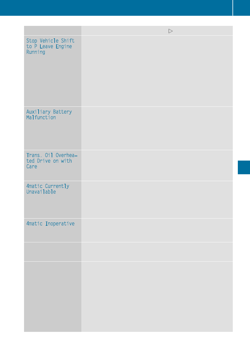
Display messages Possible causes/consequences and MSolutions
StopVehicleShift
to PLeave Engine
Running
The automatic transmission has overheated.
XDrive on carefully.
The automatic transmission is available again when thedisplay
message goesout.
If themultifunction display still shows thedisplay message:
XPull overand stop thevehiclesafely as soonaspossible, paying
attention to roadand traffic conditions.
XSecurethe vehicleagainst rollingaway (Ypage 141).
XWait until theautomatic transmission has cooled down and thedis-
play message has disappeared.
Auxiliary Battery
Malfunction
The auxiliary battery for theautomatic transmission is no longer being
charged.
XVisit aqualified specialist workshop.
XUntilthen, set thetransmission to position Pbefore you switch off
theengine.
XBeforeleaving thevehicle, apply theelectric parking brake.
Trans. Oil Overhea‐
ted Drive on with
Care
Mercedes-AMG vehicles: thetransmission oil has overheated.
Manual drive programMand thetemporarily active manual drive pro-
gramare no longer available. The enginepoweroutput is reduced.
XAllow thevehicletocooldown.
4matic Currently
Unavailable
4MATIC has overheated. The vehicleisonlydriven by thefront wheels.
XDrive on.
The airflow cools 4MATIC morequickly.
Whenthe display message goesout,4MATIC is available again and
thevehicleisdriven by all fourwheels.
4matic Inoperative 4MATIC is malfunctioning.The vehicleisonlydriven by thefront
wheels.
XVisit aqualified specialist workshop.
NThe trunk lid is open.
XClosethe trunk lid.
MThe hoodisopen.
Awarning tone also sounds.
GWARNING
The open hoodmay blockyour viewwhen thevehicleisinmotion.
There is ariskofanaccident.
XPull overand stop thevehiclesafely as soonaspossible, paying
attention to roadand traffic conditions.
XSecurethe vehicleagainst rollingaway (Ypage 141).
XClosethe hood.
Display messages 215
On-boardcomputer anddisplays
Z
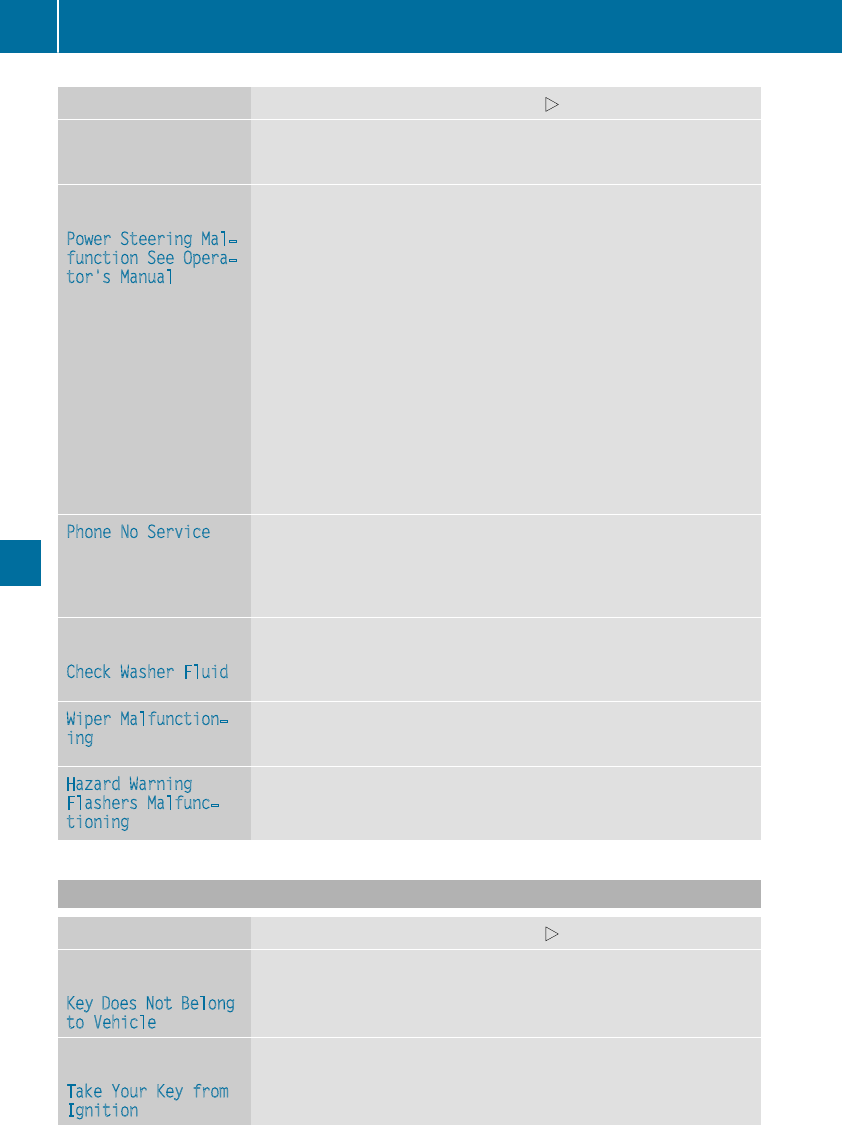
Display messages Possible causes/consequences and MSolutions
CAt least onedoor is open.Awarning tone also sounds.
XCloseall thedoors.
Ð
Power Steering Mal‐
function See Opera‐
tor's Manual
The powersteering is malfunctioning.
Awarning tone also sounds.
GWARNING
You will need to use moreforce to steer.
There is ariskofanaccident.
XCheckwhether you are able to apply theextra force required.
If you areabletosteer safely:
XDrive on carefully.
XVisit aqualified specialist workshop immediately.
If you areunable to steer safely:
XDo notdrive on.
XConsult aqualified specialist workshop.
Phone No ServiceYour vehicleisoutside thenetwork provider'stransmitter/receiver
range.
XWait until themobile phone operational readiness symbol appears
in themultifunction display.
¥
Check Washer Fluid
The washer fluidlevel in thewasher fluidreservoir has dropped below
theminimum.
XAddwasher fluid(Ypage 260).
Wiper Malfunction‐
ing
The windshield wipersare malfunctioning.
XVisit aqualified specialist workshop.
Hazard Warning
Flashers Malfunc‐
tioning
The hazard warning lampsare faulty.
XVisit aqualified specialist workshop.
SmartKey
Display messages Possible causes/consequences and MSolutions
Â
Key DoesNot Belong
to Vehicle
You haveput thewrong SmartKey in theignition lock.
XUse thecorrect SmartKey.
Â
TakeYourKey from
Ignition
The SmartKey is in theignition lock.
Awarning tone sounds
XRemove theSmartKey.
216 Display messages
On-boardcomputer anddisplays
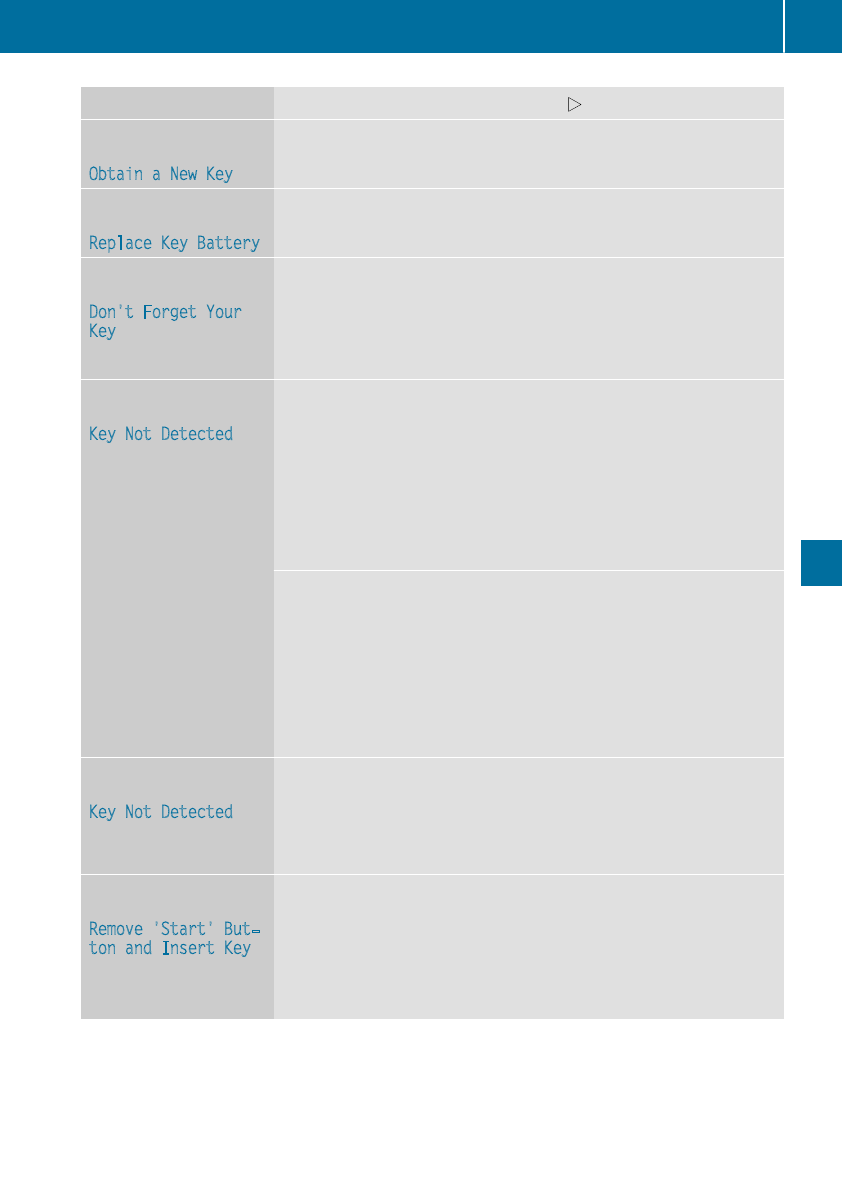
Display messages Possible causes/consequences and MSolutions
Â
Obtain aNew Key
The SmartKey needs to be replaced.
XVisit aqualified specialist workshop.
Â
ReplaceKey Battery
The SmartKey battery is discharged.
XChange thebattery (Ypage 73).
Â
Don't Forget Your
Key
The display message is shown for amaximum of 60 seconds and is
only areminder.
You haveopened thedriver's door withthe engineswitched off.The
SmartKey is notinthe ignition lock. Awarning tone sounds.
XTakethe SmartKey withyou when you leavethe vehicle.
Â
Key Not Detected
(reddisplay message)
The SmartKey is notinthe vehicle.
Awarning tone also sounds.
If theengineisswitched off,you can no longer lockthe vehiclecen-
trally or start theengine.
XPull overand stop thevehiclesafely as soonaspossible, paying
attention to roadand traffic conditions.
XSecurethe vehicleagainst rollingaway (Ypage 141).
XLocate theSmartKey.
Becausethere is interferencefromastrongsource of radiowaves, the
SmartKey is notdetectedwhilstthe engineisrunning.
Awarning tone also sounds.
XPull overand stop thevehiclesafely as soonaspossible, paying
attention to roadand traffic conditions.
XSecurethe vehicleagainst rollingaway (Ypage 141).
XInsertthe SmartKey intothe ignition lockand drive in SmartKey
mode.
Â
Key Not Detected
(whitedisplay message)
The SmartKey is currentlyundetected.
XChange thelocation of theSmartKey in thevehicle.
If theSmartKey still cannotbedetected:
XOperatethe vehiclewiththe SmartKey in theignition lock.
Â
Remove 'Start'But‐
ton and Insert Key
The SmartKey is continually undetected.
The SmartKey detection function has atemporarymalfunction or is
faulty. Awarning tone also sounds.
XInsertthe SmartKey intothe ignition lockand turnittothe desired
position.
XVisit aqualified specialist workshop.
Display messages 217
On-boardcomputer anddisplays
Z
Warning and indicator lamps in the instrument cluster
General notes
Some systems carry out aself-diagnosis when the ignition is switched on. Therefore, some indicator
and warning lamps may light up or flashtemporarily.This behavior is non-critical.
These indicator and warning lamps only indicate amalfunction if they light up or flashafter starting
the engine or whilst driving.
Safety
Seat belts
Warning/
indicator
lamp
NSignal type
Possiblecauses/consequencesand MSolutions
üNAfter engine start, the red seatbeltwarning lamplights up for six seconds.
The seatbeltwarning lampreminds the driverand front passenger to fasten their
seatbelts.
XFasten yourseatbelt(Ypage44).
üNAfter starting the engine, the red seatbeltwarning lamplights up. In addition, a
warning tone soundsfor up to six seconds.
The driver's seatbeltisnot fastened.
XFasten yourseatbelt(Ypage44).
The warning tone ceases.
üNThe red seatbeltwarning lamplights up after the engine starts, as soon as the
driver's or the front-passenger door is closed.
The driverorfront passenger has not fastened their seatbelt.
XFasten yourseatbelt(Ypage44).
The warning lampgoes out.
There are objects on the front-passenger seat.
XRemove the objects from the front-passenger seatand stow them in asecure
place.
The warning lampgoes out.
üNThe red seatbeltwarning lampflashes and an intermittent audible warning
sounds.
The driverorfront passenger has not fastened their seatbelt. The vehicleisbeing
drivenfaster than 15 mph (25 km/h)orhas briefly been drivenfaster than 15 mph
(25 km/h).
XFasten yourseatbelt(Ypage44).
The warning lampgoes out and the intermittent warning tone ceases.
There are objects on the front-passenger seat. The vehicleisbeing drivenfaster
than 15 mph (25 km/h)orhas briefly been drivenfaster than 15 mph (25 km/h).
XRemove the objects from the front-passenger seatand stow them in asecure
place.
The warning lampgoes out and the intermittent warning tone ceases.
218 Warning and indicator lamps in the instrument cluster
On-board computer and displays

Safety systems
Warning/
indicator
lamp
NSignal type
Possible causes/consequences and MSolutions
$J N$(USA only), J(Canada only): the red brake system warning lamp is lit
while the engine is running. Awarning tone also sounds.
GWARNING
The brake boosting effect is malfunctioning and the braking characteristics may be
affected.
There is arisk of an accident.
XPull over and stop the vehicle safely as soon as possible, paying attention to road
and traffic conditions. Do not continue driving under any circumstances.
XSecure the vehicle against rolling away (Ypage 141).
XConsult aqualified specialist workshop.
XObserve the additional display messages in the multifunction display.
$J N$(USA only), J(Canada only): the red brake system warning lamp is lit
while the engine is running. Awarning tone also sounds.
There is not enough brake fluid in the brake fluid reservoir.
GWARNING
The braking effect may be impaired.
There is arisk of an accident.
XPull over and stop the vehicle safely as soon as possible, paying attention to road
and traffic conditions. Do not continue driving under any circumstances.
XSecure the vehicle against rolling away (Ypage 141).
XDo not add brake fluid. Adding more will not correct the malfunction.
XConsult aqualified specialist workshop.
XObserve the additional display messages in the multifunction display.
Warning and indicator lampsinthe instrument cluster 219
On-board computer and displays
Z

Warning/
indicator
lamp
NSignal type
Possiblecauses/consequences and MSolutions
!NThe yellow ABS warning lamp is lit while the engine is running.
ABS (Anti-lock Braking System) is deactivated due to amalfunction. Therefore,
BAS (Brake Assist), Active Brake Assist, ESP®(Electronic Stability Program), the
HOLD function and hillstart assist, for example, are alsodeactivated.
ATTENTION ASSIST is deactivated.
GWARNING
The brake system continues to function normally, but without the functions listed
above. The wheels couldtherefore lock if you brake hard,for example.
The steerability and braking characteristics may be severely affected. The braking
distance in an emergency braking situation can increase.
If ESP®is not operational,ESP®is unable to stabilize the vehicle.
There is an increased risk of skidding and an accident.
XObserve the additionaldisplay messages in the multifunction display.
XDrive on carefully.
XVisitaqualified specialist workshopimmediately.
If the ABS control unit is faulty, there is alsoapossibility that other systems,such
as the navigation system or the automatic transmission, willnot be available.
!NThe yellow ABS warning lamp is lit while the engine is running.
ABS is temporarily unavailable.Therefore, BAS, Active Brake Assist, ESP®,EBD
(electronic brake force distribution), the HOLD function and hillstart assist, for
example, are alsodeactivated.
Possible causes are:
RSelf-diagnosisisnot yet complete.
RThe on-board voltagemay be insufficient.
ATTENTION ASSIST is deactivated.
GWARNING
The brake system continues to function normally, but without the functions listed
above. The front and rear wheels couldtherefore lock if you brake hard,for exam-
ple.
The steerability and braking characteristics may be severely affected. The braking
distance in an emergency braking situation can increase.
If ESP®is not operational,ESP®is unable to stabilize the vehicle.
There is arisk of an accident.
XCarefully drive asuitable distance, making slight steering movements at aspeed
above 12 mph (20 km/h).
The functions mentioned above are available again when the warning lamp goes
out.
If the warning lamp is still on:
XObserve the additionaldisplay messages in the multifunction display.
XDrive on carefully.
XVisitaqualified specialist workshopimmediately.
220 Warning and indicator lamps in the instrument cluster
On-board computer and displays

Warning/
indicator
lamp
NSignal type
Possiblecauses/consequences and MSolutions
!NThe yellow ABS warning lamp is lit while the engine is running. Awarning tone
alsosounds.
EBD is malfunctioning. Therefore, ABS, BAS, Active Brake Assist, ESP®,the HOLD
function and hillstart assist, for example, are not available either.
ATTENTION ASSIST is deactivated.
GWARNING
The brake system continues to function normally, but without the functions listed
above. The front and rear wheels couldtherefore lock if you brake hard,for exam-
ple.
The steerability and braking characteristics may be severely affected. The braking
distance in an emergency braking situation can increase.
If ESP®is not operational,ESP®is unable to stabilize the vehicle.
There is an increased risk of skidding and an accident.
XObserve the additionaldisplay messages in the multifunction display.
XDrive on carefully.
XVisitaqualified specialist workshopimmediately.
!
֌
$J
N$(USA only), J(Canada only): the red brake warning lamp and the yellow
ABS, ESP®and ESP®OFF warning lampsare lit while the engine is running.
ABS and ESP®are malfunctioning. Therefore, BAS, Active Brake Assist, EBD, the
HOLD function and hillstart assist, for example, are not available either.
ATTENTION ASSIST is deactivated.
GWARNING
The brake system continues to function normally, but without the functions listed
above. The front and rear wheels couldtherefore lock if you brake hard,for exam-
ple.
The steerability and braking characteristics may be severely affected. The braking
distance in an emergency braking situation can increase.
If ESP®is not operational,ESP®is unable to stabilize the vehicle.
There is an increased risk of skidding and an accident.
XObserve the additionaldisplay messages in the multifunction display.
XDrive on carefully.
XVisitaqualified specialist workshopimmediately.
Warning and indicator lamps in the instrument cluster 221
On-board computer and displays
Z

Warning/
indicator
lamp
NSignal type
Possiblecauses/consequences and MSolutions
÷NThe yellow ESP®warning lamp flashes while the vehicleisinmotion.
ESP®or traction control has intervened because there is arisk of skidding or at
least one wheelhas started to spin.
Cruise control or Distance Pilot DISTRONIC is deactivated.
XWhen pulling away, only depress the accelerator pedalasfar as necessary.
XEase off the accelerator pedalwhile the vehicleisinmotion.
XAdapt yourdriving style to suitthe road and weather conditions.
XDo not deactivate ESP®.
In rare cases (Ypage66) ,itmay be best to deactivate ESP®.
Observe the important safety notes on ESP®(Ypage64).
åNThe yellow ESP®OFF warning lamp is lit while the engine is running.
ESP®is deactivated. ESP®willnot stabilize the vehicleifitstarts to skid or if a
wheelstarts to spin.
GWARNING
If ESP®is switched off, ESP®is unable to stabilize the vehicle.
Further driving systems or driving safety systems are thus restricted.
There is an increased risk of skidding and an accident.
XReactivate ESP®.
In rare cases (Ypage66) ,itmay be best to deactivate ESP®.
Observe the important safety notes on ESP®(Ypage64).
XAdapt yourdriving style to suitthe road and weather conditions.
If ESP®cannot be activated:
XDrive on carefully.
XContact aqualified specialist workshopand have ESP®checked.
MNMercedes-AMG vehicles only:
The yellow SPORT handling mode warning lamp is lit while the engine is running.
SPORT handling mode is activated.
GWARNING
When SPORT handling mode is switched on, ESP®is unable to stabilize the vehicle.
There is an increased risk of skidding and an accident.
XOnly switch to SPORT handling mode in accordance with the conditions descri-
bed in the "Activating/deactivating ESP®"section (Ypage66).
222 Warning and indicator lamps in the instrument cluster
On-board computer and displays

Warning/
indicator
lamp
NSignal type
Possiblecauses/consequences and MSolutions
÷å NThe yellow ESP®and ESP®OFF warning lampsare lit while the engine is running.
ESP®,BAS, Active Brake Assist, the HOLD function and hillstart assist are not
available due to amalfunction.
ATTENTION ASSIST is deactivated.
GWARNING
The brake system continues to function normally, but without the functions listed
above.
The braking distance in an emergency braking situation can thus increase.
If ESP®is not operational,ESP®is unable to stabilize the vehicle.
There is an increased risk of skidding and an accident.
XObserve the additionaldisplay messages in the multifunction display.
XDrive on carefully.
XVisitaqualified specialist workshopimmediately.
÷å NThe yellow ESP®and ESP®OFF warning lampsare lit while the engine is running.
ESP®,BAS, the HOLD function and hillstart assist are temporarily unavailable.
Active Brake Assist may have alsofailed.
ATTENTION ASSIST is deactivated.
Self-diagnosisisnot yet complete.
GWARNING
The brake system continues to function normally, but without the functions listed
above.
The braking distance in an emergency braking situation can thus increase.
If ESP®is not operational,ESP®is unable to stabilize the vehicle.
There is an increased risk of skidding and an accident.
XCarefully drive asuitable distance, making slight steering movements at aspeed
above 12 mph (20 km/h).
The functions mentioned above are available again when the warning lamp goes
out.
If the warning lamp is still on:
XObserve the additionaldisplay messages in the multifunction display.
XDrive on carefully.
XVisitaqualified specialist workshopimmediately.
Warning and indicator lamps in the instrument cluster 223
On-board computer and displays
Z
Warning/
indicator
lamp
NSignal type
Possiblecauses/consequences and MSolutions
!F NF(USA only), !(Canada only): the red indicator lamp for the electric
parking brake flashes or lights up and/or the yellow warning lamp for the electric
parking brake lights up.
XObserve the additionaldisplay messages in the multifunction display.
6NThe red restraint system warning lamp is lit while the engine is running.
The restraint system is malfunctioning.
GWARNING
The air bagsorEmergency Tensioning Devices may either be triggereduninten-
tionally or, in the event of an accident, may not be triggered.
There is an increased risk of injury.
XObserve the additionaldisplay messages in the multifunction display.
XDrive on carefully.
XContact aqualified specialist workshopand have the restraint system checked.
For further information about the restraint system, see (Ypage40).
Engine
Warning/
indicator
lamp
NSignal type
Possiblecauses/consequences and MSolutions
;NThe yellow Check Engine warning lamp lights up while the engine is running.
There may be amalfunction, for example:
Rin the engine management
Rin the fuel injection system
Rin the exhaust system
Rin the ignitionsystem
Rin the fuel system
The emission limitvalues may be exceededand the engine may be in emergency
mode.
XVisitaqualified specialist workshopimmediately.
iIn some states, you must immediatelyvisit aqualified specialist workshopas
soon as the yellow Check Engine warning lamp lights up. This is due to the legal
requirements in effect in these states. If in doubt, check whethersuch legal
regulations apply in the state in which you are currently driving.
æNThe yellow reserve fuel warning lamp lights up while the engine is running.
The fuel levelhas dropped into the reserve range.
XRefuel at the nearestgas station.
224 Warning and indicator lamps in the instrument cluster
On-board computer and displays

Warning/
indicator
lamp
NSignal type
Possiblecauses/consequences and MSolutions
æNThe yellow reserve fuel warning lamp flashes while the vehicleisinmotion.
In addition, the ;Check Engine warning lamp may light up.
The fuel filler cap is not closed correctly or the fuel system is leaking.
XCheck that the fuel filler cap is correctly closed.
XIf the fuel filler cap is not correctly closed: close the fuel filler cap.
XIf the fuel filler cap is closed: visit aqualified specialist workshop.
?NThe red coolant warning lamp lights up while the engine is running and the
coolant temperature gage is at the start of the scale.
The temperature sensor for the coolant temperature gauge is malfunctioning.
The coolant temperature is no longer being monitored.There is arisk of engine
damage if the coolant temperature is too high.
XPullover and stop the vehiclesafelyand switch off the engine, paying attention
to road and traffic conditions. Do not continue driving under any circumstances.
XSecure the vehicleagainst rolling away(Ypage141).
XConsult aqualified specialist workshop.
Warning and indicator lamps in the instrument cluster 225
On-board computer and displays
Z

Warning/
indicator
lamp
NSignal type
Possiblecauses/consequences and MSolutions
?NThe red coolant warning lamp comes on while the engine is running.
The coolant levelistoo low.
If the coolant leveliscorrect, the airflow to the engine radiator may be blocked or
the electric engine radiator fan may be defective.
The coolant is too hot and the engine is no longer being cooledsufficiently.
XObserve the additionaldisplay messages in the multifunction display.
XPullover and stop the vehiclesafelyand switch off the engine, paying attention
to road and traffic conditions.
XSecure the vehicleagainst rolling away(Ypage141).
XLeave the vehicleand keep asafe distance from the vehicleuntil the engine has
cooleddown.
XCheck the coolant leveland add coolant, observing the warning notes
(Ypage260).
XIf you have to add coolant frequently, have the engine cooling system checked.
XMake sure that the air supply to the engine radiator is not blocked,e.g. by snow,
slush or ice.
XDo not start the engine again until the coolant temperature is below 248 ‡
(120 †). Otherwise, the engine couldbedamaged.
XDrive to the nearestqualified specialist workshop.
XAvoid heavy loads on the engine as you do so, e.g. driving in mountainous terrain
and stop-and-go traffic.
?NThe red coolant warning lamp comes on while the engine is running. Awarning
tone alsosounds.
The coolant temperature has exceeded248 ‡(120 †). The airflow to the engine
radiator may be blocked or the coolant levelmay be too low.
GWARNING
The engine is not being cooledsufficiently and may be damaged.
Do not drive whenyourengine is overheated. This can cause some fluids which
may have leaked into the engine compartment to catch fire.
Steam from the overheated engine can also cause serious burns which can occur
just by opening the hood.
There is arisk of injury.
XObserve the additionaldisplaymessages in the multifunction display.
XPullover and stop the vehicle safely and switch off the engine, paying attention
to road and traffic conditions.
XSecure the vehicle against rolling away (Ypage141).
XLeavethe vehicle and keep asafe distance from the vehicle until the engine has
cooleddown.
XCheck the coolant leveland add coolant, observing the warning notes
(Ypage260).
XIf you have to add coolant frequently, have the engine cooling system checked.
XMake sure that the airsupply to the engine radiator is not blocked, e.g. by snow,
slush or ice.
226 Warning and indicator lamps in the instrument cluster
On-board computer and displays
Warning/
indicator
lamp
NSignal type
Possiblecauses/consequences and MSolutions
XAt coolant temperatures below 248 ‡(120 †), drive to the nearestqualified
specialist workshop.
XAvoid heavy loads on the engine as you do so, e.g. driving in mountainous terrain
and stop-and-go traffic.
Driving systems
Warning/
indicator
lamp
NSignal type
Possiblecauses/consequences and MSolutions
·NThe red distance warning lamp lights up while the vehicleisinmotion. Awarning
tone alsosounds.
You are approaching avehicleorastationary obstacleinyourline of travel at too
high aspeed.
XBe prepared to brake immediately.
XPay carefulattention to the traffic situation. You may have to brake or take
evasive action.
Further information on the distance warning function of Active Brake Assist
(Ypage62).
Warning and indicator lamps in the instrument cluster 227
On-board computer and displays
Z
Tires
Warning/
indicator
lamp
NSignal type
Possible causes/consequencesand MSolutions
hNThe yellow tire pressure monitor warning lamp (pressure loss/malfunction) is lit.
The tire pressure monitor hasdetectedalossofpressure in at leastone of the tires.
GWARNING
Tire pressures thatare too lowposethe following hazards:
Rtheymay burst, especially as the load and vehiclespeed increase
Rtheymay wear excessivelyand/or unevenly, which maygreatlyimpairtire trac-
tion.
Rthe drivingcharacteristics, as well as steeringand braking,may be greatly
impaired
There is ariskofanaccident.
XStop the vehiclewithoutmaking any sudden steeringorbraking maneuvers. Pay
attentiontothe trafficconditions as youdoso.
XSecure the vehicleagainst rolling away (Ypage 141).
XObserve the additional displaymessagesinthe multifunctiondisplay.
XCheck the tiresand,ifnecessary,followthe instructions for aflattire
(Ypage 271).
XCheck the tire pressure (Ypage 294).
XIf necessary,correct the tire pressure.
hNThe yellow tire pressure monitor warning lamp (pressure loss/malfunction)
flashesfor approximately one minute and thenremains lit.
The tire pressure monitor is faulty.
GWARNING
The system is possiblyunabletorecognize or register lowtire pressure.
There is ariskofanaccident.
XObserve the additional displaymessagesinthe multifunctiondisplay.
XVisitaqualified specialistworkshop immediately.
228 Warning and indicator lamps in the instrument cluster
On-board computer and displays

General notes
The multimedia system section in this Opera-
tor's Manualdescribes the basicprinciples for
operation. More information can be found in the
Digital Operator's Manual.
Important safety notes
GWARNING
If you operate information systems and com-
municationequipment integrated in the vehi-
cle when driving, you may be distracted from
the traffic situation. You could also lose con-
trol of the vehicle.There is arisk of an acci-
dent.
Only operate this equipment when the traffic
situation permits. If you are not sure that this
is possible, park the vehicle paying attention
to traffic conditions and operate the equip-
ment when the vehicle is stationary.
You must observe the legalrequirements for the
country in which you are currently driving when
operating the multimedia system.
The multimedia system calculates the route to
the destination withouttaking the following into
account, for example:
Rtraffic lights
Rstop and yield signs
Rparking or stopping restrictions
Rroad narrowing
Rother road and traffic rulesand regulations
The multimedia system may give incorrect nav-
igation recommendations if the actual street/
traffic situation does not correspond with the
digital map's data.
For example:
Radiverted route
Rthe road layout or the direction of aone-way
street has been changed
For this reason, you must alwaysobserve road
and traffic rulesand regulations during your
journey. Roadand traffic rulesand regulations
alwayshave priority over multimedia system
driving recommendations.
Navigation announcements are intended to
direct you whiledriving withoutdiverting your
attention from the road and driving.
Please alwaysuse this feature instead of con-
sulting the map display for directions. Looking
at the icons or map display can distract you from
traffic conditions and driving, and increase the
risk of an accident.
This equipment complies with FCC radiation
exposure limits set forth for uncontrolled equip-
ment and meets the FCC radiofrequency (RF)
Exposure Guidelines in Supplement CtoOET65.
This equipment has very low levelsofRFenergy
that is deemedtocomply withoutmaximum
permissive exposure evaluation (MPE). How-
ever, it is recommended to install it at adistance
of at least 8inches (approx. 20 cm) betweenthe
radiation source and aperson's body (not
including limbssuch as hands, wrists, feet and
legs).
GWARNING
Modifications to electronic components, their
software as wellaswiring can impair their
function and/or the function of other net-
worked components. In particular, systems
relevant to safety could also be affected. As a
result, these may no longer function as inten-
ded and/or jeopardize the operating safety of
the vehicle.There is an increasedrisk of an
accident and injury.
Never tamper with the wiring as wellaselec-
tronic components or their software.You
shouldhave all work to electricaland elec-
tronic equipment carried out at aqualified
specialist workshop.
Function restrictions
For safety reasons, some functions are restric-
ted or unavailable whilethe vehicle is in motion.
You willnotice this, for example, because either
you willnot be abletoselect certain menu items
or amessagewillappear to this effect.
Function restrictions 229
Multimedia system
Z

Operating system
Overview
General notes
!Do not use the space in frontofthe display
for storage. Objects placed here could dam-
age the display or impair its function.Avoid
any direct contact with the display surface.
Pressure on the display surface may result in
impairmentstothe display, which could be
irreversible.
Wearing polarized sunglasses may impair your
ability to read the display.
The display has an automatic temperature-con-
trolled switch-off feature. The brightness is
automatically reduced if the temperature is too
high. The display may temporarily switch off
completely.
Cleaning instructions
!Do not touch the display. The display has a
very sensitive high-gloss surface; there is a
risk of scratching.Ifyou have to clean the
screen,however, use amild cleaningagent
and asoft,lint-free cloth.
The display must be switched off and have
cooled down before you start cleaning. Do not
apply pressure to the display surface when
cleaningit, as this could cause irreversible dam-
age to the display.
Switching the multimedia system
on/off
XPress the qcontrol knob.
Adjusting the volume
XTurn the qcontrol knob.
The volume is adjusted:
Rfor the currently selected media source
Rduring traffic or navigation announcements
Rin hands-free mode during an active call
Switching the sound on or off
XPress the 8button on the control panel.
If the audio output is switched off, the status
line will show the 8symbol. If you switch
the media source or set the volume, the sound
is automatically switched on.
iNavigation announcements will be heard
even if the sound is muted.
Functions
The multimedia system has the following func-
tions:
RRadio mode
RMedia mode with media search
RSound systems
RNavigation system
COMAND:navigation via the hard drive
Audio 20: navigation via SD card
RCommunication functions
RSIRIUS Weather (COMAND)
RVehicle functionswith system settings
RFavorites functions
Controller
The controller in the center console lets you:
Rselect menu items on the display
Renter characters
Rselect adestination on the map
Rsave entries
The controller can be:
Rturned 3
Rslid left or right 1
Rslid forwards or back 4
Rslid diagonally 2
Rpressed briefly or pressed and held7
Back button
You can use the %button to exit amenu or to
call up the main menu of the currentoperating
mode.
XTo exit the menu: briefly press the %
button.
The multimedia system changes to the next
higher menu level in the currentoperating
mode.
XTo call up the main menu: press the %
button for longer than two seconds.
The multimedia system changes to the main
menu of the currentoperatingmode.
230 Operating system
Multimedia system
Favorites button
You can assign predefinedfunctionsusingthe
gfavoritesbuttonand call them up by press-
ing thebutton(
Ypage 231).
Favorites
Calling up and exiting favorites
XTo call up:press thegbuttononthe con-
troller.
XSelectafavorite,e.g.Vehicle.
The favoritesare displayed.
XTo exit:press thegbuttonagain.
Adding favorites
Adding predefined favorites
XPress thegbutton.
XCOMAND: slide 6thecontroller.
XAudio 20: slide 5or 6thecontroller.
The menubar is displayed.
XSelectReassign.
The categories are displayed.
XSelectacategory.
The favoritesare displayed.
XSelectafavorite.
XCOMAND: to add thefavorite to thedesired
position,turnand press thecontroller.
XAudio 20: to add thefavorite to thedesired
position,turn, slide 5or 6and press the
controller.
If afavorite has already been added at this
position,itwill be overwritten.
Adding yourown favorites
You can add climatecontrolasafavorite,for
example.
XSelectVehicleQClimate Control.
XPress and hold thegbuttonuntil the
favoritesare displayed.
XAddafavorite to thedesired position.
If afavorite has already been added at this
position,itwill be overwritten.
Navigation mode
Important safety notes
GWARNING
If you operate information systems and com-
munication equipmentintegratedinthe vehi-
cle when driving,you may be distractedfrom
thetraffic situation.You could also lose con-
trol of thevehicle. Thereisariskofanacci-
dent.
Only operate this equipmentwhen thetraffic
situation permits. If you are notsure that this
is possible,park thevehiclepayingattention
to traffic conditionsand operate theequip-
mentwhen thevehicleisstationary.
You must observethe legal requirements for the
country in whichyou are currentlydriving when
operating thenavigation system.
General notes
Amongother things, correct functioning of the
navigation system dependsonGPS reception.In
certainsituations, GPS reception may be
impaired,there may be interferenceorthere
may be no reception at all, e.g. in tunnels or
parking garages.
Audio 20 is equipped withGarmin®MAPPILOT
(see themanufacturer'soperating instructions).
The Garmin®MAPPILOT operating instructions
are storedonthe SD cardasaPDF file.The SD
cardbox contains aquickguide.
The followingdescriptionsapply to navigation
withCOMAND.Further information can be
foundinthe Digital Operator's Manual.
Selecting aroute type and route options
Multimedia system:
XSelectNaviQNavigation.
The map shows thevehicle's currentposition.
XSlide 6thecontroller.
XSelectOptionsQRouteSettings.
Notes for routetypes:
REco Route
RDynamicTrafficRoute
Operating system 231
Multimedia system
Z
Traffic reports on the route for the route guid-
ance are taken into account (not availablein
all countries).
RDynamic TRF. Route After Request
You can decide whether or not current traffic
reports should be included in the route cal-
culation (not availableinall countries).
RCalculate Alternative Routes
Different routes are being calculated. In order
to do so, instead of Start,select the menu
item Continue.
XTo avoid/use routeoptions: select Avoid
Options.
XSelect aroute option.
Notes for route options:
RUse Toll Roads
The route calculation includes roads which
require you to pay ausage fee (toll).
RNumber of Occupants in the Vehicle:
(only availableinthe USA)
Prerequisite: your vehicle meets the access
conditions for carpool lanes.
Carpool lanes will be included if the carpool
lanes option is activated.
Entering an address
Multimedia system:
XSelect NaviQNavigation.
The map shows the vehicle's current position.
XSlide 6the controller.
XSelect DestinationQAddress Entry.
Enter an address, e.g. as follows:
Rcity or ZIP code, street,house number
Rstate/province, city or ZIP code
Rcity or ZIP code, center
Rstreet,city or ZIP code, intersection
XSelect City.
The city in which the vehicle is currently loca-
ted (current vehicle position) is at the top.
Below this, you will see locations for which
route guidance has already been carried out.
XEnter the city.
The Gsymbol: the location is contained on
the digital map multiple times.
XTo switch to the list: slide the 5control-
ler.
XSelect the location.
If available, the ZIP code is shown. If there are
different ZIP codes availablefor the location,
the corresponding digits are displayed with an
X.
XEnter the street and house number.
The address is in the menu.
Further options for destination entry:
Rsearch for akeyword
The keyword search finds destinations using
fragmentsofwords.
Rselect the last destination
Rselect acontact
Rselect aPOI
You can search for aPOI by location, name or
telephone number.
Rselect destination on the map
Renter intermediate destination
You can map the route to the destination
yourself with up to four intermediate destina-
tions.
Rselect destinations from Mercedes-Benz
Apps
Rselect geo-coordinates
Calculating the route
Prerequisite: the address has been entered and
is in the menu.
XSelect Start or Continue.
The route is calculated with the selected route
type and the selected route options.
If route guidance has already been activated,
aprompt will appear asking whether you wish
to end the current route guidance.
XSelect Cancel Active Route Guidance or
Set as IntermediateDestination.
Cancel Active Route Guidance cancels
the current route guidance and startsroute
calculation to the new destination.
Set as IntermediateDestination adds
the new destination in addition to the existing
destination and opens the intermediate des-
tinations list.
232 Operating system
Multimedia system
Connecting amobile phone
(COMAND)
Requirements
For telephony via theBluetooth®interface, you
require aBluetooth®-capable mobile phone. The
mobile phonemust support Hands-Free Profile
1.0orabove.
Multimedia system:
XSelect VehicleQSystem Set‐
tingsQActivate Bluetooth.
XActivate Bluetooth®O.
Mobilephone:
XActivate Bluetooth®and,ifnecessary, Blue-
tooth®visibilityfor other devices (see the
manufacturer'soperatinginstructions).
The Bluetooth®device names for all of oneman-
ufacturer'sproductsmightbeidentical. To
makeitpossible to clearly identifyyour mobile
phone, changethe device name(see theman-
ufacturer'soperatinginstructions).
If themobile phonesupportsthe PBAP(Phone
BookAccess Profile) and MAP(Message
Access Profile)Bluetooth®profiles, thefollow-
ing informationwill be transmittedafter you
connect:
RPhonebook
RCall lists
RTextmessages and e-mail
iFurther informationonsuitable mobile
phones can be foundat: http://
www.mercedes-benz.com/connect
iIn theUSA,you can get in touch withthe
Mercedes-BenzCustomerAssistanceCenter
on 1-800-FOR-MERCedes (1-800-367-6372).
In Canada, you can get in touch with the Cus-
tomer Relations Center on 1-800-387-0100.
Searchingfor and authorizing (connect-
ing) amobile phone
Before using yourmobilephone with the multi-
media system for the first time, you willneed to
search for the phone and then authorize (con-
nect) it. Depending on the mobilephone, author-
ization either takes place by means of Secure
Simple Pairing or by entering apasskey.The
multimedia system automatically makes the
procedure that is relevant for yourmobilephone
available. The mobilephone is always connec-
ted automatically after authorization. Further
information on using amobilephone with the
multimedia system (see the Digital Operator's
Manual).
If the multimedia system does not detect your
mobilephone, this may be due to particular
security settings on yourmobilephone (see the
manufacturer's operating instructions).
Only one mobilephone can be connected to the
multimedia system at any one time.
Searchingfor amobile phone
Multimedia system:
XSelect Tel/®QConn.
DeviceQSearchfor PhonesQStart
Search.
The available mobilephones are displayed.
Symbols in the devicelist
Sym-
bol
Explanation
ÏNew mobilephone found, not yet
authorized.
ÑMobilephone is authorized, but is
not connected.
#Mobilephone is authorized and
connected.
Connecting amobile phone
Authorization using Secure Simple Pairing:
XSelect mobilephone.
Acode is displayedinthe multimedia system
and on the mobilephone.
XIf codesmatch: select Yes on the multimedia
system.
XConfirm code on the mobilephone. Depend-
ing on the mobilephone used,confirm the
connection to the multimedia system and for
the PBAP and MAP Bluetooth®profiles. The
prompt to confirm may take up to two
minutes to be displayed(see the manufactur-
er's operating instructions).
XIf the codesare different: select No on the
multimedia system.
The process is canceled.
Repeat authorization.
Operating system 233
Multimedia system
Z
Authorization by entering apasskey(passcode):
XSelect the Bluetooth®nameofthe mobile
phone.
The input menu for the passkeyisdisplayed.
XChooseaone to sixteen-digitnumbercombi-
nation as apasskey.
XEnter the passkeyonthe multimedia system.
XPress ¬to confirm.
XEnter and confirm the passkeyonthe mobile
phone. Depending on the mobilephone used,
confirm the connectiontothe multimedia sys-
tem and for the PBAP and MAP Bluetooth®
profiles. The prompt to confirm maytake up
to two minutes to be displayed (seethe man-
ufacturer's operating instructions).
Connectingamobilephone(Audio 20)
Requirements
For telephony via the Bluetooth®interface, you
require at leastone Bluetooth®-capable mobile
phone depending on useofone-telephone
mode or two-telephonemode.The mobile
phone must support Hands-FreeProfile1.0 or
above.
In two-telephonemode youcan useall the
functions of the multimedia system with the
main telephone.Withthe additional tele-
phone,you can receive incoming calls.
Multimedia system:
XSelect VehicleQSystem Set‐
tingsQActivate Bluetooth.
XActivate Bluetooth®O.
Mobilephone:
XActivate Bluetooth®and,ifnecessary,Blue-
tooth®visibility for otherdevices(seethe
manufacturer's operating instructions).
The Bluetooth®device names for allofone man-
ufacturer's products might be identical.To
make it possibletoclearly identify your mobile
phone, change the device name(seethe man-
ufacturer's operating instructions).
If the mobilephone supports the PBAP (Phone
Book Access Profile)and MAP (Message
Access Profile) Bluetooth®profiles, the follow-
ing informationistransmittedafteryou connect
the main telephone:
RPhone book
RCall lists
RText messages and e-mail
iFurther informationonsuitablemobile
phones can be found at: http://
www.mercedes-benz.com/connect
iIn the USA, youcan getintouch with the
Mercedes-Benz Customer Assistance Center
on 1-800-FOR-MERCedes (1-800-367-6372).
In Canada, youcan getintouch with the Cus-
tomerRelations Center on 1-800-387-0100.
Searching for and authorizing (connect-
ing) amobile phone
Before using your mobile phone with the multi-
media system for the first time, you will need to
search for the phone and then authorize (con-
nect)it. Depending on the mobile phone, author-
ization either takes place by means of Secure
Simple Pairing or by enteringapasskey. The
multimedia system automatically makes the
procedure that is relevant for your mobile phone
available. The mobile phone is always connec-
ted automatically after authorization. Further
information on using amobile phone with the
multimedia system (see the Digital Operator's
Manual).
If the multimedia system does not detect your
mobile phone, this may be due to particular
security settings on your mobile phone (see the
manufacturer's operating instructions).
Searching for amobile phone
Multimedia system:
XSelect Tel/®QConn. DeviceQCon‐
nect New Device.
XSelect Connect via vehicle.
XSelect mobile phone.
Connecting amobile phone
XOne-telephone mode:select Main Phone.
XTwo telephone mode: select Additional
Phone (Incoming Calls Only) when a
mobile phone is already connected.
234 Operating system
Multimedia system
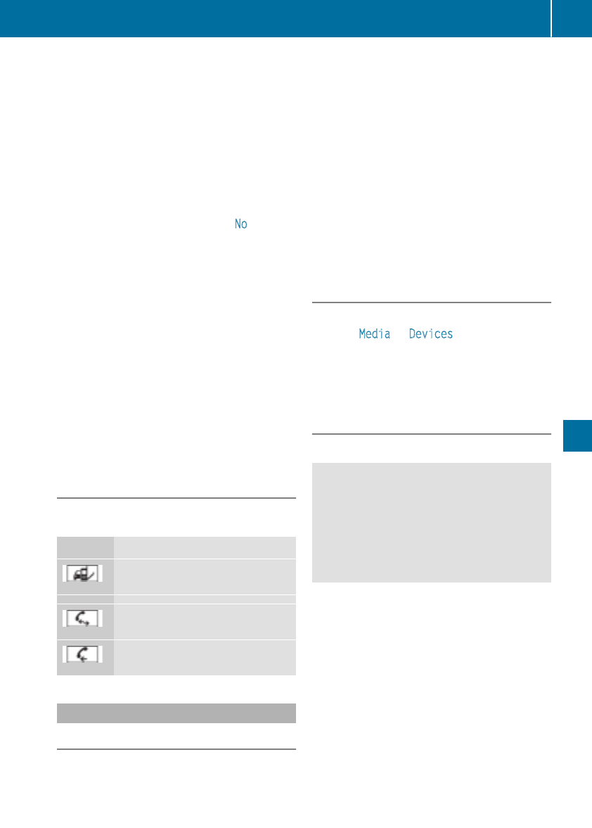
XAuthorizationusingSecureSimple Pair-
ing:
Acodeisdisplayed in themultimedia system
and on themobile phone.
XConfirmcodeonthe mobile phone. Depend-
ing on themobile phoneused, confirm the
connection to themultimedia system and for
thePBAPand MAPBluetooth®profiles. The
prompt to confirm may takeuptotwo
minutestobedisplayed (see themanufactur-
er'soperatinginstructions).
XIf thecodes are different:select No on the
multimedia system.
The processiscanceled.
Repeat authorization.
or
XAuthorizationbyentering apasskey
(passcode): enterany one- to sixteen-digit
number sequencewhichyou have chosen
yourself intothe passkeyinput menu.
XPress ¬to confirm.
XEnterand confirm thepasskeyonthe mobile
phone. Dependingonthe mobile phoneused,
confirm theconnectiontothe multimedia sys-
temand for thePBAPand MAPBluetooth®
profiles. The prompt to confirm may takeup
to two minutestobedisplayed (see theman-
ufacturer'soperatinginstructions).
Symbols in thedevice manager
The symbols are shown in color dependingon
their use.
Symbol Explanation
Mobile phoneconnected to the
multimedia system
Main telephone withfull range of
functions
Additional telephone for incoming
calls in two telephone mode
Media mode
General notes
If you wish to play external mediasources,the
appropriatemediamodemust alreadybeturned
on.Further informationonmediamode(see the
Digital Operator's Manual).
The followingexternalmediasources can be
used:
RApple®devices(e.g. iPhone®)
RUSBdevices(e.g. USBstick,MP3 player)
(Ypage 236)
RCD
RDVD(COMAND)
RSD cards
Rvia devicesconnected by Bluetooth®
iInformation on single CD/DVDdriveorDVD
changer (see theDigital Operator's Manual).
Selecting usingthe device list
Multimedia system:
XSelect MediaQDevices.
The available mediasources will be shown.
The #dot indicates thecurrentsetting.
XSelect themediasource.
Playable filesare played.
Inserting/removing an SD card
Important safety notes
GWARNING
SD cards are smallparts. They can be swal-
lowed and causechoking. This posesan
increased riskofinjury or evenfatal injury.
Keep theSDcardout of thereachofchildren.
If aSDcardisswallowed, seek medical atten-
tionimmediately.
!If you are no longer usingthe SD card, you
should remove it and store it outside thevehi-
cle.Hightemperatures can damagethe card.
InsertinganSDcard
The SD cardslot is locatedonthe control panel.
XInsertthe SD cardintothe SD cardslot until
theSDcardengages.The side withthe con-
tacts must facedown.
Removing an SD card
XPress theSDcard.
The SD cardisejected.
XRemove theSDcard.
Operatingsystem 235
Multimedia system
Z
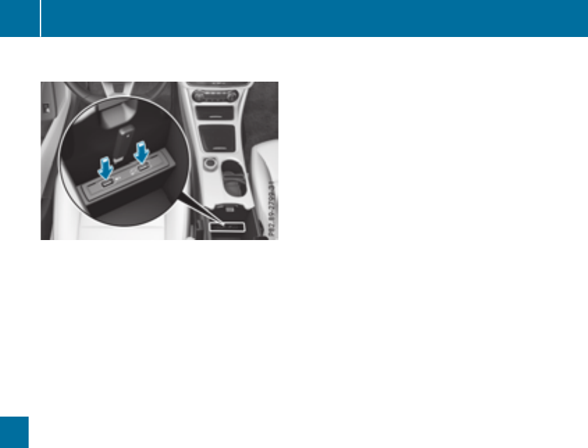
Connecting USB devices
XConnectthe USBdevice to theUSB port.
Thereare two USBportsinthe stowage space
underthe armrest.
XSelect themediasource (Ypage 235).
236 Operating system
Multimedia system

Loading guidelines
GWARNING
If objects, luggage or loads are not secured or
not secured sufficiently, they could slip, tip
over or be flungaroundand therebyhit vehicle
occupants. Thereisarisk of injury, particu-
larly in theeventofsudden braking or asud-
den change in direction.
Always store objectssothattheycannot be
flungaround. Secure objects, luggage or
loads against slippingortipping before the
journey.
GWARNING
Combustionenginesemit poisonous exhaust
gases such as carbon monoxide. Exhaust
gases can enter thevehicle interiorifthe
trunk lid is open when theengine is running,
especially if thevehicle is in motion.Thereisa
risk of poisoning.
Always switch off theengine before opening
thetrunk lid. Never drivewith thetrunk lid
open.
GWARNING
The exhaust tail pipe and tail pipe trim can
become veryhot.Ifyou comeintocontact
with these partsofthe vehicle,you could burn
yourself. Thereisarisk of injury.
Always be particularly careful aroundthe
exhaust tail pipe and thetail pipe trim. Allow
these componentstocooldown before touch-
ing them.
The handlingcharacteristicsofaladen vehicle
are dependentonthe distribution of theload
within thevehicle.
Observe thefollowing notes when loadingand
transporting aload:
RNever exceed themaximum permissible
gross vehicle mass or thegross axle weight
rating for thevehicle (includingoccupants).
The values are specified on thevehicle iden-
tification plateonthe B-pillar of thedriver's
door.
RThe trunk is thepreferred place to carry
objects.
RPosition heavy loads as far forwards as pos-
sible and as low down in thetrunk as possible.
RThe load must not protrude above theupper
edge of theseat backrests.
RAlways place theload against therear or front
seat backrests.Makesure that theseat
backrests are securely locked intoplace.
RAlways place theload behindunoccupied
seatsifpossible.
RUse thecargo tie-down rings and theparcel
netstotransport loads and luggage.
RUse cargo tie-down rings and fastening mate-
rials appropriatefor theweight and sizeofthe
load.
RSecure theload with sufficiently strongand
wear-resistant tie-downs.Pad sharpedges for
protection.
Stowage areas
Stowage spaces
Important safety notes
GWARNING
If objectsinthe passengercompartmentare
stowed incorrectly, they can slide or be
thrown aroundand hit vehicle occupants. In
addition,cupholders, open stowage spaces
and mobile phonebracketscannot always
retain all objectstheycontain.Thereisarisk
of injury, particularly in theeventofsudden
braking or asudden change in direction.
RAlways stow objectssothattheycannot be
thrown aroundinsuch situations.
RAlways makesure that objectsdonot pro-
trude fromstowage spaces, parcel netsor
stowage nets.
RClose thelockable stowage spaces before
starting ajourney.
RAlways stow and secure heavy, hard, poin-
ted,sharp-edged, fragile or bulky objectsin
thetrunk.
Observe theloadingguidelines (Ypage 237).
Stowage areas 237
Stowage and features
Z
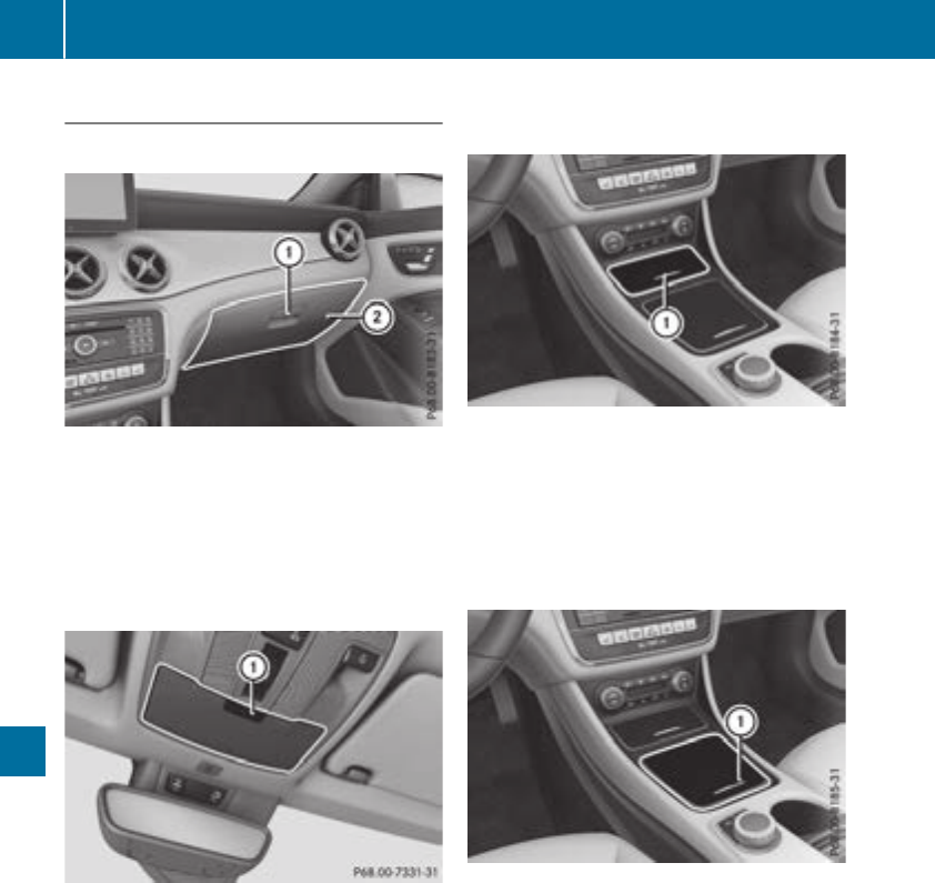
Stowage compartments in the front
Glove box
XTo open: pull handle :and open glove box
flap ;.
XTo close: fold glove box flap ;upwards until
it engages.
There is apen holder at the top of the glove box
flap.
Eyeglasses compartment
XTo open: press marking :.
Make sure that the eyeglasses compartmentis
always closed while the vehicle is in motion.
Stowage compartment in the front center
console
XTo open: press the marking on cover :.
iDepending on the vehicle equipment, there
may be an ashtray in the center console
instead of astorage compartment.
Stowage compartment in front of the arm-
rest (vehicleswith automatic transmis-
sion)
XTo open: press the marking on cover :.
iYou can remove the non-slip mat and the
insert for cleaning. When removing the insert
you will have to overcome some slight resist-
ance.
238 Stowage areas
Stowage and features
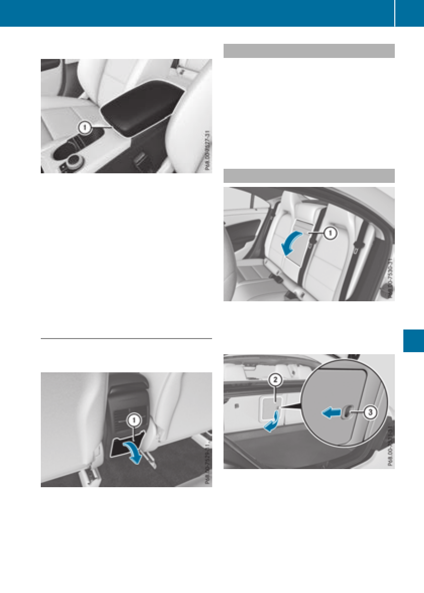
Stowage compartment under the armrest
XTo open: on vehicles with movable armrests,
make sure that the armrest is in the rearmost
position.
XPress button :and fold the armrest up.
Depending on the vehicle equipment, the arm-
rest can be moved backwards or forwards in a
longitudinal direction.
Depending on the vehicle's equipment, the fol-
lowing may be in the stowage compartment: a
multimedia connector unit with an SD card slot
and 2USB ports, e.g. for use with an iPod®,
iPhone®or MP3 player; see the separate oper-
ating instructions.
Stowage space in the rear
Stowage compartment in the rear center
console
XTo open: pull down the top of stowage com-
partment :by the edge of the handle.
iDepending on the vehicle's equipment,
there may be an open stowage space above
the stowage compartment.
Parcel nets
Stowage nets are located:
Rin the front-passenger footwell
Ron the back of the driver's and the front-
passenger seat
Ron the left and right-hand side in the trunk
Observe the loading guidelines (Ypage 237)
and the safety notes regarding stowage spaces
(Ypage 237).
Through-loading facility in the rear
XTo open: fold down seat armrest :.
XPull the center head restraint on the rear
bench seat into the uppermost position
(Ypage 93).
XSlide locking mechanism =in the direction
of the arrow.
XSwing flap ;fully to the side.
Flap ;is held open by amagnet.
XTo close: swing flap ;in the trunk back until
it engages.
XFold armrest :up fully if necessary.
Observe the loading guidelines (Ypage 237).
Stowage areas 239
Stowage and features
Z
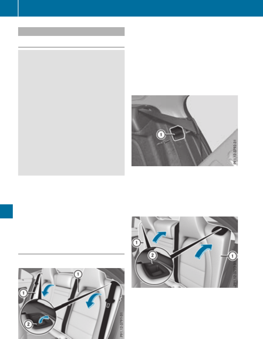
Cargo compartment enlargement
Important safety notes
GWARNING
If therear bench seat/rear seat and seat
backrestare notengaged they couldfold for-
wards,e.g.when braking suddenly or in the
event of an accident.
RThe vehicle occupant would thereby be
pushedintothe seat belt by therear bench
seat/rear seat or by theseat backrest. The
seat belt can no longer offer theintended
levelofprotection and couldevencause
injuries.
RObjectsorloads in thetrunk cannotbe
restrainedbythe seat backrest.
Thereisanincreased riskofinjury.
Before every trip, makesure that theseat
backrests and therear bench seat/rear seat
are engaged.
!Before folding thebackrestinthe rear com-
partmentforwards,makesure that therear
compartmentarmrestand thecupholder are
folded in. They may otherwise be damaged.
Observethe loadingguidelines(
Ypage 237).
The left-hand and right-handrear seat backrests
can be folded forwards separately to increase
thetrunk capacity.
Folding therearseat backrestforwards
and back
Folding therearseat backrests forward
XFully insert thebackresthead restraintsif
necessary (Ypage 93).
XMovethe driver'sorfront-passenger seat
forward if necessary.
XPull left-hand or right-handrelease handle ;
of theseat backrestforward.
Corresponding seat backrest :is released.
XFoldbackrest :forward.
XMovethe driver'sorfront-passenger seat
back if necessary.
XInsertthe seat belt intoseat-belt holder :.
Folding therearseat backrestback
!Makesure that theseat belt does not
become trapped when folding therear seat
backrestback.Otherwise, it couldbedam-
aged.
XMovethe driver'sorfront-passenger seat
forward if necessary.
XFoldseat backrest :back until it engages.
Red lockstatus indicator ;is no longer visi-
ble.
XAdjust thehead restraintsifnecessary
(Ypage 93).
XMovethe driver'sorfront-passenger seat
back if necessary.
240 Stowage areas
Stowage and features
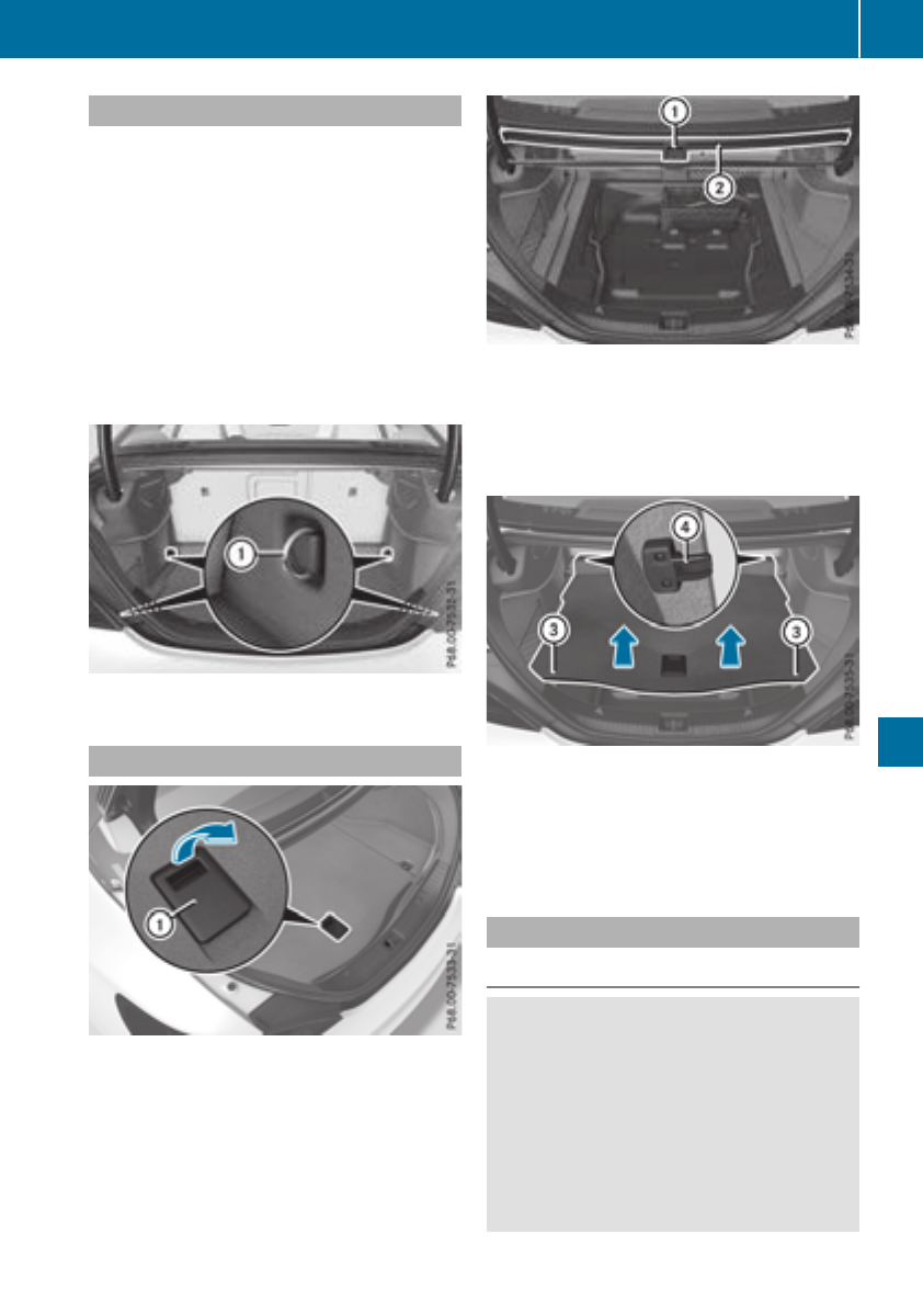
Securing loads
Observe the following notes on securing loads:
RObserve the loading guidelines (Ypage 237).
RSecure the load using the cargo tie-down
rings.
RDistribute the load on the cargo tie-down
rings evenly.
RDo not use elastic straps or nets to secure a
load, as these are only intended as an anti-slip
protection for light loads.
RDo not route tie-downs across sharp edges or
corners.
RPad sharp edges for protection.
:Cargo tie-down rings
Stowage well under the trunk floor
Under the trunk floor you can find abracket for
TIREFIT and the vehicle tool kit, etc.
XTo open: pull handle :up.
XHook handle :into rain trough ;.
To enlarge the trunk you can remove the trunk
floor.
XTo remove: lift the trunk floor almost to rain
trough ;and pull it out.
XTo insert: place the trunk floor at the bottom
in the center.
XHold sides of trunk floor =and press in the
direction of the arrow until it engages in
hooks ?.
Roof carrier
Important safety notes
GWARNING
When you load the roof, the center of gravity
of the vehicle rises and the driving character-
istics change. If you exceed the maximum roof
load, the driving characteristics, as well as
steering and braking, will be greatly impaired.
There is arisk of an accident.
Never exceed the maximum roof load and
adjust your driving style.
Stowage areas 241
Stowage and features
Z
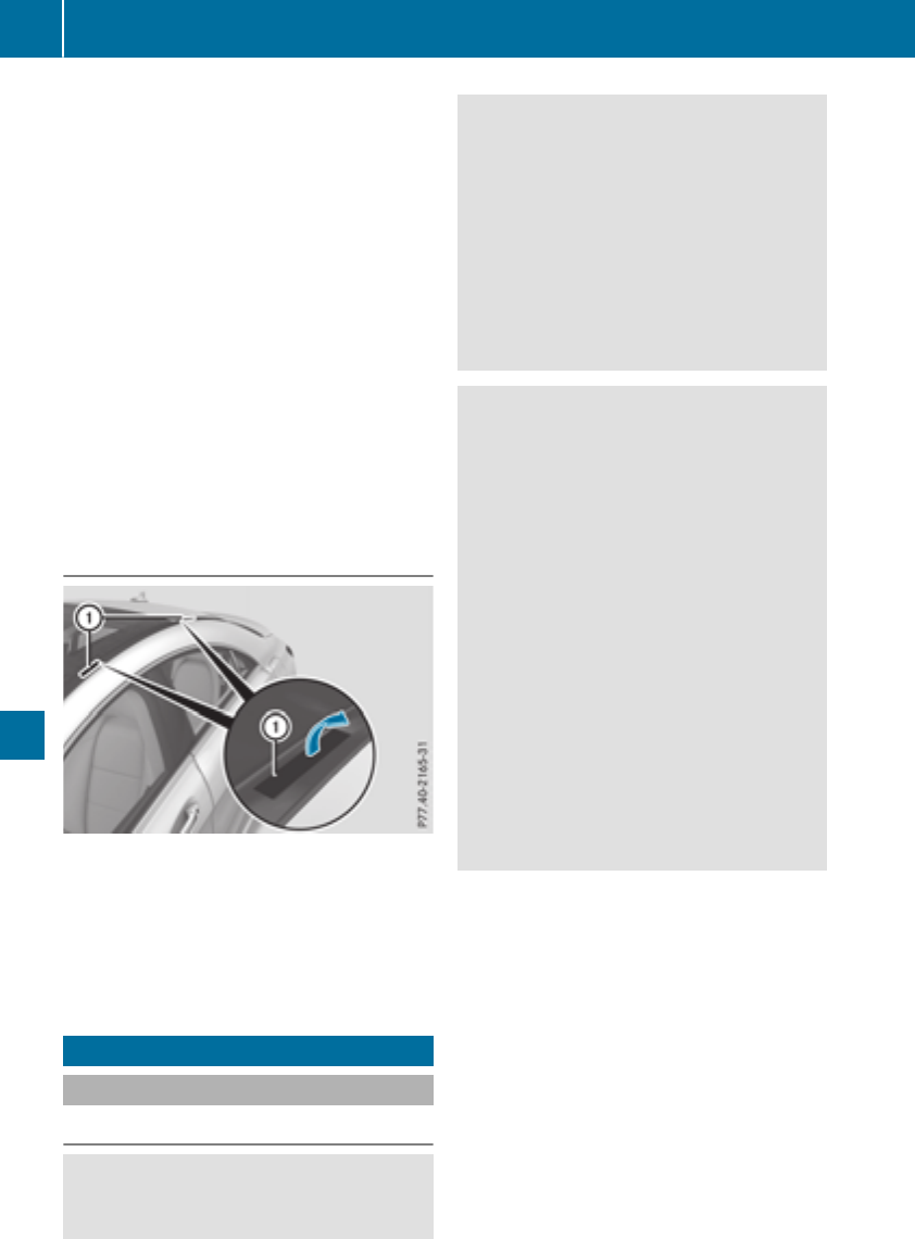
!Mercedes-Benz recommends that you only
use roof carriers that have been tested and
approved for Mercedes-Benz vehicles. This
helps to prevent damage to the vehicle.
Position the load on the roof rack in such a
way that the vehicle will not sustain damage
even when it is in motion.
Depending on the vehicle equipment, ensure
that when the roof carrier is installed you can:
Ropen the panorama roof with power tilt/
sliding panel fully
Ropen the trunk lid fully
You will find information on the maximum roof
load in the "Technical data" section
(Ypage 320).
An incorrectly secured roof carrier or roof load
may become detached from the vehicle. You
must therefore ensure that you observe the roof
carrier manufacturer's installation instructions.
Attaching the roof carrier
XOpen and fold the covers :upwards care-
fully in the direction of the arrow.
XOnly secure the roof carrier to the anchorage
points under covers :.
XObserve the manufacturer's installation
instructions.
Features
Cup holder
Important safety notes
GWARNING
The cup holder cannot hold acontainer secure
whilst traveling. If you use acup holder whilst
traveling, the container may be flung around
and liquid may be spilled. The vehicle occu-
pants may come into contact with the liquid
and if it is hot, they may be scalded. You may
be distracted from the traffic conditions and
you could lose control of the vehicle. There is
arisk of an accident and injury.
Only use the cup holder when the vehicle is
stationary. Only use the cup holder for con-
tainers of the right size. Alwaysclose the con-
tainer, particularlyifthe liquid is hot.
GWARNING
If objects in the passenger compartment are
stowed incorrectly, they can slide or be
thrown around and hit vehicle occupants. In
addition, cupholders, open stowage spaces
and mobile phone brackets cannot always
retain all objects they contain. There is arisk
of injury, particularlyinthe event of sudden
braking or asudden change in direction.
RAlwaysstow objects so that they cannot be
thrown around in such situations.
RAlwaysmake sure that objects do not pro-
trude from stowage spaces, parcel nets or
stowage nets.
RClose the lockable stowage spaces before
starting ajourney.
RAlwaysstow and secure heavy, hard, poin-
ted, sharp-edged, fragile or bulky objects in
the trunk.
!Only use the cup holders for containers of
the right size and which have lids. The drinks
could otherwise spill.
Observe the loading guidelines (Ypage 237).
The stowage compartmentsinthe doors provide
space for bottles:
Rfront:capacity up to 34 fl. oz. (1.0 l)
Rrear: capacity up to 17 fl. oz. (0.5 l)
242 Features
Stowage and features
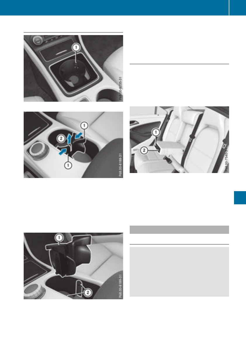
Cup holder in thefront center console
:Cup holder
The cup holder and therubbermat underneath
can be removedfor cleaning. Clean them with
clean, lukewarm wateronly.
XTo remove: carefullypull in upper sections of
cup holder :on thedriver'sand front-
passenger sides until they release.
XLiftthe cup holderupwards ;until it can be
removed.
XTo install: insert cup holder intolateral
curved sections ;in thestowage compart-
ment. Insertthe cup holdersothatthe wedge
of theupper sectionofcup holder :faces
forwards.
XPress thecup holder downwards until it
engages on therightand left-hand sides.
Cup holder in therearseat armrest
!Do notsit on or support your body weighton
therear seat armrestwhen it is folded down,
as you couldotherwise damageit.
!Close thecup holderbefore folding therear
seat armrestup. Otherwise, thecup holder
couldbedamaged.
XFolddown therear seat armrest.
XTo open: pressthe frontofcup holder :
or ;.
Cup holder :or ;extends automatically.
XTo close: slide cup holder :or ;back until
it engages.
Sun visors
Overview
GWARNING
If themirror cover of thevanity mirror is folded
up when thevehicle is in motion,you couldbe
blinded by incidentlight.Thereisariskofan
accident.
Always keep themirror cover folded down
while driving.
Features 243
Stowage and features
Z
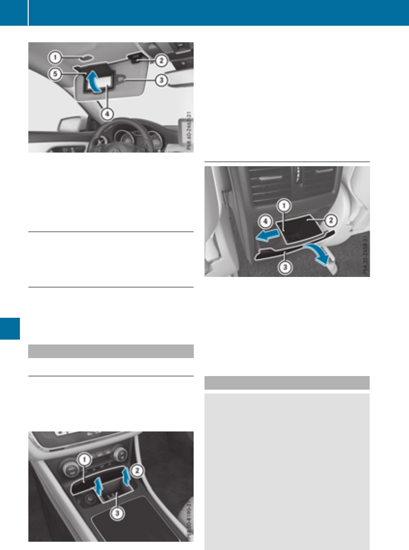
:Mirror light
;Bracket
=Retaining clip, e.g. for acar park ticket
?Vanity mirror
AMirror cover
Vanity mirror in the sun visor
Mirror light :only functions if the sun visor is
clipped into bracket ;and mirror cover Ahas
been folded up.
Glare from the side
XFold down the sun visor.
XPull the sun visor out of retainer ;.
XSwing the sun visor to the side.
Ashtray
Front ashtray
!The stowage space under the ashtray is not
heat resistant. Before placing lit cigarettes in
the ashtray, make sure that the ashtray is
properly engaged. Otherwise, the stowage
space could be damaged.
XVehicles with astowage compartment
cover: press the lower section of cover :.
The stowage compartmentopens.
XTo remove the insert: lift insert =up ;and
out.
XTo re-install the insert: press insert =into
the holder until it engages.
iIf you remove the ashtray insert, you can use
the resulting compartmentfor stowage.
Rear compartment ashtray
XTo open: pull cover =out by its top edge.
XTo remove: pull insert ;by recess :in the
direction of arrow ?until it audibly releases.
XLift insert ;up and out.
XTo install the insert: install insert ;from
above into the holder and press down until it
engages.
Cigarette lighter
GWARNING
You can burn yourself if you touch the hot
heating element or the socket of the cigarette
lighter.
In addition, flammable materials can ignite if:
Rthe hot cigarette lighter falls
Rachild holds the hot cigarette lighter to
objects, for example
There is arisk of fire and injury.
Always hold the cigarette lighter by the knob.
Always make sure that the cigarette lighter is
out of reach of children. Never leave children
unsupervised in the vehicle.
244 Features
Stowage and features
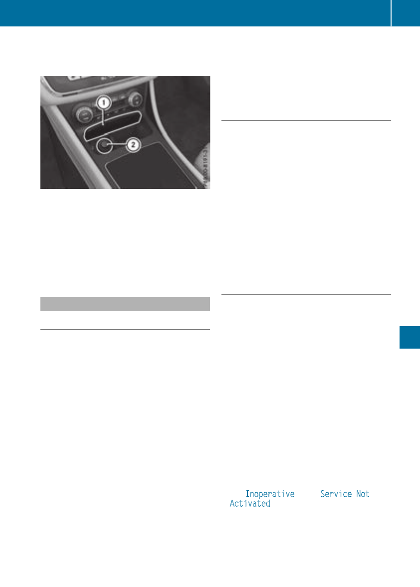
Your attention must always be focused on the
traffic conditions. Only use the cigarettelighter
when road and traffic conditionspermit.
XTurn the SmartKey to position 2in the igni-
tion lock (Ypage 122).
XVehicles with astowagecompartment
cover: press the lower section of cover :.
The stowage compartmentopens.
XPress in cigarettelighter ;.
Cigarette lighter ;will pop out automatically
when the heatingelementisred-hot.
mbrace
Generalnotes
The mbracesystemisonly available in the USA.
You must have alicense agreement to activate
the mbraceservice. Make sure that your system
is activatedand operational. To log in, press the
ïMB Infocall button. If any of the steps
mentioned are not carried out, the systemmay
not be activated.
If you have questions about the activation, con-
tactone of the followingtelephone hotlines:
Mercedes-BenzCustomer Assistance Center at
1-800-FOR-MERCedes (1-800-367-6372) or
1-866-990-9007
Shortly aftersuccessfully registeringwith the
mbraceservice, auser ID and password will be
sent to you by mail. You can use this password
to log ontothe mbracearea under "Owners
Online" at http://www.mbusa.com.
The systemisavailable if:
Rit has been activatedand is operational
Rthe corresponding mobile phonenetwork is
available for transmitting data to the Cus-
tomer Center
Raservice subscription is available
Determining the location of the vehicle on amap
is only possible if:
RGPS receptionisavailable.
Rthe vehicle position can be forwarded to the
Customer Assistance Center
Thembrace system
To adjust the volume during acall, proceed as
follows:
XPress the Wor Xbutton on the multi-
function steeringwheel.
or
XUse the multimedia system's volume control.
The systemoffers various services, e.g.:
RAutomatic and manual emergencycall
RRoadside Assistance call
RMB Infocall
You can findinformation and adescription of all
available features under "OwnersOnline" at
http://www.mbusa.com.
System self-test
After you have switched on the ignition, the sys-
tem carries out aself-diagnosis.
Amalfunction in the systemhas been detected
if one of the followingoccurs:
RThe indicator lamp in the SOS button does not
comeonduring the systemself-test.
RThe indicator lamp in the FRoadside
Assistance button does not light up during
self-diagnosis of the system.
RThe indicator lamp in the ïMB Infocall
button does not light up during self-diagnosis
of the system.
RThe indicator lamp in one or more of the fol-
lowing buttons continues to light up red after
the systemself-diagnosis:
-SOS button
-FRoadside Assistance call button
-ïMB Infocall button
RThe Inoperative or the Service Not
Activated messageappears in the multi-
function display afterthe systemself-diagno-
sis.
If amalfunction is indicated as outlined above,
the systemmay not operateasexpected. In the
eventofanemergency, help will have to be
summoned by other means.
Features 245
Stowage and features
Z
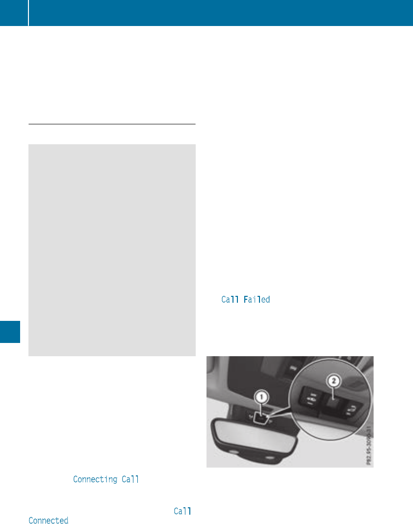
Have the system checked at the nearest
Mercedes-Benz Service Center or contact the
following service hotlines:
Mercedes-Benz Customer Assistance Center at
1-800-FOR-MERCedes(1-800-367-6372) or
1-866-990-9007
Emergencycall
Important safety notes
GWARNING
It can be dangeroustoremaininthe vehicle,
evenifyou have pressedthe SOS button in an
emergency if:
Ryousee smoke insideoroutsideofthe vehi-
cle,e.g.ifthereisafireafteranaccident
Rthe vehicleisonadangeroussection of
road
Rthe vehicleisnot visible or cannoteasilybe
seenbyotherroadusers,particularly when
dark or in poorvisibility conditions
There is ariskofanaccident and injury.
Leave the vehicleimmediatelyinthis or simi-
larsituations as soonasitissafetodoso.
Movetoasafelocation along with othervehi-
cle occupants. In such situations, secure the
vehicleinaccordance with nationalregula-
tions, e. g. with awarning triangle.
General notes
Observe the notes on system activation
(Ypage 245).
An emergency callisdialed automaticallyifan
airbag or Emergency Tensioning Device is trig-
gered.You cannotend an automaticallytrig-
gered emergency callyourself.
An emergency callcan also be initiated man-
ually.
As soonasthe emergency callhas been initi-
ated, the indicator lamp in the SOS button
flashes. The ConnectingCall message
appears in the multifunctiondisplay.
The audiooutputismuted.
Once the connectionhas been made, the Call
Connected message appears in the multifunc-
tiondisplay.
All important informationonthe emergency is
transmitted, for example:
Rcurrent location of the vehicle(as determined
by the GPSsystem)
Rvehicleidentificationnumber
Rinformationonthe severity of the accident
Shortly afterthe emergency callhas been initi-
ated, avoice connectionisautomaticallyestab-
lishedbetween the Customer Assistance Center
and the vehicleoccupants.
RIf the vehicleoccupants respond,the
Mercedes-Benz Customer Assistance Center
attempts to get more informationonthe
emergency.
RIf thereisnoresponsefrom the vehicleoccu-
pants, an ambulance is immediatelysent to
the vehicle.
If no voice connectioncan be established to the
Mercedes-Benz Customer Assistance Center,
the system hasbeenunabletoinitiate an emer-
gencycall.
Thiscan occur, for example, if the relevant
mobilephone network is not available.The indi-
catorlampinthe SOS button flashescontinu-
ously.
The CallFailed message appears in the mul-
tifunctiondisplay and must be confirmed.
In this case, summon assistance by other
means.
Making an emergencycall
XTo initiate an emergencycallmanually:
press cover :brieflytoopen.
XPress and holdthe SOS button for at leastone
second ;.
The indicator lamp in SOS button ;flashes
untilthe emergency callisconcluded.
XWait for avoice connectiontothe Mercedes-
Benz Customer Assistance Center.
246 Features
Stowageand features
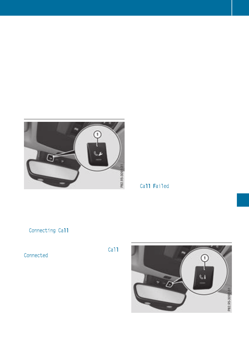
XTo endacall: press the ~button on the
multifunctionsteering wheel.
or
XPress the corresponding multimedia system
button for ending aphone call.
XAfter the emergency call, close cover :.
If the mobilephone network is unavailable,
mbrace will not be able to make the emergency
call. If youleave the vehicleimmediatelyafter
pressing SOS button ;,you do not know if
mbrace hassuccessfullymade theemergency
call. In thiscase, always summon assistance by
othermeans.
Breakdownassistancebutton
XTo make acall: press Roadside assistance
callbutton :.
Thisinitiates acalltothe Mercedes-Benz Cus-
tomerAssistance Center.
The indicator lamp in Roadside assistanc but-
ton :flasheswhile the callisactive. The
ConnectingCall message appears on the
multifunctiondisplay.The audiooutputis
muted.
If aconnectioncan be established,the Call
Connected message appears in the multifunc-
tiondisplay.
If amobilephone network and GPSreception
are available,the system transfers data to the
Mercedes-Benz Customer Assistance Center,
for example:
Rcurrent location of the vehicle
Rvehicleidentificationnumber
The display of the multimedia system indicates
thatacallisactive. During the call, youcan
change to the navigationmenu by pressing the
NAVI button on the multimedia system,for
example.
Voice outputisnot available in thiscase.
Avoice connectionisestablished between the
Mercedes-Benz Customer Assistance Center
and the vehicleoccupants.
From the remote malfunctiondiagnosis, the
Mercedes-Benz Customer Assistance Center
can ascertain the nature of the problem
(Ypage 250).
The Mercedes-Benz Customer Assistance Cen-
ter either sendsaqualified Mercedes-Benz tech-
nician or makes arrangements for your vehicle
to be transported to the nearestMercedes-Benz
Service Center.
Youmay be chargedfor servicessuchasrepair
work and/or towing.
Youcan find more informationinthe separate
mbrace manual.
The system hasnot been able to initiate aRoad-
side assistance call, if:
Rthe Findicator lamp for the Roadside
assistance callbutton is flashing continu-
ously.
Rno voice connectiontothe Mercedes-Benz
Customer Assistance Center wasestab-
lished.
Thiscan occurifthe relevant mobilephone net-
work is not available,for example.
The Call Failed message appears on the mul-
tifunctiondisplay.
XTo endacall: press the ~button on the
multifunctionsteering wheel.
or
XPress the corresponding multimedia system
button for ending aphone call.
MB Info callbutton
XTo make acall: press MB Info callbutton :.
Thisinitiates acalltothe Mercedes-Benz Cus-
tomerAssistance Center.
Features 247
Stowageand features
Z

The indicator lamp in MB Info call button :
flashes while the connection is being made.
The Connecting Call message appears on
the multifunction display.The audio output is
muted.
If aconnection can be established, the Call
Connected message appears in the multifunc-
tion display.
If amobile phone network and GPS reception
are available, the system transfers data to the
Mercedes-Benz Customer Assistance Center,
for example:
Rcurrent location of the vehicle
Rvehicle identification number
The display of the multimedia system indicates
that acall is active. During the call, you can
change to the navigation menu by pressing the
NAVI button on the multimedia system, for
example.
Voice output is not availableinthis case.
Avoice connection is established between the
Mercedes-Benz Customer Assistance Center
and the vehicle occupants.
You receive information about operating your
vehicle, about the nearest Mercedes-Benz Ser-
vice Center and about other products and serv-
ices from Mercedes-Benz.
You can find further information on the mbrace
system under "Owners Online" at http://
www.mbusa.com.
The system has not been able to initiate an MB
Info call, if:
Rthe indicator lamp in MB Info call button ï
is flashing continuously.
Rno voice connection to the Mercedes-Benz
Customer Assistance Center was estab-
lished.
This can occur if the relevant mobile phone net-
work is not available, for example.
The Call Failed message appears on the mul-
tifunction display.
XTo end acall: press the ~button on the
multifunction steeringwheel.
or
XPress the corresponding multimedia system
button for ending aphone call.
Call priority
When service calls are active, e.g. Roadside
Assistance or MB Info calls, an emergencycall
can still be initiated. In this case, an emergency
call will take priority and override all other active
calls.
The indicator lamp of the respective button
flashes until the call is ended.
An emergencycall can only be terminated by the
Mercedes-Benz Customer Assistance Center.
All other calls can be ended by pressing:
Rthe ~button on the multifunction steering
wheel
Rthe corresponding button in the multimedia
system to end the voice call
When acall is initiated, the audio system is
muted.
The mobile phone is no longer connected to the
multimedia system.
However, if you want to use your mobile phone,
do so only when the vehicle is stationary and in
asafe location.
Downloading destinations
Downloading destinations
Downloading destinations gives you access to a
database with over 15 million points of interest
(POIs). These can be downloaded on the navi-
gation system in your vehicle. If you know the
destination, the address can be downloaded.
Alternatively, you can obtain the location of
Points of Interest (POIs)/important destinations
in the vicinity.
Furthermore, you can download routes with up
to four way points.
You are prompted to confirm route guidance to
the address entered.
XSelectYes by turning 3or sliding 1
the controller and confirm with 7.
The system calculates the route and subse-
quently startsthe route guidance with the
address entered.
If you select No the address can be stored in
the address book.
248 Features
Stowage and features

The destination download function is available
if:
Rthe vehicle is equipped with anavigation sys-
tem.
Rthe relevant mobile phone network is availa-
ble and data transfer is possible.
Route Assistance
This service is part of the mbrace PLUS Package
and cannot be purchased separately.
You can use the Route Assistance function even
if the vehicle is not equipped with anavigation
system.
Within the framework of this service, you receive
aprofessional and reliable form of navigation
support without having to leave your vehicle.
The customer service representative finds a
suitable route depending on your vehicle's cur-
rent position and the desired destination. You
will then be guided live through the current route
section.
Search and Send
General notes
To use "Search &Send", your vehicle must be
equipped with mbrace and anavigation system.
Additionally, an mbrace service subscription
must be completed.
"Search &Send" is adestination entryservice. A
destination address found on Google Maps™
can be transferred via mbrace directly to your
vehicle's navigation system.
Specifying and sending the destination
address
XGo to the website http://maps.google.com
and enter adestination address into the entry
field.
XTo send the destination address to the e-
mail address of your mbrace account:
click on the corresponding button on the web-
site.
Example:
If you select 'Send to vehicle' and then
'Mercedes-Benz', the destination address will
be sent to your vehicle.
XWhen the "Send" dialog window appears:
Enter the e-mail address you specified when
setting up your mbrace account into the cor-
responding field.
XClick "Send".
Information on specific commands such as
"Address entry" or "Send" can be found on the
website.
Calling up atransmitted destination
address
XTurn the SmartKey to position 2in the igni-
tion lock (Ypage 122).
The transmitted destination address is loaded
into the vehicle's navigation system.
Adisplay message appears, asking whether
navigation should be started.
XSelectYes by turning 3or sliding 1
the controller and confirm with 7.
The system calculates the route and subse-
quently startsthe route guidance with the
address entered.
If you select No the address can be stored in
the address book.
If you have sent more than one destination
address, each individual destination must be
confirmed separately.
Destination addresses are loaded in the same
order as the order in which they were sent.
If you own multiple Mercedes-Benz vehicles with
mbrace and activated mbrace accounts:
If multiple vehicles are registered under the
same e-mail address, the destination will be
sent to all the vehicles.
Vehicle remoteopening
You can use the vehicle remote opening if you
have unintentionally locked your vehicle and a
replacement SmartKey is not available.
The vehicle can be opened by the Mercedes-
Benz Customer Assistance Center.
The vehicle can be immediately opened
remotely within four days of the ignition being
turned off. After this time, the remote unlocking
may be delayed by 15 to 60 minutes. After
30 days, the vehicle can no longer be opened
remotely.
The vehicle remote unlockingfeature is availa-
ble if the relevant mobile phone network is avail-
able and adata connection is possible.
XContact the following service hotlines:
Features 249
Stowage and features
Z
Mercedes-BenzCustomer AssistanceCenter
at 1-800-FOR-MERCedes (1-800-367-6372)
or 1-866-990-9007
You will be asked for your password.
XReturn to your vehicle at the time agreed upon
with the Mercedes-BenzCustomer Assis-
tance Center.
Alternatively, the vehicle can be opened via:
Rthe Internet, under the "Owners Online" sec-
tion
Rtelephone applications (e.g. for iPhone®,
Android™)
To do this, you will need your identification num-
ber and password.
Vehicle remote closing
The vehicle remote-closing feature can be used
when you have forgotten to lock the vehicle and
you are no longer nearby.
The vehicle can then be locked by the Mercedes-
Benz Customer AssistanceCenter.
The vehicle can be immediately remotely locked
within four days of the ignition being turned off.
After this time, remote closing may be delayed
by 15 to 60 minutes. After 30 days the vehicle
can no longer be valet locked remotely.
The vehicle remote closing feature is available if
the relevant mobile phone network is available
and adata connection is possible.
XContact the following service hotlines:
Mercedes-BenzCustomer AssistanceCenter
at 1-800-FOR-MERCedes (1-800-367-6372)
or 1-866-990-9007
You will be asked for your password.
The next time you are inside the vehicle and you
switch on the ignition, the Doors Locked
Remotely message appears in the multifunction
display.
Alternatively, the vehicle can be locked via:
Rthe Internet, under the "Owners Online" sec-
tion
Rtelephone applications (e.g. for iPhone®,
Android™)
To do this, you will need your identification num-
ber and password.
Stolen vehicle recovery service
If your vehicle has been stolen:
XNotify the police.
The police will issue anumbered incident
report.
XThis number will be forwarded to the
Mercedes-BenzCustomer AssistanceCenter
together with your PIN.
The Mercedes-BenzCustomer Assistance
Center then tries to locate the system. The
Mercedes-BenzCustomer AssistanceCenter
contacts you and the local law enforcement
agency if the vehicle is located.
However, only the law enforcement agency is
informed of the location of the vehicle.
If the anti-theft alarm system is activated for
longer than 30 seconds, the Mercedes-Benz
Customer AssistanceCenter is automatically
notified.
Vehicle Health Check
With the Vehicle Health Check, the Customer
AssistanceCenter can provide improved sup-
port for problems with your vehicle. During an
existing call, vehicle data is transferred to the
Customer AssistanceCenter.
The customer service representative can use
the received data to decide what kind of assis-
tance is required. You are then, for example,
guided to the nearest Mercedes-BenzService
Center or arecovery vehicle is called.
If vehicle data needs to be transferred during an
MB Info call or aRoadside Assistancecall, this is
initiated by the Customer AssistanceCenter.
The Roadside Assistance Connected mes-
sage appears in the display.Ifthe Vehicle Health
Check can be started, the Request for Vehi‐
cle Diagnostics Received Start vehi‐
cle diagnostics? message appears in the
display.
XPress the Yes button to confirm the message.
XWhen the Vehicle Diagnostics Please
Start Ignition message appears: turn the
SmartKey to position 2in the ignition lock
(Ypage 122).
XIf the Please follow the instructions
received by phone and move your vehi‐
cle to asafe position. message
appears: please follow the instructions
250 Features
Stowage and features
receivedbyphone and move yourvehicletoa
safe position.
The message in the display disappears.
The vehicleoperating state check begins.
During this procedure, you willsee the Vehi‐
cle Diagnostics Active message.
If you select Cancel,the VehicleHealth
Check is canceled completely.
When the check is complete, the Sending
vehicle diagnostics data. (Voice con‐
nection may be interrupted during
data transfer) message appears. The vehicle
data can now be sent.
XPress the OK button to confirm the message.
The voice connection with the Customer
Assistance Center is terminated.
The Vehicle Diagnostics: Transfer‐
ring Data... message appears.
The vehicledata is sent to the Customer
Assistance Center.
Depending on whatthe customer service rep-
resentative agreedwith you,the voice connec-
tion is re-establishedafter the transfer is com-
plete. If necessary,you willbecontacted at a
later time by another means, e.g. by e-mail or
phone.
Another function of the VehicleHealth Check is
the transfer of service data to the Customer
Assistance Center. If aservice is due,the display
shows amessage to this effect together with
informationabout any specialoffers at your
workshop.
This informationcan alsobecalled up under
"Owners Online" at http://www.mbusa.com.
Information on the data stored in the vehicle
(Ypage29).
Information on RoadsideAssistance
(Ypage26).
Downloading routes
Downloading routes allows you to transfer and
save predefined routes in the navigation sys-
tem.
Aroute can be prepared and sent by either a
customer service representative or under "Own-
ers Online" at http://www.mbusa.com.
Each route can includeuptofour way points.
Once aroute has been receivedbythe naviga-
tion system, you willsee the Do you want to
start route guidance?Destination
Received destination has been saved
in "Previousdestinations". message on
the multimedia system display.
The route is saved.
XTo start route guidance: select Yes.
An overviewofthe route is shown in the dis-
play.
If you select No,the saved route can be called
up later in the navigation menu.
XSelect Start.
Route guidance starts.
Downloaded and saved routes can be called up
again.
Speed alert
You can define the upper speedlimit, which
must not be exceededbythe vehicle.
If this selected speedisexceededbythe vehicle,
amessage willbesent to the Customer Assis-
tance Center. The Customer Assistance Center
then forwards this informationtoyou.
You can select the way in which you receive this
informationbeforehand. Possible options
includetext message, e-mail or an automated
call.
The data you receive contains the following
information:
Rthe location where the speedlimitwas excee-
ded
Rthe time at which the speedlimitwas excee-
ded
Rthe selected speedlimitwhich was exceeded
Geo fencing
Geo fencing allows you to select areaswhich the
vehicleshould not enter or leave. You willbe
informed if the vehiclecrosses the boundaries
of the selected areas. You can select the way in
which you receive this informationbeforehand.
Possible options includetext message, e-mail or
an automated call.
The area can be determinedaseither acircle or
apolygon with amaximumoften corners. You
can specify up to ten areassimultaneously.Dif-
ferent settings are possible for each area.
These settings can be called up under "Owners
Online" at http://www.mbusa.com.
Alternatively, you can trigger an MB Info call and
inform the customer service representative that
you wishtoactivate geo fencing.
Features 251
Stowage and features
Z
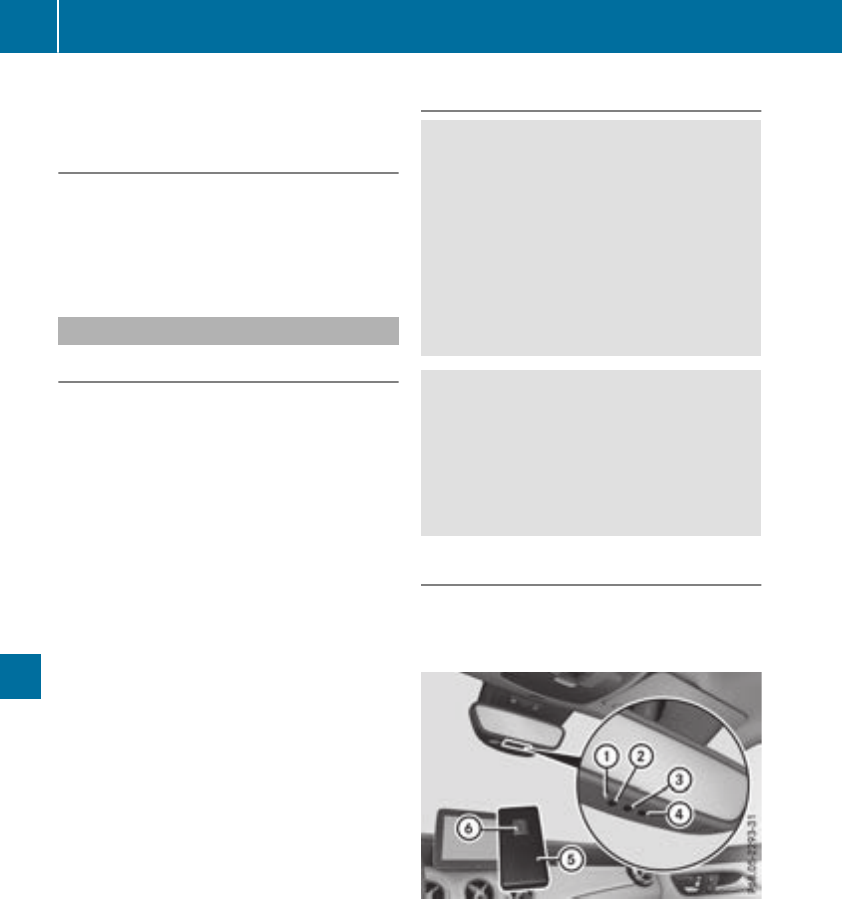
Currently inactiveareas can be activated by text
message.
Triggering thevehicle alarm
Withthisfunction,you can triggerthe vehicle's
panic alarm via text message. An alarm sounds
and theexterior lighting flashes. Dependingon
thesetting, thepanic alarm lastsfiveorten sec-
onds. Afterwards, thealarm switches off.
Garage door opener
General notes
The HomeLink®garagedoor opener integrated
in therear-view mirror allows you to operate up
to three different door and gatesystems.
Use theintegratedgaragedoor opener only on
garagedoorsthat:
Rhave safety stop and reversefeatures and
RmeetcurrentU.S.federal safety standards
Once programed, theintegratedgaragedoor
opener in therear-view mirror will assumethe
function of thegaragedoor system'sremote
control. Pleasealso read theoperatinginstruc-
tions for thegaragedoor system.
When programmingagaragedoor opener, park
thevehicle outside thegarage. Do notleave the
enginerunningwhile programming.
Certain garagedoor drives are incompatible
withthe integratedgaragedoor opener. If you
have difficultyprograming theintegratedgarage
door opener, contact aMercedes-BenzService
Center.
Alternatively, you can call thefollowingtele-
phoneassistance services:
RUSA: Mercedes-BenzCustomerAssistance
Centerat1-800-FOR-MERCedes
RCanada: CustomerServiceat
1-800-387-0100
RHomeLink®hotline1-800-355-3515(free of
charge)
MoreinformationonHomeLink®and/or com-
patible productsisalso available onlineat
http://www.homelink.com.
Notes on the declaration of conformity
(Ypage 27).
USA: FCC ID: CB2HMIHL4
Canada: IC: 279B-HMIHL4
Important safety notes
GWARNING
When you operate or program the garagedoor
with the integrated garagedoor opener, per-
sons in the range of movement of the garage
door can become trapped or struck by the
garagedoor. There is arisk of injury.
When using the integrated garagedoor
opener, always make sure that nobody is
within the range of movement of the garage
door.
GWARNING
Combustion engines emit poisonousexhaust
gases such as carbon monoxide. Inhaling
these exhaust gases leadstopoisoning. There
is arisk of fatal injury. Therefore never leave
the engine running in enclosed spaces with-
out sufficient ventilation.
Programming
Programming the buttons
Pay attention to the "Important safety notes"
(Ypage 252).
Garage door remote control Ais not included
with the integrated garagedoor opener.
XTurn the SmartKey to position 2in the ignition
lock (Ypage 122).
XSelect one of buttons ;to ?to control the
garagedoor drive.
252 Features
Stowage and features

XTo start program mode: press and holdone
of buttons ;to ?on the integrated garage
door opener.
The garagedooropenerisnow in program
mode. After ashort time,indicator lamp :
lights up yellow.
Indicatorlamp:lights up yellow as soonas
button ;,=or ?is stored for the first time.
If the selectedbutton hasalready been pro-
gramed,indicator lamp :will onlylight up
yellow afterten seconds have elapsed.
XReleasebutton ;,=or ?.Indicator
lamp :flashesyellow.
XTo program the remote control: point
garagedoorremote control Atowardsbut-
tons ;to ?on the rear-view mirror at adis-
tance of 2to8in(5to20cm).
XPress and holdbutton Bon remote control
Auntilindicator lamp :lights up green.
Whenindicator lamp :lights up green: pro-
gramming is finished.
Whenindicator lamp :flashesgreen: pro-
gramming wassuccessful. The next step is to
synchronize the rolling code(
Ypage 253).
XReleasebutton Bon remote control Afor
the garagedoordrive system.
If indicator lamp :lights up red:repeatthe
programing procedurefor the corresponding
button on the rear-view mirror. Whendoing
so, varythe distance between remote control
Aand the rear-view mirror.
The required distance between remote con-
trol Aand the integrated garagedooropener
depends on the garagedoordrive system.
Several attempts might be necessary.You
shouldtest every positionfor at least
25 seconds before trying another position.
Synchronizingthe rolling code
Payattentiontothe "Important safety notes"
(Ypage 252).
If the garagedoorsystem uses arolling code,
youwillalsohavetosynchronize the garage
door system with the integrated garagedoor
openerinthe rear-view mirror. To do thisyou will
needtouse the programming button on the door
drive controlpanel.The programming button
maybelocatedindifferent placesdepending on
the manufacturer. It is usuallylocatedonthe
door drive unitonthe garageceiling.
Familiarize yourselfwiththe garagedoordrive
operating instructions, e.g.under "Program-
ming additional remote controls", before carry-
ing outthe following steps.
Your vehiclemustbewithinreach of the garage
door or gate openerdrive. Make sure thatnei-
ther your vehiclenor any persons/objects are
present withinthe sweepofthe door or gate.
XTurn the SmartKey to position 2in the ignition
lock (Ypage 122).
XGetout of the vehicle.
XPress the programming button on the door
drive unit.
Usually,you now have 30 seconds to initiate
the next step.
XGetinto the vehicle.
XPress previously programed button ;,=
or ?on the integrated garagedooropener
repeatedly and in quick succession untilthe
door closes.
The rolling codesynchronizationisthen com-
plete.
Notesonprogrammingthe remote con-
trol
Canadianradio frequency laws require a"break"
(orinterruption) of the transmission signals
afterbroadcasting for afew seconds. Therefore,
thesesignals maynot last long enough for the
integrated garagedooropener. The signalisnot
detectedduring programming. Comparable with
Canadianlaw,someU.S. garagedooropeners
also feature a"break".
Proceedasfollows:
Rif youliveinCanada
Rif youhavedifficultiesprogramming the
garagedooropener(regardless of where you
live) as youfollowthe programming steps.
XPress and holdone of buttons ;to ?on the
integrated garagedooropener.
After ashort time,indicator lamp :lights up
yellow.
XReleasethe button.
Indicatorlamp:flashesyellow.
XPress button Bof garagedoorremote con-
trol Afor two seconds, then release it for two
seconds.
XPress button Bagainfor two seconds.
XRepeat thissequence on button Bof remote
control Auntilindicator lamp :lights up
green.
Whenindicator lamp :lights up green: pro-
gramming is finished.
Features 253
Stowageand features
Z

When indicator lamp :flashes green: pro-
gramming was successful. The next step is to
synchronize the rolling code.
XRelease button Bof remotecontrol Aof the
garage door drive.
If indicator lamp :lights up red: repeat the
programmingprocess for the corresponding
button on the rear-view mirror. When doing
so, vary the distancebetween remotecontrol
Aand the rear-view mirror.
The required distancebetween remotecon-
trol Aand the integrated garage door opener
depends on the garage door drive system.
Several attempts might be necessary. You
should test every position for at least
25 seconds before trying another position.
Problems when programming
If you are experiencing problems programming
the integrated garage door opener on the rear-
view mirror, take noteofthe following instruc-
tions:
RCheck the transmitter frequencyused by
garage door drive remotecontrol Aand
whether it is supported. The transmitter fre-
quency can usually be found on the back of
remotecontrol Afor the garage door drive.
The integrated garage door opener is com-
patible with devices that have units which
operate in the frequencyrange of 280 to
433 MHz.
RReplace the batteries in garage door remote
control A.This increases the likelihood that
garage door remotecontrol Awill transmit a
strongand precise signal to the integrated
garage door opener.
RWhen programming, hold remotecontrol A
at varying distances and angles from but-
tons ;to ?which you are programming. Try
various angles at adistancebetween 2and
8inches (5to 20 cm) or at the same angle but
at varying distances.
RIf another remotecontrol Ais available for
the same garage door drive, repeat the same
programmingsteps with this remotecontrol
A.Beforeperforming these steps, make sure
that new batteries have been installed in
garage door drive remotecontrol A.
RNote that some remotecontrols only transmit
for alimited amount of time (the indicator
lamp on the remotecontrol goes out). Press
button Bon remotecontrol Aagain before
transmission ends.
RAlign the antenna cable of the garage door
opener unit. This can improve signal recep-
tion/transmission.
Opening/closing the garage door
After it has been programmed, the integrated
garage door opener performsthe function of the
garage door system remotecontrol. Please also
read the operating instructionsfor the garage
door system.
XTurn the SmartKey to position 2in the ignition
lock (Ypage 122).
XPress button ;,=or ?which you have
programmed to operate the garage door.
Garage door system with afixed code: indi-
cator lamp :lights up green.
Garage door system with arolling code: indi-
cator lamp :flashes green.
The transmitter will transmit asignal as long
as the button is pressed. The transmission is
halted after amaximum of ten seconds and
indicator lamp :lights up yellow.
XPress button ;,=or ?again if necessary.
Clearing the memory
Make sure that you clear the memory of the
integrated garage door opener before selling the
vehicle.
XTurn the SmartKey to position 2in the ignition
lock (Ypage 122).
XPress and hold buttons ;and ?.
The indicator lamp initially lights up yellow
and then green.
XRelease buttons ;and ?.
The memory of the integrated garage door
opener in the rear-view mirror is cleared.
254 Features
Stowage and features

Compass
Callingupthe compass
:Rear-view mirror
;Compass display
=Opening
The compass displays in whichcompass direc-
tionthe vehicle is currently traveling: N,NE,E,
SE,S,SW,Wor NW.
To receive acorrectcompass display reading,
themagnetic fieldzonemust be set and the
compass calibrated.
Settingthe compass
XSet your locationusingthe magnetic field
zone maps (Ypage 255).
XPush aroundpen intoopening =for approx-
imately three seconds.
The magnetic fieldzonecurrently selected
appearsincompass display ;.
XTo select themagnetic field zone: push a
roundpen intoopening =until thedesired
magnetic fieldzoneisselected.
If,after afew seconds, thedisplay in compass
display ;changes direction,the magnetic
fieldzonehas been selected.
Calibratingthe compass
Notes
In order to calibratethe compass correctly, do
thefollowing:
Rcalibratethe compass in theopen and notin
thevicinity of steel structures or high-voltage
transmission lines.
Rswitch off electrical consumers suchasthe
climate control, windshield wipersorrear win-
dow defroster.
Rclose all doorsand thetrunk lid.
Calibrating
XMakesure that there is sufficient spacefor
you to driveinacircle without impedingtraf-
fic.
XSwitch on theignition.
XPush aroundpin intoopening =for approx-
imately six seconds, until symbol Cis shown in
compass display ;.
XDrive your vehicle in afull circle at approx-
imately 3mph (5 km/h)to6mph (10 km/h).
When thecalibration has been successfully
completed, thecurrentdirection is shown in
compass display ;.
Magnetic field zone maps
North America
Features 255
Stowage and features
Z
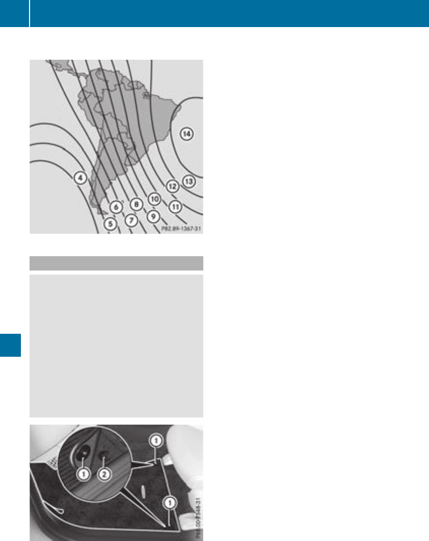
South America
Floormats
GWARNING
Objectsinthe driver's footwell can restrict the
pedal travel or obstruct adepressed pedal.
The operating and road safety of the vehicle is
jeopardized. There is arisk of an accident.
Make sure that all objectsinthe vehicle are
stowed correctly, and that they cannot enter
the driver's footwell. Install the floormats
securely and as specified in order to ensure
sufficient clearance for the pedals. Do not use
loose floormats and do not place floormats on
top of one another.
XSlide the seat back.
XTo install: place the floormat in the footwell.
XPress safety catch knobs :onto retain-
ers ;.
XTo remove: pull the floormat off retainers ;.
XRemove the floormat.
256 Features
Stowage and features

Engine compartment
Hood
Important safety notes
GWARNING
If thehood is unlatched, it may open up when
thevehicle is in motion and blockyour view.
Thereisarisk of an accident.
Never unlatch thehood while driving.Before
everytrip, ensure that thehood is locked.
GWARNING
When opening and closingthe hood,itmay
suddenly fall intothe closed position.Thereis
arisk of injury to personswithin range of
movementofthe hood.
Open and close thehood only when no oneis
within its range of movement.
GWARNING
Opening thehood when theengine is over-
heated or when there is afireinthe engine
compartmentcouldexpose you to hot gases
or other serviceproducts. Thereisarisk of
injury.
Let an overheatedengine cooldown before
opening thehood.Ifthere is afireinthe
engine compartment, keep thehood closed
and contactthe firedepartment.
GWARNING
The engine compartmentcontainsmoving
components. Certain components, suchas
theradiator fan,may continue to run or start
again suddenly when theignition is off.There
is arisk of injury.
If you needtodoany work inside theengine
compartment:
Rswitch off theignition
Rnever reachintothe area wherethere is a
risk of danger from moving components,
suchasthe fan rotationarea
Rremove jewelry and watches
Rkeep items of clothing and hair, for exam-
ple, away from moving parts
GWARNING
The ignition system and thefuel injection sys-
temwork underhigh voltage. If you touch
componentswhichare undervoltage, you
couldget an electric shock. Thereisarisk of
injury.
Never touch componentsofthe ignition sys-
temorfuel injection system when theignition
is switched on.
Opening thehood
GWARNING
Certain componentsinthe engine compart-
ment, suchasthe engine,radiator and parts
of theexhaust system, can become veryhot.
Workinginthe engine compartmentposesa
risk of injury.
Wherepossible, let theengine cooldown and
touch only thecomponentsdescribedinthe
following.
GWARNING
When thehood is open and thewindshield
wipersare set in motion,you can be injured by
thewiper linkage. Thereisarisk of injury.
Always switch off thewindshield wipersand
theignition before opening thehood.
!Makesure that thewindshield wipersare
notfolded away from thewindshield. You
couldotherwise damagethe windshield wip-
ers or thehood.
Engine compartment 257
Maintenance and care
Z
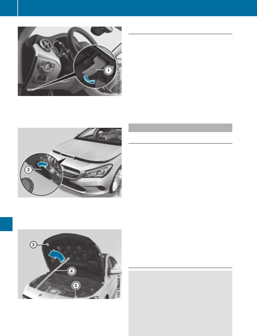
XMake sure that the windshield wipers are
switched off.
XPull release lever :on the hood.
The hood is released.
XReach into the gap between the hood and the
radiator trim and press hood catch lever ;to
the left.
XRaise the hood.
XPull support strut ?out of bracket A.
XLift up support strut ?and insert it into yel-
low retaining clip =.
Closing the hood
XRaise the hood slightly and, at the same time,
remove support strut ?from yellow retaining
clip =.
XSwing support strut ?down and press it into
bracket Auntil it engages.
XLower the hood and let it fall from aheight of
approximately 8in(20 cm).
XCheck that the hood has engaged properly.
If the hood can be raised slightly, it is not
properly engaged. Do not press the hood
closed. Open the hood again and close it with
alittle more force.
Engine oil
General notes
Depending on your driving style, the vehicle
consumes up to 0.9 US qt (0.8 liters) of oil per
600 miles (1,000 km). The oil consumption may
be higher than this when the vehicle is new or if
you frequently drive at high engine speeds.
Depending on the engine, the oil dipstick may be
in adifferent location.
When checking the oil level:
Rpark the vehicle on alevel surface
Rthe engine should be switched off for approx-
imately five minutes if the engine is at normal
operating temperature
Rif the engine is not at normal operating tem-
perature, e.g. if the engine was only started
briefly, wait about 30 minutes before carrying
out the measurement
Checking the oil level using the oil dip-
stick
GWARNING
Certain components in the engine compart-
ment, such as the engine, radiator and parts
of the exhaust system, can become very hot.
Working in the engine compartmentposes a
risk of injury.
Where possible, let the engine cool down and
touch only the components described in the
following.
258 Engine compartment
Maintenance and care
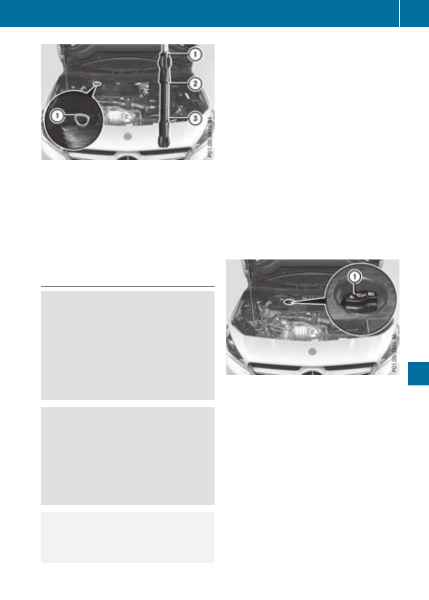
XPull oil dipstick :out of the dipstick guide
tube.
XWipe off oil dipstick :.
XSlowly slide oil dipstick :into the guide tube
to the stop, and take it out again.
If the level is between MIN mark =and MAX
mark ;,the oil level is correct.
XIf the oil level has dropped to MIN mark =or
below, add 1.1 US qt (1.0 liter) engine oil.
Adding engine oil
GWARNING
Certain components in the engine compart-
ment,such as the engine, radiator and parts
of the exhaust system, can become very hot.
Workinginthe engine compartment poses a
risk of injury.
Where possible, let the engine cool down and
touch only the components described in the
following.
GWARNING
If engine oil comes into contact with hot com-
ponentsinthe engine compartment,itmay
ignite. There is arisk of fire and injury.
Make sure that engine oil is not spilled next to
the filler neck.Let the engine cool down and
thoroughly clean the engine oil off the com-
ponentsbefore starting the engine.
HEnvironmentalnote
When adding oil, take care not to spill any. If
oil entersthe soil or waterways, it is harmful to
the environment.
!Use only engine oils and oil filters that are
approved for vehicles with aservice system. A
list of the engine oils and oil filters that have
been tested and approved in accordancewith
Mercedes-Benz Specifications for Service
Products is availableatany authorized
Mercedes-Benz Center.
The following cause engine failure or damage
to the exhaust system:
RUse of engine oils and oil filters that have
not been expressly approved for the service
system
RReplacement of engine oil and oil filter after
the replacement interval specified by the
service system has expired
RUse of engine oil additives
!Do not add too much oil. adding too much
engine oil can result in damage to the engine
or to the catalytic converter. Have excess
engine oil siphoned off.
Example: engine oil cap
XTurn cap :counter-clockwise and remove it.
XAdd engine oil.
If the oil level is at or below the MIN mark on
the oil dipstick,add 1.1 US qt (1.0 liter) of
engine oil.
XReplace cap :on the filler neck and turn
clockwise.
Ensure that the cap locks into place securely.
XCheck the oil level again with the oil dipstick
(Ypage 258).
Further information on engine oil (Ypage 317).
Engine compartment 259
Maintenance and care
Z
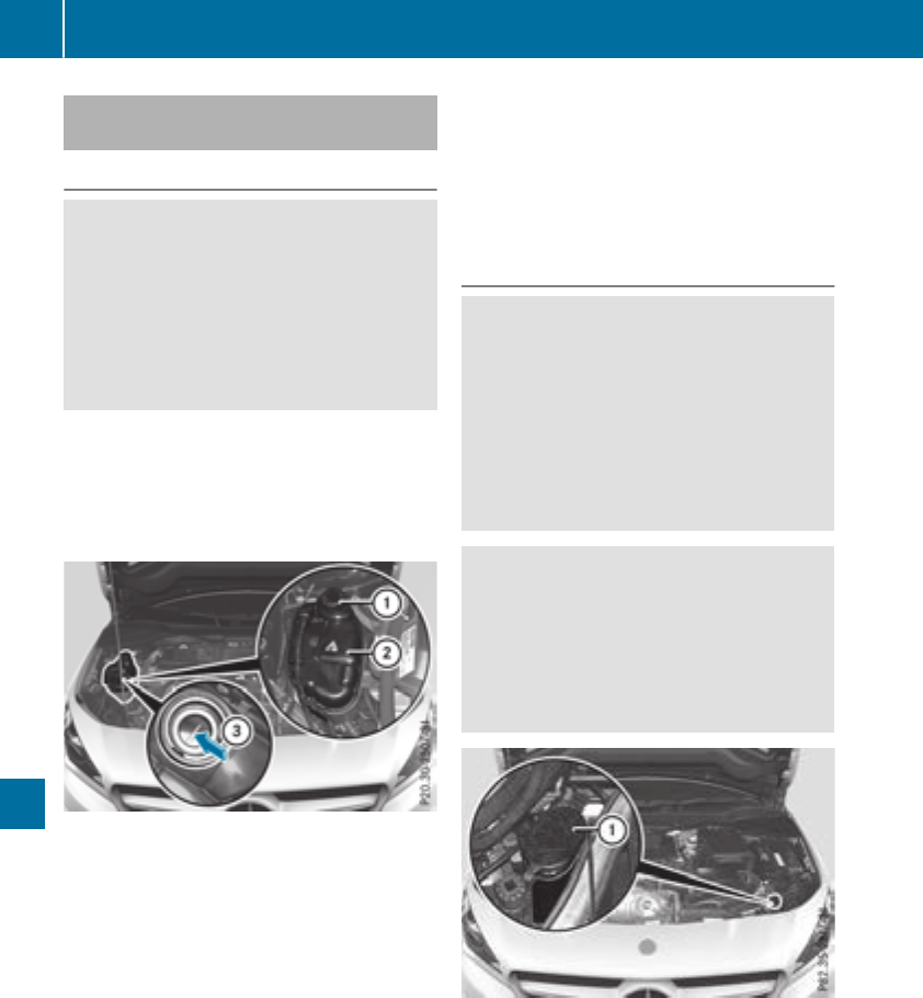
Checking and addingother service
products
Checking coolantlevel
GWARNING
The coolingsystem is pressurized, particularly
when themotor is warm.Ifyou open thecap,
you couldbescalded if hot coolant sprays out.
Thereisariskofinjury.
Let theenginecooldown before you open the
cap. Wear gloves and eye protection.Slowly
open thecap to relieve pressure.
!The coolant may only be checked and cor-
rectedwhen theengineiscool(coolanttem-
peraturebelow 104‡(40 †).Checkingthe
coolantwhen thecoolanttemperatureis
above104 ‡(40 †) mayresult in damage to
theengineortothe enginecoolingsystem.
XParkthe vehicleonalevel surface.
Only checkthe coolantlevel when thevehicle
is on alevel surfaceand theenginehas cooled
down.
XTurn theSmartKey to position 2in theigni-
tion lock(
Ypage 122).
XCheckthe coolanttemperature display in the
instrumentcluster.
The coolanttemperature mustbebelow
104‡(40 †).
XTurn theSmartKey to position g
(Ypage 122) in theignition lock.
XSlowly turncap :counter-clockwise and to
relieveexcesspressure.
XTurn cap :further counter-clockwise and
remove it.
If thecoolantisatthe level of markerbar =
in thefiller neck when cold, there is enough
coolantincoolantexpansion tank;.
XIf necessary, add coolantthathas been tested
and approvedbyMercedes-Benz.
XReplacecap :and turnitclockwise as far as
it will go.
Forfurther information on coolant, see
(Ypage 318).
Windshieldwasher system
GWARNING
Certain componentsinthe enginecompart-
ment, suchasthe engine, radiatorand parts
of theexhaust system, can become veryhot.
Working in theenginecompartmentposes a
riskofinjury.
Where possible, let theenginecooldown and
touch only thecomponentsdescribed in the
following.
GWARNING
Windshield washer concentrate could igniteif
it comes into contact withhot enginecompo-
nentsorthe exhaust system. There is ariskof
fireand injury.
Makesurethatnowindshield washer con-
centrateisspilled next to thefiller neck.
XTo open: pull cap :upwards by thetab.
XAddthe premixed washer fluid.
XTo close: press cap :onto thefiller neck
until it engages.
If thewasher fluidlevel drops belowthe recom-
mended minimum of 1liter, amessage appears
in themultifunction display promptingyou to
add washer fluid(
Ypage 216).
Further information on windshield washer fluid/
antifreeze(
Ypage 319).
260 Engine compartment
Maintenance and care
ASSYSTPLUS
Service message
The ASSYSTPLUSserviceinterval display
informsyou of thenextservicedue date.
You can findinformation on thetypeofservice
and serviceintervals in theMaintenance Book-
let.
You can obtain further information from an
authorizedMercedes-Benz Centerorat
http://www.mbusa.com(USAonly).
iThe ASSYSTPLUSserviceinterval display
does notshowany information on theengine
oil level. Observethe notesonthe engineoil
level (Ypage 258).
The multifunction display shows aservicemes-
sage for several seconds, e.g.:
RServiceAin..days
RServiceAdue
RServiceAoverdueby..days
Dependingonthe operating conditionsofthe
vehicle, theremaining time or distanceuntil the
next servicedue dateisdisplayed.
The letterAor B,possiblyinconnectionwitha
number or another letter, indicates thetypeof
service. Astandsfor aminor serviceand Bfor a
major service.
You can obtain further information from an
authorizedMercedes-Benz Center.
The ASSYSTPLUSserviceinterval display does
nottakeintoaccountany periods of time during
whichthe battery is disconnected.
Maintainingthe time-dependentservicesched-
ule:
XNotedown theservicedue datedisplayed in
themultifunction display before disconnect-
ing thebattery.
or
XAfterreconnecting thebattery, subtractthe
battery disconnection periods from theser-
vicedateshown on thedisplay.
Hiding aservice message
XPress theaor %buttononthe steering
wheel.
Displaying service messages
XSwitchonthe ignition.
XPress the=or ;buttontoselect the
Serv. menu.
XPress the9or :buttontoselect the
ASSYST PLUSsubmenuand confirm by press-
ing theabutton.
The servicedue dateappearsinthe multi-
function display.
Information aboutService
Resetting theASSYSTPLUS service
interval display
!If theASSYSTPLUSserviceinterval display
has been inadvertentlyreset,thissetting can
be correctedataqualified specialist work-
shop.
Haveserviceworkcarriedout as described in
theMaintenance Booklet.This may otherwise
lead to increased wear and damagetothe
major assemblies or thevehicle.
Aqualified specialist workshop,e.g.anauthor-
ized Mercedes-Benz Center, will reset the
ASSYSTPLUSserviceinterval display after the
serviceworkhas been carriedout.You can also
obtain further information on maintenance
work, for example.
Special service requirements
The specifiedmaintenance interval takes only
thenormaloperation of thevehicleinto
account. Under arduous operating conditionsor
increased load on thevehicle, maintenance
workmustbecarriedout morefrequently, for
example:
Rregular citydrivingwithfrequentintermediate
stops
Rif thevehicleisprimarily used to travel short
distances
Ruse in mountainous terrain or on poor road
surfaces
Rif theengineisoften leftidlingfor longperiods
Rin particularly dustyconditions, or if air-recir-
culation modeisfrequentlyused
In these or similar operating conditions, have
theinterior filter, engineair cleaner, engineoil
and oil filter, for example, changed morefre-
ASSYST PLUS 261
Maintenance and care
Z

quently. Under arduous operatingconditions,
the tires must be checked more often. Further
information can be obtained at aqualified spe-
cialist workshop, e.g. an authorized Mercedes-
BenzCenter.
Driving abroad
An extensive Mercedes-Benz Service network is
also available in other countries. You can obtain
further information from any authorized
Mercedes-Benz Center.
Care
General notes
HEnvironmental note
Dispose of empty packagingand cleaning
cloths in an environmentally responsible man-
ner.
!For cleaningyour vehicle, do not use any of
the following:
Rdry, rough or hard cloths
Rabrasive cleaningagents
Rsolvents
Rcleaningagentscontainingsolvents
Do not scrub.
Do not touch the surfaces or protective films
with hard objects, e.g. aring or ice scraper.
You could otherwise scratch or damage the
surfaces and protective film.
!Do not park your vehicle for along period of
time directly after cleaning, particularly after
cleaningthe wheel rim with wheel cleaner.
Wheel cleaner can lead to the increased cor-
rosion of the brake discs and pads. Therefore,
drive for afew minutes after cleaning. By
heating up the brakes, the brake discs and
pads dry. The vehicle can then be parked for a
long period of time.
Regular care of your vehicle is acondition for
retaining the quality in the long term.
Use care productsand cleaningagentsrecom-
mended and approved by Mercedes-Benz.
Washing the vehicle and cleaning the
paintwork
Automatic car wash
GWARNING
Braking efficiency is reduced after washing
the vehicle. There is arisk of an accident.
After the vehicle has been washed, brake
carefully while paying attention to the traffic
conditionsuntil full brakingpower is restored.
!When Distance Pilot DISTRONIC or the
HOLD function is activated, the vehicle
brakes automatically in certain situations.
To avoid damage to the vehicle, deactivate
Distance Pilot DISTRONIC and the HOLD
function in the following or similar situations:
Rwhen towing the vehicle
Rin the car wash
!Never clean your vehicle in aTouchless
Automatic Car Wash as these use special
cleaningagents. These cleaningagentscan
damage the paintworkorplastic parts.
!Make sure that the automatic transmission
is in position Nwhen washing your vehicle in
atow-through car wash. The vehicle could be
damaged if the transmission is in another
position.
!Make sure that:
Rthe side windows and the sliding sunroof
are fully closed.
Rthe blower is switched off.
Rthe windshield wiper switch is at position 0.
The vehicle may otherwise be damaged.
You can wash the vehicle in an automatic car
wash from the very start.
If the vehicle is very dirty, pre-wash it before
cleaningitinanautomatic car wash.
After using an automatic car wash, wipe off wax
from the windshield and the wiper blades. This
will preventsmears and reduce wiping noises
caused by residue on the windshield.
Washing by hand
In some countries, washing by hand is only
allowed at specially equipped washing bays.
Observe the legal requirements in each country.
262 Care
Maintenance and care

XDo not usehot water and do not wash the
vehicleindirect sunlight.
XUse asoftspongetoclean.
XUse amildcleaning agent, such as acar
shampooapproved by Mercedes-Benz.
XThoroughlyhosedownthe vehiclewithagen-
tle jet of water.
XDo not point the water jet directlytowards the
airinlet.
XUse plenty of water and rinse outthe sponge
frequently.
XRinse the vehiclewithclean water and dry
thoroughlywithachamois.
XDo not letthe cleaning agent dry on the paint-
work.
Carefully remove alldepositsofroadsaltas
soonaspossiblewhendrivinginwinter.
Powerwashers
GWARNING
The water jet fromacircular jet nozzle(dirt
blasters)can cause invisible exteriordamage
to the tiresorchassiscomponents. Compo-
nents damagedinthisway mayfailunexpect-
edly.There is ariskofanaccident.
Do not usepower washers with circular jet
nozzles to clean the vehicle. Havedamaged
tiresorchassiscomponents replaced imme-
diately.
!Alwaysmaintain adistance of at least
11.8 in (30 cm)between the vehicleand the
powerwashernozzle. Informationabout the
correct distance is availablefromthe equip-
ment manufacturer.
Movethe powerwashernozzlearound when
cleaning your vehicle.
Do not aimdirectlyatany of the following:
RTires
RDoorgaps, roofgaps, joints, etc.
RElectrical components
RBattery
RConnectors
RLamps
RSeals
RTrim
RVentilationslots
Damaged seals or electrical components can
lead to leaks or failures.
!Vehicles with decorative film: parts of your
vehicleare covered with adecorative film.
Maintain adistance of at least27.5 in (70 cm)
between the parts of the vehiclecovered with
the filmand the nozzleofthe high pressure
cleaner.
Informationabout the correct distance is
availablefromthe equipment manufacturer.
Movethe powerwashernozzlearound when
cleaning your vehicle.
Cleaningthe paintwork
!Do not affix:
Rstickers
Rfilms
Rmagnetic platesorsimilar items
to paintedsurfaces.You could otherwise
damage the paintwork.
Scratches, corrosive deposits, areasaffectedby
corrosion and damage caused by inadequate
carecannotalwaysbecompletelyrepaired.In
such cases, visit aqualified specialistworkshop.
XRemovedirtimmediately, where possible,
whileavoidingrubbing too hard.
XSoakinsect remains with insect removerand
rinse off the treated areasafterwards.
XSoakbirddroppingswithwater and rinse off
the treated areasafterwards.
XRemovecoolant, brake fluid,tree resin, oils,
fuelsand greases by rubbing gently with a
cloth soaked in petroleumether or lighter
fluid.
XUse tar removertoremove tar stains.
XUse silicone removertoremove wax.
If water no longerforms "beads"onthe paint
surface, usethe paint careproducts recommen-
dedand approved by Mercedes-Benz. Thisisthe
caseapproximately every threetofivemonths,
depending on the climate conditions and the
careproduct used.
If dirt haspenetrated the paint surface or if the
paint hasbecome dull,the paint cleanerrecom-
mended and approved by Mercedes-Benz
shouldbeused.
Do not usethese careproducts in the sunoron
the hoodwhile the hoodishot.
Care 263
Maintenance and care
Z

XUse asuitabletouch-up stick, e.g. MB Touch-
Up Stick,torepair slight damage to the paint-
work quickly and provisionally.
Mattefinish care
!Never polish the vehicle or the light alloy
wheels. Polishing causes the finish to shine.
!The following may cause the paint to
become shiny and thus reduce the matte
effect:
Rstrong rubbing of the paintwork with
unsuitablematerials
Rfrequent use of automatic car washes
Rwashing the vehicle in direct sunlight
!Never use paint cleaner, buffing or polishing
products, or gloss preserver, e.g. wax, for the
purpose of paintwork care. These products
are only suitablefor high-gloss surfaces. Their
use on vehicles with matte paintwork leads to
considerable surface damage or, more spe-
cifically,toshiny, spotted areas.
Alwayshave paintwork repairs carried out at a
qualified specialist workshop.
!Do not use wash programs with ahot wax
treatment under any circumstances.
Observe these notes if your vehicle has aclear
matte finish. This will help you to avoid damage
to the paintwork due to incorrect treatment.
These notes also apply to light alloy wheels with
aclear matte finish.
The vehicle should ideally be washed by hand
using asoft sponge, car shampoo and plenty of
water.
Use only insect remover and car shampoo from
the range of approved Mercedes-Benz care
products.
Cleaning the vehicleparts
Cleaning the wheels
GWARNING
The water jet from acircular jet nozzle (dirt
blasters) can cause invisible exterior damage
to the tires or chassis components. Compo-
nentsdamagedinthis way may fail unexpect-
edly.There is arisk of an accident.
Do not use power washers with circular jet
nozzles to clean the vehicle. Have damaged
tires or chassis componentsreplaced imme-
diately.
!Do not use acidic wheel cleaning products
to remove brake dust. This could damage
wheel bolts and brake components.
!Do not park your vehicle for along period of
time directly after cleaning, particularlyafter
cleaning the wheel rim with wheel cleaner.
Wheel cleaner can lead to the increased cor-
rosion of the brake discs and pads. Therefore,
drive for afew minutes after cleaning. By
heating up the brakes, the brake discs and
pads dry. The vehicle can then be parked for a
long period of time.
Cleaning the windows
GWARNING
You could become trapped by the windshield
wipers if they start moving while cleaning the
windshieldorwiper blades. There is arisk of
injury.
Alwaysswitch off the windshieldwipers and
the ignition before cleaning the windshieldor
wiper blades.
!Only fold the windshieldwipers awayfrom
the windshieldwhen vertical. Otherwise, you
will damage the hood.
!Do not use dry cloths, abrasive products,
solvents or cleaning agents containing sol-
vents to clean the inside of the windows. Do
not touch the insides of the windows with
hard objects, e.g. an ice scraper or ring. There
is otherwise arisk of damaging the windows.
!Cleanthe water drainage channels of the
windshieldand the rear window at regular
intervals. Deposits such as leaves, petals and
pollen may under certain circumstances pre-
vent water from draining away. This can lead
to corrosion damage and damage to elec-
tronic components.
XCleanthe inside and outside of the windows
with adamp cloth and acleaning product that
is recommended and approved by Mercedes-
Benz.
264 Care
Maintenance and care
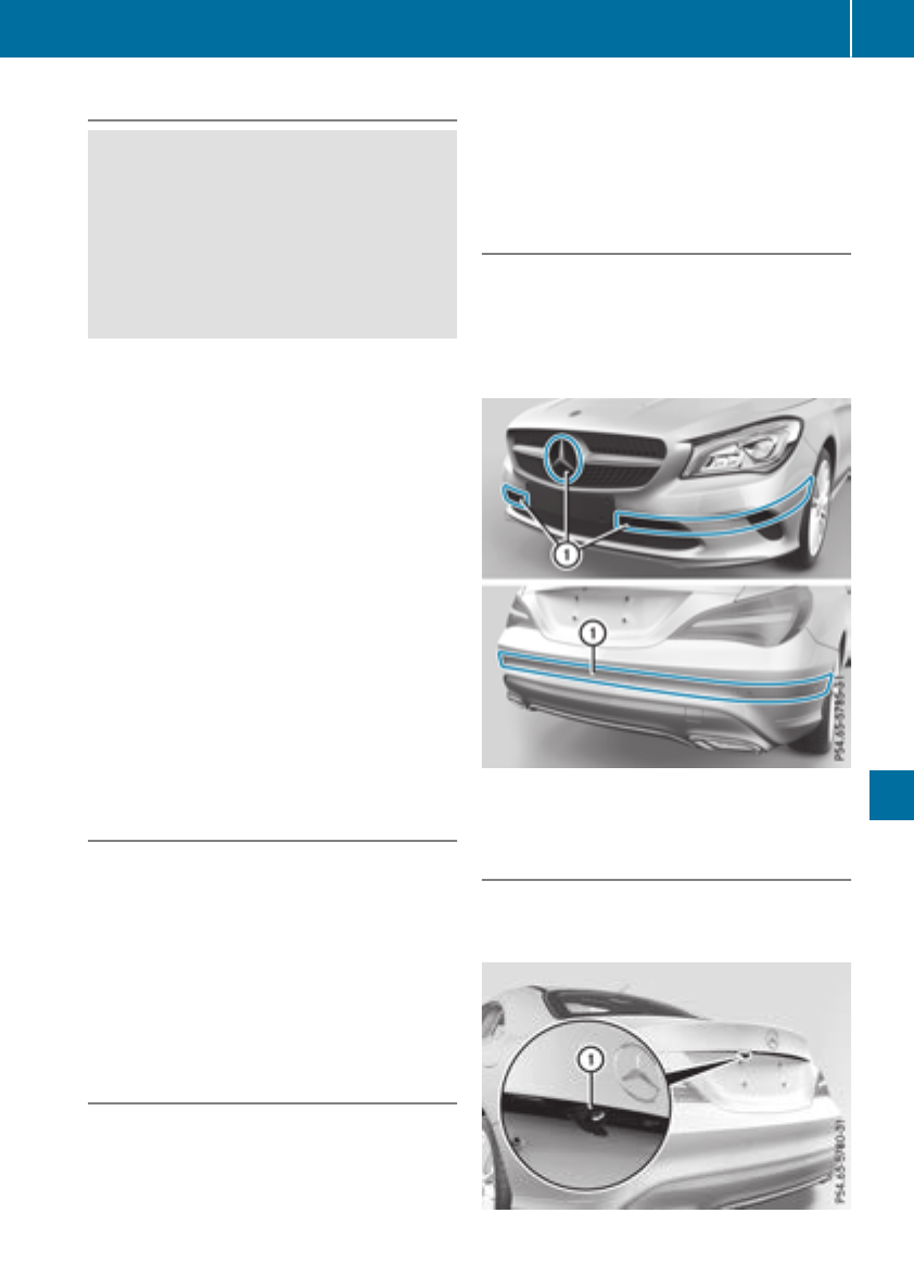
Cleaning wiper blades
GWARNING
You couldbecome trapped by thewindshield
wipersiftheystart moving while cleaningthe
windshield or wiper blades.Thereisariskof
injury.
Always switch off thewindshield wipersand
theignition before cleaningthe windshield or
wiper blades.
!Only fold thewindshield wipersaway from
thewindshield when vertical. Otherwise, you
will damagethe hood.
!Do notpull thewiper blade. Otherwise, the
wiper blade couldbedamaged.
!Do notclean wiper blades toooften and do
notrub them toohard.Otherwise, thegraph-
ite coatingcouldbedamaged. This could
causewiper noise.
!Holdthe wiper arm securely when folding
back.The windshield couldbedamaged if the
wiper arm smacks against it suddenly.
XFoldthe windshield wiper armsaway from the
windshield.
XCarefully clean thewiper blades withadamp
cloth.
XFoldthe windshield wiper armsback again
before switching on theignition.
Cleaning theexterior lighting
!Only use cleaningagents or cleaningcloths
whichare suitable for plastic light lenses.
Unsuitable cleaningagents or cleaningcloths
couldscratch or damagethe plastic light len-
ses.
XClean theplastic lenses of theexterior lights
withawet sponge and amild cleaningagent,
e.g.Mercedes-Benzcar shampoo or cleaning
cloths.
Cleaning themirror turn signals
!Only use cleaningagents or cleaningcloths
that are suitable for plastic lenses.Unsuitable
cleaningagents or cleaningclothscould
scratch or damagethe plastic lenses of the
mirror turnsignals.
XClean theplastic lenses of themirror turnsig-
nals in theexterior mirror housing usingawet
sponge and mild cleaningagent, e.g.
Mercedes-Benzcar shampoo or cleaning
cloths.
Cleaning thesensors
!If you clean thesensorswithapower
washer, makesure that you keep adistance
of at least 11.8 in (30 cm)between the vehicle
and thepower washer nozzle. Information
about thecorrectdistanceisavailablefrom
theequipment manufacturer.
XClean sensors :of thedriving systems with
water, car shampoo and asoftcloth.
Cleaning therearview camera
!Do notclean thecamera lensand thearea
aroundthe rear view camera with apower
washer.
Care 265
Maintenance and care
Z

XMake sure that the vehicle is at astandstill
and the SmartKey is in key position 2in the
ignition lock.
XOpen the camera cover for cleaning via the
multimedia system (see the separate operat-
ing instructions).
XTo clean the rear view camera: use clear
water and asoft cloth to clean camera
lens :.
Cleaningthe exhaust pipes
GWARNING
The exhaust tail pipe and tail pipe trim can
become very hot. If you come into contact
with these parts of the vehicle, you could burn
yourself. There is arisk of injury.
Always be particularly careful around the
exhaust tail pipe and the tail pipe trim. Allow
these components to cool down before touch-
ing them.
!Do not clean the exhaust pipe with acid-
based cleaning agents, such as bathroom
cleaner or wheel cleaner.
!Mercedes-AMG vehicles with black exhaust
pipes: the black-chrome tailpipe finishers
should not be polished with achrome polish.
They will otherwise lose their black sheen. For
optimal care, the faceplates should be rubbed
with alightly oiled cloth after every car wash.
Commercially available engine and care oils
are suitable for this.
For heavier soiling, you can apply afine paint-
work polish with amicrofiber cloth. Remove
the excess polish residue after polishing.
Impurities combined with the effectsofroad grit
and corrosive environmental factors may cause
flash rust to form on the surface. You can
restore the original shine of the exhaust pipe by
cleaning it regularly,especially in winter and
after washing.
XClean the exhaust pipe with acare product
tested and approved by Mercedes-Benz.
Interior care
Cleaningthe display
!For cleaning, do not use any of the following:
Ralcohol-based thinner or gasoline
Rabrasive cleaning agents
Rcommercially-availablehousehold cleaning
agents
These may damage the display surface. Do
not put pressure on the display surface when
cleaning. This could lead to irreparable dam-
age to the display.
XBefore cleaning the display,make sure that it
is switched off and has cooled down.
XClean the display surface using acommer-
cially available microfiber cloth and TFT/LCD
display cleaner.
XDry the display surface using adry microfiber
cloth.
Cleaningthe plastic trim
GWARNING
Care products and cleaning agents containing
solvents cause surfaces in the cockpit to
become porous. As aresult, plastic parts may
come loose in the event of air bag deploy-
ment. There is arisk of injury.
Do not use any care products and cleaning
agents to clean the cockpit.
!Never attach the following to plastic surfa-
ces:
Rstickers
Rfilms
Rperfume oil container or similar
You could otherwise damage the plastic.
!Do not allow cosmetics, insect repellent or
sunscreen to come into contact with the plas-
tic trim. This maintains the high-quality look of
the surfaces.
XWipe the plastic trim with adamp, lint-free
cloth, e.g. amicrofiber cloth.
XHeavy soiling: use care and cleaning prod-
ucts recommended and approved by
Mercedes-Benz.
The surface may change color temporarily.
Wait until the surface is dry again.
266 Care
Maintenance and care

Cleaning thesteering wheel and gear or
selector lever
XThoroughlywipe withadamp cloth or use
leather careagents that have been recom-
mended and approved by Mercedes-Benz.
Cleaning genuine wood and trim ele-
ments
!Do notuse solvent-based cleaningagents
suchastar remover, wheel cleaners, polishes
or waxes. Thereisotherwise ariskofdamag-
ing thesurface.
!Do notuse chromepolishontrimpieces.
The trim pieces have achromelook but are
mostly made of anodized aluminum and can
lose their shineifchromepolishisused. Use
adamp, lint-free cloth instead when cleaning
thetrimpieces.
If thechrome-plated trim pieces are very
dirty, you can use achromepolish. If you are
unsure as to whether thetrimpieces are
chrome-plated or not, consult an authorized
Mercedes-BenzCenter.
XWipe thewoodentrimand trim pieces witha
damp, lint-free cloth,e.g.amicrofiber cloth.
XHeavy soiling: use careand cleaningprod-
uctsrecommended and approved by
Mercedes-Benz.
Cleaning theseat covers
General notes
!Do notuse amicrofiber cloth to clean covers
made out of real leather,artificial leather or
DINAMICA.Ifused often,these can damage
thecover.
Notethatregular careisessential to ensure that
theappearanceand comfortofthe covers is
retainedovertime.
Genuine leather seat covers
!To retain thenatural appearanceofthe
leather,observethe followingcleaning
instructions:
RClean genuine leather covers carefullywith
adamp cloth and then wipe thecovers
down withadry cloth.
RMakesure that theleather does not
become soaked. It may otherwise become
roughand cracked.
ROnly use leather careagents that have
been tested and approved by Mercedes-
Benz. You can obtain these from aqualified
specialist workshop.
Leather is anatural product.
It exhibitsnatural surface characteristics, for
example:
Rdifferences in thetexture
Rmarks caused by growth and injury
Rslightnuances of color
Theseare characteristicsofleather and not
material defects.
Seat coversofother materials
!Observethe followingwhen cleaning:
Rclean artificial leather covers withacloth
moistenedwithasolution containing 1%
detergent(e.g. dish washingliquid).
Rclean cloth covers withamicrofiber cloth
moistenedwithasolution containing 1%
detergent(e.g. dish washingl
iquid). Rub
carefullyand always wipe entireseat sec-
tions to avoid leaving visible lines. Leave
theseat to dry afterwards. Cleaning results
dependonthe type of dirt and how longit
has been there.
Rclean DINAMICA covers withadamp cloth.
Makesure that you wipe entireseat sec-
tions to avoid leaving visible lines.
Cleaning theseat belts
GWARNING
Seat beltscan become severely weakened if
bleached or dyed. This couldcausethe seat
beltstotearorfail, for instance, in theevent of
an accident. This posesanincreased riskof
injury or fatal injury.
Never bleachordye theseat belts.
Care 267
Maintenance and care
Z

!Do not clean the seat belts using chemical
cleaning agents. Do not dry the seat belts by
heating at temperatures above 176 ‡(80 †)
or in direct sunlight.
XUse clean, lukewarm water and soapsolution.
Cleaning the headliner and carpets
XHeadliner: if it is very dirty,use asoft brushor
dry shampoo.
XCarpets: use the carpetand textile cleaning
agents recommended and approved by
Mercedes-Benz.
268 Care
Maintenanceand care
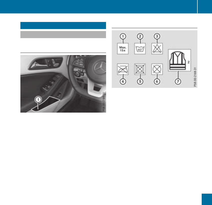
Where will Ifind...?
Reflective safety jacket
Removing/replacing the reflective
safety jacket
The reflective safety jackets are located in front
door stowage compartments :.Reflective
safety jackets can alsobestored in the rear door
stowage compartments.
XTo remove: pullout the safety jacket bag
containing the reflective safety jacket.
XOpen the safety jacket bag and pullout the
reflective safety jacket.
XTo stow: fold the reflective safety jacket, roll
it up and stow it in the safety jacket bag.
XReplace the safety jacket bag into stowage
compartment :.
iRemove anew reflective safety jacket from
its packaging material before sliding it into
the stowage compartment. The packaging
material may otherwise causeittoslipout or
make removing it difficult.
Observe the legalrequirements in each country.
Information on reflective safety jackets
:Maximum numberofwashes
;Maximum wash temperature
=Do not bleach
?Do not iron
ADo not use alaundry dryer
BDo not dry-clean
CThis is aclass2vest
RThe reflective safety jackets meet the require-
ments defined by the legalstandard only:
-if the correct size is usedand
-if the reflective safety jackets are correctly
fastened
RBefore use,ensure that the reflective safety
jackets are cleanand intact. The special prop-
erties may otherwise be compromised.
RThe reflective safety jackets should be stored
in their original packaging in adry place away
from sources of heatand light.
RThe maximumnumberofwashes specified is
not the only factor influencing the life spanof
the reflective safety jackets. Theirlife span
alsodepends on use,care, storage,etc.
RThe reflective safety jackets should be dis-
posedofand replaced with new ones:
-after 15 washes, and/or
-if the reflective strips have become
scratched,and/or
-if the backing material and/or reflective
strips have become soiled and cannot be
cleaned off, and/or
-if the fluorescence has fadede.g. due to the
effects of sunlight
RDisposeofreflective safety jackets in an envi-
ronmentallyresponsiblemanner. To do so,
contact yourlocalwaste disposal company.
Where will Ifind...? 269
Breakdown assistance
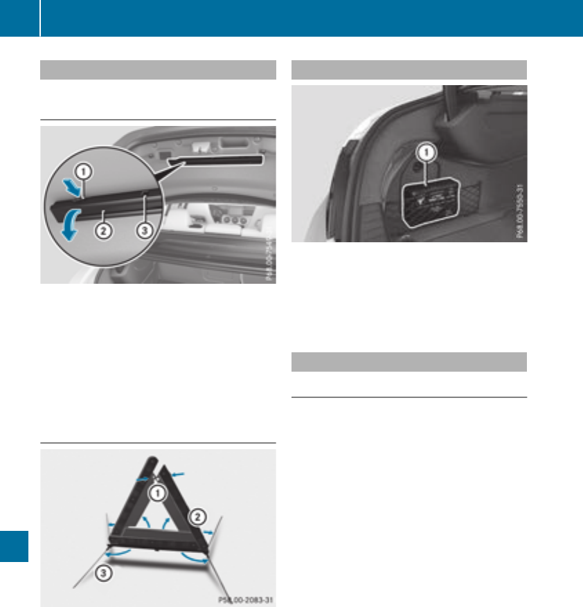
Warning triangle
Removing/replacing the warning trian-
gle
XTo remove: open the trunk lid.
XPress warning triangleholder :in the direc-
tion of the arrow and open. Lift retaining clip
=and remove warning triangle ;.
XTo replace: place warning triangle ;back
into warning triangleholder :.
XClose warning triangleholder :and pushup
to secure.
Setting up the warning triangle
XFold feet =out to the side.
XPullside reflectors ;upwards to form atri-
angleand lock them at the top using upper
press-stud :.
First-aid kit
XOpen the trunk lid.
XRemove first-aidkit :.
Check the expiration date on the first-aidkit at
least once ayear. Replace the contents if nec-
essary, and replace missing items.
Vehicle tool kit
General notes
Vehicles with aTIREFIT kit: the TIREFIT kit is
located in the stowage wellunder the trunk
floor.
Vehicles with atire-change tool kit: the tire-
change tool kit is in the stowage wellunder the
trunk floor.
Apart from certain country-specificvariations,
the vehicles are not equipped with atire-change
tool kit. Some tools for changing awheel are
specific to the vehicle. For more information on
which tire changing tools are required and
approved to perform awheel change on your
vehicle, consultaqualified specialist workshop.
Toolsrequired for changing awheel may
include, for example:
RJack
RWheelchock
RLug wrench
RAlignment bolt
270 Where will Ifind...?
Breakdown assistance
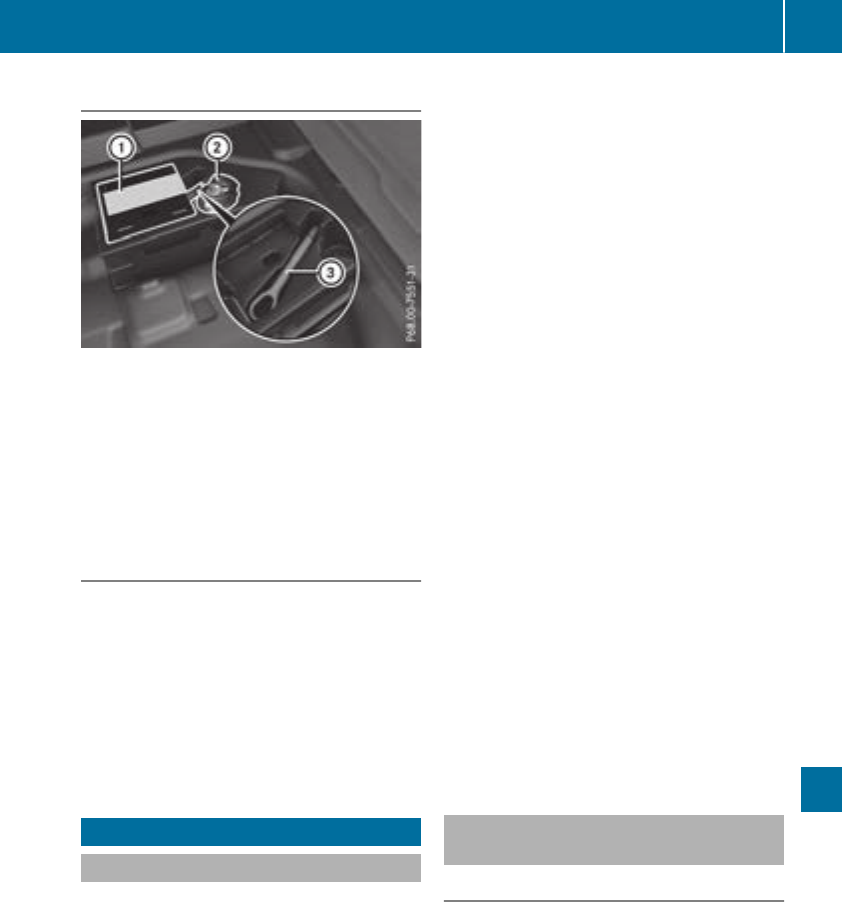
Vehicles with aTIREFITkit
:Tire inflation compressor
;Tire sealant fillerbottle
=Towing eye
XOpenthe trunk lid.
XLiftthe trunk floor upwards (Ypage 241).
XUse the TIREFIT kit (Ypage 272)orremove it.
Towing eye =is located under tire inflation
compressor :.
Vehicles with atire-changetool kit
XOpen the trunk lid.
XLift the trunk floor upwards (Ypage241).
XRemove the tire-change tool kit.
The tire-change tool kit contains:
RJack
RLug wrench
ROne pairofgloves
RFolding wheelchock
Flat tire
Preparing the vehicle
Yourvehiclemay be equipped with:
RMOExtended tires (tires with run-flat proper-
ties) (Ypage271)
Vehiclepreparation is not necessary on vehi-
cles with MOExtended tires
RaTIREFIT kit (Ypage270)
Vehicles equipped with MOExtended tires are
not equipped with aTIREFIT kit at the factory. It
is therefore recommended that you additionally
equip yourvehiclewith aTIREFIT kit if you mount
tires that do not feature run-flat properties, e.g.
winter tires. ATIREFIT kit may be obtained from
aqualified specialist workshop.
Information on changing and mounting wheels
(Ypage307).
XStop the vehicleonsolid, non-slippery and
level ground,asfar awayaspossible from
traffic.
XSwitch on the hazard warning lamps.
XSecure the vehicleagainst rolling away
(Ypage141).
XIf possible, bring the front wheels into the
straight-ahead position.
XSwitch off the engine.
XVehicles without KEYLESS-GO: remove the
SmartKey from the ignitionlock.
XVehicles with KEYLESS-GO start-function
or KEYLESS-GO: open the driver'sdoor.
The vehicleelectronics are now in position
g.This is the same as "Key removed".
XVehicles with KEYLESS-GO start-function
or KEYLESS-GO: remove the Start/Stop but-
ton from the ignitionlock (Ypage122).
XMake sure that the engine cannot be started
via yoursmartphone (Ypage83).
XMake sure that the passengers are not endan-
gered as they do so. Make sure that no one is
near the dangerarea while awheelisbeing
changed.Anyone who is not directly assisting
in the wheelchange should, for example,
stand behind the barrier.
XGet out of the vehicle. Pay attention to traffic
conditions when doing so.
XClose the driver'sdoor.
MOExtended tires (tires with run-flat
properties)
General notes
With MOExtended tires (tires with run flat char-
acteristics),you can continue to drive yourvehi-
cle even if there is atotal loss of pressure in one
or more tires. The affected tire must not show
any clearly visible damage.
You can recognize aMOExtended tire by the
MOExtended marking which appears on the
sidewallofthe tire. You willfind this marking
next to the tire size designation, the load-bear-
ing capacity and the speedindex (Ypage302).
MOExtended tires may be used only in conjunc-
tion with an activated tire pressure loss warning
Flat tire 271
Breakdown assistance

system (Canadaonly) or tire pressure monitor
(USA only).
If apressure loss warning message appears
in the multifunction display:
Robserve the instructions in the displaymes-
sages (Ypage 211).
Rcheck the tire for damage
Rif driving on, observe the following notes
The driving distance possible in run-flat mode is
approximately 50 miles (80 km) when the vehi-
cle is partiallyladen. When the vehicle is fully
laden it is approximately 19 miles (30 km).
In addition to the vehicle load, the driving dis-
tance possible depends upon:
Rvehicle speed
Rroad condition
Routside temperature
The driving distance possible in run-flat mode
may be reduced by extreme driving conditions
or maneuvers, or it can be increased through a
moderate style of driving.
The driving distance possible in run-flat mode is
counted from the moment the tire pressure loss
warning appears in the multifunction display.
You must not exceed amaximum speed of
50 mph (80 km/h).
When replacing one or all tires, please observe
the following specifications for your vehicle's
tires:
Rsize
Rtype and
Rthe "MOExtended" marking
If atire has gone flat and cannot be replaced
with aMOExtended tire, astandard tire may be
used as atemporary measure. Make sure that
you use the proper size and type (summer or
winter tire).
Vehicles equipped with MOExtended tires are
not equipped with aTIREFIT kit at the factory. It
is therefore recommended that you additionally
equip your vehicle with aTIREFIT kit if you mount
tires that do not feature run-flat properties, e.g.
winter tires. ATIREFIT kit may be obtained from
aqualified specialist workshop.
Important safety notes
GWARNING
When driving in emergency mode, the driving
characteristics deteriorate, e.g. when corner-
ing, accelerating quickly and when braking.
There is arisk of an accident.
Do not exceed the stated maximum speed.
Avoid abrupt steering and driving maneuvers,
and driving over obstacles (curbs, potholes,
off-road). This applies in particular to aladen
vehicle.
Stop driving in emergency mode if:
Ryou hear banging noises.
Rthe vehicle starts to shake.
Ryou see smoke and smell rubber.
RESP®is interveningconstantly.
Rthere are tears in the sidewalls of the tire.
After driving in emergency mode, have the
wheel rims checked at aqualified specialist
workshop with regard to their further use. The
defective tire must be replaced in every case.
TIREFIT kit
Important safety notes
TIREFIT is atire sealant.
Only valid for USA: You can use TIREFIT to seal
punctures of up to 0.16 in (4 mm), particularly
those in the tire tread. You can use TIREFIT at
outside temperatures down to Ò4‡(Ò20 †).
GWARNING
In the following situations, the tire sealant is
unable to provide sufficient breakdown assis-
tance, as it is unable to seal the tire properly:
Rthere are cuts or punctures in the tire larger
than those mentioned above.
Rthe wheel rim is damaged.
Ryou have driven at very low tire pressures or
on aflat tire.
There is arisk of an accident.
Do not drive the vehicle. Contact aqualified
specialist workshop.
GWARNING
The tire sealant is harmful and causes irrita-
tion. It must not come into contact with your
skin, eyes or clothing or be swallowed. Do not
272 Flat tire
Breakdown assistance
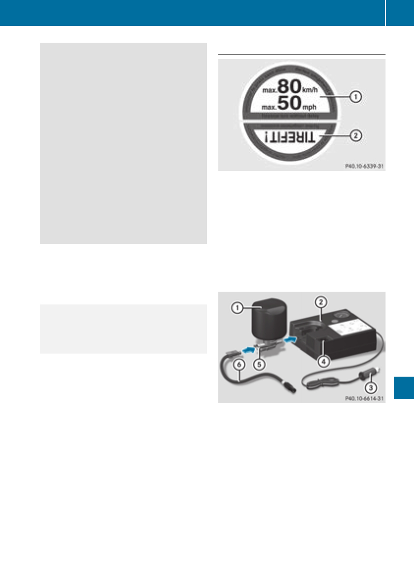
inhale TIREFIT fumes.Keep tiresealant away
fromchildren. There is arisk of injury.
If you comeintocontactwith the tiresealant,
observe the following:
RRinse off the tiresealant fromyour skin
immediately with water.
RIf the tiresealant comes intocontactwith
your eyes, immediately rinse themthor-
oughly with clean water.
RIf tiresealant is swallowed, immediately
rinse your mouthout thoroughly and drink
plentyofwater.Donot inducevomiting,
and seek medical attention immediately.
RImmediately change out of clothing which
has comeintocontactwith tiresealant.
RIf an allergic reaction occurs, seek medical
attention immediately.
!Residue fromthe tiresealant may comeout
of the filler hose after use. This could cause
stains.
Therefore, place the filler hose in the plastic
bag which contained the TIREFIT kit.
HEnvironmental note
Have the used tiresealant bottle disposedof
professionally, e.g. at aqualified specialist
workshop.
!Do not operatethe tireinflation compressor
for longer than ten minutes at atimewithout
abreak.Itmay otherwise overheat.
The tireinflation compressor can be operated
again onceithas cooleddown.
Comply with the manufacturer’s safetyinstruc-
tionsonthe sticker on the tireinflation com-
pressor.
Using theTIREFIT kit
XDo not remove any foreign objectswhich have
penetratedthe tire, e.g. screws or nails.
XUSA only: Remove the tiresealant bottle, the
accompanying TIREFIT sticker and the tire
inflation compressor fromthe stowage space
under the trunk floor (Ypage 271).
XAffix part :of the TIREFIT sticker to the
instrumentcluster within the driver's field of
vision.
XAffix part ;of the TIREFIT sticker near the
valve on the wheel with the defectivetire.
XRemove filler hose Band connector =from
the bottom section of the tireinflation com-
pressor housing ;.
XSlide the yellow filler hose connector intothe
mountingonyellow cap Aof tiresealant filler
bottle :until the connector engages.
XWith the sealing rings in front,slide yellow cap
Aof tiresealant bottle :intothe mounting
of tireinflation compressor ;.
Yellow cap Aand both hooksmust engage.
Flat tire 273
Breakdown assistance
Z
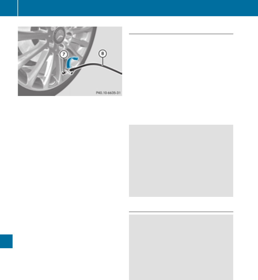
XRemove thecap from valveCon thefaulty
tire.
XScrew filler hoseDonto valveC.
XInsertplug =intoa12Vsocketinyour vehi-
cle.
Observethe notesonsockets (Ypage 244).
XTurn theSmartKey to position 1in theigni-
tion lock(
Ypage 122).
XPress on and off switch ?on thetireinflation
compressor to ON.
The tire inflation compressor is switched on.
The tire is inflated.
First,tiresealantispumped intothe tire. The
pressurecan briefly risetoapproximately
500kPa (5 bar/73 psi).
Do not switch off thetireinflation com-
pressor during this phase.
XLet thetireinflation compressor run for a
maximum of tenminutes. The tire should then
haveattained apressureofatleast 200kPa
(2.0 bar/29 psi).
If apressureof200 kPa(2.0 bar/29 psi) has
been attained after fiveminutes, see"Tire pres-
sure reached" (Ypage 274).
If atire pressure of 200 kPa (2.0 bar/29 psi) has
not been attainedafter fiveminutes, see"Tire
pressure not reached" (Ypage 274).
If tire sealant hasescaped,clean it off affected
areasasquicklyaspossible. Use plainwater if
possible.
If your clothesare soiledwithtire sealant, have
themcleanedwithperchloroethylene at adry
cleanerassoonaspossible.
Tire pressure notreached
If atire pressure of 200 kPa (2.0 bar/29psi)has
not been attainedafter ten minutes:
XSwitch off the tire inflationcompressor.
XUnscrew the fillerhosefromthe valve of the
faulty tire.
Note thattire sealant mayescapewhenyou
unscrew the fillerhose.
XUSAonly: veryslowlydrive forwards or
reverseapproximately 30 ft (10 m).
XPump up the tire again.
After amaximum of ten minutes, the tire pres-
sure must be at least200 kPa (2.0 bar/
29 psi).
GWARNING
If the required tire pressure is not reached
afterthe specified time,the tire is too badly
damaged. The tire sealant cannot repairthe
tire in this instance. Damaged tiresand atire
pressure that is too low can significantly
impairthe vehicle's braking and driving char-
acteristics. There is ariskofaccident.
Do not continuedriving.Contact aqualified
specialist workshop.
Tire pressure reached
GWARNING
Atire temporarilysealedwithtire sealant
impairs the driving characteristics and is not
suitablefor higher speeds.There is ariskof
accident.
You shouldtherefore adaptyourdriving style
accordingly and drive carefully.Donot exceed
the specified maximum speed with atire that
hasbeenrepaired using tire sealant.
USA only: The maximum permissible speed for
atire sealedwithtire sealant is 50 mph
(80 km/h). The upper part of the TIREFIT sticker
mustbeaffixed to the instrument cluster in the
driver'sfield of vision.
274 Flat tire
Breakdown assistance
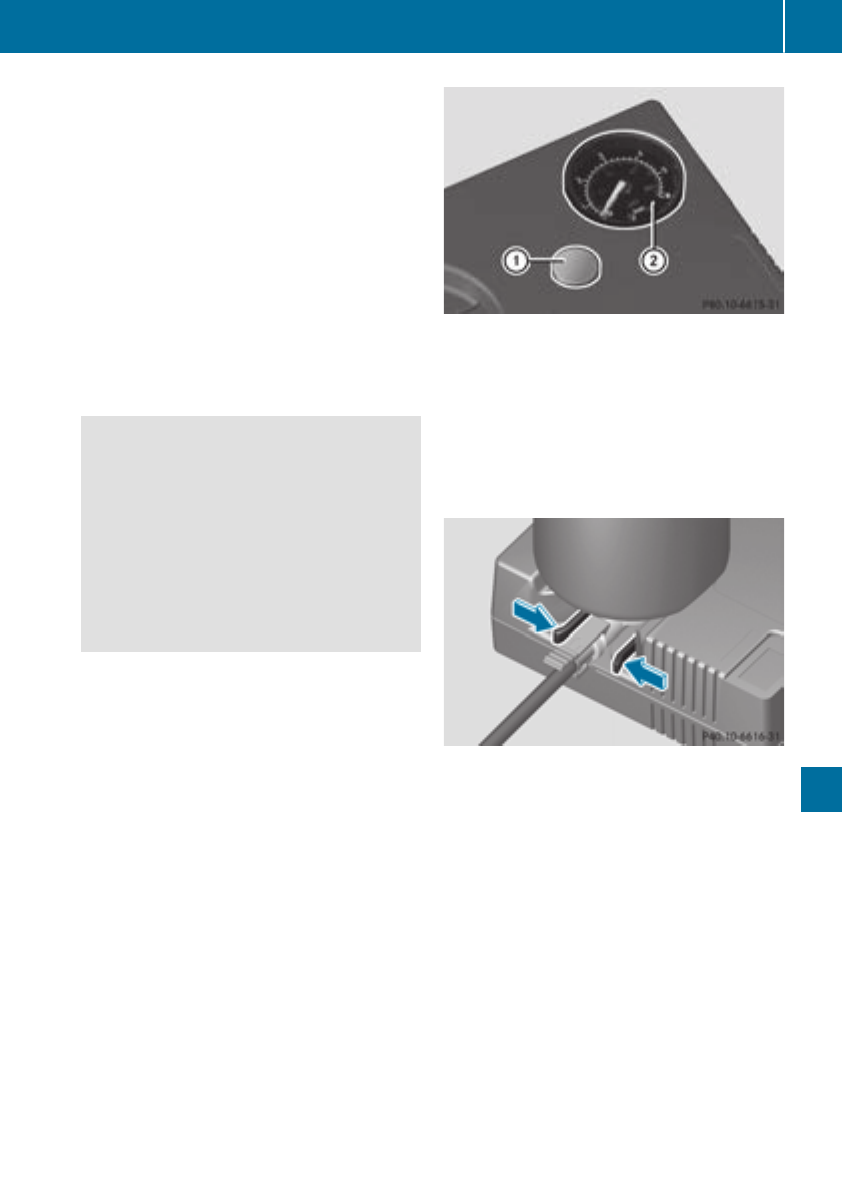
If atire pressure of 200 kPa (2.0 bar/29 psi) has
been attained after ten minutes:
XSwitch off the tire inflation compressor.
XUnscrew the fillerhose from the valve of the
faulty tire.
Note that tire sealant may escape when you
unscrew the fillerhose.
XUSA only: Stow the tire sealant bottle and the
tire inflation compressor.
XPull away immediately.
XStop after driving for approximately ten
minutes and check the tire pressure with the
tire inflation compressor.
The tire pressure must now be at least
130 kPa (1.3 bar/19 psi).
GWARNING
If the required tire pressure is not reached
after driving for ashort period,the tire is too
badlydamaged. The tire sealant cannot repair
the tire in this instance. Damaged tires and a
tire pressure that is too low can significantly
impair the vehicle's braking and driving char-
acteristics. There is arisk of accident.
Do not continue driving. Contact aqualified
specialist workshop.
iUSA only: In cases such as the one men-
tioned above,contact an authorized
Mercedes-Benz Center. Or call
1-800-FOR-MERCedes (in the USA) or
1-800-387-0100 (in Canada).
XUSA only: Correct the tire pressure if it is still
at least 130 kPa (1.3 bar/19 psi). See the Tire
and Loading Information placard on the driv-
er's side B-pillarorthe tire pressure table in
the fuel fillerflap for values.
XTo increase the tire pressure: switch on the
tire inflation compressor.
XTo reduce the tire pressure: depresspres-
sure release button :next to pressure
gauge ;.
XWhen the tire pressure is correct, unscrew the
fillerhose from the valve of the sealed tire.
Note that tire sealant may escape when you
unscrew the fillerhose.
XScrew the valve cap onto the tire valve of the
sealed tire.
XTo remove the tire sealant bottle from the tire
inflation compressor, press together the lock-
ing tabs on the yellow cap.
XPullthe tire sealant bottle out of the tire infla-
tion compressor.
The fillerhose remains attached to the tire
sealant bottle.
XDrive to the nearest qualifiedspecialist work-
shop and have the tire changed there.
XHave the tire sealant bottle and the fillerhose
replaced as soon as possible at aqualified
specialist workshop.
XHave the tire sealant bottle replaced every
four years at aqualifiedspecialist workshop.
Flat tire 275
Breakdownassistance
Z

Battery (vehicle)
Important safety notes
Specialtoolsand expert knowledgeare required
when working on the battery,e.g.removaland
installation. Youshouldtherefore have allwork
involving the battery carriedout at aqualified
specialist workshop.
GWARNING
Workcarriedout incorrectly on the battery
can lead,for example, to ashort circuitand
thusdamagethe vehicleelectronics.Thiscan
lead to functionrestrictions applying to
safety-relevant systems, e.g the lighting sys-
tem, the ABS (anti-lock braking system)orthe
ESP®(Electronic Stability Program). The oper-
ating safety of your vehiclemay be restricted.
Youcould lose controlofthe vehicle, for
example:
Rwhen braking
Rin the event of abrupt steering maneuvers
and/or when the vehicle's speed is not
adapted to the roadconditions
There is ariskofanaccident.
In the event of ashort circuitorasimilar inci-
dent, contact aqualified specialist workshop
immediately. Do not drive any further.You
shouldhaveall work involving the battery car-
riedout at aqualified specialist workshop.
For further informationabout ABS and ESP®,
see (Ypage 61)and (Ypage 64).
GWARNING
Electrostaticbuild-upcan lead to the creation
of sparks, which could ignite the highlyexplo-
sive gases of abattery.There is ariskofan
explosion.
Before handling the battery,touch the vehicle
body to remove any existing electrostatic
build-up.
The highlyflammablegas mixture formswhen
charging the battery as well as when jump-start-
ing.
Alwaysmakesurethatneither younor the bat-
tery is electrostaticallycharged. Abuild-upof
electrostatic charge can be caused,for exam-
ple:
Rby wearing clothing made from synthetic
fibers
Rduetofrictionbetween clothing and seats
Rif youpushorpullthe battery across the car-
petorothersyntheticmaterials
Rif yourub the battery with acloth
GWARNING
During the charging process,abattery produ-
ces hydrogen gas. If ashort circuitoccurs or
sparks are created,the hydrogen gascan
ignite.There is ariskofanexplosion.
RMake sure thatthe positive terminal of a
connected battery does not come into con-
tact with vehicleparts.
RNever place metalobjects or toolsonabat-
tery.
RIt is important thatyou observe the descri-
bedorder of the battery terminalswhen
connecting and disconnecting abattery.
RWhenjump-starting,makesurethatthe
battery poleswithidentical polarity are
connected.
RIt is particularly important to observe the
describedorder when connecting and dis-
connecting the jumper cables.
RNever connect or disconnect the battery
terminalswhile the engine is running.
GWARNING
Battery acidiscaustic.There is ariskofinjury.
Avoidcontact with skin, eyes or clothing. Do
not inhaleany battery gases.Donot lean over
the battery.Keepchildren away from batter-
ies. Wash away battery acidimmediatelywith
plenty of clean water and seekmedicalatten-
tion.
HEnvironmental note
Batteriescontain dangerous
substances. It is against the
lawtodispose of them with
276 Battery (vehicle)
Breakdown assistance
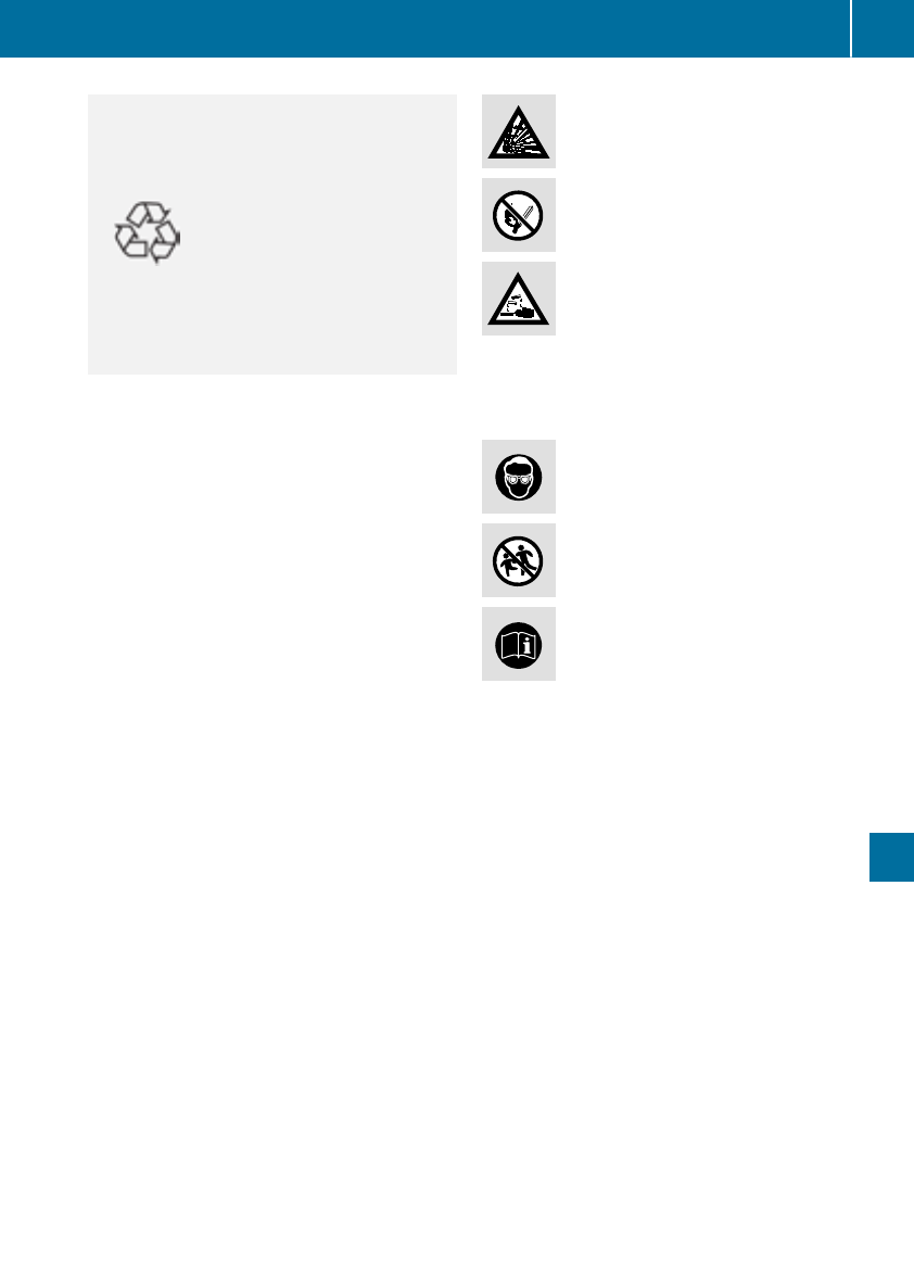
the householdrubbish.They
must be collected separately
and recycledtoprotect the
environment.
Dispose of batteries in an
environmentallyfriendly
manner. Take discharged
batteries to aqualified spe-
cialist workshop or aspecial
collectionpoint for used bat-
teries.
!Havethe battery checked regularly at a
qualified specialistworkshop.
Observe the service intervals in the Mainte-
nanceBookletorcontact aqualified specialist
workshop for moreinformation.
!Youshouldhaveall work involvingthe bat-
tery carriedout at aqualified specialistwork-
shop. In the exceptionalcasethatitisneces-
sary for youtodisconnect the battery your-
self, make sure that:
Ryouswitch off the engine and remove the
key.Onvehicles with KEYLESS-GO, ensure
thatthe ignition is switched off.Check that
allthe indicator lamps in the instrument
clusterare off.Otherwise, electronic com-
ponents,suchasthe alternator, maybe
damaged.
Ryoufirst remove the negative terminal
clamp and thenthe positive terminal
clamp. Never swap the terminalclamps.
Otherwise, the vehicle'selectronic system
maybedamaged.
Rin vehicles with automatic transmission,
the transmission is locked in position P
after disconnecting the battery.The vehicle
is secured against rolling away.You can
thennolongermovethe vehicle.
The battery and the coverofthe positive ter-
minal clamp must be installedsecurelyduring
operation.
Complywithsafety precautions and take pro-
tective measures when handling batteries.
Risk of explosion.
Fire, open flames and smoking are
prohibited when handling the bat-
tery.Avoidcreating sparks.
Battery acidiscaustic. Avoidcontact
with skin, eyes or clothing.
Wear suitableprotective clothing,
especiallygloves, apron and face-
guard.
Rinse any acidspills immediately
with clear water. Contact aphysician
if necessary.
Wear eyeprotection.
Keepchildren away.
Observe thisOperator'sManual.
For safety reasons, Mercedes-Benz recom-
mendsthatyou onlyuse batteries which have
been tested and approved for your vehicleby
Mercedes-Benz. Thesebatteries provide
increasedimpact protection to prevent vehicle
occupants fromsufferingacidburns shouldthe
battery be damagedinthe event of an accident.
In order for the battery to achieve the maximum
possibleservice life, it must always be suffi-
ciently charged.
Like otherbatteries,the vehiclebattery may
discharge overtimeifyou do not usethe vehicle.
In thiscase, have the battery disconnectedata
qualified specialistworkshop.You can also
charge the battery with achargerrecommended
by Mercedes-Benz. Contact aqualified special-
istworkshop for furtherinformation.
Havethe battery condition of charge checked
morefrequentlyifyou usethe vehiclemainlyfor
short tripsorifyou leaveitstanding idle for a
lengthyperiod. Consult aqualified specialist
workshop if youwishtoleave your vehicle
parked for alongperiodoftime.
Onlyreplace abattery with abattery thathas
been recommended by Mercedes-Benz.
Battery (vehicle) 277
Breakdownassistance
Z

Remove theSmartKey if you park thevehicle
and do notrequire any electrical consumers.
The vehiclewill then use verylittleenergy, thus
conserving battery power.
If thepower supplyhas been interrupted, e.g. if
you reconnect thebattery, you will haveto:
Rset theclock usingthe multimedia system;
see theseparateoperating instructions
Rreset thefunction for foldingthe exteriormir-
rorsin/out automatically, by foldingthe mir-
rorsout once (Ypage 97)
Charging thebattery
GWARNING
During charging and jump-starting,explosive
gasescan escape from thebattery. There is a
riskofanexplosion.
Particularly avoidfire, open flames, creating
sparks and smoking. Ensurethere is sufficient
ventilation while charging and jump-starting.
Do notlean overabattery.
GWARNING
Battery acid is caustic. There is ariskofinjury.
Avoid contact withskin, eyes or clothing.Do
notinhale any battery gases. Do notlean over
thebattery. Keepchildren away from batter-
ies. Wash away battery acid immediately with
plenty of clean water and seek medical atten-
tion.
GWARNING
Adischarged battery can freezeattempera-
tures belowfreezing point. When jump-start-
ing thevehicleorcharging thebattery, gases
can escape from thebattery. There is ariskof
an explosion.
Allow thefrozenbattery to thaw out before
charging it or jump-starting.
!Only use battery chargers withamaximum
charging voltageof14.8V.
!Only charge thebattery usingthe jump-
starting connection point.
The jump-starting connection pointisinthe
enginecompartment(
Ypage 278).
XOpen thehood.
XConnect thebattery chargertothe positive
terminaland ground pointinthe sameorder
as when connecting thedonor battery in the
jump-starting procedure (Ypage 278).
If theindicator/warning lampsdonot lightupin
theinstrumentclusteratlow temperatures,itis
verylikely that thedischarged battery has fro-
zen. In this caseyou may neither jump-start the
vehiclenor charge thebattery. The servicelife of
athawed-out battery may be shorter. The start-
ing characteristics can be impaired, particularly
at low temperatures.Havethe thawed-out bat-
tery checkedataqualified specialist workshop.
Only charge theinstalled battery withabattery
chargerwhichhas been tested and approvedby
Mercedes-Benz.Abattery chargeru
nitspecially
adapted for Mercedes-Benz vehicles and tested
and approvedbyMercedes-Benz is available as
an accessory. It permitsthe charging of thebat-
tery in itsinstalled position.Contactanauthor-
ized Mercedes-Benz Centerfor further informa-
tion and availability. Read thebattery charger's
operating instructionsbefore charging thebat-
tery.
Jump-starting
Forthe jump-starting procedure,use only thejump-starting connection point, consisting of apos-
itive terminaland aground point, in theenginecompartment.
GWARNING
Battery acid is caustic. There is ariskofinjury.
Avoid contact withskin, eyes or clothing.Donot inhale any battery gases. Do notlean overthe
battery. Keepchildren away from batteries. Wash away battery acid immediately withplenty of
clean water and seek medical attention.
278 Jump-starting
Breakdown assistance

GWARNING
During charging and jump-starting, explosive gasescan escapefrom the battery.There is arisk
of an explosion.
Particularlyavoidfire, open flames, creating sparks and smoking. Ensure there is sufficient ven-
tilation while charging and jump-starting. Do not leanover abattery.
GWARNING
During the charging process,abattery produces hydrogen gas. If ashort circuitoccurs or sparks
are created,the hydrogen gas can ignite. There is arisk of an explosion.
RMake sure that the positive terminal of aconnected battery does not come into contact with
vehicleparts.
RNever place metal objects or tools on abattery.
RIt is important that you observe the described order of the battery terminalswhen connecting
and disconnecting abattery.
RWhen jump-starting, make sure that the battery poleswith identical polarity are connected.
RIt is particularlyimportant to observe the described order when connecting and disconnecting
the jumper cables.
RNever connect or disconnect the battery terminalswhile the engine is running.
GWARNING
Adischarged battery can freeze at temperatures below freezing point. When jump-starting the
vehicleorcharging the battery,gasescan escapefrom the battery.There is arisk of an explosion.
Allow the frozen battery to thaw out before charging it or jump-starting.
!Avoid repeated and lengthy starting attempts. Otherwise, the catalytic converter couldbe
damaged by the non-combusted fuel.
If the indicator/warning lampsdonot light up in the instrument cluster at low temperatures, it is very
likelythat the discharged battery has frozen. In this case you may neither jump-start the vehiclenor
charge the battery.Let the battery thaw first. The service life of athawed-out battery may be shorter.
The starting characteristics can be impaired,particularlyatlow temperatures. Have the thawed-out
battery checked at aqualified specialist workshop.
Do not start the vehicleusing arapidcharging device. If yourvehicle's battery is discharged, the
engine can be jump-started from another vehicleorfrom asecond battery using jumper cables.
Observe the following points:
RThe battery is not accessible in all vehicles. If the other vehicle's battery is not accessible,jump-
start the vehicleusing asecond battery or ajump-starting device.
RYou may only jump-start the vehiclewhen the engine and exhaust system are cold.
RDo not start the engine if the battery is frozen. Let the battery thaw first.
ROnly jump-start from batterieswith a12Vvoltagerating.
ROnly use jumper cables that are not damaged and have asufficient cross-section and insulated
terminal clamps.
RMake sure that the two vehicles do not touch.
Jump-starting 279
Breakdown assistance
Z
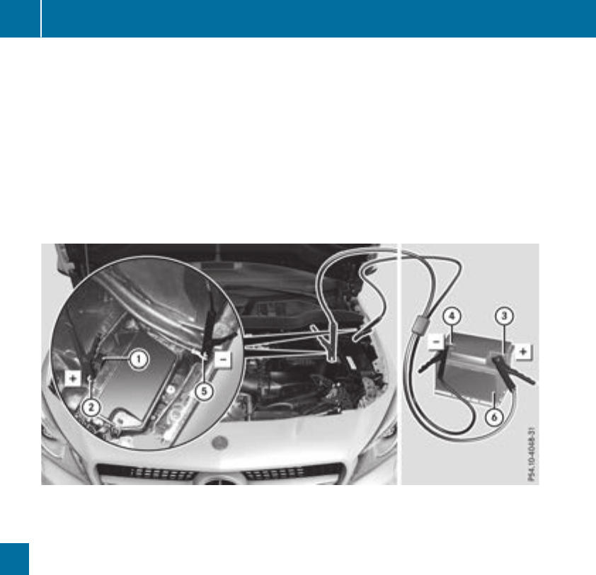
Make sure that:
RThe jumper cables are not damaged.
RNon-insulated parts of the terminal clamps do not come into contact with other metal parts while
the jumper cables are connected to the battery.
RThe jumper cables cannot come into contact with parts that can move when the engine is running,
such as the V-belt pulleyorthe fan.
XSecure the vehicle by applying the electric parking brake.
XShift the transmission to position j.
XTurn the SmartKey to position gin the ignition lock and remove it.
XSwitch off all electrical consumers, e.g. rear window defroster, lighting, etc.
XOpen the hood.
Position number Bidentifies the charged battery of the other vehicle or an equivalent jump-starting
device.
XPress together cover :of positive clamp ;and slide it back.
XConnect positive terminal ;on your vehicle to positive terminal =of donor battery Busing the
jumper cable, beginning with your own battery.
XStart the engine of the donor vehicle and run it at idling speed.
XConnect negative terminal ?of donor battery Bto ground point Aof your vehicle using the
jumper cable, connecting the jumper cable to battery of other vehicle Bfirst.
XIf the battery is fully discharged, leave the battery that is being used to jump-start connected for
afew minutes before attempting to start. This charges the battery slightly.
XStart the engine.
XBefore disconnecting the jumper cables, let the engine run for several minutes.
XFirst, remove the jumper cables from ground point Aand negative terminal ?,then from pos-
itive terminal ;and positive terminal =.Begin each time at the contacts on your own vehicle
first.
XClose cover :of positive terminal ;after removing the jumper cables.
XClose the hood.
XHave the battery checked at aqualified specialist workshop.
iJump-starting is not considered to be anormal operating condition.
280 Jump-starting
Breakdown assistance

iJumper cablesand further informationregardingjump-startingcan be obtainedatany qualified
specialist workshop.
Towing and tow-starting
Important safety notes
GWARNING
Functionsrelevanttosafety are restricted or
no longer available if:
Rtheengine is notrunning.
Rthebrakesystem or thepower steering is
malfunctioning.
Rthere is amalfunctioninthe voltage supply
or thevehicle's electrical system.
If your vehicle is beingtowed, muchmore
force may be necessarytosteer or brake.
Thereisarisk of an accident.
In such cases, use atow bar. Before towing,
makesure that thesteering moves freely.
GWARNING
You can no longer steer thevehicle if the
steering wheel lockhas been engaged. There
is arisk of an accident.
Always switch off theignitionwhen towing the
vehicle with atow cable or atow bar.
GWARNING
When towing or tow-startinganother vehicle
and its weight is greater than thepermissible
gross weight of your vehicle,the:
Rthetowing eye could detach itself
Rthevehicle/trailer combinationcould roll-
over.
Thereisarisk of an accident.
When towing or tow-startinganother vehicle,
its weight shouldnot be greater than theper-
missible gross weight of your vehicle.
Details on thepermissible gross vehicle weight
of your vehicle can be foundonthe vehicle iden-
tification plate(
Ypage 314).
!When ActiveBrake Assist,Distance Pilot
DISTRONIC or theHOLDfunction is activated,
thevehicle brakes automatically in certain
situations.
To avoid damage to thevehicle,deactivate
these systems in thefollowing or similar sit-
uations:
Rwhen towing thevehicle
Rin thecar wash
!Makesure that theelectric parking brakeis
released. If theelectric parking brakeisfaulty,
visitaqualifiedspecialist workshop.
!Only secure thetow rope or towbar at the
towing eyes. Otherwise, thevehicle couldbe
damaged.
!Do notuse thetowing eyes for recoverypur-
posesasthiscoulddamage thevehicle.Ifin
doubt,recover thevehicle with acrane.
!When towing,pull away slowly and
smoothly. If thetractive power is toohigh,the
vehiclescouldbedamaged.
!The vehicle can be towed amaximum of
30 miles (50km). The towing speed of 30 mph
(50km/h) must notbeexceeded.
If thevehicle has to be towed morethan
30 miles (50km), thefront axle must be raised
or theentire vehicle raisedand transported.
!Do nottow with sling-type equipment.This
coulddamage thevehicle.
!When towing vehicleswith KEYLESS-GO,
use thekey instead of theStart/Stopbutton.
Otherwise, theautomatic transmission may
shifttoposition Pwhen thedriver'sorfront-
passenger door are opened, whichcouldlead
to damage to thetransmission.
!Vehicles with automatic transmission must
notbestarted by tow-starting. This couldoth-
erwisedamage thetransmission.
It is bettertohave thevehicle transported than
to have it towed away.
If thevehicle can no longer be driven because of
an accidentorbreakdown,you have thefollow-
ing options:
RTransportingthe vehicle.
Towing and tow-starting 281
Breakdown assistance
Z
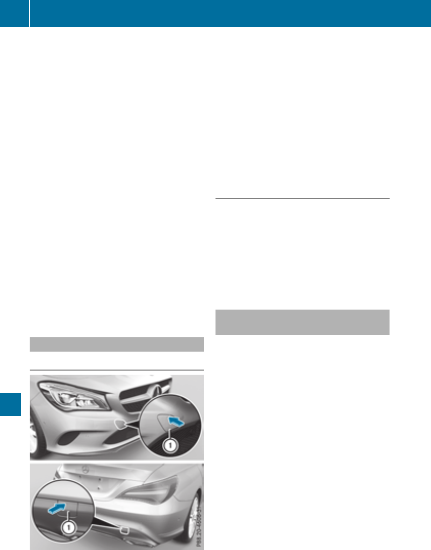
As arule, youshouldhavethe vehicletrans-
ported.
RTowing the vehiclewithatow ropeortow bar.
Onlytow the vehicleinexceptionalcases.
The battery must be connected and charged.
Otherwise, you:
Rcannotturn the SmartKeytoposition 2in
the ignition lock.
Rcannotrelease the electricparking brake.
Rcannotshift the transmission to position i.
The functionofthe electricparking brake and
the parking lock is dependent on the on-board
voltage.
If the on-board voltageislow or if thereisasys-
tem malfunction:
Rthe electricparking brake maynot be applied
in certain circumstances,or
Rit maynolongerbepossibletoshift the trans-
mission to position j
Switch off non-essentialconsumers, e.g.the
radio.
Disarmthe automatic locking feature before the
vehicleistowed (Ypage 187). Youcould other-
wise be locked outwhenpushing or towing the
vehicle.
Installing/removingthe towingeye
Installing the towingeye
The brackets for the screw-intowing eyeare
locatedinthe bumpers. Theyare at the rearand
at the front, under covers :.
XRemove the towing eyefrom the stowage
space.
The towing eyeislocatedwiththe vehicletool
kit under the cargo compartment floor
(Ypage 270).
Vehicles with the TIREFIT kit: the towing eyeis
beneath the tire inflation compressor
(Ypage 271).
XPress the mark on cover :inwards in the
direction of the arrow.
XTake cover :off the opening.
XScrew in the towing eyeclockwise to the stop.
Removing the towingeye
XUnscrew and remove the towing eye.
XAttach cover :to the bumperand press until
it engages.
XPlace the towing eyeinthe stowagewell
beneath the cargo compartment floor in the
cargo compartment (Ypage 270).
XVehicles with the TIREFIT kit: putbackthe tire
inflation compressor (Ypage 271).
Towingthe vehicle with the frontaxle
raised
Observethe important safety notes when tow-
ing your vehiclewiththe front axleraised
(Ypage 281).
Only vehicleswithout4MATIC can be towed
with the frontaxleraised.
!Vehicles with 4MATIC must not be towed
with either the front or the rearaxleraised, as
doing so will damage the transmission.
Vehicles with 4MATIC mayeither be towed away
with both axles on the ground or be loaded up
and transported.
!The ignition must be switched off if the vehi-
cle is being towed with the front axleraised.
Otherwise, ESP®mayintervene and damage
the brake system.
XOn vehicleswithKEYLESS-GO or the KEY-
LESS-GO start function: youmustuse the
SmartKeyinsteadofthe Start/Stop button
(Ypage 123).
XMake sure thatthe vehicleisstationary.
XTurn the SmartKeytoposition 2in the igni-
tionlock.
282 Towingand tow-starting
Breakdown assistance
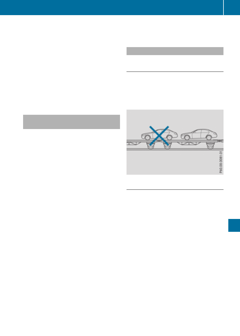
XWhen the vehicle is stationary, depress the
brake pedal and keep it depressed.
XShift the automatic transmission to position
j.
XRelease the brake pedal.
XRelease the electric parking brake.
XSwitchoff the automatic locking
(Ypage 187).
XSwitchonthe hazard warning lamps
(Ypage 102).
XTurn the SmartKey in the ignition lock to posi-
tion gand leave the SmartKey in the ignition
lock.
Towing avehicle with both axles on
the ground
It is importantthat you observe the safety
instructionswhen towing away your vehicle
(Ypage 281).
XOn vehicles with KEYLESS-GO or the KEY-
LESS-GO startfunction: you must use the
SmartKey instead of the Start/Stop button
(Ypage 123).
The automatic transmission automatically shifts
to position jwhen you open the driver's or
front-passenger door or when you remove the
SmartKey from the ignition lock. In order to
ensure that the automatic transmission stays in
position iwhen towing away the vehicle, you
must observe the following points:
XMake sure that the vehicle is stationary.
XTurn the SmartKey to position 2in the igni-
tion lock.
XDepress and hold the brake pedal.
XShift the automatic transmission to position
i.
XLeave the SmartKey in position 2in the igni-
tion lock.
XRelease the brake pedal.
XRelease the electric parking brake.
XSwitchonthe hazard warning lamps
(Ypage 102).
iIn order to signal achange of direction when
towing the vehicle with the hazard warning
lamps switched on, use the combination
switch as usual. In this case, only the indicator
lamps for the direction of travel flash. After
resetting the combination switch, the hazard
warning lamp startsflashing again.
Transporting the vehicle
4MATIC vehicles or vehicles with auto-
matic transmission
!When the vehicle is loaded for transport, the
frontand rear axles must be stationary and on
the same transportation vehicle. Positioning
over the connection point of the transport
vehicle is not permitted. The drive train may
otherwise be damaged.
All vehicles
!You may only secure the vehicle by the
wheels, not by parts of the vehicle such as
axle or steeringcomponents. Otherwise, the
vehicle could be damaged.
XTurn the SmartKey to position 2in the igni-
tion lock (Ypage 122).
XShift the transmission to position i.
As soon as the vehicle has been loaded:
XPreventthe vehicle from rolling away by
applying the electric parking brake.
XShift the transmission to position j.
XTurn the SmartKey to position gin the igni-
tion lock and remove it.
XSecure the vehicle.
The towing eye can be used to pull the vehicle
ontoatrailer or transporter for transportingpur-
poses.
Towing and tow-starting 283
Breakdown assistance
Z

Noteson4MATIC vehicles
!Vehicleswith4MATIC must not be towed
with eitherthe front or the rearaxleraised, as
doing so will damage the transmission.
Vehicleswith4MATIC mayonlyeitherbetowed
away with both axles on the ground or be loaded
up and transported.
If the vehicle'stransmission, front, or rearaxleis
damaged, have the vehicletransportedona
truck or trailer.
In the eventofdamagetothe electrical sys-
tem:
If the battery is defective, the automatic trans-
mission will be locked in position j.Toshift the
automatic transmission to position i,you
must provide powertothe vehicle'son-board
electricalsysteminthe same wayaswhenjump-
starting (Ypage 278).
Have the vehicletransportedonatransporteror
trailer.
Tow-starting(emergency engine
starting)
!Vehicleswithautomatic transmission must
not be tow-started.You could otherwisedam-
agethe automatic transmission.
iYoucan find information on "Jump-starting"
under (Ypage 278).
Fuses
Important safety notes
GWARNING
If youmanipulate or bridgeafaulty fuse or if
youreplace it with afusewithahigheramper-
age, the electric cablescould be overloaded.
This could resultinafire. There is ariskofan
accident and injury.
Alwaysreplace faulty fuseswiththe specified
new fuseshavingthe correctamperage.
!Onlyuse fusesthathavebeenapproved for
Mercedes-Benz vehicles and which have the
correctfuserating for the systemconcerned.
Onlyuse fusesmarked with an "S".Other-
wise,components or systems could be dam-
aged.
!Make sure thatnomoisture can enterthe
fuse boxwhenthe cover is open.
!When closing the cover, make sure thatitis
lying correctly on the fuse box. Moistureseep-
ing in or dirt could otherwiseimpair the oper-
ation of the fuses.
Thefuses in your vehicleserve to close down
faulty circuits.Ifafuse blows, allthe compo-
nents on the circuit and their functions stop
operating.
Blown fusesmustbereplaced with fusesofthe
same rating,which youcan recognize by the
color and value. Thefuseratingsare listedinthe
fuse allocation chart.
Thefuseallocationchart is in the fuse boxinthe
front-passengerfootwell (Ypage 285).
If anewly insertedfusealsoblows,havethe
cause traced and rectifiedataqualified special-
istworkshop,e.g.anauthorized Mercedes-Benz
Center.
Before changingafuse
XSecure the vehicleagainst rolling away
(Ypage 141).
XSwitch off allelectricalconsumers.
XVehicleswithout KEYLESS-GO: remove the
SmartKeyfromthe ignition lock.
XVehicleswithKEYLESS-GOstart-function
or KEYLESS-GO: open the driver's door.
Thevehicleelectronics arenow in position
g.Thiscorresponds to the SmartKeybeing
removedfromthe ignition.
Thefuses arelocated in variousfuseboxes:
RFuse boxinthe engine compartment on the
left-hand side of the vehicle, when viewed in
the directionoftravel
RFuse boxinthe front-passengerfootwell
Thefuseallocationchart is on the fuse boxinthe
front-passengerfootwell (Ypage 285).
284 Fuses
Breakdownassistance
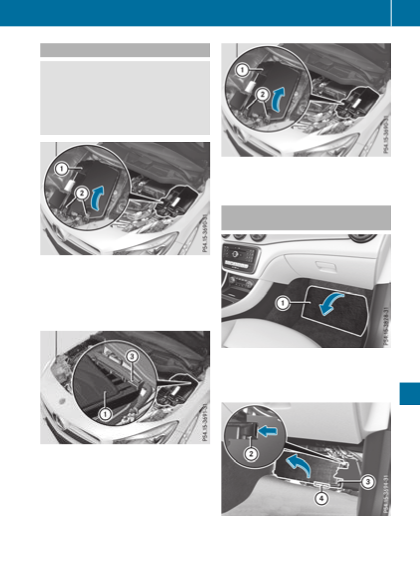
Fuse box in theengine compartment
GWARNING
When thehoodisopen and thewindshield
wipersare set in motion,you can be injured by
thewiper linkage. Thereisariskofinjury.
Always switch off thewindshield wipersand
theignition before opening thehood.
XOpen thehood.
XUse adry cloth to remove any moisture from
thefusebox.
XTo open:open clamps ;.
XFold up cover :in thedirection of thearrow
and remove it.
XTo close: check whether theseal is lyingcor-
rectlyincover :.
XInsertcover :at thebackintoopenings=
on thefusebox.
XFold down cover :.
XHook clamps ;intothe fusebox and close.
XClose thehood.
Fuse box in thefront-passenger foot-
well
XTo open:open thefront-passenger door.
XRemove thefloormat.
XFold out perforatedfloor covering :in the
direction of thearrow.
XTo release cover =,press retaining
clamp;.
XFold out cover =in thedirection of thearrow
to thecatch.
Fuses 285
Breakdown assistance
Z

XRemove cover =forwards.
Fuseallocation chart ?is locatedonthe
lower right-hand side of cover =.
XTo close: insert cover =on theleft-handside
of thefusebox intothe retainer.
Cover=engagesinthe retainers.
XFold down cover =until clamps ;lockaudi-
bly.
XFold backperforatedfloor covering :.
XInstall thefloormats.
286 Fuses
Breakdown assistance

Important safety notes
GWARNING
If wheels and tires of thewrong sizeare used,
thewheelbrakes or suspension components
may be damaged. Thereisariskofanacci-
dent.
Always replace wheels and tires withthose
that fulfill thespecificationsofthe original
part.
When replacing wheels, makesuretouse the
correct:
Rdesignation
Rmodel
When replacing tires,makesuretouse the
correct:
Rdesignation
Rmanufacturer
Rmodel
GWARNING
Aflat tire severely impairs thedriving,steer-
ing and braking characteristics of thevehicle.
Thereisariskofaccident.
Tires without run-flat characteristics:
Rdo notdrivewithaflat tire.
Rimmediately replace theflat tire withyour
emergencysparewheelorsparewheel, or
consult aqualified specialist workshop.
Tires withrun-flat characteristics:
Rpay attention to theinformation and warn-
ing noticesonMOExtended tires (tireswith
run-flat characteristics).
Accessories that are notapprovedfor your vehi-
cle by Mercedes-Benzorare notbeingused cor-
rectlycan impair theoperating safety.
Before purchasing and usingnon-approved
accessories, visit aqualified specialist work-
shopand inquire about:
Rsuitability
Rlegal stipulations
Rfactory recommendations
Further information regarding wheels and tires
can be foundunder "Wheel/tire combinations"
(Ypage 312).
You can ask for information regarding permitted
wheel/tire combinationsatanauthorized
Mercedes-BenzCenter.
Information on tire pressurecan be found:
Ron theTireand Loading Information placard
on theB-pillar on thedriver'sside
(Ypage 298)
Rin thetirepressuretable in thefuel filler flap
(Ypage 139)
Runder "Tirepressure" (Ypage 290)
Operation
Information on driving
Checkthe tire pressurewhen thevehicleis
heavily laden and adjust priortoatrip.
While driving,pay attention to vibrations, noises
and unusual handlingcharacteristics,e.g.pull-
ing to oneside.This may indicatethatthe
wheels or tires are damaged. If you suspectthat
atireisdefective, reduce your speedimmedi-
ately. Stop thevehicleassoonaspossible to
checkthe wheels and tires for damage. Hidden
tire damagecould also be causing theunusual
handlingcharacteristics.Ifyou findnosignsof
damage, havethe tires and wheels checkedata
qualified specialist workshop.
When parking your vehicle, makesurethatthe
tires do notget deformed by thecurborother
obstacles. If they cannotbeavoided, driveover
obstacles suchascurbs slowly and at an obtuse
angle. Otherwise, you may damagethe wheels
or tires.
Regularchecking of wheels and tires
GWARNING
Damaged tires can causetireinflation pres-
sureloss.Asaresult,you could lose control of
your vehicle. Thereisariskofaccident.
Checkthe tires regularly for signsofdamage
and replace any damaged tires immediately.
Operation 287
Wheels and tires
Z
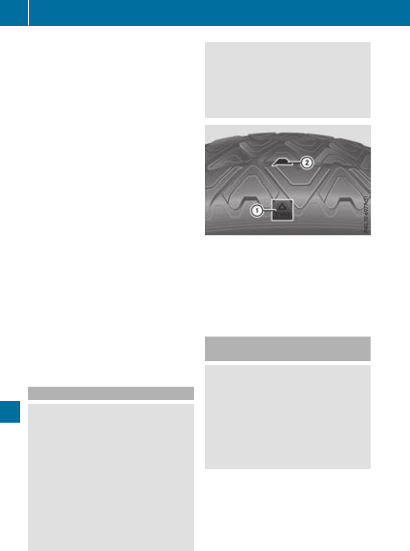
Checkwheelsand tires for damageatleast once
amonth.Checkwheelsand tires after driving
off-road or on roughroads. Damaged wheels
can causealoss of tirepressure. Pay particular
attentiontodamagesuchas:
RCuts in thetires
RPunctures in thetires
RTearsinthe tires
RBulges on tires
RDeformation or severe corrosiononwheels
Regularly check thetiretread depthand the
conditionofthe tread across thewhole widthof
thetire(
Ypage 288). If necessary, turnthe
frontwheelstofull lockinorder to inspectthe
inner side of thetiresurface.
All wheelsmust have avalvecap to protect the
valveagainst dirt and moisture. Do notmount
anythingontothe valveother than thestandard
valvecap or other valvecaps approved by
Mercedes-Benzfor your vehicle.Donot use any
other valvecaps or systems,e.g.tirepressure
monitoringsystems.
Regularly check thepressureofall thetires par-
ticularly priortolongtrips. Adjustthe tirepres-
sure as necessary (Ypage 290).
Observethe notesonthe emergencyspare
wheel (Ypage 312).
The servicelife of tires depends, amongother
things, on thefollowingfactors:
RDrivingstyle
RTire pressure
RDistance covered
Notes on tiretread
GWARNING
Insufficient tiretread will reduce tiretraction.
The tireisnolonger able to dissipatewater.
This meansthatonwet road surfaces,the risk
of hydroplaning increases, in particular where
speedisnot adapted to suit thedriving con-
ditions. Thereisariskofaccident.
If thetirepressureistoo high or toolow, tires
may exhibit different levels of wear at differ-
entlocations on thetiretread. Thus,you
should regularly check thetread depthand
theconditionofthe tread across theentire
widthofall tires.
Minimum tiretread depthfor:
RSummer tires: âin (3 mm)
RM+S tires: ãin (4 mm)
For safety reasons, replace thetires before
thelegally prescribedlimit for theminimum
tiretread depthisreached.
Marking :shows wherebar indicator ;for
tread wear is integratedintothe tiretread.
Treadwear indicators (TWI)are required by law.
Six indicators are positionedonthe tiretread.
They are visible once atread depthofapprox-
imately áin (1.6mm) has been reached. If this
is thecase, thetireissoworn that it must be
replaced.
Selecting, mounting and replacing
tires
GWARNING
Exceedingthe statedtireload-bearing capa-
cityand theapprovedmaximum speedcould
lead to tiredamageorthe tirebursting. There
is ariskofaccident.
Therefore, only use tiretypesand sizes
approvedfor your vehicle model. Observethe
tireload rating and speedrating required for
your vehicle.
ROnly mounttires and wheelsofthe same type
and make.
Exception: it is permissible to install adiffer-
enttype or makeinthe event of aflat tire.
Observeherethe "MOExtended tires (tires
288 Operation
Wheels and tires

with run-flat characteristics)"section
(Ypage 271).
ROnly mounttires of thecorrectsizeontothe
wheels.
RBreak in new tires at moderatespeeds for the
first60miles (100km).The newtires only
reachtheir full performanceafter this dis-
tance.
RDo not drivewith tires which have too little
tread depth, as this significantly reduces the
traction on wet roads (hydroplaning).
RReplace thetires after six years at thelatest,
regardless of wear.
Observe thenotes on theemergency spare
wheel (Ypage 312).
MOExtended tires (tires with run-flat
properties)
With MOExtended tires (tires with run flat char-
acteristics),you can continue to driveyour vehi-
cle even if there is atotal loss of pressure in one
or moretires.
MOExtended tires may only be used in conjunc-
tionwith an activated tirepressure loss warning
system (Canada only) or tirepressure monitor
(USAonly) and only on wheels specifically tes-
ted by Mercedes-Benz.
Notes on driving with MOExtended tires with a
flat tire(
Ypage 271).
Vehicles equipped with MOExtended tires are
not equipped with aTIREFIT kit at thefactory. It
is therefore recommended that you additionally
equip your vehicle with aTIREFIT kit if you mount
tires that do not feature run-flat properties, e.g.
winter tires. ATIREFITkit may be obtained from
aqualified specialist workshop.
Winter operation
General notes
Have your vehicle winter-proofed at aqualified
specialist workshop at theonset of winter.
Observe thenotes in the"Changing awheel"
section(
Ypage 307).
Driving with summer tires
At temperatures below 45 ‡(+7 †),summer
tiresloseelasticityand therefore traction and
braking power.Change thetires on your vehicle
to M+S tires. Usingsummer tires at verycold
temperatures couldcausecrackstoform,
therebydamaging thetires permanently.
Mercedes-Benzcannotaccept responsibilityfor
this type of damage.
GWARNING
Damaged tires can causetireinflation pres-
sure loss.Asaresult, you couldlose control of
your vehicle.Thereisarisk of accident.
Checkthe tires regularly for signsofdamage
and replace any damagedtires immediately.
M+S tires
GWARNING
M+S tires with atiretread depthofless than
ãin (4 mm)are notsuitable for use in winter
and do notprovide sufficient traction.Thereis
arisk of an accident.
M+S tires with atread depthofless than ãin
(4 mm) must be replaced immediately.
At temperatures below 45 ‡(+7 †), use winter
tires or all-season tires. Both typesoftire are
identified by the M+S marking.
Only winter tires bearing the isnowflake
symbol in addition to the M+S marking provide
the best possiblegrip in wintry road conditions.
Only these tires willallow driving safety systems
such as ABS and ESP®to function optimally in
winter. Thesetires have beendeveloped specif-
ically for driving in snow.
Use M+S tires of the same make and tread on all
wheels to maintain safe handling characteris-
tics.
Always observe the maximumpermissible
speedspecified for the M+S tires you have
mounted.
Winteroperation 289
Wheels and tires
Z

When you have mounted the M+S tires:
XCheck the tire pressures (Ypage 290).
XRestart the tire pressure monitor (USA only)
(Ypage 297).
XRestart the tire pressure loss warning system
(Canada) (Ypage 294)
Snow chains
GWARNING
If snow chains are mounted on the rear
wheels, the snow chains could cause abrasion
to the vehicle body or to chassis components.
This could cause damage to the vehicle or the
tires. There is arisk of an accident.
To avoid hazardous situations:
Rnever mount snow chains on the rear
wheels
Ronly mount snow chains in pairs on the
frontwheels.
!On some tire sizes there is not enough space
for snow chains. To avoid damage to the vehi-
cle or tires, observe the "Wheel and tire com-
binations" section under "Tires and wheels".
For safety reasons, Mercedes-Benz recom-
mends that you only use snow chains that have
been specially approved for your vehicle by
Mercedes-Benz,orare of acorresponding
standard of quality. For more information,
please contact aqualified specialist workshop.
If you intendtomount snow chains, please bear
the following points in mind:
RSnowchains may not be mounted on all
wheel/tire combinations. Permissible wheel-
tire combinations (Ypage 312).
ROnly use snow chains when driving on roads
completely covered by snow. Remove the
snow chains as soon as possible when you
come to aroad that is not snow-covered.
RLocal regulations may restrict the use of snow
chains. Observe the appropriate regulations if
you wish to mount snow chains.
RDo not exceed the maximum permissible
speed of 30 mph (50 km/h).
RNever use Parking Pilot when snow chains are
installed (Ypage 165).
You may wish to deactivateESP®when pulling
away with snow chains installed .You can
thereby allow the wheels to spin in acontrolled
manner, achieving an increased driving force
(cutting action).
RDeactivate ESP®(all vehicles except
Mercedes-AMG vehicles) (Ypage 65)
RDeactivate ESP®(Mercedes-AMG vehicles)
(Ypage 66)
Information about driving with an emergency
spare wheel (Ypage 312).
Tirepressure
Tirepressure specifications
Important safety notes
GWARNING
Underinflated or overinflated tires pose the
following risks:
Rthe tires may burst, especially as the load
and vehicle speed increase.
Rthe tires may wear excessively and/or
unevenly, which may greatly impair tire
traction.
Rthe driving characteristics, as well as steer-
ing and braking, may be greatly impaired.
There is arisk of an accident.
Follow recommended tire inflation pressures
and check the pressure of all the tires includ-
ing the spare wheel:
Rmonthly, at least
Rif the load changes
Rbefore beginningalong journey
Runder differentoperating conditions, e.g.
off-road driving
If necessary, correct the tire pressure.
iThe data on the Tire and Loading Informa-
tion placard and tire pressure table shown
here are examples. Tire pressure specifica-
tions are vehicle-specific and may deviate
from the data shown here. The tire pressure
specifications that are valid for your vehicle
can be found on the Tire and Loading Infor-
290 Tirepressure
Wheels and tires
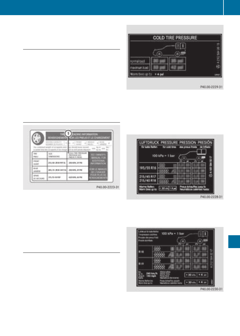
mation placard and tire pressure table on the
vehicle.
General notes
The recommended tire pressures for the tires
mounted at the factory can be found on the
labels described here.
Operation with an emergency spare wheel:
informationonoperation with an emergency
spare wheelcan be found in the general notes in
the "Emergency spare wheel" section
(Ypage 312).
Further informationontire pressures can be
obtained at aqualified specialist workshop.
Tire and Loading Information placard
:Recommended tire pressures
The Tire and Loading Information placard is on
the B-pillar on the driver'sside (Ypage 298).
The Tire and Loading Information placard con-
tains the recommended tire pressures for cold
tires. The recommended tire pressures are valid
for the maximumpermissibleloadand up to the
maximumpermissiblevehiclespeed.
Tire pressure table
The tire pressure table is on the inside of the fuel
filler flap.Itshows the tire pressure for all tires
permitted at the factory for this vehicle; see
illustration(example).
The tire pressure table contains the recommen-
ded pressures for cold tires for various operat-
ing conditions, i.e. differing loadand speed con-
ditions.
If atire size precedesatire pressure, the fol-
lowing tire pressure informationisonly validfor
that tire size; see illustration(example).
The loadconditions "partiallyladen" and "fully
laden" are defined in the table for different num-
bers of occupants and amounts of luggage.The
actualnumber of seats may differ.
Some tire pressure tablesshow only the rim
diameters instead of the full tire size, e.g. R18.
Rim diameter is part of the tire size and can be
found on the tire sidewall(
Ypage 302).
Tire pressure 291
Wheelsand tires
Z

If the tire pressures have been set to the lower
values for lighter loadsand/or lowerroad
speeds, the pressures shouldbereset to the
higher values:
Rif you want to drive with an increased load
and/or
Rif you want to drive at higher speeds
iThe tire pressures for increased loadsand/
or higher road speeds, shown in the tire pres-
sure table, may have anegative effect on driv-
ing comfort.
If the tire pressure is not set correctly, this can
leadtoanexcessive build up of heat and asud-
den loss of pressure.
For more information, contact aqualifiedspe-
cialist workshop.
Important notes on tire pressure
GWARNING
If the tire pressure drops repeatedly,the
wheel,valve or tire may be damaged. Tire
pressure that is too low may resultinatire
blow-out. There is arisk of an accident.
RCheck the tire for foreign objects.
RCheck whether the wheel is losing air or the
valve is leaking.
If you are unabletorectify the damage, con-
tact aqualifiedspecialist workshop.
GWARNING
If you fit unsuitable accessoriesonto tire
valves,the tire valves may be overloaded and
malfunction, which can cause tire pressure
loss. Due to their design, retrofitted tire pres-
sure monitors keep the tire valve open. This
can also resultintire pressure loss. There is a
risk of an accident.
Only screw the standard valve cap or other
valve caps approved by Mercedes-Benz for
yourvehicle onto the tire valve.
Use asuitable pressure gauge to check the tire
pressure. The outer appearance of atire does
not permit any reliable conclusion aboutthe tire
pressure. On vehiclesequipped with the elec-
tronic tire pressure monitor, the tire pressure
can be checked in the on-board computer.
The tire temperature and pressure increase
when the vehicle is in motion. This is dependent
on the driving speed and the load.
Therefore, you shouldonly correct tire pres-
sures when the tires are cold.
The tires are cold:
Rif the vehicle has been parked with the tires
out of direct sunlight for at least three hours
and
Rif the vehicle has been driven less than 1mile
(1.6 km)
The tire temperature changes depending on the
outsidetemperature,the vehicle speed and the
tire load.Ifthe tire temperature changes by
18 ‡(10 †), the tire pressure changes by
approximately 10 kPa (0.1 bar/1.5 psi).Take
this into account when checking the pressure of
warm tires. Only correct the tire pressure if it is
too low for the current operating conditions. If
you check the tire pressure when the tires are
warm, the resulting valuewillbehigherthan if
the tires were cold. This is normal. Do not
reduce the tire pressure to the valuespecified
for cold tires. The tire pressure would otherwise
be too low.
Observe the recommended tire pressures for
cold tires:
Ron the Tire and Loading Information placard
on the B-pillaronthe driver's side
Rin the tire pressure table in the fuel fillerflap
(Ypage 139)
Underinflated or overinflated tires
Underinflated tires
GWARNING
Tires with pressure that is too low can over-
heat and burst as aconsequence. In addition,
they also suffer from excessive and/or irreg-
ularwear, which can severelyimpair the brak-
ing propertiesand the driving characteristics.
There is arisk of an accident.
Avoid tire pressures that are too low in all the
tires, including the spare wheel.
Underinflated tires may:
Roverheat, leading to tire defects
Radversely affect handling
292 Tire pressure
Wheelsand tires
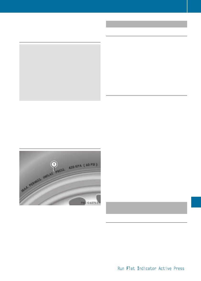
Rwear excessively and/or unevenly
Rhave an adverse effect on fuel consumption
Overinflated tires
GWARNING
Tires with excessively high pressure can burst
becausetheyare damaged moreeasily by
road debris,potholes etc.Inaddition, they
also suffer fromirregular wear, which can
severely impair thebraking properties and the
driving characteristics. Thereisarisk of an
accident.
Avoid tirepressures that are too high in all the
tires, including thespare wheel.
Overinflated tires may:
Rincrease thebraking distance
Radversely affect handling
Rwear excessively and/or unevenly
Rhave an adverse effect on ride comfort
Rbe moresusceptible to damage
Maximumtirepressures
:Example: maximum permissible tirepres-
sure
Never exceed themaximum permissible tire
inflationpressure. Always observe therecom-
mended tirepressure for your vehicle when
adjustingthe tirepressure (Ypage 290).
iThe actual values for tires are vehicle-spe-
cific and may deviatefromthe values in the
illustration.
Checking thetirepressures
Important safety notes
Observe thenotes on tirepressure
(Ypage 290).
Information on air pressure for thetires on your
vehicle can be found:
Ron thevehicle's Tire and LoadingInformation
placardonthe B-pillar
Rin thetirepressure table in thefuel filler flap
(Ypage 139)
Rin the"Tire pressure" section
Checking tirepressures manually
To determine and set thecorrecttirepressure,
proceed as follows:
XRemovethe valve cap of thetirethatistobe
checked.
XPressthe tirepressure gauge securely onto
thevalve.
XRead thetirepressure and compare it to the
recommended value on theTire and Loading
Information placardorthe tirepressure table
(Ypage 290).
XIf thetirepressure is too low, increase thetire
pressure to therecommended value.
XIf thetirepressure is too high, releaseair. To
do so, pressdown themetal pin in thevalve,
using thetip of apen for example. Then check
thetirepressure again using thetirepressure
checker.
XScrew thevalve cap ontothe valve.
XRepeat these steps for theother tires.
Tirepressureloss warning system
(Canada only)
General notes
While thevehicle is in motion, thetirepressure
loss warning system monitors theset tirepres-
sure using therotational speed of thewheels.
This enables thesystem to detect significant
pressure loss in atire. If thespeed of rotation of
awheel changes as aresult of aloss of pressure,
acorresponding warning message will appear in
themultifunction display.
You can recognize thetirepressure loss warning
by the Run Flat IndicatorActive Press
Tirepressure 293
Wheels and tires
Z
'OK' to Restart message in the multifunction
displayinthe Serv. menu. Information on the
message displaycan be found in the "Restarting
the tire pressure loss warning" section
(Ypage 294).
Important safety notes
The tire pressure warning system does not warn
you of an incorrectly set tire pressure. Observe
the notes on the recommended tire pressure
(Ypage 290).
The tire pressure loss warning does not replace
the need to regularly check the tire pressure. An
even loss of pressure on several tires at the
same time cannot be detected by the tire pres-
sure loss warning system.
The tire pressure monitor is not able to warn you
of asudden loss of pressure, e.g. if the tire is
penetrated by aforeign object. In the event of a
sudden loss of pressure, bring the vehicle to a
halt by braking carefully.Avoid abrupt steering
movements.
The function of the tire pressure loss warning
system is limited or delayed if:
Rsnow chains are mounted on your vehicle's
tires.
Rroad conditions are wintry.
Ryou are driving on sand or gravel.
Ryou adopt avery sporty driving style (corner-
ing at high speeds or driving with high rates of
acceleration).
Ryou are driving with aheavy load (in the vehi-
cle or on the roof)
Restarting the tire pressure loss warn-
ing system
Restart the tire pressure loss warning system if
you have:
Rchanged the tire pressure
Rchanged the wheels or tires
Rmounted new wheels or tires
XBefore restarting, make sure that the tire
pressures are set properly on all four tires for
the respective operating conditions.
The recommended tire pressure can be found
on the Tire and Loading Information placard
on the B-pillar. Additionally,atire pressure
table is attached to the fuel filler flap. The tire
pressure loss warning system can only give
reliable warnings if you have set the correct
tire pressure. If an incorrect tire pressure is
set, these incorrect valueswill be monitored.
XAlso observe the notes in the section on tire
pressures (Ypage 290).
XMake sure that the SmartKey is in position 2
in the ignition lock (Ypage 122).
XPress =or ;on the steering wheel to
select the Serv. menu.
XPress the 9or :button to select
Tire Pressure.
XPress the abutton.
The Run Flat Indicator Active Press
'OK' to Restart message appears in the
multifunction display.
If you wish to confirm the restart:
XPress the abutton.
The Tire Pressure Now OK? message
appears in the multifunction display.
XPress the 9or :button to select Yes.
XPress the abutton.
The Run Flat Indicator Restarted mes-
sage appears in the multifunction display.
After ateach-in period, the tire pressure loss
warning system will monitor the set tire pres-
sures of all four tires.
If you wish to cancelthe restart:
XPress the %button.
or
XIf the Tire Pressure Now OK? message
appears, press the 9or :button to
select Cancel.
XPress the abutton.
The tire pressure valuesstored at the last
restart will continue to be monitored.
Tire pressure monitor (Canada only)
General notes
If atire pressure monitor is installed, the vehi-
cle's wheels have sensors that monitor the tire
pressures in all four tires. The tire pressure mon-
itor warns you if the pressure drops in one or
more of the tires. The tire pressure monitor only
functions if the corresponding sensors are
installed in all wheels.
Information on tire pressures is displayed in the
multifunction display. After afew minutes of
driving, the current tire pressure of each tire is
294 Tire pressure
Wheels and tires
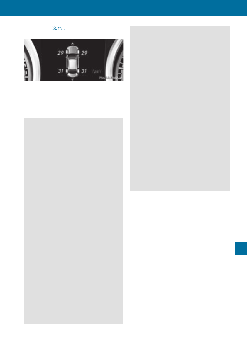
shown in the Serv. menu of the multifunction
display, see illustration (example).
For information on the message display, refer to
the "Checking the tire pressure electronically"
section (Ypage 296).
Important safety notes
GWARNING
Each tire, including the spare (if provided),
should be checked at least once every two
weeks when cold and inflated to the pressure
recommended by the vehicle manufacturer
on the Tire and Loading Information placard
on the driver's door B-pillar or the tire pres-
sure label on the inside of the fuel filler flap. If
your vehicle has tires of adifferent size than
the size indicated on the Tire and Loading
Information placard or, if available, the tire
pressure label,you should determine the
proper tire pressure for those tires.
As an added safety feature, your vehicle has
been equipped with atire pressure monitoring
system (TPMS) that illuminates alow tire pres-
sure telltale when one or more of your tires
are significantly underinflated. Accordingly,
when the low tire pressure telltale lights up,
you should stop and check your tires as soon
as possible,and inflate them to the proper
pressure. Driving on asignificantly underin-
flated tire causes the tire to overheat and can
lead to tire failure.
Underinflation also reduces fuel efficiency
and tire tread life, and may affect the vehicle's
handling and stopping ability. Please note that
the TPMS is not asubstitute for proper tire
maintenance, and it is the driver's responsi-
bility to maintain correct tire pressure, even if
underinflation has not reached the level to
trigger illumination of the TPMS low tire pres-
sure telltale.
Your vehicle has also been equipped with a
TPMS malfunction indicator to indicate when
the system is not operating properly. The
TPMS malfunction indicator is combined with
the low tire pressure telltale. When the sys-
tem detects amalfunction, the warning lamp
will flash for approximately aminute and then
remain continuously illuminated. This
sequence will be repeated every time the vehi-
cle is started as long as the malfunction
exists. When the malfunction indicator is illu-
minated, the system may not be able to detect
or signal low tire pressure as intended.
TPMS malfunctions may occur for avariety of
reasons, including the installation of incom-
patible replacement or alternate tires or
wheels on the vehicle that prevent the TPMS
from functioningproperly. Always check the
TPMS malfunction telltale after replacing one
or more tires or wheels on your vehicle to
ensure that the replacement or alternate Tires
and wheels allow the TPMS to continue to
function properly.
It is the driver's responsibility to set the tire
pressure to that recommended for cold tires
which is suitable for the operating situation
(Ypage 290). Note that the correct tire pressure
for the current operating situation must first be
taught-in to the tire pressure monitor. If asub-
stantial loss of pressure occurs, the warning
threshold for the warning message is aligned to
the taught-in reference values. Restart the tire
pressure monitor after adjusting the pressure of
the cold tires (Ypage 297). The current pres-
sures are saved as new reference values. As a
result, awarning message will appearifthe tire
pressure drops significantly.
The tire pressure monitor does not warn you of
an incorrectly set tire pressure. Observe the
notes on the recommended tire pressure
(Ypage 290).
The tire pressure monitor is not able to warn you
of asudden loss of pressure, e.g. if the tire is
penetrated by aforeign object. In the event of a
sudden loss of pressure, bring the vehicle to a
halt by braking carefully.Avoid abrupt steering
movements.
Tire pressure 295
Wheels and tires
Z
The tire pressure monitor has ayellow warning
lamp in the instrument cluster for indicating
pressure loss or amalfunction. Whether the
warning lamp flashes or lights up indicates
whether atire pressure is too low or the tire
pressure monitor is malfunctioning:
Rif the warning lamp is lit continuously, the tire
pressure on one or more tires is significantly
too low. The tire pressure monitor is not mal-
functioning.
Rif the warning lamp flashes for around a
minute and then remains lit constantly, the
tire pressure monitor is malfunctioning.
In addition to the warning lamp, amessage
appears in the multifunction display.Observe
the information on display messages
(Ypage 211).
It may take up to ten minutes for amalfunction
of the tire pressure monitor to be indicated. A
malfunction will be indicated by the tire pres-
sure warning lamp flashing for approximately
one minute and then remaining lit. When the
malfunction has been rectified, the tire pressure
warning lamp goes out after afew minutes of
driving.
The tire pressure values indicated by the on-
board computer may differ from those meas-
ured at agas station with apressure gauge. The
tire pressures shown by the on-board computer
refer to those measured at sea level. At high
altitudes, the tire pressure values indicated by a
pressure gauge are higher than those shown by
the on-board computer. In this case, do not
reduce the tire pressures.
The operation of the tire pressure monitor can
be affected by interferencefrom radio transmit-
ting equipment (e.g. radio headphones, two-way
radios) that may be being operated in or near the
vehicle.
Checking the tire pressureelectroni-
cally
XMake sure that the SmartKey is in position 2
in the ignition lock (Ypage 122).
XPress =or ;on the steeringwheel to
select the Serv. menu.
XPress the 9or :button to select
Tire Pressure.
XPress the abutton.
The current tire pressure of each tire is shown
in the multifunction display.
If the vehicle was parked for longer than
20 minutes, the Tire pressure will be
displayed after driving afew minutes
message is shown.
After ateach-in process, the tire pressure mon-
itor automatically detectsnew wheels or new
sensors. As long as aclear allocation of the tire
pressure value to the individual wheels is not
possible, the Tire Pressure Monitor Active
message is shown instead of the tire pressure
display.The tire pressures are already being
monitored.
If an emergencyspare wheel is mounted, the
system may continue to show the tire pressure
of the wheel that has been removed for afew
minutes. If this occurs, notethat the value dis-
played for the position where the spare wheel is
mounted is not the same as the current tire
pressure of the emergencyspare wheel.
Tire pressuremonitor warning mes-
sages
If the tire pressure monitor detectsapressure
loss in one or more tires, awarning message is
shown in the multifunction display.The yellow
tire pressure warning lamp then lights up.
RIf the Please Correct Tire Pressure
message appears in the multifunction display,
the tire pressure in at least one tire is too low.
The tire pressure must be corrected when the
opportunityarises.
RIf the Check Tire Pressure message
appears in the multifunction display,the tire
pressure in one or more tires has dropped
significantly. The tires must be checked.
RIf the Tire Pressure Warning Tire Fail‐
ure message appears, the tire pressure in one
or more tires has dropped suddenly. The tires
must be checked.
Observe the instructions and safety notes in the
display messages in the "Tires" section
(Ypage 211).
If the wheel positions on the vehicle are rotated,
the tire pressures may be displayed for the
wrong positions for ashort time. This is rectified
after afew minutes of driving, and the tire pres-
sures are displayed for the correctpositions.
296 Tirepressure
Wheels and tires
Restarting the tire pressure monitor
Whenyou restart the tire pressure monitor, all
existing warning messages are deleted and the
warning lamps go out. The monitor uses the cur-
rentlyset tire pressures as the reference values
for monitoring. In most cases, the tire pressure
monitor will automaticallydetect the new refer-
ence valuesafteryou have changed the tire
pressure. However, youcan also set reference
valuesmanually as described here. The tire
pressure monitor then monitors the new tire
pressure values.
XSet the tire pressure to the value recommen-
ded for the corresponding driving situation on
the Tire and Loading Information placard on
the driver'ssideB-pillar (Ypage 290).
Youcan find more tire pressure valuesfor
various operating conditions in the tire pres-
sure table inside the fuelfillerflap
(Ypage 139).
XMake sure that the tire pressure is correct on
allfourwheels.
XMake sure that the SmartKey is in position 2
in the ignition lock (Ypage 122).
XPress =or ;on the steering wheel to
select the Serv. menu.
XPress the 9or :button to select
Tire Pressure.
XPress the abutton.
The multifunction display shows the current
tire pressure for each tire or the Tire pres‐
sure will be displayed after driving
afew minutes message.
XPress the :button.
The multifunction display shows the Use
Current PressuresasNew Reference
Values message.
If you wish to confirm the restart:
XPress the abutton.
The Tire Press. Monitor Restarted mes-
sage appears in the multifunction display.
After driving for afew minutes, the system
checks whetherthe current tire pressures are
within the specified range. The new tire pres-
sures are then accepted as reference values
and monitored.
If you wish to cancelthe restart:
XPress the %button.
The tire pressure valuesstoredatthe last
restart will continuetobemonitored.
Radio type approval for the tire pres-
sure monitor
Country Radio type approval number
USA FCC ID: MRXMW2433A
FCCIC ID:MRXGG4 Thisdevice
complies with part 15 of the FCC
rules and with license exempt
RSS standardsofIndustry Can-
ada. Operation is subject to the
following conditions.(1) This
device may not cause harmful
interference, and (2) Thisdevice
mustaccept any interference
received, including interference
that may cause undesired oper-
ation. Le present appareilest
conforme d'industrieCanada
applicables auxappereils radio
exempts de licence. L'exploita-
tion est authorisee auxdeuxcon-
ditions suivantes. (1).L'appareil
ne doitpas produire de brouil-
lage, et (2) L'autisatuerdel'ap-
pareildoitaccepter toutbrouil-
lage radioelectriquesubi, meme
si le brouillageest susceptible
d'encompromettre le fonc-
tionnement. WARNING:Changes
or modifications not expressively
approved by the party responsi-
blefor compliance could voidthe
users authority to operate the
equipment. The term "IC:" before
the radio certification number
only signifies Canadatechnical
specifications were met.
FCC ID:MRXMC34MA4 This
device complies with part 15 of
the FCC rules and with license
exempt RSS standardsofIndus-
try Canada. Operation is subject
to the following conditions.(1)
Thisdevice may not cause harm-
ful interference, and (2) This
device mustaccept any interfer-
ence received, including interfer-
ence that may cause undesired
operation. Le present appareil
est conforme d'industrieCanada
applicables auxappereils radio
exempts de license.L'exploita-
tion est authorisee auxdeuxcon-
ditions suivantes. (1).L'appareil
Tire pressure 297
Wheelsand tires
Z
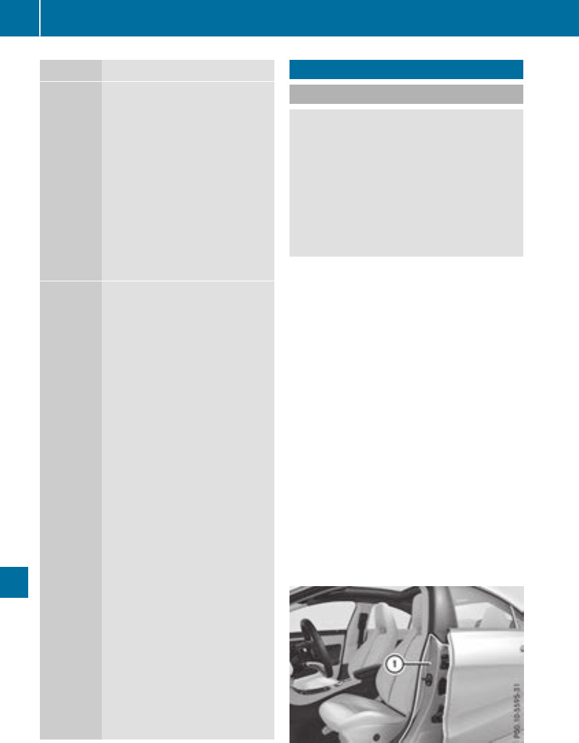
Country Radio type approval number
ne doit pas produire de brouil-
lage, et (2) L'autisatuer de l'ap-
pareil doit accepter tout brouil-
lage radioelectrique subi, meme
si le brouillage est susceptible
d'en compromettre le fonc-
tionnement. WARNING: Changes
or modifications not expressively
approved by thepartyresponsi-
ble for compliance could void the
users authoritytooperate the
equipment.The term"IC:"before
theradio certification number
onlysignifies Canada technical
specifications were met.
Canada IC: 2546A-MW2433A
IC:2546A-GG4 This devicecom-
plies with part 15 of theFCC
rules and with licenseexempt
RSS standards of Industry Can-
ada. Operationissubject to the
following conditions. (1) This
devicemay not cause harmful
interference, and (2) This device
must accept any interference
received,includinginterference
that may cause undesiredoper-
ation. Le present appareil est
conforme d'industrie Canada
applicables aux appereils radio
exemptsdelicense. L'exploita-
tionest authorisee aux deux con-
ditionssuivantes.(1). L'appareil
ne doit pas produire de brouil-
lage, et (2) L'autisatuer de l'ap-
pareil doit accepter tout brouil-
lage radioelectrique subi, meme
si le brouillage est susceptible
d'en compromettre le fonc-
tionnement. WARNING: Changes
or modifications not expressively
approved by thepartyresponsi-
ble for compliance could void the
users authoritytooperate the
equipment.The term"IC:"before
theradio certification number
onlysignifies Canada technical
specifications were met.
IC: 2546A-MC34MA4
Loading thevehicle
Instruction labels for tires and loads
GWARNING
Overloadedtires can overheat,causing a
blowout.Overloadedtires can also impair the
steeringand driving characteristicsand lead
to brakefailure. Thereisarisk of accident.
Observe theload rating of thetires. The load
rating must be at least half of theGAWR of
your vehicle.Never overload thetires by
exceedingthe maximum load.
Two instruction labels on your vehicle show the
maximum possible load.
(1) The Tire and LoadingInformation placardis
on theB-pillar on thedriver'sside. The Tire
and LoadingInformation placardshows the
maximum permissible number of occu-
pantsand themaximum permissible vehicle
load. It also containsdetails of thetiresizes
and corresponding pressures for tires
mounted at thefactory.
(2) The vehicle identification plateisonthe B-
pillar on thedriver'sside. The vehicle iden-
tification plateinformsyou of thegross
vehicle weight rating.Itismade up of the
vehicle weight,all vehicle occupants, the
fuel and thecargo. You can also findinfor-
mation about themaximum gross axle
weight rating on thefront and rear axle.
The maximum gross axle weight rating is
themaximum weight that can be carried by
one axle (front or rear axle).Never exceed
themaximum load or themaximum gross
axle weight rating for thefront or rear axle.
:B-pillar,driver'sside
298 Loading thevehicle
Wheels and tires
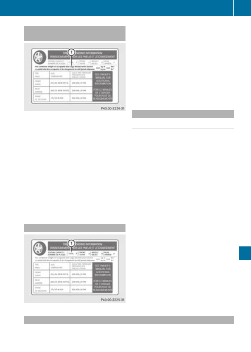
Maximum permissible gross vehicle
weight rating
XSpecification for maximumgross vehicle
weight :is listed in the Tire and Loading
Informationplacard: "The combined weight of
occupants and cargo should never exceed
XXX kilograms or XXX lbs."
The gross weight of all vehicleoccupants, load
and luggage must not exceed the specified
value.
iThe specifications shownonthe Tire and
Loading Informationplacard in the illustration
are examples. The maximumpermissible
gross vehicleweight rating is vehicle-specific
and may differfrom that in the illustration.
You can find the validmaximumpermissible
gross vehicleweight rating for yourvehicleon
the Tire and Loading Informationplacard.
Number of seats
Maximumnumber of seats :indicates the
maximumnumber of occupants allowedto
travel in the vehicle. This information can be
found on the Tire and Loading Informationplac-
ard.
iThe specifications shownonthe Tire and
Loading Informationplacard in the illustration
are examples. The number of seats is vehicle-
specific and can differfrom the details shown.
The number of seats in yourvehiclecan be
found on the Tire and Loading Information
placard.
Determiningthe correct load limit
Step-by-stepinstructions
The following steps have been developed as
required of all manufacturers under Title 49,
CodeofU.S. FederalRegulations, Part 575 pur-
suant to the "National Trafficand Motor Vehicle
Safety Act of 1966".
XStep 1: Locate the statement "The combined
weight of occupants and cargo should never
exceed XXX kg or XXX lbs." on yourvehicle’s
Tire and Loading Informationplacard.
XStep 2: Determine the combined weight of
the driverand passengers that willberiding in
yourvehicle.
XStep 3: Subtract the combined weight of the
driverand passengers from XXX kilograms or
XXX lbs.
XStep 4: The resulting figure equals the avail-
ableamount of cargo and luggage loadcapa-
city. For example, if the "XXX"amount equals
1400 lbs and there willbefive 150-lb pas-
sengers in yourvehicle, the amount of avail-
ablecargo and luggage loadcapacity is
650 lbs (1400 -750 (5 x150) = 650 lbs).
XStep 5: Determine the combined weight of
luggage and cargo being loaded on the vehi-
cle. That weight may not safelyexceed the
available cargo and luggage loadcapacity cal-
culated in step 4.
Example:steps 1to3
The following table showsexamples on how to calculate total and cargo loadcapacities with varying
seating configurations and number and size of occupants. The following examples use aloadlimitof
Loading the vehicle 299
Wheels and tires
Z

1500 lbs (680 kg). This is for illustration purposes only. Make sure you are using the actualload
limitfor yourvehicle stated on yourvehicle's Tire and Loading Information placard (Ypage298).
The greater the combined weight of the occupants, the lower the maximumluggage load.
Step 1
Example 1 Example 2 Example 3
Combinedmaximum
weight of occupants
and cargo (data from
the Tire and Loading
Information placard)
1500 lbs (680 kg) 1500 lbs (680 kg) 1500 lbs (680 kg)
Step 2
Example 1 Example 2 Example 3
Number of peoplein
the vehicle (driverand
occupants)
5 3 1
Distributionofthe
occupants
Front: 2
Rear: 3
Front: 1
Rear: 2
Front: 1
Weight of the occu-
pants
Occupant 1: 150 lbs
(68 kg)
Occupant 2: 180 lbs
(82 kg)
Occupant 3: 160 lbs
(73 kg)
Occupant 4: 140 lbs
(63 kg)
Occupant 5: 120 lbs
(54 kg)
Occupant 1: 200 lbs
(91 kg)
Occupant 2: 190 lbs
(86 kg)
Occupant 3: 150 lbs
(68 kg)
Occupant 1: 150 lbs
(68 kg)
Gross weight of all
occupants
750 lbs (340 kg) 540 lbs (245 kg) 150 lbs (68 kg)
Step 3
Example 1 Example 2 Example 3
Permissibleload (maxi-
mum gross vehicle
weight rating from the
Tire and Loading Infor-
mation placard minus
the gross weight of all
occupants)
1500 lbs (680 kg) Ò
750 lbs (340 kg) =
750 lbs (340 kg)
1500 lbs (680 kg) Ò
540 lbs (245 kg)
=960 lbs (435 kg)
1500 lbs (680 kg) Ò
150 lbs (68 kg) =
1350 lbs (612 kg)
Vehicle identification plate
Even if you have calculated the total cargo care-
fully,you should still make sure that the gross
vehicle weight rating and the gross axle weight
rating are not exceeded. Detailscan be found on
the vehicle identification plate on the B-pillar on
the driver's side of the vehicle (Ypage298).
300 Loading the vehicle
Wheels and tires
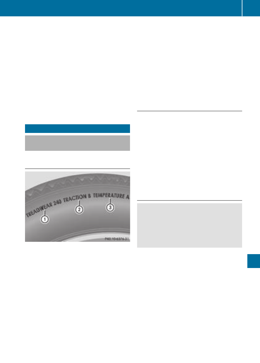
Permissible Gross Vehicle Weight Rating
(GVWR): the gross weight of the vehicle, all pas-
sengers, load and trailer load/noseweight (if
applicable) must not exceed the permissible
gross vehicle weight.
Gross Axle Weight Rating (GAWR): the maxi-
mum permissible weight that can be carried by
one axle (front or rear axle).
To ensure that your vehicle does not exceed the
maximum permissible values (gross vehicle
weight and maximum gross axle weight rating),
have your loaded vehicle (including driver, occu-
pants, cargo, and full trailer load if applicable)
weighed on asuitable vehicle weighbridge.
All about wheelsand tires
Uniform Tire Quality Grading Stand-
ards
Overview of Tire Quality Grading Stand-
ards
Uniform Tire Quality Grading Standards are U.S.
governmentspecifications. Their purpose is to
provide drivers with uniform reliable information
on tire performance data. Tire manufacturers
have to grade tires using three performance fac-
tors: :tread wear grade, ;traction grade and
=temperature grade. These regulations do not
apply to Canada. Nevertheless, all tires sold in
North America are provided with the corre-
sponding quality grading markings on the side-
wall of the tire.
Quality grades can be found, where applicable,
on the tire sidewallbetween tread shoulder and
maximum section width.
Example:
RTreadwear grade: 200
RTraction grade: AA
RTemperaturegrade: A
All passenger car tires must conformtothe stat-
utory safety requirements in addition to these
grades.
iThe actual values for tires are vehicle-spe-
cific and may deviate from the values in the
illustration.
Treadwear
The treadwear grade is acomparative rating
based on the wear rate of the tire when tested
under controlled conditionsonaspecified U.S.
governmentcourse. For example, atire graded
150 would wear one and one-half times as well
on the governmentcourse as atire graded 100.
The relative performance of tires depends upon
the actual conditionsoftheir use, however, and
may depart significantly from the norm due to
variations in driving habits, service practices
and differences in road characteristics and cli-
mate.
Traction
GWARNING
The traction grade assigned to this tire is
based on straight-ahead braking traction
tests, and does not include acceleration, cor-
nering, hydroplaning, or peak traction char-
acteristics.
!Avoid wheelspin. This can lead to damage to
the drive train.
The traction grades –from highest to lowest –
are AA, A, Band C. Those grades represent the
tire's ability to stop on wet pavement as meas-
ured under controlled conditionsonspecified
governmenttest surfaces of asphalt and con-
crete. Atire marked Cmay have poor traction
performance.
The safe speed on awet, snow covered or icy
road is always lower than on dry road surfaces.
You should pay special attention to road condi-
tions when temperatures are around freezing
point.
Mercedes-Benzrecommends aminimum tread
depth of ãin (4 mm) on all four winter tires.
All about wheels and tires 301
Wheels and tires
Z
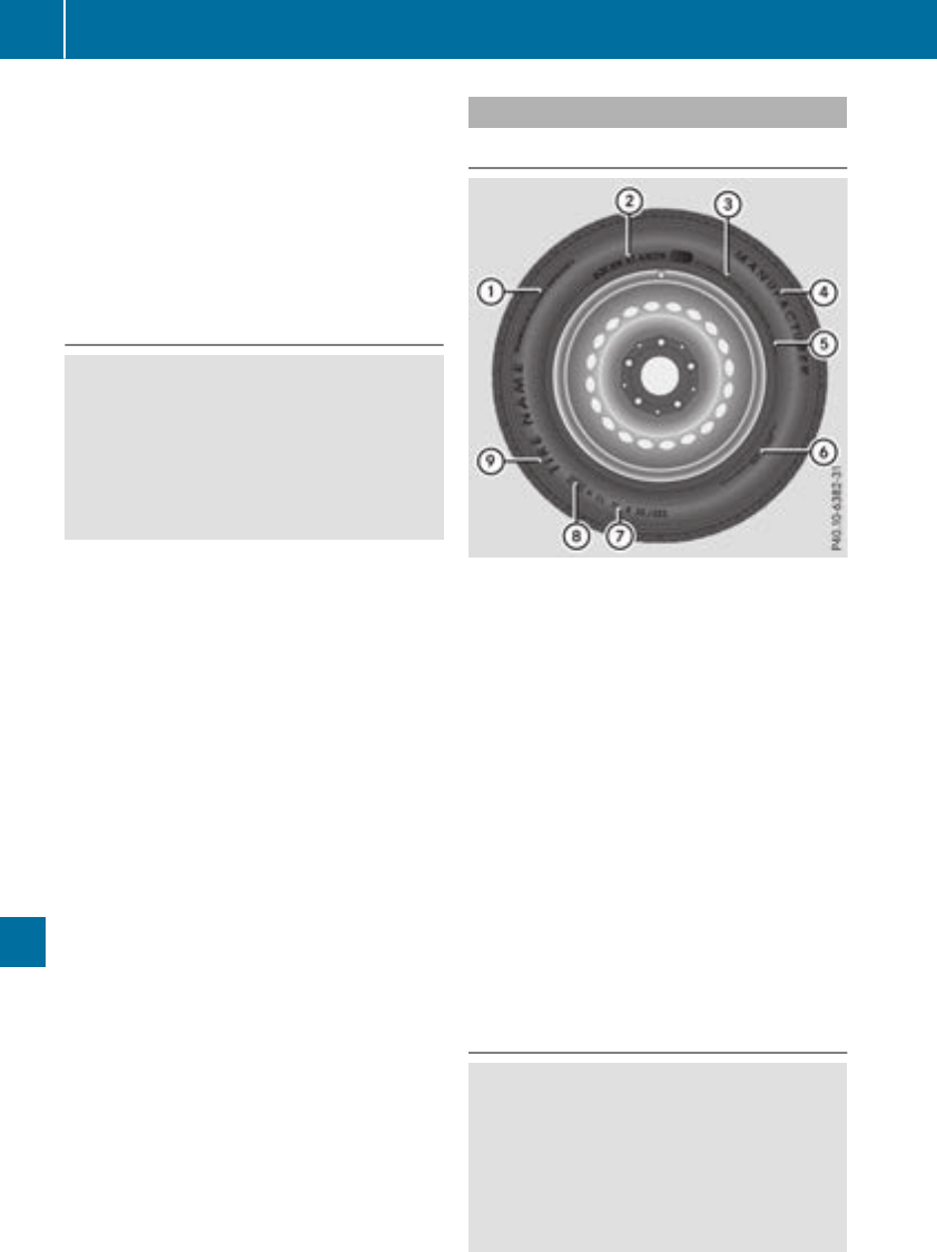
Observe the legally required minimum tire tread
depth (Ypage 288). Winter tires can reduce the
braking distance on snow-covered surfaces in
comparison with summer tires. The braking dis-
tance is still much further than on surfaces that
are not icy or covered with snow. Take appro-
priate care when driving.
Further information on winter tires (M+S tires)
(Ypage 289).
Temperature
GWARNING
The temperature grade for this tire is estab-
lished for atire that is properly inflated and
not overloaded.Excessive speed, underinfla-
tion, or excessive loading, either separately or
in combination, can cause excessive heat
build-up and possible tire failure.
The temperature grades are A(the highest), B,
and C, representing the tire's resistance to the
generation of heat and its ability to dissipate
heat when tested under controlled conditions
on aspecified indoor laboratory test wheel. Sus-
tained high temperature can cause the material
of the tire to degenerate and reduce tire life, and
excessive temperature can lead to sudden tire
failure. The grade Ccorresponds to alevel of
performance which all passenger car tires must
meet under the Federal Motor Vehicle Safety
Standard No. 109. Grades Band Arepresent
higher levels of performance on the laboratory
test wheel than the minimum required by law.
Tire labeling
Overview
:Uniform Tire Quality Grading Standards
(Ypage 306)
;Department of Transportation, Tire Identifi-
cation Number (Ypage 305)
=Maximum load rating (Ypage 304)
?Maximum tire pressures (Ypage 293)
AManufacturer
BTire material (Ypage 305)
CTire size designation, load-bearing capacity
and speed rating (Ypage 302)
DLoad index (Ypage 304)
ETire name
The markings described above are on the tire in
addition to the tire name (sales designation) and
the manufacturer's name.
iTire data is vehicle-specific and may deviate
from the data in the example.
Tire size designation, load-bearing
capacity and speed rating
GWARNING
Exceeding the stated tire load-bearing capa-
city and the approved maximum speed could
lead to tire damage or the tire bursting. There
is arisk of accident.
Therefore, only use tire types and sizes
approved for your vehicle model. Observe the
302 All about wheels and tires
Wheels and tires
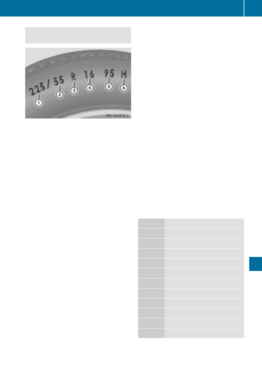
tire load rating and speedrating required for
your vehicle.
:Tire width
;Nominalaspectratio in %
=Tire code
?Rimdiameter
ALoadbearing index
BSpeed rating
General: depending on the manufacturer's
standards,the size imprinted in the tire wall may
not contain any letters or maycontain one letter
thatprecedes the size description.
If there is no letter preceding the size descrip-
tion(as shown above): these arepassenger
vehicletiresaccording to Europeanmanufac-
turing standards.
If "P"precedes the size description: these are
passengervehicletiresaccording to U.S. man-
ufacturingstandards.
If "LT" precedes the size description: these are
light truck tiresaccording to U.S. manufacturing
standards.
If "T"precedes the size description: compact
emergency wheels with high tire pressure that
areonlydesignedfor temporary useinanemer-
gency.
Tire width: tire width :shows the nominal tire
width in millimeters.
Aspectratio: aspect ratio ;is the size ratio
between the tire height and tire width and is
shown in percent. The aspect ratio is calculated
by dividing the tire width by the tire height.
Tire code: tire code =specifiesthe tire type.
"R"represents radial tires; "D" represents diag-
onaltires; "B" represents diagonalradial tires.
Optionally,tireswithamaximum speedofover
149 mph (240 km/h)may have "ZR" in the size
description, depending on the manufacturer
(e.g. 245/40ZR18).
Rim diameter: rim diameter ?is the diameter
of the bead seat, not the diameterofthe rim
flange.The rimdiameterisspecifiedin
inches (in).
Load-bearingindex: load-bearing index Ais a
numerical codethatspecifiesthe maximum
load-bearing capacity of atire.
Do not overload the tiresbyexceeding the
specifiedloadlimit.The maximumpermissible
load can be found on the vehicle's Tire and
Loading Informationplacard on the B-pillar on
the driver's side (Ypage 298).
Example:
Load-bearingindex 91 indicates amaximum
load of 1,356 lb (615kg) thatthe tirescan bear.
For furtherinformation on the maximum tire
load in kilograms and lbs, see(
Ypage 304).
For furtherinformation on the load bearing
index, see"Load index" (Ypage 304).
Speed rating: speedrating Bspecifiesthe
approved maximum speedofthe tire.
iTire data is vehicle-specific and maydeviate
fromthe data in the example.
Regardlessofthe speedrating,alwaysobserve
the speedlimits. Drive carefullyand adaptyour
drivingstyle to the trafficconditions.
Summertires
Index Speed rating
Q up to 100 mph (160km/h)
R up to 106 mph (170km/h)
S up to 112 mph (180km/h)
T up to 118 mph (190km/h)
H up to 130 mph (210km/h)
V up to 149 mph (240km/h)
W up to 168 mph (270km/h)
Y up to 186 mph (300km/h)
ZR...Y up to 186 mph (300km/h)
ZR...(..Y) over186 mph (300 km/h)
ZR over149 mph (240 km/h)
ROptionally,tireswithamaximum speedof
over149 mph (240km/h)may have "ZR" in
Allabout wheels andtires 303
Wheelsand tires
Z
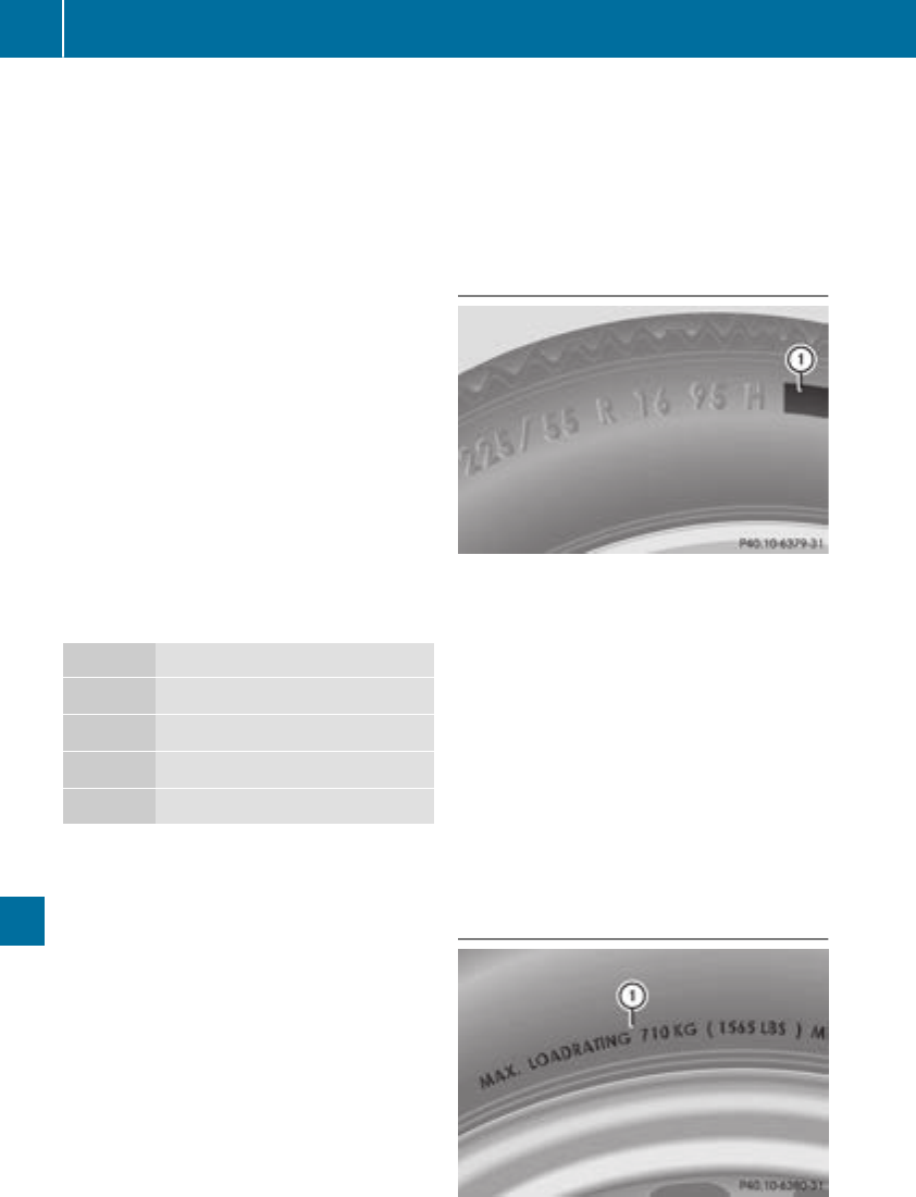
the size description, depending on the man-
ufacturer (e.g. 245/40ZR18).
The service specification is made up of load-
bearing index Aand speedrating B.
RIf the size description of your tire includes
"ZR" and there arenoservice specifications,
askthe tire manufacturer in order to findout
the maximum speed.
If aservice specification is available, the max-
imum speedislimited according to the speed
rating in the service specification. Example:
245/40ZR1897Y.Inthis example,"97 Y" is
the service specification. The letter "Y" rep-
resents the speed rating. The maximum
speed of the tire is limited to 186 mph
(300 km/h).
RThe size descriptionfor all tires with maxi-
mum speedsofover 186 mph (300 km/h)
must include "ZR" and the service specifica-
tion must be given in parentheses.Example:
275/40 ZR 18 (99 Y).Speed rating "(Y)" indi-
cates that the maximum speed of the tire is
over 186 mph (300 km/h). Ask the tire man-
ufacturer aboutthe maximum speed.
All-weather tires and winter tires
Index Speed rating
QM+S1up to 100 mph (160 km/h)
TM+S1up to 118 mph (190 km/h)
HM+S1up to 130 mph (210 km/h)
VM+S1up to 149 mph (240 km/h)
iNot all tires with the M+S marking provide
the driving characteristics of winter tires. In
addition to the M+S marking, winter tires also
have the isnowflake symbolonthe tire
wall. Tires with this marking fulfill the require-
ments of the Rubber Manufacturers Associa-
tion (RMA) and the Rubber Association of
Canada (RAC) regarding the tire traction on
snow. They have been especially developed
for driving on snow.
An electronic speed limiter prevents yourvehi-
cle from exceeding aspeed of 130 mph
(210 km/h).
The speed rating of tires mounted at the factory
may be higher than the maximum speed that the
electronic speed limiter permits.
Make sure that yourtires have the required
speed rating, e.g. when buying new tires. The
required speed rating for yourvehicle can be
found in the "Tires" section (Ypage 312).
Further information aboutreading tire data can
be obtained from any qualifiedspecialist work-
shop.
Load index
In addition to the load-bearing index, load
index :may be imprinted after the letters that
identify speed rating on the sidewall of the tire.
Speed rating (Ypage 302).
RIf no specification is given: no text (as in the
example above), represents astandard load
(SL) tire
RXL or ExtraLoad: represents areinforced tire
RLight Load: represents alightload tire
RC, D, E: represents aload range that depends
on the maximum load that the tire can carry at
acertain pressure
iTire data is vehicle-specific and may deviate
from the data in the example.
Maximum load rating
1Or M+S ifor winter tires.
304 Allabout wheels and tires
Wheelsand tires
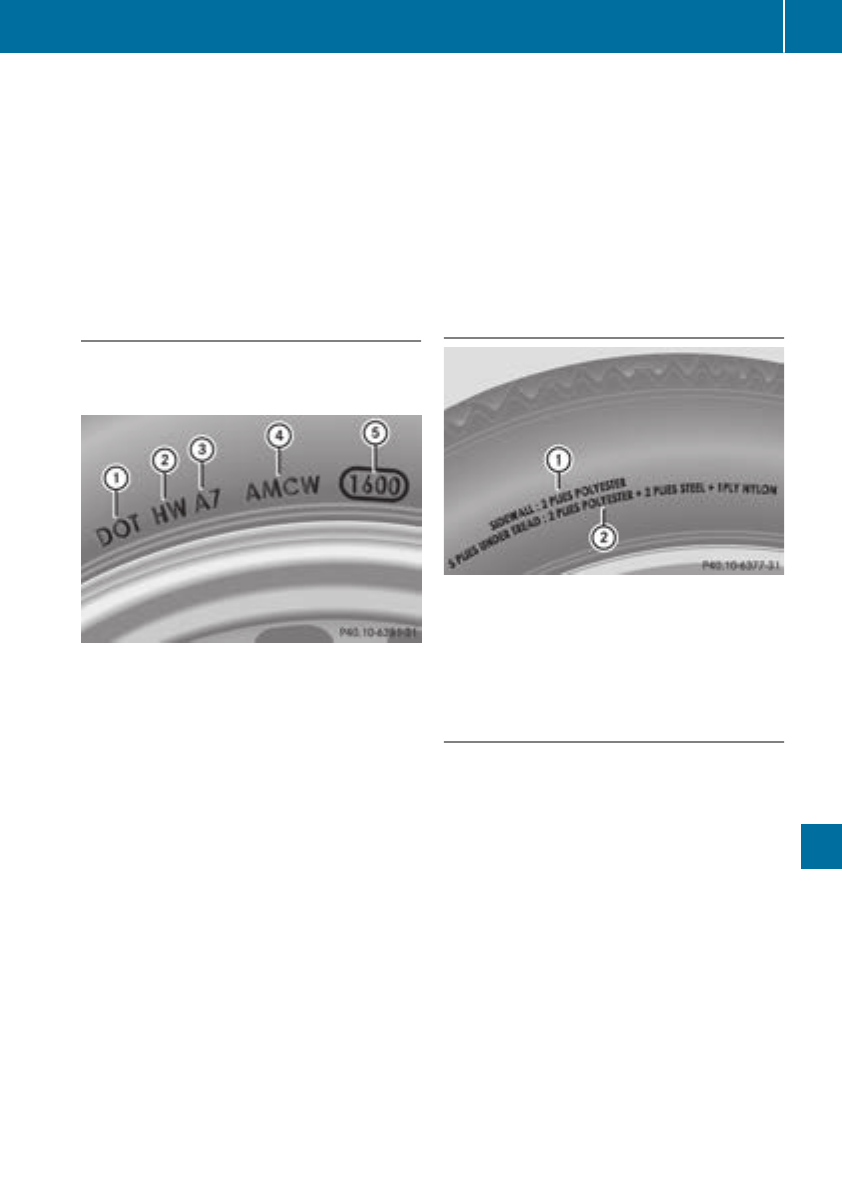
Maximum tire load :is the maximum permis-
sible weight for which the tire is approved.
Do not overload the tires by exceeding the
specified load limit. The maximum permissible
load can be found on the vehicle's Tire and
Loading Information placard on the B-pillar on
the driver's side (Ypage 298).
iThe actual values for tires are vehicle-spe-
cific and may deviate from the values in the
illustration.
DOT, Tire Identification Number (TIN)
US tire regulations stipulate that every tire man-
ufacturer or retreader must imprint aTIN in or on
the sidewall of each tire produced.
The TIN is aunique identification number. The
TIN enables the tire manufacturers or retreaders
to inform purchasers of recalls and other safety-
relevant matters. It makes it possible for the
purchaser to easily identify the affected tires.
The TIN is made up of manufacturer identifica-
tion code ;,tire size =,tire type code ?and
manufacturing date A.
DOT (Department of Transportation): tire
symbol :marks that the tire complies with the
requirements of the U.S. DepartmentofTrans-
portation.
Manufacturer identification code: manufac-
turer identification code ;provides details on
the tire manufacturer. New tires have acode
with two symbols. Retreaded tires have acode
with four symbols.
For further information about retreaded tires,
see (Ypage 312).
Tire size: identifier =describes the tire size.
Tire type code: tire type code ?can be used by
the manufacturer as acode to describe specific
characteristics of the tire.
Date of manufacture: date of manufacture A
provides information about the age of atire. The
first and second positions represent the week of
manufacture, startingwith "01" for the first cal-
endar week. Positions three and four represent
the year of manufacture. For example, atire that
is marked with "3208", was manufactured in
week 32 in 2008.
iTire data is vehicle-specific and may deviate
from the data in the example.
Tire characteristics
This information describes the type of tire cord
and the number of layers in sidewall :and
under tire tread ;.
iTire data is vehicle-specific and may deviate
from the data in the example.
Definition of termsfor tires and loading
Tire ply composition and material used
Describes the number of plies or the number of
layers of rubber-coated fabric in the tire tread
and sidewall. These are made of steel, nylon,
polyester and other materials.
Bar
Metric unit for tire pressure. 14.5038 pounds
per square inch (psi) and 100 kilopascals (kPa)
are the equivalent of 1bar.
DOT (Department of Transportation)
DOT-marked tires fulfill the requirements of the
USDepartmentofTransportation.
Normal occupant weight
The number of occupants for which the vehicle
is designed multiplied by 68 kilograms (150 lbs).
All about wheels and tires 305
Wheels and tires
Z

Uniform TireQualityGrading Standards
Auniformstandard to grade the quality of tires
with regards to tread quality, tire traction and
temperature characteristics. The quality grad-
ing assessmentismade by the manufacturer
following specificationsfrom the U.S.govern-
ment.The ratings are molded intothe sidewall of
the tire.
Recommended tirepressures
The recommended tire pressure applies to the
tires mounted at the factory.
The Tire and Loading Information placard con-
tains the recommended tire pressures for cold
tires on afully loaded vehicle and for the maxi-
mum permissible vehicle speed.
The tire pressure table contains the recommen-
ded pressures for cold tires for various operat-
ing conditions, i.e. differingload and speed con-
ditions.
Increased vehicle weight due to optional
equipment
The combined weight of all standard and
optional equipment available for the vehicle,
regardless of whether it is actually installed on
the vehicle or not.
Rim
This is the part of the wheel on which the tire is
mounted.
GAWR (Gross Axle Weight Rating)
The GAWR is the maximum gross axle weight
rating. The actual load on an axle must never
exceed the gross axle weight rating. The gross
axle weight ratingcan be found on the vehicle
identification plate on the B-pillar on the driver's
side.
Speed rating
The speed ratingispart of the tire identification.
It specifies the speed range for which the tire is
approved.
GVW (Gross Vehicle Weight)
The gross vehicle weight includes the weight of
the vehicle includingfuel, tools, the spare wheel,
accessories installed, occupants, luggage and
the drawbar noseweight,ifapplicable. The gross
vehicle weight must not exceed the gross vehi-
cle weight ratingGVWR as specified on the vehi-
cle identification plate on the B-pillar on the
driver'sside.
GVWR(Gross Vehicle Weight Rating)
The GVWR is the maximum permissible gross
weight of afully loaded vehicle (the weight of the
vehicle includingall accessories, occupants,
fuel, luggage and the drawbar noseweight,if
applicable). The gross vehicle weight ratingis
specified on the vehicle identification plate on
the B-pillar on the driver'sside.
Maximum loaded vehicle weight
The maximum weight is the sum of:
Rthe curb weight of the vehicle
Rthe weight of the accessories
Rthe load limit
Rthe weight of the factory installed optional
equipment
Kilopascal (kPa)
Metric unit for tire pressure. 6.9 kPa corre-
sponds to 1psi. Another unit for tire pressure is
bar. 100 kilopascals (kPa) are the equivalent of
1bar.
Load index
In addition to the load-bearingindex,the load
index may also be imprinted on the sidewall of
the tire. This specifies the load-bearingcapacity
more precisely.
Curb weight
The weight of avehicle with standard equipment
includingthe maximum capacityoffuel, oil and
coolant.Italso includes the air-conditioningsys-
tem and optional equipment if these are instal-
led in the vehicle, but does not include passen-
gers or luggage.
Maximum load rating
The maximum tire load is the maximum permis-
sible weight in kilogramsorlbs for which atire is
approved.
Maximum permissible tirepressure
Maximum permissible tire pressure for one tire.
Maximum load on one tire
Maximum load on one tire. This is calculated by
dividing the maximum axle load of one axle by
two.
306 All about wheels and tires
Wheels and tires

PSI (pounds per squareinch)
Astandard unit of measure for tire pressure.
Aspect ratio
Relationship between tire height and tire width
in percent.
Tire pressure
This is pressure inside the tire applying an out-
ward force to each square inch of the tire's sur-
face. The tire pressure is specified in pounds per
square inch (psi), in kilopascal (kPa) or in bar.
The tire pressure should only be corrected when
the tires are cold.
Cold tire pressure
The tires are cold:
Rif the vehicle has been parked with the tires
out of direct sunlight for at least three hours
and
Rif the vehicle has not been driven further than
1mile (1.6 km)
Tread
The part of the tire that comes into contact with
the road.
Bead
The tire bead ensures that the tire sits securely
on the wheel. There are several steel wires in the
bead to prevent the tire from coming loose from
the wheel rim.
Sidewall
The part of the tire between the tread and the
bead.
Weight of optional extras
The combined weight of those optional extras
that weigh more than the replaced standard
parts and more than 2.3 kg (5 lbs). These
optional extras, such as high-performance
brakes, level control, aroof rack or ahigh-per-
formancebattery, are not included in the curb
weight and the weight of the accessories.
TIN (Tire Identification Number)
This is aunique identifier which can be used by
atire manufacturer to identify tires, for example
for aproduct recall, and thus identify the pur-
chasers. The TIN is made up of the manufactur-
er's identity code, tire size, tire type code and
the manufacturing date.
Load bearing index
The load bearing index (also load index) is acode
that contains the maximum load bearing capa-
city of atire.
Traction
Traction is the result of friction between the tires
and the road surface.
Treadwear indicators
Narrow bars (tread wear bars) that are distrib-
uted over the tire tread. If the tire tread is level
with the bars, the wear limit of áin (1.6 mm)
has been reached.
Occupant distribution
The distribution of occupants in avehicle at their
designated seating positions.
Total load limit
Nominal load and luggage load plus 68 kg
(150lbs)multiplied by the number of seats in
the vehicle.
Changing awheel
Flat tire
The "Breakdown assistance" section
(Ypage 271) contains information and notes on
how to deal with aflat tire. Information on driv-
ing with MOExtended tires in the event of aflat
tire can be found under "MOExtended tires (tires
with run-flat characteristics" (Ypage 271).
Rotating the wheels
GWARNING
Interchanging the front and rear wheels may
severely impair the driving characteristics if
the wheels or tires have different dimensions.
The wheel brakes or suspension components
may also be damaged. There is arisk of acci-
dent.
Rotate front and rear wheels only if the wheels
and tires are of the same dimensions.
!On vehicles equippedwith atire pressure
monitor,electronic components are located
in the wheel.
Changing awheel 307
Wheels and tires
Z

Tire-mounting tools should not be used near
the valve. This could damage the electronic
components.
Only have tires changed at aqualified spe-
cialist workshop.
Observe the instructions and safety notes in the
"Changing awheel" section (Ypage 307).
The wear patternsonthe front and rear tires
differ, depending on the operating conditions.
Rotate the wheels before aclear wear pattern
has formed on the tires. Fronttires typically
wear more on the shoulders and the rear tires in
the center.
On vehicles that have the same size front and
rear wheels, you can rotatethe wheels accord-
ing to the intervals in the tire manufacturer's
warranty book in your vehicle documents. If no
warranty book is available, the tires should be
rotated every 3,000 to 6,000 miles (5,000 to
10,000km).Dependingontire wear, this may
be required earlier. Do not change the direction
of wheel rotation.
Clean the contact surfaces of the wheel and the
brake disc thoroughly every time awheel is rota-
ted. Check the tire pressure and, if necessary,
restart the tire pressure loss warning system
(Canada only) or the tire pressure monitor (USA
only).
Direction of rotation
Tires with aspecified direction of rotation have
additional benefits,e.g. if there is arisk of hydro-
planing. These advantages can only be gained if
the tires are installed corresponding to the
direction of rotation.
An arrow on the sidewall of the tire indicates its
correctdirection of rotation.
Storing wheels
Storewheels that are not being used in acool,
dry and preferably dark place. Protectthe tires
from oil, grease, gasoline and diesel.
Mounting awheel
Preparing the vehicle
XStop the vehicle on solid, non-slippery and
level ground.
XApply the electric parking brake manually.
XBring the front wheels into the straight-ahead
position.
XShift the transmission to position j.
XSwitch off the engine.
XVehicles without KEYLESS-GO: remove the
SmartKey from the ignition lock.
XVehicles with KEYLESS-GO start-function
or KEYLESS-GO: open the driver's door.
The vehicle electronics are now in position
u.This is the same as “key removed”.
XVehicles with KEYLESS-GO start-function
or KEYLESS-GO: remove the Start/Stop but-
ton from the ignition lock (Ypage 122).
XMake sure that the engine cannot be started
via your smartphone(
Ypage 83).
XIf included in the vehicle equipment, remove
the tire-change tool kit from the vehicle.
XSafeguard the vehicle against rolling away
(Ypage 141).
iApart from certain country-specific varia-
tions, the vehicles are not equipped with a
tire-change tool kit. Some tools for changing a
wheel are specific to the vehicle. For more
information on which tools are required to
perform awheel change on your vehicle, con-
sult aqualified specialist workshop.
Necessary tire-changing tools can include, for
example:
RJack
RWheel chock
RLug wrench
308 Changing awheel
Wheels and tires
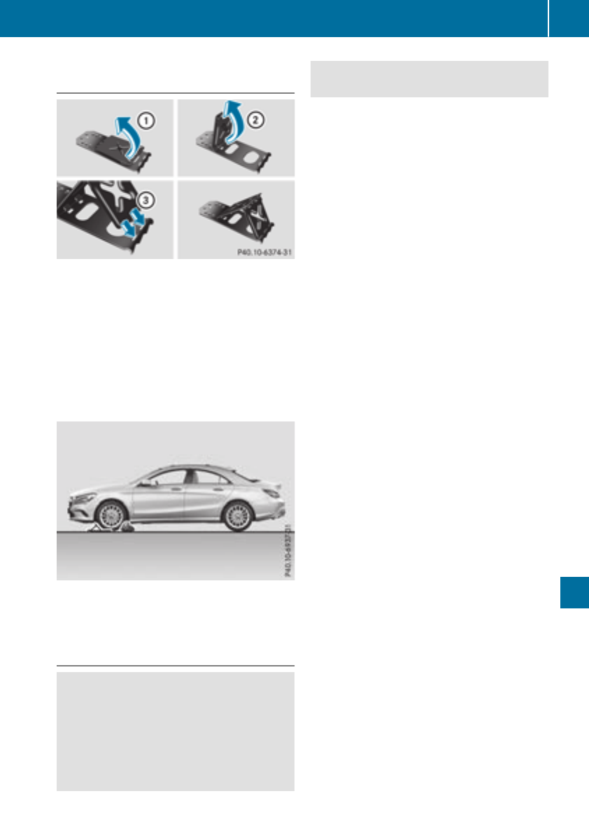
Securing the vehicle to prevent it from
rolling away
If your vehicle is equippedwith awheel chock,it
can be found in the tire-change tool kit
(Ypage 270).
The folding wheel chock is an additional safety
measure to prevent the vehicle from rolling
away,for example when changing awheel.
XFold both plates up :.
XFold out lower plate ;.
XGuide the lugs on the lower plate fully into the
openings in base plate =.
XPlace chocksorother suitable items under
the front and rear of the wheel that is diago-
nally opposite the wheel you wish to change.
Raising the vehicle
GWARNING
If you do not position the jack correctly at the
appropriate jackingpoint of the vehicle, the
jack could tip over with the vehicle raised.
There is arisk of injury.
Only position the jack at the appropriate jack-
ing point of the vehicle. The base of the jack
must be positioned vertically, directly under
the jackingpoint of the vehicle.
!Only position the jack at the appropriate
jackingpoint of the vehicle. Otherwise, you
could damage the vehicle.
Observe the following when raising the vehi-
cle:
RTo raise the vehicle, only use the vehicle-spe-
cific jack that has been tested and approved
by Mercedes-Benz. If used incorrectly, the
jack could tip over with the vehicle raised.
RThe jack is designed only to raise and hold the
vehicle for ashort time while awheel is being
changed. It must not be used for performing
maintenance work under the vehicle.
RAvoid changing the wheel on uphill and down-
hill slopes.
RBefore raising the vehicle, secure it from roll-
ing away by applying the parking brake and
insertingwheel chocks. Do not disengage the
parking brake while the vehicle is raised.
RThe jack must be placed on afirm, flat and
non-slip surface. On aloose surface, alarge,
flat, load-bearing underlay must be used. On a
slippery surface, anon-slip underlay must be
used, e.g. rubber mats.
RDo not use wooden blocks or similar objects
as ajack underlay. Otherwise, the jack will not
be able to achieve its load-bearing capacity
due to the restricted height.
RMake sure that the distance between the
underside of the tires and the ground does not
exceed 1.2 in (3 cm).
RNever place your hands and feet under the
raised vehicle.
RDo not lie under the vehicle.
RDo not start the engine when the vehicle is
raised.
RDo not open or close adoor or the trunk lid
when the vehicle is raised.
RMake sure that no persons are present in the
vehicle when the vehicle is raised.
Changing awheel 309
Wheels and tires
Z
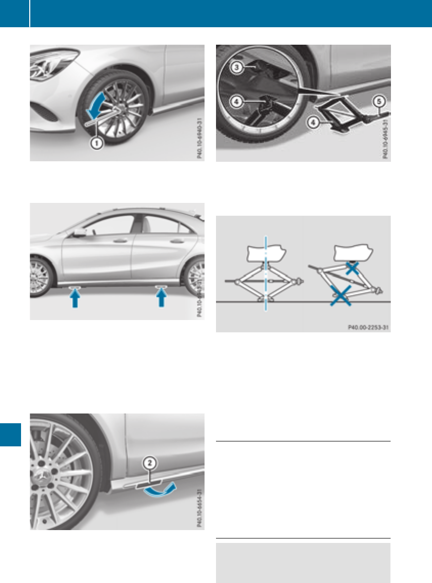
XUsing lug wrench :,loosen the bolts on the
wheel you wish to change by aboutone full
turn. Do not unscrew the bolts completely.
Jacking points
The jacking points are located just behind the
front wheel housings and just in front of the rear
wheel housings (arrows).
Mercedes-AMG vehicles and vehicles with
AMG Line: to protect the vehicle body, the vehi-
cle has covers installed next to the jacking
points on the outer sills.
Covers, front (example: vehicles with AMG Line)
XMercedes-AMG vehicles and vehicles
with AMG Line: fold cover ;upwards.
XTake ratchet wrench Aout of the vehicle tool
kit and place it on the hexagon nut of jack ?
so that the letters AUF are visible.
XPosition jack ?at jacking point =.
XMake sure the foot of the jack is directly
beneath the jacking point.
XTurn ratchet wrench Auntil jack ?sits
completely on jacking point =and the base
of the jack lies evenly on the ground.
XTurn ratchet wrench Auntil the tire is raised
amaximum of 1.2 in (3 cm)from the ground.
Removing awheel
!Do not place wheel bolts in sand or on adirty
surface. The bolt and wheel hub threads could
otherwise be damagedwhen you screw them
in.
XUnscrew the wheel bolts.
XRemove the wheel.
Mounting anew wheel
GWARNING
Oiled or greased wheel bolts or damaged
wheel bolts/hub threads can cause the wheel
310 Changing awheel
Wheels and tires
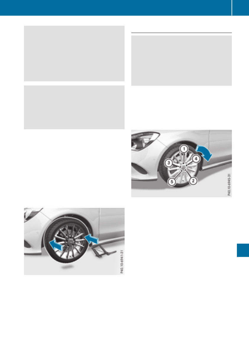
bolts to come loose. As aresult, you could
lose awheel while driving.There is arisk of
accident.
Never oil or grease wheel bolts. In the event of
damage to the threads, contact aqualified
specialist workshop immediately. Have the
damaged wheel bolts or hub threads
replaced/renewed. Do not continue driving.
GWARNING
If you tighten the wheel bolts or wheel nuts
when the vehicle is raised, the jack could tip
over. There is arisk of injury.
Only tighten the wheel bolts or wheel nuts
when the vehicle is on the ground.
Always pay attention to the instructions and
safety notes in the "Changing awheel" section
(Ypage 307).
Only use wheel bolts that have been designed
for the wheel and the vehicle. For safety rea-
sons, Mercedes-Benz recommends that you
only use wheel bolts which have been approved
for Mercedes-Benz vehicles and the respective
wheel.
!To preventdamage to the paintwork, hold
the wheel securely against the wheel hub
while screwinginthe first wheel bolt.
XClean the wheel and wheel hub contact sur-
faces.
XPlace the new wheel on the wheel hub and
push it on.
XTighten the wheel bolts until they are finger-
tight.
Lowering the vehicle
GWARNING
The wheels could work loose if the wheel nuts
and bolts are not tightened to the specified
tighteningtorque. There is arisk of accident.
Have the tighteningtorque immediately
checked at aqualified specialist workshop
after awheel is changed.
XPlace the ratchet wrenchontothe hexagon
nut of the jack so that the letters AB are visi-
ble.
XTurn the ratchet wrenchuntil the vehicle is
onceagain standing firmly on the ground.
XPlace the jack to one side.
XTighten the wheel bolts evenly in acrosswise
pattern in the sequence indicated (:to A).
The specified tighteningtorque is 96 lb-ft
(130 Nm).
XTurn the jack back to its initial position.
XStow the jack and the rest of the vehicle tools
in the vehicle again.
XMercedes-AMG vehicles and vehicles
with AMG Line: use the cover of the outer sill.
XCheck the tire pressure of the newly mounted
wheel and adjust it if necessary.
Observe the recommended tire pressure
(Ypage 290).
Canadaonly: as long as you are driving with the
emergency spare wheel mounted, the tire pres-
sure loss warning system cannot function relia-
bly. Only restart the tire pressure loss warning
system when the defective wheel has been
replaced with anew wheel.
Vehicles with tirepressure monitor (USA
only): all mounted wheels must be equipped
with functioning sensors.
Changing awheel 311
Wheels and tires
Z

Wheeland tire combinations
General notes
You can ask for information regarding permitted
wheel/tire combinations at an authorized
Mercedes-Benz Center.
You should regularlycheck the pressure of the
emergency spare wheel, particularly priorto
long trips, and correct the pressure as neces-
sary (Ypage290). The valueonthe wheel is
valid.
!For safety reasons, Mercedes-Benz recom-
mends that you only use tires and wheels
which have been approved by Mercedes-Benz
specifically for yourvehicle.
These tires have been speciallyadapted for
use with the control systems, such as ABS or
ESP®,and are marked as follows:
RMO = Mercedes-Benz Original
RMOE = Mercedes-Benz Original Extended
(tires featuring run-flatcharacteristics)
RMO1 = Mercedes-Benz Original (only cer-
tain AMG tires)
Mercedes-Benz Original Extended tires may
only be usedonwheels that have been spe-
cifically approved by Mercedes-Benz.
Only use tires, wheels or accessories tested
and approved by Mercedes-Benz. Certain
characteristics, e.g. handling, vehiclenoise
emissions or fuel consumption, may other-
wisebeadversely affected.Inaddition, when
driving with aload, tire dimension variations
couldcausethe tires to come into contact
with the bodywork and axle components. This
couldresult in damage to the tires or the vehi-
cle.
Mercedes-Benz accepts no liability for dam-
age resulting from the use of tires, wheels or
accessories other than those tested and
approved.
Informationontires, wheels and approved
combinations can be obtained from any quali-
fied specialist workshop.
!Retreaded tires are neither tested nor rec-
ommendedbyMercedes-Benz, since previ-
ous damage cannot alwaysbedetected on
retreaded tires. As aresult, Mercedes-Benz
cannot guarantee vehiclesafety if retreaded
tires are mounted.Donot mount usedtires if
you have no information about their previous
usage.
The recommendedpressures for various oper-
ating conditions can be found:
Ron the Tire and Loading Informationplacard
on the B-pillar on the driver's side
Rin the tire pressure tableinthe fuel filler flap
Observe the notes on recommendedtire pres-
suresunder various operating conditions
(Ypage290).
Check tire pressures regularly,and only when
the tires are cold. Comply with the maintenance
recommendations of the tire manufacturer in
the vehicledocument wallet.
Notes on the vehicleequipment –alwaysequip
the vehicle:
Rwith tires of the same size on agivenaxle (left
and right)
Rwith the same type of tire (summer tires,
MOExtended tires, winter tires)
Exception: it is permissible to installadiffer-
ent type or make in the event of aflat tire.
Observe the "MOExtended tires (tires with
run-flatcharacteristics" section (Ypage271).
Vehicles equipped with MOExtended tires are
not equipped with aTIREFIT kit at the factory.It
is therefore recommendedthat you additionally
equip yourvehiclewith aTIREFIT kit if you mount
tires that do not feature run-flatproperties, e.g.
winter tires. ATIREFIT kit may be obtained from
aqualified specialist workshop.
312 Wheeland tire combinations
Wheels and tires
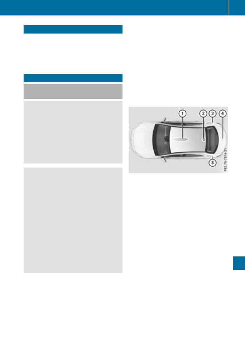
Information regardingtechnicaldata
iThe datastatedherespecifically refers to a
vehiclewithstandard equipment. Consult an
authorizedMercedes-BenzCenterfor the
datafor all vehiclevariants and trim levels.
Vehicle electronics
Installing two-way radiosand mobile
phones (RF transmitters)
GWARNING
The electromagneticradiation from modified
or incorrectlyretrofittedRF-transmitters can
interfere withthe vehicleelectronics.This can
compromise theoperational safetyofthe
vehicle. Thereisariskofanaccident.
You should haveall worktoelectrical and
electronic equipmentcarried out at aqualified
specialist workshop.
GWARNING
The electromagneticradiation from incor-
rectlyoperatedRFtransmitters can interfere
withthe vehicleelectronics,for example:
Rif theRFtransmitterisnot connectedwith
an exteriorantenna
Rtheexteriorantenna has been installed
incorrectlyorisnot alow-reflection type
This can compromise theoperational safety
of thevehicle. Thereisariskofanaccident.
Havethe low-reflection exteriorantenna
mountedataqualified specialist workshop.
When operating RF transmitters in thevehi-
cle,always connectthemwiththe low-reflec-
tion exteriorantenna.
!The operating permit may be invalidated if
theinstructionsfor installation and use of RF
transmitters are notobserved.
In particular, thefollowingconditionsmust be
complied with:
Ronly approvedwavebands may be used.
Robservethe maximum permissible output
in these wavebands.
Ronly approvedantenna positionsmay be
used.
Excessivelevels of electromagneticradiation
may causedamagetoyour healthand thehealth
of others. Using an exteriorantenna takes into
accountcurrentscientific discussionsrelating
to thepossible healthhazards that may result
from electromagneticfields.
Approved antenna positions
:Frontroofarea
;Rear roofarea
=Rear fender
?Trunklid
iOn vehicles withpanoramaroofwithpower
tilt/slidingpanel, installinganantenna to the
frontorrear roofarea is notpermitted.
On therear fenders, it is recommended to
position theantenna on theside of thevehicle
closesttothe center of theroad.
Use theTechnical Specification ISO/TS 21609
when retrofitting RF transmitters (Road Vehicles
-EMC guidelines for installation of aftermarket
radiofrequency transmitting equipment).
Observethe legal requirements for accessory
parts.
If your vehiclehas installationsfor two-way radio
equipment, use thepower supplyorantenna
connectionsintended for use withthe basic wir-
ing.Besuretoobservethe manufacturer'sSup-
plementwhen installing.
Deviationswithrespecttofrequency bands,
maximum transmission outputsorantenna
positionsmust be approvedbyMercedes-Benz.
Vehicle electronics 313
Technical data
Z
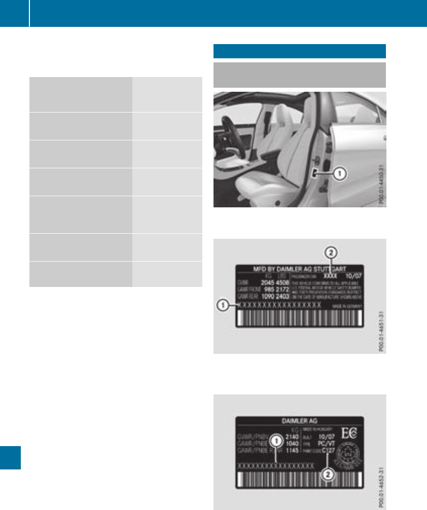
The maximum transmission output (PEAK)atthe
base of the antenna must not exceed the fol-
lowing values:
Frequency band Maximum
transmission
output
Short wave
3-54MHz
100 W
4mwaveband
74 -88MHz
30 W
2mwaveband
144 -174 MHz
50 W
Trunked radio system/
Tetra
380 -460 MHz
10 W
70 cm waveband
400 -460 MHz
35 W
Mobile communications
(2G/3G/4G)
10 W
The following can be used in the vehicle without
restrictions:
RRF transmitters with amaximum transmis-
sion output of up to 100 mW
RRF transmitters with transmitter frequencies
in the 380 -410 MHz frequency band and a
maximum transmission output of up to 2W
(trunked radio system/Tetra)
RMobile phones (2G/3G/4G)
There is no restriction for antenna positions on
the outside of the vehicle for the following fre-
quency bands:
RTrunked radio system/Tetra
R70 cm waveband
R2G/3G/4G
Identification plates
Vehicle identification platewith vehi-
cle identification number (VIN)
XOpen the driver's door.
You will see vehicle identification plate :.
Example: vehicle identification plate (USA only)
:VIN
;Paint code
Example: vehicle identification plate (Canada only)
:VIN
;Paint code
iThe data shown on the vehicle identification
plate is used only as an example. This data is
314 Identification plates
Technical data
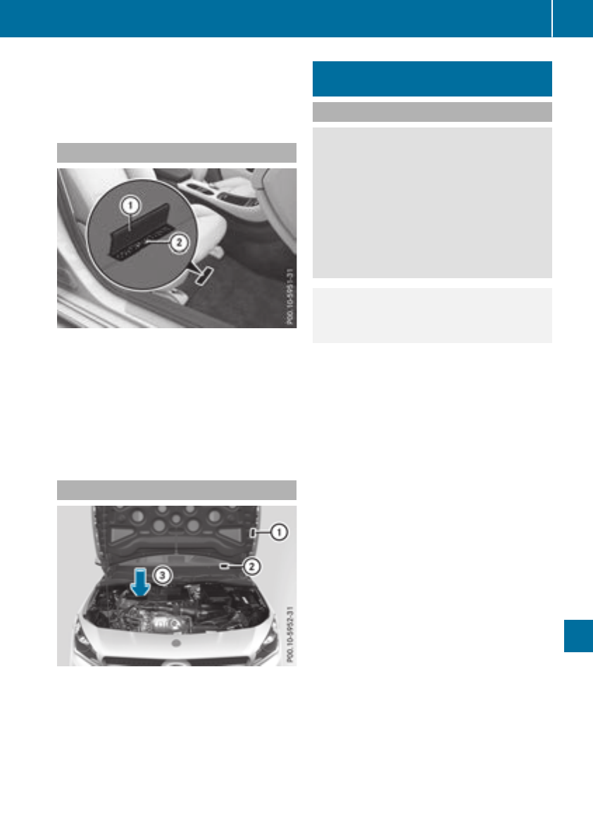
differentfor every vehicle and can deviate
from the data shown here. You can find the
data applicable to your vehicle on the vehicle
identification plate.
Vehicle identification number (VIN)
XSlide the right-handfrontseat to its rearmost
position.
XFold floor covering :upwards.
You will see VIN ;.
The VIN can also be found on the vehicle iden-
tification plate (Ypage 314).
The VIN can also be found at the lower edge of
the windshield (Ypage 315).
Engine number
:Emission control information plate, includ-
ing the certification of both federal and Cali-
fornian emissionsstandards
;VIN (on the lower edge of the windshield)
=Engine number (stamped intothe crank-
case)
Service productsand filling capaci-
ties
Important safetynotes
GWARNING
Service productsmay be poisonous and haz-
ardous to health. There is arisk of injury.
Comply with instructions on the use, storage
and disposal of serviceproductsonthe labels
of the respective original containers. Always
storeserviceproductssealed in their original
containers. Always keep serviceproductsout
of the reach of children.
HEnvironmental note
Dispose of serviceproductsinanenviron-
mentally responsible manner.
Service productsinclude the following:
RFuels
RLubricants (e.g. engineoil, transmission oil)
RCoolant
RBrakefluid
RWindshield washer fluid
RClimate control system refrigerant
Components and serviceproductsmust match.
Only use productsrecommended by Mercedes-
Benz. Damage which is caused by the use of
productswhich have not been recommended is
not covered by the Mercedes-Benz warrantyor
goodwill gestures.Productsapproved by
Mercedes-Benz are listed in this Operator's
Manual in the appropriate section.
Information on tested and approved products
can be obtained at aMercedes-Benz Service
Center or on the Internet at
http://bevo.mercedes-benz.com.
You can recognizeservice products approvedby
Mercedes-Benzbythe followinginscription on
the containers:
RMB-Freigabe (e.g. MB-Freigabe 229.51)
RMB-Approval (e.g. MB-Approval 229.51)
Other designationsorrecommendations indi-
catealevel of quality or aspecification in
accordancewith an MB SheetNumber (e.g. MB
229.5). They have not necessarily been
approvedbyMercedes-Benz.
Service productsand filling capacities 315
Technical data
Z

Other identifications, for example:
R0W-30
R5W-30
R5W-40
Fuel
Important safety notes
GWARNING
Fuel is highly flammable. If you handle fuel
incorrectly, there is arisk of fire and explo-
sion.
You must avoid fire, open flames, creating
sparks and smoking. Switch off the engine
and, if applicable, the auxiliary heating before
refueling.
GWARNING
Fuel is poisonous and hazardous to health.
There is arisk of injury.
You must make sure that fuel does not come
into contact with your skin, eyes or clothing
and that it is not swallowed. Do not inhale fuel
vapors. Keep fuel awayfrom children.
If you or others come into contact with fuel,
observe the following:
RWash awayfuel from skin immediately
using soap and water.
RIf fuel comes into contact with your eyes,
immediately rinse them thoroughly with
clean water. Seek medical assistance with-
out delay.
RIf fuel is swallowed, seek medical assis-
tance without delay.Donot induce vomit-
ing.
RImmediately change out of clothing which
has come into contact with fuel.
Tank capacity
Model Total capa-
city
CLA 250 13.2 US gal
(50.0 l)
Allother models 14.8 US gal
(56.0 l)
Model Of which
reserve
Mercedes‑AMGvehicles Approx.
2.1 US gal
(8.0 l)
All other models Approx.
1.6 US gal
(6.0 l)
Gasoline
Fuel grade
!Do not use diesel to refuelvehicles with a
gasoline engine. Do not switch on the ignition
if you accidentally refuelwith the wrong fuel.
Otherwise, the fuel willenter the fuel system.
Even smallamounts of the wrong fuel could
resultindamage to the fuel system and the
engine. Notify aqualified specialist workshop
and have the fuel tank and fuel lines drained
completely.
!Only refuelusing unleaded premium grade
gasoline with at least 91 AKI/95 RON.
iE10 fuel contains up to 10% bioethanol.
YourvehicleisE10-compatible. You can
refuelyourvehicleusing E10 fuel.
!Only use the fuel recommended. Operating
the vehiclewith other fuelscan leadtodam-
age to the fuel system, engine and exhaust
system.
!Do not use the following:
RGasoline with more than 10% ethanol
RE100 (100% ethanol)
RGasoline with methanol
RM100 (100% methanol)
RGasoline with metalliferous additives
RDiesel
316 Service products and fillingcapacities
Technical data
Do not mix such fuelswiththe fuel recom-
mended for your vehicle.
!To ensurethe longevity and full perform-
ance of the engine,onlypremium-grade
unleadedgasoline must be used.
If standard unleadedgasoline is unavailable
and youhavetorefuelwithunleadedgasoline
of alower grade,observe the following pre-
cautions:
ROnlyfillthe fuel tank to half full with regular
unleadedgasoline and fillthe restwithpre-
mium-gradeunleadedgasoline as soonas
possible.
RDo not drive at the maximum speed.
RAvoidsuddenaccelerationand engine
speeds over3,000 rpm.
Youwillusually find informationabout the fuel
grade on the fuel pump. If youcannotfind the
labelonthe fuel pump, askthe gasstationstaff.
iFor furtherinformation, consultaqualified
specialistworkshop or visit
http://www.mbusa.com (USA only).
CLA250,CLA 250Sport, CLA250 4MATIC,
CLA250 Sport 4MATIC: as atemporary meas-
ure, if the recommendedfuelisnot available,
youmay also useregular unleadedgasoline with
an octane rating of 88 AKI/93 RON.
All othermodels: as atemporary measure, if
the recommendedfuelisnot available, youmay
also useregular unleadedgasoline with an
octane rating of 87 AKI/91 RON. Thismay
reduce engine performance and increase fuel
consumption. Avoiddrivingatfullthrottle and
sudden acceleration. Never refuelusing gaso-
line with alower AKI.
Informationonrefueling (Ypage 139).
Additives
!Operating the engine with fuel additives
addedlater can lead to engine failure. Do not
mix fuel additiveswithfuel. Thisdoesnot
includeadditivesfor the removaland preven-
tionofresidue buildup. gasoline must onlybe
mixed with additivesrecommendedby
Mercedes-Benz. Complywiththe instructions
for useonthe product label. Moreinformation
aboutrecommendedadditivescan be
obtained fromany authorizedMercedes-Benz
Center.
Mercedes-Benz recommends thatyou usebran-
dedfuels thathaveadditives.
The fuel quality availableinsomecountries may
not be sufficient. Residuecould buildupinthe
fuel injectionsystem as aresult. In such cases,
and in consultation with an authorized
Mercedes-Benz Center, the fuel maybemixed
with the cleaning additive recommendedby
Mercedes-Benz. Youmustobserve the notes
and mixing ratiosspecifiedonthe container.
Engine oil
General notes
!Do not useengine oiloranoil filter with
specifications deviating fromthoseexpressly
required for the prescribedserviceintervals.
Do not change the engine oiloroil filter in
order to set replacement intervals longerthan
thoseprescribed. Thiscould otherwisecause
damage to the engine or exhaust gasafter-
treatment.
Followthe instructions on the serviceinterval
displayfor changing the engine oil. Thiscould
otherwisecause damage to the engine or
exhaust gasaftertreatment.
When handling engine oil, observe the important
safety notesonserviceproducts (Ypage 315).
The engine oils arematchedtothe performance
of Mercedes-Benz enginesand serviceintervals.
Youshouldtherefore onlyuse engine oils and oil
filters thatare approved for vehicles with main-
tenance systems.
For alistofapproved engine oils and oilfilters,
consultanauthorizedMercedes-Benz Center.
Or visit the website
http://bevo.mercedes-benz.com.
The table shows which engine oils have been
approved for your vehicle.
Service products and filling capacities 317
Technical data
Z

Model MB-Freigabe or
MB-Approval
All models 229.5
Use only SAE 0W-40 or SAE 5W-40 engine oils
for Mercedes-AMG vehicles.
iMB approval is indicated on the oil contain-
ers.
Fillingcapacities
The following values refer to an engine oil
change, including the oil filter.
Model Capacity
Mercedes‑AMGvehicles 5.8 US qt (5.5 l)
All other models 5.9 US qt (5.6 l)
Additives
!Do not use any additives in the engine oil.
This could damage the engine.
Brake fluid
GWARNING
The brake fluidconstantly absorbs moisture
from the air. This lowers the boiling point of
the brake fluid. If the boiling point of the brake
fluidistoo low,vaporpockets may form in the
brake system when the brakes are applied
hard. This would impair braking efficiency.
There is arisk of an accident.
You should have the brake fluidrenewedat
the specified intervals.
When handling brake fluid, observe the impor-
tant safety notes on service products
(Ypage315).
The brake fluidchange intervalscan be found in
the Maintenance Booklet.
Only use brake fluidapproved by Mercedes-
Benz in accordance with MB-Freigabe or MB-
Approval331.0.
Information about approved brake fluidcan be
obtained at any qualified specialist workshop or
on the Internet at
http://bevo.mercedes-benz.com.
iHave the brake fluidregularlyreplaced at a
qualified specialist workshop and the replace-
ment confirmed in the Maintenance Booklet.
Coolant
Important safety notes
GWARNING
If antifreeze comes into contact with hot com-
ponents in the engine compartment, it may
ignite. There is arisk of fire and injury.
Let the engine cool down before you add anti-
freeze. Make sure that antifreeze is not spilled
next to the filler neck. Thoroughly cleanthe
antifreeze from components before starting
the engine.
!Only add coolant that has been premixed
with the desired antifreeze protection. You
couldotherwise damage the engine.
Further information on coolants can be found
in the Mercedes-Benz Specifications for Ser-
vice Products, MB BeVo 310.1, e.g. on the
Internet at http://bevo.mercedes-benz.com.
Or contact aqualified specialist workshop.
!Always use asuitable coolant mixture, even
in countries where high temperatures prevail.
Otherwise, the engine cooling system is not
sufficiently protected from corrosionand
overheating.
iHave the coolant regularlyreplaced at a
qualified specialist workshop and the replace-
ment confirmed in the Maintenance Booklet.
Comply with the important safety precautions
for service products when handling coolant
(Ypage315).
The coolant is amixture of water and corrosion
inhibitor/antifreeze concentrate. It performs
the following tasks:
RAnti-corrosion protection
RAntifreeze protection
RRaising the boiling point
If the coolant has antifreeze protection down to
-35 ‡(-37 †), the boiling point of the coolant
during operation is approximately266 ‡
(130 †).
318 Serviceproducts and filling capacities
Technical data

The antifreeze concentrate/corrosion inhibitor
concentration in the engine cooling system
should:
Rbe at least 50%. This will protectthe engine
cooling system against freezingdown to
approximately -35 ‡(-37 †)
Rnot exceed 55% (antifreezeprotection down
to -49 ‡[-45 †]).Otherwise,heatwill notbe
dissipated as effectively
Mercedes-Benzrecommends acoolantorcor-
rosioninhibitor/antifreezeconcentratein
accordance with
MB Specificationsfor ServiceProducts 310.1.
iWhen the vehicle is first delivered, it is filled
with acoolant mixture that ensures adequate
antifreeze and anti-corrosion protection.
iThe coolant is checked with every mainte-
nanceinterval at aqualified specialist work-
shop.
Filling capacities
Model Capacity
Mercedes‑AMG
vehicles
Approx.12.6USqt
(11.9l)
Allother models Approx. 8.2 US qt
(7.8 l)
Windshield washersystem
Important safety notes
GWARNING
Windshieldwasher concentrate couldignite if
it comes into contact with hot engine compo-
nents or the exhaust system.There is arisk of
fire and injury.
Make sure that no windshield washer con-
centrate is spilled next to the filler neck.
!Only MB SummerFitand MB WinterFit
washer fluidshould be mixed together. The
spraynozzles may otherwise become
blocked.
Do not use distilledorde-ionized water. Other-
wise, the levelsensor may give afalsereading.
When handling washer fluid, observe the impor-
tant safety notes on service products
(Ypage315).
At temperatures above freezing:
XFill the washer fluidreservoir with amixture of
water and windshield washer fluid, e.g. MB
SummerFit.
Add 1part MB SummerFitto100 parts water.
At temperatures below freezing:
XFill the washer fluidreservoir with amixture of
water and washer fluid, e.g. MB WinterFit.
For the correct mixing ratio refer to the infor-
mation on the antifreeze reservoir.
iAdd windshield washer fluid, e.g. MB Sum-
merFit or MB WinterFit, to the washer fluidall
yearround.
Climate control system refrigerant
Important safety notes
The climate control system of yourvehicleisfil-
led with refrigerant R‑134a.
The instruction label regarding the refrigerant
type usedcan be found on the left, on the under-
side of the hood.
!Only the refrigerant R‑134a and the PAG oil
approved by Mercedes-Benz may be used.
The approved PAG oil may not be mixed with
any other PAG oil that is not approved for
R-134a refrigerant. Otherwise, the climate
control system may be damaged.
Service work, such as refilling with refrigerant or
replacing component parts, may only be carried
out by aqualified specialist workshop. All appli-
cableregulations, as wellasSAE standard J639,
must be adhered to.
Always have work on the climate control system
carriedout at aqualified specialist workshop.
Service products and filling capacities 319
Technical data
Z
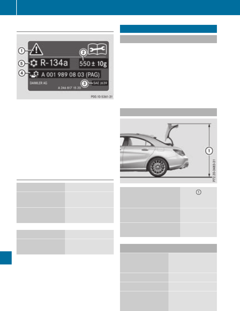
Refrigerant instructionlabel
Example:refrigerant instruction label
:Warning symbol
;Refrigerant filling capacity
=Applicablestandards
?PAG oilpartnumber
AType of refrigerant
Warning symbol :advises youabout:
RPossible dangers
RHaving service work carriedout at aqualified
specialist workshop
Fillingcapacities
Model Refrigerant
Mercedes‑AMG
vehicles
23.6 ±0.4 oz
(670 ±10g)
Allothermodels 22.9 ±0.4 oz
(650 ±10g)
Model PAG oil
All models 4.2 oz
(120 g)
Vehicle data
General notes
Please note that for the specified vehicledata:
RThe heights specified may vary as aresultof:
-Tires
-Load
-Condition of the suspension
-Optionalequipment
ROptionalequipment reduces the maximum
payload.
Dimensions and weights
Model :
Height when
opened
Mercedes‑AMGvehicles 68.0 in
(1727 mm)
All other models 68.3 in
(1737 mm)
Model
Vehicle width
including exterior
mirrors
80.0 in (2032 mm)
Wheelbase 106.3 in (2699 mm)
Turning radius 36.1 ft (11.0 m)
Turning circle,
Mercedes-AMG
vehicles
36.2 ft (11.04 m)
320 Vehicle data
Technical data

Model Vehicle length
Mercedes‑AMGvehi-
cles
184.7 in (4691 mm)
All other models 182.7 in (4640 mm)
Model Vehicle height
Mercedes‑AMGvehi-
cles
55.7 in (1416 mm)
All other models 56.5 in (1436 mm)
Model Maximum roof
load
Mercedes‑AMGvehi-
cles
220.5 lb (100 kg)
All other models 220.5 lb (100 kg)
Model Maximum trunk
load
Mercedes‑AMGvehi-
cles
220.5 lb (100 kg)
All other models 220.5 lb (100 kg)
Vehicle data 321
Technical data
Z

322

323

324
