MY18 E 63 Wagon Operators Manual
User Manual: Pdf 2018 Mercedes-Benz E-Wagon AMG E 63 S Owners Manual PDF | SERVICE MANUAL OWNERS
Open the PDF directly: View PDF ![]() .
.
Page Count: 510 [warning: Documents this large are best viewed by clicking the View PDF Link!]

Digital–inthe vehicleVehicle document walletDigital –onthe InternetDigital –asanApp
Familiarize yourself withthe con‐
tents of theOperator's Manual
directly via thevehicle's multi‐
media system (menu item "Vehi‐
cle"). Startwiththe quickguide,
discoveryour vehicle's highlights
or broaden your knowledgewith
useful tips.
Hereyou can find comprehen‐
sive informationabout operating
your vehicle and about services
and warranties in printed form.
Youcan find theOperator's Man‐
ual on theMercedes-Benz home‐
page.
The Mercedes-Benz Guides App
is available free-of-charge in
familiar App stores.
É2135842508rËÍ
2135842508
Apple®iOS AndroidTM
Order no. P213 0748 13
EditionB-2018
Part no. 213584 25 08
E-Class Wagon
Operator'sManual
Mercedes-Benz
Mercedes-Benz E-Class Wagon

Publication details
Internet
Further information about Mercedes-Benzvehi‐
cles and about Daimler AG can be found on the
following websites:
http://www.mbusa.com (USAonly)
http://www.mercedes-benz.ca (Canada only)
Editorial office
©Daimler AG:Not to be reprinted, translated or
otherwise reproduced, in whole or in part, with‐
out written permission from Daimler AG.
Vehiclemanufacturer
Daimler AG
Mercedesstrasse 137
70327Stuttgart
Germany
Symbols
In this Operator's Manual, youwill find thefol‐
lowing symbols:
&DANGER Dangerdue to notobserving
thewarning notices
Warning notices draw your attentiontohaz‐
ards that mayendanger your healthorlife, or
thehealthorlifeofothers.
#Please observe thewarning notices in
this manual.
+ENVIRONMENTAL NOTE Environmental
damage due to failuretoobserve envi‐
ronmental notes
Environmental notesinclude information on
environmentally responsible behavior or envi‐
ronmentally responsible disposal.
#Observe environmentalnotes.
*NOTE Damage to property due to failure
to observe notesonmaterial damage
Notesonmaterial damageinformyou of
riskswhichmay lead to your vehicle being
damaged.
#Observe notesonmaterial damage.
%Useful instructions or further information
that couldbehelpful to you.
XInstruction
(Qpage)Further information on atopic
Display Information in themultifunction dis‐
play/multimedia display
+Highestmenu level, whichistobe
selected in themultimedia system
*Corresponding submenus, whichare
to be selected in themultimedia sys‐
tem
*Indicates acause
As at 04.04.17

Welcome to theworld of Mercedes-Benz
Before youfirst drive off, read this Operator's
Manual carefully and familiarize yourself with
your vehicle. Foryour own safety and a longer
vehicle life, follow the instructions and warning
notices in this Operator's Manual. Disregarding
them may lead to damage to thevehicle or per‐
sonal injury.
Vehicle damage resulting from the disregard of
the instructions is not coveredby the Mercedes-
Benz Limited Warranty.
The equipment or model designation of your
vehicle may vary according to:
RModel
ROrder
RNational version
RAvailability
Mercedes-Benz reservestheright to introduce
changes in thefollowing areas:
RDesign
REquipment
RTechnical features
The equipment in your vehicle may therefore dif‐
fer from that shown in the descriptions and illus‐
trations.
The following are integral parts of thevehicle:
RDigital Operator's Manual
RPrinted Operator's Manual
RMaintenance Booklet
REquipment-dependent supplements
Keep these documents in thevehicle at all
times. If you sell thevehicle, always pass all of
the documents on to the new owner.
Mercedes-Benz USA, LLC
Mercedes-Benz Canada, Inc.
A Daimler Company
2135842508
2135842508

At aglance .................................................... 6
Cockpit ........................................................... 6
Overview of warning and indicator lamps .......8
Overhead control panel ................................ 12
Door control panel and seat adjustment ....... 14
Emergencies and breakdowns ...................... 16
DigitalOperator'sManual.........................18
Calling up the Digital Operator's Manual ...... 18
General notes............................................. 19
Protecting the environment .......................... 19
Mercedes-Benz GenuineParts ....................... 19
Operator's Manual ........................................20
Service and vehicle operation ....................... 21
Operating safety...........................................22
Declaration of conformity for wireless
vehicle components .....................................23
Diagnostics connection ................................ 24
Qualified specialist workshop ....................... 25
Correct use of thevehicle ............................25
Problems with your vehicle ........................... 25
Reporting safetydefects ...............................25
Limited Warranty .......................................... 26
QR codes fortherescue card ....................... 26
Vehicle data storage .....................................26
Copyright ...................................................... 30
Occupant safety......................................... 31
Restraint system ...........................................31
Seat belts ..................................................... 33
Airbags ......................................................... 38
PRE-SAFE®system ....................................... 45
Children in thevehicle ..................................46
Notes on pets in thevehicle .........................55
Opening and closing .................................. 57
SmartKey ...................................................... 57
Doors ............................................................ 62
Load compartment ....................................... 65
Roller sun blinds ...........................................72
Side windows ................................................ 72
Sliding sunroof .............................................. 76
Anti-theft protection .....................................81
Seats and stowing .....................................83
Notes on the correct driver's seat position ... 83
Seats ............................................................ 84
Steering wheel ..............................................97
Using the memory function ........................ 100
Stowage areas ............................................ 101
Cup holder .................................................. 115
Ashtray and cigarette lighter .......................116
Sockets ....................................................... 118
Wireless charging of the mobile phone
and connection with theexterior antenna ... 121
Installing or removing thefloor mats ..........122
Light and visibility ................................... 124
Exterior lighting ........................................... 124
Interior lighting ........................................... 128
Windshield wiper and windshield washer
system ........................................................ 130
Mirrors ........................................................ 133
Operating the sun visors ............................. 136
Infrared reflective windshield ......................137
Climate control ........................................ 138
Overview of climate control systems ..........138
Operating the climate control system ......... 139
2Contents

Drivingand parking ................................. 145
Driving ........................................................ 145
DYNAMIC SELECT switch ........................... 152
Automatic transmission .............................. 153
Refueling ..................................................... 157
Parking .......................................................159
Driving and driving safetysystems .............168
Instrument Display and on-board
computer ................................................... 216
Instrument Display overview .......................216
Overview of the buttons on thesteering
wheel ..........................................................217
Operating the on-board computer ............... 217
Setting the additional value range ............... 219
Overview of displays on the multifunc‐
tion display .................................................219
Adjusting the instrument lighting ............... 220
Menus and submenus ................................ 220
Head-up Display ......................................... 227
Voice Control System .............................. 229
Notes on operating safety.......................... 229
Operation ................................................... 229
Using theVoice Control System effec‐
tively ........................................................... 231
Essential voice commands .......................... 231
Multimedia system .................................. 242
Overview and operation .............................. 242
System settings .......................................... 250
Navigation .................................................. 262
Telephone ...................................................286
Online and Internet functions ..................... 303
Media .......................................................... 310
Radio .......................................................... 322
Sound .........................................................330
Maintenance and care ............................. 332
ASSYST PLUS service interval display ........ 332
Engine compartment .................................. 333
Cleaning and care .......................................339
Breakdown assistance ............................ 346
Emergency .................................................. 346
Flat tire ....................................................... 346
Battery (vehicle) ......................................... 352
Towstarting or towing away ....................... 357
Electrical fuses ........................................... 362
Wheels and tires ...................................... 366
Notes on noise or unusual handling char‐
acteristics ...................................................366
Regular checking of wheels and tires ......... 366
Notes on snow chains .................................367
Tire pressure .............................................. 368
Loading thevehicle .....................................373
Tire labeling ................................................ 378
Definition of termsfor tires and loading ..... 384
Changing a wheel ....................................... 386
Technical data .......................................... 396
Notes on technical data .............................. 396
Vehicle electronics .....................................396
Vehicle identification plate, VIN and
engine number ...........................................398
Operating fluids .......................................... 400
Vehicle data ................................................ 406
Contents 3

Displaymessages and warning/indi‐
cator lamps .............................................. 408
Display messages .......................................408
Warning and indicator lamps ...................... 452
Index .......................................................... 471
4Contents
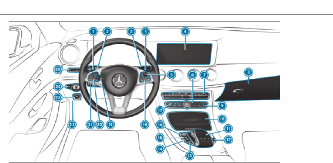
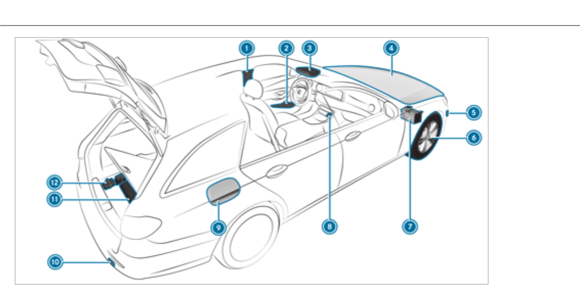
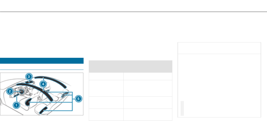
6At aglance – Cockpit

1Steering wheel gearshift paddle →155
2Combination switch →125
3DIRECT SELECT lever→153
4Display (multimedia system) →242
5Start/Stop button →146
6Control panel forthe multimedia system →242
7Climate control systems →138
8Glove box →102
9Hazard warning lights →126
AStowage compartment →102
BControl elements forthe multimedia system →242
CLowers therear seat head restraints →90
DECO start/stop function →151
EActive Parking Assist →202
FSets thevehicle level→190
GDYNAMIC SELECT switch →153
HPASSENGER AIRBAG indicator lamps →42,
IControl panel forthe multimedia system →217
JAdjusts thesteering wheel →98
KControl panel forthe on-board computer →217
LCruise control lever→175
MUnlocks the hood →333
NElectric parking brake →165
OLight switch →124
PControl panel for:
Active Steering Assist →183
Active Lane Keeping Assist →214
Parking Assist PARKTRONIC→194
Head-up Display →228
At aglance – Cockpit 7

Instrument Display (standard)
8At aglance – Overview of warning and indicator lamps

1Speedometer →216
2÷ESP®→455
3#! Turn signal light →125
4ÐSteering assistance malfunction →464
5Multifunction display →219
6!ABS malfunction →455
7;Check Engine →465
8Tachometer→216
9%This indicator lamp has no function
AElectric parking brake applied (red) →455
FUSA only
!Canada only
BBrakes (red) →455
$USA only
JCanada only
C#Electrical defect →465
D·Distance warning →463
E?Coolant too hot/cold →465
FCoolant temperature display →216
GJBrakes (yellow)→455
H!Electric parking brake (yellow)→455
I6Restraint system →32
JüSeat belt is not fastened →462
KTParking lights →124
LFuel level indicator
8Fuel reserve with fuel filler flap location
indicator
→465
MKHigh beam →125
NLLow beam →124
ORRear fog light →125
PAIR BODY CONTROL malfunctioning →463
QhTire pressure monitoring system →469
RåESP®OFF →455
At aglance – Overview of warning and indicator lamps 9
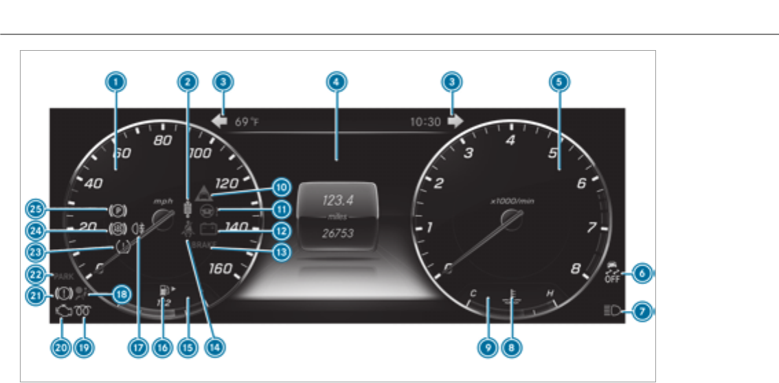
Instrument Display in theWidescreen Cockpit
10 At aglance – Overview of warning and indicator lamps

1Speedometer →216
2AIR BODY CONTROL malfunctioning →463
3#! Turn signal light →125
4Multifunction display →219
5Tachometer→216
6åESP®OFF →455
÷ESP®→455
7KHigh beam →125
LLow beam →124
TParking lights →124
8?Coolant too hot/cold →465
9Coolant temperature display →216
A·Distance warning →463
BÐSteering assistance malfunction →464
C#Electrical defect →465
DBrakes (red) →455
$USA only
JCanada only
EüSeat belt is not fastened →462
FFuel level indicator
G8Fuel reserve with fuel filler flap location
indicator
→465
HRRear fog light →125
I6Restraint system →32
J%This indicator lamp has no function
K;Check Engine →465
LJBrakes (yellow) →455
MElectric parking brake applied (red) →455
FUSA only
!Canada only
NhTire pressure monitoring system →469
O!ABS malfunction →455
P!Electric parking brake (yellow) →455
At aglance – Overview of warning and indicator lamps 11
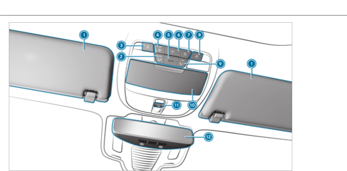
12 At aglance – Overhead control panel

1Sun visors →136
2Roadside Assistance call button (mbrace®)→302
3pSwitches the left-hand reading lamp
on/off
→128
4|Switches the automatic lighting control
on/off
→128
5SOS button (mbrace®)→301
6cSwitches the front interior lighting on/off →128
7uSwitches therear interior lighting on/off →128
8pSwitches theright-hand reading lamp
on/off
→128
9MB Info call button (mbrace®)→302
ASpectacles compartment →103
B3Opens/closes the panoramic sliding sun‐
roof
→76
Opens/closes theroller sunblinds →76
CInside rearview mirror→134
At aglance – Overhead control panel 13
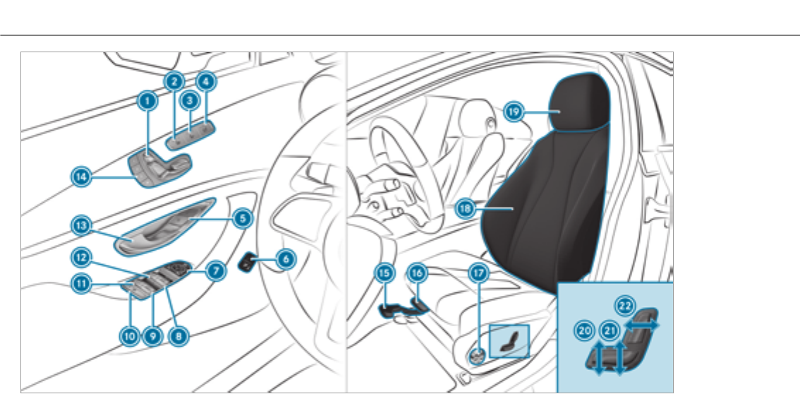
14 At aglance – Door control panel and seat adjustment

1Adjusts the seats electrically →87
2Switches the seat heating on/off →92
3Switches the seat ventilation on/off →93
4Adjusts the front passenger seat from the driv‐
er's seat
→87
5&%Locks/unlocks thevehicle →62
6Opens/closes thetailgate →65
7Adjusts and folds the outside mirrors out/in
electrically
→133
8WOpens/closes theright side window →72
9WOpens/closes therear right side window →72
AChild safetylockfortherear side windows →55
BWOpens/closes therear left side window →72
CWOpens/closes the left side window →72
DOpens the door →62
ESets the memory function →100
FSets the seat fore-and-aft position →86
GAdjusts the seat cushion length →86
HAdjusts the 4-way lumbar support →88
ISeat adjustment using the multimedia system →91
JAdjusts the head restraints →88
KAdjusts the seat cushion inclination →86
LAdjusts the seat height →86
MSets the seat backrest inclination →86
At aglance – Door control panel and seat adjustment 15
16 At aglance – Emergencies and breakdowns

What to do in theevent of an accident
1QR code for accessing therescue card →26
2Safetyvests→346
3Button forthe SOS emergency call system and
Roadside Assistance
→300
4Checking and topping up operating fluids →400
5Tow-starting and towing away →358
6Flat tire →346
7Starting assistance →354
8Hazard warning lights →126
9Fuel filler flap with instruction labels for tire
pressure, fuel type and QR code for accessing
therescue card
→157
ATow-starting and towing away →358
BTire-change tool kit →389
CTIREFIT kit →348
At aglance – Emergencies and breakdowns 17
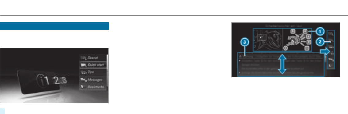
Calling up the Digital Operator's Manual
Multimedia system:
, .Õ
#Select a menu item.
In addition, you can also call up the Operator's
Manual within a main function (e.g. via
).
The Digital Operator's Manual describes the
function and operation of:
Rthevehicle
Rthe multimedia system
For safetyreasons, the Digital Operator's Man‐
ual is deactivated while driving.
The Digital Operator's Manual contains thefol‐
lowing menu items:
R: allows youto search precisely for
keywords.
R:provides you with important
information so that you can start using your
vehicle immediately.
R: provides tips on how to use your vehicle
in certain situations.
R: provides you with further informa‐
tion about the messages in the instrument
cluster.
R: provides youwith a list of all the
bookmarks you have stored yourself.
1Picture
2Menu
3Navigation window
Some sections of the Digital Operator's Manual,
e.g. warnings, can be made visible by highlight‐
ing and pressing them.
%The Operator's Manual can also be found in
the Mercedes-Benz Guides app in all com‐
mon app stores.
18 Digital Operator's Manual

Protecting the environment
+ENVIRONMENTAL NOTE Environmental
damage due to operating conditions and
personal driving style
The pollutant emission of your vehicle is
directly related to thewayyou operate your
vehicle.
You can help to protect the environment by
operating your vehicle in an environmentally
responsible manner. Please observe thefol‐
lowing recommendations on operating condi‐
tions and personal driving style.
Operating conditions:
#Make sure that the tire pressure is cor‐
rect.
#Do not carry any unnecessary weight
(e.g. roof luggage racks once you no
longer need them).
#Adhere to the service intervals.
Aregularly serviced vehicle will contrib‐
ute to environmental protection.
#Always have service work carried out at
aqualified specialist workshop.
Personal driving style:
#Do not depress the accelerator pedal
when starting the engine.
#Do not warm up the engine while the
vehicle is stationary.
#Drive carefully and maintain a suitable
distance from thevehicle in front.
#Avoid frequent, sudden acceleration
and braking.
#Change gear in good time and use each
gear only up to Ôof its maximum
engine speed.
#Switch off the engine in stationary traf‐
fic, e.g. by using the ECO start/stop
function.
#Drive in a fuel-efficient manner.
Environmental issues and recommendations:
it is recommended that youre-use or recycle
materials first instead of just disposing of them.
The relevant environmental guidelines and regu‐
lations serve to protect the environment and
must be strictly observed.
Mercedes-Benz GenuineParts
+ENVIRONMENTALNOTE Environmental
damage caused by not using recycled
reconditioned components
Daimler AG offers recycled reconditioned
components and parts with the same quality
as new parts. The same entitlement from the
Limited Warranty is valid as for new parts.
#Use recycled reconditioned compo‐
nents and parts from Daimler AG.
General notes19

*NOTE Impairment of the operating effi‐
ciency of therestraint systems from
installing accessories or from repairs or
welding
Airbags, Emergency Tensioning Devices, as
well as control units and sensors forthe
restraint systems, may be installed in thefol‐
lowing areas of your vehicle:
RDoors
RDoor pillars
RDoor sills
RSeats
RCockpit
RInstrument cluster
RCenter console
#Do not install accessories such as audio
systems in these areas.
#Do not carry out repairs or welding.
#Have accessories retrofitted at a quali‐
fied specialist workshop.
You could jeopardize the operating safetyof your
vehicle if you use parts, tires and wheels as well
as accessories relevant to safetywhichhave not
been approvedby Mercedes-Benz. Safety-rele‐
vant systems, e.g. the brake system, may mal‐
function. Only use Mercedes-Benz GenuineParts
or parts of equal quality. Only use tires, wheels
and accessory parts that have been specifically
approvedforyour vehicle model.
Mercedes-Benz GenuineParts are subject to
strict quality control. Each part has been spe‐
cially developed, manufactured or selectedfor
Mercedes-Benz vehicles and fine-tuned forthem.
Therefore, only Mercedes-Benz GenuineParts
should be used.
More than 300,000 different Mercedes-Benz
GenuineParts are available for Mercedes-Benz
models.
All authorized Mercedes-Benz Centers maintain
a supply of Mercedes-Benz GenuineParts for
necessary service and repair work. In addition,
strategically located parts-delivery centers pro‐
vide forquick and reliable parts service.
Always specify thevehicle identification number
(VIN) (→page 398) when ordering Mercedes-
Benz GenuineParts.
Operator's Manual
This Operator's Manual describes all models and
all standard and optional equipment available for
your vehicle at the time of this Operator's Man‐
ual going to press. Country-specific differences
are possible. Note that your vehicle may not be
equipped with all features described. This also
applies to safety-relevant systems and functions.
Therefore, the equipment on your vehicle may
differ from that in the descriptions and illustra‐
tions.
The original purchase contract documentation
foryour vehicle contains a list of all of the sys‐
tems in your vehicle.
Should you have any questions concerning
equipment and operation, please consult an
authorized Mercedes-Benz Center.
The Operator's Manual and Maintenance Booklet
are important documents and should be kept in
thevehicle.
20 General notes

Service and vehicle operation
Vehicle operation outside the USA or Canada
When you are abroad withyour vehicle, observe
thefollowing points:
RService points or replacement parts may not
be available immediately.
RUnleaded fuel may not be available forvehi‐
cles with a catalytic converter. Leaded fuel
may cause damage to the catalytic converter.
RThe fuel may have an extremely low octane
number. Unsuitable fuel can cause engine
damage.
Some Mercedes-Benz models are available in
Europe through our European Delivery Program.
For more information, please consult an author‐
ized Mercedes‑Benz service center, or write to
one of thefollowing address:
In the USA:
Mercedes-Benz USA, LLC
European Delivery Department
One Mercedes Drive
Montvale, NJ 07645-0350
In Canada:
Mercedes-Benz Canada, Inc.
European Delivery Department
98 Vanderhoof Avenue
Toronto, Ontario M4G 4C9
Maintenance
Your customer advisor confirms the service in
the service report.
Roadside Assistance
The Mercedes-Benz Roadside Assistance Pro‐
gram offers technical help in the case of a
breakdown. Your calls to thetoll-freeRoadside
Assistance Hotline are answeredby our agents
24 hours a day, 365 days ayear.
1-800-FOR-MERCedes (1-800-367-6372) (USA)
1-800-387-0100 (Canada)
You can find further information in the
Mercedes-Benz Roadside Assistance Program
brochure (USA) or the "Roadside Assistance"
section in the maintenance and warranty infor‐
mation booklet (Canada). Youwill find both in
thevehicle document wallet.
Change of address or change of ownership
In theevent of a change of address, please send
us the "Notification of address change" in the
Service and Guarantee booklet or simply call the
Mercedes-Benz Customer Assistance Center
(USA) on the hotline number
1-800-FOR-MERCedes (1-800-367-6372) or Cus‐
tomer Service (Canada) on 1-800-387-0100. We
can then reach you in a timely fashion, if neces‐
sary.
If you sell your Mercedes, please leave all litera‐
ture in thevehicle so that it is available to the
next owner. If you have purchased a used vehi‐
cle, please send us the "Notice of Purchase of
Used Car" in the Service and Guarantee booklet
or simply call the Mercedes-Benz Customer
Assistance Center (USA) at the hotline number
1-800-FOR-MERCedes (1-800-367-6372) or Cus‐
tomer Service (Canada) at 1-800-387-0100.
General notes21

Important notice for California retail buyers
and lessees of Mercedes-Benz automobiles
Under California law you may be entitled to a
replacement of your vehicle or a refund of the
purchase price or lease price, if after a reasona‐
ble number of repair attempts Mercedes-Benz
USA, LLC and/or its authorized repair or service
facilities fail to fix one or more substantial
defects or malfunctions in thevehicle that are
coveredby its express warranty.
During a period of 18 months from original deliv‐
ery of thevehicle or a kilometer/mileage read‐
ing of 18,000 miles (29,000 km), whichever
occurs first, vehicle repair is presumed for a
retail buyer or lessee if one or more of thefol‐
lowing occurs:
(1) the serious defect or damage can result in
deadly or serious injury to thevehicle occu‐
pants while driving AND this defect has
already been repaired at least twice AND
Mercedes‑Benz, LLC has been informed in
writing of the necessity of a repair.
(2) the defect or damage, though less serious
than (1) above, has already been repaired at
least four times AND Mercedes‑Benz has
been informed in writing of the necessity of
arepair.
(3) thevehicle cannot be used for longer than
30 calendar days because of repair work
resulting from this or other serious defects
or damage.
Please send your written notice to:
Mercedes‑Benz USA, LLC
Customer Assistance Center
3 Mercedes Drive
Montvale, NJ 07645-0350
Operating safety
&WARNING Risk of accident due to mal‐
functions or system failures
If you do not have the prescribed service/
maintenance work or any required repairs
carried out, this could result in malfunctions
or system failures.
#Always have the prescribed service/
maintenance work as well any required
repairs carried out at a qualified spe‐
cialist workshop.
&WARNING Risk of accident or injury due
to incorrect modification of electronic
components and parts
Modification to electronic components, their
software or wiring could impair their function
and/or the function of other networked com‐
ponent parts. In particular, systems relevant
to safetycould also be affected.
As a result, these may no longer function
properly and/or jeopardize the operating
safetyof thevehicle.
#Nevertamper with thevehicle's wiring,
electronic components or software.
#You should have all work on electrical
and electronic components carried out
at a qualified specialist workshop.
22 General notes

&WARNING Risk of fire due to flammable
materials on hot parts of theexhaust
system
Flammable material such as leaves, grass or
twigs may ignite if they come into contact
with hot parts of theexhaust system.
#When driving on unpavedroads or off-
road, regularly check thevehicle under‐
side.
#Remove trapped plants or other flam‐
mable material.
#If there is damage, consult a qualified
specialist workshop immediately.
*NOTE Damage to thevehicle
Damage to thevehicle may occur in thefol‐
lowing cases:
Rthevehicle becomes grounded, e.g. on a
high curb or an unpavedroad.
Rthevehicle is driven toofast over an
obstacle, e.g. a curb, speed bump or pot‐
hole.
Ra heavy object strikesthe underbody or
chassis components.
In situations such as this, the body, the
underbody, chassis components, wheels or
tires could be damaged without the damage
being visible. Components damaged in this
waycan unexpectedly fail or, in the case of
an accident, no longer withstand thestrain
they are designed to.
If the underbody paneling is damaged, flam‐
mable materials such as leaves, grass or
twigs can gather between the underbody and
the underbody paneling. These materials may
ignite if they come into contact with hot
parts on theexhaust system.
#Have thevehicle checked and repaired
immediately at a qualified specialist
workshop.
or
#If driving safetyis impaired while con‐
tinuing your journey, pull over and stop
thevehicle immediately, paying atten‐
tion to road and traffic conditions, and
contact a qualified specialist workshop.
Declaration of conformity for wireless vehi‐
cle components
USA: "The wireless devices of this vehicle com‐
ply with Part 15 of the FCC Rules. Operation is
subject to thefollowing two conditions: 1) These
devices may not cause harmful interference, and
2) These devices must accept any interference
received, including interference that may cause
undesired operation. Changes or modifications
not expressly approvedby the party responsible
for compliance could void the user's authority to
operate the equipment."
Canada: "The wireless devices of this vehicle
comply with Industry Canada license-exempt
RSS standard(s). Operation is subject to thefol‐
lowing two conditions: (1) These devices may
not cause interference, and (2) These devices
General notes23

must accept any interference, including interfer‐
ence that may cause undesired operation of the
device."
USA: "Wireless charging system for mobile devi‐
ces (Model: D-WMI2015A): this device complies
with Part 18 of the FCC Rules."
The name and address of theresponsible party
is:
Continental Automotive Systems US Inc.
2400 Executive Hills Drive
Auburn Hills, MI 48326-2980
UnitedStates of America
Diagnostics connection
The diagnostics connection is only intended for
the connection of diagnostic devices at a quali‐
fied specialist workshop.
&WARNING Risk of accident due to con‐
necting devices to the diagnostics con‐
nection
If you connect equipment to a diagnostics
connection in thevehicle, it may affect the
operation of vehicle systems.
As a result, the operating safetyof thevehi‐
cle could be affected.
#Only connect equipment to a diagnos‐
tics connection in thevehicle which is
approvedforyour vehicle by Mercedes-
Benz.
&WARNING Risk of accident due to
objects in the driver's footwell
Objects in the driver's footwell may impede
pedal travel or block a depressed pedal.
This jeopardizes the operating and road
safetyof thevehicle.
#Stow all objects in thevehicle securely
so that they cannot get into the driver's
footwell.
#Always install thefloor mats securely
and as prescribed in order to ensure
that there is always sufficient room for
the pedals.
#Do not use loose floor mats and do not
place floor mats on top of one another.
*NOTE Battery discharging from using
devices connected to the diagnostics
connection
Using devices at the diagnostics connection
drains the battery.
#Check thecharge level of the battery.
#If thecharge level is low, charge the
battery, e.g. by driving a considerable
distance.
Connecting equipment to the diagnostics con‐
nection can lead to emissions monitoring infor‐
mation being reset, forexample. This may lead
to thevehicle failing to meet therequirements of
the next emissions inspection during the main
inspection.
24 General notes
Qualified specialist workshop
An authorized Mercedes-Benz Center is a quali‐
fied specialist workshop. It has the necessary
specialist knowledge, tools and qualifications to
correctly carry out thework required on your
vehicle. This particularly applies to work relevant
to safety.
Forthefollowing, always have your vehicle
checked at an authorized Mercedes-Benz Cen‐
ter:
Rwork relevant to safety
Rservice and maintenance work
Rrepair work
Rmodifications as well as installations and
conversions
Rwork on electronic component parts
Mercedes‑Benz recommends an authorized
Mercedes‑Benz Center.
Correct use of thevehicle
If youremove any warning stickers,you or others
could fail to recognize certain dangers. Leave
warning stickers in position.
When using thevehicle, observe thefollowing
information:
Rthe safetynotes in this manual
Rtechnical data forthevehicle
Rtrafficrules and regulations
Rlaws and safetystandards pertaining to
motorvehicles
Problems with your vehicle
If you should experience a problem with your
vehicle, particularly one that you believe may
affect its safe operation, we urge youto contact
an authorized Mercedes-Benz service center
immediately to have the problem diagnosed and
rectified. If the problem is not resolved to your
satisfaction, please discuss the problem again
with the authorized Mercedes-Benz service cen‐
ter or, if necessary, contact us at one of thefol‐
lowing addresses.
In the USA:
Customer Assistance Center
Mercedes-Benz USA, LLC
3 Mercedes Drive
Montvale, NJ 07645-0350
In Canada:
Customer Relations Department
Mercedes-Benz Canada, Inc.
98 Vanderhoof Avenue
Toronto, Ontario M4G 4C9
Reporting safety defects
USA only:
The following text is published as required of
manufacturers under Title 49, Code of U.S. Fed‐
eral Regulations, Part 575 pursuant to the
"National Traffic and MotorVehicle SafetyAct of
1966".
General notes25

If youbelieve that your vehicle has a defect
which could cause a crash or could cause injury
or death, you should immediately inform the
National Highway Traffic SafetyAdministration
(NHTSA) in addition to notifying Mercedes-Benz
USA, LLC.
If NHTSA receives similar complaints, it may
open an investigation, and if it finds that a safety
defect exists in a groupof vehicles, it may order
arecall and remedy campaign. However, NHTSA
cannot become involved in individual problems
between you, your dealer, or Mercedes-Benz
USA, LLC.
To contact NHTSA,you may call theVehicle
SafetyHotlinetoll-free at 1-888-327-4236
(TTY: 1-800-424-9153) (inside the USA); go to
http://www.safercar.gov; or write to:Adminis‐
trator, NHTSA, 400 Seventh Street,SW., Wash‐
ington, DC 20590, USA.
Further information on vehicle safetycan be
found at: http://www.safercar.gov
Limited Warranty
*NOTE Damage to thevehicle arising
from violation of these operating instruc‐
tions.
Damage to thevehicle can arise from viola‐
tion of these operating instructions.
This damage is not covered either by the
Mercedes-Benz implied warranty or by the
New‑ or Used-Vehicle Warranty.
#Follow the instructions in these operat‐
ing instructions on proper operation of
your vehicle as well as on possible vehi‐
cle damage.
QR codes for the rescue card
The QR code is secured in the fuel filler flap and
on the opposite side on the B-pillar. In theevent
of an accident, rescue services can use the QR
code to quickly find the appropriate rescue card
foryour vehicle. The current rescue card con‐
tains the most important information about your
vehicle in a compact form, e.g. therouting of the
electric lines.
Further information can be obtained at http://
www.mercedes-benz.de/qr-code.
Vehicle data storage
Information from electronic control units
Your vehicle is equipped with electronic control
units. Some of these are necessary forthe safe
operation of your vehicle, while some assist you
when driving (driver assistance systems). In
addition, your vehicle provides convenience and
entertainment functions, which are also made
possible by electronic control units.
Electronic control units contain data memories
which can temporarily or permanently store
technical information about thevehicle's operat‐
ing status, component loads, maintenance
requirements and technical events or malfunc‐
tions.
26 General notes

In general, this information documents thestate
of a component part, a module, a system or the
surroundings, forexample:
Roperating statuses of system components
(e.g. fluid levels, battery status, tire pressure)
Rstatus messages concerning thevehicle and
its individual components (e.g. number of
wheel revolutions/speed, deceleration, lat‐
eral acceleration, display of thefastened seat
belts)
Rmalfunctions or defects in important system
components (e.g. lights, brakes)
Rinformation on vehicle damage events
Rsystem reactions in special driving situations
(e.g. air bag deployment, intervention of sta‐
bility control systems)
Rambient conditions (e.g. temperature, rain
sensor)
In addition to providing the actual control unit
function, this data assists the manufacturer in
detecting and rectifying malfunctions and opti‐
mizing vehicle functions. The majority of this
data is temporary and is only processed in the
vehicle itself. Only a small portion of the data is
stored in theevent or malfunction memory.
When your vehicle is serviced, technical data
from thevehicle can be read out by service net‐
work employees or third parties. Services
include repair services, maintenance processes,
warranty events and quality assurance meas‐
ures, forexample. The read out is performed via
the legally prescribed port for OBD ("on-board
diagnostics") in thevehicle. The respective
service network locations or third parties col‐
lect, process and use the data. They document
technical statuses of thevehicle, assist in find‐
ing malfunctions and improving quality and are
transmitted to the manufacturer, if necessary.
Furthermore, the manufacturer is subject to
product liability. Forthis, the manufacturer
requires technical data from vehicles.
Malfunction memories in thevehicle can be
reset by a service outlet as part of repair or
maintenance work.
They can enter data into thevehicle's conveni‐
ence and infotainment functions themselves as
part of the selected equipment.
This includes, forexample:
Rmultimedia data such as music, films or pho‐
tosfor playback in an integrated multimedia
system
Raddress book data for use in connection with
an integrated hands-free system or an inte‐
grated navigation system
Rentered navigation destinations
Rdata about the use of Internet services
This data can be stored locally in thevehicle or
is located on a device which you have connected
to thevehicle. If this data is stored in thevehi‐
cle, you can delete it at any time. This data can
only be transmittedto third parties upon your
request with particular regard to the scope of
use of online services according to your selected
settings.
You can store or change convenience settings/
individualization in thevehicle at any time.
Depending on the equipment, this includes, for
example:
Rseat and steering wheel position settings
Rsuspension and climate control settings
General notes27

Rindividualization such as interior lighting
If your vehicle is accordingly equipped, you can
connect your smartphone or another mobile end
device to thevehicle. You can controlthem via
the control elements integrated in your vehicle.
Images and audio from the smartphone can be
output via the multimedia system. Certain infor‐
mation is simultaneously transmittedto your
smartphone.
Depending on therespective integration type,
this includes, forexample:
Rgeneral vehicle information
Rposition data
This enables the use of selected smartphone
Apps, e.g. navigation or music playback. There is
no further interaction between the smartphone
and thevehicle; in particular, vehicle data is not
directly accessible. The type of further data pro‐
cessing is determined by the provider of the App
used. The respective App and your smartphone's
operating system determine whether changes
can be made to the settings and which settings
can be changed.
Service providers
Wireless network connection
If your vehicle has a wireless network connec‐
tion, it enables data to be exchanged between
your vehicle and additional systems. The wire‐
less network connection is enabled via thevehi‐
cle's transmission and reception unit or via con‐
nected mobile end devices (e.g. smartphones).
Online functions can be used via the wireless
network connection. This includes online serv‐
ices and applications/Apps provided by the
manufacturer or other providers.
Manufacturer's services
The manufacturer describes therespective func‐
tions and corresponding legal data protection
information when suitable forthe manufacturer's
online services. Personal data may be used for
the provision of online services. Data is
exchanged via a secure connection, e.g. to the
manufacturer's designated IT systems. Personal
data is collected, processed and used via the
provision of services exclusively on the basis of
legal permissions or with prior consent.
The services and functions (sometimes subject
to afee) can usually be activated or deactivated.
In some cases, this also applies to the entire
vehicle's data connection. This excludes, in par‐
ticular, legally prescribed functions and services.
Third party services
If it is possible to use online services from other
providers, these services are subject to the data
protection and terms of use of theresponsible
provider. The manufacturer has no influence on
the content exchanged.
Please enquire, therefore, about the type, scope
and purpose of the collection and use of per‐
sonal data as part of third party services from
their respective provider.
COMAND/mbrace
If thevehicle is equipped with COMAND or
mbrace, additional data about thevehicle's oper‐
ation, the use of thevehicle in certain situations,
and the location of thevehicle may be compiled
through COMAND or the mbrace system.
28 General notes

For additional information please referto the
chapter Multimedia system and/or the mbrace
Terms and Conditions.
Event Data Recorders
This vehicle is equipped with an event data
recorder (EDR). The main purpose of an EDR is
to record, in certain crash or near crash-like sit‐
uations, such as an air bag deployment or hitting
aroad obstacle, data that will assist in under‐
standing how a vehicle's systems performed.
The EDR is designed to record data related to
vehicle dynamics and safetysystems for a short
period of time, typically 30 seconds or less.
The EDR in this vehicle is designed to record
such data as:
RHow various systems in your vehicle were
operating
RWhether or not the driver and front
passenger seat belts were buckled/fastened
RHow far (if at all) the driver was depressing
the accelerator and/or brake pedal and
RHow fast thevehicle was traveling.
This data can help provide a better understand‐
ing of the circumstances in which accidents and
injuries occur. NOTE: EDR data is recorded by
your vehicle only if a non-trivial crash situation
occurs; no data is recorded by the EDR under
normal driving conditions and no personal data
(e.g. name, gender, age and crash location) is
recorded. However, other parties, such as law
enforcement, could combine the EDR data with
the type of personally identifying data routinely
acquired during a crash investigation.
Access to thevehicle and/or the EDR is needed
to read data that is recorded by an EDR, and
special equipment is required. In addition to the
vehicle manufacturer, other parties that have the
special equipment, such as law enforcement,
can read the information by accessing thevehi‐
cle or the EDR.
EDR data may be used in civil and criminal mat‐
ters as a tool in accident reconstruction, acci‐
dent claims and vehicle safety. Since the Crash
Data Retrieval (CDR) tool that is used to extract
data from the EDR is commercially available,
Mercedes-Benz USA, LLC ("MBUSA") expressly
disclaims any and all liability arising from the
extraction of this information by unauthorized
Mercedes-Benz personnel.
MBUSA will not share EDR data withothers with‐
out the consent of thevehicle owner or, if the
vehicle is leased, without the consent of the les‐
see. Exceptions to this representation include
responses to subpoenas by law enforcement; by
federal, state or local government; in connection
with or arising out of litigation involving MBUSA
or its subsidiaries and affiliates; or, as required
by law.
Warning: the EDR is a component of the
Restraint System Module. Tampering with, alter‐
ing, modifying or removing the EDR component
may result in a malfunction of theRestraint Sys‐
tem Module and other systems.
State laws or regulations regarding EDRs that
conflict with federal regulation are pre-empted.
This means that in theevent of such conflict, the
federal regulation governs. As of February 2013,
13 states have enacted laws relating to EDRs.
General notes29

Copyright
Free and open source software
Information on free and open source software
licenses foryour vehicle's software can be found
on the data storage medium in your vehicle
document wallet and on the Internet together
with updates:
http://www.mercedes-benz.com/opensource
Registered trademarks
RBluetooth®is a registered trademark of Blue‐
tooth SIG Inc.
RDTS™ is a registered trademark of DTS, Inc.
RDolby®and MLP™ are registered trademarks
of DOLBY Laboratories.
RBabySmart™, ESP®and PRE-SAFE®are reg‐
istered trademarks of Daimler AG.
RHomeLink®is a registered trademark of
Johnson Controls.
RiPod®and iTunes®are registered trademarks
of Apple Inc.
RBurmester®is a registered trademark of
BurmesterAudiosysteme GmbH.
RMicrosoft®and Windows Media®are regis‐
tered trademarks of Microsoft Corporation.
RSIRIUS®is a registered trademark of Sirius
XM Radio Inc.
RHD Radio™ is a registered trademark of iBiq‐
uity Digital Corporation.
RGracenote®is a registered trademark of
Gracenote, Inc.
RZAGATSurvey®and related brands are regis‐
tered trademarks of ZagatSurvey, LLC.
30 General notes

Restraint system
Protection by therestraint system
The restraint system includes thefollowing:
RSeat belt system
RAir bags
RChild restraint system
RChild seat securing system
The restraint system can reduce therisk of vehi‐
cle occupants coming into contact with parts of
thevehicle interior in theevent of an accident. In
theevent of an accident, therestraint system
can also reduce theforces to which thevehicle
occupants are subjected.
A seat belt can only provide the best level of pro‐
tection if it is worn correctly. Depending on the
detected accident situation, Emergency Tension‐
ing Devices and/or air bags supplement the pro‐
tection offeredby a correctly worn seat belt.
Emergency Tensioning Devices and/or air bags
are not deployed in every accident.
In order fortherestraint system to provide the
intended level of protection, each vehicle occu‐
pant must observe thefollowing information:
RFasten seat belts correctly.
RSit in an almost upright seat position with
their back against the seat backrest.
RSit with their feet resting on thefloor, if pos‐
sible.
RAlways secure persons under 5 ft (1.50 m)
tall in an additional restraint system suitable
for Mercedes-Benz vehicles.
However, no system available today can com‐
pletely eliminate injuries and fatalities in every
accident situation. In particular, the seat belt
and air bag generally do not protect against
objects penetrating thevehicle from the outside.
It is also not possible to completely rule out the
risk of injury caused by the air bag deploying.
Reduced restraint system protection
&WARNING Risk of injury or death from
modifications to therestraint system
The restraint system can no longer function
correctly after alterations have been made.
The restraint system may then not protect
thevehicle occupants as intended by failing
in an accident or triggering unexpectedly, for
example
#Never alter the parts of therestraint
system.
#Nevertamper with the wiring or any
electronic component parts or their
software.
RIf it is necessary to modify thevehicle to
accommodate a person with disabilities, con‐
tact an authorized Mercedes-Benz Center for
details.
RUSA only: for details, contact our Customer
Assistance Center on 1-800-FOR-MERCedes
(1‑800‑367‑6372).
Occupant safety31

Restraint system functionality
When the ignition is switched on, a system self-
test is performed, during which the6
restraint system warning lamp lights up. It goes
out no later than a few seconds afterthevehicle
is started. The components of therestraint sys‐
tem are then functional.
Malfunctioning restraint system
A malfunction has occurred in therestraint sys‐
tem if:
RThe 6restraint system warning lamp
does not light up when the ignition is
switched on.
RThe 6restraint system warning lamp
lights up continuously or repeatedly during a
journey.
&WARNING Risk of injury or fatal injury
due to a malfunction in therestraint sys‐
tem
If therestraint system is malfunctioning,
restraint system components may be trig‐
gered unintentionally or might not be trig‐
gered at all in theevent of an accident. This
may affect the Emergency Tensioning Device
or airbag, forexample.
#Have therestraint system checked and
repaired immediately at a qualified spe‐
cialist workshop.
Function of therestraint system in an acci‐
dent
How therestraint system works is determined by
the severity of the impact detected and the type
of accident anticipated:
RFrontal impact
RRear impact
RSide impact
RRollover
The activation thresholds forthe components of
therestraint system are determined based on
theevaluation of the sensor values measured at
various points in thevehicle. This process is pre-
emptive in nature. The triggering/deployment of
the components of therestraint system should
take place in good time at thestart of the colli‐
sion.
Factors which can only be seen and measured
after a collision has occurred cannot play a deci‐
sive role in air bag deployment, nor do they pro‐
vide an indication of air bag deployment.
The vehicle may be deformed significantly with‐
out an air bag being deployed. This is the case if
only parts which are relatively easily deformed
are affected and therate of vehicle deceleration
is not high. Conversely, an air bag may be
deployedeven though thevehicle suffers only
minor deformation. If very rigid vehicle parts
such as longitudinal members are hit, forexam‐
ple, thevehicle deceleration may be high enough
forthis to happen.
32 Occupant safety

The components of therestraint system can
be activated or deployed independently of
each other:
Component Detected deploy‐
ment situation
Emergency Tension‐
ing Devices
Frontal impact, rear
impact, side impact,
rollover
Driver's air bag, front
passenger air bag
Frontal impact
Knee air bag Frontal impact
Side air bag Side impact
Window air bagSide impact, rollover,
frontal impact
PRE-SAFE®Impulse
Side
Side impact
The front-passenger air bag can be deployed in
an accident only if thePASSENGER AIR BAG OFF
indicator lamp is off. If the front passenger seat
is occupied, make sure, both before and during
the journey, that thestatus of the front
passenger air bag is correct (→page 42).
&WARNING Risk of burns from hot air bag
components
The air bag parts are hot after an air bag has
been deployed.
#Do not touch the air bag parts.
#Have a deployed air bag replaced at a
qualified specialist workshop as soon
as possible.
Mercedes-Benz recommends that you have the
vehicle towedto aqualified specialist workshop
after an accident. Take this into account, partic‐
ularly if an Emergency Tensioning Device is trig‐
gered or an air bag is deployed.
If the Emergency Tensioning Devices are trig‐
gered or an air bag is deployed, youwill hear a
bang, and powder may also be released:
RThe bang will not generally affect your hear‐
ing.
RIn general, the powder released is not haz‐
ardous to health but may cause short-term
breathing difficulties to persons suffering
from asthma or other pulmonary conditions.
Provided it is safe to do so, leave thevehicle
immediately or open the window in order to
prevent breathing difficulties.
Air bags and pyrotechnic Emergency Tensioning
Devices contain perchlorate material, which may
require special handling or environmental pro‐
tection measures. National guidelines must be
observed during disposal. In California, see
http://www.dtsc.ca.gov/HazardousWaste/
Perchlorate/index.cfm.
Seat belts
Protection provided by the seat belt
Alwaysfasten your seat belt correctly before
starting a journey. A seat belt can only provide
the best level of protection if it is worn correctly.
Occupant safety33

&WARNING Risk of injury or death due to
incorrectly fastened seat belt
If the seat belt is not worn correctly, it can‐
not perform its intended protective function.
In addition, an incorrectly fastened seat belt
can also cause injuries, forexample, in the
event of an accident or when braking or
changing direction suddenly.
#Always ensure that all vehicle occu‐
pants have their seat belts fastened
correctly and are sitting properly.
In order forthe correctly worn seat belt to pro‐
vide the intended level of protection, each vehi‐
cle occupant must observe thefollowing infor‐
mation:
RThe seat belt must not be twisted and must
fit tightly and snuglyacross the body.
RThe seat belt must be routed across the cen‐
ter of the shoulder and as low down across
the hips as possible.
RThe shoulder section of the seat belt should
not touch your neck nor be routed under
your arm or behind your back.
RAvoid wearing bulky clothing, e.g. a winter
coat.
RPush the lap belt down as far as possible
across your hips and pull tight with the shoul‐
der section of the belt. Neverroute the lap
belt across your abdomen.
RNeverroute the seat belt across sharp, poin‐
ted, abrasive or fragile objects.
ROnly one person should use each seat belt at
any one time. Never allow babies and chil‐
dren to travel sitting on the lap of another
vehicle occupant.
RNever secure objects with a seat belt if the
seat belt is also being used by one of the
vehicle's occupants. Always observe the
instructions for loading thevehicle when
securing objects, luggage or loads
(→page 101).
Also ensure that no objects, e.g. a cushion,
are ever placed between a person and the
seat.
The seat belts on thefollowing seats are equip‐
ped with a child seat safetyfeature:
RFront passenger seat
RRear seats
The seat belts forthefolding bench seat in the
cargo compartment are not equipped with a
child seat safetyfeature.
Activate or deactivate thechild seat safetyfea‐
ture of the seat belt (→page 48).
If children are traveling in thevehicle, be sure to
observe the instructions and safetynotes on
"Children in thevehicle" (→page 46).
Reduced seat belt protection
&WARNING Risk of injury or death due to
incorrect seat position
The seat belt does not offerthe intended
level of protection if you have not movedthe
seat backrest to an almost vertical position.
When braking or in theevent of an accident,
you could slide underneath the seat belt and
34 Occupant safety

sustain abdominal or neck injuries, forexam‐
ple.
#Adjust the seat properly before begin‐
ning your journey.
#Always ensure that the seat backrest is
in an almost vertical position and that
the shoulder section of your seat belt is
routed across the center of your shoul‐
der.
&WARNING Risk of injury or death when
additional restraint systems are not used
for persons with a smaller build
Persons under 5 ft (1.50 m) tall cannot wear
the seat belt correctly without a suitable
additional restraint system.
If the seat belt is not worn correctly, it can‐
not perform its intended protective function.
In addition, an incorrectly fastened seat belt
can also cause injuries, forexample, in the
event of an accident or when braking or
changing direction suddenly.
#Always secure persons under 5 ft
(1.50 m) tall in a suitable restraint sys‐
tem.
&WARNING Risk of injury or death due to
blocked seat belt buckle or seat belt
anchorage
Objects next to the front seat that block the
seat belt buckle or the moving seat belt
anchorage on the front seat impair the func‐
tion of the Emergency Tensioning Devices.
The Emergency Tensioning Devices can,
then, not function as intended and the seat
belt can no longer provide the intended pro‐
tection.
#Before starting the journey, make sure
that there are no objects around the
seat belt buckle or between the front
seat and door.
&WARNING Risk of injury or death due to
damaged or modified seat belts
Seat belts cannot provide protection in the
following situations:
RIf the seat belts are damaged, modified,
extremely dirty, bleached or dyed
RIf the seat belt buckle is damaged or
extremely dirty
RIf the Emergency Tensioning Devices,
seat belt anchorages or seat belt retrac‐
tors have been modified
Seat belts may be damaged in an accident,
although the damage may not be visible, e.g.
due to splinters of glass.
Modified or damaged seat belts may tear or
fail, e.g. in an accident.
Modified Emergency Tensioning Devices can
accidentally trigger or fail to function as
intended.
#Never modify the seat belts, Emergency
Tensioning Devices, seat belt ancho‐
rages or seat belt retractors.
Occupant safety 35
#Make sure that the seat belts are
undamaged, not worn and clean.
#Always have the seat belts checked
immediately after an accident at a
qualified specialist workshop.
Only use seat belts that have been approvedfor
your vehicle by Mercedes-Benz.
&WARNING Risk of injury or death from
deployedpyrotechnic Emergency Ten‐
sioning Devices
Pyrotechnic Emergency Tensioning Devices
that have been deployed are no longer opera‐
tional and are unable to perform their inten‐
ded protective function.
#Therefore, have deployedpyrotechnic
Emergency Tensioning Devices immedi‐
ately replaced at a qualified specialist
workshop.
Mercedes-Benz recommends that you have the
vehicle towedto aqualified specialist workshop
after an accident.
*NOTE Damage caused by trapping the
seat belt
If an unused seat belt is not fully retracted, it
may become trapped in the door or in the
seat mechanism.
#Always ensure that an unused seat belt
is fully retracted.
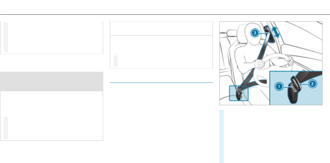
Fastening and adjusting the seat belts
If the seat belt is pulled quickly or sharply, the
seat belt retractor locks. The seat belt strap can‐
not be pulled out any further.
#Always engage seat belt tongue 2of the
seat belt into seat belt buckle 1of the cor‐
responding seat.
#Press and hold the seat belt outlet release
and slide seat belt outlet 3into the desired
position.
#Let go of the seat belt outlet release and
ensure that seat belt outlet 3locks into
position.
36 Occupant safety

Vehicles with PRE-SAFE®:If the front seat belt
is not pulled tight across your body,the seat belt
adjustment may automatically apply a certain
tightening force. Do not hold the seat belt tightly
while it is adjusting. You can activate and deacti‐
vate the seat belt adjustment function using the
multimedia system.
Vehicles with automatic front passenger
front air bag shutoff:
*NOTE Deployment of the Emergency
Tensioning Device and side air bag when
the front passenger seat is unoccupied
If the seat belt tongue is engaged in the seat
belt buckle of the unoccupied front
passenger seat, the Emergency Tensioning
Device and the side air bag may also deploy
in theevent of an accident along with other
systems.
#Only one person should use each seat
belt at any one time.
Vehicles without automatic front passenger
front air bag shutoff:
*NOTE Deployment of the Emergency
Tensioning Device when the front
passenger seat is unoccupied
If the seat belt tongue is engaged in the seat
belt buckle of the unoccupied front
passenger seat, the Emergency Tensioning
Device may also deploy in theevent of an
accident along with other systems.
#Only one person should use each seat
belt at any one time.
Releasing seat belts
#Press therelease button in the seat belt
buckle and guide the seat belt back with the
seat belt tongue.
Activating or deactivating seat belt adjust‐
ment via the multimedia system
Multimedia system:
, .î .
#Activate Oor deactivate ªthe function.
Seat belt warning function for the driver and
front passenger
The üseat belt warning lamp in the Instru‐
ment Display is a reminder that all vehicle occu‐
pants must wear their seat belts correctly.
The üseat belt warning lamp lights up for six
seconds afterevery engine start.
In addition, an acoustic warning tone may sound.
When the driver's and front passenger doors are
closed and the driver and front passenger have
fastened their seat belts, the seat belt warning
goes out.
Occupant safety37
During a journey,the seat belt warning lights up
if:
RThe vehicle speed exceeds 15 mph
(25 km/h) and the driver's or front
passenger seat belt is not fastened.
RThe driver or front passenger unfastens their
seat belt while thevehicle is in motion.
Airbags
Overview of air bags
1Knee air bag
2Driver's air bag
3Front passenger front air bag
4Window curtain air bag
5Side impact air bag
The installation location of an air bag is identi‐
fied by the AIRBAG symbol.
When activated, an air bag can provide addi‐
tional protection for the respective vehicle
occupant.
AIRBAG Potential protection for
…
Knee air bag Thigh, knee and lower leg
Driver's air bag,
front passenger
front air bag
Head and ribcage
Window curtain
air bag
Head
Side impact air
bag
Ribcage, also pelvis for
front seat occupants
The front passenger front air bag can only be
deployed in an accident if thePASSENGER AIR
BAG OFF indicator lamp is off. If the front
passenger seat is occupied, make sure, both
before and during the journey, that thestatus of
the front passenger air bag is correct
(→page 42).
*NOTE Important points to remember if
the front passenger seat is unoccupied
In an accident, the components of the
restraint system may deploy unnecessarily
on the front passenger side if:
RThere are heavy objects on the front
passenger seat.
RThe seat belt tongue is engaged in the
seat belt buckle of the front passenger
seat and the front passenger seat is
unoccupied.
#Stow objects in a suitable place.
#Only one person should use each seat
belt at any one time.
38 Occupant safety

Protection by the air bags
Depending on the accident situation, an air bag
may supplement the protection offeredby a cor‐
rectly fastened seat belt.
&WARNING Risk of injury or death due to
incorrect seat position
If youdeviate from the correct seat position,
the air bag cannot perform its intended pro‐
tective function and deployment may even
cause further injuries.
To avoid hazardous situations, always make
sure that all vehicle occupants:
RHave their seat belt fastened correctly,
including pregnant women.
RAre seated properly and that distance to
the air bags is as large as possible.
RObserve thefollowing information.
#Always make sure that there are no
objects between the air bag and the
vehicle occupant.
To avoid therisks resulting from the deployment
of an air bag, each vehicle occupant must
observe thefollowing information:
RBefore starting your journey, adjust your seat
correctly;the driver's seat and front
passenger seat should be moved as far back
as possible.
When doing so, always observe the informa‐
tion on the correct driver's seat position
(→page 83).
ROnly hold thesteering wheel by thesteering
wheel rim. This allowsthe air bag to be fully
deployed.
RAlways lean against the seat backrest when
thevehicle is in motion. Do not lean forwards
or against the door or side window. You may
otherwise be in the deployment area of the
air bags.
RAlwayskeep your feet on thefloor. Do not
put your feet on the cockpit, forexample.
Your feet may otherwise be in the deploy‐
ment area of the air bag.
RIf children are traveling in thevehicle,
observe the additional notes (→page 46).
RAlwaysstow and secure objects correctly.
Objects in thevehicle interior may prevent an air
bag from functioning correctly. Each vehicle
occupant must always make sure of thefollow‐
ing:
RThere are no people, animals or objects
between thevehicle occupants and an air
bag.
RThere are no objects between the seat, door
and door pillar (B-pillar).
RThere are no hard objects, e.g. coat hangers,
hanging on the grab handles or coat hooks.
RThere are no accessory parts, such as cup
holders, attached to thevehicle within the
deployment area of an air bag, e.g. on doors,
side windows or side trim.
RThere are no heavy, sharp-edged or fragile
objects in the pockets of your clothing. Store
such objects in a suitable place.
Occupant safety39

Reduced air bag protection
&WARNING Risk of injury from modifica‐
tions to the airbag cover
If you modify an airbag cover or affix objects
such as stickers to it, the airbag can no lon‐
ger function correctly.
#Never modify an airbag cover and do
not affix objects to it.
The installation location of an air bag is identi‐
fied by the AIRBAG symbol (→page 38).
&WARNING Risk of injury or death due to
the use of unsuitable seat covers
Unsuitable seat covers can obstruct or pre‐
vent the deployment of air bags integrated
into the seats.
Consequently, the air bags cannot protect
vehicle occupants as they are designed to
do. In addition, operation of the automatic
front passenger air bag shutoff may be
restricted.
#You should only use seat covers that
have been approved forthe correspond‐
ing seats by Mercedes-Benz.
&WARNING Risk of injury due to malfunc‐
tions of the sensors in the door paneling
Sensors to control the airbags are located in
the doors. Modifications or work not per‐
formed correctly to the doors or door panel‐
ing, as well as damaged doors, can lead to
the function of the sensors being impaired.
The airbags might therefore not function
properly any more.
Consequently,the airbags cannot protect
vehicle occupants as they are designed to
do.
#Never modify the doors or parts of the
doors.
#Always have work on the doors or door
paneling carried out at a qualified spe‐
cialist workshop.
&WARNING Risk of injury due to deployed
airbag
A deployed airbag no longer has a protective
function and cannot protect as intended in
theevent of an accident.
#Have thevehicle towedto aqualified
specialist workshop in order to have the
deployed airbag replaced.
Have deployed air bags replaced immediately.
Status of the front passenger airbag
Function of the front passenger front air bag
shutoff
The automatic front passenger front air bag
shutoff is able to detect whether the front
passenger seat is occupied by a person or a
child restraint system. The front passenger air
bag is enabled or deactivated accordingly.
40 Occupant safety

When installing a child restraint system to the
front passenger seat, always make sure of the
following:
REnsure that thechild restraint system is posi‐
tioned correctly (→page 46).
RAlways observe thechild restraint system
manufacturer's installation instructions.
RNever place objects, e.g. cushions, under or
behind thechild restraint system.
RFully retract the seat cushion length adjust‐
ment.
RThe entire base of thechild restraint system
must alwaysrest on the sitting surface of the
front passenger seat.
RThe backrest of theforward-facing child
restraint system must, as far as possible, be
resting on the seat backrest of the front
passenger seat.
RThe child restraint system must not touch the
roof or be put under strain by the head
restraints. Adjust the seat backrest inclina‐
tion and the head restraint setting accord‐
ingly.
&WARNING Risk of injury or death due to
objects between the sitting surface and
thechild restraint system
Objects between the sitting surface and the
child restraint system could affect the func‐
tion of the automatic front passenger airbag
shutoff.
This could result in the front passenger air‐
bag not functioning as intended during an
accident.
#Do not place any objects between the
sitting surface and thechild restraint
system.
#The entire base of thechild restraint
system must alwaysrest on the sitting
surface of the front passenger seat.
#The backrest of theforward-facing child
restraint system must lie as flat as pos‐
sible against the backrest of the front
passenger seat.
#Always comply with thechild restraint
system manufacturer's installation
instructions.
A person on the front passenger seat must
observe thefollowing information:
RFasten seat belts correctly.
RSit in an almost upright seat position with
their back against the seat backrest.
RSit with their feet resting on thefloor, if pos‐
sible.
Otherwise, the front passenger air bag may be
deactivated by mistake,forexample in thefol‐
lowing situations:
RThe front passenger transfers their weight by
supporting themselves on a vehicle armrest.
RThe front passenger sits in such a waythat
their weight is raised from the sitting sur‐
face.
&WARNING Risk of injury or death due to
deactivated front passenger airbag
If thePASSENGER AIR BAG OFF indicator
lamp is lit, the front passenger airbag is disa‐
bled. It will not be deployed in theevent of
an accident and cannot perform its intended
protective function.
Occupant safety41

A person in the front passenger seat could
then, forexample, come into contact with
thevehicle interior, especially if the person is
sitting too close to the cockpit.
If the front passenger seat is occupied,
always ensure that:
RThe classification of the person in the
front passenger seat is correct and the
front passenger airbag is enabled or disa‐
bled in accordance with the person in the
front passenger seat.
RThe front passenger seat has been moved
as far back as possible.
RThe person is seated correctly.
#Ensure, both before and during the jour‐
ney, that thestatus of the front
passenger airbag is correct.
Function of thePASSENGER AIR BAG indica‐
tor lamps
System self-test
When the ignition is switched on, a system self-
test is performed during which the two
PASSENGER AIR BAG ON and OFF indicator
lamps light up simultaneously.
The status of the front passenger air bag is dis‐
played afterthe system self-test:
RPASSENGER AIR BAG ON lights up for
60 seconds, subsequently both PASSENGER
AIR BAG ON and OFF indicator lamps are off:
the front passenger air bag is able to deploy
in theevent of an accident.
RPASSENGER AIR BAG OFF lights up continu‐
ously: the front passenger air bag is deactiva‐
ted. It will then not be deployed in theevent
of an accident.
If thePASSENGER AIR BAG ON indicator lamp is
off, only thePASSENGER AIR BAG OFF indicator
lamp shows thestatus of the front passenger air
bag. The PASSENGER AIR BAG OFF indicator
lamp may be lit continuously or be off.
If thePASSENGER AIR BAG OFF indicator lamp
and the6restraint system warning lamp
light up simultaneously, the front passenger seat
may not be used. Also in this case, do not install
achild restraint system on the front passenger
seat. Have the automatic front passenger air bag
shutoff checked and repaired immediately at a
qualified specialist workshop.
42 Occupant safety

Status display
If the front passenger seat is occupied, ensure,
both before and during the journey, that thesta‐
tus of the front passenger air bag is correct for
the prevailing situation.
After installing a rearward-facing child
restraint system to the front passenger
seat: PASSENGER AIR BAG OFF must be lit con‐
tinuously.
&WARNING Risk of injury or death from
using a rearward-facing child restraint
system when the front passenger air bag
is enabled
If you secure a child in a rearward-facing
child restraint system on the front passenger
seat and thePASSENGER AIR BAG OFF indi‐
cator lamp is off, the front passenger air bag
can deploy in theevent of an accident.
The child could be struck by the air bag.
Always ensure that the front passenger air
bag is disabled. The PASSENGER AIR BAG
OFF indicator lamp must be lit.
NEVER use a rearward facing child restraint
on a seat protected by an ACTIVE FRONT AIR
BAG in front of it; DEATH or SERIOUS INJURY
to thechild can occur.
When installing a child restraint system to the
front passenger seat, observethevehicle-spe‐
cific information .
Depending on thechild restraint system and the
stature of thechild, thePASSENGER AIR BAG
OFF indicator lamp may be off. In this case, do
not fittherearward-facing child restraint system
to the front passenger seat.
Instead, fittherearward-facing child restraint
system to a suitable rear seat.
After installing a forward-facing child
restraint system to the front passenger
seat: depending on thechild restraint system
and thestature of thechild, PASSENGER AIR
BAG OFF may be lit continuously or be off.
Always observe thefollowing information.
&WARNING Risk of injury or death due to
incorrect positioning of theforward-
facing child restraint system
If you secure a child in a forward-facing child
restraint system on the front passenger seat
and you position the front passenger seat too
close to the cockpit, in theevent of an acci‐
dent, thechild could:
RCome into contact with thevehicle inte‐
rior if thePASSENGER AIR BAG OFF indi‐
cator lamp is lit, forexample.
RBe struck by the air bag if the
PASSENGER AIR BAG OFF indicator lamp
is off.
#Always move the front passenger seat
as far back as possible and fully retract
the seat cushion length adjustment.
Always make sure that the shoulder belt
strap is correctly routed from the seat
belt outlet on thevehicle to the shoul‐
der belt guide on thechild restraint sys‐
tem. The shoulder belt strap must be
routed forwards and downwards from
Occupant safety43

thevehicle belt outlet. If necessary,
adjust the seat belt outlet and the front
passenger seat accordingly.
#Always observe thechild restraint sys‐
tem manufacturer's installation instruc‐
tions.
When installing a child restraint system to the
front passenger seat, observethevehicle-spe‐
cific information .
If a person is sitting in the front passenger
seat: PASSENGER AIR BAG OFF may be lit con‐
tinuously or be off, depending on the person's
stature.
A person on the front passenger seat must
always observe thefollowing information:
RIf the front passenger seat is occupied with
an adult or a person with a stature corre‐
sponding to that of an adult, thePASSENGER
AIR BAG OFF indicator lamp must be off. This
indicates that the front passenger air bag is
enabled.
If thePASSENGER AIR BAG OFF indicator
lamp is lit continuously, an adult or person
with a build corresponding to that of an adult
should not use the front passenger seat.
Instead, they should use a rear seat.
RIf the front passenger seat is occupied by a
person of smaller stature (e.g. a teenager or
small adult), thePASSENGER AIR BAG OFF
indicator lamp either lights up continuously
or remains off, depending on theresult of the
classification.
-PASSENGER AIRBAG OFF is off: move the
front passenger seat as far back as possi‐
ble or a person of smaller stature should
use a rear seat.
-If thePASSENGER AIRBAG OFF indicator
lamp is lit continuously: a person of
smaller stature should not use the front
passenger seat.
&WARNING Risk of injury or death when
thePASSENGER AIR BAG OFF indicator
lamp is lit
If thePASSENGER AIR BAG OFF indicator
lamp remains lit afterthe system self-test,
the front passenger air bag is deactivated. It
will not be deployed in theevent of an acci‐
dent. In this case, the front passenger air bag
cannot perform its intended protective func‐
tion, e.g. when a person is seated in the front
passenger seat.
That person could, forexample, come into
contact with thevehicle interior, especially if
the person is sitting too close to the cockpit.
If the front passenger seat is occupied,
always ensure that:
RThe classification of the person in the
front passenger seat is correct and the
front passenger air bag is enabled or
deactivated in accordance with the per‐
son in the front passenger seat.
RThe person is seated properly with a cor‐
rectly fastened seat belt.
RThe front passenger seat has been moved
as far back as possible.
Further related subjects:
RChild restraint system on the front passenger
seat (→page 53).
44 Occupant safety

PRE-SAFE®system
PRE-SAFE®(Pre-Crash Safety-System)
PRE-SAFE®is able to detect certain critical driv‐
ing situations and implement pre-emptive meas‐
ures to protect thevehicle occupants.
PRE-SAFE®can implement thefollowing meas‐
ures independently of each other:
RTightening the seat belts on the driver's seat
and front passenger seat.
RClosing the side windows.
RVehicles with sliding sunroof: closing the
sliding sunroof.
RVehicles with memory function: moving
the front passenger seat to a more favorable
seat position.
RVehicles with multicontour seat: increas‐
ing the air pressure in the seat side bolsters
of the seat backrest.
RPRE-SAFE®Sound: provided that the multi‐
media system is switched on, generates a
brief noise signal to stimulate the innate pro‐
tective mechanism of a person's hearing.
*NOTE Damage caused by objects in the
footwell or behind the seat
The automatic adjustment of the seat posi‐
tion may result in damage to the seat and/or
the object.
#Stow objects in a suitable place.
Reversing the PRE-SAFE®system measures
If an accident did not occur, the pre-emptive
measures that were taken are reversed.
Youwill need to perform certain settings your‐
self.
#If the seat belt pre-tensioning is not reduced,
move the seat backrest back slightly.
The locking mechanism releases.
Function of PRE-SAFE®PLUS (anticipatory
occupant protection plus)
PRE-SAFE®PLUS can detect certain impacts,
particularly an imminent rear impact, and take
pre-emptive measures to protect thevehicle
occupants. These measures cannot necessarily
prevent an imminent impact.
PRE-SAFE®PLUS can implement thefollowing
measures independently of each other:
RTightening the seat belts on the driver's seat
and front passenger seat.
RIncreasing brake pressure when thevehicle
is stationary. This brake application is can‐
celed automatically when thevehicle pulls
away.
If an accident did not occur, the pre-emptive
measures that were taken are reversed.
System limitations
The system will not initiate any action in thefol‐
lowing situations:
Rwhen reversing
The system will not initiate any braking applica‐
tion in thefollowing situations:
Rwhilst driving
or
Occupant safety45
Rwhen entering or exiting a parking space
while using Active Parking Assist
Information on PRE-SAFE®Impulse Side
If an imminent side impact is detected, PRE-
SAFE®Impulse Side can pre-emptively move the
front-seat vehicle occupant's upper body
towardsthe center of thevehicle. It does this by
rapidly inflating an air cushion in the outer seat
side bolster of the seat backrest on the side on
which the impact is anticipated. This increases
the distance between the door and thevehicle
occupant.
If PRE-SAFE®Impulse Side has been deployed or
is defective, the
display message is
shown (→page 409).
Children in thevehicle
Notes on the safe transportation of children
&WARNING Risk of accident and injury
due to children left unattended in the
vehicle
If you leave children unaccompanied in the
vehicle, they may be able to set thevehicle in
motion, forexample by:
RReleasing the parking brake.
RShifting the transmission out of park
position j.
RStarting the engine.
In addition, they may operate vehicle equip‐
ment.
#Never leave children and animals unat‐
tended in thevehicle.
#When leaving thevehicle, alwaystake
the SmartKey with you and lock the
vehicle.
&WARNING Risk of fatal injury due to
exposure to extreme heat or cold in the
vehicle
If people – particularly children – are
exposed to extreme heat or cold over an
extended period of time, there is a risk of
injury or evenfatal injury.
#Never leave anyone – particularly chil‐
dren – unattended in thevehicle.
&WARNING Risk of burns when thechild
seat is exposed to direct sunlight
If thechild restraint system is exposed to
direct sunlight or heat, parts could heat up.
Children could suffer burns from these parts,
particularly on metallic parts of thechild
restraint system.
#Always make sure that thechild
restraint system is not exposed to
direct sunlight.
#Protect it with a blanket,forexample.
46 Occupant safety

#If thechild restraint system has been
exposed to direct sunlight, allow it to
cool before securing a child into it.
#Never leave children unattended in the
vehicle.
The use of seat belts and child restraint systems
is required by law in:
RAll 50 states
RThe U.S. territories
RThe District of Columbia
RAll Canadian provinces
All child restraint systems must meet thefollow‐
ing standards:
RU.S. Federal MotorVehicle SafetyStandards
213 and 225
RCanadian MotorVehicle SafetyStandards
213 and 210.2
You can obtain further information about the
correct child restraint system from any author‐
ized Mercedes-Benz Center.
To improve protection forchildren younger than
12 years old or under 5 ft (1.50 m) in height,
Mercedes-Benz recommends you observethe
following information:
ROnly secure children using a child restraint
system which is appropriate to the height,
age and weight of thechild and suitable for
Mercedes-Benz vehicles. Be sure to observe
the instructions for correct use of thechild
restraint system.
RAlways install a child restraint system on a
rear seat if possible.
ROnly use thefollowing securing systems for
child restraint systems:
-the seat belt system
-theLATCH-type (ISOFIX) mounting brack‐
ets
-theTopTether anchorages
RThe manufacturer's installation instructions
forthechild restraint system.
RThe warning labels in thevehicle interior and
on thechild restraint system.
&WARNING Risk of injury or death caused
by incorrect installation of thechild
restraint system
If thechild restraint system is incorrectly
installed on a suitable seating position, it
cannot perform its intended protective func‐
tion.
The child cannot be restrained in theevent of
an accident, heavy braking or a sudden
change of direction.
#Always comply with the manufacturer's
installation instructions forthechild
restraint system and its correct use.
#Make sure that the entire base of the
child restraint system alwaysrests on
the sitting surface of the seat.
#Never place objects under or behind
thechild restraint system, e.g. cush‐
ions.
#Always use child restraint systems with
the original cover designed forthem.
#Alwaysreplace damaged covers with
genuine covers.
Occupant safety47

&WARNING Risk of accident caused by
incorrectly installed child restraint sys‐
tems
If thechild restraint system is not correctly
installed or secured, it could release in the
event of an accident, sudden braking or a
sudden change in direction.
The child restraint system could be flung
around and hit vehicle occupants. This poses
an increased risk of injury or even fatal
injury.
#Always install child restraint systems
correctly, even when not in use.
#Always comply with thechild restraint
system manufacturer's installation
instructions.
&WARNING Risk of injury or death caused
by the use of damaged child restraint
systems
Child restraint systems or their retaining sys‐
tems that have been subjectedto a load in
an accident may then not be able to perform
their intended protective function.
The child cannot be restrained in theevent of
an accident, heavy braking or a sudden
change of direction.
#Alwaysreplace child restraint systems
immediately that have been damaged or
involved in an accident.
#Have the securing systems forthechild
restraint systems checked at a qualified
specialist workshop before installing a
child restraint system again.
A booster seat may be necessary to achieve
proper seat belt positioning forchildren over
40 lbs (18 kg) in weight or until they reach a
height where a three-point seat belt can be fitted
properly without a booster seat.
The following notes must be observed:
RWhen installing a child restraint system on
the front passenger seat, the information on
installing a child restraint system on the front
passenger seat (→page 53).
RInstructions and safetynotes on the auto‐
matic front passenger airbag shutoff
(→page 40).
RSafetynotes on the seat belt (→page 33).
RInformation on the correct use of the seat
belt (→page 37).
Activating/deactivating the child seat safety
feature of the seat belt
&WARNING Risk of injury or death if a
seat belt is unfastened while thevehicle
is in motion
If the seat belt is released while thevehicle is
in motion, thechild restraint system is no
longer correctly secured. The child seat
safetyfeature is deactivated and the seat
belt is drawn in a bit by the inertia reel.
It is therefore not possible to engage the seat
belt again.
#Pull over and stop thevehicle safely as
soon as possible, paying attention to
road and traffic conditions.
48 Occupant safety

#Activate thechild seat safetyfeature
again and correctly secure thechild
restraint system.
When enabled, thechild seat safetyfeature
ensures that the seat belts of the front
passenger seat and rear seats do not slacken
once thechild restraint system is secured.
Installing a child restraint system:
#Always comply with the manufacturer's
installation instructions when installing and
removing thechild restraint system.
#Pull the seat belt smoothly from the seat belt
outlet.
#Engage the seat belt tongue in the seat belt
buckle.
Activating the child seat safetyfeature:
#Pull the seat belt out fully and let the inertia
reel retract it again.
When thechild seat safetyfeature is activa‐
ted,you should hear a ratcheting sound.
#Push thechild restraint system down until
the seat belt sits tightly.
Deactivating the child seat safetyfeature:
#Press therelease button of the seat belt
buckle.
#Hold the seat belt tongue and guide it back
to the seat belt outlet.
LATCH-type (ISOFIX) child seat attachment
Notes on LATCH-type (ISOFIX) child seat
attachments
&WARNING Risk of‑ injury or death if the
maximum permissible gross mass for
using a LATCH-type (ISOFIX) child
restraint system is exceeded
ForLATCH-type (ISOFIX) child restraint sys‐
tems in which thechild is secured using the
integrated seat belt integrated in thechild
restraint system, the permissible gross mass
of thechild and child restraint system is
73 lb (33 kg).
If thechild and thechild restraint system
together weigh more than 73 lb (33 kg), the
LATCH-type (ISOFIX) child restraint system
with integrated seat belt does not offer suffi‐
cient protection. An excessive load may be
placed on theLATCH-type (ISOFIX) child seat
attachments and thechild may not be
restrained in theevent of an accident, for
example.
#If thechild and thechild restraint sys‐
temtogether weigh more than 73 lb
(33 kg), only use a LATCH-type (ISOFIX)
child restraint system which secures
thechild with thevehicle seat belt.
#Also secure thechild restraint system
with theTopTether belt, if available.
Always comply with the information about the
mass of thechild restraint system:
Rin the manufacturer's installation and operat‐
ing instructions forthechild restraint system
used
Ron a label on thechild restraint system, if
present
Occupant safety49
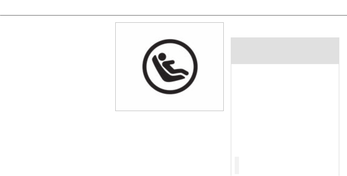
Regularly check that the permissible gross mass
of thechild and child restraint system is still
being adhered to.
When using a child restraint system, be sure to
observe the manufacturer's installation and
operating instructions as well as its correct use
and the suitability of the seats for attaching a
child restraint system.
ISOFIX is a standardized securing system for
specially designed restraint systems. LATCH-
type (ISOFIX) child restraint systems are
approved in accordance with ECE R44.
Only child restraint systems that have been
approved in accordance with ECE R44 may be
attached to LATCH-type (ISOFIX) mounting
brackets. Symbol forfitting a LATCH-type (ISOFIX) child
restraint system
Installing LATCH-type (ISOFIX) child seat
attachments
&WARNING Risk of‑ injury or death if the
maximum permissible gross mass for
using a LATCH-type (ISOFIX) child
restraint system is exceeded
ForLATCH-type (ISOFIX) child restraint sys‐
tems in which thechild is secured using the
integrated seat belt integrated in thechild
restraint system, the permissible gross mass
of thechild and child restraint system is
73 lb (33 kg).
If thechild and thechild restraint system
together weigh more than 73 lb (33 kg), the
LATCH-type (ISOFIX) child restraint system
with integrated seat belt does not offer suffi‐
cient protection. An excessive load may be
placed on theLATCH-type (ISOFIX) child seat
attachments and thechild may not be
restrained in theevent of an accident, for
example.
#If thechild and thechild restraint sys‐
temtogether weigh more than 73 lb
(33 kg), only use a LATCH-type (ISOFIX)
50 Occupant safety
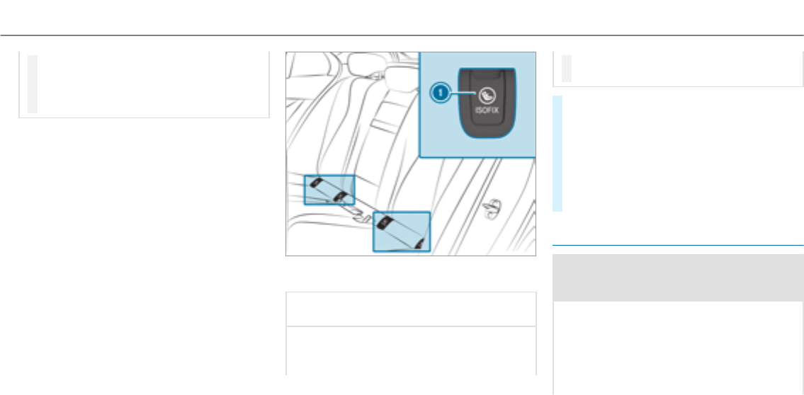
child restraint system which secures
thechild with thevehicle seat belt.
#Also secure thechild restraint system
with theTopTether belt, if available.
Always comply with the information about the
mass of thechild restraint system:
Rin the manufacturer's installation and operat‐
ing instructions forthechild restraint system
used
Ron a label on thechild restraint system, if
present
Regularly check that the permissible gross mass
of thechild and child restraint system is still
being adhered to.
When using a child restraint system, be sure to
observe the manufacturer's installation and
operating instructions as well as its correct use
and the suitability of the seats for attaching a
child restraint system.
Before every trip, make sure that theLATCH-type
(ISOFIX) child restraint system is engaged cor‐
rectly in both LATCH-type (ISOFIX) mounting
brackets.
1LATCH-type (ISOFIX) mounting brackets
*NOTE Damage to the seat belt forthe
center seat
When installing a child restraint system, the
seat belt forthe center seat could be dam‐
aged.
#Make sure that the seat belt is not trap‐
ped.
#Remove each coverforLATCH-type (ISOFIX)
mounting brackets 1.
#Attach theLATCH-type (ISOFIX) child
restraint system to both LATCH-type (ISOFIX)
mounting brackets 1.
#Afterremoving thechild seat, replace each
coverforLATCH-type (ISOFIX) mounting
brackets 1.
Securing TopTether
&WARNING Risk of injury or death if the
rear seat backrests are not locked after
installing TopTether belts
If therear seat backrests are not locked, they
could fold forwards in theevent of an acci‐
dent or during braking or sudden changes of
direction.
As a result, child restraint systems cannot
perform their intended protective function.
Occupant safety51
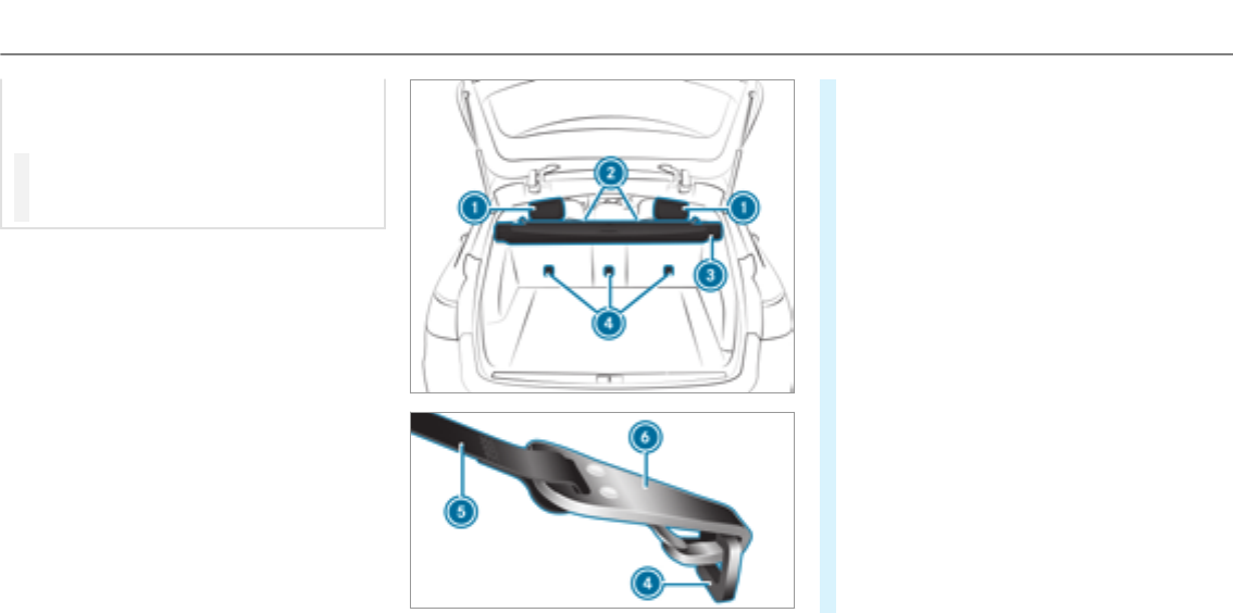
Rear seat backrests that are not locked can
also cause additional injuries, e.g. in the
event of an accident.
#Always lock rear seat backrests after
installing TopTether belts.
#Observe the lock verification indicator.
If the seat backrest is not engaged and locked,
this will be shown on the multifunction display
on the instrument cluster.
The risk of injury can be reduced by TopTether
as TopTether provides an additional connection
between thechild restraint system secured with
LATCH-type (ISOFIX) and thevehicle.
The child restraint system must be equipped
with a TopTether belt.
#If necessary, move head restraint 1
upwards Adjusting therear seat head
restraints(→page 90).
#Install theLATCH-type (ISOFIX) child restraint
system with TopTether. Always comply with
thechild restraint system manufacturer's
installation instructions when doing so.
#Route TopTether belt 5under head
restraint 1between the two head restraint
bars.
#Guide TopTether belt 5downwards
between combined luggage cover and net 3
and backrest 2.
#Hook TopTether hook 6of TopTether belt
5without twisting into TopTether anchor‐
age 4.
#Tension TopTether belt 5. Always comply
with thechild restraint system manufactur‐
er's installation instructions when doing so.
#If necessary, move head restraint 1down‐
wardsAdjusting therear seat head
restraints(→page 90). Make sure that you do
not interfere with therouting of TopTether
belt 5.
52 Occupant safety

Child restraint systems on the front
passenger seat
Notes on child restraint systems on the front
passenger seat
Accident statistics show that children secured in
therear seats are safer than children secured in
the front seats. Forthis reason, Mercedes-Benz
strongly advises that you install a child restraint
system on a rear seat.
If it is absolutely necessary to install a child
restraint system on the front passenger seat,
always observe the information on the automatic
front passenger airbag shutoff (→page 40).
By doing this, you can avoid risks caused by:
RAchild restraint system that is not detected
by the automatic front passenger airbag
shutoff.
RThe unintentionally deactivated front
passenger airbag.
RIncorrect positioning of thechild restraint
system.
Notes on forward-facing and rearward-facing
child restraint systems on the front
passenger seat
When using a rearward-facing child restraint sys‐
tem on the front passenger seat, the front
passenger front air bag must always be deactiva‐
ted. This is only the case if thePASSENGER AIR
BAG OFF indicator lamp is lit continuously
(→page 42).
When using thechild restraint system on the
front passenger seat, it is essential to observe
thefollowing:
RMove the front passenger seat as far back as
possible.
RSet the seat backrest to an almost vertical
position.
RRetract the seat cushion length as far as pos‐
sible.
RThe entire base of thechild restraint system
must alwaysrest on the sitting surface of the
front passenger seat.
RThe backrest of theforward-facing child
restraint system must lie as flat as possible
against the seat backrest of the front
passenger seat. The child restraint system
must not touch theroof or be put under
strain by the head restraints.
RIf necessary, adjust the angle of the seat
backrest and the head restraint position
accordingly.
RAdjust the seat cushion inclination so that
the front edge of the seat cushion is in the
highest position and therear edge of the
seat cushion is in the lowest position.
RAlways make sure that the shoulder belt
strap is correctly routed from the seat belt
outlet of thevehicle to the shoulder belt
guide on thechild restraint system. The
shoulder belt strap must be routed forwards
and downwards from the seat belt outlet.
RIf necessary, adjust the seat belt outlet and
the front passenger seat accordingly.
RNever place objects under or behind the
child restraint system, e.g. cushions.
Always comply with the manufacturer's installa‐
tion and operating instructions forthechild
restraint system used.
Occupant safety53

Child safety locks
Activating/deactivating the child safety lock
for the rear doors
&WARNING Risk of accident and injury
due to children left unattended in the
vehicle
If you leave children unaccompanied in the
vehicle, they may be able to set thevehicle in
motion, forexample by:
RReleasing the parking brake.
RShifting the transmission out of park
position j.
RStarting the engine.
In addition, they may operate vehicle equip‐
ment.
#Never leave children and animals unat‐
tended in thevehicle.
#When leaving thevehicle, alwaystake
the SmartKey with you and lock the
vehicle.
&WARNING Risk of fatal injury due to
exposure to extreme heat or cold in the
vehicle
If people – particularly children – are
exposed to extreme heat or cold over an
extended period of time, there is a risk of
injury or evenfatal injury.
#Never leave anyone – particularly chil‐
dren – unattended in thevehicle.
&WARNING There is a risk of accident
and injury if you leave children unatten‐
ded in thevehicle
If children are traveling in thevehicle, they
could:
ROpen doors,thereby endangering other
persons or road users.
RGet out of thevehicle and be hit by
oncoming traffic.
ROperate vehicle equipment and become
trapped, forexample.
#Always activate thechild safetylocks
available if children are traveling in the
vehicle.
#Never leave children unattended in the
vehicle.
#When leaving thevehicle, alwaystake
the SmartKey with you and lock the
vehicle.
Child safetylocks are available fortherear doors
and fortherear side windows.
The child safetylockon therear doors secures
each door separately. The doors can no longer
be opened from the inside.
54 Occupant safety
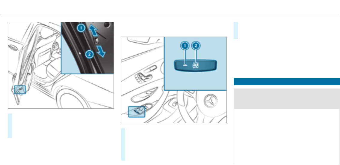
#Press the lever in direction 1(activate) or
2(deactivate).
#Make sure that thechild safetylocks are
working properly.
Activating/deactivating the override feature
for the rear side windows
#To activate/deactivate:press button 2.
Opening/closing the side window in therear
is possible:
RWith indicator lamp 1lit: via the switch
on the driver's door.
RWith indicator lamp 1off: via the switch
on the corresponding rear door or driv‐
er's door.
%Vehicles with folding bench seat: The
switch for opening thetailgate which is loca‐
ted on theright-hand wheel arch when
viewed in the direction of travel is also
secured.
Notes on pets in thevehicle
&WARNING Risk of accident and injury
due to animals left unsecured or unat‐
tended in thevehicle
If you leave animals in thevehicle unatten‐
ded or unsecured, they could possibly press
down buttons or switches.
Thereby an animal may:
Ractivate vehicle equipment and become
trapped, forexample
Rswitch systems on or off and endanger
other road users
Occupant safety55

Unsecured animals may be thrown around in
thevehicle in theevent of an accident or
sudden steering and braking maneuver and
injure vehicle occupants in the process.
#Never leave animals in thevehicle unat‐
tended.
#Always correctly secure animals while
driving, forexample using a suitable
animal carrier.
56 Occupant safety
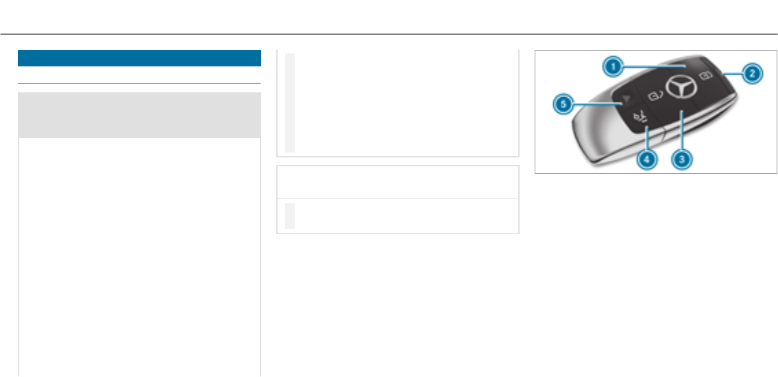
SmartKey
Overview of SmartKey functions
&WARNING Risk of accident and injury
due to children left unattended in the
vehicle
If children are left unattended in thevehicle,
they could:
ROpen doors,thereby endangering other
persons or road users.
RGet out of thevehicle and be hit by
oncoming traffic.
ROperate vehicle equipment and become
trapped, forexample.
In addition, children could also set thevehi‐
cle in motion, forexample, by:
RReleasing the parking brake.
RShifting the automatic transmission out
of park position jor shifting manual
transmission into neutral.
RStarting the engine
#When leaving thevehicle, alwaystake
the SmartKey with you and lock the
vehicle.
#Never leave children and animals unat‐
tended in thevehicle.
#Keep the SmartKey out of reach of chil‐
dren.
*NOTE Damage to thekeycaused by
magnetic fields
#Keep thekeyaway from strong mag‐
netic fields.
1Locks
2Battery check lamp
3Unlocks
4Opens/closes thetailgate
5Panic alarm
The SmartKeylocks and unlocksthefollowing
components:
RThe doors
RThe tailgate
RThe fuel filler flap
Opening and closing 57
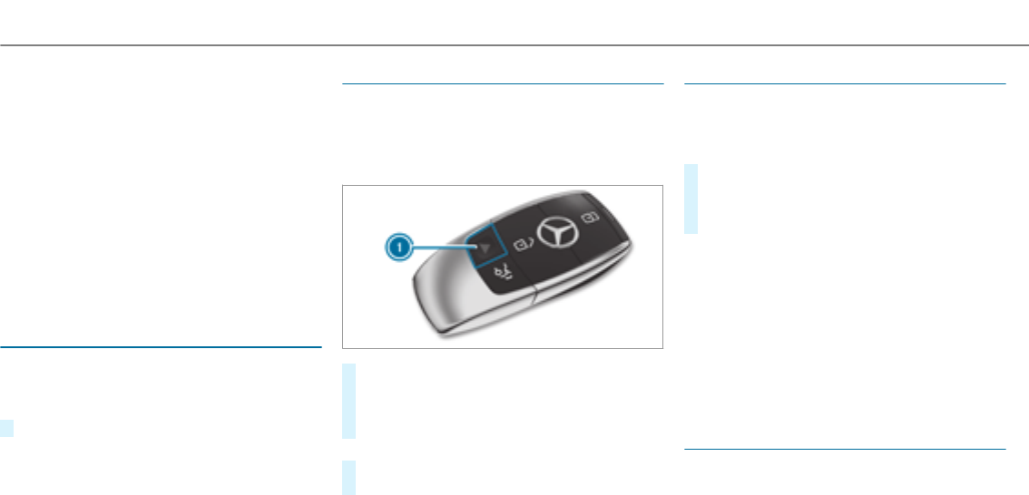
If youdo not open thevehicle within approx‐
imately 40 seconds after unlocking:
RThe vehicle is locked again
RAnti-theft protection is reactivated
Do not keep the SmartKey together with elec‐
tronic devices or metal objects. This can affect
the SmartKey's functionality.
%If battery check lamp 2does not light up
after pressing the%or &button, the
battery is discharged.
Changing the SmartKey battery (→page 59).
Activating/deactivating the acoustic locking
verification signal
Multimedia system:
, .î
.
#Activate Oor deactivate ªthe function.
Activating/deactivating the panic alarm
Requirements
%The panic alarm function is only available in
certain countries.
RThe ignition is switched off.
#To activate: press button 1for approx‐
imately one second.
A visual and audible alarm is triggered.
#To deactivate: brieflypress button1again.
or
#Press thestart/stop button on the dash‐
board (the SmartKey is inside thevehicle).
Changing the unlocking settings
Possible unlocking functions of the SmartKey:
RCentral unlocking
RUnlocking the driver's door and fuel filler flap
#To switch between settings: press the
%and &buttons simultaneously for
approximately six seconds until the battery
check lamp flashes twice.
If the unlocking function forthe driver's door
and fuel filler flap has been selected:
RPressing the%button a second time cen‐
trally unlocks thevehicle.
RVehicles with KEYLESS-GO: if youtouch
the inner surface of the door handle on the
driver's door, only the driver's door and fuel
filler flap are unlocked.
Reducing the energy consumption of the
SmartKey
All vehicles: if youdo not use thevehicle or a
SmartKey for an extended period of time, you
can reduce the energy consumption of the
58 Opening and closing
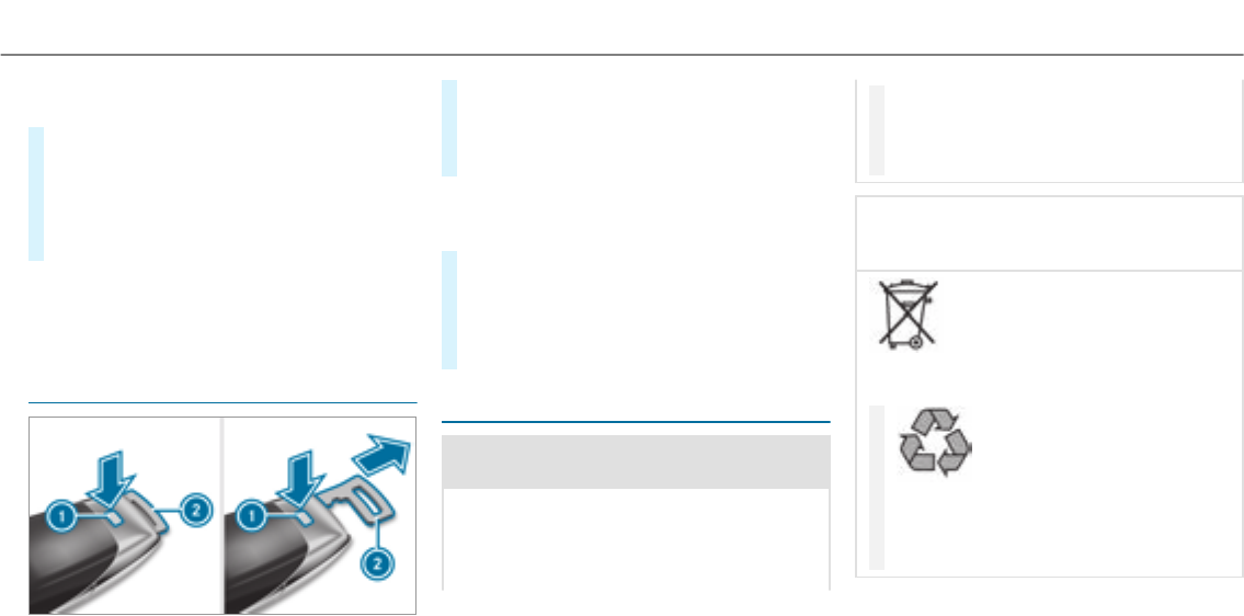
respective SmartKey.To do so, deactivate the
SmartKey functions.
#To deactivate: press the&button on the
SmartKey twice in rapid succession.
The battery check lamp of the SmartKey
flashes twice briefly and lights up once.
#To activate: press any button on the Smart‐
Key.
%When thevehicle is started with the Smart‐
Keyin thestowage compartment of the cen‐
ter console, the SmartKey functions are
automatically activated (→page 147).
Removing/inserting the mechanical key
#To remove:press release knob 1.
Mechanical key2is pushed out slightly.
#Pull outmechanical key2until it engages in
the intermediate position.
%You can use the intermediate position of
mechanical key2to attach thekeyto akey
ring.
#Press release knob 1again and fully
remove mechanical key2.
#To insert: press release knob 1.
#Insert mechanical key2to the intermediate
position or fully until it engages.
Replacing the SmartKey battery
&DANGER Serious damage to health
caused by swallowing batteries
Batteries contain toxic and corrosive sub‐
stances. Swallowing batteries may cause
serious damage to health.
There is a risk of fatal injury.
#Keep batteries out of thereach of chil‐
dren.
#If batteries are swallowed, seek medical
attention immediately.
+ENVIRONMENTALNOTE Environmental
damage caused by improper disposal of
batteries
Batteries contain pollutants. It is
illegal to dispose of them with the household
rubbish.
#
Dispose of batteries in an
environmentally responsible manner.
Take discharged batteries to aqualified
specialist workshop or to a collection
point for used batteries.
Opening and closing 59
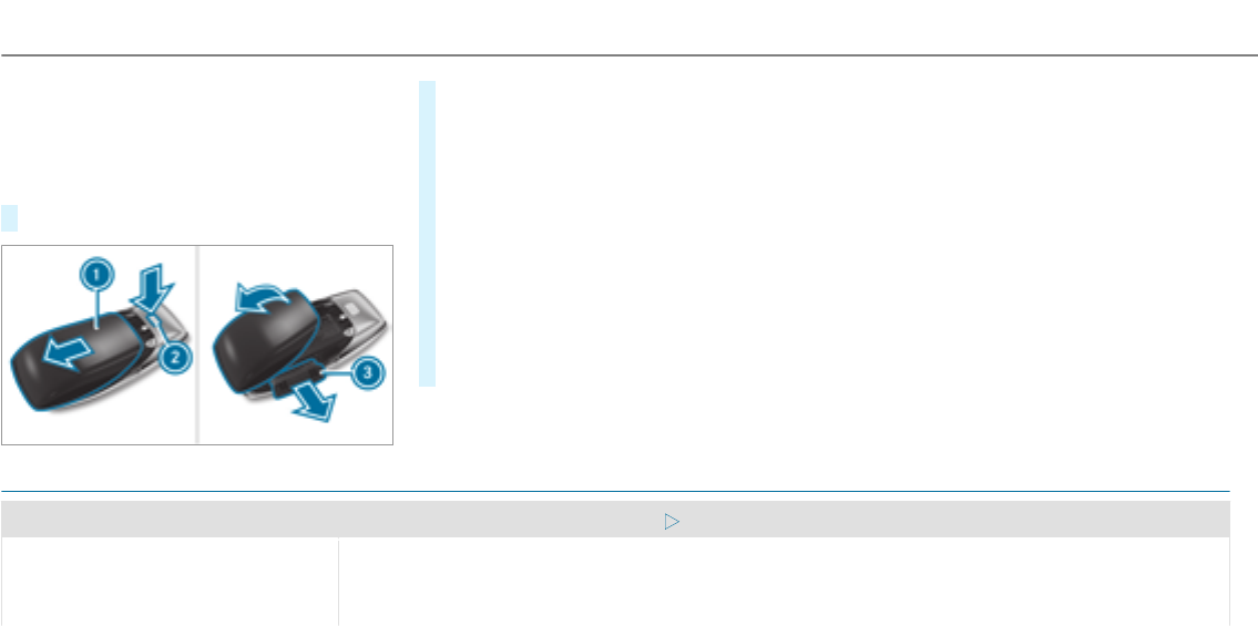
Requirements:
RYourequire a CR 2032 3 V cell battery.
Mercedes-Benz recommends that you have the
battery replaced at a qualified specialist work‐
shop.
#Remove the emergency key (→page59).
#Press release button 2down fully and slide
cover1in the direction of the arrow.
#Fold out cover1in the direction of the
arrow and remove.
#Remove battery compartment 3and take
out the discharged battery.
#Insert the new battery into battery compart‐
ment 3. Observe the positive pole marking
in the battery compartment and on the bat‐
tery.
#Push in battery compartment 3.
#Re-attach cover1and push it until it
engages.
Problems with the SmartKey
Problem Possible causes/consequences and MSolutions
You can no longer lock or unlock the
vehicle.
Possible causes are:
RThe SmartKey battery is discharged or nearly discharged.
RThere is interference from a powerful radio signal source.
60 Opening and closing

Problem Possible causes/consequences and MSolutions
RThe SmartKey is defective.
#Check the battery using the battery check lamp and replace if necessary.
#Use the mechanical keyto lock or unlock.
#Have the SmartKey checked at a qualified specialist workshop.
You have lost a SmartKey.#Have the SmartKey deactivated at a qualified specialist workshop.
#If necessary, have the locks changed as well.
Opening and closing 61
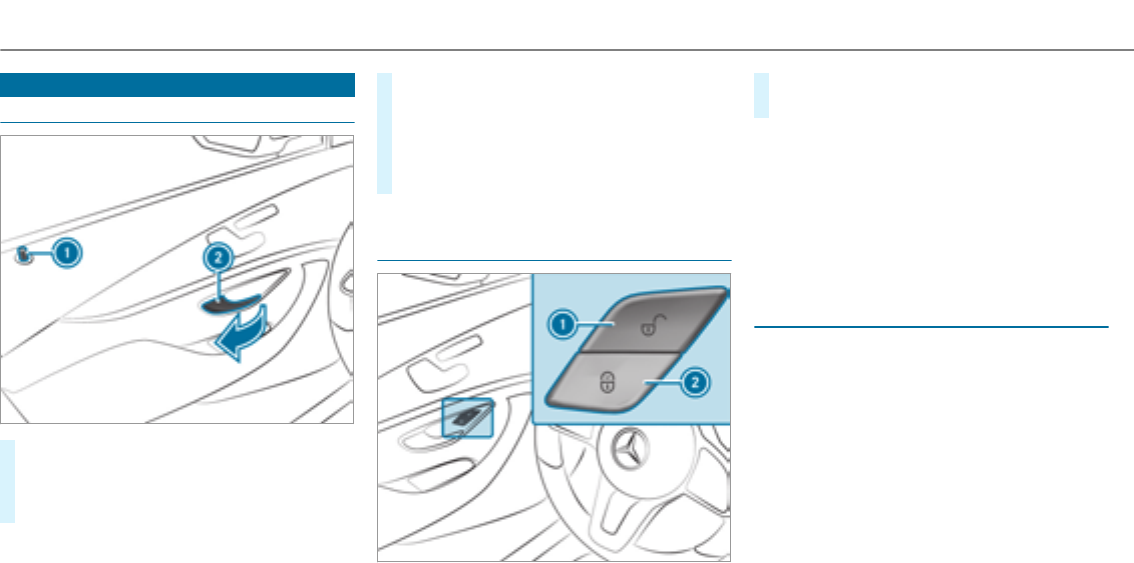
Doors
Unlocking and opening doors from the inside
#To unlock and open a front door: pull door
handle 2.
Locking pin 1pops up when the door is
unlocked.
#To unlock arear door: pull therear door
handle.
The locking pin pops up when therear door
is unlocked.
#To open a rear door: pull therear door han‐
dle again.
Centrally locking and unlocking thevehicle
from the inside
#To unlock:press button 1.
#To lock: press button 2.
This does not lock or unlock the fuel filler flap.
The vehicle is not unlocked:
RIf you have lockedthevehicle using the
SmartKey.
RIf you have lockedthevehicle using KEY‐
LESS-GO.
Locking/unlocking thevehicle with KEY‐
LESS-GO
Requirements:
RThe SmartKey is outside thevehicle.
RThe distance between the SmartKey and the
vehicle does not exceed 3 ft (1 m).
RThe driver's door and the door at which the
door handle is used are closed.
62 Opening and closing
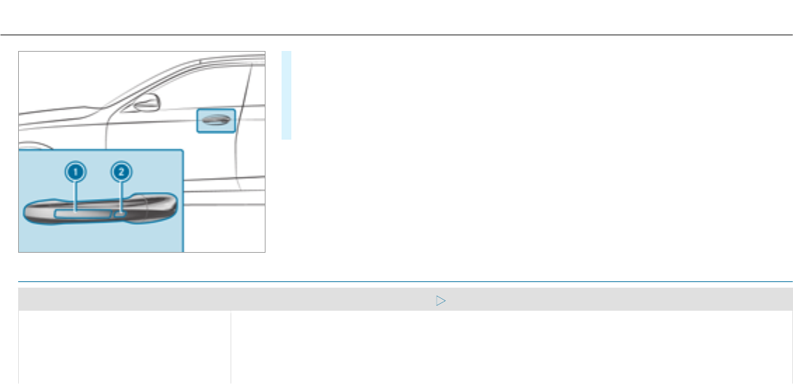
#To unlock thevehicle: touch the inner sur‐
face of the door handle.
#To lock thevehicle: touch sensor surface
1or 2.
#Convenience closing: touch recessed sen‐
sor surface 2for an extended period.
%Further information on convenience closing
(→page 74).
If you open thetailgate from outside it is auto‐
matically unlocked.
Problems with KEYLESS-GO
Problem Possible causes/consequences and MSolutions
You can no longer lock or unlock the
vehicle using KEYLESS-GO.
Possible causes are:
RKEYLESS-GO has been deactivated .
RThe SmartKey battery is discharged or nearly discharged.
RThere is interference from a powerful radio signal source.
Opening and closing 63
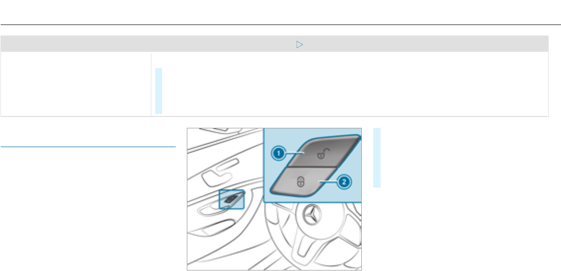
Problem Possible causes/consequences and MSolutions
RThe SmartKey is defective.
#Activate KEYLESS-GO .
#Check the battery using the battery check lamp and replace if necessary .
#Use the mechanical keyto lock or unlock thevehicle .
#Have thevehicle and SmartKey checked at a qualified specialist workshop.
Activating/deactivating the automatic lock‐
ing feature
The vehicle is locked automatically when the
ignition is switched on and the wheels are turn‐
ing faster than walking pace.
#To activate: press and hold button 2for
approximately five seconds until an acoustic
signal sounds.
#To deactivate: press and hold button 1for
approximately five seconds until an acoustic
signal sounds.
There is a danger of being locked out if the func‐
tion is activated:
RWhile thevehicle is being towstarted/
pushed.
ROn a roller dynamometer.
64 Opening and closing
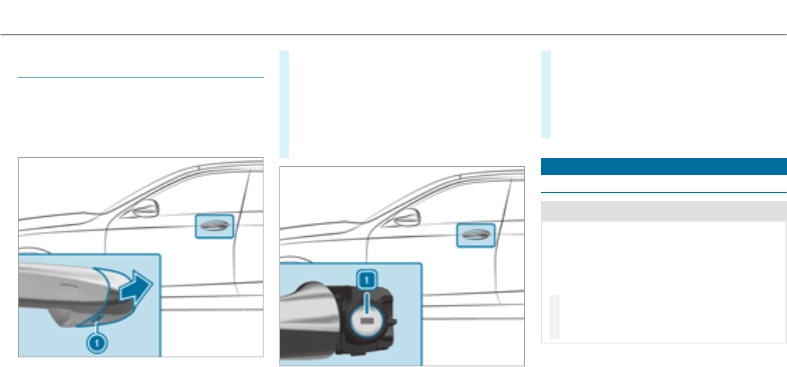
Locking/unlocking the driver's door with the
mechanical key
%If youwish to lock thevehicle entirely using
the mechanical key, first press the button for
locking from the inside while the driver's
door is open. Then proceed to lock the driv‐
er's door using the mechanical key.
#Insert the mechanical keyas far as it will go
into opening 1in the cover.
#Pull and hold the door handle.
#Pull the cover on the mechanical keyas
straight as possible away from thevehicle
until it releases.
#Release the door handle.
#To unlock:turn the mechanical keycounter-
clockwise to position 1.
#To lock: turn the mechanical keyclockwise
to position 1.
#Carefully press the cover onto the lock cylin‐
der until it engages and is seated firmly.
Load compartment
Opening the tailgate
&WARNING Risk of exhaust gas poisoning
Combustion engines emit poisonous exhaust
gases such as carbon monoxide. Exhaust
gases can enter thevehicle interior if thetail‐
gate is open when the engine is running,
especially if thevehicle is in motion.
#Always switch off the engine before
opening thetailgate.
#Never drive with thetailgate open.
Opening and closing 65
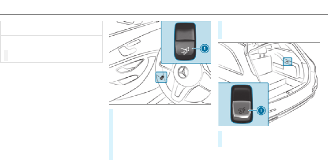
*NOTE Damage to thetailgate caused by
obstacles above thevehicle
The tailgate swings rearwards and upwards
when it is opened.
#Make sure that there is sufficient space
behind and above thetailgate.
To open the tailgate, thefollowing options
are available:
#Pull remote opening switch 1forthetail‐
gate.
#Press and hold thepbutton on the
SmartKey.
#Vehicles with HANDS-FREE ACCESS: Move
your foot below the bumper (→page 69).
#If thetailgate is unlocked, pull thetailgate
handle and release it again immediately.
#For a tailgate stopped in an intermediate
position, pull it upwards and release it as
soon as it starts to open.
#Vehicles with folding bench seat: Pull
switch 1forthetailgate twice.
The tailgate is unlocked.
66 Opening and closing

If thetailgate has been locked from the outside,
or thechild safetylockhas been activated, the
tailgate cannot be unlocked with switch 1.
The tailgate is equipped with an automatic
obstacle detection function. If a solid object
blocks or restricts thetailgate when automati‐
cally opening, this process is stopped. The auto‐
matic obstacle detection function is only an aid.
It is not a substitute foryour attentiveness when
opening thetailgate.
Closing the tailgate
&WARNING Risk of injury from unsecured
items in thevehicle
If objects, luggage or loads are not secured
or not secured sufficiently, they could slip,
tip over or be thrown around and thereby hit
vehicle occupants.
There is a risk of injury, particularly in the
event of sudden braking or a sudden change
in direction.
#Alwaysstow objects in such a waythat
they cannot be thrown around.
#Before the journey, secure objects, lug‐
gage or loads against slipping or tipping
over.
&WARNING Risk of becoming trapped
during automatic closing of thetailgate
Parts of the body could become trapped dur‐
ing automatic closing of thetailgate. More‐
over, people, e.g. children, may be standing
in the closing area or may enter the closing
area during the closing process.
#Make sure that nobody is in the vicinity
of the closing area during the closing
process.
Use one of thefollowing options to stop the
closing process:
RPress thepbutton on the SmartKey.
RPress or pull theremote operating switch
on the driver's door.
RPress the closing or locking button on the
tailgate.
RPull thetailgate handle.
Vehicles with HANDS-FREE ACCESS: It is also
possible to stop the closing process by moving
your foot in a kicking motion under therear
bumper.
To close the tailgate, thefollowing options
are available:
#Pull thetailgate downwards slightly. Release
it as soon as it begins to close.
#Vehicles with HANDS-FREE ACCESS: Move
your foot below the bumper (→page 69).
#Vehicles with KEYLESS-GO: Press and hold
thepbutton on the SmartKey (with the
SmartKey in the vicinity of thevehicle).
Opening and closing 67
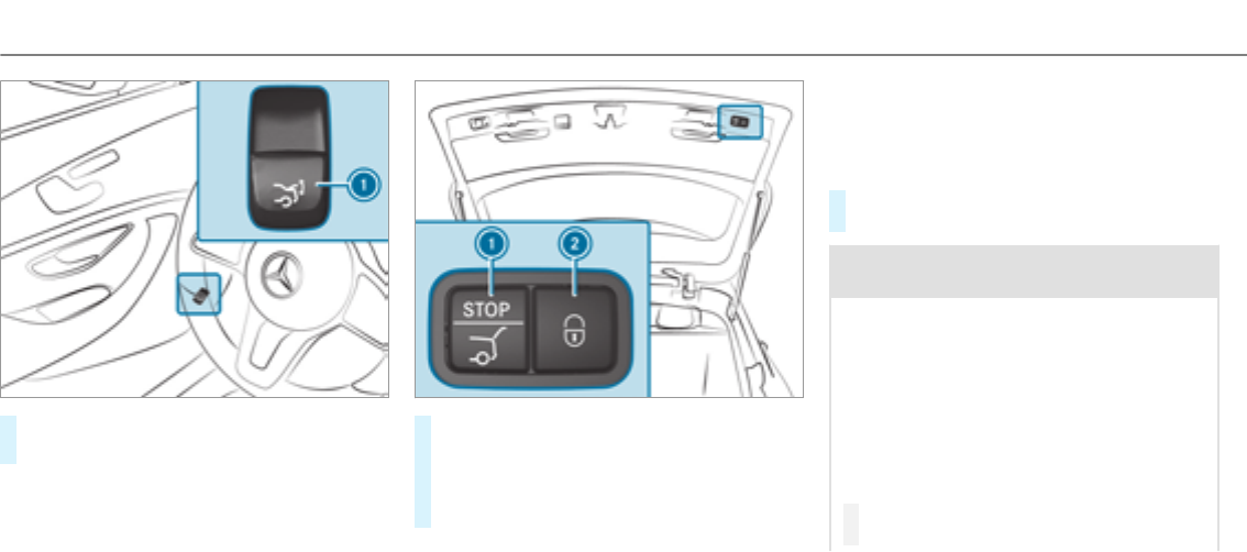
#Press remote operating switch 1forthe
tailgate.
#Press closing button 1on thetailgate.
#Vehicles with KEYLESS-GO: Press locking
button 2in thetailgate.
If a SmartKey is detected outside thevehicle,
thetailgate closes and thevehicle is locked.
Automatic reversing function for the tailgate
The tailgate is equipped with automatic obstacle
detection with reversing function. If a solid
object blocks or restricts thetailgate when auto‐
matically closing, thetailgate automatically
opens again slightly. The automatic obstacle
detection with reversing function is only an aid.
It is not a substitute foryour attentiveness when
closing thetailgate.
#When closing, make sure that no body parts
are in the closing area.
&WARNING Risk of becoming trapped
despite thereversing function
The reversing function does not react:
RTo soft, light and thin objects, e.g. fin‐
gers.
ROver the last Óin (8 mm) of the closing
path.
In these situations in particular, thereversing
function cannot prevent someone being trap‐
ped.
#When closing, make sure that no body
parts are in the closing area.
68 Opening and closing
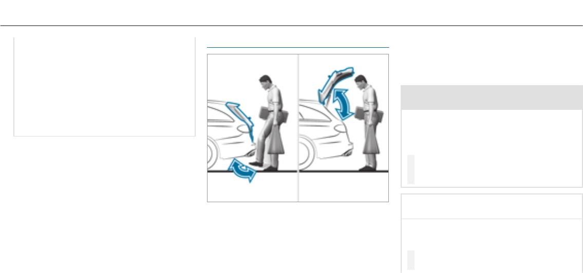
If someone is trapped:
RPress thepbutton on the SmartKey,
or
RPress or pull theremote operating switch
on the driver's door, or
RPress the closing or locking button on the
tailgate, or
RPull thetailgate handle.
HANDS-FREE ACCESS function
With HANDS-FREE ACCESS you can open, close
or stop the closing process of thetailgate by
performing a kicking movement under therear
bumper.
The kicking movement triggers the opening or
closing process alternately.
Observe the notes when opening (→page 65)
and closing (→page 67)thetailgate.
%Twowarning tones sound when thetailgate
is opening or closing.
&WARNING Risk of burns caused by a hot
exhaust system
The vehicle exhaust system can become very
hot. If you use HANDS-FREE ACCESS, you
could burn yourself by touching theexhaust
system.
#Always ensure that you only make a
kicking movement within the detection
range of the sensors.
*NOTE Vehicle damage due to uninten‐
tional opening of thetailgate
Rwhen using an automatic car wash
Rwhen using a high pressure cleaner
#Deactivate KEYLESS-GO or make sure
that thekeylocated is at least10 ft
Opening and closing 69
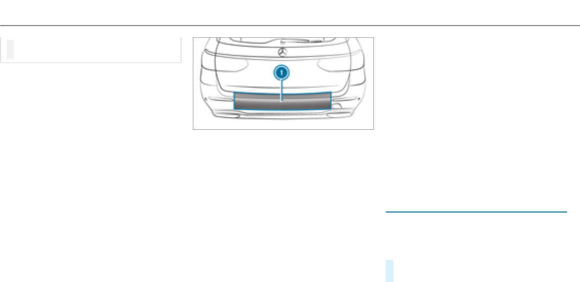
(3 m) away from thevehicle in such sit‐
uations.
When making the kicking movement, make sure
that your feet are firmly on the ground, other‐
wise you could lose your balance, e.g. on ice.
Requirements:
RThe SmartKey is behind thevehicle.
RStand at least 12 in (30 cm) away from the
vehicle while performing the kicking move‐
ment.
RDo not come into contact with the bumper
while making the kicking movement.
RDo not carry out the kicking movement too
slowly.
RThe kicking movement must be towardsthe
vehicle and back again.
1Sensor detection range
If several consecutive kicking movements are
not successful, wait ten seconds.
System limitations
The system may be impaired or may not function
if:
RThe area around the sensor is dirty, e.g. due
to road salt or snow.
RThe kicking movement is made using a pros‐
thetic leg.
The tailgate can open or close unintentionally in
thefollowing situations:
RIf persons' arms or legs move in the sensor
detection range, e.g. when polishing thevehi‐
cle, sitting on the edge of the cargo compart‐
ment, or picking up objects.
RIf objects are moved or placed behind the
vehicle, e.g. charging cables, tensioning
straps or luggage.
RWhen working on the trailer coupling, trailers
or rear bicycle racks.
Deactivate KEYLESS-GO (→page 58) or do not
carry the SmartKey about your person in such
situations.
Limiting the opening angle of the tailgate
Activating the opening angle limiter
You can limit the opening angle of thetailgate in
thetop half of its opening range, to approx‐
imately 8 in (20 cm) before the end position.
#Stop the opening procedure of thetailgate at
the desired position.
70 Opening and closing
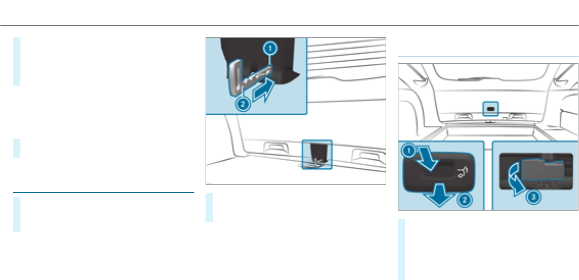
#Press and hold the closing button in thetail‐
gate until you hear a short acoustic signal.
The opening angle limiter is activated. The
tailgate then stops in thestored position
when opened.
To open thetailgate fully, pull the handle on the
outside of thetailgate again after it has stopped
automatically.
Deactivating theopening angle limiter
#Press and hold the closing button in thetail‐
gate until two short acoustic signals sound.
Unlocking the tailgate with the mechanical
key
#Fold therear seat backrest forwards.
#Remove the combined luggage cover and net
(→page 108).
#Insert mechanical key2into opening 1in
the trim and push it in.
The tailgate is unlocked.
Emergency release of the tailgate from the
inside (vehicles with a folding bench seat)
#Press the cover down in the direction of
arrow 1and pull in the direction of arrow
2and remove it.
#Pull the emergency release lever in the direc‐
tion of arrow 3.
The tailgate is unlocked.
Opening and closing 71
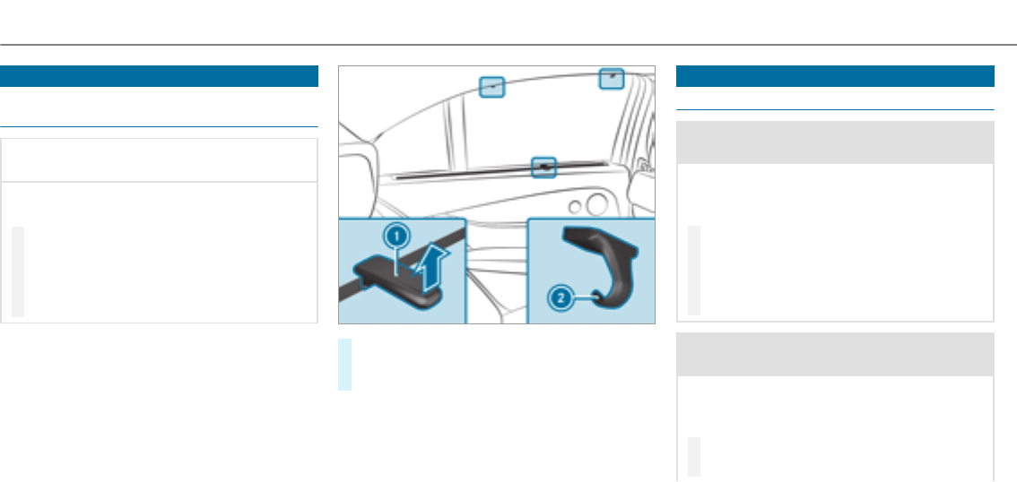
Roller sun blinds
Extending therear side window roller sun‐
blinds
*NOTE Damage to the inertia reel due to
it snapping back
If suddenly snapped back, the inertia reel
may be damaged.
#Always move theroller sun blind by
hand.
#Do not drive with theroller sun blind
hooked in and side windows opened at
the same time.
#Pull theroller sunblind out by tab1and
hook it onto brackets 2at thetop of the
window.
Side windows
Opening and closing the side windows
&WARNING Risk of entrapment when
opening a side window
When opening a side window, parts of the
body could be drawn in or become trapped
between the side window and window frame.
#When opening, make sure that nobody
is touching the side window.
#If someone is trapped, release the but‐
ton immediately or pull it in order to
close the side window again.
&WARNING Risk of becoming trapped
when closing a side window
When closing a side window, body parts
could be trapped in the closing area in the
process.
#When closing, make sure that no body
parts are in the closing area.
72 Opening and closing
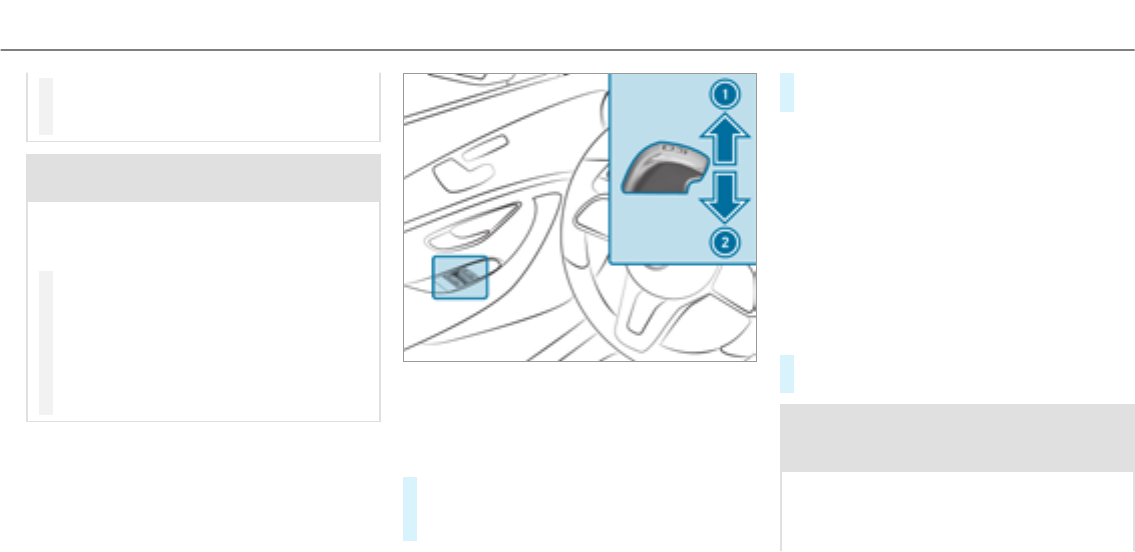
#If someone is trapped, release the but‐
ton immediately or pressthe button in
order to reopen the side window.
&WARNING Risk of becoming trapped
when children operate the side windows
Children could become trapped if they oper‐
ate the side windows, particularly when unat‐
tended.
#Activate thechild safetylockforthe
rear side windows.
#When leaving thevehicle, alwaystake
the SmartKey with you and lock the
vehicle.
#Never leave children unattended in the
vehicle.
Requirements
RThe power supply or the ignition is switched
on.
1Closes
2Opens
The buttons on the driver's door take prece‐
dence.
#To start automatic operation: press the
Wbutton beyond the point of resistance
or pull and release it.
#To interrupt automatic operation: press or
pull theWbutton again.
When thevehicle is switched off, the side win‐
dows can continue being operated.
The function is available for around five minutes
or until a front door is opened.
Automatic reversing function of the side win‐
dows
If an object blocks a side window during the
closing process, the side window opens again
automatically. The automatic reversing function
is only an aid and is not a substitute foryour
attentiveness.
#When closing, make sure that no body parts
are in the closing area.
&WARNING Risk of becoming trapped
despite there being reversing protection
on the side window
The reversing function does not react:
Rto soft, light and thin objects, e.g. small
fingers
Opening and closing 73

Rduring resetting
This means that thereverse function cannot
prevent someone from becoming trapped in
these situations.
#When closing, make sure that no body
parts are in the closing area.
#If someone becomes trapped, press the
Wbutton to open the side window
again.
Convenience opening (ventilating thevehicle
before starting a journey)
&WARNING Risk of entrapment when
opening a side window
When opening a side window, parts of the
body could be drawn in or become trapped
between the side window and window frame.
#When opening, make sure that nobody
is touching the side window.
#Release the button immediately if
somebody becomes trapped.
#Press and hold the%button on the
SmartKey.
The following functions are performed:
RThe vehicle is unlocked.
RThe side windows are opened.
RThe sliding sunroof is opened.
RThe panoramic sliding sunroof is opened.
RThe seat ventilation of the driver's seat is
switched on.
If theroller sunblinds of the panoramic sliding
sunroof are closed, theroller sunblinds are
opened first.
#To continue convenience opening: press
the%button again.
#To interrupt convenience opening: release
the%button.
Convenience closing (closing thevehicle
from outside)
&WARNING Risk of entrapment caused by
inadvertent convenience closing
When the convenience closing feature is
operating, parts of the body could become
trapped in the closing area of the side win‐
dow and the sliding sunroof.
#Observe the complete closing proce‐
dure when using convenience closing.
#When closing, make sure that no body
parts are in the closing area.
#Press and hold the&button on the
SmartKey.
The following functions are performed:
RThe vehicle is locked.
RThe side windows are closed.
RThe sliding sunroof is closed.
RThe panoramic sliding sunroof is closed.
74 Opening and closing

#To close theroller sunblinds: press the
&button again.
#To interrupt convenience closing: release
the&button.
%Convenience closing can also be operated
with KEYLESS-GO (→page 62).
Problems with the side windows
Problem Possible causes/consequences and MSolutions
A side window cannot be closed and
you cannot see the cause.
#Check to see if any objects are in the window guide.
&WARNING Risk of becoming trapped or fatally injured if reversing protection is not activated
If you close a side window again immediately after it has been blocked or reset, the side window closes
with increased or maximum force. The reversing feature is then not active.
Parts of the body could become trapped in the closing area in the process.
#Make sure that no parts of the body are in the closing area.
#To stop the closing process, release the button or press the button again to reopen the side win‐
dow.
If a side window is obstructed during closing and reopens again slightly:
#Immediately afterthe window blocks, pull the corresponding button again until the side window has
closed, and hold the button for an additional second.
The side window is closed with increased force.
If a side window is obstructed again during closing and reopens again slightly:
Opening and closing 75
Problem Possible causes/consequences and MSolutions
#Repeat the previous step.
The side window is closed without the automatic reversing function.
The side windows cannot be opened or
closed using the convenience opening
feature.
The SmartKey battery is discharged or nearly discharged.
#Check the battery using the battery check lamp and replace if necessary .
Sliding sunroof
Opening and closing the sliding sunroof
%The term "sliding sunroof" also refers to the
panoramic sliding sunroof.
&WARNING Risk of becoming trapped
while opening and closing the sliding
sunroof
During opening and closing, parts of the
body could get caught in the sweep of the
sliding sunroof.
#When opening or closing, make sure
that no body parts are in the sweep.
#Release the button immediately if
somebody becomes trapped.
or
#Press the button in any direction during
the automatic opening/closing process.
The opening/closing process is stop‐
ped.
&WARNING Risk of becoming trapped if
the sliding sunroof is operated by chil‐
dren
Children operating the sliding sunroof could
get caught in the moving parts, particularly if
unattended.
#Never leave children unattended in the
vehicle.
#When leaving thevehicle, alwaystake
thekeywithyou and lock thevehicle.
&WARNING Risk of becoming trapped
while opening and closing theroller sun
blind
When opening or closing, make sure that no
body parts become trapped between the
roller sun blind and frame or the sliding sun‐
roof.
76 Opening and closing
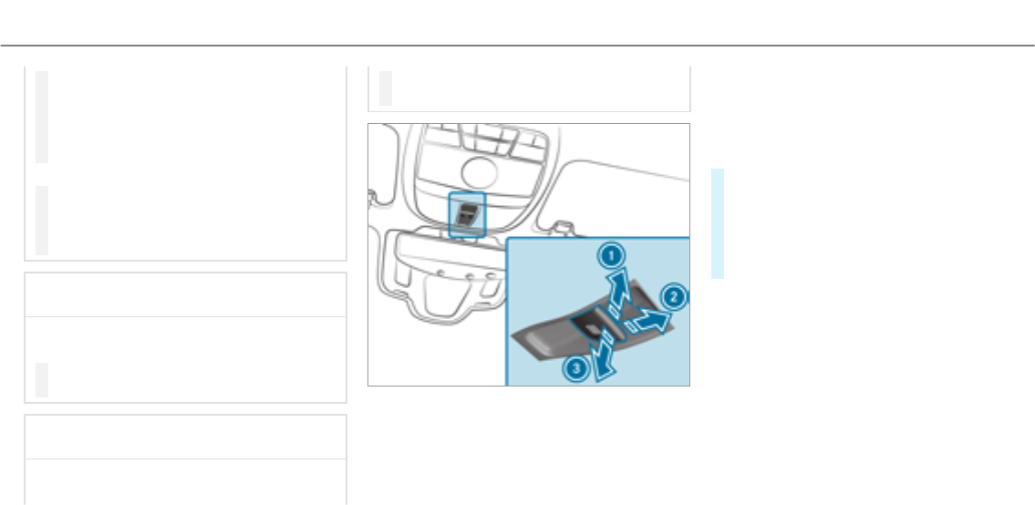
#When opening or closing, make sure
that no body parts are in the sweep of
theroller sun blind.
#Release the button immediately if
somebody becomes trapped.
or
#Press the button in any direction during
the automatic opening/closing process.
The opening/closing process is stop‐
ped.
*NOTE Malfunction caused by snow and
ice
Snow and ice may lead to a malfunction of
the sliding sunroof.
#Only open the sliding sunroof if it is free
of snow and ice.
*NOTE Damage caused by protruding
objects
Objects that protrude from the sliding sun‐
roof may damage the sealing strips.
#Do not allow anything to protrude from
the sliding sunroof.
1To raise
2To open
3To close/lower
Use the3button to operate the panoramic
sliding sunroof and theroller sunblind.
RThe panoramic sliding sunroof can be
opened only when theroller sunblind is open.
RThe roller sunblind can be operated only
when the panoramic sliding sunroof is
closed.
#To start automatic operation: press the
3button beyond the pressure point or
pull and release it.
#To interrupt automatic operation: briefly
press the3button in any direction.
The opening/closing process is stopped.
RVehicles with a panoramic sliding sun‐
roof: The automatic raising feature is availa‐
ble only when the sliding sunroof is closed or
raised.
RVehicles without a panoramic sliding sun‐
roof: The automatic opening and raising fea‐
ture is available only when the sliding sun‐
roof is closed.
Automatic reversing function of the sliding
sunroof
If there is an object obstructing the sliding sun‐
roof during the closing process, the sliding sun‐
Opening and closing 77

roof opens again automatically. The automatic
reverse function is only an aid and is not a sub‐
stitute foryour attentiveness.
#When closing, make sure that no body parts
are in the closing area.
&WARNING Risk of entrapment even with
thereversing feature active
The reverse function does not react in partic‐
ular:
Rto soft, light and thin objects, e.g. small
fingers
Roverthe last ãin (4 mm) of the closing
path
Rduring resetting
This means that thereverse function cannot
prevent someone from becoming trapped in
these situations.
#When closing, make sure that no body
parts are in the closing area.
#Release the button immediately if
somebody becomes trapped.
or
#Briefly press the button in any direction
during automatic operation.
The closing process is stopped.
Automatic reversing function of theroller
sunblind
If there is an object obstructing theroller sun‐
blind during the closing process, theroller sun‐
blind opens again automatically. The automatic
reverse function is only an aid and is not a sub‐
stitute foryour attentiveness.
#When closing theroller sunblind, make sure
that no body parts are in therange of move‐
ment.
&WARNING Risk of becoming trapped
despite reversing function
In particular, thereversing function does not
react to soft, light and thin objects, e.g. small
fingers.
This means that thereversing function can‐
not prevent entrapment in these situations.
#When closing theroller sunblind, make
sure that no body parts are in therange
of movement.
#Release the button immediately if
somebody becomes trapped.
or
#Press the button in any direction during
the automatic closing process.
The closing process is stopped.
Automatic features of the sliding sunroof
%The term "sliding sunroof" also refers to the
panoramic sliding sunroof.
By pushing or pulling the3button, you can
interrupt the automatic functions: "Rain closing
function when driving" and "Automatic lowering
feature".
Rain closing function when driving
Vehicles with a panoramic sliding sunroof: If
it starts to rain, theraised sliding sunroof is
automatically lowered while thevehicle is in
motion.
78 Opening and closing

Automatic lowering feature
Vehicles with a panoramic sliding sunroof: If
the sliding sunroof is raised at therear, the slid‐
ing sunroof is automatically lowered slightly at
higher speeds. At low speeds, it is raised again
automatically.
&WARNING Risk of entrapment by auto‐
matic lowering of the sliding sunroof
At high speeds theraised sliding sunroof
automatically lowers slightly at therear.
This could trap you or other persons.
#Make sure that nobody reaches into the
sweep of the sliding sunroof whilst the
vehicle is in motion.
#If somebody becomes trapped, briefly
push the sliding sunroof button for‐
wards or backwards.
The sliding sunroof lifts during opening.
Problems with the sliding sunroof
%The term "sliding sunroof" also refers to the
panoramic sliding sunroof.
Problem Possible causes/consequences and MSolutions
The sliding sunroof cannot be closed
and you cannot see the cause. &WARNING Risk of becoming trapped or fatal injury by closing the sliding sunroof again
If you close the sliding sunroof again immediately after it has been blocked or reset, the sliding sunroof
closes with increased force.
Parts of the body could become trapped in the closing area in the process.
#Make sure that no parts of the body are in the closing area.
#Release the button immediately if somebody becomes trapped.
or
Opening and closing 79

Problem Possible causes/consequences and MSolutions
#Press the button in any direction during the automatic closing process.
The closing process is stopped.
If the sliding sunroof is obstructed during closing and reopens again slightly:
#Immediately after automatic reversing, pull and hold the3button down again to the pressure point
until the sliding sunroof is closed.
The sliding sunroof is closed with increased force.
If the sliding sunroof is obstructed again and reopens again slightly:
#Repeat the previous step.
The sliding sunroof is closed again with increased force.
Vehicles without a panoramic slid‐
ing sunroof: The sliding sunroof does
not operate smoothly.
#Pull the3button up repeatedly to the pressure point until the sliding sunroof is fully open.
#Press the3button for another second.
#Close the sliding sunroof.
Vehicles with a panoramic sliding
sunroof: The sliding sunroof or the
roller sunblind does not operate
smoothly.
#Pull and hold the3button little by little until the sliding sunroof is fully closed.
#Pull and hold the3button little by little until theroller sunblind is fully closed.
#Use automatic operation to fully open and then close the sliding sunroof.
80 Opening and closing
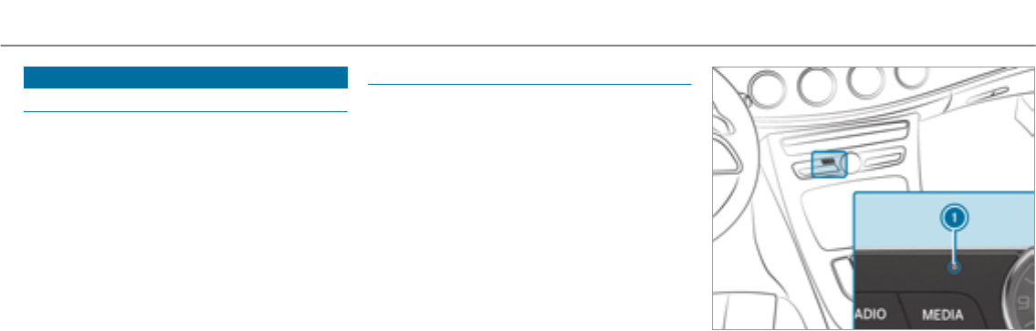
Anti-theft protection
Function of the immobilizer
The immobilizer prevents your vehicle from being
started without the correct SmartKey.
The immobilizer is automatically activated when
the ignition is switched off and deactivated when
the ignition is switched on.
When leaving thevehicle, alwaystake the Smart‐
Keywithyou and lock thevehicle. Anyone can
start the engine if a valid SmartKey has been left
inside thevehicle.
%In theevent the engine cannot be started
(yet thevehicle’s starter battery is charged),
the system is not operational. Contact an
authorized Mercedes-Benz Center or call
1-800-FOR-MERCedes (in the USA) or
1-800-387-0100 (in Canada).
ATA (anti-theft alarm system)
Function of theATA system
If theATA system is armed, a visual and audible
alarm is triggered in thefollowing situations:
RWhen a door is opened
RWhen thetailgate is opened
RWhen the hood is opened
The ATA system is armed automatically after
approximately 10 seconds:
RAfter locking thevehicle with the SmartKey.
RAfter locking thevehicle using KEYLESS-GO.
Indicator lamp 1flashes when theATA system
is activated.
The ATA system is automatically deactivated:
RAfter unlocking thevehicle with the Smart‐
Key
RAfter pressing thestart/stop button with the
SmartKey in thestowage compartment
(→page 147)
Openingand closing 81

RAfter unlocking thevehicle using KEYLESS-
GO.
%When the mbrace service (→page 301) is
active and the alarm stays on for more than
30 seconds, a message is automatically sent
to the Customer Assistance Center.
Deactivating the ATA
#Press the%,&or pbutton on the
SmartKey.
or
#Press thestart/stop button with the Smart‐
Keyin thestowage compartment
(→page 147)
Deactivating the alarm using KEYLESS-GO:
#Grasp the outside door handle with the
SmartKey outside thevehicle.
82 Opening and closing
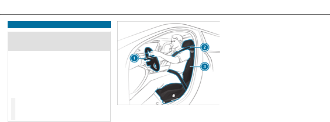
Notes on the correct driver's seat position
&WARNING Risk of injury from adjusting
thevehicle settings while thevehicle is in
motion
You could lose control of thevehicle in the
following situations:
Rif you adjust the driver's seat, the head
restraint, thesteering wheel or the mirror
while thevehicle is in motion
Rif youfasten your seat belt while thevehi‐
cle is in motion
#Before starting the engine: adjust the
driver's seat, the head restraint, the
steering wheel or the mirror and fasten
your seat belt.
Ensure thefollowing when adjusting thesteering
wheel 1, seat belt 2and driver's seat 3:
Ryou are as faraway from the driver's air bag
as possible
Ryou are sitting in a normal upright position
Ryour thighs are slightly supportedby the seat
cushion
Ryour legs are not entirely stretched and you
can depress the pedals properly
Rthe back of your head is supported at eye
levelby the center of the head restraint
Ryou can hold thesteering wheel with your
arms slightly bent
Ryou can move your legs freely
Ryou can see all the displays on the instru‐
ment cluster clearly
Ryou have a good overview of the traffic con‐
ditions
Rthe seat belt is pulled snugly against the
body and is routed across the center of your
shoulder and across your hips in the pelvic
area
Seats and stowing 83

Seats
Adjusting the front seat mechanically and
electrically (without Seat Comfort Package)
&WARNING Risk of becoming trapped if
the seats are adjustedby children
Children could become trapped if they adjust
the seats, particularly when unattended.
#When leaving thevehicle, alwaystake
the SmartKey with you and lock the
vehicle.
#Never leave children unattended in the
vehicle.
The seats can be adjusted when the ignition is
switched off.
&WARNING Risk of becoming trapped
when adjusting the seats
When you adjust a seat, you or other vehicle
occupants could become trapped, e.g. on the
seat guide rail.
#Make sure when adjusting a seat that
no one has any body parts in the sweep
of the seat.
Observe the safetynotes on "Air bags" and "Chil‐
dren in thevehicle".
&WARNING Risk of accident due to the
driver's seat not being engaged
If the driver's seat is not engaged, it could
move unexpectedly while thevehicle is in
motion.
This could cause youto lose control of the
vehicle.
#Always make sure that the driver's seat
is engaged before starting thevehicle.
&WARNING Risk of injury from adjusting
thevehicle settings while thevehicle is in
motion
You could lose control of thevehicle in the
following situations:
Rif you adjust the driver's seat, the head
restraint, thesteering wheel or the mirror
while thevehicle is in motion
Rif youfasten your seat belt while thevehi‐
cle is in motion
#Before starting the engine: adjust the
driver's seat, the head restraint, the
steering wheel or the mirror and fasten
your seat belt.
&WARNING Risk of becoming trapped if
the seat height is adjusted carelessly
If you adjust the seat height carelessly, you
or other vehicle occupants could be trapped
and thereby injured.
84 Seats and stowing

Children in particular could accidentally
press the electrical seat adjustment buttons
and become trapped.
#While moving the seats, make sure that
hands or other body parts do not get
under the lever assembly of the seat
adjustment system.
&WARNING Risk of injury due to head
restraints which are not installed or are
adjusted incorrectly
If head restraints are not installed or are
adjusted incorrectly, the head restraints can‐
not provide protection as intended.
There is an increased risk of injury in the
head and neck area, e.g. in theevent of an
accident or when braking.
#Always drive with the head restraints
installed.
#Before driving off, make sure forevery
vehicle occupant that the center of the
head restraint supports the back of the
head at about eye level.
Do not interchange the head restraints of the
front and rear seats. Otherwise, you cannot
adjust the height and angle of the head
restraints correctly.
Adjust the head restraint fore-and-aft position so
that it is as close as possible to the back of your
head.
&WARNING Risk of injury or death due to
incorrect seat position
The seat belt does not offerthe intended
level of protection if you have not movedthe
seat backrest to an almost vertical position.
When braking or in theevent of an accident,
you could slide underneath the seat belt and
sustain abdominal or neck injuries, forexam‐
ple.
#Adjust the seat properly before begin‐
ning your journey.
#Always ensure that the seat backrest is
in an almost vertical position and that
the shoulder section of your seat belt is
routed across the center of your shoul‐
der.
*NOTE Damage to the seats when moving
the seats back
The seats may be damaged by objects when
moving the seats back.
#When moving the seats back, make
sure that there are no objects in the
footwell or under or behind the seats.
Seats and stowing 85
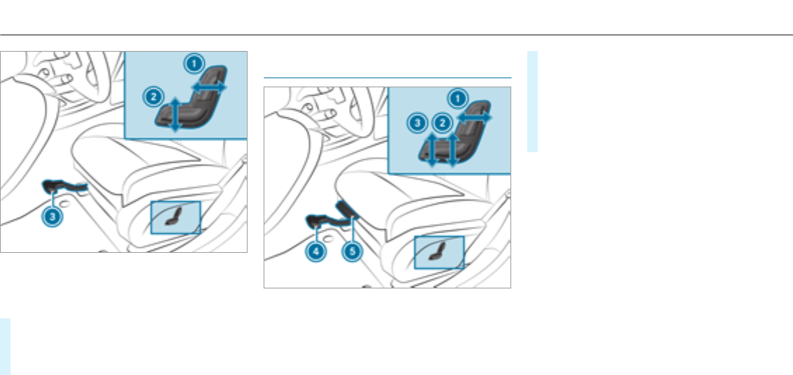
1Seat backrest inclination
2Seat height
3Seat fore-and-aft position
#To adjust the seat fore-and-aft position:
lift lever3and slide the seat into the
desired position.
#Make sure that the seat is engaged.
Adjusting the front seat manually and elec‐
trically (with Seat Comfort Package)
1Seat backrest inclination
2Seat height
3Seat cushion inclination
4Seat fore-and-aft adjustment
5Seat cushion length
#To adjust the seat fore-and-aft position:
lift lever4and slide the seat into the
desired position.
#Make sure that the seat is engaged.
#To adjust the seat cushion length: lift lever
5and slide the front section of the seat
cushion forwards or backwards.
86 Seats and stowing
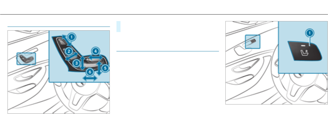
Adjusting the front seat electrically
1Head restraint height
2Seat backrest inclination
3Seat height
4Seat cushion length
5Seat cushion inclination
6Seat fore-and-aft adjustment
#Save the settings with the memory function
(→page 100).
Adjusting the front passenger seat from the
driver's seat electrically
Requirements:
RThe power supply is switched on.
This function is only available on vehicles with an
electrically adjustable front passenger seat.
You can call up thefollowing functions forthe
front passenger seat:
RSeat adjustment
RSeat heating
RSeat ventilation
RMemory function
Seats and stowing 87
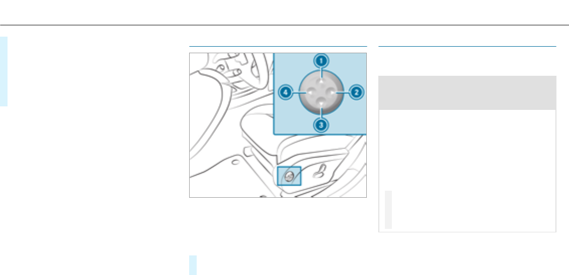
#To select the front passenger seat: press
button 1.
When the indicator lamp lights up, the front
passenger seat is selected.
#Adjust the front passenger seat using the
buttons in the door control panel on the driv‐
er's side.
Adjusting the 4-way lumbar support
1To raise
2To soften
3To lower
4To harden
#Using buttons 1to 4, adjust the contour
of the backrest individually to suit your back.
Head restraints
Adjusting the front seat head restraints man‐
ually
&WARNING Risk of injury from adjusting
thevehicle settings while thevehicle is in
motion
You could lose control of thevehicle in the
following situations:
Rif you adjust the driver's seat, the head
restraint, thesteering wheel or the mirror
while thevehicle is in motion
Rif youfasten your seat belt while thevehi‐
cle is in motion
#Before starting the engine: adjust the
driver's seat, the head restraint, the
steering wheel or the mirror and fasten
your seat belt.
88 Seats and stowing
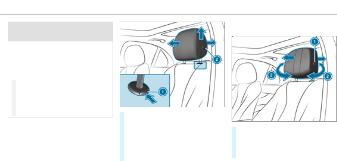
&WARNING Risk of injury due to head
restraints which are not installed or are
adjusted incorrectly
If head restraints are not installed or are
adjusted incorrectly, the head restraints can‐
not provide protection as intended.
There is an increased risk of injury in the
head and neck area, e.g. in theevent of an
accident or when braking.
#Always drive with the head restraints
installed.
#Before driving off, make sure forevery
vehicle occupant that the center of the
head restraint supports the back of the
head at about eye level.
Do not interchange the head restraints of the
front and rear seats. Otherwise, you cannot
adjust the height and angle of the head
restraints correctly.
Adjust the head restraint fore-and-aft position so
that it is as close as possible to the back of your
head.
#To raise: pull the head restraint up.
#To lower: press release knob 1in the direc‐
tion of the arrow and push the head restraint
down.
#To move forwards: pull the head restraint
forwards.
#To move backwards: press release knob 2
and push the head restraint backwards.
Adjusting the front seat luxury head
restraints manually
#To adjust the side bolsters of the head
restraint: pull or push right or left-hand side
bolster2.
#To move forwards: pull the head restraint
forwards.
Seats and stowing 89
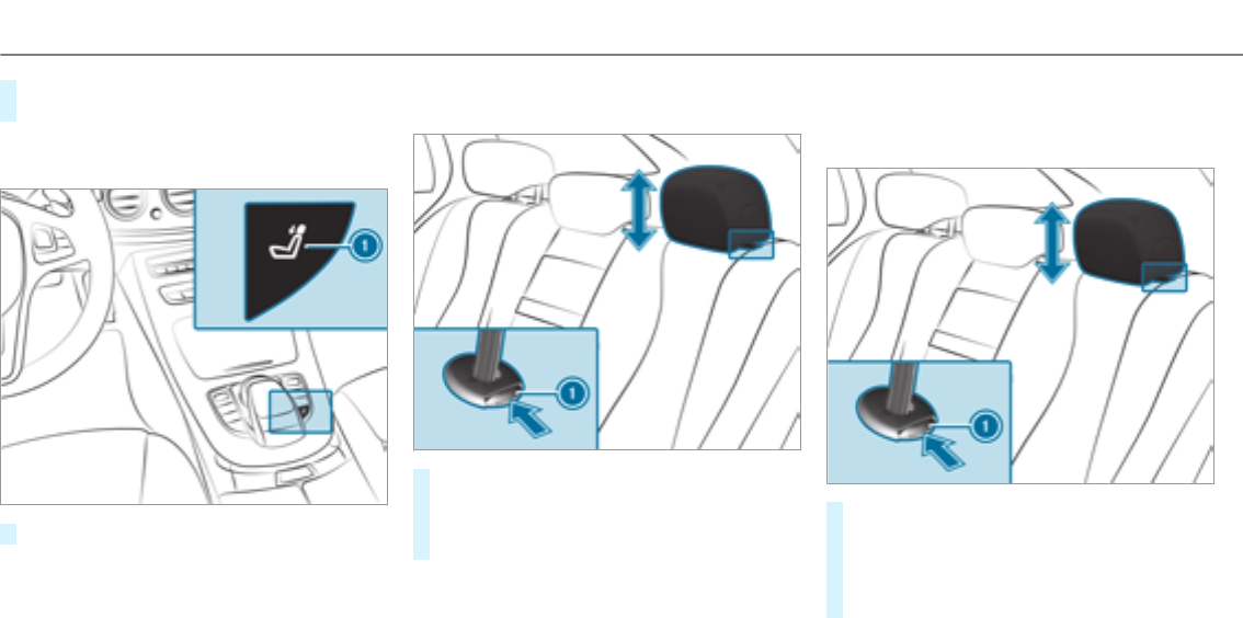
#To move backwards: press release knob 1
and push the head restraint backwards.
Lowering therear seat head restraints from
the front
#Press button 1.
Adjusting the head restraints of therear
seats mechanically
#To raise: pull the head restraint up.
#To lower: press release knob 1in the direc‐
tion of the arrow and push the head restraint
down.
Installing/removing the outer rear seat head
restraints
Removing
#Release therear seat backrest and fold it
slightly forwards (→page 103).
#Pullthe head restraint up to thestop.
#Push release knob 1in the direction of the
arrow and pull out the head restraint.
90 Seats and stowing

Installing
#Insert the head restraint so that the notches
on the bar are on the left when viewed in the
direction of travel.
#Push the head restraint down until you hear
it engage in position.
#Fold therear seat backrest back until it
engages.
Configuring seat settings
Multimedia system:
, .a
#Select or .
Adjusting the backrest side bolsters
#Select .
#Select the setting.
Adjusting the seat contour in the lumbar
region of the seat backrest
#Select .
#Adjust the air cushion.
Memory function
#Save the seat settings with the memory func‐
tion (→page 100).
Setting automatic adjustment of the lateral
support (active multicontour seat)
Multimedia system:
, .a
With this function, the lateral support of the
active multicontour seat is automatically adjus‐
tedto the driving and cornering dynamics of the
vehicle.
#Select or .
#Select .
#Select setting: , or .
Overview of massage and workout programs
Massage programs
The following programs can be selected:
R
R
R
R
R
R
Active Workout
The and
programs require your active cooperation.
Tensing and releasing also helps to improve
blood flow to your muscles. Press against a pres‐
sure point as soon as youfeel it.
Selecting the massage programfor the front
seats
Multimedia system:
, .a
#Select or .
#Select .
#Select a massage program.
The massage program runs for approximately
9to 15 minutes, depending on the setting.
Seats and stowing 91
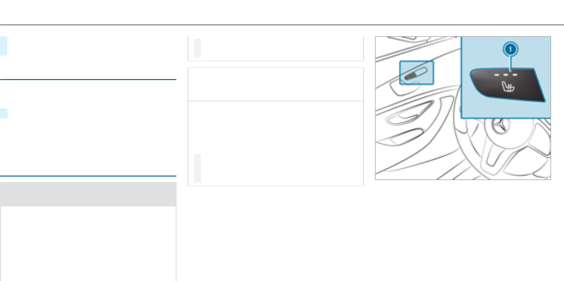
#To set the massage intensity: switch
on Oor off ª.
Resetting seat and massage settings
Multimedia system:
, .a .
#Select or .
Depending on whether the settings forthe driver
or front passenger seat are selected, only the
selected seat can be reset.
Switching the seat heating on/off
&WARNING Risk of burns due to repeat‐
edly switching on the seat heater
Repeatedly switching on the seat heater can
cause the seat cushion and seat backrest
padding to become very hot.
The health of persons with limited tempera‐
ture sensitivity or a limited ability to react to
excessively high temperatures may be affec‐
ted or they may even suffer burn-like injuries.
#Do not repeatedly switch on the seat
heater.
*NOTE Damage to the seats caused by
objects or documents when the seat
heater is switched on
When the seat heater is switched on, over‐
heating can occur due to objects or docu‐
ments placed on the seats e.g. seat cushions
or child seats. This could cause damage to
the seat surface.
#Make sure that no objects or docu‐
ments are on the seats when the seat
heater is switched on.
Requirements
RThe power supply is switched on.
92 Seats and stowing
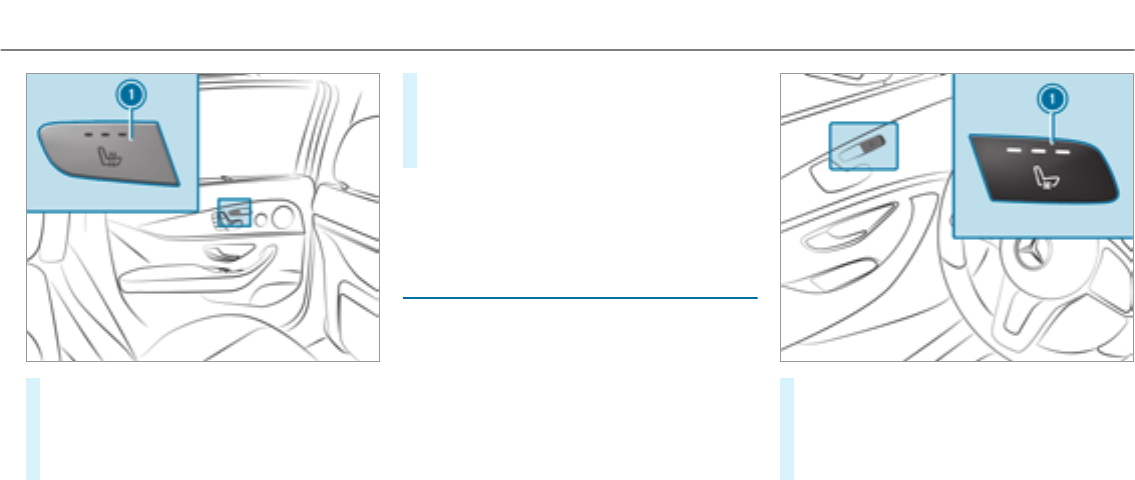
#To switch on/increase the level: press but‐
ton1repeatedly until the desired heating
level is set.
Depending on the heating level, up to three
indicator lamps light up.
#To switch off/reduce the level: press but‐
ton1repeatedly until the desired heating
level is set.
If all indicator lamps are off, the seat heating
is switched off.
%The seat heating automatically switches
down from thethree heating levels after 8,
10 and 20 minutes until the seat heating is
switched off.
Switching the seat ventilation on/off
Requirements:
RThe power supply is switched on.
#To switch on/increase the level: press but‐
ton1repeatedly until the desired ventila‐
tion level is set.
Depending on theventilation level, up to
three indicator lamps light up.
Seats and stowing 93
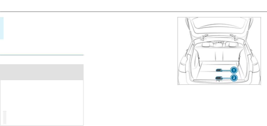
#To switch off/reduce the level: press but‐
ton1repeatedly until the desired ventila‐
tion level is set.
If all indicator lamps are off, the seat ventila‐
tion is switched off.
Folding bench seat in the cargo compart‐
ment
Notes on thefolding bench seat
&WARNING Risk of injury when the seat
backrest is not upright and locked in
position
If the seat backrests of therear bench seat
are not locked in the upright position, the
seat backrest of thefolding bench seat may
fold down while driving.
In this case, the seat belts may not perform
their intended protective function.
#Make sure that the seat backrests of
therear bench seat are locked in the
upright position.
Observe the notes on "Seat belts" (→page 37),
"Head restraints" (→page 88) and "Children in
thevehicle" (→page 46).
The folding bench seat is only approvedfor use
with child seats designed forchildren up to six
years old . Information on suitable child restraint
systems on thefolding bench seat can be
obtained at any authorized Mercedes-Benz Cen‐
ter.
The folding bench seat may only be used when
the combined luggage cover and net is installed.
The tailgate can be opened from thefolding
bench seat. The switch is located on the wheel
arch on theright-hand side when viewed in the
direction of travel.
Folding out the folding bench seat
Requirements:
RThe seat backrests of therear bench seat are
locked in the upright position.
RThe handle forthe combined luggage cover
and net has been moved up. To improvethe
rear view, the upper part of the plate has
been folded down.
94 Seats and stowing
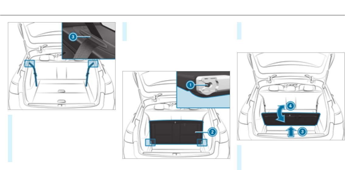
#Pull release handle 1and fold the seat
backrest of thefolding bench seat upwards.
#Hook the seat belts into retainers 3.
#Secure the seat belt buckles in the back of
the seat backrest.
#Pull release 2and fold the seat cushion of
thefolding bench seat into the seat position.
#Push down the seat cushion until the seat
backrest engages fully.
#Fold the head restraints upwards.
Removing or installing the seat cushion
If youwant to open the cargo compartment floor
while thefolding bench seat is folded back, you
must first of all remove the seat cushion.
#To remove:fold seat cushion 2vertically
upwards and remove it from seat cushion
guide 1.
Installing
#Push seat cushion 2into seat cushion
guide 1at a slight angle from therear 3.
#Fold seat cushion 2back into its starting
position 4until it engages.
Seats and stowing 95
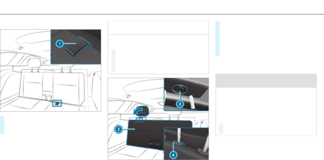
Folding back thefolding bench seat
#Pull the seat cushion upwards by tab1and
fold it back into its starting position until it
engages.
*NOTE Damage to thefolding bench seat
when folding back
The folding bench seat may be damaged
when it is folded back.
#Fully insert the head restraints into the
guides.
#Make sure that the seat belt buckles
engages in their guides.
#Press release knob 3and fold the head
restraints down.
#Press release knob 4and push the head
restraints all thewayin.
#Fold back seat backrest 2of thefolding
bench seat into its starting position.
Opening/closing the cargo compartment
floor
&WARNING Risk of injury due to an open
cargo compartment floor
If you drive when the cargo compartment
floor is open, objects could be thrown around
and thereby strike vehicle occupants. There
is a risk of injury, particularly in theevent of
sudden braking or a sudden change in direc‐
tion.
#Always close the cargo compartment
floor before a journey.
96 Seats and stowing
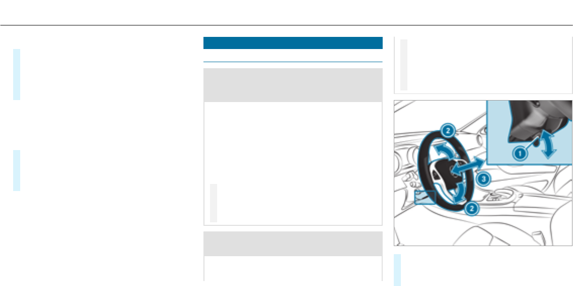
Opening
#Press therelease knob in the middle of the
cargo compartment floor and turn to the
OPEN position.
#Pull the loop on the cargo compartment floor
and fold the cargo compartment floor up.
%If the seat cushions are not installed
(→page 95), the cargo compartment floor
can be completely removed.
Closing
#Reinstall the cargo compartment floor, if nec‐
essary, and fold down.
#Press therelease knob and turn to the
CLOSE position.
Steering wheel
Adjusting the steering wheel manually
&WARNING Risk of injury from adjusting
thevehicle settings while thevehicle is in
motion
You could lose control of thevehicle in the
following situations:
Rif you adjust the driver's seat, the head
restraint, thesteering wheel or the mirror
while thevehicle is in motion
Rif youfasten your seat belt while thevehi‐
cle is in motion
#Before starting the engine: adjust the
driver's seat, the head restraint, the
steering wheel or the mirror and fasten
your seat belt.
&WARNING Risk of entrapment forchil‐
dren when adjusting thesteering wheel
Children could injure themselves if they
adjust thesteering wheel.
#Never leave children unattended in the
vehicle.
#When leaving thevehicle, alwaystake
the SmartKey with you and lock the
vehicle.
#Push release lever1down as far as it will
go.
The steering column is unlocked.
Seats and stowing 97
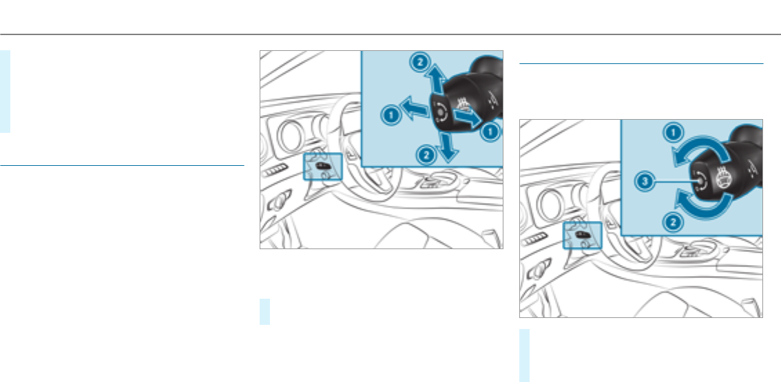
#Adjust height 2and distance 3to the
steering wheel.
#Push release lever1up as far as it will go.
The steering column is locked.
#Check and make sure that thesteering col‐
umn is lockedby moving thesteering wheel.
Adjusting the steering wheel electrically
The steering wheel can be adjusted when the
power supply is switched off.
1Adjusts the distance to thesteering wheel
2Adjusts the height
#Save the settings with the memory function
(→page 100).
Switching thesteering wheel heater on/off
Requirements
RThe power supply or the ignition is switched
on.
#To switch on/off: turn the lever in the direc‐
tion of arrow 1or 2.
If indicator lamp 3lights up, thesteering
wheel heater is switched on.
98 Seats and stowing

Easy entry and exit feature
Function of the easy entry and exit feature
&WARNING Risk of accident when driving
off while adjusting the easy exit feature
‑ If youdrive off while the easy entry and exit
feature is making adjustments, you could
lose control of thevehicle.
#Alwayswait until the adjustment proc‐
ess is complete before driving off.
&WARNING Risk of entrapment when
adjusting the easy entry and exit feature
‑
‑ When the easy entry and exit feature
adjusts thesteering wheel, you and other
vehicle occupants – particularly children –
could become trapped.
#‑ While the easy entry and exit feature
is making adjustments, make sure that
no one has any body parts in the sweep
of thesteering wheel.
#Move the adjustment lever of thesteer‐
ing wheel if there is a risk of becoming
trapped by thesteering wheel.
The adjustment process is stopped.
#Never leave children unattended in the
vehicle.
#When leaving thevehicle, alwaystake
thekeywithyou and lock thevehicle.
Vehicles with memory function: you can stop
the adjustment process by pressing one of the
memory position buttons of the memory func‐
tion.
If the easy entry and exit feature is active, the
steering wheel will move upwards in thefollow‐
ing situations:
RYou switch the ignition off.
RYou open the driver's door when the ignition
is switched on.
The steering wheel moves back to the last drive
position in thefollowing cases:
RYouswitch the ignition on when the driver's
door is closed.
RYou close the driver's door when the ignition
is switched on.
The last drive position of thesteering wheel is
stored in thefollowing situations:
RYouswitch the ignition off.
RVehicles with memory function: save the
seat settings via the memory function.
Vehicles with memory function: press one of
the memory function saved position buttons to
stop the adjustment process.
Setting the easy entry and exit feature
Multimedia system:
, .î
.
#Select or .
Seats and stowing 99
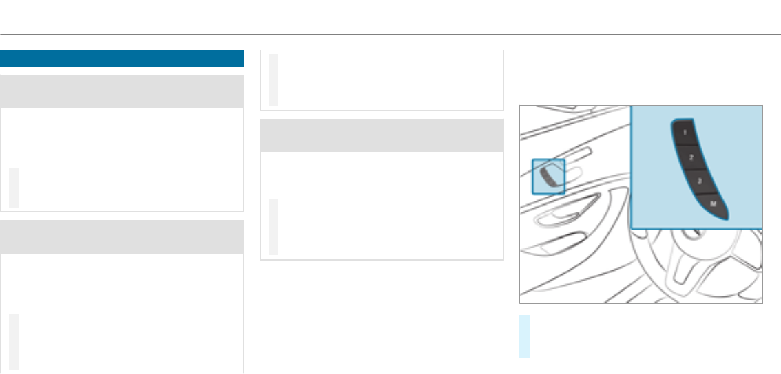
Using the memory function
&WARNING Risk of an accident if memory
function is used while driving
If you use the memory function on the driv‐
er's side while driving, you could lose control
of thevehicle as a result of the adjustments
being made.
#Only use the memory function on the
driver's side when thevehicle is station‐
ary.
&WARNING Risk of entrapment when set‐
ting the seat with the memory function
When the memory function adjusts the seat
or steering wheel, you and other vehicle
occupants – particularly children – could
become trapped.
#During the setting procedure of the
memory function, ensure that no body
parts are in the sweep of the seat or
thesteering wheel.
#If somebody becomes trapped, immedi‐
ately release the memory function posi‐
tion button.
The adjustment process is stopped.
&WARNING Risk of entrapment if the
memory function is activated by children
Children could become trapped if they acti‐
vate the memory function, particularly when
unattended.
#Never leave children unattended in the
vehicle.
#When leaving thevehicle, alwaystake
thekeywithyou and lock thevehicle.
The memory function can be used when the igni‐
tion is switched off.
Storing
Seat adjustments for up to three people can be
stored and called up using the memory function.
The following systems can be selected:
RSeat, backrest and head restraint
RSteering wheel
ROutside mirrors
RHead-up Display
#Set the seat, thesteering wheel, the head-up
display and the outside mirrorto the desired
position.
100Seats and stowing

#Press memory button M together with one of
the memory position switches 1, 2 or 3.
An acoustic signal sounds. The settings are
stored.
#To call up: press and hold therelevant pre‐
set position button 1, 2 or 3 until the front
seat, thesteering wheel, Head-up Display
and outside mirror is in thestored position.
Stowage areas
Notes on loading thevehicle
&WARNING Risk of exhaust gas poisoning
Combustion engines emit poisonous exhaust
gases such as carbon monoxide. Exhaust
gases can enter thevehicle interior if thetail‐
gate is open when the engine is running,
especially if thevehicle is in motion.
#Always switch off the engine before
opening thetailgate.
#Never drive with thetailgate open.
&WARNING Risk of injury from unsecured
items in thevehicle
If objects, luggage or loads are not secured
or not secured sufficiently, they could slip,
tip over or be thrown around and thereby hit
vehicle occupants.
There is a risk of injury, particularly in the
event of sudden braking or a sudden change
in direction.
#Alwaysstow objects in such a waythat
they cannot be thrown around.
#Before the journey, secure objects, lug‐
gage or loads against slipping or tipping
over.
&WARNING Risk of injury due to objects
being stowed incorrectly
If objects in thevehicle interior are stowed
incorrectly, they can slide or be thrown
around and hit vehicle occupants. In addi‐
tion, cup holders, open stowage spaces and
mobile phone brackets cannot alwaysretain
all objects they contain.
There is a risk of injury, particularly in the
event of sudden braking or a sudden change
in direction.
#Alwaysstow objects so that they can‐
not be thrown around in such situa‐
tions.
#Always make sure that objects do not
protrude from stowage spaces, luggage
nets or stowage nets.
#Close the lockable stowage spaces
before starting a journey.
#Stow and secure objects that are heavy,
hard, pointed, sharp-edged, fragile or
too large in the cargo compartment.
&WARNING Risk of burns from tailpipes
and tailpipe trim
The tailpipe and tailpipe trim can become
very hot. If you come into contact withthese
parts of thevehicle, you could burn yourself.
#Always be particularly careful around
thetailpipe and thetailpipe trim.
Seats and stowing 101
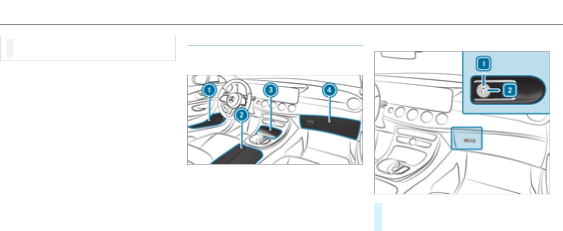
#Allow thevehicle parts to cool down
before youtouch them.
The handling characteristics of your vehicle are
dependent on the distribution of the load within
thevehicle. You should bear thefollowing in
mind when loading thevehicle:
Rneverexceed the permissible gross mass or
the permissible axle loads forthevehicle
(including occupants). The values are speci‐
fied on thevehicle identification plate on the
vehicle's B-pillar.
Rthe load must not protrude above the upper
edge of the seat backrests.
Rwhen transporting objects in the cargo com‐
partment, the combined cargo cover and net
must always be installed (cargo compart‐
ment cover and safetynet).
Ralways place the load behind unoccupied
seats if possible.
Rsecure the load using the tie-down eyes and
distribute the load evenly.
Stowage spaces in thevehicle interior
Overview of the front stowage compart‐
ments
1Stowage compartment in the doors
2Stowage/telephone compartment in the
armrest with multimedia connections and
stowage compartment, e.g. for an MP3
player
3Stowage compartment in the front center
console with a USB port (depending on the
vehicle's equipment)
4Glove box
Locking or unlocking theglove box
#Turn the mechanical key a quarter turn clock‐
wise 2(to lock) or counter-clockwise 1(to
unlock).
102Seats and stowing
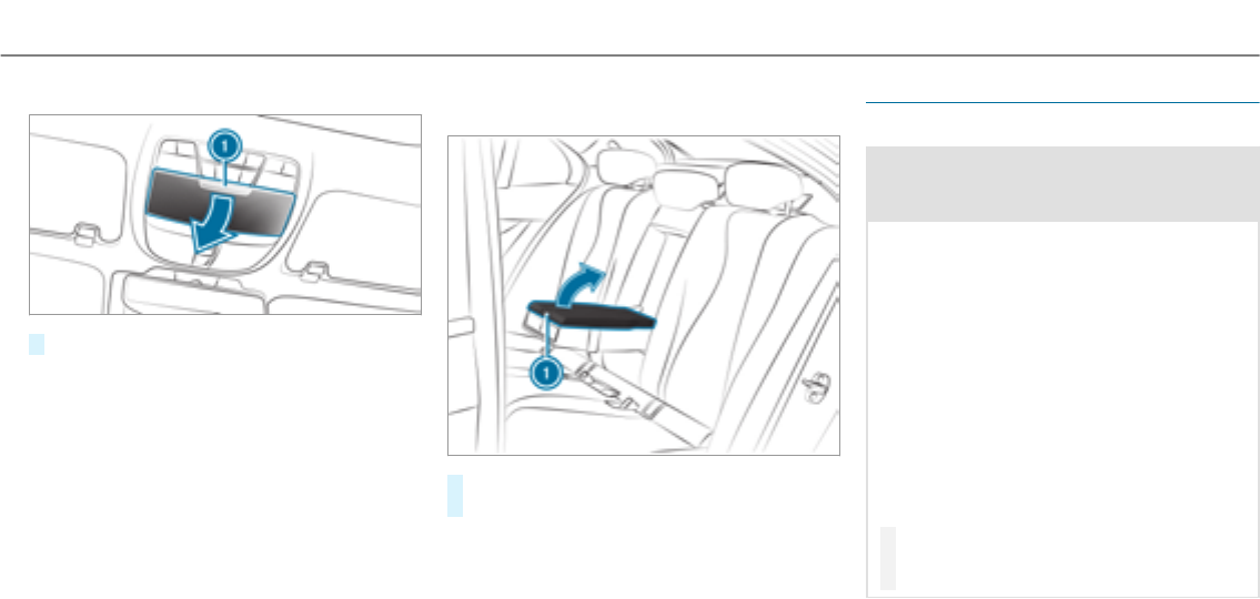
Opening the spectacles compartment
#Press button 1.
Opening the stowage compartment in the
rear armrest
#Press release catch 1and swing the cover
of the armrest upwards.
Rear bench seat through-loading feature
Folding therear seat backrests forward
&WARNING Risk of injury if therear
bench seat/rear seat and seat backrest
are not engaged
If therear bench seat/rear seat and seat
backrest are not engaged they could fold for‐
wards, e.g. when braking suddenly or in the
event of an accident.
RIf this is the case, thevehicle occupant
would be forced into the seat belt by the
rear bench seat/rear seat or by the seat
backrest. The seat belt cannot protect as
intended and could result in additional
injury.
RObjects or loads in the trunk/cargo com‐
partment cannot be restrained by the
seat backrest.
#Make sure that the seat backrest and
therear bench seat/rear seat are
engaged before every trip.
Seats and stowing 103
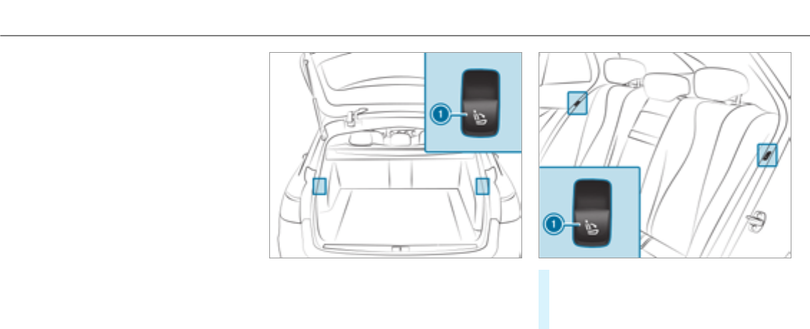
If the seat backrest is not engaged and locked,
this will be shown on the multifunction display
on the instrument cluster.
Requirements:
RThe rear seat backrest head restraints are
fully inserted.
The center and outer seat backrests can be fol‐
ded forwards separately.
The right seat backrest can only be folded for‐
wardstogether with the center seat backrest.
The outer seat backrests are unlocked electri‐
cally. Depending on the equipment, therelease
buttons are located either in the load compart‐
ment or beside the seat backrests.
#Left and right seat backrest: press the
right or left button 1.
The corresponding seat backrest folds for‐
wards.
104Seats and stowing
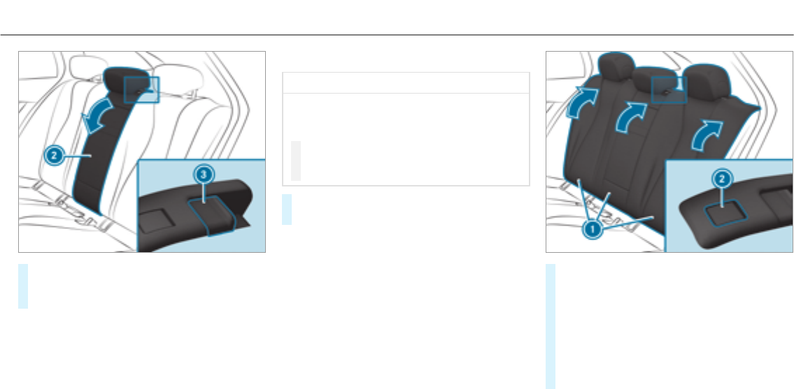
#Center seat backrest: pull release 3of
seat backrest 2forwards.
#Fold seat backrest 2forwards.
Folding therear seat backrest back
*NOTE Damage to the seat belt
The seat belt could become trapped and thus
damaged when folding back the seat back‐
rest.
#Make sure that the seat belt is not trap‐
ped when folding back the seat back‐
rest.
#Move the driver's or front passenger seat for‐
wards, if necessary.
#Fold corresponding seat backrest 1back
until it engages.
Left and right seat backrests: if the seat
backrest is not engaged and locked, this will
be shown in the multifunction display in the
instrument cluster.
Center seat backrest: if the seat backrest is
not engaged and locked, red lock verification
indicator 2will be visible.
Seats and stowing 105
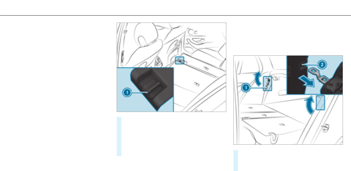
Blocking therelease catch of the center rear
seat backrest
Requirements:
RThe left and center seat backrest are
engaged and joined together.
Lock the center seat backrest release catch if
youwant to secure the cargo compartment from
unauthorized access. The center seat backrest
can then only be folded forwards together with
the left seat backrest.
#Fold the center and left seat backrest for‐
wards.
#To lock: slide catch 1upwards.
The release mechanism of the center seat
backrest is locked.
#To unlock:slide catch 1downwards.
Adjusting the angle of the rear seat backr‐
ests (cargo position)
To enlarge the load compartment, you can adjust
the seat backrests so that they are 10 degrees
steeper (cargo position).
#Fold the seat backrest forwards
(→page 103).
#Move bar 1in the direction of the arrow.
106Seats and stowing
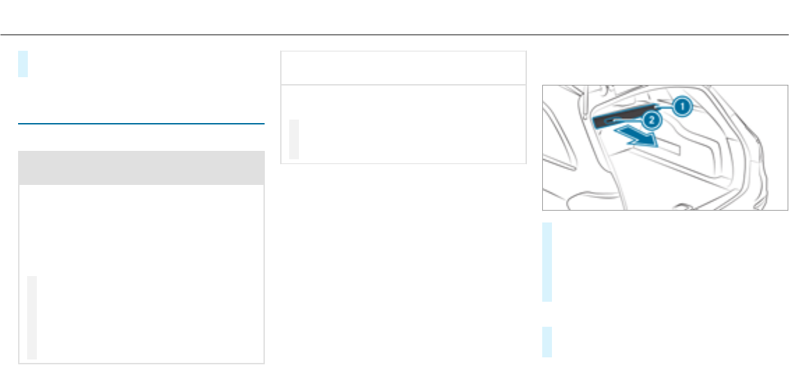
#Push seat backrest 2back to bar 1until
the backrest engages.
Load compartment cover with safety net
(combined cargo cover and net)
Notes on the cargo compartment cover
&WARNING Risk of injury or death due to
objects being poorly secured
On its own, the cargo compartment cover
cannot secure or restrain heavy objects,
items of luggage and heavy loads.
You could be hit by an unsecured load during
sudden changes in direction, braking or in
theevent of an accident.
#Alwaysstow objects in such a waythat
they cannot be thrown around.
#Secure objects, luggage or loads
against slipping or tipping over, e.g. by
using tie-downs, even if you are using
the cargo compartment cover.
*NOTE Damage to the cargo compart‐
ment cover when loading thevehicle
The cargo compartment cover may be dam‐
aged when loading thevehicle.
#Do not place any objects above the
lower edge of the side windows or on
the cargo compartment cover.
The cargo compartment cover and the safetynet
form the combined luggage cover and net.
When the cargo compartment cover is clipped
in, no objects in the cargo compartment should
obstruct the downwards movement of the cover
when thetailgate is closed. The cargo compart‐
ment cover will otherwise be raised again auto‐
matically.
Extending/retracting the cargo compart‐
ment cover
#To extend: pull cargo compartment cover1
back by grab handle 2and clip it into the
brackets on the left and right.
The cargo compartment coverraises auto‐
matically when thetailgate is opened and
lowers again when thetailgate is closed.
Retraction
#Remove the cargo compartment cover1
from the brackets on the left and right.
Seats and stowing 107
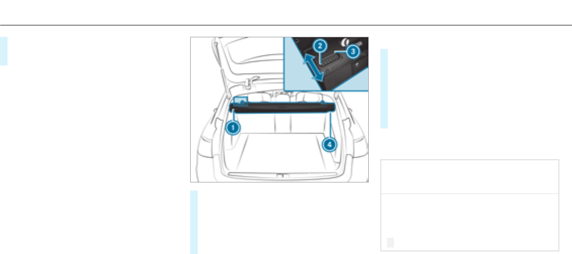
#Guide the cargo compartment cover1for‐
wards on the grab handle 2until it is fully
retracted.
The contour plate of theextended cargo com‐
partment cover1can be used in three posi‐
tions:
Rfolded up by 45° (loading position)
Rhorizontal position (driving position)
Rfolded down and locked in place (rattle-free
position when driving)
Installing/removing the combined luggage
cover and net
Requirements:
RThe cargo compartment cover and safetynet
areretracted.
Removing
Remove the combined luggage cover and net
from the cargo compartment, or from the left-
hand rear door if the seat backrests are folded
forwards.
#Press button 2.
#Fold the combined luggage cover and net
backwards with the seat backrest folded up.
#First, detach the combined luggage cover
and net from left-hand catch 1and then
remove it from right-hand bracket4.
Installing
#Slide the combined luggage cover and net
into right-hand bracket4up to thestop.
#Place the combined luggage cover and net
into the left-hand bracket and slide it into
catch 1until the combined luggage cover
and net engages audibly.
Red lock verification indicator 3must no
longer be visible.
Attachingthe combined luggage cover and
net to therear seat backrest
*NOTE Damage to the combined luggage
cover and net when attaching it to the
seat backrest
When the combined luggage cover and net is
attached to the seat backrest, it may be
damaged when the seat backrest is folded
back.
#Do not fold the seat backrests back.
Requirements:
RThe seat backrests are folded forwards.
108Seats and stowing
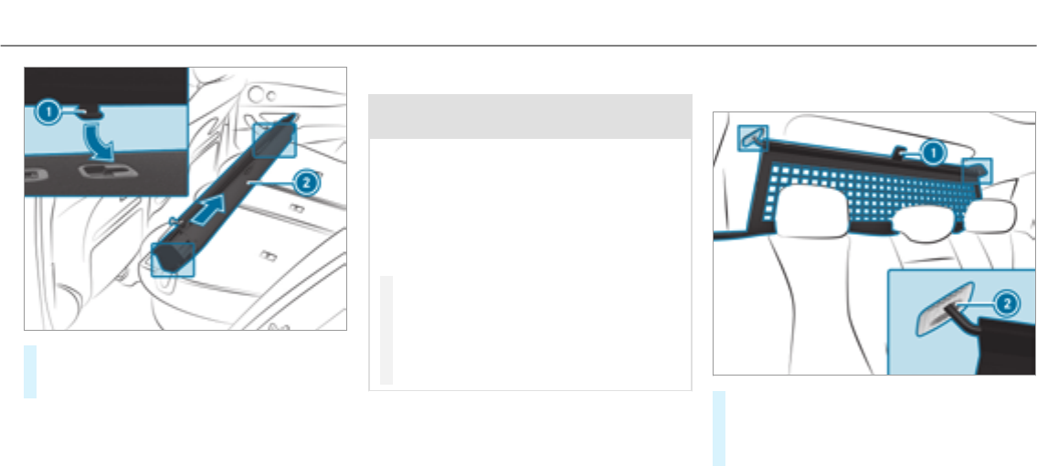
#Insert combined luggage cover and net 2
into both guides 1and push it up to the
stop in the direction of the arrow.
To disassemble the combined luggage cover and
net, follow the instructions in reverse order.
Attachingthe safety net
&WARNING Risk of injury due to poorly
secured objects
On its own, the safetynetcannotsecureor
restrain heavy objects, items of luggage or
heavy loads.
You could be hit by an unsecured load during
sudden changes in direction, braking or in
theevent of an accident. There is an
increased risk of injury or even fatal injury.
#Alwaysstow objects in such a waythat
they cannot be thrown around.
#Secure objects, luggage or loads
against slipping or tipping over, e.g. by
using lashing material, even if you are
using the safetynet.
For safetyreasons, always use a safetynetwhen
transporting aload.
Damaged safetynets can no longer fulfill their
protective functions and must be replaced. Visit
aqualified specialist workshop.
Safety net without cargo compartment
enlargement
#Pull the safetynetfrom therear bench seat
back to therear using tab1.
#Hook the safetynetinto eyelets 2,first on
the left, then on theright.
Seats and stowing 109
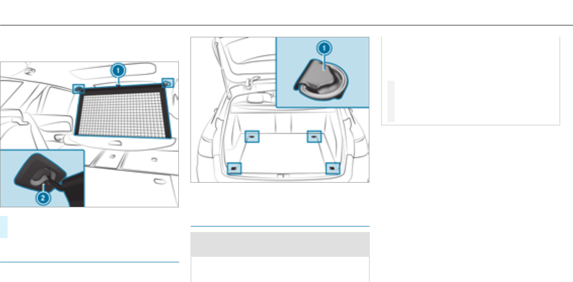
Safety net with cargo compartment enlarge‐
ment
#Guide the safetynetupwards on thetab1.
#Hook the safetynetinto theeyelets 2.
Overview of the tie-down eyes
Observe the notes on loading thevehicle
(→page 101).
1Tie-down eyes
Overview of bag hooks
&WARNING Risk of injury when using bag
hooks with heavy objects
The bag hooks cannot restrain heavy objects
or items of luggage.
Objects or items of luggage could be thrown
around and thereby hit vehicle occupants
when braking or abruptly changing direc‐
tions.
#Only hang light objects on the bag
hooks.
#Never hang hard, sharp-edged or fragile
objects on the bag hooks.
Observe the notes on loading thevehicle
(→page 101).
The bag hook can bear a maximum load of
6.6 lbs (3 kg). Do not use it to secure a load.
110Seats and stowing
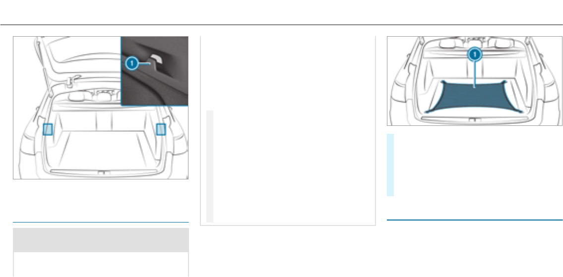
1Bag hook
Hooking the luggage net
&WARNING Risk of injury due to objects
being stowed incorrectly
If objects in thevehicle interior are stowed
incorrectly, they can slide or be thrown
around and hit vehicle occupants. In addi‐
tion, cup holders, open stowage spaces and
mobile phone brackets cannot alwaysretain
all objects they contain.
There is a risk of injury, particularly in the
event of sudden braking or a sudden change
in direction.
#Alwaysstow objects so that they can‐
not be thrown around in such situa‐
tions.
#Always make sure that objects do not
protrude from stowage spaces, luggage
nets or stowage nets.
#Close the lockable stowage spaces
before starting a journey.
#Stow and secure objects that are heavy,
hard, pointed, sharp-edged, fragile or
too large in the cargo compartment.
Observe the notes on loading thevehicle.
#Vehicles with a cargo compartment package:
insert the brackets with the tie-down eyes
into the load rails (→page 112).
#Fold up the tie-down eyes.
#Hook luggage net 1into the front and rear
tie-down eyes.
EASY-PACK load-securing kit
Notes on the EASY-PACK load-securing kit
The EASY-PACK load-securing kit allows youto
use your cargo compartment for a varietyof pur‐
poses. The components are located in thestow‐
age space under the cargo compartment floor.
Seats and stowing 111
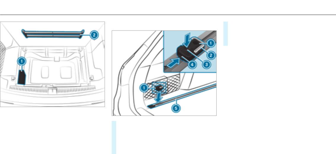
1Bag containing the brackets and luggage
holder
2Telescopic rod
Inserting the brackets into the load rail
#Insert bracket1into the center of load rail
5.
#Press release knob 3and slide bracket1
into the desired position in load rail 5.
#Let go of release knob 3.
#Press locking button 4.
Bracket1has been secured in the selected
position in the load rail 5.
#If necessary, fold tie-down eye2upwards.
Installing or removing the luggage holder
Requirements:
RSelect a load size that can be secured by the
luggage holder.
The luggage holder is used to secure loads
against the side wall of the load compartment to
prevent them from moving around.
You can subject the load holder to a maximum
load of 15.4 lbs (7 kg).
112Seats and stowing
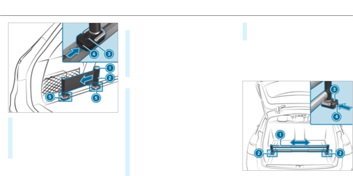
#Insert two brackets 5into the load rail
(→page 112).
#Pressandhold release knob 1on luggage
holder 2.
#Pull the belt on the handle out slightly.
#Let go of release knob 1.
Installing
#Press and hold release knob 3of first
bracket5.
#Insert luggage holder 2into first bracket5
and slide it downwards until it engages.
#Let go of release knob 3.
#Repeat the process with second bracket5
and the handle.
Loading
#Press and hold release knob 1on luggage
holder 2.
#Pull the belt on the handle out.
#Place the load between thestrap and the
load compartment side wall.
#Press and hold release knob 1on luggage
holder 2.
#Hold the belt on the handle firmly and slowly
guide it back until the load has been
secured.
#Let go of release knob 1.
#On both brackets 5, press locking button
4.
#To remove:press release knob 3on
respective bracket5and remove luggage
holder 2by pulling it out.
Installing or removing the telescopic rod
Installing
The telescopic rod is used to secure loads
against therear seats to prevent them from
moving around.
Seats and stowing 113
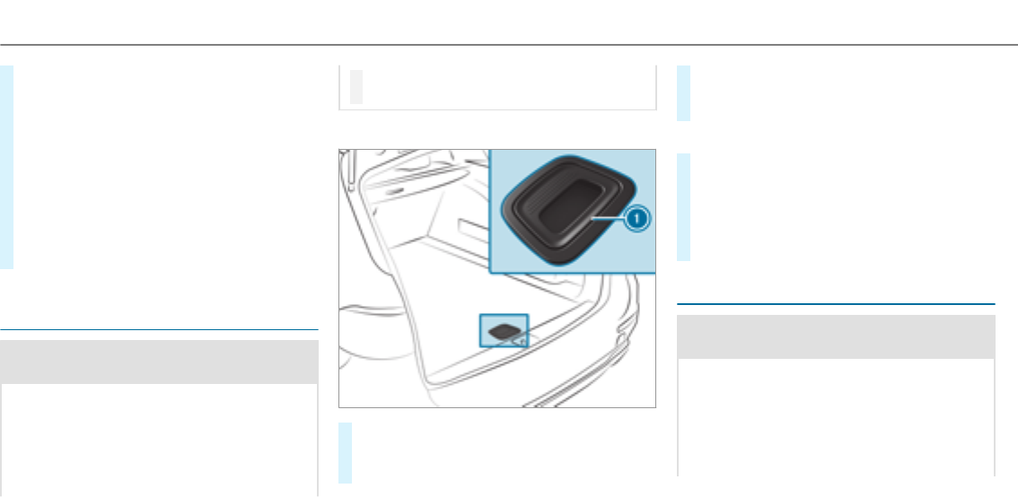
#Insert one bracket2into both the left and
right load rails and slide it to the desired
position.
#Press and hold release knob 3.
#Insert thetelescopic rod1into brackets 2
and slide it downwards until it engages.
#On both brackets 5, press locking button
4.
#To remove:press release knob 3on
respective bracket2and remove telescopic
rod1by pulling it upwards and out.
Opening or closing thestowage space under
the cargo compartment floor
&WARNING Risk of injury due to an open
cargo compartment floor
If youdrive when the cargo compartment
floor is open, objects could be thrown around
and thereby strike vehicle occupants. There
is a risk of injury, particularly in theevent of
sudden braking or a sudden change in direc‐
tion.
#Always close the cargo compartment
floor before a journey.
Opening
#Pull handle 1upwards.
#Lift the load compartment floor upwards by
handle 1.
#Fold out hook on the underside of the cargo
compartment floor.
#Clip hook into drip rail.
Closing
#Unhook the hook from the drip rail and fas‐
ten it to the bracket on the underside of the
load compartment floor.
#Fold the load compartment floor downwards
and then press handle 1down until it
engages.
Attachingtheroof rack
&WARNING Risk of injury by exceeding
the maximum roof load
When you load theroof, thevehicle center of
gravity rises and the driving characteristics
change.
If youexceed the maximum roof load, the
driving characteristics, as well as thesteer‐
ing and braking, will be greatly impaired.
114Seats and stowing

#Neverexceed the maximum roof load
and adjust your drivingstyle.
Youwill find information on the maximum roof
load in the "Technical data" section.
*NOTE Vehicle damage from non-
approvedroof racks
The vehicle could be damaged by roof racks
which have not been tested and approvedby
Mercedes-Benz.
#Only use roof rackstested and
approvedby Mercedes-Benz.
#Depending on thevehicle equipment,
ensure that when theroof rack is fitted:
RThe sliding sunroof can be fully
raised.
RThe tailgate can be opened com‐
pletely.
#Position the load on theroof rack in
such a waythat thevehicle will not sus‐
tain damage even when it is in motion.
*NOTE Damage to the panoramic sliding
sunroof when a roof rack is fitted
The panoramic sliding sunroof may be dam‐
aged by theroof rack if you attempt to open
it when theroof rack is fitted.
#Do not open the panoramic sliding sun‐
roof if a roof rack is fitted.
In order to allow ventilation of thevehicle
interior, you can raise the panoramic sliding
sunroof.
#Secure theroof rack to theroof railing.
#Observe the manufacturer's installation
instructions.
Cup holder
Installing the cup holder in or removing it
from the center console (automatic trans‐
mission)
&WARNING ‑ Risk of accident or injury
when using the cup holder while the
vehicle is moving
The cup holder cannot secure containers
while thevehicle is moving.
If you use a cup holder while thevehicle is
moving, the container may be flung around
and liquids may be spilled. The vehicle occu‐
pants may come into contact with the liquid
and if it is hot, they could be scalded. You
could be distracted from traffic conditions
and you may lose control of thevehicle.
#Only use the cup holder when thevehi‐
cle is stationary.
#Only use the cup holder for containers
of theright size.
#Close the container, particularly if the
liquid is hot.
Seats and stowing 115
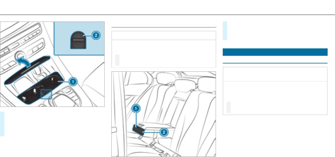
#To remove:slide catch 2forwards and pull
out cup holder 1.
#To install: insert cup holder 1and slide
back catch 2.
%The cup holder rubber mat can be removed
for cleaning, e.g. using clean, lukewarm
water.
Opening the cup holder in therear armrest
*NOTE Damage to the cup holder
When therear armrest is folded back the cup
holder could become damaged.
#Only fold therear armrest back when
the cup holder is closed.
#Press cup holder 1or 2.
#Place a container in or remove a container
from cup holder 1or 2.
Ashtray and cigarette lighter
Using the ashtray in the front center console
*NOTE Damage to thestowage compart‐
ment under the ashtray
The stowage compartment under the ashtray
is not heat resistant and could be damaged if
yourest a lit cigarette on it.
#Make sure that the ashtray is fully
engaged.
116Seats and stowing
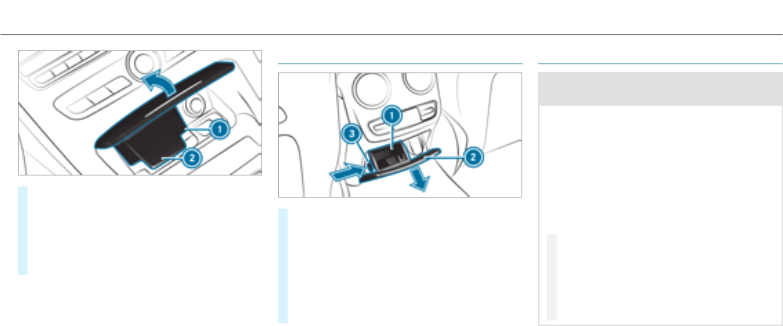
#To open: push up the cover2of the ash‐
tray on its right or left side.
#To remove the insert: press insert 1
upwards slightly and pull it out upwards.
#To refit the insert:press insert 1into the
holder until it engages.
Using therear ashtray
#To open: pull cover2out by its top handle
edge.
#To remove the insert: push ribbing 3from
the left side and pull insert 1upwards and
out.
#To install the insert: install insert 1from
above and press down into the holder until it
engages.
Using the cigarette lighter
&WARNING ‑ Risk of fire and injury from
hot cigarette lighter
You can burn yourself if youtouch the hot
heating element or the socket of the ciga‐
rette lighter.
In addition, flammable materials may ignite
if:
Ryoudrop the hot cigarette lighter
Rachild holds the hot cigarette lighter to
objects, forexample
#Always hold the cigarette lighter by the
knob.
#Always make sure that the cigarette
lighter is out of reach of children.
#Never leave children unattended in the
vehicle.
Requirements:
Rthe ignition is switched on.
Seats and stowing 117
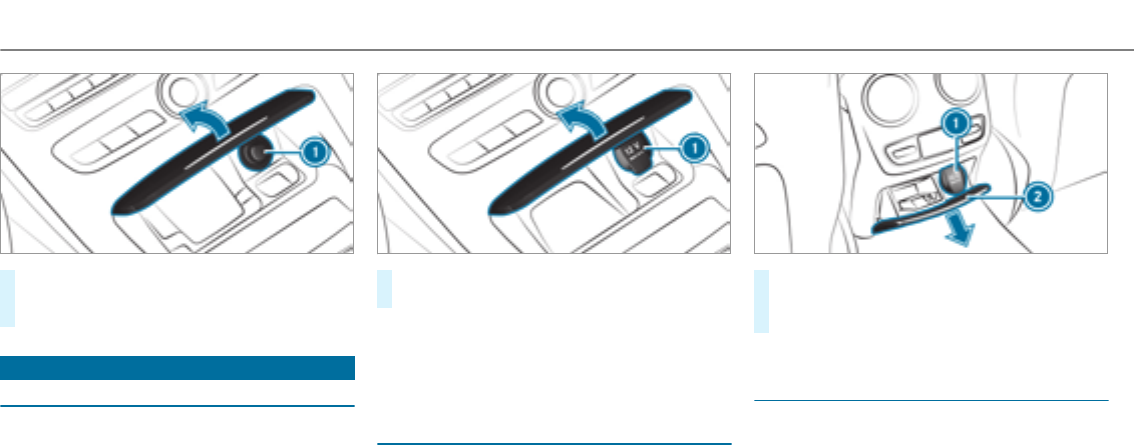
#Press in cigarette lighter 1.
The cigarette lighter will pop out automati‐
cally when the heating element is red-hot.
Sockets
12 V socket in the front center console
Requirements
ROnly connect devices up to a maximum of
180watts (15 A).
#Lift up cap 1of the socket and insert the
plug of the device.
If you have connected a device to the12 V
socket, leave the cover of thestowage compart‐
ment open.
Using the12 V socket in therear passenger
compartment
Requirements
ROnly connect devices up to a maximum of
180watts (15 A).
#Brieflypress the trim element of cover2.
#Lift up cap 1of the socket and insert the
plug of the device.
Using the12 V socket in the front passenger
footwell
Requirements
ROnly connect devices up to a maximum of
180watts (15 A).
118Seats and stowing
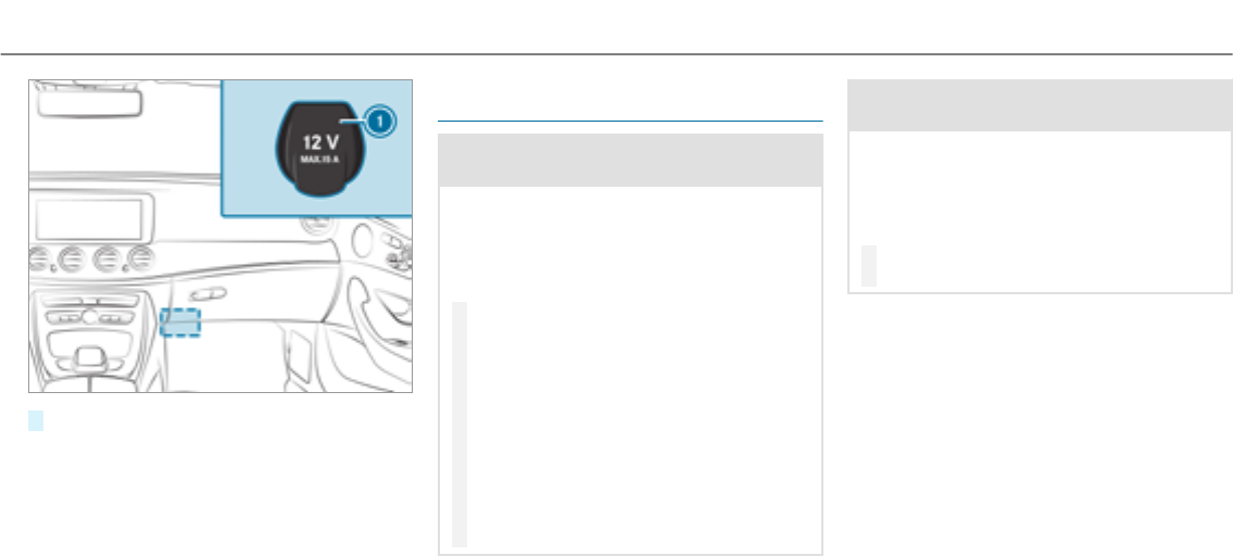
#Lift up socket cap 1.
Using the 115 V socket in the rear passenger
compartment
&DANGER Risk of fatal injury due to dam‐
aged connecting cables or sockets
If a suitable device is connected, the115 V
socket will be carrying a high voltage. If the
connecting cable or the115 V socket is
pulled out of the trim or is damaged or wet,
you could receive an electric shock.
#Only use dry and damage-free connect‐
ing cables.
#When the ignition is switched off,
ensure that the115 V socket is dry.
#If the115 V socket is damaged or gets
pulled out of the paneling, immediately
have the socketchecked or replaced at
aqualified specialized workshop.
#Never plug the connecting cable into a
115 V socketthat is damaged or has
been pulled out of the trim.
&DANGER Risk of fatal injury due to incor‐
rect handling of the socket
You could receive an electric shock:
Rif youreach into the socket.
Rif you insert unsuitable devices or objects
into the socket.
#Only connect suitable devices to the
socket.
Requirements
ROnly connect devices with a suitable plug
which conformsto thestandards specific to
the country you are in.
ROnly connect devices up to a maximum of
150watts.
RDo not use multiple socket outlets.
Seats and stowing 119
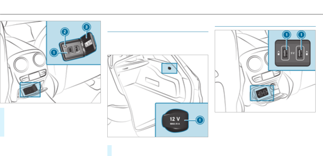
#Open flap 3.
#Insert the plug of the device into 115 V
socket1.
When the on-board electrical system voltage
is sufficient, indicator lamp 2lights up.
Using the12 V socket in the load compart‐
ment
Requirements
ROnly connect devices up to a maximum of
180watts (15 A).
#Lift up cap 1of the socket and insert the
plug of the device.
USB port in therear passenger compartment
You can charge a USB device, e.g. a mobile
phone, at USB ports 1using a suitable charg‐
ing cable. The devices can be charged with 5 V
(2.1 A) and when the ignition is switched on.
120Seats and stowing

Wireless charging of the mobile phone and
connection with theexterior antenna
Notes on wireless charging of the mobile
phone
&WARNING Risk of injury due to objects
being stowed incorrectly
If objects in thevehicle interior are stowed
incorrectly, they can slide or be thrown
around and hit vehicle occupants. In addi‐
tion, cup holders, open stowage spaces and
mobile phone brackets cannot alwaysretain
all objects they contain.
There is a risk of injury, particularly in the
event of sudden braking or a sudden change
in direction.
#Alwaysstow objects so that they can‐
not be thrown around in such situa‐
tions.
#Always make sure that objects do not
protrude from stowage spaces, luggage
nets or stowage nets.
#Close the lockable stowage spaces
before starting a journey.
#Stow and secure objects that are heavy,
hard, pointed, sharp-edged, fragile or
too large in the cargo compartment.
Observe the notes on loading thevehicle.
&WARNING Risk of fire from placing
objects in the mobile phone stowage
compartment
If you place objects in the mobile phone
stowage compartment, they may heat up
excessively and even catch fire.
#Do not place additional objects, espe‐
cially those mode of metal, in the
mobile phone stowage compartment.
*NOTE Damage to objects caused by
placing them in the mobile phone stow‐
age compartment
If you place objects in the mobile phone
stowage compartment, these may be dam‐
aged by electromagnetic fields.
#Do not place credit cards, storage
media or other objects sensitive to
electromagnetic fields in the mobile
phone stowage compartment.
*NOTE Damage to the mobile phone
stowage compartment caused by liquids
If liquids enter the mobile phone stowage
compartment, the compartment may be
damaged.
#Ensure that no liquids enter the mobile
phone stowage compartment.
RDepending on thevehicle equipment, the
mobile phone is connected to thevehicle's
exterior antenna via thecharging module.
Seats and stowing 121
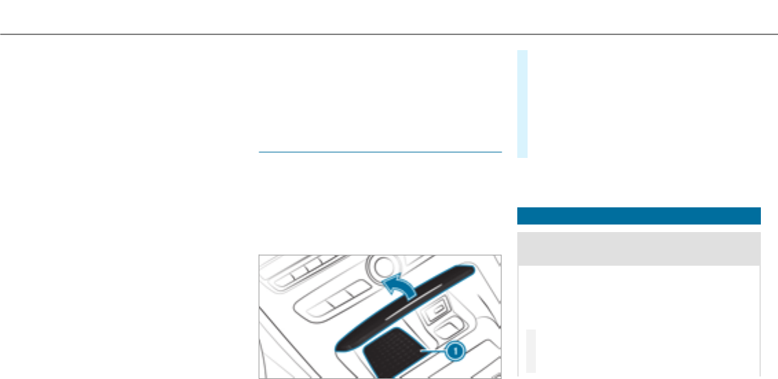
RThe charging function and wireless connec‐
tion of the mobile phone to thevehicle's
exterior antenna are only available if the igni‐
tion is switched on.
RSmall mobile phones may not be able to be
charged in every position of the mobile
phone stowage compartment.
RLarge mobile phones which do not rest flat in
the mobile phone stowage compartment may
not be able to be charged or connected with
thevehicle's exterior antenna.
RThe mobile phone may heat up during the
charging process. This depends on the appli‐
cations (apps) currently running.
The mobile phone can be cooled in the
mobile phone stowage compartment when
the air conditioning system is switched on.
The cooling output in the mobile phone stow‐
age compartment is highest when the con‐
troller in theglove box is closed.
RTo ensure more efficient charging and con‐
nection with thevehicle's exterior antenna,
remove the protective cover from the mobile
phone. Protective covers which are designed
for wireless charging are excluded.
RWhen charging, the mat should be used if
possible.
Wireless charging of the mobile phone in the
front
Requirements
RThe mobile phone is suitable for wireless
charging (Qi-compatible mobile phone).
%A list of Qi-compatible mobile phones can be
found at: http://www.mercedes-benz.com/
connect.
#Place the mobile phone as close to the cen‐
ter of mat 1as possible with the display
facing upwards.
When thecharging symbol is shown in the
multimedia system, the mobile phone is
being charged.
Malfunctions during thecharging process are
shown in the multimedia system display.
%The mat can be removedfor cleaning, e.g.
using clean, lukewarm water.
Installing or removing the floor mats
&WARNING Risk of accident due to
objects in the driver's footwell
Objects in the driver's footwell may impede
pedal travel or block a depressed pedal.
This jeopardizes the operating and road
safetyof thevehicle.
#Stow all objects in thevehicle securely
so that they cannot get into the driver's
footwell.
122Seats and stowing
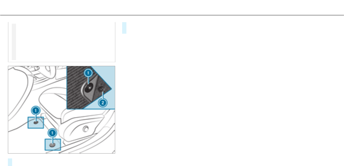
#Always install thefloor mats securely
and as prescribed in order to ensure
that there is always sufficient room for
the pedals.
#Do not use loose floor mats and do not
place floor mats on top of one another.
#To install: press stud 1into holder 2.
#To remove:pull thefloor mat off the holders
2.
Seats and stowing 123
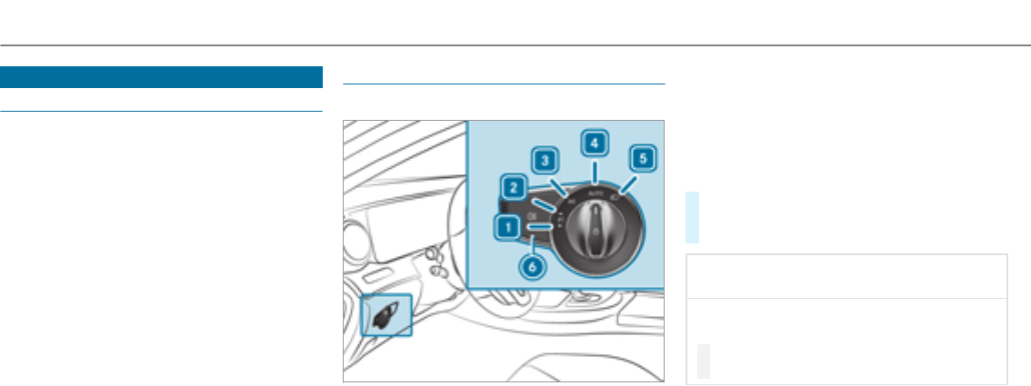
Exterior lighting
Lighting systems and your responsibility
The various lighting systems of thevehicle are
only aids. The driver of thevehicle is responsible
for correct vehicle illumination in accordance
with the prevailing light and visibility conditions,
legal requirements and traffic situation.
Light switch
Operating the light switch
1WLeft-hand parking lights
2XRight-hand parking lights
3TParking lights and license plate lighting
4ÃAutomatic driving lights (preferred light
switch position)
5LLow beam/high beam
6RSwitches therear fog light on or off
When low beam is activated, theTindicator
lamp forthe parking lights is deactivated and
replaced by theLindicator lamp forthe low
beam.
#Always park your vehicle safely and in a well-
lit area, in accordance with therelevant legal
stipulations.
*NOTE Battery discharging by operating
thestanding lights
Operating thestanding lights over a period of
hours puts a strain on the battery.
#Where possible, switch on the
right Xor left Wparking light.
In the case of severe battery discharging, the
parking lights or standing lights are automati‐
cally switched off to facilitate the next engine
start.
124Light and visibility
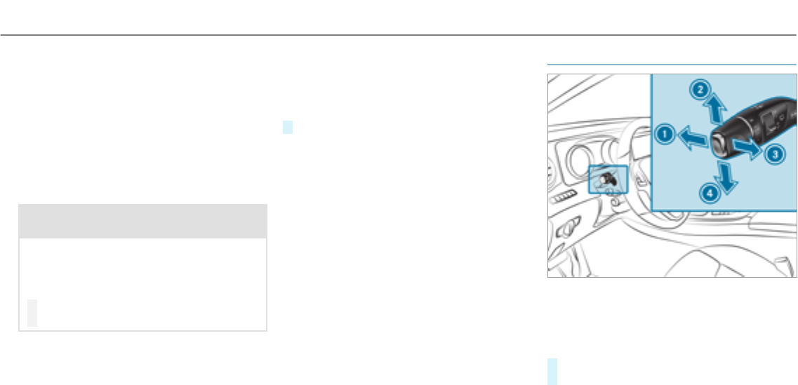
The exterior lighting (except parking and stand‐
ing lights) switches off automatically when the
driver's door is opened.
RObserve the notes on surround lighting
(→page 128).
Automatic driving lights function
The parking lights, low beam and daytime run‐
ning lights are switched on automatically
depending on the ignition status, whether the
engine is running and the light conditions.
&WARNING Risk of accident when the low
beam is switched off in poor visibility
When the light switch is set to Ã,the low
beam may not be switched on automatically
if there is fog, snow or other causes of poor
visibility such as spray.
#In such cases, turn the light switch to
L.
The automatic driving lights are only an aid. You
are responsible forvehicle lighting.
Activating/deactivating the rear fog light
Requirements
RThe light switch is in theLor Ãposi‐
tion.
#Press theRbutton.
Please observe the country-specific laws on the
use of rear fog lights.
Operating the light combination switch
1High beam
2Turn signal light, right
3High-beam flasher
4Turn signal light, left
#Pull or push the combination switch in the
relevant direction following the arrow.
Light and visibility 125
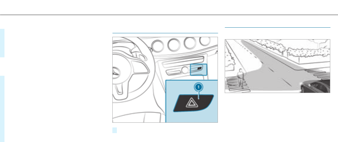
Switching on the high beam manually
#Vehicles with Adaptive Highbeam Assist:
Turn the light switch to theLposition.
RPress the combination switch beyond the
pressure point in the direction of
arrow1.
When the high beam is activated, the indicator
lamp for low beam is deactivated and replaced
by the indicator lamp forthe high beam.
#To switch off the high beam: move the
combination switch back to its starting posi‐
tion.
#To indicate briefly: press the combination
switch briefly up to the pressure point in the
direction of arrow 2or 4.
The corresponding turn signal light flashes
three times.
#To indicate for a duration: press the combi‐
nation switch beyond the pressure point in
the direction of arrow 2or 4.
Activating/deactivating the hazard warning
light
#Press button 1.
Cornering light
Cornering light function
The cornering light improvesthe illumination of
the carriagewayover a wide angle in the turning
direction, enabling better visibility on tight
bends, forexample. It can be activated only
when the low beam is switched on.
The function is active:
RAt speeds below 25 mph (40 km/h) when
the turn signal light is switched on or the
steering wheel is turned.
126Light and visibility
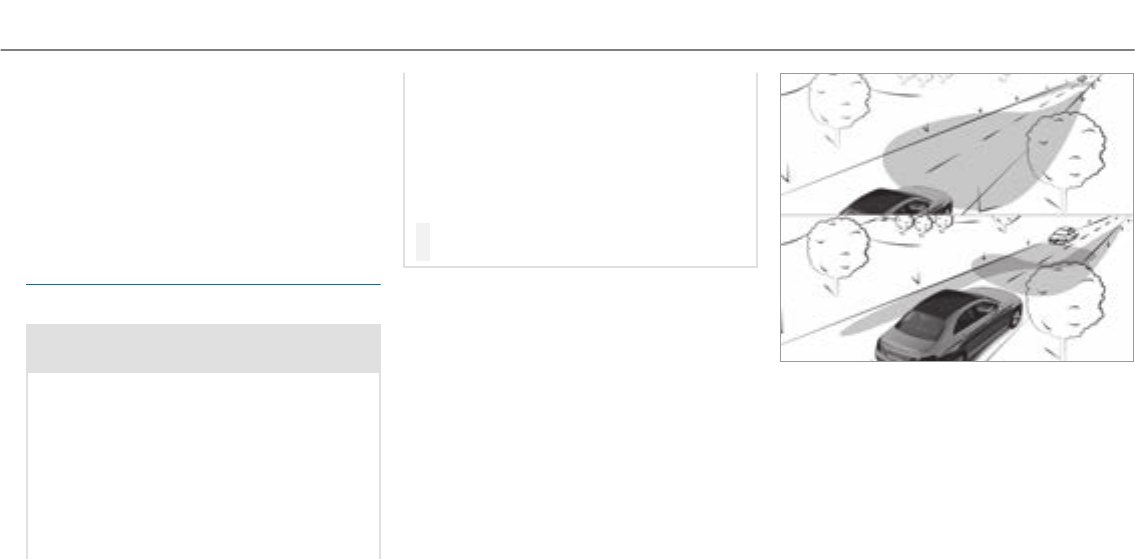
RAt speeds between 25 mph(40 km/h) and
45 mph(70 km/h) when thesteering wheel
is turned.
Traffic circle and intersection function: the
cornering light is activated on both sides through
an evaluation of the current GPS position of the
vehicle. It remains active until afterthevehicle
has left the traffic circle or the intersection.
Adaptive Highbeam Assist
Function of Adaptive Highbeam Assist
&WARNING Risk of accident despite
Adaptive Highbeam Assist
Adaptive Highbeam Assist does not recog‐
nize thefollowing road users:
RRoad users without lights, e.g. pedes‐
trians
RRoad users with poor lighting, e.g.
cyclists
RRoad users whose lighting is obstructed,
e.g. by a barrier
On very rare occasions, Adaptive Highbeam
Assist may fail to recognize other road users
with their own lighting, or may recognize
them too late.
In these or similar situations, the automatic
high beam is not deactivated or is activated
despite the presence of other road users.
#Always observe the traffic carefully and
switch off the high beam in good time.
System limitations
Adaptive Highbeam Assist cannot take into
account road, weather or traffic conditions.
Detection may be restricted if:
RVisibility is impaired, forexample in fog,
heavy rain or snow.
RThere is dirt on the sensors or the sensors
are obscured.
Adaptive Highbeam Assist is only an aid. You are
responsible for adjusting thevehicle's lighting to
the prevailing light, visibility and traffic condi‐
tions.
Adaptive Highbeam Assist switches automati‐
cally between:
RLow beam
RHigh beam
At speeds above 19 mph (30 km/h):
RIf no other road users are detected, high
beam is automatically switched on.
Light and visibility 127
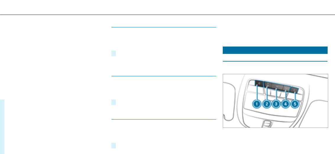
High beam switches off automatically:
RAt speeds below 16 mph (25 km/h).
RIf other road users are detected.
RIf street lighting is sufficient.
At speeds above approx.31 mph (50 km/h):
RThe headlamp range of low beam is regulated
automatically based on the distance to other
road users.
The system's optical sensor is located behind
the windshield near theoverhead control panel.
Switching Adaptive Highbeam Assist on/off
#To switch on: turn the light switch to
theÃposition.
#Switch on the high beam using the combina‐
tion switch.
When the high beam is switched on automat‐
ically in the dark, the_indicator lamp in
the multifunction display comes on.
#To switch off: switch off the high beam
using the combination switch.
Switching the daytime running lights on/off
Multimedia system:
, .÷ .
#Activate Oor deactivate ªthe function.
Setting theexterior lighting switch-off delay
time
Multimedia system:
, .÷ .
#Set the switch-off delay time.
Setting the surround lighting
Multimedia system:
, .÷ .
#Switch the function on Oor off ª.
If the surround lighting is switched on, theexte‐
rior lighting remains lit for 40 seconds afterthe
vehicle is unlocked. When youstart thevehicle,
the surround lighting is switched off and auto‐
matic driving lights are activated.
Interior lighting
Adjusting the interior lighting
Front overhead control panel
1pFront left reading lamp
2|Automatic interior lighting control
3cFront interior lighting
4uRear interior lighting
5pFront right reading lamp
128Light and visibility
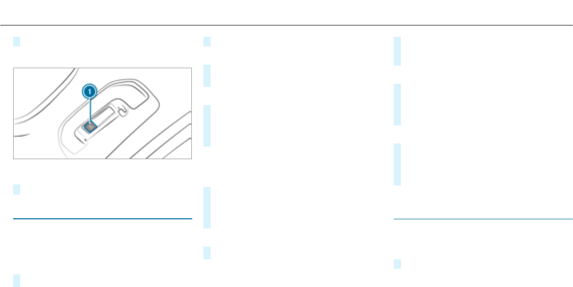
#To switch on or off: press button 1-5.
Control panel in thegrab handle
1pRear reading lamp
#To switch on or off: press button 1.
Adjusting the ambient lighting
Multimedia system:
, .÷ .
Setting the color
#Select .
#Set a color.
Adjusting the brightness
#Select .
#Set a brightness value.
Activating the brightness for zones
#Select .
#Activate Oor deactivate ªthe function.
The , and zones can be set
separately.
%Setting brightness zones is not available for
theRear Seat Entertainment System.
Activating multi-colored lighting
#Select .
#Activate Oor deactivate ªthe function.
There are ten preset color combinations
available.
Activating multi-colored animation
#Select .
#Activate Oor deactivate ªthe function.
The chosen color combination changes in a
predefined rhythm.
Activating climate-dependent lighting
#Select .
#Activate Oor deactivate ªthe function.
The color of the ambient lighting adapts to
suit the air conditioning setting.
Activating welcome lighting
#Select .
#Activate Oor deactivate ªthe function.
When thevehicle is unlocked, a special inte‐
rior lighting sequence runs.
Setting the interior lighting switch-off delay
time
Multimedia system:
, .÷ .
#Set the switch-off delay time.
Light and visibility 129
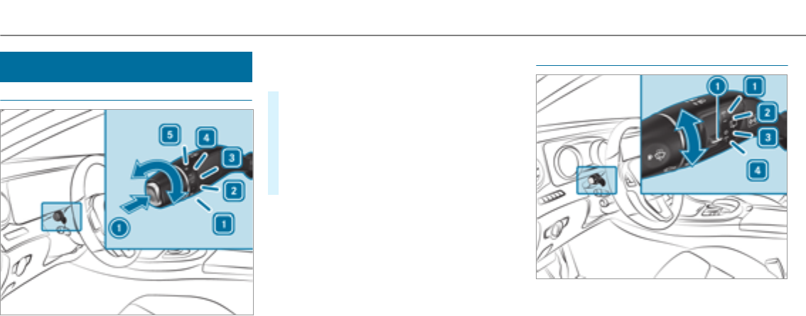
Windshield wiper and windshield washer
system
Switching the windshield wipers on/off
1gWindshield wipers off
2ÄIntermittent wiping, normal
3ÅIntermittent wiping, frequent
4°Continuous wiping, slow
5¯Continuous wiping, fast
#Turn the combination switch to the correct
position 1-5.
#Single wipe/washing: push the button on
the combination switch in the direction of
arrow 1.
RíSingle wipe
RîWipes with washer fluid
Switching therear window wiper on/off
1bWipes with washer fluid
2°Switches on intermittent wiping
3gSwitches off intermittent wiping
4bWipes with washer fluid
130Light and visibility
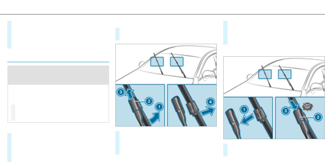
#Turn the1èswitch to the correct posi‐
tion 1-4.
If therear window wiper is switched on, the
èsymbol appears on the instrument clus‐
ter.
Changing the windshield wiper blades
&WARNING Risk of becoming trapped if
the windshield wipers are switched on
while wiper blades are being replaced
If the windshield wipers begin to move while
you are changing the wiper blades, you can
be trapped by the wiper arm.
#Always switch off the windshield wipers
and the ignition before changing the
wiper blades.
Moving the wiper arms to avertical position
#Set the windshield wipers to the°slow
continuous wiping position on the combina‐
tion switch.
#As soon as the wiper arms are vertical rela‐
tive to the hood, switch off the ignition.
Removing the wiper blades
#Fold the wiper arms away from the wind‐
shield.
#Hold the wiper arm with one hand. With the
other hand, turn the wiper blade in the direc‐
tion of arrow 1away from the wiper arm to
thestop.
#Slide catch 2in the direction of arrow3
until it engages in theremoval position.
#Remove the wiper blade in the direction of
arrow 4away from the wiper arm.
Fitting the wiper blades
#Insert the new wiper blade into the wiper
arm in the direction of arrow 1.
Light and visibility 131
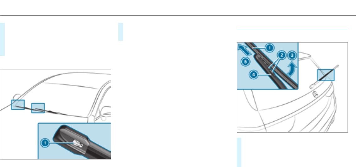
#Slide catch 2in the direction of arrow3
until it engages in the locking position.
#Make sure that the wiper blade sits correctly.
#Fold the wiper arms back onto the wind‐
shield.
Maintenance display
#Remove protective film 1of the mainte‐
nance display on the tip of the newly instal‐
led wiper blades.
If the color of the maintenance display changes
from black to yellow, the wiper blades should be
replaced.
%The duration of the color change varies
depending on the usage conditions.
Replacing the rear window wiper blades
Removing the wiper blade
#Switch the ignition off.
#Fold wiper arm 4away from therear win‐
dow.
#Press both release clips 2.
132Light and visibility
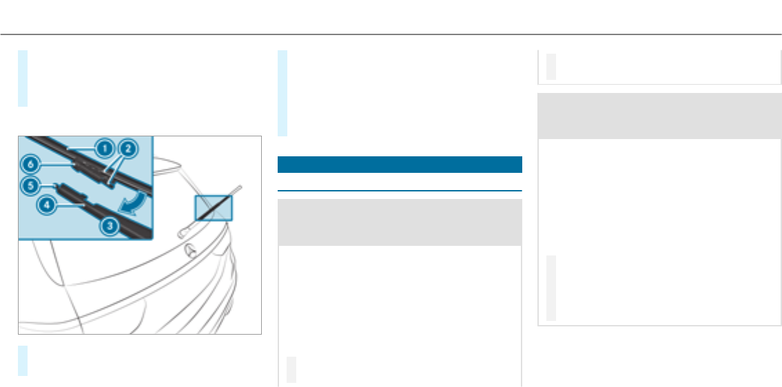
#Fold wiper blade 1in the direction of arrow
3away from wiper arm 4.
#Remove wiper blade 1in the direction of
arrow 5.
Installing the wiper blades
#Position new wiper blade 1with recess 6
on lug 5.
#Fold wiper blade 1in the direction of arrow
3onto the wiper arm until retaining clips
2engage in bracket4.
#Make sure that wiper blade 1sits correctly.
#Fold the wiper arm back onto therear win‐
dow.
Mirrors
Operating the outside mirrors
&WARNING Risk of injury from adjusting
thevehicle settings while thevehicle is in
motion
You could lose control of thevehicle in the
following situations:
Rif you adjust the driver's seat, the head
restraint, thesteering wheel or the mirror
while thevehicle is in motion
Rif youfasten your seat belt while thevehi‐
cle is in motion
#Before starting the engine: adjust the
driver's seat, the head restraint, the
steering wheel or the mirror and fasten
your seat belt.
&WARNING Risk of accident due to mis‐
judgment of distances when using the
passenger mirror
The outside mirror on the front passenger
side reflects objects on a smaller scale. The
objects in view are in fact closer than they
appear.
As a result, you may misjudge the distance
between you and theroad user driving
behind you, forexample, when changing
lanes.
#Therefore, always look over your shoul‐
der in order to ensure that you are
aware of the actual distance between
you and theroad users driving behind
you.
Light and visibility 133
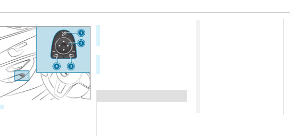
Folding the outside mirrors in/out
#Briefly press switch 1.
%If the battery has been disconnected or com‐
pletely discharged,the outside mirrors must
be reset. Only then will the automatic mirror
folding function work properly.
Adjusting the outside mirrors
#Press the3or 4buttons to select the out‐
side mirrorto be set.
#Press the2button to set the position of the
mirrorglass.
Engaging the outside mirrors
#Press and hold button 1.
Youwill hear a click and the mirror audibly
engage in position. The outside mirror is set
in the correct position.
Automatic anti-glare mirrors function
&WARNING Risk of burns and poisoning
due to the anti-glare mirror electrolyte
Electrolyte may escape if theglass in an
automatic anti-glare mirror breaks.
The electrolyte is harmful and causes irrita‐
tion. It must not come into contact with your
skin, eyes, respiratory organs or clothing or
be swallowed.
#If you come into contact with electro‐
lyte, observe thefollowing:
RRinse the electrolyte from your skin
and seek medical attention immedi‐
ately.
RIf electrolyte comes into contact
with your eyes, rinse them thor‐
oughly with clean water and seek
medical attention immediately.
RIf the electrolyte is swallowed,
immediately rinse your mouth out
thoroughly. Do not induce vomiting.
Seek medical attention immediately.
RImmediately change out of clothing
which has come into contact with
electrolyte.
RIf an allergic reaction occurs, seek
medical attention immediately.
The inside rearview mirror and the outside mir‐
ror on the driver's side automatically go into
anti-glare mode if light from a headlamp hits the
inside rearview mirror.
134Light and visibility
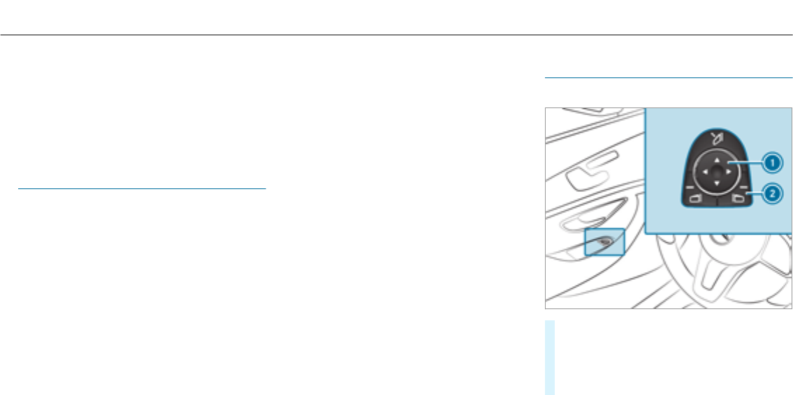
System limitations
The system does not go into anti-glare mode in
thefollowing situations:
Rthe engine is switched off.
Rreversegear is engaged
Rthe interior lighting is switched on
Function of the front-passenger outside mir‐
ror parking position
%The parking position is available only in vehi‐
cles with a memory function.
The parking position makes parking easier.
The front-passenger outside mirror tilts down‐
wards and shows therear wheel on the front
passenger side in thefollowing situations:
Rthe parking position is stored (→page 135)
Rthe passenger mirror is selected
Rreversegear is engaged
The front-passenger outside mirror moves back
to its original position in thefollowing situations:
Rif you shift the transmission to another trans‐
mission position
Rat speeds greater than 9 mph(15 km/h)
Rif youpress the button forthe outside mirror
on the driver's side
Storing the parking position of the
passenger outside mirror using reversegear
Storing
#Select the passenger outside mirror using
button 2.
#Engage reversegear.
#Move the passenger outside mirror into the
desired parking position using button 1.
Light and visibility 135
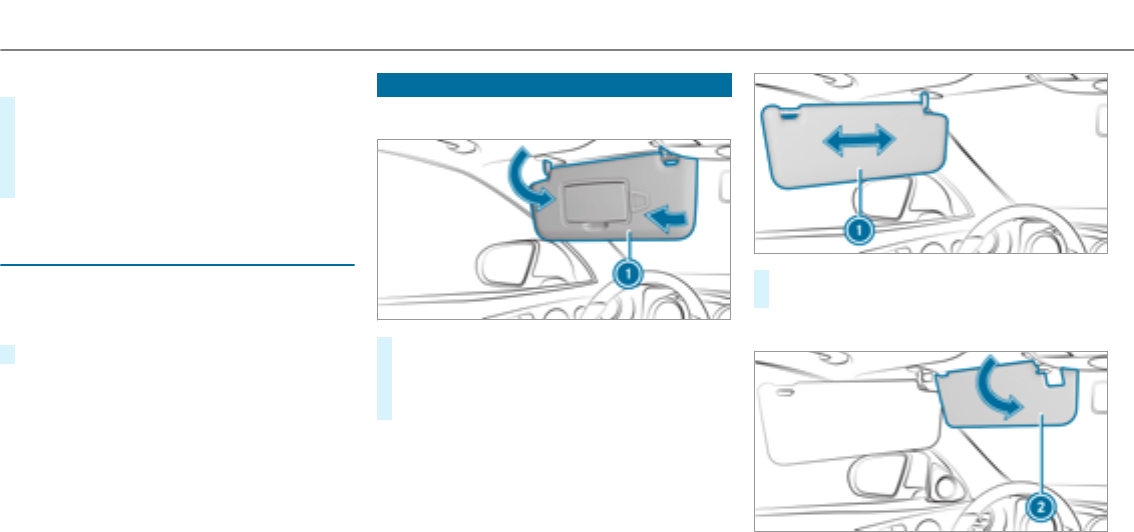
Calling up
#Select the passenger outside mirror using
button 2.
#Engage reversegear.
The passenger outside mirror movesto the
stored parking position.
Activating/deactivating the automatic mirror
folding function
Multimedia system:
, .î
.
#Activate Oor deactivate ªthe function.
Operating the sun visors
Using the single sun visor
#Glare from the front: fold sun visor 1
down.
#Glare from the side: swing sun visor 1to
the side.
#Vehicles with an extendable sun visor: slide
sun visor 1horizontally as required.
Using the additional sun visor
136Light and visibility
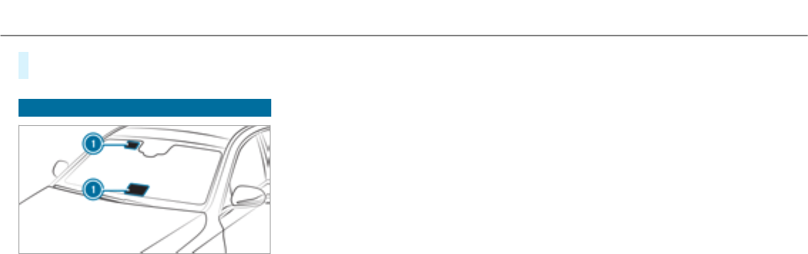
#Vehicles with an additional sun visor: fold
additional sun visor 2down.
Infrared reflective windshield
The infraredreflective windshield is coated and
prevents an excessive build-up of heat in the
vehicle interior.
The coating shields thevehicle interior against
radio waves up into the gigahertz range.
Radio-controlled equipment, such as toll sys‐
tems, can only be mounted on areas of the wind‐
shield which are permeable to radio waves 1.
Areas permeable to radio waves 1are best visi‐
ble from outside thevehicle when the windshield
is illuminated using an external light source.
Light and visibility 137
Overview of climate control systems
Dual-zone climate control panel overview
The indicator lamps in the buttons indicate that
the current function is activated.
1wTo set the driver's side temperature
2_To set the air distribution
3HTo set the airflow or switch off climate
control
4ÃTo set climate controlto automatic
mode (→page 139)
5¬To defrost the windshield
6tTo call up the air conditioning menu
7¤To switch therear window heater
on/off
80To activate or deactivate synchroniza‐
tion (→page 140)
9gTo activate/deactivate air-recirculation
mode (→page 141)
A¿To switch the A/C function on/off
(→page 139)
BwTo set the front passenger side tem‐
perature
3-zone automatic climate control panel over‐
view
The indicator lamps in the buttons indicate that
the current function is activated.
1wTo set the driver's side temperature
2_To set the driver's side air distribution
3HTo set the airflow or switch off climate
control
4ÃTo set climate controlto automatic
mode (→page 139)
5¬To defrost the windshield
6!To call up the air conditioning menu
To switch theresidual heat on or off
(→page 141)
7¤To switch therear window heater
on/off
8¿To switch the A/C function on/off
(→page 139)
138Climate control
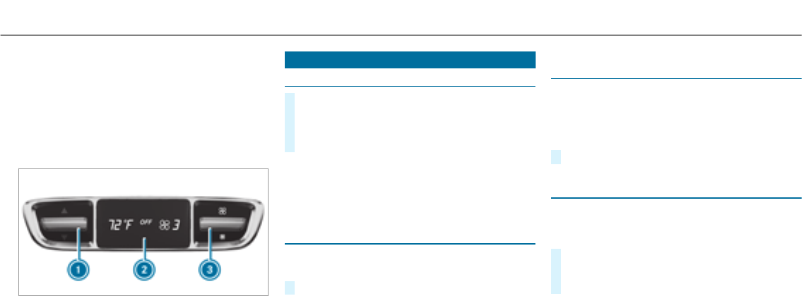
9gTo switch air-recirculation mode on/off
(→page 141)
A_To set the front passenger side air dis‐
tribution
BwTo set the front passenger side tem‐
perature
Rear operating unit
1To set thetemperature
2Display
3To set the airflow
Operating the climate control system
Activating/deactivating climate control
#To activate: set the airflow to level 1 or
higher using theHbutton.
#To deactivate: set the airflow to level 0
using theHbutton.
%If climate control is deactivated, the win‐
dows can fog up more quickly. Deactivate
climate control only briefly.
Activating/deactivating the A/C function via
the control panel
The A/C function cools, heats and dehumidifies
the interior air in thevehicle.
#Press the¿button.
Deactivate the A/C function only briefly other‐
wise the windows can fog up more quickly.
Condensation may drip from the underside of
thevehicle when cooling mode is active. This is
not a sign that there is a malfunction.
Activating/deactivating the A/C function
using the multimedia system
Multimedia system:
, .b .
The A/C function heats, cools and dehumidifies
thevehicle's interior air.
#Switch the function on Oor off ª.
Setting climate control to automatic
In automatic mode, the set temperature is con‐
trolled and maintained at a constant levelby the
air supply.
#Press theÃbutton.
#To switch to manual mode: press theH
or _button.
Climate control 139

Climate style
Climate style function
In automatic mode, you can select thefollowing
climate style settings forthe driver's and front
passenger areas:
RFOCUS: high airflow, slightly cooler setting
RMEDIUM: medium airflow,standard setting
RDIFFUSE: low airflow, slightly warmer and
draft-free setting
Adjusting the climate style settings
Multimedia system:
, .b .
#Select , or .
%In order to feel the effect of the climate
style, theÃfunction must be active
(→page 139).
Overview of air distribution settings
The symbols in the display indicate which vents
the airflow is being directed through:
R¯demistervents
RPcenter and side air vents
ROfootwell vents
RScenter, side and footwell vents
Radefroster and footwell vents
R_all vents
Rbdefroster, middle and side air vents
RWautomatic air distribution
Setting therear climate control using the
multimedia system
Multimedia system:
, .b
.
Setting the airflow
#Select .
#Set the airflow.
Setting thetemperature
#Select .
#Set thetemperature.
Activating/deactivating the climate control
synchronization function via the control
panel
Climate control can be set centrally using the
synchronization function. The temperature and
air distribution setting forthe driver's side is
adopted automatically forthe front passenger
side.
#Press the0button.
The synchronization function is deactivated if the
settings for one of theother climate zones are
changed.
140Climate control

Activating/deactivating the climate control
synchronization function using the multime‐
dia system
Multimedia system:
, .b
.
Climate control can be set centrally using the
synchronization function. The temperature set‐
ting is automatically adoptedfor all climate
zones.
#Switch the function on Oor off ª.
Defrosting the windows
Windows fogged up on the inside
#Press theÃbutton.
#If the windows continue to fog up: press the
¬button.
Windows fogged up on the outside
#Switch on the windshield wiper.
#Press theÃbutton.
Switching air-recirculation mode on/off
#Press thegbutton.
The interior air will be recirculated.
Air-recirculation mode is switched off automati‐
cally.
%If air-recirculation mode is switched on, the
windows may fog up more quickly. Switch on
air-recirculation mode only briefly.
Switching theresidual heat on or off
Requirements:
RThe vehicle is parked.
It is possible to make use of theresidual heat
from the engine to continue heating or ventilat‐
ing the front compartment of thevehicle for
approximately 30 minutes.
#To switch on: press the!button.
Residual heat is switched off automatically.
Activating and deactivating ionization
Multimedia system:
, .b .
Ionization cleans and refreshes the interior air of
thevehicle. The ionization of the interior air is
odorless.
#Switch the function on Oor off ª.
Fragrance system
Setting the fragrance system
Requirements
RAutomatic climate control is activated.
RThe glove box is closed.
Multimedia system:
, .b .
The fragrance system distributes a pleasant fra‐
grance throughout thevehicle interior from a fla‐
con located in theglove box.
Climate control 141
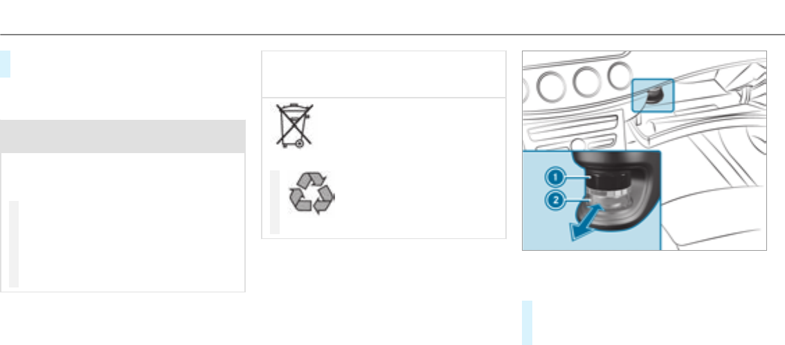
#To set the intensity: select ,,
or .
Inserting or removing the flacon of the fra‐
grance system
&WARNING Risk of injury from liquid per‐
fume
If children open theflacon, they could drink
the liquid perfume or it could come into con‐
tact with their eyes.
#Consult a doctor immediately if liquid
perfume has been drunk.
#If liquid perfume comes into contact
with your eyes or skin, rinse your eyes
with clean water.
#If symptoms continue, consult a doctor.
+ENVIRONMENTAL NOTE Environmental
damage due to improper disposal of full
flacons
Full flacons must not be disposed
of with household waste.
#
Full flacons must be takento
a harmful substance collection point.
1Cap
2Flacon
#To insert: slide theflacon into the holder as
far as it will go.
#To remove:pull out theflacon.
If you do not use genuine Mercedes-Benz interior
perfumes, observethe manufacturers' safety
notices on the perfume packaging.
142Climate control
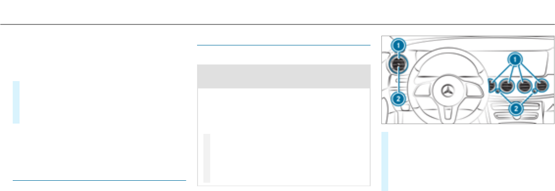
Dispose of thegenuine Mercedes-Benz interior
perfume flacon when it is emptyand do notrefill
it.
Refillable flacon
#Unscrew the cap of the emptyflacon.
#Fill theflacon with a maximum of 0.5 fl. oz.
(15 ml).
#Screw the cap back on to theflacon.
Alwaysrefill the emptyrefillable flacon with the
same perfume. Observe the separate informa‐
tion sheet attached to theflacon.
Information on the windshield heater
The windshield heater is switched on automati‐
cally if the¬button is activated.
Afterthevehicle is startedthe windshield heater
is switched on automatically as needed.
Air vents
Adjusting the front air vents
&WARNING ‑ Danger of burns or frostbite
due to being too close to the air vents
Very hot or very cold air can flow from the air
vents.
This could result in burns or frostbite in the
immediate vicinity of the air vents.
#Make sure that all vehicle occupants
always maintain a sufficient distance to
the air vents.
#If necessary, direct the airflow to
another area of thevehicle interior.
#To open or close: turn controller 2to
clockwise or anti-clockwise as far as it will
go.
#To adjust the air direction: hold air vent 1
in the center and move it up or down or to
the left or right.
Climate control143
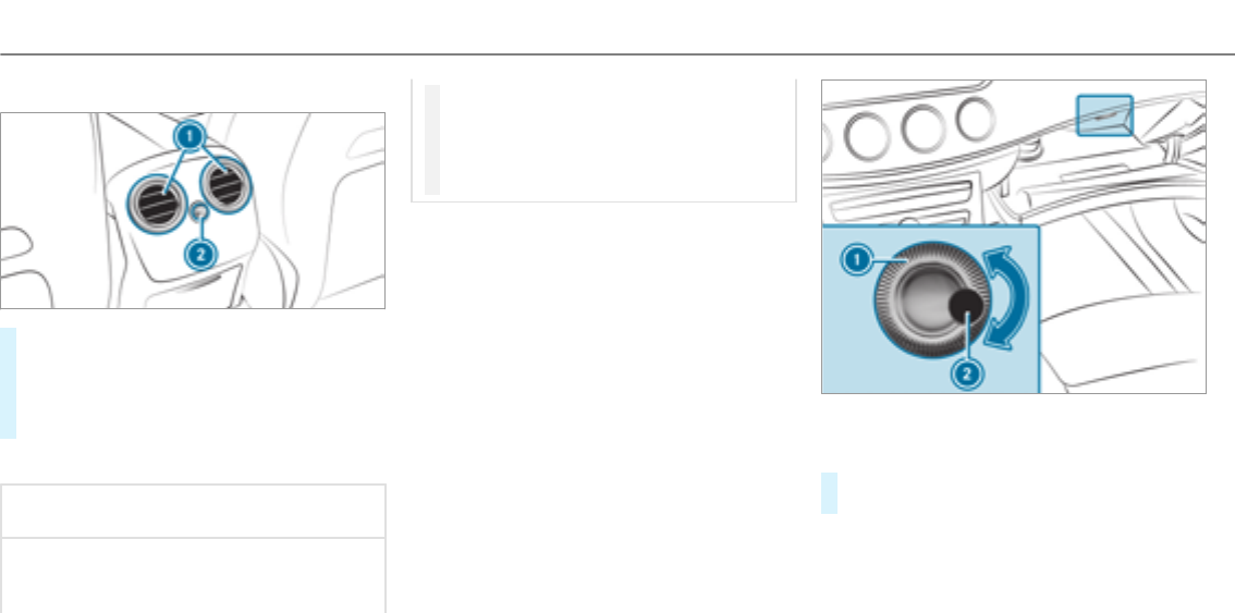
Adjusting the rear air vents
#To open or close: turn controller 2to the
left or right as far as it will go.
#To adjust the air direction: hold rear air
vent 1in the center and move it up or down
or to the left or right.
Opening/closing the air vent in theglove box
*NOTE Damage to temperature-sensitive
objects in theglove box
Temperature-sensitive objects stored in the
glove box may be damaged by the air vent
located inside it.
#Close the air vent when you heat the
vehicle.
#At high outside temperatures, open the
air vent and switch on the A/C func‐
tion.
Requirements:
RAutomatic climate control is activated.
1Air vent controller
2Air vent
#To open or close: turn controller 1to the
left or right.
144Climate control

Driving
Notes on Mercedes-AMG vehicles
Observe the notes on thefollowing topics in the
Supplement. Otherwise, you may not recognize
dangers.
RRear axle locking differential
RAMG Performance exhaust system
RAMG ceramic high-performance composite
brake system
RRACE START
RDRIFT MODE
RAMG adaptive sport suspension system
Switching on the power supply or ignition
using theStart/Stop button
&WARNING Risk of accident and injury
due to children left unattended in the
vehicle
If children are left unattended in thevehicle,
they could:
ROpen doors,thereby endangering other
persons or road users
RGet out of thevehicle and be hit by
oncoming traffic
ROperate vehicle equipment
In addition, thechildren could also set the
vehicle in motion, forexample, by:
RReleasing the parking brake
RShifting the transmission out of park
position j
RStarting the engine.
#Never leave children and animals unat‐
tended in thevehicle.
#When leaving thevehicle, alwaystake
the SmartKey with you and lock the
vehicle.
#Keep the SmartKey out of thereach of
children.
&WARNING Risk of exhaust gas poisoning
Combustion engines emit poisonous exhaust
gases such as carbon monoxide. Inhaling
these exhaust gases causes poisoning.
#Never leave the engine running in an
enclosed space without sufficient venti‐
lation.
&WARNING Risk of fire caused by flam‐
mable material on theexhaust system
Flammable materials brought in by either ani‐
mals or environmental influences may ignite
if they come into contact with hot parts of
the engine or exhaust system.
#Therefore, check regularly that there
are no flammable materials in the
Driving and parking 145
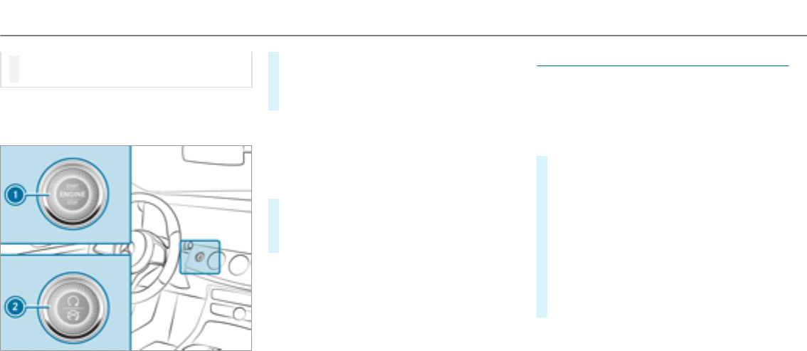
engine compartment or on theexhaust
system.
Requirements:
RThe SmartKey is located in thevehicle and
the SmartKey battery is not discharged.
#To switch on the power supply:press but‐
ton1(USA) or 2(Canada) once.
You can activate the windshield wiper, for
example.
The power supply is switched off again if thefol‐
lowing conditions are met:
Ryou open the driver's door.
Ryou press button1(USA) or 2(Canada)
twice.
#To switch on the ignition: press button 1
(USA) or 2(Canada) twice.
The indicator lamps in the instrument cluster
light up.
The ignition is switched off again if one of the
following conditions is met:
RYou do not start thevehicle within
15 minutes.
The transmission is in position j.
or
The electric parking brake is applied.
RYou press button1(USA) or 2(Canada)
once.
Starting thevehicle
Starting thevehicle with thestart/stop but‐
ton
Requirements:
RThe SmartKey is located in thevehicle and
the SmartKey battery is not discharged.
#Shift the transmission to position jor i.
#Depress the brake pedal and push button 1
(USA) or 2(Canada) once.
#If thevehicle does not start: switch off non-
essential consumers and press button 1
(USA) or 2(Canada) once.
#If thevehicle still does not start and the
display message also
appears in the multifunction display: start
thevehicle in emergency operation mode.
You can switch off the engine while driving by
pressing button 1(USA) or 2(Canada) for
about three seconds. Be sure to observe the
safetynotes under "Driving instructions".
146Driving and parking
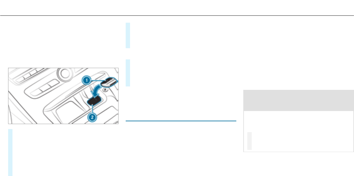
Starting thevehicle in emergency operation
mode
If thevehicle does not start and the
display message appears in the multifunction
display, you can start thevehicle in emergency
operation mode.
#Ensure that marked space 2is empty.
#Remove SmartKey 1from thekeyring.
#Lay SmartKey1in marked space 2.
The vehicle will start after a short while.
If youremove SmartKey 1from marked
space 2,the engine starts again. For fur‐
ther vehicle starts, however, SmartKey 1
must be located in marked space 2during
the entire journey.
#Have SmartKey 1checked at a qualified
specialist workshop.
If thevehicle does not start:
#Leave SmartKey 1in marked space 2.
#Depress the brake pedal and start thevehicle
using thestart/stop button.
#Start thevehicle using thestart/stop button.
%You can also switch on the power supply or
the ignition with thestart/stop button.
Starting thevehicle via Remote Online serv‐
ices
Cooling or heating thevehicle interior before
starting a journey
%This function is not available in all countries.
If youstart thevehicle via your smartphone, the
previously selected air conditioning setting is
active.
Ensure thefollowing before starting the engine:
RThe legal stipulations in the area where your
vehicle is parked allow engine starting via
smartphone.
RIt is safe to start and runthe engine where
your vehicle is parked.
RThe fuel tank is sufficiently filled.
RThe starter battery is sufficiently charged.
Starting thevehicle
&WARNING Risk of crushing or entrap‐
ment due to unintentional starting of the
engine
Limbs could be crushed or trapped if the
engine is started unintentionally during
service or maintenance work.
#Always secure the engine against unin‐
tentional starting before carrying out
maintenance or repair work.
Requirements:
Rpark position jis selected.
Rthe anti-theft alarm system is not activated.
Driving and parking 147

Rthe panic alarm is not activated.
Rthe hazard warning lights are switched off.
Rthe hood is closed.
Rthe doors are closed and locked.
Rthe windows and sliding sunroof are closed.
#Start thevehicle using the smartphone:
Rafterevery vehicle start, the engine runs for
ten minutes.
Ryou can carry out a maximum of two consec‐
utive starting attempts.
Ryou can stop thevehicle again at any time.
Rfurther information can be found in the
smartphone app.
Securing the engine against starting before
carrying out maintenance or repair work:
#Switch on the hazard warning lights.
or
#Unlock the doors.
or
#Open a side window or the sliding sunroof.
Running-in notes
Mercedes-AMG vehicles: observethe notes in
the Supplement. Otherwise, you may not recog‐
nize dangers.
To preserve the engine during thefirst
1,000 miles (1,500 km):
Rdrive at varying road speeds and engine
speeds.
Rdrive in drive program Cor E.
Rchange gear before therev counter needle is
Ôof thewayto thered area of therev coun‐
ter.
Rdo not shift down a gear manually in order to
brake.
Ravoid overstraining thevehicle, e.g. driving at
full throttle.
Rdo not depress the accelerator pedal past
the pressure point (kickdown).
Ronly increase the engine speed gradually and
accelerate thevehicle to full speed after
1,000 miles (1,500 km).
This also applies when the engine or parts of the
drivetrain have been replaced.
Please also observe thefollowing running-in
notes:
RIn certain driving and driving safetysystems,
the sensors adjust automatically while a cer‐
tain distance is driven afterthevehicle has
been delivered or afterrepairs. Full system
effectiveness is not achieved until the end of
this teach-in process.
RBrake pads, brake discs and tires that are
either new or have been replaced only ach‐
ieve optimum braking effect and grip after
several hundred kilometers of driving. Com‐
pensate forthereduced braking effect by
applying greater forceto the brake pedal.
Notes on driving
&WARNING Risk of accident due to
objects in the driver's footwell
Objects in the driver's footwell may impede
pedal travel or block a depressed pedal.
148Driving and parking

This jeopardizes the operating and road
safetyof thevehicle.
#Stow all objects in thevehicle securely
so that they cannot get into the driver's
footwell.
#Always install thefloor mats securely
and as prescribed in order to ensure
that there is always sufficient room for
the pedals.
#Do not use loose floor mats and do not
place floor mats on top of one another.
&WARNING Risk of accident due to
unsuitable footwear
Operation of the pedals may be restricted
due to unsuitable footwear such as:
RShoes with platform soles
RShoes with high heels
RSlippers
#When driving alwayswear suitable
shoes in order to be able to operate the
pedals safely.
&WARNING Risk of accident due to the
ignition being switched off whilst the
vehicle is in motion
If youswitch off the ignition whilst thevehi‐
cle is in motion safety-relevant functions will
be restricted or no longer available. This may
effect the powersteering system and brake
force boosting, forexample.
You will need to use considerably more force
to steer and brake.
#Do not switch off the ignition whilst the
vehicle is in motion.
&WARNING Risk of exhaust gas poisoning
Combustion engines emit poisonous exhaust
gases such as carbon monoxide. Inhaling
these exhaust gases causes poisoning.
#Never leave the engine running in an
enclosed space without sufficient venti‐
lation.
&WARNING Risk of skidding and of an
accident due to shifting down on slippery
road surfaces
If you shift down on slippery road surfaces to
increase the engine braking effect, the drive
wheels may lose traction.
#Do not shift down on slippery road sur‐
faces to increase the engine braking
effect.
&DANGER Risk of fatal injury due to poi‐
sonous exhaust gases
If thetailpipe is blocked or sufficient ventila‐
tion is not possible, poisonous exhaust gases
such as carbon monoxide may enter thevehi‐
cle. This is the case if thevehicle getsstuck
in snow,forexample.
#Keep thetailpipe and the area around
thevehicle free from snow when the
engine or thestationary heater are run‐
ning.
Driving and parking 149

#Open a window on the windward side of
thevehicle to ensure an adequate sup‐
ply of fresh air.
&WARNING Risk of accident and injury
due to being under the influence of alco‐
hol and drugs while driving
Driving when under the influence of alcohol
and/or drugs is an extremely dangerous
combination. Even small quantities of alcohol
or drugs may affect your reflexes, perception
and judgment.
The probability of a serious or even fatal acci‐
dent greatly increases if youdrive when
under the influence of alcohol or drugs.
#Do not drink alcohol or take drugs while
driving, and do not allow anyone to
drive who has been drinking alcohol or
taking drugs.
&WARNING Risk of accident due to the
brake system overheating
If you leave your foot on the brake pedal
when driving, the brake system may over‐
heat.
This increases the braking distance and the
brake system may evenfail.
#Never use the brake pedal as a footrest.
#Do not depress the brake pedal and the
accelerator pedal at the same time
while driving.
*NOTE Wearing out the brake linings by
continuously depressing the brake pedal
#Do not depress the brake pedal contin‐
uously whilst driving.
#To use the braking effect of the engine,
shift to a lowergear in good time.
*NOTE Damage to the drivetrain and the
engine when pulling away
#Do not warm up the engine when the
vehicle is stationary. Pull away immedi‐
ately.
#Avoid high engine speeds and driving at
full throttle until the engine has reached
operating temperature.
#Do not allow the wheels to spin.
*NOTE Damage to the catalytic converter
due to non-combusted fuel
The engine is not running smoothly and is
misfiring.
Non-combusted fuel may get into the cata‐
lytic converter.
#Only depress the accelerator pedal
slightly.
#Have the cause rectified immediately at
aqualified specialist workshop.
150Driving and parking

Limited braking effect on salt-treatedroads:
Rdue to salt build-up on the brake discs and
brake lining, the braking distance can
increase considerably or result in braking
only on one side.
Rmaintain a much greater safe distance to the
vehicle in front.
To prevent salt build-up:
Rbrake occasionally while paying attention to
the traffic conditions.
Rcarefully depress the brake pedal at the end
of the journey and when starting the next
journey.
ECO start/stop function
Operating the ECO start/stop function
Mercedes-AMG vehicles: observethe notes in
the Supplement. Otherwise, you may not recog‐
nize dangers.
The engine is automatically switched off if the
following conditions are met:
RYou brake thevehicle to astandstill in trans‐
mission position hor i.
RAll vehicle conditions for an automatic
engine stop are met.
The èsymbol appears in the multifunction
display when thevehicle is stationary.
The engine is restarted automatically if:
RYourelease the brake pedal in transmission
position hwhen the HOLD function is not
active.
RYou shift from transmission position j.
RYou engage transmission position hor k.
RYou depress the accelerator pedal.
RYouchange thevehicle level.
RAn automatic engine start is necessary.
If the engine was switched off by the ECO start/
stop function and you leave thevehicle, a warn‐
ing tone sounds. The
display message
also appears in the multifunction display. If you
do not switch off the ignition, the ignition is
automatically switched off after one minute.
Deactivating or activating the ECO start/
stop function
#Press button 1.
If indicator lamp 2lights up, the ECO start/
stop function is switched on.
Driving and parking 151

%Depending on the model, the button may
also be located at a different position in the
center console.
Function of the ECO display
The ECO display summarizes the driving style
from thestart of the journey to its completion
and assists youin achieving the most economi‐
cal driving style.
You can influence consumption if you:
Rdrivewith particular care
Rdrivethevehicle in drive program E
Robserve thegearshift recommendations
The inner segment lights up green and the outer
segment fills up:
R1Moderate acceleration
R2Gentle deceleration and rolling
R3Consistent speed
The inner segment is grey and the outer seg‐
ment empties:
R1Sporty acceleration
R2Heavy braking
R3Fluctuations in speed
You have driven economically when:
Rthethree outer segments are completely fil‐
led simultaneously.
Rthe ECO display border lights up.
The additional range achieved as a result of your
drivingstyle in comparison to a driver with a
very sporty driving style is shown under
. The range displayed does not indicate a
fixedreduction in consumption.
DYNAMIC SELECT switch
Function of theDYNAMIC SELECT switch
Mercedes-AMG vehicles: observethe notes in
the Supplement. Otherwise, you may not recog‐
nize dangers.
Use theDYNAMIC SELECT switch to change
between thefollowing drive programs:
RI (Individual): individual settings
RS+ (Sport Plus): particularly sporty driving
style
RS (Sport): sporty driving style
RC (Comfort): comfortable and economical
driving style
RE (Eco): particularly economical driving style
Depending on the drive program selected, the
following vehicle characteristics will change:
RDrive system
-Engine and transmission management
-Active Distance Assist DISTRONIC
RESP®
152Driving and parking
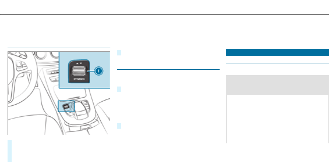
RSuspension
RSteering
Selecting the drive program
#Press DYNAMIC SELECT switch 1forwards
or backwards.
The drive program selected appears in the
multifunction display.
Configuring drive program I
Multimedia system:
, .e
.
#Select the individual setting.
Displaying vehicle data
Multimedia system:
, .e
#Select .
Displaying engine data
Multimedia system:
, .e
#Select .
%The values for engine output and engine tor‐
que may deviate from the nominal values.
Items that can influence this are, forexam‐
ple:
REngine speed
RSea level
RFuel grade
ROutside temperature
Automatic transmission
DIRECT SELECT lever
Function of the DIRECT SELECT lever
&WARNING Risk of accident and injury
due to children left unattended in the
vehicle
If children are left unattended in thevehicle,
they could:
ROpen doors,thereby endangering other
persons or road users
RGet out of thevehicle and be hit by
oncoming traffic
ROperate vehicle equipment
Driving and parking 153
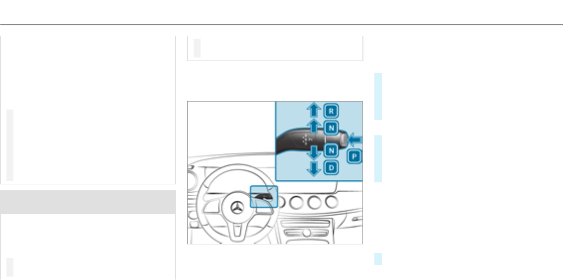
In addition, thechildren could also set the
vehicle in motion, forexample, by:
RReleasing the parking brake
RShifting the transmission out of park
position j
RStarting the engine.
#Never leave children and animals unat‐
tended in thevehicle.
#When leaving thevehicle, alwaystake
the SmartKey with you and lock the
vehicle.
#Keep the SmartKey out of thereach of
children.
&WARNING Risk of accident due to incor‐
rect gearshifting
If the engine speed is higher than the idle
speed and you engage the transmission posi‐
tion hor k,thevehicle may accelerate
sharply.
#If you engage the transmission position
hor kalways depress the brake
pedal firmly and do not accelerate at
the same time.
Use the DIRECT SELECT leverto shift the trans‐
mission position. The current transmission posi‐
tion is displayed in the multifunction display.
jPark position
kReversegear
iNeutral
hDrive position
Engaging reversegear R
#Depress the brake pedal and push the
DIRECT SELECT lever up past thefirst point
of resistance.
The transmission position display shows k
in the multifunction display.
Shifting to neutral N
#Depress the brake pedal and push the
DIRECT SELECT lever up or down to thefirst
point of resistance.
The transmission position display shows i
in the multifunction display.
Subsequently releasing the brake pedal will
allow youto move thevehicle freely, e.g. to push
it or tow it away.
If youwant the automatic transmission to
remain in neutral N even if the ignition is
switched off:
#Start thevehicle.
154Driving and parking
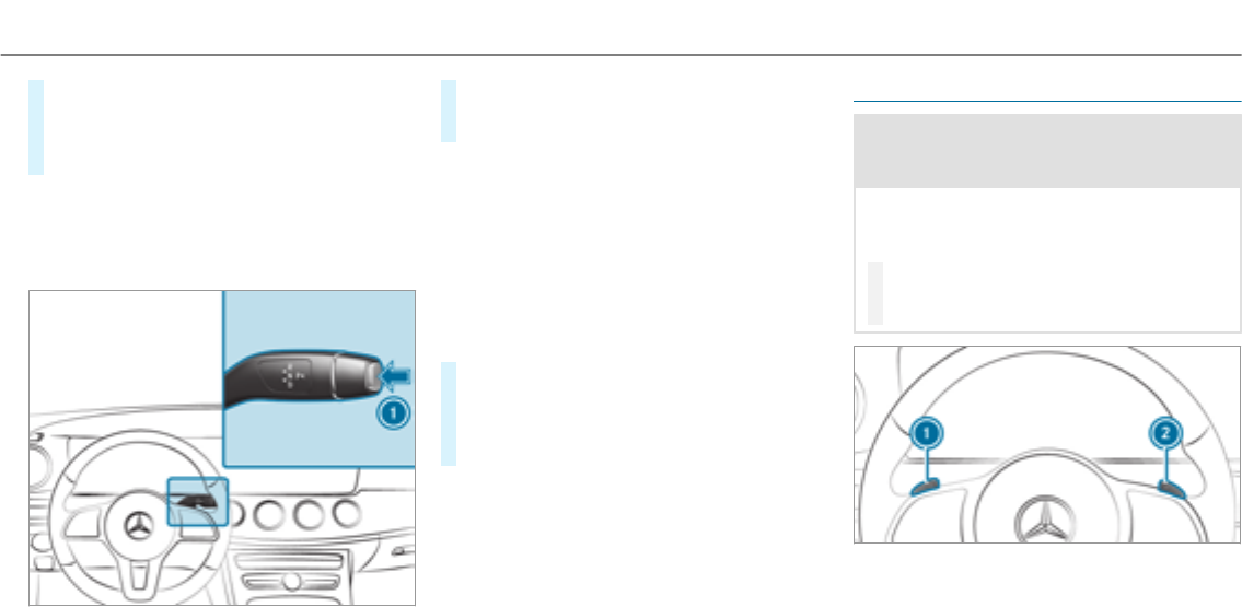
#Depress the brake pedal and shift to neutral
i.
#Release the brake pedal.
#Switch the ignition off.
%If youthen exit thevehicle leaving thekeyin
thevehicle, the automatic transmission
remains in neutral i.
Engaging park position P
#Press button 1.
The transmission position display shows j
in the multifunction display.
Park position jis engaged automatically if one
of thefollowing conditions is met:
Ryou switch the engine off with the transmis‐
sion in position hor k.
Ryou open the driver's door when thevehicle
is stationary or when driving at a very low
speed and the transmission is in position h
or k.
Engaging drive position D
#Depress the brake pedal and push the
DIRECT SELECT lever down past thefirst
point of resistance.
The transmission position display shows h
in the multifunction display.
When the automatic transmission is in transmis‐
sion position h, it shifts thegears automati‐
cally. This depends on thefollowing factors:
Rthe selected drive program
Rthe position of the accelerator pedal
Rtheroad speed
Manual gearshifting
&WARNING Risk of skidding and of an
accident due to shifting down on slippery
road surfaces
If you shift down on slippery road surfaces to
increase the engine braking effect, the drive
wheels may lose traction.
#Do not shift down on slippery road sur‐
faces to increase the engine braking
effect.
Driving and parking 155

#To activate: pull steering wheel gearshift
paddle 1or 2.
Manual gearshifting is activated for a short
time. The current gear is displayed in the
multifunction display.
#To shift up: pull steering wheel gearshift
paddle 2.
#To shift down: pull steering wheel gearshift
paddle 1.
#To deactivate: pull steering wheel gearshift
paddle 2and hold it in place.
The transmission position happears in the
multifunction display.
%If you select theManual drive setting in
drive programI, manual gearshifting is per‐
manently activated.
Mercedes-AMG vehicles: observethe notes in
the Supplement. Otherwise, you may not recog‐
nize dangers.
Shift recommendation
Mercedes-AMG vehicles: observethe notes in
the Supplement. Otherwise, you may not recog‐
nize dangers.
The gearshift recommendations assist you in
adopting an economical driving style.
#If gearshift recommendation message 1is
shown in the multifunction display, shift to
therecommended gear.
Using kickdown
Mercedes-AMG vehicles: observethe notes in
the Supplement. Otherwise, you may not recog‐
nize dangers.
#Maximum acceleration: depress the accel‐
erator pedal beyond the pressure point.
During kickdown, you cannot shift gears using
thesteering wheel gearshift paddles. The auto‐
matic transmission shifts up to the next gear
when the maximum engine speed is reached to
protect the engine from overrevving.
#Ease off the accelerator pedal once the
desired speed is reached.
Glide mode function
Mercedes-AMG vehicles: observethe notes in
the Supplement. Otherwise, you may not recog‐
nize dangers.
With an anticipatory driving style, glide mode
helps youto reduce fuel consumption.
156Driving and parking

Glide mode is characterized by thefollowing:
RThe combustion engine is disconnected from
the drivetrain and thevehicle continues to
roll in neutral.
RThe transmission position his displayed in
green in the multifunction display.
Glide mode is activated if thefollowing condi‐
tions are met:
RDrive program Eis selected.
RThe speed is within a suitable range
RThe course of theroad is suitable, e.g. no
steep uphill or downhill gradients or tight
bends.
RYou are no longer depressing the accelerator
or brake pedal.
%Glide mode can also be activated if you have
selected the "Eco" setting forthe drive
(engine management) when in drive program
I.
Glide mode is deactivated again if one of the
conditions is no longer met.
Vehicles with Driving Assistance Package,
Active Distance Assist DISTRONIC or Active
Brake Assist:glide mode is also deactivated
depending on the traffic situation and thevehi‐
cle then switches to overrun mode. This further
reduces fuel consumption.
Glide mode can also be prevented by thefollow‐
ing parameters:
RUphill gradient
RDownhill gradient
RTemperature
RHeight
RSpeed
RObstruction detection
ROperating status of the engine
Refueling
Refueling thevehicle
&WARNING Risk of fire and explosion
caused by fuel
Fuels are highly inflammable.
#You must avoid fire, open flames, creat‐
ing sparks and smoking.
#Before refueling, switch off the engine
and, if installed in your vehicle, thesta‐
tionary heater.
&WARNING Risk of injury from fuel
Fuels are poisonous and harmful to your
health
#Do not swallow fuel or let it come into
contact with skin, eyes or clothing.
#Do not inhale fuel vapors.
#Keep children away from fuel.
If you or other people come into contact with
fuel, observe thefollowing:
Driving and parking 157

#Immediately rinse fuel off your skin with
soap and water.
#If fuel comes into contact with your
eyes, immediately rinse them thor‐
oughly with clean water. Seek medical
attention immediately.
#If you swallow fuel, seek medical atten‐
tion immediately. Do not induce vomit‐
ing.
#Change immediately out of clothing that
has come into contact with fuel.
&WARNING Risk of explosion or fire due
to electrostatic charge
Electrostatic charge can cause sparks and
thereby ignite fuel vapors.
#Alwaystouch the metalvehicle body
before opening the fuel filler cap or
touching the pump nozzle.
This discharges any electrostatic charge that
may have built up.
*NOTE Damage caused by the wrong fuel
Fuel that does not conform to therequired
quality can lead to increased wear as well as
damage to the engine and exhaust system.
#Only use the fuel recommended.
*NOTE Damage caused by the wrong fuel
Vehicles with a gasoline engine:
Even small amounts of the wrong fuel could
result in damage to the fuel system, the
engine and the emission control system.
#The RON octane rating can be found on
the fuel filler flap.
#Only refuel with low-sulfur unleaded
fuel.
This fuel may contain up to 10 %ethanol.
Your vehicle is suitable for use with E10 fuel.
Do not refuel using:
RDiesel
RE15, E85, E100
RGasoline containing methanol (M15, M30,
M85, M100)
RGasoline with additives containing metal
If you accidentally refuel with the wrong fuel:
#Do not switch the ignition on.
#Consult a qualified specialist workshop.
*NOTE Do not use diesel to refuel vehi‐
cles with a gasoline engine.
If you accidentally refuel with the wrong fuel:
RDo not switch on the ignition. Otherwise
fuel can enter the engine.
Even small amounts of the wrong fuel
could result in damage to the fuel system
and the engine. The repair costs are high.
#Contact a qualified specialist workshop.
#Have the fuel tank and fuel lines
drained completely.
158Driving and parking
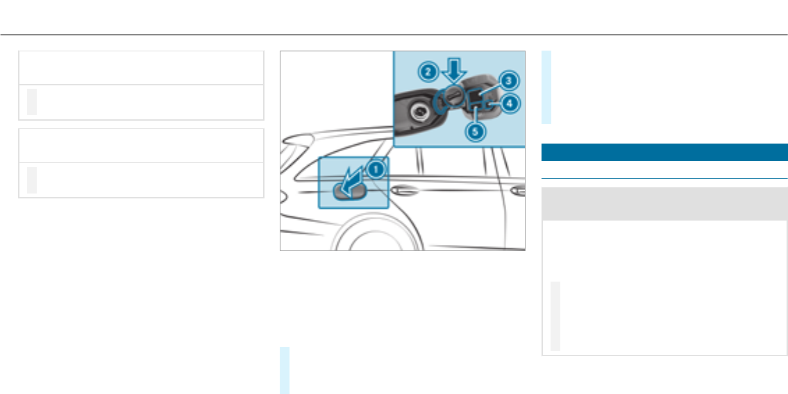
*NOTE Damage to the fuel system caused
by overfilled fuel tanks.
#Only fill the fuel tank until the pump
nozzle switches off.
*NOTE Fuel may spray out when you
remove the fuel pump nozzle.
#Only fill the fuel tank until the pump
nozzle switches off.
Requirements:
RUnlock thevehicle.
%Do not get into thevehicle again during the
refueling process. Otherwise, electrostatic
charge could build up again.
Observe the notes on operating fluids
(→page 400).
1Fuel filler flap
2Bracketforthe fuel filler cap
3Tire pressure table
4QR code forrescue card
5Fuel type
#Press fuel filler flap 1.
#Turn the fuel filler cap counter-clockwise and
remove it.
#Insert the fuel filler cap into holder 2.
#Completely insert the fuel pump nozzle into
thetank filler neck, hook in place and refuel.
#Only top up the fuel tank until the fuel pump
nozzle switches off.
Parking
Switching off thevehicle
&WARNING Risk of fire caused by hot
exhaust system parts
Flammable material such as leaves, grass or
twigs may ignite if they come into contact
with hot parts of theexhaust system or
exhaust gasflow.
#Park thevehicle so that no flammable
material can come into contact with hot
vehicle components.
#In particular, do not park on dry grass‐
land or harvested grain fields.
Driving and parking 159
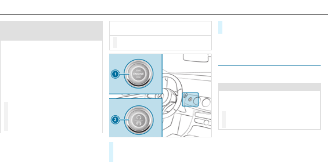
&WARNING Risk of accident and injury
due to children left unattended in the
vehicle
If you leave children unaccompanied in the
vehicle, they may be able to set thevehicle in
motion, forexample by:
RReleasing the parking brake.
RShifting the transmission out of park
position j.
RStarting the engine.
In addition, they may operate vehicle equip‐
ment.
#Never leave children and animals unat‐
tended in thevehicle.
#When leaving thevehicle, alwaystake
the SmartKey with you and lock the
vehicle.
*NOTE Damage to thevehicle or the driv‐
etrain caused by thevehicle rolling away
#Always properly secure thevehicle
against rolling away.
#On uphill or downhill inclines, turn the front
wheels towardsthe curb.
#Select transmission position j.
#Apply the electric parking brake.
#Press button 1(USA) or 2(Canada) once.
%When you switch off thevehicle, you can still
operate the side windows and the panoramic
sliding sunroof forfive minutes.
Garage door opener
Programming buttons for the garage door
opener
&WARNING Risk of exhaust gas poisoning
Combustion engines emit poisonous exhaust
gases such as carbon monoxide. Inhaling
these exhaust gases causes poisoning.
#Never leave the engine running in an
enclosed space without sufficient venti‐
lation.
160Driving and parking
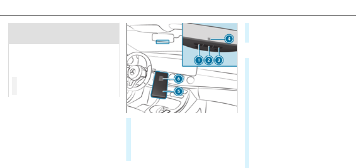
&WARNING Risk of injury and entrapment
when opening thegarage door using the
garage door opener
When you operate or program thegarage
door with the integrated garage door opener,
persons in therange of movement of the
garage door can become trapped or struck
by thegarage door.
#When using the integrated garage door
opener, always make sure that nobody
is within the sweep of thegarage door.
Only operate thegarage door opener on thefol‐
lowing garage doors:
RGarage doors with a safetystop and revers‐
ing feature.
RGarage doors which conform to the current
U.S. safety standards.
Requirements:
RThe vehicle is parked outside of thegarage.
RThe engine is switched off.
#Check if the transmitter frequency of the
remote control has the frequency range of
280 to 868 MHz.
Radio equipment approval number:
RNZLMUAHL5 (USA)
R4112A-MUAHL5 (Canada)
#Press and hold button 1,2or 3that you
wish to program.
Indicator lamp 4flashes yellow.
%It can take up to 20 seconds before the indi‐
cator lamp flashes yellow.
#Release the previously pressed button.
Indicator lamp 4continues to flash yellow.
#Point remote control 5at a distance of 1 in
(1 cm) to 3 in (8 cm) towards buttons 1,2
or 3.
#Press and hold button 6of remote control
5until:
RIndicator lamp 4lights up greencontin‐
uously. Programming is complete.
RIndicator lamp 4flashes green. Pro‐
gramming was successful. Additionally,
synchronization of therolling code with
thegarage door system must also be car‐
ried out.
#If indicator lamp 4does not light up or flash
green: repeat the procedure.
#Release all of the buttons.
Driving and parking 161
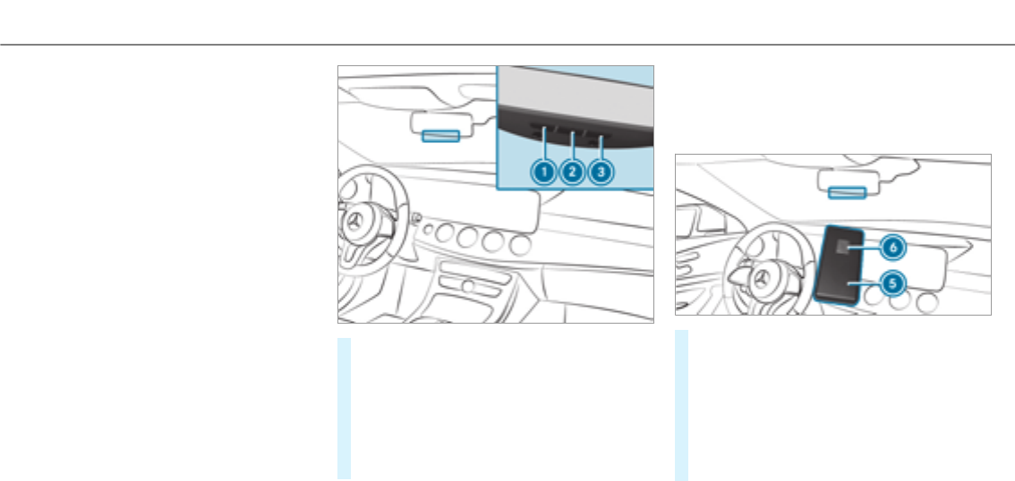
%The remote control forthegarage door drive
is not included in the scope of delivery of the
garage door opener.
Synchronizing therolling code
Requirements:
RThe garage door system uses a rolling code.
RThe vehicle must be within range of the
garage door or exterior gate drive.
RThe vehicle as well as persons and objects,
are located outside the sweep of thegarage
door.
#Press the programming button on the door
drive unit.
Initiate the next step within approximately
30 seconds.
#Press previously programmed button 1,2
or 3repeatedly, until the door closes.
When the door closes, programming is com‐
pleted.
%Please also read the operating instructions
forthegarage door drive.
Troubleshooting when programming the
remote control
#Check if the transmitter frequency of remote
control 5is supported.
#Replace the batteries in remote control 5.
#Hold remote control 5at various angles at
a distance between 1 in (1 cm) to 3 in (8 cm)
in front of the inside rearview mirror. You
should test every position for at least 25 sec‐
onds before trying another position.
162Driving and parking
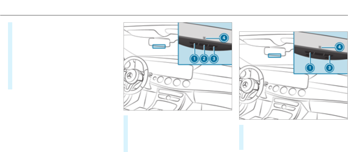
#Hold remote control 5at the same angles
at various distances in front of the inside
rearview mirror. You should test every posi‐
tion for at least 25 seconds before trying
another position.
#Note that some remote controls transmit
only for a limited period, press button 6on
remote control 5again before transmission
ends.
#Align the antenna line of thegarage door
opener unit with theremote control.
%Support and additional information on pro‐
gramming:
ROn thetoll free HomeLink®Hotline on
1-800-355-3515.
ROn the Internet at http://
www.homelink.com/mercedes.
Opening/closing thegarage door
Requirements
RThe corresponding button is programmed to
operate thegarage door.
#Press and hold buttons 1,2or 3until
thegarage door opens or closes.
#If indicator lamp 4flashes yellow after
approximately 20 seconds: press and hold
the previously pressed button again until the
garage door opens or closes.
Clearing thegarage door opener memory
#Press and hold buttons 1and 3.
Indicator lamp 4lights up yellow.
#If indicator lamp 4flashes green: release
buttons 1and 3.
Driving and parking 163

Radio equipment approval numbers for the
garage door opener
Radio equipment approval numbers
CountryRadio type approval number
EgyptTAC.2511151293.WIR
Andorra CE
Australia R-NZ
Barbados MED1578
Chile 2488/DFRS20576/F-74
European
Union
CE
GibraltarCE
Iceland CE
Jordan TRC/LPD/2015/299
CanadaIC: 4112A-MUAHL5
Kuwait CE
Country Radio type approval number
Liechten‐
stein
CE
Mexico RCPGEMU15-0448
Monaco CE
New Zea‐
land
R-NZ
NorwayCE
Russian
Federa‐
tion
not required
Saudi Ara‐
bia
TA 10525
Switzer‐
land
CE
CountryRadio type approval number
South
Africa
TA-2015/1386
Turkey not required
United
Arab Emi‐
rates
ER41849/15
Dealer No: DA35176/14
United
States
FCC ID: NZLMUAHL5
164Driving and parking

Brazil
Este equipamento opera em caráter secundário,
isto é, não tem direito à proteção contra interfer‐
ência prejudicial, mesmo de estações do mesmo
tipo, e não pode causar interferência a sistemas
operando em caráter primário.
Para maiores informações acessar
www.anatel.gov.br
Further information on the declaration of con‐
formity for wireless vehicle components
(→page 23).
Electric parking brake
Electric parking brake function (applying
automatically)
&WARNING Risk of accident and injury
due to children left unattended in the
vehicle
If you leave children unaccompanied in the
vehicle, they may be able to set thevehicle in
motion, forexample by:
RReleasing the parking brake.
RShifting the transmission out of park
position j.
RStarting the engine.
In addition, they may operate vehicle equip‐
ment.
#Never leave children and animals unat‐
tended in thevehicle.
#When leaving thevehicle, alwaystake
the SmartKey with you and lock the
vehicle.
The electric parking brake is applied if the trans‐
mission is in position jand one of thefollow‐
ing conditions is fulfilled:
RThe engine is switched off.
RThe seat belt tongue is not inserted in the
seat belt buckle of the driver's seat and the
driver's door is opened.
%To prevent application: pull the handle of the
electric parking brake.
In thefollowing situations, the electric parking
brake is also engaged:
RActive Distance Assist DISTRONIC is bringing
thevehicle to astandstill.
RThe HOLD function is keeping thevehicle sta‐
tionary.
RActive Parking Assist is keeping thevehicle
stationary.
This is only the case if one of thefollowing con‐
ditions is also fulfilled:
RThe engine is switched off.
Driving and parking 165
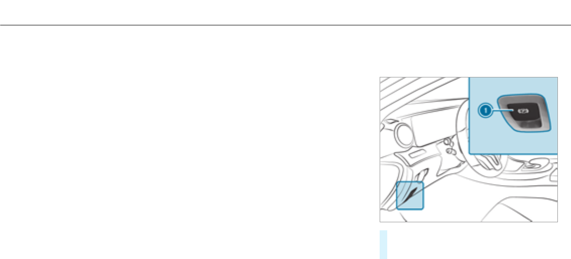
RThe seat belt tongue is not inserted in the
seat belt buckle of the driver's seat and the
driver's door is opened.
RThere is a system malfunction.
RThe power supply is insufficient.
RThe vehicle is stationary for a lengthy period.
When the electric parking brake is applied, the
F(USA) or !(Canada) indicator lamp
lights up in the instrument cluster.
The electric parking brake is not automatically
applied if the engine is switched off by the ECO
start/stop function.
Electric parking brake function (releasing
automatically)
The electric parking brake is released when the
following conditions are fulfilled:
RThe engine is running.
RThe seat belt tongue is inserted into the seat
belt buckle of the driver's seat.
RThe transmission is in position hor kand
youdepress the accelerator pedal or you
shift from transmission position jto hor
k.
RIf the transmission is in position k,thetail‐
gate must be closed.
If the seat belt tongue is not inserted into the
seat belt buckle of the driver's seat, thefollow‐
ing conditions must be fulfilled:
RThe driver's door is closed.
RYou move the transmission out of transmis‐
sion position jor you have previously
driven faster than 2 mph (3 km/h).
RIf the transmission is in position k,thetail‐
gate must be closed.
If the electric parking brake is released, the
F(USA) or !(CANADA) indicator lamp in
the instrument cluster goes out.
Applying or releasing the electric parking
brake manually
Applying
#Push handle 1.
The F(USA) or !(Canada) indicator
lamp appears in the instrument cluster.
166Driving and parking

%The electric parking brake is only securely
applied if the indicator lamp is lit continu‐
ously.
Releasing
#Switch on the ignition.
#Pull handle 1.
The F(USA) or !(Canada) indicator
lamp in the instrument cluster goes out.
Emergency braking
#Press and hold handle 1.
When thevehicle has been braked to a
standstill, the electric parking brake is
applied. The F(USA) or !(Canada)
indicator lamp appears in the instrument
cluster.
Notes on parking thevehicle for a long
period
If you leave thevehicle parkedfor longer than
four weeks, the disconnected battery may be
damaged by deep discharge.
If you leave thevehicle parkedfor longer than six
weeks, it may suffer damage as a result of lack
of use.
%Further information can be obtained at a
qualified specialist workshop.
Standby mode (extension of the starter bat‐
tery's period out of use)
Standby mode function
If standby mode is activated, thevehicle can be
parkedfor an extended period of time without
losing power.
Standby mode is characterized by thefollowing:
Rthestarter battery is preserved.
Rthe maximum period out of use is displayed
in the multimedia system display.
Rfunctions such as interior protection or tow-
away protection are not available.
Rthe connection to online services is interrup‐
ted.
If thefollowing conditions are fulfilled, standby
mode can be activated or deactivated using the
multimedia system:
Rthe engine is switched off.
Rthe ignition is switched on.
Exceeding thevehicle's displayed period out of
use may cause inconvenience, i.e. it cannot be
guaranteed that thestarter battery will reliably
start the engine.
The starter battery must be chargedfirst in the
following situations:
Rthevehicle's period out of use must be
extended.
Rthe
message appears in the multimedia
system display.
%Standby mode is automatically deactivated
when the ignition is switched on.
Driving and parking 167

Activating or deactivating standby mode
Multimedia system:
, .î
.
#Activate Oor deactivate ªthe function.
When you activate the function, a prompt
appears.
#Select .
Standby mode is activated.
Driving and driving safety systems
Driving systems and your responsibility
Your vehicle is equipped with driving systems
which assist youin driving, parking and maneu‐
vering thevehicle. The driving systems are tools
and do not relieve you of your responsibility. Pay
attention to the traffic conditions at all times
and intervene when necessary. Be aware of the
limitations regarding the safe use of these sys‐
tems.
Function of theradar sensors
Some driving and driving safety systems use
radar sensors to monitor the area in front of,
behind or next to thevehicle (depending on the
vehicle's equipment).
Depending on thevehicle's equipment, theradar
sensors are integrated behind the bumpers
and/or behind theradiator grille. Keep these
parts free of dirt, ice and slush (→page 342).
The sensors must not be covered, forexample
by bicycle racks, overhanging loads or radar-
reflecting stickers.Following an impact and in
theevent of associated damage, which may not
be visible, to the bumpers or radiator grille, have
the function of theradar sensors checked at a
qualified specialist workshop. The driver assis‐
tance system may no longer work properly.
Overview of driving systems and driving
safety systems
In this section, you will find information about
thefollowing driving systems and driving safety
systems:
R360° Camera (→page 198)
RABS (Anti-lock Braking System)
(→page 169)
RActive Distance Assist DISTRONIC
(→page 177)
RAIR BODY CONTROL (→page 187)
(→page188)
RActive Brake Assist (→page 170)
RActive Lane Keeping Assist (→page 212)
RATTENTION ASSIST (→page 206)
RBAS (Brake Assist System) (→page 169)
RDYNAMIC BODY CONTROL (→page 186)
REBD (Electronic BrakeforceDistribution)
(→page 170)
RESP®(Electronic Stability Program)
RHill Start Assist
168Driving and parking

RHOLD function (→page 185)
RSTEER CONTROL (→page 170)
RActive Steering Assist (→page 182)
RActive Parking Assist (→page 201)
RParking Assist PARKTRONIC (→page192)
RRear view camera (→page 195)
RCruise control (→page 175)
RBlind Spot Assist and Active Blind Spot Assist
(→page 210)
RTraffic Sign Assist (→page 208)
Functions of ABS (Anti-lock Brake System)
ABS regulates the brake pressure in critical driv‐
ing situations:
RDuring braking, e.g. at maximum full-stop
braking or insufficient traction of the tires,
the wheels are prevented from blocking.
RVehicle steerability while braking is ensured.
If ABS intervenes when braking, youwill feel a
pulsing in the brake pedal. The pulsating brake
pedal can be an indication of hazardous road
conditions and can serve as a reminder to take
extra care while driving.
System limitations
RABS is active from speeds of approx. 5 mph
(8 km/h).
RABS may be impaired or may not function if a
malfunction has occurred and theyel‐
low !ABS warning lamp lights up contin‐
uously in the instrument cluster afterthe
engine is started.
Function of BAS (Brake Assist System)
&WARNING Risk of an accident caused by
a malfunction in BAS (Brake Assist Sys‐
tem)
If BAS is malfunctioning, the braking distance
in an emergency braking situation is
increased.
#Depress the brake pedal with full force
in emergency braking situations. ABS
prevents the wheels from locking.
BAS supportsyour emergency braking situation
with additional brake force.
If you depress the brake pedal quickly, BAS is
activated:
RBAS automatically boosts the brake pres‐
sure.
RBAS can shorten the braking distance.
RABS prevents the wheels from locking.
The brakes will function as usual once you
release the brake pedal. BAS is deactivated.
Activating/deactivating ESP®(Electronic Sta‐
bility Program)
Multimedia system:
, .k .
Mercedes‑AMG vehicles: observethe notes in
the Supplement. Otherwise, you may not recog‐
nize dangers.
#Activate Oor deactivate ªthe function.
Driving and parking 169

ESP®is deactivated if theåESP®OFF warn‐
ing lamp lights up continuously in the instrument
cluster.
Observe the information on warning lamps and
display messages which may be shown in the
instrument cluster.
Functions of ESP®Crosswind Assist
ESP®Crosswind Assist detects sudden gusts of
side wind and helps the driver to keep thevehi‐
cle in the lane:
RESP®Crosswind Assist is active at vehicle
speeds between 50 mph (80 km/h) and
125mph (200 km/h) when driving straight
ahead or cornering slightly.
RThe vehicle is stabilized by means of individ‐
ual brake application on one side.
Function of EBD (Electronic Brake force Dis‐
tribution)
EBD is characterized by thefollowing:
RMonitoring and regulating the brake pressure
on therear wheels.
RImproved driving stability when braking,
especially on bends.
STEER CONTROL function
STEER CONTROL helps youby transmitting a
noticeable steering forceto thesteering wheel in
the direction required forvehicle stabilization.
This steering recommendation is given particu‐
larly in thefollowing situations:
RBoth right wheels or both left wheels are on
awet or slippery road surface when you
brake.
RThe vehicle starts to skid.
System limitations
STEER CONTROL may be impaired or may not
function in thefollowing situations:
RESP®is deactivated.
RESP®is malfunctioning.
RThe steering is malfunctioning.
If ESP®is malfunctioning, youwill be assisted
further by the electric powersteering.
Function of Active Brake Assist
Active Brake Assist consists of:
RDistance warning function
RAutonomous braking function
RSituation-dependent braking assistance
RVehicles with Driving Assistance Pack‐
age: Evasive Steering Assist
Active Brake Assist can help youto minimize the
risk of a collision with vehicles or pedestrians or
to reduce the effects of such a collision.
170Driving and parking

If Active Brake Assist has detected a risk of colli‐
sion, youwill be warned visually and acousti‐
cally.
If youdo not react to the visual and audible colli‐
sion warning, autonomous braking can be initi‐
ated in critical situations.
In especially critical situations, Active Brake
Assist can initiate autonomous braking directly.
In this case, the visual and acoustic warning
occurs simultaneously with the braking applica‐
tion.
If youapplythe brake yourself in a critical situa‐
tion or applythe brake during autonomous brak‐
ing, situation-dependent braking assistance
occurs. This increases the brake pressure up to
maximum full-stop braking if necessary.
If the autonomous braking function or the situa‐
tion-dependent braking assistance is triggered,
additional preventive measuresfor occupant
protection (PRE-SAFE®) may also be initiated, if
thevehicle is equipped with these.
&WARNING Risk of an accident caused by
limited detection performance of Active
Brake Assist
Active Brake Assist cannot always clearly
identify objects and complex traffic situa‐
tions.
In such cases, Active Brake Assist might:
RGive a warning or brake without reason
RNot give a warning or not brake
#Always pay careful attention to the traf‐
fic situation; do not rely on Active Brake
Assist alone. Active Brake Assist is only
an aid. The driver is responsible for
maintaining a suitable distance to the
vehicle in front, vehicle speed and for
braking in good time.
#Be prepared to brake or swerve if nec‐
essary.
Also observe the system limitations of Active
Brake Assist.
The individual subfunctions are available in
thefollowing speed ranges:
Distance warning function
The distance warning function issues a warning
at speeds:
RFrom approximately 4 mph (7 km/h), if your
vehicle is critically close to avehicle or
pedestrian. An intermittent warning tone
sounds and the·distance warning lamp
lights up in the instrument cluster.
Brake immediately or take evasive action, provi‐
ded it is safe to do so and the traffic situation
allows this.
Driving and parking 171

The distance warning function can aid you in thefollowing situations with an intermittent warning tone and a warning lamp:
Vehicles traveling in
front
Stationary vehicles Crossing vehicles Crossing pedestrians Stationary pedes‐
trians
Vehicles without Driv‐
ing Assistance pack‐
age
up to approx.155mph
(250 km/h)
up to approx. 50 mph
(80 km/h)
no reaction up to approx.37 mph
(60 km/h)
no reaction
Vehicles with Driving
Assistance package
up to approx.155mph
(250 km/h)
up to approx. 62 mph
(100 km/h)
up to approx. 43 mph
(70 km/h)
up to approx. 43 mph
(70 km/h)
up to approx. 43 mph
(70 km/h)
Autonomous braking function
The autonomous braking function may intervene at speeds starting from approximately 4mph(7 km/h)in the following situations:
Vehicles traveling in
front
Stationary vehicles Crossing vehicles Crossing pedestrians Stationary pedes‐
trians
Vehicles without Driv‐
ing Assistance pack‐
age
up to approx.124mph
(200 km/h)
up to approx.31 mph
(50 km/h)
no reaction up to approx.37 mph
(60 km/h)
no reaction
Vehicles with Driving
Assistance package
up to approx.155mph
(250 km/h)
up to approx. 62 mph
(100 km/h)
up to approx. 43 mph
(70 km/h)
up to approx. 43 mph
(70 km/h)
up to approx. 43 mph
(70 km/h)
172Driving and parking

Situation-dependent braking assistance
Situation-dependent braking assistance may intervene at speeds starting from approximately 4mph(7 km/h)in thefollowing situations:
Vehicles traveling in
front
Stationary vehicles Crossing vehicles Crossing pedestrians Stationary pedes‐
trians
Vehicles without Driv‐
ing Assistance pack‐
age
up to approx.155mph
(250 km/h)
up to approx. 50 mph
(80 km/h)
no reaction up to approx.37 mph
(60 km/h)
no reaction
Vehicles with Driving
Assistance package
up to approx.155mph
(250 km/h)
up to approx. 62 mph
(100 km/h)
up to approx. 43 mph
(70 km/h)
up to approx. 43 mph
(70 km/h)
up to approx. 43 mph
(70 km/h)
Canceling a brake application of Active Brake
Assist
You can cancel a brake application of Active
Brake Assist at any time by:
RDepressing the accelerator pedal fully.
RReleasing the brake pedal.
Active Brake Assist may cancel the brake appli‐
cation when one of thefollowing conditions is
fulfilled:
RYou maneuver to avoid the obstacle.
RThere is no longer a risk of collision.
RAn obstacle is no longer detected in front of
your vehicle.
Evasive Steering Assist (only vehicles with
Driving Assistance package)
Evasive Steering Assist has thefollowing charac‐
teristics:
RCan detect stationary or crossing pedes‐
trians.
RCan assist the driver with additional steering
assistance if it detects a swerving maneuver.
RCan be activatedby an abrupt steering move‐
ment during a swerving maneuver.
RCan assist during swerving and straightening
of thevehicle.
RCan react from a speed of approximately
12 mph(20 km/h) up to a speed of approx‐
imately 43 mph(70 km/h).
RYou can prevent the assistance at any time
by actively steering.
Driving and parking 173

&WARNING Risk of an accident despite
Evasive Steering Assist
Evasive Steering Assist cannot always clearly
identify objects and complex traffic situa‐
tions.
In addition, thesteering support of Evasive
Steering Assist is generally not sufficient to
avoid a collision.
In such cases Evasive Steering Assist can:
Rgive an unnecessary warning or provide
assistance
Rnot give awarning or not provide assis‐
tance
#Always pay careful attention to the traf‐
fic situation; do not rely on Evasive
Steering Assist alone.
#Be ready to brake and take evasive
action if necessary.
#Prevent the assistance by actively steer‐
ing in non-critical driving situations.
#Drive at an appropriate speed if pedes‐
trians are close to the path of your vehi‐
cle.
Also observe the system limitations of Evasive
Steering Assist.
System limitations
The system may be impaired or may not function
in thefollowing situations:
RIn snow, rain, fog, heavy spray, if there is
glare, in direct sunlight or in greatly varying
light conditions.
RIf the sensors are dirty, misted up, damaged
or covered.
RIf the sensors malfunction due to other radar
source interference, forexample strong radar
reflections in parking garages.
RIf a loss of tire pressure or a defective tire
has been detected and displayed.
The system may not react correctly:
RIn complex traffic situations where objects
cannot always be clearly identified.
RTo pedestrians or vehicles if they move
quickly into the sensor detection range.
RTo pedestrians who are hidden by other
objects.
RIf the typical outline of a pedestrian cannot
be distinguished from the background.
RIf a pedestrian is not recognized as such, e.g.
due to special clothing or other objects.
ROn bends with a tight radius.
Setting Active Brake Assist
Multimedia system:
, .k .
Vehicles without Driving Assistance pack‐
age: The settings can be made afterstarting the
vehicle.
Vehicles with Driving Assistance package:
The settings can be made when the ignition is
switched on.
%It is recommended that you always leave
Active Brake Assist activated.
174Driving and parking

Select one of thefollowing settings:
#:your selection is retained when the
vehicle is next started.
#:your selection is retained when the
vehicle is next started.
#:your selection is retained when the
vehicle is next started.
#:
Vehicles without Driving Assistance pack‐
age: The distance warning function and the
autonomous braking function are deactiva‐
ted. When thevehicle is next started, the
middle setting is automatically selected.
Vehicles with Driving Assistance pack‐
age: The distance warning function and the
autonomous braking function are deactiva‐
ted. Evasive Steering Assist is unavailable.
When the ignition is next started, the middle
setting is selected automatically and Evasive
Steering Assist is available.
%When Active Brake Assist is deactivated, the
æsymbol appears in the assistance
graphic in the multifunction display.
Speed control cruise control
Function of cruise control
Cruise control accelerates and brakes thevehi‐
cle automatically in order to maintain a previ‐
ously stored speed.
If you accelerate to overtake, forexample, the
stored speed is not deleted. If youremove your
foot from the accelerator pedal afterovertaking,
cruise control will resume speed regulation back
to thestored speed.
You can operate cruise control with the cruise
control lever.
If youfail to adapt your drivingstyle, cruise con‐
trol can neither reduce therisk of an accident
nor override the laws of physics. It cannot take
into account road, weather or traffic conditions.
Cruise control is only an aid. You are responsible
forthe distance to thevehicle in front, forvehi‐
cle speed, for braking in good time and forstay‐
ing in lane.
System limitations
Cruise control may be unable to maintain the
stored speed on uphill gradients. The stored
speed is resumed when the gradient evens out.
Change into a lowergear in good time on long
and steep downhill gradients. Take particular
note of this when driving a laden vehicle. By
doing so, you will make use of the braking effect
of the engine. This relievesthe load on the brake
system and prevents the brakes from overheat‐
ing and wearingtooquickly.
Do not use cruise control in thefollowing situa‐
tions:
RIn traffic situations which require frequent
changes of speed, e.g. in heavy traffic, on
winding roads.
ROn slippery roads. Accelerating can cause
the drive wheels to lose traction and the
vehicle could then skid.
RIf you are driving when visibility is poor.
Operating cruise control
&WARNING Risk of accident due to
unknown stored speed
If you call up thestored speed and this is
lowerthan your current speed, thevehicle
decelerates.
Driving and parking 175
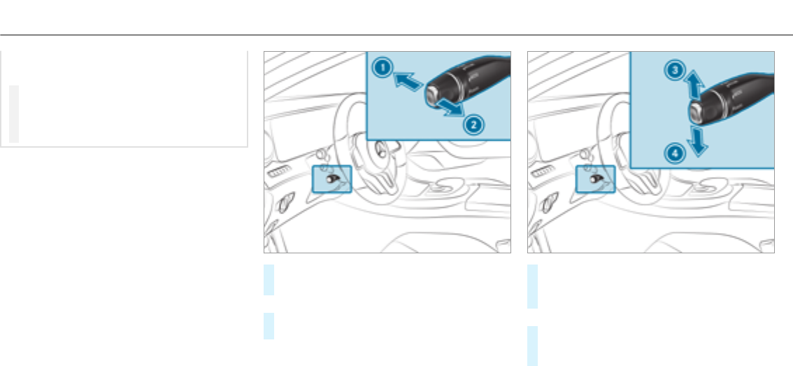
If youdo not know thestored speed, the
vehicle could decelerate unexpectedly.
#Take into account the traffic situation
before calling up thestored speed.
#If thestored speed is not known, store
the desired speed again.
Change into a lowergear in good time on long
and steep downhill gradients. Take particular
note of this when driving a laden vehicle. By
doing so, youwill make use of the braking effect
of the engine. This relievesthe load on the brake
system and prevents the brakes from overheat‐
ing and wearing tooquickly.
Requirements:
RCruise control is selected.
RESP®must be activated, but not intervening.
RThe driving speed must be at least 15 mph
(20 km/h).
#Store current speed 2(once afterstarting
thevehicle).
or
#Call up stored speed 2.
#Deactivate cruise control1.
#Press the lever briefly:thestored speed is
increased 3or reduced
4by 1mph (1 km/h).
or
#Press the lever beyond the pressure point:
thestored speed is increased 3or reduced
4by 5mph (10 km/h).
If cruise control has been deactivated, the cur‐
rent driven speed is adopted with 3or 4.
176Driving and parking

%If youbrake, deactivate ESP®or if ESP®
intervenes, cruise control is deactivated.
When youswitch off thevehicle, the last
speed stored is cleared.
Active Distance Assist DISTRONIC
Function of Active Distance Assist
DISTRONIC
Active Distance Assist DISTRONIC
RMaintains the set speed and accelerates or
decelerates thevehicle if the distance from
thevehicle in front permits.
RAssists youin maintaining the distance from
thevehicle in front and can bring your vehi‐
cle to astandstill if necessary.
RBrakes your vehicle with up to 50 % of the
maximum possible braking power. If greater
deceleration performance is required, a vis‐
ual and acoustic warning is given and you
must then intervene yourself.
RVehicles with Driving Assistance Pack‐
age, Active Parking Assist and COMAND:
When driving in stop-start traffic, the driver is
supportedby extended automatic re-start in
traffic jams.
RVehicles with Driving Assistance Pack‐
age: Responds to stationary vehicles in
urban speed ranges (except bicycles, motor‐
cycles and pedestrians) if conditions are suf‐
ficient to enable detection.
If youfail to adapt your driving style, Active Dis‐
tance Assist DISTRONIC can neither reduce the
risk of an accident nor override the laws of phys‐
ics. It cannot take into account road, weather or
traffic conditions. Active Distance Assist
DISTRONIC is only an aid. You are responsible
forthe distance to thevehicle in front, forvehi‐
cle speed, for braking in good time and forstay‐
ing in lane.
If all activation conditions are met, you can acti‐
vate Active Distance Assist DISTRONIC during a
journey or while stationary. When Active Dis‐
tance Assist DISTRONIC is activated, a speed is
stored which the driver can increase or reduce
at any time. The speed can be adjusted between
15 mph (20 km/h) and 120mph (200 km/h).
Vehicles with the Driving Assistance Pack‐
age: The speed can be adjusted between
15 mph (20 km/h) and 130mph (210 km/h).
Vehicles with Driving Assistance Package,
Active Parking Assist and COMAND: Up to 30
seconds afterstopping, thevehicle automatically
follows thevehicle ahead without the interven‐
tion of the driver. This is only possible if thevehi‐
cle is traveling on a motorway or a high-speed
major road. If an obstacle is detected in front of
thevehicle during the driving-off procedure, a
takeoverwarning is given. Acceleration is
reduced, the driver is given a visual and acoustic
warning and must stop thevehicle before reach‐
ing the obstacle or take evasive action.
Vehicles with the Driving Assistance Pack‐
age: In conjunction with navigation systems,
Active Distance Assist DISTRONIC prevents pro‐
hibited overtaking on theright at speeds over
50 mph (80 km/h) in right-hand traffic and over‐
taking on the left in left-hand traffic on freeways
and high-speed major roads.
If you activate the turn signal indicator to change
lanes, thevehicle will accelerate more briskly to
the set speed under thefollowing conditions:
Driving and parking 177

RActive Distance Assist DISTRONIC is activa‐
ted.
RIf the driving speed is higher than 45 mph
(70 km/h).
RIf the driven speed drops below thestored
speed.
RThe system cannot detect a vehicle in therel‐
evant area of theovertaking lane.
Vehicles with Driving Assistance Package
and Traffic Sign Assist: Active Distance Assist
DISTRONIC also has theActive Speed Limit
Assist function. This function can be configured
in the multimedia system. If a change in the
speed limit is detected and Active Distance
Assist DISTRONIC is activated, Active Distance
Assist DISTRONIC assumes this new speed.
The driven speed is adapted when thevehicle is
level with the traffic signs. The speed limit dis‐
play in the Instrument Display is always updated
when thevehicle is level with the traffic sign.
If Active Distance Assist DISTRONIC has been
put into passive mode by pressing the accelera‐
tor pedal, only speed limits which are higher
than the set speed are adopted.
Pulling the cruise control lever will set the dis‐
played speed limit as the speed, provided that:
RActive Speed Limit Assist has been activated
in the multimedia system and
RActive Distance Assist DISTRONIC has been
activated.
If no speed limit is displayed when the lever is
operated, the speed set by the driver is adopted.
Drive program
The DYNAMIC SELECT switch allows youto
change the driving style of Active Distance
Assist DISTRONIC. Depending on which drive
program is selected, the driving characteristics
can be geared towards fuel economy, comfort or
dynamic performance (→page 152).
System limitations
Vehicles with the Driving Assistance Pack‐
age: Active Distance Assist DISTRONIC is active
in the 0 mph(0 km/h) to 130mph(210 km/h)
speed range.
The system may be impaired or may not function
in thefollowing instances, forexample:
RIn snow,rain, fog, heavy spray, if there is
glare, in direct sunlight or in greatly varying
light conditions.
RThe windshield in the area of the camera is
dirty, misted up, damaged or covered.
RIf theradar sensors are dirty or covered.
ROn slippery roads, braking or accelerating
can cause the drive wheels to lose traction
and thevehicle could then skid.
RIn parking garages, toll stations or on roads
with steep uphill or downhill gradients.
Do not use Active Distance Assist DISTRONIC in
these situations.
Tips
Payparticularattention in thefollowing traffic
situations. In such situations, brake if necessary.
Active Distance Assist DISTRONIC is then deacti‐
vated:
RWhen cornering, entering and exiting a bend.
RWhen not driving in the center of the lane.
178Driving and parking
RWhen other vehicles are changing lane.
RIf there are narrow vehicles.
RIf there are obstacles and stationary vehi‐
cles.
RIf there are crossing vehicles, pedestrians,
motorcyclists or cyclists.
Display of Active Distance Assist DISTRONIC
in the assistance graphic and in the speed‐
ometer
1Vehicle ahead
2Distance indicator
3Set specified distance
4Your vehicle
1Speed of vehicle ahead
2Stored speed
Displays in the multifunction display
When activating Active Distance Assist
DISTRONIC or when changing thestored speed,
the new stored speed is shown for around five
seconds in the multifunction display ç
50 mph (70 km/h).
When Active Distance Assist DISTRONIC is
active,the set stored speed is displayed next to
theçsymbol. When distance control is
active,the symbol is shown in green.
Vehicles with the Driving Assistance Pack‐
age: On freeways or high-speed major roads the
çsymbol is displayed cyclically when the
vehicle is ready to pull away.
Vehicles with Active Speed Limit Assist:If a
speed limit is automatically adopted, this is
shown as thestored speed with theêsym‐
bol.
Operating Active Distance Assist DISTRONIC
&WARNING Risk of accident if detection
function of Active Distance Assist
DISTRONIC is impaired
Active Distance Assist DISTRONIC does not
react:
RTo people or animals.
RTo stationary obstacles on theroad, e.g.
stopped or parkedvehicles (vehicles with‐
out the Driving Assistance Package).
Driving and parking 179

RTo stationary obstacles on theroad, e.g.
stopped or parkedvehicles, if conditions
are not sufficient to enable detection
(vehicles with the Driving Assistance
Package).
RTo oncoming vehicles and crossing traf‐
fic.
Active Distance Assist DISTRONIC can nei‐
ther give warnings nor intervene in such sit‐
uations.
#Always carefully observe the traffic con‐
ditions and be ready to brake at all
times.
&WARNING Risk of accident due to limi‐
ted detectability of road users and traffic
situations
Active Distance Assist DISTRONIC cannot
always clearly identify other road users and
complex traffic situations.
In these conditions, Active Distance Assist
DISTRONIC may:
RGive an unnecessary warning and then
brake thevehicle.
RNeither give a warning nor intervene.
RAccelerate or brake unexpectedly.
#Continue driving with care and be ready
to brake, particularly if Active Distance
Assist DISTRONIC warnsyou.
&WARNING Risk of accident from acceler‐
ation or braking by Active Distance
Assist DISTRONIC
Active Distance Assist DISTRONIC may accel‐
erate or brake in thefollowing cases, for
example:
RIf thevehicle pulls away using Active Dis‐
tance Assist DISTRONIC.
RIf thestored speed is called up and is
considerably faster or slowerthan the
currently driven speed.
RIf Active Distance Assist DISTRONIC no
longer detects a vehicle in front or does
not react to relevant objects.
#Always carefully observe the traffic con‐
ditions and be ready to brake at all
times.
#Take into account the traffic situation
before calling up thestored speed.
&WARNING Risk of accident due to insuf‐
ficient deceleration by Active Distance
Assist DISTRONIC
Active Distance Assist DISTRONIC brakes
your vehicle with up to 50 % of the maximum
possible deceleration. If this deceleration is
not sufficient, Active Distance Assist
DISTRONIC alerts you with a visual and
acoustic warning.
#In these cases, adjust your speed and
keep a sufficient distance.
#Brake thevehicle yourself and/or take
evasive action.
180Driving and parking
&WARNING Risk of accident due to Active
Distance Assist DISTRONIC still being
activated when you leave the driver's
seat
If you leave the driver's seat while thevehicle
is being braked by Active Distance Assist
DISTRONIC only, thevehicle can roll away.
#Always deactivate Active Distance
Assist DISTRONIC and secure thevehi‐
cle to prevent it from rolling away
before you leave the driver's seat.
Requirements
RThe vehicle's engine must be switched on.
RThe electric parking brake must be released.
RActive Parking Assist is not being used to
park thevehicle or to exit from a parking
space.
RESP®must be activated, but not intervening.
RThe transmission must be in position h.
RThe driver door, front passenger door and the
rear doors must be closed.
RThe engine hood must be closed.
#Remove your foot from the accelerator pedal.
#To store current speed 2.
Your vehicle adapts its speed to that of the
vehicle in front, but only up to thestored
speed.
or
#Call up stored speed 2.
#Or on vehicles with Driving Assistance
Package and Traffic Sign Assist: the dis‐
played speed limit is adopted, if available 2.
#Deactivate Active Distance Assist DISTRONIC
1.
#Increase 3or reduce 4the speed.
Driving and parking 181
#Reduce 5or increase 6the specified dis‐
tance from thevehicle in front.
Pulling away withActive Distance Assist
DISTRONIC
Requirement: a speed must have been previ‐
ously stored.
#Remove your foot from the brake pedal.
#Briefly pull the cruise control levertowards
you2.
or
#Accelerate briefly.
Your vehicle pulls away and adapts its speed
to that of thevehicle in front. If no vehicle is
detected in front, your vehicle accelerates to
the set speed.
Adopting the speed limit as thestored speed
Requirements:
RActive Speed Limit Assist is activated in the
multimedia system (→page 209).
RActive Distance Assist DISTRONIC is activa‐
ted.
RThe system detects a traffic sign indicating a
speed limit.
#Brieflypull the cruise control levertowards
you2.
The displayed speed limit is adopted as the
stored speed. Your vehicle adapts its speed
to that of thevehicle in front, but only up to
thestored speed. If Active Speed Limit Assist
is activated, any detected changes in the
speed limit are adoptedby the system.
Collision warning
If Active Distance Assist DISTRONIC is unable to
sufficiently decelerate thevehicle in order to
prevent it from approaching thevehicle in front,
you will be warned visually and acoustically. An
intermittent warning tone will then sound and
the distance warning lamp will light up in the
instrument cluster.
#Brake immediately in order to increase the
distance from thevehicle in front.
or
#Take evasive action provided it is safe to do
so.
Active Steering Assist
Function of Active Steering Assist
Active Steering Assist is only available for
vehicles with the Driving Assistance Pack‐
age.
RActive Steering Assist is operational at
speeds up to 130mph(210 km/h) and helps
182Driving and parking

youto stay in the center of the lane by
means of moderate steering interventions.
RIt uses thevehicle in front and the lane mark‐
ings as a reference depending on the driven
speed.
RActive Steering Assist requires you as the
driver, to keep your hands on thesteering
wheel at all times so that you are able to
intervene at any time to correct the course of
thevehicle and keep it in lane.
RActive Steering Assist can be overridden at
any time by steering thevehicle yourself.
RWhen the system is actively steering, the
èsymbol is shown in green in the multi‐
function display.
System limitations of Active Steering Assist
Active Steering Assist has a limited steering tor‐
quefor lateral guidance. In some cases, the
steering intervention is not sufficient to keep the
vehicle in the lane.
If the detection of lane markings and vehicles
ahead is impaired, Active Steering Assist
switches to passive mode. The system provides
no support in this case. During the transition
from the active to passive status, theèsym‐
bol is shown as enlarged and flashes yellow.
Once the system is passive theèsymbol is
shown as gray in the multifunction display.
The system may be impaired or may not function
in thefollowing instances:
RIf there is poor visibility, e.g. due to insuffi‐
cient illumination of theroad, or due to snow,
rain, fog or heavy spray.
RIf there is glare, e.g. from oncoming traffic,
direct sunlight or reflection from other vehi‐
cles (e.g. if the carriagewayis wet).
RIf the windshield is dirty, misted up, damaged
or covered, for instance by asticker, in the
vicinity of the camera.
RIf no, or several, unclear lane markings are
present for one lane, e.g. in a construction
area.
RIf the lane markings are worn away, dark or
covered up, e.g. by dirt or snow.
RThe distance to thevehicle in front is too
small and the lane markings thus cannot be
detected.
RIf the lane markings change quickly, e.g.
lanes branch off, cross one another or
merge.
RThe carriagewayis narrow and winding.
RIf there are highly variable shade conditions
on the carriageway.
RIf there are obstacles such as object markers
on the lane or projecting out into the lane.
The system does not provide assistance in the
following conditions:
ROn very sharp bends.
RWhen towing a trailer.
RIf you actively change lane without switching
on the turn signal indicator.
RIf you switch on the turn signal indicator and
the conditions for activating Active Lane
Change Assist are not fulfilled.
Activating Active Steering Assist
Requirements:
RESP®must be activated, but not intervening.
Driving and parking 183
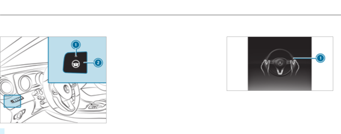
RActive Distance Assist DISTRONIC is activa‐
ted.
#If indicator lamp 1is off: press button 2.
Function of Active Lane Change Assist
Active Steering Assist is only an aid. You are
responsible forthe distance to thevehicle in
front, forvehicle speed, for braking in good time
and forstaying in your lane. Before changing
lanes, make sure that the neighboring lane is
free (shoulder view).
%The availability of thefollowing function is
country-dependent.
Active Steering Assist remains active even if the
turn signal indicator is switched on. Active Steer‐
ing Assist then assists the driver when changing
lanes by applying steering torques to initiate the
lane change.
Assistance when changing lanes is provided if all
thefollowing conditions are met:
RYou are driving on a motorway or high-speed
multi-lane major road with multiple lanes in
the direction of travel.
RThe neighboring lane is free and separated
by a broken lane marking.
RThe driven speed is between 50 mph
(80 km/h) and 110mph(180 km/h).
RThe turn signal indicator is switched on for
longer than two seconds.
If the system is impaired, Active Lane Change
Assist may be canceled. If an interruption
occurs, display 1appears in the multifunction
display along with a warning tone promptingyou
to take control of thevehicle.
Steering and contact detection
Active Steering Assist requires you as the driver,
to keep your hands on thesteering wheel at all
times so that you are able to intervene at any
time to correct the course of thevehicle and
keep it in lane. The driver must expect a change
from active to passive mode or vice versa at any
time.
If you are not steering yourself or if you take
your hands off thesteering wheel for a pro‐
longed period of time, the system will, depend‐
ing on the situation, first alert youwith a visual
184Driving and parking

warning. 1appears in the multifunction display.
If you are still not steering thevehicle yourself or
if you have not taken hold of thesteering wheel,
awarning tone sounds in addition to thewarning
message to remind youto take control of the
vehicle.
The warning message does not appear or disap‐
pears if one of thefollowing conditions are met:
RThe driver steers thevehicle.
RThe driver presses a steering wheel button or
operates Touch Control.
Function of Active Emergency Stop Assist
If the driver continues to ignore the acoustic
warning of Active Lane Change Assist,Active
Distance Assist DISTRONIC reduces the speed.
If the driver still does not respond, thevehicle is
decelerated in stages to astandstill.
The driver can cancel the deceleration at any
time by performing one of thefollowing actions:
RSteering
RBraking or accelerating
RPressing a steering wheel button or operat‐
ing Touch Control
RActivating or deactivating Active Steering
Assist or Distance Assist DISTRONIC
The driver must be ready to take control of the
vehicle at any time.
Information on Hill Start Assist
Hill Start Assist holds thevehicle for a short
time when pulling away on a hill under thefol‐
lowing conditions:
RThe transmission is in position hor k.
RThe electric parking brake is released.
This gives you enough time to move your foot
from the brake pedal to the accelerator pedal
and depress it before thevehicle begins to roll.
&WARNING Risk of accident and injury
caused by thevehicle rolling away
After a short time, Hill Start Assist no longer
holds thevehicle and it can roll away.
#Therefore, swiftly move your foot from
the brake pedal to the accelerator
pedal. Never attempt to leave thevehi‐
cle if it is being held by Hill Start Assist.
HOLD function
HOLD function
The HOLD function holds thevehicle at a stand‐
still without requiring youto depress the brake
pedal, e.g. when pulling away on steep slopes.
System limitations
RThe incline must not be greaterthan 30%.
Activating/deactivating the HOLD function
&WARNING Risk of an accident due to the
HOLD function being activated when you
leave thevehicle
If you leave thevehicle while only the HOLD
function is braking thevehicle, thevehicle
can roll away in thefollowing situations:
RIf there is a malfunction in the system or
in the power supply.
Driving and parking 185

RIf the HOLD function is deactivated by
depressing the accelerator pedal or the
brake pedal, e.g. by avehicle occupant.
RIf the electrics in the engine compart‐
ment, the battery or the fuses are tam‐
pered with or if the battery is disconnec‐
ted.
#Always deactivate the HOLD function
and secure thevehicle against rolling
away before leaving thevehicle.
*NOTE Damage from automatic braking
When Active Brake Assist,Active Distance
Assist DISTRONIC or the HOLD function are
activated, thevehicle brakes autonomously
in certain situations.
To avoid damage to thevehicle, deactivate
these systems in thefollowing or similar sit‐
uations:
#During towing
#In a car wash
Requirements:
RThe vehicle is stationary.
RThe driver's door is closed or the seat belt on
the driver's side is fastened.
RThe engine is running or has been automati‐
cally switched off by the ECO start/stop
function.
RThe electric parking brake is released.
RActive Distance Assist DISTRONIC is not acti‐
vated.
RThe transmission is in position h,kor i.
Activating the HOLD function
#Depress the brake pedal and after a short
time depress further until theëdisplay
appears in the multifunction display.
#Release the brake pedal.
Deactivating the HOLD function
#Depress the accelerator pedal to pull away.
or
#Depress the brake pedal until theëdis‐
play disappears from the multifunction dis‐
play.
The HOLD function is deactivated in thefollow‐
ing situations:
RWhen Active Distance Assist DISTRONIC is
activated.
RThe transmission is switched to position j.
RWhen thevehicle is secured with the electric
parking brake.
In thefollowing situations, thevehicle is held by
the transmission position jor by the electric
parking brake:
RWhen the seat belt is unfastened and the
driver's door is opened.
RWhen the engine is switched off.
RWhen there is a malfunction in the system or
if the power supply is insufficient.
DYNAMIC BODY CONTROL
DYNAMIC BODY CONTROL has thefollowing
characteristics:
RVariable damping characteristics
RContinual adjustment of the damping forces
186Driving and parking

The damping characteristics adapt to the current
operating and driving situation.
The damping is tuned individually for each wheel
and is affected by thefollowing factors:
RThe road surface conditions
RVehicle load
RThe drive program selected
The drive program can be adjusted using the
DYNAMIC SELECT switch.
AIR BODY CONTROL
AIR BODY CONTROL function
AIR BODY CONTROL is an air suspension system
with variable damping for improved driving com‐
fort. The all-round level control system ensures
the best possible suspension and constant
ground clearance, even with a laden vehicle.
When driving at speed, thevehicle is lowered
automatically to improve driving safetyand to
reduce fuel consumption. The option of manually
adjusting thevehicle level is also available.
AIR BODY CONTROL comprises:
RAir suspension with variable spring rate
RAutomatic level control system
RSpeed-dependent lowering to reduce fuel
consumption
RManual level adjustment
RADS PLUS (Adaptive Damping System with
constant damping force adjustment)
RDYNAMIC SELECT switch and level button
Available suspension settings
Drive programCharacteristics
C
(Comfort)
RThe suspension tuning is comfortable.
RThe vehicle is set to the normal level.
RWhen driving at speeds of above 78 mph (125 km/h) thevehicle is lowered.
RWhen driving at speeds below 50 mph (80 km/h), thevehicle is raised.
E
(Economy)
RThe suspension tuning is comfortable.
RThe vehicle is set to the low level.
RThe vehicle is not lowered any further if you are traveling at higher speeds.
Driving and parking 187

DriveprogramCharacteristics
S
(Sport)
RThe suspension tuning is firmer.
RThe vehicle is set to the low level.
RThe vehicle is not lowered any further if you are traveling at higher speeds.
S+
(Sport Plus)
RThe suspension tuning is evenfirmer.
RThe vehicle is set to the low level.
RThe vehicle is not lowered any further if you are traveling at higher speeds.
AIR BODY CONTROL function
AIR BODY CONTROL is an air suspension system
with variable damping for improved driving com‐
fort. The all-round level control system ensures
the best possible suspension and constant
ground clearance, even with a laden vehicle.
When driving at speed, thevehicle is lowered
automatically to improve driving safetyand to
reduce fuel consumption. The option of manually
adjusting thevehicle level is also available.
AIR BODY CONTROL comprises:
RAir suspension with variable spring rate
RAutomatic level control system
RSpeed-dependent lowering to reduce fuel
consumption
RManual level adjustment
RADS PLUS (Adaptive Damping System with
constant damping force adjustment)
RDYNAMIC SELECT switch and level button
188Driving and parking

Available suspension settings
Drive programCharacteristics
C
(Comfort)
RThe suspension tuning is comfortable.
RThe vehicle is set to the normal level.
RWhen driving at speeds of above 78 mph (125 km/h) thevehicle is lowered.
RWhen driving at speeds below 50 mph (80 km/h), thevehicle is raised again.
E
(Economy)
RThe suspension tuning is comfortable.
RThe vehicle is set to the low level.
RThe vehicle is not lowered any further if you are traveling at higher speeds.
S
(Sport)
RThe suspension tuning is firmer.
RThe vehicle is set to the low level.
RThe vehicle is not lowered any further if you are traveling at higher speeds.
Driving and parking 189

DriveprogramCharacteristics
All vehicles except All-Terrain
vehicles: S+
(Sport Plus)
RThe suspension tuning is evenfirmer.
RThe vehicle is set to the low level.
RThe vehicle is not lowered any further if you are traveling at higher speeds.
All-Terrain vehicles: AT
(All-Terrain)
RSuspension tuning is for easily negotiable offroad terrain.
RThe vehicle is set to the high level.
RWhen driving at speeds of above 22 mph(35 km/h) thevehicle is loweredto the normal level.
RWhen driving at speeds below 12 mph(20 km/h), thevehicle is raised again.
Setting thevehicle level
&WARNING Risk of accident because
vehicle level is too high
If youdrive at a higher vehicle level, the driv‐
ing characteristics may be impaired due to
the higher vehicle center of gravity.
The vehicle can drift outwards, forexample,
when steering or cornering.
#Alwayschoose a vehicle level which is
suited to the driving style and theroad
surface conditions.
&WARNING Risk of entrapment from vehi‐
cle lowering
When lowering thevehicle, people could
become trapped if their limbs are between
thevehicle body and the tires or underneath
thevehicle.
#Make sure no one is underneath the
vehicle or in the immediate vicinity of
the wheel arches when you lowerthe
vehicle.
&WARNING Risk of entrapment from vehi‐
cle lowering
Vehicles with AIR BODY CONTROL or
level control system: When you unload lug‐
gage or leave thevehicle, thevehicle first
190Driving and parking
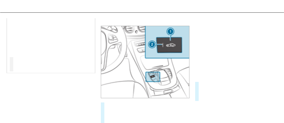
rises slightly and then returns to the set level
shortly afterwards.
You or anyone else in the vicinity of the
wheel arches or the underbody could thus
become trapped.
The vehicle can also be lowered after being
locked.
#When leaving thevehicle, make sure
that nobody is in the vicinity of the
wheel arches or the underbody.
Requirements
RThe vehicle has been started.
RThe vehicle must not be moving faster than
37 mph (60 km/h).
Raising thevehicle
#Press button 1.
Indicator lamp 2lights up.
The vehicle is raised by 1 in (25 mm) com‐
pared to the normal level.
Your selection is saved.
The vehicle is lowered again in thefollowing sit‐
uations:
RWhen driving faster than 50 mph (80 km/h).
RWhen driving between 37 mph (60 km/h)
and 50 mph (80 km/h) for approximately
three minutes.
RAfter selecting a drive program using the
DYNAMIC SELECT switch.
The vehicle is adjustedto the height of the last
active drive program.
Lowering thevehicle
#Press button 1.
Indicator lamp 2goes out. The vehicle is
adjustedto the height of the last active drive
program.
Driving and parking 191
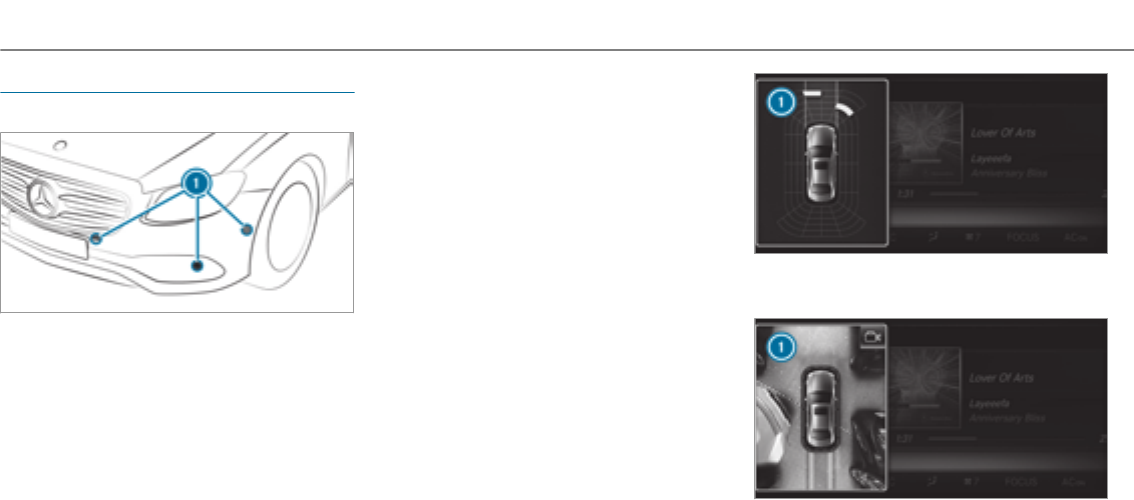
Parking Assist PARKTRONIC
Function of Parking Assist PARKTRONIC
Parking Assist PARKTRONICis an electronic
parkingassistance system with ultrasound. It
monitors the area around your vehicle using six
sensors 1in the front bumper and six sensors
in therear bumper. Parking Assist PARKTRONIC
indicates visuallyand audiblythe distance
between your vehicle and an object.
Parking Assist PARKTRONICis only an aid. It is
not a substitute for paying attention to your sur‐
roundings. You are alwaysresponsible for safe
maneuvering, parking and exiting a parking
space. Make sure that there are no persons, ani‐
mals or objects in the maneuvering area while
maneuvering and parking in/exiting parking
spaces.
In thestandard setting, an intermittent warning
tone sounds from a distance of approximately
1.0ft (0.3 m) to an obstacle. A continuous tone
sounds from a distance of approximately 0.7 ft
(0.2 m). You can set thewarning tone in the mul‐
timedia system so that it will sound earlier at a
greater distance of approximately 3.3 ft (1.0 m)
(→page 195).
If Parking Assist PARKTRONICis deactivated,
Active Parking Assist is unavailable.
Parking Assist PARKTRONIC display in the
multimedia system
If Active Parking Assist is not activated and an
obstacle is detected in the path of thevehicle, a
pop-up window forParking Assist PARKTRONIC
1appearsin the multimedia system at speeds
up to approximately 6 mph (10 km/h).
Vehicles with Active Parking Assist without a 360°
Camera
Vehicles with Active Parking Assist and a 360°
Camera
192Driving and parking
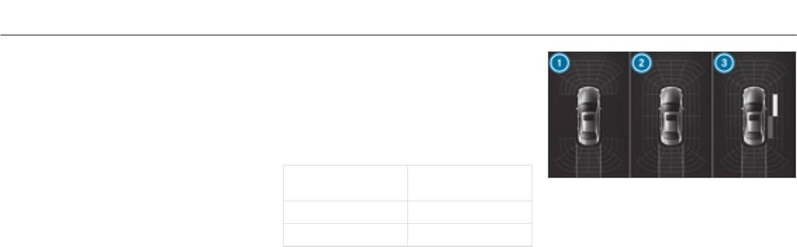
System limitations
Parking Assist PARKTRONICdoes notnecessa‐
rily take into account thefollowing obstacles:
RObstacles below the detection range, e.g.
persons, animals or objects.
RObstacles abovethe detection range, e.g.
overhanging loads, overhangs or loading
ramps of trucks.
The sensors must be free of dirt, ice and slush.
Otherwise, they may not function correctly.
Clean the sensors regularly, taking care not to
scratch or damage them.
Function of the passive side impact protec‐
tion
Passive side impact protection is an additional
Parking Assist PARKTRONICfunction which
warnsthe driver about obstacles at the side of
thevehicle. A warning is issued when obstacles
are detected between the front and rear detec‐
tion range. In order for an object to be detected,
the sensors in the front and rear bumper must
detect the object while you are driving past it.
During the parking procedure or maneuvering,
objects are detected as thevehicle drives past.
If yousteer in the direction of a detected obsta‐
cle and there is a risk of a lateral collision, a
warning is issued. The lateral segments light up
orange or red, depending on the distance to the
obstacle.
Segment color depending on distance
Color Lateral distance in
cm
RedApprox. < 30
OrangeApprox. 30 - 60
In order for lateral front or rear segments to be
displayed, thevehicle must first travel a distance
of at least half of thevehicle length. Once the
vehicle has traveled the length of thevehicle, all
of the lateral front and rear segments can be dis‐
played.
Vehicles without 360° Camera
1Parking Assist PARKTRONICis only opera‐
tional in the front and rear
2Parking Assist PARKTRONICis operational
and can also warn the driver about obstacles
at the side of thevehicle
3Obstacle detected at the front right (orange)
and rear (red)
Driving and parking 193
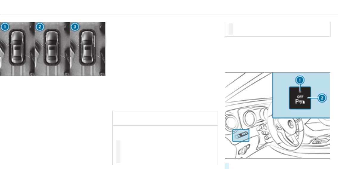
Vehicles with 360° Camera
1Parking Assist PARKTRONICis only opera‐
tional in the front and rear
2Parking Assist PARKTRONICis operational
and can also warn the driver about obstacles
at the side of thevehicle
3Obstacle detected at the front right (orange)
and rear (red)
Saved obstacles are deleted in thefollowing sit‐
uations, forexample:
RYouswitch off thevehicle
RYou open the doors
Afterthe engine is restarted, obstacles must be
detected again, before a new warning can be
issued.
System limitations
The system limitations forParking Assist
PARKTRONICapplyfor passive side impact pro‐
tection.
The following objects are not detected, forexam‐
ple:
RPedestrians who approach thevehicle from
the side
RObjects placed next to thevehicle
Deactivating/activating PARKTRONIC
*NOTE Risk of an accident from objects
at close range
Parking Assist PARKTRONICmaynotdetect
certain objects at close range.
#When parking or maneuvering thevehi‐
cle, pay particular attention to any
objects which are above or below the
sensors, e.g. flower pots or drawbars.
The vehicle or other objects could oth‐
erwise be damaged.
If indicator lamp 1is not lit, Parking Assist
PARKTRONICis active. If the indicator lamp is lit
or theésymbol appears in the multifunction
display, Parking Assist PARKTRONICis not
active.
#Press button2.
194Driving and parking
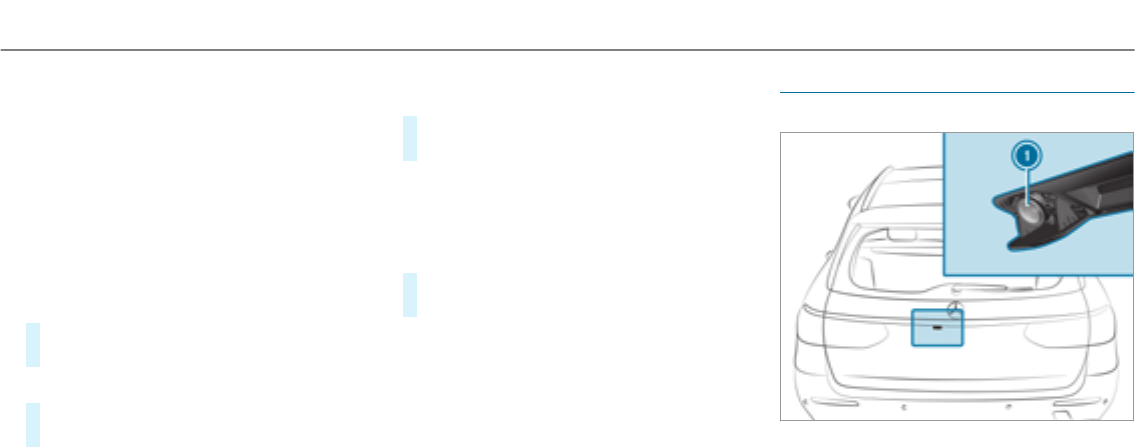
%Depending on thevehicle's equipment, the
button may also be located in the center
console.
%Parking Assist PARKTRONICis automatically
activated when thevehicle is started.
Adjusting the warning tones of Parking
Assist PARKTRONIC
Multimedia system:
, .k .
.
Adjusting the volume of thewarning tones
#Select .
#Adjust thevalue.
Adjusting the pitch of the warning tones
#Select .
#Adjust thevalue.
Specifying thestarting point for the warning
tones
You can specify whether theParking Assist
PARKTRONICwarning tones should commence
when thevehicle is further away from an obsta‐
cle.
#Select .
#Activate Oor deactivate ªthe function.
Activating/deactivating audio fadeout
You can specify whether thevolume of a media
source in the multimedia system is to be
reduced when Parking Assist PARKTRONICgives
an audible warning.
#Select .
#Activate Oor deactivate ªthe function.
Reversing camera
Function of therear view camera
When you engage reversegear, the image from
rear view camera 1is shown in the multimedia
system. Dynamic guide lines show the path the
vehicle will take with thesteering wheel in its
current position. This helps youto orientate
Driving and parking 195
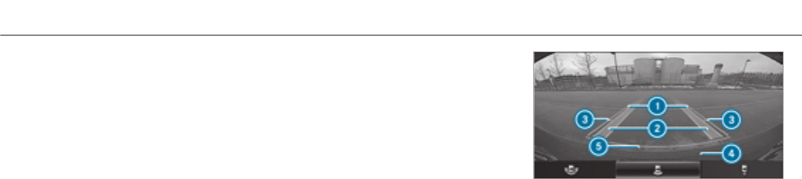
yourself and to avoid obstacles when backing
up.
The rear view camera is only an aid. It is not a
substitute foryour attention to the surroundings.
The responsibility for safe maneuvering and
parking remains with you. Make sure that there
are no persons, animals or objects in the maneu‐
vering area while maneuvering and parking in
parking spaces.
You can select from thefollowing views:
RNormal view
RWide-angle view
RTrailer view
The area behind thevehicle is displayed as a
mirror image, as in the inside rearview mirror.
System limitations
The rear view camera will not function or will
only partially function in thefollowing situations:
RIf the trunk lid or tailgate is open.
RThere is heavy rain, snow or fog.
RThe light conditions are poor, e.g. at night.
RThe camera lens is obstructed, dirty or mis‐
ted up. Observe the notes on cleaning the
rear camera (→page 342).
RThe camera or rear of your vehicle is dam‐
aged. In this case, have the camera and its
position and setting checked at a qualified
specialist workshop.
The field of vision and other functions of therear
view camera may be restricted due to additional
accessories on therear of thevehicle (e.g.
license plate bracket or bicycle rack).
%The display contrast may be impaired due to
incident sunlight or other light sources. In
this case, pay particular attention.
%If the display operation is considerably
impaired due to pixel errors,forexample,
have the display repaired or replaced.
Vehicles without Active Parking Assist
The following camera views are available in the
multimedia system:
Normal view
1Yellow guide line, vehicle width (driven sur‐
face) depending on the current steering
wheel angle (dynamic)
2Yellow lane marking the course the tires will
take at the current steering wheel angle
(dynamic)
3Yellow guide line at a distance of approx‐
imately 3.3 ft (1.0 m) from therear area
4Bumper
5Red guide line at a distance of approximately
12 in (0.3 m) from therear area
196Driving and parking
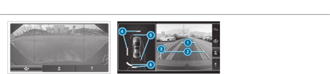
Wide-angle view
Vehicles with Active Parking Assist
The following camera views are available in the
multimedia system:
Normal view
1Yellow lane marking the course the tires will
take at the current steering wheel angle
(dynamic)
2Yellow guide line, vehicle width (driven sur‐
face) depending on the current steering
wheel angle (dynamic)
3Red guide line at a distance of approximately
12 in (0.3 m) from therear area
4Yellow warning display of Parking Assist
PARKTRONIC: obstacles areat adistance of
between approximately 2.0 ft (0.6 m) and
3.3 ft (1.0 m)
5Redwarning display of Parking Assist
PARKTRONIC: obstacles arevery close
(approximately 1.0ft (0.3 m) or less)
6Orange warning display of Parking Assist
PARKTRONIC: obstacles are a medium dis‐
tance away (between approximately 1.0ft
(0.3 m) and 2.0 ft (0.6 m))
%If the entire system fails, the inner segments
of thewarning display are shown in red. The
indicator lamp on thePARKTRONICbutton
lights up and theésymbol appears in
the multifunction display.
If the system fails at therear:
RThe rear segments are shown in red
when backing up.
RThe rear segments are hidden when driv‐
ing forwards.
When Active Parking Assist is active, the
lanes are displayed in green.
If Parking Assist PARKTRONICis deactivated,
thewarning display fades out.
Driving and parking 197
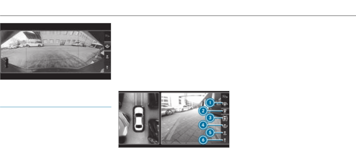
Wide-angle view
360° camera
Function of the 360° Camera
The 360° Camera is a system that consists of
four cameras. The cameras coverthe immediate
vehicle surroundings. The system supports you,
e.g. when parking or at exits with reduced visibil‐
ity.
The 360° Camera is only an aid. It is not a sub‐
stitute foryour attention to the surroundings.
The responsibility for safe maneuvering and
parking remains with you. Make sure that there
are no persons, animals or objects in the maneu‐
vering area while maneuvering and parking in
parking spaces.
The system evaluates images from thefollowing
cameras:
RRear view camera
RFront camera
RTwo side cameras in the outside mirrors
Views of the 360° Camera
You can select from different views:
1Wide-angle view, front
2Top view with image from the front camera
3Top view with images from the side cameras
in the outside mirrors
4Wide-angle view, rear
5Top view with image from therear view cam‐
era
6Top view with trailer view (if trailer hitch is
fitted)
198Driving and parking
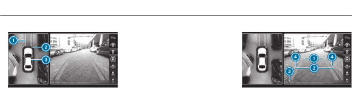
Top view
1Lane indicating theroute thevehicle will
take with thesteering wheel in its current
position
2Yellow warning display of Parking Assist
PARKTRONIC: obstacles at adistance of
approximately 3.3 ft (1.0 m) or less
3Your vehicle from above
If the distance to the object lessens, the color of
thewarning display changes 2.From a dis‐
tance of approximately 2.0 ft (0.6 m) thewarn‐
ing display is shown in orange. From a distance
of approximately 1.0ft (0.3 m) thewarning dis‐
play is shown in red.
When Parking Assist PARKTRONICis operational
and no objectis detected, the segments of the
warning display are shown in gray.
%If the entire system fails, the segments of
thewarning display are shown in red. The
indicator lamp on thePARKTRONICbutton
lights up and theésymbol appears in
the multifunction display.
If the system fails at therear, the display of
the segments changes as follows:
RThe rear segments are shown in red
when backing up.
RThe rear segments are hidden when driv‐
ing forwards.
If Parking Assist PARKTRONICis deactivated,
thewarning display fades out.
Guide lines
1Yellow lane marking the course the tires will
take at the current steering wheel angle
(dynamic)
2Yellow guide line, vehicle width (driven sur‐
face) depending on the current steering
wheel angle (dynamic)
3Red guide line at a distance of approximately
12 in (0.3 m) from therear area
4Mark at a distance of approx. 3.3 ft (1.0 m)
%When Active Parking Assist is active, the
lanes are displayed in green.
Driving and parking 199
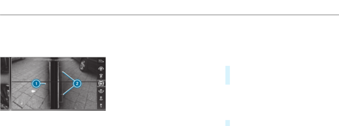
The guide lines in the multimedia system dis‐
play show the distances to your vehicle. The
distances only apply to road level.
Side view of the mirror cameras
The sides of thevehicle can be seen in this view.
1Guide line of external vehicle dimensions
with outside mirrors folded out
2Marker of the wheel contact points
System limitations
The 360° Camera will not function or will only
partially function in thefollowing situations:
RIf the doors are open.
RThe side mirrors are folded in.
RIf the trunk lid or tailgate is open.
RThere is heavy rain, snow or fog.
RThe light conditions are poor, e.g. at night.
RThe camera lens is obstructed, dirty or fog‐
ged up.
RCameras, or vehicle components in which
the cameras are installed, are damaged. In
this event, have the cameras, their positions
and their setting checked at a qualified spe‐
cialist workshop.
Do not use the 360° Camera under such circum‐
stances. You could otherwise injure others or
collide with objects when parking thevehicle.
On vehicles with height-adjustable suspension or
if thevehicle is carrying a heavy load, leaving the
standard height can result in inaccuracies in the
guide lines and in the display of thegenerated
images, depending on technical conditions.
The field of vision and other functions of the
camera system may be restricted due to addi‐
tional accessories on therear of thevehicle (e.g.
license plate bracket, bicycle rack).
See the notes on cleaning the 360° Camera
(→page 342).
Selecting a view for the 360° Camera
Requirements
RThe function is selec‐
ted in the multimedia system.
#Engage reversegear.
#In the multimedia system, select the desired
view.
Opening the camera cover of the reversing
camera
Multimedia system:
, .k .
#Select .
%The camera cover closes automatically after
some time or after an ignition cycle.
Assigning the camera as a favorite
You can call up the camera view directly in the
multimedia system by assigning it as a favorite.
200 Driving and parking

#Press theòbutton on thetouchpad or
controller.
The main functions are displayed.
#Navigate downwards twice.
The Favorites menu appears.
#Select .
#Select .
#Select .
Active Parking Assist
Function of Active Parking Assist
Active Parking Assist is an electronic parking
assistance system which uses ultrasound and is
automatically activated during forward travel.
The system is operational at speeds of up to
approximately 22 mph (35 km/h). When all the
conditions are fulfilled, thecsymbol appears
in the multifunction display and the system auto‐
matically searches for and measures parking
spaces on both sides of thevehicle parallel and
perpendicular to the direction of travel. If Active
Parking Assist is activated, suitable parking
spaces are displayed in the multimedia system.
The ësymbol appears in the multifunction
display. The arrows show on which side of the
carriagewayfree parking spaces arelocated.
The parking spaceand,if necessary, the parking
direction can be selected as desired. Active
Parking Assist calculates a suitable vehicle path
and assists you in parking and exiting the park‐
ing space.
Active Parking Assist changes gear, accelerates,
brakes and steers thevehicle.
Active Parking Assist is only an aid. It is not a
substitute foryour attention to the surroundings.
The responsibility for safe maneuvering and
parking remains with you. Make sure that no
persons, animals or objects etc. are in the
maneuvering range.
Active Parking Assist is canceled if, among other
things, one of thefollowing actions is carried
out:
RYou deactivate Parking Assist PARKTRONIC.
RYou deactivate Active Parking Assist.
RYou begin steering.
RYouapplythe parking brake.
RYou engage j.
RESP®intervenes.
RYou open thetailgate.
System limitations of Active Parking Assist
Objects located above or below the detection
range of Active Parking Assist are not detected
when the parking space is being measured.
These are also not taken into account when the
parking maneuver is calculated, e.g. overhanging
loads, overhangs or loading ramps of trucks or
the boundaries of parking spaces. In some cir‐
cumstances, Active Parking Assist may therefore
guide you into the parking space prematurely.
&WARNING Risk of accident due to
objects located above or below the
detection range of Active Parking Assist
If there are objects above or below the
detection range, thefollowing situations may
arise:
RActive Parking Assist may steer too early.
Driving and parking 201
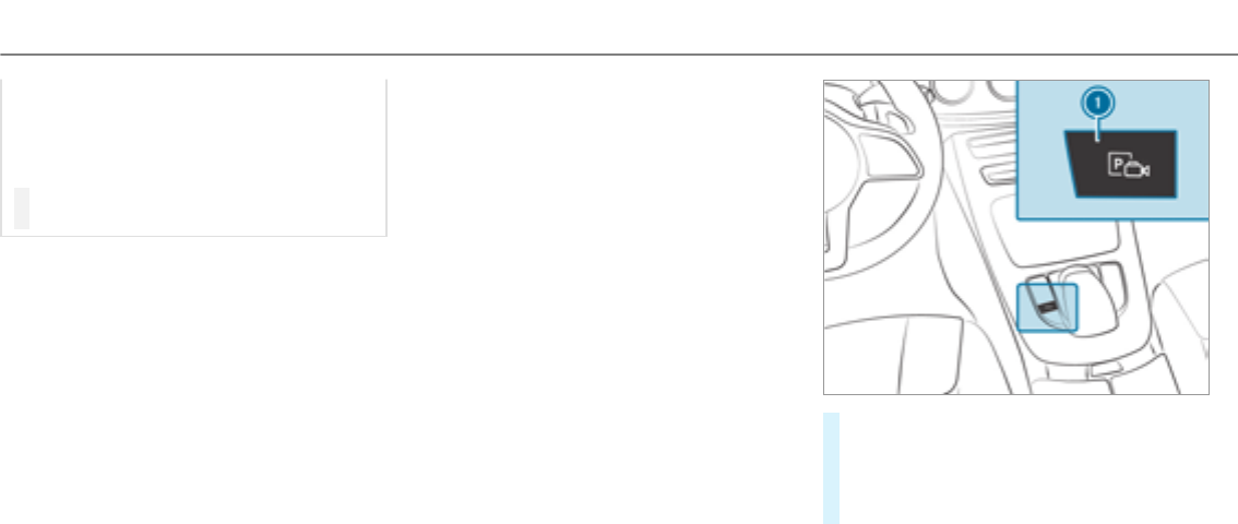
RVehicles with automatic transmis‐
sion: The vehicle may not stop in front of
these objects.
This could cause a collision.
#In these situations, do not use Active
Parking Assist.
Snowfall or heavy rain may lead to a parking
space being measured inaccurately. Parking
spaces that are partially occupied by trailer draw
bars might not be identified as such or be meas‐
ured incorrectly. Only use Active Parking Assist
on level, high-grip ground.
Do not use Active Parking Assist in thefollowing
situations:
RIf you are drivingin extreme weather condi‐
tions such as ice, packed snow or in heavy
rain.
RIf you are transporting a load that protrudes
beyond thevehicle.
RIf the parking space is on a steep downhill or
uphill gradient.
RIf you have installed snow chains.
Active Parking Assist may also display parking
spaces that are not suitable for parking, e.g.:
RParking spaces where parking is prohibited.
RParking spaces on unsuitable surfaces.
Active Parking Assist will not assist you with
parking spaces at right angles to the direction of
travel in thefollowing situations:
RIf two parking spaces are located immedi‐
ately next to each other.
RIf the parking space is directly next to a low
obstacle such as a low curb.
Active Parking Assist will not assist you with
parking spaces at right angles to the direction of
travel in thefollowing situations:
RIf the parking space is on a curb.
RIf the parking space is bordered by an obsta‐
cle, e.g. a tree, a post or a trailer.
Parking with Active Parking Assist
%Depending on thevehicle's equipment, the
button may also be located at a different
position in the center console.
#Press button 1.
The Active Parking Assist view appears on
the multimedia system display. Area 2dis‐
plays detected parking spaces 4and vehi‐
cle path 3.
%Vehicle path 3shown on the multimedia
system display may differ from the actual
vehicle path.
202 Driving and parking
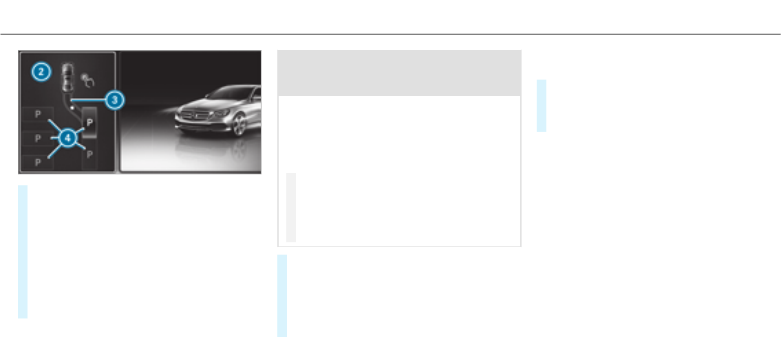
#If you have driven past a suitable parking
space: bring thevehicle to astandstill.
#Select desired parking space 4.
#Where necessary, select the parking direc‐
tion: forwards or backwards.
Vehicle path 3is shown, depending on the
selected parking space and parking direc‐
tion.
#Confirm the selected parking space.
&WARNING Risk of accident due to vehi‐
cle swinging out while parking or pulling
out of a parking space
While parking or exiting a parking space, the
vehicle swings out and can drive onto areas
of the oncoming lane.
This could cause youto collide with objects
or other road users.
#Payattention to objects and other road
users.
#Where necessary, stop thevehicle or
cancel the parking procedure with
Active Parking Assist.
#If, forexample, the
message appears in the multimedia system
display: select the corresponding transmis‐
sion position.
The vehicle drives into the selected parking
space.
On completion of the parking procedure, the
display message appears. Further maneuvering
may still be necessary.
#After completion of the parking procedure,
safeguard thevehicle against rolling away.
When required by legal requirements or local
conditions: turn the wheels towardsthe curb.
%You can stop thevehicle and change the
transmission position during the parking pro‐
cedure. The system then calculates a new
vehicle path. The parking procedure can
then be continued. If no new vehicle path is
available, the transmission position will be
changed again. If thevehicle has not yet
reached the parking space, the parking pro‐
cedure will be canceled, should a gear be
changed.
Exiting a parking space with Active Parking
Assist
Requirement
You can only exit a parking space with Active
Parking Assist if you have previously parkedthe
vehicle with Active Parking Assist.
Driving and parking 203
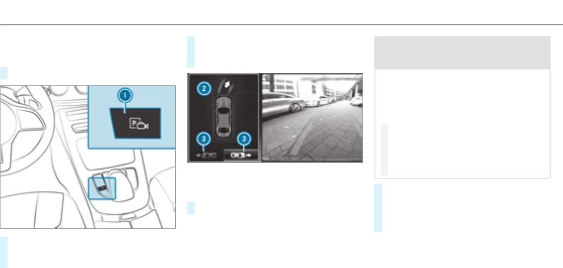
Please note that you are responsible forthevehi‐
cle and surroundings during the entire parking
procedure.
#Start thevehicle.
#Press button 1.
The Active Parking Assist view appears on
the multimedia system display.
#If thevehicle has been parked at right angles
to the direction of travel: in area 2, select
direction of travel3.
%The vehicle path shown on the multimedia
system display may differ from the actual
vehicle path.
#Confirm to start theexiting process.
&WARNING Risk of accident due to vehi‐
cle swinging out while parking or pulling
out of a parking space
While parking or exiting a parking space, the
vehicle swings out and can drive onto areas
of the oncoming lane.
This could cause youto collide with objects
or other road users.
#Payattention to objects and other road
users.
#Where necessary, stop thevehicle or
cancel the parking procedure with
Active Parking Assist.
#If, forexample, the
message appears in the multimedia system
display: select the corresponding transmis‐
sion position.
The vehicle moves out of the parking space.
204 Driving and parking
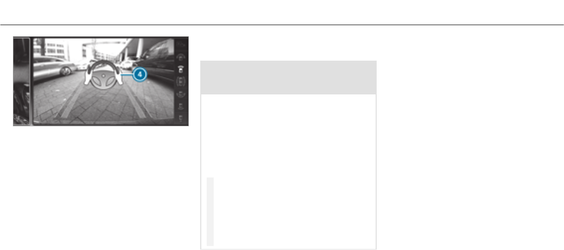
Example: vehicles with 360° Camera
Aftertheexiting procedure has been completed,
the
message appears in the display of the
multimedia system. A warning tone and display
4in the multimedia system prompt youto take
over control of thevehicle. You have to acceler‐
ate, brake, steer and change gear yourself again.
Function of Drive Away Assist
Drive Away Assist can reduce the severity of an
impact when pulling away. If an obstacle is
detected in the direction of travel, thevehicle's
speed is briefly reduced to approx. 1 mph
(2 km/h). If a critical situation is detected, a
symbol appears on the camera image of the mul‐
timedia system.
&WARNING Risk of accident caused by
limited detection performance of Drive
Away Assist
Drive Away Assist cannot always clearly iden‐
tify objects and traffic situations.
In such cases, Drive Away Assist might:
RWarn you without reason and limit the
vehicle speed.
RNot warn you or not limit thevehicle
speed.
#Always pay careful attention to the traf‐
fic situation; do not rely on DriveAway
Assist alone.
#Be prepared to brake or swerve as nec‐
essary, provided the traffic situation
permits and that it is safe to take eva‐
sive action.
Drive Away Assist is only an aid. It is not a sub‐
stitute foryour attention to the surroundings.
The responsibility for safe maneuvering and
parking remains with you. Make sure that no
persons, animals or objects etc. are in the
maneuvering range.
Arisk of a collision may arise in thefollowing sit‐
uations, forexample:
RIf the driver mixes up the accelerator and
brake pedals.
RIf the wrong gear is selected.
The Drive Away Assist function is active under
thefollowing conditions:
RIf Parking Assist PARKTRONICis activated.
REverytime thegear is changed to kor h
when thevehicle is at a standstill.
RIf the detected obstacle is less than approx.
3.3 ft (1.0 m) away.
RIf the maneuvering assistant function is acti‐
vated in the multimedia system.
System limitations
Drive Away Assist is not available on inclines.
Driving and parking 205

Function of Cross Traffic Alert
%Also read the instructions on Blind Spot
Assist (→page 210).
Vehicles with Blind Spot Assist: Drivers can
also be warned of any crossing traffic when
backing out of a parking space. If a critical situa‐
tion is detected, a warning symbol appears on
the camera image of the multimedia system. If
the driver does not respond to thewarning, the
vehicle's brakes can be applied automatically. To
do this, the function uses theradar sensors in
the bumper. The area adjacent to thevehicle is
continually monitored.
If theradar sensors are obstructed by vehicles
or other objects, detection is not possible.
The Cross Traffic Alert function is active under
thefollowing conditions:
RIf Blind Spot Assist is activated.
RIf thevehicle is backing up at walking pace.
RIf the maneuvering assistant function is acti‐
vated in the multimedia system.
The Cross Traffic Alert function is not available
on inclines.
Deactivating/activating the maneuvering
assistant
Multimedia system:
, .k .
.
#Switch the function on Oor off ª.
ATTENTION ASSIST
Function of ATTENTION ASSIST
ATTENTION ASSIST assists you on long, monoto‐
nous journeys, e.g. on freeways and trunk roads.
If ATTENTION ASSIST detects indicators of fati‐
gue or increasing lapses in concentration on the
part of the driver, it suggests taking a break.
ATTENTION ASSIST is only an aid. It cannot
always detect fatigue or lapses in concentration
until too late. The system is not a substitute for a
well-rested and attentive driver. On long jour‐
neys,takeregular breaks in good time that allow
for adequate recuperation.
You can choose between two settings.
RStandard: normal system sensitivity.
RSensitive: higher system sensitivity. The
driver is warned earlier and the attention
level detected by ATTENTION ASSIST is adap‐
ted accordingly.
If drowsiness or increasing lapses in concentra‐
tion are detected, the
warning appears in the Instrument Dis‐
play. You can acknowledge the message and
take a break where necessary. If you do not take
a break and ATTENTION ASSIST continues to
detect increasing lapses in concentration, you
will be warned again after a minimum of
15 minutes.
206 Driving and parking

You can have thefollowing status information for
ATTENTION ASSIST displayed in the assistance
menu of the on-board computer:
RThe length of the journey since the last
break.
RThe attention level determined by ATTENTION
ASSIST.
If ATTENTION ASSIST is unable to calculate the
attention level and cannot issue a warning, the
message appears.
If a warning is given in the Instrument Display,
the multimedia system offers to search for a rest
area. You can select a rest area and start naviga‐
tion to this rest area. This function can be activa‐
ted and deactivated in the multimedia system.
If ATTENTION ASSIST is deactivated, theé
symbol appears in the assistance graphic in the
Instrument Display when the engine is running.
ATTENTION ASSIST is activated automatically
when the engine is re-started. The last selected
sensitivity levelremains stored.
System limitations
ATTENTION ASSIST is active in the37 mph
(60 km/h) to 124mph (200 km/h) speed range.
The functionality of ATTENTION ASSIST is
restricted, and warnings may be delayed or not
occur at all in thefollowing situations:
RIf you have been driving for less than 30
minutes.
RIf theroad condition is poor (unevenroad
surface or potholes).
RIf there is a strong side wind.
RIf you adopt a sporty driving style (high cor‐
nering speeds or high rates of acceleration).
RIf theSteering Assist function of Active Dis‐
tance Assist DISTRONIC is active.
RIf the time has been set incorrectly.
RIn active driving situations, if youchange
lanes and vary your speed frequently.
The ATTENTION ASSIST tiredness or alertness
assessment is deleted and restarted when con‐
tinuing the journey in thefollowing situations:
RIf youswitch off the engine.
RIf you unfastenyour seat belt and open the
driver's door (e.g. change drivers or take a
break).
Setting ATTENTION ASSIST
Multimedia system:
, .k .
Setting options
#Select , or .
Suggesting a rest area
#Select .
#Activate Oor deactivate the function ª.
If ATTENTION ASSIST detects fatigue or
increasing lack of attention, it suggests a
rest area in the vicinity.
#Select a suggestedrest area.
You are guided to the selected rest area.
Driving and parking 207
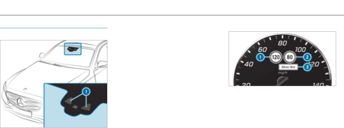
Traffic Sign Assist
Function of Traffic Sign Assist
Traffic Sign Assist detects traffic signs using
multifunction camera 1. It assists youby dis‐
playing detected speed limits and overtaking
restrictions in the instrument cluster.
Since Traffic Sign Assist also uses the data
stored in the navigation system, it can update
the display in thefollowing situations without
detecting traffic signs:
RWhen thevehicle changes roads, e.g. slip
road or motorway exit.
RWhen a village or town boundary is passed
which is stored in the digital map.
The camera also detects traffic signs with a
restriction indicated by an additional sign (e.g.
relating to wet conditions).
Warning when the maximum permissible
speed is exceeded
The system can warn youif you unintentionally
exceed the maximum permissible speed. To do
this, you can specify in the multimedia system
by how much the maximum permissible speed
can be exceeded before a warning is issued. You
can specify whether thewarning is to be just a
visual warning or an acoustic one as well.
Display in the Instrument Display
1Permissible speed
2Permissible speed when there is a restriction
3Additional sign with restriction
%The illustration shows the Instrument Display
in theWidescreen Cockpit
208 Driving and parking
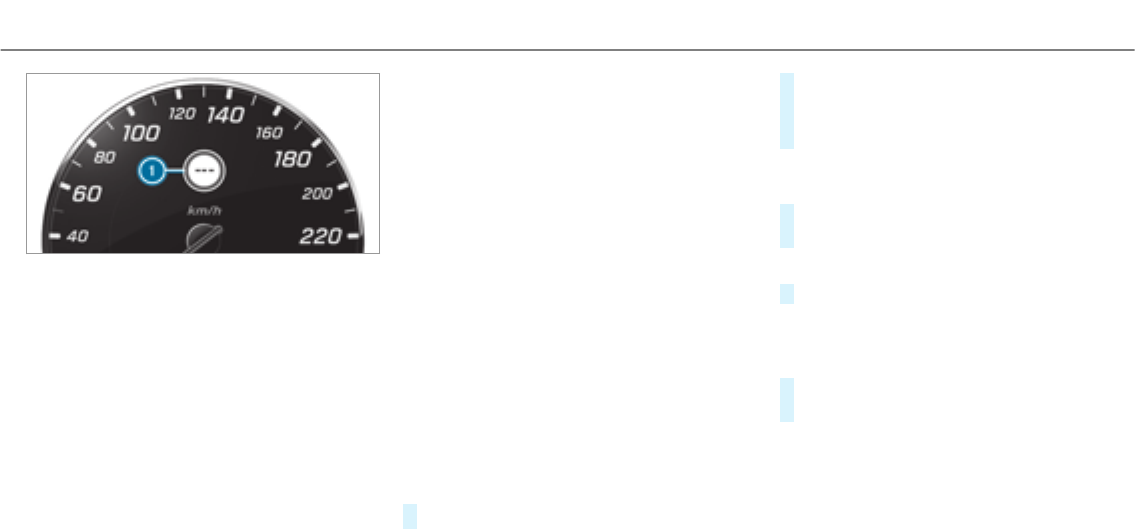
Traffic Sign Assist is not available in all coun‐
tries. If it is unavailable, display 1is shown in
the speedometer.
System limitations
The system may be impaired or may not function
in thefollowing situations:
RIf there is poor visibility, e.g. due to insuffi‐
cient illumination of theroad, highly variable
shade conditions, or due to rain, snow, fog or
heavy spray.
RIf there is glare, e.g. from oncoming traffic,
direct sunlight or reflections.
RIf there is dirt on the windshield in the vicin‐
ity of the multifunction camera or the camera
is fogged up, damaged or obscured.
RIf the traffic signs are hard to detect, e.g. due
to dirt or snow, or because they are covered,
or due to insufficient lighting.
RIf the information in the navigation system's
digital map is incorrect or out-of-date.
RIf the signs are ambiguous, e.g. traffic signs
on construction sites or in adjacent lanes.
Setting Traffic Sign Assist
Multimedia system:
, .k .
Activating /deactivating automatic adoption
of speed limits
Requirements
RActive Distance Assist DISTRONIC is activa‐
ted.
#Select .
#Activate Oor deactivate ªthe function.
The speed limits detected by Traffic Sign
Assist are automatically adoptedby Active
Distance Assist DISTRONIC.
Displaying detected traffic signs in the
media display
#Select .
#Activate Oor deactivate ªthe function.
Adjusting the type of warning
#Select , or .
Adjusting the warning threshold
This value determines the speed at which a
warning is issued when exceeded.
#Select .
#Set the desired speed.
Driving and parking 209

Blind Spot Assist and Active Blind Spot
Assist
Function of Blind Spot Assist and Active
Blind Spot Assist
Blind Spot Assist uses two lateral, rear-facing
radar sensors to monitor the area up to 130ft
(40 m) behind your vehicle and 10 ft (3 m)
directly next to your vehicle.
If a vehicle is detected at speeds above approx‐
imately 8 mph (12 km/h) and this vehicle subse‐
quently enters the monitoring range directly next
to your vehicle, thewarning lamp in the outside
mirror lights up red.
If a vehicle is detected close to your vehicle in
the lateral monitoring range and youswitch on
the turn signal indicator in the corresponding
direction, a warning tone sounds once. The red
warning lamp in the outside mirrorflashes. If the
turn signal indicatorremains on, all other detec‐
tedvehicles are indicated only by theflashing of
theredwarning lamp.
If youovertake a vehicle quickly, no warning is
given.
&WARNING Risk of accident despite Blind
Spot Assist
Blind Spot Assist does not react to vehicles
approaching and overtaking you at a greatly
different speed.
As a result, Blind Spot Assist cannot warn
drivers in this situation.
#Always pay careful attention to the traf‐
fic situation and maintain a safe dis‐
tance at the side of thevehicle.
Blind Spot Assist and Active Blind Spot Assist
are only aids. They may fail to detect some vehi‐
cles and are no substitute for attentive driving.
Always ensure that there is sufficient distance to
the side forother road users and obstacles.
System limitations
The system may be limited in thefollowing situa‐
tions:
Rthe sensors are dirty or covered
Rpoor visibility, e.g. due to fog, heavy rain,
snow or spray
Rnarrowvehicles, e.g. bicycles, are within the
monitoring range
Warnings may be issued in error when driving
close to crash barriers or similar solid lane bor‐
ders. Warnings may be interrupted when driving
alongside long vehicles, e.g. trucks,for a pro‐
longed time.
Blind Spot Assist is not operational when reverse
gear is engaged.
Function of braking applications (Active
Blind Spot Assist)
If Active Blind Spot Assist detects a risk of a side
impact in the monitoring range, a course-cor‐
recting brake application is carried out. This is
designed to help youavoid a collision.
The course-correcting brake application is availa‐
ble in the speed range between approximately
20 mph (30 km/h) and 125mph (200 km/h).
210Driving and parking
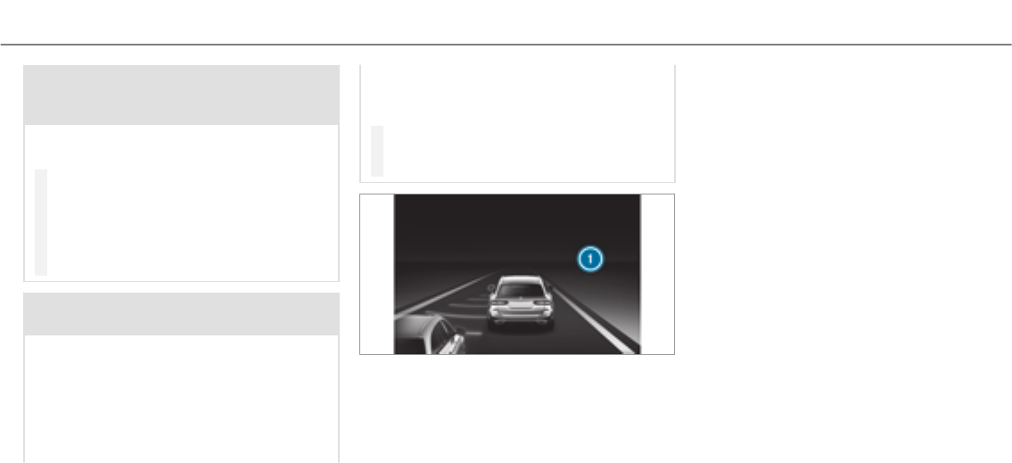
&WARNING Risk of accident despite
brake application of Active Blind Spot
Assist
A course-correcting brake application cannot
always prevent a collision.
#Alwayssteer, brake or accelerate your‐
self, especially if Active Blind Spot
Assist warnsyou or makes a course-
correcting brake application.
#Always maintain a safe distance at the
sides.
&WARNING Risk of accident despite
Active Blind Spot Assist
Active Blind Spot Assist does not react to the
following:
ROvertaking vehicles closely on the side,
placing them in the blind spot area.
RVehicles approaching and overtaking you
at a very different speed.
As a result, Active Blind Spot Assist may nei‐
ther give warnings nor intervene in such sit‐
uations.
#Always pay careful attention to the traf‐
fic situation and maintain a safe dis‐
tance at the side of thevehicle.
If a course-correcting brake application occurs,
theredwarning lamp flashes in the outside mir‐
ror and a warning tone sounds. In addition, a dis‐
play 1indicating the danger of a side collision
appears in the multifunction display.
In rare cases, the system may make an inappro‐
priate brake application. This brake application
may be interrupted at any time if yousteer
slightly in the opposite direction or accelerate.
System limitations
Either a course-correcting brake application
appropriate to the driving situation, or none at
all, may occur in thefollowing situations:
RVehicles or obstacles, e.g. crash barriers, are
located on both sides of your vehicle.
RAvehicle approaches too closely on the side.
RYou have adopted a sporty driving style with
high cornering speeds.
RYou brake or accelerate significantly.
RA driving safety system intervenes, such as
ESP®or Active Brake Assist.
RESP®is deactivated.
RA loss of tire pressure or a defective tire is
detected.
Driving and parking 211
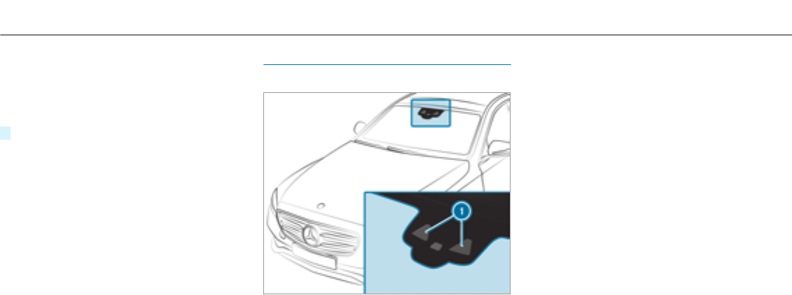
Activating or deactivating Blind Spot Assist
or Active Blind Spot Assist
Multimedia system:
, .k .
#Activate Oor deactivate ªthe function.
Active Lane Keeping Assist
Function of Active Lane Keeping Assist
Active Lane Keeping Assist monitors the area in
front of your vehicle by means of multifunction
camera 1. It servesto protect you against unin‐
tentionally leaving your lane. Youwill be warned
by means of a vibration in thesteering wheel
and a course-correcting brake application guides
you back into your lane.
You are warned by vibration pulses in thesteer‐
ing wheel in thefollowing circumstances:
RActive Lane Keeping Assist detects lane
markings.
RA front wheel passes over the lane markings.
Youwill also be guided back into your lane by
means of a course-correcting brake application
if thefollowing conditions are met:
RActive Lane Keeping Assist detects lane
markings on both sides.
RA front wheel drives over a solid lane mark‐
ing.
Whether a warning is issued and when this
occurs also depends on the selected sensitivity
setting (standard or adaptive).
If youfail to adapt your driving style, Active Lane
Keeping Assist can neither reduce therisk of an
accident nor override the laws of physics. It can‐
not take into account road, weather or traffic
conditions. Active Lane Keeping Assist is only an
aid. You are responsible forthe distance to the
212Driving and parking

vehicle in front, forvehicle speed, for braking in
good time and forstaying in lane.
Vehicles with Lane Tracking package:If the
lane markings are solid lines and youdo not
react to thewarning, a lane-correcting brake
application can bring thevehicle back into the
original lane.
Vehicles with Driving Assistance package or
Driving Assistance Plus package: If youdo not
react to thewarning, a lane-correcting brake
application can bring thevehicle back into the
original lane. In the case of a broken lane mark‐
ing being detected, a brake application will only
be made if a vehicle has been detected in the
adjacent lane. Oncoming vehicles, overtaking
vehicles and vehicles in adjacent lanes can be
detected.
The brake application is available in the speed
range between 40 mph (60 km/h) and 120mph
(200 km/h).
If a lane-correcting brake application occurs, dis‐
play 1appears in the multifunction display.
System limits
No lane-correcting brake application occurs in
thefollowing situations:
RYou clearly and actively steer, brake or accel‐
erate.
RYou have switched on the turn signal indica‐
tor.
RA driving safety system intervenes, such as
ESP®,Active Brake Assist or Active Blind
Spot Assist.
RYou have adopted a sporty driving style with
high cornering speeds or high rates of accel‐
eration.
RESP®is deactivated.
RWhen driving with a trailer, the electrical con‐
nection to the trailer has been correctly
established.
RIf a loss of tire pressure or a defective tire
has been detected and displayed.
The system may be impaired or may not function
in thefollowing situations:
RThere is poor visibility, forexample due to
insufficient illumination of theroad, highly
variable shade conditions, or due to rain,
snow, fog or heavy spray.
RThere is glare, forexample from the sun,
reflections or oncoming traffic.
RThere is dirt on the windshield in the vicinity
of the multifunction camera or the camera is
fogged up, damaged or obscured.
RNo or several, unclear lane markings are
present for one lane, forexample in a con‐
struction area.
Driving and parking 213

RThe lane markings are worn, dark or covered.
RThe distance to thevehicle in front is too
small and the lane markings thus cannot be
detected.
RThe lane markings change quickly, e.g. lanes
branch off, cross one another or merge.
RThe road is very narrow and winding.
Vehicles with Driving Assistance package or
Driving Assistance Plus package: Active Lane
Keeping Assist uses radar sensors to monitor
several areas around thevehicle. If theradar
sensors in therear bumper are dirty or covered
with snow,the system may be impaired or may
not function. If an obstacle in the lane in which
you are driving has been detected, no lane-cor‐
recting brake application occurs.
Activating Active Lane Keeping Assist
&WARNING Risk of accident despite
Active Lane Keeping Assist warning
A lane-correcting brake application cannot
always bring thevehicle back into the origi‐
nal lane.
#Alwayssteer, brake or accelerate your‐
self, especially if Active Lane Keeping
Assist warnsyou or makes a lane-cor‐
recting brake application.
&WARNING Risk of accident despite inter‐
vention of Active Lane Keeping Assist
Active Lane Keeping Assist does not detect
traffic conditions or road users. In very rare
cases, the system may make an inappropri‐
ate brake application, e.g. after intentionally
driving over a solid lane marking.
The brake application can be interrupted at
any time if yousteer slightly in the opposite
direction.
#Always make sure that there is suffi‐
cient distance to the side forother traf‐
fic or obstacles.
&WARNING Risk of accident despite Lane
Keeping Assist
Lane Keeping Assist cannot always clearly
detect lane markings.
In such cases, Lane Keeping Assist can:
Rgive an unnecessary warning
Rnot give a warning
#Always pay particular attention to the
traffic situation and keep within the
lane, especially if Active Lane Keeping
Assist alerts you.
Requirement
The driving speed is at least 40 mph (60 km/h).
214Driving and parking
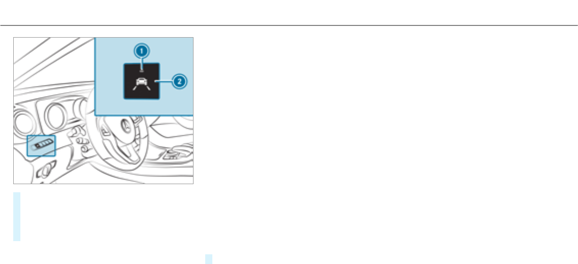
#Press button 2.
If indicator lamp 1lights up, Lane Keeping
Assist is activated. When lane markings are
detected, the lines in the assistance graphic
are shown in white.
Sensitivity of Active Lane Keeping Assist
With thestandard or adaptive setting, you can
influence when thewarning vibration of Lane
Keeping Assist takes place.
In both thestandard and adaptive settings, no
warning vibration occurs in thefollowing situa‐
tions:
RYou have switched on the turn signal indica‐
tor.
RA driving safety system intervenes, such as
ABS, BAS or ESP®.
In the adaptive setting, there will also be no
warning vibration in thefollowing situations:
RThe vehicle is accelerated or braked consid‐
erably.
RYousteer actively, e.g. swerve to avoid an
obstacle or change lane quickly.
RYou cut the corner on a sharp bend.
Setting the sensitivity of Active Lane Keep‐
ing Assist
Multimedia system:
, .k .
#Select a setting.
Driving and parking 215
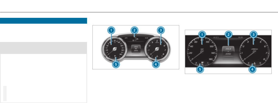
Instrument Display overview
Mercedes-AMG vehicles: be sure to observe
the notes in the Supplement. Otherwise, you
may not recognize dangers.
&WARNING Risk of accident due to an
instrument display malfunction
If the instrument display has failed or mal‐
functioned, you cannot recognize function
restrictions applying to safetyrelevant sys‐
tems.
The operating safetyof your vehicle may be
impaired.
#Drive on carefully.
#Have thevehicle checked immediately
at a qualified specialist workshop.
If the operating safetyof your vehicle is
impaired, park thevehicle safely as soon as pos‐
sible. Contact a qualified specialist workshop.
Instrument Display (standard)
1Speedometer
2Multifunction display
3Tachometer
4Coolant temperature display
5Fuel level and fuel filler flap location indica‐
tor
Instrument Display in theWidescreen Cock‐
pit
1Speedometer
2Multifunction display
3Example: area for additional values
4Coolant temperature display
5Fuel level and fuel filler flap location indica‐
tor
%Further display content can be shown in dis‐
play 3for additional values (→page 219).
Thesegments in speedometer1indicate the
system status forthefollowing:
RCruise control (→page 175)
216Instrument Display and on-board computer
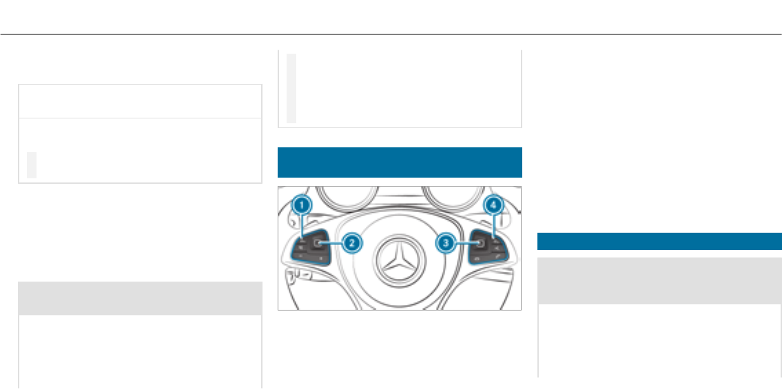
RActive Distance Assist DISTRONIC
(→page 177)
*NOTE Engine damage due to excessively
high engine speeds
The engine will be damaged if youdrivewith
the engine in theoverrevving range.
#Do not drive with the engine in theover‐
revving range.
The fuel supply is interrupted to protect the
engine when thered band in tachometer3
(overrevving range) is reached.
During normal operating conditions, coolant
temperature display 4may rise to thered
mark.
&WARNING Danger of burns when open‐
ing the hood
If you open the hood when the engine has
overheated or during a fire in the engine
compartment, you could come into contact
with hot gases or other escaping operating
fluids.
#Before opening the hood, allow the
engine to cool down.
#In theevent of a fire in the engine com‐
partment, keep the hood closed and
call thefire service.
Overview of the buttons on thesteering
wheel
1Button group:
¤Main menu and back button (on-board
computer)
8Switches sound off/on
WIncreases thevolume
XDecreases thevolume
2Touch Control (on-board computer)
3Touch Control (multimedia system)
4Button group:
¤Main menu and back button (multime‐
dia system)
£LINGUATRONIC or voice control sys‐
tem
6Makes/accepts a call
~Rejects/ends a call
Operating the on-board computer
&WARNING Risk of distraction from infor‐
mation systems and communications
equipment
If you operate information and communica‐
tion equipment integrated in thevehicle
when driving, youwill be distracted from the
traffic situation. This could also cause youto
lose control of thevehicle.
Instrument Display and on-board computer 217
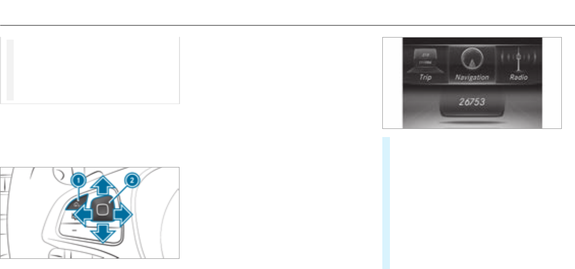
#Only operate this equipment when the
traffic situation permits.
#If you cannot be sure of this, stop the
vehicle whilst paying attention to road
and traffic conditions and operate the
equipment with thevehicle stationary.
You must observethe legal requirements forthe
country in which you are currently driving when
operating the on-board computer.
%The on-board computer displays appear on
the multifunction display (→page 219).
Theon-board computer can be operated using
Touch Control 2and back button1on the
left-hand side of thesteering wheel.
Different acoustic signals provide feedback
when operating the on-board computer, e.g:
Rreaching the end of a list
Rscrolling through a list
The following menus are available:
R
R
R
R
R
R
R
R
RVehicles with an instrument display in
the widescreen cockpit:
The menus can be called up from the menu bar
on the multifunction display.
#To call up the menu bar: press the back
button on the left 1.
#To scroll in the menu bar: swipe to the left
or right on the left-hand Touch Control 2.
#To call up the menu or confirm the selec‐
tion: press the left-hand Touch Control 2.
#To scroll through displays or lists on the
menu: swipe upwards or downwards on the
left-hand Touch Control2.
#To call up a submenu or confirm the
selection: press the left-hand Touch Control
2.
218Instrument Display and on-board computer
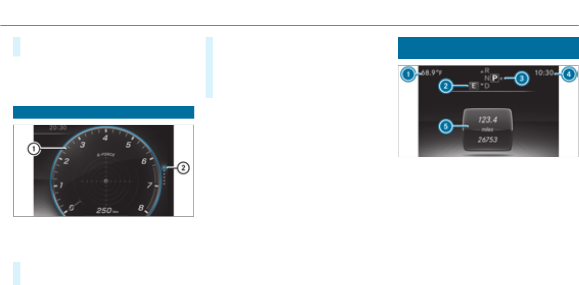
#To exit a submenu: press the back button
on the left 1.
If you are browsing a submenu and youpress
and hold the back button on the left 1,the
menu bar appears.
Setting the additional value range
Example: G-Meter
1Additional value range
2Index points
#To select display content: swipe to the
right on the left-hand Touch Control.
#Swipe upwards or downwards on the left-
hand Touch Control to select display content.
When display content is selected, the addi‐
tional value range 1is brieflyhighlighted.
The index points 2display the selected list
item.
The following display content can be selected in
the and designs:
RTachometer
RNavigation
RECO display
RConsumption
RG-Meter
The following content can be selected in the
design:
RDate
RNavigation
RECO display
RConsumption
RG-Meter
Overview of displays on the multifunction
display
1Outside temperature
2Drive program
3Transmission position
4Time
5Display section
%Vehicles with the Instrument Display in
theWidescreen Cockpit: the position of
the displays deviates from those displayed
here.
Instrument Display and on-board computer 219
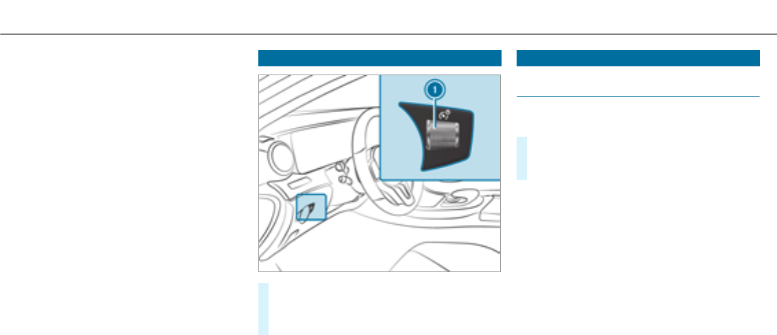
Further displays on the multifunction display:
ZGearshift recommendation (→page 156)
ëActive Parking Assist activated
(→page 202)
éParking Assist PARKTRONICdeactivated
(→page 194)
¯Cruise control (→page 175)
çActive Distance Assist DISTRONIC
(→page 177)
èActive Steering Assist (→page 182)
èECO start/stop function (→page 151)
ëHOLD function (→page 185)
_Adaptive Highbeam Assist (→page 127)
Vehicles with Traffic Sign Assist: detected
instructions and traffic signs (→page 208).
Adjusting the instrument lighting
#Turn brightness control 1up or down.
The lighting of the Instrument Display and in
the control elements in thevehicle interior is
adjusted.
Menus and submenus
Functions in the Service menu of the on-
board computer
On-board computer:
,
#To select the function: swipe upwards or
downwards on the left-hand Touch Control.
#Press the left-hand Touch Control.
Functions in the menu:
RMessage memory (→page 408)
R:
-Checking tire pressure with the tire pres‐
sure monitoring system (→page 372)
-Restarting the tire pressure monitoring
system(→page 373)
R : Calling up the service due
date (→page 332)
220 Instrument Display and on-board computer

Calling up the assistant display
On-board computer:
,
%Vehicles with the Instrument Display in
theWidescreen Cockpit: when you have
the design set to ,you can view
the assistant display in the left-hand portion
of the Instrument Display.
The following displays are available from the
assistant display menu:
RAssistant display
RAttention level (→page 206)
#To switch between the displays:swipe
upwards or downwards on the left-hand
Touch Control. Status displays on the assistant display:
Ré:ATTENTION ASSIST deactivated
Ræ:Active Brake Assist deactivated
RLight lane markings: Active Lane Keeping
Assist activated
RGreen lane markings: Active Lane Keeping
Assist active
RGray radar waves next to vehicle: Blind Spot
Assist activated
RGreen radar waves next to vehicle: Blind Spot
Assist active
RActive Distance Assist DISTRONIC displays
(→page 177)
Calling up displays in theTrip menu
On-board computer:
,
%Vehicles with an Instrument Display in
theWidescreen Cockpit: when you have
the design set to ,you can view
information on the journey in the left-hand
area of the Instrument Display.
#To select a display: swipe upwards or down‐
wards on the left-hand Touch Control.
Displays in the menu:
RStandard display
RRange and current fuel consumption
Instrument Display and on-board computer 221
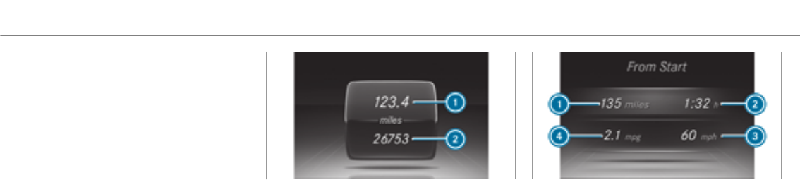
When glide mode is active (→page 156),
is displayed instead of the cur‐
rent fuel consumption.
Arecuperation display is also available for
certain engines. If there is only a small
amount of fuel left in the fuel tank, the dis‐
play shows avehicle being refueled instead
of therange.
RECO display (→page 152)
RTrip computer and
RDigital speedometer
%Vehicles with an Instrument Display in
theWidescreen Cockpit: the digital speed‐
ometer only appears in the and
designs.
Example: standard display
1Trip distance
2Total distance recorder
Example: trip computer
1Total distance recorder
2Driving time
3Average speed
4Average fuel consumption
222 Instrument Display and on-board computer
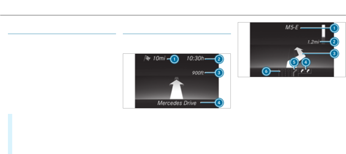
Resetting values on theTrip menu of the on-
board computer
On-board computer:
,
%The spelling may differ in the main menu dis‐
played. Therefore, observe the menu over‐
view forthe Instrument Display
(→page 217).
You can reset thevalues of thefollowing func‐
tions:
RTrip distance
RTrip computer and
RECO display (→page 152)
#To select the function to be reset: swipe
upwards or downwards on the left-hand
Touch Control.
#Press the left-hand Touch Control.
#Select .
#Press the left-hand Touch Control.
If youpress and hold the left-hand Touch Con‐
trol, the function will be reset immediately.
Calling up navigation instructions in the on-
board computer
On-board computer:
,
Example: no change of direction announced
1Distance to the next destination
2Estimated arrival time
3Distance to the next change of direction
4Current road
Example: change of direction announced
1Road to which thechange of direction leads
2Distance to thechange of direction
3Change-of-direction symbol
4Recommended lane and new lane during a
change of direction (white)
5Possible lane
6Lane not recommended (dark gray)
Further possible displays on the
menu:
R : display of direction of
travel and road currently being traveled on.
Instrument Display and on-board computer 223

R or : a new
route is calculated.
R :theroad is unknown, e.g.
for newly built roads.
R : no route could be calculated to
the selected destination.
R :the map forthe current location is
not available.
R :you have
reached the area of destination.
RO:you have reached the destination or an
intermediate destination.
#To exit the menu: press the back button on
the left.
Vehicles with the COMAND multimedia sys‐
tem: You can also start navigation to one of the
recent destinations on the menu:
#Press the left-hand touch control.
#Select a destination: swipe upwards or
downwards on the left-hand touch control.
#Press the left-hand touch control.
Route guidance is started.
If route guidance has already been activated,
arequest will appear asking whether you
wish to end the current route guidance.
#Select .
#Press the left-hand touch control.
Route guidance is started.
Selecting radio stations using the on-board
computer
On-board computer:
,
1Frequency range
2Station
3Name of track
4Name of artist
When you select a station in the memory pre‐
sets, the preset appears next to thestation
name. When you select a savedstation in the
frequency range, an asterisk appears next to the
station name.
224 Instrument Display and on-board computer
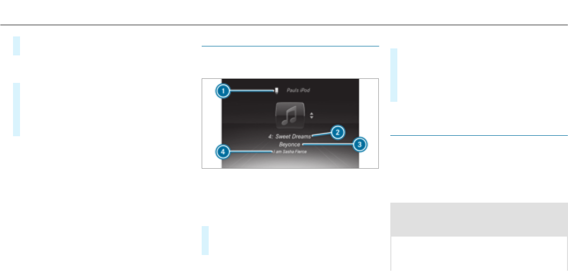
#To select a radio station: swipe upwards or
downwards on the left-hand Touch Control.
Selecting the frequency range or station pre‐
set
#Press the left-hand Touch Control.
#To select the frequency range/station
preset: swipe upwards or downwards on the
left-hand Touch Control.
#Press the left-hand Touch Control.
Media playback using the on-board computer
On-board computer:
,
1Media source
2Current track and track number
3Name of artist (example)
4Name of album
#To change tracks on an active media
source: swipe upwards or downwards on the
left-hand Touch Control.
Changing a media source
#Press the left-hand Touch Control.
#To select a media source: swipe upwards
or downwards on the left-hand Touch Con‐
trol.
#Press the left-hand Touch Control.
Dialing telephone numbers using the on-
board computer
Requirements:
RThe mobile phone is connectedto the multi‐
media system.
On-board computer:
,
&WARNING Risk of distraction from infor‐
mation systems and communications
equipment
If you operate information and communica‐
tion equipment integrated in thevehicle
when driving, youwill be distracted from the
Instrument Display and on-board computer 225

traffic situation. This could also cause youto
lose control of thevehicle.
#Only operate this equipment when the
traffic situation permits.
#If you cannot be sure of this, stop the
vehicle whilst paying attention to road
and traffic conditions and operate the
equipment with thevehicle stationary.
When telephoning, you must observethe legal
requirements forthe country in which you are
currently driving.
Vehicles with the COMAND multimedia sys‐
tem: The most recent telephone connections
(dialed, received and missed calls) are displayed
on the menu.
#Select an entry: swipe upwards or down‐
wards on the left-hand touch control.
#Press the left-hand touch control.
If there is only one telephone number
savedto an entry: thetelephone number is
selected.
#If there are multiple telephone numbers
savedto an entry: swipe upwards or down‐
wards on the left-hand touch controlto
select the desired telephone number.
#Press the left-hand touch control.
The telephone number is dialed.
The following displays may appear instead of the
telephone numbers dialed:
R :the application is starting.
When a Bluetooth®connection to the mobile
phone is not established, the menu for
authorizing and connecting a mobile phone is
displayed in the multimedia system
(→page 288).
R :the call list is being upda‐
ted.
R :the contacts from the
mobile phone or from a storage medium are
being imported.
Accepting/rejecting a call
When youreceive a call, the mes‐
sage appears on the head-up display.
#Swipe upwards or downwards on the left-
hand touch control and select 6(Accept)
or ~(Reject).
#Press the left-hand touch control.
The call may be accepted/rejected using the
6or ~buttons on thesteering wheel.
Adjusting the Head-up Display settings via
the on-board computer
On-board computer:
,
The following Head-up Display settings can be
adjusted:
R
R
R
#To select a setting: swipe upwards or down‐
wards on the left-hand Touch Control.
#Press the left-hand Touch Control.
#To adjust a value: swipe upwards or down‐
wards on the left-hand Touch Control.
#Press the left-hand Touch Control.
226 Instrument Display and on-board computer
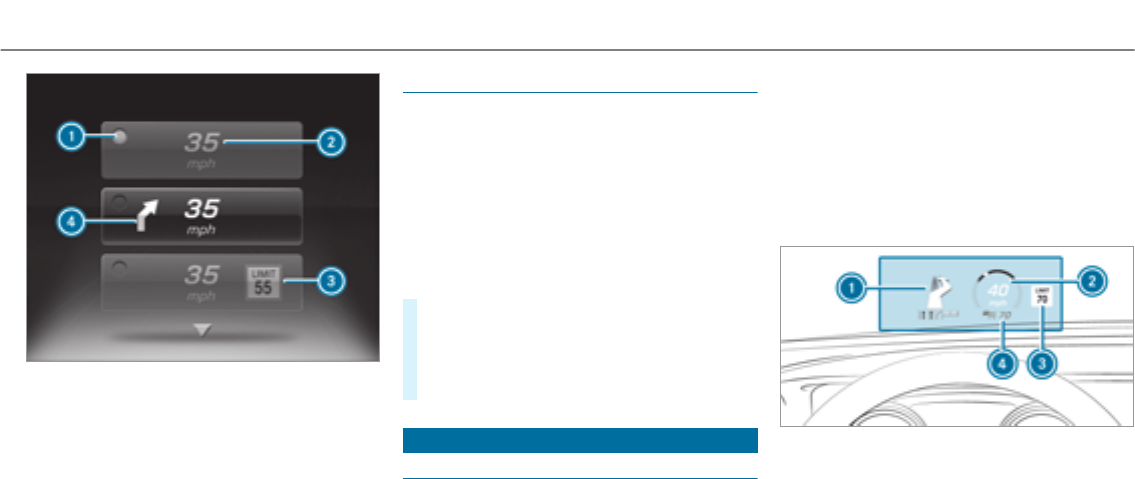
1Setting currently selected
2Digital speedometer
3Traffic Sign Assist
4Navigation displays
Setting the design
On-board computer
,
%This function is only available forvehicles
with a Widescreen Cockpit.
The following designs can be selected:
R
R
R
#To select a design: swipe upwards or down‐
wards on the left-hand Touch Control.
#Press the left-hand Touch Control.
The Instrument Display is shown in the selec‐
ted design.
Head-up Display
Function of the Head-up Display
Mercedes-AMG vehicles: be sure to observe
the notes in the Supplement. Otherwise, you
may not recognize dangers.
The Head-up Display projects into the driver's
field of vision:
RInformation from the navigation system
RInformation from the driver assistance sys‐
tems
RSome warning messages
Display elements
1Navigation messages
2Current speed
3Detected instructions and traffic signs
4Set speed in the driver assistance system
(e.g. cruise control)
Instrument Display and on-board computer 227
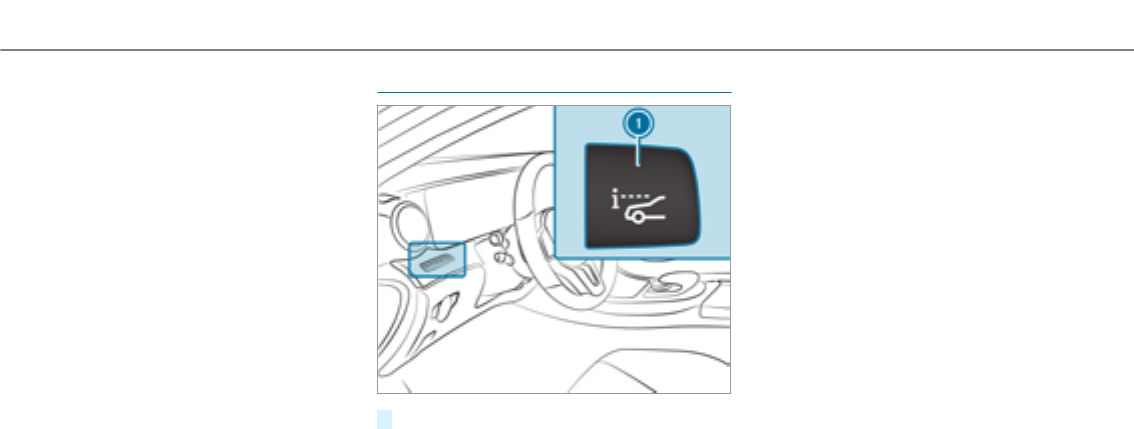
When youreceive a call, the6
message appears on the Head-up Display.
In audio mode, thestation name or track is tem‐
porarily shown when the active audio source is
being operated.
System limitations
The visibility is influenced by thefollowing condi‐
tions:
RSeat position
RThe positioning of the display image
RLight conditions
RWetroads
RObjects on the display cover
RPolarization in sunglasses
%In extreme sunlight, sections of the display
may appear washed out. You can correct this
by switching the Head-up Display off and on
again.
Switching the Head-up Display on/off
#Press button 1.
228 Instrument Display and on-board computer
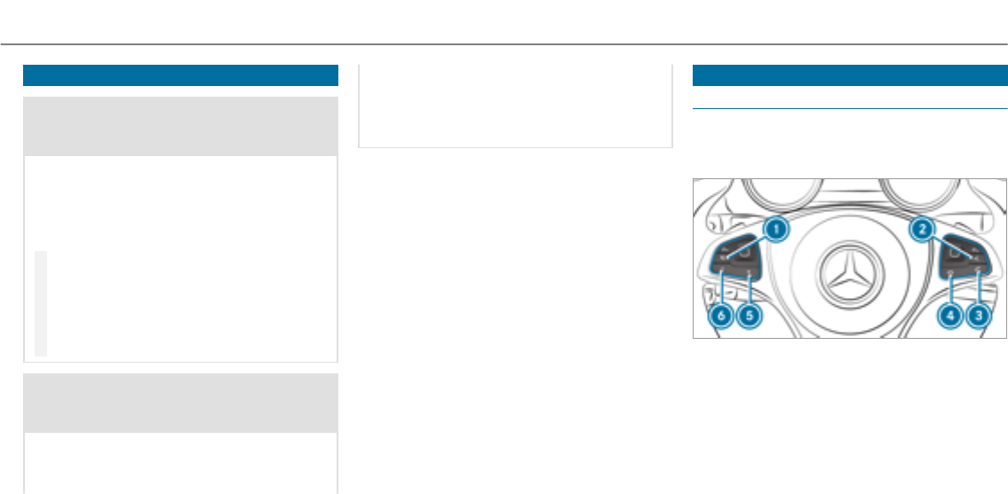
Notes on operating safety
&WARNING Risk of distraction from infor‐
mation systems and communications
equipment
If you operate information and communica‐
tion equipment integrated in thevehicle
when driving, youwill be distracted from the
traffic situation. This could also cause youto
lose control of thevehicle.
#Only operate this equipment when the
traffic situation permits.
#If you cannot be sure of this, stop the
vehicle whilst paying attention to road
and traffic conditions and operate the
equipment with thevehicle stationary.
&WARNING Risk of distraction from oper‐
ating mobile communication equipment
while thevehicle is in motion
If you operate communication equipment
integrated in thevehicle when driving, you
will be distracted from the traffic situation.
This could also cause youto lose control of
thevehicle.
Only operate this equipment when thevehi‐
cle is stationary.
Foryour own safety, always observe thefollow‐
ing points when operating mobile communica‐
tions equipment and especially your voice con‐
trol system:
RObserve the legal requirements forthe coun‐
try in which you are driving.
RWhile driving, only operate mobile communi‐
cations equipment and your voice control
system when the traffic conditions permit it.
You may otherwise be distracted from the
traffic conditions and cause an accident,
injuring yourself and others.
RDo not use thevoice control system in an
emergency as your voice can change and
your telephone call can be unnecessarily
delayed.
RFamiliarize yourself with thevoice control
system functions before starting the journey.
Operation
Operating the multifunction steering wheel
The Voice Control System is operational approx‐
imately thirty seconds afterthe ignition is
switched on.
18Switches the sound off/on (ends Voice
Control System)
2óStarts Voice Control System
36Makes/accepts a call
4~Rejects/ends a call (ends Voice Con‐
trol System)
Voice Control System 229
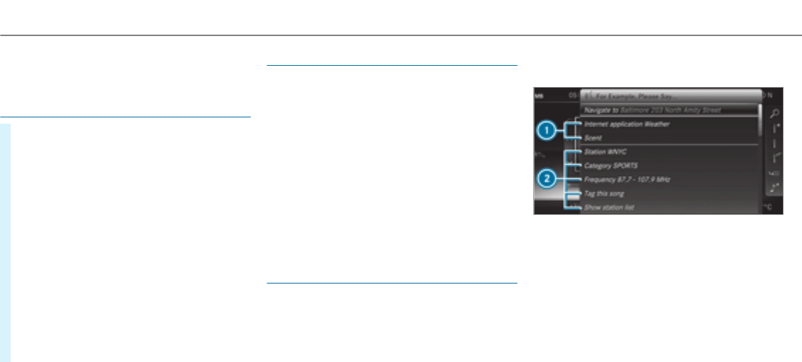
5WIncreases thevolume
6XDecreases thevolume
Conducting a dialog
#To start or continue a dialog: press the
óbutton on the multifunction steering
wheel.
You can say a voice command after an
acoustic signal.
#To correct an entry:say the
voice command.
#To select an entry from the selection list:
say the line number or the contents.
#To browsethe selection list: say the
or voice command.
#To interrupt the dialog: say the voice
command.
#To cancel the dialog: say the voice
command or press the8button on the
multifunction steering wheel.
Operable functions
You can use theVoice Control System to operate
thefollowing equipment depending on thefea‐
tures:
RTelephone
RText messages
RNavigation
RAddress book
RRadio
RAudio (memory card, Media Interface, USB
and Bluetooth®audio)
RVehicle
Overview of types of voice commands
A distinction is made between thefollowing
voice commands:
RGlobal voice commands can be said at any
time and regardless of the current applica‐
tion, e.g. thevoice commands ,
or .
RApplication-specific voice commands are
only available forthe active application.
1Global voice commands
2Application-specific voice commands
On the display next to the active application,
examples of global voice commands and the cor‐
responding application-specific voice commands
are displayed on an autocue. This makes entry
easier and supports interactive operation. The
list can be scrolled or it can be operated by
speech or the controller/touchpad.
230 Voice Control System
Number entry functions
RThe numbers allowed are to .
RTelephone numbers can be entered as single
digits.
Information on the language setting
You can change the language of theVoice Con‐
trol System via the system language settings. If
the set system language is not supportedby the
Voice Control System, English will be selected.
The Voice Control System is available in English,
French, Portuguese and Spanish.
Using theVoice Control System effectively
Features of audible help functions
Youreceive information and help for:
ROptimal operation: say the
voice command.
RCurrent application: on the multifunction
steering wheel, press theórocker switch
up and say the voice command.
RContinued dialog: say the voice com‐
mand during a voice dialog.
RA specific system: say thevoice commands
forthe desired system, e.g. .
Notes on how to improve speech quality
If The Voice Control System does not under‐
stand you:
Ronly operate The Voice Control System from
the driver's seat.
Rsay thevoice commands coherently and
clearly, but do not exaggerate thewords.
Ravoid loud noises, e.g. the blower, that cause
interference while making a voice command
entry.
Rsay thevoice tag with the same intonation
when creating voice tags.
If an address book entry voice tag is not rec‐
ognized:
Ronly create sensible address book entries in
the system/mobile phone, e.g. enter sur‐
name and first name in the correct field.
Rdo not use any abbreviations, unnecessary
spaces or special characters.
If a station list entry is not recognized:
Rsay the voice command.
Essential voice commands
Overview of switch voice commands
Switch voice commands can be used to open
certain applications. The voice command selec‐
tion can be used regardless of the application
that is currently active.
Voice Control System 231

Voice command Function
To switch to navigation mode
To switch to map display
To switch to address book
To switch to telephone mode
To switch to text messages
To switch to radio mode
To switch to media mode
To switch to USB
To switch to memory card
To start a Mercedes-Benz online application. The application must be called up by touch once prior
to use.
To switch to Mercedes-Benz Apps
To switch to Internet mode
232 Voice Control System

Voice command Function
To switch to vehicle settings
To switch to system settings
Overview of navigation voice commands Using navigation voice commands, you can enter
POIs or conventional addresses as well as
directly change important navigation settings.
Voice command Function
Universal search for all types of destinations. A search is also conducted in the address book con‐
tacts, the navigation database and on the Internet (POIs). The order of the details, e.g. city, street or
house number, can be changed.
Destination entry in a desired country, e.g. address in France.
Starts navigation to home address
Starts navigation to your workspace
Destination entry for a POI, e.g. the POI Brandenburg Gate. A search is also performed in the navi‐
gation database and on the Internet.
Conducts a POI search on the Internet only
Voice Control System 233

Voice command Function
Destination entry to a contact in the address book
Enters a country/town/district/street/intersection/house number/ZIP code
Searches for nearby restaurants, parking lots, rest areas with restrooms and gasstations
Searches forrestaurants, parking lots, rest areas with restrooms and gasstations along theroute
234Voice Control System

Voice command Function
Searches forrestaurants, parking lots, rest areas with restrooms and gasstations at the destination
Selects a destination from the list of last entered destinations
Switches route guidance to another route
Starts route guidance after entering a valid destination
Cancels route guidance
Switches theroute guidance voice output on/off
Switches the traffic map on/off
Switches the POI symbols display on the map on/off
Overview of telephone voice commands You can use thetelephone voice commands to
make phone calls or search through the address
book.
Voice Control System 235

Voice command Function
Makes a phone call. All address book names are available.
Searches for and displays a contact. All address book names are available.
Displays the last call
Selects the last phone number dialed
Overview of radio voice commands Radio voice commands can also be used when
theradio application is running in the back‐
ground.
Voice command Function
To call up receivable or savedstations
To enter a frequency directly
To switch to the next available station
To save astation in thestation list
236 Voice Control System

Voice command Function
To display the names of all receivable stations
To listento the names of all receivable stations
To switch the traffic information service on/off
To switch the current station information on/off
Overview of media playervoice commands Media playervoice commands can also be used
when the media playerruns in the background.
Voice Control System 237

Voice command Function
The names of all available tracks, albums, artists, composers, genres or playlists are accepted dur‐
ing the search.
The names of all available tracks, albums, artists, composers, genres or playlists are accepted dur‐
ing the search.
238 Voice Control System

Voice command Function
Available albums, artists, composers,genres, tracks or playlists are searched for.
To select the next track
To select the previous track
To switch therandom track list on/off
Overview of message voice commands Text messages can be created, edited and lis‐
tened to using the message voice commands.
Voice Control System 239

Voice command Function
To create a message. All address book names are available.
To reply to a message
To forward a message
Overview of vehicle voice commands You can use thevehicle voice commands to
directly call up the corresponding menus forthe
vehicle settings.
Voice command Function
To display ambient light settings
To display the blue ambient light
To show display settings
To display assistance settings
To display fragrance settings
To display energy flow settings
To display ionization settings
240Voice Control System

Voice command Function
To display climate control settings
To switch on the automatic climate control settings on the driver's side
To display light settings
To display massage settings
To switch on the massage function forthe driver's seat
To switch off the massage function forthe driver's seat
To display the outside temperature
To display engine data
To display seat adjustment settings
To set the seat heating forthe front passenger seat to level 2
To display consumption
To display vehicle data
Voice Control System 241
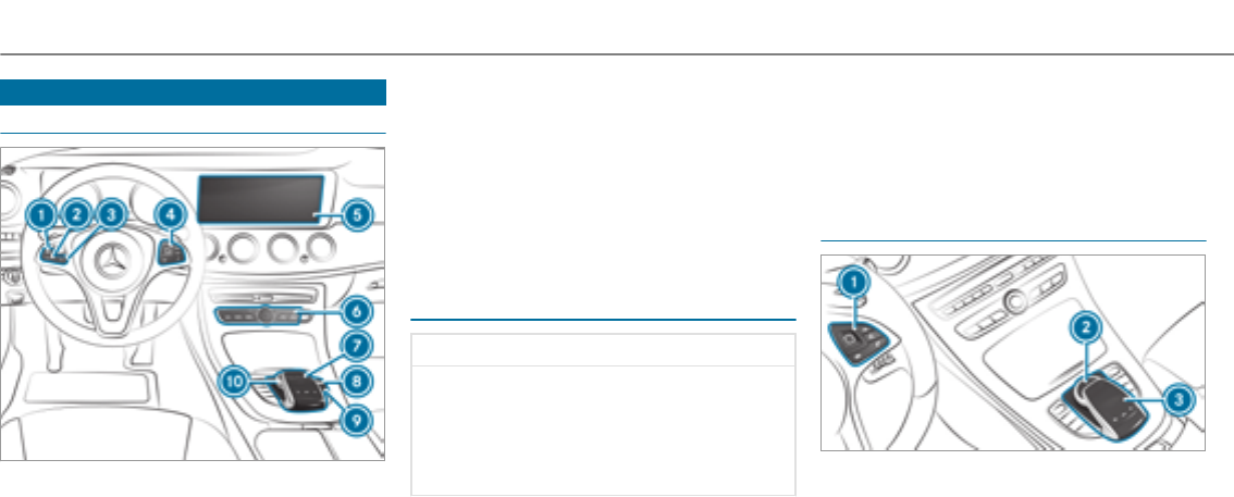
Overview and operation
Overview of the multimedia system
18Switches the sound on/off
2XDecreases thevolume
3WIncreases thevolume
4Touch Control
5Media display
6Main function button group (→page 245)
7Touchpad
8Volume control
Adjusts volume and switches the sound
on/off
9Übutton
Switches multimedia system on/off
AController
Notes on the media display
*NOTE Scratching of the display
The display has a highly sensitive, high-gloss
surface. There is a risk of it becoming
scratched.
Avoid touching the display.
Observe the notes on cleaning.
Observe the notes on caring forthe interior
(→page 344).
Automatic temperature-controlled switch-
off feature: if thetemperature is too high, the
brightness is initially reduced automatically. The
media display may then switch off completely for
a while.
%If you are wearing polarized sunglasses, it
may be difficult to read the media display.
Central control elements overview
1Touch Control
2Controller
3Touchpad
242Multimedia system
Touch Control
Operating Touch Control
#To select a menu item: swipe up, down, left
or right on Touch Control 1.
#Press Touch Control 1.
#To open a list: press Touch Control 1.
#To close a list: press the2button.
#To call up the menu list/favorites: hold
button 2.
#To move the digital map: swipe in any
direction.
Setting the sensitivity forTouch Control
Multimedia system:
, .w .
#Select , or .
Operating the controller
1%button
Press briefly:returns to the previous display
Press and hold: calls up main functions
2©button
To call up the main functions
Multimedia system 243
To call up favorites: when the main functions
are displayed, slide controller 3down.
3Controller
Controller operating options:
#Turn 3left or right.
#Slide 1left or right.
#Slide 4up or down.
#Slide 2diagonally.
#Press 7briefly or press and hold.
Touchpad
Activating/deactivating the touchpad
Multimedia system:
, .w
#Activate Oor deactivate ªthe.
Operating thetouchpad
Requirement:
Forvehicles with a controller: thetouchpad is
switched on (→page 244).
1Touchpad
2Button©
Calls up main functions and favorites
3Button D
Calls up the control menu of the last active
audio source
4Button %
Press briefly:returns to the previous display
Press and hold: calls up main functions
You can navigate in menus and lists via touch-
sensitive surface 1by using a single-finger
swipe.
#To open or close lists: swipe left or right.
#To select the menu item: swipe up, down,
left or right.
#Press touchpad 1.
#To move the digital map: swipe in any
direction.
Use thefollowing functions with a two-finger
swipe:
#To call up main functions and favorites:
swipe down with two fingers.
#To zoom in and out of the map: move two
fingers together or apart.
#To call up the control menu of the last
active audio source: swipe up with two fin‐
gers.
244Multimedia system
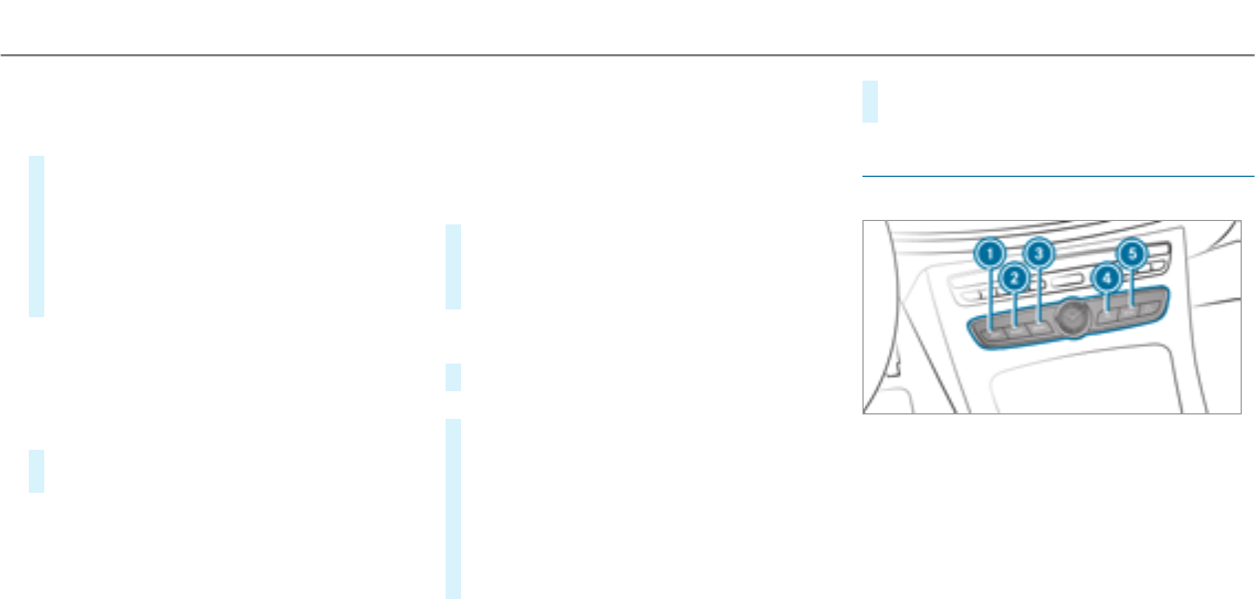
Setting the sensitivity for the touchpad
Multimedia system:
, .w
#Select .
#Select , or .
#To set the pressure sensitivity: switch
on Oor off ª.
If the function is switched on O, a tap on
thetouchpad is enough to select a menu
item.
Handwriting recognition: switching theread-
aloud function on/off
Multimedia system:
, .õ .
#Switch on
Oor off ª.
Activating/deactivating haptic feedback for
operation on thetouchpad
Multimedia system:
, .w
The function supports you when making entries
on thetouchpad and when selecting menus.
#Switch on or off.
When the function is activated, a tactile feed‐
back in theform of a vibration is effected
when thetouchpad is operated.
Selecting a station and track using the
touchpad
#Press theDbutton on thetouchpad.
or
#Swipe upwards using two fingers on the
touchpad.
The control menu appears forthe audio
source that was last selected.
#Use one finger to swipe up or down.
Radio: the previous or the next station is set.
Media source: the previous or the next music
track is selected.
#To hide the control menu: swipe down on
thetouchpad using two fingers.
Main functions
Calling up the main functions
1ßbutton
To call up navigation
2$button
To call up theradio
3Õbutton
To call up media
4%button
To call up thetelephone
Multimedia system 245

5Øbutton
To set vehicle functions
#Alternatively: press the©button on the
controller, thetouchpad or theTouch Con‐
trol.
The main functions are displayed.
#Select the main function.
Calling up lists and menus on the multimedia
system
Call up a list
#Call up a main function (→page 245).
#To open a list: swipe left on thetouchpad.
#To close a list: swipe right on thetouchpad.
#To select a menu item: swipe up or down
on thetouchpad.
#Press thetouchpad.
Favorites
Overview of favorites
Favorites offeryouquick access to frequently
used applications. It is possible to create 20
favorites in total.
The following functions are available:
Radd pre-defined favoritesfrom thefollow‐
ing categories (→page 246):
-
-
-
-
-
-
Radd your ownfavorites(→page 246).
Rrename a favorite (→page 247).
Rmove afavorite (→page 247).
Rdelete afavorite (→page 247).
Rreset all favorites (→page 247).
Calling up favorites
#Press the©button.
The main functions are displayed.
#Navigate downwards once.
Navigating means:
RSwiping on Touch Control or thetouch‐
pad
RSliding the controller
Leaving thefavorites menu
#Press the©button.
Adding a favorite
Adding a pre-defined favorite
#Press the©button.
The main functions are displayed.
#Navigate downwards twice.
The Favorites menu appears.
#Select .
The categories are displayed.
#Select a category.
The favorites are displayed.
#Select a favorite.
246Multimedia system
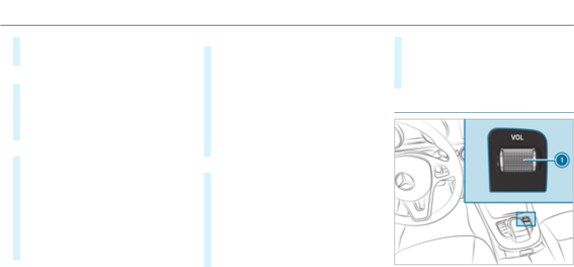
#Store thefavorite at the desired position.
If a favorite has already been added at this
position, it will be overwritten.
Example: adding your ownfavorite
#Select .
#Select .
#Press and hold the©button until the
favorites are displayed.
#Store thefavorite at the desired position.
Renaming a favorite
#Press the©button.
The main functions are displayed.
#Navigate downwards once.
#Select a favorite.
#Navigate downwards once.
The Favorites menu appears.
#Select .
#Enter thecharacters.
#To confirm the entry: select ¡.
Moving a favorite
#Press the©button.
The main functions are displayed.
#Navigate downwards once.
#Select a favorite.
#Navigate downwards once.
The Favorites menu appears.
#Select .
#Move thefavorite to the desired position.
If a favorite has already been added at this
position, it will be overwritten.
Deleting a favorite
#Press the©button.
The main functions are displayed.
#Navigate downwards once.
#Select a favorite.
#Navigate downwards once.
The Favorites menu appears.
#To delete: select .
#Select .
#To restore all favorites: select .
A prompt appears.
#Select .
The favorites are reset to thefactory set‐
tings.
Switching the sound on or off
Multimedia system 247
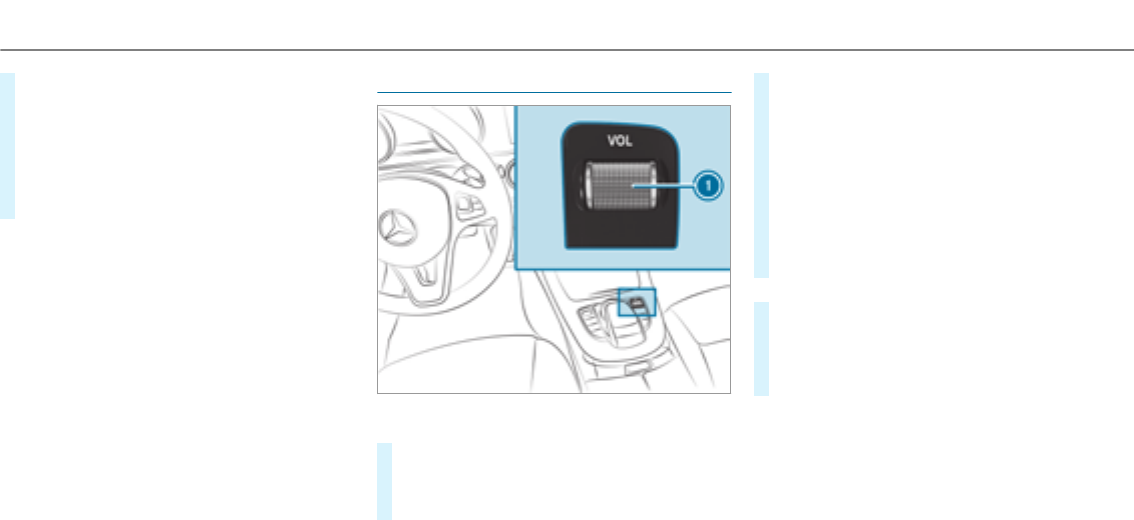
#To mute: press volume control 1.
The 8symbol appears in thestatus line.
Youwill also hear traffic announcements and
navigation announcements even when the
sound is muted.
#To switch on: change the media source or
adjust thevolume.
Adjusting the volume
On the multimedia system
#Turn volume control 1.
The volume of the current radio or media
source is set. The volume of other audio
sources can be adjusted separately.
Adjust this in thefollowing situations:
Rduring a traffic announcement
Rduring a navigation announcement
The volume of the navigation announce‐
ment changes in accordance with thevol‐
ume of the current media source.
Rduring a telephone call
Rwhen entering or exiting a parking space
while using Active Parking Assist
or
#Select .
#Select .
#Select a volume setting.
#Set thevolume.
%The volume can also be set on the multifunc‐
tion steering wheel (→page 217).
248Multimedia system

Entering characters
Using thecharacter input function
Use thecharacter input function in thefollowing
situations, forexample:
RTo rename a favorite
RTo enter a POI or address
RTo make a phone call
The following functions are available:
RSelecting a character in thecharacter bar
RWriting a character on thetouchpad
Character input can be started with a control
element and resumed with another.
#On theTouch Control and controller:
select a character in thecharacter bar.
Depending on thetarget entry,thefollowing
characters are available:
RThe full set of characters is shown
ROnly those characters which are useful
forthe current input string are shown
Other characters are grayed out.
#On thetouchpad: select a character in the
character bar.
or
#Write thecharacters on thetouch-sensitive
surface of thetouchpad.
Handwriting recognition supportsyouby
means of character suggestions and a read-
aloud function.
Examples of character entry:
RRename a favorite
REnter a POI or an address using free or step-
by-step search
REnter a web address
Entering characters using the controller.
Example: renaming a favorite
#Call up the "Renaming a favorite" function
(→page 247).
#To enter a character: turn 3, slide 4
and press the controller.
The character is entered in the input line.
Use thefollowing entry functions:
%To delete acharacter: press the control‐
ler.
To delete an entry: press and hold the
controller until the entire entry is deleted.
Multimedia system 249
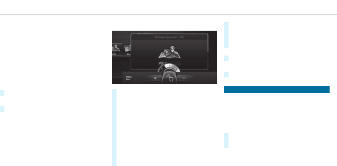
ÄTo switch to special characters and sym‐
bols.
XTo switch to upper-case or lower-case let‐
ters.
BTo switch the language.
vTo switch to character entry on thetouch‐
pad.
%The available editing functions depend on
the editing task, the language set and the
character level.
#To confirm the entry: select ¡.
Example: entering a destination (navigation)
#Enter the POI or address (→page 263).
Entering characters on thetouchpad
Requirements
RThe touchpad is switched on (→page 244).
RTheentered or selected character should be
read out: the handwriting recognition read-
aloud function is switched on (→page 245).
Example: renaming a favorite
#Call up the "Renaming a favorite" function
(→page 247).
#To enter a character: use your finger to
write characters on thetouchpad.
The character is entered in the input line. If
different interpretations are possible, charac‐
ter suggestions are displayed.
#To select a character suggestion: turn the
controller.
#Resume character input.
#To enter a space: swipe right when the cur‐
sor is located in the input line.
#To delete a character: swipe left when the
cursor is located in the input line.
#To confirm the entry: press thetouchpad.
#To finish character entry: swipe upwards.
or
#Press the%button.
Example: entering a destination (navigation)
#Enterthe POI or address (→page 263).
System settings
Display
Configuring display settings
Multimedia system:
, .G
Designs
#Select .
#Select , or .
Adapting the ambient lighting for the style
250 Multimedia system

#Select .
Activate Oor deactivate ªthe function.
This function adjusts the ambient lighting for
the selected display style.
Additional display area
Depending on thevehicle, various items of addi‐
tional information can be shown. The additional
display area comprises the left-hand or right-
hand third of the display.
#Select .
The following display content can be selected:
R
R
R
R
Display brightness
#Select .
#Select a brightness value.
Switching the display off/on
#Off: select .
#On: press a button, %,forexample.
Display design
#Select .
#Select , or
.
Time and date
Setting the time and date automatically
Multimedia system:
, .&
#Deactivate ª .
The time and date are set automatically for
the selected time zone and summer time
option.
%The correct time is required forthefollowing
functions:
RRoute guidance with time-dependent
traffic guidance.
RCalculation of expected time of arrival.
Setting the time zone
Multimedia system:
, .& .
The list of countries is displayed.
#Select a country #.
Depending on the country, time zones are
displayed.
#Select a time zone.
The time zone set is displayed after
.
Setting summer time
The and
options cannot be selected in
all countries.
Multimedia system:
, .&
Automatically
#Switch on
Oor off ª.
Multimedia system 251

Manually
#Deactivate ª
.
#Select .
#Select or .
Setting the time and date format
Multimedia system:
, .& .
#Set the date and time format #.
Setting the time manually
Requirement
RThe function is
switched on.
Multimedia system:
, .& .
#Set the hours.
#Navigate to theright to set the minutes.
#Set the minutes.
#Confirm changes when exiting the menu.
The date is set automatically via GPS.
Connectivity
Switching transmission of thevehicle posi‐
tion on/off
Multimedia system:
, .ö
#Select .
#Switch the function on Oor off ª.
Bluetooth®
Information about Bluetooth®
Bluetooth®technology is a standard for short-
range wireless data transfer up to approximately
32.8 ft (10 m). You can use Bluetooth®to con‐
nect your mobile phone to the multimedia sys‐
tem and use thefollowing functions, forexam‐
ple:
Rhands-free system with access to thefollow‐
ing options:
-contacts (→page 291)
-call lists (→page 294)
-text messages
RInternet connection
Rlistening to music via Bluetooth®audio
(→page 319)
Rtransferring business cards (vCards) into the
vehicle
Bluetooth®is a registered trademark of Blue‐
tooth Special Interest Group (SIG) Inc.
%Internet connection via Bluetooth®is not
available in all countries.
Activating/deactivating Bluetooth®
Requirement
RApple CarPlay™ is not active.
Multimedia system:
, .ö
#Activate Oor deactivate ªBluetooth®.
252 Multimedia system

If Android Auto is active, a prompt appears ask‐
ing whether Bluetooth®should be deactivated.
#Select .
Android Auto is closed and Bluetooth®is
deactivated.
Wi-Fi
Wi-Fi connection overview
You can use Wi-Fi to establish a connection with
aWi-Fi network and to access the Internet or
other network devices.
The following connection options are available:
RWi-Fi connection
The Wi-Fi connection to aWi-Fi-capable
device, e.g. the customer's mobile phone or
atablet PC is established.
Rmultimedia system as a Wi-Fi hotspot
Using this function, a tablet PC or notebook
can be connected, forexample.
To establish a connection, you can use thefol‐
lowing methods:
RWPS PIN
The connection to a secure Wi-Fi network is
made via a PIN.
RWPS PBC
The connection to a secure Wi-Fi network is
made by pressing a button (push button).
Rsecurity key
The connection to a secure Wi-Fi network is
made via a security key.
Setting up Wi-Fi
Prerequisite
RThe device to be connected supports one of
thethree means of connection described
(→page 253).
Multimedia system:
, .ö
Activating/deactivating Wi-Fi
#Switch on Oor off ª.
If is deactivated ª, communication via
Wi-Fi to all devices is interrupted. This also
means that a connection to the HERMES
communication module cannot be estab‐
lished. Then functions such as dynamic route
guidance with Live Traffic Information are not
available.
Connecting the multimedia system with a
device via Wi-Fi
This function is available if a HERMES communi‐
cation module is not installed.
The type of connection established must be
selected on the multimedia system and on the
device to be connected.
%The connection procedure may differ
depending on the device. Follow the instruc‐
tions that are shown in the display. Further
information (see the manufacturer's operat‐
ing instructions).
#Select .
#Select .
Using a WPS PIN:
#Highlight a Wi-Fi network in the list.
#Select ¥ .
The multimedia system generates an eight-
digit PIN.
Multimedia system 253

#Enter this PIN on the device to be connected.
#Confirm the entry.
Using a button:
Requirements
RThis function is only available in a Wi-Fi fre‐
quency of 2.4 GHz.
#Highlight a Wi-Fi network in the list.
#Select ¥ .
#Select "Connect via WPS PBC" in the options
on the device to be connected.
#Press the WPS button on the device to be
connected.
#Select in the multimedia system.
Using a security key:
#Highlight a Wi-Fi network in the list.
#Select ¥ .
#Have the security keydisplayed on the device
to be connected (see the manufacturer's
operating instructions).
#Enterthis security keyon the multimedia sys‐
tem.
#Confirm the entry with ¡.
%All devices support a security keyas a
meansof connection.
Device hasalreadybeen connected:
#To automatically connect: highlight a Wi-Fi
network in the list.
#Activate ¥ O.
#To connect: highlight a Wi-Fi network in the
list.
#Select ¥.
The connection is established again. These
functions are possible when the device has
already been connected to theWi-Fi network.
Setting up a Wi-Fi hotspot
Multimedia system:
, .ö
Configuring the multimedia system as a Wi-
Fi hotspot
The type of connection established depends on
the device to be connected. The function must
be supportedby the multimedia system and by
the device to be connected. The type of connec‐
tion established must be selected on the multi‐
media system and on the device to be connec‐
ted.
#Select .
#Highlight .
Generating a WPS PIN
#Select ¥
.
#Enterthe PIN shown in the multimedia sys‐
tem display on the device to be connected
and confirm.
Connecting using a WPS PIN
#Select ¥ .
#Select .
#Enterthe PIN that is shown on theexternal
device's display on the multimedia system.
#Select .
254 Multimedia system

Connecting using a button
Requirements
RThis function is only available in a Wi-Fi fre‐
quency of 2.4 GHz.
#Select ¥ .
#Press the WPS button on the device to be
connected or select .
#Select in the multimedia system.
Connecting using a security key
#Select .
A security keyis displayed.
#Select thevehicle from the device to be con‐
nected. The vehicle is displayed with the
SSID .
#Enter the security keywhichis shown in the
multimedia system display on the device to
be connected.
#Confirm the entry.
Connecting using NFC
#Select .
#Activate NFC on the mobile device (see the
manufacturer's operating instructions).
#Bring the mobile device into the NFC area of
thevehicle (→page 289).
#Select .
The mobile device is now connected to the
multimedia system hotspot via NFC.
To generate a new security key:
#Select .
#Select .
A connection will be established with the
newly created security key.
#To save a security key: select .
When a new security keyis saved, all existing
Wi-Fi connections are then disconnected. If
theWi-Fi connections are being re-estab‐
lished, the new security keymustbe entered.
Managing COMAND Touch devices
Requirements
RThe COMAND Touch app is installed on the
external device (e.g. tablet or smartphone).
RWi-Fi is activated (→page 253) and the mul‐
timedia system is configured as a Wi-Fi hot‐
spot (→page 254).
Multimedia system:
, .
Connecting a new device
#Select .
#Select .
# the connection request from the new
device.
A security keyis displayed.
#Enterthe security keyin theexternal device.
The device is authorized.
Selecting a connected device
#Select .
The devices already connected are displayed.
#Select .
The
message
appears.
Multimedia system 255

#Select .
Follow the instructions to authorize the
selected device.
De-authorizing the device
#Select a connected device from the list.
The
message
appears.
#Select .
A prompt will appear asking whether you
would liketo de-authorize the selected
device.
#Select .
The device is de-authorized.
Activating/deactivating child safety lock
Multimedia system:
, .
Locking an external device
#Select an external device.
#Select .
The device connected via theCOMAND
Touch App is lockedOor unlockedª.
System language
Notes on the system language
This function allows youto determine the lan‐
guage forthe menu displays and the navigation
announcements. The selected language affects
thecharacters available for entry. The navigation
announcements are not available in all lan‐
guages. If a language is not available, the naviga‐
tion announcements will be in English.
Setting the system language
Multimedia system:
, .
#Set the language.
%If you are using Arabic map data, thetext
information can also be shown in Arabic on
the navigation map. To do so, select ةيبرعلا as
the language from the language list. Naviga‐
tion announcements are then also made in
Arabic.
Setting the distance unit
Multimedia system:
, .%
#Select or .
#In the multifunction display of the Instrument
Display, switch the
display on O.
Data import and export
Data import/export function
The following functions are possible:
Rtransferring data from one system or vehicle
to another system or vehicle.
Rcreating a backup copy of your personal data
and loading it again.
Rprotecting your personal data against unwan‐
tedexport with PIN protection.
%Please note that the NTFS file system is not
supported. The FAT32 file system is recom‐
mended.
256 Multimedia system

Importing/exporting data
*NOTE Data loss
#Do not remove the data storage
medium when data is being exported.
Mercedes-Benz is not liable for any loss of
data.
Requirements
RThe vehicle is stationary.
RThe ignition is switched on or thevehicle has
been started.
RThe SD card is inserted (→page 312) or the
USB device is connected (→page 314).
Multimedia system:
, .
#Select or .
Importing
#Select a data storage medium.
A prompt appears asking whether youreally
wish to overwrite the current data. If data
originates from another vehicle, this is recog‐
nized during data reading.
The multimedia system is restarted once the
data has been imported.
%Current vehicle settings can be edited after
the import.
Exporting
If PIN protection is activated, your PIN is reques‐
ted.
#Enterthefour-digit PIN.
#Select a data storage medium.
The data is exported. The data export may
take several minutes.
Activating/deactivating PIN protection
Multimedia system:
, .
Setting the PIN
#Select .
#Enter a four-digit PIN.
#Enterthefour-digit PIN again.
If both PINs match, PIN protection is active.
Changing the PIN
Requirement
RA current PIN must be set.
#Select .
#Enterthe current PIN.
#Select .
#Set a new PIN.
Activating PIN protection for data export
#Select .
Confirm with the PIN.
#Select .
Activate Oor deactivate ªthe function.
Activating PIN protection for offline mode
#Select .
Confirm with the PIN.
#Select .
Activate Oor deactivate ªthe function.
Multimedia system 257

Unblocking the PIN
Requirements
RThere is an Internet connection.
RA Mercedes me account exists at http://
www.mercedes.me.
RThe service is active
(→page 258).
If the PIN has been entered incorrectly three
times, the PIN will be blocked. You can have a
single-use password sent to you via the
Mercedes me connect online portal to reset the
PIN protection.
#Select .
#Enterthe single-use password.
PIN protection is reset, and you can set a
new PIN.
%Alternatively, you can have PIN protection
reset at an authorized Mercedes-Benz Cen‐
ter.
User profile
Setting a user profile
Multimedia system:
, .g
Displaying a user profile when starting
If this function is active, a prompt appears when
starting the system asking which user profile to
use.
#Select .
#Activate Oor deactivate ªthe function.
Selecting a user profile
#Select or individual profile #.
%Some settings from the user profile are only
loaded when thevehicle is stationary or
when the ignition is switched on.
Automatic synchronization
Each time the ignition is switched off or on, the
individual user profiles are synchronized on the
multimedia system and on the server. This
ensures that the latest user profiles are always
available.
#Select .
#Activate Oor deactivate ªthe function.
%For more information about importing/
exporting user profiles (→page 258).
Creating a user profile
Multimedia system:
, .g .
#Enter a name.
#Select a.
Individual settings are saved in the user profile,
e.g.:
RSystem settings
RSettings in theTV tuner's channel list
RNavigation and traffic information
The settings differ depending on thevehicle
equipment.
Importing/exporting user profiles
Requirements:
RThere is an Internet connection .
258 Multimedia system

RA Mercedes me account exists at http://
www.mercedes.me.
RThe service is active.
Multimedia system:
, .g .
This function is not available in all countries.
Only individual profiles can be imported or
exported.
The individual profiles are always collectively
imported or exported.
#Import: select .
The
message appears.
#Select .
User profiles are imported.
#Export: select .
User profiles are exported.
%Certain settings, such as address book
entries or previous destinations from the
navigation system, are not exported.
Setting user profile options
Multimedia system:
, .g
#Highlight a profile.
#Select ¥options.
The following options are available:
R
R
R
%The guest profile cannot be deleted or
renamed.
Software update
Information on software updates
The multimedia system provides a message
when an update is available.
Depending on the source, you can perform vari‐
ous updates:
Software update
Source of the
update
Update type
InternetNavigation map, sys‐
tem updates, Digital
Operator's Manual
External storage
medium, e.g. USB
flash drive
Navigation maps
Software updates ensure your vehicle's technol‐
ogy is always up-to-date.
In order to constantly improve thequality of our
services you will receive future updates foryour
multimedia system, the Mercedes-Benz mbrace®
services and your vehicle's communication mod‐
ule. These will conveniently be sent to you via
the mobile phone connection in your vehicle
and, in many cases, installed automatically. You
can monitorthestatus of your updates at any
time on the Mercedes me portal and find infor‐
mation about potential innovations.
Multimedia system 259

Your advantages at a glance:
Rconveniently receive software updates via
the mobile phone network
Rthe long-term quality and availability of
Mercedes-Benz mbrace®is guaranteed
Rkeep your multimedia system and communi‐
cation module up-to-date
Further information about software updates can
be found at http://me.mercedes-benz.com
Performing a software update
Requirements
RAn Internet connection is required for
updates which are obtained online .
Multimedia system:
, .
Automatically
Requirements
RYour vehicle has a built-in communication
module.
#Activate O.
Updates are performed.
The current status of the updates is dis‐
played.
Manually
#Deactivate ª.
#Select an update from the list and start the
update.
Searching for new Updates
Requirements
RYour vehicle does not have a built-in commu‐
nication module.
RAn Internet-enabled mobile phone is connec‐
tedto the multimedia system (→page 288).
#Select .
The list of available updates is refreshed.
#Select an update and start the update.
The selected update is downloaded via the
connected mobile phone.
Activating the software update
#Restart the system.
Important system updates
Important system updates may be necessary for
the security of your multimedia system's data.
Please install these updates, or else the security
of your multimedia system cannot be ensured.
%If automatic software updates are activated,
the system updates will be downloaded auto‐
matically (→page 260).
As soon as an update is available for download,
a corresponding message appears on the multi‐
media system display.
You have thefollowing selection options:
R
The update will be downloaded in the back‐
ground.
R
Information about the pending system
update is displayed.
R
The update can be downloaded manually at a
later time (→page 260).
260 Multimedia system

If the download is completed and the update is
ready for installation, youwill be informed of this
afterthe next ignition cycle, forexample.
Requirements forthe installation:
RThe ignition is switched off.
RNotes and warnings have been read and
accepted.
RThe electric parking brake is applied.
If all requirements are met, the update will be
installed. The multimedia system cannot be
operated while the update is being installed and
vehicle functions are restricted.
If errors should occur during the installation, the
multimedia system automatically attemptsto
restore the previous version. If restoration of the
previous version is not possible, a symbol
appears on the center console display. Please
consult a qualified specialist workshop to
resolve the problem.
Reset function
Multimedia system:
, .
Personal data is deleted, forexample:
Rstation presets
Rconnected mobile phones
#Select .
If PIN protection is activated, a prompt appears
asking if you also wish to restore this to thefac‐
tory settings during a reset.
#Select
#Enter the current PIN.
The PIN is reset.
Or
#Select .
The current PIN staysthe same afterreset‐
ting.
%If you have forgottenyour PIN, an authorized
Mercedes-Benz Center can deactivate your
PIN protection foryou.
Aprompt appears again asking whether you
really wish to reset.
#Select .
The multimedia system is reset to thefactory
settings.
Multimedia system 261
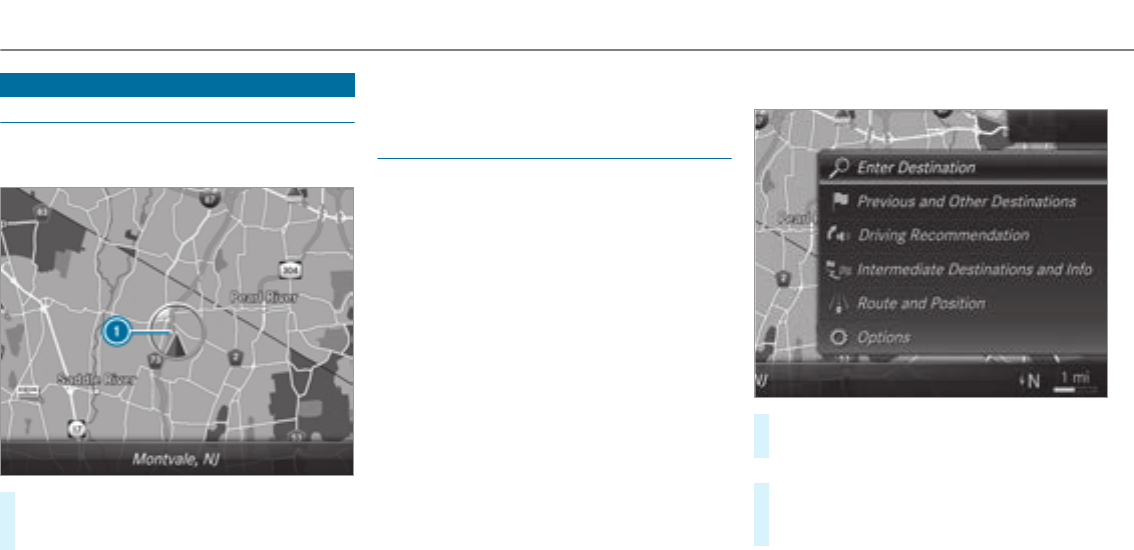
Navigation
Switching navigation on
Multimedia system:
,
#Alternatively: press theßbutton.
The map appears and shows current vehicle
position 1.
%If a climate control setting is changed, a cli‐
mate bar appears briefly.
Showing/hiding the navigation menu
Requirements
RThe map shows thevehicle's current posi‐
tion.
,
#To show: swipe left on thetouchpad or the
Touch Control.
or
#Slide the controller to the left.
#To hide: swipe right on thetouchpad or the
Touch Control.
or
262 Multimedia system
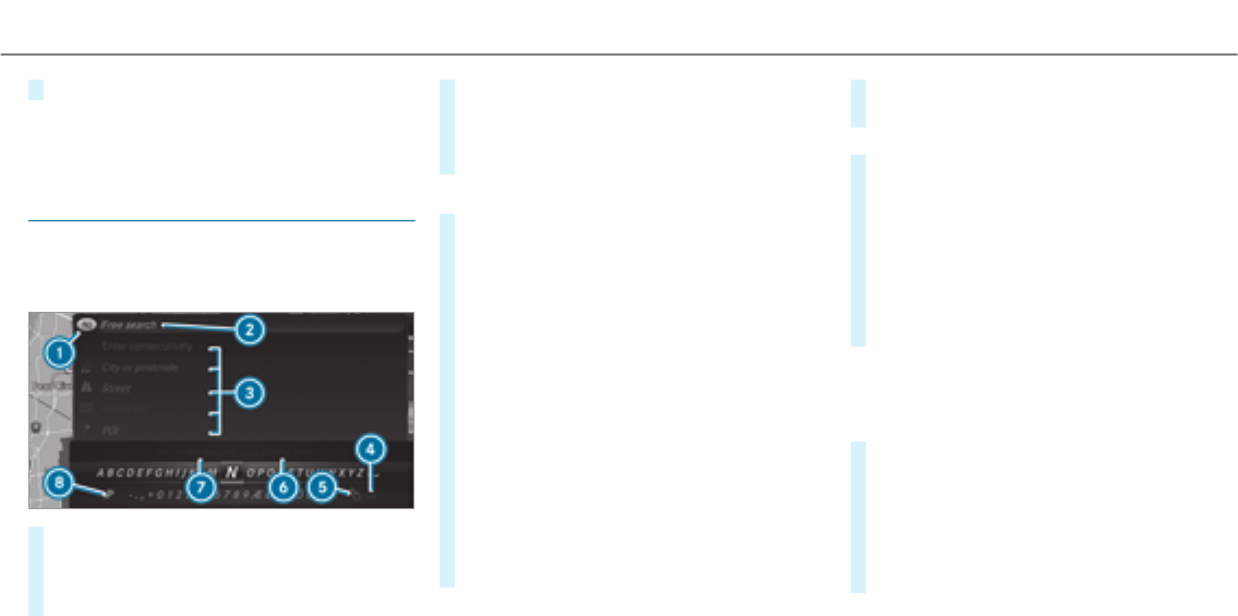
#Slide the controller to theright.
%To show or hide lower menu levels, swipe or
slide to the left or right as many times as
necessary.
Destination entry
Entering a POI or address
Multimedia system:
,
#Show the navigation menu.
#Select ª .
The state or province in which thevehicle is
located is set 1.
There are two available methods of destina‐
tion entry:
Rfree search 2
Rstep-by-step search 3
Method 1: free search
#Enter the POI or address in 2. The entries
can be made in any order.
During destination entry, suggestions are
made by the multimedia system. A selection
of destinations appears in a list.
Enterthese address elements, forexample:
Rcity, street, house number
Rstreet, city
RZIP code
RPOI name
RPOI category, e.g.
Rcity, POI name
#To switch to handwriting recognition:
select 5v.
#Write thecharacter on thetouchpad.
#To switch to character selection: press the
%button.
or
#Press thetouchpad.
#To delete an entry: select 4%(if avail‐
able).
RPress briefly:deletesthe last character
entered or the last suggestion adopted.
RPress and hold: deletesthe entire entry.
#To set the language: select 8.
#Select the language.
%This function is useful for countries in which
severalcharacter sets are supported. An
example is Russia, which uses Cyrillic and
Latin characters.
#To call up the online search function:
select 6 .
Once an Internet connection is established, a
list appears. It shows online destinations
related to the previous entry.
Online destinations are provided by the Inter‐
net service provider.
Multimedia system 263

#Select the online destination.
or
#Enter an online destination in the input line.
%Online search is not available in all coun‐
tries.
%Requirement (USA): Mercedes-Benz
mbrace®is activated.
#To call up the list: press the%button.
or
#If thetop line of thecharacter bar is highligh‐
ted, navigate upwards.
#Select the destination in the list.
#To adopt a destination: select
7.
If there are several listings for a destination,
a list appears.
#Select the destination.
The destination address is shown.
Method 2: search step-by-step
#Press the%button.
or
#If thetop line of thecharacter bar is highligh‐
ted, navigate upwards.
The character bar is hidden. is
highlighted. Additional entry fields, e.g. for
, are available.
#Select .
The character bar appears.
#Enterthe city or the ZIP code.
During destination entry, suggestions are
made by the multimedia system. A selection
of destinations appears in a list.
The address entries can be made in any
order, forexample:
R ,,
Enter an intersecting street, if available.
R,
R, e.g. ,
%During destination entry, use thefollowing
functions:
Rswitching to handwriting recognition
Rswitching to character selection
Rdeleting an entry
An entry, e.g. , can be deleted with
£in a step-by-step search.Navigate
to the left to do so.
Rcall up online search function (if availa‐
ble)
Rcalls up a list
The functions are described in the free
search.
#To change thestate/province: select the
state or the province.
#Enterthestate or the province. You only
need to enter thefirstcharacter.
#Select thestate or the province in the list.
#To change the country:select the country.
#Enter the country.You only need to enter the
firstcharacter.
#Select the country on the list.
#To adopt a destination: select
.
If there are several listings for a destination,
a distance-orientated list appears.
264 Multimedia system

#Select the destination.
The destination address is shown.
Selecting previous destinations
Multimedia system:
, .
#Select .
#Select the destination suggestion or the des‐
tination.
The destination address is shown.
%If is switched on O, destina‐
tion suggestions are displayed (→page 277).
#Alternatively: if a favorite has been saved
(→page 276), select .
#Select thefavorite.
The destination address is shown.
Selecting a POI
Multimedia system:
, .
.
Method 1
#Select the category.
If route guidance is not active: the search
begins in the vicinity of the current vehicle
position. The list is sortedby distance in
ascending order.
If route guidance is active: the search begins
after selecting a search position.
The POIs show thefollowing information:
Rname of POI
Rlinear distance to the POI
Rthe direction of the linear distance to the
POI (arrow) is displayed when searching
forthevehicle's current position
#Select the POI.
#Route guidance is active: select the search
position prior to choosing a POI.
#If intermediate destinations are set, these
can also be selected as the search position
after selecting .
Method 2
#Select .
#Select the category.
#Select the POI.
#Route guidance is active: select the search
position prior to choosing a POI.
#If intermediate destinations are set, these
can also be selected as the search position
after selecting .
Alternatively filtering the display by POI
#Enter a search term in theª
line.
The results list shows relevant POIs.
#Select ¡.
The first POI in the list is highlighted.
#Select the POI.
Multimedia system 265

Example: setting the search position for the
parking category during active route guid‐
ance
#Select , or
.
The list shows the located POIs or opens an
overview of theroute destination after
selecting .
#Select the POI.
#Select : select the inter‐
mediate destination or the destination.
Starting an automatic gasstation search
Requirements:
RThe automatic gasstation search is activated
O(→page 271).
Driving situation
Route guidance is active. The fuel level in the
fuel tank reaches the fuel reserve.
The
message is
shown.
#Select .
The automatic gasstation search begins. The
available gasstations along theroute or in
the vicinity of thevehicle's current position
are displayed.
#Select thegasstation.
The address of thegasstation is displayed.
#If route guidance is not active, select
.
The selected gasstation is set as the desti‐
nation. Route guidance begins.
or
#If route guidance is active, select
or
.
:the selected gas
station is set as a new destination. The previ‐
ous destinations and intermediate destina‐
tions are deleted. Route guidance to thegas
station begins.
:the
selected gasstation is set as the next inter‐
mediate destination. Route guidance begins.
#If there are already four intermediate des‐
tinations: select in the prompt.
The selected gasstation is entered into posi‐
tion 1 of the intermediate destinations menu.
Intermediate destination 4 is deleted. Route
guidance begins.
Entering an intermediate destination
Requirements
RA destination is entered.
Multimedia system:
, .
#Select
.
#Enterthe intermediate destination as a POI
or address (→page 263).
#Select the intermediate destination.
#Select .
or
266 Multimedia system

#Select an intermediate destination using
ª during route guid‐
ance.
#Select
after entering the destination.
Editing intermediate destinations
Requirements:
RA destination is entered.
Multimedia system:
, .
#To change the order of destinations: high‐
light the destination or the intermediate des‐
tination.
#Select ¥.
#Move the intermediate destination to the
desired position.
#Press theTouch Control, the controller or the
touchpad.
#To call up the map: highlight the destination
or the intermediate destination.
#Select ¥ .
#Move the map (→page 281).
#Select destination on the map (→page 268).
#To delete a destination: highlight the desti‐
nation or the intermediate destination.
#Select ¥ .
Calculating a route with intermediate desti‐
nations
Requirements
RThe destination and at least one intermediate
destination have been entered.
Multimedia system:
, .
#Select .
The route is calculated withthe set inter‐
mediate destinations.
Selecting a contact
Requirements
Ra mobile phone is connectedto the multime‐
dia system (→page 288).
Multimedia system:
, .
.
#Select the contact.
The contact details are displayed.
#Select the address.
Alternatively filtering the display by contacts
#Enter a name or telephone number, forexam‐
ple, into the search field.
#Select ¡.
The first contact in the list is highlighted.
#Select the contact.
#Select the address.
Entering geo-coordinates
Multimedia system:
, .
.
#Entergeo-coordinates as latitude and longi‐
tude coordinates in degrees, minutes and
seconds.
The map shows the position.
Multimedia system 267

#Confirm the entry.
#To calculate a route: select
.
#If a route has already been created, select
or
.
Selecting from the map
Multimedia system:
, .Z .
#Alternatively: if the map is displayed in full
screen mode, press theTouch Control, the
controller or thetouchpad.
The map menu appears.
#Select "move map" in map menu 2
(→page 280).
#Swipe in any direction on theTouch Control
or touchpad.
or
#Slidethe controller in any direction.
The map moves in the corresponding direc‐
tion under the crosshair. The more you move
your finger away from thestarting position
on thetouchpad, thefaster the map moves.
#Press theTouch Control, the controller or the
touchpad.
If several destinations are located around the
crosshair, a list shows theavailable POIs and
roads.
If a destination is located exactly on the
crosshair, the destination address is dis‐
played.
#Select the destination in the list.
The destination address is shown.
Setting the map orientation to 2D or 3D
#Highlight .
#Press theTouch Control, thetouchpad or the
controller.
The map will be displayed in the selected
map orientation.
Showing traffic messages in the vicinity of
the map
#Select .
The map appears.
#Swipe left or right on thetouchpad.
or
#Slide the controller to the left or right.
The previous or next traffic incident is high‐
lighted on the map. Information on the traffic
incident is displayed.
Showing POIs in the vicinity of the map
#Select .
#Swipe left or right on thetouchpad.
or
#Slide the controller to the left or right.
The previous or next POI is highlighted on the
map. The name or the address is shown.
#Alternatively, to filter the display by POI
category: swipe down on theTouch Control
or thetouchpad.
or
#Slide the controller down.
#Select the POI category.
% allows personal POI symbols to
be selected (→page 282).
268 Multimedia system

Route
Calculating a route
Requirements:
RThe destination has been entered.
RThe destination address is shown.
#If route guidance is not active, select
.
The route to the destination is calculated.
The map shows theroute. Route guidance
then begins.
or
#If route guidance is active, select
or
.
:the selected des‐
tination address is set as a new destination.
The previous destinations and intermediate
destinations are deleted. Route guidance to
the new destination begins.
:the
selected destination address is set as the
next intermediate destination. Route guid‐
ance begins.
Taking alternative routes into consideration
#Select an alternative route (→page 271).
Other menu functions
#To save the destination: select ¥
.
#To display on the map: select ¥.
#To call a telephone number: select ¥
.
#To call up an Internet address: select
¥ (if available).
Selecting a route type
Multimedia system:
, .À
#Select .
#Select theroute type.
Aroute has already been created: theroute
is calculated on the basis of the new route
type.
Aroute has not been created: the next route
is calculated on the basis of the new route
type.
R
An economical route is calculated. The
journey time may be somewhat longer
than forquickerroutes.
The symbol forthe current vehicle posi‐
tion is displayed in green.
R
Aroute with a quick journey time is cal‐
culated.
R
Aroute with a short driving distance is
calculated.
can be
switched on Oor off ªforthese route
types. If is
switched on,
can be selected.
The route types
and
are not available in every country.
R
Multimedia system 269

The route is calculated withthe currently
set route type.
Trafficreports via Live Traffic Information
are taken into account.
Live Traffic Information is not available in
all countries.
R
A prompt appears when a new route is
detected with a shorter journey time
based on trafficreports. You can con‐
tinue to use the current route or use the
dynamic route instead.
Selecting route options
Multimedia system:
, .À.
.
Avoiding areas
#Select (→page 283).
Avoiding motorways, ferries, motorail trains,
tunnels, unpavedroads
#Select Oor deselect ªavoid option.
Using toll roads
#Select .
#Select or or .
The route takes into account roads that
require the payment of a usage fee (toll).
If is selected, toll roads are not taken into
account.
The selected route options cannot always be
implemented. Therefore, a route may include a
ferry, for instance, eventhough theavoid
option is enabled. A message appears and you
will hear a corresponding message.
Using carpool lanes
#Select .
#Select number.
When using carpool lanes, observe the appli‐
cable legal requirements as well as any con‐
ditions pertaining to when and where such
lanes may be used. Carpool lanes may only
be used if certain conditions are met.
These route options are not available in every
country.
Selecting notifications
Multimedia system:
,
.Z .
#Switch announcements on Oor off ª.
R
The function is not available in all coun‐
tries.
R
The multimedia system announces the
names of theroads that will follow the
upcoming change of direction.
This function is not available in all coun‐
tries and languages.
Displaying destination information
Requirements:
RA destination is entered.
270Multimedia system

Multimedia system:
,
#Select .
The following information is displayed:
Rintermediate destinations and destination
The route can also include up to four
intermediate destinations.
Rname, address
Rremaining driving distance
Rtime of arrival
Selecting an alternative route
Multimedia system:
, .À
#Select .
The routes are displayed in accordance with
the setting made in theroute settings.
The currently selected route is shown with a
dark blue line.
#Select the alternative route.
Switching the automatic gasstation search
on/off
Multimedia system:
, .Z
#Switch on Oor off ª.
Switched on O: when the fuel reserve level
is reached, a prompt appears asking whether
youwant to start searching forgasstations.
Starting the automatic service station
search
Requirements:
RATTENTION ASSIST and the
function are activated (→page 207).
Driving situation
The
message is shown.
#Select .
The service station search starts. The availa‐
ble service stations along theroute or in the
vicinity of thevehicle's current position are
displayed.
#Select the service station.
The service station address is displayed.
#If route guidance is not active, select
.
The selected service station is set as a desti‐
nation. Route guidance begins.
or
#If route guidance is active, select
or
.
:the selected
service station is set as a new destination.
The previous destination and all intermediate
destinations are deleted. Route guidance to
the service station begins.
:the
selected service station is set as the next
intermediate destination. Route guidance
begins.
Multimedia system 271
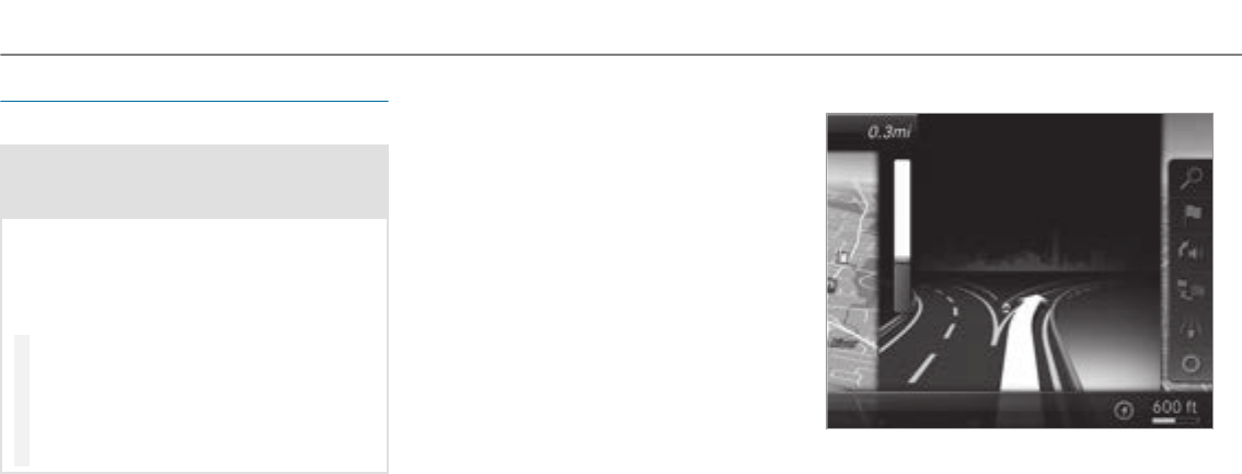
Route guidance
Notes on route guidance
&WARNING Risk of distraction from oper‐
ating integrated communication equip‐
ment while thevehicle is in motion
If you operate communication equipment
integrated in thevehicle when driving, you
will be distracted from the traffic situation.
This could also cause youto lose control of
thevehicle.
#Only operate this equipment when the
traffic situation permits.
#If you cannot be sure of this, stop the
vehicle whilst paying attention to road
and traffic conditions and operate the
equipment with thevehicle stationary.
Route guidance begins once a route has been
calculated.
The road and trafficrules and regulations always
have priority over multimedia system driving rec‐
ommendations.
Driving recommendations are:
RNavigation announcements
RRoute guidance displays
RLane recommendations
If youdo not follow the navigation announce‐
ments or if you leave the calculated route, a new
route is calculated automatically.
Driving recommendations may differ from the
actual road and traffic conditions if:
Rtheroute is diverted.
Rthe direction of a one-waystreet has been
changed.
Forthis reason, you must always observe road
and trafficrules and regulations during your
journey.
The route may differ from the ideal route due to
thefollowing:
Rroadworks
Rincomplete digital map data
Changing direction overview
There are three phases when changing direction:
RPreparation phase
If there is enough time between thechanges
of direction, the multimedia system prepares
youforthe upcoming change of direction. A
navigation announcement, e.g. "Prepare to
turn right", is issued.
272Multimedia system
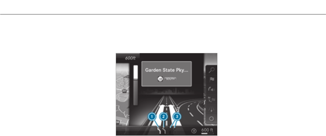
The map appears in full-screen mode.
RAnnouncement phase
The multimedia system announces the
upcoming change of direction, e.g. by
announcing "Turn right in 300 feet (100 m)".
The display is split into two parts. The map is
displayed on the left; on theright, there is a
detailed image of the junction or a 3D image
of the upcoming change of direction.
RChange-of-direction phase
The multimedia system announces the immi‐
nent change of direction, e.g. by announcing
"Now turn right".
The display is split into two parts.
The vehicle has successfully changed direc‐
tion when the light-colored bar on theright
drops down to 0feet (0 meters) and the cur‐
rent vehicle position symbol has reached the
highlighted change-of-direction point.
When thechange of direction is complete,
the map appears in full-screen mode.
%Changes of direction are also shown in the
Instrument Display.
Lane recommendations overview
This display appears for multi-lane roads.
If the digital map contains therelevant data,the
multimedia system can display lane recommen‐
dations forthe next two changes of direction.
1Recommended lane
2Possible lane
3Lanes not recommended
RRecommended lane 1
In this lane, youwill be able to complete both
the next change of direction and the one
afterthat.
RPossible lane 2
In this lane, youwill only be able to complete
the next change of direction.
RLane not recommended 3
In this lane, youwill not be able to complete
the next change of direction without chang‐
ing lane.
During thechange of direction, new lanes may
be added.
%Lane recommendations can also be dis‐
played in the Instrument Display and in the
Head-up Display.
Destination reached
Once the destination is reached, youwill see the
checkeredflag Í.Route guidance is finished.
When an intermediate destination has been
reached, you will see the intermediate destina‐
tion flag with the number of your intermediate
Multimedia system 273

destination Î. Afterthis, route guidance is
continued.
Switching navigation announcements on/off
Requirements:
Raroute has already been created.
Rroute guidance is active.
#To switch off: press the8button on the
multifunction steering wheel during a naviga‐
tion announcement.
or
#Press on thevolume control to theright of
the controller during a navigation announce‐
ment (→page 247).
The
message appears.
or
#Show the navigation menu (→page 262).
#Select ! .
The symbol changes to #.
#To activate: select # .
The current navigation announcement is
played.
%In thefollowing situations, navigation
announcements are switched on automati‐
cally:
RA new route guidance is started.
RThe route is recalculated.
%You can access and add this function as a
favorite under .
Switching navigation announcements on/off
during a phone call
#Select .
#Select õ .
#Select
.
#Switch on Oor
off ª.
Adjusting the volume of navigation
announcements
Requirements:
Raroute has already been created.
Rroute guidance is active.
On the multifunction steering wheel or on
the multimedia system
#Press theWor Xbutton on the multi‐
function steering wheel during a navigation
announcement.
or
#Turn thevolume control to theright of the
controller during a navigation announcement
(→page 248).
%In thefollowing situations, thevolume is
raised to the minimum volume or loweredto
the maximum volume:
RA new route guidance is started.
RThe route is recalculated.
%The minimum volume can be individually set
at an authorized Mercedes-Benz Center.
Via system settings
#Select .
#Select õ .
#Select
.
#Select .
274Multimedia system

#Set thevolume.
Switching audio fadeout on/off during navi‐
gation announcements
#Select .
#Select õ .
#Select
.
#Switch
on Oor off ª.
Repeating navigation announcements
Requirements:
Raroute has already been created.
Rroute guidance is active.
Multimedia system:
,
#Select ! .
#Select # .
The current navigation announcement is
repeated.
%You can access and add this function as a
favorite under
.
Canceling route guidance
Requirements:
Raroute has already been created.
Rroute guidance is active.
Multimedia system:
,
#Select .
Continuing route guidance
Requirements:
Raroute has already been created.
Rroute guidance is interrupted.
%If the journey was interrupted for less than 2
hours, route guidance continues automati‐
cally.
Multimedia system:
, .À
#Select .
The route is recalculated.
Route guidance to an off-road destination
Off-road destination: the destination is within
the digital map. However, the map contains no
roads that lead to the destination.
You can enter off-road destinations on the map.
Route guidance guides youfor as long as possi‐
ble with navigation announcements and displays
on roads that are knownto the multimedia sys‐
tem.
Shortly before youreach the last known position
on the map, you will hear the "Please follow the
direction arrow" announcement. The display
shows a direction arrow and the linear distance
to the destination.
Route guidance from an off-road location to
a destination
Off-road position: the current vehicle position is
located within the digital map on roads that are
not available.
Multimedia system 275

The following displays appear when route guid‐
ance begins:
Rthe message
Ra direction arrow showing the linear direction
to the POI
When thevehicle is back on a road knownto the
multimedia system, route guidance continues as
normal.
Notes on the off-road status during route
guidance
Due to roadworks,forexample, there may be dif‐
ferences between the data on the digital map
and the actual course of theroad. In such cases,
the multimedia system will temporarily be
unable to locate thevehicle's current position on
the digital map. The vehicle is off-road.
The following displays appear when thevehicle
is off-road:
Rthe message
Ra direction arrow showing the linear direction
to the POI
When thevehicle is back on a road knownto the
multimedia system, route guidance continues as
normal.
Destination
Saving the current vehicle position
Multimedia system:
,
#If the map is displayed in full screen mode,
press the central control element.
The map menu appears.
#Select 1on the map menu (→page 280).
The current vehicle position is savedto the
"Previous destinations" memory.
Storing a map position
Multimedia system:
,
The map is in full-screen mode.
#Press theTouch Control, the controller or the
touchpad.
#Select "move map" in map menu 2
(→page 280).
#Select a position on the map.
If multiple entries are available for a map
position, a list appears.
#Highlight an entry.
#Select ¥
.
The map position is savedto the "Previous
destinations" memory.
Editing the previous destinations
Multimedia system:
, .¬
.
#Highlight one of the previous destinations.
#To save as a favorite:select ¥
.
The favorites are displayed.
#Move thefavorite to the desired position.
If a favorite has already been added at this
position, it will be overwritten.
#To save as "Home" address: select ¥
.
276Multimedia system

#To save as "Work" address: select ¥
.
#To delete a single or all destinations:
select ¥ or .
A prompt appears.
#Select .
#To display destination information: select
¥.
Using intelligent destination suggestions
Multimedia system:
, .Z .
The navigation system learns the user habits of
the driver. The most probable destinations are
suggested.
#Activate O.
The vehicle can provide destination sugges‐
tions based on navigation destinations that
have been visited.
If the function has been activated, destina‐
tion suggestions are shown in previous desti‐
nations and can be selectedforroute guid‐
ance.
#Select or .
allows data acquisition and changes
to the last display.
rejects data acquisition and deacti‐
vatesthe function.
#To deactivate the function: deactivate
ª.
#To delete destination suggestions: select
.
Using external destinations and routes
External destinations and routes can be received
from thefollowing sources:
RMercedes-Benz Apps
RDoor-to-door navigation with Companion App
(USA)
RVia an MB Info call to the Mercedes-Benz
Customer Assistance Center
A prompt appears on the media display.
Received destinations and routes are saved in
the previous destinations.
#If a destination is received: select and
continue with method 1 or 2.
or
#If a destination wasreceived with photo
information, select .
Route guidance starts.
#Method 1: if route guidance is not activated,
select .
The route to the destination is calculated.
The map shows theroute. Route guidance
then begins.
#Method 2: if route guidance is active, select
or
.
:thereceived des‐
tination address is set as a new destination.
The previous destinations and intermediate
destinations are deleted. Route guidance to
the new destination begins.
:the
received destination address is set as the
next new intermediate destination. Route
guidance begins.
Multimedia system 277

#Aroute has been received: select
or
.
Route guidance starts from the selected
position.
Route guidance with current trafficreports
Traffic information overview
Trafficreports are received using Live Traffic
Information and are used forroute guidance.
This service is unavailable in some countries.
%There may be differences between the traffic
reports received and the actual road and
traffic conditions.
Important information on Live Traffic Informa‐
tion:
RCurrent traffic reports are received via the
Internet connection.
RThe traffic situation is updated at short, regu‐
lar intervals.
RThe status of the service subscription can be
displayed (→page 278).
Information on thevehicle's position is regularly
sent to Daimler AG. The data is immediately ren‐
dered anonymous by Daimler AG and forwarded
to the traffic data provider. Using this data, traf‐
ficreports relevant to thevehicle's position are
sent to thevehicle. The vehicle acts as a sensor
fortheflow of traffic and helps to improve the
quality of the trafficreports.
If you do not wish to transmit your vehicle posi‐
tion, you can have this service deactivated at an
authorized Mercedes-Benz Center.
Displaying subscription information
Requirements:
RThe vehicle is equipped with Live Traffic
Information.
Multimedia system:
, .Z
The subscription expiry date is automatically dis‐
played:
Rone month before theexpiry date
Rone week before theexpiry date
Ron theexpiry date
#To display manually: select
.
Depending on thestatus, one of thefollowing
messages appears:
Rthe period of validity forthe subscription
is displayed.
Rthe subscription has expired.
%The subscription can be extended:
Rat an authorized Mercedes-Benz Center
Rvia an MB Info call to the Mercedes-Benz
Customer Assistance Center
Displaying the traffic map
Requirements:
RFor Live Traffic Information: thevehicle is
equipped with a communication module fea‐
turing an activated, integrated SIM card.
RWhen thevehicle is started, the communica‐
tion module automatically establishes an
Internet connection. Traffic information is
made available shortly afterwards.
278Multimedia system

Multimedia system:
, .Z .
#Alternatively: if the map is displayed in full
screen mode, press theTouch Control, the
controller or thetouchpad.
The map menu appears.
#Activate ºO.
The traffic map shows thefollowing information,
forexample:
Rtraffic incidents, forexample:
-roadworks
-road blocks
-warning messages
The symbols for traffic incidents are dis‐
played in color (on theroute) or gray (off the
route).
Rtrafficflow information:
-traffic jam (red line)
-congested traffic conditions (orange line)
-slow-moving traffic (yellow line)
-free-flowing traffic (green line)
Rdisplay for traffic delays on theroute lasting
at least one minute
Rwarning message symbols:
-symbol Ô
-additional road safetynotes when
approaching a traffic incident, e.g. the
end of a traffic jam
If thevehicle approaches a danger area
on theroute, a warning message is dis‐
played on the map. A warning message
may also be issued (→page 280).
Displaying traffic incidents
Multimedia system:
, .Z .
#Activate O .
Roadworks,road blocks, local area reports
(e.g. fog) and warning messages are dis‐
played.
Activating free flowand traffic display
#Activate O and
.
%The traffic delay is displayedforthe current
route. Traffic delays lasting one minute or
longer are taken into consideration.
Displaying details
#Displaying the traffic map (→page 278).
#Moving the map (→page 281).
#When a traffic report symbol is under the
crosshair, press theTouch Control, the con‐
troller or thetouchpad.
The trafficreport details are displayed.
or
#Press theTouch Control, the controller or the
touchpad.
#Select .
The map shows the trafficreport symbols in
the vicinity.
Trafficreport information is displayed in the
status line:
Rtrafficreport symbol
Multimedia system 279
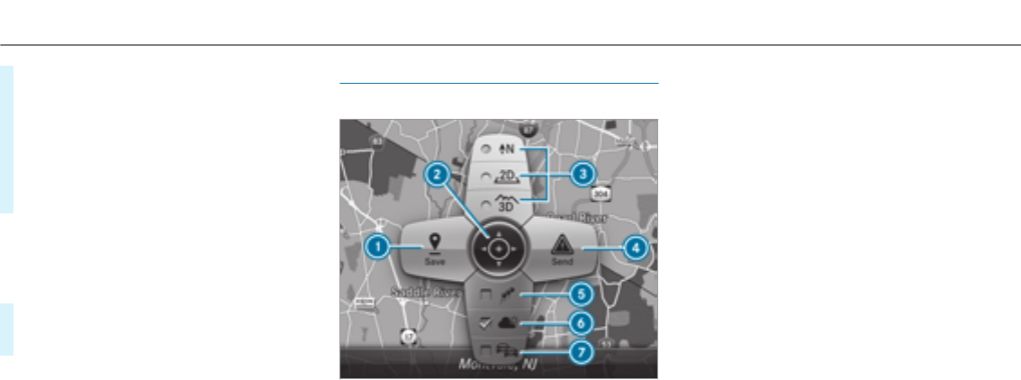
Rreason forthe trafficreport, e.g. traffic
jam
Rwarning message (highlighted in red)
#To select a trafficreport symbol: select
or .
#Press theTouch Control, the controller or the
touchpad.
The trafficreport details are displayed.
Issuing hazard alerts
Multimedia system:
,
.Z .
#Activate O .
Warning messages are issued and tailbacks
which pose a risk are announced.
Map and compass
Map and compass overview
1Savesthe current vehicle position
2Movesthe map
3Selects the map orientation and map view
4Selects the function depending on the equip‐
ment:
•To transmit a hazard alert (Car-to-X)
•To filter the display of POIs in the vicinity
according to POI category
5Switches the display of personal POI sym‐
bols on the map on or off
6Switches one of thefollowing displays on or
off depending on the equipment:
•Weather information
• Satellite map
•Traffic incidents
7Switches the traffic map display on or off
The map and satellite images are shown in globe
projection. This allows for a realistic map display
in all map scales. The map uses elevation model‐
ing.
Depending on the map data, important buildings
in many cities are depicted realistically on the
map in small map scales (1/32 mi (20 m),
1/16 mi (50 m)). Other buildings are shown as
models.
%You can set the unit of measurement of the
map scale (→page 256).
280 Multimedia system

If online information is available, fuel prices and
theavailability of parking spaces in parking
garages are displayed, forexample.
%Online information is not available in all
countries.
%Requirement (USA): Mercedes-Benz
mbrace®is activated.
If is activated in Traffic Sign
Assist (→page 209), speed limits and overtak‐
ing restrictions are displayed on the map.
%Company logos displayed on the map are
trademarks of therespective companies and
used solely forthe purpose of indicating the
locations of these companies. The use of
such logos on the map does not indicate
approval of, support of or advertising by
these companies forthe navigation system
itself.
Setting the map scale
Requirements:
RThe map is shown.
Multimedia system:
,
#To zoom in: swipe down on theTouch Con‐
trol.
or
#Turn the controller anti-clockwise.
or
#Move two fingers apart on thetouchpad.
#To zoom out: swipe up on theTouch Control.
or
#Turn the controller clockwise.
or
#Move two fingers together on thetouchpad.
%You can set the unit of measurement of the
map scale (→page 256).
Moving the map
Multimedia system:
, .Z .
#Alternatively: if the map is displayed in full
screen mode, press theTouch Control, the
controller or thetouchpad.
The map menu appears.
#Select "move map" in map menu 2
(→page 280).
#Swipe in any direction on theTouch Control
or touchpad.
or
#Slide the controller in any direction.
The map moves in the corresponding direc‐
tion under the crosshair. The further you
move your finger away from thestarting posi‐
tion on thetouchpad, thefaster the map
moves.
Multimedia system 281

Selecting the map orientation
Multimedia system:
, .Z .
#Alternatively: if the map is displayed in full
screen mode, press theTouch Control or the
touchpad.
The map menu appears.
#In map menu 3, select , or
(→page 280).
R:the 2D map view is displayed so that
north is always at thetop.
R:the 2D map view is aligned to the
direction of travel.
R:the 3D map view is aligned to the
direction of travel.
Selecting POI symbols
Multimedia system:
, .Z .
POIs include filling stations and hotels which can
be displayed as symbols on the map, forexam‐
ple. Not all POIs are available everywhere.
#Select .
The #dot indicates the current setting.
displays symbols of predefined cat‐
egories on the map.
allows youto personally select
the symbols fortheavailable categories.
switches the display off.
#Select a setting.
# : select categories.
The POI symbols of the selected categories
are displayedOor not displayedª.
Selecting text information
Multimedia system:
, .Z .
#Select text information.
shows thestreet you are cur‐
rently driving on at the bottom of the display.
When the map is moved, thefollowing infor‐
mation appears under the crosshair:
Rstreet name
RPOI name
Rarea name
displaysthefollowing infor‐
mation:
Rlongitude and latitude
Relevation
The elevation shown may deviate from
the actual elevation.
Rnumber of satellites from which a signal
can be received
When the map is moved, this information
does not appear.
displays the current climate
control settings.
switches the display off.
Switching highway information on/off
Multimedia system:
, .Z
#Switch on Oor off ª.
The function is switched on O: during a
journey, additional information on upcoming
facilities appears on theright side of the
282 Multimedia system

screen. These include parking lots, service
stations and highwayexits, forexample.
Displaying the next intersecting street
Requirements:
RRoute guidance is not active.
Multimedia system:
, .Z
#Activate O .
The name of the next intersecting street will
be displayed at the upper edge of the display.
Displaying the map version
Multimedia system:
, .Z
#Select .
#Select .
%Information about new versions of the digital
map can be obtained from an authorized
Mercedes-Benz Center.
Avoiding an area
You can define areas along a route that you
would liketo avoid.
Avoiding a new area
Multimedia system:
, .À
. .
#Select .
#To search for an area via the map: select
.
#Move the map
or
#To search for an area using an address:
select .
#Enter the address.
#Select .
The map appears.
#To display an area: press theTouch Control,
thetouchpad or the controller.
Aredrectangle appears. This designates the
area that should be avoided.
#To change the size of the area: swipe up or
down on theTouch Control or thetouchpad.
or
#Slide the controller up or down.
The map scale is enlarged or reduced and
changes the size of the area.
#To set the area: press theTouch Control,
thetouchpad or the controller.
The area is entered into the list.
Changing an area
Multimedia system:
, .À
. .
#Highlight an area in the list.
#Select ¥.
Moving the area on the map
#Swipe in any direction on theTouch Control
or touchpad.
or
#Slide the controller in any direction.
Changing the size of the area
#To start: press theTouch Control, thetouch‐
pad or the controller.
Multimedia system 283

#To change: swipe up or down on theTouch
Control or thetouchpad.
or
#Slidethe controller up or down.
#To stop: press theTouch Control, thetouch‐
pad or the controller.
Taking the area for the route into account
#Avoid Oan area in the list.
If route guidance is active, a new route is cal‐
culated.
If there is no route yet, the setting is carried
overto the next route guidance.
The route can include an area that is to be
avoided in thefollowing cases:
Rthe destination is located in an area that
is to be avoided
Rthere is no sensible alternative route
Deleting one or all areas
Multimedia system:
, .À
. .
#Highlight an area in the list.
#Select ¥ or ¥ .
#Confirm the prompt with .
One or all areas are deleted.
Map data update overview
Updating at the authorized Mercedes-Benz
Center
The digital maps generated by the map software
become outdated in the same wayas conven‐
tional road maps. Optimal route guidance can
only be provided by the navigation system in
conjunction with the most up-to-date map data.
Information about new versions of the digital
map can be obtained from an authorized
Mercedes-Benz Center.
You can receive updates to the digital map there.
Information on map data
Your vehicle is supplied with map data at thefac‐
tory. Depending on the country, map data for
your region is either pre-installed or the map
data is supplied on a data storage medium. You
do not require an activation code forthe map
data which is provided with your vehicle.
If the map data on your vehicle has been instal‐
led at thefactory and you wish to reinstall it, you
do not need to enter the activation code.
An activation code is required for purchased
map data.
Observe thefollowing notes:
RThe activation code can be used for one vehi‐
cle
RThe activation code is not transferable
RThe activation code has six digits
In theevent of thefollowing problems, please
contact an authorized Mercedes-Benz Center:
RThe multimedia system does not accept the
activation code
RYou have lost the activation code
284 Multimedia system

Displaying the compass
Multimedia system:
, .À
#Select .
The compass display shows thefollowing
information:
Rthe current direction of travel with bear‐
ing (360 degreeformat) and compass
direction
Rlongitude and latitude coordinates in
degrees, minutes and seconds
Rheight (rounded)
Rnumber of GPS satellites from which a
signal can be received
Setting the map scale automatically
Multimedia system:
, .Z
The map scale is set automatically depending on
your driving speed.
For journeys in cities with detailed city models, a
map view from the driver's perspective is used.
#Switch on Oor off ª.
%The automatically selected map scale can be
changed manually for a short time. The set‐
ting is reset automatically after a few sec‐
onds.
Displaying the satellite map
Multimedia system:
, .Z .
#Switch on Oor off ª.
or
#If satellite map display 6is available in the
map menu, switch it on Oor off ª
(→page 280).
Switched on O: satellite maps are displayed
in map scales of 2 mi (2 km).
Switched off ª: satellite maps are not dis‐
played in map scales from 2 mi (2 km) to
10 mi (10 km).
%Satellite maps forthese map scales are not
available in all countries.
Displaying weather information
Multimedia system:
, .Z .
#Activate O .
or
#If weather information display 6is available
in the map menu, activate O(→page 280)
it.
Current weather information is displayed on
the navigation map, e.g. temperature or
cloud cover.
%Requirement (USA): Mercedes-Benz
mbrace®is activated.
%Weather information is not available in all
countries.
Multimedia system 285
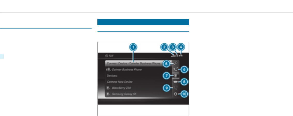
Calling up the Digital Operator's Manual
(navigation)
Calling up information on navigation
Multimedia system:
, .Z .
#Select thetopic.
Telephone
Telephony
Telephone menu overview
1Bluetooth®device name of the currently
connected mobile phone
2Signal strength of the mobile phone network
3Battery status of the connected mobile
phone
4¢(telephone ready) or w(call active)
5 (→page 291)
6 (→page 294)
7 (→page 288)
8
9Active call
A
Symbols 1to 4are not shown until after a
mobile phone has been connected to the multi‐
media system. The symbols depend on your
mobile phone and your mobile phone network
provider.
286 Multimedia system

Bluetooth®profile overview
Bluetooth®profile
of the mobile phone
Function
PBAP (Phone Book
Access Profile)
Contacts are auto‐
matically displayed in
the multimedia sys‐
tem
MAP (Message
Access Profile)
Message functions
can be used
Telephony operating modes overview
Depending on your equipment, thefollowing tel‐
ephony operating modes are available:
RA mobile phone is connectedto the multime‐
dia system via Bluetooth®(→page 288).
Notes on telephony
&WARNING Risk of distraction from oper‐
ating integrated communication equip‐
ment while thevehicle is in motion
If you operate communication equipment
integrated in thevehicle when driving, you
will be distracted from the traffic situation.
This could also cause youto lose control of
thevehicle.
#Only operate this equipment when the
traffic situation permits.
#If you cannot be sure of this, stop the
vehicle whilst paying attention to road
and traffic conditions and operate the
equipment with thevehicle stationary.
&WARNING Risk of distraction from oper‐
ating mobile communication equipment
while thevehicle is in motion
If you operate communication equipment
integrated in thevehicle when driving, you
will be distracted from the traffic situation.
This could also cause youto lose control of
thevehicle.
Only operate this equipment when thevehi‐
cle is stationary.
You must observethe legal requirements forthe
country in which you are currently driving when
operating mobile communication equipment in
thevehicle.
Further information can be obtained from an
authorized Mercedes-Benz Center or at: http://
www.mercedes-benz.com/connect.
Information on telephony
The following situations can lead to the call
being disconnected while thevehicle is in
motion:
Rthere is insufficient network coverage in the
area
Ryou move from one GSM or MUST transmit‐
ter/receiver area (cell) into another and no
communication channels are free
Rthe SIM card used is not compatible with the
network available
Multimedia system 287

Ra mobile phone with "Twin card" is logged
into the network with the second SIM card at
the same time
HD Voice®
RTo improve voice quality, the multimedia sys‐
tem supports telephone calls in HD Voice®.
RIn order to use this function, the mobile
phones and the mobile phone network pro‐
vider of the person you are calling must sup‐
port HD Voice®.
Depending on thequality of the connection, the
voice quality may fluctuate.
Connecting a mobile phone (Bluetooth®tel‐
ephony)
Requirements:
RBluetooth®is activated on the mobile phone
(see the manufacturer's operating instruc‐
tions).
RBluetooth®is activated on the multimedia
system (→page 252).
Multimedia system:
, .á
Searching for a mobile phone
#Select .
#Select .
The available mobile phones are displayed. If
a new mobile phone is found, it is indicated
by theásymbol.
Connecting a mobile phone (authorization
using Secure Simple Pairing)
#Select the mobile phone.
A code is displayed in the multimedia system
and on the mobile phone.
#If the codes match: confirm the code on
the mobile phone.
Connecting a mobile phone (authorization by
entering a passkey)
#Select the mobile phone.
#Choose a one to sixteen-digit number combi‐
nation as a passkey.
#On the multimedia system: enter the pass‐
keyand select a.
#On the mobile phone: enter the passkey
again and confirm.
%Up to 15 mobile phones can be authorized
on the multimedia system.
Authorized mobile phones are reconnected
automatically.
Switching mobile phones
Requirements:
RThe mobile phones are authorized
(→page 288).
Multimedia system:
, .á
#In the device list, select a mobile phone
which has already been authorized.
%Only one mobile phone can be connected at
any one time. The connected mobile phone
is displayed at thetop of the list.
288 Multimedia system

Disconnecting amobile phone (de-authoriz‐
ing)
Multimedia system:
, .á
#Select the mobile phone from the device list.
#Select ¥.
#Select .
#Select .
Information on Near Field Communication
(NFC)
NFC enables short-range wireless data transfer
or (re)connection of a mobile phone with the
multimedia system.
The following functions are available without
having authorized a mobile phone:
RTransferring a URL to be viewed in the multi‐
media system (see the manufacturer's oper‐
ating instructions).
RSetting up thevehicle's Wi-Fi access data via
the system settings (→page 254).
Further information can be found at: http://
www.mercedes-benz.com/connect
Using the mobile phone with Near Field Com‐
munication (NFC)
Requirements:
RNFC is activated on the mobile phone (see
the manufacturer's operating instructions)
RThe mobile phone's screen is switched on
and unlocked (see the manufacturer's oper‐
ating instructions)
#To connect a mobile phone: open stowage
compartment cover1.
#Place the NFC area of the mobile phone (see
manufacturer's operating instructions) on
NFC logo 2on the inside of the cover.
The mobile phone is connected to the multi‐
media system.
#To change mobile phones: place the NFC
area of the mobile phone (see manufactur‐
er's operating instructions) on NFC logo 2.
If the mobile phone has already been author‐
ized on the multimedia system, it is now con‐
nected.
If the mobile phone is authorized on the mul‐
timedia system forthefirst time, it is connec‐
ted after confirming the mobile phone
instructions (see the manufacturer's operat‐
ing instructions).
Further information can be found at: http://
www.mercedes-benz.com/connect
Multimedia system 289

Setting thereception and transmission vol‐
ume
Requirements:
RA mobile phone is authorized (→page 288).
Multimedia system:
, .á
This function ensures optimal language quality.
#Highlight the mobile phone in the device list.
#Select ¥.
#Select or
.
#Set thevolume.
Further information on therecommended recep‐
tion and transmission volume: http://
www.mercedes-benz.com/connect
Adjusting the call and ring tone volume
Multimedia system:
, .õ .
#Select or .
#Set thevolume.
Starting/stopping mobile phone voice recog‐
nition
Requirements
RThe mobile phone is connectedto the multi‐
media system (→page 288).
Starting mobile phone voice recognition
#Press and hold theóbutton on the multi‐
function steering wheel for more than one
second.
You can use mobile phone voice recognition.
Stopping mobile phone voice recognition
#Press the8or ~button on the multi‐
function steering wheel.
Calls
Using thetelephone
Multimedia system:
, .ª
Making a call
#Select .
#Enterthe number.
#Select w.
The call is made.
Accepting a call
#Select .
Rejecting a call
#Select .
Ending a call
#Select =.
Activating functions during a call
#To show all functions, navigate down.
The following functions are available during a
call:
R
R
R (show to send DTMF tones)
RSwitch on Oor off ª.
R (an active call in hands-free
mode is transferredoverto thetelephone)
290 Multimedia system

Conducting calls with several participants
Requirements:
RThere is an active call (→page 290).
RAnother call is being made.
Switching between calls
#Select call #.
The selected call is active. The other call is
on hold.
Activating or ending a call on hold
#Select or .
Conducting a conference call
#Select in thetele‐
phone menu.
The new participant is included in the confer‐
ence call.
Ending an active call
#Select =.
%On some mobile phones, the call on hold is
activated as soon as the active call is ended.
Accepting/rejecting a waiting call
Requirements:
RThere is an active call (→page 290).
If youreceive a call while already in a call, a
message is displayed. An acoustic signal also
sounds.
#Select .
The incoming call is active. The previous call
is on hold.
#Select .
%This function and behavior depends on your
mobile phone network provider and the
mobile phone (see the manufacturer's oper‐
ating instructions).
Contacts
Information about the contacts menu
The contacts menu contains all contacts from
existing data sources, e.g. mobile phone or
memory card.
It is possible to store up to 6,000 contacts:
R3,000 entries are for permanently saved con‐
tacts.
R3,000 for contacts loaded from the mobile
phone.
From the contacts menu, you can perform the
following actions:
RUsing thetelephone:
-Calling a contact (→page 293)
-Calling a new number (→page 290)
RNavigation (→page 267)
RCompose messages (→page 295)
If a mobile phone is connected to the multimedia
system (→page 288) and automatic calling up
(→page 291) is activated, the mobile phone's
contacts are displayed in the address book.
Downloading mobile phone contacts
Multimedia system:
, .Z
Automatically
#Activate O
.
Multimedia system 291

Manually
#Deactivate ª
.
#Select .
Calling up contacts
Multimedia system:
, .ª
Depending on thecharacter set, thefollowing
options can be used to search for contacts:
Rsearching by initials
Rsearching by name
Rsearching by phone number
#Entercharacters into the search field.
A selection of possible contacts appears.
Entering more characters into the search
field narrows down the number of possible
selections.
#Select the contact.
A contact can contain thefollowing details:
Rphone numbers
Rnavigation addresses
Rgeo-coordinates
RInternet address
Editing theformat of a contact's name
Multimedia system:
, .Z .
The following options are available:
R
R
R
#Select an option.
Overview of importing contacts
Importing contacts as electronic business
cards
Source Requirements
òMemory cardThe SD memory card
is inserted.
òUSB device The USB device is
inserted in the USB
port.
292 Multimedia system

Source Requirements
ñBluetooth®con‐
nection
If the sending of
vCards via Bluetooth®
is supported, vCards
can be received on
mobile phones or net‐
books, forexample.
Bluetooth®is activa‐
ted in the multimedia
system and on the
respective device
(see the manufactur‐
er's operating instruc‐
tions).
óMobile phone The mobile phone is
connected to the mul‐
timedia system.
Importing contacts into the contacts menu
Multimedia system:
, .Z
#Select .
#Select an option.
Saving a mobile phone contact
Multimedia system:
, .ª
#Select theómobile phone contact.
#Select ¥.
#Select .
The contact saved in the multimedia system
is identified by thefsymbol.
Calling a contact
Multimedia system:
, .ª
#Entercharacters into the search field.
#Select the contact.
#Select thetelephone number.
The number is dialed.
Selecting further options in the contacts
menu
Multimedia system:
, .ª
#Select a contact.
#Select ¥.
Depending on thestored data, thefollowing
options are available:
R
R
R (if a web address has been
stored)
R (if an address has been stored)
R
R (for a number with DTMF
tones)
#Select an option.
Deleting a contact
Multimedia system:
, .ª
You can delete contacts stored in thevehicle.
#Search forthe contact.
#Select the contact.
#Select ¥.
#Select .
#Select .
Multimedia system 293

Call list
Call list overview
If your mobile phone supportsthe PBAP Blue‐
tooth®profile:
RThe call lists from the mobile phone are dis‐
played in the multimedia system.
RWhen connecting the mobile phone, you may
have to confirm the connection forthe PBAP
Bluetooth®profile.
If your mobile phone does not support the PBAP
Bluetooth®profile:
RThe multimedia system generates its own call
lists.
RThe call list is not synchronized with the call
lists in the mobile phone.
Making a call from the call list
Multimedia system:
, .ø
#Select an entry.
The call is made.
Options in the call list
Multimedia system:
, .ø
#Highlight an entry.
#Select ¥.
The following options are available:
R
R
#Select an option.
Text messages
Overview of text message functions
If the connected mobile phone supports the
MAP Bluetooth®profile, thetext message func‐
tions can be used on the multimedia system.
You can obtain further information about set‐
tings and supported functions of Bluetooth®-
capable mobile phones from an authorized
Mercedes-Benz Center or at: http://
www.mercedes-benz.com/connect
Some mobile phones require further settings
after being connected to the multimedia system
(see manufacturer's operating instructions).
New messages are identified by the1symbol
in the multimedia system's display and an audi‐
ble signal.
Depending on the mobile phone, the multimedia
system only displays new incoming text mes‐
sages or the100 newest text messages.
Configuring the displayedtext messages
Multimedia system:
, .Z .
#Select ¥.
A menu with thefollowing options is shown:
R
R
R
R (The text messages are not displayed
automatically.)
#Select an option.
294 Multimedia system

Reading text messages
Multimedia system:
, .i
Reading a text message
#Select a text message.
The message text is displayed.
Using theread-aloud function
#Select a text message.
#Select .
The text message is read aloud.
Composing and sending a text message
Multimedia system:
, .i
#Navigate to the left twice.
#Select .
Adding a recipient
#Select .
#Select the contact.
Dictating text
#Select .
The app forthe dictation function is loaded.
If there was no prior Internet connection, a
connection is now established.
#To start the dictation function: press the
controller or touchpad.
#Say the message.
The dictation ends automatically afteryou
have finished speaking.
Afterthevoice message has been processed,
it is shown as text.
Editing text
#Select theword.
#To call up the correction menu: press the
controller or touchpad.
The following options are available:
Radjusting the capitalization of words (if
supportedby thecharacter set)
Rexpanding thechoice of words
Rdeleting the selection
Rrecording a new dictation
#To leave the menu: select .
Sending text messages
#Select .
Replying to atext message
Multimedia system:
, .i
#Select thetext message.
#Select ¥.
#Select .
Calling a text message sender
Multimedia system:
, .i
#Select thetext message.
#Select ¥.
#Select .
Multimedia system 295

Deleting text messages
Multimedia system:
, .i
#Select ¥.
#To delete a text message: select .
#To change folders: select .
#
or
#Select .
In Car Office
"In Car Office" functions
Using "In Car Office", you can connect your
online services withthe multimedia system.
The following functions are available:
RDisplay of upcoming meetings in the calen‐
dar
RSelection of a meeting as a destination in the
navigation
RDisplay of upcoming telephone conferences
RSelection of telephone conferences for auto‐
matic dialing
RDisplay of participants in a telephone confer‐
ence
RDisplay and selection of calls to be made
%Please note that certain functions are only
available when thevehicle is stationary.
Calling up "In Car Office"
Requirements:
Ra mobile phone is connectedto the multime‐
dia system.
Rthe mobile phone is enabled for Internet
access.
Ryou have a user account on the Mercedes me
portal (https://me.Mercedes-benz-com).
Rthe "In Car Office" service is activated in the
Mercedes me portal.
Ryou have an account with an online service,
forexample Office 365.
#Select .
Switching automatic start of "In Car Office"
on/off
Multimedia system:
, .
#Switch on
Oor off ª.
If the automatic start of "In Car Office" is
switched on, displays with options regarding
upcoming appointments automatically
appear in the display of the multimedia sys‐
tem.
If the automatic start of "In Car Office“ is
switched off, you can call up the application
via the main menu.
Selecting "In Car Office" functions
Multimedia system
,
#Select an appointment.
Depending on the appointment and the
stored information, thefollowing functions
are available:
R /
296 Multimedia system

R
R /
#Select a function.
Marking an entry in the to-do list as comple‐
ted
Multimedia system
,
#Select an entry in theto-do list O.
Accepting/rejecting an incoming call for a
telephone conference
#To accept: select .
#To reject: select .
Apple CarPlay™
Overview of Apple CarPlay™
iPhone®functions can be used via the multime‐
dia system using Apple CarPlay™. They are oper‐
ated using the controller or the Siri®voice-oper‐
ated control system. You can activate thevoice-
operated control system by pressing and holding
theóbutton on the multifunction steering
wheel.
When using Apple CarPlay™ via thevoice-oper‐
ated control system, the multimedia system can
still be operated via theVoice Control System
(→page 229).
Only one mobile phone at a time can be connec‐
ted via Apple CarPlay™ to the multimedia sys‐
tem.
The availability of Apple CarPlay™ may vary
according to the country.
The service provider is responsible forthis appli‐
cation and the services and content connected
to it.
Information on Apple CarPlay™
While using Apple CarPlay™ various functions of
the multimedia system, e.g. telephony or the
media sources Bluetooth®audio and iPod®, are
unavailable.
Only one route guidance can be active at a time.
If route guidance is active on the multimedia sys‐
tem, it is closed when route guidance is started
on the mobile phone.
Connecting an iPhone®via Apple CarPlay™
Requirements:
RApple®operating system version iOS 8.3 or
above is installed on the iPhone®.
RThere is an Internet connection forthe full
range of functions for Apple CarPlay™.
RThe iPhone®is connected to the multimedia
system via the USB port çusing a suita‐
ble cable (→page 314).
Multimedia system:
, .
Setting automatic or manual start
A message appears when connectedforthefirst
time.
#Automatic start: select .
is activated O.
Apple CarPlay™ will now start immediately
afterthe iPhone®is connected to the multi‐
media system using a USB cable.
#Manual start: select .
#Select the iPhone®in the device list.
Multimedia system 297

Accepting/rejecting the data protection reg‐
ulations
A message with the data protection regulations
appears.
#Select .
or
#Select .
If you selected automatic start, youwill have
to start Apple CarPlay™ manually the next
time youwant to use it.
Exiting Apple CarPlay™
#Press theòbutton on the multifunction
steering wheel, forexample.
%If Apple CarPlay™ was not displayed in the
foreground before disconnecting, the appli‐
cation starts in the background when recon‐
nected. You can call up Apple CarPlay™ in
the main menu.
Calling up Apple CarPlay™ sound settings
Multimedia system:
, . .
#Select thetone menu (→page 330).
Ending Apple CarPlay™
Multimedia system:
, .
#Select .
The connection is ended.
The mobile phone continues to be supplied
with electricity.
or
#Disconnect the connecting cable between
the mobile phone and multimedia system.
Mercedes-Benz recommends disconnecting
the connecting cable only when thevehicle is
stationary.
Android Auto
Android Auto overview
Mobile phone functions can be used with
Android Auto using the Android operating sys‐
tem on the multimedia system. It is operated
using the controller or thevoice-operated con‐
trol system. You can activate thevoice-operated
control system by pressing and holding theó
button on the multifunction steering wheel.
When using Android Auto via thevoice-operated
control system, the multimedia system can still
be operated via theVoice Control System
(→page 229).
Only one mobile phone at a time can be connec‐
ted via Android Auto to the multimedia system.
The availability of Android Auto and Android Auto
Apps may vary according to the country.
The service provider is responsible forthis appli‐
cation and the services and content connected
to it.
Information on Android Auto
While using Android Auto,various functions of
the multimedia system, forexample the media
source Bluetooth®audio, are not available.
Only one route guidance can be active at a time.
If route guidance is active on the multimedia sys‐
tem, it is closed when route guidance is started
on the mobile phone.
298 Multimedia system

Connecting a mobile phone via Android Auto
Requirements:
RThe first activation of Android Auto on the
multimedia system must be carried out when
thevehicle is stationary for safetyreasons.
RThe mobile phone supports Android Auto
from Android 5.0.
RThe Android Auto app is installed on the
mobile phone.
RIn order to use thetelephone functions, the
mobile phone must be connected to the mul‐
timedia system via Bluetooth®(→page 288).
If there was no prior Internet connection, this
is established with the use of the mobile
phone with Android Auto.
RThe mobile phone is connected to the multi‐
media system via the USB port çusing a
suitable cable (→page 314).
RThere is an Internet connection forthe full
range of functions for Android Auto.
Multimedia system:
, .
#Select the mobile phone from the device list.
Accepting/rejecting the data protection reg‐
ulations
A message with the data protection regulations
appears.
#Select .
or
#Select .
Activating automatic start
#Select O.
Starting manually
#Select the mobile phone from the device list.
Exiting Android Auto
#Press theòbutton on the multifunction
steering wheel, forexample.
%If Android Auto was not displayed in thefore‐
ground before disconnecting, the application
starts in the background when reconnected.
You can call up Android Auto in the main
menu.
Calling up the Android Auto sound settings
Multimedia system:
, . .
#Selecting thetone menu (→page 330).
Ending Android Auto
Multimedia system:
, .
#Select .
The connection is ended.
The mobile phone continues to be supplied
with electricity.
or
#Disconnect the connecting cable between
the mobile phone and multimedia system.
Mercedes-Benz recommends disconnecting
the connecting cable only when thevehicle is
stationary.
Multimedia system 299
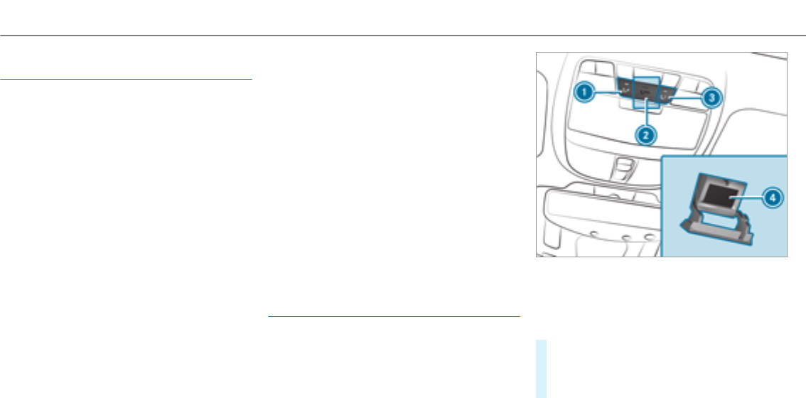
Transferredvehicle data when using Apple
CarPlay™ and Android Auto
Information on transferred vehicle data
When using Android Auto or Apple CarPlay™,
certain vehicle data is transferredto the mobile
phone. This enables youto getthe best out of
selected mobile phone services. Vehicle data is
not directly accessible.
System information:
RSoftware release of the multimedia system
RSystem ID (anonymized)
The transfer of this data is used to optimize com‐
munication between thevehicle and the mobile
phone.
To do this, and to assign severalvehicles to the
mobile phone, a vehicle identifier is randomly
generated.
This has no connection to thevehicle identifica‐
tion number (VIN) and is deleted when the multi‐
media system is reset (→page 261).
Driving status data:
RTransmission position engaged
RDistinction between parked, standstill, rolling
and driving
RDay/night mode of the instrument cluster
The transfer of this data is used to alter how
content is displayed to correspond to the driving
situation.
Position data:
RCoordinates
RSpeed
RCompass direction
RAcceleration direction
This data is only transferred while the navigation
system is active in order to improve it (e.g. so it
can continue functioning when in a tunnel).
Mercedes-Benz mbrace®(USA)
Making a call via theoverhead control panel
Mercedes-Benz mbrace®is available in the USA.
1Roadside Assistance call
2SOS button cover
3MB Info call
4SOS button
#To make a Roadside Assistance call: press
button 1.
This initiates a call to the Mercedes-Benz
Customer Assistance Center.
300 Multimedia system

#To make an emergency call: press SOS
button cover2briefly to open.
#Press and hold SOS button 4for at least
one second.
This initiates a call to the Mercedes-Benz
Customer Assistance Center.
#To make an MB Info call: press button 3.
This initiates a call to the Mercedes-Benz
Customer Assistance Center.
An emergency call can be initiatedeven if a
Roadside Assistance or MB Info call is active.
This has priority over all other active calls.
Calls via theoverhead control panel are only
possible with an available mobile phone net‐
work.
Further information on Mercedes-Benz mbrace®
and other services can be found at: http://
www.mbusa.com
Information on the emergency call system
&WARNING Risk of accident and injury
despite pressing the SOS button
Even if youpress the SOS button in an emer‐
gency, remaining in thevehicle may be dan‐
gerous forthefollowing reasons:
Ryou see smoke inside or outside of the
vehicle, e.g. if there is a fire after an acci‐
dent
Rthevehicle is on a dangerous section of
road
Rthevehicle is not visible or cannot easily
be seen by other road users, particularly
when dark or in poor visibility conditions
#Leave thevehicle immediately in this or
similar situations as soon as it is safe to
do so.
#Move to a safe location along with other
vehicle occupants.
#In such situations, secure thevehicle in
accordance with national regulations,
e.g. with a warning triangle.
Automatic emergency call
The emergency call is initiated in thefollowing
situations:
Rthe air bag is deployed.
Rthe Emergency Tensioning Devices are trig‐
gered.
You can end an automatically initiated emer‐
gency call yourself after 60 seconds.
Manual emergency call
An emergency call can be initiated manually via
the SOS button in theoverhead control panel
(→page 300).
If you leave thevehicle immediately after press‐
ing the SOS button, you do not know if
Mercedes-Benz mbrace®has successfully made
the emergency call.
Initiated emergency call
When a voice connection is established between
the Customer Assistance Center and thevehicle
occupants, thefollowing options apply:
RIf thevehicle occupants are responsive: the
Mercedes-Benz Customer Assistance Center
Multimedia system 301

asks for more detailed information on the
emergency.
RIf thevehicle occupants are not responsive:
an ambulance is sent to thevehicle immedi‐
ately.
Transferred data
During thevoice connection to the Customer
Assistance Center, thefollowing data is transfer‐
red:
RCurrent vehicle location
RVehicle identification number
Emergency call not possible
RIf the mobile phone network is unavailable,
Mercedes-Benz mbrace®is not able to make
an emergency call.
A corresponding message appears in the
multimedia system display.
The indicator lamp flashes continuously.
In this case, seek assistance by other means.
Information on the MB Info call
An Info call to the Mercedes-Benz Customer
Assistance Center has been initiated via the
overhead control panel (→page 300).
You can find information on thefollowing topics:
RMercedes-Benz mbrace®activation
Roperating thevehicle
Rnearest authorized Mercedes-Benz Center
Rother products and services from Mercedes-
Benz
Data is transmitted during the connection to the
Mercedes-Benz Customer Assistance Center
(→page 302).
Information on theRoadside Assistance call
ARoadside Assistance call to the Mercedes-
Benz Customer Assistance Center has been initi‐
ated via theoverhead control panel:
Rthe problem with thevehicle is analyzed
using remote diagnosis.
Further information about this can be
obtained at: http://www.mbusa.com
Raqualified Mercedes-Benz technician carries
out repairs on site and/or thevehicle will be
towedto the nearest authorized
Mercedes-Benz Center.
You may be chargedforthese services.
Data is transmitted during the connection to the
Mercedes-Benz Customer Assistance Center
(→page 302).
Transferred data during a service call
In certain countries you must confirm the data
transfer.
If you make service calls using Mercedes-Benz
brace®(USA), transferred data includes thefol‐
lowing:
302 Multimedia system

Overview of transferred data
Service callTransferred data
MB Info call
Roadside Assistance
call
RCurrent vehicle
location
RVehicle identifica‐
tion number
RService code
RSelected data
about thestatus
of thevehicle
Online and Internet functions
Internet connection
Information on connecting to the Internet
&WARNING Risk of distraction from infor‐
mation systems and communications
equipment
If you operate information and communica‐
tion equipment integrated in thevehicle
when driving, youwill be distracted from the
traffic situation. This could also cause youto
lose control of thevehicle.
#Only operate this equipment when the
traffic situation permits.
#If you cannot be sure of this, stop the
vehicle whilst paying attention to road
and traffic conditions and operate the
equipment with thevehicle stationary.
You must observethe legal requirements forthe
country in which you are currently driving when
operating the multimedia system.
USA: to use Mercedes-Benz Apps and access
the Internet, Mercedes-Benz mbrace®must be
activated and operational. Furthermore,
mbrace®must be activated for Mercedes-Benz
Apps and Internet access.
Canada: the multimedia system must be con‐
nected to a mobile phone via Bluetooth®or to an
external device acting as a Wi-Fi hotspot. Fur‐
thermore, you need a valid mobile service con‐
tract with a data option, which is used to calcu‐
late the associated connection costs.
The Internet functions can only be used to a limi‐
ted degree whilst driving.
Setting up an Internet connection via Wi-Fi
Requirements
RtheWi-Fi function is activated on the multi‐
media system (→page 253).
RtheWi-Fi function is activated on theexternal
device (see the manufacturer's operating
instructions).
RInternet access via Wi-Fi is activated (see the
manufacturer's operating instructions).
The Internet connection via Wi-Fi is restricted or
does not function if:
Rthe mobile phone is switched off
Rmobile data use is deactivated on the mobile
phone
RtheWi-Fi function is deactivated on the multi‐
media system
RtheWi-Fi function is deactivated on theexter‐
nal device
RInternet access via Wi-Fi is deactivated on
theexternal device
Multimedia system 303

Multimedia system:
, .ö .
.
#Select the network.
#Logging in to theWi-Fi network
(→page 253).
Setting up an Internet connection via Blue‐
tooth®
Requirements:
RA mobile phone is connectedto the multime‐
dia system via Bluetooth®(→page 288).
To connect via Bluetooth®,the mobile phone
supports one of thefollowing Bluetooth®pro‐
files:
RDUN (Dial-UpNetworking)
RPAN (Personal AreaNetwork)
The Internet connection via Bluetooth®is restric‐
ted or does not function if:
Rthe mobile phone is switched off
Rthe mobile phone network coverage is insuf‐
ficient
Rmobile data use is deactivated on the mobile
phone
Rthe Bluetooth®function on the multimedia
system is switched off and the mobile phone
is to be connected via Bluetooth®
Rthe Bluetooth®function is switched off on
the mobile phone and the mobile phone is to
be connected via Bluetooth®
Rneither the mobile phone network nor the
mobile phone allow simultaneous use of a
telephone and an Internet connection
Rthe mobile phone has not been enabled for
Internet access via Bluetooth®
If a mobile phone is connected to the multimedia
system forthefirst time via Bluetooth®,you will
be assistedthrough the process of setting up an
Internet connection.
The Internet connection can also be configured
manually.
Further information can be obtained at http://
www.mercedes-benz.com/connect or from an
authorized Mercedes-Benz Center.
Multimedia system:
, .ö .
Bluetooth®connection via PAN
#Select the mobile phone.
The Internet connection is established.
Bluetooth®connection via DUN
#Select the mobile phone.
#To select the predefined access data of
the mobile phone network provider: select
.
A list of countries appears.
#Select the country of your mobile phone net‐
work provider.
The list of available providers appears.
#Select your mobile phone network provider.
When an overview of the provider settings
appears, make the necessary settings.
304 Multimedia system

#Select .
#To manually set the access data of the
mobile phone network provider: select
.
An overview of the provider settings appears.
#Set the access data.
#Select .
%Set the access data in accordance with your
data package. Otherwise, additional costs
may be incurred. You can contact your
mobile phone network provider to obtain the
precise access data.
Switching the Bluetooth®profile
Requirements
RThe mobile phone supports the DUN and
PAN Bluetooth®profiles.
Multimedia system:
, .ö .
#To switch from DUN to PAN: select the
mobile phone.
#Select ¥.
#Select .
#Activate O .
The Internet connection is automatically con‐
figured using thePAN Bluetooth®profile.
#To switch from PANto DUN:select the
mobile phone.
#Select ¥.
#Select .
#Deactivate ª .
#Select .
#Configuring the Internet connection using
preset or manual access data (→page 304).
Editing access data
Requirements
RThe mobile phone supports the Bluetooth®
DUN profile.
Multimedia system:
, .ö .
#Highlight the mobile phone.
#Select ¥.
#Select .
#For mobile phones with PAN and DUN:
select .
#Configure the Internet connection using pre‐
set or manual access data (→page 304).
Canceling Internet access permission for a
mobile phone
Multimedia system:
, .ö .
#Highlight the mobile phone.
#Select ¥.
#Select .
#Select .
Multimedia system 305
Displaying mobile phone details
Multimedia system:
, .ö .
#Highlight the mobile phone.
#Select ¥.
#Select .
Establishing an Internet connection
Multimedia system:
,
#Forexample, select z.
%The multimedia system usually establishes
the Internet connection automatically. If the
multimedia system is not connected to the
Internet, the Internet connection is estab‐
lished when an Internet application is used.
Connection status
Connection status overview
1Display of existing connection and reception
field strength of the connected device
Displaying the connection status
Multimedia system:
, .ö
#Select .
%Depending on the means of connection, the
approximate data volume transmitted is dis‐
played.
Mercedes-Benz Apps
Calling up Mercedes-Benz Apps
Requirements:
RThe registration forthe use of Mercedes-
Benz Apps has been completed.
RThe general terms and conditions have been
confirmed.
Multimedia system:
, .Ú
#Select an app.
Further Mercedes-Benz Apps and information
can be obtained at: http://apps.mercedes-
benz.com/apps/
%The available features are country-depend‐
ent.
License fees may be applicable.
Operating Mercedes-Benz Apps using voice
control
Requirements:
RThe registration forthe use of Mercedes-
Benz Apps has been completed.
306 Multimedia system
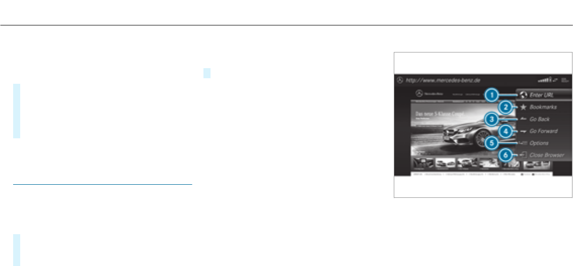
RThe general terms and conditions have been
confirmed.
The ?symbol indicates that a Mercedes-
Benz app can be used via voice control.
#Select a Mercedes-Benz App (→page 306).
The app menu is displayed.
#To use voice control: select ?
.
#Say thequestion or command.
%Voice control is not available in all countries
and languages.
Web browser
Calling up a web page
Multimedia system:
,
.z .z
#Enter a web address.
#To finish the entry and call up theweb‐
site: select ¬.
Showing/hiding theweb browser menu
If you call up a website by selecting a link, for
example, theweb browser menu is hidden.
#To show/hide: press the%button.
%The web browser supports video playback.
%No websites or videos are displayed while
thevehicle is in motion.
Web browser overview
1URL entry
2Bookmarks
3Web page, back
4Web page, forwards
5Options
6To close the browser
Multimedia system 307

Calling up web browser options
Multimedia system:
,
.z .Z
The following functions are available:
R /
R
R
R
#Select an option.
#Make the desired changes to the settings.
Calling up theweb browser settings
Multimedia system:
,
.z .Z .
The following functions are available:
R
R
R
#Activate Oor deactivate ªthe function.
Deleting browser data
Multimedia system:
,
.z .Z .
The following options are available:
R
R
R
R
R
#Select an option.
#Select .
Managing bookmarks
Multimedia system:
,
.z .ß
Selecting a bookmark
#Select an entry.
Creating a bookmark
#Select .
#Enter a URL and a name.
#Select ¡.
Editing a bookmark
#Highlight a bookmark.
#Select ¥.
#Select .
#Enter a URL and a name.
#Select ¡.
Deleting a bookmark
#Highlight a bookmark.
#Select ¥.
#Select .
#Select .
Closing the browser
Multimedia system:
, .z
#Select å .
308 Multimedia system
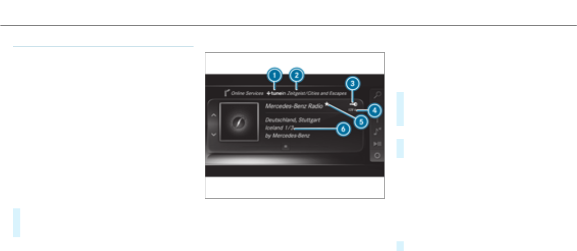
Internet radio
Calling up the Internet radio
Requirements:
RThe Internet radio service is activated.
RThe data volume is available.
Depending on the country, data volume may
need to be purchased.
RAfast Internet connection for data transmis‐
sion free of interference.
The services are country-dependent.
For more information, consult an authorized
Mercedes-Benz Center.
Multimedia system:
, .Þ
#Select .
The Internet radio display appears. The last
station set starts playing.
%The connection quality depends on the local
mobile phone reception.
Internet radio overview
1Internet radio provider
2Selected category
3Display (if connectedto private user
account)
4Data transfer rate
5Current station is stored as a favorite
6Additional information on the current station
Selecting and connecting to Internet radio
stations
Multimedia system:
, .Þ .
.è
#Select a category.
#Select a station.
The connection is established automatically.
or
#Select .
#Enter a station name using the entry field.
%Arelatively large volume of data can be
transmitted when using Internet radio.
Saving/deleting Internet radio stations as
favorites
Multimedia system:
, .Þ .
#Select a station.
Multimedia system 309

#Press and hold thetouchpad or controller
until an audible signal sounds.
The ßsymbol appears by thestation
name.
#Select ß.
The list of savedfavorite stations appears.
or
#Create an account forthe online provider
(TuneIn radio) and then log in on the multi‐
media system.
Your favorites are importedto the multimedia
system.
Deleting favorites
#Select ß.
#Select a station.
#Press and hold thetouchpad or controller
until an audible signal sounds.
The ßsymbol by thestation name disap‐
pears.
Setting the Internet radio options
Multimedia system:
, .Þ .
.Z
The following options are available:
R : select thestream quality.
R : log in to your
TuneIn user account.
R : log out of your TuneIn
user account.
#Select an option.
Media
Audio mode
Information on the audio mode
&WARNING Risk of distraction when han‐
dling data storage media
If you handle a data storage medium while
driving, your attention is diverted from the
traffic conditions. This could also cause you
to lose control of thevehicle.
#Only handle a data storage medium
when thevehicle is stationary.
Permissible file systems:
RFAT32
RexFAT
RNTFS
Permissible data storage medium:
RSD card
RUSB storage device
RiPod®/iPhone®
RMTP devices
RBluetooth®audio equipment
%RThe multimedia system supports a total
of up to 50,000 files.
RData storage media up to 2 TB are sup‐
ported (32-bit address space).
310Multimedia system

Supportedformats:
RMP3
RWMA
RAAC
RWAV
RFLAC
RALAC
%Observe thefollowing notes:
RDue to the large varietyof available
music files regarding encoders, sampling
rates and data rates, playback cannot
always be guaranteed.
RDue to the wide range of USB devices
available on the market, playback cannot
be guaranteed for all USB devices.
RCopy-protected music files or DRM
encryptedfiles cannot be played back.
RMP3 players must support Media Trans‐
fer Protocol (MTP).
Manufactured under license from Dolby Labora‐
tories. Dolby, Dolby Audio and the double-D sym‐
bol are trademarks of Dolby Laboratories.
Gracenote,the Gracenote logo and logotype,
"Powered by Gracenote", MusicID and Playlist
Plus are either registered trademarks or trade‐
marks of Gracenote, Inc. in theUnited States
and/or other countries.
Notes on copyright
Audio files that you create or reproduce yourself
for playback are generally subject to copyright
protection. In many countries, reproductions,
evenfor private use, are not permitted without
the prior consent of the copyright holder. Make
sure that you know about the applicable copy‐
right regulations and that you comply with these.
Multimedia system 311

Activating media mode
Multimedia system:
, .à
#Select a media source.
Playable music files are played back.
Inserting/removing an SD card
&DANGER Risk of fatal injury from swal‐
lowing SD cards
SD cards are small parts.
They could be swallowed and lead to chok‐
ing.
#Keep SD cards out of thereach of chil‐
dren.
#Seek medical attention immediately if
an SD card has been swallowed.
*NOTE Damage caused by high tempera‐
tures
High temperatures can damage the SD mem‐
ory card.
#Remove the SD memory card after use
and take it out of thevehicle.
Multimedia system:
, .à .
Inserting
The multimedia connection unit is located in the
stowage compartment under the armrest.
#Insert the SD memory card into the SD card
slot until it engages. The side with the con‐
tacts must face downwards.
Playable music files are played back.
Removing
#Press the SD card.
#Remove the SD card.
312Multimedia system
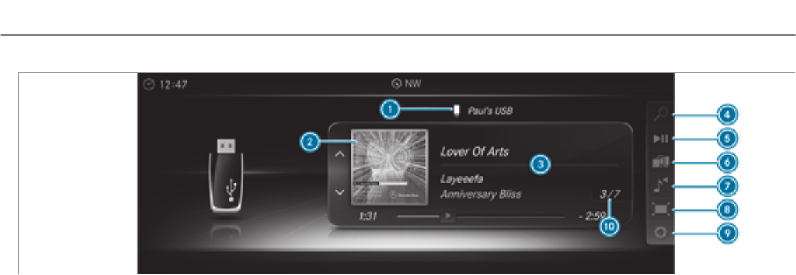
Overview of the audio mode
1Active data storage medium
2Album cover
3Track, artist, album
4
5
6
7
8 (for video playback)
9
ATrack number and number of tracks in the
track list
Multimedia system 313

Connecting USB devices
*NOTE Damage caused by high tempera‐
tures
High temperatures can damage USB devices.
#Remove the USB device after use and
take it out of thevehicle.
The multimedia connection unit is found in the
stowage compartment under the armrest and
has two USB ports. Depending on thevehicle's
equipment, additional USB ports can be found in
thestowage compartment of the center console
or rear folding compartment.
#Connect the USB device to the USB port.
Playable music files are played back only if
the corresponding media display is activated.
%Use the USB port identified by çto use
Apple CarPlay™ and Android Auto.
Selecting a track
Multimedia system:
,
Selecting a track by skipping to a track
#To skip backwards or forwards to a
track: navigate up or down.
Selecting a track using the current track list
#Select è.
#Select .
#Select a track.
Selecting playback options
Multimedia system:
, .Z
Playing back similar tracks
#Select .
A track list with similar tracks is created and
played back.
Playback mode
#Select .
The current track list is played in random
order.
#Select .
All tracks on the active data storage medium
are played in random order.
#Select .
The current track list is played in the order it
appears on the data storage medium.
Controlling media playback
Multimedia system:
, .
A bar with playback controls is shown.
#To pause playback: press thetouchpad.
The Ësymbol is displayed.
#To resume playback: press thetouchpad
again.
The Ìsymbol is displayed.
To fast forward/rewind
#To move Ëon the timeline: swipe left or
right on thetouchpad.
314Multimedia system

To hide the playback controls
#Press the%button.
Video mode
Switching to video mode
Multimedia system:
, .à
#Select a data storage medium.
Playable video files are played back.
The multimedia system supports thefollowing
formats:
RMPEG
RAVI, DivX, MKV
RMP4, M4V
RWMV
%Due to the large varietyof available video
files regarding encoders, sampling rates and
data transfer rates, playback cannot always
be guaranteed.
Videos up to FullHD (1920x1080) are sup‐
ported.
Copy-protected video files or DRM (Digital
Rights Management) encryptedfiles cannot
be played back.
Multimedia system 315
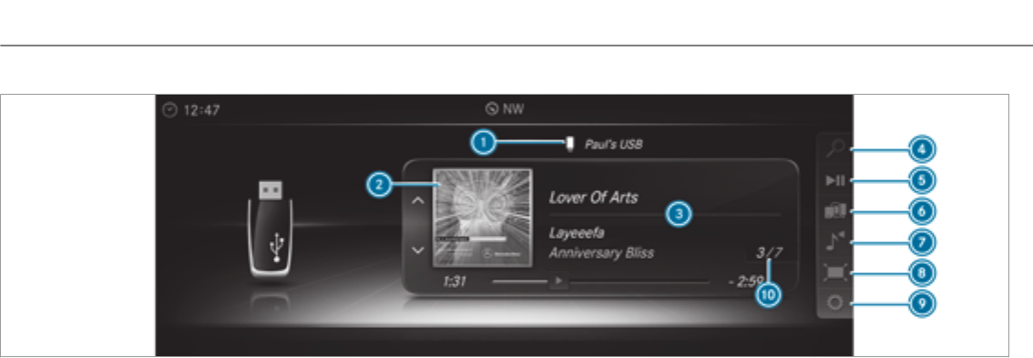
Overview of video mode
1Active data storage medium
2Album cover
3Track, artist, album
4
5
6
7
8
9
ATrack number and number of tracks in the
track list
316Multimedia system

Activating/deactivating full-screen mode
Multimedia system:
, .à
#Select a data storage medium.
Playable video files are played back.
#To activate full-screen mode: select #
.
#To deactivate full-screen mode: press the
touchpad.
Changing video settings
Multimedia system:
, .Z .
The following picture formats are available:
R
R
R
R
#Select a picture format.
Adjusting the brightness manually
#Select .
#Adjust the brightness.
Media search
Starting the media search
Multimedia system:
, .ª
Depending on the connected media sources and
files, thefollowing categories are listed:
R
R
R
R
R
R
R
R
R
R
R
R (Apple®devices)
R (Apple®devices)
#Select a category.
%The categories are available as soon as the
entire media content has been read in and
analyzed.
Media Interface
Information about the Media Interface
Media Interface is a universal interface forthe
connection of mobile audio equipment. The mul‐
timedia system has two USB ports. The USB
ports are located in thestowage compartment
under the armrest.
Supported devices
The Media Interface allows youto connect the
following data storage media:
RiPod®
RiPhone®
RMP3 player
Multimedia system 317

RUSB devices
For details and a list of supported devices, visit
our website at http://www.mercedes-
benz.com/connect. Follow the instructions in
the "Media Interface" section.
Switching to Media Interface
Multimedia system:
, .à
#Connect a data storage medium to the USB
port (→page 314).
#Select a media device.
Playable music files are played back.
318Multimedia system
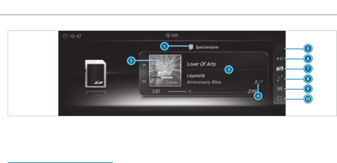
Overview of Media Interface
1Active data storage medium
2Cover
3Artist, track and album
4Track number and number of tracks in the
track list
5
6
7
8
9 (video playback only)
A
Bluetooth®audio Information about Bluetooth®audio
Multimedia system 319
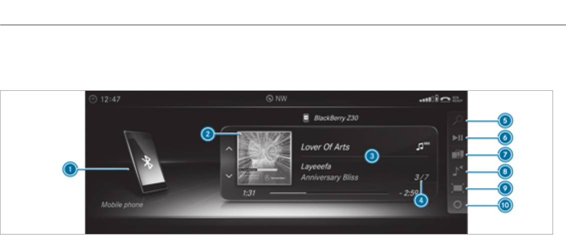
Before using your Bluetooth®audio equipment
with the multimedia system forthefirst time,
youwill need to authorize it (→page 321).
Bluetooth®Audio overview
1Active data storage medium
2Cover art
3Track, artist, album 4Track number and number of tracks in the
track list
320 Multimedia system

5
6
7
8
9 (video playback only)
A
Searching for and authorizing Bluetooth®
audio equipment
Requirements
RBluetooth®is activated on the multimedia
system and audio equipment (→page 252).
RThe audio equipment supports the Blue‐
tooth®audio profiles A2DP and AVRCP.
RThe audio equipment is "visible" forother
devices.
Multimedia system:
, .à
.á
Authorizing new Bluetooth®audio equipment
#Select ¥.
#Select .
#Select .
Detected audio equipment is displayed in the
device list.
#Select a Bluetooth®audio device.
Authorization starts. A code is displayed on
the multimedia system and on the mobile
phone.
#If the codes are identical, confirm on the
audio device.
The audio equipment is connected and play‐
back starts.
Selecting Bluetooth®audio equipment that
has already been authorized
#Select ¥.
#Select a Bluetooth®audio device.
Establishing a connection from the Blue‐
tooth®audio device
The Bluetooth®device name of the multimedia
system is .
#Select .
#Start the authorization on the audio equip‐
ment (see manufacturer's operating instruc‐
tions).
A code is displayed on the multimedia sys‐
tem and on the mobile phone.
#Confirm on both devices if the codes are
identical.
The audio equipment is connected and play‐
back starts.
With some audio equipment, playback must be
initially started on the device itself so that the
multimedia system can play the audio files.
%Device-specific information on authorizing
and connecting Bluetooth®-capable mobile
phones can be obtained at http://
www.mercedes-benz.com/connect or from
an authorized Mercedes-Benz Center.
Multimedia system 321

Activating Bluetooth®audio
Multimedia system:
, .à
#Select á .
The multimedia system activates the connec‐
ted Bluetooth®audio equipment.
Selecting a music player
Multimedia system:
, .à
.á
#Select a Bluetooth®audio device.
If multiple music players are present on the
Bluetooth®audio equipment a list appears.
#Select a music player.
Playback starts.
Searching for a track
Multimedia system:
, .à
.á
#Select ª.
#Select a category.
A track list appears.
#Select a track.
%The function is only available when the
mobile phone and the music player selected
on the mobile phone support this function.
Switching Bluetooth®audio equipment via
NFC
Requirements:
RObserve the notes on using NFC
(→page 289).
RThe Bluetooth®audio overview is displayed
(→page 322).
#Lightly press the NFC area on the mobile
phone (see the manufacturer's operating
instructions).
If the mobile phone has already been author‐
ized on the multimedia system as Bluetooth®
audio equipment, it is now connected.
If the mobile phone is authorized on the mul‐
timedia system as Bluetooth®audio equip‐
ment forthefirst time, it is connected after
confirming the instructions forthe mobile
phone (see the manufacturer's operating
instructions).
Disconnecting Bluetooth®audio equipment
Multimedia system:
, .á
#Select a Bluetooth®audio device.
#Select ¥.
#Select .
Radio
Switching on the radio
Multimedia system:
,
#Alternatively: press the$button.
The radio display appears. Youwill hear the
last station played on the last frequency
band selected.
322 Multimedia system
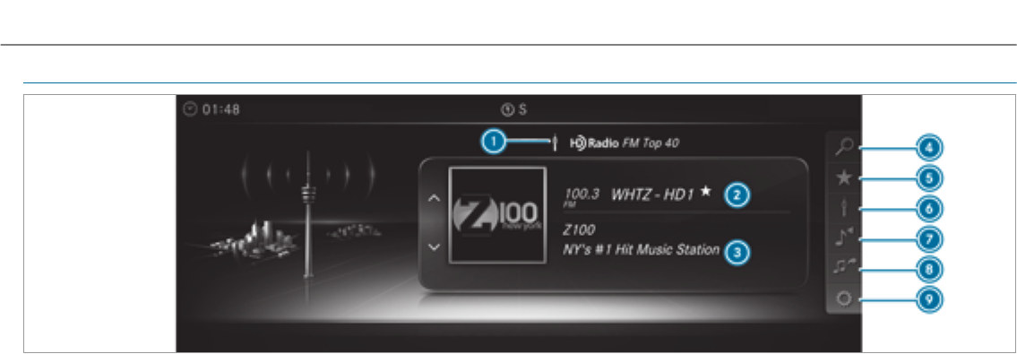
Radio overview
1Active frequency band
2Station name or set frequency
3Artist, title, album and radio text
4Station list
5
6
7
8
9
Multimedia system 323

Switching HD Radio on/off
Multimedia system:
, .Z .
#Switch the function on Oor off ª.
%HD Radio Technology manufactured under
license from iBiquity Digital Corporation.
U.S. and Foreign Patents. HD Radio™ and
the HD, HD Radio and "Arc" logos are propri‐
etary trademarks of iBiquity Digital Corp.
Setting the frequency band
Multimedia system:
, .Þ
and
can be selected.
#Select a frequency band.
Selecting a radio station
Multimedia system:
,
#Navigate up or down.
Calling up theradio station list
Multimedia system:
, .è
#Select a station.
Searching forradio stations using station
names or direct frequency entry
Multimedia system:
, .è.è
#Enter a station name or frequency.
#Select a.
The searchresults are displayed.
#Select a station.
Storing radio stations
Multimedia system:
, .ß
#Select .
Editing radio station presets
Multimedia system:
, .ß
Moving stations:
#Highlight a preset entry and navigate to the
left.
324 Multimedia system

#Select .
#Select a preset.
Deleting stations:
#Highlight a preset entry and navigate to the
left.
#Select .
#Select .
Tagging music tracks
Multimedia system:
,
If radio stations provide therelevant information,
this function allows youto transfer information
on the music track currently playing to an
Apple®device. You can then purchase the audio
file from theiTunes Store®.
#Select .
The track information is saved.
Activating/deactivating radio text
Multimedia system:
, .Z .
#Activate Oor deactivate ªthe function.
Satellite radio
Information on the satellite radio
SIRIUS XM®Satellite Radio offers more than 175
digital-quality radio channels providing 100%
commercial-free music, sports, news and enter‐
tainment, forexample. SIRIUS XM satellite radio
employs afleet of high-performance satellites to
broadcast around the clock throughout the USA
and Canada. The satellite radio program is avail‐
able for a monthly fee. Information about this
can be obtained from a Sirius XM®Service Cen‐
ter and at http://www.siriusxm.com (USA) or
http://www.siriusxm.ca (Canada). Your new
Mercedes-Benz vehicle comes with SIRIUS XM®
Satellite Radio pre-installed at thefactory. This
service is free for a six-month trial period. About
a month before the trial period ends, information
will be provided on how to extend this subscrip‐
tion. A message is shown, describing how the
subscription can be extended.
%Sirius, XM and all related marks and logos
are trademarks of Sirius XM Radio Inc. and
its subsidiaries. All other marks,channel
names and logos are the property of their
respective owners. All rights reserved.
Satellite radio restrictions
Satellite radio mode may be temporarily unavail‐
able or interruptedfor a varietyof reasons.
These include environmental or topographical
conditions beyond the control of Mercedes-Benz
USA, LLC. Thus, operation at certain locations
may not be possible.
Registering satellite radio
Requirements:
Rsatellite radio equipment
Rregistration with a satellite radio provider
Rif registration is not included when purchas‐
ing the system, your credit card details will
be required to activate your account
Multimedia system 325

Multimedia system:
, .Þ .
.Z
#Select .
The service information screen appears
showing theradio ID and the current sub‐
scription status.
#Establish a telephone connection.
#Follow the service staff's instructions.
The activation process may take up to ten
minutes.
%You can also have the satellite service acti‐
vated online. To do so, please visit http://
www.siriusxm.com (USA) or http://
www.siriusxm.ca (Canada).
Switching on satellite radio
Multimedia system:
, .Þ
#Select .
326 Multimedia system
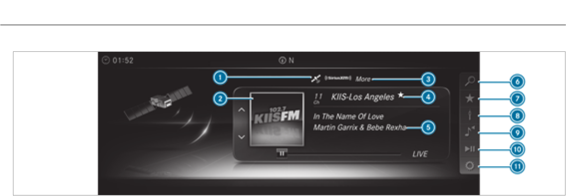
Overview of the satellite radio
1Active frequency band
2Logo or album art (if available)
3Category
4Channel name
5Channel information
6
7
8
9
A
B
Multimedia system 327

Selecting a satellite radio category
Multimedia system:
, .Þ .
.è
.
#Select a category.
Selecting a satellite radio channel
Multimedia system:
, .Þ .
#Navigate up or down.
Saving or deleting a satellite radio channel
Multimedia system:
, .Þ .
.ß
#Select .
Moving a channel
#Select .
#Select .
#Select a preset.
Deleting a channel
#Select .
#Select a preset.
Displaying PEG information for the current
channel
Multimedia system:
, .Þ .
.Z
#Select
.
Setting the parental control
Multimedia system:
, .Þ .
.Z .
#Activate the function O.
#Determine a four-digit character sequence
and select ¡.
All channels with adult content are locked.
Unlocking a channel
#Enter thefour-digit character sequence and
select ¡.
All channels with adult content are unlocked.
Music and sport alerts function
This function enables youto program an alert for
your favorite artists, tracks or sporting events.
Music alerts can be saved whilst a track is being
played and sport alerts can be saved during a
live game. You can also specify sport alerts via
the menu option. The system then continuously
searches through all thechannels. If a match is
found with a stored alert, youwill be informed.
Setting music and sport alerts
Multimedia system:
, .Þ .
.Z .
Setting a music alert
#Select .
or
#Select .
328 Multimedia system

#Select ¥.
The following options are available:
R
R
R
R
R
R
#Select an option.
# O.
The alert is set forthe current artist or track.
If a match is found, a prompt appears asking
whether youwish to change to thestation.
Setting a sport alert
#Select .
or
#Select .
#Select .
or
#Select .
#Select a team from a league.
# O.
Information on Smart Favorites and Tune
Start
Stations in thestation presets can be added as
smart favorites. Smart favoritesstations are
automatically savedto temporary storage in the
background. If youchange to a smart favorite
station, you can replay, pause or actively skip
forward or back to broadcasts which you have
missed. If Tune Start is activated and youchange
to another smart favorite station, the music
track currently playing on thestation is automat‐
ically restarted from the beginning of the track.
Adding a channel to Smart Favorites
Multimedia system:
, .Þ .
#Select the active frequency band.
#Highlight an entry.
#Select ¥.
#Select
.
Activating/deactivating Tune Start
Multimedia system:
, .Z .
#Activate Oor deactivate ªthe function.
Playback controls
Multimedia system:
, .
You can pause the playback of the current sta‐
tion or skip forward or backward in the timeline.
This leaves live mode to access the internal tem‐
porary storage.
#To fast forward/rewind: turn the controller
anti-clockwise or clockwise.
#To jump to the previous/next song: slide
the controller to the left or right.
#To pause playback: select Ë.
#To return to live mode: navigate to the end
of the timeline.
Multimedia system 329

Displaying satelliteradio service information
Multimedia system:
, .Þ .
.Z
#Select .
Sound
Tone settings
Information about the sound system
The sound system has a total output of 100
watts and is equipped with seven speakers. It is
available for all functions in theradio and media
modes.
Calling up the sound menu
Multimedia system:
, .à
The following functions are available:
R
R
R
R
#Select a sound menu.
Adjusting treble, mid-range and bass set‐
tings
Multimedia system:
, .à .
#Select , or .
#Change the settings.
Activating/deactivating automatic volume
adjustment
Multimedia system:
, .à .
Automatic volume adjustment compensates for
differing volumes when changing between audio
sources.
#Switch the function on Oor off ª.
Adjusting the balance/fader
Multimedia system:
, .à .
#Adjust the balance and fader.
#To exit the menu: press the%button.
Burmester®surround sound system
Information about the Burmester®surround
sound system
The Burmester®surround sound system has a
total output of 590 watts and is equipped with
13 speakers. It is available for all functions in the
radio and media modes.
Calling up the sound menu in the
Burmester®surround sound system
Multimedia system:
, .à
The following functions are available:
R
R
R
R
R
R
#Select a function.
330 Multimedia system

Adjusting the treble, mid and bass settings
on the Burmester®surround sound system
Multimedia system:
, .à .
#Select , or .
#Set the desired values.
Activating/deactivating volume adjustment
in the Burmester®surround sound system
Multimedia system:
, .à .
Automatic volume adjustment compensates for
differing volumes when changing between audio
sources.
#Switch the function on Oor off ª.
Adjusting the balance/fader in the
Burmester®surround sound system
Multimedia system:
, .à .
#Adjust the balance and fader.
#To exit the menu: press the%button.
Switching surround sound on/off in the
Burmester®surround sound system
Multimedia system:
, .à .
#Switch the function on Oor off ª.
Adjusting the sound focus in the Burmester®
surround sound system
Multimedia system:
, .à .
#Adjust the sound focus.
Multimedia system 331

ASSYST PLUS service interval display
Function of the ASSYST PLUS service interval
display
The ASSYST PLUS service interval display in the
instrument display provides information on the
remaining time or distance before the next
service due date.
You can hide this service message using the
back button on the left-hand side of thesteering
wheel.
You can obtain further information concerning
the servicing of your vehicle from a qualified
specialist workshop, e.g. an authorized
Mercedes-Benz Center.
Displaying the service due date
On-board computer:
, .
The next service due date is displayed.
#To exit the display: press the back button
on the left-hand side of thesteering wheel.
Make sure to observe thefollowing further rela‐
ted subject:
ROperating the on-board computer
(→page 217).
Carrying out maintenance work at regular
intervals
*NOTE Premature wear through failure to
observe service due dates
Service work which is not carried out at the
right time or incompletely can lead to
increased wear and damage to thevehicle.
#Always observe the prescribed service
intervals.
#Always have the prescribed service
work carried out at a qualified specialist
workshop.
Special service requirements
The prescribed service interval is based on nor‐
mal operation of thevehicle. Maintenance work
will need to be performed more oftenthan
specified if thevehicle is operated under ardu‐
ous conditions or increased loads, forexample:
Rregular city driving with frequent intermedi‐
ate stops.
Rif thevehicle is primarily used for short-dis‐
tance driving.
Rfor frequent operation in mountainous terrain
or on poor road surfaces.
Rif the engine is often left idling for long peri‐
ods.
Rin particularlydusty conditionsand/orif air-
recirculation mode is frequently used.
In these or similar operating conditions, have the
interior air filter, engine air cleaner, engine oil, oil
filter etc. changed more frequently.Thetires
must be checked more frequently if thevehicle
is operated under increased loads. Further infor‐
mation can be obtained at a qualified specialist
workshop.
332 Maintenance and care
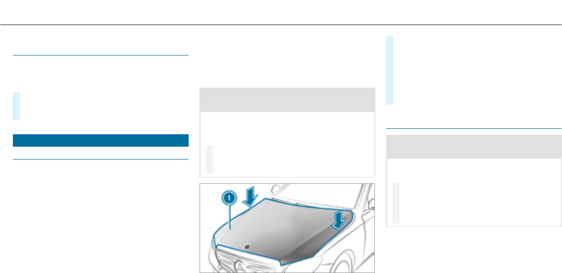
Non-operational times with the battery dis‐
connected
The ASSYST PLUS service interval display
can only calculate the service due date when
the battery is connected.
#Note down the service due date displayed on
the instrument display before disconnecting
the battery (→page 332).
Engine compartment
Active hood (pedestrian protection)
Operation of the active hood (pedestrian pro‐
tection)
In certain accident situations, therisk of injury
to pedestrians can be reduced by the actuation
of the active hood. The rear area of the engine
hood is raised by approximately 85 mm.
Forthe drive to theworkshop, reset the trig‐
gered active hood yourself. If the active hood
has been triggered, pedestrian protection may
be limited.
Aqualified specialist workshop must re-instate
the full functionality of the active hood.
The active hood is not available in all countries.
Resetting the active hood
&WARNING Risk of burns from hot com‐
ponent parts in the engine compartment
Certain component parts in the engine com‐
partment can be very hot, e.g. the engine,
the cooler and parts of theexhaust system.
#Let the engine cool down and only
touch the component parts described
as follows.
#With your hand flat, push down active hood
1in the area around the hinges on both
sides (arrows).
The hood must engage in position.
#If the active hood can be raised slightly at
therear in the area of the hinges, repeat the
step until it engages correctly.
Opening/closing the hood
&WARNING Risk of accident if the engine
hood is unlatched while driving
An unlocked engine hood may open up when
thevehicle is in motion and block your view.
#Never unlatch the engine hood while
driving.
#Before every trip, ensure that the
engine hood is latched.
Maintenance and care 333

&WARNING Risk of accident and injury
when opening and closing the engine
hood
When opening or closing the engine hood, it
may suddenly drop into the end position.
There is a risk of injury for anyone in the
engine hood's range of movement.
#Only open or close the engine hood
when there are no persons in the
engine hood's range of movement.
&WARNING Danger of burns when open‐
ing the hood
If you open the hood when the engine has
overheated or during a fire in the engine
compartment, you could come into contact
with hot gases or other escaping operating
fluids.
#Before opening the hood, allow the
engine to cool down.
#In theevent of a fire in the engine com‐
partment, keep the hood closed and
call thefire service.
&WARNING Risk of injury due to moving
parts
Certain components in the engine compart‐
ment may continue to move or suddenly
move again even afterthe ignition has been
switched off, e.g. the cooler fan.
Make sure of thefollowing before performing
tasks in the engine compartment:
#Switch the ignition off.
#Nevertouch the danger zone surround‐
ing moving component parts, e.g. the
rotation area of thefan.
#Remove jewelry and watches.
#Keep items of clothing and hair away
from moving parts.
&WARNING Risk of injury from touching
component parts under voltage
The ignition system and the fuel injection
system work under high voltage. If youtouch
component parts which are under voltage,
you could receive an electric shock.
#Nevertouch component parts of the
ignition system or the fuel injection sys‐
tem when the ignition is switched on.
&WARNING Risk of burns from hot com‐
ponent parts in the engine compartment
Certain component parts in the engine com‐
partment can be very hot, e.g. the engine,
the cooler and parts of theexhaust system.
#Let the engine cool down and only
touch the component parts described
as follows.
334 Maintenance and care
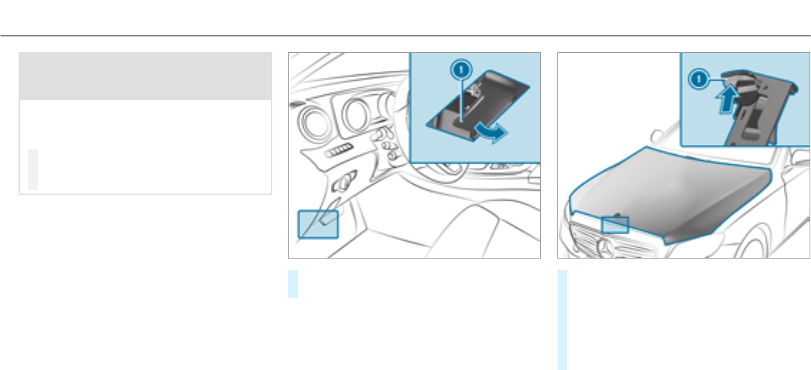
&WARNING Risk of injury from using the
windshield wipers while the engine hood
is open
When the engine hood is open and the wind‐
shield wipers are set in motion, you can be
trapped by the wiper linkage.
#Always switch off the windshield wipers
and ignition before opening the engine
hood.
#To open: pull lever1to release the engine
hood.
#Push hood catch 1upwards and lift the
hood by approximately 15 in (40 cm).
#To close: lowerthe hood and let it fall from a
height of approximately 8 in (20 cm).
#If the hood can still be lifted slightly, open
the hood again and close it with a little more
force until it engages correctly.
Maintenance and care 335
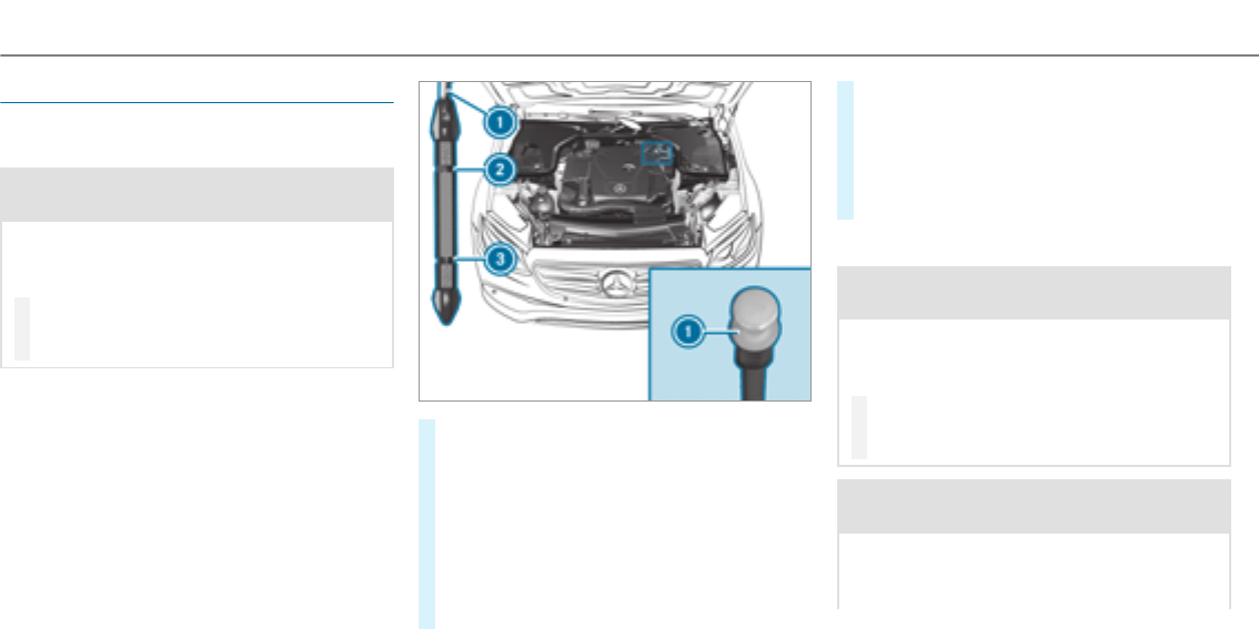
Engine oil
Checking the engine oil level using the oil
dipstick
&WARNING Risk of burns from hot com‐
ponent parts in the engine compartment
Certain component parts in the engine com‐
partment can be very hot, e.g. the engine,
the cooler and parts of theexhaust system.
#Let the engine cool down and only
touch the component parts described
as follows.
Depending on the engine, the oil dipstick may be
installed in the engine compartment in different
locations.
Waiting time before checking the oil level:
REngine at normal operating temperature: five
minutes.
#Park thevehicle on a flat surface.
#Remove oil dipstick 1and wipe off.
#Slowly slide oil dipstick 1into the guide
tube to thestop, and take it out again after
approximately three seconds.
ROil level is correct: oil level is between 2
and 3.
ROil leveltoo low: oil level is at 3or
below.
ROil leveltoo high: oil level is above 2.
#If the oil level is too low, top up with
1.1 US qt (1 l) of engine oil.
#If the oil level is too high, drain off excess
engine oil. Consult a qualified specialist
workshop.
Adding engine oil
&WARNING Risk of burns from hot com‐
ponent parts in the engine compartment
Certain component parts in the engine com‐
partment can be very hot, e.g. the engine,
the cooler and parts of theexhaust system.
#Let the engine cool down and only
touch the component parts described
as follows.
&WARNING Risk of fire and injury from
engine oil
If engine oil comes into contact with hot
component parts in the engine compart‐
ment, it may ignite.
336 Maintenance and care
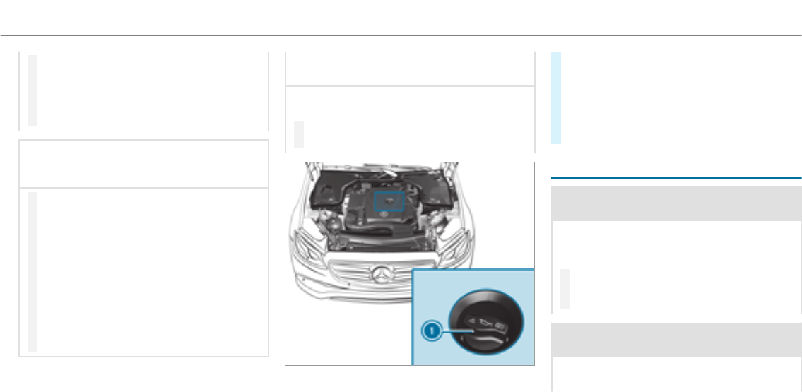
#Make sure that no engine oil is spilled
next to thefiller opening.
#Allow the engine to cool off and thor‐
oughly clean the engine oil from compo‐
nent parts before starting thevehicle.
*NOTE Engine damage caused by an
incorrect oil filter, incorrect oil or addi‐
tives
#Do not use engine oils or oil filters
which do not correspond to the specifi‐
cations explicitly prescribed forthe
service intervals.
#Do not alter the engine oil or oil filter in
order to achieve longer change intervals
than prescribed.
#Do not use additives.
#Follow the instructions in the service
interval display regarding the oil
change.
*NOTE Damage caused by topping up too
much engine oil
Adding too much engine oil can cause dam‐
age to the engine or the catalytic converter.
#Have excess engine oil removed at a
qualified specialist workshop.
#Turn cap 1counter-clockwise and remove
it.
#Add engine oil.
#Replace cap 1and turn it clockwise as far
as it will go.
#Check the oil level again (→page 336).
Checking the coolant level
&WARNING Risk of burns from hot com‐
ponent parts in the engine compartment
Certain component parts in the engine com‐
partment can be very hot, e.g. the engine,
the cooler and parts of theexhaust system.
#Let the engine cool down and only
touch the component parts described
as follows.
&WARNING Danger of burns from hot
coolant
The engine cooling system is pressurized,
particularly when the engine is warm. If you
Maintenance and care 337
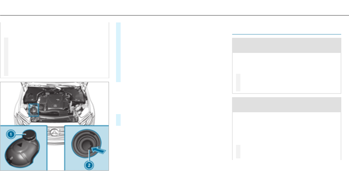
open the cap, you could be scalded by hot
coolant spraying out.
#Let the motor cool down before opening
the cap.
#When opening the cap, wear gloves and
protective eyewear.
#Slowly turn the cap half a turn to allow
pressure to escape.
#Park thevehicle on a level surface.
#Check the coolant temperature display in the
instrument cluster.
The coolant temperature must be below
158 °F (70 °C).
#Slowly turn cap 1counter-clockwise to
relieve excess pressure.
#Continue turning cap 1counter-clockwise
and remove it.
The coolant level is correct:
Rif the engine is cold up to marker bar 2
Rif the engine is warm up to 0.6 in (1.5 cm)
over marker bar 2
#If necessary, top up with coolant that has
been approvedby Mercedes-Benz.
RFurther information on coolant (→page 404)
Adding washer fluid to the windshield
washer system
&WARNING Risk of burns from hot com‐
ponent parts in the engine compartment
Certain component parts in the engine com‐
partment can be very hot, e.g. the engine,
the cooler and parts of theexhaust system.
#Let the engine cool down and only
touch the component parts described
as follows.
&WARNING Danger of burns when open‐
ing the hood
If you open the hood when the engine has
overheated or during a fire in the engine
compartment, you could come into contact
with hot gases or other escaping operating
fluids.
#Before opening the hood, allow the
engine to cool down.
338 Maintenance and care
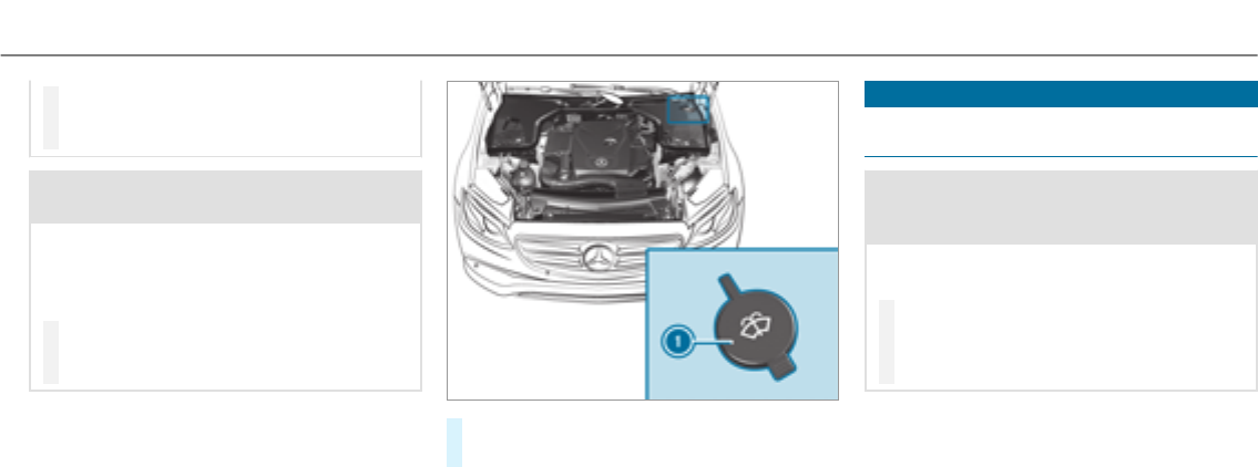
#In theevent of a fire in the engine com‐
partment, keep the hood closed and
call thefire service.
&WARNING ‑ Risk of fire and injury from
windshield washer concentrate
Windshield washer concentrate is highly
flammable. It could ignite if it comes into
contact with hot engine component parts or
theexhaust system.
#Make sure that no windshield washer
concentrate spills out next to thefiller
opening.
#Remove cap 1by thetab.
#Top up thewasher fluid.
Cleaning and care
Information on washing thevehicle in a car
wash
&WARNING Risk of accident due to
reduced braking effect afterwashing the
vehicle
The braking effect is reduced afterwashing
thevehicle.
#Afterthevehicle has been washed,
brake carefully while paying attention to
the traffic conditions until the braking
effect has been fully restored.
To avoid damage to your vehicle when using a
car wash, ensure thefollowing beforehand:
RActive Distance Assist DISTRONIC and the
HOLD function are deactivated.
RThe 360° Camera or therear view camera is
switched off.
RThe side windows and sliding sunroof are
completely closed.
Maintenance and care 339

RThe blowerfortheventilation/heating is
switched off.
RThe windshield wiper switch is in position
g.
RIn car washes with a towing mechanism: neu‐
tral iis engaged.
RThe SmartKey is at a distance of at least
10 ft (3 m) away from thevehicle, otherwise
thetailgate could open unintentionally.
%If, afterthe car wash, youremove thewax
from the windshield and wiper rubber, this
will prevent smearing and reduce wiper
noise.
Information on using a powerwasher
&WARNING Risk of accident when using
high-pressure cleaning equipment with
round-spray nozzles
The water jet from a round-spray nozzle (dirt
grinder) may cause damage to tires and sus‐
pension components that is not visible.
Components damaged in this waymayfail
unexpectedly.
#Do not use high-pressure cleaning
equipment with round-spray nozzles to
clean your vehicle.
#Damaged tires or suspension compo‐
nents must be replaced immediately.
To avoid damage to your vehicle, observe thefol‐
lowing when using a powerwasher:
RKeep the SmartKey at least 10 ft (3 m) away
from thevehicle. Otherwise thetailgate
could open unintentionally.
RMaintain a distance of at least 11.8 in
(30 cm) to thevehicle.
RVehicles with decorative foil: parts of your
vehicle are covered with a decorative foil.
Maintain a distance of at least 27.6 in
(70 cm) between thefoil-covered parts of the
vehicle and the nozzle of the powerwasher.
Move the powerwasher nozzle around whilst
cleaning.
RObserve the information on the correct dis‐
tance in the equipment manufacturer's oper‐
ating instructions.
RDo not point the nozzle of the powerwasher
directly at sensitive parts such as tires, gaps,
electrical components, batteries, light sour‐
ces and ventilation slots.
Washing thevehicle by hand
Observe the legal requirements, e.g. in a number
of countries, washing by hand is only permitted
in specially designated wash bays.
#Use a mild cleaning agent, e.g. car shampoo.
#Wash thevehicle with lukewarm water using
a soft car sponge. When doing so, do not
expose thevehicle to direct sunlight.
#Carefully hose thevehicle off with water and
dry using a chamois. Take care not to point
thewater jet directly towardsthe air inlet
grille.
340Maintenance and care

Notes on paintwork/matt finish paintwork care
Observe thefollowing information:
Cleaning and careAvoiding paintwork damage
Paintwork RInsect remains: soak with insect remover and rinse off the
treated areas afterwards.
RBird droppings: soak with water and rinse off afterwards.
RCoolant, brake fluid, tree resins, oils, fuel and greases:
remove by gently rubbing with a cloth soaked in petroleum
ether or lighter fluid.
RTarstains: use tarremover.
RWax: use silicone remover.
RDo not attach stickers,films or similar.
RRemove dirt immediately, where possible.
Matt finish ROnly use care products approved by Mercedes-Benz. RDo not polish thevehicle and light-alloy wheels.
ROnly use car washes that correspond to the latest engi‐
neering standards.
RDo not use car wash programs with a final hot wax treat‐
ment.
RDo not use paint cleaners, buffing or polishing products,
gloss preservers, e.g. wax.
RAlways have paintwork repairs carried out at a qualified
specialist workshop.
Maintenance and care 341

Notes on care of car parts
&WARNING Risk of entrapment if the
windshield wipers are switched on while
the windshield is being cleaned
If the windshield wipers are set in motion
while you are cleaning the windshield or
wiper blades, you can be trapped by the
wiper arm.
#Always switch off the windshield wipers
and the ignition before cleaning the
windshield or wiper blades.
&WARNING Risk of burns from tailpipes
and tailpipe trim
The tailpipe and tailpipe trim can become
very hot. If you come into contact withthese
parts of thevehicle, you could burn yourself.
#Always be particularly careful around
thetailpipe and thetailpipe trim.
#Allow thevehicle parts to cool down
before youtouch them.
Observe thefollowing information:
Notes on cleaning and careAvoiding vehicle damage
Wheels/rims Use water and acid-free wheel cleaners. RDo not use acidic wheel cleaners to remove brake dust.
This could damage wheel bolts and brake components.
RTo avoid corrosion of the brake discs and brake pads,
drive thevehicle for a few minutes after cleaning before
parking it. The brake discs and brake pads warm up and
dry out.
Windows Clean the windows on the inside and outside using a damp
cloth and cleaning agents recommended by Mercedes-Benz.
Do not use dry cloths or abrasive or solvent-based cleaning
agents to clean the inside of windows.
342Maintenance and care

Notes on cleaning and careAvoiding vehicle damage
Wiper blades Fold out the wiper blades and clean them using a damp cloth.Do not clean the wiper blades too often.
Exterior lighting Clean the lenses with a wet sponge and mild cleaning agent,
e.g. car shampoo.
Only use cleaning agents or cleaning clothsthat are suitable
for plastic lenses.
AIRPANEL If thevehicle is very dusty or there are salt deposits in the
AIRPANEL mechanics, the adjustment range of the shutters in
theradiator grille may be restricted.
RSwitch on the ignition, and the shutters open automati‐
cally after approximately 120 seconds.
RClean the bearing points of the shutters with a power
washer.
When using a powerwasher, maintain a minimum distance of
11.8 in (30 cm).
Sensors Clean the sensors in the front and rear bumper and in the
radiator grille with a soft cloth and car shampoo.
When using a powerwasher, maintain a minimum distance of
11.8 in (30 cm).
Reversing camera
and 360° Camera
ROpen the camera cover with the multimedia sys‐
tem(→page 200) .
RUse clear water and a soft cloth to clean the camera lens.
Do not use a powerwasher.
Tailpipes Clean with cleaning agents recommended by Mercedes-Benz,
particularly in the winter and afterwashing thevehicle.
Do not use acidic cleaning agents.
Maintenance and care 343

Notes on care of the interior
&WARNING Risk of injury from plastic
parts breaking off afterthe use of sol‐
vent-based care products
Care and cleaning products containing sol‐
vents can cause surfaces in the cockpit to
become porous.
When the airbags are deployed, plastic parts
may break away.
#Do not use any care or cleaning prod‐
ucts containing solvents to clean the
cockpit.
&WARNING Risk of injury or death from
bleached seat belts
Bleaching or dyeing seat belts can severely
weaken them.
This can, forexample, cause seat belts to
tear or fail in an accident.
#Never bleach or dye seat belts.
Observe thefollowing information:
Cleaning and careAvoiding vehicle damage
Seat belts Clean with lukewarm and soapy water. RDo not use chemical cleaning agents.
RDo not dry seat belts by heating them to over176 °F
(80 °C) or exposing them to direct sunlight.
Display Clean the surface carefully with a microfiber cloth and
TFT/LCD display care product.
RSwitch off the display and let it cool down.
RDo not use any other cleaning products.
Plastic trim RClean with a damp microfiber cloth.
RFor heavy soiling: use care product recommended by
Mercedes-Benz.
RDo not attach stickers,films or similar.
RDo not allow cosmetics, insect repellent or sun cream to
come in contact with the plastic trim.
344Maintenance and care

Cleaning and careAvoiding vehicle damage
Real wood/trim ele‐
ments
RClean with a microfiber cloth.
RBlack piano-lacquer look: clean with a damp cloth and
soap solution.
RFor heavy soiling: use care product recommended by
Mercedes-Benz.
Do not use solvent-based cleaning agents, polishes or waxes.
Roof lining Clean with a brush or dry shampoo.
Carpet Use carpet and textile cleaning agents recommended by
Mercedes-Benz.
Genuine leather
seat covers
RClean with a damp cloth and then wipe with a dry cloth.
RLeather care: use leather care agents that have been rec‐
ommended by Mercedes-Benz.
Do not allow the leather to become too damp.
Do not use a microfiber cloth.
DINAMICAseatcov‐
ers
Clean with a dampcloth.Do not use a microfiber cloth.
Artificial leather
seat covers
Clean with a damp cloth and 1% soapy water. Do not use a microfiber cloth.
Cloth seat covers Clean with a damp cloth and 1% soapy water and allow to dry.
Maintenance and care 345
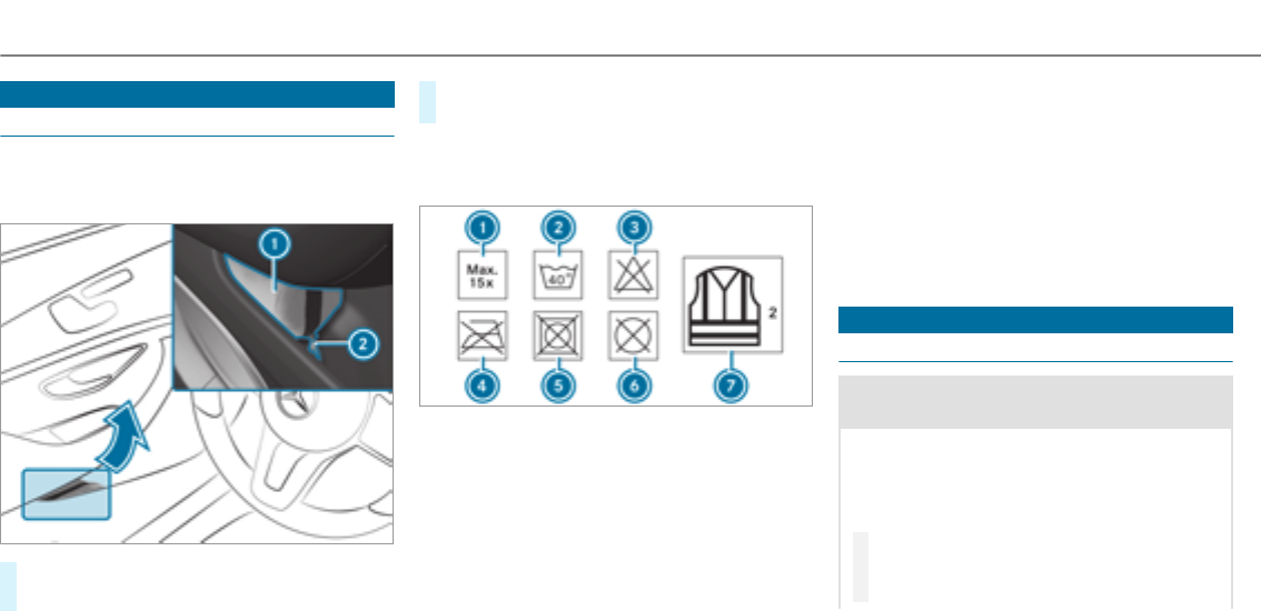
Emergency
Removing the safetyvest
The safetyvests are located in the safetyvest
compartments in the driver's and front
passenger door stowage compartments.
#To remove:pull out safety jacket bag 1by
loop 2.
#Open safetyvest bag 1and pull out the
safetyvest.
%There are also safetyvest compartments in
therear door stowage compartments in
which safetyvests can be stowed.
1Maximum number of washes
2Maximum wash temperature
3Do not bleach
4Do not iron
5Do not use a laundry dryer
6Do not dry-clean
7This is a class 2 jacket
The requirements defined by the legal standard
are only fulfilledif the safetyvest is the correct
size and is fully closed.
Replace the safetyvest if:
Rit is damaged or dirt on thereflective strips
can no longer be removed
Rthe maximum number of washes is exceeded
Rthefluorescence of the safetyvest has faded
Flat tire
Notes on flat tires
&WARNING Risk of accident due to aflat
tire
Aflat tire severely affects the driving charac‐
teristics as well as thesteering and braking
of thevehicle.
Tires without run-flat characteristics:
#Do not drive on with a flat tire.
#Change theflat tire immediately with
the emergency spare wheel or spare
346Breakdown assistance

wheel. Alternatively, consult a qualified
specialist workshop.
Tires with run-flat characteristics:
#Observethe information and warning
notes on MOExtended tires (run-flat
tires).
In theevent of a flat tire, thefollowing options
are available depending on your vehicle's equip‐
ment:
RVehicles with MOExtended tires: it is pos‐
sible to continue the journey for a short
period of time. Make sure you observethe
notes on MOExtended tires (run-flat tires)
(→page 347).
RVehicles with a TIREFIT kit: you can repair
the tire so that it is possible to continue the
journey for a short period of time. To do this,
use the TIREFIT kit (→page 348).
RVehicles with Mercedes-Benz
mbrace®(USA only): you can make a call for
Roadside Assistance via theoverhead control
panel in the case of a breakdown
(→page 300).
RAll vehicles: change the wheel
(→page 390).
MOExtended tires (run-flat tires)
&WARNING Risk of accident when driving
in limp-home mode
When driving in emergency mode the han‐
dling characteristics are impaired, e.g. when
cornering, when accelerating strongly and
when braking.
#Do not exceed the specified maximum
speed.
#Avoid any abrupt steering and driving
maneuvers as well as driving over
obstacles (curbs, pot holes, off-road).
This applies, in particular, to a loaded
vehicle.
#Stop driving in the emergency mode if
you notice:
Rbanging noise
Rvehicle vibration
Rsmoke which smells like rubber
Rcontinuous ESP®intervention
Rcracks in tire side walls
#After driving in emergency mode have
therims checkedby aqualified special‐
ist workshop with regard to their further
use.
#The defective tire must be replaced in
every case.
With MOExtended tires (run-flat tires), you can
continue to drive your vehicle even if there is a
total loss of pressure in one or more tires. How‐
ever, the tire affected must not show any clearly
visible damage.
You can recognize MOExtended tires by the
MOExtended marking which appears on the side
wall of the tire.
Vehicles with tire pressure monitoring sys‐
tem: MOExtended tires may only be used in con‐
Breakdown assistance 347
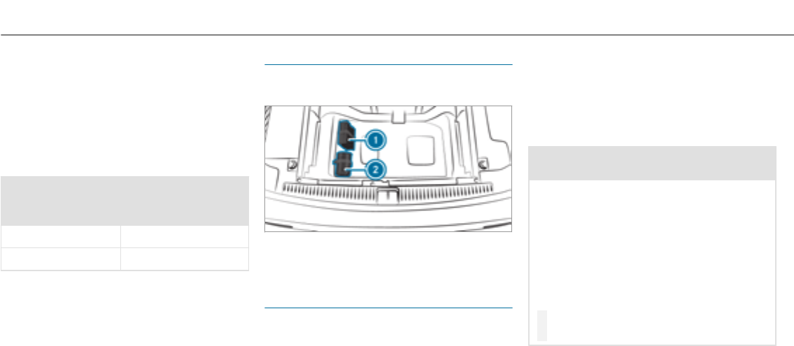
junction with an activated tire pressure monitor‐
ing system.
If a pressure loss warning message appears in
the multifunction display:
RCheck the tire for damage.
RIf driving on, observe thefollowing notes.
Driving distance possible in limp-home mode
after the pressure loss warning:
Load condition Driving distance pos‐
sible in limp-home
mode
Partially laden 50 miles (80 km)
Fully laden 19 miles (30 km)
RThe driving distance possible in limp-home
mode may vary depending on the driving
style.
RMaximum permissible speed 50 mph
(80 km/h).
If a tire has gone flat and cannot be replaced
with an MOExtended tire, you can use a stand‐
ard tire as a temporary measure.
TIREFIT kit storage location
The TIREFIT kit is located under the cargo com‐
partment floor.
1Tire inflation compressor
2Tire sealant bottle
Using the TIREFIT kit
Requirements
Have thefollowing tools readily available:
RTire sealant bottle
RSticker TIREFIT
RTire inflation compressor
You can use TIREFIT tire sealant to seal perfora‐
tion damage of up to 0.16 in (4 mm), particularly
those in the tire contact surface. You can use
TIREFIT in outside temperatures down to -4 °F
(-20 °C).
&WARNING Risk of accident when using
tire sealant.
In thefollowing situations, the tire sealant is
unable to provide sufficient breakdown assis‐
tance, as it is unable to seal the tire properly:
RThere are cuts or punctures in the tire
largerthan those previously mentioned.
RThe wheel rim is damaged.
RYou have driven at a very low tire pres‐
sure or on a flat tire.
#Do not continue driving.
#Consult a qualified specialist workshop.
348Breakdown assistance
&WARNING Risk of injury and poisoning
from tire sealant
The tire sealant is harmful and causes irrita‐
tion. Do not allow it to come into contact
with the skin, eyes or clothing, and do not
swallow it. Do not inhale tire sealant fumes.
Keep the tire sealant away from children.
If you come into contact withthe tire sealant,
observe thefollowing:
#Rinse off the tire sealant from your skin
immediately using water.
#If tire sealant gets into your eyes, thor‐
oughly rinse out theeyes using clean
water.
#If tire sealant has been swallowed,
immediately rinse out the mouth thor‐
oughly and drink plenty of water. Do not
induce vomiting and seek medical
attention immediately.
#Change out of any clothes contamina‐
ted with tire sealant immediately.
#If allergic reactions occur, seek medical
attention immediately.
*NOTE Overheating due to the tire infla‐
tion compressor running too long
#Do not runthe tire inflation compressor
for longer than ten minutes without
interruption.
Comply with the manufacturer's safetynotes on
thesticker on the tire inflation compressor.
Have the tire sealant bottle replaced in a quali‐
fied specialist workshop every five years.
#Do not remove any foreign objects which
have entered the tire.
#Affix part 1of the TIREFIT stickerto the
instrument cluster within the driver's field of
vision.
#Affix part 2of the TIREFIT sticker near the
valve on the wheel with the defective tire.
#Pull plug 4with the cable and hose 5out
of the tire inflation compressor housing.
Breakdown assistance 349
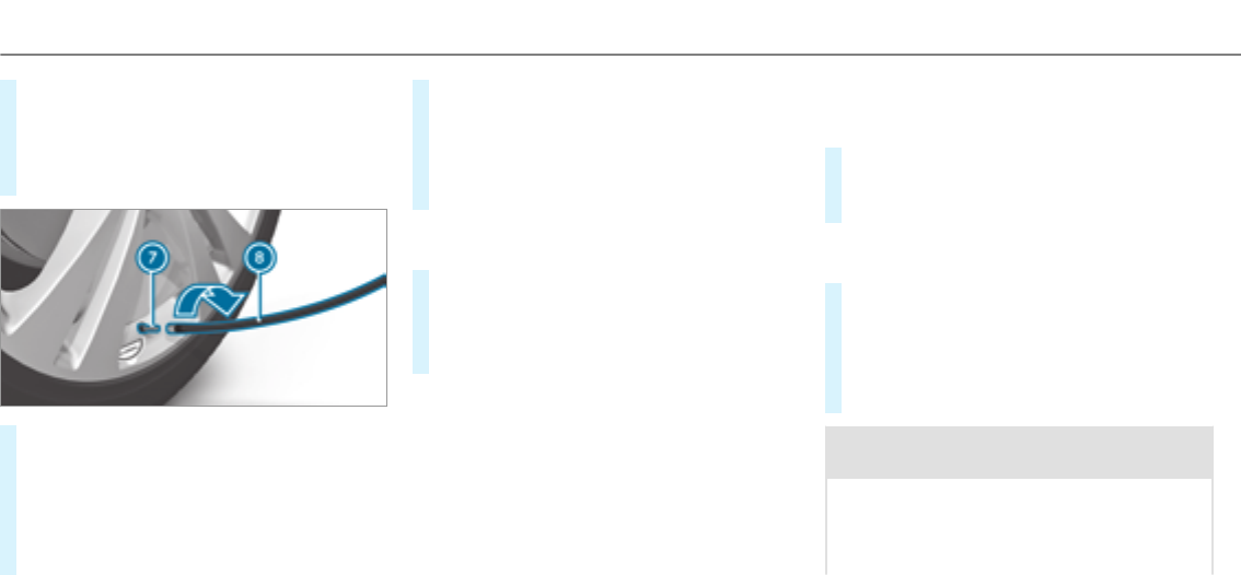
#Push the plug of hose 5into flange 6of
tire sealant bottle 1until the plug engages.
#Place tire sealant bottle 1head downwards
into recess 2of the tire inflation compres‐
sor.
#Remove thevalve cap from valve 7on the
defective tire.
#Screw filling hose 8onto valve 7.
#Insert plug 4into a 12 V socket in your
vehicle.
#Switch on the ignition.
#Press on and off switch 3on the tire infla‐
tion compressor.
The tire inflation compressor is switched on.
The tire is inflated. First, tire sealant is pum‐
ped into the tire. The pressure may briefly
rise to approximately 500 kPa (5 bar/73 psi).
Do not switch off the tire inflation compres‐
sor during this phase.
#Let the tire inflation compressor runfor a
maximum of ten minutes.
The tire should then have attained a tire
pressure of at least 200 kPa (2.0 bar/
29 psi).
If tire sealant leaks out, make sure you clean the
affected areas as quickly as possible. It is pref‐
erable to use clean water.
If youget tire sealant on your clothing, have it
cleaned as soon as possible with perchloroethy‐
lene.
If, afterten minutes, a tire pressure of
200 kPa (2.0 bar/29 psi) has not been ach‐
ieved:
#Switch off the tire inflation compressor.
#Unscrew thefilling hose from thevalve of the
defective tire.
Please note that tire sealant may leak out when
unscrewing thefilling hose.
#Very slowly drive thevehicle forwards or
reverse approximately 33 ft (10 m).
#Pump up the tire again.
After a maximum of ten minutesthe tire
pressure must be at least 200 kPa (2.0 bar/
29 psi).
&WARNING Risk of accident due to the
specified tire pressure not being reached
If the specified tire pressure is not reached
afterthe specified time, the tire is too badly
damaged. The tire sealant cannot repair the
tire in this instance.
350 Breakdown assistance

Damaged tires and a tire pressure that is too
low can significantly impair braking and han‐
dling characteristics.
#Do not continue driving.
#Consult a qualified specialist workshop.
If, afterten minutes, a tire pressure of
200 kPa (2.0 bar/29 psi) has been achieved:
&WARNING Risk of accident from driving
with sealed tires
A tire temporarily sealed with tire sealant
impairs the handling characteristics and is
not suitable for higher speeds.
#Adapt your drivingstyle accordingly and
drive carefully.
#Do not exceed the specified maximum
speed with a tire that has been repaired
using tire sealant.
#Observe the maximum permissible speed for
a tire sealed with tire sealant 50 mph
(80 km/h).
#Fasten the upper section of the TIREFIT
stickerto the instrument cluster where it will
be easily seen by the driver.
*NOTE Staining caused by leaking tire
sealant
After use, excess tire sealant may leak out
from thefilling hose.
#Therefore, place thefilling hose in the
plastic bag that contained the TIREFIT
kit.
+ENVIRONMENTALNOTE Environmental
pollution caused by environmentally irre‐
sponsible disposal
Tire sealant contains pollutants.
#Have the tire sealant bottle disposed of
professionally, e.g. at an authorized
Mercedes-Benz Center.
#Switch off the tire inflation compressor.
#Unscrew thefilling hose from thevalve of the
defective tire.
#Store the tire sealant bottle and the tire infla‐
tion compressor.
#Pull away immediately.
#Stop after driving for approximately ten
minutes and check the tire pressure using
the tire inflation compressor.
The tire pressure must now be at least
130 kPa (1.3 bar/19 psi).
&WARNING Risk of accident due to the
specified tire pressure not being reached
If the specified tire pressure is not reached
after a brief drive, the tire is too badly dam‐
aged. The tire sealant cannot repair the tire
in this instance.
Damaged tires and tire pressure that is too
low can significantly impair the braking prop‐
erties and the handling characteristics.
#Do not continue driving.
#Consult a qualified specialist workshop.
In cases such as the one mentioned above, con‐
tact an authorized Mercedes-Benz Center. Or
Breakdown assistance 351
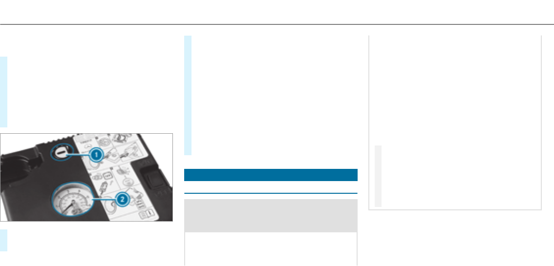
call 1-800-FOR-MERCedes (in the USA) or
1-800-387-0100 (in Canada).
#Correct the tire pressure if it is still at least
130 kPa (1.3 bar/19 psi). See theTire and
Loading Information placard on the driver's
side B‑pillar or the tire pressure table in the
fuel filler flap forvalues.
#To increase the tire pressure: switch on
the tire inflation compressor.
#To reduce the tire pressure: press pressure
release button 1next to manometer2.
#When the tire pressure is correct, unscrew
thefilling hose from thevalve of the sealed
tire.
#Screw thevalve cap onto the tire valve of the
sealed tire.
#Pull the tire sealant bottle out of the tire
inflation compressor.
The filling hose stays on the tire sealant bot‐
tle.
#Drive to the nearest qualified specialist work‐
shop and have the tire, tire sealant bottle and
filling hose replaced there.
Battery (vehicle)
Notes on the12 V battery
&WARNING Risk of an accident due to
work carried out incorrectly on the bat‐
tery
Work carried out incorrectly on the battery
can, forexample, lead to a short circuit. This
can lead to function restrictions in safety-rel‐
evant systems, forexample the lighting sys‐
tem, ABS (anti-lock braking system) or ESP®
(Electronic Stability Program). The operating
safetyof your vehicle may be restricted.
You could lose control of thevehicle in the
following situations:
Rwhen braking
Rin theevent of abrupt steering maneuvers
and/or when thevehicle's speed is not
adaptedto theroad conditions
#In theevent of a short circuit or a simi‐
lar incident, contact a qualified special‐
ist workshop immediately.
#Do not continue driving.
#Always have work on the battery carried
out at a qualified specialist workshop.
RFurther information on ABS (→page 169)
RFurther information on ESP®
For safetyreasons, Mercedes-Benz recommends
that you only use batteries which have been tes‐
ted and approved foryour vehicle by Mercedes-
352 Breakdown assistance

Benz. These batteries provide increased impact
protection to prevent vehicle occupants from
suffering acid burns should the battery be dam‐
aged in theevent of an accident.
All vehicles except vehicles with a lithium-
ion battery
&WARNING Risk of explosion due to elec‐
trostatic charge
Electrostatic charge can cause sparks which
may ignite the highly flammable gas mixture
in the battery.
#To discharge any electrostatic charge
that may have built up, touch the metal
vehicle body before handling the bat‐
tery.
The highly flammable gas mixture is created
while the battery is charging and during starting
assistance.
&WARNING Danger of chemical burns
from the battery acid
Battery acid is caustic.
#Avoid contact with the skin, eyes or
clothing.
#Do not lean overthe battery.
#Do not inhale battery gases.
#Keep children away from the battery.
#Immediately rinse battery acid off thor‐
oughly with plenty of clean water and
seek medical attention immediately.
All vehicles
+ENVIRONMENTAL NOTE Environmental
damage caused by improper disposal of
batteries
Batteries contain pollutants. It is
illegal to dispose of them with the household
rubbish.
#
Dispose of batteries in an
environmentally responsible manner.
Take discharged batteries to aqualified
specialist workshop or to a collection
point for used batteries.
If you have to connect the12 volt battery, con‐
tact a qualified specialist workshop.
Comply with safetynotes and take protective
measures when handling batteries.
Risk of explosion
Fire, open flames and smoking are
prohibited when handling the battery.
Avoid creating sparks.
Electrolyte or battery acid is corro‐
sive. Avoid contact with the skin, eyes
or clothing. Wear suitable protective
clothing, in particular gloves, an
Breakdown assistance 353
apron and a face mask. Immediately
rinse electrolyte or acid splashes off
with clean water. Consult a doctor if
necessary.
Wear safetyglasses.
Keep children away.
Observe this Operator's Manual.
If youdo not intend to use thevehicle over an
extended period of time:
RActivate standby mode, or
RConnect the battery to a battery charger
approvedby Mercedes-Benz, or
RConsult a qualified specialist workshop to
disconnect the battery
Starting assistance and charging the12 V
battery
Vehicles with a lithium-ion battery
#When charging the battery and during start‐
ing assistance, always use the jump-start
connection point in the engine compartment.
*NOTE Damage to the battery from over‐
voltage
When charging using a battery charger with‐
out a maximum charging voltage, the battery
or the on-board electronics may be damaged.
#Only use battery chargers with a maxi‐
mum charging voltage of 14.4 V.
All other vehicles
#When charging the battery and during start‐
ing assistance, always use the jump-start
connection point in the engine compartment.
*NOTE Damaging the battery through
overvoltage
When charging using a battery charger with‐
out a maximum charging voltage, the battery
or thevehicle electronics may be damaged.
#Only use battery chargers with a maxi‐
mum charging voltage of 14.8 V.
&WARNING Risk of explosion from hydro‐
gengas igniting
A battery generates hydrogen gas during the
charging process. If there is a short circuit or
sparks start to form,there is a danger of the
hydrogen gas igniting.
#Make sure that the positive terminal of
the connected battery does not come
into contact with vehicle parts.
#Never place metal objects or tools on a
battery.
#When connecting and disconnecting the
battery, you must observethe descri‐
bed order forthe battery clamps.
354 Breakdown assistance

#When giving starting assistance, always
make sure that you only connect bat‐
tery terminals with identical polarity.
#During starting assistance, you must
observethe described order for con‐
necting and disconnecting the jumper
cables.
#Do not connect or disconnect the bat‐
tery clamps while the engine is running.
&WARNING Risk of explosion during
charging process and starting assistance
During thecharging process and starting
assistance, the battery may release an explo‐
sive gas mixture.
#Avoid fire, open flames, creating sparks
and smoking.
#Make sure that there is sufficient venti‐
lation during thecharging process and
during starting assistance.
#Do not lean over a battery.
If the indicator/warning lamps in the instrument
cluster do not light up at low temperatures, it is
very likely that the discharged battery has fro‐
zen.
&WARNING Risk of explosion from a fro‐
zen battery
A discharged battery may freeze at tempera‐
tures slightly above or below freezing point.
During starting assistance or battery charg‐
ing, battery gas may be released.
#Alwaysthaw a frozen battery out first
before charging it or performing start‐
ing assistance.
The service life of a battery that has been
thawed may be dramatically shortened.
It is recommended that you have athawed bat‐
tery checked at a qualified specialist workshop.
All vehicles
*NOTE Damage caused by numerous or
extended attemptsto start the engine
Numerous or extended attemptsto start the
engine may damage the catalytic converter
due to non-combusted fuel.
#Avoid numerous and extended attempts
to start the engine.
Observe thefollowing points during starting
assistance and when charging the battery:
ROnly use undamaged jumper/charging
cables with a sufficient cross-section and
insulatedterminal clamps.
RNon-insulated parts of theterminal clamps
must not come into contact with other metal
parts while the jumper/charging cable is
connected to the battery/jump-start connec‐
tion point.
RThe jumper/charging cable must not come
into contact with any parts which may move
when the engine is running.
Breakdown assistance 355
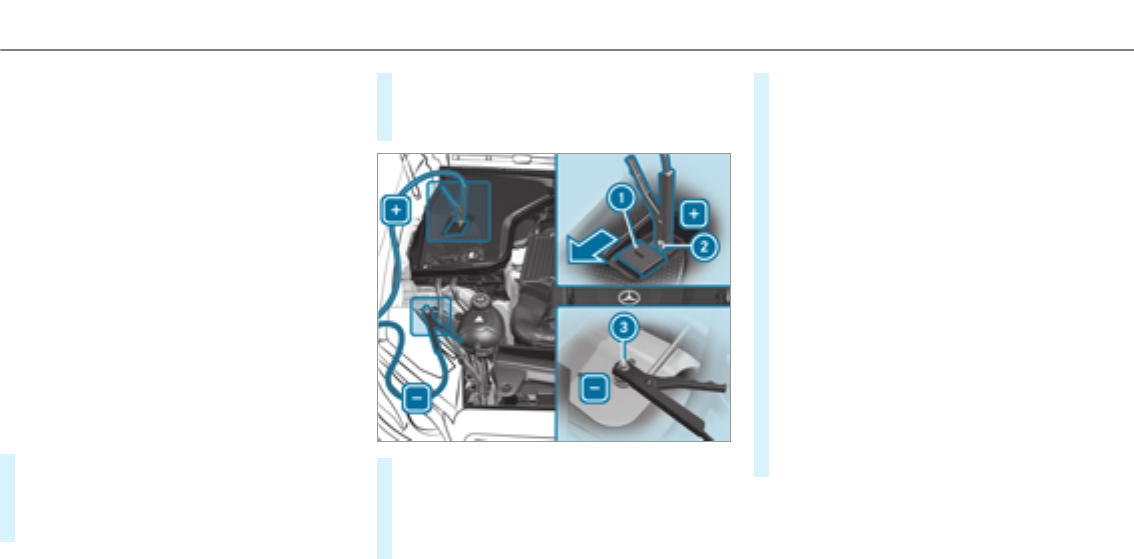
RAlways make sure that neither you nor the
battery is electrostatically charged.
RKeep away from fire and open flames.
RDo not lean overthe battery.
RWhen charging: only use battery chargers
tested and approvedby Mercedes-Benz and
read the battery charger's operating instruc‐
tions before charging the battery.
Observe the additional following points during
starting assistance:
RStarting assistance may only be provided
using batteries with a nominal voltage of
12 V.
RThe vehicles must not touch.
RGasoline engine: only accept starting assis‐
tance if the engine and exhaust system are
cold.
#Secure thevehicle by applying the electric
parking brake.
#Automatic transmission: shift the transmis‐
sion to position j.
#Make sure that the ignition and all electrical
consumers are switched off.
#Open the hood.
#Slide cover1of positive clamp 2on the
jump-starting connection point in the direc‐
tion of the arrow.
#Connect positive clamp 2on your vehicle to
positive pole of the donor battery using the
jumper/charging cable. Always begin with
positive clamp 2on your ownvehicle first.
#During thestarting assistance proce‐
dure: start the engine of the donor vehicle
and run at idle speed.
#Connect the negative pole of the donor bat‐
tery and ground point 3of your ownvehicle
by using the jumper/charging cable. Begin
with the donor battery first.
#During starting assistance: start the
engine of your ownvehicle.
#During thecharging process: start the
charging process.
#During starting assistance: let the engines
runfor several minutes.
#During starting assistance: before discon‐
necting the jumper cable, switch on an elec‐
trical consumer in your ownvehicle, e.g. the
rear window heater or lighting.
When thestarting assistance/charging process
is complete:
356 Breakdown assistance

#First,remove the jumper/charging cable
from ground point 3and negative pole of
the donor battery, then from positive clamp
2and positive pole of the donor battery.
Begin each time with the contacts on your
ownvehicle first.
#Afterremoving the jumper/charging cable,
close cover1of positive clamp 2.
Further information can be obtained at a quali‐
fied specialist workshop.
Towstarting or towing away
Permitted towing methods
Mercedes-Benz recommends transporting your
vehicle in the case of a breakdown, rather than
towing it away.
*NOTE Damage to thevehicle due to tow‐
ing away incorrectly
#Observe the instructions and notes on
towing away.
Breakdown assistance 357
Permitted towing methods
Vehicle equipment/towing
method
Both axles on theground Front axle raised Rear axle raised
Vehicles with manual transmission Yes, maximum 31 miles (50 km) at
31 mph (50 km/h)
Yes, maximum 31 miles (50 km) at
31 mph (50 km/h)
Yes, maximum 31 miles (50 km) at
31 mph (50 km/h)
Vehicles with automatic transmis‐
sion
Yes, maximum 31 miles (50 km) at
31 mph (50 km/h)
No Yes, if thesteering wheel is fixed in
the center position with a steering
wheel lock.
4MATIC vehicles Yes, maximum 31 miles (50 km) at
31 mph (50 km/h)
No No
Towing with a raised axle: towing should be
performed by atowing company.
Towing thevehicle with both axles on the
ground
#Observe the notes on the permitted towing
methods (→page 357) (→page 358).
#Make sure that the battery is connected and
charged.
When the battery is discharged:
Rthe engine cannot be started.
Rthe electric parking brake cannot be released
or applied.
Rvehicles with automatic transmission: the
automatic transmission cannot be shiftedto
position ior j.
358 Breakdown assistance

%Vehicles with automatic transmission: if
the automatic transmission cannot be shif‐
tedto position i, or the multifunction dis‐
play in the instrument cluster does not show
anything, have thevehicle transported
away(→page 360). A towing vehicle with lift‐
ing equipment is required forvehicle trans‐
portation.
*NOTE Damage due to towing away at
excessively high speeds or over long dis‐
tances
The drivetrain could be damaged when tow‐
ing at excessively high speeds or over long
distances.
#Atowing speed of 30 mph (50 km/h)
must not be exceeded.
#Atowing distance of 30 miles (50 km)
must not be exceeded.
&WARNING Risk of accident when towing
avehicle which is too heavy
If thevehicle being tow-started or towed
away is heavier than the permissible gross
mass of your vehicle, thefollowing situations
can occur:
RThe towing eye may become detached.
RThe vehicle/trailer combination may
swerve or evenoverturn.
#If another vehicle is tow-started or
towedaway, its weight must not exceed
the permissible gross mass of your own
vehicle.
If a vehicle must be tow-started or towedaway,
its weight must not exceed the permissible gross
mass of thetowing vehicle.
#Information on the permissible gross mass of
thevehicle can be found on thevehicle iden‐
tification plate.
#Vehicles with automatic transmission: do
not open the driver's door or front passenger
door, otherwise the automatic transmission
automatically shifts to position j.
#Install thetowing eye (→page 362).
#Attach thetow bar.
*NOTE Damage due to incorrect connec‐
tion
#Only connect thetowrope or tow bar to
thetowing eyes.
#Deactivate the automatic locking mechanism
(→page 64).
#Do not activate the HOLD function.
#Deactivate Active Brake Assist (→page 174).
#Vehicles with automatic transmission:
shift the automatic transmission to position
i.
#Release the electric parking brake.
Breakdown assistance 359

&WARNING Risk of accident due to limi‐
ted safety-related functions during the
towing process
Safety-related functions are limited or no lon‐
geravailable in thefollowing situations:
Rthe ignition is switched off.
Rthe brake system or powersteering sys‐
tem is malfunctioning.
Rthe energy supply or the on-board electri‐
cal system is malfunctioning.
When your vehicle is then towedaway, signif‐
icantly more effort may be required to steer
and brake than is normally required.
#Use a tow bar.
#Make sure that thesteering wheel can
move freely, before towing thevehicle
away.
*NOTE Damage due to excessive tractive
power
If you pull away sharply, the tractive power
may be too high and thevehicles could be
damaged.
#Pull away slowly and smoothly.
Loading the vehicle for transport
#Observe the notes on towing away
(→page 358).
#Connect thetow bar to thetowing eyeto
load thevehicle.
#Vehicles with automatic transmission:
Shift the automatic transmission to position
i.
%Vehicles with automatic transmission:
The automatic transmission may be locked
in position jin theevent of damage to the
electrical system. To shift to i, provide the
on-board electrical system with power
(→page 354).
#Load thevehicle onto the transporter.
#Vehicles with automatic transmission:
Shift the automatic transmission to position
j.
#Use the electric parking brake to secure the
vehicle and prevent it from rolling away.
#Only secure thevehicle by the wheels.
Vehicles with ADS PLUS (Adaptive Damping
System PLUS)
&WARNING Risk of an accident when
transporting vehicles with Adaptive
Damping System PLUS
The reduced damping forces on thevehicle
being transported can cause thevehicle/
trailer combination to start to swing.
As a result, when transporting vehicles with
theAdaptive Damping System PLUS, the
vehicle/trailer combination may start to skid.
Consequently, you could lose control of your
vehicle.
#When transporting, ensure that:
360 Breakdown assistance
RThe vehicle has been loaded onto
the transporter correctly
RThe vehicle is secured at all four
wheels with suitable tensioning
straps
RThe maximum permissible speed of
35 mph (60 km/h) is not exceeded
when transporting
*NOTE Damage to thevehicle from secur‐
ing it incorrectly
#After loading, thevehicle must be
secured at all four wheels. Otherwise,
thevehicle could be damaged.
#A minimum distance of 8 in (20 cm) up
and 4 in (10 cm) down must be kept to
the transport platform.
#Secure thevehicle on all four wheels after
loading.
4MATIC vehicles/vehicles with automatic
transmission
#Make sure that the front and rear axles come
to rest on the same transportation vehicle.
*NOTE Damage to the drivetrain due to
incorrect positioning
#Do not position thevehicle above the
connection point of the transport vehi‐
cle.
Towing eyestorage location
Towing eye1is attached to the edge of the
cargo compartment under the cargo compart‐
ment floor.
Vehicles with folding bench seat: thetowing
eye is located under a cover.
Breakdown assistance 361
Installing thetowing eye
#Press the mark on cover1inwards and
remove.
#Screw in thetowing eye clockwise as far as it
will go and tighten.
%Make sure that cover1engages in the
bumper when youremove thetowing eye.
*NOTE Damage due to incorrect use of
thetowing eye
When a towing eye is used to recover a vehi‐
cle, thevehicle may be damaged in the proc‐
ess.
#Only use thetowing eyeto towaway or
towstart thevehicle.
Towstarting thevehicle (emergency engine
starting)
Vehicles with automatic transmission
*NOTE Damage to the automatic trans‐
mission due to towstarting
The automatic transmission may be damaged
in the process of towstarting vehicles with
automatic transmission.
#Vehicles with automatic transmission
must not be towstarted.
#Vehicles with automatic transmission must
not be towstarted.
Electrical fuses
Notes on electrical fuses
&WARNING Risk of accident and injury
due to overloaded lines
If you manipulate or bridge a faulty fuse or if
youreplace it with a fuse with a higher
amperage, the electric line could be overloa‐
ded.
This could result in a fire.
#Alwaysreplace faulty fuses with speci‐
fied new fuses containing the correct
amperage.
*NOTE Damage caused by incorrect fuses
Incorrect fuses may cause damage to electri‐
cal components or systems.
#Only use Mercedes-Benz approved
fuses with the correct fuse rating.
Blown fuses must be replaced with fuses of the
same rating, which you can recognize by the
color and fuse rating. For engine compartment
362 Breakdown assistance

and cargo compartment fuses, only use those
fuses marked with an "S". The fuse ratings are
listed in the fuse assignment diagram.
Fuse assignment diagram: on the fuse box in
the cargo compartment (→page 365).
*NOTE Damage or malfunctions caused
by moisture
Moisture may cause damage to the electrical
system or cause it to malfunction.
#When the fuse box is open, make sure
that no moisture can enter the fuse
box.
#When closing the fuse box, make sure
that the seal of the lid is positioned cor‐
rectly on the fuse box.
If the newly inserted fuse also blows, have the
cause traced and rectified at a qualified special‐
ist workshop, e.g. a Mercedes-Benz Service Cen‐
ter.
Ensure thefollowing before replacing a fuse:
RThe vehicle is secured against rolling away.
RAll electrical consumers are switched off.
RThe ignition is switched off.
The electrical fuses are located in various fuse
boxes:
RFuse box on the driver's side of the engine
compartment (→page 363)
RFuse box on the driver's side of the cockpit
(→page 364)
RFuse box in the front passenger footwell
(→page 364)
RFuse box in the cargo compartment on the
right-hand side of thevehicle, when viewed
in the direction of travel (→page 365)
Fuse box in the engine compartment
Observethe notes on electrical fuses
(→page 362).
Requirements:
RYou need a dry cloth and a screwdriver.
Opening
&WARNING Risk of injury from using the
windshield wipers while the engine hood
is open
When the engine hood is open and the wind‐
shield wipers are set in motion, you can be
trapped by the wiper linkage.
#Always switch off the windshield wipers
and ignition before opening the engine
hood.
Breakdown assistance 363
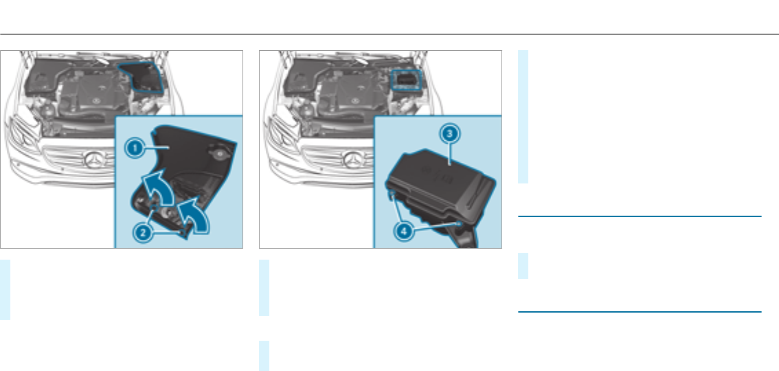
#Turn clip 2on cover1aquarter-turn to
the left.
#Pull cover1upwards in the direction of the
arrow.
#Remove any existing moisture from the fuse
box using a dry cloth.
#Loosen screws4,remove fuse box lid 3
from thetop.
Closing
#Check whether the seal is positioned cor‐
rectly in the lid.
#Insert the lid into the bracket at therear of
the fuse box.
#Fold down lid of the fuse box and tighten
screws4.
#Insert cover1on both sides and engage
the safetyclips.
#Turn clip 2on cover1one quarter-turn to
theright.
#Close the engine hood.
Dashboard fuse box
The fuse box is on the side of the dashboard
under a cover.
#Contact an authorized Mercedes-Benz Cen‐
terfor further information.
Fuse box in the front-passenger footwell
Observe the notes on electrical fuses
(→page 362).
364 Breakdown assistance
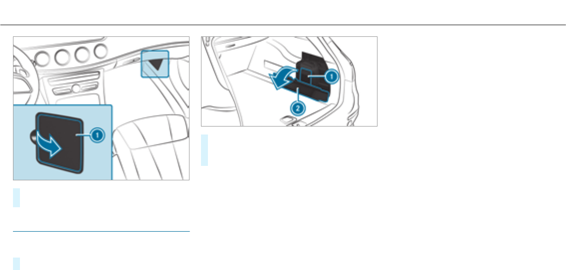
#Open cover1in the direction of the arrow
and remove it.
Fuse box in the cargo compartment
Observethe notes on electrical fuses
(→page 362).
#Fold down the side cover.
#Fold cover2down in the direction of the
arrow.
#Remove cover1.
The fuse assignment diagram is in a recess on
the side of the fuse box.
Breakdown assistance 365

Notes on noise or unusual handling charac‐
teristics
While driving, pay attention to vibrations, noises
and unusual handling characteristics, e.g. pulling
to one side. This may indicate that the wheels or
tires are damaged. If you suspect that a tire is
defective, reduce your speed immediately. Stop
thevehicle as soon as possible to check the
wheels and tires for damage. Hidden tire dam‐
age could also be causing the unusual handling
characteristics. If youfind no signs of damage,
have the tires and wheels checked at a qualified
specialist workshop.
Regular checking of wheels and tires
&WARNING Risk of accident from dam‐
aged tires
Damaged tires can cause tire pressure loss.
As a result, you could lose control of your
vehicle.
#Check the tires regularly for signs of
damage and replace any damaged tires
immediately.
&WARNING Risk of aquaplaning due to
insufficient tire tread
Insufficient tire tread will result in reduced
tire grip. The tire tread is no longer able to
dissipate water.
This means that in heavy rain or slush the
risk of hydroplaning is increased, in particu‐
lar if vehicle speed is not adaptedto suit the
conditions.
If the tire pressure is too high or too low,
tires may exhibit different levels of wear at
different locations on the tire contact sur‐
face.
#Thus, you should regularly check the
tread depth and the condition of the tire
contact surface across the entire width
of all tires.
Minimum tread depth for:
RSummer tires: âin (3 mm)
RM+S tires: ãin (4 mm)
#For safetyreasons, replace the tires
before the legally prescribed limit for
the minimum tread depth is reached.
Carry out thefollowing checks on all wheels reg‐
ularly, at least once a month or as required, e.g.
prior to a long journey or driving off-road:
RCheck the tire pressure (→page 368).
RVisual inspection of wheels and tires for
damage.
RCheck thevalve caps.
The valves must be protected against mois‐
ture and dirt by thevalve caps approved
especially foryour vehicle by Mercedes-Benz.
RVisual check of the tire tread depth and the
tire contact surface condition across the
entire width.
366 Wheels and tires
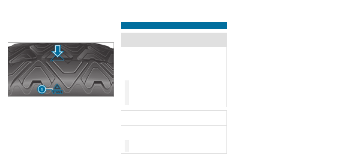
The minimum tread depth for summer tires is
âin (3 mm) and for winter tires ãin
(4 mm).
Six marks 1show where the bar indicators
(arrow) are integrated into the tire tread. They
are visible once a tread depth of approximately
áin (1.6 mm) has been reached.
Notes on snow chains
&WARNING Risk of accident due to incor‐
rect mounting of snow chains
If you have mounted snow chains to the front
wheels, the snow chains may drag against
thevehicle body or chassis components.
This could cause damage to thevehicle or
the tires.
#Never mount snow chains on the front
wheels.
#Only mount snow chains on therear
wheels in pairs.
*NOTE Damage to the wheel trim from
mounted snow chains
If snow chains are mountedto steel wheels,
the wheel trims can be damaged.
#Remove the wheel trims of steel wheels
before mounting snow chains.
RSnow chains are only permissible for certain
wheel/tire combinations. You can obtain
information about this from an authorized
Mercedes-Benz Center.
RFor safetyreasons, only use snow chains that
have been specifically approved foryour
vehicle by Mercedes-Benz, or snow chains
with the same quality standard.
RIf snow chains are mounted, the maximum
permissible speed is 30 mph (50 km/h).
RVehicles with Active Parking Assist: Do
not use Active Parking Assist when snow
chains are mounted.
RVehicles with AIR BODY CONTROL: Only
drive at raised vehicle level when snow
chains are mounted.
%You can deactivate ESP®to pull away
(→page 169). This allows the wheels to
spin, achieving an increased driving force.
Wheels and tires 367

Tire pressure
Notes on tire pressure
&WARNING Risk of accident due to insuf‐
ficient or excessive tire pressure
Underinflated or overinflated tires pose the
following risks:
RThe tires may burst, especially as the
load and vehicle speed increase.
RThe tires may wear excessively and/or
unevenly, which may greatly impair tire
traction.
RThe driving characteristics, as well as
steering and braking, may be greatly
impaired.
#Comply with therecommended tire
pressure and check the tire pressure of
all tires including the spare wheel regu‐
larly:
Rat least once a month
Rwhen the load changes
Rbefore embarking on a longer journey
Rif operating conditions change, e.g. off-
road driving
#Adjust the tire pressure as necessary.
Driving with tire pressure that is too high or too
low can:
RShorten the service life of the tires.
RCause increased tire damage.
RAdversely affect driving characteristics and
thus driving safety, e.g. due to aquaplaning.
&WARNING Risk of an accident due to
insufficient tire pressure
Tires with pressure that is too low can over‐
heat and burst as a result.
In addition, they also suffer from excessive
and/or irregular wear, which can significantly
impair the braking properties and the han‐
dling characteristics.
#Avoid excessively low tire pressures in
all the tires, including the spare wheel.
Tire pressure which is too low can cause:
RTire defects as a result of overheating
RImpaired handling characteristics
RIrregular wear
RIncreased fuel consumption
&WARNING Risk of accident from exces‐
sive tire pressure
Tires with excessively high pressure can
burst because they are damaged more easily
by highway fill, pot holes etc.
In addition, they also suffer from irregular
wear, which can significantly impair the brak‐
ing properties and the handling characteris‐
tics.
#Avoid excessively high tire pressures in
all the tires, including the spare wheel.
Excessively high tire pressure can result in:
RIncreased braking distance
RImpaired handling characteristics
RIrregular wear
368 Wheels and tires

RImpaired driving comfort
RSusceptibility to damage
&WARNING Risk of accident caused by
repeated drop in tire pressure
If the tire pressure drops repeatedly, the
wheel, valve or tire may be damaged.
Insufficient tire pressure can cause the tires
to burst.
#Inspect the tire for signs of foreign
objects.
#Check whether the wheel or valve has a
leak.
#If you are unable to rectify the damage,
contact a qualified specialist workshop.
You can find information on tire pressures for
thevehicle's factory-installed tires on thefollow‐
ing labels:
RTire and Loading Information placard on the
B‑pillar of your vehicle (→page 373).
RTire pressure table on the inside of the fuel
filler flap (→page 369).
Observethe maximum tire pressure
(→page 381).
Use a suitable pressure gauge to check the tire
pressure. The outer appearance of a tire does
not permit any reliable conclusion about the tire
pressure.
Vehicles with a tire pressure monitoring sys‐
tem: You can also check the tire pressure using
the on-board computer.
Only correct tire pressures when the tires are
cold. Conditions for cold tires:
RThe vehicle has been parked with the tires
out of direct sunlight for at least three hours.
RThe vehicle has traveled less than 1 mile
(1.6 km).
Arise in the tire temperature of 18 °F (10 °C)
increases the tire pressure by approx.10 kPa
(0.1 bar/1.5 psi). Take this into account when
checking the tire pressure of warm tires.
The tire pressuresrecommended for increased
load/speed in the tire pressure table can affect
theride comfort.
&WARNING Risk of accident from unsuita‐
ble accessories on the tire valves
If you mount unsuitable accessories onto tire
valves, the tire valves may be overloaded and
malfunction, which can cause tire pressure
loss. Tire pressure monitoring systems for
retrofitting will cause the tire valve to remain
open. This can also result in tire pressure
loss.
#Only screw standard valve caps or valve
caps specifically approvedby
Mercedes-Benz foryour vehicle onto
the tire valve.
Tire pressure table
The tire pressure table is on the inside of the
fuel filler flap.
%The data shown in the images is example
data.
Wheels and tires 369
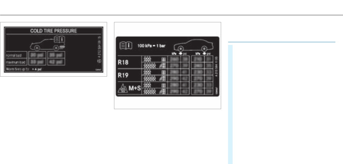
The tire pressure table shows therecommended
tire pressure for all tires approvedforthis vehi‐
cle. The recommended tire pressures apply for
cold tires under various operating conditions, i.e.
loading and/or speed of thevehicle.
If one or more tire sizes precede a tire pressure,
the tire pressure information following is only
valid forthose tire sizes.
The load conditions "partially laden" and "fully
laden" are defined in thetable for different num‐
bers of passengers and amounts of luggage. The
actual number of seats may differ from this.
Some tire pressure tables only show therim
diameter instead of the complete tire size, e.g.
R18. The rim diameter is part of the tire size and
can be found on the tire side wall (→page 381).
Be sure to also observethefollowing further
related subjects:
RNotes on tire pressure (→page 368)
RTire and Loading Information placard
(→page 373)
RMaximum tire pressure (→page 381)
Checking tire pressures manually
#Read the tire pressure forthe current operat‐
ing conditions from theTire and Loading
Information placard or the tire pressure
table. Observe the notes on tire pressure.
#Remove thevalve cap of the tire to be
checked.
#Press the tire pressure gauge securely onto
thevalve.
#Read the tire pressure.
#If the tire pressure is lowerthan therecom‐
mended value, increase the tire pressure to
therecommended value.
#If the tire pressure is higher than therecom‐
mended value, release air. To do so, press
down the metal pin in thevalve, e.g. using
the tip of a pen forexample. Then check the
tire pressure again using the tire pressure
gauge.
#Screwthevalve cap onto thevalve.
370Wheels and tires

Further related subjects:
RNotes on tire pressure (→page 368)
RTire pressure table (→page 369)
RTire and Loading Information placard
(→page 373)
Tire pressure monitoring system
Function of the tire pressure monitoring sys‐
tem
&DANGER Risk of accident due to incor‐
rect tire pressure
Every tire, including the spare (if provided),
should be checked when cold at least once a
month and inflated to the pressure recom‐
mended by thevehicle manufacturer (see
Tire and Loading Information placard on the
B-pillar on the driver’s side or the tire pres‐
sure label on the inside of the fuel filler flap
of your vehicle). If your vehicle has tires of a
different size than the size indicated on the
Tire and Loading Information placard or the
tire pressure table, you need to determine
the proper tire pressure forthose tires.
As an added safetyfeature, your vehicle has
been equipped with a tire pressure monitor‐
ing system (TPMS) that illuminates a low tire
pressure indicator lamp when one or more of
your tires are significantly underinflated.
Accordingly, if the low tire pressure indicator
lamp lights up, you should stop and check
your tires as soon as possible, and inflate
them to the proper pressure. Driving on a
significantly underinflated tire causes the tire
to overheat and can lead to tire failure.
Underinflation also increases fuel consump‐
tion and reduces tire tread life, and may
affect thevehicle's handling and braking abil‐
ity. Please note that the TPMS is not a substi‐
tute for proper tire maintenance, and it is the
driver's responsibility to maintain correct tire
pressure, even if underinflation has not
reached the levelto trigger illumination of
the TPMS low tire pressure indicator lamp.
Your vehicle has also been equipped with a
TPMS malfunction indicator to indicate when
the system is not operating properly. The
TPMS malfunction indicator is combined with
the low tire pressure indicator lamp. When
the system detects a malfunction, the indica‐
tor lamp will flash for approximately a minute
and then remain continuously illuminated.
This sequence will continue upon subsequent
vehicle start-ups as long as the malfunction
exists.
When the malfunction indicator is illumina‐
ted, the system may not be able to detect or
signal low tire pressure as intended. TPMS
malfunctions may occur for a varietyof rea‐
sons, including the installation of incompati‐
ble replacement or alternate tires or wheels
on thevehicle that prevent the TPMS from
functioning properly.
Alwayscheck the TPMS malfunction warning
lamp afterreplacing one or more tires or
wheels on your vehicle to ensure that the
replacement or alternate tires and wheels
allow the TPMS to continue to function prop‐
erly.
Wheels and tires 371

The system checks the tire pressure and the tire
temperature of the tires fitted to thevehicle by
means of a tire pressure sensor.
New tire pressure sensors, e.g. in winter tires,
are automatically taught-in thefirst time they are
driven.
The tire pressure and the tire temperature
appear in the multifunction display
(→page 219).
If there is a substantial pressure loss or if the
tire temperature is excessive, a warning will be
given:
RVia display messages (→page 438).
RViathehwarning lamp in the instrument
cluster (→page 469).
It is the driver's responsibility to set the tire
pressure to therecommended cold tire pressure
suitable forthe operating situation. Set the tire
pressure for cold tires using a tire pressure
gauge. Note that the correct tire pressure forthe
current operating situation must first be taught-
in to the tire pressure monitoring system.
In most cases, the tire pressure monitoring sys‐
tem will automatically update the new reference
values afteryou have changed the tire pressure.
You can, however, also update thereference val‐
ues by restarting the tire pressure monitoring
system manually (→page 373).
System limitations
The system may be impaired or may not function
in thefollowing situations:
RIf the tire pressure is set incorrectly.
RIf there is a sudden pressure loss caused, for
example, by aforeign object penetrating the
tire.
RIf there is a malfunction caused by another
radio signal source.
Make sure to observe thefollowing further rela‐
ted subject:
RNotes on tire pressure (→page 368)
Checking the tire pressure with the tire pres‐
sure monitoring system
Requirement:
RThe ignition is switched on.
On-board computer:
, .
One of thefollowing displays appears:
RCurrent tire pressure and tire temperature of
the individual wheels:
R
R :theteach-in
process of the system is not yet complete.
The tire pressures are already being moni‐
tored.
#Compare the tire pressure with therecom‐
mended tire pressure forthe current operat‐
372Wheels and tires

ing status (→page 369). Observethe notes
on tire temperature (→page 368).
%The values displayed in the multifunction dis‐
play may deviate from those of the tire pres‐
sure gauge as they referto sea level. At high
altitudes, the tire pressure values indicated
by pressure gauges are higher than those
shown by the on-board computer. In this
case, do not reduce the tire pressure.
Make sure to observe thefollowing further rela‐
ted subject:
RNotes on tire pressure (→page 368)
Restarting the tire pressure monitoring sys‐
tem
Requirement:
RThe recommended tire pressure is correctly
set fortherespective operating condition on
each of thefour wheels (→page 368).
Restart the tire pressure monitoring system in
thefollowing situations:
RThe tire pressure has changed.
RThe wheels or tires have been changed or
newly installed.
On-board computer:
, .
#Swipe downwards on theTouch Control on
the left-hand side of thesteering wheel.
The
message is shown in the multi‐
function display.
#Press ato confirm therestart.
The message is
shown in the multifunction display.
Current warning messages are deleted and
thehyellow warning lamp goes out.
Afteryou have driven for a few minutes, the
system checks whether the current tire pres‐
sures are within the specified range. The cur‐
rent tire pressures are then accepted as ref‐
erence values and monitored.
Make sure to observe thefollowing further rela‐
ted subject:
RNotes on tire pressure (→page 368)
Radio-equipment approval of the tire pres‐
sure monitoring system
Radio equipment approval numbers
CountryRadio equipment approval
number
Canada
USA
FCC ID: MRXAG5SP4
FCC ID: MRXMFR
IC: 2546A-AG5SP4
Further information on the declaration of con‐
formity for wireless vehicle components
(→page 23).
Loading thevehicle
Tire and Loading Information placard
&WARNING Risk of accident from overloa‐
ded tires
Overloaded tires may overheat and burst as a
consequence. Overloaded tires can also
impair thesteering and handling characteris‐
tics and lead to brake failure.
Wheels and tires 373
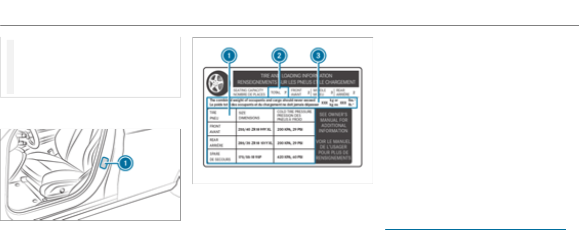
#Observe the load rating of the tires.
#The load rating must be at least half the
permissible axle load of thevehicle.
#Neveroverload the tires by exceeding
the maximum load.
The Tire and Loading Information placard is on
the B-pillar on the driver's side of thevehicle.
1Tire and Loading Information placard
%The data shown in the image is example
data.
The Tire and Loading Information placard shows:
RMaximum number of seats 2according to
the maximum number of people permitted to
travel in thevehicle.
RMaximum permissible load 3comprises the
grossweight of all vehicle occupants, load
and luggage.
RRecommended tire pressures 1for cold
tires. The recommended tire pressures are
valid forthe maximum permissible load and
up to the maximum permissible vehicle
speed.
Please also note:
RInformation on permissible weights and loads
on thevehicle identification plate
(→page 398).
RInformation on tire pressure on the tire pres‐
sure table (→page 369).
Further related subjects:
RDetermining the maximum permissible load
(→page 374)
RNotes on tire pressure (→page 368)
Determining the maximum permissible load
The following steps have been developed as
required of all manufacturers under Title 49,
Code of U.S. Federal Regulations, Part 575, pur‐
suant to the "National Traffic and MotorVehicle
SafetyAct of 1966".
374Wheels and tires

#Step 1: locate thestatement "The combined
weight of occupants and cargo should never
exceed XXX kg or XXX lbs." ("The combined
weight of occupants and cargo should never
exceed XXX kg or XXX lbs.") on your vehicle's
Tire and Loading Information placard.
#Step 2: determine the combined weight of
the driver and passengers that will be travel‐
ing in your vehicle.
#Step 3: subtract the combined weight of the
driver and passengers from XXX kg or
XXX lbs.
#Step 4: theresulting figure equals the per‐
missible cargo and luggage load capacity. For
example: If "XXX" equals 1400 lbs and there
are five occupants in your vehicle with a
weight of 150 lbs each, the maximum cargo
and luggage load capacity is 650 lbs (1400 -
750 (5 x 150) = 650 lbs).
#Step 5: determine the combined weight of
luggage and cargo that thevehicle will be
carrying. For safetyreasons, this weight may
not safely exceed theavailable cargo and lug‐
gage load capacity calculated in step 4.
Even if you have calculated thetotal load care‐
fully, you should still make sure that the maxi‐
mum permissible gross mass and the maximum
permissible axle load of your vehicle are not
exceeded. Details can be found on thevehicle
identification plate.
#Have your loaded vehicle – including driver,
occupants and load – weighed on a vehicle
weighbridge.
The measured values may not exceed the
maximum permissible values stated on the
vehicle identification plate.
Further related subjects:
RCalculation example for determining the max‐
imum load (→page 375)
RTire and Loading Information placard
(→page 373)
RTire pressure table (→page 369)
RVehicle identification plate
Calculation example for determining the
maximum load
The following table shows examples of how to
calculate total and load capacities with varying
seating configurations and different numbers
and sizes of occupants. The following examples
use a maximum load of 1500 lbs (680 kg). This
is for illustration purposes only.Make sure
you are using the actual load limit foryour vehi‐
cle stated on your vehicle's Tire and Loading
Information placard (→page 373).
The higher theweight of all the occupants, the
smaller the maximum load for luggage.
Wheels and tires 375

Step 1
Example 1Example 2
Combined maximum weight of occupants and
load (data from theTire and Loading Information
placard)
1500 lbs (680 kg)1500 lbs (680 kg)
Step 2
Example 1Example 2
Number of people in thevehicle (driver and
occupants)
51
Distribution of the occupantsFront: 2
Rear: 3
Front: 1
Weight of occupantsOccupant 1: 150 lbs (68 kg)
Occupant 2: 180 lbs (82 kg)
Occupant 3: 160 lbs (73 kg)
Occupant 4: 140 lbs (63 kg)
Occupant 5: 120 lbs (54 kg)
Occupant 1: 200 lbs (91 kg)
Totalweight of all occupants750 lbs (340 kg)200 lbs (91 kg)
376Wheels and tires

Step 3
Example 1Example 2
Permissible load (maximum grossvehicle weight
rating from theTire and Loading Information
placard minus the gross weight of all occupants)
1500 lbs (680 kg)Ò750 lbs (340 kg) = 750 lbs
(340 kg)
1500 lbs (680 kg)Ò200 lbs (91 kg) = 1300 lbs
(589 kg)
Wheels and tires 377
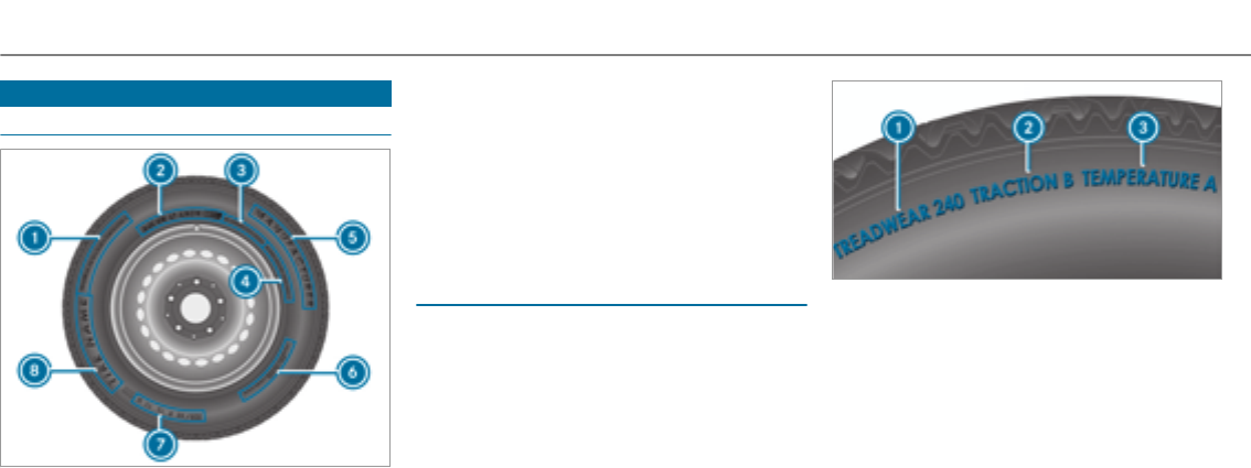
Tire labeling
Overview of tire labeling
1Uniform Tire Quality Grading Standard
(→page 378)
2DOT, Tire Identification Number
(→page 379)
3Maximum tire load (→page 380)
4Maximum tire pressure (→page 381)
5Manufacturer
6Characteristics of the tire (→page 381)
7Tire size designation, load-bearing capacity,
speed rating and load index (→page 381)
8Tire name
%The data shown in the image is example
data.
Tire Quality Grading
In accordance with the US Department of Trans‐
portation's "Uniform Tire Quality Grading Stand‐
ards", tire manufacturers are required to grade
their tires on the basis of thefollowing three per‐
formance factors:
1Tread wear grade
2Traction grade
3Temperature grade
%The data shown in the image is example
data.
%The classification is not legally stipulated for
Canada, but it is generally stated.
Tread wear grade
The tread wear grade is a comparative rating
based on thewear rate of the tire when tested
under controlled conditions on a specified test
track of the US Department of Transportation.
Forexample, a tire graded 150would wear one
378Wheels and tires
and one-half times as well on the government
test track as a tire graded 100.
The relative performance of tires depends upon
the actual conditions of their use, however, and
may depart significantly from the norm due to
variations in driving habits, service practices and
differences in road characteristics and climate
conditions.
Traction grade
&DANGER Risk of accident due to inade‐
quate traction
The traction grade assigned to this tire is
based on straight-ahead braking traction
tests, and does not include either accelera‐
tion, cornering, hydroplaning or peak traction
characteristics.
#Always adapt your drivingstyle and
drive at a speed to suit the prevailing
traffic and weather conditions.
*NOTE Damage to the drivetrain from
wheelspin
#Avoid wheelspin.
The traction grades – from highest to lowest –
are AA, A, B and C. Those grades represent the
tire's ability to stop on wet pavement as meas‐
ured under controlled conditions on specified
government test surfaces made of asphalt and
concrete.
Temperature grade
&WARNING Risk of accident from tire
overheating and tire failure
The temperature grade forthis tire is estab‐
lished for a tire that is properly inflated and
not overloaded. Excessive speed, underinfla‐
tion, or excessive loading, either separately
or in combination, can cause excessive heat
build-up and possible tire failure.
#Observe therecommended tire pres‐
sures and regularly check the tire pres‐
sure of all tires including the spare
wheel.
#Adjust the tire pressure as necessary.
The temperature grades are A (the highest), B
and C. They represent the tire's resistance to the
generation of heat and its ability to dissipate
heat when tested under controlled conditions on
a specified indoor laboratory test wheel. Sus‐
tained high temperature can cause the material
of the tire to degenerate and reduce tire life, and
excessive temperature can lead to sudden tire
failure. Grade C corresponds to a level of per‐
formance which all passenger car tires must
meet under therequirements of the US Depart‐
ment of Transportation.
DOT, Tire Identification Number (TIN)
US tire regulations stipulate that every tire man‐
ufacturer or retreader must imprint a TIN in or
on the side wall of each tire produced.
Wheels and tires 379
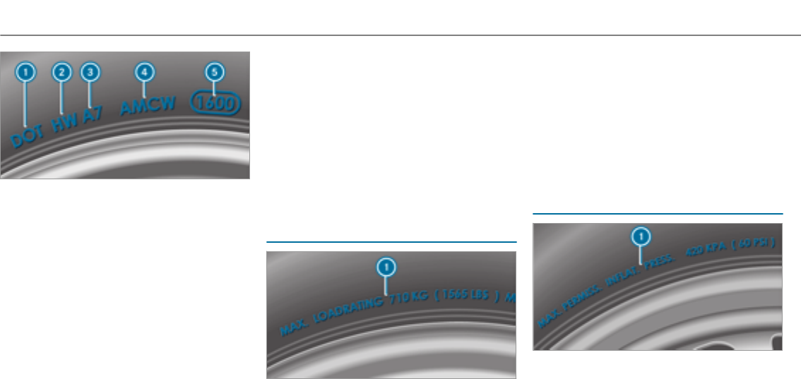
%The data shown in the image is example
data.
The TIN is a unique identification number to
identify tires and comprises thefollowing:
RDOT (Department of Transportation): tire
symbol marks 1indicating that the tire
complies with therequirements of the US
Department of Transportation.
RManufacturer identification code: manu‐
facturer identification code 2contains
details of the tire manufacturer. New tires
have a code with two symbols. Retreaded
tires have a code with four symbols. Further
information on retreaded tires (→page 386).
RTire size: identifier 3describes the tire
size.
RTire type code: tire type code 4can be
used by the manufacturer as a code to
describe specific characteristics of the tire.
RManufacturing date: manufacturing date
5provides information about the age of a
tire. The 1st and 2nd positions represent the
calendar week and the 3rd and 4th positions
state theyear of manufacture (e.g. "3208"
represents the 32nd week of 2008).
Information on the maximum tire load
%The data shown in the image is example
data.
Maximum tire load 1is the maximum permissi‐
ble weight for which the tire is approved.
Do not overload the tires by exceeding the speci‐
fied load limit. The maximum permissible load
can be found on thevehicle's Tire and Loading
Information placard on the B-pillar on the driv‐
er's side (→page 373).
Specifications for maximum tire pressure
%The data shown in the image is example
data.
380 Wheels and tires
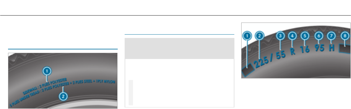
Neverexceed maximum tire pressure 1speci‐
fied forthe tire.
Information on tire characteristics
%The data shown in the image is example
data.
This information describes the type of tire cord
and the number of layers in side wall 1and
under tire tread 2.
Tire size designation, load-bearing capacity,
speed rating and load index
&WARNING Risk of injury through exceed‐
ing the specified tire load rating or the
permissible speed rating
Exceeding the specified tire load rating or
the permissible speed rating may lead to tire
damage and to the tires bursting.
#Therefore, only use tire types and sizes
approvedforyour vehicle model.
#Observe the tire load rating and speed
rating required foryour vehicle.
1Preceding letter
2Nominal tire width in millimeters
3Aspect ratio in %
4Tire code
5Rim diameter
6Load-bearing index
7Speed rating
8Load index
%The data shown in the image is example
data.
Information about reading tire data can be
obtained from any qualified specialist workshop.
Wheels and tires 381

Preceding letter 1:
RWithout: passenger vehicle tires according to
European manufacturing standards.
R"P": passenger vehicle tires according to US
manufacturing standards.
R"LT": light truck tires according to US manu‐
facturing standards.
R"T": compact emergency spare wheels with
high tire pressure that are only designedfor
temporary use in an emergency.
Aspect ratio 3:
Ratio between tire height and tire width in per‐
cent (tire height divided by tire width).
Tire code 4(tire type):
R"R" radial tire
R"D": bias ply tire
R"B": bias belted tires
R"ZR": radial tire with a maximum speed above
149mph (240 km/h) (optional)
Rim diameter5:
The diameter of the bead seat (not the diameter
of therimflange). The rim diameter is specified
in inches (in).
Load-bearing index 6:
Numerical code that specifies the maximum
load-bearing capacity of a tire (e.g. "91" corre‐
sponds to 1356 lbs (615 kg)).
The load-bearing capacity of the tire must be at
least half the permissible axle load of your vehi‐
cle. Do not overload the tires by exceeding the
specified load limit.
See also:
RMaximum permissible load on theTire and
Loading Information placard (→page 373)
RMaximum tire load (→page 380)
RLoad index
Speed rating 7:
Specifies the approved maximum speed of the
tire.
%An electronic speed limiter prevents your
vehicle from exceeding a speed of 130mph
(210 km/h).
Make sure that your tires have therequired
speed rating. You can obtain information on the
required speed rating from an authorized
Mercedes-Benz Center.
Summer tires
IndexSpeed rating
Qupto 100mph (160 km/h)
Rupto 106mph (170 km/h)
Supto 112mph(180 km/h)
Tupto 118mph (190 km/h)
Hupto 130mph(210 km/h)
Vupto 149mph(240 km/h)
Wupto 168mph (270 km/h)
Yupto 186mph(300 km/h)
382 Wheels and tires

IndexSpeed rating
ZR...Y1up to 186mph(300 km/h)
ZR...(..Y)1over186mph(300 km/h)
ZR1over149mph (240 km/h)
RSpecifying the speed rating as the "ZR" index
in tire code 4is optional for tires up to
186mph(300 km/h).
RIf your tire code 4includes "ZR" and there
is no speed rating 7,find out what the max‐
imum speed is from the tire manufacturer.
RIf load-bearing index 6and speed rating 7
are in brackets, the maximum speed rating of
your tire is above 186mph (300 km/h). To
find out the maximum speed, ask the tire
manufacturer.
All-weather tires and winter tires
IndexSpeed rating
Q M+S2up to 100mph (160 km/h)
T M+S2up to 118mph(190 km/h)
H M+S2up to 130mph (210 km/h)
V M+S2up to 149mph (240 km/h)
Winter tires bear theisnowflake symbol
and fulfill therequirements of theRubber Manu‐
facturers Association (RMA) and theRubber
Association of Canada (RAC) regarding the tire
traction on snow.
Load index 8:
RNo specification given: standard load (SL)
tire
R"XL" or "Extra Load": extra load tire or rein‐
forced tire
R"Light Load": light load tire
R"C", "D", "E": a load range that depends on
the maximum load that the tire can carry at a
certain pressure
Definition of termsfor tires and loading
Tire structure and characteristics: describes
the number of layers or the number of rubber-
coated belts in the tire contact surface and the
tire wall. These are made of steel, nylon, poly‐
ester and other materials.
Bar: metric unit for tire pressure.
14.5038 pounds per square inch (psi) and
100 kilopascal (kPa) is the equivalent of one bar.
DOT (Department of Transportation): DOT-
marked tires fulfill therequirements of the
US Department of Transportation.
Average weight of thevehicle occupants: the
number of vehicle occupants for which thevehi‐
cle is designed, multiplied by 150 lb (68 kg).
1"ZR" stated in the tire code.
2Or "M+S i"for winter tires
Wheels and tires 383

Uniform Tire Quality Grading Standards: a
uniform standard to grade thequality of tires
with regard to tread quality, tire traction and
temperature characteristics. The quality grading
assessment is made by the manufacturer follow‐
ing specifications from theU.S. government. The
quality grade of a tire is imprinted on the side
wall of the tire.
Recommended tire pressure:therecommen‐
ded tire pressure is the tire pressure specified
forthe tires mounted to thevehicle at thefac‐
tory.
The tire and information table contains therec‐
ommended tire pressures for cold tires, the max‐
imum permissible load and the maximum per‐
missible vehicle speed.
The tire pressure table contains therecommen‐
ded tire pressures for cold tires under various
operating conditions, i.e. loading and/or speed
of thevehicle.
Increased vehicle weight due to optional
equipment: the combined weight of all standard
and optional equipment available forthevehicle,
regardless of whether it is actually installed on
thevehicle or not.
Rim: the part of the wheel on which the tire is
installed.
GAWR (Gross Axle Weight Rating): the GAWR
is the maximum permissible axle load. The
actual load on an axle must neverexceed the
gross axle weight rating. The gross axle weight
rating can be found on thevehicle identification
plate on the B‑pillar on the driver's side.
Speed rating: the speed rating is part of the tire
identification. It specifies the speed range for
which a tire is approved.
GVW (Gross Vehicle Weight): the gross vehicle
weight comprises theweight of thevehicle
including fuel, tools, the spare wheel, accesso‐
ries installed, occupants, luggage and the trailer
drawbar noseweight, if applicable. The gross
vehicle weight must not exceed the gross vehicle
weight rating GVWR as specified on thevehicle
identification plate on the B‑pillar on the driver's
side.
GVWR (Gross Vehicle Weight Rating): the
GVWR is the maximum permitted gross weight
of the fully laden vehicle (weight of thevehicle
including all accessories, occupants, fuel, lug‐
gage and the trailer drawbar noseweight if appli‐
cable). The grossvehicle weight rating is speci‐
fied on thevehicle identification plate on the
B‑pillar on the driver's side.
Maximum weight of the laden vehicle: the
maximum weight is the sum of the curb weight
of thevehicle, theweight of the accessories, the
maximum load and theweight of optional equip‐
ment installed at thefactory.
Kilopascal (kPa): metric unit for tire pressure.
6.9 kPa corresponds to 1 psi. Another unit for
tire pressure is bar. 100 kilopascal (kPa) equals
1 bar.
Load index: in addition to the load-bearing
index, the load index may also be imprinted on
the side wall of the tire. This specifies the load-
bearing capacity of the tire more precisely.
Curb weight: theweight of a vehicle with stand‐
ard equipment including the maximum capacity
of fuel, oil and coolant. It also includes the air
conditioning system and optional equipment if
384 Wheels and tires

these are installed on thevehicle, but does not
include passengers or luggage.
Maximum tire load: the maximum tire load is
the maximum permissible weight in kilograms or
lbs for which a tire is approved.
Maximum permissible tire pressure: maxi‐
mum permissible tire pressure for one tire.
Maximum load on one tire: maximum load on
one tire. This is calculated by dividing the maxi‐
mum axle load of one axle by two.
PSI (pounds per square inch): standard unit of
measurement for tire pressure.
Aspect ratio: ratio between tire height and tire
width in percent.
Tire pressure: pressure inside the tire applying
an outward forceto every square inch of the tire.
The tire pressure is specified in pounds per
square inch (psi), in kilopascals (kPa) or in bar.
The tire pressure should only be corrected when
the tires are cold.
Cold tire pressure: the tires are cold when the
vehicle has been parkedfor at least 3 hours
without direct sunlight on the tires or thevehicle
has been driven for less than 1 mile (1.6 km).
Tire contact surface: the part of the tire that
comes into contact with theroad.
Tire bead: the purpose of the tire bead is to
ensure that the tire sits securely on the wheel
rim. There are several wire cores in the tire bead
to prevent the tire from changing length on the
wheel rim.
Side wall: the part of the tire between the tread
and the tire bead.
Weight of optional equipment: the combined
weight of the optional equipment weighing more
than thereplaced standard parts and more than
5 lbs (2.3 kg). This optional equipment, such as
high-performance brakes, level control system, a
roof luggage rack or high-performance batteries,
is not included in the curb weight and theweight
of the accessories.
TIN (Tire Identification Number): a unique
identification number which can be used by a
tire manufacturerto identify tires, forexample,
in a product recall, and thus identify the pur‐
chasers. The TIN is made up of the manufactur‐
er's identity code, tire size, tire type code and
the manufacturing date.
Load-bearing index: the load-bearing index is a
code that contains the maximum load-bearing
capacity of a tire.
Traction: traction is the grip resulting from fric‐
tion between the tires and theroad surface.
Wear indicator: narrow bars (tread wear bars)
that are distributed overthe tire contact surface.
If the tire tread is level with the bars, thewear
limit of 1/16 in (1.6 mm) has been reached.
Distribution of vehicle occupants: distribution
of vehicle occupants over designated seat posi‐
tions in a vehicle.
Maximum permissible payload weight: nomi‐
nal load and luggage load plus 150 lb (68 kg)
multiplied by the number of seats in thevehicle.
Wheels and tires 385

Changing a wheel
Notes on selecting, installing and replacing
tires
Mercedes-AMG vehicles: observethe notes in
the Supplement. Otherwise, you may not recog‐
nize dangers.
You can ask for information regarding permitted
wheel/tire combinations at an authorized
Mercedes-Benz Center.
&WARNING Risk of accident due to incor‐
rect dimensions of wheels and tires
If wheels and tires of the wrong size are
installed, the wheel brakes or wheel suspen‐
sion components may be damaged.
#Alwaysreplace wheels and tires with
those that fulfill the specifications of
the original part.
When replacing wheels, make sure to fitthe
correct:
RDesignation
RModel
When replacing tires, make sure to install the
correct:
RDesignation
RManufacturer
RModel
&WARNING Risk of injury through exceed‐
ing the specified tire load rating or the
permissible speed rating
Exceeding the specified tire load rating or
the permissible speed rating may lead to tire
damage and to the tires bursting.
#Therefore, only use tire types and sizes
approvedforyour vehicle model.
#Observe the tire load rating and speed
rating required foryour vehicle.
*NOTE Damage to vehicle and tires due to
non-approved tire types and sizes
For safetyreasons, only use wheels, tires
and accessories which have been approved
foryour vehicle by Mercedes-Benz.
These tires have been specially adaptedfor
use with the control systems, e.g. ABS or
ESP®, and are marked as follows:
RMO = Mercedes-Benz Original
RMOE = Mercedes-Benz Original Extended
(run-flat tires only for certain wheels)
RMO1 = Mercedes-Benz Original (only cer‐
tain AMG tires)
Certain characteristics, e.g. handling, vehicle
noise emissions or fuel consumption, may
otherwise be adversely affected. In addition,
when driving with a load, tire dimension var‐
iations could cause the tires to come into
contact with the body and axle components.
This could result in damage to the tires or the
vehicle.
386 Wheels and tires

Only use tires, wheels or accessories tested
and approvedby Mercedes-Benz.
*NOTE Risk to driving safetyfrom retrea‐
ded tires
Retreaded tires are neither tested nor recom‐
mended by Mercedes-Benz, since previous
damage cannot always be detected on
retreaded tires.
Forthis reason driving safetycannotbe guar‐
anteed.
#Do notuse used tires if you have no
information about their previous usage.
*NOTE Possible damage to wheels or tires
when driving over obstacles
Large wheels have a lower tire section width.
The lowerthe tire section width, the greater
is therisk of damage to wheels or tires when
driving over obstacles.
#Avoid obstacles or drive particularly
carefully.
*NOTE Damage to electronic component
parts from the use of tire-mounting tools
Vehicles with a tire pressure monitoring
system: Electronic component parts are
located in the wheel. Tire-mounting tools
should not be used in the area of thevalve.
This could otherwise damage the electronic
component parts.
#Have the tires changed at a qualified
specialist workshop only.
*NOTE Damage to summer tires at low
ambient temperatures
Using summer tires at very low ambient tem‐
peratures can cause cracks to form,thereby
damaging the tires permanently.
#At temperatures below 45 °F (7 °C) use
M+S tires.
Accessory partsthat are not approvedforyour
vehicle by Mercedes-Benz or are not being used
correctly can impair the operating safety.
Before purchasing and using non-approved
accessories, visit a qualified specialist workshop
and enquire about:
RSuitability
RLegal stipulations
RFactory recommendations
&WARNING Risk of accident with high
performance tires
The special tire tread in combination with the
optimized tire compound means that therisk
of skidding or hydroplaning on wetroads is
increased.
In addition, the tire grip is greatly reduced at
a low outside temperature and tire running
temperature.
#Switch on the ESP®and adapt your
drivingstyle accordingly.
#Use M+S tire at outside temperatures
of less than 10 °C (50 °F).
Wheels and tires 387

Observe thefollowing when selecting, installing
and replacing tires:
ROnly use tires and wheels of the same type
(summer tires, winter tires, MOExtended
tires) and the same make.
ROnly install wheels of the same size on one
axle (left and right).
It is only permissible to install a different
wheel size in theevent of a flat tire in order
to drive to the specialist workshop.
ROnly install tires of the correct size onto the
wheels.
RVehicles with a tire pressure monitoring
system: all mounted wheels must be equip‐
ped with functioning sensors forthe tire
pressure monitoring system.
RAt temperatures below 45 °F (7 °C), use win‐
ter tires or all-season tires marked M+S for
all wheels.
Winter tires bearing theisnowflake sym‐
bol in addition to the M+S marking provide
the best possible grip in wintry road condi‐
tions.
RFor M+S tires, only use tires with the same
tread.
RObserve the maximum permissible speed for
the M+S tires installed.
If this is below thevehicle's maximum speed,
this must be indicated in an appropriate label
in the driver's field of vision.
RRun in new tires at moderate speeds forthe
first 60 miles (100 km).
RReplace the tires after six years at the latest,
regardless of wear.
RWhen replacing with tires that do not fea‐
ture run-flat characteristics: vehicles with
MOExtended tires are not equipped with a
TIREFIT kit at thefactory. Equip thevehicle
with a TIREFIT kit afterreplacing with tires
that do not feature run-flat characteristics,
e.g. winter tires.
For more information on wheels and tires, con‐
tact a qualified specialist workshop.
Be sure to also observethefollowing further
related subjects:
RNotes on tire pressure (→page 368)
RTire and Loading Information placard
(→page 373)
RTire size designation, load-bearing capacity,
speed rating and load index (→page 381)
RTire pressure table (→page 369)
Notes on rotating wheels
&WARNING Risk of injury through differ‐
ent wheel sizes
Interchanging the front and rear wheels if the
wheels or tires have different dimensions
may severely impair the driving characteris‐
tics.
The wheel brakes or wheel suspension com‐
ponents may also be damaged.
#Rotate front and rear wheels only if the
wheels and tires are of the same dimen‐
sions.
388 Wheels and tires
The wear patterns on the front and rear wheels
differ:
RFront wheels wear more on the shoulder of
the tire
RRear wheels wear more in the center of the
tire
On vehicles that have the same size front and
rear wheels, rotatethe wheels according to the
intervals in the tire manufacturer's warranty
book in your vehicle documents. If this is not
available, rotate the tires every
3,000 to 6,000 miles (5,000 to 10,000 km),
depending on thewear. Ensure that the direction
of rotation is maintained.
It is imperative to observe the instructions and
safetynotes on "Wheel change" when doing so.
Notes on storing wheels
RAfterremoving wheels, store them in a cool,
dry and preferably dark place.
RProtect the tires from contact with oil, grease
or fuel.
Overview of the tire-change tool kit
Apart from some country-specific variants, vehi‐
cles are not equipped with a tire-change tool kit.
For more information on which tire-changing
tools are required and approved for performing a
wheel change on your vehicle, consult a qualified
specialist workshop.
Required tire-change tool kits may include, for
example:
RJack
RChock
RWheel wrench
RCentering pin
The tire-change tool kit is in tool bag 1under
the cargo compartment floor.
1Tool bag
Tool bag 1contains:
RJack
RGloves
RWheel wrench
RCentering pin
RFolding wheel chock
RRatchet for jack
Wheels and tires 389
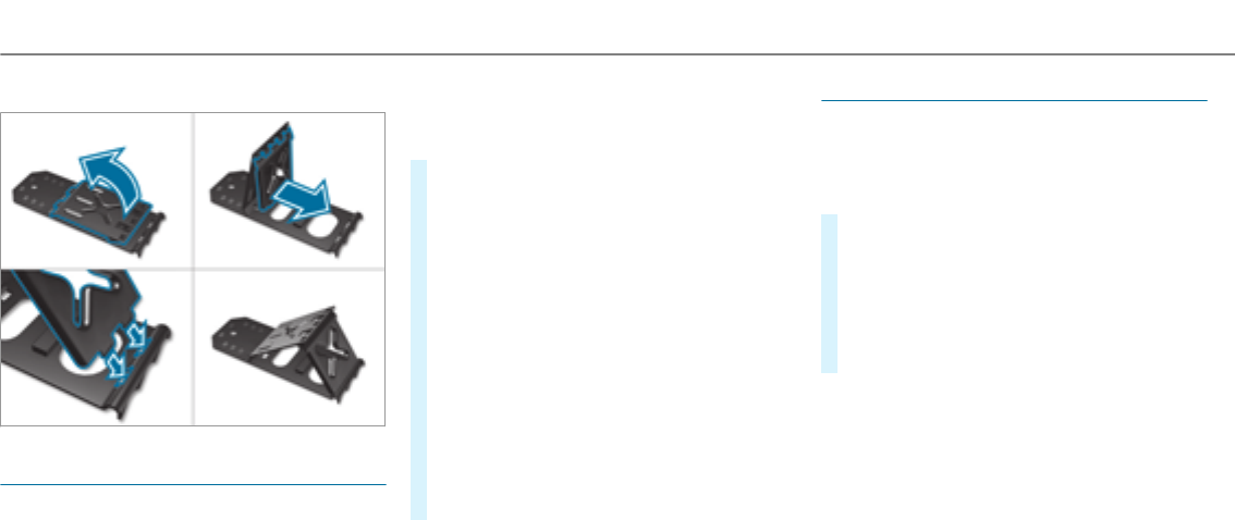
Setting up thefolding wheel chock
Preparing thevehicle for a wheel change
Requirements
RThe required tire-change tool kit is available.
If your vehicle is not equipped with the tire-
change tool kit, consult a qualified specialist
workshop to find out about suitable tools.
RThe vehicle is not on a slope.
RThe vehicle is on solid, non-slippery and level
ground.
#Apply the electric parking brake manually.
#Move the front wheels to thestraight-ahead
position.
#Vehicles with automatic transmission:
shift into position j.
#Vehicles with AIR BODY CONTROL: set the
normal vehicle level (→page 190).
#Switch off the engine.
#Make sure that the engine cannot be started.
#Place chocks or other suitable items under
the front and rear of the wheel that is diago‐
nally opposite the wheel youwish to change.
#Remove the hub caps if necessary
(→page 390).
#Raising thevehicle (→page 391).
Removing and installing hub caps
Requirement:
RThe vehicle is prepared for a wheel change
(→page 390).
Plastic hub cap
#To remove:turn the center cover of the hub
cap anti-clockwise and remove the hub cap.
#To install: make sure that the center cover of
the hub cap is turned anti-clockwise.
#Position the hub cap and turn the center
cover clockwise until the hub cap engages
physically and audibly.
390 Wheels and tires
Aluminum hub cap
#To remove:position socket2on hub cap
1.
%The socket can be found in the tire-change
tool kit.
#Position wheel spanner 3on socket2.
#Using wheel spanner 3, turn hub cap 1
counter-clockwise and remove it.
#To install: position hub cap 1and turn until
it is completely flush withthe wheel.
#Position socket2on hub cap 1.
#Attach wheel spanner 3to socket2and
tighten the hub cap clockwise.
Specified tightening torque: 18 lb-ft
(25 Nm).
#Raise thevehicle (→page 391).
Raising thevehicle when changing a wheel
Requirements:
RThere are no persons in thevehicle.
RThe vehicle has been prepared for a wheel
change (→page 390).
RThe hub caps have been removed
(→page 390).
Important notes on using the jack:
Ronly use thevehicle-specific jack that has
been tested and approvedby Mercedes-Benz
to raise thevehicle.
Rthe jack is only designed forraising and hold‐
ing thevehicle for a short time while a wheel
is being changed and not for maintenance
work under thevehicle.
Rthe jack must be placed on a firm,flat and
non-slip surface. If necessary, use a large,
load-bearing, non-slip underlay.
Rthefoot of the jack must be positioned verti‐
cally under the jack support point.
Rules of conduct when thevehicle is raised:
RNever place your hands or feet under the
vehicle.
RDo not lie under thevehicle.
RDo not start the engine and do not release
the electric parking brake.
RDo not open or close any doors or thetail‐
gate.
Wheels and tires 391
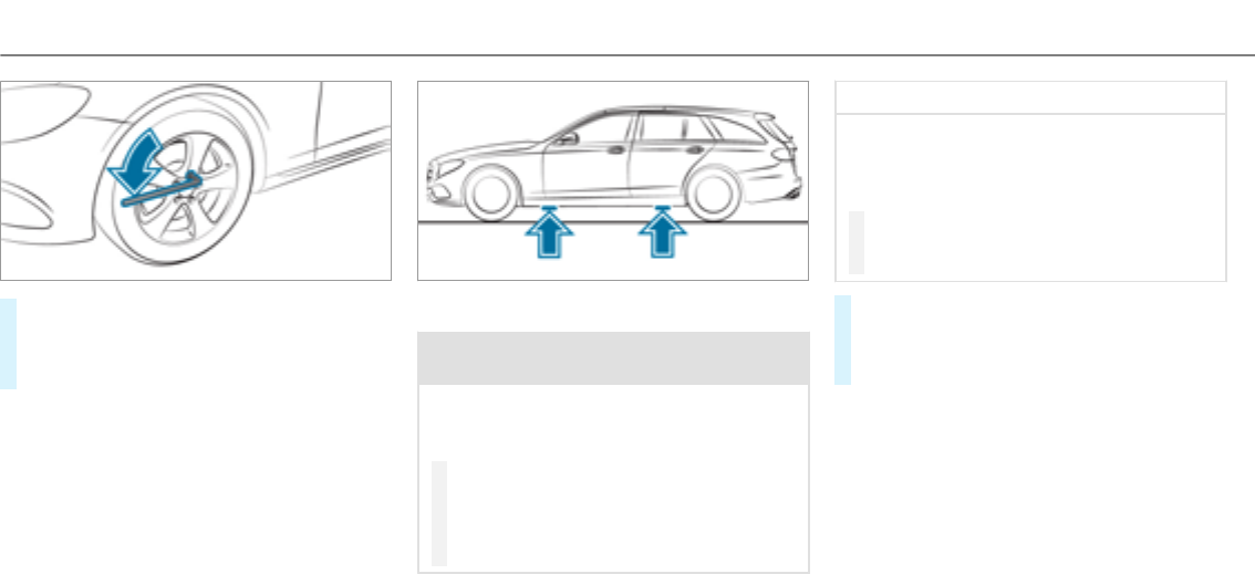
#Using the wheel wrench, loosen the wheel
bolts on the wheel youwish to change by
about one full turn. Do not unscrew the bolts
completely.
Position of jack support points
&WARNING Risk of injury from incorrect
positioning of the jack
If you do not position the jack correctly at
the appropriate jacking point of thevehicle,
the jack could tip with thevehicle raised.
#Only position the jack at the appropri‐
ate jacking point of thevehicle. The
base of the jack must be positioned ver‐
tically under the jacking point of the
vehicle.
*NOTE Vehicle damage from the jack
If youdo not position the jack correctly at
the appropriate jack support point of the
vehicle, the jack could tip over with thevehi‐
cle raised.
#The jack is designed exclusively for
jacking up thevehicle at the jack sup‐
port points.
#Take theratchet ring spanner out of the tire-
change tool kit and place it on the hexagon
nut of the jack so that the lettering "AUF" is
visible.
392 Wheels and tires
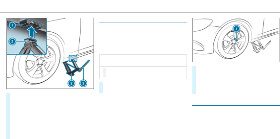
#Position jack 2at jack support point 1.
#Turn ratchet ring spanner 3clockwise until
jack 2sits completely on jack support point
1and the base of the jack lies evenly on
the ground.
#Continue to turn ratchet ring spanner 3
until the tire is raised a maximum of 1.2 in
(3 cm) off the ground.
#Loosen and remove the wheel (→page 393).
Removing a wheel
Requirement:
RThe vehicle is raised (→page 391).
When changing a wheel, avoid applying any force
to the brake discs, since this could impair the
level of comfort when braking.
*NOTE Damage to threading from dirt on
wheel bolts
#Do not place wheel bolts in sand or on
a dirty surface.
#Unscrew the uppermost wheel bolt com‐
pletely.
#Screw centering pin 1instead of the wheel
bolt into thethreading.
#Unscrew theremaining wheel bolts fully.
#Remove the wheel.
#Install the new wheel (→page 393).
Installing a new wheel
Requirement:
RThe wheel is removed (→page 393).
Wheels and tires 393

&WARNING Risk of accident from losing a
wheel
Oiled, greased or damaged wheel bolt/wheel
nut threads or wheel hub/wheel mounting
bolt threads can cause the wheel bolts/
wheel nuts to come loose.
As a result, you could lose a wheel while driv‐
ing.
#Never oil or grease thethreads.
#In theevent of damage to thethreads,
contact a qualified specialist workshop
immediately.
#Have the damaged wheel bolts or dam‐
aged hub threads replaced.
#Do not continue driving.
#Observe the information on thechoice of
tires (→page 386).
For tires with a specified direction of rotation, an
arrow on the side wall of the tire indicates the
correct direction of rotation. Observethe direc‐
tion of rotation when installing.
#Slide the wheel to be mounted onto the cen‐
tering pin and push it on.
&WARNING Risk of injury from tightening
wheel bolts and nuts
If you tighten the wheel bolts or wheel nuts
when thevehicle is raised, the jack could tip.
#Only tighten wheel bolts or wheel nuts
when thevehicle is on the ground.
#For safetyreasons, only use wheel bolts
which have been approvedby Mercedes-
Benz and forthe wheel in question.
*NOTE Damage to paintwork of the wheel
rim when screwing on thefirst wheel bolt
If the wheel has too much play when screw‐
ing in thefirst wheel bolt, the wheel rim paint
can be damaged.
#Press the wheel firmly against the
wheel hub when screwing on thefirst
wheel bolt.
#Tighten the wheel bolts until they are finger-
tight.
#Unscrew the centering pin.
#Tighten the last wheel bolt until it is finger-
tight.
#Lowerthevehicle (→page 394).
Lowering thevehicle after a wheel change
Requirements:
RThe new wheel has been installed
(→page 393).
#Place theratchet ring spanner onto the hexa‐
gon nut of the jack so that the lettering "AB"
is visible.
#To lower the vehicle: turn theratchet ring
spanner of the jack anti-clockwise.
394 Wheels and tires

#Tighten the wheel bolts evenly in a diagonal
pattern in the order indicated (1to 5).
Specified tightening torque: 111 lb-ft
(150 Nm).
&WARNING Risk of accident due to incor‐
rect tightening torque
Thewheels could come loose if the wheel
bolts or wheel nuts are not tightened to the
prescribed tightening torque.
#Have the tightening torque checked
immediately at a qualified specialist
workshop afterchanging a wheel.
#Check the tire pressure of the newly moun‐
ted wheel and adjust accordingly.
#Vehicles with a tire pressure monitoring
system: Restart the tire pressure monitoring
system (→page 373).
Make sure to observe thefollowing further rela‐
ted subject:
RNotes on tire pressure (→page 368)
Wheels and tires 395

Notes on technical data
Mercedes-AMG vehicles: be sure to observe
the notes in the Supplement. Otherwise, you
may not recognize dangers.
The data stated only applies to vehicles with
standard equipment. You can obtain further
information from an authorized Mercedes-Benz
Center.
Vehicle electronics
Two-way radios
Notes on installing two-way radios
&WARNING Risk of accident due to
improper work on two-way radios
The electromagnetic radiation from two-way
radios can interfere with the on-board elec‐
tronics if RF transmitters are manipulated or
retrofitted incorrectly.
This could jeopardize the operating safetyof
thevehicle.
#You should have all work on electrical
and electronic components carried out
at a qualified specialist workshop.
&WARNING Risk of accident from incor‐
rect operation of two-way radios
If you operate two-wayradios incorrectly in
thevehicle, the electromagnetic radiation
could interfere with the on-board electronics,
e.g.:
Rif the two-way radio is not connectedto
an exterior antenna
Rif theexterior antenna is not correctly
mounted or is not of low reflection
This could jeopardies the operating safetyof
thevehicle.
#Have the low-reflection exterior
antenna installed at a qualified special‐
ist workshop.
#When operating two-way radios in the
vehicle, always connect them to the
low-reflection exterior antenna.
*NOTE Invalidation of the operating per‐
mit due to failure to comply with the
instructions for installation and use
The operating permit may be invalidated if
the instructions for installation and use of
two-way radios are not observed.
#Only use approved frequency bands.
#Observe the maximum permissible out‐
put power in these frequency bands.
#Only use approved antenna positions.
396 Technical data
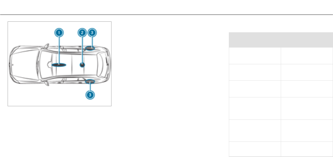
1Front roof area
2Rear roof area
3Rear wing
On vehicles with a panoramic sliding sunroof,
installing an antenna to the front or rear roof
area is not permitted.
On therear wings, it is recommended that you
install the antenna on the side of thevehicle
closest to the center of theroad.
Use Technical Specification ISO/TS 21609 (Road
Vehicles – "EMCs for installation of aftermarket
radio frequency transmitting equipment") when
installing two-way radios. Comply with the legal
requirements for detachable parts.
If your vehicle has installations for two-way radio
equipment, use the power supply or antenna
connectors intended for use with the basic wir‐
ing. Be sure to observe the manufacturer's Sup‐
plements when installing.
Two-way radio transmission output
The maximum transmission output (PEAK) at the
base of the antenna must not exceed thevalues
in thefollowing table:
frequency band and maximum transmission
output
Frequency band Maximum transmis‐
sion output
Short wave
3 - 54 MHz
100 W
4 m frequency band
74 - 88 MHz
30 W
2 m frequency band
144 - 174 MHz
50 W
Trunked radio sys‐
tem/Tetra
380 - 460 MHz
10 W
70 cm frequency
band
420 - 450 MHz
35 W
Two-way radio
(2G/3G/4G)
10 W
Technical data 397
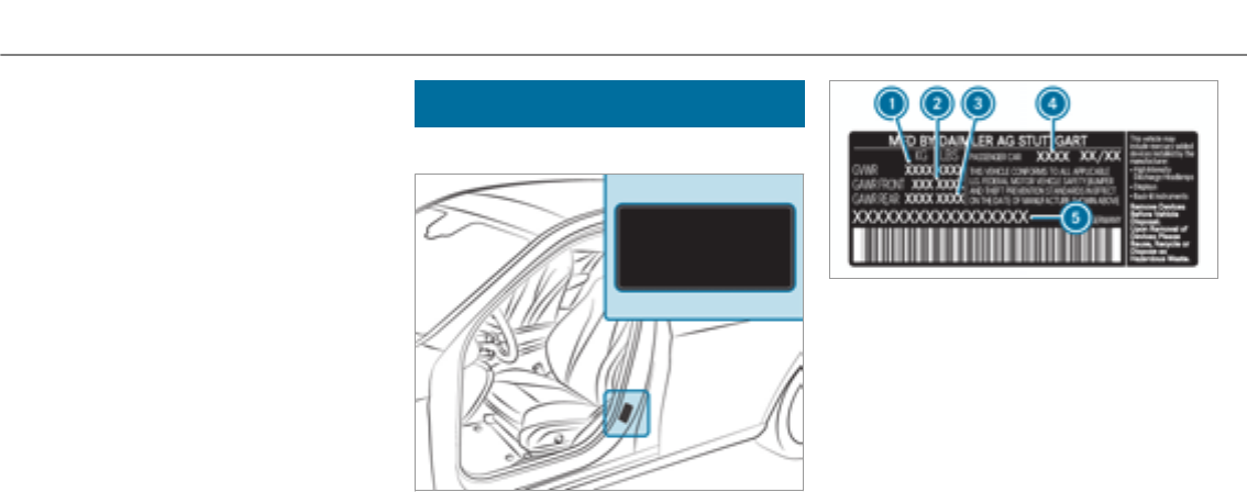
The following can be used in thevehicle without
restrictions:
Rtwo-way radios with a maximum transmission
output of up to 100 mW
Rtwo-way radios with transmitter frequencies
in the 380 - 410 MHz frequency band and a
maximum transmission output of up to 2 W
(trunked radio system/Tetra)
Rmobile phones (2G/3G/4G)
There are no restrictions when positioning the
antenna on the outside of thevehicle forthefol‐
lowing frequency bands:
RTrunked radio system/Tetra
R70 cm frequency band
R2G/3G/4G
Vehicle identification plate, VIN and engine
number
Vehicle identification plate
Vehicle identification plate (USA only)
1Permissible grossmass
2Permissible front axle load
3Permissible rear axle load
4Paint code
5VIN (vehicle identification number)
398 Technical data
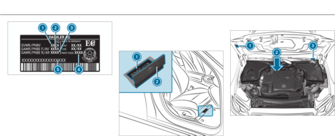
Vehicle identification plate (Canada only)
1Permissible grossmass
2Permissible front axle load
3Permissible rear axle load
4Paint code
5VIN (vehicle identification number)
The maximum permissible gross vehicle weight
is made up of thevehicle weight, all vehicle
occupants, the fuel and the load. The maximum
permissible axle load is the maximum weight
that can be carried on one axle (front or rear
axle).
Neverexceed the maximum gross vehicle weight
or the maximum permissible axle load forthe
front or rear axle.
VIN in front of theright-hand front seat
1VIN (vehicle identification number)
2Floor covering
Additional plates
1Plate with information about emissions test‐
ing, including confirmation of emissions
guidelines at theU.S. federal level as well as
for California
2Engine number (stamped into the crankcase)
3VIN (vehicle identification number)
Technical data 399
Operating fluids
Notes on operating fluids
Mercedes-AMG vehicles: be sure to observe
the notes in the Supplement. Otherwise, you
may not recognize dangers.
&WARNING Risk of injury from operating
fluids harmful to your health
Operating fluids may be poisonous and harm‐
ful to your health.
#Observe thetext on the original con‐
tainers when using, storing or disposing
of operating fluids.
#Alwaysstore operating fluids sealed in
their original containers.
#Alwayskeep children away from operat‐
ing fluids.
+ENVIRONMENTALNOTE Environmental
pollution caused by environmentally irre‐
sponsible disposal
#Dispose of operating fluids in an envi‐
ronmentally responsible manner.
Operating fluids include thefollowing:
RFuels
RLubricants
RCoolant
RBrake fluid
RWindshield washer fluid
RClimate control system refrigerant
Only use products approvedby Mercedes-Benz.
Damage caused by the use of products on the
vehicle that have not been approved is not cov‐
ered by the Mercedes-Benz warranty or goodwill
gestures.
You can identify operating fluids approvedby
Mercedes-Benz by thefollowing inscription on
the containers:
RMB-Freigabe (e.g. MB-Freigabe 229.51)
RMB-Approval (e.g. MB-Approval 229.51)
Further information on approved operating flu‐
ids:
Rin the Mercedes-Benz Specifications for
Operating Fluids at http://bevo.mercedes-
benz.com (byentering the designation)
Rin the Mercedes-Benz Specifications for
Operating Fluids in the Mercedes-Benz BeVo
app (by entering the designation)
Rat a qualified specialist workshop
&WARNING Risk of fire and explosion
caused by fuel
Fuels are highly inflammable.
#You must avoid fire, open flames, creat‐
ing sparks and smoking.
#Before refueling, switch off the engine
and, if installed in your vehicle, thesta‐
tionary heater.
400 Technical data

&WARNING Risk of injury from fuel
Fuels are poisonous and harmful to your
health
#Do not swallow fuel or letit come into
contact with skin, eyes or clothing.
#Do not inhale fuel vapors.
#Keep children away from fuel.
If you or other people come into contact with
fuel, observe thefollowing:
#Immediately rinse fuel off your skin with
soap and water.
#If fuel comes into contact with your
eyes, immediately rinse them thor‐
oughly with clean water. Seek medical
attention immediately.
#If you swallow fuel, seek medical atten‐
tion immediately. Do not induce vomit‐
ing.
#Change immediately out of clothing that
has come into contact with fuel.
Fuel
Information on fuel grades forvehicles with
agasoline engine
Observe the notes on operating fluids
(→page 400).
*NOTE Damage caused by the wrong fuel
Even small amounts of the wrong fuel could
result in damage to the fuel system, the
engine and the emission control system.
#Only refuel with low-sulfur premium
grade fuel.
This fuel may contain up to 10 %ethanol.
Your vehicle is suitable for use with E10 fuel.
Do not refuel using:
RDiesel
RE15, E85, E100
RGasoline containing methanol (M15, M30,
M85, M100)
RGasoline with additives containing metal
If you accidentally refuel with the wrong fuel:
#Do not switch the ignition on.
#Consult a qualified specialist workshop.
If theavailable fuel is not sufficiently low in sul‐
fur, this can produce unpleasant odors.
Only refuel with fuel that has at least the octane
number specified in the instruction label in the
fuel filler flap (→page 157).
If youwant maximum engine output: only
refuel with unleaded premium grade gasoline
with at least 91 AKI/95 RON.
As a temporary measure, if therecommended
fuel is not available, you may also refuel with
unleaded regular gasoline with at least 87 AKI/
91 RON. This mayreduce engine output and
increase fuel consumption.
Neverrefuel using gasoline with a lowerRON.
*NOTE Premature wear caused by unlea‐
ded regular gasoline
Unleaded regular gasoline can cause the
engine to wear more quickly and impair lon‐
gevity and performance.
Technical data 401
If unleaded premium grade gasoline is
unavailable and you have to refuel using
unleaded regular gasoline:
#Only fill the fuel tank to half full with
unleaded regular gasoline and refill as
soon as possible with unleaded pre‐
mium grade gasoline.
#Do not drive at the maximum speed.
#Avoid sudden acceleration and engine
speeds over 3,000 rpm.
Further information on fuel can be found:
Rat a gasstation
Rat a qualified specialist workshop
RUSA only: at http://www.mbusa.com
Information on additives in gasoline
Observe the notes on operating fluids
(→page 400).
*NOTE Damage caused by non-approved
additives
Even small amounts of the wrong additive
may lead to malfunctions occurring.
#Only add cleaning additives recommen‐
ded by Mercedes-Benz to the fuel.
Mercedes-Benz recommends that you use
brand-name fuels with additives.
The fuel grade available in some countries may
not be sufficient. Residue could build up in the
fuel injection system as a result. In this case, in
consultation with an authorized Mercedes-Benz
Center, the fuel may be mixed with the cleaning
additive recommended by Mercedes-Benz. Be
sure to observe the notes and mixing ratios
specified on the container.
Tank capacity and fuel reserve
Capacity
Model Total capacity
Allmodels 21.1 US gal(80.0 l)
Model Of which reserve
All models3.2 gal (12.0 l)
Engine oil
Notes on engine oil
Observe the notes on operating fluids
(→page 400).
402 Technical data

*NOTE Engine damage caused by an
incorrect oil filter, incorrect oil or addi‐
tives
#Do not use engine oils or oil filters other
than those which meet the specifica‐
tions necessary forthe prescribed
service intervals.
#Do not alter the engine oil or oil filter in
order to achieve longer change intervals
than prescribed.
#Do not use additives.
#Have the engine oil changed afterthe
prescribed intervals.
Mercedes-Benz recommends that you have the
oil change carried out at a qualified specialist
workshop.
Further information on engine oils and oil filters:
RIn the Mercedes-Benz Specifications for
Operating Fluids at http://bevo.mercedes-
benz.com (byentering the designation)
RAt aqualified specialist workshop
Quality and filling capacity of engine oil
MB-Freigabe or MB-Approval
Gasoline enginesMB-Freigabe or MB-
Approval
All models 229.5, 229.6
The following values referto an oil change,
including the oil filter.
Replacement amount
ModelReplacement
amount
All models6.9 US qt (6.5 l)
Notes on brake fluid
Observe the notes on operating fluids
(→page 400).
&WARNING Risk of an accident due to
vapor pockets forming in the brake sys‐
tem
The brake fluid constantly absorbs moisture
from the air. This lowers the boiling point of
the brake fluid. If the boiling point is too low,
vapor pockets may form in the brake system
when the brakes are applied hard.
This causes the braking effect to be
impaired.
#Have the brake fluid renewed at the
specified intervals.
Have the brake fluid regularly changed at a quali‐
fied specialist workshop.
Only use brake fluid approvedby Mercedes-Benz
according to MB-Freigabe or MB-Approval 331.0.
Further information on brake fluid:
Rin the Mercedes-Benz Specifications for
Operating Fluids at http://bevo.mercedes-
benz.com
Rat a qualified specialist workshop
Technical data 403

Coolant
Notes on coolant
Observe the notes on operating fluids
(→page 400).
&WARNING ‑ Risk of fire and injury from
antifreeze
If antifreeze comes into contact with hot
component parts in the engine compart‐
ment, it may ignite.
#Allow the engine to cool down before
adding antifreeze.
#Make sure that no antifreeze spills out
next to thefiller opening.
#Thoroughly clean off any antifreeze
from component parts before starting
thevehicle.
*NOTE Damage caused by incorrect cool‐
ant
#Only add coolant that has been pre‐
mixed with therequired antifreeze pro‐
tection.
Further information on coolant:
RIn the Mercedes-Benz Specifications for
Operating Fluids 310.1, e.g. online at
http://bevo.mercedes-benz.com.
RAt aqualified specialist workshop.
*NOTE Overheating at high outside tem‐
peratures
If an inappropriate coolant is used, the
engine cooling system is not sufficiently pro‐
tected against overheating and corrosion at
high outside temperatures.
#Always use coolant approvedby
Mercedes-Benz.
#Observe the instructions in the
Mercedes-Benz Specifications for Oper‐
ating Fluids 310.1.
Have the coolant regularly replaced at a qualified
specialist workshop.
The proportion of corrosion inhibitor/antifreeze
concentrate in the engine cooling system should
be:
Ra minimum of 50% (antifreeze protection
down to approximately -35 °F (-37 °C)).
Ra maximum of 55% (antifreeze protection
down to -49 °F (-45 °C)).
Coolant capacity
Capacity
ModelCapacity
All models 12.7 US qt (12.0 l)
Notes on windshield washer fluid
Observe the notes on operating fluids
(→page 400).
404Technical data

&WARNING ‑ Risk of fire and injury from
windshield washer concentrate
Windshield washer concentrate is highly
flammable. It could ignite if it comes into
contact with hot engine component parts or
theexhaust system.
#Make sure that no windshield washer
concentrate spills out next to thefiller
opening.
*NOTE Damage to theexterior lighting
due to unsuitable windshield washer fluid
Unsuitable windshield washer fluid may dam‐
age the plastic surface of theexterior light‐
ing.
#Only use windshield washer fluid which
is also suitable for use on plastic surfa‐
ces, e.g. MB SummerFit or MB Winter‐
Fit.
*NOTE Blocked spray nozzles caused by
mixing windshield washer fluids
#Do not mix MB SummerFit and MB Win‐
terFit with other windshield washer flu‐
ids.
Do not use distilled or de-ionized water as thefill
level sensor may be triggered erroneously.
Recommended windshield washer fluid:
RAbove freezing point: e.g. MB SummerFit
RBelow freezing point: e.g. MB WinterFit
Forthe correct mixing ratio referto the informa‐
tion on the antifreeze container.
Mix thewasher fluid with the windshield washer
fluid all year round.
Refrigerant
Notes on refrigerants
Observe the notes on operating fluids
(→page 400).
*NOTE Damage due to incorrect refriger‐
ant
If a non-approvedrefrigerant is used, the cli‐
mate control system may be damaged.
#Only use therefrigerant R‑134a
*NOTE Damage to the climate control
system due to incorrect refrigerant com‐
pressor oil
#Only use refrigerant compressor oil that
has been approvedby Mercedes-Benz.
#Do not mix the approvedrefrigerant
compressor oil with a different refriger‐
ant compressor oil.
Work on the climate control system may only be
carried out by aqualified specialist workshop. All
applicable regulations, as well as SAEstandard
J639, must be adhered to.
Technical data 405
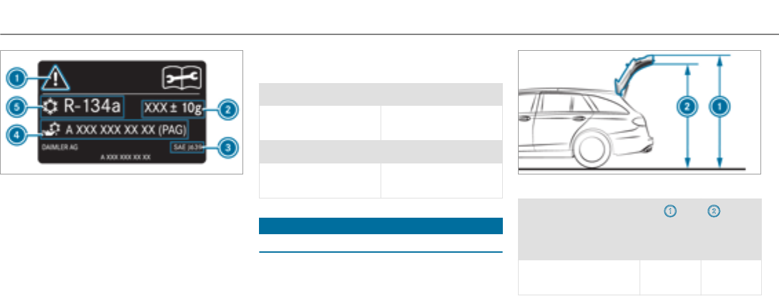
1Warning symbols
2Refrigerant filling capacity
3Applicable standards
4PAG oil part number
5Refrigerant type
Warning symbols 1advise you about:
Rpossible dangers
Rhaving service work carried out at a qualified
specialist workshop
Refrigerant filling capacity
Filling capacity forrefrigerant and PAG oil
Model Refrigerant
All models22.2 ± 0.4 oz
(630 ± 10 g)
Model PAG oil
All models2.8 ± 0.4 oz
(80 ± 10 g)
Vehicle data
Vehicle dimensions
The heights specified may vary as a result of the:
RTires
RLoad
RCondition of the suspension
ROptional equipment
Height when opened
Model 1
Height
when
opened
2Head‐
room
All models 81.2 in
(2062 mm)
76.2 in
(1936 mm)
406 Technical data

Vehicle dimensions
All models
Vehicle length194.2 in
(4933 mm)
Vehicle width including out‐
side mirrors
81.3 in
(2065 mm)
Vehicle height 57.8 in
(1467 mm)
Wheelbase 115.7 in
(2939 mm)
Turning circle 39.0 ft
(11.90 m)
Weights and loads
Please note that forthe specified vehicle data:
Ritems of optional equipment increase the
unladen weight and reduce the payload.
Roof load
All models
Maximum roof load 220 lb (100 kg)
Technical data 407

Displaymessages
Introduction
Notes on display messages
Display messages appear on the multifunction
display.
Display messages with graphic symbols are sim‐
plified in the Operator's Manual and may differ
from the symbols on the multifunction display.
The multifunction display shows high-priority dis‐
play messages in red. Certain display messages
are accompanied by awarning tone.
Please respond in accordance with the display
messages and follow the additional notes in this
Operator's Manual.
For some display messages, a symbol is also
shown:
R¤Further information
ROHide display message
You can select the desired symbol by swiping
left or right on the left-hand Touch Control.
Press the¤symbol to show further informa‐
tion on the multifunction display. Press theO
symbol to hide the display message.
You can hide low-priority display messages by
pressing the¤button or the left-hand Touch
Control. The display messages are then stored in
the message memory.
Rectify the cause of a display message as
quickly as possible.
High-priority display messages cannot be hid‐
den. The multifunction display shows these dis‐
play messages continuously until the cause of
the display message has been rectified.
Calling up stored display messages
On-board computer:
, .
If there are no display messages,
appears on the multifunction display.
#Scroll through the display messages by swip‐
ing upwards or downwards on the left-hand
Touch Control.
#To exit the message memory: press the
¤button.
408 Display messages and warning/indicator lamps
Safety systems
Display messages Possible causes/consequences and MSolutions
!
÷
*ABS and ESP®are malfunctioning.
Other driving and driving safetysystems may also be malfunctioning.
The brake system continues to operate normally. The braking distance in an emergency braking situation can
increase.
&WARNING Risk of skidding if ABS and ESP®are malfunctioning
If ABS and ESP®are malfunctioning, the wheels could lock when braking and ESP®cannot carry out vehicle
stabilization.
The steering capability and braking characteristics are thus severely impaired.Thebraking distance in an emer‐
gency braking situation can increase. In addition, other driving safetysystems are switched off.
#Drive on carefully.
#Have ABS and ESP®checked immediately at a qualified specialist workshop.
#Drive on carefully.
#Consult a qualified specialist workshop immediately.
Display messages and warning/indicator lamps 409

Displaymessages Possible causes/consequences and MSolutions
!
÷
*ABS and ESP®are temporarily unavailable.
Other driving systems and driving safetysystems may also be temporarily unavailable.
The brake system continues to operate normally. The braking distance in an emergency braking situation can
increase.
&WARNING Risk of skidding if ABS and ESP®are malfunctioning
If ABS and ESP®are malfunctioning, the wheels could lock when braking and ESP®cannot carry out vehicle
stabilization.
The steering capability and braking characteristics are thus severely impaired.Thebraking distance in an emer‐
gency braking situation can increase. In addition, other driving safetysystems are switched off.
#Drive on carefully.
#Have ABS and ESP®checked immediately at a qualified specialist workshop.
#Drive carefully on a suitable stretch of road, making slight steering movements at a speed above 19 mph
(30 km/h).
#If the display message does not disappear, consult a qualified specialist workshop immediately. Drive carefully.
410Display messages and warning/indicator lamps

Displaymessages Possible causes/consequences and MSolutions
÷
*ESP®is temporarily unavailable.
Other driving and driving safetysystems may also be malfunctioning.
&WARNING Risk of skidding if ESP®is malfunctioning
If ESP®is malfunctioning, ESP®cannot carry out vehicle stabilization. In addition, other driving safetysystems
are switched off.
#Drive on carefully.
#Have ESP®checked at a qualified specialist workshop.
#Carefully drive on a suitable stretch of road, making slight steering movements at a speed above 19 mph
(30 km/h).
#If the display message does not disappear, consult a qualified specialist workshop immediately. Drive carefully.
Display messages and warning/indicator lamps 411

Displaymessages Possible causes/consequences and MSolutions
÷
*ESP®is malfunctioning.
Other driving and driving safetysystems may also be malfunctioning.
The brake system continues to operate normally. The braking distance in an emergency braking situation can
increase.
&WARNING Risk of skidding if ESP®is malfunctioning
If ESP®is malfunctioning, ESP®cannot carry out vehicle stabilization. In addition, other driving safetysystems
are switched off.
#Drive on carefully.
#Have ESP®checked at a qualified specialist workshop.
#Drive on carefully.
#Consult a qualified specialist workshop immediately.
412Display messages and warning/indicator lamps

Displaymessages Possible causes/consequences and MSolutions
T
!
÷
*EBD, ABS and ESP®are malfunctioning.
Other driving and driving safetysystems may also be malfunctioning.
&WARNING Risk of skidding if EBD, ABS and ESP®are malfunctioning
If EBD, ABS and ESP®are malfunctioning, the wheels can lock when braking and ESP®cannot carry out vehicle
stabilization.
The steering capability and braking characteristics are thus severely impaired.Thebraking distance in an emer‐
gency braking situation can increase. In addition, other driving safetysystems are switched off.
#Drive on carefully.
#Have the brake system checked immediately at a qualified specialist workshop.
#Drive on carefully.
#Consult a qualified specialist workshop immediately.
Display messages and warning/indicator lamps 413

Displaymessages Possible causes/consequences and MSolutions
F
(USA only)
!
(Canada only)
*The redF(USA only) or !(Canada only) indicator lamp is lit.
You have attemptedto release the electric parking brake with the ignition switched off.
#Switch on the ignition.
F
(USA only)
!
(Canada only)
*The redF(USA only) or !(Canada only) indicator lamp flashes.
The electric parking brake is applied while you are driving:
RA condition for automatic release of the electric parking brake is not fulfilled.
RYou are performing emergency braking using the electric parking brake.
#Check that the conditions for automatic release of the electric parking brake are fulfilled.
#Release the electric parking brake manually.
414Display messages and warning/indicator lamps

Displaymessages Possible causes/consequences and MSolutions
F
(USA only)
!
(Canada only)
*The yellow !indicator lamp is lit. The electric parking brake is malfunctioning.
To apply:
#Switch off the ignition and turn it back on.
#Apply the electric parking brake manually.
If it is not possible to apply the electric parking brake:
#Visit a qualified specialist workshop.
#Where necessary, also safeguard the parkedvehicle against rolling away.
The yellow !and theredF(USA only) or !(Canada only) indicator lamps are lit. The electric parking
brake is malfunctioning.
To release:
#Switch off the ignition and turn it back on.
#Release the electric parking brake manually.
or
#Release the electric parking brake automatically.
If it is still not possible to release the electric parking brake:
#Do not continue driving under any circumstances. Consult a qualified specialist workshop.
The yellow !indicator lamp is lit and theredF(USA only) or !(Canada only) indicator lamp is flashing.
The electric parking brake is malfunctioning.
The electric parking brake could not be applied or released.
Display messages and warning/indicator lamps 415

Displaymessages Possible causes/consequences and MSolutions
#Switch off the ignition and turn it back on.
To apply:
#Release and then apply the electric parking brake manually.
To release:
#Apply and then release the electric parking brake manually.
If the electric parking brake cannot be applied or theredF(USA only) or !(Canada only) indicator lamp
continues to flash:
#Do not continue driving under any circumstances. Consult a qualified specialist workshop.
#Where necessary, also safeguard the parkedvehicle against rolling away.
The yellow !indicator lamp is on and theredFindicator lamp (USA only) or !(Canada only) indicator
lamp flashes for approximately ten seconds afterthe electric parking brake has been applied or released. It then
remains lit or goes out. The electric parking brake is malfunctioning.
If the battery charge level is too low:
#Charge the battery.
To apply:
#Switch the ignition off.
The electric parking brake is applied automatically.
416Display messages and warning/indicator lamps

Displaymessages Possible causes/consequences and MSolutions
If the electric parking brake should not be applied, e.g. when washing thevehicle in an automatic car wash or when
having thevehicle towed, leave the ignition switched on. Do not do this when having thevehicle towed with the
rear axle raised.
If the electric parking brake is not applied automatically:
#Switch off the ignition and turn it back on.
#Release and then apply the electric parking brake manually.
If it is still not possible to apply the electric parking brake:
#Visit a qualified specialist workshop.
#Where necessary, also safeguard the parkedvehicle against rolling away.
To release:
#If the conditions for automatic release are fulfilled and the electric parking brake is not released automatically,
release the electric parking brake manually.
If it is still not possible to release the electric parking brake:
#Do not continue driving under any circumstances. Consult a qualified specialist workshop.
Display messages and warning/indicator lamps 417

Displaymessages Possible causes/consequences and MSolutions
$
(USA only)
J
(Canada only)
*There is insufficient brake fluid in the brake fluid reservoir.
&WARNING Risk of an accident due to low brake fluid level
If the brake fluid level is too low, the braking effect and the braking characteristics may be impaired.
#Pull over and stop thevehicle safely as soon as possible, paying attention to road and traffic conditions.
Do not continue driving under any circumstances.
#Consult a qualified specialist workshop.
Do not add brake fluid.
#Pull over and stop thevehicle safely as soon as possible, paying attention to road and traffic conditions. Do not
continue driving under any circumstances.
#Consult a qualified specialist workshop.
Do not top up the brake fluid.
#
*The brake pads have reached thewear limit.
#Visit a qualified specialist workshop.
G
*USA only: at least one of the mbrace system's main features is malfunctioning.
#Visit a qualified specialist workshop.
418Display messages and warning/indicator lamps

Displaymessages Possible causes/consequences and MSolutions
*The radar sensor system is malfunctioning. Possible causes are:
Rsoiling of the sensors
Rheavy rain
Rextended country driving without other traffic, e.g. in the desert
Driving systems and driving safetysystems may be malfunctioning or temporarily unavailable.
Once the cause of the problem is no longer present, driving systems and driving safetysystems are available again.
If the display message does not disappear:
#Pull over and stop thevehicle safely as soon as possible, paying attention to road and traffic conditions.
#Clean all sensors.
#Restart the engine.
Display messages and warning/indicator lamps 419

Displaymessages Possible causes/consequences and MSolutions
*The radar sensor system is malfunctioning. Possible causes are:
RSoiling of the sensors
RHeavy rain
RExtended country driving without moving traffic, e.g. in the desert
Driving systems and driving safetysystems may be malfunctioning or temporarily unavailable.
Once the cause of the problem is no longer present, driving systems and driving safetysystems are available again.
If the display message does not disappear:
#Pull over and stop thevehicle safely as soon as possible, paying attention to road and traffic conditions.
#Clean all sensors.
#Restart the engine.
*Vehicles with the Driving Assistance Package: Active Brake Assist with cross-traffic function, Evasive Steering
Assist or PRE‑SAFE®PLUS are temporarily unavailable or only partially available.
Vehicles without the Driving Assistance package: Active Brake Assist is temporarily unavailable.
The ambient conditions are outside the system limitations.
#Drive on.
As soon as the ambient conditions are within the system limitations, the system will become available again.
#If the display message does not disappear, stop thevehicle while paying attention to road and traffic conditions
and restart the engine.
420 Display messages and warning/indicator lamps

Displaymessages Possible causes/consequences and MSolutions
*Vehicles with Driving Assistance Package: Active Brake Assist with cross-traffic function, Evasive Steering
Assist or PRE‑SAFE®PLUS is malfunctioning.
Vehicles without Driving Assistance Package: Active Brake Assist is malfunctioning.
#Visit a qualified specialist workshop.
*PRE‑SAFE®functions are malfunctioning.
#Visit a qualified specialist workshop.
*PRE-SAFE®Impulse Side is malfunctioning or inoperative after having already been triggered.
#Visit a qualified specialist workshop.
Display messages and warning/indicator lamps 421

Displaymessages Possible causes/consequences and MSolutions
6
*The restraint system is defective .
&WARNING Risk of injury or fatal injury due to a malfunction in therestraint system
If therestraint system is malfunctioning, restraint system components may be triggered unintentionally or
might not be triggered at all in theevent of an accident. This may affect the Emergency Tensioning Device or
airbag, forexample.
#Have therestraint system checked and repaired immediately at a qualified specialist workshop.
Detection of a restraint system malfunction:
Rthe6restraint system warning lamp does not light up when the ignition is switched on.
Rthe6restraint system warning lamp lights up continuously or repeatedly during a journey.
#Consult a qualified specialist workshop immediately.
422 Display messages and warning/indicator lamps

Displaymessages Possible causes/consequences and MSolutions
6
(Example)
*The corresponding restraint system is malfunctioning.
&WARNING Risk of injury or fatal injury due to a malfunction in therestraint system
If therestraint system is malfunctioning, restraint system components may be triggered unintentionally or
might not be triggered at all in theevent of an accident. This may affect the Emergency Tensioning Device or
airbag, forexample.
#Have therestraint system checked and repaired immediately at a qualified specialist workshop.
Detection of a restraint system malfunction:
Rthe6restraint system warning lamp does not light up when the ignition is switched on.
Rthe6restraint system warning lamp lights up continuously or repeatedly during a journey.
#Consult a qualified specialist workshop immediately.
6
(Example)
*The corresponding window curtain air bag is malfunctioning.
&WARNING Risk of injury or fatal injury due to malfunctions in the window airbag
If the window airbag is malfunctioning, it might be triggered unintentionally or might not be triggered at all in
theevent of an accident with high deceleration.
#Have the window airbag checked and repaired immediately at a qualified specialist workshop.
#Consult a qualified specialist workshop immediately.
Display messages and warning/indicator lamps 423

Displaymessages Possible causes/consequences and MSolutions
*The front passenger air bag and the knee air bag are deactivated, eventhough an adult or a person with a build
corresponding to that of an adult is seated on the front passenger seat. If additional forces are applied to the seat,
theweight the system detects may be too low.
&WARNING Risk of injury or fatal injury due to a disabled front passenger airbag
If the front passenger airbag is disabled, the front passenger airbag will not be deployed in theevent of an acci‐
dent and cannot perform its intended protective function.
A person in the front passenger seat could then, forexample, come into contact with thevehicle's interior,
especially if the person is sitting too close to the cockpit.
#Make sure, both before and during the journey, that thestatus of the front passenger airbag is correct.
#Pull over and stop thevehicle safely as soon as possible, paying attention to road and traffic conditions.
#Check thestatus of the automatic front passenger air bag shutoff .
#If necessary, consult a qualified specialist workshop immediately.
424 Display messages and warning/indicator lamps

Displaymessages Possible causes/consequences and MSolutions
*The front passenger air bag and knee air bags are enabled during the journey:
Reven when a child, a small adult or an object weighing less than the system weight threshold is located on the
front passenger seat
Reven when the front passenger seat is not occupied
The system may detect objects or forces that are adding to theweight applied to the seat.
&WARNING Risk of injury or fatal injury when using a child restraint system while the front passenger air bag
is enabled
If you secure a child in a child restraint system on the front passenger seat and the front passenger air bag is
enabled, the front passenger air bag can deploy in theevent of an accident.
The child could be struck by the air bag.
#Ensure, both before and during the journey, that thestatus of the front passenger air bag is correct.
NEVER use a rearward facing child restraint on a seat protected by an ACTIVE FRONT AIR BAG; DEATH or SERI‐
OUS INJURY to theCHILD can occur.
#Pull over and stop thevehicle safely as soon as possible, paying attention to road and traffic conditions.
#Check thestatus of the automatic front passenger air bag shutoff.
#If necessary, consult a qualified specialist workshop immediately.
Display messages and warning/indicator lamps 425

Drivingsystems
Display messages Possible causes/consequences and MSolutions
À
*ATTENTION ASSIST has detected fatigue or an increasing lack of concentration on the part of the driver
(→page 206).
#If necessary, take a break.
À
*ATTENTION ASSIST is malfunctioning.
#Visit a qualified specialist workshop.
Á
*Your vehicle is adjusting to the levelyou have selected.
Â
*Your vehicle is adjusting to the levelyou have selected.
426 Display messages and warning/indicator lamps

Displaymessages Possible causes/consequences and MSolutions
Á
*The vehicle level is too low. The vehicle will be raised to the selected vehicle level.
#Wait until the display message disappears before pulling away.
Á
*You have pulled away despite thevehicle level being too low.
#Pull over and stop thevehicle safely as soon as possible, paying attention to road and traffic conditions.
The vehicle will be raised to the selected vehicle level.
#Wait until the display message disappears before pulling away.
If the display message does not disappear and a warning tone also sounds, AIR BODY CONTROL/DYNAMIC BODY
CONTROL is malfunctioning:
#Do not drive faster than 50 mph (80 km/h) and consult a qualified specialist workshop immediately.
*NOTE The tires of the front axle or the front fenders could be damaged by large steering movements
#Avoid large steering movements while driving and listenfor scraping sounds.
#If you hear scraping sounds, pull over and stop thevehicle safely, paying attention to road and traffic con‐
ditions, and set a higher vehicle level if possible.
#Set a higher vehicle level.
Depending on the malfunction, thevehicle is raised.
Display messages and warning/indicator lamps 427

Displaymessages Possible causes/consequences and MSolutions
*The AIR BODY CONTROL function is restricted. The vehicle's handling characteristics may be affected.
#Drive in a manner appropriate forthe current level, but do not exceed 50 mph (80 km/h).
#Visit a qualified specialist workshop.
DYNAMIC BODY CONTROL is malfunctioning. The vehicle's handling characteristics may be affected.
#Do not drive at speeds greaterthan 50 mph (80 km/h).
#Visit a qualified specialist workshop.
*Active Lane Keeping Assist is temporarily unavailable.
The ambient conditions are outside the system limitations (→page 212).
Vehicles with Active Steering Assist: The camera view may be limited by the windshield.
#Drive on.
As soon as the ambient conditions are within the system limitations, the system will become available again.
If the display message does not disappear on vehicles with Active Steering Assist:
#Pull over and stop thevehicle safely as soon as possible, paying attention to road and traffic conditions.
#Clean the windshield.
*Active Lane Keeping Assist is malfunctioning.
#Visit a qualified specialist workshop.
428 Display messages and warning/indicator lamps

Displaymessages Possible causes/consequences and MSolutions
*Vehicles without Active Steering Assist: the camera view is restricted.
Possible causes are:
Rdirt on the windshield in the camera's field of vision
Rheavy rain, snow or fog
Driving systems and driving safetysystems may be malfunctioning or temporarily unavailable.
Once the cause of the problem is no longer present, driving systems and driving safetysystems are available again.
If the display message does not disappear:
#Pull over and stop thevehicle safely as soon as possible, paying attention to road and traffic conditions.
#Clean the windshield.
*Blind Spot Assist is temporarily unavailable.
The system limitations have been reached (→page 210).
#Drive on.
Once the cause of the problem is no longer present, the system will be available again.
or
#If the display message does not disappear, stop thevehicle while paying attention to road and traffic conditions
and restart the engine.
#If necessary, clean therear bumper. If the bumper is extremely dirty, the sensors in the bumper may be mal‐
functioning.
Display messages and warning/indicator lamps 429

Displaymessages Possible causes/consequences and MSolutions
*Active Blind Spot Assist is temporarily unavailable.
The system limitations have been reached (→page 210).
#Drive on.
Once the cause of the problem is no longer present, the system will be available again.
#If the display message does not disappear, stop thevehicle while paying attention to road and traffic conditions
and restart the engine.
*When you establish the electrical connection to the trailer, Blind Spot Assist is unavailable.
#Press the left-hand side Touch Control and acknowledge the display message.
*When you establish the electrical connection to the trailer, Active Blind Spot Assist is unavailable.
#Press the left-hand Touch Control and acknowledge the display message.
*Blind Spot Assist is malfunctioning.
#Visit a qualified specialist workshop.
*Active Blind Spot Assist is malfunctioning.
#Visit a qualified specialist workshop.
430 Display messages and warning/indicator lamps

Displaymessages Possible causes/consequences and MSolutions
*Active Parking Assist and Parking Assist PARKTRONICaremalfunctioning.
#Stop thevehicle, paying attention to road and traffic conditions, and restart the engine.
#If the display message continues to be displayed, consult a qualified specialist workshop.
*Traffic Sign Assist is temporarily unavailable.
#Drive on.
Once the cause of the problem is no longer present, the system will be available again.
*The camera view is restricted. Possible causes are:
Rdirt on the windshield in the camera's field of vision
Rheavy rain, snow or fog
Driving systems and driving safetysystems may be malfunctioning or temporarily unavailable.
Once the cause of the problem is no longer present, driving systems and driving safetysystems will become availa‐
ble again.
If the display message does not disappear:
#Pull over and stop thevehicle safely as soon as possible, paying attention to road and traffic conditions.
#Clean the windshield.
*Traffic Sign Assist is malfunctioning.
#Visit a qualified specialist workshop.
Display messages and warning/indicator lamps 431

Displaymessages Possible causes/consequences and MSolutions
ë
*The HOLD function is deactivated because thevehicle is skidding or a condition for activation is not met.
#Reactivate the HOLD function later or check the activation conditions forthe HOLD function.
*Active Distance Assist DISTRONIC is operational again and can be activated (→page 179).
*Active Distance Assist DISTRONIC is temporarily unavailable.
The ambient conditions are outside the system limitations (→page 177).
#Drive on.
As soon as the ambient conditions are within the system limitations, the system will become available again.
*Active Distance Assist DISTRONIC is malfunctioning.
Other driving and driving safety systems may also be malfunctioning.
#Visit a qualified specialist workshop.
è
*Active Steering Assist is temporarily unavailable.
The ambient conditions are outside the system limitations (→page 182).
#Drive on.
As soon as the ambient conditions are within the system limitations, the system will become available again.
#If necessary, clean the windshield in the camera's field of vision.
432 Display messages and warning/indicator lamps

Displaymessages Possible causes/consequences and MSolutions
è
*Active Steering Assist is malfunctioning. Active Distance Assist DISTRONIC remains available.
#Visit a qualified specialist workshop.
¯
*Cruise control cannot be activated as not all activation conditions are fulfilled.
#Observe the activation conditions for cruise control.
*Cruise control has been deactivated.
If there is an additional warning tone, cruise control has been switched off automatically (→page 175).
*Cruise control is malfunctioning.
#Visit a qualified specialist workshop.
Display messages and warning/indicator lamps 433
Engine
Display messages Possible causes/consequences and MSolutions
*The coolant level is too low.
*NOTE Engine damage due to insufficient coolant
#Avoid long journeys with insufficient coolant.
#Add coolant.
?
*The coolant is too hot.
#Pull over and stop thevehicle safely and switch off the engine, paying attention to road and traffic conditions.
&WARNING Danger of burns when opening the hood
If you open the hood when the engine has overheated or during a fire in the engine compartment, you could
come into contact with hot gases or other escaping operating fluids.
#Before opening the hood, allow the engine to cool down.
#In theevent of a fire in the engine compartment, keep the hood closed and call thefire service.
#Wait until the engine has cooled down.
#Make sure that the air supply to theradiator is not obstructed.
#Avoiding high loads on the engine, drive on to the nearest qualified specialist workshop. In doing so, ensure that
the coolant temperature display remains below thered area.
434 Display messages and warning/indicator lamps

Displaymessages Possible causes/consequences and MSolutions
#
*The battery is not being charged.
*NOTE Possible engine damage if you continue driving
#Do not continue driving under any circumstances.
#Consult a qualified specialist workshop.
#Pull over and stop thevehicle safely and switch off the engine, paying attention to road and traffic conditions.
#Consult a qualified specialist workshop.
#
*The engine is off and the battery charge level is too low.
#Switch off electrical consumers that are not required.
#Leave the engine running for a few minutes, or drive for a longer distance.
The battery charges.
Display messages and warning/indicator lamps 435

Displaymessages Possible causes/consequences and MSolutions
#
*The battery is no longer being charged and the battery charge level is too low.
*NOTE Possible engine damage if you continue driving
#Do not continue driving under any circumstances.
#Consult a qualified specialist workshop.
#Pull over and stop thevehicle safely as soon as possible, paying attention to road and traffic conditions. Do not
continue driving under any circumstances.
#Switch off the engine.
#Consult a qualified specialist workshop.
#
*The battery charge level is too low.
#Pull over and stop thevehicle safely as soon as possible, paying attention to road and traffic conditions. Do not
continue driving under any circumstances.
#Leave the engine running.
#Wait until the display message disappears before pulling away.
436 Display messages and warning/indicator lamps

Displaymessages Possible causes/consequences and MSolutions
4
*The engine oil level has dropped to the minimum level.
*NOTE Engine damage caused by driving with insufficient engine oil
#Avoid long journeys with insufficient engine oil.
#Check the engine oil level when next refueling.
Top up the engine oil (→page 336).
Notes on engine oil (→page 402).
8
*The fuel supply has dropped into thereserve range.
#Refuel.
8
*There has been pressure loss in the fuel system. The fuel filler cap is not closed correctly or the fuel system is
leaking.
#Close the fuel filler cap.
#If the fuel filler cap was already properly closed: consult a qualified specialist workshop.
?*The fan motor is defective.
#Avoiding high loads on the engine, drive on to the nearest qualified specialist workshop. In doing so, ensure that
the coolant temperature display remains below thered marking.
Display messages and warning/indicator lamps 437
Tires
Displaymessages Possible causes/consequences and MSolutions
h
*The tire pressure is too low in at least one of the tires, or the tire pressure difference between the wheels is too
great.
#Check the tire pressure and add air, if necessary.
#When the tire pressure is correct, restart the tire pressure monitoring system.
h
*The tire pressure in one or more tires has dropped significantly. The wheel position is displayed.
&WARNING Risk of an accident due to insufficient tire pressure
Tire pressures that are too low pose thefollowing hazards:
RThe tires may burst, especially as the load and vehicle speed increase.
RThe tires may wear excessively and/or unevenly, which may greatly impair tire traction.
RThe driving characteristics, as well as steering and braking, may be greatly impaired.
You could then lose control of thevehicle.
#Observe therecommended tire pressure.
#Adjust the tire pressure if necessary.
#Stop thevehicle, paying attention to road and traffic conditions.
#Check the tire pressure and the tires.
438 Display messages and warning/indicator lamps

Displaymessages Possible causes/consequences and MSolutions
h
*The tire pressure in one or more tires has dropped suddenly. The wheel position is displayed.
&WARNING Risk of an accident from driving with aflat tire
Flat tires are dangerous in thefollowing ways:
RThe tires can overheat and cause a fire.
RThe driving characteristics, as well as steering and braking, may be greatly impaired.
You could then lose control of thevehicle.
#Do not drive with a flat tire.
#Observethe notes on flat tires.
Notes on flat tires (→page 346).
#Stop thevehicle, paying attention to road and traffic conditions.
#Check the tires.
*No signals can be received from the tire pressure sensors due to strong radio signal source interference. The tire
pressure monitoring system is temporarily unavailable.
#Drive on.
The tire pressure monitoring system restarts automatically as soon as the cause has been rectified.
Display messages and warning/indicator lamps 439

Displaymessages Possible causes/consequences and MSolutions
h
*There is no signal from the tire pressure sensor of one or more tires. The pressure of the affected tire is not dis‐
played.
#Have the defective tire pressure sensor replaced at a qualified specialist workshop.
*The wheels installed do not have suitable tire pressure sensors. The tire pressure monitoring system is deactivated.
#Install wheels with suitable tire pressure sensors.
*The tire pressure monitoring system is defective.
&WARNING There is a risk of an accident if the tire pressure monitoring system is malfunctioning
If the tire pressure monitoring system is malfunctioning, it is not able to issue a warning if there is pressure loss
in one or more of the tires.
Underinflated tires may, forexample, impair the driving, steering and braking characteristics.
#Have the tire pressure monitoring system checked at a qualified specialist workshop.
#Visit a qualified specialist workshop.
*At least one tire is overheating. The affected tires are displayed in red. At temperatures close to the limit value, the
tires are displayed in yellow.
#Drive more slowly.
440Display messages and warning/indicator lamps

Displaymessages Possible causes/consequences and MSolutions
*At least one tire is overheating.
&WARNING Risk of an accident from driving with overheated tires
Overheated tires may burst, particularly at high speeds.
#Reduce speed so that the tires cool down.
#Reduce speed so that the tires cool down.
SmartKey
Displaymessages Possible causes/consequences and MSolutions
Â
*The SmartKey needs to be replaced.
#Visit a qualified specialist workshop.
Â
*The SmartKey battery is discharged.
#Replace the battery.
Display messages and warning/indicator lamps 441

Displaymessages Possible causes/consequences and MSolutions
Â
(white
display message)
*The SmartKey is currently undetected.
#Change the location of the SmartKey in thevehicle.
#If the SmartKey is still not recognized, start the engine with the SmartKey in thestowage compartment.
Â
(red dis‐
play message)
*The SmartKey cannot be detected and may no longer be in thevehicle.
The SmartKey is no longer in thevehicle and youswitch off the engine:
Ryou can no longerstart the engine.
Ryou cannot centrally lock thevehicle.
#Ensure that the SmartKey is in thevehicle.
If the SmartKey detection function has a malfunction due to astrong radio signal source:
#Pull over and stop thevehicle safely as soon as possible, paying attention to road and traffic conditions.
#Place the SmartKey in thestowage compartment forstarting the engine with the SmartKey.
Â
*Awarning tone also sounds. This message reminds youto take your SmartKey with you when you leave thevehicle.
442Display messages and warning/indicator lamps

Displaymessages Possible causes/consequences and MSolutions
Â
*The SmartKey detection function is malfunctioning.
#Change the location of the SmartKey in thevehicle.
#Start thevehicle with the SmartKey in thestowage compartment.
Vehicle
Display messages Possible causes/consequences and MSolutions
*You have attemptedto shift the transmission out of position jand into another transmission position.
#Depress the brake pedal.
*You have attemptedto shift the transmission out of position jor iinto another transmission position.
#Depress the brake pedal.
#Start the engine.
*The driver's door is not fully closed and the transmission is in position k,ior h.
#Shift the transmission to position jwhen you park thevehicle.
Display messages and warning/indicator lamps 443

Displaymessages Possible causes/consequences and MSolutions
*While thevehicle is rolling or while you are driving, the transmission has been shiftedto position i.
#Depress the brake pedal to stop and, when thevehicle is stationary, shift the transmission to position j.
#To continue your journey, shift the transmission to position hor k.
*The transmission can be shiftedto position jonly when thevehicle is stationary.
*The transmission is malfunctioning. The transmission position can no longer be shifted.
#When the transmission is in position h, consult a qualified specialist workshop and do not shift the transmis‐
sion position.
#For all other transmission positions, park thevehicle safely.
#Consult a qualified specialist workshop or breakdown service.
d
*You are leaving thevehicle when it is in a ready-to-drive state.
#When you leave thevehicle, switch off the ignition and take the SmartKey with you.
#If youdo not leave thevehicle, switch off the electrical consumers, e.g. the seat heating. Otherwise, the12 V
battery may discharge and it will then be possible to start thevehicle only using a donor battery (starting assis‐
tance).
444 Display messages and warning/indicator lamps

Displaymessages Possible causes/consequences and MSolutions
*The transmission is malfunctioning. The transmission shifts to position iautomatically.
#Pull over and stop thevehicle safely as soon as possible, paying attention to road and traffic conditions.
#Switch the transmission to position j.
#Consult a qualified specialist workshop.
*The transmission is malfunctioning. Reversegear can no longer be engaged.
#Visit a qualified specialist workshop.
*The transmission is overheating. Pulling away may be temporarily impaired or not possible.
#Pull over and stop thevehicle safely as soon as possible, paying attention to road and traffic conditions. Do not
continue driving under any circumstances.
#Leave the engine running.
#Wait until the display message disappears before pulling away.
*The auxiliary battery forthe transmission is no longer being charged.
#Visit a qualified specialist workshop.
#Until then, always manually set the transmission to position jbefore youswitch off the engine.
#Before leaving thevehicle, apply the electric parking brake.
*Operation of the climate control system is temporarily restricted. Airflow and fresh air supply are set to automatic
mode.
#Have the climate control system checked at a qualified specialist workshop.
Display messages and warning/indicator lamps 445

Displaymessages Possible causes/consequences and MSolutions
*You have attemptedto shift the transmission out of position hand into transmission position k.
#Depress the brake pedal.
#Switch the transmission to position k.
Ð
*The power assistance forthesteering is malfunctioning. You may need to use more forceto steer.
#Drive on carefully.
#Visit a qualified specialist workshop.
*The climate control system is malfunctioning.
&WARNING Risk of injury and accident due to an insufficient supply of fresh air
If the climate control system is malfunctioning, carbon dioxide levels may increase in thevehicle interior.
Breathing in carbon dioxide may cause dizziness.
#Open the window to ensure that there is a sufficient supply of fresh air.
#Open the window to ensure that there is an adequate supply of fresh air.
#Consult a qualified specialist workshop immediately.
446Display messages and warning/indicator lamps

Displaymessages Possible causes/consequences and MSolutions
Ð
*The steering is malfunctioning. Steering capability is considerably impaired.
&WARNING Risk of accident if steering capability is impaired
If thesteering does not function as intended, thevehicle's operating safetyis jeopardized.
#Pull over and stop thevehicle safely as soon as possible, paying attention to road and traffic conditions.
Do not continue driving under any circumstances.
#Consult a qualified specialist workshop.
#Pull over and stop thevehicle safely as soon as possible, paying attention to road and traffic conditions. Do not
continue driving under any circumstances.
#Consult a qualified specialist workshop.
Ð
*The power assistance forthesteering is malfunctioning.
&WARNING Risk of an accident due to altered steering characteristics
If the power assistance of thesteering fails partially or completely,youwill need to use more forceto steer.
#If safe steering is possible, drive on carefully.
#Visit or consult a qualified specialist workshop immediately.
#If safe steering is possible, drive on carefully.
#Visit or consult a qualified specialist workshop immediately.
Display messages and warning/indicator lamps 447

Displaymessages Possible causes/consequences and MSolutions
*The active hood (pedestrian protection) is malfunctioning or inoperative after having already been triggered.
#Visit a qualified specialist workshop.
?*The hood is open.
&WARNING Risk of accident if the engine hood is unlatched while driving
An unlocked engine hood may open up when thevehicle is in motion and block your view.
#Never unlatch the engine hood while driving.
#Before every trip, ensure that the engine hood is latched.
#Pull over and stop thevehicle safely as soon as possible.
#Close the hood.
C*At least one door is open.
#Close all doors.
448Display messages and warning/indicator lamps

Displaymessages Possible causes/consequences and MSolutions
A*The tailgate is open.
&WARNING Risk of exhaust gas poisoning
Combustion engines emit poisonous exhaust gases such as carbon monoxide. Exhaust gases can enter the
vehicle interior if thetailgate is open when the engine is running, especially if thevehicle is in motion.
#Always switch off the engine before opening thetailgate.
#Never drive with thetailgate open.
#Close thetailgate.
_
(Example)
*The corresponding seat backrest of therear bench seat is not engaged.
#Fold the corresponding seat backrest back until it engages.
¥
*The washer fluid level in thewasher fluid reservoir has dropped below the minimum.
#Top up thewasher fluid.
Display messages and warning/indicator lamps 449

Lights
Display messages Possible causes/consequences and MSolutions
b
(Example)
*The corresponding light source is defective.
#Visit a qualified specialist workshop.
%LED light bulbs: the display message forthe corresponding lamp appears only when all the light-emitting diodes
in the lamp have failed.
b
*The active headlamps are defective.
#Visit a qualified specialist workshop.
b
*The exterior lighting is defective.
#Visit a qualified specialist workshop.
450 Display messages and warning/indicator lamps

Displaymessages Possible causes/consequences and MSolutions
b
*The light sensor is defective.
#Visit a qualified specialist workshop.
b
*You are leaving thevehicle and the lights are still switched on.
#Turn the light switch to theÃposition.
b
*You are driving without low-beam headlamps.
#Turn the light switch to theLor Ãposition.
*Adaptive Highbeam Assist is malfunctioning.
#Visit a qualified specialist workshop.
*Adaptive Highbeam Assist is temporarily unavailable.
The system limitations have been reached (→page 127).
#Drive on.
Once the cause of the problem is no longer present, the system will be available again. The
display message appears.
Display messages and warning/indicator lamps 451

Displaymessages Possible causes/consequences and MSolutions
*The camera view is restricted. Possible causes are:
Rdirt on the windshield in the camera's field of vision
Rheavy rain, snow or fog
Driving systems and driving safetysystems may be malfunctioning or temporarily unavailable.
Once the cause of the problem is no longer present, driving systems and driving safetysystems will become availa‐
ble again.
If the display message does not disappear:
#Pull over and stop thevehicle safely as soon as possible, paying attention to road and traffic conditions.
#Clean the windshield.
Warning and indicator lamps
Overview of warning and indicator lamps
Some systems perform a self-test when the igni‐
tion is switched on. Some warning and indicator
lamps may briefly light up or flash. This behav‐
iour is non-critical. These warning and indicator
lamps indicate a malfunction only if they light up
or flash afterthe engine is started or during a
journey.
452 Display messages and warning/indicator lamps
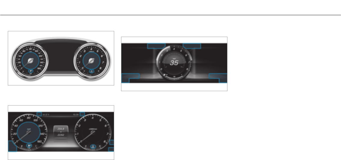
Instrument Display (standard)
Instrument Display in theWidescreen Cock‐
pit
Progressive setting in theWidescreen Cock‐
pit
If you select the progressive display setting in
vehicles with a Widescreen Cockpit, the posi‐
tions of the indicator lamps on the Instrument
Display change.
Warning and indicator lamps:
LLow beam (→page 124)
TParking lights (→page 124)
KHigh beam (→page 125)
#! Turn signal light (→page 125)
RRear fog lights (→page 124)
üSeat belt is not fastened
(→page 462)
$USA: brakes (red) (→page 455)
JCanada: brakes (red) (→page 455)
!ABS malfunction (→page 455)
àAIR BODY CONTROL malfunction
(→page 463)
àDYNAMIC BODY CONTROL malfunc‐
tion (→page 463)
÷ESP®(→page 455)
åESP®OFF (→page 455)
FUSA: electric parking brake applied
(red) (→page 455)
!Canada: electric parking brake
applied (red) (→page 455)
!Electric parking brake (yellow)
(→page 455)
ÐSteering assistance malfunction
(→page 464)
#Electrical fault (→page 465)
6Restraint system (→page 455)
Display messages and warning/indicator lamps 453

;Check Engine (→page 465)
8Fuel reserve with fuel filler flap loca‐
tion indicator (→page 465)
?Coolant too hot/cold (→page 465)
·Distance warning (→page 463)
hTire pressure monitoring system
(→page 469)
454 Display messages and warning/indicator lamps

Safety systems
Warning/indicator lamp Possible causes/consequences and MSolutions
$
Brake warning lamp (USA)
J
Brakes warning lamp (Can‐
ada)
The red brake system warning lamp is lit while the engine is running.
Possible causes are:
RThe brake force boosting is malfunctioning and the braking characteristics may be affected.
RThere is insufficient brake fluid in the brake fluid reservoir.
&WARNING There is a risk of an accident if brake force boosting is malfunctioning
If brake force boosting is malfunctioning, increased brake pedal force may be necessary for braking. Braking char‐
acteristics may be impaired. The braking distance in an emergency braking situation can increase.
#Pull over and stop thevehicle safely as soon as possible, paying attention to road and traffic conditions. Do
not continue driving under any circumstances.
#Consult a qualified specialist workshop.
&WARNING Risk of an accident due to low brake fluid level
If the brake fluid level is too low, the braking effect and the braking characteristics may be impaired.
#Pull over and stop thevehicle safely as soon as possible, paying attention to road and traffic conditions. Do
not continue driving under any circumstances.
#Consult a qualified specialist workshop.
Do not add brake fluid.
Display messages and warning/indicator lamps 455

Warning/indicator lamp Possible causes/consequences and MSolutions
#Pull over and stop thevehicle safely as soon as possible, paying attention to road and traffic conditions. Do not
continue driving under any circumstances.
#Observe the messages on the multifunction display.
#Consult a qualified specialist workshop.
USA only: if an additional display message appears with the#symbol on the multifunction display, the brake pads
have reached their wear limit.
#Visit a qualified specialist workshop.
456 Display messages and warning/indicator lamps

Warning/indicator lamp Possible causes/consequences and MSolutions
!
ABS warning lamp
The yellow ABS warning lamp is lit while the engine is running.
ABS is malfunctioning.
If there is an additional warning tone, EBD is malfunctioning.
Other driving and driving safety systems may also be faulty.
&WARNING There is risk of skidding if EBD or ABS is malfunctioning
If EBD or ABS is malfunctioning, the wheels could lock when braking
The steering capability and braking characteristics are thus severely impaired.Thebraking distance in an emer‐
gency braking situation can increase. In addition, other driving safetysystems are switched off.
#Drive on carefully.
#Have the brake system checked immediately at a qualified specialist workshop.
#Drive on carefully.
#Observe the messages in the multifunction display.
#Visit a qualified specialist workshop.
÷
ESP®warning lamp flashes
The yellow ESP®warning lamp flashes while thevehicle is in motion.
ESP®is intervening.
#Adapt your drivingstyleto suit theroad and weather conditions.
Display messages and warning/indicator lamps 457

Warning/indicator lamp Possible causes/consequences and MSolutions
÷
ESP®warning lamp lights
up
The yellow ESP®warning lamp is lit while the engine is running.
ESP®is malfunctioning.
Other driving and driving safety systems may also be malfunctioning.
&WARNING Risk of skidding if ESP®is malfunctioning
If ESP®is malfunctioning, ESP®cannot carry out vehicle stabilization. In addition, other driving safetysystems are
switched off.
#Drive on carefully.
#Have ESP®checked at a qualified specialist workshop.
#Drive on carefully.
#Observe the messages in the multifunction display.
#Consult a qualified specialist workshop.
458 Display messages and warning/indicator lamps

Warning/indicator lamp Possible causes/consequences and MSolutions
å
ESP®OFF warning lamp
The yellow ESP®OFF warning lamp is lit while the engine is running.
ESP®is deactivated.
&WARNING Risk of skidding when driving with ESP®deactivated
If ESP®is deactivated, ESP®cannot carry out vehicle stabilization. The availability of further driving safetysystems
is also limited.
#Drive on carefully.
#Only deactivate ESP®for as long as the situation requires.
If ESP®cannot be activated, ESP®is malfunctioning.
#Have ESP®checked immediately at a qualified specialist workshop.
#Observe the notes on deactivating ESP®.
Display messages and warning/indicator lamps 459

Warning/indicator lamp Possible causes/consequences and MSolutions
F
Red indicator lamp, electric
parking brake applied (USA
only)
!
Red indicator lamp, electric
parking brake applied (Can‐
ada only)
!
Yellow electric parking
brake indicator lamp is mal‐
functioning
The red electric parking brake indicator lamp flashes or is lit. The yellow indicator lamp is also lit if the electric parking
brake malfunctions.
#Observe the messages in the multifunction display.
460 Display messages and warning/indicator lamps

Warning/indicator lamp Possible causes/consequences and MSolutions
6
Restraint system warning
lamp
The redrestraint system warning lamp is lit while the engine is running.
The restraint system is malfunctioning.
&WARNING Risk of injury or fatal injury due to a malfunction in therestraint system
If therestraint system is malfunctioning, restraint system components may be triggered unintentionally or might not
be triggered at all in theevent of an accident. This may affect the Emergency Tensioning Device or airbag, forexam‐
ple.
#Have therestraint system checked and repaired immediately at a qualified specialist workshop.
#Drive on carefully.
#Observe the messages in the multifunction display.
#Visit a qualified specialist workshop immediately.
Display messages and warning/indicator lamps 461

Seat belts
Warning/indicator lamp Possible causes/consequences and MSolutions
7
Seat belt warning lamp
lights up
Afterthe engine is started, thered seat belt warning lamp lights up for six seconds.
In addition, an acoustic warning tone may sound.
The seat belt warning lamp reminds the driver and front passenger to fasten their seat belts.
#Fasten your seat belt.
If you have placed objects on the front passenger seat, the seat belt warning lamp may remain lit.
7
Seat belt warning lamp
flashes
The red seat belt warning lamp flashes and an intermittent warning tone sounds.
The driver or front passenger has not fastened their seat belt while thevehicle is in motion.
#Fasten your seat belt.
There are objects on the front passenger seat.
#Remove the objects from the front passenger seat.
462 Display messages and warning/indicator lamps

Drivingsystems
Warning/indicator lamp Possible causes/consequences and MSolutions
à
Suspension warning lamp
The yellow AIR BODY CONTROL warning lamp is on.
The yellow DYNAMIC BODY CONTROL warning lamp is on.
AIR BODY CONTROL is faulty.
There is afault in theDYNAMIC BODY CONTROL.
#Observe the messages on the multifunction display.
·
Distance warning lamp
The red distance warning lamp lights up while thevehicle is in motion.
The distance to thevehicle in front is too small forthe speed selected.
If there is an additional warning tone, you are approaching an obstacle at too high a speed.
#Be prepared to brake immediately.
#Increase the distance.
Active Brake Assist.
Display messages and warning/indicator lamps 463
Vehicle
Warning/indicator lamp Possible causes/consequences and MSolutions
Ð
Powersteering system
warning lamp
The red powersteering system warning lamp is lit while the engine is running.
The powersteering assistance or thesteering itself is malfunctioning.
&WARNING Risk of accident if steering capability is impaired
If thesteering does not function as intended, thevehicle's operating safetyis jeopardized.
#Pull over and stop thevehicle safely as soon as possible, paying attention to road and traffic conditions. Do
not continue driving under any circumstances.
#Consult a qualified specialist workshop.
#Observe the messages in the multifunction display.
464 Display messages and warning/indicator lamps

Engine
Warning/indicator lamp Possible causes/consequences and MSolutions
;
Engine diagnosis warning
lamp
The yellow Check Engine warning lamp is lit while the engine is running.
A malfunction has occurred in the engine, theexhaust system or the fuel system.
The emissions limit value may have been exceeded and the engine may be running in emergency operation mode.
In some states, legal requirements stipulate that you must immediately consult a qualified specialist workshop as soon
as theyellow Check Engine warning lamp lights up.
#Have thevehicle checked as soon as possible at a qualified specialist workshop.
#
Electrical malfunction warn‐
ing lamp
The red electrical fault warning lamp is lit.
There is a fault in the electrics.
#Observe the messages in the multifunction display.
8
Fuel reserve warning lamp
The yellow fuel reserve warning lamp lights up while driving.
There has been pressure loss in the fuel system. The fuel filler cap is not closed correctly or the fuel system is leaking.
#Close the fuel filler cap.
If the fuel filler cap has already been closed correctly:
#Visit a qualified specialist workshop.
Display messages and warning/indicator lamps 465

Warning/indicator lamp Possible causes/consequences and MSolutions
8
Fuel reserve warning lamp
The yellow fuel reserve warning lamp is lit while the engine is running.
The fuel supply has dropped into thereserve range.
#Refuel.
466 Display messages and warning/indicator lamps

Warning/indicator lamp Possible causes/consequences and MSolutions
?
Coolant warning lamp
The red coolant warning lamp is lit while the engine is running.
Possible causes are:
RThe temperature sensor is malfunctioning
RCoolant leveltoo low
RThe air supply to theradiator is obstructed
RThe radiator fan is defective
If there is an additional warning tone, the coolant temperature has exceeded the maximum permissible temperature.
&WARNING Danger of burns when opening the hood
If you open the hood when the engine has overheated or during a fire in the engine compartment, you could come
into contact with hot gases or other escaping operating fluids.
#Before opening the hood, allow the engine to cool down.
#In theevent of a fire in the engine compartment, keep the hood closed and call thefire service.
#Pull over and stop thevehicle safely and switch off the engine, paying attention to road and traffic conditions. Do
not continue driving under any circumstances.
#Observe the messages in the multifunction display.
If the coolant temperature display is at the lower end of thetemperature scale:
#Consult a qualified specialist workshop.
Display messages and warning/indicator lamps 467

Warning/indicator lamp Possible causes/consequences and MSolutions
Otherwise:
#Leave thevehicle and keep a safe distance from thevehicle until the engine has cooled down.
#Check the coolant level.
#Make sure that the air supply to theradiator is not obstructed.
#Avoiding high loads on the engine, drive on to the nearest qualified specialist workshop. In doing so, ensure that the
coolant temperature display remains below thered area.
468 Display messages and warning/indicator lamps
Tires
Warning/indicator lamp Possible causes/consequences and MSolutions
h
Tire pressure monitoring
system warning lamp lights
up
The yellow tire pressure monitoring system warning lamp (pressure loss/malfunction) is lit.
The tire pressure monitoring system has detected tire pressure loss in at least one of the tires.
&WARNING Risk of an accident due to insufficient tire pressure
Tire pressures that are too low pose thefollowing hazards:
RThe tires may burst, especially as the load and vehicle speed increase.
RThe tires may wear excessively and/or unevenly, which may greatly impair tire traction.
RThe driving characteristics, as well as steering and braking, may be greatly impaired.
You could then lose control of thevehicle.
#Observe therecommended tire pressure.
#Adjust the tire pressure if necessary.
#Stop thevehicle, paying attention to road and traffic conditions.
#Check the tire pressure and the tires.
Display messages and warning/indicator lamps 469

Warning/indicator lamp Possible causes/consequences and MSolutions
h
Tire pressure monitoring
system warning lamp
flashes
The yellow tire pressure monitoring system warning lamp (pressure loss/malfunction) flashes for approximately one
minute and then remains lit.
The tire pressure monitoring system is malfunctioning.
&WARNING There is a risk of an accident if the tire pressure monitoring system is malfunctioning
If the tire pressure monitoring system is malfunctioning, it is not able to issue a warning if there is pressure loss in
one or more of the tires.
Underinflated tires may, forexample, impair the driving, steering and braking characteristics.
#Have the tire pressure monitoring system checked at a qualified specialist workshop.
#Consult a qualified specialist workshop.
470Display messages and warning/indicator lamps

1, 2, 3 ...
12 V socket
see Socket (12 V)
115 V socket
see Socket (115 V)
360° Camera ........................................... 198
Assigning as a favorite ........................ 200
Care .................................................... 342
Function .............................................. 198
Selecting a view .................................. 200
A
A/C function
Activating/deactivating (control
panel) .................................................. 139
Activating/deactivating (multimedia
system) ................................................ 139
ABS (Anti-lock Brake System) ................ 169
Acceleration
see Kickdown
Access data
Editing .................................................305
Setting ................................................. 304
Acoustic locking verification signal
Activating/deactivating ......................... 58
Active Blind Spot Assist .......................... 210
Activating/deactivating .......................212
Brake application ................................. 210
Function ............................................... 210
System limitations ...............................210
Towing a trailer .................................... 210
Active Brake Assist
Function/notes ................................... 170
Setting ................................................. 174
Active Distance Assist DISTRONIC ........ 177
Active Emergency Stop Assist .............185
Active Lane Change Assist .................. 184
Calling up a speed ...............................179
Function .............................................. 177
Increasing/decreasing speed ..............179
Requirements ...................................... 179
Steering wheel buttons ........................ 179
Storing a speed ................................... 179
Switching off/deactivating .................. 179
Switching on/activating ...................... 179
System limitations ...............................177
Active Emergency Stop Assist ...............185
Active hood (pedestrian protection) ...... 333
Method of operation ............................333
Resetting ............................................. 333
Active Lane Change Assist
Function .............................................. 184
Active Lane Keeping Assist .....................212
Function ............................................... 212
Sensitivity (function/notes) ................. 215
Setting the sensitivity .......................... 215
Switching on/off ................................. 214
System limits ....................................... 212
Towing a trailer .................................... 212
Active Parking Assist .............................. 201
Cross Traffic Alert ............................... 206
Drive Away Assist ................................ 205
Exiting a parking space .......................203
Function .............................................. 201
Parking ................................................ 202
System limitations ...............................201
Active Speed Limit Assist ....................... 209
Setting ................................................. 209
Active Steering Assist .............................182
Activating/deactivating .......................183
Active Emergency Stop Assist .............185
Index 471

Active Lane Change Assist .................. 184
Function .............................................. 182
System limitations ...............................182
Adaptive cruise control
see Active Distance Assist DISTRONIC
Adaptive Highbeam Assist
Function .............................................. 127
Switching on/off ................................. 128
Additives.................................................. 402
Engine oil ............................................ 402
Fuel ..................................................... 402
Additives (engine oil)
see Additives
Additives (fuel)
see Fuel
Address book
see Contacts
Adjusting the balance/fader
Burmester®surround sound system ....331
Adjusting the sound focus
Burmester®surround sound system ....331
ADS PLUS damping system
see AIR BODY CONTROL
After-sales service center
see ASSYST PLUS
Air bag ........................................................ 38
Activation .............................................. 32
Front air bag (driver, front passenger) ... 38
Installation locations .............................38
Knee airbag ........................................... 38
Overview ............................................... 38
Protection ..............................................39
Reduced protection ...............................40
Side impact air bag ............................... 38
Window curtain air bag .......................... 38
AIR BODY CONTROL........................ 187, 188
Setting ................................................. 190
Suspension .................................. 187, 188
Air conditioning system
see Climate control
Air distribution ........................................ 138
Air freshener system
see Fragrance system
Air pressure
see Tire pressure
Air suspension
see AIR BODY CONTROL
Air vents ................................................... 143
Adjusting (front) .................................. 143
Adjusting (rear passenger compart‐
ment) ................................................... 144
Glove box .............................................144
Air vents
see Air vents
Air-recirculation mode .............................141
Airflow ...................................................... 138
AIRPANEL (Care) ...................................... 342
Alarm
see Panic alarm
Alarm system
see ATA (anti-theft alarm system)
Alternative route
see Route
Ambient lighting ...................................... 129
Android Auto ............................................ 298
Connecting a mobile phone ................. 299
Ending ................................................. 299
472Index

Note .................................................... 298
Overview ............................................. 298
Sound settings .................................... 299
Transferred vehicle data ......................300
Animals
Pets in thevehicle ................................. 55
Anti-lock braking system
see ABS (Anti-lock Brake System)
Anti-skid chains
see Snow chains
Anti-theft alarm system
see ATA (anti-theft alarm system)
Anti-theft protection
Immobilizer ............................................ 81
Anti-theft protection
see ATA (anti-theft alarm system)
Anticipatory occupant protection
see PRE-SAFE®(anticipatory occu‐
pant protection)
see PRE-SAFE®PLUS (anticipatory
occupant protection plus)
Apple CarPlay™ ....................................... 297
Connecting an iPhone®....................... 297
Ending .................................................298
Notes ................................................... 297
Overview ............................................. 297
Sound settings .................................... 298
Transferred vehicle data ......................300
Ashtray
Front center console ............................116
Rear passenger compartment .............. 117
Assistance graphic
Menu (on-board computer) .................. 221
Assistance systems
see Driving safetysystem
ASSYSTPLUS ........................................... 332
Displaying the service due date ........... 332
Function/notes ................................... 332
Non-operational times with the bat‐
tery disconnected ...............................333
Regular maintenance work .................. 332
Special service requirements .............. 332
ATA (anti-theft alarm system) ...................81
Deactivating the alarm .......................... 82
Function ................................................. 81
ATTENTION ASSIST .......................... 206, 207
Function .............................................. 206
Setting ................................................. 207
System limitations ...............................206
Attention assistant
see ATTENTION ASSIST
Audio mode
Activating media mode ........................ 312
Connecting USB devices ...................... 314
Copyright .............................................311
Information ..........................................310
Inserting/removing an SD card ........... 312
Media search ....................................... 317
Overview ..............................................313
Pause and playback function ...............314
Selecting a track .................................. 314
Selecting playback options .................. 314
Track list .............................................. 314
Authorized workshop
see Qualified specialist workshop
Automatic car wash (care) ..................... 339
Automatic distance control
see Active Distance Assist DISTRONIC
Automatic driving lights ......................... 125
Index 473

Automatic engine start (ECO start/
stop function) ........................................... 151
Automatic front passenger front air
bag shutoff .......................................... 40, 42
PASSENGER AIR BAG indicator lamp .....42
Automatic front-passenger front air
bag deactivation system .......................... 40
Function of the automatic front
passenger air bag shutoff ......................40
Automatic lateral support adjustment
Setting ................................................... 91
Automatic mirrorfolding function
Activating/deactivating .......................136
Automatic transmission
DIRECT SELECT lever ........................... 153
Drive program display .......................... 153
Drive programs .................................... 152
DYNAMIC SELECT switch .................... 152
Engaging drive position ....................... 155
Engaging reversegear .........................154
Kickdown ............................................. 156
Manual gearshifting .............................155
Selecting park position ........................ 155
Shifting to neutral ................................ 154
Steering wheel paddle shifters ............ 155
Transmission position display .............. 153
Transmission positions ........................ 153
B
Bag hook ................................................... 110
BAS (Brake Assist System) .....................169
Battery
SmartKey ............................................... 59
Battery (vehicle)
Charging .............................................. 354
Jump-starting ...................................... 354
Notes .................................................. 352
Belt
see Seat belts
Blind Spot Assist ...................................... 210
Activating/deactivating .......................212
Function ............................................... 210
System limitations ...............................210
Blower
see Climate control
Bluetooth®
Activating/deactivating .......................252
Setting up an Internet connection ....... 304
Settings ............................................... 252
Switching profile (DUN/PAN) .............. 305
Bluetooth®audio
Activating ............................................ 322
De-authorizing (de-registering) the
device .................................................. 322
Information .......................................... 319
Overview ............................................. 320
Searching for a track ........................... 322
Searching for and authorizing the
device .................................................. 321
Selecting a music player .....................322
Switching device via NFC .................... 322
Brake Assist System
see BAS (Brake Assist System)
Brake fluid
Notes .................................................. 403
Brake force distribution
EBD (Electronic Brake force Distribu‐
tion) ..................................................... 170
Brakes
ABS (Anti-lock Braking System) ........... 169
Active Brake Assist .............................. 170
474Index

BAS (Brake Assist System) .................. 169
Driving tips .......................................... 148
EBD (Electronic Brake force Distribu‐
tion) ..................................................... 170
HOLD function .....................................185
Limited braking effect (salt-treated
roads) .................................................. 148
New/replaced brake pads/brake
discs .................................................... 148
Notes on breaking-in a new vehicle ..... 148
Braking assistance
see BAS (Brake Assist System)
Breakdown
Changing a wheel ................................ 390
Overview of the help functions .............. 16
Roadside Assistance .............................. 21
Tow-starting ........................................ 362
Towing away ........................................ 358
Transporting thevehicle ......................360
Breakdown
see Flat tire
Burmester®surround sound system .....330
Adjusting the balance/fader ................331
Adjusting the sound focus ................... 331
Adjusting treble, mid-range and bass
settings ................................................ 331
Automatic volume adjustment .............331
Calling up the sound menu .................. 330
Information .......................................... 330
Switching the surround sound on/off
.............................................................331
Buttons
Steering wheel .....................................217
C
California
Important information for private
customers and lessees ..........................22
Call list
Making a call .......................................294
Options in the call list .......................... 294
Overview ............................................. 294
Calling up the sound menu
Burmester®surround sound system ... 330
Calls ..........................................................290
Accepting ............................................ 290
Activating functions during a call ........ 290
Calls with several participants .............291
Declining ............................................. 290
Ending a call ........................................ 290
Incoming call during an existing call .... 291
Making ................................................ 290
Camera
see 360° Camera
see Rear view camera
Car key
see SmartKey
Car wash
see Care
Care ..........................................................344
AIRPANEL ............................................ 342
Car wash ............................................. 339
Carpet .................................................344
Display ................................................ 344
EASY-PACK trunk box .......................... 344
Exhaust pipes ...................................... 342
Exterior lighting ................................... 342
Matt finish ........................................... 341
Paintwork ............................................ 341
Plastic trim .......................................... 344
Powerwasher ...................................... 340
Real wood/trim elements ...................344
Index 475

Rear view camera/360° Camera ........ 342
Roof lining ...........................................344
Seat belts ............................................ 344
Seat cover ........................................... 344
Sensors ............................................... 342
Washing by hand ................................. 340
Wheels/rims ....................................... 342
Windows .............................................. 342
Wiper blades .......................................342
Cargo compartment cover
Extending/retracting ........................... 107
Notes ................................................... 107
Carpet (Care) ...........................................344
Change of address .....................................21
Change of ownership ................................ 21
Changing a wheel
Lowering thevehicle ............................394
Mounting a new wheel ........................ 393
Preparation ......................................... 390
Raising thevehicle ...............................391
Removing a wheel ...............................393
Removing/installing hub caps .............390
Changing hub caps ................................. 390
Channel list
Calling up ............................................ 324
Character entry
Function/notes ................................... 249
On thetouchpad .................................250
Using the controller ............................. 249
Charging
Battery (vehicle) .................................. 354
Mobile phone (wireless) .......................121
USB port ..............................................120
Chassis level (AIR BODY CONTROL)
Setting .................................................190
Child safety lock
Rear door .............................................. 54
Rear side windows ................................. 55
Setting ................................................. 256
Child seat
Front passenger seat (notes) ................. 53
Front passenger seat (rearward-
facing/forward-facing) .......................... 53
LATCH-type (ISOFIX) (installing) ............ 50
LATCH-type (ISOFIX) (notes) .................. 49
Notes ..................................................... 46
TopTether ..............................................51
Child seat safetyfeature .......................... 48
Children
Child seat safetyfeature ........................ 48
Restraint systems ..................................46
Chock .......................................................389
Storage location ..................................389
Cigarette lighter
Front center console ............................117
Cleaning
see Care
Climate control ........................................ 138
3-zone automatic climate control
panel ................................................... 138
Activating/deactivating .......................139
Activating/deactivating the A/C
function (control panel) .......................139
Activating/deactivating the A/C
function (multimedia system) .............. 139
Activating/deactivating the synchro‐
nization function (control panel) .......... 140
Activating/deactivating the synchro‐
nization function (multimedia sys‐
tem) ..................................................... 141
Adjusting the climate style settings ..... 140
476Index

Air distribution settings .......................140
Air-recirculation mode ......................... 141
Automatic control ................................ 139
Climatestyle function .......................... 140
Defrosting the windows ....................... 141
Defrosts the windshield ....................... 138
Dual-zone automatic climate control
panel ................................................... 138
Filling capacity forPAG oil ...................406
Front air vents ..................................... 143
Glove box air vent ................................ 144
Inserting/removing theflacon (fra‐
grance system) .................................... 142
Ionization ............................................. 141
Rear air vents ...................................... 144
Rear operating unit .............................. 138
Refrigerant .......................................... 405
Refrigerant filling capacity ...................406
Residual heat ....................................... 141
Sets the airflow ................................... 138
Setting the air distribution ...................138
Setting the fragrance system ............... 141
Setting thetemperature ......................138
Switching therear window heater
on/off .................................................138
Ventilating thevehicle (convenience
opening) ................................................. 74
Windshield heater ................................ 143
Climate style
Function .............................................. 140
Setting ................................................. 140
Cockpit .........................................................6
Overview .................................................6
COMAND
see Multimedia system
COMAND Touch
Managing devices ................................ 255
Combination switch
see Turn signal light
Combined luggage cover and net
Attaching to therear seat backrest .....108
Installing/removing ............................. 108
Compass .................................................. 285
Computer
On-board computer .............................. 217
Connection status
Displaying ............................................ 306
Overview .............................................306
Contacts ................................................... 291
Calling up ............................................ 292
Deleting ............................................... 293
Downloading (from mobile phone) ....... 291
Importing ............................................ 293
Information .......................................... 291
Making a call ....................................... 293
Name format .......................................292
Options ................................................ 293
Storing ................................................ 293
Controller
Operating ............................................ 243
Convenience closing feature .................... 74
Convenience opening ................................ 74
Coolant (engine)
Filling capacity .................................... 404
Levelcheck ......................................... 337
Notes .................................................. 404
Cooling
see Climate control
Copyright
Licenses ................................................ 30
Trademarks ............................................ 30
Index 477

Cornering light function .......................... 126
Cover.......................................................... 72
Cross Traffic Alert ...................................206
Crosswind Assist
Function/notes ................................... 170
Cruise control .......................................... 175
Activating .............................................175
Calling up a speed ...............................175
Deactivating ......................................... 175
Function ............................................... 175
Lever .................................................... 175
Prerequisites ........................................175
Selecting .............................................. 175
Setting a speed .................................... 175
Storing a speed .................................... 175
System limitations ...............................175
Cup holder
Rear passenger compartment .............. 116
Cup holder in the center console
Installing/removing (automatic
transmission) .......................................115
Customer Assistance Center (CAC).........25
Customer Relations Department .............25
D
Dashboard
see Cockpit
Dashboard lighting
see Instrument lighting
Data acquisition
Vehicle .................................................. 26
Data import/export
Function/notes ................................... 256
Importing/exporting ........................... 257
Date
Setting the time and date automati‐
cally ..................................................... 251
Daytime running lights ........................... 128
Activating/deactivating .......................128
Daytime running lights mode
see Daytime running lights
Deactivating the alarm (ATA).................... 82
Declaration of conformity
Wireless vehicle components ................23
Definitions (tires and loading) ............... 383
Designs
Menu (on-board computer) .................. 227
Destination ............................................... 276
Editing intermediate destinations ........ 267
Editing the previous destinations .........276
External ............................................... 277
Saving (current vehicle position) ..........276
Saving as global favorite ...................... 276
Storing a map position .........................276
Using intelligent destination sugges‐
tions .................................................... 277
Destination entry ............................ 263, 265
Enter geo-coordinates .........................267
Entering a POI or address .................... 263
Entering an intermediate destination .. 266
Selecting a contact .............................. 267
Selecting a POI .................................... 265
Selecting from the map ....................... 268
Selecting previous destinations ...........265
Detecting inattentiveness
see ATTENTION ASSIST
Diagnostics connection ............................24
DigitalOperator'sManual.........................18
Digitalspeedometer................................ 221
478Index

DIRECT SELECT lever............................... 153
Engaging drive position ....................... 155
Engaging park position automatically .. 155
Engaging reversegear .........................154
Function .............................................. 153
Selecting park position ........................ 155
Shifting to neutral ................................ 154
Display
Care.................................................... 344
Display(multimediasystem)
Notes ................................................... 242
Settings ............................................... 250
Display (on-board computer)
Displays in the multifunction display ....219
Displaycontent
(Additional value range) ....................... 219
Displaymessage.....................................408
Calling up (on-board computer) ........... 408
Notes .................................................. 408
Display messages
?.......................................... 437, 448
A................................................... 449
C................................................... 448
¯.................................................... 433
Active Blind Spot Assist Currently
Unavailable See Operator's Manual .....430
Active Blind Spot Assist Inoperative .... 430
Active Blind Spot Asst. Not Available
When Towing a Trailer See Opera‐
tor's Manual ........................................ 430
Active Brake Assist Functions Cur‐
rently Limited See Operator's Man‐
ual....................................................... 420
Active Brake Assist Functions Limi‐
ted See Operator's Manual .................. 421
Active Distance Assist Currently
Unavailable See Operator's Manual .....432
Active Distance Assist Inoperative ......432
Active Distance Assist Now Available
.............................................................432
bActive Headlamps Inoperative ..... 450
Active Hood Malfunction See Opera‐
tor's Manual ........................................ 448
Active Lane Keeping Assist Camera
View Restricted See Operator's Man‐
ual ....................................................... 429
Active Lane Keeping Assist Currently
Unavailable See Operator's Manual .....428
Active Lane Keeping Assist Inopera‐
tive ...................................................... 428
Active Parking Assist and
PARKTRONICInoperative See Opera‐
tor's Manual ........................................ 431
èActive Steering Assist Currently
Unavailable See Operator's Manual .....432
èActive Steering Assist Inopera‐
tive ...................................................... 433
Adaptive Highbeam Assist Camera
View Restricted See Operator's Man‐
ual ....................................................... 452
Adaptive Highbeam Assist Currently
Unavailable See Operator's Manual .....451
Index 479

Adaptive Highbeam Assist Inopera‐
tive ...................................................... 451
Air Conditioning Malfunction See
Operator's Manual .............................. 445
Apply Brake to Shift from 'P' ............... 443
ÀATTENTION ASSIST Inoperative ... 426
ÀATTENTION ASSIST: Take a
Break! .................................................. 426
bAuto Lamp Function Inoperative
............................................................. 451
Auxiliary Battery Malfunction .............. 445
Blind Spot Assist Currently Unavaila‐
ble See Operator's Manual .................. 429
Blind Spot Assist Inoperative ............... 430
Blind Spot Assist Not Available When
Towing a Trailer See Operator's Man‐
ual .......................................................430
$Check Brake Fluid Level...............418
Check Coolant Level See Operator's
Manual ................................................ 434
4Check Engine Oil At Next Refu‐
eling .................................................... 437
bCheck Left Low Beam (Exam‐
ple) ...................................................... 450
hCheck Tires................................. 438
¥Check Washer Fluid .................... 449
?Coolant Too Hot Stop Vehicle
Turn Engine Off .................................... 434
Cruise Control Canceled ..................... 433
Cruise Control Inoperative .................. 433
!Currently Unavailable See Oper‐
ator's Manual .......................................410
÷Currently Unavailable See Oper‐
ator's Manual .......................................411
ÂDon't Forget Your Key.................442
Driver's Door Open & Transmission
Not in P Risk of Vehicle Rolling Away .. 443
6Front Left Malfunction Service
Required (Example) .............................423
Front Passenger Airbag Disabled See
Operator's Manual ...............................424
Front Passenger Airbag Enabled See
Operator's Manual ...............................425
8Fuel Level Low .............................437
8Gas Cap Loose ............................ 437
!Inoperative See Operator's
Manual ................................................ 409
÷Inoperative See Operator's
Manual .................................................412
TInoperative See Operator's
Manual ................................................. 413
GInoperative ................................... 418
ÂKeyNotDetected (white dis‐
play message).....................................442
ÂKeyNotDetected (red display
message).............................................442
6Left Side Curtain Airbag Mal‐
function Service Required (Example) ...423
480 Index

Let fresh air into thevehicle interior.
Air Conditioning Malf. Visit Work‐
shop ....................................................446
ÂLowering .................................... 426
Malfunction Drive at Max. 50 mph...... 428
bMalfunction See Operator’s
Manual ................................................ 450
NPermanently Active Risk of Rolling
Away ................................................... 444
ÂObtain a New Key........................ 441
ëOff ............................................... 432
Only Shift to 'P' when Vehicle is Sta‐
tionary .................................................444
FParking Brake See Operator's
Manual ................................................. 415
ÂPlace theKeyin the Marked
Space See Operator's Manual .............443
hPlease Correct Tire Pressure .......438
FPlease Release Parking Brake ...... 414
PRE-SAFE Impulse Side Inoperative
See Operator's Manual ........................ 421
PRE-SAFE Inoperative See Opera‐
tor's Manual ........................................ 421
Radar Sensors Dirty See Operator's
Manual .........................................419, 420
_Rear Left Backrest Not
Latched (Example) ...............................449
ÂReplace KeyBattery .................... 441
Reversing Not Possible Service
Required .............................................. 445
#See Operator's Manual ............... 435
Service Required Do Not Shift Gears
Visit Dealer .......................................... 444
6SRS Malfunction Service
Required .............................................. 422
#Start Engine See Operator's
Manual ................................................ 435
ÐSteering Malfunction Drive
Carefully Service Required .................. 446
ÐSteering Malfunction Increased
Physical Effort See Operator's Man‐
ual ....................................................... 447
ÐSteering Malfunction Stop
Immediately See Operator's Manual ....447
Stop Vehicle Leave Engine Running
Wait Transmission Cooling .................. 445
#Stop Vehicle Leave Engine Run‐
ning ..................................................... 436
#Stop Vehicle See Operator's
Manual ................................................ 436
ÁStop Vehicle Vehicle Too Low ...... 427
bSwitch Off Lights .........................451
bSwitch On Headlamps ................. 451
Tire Press. Monitor Currently
Unavailable .......................................... 439
Tire Press. Monitor Inoperative ........... 440
Tire Pressure Monitor Inoperative No
Wheel Sensors .................................... 440
Tires Overheated ................................. 440
Index 481

Tires Overheated Decrease Speed .......441
To Deselect P or N, Depress Brake
and Start Engine .................................. 443
To Engage Transmiss. Position R First
Depress the Brake ...............................446
Traffic Sign Assist Camera View
Restricted See Operator's Manual .......431
Traffic Sign Assist Currently Unavail‐
able See Operator's Manual ................ 431
Traffic Sign Assist Inoperative ............. 431
Transmission Malfunction Stop ........... 445
FTurn On the Ignition to Release
theParking Brake .................................414
dVehicle Operational Switch the
Ignition Off Before Exiting ................... 444
ÁVehicle Rising Please Wait ...........427
ÁVehicle Rising .............................. 426
hWarning Tire Malfunction ............ 439
hWheel Sensor(s) Missing .............440
Display on the windshield
see Head-up Display
Distance control
see Active Distance Assist DISTRONIC
Distance recorder
see Trip distance
DISTRONIC
see Active Distance Assist DISTRONIC
Door
Locking (mechanical key) ...................... 65
Opening (from the inside) ......................62
Unlocking (from the inside) ...................62
Unlocking (mechanical key) ...................65
Door control panel .....................................14
DOT, Tire Identification Number (TIN) ... 379
Drinking and driving................................ 148
DriveAway Assist .................................... 205
Drive position
Selecting .............................................155
Drive program display ............................. 153
Driveprograms
see DYNAMIC SELECT
Driver's seat
see Seat
Driving lights
see Automatic driving lights
Driving safety system .............................168
ABS (Anti-lock Brake System) .............. 169
Active Brake Assist .............................. 170
BAS (Brake Assist System) .................. 169
EBD (Electronic Brake force Distribu‐
tion) ..................................................... 170
ESP®(Electronic Stability Program)
Crosswind Assist ................................. 170
Overview ............................................. 168
Radar sensors ...................................... 168
Responsibility ...................................... 168
STEER CONTROL ................................. 170
Drivingsystem
DYNAMIC BODY CONTROL .................. 186
Drivingsystem
see 360° Camera
see Active Blind Spot Assist
see Active Distance Assist DISTRONIC
see Active Lane Keeping Assist
see Active Parking Assist
482 Index

see Active Speed Limit Assist
see Active Steering Assist
see AIR BODY CONTROL
see ATTENTION ASSIST
see Blind Spot Assist
see Cruise control
see Driving safetysystem
see HOLD function
see Parking Assist PARKTRONIC
see Rear view camera
see Traffic Sign Assist
Drivingtips
Drinking and driving............................ 148
General driving tips .............................148
Notes on breaking-in a new vehicle ..... 148
Drowsiness detection
see ATTENTION ASSIST
DYNAMIC BODY CONTROL
Suspension .......................................... 186
DYNAMIC SELECT .................................... 152
Configuring drive program I ................. 153
Displaying engine data ........................ 153
Displaying vehicle data ........................ 153
Drive program display .......................... 153
Drive programs .................................... 152
Function .............................................. 152
Operating (DYNAMIC SELECT switch)
.............................................................153
Selecting the drive program ................153
E
E10 ............................................................ 401
Easy entry feature
Function/notes .....................................99
Setting ................................................... 99
Easy exit feature
Function/notes .....................................99
Setting ................................................... 99
EASY-PACK load-securing kit ...................111
Inserting brackets ................................ 112
Installing/removing the luggage
holder .................................................. 112
Installing/removing thetelescopic
rod .......................................................113
Notes ................................................... 111
EBD (Electronic Brake force Distribu‐
tion)
Function/notes ................................... 170
ECO display
Function .............................................. 152
Resetting ............................................. 223
ECO start/stop function ......................... 151
Automatic engine start ........................ 151
Automatic engine stop .........................151
Method of operation ............................151
Switching off/on .................................. 151
Electric parking brake .............165, 166, 167
Applying automatically ........................ 165
Applying or releasing manually ............ 166
Emergency braking .............................. 167
Releasing automatically .......................166
Electrical fuses
Before replacing a fuse ........................ 362
Electrical fuses
see Fuses
Electronics ............................................... 396
Emergency
Overview of the help functions .............. 16
Safetyvest .......................................... 346
Emergency braking .................................. 167
Index 483

Emergency call system
Mercedes-Benz mbrace®(USA) ...........301
Emergency engine start ......................... 362
Emergency operation mode
Starting thevehicle .............................. 147
Emergency Tensioning Devices
Activation .............................................. 32
Energy consumption
SmartKey ............................................... 58
Engine
ECO start/stop function ......................151
Engine number .................................... 398
Jump-starting ...................................... 354
Starting (emergency operation
mode) .................................................. 147
Starting (Remote Online) ..................... 147
Starting (start/stop button) .................146
Switching off (start/stop button) ........ 159
Engine data
Displaying ............................................ 153
Engine number ........................................ 398
Engine oil .................................................336
Adding .................................................336
Additives .............................................402
Capacity .............................................. 403
Checking the oil level using the oil
dipstick ............................................... 336
MB-Freigabe or MB-Approval ...............403
Quality ................................................. 403
ESP®
Crosswind Assist ................................. 170
ESP®(Electronic Stability Program)
Activating/deactivating .......................169
Exhaust pipes (Care) ............................... 342
Exterior lighting
Care .................................................... 342
Exterior lighting
see Lights
External device
Locking ...............................................256
Eyeglasses compartment ....................... 103
F
Fatigue detection
see ATTENTION ASSIST
Fault message
see Display message
Favorites
Adding .................................................246
Calling up ............................................ 246
Deleting ...............................................247
Moving .................................................247
Overview ............................................. 246
Renaming ............................................. 247
Flacon
Inserting/removing .............................142
Flat tire ..................................................... 346
Changing a wheel ................................ 390
MOExtended tires ................................ 347
Notes .................................................. 346
TIREFIT kit ...........................................348
Floor mats ................................................ 122
Folding bench seat .................................... 94
Folding back .......................................... 96
Folding out ............................................ 94
Installing and removing the seat
cushion .................................................. 95
Notes ..................................................... 94
484 Index

Opening and closing the cargo com‐
partment floor ....................................... 96
Fragrance
see Fragrance system
Fragrance system .................................... 142
Inserting/removing theflacon .............142
Free software ............................................ 30
Frequencies
Two-way radio ...................................... 397
Frequency band
Selecting (on-board computer) ............ 224
Front air bag (driver, front passenger) .... 38
Front passenger front air bag shutoff
see Automatic front passenger front
air bag shutoff
Front passenger seat
Adjusting from the driver's seat ............ 87
Front passenger seat
see Seat
Fuel ...........................................................402
Additives .............................................402
E10 ...................................................... 401
Gasoline .............................................. 401
Quality (gasoline) ................................. 401
Refueling ............................................. 157
Reserve fuel level ................................ 402
Sulfur content ...................................... 401
Tank capacity ...................................... 402
Fuel consumption
On-board computer .............................221
Function seat
see Door control panel
Fuse insert
see Fuses
Fuses ........................................................ 362
Assignment diagram ............................362
Dashboard fuse box ............................ 364
Fuse box in the cargo compartment ....365
Fuse box in the engine compartment .. 363
Fuse box in the front-passengerfoot‐
well ...................................................... 364
Notes .................................................. 362
G
Garage door opener
Clearing the memory ........................... 163
Opening/closing thegarage door ........ 163
Programming buttons .......................... 160
Radio equipment approval numbers .... 164
Resolving problems ............................. 162
Synchronizing therolling code .............162
Gas station search
Starting an automatic gasstation
search ................................................. 266
Switching the automatic gasstation
search on/off ...................................... 271
Gasoline ...................................................401
Gearshift paddles
see Steering wheel paddle shifters
Gearshift recommendation .................... 156
Genuine parts ............................................ 19
Glide mode ............................................... 156
Glove box
Air vent ................................................ 144
Locking/unlocking .............................. 102
H
Handbrake
see Electric parking brake
Index 485

Handling characteristics (unusual) ....... 366
HANDS-FREE ACCESS ................................ 69
HANDS-FREE ACCESS
see Opening thetailgate using your foot
Hazard warning lights .............................126
Head restraint ...........................................88
Front (adjusting manually) ..................... 88
Front (luxury head restraint) .................. 89
Rear (adjusting) .....................................90
Rear (lowering from the front) ............... 90
Rear passenger compartment
(removing/installing) .............................90
Head-up Display ...................................... 226
Adjusting brightness (on-board com‐
puter) .................................................. 226
Adjusting display elements (on-board
computer) ............................................ 226
Function .............................................. 227
Menu (on-board computer) .................. 226
Setting the position (on-board com‐
puter) .................................................. 226
Switching on/off ................................. 228
Using the memory function ................. 100
Heating
see Climate control
High beam
Activating/deactivating .......................125
High-beam flasher ................................... 125
High-beam headlamps
Adaptive Highbeam Assist ...................127
Hill start assist ........................................ 185
HOLD function ......................................... 185
Activating/deactivating .......................185
Function/notes ................................... 185
Hood
Function (active hood) ......................... 333
Opening/closing ................................. 333
Resetting (active hood) ........................ 333
Hooking the luggage net .........................111
Hotspot
Setting up (Wi-Fi) ................................. 254
I
Identification plate
Engine .................................................398
Refrigerant .......................................... 405
Vehicle ................................................ 398
Ignition
Switching on (Start/Stop button) ........ 145
Ignition key
see SmartKey
Immobilizer ................................................ 81
In Car Office
Accepting/rejecting a call for a tele‐
phone conference ....................... 296, 297
Features .............................................. 296
Marking a to-do entry as completed ....297
Selecting functions .............................. 296
Switching automatic start on/off ........ 296
Indicator lamp
see Warning/indicator lamps
Individual drive program
Configuring .......................................... 153
Selecting ............................................. 153
Instrument cluster
see Instrument Display
see Warning/indicator lamps
Instrument Display .................................. 216
Adjusting the lighting .......................... 220
486 Index

Function/notes .................................... 216
Overview ..............................................216
Overview (standard) ................................ 8
Overview (Widescreen) ............................ 8
Warning/indicator lamps .................... 452
Instrument lighting .................................220
Intelligent Light System
Cornering light function .......................126
Interior lighting ........................................ 128
Ambient lighting .................................. 129
Setting ................................................. 128
Switch-off delay time ........................... 129
Interior lighting
see Interior lighting
see Lighting
see Lights
Intermediate destination
Calculating a route with intermediate
destinations .........................................267
Editing .................................................267
Entering ............................................... 266
Starting an automatic gasstation
search ................................................. 266
Starting the automatic service sta‐
tion search ........................................... 271
Internet
Deleting a bookmark ...........................308
Deleting browser data .........................308
Managing bookmarks .......................... 308
Internet connection
Canceling permission .......................... 305
Connection status ...............................306
Displaying the connection status ........ 306
Editing access data .............................305
Establishing .........................................306
Information .......................................... 303
Mobile phone details ...........................306
Restrictions ......................................... 303
Setting access data ............................. 304
Setting up (Bluetooth®) .......................304
Switching Bluetooth®profile (DUN/
PAN) .................................................... 305
Via Bluetooth®..................................... 304
ViaWi-Fi .............................................. 303
Internet radio
Calling up ............................................ 309
Deleting stations .................................309
Logging in ............................................ 310
Logging out ..........................................310
Overview ............................................. 309
Saving stations .................................... 309
Selecting and connecting to astation
.............................................................309
Selecting stream .................................. 310
Setting options .................................... 310
Terms of use ........................................310
Ionization .................................................. 141
iPhone®
see Apple CarPlay™
J
Jack
Storage location ..................................389
Jump-start connection ............................ 354
Jump-starting
see Jump-start connection
K
KEYLESS-GO
Locking thevehicle ................................ 62
Problem .................................................63
Index 487

Unlocking setting .................................. 58
Unlocking thevehicle ............................62
Kickdown.................................................156
Using ................................................... 156
Knee air bag ...............................................38
L
Labeling (tires)
see Tire labeling
Laden ........................................................ 110
Stowage space underneath the cargo
compartment floor ...............................114
Tie-down eyes ...................................... 110
Laden
see EASY-PACK load-securing kit
Lamp (Instrument Display)
see Warning/indicator lamps
Lamps
see Interior lighting
Lane Keeping Assist
see Active Lane Keeping Assist
Language
Notes .................................................. 256
Setting .................................................256
LATCH-type (ISOFIX) child seat
attachment
Installing ................................................ 50
Notes ..................................................... 49
Level control system
see AIR BODY CONTROL
Light switch
Overview .............................................. 124
Lighting .................................................... 128
Lighting
see Lights
Lights ................................................ 124, 128
Adaptive Highbeam Assist ...................127
Adjusting the instrument lighting ........ 220
Automatic driving lights ....................... 125
Combination switch ............................. 125
Cornering light function ....................... 126
Hazard warning lights .......................... 126
High beam ........................................... 125
High-beam flasher ...............................125
Light switch ......................................... 124
Low beam ............................................ 124
Parking lights .......................................124
Rear fog light ....................................... 125
Responsibility for lighting systems .......124
Setting the surround lighting ...............128
Standing lights .....................................124
Turn signal light ................................... 125
Limited Warranty
Vehicle .................................................. 26
Limiting the opening angle (tailgate) ...... 70
Live Traffic Information
Displaying subscription information .... 278
Displaying the traffic map .................... 278
Displaying traffic incidents .................. 279
Extending a subscription ..................... 278
Issuing hazard alerts ........................... 280
Load index (tires) .....................................381
Load-bearing capacity (tires) ................. 381
Loading
Bag hook ..............................................110
Definitions ........................................... 383
Roof rack ............................................. 114
Loading guidelines .................................. 101
Loading information table ...................... 373
488 Index

Loads
Securing .............................................. 101
Locator lighting
Activating/deactivating .......................128
Locking/unlocking .................................... 65
KEYLESS-GO .......................................... 62
Unlocking and opening doors from
the inside ..............................................62
Low beam
Switching on/off .................................124
Lubricant additives
see Additives
Luggage
Luggage net .......................................... 111
Securing .............................................. 101
Lumbar support
see Lumbar support (4-way)
Lumbar support (4-way)...........................88
M
Maintenance
Menu (on-board computer) .................. 220
Vehicle ................................................... 21
Maintenance
see ASSYST PLUS
Making a call via theoverhead con‐
trol panel
Mercedes-Benz mbrace®(USA) ...........300
Malfunction
Restraint system ................................... 32
Map ...........................................278, 280, 281
Avoiding an area ..................................283
Avoiding an area (overview) .................283
Changing an area ................................ 283
Deleting an area .................................. 284
Displaying the compass ....................... 285
Displaying the map version .................283
Displaying the next intersecting
street ................................................... 283
Displaying the satellite map ................285
Displaying the traffic map .................... 278
Displaying weather information ...........285
Map data ............................................. 284
Moving ................................................. 281
Overview ............................................. 280
Selecting POI symbols ......................... 282
Selecting text information ................... 282
Selecting the map orientation .............282
Setting the map scale .......................... 281
Setting the map scale automatically ....285
Switching highwayinformation
on/off .................................................282
Updating .............................................. 284
Map and compass
Overview .............................................280
Massage program
Selecting the front seats ........................ 91
Massage programs
Overview ................................................ 91
Massage settings
Resetting ............................................... 92
Matt finish (cleaning instructions) ......... 341
Maximum load rating .............................. 380
Maximum permissible load
Calculation example ............................ 375
Determining .........................................374
Maximum tire pressure ..........................380
Mechanical key
Inserting/removing ............................... 59
Locking a door ....................................... 65
Unlocking a door ................................... 65
Index 489

Unlocking thetailgate ............................ 71
Media
Menu (on-board computer) .................. 225
Searching .............................................317
Media display
Notes ................................................... 242
Media Interface
Activating .............................................318
Information .......................................... 317
Overview ..............................................319
Media mode
Activating .............................................312
Media playback
Operating (on-board computer) ........... 225
Media search
Starting ................................................ 317
Media source
Dialling (on-board computer) ............... 225
Memory function
Head-up display — Calling up saved
settings ............................................... 100
Head-up Display — Saving settings ...... 100
Operating ............................................ 100
Outside mirror — Calling up saved
settings ............................................... 100
Outside mirror — Saving settings ......... 100
Seat — Calling up saved settings .........100
Seat — Saving settings ......................... 100
Steering wheel — Calling up saved
settings ............................................... 100
Steering wheel — Saving settings ......... 100
Menu (on-board computer)
Assistance graphic .............................. 221
Designs ............................................... 227
Maintenance ....................................... 220
Media .................................................. 225
Navigation ...........................................223
Overview .............................................. 217
Radio ...................................................224
Telephone ............................................ 225
Trip ...................................................... 221
Mercedes-AMG vehicles
Notes ................................................... 145
Mercedes-Benz Apps
Calling up ............................................ 306
Using voice control .............................. 306
Mercedes-Benz Center
see Qualified specialist workshop
Mercedes-Benz mbrace®(USA)
Emergency call system ........................ 301
Making a call via theoverhead con‐
trol panel ............................................. 300
MB Info call ......................................... 302
Roadside Assistance call ..................... 302
Transferred data ..................................302
Message (multifunction display)
see Display message
Message memory .................................... 408
Messages
see Text messages
Mirrors
see Outside mirrors
Mobile phone
Canceling permission for Internet
connection .......................................... 305
Wireless charging ................................ 122
Mobile phone
see Android Auto
see Apple CarPlay™
490 Index

see Telephone
Mobile phone voice recognition
Starting ...............................................290
Stopping ..............................................290
Model series ............................................ 398
MOExtended tires .................................... 347
Multifunction display (on-board com‐
puter) ........................................................ 219
Multifunction steering wheel
Overview of buttons .............................217
Multifunction steering wheel
see Steering wheel
Multimedia system .........................242, 250
Activating/deactivating standby
mode ...................................................168
Adjusting thevolume ...........................248
Calling up lists and menus ................... 246
Central control elements .....................242
Configuring display settings ................250
Main functions ..................................... 245
Overview ............................................. 242
Rear climate control ............................ 140
Restoring thefactory settings .............. 261
Switching the sound on/off ................. 247
N
Navigation
Calling up the Digital Operator's
Manual ................................................ 286
Menu (on-board computer) .................. 223
Showing/hiding the menu ...................262
Switching on ....................................... 262
Updating the map data ........................ 284
Voice commands (Voice Control Sys‐
tem) ..................................................... 233
Navigation
see Destination
see Destination entry
see Map
see Route
see Route guidance
see Traffic information
Navigation announcements
Activating/deactivating .......................274
Adjusting thevolume ...........................274
Repeating ............................................ 275
Switching audio fadeout on/off ...........274
Switching on/off during a phone call .. 274
Navigation messages
On-board computer ............................. 223
Near Field Communication (NFC) .......... 289
Connecting the mobile phone to the
multimedia system .............................. 289
Information .......................................... 289
Switching Bluetooth®audio equip‐
ment .................................................... 322
Switching mobile phones .................... 289
Neutral
Selecting ............................................. 154
NFC
see Near Field Communication (NFC)
Notes on breaking-in a new vehicle .......148
O
Occupant safety
Pets in thevehicle ................................. 55
Occupant safety
see Air bag
see Automatic front-passenger front
air bag deactivation system
Index 491

see PRE-SAFE®(anticipatory occu‐
pant protection)
see PRE-SAFE®Impulse Side
see PRE-SAFE®PLUS (anticipatory
occupant protection plus)
see Restraint system
see Seat belts
Odometer
see Total distance
Oil
see Engine oil
On-board computer ................................. 226
Assistance graphic menu ..................... 221
Displaying the service due date ........... 332
Media menu ........................................225
Menu designs ...................................... 227
Menus ..................................................217
Multifunction display ............................219
Navigation system menu ..................... 223
Operating ............................................. 217
Radio menu .........................................224
Service menu ...................................... 220
Telephone menu .................................. 225
Trip menu ............................................ 221
On-board diagnostics interface
see Diagnostics connection
Open-source software .............................. 30
Opening the tailgate using your foot ....... 69
Operating fluids
Additives (fuel) .................................... 402
Brake fluid ...........................................403
Coolant (engine) .................................. 404
Engine oil ............................................ 402
Fuel (gasoline) .....................................401
Notes .................................................. 400
Refrigerant (air conditioning system) ... 405
Windshield washer fluid ...................... 404
Operating safety
Declaration of conformity (wireless
vehicle components) ............................. 23
Information ............................................ 22
Operating system
On-board computer .............................. 217
Operator's Manual
Vehicle equipment ................................. 20
Operator's Manual (digital) ....................... 18
Outside mirrors ....................... 133, 134, 135
Anti-glare mode (automatic) ................134
Automatic mirrorfolding function ........ 136
Folding in/out .....................................133
Parking position ...................................135
Setting ................................................. 133
Using the memory function ................. 100
Overhead control panel ............................12
P
Paint code ................................................ 398
Paintwork (cleaning instructions) .......... 341
Panic alarm ................................................ 58
Activating/deactivating ......................... 58
Panoramic sliding sunroof
see Sliding sunroof
Park position
Selecting ............................................. 155
Selecting automatically ....................... 155
Parking .....................................................167
Parking
see Electric parking brake
492 Index

Parking aid
see Parking Assist PARKTRONIC
Parking Assist
Maneuvering assistance ...................... 206
Parking Assist PARKTRONIC ................... 192
Adjusting warning tones ...................... 195
Function .............................................. 192
Side impact protection ........................ 193
Switching off ....................................... 194
Switching on ........................................ 194
System limitations ...............................192
Parking assistance systems
see Active Parking Assist
Parking brake
see Electric parking brake
Parking lights ...........................................124
Parking position
Outside mirrors ................................... 135
Storing the position of the passenger
outside mirror using reversegear ........ 135
PASSENGER AIR BAGstatus display
see Automatic front passenger front
air bag shutoff
Payload
Calculation example ............................ 375
Determining the maximum ...................374
Pedestrian protection
see Active hood (pedestrian protection)
Perfume
see Fragrance system
Perfume atomizer
Setting .................................................141
Perfume vial
see Fragrance system
Period out of use
Activating/deactivating standby
mode ...................................................168
Permitted towing methods .....................357
Personalization
see User profile
Pets in the vehicle .....................................55
Phone book
see Contacts
Picture formats
see Video mode
Picture settings
see Video mode
PIN protection
Activating/deactivating .......................257
Plastic trim (Care) ................................... 344
Playback options
Selecting ..............................................314
POI symbols
Custom ................................................ 282
Power supply
Switching on (Start/Stop button) ........ 145
Powerwasher (care) ...............................340
PRE-SAFE®(anticipatory occupant
protection) .................................................45
Function ................................................ 45
PRE-SAFE®Sound ................................. 45
Reversing the measures ........................ 45
PRE-SAFE®Impulse Side ........................... 46
Activation .............................................. 32
Function ................................................ 46
Index 493

PRE-SAFE®PLUS (anticipatory occu‐
pant protection plus) ................................ 45
Function ................................................ 45
Reversing the measures ........................ 45
Preventative occupant protection sys‐
tem
see PRE-SAFE®(anticipatory occu‐
pant protection)
Previous destinations
Selecting .............................................265
Programs
see DYNAMIC SELECT
Protecting the environment
Notes ..................................................... 19
Q
QR code
Rescue card .......................................... 26
Qualified specialist workshop ................. 25
R
Radar sensors .......................................... 168
Radiator shutters
see AIRPANEL (Care)
Radio
Activating ............................................ 322
Activating/deactivating radio text ....... 325
Calling up thechannel list ...................324
Deleting stations .................................324
Direct frequency entry ......................... 324
Displaying information .........................325
Displaying radio text ............................ 325
Editing station presets .........................324
Menu (on-board computer) .................. 224
Moving stations ...................................324
Overview ............................................. 323
Searching forstations .........................324
Setting a station .................................. 324
Setting thewaveband .......................... 324
Storing radio stations .......................... 324
Switching HD Radio on/off .................324
Tagging music tracks ........................... 325
Voice commands (Voice Control Sys‐
tem) ..................................................... 236
Radio stations
Selecting (on-board computer) ............ 224
Rain closing function
Sliding sunroof ...................................... 78
Range
Displaying ............................................ 221
Reading lamp
see Interior lighting
Real wood (Care) .....................................344
Rear climate control
Setting ................................................. 140
Rear door (child safety lock) .................... 54
Rear fog light ...........................................125
Rear seat
see Seat
Rear view camera ....................................195
Assigning as a favorite (360° Cam‐
era) ...................................................... 200
Care .................................................... 342
Function .............................................. 195
Opening the camera cover (360°
Camera) ..............................................200
Rear window
Replacing the wiper blade ...................132
494 Index

Rear window heater ................................ 138
Rear window wiper
Activating/deactivating .......................130
Rear-view mirror
see Outside mirrors
Refrigerant (air conditioning system)
Notes .................................................. 405
Refueling
Refueling thevehicle ........................... 157
Remote Online
Cooling or heating thevehicle inte‐
rior .......................................................147
Starting thevehicle .............................. 147
Reporting malfunctions relevant to
safety.......................................................... 25
Rescue card ............................................... 26
Reserve
Fuel ..................................................... 402
Reset function (multimedia system) ...... 261
Residual heat ...........................................141
Restoring (factory settings)
see Reset function (multimedia system)
Restraint system .......................................31
Children .................................................46
Function in an accident ......................... 32
Functionality .......................................... 32
Malfunction ........................................... 32
Protection ..............................................31
Reduced protection ...............................31
System self-test .....................................32
Warning lamp ........................................ 32
Reversegear
Selecting ............................................. 154
Rims (Care) .............................................. 342
Roadside Assistance ................................. 21
Roadside Assistance call
Mercedes-Benz mbrace®(USA) ........... 302
Roll away protection
see HOLD function
Roller sunblind
Side windows ........................................ 72
Roller sunblind
see Cover
Roof lining (care) .....................................344
Roof load .................................................. 407
Roof rack .................................................. 114
Route ................................................ 269, 271
Calculating .......................................... 269
Displaying destination information ...... 270
External ............................................... 277
Selecting a type .................................. 269
Selecting an alternative route .............. 271
Selecting notifications ......................... 270
Selecting options ................................. 270
Starting the automatic service sta‐
tion search ........................................... 271
Switching the automatic gasstation
search on/off ...................................... 271
With intermediate destinations ............ 267
Route guidance ........................................ 272
Canceling ............................................ 275
Changing direction .............................. 272
Continuing ...........................................275
Destination reached ............................ 273
From an off-road location .................... 275
Lane recommendations ....................... 273
Notes ................................................... 272
Off-road ............................................... 276
To an off-road destination .................... 275
Index 495

Run-flat characteristics
MOExtended tires ................................ 347
S
Safety net
Attaching .............................................109
Safety systems
see Driving safetysystem
Safetyvest ............................................... 346
Satellite map ........................................... 285
Satellite radio
Activating/deactivating Tune Start ...... 329
Adding a channel to Smart Favorites ... 329
Deleting a channel ...............................328
Displaying EPG information .................328
Displaying service information ............ 330
Information .......................................... 325
Information on smart favorites and
Tune Start ............................................ 329
Logging in ............................................ 325
Moving a channel ................................ 328
Music and sport alerts function .......... 328
Overview .............................................327
Pause and playback function ...............329
Restrictions ......................................... 325
Selecting a category ............................ 328
Selecting a channel .............................328
Setting music and sport alerts ............ 328
Setting the parental control ................. 328
Storing a channel ................................ 328
Switching on .......................................326
SD card
Inserting/removing .............................. 312
Seat ....................................................84, 103
4-way lumbar support ...........................88
Adjusting (electrically) ...........................87
Adjusting (manually and electrically) ..... 84
Adjusting (Seat Comfort) ....................... 86
Adjusting the seat backrest angle
(rear passenger compartment) ............ 106
Backrest (rear) folding forward ............ 103
Correct driver's seat position ................ 83
Folding back the backrest (rear
passenger compartment) .................... 105
Locking the backrest (rear passenger
compartment) .....................................106
Massage program overview ...................91
Resetting the settings ............................92
Selecting a massage program ................ 91
Setting automatic lateral support
adjustment ............................................ 91
Setting options ...................................... 14
Using the memory function ................. 100
Seat
see Folding bench seat
see Head restraint
Seat adjustment
Configuring ............................................ 91
Seat belt
Releasing ...............................................37
Seat belt adjustment
Activating/deactivating ......................... 37
Function ................................................ 36
Seat belt warning
see Seat belts
Seat belts .............................................33, 37
Activating/deactivating seat belt
adjustment ............................................ 37
Adjusting the height .............................. 36
Care ....................................................344
Fastening ............................................... 36
Protection ..............................................33
Reduced protection ...............................34
496 Index

Seat belt adjustment (function) ............. 36
Warning lamp ........................................ 37
Seat cover (Care) .....................................344
Seat heating
Activating/deactivating ......................... 92
Seat ventilation
Switching on/off ................................... 93
Selecting a gear
see Shifting gears
Selecting a POI
see Destination entry
Selector lever
see DIRECT SELECT lever
Sensors (Care) ......................................... 342
Service center
see Qualified specialist workshop
Service interval display
see ASSYST PLUS
Setting a speed
see Cruise control
Setting summer time .............................. 251
Setting the date format .......................... 252
Setting the distance unit ........................ 256
Setting the map scale
see Map
Shifting gears .......................................... 155
Gearshift recommendation .................. 156
Manual ................................................ 155
Short messages
see Text messages
Side impact air bag ................................... 38
Side impact protection ...........................193
Side windows ............................................. 72
Child safetylockin therear
passenger compartment .......................55
Closing .................................................. 72
Closing using the SmartKey ................... 74
Convenience closing feature .................. 74
Convenience opening ............................ 74
Opening .................................................72
Opening with the SmartKey ................... 74
Problem .................................................75
Roller sunblind .......................................72
Size designation (tires) ........................... 381
Sliding sunroof ...........................................76
Automatic features ................................ 78
Closing ...................................................76
Closing using the SmartKey ................... 74
Opening .................................................76
Opening with the SmartKey ................... 74
Problem .................................................79
Rain closing function .............................78
SmartKey ................................................... 57
Battery .................................................. 59
Energy consumption .............................. 58
Features ................................................ 57
Keyring attachment .............................. 59
Mechanical key...................................... 59
Overview...............................................57
Panic alarm ........................................... 58
Problem .................................................6
0
Unlocking setting .................................. 58
Smartphone
see Android Auto
see Apple CarPlay™
see Telephone
Snow chains ............................................. 367
Index 497

Socket (12 V) ............................................ 118
Cargo compartment ............................ 120
Front center console ............................118
Front passenger footwell ...................... 118
Rear passenger compartment .............. 118
Socket (115 V) .......................................... 119
Rear passenger compartment .............. 119
Software update
Important system updates .................. 260
Information .......................................... 259
Performing .......................................... 260
Sound
PRE-SAFE®Sound ................................. 45
Wheels and tires ..................................366
Sound
see Burmester®surround sound system
see Sound settings
Sound settings ........................................330
Adjusting the balance/fader ............... 330
Adjusting treble, mid-range and bass
settings ............................................... 330
Automatic volume adjustment .............330
Calls up the sound menu ..................... 330
Information .......................................... 330
Speech dialog system
see Voice Control System
Speed index (tires) ..................................381
Speedometer
Digital .................................................. 221
Standby mode
Activating/deactivating .......................168
Function ............................................... 167
Standing lights ......................................... 124
Start/Stop button
Starting thevehicle ............................. 146
Switching off thevehicle ..................... 159
Switching on the power supply or
ignition ................................................ 145
Start/stop function
see ECO start/stop function
Starting the engine
see Vehicle
Starting-off aid
see Hill start assist
Station
Deleting ............................................... 324
Direct frequency entry ......................... 324
Moving ................................................. 324
Searching ............................................ 324
Setting .................................................324
Storing .................................................324
Station presets
Editing ................................................. 324
STEER CONTROL
Function/notes ................................... 170
Steering wheel .........................................217
Adjusting (electrically) ........................... 98
Adjusting (manually) .............................. 97
Buttons ................................................ 217
Steering wheel heater ........................... 98
Using the memory function ................. 100
Steering wheel heater
Switching on/off ...................................98
Steering wheel paddle shifters .............. 155
Stowage areas
see Laden
see Stowage compartment
Stowage compartment ........................... 102
Armrest ............................................... 102
Center console ....................................102
498 Index

Door .................................................... 102
Eyeglasses compartment .................... 103
Glove box .............................................102
Rear armrest .......................................103
Stowage compartments
see Laden
see Stowage compartment
Stowage space underneath the cargo
compartment floor .................................. 114
Sulfur content .......................................... 401
Sun visor
Operating ............................................ 136
Surround View
see 360° Camera
Suspension
Adjusting thechassis level (AIR
BODY CONTROL) .................................190
Damping characteristics ...................... 186
DYNAMIC BODY CONTROL .................. 186
Suspension
see AIR BODY CONTROL
Switch-off delay time
Exterior ................................................ 128
Interior ................................................. 129
Switching the surround sound on/off
Burmester®surround sound system ....331
Synchronization function
Activating/deactivating (control
panel) .................................................. 140
Activating/deactivating (multimedia
system) ................................................ 141
System self-test
Automatic front passenger front air
bag shutoff ............................................ 42
System settings
Language .............................................256
Notes on language selection ............... 256
Reset function (multimedia system) ..... 261
Setting the distance unit ..................... 256
Software update .................................. 260
System settings
see Multimedia system
T
Tailgate .......................................................65
Closing .................................................. 67
Emergency release from the inside ........ 71
HANDS-FREE ACCESS ...........................69
Limiting the opening angle .................... 70
Opening .................................................65
Opening dimensions ............................406
Unlocking (mechanical key) ...................71
Tailgate
see Locking/unlocking
Tank capacity
Fuel ..................................................... 402
Reserve (fuel) ...................................... 402
Technical data
Information .......................................... 396
Tire pressure monitoring system ......... 373
Vehicle identification plate .................. 398
Telephone ........................................ 225, 286
Activating functions during a call ........ 290
Call and ringtone volume .....................290
Calls with several participants .............291
Connecting a mobile phone (Near
Field Communication (NFC)) ...............289
Connecting a mobile phone (Pass‐
key) .....................................................288
Connecting a mobile phone (Secure
Simple Pairing) .................................... 288
Index 499

Disconnecting a mobile phone ............ 289
Importing contacts ..............................292
Incoming call during an existing call .... 291
Information .......................................... 287
Menu (on-board computer) .................. 225
Mobile phone voice recognition .......... 290
Notes ................................................... 287
Operating modes ................................. 287
Reception and transmission volume .... 290
Switching mobile phones .................... 288
Switching mobile phones (Near Field
Communication (NFC)) ........................ 289
Telephone menu overview ...................286
Telephone operation ............................ 290
Using Near Field Communication
(NFC) ...................................................289
Voice commands (Voice Control Sys‐
tem) ..................................................... 235
Wireless charging (mobile phone) ........ 122
Telephone number
Dialing (on-board computer) ................ 225
Telephony operating modes
Bluetooth®Telephony .......................... 287
Temperature ............................................ 138
Temperature grade .................................. 378
Text messages ......................................... 294
calling a message sender .................... 295
Changing folders .................................296
Composing .......................................... 295
Configuring the displayedtext mes‐
sages ................................................... 294
Deleting ............................................... 296
Drafts .................................................. 296
Notes ................................................... 294
Options ................................................ 296
Outbox ................................................ 296
Read-aloud function ............................ 295
Reading ...............................................295
Replying .............................................. 295
Sending ...............................................295
Voice commands (Voice Control Sys‐
tem) ..................................................... 239
Through-loading feature
see Seat
Tie-downeyes .......................................... 110
Time
Manual time setting ............................. 252
Setting summer time ........................... 251
Setting the time and date automati‐
cally ..................................................... 251
Setting the time zone ........................... 251
Setting the time/date format .............. 252
TIN (Tire Identification Number) ............379
Tire and Loading Information placard ... 373
Tire characteristics ................................. 381
Tire inflation compressor
see TIREFIT kit
Tire information table .............................373
Tire labeling .............................................378
Characteristics .................................... 381
DOT, Tire Identification Number (TIN)
.............................................................379
Load index ...........................................381
Load-bearing capacity .........................381
Maximum tire load .............................. 380
Maximum tire pressure ....................... 380
Overview ............................................. 378
Speed rating ........................................ 381
Temperature grade .............................. 378
Tire Quality Grading ............................. 378
Tire size designation ............................381
Traction grade .....................................378
500 Index

Tread wear grade .................................378
Tire load (maximum) ...............................380
Tire pressure ............................................ 370
Checking (manually) ............................ 370
Checking (tirepressure monitoring
system) ................................................ 372
Maximum ............................................ 380
Notes .................................................. 368
Restarting the tire pressure monitor‐
ing system ...........................................373
Tire pressure monitoring system
(function) ............................................. 371
Tire pressure table .............................. 369
TIREFIT kit ...........................................348
Tire pressure monitoring system
Checking the tire pressures ................. 372
Checking the tire temperature .............372
Function ............................................... 371
Restarting ............................................ 373
Technical data ..................................... 373
Tire pressure table .................................. 369
Tire Quality Grading ................................ 378
Tire temperature
Checking (tire pressure monitoring
system) ................................................ 372
Tire pressure monitoring system
(function) ............................................. 371
Tire tread ................................................. 366
Tire-change tool kit
Overview .............................................389
TIREFIT kit ................................................ 348
Storage location ..................................348
Using ................................................... 348
Tires
Changing hub caps .............................. 390
Characteristics .................................... 381
Checking .............................................366
Checking the tire pressure (man‐
ually) ....................................................370
Checking the tire pressure (tire pres‐
sure monitoring system) ......................372
Definitions ........................................... 383
DOT, Tire Identification Number (TIN)
.............................................................379
Flat tire ................................................ 346
Installing .............................................. 393
Load index ...........................................381
Load-bearing capacity .........................381
Maximum tire load .............................. 380
Maximum tire pressure ....................... 380
MOExtended tires ................................ 347
Noise ...................................................366
Notes on installing .............................. 386
Overview of tire labeling ...................... 378
Removing ............................................ 393
Replacing .................................... 386, 390
Restarting the tire pressure monitor‐
ing system ...........................................373
Selection ............................................. 386
Snow chains ........................................ 367
Speed rating ........................................ 381
Storing ................................................ 389
Temperature grade .............................. 378
Tire and Loading Information placard .. 373
Tire pressure (Notes) ........................... 368
Tire pressure monitoring system
(function) ............................................. 371
Tire pressure table .............................. 369
Tire Quality Grading ............................. 378
Tire size designation ............................381
TIREFIT kit ...........................................348
Traction grade .....................................378
Index 501

Tread wear grade .................................378
Unusual handlingcharacteristics ........ 366
Tool
see Vehicle tool kit
TopTether ...................................................51
Total distance .......................................... 221
Displaying ............................................ 221
Touch Control
On-board computer .............................. 217
Operating ............................................ 243
Setting the sensitivity .......................... 243
Touchpad
Activating/deactivating .......................244
Activating/deactivating haptic oper‐
ation feedback .....................................245
Operating ............................................ 244
Reading the handwriting recognition
aloud ................................................... 245
Selecting a station and track ...............245
Setting the sensitivity .......................... 245
Tow-starting ............................................. 362
Towing atrailer
Active Blind Spot Assist ....................... 210
Active Lane Keeping Assist .................. 212
Towing away ............................................ 358
Towing eye
Installing .............................................. 362
Storage location ................................... 361
Towing methods ...................................... 357
Track
Selecting (audio mode) ........................ 314
Traction grade .......................................... 378
Traffic information .................................. 278
Displaying the traffic map .................... 278
Displaying traffic incidents .................. 279
Issuing hazard alerts ........................... 280
Live Traffic Information ........................ 278
Overview ............................................. 278
Traffic map
see Map
Traffic Sign Assist ...................................208
Function/notes ................................... 208
Setting .................................................209
System limitations ...............................208
Transferredvehicle data
Android Auto ....................................... 300
Apple CarPlay™ ................................... 300
Transmission position display ................ 153
Transporting
Vehicle ................................................ 360
Tread wear grade ..................................... 378
Trim element (Care) ................................ 344
Trip
Menu (on-board computer) .................. 221
Trip computer
Displaying ............................................ 221
Resetting ............................................. 223
Trip distance ............................................ 221
Displaying ............................................ 221
Resetting ............................................. 223
Trip odometer
see Trip distance
Trunk lid
see Tailgate
Turn signal indicator
see Turn signal light
Turn signal light ....................................... 125
Activating/deactivating .......................125
502 Index

Two-way radios
Frequencies ......................................... 397
Notes on installation ...........................396
Transmission output (maximum) .........397
U
Units of measurement
Setting .................................................256
Unlocking setting ...................................... 58
USB devices
Connecting .......................................... 314
USB port ...................................................120
User profile .............................................. 258
Creating .............................................. 258
Importing/exporting ........................... 258
Options ................................................ 259
Selecting ............................................. 258
Using thetelephone
see Calls
V
Vehicle .............................................. 146, 147
Activating/deactivating standby
mode ...................................................168
Correct use ........................................... 25
Data acquisition .................................... 26
Diagnostics connection ......................... 24
Equipment ............................................. 20
Limited Warranty ...................................26
Locking (automatically) ......................... 64
Locking (emergency key) .......................64
Locking (from the inside) ....................... 62
Locking (KEYLESS-GO) .......................... 62
Lowering .............................................. 394
Maintenance .......................................... 21
Parking ................................................ 167
Problem notification .............................. 25
QR code rescue card ............................. 26
Qualified specialist workshop ................25
Raising .................................................391
Starting (emergency operation
mode) .................................................. 147
Starting (Remote Online) ..................... 147
Starting (start/stop button) .................146
Switching off (start/stop button) ........ 159
Unlocking (from the inside) ...................62
Unlocking (KEYLESS-GO) .......................62
Ventilating (convenience opening) ......... 74
Voice commands (Voice Control Sys‐
tem) ..................................................... 240
Vehicle data
Displaying (DYNAMIC SELECT) ............ 153
Roof load ............................................. 407
Turning radius ...................................... 406
Vehicle height ...................................... 406
Vehicle length ...................................... 406
Vehicle width ....................................... 406
Wheelbase ...........................................406
Vehicle data storage
COMAND/mbrace ................................. 28
Electronic control units .........................26
Event data recorders .............................29
Service providers .................................. 28
Vehicle dimensions ................................. 406
Vehicle electronics
Notes .................................................. 396
Two-way radios .................................... 396
Vehicle identification number
see VIN
Index 503

Vehicle identification plate
Paint code ...........................................398
VIN ...................................................... 398
Vehicle identification plate
see Model series
Vehicle interior
Cooling or heating (Remote Online) ..... 147
Vehicle key
see SmartKey
Vehicle maintenance
see ASSYST PLUS
Vehicle operation
Outside the USA or Canada ...................21
Vehicle position
Transmitting ........................................ 252
Vehicle tool kit ........................................ 348
TIREFIT kit ...........................................348
Towing eye ...........................................361
Ventilating
Convenience opening ............................ 74
Ventilation
see Climate control
Vents
see Air vents
Video mode .............................................. 317
Activating .............................................315
Activating/deactivating full-screen
mode ................................................... 317
Overview ..............................................316
Settings ............................................... 317
VIN ............................................................ 398
Identification plate .............................. 398
Seat ..................................................... 398
Windshield ........................................... 398
Visibility
Defrosting the windows ....................... 141
Windshield heater ................................ 143
Voice command types (Voice Control
System) .................................................... 230
Voice Control System .............................229
Application specificvoice commands
.............................................................230
Audible help functions .........................231
Entering numbers ................................ 231
Global voice commands ...................... 230
Improving speech quality .....................231
Language setting ................................. 231
Media playervoice commands ............ 237
Message voice commands .................. 239
Multifunction steering wheel (operat‐
ing) ...................................................... 229
Navigation voice commands ................ 233
Operable functions .............................. 230
Operating safety.................................. 229
Radio voice commands .......................236
Switch voice commands ...................... 231
Telephone voice controls .....................235
Text message voice commands ...........239
Types of voice commands ...................230
Vehicle voice commands .....................240
Voice prompting .................................. 230
W
Warning lamp
see Warning/indicator lamps
Warning system
see ATA (anti-theft alarm system)
Warning/indicator lamp
!ABS warning lamp .......................457
$Brake warning lamp (USA) ...........455
504 Index

JBrakes warning lamp (Canada) .... 455
?Coolant warning lamp .................467
·Distance warning lamp ................ 463
#Electrical malfunction warning
lamp .................................................... 465
;Engine diagnosis warning lamp ...465
åESP®OFF warning lamp .............. 459
÷ESP®warning lamp flashes .........457
÷ESP®warning lamp lights up .......458
8Fuel reserve warning lamp .. 465, 466
ÐPowersteering system warning
lamp .................................................... 464
!Red indicator lamp, electric
parking brake applied (Canada only) ...460
FRed indicator lamp, electric
parking brake applied (USA only) ........ 460
6Restraint system warning lamp .... 461
7Seat belt warning lamp flashes ...462
7Seat belt warning lamp lights
up ........................................................ 462
àSuspension warning lamp ...........463
hTire pressure monitoring sys‐
temwarning lamp flashes .................... 470
hTire pressure monitoring sys‐
temwarning lamp lights up .................469
!Yellow electric parking brake
indicator lamp is malfunctioning .........460
Warning/indicator lamps ...................8, 452
Instrument display (overview) .................. 8
Overview .............................................452
PASSENGER AIR BAG ............................ 42
Warranty ....................................................26
Washer fluid
see Windshield washer fluid
Washing by hand (care) .......................... 340
Weather information ............................... 285
Web browser
Calling up a web page .........................307
Calling up options ...............................308
Calling up the settings .........................308
Deleting a bookmark ........................... 308
Deleting browser data .........................308
Ending ................................................. 308
Managing bookmarks .......................... 308
Overview ............................................. 307
Showing/hiding the menu ...................307
Website
Calling up ............................................ 307
Showing/hiding theweb browser
menu ................................................... 307
Wheel chock
see Chock
Wheel rotation .........................................388
Wheels
Care .................................................... 342
Changing hub caps .............................. 390
Checking ............................................. 366
Checking the tire pressure (man‐
ually) ....................................................370
Checking the tire pressure (tire pres‐
sure monitoring system) ......................372
Definitions ........................................... 383
DOT, Tire Identification Number (TIN)
.............................................................379
Fitting ..................................................393
Flat tire ................................................ 346
Index 505

Load index ........................................... 381
Load-bearing capacity ......................... 381
Maximum tire load .............................. 380
Maximum tire pressure ....................... 380
MOExtended tires ................................ 347
Noise ...................................................366
Notes on installing .............................. 386
Overview of tire labeling ...................... 378
Removing ............................................ 393
Replacing .................................... 386, 390
Restarting the tire pressure monitor‐
ing system ...........................................373
Rotating ............................................... 388
Selection .............................................386
Snow chains ........................................ 367
Speed rating ........................................ 381
Storing ................................................ 389
Temperature grade .............................. 378
Tire and Loading Information placard .. 373
Tire characteristics .............................. 381
Tire pressure (Notes) ........................... 368
Tire pressure monitoring system
(function) ............................................. 371
Tire pressure table .............................. 369
Tire Quality Grading ............................. 378
Tire size designation ............................381
TIREFIT kit ...........................................348
Traction grade .....................................378
Tread wear grade .................................378
Unusual handling characteristics ........ 366
Wi-Fi
Overview ............................................. 253
Setting .................................................253
Setting up a hotspot ............................ 254
Setting up an Internet connection ....... 303
Window curtain air bag ............................38
Window lifter
see Side windows
Windows
see Side windows
Windows (Care) .......................................342
Windshield
Defrosting ............................................ 138
Infrared reflective ................................ 137
Replacing the wiper blades .................. 131
Windshield heater ................................... 143
Windshield heating
see Windshield heater
Windshield washer fluid .........................404
Notes .................................................. 404
Windshield washer system
Refilling ...............................................338
Windshield wipers
Replacing the wiper blades .................. 131
Switching on/off ................................. 130
Winter operation
Snow chains ........................................ 367
Wiper blades
Care .................................................... 342
Replacing .............................................131
Wireless charging
Function/notes .................................... 121
Mobile phone ....................................... 122
Wireless vehicle components
Declaration of conformity ...................... 23
Workout program
Overview ................................................ 91
Workshop
see Qualified specialist workshop
506 Index
