Mach4 Installation Manual
User Manual: Pdf
Open the PDF directly: View PDF ![]() .
.
Page Count: 26
- Chapter 1 Introduction to CNC Systems
- Chapter 2 Installing Mach4 Software
- Chapter 3 Setting up the software
- Chapter 4 Machine Settings
- Default Modal State
- Motor Tuning
- Counts Per Unit
- Velocity
- Acceleration
- Backlash
- Reverse
- Enable Delay
- Axis Mapping
- Homing and Limits
- Home Direction
- Home Order
- Home Offset
- Home Speed
- Home In Place
- Soft Enable
- Soft Max / Soft Min
- Signals in General
- Input Signals
- Output Signals
- Spindle
- Max Motor RPM
- Motor as Spindle
- Tool Path Settings
- Machine Limits
- Extended Functionality

1 Of 26
Mach4 CNC Controller
Software Installation and
Configuration Guide
Version 1.0
2 Of 26
Copyright © 2014 Newfangled Solutions, Artsoft USA, All Rights Reserved
The following are registered trademarks of Microsoft Corporation: Microsoft, Windows. Any
other trademarks used in this manual are the property of the respective trademark holder.
Table of Contents
Chapter 1 Introduction to CNC Systems ........................................................................................................ 4
Before You Begin.... ....................................................................................................................................... 4
Introduction .................................................................................................................................................. 4
Mach4 Layout ............................................................................................................................................... 5
Chapter 2 Installing Mach4 Software ............................................................................................................ 6
Installation .................................................................................................................................................... 6
Downloading ................................................................................................................................................. 6
Installing ........................................................................................................................................................ 7
Run the installer ............................................................................................................................................ 7
Setting up the Profile .................................................................................................................................... 7
Create Shortcut to Profile ............................................................................................................................. 9
Chapter 3 Setting up the software ................................................................................................................ 9
Step by step setting up of the machine ........................................................................................................ 9
Plugins and their function .......................................................................................................................... 10
Adding and removing Plugins ..................................................................................................................... 10
Configuring Plugins .................................................................................................................................... 11
Select Motion device .................................................................................................................................. 11
Other Plugins .............................................................................................................................................. 12
Chapter 4 Machine Settings ........................................................................................................................ 12
3 Of 26
Default Modal State .................................................................................................................................... 12
Motor Tuning .............................................................................................................................................. 14
Counts Per Unit ........................................................................................................................................... 15
Velocity........................................................................................................................................................ 16
Acceleration ................................................................................................................................................ 17
Backlash ...................................................................................................................................................... 17
Reverse ........................................................................................................................................................ 17
Enable Delay ............................................................................................................................................... 17
Axis Mapping............................................................................................................................................... 18
Homing and Limits ...................................................................................................................................... 18
Home Direction ........................................................................................................................................... 18
Home Order ................................................................................................................................................ 19
Home Offset ................................................................................................................................................ 19
Home Speed ................................................................................................................................................ 19
Home In Place ............................................................................................................................................. 20
Soft Enable .................................................................................................................................................. 20
Soft Max / Soft Min ..................................................................................................................................... 20
Signals in General ........................................................................................................................................ 20
Input Signals ................................................................................................................................................ 23
Output Signals ............................................................................................................................................. 24
Spindle ........................................................................................................................................................ 26
Max Motor RPM .......................................................................................................................................... 26
Motor as Spindle ........................................................................................................................................ 27
Tool Path Settings ........................................................................................................................................ 27
Machine Limits ............................................................................................................................................ 27
4 Of 26
Chapter 1 Introduction to CNC Systems
This chapter introduces you to terminology used in the rest of this manual and explains the purpose
of the different components in a computer numerically controlled (CNC) system. CNC machines are in
many industries and becoming more popular in manufacturing lines. The traditional machine types are
Mills, Routers, Lathes and Plasma cutters. The non traditional things that can be done with a CNC system
can be but not limited it laser measurement, pick and place, quilting, assembly, laser cutting, rapid
prototype, painting and so on. Because of the popularity of CNC's in non traditional CNC industries
Mach4 has been made to be extremely configurable and expandable. The ability to add and remove
modules will be covered in this manual but the screen and scripting customization will be covered in
there respective manuals.
Before You Begin....
Any machine tool is potentially dangerous. Computer controlled machines are potentially more
dangerous than manual ones because, for example, a computer is quite prepared to rotate an 8"
unbalanced cast iron four-jaw chuck at 3000 rpm, to plunge a panel-fielding router cutter deep into a
piece of oak, or to mill away the clamps holding your work to the table. Because we do not know the
details of your machine or local conditions we can accept no responsibility for the performance of any
machine or any damage or injury caused by its use. It is your responsibility to ensure that you
understand the implications of what you design and build and to comply with any legislation and codes
of practice applicable to your country or state. If you are in any doubt, be sure to seek guidance from a
professionally qualified expert rather than risk injury to yourself or to others.
Introduction
This document tells how to install and setup Mach4 motion control software. The foundation of
Mach4 is the core called Mach4Core, Mach4Core can be setup in many configurations for the following
machine configurations general automation, Mill, Router, Lathe, Plasma, Pick and Place, etc... A separate
documents explain how to operate Mach4 with the specific machine types. The user interface has no
relation to the core or motion and/or IO devices used.
YOU WILL NEED TO READ THIS DOCUMENTATION! Mach4 is a very complex software package that
cannot be simply made "to work" without proper configuration. The install and play with the settings
approach may work for other software packages but this is not the case with Mach4. The time spent
reading the manual will save many hours of aggravation and will result in a better running machine. This
manual will give the steps in a logical order that must be followed.
5 Of 26
Mach4 Layout
Mach4 is built on a central core called Mach4Core.dll and is what connects all the parts of Mach4
together. The following diagram (see Drawing 1) shows how all the components are connected:
All IO, Motion and addon devices are plugins allowing them to be setup and configured in Mach4. The
plugins supplied by Newfangled Solutions in the installer are added as appendixes to the end of this
document. Any plugins that are not being used should be removed from the system to lower the
overhead of Mach4 on the computer. Development partners of Newfangled Solutions have access to
Mach4's SDK allowing them to manufacture plugins for other devices and/or functions. The setup,
configuration, and any diagnostics will not be covered in this manual for their devices.
Chapter 2 Installing Mach4 Software
If Mach4's installer is not on the machine, a copy can be found at www.machsupport.com in the
downloads section of the web page. The machine tool does not need to be connected to the web to
install Mach4.
If the machine is setup by an OEM or manufacture as a complete system, many if not all of the steps
in the following chapter may have already been done for you. The machine settings are all saved in the
profile directory with its own named directory. The named directories can be added and removed from
the profiles dialog but it is useful to know where the settings are. The named directory for each machine
contains all the machine settings in it's machine.ini file. The machine.ini file is backed up every time
mach4 is started so the user can roll back settings if there was an error made during software
configuration. The other directories in the named profile directory contain the macros, tool table, fixture
table, ini backups, screw maps and so on. If a new computer is being setup to replace the an existing PC
with Mach4 a simple copy of the profile named directory can be done to move over all the machine
settings.
Installation
Mach4 is distributed by Newfangled Solutions over the internet. The software is available as a single
installer from the web-page with a download size of about 17MB. After install Mach4 will be in demo
mode with a limitation of how long Gcode will execute. The time the software can be run in demo is
about 20 min and then it will randomly stop in the middle of a run. Newfangled Solutions recommends
that Mach4 is setup and tested before purchasing a license. Pricing and options are available at
www.machsupport.com .
Drawing 1: Mach4Layout
6 Of 26
Downloading
Download the installation package from www.machsupport.com . Click on the download link and
save the self-installing file on the desktop or in a convenient folder. Mach4 needs to be install as
administrator, this can be done by right clicking on the self-installing file and telling it to “Run as
Administrator”. If installing in a remote location the installation file can be saved and moved to a
machine that has no web access. The file will require a CD or USB drive to have adequate storage
volume.
Installing
This section will guide the process of installing Mach4 software. If Mach4 has been previously
installed on the machine, Mach4 can be installed on top of a previous installation. There is no need to
uninstall before reinstalling.
If a machine is connected:
The machine that is connected to the computer should be set in a condition that will not allow
motion or IO to be triggered. If the machine can be disconnected please disconnect. If the machine
can't be disconnected please press the E-stop button to put the machine into an E-stop condition.
Run the installer
Running the installer should be done as Administrator to allow Mach4 to be installed correctly. The
package will be installed by default in the C:/Mach4 directory. It is recommended that you keep the
installation directory as C:/Mach4 so the support staff can better assist you with your future support
needs. The basic install will load the appropriate files needed for each machine type (Lathe. Mill and
Plasma).
Setting up the Profile
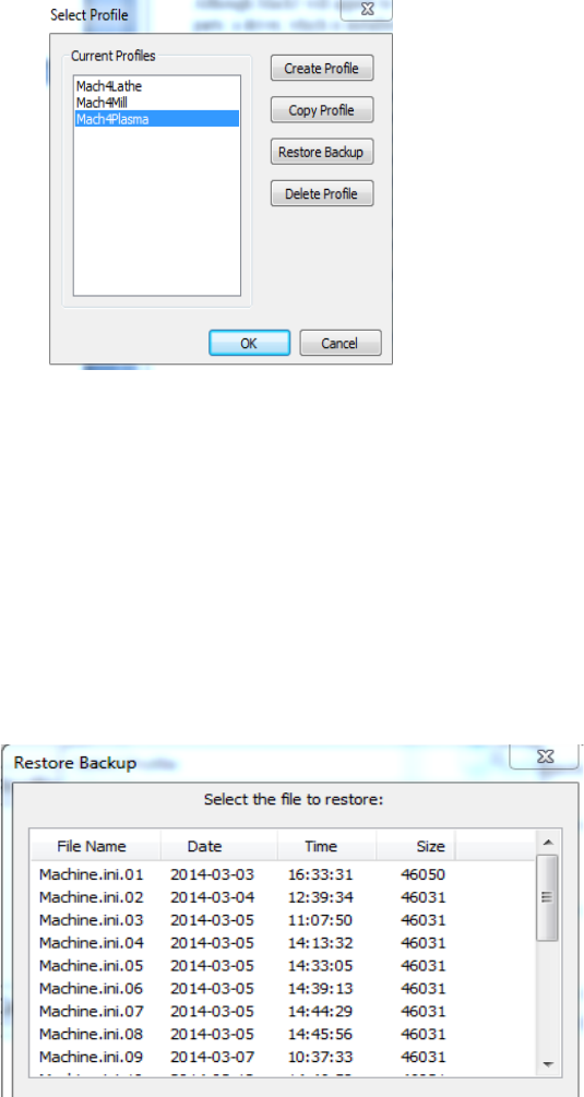
To test the installation double click on the Mach4 Icon that was placed on the desktop by the Mach4
installer. The icon will launch the MachGUI.exe executable and allow the selection of a profile. It is
recommended that a new profile is setup for the machine that is being configured. A new profile can be
generated by pressing the "Create Profile" button (see Figure 1),but this will create a blank profile. If a
similar setup is available the "Copy Profile" button (see Figure 1) can be used to copy all the profile
settings and create the profile.
7 Of 26
A "Copy Profile" is very powerful as it will copy all the machine settings such as the tool data, fixture
data, ini backups, Macros, and all machine settings. This can be used later to make a test profile to allow
changes to be made without harming the running machine profile. The profile can be removed after
testing is finished with the "Delete Profile" button. The profile settings can also be restored to a previous
session if a bad setting has been made. The "Restore Backup" button (see Figure 1) will launch the
Restore Backup dialog (see Figure 2). The machine.ini can be selected by looking at the Date and Time if
the last known running configuration.
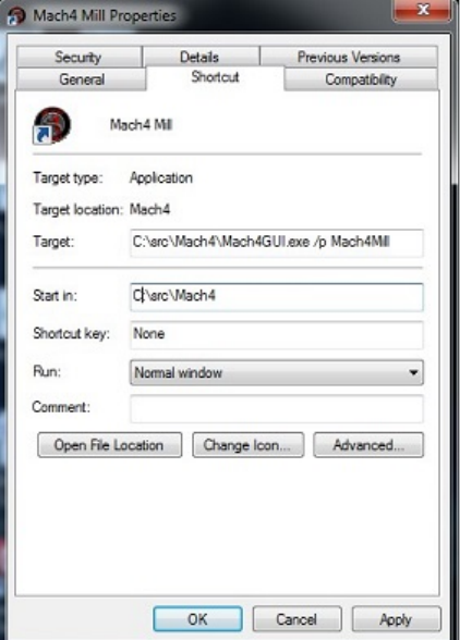
Create Shortcut to Profile
Figure 1
8 Of 26
A shortcut can be created to allow the an immediate launch of the software with a selected profile.
By adding the following " /p Mach4Mill" to the end of the target string (see Figure 3) allows
MachGUI.exe to load and immediately load the "Mach4Mill" profile.
Any other profile can be loaded by changing the profile name after the /p in the target string.
Chapter 3 Setting up the software
Step by step setting up of the machine
In this section the machine specific settings will be done to transform the software into a functioning
machine controller. The first step was to create a new profile to save the machine settings. This was done
as part of the installation process to protect the machine settings. If this was not done please review the
“Setting up the Profile” section of this manual.
By the end of this chapter a typical machine should be setup and capable of motion and IO (inputs and
outputs). In order to setup the machine the first step is to install all the plugins that you need for the
machine. Examples of plugins that may be needed could be Parallel Port and Modbus.
Note: If the software is locked the configuration settings may not be available. If the software is locked
non of the configuration dialogs will be available.
Fi 3
9 Of 26
Plugins and their function
The plugins in Mach4 are the building blocks of the system. The plugins all use the Mach4core.dll as a
base but have the power to add functionality to the system. Plugins can perform the following functions
Scipting, Motion, IO, File conversions, File loading, Motion Generation and countless other functions.
The ability to add such functionality is fundamental in the setup of the machine. The most important
plugin is the motion control plugin. A careful selection of plugins needs to be done to add the
appropriate functionality for the machine to be configured.
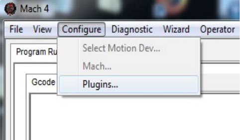
Adding and removing Plugins
To add a plugin from a plugin archive file m4plugw for windows, m4plugl for linux, and m4plugm for
mac. To load a plugin archive navigate to the "Configure Plugin" Dialog (see Figure 5) by navigating
Configure/Plugins (see Figure 4)
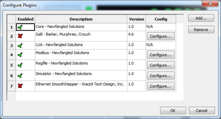
A plugin must be enabled to allow the plugin to function. The software must be restarted after enabling
or disabling to allow the plugin function to change its state. To remove a plugin highlight the row of the
plugin and press the "Remove" button (see Figure 5).
Configuring Plugins
The configuration of the plugins can be done from the "Configure Plugins" dialog (see Figure 5). Not
all plugins can be configured as they have no settings that can be customized. For the plugins that can be
configured a "configure" plugin button is available to the right of the pugin description. When the
configure button is pressed it will launch the configuration dialog supplied by the Plugin author. The
configuration of the device must be done before the devices IO can be accessed or used by Mach4. The
configuration of the plugins incorporated in the installer will be covered in appendixes to this document.
Fi 4
10 Of 26
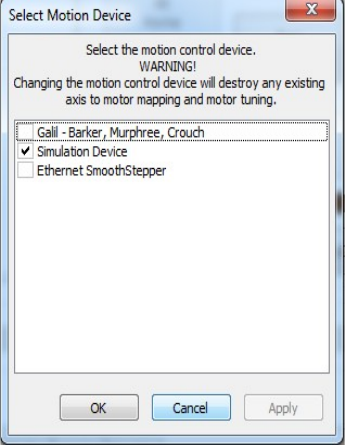
Select Motion device
The first device that needs to be setup is the motion device. To select the device go to
"Configure/Select Motion Dev." (see Figure 4). The "Select Motion Device " dialog (see Figure 6) allows
the appropriate motion device to be selected. The selected motion device tells the core what device can
drive the motors and the high speed IO. The all other motion devices are set to be deactivated and will
not allow the IO or motion to be controlled. The system must be restarted after motion device has been
selected to allow the motion device plugin to do its startup initialization. After the restart the motion
device needs to be configured. To configure the motion device please use the Motion device supplied
manual and continue setting up the software once it is complete.
Figure 5
11 Of 26
Other Plugins
The rest of the IO devices can be setup at this time if the settings are known. Some plugins that are
not fundamental to the machine can be setup at a later time. It is the responsibility of the installer to
determine what is needed to get the machine running. An example of a plugin that would need to be
setup and configured would be if a PLC was installed to enable the servo amps and machine. In this case
no testing can be done without Modbus communication to the PLC. To many machine configurations can
be done for this manual to take them into account so careful planning on the part of the installer is the
only way to get a system setup.
Chapter 4 Machine Settings
Default Modal State
The default state of the software is set at start-up or when the reset button is pressed. The following
options can be set and should only be set once. If the CV mode or some other setting needs to be
changed in a Gcode or for a short period of time, MDI should be used. The configuration dialogs are only
used for setting the start up state
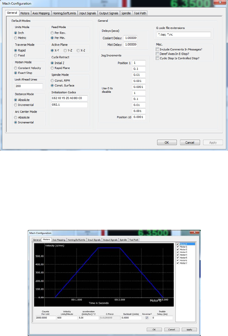
All configuration settings can be found in the "Mach Configuration" dialog (see Figure 7). The following is
a description of the settings that can be changed in the dialog (see Table 1).
Figure 6

12 Of 26
Setting
Description
Units Mode
Inch G20 / G21 Millimeters, The default units the machine is setup in such as
Traverse Mode
Rapid G00 / Feed G01
Motion Mode
Exact Stop G61 / Constant Velocity G64
Look Ahead Lines
Number of lines the interpreter can chain together to get to the programmed
Feedrate
Distance Mode
Absolute G90 / Incremental G91, Distance mode used by default
Arc Center Mode
Absolute G90.1 / Incremental G91.1, Distance mode for the IJK circle centers. R
type centers are not effected.
Feed Mode
Feed Per Rev G95 / Feed Per Min G94, feed mode used by linear and arc feed
moved. Feed per rev must have true spindle RPM to be used.
Active Plane
XY Plane G17 / XZ Plane G18 / YZ Plane G19, The plane selection used for Drill
cycles, Arcs and cutter comp
Cycle Retract
Initial Z G98 / Rapid Plane G99, Selects the can cycle position for the moves in
the working axis. The working axis is perpendicular to the current active plane.
Spindle Mode
Constant RPM G97 / Constance surface Speed G96, Selects the default spindle
speed mode.
Initialization Codes
The init codes are run when the program starts and also when the reset is
pressed
Coolant Delay
Time to wait for the Coolant to turn on
Mist Delay
Time to wait for the Mist to turn on
Jog Increments
Increments used for Incjog register
Gcode File
Extensions
The Gcode extensions for files to be executed. This sets the open able extensions
of the file open dialog.
Include Comments
in Message
Enabling the selection will add all comments in the Gcode file to the messages
log.
Deref Axis In E-
stop
Enabling sets the axis homing to be false when in E-stop is active
Cycle Stop is
Controlled Stop
Enabling will set the axis to do a controlled deceleration when a Cycle Stop is
commanded. A very slight delay will be seen as the axis comes to a stop.
Table 1: General Settings
13 Of 26
Motor Tuning
Motor tuning is one of the most important settings in configuring a machine. The settings available in
the motor tuning dialog (see Figure 8) will allow the motor to be setup for the appropriate Counts per
Unit, Max Velocity, Acceleration, Backlash, Direction Reversal and delay for enable signal. A detailed
description of each of the settings will be given in the following section.
Figure 7
Figure 8

14 Of 26
Counts Per Unit
The Counts Per Unit is used to convert the users units (Inches, Millimeters, Degrees,etc...) into
encoder counts or step pulses depending on the type of system. The counts per unit is a value that can
be found with mathematics. The value should never be “tuned” or “adjusted” because it is a
mathematical relationship with the drives, screw pitch, reduction ratio and so on. The following
examples will show how this value can be calculated:
Example 1: CNC Router with rack and pinion drive
Stepper Motor with 2000 Steps per Rev
Belt Reduction (Small Pulley 15 teeth(Input Gear), Large Pulley is 40 teeth(Output Gear))
Pitch Ratio of the Pinion gear is .765 “
(
)
=
(15
40)2000
.765 =6971.67756
Example 2: CNC Lathe with a lead screw
Lead of screw .25 inch Per Rev
Belt Reduction 15 tooth (Input Gear), 30 tooth (Output Gear)
Servo drive with 5000 encoder counts per rev
(
)
=
(15
30)5000
.25 =40,000
As a rule of thumb an inch machine should have the steps per unit greater then 5000 (200 for MM). A
value of 5000 will give a resolution of .0002 inches. A greater number of steps per unit will give better
performance as well as finer resolution. The only issue with a very high count per unit is that the max
velocity can become limited. The motion controller may only be able do deal with a limited number of
counts or steps per sec. Please check your motion controllers documentation to see get the max
frequency of the motors. If you would like to predict the max frequency this can also be done with
mathematics.
60 =
In the next examples we will consider the max velocity to be 200 Inches per minute
40,000 counts per unit,
=133,333.333 =133.33kHz

15 Of 26
6971.67756 counts per unit.
=23,238.93 =32.24
Velocity
The Velocity in the dialog is the maximum rate in units per min. This is also the velocity that will be
used for rapid moves when running Gcode.
Setting a Stepper:
On a stepper machine to set the max velocity a series of test need to be made. The Steps per Unit
must be set before the axis can be tested. Set a value of a max velocity that seems to be reasonable and
test with a jog at 100% jog rate. If the axis is able to move without missing steps (most times you will
hear a “buzzing” or “squealing” sound when steps are missed, repeat this process until the upper limit is
found. Once the max velocity is found the max velocity should then be set to 20% - 30% less. To insure
that there are no missed steps during motion.
Setting a Servo:
To set the max velocity of a servo machine a small series of tests can be preformed or it can be done
mathematically with some calculations. When testing the max rate of a servo and the max velocity is
exceeded the servo may fault from being out of position (digital servo) or will not get to max velocity and
make an abrupt stop. If ether one of the following happen the velocity must be lowered until the
behavior is fixed. Once the motor is fixed the velocity should be lowered by 5% to insure that the best
performance can be obtained.
Acceleration
The max acceleration sets how quickly the motor can get to speed. The higher the acceleration the
faster the cutting can be done. The higher the acceleration the quicker an axis can reverse and go around
corners. Cycle times can be lowered by running higher accelerations and lowering the max velocity. The
acceleration should not be raised to the point that it causes motor stalling, vibration in the frame, or
other unwanted vibration.
Backlash
Backlash is used to take out mechanical wind up in the drive system. The misconception is that
backlash can be used to fix “slop” in a screw/ ball-nut or slop in a rack and pinion. This can be used to
help fix the machine but is not the proper way to correct the problem. The only way to truly fix the issue
is to fix the mechanical issue. The backlash should never exceed .005 inches or .1 mm .
16 Of 26
Reverse
The reverse section is used to reverse the motion of the motor.
Enable Delay
Enable delay will allow a the enable signals to turn on with a delay. The delay can be used to stage the
enabling of the amps. This can be used to lower the inrush current by enabling the amps one by one.
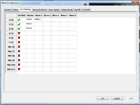
Axis Mapping
The axis mapping dialog (see Figure 9) is used to set what motors are used for an axis as well as the
homing order and max limits for the axis. The motors can be assigned to an axis with a maximum of 6
motors per axis. The axis will use the lowest max velocity and the lowest acceleration. This is done to
alow slave motors to not have the same motor settings as the other motors associated to he axis. The
steps per unit also do not need to be the same for each motor that is part of the axis.
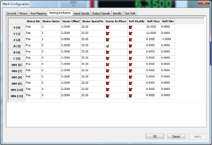
Homing and Limits
Setting the homing and limits will set what the machine will do when the machine enters a home
state or reaches a limit. The act of homing is fundamental in the operation of CNC's and automated
equipment. Homing the machine will set the machine zero position of the motors. This will be the base
from with all work / fixture offsets are calculated from. All the settings for the homing of the axis are
done in the Homing and Limits dialog (see Figure 10).
Figure 9
17 Of 26
Home Direction
This sets the direction to home the axis (see Figure 10). Pos for homing in the positive direction Neg
for homing in the negative direction.
Home Order
The sequence the axis home in can be controlled by setting the “Home Order” (see Figure 10). The
first axis to home will be axis with the number 0 and then subsequent axis will home with the next
greatest home order value. For example if you would like to home the Z axis first then the X and Y at the
same time the values would be as follows:
X=2
Y=2
Z=1
Home Offset
The home offset allows for a shift from the home switch position(see Figure 10). This can be used to
to shift the home position if the home switch is not located at the end of travel.
Figure 10

18 Of 26
Home Speed
The home speed is the rate the machine moves to detect the home switch (see Figure 10). The home
switch will set the machine zero position with the addition of any home offset. The Home Speed is set as
a percentage of the max velocity of the axis. Example :
MaxVel = 200 Units Per Min
HomeSpeed = 20%
(
100 ) = 40
200 (20
100) = 40
Home In Place
The Home in Place selection tells the axis to set the machine zero where it is when a home axis is
requested (see Figure 10). This feature is used on machines that have no home switches or an axis that
has no home switch. On a machine with no home switches the axis can be moved to the end of the
travel and lined up with an indicator mark. With the machine at the home position the home can be
triggered for that axis setting the machine position. This will allow the softlimits to be used and fixture
offsets.
Soft Enable
The state of the Soft Enable tells the core if the axis should be checked against the upper and lower
soft limits (see Figure 10). With the soft limits active the axis will decelerate to the Max or Min limit if it
is jogging and will prevent any incremental jogs past the limits. When running Gcode any moves panned
past the limits will not be done and the machine will be put into a stop condition and a soft limit error
will be displayed.
Soft Max / Soft Min
The max and min settings are the most positive and negative machine positions for the axis (see
Figure 10). The most simplistic way to get to get the values is to use the machine position DRO's. The
process is to home the machine, jog each axis to the most positive position in each axis and enter as the
positive soft limit. Then repeat the process in the negative direction and set the min soft limit.
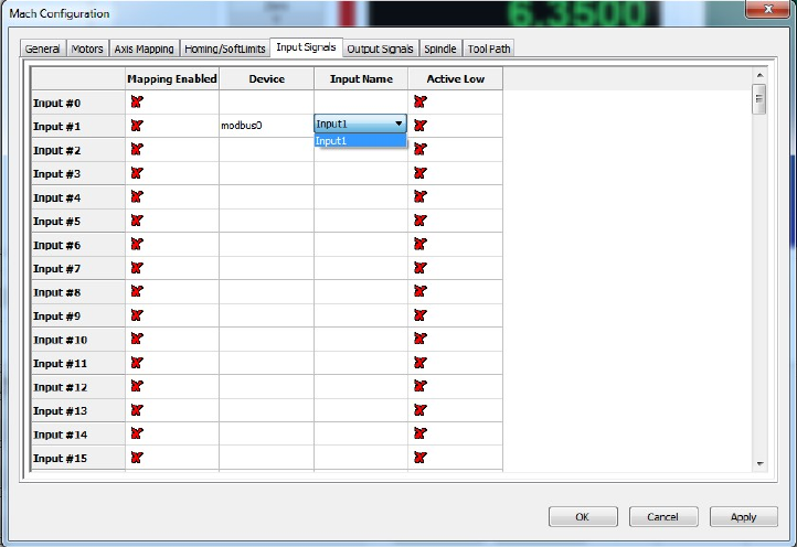
Signals in General
The signals are used to represent the internal state of items needed by the controller or items needed
to trigger IO for special functions. The signals can be triggered by Inputs, Outputs, Plugins, or Lua. When
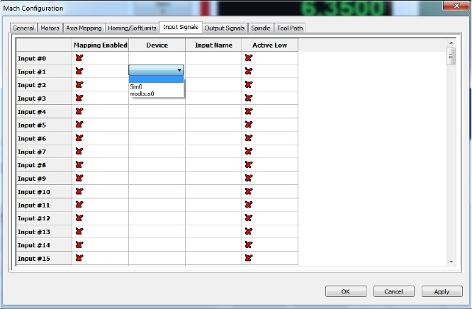
19 Of 26
a signal changes state, a state change event is propagated throughout the system and will be seen by all
plugins, and Lua event scripts. Later in the customization of Mach4 the utilization of Mach4's signals will
be seen. In the section the setup of triggering IO with signals will be shown. When setting up an IO point
the device's plugin must be first setup. A device could be a motion controller, bussed IO (modbus), Input
device (keyboard), Special Functions in plugins, etc.. The “Device” is the first selection and displays all
the registered IO devices to the system (see Figure 11)
Once the device is selected the appropriate Inputs / Outputs will be displayed in the I/O Name's
column. A drop down list will appear allowing the selection of the desired IO (see Figure 12). With the
Device and IO name selected the signal will now be tied to that IO. The Input signal will change state
when the Input assigned to it changes state, and Outputs are triggered by their associated Output
signals. The high / low state can be inverted by selecting the Active low state.
Figure 11
20 Of 26
Figure 12

21 Of 26
Input Signals
The input signals are used to connect Inputs from devices to Input Signals in the core. Some of the
most important signals are the Homing and Limit inputs. The Homing and Limits are set per motor NOT
per axis. The axis use motors to show what motors drive the axis and to display the state of the limits
and homes. As an example if Motor 1 and Motor 5 where used on the X axis and the + Limit was hit the X
axis would show positive limit as being active. The inputs of the motors are or'ed to the axis states.
Below is a complete list of the Input signals (See Table 2).
Input Signal
Description
Input #0 To
Input #63
User inputs that can be mapped to any function
Motor 0 Home To
Motor 31 Home
The home input of the motor with the associated number
Motor 0 ++ To
Motor 31 ++
Positive limit for the motor
Motor 0 – To
Motor 31 --
Negative limit for the motor
Digitize
Probe input for G31 commands
Index
Once per rev input for getting the RPM of the spindle
Limit Override
Override the limits to allow jogging when on a limit switch
E-Stop
Used to tell the core that the system is in E-stop. This input is NOT to
issue an an E-stop but to tell that the one has occurred with the proper
e-stop hardware (Master control relay disabled for example).
THC On
THC (Torch Height Control) is enabled allowing the head to be jogged up
and down while Gcode motion is active to keep a proper gap from the
plate to the tip.
THC Up
Move the Torch tip Up when THC is active , Disabled it THC On is off
THC Down
Move the Torch tip Down when THC is active, Disabled it THC On is off
Timing
More then one input per rev to get spindle speed (legacy input and may
not be in all motion devices).
Jog Axis +/-
Jog X+, Jog X-,Jog Y+... Command axis to jog in the +/- direction
Spindle At Speed
Input to tell the the spindle is at the commanded Speed. This will take
the place of the spindle speed up delay if enabled.
Spindle At Zero
Input to tell the spindle has reached zero Speed. This will take the place
of the Spindle deceleration time if enabled.
Table 2: Input Signals

22 Of 26
Output Signals
The output signals are used to tie the device outputs to the output signals. The output signals can be
used to drive outputs directly for things such as Spindle ouputs, Coolant, indicator lights on panels and
so on.
Output Signal
Description
X ++
Activated when one of the motors that makes up the X axis has a positive limit
switch pressed.
X --
Activated when one of the motors that makes up the X axis has a negative limit
switch pressed.
X Home
Activated when one of the motors that makes up the X axis has a Home switch
pressed.
Y ++
Activated when one of the motors that makes up the Y axis has a positive limit
switch pressed.
Y --
Activated when one of the motors that makes up the Y axis has a negative limit
switch pressed.
Y Home
Activated when one of the motors that makes up the Y axis has a Home switch
pressed.
Z ++
Activated when one of the motors that makes up the Z axis has a positive limit
switch pressed.
Z --
Activated when one of the motors that makes up the Z axis has a negative limit
switch pressed.
Z Home
Activated when one of the motors that makes up the Z axis has a Home switch
pressed.
A ++
Activated when one of the motors that makes up the A axis has a positive limit
switch pressed.
A --
Activated when one of the motors that makes up the A axis has a negative limit
switch pressed.
A Home
Activated when one of the motors that makes up the A axis has a Home switch
pressed.
B ++
Activated when one of the motors that makes up the B axis has a positive limit
switch pressed.
B --
Activated when one of the motors that makes up the B axis has a negative limit
switch pressed.
B Home
Activated when one of the motors that makes up the B axis has a Home switch
pressed.
C ++
Activated when one of the motors that makes up the C axis has a positive limit
switch pressed.
C --
Activated when one of the motors that makes up the C axis has a negative limit
switch pressed.
C Home
Activated when one of the motors that makes up the C axis has a Home switch
pressed.
Enable #0 →
Enable #31
Enable will be active when the machine is enabled. The enables can be turned
on with a delay set under the motor tuning dialog. If the axis that uses the
motor is not enabled the motor will not get an enable signal

23 Of 26
Output Signal
Description
Output #0 →
Output #63
Output #0 → #63 are used for OEM and user output signals
Gcode Running
Output is active when running Gcode, used for indicator lights to show a file is
running
Feed Hold
Output is active when in a Feed Hold state
Block Delete
Output is active when Block delete is active
Single Block
Output is active when Single Block is active
Reverse Run
Output is active when Reverse Run is active (reverse run is to run a file
backwards)
Opt Stop
Output is active when optional stop is active (stop on M01's in Gcode file)
Machine Enabled
Output is active when the machine is in an enabled state
Tool Change
Output is active when a tool change is active or waiting for a Cycle start when
in manual toolchange
Dist To Go
Output active when selectable DRO is set to display Distance To Go (distance
from end point of the current move)
Machine coord
Output active when selectable DRO is set to display Machine Position (position
from the home switch)
Softlimits On
Output active when the softlimits are active
Jog Inc
Output active when the cores user Jog mode is set to Incremental jog mode
Jog Cont
Output active when the cores user Jog mode is set to continuous jog mode
Jog Enabled
Output active when the cores user Jog mode is enabled
Jog MPG
Output active when the cores user Jog mode is set to Manual Pulse Generator
(MPG) jog mode
X Homed
Output active when a home cycle has been completed for the X axis
Y Homed
Output active when a home cycle has been completed for the Y axis
Z Homed
Output active when a home cycle has been completed for the Z axis
A Homed
Output active when a home cycle has been completed for the A axis
B Homed
Output active when a home cycle has been completed for the B axis
C Homed
Output active when a home cycle has been completed for the C axis
Dwell
Output active when a Dwell is acitve (G4 command in Gcode)
Toolpath Mouse
Down
Output toggles when the toolpath is set to report the mouse position and Core
is set to report clicks. See Lua Script manual to set the core into Toolpath
capture mode
Limit Override
Output active when the Limit override is acitve
Charge Pump #1
Output when the Charge Pump #1 should be active
Charge Pump #2
Output when the Charge Pump #2 should be active
Current Hi/Low
Output active when motion is about to be done to set drive to be in high
current mode
Spindle On
Output active when the spindle is on
Spindle Fwd
Output active when the spindle is running in forward direction
Spindle Rev
Output active when the spindle is running in the reverse direction
Coolant On
Output active when the Coolant is set to be on
Mist On
Output active when the Mist is set to be on

24 Of 26
Output Signal
Description
Digitize Trigger
Output active with the digitize input is active
Table 3: Output Settings
Spindle
The Spindle dialog allows the configuration and setup of up to 20 spindle rages. The spindle ranges can
be gears and or belt settings to allow for a change in the range of speeds avalable.
Output Signal
Description
MinRPM
The minimum RPM the spindle in the selected range
MaxRPM
The maximum RPM the spindle in the selected range
Accel Time
The time to accerate the spindle in the slected range. If the “Spindle At Speed”
signal is enabled the Accel Time is not need and should be set to zero. Any
value in the Accel Time field will be done after the Spindle At Speed signal has
been toggled.
Decel Time
The time to decelerate the spindle in the slected range. If the “Spindle At Zero”
signal is enabled the Decel Time is not need and should be set to zero. Any
value in the Decel Time field will be done after the Spindle At Zero signal has
been toggled.
Feedback Ratio
By default the Feedback ratio is 1, a value of one is used in an application
where the feed back device is mounted on the spindle. If the feedback device is
mounted on the motor or some other part of th gear train the feedback ratio
can be used to get the correct speed.
Reversed
Reversed selection allows the spindle motor to reverse the direction based on
the reversed check box. This selection is used when a gear or ratio causes a
reverse in the spindle direction. It is common for knee type mills to reverse
direction from high to low range.
Max Motor RPM
The maximum RPM of the spindle motor. The reason for the maximum RPM is to allow for proper
scalling of the motors RPM on all ranges. The motor RPM is used by motion devices, plugins, VFD's, Lua
etc for planning the proper motor RPM to get the requested spindle RPM.
Motor as Spindle
With this selection a stepper motor, servo motor, or VFD that can be setup as a motor in the motion
device. The motor will be treated as an out of band axis and will use the motors acceleration settings.
25 Of 26
Tool Path Settings
The toolpath has some parameters that can be changed to allow better visualation of the toolpath.
The colors of the toolpath can be changed to allow for a better “looking” toolpath. But more importantly
is the ablilty to change the color of the toolpath to aid color blind users.
Machine Limits
The machine limits can be show in the toolpath, showing where the machine can traverse to by
displaying dotted lines.
Extended Functionality
To get more extended functionality and or customization, Plugins and or scripts will need to be added
and configured. The Customization and scripting manual covers topics such as on screen buttons to
trigger outputs, Tool changers, Buttons to move the machine to a specific location, hardware buttons for
operator interfaces, etc. Some of the plugins are covered in the appendixes for your convenience . If the
plugin of interest is not covered in the appendix please visit www.machsupport.com and look under
Mach4 plugins for more information.

26 Of 26
Appendix A mcKeyboard (how to get keyboard input)
Purpose:
Reading keyboard inputs and getting all key presses even if Mach4 is not in focus.
Description:
Mach4 has no native way of getting the key presses to the “jog” buttons or any other buttons for
that matter. Mach4 is designed to use inputs to trigger event. This is a fundamental difference
from most software packages and allows custom operator panels to be made with the
maximum amount of functionality. McKeyboard will consume any key presses that it is mapped
to while it is enabled.
Operation:
The disabling of the keyboard can be done many ways. The first way is to click on the CNC
Keyboard Icon in the taskbar and when disabled a red X will appear on the keyboard icon.
Setup:
Test:
