FrontBravos Maytag Bravos Washer 8178643
Maytag Bravos Washer W 6Th Sense Tech 8178643 Maytag Bravos Washer w 6th Sense Tech 8178643 Maytag Bravos Washer w 6th Sense Tech 8178643 Maytag, Magic Chef, Jenn Air applianceservicesecretsmembership.com_manuals
2013-04-06
: Pdf Maytag - Bravos Washer - 8178643 Maytag - Bravos Washer - 8178643 Maytag, Magic Chef, Jenn Air
Open the PDF directly: View PDF ![]() .
.
Page Count: 84

TECHNICAL EDUCATION
JOB AID 8178643
ML-
6
MODELS: MTW6500TB
MTW6600TB
MTW6600TQ
AUTOMATIC WASHER
WITH 6TH SENSE
™
TECHNOLOGY
™

- ii -
WHIRLPOOL CORPORATION assumes no responsibility for any repairs made on
our products by anyone other than Authorized In-Home Service Professionals.
FORWARD
This Maytag Job Aid, “Bravos™ Automatic Washer With 6th Sense™ Technology” (Part No.
8178643), provides the In-Home Service Professional with information on the installation, op-
eration, and service of the Bravos™ Automatic Washer With 6th Sense™ Technology. For specific
information on the model being serviced, refer to the “Use and Care Guide,” or “Tech Sheet”
provided with the washer.
The Wiring Diagram used in this Job Aid is typical and should be used for training purposes only.
Always use the Wiring Diagram supplied with the product when servicing the washer.
GOALS AND OBJECTIVES
The goal of this Job Aid is to provide information that will enable the In-Home Service Profes-
sional to properly diagnose malfunctions and repair the Bravos™ Automatic Washer With 6th
Sense™ Technology.
The objectives of this Job Aid are to:
Understand and follow proper safety precautions.
Successfully troubleshoot and diagnose malfunctions.
Successfully perform necessary repairs.
Successfully return the washer to its proper operational status.
•
•
•
•
Copyright © 2007, Whirlpool Corporation, Benton Harbor, MI 49022
- iii -
TABLE OF CONTENTS
Page
GENERAL . . . . . . . . . . . . . . . . . . . . . . . . . . . . . . . . . . . . . . . . . . . . . . . . . . . . . . . . . . . . . . 1-1
Washer Safety . . . . . . . . . . . . . . . . . . . . . . . . . . . . . . . . . . . . . . . . . . . . . . . . . . . . . . . . . . 1-1
Model & Serial Number Designations . . . . . . . . . . . . . . . . . . . . . . . . . . . . . . . . . . . . . . . . 1-2
Model & Serial Number Label & Tech Sheet Locations . . . . . . . . . . . . . . . . . . . . . . . . . . . 1-3
Specifications . . . . . . . . . . . . . . . . . . . . . . . . . . . . . . . . . . . . . . . . . . . . . . . . . . . . . . . . . . 1-4
INSTALLATION INFORMATION . . . . . . . . . . . . . . . . . . . . . . . . . . . . . . . . . . . . . . . . . . . . . 2-1
Installation Requirements . . . . . . . . . . . . . . . . . . . . . . . . . . . . . . . . . . . . . . . . . . . . . . . . . 2-1
Installation Instructions . . . . . . . . . . . . . . . . . . . . . . . . . . . . . . . . . . . . . . . . . . . . . . . . . . . 2-5
PRODUCT OPERATION . . . . . . . . . . . . . . . . . . . . . . . . . . . . . . . . . . . . . . . . . . . . . . . . . . . 3-1
Theory Of Operation . . . . . . . . . . . . . . . . . . . . . . . . . . . . . . . . . . . . . . . . . . . . . . . . . . . . . 3-1
Washer Use . . . . . . . . . . . . . . . . . . . . . . . . . . . . . . . . . . . . . . . . . . . . . . . . . . . . . . . . . . . . 3-3
Washer Care . . . . . . . . . . . . . . . . . . . . . . . . . . . . . . . . . . . . . . . . . . . . . . . . . . . . . . . . . . 3-12
Troubleshooting . . . . . . . . . . . . . . . . . . . . . . . . . . . . . . . . . . . . . . . . . . . . . . . . . . . . . . . . 3-14
COMPONENT ACCESS . . . . . . . . . . . . . . . . . . . . . . . . . . . . . . . . . . . . . . . . . . . . . . . . . . . 4-1
Component Locations . . . . . . . . . . . . . . . . . . . . . . . . . . . . . . . . . . . . . . . . . . . . . . . . . . . . 4-1
Removing The Encoder And The User Interface Board . . . . . . . . . . . . . . . . . . . . . . . . . . 4-2
Removing The Water Inlet/Dispenser Valve Assembly, Power Supply Cord,
And Machine/Motor Control & Pressure Transducer . . . . . . . . . . . . . . . . . . . . . . . . . . . 4-4
Removing A Dispenser, The Fresh Fill Inlet Valve, And The Lid Lock . . . . . . . . . . . . . . . . 4-6
Removing The Lid And A Hinge . . . . . . . . . . . . . . . . . . . . . . . . . . . . . . . . . . . . . . . . . . . . . 4-9
Removing The Basket, Basket Hub, & Lint Filter . . . . . . . . . . . . . . . . . . . . . . . . . . . . . . 4-10
Removing The Drain And Recirculation Pumps . . . . . . . . . . . . . . . . . . . . . . . . . . . . . . . 4-12
Removing The Drive Motor & Rotor Position Sensor . . . . . . . . . . . . . . . . . . . . . . . . . . . 4-14
Removing The Tub . . . . . . . . . . . . . . . . . . . . . . . . . . . . . . . . . . . . . . . . . . . . . . . . . . . . . 4-16
Accessing The Pressure Transducer Tubing, Recirculation Tube,
And Drain Pump Harness . . . . . . . . . . . . . . . . . . . . . . . . . . . . . . . . . . . . . . . . . . . . . . 4-18
COMPONENT TESTING . . . . . . . . . . . . . . . . . . . . . . . . . . . . . . . . . . . . . . . . . . . . . . . . . . . 5-1
Water Inlet/Dispenser Valve Assembly . . . . . . . . . . . . . . . . . . . . . . . . . . . . . . . . . . . . . . . 5-1
Drain Pump . . . . . . . . . . . . . . . . . . . . . . . . . . . . . . . . . . . . . . . . . . . . . . . . . . . . . . . . . . . . 5-2
Recirculation Pump . . . . . . . . . . . . . . . . . . . . . . . . . . . . . . . . . . . . . . . . . . . . . . . . . . . . . . 5-2
Lid Lock . . . . . . . . . . . . . . . . . . . . . . . . . . . . . . . . . . . . . . . . . . . . . . . . . . . . . . . . . . . . . . . 5-3
Drive Motor Stator . . . . . . . . . . . . . . . . . . . . . . . . . . . . . . . . . . . . . . . . . . . . . . . . . . . . . . . 5-4
DIAGNOSTICS & TROUBLESHOOTING . . . . . . . . . . . . . . . . . . . . . . . . . . . . . . . . . . . . . . 6-1
Display Fault/Error Codes . . . . . . . . . . . . . . . . . . . . . . . . . . . . . . . . . . . . . . . . . . . . . . . . . 6-1
Diagnostic Guide . . . . . . . . . . . . . . . . . . . . . . . . . . . . . . . . . . . . . . . . . . . . . . . . . . . . . . . . 6-4
Diagnostic Tests . . . . . . . . . . . . . . . . . . . . . . . . . . . . . . . . . . . . . . . . . . . . . . . . . . . . . . . . 6-4
Troubleshooting Guide . . . . . . . . . . . . . . . . . . . . . . . . . . . . . . . . . . . . . . . . . . . . . . . . . . . 6-9
Troubleshooting Tests . . . . . . . . . . . . . . . . . . . . . . . . . . . . . . . . . . . . . . . . . . . . . . . . . . . . 6-9
Accessing & Removing The Electronic Assemblies . . . . . . . . . . . . . . . . . . . . . . . . . . . . . 6-15
WIRING DIAGRAM . . . . . . . . . . . . . . . . . . . . . . . . . . . . . . . . . . . . . . . . . . . . . . . . . . . . . . . 7-1
- iv -
— NOTES —

1-1
GENERAL
WASHER SAFETY
Your safety and the safety of others are very important.
We have provided many important safety messages in this manual and on your appliance.
Always read and obey all safety messages.
This is the safety alert symbol.
This symbol alerts you to potential hazards that can kill or hurt you and others.
All safety messages will follow the safety alert symbol and either the word
“DANGER” or “WARNING.” These words mean:
All safety messages will tell you what the potential hazard is, tell you how to reduce the
chance of injury, and tell you what can happen if the instructions are not followed.
You can be killed or seriously injured if you don’t
immediately follow instructions.
You can be killed or seriously injured if you don’t
follow instructions.
DANGER
WARNING

1-2
MODEL & SERIAL NUMBER DESIGNATIONS
MODEL NUMBER
SERIAL NUMBER
SERIAL NUMBER C U 41 10200
MANUFACTURING SITE
C = Clyde, OH
YEAR OF PRODUCTION
U = 2007
WEEK OF PRODUCTION
41 = 41st Week
PRODUCT SEQUENCE NUMBER
MODEL NUMBER M T W 6 6 00 T B 0
BRAND
M = Maytag
ACCESS / FUEL
T = Top Load G = Gas
F = Front Load H = Horizontal
W = Work Space V = Vertical
E = Electric
PRODUCT
W = Washer P = Pedestal
D = Dryer B = Combo
T = Thin Twin C = Compact
SERIES
1 = Innovation 6 = Oasis
2 = Commercial 7 = Merloni
3 = Compact 8 = Horizon
4 = Stack 9 = Duet/Combo
5 = LEAP
PRICE POINT LEVELS (1 - 7)
TRADE PARTNER
00 = Brand 30 = NATM
10 = SBC 40 = Lowe’s
20 = Best Buy
YEAR OF INTRODUCTION
T = 2007
COLOR CODE
Q = White
B = Black
ENGINEERING CHANGE
0 = Basic Original Release
1 = First Revision
1-3
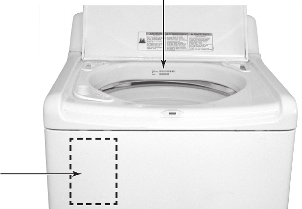
MODEL & SERIAL NUMBER LABEL &
TECH SHEET LOCATIONS
The Model/Serial Number Label and Tech Sheet locations are shown below.
Model/Serial Number Location
Tech Sheet Location
(Access Under Cabinet Top)

1-4
SPECIFICATIONS
MODEL NUMBERS MTW6500TB MTW6600TQ, B
PRIMARY FEATURES
CAPACITY (IEC) 4.5 CU FT 4.5 CU FT
USABLE CAPACITY 18 LBS (8.16 KG) 18 LBS (8.16 KG)
MAX SPIN SPEED 950 1000
EXTERIOR
LID FINISH PORCELAIN POWDER COAT
LID SOLID GLASS
TOP FINISH PORCELAIN PORCELAIN
AGITATOR --- ---
WASHPLATE IMPELLER IMPELLER
SOUND PACK Q. WASH PLUS Q. WASH ULTRA
TUB WRAP NO YES
MASTIC (FRONT) 1 - 4 X 12 PIECE 1 - 4 X 12 PIECE
CABINET PAD YES YES
LID SEALS NO YES
MAIN DRIVE MOTOR BRUSHLESS PERM MAGNET BRUSHLESS PERM MAGNET
DISPENSERS
MAIN DETERGENT YES YES
TYPE FLUSH FLUSH
CAPACITY 2/3 CUP 2/3 CUP
BLEACH YES YES
TYPE FLUSH/TIMED FLUSH/TIMED
CAPACITY 1 CUP 1 CUP
FABRIC SOFTENER YES YES
TYPE FLUSH/TIMED FLUSH/TIMED
CAPACITY 1/2 CUP 1/2 CUP
CYCLE DEFINITIONS
# OF CYCLES 10
SUPER WASH
NORMAL
WHITES
DELICATE
WRINKLE CONTROL
SHEETS
COLORS / JEANS
RAPID WASH
BULKY
HANDWASH
—
11
SUPER WASH
NORMAL
WHITES
DELICATE
WRINKLE CONTROL
SHEETS
COLORS / JEAN
RAPID WASH
BULKY
HANDWASH
SOAK
DELAY START —
RINSE & SPIN
SPIN ONLY
CLEAN WASHER
YES -10 HOURS
RINSE & SPIN
SPIN ONLY
CLEAN WASHER
OPTIONS
FINAL SPIN SPEEDS SELECTABLE (3) L, M, H SELECTABLE (4) NO SPIN, L, M, H
SOAK PRE SOAK PRE SOAK
CATALYST OPTIONS STAIN CYCLE
EXTRA RINSE
STAIN CYCLE
EXTRA RINSE

1-5
MODEL NUMBERS MTW6500TB MTW6600TQ, B
SECONDARY
EOC OFF / LOW / HIGH OFF / LOW / HIGH
TIME REMAINING YES YES
TEMPS 5 - 4 ATC 5 - 4 ATC
ATC TEMPS H/C , W/W, W/C, C/C H/C , W/W, W/C, C/C
AUTO WATER LEVEL YES YES
WATER LEVELS AUTO - NON SELECTABLE MIN. LEVEL = 3.5˝
(9 CM) ABOVE BASKET BOTTOM
AUTO - NON SELECTABLE MIN. LEVEL =
3.5˝ (9 CM) ABOVE BASKET BOTTOM
SOIL LEVELS 4 4
STATUS LED’S WASH (4) / STATUS (3)
SOAK
WASH
RINSE
SPIN
CLEAN
ADD-A-GARMENT
LID LOCK
WASH (4) / STATUS (3)
SOAK
WASH
RINSE
SPIN
CLEAN
ADD-A-GARMENT
LID LOCK
ADDITIONAL INFORMATION
COLORS BLACK WHITE / BLACK
SIZE ( W X D X H ) 28 X 27 X 42 IN (71.2 x 68.5 X 106.6 CM) 28 X 27 X 42 IN (71.2 x 68.5 X 106.6 CM)
WEIGHT (IN CARTON) 165 LBS (74.8 KG) 165 LBS (74.8 KG)
1-6
— NOTES —
2-1
INSTALLATION INFORMATION
INSTALLATION REQUIREMENTS
TOOLS AND PARTS
Gather the required tools and parts before
starting installation. The parts supplied are in
the washer basket.
Tools needed for connecting the drain
hose and water inlet hoses:
Pliers that open to 1-9/16˝ (3.95 cm)
Flashlight (optional)
NOTE: Replace inlet hoses after 5 years of
use to reduce the risk of hose failure. Record
hose installation or replacement dates for fu-
ture reference.
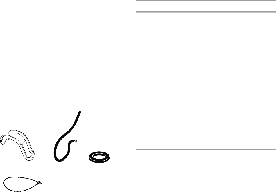
Parts Supplied:
•
•
Alternate Parts
Tools needed for securing the drain hose
and leveling the washer:
Adjustable or open end wrench 9/16˝
(14 mm)
Level
Wood block
Ruler or measuring tape
•
•
•
•
A. Drain hose form
B. Water inlet hoses (2)
C. Flat water inlet hose washers (4)
D. Beaded tie strap
A B C
D
If You Have: You Will Need to Buy:
Laundry tub or
standpipe taller
than 96˝ (2.4 m)
Sump pump system (if not already
available)
1˝ (2.5 cm)
diameter
standpipe
2˝ (5 cm) diameter to 1˝ (2.5 cm)
diameter standpipe adapter,
Part Number 3363920 and connector kit
Part Number 285835
Overhead sewer Standard 20 gal. (76 L) 39˝ (99 cm) tall
drain tub or utility sink, sump pump and
connectors (available from local
plumbing suppliers)
Floor drain Siphon break, Part Number 285834;
additional drain hose,
Part Number 8318155 and connector
kit, Part Number 285835
Water faucets
beyond reach of
fill hoses
2 longer water fill hoses:
6 ft (1.8 m) Part Number 76314,
10 ft (3.0 m) Part Number 350008
Lint clogged drain Drain protector, Part Number 367031
2-2
LOCATION REQUIREMENTS
Selecting the proper location for your washer
improves performance and minimizes noise
and possible washer “walk.”
The washer can be installed in a basement,
laundry room, closet, or recessed area. See
“Drain System,” page 2-3.
IMPORTANT: Do not install or store the wash-
er where it will be exposed to the weather.
Proper installation is your responsibility.
You will need:
A water heater set to deliver 120°F (49°C)
water to the washer.
A grounded electrical outlet located with-
in 4 ft (1.2 m) of where the power cord is
attached to the back of the washer. See
“Electrical Requirements,” page 2-4.
Hot and cold water faucets located within
3 ft (90 cm) of the hot and cold water fill
valves, and water pressure of 20-100 psi
(138-690 kPa) for best performance.
A level floor with a maximum slope of
1˝(2.5 cm) under entire washer. Install-
ing the washer on carpeting is not recom-
mended.
A sturdy floor to support the washer
weight (washer, water and load) of 315 lbs
(143 kgs).
Do not store or operate your washer in tem-
peratures at or below 32°F (0°C). Some wa-
ter can remain in the washer and can cause
damage in low temperatures.
•
•
•
•
•
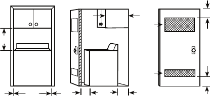
INSTALLATION SPACING FOR RECESSED
AREA AND CLOSET INSTALLATIONS
The following spacing dimensions are rec-
ommended for this washer. This washer has
been tested for installation with spacing of 0˝
(0 cm) clearance on the sides. Recommend-
ed spacing should be considered for the fol-
lowing reasons:
Additional spacing should be considered
for ease of installation and servicing.
Additional spacing should be considered
on all sides of the washer to reduce noise
transfer.
For closet installation with a door, minimum
ventilation openings in the top and bottom
of the door are required. Louvered doors
with equivalent ventilation openings are
acceptable.
Companion appliance spacing should also
be considered.
•
•
•
•
A. Front view
B. Side view
C. Closet door with vents
ABC
17"*
(43.2 cm)
1"
(2.5 cm)
1"
(2.5 cm)
27-1/2"
(69.9 cm)
1"*
(2.5 cm)
27"
(68.6 cm)
5"*
(12.7 cm)
14"
*
max.
(35.6 cm)
3"*
(7.6 cm)
3"*
(7.6 cm)
24 in. *
(155 cm )
2
2
48 in. *
(310 cm )
2
2
* Required spacing
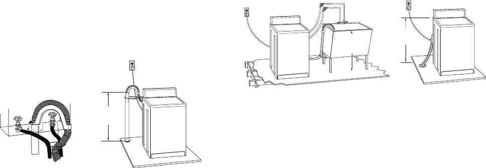
2-3
AB
(99 cm)
39"
DRAIN SYSTEM
The washer can be installed using the stand-
pipe drain system (floor or wall), the laundry
tub drain system, or the floor drain system.
Select the drain hose installation method you
need. See “Tools and Parts,” page 2-1.
STANDPIPE DRAIN SYSTEM—WALL OR
FLOOR (VIEWS A & B)
The standpipe drain requires a minimum di-
ameter standpipe of 2˝ (5 cm). The minimum
carry-away capacity can be no less than 17
gal. (64 L) per minute. A 2˝ (5 cm) diameter to
1˝ (2.5 cm) diameter standpipe adapter kit is
available. See “Tools and Parts,” page 2-1.
The top of the standpipe must be at least 39˝
(99 cm) high and no higher than 96˝ (244 cm)
from the bottom of the washer.
LAUNDRY TUB DRAIN SYSTEM (VIEW C)
The laundry tub needs a minimum 20 gal.
(76 L) capacity. The top of the laundry tub
must be at least 39˝ (99 cm) above the floor
and no higher than 96˝ (244 cm) from the
bottom of the washer.
FLOOR DRAIN SYSTEM (VIEW D)
The floor drain system requires a siphon break
that may be purchased separately. See “Tools
and Parts,” page 2-1.
The siphon break must be a minimum of 28˝
(71 cm) from the bottom of the washer. Addi-
tional hoses might be needed.
CD
39"
(99 cm)
28"
(71 cm)
2-4
Electrical Shock Hazard
Plug into a grounded 3 prong outlet.
Do not remove ground prong.
Do not use an adapter.
Do not use an extension cord.
Failure to follow these instructions can
result in death, fire, or electrical shock.
A 120 volt, 60 Hz., AC only, 15- or 20-
amp, fused electrical supply is required. A
time-delay fuse or circuit breaker is recom-
mended. It is recommended that a sepa-
rate circuit serving only this appliance be
provided.
This washer is equipped with a power sup-
ply cord having a 3 prong grounding plug.
To minimize possible shock hazard, the
cord must be plugged into a mating, 3
prong, grounding-type outlet, grounded
in accordance with local codes and ordi-
nances. If a mating outlet is not available,
it is the personal responsibility and obli-
gation of the customer to have the prop-
erly grounded outlet installed by a qualified
electrician.
If codes permit and a separate ground wire
is used, it is recommended that a qualified
electrician determine that the ground path
is adequate.
Do not ground to a gas pipe.
Check with a qualified electrician if you are
not sure the washer is properly grounded.
Do not have a fuse in the neutral or ground
circuit.
•
•
•
•
•
•
•
ELECTRICAL REQUIREMENTS
GROUNDING INSTRUCTIONS
For a grounded, cord-connected washer:
This washer must be grounded. In the event
of a malfunction or breakdown, grounding
will reduce the risk of electrcal shock by
providing a path of least resistance for elec-
tric current. This washer is equipped with a
cord having an equipment-grounding con-
ductor and a grounding plug. The plug must
be plugged into an appropriate outlet that
is properly installed and grounded in accor-
dance with all local codes and ordinances.
WARNING: Improper connection of the
equipment-grounding conductor can result
in a risk of electric shock. Check with a quali-
fied electrician or serviceman if you are in
doubt as to whether the appliance is properly
grounded.
Do not modify the plug provided with the
appliance—if it will not fit the outlet, have a
proper outlet installed by a qualified electri-
cian.
For a permanently connected washer:
This washer must be connected to a ground-
ed metal, permanent wiring system, or an
equipment-grounding conductor must be
run with the circuit conductors and connect-
ed to the equipment-grounding terminal or
lead on the appliance.
WARNING
2-5
INSTALLATION INSTRUCTIONS
WARNING
Excessive Weight Hazard
Use two or more people to move and
install washer.
Failure to do so can result in back or
other injury.
NOTE: To avoid floor damage, set the washer
onto cardboard before moving across floor.
IMPORTANT:
Be sure the foam shipping base has been
removed from the bottom of the washer as
directed in the Unpacking Instructions.
If foam shipping base has not been re-
moved, be sure lid is secured with tape be-
fore laying washer on its back.
Removing the foam shipping base is nec-
essary for proper operation.
REMOVE SHIPPING BASE
AND PACKING RING
1. Place cardboard supports from shipping
carton on floor behind washer for sup-
port.
2. Secure the lid with tape.
3. Using 2 or more people, tip the washer
onto its back and place on cardboard
supports.
4. Remove foam shipping base.
•
•
•
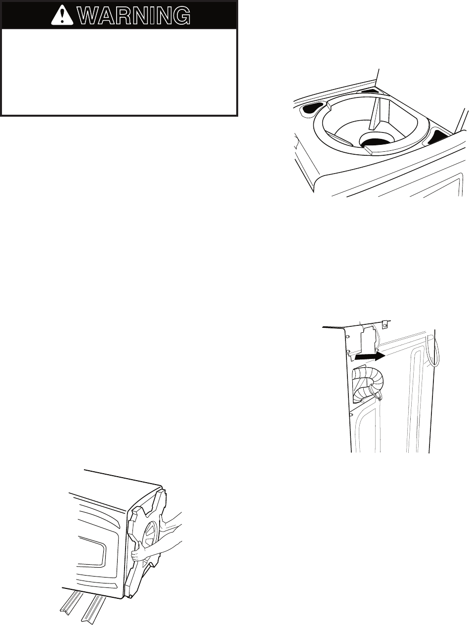
5. Set washer upright.
6. Remove tape from lid. Open lid and re-
move foam packing ring from washer tub.
Keep foam packing ring in case you need
to move the washer in the future.
CONNECT THE DRAIN HOSE
Proper connection of the drain hose protects
your floors from damage due to water leak-
age. Read and follow these instructions.
The drain hose is connected to your washer
and is stored inside the washer cabinet.
2-6
REMOVE DRAIN HOSE
FROM WASHER CABINET
Pull the corrugated drain hose out of the
washer by first grabbing the pull tie. Continue
to pull the hose until the end emerges. Do not
force excess drain hose back into the rear of
the washer.
LAUNDRY TUB DRAIN
OR STANDPIPE DRAIN
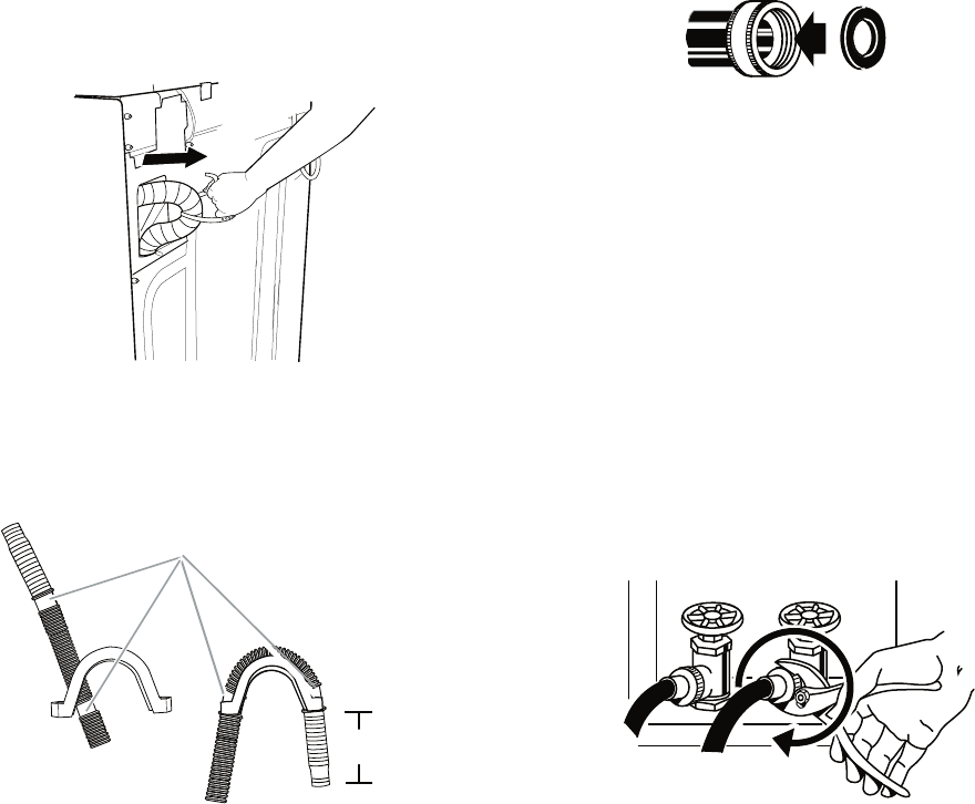
Connecting the drain hose form to the cor-
rugated drain hose
To keep drain water from going back into
the washer:
Do not force excess drain hose into stand-
pipe. Hose should be secure but loose
enough to provide a gap for air.
Do not lay excess hose on the bottom of
the laundry tub.
FLOOR DRAIN
Do not install the drain hose form on to the
corrugated drain hose. You may need addi-
tional parts. See Floor drain under “Tools and
Parts,” page 2-1.
•
•
A. Coupling
B. Washer
A B
sfeiler es
o
h niarD .A
e
soh
niard f
o
d
ne
ec
alP .
mr
of
fo dne e
n
o ot
ni
esoh nia
r
d
f
o d
ne
deeF.1
.
f
eile
r
esoh n
i
a
r
d eht o
t
ni m
r
of
fo d
n
e re
hto
eht
otn
i
d
e
ef
dna m
r
o
f
eht f
o
p
ot
e
h
t revo
e
s
oh
eht
d
neB
.2
esoh n
i
ard rehto
eht otni mro
f
eht fo dn
e
r
ehto eht hcattA .mrof eht
.mrof eht dnoyeb )mc 4.11("4-1/2 dnetxe tsum esoh ehT .feiler
"
5
.
4
)
m
c
4
.
11(
A
CONNECT THE INLET HOSES
1. Insert new flat washers (supplied) into
each end of the inlet hoses. Firmly seat
the washers in the couplings.
CONNECT THE INLET HOSES TO
THE WATER FAUCETS
Make sure the washer basket is empty.
2. Attach the hose labeled hot to the hot
water faucet. Screw on coupling by hand
until it is seated on the washer.
3. Attach the hose labeled cold to the cold
water faucet. Screw on coupling by hand
until it is seated on the washer.
4. Using pliers, tighten the couplings with
an additional two-thirds turn.
NOTE: Do not overtighten or use tape or seal-
ants on the valve. Damage to the valves can
result.
Clear the water lines
Run water through both faucets and inlet
hoses, into a laundry tub, drainpipe or buck-
et, to get rid of particles in the water lines
that might clog the inlet valve screens.
Check the temperature of the water to
make sure that the hot water hose is con-
nected to the hot water faucet and that the
cold water hose is connected to the cold
water faucet.
•
•
Tighten the couplings with an additional two-thirds turn.
2-7
CONNECT THE INLET HOSES
TO THE WASHER
1. Attach the hot water hose to the inlet
valve labeled hot.
2. Attaching one hose coupling first makes
it easier to tighten the connection with pli-
ers.
3. Screw on coupling by hand until it is seat-
ed on the washer.
COLD
HOT
A. Hot water inlet valve
B. Cold water inlet valve
HOTCOLD
AB
4. Using pliers, tighten the coupling with an
additional two-thirds turn.
NOTE: Do not overtighten or use tape or seal-
ants on the valve. Damage to the valves can
result.
Check for leaks
Turn on the water faucets and check for
leaks. A small amount of water might en-
ter the washer. You will drain this in a later
step.
NOTE: Replace inlet hoses after 5 years of
use to reduce the risk of hose failure. Record
hose installation or replacement dates for fu-
ture reference.
If you connect only one water hose, you
must cap off the remaining water inlet
port.
Periodically inspect and replace hoses
if bulges, kinks, cuts, wear, or leaks are
found.
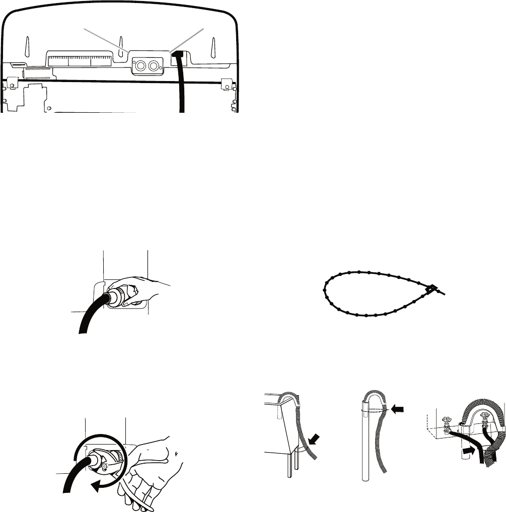
SECURE THE DRAIN HOSE
1. Drape the power cord over the console.
2. Remove any cardboard used to move
washer.
•
•
•
COLD
HOT
5. Attach the cold water hose to the inlet
valve labeled cold.
6. Screw on coupling by hand until it is seat-
ed on the washer.
7. Using pliers, tighten the coupling with an
additional two-thirds turn.
NOTE: Do not overtighten or use tape or seal-
ants on the valve. Damage to the valves can
result.
3. Fasten the drain hose to the laundry tub
leg or drain standpipe with the beaded tie
strap. See view A or B.
Beaded tie strap
If the washer faucets and the drain stand-
pipe are recessed, put the formed end of
the drain hose into the standpipe. Tightly
wrap the tie strap around the water inlet
hoses and the drain hose. See view C.
CBA
2-8
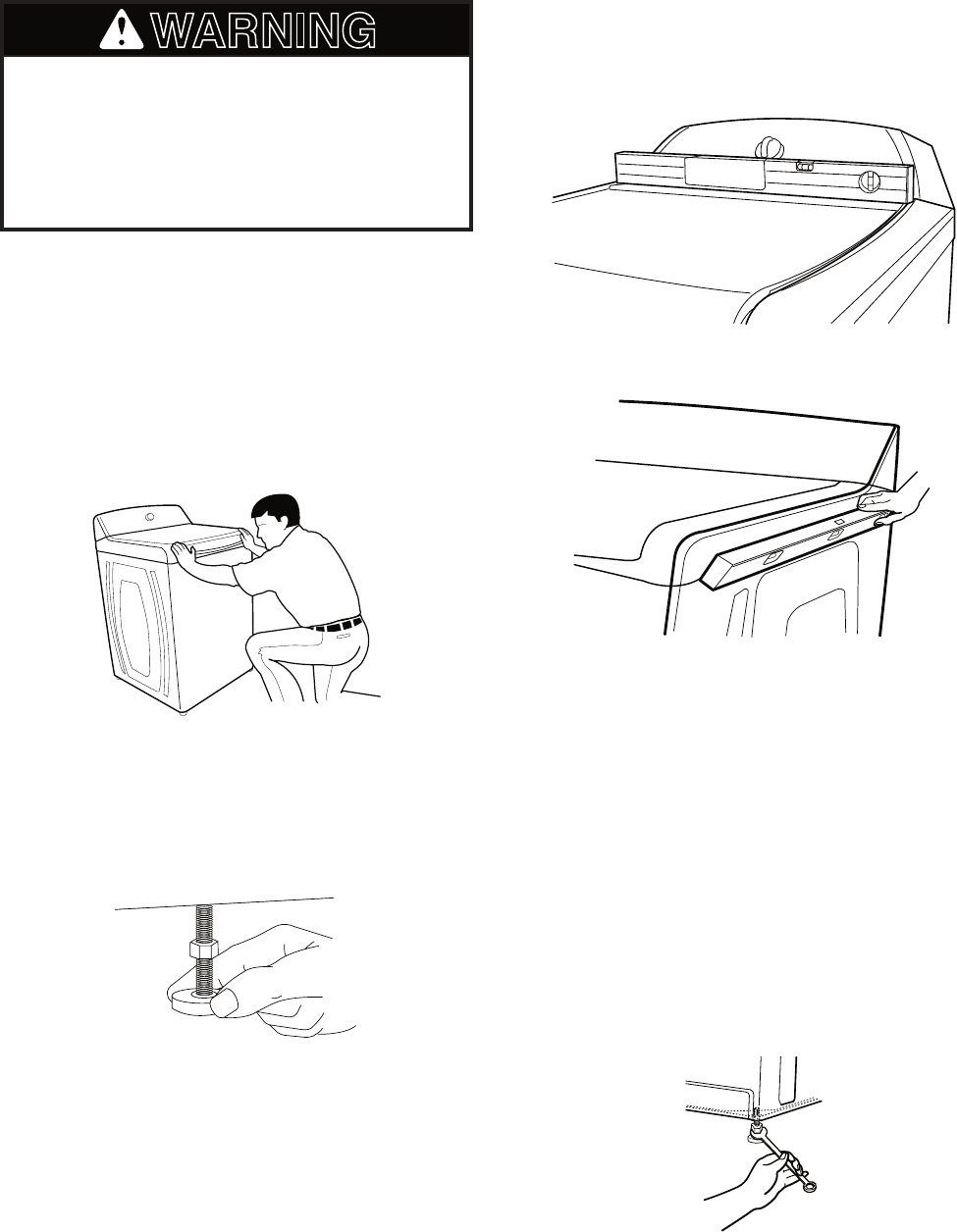
LEVEL THE WASHER
One washer foot has been installed at a dif-
ferent height on the washer. The other three
feet were preset at the factory. Properly level-
ing your washer will minimize noise and vibra-
tion.
1. Slide the washer to its final location.
2. Push on upper front panel to be sure the
washer is on its rear feet.
WARNING
Excessive Weight Hazard
Use two or more people to move and
install washer.
Failure to do so can result in back or
other injury.
4. Check the levelness of the washer by
first placing a level on the lid near the
console. Next, place the level on the side
of the washer in the crease between the
top of the washer and the cabinet.
3. Lower right front foot until it contacts the
floor. By hand, firmly rotate foot as much
as an additional 1-1/2 turns. The other
three feet have been preset at the fac-
tory.
Level the front.
Level the side.
5. If the washer is not level, move the wash-
er out slightly, tip back, prop up the front
of the washer on a wood block. Adjust the
feet up or down as necessary by twisting
the feet. Repeat steps 1 through 4 until
washer is level.
6. Use a 9/16˝ or 14 mm open-end wrench
to turn the locknut counterclockwise on
the foot tightly against the washer cabi-
net.
IMPORTANT: If the locknut is not tight against
the washer cabinet, the washer may vibrate.
2-9
COMPLETE INSTALLATION
1. Check the electrical requirements. Be
sure that you have the correct electrical
supply and the recommended grounding
method. See “Electrical Requirements,”
page 2-4.
2. Check that all parts are now installed. If
there is an extra part, go back through the
steps to see which step was skipped.
3. Check that you have all of your tools.
4. Keep the foam packing ring from the
washer tub for future relocation of the
washer. Dispose of or recycle all other
packaging materials.
5. Check that the water faucets are on.
6. Check for leaks around faucets and inlet
hoses.
Electrical Shock Hazard
Plug into a grounded 3 prong outlet.
Do not remove ground prong.
Do not use an adapter.
Do not use an extension cord.
Failure to follow these instructions can
result in death, fire, or electrical shock.
WARNING
7. Plug into a grounded 3 prong outlet.
8. Remove any protective film or tape re-
maining on the washer.
9. Read “Washer Use,” page 3-3.
10. To test and to clean your washer, mea-
sure 1/2 of the detergent manufacturer’s
recommended amount of High Efficiency
(HE) powdered or liquid detergent for a
medium size load and pour it into the de-
tergent dispenser. Close the lid. Press
POWER. Select a normal cycle and press
Start. Allow it to complete one whole cycle.
2-10
— NOTES —
3-1
PRODUCT OPERATION
THEORY OF OPERATION
INTRODUCTION
The Bravos™ Automatic Washer represents a
new design that differs from the traditional top
load machine. This washer operates without a
transmission, motor coupler, belt, basket drive
tube, or brake assembly.
NEW COMPONENTS
The washer has the following new compo-
nents:
Drive Motor—The drive motor is an electroni-
cally commutated direct drive 3-phase brush-
less DC design that moves the impeller/agitator
and spin basket without the use of a transmis-
sion. The motor is comprised of a stator that
is bolted to the base of the washer tub and a
rotor that is attached to the drive shaft. The
motor direction and speed is controlled by the
machine/motor controller, and is monitored by
a rotor position sensor, (RPS), located on the
stator.
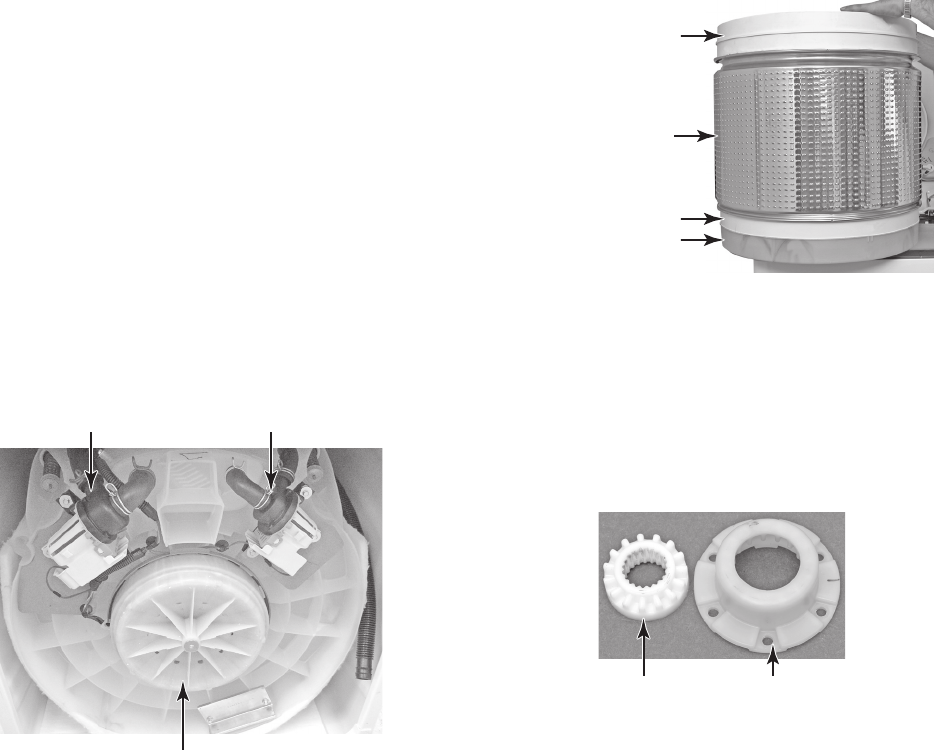
Basket—The basket is designed with a tra-
ditional balance ring at the top and a flotation
chamber at the base. The outside surface of
the basket is punched to allow lint to catch on
the holes during the wash cycle. When the
water drains, the lint will be flushed off and
out the drain.
Drive Motor
Recirculation PumpDrain Pump
Basket Hub—The basket hub consists of two
splined components that engage or disengage
based on the position of the basket in the
vertical direction. The outer hub component
is fastened to the bottom of the basket, while
the inner component is attached to the end of
the drive shaft.
Inner Hub
(Drive Shaft)
Outer Hub
(Basket)
Continued on the next page.
Flotation Chamber
Basket
Balance Ring
Balance Ring
3-2
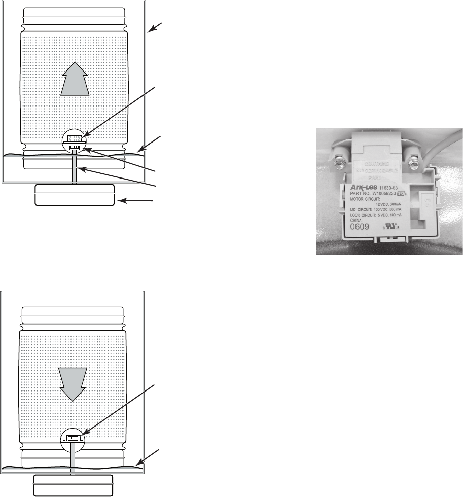
Lid Lock Mechanism—Since this washer
does not utilize a brake, a lid lock is used to
prevent access during the spin cycles. During
the drain and spin portions of the cycle, a lid
lock mechanism will lock the lid. The lid locks
are based on cycle phase. In general, the lid
locks when the basket spins greater than 23
rpm. After main wash, the lid is locked, and
remains locked until the end of the cycle. The
lid must be closed for the machine to fill, wash,
drain, or spin. Magnets in the washer lid close
a reed switch in the lid lock. This acts as the
lid switch.
As the tub fills with water, the basket begins to
float and to rise. The splined hub components
now separate, and allow the basket to move
independently of the drive shaft.
(Drive Motor)
Tub
Water Level
Rises & Basket
Floats
Outer Basket Hub
Disengages
When the tub drains, the basket drops back to
it’s original position, and the hub components
re-engage, connecting the basket to the shaft,
and permitting the basket to spin.
Outer Basket Hub
Re-engages With Inner
Drive Shaft Hub
Water Level Drains
& Basket Drops
Inner Hub Free
Drive Shaft
3-3
WASHER USE
STARTING THE WASHER The following is a guide to starting the washer.
Periodic references to other sections of this
manual provide more detailed information.
USING THE PROPER DETERGENT
Use only High Efficiency detergents. The pack-
age for this type of detergent will be marked
“HE” or “High Efficiency.” This wash system,
along with less water, will create too much
sudsing with a regular non-HE detergent. Us-
ing regular detergent will likely result in washer
errors, longer cycle times and reduced rinsing
performance. It may also result in component
failures and noticeable mold or mildew. HE de-
tergents are made to produce the right amount
of suds for the best performance. Follow the
manufacturer’s instructions to determine the
amount of detergent to use.
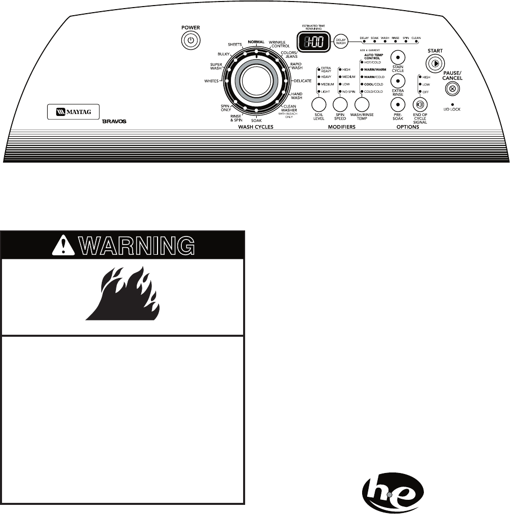
WARNING
Fire Hazard
Never place items in the washer that
are dampened with gasoline or other
flammable fluids.
No washer can completely remove oil.
Do not dry anything that has ever had
any type of oil on it (including cooking
oils).
Doing so can result in death, explosion,
or fire.
NOTE: Your washer model may differ slightly.
Use only “HE” High Efficiency detergent.
3-4
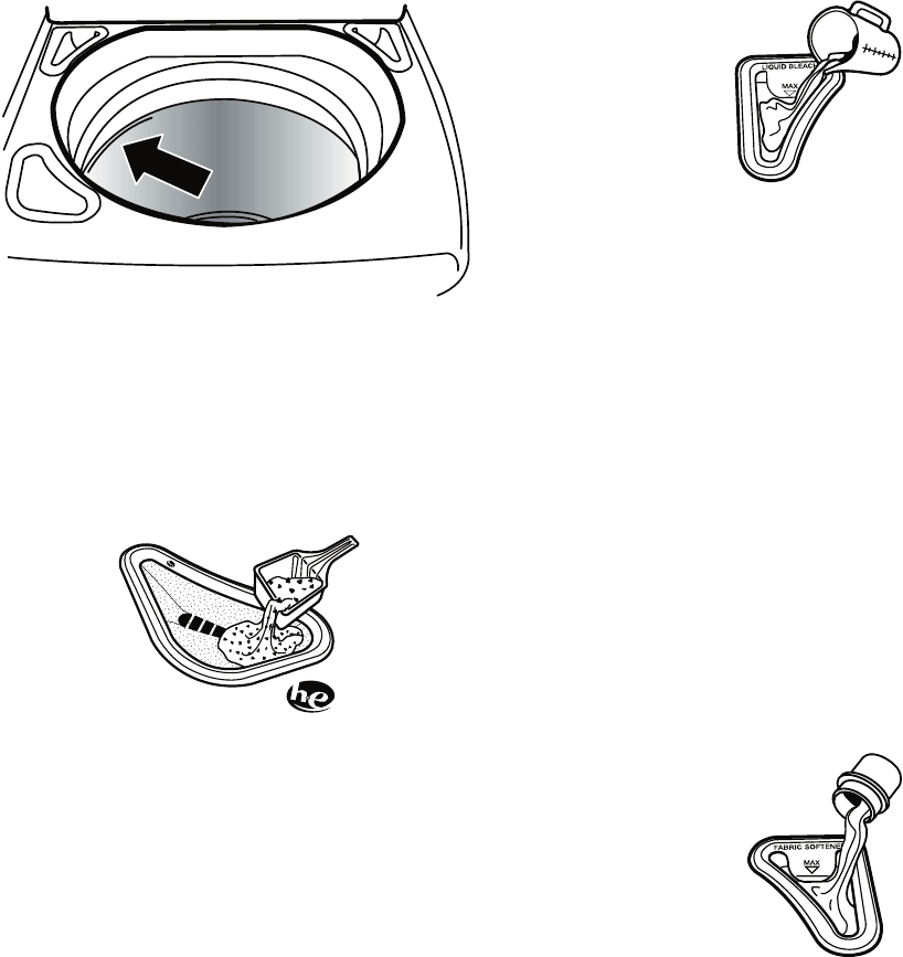
3. Add color-safe bleach, (powdered or liq-
uid) to this dispenser, if needed. Be sure
to match powdered color-safe bleach with
powdered detergent or match liquid color-
safe bleach with liquid detergent.
4. Pour measured liquid chlorine bleach into
the liquid chlorine bleach dispenser, if
needed. Bleach is diluted and automati-
cally dispensed at the proper time during
the wash cycle.
2. Pour measured powdered or liquid High
Efficiency (HE) detergent into the detergent
dispenser. Always use the detergent dis-
penser, and do not put detergent directly
into the wash tub or onto clothes in the
washer.
1. Place a load of sorted clothes into the
washer.
Load evenly to maintain washer bal-
ance. Mix large and small items. Items
should move easily through the wash
water.
Load only to the top of the basket as
shown. Overloading can cause poor
cleaning. Items need to move easily
through the wash water.
•
•
H
i
g
h
E
f
f
i
c
i
e
n
c
y
D
e
t
e
r
g
e
n
t
Do not overfill. Do not dilute. Do not use
more than 1 cup (250 mL) for a full load.
Use less with a smaller load size.
Follow the garment and the chlorine
bleach manufacturer’s directions for
proper use.
To avoid spilling, use a cup with a pour-
ing spout. Do not let bleach splash, drip,
or run down into the washer basket.
At the end of the cycle, a small amount
of water may be left in the dispenser.
This is normal.
NOTE: Use only liquid chlorine bleach
in this dispenser.
5. Pour measured liquid fabric softener into
the fabric softener dispenser, if desired.
•
•
•
•
3-5
Do not overfill. The dispenser holds
3 oz. (94 mL), or a capful of fabric soft-
ener.
The fabric softener is dispensed in the
final rinse. If Extra Rinse is selected, the
fabric softener will be dispensed during
the Extra Rinse.
Do not spill or drip any fabric softener
onto the clothes.
At the end of the cycle, a small amount
of water may be left in the dispenser.
This is normal.
NOTE: Use only liquid fabric softener
in this dispenser.
6. Close the washer lid.
7. Press POWER. This turns on the washer
display.
8. Select a Wash Cycle. See “Cycles,” page
3-6.
9. Select the desired Modifiers. See “Modi-
fiers,” page 3-8.
10. Select an Option, if desired. See “Options,”
page 3-10.
11. Select Delay Wash, if desired. See “Delay
Wash,” page 3-9 in the “Modifiers” sec-
tion.
12. Press START. The wash cycle begins, and
the display shows the estimated remaining
time. The lid will lock.
NOTE: If you do not press Start within 5
minutes of pressing Power, the washer
automatically drains and shuts off.
PAUSING OR RESTARTING
THE WASHER
ADD A GARMENT
You can place additional clothing in the wash
when the “Add a Garment” status light is glow-
ing without sacrificing wash performance.
To add a garment or pause the washer at
any time:
1. Press PAUSE/CANCEL once.
2. Wait until the Lid Lock light turns off, then
open the lid.
3. Add items.
•
•
•
•
To restart the washer:
1. Close the lid and press START.
2. To unlock the lid after the Add a Garment
period, press PAUSE/CANCEL once.
Pressing PAUSE/CANCEL twice will can-
cel the wash cycle.
STOPPING THE WASHER
You can stop the wash cycle and drain the tub
by pressing the PAUSE/CANCEL button twice
or the Power button once.
CHANGING CYCLES, MODIFIERS
AND OPTIONS
You can change Cycles, Modifiers and Options
anytime before Start is pressed. Not all Modifiers
and Options are available for all cycles.
A short tone sounds when a change is se-
lected.
Three short tones sound if an unavailable
combination is selected. The last selection
will not be accepted.
CHANGING CYCLES AFTER PRESSING
START
1. Press PAUSE/CANCEL twice to cancel
the cycle. The washer will drain.
2. Press POWER.
3. Select the desired wash cycle.
4. Select the desired Modifiers and Op-
tions.
5. Press START.
The washer restarts at the beginning of the
new cycle.
NOTE: If you do not press Start within 5 minutes
of pausing the washer, the washer automati-
cally shuts off.
•
•
3-6
CHANGING MODIFIERS AND OPTIONS
AFTER PRESSING START
You can change a Modifier or Option anytime
before the selected Modifier or Option begins
by choosing the desired Modifiers and/or Op-
tions.
NOTE: An error tone will sound if your selec-
tion is unavailable.
TO MANUALLY DRAIN THE WASHER AND
SPIN THE LOAD
1. Press PAUSE/CANCEL twice to cancel
the wash cycle and drain the washer.
2. Press POWER.
3. Turn knob to select DRAIN & SPIN.
4. Press START.
When the spin is complete, the lid unlocks.
Items can be removed from the washer.
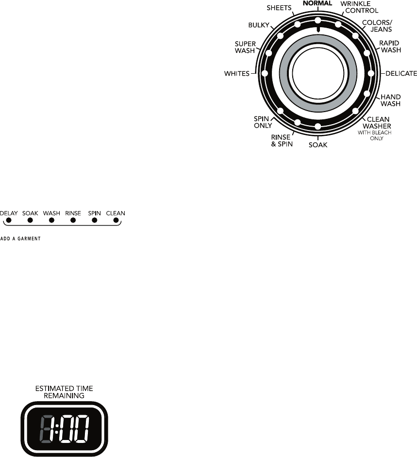
STATUS LIGHTS
These lights show which portion of the cycle the
washer is operating. They also indicate when
you can add other garments to the wash load.
INDICATOR LIGHTS
An indicator light shows which Cycle, Modifiers
and Options you have selected.
ESTIMATED TIME REMAINING
When a wash cycle is started, the estimated
time remaining for the cycle, including fills and
drains, will be displayed. The time will count
down to the end of the cycle.
CYCLES
Turn the knob to choose the right wash cycle
for the type of fabrics you are washing. When
the knob points to a cycle, the indicator light
for the cycle will glow and the indicator light
for Start will blink. If the default settings for the
Modifiers and Options are acceptable, you may
press Start to begin the wash cycle.
PRESET CYCLE SETTINGS
For ease of use, preset cycle settings provide
the recommended fabric care settings for each
cycle.
To use the preset cycle settings:
1. Press POWER.
2. Select the cycle you want by turning the
knob. The preset cycle settings will be dis-
played (see the chart on the next page).
NOTE: The preset times may vary slightly
depending on your model.
3. Press START. The wash cycle will begin.

3-7
PRESET CYCLE SETTINGS SUPER WASH
Use this cycle for heavily soiled or sturdy items.
Cycle combines high-speed wash action and
high-speed spin. Stain Cycle is the default op-
tion for this cycle, but it can be turned off. See
“Changing Cycles, Modifiers and Options,”
page 3-5.
BULKY
Use this cycle to wash large items such as
comforters, sleeping bags and blankets. This
cycle starts with a soak to thoroughly saturate
your large load. This is followed by medium
wash action and medium spin speeds to main-
tain load balance.
SHEETS
Use this cycle for sheets, pillowcases and tow-
els. The wash action of this cycle is designed
to keep large items from tangling and balling
up.
IMPORTANT: For best performance, drop
items in loose heaps evenly around the basket
wall. Do not load items directly on the impeller
for this cycle.
NORMAL
Use this cycle for normally soiled cottons and
mixed fabric loads. Cycle combines high-speed
wash action and high-speed spin.
WRINKLE CONTROL
Use this cycle to wash loads of no-iron fabrics
such as sport shirts, blouses, casual busi-
ness clothes, permanent press and blends.
This cycle uses medium-speed wash action,
a low-speed spin and a cool down process to
reduce wrinkling.
COLORS / JEANS
Use this cycle for lightly soiled, dark or highly
dyed natural fabrics such as cotton that may be
susceptible to dye loss. Cycle uses low to me-
dium-speed wash action and high-speed spin.
For best results use cold or warm water.
QUICK WASH
Use this cycle to wash small, lightly soiled
loads that are needed in a hurry. This short
cycle combines high-speed wash action and
high-speed spin for the best cleaning and
shortened dry times.
Cycle Preset
Minutes*
Soil
Level**
Wash/Rinse
Temp
Whites 79 Heavy Hot/Cold
Super Wash 66 Heavy Hot/Cold
Bulky46 Normal Warm/Cold
Sheets 46 Normal Warm/Cold
Normal 43 Normal Warm/Cold
Wrinkle Control 44 Medium Warm/Cold
Colors/Jeans42 Normal Cold/Cold
Quick Wash 34 Light Warm/Warm
Delicate 36 Light Cold/Cold
Handwash 35 Light Cold/Cold
Clean Washer
with bleach only
41 Medium Warm/Cold
Soak 20 Not
applicable
Cold/Cold
Rinse & Spin 10 Not
applicable
Not
applicable
Spin Only 60 Not
applicable
Not
applicable
* These times are for reference only and may not match
your model exactly.
** Cycle time in minutes will appear in the display while
you are making selections. The total cycle time will
appear, including an estimated time for drain and fill
times, once Start is pressed.
NOTE: Load only to the top of the basket.
Overloading can cause poor cleaning. See
“Starting The Washer,” page 3-3.
WHITES
This cycle introduces liquid chlorine bleach
to the load at the proper time for improved
whitening of your heavily soiled white fabrics.
Cycle combines high-speed wash action and
high-speed spin speed. For maximum soil and
stain removal, liquid chlorine bleach must be
used.
3-8
DELICATE
Use this cycle to wash lightly soiled garments
indicating “Machine Washable Silks” or “Gentle”
cycle on the care label. This cycle uses inter-
mittent low speed wash action and low-speed
spin for optimal fabric care.
When washing waterproof items, such as plas-
tic-lined mattress pads, shower curtains, tar-
paulins (tarps) or waterproof or water-resistant
sleeping bags, use the Delicate or Handwash
cycle with the lowest spin speed setting avail-
able for the washer model that you have.
Garments are labeled “Handwash” be-
cause:
The fiber construction may be sensitive to
wash action.
The fabric contains sensitive dyes that may
bleed.
HANDWASH
This cycle combines low-speed wash and
low-speed spin action to clean items labeled
as “Machine Washable Wool” on the garment
care label. Pre Soak and Deep Clean options
are not available in this cycle.
When washing waterproof items, such as plas-
tic-lined mattress pads, shower curtains, tar-
paulins (tarps) or waterproof or water-resistant
sleeping bags, use the Delicate or Handwash
cycle with the lowest spin speed setting avail-
able for the washer model that you have.
SOAK
This cycle is preset for a 41-minute cycle and
soak time can be adjusted according to your
needs by selecting Soil Level. After the selected
soak period has ended, the washer will drain
but does not spin the load.
NOTE: Automatic bleach dispensing is not part
of the soak cycle.
RINSE & SPIN
Use this option to get a deep rinse followed by
a high-speed spin. The time display will include
an estimate of how long it will take to fill and
drain the washer.
•
•
When to use Rinse & Spin:
For loads that need rinsing only.
For completing a cycle after the power has
been off.
To use or change Rinse & Spin setting:
1. Turn knob to RINSE & SPIN until the Rinse
& Spin indicator light glows.
2. Press START
SPIN ONLY
Spin Only may help shorten drying times for
some heavy fabrics or special-care items. Spin
Only may also be used for draining the washer
after canceling a cycle or completing a cycle
after a power failure.
To use or change Spin Only setting:
1. Turn knob to SPIN ONLY until the SPIN
ONLY indicator light glows.
2. Press START.
CLEAN WASHER
Use the Clean Washer cycle once a month to
keep the inside of your washer fresh and clean.
This cycle uses a higher water level in combi-
nation with liquid chlorine bleach to thoroughly
clean the inside of your washing machine.
IMPORTANT: Do not add detergent to this
cleaning cycle. Use only liquid chlorine bleach.
Do not place garments or other items in the
washer during the Clean Washer cycle. Use
this cycle with an empty wash tub.
MODIFIERS
Modifiers allow you to further customize the
cycles and save energy.
•
•

3-9
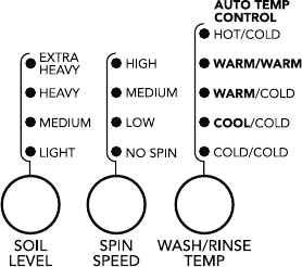
SOIL LEVEL
Soil level (wash time) is preset for each cycle.
See “Preset Cycle Settings,” page 3-6 in
“Cycles.” As you press the Soil Level pad, the
cycle time (minutes) will increase or decrease
in the Estimated Time Remaining display, and
a different wash time will appear. To get the
minimum wash time, press the pad until the
indicator light next to Light illuminates. This is the
shortest wash time available for that cycle.
For most loads, use the time recommended
in the preset cycle settings.
For heavy soil and sturdy fabrics, press Soil
Level to select more wash time, if needed.
For light soil and delicate fabrics, press Soil
Level to select less wash time, if needed.
SPIN SPEED
This washer automatically selects the spin
speed based on the cycle selected. The preset
speeds can be changed. Spin speeds may
vary by cycle.
WASH/RINSE TEMP
Select a water temperature based on the type
of load you are washing. Use the warmest
wash water safe for fabrics. Follow garment
label instructions.
Warm rinses leave the loads drier and more
comfortable to handle than cold rinses. How-
ever, warm rinses also increase wrinkling.
Cold rinses may help with wrinkling and save
energy.
•
•
•
TEMPERATURE GUIDE
Wash Water Temperature Suggested Fabrics
HotWhites and pastels
Warm Bright colors
Cold Colors that bleed or fade
AUTO TEMP CONTROL
Auto Temp Control (ATC) electronically senses
and maintains a uniform wash and rinse wa-
ter temperature. ATC regulates incoming hot
and cold water and is automatically turned on
when a cycle is selected. (See “Preset Cycle
Settings,” page 3-6 in “Cycles.”)
ATC is available with Warm/Warm, Warm/Cold
and Cool/ Cold settings. The water tempera-
ture in the Hot/Cold and Cold/Cold settings
depends on the water temperature at the water
inlet faucets.
ATC ensures consistent cleaning.
Heated water consumes the largest amount
of energy that a washer uses.
Today’s detergents work well at temperatures
above 60°F (15.6°C).
DELAY WASH
You can use the Delay Wash feature to delay
the start of a wash cycle for up to 10 hours
(depending on your model).
1. Load the washer and fill the dispensers.
2. Close the washer lid.
3. Press POWER.
4. Select the desired Cycle, Modifiers and
Options.
5. Press DELAY WASH. 1H (one hour) will be
displayed in the time display window. The
indicator light for Delay Wash will glow.
•
•
•
NOTE: In wash water temperatures colder than
60°F (15.6°C), detergents do not dissolve well.
Soils may be difficult to remove.
6. For a longer delay time, press DELAY
WASH. The Start time will increase by
1-hour steps.
7. Press START. The countdown in hours to
the wash cycle will show in the time display
window and the indicator light will begin to
flash.
NOTE: The Start indicator light will not
flash when Delay Wash is chosen. You
must press Start to initiate a countdown
for the cycle to begin.
3-10
To change the Delay Wash time:
Press PAUSE/CANCEL.
Press DELAY WASH to select the desired
delay time.
Press START to begin the countdown.
To cancel Delay Wash:
Press START again to begin the cycle right
away or press PAUSE/CANCEL twice.
OPTIONS
Use these pads to select the desired options
for your wash cycle.
•
•
•
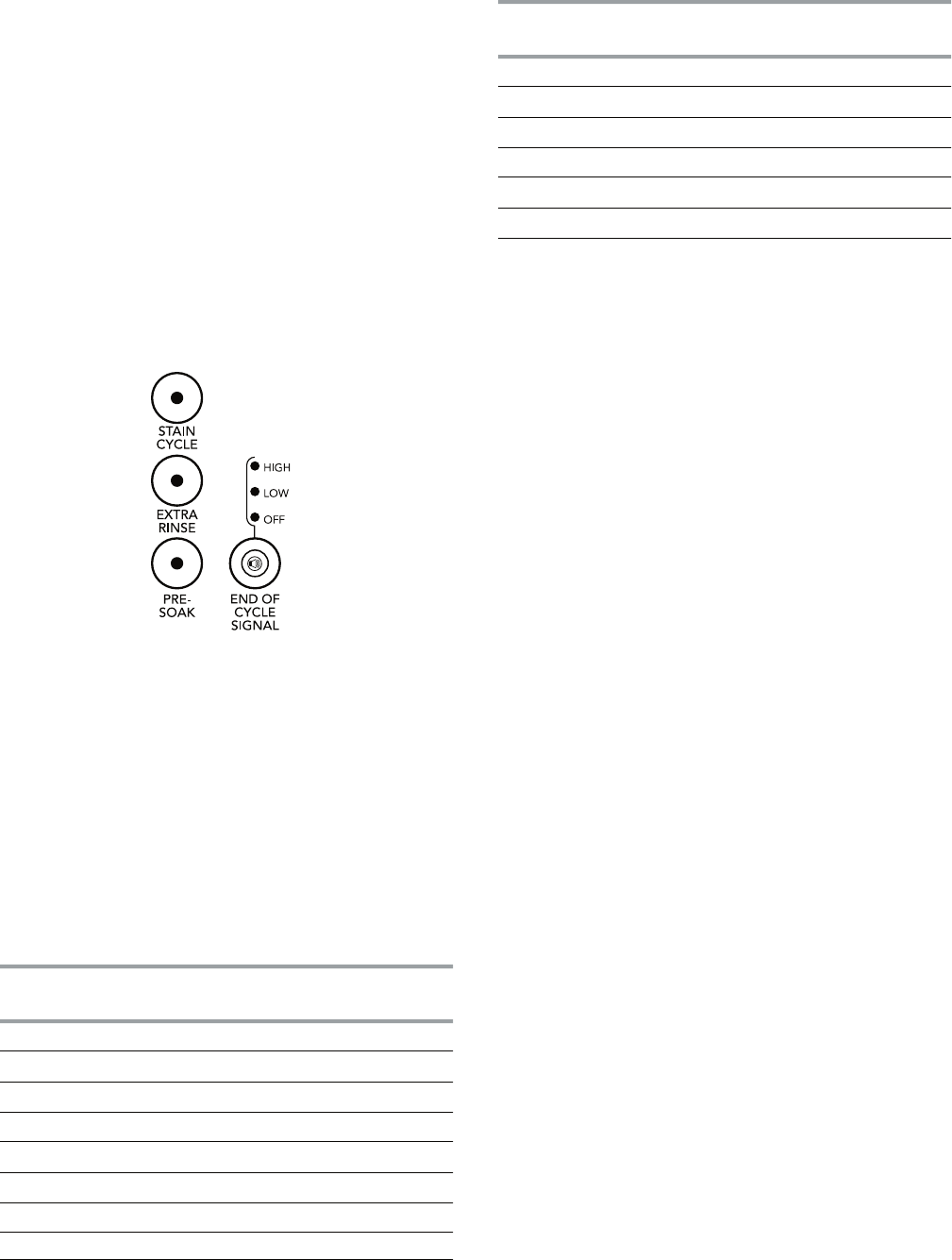
EXTRA RINSE
An extra rinse can be used to aid in the removal
of detergent or bleach residue from garments.
This option provides an additional rinse with
the same water temperature as the first rinse.
This is the default rinse setting for the Whites
cycle.
PRE SOAK
Use this option for set-in stains and soil that
need extra time for removal. Soaking in this
washer is different than in a conventional
washer. The washer sprays the load with water
and detergent at extra-low spin speed followed
by a brief period of wash action at the speed
of the selected cycle. This action is repeated.
Pre Soak cycles through a series of sprays and
wash actions followed by a pause to allow the
detergent to work on the soils. The Pre Soak
feature is followed by the selected cycle. Using
Pre Soak will extend your wash cycle.
END OF CYCLE SIGNAL VOLUME
The End of Cycle Signal produces an audible
sound when the wash cycle is finished. This
signal is helpful when you are removing items
from the washer as soon as it stops. Select
High, Low or Off.
STAIN CYCLE
This option provides enhanced cleaning ac-
tion for tough stains. The Super Wash cycle
automatically includes Stain Cycle. Choosing
Stain Cycle will add approximately 5 minutes
to a cycle. Stain Cycle should be started on a
dry load only and cannot be selected after the
tub has started filling with water.
Stain Cycle may be selected as an option with
other cycles. See table for details.
e
l
c
yC
n
i
a
tSelcyC
)
e
l
c
yc
h
s
a
w
e
h
t
o
t
e
mi
t
sddA
(
se
ti
hW no
i
t
p
O
hsa
W
r
e
p
u
Stlua
f
eD
y
k
lu
Bel
b
a
l
i
a
v
a
t
o
N
s
t
e
e
hS el
ba
li
a
va
t
o
N
lamro
Nnoi
t
p
O
l
o
rtnoC elkn
i
r
Wn
oi
t
pO
sn
ae
J
/s
rol
o
Cno
i
t
pO
hsaW kciuQ noit
p
O
e
t
a
ci
l
eD
n
o
i
t
pO
hs
aw
d
n
aH n
oi
t
pO
yl
n
o
hca
e
l
b
hti
w
r
e
h
s
aW
na
el
C
e
l
b
a
l
i
av
a
t
o
N
k
a
oS e
l
b
a
l
i
av
a
t
o
N
n
i
p
S &
es
n
iR
e
l
b
a
l
iav
a
t
o
N
y
ln
O
ni
p
Se
l
b
a
l
iav
a
to
N
el
c
y
C
n
i
at
S
el
cyC
)
e
l
c
yc
hsawo
t
e
m
it
s
d
d
A
(
3-11
NORMAL SOUNDS
Your new washer may make sounds your old
one didn’t. Because the sounds might be un-
familiar, you may be concerned about them.
These sounds are normal.
DURING WASHING
If you select the Stain Cycle option, you will
hear a spin/spray noise at the start of the
cycle.
DURING DRAIN
If water is drained quickly from your washer
(depending on your installation), you may hear
air being pulled through the pump during the
end of draining.
DURING WASH AND SPIN
This washer does not have a transmission. The
motor provides direct drive for agitation and
spin. You will hear sounds that are different
from those of a conventional washer.
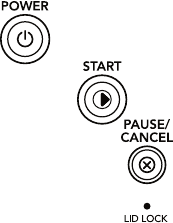
OPERATING CONTROLS
POWER
Press POWER to turn the washer on or off.
START
Press START to start your washer after a cycle
has been selected. Be sure all desired Modi-
fiers and Options have been selected. The lid
must be closed for the washer to start.
PAUSE/CANCEL
Press PAUSE/CANCEL once to pause or stop
the washer at any time. Press PAUSE/CAN-
CEL once to unlock the lid and add a garment.
Press START to complete the cycle from where
it was stopped. Press PAUSE/CANCEL twice
to stop the wash cycle. The washer will then
drain and turn off.
LID LOCK
When the Lid Lock status light glows, the washer
lid is locked.
NOTE: You must wait until the lid lock light
turns off before the lid can be opened.
3-12
WASHER CARE
CLEANING YOUR WASHER
WASHER MAINTENANCE PROCEDURE
This washer has a special cycle that uses
higher water volumes in combination with liquid
chlorine bleach to thoroughly clean the inside
of the washing machine.
NOTES:
Read these instructions completely before
beginning the cleaning process.
It is recommended that you allow the cleanout
cycle to complete without interruptions. If
necessary, the cleanout cycle may be inter-
rupted by pressing the Power button once
or the PAUSE/CANCEL button twice.
IMPORTANT: If the cleanout cycle is inter-
rupted, run a Rinse & Spin cycle to ensure
that all remaining bleach is rinsed from the
washer.
Begin procedure
1. Open the washer lid and remove all items
from the washer.
2. Add liquid chlorine bleach to the bleach
dispenser.
Add 1 cup (250 mL) liquid chlorine
bleach to the bleach dispenser.
NOTE: Do not add any detergent to this
cleaning cycle. Use of more than 1 cup
(250 mL) of bleach will cause product
damage over time.
3. Close the lid.
4. Press POWER.
5. Turn cycle control knob to CLEAN WASH-
ER cycle.
The Estimated Time Remaining display
will show approximately 60 minutes.
6. Press START.
The cycle will begin and water will dis-
pense in the washer for a moment and
pause, then the lid will lock and the cycle
will continue.
•
•
•
•
•
Once the cleaning cycle has begun, al-
low the cycle to complete. An estimated
cycle time will appear on the display.
If the procedure does not sufficiently im-
prove the machine freshness, evaluate
your installation and usage conditions
for other causes.
Always do the following to maintain washer
freshness
Use only High Efficiency (HE) detergent.
Cleaning the exterior
Use a soft damp cloth or sponge to wipe up any
spills. Occasionally wipe the outside of your
washer to keep it looking new. Use mild soap
and water. Do not use abrasive products.
WATER INLET HOSES
Replace inlet hoses after 5 years of use to
reduce the risk of hose failure. Periodically in-
spect and replace inlet hoses if bulges, kinks,
cuts, wear or leaks are found.
When replacing your inlet hoses, mark the date
of replacement on the label with a permanent
marker.
VACATION, STORAGE, AND
MOVING CARE
Install and store your washer where it will not
freeze. Because some water may stay in the
hoses, freezing can damage your washer. If
storing or moving your washer during freezing
weather, winterize it.
Non-use or vacation care:
Operate your washer only when you are at
home. If you will be on vacation or not using
your washer for an extended period of time,
you should:
Unplug washer or disconnect power.
Turn off the water supply to the washer. This
helps avoid accidental flooding (due to a water
pressure surge) while you are away.
•
•
•
•
•
3-13
To winterize washer:
1. Shut off both water faucets.
2. Disconnect and drain water inlet hoses.
3. Put 1 qt (1 L) of R.V.-type antifreeze in the
basket.
4. Run washer on the Rinse & Spin setting
for about 30 seconds to mix the antifreeze
and remaining water.
5. Unplug washer or disconnect power.
To use washer again:
1. Flush water pipes and hoses. Reconnect
water inlet hoses. Turn on both water
faucets.
To transport the washer:
1. Shut off both water faucets.
2. Disconnect and drain water inlet hoses.
3. If the washer will be moved during freez-
ing weather, put 1 qt (1 L) of R.V.-type
antifreeze in the basket. Run washer on
the Rinse & Spin setting for about 30 sec-
onds to mix the antifreeze and remaining
water.
4. Disconnect the drain from the drain sys-
tem.
5. Unplug the power cord.
6. Place the inlet hoses into the basket.
7. Drape the power cord and drain hose over
edge into the basket.
8. Place foam packing ring from the original
shipping materials in the top of washer. If
you do not have the original foam packing
ring, place heavy blankets, towels, etc. into
basket opening. Close the lid and put a
piece of tape over the lid and down to the
front of the washer. Keep lid taped until the
washer is placed into the new location.
Reinstalling the washer
1. Follow the “Installation Instructions,”
page 2-5 to locate, level and connect the
washer.
2. Run the washer through the Bulky cycle
to clean the washer and remove the anti-
freeze, if used. Use only HE High Efficiency
detergent. Use 1/2 the manufacturer’s
recommended amount for a medium sized
load.
Electrical Shock Hazard
Plug into a grounded 3 prong outlet.
Do not remove ground prong.
Do not use an adapter.
Do not use an extension cord.
Failure to follow these instructions can
result in death, fire, or electrical shock.
WARNING
2. Plug in washer or reconnect power.
3. Run the washer through the Bulky cycle to
clean the washer and remove the antifreeze,
if used. Use only HE High Efficiency deter-
gent. Use 1/2 the manufacturer’s recom-
mended amount for a medium sized load.

3-14
TROUBLESHOOTING
WASHER AND COMPONENTS
Washer displaying code messages
“LF” (Washer is taking too long to fill)
Check the following:
Are the water inlet hoses kinked or
clogged?
Are the water inlet valve screens clear?
Press PAUSE/CANCEL to clear display.
“Ld” (Washer is taking too long to drain
water from the wash tub)
Check the following:
Is the drain hose kinked or clogged?
Is the drain hose installed properly? See
“Connect the Drain Hose,” page 2-5. Press
PAUSE/CANCEL to clear display.
“uL” (Unbalanced Load)
If the load is unbalanced, the washer will
display this code while running an imbal-
anced load correction routine at the end of
the wash cycle and before the final spin. If
the code remains and the wash cycle dial
is flashing after the recovery routine has
stopped, open lid and redistribute the load.
Close lid and press START.
“oL” (Over Load)
Is the washer overloaded? The washer has
attempted to fill and begin the wash cycle.
If the washer is overloaded, it will drain any
water and detergent that was added dur-
ing the fill. To correct the overload, remove
several items and add detergent. Close lid
and press START.
“Sd” (Suds Detected)
Did you use regular detergent?
Regular or hand-washing detergents are not
recommended for this washer. Use only High
Efficiency (“HE”) detergent.
•
•
•
•
•
Did you add too much detergent?
Always measure detergent. Follow detergent
manufacturer’s directions.
If excessive suds are detected, the washer
will display this code while running a suds
reduction correction routine at the end of
the wash cycle. The suds reduction routine
removes extra suds and assures proper
rinsing of your garments. If the code remains
and the wash cycle dial is flashing after the
recovery routine has stopped, re-select your
desired cycle using cold water. Press START.
Do not add detergent.
“lid” (Lid Opened)
Is the lid open? Close the lid to clear the dis-
play. If the lid remains open for more than 10
minutes, water in the wash tub will drain.
“HC” (Cold and Hot hoses switched)
This code will appear at the end of the wash
cycle to indicate that the cold and hot water
inlet hoses are switched. See “Connect the
Inlet Hoses,” page 2-6.
“dL” (Door/Lid cannot lock)
Indicates lid is not locked. Check for items
caught in the lid keeping it from closing. Press
PAUSE/CANCEL once to clear the code.
“dU” (Door/Lid cannot unlock)
Is there excessive weight on the lid, such as
a basket of laundry? Excessive weight will
keep the lid from unlocking. Press PAUSE/
CANCEL once to clear the code.
F _ _ “F##” code
Press PAUSE/CANCEL once to clear code.
Press START. If code appears again, call for
service.
•
•
•
•
•

3-15
Noisy, vibrating, off-balance
Is the washer level? Does the washer rock
when pushed against the corners?
The washer must be level. The front and rear
feet must be in firm contact with the floor.
Check that the locknuts are tightened. See
“Level the Washer,” page 2-8.
Is the floor flexing, sagging or not level?
Flooring that flexes or is uneven can con-
tribute to noise and vibration of the washer.
A 3/4˝ (1.9 cm) piece of plywood under the
washer will reduce the sounds. See “Loca-
tion Requirements,” page 2-2.
Is the load balanced?
Evenly distribute the load in the washer
basket and make sure the height of the load
does not exceed the top row of basket holes.
See “Starting The Washer,” page 3-3.
Do you hear clicking or other noises when
the cycle changes from washing to drain-
ing or spinning?
When the drive system shifts or the washer
basket settles between cycles you may hear
noises that are different from your previous
washer. These are normal washer noises.
Is the washer gurgling or humming?
When the washer drains, the pump will make
a continuous humming with periodic gurgling
or surging sounds as the final amounts of
water are removed. This is normal.
Are you washing a small load?
You will hear more splashing sounds when
washing small loads. This is normal.
The washer basket moves while wash-
ing.
This is normal.
Can you hear water spraying?
This is part of the wash action.
•
•
•
•
•
•
•
•
Are you washing items with metal snaps,
buckles or zippers?
You may hear metal items touching the bas-
ket. This is normal.
Did you select the Bulky cycle?
Use the Bulky cycle only for oversized, non-
absorbent items such as comforters, pillows
or poly-filled jackets. Other items will create
an unbalanced load in this cycle.
Washer leaks
Are the fill hoses tight?
Are the fill hose washers properly seated?
Check both ends of each hose. See “Connect
the Inlet Hoses,” page 2-6.
Did you pull the drain hose from the
washer cabinet and install it in a standpipe
or laundry tub?
The drain hose should be pulled from the
washer cabinet and secured to the drainpipe
or laundry tub. See “Connect The Drain
Hose,” page 2-5, and “Secure the Drain
Hose,” page 2-7.
Is the sink or drain clogged?
Sink and drainpipe must be able to carry
away 17 gal. (64 L) of water per minute. If
sink or drainpipe is clogged or slow, water
can back up out of drainpipe or sink.
Is water splashing off the tub ring or the
load?
The wash load should be balanced and not
overloaded. If the wash load is unbalanced
or overloaded, incoming water can deflect
off the load.
Is the washer properly installed?
The washer must be level. The feet should
be properly installed and the nuts tightened.
See “Level the Washer,” page 2-8.
Was the cycle interrupted and then the
Stain Cycle option selected?
The Stain Cycle option should be started on a
dry load only. The Stain Cycle option should
not be selected after the tub has started filling
with water.
•
•
•
•
•
•
•
•
•
3-16
Did you select Stain Cycle option and use
a handwashing detergent?
Regular or handwashing detergents are not
recommended for this washer. Use only High
Efficiency (“HE”) detergent.
Check household plumbing (laundry tubs,
faucets, drainpipe, water pipes) for leaks.
•
•
Dispenser operation
Are the laundry additives in the correct
dispensers?
Add the correct amounts of detergent (pow-
dered or liquid), liquid chlorine bleach, or
fabric softener to the correct dispenser. You
can add powdered or liquid color-safe bleach
to the detergent dispenser. Be sure to match
powdered color-safe bleach with powdered
detergent or match liquid color-safe bleach
with liquid detergent. Use only liquid chlorine
bleach in the bleach dispenser.
Is there water remaining in the bottom
of a dispenser? Did the dispenser drain
properly?
A small amount of water may be left in a
dispenser at the end of the cycle. This is
normal.
WASHER OPERATION
•
•
Electrical Shock Hazard
Plug into a grounded 3 prong outlet.
Do not remove ground prong.
Do not use an adapter.
Do not use an extension cord.
Failure to follow these instructions can
result in death, fire, or electrical shock.
WARNING
Washer won’t fill, rinse or agitate; washer
stops
Is the power cord plugged into a grounded
3 prong outlet?
Plug power cord into a grounded 3 prong
outlet.
Are you using an extension cord?
Do not use an extension cord.
Is there power at the plug?
Check electrical source or call electrician.
Is the indicator on the Cycle control knob
properly lined up with a cycle?
Turn the Cycle control knob to the right
slightly.
Are the water inlet valve screens clogged?
Turn off the water and remove inlet hoses
from the washer. Remove any accumulated
film or particles. Reinstall hoses, turn on water
and check for leaks.
Are the hot and cold water faucets turned
on?
Turn on the water.
Is the water inlet hose kinked?
Straighten the hoses.
Does the water level seem too low, or
does the washer appear to not fill com-
pletely?
The Auto Water Level feature senses the size
of the load and adds the correct amount of
water for the load size. You may notice during
a cycle that the wash load is not completely
submerged in water. This is normal and
necessary for clothes to move.
Has a household fuse blown, or has a
circuit breaker tripped?
Replace the fuse or reset the circuit breaker. If
the problem continues, call an electrician.
Is the washer in a normal pause in the
cycle?
The washer may pause during certain cycles.
Allow the cycle to continue.
•
•
•
•
•
•
•
•
•
•

3-17
Is the washer overloaded?
Wash smaller loads. See “Starting The
Washer,” page 3-3 for maximum load size.
Is there oversudsing?
Cancel the current cycle. Select SPIN ONLY
to drain the load. Re-select your desired cycle
and press START. Do not add detergent. Use
cold water.
Is the lid open?
The lid must be closed during operation. The
washer will not operate with the lid open.
Did you add more items to the load once
the washer started?
Once the load is wet, there may appear to be
space for more items. Do not add more than
1 or 2 garments after the cycle has started.
For best results determine load size with dry
items only.
Washer continues to fill or drain, or the
cycle seems stuck
Is the top of drain hose lower than the
control knobs on washer?
The top of the drain hose must be at least
39˝ (99 cm) above the floor. See “Drain
System,” page 2-3.
Does the drain hose fit too tightly in the
standpipe, or is it taped to the stand-
pipe?
The drain hose should be loose yet fit se-
curely. Do not seal the drain hose with tape.
The hose needs an air gap. See “Installation
Instructions,” page 2-5.
Washer won’t drain or spin; water remains
in washer
Is the drain hose clogged, or the end of
the drain hose more than 96˝ (244 cm)
above the floor?
See “Drain System,” page 2-3.
Is the lid open?
The lid must be closed during operation. The
washer will not operate with the lid open.
•
•
•
•
•
•
•
•
Is there excessive sudsing?
Always measure detergent. Follow deter-
gent manufacturer’s directions. If you have
very soft water, you may need to use less
detergent. Use only High Efficiency (“HE”)
detergent.
•
Wash/Rinse temperature
Are the hot and cold water inlet hoses
reversed?
If the hot and cold water inlet hoses are re-
versed, the washer will display an “HC” error
code at the end of the cycle. See “Connect
the Inlet Hoses,” page 2-6.
Are you washing many loads?
As your frequency of loads washed increases,
the water temperature may decrease for hot
and warm temperatures. This is normal.
Do you have an ENERGY STAR® qualified
washer?
The wash water temperatures may feel cooler
to you than those of your previous washer.
This is normal.
Does the wash water temperature feel
lower than usual?
As washing progresses, the wash tempera-
ture will decrease slightly for hot and warm
washes. This is normal.
To reduce wrinkling, the warm rinse is regu-
lated to be cooler than the warm wash.
Excessive sudsing
Did you use a non-HE detergent?
Regular or handwashing detergents are not
recommended for this washer. Use only High
Efficiency (“HE”) detergent.
•
•
•
•
•

3-18
Is there excessive sudsing?
Always measure detergent. Follow deter-
gent manufacturer’s directions. If you have
very soft water, you might need to use less
detergent.
Was the cycle interrupted and then the
Stain Cycle option selected?
The Stain Cycle option should be started on a
dry load only. The Stain Cycle option should
not be selected after the tub has started filling
with water.
Cycle did not run Stain Cycle option
Did you select the Stain Cycle option?
The Stain Cycle option must be selected for
it to be included in a wash cycle. The Stain
Cycle option should be started on a dry load
only. Stain Cycle should not be selected after
the tub has started filling with water.
The Stain Cycle option is a default in the
Super Wash cycle and may be added to
other cycles.
CLOTHING CARE
Load too wet
Did you use the right cycle for the load
being washed?
Select a higher spin speed.
Did you use a cold rinse?
Cold rinses leave loads wetter than warm
rinses. This is normal.
Did you wash an extra large load?
A large unbalanced load could result in a
reduced spin speed and wet clothes at the
end of the cycle. Evenly distribute the load
and make sure the height of the load does
not exceed the top row of basket holes.
•
•
•
•
•
•
Residue or lint on load
Did you add detergent to the dispenser?
For best results, use the dispenser to dis-
solve the detergent.
Did you sort properly?
Sort lint givers (towels, chenille) from lint
takers (corduroy, synthetics). Also sort by
color.
Did you overload the washer?
The wash load must be balanced and not
overloaded. Clothes should move freely. Lint
or powdered detergent can be trapped in
the load if the washer is overloaded. Wash
smaller loads. See “Starting The Washer,”
page 3-3 for maximum load size.
Did you use enough detergent?
Follow detergent manufacturer’s directions.
Use enough detergent to hold the lint in the
water.
Did you line dry your clothing?
If so, you can expect some lint on the clothing.
The air movement and tumbling of a dryer
removes lint from the load.
Was paper or tissue left in pockets?
Is your water colder than 60°F (15.6°C)?
Wash water colder than 60°F (15.6°C) may
not completely dissolve the detergent.
Did you use the proper Soil Level and
Wash Cycle for the load?
Reducing wash time (duration) and wash
speed are ways to reduce lint.
Did you add detergent to the dispenser?
For best results, use the dispenser to dis-
solve the detergent.
•
•
•
•
•
•
•
•
•

3-19
Load is wrinkled, twisted or tangled
Did you unload the washer promptly?
Unload the washer as soon as it stops.
Did you use the right cycle for the load
being washed?
To reduce wrinkling, tangling and twisting,
select a cycle with low wash and spin speeds,
such as Delicate, Handwash or Wrinkle Con-
trol.
Did you overload the washer?
The wash load must be balanced and not
overloaded. Loads should move freely during
washing to reduce wrinkling, tangling and
twisting.
Was the wash water warm enough to relax
wrinkles?
If safe for the load, use warm or hot wash
water. Use cold rinse water.
Are the hot and cold water hoses re-
versed?
Check that the hot and cold water hoses
are connected to the correct faucets. If the
hot and cold water inlet hoses are reversed,
the washer will display an “HC” error code
at the end of the cycle. See “Connect the
Inlet Hoses,” page 2-6. A hot rinse followed
by spin will cause wrinkling.
Stains, gray whites, dingy colors
Did you properly sort the load?
Dye transfer can occur when mixing whites
and colors in a load. Sort dark clothes from
whites and lights.
Was the wash temperature too low?
Use hot or warm washes if safe for the load.
Make sure your hot water system is adequate
to provide a hot water wash.
•
•
•
•
•
•
•
Did you use enough detergent, or do you
have hard water?
Use more detergent for washing heavy soils
in cold or hard water. Water temperature
should be at least 60°F (15.6°C) for soap to
dissolve and work properly. For best perfor-
mance, use the detergent manufacturer’s
recommended amounts.
Did you follow the manufacturer’s direc-
tions when adding detergent and fabric
softener?
Measure detergent and fabric softener. Use
enough detergent to remove soil and hold
it in suspension. Dilute fabric softener and
add to the rinse portion of a cycle only. Do
not drip fabric softener onto clothes.
Is there above average iron (rust) in water?
You may need to install an iron filter.
Did you add detergent to the dispenser?
For best results, use the dispenser to dis-
solve the detergent.
Did you add fabric softener directly to
the load?
Use your fabric softener dispenser. Do not
drip fabric softener onto clothes.
Did you use a fabric softener dispensing
ball?
Use the fabric softener dispenser provided
with the washer. Dispensing balls will not
operate correctly with this washer.
Did you unload the washer promptly?
To avoid dye transfer, unload the washer as
soon as it stops.
Did you add detergent, chlorine bleach or
fabric softener too late in the cycle?
Detergent, chlorine bleach, and fabric soft-
ener should be added to the dispensers
before starting the washer.
Did you use Quick Wash on a large load?
Quick Wash is designed to wash only a few
items for best results.
•
•
•
•
•
•
•
•
•

3-20
Garments damaged
Were sharp items removed from pockets
before washing?
Empty pockets, zip zippers, snap or hook
fasteners before washing to avoid snagging
and tearing of load.
Were strings and sashes tied to avoid
tangling?
Straps and strings can easily become en-
tangled in the load, causing strain on seams
and tearing.
Were items damaged before washing?
Mend rips and broken threads in seams
before washing.
•
•
•
Did you overload the washer?
The wash load must be balanced and not
overloaded. Loads should move freely during
washing.
Did you add chlorine bleach properly?
Do not pour chlorine bleach directly onto load.
Wipe up bleach spills. Undiluted bleach will
damage fabrics. Do not place load items on
top of the bleach dispenser when loading
and unloading the washer (on some models).
Do not use more than the manufacturer’s
recommended amount for a full load.
Did you follow the garment manufactur-
er’s care label instructions?
•
•
•
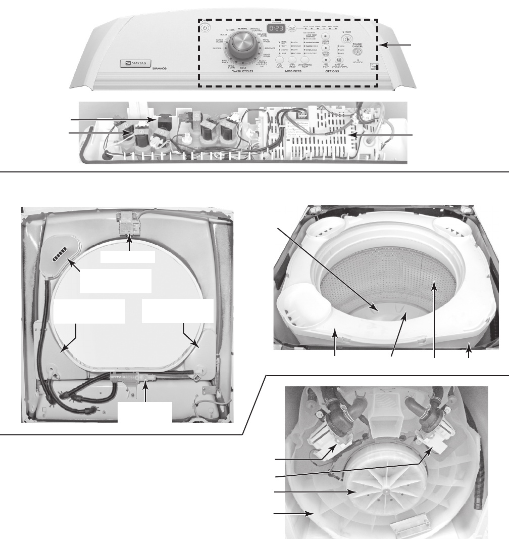
4-1
COMPONENT ACCESS
COMPONENT LOCATIONS
This section instructs you on how to service each component inside the Bravos™ Automatic
Washer With 6th Sense™ Technology. The components and their locations are shown below.
CONSOLE & TOP CABINET COMPONENTS
DISPENSER & BASKET COMPONENTS
BOTTOM COMPONENTS
Machine/Motor
Control & Pressure
Transducer
Water Inlet/
Dispenser
Valve Assy.
Tub Ring Tub
Impeller Basket
Lid Lock
HE Detergent
Dispenser
Fabric Softener
Dispenser
Fresh Fill
Inlet Valve
Liquid Bleach
Dispenser
Drain Pump
Drive Motor
Recirculation Pump
Bottom Of Tub
Power
Supply Cord
Lint Filter
User Interface
Board & Encoder
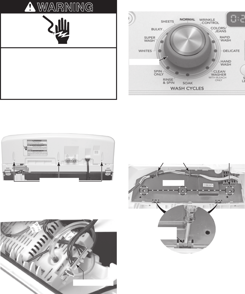
4-2
REMOVING THE ENCODER AND
THE USER INTERFACE BOARD
Electrical Shock Hazard
Disconnect power before servicing.
Replace all parts and panels before
operating.
Failure to do so can result in death or
electrical shock.
1. Unplug washer or disconnect power.
2. Remove the three hex-head mounting
screws from the rear of the console.
WARNING
3. Lift the console off the cabinet and dis-
connect the user interface board cable
connector at machine/motor control con-
nector P11.
UI Connector P11
4. Pull the knob off the control shaft.
5. Unhook the user interface (UI) wire har-
ness from the cover clips.
6. Remove the three screws from the UI
board cover.
7. Using a flat-blade screwdriver, pry the
two locking tabs out, and unclip and re-
move the UI cover from the console.
Control Knob
Console Screws UI Cover
Wire Harness Clips 3 Screws
Pry Out On
Locking Tab
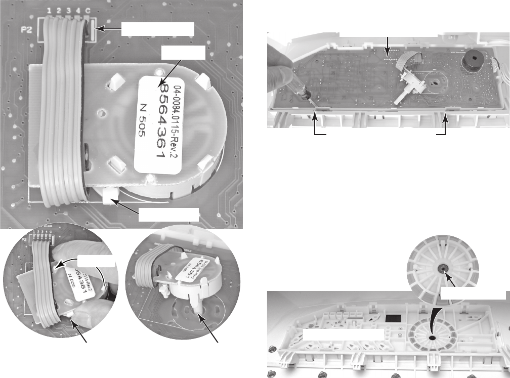
4-3
User Interface Board
8. To remove the encoder, lift the locking
tab and turn the encoder to the left (coun-
terclockwise) as far as it will go, then lift
the encoder straight up so that the shaft
slides out of the rubber console seal, and
remove it from the console. NOTE: Do not
flex the encoder ribbon cable wires at the
user interface board or they could break.
Encoder Wires
Locking Tab
Encoder
Remove
Lift Locking Tab
NOTE: Before you can remove the user in-
terface board, you must first remove the en-
coder.
9. To remove the user interface board:
a) Remove the encoder (see step 8).
b) Using a flat-blade screwdriver, care-
fully pry the front edge of the user in-
terface board up, then pull the board
forward, and remove it from the con-
sole.
Pry Up Edge Of Board
REASSEMBLY NOTE: When you reinstall
the encoder, make sure that the rubber seal
does not become dislodged when installing
the encoder shaft, or else water can leak into
the console area.
Pull Shaft From Seal
Console Seal
Rear Of Console
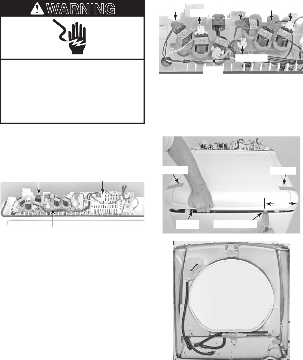
4-4
REMOVING THE WATER INLET/ DISPENSER VALVE
ASSEMBLY, POWER SUPPLY CORD, AND
MACHINE/MOTOR CONTROL & PRESSURE TRANSDUCER
Electrical Shock Hazard
Disconnect power before servicing.
Replace all parts and panels before
operating.
Failure to do so can result in death or
electrical shock.
1. Unplug washer or disconnect power.
2. Turn off water supply.
3. Remove the console from the top of the
washer (see page 4-2 for the procedure).
WARNING
Power Supply Cord Machine/Motor Control
Water Inlet/Dispenser Valve Assembly
4. To remove the water inlet/dispenser
valve assembly (see the top right pho-
to):
a) Disconnect the hot and cold water
hoses from the water inlets.
b) Release the locking tab and discon-
nect the wire connectors from the wa-
ter inlet/dispenser valve assembly so-
lenoid terminals.
c) Release the locking tab and discon-
nect the wire connector from the ther-
mistor.
Red Violet
Violet White
Yellow
White
Thermistor
d) Tape the washer lid closed.
e) Using a putty knife, press and unlock the
two front top locks. The locks are approx-
imately 6-1/2˝ from the outside edge of
the washer.
Water Inlet/Dispenser Valve Assembly
Lift Top Press Top Lock
6-1/2˝
Tape Lid
Tape Lid
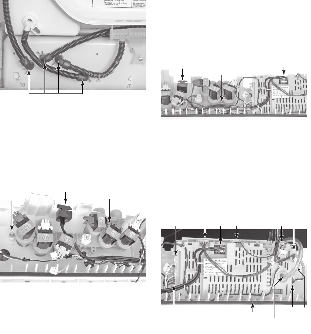
4-5
g) Lower the cabinet top.
h) Slide the power supply cord strain relief
out of the housing and move it away from
the valve assembly.
i) Remove the two hex-head screws from
the water inlet/dispenser valve assem-
bly, and remove the assembly from the
washer.
Water Inlet/Dispenser Valve Assembly
Screw Screw
Strain Relief
5. To remove the power supply cord:
a) Disconnect the power supply cord
connector from the machine/motor
control.
b) Remove the hex-head screw from the
green ground wire.
c) Slide the power supply cord strain re-
lief out of the housing and remove the
cord.
Connector
Power Supply
Cord Strain Relief
Ground Screw
6. To remove the machine/motor control
& pressure transducer:
a) Disconnect the nine wire connectors
from the control.
b) Pull the pressure transducer tube off
the fitting on the control.
c) Remove the hex-head mounting screw.
d) Lift the front of the control, slide it out
from under the clips at the back, and
remove it.
P2
P1
P4 P13 P5 P9 P10
P12
Pressure Transducer
Tube
P11
Machine/Motor Control
Screw
f) Loosen the clamps and remove the four
hoses going to the water inlet/dispenser
valve assembly.
Water Inlet/Dispenser Valve Hoses
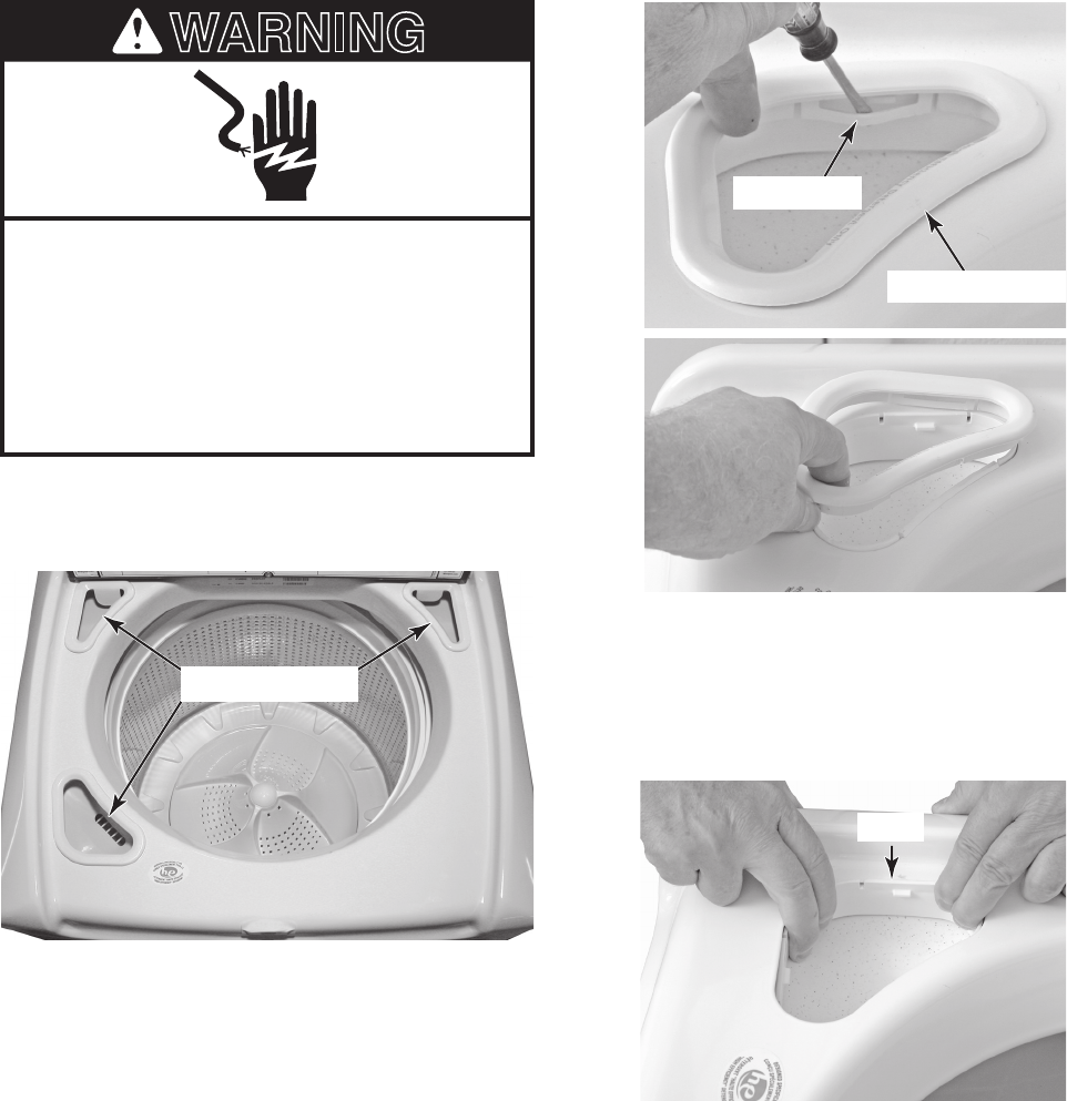
4-6
REMOVING A DISPENSER, THE
FRESH FILL INLET VALVE, AND THE LID LOCK
Electrical Shock Hazard
Disconnect power before servicing.
Replace all parts and panels before
operating.
Failure to do so can result in death or
electrical shock.
1. Unplug washer or disconnect power.
2. Raise the washer lid.
WARNING
NOTE: The removal procedure for the three
dispensers is the same so only one will be
shown removed.
3. To remove a dispenser:
a) Use a small screwdriver and pry out
on the three dispenser cover tabs
while you lift the cover off the dispens-
er (see the top right photo).
Dispenser Cover
Pry Out Tab
b) Squeeze the bottom of the dispenser,
and release the hooked segments at
the top of the dispenser from the cabi-
net, then push the dispenser out of its
cutout.
Hook
Dispensers
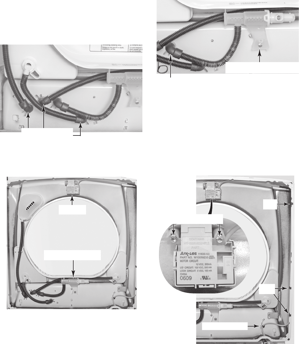
4-7
Continued on the next page.
c) Raise the cabinet top (see page 4-4
for the procedure).
d) Loosen the clamp and disconnect the
end of the dispenser hose from its wa-
ter inlet/dispenser valve connector.
NOTE: The dispenser hoses are per-
manently attached to the dispenser.
They are not intended to be removed.
4. To remove the fresh fill inlet valve:
a) Raise the cabinet top (see page 4-4 for
the procedure).
Fresh Fill Inlet Valve Hose
Fresh Fill Inlet Valve Screw
Fresh Fill Inlet Valve
Dispenser Hoses
b) Loosen the clamp and disconnect the
end of the fresh fill inlet valve hose
from its water inlet/dispenser valve
connector (see the top right photo).
NOTE: The fresh fill inlet valve hose is
permanently attached to the inlet. It is
not intended to be removed.
5. To remove the lid lock:
a) Raise the cabinet top (see page 4-4 for
the procedure).
b) Remove the two hex-head screws from
the lid lock and remove the lock.
c) Cut the indicated cable standoff from
the cabinet top.
d) Unclip the lid lock cable from the cabi-
net top flange.
Lid Lock
Cable Standoff
Lid Lock Screws
c) Remove the screw from the fresh fill
inlet valve and remove the valve as-
sembly.
Clip
Clips
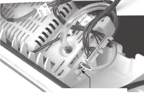
4-8
e) Disconnect the lid lock cable connector
from the machine/motor control con-
nector at P12.
f) Pull the end of the lid lock cable from
the control, and remove the lid lock and
cable assembly from the washer.
Lid Lock Connector P12
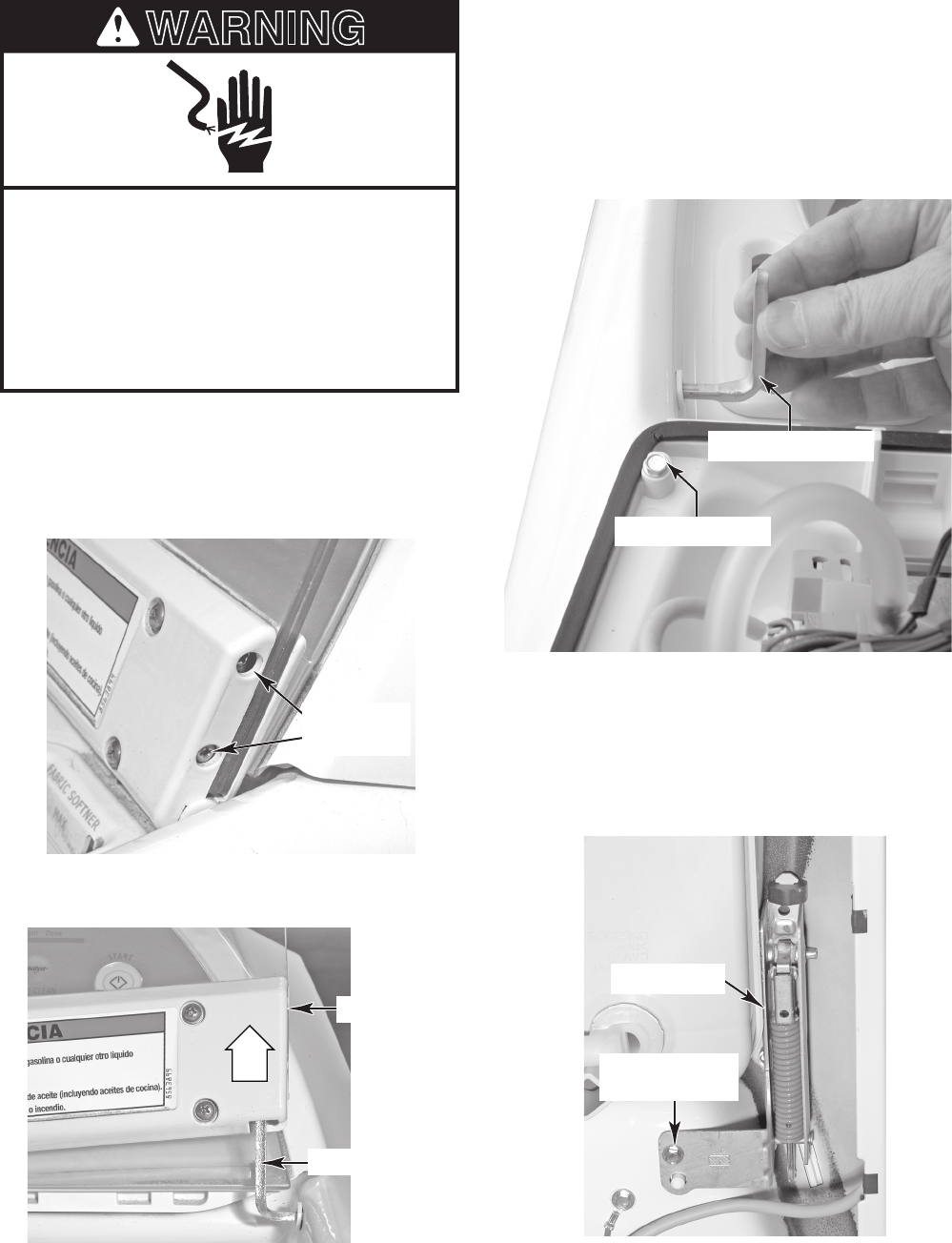
4-9
Electrical Shock Hazard
Disconnect power before servicing.
Replace all parts and panels before
operating.
Failure to do so can result in death or
electrical shock.
WARNING
REMOVING THE LID AND A HINGE
1. Unplug washer or disconnect power.
2. To remove the lid:
a) Raise the lid and remove the two hinge
pin screws from both sides.
3. To remove a hinge:
a) Remove the lid (see step 2).
b) Pull the hinge pin out of the hinge you
are removing.
c) Remove the top hex-head screw from
the hinge you are removing.
Top Hinge Screw
Pull Hinge Pin Out
d) Raise the cabinet top (see page 4-4 for
the procedure).
e) Remove the hex-head screw from the
hinge mounting bracket, and remove
the hinge from the cabinet top.
Hinge Bracket
Screw
b) Lift the lid, slide it off the hinge pins,
and remove the lid from the washer.
Lid Hinge
Pin Screws
LIFT
Washer Lid
Hinge Pin
Lid Hinge
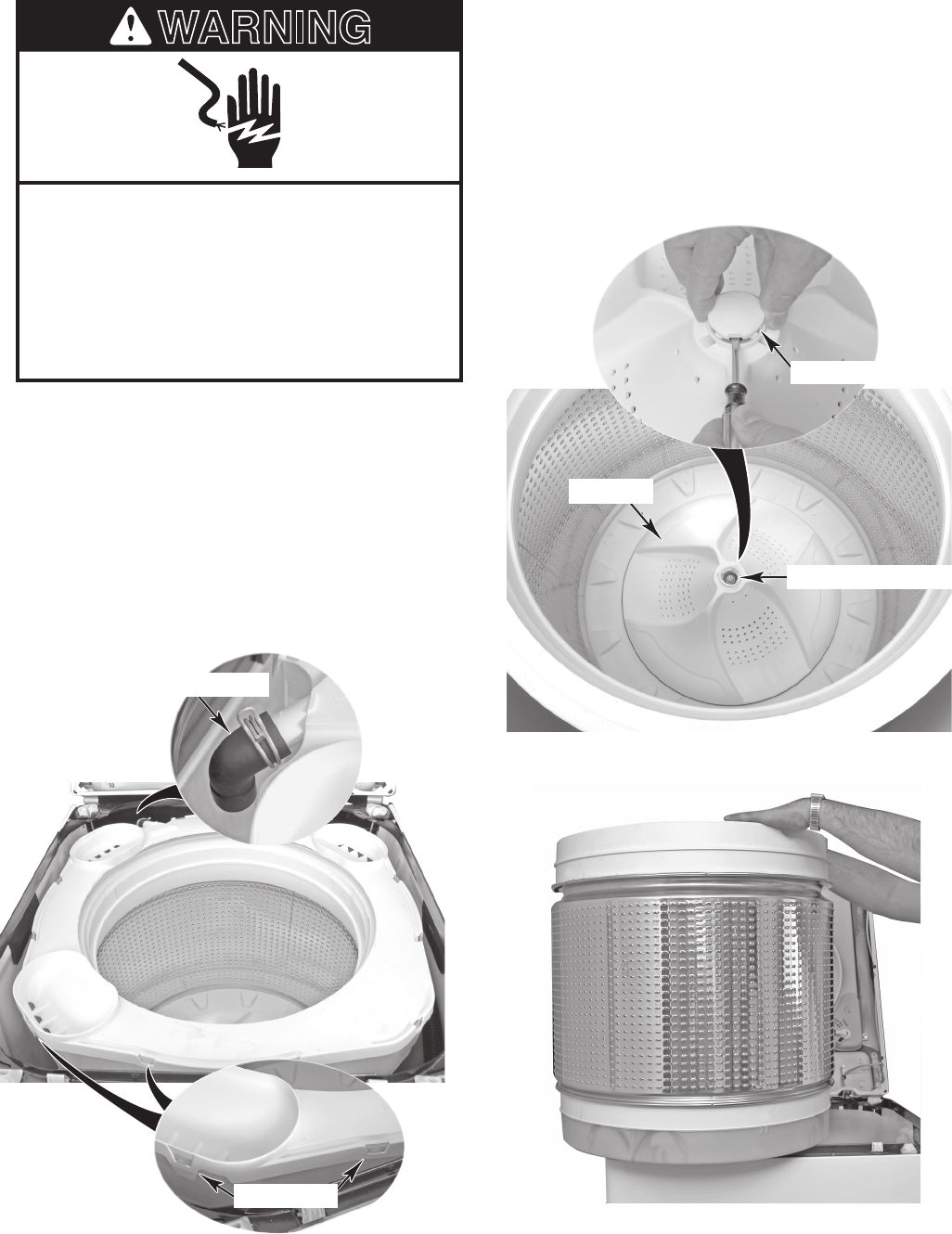
4-10
REMOVING THE BASKET, BASKET HUB, & LlNT FILTER
Electrical Shock Hazard
Disconnect power before servicing.
Replace all parts and panels before
operating.
Failure to do so can result in death or
electrical shock.
WARNING
Ring Tabs
Recirculation Hose
e) Lift the basket out of the washer.
Impeller Cap
Impeller
7/16˝ Impeller Bolt
1. Unplug washer or disconnect power.
2. Raise the cabinet top (see page 4-4 for
the procedure).
3. To remove the basket:
a) Loosen the clamp and pull the recircu-
lation hose off the tub ring.
b) Pry out and unsnap the tub ring tabs
from the tub and remove the tub ring.
c) Insert the blade of a small screwdriver
into the slot in the impeller cap, then
pry the cap up, and remove it.
d) Remove the 7/16˝ hex-head bolt from
the impeller, then lift and remove the
impeller from the basket. NOTE: Lift-
ing the basket will assist in removing
the impeller.
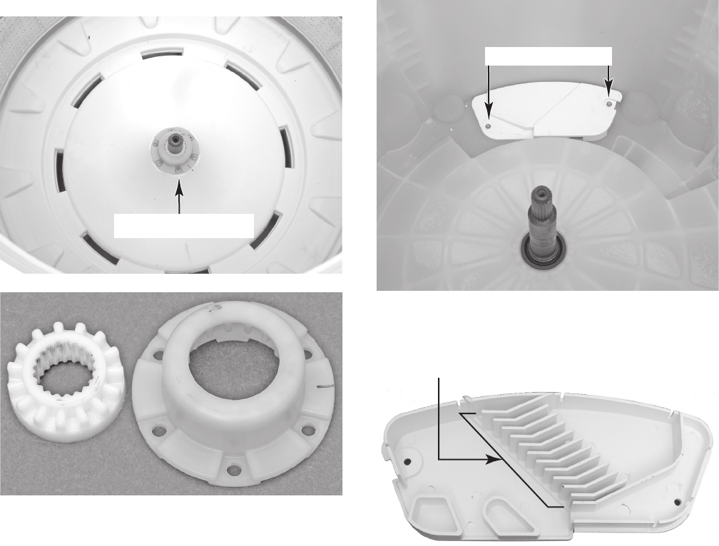
4-11
5. To remove the lint filter, remove the two
screws, and lift the filter from the tub.
Lint Filter Screws
NOTE: Clean the lint from the vanes in the
filter and reinstall it in the washer.
Lint Filter Vanes
4. To remove the basket hub, remove the
six screws, and lift the hub assembly from
the basket.
Basket Hub Screws
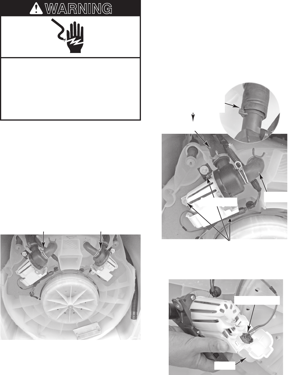
4-12
REMOVING THE DRAIN AND RECIRCULATION PUMPS
Electrical Shock Hazard
Disconnect power before servicing.
Replace all parts and panels before
operating.
Failure to do so can result in death or
electrical shock.
WARNING
1. Unplug washer or disconnect power.
2. Turn off the water supply to the washer.
3. Disconnect the hot and cold water hoses
from the rear of the washer, and remove
the end of the drain hose from the stand-
pipe or laundry tub.
4. Tape the washer lid closed.
5. Carefully lay the washer on its front pan-
el. Place padding on the floor to protect
the surfaces.
6. To remove the drain pump:
a) Loosen the clamps and pull the inlet
and outlet drain hoses off the pump.
Note that there is a tab on the outlet
connector that fits into a slot in the
hose.
b) Remove the three 5/16˝ hex-head
screws from the drain pump and re-
move the pump from the tub.
Drain Pump Recirculation Pump
Slide Pump Hose
Onto Connector With
Tab Into Hose Slot
Outlet Hose
Drain Pump Screws
Drain Pump Inlet Hose
c) Open the wire cover on the pump and
disconnect the 2-wire connector from
the terminals.
Cover
Wire Connector
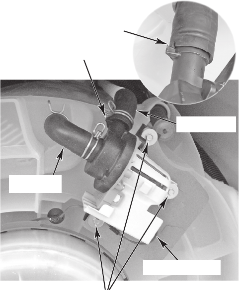
4-13
7. To remove the recirculation pump:
a) Loosen the clamps and pull the recir-
culation hoses off the pump. Note that
there is a tab on the outlet connector
that fits into a slot in the hose.
b) Remove the three 5/16˝ hex-head
screws from the recirculation pump
and remove the pump from the tub.
c) Disconnect the 2-wire connector from
the recirculation pump terminals.
Inlet Hose
Recirculation Pump Screws
Outlet Hose
Wire Connector
Slide Pump Hose
Onto Connector With
Tab Into Hose Slot
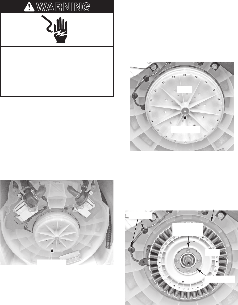
4-14
REMOVING THE DRIVE MOTOR & ROTOR POSITION SENSOR
Electrical Shock Hazard
Disconnect power before servicing.
Replace all parts and panels before
operating.
Failure to do so can result in death or
electrical shock.
WARNING
1. Unplug washer or disconnect power.
2. Turn off the water supply to the washer.
3. Disconnect the hot and cold water hoses
from the rear of the washer, and remove
the end of the drain hose from the stand-
pipe or laundry tub.
4. Tape the washer lid closed.
5. Carefully lay the washer on its front pan-
el. Place padding on the floor to protect
the surfaces.
Drive Motor
6. Use a 1/4˝ Allen wrench and loosen the
rotor mounting screw as far as it will go
(the screw is captive and cannot be re-
moved from the rotor). The rotor is seated
on the splined tub shaft. Rock the rotor
back and forth and pull it off the shaft so
it contacts the screw washer-head, then
further loosen the screw. Do this until the
rotor is removed from the shaft.
Rotor Screw
Rotor
7. Pull the two wire standoffs out of the tub
holes.
8. Remove the four 3/8˝ bolts from the drive
motor stator assembly.
9. Pull the shield and the stator with the two
round spacers (front and back) off the
tub.
Drive Motor
Stator Bolts
Front Spacer
Stator
Standoffs
Shield
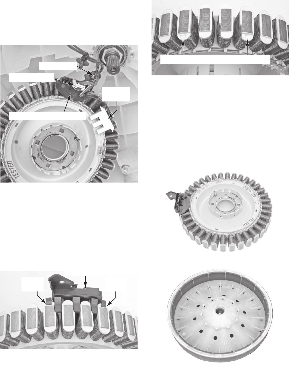
4-15
10. Disconnect the power connector from the
stator terminals.
11. Disconnect the wire standoff and edge
connector from the rotor position sensor
cover.
Power
Connector
12. Pry up on the two locking tabs and pull
the rotor position sensor cover off the
stator housing. NOTE: In the top right
photo, there are two indents on the hous-
ing to mark where the rotor position sen-
sor cover is installed. Be sure to snap the
two tabs on the rotor position sensor cov-
er into these indents when you reinstall it
on the stator assembly.
Pry Up
Tab
Rotor Position Sensor Cover Tab Indents
REASSEMBLY NOTE: When you reinstall
the drive motor rotor over the stator assembly,
do not grip the rotor housing around the rear
edge with your fingers. The magnets around
the rotor housing are very strong, and they
will pull the rotor into the stator coil magnets
when the rotor magnets come within their
magnetic field. Keep your fingers along the
outside of the rotor housing and away from
the rear edge when you are installing it on the
stator assembly.
Drive Motor Stator Assembly
Drive Motor Rotor Assembly
Pry Up
Tab
Rotor Position Sensor Cover
Edge Connector
Wire Standoff
Rotor Position Sensor Cover
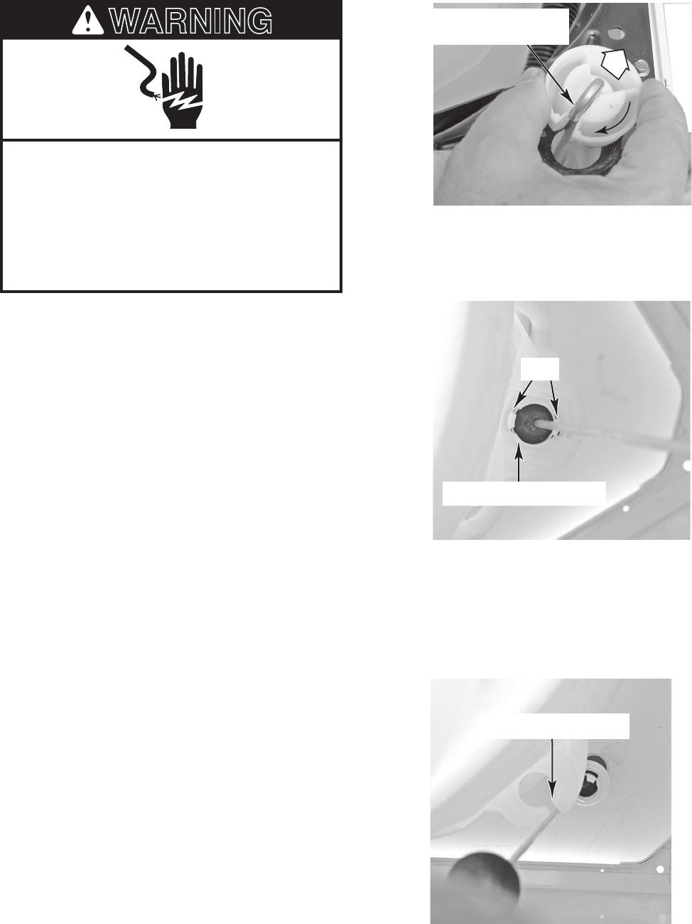
4-16
REMOVING THE TUB
Electrical Shock Hazard
Disconnect power before servicing.
Replace all parts and panels before
operating.
Failure to do so can result in death or
electrical shock.
WARNING
1. Unplug washer or disconnect power.
2. Turn off the water supply to the washer.
3. Disconnect the hot and cold water hoses
from the rear of the washer, and remove
the end of the drain hose from the stand-
pipe or laundry tub.
4. Remove the basket and lint filter from
the washer (see page 4-10 for the proce-
dures).
NOTE: Have a shop cloth handy to clean off
any grease from your hands.
5. Remove the four suspension rod assem-
blies from the washer. To remove a rod
assembly:
a) Grasp the rod several inches below
the suspension ball, and lift the rod so
the hooked end is free of the ball (see
the top right photo).
b) Rotate the suspension ball so that the
slotted side is parallel with the hooked
end of the rod, and slide the rod out of
the ball. Keep the ball in its holder.
d) Position the suspension rod through
the slot in the tub opening, and remove
the rod assembly from the washer.
NOTE: Unsnap the wire holder from
the right rear suspension rod before
removing it.
c) Reach down along the side of the
tub, and press in on the suspension
rod holder locking tabs, then push the
holder out of the tub opening.
Keep Suspension Ball
Slot Parallel With Rod
Suspension Rod Slot
Suspension Rod Holder
Tabs
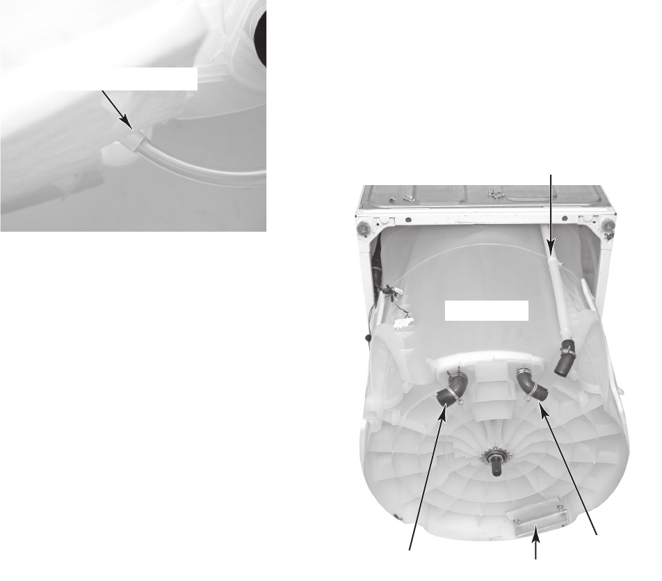
4-17
6. At the right rear corner of the washer,
reach down and pull the pressure trans-
ducer tube off the tank.
7. Lower (do not latch) the top of the cabi-
net.
8. Carefully lay the washer on its front pan-
el. Place padding on the floor to protect
the surfaces.
9. Remove the drain and recirculation pumps
(see page 4-12 for the procedures).
10. Remove the drive motor (see page 4-14
for the procedure).
Pressure Transducer Tube
11. Pull the tub out of the bottom of the washer.
12. Remove the two 5/16˝ hex-head screws
from the counterbalance weight and re-
move the weight from the tub.
13. Loosen the clamps and remove the recir-
culation and drain hoses from the tub.
14. Remove the hex-head clamp screw from
the recirculation outlet hose extension,
and remove the extension from the side of
the tub.
Counterbalance Weight
Drain Hose
Recirc. Hose
Recirculation Outlet Hose Extension
Washer Tub
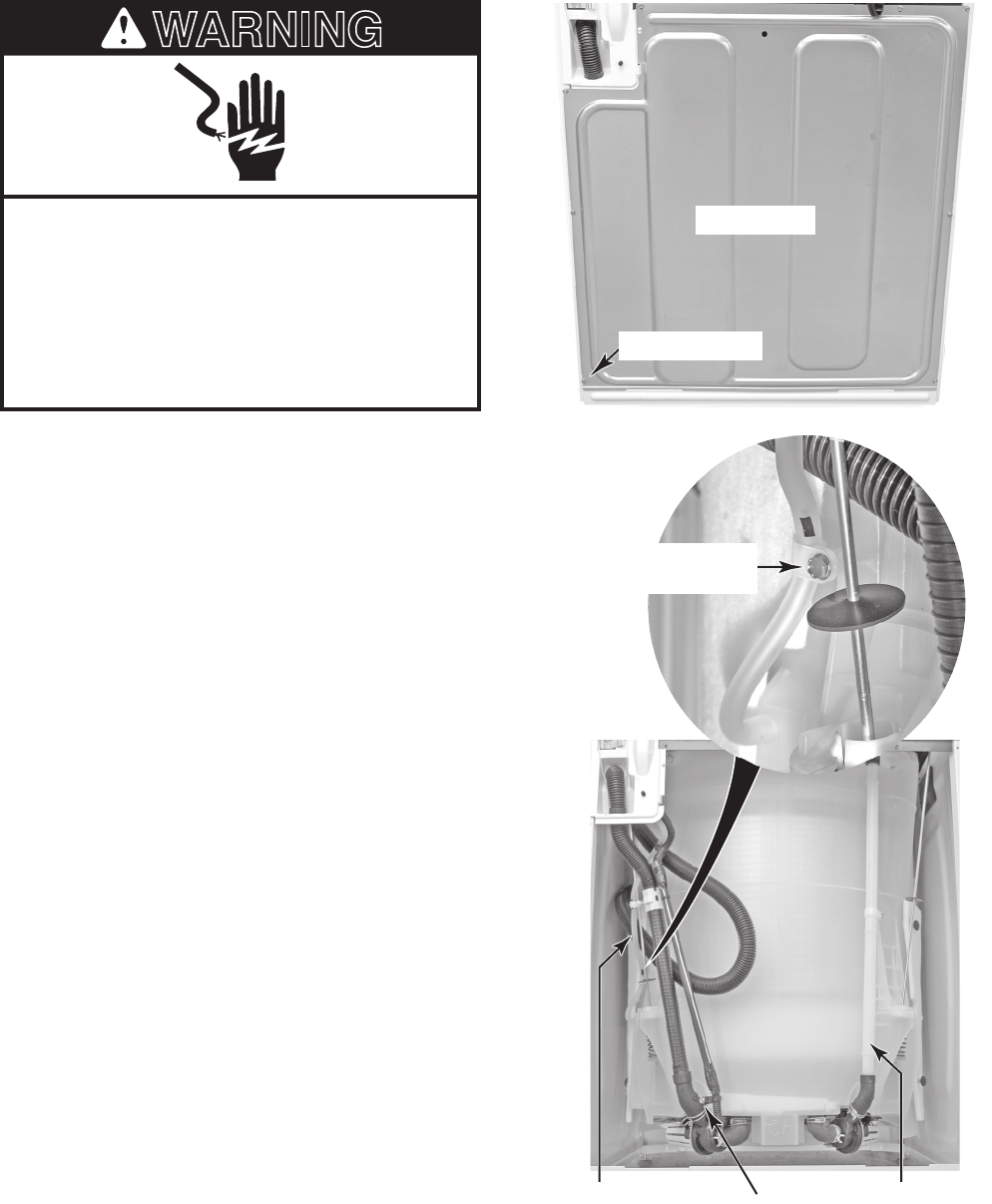
4-18
ACCESSING THE PRESSURE TRANSDUCER TUBING,
RECIRCULATION TUBE, AND DRAIN PUMP HARNESS
Electrical Shock Hazard
Disconnect power before servicing.
Replace all parts and panels before
operating.
Failure to do so can result in death or
electrical shock.
WARNING
The following procedure allows you to access
the following components for service by re-
moving the rear panel:
Drain Pump Harness
Pressure Transducer Tubing
Recirculation Tube
1. Unplug washer or disconnect power.
2. Turn off the water supply to the washer.
3. Disconnect the hot and cold water hoses
from the rear of the washer, and remove
the end of the drain hose from the stand-
pipe or laundry tub.
4. Remove the eight screws from the rear
panel and remove the panel (see the top
right photo).
•
•
•
Rear Panel
Screw (1 of 8)
Recirculation Tube
Pressure Transducer
Tubing Drain Pump Harness
Retainer Screw
Pressure Transducer
Tubing Retainer Screw
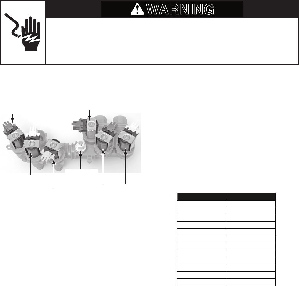
5-1
COMPONENT TESTING
Before testing any of the components, perform
the following checks:
The most common cause for control failure
is corrosion on connectors. Therefore, dis-
connecting and reconnecting wires will be
necessary throughout test procedures.
All tests/checks should be made with a
VOM or DVM having a sensitivity of 20,000
ohms-per-volt DC, or greater.
•
•
WATER INLET/ DISPENSER
VALVE ASSEMBLY
Check all connections before replacing
components, looking for broken or loose
wires, failed terminals, or wires not pressed
into connectors far enough.
Resistance checks must be made with
power cord unplugged from outlet, and
with wiring harness or connectors discon-
nected.
•
•
Electrical Shock Hazard
Disconnect power before servicing.
Replace all parts and panels before operating.
Failure to do so can result in death or electrical shock.
WARNING
2. Disconnect the wire connector from the
component under test.
3. Set the ohmmeter to the R x 1 scale.
4. Water Inlet / Dispenser Solenoids: Touch
the ohmmeter test leads to each of the
water inlet/dispenser valve solenoid termi-
nals. The meter should indicate between
700 and 900 Ω. If the reading is outside
this range, replace the valve assembly.
5. Thermistor: Touch the ohmmeter test
leads to the thermistor terminals. The
meter should indicate as shown in the
following chart.
Thermistor
Detergent
Dispenser
Fabric Softener
Dispenser Fresh Fill
Inlet Valve
Bleach Dispenser
Hot & Cold
Water Inlet Valves
THERMISTOR RESISTANCE
Temperature Resistance (
40°F (4.4°C) 26–27.5 k Ω
Ω
50°F (10°C) 19–20.5 k Ω
60°F (16°C) 15–15.7 k Ω
70°F (21°C) 11.7–12.2 k Ω
80°F (27°C) 9.1–9.5 k Ω
90°F (32°C) 7.2–7.6 k Ω
100°F (38°C) 5.6–5.9 k Ω
110°F (44°C) 4.6–4.9 k Ω
120°F (49°C) 3.6–3.8 k Ω
130°F (55°C) 2.9–3.1 k Ω
140°F (60°C) 2.4–2.6 k Ω
)
Refer to page 4-4 for the procedure for ac-
cessing the water inlet/dispenser valve as-
sembly.
1. Unplug washer or disconnect power.
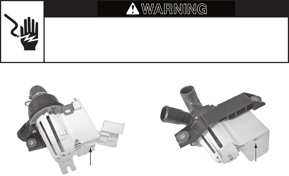
5-2
DRAIN PUMP
Refer to page 4-12 for the procedure for ac-
cessing the drain pump.
1. Unplug washer or disconnect power.
2. Disconnect the wire connector from the
drain pump terminals.
3. Set the ohmmeter to the R x 1 scale.
4. Touch the ohmmeter test leads to each
of the drain pump terminals. The meter
should indicate between 10.5 and 14 Ω.
Electrical Shock Hazard
Disconnect power before servicing.
Replace all parts and panels before operating.
Failure to do so can result in death or electrical shock.
WARNING
Terminals
RECIRCULATION PUMP
Refer to page 4-12 for the procedure for ac-
cessing the recirculation pump.
1. Unplug washer or disconnect power.
2. Disconnect the wire connector from the
recirculation pump terminals.
3. Set the ohmmeter to the R x 1 scale.
4. Touch the ohmmeter test leads to each of
the recirculation pump terminals. The me-
ter should indicate between 30 and 38 Ω.
Terminals
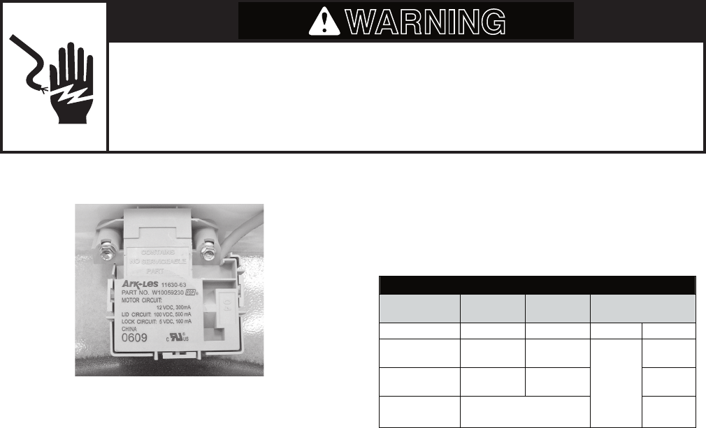
5-3
Refer to page 4-6 for the procedure for ac-
cessing the lid lock.
1. Perform the Manual: Door Lid Switch and
Manual: Door Lid Lock tests on page 6-7.
2. Remove the console to access the ma-
chine/motor control assembly (see “Ac-
cessing & Removing the Electronic As-
semblies” on page 6-15).
3. Visually check that the P12 connector is
inserted all the way into the machine/mo-
tor control.
If visual check passes, go to step 4.
If visual check fails, reconnect P4 and
repeat step 1.
4. Unplug washer or disconnect power.
•
•
LID LOCK RESISTANCE
Component Resistance
Unlocked
Resistance
Locked Contacts Measured
Motor Winding 35 ±5 Ω 35 ±5 Ω P12-2 P12-3
Lock Switch -
Home 0 Ω Open Circuit
P12-1
P12-4
Lock Switch -
Lock Open Circuit 0 Ω P12-7
Lock Switch -
Lid
Lid Closed = 0 Ω
Lid Open = Open Circuit P12-5
5. Check the lid lock motor winding and
switches by removing P12 from the ma-
chine/motor control, and checking the
resistance values shown in the following
Lid Lock Resistance table.
If resistance values are good, go to
step 6.
If switch measurements do not match
the values shown in the table for un-
locked (or locked) conditions, a prob-
lem exists in the door lid lock. Replace
the door lid lock.
6. If the Manual: Door Lid Switch or Manual:
Door Lid Lock tests in step 1 failed, then
the machine/motor control has failed:
Replace machine/motor control as-
sembly.
Perform the Manual: Door Lid Switch
and Manual: Door Lid Lock tests in
step 1 to verify repair.
•
•
•
•
Electrical Shock Hazard
Disconnect power before servicing.
Replace all parts and panels before operating.
Failure to do so can result in death or electrical shock.
WARNING
LID LOCK
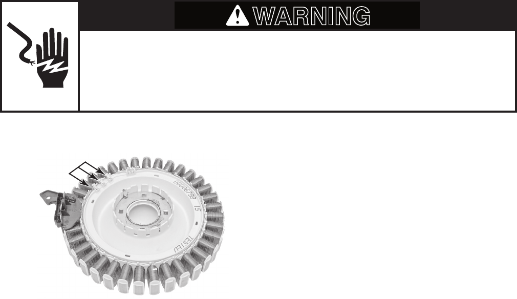
5-4
DRIVE MOTOR STATOR Refer to page 4-14 for the procedure for ac-
cessing the drive motor.
1. Unplug washer or disconnect power.
2. Disconnect the wire connector from the
drive motor terminals.
3. Set the ohmmeter to the R x 1 scale.
4. Touch the ohmmeter test leads to any
two of the three drive motor terminals.
The meter should indicate 31 Ω.
3 Terminals
Electrical Shock Hazard
Disconnect power before servicing.
Replace all parts and panels before operating.
Failure to do so can result in death or electrical shock.
WARNING
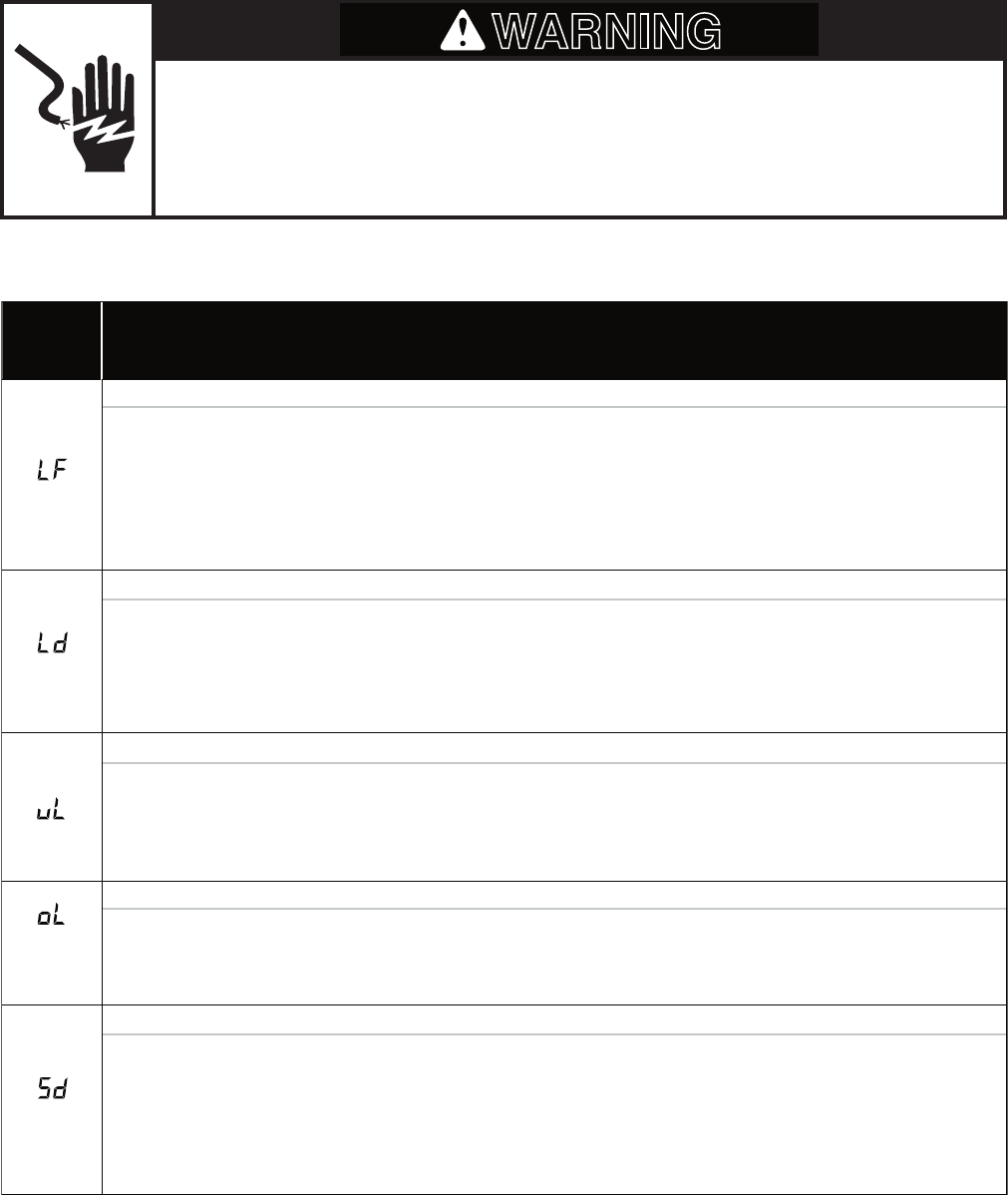
6-1
DIAGNOSTICS & TROUBLESHOOTING
DISPLAY FAULT / ERROR CODES
DISPLAY
(Saved Code) EXPLANATION AND RECOMMENDED PROCEDURE
(F30)
Long Fill
LF flashes when the water level does not change for a period of time on OR water is present but control does not detect
the water level changing.
• Is water supply connected and turned on?
• Are hose screens plugged?
• Is water water siphoning out of the drain hose? Check for proper drain hose installation.
• Is the pressure hose connection from the tub to the machine/motor control pinched or plugged?.
• See TEST #2.
(F32)
Long Drain
Ld flashes when the water level does not change after the drain pump is on.
• Is the drain hose or the drain pump clogged?
• Is the drain hose height greater than 96˝ ?
• Is the pressure hose connection from the tub to the machine/motor control pinched or plugged?
• Is the pump running? If not, see TEST #7.
(none)
Unbalanced Load
uL is displayed when the machine/motor control detects an off-balance load, and is steady on while the washer runs a
mini-cycle to rebalance the load.
• Display clears if mini-cycle successfully rebalanced the load.
• If the mini-cycle is unsuccessful, uL will flash until the door lid is opened, allowing the customer to view and redistribute
the load.
(F70)
Overloaded
oL flashes when the machine/motor control detects a load size that exceeds the washer’s capacity OR basket can not
disengage. This may signify:
• Load size exceeds washer capacity. Remove excess laundry, then restart cycle.
• Mechanical friction on drive mechanism, mot allowing the basket to disengage.
(F71)
Suds Detection
Sd is displayed when the machine/motor control, by analyzing drag on the basket, detects a suds-lock condition, and is steady
on while the control then runs a mini-clean out cycle. If the clean out cycle is unable to correct the over-sudsing problem, the
cycle ends and Sd flashes in the display. This may signify:
• Excessive detergent usage.
• Load is bunched or twisted around agitator.
• Basket cannot engage during drain step.
• Mechanical friction on drive mechanism, not allowing basket to engage.
Continued on the next page.
Electrical Shock Hazard
Disconnect power before servicing.
Replace all parts and panels before operating.
Failure to do so can result in death or electrical shock.
WARNING
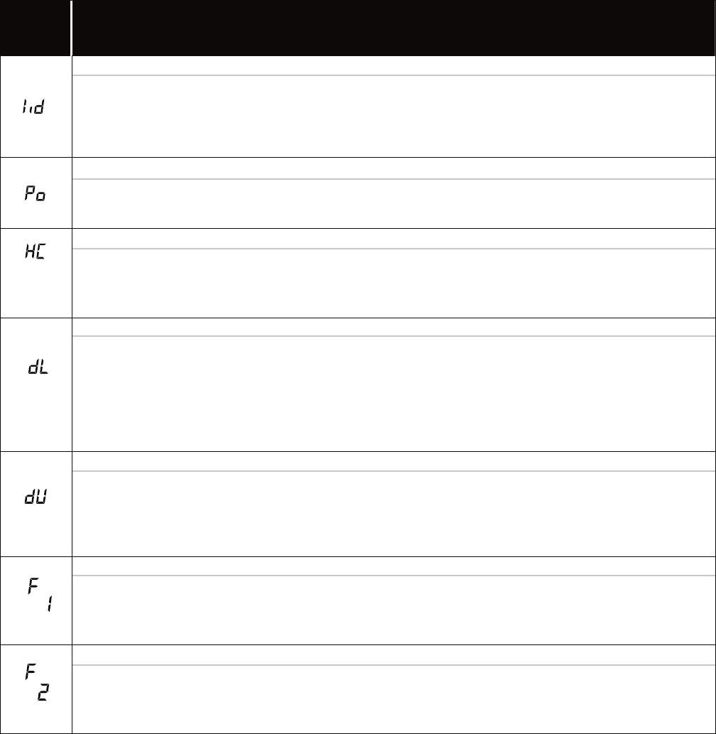
6-2
(F81)
Open/Close Door Lid
Lid flashes when the following conditions occur:
• User presses START with lid open.
• User presses START after 2 consecutive machine cycles without opening lid.
• The machine/motor control cannot detect the lid switch opening and closing properly.
• See TEST #8.
• See TEST #5.
(none)
(none)
Pump Out (lid opened)
Po flashes when drain pump begins pumping out water from tub upon activation by the door lid having been left open for
more than 10 minutes.
• Close door lid to stop drain pump.
If drain pump turns on when there is no water in tub,
Hot, Cold Reversed
HC flashes when the hot and cold inlet hoses are reversed.
• Make sure inlet hoses are connected correctly.
• If hoses are connected correctly, Automatic Temperature Control may be stuck in low resistance range.
(F80, 82,
84, 85)
Door Lock Failure
dL flashes if the following conditions occur:
• Door lid is not closed completely due to interference.
• Wash media buildup is preventing the lock bolt from extending.
• Check for lock interference with lid or lock bezel.
• Machine/motor control detects open door lid switch when attempting to lock.
• Machine/motor control cannot determine if door lid is in a locked state.
• See TEST #8.
(F83)
Door Unlock Failure
dU flashes if the following conditions occur:
• Excessive force on door lid is preventing lock bolt from retracting.
• Check pressure hose connection from tub to machine/motor control. Is hose pinched or kinked?
• If F then 1 repeats numerous times after POWER is pressed and the pressure hose connection is not pinched or kinked,
replace the machine/motor control.
• Wash media buildup is preventing lock bolt from retracting.
• Machine/motor control cannot determine if door lid is in an unlocked state.
• See TEST #8.
(F68)
Pressure Signal Out-Of-Range
F then 1 flashes when the control detects an out of range pressure signal.
(F2)
Keypad/User Interface Failure
F then 2 flashes when in:
• Diagnostics Test mode if a stuck key is detected.
• Standby mode if there is a user interface mismatch.
DISPLAY
(Saved Code) EXPLANATION AND RECOMMENDED PROCEDURE
• See TEST #4.
6-3
If drain pump turns on when there is no water in tub,
DISPLAY
(Saved Code) EXPLANATION AND RECOMMENDED PROCEDURE
(F40)
ATC Thermistor Open/Short
F then 40 flashes when the ATC Thermistor is detected to be open or shorted.
• See TEST #5.
(F41)
Motor RPS Thermistor Open/Short
F then 41 flashes when the motor rotor position sensor (RPS) thermistor is detected to be open or shorted.
• See TEST #3.
(F42)
Heater Thermistor Open/Short (Not Used)
F then 42 flashes when the heater thermistor is open or shorted.
(F50)
Motor Stalled
F then 50 flashes when the motor rotor position sensor (RPS) senses no rotation.
• Does basket turn freely? If not, make sure bottom shipping pack has been removed. Determine cause of friction.
• If basket turns freely, see TEST #3.
(F51)
Motor RPS Failure
F then 51 flashes when there is a motor rotor position sensor (RPS) failure or lower harness pboblem.
• See TEST #3.
(F52)
Motor Stop Failure
F then 52 flashes when the motor rotor position sensor (RPS) senses rotation after stop command.
• See TEST #3.
(F53)
Motor Control Overtemp
F then 53 flashes when the machine/motor control detects high temperature for the motor module.
• Does basket turn freely? If not, determine cause of friction.
• If basket turns freely, see TEST #3.
• Does basket turn freely? If not, determine cause of friction.
• If basket turns freely, see TEST #3.
(F54)
Motor Control Overcurrent
F then 54 flashes when the machine/motor control detects high current for the motor module.
(F72)
Basket Re-engagement Failure
F then 72 flashes when the basket check routine fails to determine if the basket is re-engaged after being disengaged.
• Is the basket floating? If yes, pump out water. See Long Drain.
• Does basket turn freely? If not, determine cause of friction.
NOTE: This error code is only displayed when viewing saved fault codes.
• See Diagnostic Test for accessing saved fault codes.

6-4
DIAGNOSTIC GUIDE
Before servicing, check the following:
Make sure there is power at the wall outlet.
Has a household fuse blown or circuit break-
er tripped? Time delay fuse?
Are both hot and cold water faucets open
and water supply hoses unobstructed?
All tests/checks should be made with a
VOM (volt-ohm-milliammeter) or DVM (digi-
tal-voltmeter) having a sensitivity of 20,000
ohms per volt DC or greater. NOTE: Avoid
using large diameter probes when check-
ing harness connectors as the probes may
damage the connectors upon insertion.
Check all connections before replacing
components. Look for broken or loose
wires, failed terminals, or wires not pressed
into connectors far enough.
A potential cause of a control not function-
ing is corrosion on connections. Observe
connections and check for continuity with
an ohmmeter.
Connectors: Look at top of connector.
Check for broken or loose wires. Check
for wires not pressed into connector far
enough to engage metal barbs.
Resistance checks must be made with
washer unplugged or power disconnected.
DIAGNOSTIC TESTS
There are three diagnostic test modes avail-
able: Automatic, Manual, and Console. These
tests allow the factory or service personnel to
test and verify all inputs to the machine/motor
control. You may want to allow the automatic
test cycle to complete prior to going into spe-
cific troubleshooting tests.
•
•
•
•
•
•
•
•
If this test mode has been entered suc-
cessfully, all indicators on the console
are illuminated for 5 seconds with 88
showing in the Estimated Time Re-
maining two-digit display.
If indicators do not display as de-
scribed above, the press/hold/release
procedure above may not have been
performed within the time frame neces-
sary for successful entry. Repeat step
2 to ensure this was not the cause. If
still unsuccessful, see Diagnostic: Un-
successful Entry.
3. The program then checks for saved fault
codes:
If there are saved fault codes, see Di-
agnostic: Saved Fault Codes.
If there are no saved fault codes, all
indicators on the console will momen-
tarily turn off, then turn back on with 88
displayed. After 5 seconds, the Auto-
matic test begins.
•
•
•
•
Press/hold
3 seconds
Release for
3 seconds
Press/hold
3 seconds
Release for
3 seconds
Press/hold
3 seconds
ACTIVATION OF AUTOMATIC
DIAGNOSTIC TEST MODE
1. Be sure the washer is in standby mode
(plugged in with all indicators off, or with
only the Clean indicator on).
2. Select any one button (except POWER,
START, and PAUSE/CANCEL) and fol-
low the steps below, using the same but-
ton (remember the button):

6-5
Two-Digit
Indicator Machine Function Recommended Procedure
C0 Slow spin to 23 rpm. If no spin go to Manual: Motor,
Spin.
C1
Warm water fills through
Fresh and Detergent
valves, then Fresh valve
until basket floats
(disengages); then
washer continues filling
through Fresh and
Detergent valves to
minimum water level.
If no water or fill temperature is
wrong, go to Manual: Water
Valves.
If basket does not float or
disengage, determine cause of
friction.
C2
Cold water fills through
Bleach valve for
10 seconds.
If no water in bleach cup go to
Manual: Water Valves.
C3
Hot water fills through
Fabric Softener valve
for 10 seconds.
NOTE: Step will occur
but no water can be
dispensed with models
that do not have a
fabric softener valve.
If no water in fabric softener cup
go to Manual: Water Valves.
C4
Warm water fills through
Detergent valve for
10 seconds.
If no water in detergent cup
go to Manual: Water Valves.
C5 Agitate for 15 seconds. If no wash action go to
Manual: Motor, Agitate.
C6 Recirculate for
10 seconds.
If water is not being recirculated
go to Manual: Pumps.
C7
Drain to basket engaged
plus timed drain for
10 seconds.
If water is not draining go to
Manual: Pumps.
If basket does not engage
determine cause of friction.
C8 Drain & slow spin
23 rpm.
If drain pump is not on go to
Manual: Pumps.
If basket is not turning go to
Manual: Motor.
C9 Coast to 0 rpm.
If basket does not stop spinning
within 5 seconds, press PAUSE/
CANCEL and restart test.
(none)
(Test
ends)
End of cycle beep.
If no end of cycle beep, make sure
cycle signal is on. From Setting
Mode, pressing buttons should
sound valid key press beep.
DIAGNOSTIC: Unsuccessful Entry
If entry into diagnostic mode is unsuccessful
(see steps 1 and 2 of Activation of Automatic
Diagnostic Test Mode), refer to the following
indications and actions:
DIAGNOSTIC: Automatic
Performs a five-minute automatic test with wa-
ter functions to check major washer functions
(door can be open). Press the same button
used in step 2 to advance through automatic
test steps.
NOTE: Basket must be floating in order to
agitate. Step C1 must be allowed to complete
before advancing to step C5.
Press and release the
same button used to
activate Diagnostics
•
•
•
•
Second most recent fault code is
displayed.
Repeat Third most recent fault code is displayed.
Repeat Fourth most recent fault code is displayed.
Repeat
All indicators momentarily turn off, then
stay on. After 5 seconds, Automatic test
cycle begins.
NOTE: Fault codes are retained.
Indication 1: None of the indicators or dis-
play turns on.
Action: Press POWER button to enter setting
mode.
If indicators come on, try to change the
function for the button used to activate
the diagnostic test mode. If that button
fails to change the function, something
is faulty with the button, and it is not
possible to enter the diagnostic mode.
If no indicators come on after pressing
POWER button, go to TEST #1.
Indication 2: Fault code flashes from the
display.
Action: Review the Display Fault/Error Codes
table for the recommended procedure.
DIAGNOSTIC: Saved Fault Codes
If there are saved fault codes (as indicated in
step 3 of Activation of Automatic Diagnostic
Test Mode), the most recent fault code will be
displayed and alternately show “F” and “XX”
where XX is the fault code, and all the cycle
selector indicators flash.
•
•
ACTIVATION OF MANUAL
DIAGNOSTIC TEST MODE
1. Carefully read and perform steps 1 and 2
under Activation of Automatic Diagnostic
Test Mode, and press the same button
once during the 5 second display time of
the 88.
NOTE: If the button is not pressed within
5 seconds, the Automatic test will start
(after saved fault codes).

6-6
2. If done successfully, a single beep oc-
curs and the two-digit display shows the
control ID# for 3 seconds, then displays
00 and the Add A Garment indicator LED
flashes. See Diagnostic: Manual.
DIAGNOSTIC: Manual
Assumes Manual Diagnostic mode has been
entered, two-digit display shows 00, and ADD
A GARMENT indicator LED is flashing.
NOTE: If there is no activity (button press,
cycle select) within 5 minutes, the control au-
tomatically exits Diagnostic mode and enters
standby mode.
Manual: Water Valves
To check FRESH valve select or press the
following:
WHITES • START (turns on Fresh valve,
cycle indicator flashes) • WASH/RINSE
TEMP (enables fill of Hot, Warm, Cool
or Cold or no water according to WASH/
RINSE TEMP selection and indicator) •
START (turns off Fresh valve, cycle indi-
cator is steady on).
To check DETERGENT valve select or press
the following:
SUPER WASH • START (turns on De-
tergent valve, cycle indicator flashes) •
WASH/RINSE TEMP (enables fill of Hot,
Warm, Cool or Cold or no water accord-
ing to WASH/RINSE TEMP selection and
indicator) • START (turns off Detergent
valve, cycle indicator is steady on).
To check FABRIC SOFTENER valve select
or press the following:
NORMAL • START (turns on Fabric
Softener valve, cycle indicator flashes) •
WASH/RINSE TEMP (enables fill of Hot,
Warm, Cool or Cold or no water accord-
ing to WASH/RINSE TEMP selection and
indicator) • START (turns off Fabric Soft-
ener valve, cycle indicator is steady on).
To check BLEACH valve select or press the
following:
WRINKLE CONTROL • START (turns on
Bleach valve with cold water, cycle indi-
cator flashes) • START (turns off Bleach
valve, cycle indicator is steady on).
NOTE: Washer can only fill cold through
Bleach valve.
If any valve fails to turn on go to TEST #2.
Manual: Pumps
•
•
•
•
•
Select CLEAN WASHER or SPIN ONLY.
Press and release:
START
Turns on recirculation pump, cycle
indicator is steady on.
Repeat Turns off recirculation pump, indicator
is steady on.
Repeat Turns on drain pump, indicator flashes.
Repeat Turns off drain pump, indicator is
steady on.
If pumps fail to turn on go to TEST #7.•

6-7
Press and release:
EXTRA RINSE Door locks, lid lock indicator turns on.
Repeat Door unlocks, lid lock indicator turns off.
•
•
Manual: Door Lid Switch
Opening the door should cause the Clean
status indicator to turn off. Closing the door
should cause the indicator to turn on.
If Clean indicator does not turn off or on, go
to TEST #8.
Manual: Door Lid Lock
NOTE: Door must be closed. If door is not
closed, an invalid button press beep will oc-
cur when performing next step.
•
If door does not lock or unlock, go to TEST
#8.
•
Press and release:
SPIN SPEED, or
LOAD SIZE Motor/basket spins at 23 rpm.
Repeat Motor/basket spins at 530 rpm.
Repeat Motor/basket spins at 1000 rpm.
Repeat Motor turns off.
•
•
•
•
Press and release:
SOIL LEVELGentle wash action.
Repeat Normal wash action.
Repeat Heavy wash action.
Repeat Motor turns off.
•
•
•
•
Manual: Motor
Rotor Position Sensor (RPS): Uses Wash,
Rinse and Spin indicators to detect the three
hall sensors. Console may have up to two of
these indicators on at one time when the bas-
ket is not moving. Open door and rotate bas-
ket by hand. The Wash, Rinse and Spin status
indicators should toggle on and off according
to direction the basket is being turned.
If none of these indicators are on go to
TEST #3.
Spin: To activate Spin, door must be closed
with door lock enabled. See Manual: Door Lid
Lock.
NOTE: If door is not closed, an invalid button
press beep will occur when performing next
step.
•
Agitate: Water must cover the wash plate (or
agitator vanes) to ensure the basket is float-
ing prior to agitation. Enabling agitation with-
out enough water may cause a fault condition
to occur. See Manual: Water Valves.
NOTE: Indicators above button scroll from
top to bottom.
If motor fails to agitate, go to TEST #3.•
NOTE: Indicators above button scroll from
top to bottom.
If motor fails to spin, go to TEST #3.•
ACTIVATION OF CONSOLE AND
INDICATORS DIAGNOSTIC TEST MODE
This test checks the cycle selector knob, indi-
cators, buttons, two-digit display and beeper.
1. Plug in washer or reconnect power.
2. Read through step 3 before continuing.
From Standby (Off) Mode press and re-
lease (key-dance) the following buttons
within 4 seconds:
If successful, two-digit dt will display and
you will have 5 seconds to complete next
step.
3. Within 5 seconds of dt showing in display,
press START (all indicators in display are
illuminated and 88 is displayed).
Press START a second time. This
turns off status indicators and two-digit
display (all other indicators remain il-
luminated).
Press START a third time. This turns
on status indicators and two-digit dis-
play (all indicators are illuminated).
4. Rotate WASH CYCLE selector back and
forth. Indicators will toggle on (or off).
•
•
SOIL
LEVEL
WASH/RINSE
TEMP
SOIL
LEVEL
WASH/RINSE
TEMP
6-8
5. Press buttons to verify function. Indica-
tors will toggle on (or off) and beep tone
will sound when buttons are pressed.
NOTE: Pressing SOIL LEVEL, SPIN
SPEED, or LOAD SIZE, and WASH/RINSE
TEMP will cause all indicators above
these buttons to toggle on (or off) at one
time.
If any of the following occur during steps, see
TEST #4:
None of the indicators light up
No beep sound is heard
Some buttons do not light indicators
DEACTIVATION OF DIAGNOSTIC
TEST MODE
Press the PAUSE/CANCEL or POWER but-
ton at any time to exit Automatic, Manual, or
Console & Indicators diagnostic test modes.
•
•
•

6-9
TROUBLESHOOTING GUIDE
PROBLEM
POSSIBLE CAUSE/TEST
NOTE: Possible Cause/Test must be performed in
the sequence shown for each problem.
WON’T POWER
UP
(No response
when buttons
are pressed.)
1. Supply connections. See TEST #1.
2. Unplug washer or disconnect power.
3. Check harness connections.
4. User interface assembly. See TEST #4.
WON’T START
CYCLE
(No response
when Start
button is
pressed.)
1. Supply connections. See TEST #1.
2. Unplug washer or disconnect power.
3. Check harness connections.
4. User interface assembly. See TEST #4.
WON’T SHUT
OFF WHEN
EXPECTED
1. User interface assembly. See TEST #4.
2. Lid switch. See TEST #8.
CONTROL
WON’T ACCEPT
SELECTIONS
User interface assembly. See TEST #4.
WON’T
DISPENSE
3. Log valve. See TEST #2.
1. Check water connections to machine.
2. Check for plugged screen in water source.
WON’T FILL 1. Check water connections to machine.
2. Check for plugged screen in water source.
3. Log valve. See TEST #2.
4. Unplug washer or disconnect power.
5. Check harness connections.
OVER FILLS 1. Unplug washer or disconnect power.
2. Check pressure hose connections.
3. Check to see if the pressure hose has a hole,
is pinched or plugged..
4. Water level and calibration. See TEST #6.
WON’T
AGITATE
1. Make sure basket is floating.
2. Unplug washer or disconnect power.
3. Check harness connections.
4. Lid switch. See TEST #8.
5. Motor. See TEST #3.
WON’T SPIN 1 Lid switch. See TEST #8.
2. Unplug washer or disconnect power.
3. Check harness connections.
4. Motor. See TEST #3.
WON’T DRAIN 1. Check drain hose installation.
2. Check for plugged drain hose.
3. Drain pump. See TEST #7.
INCORRECT
WATER
TEMPERATURE
1. Check for swapped water connections to
1. ATC thermistor stuck in high resistance range.
machine.
2. ATC (Automatic Temperature Control).
See TEST #5.
ALL HOT FILLS
2. ATC (Automatic Temperature Control).
See TEST #5.
WON’T
RECIRCULATE
WATER
1. Unplug washer or disconnect power.
2. Check for plugged recirculation hose.
3. Check for leaks in recirculation system.
4. Recirculate pump. See TEST #7.
DISPLAY IS
FLASHING
See “Display Fault/Error Codes.”
TROUBLESHOOTING TESTS
TEST #1 Supply Connections
This test assumes that proper voltage is pres-
ent at the outlet.
1. Unplug washer or disconnect power.
2. Access the machine/motor control as-
sembly. See Accessing & Removing the
Electronic Assemblies.
3. With an ohmmeter, check for continuity
between the neutral (N) terminal of the
plug and P13-1 on the machine/motor
control. See Figures 3 and 4, page 6-16.
If there is continuity, go to step 4.
If there is no continuity, replace the
power cord.
4. In a similar way, check the continuity be-
tween the L1 terminal of the plug and
P13-3 on the machine/motor control. See
Figures 3 and 4, page 6-16.
If there is continuity, go to step 5.
If there is no continuity, replace the
power cord.
5. Visually check that the P10 connector is
inserted all the way into the machine/mo-
tor control.
6. Visually check that the user interface as-
sembly is properly inserted into the front
console.
7. If both visual checks pass, replace the
user interface assembly. See Reinstall-
ing the Electronic Assemblies.
8. Plug in washer or reconnect power.
9. Activate the Console and Indicators Di-
agnostic Test mode to verify repair.
10. If indicators still do not light, the machine/
motor control has failed:
Unplug washer or disconnect power.
Replace the machine/motor control as-
sembly.
Plug in washer or reconnect power.
•
•
•
•
•
•
•

6-10
TEST #2 Log Valve
This test checks the electrical connections to
the valves, and the valves themselves.
1. Check the relays and electrical connec-
tions to the valves by performing the steps
under Diagnostic: Manual, then Manual:
Water Valves. Each step in the test ac-
tivates a group of valves. The following
steps assumes one (or more) valve(s)
failed to turn on.
2. For the valve(s) in question check the in-
dividual solenoid valves:
Unplug washer or disconnect power.
Disconnect connector P1 and P2 from
the machine/motor control.See Figure
4, page 6-16.
Check harness connection to solenoid
valves.
3. Check resistance of valve coils at con-
tacts P1 and P2 shown in the Wiring Dia-
gram on page 7-1. Resistance values
should match those shown.
If resistance readings are tens of ohms
outside of range, replace the entire log
valve assembly.
If resistance readings are within range,
replace the machine/motor control as-
sembly.
4. Reconnect connectors P1 and P2 to the
machine/motor control.
TEST #3 Motor Circuit
This test checks the wiring to the motor and
rotor position sensor; and the motor and rotor
position sensor themselves.
NOTE: Drain water from tub.
1. See Activation of Manual Diagnostic Test
Mode, and check the motor and electrical
connections by performing the Spin test
under Manual: Motor. The following steps
assumes that this step failed.
2. Unplug washer or disconnect power.
•
•
•
•
•
3. Check to see if basket will turn freely.
If basket turns freely, go to step 4.
If basket does not turn freely, deter-
mine what is causing the mechanical
friction or lock up.
4. Remove the console to access the ma-
chine/motor control assembly. See Ac-
cessing & Removing the Electronic As-
semblies.
5. Visually check that the P5 and P10 con-
nectors are inserted all the way into the
machine/motor control.
If visual checks pass, go to step 6.
If visual checks fail, reconnect P5 and
P10 and repeat step 1.
6. Visually check that the P5 and P10 con-
nectors are inserted all the way into the
machine/motor control.
With an ohmmeter, verify resistance
values as shown below:
•
•
•
•
•
7. Tilt machine forward to access the bottom
of the machine and the drive motor area.
See Figure 1 on page 6-13. Remove the
motor bolt, then the motor cover to ac-
cess the motor connections. See Figure
2 on page 6-13.
8. Visually check the mounting bracket and
electrical connections to the motor and
rotor position sensor board.
If visual check passes, go to step 9.
If visual check fails, reconnect the elec-
trical connections, reassemble stator
and motor cover and repeat step 1.
•
•
Check
between
connector
pins
Resistance values
should be:
Go to
step 7 if
values are:
Go to
step 12 if:
P5 1-5 31 Ω ± 5 Ω Much higher
than 31 Ω
Resistances
at all
connectors
are correct
1-3
P10
6-5
15 kΩ ± 100 Ω
Much higher
or much
lower than
15 kΩ
6-4
6-3
1-7 600 Ω to
21.2 k ΩOut of range
6-11
9. With an ohmmeter, check for continuity
between all pins on the P10 machine/mo-
tor control connector and the motor rotor
position sensor (RPS) connector. See
Figures 2 and 4, pages 6-13 and 6-16.
If there is continuity, check the motor
windings. If the windings are open, re-
place the drive motor.
If there is no continuity, replace the
lower machine harness.
10. With an ohmmeter, check for continuity
between all pins on the P5 machine/mo-
tor control connector and the drive motor
connector.
If there is continuity, replace the drive
motor.
If there is no continuity, replace the
lower machine harness.
11. The drive motor and lower harness are
good. Replace the motor RPS board and
perform the Diagnostics test in step 1 to
verify repair.
12. If the Diagnostics motor test in step 1
failed, then the machine/motor control
has failed:
Unplug the washer or disconnect power.
Replace the machine/motor control as-
sembly.
Perform the Motor Diagnostics in step
1 to verify repair.
TEST #4 Console and Indicators
This test is performed when any of the follow-
ing situations occurs during the Console and
Indicators Diagnostic Test:
None of the indicators light up
No beep sound is heard
Some buttons do not light indicators
None of the indicators light up:
1. Perform steps in Accessing & Removing
the Electronic Assemblies, and visually
check that the P11 connector is inserted all
the way into the machine/motor control.
2. Visually check that the user interface as-
sembly is properly inserted in the console
assembly.
•
•
•
•
•
•
•
•
•
•
3. If both visual checks pass, replace the
user interface assembly.
4. Plug in washer or reconnect power.
5. Activate the Console and Indicators Di-
agnostic Test mode to verify repair.
6. If indicators still do not light, the machine/
motor control has failed:
Unplug washer or disconnect power.
Replace the machine/motor control as-
sembly.
Plug in washer or reconnect power.
Activate the Console and Indicators
Diagnostic Test mode to verify repair.
No beep sound is heard:
1. Perform steps in Accessing & Removing
the Electronic Assemblies, and visually
check that the P5 connector is inserted all
the way into the machine/motor control.
If visual check passes, replace the user
interface assembly.
2. Plug in washer or reconnect power.
3. Activate the Console and Indicators Di-
agnostic Test mode to verify repair.
4. If replacing the user interface assembly
failed:
Unplug washer or disconnect power.
Replace the machine/motor control as-
sembly.
Plug in washer or reconnect power.
Activate the Console and Indicators
Diagnostic Test mode to verify repair.
Some buttons do not light indicators:
1. Perform steps in Accessing & Removing
the Electronic Assemblies, and visually
check that the console electronics and
housing assembly is properly inserted
into the front console.
If visual check passes, replace the user
interface assembly.
2. Plug in washer or reconnect power.
3. Activate the Console and Indicators Di-
agnostic Test mode to verify repair.
•
•
•
•
•
•
•
•
•
•

6-12
TEST #5 Automatic Temperature Control
This test checks the water inlet valves, the
temperature sensor, and the machine/motor
control.
1. Check the valves by performing Test #2,
before continuing to the next step.
2. Ensure proper hose connections and that
household’s hot water is present.
3. Plug in washer or reconnect power.
4. Remove all clothes from the machine.
5. Select POWER • wash cycle NORMAL
• Wash/Rinse Temp. WARM/COLD •
START.
6. After the tub fills and starts to wash, stop
the machine.
7. Measure the water temperature, and ver-
ify it is 85°±5°F (29°±3°C).
If the water temperature is correct, ATC
is functional.
If the water temperature is incorrect,
then go to step 8.
8. Unplug washer or disconnect power.
9. Access the machine/motor control as-
sembly. See Accessing & Removing the
Electronic Assemblies.
10. Remove the P9 connector, and using an
ohmmeter, measure the resistance be-
tween pins P9-1, and P9-3. Verify that
the resistance is within range as shown
in the following table:
•
•
11. Using an ohmmeter, measure continuity
between all pins on the P9 connector and
the thermistor contacts.
If there is continuity, replace the log
valve assembly.
If there is no continuity, replace the up-
per harness.
12. The log valve and upper harness are
good. Replace the machine/motor con-
trol assembly. See Reinstalling the Elec-
tronic Assemblies.
TEST #6 Water Level and Pressure Trans-
ducer Calibration
This test checks the water level sensing com-
ponents, and calibrates the pressure sensor.
1. Unplug washer or disconnect power.
2. Access the machine/motor control as-
sembly. See Accessing & Removing the
Electronic Assemblies.
3. Check hose connection between the
pressure transducer on the machine/mo-
tor control and the pressure dome at-
tached to the tub. Check to ensure hose
is routed correctly in the lower cabinet
and not pinched or crimped by the back
panel.
4. Plug in washer or reconnect power.
5. Drain the tub until all water has been re-
moved from tub.
6. Remove all clothes from the machine.
7. Calibrate the pressure transducer:
See Activation of Manual Diagnostic
Test Mode, and perform steps 1 and 2
until the display shows 00 and the Add
A Garment indicator LED is flashing.
Press and hold the Cycle Signal button
until a single beep sounds, and the dis-
play shows Pt to indicate zero calibra-
tion has completed.
Exit Diagnostic: Manual by pressing
PAUSE/CANCEL or POWER.
•
•
•
•
•
If the resistance is not within this range,
go to step 11.
If the resistance is within this range, go
to step 12.
•
•
THERMISTOR RESISTANCE
Temperature Resistance (
40°F (4.4°C) 26–27.5 k Ω
Ω
50°F (10°C) 19–20.5 k Ω
60°F (16°C) 15–15.7 k Ω
70°F (21°C) 11.7–12.2 k Ω
80°F (27°C) 9.1–9.5 k Ω
90°F (32°C) 7.2–7.6 k Ω
100°F (38°C) 5.6–5.9 k Ω
110°F (44°C) 4.6–4.9 k Ω
120°F (49°C) 3.6–3.8 k Ω
130°F (55°C) 2.9–3.1 k Ω
140°F (60°C) 2.4–2.6 k Ω
)
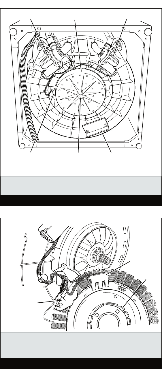
6-13
Motor
Connector
Stator
Motor Rotor
Position Sensor
(RPS)
Motor cover removed to access RPS and motor
connector.
Figure 2
Drain Pump Recirculation Pump
Motor Bolt
Motor Rotor Position
Sensor (RPS)
or Motor Connection
Counterweight
Motor Cover
Drive motor area, viewed from bottom.
Figure 1
6-14
8. Select POWER • wash cycle NORMAL •
START.
9. Verify that the tub fills to the top of the
impeller plate (impeller models), or to a
level above the agitator vanes (agitator
models), but much lower than the SU-
PER Load Size water level.
TEST #7 Drain/Recirculation
Perform the following checks if washer fails to
drain or recirculate.
1. See Activation of Manual Diagnostic Test
Mode, and perform the Manual: Pumps
test.
2. Remove the console to access the ma-
chine/motor control assembly. See Ac-
cessing & Removing the Electronic As-
semblies.
3. Visually check that the P4 connector is
inserted all the way into the machine/mo-
tor control.
If visual check passes, go to step 4.
If visual check fails, reconnect P4 and
repeat step 1.
4. Remove connector P4 from the machine/
motor control and check resistance val-
ues of pump motor windings. Resistance
values should match those shown in wir-
ing diagram, page 7-1.
If resistance values are good, go to
step 7.
If winding measurements are much
higher (tens of ohms to infinity) than
shown in wiring diagram, a problem
exists in the motor winding or in the
connection between the machine/motor
control and the motor. Go to step 5.
5. Tilt machine forward to access the bot-
tom of the machine and the pumps. See
Figure 1, page 6-13.
•
•
•
•
6. Check the resistance at the pump motor.
Remove the connector at the motor and
take measurements across pump termi-
nals. Measurements should be as shown
in the wiring diagram.
If winding measurements are much
higher (tens of ohms to infinity) than
shown in wiring diagram, replace the
pump motor.
If the resistance at the pump motor is
correct, there is an open circuit in the
wiring between the motor and the ma-
chine/motor control. Repair or replace
the lower wiring harness.
If the pump motor windings and ma-
chine/motor control check OK, repair
or replace the pump. Be sure to check
the pump and tub sump for foreign ob-
jects before replacing pump.
7. See Activation of Manual Diagnostic Test
Mode, and perform the Manual: Pumps
test.
8. If the Manual: Pumps test failed, then the
machine/motor control has failed:
Unplug the washer or disconnect power.
Replace the machine/motor control as-
sembly.
Perform the Manual: Pump test.
TEST #8 Door Lid Lock
Perform the following checks if washer fails to
lock (or unlock).
1. Perform Manual: Door Lid Switch and
Manual: Door Lid Lock tests.
2. Remove the console to access the ma-
chine/motor control assembly. See Ac-
cessing & Removing the Electronic As-
semblies.
3. Visually check that the P12 connector is
inserted all the way into the machine/mo-
tor control.
If visual check passes, go to step 4.
If visual check fails, reconnect P4 and
repeat step 1.
•
•
•
•
•
•
•
•

6-15
4. Check the lid lock motor winding and
switches by removing P12 from the ma-
chine/motor control and checking the
resistance values shown in the Lid Lock
Resistance table below:
LID LOCK RESISTANCE
Component Resistance
Unlocked
Resistance
Locked Contacts Measured
Motor Winding 35 ±5 Ω 35 ±5 Ω P12-2 P12-3
Lock Switch -
Home 0 Ω Open Circuit
P12-1
P12-4
Lock Switch -
Lock Open Circuit 0 Ω P12-7
Lock Switch -
Lid
Lid Closed = 0 Ω
Lid Open = Open Circuit P12-5
If resistance values are good, go to
step 5.
If switch measurements do not match
the values shown in the table for un-
locked (or locked) conditions, a prob-
lem exists in the door lid lock. Replace
the door lid lock.
5. If the Manual: Door Lid Switch or Manual:
Door Lid Lock in step 1 failed, then the
machine/motor control has failed:
Unplug washer or disconnect power.
Replace Door Lid Lock assembly.
Perform the Manual: Door Lid Switch
and Manual: Door Lid Lock in step 1 to
verify repair.
ACCESSING & REMOVING THE
ELECTRONIC ASSEMBLIES
There are two electronic assemblies; the ma-
chine/motor control assembly and the user
interface assembly. See Figures 3 and 4 on
page 6-16.
Accessing the Electronic Assemblies
1. Unplug washer or disconnect power.
2. Remove three screws from the rear of the
console assembly. Pull console towards
front of washer to hinge open and/or re-
move console.
Removing the Machine/Motor
Control Assembly
3. Remove all the wire connections to
the machine/motor control.
•
•
•
•
•
4. Remove the one screw holding the
machine/motor control assembly to
the console tray.
5. There are two plastic legs on the rear
of the machine/motor control assem-
bly that fit into the console tray. Lift the
front of the control assembly to pivot it
out from the console tray.
Removing the User Interface Assembly
3. Remove the wire connection to the
user interface assembly.
4. Remove the wash cycle selector knob
by firmly pulling on it.
5. The user interface assembly is held
to the console insert panel by three
screws and two locking tabs. After the
screws are removed, lift each of the
locking tabs to remove the back cover
of the user interface assembly.
6. Remove the wash cycle selector
switch from the user interface assem-
bly opening by lifting the locking tab
on the wash cycle selector switch and
turning the selector switch in a coun-
terclockwise direction.
7. Three locking tabs located at the bot-
tom of the console insert panel se-
cure the user interface assembly to
the console insert panel. Using a flat-
blade screwdriver, gently apply pres-
sure to the locking tabs to release the
user interface assembly.
Reinstalling the Electronic Assemblies
1. Refer to preceding removal sections and
replace in reverse order.
2. Plug in washer or reconnect power.
NOTE: When reconnecting wire connections,
route wires as shown in Figure 3, page 6-16.
Be sure to route wires beneath the retainer
clips on the machine/motor control, and en-
sure user interface assembly wire does not
get pinched between the console assembly
and the console tray when reassembling top.
NOTE: Ensure the console gasket is in place
when reinstalling the console.
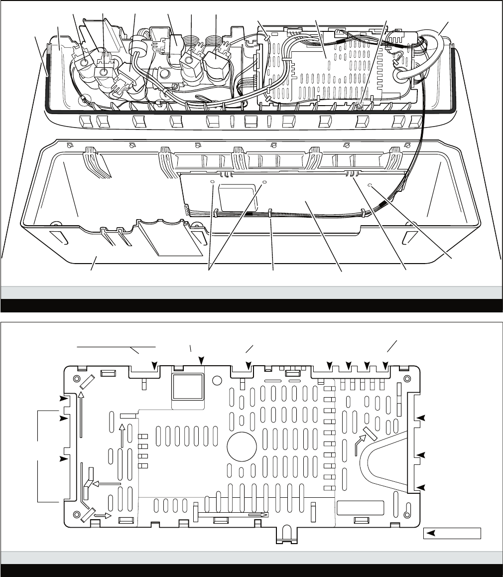
6-16
RED
T
U
P
N
I
R
E
W
O
P
BLU-YEL-RD
RED BLK
FLASH CNTRL
WIDE
N
W
O
R
BE
U
L
B
T
E
K
C
A
J
Y
A
R
G
K
C
ALB
ABS
8565548
BLACK
D
E
R
D
R
O
C
R
E
W
O
P
K
C
A
L
B
T
I
H
W
-
DR T
L
V
-N
R
O
-
D
R
-
T
L
V
-
T
I
H
W
Valve Thermistor
P9P8P7P6
P10
P11
P12
Motor Rotor
Position Sensor
User Interface
Lid Lock
P5P13P4
Drain Pump Recirc Pump 3 Phase BPM Motor
120 VAC Power Cord
P1
P2
P3
120 VAC
Log Valve
Pin #1 Locations
Machine/Motor Control Connections
Figure 4
User Interface Assembly Locking Tab
Screws
Screw
Wire Harness Retainer
Machine/Motor
Control AssemblyMachine/Motor Control
Assembly Holding Screw
Console Gasket
Console Assembly
Retaining Clip Pressure Hose
Console Tray
Detergent Fabric Softener Fresh Bleach Cold Hot
Location Of Machine/Motor Control and User Interface Assemblies
Figure 3
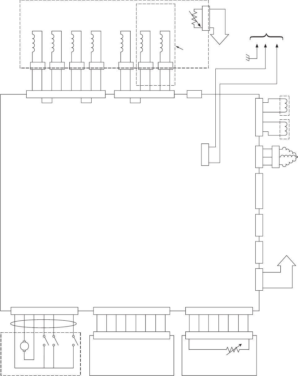
7-1
WIRING DIAGRAM
1
3
1
3
4
6
7
9
1
3
1
3
1
3
1
3
4
6
7
9
1
3
1
3
0
1
2
1
1
3
Y
Y
R
R
V
W
V
W
V
W
V
W
1
3
1
2
3
4
C
B
A
7
6
5
4
3
R
B
2
1
R
B
R
B
R
B
R
B
R
B
R
B
8
7
6
5
4
U
B
3
2
U
B
U
B
U
B
U
B
U
B
U
B
1
U
B
7
6
5
4
3
2
1
R
O
T
O
M
R
O
T
O
R
N
O
I
T
I
S
O
P
R
O
S
N
E
S
)
S
P
R
(
1
2
3
4
5
6
7
8
R
E
S
U
E
C
A
F
R
E
T
N
I
s
D
E
L
•
h
c
t
i
w
S
y
r
a
t
o
R
•
s
e
h
c
t
i
w
S
y
e
K
•
r
e
z
z
u
B
•
7
6
5
4
3
2
1
T
E
K
C
A
J
Y
A
R
G
6
P
L
O
R
T
N
O
C
R
O
T
O
M
/
E
N
I
H
C
A
M
5
P
4
P
3
1
P
7
P
3
P
2
P
1
P
0
1
P
1
1
P
2
1
PK
C
O
L
D
I
L
N
(NOT USED)
S
P
M
U
P
C
A
V
0
2
1R
O
T
O
M
M
P
B
E
V
I
R
D
AY
L
E
R
R
E
T
A
E
H
T
U
E
N
H
S
A
W
E
R
P
F F
O
S
C
I
R
B
AT
T
U
E
N
T
N
E
G
R
E
T
E
D
T
U
E
N
T
O
H
D
L
O
C
H
C
A
E
L
B
H
S
E
R
F
T
U
E
N
T
O
H
D
L
O
C
H
C
A
E
L
B
L
L
I
F
H
S
E
R
F
T
N
E
G
R
E
T
E
D
F C
I
R
B
A
R
E
N
E
T
F
O
S
H
S
A
W
E
R
P
L
L
A
N
O
T
O
N
S
L
E
D
O
M
L
C
A
V
0
21 E
V
L
A
V
G
O
T
S
I
S
E
R
L
I
O
C
E
V
L
AV E
C
N
A
840
–
0
97 Ω
1
LN
1
L
N
GG
K
B
B
A
BA
RR
R
R
N
I
A
R
D
P
M
U
P
1
5
.
0
14
–Ω
C
R
I
C
E
R
P
M
U
P
8
3
0
3–Ω
6
1
x
3 Ω
R
OT
O
M
M
P
B
E
S
A
H
P
3
U
B
Y R
N
N
O
C
H
S
A
L
FE
D
I
W
T
R
O
P
M
O
CE
V
L
A
V
R
O
T
S
I
M
R
E
H
TS
S
V
C
D
V
5
1
A
B
C
MOTOR THERMISTOR
THERMISTOR
600 - 21.2K Ω
C
D
V
5
1
R
E
Z
Z
U
B
K
L
C
T
U
O
A
T
A
D
E
B
O
R
T
S
S
S
V
N
I
A
T
A
D
C
D
V
5
LW
S
K
C
O
W
S
D
I
L
W
S
E
M
O
H
LR
O
T
O
M
K
C
O
LR
O
T
O
M
K
C
O
S
S
V
LK
C
O
D
I
L
E
M
O
H
R
O
T
O
M
C
D
V
2
1
C
A
V
0
2
1
D
R
O
C
R
E
W
O
P
K
B
9
P
1
2
3
R
E
T
A
E
H
R
O
T
S
I
M
R
E
HT
8
P
1
2
3
4
5
T
R
O
T
S
I
M
R
E
H
T
K
B
K
B
3
1
N
K
B
N
K
B
9
P
O
T
E
V
L
A
V
G
O
L
O
T
1
2
3
1
2
3
1
2
3
1
2
3
W
W
k
5
.
0
2
–
k
9
.2 Ω
7-2
— NOTES —
7-3
— NOTES —
7-4
— NOTES —

IN THE UNITED STATES:
FOR PRODUCT SPECIFICATIONS AND WARRANTY INFORMATION CALL:
FOR TECHNICAL ASSISTANCE WHILE AT THE CUSTOMER’S HOME CALL:
THE TECHNICAL ASSISTANCE LINE: 1-800-832-7174
HAVE YOUR STORE NUMBER READY TO IDENTIFY YOU AS AN
AUTHORIZED IN-HOME SERVICE PROFESSIONAL
FOR LITERATURE ORDERS:
PHONE: 1-800-851-4605
FOR TECHNICAL INFORMATION AND SERVICE POINTERS:
www.servicematters.com
IN CANADA:
FOR PRODUCT SPECIFICATIONS AND WARRANTY INFORMATION CALL:
1-800-461-5681
FOR TECHNICAL ASSISTANCE WHILE AT THE CUSTOMER’S HOME CALL:
THE TECHNICAL ASSISTANCE LINE: 1-800-488-4791
HAVE YOUR STORE NUMBER READY TO IDENTIFY YOU AS AN
AUTHORIZED IN-HOME SERVICE PROFESSIONAL
FOR WHIRLPOOL PRODUCTS: 1-800-253-1301
FOR KITCHENAID PRODUCTS: 1-800-422-1230
FOR ROPER PRODUCTS: 1-800-447-6737
PRODUCT SPECIFICATIONS
AND
WARRANTY INFORMATION SOURCES