Maytag Range Codes Heritage Series 8178713
Maytag - Range - Heritage - Wiring Diagrams & Fault Codes - Mc-1 Maytag - Range - Heritage - Wiring Diagrams & Fault Codes - MC-1 Maytag - Range - Heritage - Wiring Diagrams & Fault Codes - MC-1 Maytag, Magic Chef, Jenn Air applianceservicesecretsmembership.com_manuals
Maytag - Range Codes - Heritage Series - 8178713 Maytag - Range Codes - Heritage Series - 8178713 Maytag - Range Codes - Heritage Series - 8178713 Maytag, Magic Chef, Jenn Air applianceservicesecretsmembership.com_manuals
Maytag - Range - Heritage - Wiring Diagrams & Fault Codes - Mc-1 Maytag - Range - Heritage - Wiring Diagrams & Fault Codes - MC-1 Maytag - Range - Heritage - Wiring Diagrams & Fault Codes - MC-1 Maytag, Magic Chef, Jenn Air applianceservicesecretsmembership.com_manuals
2013-04-06
: Pdf Maytag - Range Codes - Heritage Series - 8178713 Maytag - Range Codes - Heritage Series - 8178713 Maytag, Magic Chef, Jenn Air
Open the PDF directly: View PDF ![]() .
.
Page Count: 124 [warning: Documents this large are best viewed by clicking the View PDF Link!]
TECHNICAL EDUCATION
JOB AID 8178713
MC-
1
WIRING DIAGRAMS
for
MAYTAG HERITAGE
GAS & ELECTRIC RANGES
FAILURE CODES AND

- ii -
Copyright © 2008, Whirlpool Corporation, Benton Harbor, MI 49022
FORWARD
This Maytag Heritage Job Aid, “Failure Codes And Wiring Diagrams For Gas & Electric Ranges,”
(Part No. 8178713), provides the technician with information on Diagnosing and Troubleshoot-
ing Maytag Heritage Gas & Electric Ranges. It is to be used as a training Job Aid. For specic
information on the model being serviced, refer to the “Use and Care Guide,” or “Tech Sheet”
provided with the unit.
The Wiring Diagrams used in this Job Aid are typical and should be used for training purposes
only. Always use the Wiring Diagram supplied with the product when servicing the unit.
GOALS AND OBJECTIVES
The goal of this Job Aid is to provide detailed information that will enable the In-Home Service
Professionals to properly diagnose malfunctions and repair Maytag Heritage Ranges.
The objectives of this Job Aid are to:
• Successfully troubleshoot and diagnose malfunctions.
• Offer Electronic Oven Control information.
WHIRLPOOL CORPORATION assumes no responsibility for any repairs made
on our products by anyone other than In-Home Service Professionals.
- iii -
TABLE OF CONTENTS
Page
GENERAL .............................................................................................................................. 1-1
Gas & Electric Range Safety.............................................................................................. 1-1
Cooking Nomenclature....................................................................................................... 1-2
Model & Serial Number Label And Wiring Diagram Locations ........................................... 1-3
Description of Error Codes ................................................................................................... 2-1
NSC (Non-Self Cleaning) Controls ....................................................................................... 3-1
H1 Controls ............................................................................................................................ 4-1
H2 Controls ............................................................................................................................ 5-1
H2.5 Controls ......................................................................................................................... 6-1
H3 Controls ............................................................................................................................ 7-1
M1/M2 Controls ...................................................................................................................... 8-1
EOC III Controls ..................................................................................................................... 9-1
UH Controls .......................................................................................................................... 10-1
- iv -
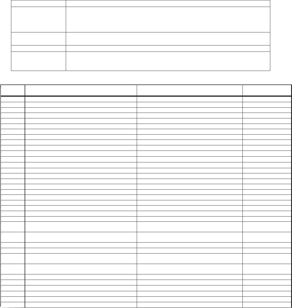
Family Control Part # Model # Application Tech Sheet Page #
H2.5 8507P328-60 629.600 6-2
H2.5 8507P328-60 629.600 6-2
H2.5 8507P328-60 629.600 6-2
H2.5 8507P328-60 629.600 6-2
NSC 8507P347-60 AER4311AAW Electric F/S Range 16026465 3-4
NSC 8507P348-60 AER4311ACW Electric F/S Range 16026465 3-4
M1 8507P304-60 AER5511AAW Electric F/S Range 16023530 8-4
M1 8507P304-60 AER5511ACW Electric F/S Range 16023539 8-4
M1 8507P304-60 AER5511BAW Electric F/S Range 16026686 8-4
M1 8507P304-60 AER5512AAW Electric F/S Range 16023530 8-4
M1 8507P252-60 AER5515QAW Electric F/S Range 16025645 8-7
M1 8507P252-60 AER5515QCW Electric F/S Range 16026853 8-14
M1 8507P252-60 AER5515RCW Electric F/S Range 16027236 8-17
M1 8507P304-60 AER5710BAH Electric F/S Range 16026813 8-4
M1 8507P304-60 AER5712AAW Electric F/S Range 16023531 8-4
M1 8507P304-60 AER5712ACW Electric F/S Range 16023542 8-4
M1 8507P304-60 AER5712BAW Electric F/S Range 16026688 8-4
M1 8507P252-60 AER5715QAW Electric F/S Range 16025646 8-7
M1 8507P252-60 AER5715QCW Electric F/S Range 16023319 8-3
M1 8507P252-60 AER5715RCW Electric F/S Range 16027231 8-17
M1 8507P304-60 AER5722BAW Electric F/S Range 16026691 8-4
M1 8507P304-60 AER5722CAS Electric F/S Range 16027074 8-4
M1 8507P252-60 AER5725QAW Electric F/S Range 16027227 8-17
M2 8507P253-60 AER5735QAW Electric F/S Range 16025648 8-7
H1 8507P293-60 AER5815RCW Electric F/S Range 16027233 4-22
H1 8507P356-60 AER5845QAB Electric F/S Range 16022492 4-15
H1 8507P356-60 AER5845RAW Electric F/S Range 16027232 4-21
M1 8507P239-60 AES1350BAW Electric Slide-In Range 16026294 8-10
M2 8507P260-60 AES3760BAW Electric F/S Range 16026295 8-11
H1 8507P260-60 AES3760BCW Electric F/S Range 16026298 4-16
H1 8507P305-60 AES5730BAB Electric Slide-In Range 16026296 4-16
H1 8507P286-60 AEW3530DDW Electric Wall Oven 16022507 4-9
H2.5 8507P325-60 AEW3630DDW Electric Wall Oven 16022511 5-5
H1 8507P287-60 AEW4530DDW Electric Wall Oven 16022507 4-9
H2.5 8507P326-60 AEW4630DDW Electric Wall Oven 16022511 5-5
NSC 8507P348-60 AGR4412ADW Gas F/S Range 16026763 3-7
M1 8507P250-60 AGR5712ADW Gas F/S Range 16023524 8-6
M1 8507P250-60 AGR5712BDW Gas F/S Range 16026684 8-6
- v -
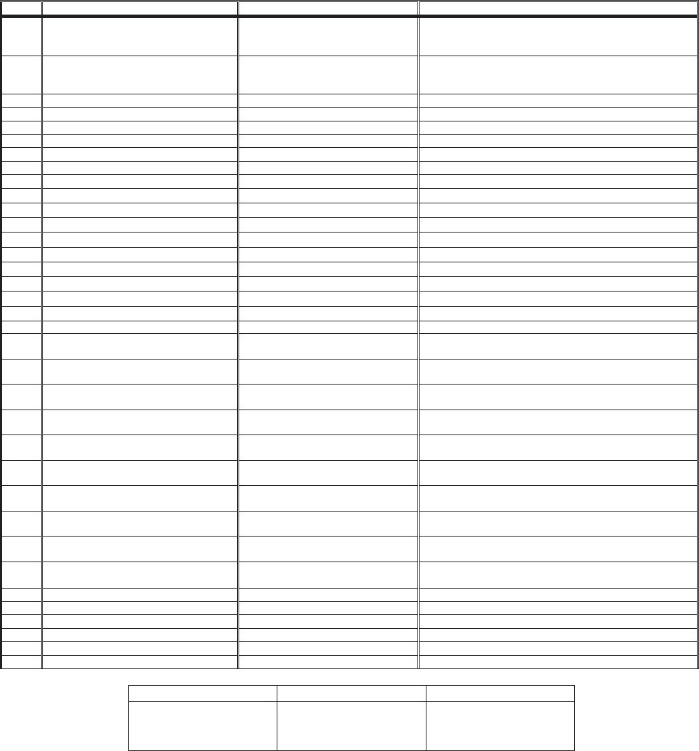
Family Control Part # Model # Application Tech Sheet Page #
M1 8507P254-60 AGR5715QDW Gas F/S Range 16027222 8-16
M2 8507P255-60 AGR5725QDW Gas F/S Range 16022500 8-5
M1 8507P254-60 AGR5725RDW Gas F/S Range 16026797 8-13
M1 8507P254-60 AGR5725SDS Gas F/S Range 16027246 8-16
M2 8507P255-60 AGR5735QDW Gas F/S Range 16022500 8-5
H1 8507P292-60 AGR5825RDW Gas F/S Range 16026851 4-18
H1 8507P292-60 AGR5835QDW Gas F/S Range 16022501 4-8
M1 8507P259-60 AGS1740BDW Gas Slide-In Range 16026289 8-8
M2 8507P261-60 AGS3760BDW Gas Slide-In Range 16026290 8-9
H1 8507P306-60 AGS5730BDW Gas Slide-In Range 16026291 4-11
M1 8507P254-60 ALR5715QDW Gas F/S Range LP 16027225 8-18
NSC 8507P347-60 CE35400AAV Electric F/S Range 16026465 3-4
NSC 8507P347-60 CE35400ACV Electric F/S Range 16023535 3-4
M1 8507P304-60 CE38600AAW Electric F/S Range 16023530 8-4
M1 8507P304-60 CE38600ACV Electric F/S Range 16023539 8-4
M1 8507P304-60 CE38800AAW Electric F/S Range 16023534 8-4
M1 8507P304-60 CE38800ACS Electric F/S Range 16023481 8-4
M1 8507P304-60 CE38800BAS Electric F/S Range 16026978 8-4
NSC 8507P347-60 CER1125AAW Electric F/S Range 16026465 3-4
NSC 8507P347-60 CER1125ACW Electric F/S Range 16023535 3-5
M1 8507P304-60 CER3525AAW Electric F/S Range 16023530 8-4
M1 8507P304-60 CER3525ACW Electric F/S Range 16023539 8-4
M1 8507P304-60 CER3725AAW Electric F/S Range 16023531 8-4
M1 8507P304-60 CER3725ACW Electric F/S Range 16023542 8-4
NSC 8507P349-60 CER3725AGW Electric F/S Range 16026838 3-8
NSC 8507P349-60 CER4351AGW Electric F/S Range 16026300 3-6
M1 8507P240-60 CES3759BCW Electric Slide-In Range 16027221 8-15
NSC 8507P348-60 CG31600ADV Gas F/S Range 16026763 3-7
M1 8507P250-60 CG34800ADW Gas F/S Range 16023524 8-6
M1 8507P250-60 CG34800BDS Gas F/S Range 16026791 8-12
NSC 8507P348-60 CGR1425ADW Gas F/S Range 16026763 3-7
M1 8507P250-60 CGR3725ADW Gas F/S Range 16023524 8-6
M1 8507P250-60 CGR3726ADW Gas F/S Range 16026551 8-6
NSC 8507P348-60 CP31600ADV Gas F/S Range 16026763 3-7
H1 8507P389-60 GW397LXUB Gas Slide-In Range
H1 8507P391-60 GW399LXUB Gas Slide-In Range 16026291 4-15
H1 8507P390-60 GY397LXUB Electric Slide-In Range
H1 8507P392-60 GY399LXUB Electric Slide-In Range 16026296 4-16
- vi -
Family Control Part # Model # Application Tech Sheet Page #
H2.5 8507P302-60 JDR8895AAW Double Oven Dual Fuel 16023460 6-8
H2.5 8507P302-60 JDR8895ACW Double Oven Dual Fuel 16023460 6-8
EOCIII 8507P333-60 JDR8895RDW Double Oven Dual Fuel 16023506
EOCIII 8507P230-60 JDS8850BDW Dual Fuel Slide-In 16026930 9-15
EOCIII 8507P231-60 JDS9860BDW Dual Fuel Slide-In 16026930 9-15
EOCIII 8507P380-60 JDS9860AAW Dual Fuel Slide-In 16026780 9-15
EOCIII 8507P232-60 JDS9865BDP Dual Fuel Slide-In 16026930 9-15
EOCIII 8507P278-60 JER8785QAB Electric F/S Range 16027223 4-19
EOCIII 8507P331-60 JER8785RAB Electric F/S Range 16027306 9-17
H1 8507P279-60 JER8885QAB Electric F/S Range 16027226 9-19
H1 8507P279-60 JER8885QCB Electric F/S Range 16027224 4-14
U3 8507P386-60 JER8885RAB Electric F/S Range 16027307 9-18
EOCIII 8507P331-60 JER8885RCW Electric F/S Range 16027308 9-14
EOCIII 8507P225-60 JES8750BAW Electric Slide-In 16026927 9-14
EOCIII 8507P226-60 JES8850BAB Electric Slide-In 16026927 9-15
EOCIII 8507P226-60 JES8850BCW Electric Slide-In 16027013 9-15
EOCIII 8507P233-60 JES9750BAW Electric Slide-In 16026928 9-15
EOCIII 8507P234-60 JES9800BAB Electric D/D Slide-In 16027004 9-15
EOCIII 8507P234-60 JES9860BAW Electric Slide-In 16026928 9-15
EOCIII 8507P234-60 JES9900BAB Electric D/D Slide-In 16027004 9-15
EOCIII 8507P234-60 JES9900BCW Electric Slide-In 16027013 9-15
H1 8507P289-60 JGR8775QDW Gas F/S Range 16022502 4-8
EOCIII 8507P351-60 JGR8775RDW Gas Freestanding Range 16027309 9-19
H1 8507P290-60 JGR8875QDW Gas F/S Range 16022503 4-10
EOCIII 8507P351-60 JGR8875RDW Gas Freestanding Range 16027310 9-20
EOCIII 8507P351-60 JGR8885RDP Gas Freestanding Range 16027248 9-16
EOCIII 8507P227-60 JGS8750BDW Gas Slide-In 16026924 9-13
EOCIII 8507P228-60 JGS8850BDW Gas Slide-In 16026924 9-13
EOCIII 8507P229-60 JGS8860BDP Gas Slide-In 16026924 9-13
EOCIII 8507P236-60 JGS9900BDB Gas Slide-In 16026925 9-13
H1 8507P085-60 JGW8130DDW Gas Wall Oven 16022515 4-13
H1 8507P090-60 JJW7530DDW Electric Wall Oven 16022508 4-12
H1 8507P285-60 JJW8130DDW Electric Wall Oven 16022507 4-9
H2.5 8507P324-60 JJW8230DDW Electric Wall Oven 16022511 5-5
M1 8507P345-60 JJW8527DDW Electric Wall Oven 16026101 8-6
M1 8507P263-60 JJW8530DDW Electric Wall Oven 16026101 8-6
UH 8507P364-60 JJW8627DDW Electric Wall Oven 16022512 10-4
UH 8507P364-60 JJW8630DDW Electric Wall Oven 16022512 10-4
H1 8507P291-60 JJW9130DDW Electric Wall Oven 16026545 4-9
H2.5 8507P327-60 JJW9230DDW Electric Wall Oven 16026546 5-5
- vii -
Family Control Part # Model # Application Tech Sheet Page #
H1 8507P291-60 JJW9330DDB Electric Wall Oven 16026545 4-9
H2.5 8507P360-60 JJW9430DDB Electric Wall Oven 16026546 5-5
UH 8507P264-60 JJW9527DDW Electric Wall Oven 16026101 10-5
UH 8507P338-60 JJW9530DDP Electric Wall Oven 16026100 10-8
UH 8507P264-60 JJW9530DDW Electric Wall Oven 16026101 10-5
UH 8507P363-60 JJW9627DDW Electric Wall Oven 16022512 10-4
UH 8507P363-60 JJW9630DDW Electric Wall Oven 16022512 10-4
UH 8507P361-60 JJW9827DDP Electric Wall Oven 16026100 10-8
UH 8507P342-60 JJW9827DDW Electric Wall Oven 16022512 10-4
UH 8507P361-60 JJW9830DDP Electric Wall Oven 16026100 10-8
UH 8507P362-60 JJW9830DDW Electric Wall Oven 16022512 10-4
H1 8507P285-60 JMW8130DAW Electric Wall Oven w/MW 16026568 4-17
H1 8507P285-60 JMW8330DAW Electric Wall Oven w/MW 16026568 4-17
UH 8507P263-60 JMW8527DAW Electric Wall Oven w/MW 16022823 10-5
UH 8507P263-60 JMW8530DAW Electric Wall Oven w/MW 16022823 10-5
UH 8507P345-60 JMW8530DAW Elec. Wall Oven w/MW 16022823 10-5
H1 8507P291-60 JMW9130DAW Electric Wall Oven w/MW 16026569 4-17
H1 8507P291-60 JMW9330DAW Electric Wall Oven w/MW 16026569 4-17
UH 8507P264-60 JMW9527DAW Electric Wall Oven w/MW 16022823 10-5
UH 8507P346-60 JMW9527DAW Elec. Wall Oven w/MW 16022823 10-5
UH 8507P264-60 JMW9530DAW Electric Wall Oven w/MW 16022823 10-5
UH 8507P346-60 JMW9530DAW Elec. Wall Oven w/MW 16022823 10-5
M1 8507P304-60 LER3330AAW Electric F/S Range 16026105 8-4
M1 8507P250-60 LGR3330ADW Gas F/S Range 16026106 8-12
NSC 8507P350-60 LLR4451AJW Gas F/S Range 16026765 3-7
H1 8507P299-60 MEP5775BAB Electric Slide-In Range 16026297 4-16
NSC 8507P347-60 MER4351AAW Electric F/S Range 16026465 3-4
NSC 8507P347-60 MER4351ACW Electric F/S Range 16026465 3-4
NSC 8507P349-60 MER4351AGW Electric F/S Range 16026535 3-5
M1 8507P304-60 MER5520AAW Electric F/S Range 16026686 8-4
M1 8507P304-60 MER5551AAW Electric F/S Range 16023530 8-4
M1 8507P304-60 MER5551BAW Electric F/S Range 16026686 8-4
M1 8507P304-60 MER5552AAW Electric F/S Range 16023530 8-4
M1 8507P249-60 MER5552ACW Electric F/S Range 16023530 8-4
M1 8507P304-60 MER5552BAW Electric F/S Range 16026686 8-4
M1 8507P252-60 MER5555QAW Electric F/S Range 16025645 8-7
M1 8507P252-60 MER5555QCW Electric F/S Range 16023318 8-3
M1 8507P252-60 MER5555RCW Electric F/S Range 16027237 8-17
M1 8507P304-60 MER5751AAW Electric F/S Range 16023531 8-4
M1 8507P304-60 MER5751ACW Electric F/S Range 16026543 8-4
- viii -
Family Control Part # Model # Application Tech Sheet Page #
M1 8507P304-60 MER5751BAB Electric F/S Range 16026688 8-4
M1 8507P304-60 MER5752AAW Electric F/S Range 16023531 8-4
M1 8507P304-60 MER5752ACW Electric F/S Range 16023542 8-4
M1 8507P304-60 MER5752BAW Electric F/S Range 16026688 8-4
M1 8507P252-60 MER5754QAW Electric F/S Range 16025646 8-7
M1 8507P252-60 MER5755QAW Electric F/S Range 16025646 8-7
M1 8507P252-60 MER5755QCW Electric F/S Range 16023319 8-3
M1 8507P252-60 MER5765QAW Electric F/S Range 16025649 8-7
M1 8507P252-60 MER5765RAW Electric F/S Range 16027247 8-17
M1 8507P252-60 MER5765RCW Electric F/S Range 16027231 8-17
M2 8507P253-60 MER5775QAW Electric F/S Range 16025648 8-7
M2 8507P253-60 MER5775QCW Electric F/S Range 16023320 8-3
M2 8507P253-60 MER5775RAW Electric F/S Range 16027230 8-17
M2 8507P253-60 MER5775RCB Electric F/S Range 16027245 8-17
H1 8507P277-60 MER5875QAB Electric F/S Range 16022496 4-19
H1 8507P069-60 MER5875QCW Electric F/S Range 16023321 4-14
H1 8507P355-60 MER5875RAB Electric F/S Range 16027229 4-20
H1 8507P355-60 MER5875RCW Electric F/S Range 16027233 4-22
M1 8507P307-60 MER6541BAW Double Oven Electric Range 16027255 8-19
H3 8507P272-60 MER6555AAW Double Oven Electric Range 16023459 7-9
H3 8507P272-60 MER6555ACW Double Oven Electric Range 16023459 7-9
M1 8507P307-60 MER6741BAW Double Oven Electric Range 16027255 8-19
H3 8507P272-60 MER6751AAW Double Oven Electric Range 16023459 7-9
M1 8507P307-60 MER6752BAW Double Oven Electric Range 16027255 8-19
H3 8507P272-60 MER6755AAW Double Oven Electric Range 16023459 7-9
H3 8507P272-60 MER6755ACW Double Oven Electric Range 16023459 7-9
H3 8507P272-60 MER6765BAW Double Oven Electric Range 16027359 7-9
H3 8507P272-60 MER6775AAW Double Oven Electric Range 16023459 7-9
H3 8507P272-60 MER6775ACB Double Oven Electric Range 16026151 7-9
H3 8507P272-60 MER6775BAB Double Oven Electric Range 16027360 7-9
H3 8507P272-60 MER6775BCW Double Oven Electric Range 16027360 7-9
H2.5 8507P203-60 MER6875AAW Double Oven Electric Range 16026150 6-9
H2.5 8507P301-60 MER6875AAW Double Oven Electric Range 16026150 6-9
H2.5 8507P203-60 MER6875ACW Double Oven Electric Range 16026150 6-9
H2.5 8507P301-60 MER6875ACW Double Oven Electric Range 16026150 6-9
M1 8507P304-60 MERB750BAW
M1 8507P304-60 MERH752BAW Electric F/S Range 16026688 8-4
M1 8507P304-60 MERH752CAS Electric F/S Range 16027144 8-4
H1 8507P357-60 MERH865RAW
M1 8507P304-60 MERL752BAW Electric F/S Range 16026689 8-4
M1 8507P304-60 MERL753BAS
M1 8507P304-60 MERM752BAW Electric F/S Range 16026688 8-4
- ix -
Family Control Part # Model # Application Tech Sheet Page #
M1 8507P304-60 MERS751BAW Electric F/S Range 16027075 8-4
M1 8507P252-60 MERS755RAW Electric F/S Range 16027247 8-17
H1 8507P237-60 MES5775BAB Electric Slide-In Range 16026297 4-16
H1 8507P237-60 MES5775BCW Electric Slide-In Range 16026298 4-16
H1 8507P276-60 MES5875BAB Electric Slide-In Range 16026297 4-16
H1 8507P276-60 MES5875BCB Electric Slide-In Range 16026298 4-16
H1 8507P280-60 MEW5527DDW Electric Wall Oven 16022507 4-9
H1 8507P281-60 MEW5530DDW Electric Wall Oven 16022507 4-9
H2.5 8507P320-60 MEW5627DDW Electric Wall Oven 16022511 4-9
H1 8507P086-60 MEW5627DDW Electric Wall Oven 16022511 5-5
H2.5 8507P321-60 MEW5630DDW Electric Wall Oven 16022511 5-5
H1 8507P087-60 MEW5630DDW Electric Wall Oven 16022511 5-5
H1 8507P282-60 MEW6527DDW Electric Wall Oven 16022507 4-9
H1 8507P283-60 MEW6530DDW Electric Wall Oven 16022507 4-9
H2.5 8507P088-60 MEW6627DDW Electric Wall Oven 16022511 5-5
H2.5 8507P089-60 MEW6630DDW Electric Wall Oven 16022511 5-5
NSC 8507P348-60 MGR4451ADW Gas F/S Range 16026763 3-7
NSC 8507P250-60 MGR4451BDS Gas F/S Range 16026685 3-7
NSC 8507P348-60 MGR4451BDW Gas F/S Range 16026685 3-7
NSC 8507P348-60 MGR4452ADW Gas F/S Range 16026763 3-7
NSC 8507P348-60 MGR4452BDW Gas F/S Range 16026685 3-7
M1 8507P250-60 MGR5751ADW Gas F/S Range 16023524 8-6
M1 8507P250-60 MGR5751BDW Gas F/S Range 16026683 8-6
M1 8507P250-60 MGR5752ADW Gas F/S Range 16023524 8-6
M1 8507P250-60 MGR5752BDW Gas F/S Range 16023524 8-6
M1 8507P254-60 MGR5754QDW Gas F/S Range 16027222 8-16
M1 8507P254-60 MGR5755QDW Gas F/S Range 16027222 8-16
M1 8507P254-60 MGR5765QDW Gas F/S Range 16027222 8-16
M2 8507P255-60 MGR5775QDW Gas F/S Range 16022504 8-5
H1 8507P288-60 MGR5875QDW Gas Freestanding Range 16022505 4-11
H3 8507P262-60 MGR6751BDW Double Oven Gas Range 16027362 7-8
H3 8507P262-60 MGR6775ADW Double Oven Gas Range 16023458 7-8
H3 8507P262-60 MGR6775BDW Double Oven Gas Range 16027363 7-10
H2.5 8507P204-60 MGR6875ADW Double Oven Gas Range 16027364 6-10
H2.5 8507P300-60 MGR6875ADW Double Oven Gas Range 16027364 6-10
M1 8507P250-60 MGRH752BDW Gas F/S Range 16026684 8-6
H1 8507P358-60 MGRH865QDW Gas F/S Range
M1 8507P250-60 MGRL752BDW Gas F/S Range 16026684 8-6
M1 8507P250-60 MGRL753BDS Gas F/S Range 16026684 8-6
M1 8507P250-60 MGRM752BDW Gas F/S Range 16026683 8-6
M1 8507P250-60 MGRS752BDW Gas F/S Range 16026683 8-6
- x -
Family Control Part # Model # Application Tech Sheet Page #
M1 8507P258-60 MGS5752BDW Gas F/S Range 16026290 8-9
H1 8507P256-60 MGS5775BDW Gas Slide-In Range 16026292 4-15
H1 8507P275-60 MGS5875BDW Gas Slide-In Range 16026292 4-15
NSC 8507P350-60 MLR4451AJQ Gas F/S Range 16026765 3-7
NSC 8507P350-60 MLR4451AJS Gas F/S Range 16026765 3-7
NSC 8507P350-60 MLR4451AJW Gas F/S Range 16026765 3-7
M1 8507P254-60 MLR5755QDW Gas F/S Range 16027225 8-18
H1 8507P281-60 MMW5530DAW Electric Wall Oven w/MW 16026275 4-17
NSC 8507P347-60 PER1125ACW Electric F/S Range 16026486 3-5
M1 8507P304-60 PER3524ACW Electric F/S Range 16026485 8-4
M1 8507P304-60 PER3525ACW Electric F/S Range 16026485 8-4
M1 8507P304-60 PER3724ACW Electric F/S Range 16026484 8-4
M1 8507P304-60 PER3725ACW Electric F/S Range 16026484 8-4
NSC 8507P347-60 PER4311ACW Electric F/S Range 16023535 3-5
M1 8507P304-60 PER5720ACW Electric F/S Range 16023481 8-4
M1 8507P304-60 PER5720LAW Electric F/S Range 16023534 8-4
M1 8507P252-60 PER5750QAW Electric F/S Range 16025650 8-7
M1 8507P252-60 PER5750QCW Electric F/S Range 16023323 8-3
M1 8507P304-60 PERL252AAW
M1 8507P304-60 PERL451AAB
M1 8507P304-60 PERL451ACW Electric F/S Range 16026687
M1 8507P258-60 PGS3759BDW Gas Slide-In Range 16026792 8-12
NSC 8507P348-60 PGR4420LDW Gas F/S Range 16026763 3-7
M1 8507P250-60 PGR5720LDW Gas F/S Range 16023524 8-6
M1 8507P254-60 PGR5750LDW Gas F/S Range 16023524 8-6
NSC 8507P247-60 PGRL251ADW
M1 8507P250-60 PGRL451ADB
M1 8507P304-60 RESF3330DW
M1 8507P304-60 RESF5330DT
M1 8507P250-60 RGSF3330DW
M1 8507P250-60 RGSF5330DT
UH 8507P211-60 RJDO2702A Electric Wall Oven 16025885 10-7
UH 8507P210-60 RJDO2703A Electric Wall Oven 16025885 10-7
UH 8507P211-60 RJDO3002A Electric Wall Oven 16025885 10-7
UH 8507P210-60 RJDO3003A Electric Wall Oven 16025885 10-7
UH 8507P209-60 RJSO2701A Electric Wall Oven 16025884 10-6
UH 8507P209-60 RJSO3001A Electric Wall Oven 16025884 10-6
M1 8507P240-60 RS160LXTB Electric Slide-In Range 16026294 8-10
M1 8507P240-60 RY160LXTB Electric Slide-In Range 16026294 8-10

1-1
GENERAL
GAS & ELECTRIC RANGE SAFETY
Your safety and the safety of others are very important.
We have provided many important safety messages in this manual and on the appliance.
Always read and obey all safety messages.
This is the safety alert symbol.
This symbol alerts you to potential hazards that can kill or hurt you and others.
All safety messages will follow the safety alert symbol and either the word
“DANGER” or “WARNING.” These words mean:
All safety messages will tell you what the potential hazard is, tell you how to reduce the chance
of injury, and tell you what can happen if the instructions are not followed.
You can be killed or seriously injured if you don’t
immediately follow instructions.
You can be killed or seriously injured if you don’t
follow instructions.
DANGER
WARNING
1-2
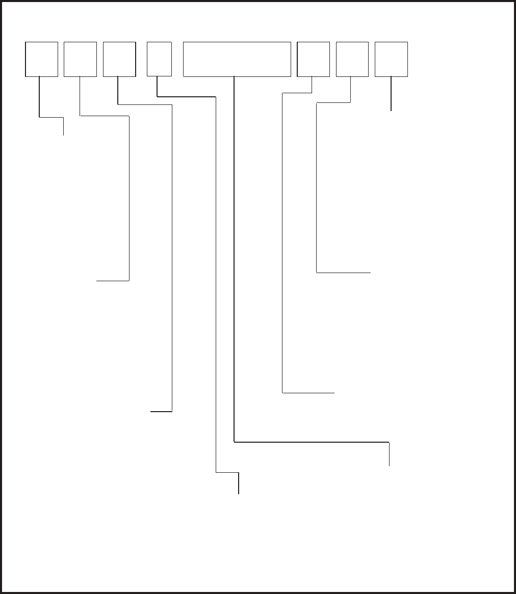
Cooking Nomenclature
M E R H 1 6 7 B D W
Brand
A Amana
C Magic Chef
G Graffer &
Sattler
H Hardwick
J Jenn-Air
M Maytag
N Norge
U Universal
Y Crosley
Product Ty pe
A Accessory/Cartridge
C Cooktop Updraft/Countertop
D Downdraft Cooktop or Warming Drawer
E Eyelevel Range
G Grill
L Range (20")
M Range (36")
P Drop In (24")
Q Wall Oven (27")
R Range, Free-Standing (30")
S Slide-In (30")
T Range Hood
V OTR
W Wall Oven
Y RV Range
Z RV Top
Fuel
B Butane
D Dual Fuel
E/J Electric
G Gas, Natural
L Liquid Propane
M Microwave
P Standing Pilot
X No Fuel
W Warming Drawer
Listing
A UL/AGA
C CSA/CGA/CUL
D Dual Listed
G 220-240 V / 50-60 Hz
M Military Model
P PSB Approved
(Singapore)
X Export 120 V / 60 Hz
Feature Content
1000-3999 Brands
4000-6999 Maytag/Amana
7000-9999 Jenn Air
Production Code
This identifies the
production version.
Color
A Almond on Almond
B Black
C Brushed Chrome
H Traditional White
L Traditional Almond
P Prostyle
Q Monochromatic Bisque
S Stainless
T Traditional Bisque
W White on White
F Frost White (True Color White)
N Natural Bisque (True Color Bisque)
National Accounts
B = Best Buy
H = Home Depot
S = Sears
1-3
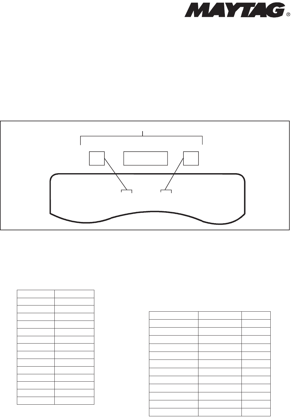
Serial Number Identification
Thereare threeparts whichIdentifies theSerialNumber.
• Series/Run Number –Indicates aspecificproduct design.
−Thesetwo digits canbeeither alpha or numeric characters.
• Serial Identity–Identifies the numberassignedtoaproduct.
• Date Code –Indicates themonthand year in whichthe productwas built.
MODELNO. SERIAL NO. RATING
C236B XXXXXXXXXX 8.036.02
KW KW
120/240VAC 120/208VAC
(60HZ3WIRE A.C. ONLY)
DO NOTCLEAN THIS LABEL
XX XXXXXX XX
Series/Run
Number
Serial
Identity
Date
Code
SERIAL NUMBER IDENTIFICATION
NOTE:Some Amana Products arestill identified by usingaManufacturing Number
(PXXXXXXXM).
All serial numbers consistofeight digits, followed by twoletters.
Thefirst letterindicatesthe year
in whichthe productwas produced.
Year Code
2000 Y
2001 Z
2002 A
2003 C
2004 E
2005 G
2006 J
2007 L
2008 N
2009 P
2010 R
2011 T
2012 V
2013 X
Thesecondletterindicates themonth in
whichthe productwas produced.
YearsSpan Month Code
2002 −2013 January A
2002 −2013 February C
2002 −2013 March E
2002 −2013 April G
2002 −2013 May J
2002 −2013 June L
2002 −2013 July N
2002 −2013 August P
2002 −2013 September R
2002 −2013 October T
2002 −2013 November V
2002 −2013 December X
1-4
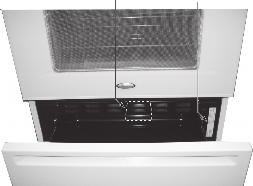
MODEL & SERIAL NUMBER LABEL
AND WIRING DIAGRAM LOCATIONS
The Model/Serial Number label and Wiring Diagram locations are shown below.
Model & Serial Number
Label Location
Wiring Diagram Location
(On Back Side Of Storage Drawer)
2-1
DESCRIPTION OF ERROR CODES
ERROR CODES
Description of Error Codes
Error diagnostic codes can only be viewed by entering the Diagnostic Code Display Mode.
Each error code is four digits long and is created based on the following table.
noitpircseD tigiD
1st Primary System: 1 – Local to the control circuit board
3 – Sensor or meat probe
4 – Control input
9 – Door lock
2nd Measurable: d – Diagnostic failure: measurable parameter
c – Control related error, replace control
3rd Primary failure mechanism
4th Oven Cavity: 1 – Upper oven (or single cavity oven)
2 – Lower oven
c – Control specific
Diagnostic Code Checking
noitceteD dekcehC nehW noitpircseD edoC
etunim 1 syawlA yek detrohS c1c1
etunim 1 syawlA detcennocsid liat draobyeK c2c1
ces 02 syawlA melborp tiucric yek lecnaC 13c1
ces 02 syawlA melborp tiucric yek lecnaC 23c1
ces 02 syawlA eruliaf noitacinummoc orcim rewoP c4c1
MORPEE c6c1 issecca nehW rorreng EEPROM 3 tries
seirt 3 syawlA detarbilac ton lortnoC c7c1
1c81 Cook profile corrupted in EEPROM Cook or clean programmed 3 tries
1c82 Cook profile corrupted in EEPROM Cook or clean programmed 3 tries
1d11 Runaway temperature (650°F), door unlocked etunim 1 dekcolnu hctaL
1d12 Runaway temperature (650°F), door unlocked etunim 1 dekcolnu hctaL
1d21 Runaway temperature (950°F), door locked etunim 1 dekcol hctaL
1d22 Runaway temperature (950°F), door locked etunim 1 dekcol hctaL
ces 02 evitca naelC ro kooC )nepo( eruliaf rosnes erutarepmeT 11d3
ces 02 evitca naelC ro kooC )nepo( eruliaf rosnes erutarepmeT 21d3
ces 02 evitca naelC ro kooC )trohs( eruliaf rosnes erutarepmeT 12d3
ces 02 evitca naelC ro kooC )trohs( eruliaf rosnes erutarepmeT 22d3
ces 02 demmargorp kooc eborP detrohs eborp taeM 14d3
ces 3 syawlA detarbilac ton eborp taeM 15d3
etunim 1 evitca tuokcoL draobyeK ro naelC eruliaf noitisop hctiws rooD 11d4
etunim 1 evitca tuokcoL draobyeK ro naelC eruliaf noitisop hctiws rooD 21d4
4d21 No Reverse Airflow Fan rotation (no/low RPM) Cook or Clean programmed 1 minute
4d22 No Reverse Airflow Fan rotation (no/low RPM) Cook or Clean programmed 1 minute
4d31 Reverse Airflow Fan state error (on when supposed
to be off)
When supposed to be off 1 minute
4d32 Reverse Airflow Fan state error (on when supposed
to be off)
When supposed to be off 1 minute
4d41 High Reverse Airflow Fan rotation, high RPM Cook or Clean programmed 1 minute
4d42 High Reverse Airflow Fan rotation, high RPM Cook or Clean programmed 1 minute
tuokcoL draobyeK ro ,naelC ,tcevnoC eruliaf tiucric hctiws rooD 15d4
programmed
1 minute
tuokcoL draobyeK ro ,naelC ,tcevnoC eruliaf tiucric hctiws rooD 25d4
programmed
1 minute
9d11 Latch will not lock 6Latch should be locked See note 6
9d12 Latch will not lock 6Latch should be locked See note 6
9d21 Latch will not unlock 6Latch should be unlocked See note 6
9d22 Latch will not unlock 6Latch should be unlocked See note 6
9d31 Latch both locked and unlocked 6Latch should be locked or when lock attempted See note 6
9d32 Latch both locked and unlocked 6Latch should be locked or when lock attempted See note 6
2-2
nekaT noitcA yalpsiD derusaeM edoC
,noisserped yek detceffa rof elbidua elbasiD sserpyeK c1c1
Disable all outputs 1, 2
Disable lights and timers
,noisserped yek rof elbidua elbasiD eulav reporpmi pool draobyeK c2c1
Disable all outputs 1
Disable lights and timers
1c31 Cancel key improper value mssg 1 (active) / mssg 2 (data) Disable all outputs for cavity 1
1c32 Cancel key improper value mssg 1 (active) / mssg 2 (data) Disable all outputs for cavity 1
)atad( 2 gssm / )evitca( 1 gssm dilavni CRC c4c1 Disable all outputs 1
1c6c No response from EEPROM mssg 1 (active) / mssg 2 (data) Disable all outputs 1
1c7c Calibration value out of range mssg 1 (active) / mssg 2 (data) Completely disable oven 4
)atad( 2 gssm / )evitca( 1 gssm dilavni CRC 18c1 Disable affected oven function 1
)atad( 2 gssm / )evitca( 1 gssm dilavni CRC 28c1 Disable affected oven function 1
1d11 Sensor resistance >2237 Ωmssg 1 (active) / mssg 3 (data) Disable all cooking functions for cavity
1d12 Sensor resistance >2237 Ωmssg 1 (active) / mssg 3 (data) Disable all cooking functions for cavity
1d21 Sensor resistance >2787 Ωmssg 1 (active) / mssg 3 (data) Disable all cooking functions for cavity
1d22 Sensor resistance >2787 Ωmssg 1 (active) / mssg 3 (data) Disable all cooking functions for cavity
3d11 Sensor resistance > Infinite Ωmssg 1 (active) / mssg 2 (data) Disable all cooking functions for cavity
3d12 Sensor resistance > Infinite Ωmssg 1 (active) / mssg 2 (data) Disable all cooking functions for cavity
3d21 Sensor resistance < 0 Ωmssg 1 (active) / mssg 2 (data) Disable all cooking functions for cavity
3d22 Sensor resistance < 0 Ωmssg 1 (active) / mssg 2 (data) Disable all cooking functions for cavity
3d41 Probe resistance < 0 Ωmssg 1 (active) / mssg 2 (data) Disable all probe functions
3d51 Calibration value out of range mssg 2 Disable all probe functions
4d11 Door switch not closed when
door is locked
mssg 1 Disable Clean and lockout functions 5
4d12 Door switch not closed when
door is locked
mssg 1 Disable Clean and lockout functions 5
4d21 Reverse Airflow Fan rotation
(no/low RPM)
mssg 1 (active) / mssg 2 (data) Disable all cooking functions for cavity
4d22 Reverse Airflow Fan rotation
(no/low RPM)
mssg 1 (active) / mssg 2 (data) Disable all cooking functions for cavity
4d31 Reverse Airflow Fan rotation
(on when should be off)
noitca oN egnahc oN
4d32 Reverse Airflow Fan rotation
(on when should be off)
noitca oN egnahc oN
4d41 Reverse Airflow Fan rotation
(high RPM)
mssg 1 (active) / mssg 2 (data) Disable all cooking functions for cavity
4d42 Reverse Airflow Fan rotation
(high RPM)
mssg 1 (active) / mssg 2 (data) Disable all cooking functions for cavity
4d51 Door switch not open or closed mssg 1 (active) / mssg 2 (data) Disable Convect, Clean, and lockout functions 4, 5
Turn off light and disable light from door switch
4d52 Door switch not open or closed mssg 1 (active) / mssg 2 (data) Disable Convect, Clean, and lockout functions 4, 5
Turn off light and disable light from door switch
9d11 Lock switch not closed mssg 1 (active) / mssg 2 (data) Disable Clean and lockout functions 4
9d12 Lock switch not closed mssg 1 (active) / mssg 2 (data) Disable Clean and lockout functions 4
9d21 Unlock switch not closed mssg 1 (active) / mssg 2 (data) Disable Clean and lockout functions 4
9d22 Unlock switch not closed mssg 1 (active) / mssg 2 (data) Disable Clean and lockout functions 4
9d31 Lock and unlock switches both closed mssg 1 (active) / mssg 2 (data) Disable Clean and lockout functions 4
9d32 Lock and unlock switches both closed mssg 1 (active) / mssg 2 (data) Disable Clean and lockout functions 4
Message 1: Message 2: Message 3:
FAULT DETECTED
PRESS ENTER
TO TRY AGAIN
FEATURE NOT
AVAILABLE
PRESS HELP
FAULTDETECTED
DISABLE POWER
TO CLEAR
2-3
NOTES:
1 “Action Taken” applies as long as the condition exists. If the condition goes away, the control recovers.
2 If there is a cook function or timer active, the function continues. The user cannot edit the function, and [Cancel] will canc el the cook
mode.
3 Flash rate: 0.2 seconds on, 0.1 second off. Pressing any key will clear the display until the fault clears and is re-triggered.
4 “Action Taken” applies until there is a POR (Power On Reset [“hard reset”]).
5 If the control believes the door is locked, it will attempt to unlock it when the function cancels and the cavity temperature cools.
6 Special conditions for latch faults (9dxx):
• A known good unlock position is defined as when the unlock switch reads closed and lock switch reads open.
• A known good lock position is defined as when the unlock switch reads open and lock switch reads closed.
• A faulted switch means the switch input is reading an invalid state, neither open nor closed.
• Once a latch fault occurs, latch movement is disabled until there is a POR. An error tone w ill sound if a function requiring a
faulted latch is attempted.
• If at POR, the latch is not at a known good unlock position:
• If the latch is at a good lock position, it will attempt to unlock when the RTD (Resistance Temperature Device)
temperature is below 400°F.
• If the latch is not at a good lock position, the control will fault.
• If a latch fault occurs while the RTD is above the lock temperature, the latch will not try to move, but the fault is still logged
to EEPROM after the first stage of detection.
• The Display column for latch faults applies 1) If the latch was moving when the fault occurred; 2) If the latch is already in a
known locked state when the fault occurs.
• LOCK flashes after a fault is detected and until the unlocked position is achieved. The unlock position may be
identified by a successful unlock switch closure, or as the result of timing when the unlock switch is not
functioning properly.
• If the last known good position was unlock (e.g. baking, or idle) and a latch fault occurs, the motor is never moved. The
fault is logged to EEPROM and is not seen by the user.
• The detection for latch faults is in two stages. The first stage is to let the control recover without moving the latch. After
this:
• If the latch was previously at a known good unlock position, the latch will not move and the control will fault.
• If the control was previously in a known good lock position:
• If the RTD is below 400°F, the latch will attempt to recover to it’s proper position (up to three
revolutions). If it cannot, the control will fault and the latch will move to a calculated unlock position.
• If the RTD is at or above 400°F, the control will fault. When the RTD cools to below 400°F, the control
will attempt to recover to a good unlock position (up to three revolution). If it cannot, the control will fault
and the latch will move to a calculated unlock position.
•Note: If the unlock position cannot be found, this may result in a second fault, the first fault occurring
when the latch request was locked, and the second when the latch request is unlocked.
• If the latch is moving when the fault occurs, the control will bypass the first stage of detection and immediately try
to find it’s proper position. If it cannot, the control will fault and the latch will move to a calculated unlock position.
• Affected DLBs (Double Line Breaks) and loads are disabled during detection.
• If the control is in a known good unlock position and the lock switch becomes faulted:
• The control will not fault.
• If a function requiring latch movement is attempted while the lock switch is faulted, the control will sound an error
tone and the function will be disabled.
• If the control is in a known good lock position and the unlock switch becomes faulted:
• The control will not fault.
• After the function is canceled and unlock is attempted, the control will attempt to unlock the latch according to
the procedures in these notes.
2-4
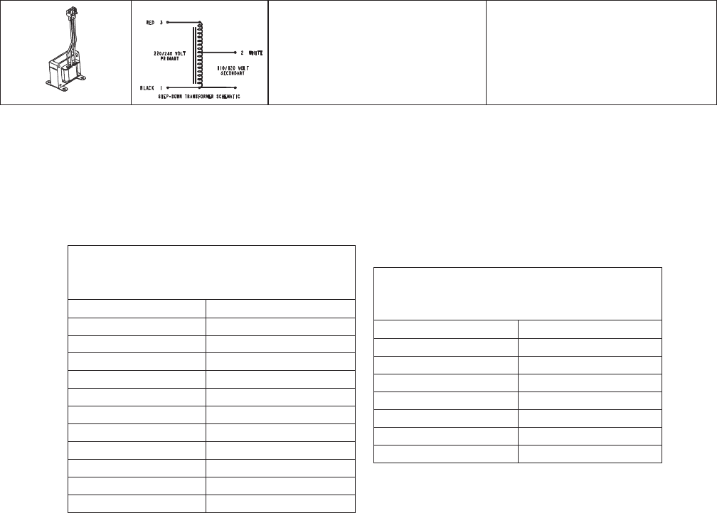
Step-down transformer Measure voltage:
Primary terminals............................
Secondary terminals.......................
220 to 240 volts
110 to 120 volts
Oven Sensor and Meat Probe Resistances
OVEN SENSOR
Sensor Type: RTD 1000 W platinum
Calibration: 1654 Ω (350° F/177° C)
Temperature F (C) Resistance (Ohms)
100 (38) 1143
200 (94) 1350
300 (149) 1553
350 (177) 1654
400 (204) 1753
500 (260) 1949
600 (316) 2142
700 (371) 2331
800 (427) 2516
900 (483) 2697
1000 (538) 2874
MEAT PROBE
Type: NTC Thermistor
Calibration: 9938 Ω (150° F/65.5° C)
Temperature F (C) Resistance (Ohms)
32 (0) 163300
68 (20) 62450
95 (35) 32660
122 (50) 18020
158 (70) 8760
185 (85) 5360
212 (100) 3400

3-1
NSC ( NON-SELF CLEANING) CONTROLS
Pin Out Locations

3-2
Hidden Functions
Illustrati stluseR erudecorP tseT tnenopmoC no
NSC Controlled Oven temperature
adjustment
Press
Bake
pad.
Enter
550
on the digit-pad.
Immediately press and hold
Bake
pad
for 3 to 5 seconds.
Oven can be adjusted from -35 to +35
degrees in 5-degree increments by
pressing
More +
or
Less -
pads. To
avoid over adjusting the oven, move
temperature 5 degrees each time.
Wait 4 seconds for the data entry
timer to expire to accept the change.
Temperature adjustment will be
retained even through a power failure.
While increasing or decreasing oven
temperature, this does not affect self-
cleaning temperature.
NSC Controlled Keypad Lockout Press and hold
Cancel
and
Timer
pads for 3 to 5 seconds. Press
More +
or
Less -
pads to change.
This mode disables keypad input to deter
against accidental keypad entries.
NSC Controlled Temperature display Press and hold
Cancel
and
Bake
pads for 3 to 5 seconds. Press
More +
or
Less -
pads to change.
This mode enables the user to indicate
°F or °C on the display.
NSC Controlled Sabbath Mode Hold
Clock
pad for 3 to 5 seconds to
activate Sabbath mode.
Hold
Clock
pad for 3 to 5 seconds to
disable Sabbath mode.
Desired bake function must be
initiated before entering Sabbath
mode.
"SAb" will be displayed and flash for 5
seconds then remain on until timed-out
or cancelled.
The status "SAB" is NOT fault code 5A6.
All pad inputs are disabled except for
CANCEL and CLOCK pads.
This mode disables the normal 12 hour
shutoff to allow operation of the bake
mode for a maximum of 72 hours.
The oven light is not disabled.
NSC Controlled Twelve Hour Off Control will automatically cancel any
cooking operation and remove all relay
drives 12 hours after the last pad
touch.
See Sabbath mode to disable.
NSC Controlled Diagnostic Code
Display
Press and hold
More +
pad for 3 to 5
seconds when powering up the unit.
Cycle through the codes using the
More +
or
Less -
pads.
The last 5 diagnostic codes will be stored
in the non-volatile memory.
See "Description of Error Codes"
for explanation.
NSC Controlled One–Watt Standby
Mode
Press and hold
Cancel
and
Less -
pads for 3 to 5 seconds.
After 15 minutes in idle, the control will
automatically enter this mode. The LED
display remains active during this mode.
page 2-1

3-3
"Quick Test" Mode for Non–Self Clean Control
Follow procedure below to use the quick test mode. Entries must be made within 32 seconds of each other or the
control will exit the quick test mode.
1. Press and hold
Cancel
and
Broil
pads for 3 to 5 seconds within 5 minutes of power-up.
2. Once the control has entered the "Quick Test" mode, release both pads.
3. Press each of the following pads indicated in the table below.
NOTE: First time one of the following pads are pressed it will activate the response.
The second time the pad is pressed it will deactivate the response.
NOTE: This mode must be entered within the first 5 minutes after power up.
NOTE: If the temperature sensor is greater than 400° F or if the temperature sensor reaches 400° F while under
test, the Quick Test mode will be disabled.
Display will indicate the following:
noitarepO yeK
[Bake] Bake relay activated
[Broil] Broil relay activated
[Timer] DLB relay activated
[Clock] Alternate between ODD LED SEGMENTS and
EVEN LED SEGMENTS on each keypress
[More +] EEPROM version number
[Less –] Code version number
[Cancel] End Factory Test Mode
Enter Diagnostic Code Display Mode by pressing
More +
for 3 to 5 seconds within 60 seconds of powering
up the control.
The control will store the last 5 error codes.
3-4
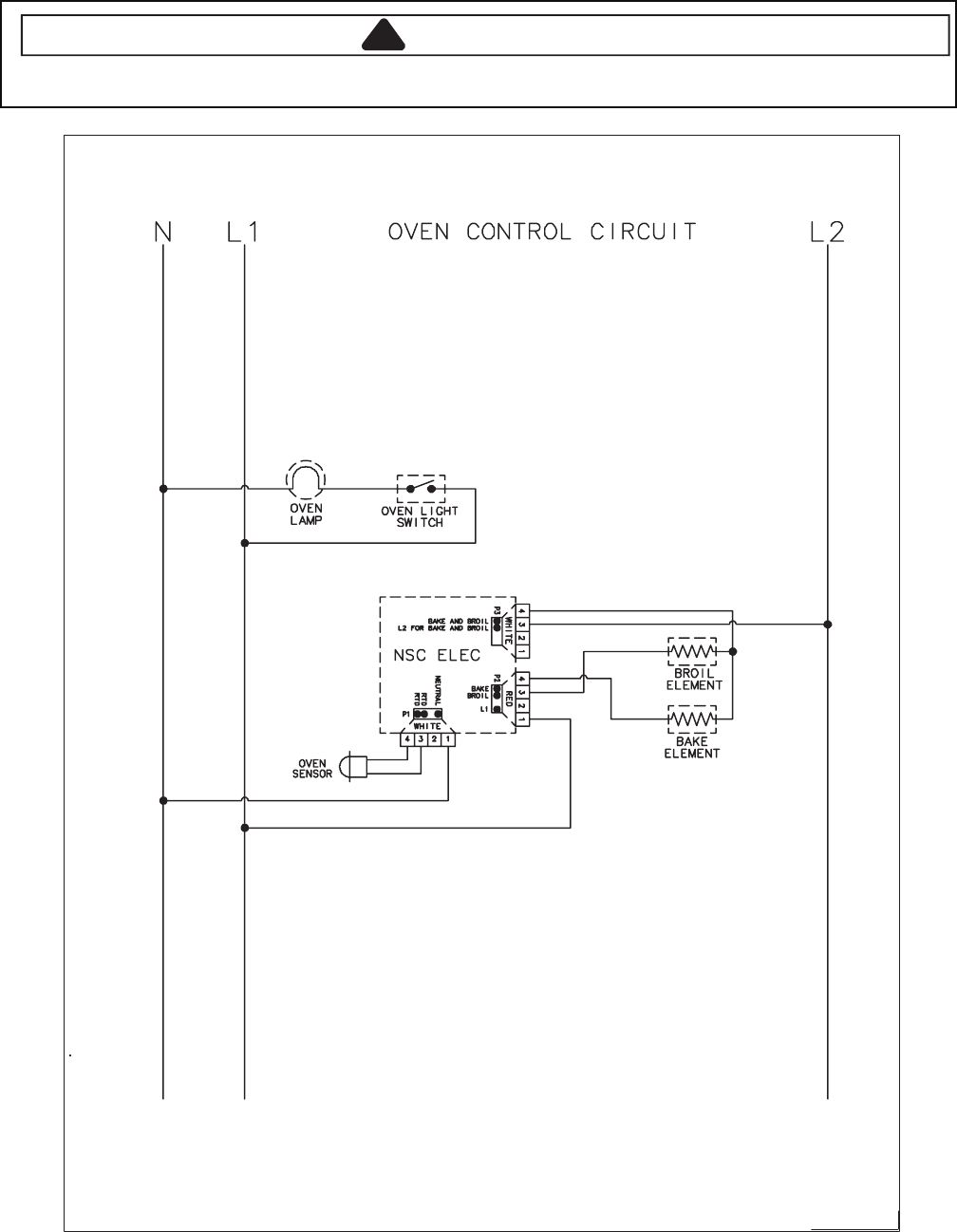
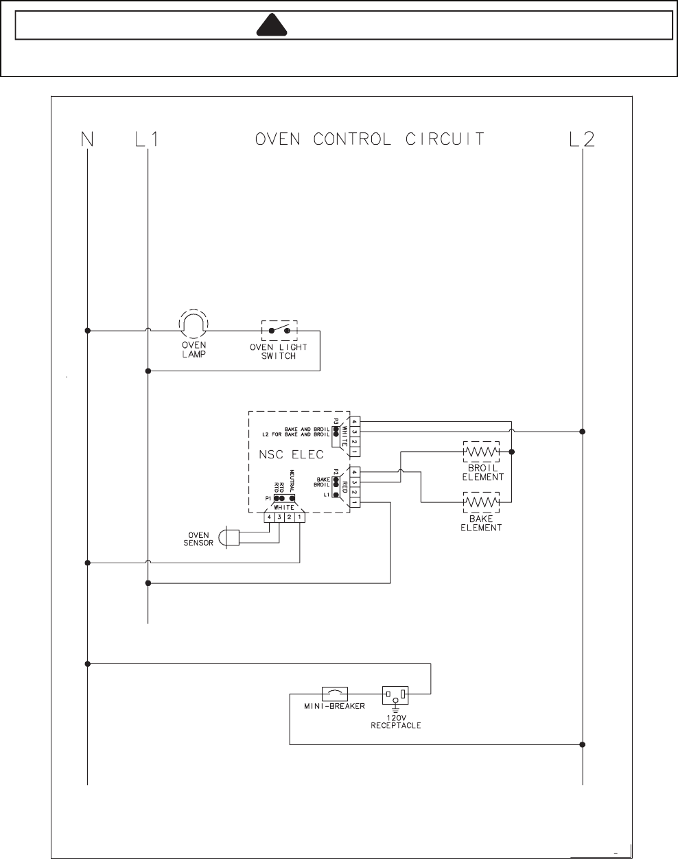
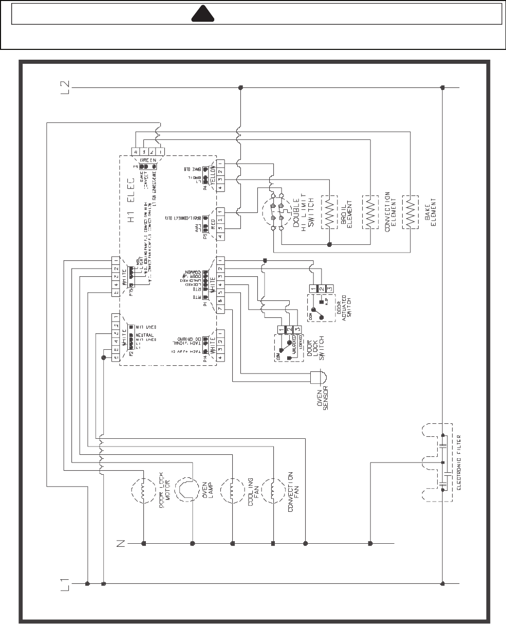
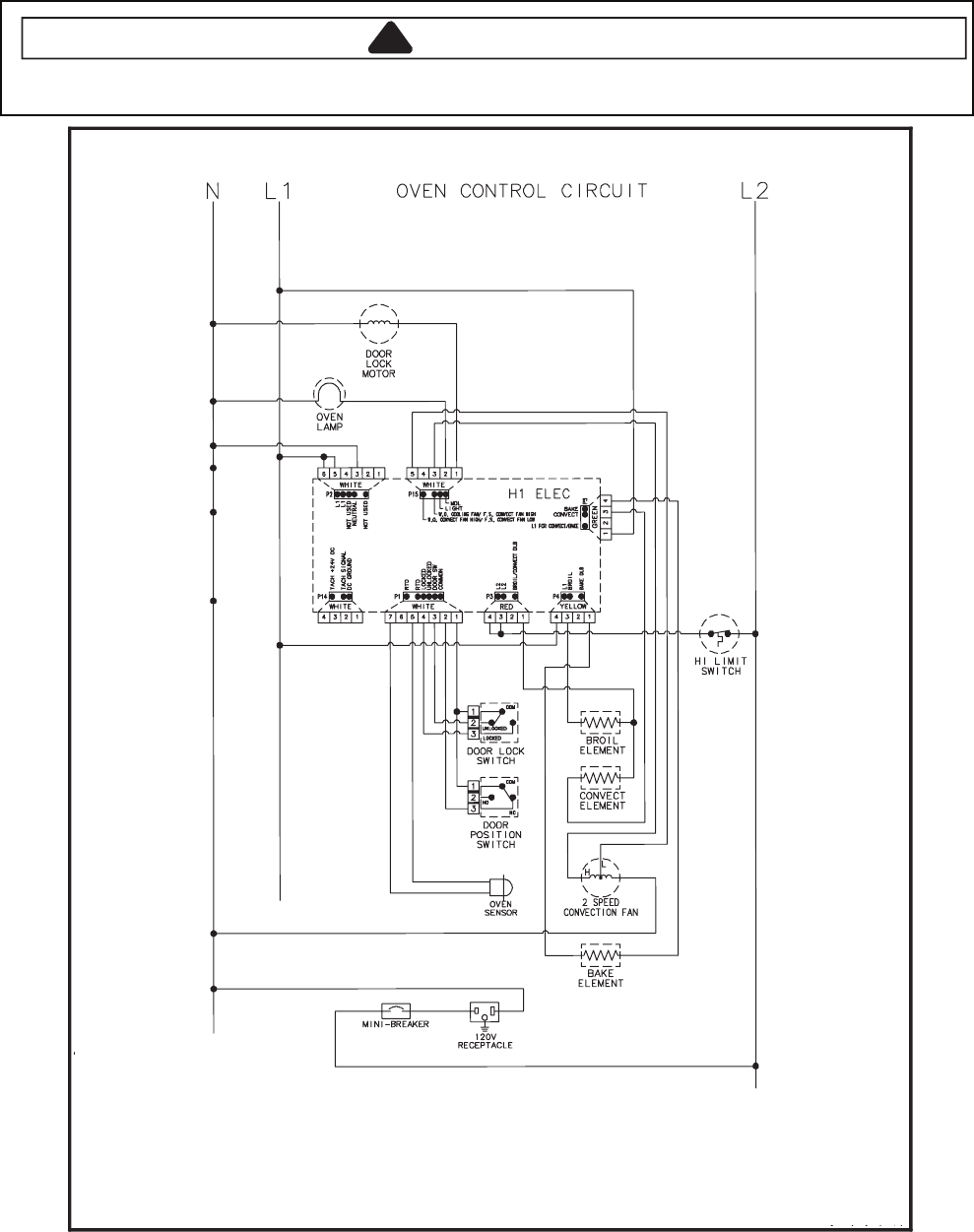
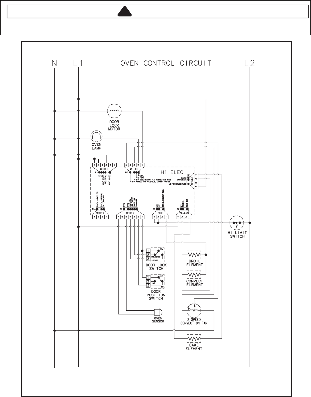
Wiring Diagram and Schematic
!WARNING
To avoid risk of electrical shock, personal injury or death; disconnect power to oven before servicing, unless
testing requires power.
16026465 92532061
3-5
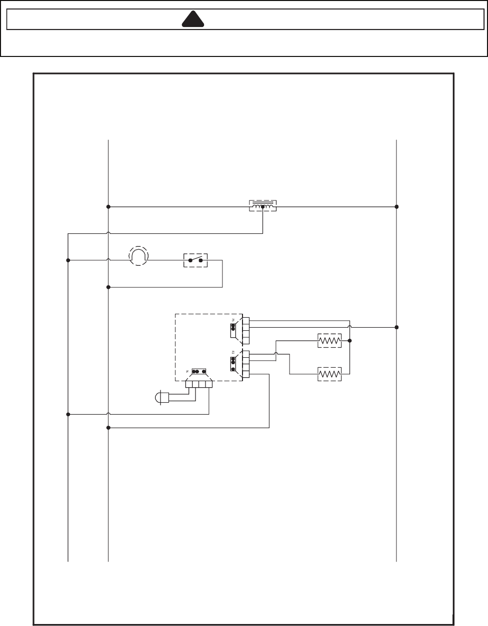
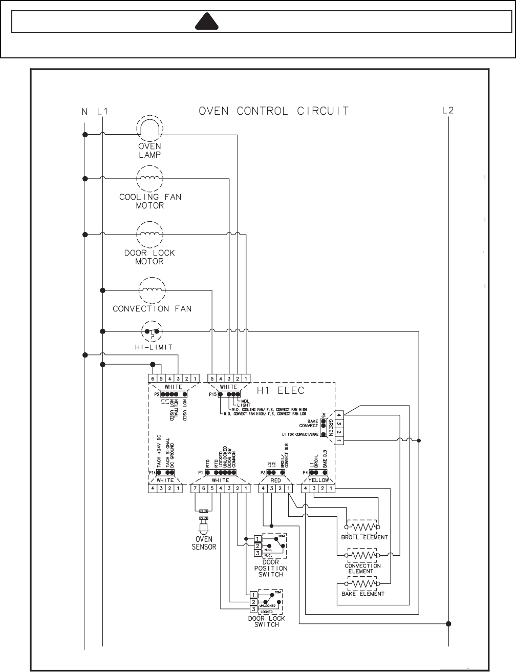
Wiring Diagram and Schematic
!WARNING
To avoid risk of electrical shock, personal injury or death; disconnect power to oven before servicing, unless
testing requires power.
53532061
16026468
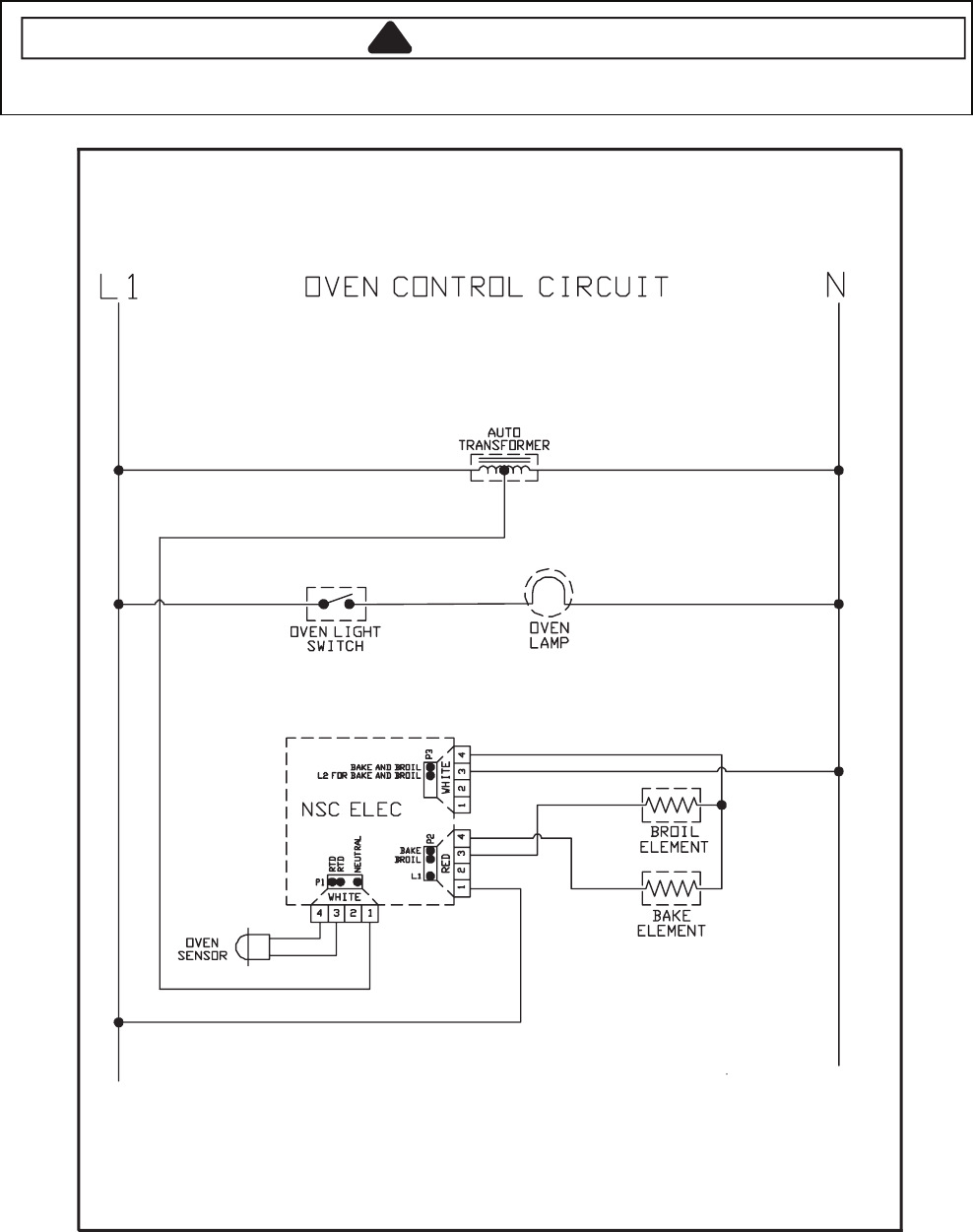
3-6
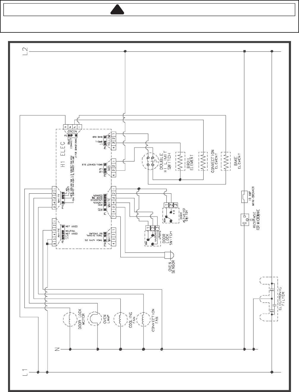
Wiring Diagram and Schematic
!WARNING
To avoid risk of electrical shock, personal injury or death; disconnect power to range before servicing, unless
testing requires power.
00362061
AUTO
TRANSFOR ME R
BAKE AN DBROIL
L2 FO RBAKEAND BR OIL
BAKE
BROIL
L1
WHITE
NSCELEC
W H I T E
1234
RED
1234
4321
RTD
RTD
NE U T R A L
L2L1
O VEN CONTROLCIRCUIT
OVEN
SENSOR
OVEN
LAMP
BAKE
ELEMENT
BROIL
ELEMENT
OVEN LIGHT
SWITCH

3-7
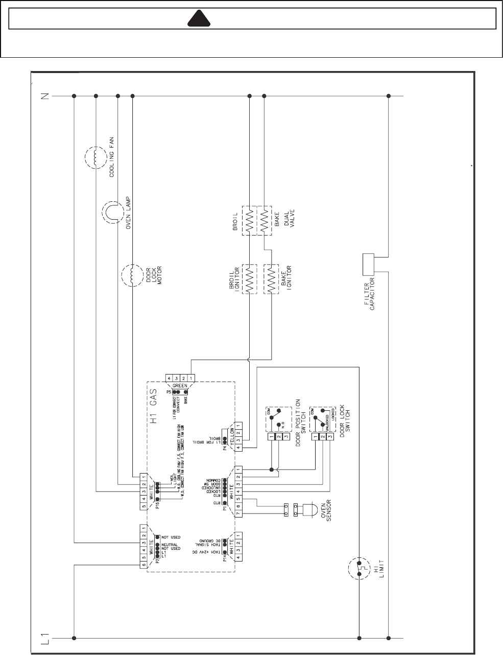
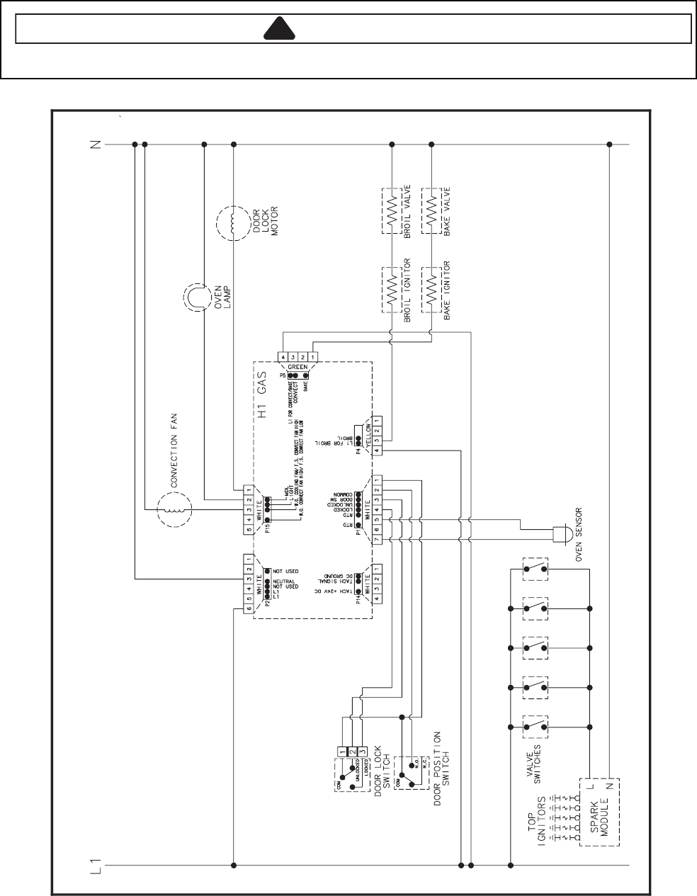
Wiring Diagram and Schematic
!WARNING
To avoid risk of electrical shock, personal injury, or death, disconnect power and gas to range before servicing,
unless testing requires power and/or gas.
58662061 16026763 16026765
3-8
Wiring Diagram and Schematic
!WARNING
To avoid risk of electrical shock, personal injury or death; disconnect power to range before servicing, unless
testing requires power.
83862061
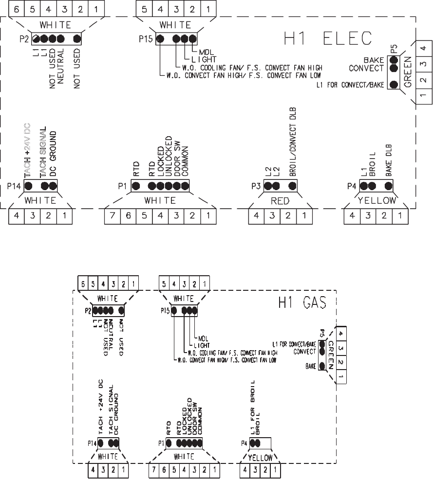
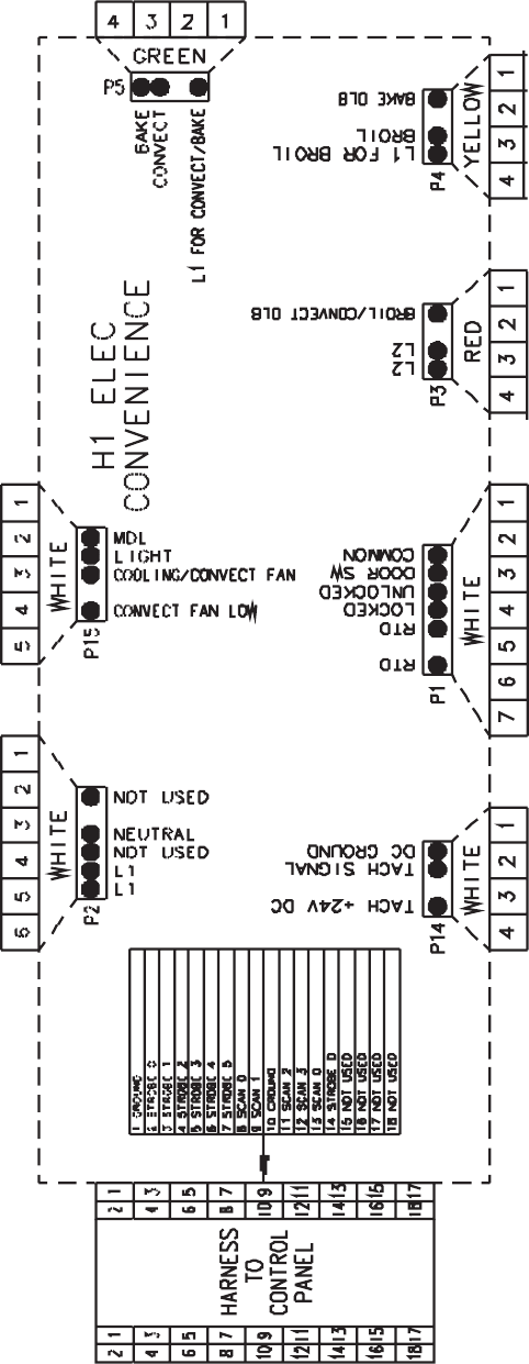
4-1
H1 CONTROLS
Pin Out Locations
TACH +24V DC
TACH SIGNAL
4-2

4-3
Hidden Functions
Illustrati stluseR erudecorP tseT tnenopmoC no
H1 Controlled Oven temperature
adjustment
Press BAKE pad.
Enter 550 on the digit-pad.
Immediately press and hold BAKE
pad for 3 seconds.
Oven can be adjusted from -35 to +35
degrees in 5-degree increments by
pressing AUTOSET pad. To avoid
over adjusting the oven, move
temperature 5 degrees each time.
Wait 4 seconds for the data entry
timer to expire to accept the change.
Temperature adjustment will be
retained even through a power failure.
While increasing or decreasing oven
temperature, this does not affect self-
cleaning temperature.
H1 Controlled Temperature display Press and hold Cancel and Bake
pads for 3 seconds.
This mode enables the user to indicate
°F or °C on the display.
H1 Controlled Clock Display Press and hold Cancel and Clock
pads for 3 seconds.
Allows clock to be toggled On or OFF.
H1 Controlled 24 Hour Clock Press and hold Cancel and Favorite
pads for 3 seconds.
Allows the time on the clock to be
toggled from 12 hour or 24 hour display.
H1 Controlled Factory Default Press and hold Cancel and Keep
Warm pads for 3 seconds.
Allows the clock to be reset to factory
settings.
H1 Controlled Twelve hour off Control will automatically cancel any
cooking operation and remove all relay
drives 12 hours after the last pad
touch.
See Sabbath mode to disable.
H1 Controlled Sabbath Mode Hold CLOCK pad for 3 seconds to
activate Sabbath mode.
Hold CLOCKpad for 3 seconds to
disable Sabbath mode.
“SAb” will be displayed and flash for
5 seconds.
Display will go back to time of day.
All pad inputs are disabled except for
CANCEL and CLOCK pads.
This mode disables the normal 12 hour
shutoff to allow operation of the bake
mode for a maximum of 72 hours.
H1 Controlled Child lock out Press and hold Cancel and Cook &
Hold pads for 3 seconds. “OFF” will
display where the temperature
normally appears. “LOCK” will display
flashing while door is locking.
To reactivate the control, press and
hold Cancel and Cook & Hold pads
for 3 seconds.
This is a safety feature that can be used
to prevent children from accidentally
programming the oven. It disables the
electronic oven control.
Child lockout features must be reset after
a power failure.
H1 Controlled Diagnostic Code
Display
See “Quick Test Mode”.
Cycle through the codes using the
number pads 1 through 5.
The last 5 diagnostic codes will be stored
in the non-volatile memory.
See“Description of Error Codes”
for explanation.
page 2-1
4-4
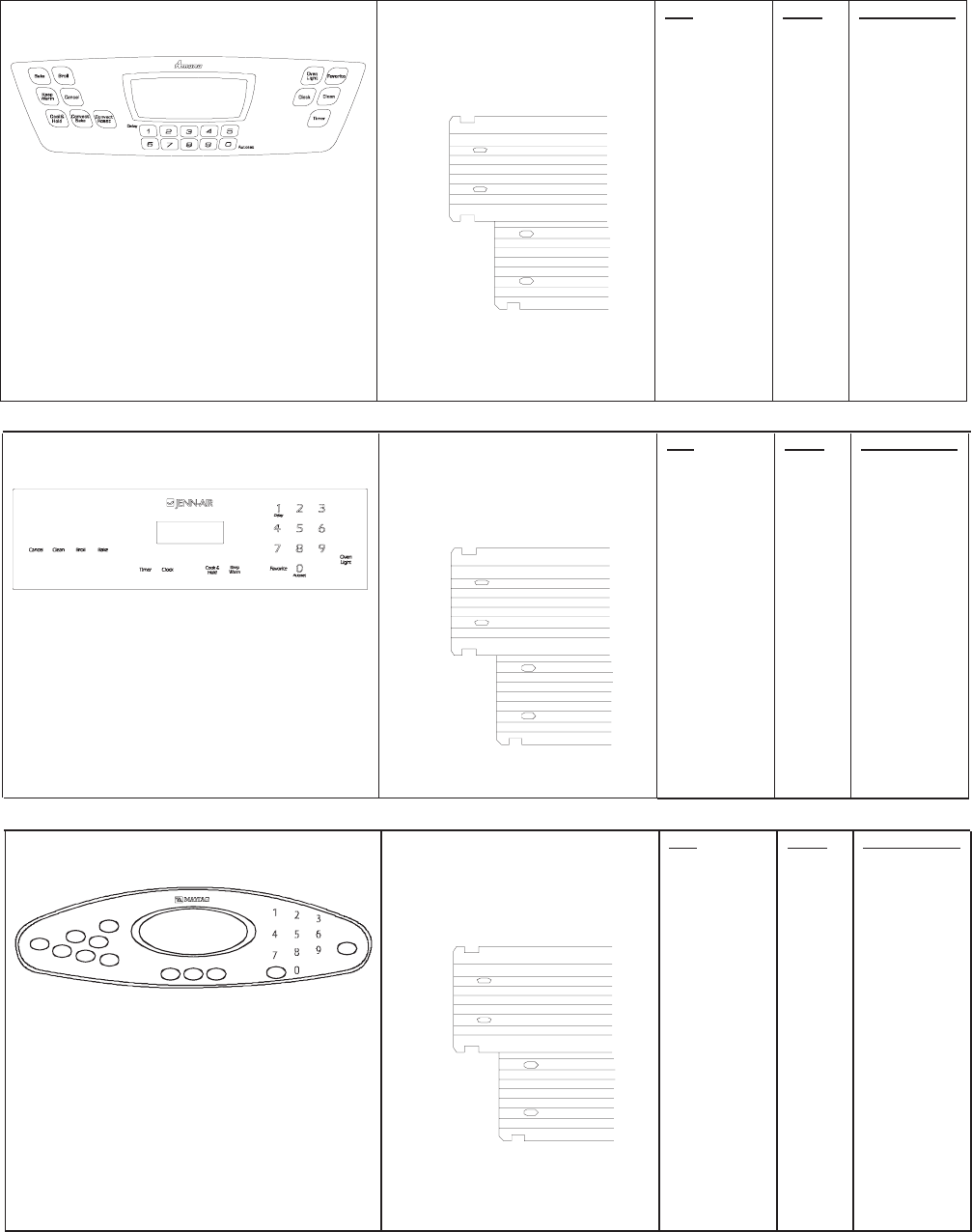
Testing the User Interface
Amana Matrix
Control Panel Assembly
Continuity is indicated as follows:
1000 – 6600 Ω for Cancel pad
1000 – 15000 Ω for All other pads
1
16
9
8
Pad
1
2
3
4
5
6
7
8
9
0
Cancel
Clock
Cook & Hold
Broil
Bake
Convect
Clean
Keep Warm
Favorite
Timer
Oven Light
Convect Roast
Trace
5 & 10
4 & 11
4 & 12
4 & 13
5 & 15
4 & 10
11 & 12
12 & 13
13 & 15
4 & 15
1 & 3
5 & 13
10 & 11
5 & 12
5 & 7
5 & 11
7 & 13
4 & 5
7 &15
4 & 7
7 &12
7 & 11
Measurement
Continuity
Continuity
Continuity
Continuity
Continuity
Continuity
Continuity
Continuity
Continuity
Continuity
Continuity
Continuity
Continuity
Continuity
Continuity
Continuity
Continuity
Continuity
Continuity
Continuity
Continuity
Continuity
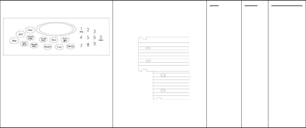
Jenn-Air Matrix
Control Panel Assembly
Continuity is indicated as follows:
1000 – 6600 Ω for Cancel pad
1000 – 15000 Ω for All other pads
1
16
9
8
Pad
1
2
3
4
5
6
7
8
9
0
Cancel
Clock
Cook & Hold
Broil
Bake
Clean
Keep Warm
Favorite
Timer
Oven Light
Trace
13 & 15
12 & 15
10 & 15
7 & 13
12 & 13
10 & 12
4 & 13
4 & 12
5 & 10
5 & 12
1 & 2/3
4 & 14
5 & 14
13 & 14
7 & 15
5 & 7
14 & 15
5 & 13
4 & 5
4 & 10
Measurement
Continuity
Continuity
Continuity
Continuity
Continuity
Continuity
Continuity
Continuity
Continuity
Continuity
Continuity
Continuity
Continuity
Continuity
Continuity
Continuity
Continuity
Continuity
Continuity
Continuity
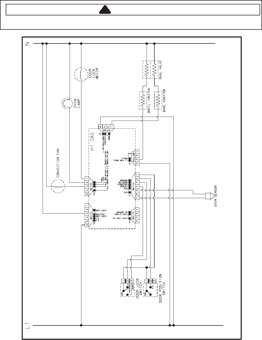
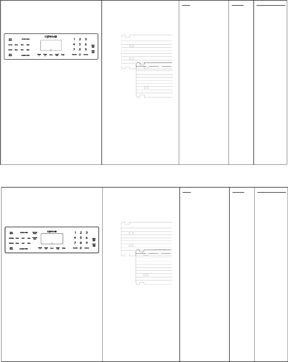
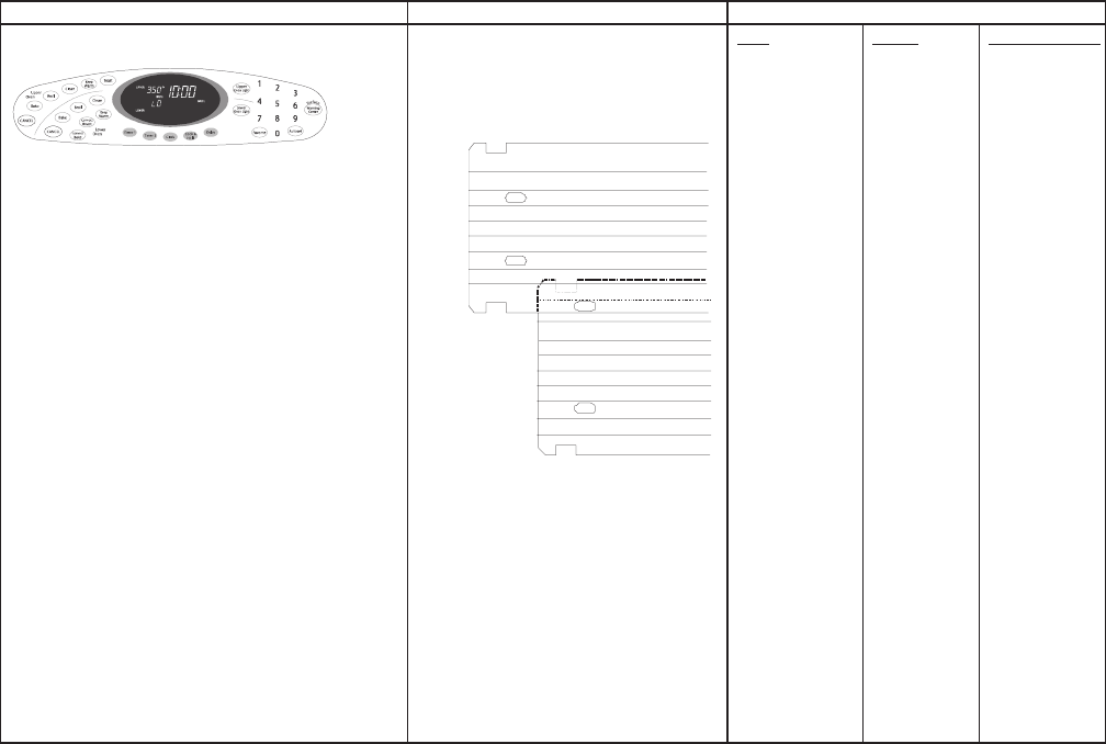
Maytag Matrix
Control Panel Assembly
Ba ke
Br oi lKe ep
wa rm
Convect
Ba ke Convect
Ro ast
CANC EL
Clean
Cloc kTime rCook &
Hold Fa vorite
Oven
Light
De lay
Autoset
Continuity is indicated as follows:
1000 – 6600 Ω for Cancel pad
1000 – 15000 Ω for All other pads
1
16
9
8
Pad
1
2
3
4
5
6
7
8
9
0
Cancel
Clock
Cook & Hold
Broil
Bake
Convect Bake
Convect Roast
Clean
Keep Warm
Favorite
Timer
Oven Light
Trace
13 & 15
12 & 13
12 & 15
4 & 11
4 & 12
4 & 10
5 & 11
5 & 13
5 & 10
5 & 12
1 & 3
7 & 13
11 & 13
11 & 12
10 & 11
11 & 15
5 & 7
4 & 13
7 & 11
4 & 5
4 & 7
10 & 12
Measurement
Continuity
Continuity
Continuity
Continuity
Continuity
Continuity
Continuity
Continuity
Continuity
Continuity
Continuity
Continuity
Continuity
Continuity
Continuity
Continuity
Continuity
Continuity
Continuity
Continuity
Continuity
Continuity
4-5
Matrix
Control Panel Assembly
Continuity is indicated as follows:
1000 – 6600 Ω for Cancel pad
1000 – 15000 Ω for All other pads
1
16
9
8
Pad
1
2
3
4
5
6
7
8
9
0
Cancel
Clock
Cook & Hold
Broil
Bake
CV Bake
CV Roast
Clean
Keep Warm
Favorites
Timer
Light
Trace
13 & 15
12 & 13
12 & 15
4 & 11
4 & 12
4 & 10
5 & 13
5 & 12
5 & 10
10 & 12
1 & 2
4 & 5
4 & 7
5 & 7
10 & 11
4 & 13
7 & 11
7 & 15
11 & 12
13 & 14
5 & 11
7 & 13
Measurement
Continuity
Continuity
Continuity
Continuity
Continuity
Continuity
Continuity
Continuity
Continuity
Continuity
Continuity
Continuity
Continuity
Continuity
Continuity
Continuity
Continuity
Continuity
Continuity
Continuity
Continuity
Continuity
Testing the User Interface

4-6
Quick Test (Convection Model)
“Quick Test” Mode for Electronic Range Control
Follow procedure below to use the quick test mode. Entries must be made within 32 seconds of each other or the
control will exit the quick test mode.
1. Press and hold CANCEL and BROIL pads for 3 seconds.
2. Once the control has entered the “Quick Test” mode, release both pads.
3. Press each of the following pads indicated in the table below.
NOTE: First time one of following pads are pressed it will activate the response.
The second time the pad is pressed it will deactivate the response.
Display will indicate the following:
esnopseR daP
BAKE...................................Bake DLB and Bake relay activated
BROIL.................................. Broil DLB and Broil relay activated
KEEP WARM ...................... Bake DLB and Broil DLB activated
CONVECT BAKE ................ Convection Fan on high speed
CONVECT ROAST ............. Cooling Fan activated
CLEAN................................. MDL relay activated
COOK & HOLD ................... Displays last diagnostic code
FAVORITE.......................... Displays EEPROM version number
TIMER ................................. Displays main code version number
CLOCK ................................ All display segments illuminated
OVEN LIGHT.......................Oven light activated
CANCEL..............................Exit Quick Test mode
1...........................................Even segments on
2........................................... Odd segments on
3...........................................Convection Ring activated; Convection Ring DLB activated
4...........................................Bake relay activated
5...........................................Broil relay activated
6...........................................Convection relay activated
7........................................... N/A
8........................................... N/A
9........................................... N/A
AUTOSET ...........................Steps through last 5 diagnostic codes
Diagnostic Code Display Mode can be activated by pressing and holding the AUTOSET pad for 3 seconds at
power-up. Diagnostic Code Display Mode can only be started while powering up the control.
(Convection Model)

4-7
Quick Test
“Quick Test” Mode for Electronic Range Control
Follow procedure below to use the quick test mode. The control will automatically exit quick test mode 10 seconds
after it exits the last test function selected.
1. Press and hold CANCEL and TOAST pads for 3 seconds.
2. Once the control has entered the “Quick Test” mode, release both pads.
3. Press each of the following pads indicated in the table below.
NOTE: First time one of following pads are pressed it will activate the response. The second time the pad is
pressed it will deactivate the response. The chosen function will be active for 3 seconds.
Display will indicate the following:
esnopseR daP
BAKE...................................Bake, Bake DLB and Broil DLB relays activated
BROIL.................................. Broil, Bake DLB and Broil DLB relays activated
KEEP WARM ...................... Bake DLB and Broil DLB relays activated
CLEAN................................. MDL relay activated
COOK & HOLD ...................Displays last diagnostic code
FAVORITE.......................... Displays EEPROM version number
TIMER ................................. Displays main code version number
CLOCK ................................ All display segments illuminated
OVEN LIGHT....................... Oven light activated
CANCEL.............................. Exit Quick Test mode
DELAY................................. Display last diagnostic code
AUTOSET ........................... Steps through last 5 diagnostic codes
0...........................................N/A
1........................................... Even segments on
2...........................................Odd segments on
3........................................... Bake DLB and Broil DLB relays activated
4........................................... N/A
5........................................... N/A
6...........................................Cooling Fan relay activated
7........................................... N/A
8........................................... N/A
9........................................... N/A
Diagnostic Code Display Mode can be activated by pressing and holding the AUTOSET pad for 3 seconds at
power-up. Diagnostic Code Display Mode can only be started while powering up the control.
4-8
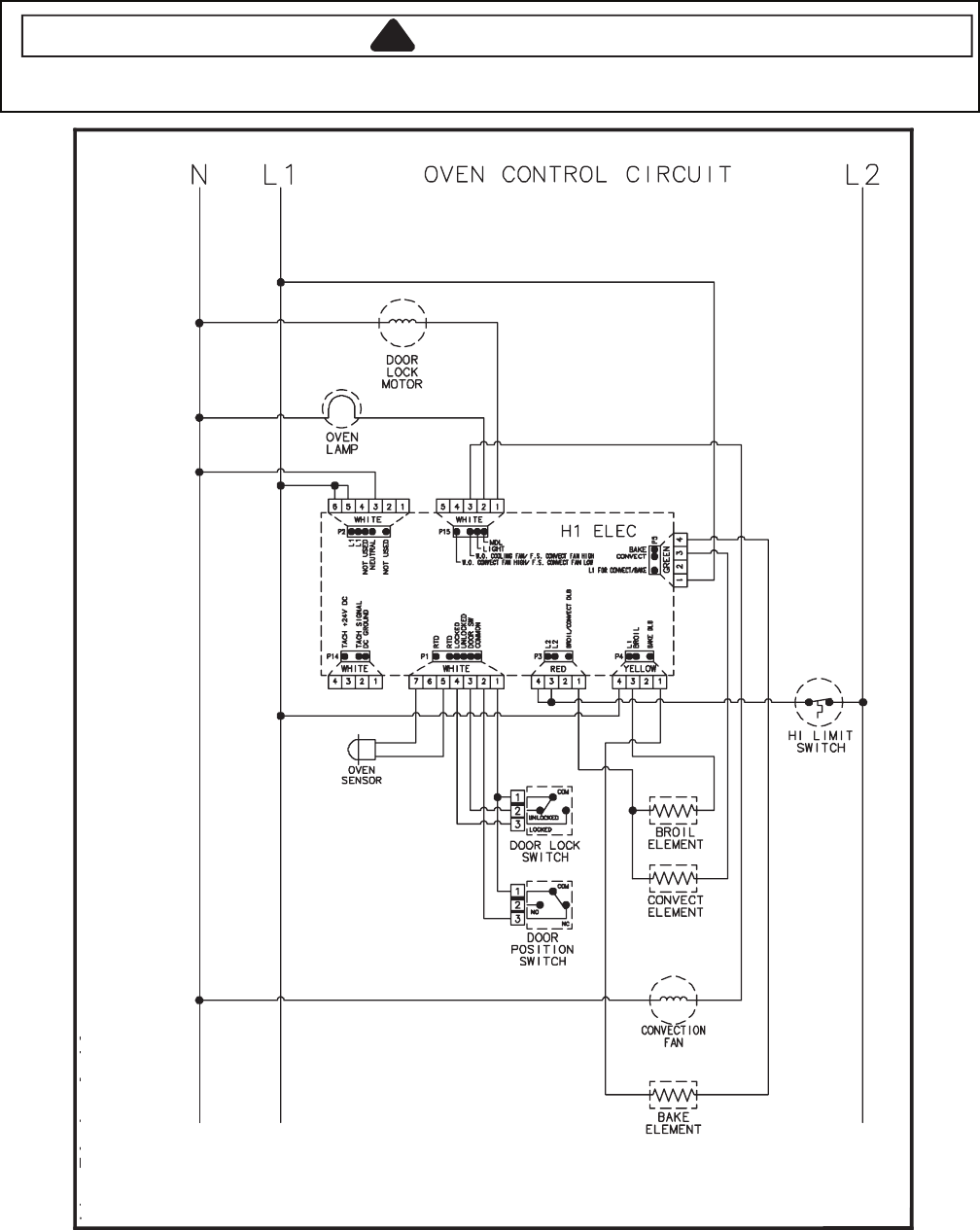
Wiring Diagram and Schematic
!WARNING
To avoid risk of electrical shock, personal injury or death; disconnect power to oven before servicing, unless
testing requires power.
10522061 20522061
4-9
Wiring Diagram and Schematic
!
WARNING
To avoid risk of electrical shock, personal injury or death: disconnect power to oven before servicing, unless
testing requires power.
54562061
16022507
4-10
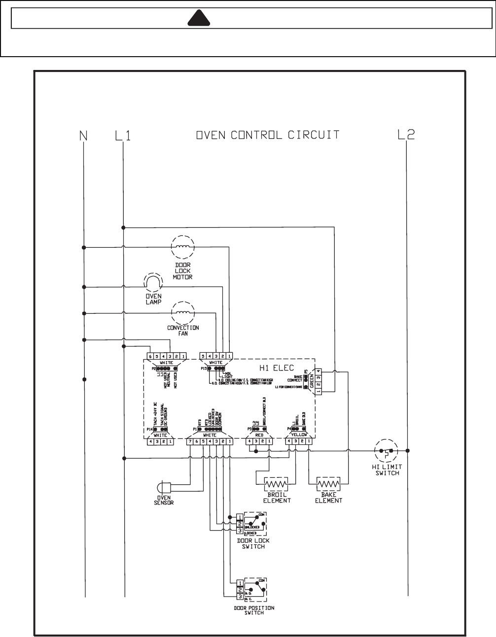
Wiring Diagram and Schematic
!WARNING
To avoid risk of electrical shock, personal injury or death; disconnect power to oven before servicing, unless
testing requires power.
30522061
4-11
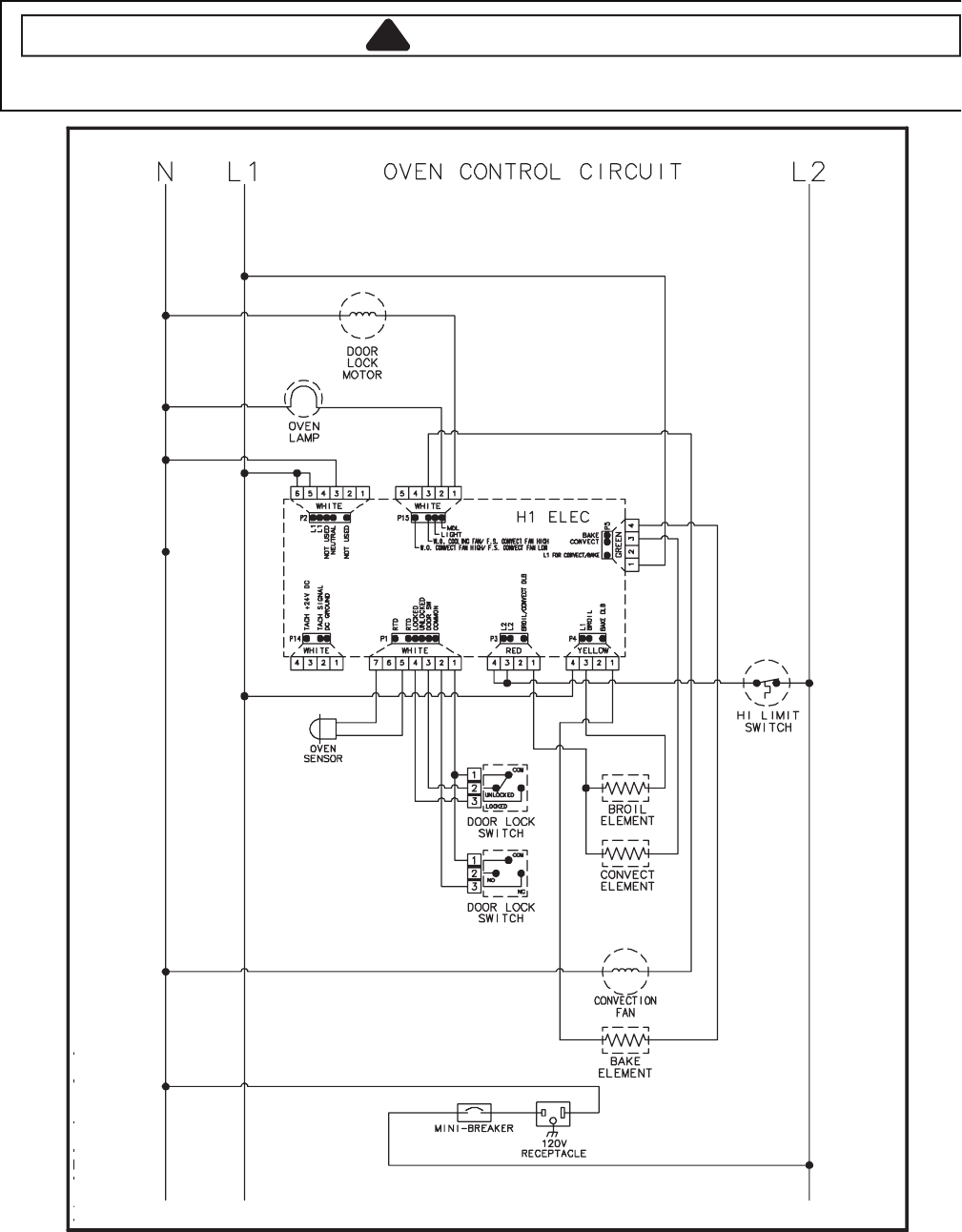
Wiring Diagram and Schematic
!WARNING
To avoid risk of electrical shock, personal injury or death; disconnect power to oven before servicing, unless
testing requires power.
50522061

4-12
Wiring Diagram and Schematic
!
WARNING
To avoid risk of electrical shock, personal injury or death; disconnect power to oven before servicing, unless
testing requires it.
80522061
4-13
Wiring Diagram and Schematic
!WARNING
To avoid risk of electrical shock, personal injury or death; disconnect power to oven before servicing, unless
testing requires power.
51522061
4-14
Wiring Diagram and Schematic
!WARNING
To avoid risk of electrical shock, personal injury or death; disconnect power to range before servicing, unless
testing requires power.
42272061
Schematic JER8885QCS Series 14 and later, JER8885QCB Series 15 and later
16023321

4-15
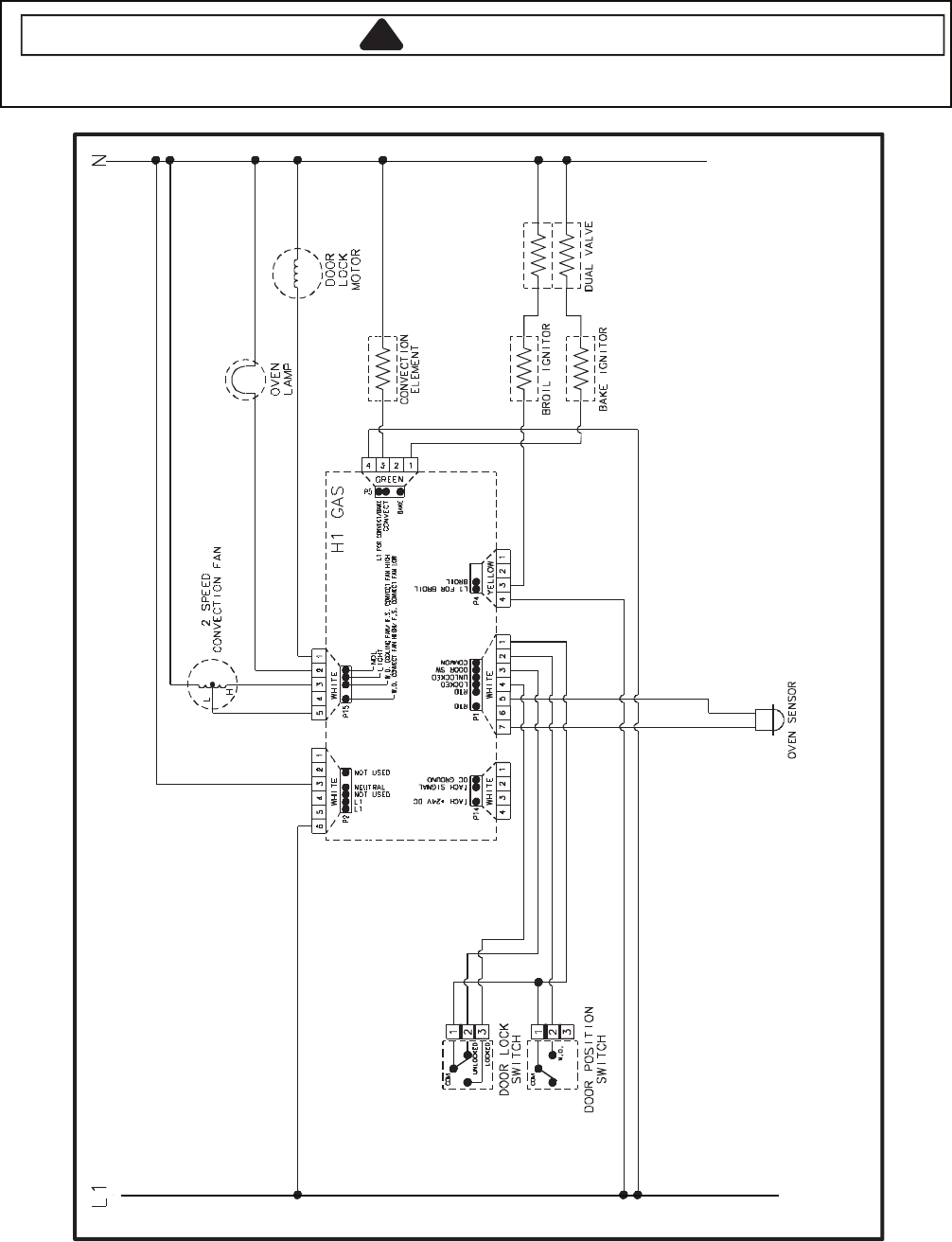
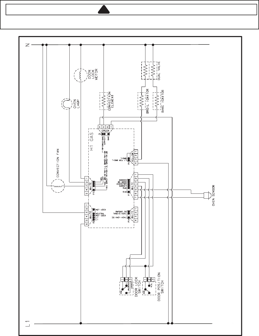
Wiring Diagram and Schematic
!WARNING
To avoid risk of electrical shock, personal injury or death; disconnect power and gas to range before servicing,
unless testing requires power and/or gas.
19262061
16026292
4-16
Wiring Diagram and Schematic
!WARNING
To avoid risk of electrical shock, personal injury or death; disconnect power to range before servicing, unless
testing requires power.
69262061
16026297 16026298
4-17
Wall Oven Wiring Diagram and Schematic
!
WARNING
To avoid risk of electrical shock, personal injury or death; disconnect power to oven before servicing, unless
testing requires power.
57262061
16026568 16026569
4-18
Wiring Diagram and Schematic
!WARNING
To avoid risk of electrical shock, personal injury, or death, disconnect power and gas to range before servicing,
unless testing requires power and/or gas.
15862061
4-19
Wiring Diagram and Schematic
!WARNING
To avoid risk of electrical shock, personal injury or death; disconnect power to range before servicing, unless
testing requires power.
6 160224962272061
Schematic Diagram (Control Circuits), JER8885QAS Series 15 and later
4-20
Wiring Diagram and Schematic
!WARNING
To avoid risk of electrical shock, personal injury, or death, disconnect power to range before servicing, unless
testing requires power.
92272061
Schematic (Control Circuits) MER5875RAS Series 13, MER5875RAF/B Series 14, MER5875RAN Series 15
4-21
Wiring Diagram and Schematic
!WARNING
To avoid risk of electrical shock, personal injury, or death, disconnect power to range before servicing, unless
testing requires power.
23272061
Schematic, AER5845RAS Series 13, AER5845RAB/W Series 14
4-22
Wiring Diagram and Schematic
!WARNING
To avoid risk of electrical shock, personal injury, or death, disconnect power to range before servicing, unless
testing requires power.
33272061
Schematic, MER5875RCQ/S Series 15; MER5875RCB Series 16

5-1
H2 CONTROLS
Pin Out Locations

5-2
Hidden Functions
stluseR erudecorP tseT tnenopmoC rellortnoC
H2 Oven temperature
adjustment
Press
BAKE
pad.
Enter
550
on the digit-pad.
Immediately press and hold
BAKE
pad for 3 to 5 seconds.
Oven can be adjusted from -35 to +35
degrees in 5-degree increments by
pressing
AUTOSET
pad. To avoid
over adjusting the oven, move
temperature 5 degrees each time.
Wait 4 seconds for the data entry
timer to expire to accept the change.
Temperature adjustment will be
retained even through a power failure.
While increasing or decreasing oven
temperature, this does not affect self-
cleaning temperature.
H2 Temperature display Press and hold
Cancel
and
Bake
pads for 3 to 5 seconds.
This mode enables the user to indicate
°F or °C on the display.
H2 Clock display Press and hold
Cancel
and
Clock
pads for 3 to 5 seconds.
Allows clock to be toggled on or off.
H2 24-hour clock Press and hold
Cancel
and
Favorite
pads for 3 to 5 seconds.
Allows the time on the clock to be
toggled from 12-hour or 24-hour display.
H2 Factory default Press and hold
Cancel
and
Keep
Warm
pads for 3 to 5 seconds.
Allows the clock to be reset to factory
settings.
H2 12-hour off Control automatically cancels cooking
operations and removes relay drives
12 hours after the last pad touch.
See Sabbath mode to disable.
H2 Sabbath mode Hold
CLOCK
pad for 3 to 5 seconds to
activate Sabbath mode.
Hold
CLOCK
pad
for 3 to 5 seconds to
disable Sabbath mode.
"SAb" flashes for 5 seconds.
Display returns to time of day.
All pad inputs are disabled except for
CANCEL and CLOCK pads.
This mode disables the normal 12-hour
shutoff to allow operation of the bake
mode for a maximum of 72 hours.
H2 Child lockout Press and hold
Cancel
and
Cook &
Hold
pads for 3 to 5 seconds. "OFF"
displays where the temperature
normally appears. "LOCK" flashes
while door is locking.
To reactivate the control, press and
hold
Cancel
and
Cook & Hold
pads
for 3 to 5 seconds.
This is a safety feature that can be used
to prevent children from accidentally
programming the oven. It disables the
electronic oven control.
Child lockout features must be reset after
a power failure.
H2 Diagnostic code
display
See "Quick Test Mode."
Cycle through the codes using the
number pads 1 through 5.
The last 5 diagnostic codes will be stored
in the non-volatile memory.
See "Description of Error Codes"
for explanation.
page 2-1
5-3
Control Panel Assembly
(Model JJW8430DD*)
Continuity is indicated as follows:
1000 – 6600 Ω for Cancel pad
1000 – 15000 Ω for all other
pads
Pad
1
2
3
4
5
6
7
8
9
0
Lower Cancel
Lower Broil
Lower Bake
Delay
Clock
Favorite
Lower Clean
Upper Clean
Upper Cancel
Lower Light
Upper Keep Warm
Upper Light
Autoset
Lower Keep Warm
Upper Bake
Timer 2
Cook & Hold
Upper Broil
Timer 1
Trace
15 & 16
14 & 16
16 & 17
6 & 16
6 & 7
7 & 17
5 & 6
5 & 14
6 & 14
14 & 15
1 & 2
or
1 & 3
8 & 15
7 & 15
5 & 7
7 & 16
4 & 16
4 & 15
4 & 14
11 & 12
or
11 & 13
14 & 17
4 & 5
8 & 17
7 & 14
4 & 8
5 & 15
7 & 8
5 & 16
8 & 14
8 & 16
Measurement
Continuity
Continuity
Continuity
Continuity
Continuity
Continuity
Continuity
Continuity
Continuity
Continuity
Continuity
Continuity
Continuity
Continuity
Continuity
Continuity
Continuity
Continuity
Continuity
Continuity
Continuity
Continuity
Continuity
Continuity
Continuity
Continuity
Continuity
Continuity
Continuity
Continuity
Continuity
Control Panel Assembly
(Models JJW9130DD*, JJW9330DD*)
Continuity is indicated as follows:
1000 – 6600 Ω for Cancel pad
1000 – 15000 Ω for all other
pads
Pad
1
2
3
4
5
6
7
8
9
0
Lower Cancel
Lower Broil
Lower Bake
Delay
Clock
Favorite
Lower Clean
Upper Clean
Upper Cancel
Lower Light
Upper Keep Warm
Upper Light
Autoset
Lower Keep Warm
Upper Bake
Timer 2
Cook & Hold
Upper Broil
Timer 1
Convect Roast
Convect Bake
Trace
15 & 16
14 & 16
16 & 17
6 & 16
6 & 7
7 & 17
5 & 6
5 & 14
6 & 14
14 & 15
1 & 2
or
1 & 3
8 & 15
7 & 15
5 & 7
7 & 16
4 & 16
4 & 15
4 & 14
11 & 12
or
11 & 13
14 & 17
4 & 5
8 & 17
7 & 14
4 & 8
5 & 15
7 & 8
5 & 16
8 & 14
8 & 16
6 & 15
4 & 7
Measurement
Continuity
Continuity
Continuity
Continuity
Continuity
Continuity
Continuity
Continuity
Continuity
Continuity
Continuity
Continuity
Continuity
Continuity
Continuity
Continuity
Continuity
Continuity
Continuity
Continuity
Continuity
Continuity
Continuity
Continuity
Continuity
Continuity
Continuity
Continuity
Continuity
Continuity
Continuity
Continuity
Continuity
1
18
11
10
1
18
11
10
Testing the User Interface

5-4
Quick Test
"Quick Test" Mode for Electronic Range Control
Follow procedure below to use the quick test mode. Entries must be made within 32 seconds of each other or the
control will exit the quick test mode.
1. Press and hold
CANCEL
and
BROIL
pads for 3 to 5 seconds.
2. Once the control has entered the "Quick Test" mode, release both pads.
3. Press each of the following pads indicated in the table below.
NOTE: First time one of the following pads is pressed it will activate the response.
The second time the pad is pressed it will deactivate the response.
Display will indicate the following:
esnopseR daP
BAKE................................... Bake DLB and Bake relay activated
BROIL.................................. Broil DLB and Broil relay activated
KEEP WARM ...................... Bake DLB and Broil DLB activated
CONVECT BAKE ................ Convection Fan on high speed
CONVECT ROAST ............. Cooling Fan activated
CLEAN................................. MDL relay activated
COOK & HOLD ................... Displays last diagnostic code
FAVORITE .......................... Displays EEPROM version number
TIMER ................................. Displays main code version number
CLOCK ................................ All display segments illuminated
OVEN LIGHT....................... Oven light activated
CANCEL.............................. Exit Quick Test mode
1........................................... Even segments on
2........................................... Odd segments on
3........................................... Convection Ring activated; Convection Ring DLB activated
4........................................... Bake relay activated
5........................................... Broil relay activated
6........................................... Convection relay activated
7........................................... N/A
8........................................... N/A
9........................................... N/A
AUTOSET ........................... Steps through last 5 diagnostic codes
Diagnostic Code Display Mode can be activated by pressing and holding the
AUTOSET
pad for 3 to 5 seconds at
power-up. Diagnostic Code Display Mode can only be started while powering up the control.
5-5
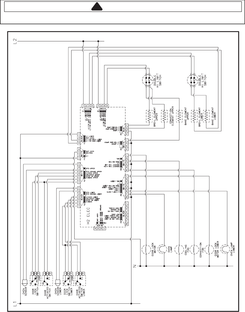
Wiring Diagram and Schematic
!
WARNING
To avoid risk of electrical shock, personal injury or death; disconnect power to oven before servicing, unless
testing requires it.
11522061 16026546
5-6
— NOTES —

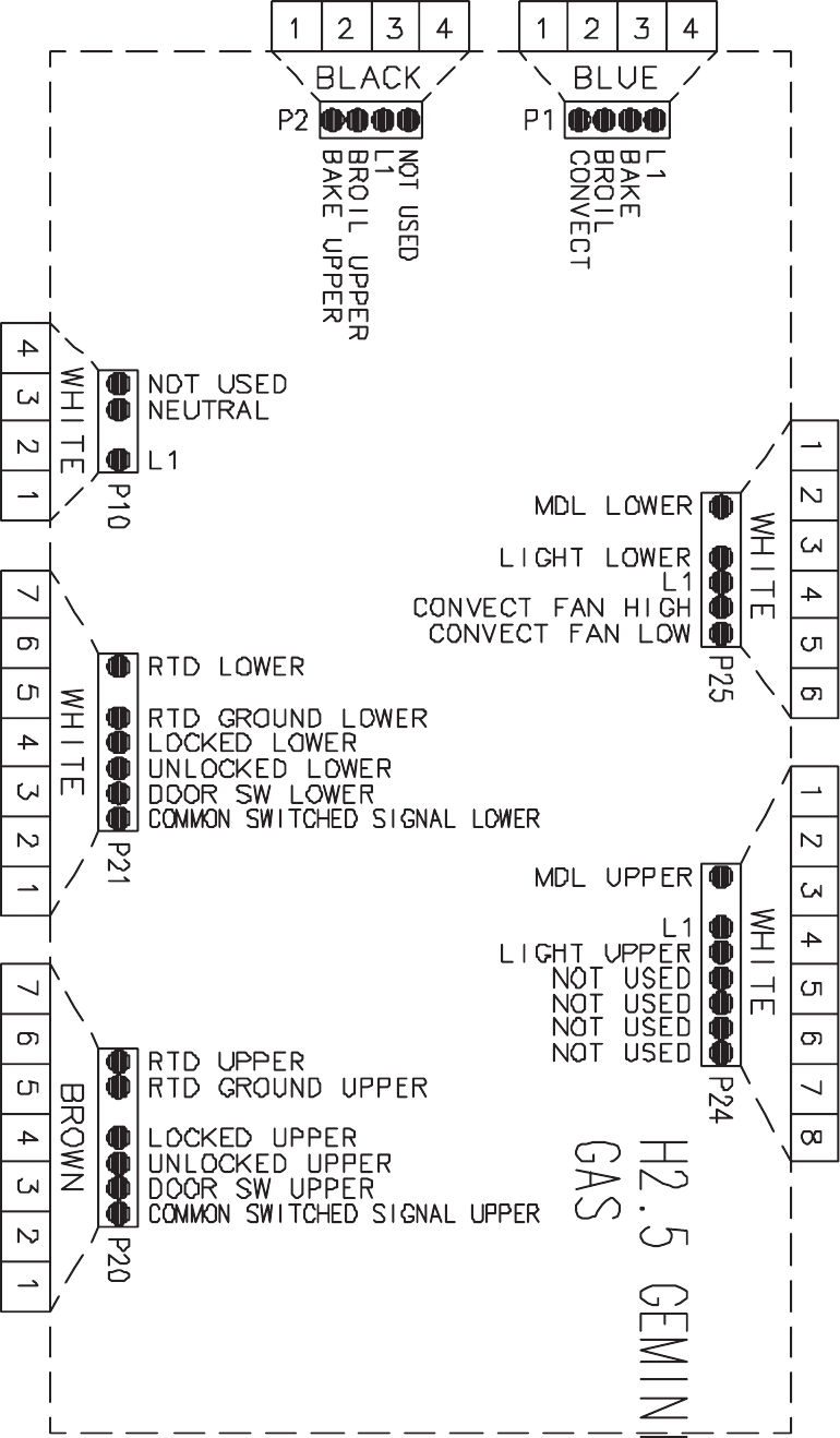
6-1
H2.5 CONTROLS
Pin Out Locations
6-2
Pin Out Locations

6-3
Hidden Functions
Illustrati stluseR erudecorP tseT tnenopmoC no
H2.5 Controlled Oven temperature
adjustment
(Upper Oven)
Press
Upper Bake
pad.
Enter
550
on the digit-pad.
Immediately press and hold
Upper
Bake
pad for 3 seconds.
Oven can be adjusted from -35 to +35
degrees in 5-degree increments by
pressing
Autoset
pad. To avoid over
adjusting the oven, move temperature
5 degrees each time. Wait 4 seconds
for the data entry timer to expire to
accept the change. Temperature
adjustment will be retained even
through a power failure.
While increasing or decreasing oven
temperature, this does not affect self-
cleaning temperature.
H2.5 Controlled Oven temperature
adjustment
(Lower Oven)
Press
Lower Bake
pad.
Enter
550
on the digit-pad.
Immediately press and hold
Lower
Bake
pad for 3 seconds.
Oven can be adjusted from -35 to +35
degrees in 5-degree increments by
pressing
Autoset
pad. To avoid over
adjusting the oven, move temperature
5 degrees each time. Wait 4 seconds
for the data entry timer to expire to
accept the change. Temperature
adjustment will be retained even
through a power failure.
While increasing or decreasing oven
temperature, this does not affect self-
cleaning temperature.
H2.5 Controlled Temperature display Press and hold
Upper
Cancel
and
Upper
Bake
pads for 3 seconds.
This mode enables the user to indicate
°F or °C on the display.
H2.5 Controlled Clock Display Press and hold
Upper
Cancel
and
Clock
pads for 3 seconds.
Allows clock to be toggled On or OFF.
H2.5 Controlled 24 Hour Clock Press and hold
Upper
Cancel
and
Favorite
pads for 3 seconds.
Allows the time on the clock to be
toggled from 12 hour or 24 hour display.
H2.5 Controlled Factory Default Press and hold
Upper
Cancel
and
Upper
Keep Warm
pads for 3
seconds.
Allows the clock to be reset to factory
settings.
H2.5 Controlled Twelve hour off Control automatically cancels/removes
any cooking operations/relay drives 12
hours after the last pad touch.
See Sabbath mode to disable.
H2.5 Controlled Sabbath Mode Hold
Clock
pad for 3 to 5 seconds to
activate Sabbath mode.
Hold
Clock
pad
for 3 to 5 seconds to
disable Sabbath mode.
“SAbbAth” will display for 5 seconds,
then change to “SAb” (displayed in Temp
area).
All pad inputs are disabled except for
CANCEL and CLOCK pads.
This mode disables the normal 12 hour
shutoff to allow operation of the bake
mode for a maximum of 72 hours.
H2.5 Controlled Beeper Volume Hold
Upper Cancel
and
Delay
pads
for 3 seconds to adjust beeper
loudness level.
Volume settings are Low, Medium and
High.
H2.5 Controlled Child lock out Press and hold
Upper
Cancel
and
Cook & Hold
pads for 3 seconds.
“OFF” will display where the
temperature normally appears.
“LOCK” will display flashing while door
is locking.To reactivate the control,
press and hold
Cancel
and
Cook &
Hold
pads
for 3 seconds.
This is a safety feature that can be used
to prevent children from accidentally
programming the oven. It disables the
electronic oven control.
Child lockout features must be reset after
a power failure.
H2.5 Controlled Diagnostic Code
Display
Press and hold
Upper
Cancel
and
Autoset
pads for 3 seconds.
See “Quick Test Mode.”
Cycle through the codes using the
number pads 1 through 5.
The last 5 diagnostic codes will be stored
in the non-volatile memory.
See “Description of Error Codes”
for explanation.
page 2-1
6-4
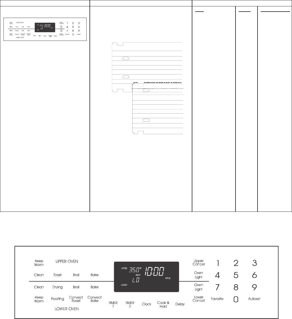
Testing the User Interface
stluseR erudecorP tseT tnenopmoC
Control Panel Assembly
Continuity is indicated as follows:
1000 – 6600 Ω for Cancel pad
1000 – 10000 Ω for All other pads
1
18
11
10
Pad
1
2
3
4
5
6
7
8
9
0
Lower Cancel
Lower Cancel
Lower Cancel
Upper Cancel
Upper Cancel
Upper Cancel
Conv Bake
Delay
Clock
Favorite
Lower Clean
Upper Clean
Lower Bake
Lower Light
Upper Keep Warm
Upper Light
Autoset
Lower Keep Warm
Conv Roast
Lower Broil
Upper Bake
Timer 2
Cook & Hold
Upper Broil
Timer 1
Drying
Proof
Toast
Trace
14 & 16
16 & 17
6 & 8
6 & 7
8 & 17
7 & 14
6 & 15
5 & 14
6 & 14
8 & 14
1 & 2
2 & 3
1 & 3
11 & 12
12 & 13
11 & 13
8 & 16
6 & 16
5 & 16
5 & 7
4 & 14
14 & 15
5 & 15
15 & 16
6 & 17
7 & 15
14 & 17
4 & 15
8 & 15
4 & 17
7 & 8
4 & 7
5 & 6
7 & 17
4 & 16
4 & 5
4 & 8
7 & 16
Measurement
Continuity
Continuity
Continuity
Continuity
Continuity
Continuity
Continuity
Continuity
Continuity
Continuity
Continuity
Continuity
Continuity
Continuity
Continuity
Continuity
Continuity
Continuity
Continuity
Continuity
Continuity
Continuity
Continuity
Continuity
Continuity
Continuity
Continuity
Continuity
Continuity
Continuity
Continuity
Continuity
Continuity
Continuity
Continuity
Continuity
Continuity
Continuity
6-5
Testing the User Interface
Illustration/Co stluseR erudecorP tseT tnenopm
Control Panel Assembly
Continuity is indicated as follows:
1000 – 6600 Ω for Cancel and
Warming Zone pads
1000 – 10000 Ω for All other pads
1
18
11
10
Pad
1
2
3
4
5
6
7
8
9
0
Lower Cancel
Upper Cancel
Convect Bake
Delay
Clock
Favorite
Lower Clean
Upper Clean
Lower Bake
Lower Light
Upper Keep
Warm
Upper Light
Autoset
Lower Keep
Warm
Conv Roast
Lower Broil
Upper Bake
Timer 2
Cook & Hold
Upper Broil
Timer 1
Toast
Warm Zone
Trace
14 & 16
16 & 17
6 & 8
6 & 7
8 & 17
7 & 14
6 & 15
5 & 14
6 & 14
8 & 14
1 & 2 or 3
11 & 12 or 13
4 & 15
6 & 16
5 & 16
5 & 7
5 & 15
7 & 16
8 & 15
7 & 15
7 & 17
15 & 16
14 & 17
8 & 16
4 & 8
4 & 5
4 & 14
4 & 7
5 & 6
14 & 15
4 & 16
7 & 8
4 & 6 or 17
Measurement
Continuity
Continuity
Continuity
Continuity
Continuity
Continuity
Continuity
Continuity
Continuity
Continuity
Continuity
Continuity
Continuity
Continuity
Continuity
Continuity
Continuity
Continuity
Continuity
Continuity
Continuity
Continuity
Continuity
Continuity
Continuity
Continuity
Continuity
Continuity
Continuity
Continuity
Continuity
Continuity
Continuity
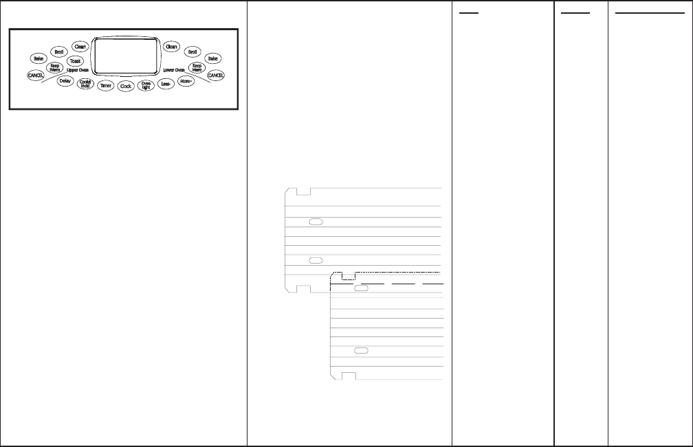
6-6
Testing the User Interface
Control Panel Assembly
Continuity is indicated as follows:
Cancel and Warming Zone pads:
1000 – 6600 Ω.
All other pads:
1000 – 10000 Ω.
NOTE: Pins 6 & 9 are jumped
together in control.
NOTE: Pins 1 & 10 and 11 & 18 are
loops in circuit.
1
18
11
10
Pad
1
2
3
4
5
6
7
8
9
0
Lower Cancel
Lower Cancel
Upper Cancel
Upper Cancel
Conv Bake
Delay
Clock
Favorite
Lower Clean
Upper Clean
Lower Bake
Lower Light
Upper Keep Warm
Upper Light
Autoset
Lower Keep Warm
Conv Roast
Upper Bake
Timer 2
Cook & Hold
Upper Broil
Timer 1
Warm Zone
Warm Zone
Warm Zone
Trace
14 & 16
17 & 16
6 & 8
7 & 6
8 & 17
7 & 14
6 & 15
5 & 14
6 & 14
8 & 14
1 & 2
1 & 3
11 & 12
11 & 13
4 & 15
16 & 6
5 & 16
5 & 7
5 & 15
7 & 16
8 & 15
7 & 15
7 & 17
15 & 16
14 & 17
8 & 16
5 & 4
4 & 14
4 & 7
6 & 5
14 & 15
4 & 16
6 & 4
17 & 4
17 & 6
Measurement
Continuity
Continuity
Continuity
Continuity
Continuity
Continuity
Continuity
Continuity
Continuity
Continuity
Continuity
Continuity
Continuity
Continuity
Continuity
Continuity
Continuity
Continuity
Continuity
Continuity
Continuity
Continuity
Continuity
Continuity
Continuity
Continuity
Continuity
Continuity
Continuity
Continuity
Continuity
Continuity
Continuity
Continuity
Continuity

6-7
Quick Test
“Quick Test” Mode for Electronic Range Control
Follow the procedure below to perform the Electronic Range Control (ERC) quick test. Instructions must be entered
within 32 seconds of each other (via the touch pad) or the ERC will exit the quick test.
1. Press and hold
CANCEL
and
BROIL
pads for 3 seconds.
2. Once the control has entered the “Quick Test” mode, release both pads.
3. Press each of the following pads indicated in the table below.
NOTE: Press the applicable pad once to activate the associated response.
Press the applicable pad a second time to deactivate the associated response.
Display will indicate the following:
esnopseR daP
BAKE...................................Bake DLB and Bake relay activated
BROIL.................................. Broil DLB and Broil relay activated
KEEP WARM ...................... Bake DLB and Broil DLB activated
CONVECT BAKE ................ Convection Fan on low speed
CONVECT ROAST ............. Convection Fan on high speed
CLEAN................................. MDL relay activated
COOK & HOLD ................... Displays last diagnostic code
FAVORITE .......................... Displays EEPROM version number
TIMER1 ............................... Displays main code version number
CLOCK ................................ All display segments illuminated
OVEN LIGHT.......................Oven light activated
CANCEL..............................Exit Quick Test mode
1...........................................Even segments on
2...........................................Odd segments on
3...........................................Convection Ring activated; Convection Ring DLB activated
4........................................... N/A
5........................................... N/A
6........................................... N/A
7........................................... N/A
8........................................... N/A
9........................................... N/A
AUTOSET ...........................Steps through last 5 diagnostic codes
Diagnostic Code Display Mode may be activated at power-up by pressing and holding the
AUTOSET
pad for 3
seconds. Diagnostic Code Display Mode may be activated only when applying power to the control.
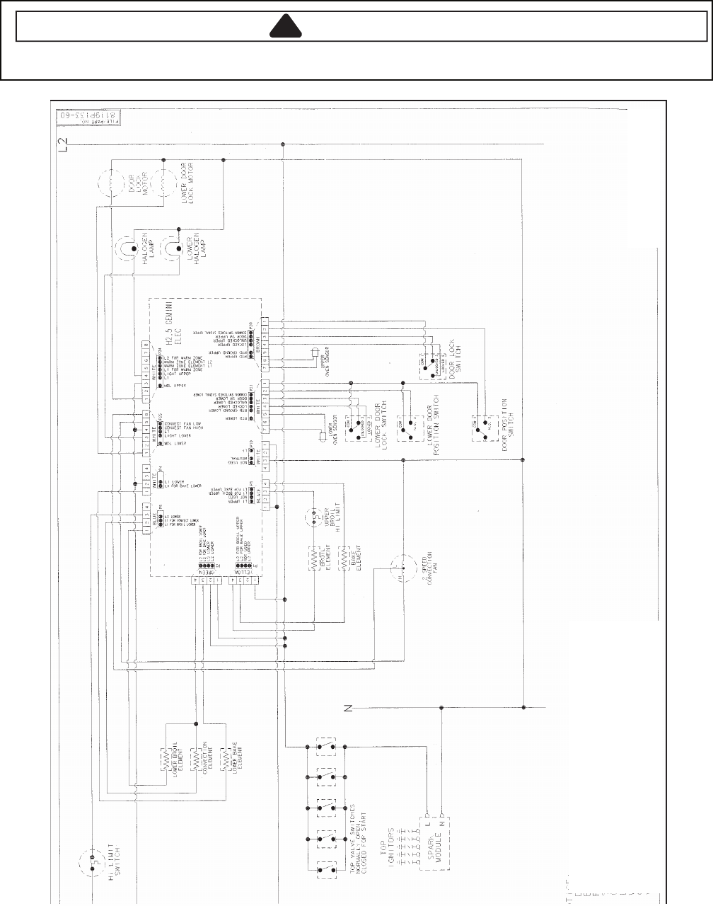
6-8
Wiring Diagram and Schematic
!WARNING
To avoid risk of electrical shock, personal injury or death; disconnect power to oven before servicing, unless
testing requires power.
0 160235066432061
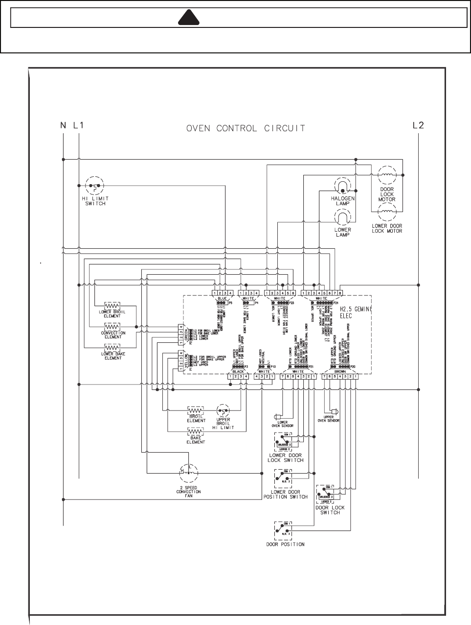
6-9
Wiring Diagram and Schematic
!WARNING
To avoid risk of electrical shock, personal injury or death; disconnect power to oven before servicing, unless
testing requires power.
05162061
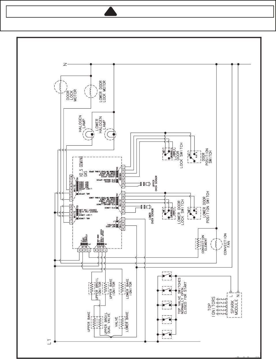
6-10
Wiring Diagram and Schematic
!WARNING
To avoid risk of electrical shock, personal injury or death; disconnect power and gas to range before servicing,
unless testing requires power and/or gas.
46372061
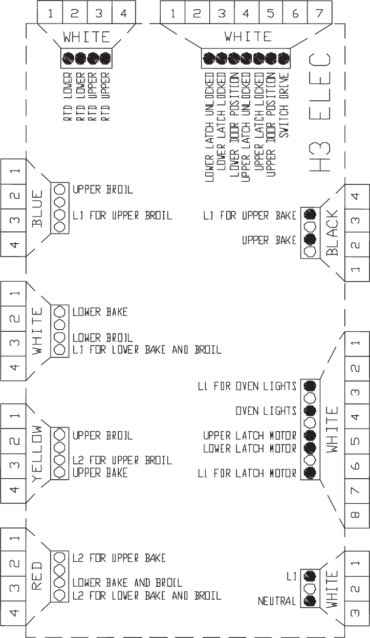
7-1
H3 CONTROLS
Pin Out Locations
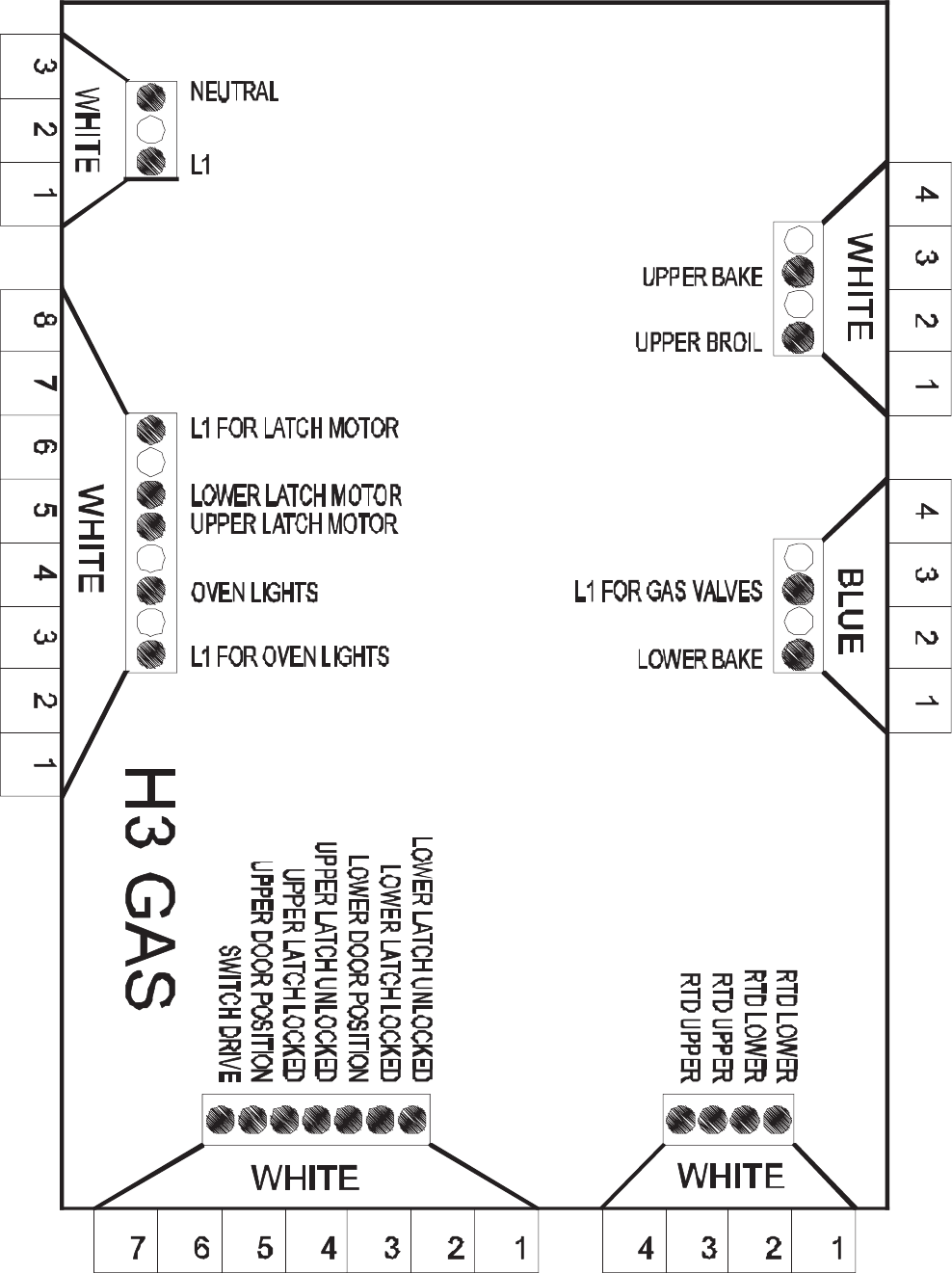
7-2
Pin Out Locations
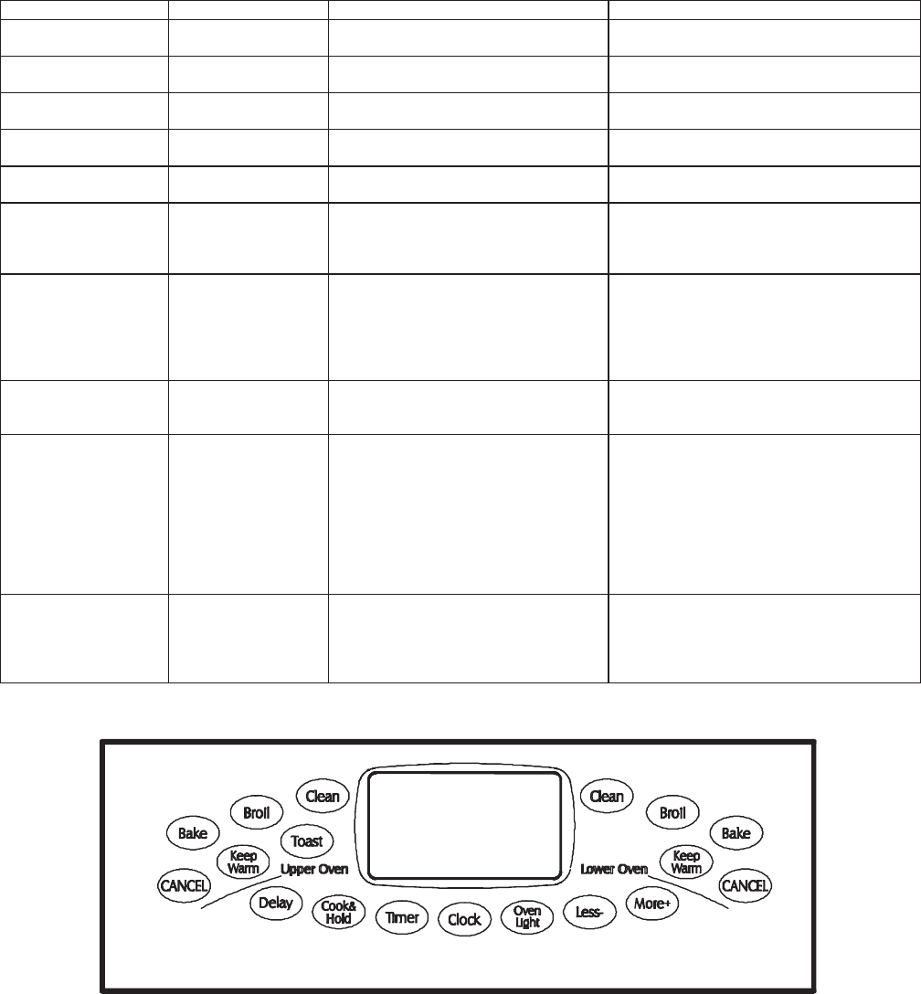
7-3
Hidden Functions
stluseR erudecorP erutaeF lortnoC
H3 Temperature display Press and hold Upper Cancel and
Upper Bake pads for 3 to 5 seconds.
Indicates °F or °C on the display.
H3 Factory Default Press and hold Upper Cancel and
Warm pads for 3 to 5 seconds.
Resets control to factory settings.
H3 Clock Display Press and hold Upper Cancel and
Clock pads for 3 to 5 seconds.
Turns clock display on or o.
H3 24 Hour Clock Press and hold Upper Cancel and
Delay pads for 3 to 5 seconds.
Displays either 12-hour or 24-hour time
format.
H3 Demo Press and hold Upper Cancel and
Less - pads for 3 to 5 seconds.
Enters a demonstrative sales mode.
H3 Twelve hour o Control w ill automatically cancel any
cooking operation and remove all relay
drives 12 hours after the last pad
touch.
See Sabbath mode to disable.
H3 Sabbath Mode Hold Clock pad for 3 to 5 seconds to
activate Sabbath mode.
Hold Clock pad for 3 to 5 seconds to
disable Sabbath mode.
Oven must be in BAKE mode before
enabling SABBATH.
"SAb" displays and ashes for 5 seconds.
All pad inputs are disabled except for
CANCEL and CLOCK pads.
This mode disables the normal 12 hour
shuto to allow operation of the bake mode
for a maximum of 72 hours.
H3 Beeper Volume Hold Upper Cancel and More+ pads
for 3 to 5 seconds to adjust beeper
loudness level.
Volume settings are Low, Medium and
High.
H3 Child lock out Press and hold Upper Cancel and
Cook & Hold pads for 3 to 5 seconds.
“OFF” will display where the
temperature normally appears.
“LOCK” will display ashing while door
is locking.
To reactivate the control, press and
hold Cancel and Cook & Hold pads
for 3 to 5 seconds.
This disables the electronic oven control
and prevents children from accidentally
programming the oven.
Child lockout features must be reset after a
power failure.
H3 Diagnostic Code
Display
Press and hold Upper Cancel and
Timer for 3 to 5 seconds within 5
minutes of power up.
See “Quick Test Mode.”
Cycle through the codes.
The last 5 diagnostic codes will be stored in
the non-volatile memory.
See “Description of Error Codes”
for explanation.
page 2-1

7- 4
Hidden Functions
H3 Controlled Oven temperature
adjustment
(Upper Oven)
Press
Upper Bake
pad.
Enter
550
on the digit-pad.
Immediately press and hold
Upper
Bake
pad for 3 seconds.
Oven can be adjusted from -35 to +35
degrees in 5-degree increments by
pressing
More+
or
Less-
pads. To
avoid over adjusting the oven, move
temperature 5 degrees each time.
Wait 4 seconds for the data entry
timer to expire to accept the change.
Temperature adjustment will be
retained even through a power failure.
While increasing or decreasing oven
temperature, this does not affect self-
cleaning temperature.
H3 Controlled Oven temperature
adjustment
(Lower Oven)
Press
Lower Bake
pad.
Enter
550
on the digit-pad.
Immediately press and hold
Lower
Bake
pad for 3 seconds.
Oven can be adjusted from -35 to +35
degrees in 5-degree increments by
pressing
More+
or
Less-
pads. To
avoid over adjusting the oven, move
temperature 5 degrees each time.
Wait 4 seconds for the data entry
timer to expire to accept the change.
Temperature adjustment will be
retained even through a power failure.
While increasing or decreasing oven
temperature, this does not affect self-
cleaning temperature.
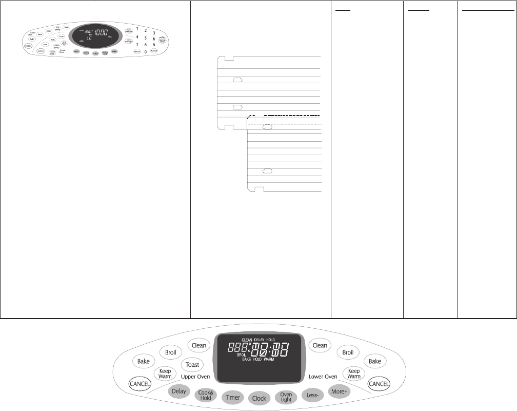
7-5
Testing the User Interface
Control Panel Assembly
MER6875AC*
Continuity is indicated as follows:
1000 – 6600 Ω for Cancel and
Warming Zone pads
1000 – 10000 Ω for All other pads
1
18
11
10
Pad
1
2
3
4
5
6
7
8
9
0
Lower Cancel
Upper Cancel
Convect Bake
Delay
Clock
Favorite
Lower Clean
Upper Clean
Lower Bake
Lower Light
Upper Keep Warm
Upper Light
Autoset
Lower Keep Warm
Conv Roast
Lower Broil
Upper Bake
Timer 2
Cook & Hold
Upper Broil
Timer 1
Toast
Warm Zone
Trace
14 & 16
16 & 17
6 & 8
6 & 7
8 & 17
7 & 14
6 & 15
5 & 14
6 & 14
8 & 14
1 & 2 or 3
11 & 12 or 13
4 & 15
6 & 16
5 & 16
5 & 7
5 & 15
7 & 16
8 & 15
7 & 15
7 & 17
15 & 16
14 & 17
8 & 16
4 & 8
4 & 5
4 & 14
4 & 7
5 & 6
14 & 15
4 & 16
7 & 8
4 & 6 or 17
Measurement
Continuity
Continuity
Continuity
Continuity
Continuity
Continuity
Continuity
Continuity
Continuity
Continuity
Continuity
Continuity
Continuity
Continuity
Continuity
Continuity
Continuity
Continuity
Continuity
Continuity
Continuity
Continuity
Continuity
Continuity
Continuity
Continuity
Continuity
Continuity
Continuity
Continuity
Continuity
Continuity
Continuity

7- 6
Testing the User Interface

7-7
Quick Test
“Quick Test” Mode for Electronic Range Control
Follow the procedure below to perform the Electronic Range Control (ERC) quick test. Instructions must be entered
within 32 seconds of each other (via the touch pad) or the ERC will exit the quick test.
1. Press and hold
UPPER
CANCEL
and
BROIL
pads for 3 seconds.
2. Once the control has entered the “Quick Test” mode, release both pads.
3. Press each of the following pads indicated in the table below.
NOTE: Press the applicable pad once to activate the associated response.
Press the applicable pad a second time to deactivate the associated response.
Display will indicate the following:
esnopseR daP
UPPER BAKE...................... Upper Bake DLB and Upper Bake relay activated
LOWER BAKE..................... Lower Bake DLB and Lower Bake relay activated
TOAST................................. DLB relays activated
UPPER BROIL .................... Upper Broil DLB and Upper Broil relay activated
LOWER BROIL ................... Lower Broil DLB and Lower Broil relay activated
UPPER KEEP WARM ......... Motorized Door Lock - Upper
LOWER KEEP WARM ........Motorized Door Lock - Lower
OVEN LIGHT.......................Oven lights activated
COOK & HOLD.................... Displays last diagnostic code
LESS (-)............................... Displays EEPROM version number
MORE (+) ............................ Displays main code version number
CLOCK ................................ All display segments illuminated
Diagnostic Code Display Mode is accessed via the Quick Test Mode. To view the last 5 error codes, enter the Quick
Test Mode by pressing and holding the
UPPER CANCEL
and
UPPER BROIL
pads for 3 seconds within 5 minutes
of power-up. Diagnostic Code Display Mode may be activated only when applying power to the control.
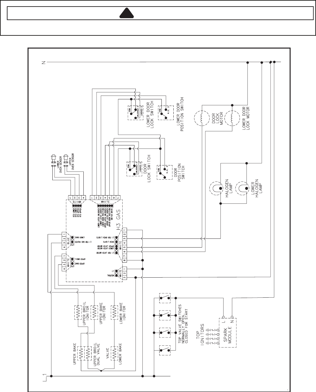
7-8
Wiring Diagram and Schematic
!WARNING
To avoid risk of electrical shock, personal injury or death; disconnect power and gas to range before servicing,
unless testing requires power and/or gas.
26372061
16023458
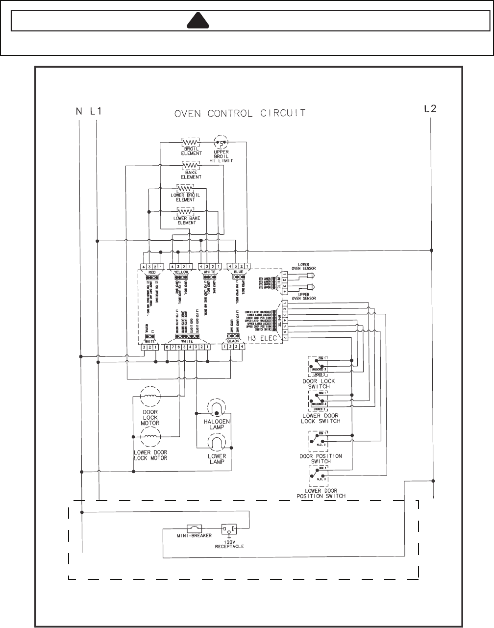
7-9
Wiring Diagram and Schematic
!WARNING
To avoid risk of electrical shock, personal injury or death; disconnect power to oven before servicing, unless
testing requires power.
15162061
16023459 16027360 16027359
If Equipped
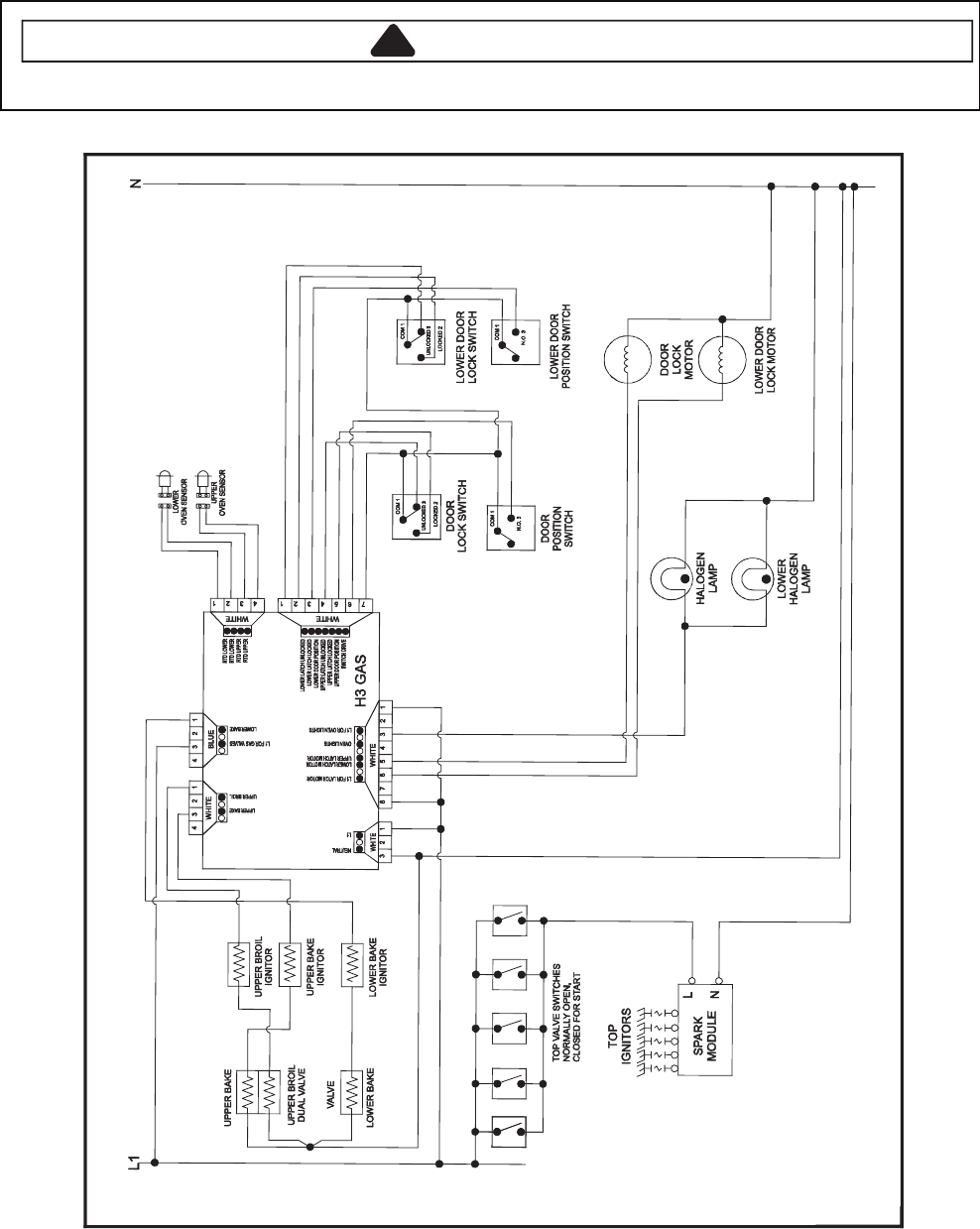
7-10
Wiring Diagram and Schematic
!WARNING
To avoid risk of electrical shock, personal injury or death; disconnect power and gas to range before servicing,
unless testing requires power and/or gas.
36372061
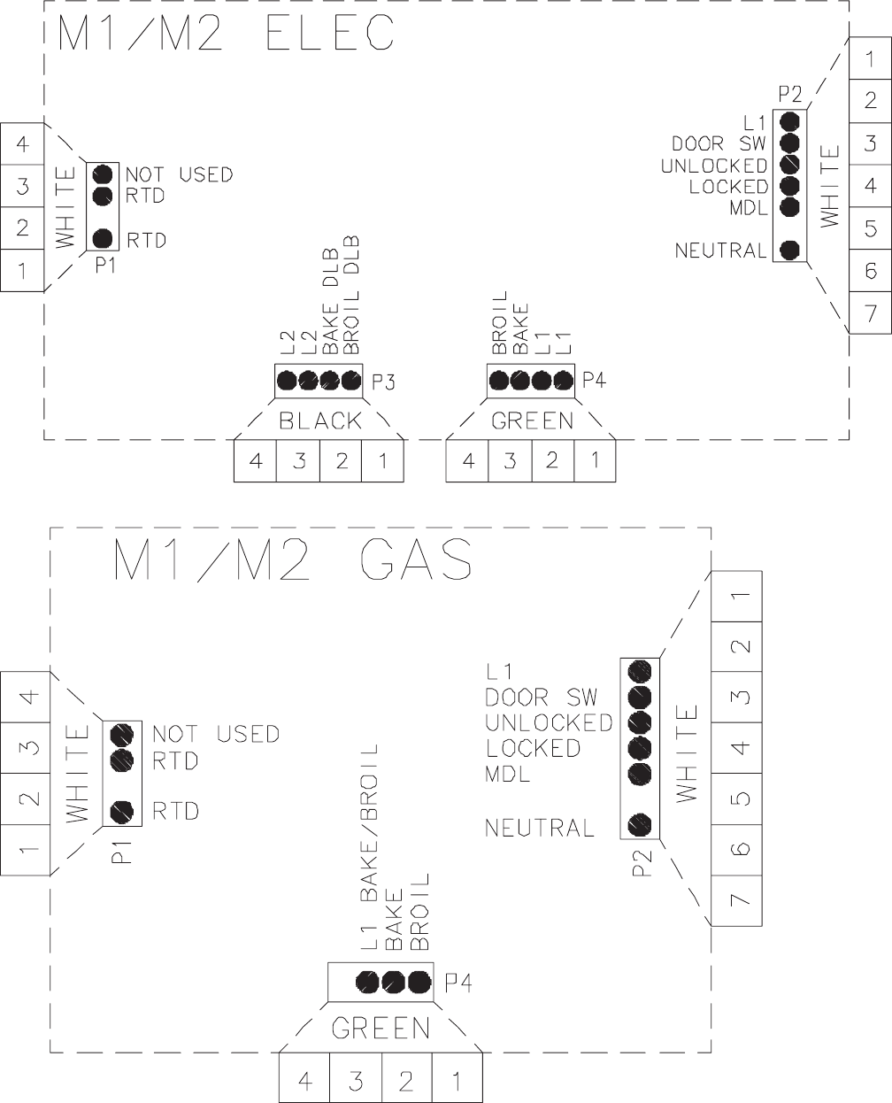
8-1
M1 / M2 CONTROLS
Pin Out Locations

8-2
Quick Test
"Quick Test" Mode for Electronic Range Control
Follow procedure below to use the quick test mode. Entries must be made within 32 seconds of each other or the
control will exit the quick test mode.
1. Press and hold
CANCEL
and
BROIL
pads for 3 seconds.
2. Once the control has entered the "Quick Test" mode, release both pads.
3. Press each of the following pads indicated in the table below.
NOTE: First time one of following pads are pressed it will activate the response.
The second time the pad is pressed it will deactivate the response.
NOTE: This mode can only be entered within the first 5 minutes after power up.
NOTE: If the temperature sensor is greater than 400° F and the Quick Test mode will be disabled if the
temperature sensor reaches 400° F while under test.
Display will indicate the following:
noitarepO yeK
[Bake] Bake relay activated
[Broil] Broil relay activated
[Keep Warm] DLB relay activated
[Cook&Hold] Last Diagnostic Code displayed
[Clean] Beep sounds
[Delay] (M1) EEPROM Version Number displayed
[Timer] Main Code Version Number displayed
[Clock] All Segments On
[More +] Even Segments On
[Less –] Odd Segments On
[Cancel] End Factory Test Mode
Diagnostic Code Display Mode can only be started within 30 seconds when powering up the control.
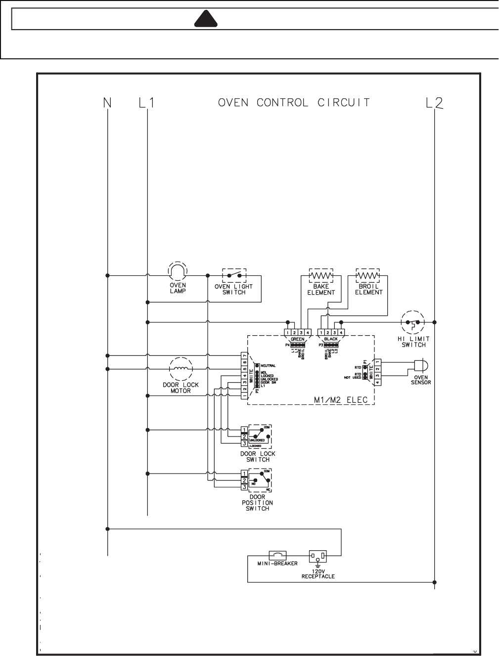
8-3
Wiring Diagram and Schematic
!WARNING
To avoid risk of electrical shock, personal injury, or death, disconnect power to range before servicing, unless
testing requires power.
16023318 16023319 16023320 16023323
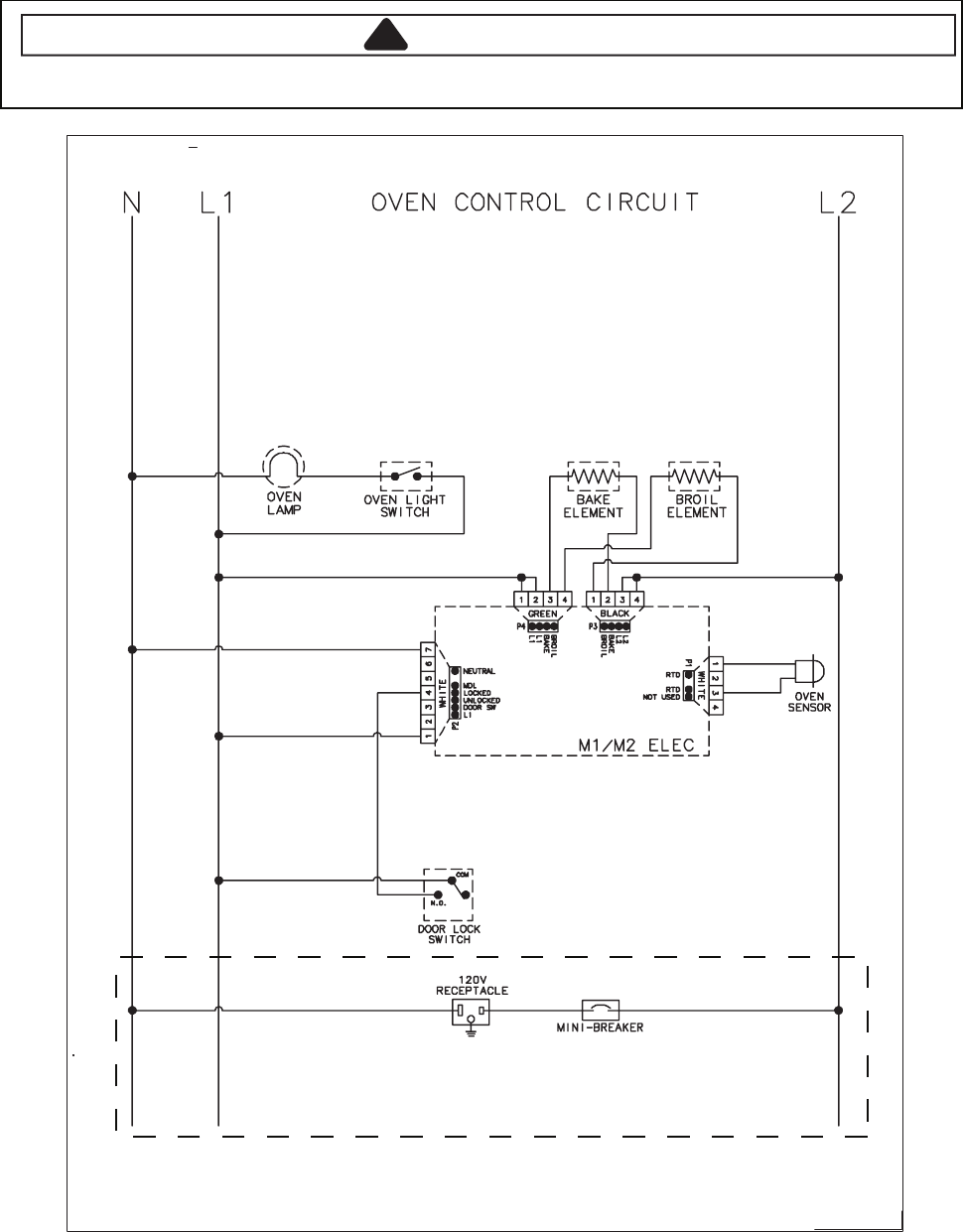
8-4
Wiring Diagram and Schematic
!WARNING
To avoid risk of electrical shock, personal injury or death; disconnect power to oven before servicing, unless
testing requires power.
If Equipped
16023530 16023531 16023534 16023539 16023481
16023542 16026105 16026484 16026485 16026543 16026686 16026688 16026689 16026691 16026813
16026978 16027074 16027075 16027144
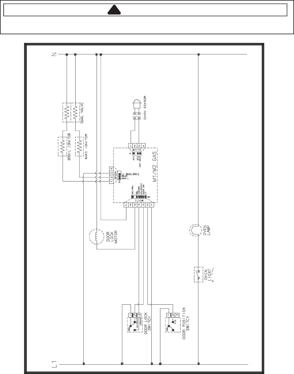
8-5
Wiring Diagram and Schematic
!WARNING
To avoid risk of electrical shock, personal injury, or death, disconnect power to oven before servicing, unless
testing requires it.
4 160225000522061
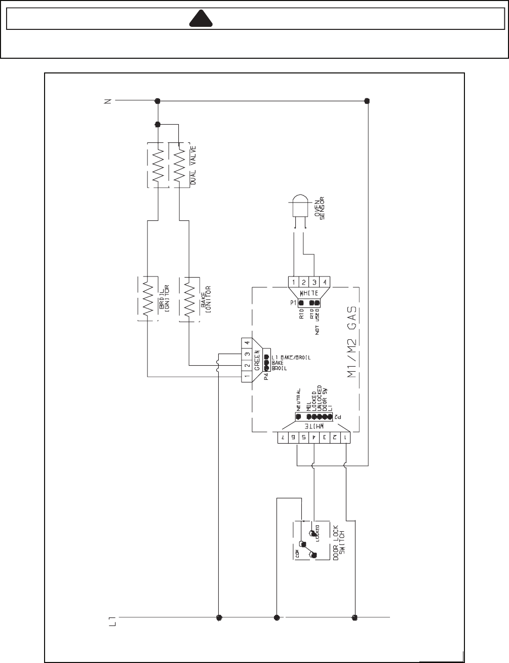
8-6
Wiring Diagram and Schematic
!WARNING
To avoid risk of electrical shock, personal injury, or death, disconnect power and gas to range before servicing,
unless testing requires power and/or gas.
48662061 16023524 16026551 16026683
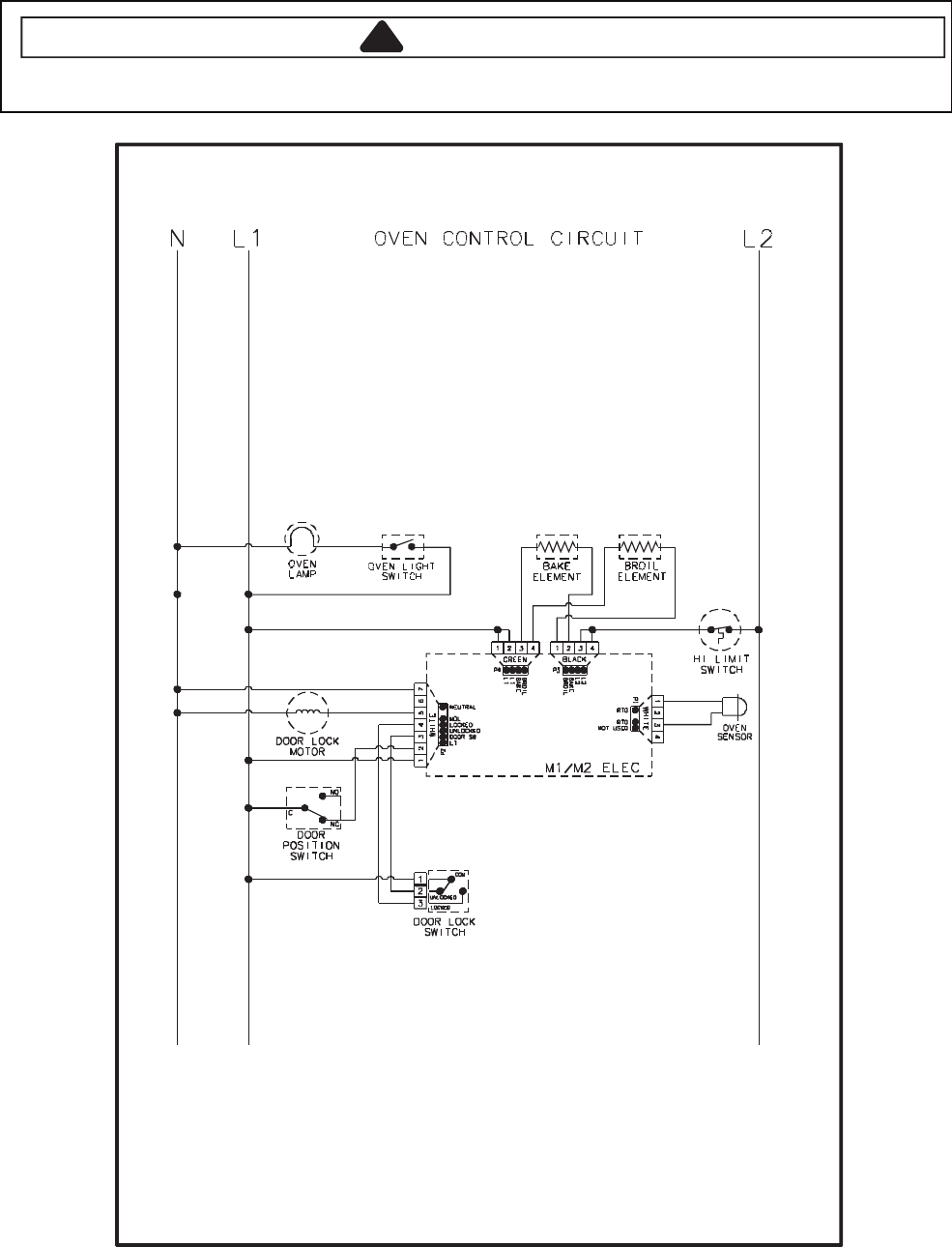
8-7
Wiring Diagram and Schematic
!WARNING
To avoid risk of electrical shock, personal injury or death; disconnect power to oven before servicing, unless
testing requires power.
84652061
16025645 16025646 16025649 16025650
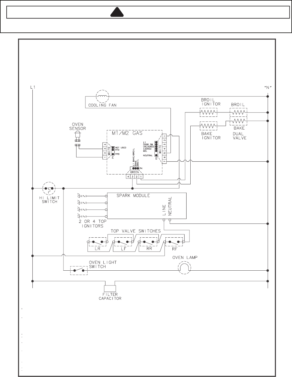
8-8
Wiring Diagram and Schematic
!WARNING
To avoid risk of electrical shock, personal injury or death; disconnect power and gas to range before servicing,
unless testing requires power and/or gas.
98262061
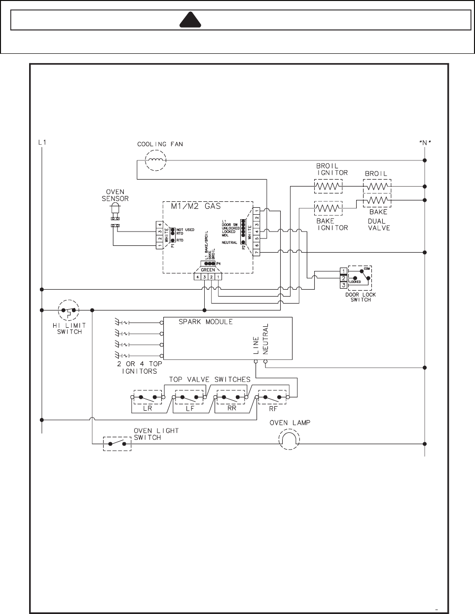
8-9
Wiring Diagram and Schematic
!WARNING
To avoid risk of electrical shock, personal injury or death; disconnect power and gas to range before servicing,
unless testing requires power and/or gas.
09262061
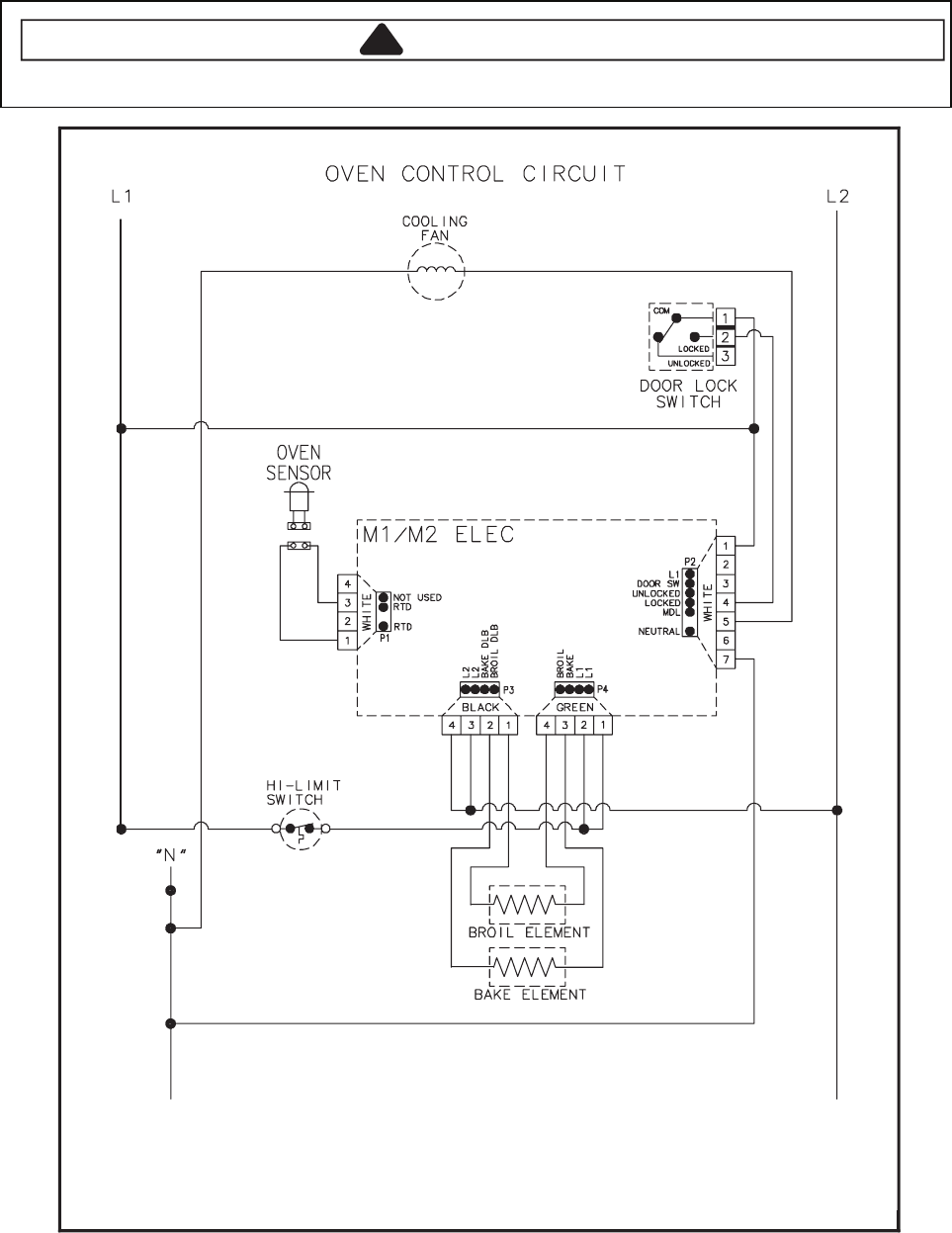
8-10
Wiring Diagram and Schematic
!WARNING
To avoid risk of electrical shock, personal injury or death; disconnect power to range before servicing, unless
testing requires power.
49262061
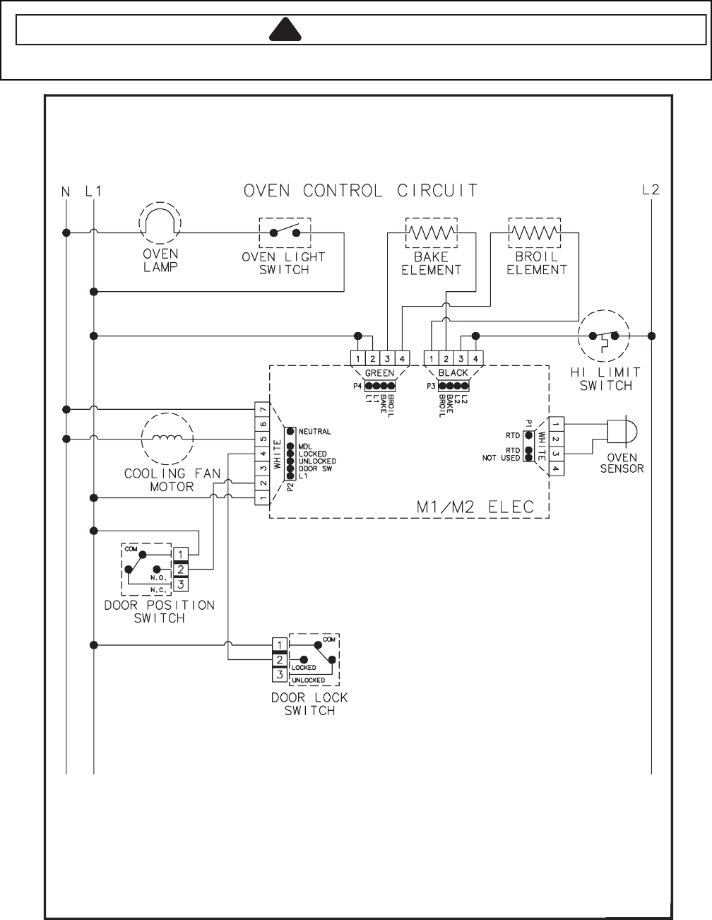
8-11
Wiring Diagram and Schematic
!WARNING
To avoid risk of electrical shock, personal injury or death; disconnect power to range before servicing, unless
testing requires power.
59262061
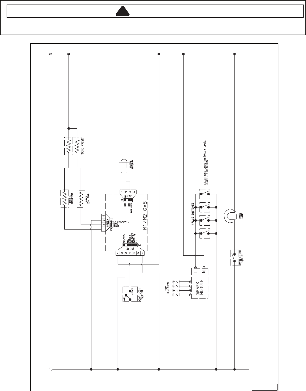
8-12
Wiring Diagram and Schematic
!WARNING
To avoid risk of electrical shock, personal injury, or death, disconnect power and gas to range before servicing,
unless testing requires power and/or gas.
19 16026106 16026792762061
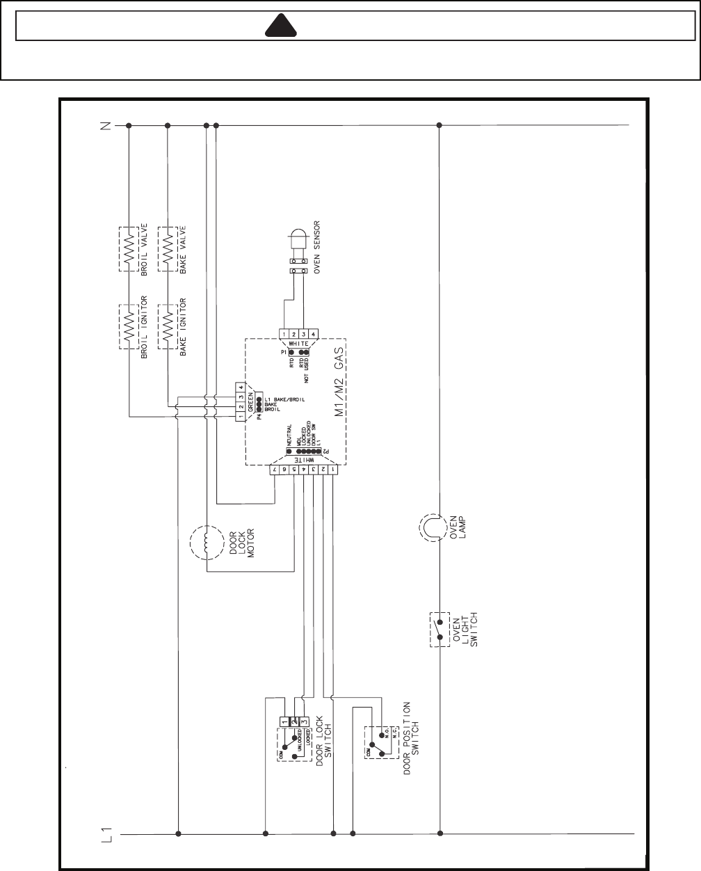
8-13
Wiring Diagram and Schematic
!WARNING
To avoid risk of electrical shock, personal injury, or death, disconnect power and gas to range before servicing,
unless testing requires power and/or gas.
79762061
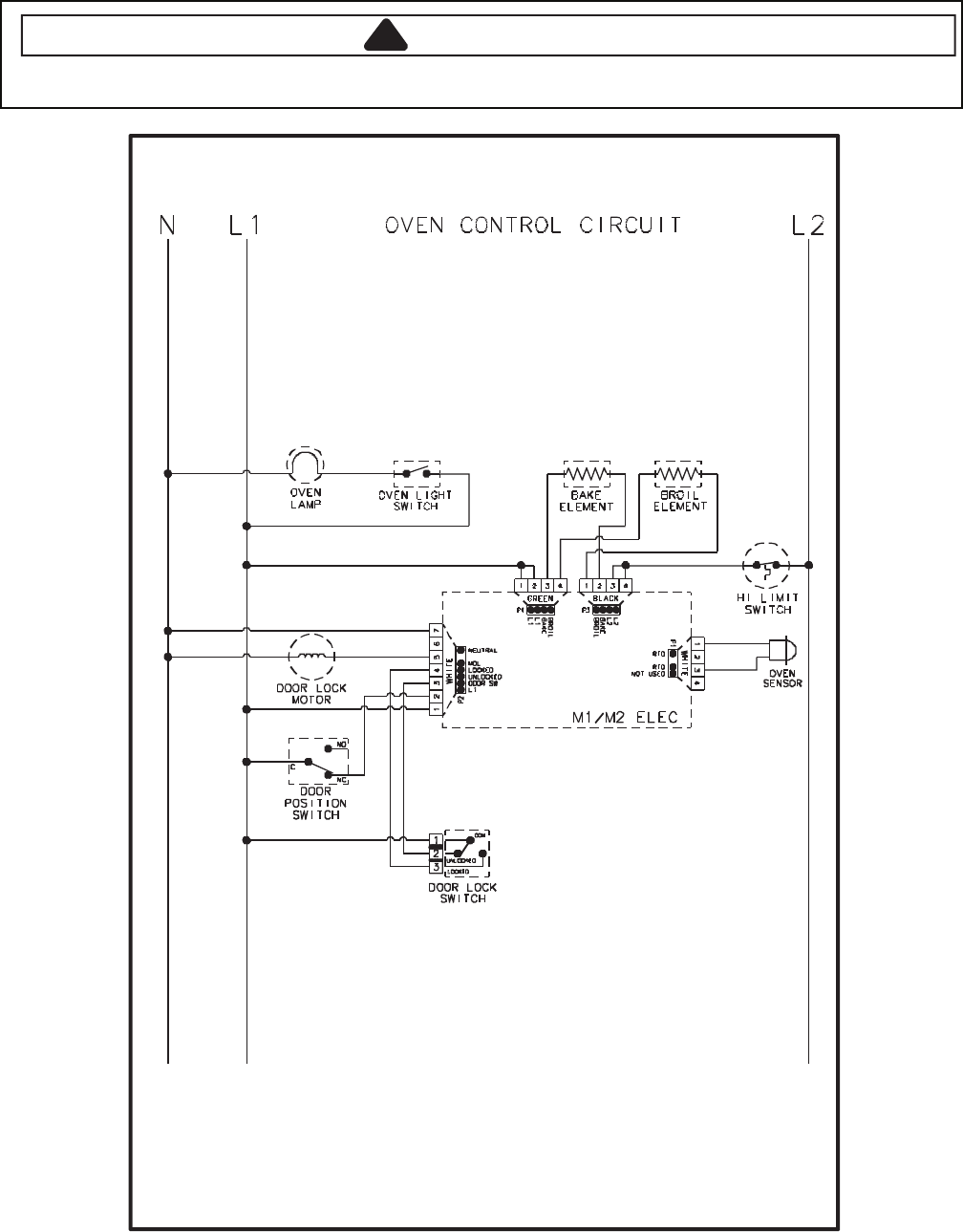
8-14
Wiring Diagram and Schematic
!WARNING
To avoid risk of electrical shock, personal injury or death; disconnect power to range before servicing, unless
testing requires power.
35862061
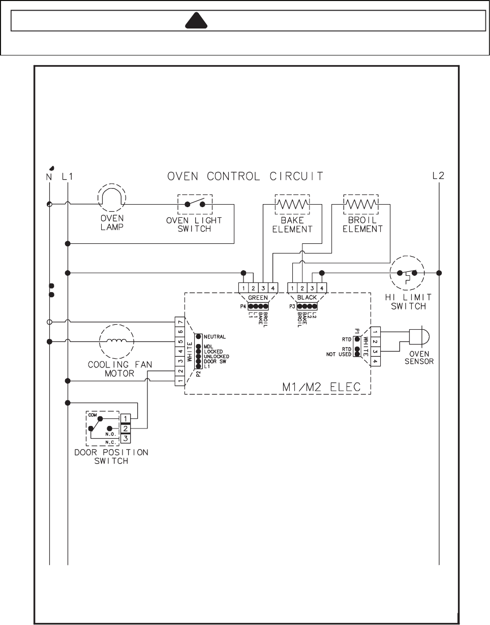
8-15
Wiring Diagram and Schematic
!WARNING
To avoid risk of electrical shock, personal injury or death; disconnect power to range before servicing, unless
testing requires power.
12272061
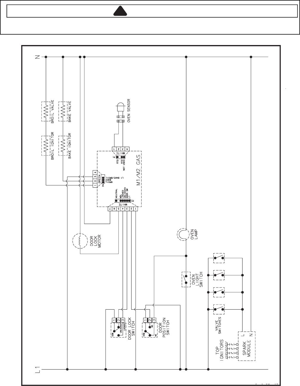
8-16
Wiring Diagram and Schematic
!WARNING
To avoid risk of electrical shock, personal injury, or death, disconnect power and gas to range before servicing,
unless testing requires power and/or gas.
22272061 16027246
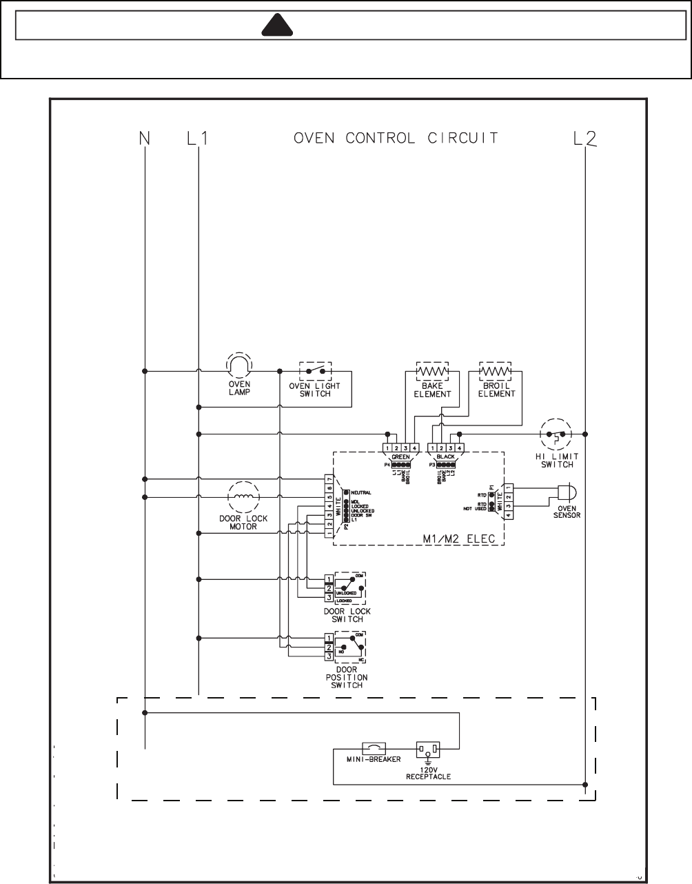
8-17
Wiring Diagram and Schematic
!WARNING
To avoid risk of electrical shock, personal injury, or death, disconnect power to range before servicing, unless
testing requires power.
16027227 16027230 16027231 16027236 16027237 16027245 16027247
If Equipped
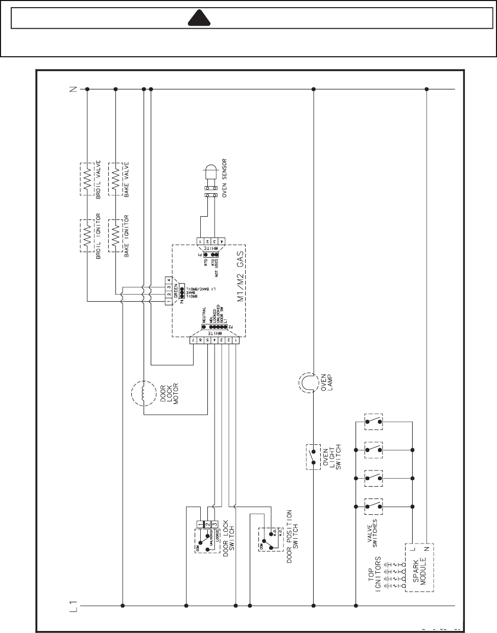
8-18
Wiring Diagram and Schematic
!WARNING
To avoid risk of electrical shock, personal injury or death; disconnect power and gas to range before servicing,
unless testing requires power and/or gas.
52272061
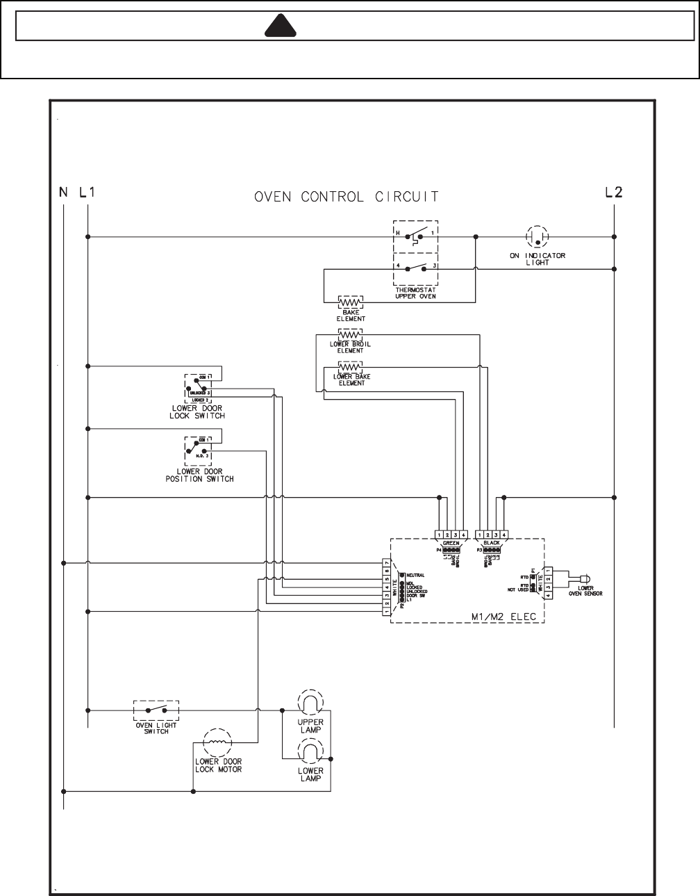
8-19
Wiring Diagram and Schematic
!WARNING
To avoid risk of electrical shock, personal injury or death; disconnect power to range before servicing, unless
testing requires power.
55272061
8-20
— NOTES —
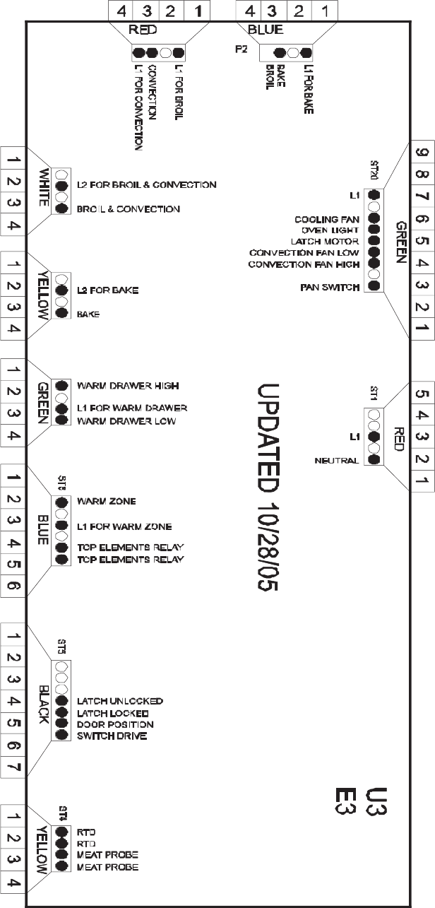
9-1
EOC III CONTROLS
Pin Out Locations

9-2
Pin Out Locations
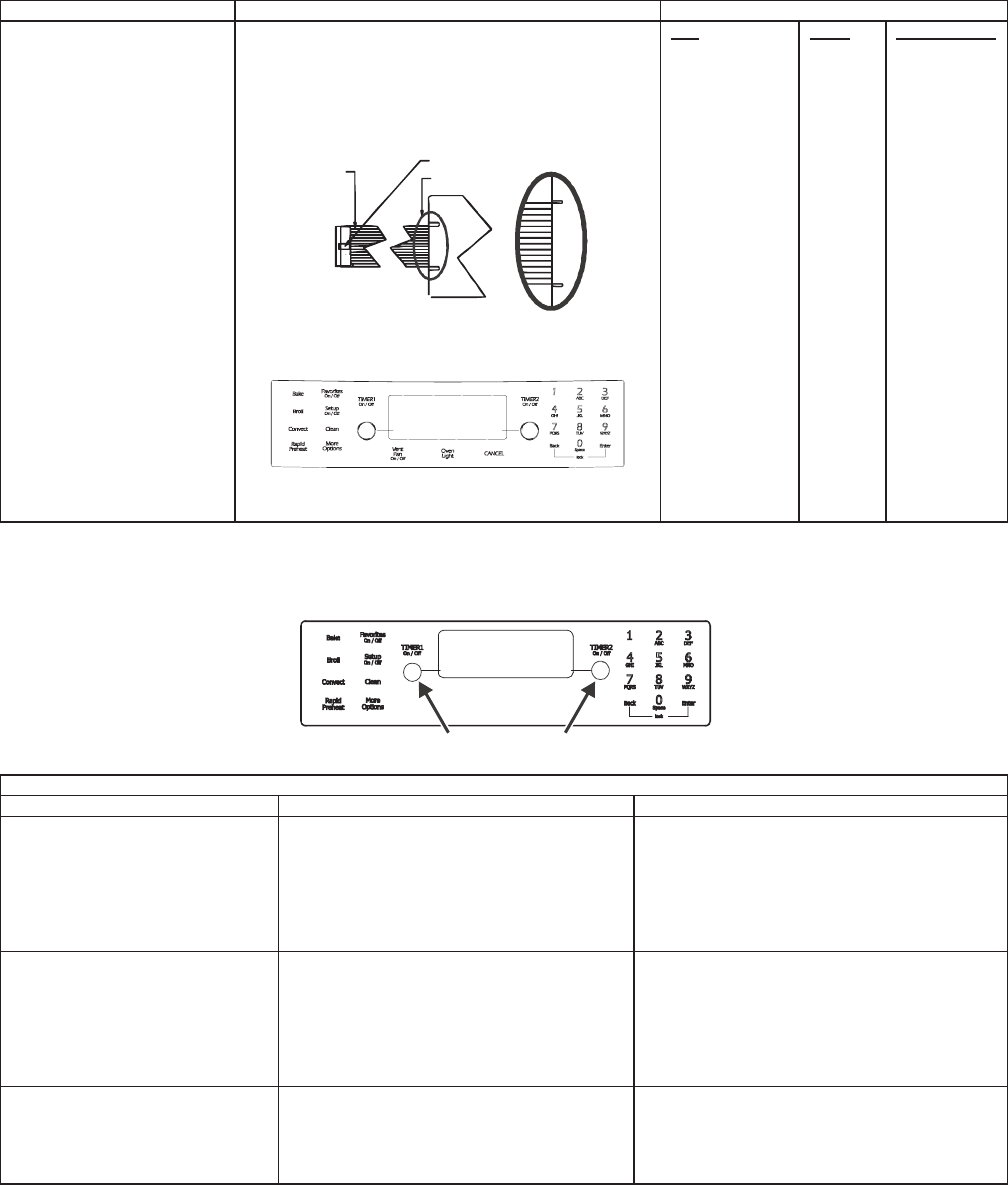
9-3
Hidden Functions
stluseR erudecorP tseT tnenopmoC lortnoC
Switch membrane assembly
NOTE: To avoid equipment
damage, use caution when
checking electronic control
circuitry.
JGS9900BD*
Closed circuitry resistance
(dened as continuity): 2000 Max Ω
Pins 1 & 10 are shorted together for control
conguration purposes
Detail B
See Detail B
Trace # 1
Latch
Pad
1
2
3
4
5
6
7
8
9
0
Cancel
Bake
Broil
Convect
Clean
Favorites
Rapid Preheat
Vent Fan
More Options
Setup
ATM 1
ATM 2
Back
Enter
Timer 1
Timer 2
Oven Light
Trace
2 & 7
2 & 8
2 & 9
2 & 10
2 & 11
2 & 12
3 & 6
3 & 7
3 & 8
2 & 6
4 & 9
4 & 10
4 & 11
5 & 9
5 & 7
4 & 12
5 & 10
5 & 11
5 & 8
5 & 6
4 & 6
4 & 7
3 & 9
3 & 10
3 & 11
3 & 12
4 & 8
Measurement
Continuity
Continuity
Continuity
Continuity
Continuity
Continuity
Continuity
Continuity
Continuity
Continuity
Continuity
Continuity
Continuity
Continuity
Continuity
Continuity
Continuity
Continuity
Continuity
Continuity
Continuity
Continuity
Continuity
Continuity
Continuity
Continuity
Continuity
Electronic Oven Control (EOC) III Testing Procedures
Warm
Drawer
ATM PADS
ELECTRONIC OVEN CONTROL (EOC) III TESTING/PROGRAMMING PROCEDURES
erudecorP noitacifidoM erudecorP sseccA erutaeF
Control Reset
Resets control to factory default
values.
Press the Setup pad, then press the right
ATM pad until SERVICE displays. Press the
left ATM pad to select SERVICE menu
options.
Press and hold the Back and Enter pads for 5
seconds to enter SERVICE menu options.
Press the right ATM pad to scroll to CONTROL
RESET. Press the left ATM pad to select
CONTROL RESET, then press the left ATM pad
again to reset the control logic. Press Setup to
exit.
Oven Temperature Adjustment
Determines oven cavity oset
temperature (range from -35° F to
+35° F, or -21° C to +21° C).
Press the Setup pad, then press the right
ATM pad until TEMP ADJUST displays.
Press the left ATM pad to select oven TEMP
ADJUSTMENT settings.
Enter the oset temperature setting desired
using the digits pads. Press the right ATM pad
for + temperature adjustment, or the left ATM
pad for – temperature adjustment. Press 0 to
reset control back to no temperature
adjustment. Wait 3 seconds for the control to
accept the request. Press Setup to exit.
Sabbath Mode
Based on the Jewish guidelines for
Sabbath/Holiday requirements.
Press the Setup pad, then press the right
ATM pad until SABBATH displays. Press the
left ATM pad to select SABBATH settings.
Press the left ATM pad to select Manual
Sabbath mode, or the right ATM pad to select
Auto Sabbath mode. Press the left ATM pad to
turn on Sabbath mode, or the right ATM pad to
turn o Sabbath mode. Press Setup to exit.

9-4
Hidden Functions
erudecorP noitacifidoM erudecorP sseccA erutaeF
Time Options
Determines control time, day of
week, 12/24 hour clock.
Press the Setup pad, then the left ATM pad
to select TIME OPTIONS.
Press the right ATM pad to scroll to the
desired function to modify.
Time Set
Determines time of day to display
on control.
Press the Setup pad, then the left ATM pad,
then the left ATM pad again to set the time of
day clock.
Enter the correct time using the digits pads
and press Enter. Press the left ATM pad to
select AM or the right ATM pad to select PM.
Press Setup to exit.
Day of Week
Determines day of week (Monday
thru Sunday) to display on control
Press the Setup pad, then the left ATM pad,
then press the right ATM pad until DAY
displays. Press the left ATM pad to set the
day of the week.
Press the right ATM pad until the correct day
displays, then press the left ATM pad to select.
Press Setup to exit.
12/24-Hour Clock Display
Determines 12-hour or 24-hour
clock display on control.
Press the Setup pad, then the left ATM pad,
then press the right ATM pad until 12/24HR
displays. Press the left ATM pad to select
12/24 HR clock.
Press the left ATM pad to select 12-hour clock,
or the right ATM pad to select 24-hour clock.
Press Setup to exit.
Clock & Day Display Disable
Determines if time of day and day of
week will display on control.
Press the Setup pad, then press the right
ATM pad until DISABLE displays. Press the
left ATM pad to select DISABLE settings.
Press the left ATM pad to select TIME, or the
right ATM pad to scroll to DAY, then press the
left ATM pad. Press the left ATM pad to turn
display on or the right ATM pad to turn display
o. Press Setup to exit.
Language Display
Determines language display on
control (English, French, Spanish).
Press the Setup pad, then press the right
ATM pad until LANGUAGE displays. Press
the left ATM pad to set LANGUAGE settings.
Press the right ATM pad until the desired
language displays (English, French, Spanish).
Press the left ATM pad. Press Setup to exit.
C/F (Celsius/Fahrenheit) Display
Determines temperature display on
control (C or F).
Press the Setup pad, then press the right
ATM pad until C/F displays. Press the left
ATM pad to select C/F settings.
Press the left ATM pad to select Celsius or the
right ATM pad to select Fahrenheit. Press
Setup to exit.
Auto Convection
When enabled, reduces the
Convection Bake and Pastry
temperatures by 25° F (-3.9° C).
Press the Setup pad, then press the right
ATM pad until AUTO CONVECT displays.
Press the left ATM pad to select AUTO
CONVECT settings.
Press the left ATM pad to turn on auto
convect, or the right ATM pad to turn o auto
convect. Press Setup to exit.
Tone Options
Determines cook tones, timer tones
and volume settings.
Press the Setup pad, then press the right
ATM pad until TONES displays. Press the
left ATM pad to select TONES options.
Press the right ATM pad to scroll to the
desired tone to modify. Press Setup to exit.
12-Hour Shutoff
Disables 12-hour shuto , allowing
the oven to operate indenitely.
Press the Setup pad, then press the right
ATM pad until 12HR Shuto displays. Press
the left ATM pad to select 12-HOUR
SHUTOFF settings.
Press the left ATM pad to turn on 12-hour
shuto, or the right ATM pad to turn o 12-
hour shuto. Press Setup to exit.
208/240 V Setting
Determines range operating voltage
(208 or 240 VAC).
Press the Setup pad, then press the right
ATM pad until 208/240 displays. Press the
left ATM pad to select 208/240 V settings.
Press the left ATM pad to select 208 VAC, or
the right ATM pad to select 240 VAC. Press
Setup to exit.
Cook Tones
Determines the number and duration
of cook time reminder chimes.
Press the Setup pad, then press the right
ATM pad until TONES displays. Press the
left ATM pad. Press the left ATM pad again
to select COOK TONES settings.
Press the left ATM pad to select 1 – 30 (1
chime every 30 seconds after the initial 4
chimes), or press the right ATM pad to scroll to
1 – 60 (1 chime every 60 seconds after the
initial 4 chimes) or 1 BEEP (no additional
chimes after the initial 4 chimes). Press the
left ATM pad to select the desired setting.
Press Setup to exit.
Timers Tones
Determines the number and
duration of timer reminder chimes.
Press the Setup pad, then press the right
ATM pad until TONES displays. Press the
left ATM pad. Press the right ATM pad to
scroll to TIMERS TONES. Press the left
ATM pad to select TIMERS TONES settings.
Press the left ATM pad to select 2 – 30, or 2
chimes every 30 seconds for up to 5 minutes
(after the initial chime), or press the right ATM
pad to scroll to 2 – 60, or 2 chimes every 60
seconds for up to 30 minutes (after the initial
chime), or 1 BEEP (no additional chimes after
the initial chime). Press the left ATM pad to
select the desired setting. Press Setup to exit.
Volume
Determines volumes of cook and
timer tones.
Press the Setup pad, then press the right
ATM pad until TONES displays. Press the
left ATM pad to select VOLUME settings.
Press the right ATM pad until VOLUME
displays. Press the left ATM pad. Press the
left ATM pad to select HIGH, or the right ATM
pad to scroll to MEDIUM or LOW. Press the
left ATM pad to select. Press Setup to exit.
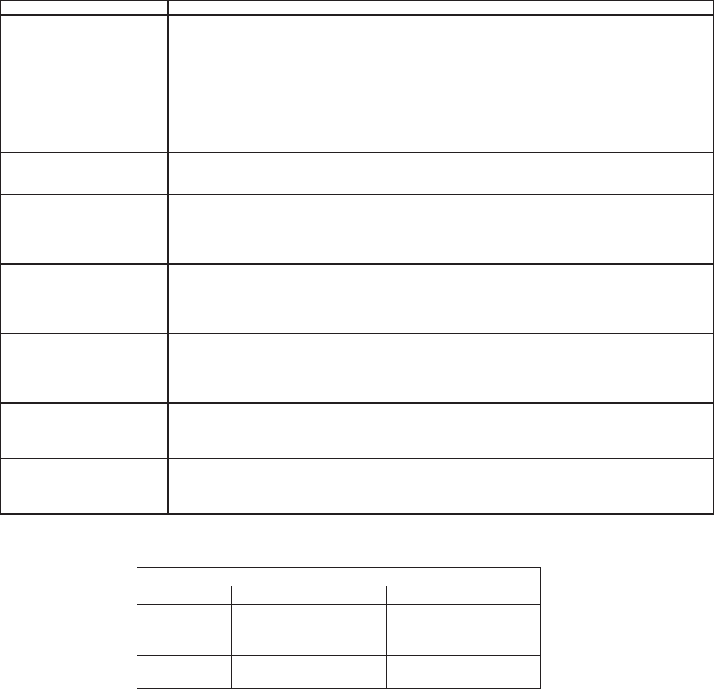
9-5
Hidden Functions
erudecorP noitacifidoM erudecorP sseccA erutaeF
Energy Saver Mode
Enables a 1 watt standby
feature. If no pad is pressed
within 5 minutes, the control
enters into a sleep mode.
Press the Setup pad, then press the right ATM
pad until ENERGY SAVER displays. Press the
left ATM pad to select ENERGY SAVER mode
settings.
Press the left ATM pad to enter the energy saver
mode or the right ATM pad to exit the energy
saver mode.
Demo Mode
Enables a 1 watt standby
feature. If no pad is pressed
within 5 minutes, the control
enters into a sleep mode.
Press the Setup pad, then press the right ATM
pad until DEMO displays. Press the left ATM
pad to select DEMO mode settings.
Press the left ATM pad to enable the DEMO
mode or the right ATM pad to exit the DEMO
mode. Once the DEMO mode begins, press any
key to exit. Press Setup to exit, also.
Service Mode
Enables access to service
menus.
Press the Setup pad, then press the right ATM
pad until SERVICE displays. Press the left ATM
pad to select SERVICE menu options.
Press and hold the Back and Enter pads for 5
seconds to enter SERVICE menu options. Press
Setup to exit.
Test Access
Enables access to service
menus.
Press the Setup pad, then press the right ATM
pad until SERVICE displays. Press the left ATM
pad to select SERVICE menu options.
Press and hold the Back and Enter pads for 5
seconds to enter SERVICE menu options. Press
the right ATM pad to scroll to TEST menu. Press
the left ATM pad to select TEST options. Press
Setup to exit.
Faults Access
Displays the 10 most recent
faults produced by the
controller.
Press the Setup pad, then press the right ATM
pad until SERVICE displays. Press the left ATM
pad to select SERVICE menu options.
Press and hold the Back and Enter pads for 5
seconds to enter SERVICE menu options. Press
the right ATM pad to scroll to the FAULTS menu.
Press the left ATM pad to select FAULTS
options. Press Setup to exit.
Software Versions Access
Displays the software and
EEPROM revision levels.
Press the Setup pad, then press the right ATM
pad until SERVICE displays. Press the left ATM
pad to select SERVICE menu options.
Press and hold the Back and Enter pads for 5
seconds to enter SERVICE menu options. Press
the right ATM pad to scroll to the VERSIONS
menu. Press the left ATM pad to view. Press
Setup to exit.
Display Test
Illuminates all lamps on the
control.
Press the Setup pad, then press the right ATM
pad until SERVICE displays. Press the left ATM
pad to select SERVICE menu options.
Press and hold the Back and Enter pads for 5
seconds to enter SERVICE menu options. Press
the right ATM pad to scroll to DISPLAY TEST.
Press the left ATM pad. Press Setup to exit.
Control Lockout
Disables the touch keypad
control and lo cks the oven
cavity door.
Press the Back and Setup pads simultaneously
for 5 seconds to lock.
Press the Back and Setup pads simultaneously
for 5 seconds to unlock.
COOLING FAN TEMPERATURES
MODE FAN ON TEMP F (C) FAN OFF TEMP F (C)
Bake 350 (177) 300 (149)
Broil Six (6) minute delay
after cycle started 225 (107)
Clean Six (6) minute delay
after cycle started 225 (107)
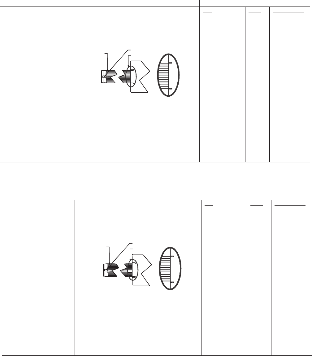
9-6
Testing the User Interface
stluseR erudecorP tseT tnenopmoC lortnoC
Switch membrane assembly
JES8850BC*
Closed circuitry resistance
(dened as continuity): 2000 Max Ω
Pins 1 & 9 are shorted together for control
conguration purposes
Detail B
See Detail B
Trace # 1
Latch
Pad
1
2
3
4
5
6
7
8
9
0
Cancel
Bake
Broil
Convect
Clean
Favorites
Rapid Preheat
Warm Zone
More Options
Setup
ATM 1
ATM 2
Back
Enter
Timer 1
Timer 2
Oven Light
Trace
2 & 7
2 & 8
2 & 9
2 & 10
2 & 11
2 & 12
3 & 6
3 & 7
3 & 8
2 & 6
4 & 9
4 & 10
4 & 11
5 & 9
5 & 7
4 & 12
5 & 10
5 & 12
5 & 8
5 & 6
4 & 6
4 & 7
3 & 9
3 & 10
3 & 11
3 & 12
4 & 8
Measurement
Continuity
Continuity
Continuity
Continuity
Continuity
Continuity
Continuity
Continuity
Continuity
Continuity
Continuity
Continuity
Continuity
Continuity
Continuity
Continuity
Continuity
Continuity
Continuity
Continuity
Continuity
Continuity
Continuity
Continuity
Continuity
Continuity
Continuity
Switch membrane assembly
JES9900BC*
JES9860BC*
Closed circuitry resistance
(dened as continuity): 2000 Max Ω
Pins 1 & 10 are shorted together for control
conguration purposes
Detail B
See Detail B
Trace # 1
Latch
Pad
1
2
3
4
5
6
7
8
9
0
Cancel
Bake
Broil
Convect
Clean
Favorites
Rapid Preheat
Vent Fan
More Options
Setup
ATM 1
ATM 2
Back
Enter
Timer 1
Timer 2
Oven Light
Trace
2 & 7
2 & 8
2 & 9
2 & 10
2 & 11
2 & 12
3 & 6
3 & 7
3 & 8
2 & 6
4 & 9
4 & 10
4 & 11
5 & 9
5 & 7
4 & 12
5 & 10
5 & 11
5 & 8
5 & 6
4 & 6
4 & 7
3 & 9
3 & 10
3 & 11
3 & 12
4 & 8
Measurement
Continuity
Continuity
Continuity
Continuity
Continuity
Continuity
Continuity
Continuity
Continuity
Continuity
Continuity
Continuity
Continuity
Continuity
Continuity
Continuity
Continuity
Continuity
Continuity
Continuity
Continuity
Continuity
Continuity
Continuity
Continuity
Continuity
Continuity
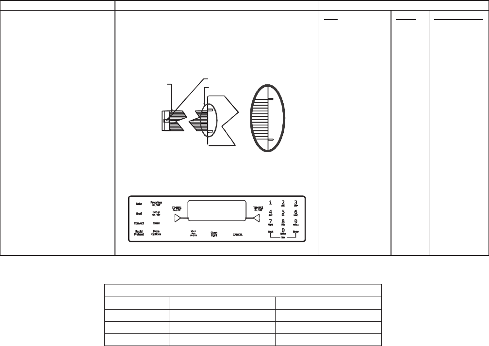
9-7
Testing the User Interface
Control Testing Procedures
stluseR erudecorP tseT tnenopmoC lortnoC
Switch membrane assembly Closed circuitry resistance
(dened as continuity): 2000 Max Ω
Pins 1 & 10 are shorted together for control
conguration purposes
Detail B
See Detail B
Trace # 1
Latch
Pad
1
2
3
4
5
6
7
8
9
0
Cancel
Bake
Broil
Clean
Convect
Favorites
Rapid Preheat
Vent Fan
More Options
Setup
ATM 1
ATM 2
Back
Enter
Timer 1
Timer 2
Oven Light
Trace
2 & 7
2 & 8
2 & 9
2 & 10
2 & 11
2 & 12
3 & 6
3 & 7
3 & 8
2 & 6
4 & 9
4 & 10
4 & 11
5 & 7
5 & 9
4 & 12
5 & 10
5 & 11
5 & 8
5 & 6
4 & 6
4 & 7
3 & 9
3 & 10
3 & 11
3 & 12
4 & 8
Measurement
Continuity
Continuity
Continuity
Continuity
Continuity
Continuity
Continuity
Continuity
Continuity
Continuity
Continuity
Continuity
Continuity
Continuity
Continuity
Continuity
Continuity
Continuity
Continuity
Continuity
Continuity
Continuity
Continuity
Continuity
Continuity
Continuity
Continuity
Cooling Fan Temperatures
COOLING FAN TEMPERATURES
MODE FAN ON TEMP F (C) FAN OFF TEMP F (C)
Bake 300° (148.9°) 275° (135°)
Broil Immediately 275° (135°)
Clean Immediately 275° (135°)
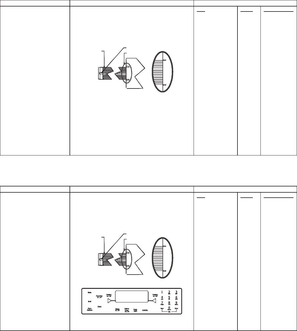
9-8
Testing the User Interface
stluseR erudecorP tseT tnenopmoC lortnoC
Switch membrane assembly
JDS9865BD*
Closed circuitry resistance
(dened as continuity): 2000 Max Ω
Pins 1 & 7 are shorted together for control
conguration purposes
Detail B
See Detail B
Trace # 1
Latch
Pad
1
2
3
4
5
6
7
8
9
0
Cancel
Bake
Broil
Convect
Clean
Favorites
Rapid Preheat
Vent Fan
More Options
Setup
ATM 1
ATM 2
Back
Enter
Timer 1
Timer 2
Oven Light
Trace
2 & 7
2 & 8
2 & 9
2 & 10
2 & 11
2 & 12
3 & 6
3 & 7
3 & 8
2 & 6
4 & 9
4 & 10
4 & 11
5 & 9
5 & 7
4 & 12
5 & 10
5 & 11
5 & 8
5 & 6
4 & 6
4 & 7
3 & 9
3 & 10
3 & 11
3 & 12
4 & 8
Measurement
Continuity
Continuity
Continuity
Continuity
Continuity
Continuity
Continuity
Continuity
Continuity
Continuity
Continuity
Continuity
Continuity
Continuity
Continuity
Continuity
Continuity
Continuity
Continuity
Continuity
Continuity
Continuity
Continuity
Continuity
Continuity
Continuity
Continuity
stluseR erudecorP tseT tnenopmoC lortnoC
Switch membrane assembly
JES8750BA*
Closed circuitry resistance
(dened as continuity): 2000 Max Ω
Pins 1 & 6 are shorted together for control
conguration purposes
Detail B
See Detail B
Trace # 1
Latch
Pad
1
2
3
4
5
6
7
8
9
0
Cancel
Bake
Broil
Clean
Favorites
More Options
Warm Zone
Setup
ATM 1
ATM 2
Back
Enter
Timer 1
Timer 2
Oven Light
Trace
2 & 7
2 & 8
2 & 9
2 & 10
2 & 11
2 & 12
3 & 6
3 & 7
3 & 8
2 & 6
4 & 9
4 & 10
4 & 11
5 & 7
4 & 12
5 & 8
5 & 12
5 & 6
4 & 6
4 & 7
3 & 9
3 & 10
3 & 11
3 & 12
4 & 8
Measurement
Continuity
Continuity
Continuity
Continuity
Continuity
Continuity
Continuity
Continuity
Continuity
Continuity
Continuity
Continuity
Continuity
Continuity
Continuity
Continuity
Continuity
Continuity
Continuity
Continuity
Continuity
Continuity
Continuity
Continuity
Continuity
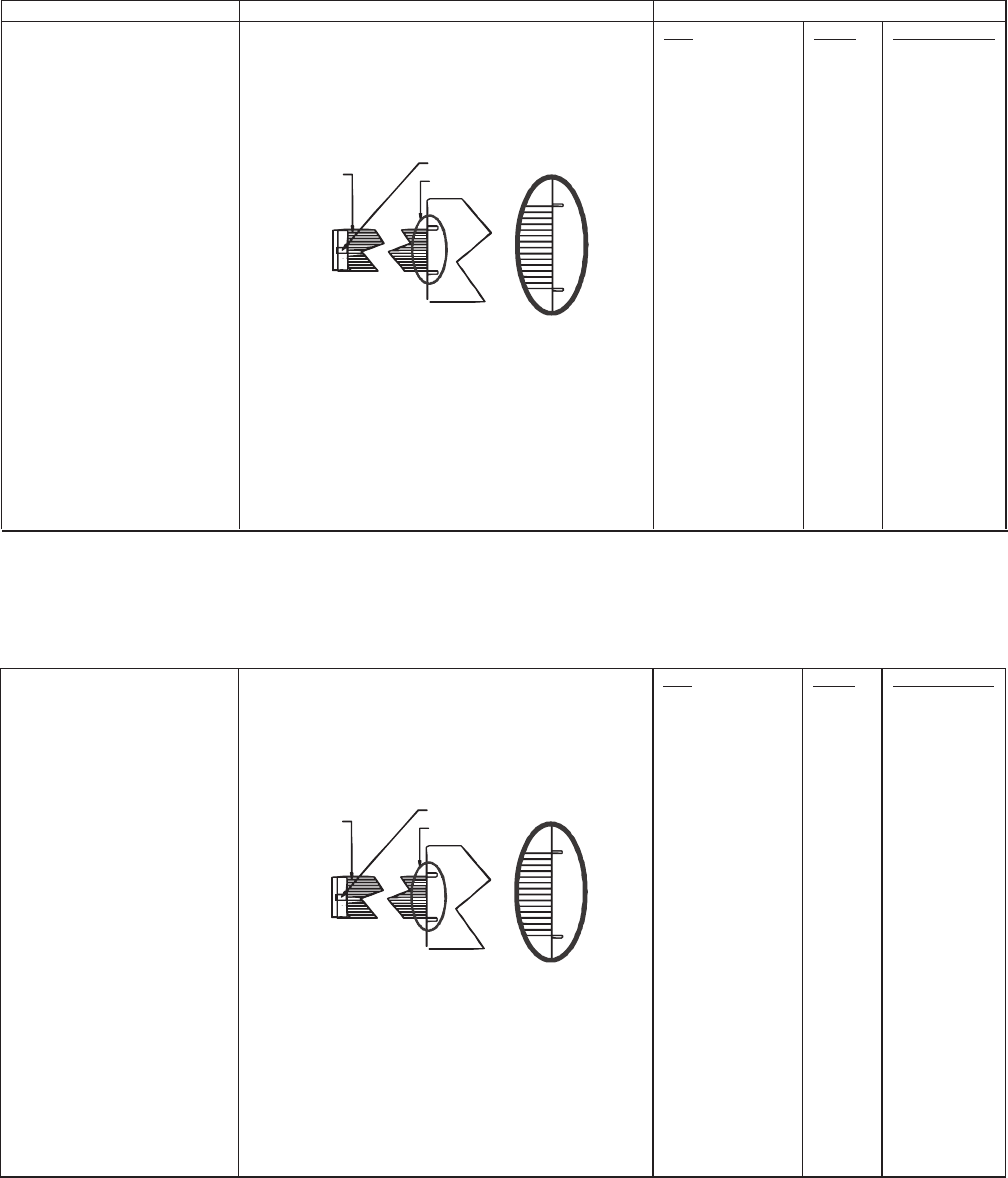
9-9
Testing the User Interface
stluseR erudecorP tseT tnenopmoC lortnoC
Switch membrane assembly
JDS8850BD*
Closed circuitry resistance
(dened as continuity): 2000 Max Ω
Pins 1 & 7 are shorted together for control
conguration purposes
Detail B
See Detail B
Trace # 1
Latch
Pad
1
2
3
4
5
6
7
8
9
0
Cancel
Bake
Broil
Convect
Clean
Favorites
Rapid Preheat
Warming Drawer
More Options
Setup
ATM 1
ATM 2
Back
Enter
Timer 1
Timer 2
Oven Light
Trace
2 & 7
2 & 8
2 & 9
2 & 10
2 & 11
2 & 12
3 & 6
3 & 7
3 & 8
2 & 6
4 & 9
4 & 10
4 & 11
5 & 9
5 & 7
4 & 12
5 & 10
5 & 11
5 & 8
5 & 6
4 & 6
4 & 7
3 & 9
3 & 10
3 & 11
3 & 12
4 & 8
Measurement
Continuity
Continuity
Continuity
Continuity
Continuity
Continuity
Continuity
Continuity
Continuity
Continuity
Continuity
Continuity
Continuity
Continuity
Continuity
Continuity
Continuity
Continuity
Continuity
Continuity
Continuity
Continuity
Continuity
Continuity
Continuity
Continuity
Continuity
Switch membrane assembly
JDS9860BD*
Closed circuitry resistance
(dened as continuity): 2000 Max Ω
Pins 1 & 7 are shorted together for control
conguration purposes
Detail B
See Detail B
Trace # 1
Latch
Pad
1
2
3
4
5
6
7
8
9
0
Cancel
Bake
Broil
Convect
Clean
Favorites
Rapid Preheat
Vent Fan
More Options
Setup
ATM 1
ATM 2
Back
Enter
Timer 1
Timer 2
Oven Light
Trace
2 & 7
2 & 8
2 & 9
2 & 10
2 & 11
2 & 12
3 & 6
3 & 7
3 & 8
2 & 6
4 & 9
4 & 10
4 & 11
5 & 9
5 & 7
4 & 12
5 & 10
5 & 11
5 & 8
5 & 6
4 & 6
4 & 7
3 & 9
3 & 10
3 & 11
3 & 12
4 & 8
Measurement
Continuity
Continuity
Continuity
Continuity
Continuity
Continuity
Continuity
Continuity
Continuity
Continuity
Continuity
Continuity
Continuity
Continuity
Continuity
Continuity
Continuity
Continuity
Continuity
Continuity
Continuity
Continuity
Continuity
Continuity
Continuity
Continuity
Continuity
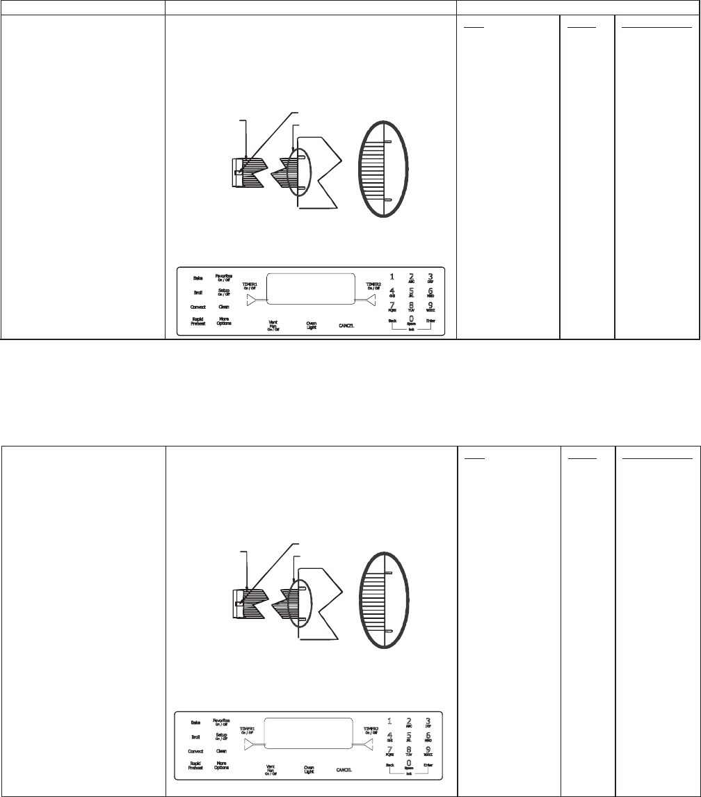
9-10
Testing the User Interface
stluseR erudecorP tseT tnenopmoC lortnoC
Switch membrane assembly
JES9750BA*
Closed circuitry resistance
(dened as continuity): 2000 Max Ω
Pins 1 & 11 are shorted together for control
conguration purposes
Detail B
See Detail B
Trace # 1
Latch
Pad
1
2
3
4
5
6
7
8
9
0
Cancel
Bake
Broil
Clean
Favorites
Vent Fan
More Options
Setup
ATM 1
ATM 2
Back
Enter
Timer 1
Timer 2
Oven Light
Trace
2 & 7
2 & 8
2 & 9
2 & 10
2 & 11
2 & 12
3 & 6
3 & 7
3 & 8
2 & 6
4 & 9
4 & 10
4 & 11
5 & 7
4 & 12
5 & 11
5 & 8
5 & 6
4 & 6
4 & 7
3 & 9
3 & 10
3 & 11
3 & 12
4 & 8
Measurement
Continuity
Continuity
Continuity
Continuity
Continuity
Continuity
Continuity
Continuity
Continuity
Continuity
Continuity
Continuity
Continuity
Continuity
Continuity
Continuity
Continuity
Continuity
Continuity
Continuity
Continuity
Continuity
Continuity
Continuity
Continuity
Switch membrane assembly
JES9860BA*
Closed circuitry resistance
(dened as continuity): 2000 Max Ω
Pins 1 & 10 are shorted together for control
conguration purposes
Detail B
See Detail B
Trace # 1
Latch
Pad
1
2
3
4
5
6
7
8
9
0
Cancel
Bake
Broil
Convect
Clean
Favorites
Rapid Preheat
Vent Fan
More Options
Setup
ATM 1
ATM 2
Back
Enter
Timer 1
Timer 2
Oven Light
Trace
2 & 7
2 & 8
2 & 9
2 & 10
2 & 11
2 & 12
3 & 6
3 & 7
3 & 8
2 & 6
4 & 9
4 & 10
4 & 11
5 & 9
5 & 7
4 & 12
5 & 10
5 & 11
5 & 8
5 & 6
4 & 6
4 & 7
3 & 9
3 & 10
3 & 11
3 & 12
4 & 8
Measurement
Continuity
Continuity
Continuity
Continuity
Continuity
Continuity
Continuity
Continuity
Continuity
Continuity
Continuity
Continuity
Continuity
Continuity
Continuity
Continuity
Continuity
Continuity
Continuity
Continuity
Continuity
Continuity
Continuity
Continuity
Continuity
Continuity
Continuity
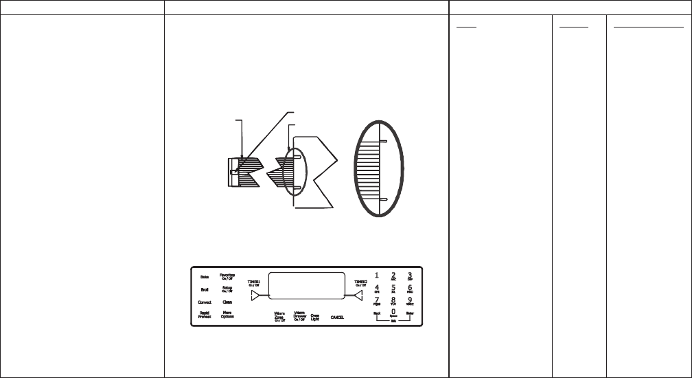
9-11
Testing the User Interface
stluseR erudecorP tseT tnenopmoC lortnoC
Switch membrane assembly
JES8850BA*
Closed circuitry resistance
(dened as continuity): 2000 Max Ω
Pins 1 & 9 are shorted together for control
conguration purposes
Detail B
See Detail B
Trace # 1
Latch
Pad
1
2
3
4
5
6
7
8
9
0
Cancel
Bake
Broil
Convect
Clean
Favorites
Rapid Preheat
Warm Drawer
Warm Zone
More Options
Setup
ATM 1
ATM 2
Back
Enter
Timer 1
Timer 2
Oven Light
Trace
2 & 7
2 & 8
2 & 9
2 & 10
2 & 11
2 & 12
3 & 6
3 & 7
3 & 8
2 & 6
4 & 9
4 & 10
4 & 11
5 & 9
5 & 7
4 & 12
5 & 10
5 & 11
5 & 12
5 & 8
5 & 6
4 & 6
4 & 7
3 & 9
3 & 10
3 & 11
3 & 12
4 & 8
Measurement
Continuity
Continuity
Continuity
Continuity
Continuity
Continuity
Continuity
Continuity
Continuity
Continuity
Continuity
Continuity
Continuity
Continuity
Continuity
Continuity
Continuity
Continuity
Continuity
Continuity
Continuity
Continuity
Continuity
Continuity
Continuity
Continuity
Continuity
Continuity

9-12
Quick Test
"Quick Test" Mode for EOC III
Follow the procedure below to perform the EOC III quick test. Once the control is in the quick test mode, any relay
may be activated in any sequence. The test mode will be exited after 10 minutes of inactivity (no pads pressed
within 10 minutes).
1. Press the Setup pad, then press the right ATM pad.
2. Press the left ATM pad, then press and hold Back and Enter pads for 5 seconds to enter SERVICE menu options.
3. Press the right ATM pad to scroll to the TEST menu.
4. Press the left ATM pad to select TEST options.
5. Press the left ATM pad again to enter the "Quick Test " mode.
6. Press each of the following pads indicated in the table below.
7. Press Cancel or Setup pads to exit.
NOTE: Press and hold the applicable pad to activate the associated response.
Release the applicable pad to deactivate the associated response.
T
he control automatically enters the engineering mode so vi sual feedback of relay operations is available on the
control display. Any time a load is activated, the cooling fan is activated. When the load is deactivated, the cooling
fan is also deactivated.
Display will indicate the following:
esnopseR daP
BAKE....................................................Bake relay activated.
BROIL ..................................................Broil relay activated.
CONVECT ...........................................Convection Bake and C ooling Fan relays activated.
OVEN LIGHT .......................................Oven light relay activated.
RAPID PREHEAT ................................Convection Fan (HIGH/LOW) activated.
WARMING ZONE ................................Warming Zone relay activated.
VENT (DOWNDRAFT) FAN ................Vent Fan relay activated.
CLEAN .................................................Motorized Door Lock relay activated.
SETUP .................................................1 Second Beep.
FAN ......................................................Downdraft Fan (HIGH/LOW) relay activated.
WARMING DRAWER ..........................Warming Drawer (HIGH/LOW) relay activated.
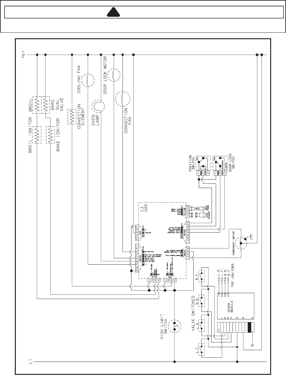
9-13
Wiring Diagram and Schematic
!WARNING
To avoid risk of electrical shock, personal injury or death; disconnect power and gas to rangebefore servicing,
unless testing requires power and/or gas.
52962061
16026924
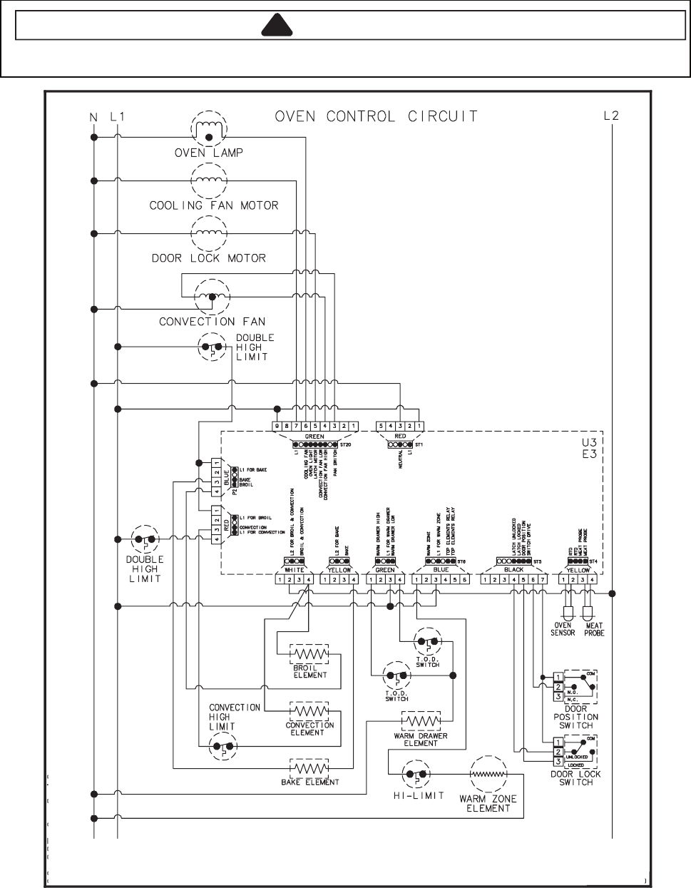
9-14
Wiring Diagram and Schematic
!WARNING
To avoid risk of electrical shock, personal injury or death; disconnect power to range before servicing, unless
testing requires power.
72962061
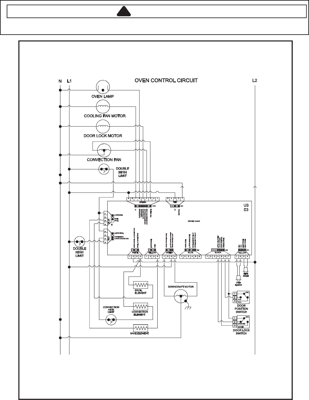
9-15
Wiring Diagram and Schematic
!WARNING
To avoid risk of electrical shock, personal injury or death; disconnect power to range before servicing, unless
testing requires power.
82962061
16026930 16027004 16027013
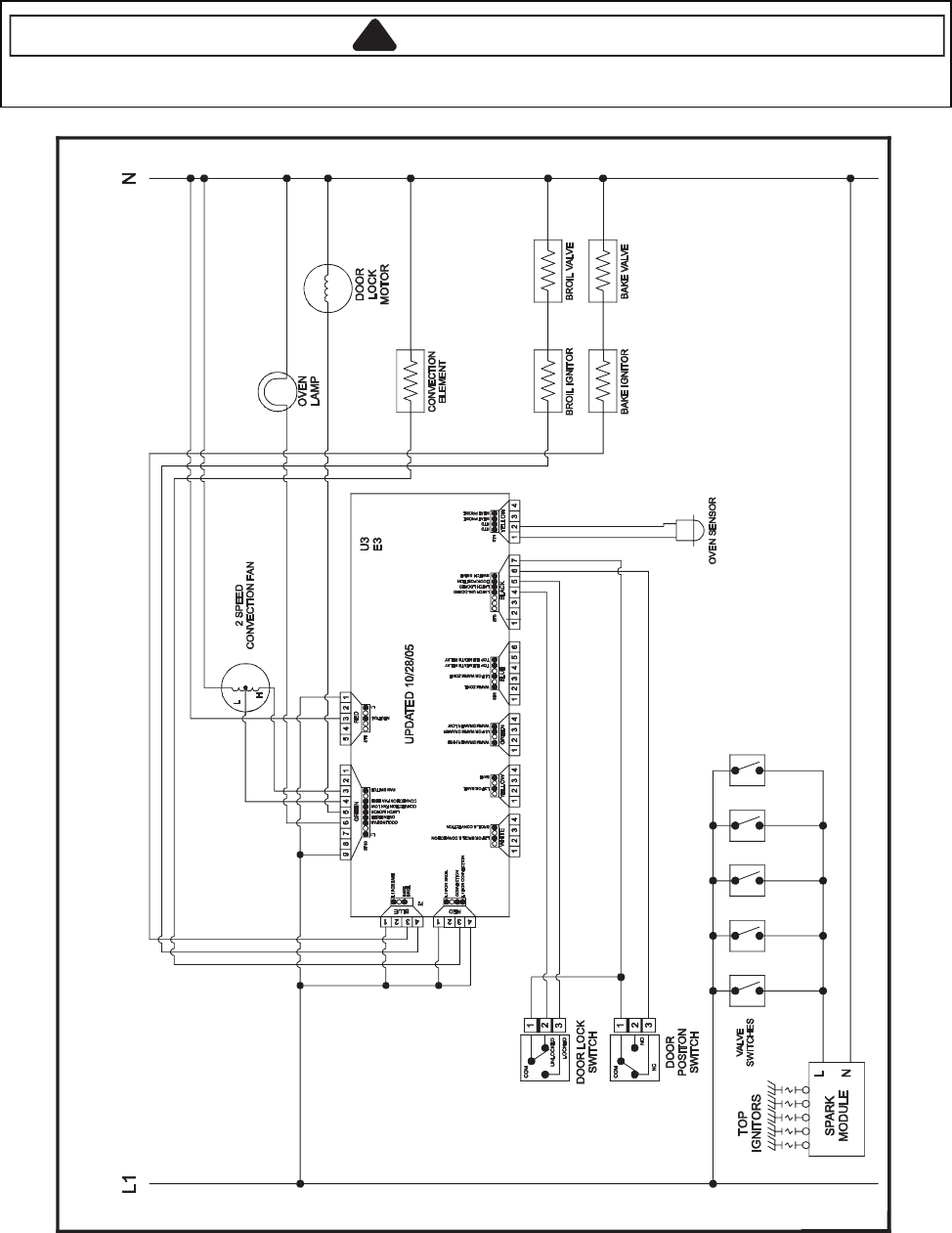
9-16
Wiring Diagram and Schematic
!WARNING
To avoid risk of electrical shock, personal injury or death; disconnect power and gas to range before servicing,
unless testing requires power and/or gas.
84272061
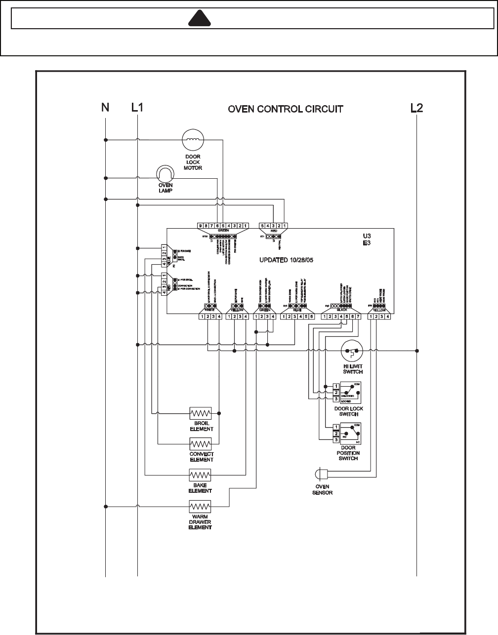
9-17
Wiring Diagram and Schematic
!WARNING
To avoid risk of electrical shock, personal injury or death; disconnect power to range before servicing, unless
testing requires power.
60372061

9-18
Wiring Diagram and Schematic
!WARNING
To avoid risk of electrical shock, personal injury or death; disconnect power to range before servicing, unless
testing requires power.
70372061
16027308
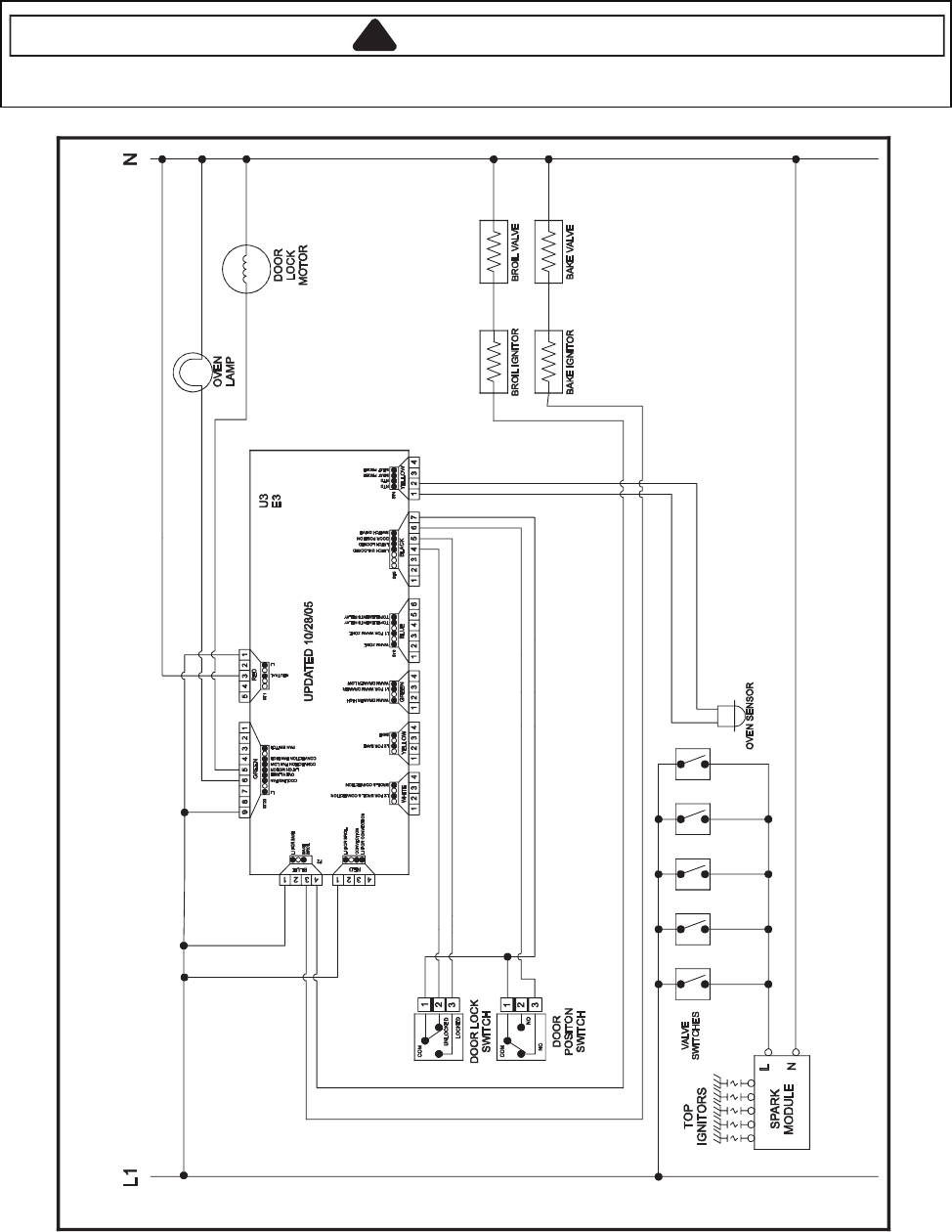
9-19
Wiring Diagram and Schematic
!WARNING
To avoid risk of electrical shock, personal injury or death; disconnect power and gas to range before servicing,
unless testing requires power and/or gas.
90372061
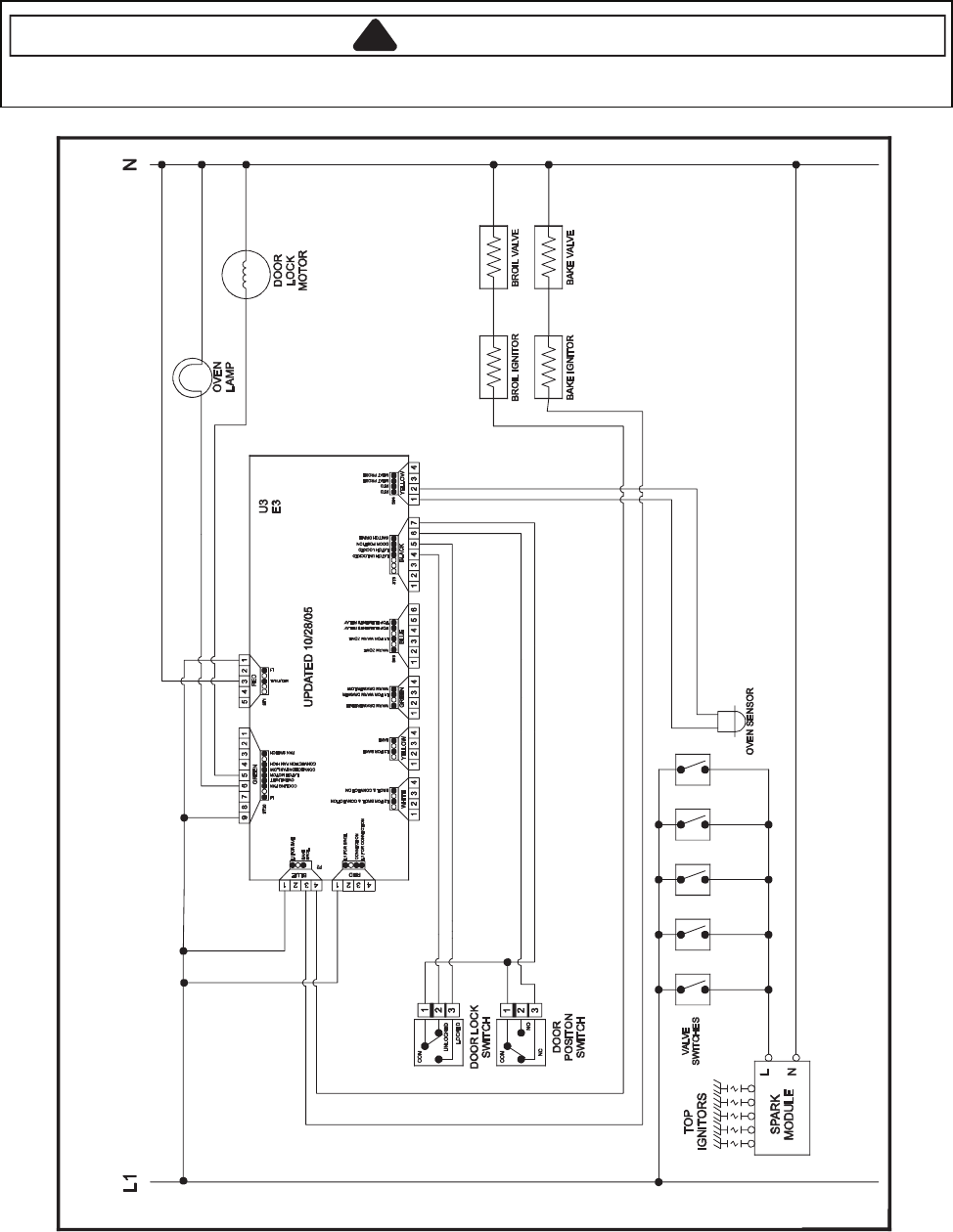
9-20
Wiring Diagram and Schematic
!WARNING
To avoid risk of electrical shock, personal injury or death; disconnect power and gas to range before servicing,
unless testing requires power and/or gas.
01372061

10-1
UH CONTROLS
Pin Out Locations

10-2
Hidden Functions
Illustrati stluseR erudecorP tseT tnenopmoC no
UH2 Controlled Oven temperature
adjustment
Press SETUP pad.
Press DOWN ARROW to scroll down
to TEMP ADJUST.
Select oven and enter desired
temperature change. Press ENTER
pad to accept the change.
Oven can be adjusted from -35 to +35
degrees inputting 5 or 35 degrees by
pressing +/- pad. To avoid over
adjusting the oven, move temperature
5 degrees each time. Wait 4 seconds
for the data entry timer to expire to
accept the change. Temperature
adjustment will be retained even
through a power failure.
While increasing or decreasing oven
temperature, this does not affect broiling
or self-cleaning temperature.
The oven offset does not need to be
readjusted if there is a power failure.
UH2 Controlled Temperature display Press SETUP pad and use the arrow
pad to scroll to the next screen. Select
C/F, then select SET. Press SETUP
pad to exit.
This mode enables the user to indicate
°F or °C on the display.
UH2 Controlled Clock Display Press SETUP pad. Press CLOCK
pad. Press TIME and enter numeric
from key pad. Select AM or PM.
Press SETUP to end. Press SETUP
pad. Press CLOCKpad. Press DAY
pad. Press back forward to select day
of week. Press SETUP to end. Press
SETUP pad. Press CLOCKpad.
Scroll down to 12/24 HR. Scroll down
to 12/24 HR format. Select SETto
activate. Press SETUP pad to exit.
Press DOWN ARROW pad to scroll
to CLOCK.
Set clock, day of week, or 12/24 HR
clock.
UH2 Controlled 12 Hour Shutoff Press SETUP pad. Press DOWN
ARROW pad to scroll to 12 HOUR
SHUTOFF pad. Select ON or OFF.
Select SET pad to activate. Press
SETUP pad to exit.
Allows the time on the clock to be
toggled from 12 hour or 24 hour display.
UH2 Controlled Demo mode Press SETUP pad. Press DOWN
ARROW pad to scroll to DEMO pad.
Select DEMO to activate. Press
SETUP pad to exit.
Control will automatically cancel any
cooking operation and remove all relay
drives 12 hours after the last pad touch.
UH2 Controlled Energy Saver Press SETUP pad. Press DOWN
ARROW pad to scroll to ENERGY
SAVER pad. Select ON or OFF.
Select SET pad to activate. Press
SETUP pad to exit.
To save energy, the display will turn off
after five minutes of no use in time of day
mode only.
UH2 Controlled 208/240 V mode Press SETUP pad. Press DOWN
ARROW pad to scroll to 208/240 V
pad. Select 208or 240. Select SET
pad to activate.
For improved results when using Radiant
Bake only, the oven can be set from 240
V to 208 V.
UH2 Controlled Control Lockout Press and hold BACK and ENTER
pads for 5 seconds.
To reactivate the control, press and
hold BACK and ENTERpads for 5
seconds.
This is a safety feature that can be used
to prevent accidentally programming the
oven. It disables the electronic oven
control and locks the cavity door(s).
Control lockout features must be reset
after a power failure.
10-3
Test Mode
UH2 Controlled Sabbath Mode Press SETUP pad. Press DOWN
ARROW pad. Press SABBATH pad to
activate Sabbath mode.
Select AUTO or MANUAL pad. If
AUTO selected, press continue. If
MANUAL selected, press ON or OFF.
Select SET pad.
The time of day and day of week must
be set correctly for this feature to be
activated.
Auto-Sabbath mode will display a
reminder at 2:00 PM on Friday.
Manual-Sabbath mode will be instantly
programmed for 72 hours.
This mode disables the normal 12 hour
energy saving mode.
Test Mode
Follow procedure below to access the Test Mode.
1. Press SETUP pad.
2. Press DOWN ARROW pad three times until SERVICE is displayed.
3. Press SERVICE pad.
4. Press and hold BACK and ENTER pads for 5 seconds.
5. Press TEST pad.
NOTE: If the oven cavity temperature is greater then 400°F, the Test Mode cannot be activated or will abort the
mode if activated.
NOTE: Once the Test Mode is activated and a function is selected the control will activate the relay until the pad is
pressed again. Upon entering TEST Mode all relays are turned off except the DLB relays, which are turned
on. All relays are turned off when the TEST Mode is exited.
Pad Pressed detavitcA noitcA ro yaleR
peeB dnoceS 1 peeB
erawtfos fo noisreV noisreV
Last Fault Display last error code and oven configuration (single, double, convection, nonconvection)
stnemges yalpsiD tseT PSID
reppU EKABU Bake Element
tnemelE liorB reppU LIORBU
tnemelE noitcevnoC reppU VNOCU
naF gnilooC reppU LOOCU
naF noitcevnoC deepS hgiH reppU H-VNOCU
naF noitcevnoC deepS woL reppU L-VNOCU
kcoL rooD dezirotoM reppU LDMU
thgiL nevO reppU ETILU
tnemelE ekaB rewoL EKABL
tnemelE liorB rewoL LIORBL
tnemelE noitcevnoC rewoL VNOCL
naF gnilooC rewoL LOOCL
naF noitcevnoC deepS hgiH rewoL H-VNOCL
naF noitcevnoC deepS woL rewoL L-VNOCL
kcoL rooD dezirotoM rewoL LDML
thgiL nevO rewoL ETILL
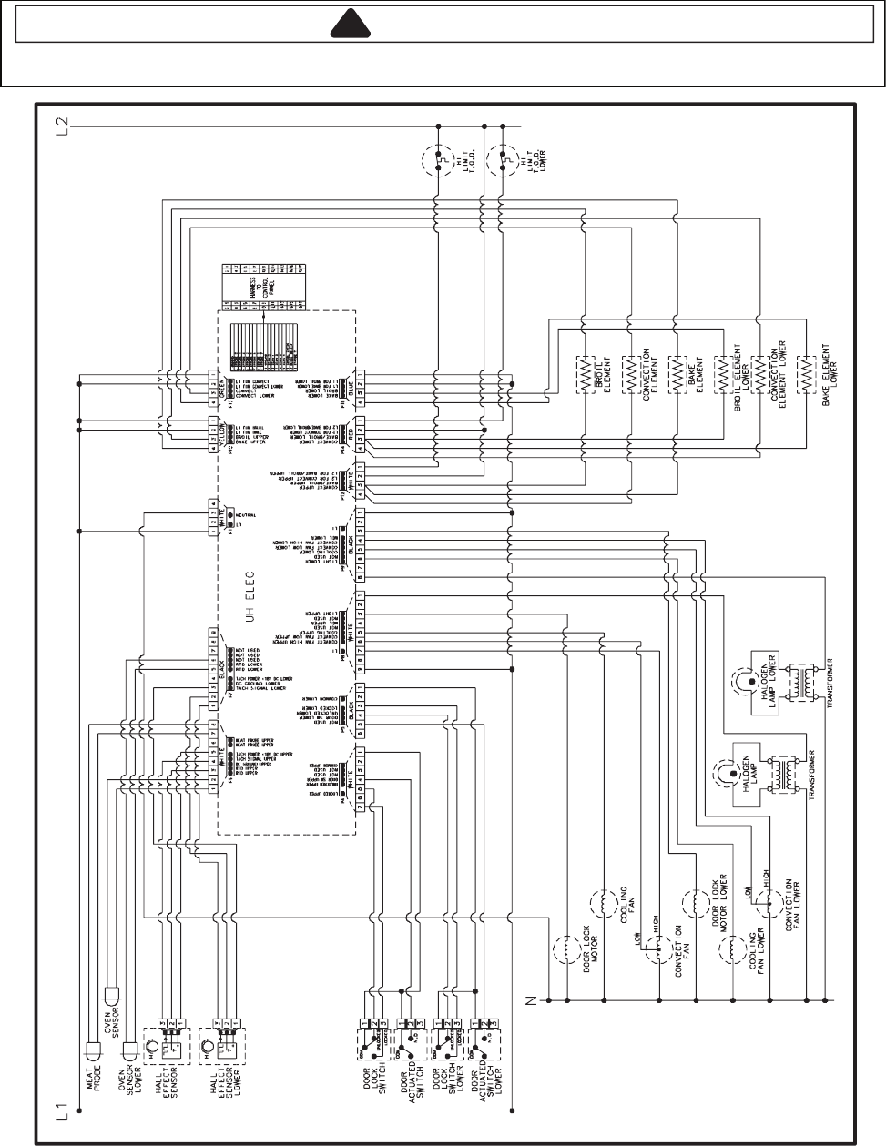
10-4
Wiring Diagram and Schematic
!
WARNING
To avoid risk of electrical shock, personal injury or death; disconnect power to oven before servicing, unless
testing requires it.
21522061
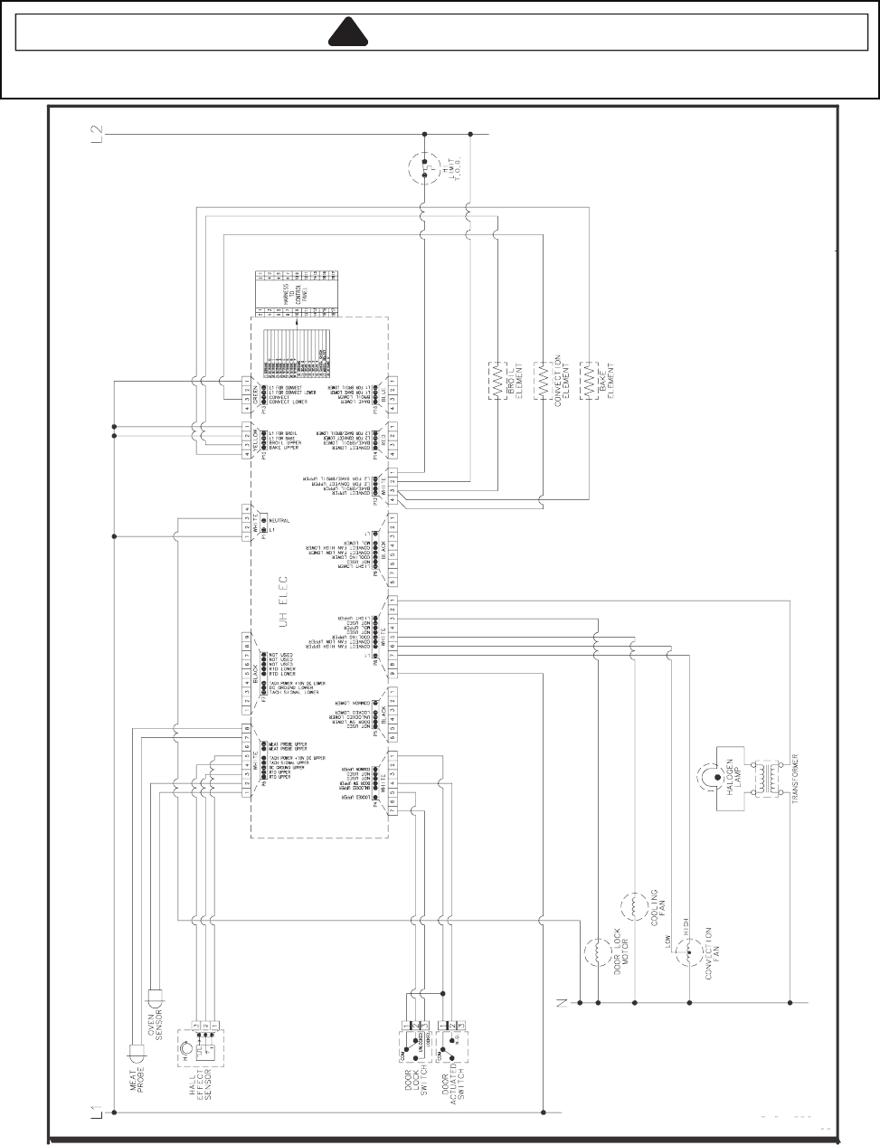
10-5
Wiring Diagram and Schematic
!
WARNING
To avoid risk of electrical shock, personal injury or death; disconnect power to oven before servicing, unless
testing requires power.
10162061
Control Circuits
16022823
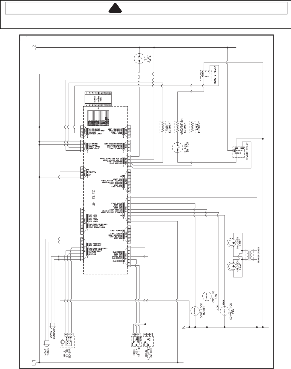
10-6
Wiring Diagram and Schematic
!
WARNING
To avoid risk of electrical shock, personal injury or death; disconnect power to oven before servicing, unless
testing requires power.
48852061
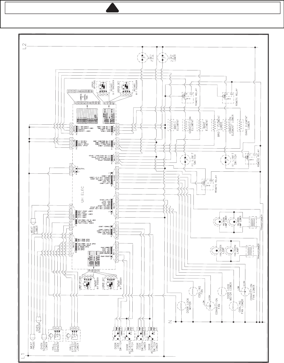
10-7
Wiring Diagram and Schematic
!
WARNING
To avoid risk of electrical shock, personal injury or death; disconnect power to oven before servicing, unless
testing requires power.
58852061
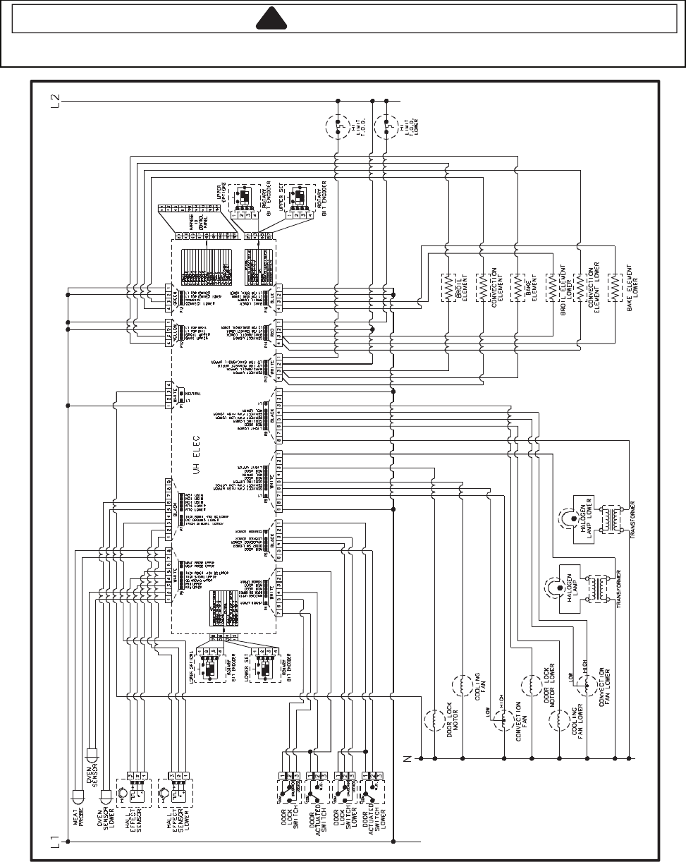
10-8
Wiring Diagram and Schematic
!
WARNING
To avoid risk of electrical shock, personal injury or death; disconnect power to oven before servicing, unless
testing requires power.
00162061

PRODUCT SPECIFICATIONS
AND
WARRANTY INFORMATION SOURCES
IN THE UNITED STATES:
FOR PRODUCT SPECIFICATIONS AND WARANTY INFORMATION CALL:
FOR TECHNICAL ASSISTANCE WHILE AT THE CUSTOMER’S HOME CALL:
THE TECHNICAL ASSISTANCE LINE: 1-800-832-7174
HAVE YOUR STORE NUMBER READY TO IDENTIFY YOU AS AN
AUTHORIZED IN-HOME SERVICE PROFESSIONAL
IN CANADA:
FOR PRODUCT SPECIFICATIONS AND WARRANTY INFORMATION CALL:
1-800-461-5681
FOR TECHNICAL ASSISTANCE WHILE AT THE CUSTOMER’S HOME CALL:
THE TECHNICAL ASSISTANCE LINE: 1-800-488-4791
HAVE YOUR STORE NUMBER READY TO IDENTIFY YOU AS AN
AUTHORIZED IN-HOME SERVICE PROFESSIONAL
FOR WHIRLPOOL PRODUCTS: 1-800-253-1301
FOR KITCHENAID PRODUCTS: 1-800-422-1230
FOR ROPER PRODUCTS: 1-800-447-6737
FOR LITERATURE ORDERS:
PHONE: 1-800-851-4605
FOR TECHNICAL INFORMATION AND SERVICE POINTERS:
www.servicematters.com