G Maytag Ref 16010154
Maytag - Refrig - Msd - 16010154 Maytag - Refrig - MSD - 16010154 Maytag - Refrig - MSD - 16010154 Maytag, Magic Chef, Jenn Air applianceservicesecretsmembership.com_manuals
Maytag Ref-Frzr - Sxs - 16010154 Maytag Ref-Frzr - SxS - 16010154 Maytag Ref-Frzr - SxS - 16010154 Maytag, Magic Chef, Jenn Air applianceservicesecretsmembership.com_manuals
2013-04-06
: Pdf Maytag Ref - 16010154 Maytag Ref - 16010154 Maytag, Magic Chef, Jenn Air
Open the PDF directly: View PDF ![]() .
.
Page Count: 118 [warning: Documents this large are best viewed by clicking the View PDF Link!]

Side-by Side
Refrigerators
This Base Manual covers general information
Refer to individual Technical Sheet
for information on specific models
This manual includes, but is
not limited to the following:
Maytag
MSB1542ARW/A
MSB2354ARW/A
MSB2554ARW/A
MSD2142ARW/A
MSD2143ARW/A
MSD2346AEW/A/B
MSD2354ARW/A
MSD2356AEW/A/B
MSD2543ARW/A
MSD2554ARW/A
MSD2556AEW/A/B
MSD2754ARW/A
MSD2756AEA/W/B
MSD2757AEA/W/B
MSD2758DRW/B/Q
MSD2759DRW/B/Q
MSD2959DRW/B/Q
Magic Chef
CSB2121ARW
CSB2122ARW/A
CSB2323ARW/A
CSD2122ARW/A
CSD2123ARW/A
CSD2324ARW/A
CSD2325ARW/A
CSD2524ARW/A
CSD2525ARW/A
CSD2725ARW/A
Service
This manual is to be used by qualified appliance
technicians only. Maytag does not assume any
responsibility for property damage or personal
injury for improper service procedures done by
an unqualified person.
16010154
November 2003
Jenn-Air
JCB2388ARW/A/B
JCB2388ATW/A/B
JCD2289AEW/A/B-
F/G/K/R/S/U
JCD2289ATW/B
JSD2388AEW/A/B
JSD2574ARW/B
JSD2588AEW/A/B
JSD2774ARW/B
JSD2789AEW/A/B/S
JSD2789ATW/B
JSD2989AEW/A/B
Admiral
ASD2514ARW/A

©2003 Maytag Corporation
16010154 CONTENTS i
SAFETY PRECAUTIONS
THIS MANUAL IS TO BE USED ONLY BY A MAYTAG AUTHORIZED SERVICE TECHNICIAN
FAMILIAR WITH AND KNOWLEDGEABLE OF PROPER SAFETY AND SERVICING PROCE-
DURES AND POSSESSING HIGH QUALITY TESTING EQUIPMENT ASSOCIATED WITH
MICROWAVE, GAS, AND ELECTRICAL APPLIANCE REPAIR.
ALL INDIVIDUALS WHO ATTEMPT REPAIRS BY IMPROPER MEANS OR ADJUSTMENTS,
SUBJECT THEMSELVES AND OTHERS TO THE RISK OF SERIOUS OR FATAL INJURY.
USE ONLY GENUINE MAYTAG APPROVED FACTORY REPLACEMENT COMPONENTS.

ii
©2003 Maytag Corporation
16010154 CONTENTS
INTRODUCTION
This refrigeration service manual provides the information necessary to service Side-by-
Side model refrigerators.
NOTE: ALL MODELS COVERED IN THIS SERVICE MANUAL USE R134A REFRIGER-
ANT.
The manual is printed in loose leaf format. Each part of this manual is divided into sec-
tions relating to a general group of components and each section is subdivided into
various parts describing a particular component or service procedure.
The subdividing of the subject matter, plus the loose leaf form, will facilitate the updating
of the manual as new models, and new or revised components of service procedures
are introduced.
Each page of this manual will be identified in the lower right hand corner. As new or
revised pages are published, it will be easy to keep the manual up to date.
This serivce manual is a valuable service tool and care should be taken to keep it up to
date by prompt and proper filing of subsequent pages as they are issued.
ALL "E" MODELS ARE ENERGY MODELS, AND HAVE A PREMIUM SOUND PACKAGE.
©2003 Maytag Corporation
16010154 CONTENTS iii

iv
©2003 Maytag Corporation
16010154 CONTENTS
CONTENTS
GENERAL SAFETY PRECAUTIONS............................................................... i
INTRODUCTION ..................................................................................... ii
CONTENTS .......................................................................................... iv
SECTION 1. GENERAL INFORMATION .......................................................1-1
ELECTRICAL REQUIREMENTS ........................................................................ 1-1
SAFETY PRECAUTIONS ................................................................................ 1-1
Grounding Instructions ............................................................................. 1-1
FORCED AIR SYSTEMS ................................................................................ 1-2
AIR FLOW - FORCED AIR SYSTEMS................................................................. 1-2
CHECKING OPERATION ................................................................................ 1-3
TOOLS NEEDED FOR R134A SEALED SYSTEM REPAIR ........................................ 1-4
ADDITIONAL SYSTEM INFORMATION.............................................................. 1-5
R134A SEALED SYSTEM SERVICE PROCEDURE ................................................. 1-7
REFRIGERATION SYSTEM ............................................................................. 1-8
REFRIGERATION CYCLE................................................................................ 1-9
DIAGNOSIS .............................................................................................. 1-10
SEALED SYSTEM DIAGNOSIS.......................................................................1-10
LEAK TESTING...........................................................................................1-12
COMPONENTS .......................................................................................... 1-13
Drier....................................................................................................1-13
Condenser ............................................................................................1-13
Yoder Loop............................................................................................ 1-14
Evaporator............................................................................................1-15
Heat Exchanger...................................................................................... 1-15
Compressor .......................................................................................... 1-15
SYSTEM FLUSH ......................................................................................... 1-15
SEALED SYSTEM REPAIR SUMMARY .............................................................1-16
SYSTEM FLUSH PROCEDURE........................................................................1-16
SWEEP AND FINAL CHARGE........................................................................ 1-19
SECTION 2. COMPONENTS ....................................................................2-1
COMPRESSOR REPLACEMENT ...................................................................... 2-1
REPLACING THE COMPRESSOR ..................................................................... 2-1
CONDENSER REPLACEMENT......................................................................... 2-2
ELECTRICAL SYSTEM................................................................................... 2-4
Testing the Compressor Direct .................................................................... 2-4
Overload Protector................................................................................... 2-5
Testing the Overload Protector .................................................................... 2-5
PTC STARTING DEVICE AND RUN CAPACITOR ................................................... 2-6
PTC Device Replacement ........................................................................... 2-7
RUN CAPACITOR......................................................................................... 2-7
Testing the Capacitor ................................................................................ 2-7
Alternate Method Using Ohmmeter.............................................................. 2-7
TEMPERATURE CONTROL............................................................................. 2-8
Checking Operating Temperatures ............................................................... 2-8
Temperature Control Replacement............................................................... 2-9
©2003 Maytag Corporation
16010154 CONTENTS v
AUTO DAMPER CONTROL MODELS .................................................................2-10
Checking the Auto Damper ........................................................................2-11
Auto Damper Control Replacement .............................................................. 2-11
AUTO DAMPER CONTROL - Exploded View ........................................................ 2-12
DEFROST TIMER......................................................................................... 2-13
Checking the Defrost Timer ........................................................................ 2-14
Timer Replacement .................................................................................. 2-14
ADAPTIVE DEFROST CONTROL ...................................................................... 2-14
Checking the Adaptive Defrost Control .......................................................... 2-15
AIR FLOW - FORCED AIR SYSTEMS.................................................................. 2-15
DEFROST HEATER REPLACEMENT .................................................................. 2-17
DEFROST THERMOSTAT REPLACEMENT........................................................... 2-17
CONDENSER FAN MOTOR ............................................................................. 2-18
To Check Condenser Motor Direct ................................................................ 2-18
Condenser Fan Motor Replacement .............................................................. 2-19
FREEZER FAN MOTOR .................................................................................. 2-19
Freezer Fan Motor Diagnosis ...................................................................... 2-19
Freezer Fan Motor Replacement .................................................................. 2-20
SECTION 3. CABINET & RELATED COMPONENTS ........................................3-1
ADJUSTABLE CANTILEVER SHELVES............................................................... 3-1
ADJUSTABLE CANTILEVER SHELF TRIMS......................................................... 3-1
CABINET DOORS AND ASSOCIATED PARTS ..................................................... 3-1
Inner Door Liner Replacement .................................................................... 3-1
Outer Door Panel Replacement ................................................................... 3-2
FRONT WHEEL ASSEMBLY............................................................................ 3-2
CABINET LEVELING ..................................................................................... 3-2
DOOR SEAL............................................................................................... 3-3
TOE-IN & TOE-OUT ADJUSTMENTS................................................................. 3-3
HINGE ADJUSTMENTS................................................................................. 3-3
DOOR ALIGNMENT...................................................................................... 3-4
DOOR SWITCH ........................................................................................... 3-4
WATER/ICE DISPENSER FREEZER DOOR REMOVAL ............................................ 3-4
FOUNTAIN ASSEMBLY - Manual Slide Control.................................................... 3-6
Ice and Water Fountain Bracket Assembly Removal .......................................... 3-6
Checking and Replacing the Crusher and Water/Cube Switch ............................. 3-6
Checking and Replacing the Actuaring Switch ................................................ 3-7
Fountain Heater....................................................................................... 3-7
PC BOARD CHECKS..................................................................................... 3-8
Fountain Door Delay ................................................................................. 3-7
Excessive Door Delay................................................................................ 3-7
Short Door Delay..................................................................................... 3-7
FOUNTAIN ASSEMBLY - Electronic Control ....................................................... 3-8
Ice and Water Fountain Bracket Removal ....................................................... 3-8
Fountain Bracket Assembly ........................................................................ 3-9
Checking and Replacing the Actuator Switch.................................................. 3-9
Electronic Control Board Troubleshooting...................................................... 3-9
ICE CRUSHER BIN AND SHELF ASSEMBLY.......................................................3-10
ICE/CRUSHER BIN SHELF ENCLOSURE ASSEMBLY ............................................3-11
vi
©2003 Maytag Corporation
16010154 CONTENTS
SECTION 4. ICEMAKER ..........................................................................4-1
SERVICING ................................................................................................ 4-1
TEST PROCEDURES..................................................................................... 4-1
SERVICE PROCEDURES ................................................................................ 4-2
ACCESSING THE CONTROL BOX .................................................................... 4-2
MODULE COMPONENTS .............................................................................. 4-3
WATER FILL ADJUSTMENT............................................................................ 4-4
WATER PROBLEMS ..................................................................................... 4-5
TEMPERATURE PROBLEMS........................................................................... 4-5
THERMOSTAT............................................................................................ 4-5
INSTALLATION ........................................................................................... 4-6
HARNESS.................................................................................................. 4-6
LEVELING ICEMAKER ................................................................................... 4-7
REMOVING & REPLACING FILL CUP ................................................................. 4-7
OTHER INFORMATION.................................................................................. 4-8
SECTION 5. TROUBLESHOOTING .............................................................5-1
SECTION 6. SPECIFICATIONS .................................................................6-1
INDEX....................................................................................................... 6-1
21' DISPENSER/NON DISPENSER .................................................................... 6-2
23'/25' DISPENSER/NON DISPENSER ................................................................ 6-3
21' NON DISPENSER (MAYTAG) ...................................................................... 6-4
23'/25' DISPENSER/NON DISPENSER (MAYTAG).................................................. 6-5
23'/25' DISPENSER/NON DISPENSER (MAYTAG PREMIUM).................................... 6-6
SECTION 7. SCHEMATICS ......................................................................7-1
INDEX........................................................................................................ 7-1
Appendix A
Climate Zone Technology.........................................................................A-1
©2003 Maytag Corporation
16010154 CONTENTS vii
© 2003 Maytag Corporation
16010154 SECTION 1. GENERAL INFORMATION 1-11-1
1-11-1
1-1
SECTION 1. GENERAL INFORMATIONSECTION 1. GENERAL INFORMATION
SECTION 1. GENERAL INFORMATIONSECTION 1. GENERAL INFORMATION
SECTION 1. GENERAL INFORMATION
INSTRUCTIONS - INSTRUCTIONS -
INSTRUCTIONS - INSTRUCTIONS -
INSTRUCTIONS - ELECTRICALELECTRICAL
ELECTRICALELECTRICAL
ELECTRICAL
REQUIREMENTSREQUIREMENTS
REQUIREMENTSREQUIREMENTS
REQUIREMENTS
It is the personal responsibility and obliga-
tion of the appliance owner to provide ad-
equate electrical service for this appliance.
Observe all electrical and local codes and
ordinaces.
A 120 volt 60 Hz, 15 ampere fused electri-
cal supply is required. An individual branch
(or separate circuit serving only this appli-
ance) is recommended.
Do not use an extension cord.Do not use an extension cord.
Do not use an extension cord.Do not use an extension cord.
Do not use an extension cord.
Before plugging in power cord, operatingBefore plugging in power cord, operating
Before plugging in power cord, operatingBefore plugging in power cord, operating
Before plugging in power cord, operating
or testing, follow grounding instructionsor testing, follow grounding instructions
or testing, follow grounding instructionsor testing, follow grounding instructions
or testing, follow grounding instructions
in Grounding Section.in Grounding Section.
in Grounding Section.in Grounding Section.
in Grounding Section.
Electrical Service
Grounding: 120 VOLTS, 60Hz Only
IMPORTANT SAFETYIMPORTANT SAFETY
IMPORTANT SAFETYIMPORTANT SAFETY
IMPORTANT SAFETY
PRECAUTIONSPRECAUTIONS
PRECAUTIONSPRECAUTIONS
PRECAUTIONS
WARNING: WARNING:
WARNING: WARNING:
WARNING:
Personal Injury Hazard - Personal Injury Hazard -
Personal Injury Hazard - Personal Injury Hazard -
Personal Injury Hazard -
To prevent unnecessary risk of fire, elec-To prevent unnecessary risk of fire, elec-
To prevent unnecessary risk of fire, elec-To prevent unnecessary risk of fire, elec-
To prevent unnecessary risk of fire, elec-
trical shock or personal injury, all wiringtrical shock or personal injury, all wiring
trical shock or personal injury, all wiringtrical shock or personal injury, all wiring
trical shock or personal injury, all wiring
and grounding must be done in accor-and grounding must be done in accor-
and grounding must be done in accor-and grounding must be done in accor-
and grounding must be done in accor-
dance with National Electrical Code anddance with National Electrical Code and
dance with National Electrical Code anddance with National Electrical Code and
dance with National Electrical Code and
local codes and ordinances.local codes and ordinances.
local codes and ordinances.local codes and ordinances.
local codes and ordinances.
Warning Warning
Warning Warning
Warning
- Electrical- Electrical
- Electrical- Electrical
- Electrical
ground is required onground is required on
ground is required onground is required on
ground is required on
this appliance!this appliance!
this appliance!this appliance!
this appliance!
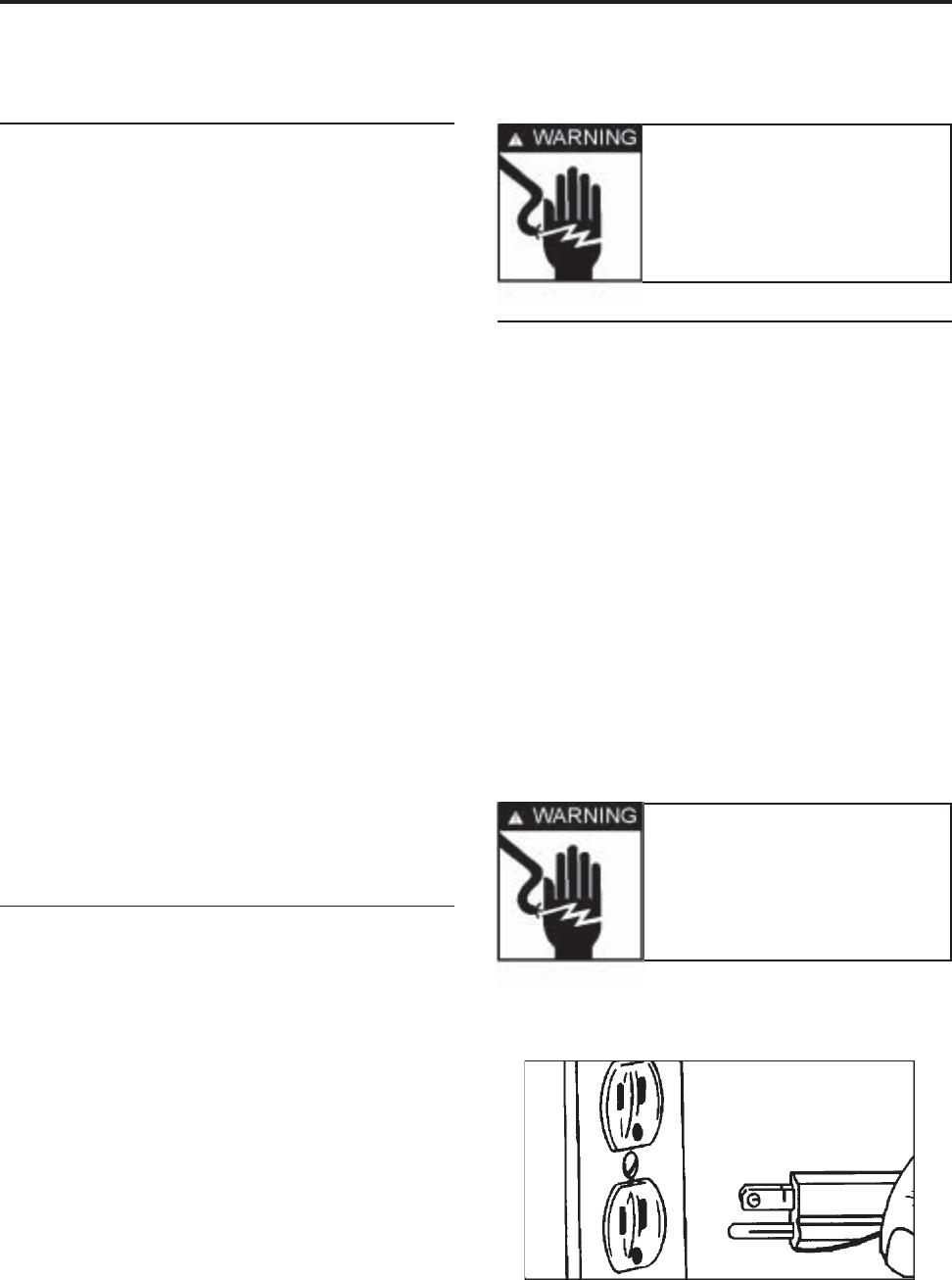
Grounding InstructionsGrounding Instructions
Grounding InstructionsGrounding Instructions
Grounding Instructions
This appliance is equipped with a power
supply cord having a 3-prong grounding
plug. For your safety, this cord must be
plugged into a mating 3-prong type wall re-
ceptacle which is
properly wired, properly wired,
properly wired, properly wired,
properly wired, groundedgrounded
groundedgrounded
grounded
and polarized.and polarized.
and polarized.and polarized.
and polarized.
If a mating wall receptacle is not available
contact a qualified electrician to have the
wall receptacle replaced.
Do not use an ACDo not use an AC
Do not use an ACDo not use an AC
Do not use an AC
adapter plug. adapter plug.
adapter plug. adapter plug.
adapter plug.
If there is any question, local
building officials or electrical utility should
be consulted.
Warning Warning
Warning Warning
Warning
- Do not under- Do not under
- Do not under- Do not under
- Do not under
any circumstances re-any circumstances re-
any circumstances re-any circumstances re-
any circumstances re-
move the groundingmove the grounding
move the groundingmove the grounding
move the grounding
prong from the powerprong from the power
prong from the powerprong from the power
prong from the power
supply cord.supply cord.
supply cord.supply cord.
supply cord.
© 2003 Maytag Corporation
16010154 SECTION 1. GENERAL INFORMATION 1-21-2
1-21-2
1-2
FORCED AIR SYSTEMSFORCED AIR SYSTEMS
FORCED AIR SYSTEMSFORCED AIR SYSTEMS
FORCED AIR SYSTEMS
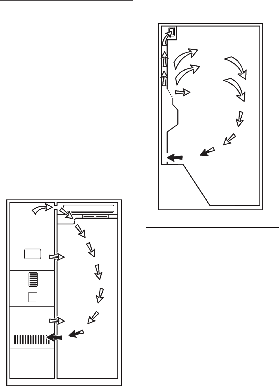
On all forced air models, an air circulating
fan draws air from across the evaporator and
directs it to the fresh food and freezer com-
partments. A carefully measured amount
of chilled air is directed into the fresh food
compartment through a baffle to maintain
the desired fresh food compartment tem-
perature. The greater part of chilled air is
directed into the freezer compartment to
maintain freezer temperature. Forced air
models use a fan cooled condenser. De-
pending on the model, the evaporator is
automatically defrosted every eight hours
of compressor run time. Defrosting is ac-
complished by a defrost heater activated by
a timer. The accumulated moisture is
drained into a defrost pan located in the
compressor area of the cabinet.
FRONT VIEWFRONT VIEW
FRONT VIEWFRONT VIEW
FRONT VIEW
FREEZER SIDE VIEWFREEZER SIDE VIEW
FREEZER SIDE VIEWFREEZER SIDE VIEW
FREEZER SIDE VIEW
AIR FLOW - FORCED AIR SYSTEMSAIR FLOW - FORCED AIR SYSTEMS
AIR FLOW - FORCED AIR SYSTEMSAIR FLOW - FORCED AIR SYSTEMS
AIR FLOW - FORCED AIR SYSTEMS
The airflow balance between the fresh food
and freezer compartments is an important
factor in maintaining proper compartment
temperatures in a forced air refrigeration
system. A baffle is used to regulate the
amount of chilled air directed into the fresh
food compartment. If a colder freezer com-
partment temperature is desired, the baffle
is adjusted so that less air is directed into
the fresh food compartment. This causes
the compressor to run longer since the ther-
mostat sensing element is located in the
fresh food compartment. Cold air is drawn
across the evaporator and into the fan. A
portion of the air is deflected into the fresh
food compartment where it absorbs heat
and returns to the fin and tube evaporator

© 2003 Maytag Corporation
16010154 SECTION 1. GENERAL INFORMATION 1-31-3
1-31-3
1-3
The following general information explains
several methods for checking operation of
the refrigeration system. This information
applies to all systems covered in this
manual. The correct operation of a refrig-
eration system is dependent upon the
proper function of each of the parts com-
prising the system.
If the system does not operate properly
(long run periods, warmer than normal tem-
peratures), the trouble may be caused by
one of the following conditions:
(1) - Restricted Capillary Tube(1) - Restricted Capillary Tube
(1) - Restricted Capillary Tube(1) - Restricted Capillary Tube
(1) - Restricted Capillary Tube
The opening of a capillary tube is about the
same diameter as the period at the end of
this sentence. Because of this, it is easy to
restrict the tube. Extra precautions should
be taken when any service procedure in-
volves moving or touching the capillary
tube. The slightest kink can cause a com-
plete tube restriction.
Restrictions of the capillary tube may be
caused by: (1) moisture freeze-up, (2) for-
eign particles lodged in the tube, or (3) a
bend or kink.
If the capillary tube is restricted, there will
be a noticeable lack of frost on all cooling
surfaces; the compressor may operate for
a short period of time and cycle on the
CHECKING OPERATIONCHECKING OPERATION
CHECKING OPERATIONCHECKING OPERATION
CHECKING OPERATION
overload. Because some models can hold
the entire charge in the condenser, the com-
pressor may run continuously and a defi-
nite vacuum will be noticed in the low side.
When moisture freeze-up causes a restric-
tion, it usually occurs at the outlet end of
the capillary tube. Normally, frost buildup
can be detected in this area.
NOTE: NOTE:
NOTE: NOTE:
NOTE:
When using a heat gun or hairWhen using a heat gun or hair
When using a heat gun or hairWhen using a heat gun or hair
When using a heat gun or hair
dryer, use low heat. Never use a torch.dryer, use low heat. Never use a torch.
dryer, use low heat. Never use a torch.dryer, use low heat. Never use a torch.
dryer, use low heat. Never use a torch.
At the discharge end of the capillary, apply
heat. If there is enough head pressure, and
if the restriction is caused by moisture
freeze-up, you will be able to hear a gurgling
noise as the heat releases the refrigerant
through the tubing.
It is possible that this moisture will be ab-
sorbed by the drier and remedy the trouble.
However, if the freeze-up reoccurs, you
must replace the drier.
A kink in the capillary tube will reveal the
same symptom as a moisture freeze-up,
except for the accumulation of frost. Where
possible, check the capillary tube and
straighten any kinks to relieve the restric-
tions. Check the unit operation. If the con-
dition persists, replace the defective part.
If the freeze-up condition does not exist and
there is not a kink, you can assume that a
foreign particle is causing the restrictions.
The only remedy in this case is to replace
the restricted part.
(2) - Partial Restriction In Low Side(2) - Partial Restriction In Low Side
(2) - Partial Restriction In Low Side(2) - Partial Restriction In Low Side
(2) - Partial Restriction In Low Side
Tubing Tubing
Tubing Tubing
Tubing
Bent tubing, foreign matter, or moisture in
the system may cause a partial restriction
in the low side tubing. This is usually indi-
cated by frost-free tubing between the re-
through the return opening in the divider.
However, most of the air moving across the
evaporator is blown through the freezer air
tunnel and circulated throughout the freezer
compartment. It then circulates back across
the fin and tube evaporator where it begins
another cycle.

© 2003 Maytag Corporation
16010154 SECTION 1. GENERAL INFORMATION 1-41-4
1-41-4
1-4
striction and the capillary tube and by frost-
covered tubing between the restriction and
the suction line. The restriction acts like a
second capillary tube, increasing the pres-
sure ahead of it (warming) and decreasing
the pressure beyond it (cooling). To con-
firm the existence of a restriction in the low
side tubing, perform operational pressure
checks.
(3) - Slow Leak In System(3) - Slow Leak In System
(3) - Slow Leak In System(3) - Slow Leak In System
(3) - Slow Leak In System
On forced air models, long run time will be
noticed during the early stages of a leak. As
the refrigerant continues to escape, both
compartments will gradually warm up and
the compressor will run continuously. The
freezer will probably warm up first.
4) - Incorrect Refrigerant Charge4) - Incorrect Refrigerant Charge
4) - Incorrect Refrigerant Charge4) - Incorrect Refrigerant Charge
4) - Incorrect Refrigerant Charge
The sealed unit may have too much refrig-
erant (overcharged system) or too little re-
frigerant (undercharged system). The para-
graphs below will inform you on how to
recognize a system with these defects.
An overcharged system may have a frost
back condition appearing on the suction
line. When the compressor stops, the frost
melts and drips on the floor. A heat ex-
changer separation will also cause this
symptom.
An undercharged system, depending on the
degree of undercharge, will operate with
temperatures above normal and the com-
pressor run time will be increased. The
greater the undercharge, the higher the tem-
perature will be and the longer the run time.
An undercharged system must be purged,
evacuated, and recharged with the proper
amount of refrigerant. Before recharging,
test for refrigerant leaks.
TOOLS NEEDED FOR R134ATOOLS NEEDED FOR R134A
TOOLS NEEDED FOR R134ATOOLS NEEDED FOR R134A
TOOLS NEEDED FOR R134A
SEALED SYSTEM REPAIRSEALED SYSTEM REPAIR
SEALED SYSTEM REPAIRSEALED SYSTEM REPAIR
SEALED SYSTEM REPAIR
The following list may help identify basic
refrigeration tools needed:
• ALL HOSES AND EQUIPMENT MUST
MEET STANDARDS FOR HANDLING R134A RE-
FRIGERANTS
• APPROVED AND CERTIFIED RECOVERY EQUIP-
MENT AND RECOVERY CYLINDER (see local sup-
plier for variety of equipment)
• MANIFOLD GAUGE SET / HOSES MUST HAVE
LOW LOSS FITTINGS
(Robinair 41365)
• HEATED CHARGING CYLINDER WITH R134A
SCALE (Robinair 43134B)
• TEMPORARY ACCESS VALVES (2)
(Robinair 40288)
• 1/4" FLARE TEE - MFL X MFL X FFL
(Robinair 40399)
• 1/4" QUICK COUPLER VALVE
(Robinair 40380)
• PROCESS TUBE ADAPTER SET
(Robinair 12458)
Other tools required, but not necessarilyOther tools required, but not necessarily
Other tools required, but not necessarilyOther tools required, but not necessarily
Other tools required, but not necessarily
dedicated to R134A Service:dedicated to R134A Service:
dedicated to R134A Service:dedicated to R134A Service:
dedicated to R134A Service:
• TUBING CUTTER
(Robinair 14987A)
• BRAZING TORCH
(Robinair 12587)
• SWAGGING TOOLS
(Robinair 14313)
• VOLT-WATT METER (MAYTAG CUSTOMER
SERVICE 20000019)
• LEAK DETECTION EQUIPMENT FOR CFC/HCFC
AND HFC OR EQUIVALENT
• PINCH-OFF TOOLS
(Robinair 12294 or 12396)

© 2003 Maytag Corporation
16010154 SECTION 1. GENERAL INFORMATION 1-51-5
1-51-5
1-5
NOTE:NOTE:
NOTE:NOTE:
NOTE:
Robinair equipment is listed as aRobinair equipment is listed as a
Robinair equipment is listed as aRobinair equipment is listed as a
Robinair equipment is listed as a
reference only, equivalent substitutes mayreference only, equivalent substitutes may
reference only, equivalent substitutes mayreference only, equivalent substitutes may
reference only, equivalent substitutes may
be used. Additional tools may be requiredbe used. Additional tools may be required
be used. Additional tools may be requiredbe used. Additional tools may be required
be used. Additional tools may be required
for special situations.for special situations.
for special situations.for special situations.
for special situations.
LEAK DETECTOR -LEAK DETECTOR -
LEAK DETECTOR -LEAK DETECTOR -
LEAK DETECTOR -
Leak detectors compat-
ible with R134A should be used. Due to the
possibility of contaminating the sealed sys-
tem with moisture, using soap bubbles can
cause problems, especially if drawn into a
low side leak. To minimize the possibility
of moisture entering the system, the use of
wet rags or towels to cool a brazed joint
should be avoided.
DRIERS/FILTERS -DRIERS/FILTERS -
DRIERS/FILTERS -DRIERS/FILTERS -
DRIERS/FILTERS -
Any time a sealed sys-
tem repair is made, the drier must be re-
placed. The drier on R134A systems is dif-
ferent, using a new desiccant which pro-
vides system compatibility and proper
moisture absorption. Use of the old type
drier on new R134A systems would result
in a repeat sealed system failure. Part num-
ber 13900-113900-1
13900-113900-1
13900-1 is the drier which must be used
on R134A systems. This drier may also be
used on R12 systems and will supersede
the 13900 drier, but be sure that the older
13900 is
NOTNOT
NOTNOT
NOT
used on the R134A system.
Additionally, "unsoldering" a joint, rather
than the score and break method, is not ac-
ceptable due to the possibility of chemical
and moisture contamination. Always cut the
drier out of the system-never apply heat.
LIMIT TIME OF EXPOSURE TO THELIMIT TIME OF EXPOSURE TO THE
LIMIT TIME OF EXPOSURE TO THELIMIT TIME OF EXPOSURE TO THE
LIMIT TIME OF EXPOSURE TO THE
ATMOSPHERE - ATMOSPHERE -
ATMOSPHERE - ATMOSPHERE -
ATMOSPHERE -
Whenever a sealed sys-
tem is repaired, do not expose an open line
to the atmosphere for more than 15 min-
utes. Replacement components will come
sealed by either brazing (drier) or plugs
(compressor). Do not open the new drier
to the atmosphere until you are ready to
braze it into place. Before installing a new
compressor, pull a plug to be sure the unit
is still pressurized. If no pressure exists, do
not use the compressor. If pressure exists,
reinstall the plug to ensure non-contamina-
tion during the service procedure.
LOW SIDE LEAKSLOW SIDE LEAKS
LOW SIDE LEAKSLOW SIDE LEAKS
LOW SIDE LEAKS
- -
- -
- In the event of a low
side leak, moisture has probably been
drawn into the system. The compressorcompressor
compressorcompressor
compressor
must be replaced must be replaced
must be replaced must be replaced
must be replaced in addition to the normal
repair. Also, a system flush must be made
before proceeding with the sweep charge
and final charge.
PLUGGED CAPILLARY TUBE - PLUGGED CAPILLARY TUBE -
PLUGGED CAPILLARY TUBE - PLUGGED CAPILLARY TUBE -
PLUGGED CAPILLARY TUBE -
Moisture or
other contaminants in the R134A system can
cause the formation of gel-like or salt-type
deposits within the system. This causes
capillary tube restrictions which may not be
removed by the flush procedure detailed
later. If the restriction cannot be removed
from the capillary tube, the heat exchanger,
evaporator and compressor must be
replaced.
ADDITIONAL SYSTEMADDITIONAL SYSTEM
ADDITIONAL SYSTEMADDITIONAL SYSTEM
ADDITIONAL SYSTEM
INFORMATIONINFORMATION
INFORMATIONINFORMATION
INFORMATION
CAUTIONCAUTION
CAUTIONCAUTION
CAUTION
Always wear eye protection andAlways wear eye protection and
Always wear eye protection andAlways wear eye protection and
Always wear eye protection and
protective clothing when handlingprotective clothing when handling
protective clothing when handlingprotective clothing when handling
protective clothing when handling
any refrigerants.any refrigerants.
any refrigerants.any refrigerants.
any refrigerants.
© 2003 Maytag Corporation
16010154 SECTION 1. GENERAL INFORMATION 1-61-6
1-61-6
1-6
SYSTEM FLUSH - SYSTEM FLUSH -
SYSTEM FLUSH - SYSTEM FLUSH -
SYSTEM FLUSH -
Flushing of the system
is required whenever there has been a low
side leak, plugged capillary tube or com-
pressor replacement. This is a procedure
in which R134A refrigerant is flushed
through the system and into the recovery
system to remove moisture and non-
condensables which may have entered the
open system. The compressor must be
isolated during the flush procedure, in or-
der to prevent contaminants from being ab-
sorbed into the ester oil, resulting in a con-
taminated system.
The system flush procedure will be done
in two parts. First, the condenser, including
the yoder loop, will be isolated by means
of process tube adapters and flushed with
4 ounces of R134A. After the drier has been
replaced, the entire sealed system, minus
the compressor, will also be flushed with 4
ounces of the refrigerant. This second step
can take about 15 minutes in order to circu-
late the refrigerant through the condenser,
the drier, the capillary tube, the evaporator
and out the suction line into the recovery
equipment. During this 15 minutes, the old
compressor can be removed and the re-
placement set into place, mounted and pre-
pared electrically. The compressor is to-
tally installed except for the final brazing of
the suction and discharge lines.
© 2003 Maytag Corporation
16010154 SECTION 1. GENERAL INFORMATION 1-71-7
1-71-7
1-7
Leaks at joints 1 or 2 will requireLeaks at joints 1 or 2 will require
Leaks at joints 1 or 2 will requireLeaks at joints 1 or 2 will require
Leaks at joints 1 or 2 will require
the replacement of the compressorthe replacement of the compressor
the replacement of the compressorthe replacement of the compressor
the replacement of the compressor
and drier. Perform system flush,and drier. Perform system flush,
and drier. Perform system flush,and drier. Perform system flush,
and drier. Perform system flush,
sweep and final charge.sweep and final charge.
sweep and final charge.sweep and final charge.
sweep and final charge.
R134A SEALED SYSTEM SERVICE PROCEDURER134A SEALED SYSTEM SERVICE PROCEDURE
R134A SEALED SYSTEM SERVICE PROCEDURER134A SEALED SYSTEM SERVICE PROCEDURE
R134A SEALED SYSTEM SERVICE PROCEDURE
Any sealed system failure in the upper area indicated below requires the replacement of
the
evaporator, heat exchanger, drier and compressor
. Perform system flush, sweep and. Perform system flush, sweep and
. Perform system flush, sweep and. Perform system flush, sweep and
. Perform system flush, sweep and
add final charge according to procedure shown.add final charge according to procedure shown.
add final charge according to procedure shown.add final charge according to procedure shown.
add final charge according to procedure shown.
Suction LineSuction Line
Suction LineSuction Line
Suction Line
Connection atConnection at
Connection atConnection at
Connection at
the compressorthe compressor
the compressorthe compressor
the compressor
Leaks or repairs to joints or components in the Leaks or repairs to joints or components in the
Leaks or repairs to joints or components in the Leaks or repairs to joints or components in the
Leaks or repairs to joints or components in the
lowerlower
lowerlower
lower
area require repair or replace-area require repair or replace-
area require repair or replace-area require repair or replace-
area require repair or replace-
ment of the component and drier. Perform system sweep and add final charge accord-ment of the component and drier. Perform system sweep and add final charge accord-
ment of the component and drier. Perform system sweep and add final charge accord-ment of the component and drier. Perform system sweep and add final charge accord-
ment of the component and drier. Perform system sweep and add final charge accord-
ing to normal procedure.ing to normal procedure.
ing to normal procedure.ing to normal procedure.
ing to normal procedure.
ProcessProcess
ProcessProcess
Process
StubStub
StubStub
Stub
Evaporator
Suction Line
Capillary
Heat Exchanger
22
22
2
11
11
1
Condenser
Yoder Heater Loop
Drier

© 2003 Maytag Corporation
16010154 SECTION 1. GENERAL INFORMATION 1-81-8
1-81-8
1-8
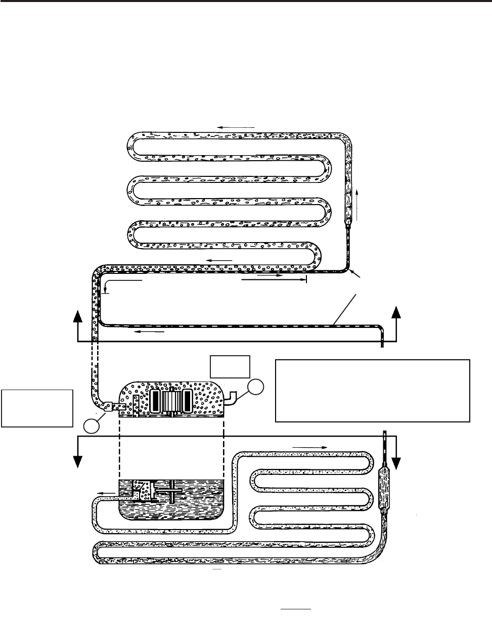
All refrigerators cool by removing heat
from the cabinet rather than pumping in cool
air. In a conventional refrigerator, liquid re-
frigerant enters the evaporator and vapor-
izes (boils) due to the low pressure, creat-
ing a very cold surface which removes heat
from inside the cabinet. This causes the re-
frigerant to boil (evaporate) into a vapor
state and be drawn into the compressor.
The compressor pressurizes the vapor and
pumps it into the condenser. The hot va-
por in the condenser gives off the heat into
the room. As the vapor cools, it condenses
back into a liquid and returns to the evapo-
rator to start the process over again. The
system continually soaks up the heat inside
the refrigerator and deposits the heat back
into the room.
• The compressor compressor
compressor compressor
compressor of the refrigeration sys-
tem serves two purposes: it ensures
movement of the refrigerant throughout
the system and it increases the pressure
and temperature of the vapor received
from the suction line and pumps the re-
frigerant into the discharge line. The
condenser receives this high tempera-
ture, high pressure refrigerant and al-
lows the heat to be released into the
cooler surroundings. This heat removal
"condenses" the refrigerant vapor into a
liquid.
• The yoder loopyoder loop
yoder loopyoder loop
yoder loop is the last pass of the
condenser routed around the cabinet of
the freezer to help prevent moisture for-
mation.
• The drierdrier
drierdrier
drier is installed at the end of the
condenser or yoder loop to capture
moisture which may be present in the
system.
REFRIGERATION SYSTEMREFRIGERATION SYSTEM
REFRIGERATION SYSTEMREFRIGERATION SYSTEM
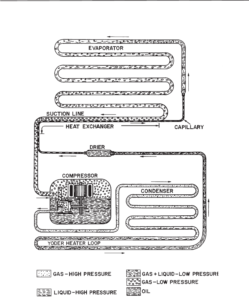
REFRIGERATION SYSTEM •The capillary tubecapillary tube
capillary tubecapillary tube
capillary tube meters the flow of
refrigerant and creates a pressure drop.
Size and length of the capillary is critical
to the efficiency of the system.
• As the refrigerant leaves the capillary
tube and enters the larger tubing of the
evaporatorevaporator
evaporatorevaporator
evaporator, the sudden increase in tub-
ing diameter, and the pumping action of
the compressor, form a low pressure
area. The temperature of the refriger-
ant drops rapidly as it changes to a mix-
ture of liquid and vapor. In the process
of passing through the evaporator, the
refrigerant absorbs heat from the stor-
age area and is gradually changed from
a liquid and vapor mixture (saturated
refrigerant) into a vapor.
• The suction linesuction line
suction linesuction line
suction line returns this low pres-
sure vapor from the evaporator back to
the compressor, and the cycle starts
again.
• Part of the capillary tube is soldered to
the suction line which forms a heatheat
heatheat
heat
exchanger.exchanger.
exchanger.exchanger.
exchanger. Heat from the capillary tube
is thus transferred to the suction line to
superheat the refrigerant there and at the
same time this further cools the liquid
in the capillary tube. This cools the re-
frigerant before it enters the evaporator
and also heats the refrigerant before it
enters the compressor to ensure a va-
por state.
© 2003 Maytag Corporation
16010154 SECTION 1. GENERAL INFORMATION 1-91-9
1-91-9
1-9
REFRIGERATION SYSTEMREFRIGERATION SYSTEM
REFRIGERATION SYSTEMREFRIGERATION SYSTEM
REFRIGERATION SYSTEM
© 2003 Maytag Corporation
16010154 SECTION 1. GENERAL INFORMATION 1-101-10
1-101-10
1-10
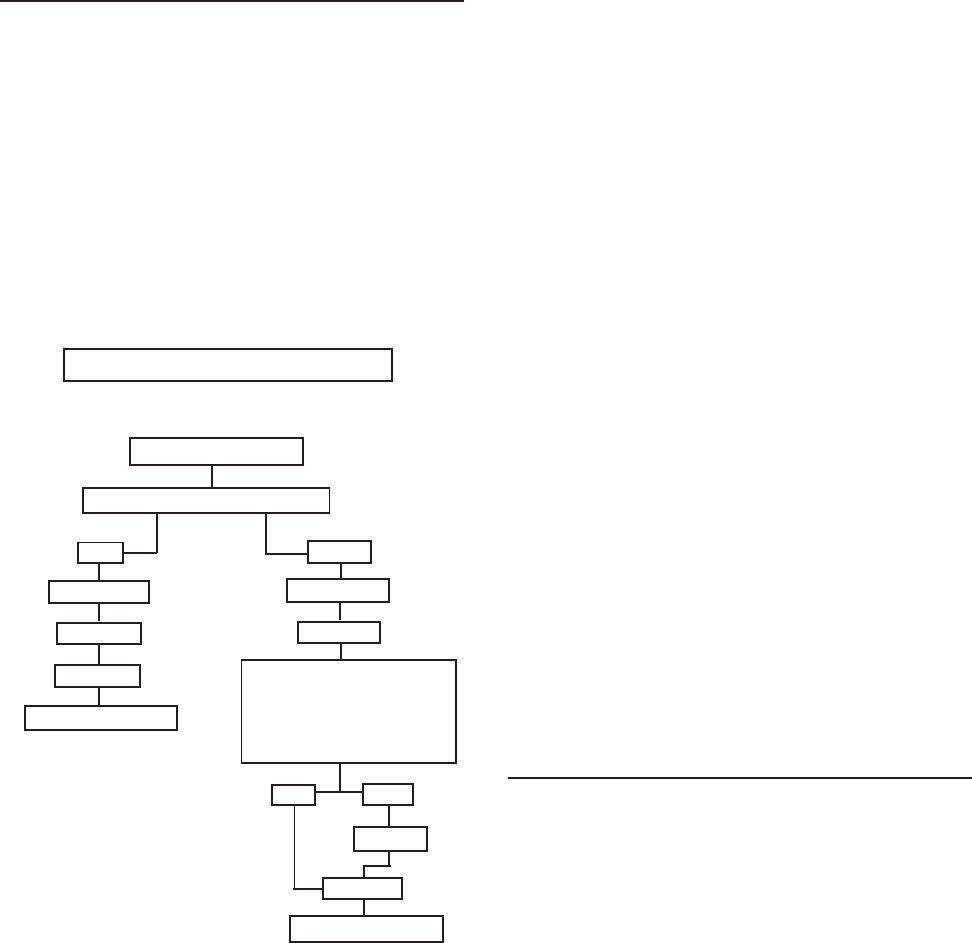
Sealed system diagnosis of R134A refriger-
ant systems is to be performed identically
to that of R12 systems. In fact, as shown in
the following flow chart, the service proce-
dures are virtually the same, except for low
side leaks, plugged capillary tube or com-
pressor failure which results in a system
flush.
IDENTIFY REFRIGERANTIDENTIFY REFRIGERANT
IDENTIFY REFRIGERANTIDENTIFY REFRIGERANT
IDENTIFY REFRIGERANT
R12R12
R12R12
R12 R134aR134a
R134aR134a
R134a
RECOVERRECOVER
RECOVERRECOVER
RECOVER RECOVERRECOVER
RECOVERRECOVER
RECOVER
REPAIRREPAIR
REPAIRREPAIR
REPAIR
REPAIRREPAIR
REPAIRREPAIR
REPAIR
SWEEPSWEEP
SWEEPSWEEP
SWEEP LOW SIDE LEAK,LOW SIDE LEAK,
LOW SIDE LEAK,LOW SIDE LEAK,
LOW SIDE LEAK,
PLUGGED CAPILLARYPLUGGED CAPILLARY
PLUGGED CAPILLARYPLUGGED CAPILLARY
PLUGGED CAPILLARY
TUBE, COMPRESSORTUBE, COMPRESSOR
TUBE, COMPRESSORTUBE, COMPRESSOR
TUBE, COMPRESSOR
REPLACEMENT?REPLACEMENT?
REPLACEMENT?REPLACEMENT?
REPLACEMENT?
FINAL CHARGEFINAL CHARGE
FINAL CHARGEFINAL CHARGE
FINAL CHARGE
NONO
NONO
NO YESYES
YESYES
YES
FLUSH*FLUSH*
FLUSH*FLUSH*
FLUSH*
FINAL CHARGEFINAL CHARGE
FINAL CHARGEFINAL CHARGE
FINAL CHARGE
REFRIGERATOR DIAGNOSISREFRIGERATOR DIAGNOSIS
REFRIGERATOR DIAGNOSISREFRIGERATOR DIAGNOSIS
REFRIGERATOR DIAGNOSIS
SWEEPSWEEP
SWEEPSWEEP
SWEEP
SEALED SYSTEMSEALED SYSTEM
SEALED SYSTEMSEALED SYSTEM
SEALED SYSTEM
* FLUSH INCLUDES COMPRESSOR
REPLACEMENT
Remember, before entering the sealed sys-
tem, all other systems must be tested and
properly repaired. These include the elec-
trical system, defrost system, control op-
eration, and air flow systems: evaporator
and condenser motors.
Before "turning aBefore "turning a
Before "turning aBefore "turning a
Before "turning a
screwdriver", many checks can be madescrewdriver", many checks can be made
screwdriver", many checks can be madescrewdriver", many checks can be made
screwdriver", many checks can be made
simply by using your senses:simply by using your senses:
simply by using your senses:simply by using your senses:
simply by using your senses:
DIAGNOSISDIAGNOSIS
DIAGNOSISDIAGNOSIS
DIAGNOSIS LISTEN:LISTEN:
LISTEN:LISTEN:
LISTEN:
• What is the customer complaint?
• Are the fans operating?
• Is the compressor operating?
LOOK:LOOK:
LOOK:LOOK:
LOOK:
• Are ice cubes present?
• Is the light on/off when the switch is
operated?
• Are the controls set properly?
• Do door gaskets seal properly?
• Is there an ice buildup on the
evaporator cover?
• Are the return air ducts free of ice?
TOUCH:TOUCH:
TOUCH:TOUCH:
TOUCH:
• Is the evaporator cover warm?
• Is air felt exhausting from the kick
plate?
• Is air circulating in the freezer and
fresh food compartments?
• Is the quarter inch discharge line
from the compressor hot?
• Is the condenser warm?
SEALED SYSTEM DIAGNOSISSEALED SYSTEM DIAGNOSIS
SEALED SYSTEM DIAGNOSISSEALED SYSTEM DIAGNOSIS
SEALED SYSTEM DIAGNOSIS
Once it has been determined that the other
refrigerator systems are working properly,
a probable sealed system problem can be
confirmed through the use of a wattmeter
and checks of low and high side pressures.
Access valves are not to be left on a sealedAccess valves are not to be left on a sealed
Access valves are not to be left on a sealedAccess valves are not to be left on a sealed
Access valves are not to be left on a sealed
system after service.system after service.
system after service.system after service.
system after service. To measure low side
pressure, a temporary access valve can be
installed on the compressor process tube.
To remove the valve after repair, a pinch off
tool may be used to seal the tube while the
valve is removed and the hole brazed shut.
To check high side pressure, a temporary
access valve should be installed on the dis-
charge line. When the high side valve is in-

© 2003 Maytag Corporation
16010154 SECTION 1. GENERAL INFORMATION 1-111-11
1-111-11
1-11
stalled, the technician is committed to re-
placement of the drier and a sealed system
repair. Once again, this valve must be re-
moved upon completion of repair. Make
sure the gauges which are used to check the
operating pressures are accurately cali-
brated. When not connected to a system,
the gauge pointer should indicate zero pres-
sure. If necessary, turn the calibrating screw
until the pointer is at "0."
NOTE:NOTE:
NOTE:NOTE:
NOTE:
The following situations are typi-The following situations are typi-
The following situations are typi-The following situations are typi-
The following situations are typi-
cal, however other factors such as gaugecal, however other factors such as gauge
cal, however other factors such as gaugecal, however other factors such as gauge
cal, however other factors such as gauge
placement, line voltage and ambient tem-placement, line voltage and ambient tem-
placement, line voltage and ambient tem-placement, line voltage and ambient tem-
placement, line voltage and ambient tem-
perature must also be considered.perature must also be considered.
perature must also be considered.perature must also be considered.
perature must also be considered.
The following symptoms use high and low
side pressures plus wattage measurements
to diagnose sealed system problems. Nor-
mal low side pressure will range from be-
low zero to about six pounds of pressure,
depending on several factors such as refrig-
erator model, ambient temperature, load
and customer usage. Normal high side
pressure is also dependent on external fac-
tors but will range in the 100 to 125 p.s.i.g.
range. Wattage and pressure figures will
vary based on the model and age of the re-
frigerator. Refer to the performance data
table(s) at the end of the manual.
SymptomsSymptoms
SymptomsSymptoms
Symptoms::
::
:
High Side -High Side -
High Side -High Side -
High Side - Near normal pressureNear normal pressure
Near normal pressureNear normal pressure
Near normal pressure
Low Side -Low Side -
Low Side -Low Side -
Low Side - Slightly lower pressureSlightly lower pressure
Slightly lower pressureSlightly lower pressure
Slightly lower pressure
Wattage -Wattage -
Wattage -Wattage -
Wattage - Lower than normalLower than normal
Lower than normalLower than normal
Lower than normal
Diagnosis Diagnosis
Diagnosis Diagnosis
Diagnosis
- Low side restriction. The
evaporator, suction line or other low side
tubing is probably restricted (kinked or
blocked with a foreign article such as mois-
ture or contaminant). This condition is usu-
ally accompanied with a frost build up on
the low side of the restriction. High side
pressure will take longer to balance with the
low side pressure when the compressor is
stopped.
SymptomsSymptoms
SymptomsSymptoms
Symptoms::
::
:
High Side -High Side -
High Side -High Side -
High Side - Lower than normalLower than normal
Lower than normalLower than normal
Lower than normal
Low Side -Low Side -
Low Side -Low Side -
Low Side - Slightly lower than normalSlightly lower than normal
Slightly lower than normalSlightly lower than normal
Slightly lower than normal
Wattage -Wattage -
Wattage -Wattage -
Wattage - Lower than normalLower than normal
Lower than normalLower than normal
Lower than normal
DiagnosisDiagnosis
DiagnosisDiagnosis
Diagnosis
- High side leak. Both high and
low side pressures will drop as more refrig-
erant escapes.
SymptomsSymptoms
SymptomsSymptoms
Symptoms::
::
:
High SideHigh Side
High SideHigh Side
High Side - Higher than normalHigher than normal
Higher than normalHigher than normal
Higher than normal
Low Side -Low Side -
Low Side -Low Side -
Low Side - Slightly lower thanSlightly lower than
Slightly lower thanSlightly lower than
Slightly lower thannormalnormal
normalnormal
normal
Wattage -Wattage -
Wattage -Wattage -
Wattage - Higher than normalHigher than normal
Higher than normalHigher than normal
Higher than normal
DiagnosisDiagnosis
DiagnosisDiagnosis
Diagnosis
- Low side leak. High side pres-
sure will continually increase since air is
being drawn into the system through the
leak and becomes trapped in the high side
tubing. The low side may show a slight in-
crease in pressure because of the air being
drawn in through the leak.
SymptomsSymptoms
SymptomsSymptoms
Symptoms::
::
:
High Side -High Side -
High Side -High Side -
High Side - Lower than normalLower than normal
Lower than normalLower than normal
Lower than normal
Low Side -Low Side -
Low Side -Low Side -
Low Side - In a vacuumIn a vacuum
In a vacuumIn a vacuum
In a vacuum
Wattage -Wattage -
Wattage -Wattage -
Wattage - Lower than normalLower than normal
Lower than normalLower than normal
Lower than normal
DiagnosisDiagnosis
DiagnosisDiagnosis
Diagnosis
- Capillary tube restriction. High
side pressure will take much longer (or not
at all) to equalize with the low side pressure
when the compressor is stopped.
SymptomsSymptoms
SymptomsSymptoms
Symptoms::
::
:
High Side -High Side -
High Side -High Side -
High Side - Higher than normalHigher than normal
Higher than normalHigher than normal
Higher than normal
Low Side -Low Side -
Low Side -Low Side -
Low Side - Higher than normalHigher than normal
Higher than normalHigher than normal
Higher than normal
Wattage -Wattage -
Wattage -Wattage -
Wattage - Higher than normalHigher than normal
Higher than normalHigher than normal
Higher than normal
DiagnosisDiagnosis
DiagnosisDiagnosis
Diagnosis
- Overcharged system. The
extent of the pressure increase depends on
the amount of overcharge and ambient tem-
perature. An overcharge may also cause the
suction line to be frosted during the run
cycle, resulting in water on the floor after
cycling off.

© 2003 Maytag Corporation
16010154 SECTION 1. GENERAL INFORMATION 1-121-12
1-121-12
1-12
SymptomsSymptoms
SymptomsSymptoms
Symptoms::
::
:
High SideHigh Side
High SideHigh Side
High Side - -
- -
- Lower than normalLower than normal
Lower than normalLower than normal
Lower than normal
Low Side -Low Side -
Low Side -Low Side -
Low Side - Higher than normalHigher than normal
Higher than normalHigher than normal
Higher than normal
Wattage -Wattage -
Wattage -Wattage -
Wattage - Lower than normalLower than normal
Lower than normalLower than normal
Lower than normal
DiagnosisDiagnosis
DiagnosisDiagnosis
Diagnosis
- Inefficient compressor. Cool-
ing surfaces may be covered with a thin film
of frost, but the temperature will not de-
scend to cut off temperature of the control,
even with continuous running. Also, the
condenser will be noticeably cooler to the
touch than normal. Once the confirmation
that an inefficient compressor is made, the
compressor should be replaced.
SymptomsSymptoms
SymptomsSymptoms
Symptoms::
::
:
High Side -High Side -
High Side -High Side -
High Side - NormalNormal
NormalNormal
Normal
Low Side -Low Side -
Low Side -Low Side -
Low Side - Normal to slightlyNormal to slightly
Normal to slightlyNormal to slightly
Normal to slightly
higher than normal -higher than normal -
higher than normal -higher than normal -
higher than normal -
suction line possiblysuction line possibly
suction line possiblysuction line possibly
suction line possibly
sweatssweats
sweatssweats
sweats
Wattage -Wattage -
Wattage -Wattage -
Wattage - NormalNormal
NormalNormal
Normal
DD
DD
Diagnosisiagnosis
iagnosisiagnosis
iagnosis
- Separated capillary tube. The
capillary tube must be connected to the suc-
tion line to provide proper heat transfer.
Without this transfer, liquid refrigerant in the
capillary tube enters the evaporator at a
slightly higher temperature thereby lessen-
ing the ability to remove heat from inside
the refrigerator. The customer complaint
would be long run time, slow ice produc-
tion, warmer fresh food temperature, in
general, poor overall performance. Another
symptom of a separated capillary tube
could be moisture on the floor behind the
refrigerator. The heat from the capillary tube
is utilized by the suction line to ensure that
vapor rather than liquid refrigerant is re-
turned to the compressor. If liquid is
present in the suction line, frost or moisture
forms on the outside of the line and even-
tually drips to the floor.
Once it has been determined through
proper diagnosis that a leak is present in the
sealed system, attempt to find the leak be-
fore opening the system if possible. To
check the high side for leaks, be sure that
the compressor is running. During run time
the high side pressure is greater. To increase
the pressure slightly, stop the condenser
fan blade or block the air flow through the
condenser. To check the low side for leaks,
stop the compressor. During off times, the
low side pressure will increase to equalize
with the high side. By warming the evapo-
rator, this pressure will increase. If too much
refrigerant has leaked out to create enough
pressure to locate the leak, add 4 ounces of
the proper refrigerant to the system and
proceed with the test procedure.
The presence of oil around a tubing joint
usually indicates a leak. Care must still be
taken to pinpoint the exact location. Re-
member that a leak detector compatible
with R134A refrigerant must be used. A
sealed system component, such as the
evaporator or yoder loop, should not be
condemned unless a non-repairable leak is
confirmed. This should be determined by
either locating the actual leak or by isolat-
ing the component from the rest of the sys-
tem and determining if it holds pressuriza-
tion or a vacuum - whichever method is
chosen.
LEAK TESTINGLEAK TESTING
LEAK TESTINGLEAK TESTING
LEAK TESTING
© 2003 Maytag Corporation
16010154 SECTION 1. GENERAL INFORMATION 1-131-13
1-131-13
1-13
DrierDrier
DrierDrier
Drier
Whenever the sealed system is entered, the
drier must be replaced. For R134A refrig-
erant systems, use a 13900-113900-1
13900-113900-1
13900-1 drier. This
drier has the proper desiccant suitable for
the refrigerant. The drier is stamped with
an arrow which indicates the direction of re-
frigerant flow. The drier inlet has two lines -
one connects to the yoder loop and the
other will be used as a process tube through
which the system sweep and final charge
will be made. The drier outlet will be con-
nected to the capillary tube. Care should
be taken to ensure that the capillary is not
inserted too far into the drier to make con-
tact with its internal screen, yet in far enough
to prevent restricting the small diameter
capillary tube opening with the solder alloy.
CondenserCondenser
CondenserCondenser
Condenser
The condenser is a long folded tube which
receives the hot, high pressure vapor from
the compressor. While the most common
problem is keeping the condenser clean
from lint and dirt buildup which prevents
proper airflow and the required transfer of
the heat to the surroundings, it is possible
that due to an unrepairable leak or a non-
removable restriction, the condenser could
require replacement. As with any R134A
sealed system repair, the key to success is
the limiting of the time of atmospheric ex-
posure. Do not remove the plugs on the
condenser inlet and outlet tubes until the
new condenser is mounted in place and
made ready for brazing. The inlet side will
connect to the compressor discharge line
and the outlet to the yoder loop.
COMPRESSORCOMPRESSOR
COMPRESSORCOMPRESSOR
COMPRESSOR
CONDENSERCONDENSER
CONDENSERCONDENSER
CONDENSER
CAPILLARYCAPILLARY
CAPILLARYCAPILLARY
CAPILLARY
TUBETUBE
TUBETUBE
TUBE
DRIERDRIER
DRIERDRIER
DRIER
SUCTIONSUCTION
SUCTIONSUCTION
SUCTION
LINELINE
LINELINE
LINE
COMPONENTSCOMPONENTS
COMPONENTSCOMPONENTS
COMPONENTS
DISCHARGEDISCHARGE
DISCHARGEDISCHARGE
DISCHARGE
TUBETUBE
TUBETUBE
TUBE
EVAPORATOREVAPORATOR
EVAPORATOREVAPORATOR
EVAPORATOR
HEAT EXCHANGERHEAT EXCHANGER
HEAT EXCHANGERHEAT EXCHANGER
HEAT EXCHANGER
YODERYODER
YODERYODER
YODER
CONDENSERCONDENSER
CONDENSERCONDENSER
CONDENSER
LOOPLOOP
LOOPLOOP
LOOP
© 2003 Maytag Corporation
16010154 SECTION 1. GENERAL INFORMATION 1-141-14
1-141-14
1-14
Yoder LoopYoder Loop
Yoder LoopYoder Loop
Yoder Loop
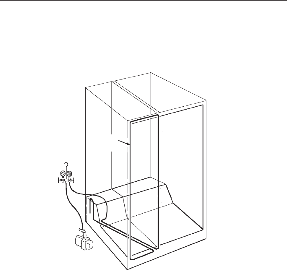
YODER LOOP DIAGNOSTIC TESTYODER LOOP DIAGNOSTIC TEST
YODER LOOP DIAGNOSTIC TESTYODER LOOP DIAGNOSTIC TEST
YODER LOOP DIAGNOSTIC TEST
1. Isolate yoder loop from remainder of sealed system.
2. Cap or seal one end of the loop (braze or use process adaptor and cap).
3. Attach process adaptor to open end of loop.
4. Attach compound gauge and vacuum pump to the loop.
5. Pull a vacuum and close valve to test for leak in the loop.
6. If unit holds a vacuum, no leak is indicated. Reconnect the yoder loop to the system, replace
the drier and recharge the system to specifications.
A VACUUM WILL BE MAINTAINED IF THE SYSTEM IS GOOD.A VACUUM WILL BE MAINTAINED IF THE SYSTEM IS GOOD.
A VACUUM WILL BE MAINTAINED IF THE SYSTEM IS GOOD.A VACUUM WILL BE MAINTAINED IF THE SYSTEM IS GOOD.
A VACUUM WILL BE MAINTAINED IF THE SYSTEM IS GOOD.
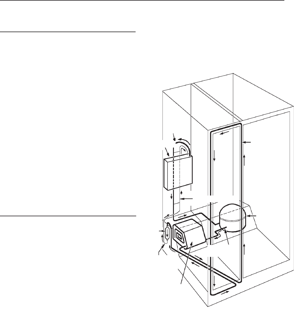
The yoder loop is a non-replaceable component of the sealed system routed within the
walls of the cabinet. To diagnose the yoder loop, the tubing must be isolated from the
sealed system. This procedure is shown below. If the loop fails to hold the vacuum, a
heater repair assembly is to be installed and the loop bypassed by connecting the con-
denser outlet tube directly to the inlet of the drier.
YoderYoder
YoderYoder
Yoder
CondenserCondenser
CondenserCondenser
Condenser
LoopLoop
LoopLoop
Loop

© 2003 Maytag Corporation
16010154 SECTION 1. GENERAL INFORMATION 1-151-15
1-151-15
1-15
EvaporatorEvaporator
EvaporatorEvaporator
Evaporator
The evaporator is a long aluminum tube
folded or coiled within the freezer compart-
ment. If a leak is present in the evaporator,
it is not repairable and must be replaced.
On R134A systems, whenever the evapo-
rator is replaced, the heat exchanger must
also be replaced as well as the compres-
sor. The replacement evaporator will come
with the heat exchanger attached. Leave the
caps in place on the opposite end of the heat
exchanger. Again, whenever the evapora-
tor and heat exchanger are replaced on
R134A units, the compressor must also bethe compressor must also be
the compressor must also bethe compressor must also be
the compressor must also be
replaced replaced
replaced replaced
replaced and the sealed system flushed. Do
not connect the suction line to the replace-
ment compressor until the system has been
flushed
(see System(see System
(see System(see System
(see System
Flush Procedure)Flush Procedure)
Flush Procedure)Flush Procedure)
Flush Procedure)
.
After mounting the evaporator in place, con-
nect the capillary tube of the heat exchanger
to the replacement drier.
Heat ExchangerHeat Exchanger
Heat ExchangerHeat Exchanger
Heat Exchanger
The heat exchanger is composed of the cap-
illary tube and suction line soldered to-
gether. The heat exchanger should be re-
placed if there is a non-repairable leak,
plugged capillary, more than 3 inches have
been removed from the capillary or the cap-
illary tube separates from the suction line.
If the heat exchanger is replaced, the evapo-
rator must also be replaced as well as the
compressor.
CompressorCompressor
CompressorCompressor
Compressor
The compressor is the "heart" of the refrig-
erator, consisting of an electrical motor and
a "pump" sealed inside a steel case. The
compressor used on R134A refrigerant sys-
tems is virtually the same in external ap-
pearance as the compressor used with R12
refrigerants. However, due to changes in
lubricants and other internal differences, the
compressors are notnot
notnot
not to be interchanged,
otherwise system failure will result. Diag-
nostic procedures will be the same as with
the R12 refrigerant systems, except that the
high side pressure will be slightly higher and
the low side pressure will be slightly lower.
If a new compressor is to be installed, pull
one of the plugs to ensure that it is prop-
erly pressurized. If no pressure is observed,
do not use the compressor. If unit is pres-
surized, reinstall the plug and keep the com-
pressor sealed until it is installed and ready
for solder connections. Whenever the com-
pressor is replaced on a R134A refrigera-
tor, the sealed system must be flushed
(see(see
(see(see
(see
System Flush Procedure).System Flush Procedure).
System Flush Procedure).System Flush Procedure).
System Flush Procedure).
Before accessing the sealed system, it is
necessary to determine that the problem
is actually a sealed system problem by
utilizing a wattmeter, thermometer, visual
and touch indicators. Once it has been
determined that the problem is in the
sealed system, and diagnosis indicates a
low side leak, plugged capillary tube, or a
defective compressor, in addition to the
normal repair, the system must be flushed
and the compressor mustmust
mustmust
must be replaced.
SYSTEM FLUSHSYSTEM FLUSH
SYSTEM FLUSHSYSTEM FLUSH
SYSTEM FLUSH

© 2003 Maytag Corporation
16010154 SECTION 1. GENERAL INFORMATION 1-161-16
1-161-16
1-16
SEALED SYSTEM REPAIRSEALED SYSTEM REPAIR
SEALED SYSTEM REPAIRSEALED SYSTEM REPAIR
SEALED SYSTEM REPAIR
SUMMARYSUMMARY
SUMMARYSUMMARY
SUMMARY
A. Recover the refrigerant in the
system, if any.
B. Repair the low side leak or replace
the evaporator and heat exchanger,
whichever applies. If the complete
low side is replaced, do not braze
the suction line to the replacement
compressor until the completion of
Step 3 of System Flush Procedure.
C. Proceed with the following flush
procedure which includes the
compressor replacement.
D. After flushing procedure is com-
pleted, continue with the normal
sweep and final charging procedure.
SYSTEM FLUSH PROCEDURESYSTEM FLUSH PROCEDURE
SYSTEM FLUSH PROCEDURESYSTEM FLUSH PROCEDURE
SYSTEM FLUSH PROCEDURE
1. Isolate and flush the Condenser1. Isolate and flush the Condenser
1. Isolate and flush the Condenser1. Isolate and flush the Condenser
1. Isolate and flush the Condenser
Score and break the discharge line at a con-
venient location to which the replacement
compressor tubing can be connected later.
Attach a process tube adapter to the con-
denser side of this break. Connect a quick
coupler hand valve to the process adapter.
Connect the hose from the charging cylin-
der to this valve
(refer to figure 1).(refer to figure 1).
(refer to figure 1).(refer to figure 1).
(refer to figure 1).
This con-
nection will remain in place throughout the
flush procedure in Step 3.
NOTE:NOTE:
NOTE:NOTE:
NOTE:
Due to the extra flushing andDue to the extra flushing and
Due to the extra flushing andDue to the extra flushing and
Due to the extra flushing and
sweep charge procedures, about 12sweep charge procedures, about 12
sweep charge procedures, about 12sweep charge procedures, about 12
sweep charge procedures, about 12
ounces of R134A refrigerant should beounces of R134A refrigerant should be
ounces of R134A refrigerant should beounces of R134A refrigerant should be
ounces of R134A refrigerant should be
added to the original charge specified onadded to the original charge specified on
added to the original charge specified onadded to the original charge specified on
added to the original charge specified on
the model/serial plate and loaded into thethe model/serial plate and loaded into the
the model/serial plate and loaded into thethe model/serial plate and loaded into the
the model/serial plate and loaded into the
charging cylinder initially.charging cylinder initially.
charging cylinder initially.charging cylinder initially.
charging cylinder initially.
Next, score and break the tube at the yoder
loop to the input side of the drier. Attach a
process tube adapter to the condenser side
of this break. Connect a quick coupler hand
valve to this process adapter. Connect the
hose from the recovery equipment to this
valve
(figure 1).(figure 1).
(figure 1).(figure 1).
(figure 1).
Use the heater on the charg-
ing cylinder to ensure the cylinder pressure
to be approximately 30 pounds above
room ambient temperature. For example,
if room temperature is 70 degrees, cylin-
der pressure should be 100 p.s.i.g. Start the
recovery system and open the valve at the
process adapter attached to yoder loop.
Open the valve from the charging cylinder
and allow 4 ounces of R134A to flow through
the condenser and into the recovery sys-
tem. This process should take about two
minutes. Keep the process adapters and
hoses attached at this time.

© 2003 Maytag Corporation
16010154 SECTION 1. GENERAL INFORMATION 1-171-17
1-171-17
1-17
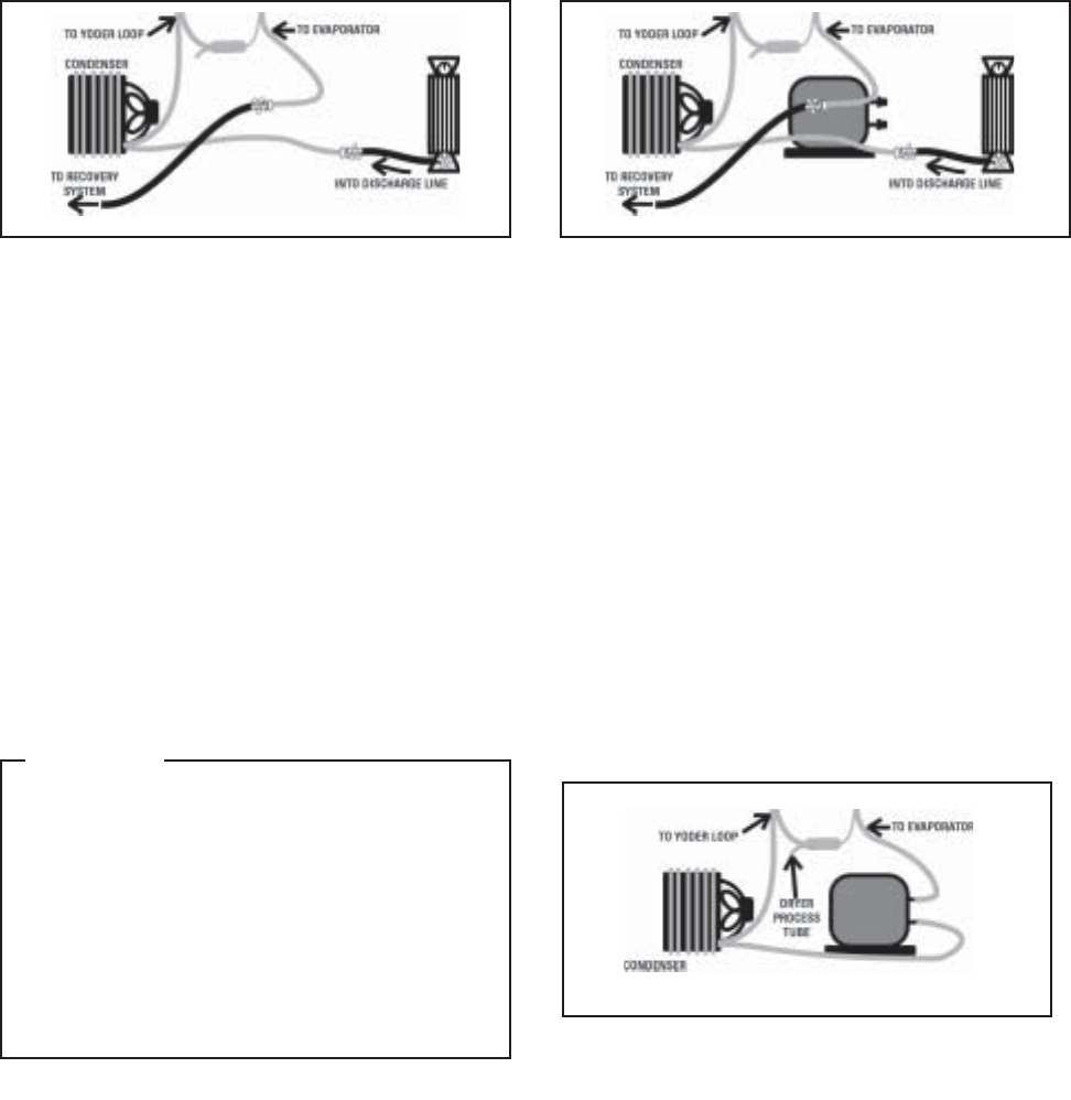
FIGURE 2FIGURE 2
FIGURE 2FIGURE 2
FIGURE 2
Flush the entire system (less compressor)
out the suction line.
Flush into discharge line, through hi-side
and out the yoder loop at drier inlet.
FIGURE 1FIGURE 1
FIGURE 1FIGURE 1
FIGURE 1
2. Replace the Drier2. Replace the Drier
2. Replace the Drier2. Replace the Drier
2. Replace the Drier
Score and break either one of the two inlet
lines on the new drier (the other line will
remain sealed until the sweep charge, at
which time it will be the process tube). Pre-
pare the drier outlet side for connection to
the capillary tube. The capillary tube should
be inserted about 3/4 inch into the drier to
prevent solder alloy from plugging the cap-
illary tube or the capillary tube extending
too far into the drier and contacting the
screen. To facilitate the installation, place a
slight bend in the capillary tube about 3/4
inch from the end and insert into the drier.
Remove the process tube adapter from the
yoder outlet and prepare the tube for con-
nection to the drier inlet. The drier inlet joint
will be the only copper-to-steel connection
which will require the silver solder and flux.
To help prevent flux from entering the sys-
tem, first insert the line from the yoder loop
into the drier inlet, then apply the flux. Braze
both the inlet and the outlet joints of the re-
placement drier.
3. Isolate and flush the remainder of3. Isolate and flush the remainder of
3. Isolate and flush the remainder of3. Isolate and flush the remainder of
3. Isolate and flush the remainder of
the systemthe system
the systemthe system
the system
Score and break the suction line close
enough to the old compressor to be able
to reconnect it to the replacement com-
pressor later. Attach a process tube adapter
to the evaporator side of the suction line.
Connect the hand valve and hose from the
recovery equipment to this adapter
(figure(figure
(figure(figure
(figure
2)2)
2)2)
2)
. Be certain that the pressure in the charg-
ing cylinder is about 30 p.s.i.g. above ambi-
ent temperature. Start the recovery unit and
open the hand valve to the suction line.
Release four (4) ounces of R134a from the
charging cylinder into the system. It will take
about 15 minutes for the refrigerant to pass
through the condenser, yoder loop, drier,
capillary tube, evaporator, suction line and
into the recovery system. This 15 minutes
time can be utilized to remove the old com-
pressor
(figure 3)(figure 3)
(figure 3)(figure 3)
(figure 3)
and prepare the new com-
pressor by mounting into place and wiring
electrically. Remember to leave the plugs
in place until brazing
(refer to (refer to
(refer to (refer to
(refer to
figure 4).figure 4).
figure 4).figure 4).
figure 4).
© 2003 Maytag Corporation
16010154 SECTION 1. GENERAL INFORMATION 1-181-18
1-181-18
1-18
4. Complete compressor replacement4. Complete compressor replacement
4. Complete compressor replacement4. Complete compressor replacement
4. Complete compressor replacement
Close valves to the recovery system. Re-
move process tube adapters from both the
suction and discharge lines.
FIGURE 3FIGURE 3
FIGURE 3FIGURE 3
FIGURE 3
During final flush, remove old compressor, and install replacement compressor leave
plugs in place until brazing.
FIGURE 4FIGURE 4
FIGURE 4FIGURE 4
FIGURE 4
Flush complete - ready for sweep charge.
FIGURE 5FIGURE 5
FIGURE 5FIGURE 5
FIGURE 5
Connect and braze suction and discharge
lines to the replacement compressor
(fig-(fig-
(fig-(fig-
(fig-
ure 5).ure 5).
ure 5).ure 5).
ure 5).
You are now ready to add the tem-
porary piercing valve to the drier process
line and proceed with the sweep and final
charging of the system.
CAUTIONCAUTION
CAUTIONCAUTION
CAUTION
In order to prevent sealed systemIn order to prevent sealed system
In order to prevent sealed systemIn order to prevent sealed system
In order to prevent sealed system
contamination, the time of atmo-contamination, the time of atmo-
contamination, the time of atmo-contamination, the time of atmo-
contamination, the time of atmo-
spheric exposure must be limited tospheric exposure must be limited to
spheric exposure must be limited tospheric exposure must be limited to
spheric exposure must be limited to
15 minutes. do not pull the plugs15 minutes. do not pull the plugs
15 minutes. do not pull the plugs15 minutes. do not pull the plugs
15 minutes. do not pull the plugs
from the new compressor until youfrom the new compressor until you
from the new compressor until youfrom the new compressor until you
from the new compressor until you
are ready to make the connections.are ready to make the connections.
are ready to make the connections.are ready to make the connections.
are ready to make the connections.
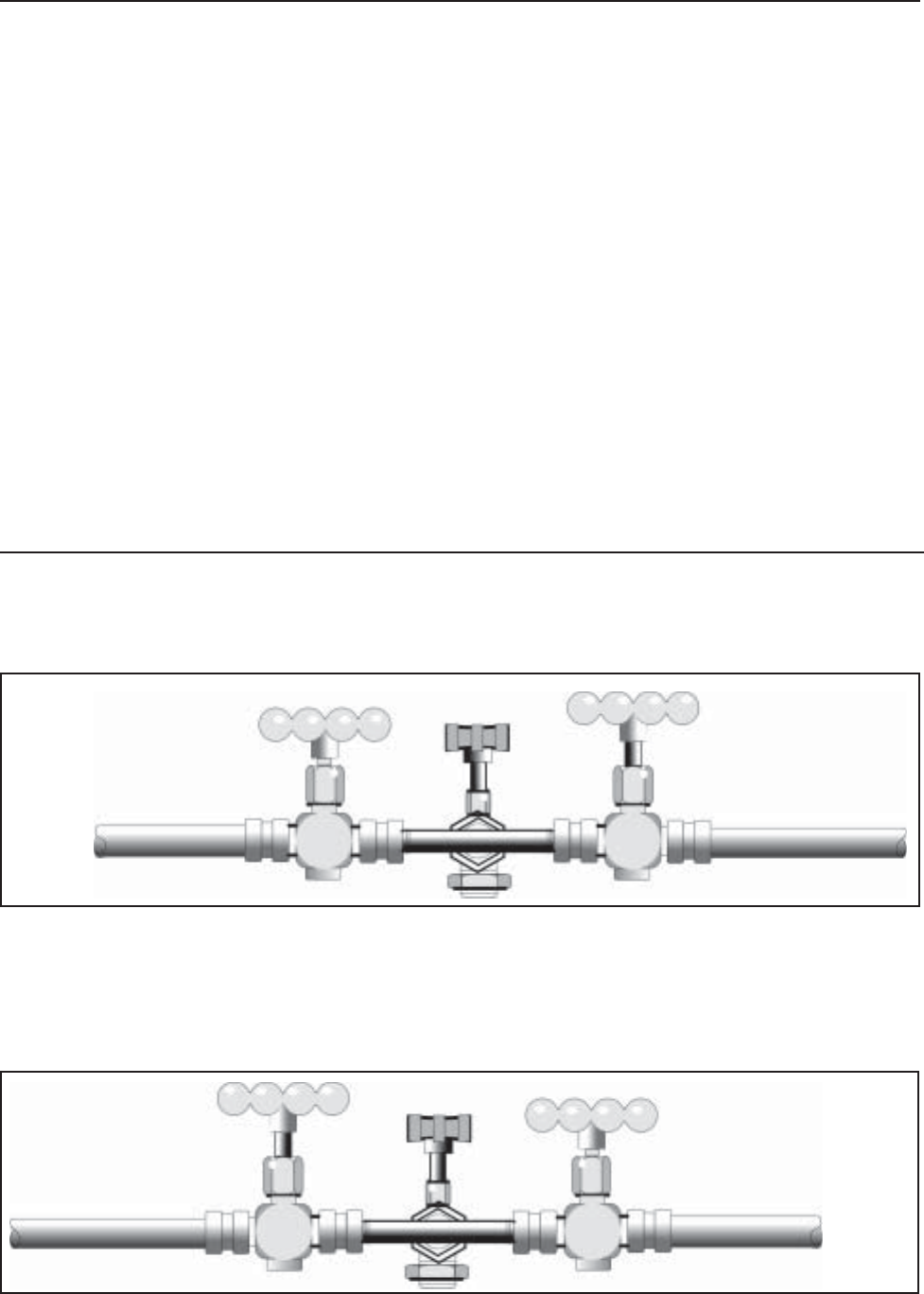
© 2003 Maytag Corporation
16010154 SECTION 1. GENERAL INFORMATION 1-191-19
1-191-19
1-19
SWEEP AND FINAL CHARGESWEEP AND FINAL CHARGE
SWEEP AND FINAL CHARGESWEEP AND FINAL CHARGE
SWEEP AND FINAL CHARGE
TOTO
TOTO
TO
CHARGINGCHARGING
CHARGINGCHARGING
CHARGING
CYLINDERCYLINDER
CYLINDERCYLINDER
CYLINDER
TOTO
TOTO
TO
RECOVERYRECOVERY
RECOVERYRECOVERY
RECOVERY
SYSTEMSYSTEM
SYSTEMSYSTEM
SYSTEM
BB
BB
B
CC
CC
C
ACCESS VALVEACCESS VALVE
ACCESS VALVEACCESS VALVE
ACCESS VALVE
AA
AA
A
The sweep charge is a method of purging
the sealed system of moisture, air and po-
tential contaminants. Also during this pro-
cedure, the system may be checked for
leaks before the final charge. If this proce-
dure is followed as outlined, it will allow for
the capture of 90-95 percent of the available
refrigerant, thereby ensuring that the sys-
tem will operate as designed.
The sweep procedure for R134a refrigerant
systems is made after the system has been
repaired and/or flushed. Three (3) ounces
of refrigerant R134a is added to the system,
circulated by the compressor for 5 minutes
and recovered. Since a new drier - part
#13900-1 #13900-1
#13900-1 #13900-1
#13900-1 has already been installed, a high
side process tube is available. Install a tem-
porary access valve to this process tube
close enough to the end of the tube so that
the tube can be pinched closed behind the
valve and the opening sealed shut after the
valve is removed. Remember, no access
valve is to be left on the sealed system. Con-
nect a 1/4 inch flare tee to the access valve.
Connect a quick coupler hand valve to each
side of the tee. To one hand valve, connect
the hose from the charging cylinder. To the
other valve, connect the hose to the recov-
ery system.
The following steps take you through the
sweep and final charge.
•Step 2•Step 2
•Step 2•Step 2
•Step 2. With liquid refrigerant present to valve A, valve B closed and valve C open
(C will remain open throughout sweep procedure), open valve A to allow three (3)
ounces of refrigerant into the system. Close valve A. Check low side for leaks. After
system has equalized (about 3 to 5 minutes), start system compressor, check for high
side leaks and allow refrigerant to circulate in the system about 5 minutes.
•Step 1.•Step 1.
•Step 1.•Step 1.
•Step 1. Set up of valves: temporary access valve (C) piercing drier process tube,
connected to flare tee, hand valve (A) to charging cylinder, hand valve (B) to recovery
system.
BB
BB
B
AA
AA
ACC
CC
C
ACCESS VALVEACCESS VALVE
ACCESS VALVEACCESS VALVE
ACCESS VALVE
TOTO
TOTO
TO
RECOVERYRECOVERY
RECOVERYRECOVERY
RECOVERY
SYSTEMSYSTEM
SYSTEMSYSTEM
SYSTEM
TOTO
TOTO
TO
CHARGINGCHARGING
CHARGINGCHARGING
CHARGING
CYLINDERCYLINDER
CYLINDERCYLINDER
CYLINDER
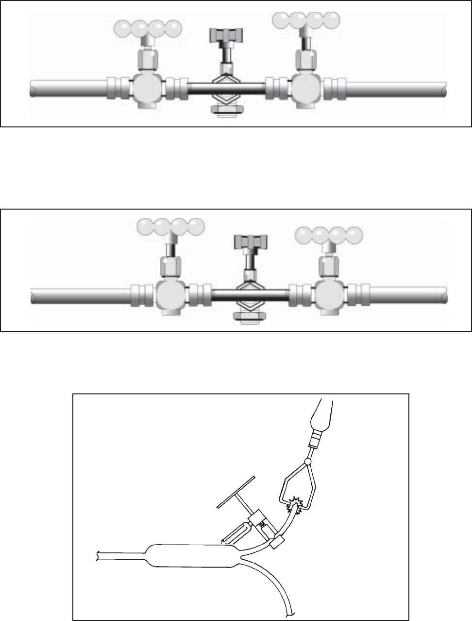
© 2003 Maytag Corporation
16010154 SECTION 1. GENERAL INFORMATION 1-201-20
1-201-20
1-20
TOTO
TOTO
TO
CHARGINGCHARGING
CHARGINGCHARGING
CHARGING
CYLINDERCYLINDER
CYLINDERCYLINDER
CYLINDER
TOTO
TOTO
TO
RECOVERYRECOVERY
RECOVERYRECOVERY
RECOVERY
SYSTEMSYSTEM
SYSTEMSYSTEM
SYSTEM
AA
AA
ABB
BB
B
CC
CC
C
ACCESS VALVEACCESS VALVE
ACCESS VALVEACCESS VALVE
ACCESS VALVE
TOTO
TOTO
TO
CHARGINGCHARGING
CHARGINGCHARGING
CHARGING
CYLINDERCYLINDER
CYLINDERCYLINDER
CYLINDER
AA
AA
ACC
CC
CBB
BB
B
ACCESS VALVEACCESS VALVE
ACCESS VALVEACCESS VALVE
ACCESS VALVE
TOTO
TOTO
TO
RECOVERYRECOVERY
RECOVERYRECOVERY
RECOVERY
SYSTEMSYSTEM
SYSTEMSYSTEM
SYSTEM
•Step 3.•Step 3.
•Step 3.•Step 3.
•Step 3. Leave valve A closed and valve C open. System compressor still running,
open valve B to allow refrigerant to flow into the recovery system. After vacuum
has been held, turn off system compressor.
•Step 4.•Step 4.
•Step 4.•Step 4.
•Step 4. Close valve B. Liquid refrigerant still present to valve A and charging cylinder
pressure is 30 p.s.i.g. above room ambient. Open valve A to slowly allow the proper
refrigerant charge into the system. Close valve A. If needed, valve C can be closed
and valves A and B opened to recover refrigerant in the hoses and charging cylinder.
•Step 5.•Step 5.
•Step 5.•Step 5.
•Step 5. Use pinch-off tool to seal the process tube between the drier and the access
valve. Remove the access valve and braze the opening. After the required five minute
equalization time, start the system compressor.
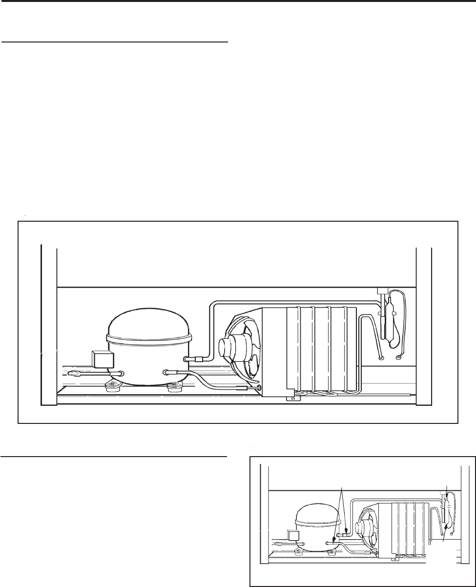
© 2003 Maytag Corporation
16010154 SECTION 2. COMPONENTS 2-12-1
2-12-1
2-1
SECTION 2. COMPONENTSSECTION 2. COMPONENTS
SECTION 2. COMPONENTSSECTION 2. COMPONENTS
SECTION 2. COMPONENTS
REPLACING THE COMPRESSORREPLACING THE COMPRESSOR
REPLACING THE COMPRESSORREPLACING THE COMPRESSOR
REPLACING THE COMPRESSOR
1.1.
1.1.
1. Disconnect the unit from the powerDisconnect the unit from the power
Disconnect the unit from the powerDisconnect the unit from the power
Disconnect the unit from the power
source.source.
source.source.
source.
2. Locate defective compressor and
evacuate the sealed system. .
. .
.
(See (See
(See (See
(See
Sweep Charging and Refrigerant Sweep Charging and Refrigerant
Sweep Charging and Refrigerant Sweep Charging and Refrigerant
Sweep Charging and Refrigerant
Recovery.) Recovery.)
Recovery.) Recovery.)
Recovery.)
3. Clean and cut the refrigerant lines as
close as possible to the compressor
stubs, leaving enough length to install
the replacement compressor.
CutCut
CutCut
Cut
HereHere
HereHere
Here
The holding charge is your assurance that
the compressor is dry and ready to install.
If you receive a replacement compressor
that shows no evidence of holding charge
when you center the lines or remove the
plugs, return it.
NOTE: NOTE:
NOTE: NOTE:
NOTE:
A new drier must be installed eachA new drier must be installed each
A new drier must be installed eachA new drier must be installed each
A new drier must be installed each
time any component of the system istime any component of the system is
time any component of the system istime any component of the system is
time any component of the system is
opened or replaced.opened or replaced.
opened or replaced.opened or replaced.
opened or replaced.
COMPRESSOR REPLACEMENTCOMPRESSOR REPLACEMENT
COMPRESSOR REPLACEMENTCOMPRESSOR REPLACEMENT
COMPRESSOR REPLACEMENT
The following general information explains
how to successfully replace compressors
for any model covered in this manual.
All replacement compressors are charged
with the correct amount of oil and a holding
charge of dry nitrogen.
CutCut
CutCut
Cut
HereHere
HereHere
Here
CutCut
CutCut
Cut
HereHere
HereHere
Here
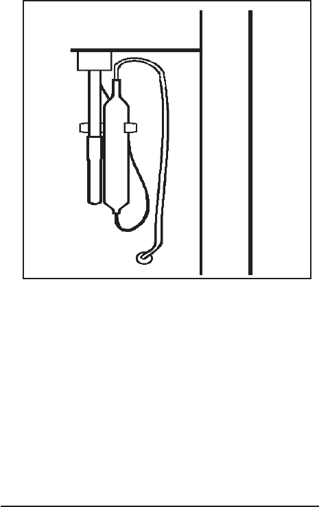
© 2003 Maytag Corporation
16010154 SECTION 2. COMPONENTS 2-22-2
2-22-2
2-2
4. Disconnect lead wires from compres-
sor terminals.
5. Remove the retaining clips from the
compressor mounts. Remove defec-
tive compressor from cabinet and in-
stall rubber grommets on replacement
compressor.
6. Clean the compressor stubs with an
abrasive cloth such as grit cloth No. 23.
Do not open the compressor stubs.
7. Install the replacement compressor us-
ing the mounting clips previously re-
moved.
8. Connect the compressor leads.
9. Solder a short piece of tubing to the pro-
cess tube (approximately 6 inches
long). Connect the refrigerant tubing
to the compressor stubs using silfos on
copper to copper joints and silver sol-
der and flux on steel to copper joints.
Locate and remove old drier. Install newLocate and remove old drier. Install new
Locate and remove old drier. Install newLocate and remove old drier. Install new
Locate and remove old drier. Install new
drier. The new driver is installed in the fol-drier. The new driver is installed in the fol-
drier. The new driver is installed in the fol-drier. The new driver is installed in the fol-
drier. The new driver is installed in the fol-
lowing manner:lowing manner:
lowing manner:lowing manner:
lowing manner:
a. Carefully bend the old drier and tubing
away from electrical parts.
b. Use steel wool or fine emery paper to
clean the capillary tube 3 inches from
the original joint. Also, clean the input
tubing to the drier of 3 inches from the
original joint.
c. Use steel wool or fine emery paper to
clean both ends of the new drier. Use a
knife or file to score the capillary tube 1
inch from the original joint. Use your
finger to break the connection.
d. Make an offset 1/2" from the end of the
cap tube to prevent it from penetrating
too far into the drier.
10. Evacuate, recharge and leak test the
system.
11. Test run the unit to check operation
12. Replace the machine compartment
cover.
CONDENSER REPLACEMENTCONDENSER REPLACEMENT
CONDENSER REPLACEMENTCONDENSER REPLACEMENT
CONDENSER REPLACEMENT
The following general information explains
how to successfully replace the condenser
for any model covered in this manual.
e. Cut the inlet tube of the replacement
drier and use pliers to snap off the
scored end.
f. Install the new drier using silver solder
with the proper flux at the Yoder tube
to drier joint. Use silfos at the drier to
capillary tube joint.
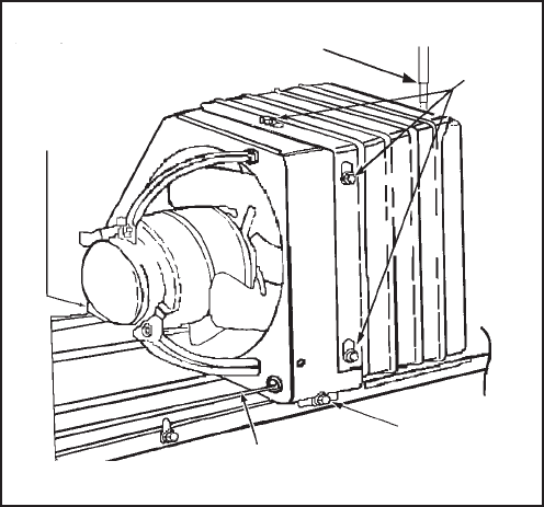
© 2003 Maytag Corporation
16010154 SECTION 2. COMPONENTS 2-32-3
2-32-3
2-3
1. Disconnect the unit from the powerDisconnect the unit from the power
Disconnect the unit from the powerDisconnect the unit from the power
Disconnect the unit from the power
source.source.
source.source.
source.
2. Remove all loose items from the refrig-
erator interior.
3. Working at the back of the cabinet, re-
move the cover from the machine com-
partment. It is necessary to reinstall this
cover after the job is completed.
4. Using a sponge, remove any drain wa-
ter from the defrost pan.
5. With assistance, tilt the cabinet back and
remove the front condenser mounting
screw.
6. With assistance, return cabinet to up-
right position. Remove the back con-
denser mounting screw.
7. Disconnect the fan motor wire lead
connector.
8. Use steel wool or fine emery paper
to clean both the inlet and outlet end of
the new condenser.
9. Evacuate the sealed system.
(See(See
(See(See
(See
Sweep Charging and Refrigerant Re-Sweep Charging and Refrigerant Re-
Sweep Charging and Refrigerant Re-Sweep Charging and Refrigerant Re-
Sweep Charging and Refrigerant Re-
covery.)covery.)
covery.)covery.)
covery.)
10. Clean and then cut the inlet and the out-
let tube of the old condenser.
11. Remove the condenser assembly from
the compressor mounting pan and
place it on a workable surface.
12. Remove the shroud/condenser screws
which secure the fan motor shroud to
the condenser.
13. Transfer all clips to the replacement con-
denser. Make sure the condenser tub-
ing goes through the rubber sleeve on
the fan motor shroud. Install the mount-
ing screws.
14. Set the replacement condenser on the
compressor mounting pan and install
both front and rear condenser mount-
ing screws.
15. Clean then connect the discharge line
to the inner tubing. Clean again and
connect the Yoder loop to the outer
tubing of the condenser.
16. Solder all joints. Silver solder and
proper flux should be used on copper
to steel or steel to steel joints. Excess
flux should be wiped off all tubing.
17. Remove and replace the old drier. DoDo
DoDo
Do
not allow more than 1/2" of the capnot allow more than 1/2" of the cap
not allow more than 1/2" of the capnot allow more than 1/2" of the cap
not allow more than 1/2" of the cap
tube to penetrate the drier.tube to penetrate the drier.
tube to penetrate the drier.tube to penetrate the drier.
tube to penetrate the drier.
18. Install the new drier using silver solder
with the proper flux.
19. Visually check the joints for leaks.
20. Connect the fan motor wire connector.
21. Evacuate and recharge the system.
CondenserCondenser
CondenserCondenser
Condenser
Mounting Mounting
Mounting Mounting
Mounting
Screw Screw
Screw Screw
Screw
Shroud/Shroud/
Shroud/Shroud/
Shroud/
Cond. Cond.
Cond. Cond.
Cond.
Screw Screw
Screw Screw
Screw
Cut Cut
Cut Cut
Cut
HereHere
HereHere
Here
Cut Cut
Cut Cut
Cut
Here Here
Here Here
Here
Front Condenser Front Condenser
Front Condenser Front Condenser
Front Condenser
Mounting Mounting
Mounting Mounting
Mounting
Screw Screw
Screw Screw
Screw
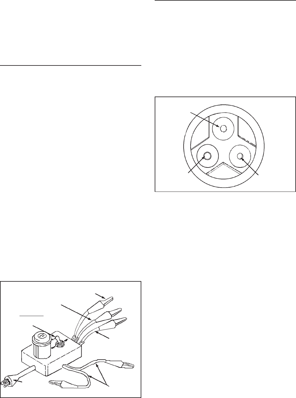
© 2003 Maytag Corporation
16010154 SECTION 2. COMPONENTS 2-42-4
2-42-4
2-4
22. Test for leaks.
23. Install the machine compartment cover.
24. Test run the refrigerator to make sure
it is operating properly.
ELECTRICAL SYSTEMELECTRICAL SYSTEM
ELECTRICAL SYSTEMELECTRICAL SYSTEM
ELECTRICAL SYSTEM
• The wiring diagram is located in the con-
trol housing area.
• All electrical components are grounded
to the cabinet.
• The green/yellow center conductor in
the power cord is attached to the cabi-
net to provide a ground circuit when the
cord is plugged into a properly
grounded outlet.
• After replacing an electrical component,
always reconnect the ground wire.always reconnect the ground wire.
always reconnect the ground wire.always reconnect the ground wire.
always reconnect the ground wire.
• The electrical outlet should be checked
to make sure it is properly wired.
Check the outlet with a circuit tester.
CapacitorCapacitor
CapacitorCapacitor
Capacitor
Start Start
Start Start
Start
RunRun
RunRun
Run
CommonCommon
CommonCommon
Common
SWITCHSWITCH
SWITCHSWITCH
SWITCH::
::
:
Off, Run, StartOff, Run, Start
Off, Run, StartOff, Run, Start
Off, Run, Start
Power Power
Power Power
Power
Plug Plug
Plug Plug
Plug
Testing the Compressor DirectTesting the Compressor Direct
Testing the Compressor DirectTesting the Compressor Direct
Testing the Compressor Direct
Testing the compressor with no other wir-
ing in the circuit is called the direct test
method. Remove all electrical components
from the compressor in order to perform
this test. It is recommended that a com-
pressor tester as illustrated be used to
make this test.
StartStart
StartStart
Start RunRun
RunRun
Run
CommonCommon
CommonCommon
Common
The tester leads are marked RUN, START,
and COMMON. Connect the common lead
to the common terminal of the compres-
sor, the start lead to the start terminal and
the run lead to the run terminal. The com-
pressor terminal arrangements are illus-
trated above. The other two leads are for a
start capacitor (if used). When not in use,
attach the two leads together and place the
toggle switch in the OFF position. There
should not be any bare leads touching the
cabinet. Plug in the tester and flip the switch
to the start position. When the compres-
sor starts, release the switch to the run po-
sition. If the compressor is operative, it will
continue operating on the run windings. If
the compressor fails to run, the compres-
sor is defective and must be replaced.
COMPRESSOR TESTERCOMPRESSOR TESTER
COMPRESSOR TESTERCOMPRESSOR TESTER
COMPRESSOR TESTER

© 2003 Maytag Corporation
16010154 SECTION 2. COMPONENTS 2-52-5
2-52-5
2-5
Overload ProtectorOverload Protector
Overload ProtectorOverload Protector
Overload Protector
The overload protector prevents the com-
pressor from burning out its electrical wind-
ings in the event the compressor becomes
overheated or draws too much current. The
overload trips, opening the circuit to the
compressor. If it does this repeatedly, the
compressor is said to be cycling on the
overload.
Cycling on the overload may be caused by:
1. Insufficient air circulation around the
compressor and condenser.
2. Pull-down on the compressor, caused
by a large quantity of warm food
placed in the refrigerator.
3. Compressor stalling due to lack of pres-
sure unloading.
4. Low line voltage.
5. Defective start relay.
6. Defective winding in the compressor or
shorted windings.
Testing the Overload ProtectorTesting the Overload Protector
Testing the Overload ProtectorTesting the Overload Protector
Testing the Overload Protector
Disconnect the unit from the powerDisconnect the unit from the power
Disconnect the unit from the powerDisconnect the unit from the power
Disconnect the unit from the power
source.source.
source.source.
source.
To test the overload protector, remove the
compressor terminal cover. Examine the
bottom of the overload for signs of arcing.
If signs of arcing are present, either check
for continuity or connect a jumper wire
across the terminals. If using a jumper wire,
plug in the line cord and set the tempera-
ture control to a cold setting. If the com-
1. Remove the PTC and overload from the
compressor.
2. Connect one ohmmeter probe to the
compressor shell. Make sure the probe
makes good contact with bare metal.
One at a time, connect the other ohm-
meter probe to each of the three com-
pressor terminals.
3. If the meter shows no continuity to
ground, install PTC and overload pro-
tector to the compressor's terminals. If
the meter indicates the compressor ter-
minals are grounded, replace the
compressor.
4. Attach a jumper wire across the over-
load terminals.
5. Make sure the jumper wire does not
short to ground.
6. Reconnect the unit to power source. If
the compressor starts, the overload
protector is defective and must be re-
placed.
pressor starts, the over load is defective
and must be replaced. If the compressor
fails to start, check for a defective start re-
lay or compressor.
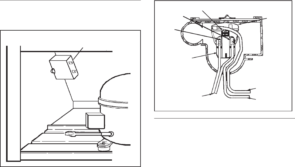
© 2003 Maytag Corporation
16010154 SECTION 2. COMPONENTS 2-62-6
2-62-6
2-6
PTC STARTING DEVICE AND RUNPTC STARTING DEVICE AND RUN
PTC STARTING DEVICE AND RUNPTC STARTING DEVICE AND RUN
PTC STARTING DEVICE AND RUN
CAPACITORCAPACITOR
CAPACITORCAPACITOR
CAPACITOR
The PTC solid state starting device is a push-
on component mounted to the start and run
terminals of the compressor. This device
is connected in parallel with the run capaci-
tor and is in series with the compressor start
windings. This will produce a short circuit
across the run capacitor during the com-
pressor starting sequence and full current
is applied to the start windings as well as
the main winding. Since the PTC device is
temperature sensitive, a variance in its tem-
perature causes a change in its resistance.
When current is first applied to the com-
pressor, the PTC device's low resistance
shorts out the run capacitor; thus produc-
ing adequate motor starting torque.
As the compressor motor approaches run-
ning speed, the current through the PTC
device causes the temperature and resis-
tance of the PTC device to increase to where
it appears to be an open circuit. The com-
pressor continues to operate on the run
winding in parallel with the series combina-
tion of the run capacitor and start winding.
Run Run
Run Run
Run
CapacitorCapacitor
CapacitorCapacitor
Capacitor
Checking the PTC DeviceChecking the PTC Device
Checking the PTC DeviceChecking the PTC Device
Checking the PTC Device
1. Disconnect the unit from the powerDisconnect the unit from the power
Disconnect the unit from the powerDisconnect the unit from the power
Disconnect the unit from the power
sourcesource
sourcesource
source.
2. Discharge the capacitor. NOTE: NOTE:
NOTE: NOTE:
NOTE:
SeeSee
SeeSee
See
"Testing The Capacitor" on page 2-7."Testing The Capacitor" on page 2-7.
"Testing The Capacitor" on page 2-7."Testing The Capacitor" on page 2-7.
"Testing The Capacitor" on page 2-7.
3. Remove the wires from the PTC de-
vice terminals.
4. Allow the PTC to cool to room
temperature.
5. Remove the PTC device.
6. Using an ohmmeter, check the resis-
tance between the PTC device termi-
nals. The ohmmeter should register
between 3 and 20 ohms.
An extreme variance between 3 and 20
ohms indicates a defective PTC device
which must be replaced.
NOTE:NOTE:
NOTE:NOTE:
NOTE:
We discourage using a voltmeter We discourage using a voltmeter
We discourage using a voltmeter We discourage using a voltmeter
We discourage using a voltmeter
to check performance of the PTC deviceto check performance of the PTC device
to check performance of the PTC deviceto check performance of the PTC device
to check performance of the PTC device
because test results are influenced bybecause test results are influenced by
because test results are influenced bybecause test results are influenced by
because test results are influenced by
several factors, such as its dependenceseveral factors, such as its dependence
several factors, such as its dependenceseveral factors, such as its dependence
several factors, such as its dependence
on line voltage to the compressor, the re-on line voltage to the compressor, the re-
on line voltage to the compressor, the re-on line voltage to the compressor, the re-
on line voltage to the compressor, the re-
sponse characteristic of the voltmetersponse characteristic of the voltmeter
sponse characteristic of the voltmetersponse characteristic of the voltmeter
sponse characteristic of the voltmeter
and the PTC device temperature at theand the PTC device temperature at the
and the PTC device temperature at theand the PTC device temperature at the
and the PTC device temperature at the
time the compressor is energized.time the compressor is energized.
time the compressor is energized.time the compressor is energized.
time the compressor is energized.
Over-Over-
Over-Over-
Over-
loadload
loadload
load
Pro-Pro-
Pro-Pro-
Pro-
tectortector
tectortector
tector
BB
BB
Bluelue
luelue
lue
PTC PTC
PTC PTC
PTC
Relay Relay
Relay Relay
Relay
Start Start
Start Start
Start
Run Run
Run Run
Run CommonCommon
CommonCommon
Common
Orange Orange
Orange Orange
Orange
Capacitor Capacitor
Capacitor Capacitor
Capacitor
Leads Leads
Leads Leads
Leads
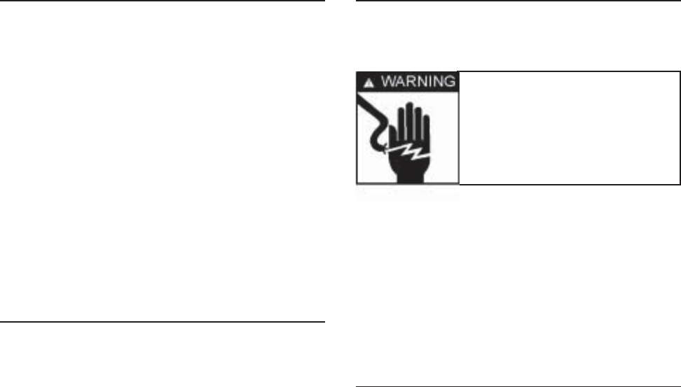
© 2003 Maytag Corporation
16010154 SECTION 2. COMPONENTS 2-72-7
2-72-7
2-7
PTC DPTC D
PTC DPTC D
PTC Device Replacementevice Replacement
evice Replacementevice Replacement
evice Replacement
1. Disconnect the unit from the power Disconnect the unit from the power
Disconnect the unit from the power Disconnect the unit from the power
Disconnect the unit from the power
source.source.
source.source.
source.
2. Disconnect the PTC from the compres-
sor terminals.
3. Remove the lead wires from the PTC
terminals.
4. Replace the PTC and reconnect the
wires to the proper terminals.
RUN CAPACITORRUN CAPACITOR
RUN CAPACITORRUN CAPACITOR
RUN CAPACITOR
The run capacitor is mounted adjacent to
the compressor. It is electrically connected
to the compressor circuit to provide the
required phase difference between the start
and run windings for running the
compressor.
Capacitor Failures May Be Caused ByCapacitor Failures May Be Caused By
Capacitor Failures May Be Caused ByCapacitor Failures May Be Caused By
Capacitor Failures May Be Caused By:
(1)(1)
(1)(1)
(1) A Short Circuit -A Short Circuit -
A Short Circuit -A Short Circuit -
A Short Circuit - Will cause the start
windings to be energized continuously
in the start mode. The compressor
could start, but the overload protector
will trip, and eventually trip continu-
ously.
(2)(2)
(2)(2)
(2) An Open Circuit - An Open Circuit -
An Open Circuit - An Open Circuit -
An Open Circuit - Should, under normal
conditions, allow the compressor to
start. Under a heavy running load, how-
ever, the compressor will trip on the
overload.
(3)(3)
(3)(3)
(3) A Capacitor Low in Capacitance - A Capacitor Low in Capacitance -
A Capacitor Low in Capacitance - A Capacitor Low in Capacitance -
A Capacitor Low in Capacitance - A
capacitor may lose capacitance by a loss
of its electrolytic properties. The com-
pressor would run under a light load,
but would trip on the overload in high
ambient conditions.
Warning Warning
Warning Warning
Warning
- Discharge a ca-- Discharge a ca-
- Discharge a ca-- Discharge a ca-
- Discharge a ca-
pacitor before handling.pacitor before handling.
pacitor before handling.pacitor before handling.
pacitor before handling.
Short across its terminals,Short across its terminals,
Short across its terminals,Short across its terminals,
Short across its terminals,
using a resistor with ausing a resistor with a
using a resistor with ausing a resistor with a
using a resistor with a
minimum resistance ofminimum resistance of
minimum resistance ofminimum resistance of
minimum resistance of
1,000 Ohms.1,000 Ohms.
1,000 Ohms.1,000 Ohms.
1,000 Ohms.
TT
TT
Testing the Capacitoresting the Capacitor
esting the Capacitoresting the Capacitor
esting the Capacitor
We recommend using a capacitor analyzer
when testing. A solid state unit that mea-
sures capacitance and power of any capaci-
tor, and has an automatic means of discharg-
ing the capacitor through resistance is pre-
ferred.
Alternate Method UsingAlternate Method Using
Alternate Method UsingAlternate Method Using
Alternate Method Using
OhmmeterOhmmeter
OhmmeterOhmmeter
Ohmmeter
1. Disconnect the unit from the powerDisconnect the unit from the power
Disconnect the unit from the powerDisconnect the unit from the power
Disconnect the unit from the power
source.source.
source.source.
source.
2. Disconnect the capacitor lead wires.
3. Short across the terminals using a re-
sistor with a minimum resistance of
1,000 ohms. This ensures that no
charge remains to damage the ohmme-
ter.
4. Set the ohmmeter selector switch to
the 10,000 ohm scale (R x 10K).
5. Connect the ohmmeter leads to the ca-
pacitor terminals and observe the
meter point lower end.
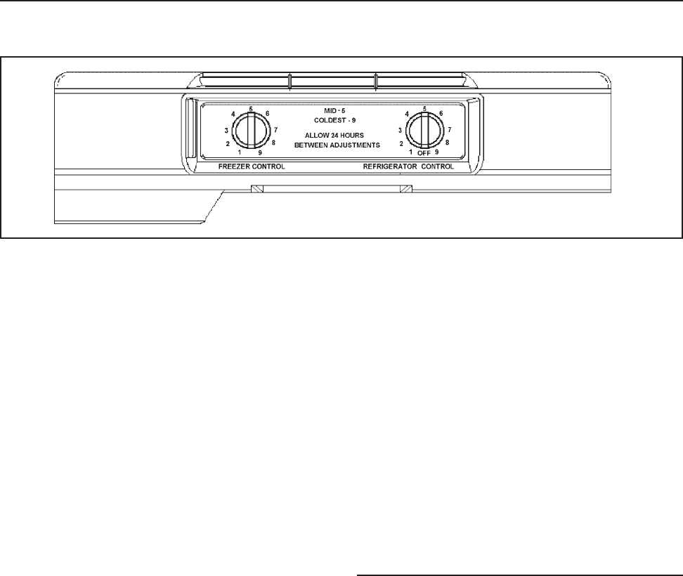
© 2003 Maytag Corporation
16010154 SECTION 2. COMPONENTS 2-82-8
2-82-8
2-8
a. If the pointer deflects to the lower
end and remains there, the capacit-
or is shorted and must be replaced.
b. If there is no deflection of the
pointer, the capacitor is open and
must be replaced.
TEMPERATURE CONTROLTEMPERATURE CONTROL
TEMPERATURE CONTROLTEMPERATURE CONTROL
TEMPERATURE CONTROL
The refrigerator has two temperature
controls:
1. Fresh Food Compartment -Fresh Food Compartment -
Fresh Food Compartment -Fresh Food Compartment -
Fresh Food Compartment - The fresh
food temperature control senses the
temperature of its compartment and
governs the compressor operation
accordingly.
2. Freezer Compartment - Freezer Compartment -
Freezer Compartment - Freezer Compartment -
Freezer Compartment - The freezer
compartment control adjusts the
damper door which regulates the
amount of air allowed to enter the fresh
food compartment.
Turning the freezer temperature control to
the coldest settings reduces the flow of
chilled air to the fresh food compartment.
The fresh food temperature control uses a
sensing element that must be cooled suffi-
ciently before stopping the compressor.
The reduced air flow causes longer com-
pressor run time and colder freezer tem-
peratures, while maintaining the required
fresh food compartment temperatures.
Conversely, by turning the freezer tempera-
ture control to the warmest setting, you in-
crease the flow of air into the fresh food
compartment and decrease the flow to the
freezer. This cools the fresh food tempera-
ture control sensing element faster, result-
ing in shorter compressor run times and
warmer freezer compartment tempera-
tures. The fresh food compartment will
stay near the recommended fresh food tem-
perature, unless the freezer temperature is
turned to an extreme temperature. The dif-
ferential between cut-in/cut-out tempera-
ture will vary approximately 100F.
CC
CC
Checking Operating Temperatureshecking Operating Temperatures
hecking Operating Temperatureshecking Operating Temperatures
hecking Operating Temperatures
The temperature control feeler tube is lo-
cated in the fresh food compartment. The
feeler tube is wrapped around a thermal
mass located in the back left corner of the
control housing. A small amount of air
passes over the thermal mass which gives
a consistent run time during ambient
changes.
c. If the pointer deflects toward the
high end of the scale and then
slowly returns to the low end,
the capacitor is good.
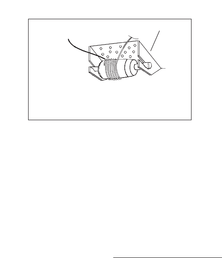
© 2003 Maytag Corporation
16010154 SECTION 2. COMPONENTS 2-92-9
2-92-9
2-9
ThermocoupleThermocouple
ThermocoupleThermocouple
Thermocouple
LeadLead
LeadLead
Lead
To check the cut-in/cut-out temperatures,
attach the bulb of thermistor temperature
tester to the control feeler tube and set con-
trols at midposition.
1. Disconnect the unit from the powerDisconnect the unit from the power
Disconnect the unit from the powerDisconnect the unit from the power
Disconnect the unit from the power
source.source.
source.source.
source.
2. Open the fresh food door and remove
any loose items on the top shelf.
3. Remove the light shield cover by pull-
ing down on the back corners of the
cover, and sliding the cover forward.
Temperature Control ReplacementTemperature Control Replacement
Temperature Control ReplacementTemperature Control Replacement
Temperature Control Replacement
••
••
•Compressor Runs ContinuouslyCompressor Runs Continuously
Compressor Runs ContinuouslyCompressor Runs Continuously
Compressor Runs Continuously
1. Turn the control knob to OFF. If the com-
pressor continues to run, proceed to
step 2. If the compressor stops, check
that the feeder tube is positioned prop-
erly and that the air flow through the con-
trol housing is not restricted. If the
feeler tube is positioned properly and
there is no air restriction, check the con-
trol operating temperatures.
2. Remove the control far enough to re-
move one of the wires from its termi-
nal. If the compressor continues to run,
there is a short in the unit wiring.
Allow the compressor to complete two or
three complete cycles. If the temperature
readings are not within two degrees of the
requirements the control is defective and
must be replaced. Do not attempt to
recalibrate.
A defective control may cause the compres-
sor to run continuously or not at all. If ei-
ther of these conditions exist, check as
follows:
••
••
•Compressor Won't RunCompressor Won't Run
Compressor Won't RunCompressor Won't Run
Compressor Won't Run
1. Remove the control enough to expose
its terminals.
2. Short across the control terminals. If
the compressor starts, install a new
control. If the compressor fails to start,
check the defrost timer, compressor
receptacle, and unit wiring for defects.
Tape thermocouple lead at the 12:00Tape thermocouple lead at the 12:00
Tape thermocouple lead at the 12:00Tape thermocouple lead at the 12:00
Tape thermocouple lead at the 12:00
position on the last wrap of theposition on the last wrap of the
position on the last wrap of theposition on the last wrap of the
position on the last wrap of the
capillary tubecapillary tube
capillary tubecapillary tube
capillary tube
Rear ofRear of
Rear ofRear of
Rear of
CabinetCabinet
CabinetCabinet
Cabinet
Front ofFront of
Front ofFront of
Front of
CabinetCabinet
CabinetCabinet
Cabinet
Thermal Mass RetainerThermal Mass Retainer
Thermal Mass RetainerThermal Mass Retainer
Thermal Mass Retainer

© 2003 Maytag Corporation
16010154 SECTION 2. COMPONENTS 2-102-10
2-102-10
2-10
4. Remove the control housing mounting
screw at the back of the control hous-
ing. Slide the control housing to the
right and lower from control housing
supports.
5. Disconnect the temperature control
housing electrical quick disconnect.
6. Remove the temperature control hous-
ing from the refrigerator and place on a
flat work surface.
7. Remove the control knob by pulling it
away from the temperature control.
8. Remove the electrical and ground leads
from the temperature control terminals.
9. Remove the control by pushing on the
tab with right thumb to release the lock.
With the left hand, rotate the control out
of its locking tabs.
10. To remove the thermal mass, insert a
flat bladed screwdriver between the
thermal mass and the control housing
area. Turn the screwdriver to release
the mass from its locking tab.
11. Install the replacement control in the re-
verse order of removal.
AUTO DAMPER CONTROLAUTO DAMPER CONTROL
AUTO DAMPER CONTROLAUTO DAMPER CONTROL
AUTO DAMPER CONTROL
MODELSMODELS
MODELSMODELS
MODELS
The Auto Damper model refrigerator has
two controls and both have capillary sens-
ing. The Auto Damper controls the fresh
food temperature and the Freezer Tempera-
ture Control guides the freezer temperature.
The fresh food compartment temperature
is maintained by a damper assembly lo-
cated at the back of the temperature con-
trol housing. Changes in air temperature
cause the damper door to open and close.
A control rod and gear connect the fresh
food control knob to the damper control.
Turning the fresh food control knob to the
COLDESTCOLDEST
COLDESTCOLDEST
COLDEST
position increases the flow of
freezer air into the fresh food section. The
freezer compartment temperature control
warms at a faster rate and cools at a slower
rate, increasing the compressor run time
necessary to maintain a satisfied freezer
temperature control.
Turning the fresh food control knob to a
WARMERWARMER
WARMERWARMER
WARMER
setting decreases the flow of
chilled air into the fresh food section. The
freezer compartment temperature control
warms at a slower rate and cools at a faster
rate, decreasing the compressor run time
necessary to maintain a satisfied freezer
temperature control.

© 2003 Maytag Corporation
16010154 SECTION 2. COMPONENTS 2-112-11
2-112-11
2-11
Checking the Auto DamperChecking the Auto Damper
Checking the Auto DamperChecking the Auto Damper
Checking the Auto Damper
1.1.
1.1.
1. Disconnect the unit from the powerDisconnect the unit from the power
Disconnect the unit from the powerDisconnect the unit from the power
Disconnect the unit from the power
source.source.
source.source.
source.
2. Open the fresh food door and remove
any items on the top shelf.
3. Set the fresh food control to the cold-
est position.
4. Remove the light shield cover by pull-
ing down on the back corners of the
cover and sliding the cover forward.
5. Remove the fascia/radiant shield
mounting screws. Remove the control
housing mounting screw at the back,
bottom center of the control housing.
Slide the control housing to the right.
Lower the control housing.
6. Disconnect the temperature control
housing electric quick disconnect.
7. Remove the temperature control hous-
ing from the refrigerator and place on a
flat work surface.
8. Remove the auto damper control rod
retainer, control rod and the slide con-
trol gear from the auto damper control.
9. Turn the control housing over.
10. Remove the two auto damper mount-
ing screws, then remove the auto
damper from the control housing.
11. Mark the auto damper rod approxi-
mately 1/4" away from the housing.
12. Uncoil the auto damper capillary tube
approximately four inches.
13. Submerge into a glass of ice (no water).
Watch for door to move to the closed
position.
14. Remove from ice and warm capillary
tube (use your hand). Watch door for
opposite reaction.
15. If no movement is detected, replace
the control.
Auto Damper Control ReplacementAuto Damper Control Replacement
Auto Damper Control ReplacementAuto Damper Control Replacement
Auto Damper Control Replacement
1. Complete steps 1 through 10, checking
auto damper.
2. Reinstall new auto damper.
3. Reinstall control housing in reverse or-
der of removal.
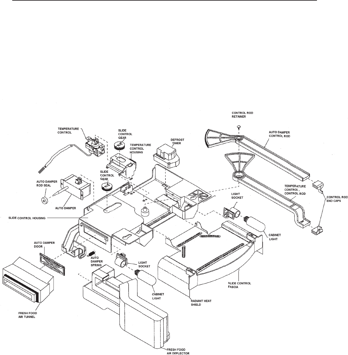
© 2003 Maytag Corporation
16010154 SECTION 2. COMPONENTS 2-122-12
2-122-12
2-12
AUTO DAMPER CONTROL - Exploded ViewAUTO DAMPER CONTROL - Exploded View
AUTO DAMPER CONTROL - Exploded ViewAUTO DAMPER CONTROL - Exploded View
AUTO DAMPER CONTROL - Exploded View
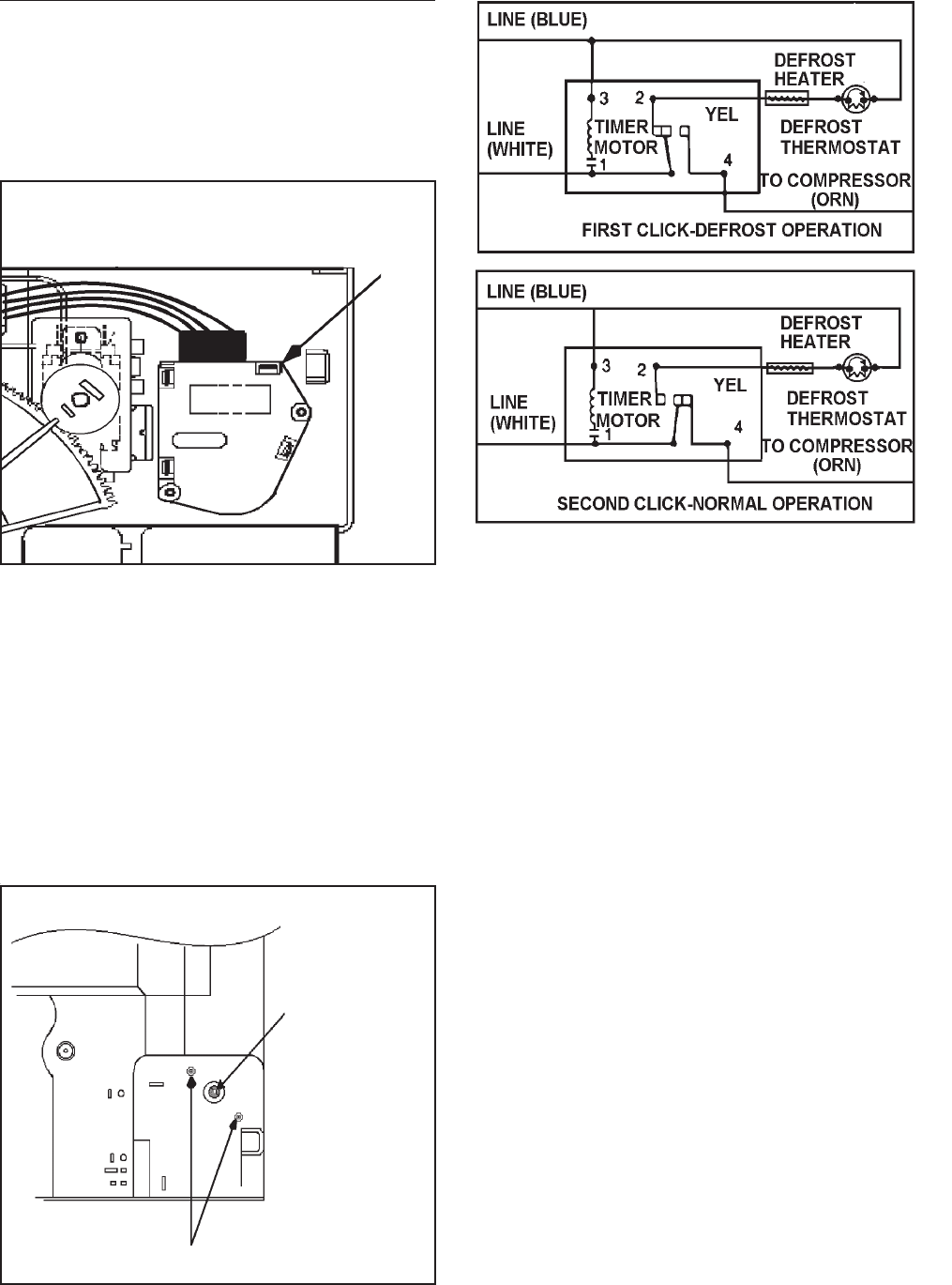
© 2003 Maytag Corporation
16010154 SECTION 2. COMPONENTS 2-132-13
2-132-13
2-13
DEFROST TIMERDEFROST TIMER
DEFROST TIMERDEFROST TIMER
DEFROST TIMER
The freezer evaporator defrosting system
is actuated by an electric timer. The timer
is mounted in the control housing located
in the fresh food compartment.
1st Click -1st Click -
1st Click -1st Click -
1st Click - The timer turns off the compres-
sor and freezer fan circuit for approximately
23 minutes, and it energizes the defrost
heater. Once the temperature of the defrost
termination thermostat reaches the cut-out
point, the termination thermostat will open
the circuit to the radiant heater. However,
the compressor circuit remains open for the
duration of the defrost interval.
2nd Click -2nd Click -
2nd Click -2nd Click -
2nd Click - The timer switches off the de-
frost circuit and starts the compressor,
freezer fan, and the condenser fan motor.
The compressor and fan motors are now
governed by the temperature control for a
period of approximately 8 hours of the com-
pressor run time, after which a new defrost
cycle begins.
The timer control shaft is designed for
screwdriver advancement. When manually
setting the timer to initiate defrosting, turn
the control shaft clockwise until you estab-
lish the approximate location of the defrost
cycle. Then turn the shaft slowly, and stop
immediately when the first click is heard.
The schematic illustrates the timer circuits
in sequence.
To advance
defrost timer
turn clockwise
Defrost timer mounting screws
Defrost
Timer
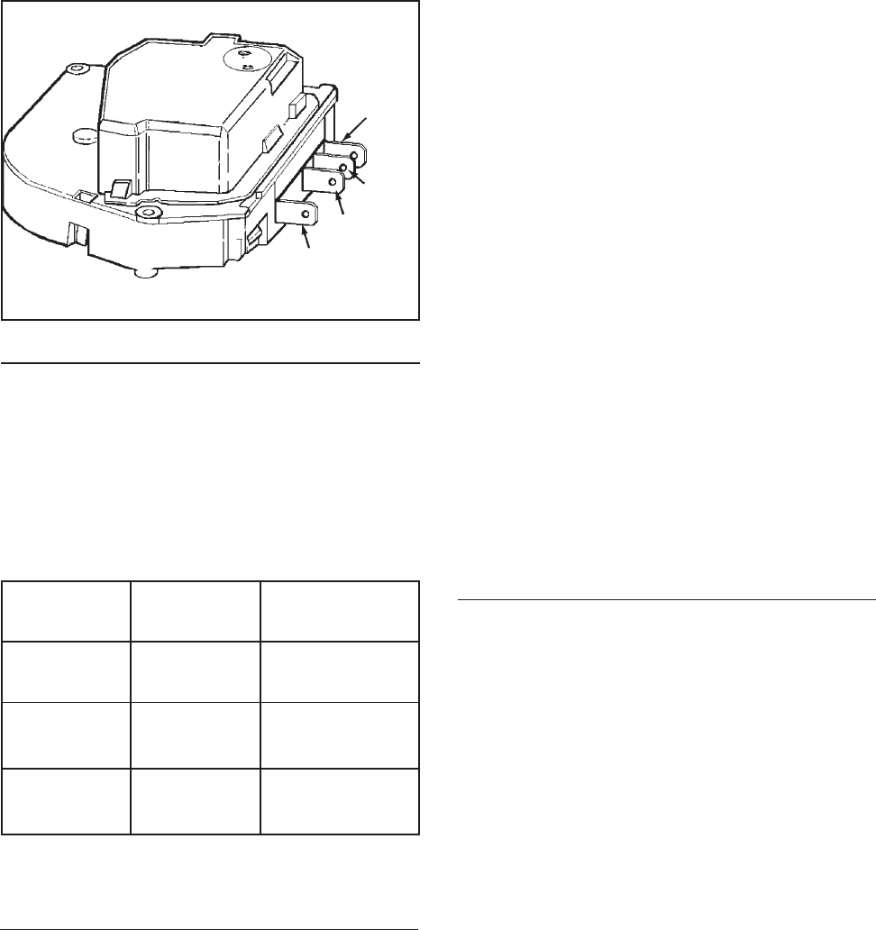
© 2003 Maytag Corporation
16010154 SECTION 2. COMPONENTS 2-142-14
2-142-14
2-14
CC
CC
Checking the Defrost Timerhecking the Defrost Timer
hecking the Defrost Timerhecking the Defrost Timer
hecking the Defrost Timer
Disconnect all wires from the timer and at-
tach ohmmeter probes to the terminals
specified in the accompanying chart. If no
continuity is indicated, the timer is defec-
tive.
To TestTo Test
To TestTo Test
To Test Turn TimerTurn Timer
Turn TimerTurn Timer
Turn Timer Check BetweenCheck Between
Check BetweenCheck Between
Check Between
Knob ToKnob To
Knob ToKnob To
Knob To Terminals Terminals
Terminals Terminals
Terminals
Timer Motor Leave as is 1 & 3 *
Circuit
Defrost 1st Click 1 & 2
Circuit
Compressor 2nd Click 1 & 4
Circuit
#1 #1
#1 #1
#1
White White
White White
White
#3 Blue#3 Blue
#3 Blue#3 Blue
#3 Blue
#4 Orange #4 Orange
#4 Orange #4 Orange
#4 Orange
4. Remove the fascia/radiant shield
mounting screws. Remove the control
housing mounting screw at the back of
the control housing. Slide the control
housing to the right and lower it from
the control housing supports.
5. Disconnect the temperature control
housing electrical quick disconnects.
6. Remove the temperature control hous-
ing from the refrigerator and place on a
flat work surface.
7. Remove the two timer mounting
screws.
8. Disconnect the electrical connector
from the timer.
9. Install the replacement timer in reverse
order of removal.
ADAPTIVE DEFROST CONTROLADAPTIVE DEFROST CONTROL
ADAPTIVE DEFROST CONTROLADAPTIVE DEFROST CONTROL
ADAPTIVE DEFROST CONTROL
The adaptive defrost control assembly is a
microprocesser controlled defrost timer.
This new control allows defrost to occur
only when needed, compared to mechani-
cal timers which defrost at a preset interval
whether it is necessary or not. The new
control will continually adjust defrost inter-
vals based on the amount of time the de-
frost heater is energized. This allows the
defrost intervals to be adjusted closer to
the optimum defrost interval based on use,
thus saving energy.
#2 Yellow#2 Yellow
#2 Yellow#2 Yellow
#2 Yellow
*See
Maytag Monthly Bulletin,
June 1993 volume:03 Issue 40
Page 1 Low watt Timers (This test works on all low watt timers.)
Timer ReplacementTimer Replacement
Timer ReplacementTimer Replacement
Timer Replacement
1. Disconnect the unit from the powerDisconnect the unit from the power
Disconnect the unit from the powerDisconnect the unit from the power
Disconnect the unit from the power
source.source.
source.source.
source.
2. Open the fresh food door and remove
any items on the top shelf.
3. Remove the light shield cover by pull-
ing down on the back corners of the
cover and sliding the cover forward.
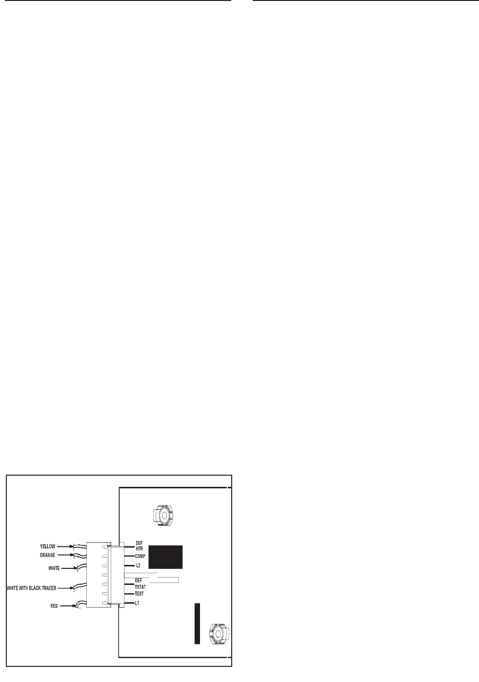
© 2003 Maytag Corporation
16010154 SECTION 2. COMPONENTS 2-152-15
2-152-15
2-15
These models use a metal sheath heater to
remove accumulated frost from the freezer
evaporator and drain trough during a de-
frost cycle.
The defrost timer (models) energizes the
defrost heater every 8 hours of accumu-
lated compressor run time. When the tem-
perature in the thermostat area reaches ap-
proximately +43o F. the thermostat contacts
open the circuit to the defrost heater.
An ohmmeter check will determine if all
phases of the defrost cycle are functioning
properly. The defrost thermostat contacts
open at approximately +43o F. and close at
approximately +15o F.
The defrost thermostat has a 240K ohm re-
sistor connected internally across the two
terminals. This resistor permits checking
the defrost heater when the evaporator tem-
perature is +15o F. or higher.
An ohmmeter can be used to test the de-
frost heater and thermostat without disas-
sembling the freezer compartment even if
the evaporator temperature is +15o F. or
higher. To check, proceed as follows:
1. Disconnect the unit from the powerDisconnect the unit from the power
Disconnect the unit from the powerDisconnect the unit from the power
Disconnect the unit from the power
source.source.
source.source.
source.
2. Open the fresh food door and remove
any items on the top shelf. Remove the
light shield and the fascia/radiant shield
mounting screws in the temperature
control housing. While holding the
front of the housing, remove the rear
mounting screw. Lower the control
housing.
Note:Note:
Note:Note:
Note:
If the temperature control is open If the temperature control is open
If the temperature control is open If the temperature control is open
If the temperature control is open
(unit not running and you jumper L1 and(unit not running and you jumper L1 and
(unit not running and you jumper L1 and(unit not running and you jumper L1 and
(unit not running and you jumper L1 and
Test) the unit will cycle through the testTest) the unit will cycle through the test
Test) the unit will cycle through the testTest) the unit will cycle through the test
Test) the unit will cycle through the test
mode in two seconds and there will be nomode in two seconds and there will be no
mode in two seconds and there will be nomode in two seconds and there will be no
mode in two seconds and there will be no
watt draw.watt draw.
watt draw.watt draw.
watt draw.
Checking the Adaptive DefrostChecking the Adaptive Defrost
Checking the Adaptive DefrostChecking the Adaptive Defrost
Checking the Adaptive Defrost
ControlControl
ControlControl
Control
1. Disconnect the unit from the powerDisconnect the unit from the power
Disconnect the unit from the powerDisconnect the unit from the power
Disconnect the unit from the power
source.source.
source.source.
source.
2. Open the fresh food door and remove
any items on the top shelf.
3. Remove the light shield and the tem-
perature control housing (see steps 3
and 4 replacing the timer).
4. Connect the refrigerator to a wattme-
ter.
5. Make sure compressor is running (cold
control closed).
6. Using an insulated number 22 jumper
wire short between L1 and Test; this will
put the refrigerator into a defrost for
approximately 23 minutes.
7. The watt meter should read between
500 to 600 watts depending on the
model.
AIR FLOW - FORCED AIR SYSTEMSAIR FLOW - FORCED AIR SYSTEMS
AIR FLOW - FORCED AIR SYSTEMSAIR FLOW - FORCED AIR SYSTEMS
AIR FLOW - FORCED AIR SYSTEMS
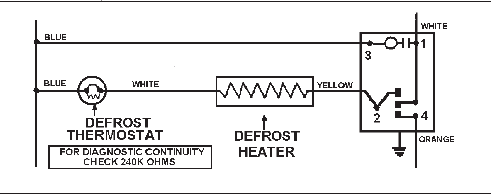
© 2003 Maytag Corporation
16010154 SECTION 2. COMPONENTS 2-162-16
2-162-16
2-16
3. Disconnect the timer wire harness con-
nector from the defrost timer.
4. Set the ohmmeter to R x 1K scale and
connect the probes to the No. 2 and
No. 3 terminals of the disconnect plug.
5. The meter should read between 20 to
40 ohms. The resistance is not critical.
If there is continuity between terminals
No. 2 and 3, the defrost heater is in op-
erative condition. If there are no resis-
tance readings (open circuit) the defrost
heater and thermostat must be checked
individually.
NOTE: NOTE:
NOTE: NOTE:
NOTE:
When using the meter, avoid When using the meter, avoid
When using the meter, avoid When using the meter, avoid
When using the meter, avoid
touching the probes as this could resulttouching the probes as this could result
touching the probes as this could resulttouching the probes as this could result
touching the probes as this could result
in a false reading and misdiagnosis.in a false reading and misdiagnosis.
in a false reading and misdiagnosis.in a false reading and misdiagnosis.
in a false reading and misdiagnosis.
To test the defrost heater and thermostat
when the evaporator temperature is +15ºF.
or below, proceed as follows:
1. Disconnect the unit from the powerDisconnect the unit from the power
Disconnect the unit from the powerDisconnect the unit from the power
Disconnect the unit from the power
source and plug it into a watt metersource and plug it into a watt meter
source and plug it into a watt metersource and plug it into a watt meter
source and plug it into a watt meter.
2. Plug the watt meter into power source
and manually advance the defrost timer
to the defrost cycle. See the defrost
timer section for information on manu-
ally advancing the timer.
3. The watt meter should read between
345 and 475 watts depending on the
model (total wattage of the timer mo-
tor and defrost heater). Should the
reading be 0 to 4.5 watts, the defrost
heater or thermostat is defective. To
further isolate the defective part, pro-
ceed to step 4.
4. Disconnect the unit from the watt meter.
5. Follow steps 2 and 3 of testing the
heater and thermostat when the evapo-
rator temperature is +15ºF. or higher.
6. If the meter reads approximately 240K
ohms, the defrost thermostat is defec-
tive.
To use an ohmmeter, set the meter to R x
1K scale. If the reading is approximately 20
to 40 ohms, the defrost heater and thermo-
stat are operative.
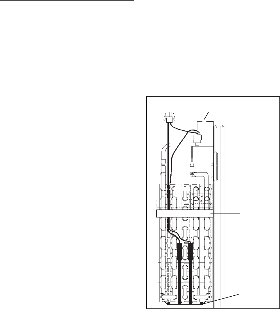
© 2003 Maytag Corporation
16010154 SECTION 2. COMPONENTS 2-172-17
2-172-17
2-17
1. Disconnect the unit from the powerDisconnect the unit from the power
Disconnect the unit from the powerDisconnect the unit from the power
Disconnect the unit from the power
source.source.
source.source.
source.
2. Remove the ice maker if equipped.
3. Remove the evaporator cover by loos-
ening the top two screws on each cor-
ner of the cover and removing the bot-
tom screws on each corner.
4. Tilt the top of the evaporator cover for-
ward and disconnect the wire harness
connector.
5. Remove the evaporator cover and fan
motor assembly. It is very important
that this part be reinstalled in the same
manner as it was originally.
6. Disconnect the defrost heater wire
leads. Using long nose pliers, remove
the defrost heater retainer clips. (One
on the right side of the heater and one
on the left side).
7. Install the replacement heater in the re-
verse order of removal.
DEFROST HEATER REPLACEMENTDEFROST HEATER REPLACEMENT
DEFROST HEATER REPLACEMENTDEFROST HEATER REPLACEMENT
DEFROST HEATER REPLACEMENT
Defrost Thermostat
1.5" Away From
Back of the Freezer Wall
Defrost Heater
Clip
Foam Block
DEFROST THERMOSTATDEFROST THERMOSTAT
DEFROST THERMOSTATDEFROST THERMOSTAT
DEFROST THERMOSTAT
REPLACEMENTREPLACEMENT
REPLACEMENTREPLACEMENT
REPLACEMENT
The defrost termination thermostat is lo-
cated on the top right side of the
evaporator.
1. Follow the first five steps in replacing
the defrost heater.
2. Disconnect the leads from the
thermostat.
3. Remove the defrost thermostat and
mounting clip by releasing the mount-
ing clip that is snapped around the
evaporator tubing.
4. Install the new defrost thermostat in the
reverse order of removal. Make sure
the thermostat is located per the draw-
ing below.
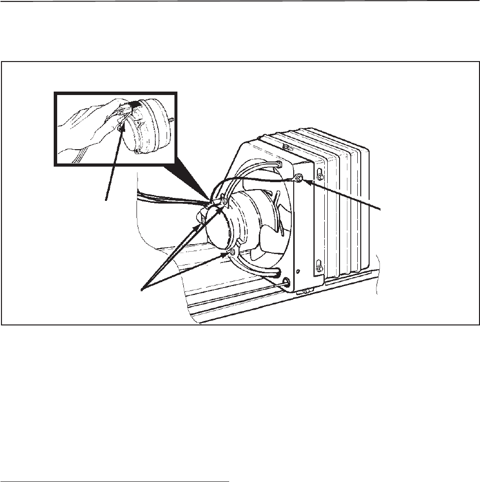
© 2003 Maytag Corporation
16010154 SECTION 2. COMPONENTS 2-182-18
2-182-18
2-18
The condenser fan motor is connected in
parallel with the compressor. If the com-
pressor runs but the motor doesn't, the
motor is either defective or disconnected.
If neither operates, check the cold control,
defrost timer, and the cabinet wiring.
TT
TT
To Check The Condenser Motoro Check The Condenser Motor
o Check The Condenser Motoro Check The Condenser Motor
o Check The Condenser Motor
DirectDirect
DirectDirect
Direct
1. Disconnect the unit from the powerDisconnect the unit from the power
Disconnect the unit from the powerDisconnect the unit from the power
Disconnect the unit from the power
source.source.
source.source.
source.
2. Remove the insulated cover from the
rear of the cabinet.
3. Disconnect the condenser fan motor
lead connector on the motor terminals.
To remove the lead connector from theTo remove the lead connector from the
To remove the lead connector from theTo remove the lead connector from the
To remove the lead connector from the
condenser fan motor, grasp the connec-condenser fan motor, grasp the connec-
condenser fan motor, grasp the connec-condenser fan motor, grasp the connec-
condenser fan motor, grasp the connec-
tor with your thumb inserted between thetor with your thumb inserted between the
tor with your thumb inserted between thetor with your thumb inserted between the
tor with your thumb inserted between the
connector and the locking lever as shown.connector and the locking lever as shown.
connector and the locking lever as shown.connector and the locking lever as shown.
connector and the locking lever as shown.
Pull the connector away from the motor.Pull the connector away from the motor.
Pull the connector away from the motor.Pull the connector away from the motor.
Pull the connector away from the motor.
4. Attach a 115v test cord to condenser
motor and plug into a power source. If
the motor fails to operate, it is defec-
tive and must be replaced.
Remove MotorRemove Motor
Remove MotorRemove Motor
Remove Motor
Wire HarnessWire Harness
Wire HarnessWire Harness
Wire Harness
Lock LeverLock Lever
Lock LeverLock Lever
Lock Lever
Remove FanRemove Fan
Remove FanRemove Fan
Remove Fan
Motor BracketMotor Bracket
Motor BracketMotor Bracket
Motor Bracket
Screws (3)Screws (3)
Screws (3)Screws (3)
Screws (3)
Remove GroundRemove Ground
Remove GroundRemove Ground
Remove Ground
Wire Screw Wire Screw
Wire Screw Wire Screw
Wire Screw
CONDENSER FAN MOTORCONDENSER FAN MOTOR
CONDENSER FAN MOTORCONDENSER FAN MOTOR
CONDENSER FAN MOTOR

© 2003 Maytag Corporation
16010154 SECTION 2. COMPONENTS 2-192-19
2-192-19
2-19
Condenser Fan Motor ReplacementCondenser Fan Motor Replacement
Condenser Fan Motor ReplacementCondenser Fan Motor Replacement
Condenser Fan Motor Replacement
1. Disconnect the unit from the powerDisconnect the unit from the power
Disconnect the unit from the powerDisconnect the unit from the power
Disconnect the unit from the power
source.source.
source.source.
source.
2. Remove the insulated cover from the
rear of cabinet.
3. Disconnect the condenser fan motor
lead connector on the motor terminals.
4. Remove the screws that mount the fan
motor to the brackets.
5. Transfer the fan blade to the replace-
ment motor making sure it is installed
in the same manner as the original.
6. Install the fan motor leads and ground
wire.
7. Install those parts previously removed.
Test run the unit.
FREEZER FAN MOTORFREEZER FAN MOTOR
FREEZER FAN MOTORFREEZER FAN MOTOR
FREEZER FAN MOTOR
The freezer fan circulates the cooled air
throughout the fresh food and freezer com-
partment. The fan blade is made of poly-
ethylene and is pushed onto the shaft. It is
important when replacing the fan blade that
the hub of the fan blade faces out, toward
the back of the evaporator fan cover. If the
fan fails or operates erratically, the reduced
air circulation will result in poor cooling char-
acteristics.
1. Disconnect unit from the powerDisconnect unit from the power
Disconnect unit from the powerDisconnect unit from the power
Disconnect unit from the power
source.source.
source.source.
source.
2. Remove the freezer shelving.
3. Loosen the two top screws and remove
the two bottom evaporator cover
mounting screws.
4. Grasp the bottom of the cover. Care-
fully pull the cover forward and down
to clear the upper flange.
5. Disconnect the evaporator fan motor
leads. The wire leads are self-locking
and it is important to squeeze the clip
before pulling the leads off the
terminals.
6. Remove the evaporator fan motor as-
sembly and place it on a work surface.
7. Connect the motor terminals to a ser-
vice cord and plug the cord into the
power source.
8. If the motor fails to operate, it is defec-
tive and must be replaced.
Freezer Fan Motor DiagnosisFreezer Fan Motor Diagnosis
Freezer Fan Motor DiagnosisFreezer Fan Motor Diagnosis
Freezer Fan Motor Diagnosis
Loosen
the screw
Remove
the screw
Fan
Cover
Remove
the screw
Loosen
the screw
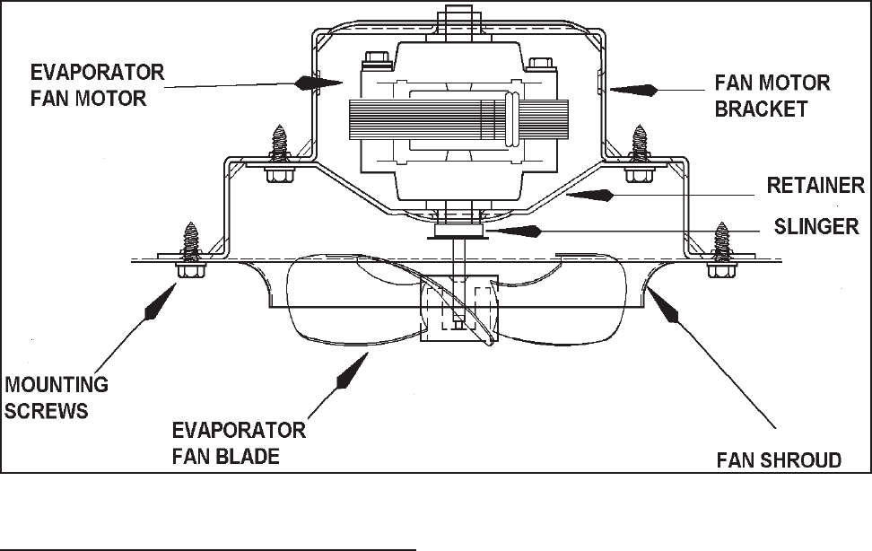
© 2003 Maytag Corporation
16010154 SECTION 2. COMPONENTS 2-202-20
2-202-20
2-20
1. Follow steps 1 through 5,
"Freezer Fan"Freezer Fan
"Freezer Fan"Freezer Fan
"Freezer Fan
Motor Diagnosis."Motor Diagnosis."
Motor Diagnosis."Motor Diagnosis."
Motor Diagnosis."
2. Remove the screws that secure the mo-
tor bracket assembly to the fan shroud.
3. Remove the fan blade by pulling it off
the shaft.
4. Remove the screws that secure the rear
bracket to the front bracket. Remove
the motor from the rear mounting
bracket.
5. Install the new motor to the rear mount-
ing bracket. Mount the rear bracket to
the front mounting bracket.
6. Install the slinger disc and fan blade on
the replacement in the same position
as on the original motor shaft.
Freezer Fan Motor ReplacementFreezer Fan Motor Replacement
Freezer Fan Motor ReplacementFreezer Fan Motor Replacement
Freezer Fan Motor Replacement NOTE: NOTE:
NOTE: NOTE:
NOTE:
Make sure the slinger disc does Make sure the slinger disc does
Make sure the slinger disc does Make sure the slinger disc does
Make sure the slinger disc does
not drag on the fan bushing.not drag on the fan bushing.
not drag on the fan bushing.not drag on the fan bushing.
not drag on the fan bushing.
7. Install the motor and bracket assembly
onto the evaporator cover.
8. Connect the wire leads and the ground
wire to the motor.
9. Reassemble those parts previously re-
moved and test the unit.
The fan blade is provided with a stop on
the face of the hub. It is properly installed
when the blade is positioned so the stop
rests against the end of the shaft.
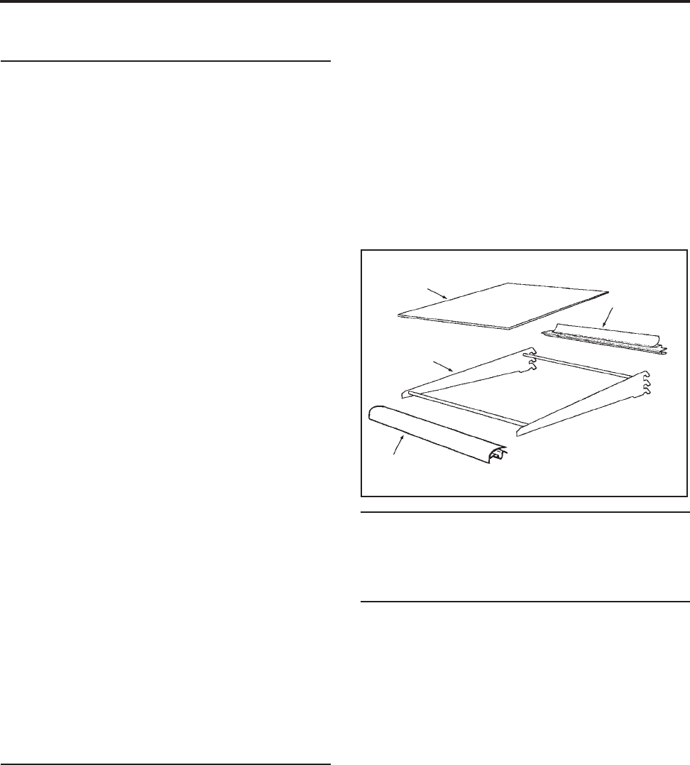
© 2003 Maytag Corporation
16010154 SECTION 3. CABINET & RELATED COMPONENTS 3-13-1
3-13-1
3-1
SECTION 3. CABINET & RELATED COMPONENTSSECTION 3. CABINET & RELATED COMPONENTS
SECTION 3. CABINET & RELATED COMPONENTSSECTION 3. CABINET & RELATED COMPONENTS
SECTION 3. CABINET & RELATED COMPONENTS
ADJUSTABLE CANTILEVERADJUSTABLE CANTILEVER
ADJUSTABLE CANTILEVERADJUSTABLE CANTILEVER
ADJUSTABLE CANTILEVER
SHELVESSHELVES
SHELVESSHELVES
SHELVES
II
II
Inner Door Liner Replacementnner Door Liner Replacement
nner Door Liner Replacementnner Door Liner Replacement
nner Door Liner Replacement
The polystyrene inner door liner and the
door seal are mounted to the outer panel
by screws placed around the door flange.
The inner door liner can be replaced with-
out removing the door from the cabinet. If
it is necessary to remove the door liner,
proceed as follows:
1. Turn the control to the
"Off""Off"
"Off""Off"
"Off"
position.
2. Open the freezer door and remove the
screws from around the door flange.
CABINET DOORS ANDCABINET DOORS AND
CABINET DOORS ANDCABINET DOORS AND
CABINET DOORS AND
ASSOCIATED PARTSASSOCIATED PARTS
ASSOCIATED PARTSASSOCIATED PARTS
ASSOCIATED PARTS
The cantilever shelf trims are easily re-
moved by placing the shelf on a flat work
surface. Raise the front of the shelf, grasp
the right underside of the front trim, and pull
toward you. Next, remove the glass from
the rear trim and remove trim.
Type #1Type #1
Type #1Type #1
Type #1
- Two support hook frame - Two support hook frame
- Two support hook frame - Two support hook frame
- Two support hook frame
design.design.
design.design.
design.
Glass or wire cantilever shelves may be
available with your refrigerator. To remove
a shelf, tilt front up and lift the rear up a frac-
tion of an inch and pull straight out. To lock
the shelf into another position, tilt the shelf
with the front up. Insert hooks into desired
shelf openings and let the shelf settle into
place. Check that the shelf is securely
locked into position before loading it with
food.
Type # 2Type # 2
Type # 2Type # 2
Type # 2
- Three support hook frame - Three support hook frame
- Three support hook frame - Three support hook frame
- Three support hook frame
design.design.
design.design.
design.
To remove the shelf, grasp the shelf at the
front with one hand and push up under the
shelf back with the other hand and pull out.
To lock shelf into another position, keep the
shelf horizontal, guiding the support hooks
into the slots in the shelf support at the rear
of the cabinet. Lower the shelf until the
hooks lock into position. Check that the
shelf is securely locked into position before
loading with food.
CANTILEVER SHELF TRIMCANTILEVER SHELF TRIM
CANTILEVER SHELF TRIMCANTILEVER SHELF TRIM
CANTILEVER SHELF TRIM
Install the new rear trim on the glass. Place
the shelf in a vertical position (shelf front up).
Install the glass and rear trim by applying a
downward force on the rear metal shelf
cross brace until it snaps securely in place.
Next, install the front trim on the glass and
the front metal shelf cross brace.
GlassGlass
GlassGlass
Glass
FrameFrame
FrameFrame
Frame
FrontFront
FrontFront
Front
TrimTrim
TrimTrim
Trim
RearRear
RearRear
Rear
TrimTrim
TrimTrim
Trim

© 2003 Maytag Corporation
16010154 SECTION 3. CABINET & RELATED COMPONENTS 3-23-2
3-23-2
3-2
3. Remove the door liner and transfer the
seal to the replacement liner. Make
sure the lip of the seal will sandwich be-
tween the inner and outer door panel.
4. Position the replacement door liner and
loosely install all the screws around the
door flange.
5. Open and close the door several times
to check the seal for proper alignment.
6. Carefully open the door by pulling on
the middle of the door panel.
NOTE: NOTE:
NOTE: NOTE:
NOTE:
Do not pull the door by the handle Do not pull the door by the handle
Do not pull the door by the handle Do not pull the door by the handle
Do not pull the door by the handle
or the panel will shift out of alignment.or the panel will shift out of alignment.
or the panel will shift out of alignment.or the panel will shift out of alignment.
or the panel will shift out of alignment.
7. Tighten all corner screws.
8. Open and close the door several times.
Recheck the door seal for proper align-
ment. If alignment is correct, tighten
remaining screws.
Tighten the screws until they are just
snug, then turn clockwise another one-
half turn.
NOTE: NOTE:
NOTE: NOTE:
NOTE:
Do not attempt to twist the door Do not attempt to twist the door
Do not attempt to twist the door Do not attempt to twist the door
Do not attempt to twist the door
panel after all the screws have beenpanel after all the screws have been
panel after all the screws have beenpanel after all the screws have been
panel after all the screws have been
tightened.tightened.
tightened.tightened.
tightened.
9. Transfer the shelves and the trim to the
replacement liner.
Outer Door Panel ReplacementOuter Door Panel Replacement
Outer Door Panel ReplacementOuter Door Panel Replacement
Outer Door Panel Replacement
NOTE:NOTE:
NOTE:NOTE:
NOTE:
Remove all food from the freezer Remove all food from the freezer
Remove all food from the freezer Remove all food from the freezer
Remove all food from the freezer
door.door.
door.door.
door.
1. Turn the control to the "Off" position.
2. Remove door handle and trim.
3. Use a soft lead pencil to trace around
the upper hinge. (This will aid in replac-
ing the hinge.)
4. Remove the upper hinge and place it
on top of the unit with newspaper or
cloth underneath to prevent scratching.
Do not misplace the spacers. Place the
door on a padded work surface.
5. Transfer the handle, trim, plug button,
bushings, gaskets and liner to replace-
ment panel.
6. Install the top hinge using the tracing
to align the hinge.
FRONT WHEEL ASSEMBLYFRONT WHEEL ASSEMBLY
FRONT WHEEL ASSEMBLYFRONT WHEEL ASSEMBLY
FRONT WHEEL ASSEMBLY
The front wheel assembly is securely fas-
tened by two screws to the face plate of the
cabinet.
Depending on the model, you will encoun-
ter adjustable or non-adjustable front wheel
assemblies. To lock the cabinet in place
lower the front leveling legs.
CABINET LEVELINGCABINET LEVELING
CABINET LEVELINGCABINET LEVELING
CABINET LEVELING
To enhance its appearance and maintain ef-
ficient performance, the refrigerator should
be level. The front wheels were adjusted
at the factory so the doors were properly
aligned and the cabinet level. However, jar-
ring in transit, or standing the refrigerator
on uneven floors may cause the doors to
shift out of alignment. If front alignment is
necessary, adjust the wheel with a hex head
driver. Clockwise raises the cabinet,
counter-clockwise lowers the cabinet. If
front wheels are not adjustable, use level-
ing legs to level.
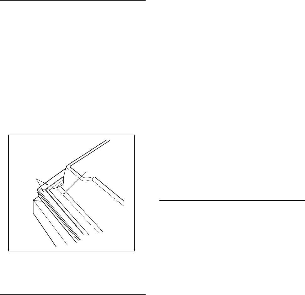
© 2003 Maytag Corporation
16010154 SECTION 3. CABINET & RELATED COMPONENTS 3-33-3
3-33-3
3-3
DOOR SEALDOOR SEAL
DOOR SEALDOOR SEAL
DOOR SEAL
The drawing shows a view of the magnetic
door seal used on all models mentioned in
this manual. The magnetic strips are at-
tracted to the metal cabinet front, provid-
ing an excellent seal around the entire door.
A visual inspection of the door seal while
opening and closing will reveal any areas
of poor seal. You will notice a slight expan-
sion and compression of the seal bellows
as the door is opened and closed.
MagneticMagnetic
MagneticMagnetic
Magnetic
Strips Strips
Strips Strips
Strips
BalloonBalloon
BalloonBalloon
Balloon
Seal Seal
Seal Seal
Seal
Door Seal And Magnetic StripsDoor Seal And Magnetic Strips
Door Seal And Magnetic StripsDoor Seal And Magnetic Strips
Door Seal And Magnetic Strips
TOE-IN & TOE-OUT ADJUSTMENTSTOE-IN & TOE-OUT ADJUSTMENTS
TOE-IN & TOE-OUT ADJUSTMENTSTOE-IN & TOE-OUT ADJUSTMENTS
TOE-IN & TOE-OUT ADJUSTMENTS
To seal evenly around the entire door, the
seal must make contact at the top and bot-
tom at the same time. For this reason, the
door, when ajar, should not
toe-in
or
toe-out
.
To correct a
toe-in
or
toe-out
condition, first
check that the hinge-side of the door is par-
allel with the cabinet then proceed as
follows:
1. Check the cabinet levelers and adjust-
able wheels. Raising the handle side
may correct a toe-out; lowering may
correct a toe-in.
2. Loosen all inner panel mounting
screws along the top, bottom and
handle side of the door. Do not loosen
the screws along the hinge side.
3. Hold the corner that toes-in stationary,
and push in on the toe-out corner until
the door is lined parallel with the
cabinet.
4. Open and close the door several times
to ensure a proper fit.
If necessary, re-If necessary, re-
If necessary, re-If necessary, re-
If necessary, re-
peat steps 2 and 3.peat steps 2 and 3.
peat steps 2 and 3.peat steps 2 and 3.
peat steps 2 and 3.
5. Tighten all loosened screws.
HINGE ADJUSTMENTSHINGE ADJUSTMENTS
HINGE ADJUSTMENTSHINGE ADJUSTMENTS
HINGE ADJUSTMENTS
Hinge adjustments are necessary when:
1. The seal is not sealed sufficiently along
the hinge side of the door.
2. The seal is compressed more than 1/
16" on the hinge side (causing a poor
seal elsewhere around the top.)
3. The distance between the door and
cabinet is greater at the top than it is at
the bottom, or vice versa.
4. The hinge side of the door is not 1/16"
out past the side of the cabinet when
(measured from the side of the cabi-
net), or when the door panel top is not
7/64" above the cabinet top.
5. If one or more of these conditions ex-
ist, adjust one or both hinges to correct
the trouble. Raising the hinge side may
correct a door sag.

© 2003 Maytag Corporation
16010154 SECTION 3. CABINET & RELATED COMPONENTS 3-43-4
3-43-4
3-4
DOOR ALIGNMENTDOOR ALIGNMENT
DOOR ALIGNMENTDOOR ALIGNMENT
DOOR ALIGNMENT
The cabinet door on all models is in correct
alignment when:
1. The hinge side of the door is an equal
distance from the cabinet flange at the
top and bottom.
2. The gasket seals smoothly and is com-
pressed no more than 1/16" along the
hinge side with the door closed.
3. The door lines up with the side of the
cabinet (viewed from the front). The
door panel is parallel with the cabinet
top.
In many cases, leveling the refrigerator will
eliminate the need for cabinet door adjust-
ments. Ensure that the refrigerator is plumb
by checking all edges as well as both sides
of the cabinet with a carpenter's level.
DOOR SWITCHDOOR SWITCH
DOOR SWITCHDOOR SWITCH
DOOR SWITCH
Disconnect the unit from the powerDisconnect the unit from the power
Disconnect the unit from the powerDisconnect the unit from the power
Disconnect the unit from the power
source.source.
source.source.
source.
The door switches can be easily removed
by using a flat blade screw driver or putty
knife. Pry from the liner and disconnect
wires.
WATER/ICE DISPENSER FREEZERWATER/ICE DISPENSER FREEZER
WATER/ICE DISPENSER FREEZERWATER/ICE DISPENSER FREEZER
WATER/ICE DISPENSER FREEZER
DOOR REMOVALDOOR REMOVAL
DOOR REMOVALDOOR REMOVAL
DOOR REMOVAL
Before attempting to remove the door
hinge, look at your refrigerator and note the
exact number and position of all protective
shims on the door hinge. Later, when you
replace the hinge, these must be positioned
correctly.
1. Disconnect the unit from the powerDisconnect the unit from the power
Disconnect the unit from the powerDisconnect the unit from the power
Disconnect the unit from the power
source.source.
source.source.
source.
2. Open the door completely. Remove
the bottom hinge cover by squeezing
on the bottom and top while pulling it
toward you.
3. Locate the water line tubing coming out
of the cabinet. Carefully pull on the tub-
ing until the connector is on the outside
of the cabinet.
4. Disconnect the door water line tubing.
5. Remove the top hinge cover.
6. Disconnect the door wire harness by
pulling apart the two halves of the con-
nector. DO NOT PULL THE WIRES.
7. Mark the position of the top hinge with
a lead pencil.
8. Remove the ground wire screw with a
1/4" socket & rachet. Hold door with
one hand and finish removing screws.
Leave the hinge in the door.
9. Replace the door in reverse order of
removal.
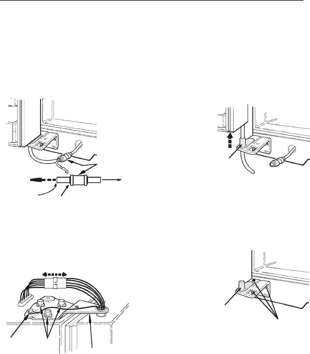
© 2003 Maytag Corporation
16010154 SECTION 3. CABINET & RELATED COMPONENTS 3-53-5
3-53-5
3-5
Lift the door up enough to allowLift the door up enough to allow
Lift the door up enough to allowLift the door up enough to allow
Lift the door up enough to allow
another adult to guide the wateranother adult to guide the water
another adult to guide the wateranother adult to guide the water
another adult to guide the water
line through the hinge pin. Restline through the hinge pin. Rest
line through the hinge pin. Restline through the hinge pin. Rest
line through the hinge pin. Rest
door on a non-scratching surface.door on a non-scratching surface.
door on a non-scratching surface.door on a non-scratching surface.
door on a non-scratching surface.
Hinge
Pin
Mark the location of the bottomMark the location of the bottom
Mark the location of the bottomMark the location of the bottom
Mark the location of the bottom
hinge with a pencil. Use a 5/16"hinge with a pencil. Use a 5/16"
hinge with a pencil. Use a 5/16"hinge with a pencil. Use a 5/16"
hinge with a pencil. Use a 5/16"
socket & ratchet to remove thesocket & ratchet to remove the
socket & ratchet to remove thesocket & ratchet to remove the
socket & ratchet to remove the
3 screws from the bottom hinge.3 screws from the bottom hinge.
3 screws from the bottom hinge.3 screws from the bottom hinge.
3 screws from the bottom hinge.
RemoveRemove
RemoveRemove
Remove
3 Screws3 Screws
3 Screws3 Screws
3 Screws
HingeHinge
HingeHinge
Hinge
Pull ApartPull Apart
Pull ApartPull Apart
Pull Apart
GroundGround
GroundGround
Ground
WireWire
WireWire
Wire
ScrewScrew
ScrewScrew
Screw
HingeHinge
HingeHinge
Hinge
ScrewsScrews
ScrewsScrews
Screws
DoorDoor
DoorDoor
Door
WaterWater
WaterWater
Water
LineLine
LineLine
Line
Water LineWater Line
Water LineWater Line
Water Line
ConnectorConnector
ConnectorConnector
Connector
Water LineWater Line
Water LineWater Line
Water Line
To CabinetTo Cabinet
To CabinetTo Cabinet
To Cabinet
Push collet againstPush collet against
Push collet againstPush collet against
Push collet against
connector to releaseconnector to release
connector to releaseconnector to release
connector to release
the door water linethe door water line
the door water linethe door water line
the door water line
WATER/ICE FREEZER DOOR REMOVALWATER/ICE FREEZER DOOR REMOVAL
WATER/ICE FREEZER DOOR REMOVALWATER/ICE FREEZER DOOR REMOVAL
WATER/ICE FREEZER DOOR REMOVAL
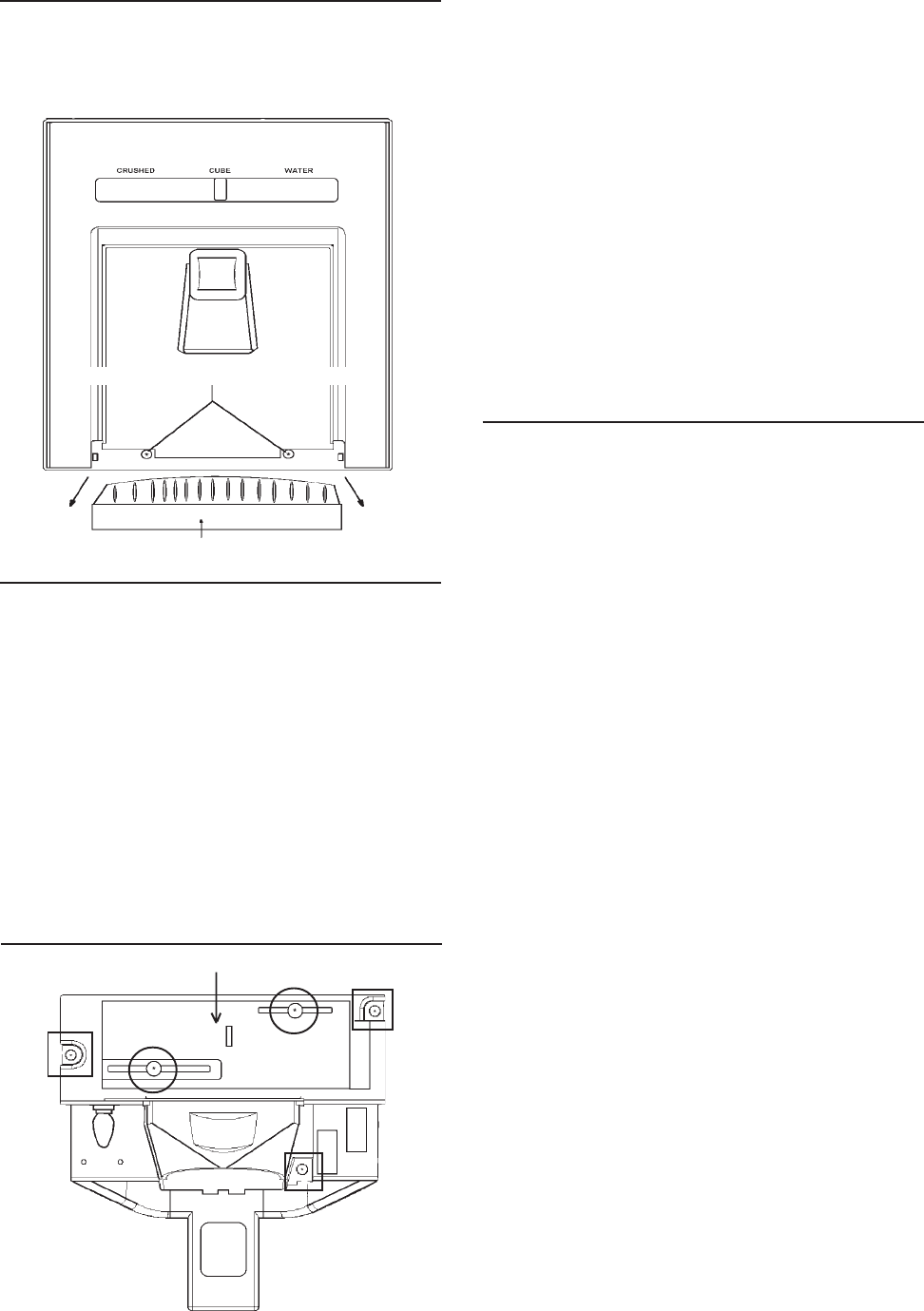
© 2003 Maytag Corporation
16010154 SECTION 3. CABINET & RELATED COMPONENTS 3-63-6
3-63-6
3-6
4. Place slide selector in center position.
5. Remove the three fountain bracket
mounting screws. (See drawing in the
lower left column.)
6. Carefully pull the assembly out of the
fountain housing. You now have full ac-
cess to the solenoid, dispenser mecha-
nism, PC delay board, lock switch, light
socket, and the light switch.
7. To repair the assembly, disconnect
electrical quick disconnect.
Checking and Replacing the CrusherChecking and Replacing the Crusher
Checking and Replacing the CrusherChecking and Replacing the Crusher
Checking and Replacing the Crusher
and Water/Cube Switch:and Water/Cube Switch:
and Water/Cube Switch:and Water/Cube Switch:
and Water/Cube Switch:
1. Disconnect the unit from the powerDisconnect the unit from the power
Disconnect the unit from the powerDisconnect the unit from the power
Disconnect the unit from the power
source.source.
source.source.
source.
2. Perform steps 1 through 3 of Ice & Wa-Ice & Wa-
Ice & Wa-Ice & Wa-
Ice & Wa-
ter Fountain Bracket Assemblyter Fountain Bracket Assembly
ter Fountain Bracket Assemblyter Fountain Bracket Assembly
ter Fountain Bracket Assembly
Removal.Removal.
Removal.Removal.
Removal.
3. Remove the two slide selector mount-
ing screws. (See drawing in the lower
left column.)
4. Remove the slide selector.
5. Check the continuity of the switch. If
defective, go to step 6.
6. Remove the switch mounting screw.
7. Remove the switch.
8. Remove the wire leads.
9. Install new switch in reverse order of
removal.
Ice and Water Fountain BracketIce and Water Fountain Bracket
Ice and Water Fountain BracketIce and Water Fountain Bracket
Ice and Water Fountain Bracket
Assembly RemovalAssembly Removal
Assembly RemovalAssembly Removal
Assembly Removal
1. Pull straight out to remove the grill
from the fountain sump.
2. Remove the two escutcheon mounting
screws.
3. Raise the escutcheon up and off the
fountain assembly.
SLIDE SELECTOR CENTEREDSLIDE SELECTOR CENTERED
SLIDE SELECTOR CENTEREDSLIDE SELECTOR CENTERED
SLIDE SELECTOR CENTERED
ESCUTCHEON MOUNTING SCREWSESCUTCHEON MOUNTING SCREWS
ESCUTCHEON MOUNTING SCREWSESCUTCHEON MOUNTING SCREWS
ESCUTCHEON MOUNTING SCREWS
GRILLGRILL
GRILLGRILL
GRILL
FOUNTAIN ASSEMBLIES - ManualFOUNTAIN ASSEMBLIES - Manual
FOUNTAIN ASSEMBLIES - ManualFOUNTAIN ASSEMBLIES - Manual
FOUNTAIN ASSEMBLIES - Manual
Slide ControlSlide Control
Slide ControlSlide Control
Slide Control
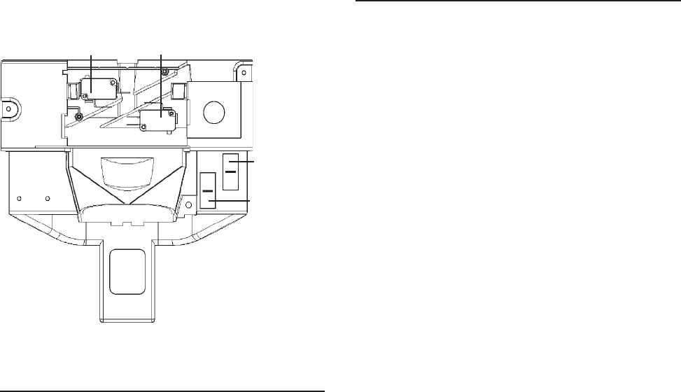
© 2003 Maytag Corporation
16010154 SECTION 3. CABINET & RELATED COMPONENTS 3-73-7
3-73-7
3-7
CRUSHER
SWITCH WATER/CUBE
SWITCH
LOCK
SWITCH
Checking and Replacing the Actua-Checking and Replacing the Actua-
Checking and Replacing the Actua-Checking and Replacing the Actua-
Checking and Replacing the Actua-
tor Switch:tor Switch:
tor Switch:tor Switch:
tor Switch:
1. Disconnect the unit from the powerDisconnect the unit from the power
Disconnect the unit from the powerDisconnect the unit from the power
Disconnect the unit from the power
source.source.
source.source.
source.
2. Perform steps 1 through 6 of To Re-To Re-
To Re-To Re-
To Re-
move Ice and Water Fountain Bracketmove Ice and Water Fountain Bracket
move Ice and Water Fountain Bracketmove Ice and Water Fountain Bracket
move Ice and Water Fountain Bracket
Assembly.Assembly.
Assembly.Assembly.
Assembly.
3. Check the continuity of the switch if
defective go to step 4.
4. Remove the mounting screw.
5. Remove the switch.
6. Remove the wire leads.
7. Install new switch in reverse order of
removal.
Fountain HeaterFountain Heater
Fountain HeaterFountain Heater
Fountain Heater
(A fountain heater is used on all dispenser
models).
The fountain heater is used to evaporate
any moisture that might accumulate from
condensation. It is bonded to self-adhesive
aluminum foil which is shaped to fit the out-
side of the fountain housing.
1. Disconnect the unit from the powerDisconnect the unit from the power
Disconnect the unit from the powerDisconnect the unit from the power
Disconnect the unit from the power
source.source.
source.source.
source.
2. Remove the ice and water fountain
bracket assembly as discussed earlier.
3. Disconnect the electrical quick
disconnect.
4. Check for resistance between the red
wire with the black tracer and the white
wire on the fountain housing, quick dis-
connect electrical connector.
5. If the fountain heater reads open, go to
step 5.
6. Remove the door from the unit and dis-
assemble liner and the gasket.
7. Carefully remove the foam seals and
disconnect the heater wire terminals.
8. Pull the foil heater backing from the
fountain.
9. Reassemble the parts in reverse order
of removal.
LIGHT
SWITCH
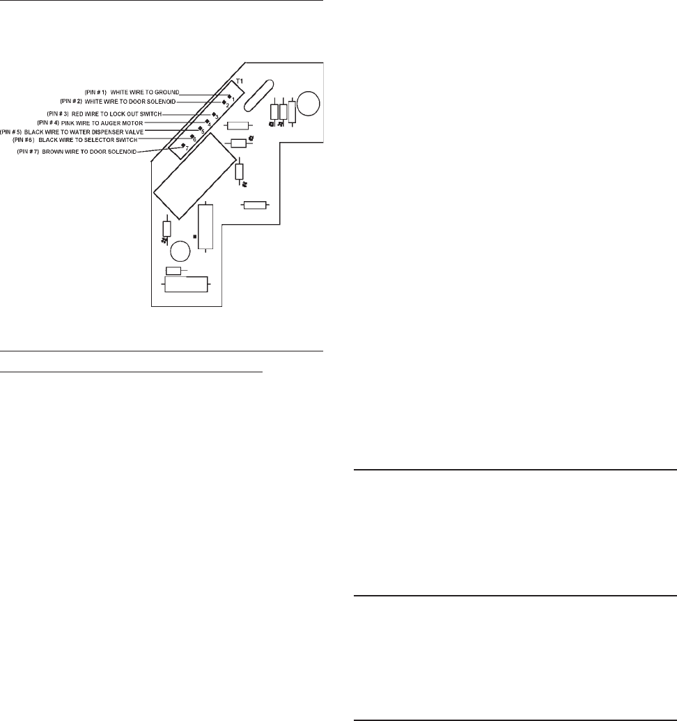
© 2003 Maytag Corporation
16010154 SECTION 3. CABINET & RELATED COMPONENTS 3-83-8
3-83-8
3-8
3. During activation, check for approxi-
mately 100 volts AC from PIN 7 to PIN2.
If 100 volts AC is not present, replace
the board. If voltage is present, check
the solenoid and associated wiring.
IF THE DOOR FAILS TO CLOSE:IF THE DOOR FAILS TO CLOSE:
IF THE DOOR FAILS TO CLOSE:IF THE DOOR FAILS TO CLOSE:
IF THE DOOR FAILS TO CLOSE:
1. Disconnect the unit from the powerDisconnect the unit from the power
Disconnect the unit from the powerDisconnect the unit from the power
Disconnect the unit from the power
source if the door still stays open.source if the door still stays open.
source if the door still stays open.source if the door still stays open.
source if the door still stays open.
Check the solenoid, door hinge and
spring assembly. If the door closes, go
to step 2.
2. Plug the unit in, check for 0 volts AC
from PIN 1 to PIN 4. If you read 115
volts AC check switches and wiring. If
voltage reads 0, go to step 3.
3. Disconnect the unit from the powerDisconnect the unit from the power
Disconnect the unit from the powerDisconnect the unit from the power
Disconnect the unit from the power
sourcesource
sourcesource
source and remove the circuit board.
Check continuity from PIN 7 to PIN 2.
If shorted, replace the circuit board.
Fountain Door DelayFountain Door Delay
Fountain Door DelayFountain Door Delay
Fountain Door Delay
Normal door delay will be approximately 2
seconds.
Excessive Door DelayExcessive Door Delay
Excessive Door DelayExcessive Door Delay
Excessive Door Delay
Check for mechnical obstruction, if none
replace PC board.
Short Door DelayShort Door Delay
Short Door DelayShort Door Delay
Short Door Delay
1. Check for 115 volts AC between PIN 3
and PIN 1. This ensures proper wiring
and good connection. Low voltage
may represent a problem in wiring con-
nections or at outlet.
2. Check for 115 AC between PIN 1 and
Pin 4 when dispenser switch is
engaged.
The following checks should only be madeThe following checks should only be made
The following checks should only be madeThe following checks should only be made
The following checks should only be made
by a Qualified Service Technician.by a Qualified Service Technician.
by a Qualified Service Technician.by a Qualified Service Technician.
by a Qualified Service Technician.
1.1.
1.1.
1. Disconnect unit from the powerDisconnect unit from the power
Disconnect unit from the powerDisconnect unit from the power
Disconnect unit from the power
source.source.
source.source.
source.
2. For easy access of the PC board, per-
form steps 1 through 5 of Ice and Wa-Ice and Wa-
Ice and Wa-Ice and Wa-
Ice and Wa-
ter Fountain Bracket Removal.ter Fountain Bracket Removal.
ter Fountain Bracket Removal.ter Fountain Bracket Removal.
ter Fountain Bracket Removal.
3. Make sure everything is clear. Apply
power to the refrigerator and perform
the following checks with a volt
ohmmeter.
IF DOOR FAILS TO OPEN:IF DOOR FAILS TO OPEN:
IF DOOR FAILS TO OPEN:IF DOOR FAILS TO OPEN:
IF DOOR FAILS TO OPEN:
Note: Note:
Note: Note:
Note:
The following checks will be atThe following checks will be at
The following checks will be atThe following checks will be at
The following checks will be at
terminal board connector T1.terminal board connector T1.
terminal board connector T1.terminal board connector T1.
terminal board connector T1.
1. Check for 115 volts AC from PIN 3 to
PIN 1. (Lock out switch must be
closed.)
2. Check for 115 volts AC from PIN 4 to
PIN 1 when selector is set to crushed
or cubed and actuator is depressed.
If not there, check selector switches,
actuator switch and associated wiring.
PC BOARD CHECKSPC BOARD CHECKS
PC BOARD CHECKSPC BOARD CHECKS
PC BOARD CHECKS
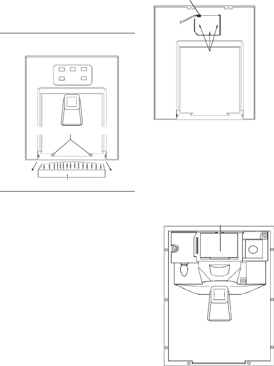
© 2003 Maytag Corporation
16010154 SECTION 3. CABINET & RELATED COMPONENTS 3-93-9
3-93-9
3-9
The PC board uses this line to charge the
holding circuit. A low voltage condition
here may represent poor switch contacts.
(Low voltage may cause short delays.) If
low voltage conditions do not exist, replace
the PC board.
Ice & Water Fountain BracketIce & Water Fountain Bracket
Ice & Water Fountain BracketIce & Water Fountain Bracket
Ice & Water Fountain Bracket
RemovalRemoval
RemovalRemoval
Removal
1. Disconnect the unit from the powerDisconnect the unit from the power
Disconnect the unit from the powerDisconnect the unit from the power
Disconnect the unit from the power
source.source.
source.source.
source.
2. To remove the grill from the fountain
sump, pull straight out.
3. Remove the two escutcheon mounting
screws.
4. Carefully raise the escutcheon up and off
the fountain assembly.
5. Disconnect the quick disconnect edge
connector from the PC fountain switch
board.
6. Remove the three fountain bracket
mounting screws.
Quick disconnect
edge connector from
the PC fountain
control board
(Pull up to remove)
PC FOUNTAIN SWITCH
BOARD, MOUNTING
SCREWS
REAR VIEW FOUNTAIN ESCUTCHEON REAR VIEW FOUNTAIN ESCUTCHEON
REAR VIEW FOUNTAIN ESCUTCHEON REAR VIEW FOUNTAIN ESCUTCHEON
REAR VIEW FOUNTAIN ESCUTCHEON
7. Carefully pull the assembly out of the
fountain housing. You now have full ac-
cess to solenoid, dispenser mecha-
nism, PC fountain control board and
light socket.
8. To repair the assembly, disconnect
electrical quick disconnect.
GRILL
FOUNTAIN ASSEMBLY - ElectronicFOUNTAIN ASSEMBLY - Electronic
FOUNTAIN ASSEMBLY - ElectronicFOUNTAIN ASSEMBLY - Electronic
FOUNTAIN ASSEMBLY - Electronic
ControlControl
ControlControl
Control
PC FOUNTAIN
CONTROL BOARD
FOUNTAIN ASSEMBLY
(ESCUTCHEON REMOVED)
ESCUTCHEON MOUNTING SCREWS
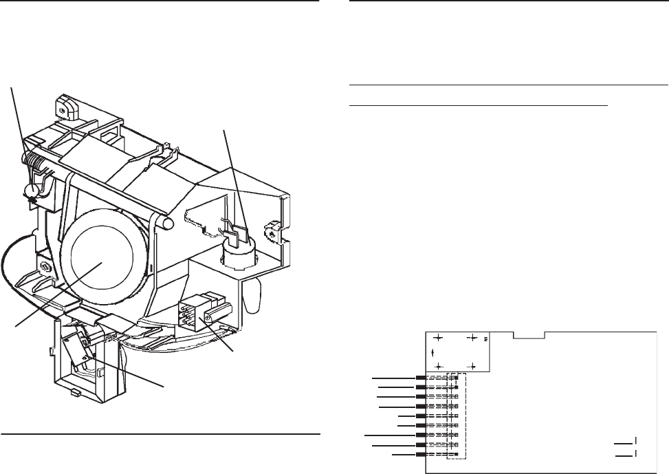
© 2003 Maytag Corporation
16010154 SECTION 3. CABINET & RELATED COMPONENTS 3-103-10
3-103-10
3-10
ICE DOOR
SOLENOID
ACTUATOR
SWITCH
Fountain Bracket AssemblyFountain Bracket Assembly
Fountain Bracket AssemblyFountain Bracket Assembly
Fountain Bracket Assembly
ICE DOOR ELECTRICAL
CONNECTOR
FOUNTAIN LIGHT
SOCKET
Checking and Replacing the Actua-Checking and Replacing the Actua-
Checking and Replacing the Actua-Checking and Replacing the Actua-
Checking and Replacing the Actua-
tor Switch:tor Switch:
tor Switch:tor Switch:
tor Switch:
1. Disconnect the unit from the powerDisconnect the unit from the power
Disconnect the unit from the powerDisconnect the unit from the power
Disconnect the unit from the power
source.source.
source.source.
source.
2. Perform Steps 1 through 6 of Ice & Wa-Ice & Wa-
Ice & Wa-Ice & Wa-
Ice & Wa-
ter Foutain Bracket Removal.ter Foutain Bracket Removal.
ter Foutain Bracket Removal.ter Foutain Bracket Removal.
ter Foutain Bracket Removal.
3. Continuity check the switch. If defective,
go to step 4.
4. Remove the mounting screw.
5. Remove the switch.
6. Remove the wire leads.
7. Install the new switch in reverse order
of removal.
The following checks should only be madeThe following checks should only be made
The following checks should only be madeThe following checks should only be made
The following checks should only be made
by a Qualified Service Technician.by a Qualified Service Technician.
by a Qualified Service Technician.by a Qualified Service Technician.
by a Qualified Service Technician.
NO LED'S ILLUMINATED ON THE FOUN-NO LED'S ILLUMINATED ON THE FOUN-
NO LED'S ILLUMINATED ON THE FOUN-NO LED'S ILLUMINATED ON THE FOUN-
NO LED'S ILLUMINATED ON THE FOUN-
TAIN TOUCH PADTAIN TOUCH PAD
TAIN TOUCH PADTAIN TOUCH PAD
TAIN TOUCH PAD
1. Check ribbon cable/wire connection
between the two PC boards ("Mechani-
cally Tight").
2. Checking the AC line in fountain veri-
fies operation/closure of door interlock
switch.
WHITE (T1)
BLUE
N/C
RED/WHITE
RED/BLACK
VIOLET
BLACK
BLACK
PINK
3. Check fountain heater continuity. Un-Un-
Un-Un-
Un-
plug the unit.plug the unit.
plug the unit.plug the unit.
plug the unit. Check heater resistance
neutral to heater connection it should
read approximately 4800 ohms.
4. Replace LED/Switch board.
5. Replace fountain control board.
SOME LED'S WILL NOT LIGHTSOME LED'S WILL NOT LIGHT
SOME LED'S WILL NOT LIGHTSOME LED'S WILL NOT LIGHT
SOME LED'S WILL NOT LIGHT
1. Replace LED/Switch board.
2. Replace fountain control board.
FOUNTAIN LIGHT WILL NOT LIGHTFOUNTAIN LIGHT WILL NOT LIGHT
FOUNTAIN LIGHT WILL NOT LIGHTFOUNTAIN LIGHT WILL NOT LIGHT
FOUNTAIN LIGHT WILL NOT LIGHT
1. Check bulb and mechanical connec-
tions.
2. Does fountain light illuminate during a
dispense?
Electronic Control BoardElectronic Control Board
Electronic Control BoardElectronic Control Board
Electronic Control Board
TroubleshootingTroubleshooting
TroubleshootingTroubleshooting
Troubleshooting
JF1
JF2
BROWN
BROWN
TRACE SIDE OF PC FOUNTAIN CONTROL BOARD
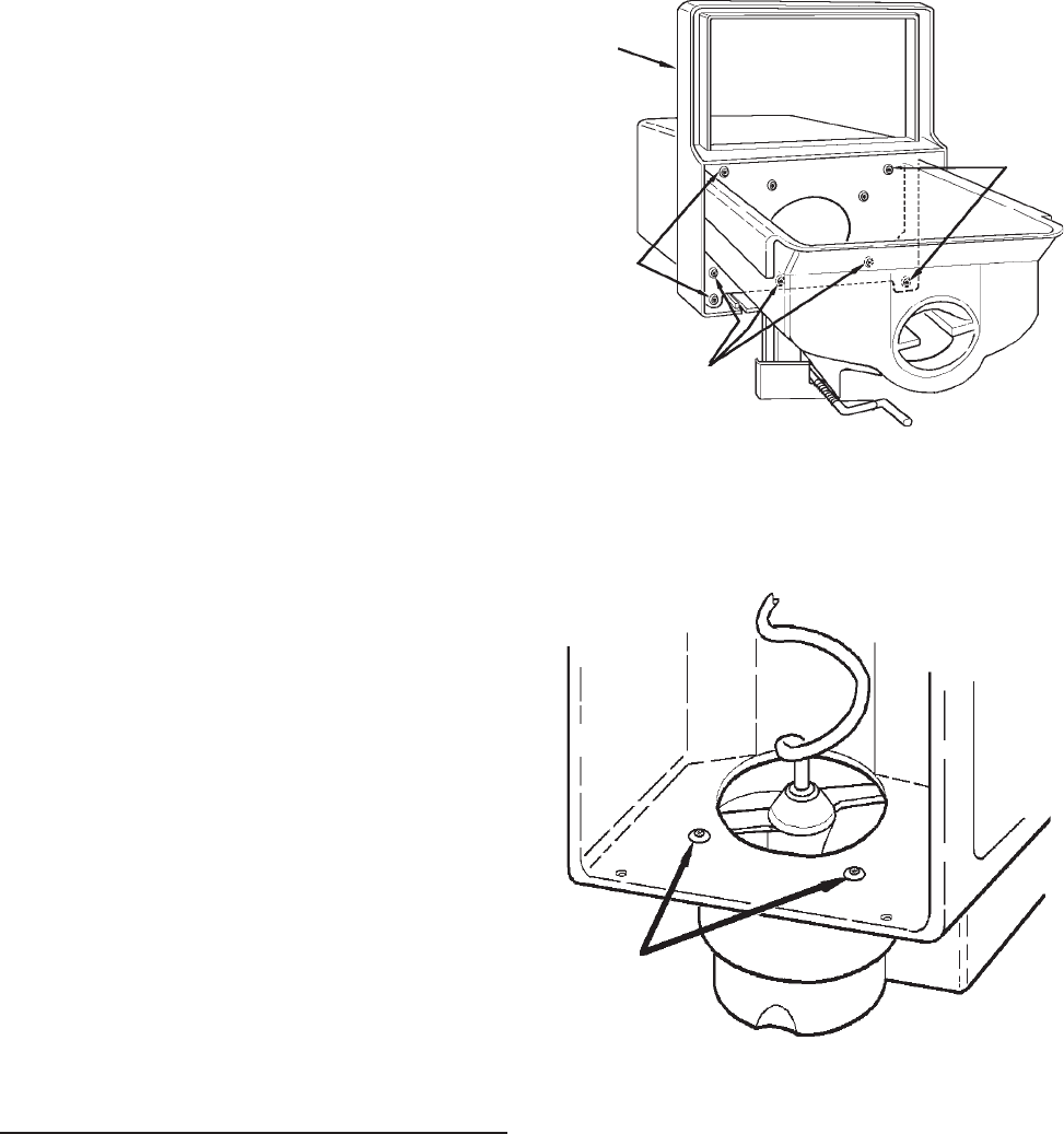
© 2003 Maytag Corporation
16010154 SECTION 3. CABINET & RELATED COMPONENTS 3-113-11
3-113-11
3-11
Yes: (a) Replace LED/Switch board.
No: (b) Replace fountain control board.
WILL NOT DISPENSE ICE OR WATERWILL NOT DISPENSE ICE OR WATER
WILL NOT DISPENSE ICE OR WATERWILL NOT DISPENSE ICE OR WATER
WILL NOT DISPENSE ICE OR WATER
1. Press lock button 3 times. If another
LED lights, replace LED/Switch PC
Board.
2. When actuator pad is pressed, does
fountain light come on?
Note: Make sure fountain light bulb isNote: Make sure fountain light bulb is
Note: Make sure fountain light bulb isNote: Make sure fountain light bulb is
Note: Make sure fountain light bulb is
good!good!
good!good!
good!
No: (a) Check actuator switch and
mechanical connections.
(b) Replace PC control board.
Yes:(a) If nothing works (ice door sole-
noid/auger/cube solenoid/water
valve), replace PC control board.
No: (b) If some functions work check for
115 VAC at ice door solenoid/
auger/cube solenoid/water valve
terminals during dispense.
(1) If 115 VAC output exists, replace
component.
(2) If 115 VAC output is not present,
replace control board.
ICE CRUSHER BIN AND SHELFICE CRUSHER BIN AND SHELF
ICE CRUSHER BIN AND SHELFICE CRUSHER BIN AND SHELF
ICE CRUSHER BIN AND SHELF
ASSEMBLYASSEMBLY
ASSEMBLYASSEMBLY
ASSEMBLY
1. To service the ice/crusher related com-
ponents, turn the ice maker off by lift-
ing the shut off arm. Remove the bin
assembly.
2. Remove the four bin front mounting
screws.
BIN FRONTBIN FRONT
BIN FRONTBIN FRONT
BIN FRONT
MOUNTINGMOUNTING
MOUNTINGMOUNTING
MOUNTING
SCREWSSCREWS
SCREWSSCREWS
SCREWS
BIN FRONTBIN FRONT
BIN FRONTBIN FRONT
BIN FRONT
CRUSHER HOUSINGCRUSHER HOUSING
CRUSHER HOUSINGCRUSHER HOUSING
CRUSHER HOUSING
MOUNTING SCREWSMOUNTING SCREWS
MOUNTING SCREWSMOUNTING SCREWS
MOUNTING SCREWS
3. Place the bin assembly on the crusher
housing.
INSIDE OF BININSIDE OF BIN
INSIDE OF BININSIDE OF BIN
INSIDE OF BIN
CRUSHER HOUSINGCRUSHER HOUSING
CRUSHER HOUSINGCRUSHER HOUSING
CRUSHER HOUSING
MOUNTING SCREWSMOUNTING SCREWS
MOUNTING SCREWSMOUNTING SCREWS
MOUNTING SCREWS
4. Care should be taken when removing
the control rod spring to ensure it does
not snap back on your finger.
BIN FRONTBIN FRONT
BIN FRONTBIN FRONT
BIN FRONT
MOUNTINGMOUNTING
MOUNTINGMOUNTING
MOUNTING
SCREWSSCREWS
SCREWSSCREWS
SCREWS

© 2003 Maytag Corporation
16010154 SECTION 3. CABINET & RELATED COMPONENTS 3-123-12
3-123-12
3-12
CRUSHER CONTROL ROD
CONTROL ROD
BRACKET
CONTROL ROD
SPRING
SCREW
DRIVER
5. When removing the control bracket,
hold the clip; this will prevent it from
being thrown off.
6. When removing the crusher housing,
position the snap ring (1) as shown in
the above drawing, then remove it and
the retainer washer (2).
7. Push the auger assembly away from the
crusher housing using your thumb (3).
8. To remove the auger nut turn it
clockwise.
IMPELLER
AUGER
AUGER
NUT
ICE DIVERTER
SNOW SHIELD
MANDIBALE PIN
CRUSHER
CONTROL
ROD
ACTUATED
BLADES
9. Replace the parts as required. The
number on the blades should face the
back of the auger nut. Blade number 4
should be nearest to the auger nut.
10. Make sure the ice diverter is aligned to
the boss on the dispenser mandiplate.
11. Reinstall all other components in the re-
verse order of removal.
ICE/CRUSHER BIN SHELF ENCLO-ICE/CRUSHER BIN SHELF ENCLO-
ICE/CRUSHER BIN SHELF ENCLO-ICE/CRUSHER BIN SHELF ENCLO-
ICE/CRUSHER BIN SHELF ENCLO-
SURE ASSEMBLYSURE ASSEMBLY
SURE ASSEMBLYSURE ASSEMBLY
SURE ASSEMBLY
SOLENOID YOKE ASSEMBLY
MOUNTING SCREWS
DISPENSER
MANDIPLATE
AUGER MOTOR
MOUNTING SCREWS
TURN CLOCKWISE TO
REMOVE DRIVE YOKE
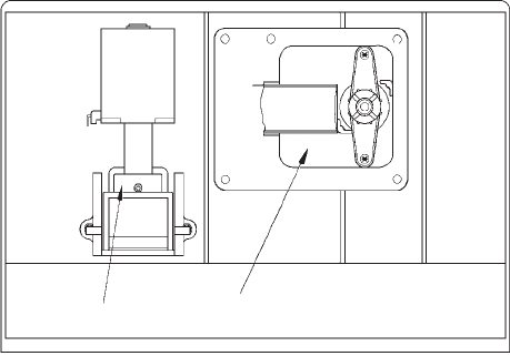
© 2003 Maytag Corporation
16010154 SECTION 3. CABINET & RELATED COMPONENTS 3-133-13
3-133-13
3-13
The auger motor and solenoid are located
behind the storage bin. The yoke, fastened
to the motor, engages the drive ring and
turns auger in a clockwise direction. Both
the yoke and drive ring are designed to pre-
vent a loosening of the yoke by exerting
counter pressure while in operation.
The auger motor makes one revolution ap-
proximately every three seconds. To de-
termine the free movement of the auger
motor, place the selector switch in either
cube or crushed position (slide selector
models). On electronic models, push the
cube or crushed selector pad. Open the
freezer door, push and hold the cabinet in-
terlock switch in the closed position while
pushing the dispenser actuator pad.
The solenoid is energized only when the
selector switch is in the cube position. This
will pull back the actuated blades. To deter-
mine the free movement of the solenoid/
yoke assembly, place the selector switch
(slide selector models) in the cube position.
On electronic models, push the cube selec-
tor pad. Open the freezer door. While push-
ing the dispenser actuator pad, push and
hold the cabinet interlock switch in the
closed position. Observe the control rod
yoke for vertical movement.
The auger motor and the solenoid/control
rod yoke assembly are easily removed.
SOLENOID YOKE
ASSEMBLY AUGER MOTOR
5. Remove the assembly from the freezer
and place on a flat work surface.
6. To check the auger motor, attach an
ohmmeter probe to the auger motor
terminals. The meter should show re-
sistance. If the meter does not show
resistance, the motor should be re-
placed.
7. To replace the motor, hold the auger
motor armature and turn the yoke
clockwise, releasing yoke from the mo-
tor shaft. Remove the yoke and
washer.
8. Remove the four mounting screws that
fasten the motor enclosure. Remove
the motor from the enclosure.
9. Install the replacement part in reverse
order of removal.
10. To check the solenoid yoke assembly,
attach an ohmmeter to the solenoid ter-
minals. The meter should show resis-
tance. If it does not show resistance,
replace the solenoid yoke assembly.
11. Remove the four screws that fasten the
solenoid yoke assembly to the enclo-
sure. Remove the assembly from the
enclosure.
12. Install the replacement part in reverse
order of removal.
1. Disconnect the unit from the powerDisconnect the unit from the power
Disconnect the unit from the powerDisconnect the unit from the power
Disconnect the unit from the power
source.source.
source.source.
source.
2. Remove the ice/crusher bin assembly.
3. Remove the retainer screw at the bot-
tom left side of the ice/crusher bin shelf
enclosure.
4. Pull the shelf forward and disconnect
the quick disconnect.
© 2003 Maytag Corporation
16010154 SECTION 3. CABINET & RELATED COMPONENTS 3-143-14
3-143-14
3-14
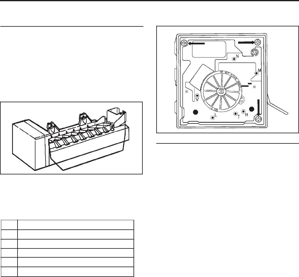
© 2003 Maytag Corporation
16010154 SECTION 4. ICE MAKER 4-14-1
4-14-1
4-1
SECTION 4. ICEMAKERSECTION 4. ICEMAKER
SECTION 4. ICEMAKERSECTION 4. ICEMAKER
SECTION 4. ICEMAKER
SERVICINGSERVICING
SERVICINGSERVICING
SERVICING
The design of this ice maker allows all of
the components to be tested without re-
moving the ice maker or moving the refrig-
erator away from the wall to access the
water valve.
Remove the cover and you will see the test
points identified on this module.
NN
NN
NNeutral side of lineNeutral side of line
Neutral side of lineNeutral side of line
Neutral side of line
MM
MM
MMotor connectionMotor connection
Motor connectionMotor connection
Motor connection
HH
HH
HHeater connectorHeater connector
Heater connectorHeater connector
Heater connector
TT
TT
TThermostat connectionThermostat connection
Thermostat connectionThermostat connection
Thermostat connection
LL
LL
LL1 side of lineL1 side of line
L1 side of lineL1 side of line
L1 side of line
VV
VV
VWater valve connectionWater valve connection
Water valve connectionWater valve connection
Water valve connection
NOTE: NOTE:
NOTE: NOTE:
NOTE:
Read this section completely be-Read this section completely be-
Read this section completely be-Read this section completely be-
Read this section completely be-
fore doing any testing or adjusting. Referfore doing any testing or adjusting. Refer
fore doing any testing or adjusting. Referfore doing any testing or adjusting. Refer
fore doing any testing or adjusting. Refer
to the tech sheet for complete testing in-to the tech sheet for complete testing in-
to the tech sheet for complete testing in-to the tech sheet for complete testing in-
to the tech sheet for complete testing in-
formation.formation.
formation.formation.
formation.
The test holes are identified as "N", "M", and
"V", etc.
TEST PROCEDURESTEST PROCEDURES
TEST PROCEDURESTEST PROCEDURES
TEST PROCEDURES
Ice maker plugged into power/Shut-off arm
down/Freezercold:
• Test points L & N will verify 120 volts to
ice maker module.
(Make sure your test probes go into
the test points 1/2".)
• Test points T & H will verify if the bimetal
thermostat is open or closed.
Short T&H with an insulated piece of
wire (14 gauge) to run the motor. If the
motor doesn't run, replace the module
assembly. If the motor runs, replace the
bimetal thermostat.
• If you leave the jumper in for half of a
revolution, you can feel the heater in the
mold heat up, if it is good.
Remove the jumper and the water valve
will be energized in the last half of the
revolution. (Make sure the freezer tem-
perature is cold enough to close the bi-
metal).
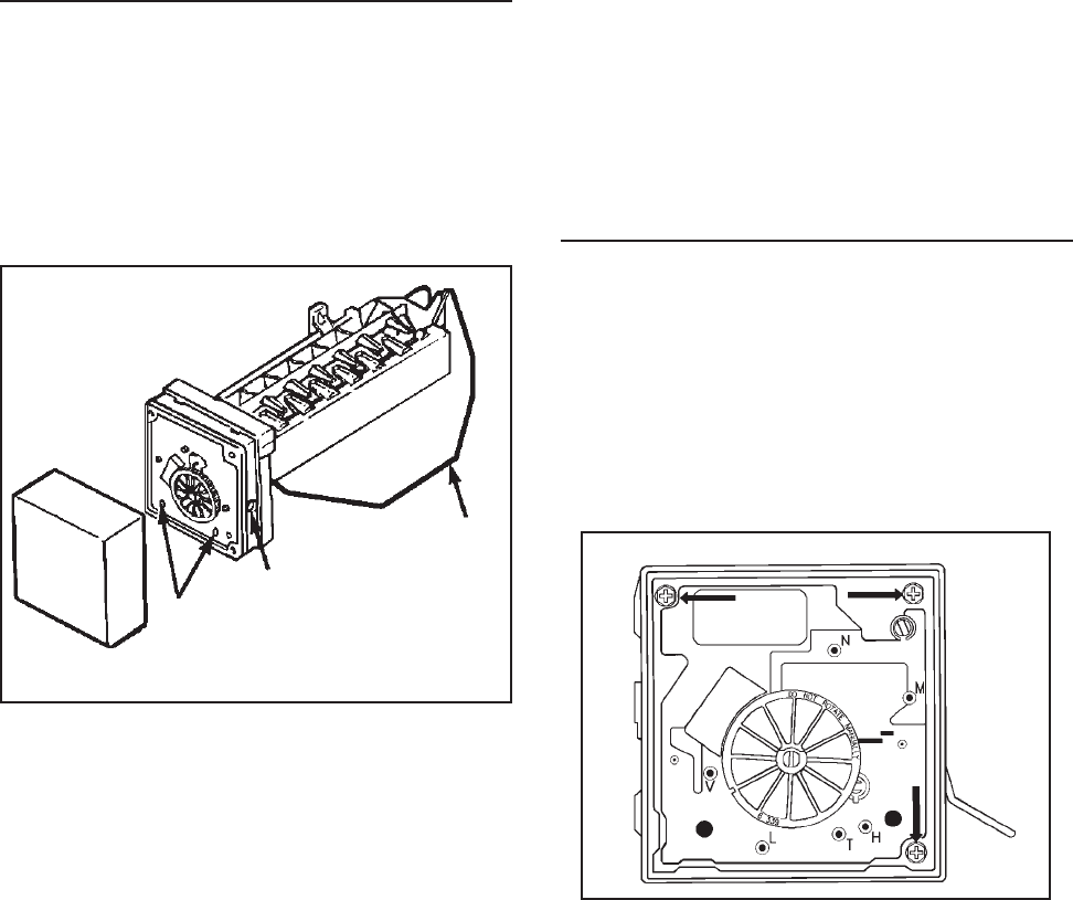
© 2003 Maytag Corporation
16010154 SECTION 4. ICE MAKER 4-24-2
4-24-2
4-2
Shut-off armShut-off arm
Shut-off armShut-off arm
Shut-off arm
Screw adjustmentScrew adjustment
Screw adjustmentScrew adjustment
Screw adjustment
Mold attachment Mold attachment
Mold attachment Mold attachment
Mold attachment
(Screw access ports) (Screw access ports)
(Screw access ports) (Screw access ports)
(Screw access ports)
Module, Motor, and Support Assembly:Module, Motor, and Support Assembly:
Module, Motor, and Support Assembly:Module, Motor, and Support Assembly:
Module, Motor, and Support Assembly:
Insert Phillips screwdriver in access ports
of module. Loosen both screws. Discon-
nect shut-off arm. Pull mold from support
assembly. To remove module only, remove
3 Phillips screws and pull module out of
housing.
NOTE:NOTE:
NOTE:NOTE:
NOTE:
Do not short any contacts otherDo not short any contacts other
Do not short any contacts otherDo not short any contacts other
Do not short any contacts other
than those specified. Damage to the icethan those specified. Damage to the ice
than those specified. Damage to the icethan those specified. Damage to the ice
than those specified. Damage to the ice
maker can result.maker can result.
maker can result.maker can result.
maker can result.
Ice Maker Unplugged:Ice Maker Unplugged:
Ice Maker Unplugged:Ice Maker Unplugged:
Ice Maker Unplugged:
• Test points L&H will check the resistance
of the heater (72 ohms). Replace the
mold and heater assembly if not near
this value (+/- 10 ohms).
(Ejector blades should be at the end of
the cycle position.)
SERVICE PROCEDURESSERVICE PROCEDURES
SERVICE PROCEDURESSERVICE PROCEDURES
SERVICE PROCEDURES
Cover:Cover:
Cover:Cover:
Cover: Pull water adjustment knob first and
snap off cover. Index knob and reinstall in
same position for same water fill. (Some
units may not have index knobs.)
Shut-Off Arm: Shut-Off Arm:
Shut-Off Arm: Shut-Off Arm:
Shut-Off Arm: Pull out from white bush-
ing. Reinsert to full depth. See page 5-15
for detailed position.
Mold & Heater: Mold & Heater:
Mold & Heater: Mold & Heater:
Mold & Heater: Remove module and sup-
port assembly. Install on new mold and
heater assembly.
Bimetal: Bimetal:
Bimetal: Bimetal:
Bimetal: Remove module and support as-
sembly. Pull out retaining ring clips with
bimetal.
Fill Cup: Fill Cup:
Fill Cup: Fill Cup:
Fill Cup: Remove module and support as-
sembly. Remove ejector blades and shut-
off arm. Pull fill cup up from mold.
Ejector Blades or Stripper: Ejector Blades or Stripper:
Ejector Blades or Stripper: Ejector Blades or Stripper:
Ejector Blades or Stripper: Remove mod-
ule and support assembly. When reinstall-
ing ejector blades, realign "D" coupling with
module cam.
ACCESSING THE CONTROL BOXACCESSING THE CONTROL BOX
ACCESSING THE CONTROL BOXACCESSING THE CONTROL BOX
ACCESSING THE CONTROL BOX
To remove motor and contact assembly
from control box, take out three screws
(see arrows) and pull free
after disconnect-after disconnect-
after disconnect-after disconnect-
after disconnect-
ing the shut-off arm.ing the shut-off arm.
ing the shut-off arm.ing the shut-off arm.
ing the shut-off arm.
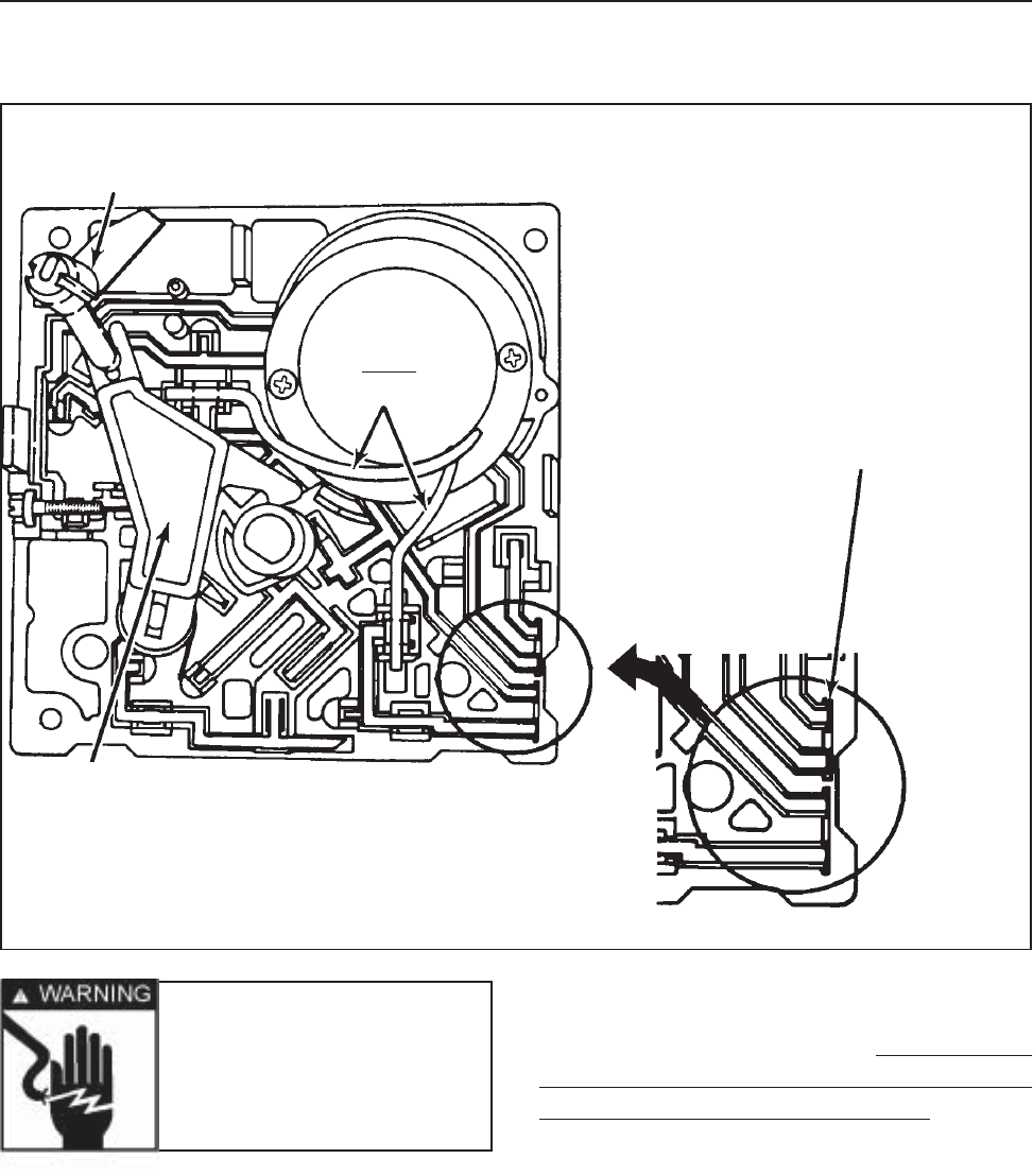
© 2003 Maytag Corporation
16010154 SECTION 4. ICE MAKER 4-34-3
4-34-3
4-3
There are several switches which will jam
if manually turned counterclockwise. Also,
the gears will be destroyed if turned clock-
wise. If you need to advance the ice maker
into the cycle, use a jumper to bridge "H""H"
"H""H"
"H" to
"T""T"
"T""T"
"T". Unless the motor is defective, it will run.
(The shut-off arm must be in the "ON""ON"
"ON""ON"
"ON"
position.)
NOTE: NOTE:
NOTE: NOTE:
NOTE:
There are no repairable or replace-There are no repairable or replace-
There are no repairable or replace-There are no repairable or replace-
There are no repairable or replace-
able components in the module. Unlessable components in the module. Unless
able components in the module. Unlessable components in the module. Unless
able components in the module. Unless
replacing the module, there should be noreplacing the module, there should be no
replacing the module, there should be noreplacing the module, there should be no
replacing the module, there should be no
need to remove it when diagnosing or re-need to remove it when diagnosing or re-
need to remove it when diagnosing or re-need to remove it when diagnosing or re-
need to remove it when diagnosing or re-
pairing the ice maker.pairing the ice maker.
pairing the ice maker.pairing the ice maker.
pairing the ice maker.
MODULE COMPONENTSMODULE COMPONENTS
MODULE COMPONENTSMODULE COMPONENTS
MODULE COMPONENTS
Shut-offShut-off
Shut-offShut-off
Shut-off
arm linkagearm linkage
arm linkagearm linkage
arm linkage
MotorMotor
MotorMotor
Motor
Staked leadsStaked leads
Staked leadsStaked leads
Staked leads
Cam Cam
Cam Cam
Cam
FollowerFollower
FollowerFollower
Follower
Ground (slightly longer)Ground (slightly longer)
Ground (slightly longer)Ground (slightly longer)
Ground (slightly longer)
than other 3 terminals sothan other 3 terminals so
than other 3 terminals sothan other 3 terminals so
than other 3 terminals so
that ground makes firstthat ground makes first
that ground makes firstthat ground makes first
that ground makes first
and breaks last when dis-and breaks last when dis-
and breaks last when dis-and breaks last when dis-
and breaks last when dis-
connected or plugged in.connected or plugged in.
connected or plugged in.connected or plugged in.
connected or plugged in.
Warning Warning
Warning Warning
Warning
- Never rotate- Never rotate
- Never rotate- Never rotate
- Never rotate
the blade or the drivethe blade or the drive
the blade or the drivethe blade or the drive
the blade or the drive
gear... It will ruin thegear... It will ruin the
gear... It will ruin thegear... It will ruin the
gear... It will ruin the
main assembly.main assembly.
main assembly.main assembly.
main assembly.
NOTE:NOTE:
NOTE:NOTE:
NOTE:
There are several slotted shafts onThere are several slotted shafts on
There are several slotted shafts onThere are several slotted shafts on
There are several slotted shafts on
the motor assembly board. the motor assembly board.
the motor assembly board. the motor assembly board.
the motor assembly board. Do not underDo not under
Do not underDo not under
Do not under
any circumstances insert a screwdriverany circumstances insert a screwdriver
any circumstances insert a screwdriverany circumstances insert a screwdriver
any circumstances insert a screwdriver
and attempt to turn these shaftsand attempt to turn these shafts
and attempt to turn these shaftsand attempt to turn these shafts
and attempt to turn these shafts. These. These
. These. These
. These
slots are to permit assembly only.slots are to permit assembly only.
slots are to permit assembly only.slots are to permit assembly only.
slots are to permit assembly only.
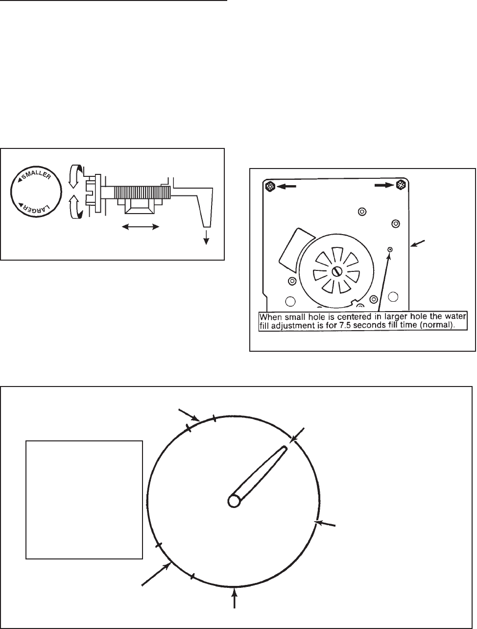
© 2003 Maytag Corporation
16010154 SECTION 4. ICE MAKER 4-44-4
4-44-4
4-4
• •
• •
• Turning the knob or screw clockwise
decreases fill - counterclockwise in-
creases the fill amount.
• Only one revolution is possible with the
cover on, due to a stop molded on cover.
WHAT HAPPENS DUR-WHAT HAPPENS DUR-
WHAT HAPPENS DUR-WHAT HAPPENS DUR-
WHAT HAPPENS DUR-
ING BLADE ROTATIONING BLADE ROTATION
ING BLADE ROTATIONING BLADE ROTATION
ING BLADE ROTATION
(Do Not Test if blades(Do Not Test if blades
(Do Not Test if blades(Do Not Test if blades
(Do Not Test if blades
are past rest position).are past rest position).
are past rest position).are past rest position).
are past rest position).
Viewed from front
(Module Side)
Water
adjustment
area
• 360o will affect fill by 40cc - 180o varies
the fill by 20cc.
• Further adjustment could damage
module.
• If water valve adjustment screw falls out,
put it back in and align the hole in the
hole as shown.
Turning the water level adjustment screw
will move the contact in its relationship with
the contact ring segment. This causes the
contact to vary the time that the water valve
is energized since the contact ring is tapered
at the end of the fill time.
WATER FILL ADJUSTMENTWATER FILL ADJUSTMENT
WATER FILL ADJUSTMENTWATER FILL ADJUSTMENT
WATER FILL ADJUSTMENT
Ejector stalls onEjector stalls on
Ejector stalls onEjector stalls on
Ejector stalls on
ice (1/2 minuteice (1/2 minute
ice (1/2 minuteice (1/2 minute
ice (1/2 minute
to 5 minutes)to 5 minutes)
to 5 minutes)to 5 minutes)
to 5 minutes)
Ejector blade stop positionEjector blade stop position
Ejector blade stop positionEjector blade stop position
Ejector blade stop position
(about 1:30 o'clock)(about 1:30 o'clock)
(about 1:30 o'clock)(about 1:30 o'clock)
(about 1:30 o'clock)
6 o'clock position6 o'clock position
6 o'clock position6 o'clock position
6 o'clock position
Thermostat opens in thisThermostat opens in this
Thermostat opens in thisThermostat opens in this
Thermostat opens in this
range of rotationrange of rotation
range of rotationrange of rotation
range of rotation
Water valve energizedWater valve energized
Water valve energizedWater valve energized
Water valve energized
7.5 secs 140cc fill7.5 secs 140cc fill
7.5 secs 140cc fill7.5 secs 140cc fill
7.5 secs 140cc fill
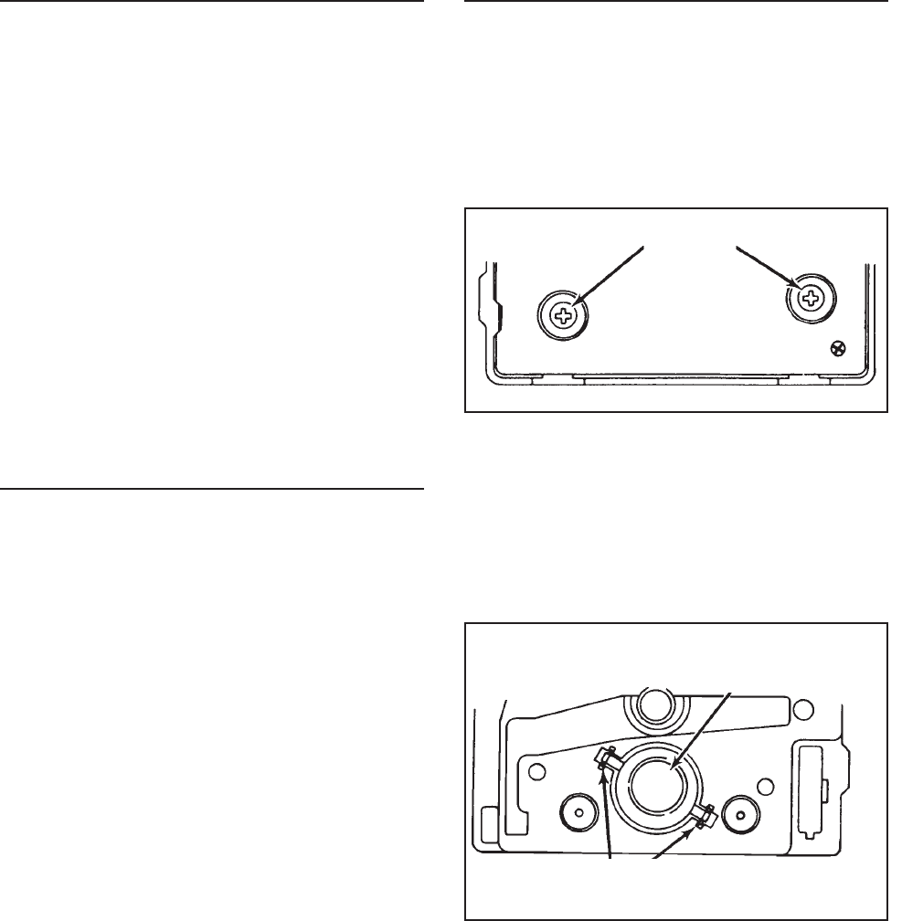
© 2003 Maytag Corporation
16010154 SECTION 4. ICE MAKER 4-54-5
4-54-5
4-5
WATER PROBLEMSWATER PROBLEMS
WATER PROBLEMSWATER PROBLEMS
WATER PROBLEMS
Water quality can cause ice makers to fail
or produce unacceptable cubes. If mineral
content or sand is a problem, the screen in
the fill valve can restrict. A particle of sand
can keep the valve from seating properly.
Results will be small crescents (or no ice)
or flooding of the ice container if the water
valve does not close.
Mineral content can also lime up the mold
causing wicking of water over the mold and
poor cube release. Silicone is applied at the
upper edges, around the fill cup and
stripper.
TEMPERATURE PROBLEMSTEMPERATURE PROBLEMS
TEMPERATURE PROBLEMSTEMPERATURE PROBLEMS
TEMPERATURE PROBLEMS
Temperatures in the freezer section which
average above the normal 0o +/- 5o will slow
the production of ice. Complaints of inad-
equate crescent production may be cor-
rected by setting the freezer to a colder tem-
perature in this one-revolution ice maker is
17o +/- 3º. Obviously, the ice will be well
frozen when these temperatures are
achieved, but cycling time will be slowed if
the freezer temperature is not cold enough
to achieve these mold temperatures easily.
NOTE: NOTE:
NOTE: NOTE:
NOTE:
Only the thermostat, mold withOnly the thermostat, mold with
Only the thermostat, mold withOnly the thermostat, mold with
Only the thermostat, mold with
heater and wiring harness are replaceable.heater and wiring harness are replaceable.
heater and wiring harness are replaceable.heater and wiring harness are replaceable.
heater and wiring harness are replaceable.
Any other failure (including the motor) re-Any other failure (including the motor) re-
Any other failure (including the motor) re-Any other failure (including the motor) re-
Any other failure (including the motor) re-
quires replacement of the module assem-quires replacement of the module assem-
quires replacement of the module assem-quires replacement of the module assem-
quires replacement of the module assem-
bly. If you are replacing the mold assem-bly. If you are replacing the mold assem-
bly. If you are replacing the mold assem-bly. If you are replacing the mold assem-
bly. If you are replacing the mold assem-
bly, it comes with a new mold heater in-bly, it comes with a new mold heater in-
bly, it comes with a new mold heater in-bly, it comes with a new mold heater in-
bly, it comes with a new mold heater in-
stalled. External plastic parts are also re-stalled. External plastic parts are also re-
stalled. External plastic parts are also re-stalled. External plastic parts are also re-
stalled. External plastic parts are also re-
placeable.placeable.
placeable.placeable.
placeable.
A failed mold heater requires complete re-
placement of the mold and mold heater
assembly.
THERMOSTATTHERMOSTAT
THERMOSTATTHERMOSTAT
THERMOSTAT
If the thermostat is diagnosed as defective,
it can be removed and replaced easily. Re-
move the module from the mold by taking
out two Phillips screws.
Using needle nose pliers, grasp one of the
thermostat clips and pull out. Press in new
thermostat, making sure that pins are prop-
erly indexed. Using this procedure, it is not
necessary to remove the electrical assem-
bly. If you are replacing the module, trans-
fer the clips to the new mold support. (Use
new thermal bonding material.)
Pull the module free of the mold and you
will see the thermostat on the mold side.
PullPull
PullPull
Pull
(Front of module)(Front of module)
(Front of module)(Front of module)
(Front of module)
Retaining ClipsRetaining Clips
Retaining ClipsRetaining Clips
Retaining Clips
ThermostatThermostat
ThermostatThermostat
Thermostat
ScrewsScrews
ScrewsScrews
Screws
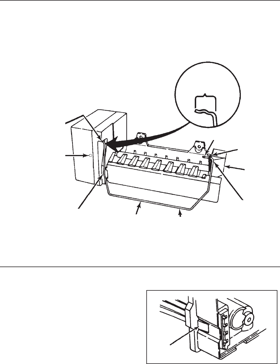
© 2003 Maytag Corporation
16010154 SECTION 4. ICE MAKER 4-64-6
4-64-6
4-6
Installation ProcedureInstallation Procedure
Installation ProcedureInstallation Procedure
Installation Procedure
1. Start with arm in "down" position.
2. Follow steps 1, 2, and 3. Into bushingInto bushing
Into bushingInto bushing
Into bushing
Shut-off armShut-off arm
Shut-off armShut-off arm
Shut-off arm
FlangeFlange
FlangeFlange
Flange
Down Down
Down Down
Down
positionposition
positionposition
position
3. Arm should be inside3. Arm should be inside
3. Arm should be inside3. Arm should be inside
3. Arm should be inside
edge of housing edge of housing
edge of housing edge of housing
edge of housing
Fill cupFill cup
Fill cupFill cup
Fill cup
HARNESSHARNESS
HARNESSHARNESS
HARNESS
To remove the wiring harness, depress the
retaining tab and pull the plug free.
DepressDepress
DepressDepress
Depress
NotchNotch
NotchNotch
Notch
2.2.
2.2.
2. Push arm Push arm
Push arm Push arm
Push arm
through fill cupthrough fill cup
through fill cupthrough fill cup
through fill cup
flange hole pastflange hole past
flange hole pastflange hole past
flange hole past
notchnotch
notchnotch
notch
1. Push arm into center1. Push arm into center
1. Push arm into center1. Push arm into center
1. Push arm into center
slot in white bushing slot in white bushing
slot in white bushing slot in white bushing
slot in white bushing
- bottom out- bottom out
- bottom out- bottom out
- bottom out
INSTALLATIONINSTALLATION
INSTALLATIONINSTALLATION
INSTALLATION
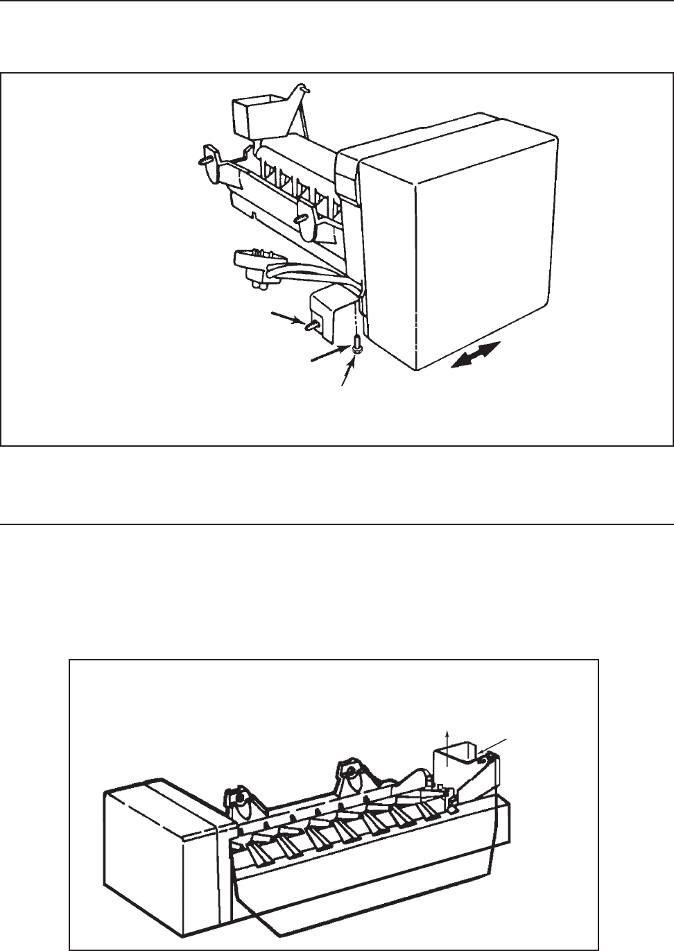
© 2003 Maytag Corporation
16010154 SECTION 4. ICE MAKER 4-74-7
4-74-7
4-7
LEVELING ICE MAKERLEVELING ICE MAKER
LEVELING ICE MAKERLEVELING ICE MAKER
LEVELING ICE MAKER
(Ensures uniform ice crescents)(Ensures uniform ice crescents)
(Ensures uniform ice crescents)(Ensures uniform ice crescents)
(Ensures uniform ice crescents)
To remove fill cup, you must separate mold
and blade from module housing. Remove
blade from fill cup.
Hex Hex
Hex Hex
Hex
1/4" Screw1/4" Screw
1/4" Screw1/4" Screw
1/4" Screw
MountingMounting
MountingMounting
Mounting
Screw Screw
Screw Screw
Screw
REMOVING & REPLACING FILL CUPREMOVING & REPLACING FILL CUP
REMOVING & REPLACING FILL CUPREMOVING & REPLACING FILL CUP
REMOVING & REPLACING FILL CUP
The appropriate break-out plug needs to be
removed from the fill cup for your model.
Check old ice maker.
Make sure the refrigerator is level front to back (adjust legs or rollers).
Loosen, Level I/M byLoosen, Level I/M by
Loosen, Level I/M byLoosen, Level I/M by
Loosen, Level I/M by
sliding left or right insliding left or right in
sliding left or right insliding left or right in
sliding left or right in
slot of bracket. Tighten.slot of bracket. Tighten.
slot of bracket. Tighten.slot of bracket. Tighten.
slot of bracket. Tighten.
Pull cup up and out of slot -Pull cup up and out of slot -
Pull cup up and out of slot -Pull cup up and out of slot -
Pull cup up and out of slot -
requires considerable forcerequires considerable force
requires considerable forcerequires considerable force
requires considerable force RemoveRemove
RemoveRemove
Remove
plugplug
plugplug
plug

© 2003 Maytag Corporation
16010154 SECTION 4. ICE MAKER 4-84-8
4-84-8
4-8
• Motor connectors can be damaged if
leads are removed.
• The motor is available only as part of the
complete module assembly.
• One revolution of the blade takes three
minutes (plus stall time on ice).
• Bench test cord can be made from cabi-
net socket.
• Tan and white wires on socket plug are
water valve leads.
SPECIFICATIONSSPECIFICATIONS
SPECIFICATIONSSPECIFICATIONS
SPECIFICATIONS
Mold 185 watts, 72 ohmsMold 185 watts, 72 ohms
Mold 185 watts, 72 ohmsMold 185 watts, 72 ohms
Mold 185 watts, 72 ohms
HeaterHeater
HeaterHeater
Heater
Thermostat Thermostat
Thermostat Thermostat
Thermostat
Close 17Close 17
Close 17Close 17
Close 17oo
oo
o (+ / -) 3(+ / -) 3
(+ / -) 3(+ / -) 3
(+ / -) 3oo
oo
o
(Bimetal) Open 32(Bimetal) Open 32
(Bimetal) Open 32(Bimetal) Open 32
(Bimetal) Open 32oo
oo
o (+ / -) 3(+ / -) 3
(+ / -) 3(+ / -) 3
(+ / -) 3oo
oo
o
Motor 1.5 watts, 8,450 ohmsMotor 1.5 watts, 8,450 ohms
Motor 1.5 watts, 8,450 ohmsMotor 1.5 watts, 8,450 ohms
Motor 1.5 watts, 8,450 ohms
Water Fill 140cc, 7.5 secondsWater Fill 140cc, 7.5 seconds
Water Fill 140cc, 7.5 secondsWater Fill 140cc, 7.5 seconds
Water Fill 140cc, 7.5 seconds
Module Stamped circuit, Plug-Module Stamped circuit, Plug-
Module Stamped circuit, Plug-Module Stamped circuit, Plug-
Module Stamped circuit, Plug-
in connectors in connectors
in connectors in connectors
in connectors
Cycle One revolutionCycle One revolution
Cycle One revolutionCycle One revolution
Cycle One revolution
(ejects and water fill) (ejects and water fill)
(ejects and water fill) (ejects and water fill)
(ejects and water fill)
OTHER INFORMATIONOTHER INFORMATION
OTHER INFORMATIONOTHER INFORMATION
OTHER INFORMATION

© 2003 Maytag Corporation
16010154 SECTION 5. TROUBLESHOOTING 5-15-1
5-15-1
5-1
SECTION 5. TROUBLESHOOTINGSECTION 5. TROUBLESHOOTING
SECTION 5. TROUBLESHOOTINGSECTION 5. TROUBLESHOOTING
SECTION 5. TROUBLESHOOTING
••
••
•No power at AC distributionNo power at AC distribution
No power at AC distributionNo power at AC distribution
No power at AC distribution
panel of house.panel of house.
panel of house.panel of house.
panel of house.
••
••
•AC outlet.AC outlet.
AC outlet.AC outlet.
AC outlet.
----
----
--Defective outlet.Defective outlet.
Defective outlet.Defective outlet.
Defective outlet.
----
----
--Open circuit to AC outlet.Open circuit to AC outlet.
Open circuit to AC outlet.Open circuit to AC outlet.
Open circuit to AC outlet.
••
••
•Defective service cord plug.Defective service cord plug.
Defective service cord plug.Defective service cord plug.
Defective service cord plug.
••
••
•Open service cord or openOpen service cord or open
Open service cord or openOpen service cord or open
Open service cord or open
machine compartmentmachine compartment
machine compartmentmachine compartment
machine compartment
wiring harness.wiring harness.
wiring harness.wiring harness.
wiring harness.
••
••
•Two simultaneous prob-Two simultaneous prob-
Two simultaneous prob-Two simultaneous prob-
Two simultaneous prob-
lems-light bulb out and openlems-light bulb out and open
lems-light bulb out and openlems-light bulb out and open
lems-light bulb out and open
AC circuit to compressor. AC circuit to compressor.
AC circuit to compressor. AC circuit to compressor.
AC circuit to compressor.
••
••
•Temperature control.Temperature control.
Temperature control.Temperature control.
Temperature control.
----
----
--Defective or adjustedDefective or adjusted
Defective or adjustedDefective or adjusted
Defective or adjusted
incorrectly.incorrectly.
incorrectly.incorrectly.
incorrectly.
----
----
--AC circuit open to control.AC circuit open to control.
AC circuit open to control.AC circuit open to control.
AC circuit open to control.
••
••
•Defrost timer.Defrost timer.
Defrost timer.Defrost timer.
Defrost timer.
----
----
--Defective (contacts com-Defective (contacts com-
Defective (contacts com-Defective (contacts com-
Defective (contacts com-
pleting compressor circuitpleting compressor circuit
pleting compressor circuitpleting compressor circuit
pleting compressor circuit
are open).are open).
are open).are open).
are open).
----
----
--AC circuits open to timerAC circuits open to timer
AC circuits open to timerAC circuits open to timer
AC circuits open to timer
(motor winding or contacts).(motor winding or contacts).
(motor winding or contacts).(motor winding or contacts).
(motor winding or contacts).
----
----
--May be defrosting.May be defrosting.
May be defrosting.May be defrosting.
May be defrosting.
••
••
•Overload protector.Overload protector.
Overload protector.Overload protector.
Overload protector.
----
----
--AC circuit open to overload.AC circuit open to overload.
AC circuit open to overload.AC circuit open to overload.
AC circuit open to overload.
----
----
--Defective overload.Defective overload.
Defective overload.Defective overload.
Defective overload.
••
••
•Starting relay.Starting relay.
Starting relay.Starting relay.
Starting relay.
----
----
--AC circuit open to coil (over-AC circuit open to coil (over-
AC circuit open to coil (over-AC circuit open to coil (over-
AC circuit open to coil (over-
load does not click).load does not click).
load does not click).load does not click).
load does not click).
----
----
--Defective relay.Defective relay.
Defective relay.Defective relay.
Defective relay.
••
••
•Compressor motor.Compressor motor.
Compressor motor.Compressor motor.
Compressor motor.
----
----
--AC circuit open toAC circuit open to
AC circuit open toAC circuit open to
AC circuit open to
compressor.compressor.
compressor.compressor.
compressor.
----
----
--Defective compressor (over-Defective compressor (over-
Defective compressor (over-Defective compressor (over-
Defective compressor (over-
load may or may not clickload may or may not click
load may or may not clickload may or may not click
load may or may not click
depending upon what isdepending upon what is
depending upon what isdepending upon what is
depending upon what is
wrong with compressor).wrong with compressor).
wrong with compressor).wrong with compressor).
wrong with compressor).
••
••
•Low line voltage (overloadLow line voltage (overload
Low line voltage (overloadLow line voltage (overload
Low line voltage (overload
will click on and off as unitwill click on and off as unit
will click on and off as unitwill click on and off as unit
will click on and off as unit
tries to start).tries to start).
tries to start).tries to start).
tries to start).
••
••
•Check and advise customer toCheck and advise customer to
Check and advise customer toCheck and advise customer to
Check and advise customer to
call an electrician.call an electrician.
call an electrician.call an electrician.
call an electrician.
••
••
•Advise customer:Advise customer:
Advise customer:Advise customer:
Advise customer:
--to have defective outlet--to have defective outlet
--to have defective outlet--to have defective outlet
--to have defective outlet
replaced.replaced.
replaced.replaced.
replaced.
----
----
--Replace fuse. If problem notReplace fuse. If problem not
Replace fuse. If problem notReplace fuse. If problem not
Replace fuse. If problem not
corrected, advise customer tocorrected, advise customer to
corrected, advise customer tocorrected, advise customer to
corrected, advise customer to
call electrician.call electrician.
call electrician.call electrician.
call electrician.
••
••
•Replace.Replace.
Replace.Replace.
Replace.
••
••
•Repair or replace if necessary.Repair or replace if necessary.
Repair or replace if necessary.Repair or replace if necessary.
Repair or replace if necessary.
Refer to wiring diagrams andRefer to wiring diagrams and
Refer to wiring diagrams andRefer to wiring diagrams and
Refer to wiring diagrams and
check circuit.check circuit.
check circuit.check circuit.
check circuit.
••
••
•Replace light bulb. Refer toReplace light bulb. Refer to
Replace light bulb. Refer toReplace light bulb. Refer to
Replace light bulb. Refer to
wiring diagrams and checkwiring diagrams and check
wiring diagrams and checkwiring diagrams and check
wiring diagrams and check
circuit.circuit.
circuit.circuit.
circuit.
••
••
•See below:See below:
See below:See below:
See below:
----
----
--Replace or adjust if necessary.Replace or adjust if necessary.
Replace or adjust if necessary.Replace or adjust if necessary.
Replace or adjust if necessary.
----
----
--Refer to wiring diagrams andRefer to wiring diagrams and
Refer to wiring diagrams andRefer to wiring diagrams and
Refer to wiring diagrams and
check circuit.check circuit.
check circuit.check circuit.
check circuit.
••
••
•See below:See below:
See below:See below:
See below:
----
----
--Replace.Replace.
Replace.Replace.
Replace.
----
----
--Refer to wiring diagrams andRefer to wiring diagrams and
Refer to wiring diagrams andRefer to wiring diagrams and
Refer to wiring diagrams and
check circuit.check circuit.
check circuit.check circuit.
check circuit.
----
----
--Repair or replace.Repair or replace.
Repair or replace.Repair or replace.
Repair or replace.
••
••
•See below:See below:
See below:See below:
See below:
----
----
--Refer to wiring diagrams andRefer to wiring diagrams and
Refer to wiring diagrams andRefer to wiring diagrams and
Refer to wiring diagrams and
check circuit.check circuit.
check circuit.check circuit.
check circuit.
----
----
--Replace.Replace.
Replace.Replace.
Replace.
••
••
•See below:See below:
See below:See below:
See below:
----
----
--Refer to wiring diagrams anRefer to wiring diagrams an
Refer to wiring diagrams anRefer to wiring diagrams an
Refer to wiring diagrams an
check circuit.check circuit.
check circuit.check circuit.
check circuit.
----
----
--Replace.Replace.
Replace.Replace.
Replace.
••
••
•Check voltage. Must be at leastCheck voltage. Must be at least
Check voltage. Must be at leastCheck voltage. Must be at least
Check voltage. Must be at least
100V with all other load on the100V with all other load on the
100V with all other load on the100V with all other load on the
100V with all other load on the
line.line.
line.line.
line.
Unit does not run. No light inUnit does not run. No light in
Unit does not run. No light inUnit does not run. No light in
Unit does not run. No light in
refrigerator.refrigerator.
refrigerator.refrigerator.
refrigerator.
Unit does not run, light inUnit does not run, light in
Unit does not run, light inUnit does not run, light in
Unit does not run, light in
refrigerator works.refrigerator works.
refrigerator works.refrigerator works.
refrigerator works.
CONDITIONCONDITION
CONDITIONCONDITION
CONDITION POSSIBLE CAUSEPOSSIBLE CAUSE
POSSIBLE CAUSEPOSSIBLE CAUSE
POSSIBLE CAUSE CORRECTIONCORRECTION
CORRECTIONCORRECTION
CORRECTION
DISCONNECT THE UNIT FROM THE POWER SOURCEDISCONNECT THE UNIT FROM THE POWER SOURCE
DISCONNECT THE UNIT FROM THE POWER SOURCEDISCONNECT THE UNIT FROM THE POWER SOURCE
DISCONNECT THE UNIT FROM THE POWER SOURCE

© 2003 Maytag Corporation
16010154 SECTION 5. TROUBLESHOOTING 5-25-2
5-25-2
5-2
CONDITIONCONDITION
CONDITIONCONDITION
CONDITION POSSIBLE CAUSEPOSSIBLE CAUSE
POSSIBLE CAUSEPOSSIBLE CAUSE
POSSIBLE CAUSE CORRECTIONCORRECTION
CORRECTIONCORRECTION
CORRECTION
Unit runs excessively orUnit runs excessively or
Unit runs excessively orUnit runs excessively or
Unit runs excessively or
continuously.continuously.
continuously.continuously.
continuously.
Unit runs continuously. TheUnit runs continuously. The
Unit runs continuously. TheUnit runs continuously. The
Unit runs continuously. The
refrigerator compartmentrefrigerator compartment
refrigerator compartmentrefrigerator compartment
refrigerator compartment
not cold enough, but freezernot cold enough, but freezer
not cold enough, but freezernot cold enough, but freezer
not cold enough, but freezer
compartment is colder thancompartment is colder than
compartment is colder thancompartment is colder than
compartment is colder than
normal.normal.
normal.normal.
normal.
Unit does not run for periodUnit does not run for period
Unit does not run for periodUnit does not run for period
Unit does not run for period
of time after defrost.of time after defrost.
of time after defrost.of time after defrost.
of time after defrost.
Unit runs continuously butUnit runs continuously but
Unit runs continuously butUnit runs continuously but
Unit runs continuously but
there is no cooling in refrigera-there is no cooling in refrigera-
there is no cooling in refrigera-there is no cooling in refrigera-
there is no cooling in refrigera-
tor and freezer compartments.tor and freezer compartments.
tor and freezer compartments.tor and freezer compartments.
tor and freezer compartments.
Unit runs excessively or contin-Unit runs excessively or contin-
Unit runs excessively or contin-Unit runs excessively or contin-
Unit runs excessively or contin-
uously. The refrigerator anduously. The refrigerator and
uously. The refrigerator anduously. The refrigerator and
uously. The refrigerator and
freezer compartments are cool-freezer compartments are cool-
freezer compartments are cool-freezer compartments are cool-
freezer compartments are cool-
ing, but are not cold enough.ing, but are not cold enough.
ing, but are not cold enough.ing, but are not cold enough.
ing, but are not cold enough.
DISCONNECT THE UNIT FROM THE POWER SOURCEDISCONNECT THE UNIT FROM THE POWER SOURCE
DISCONNECT THE UNIT FROM THE POWER SOURCEDISCONNECT THE UNIT FROM THE POWER SOURCE
DISCONNECT THE UNIT FROM THE POWER SOURCE
••
••
•Complete or possible partialComplete or possible partial
Complete or possible partialComplete or possible partial
Complete or possible partial
restriction under high ambi-restriction under high ambi-
restriction under high ambi-restriction under high ambi-
restriction under high ambi-
ent (cycles on overload pro-ent (cycles on overload pro-
ent (cycles on overload pro-ent (cycles on overload pro-
ent (cycles on overload pro-
tector after unit stops andtector after unit stops and
tector after unit stops andtector after unit stops and
tector after unit stops and
tries to restart).tries to restart).
tries to restart).tries to restart).
tries to restart).
••
••
•Check to ensure light doesCheck to ensure light does
Check to ensure light doesCheck to ensure light does
Check to ensure light does
not stay on continuously.not stay on continuously.
not stay on continuously.not stay on continuously.
not stay on continuously.
••
••
•Dirty or restricted condenser,Dirty or restricted condenser,
Dirty or restricted condenser,Dirty or restricted condenser,
Dirty or restricted condenser,
due to particularly greasy,due to particularly greasy,
due to particularly greasy,due to particularly greasy,
due to particularly greasy,
dusty, or significant petdusty, or significant pet
dusty, or significant petdusty, or significant pet
dusty, or significant pet
traffic in the hometraffic in the home
traffic in the hometraffic in the home
traffic in the home
••
••
•Defective cold control.Defective cold control.
Defective cold control.Defective cold control.
Defective cold control.
••
••
•Condenser fan not running.Condenser fan not running.
Condenser fan not running.Condenser fan not running.
Condenser fan not running.
••
••
•Defrost timer is defectiveDefrost timer is defective
Defrost timer is defectiveDefrost timer is defective
Defrost timer is defective
(does not advance - advance(does not advance - advance
(does not advance - advance(does not advance - advance
(does not advance - advance
to cool cycle).to cool cycle).
to cool cycle).to cool cycle).
to cool cycle).
••
••
•Substantial loss of sealedSubstantial loss of sealed
Substantial loss of sealedSubstantial loss of sealed
Substantial loss of sealed
system charge (low wattagesystem charge (low wattage
system charge (low wattagesystem charge (low wattage
system charge (low wattage
readings).readings).
readings).readings).
readings).
••
••
•Restricted capillary or drierRestricted capillary or drier
Restricted capillary or drierRestricted capillary or drier
Restricted capillary or drier
on high side (low wattageon high side (low wattage
on high side (low wattageon high side (low wattage
on high side (low wattage
readings while running).readings while running).
readings while running).readings while running).
readings while running).
Will cycle on overload whenWill cycle on overload when
Will cycle on overload whenWill cycle on overload when
Will cycle on overload when
unit tries to start afterunit tries to start after
unit tries to start afterunit tries to start after
unit tries to start after
defrost cycle, or afterdefrost cycle, or after
defrost cycle, or afterdefrost cycle, or after
defrost cycle, or after
having been shut-off andhaving been shut-off and
having been shut-off andhaving been shut-off and
having been shut-off and
restriction is still present.restriction is still present.
restriction is still present.restriction is still present.
restriction is still present.
••
••
•Defective compressor.Defective compressor.
Defective compressor.Defective compressor.
Defective compressor.
••
••
•Temperature control isTemperature control is
Temperature control isTemperature control is
Temperature control is
defective (short contacts ordefective (short contacts or
defective (short contacts ordefective (short contacts or
defective (short contacts or
not adjusted).not adjusted).
not adjusted).not adjusted).
not adjusted).
••
••
•Freezer control not adjustedFreezer control not adjusted
Freezer control not adjustedFreezer control not adjusted
Freezer control not adjusted
properly.properly.
properly.properly.
properly.
••
••
•Air duct from freezer toAir duct from freezer to
Air duct from freezer toAir duct from freezer to
Air duct from freezer to
refrigerator is blockedrefrigerator is blocked
refrigerator is blockedrefrigerator is blocked
refrigerator is blocked
(normal wattage reading).(normal wattage reading).
(normal wattage reading).(normal wattage reading).
(normal wattage reading).
••
••
•Freezer fan.Freezer fan.
Freezer fan.Freezer fan.
Freezer fan.
----
----
--Defective fan motor.Defective fan motor.
Defective fan motor.Defective fan motor.
Defective fan motor.
••
••
•See "Checking OperatingSee "Checking Operating
See "Checking OperatingSee "Checking Operating
See "Checking Operating
Pressure".Pressure".
Pressure".Pressure".
Pressure".
••
••
•Check light switch andCheck light switch and
Check light switch andCheck light switch and
Check light switch and
replace if needed. Checkreplace if needed. Check
replace if needed. Checkreplace if needed. Check
replace if needed. Check
door adjustment.door adjustment.
door adjustment.door adjustment.
door adjustment.
••
••
•Advise customer that itAdvise customer that it
Advise customer that itAdvise customer that it
Advise customer that it
may require cleaningmay require cleaning
may require cleaningmay require cleaning
may require cleaning
periodically in thisperiodically in this
periodically in thisperiodically in this
periodically in this
environment.environment.
environment.environment.
environment.
••
••
•Repair or replace.Repair or replace.
Repair or replace.Repair or replace.
Repair or replace.
••
••
•Repair or replace.Repair or replace.
Repair or replace.Repair or replace.
Repair or replace.
----
----
--Replace.Replace.
Replace.Replace.
Replace.
••
••
•Locate and repair leak beforeLocate and repair leak before
Locate and repair leak beforeLocate and repair leak before
Locate and repair leak before
recharging.recharging.
recharging.recharging.
recharging.
••
••
•Replace defective partReplace defective part
Replace defective partReplace defective part
Replace defective part
or parts.or parts.
or parts.or parts.
or parts.
••
••
•Repair or replace.Repair or replace.
Repair or replace.Repair or replace.
Repair or replace.
••
••
•Replace or adjust asReplace or adjust as
Replace or adjust asReplace or adjust as
Replace or adjust as
required.required.
required.required.
required.
••
••
•See "Freezer Cold Control" forSee "Freezer Cold Control" for
See "Freezer Cold Control" forSee "Freezer Cold Control" for
See "Freezer Cold Control" for
proper adjustment.proper adjustment.
proper adjustment.proper adjustment.
proper adjustment.
••
••
•Remove what is blocking theRemove what is blocking the
Remove what is blocking theRemove what is blocking the
Remove what is blocking the
air duct. See "Air Flowair duct. See "Air Flow
air duct. See "Air Flowair duct. See "Air Flow
air duct. See "Air Flow
Diagram".Diagram".
Diagram".Diagram".
Diagram".
••
••
•See below:See below:
See below:See below:
See below:
----
----
--Replace.Replace.
Replace.Replace.
Replace.
Unit runs continuously. TheUnit runs continuously. The
Unit runs continuously. TheUnit runs continuously. The
Unit runs continuously. The
refrigerator and freezer com- refrigerator and freezer com-
refrigerator and freezer com- refrigerator and freezer com-
refrigerator and freezer com-
partment are both too cold partment are both too cold
partment are both too cold partment are both too cold
partment are both too cold
(normal wattage reading).(normal wattage reading).
(normal wattage reading).(normal wattage reading).
(normal wattage reading).

© 2003 Maytag Corporation
16010154 SECTION 5. TROUBLESHOOTING 5-35-3
5-35-3
5-3
CONDITIONCONDITION
CONDITIONCONDITION
CONDITION POSSIBLE CAUSEPOSSIBLE CAUSE
POSSIBLE CAUSEPOSSIBLE CAUSE
POSSIBLE CAUSE CORRECTIONCORRECTION
CORRECTIONCORRECTION
CORRECTION
----
----
--AC circuit to fan open (lowerAC circuit to fan open (lower
AC circuit to fan open (lowerAC circuit to fan open (lower
AC circuit to fan open (lower
wattage readings).wattage readings).
wattage readings).wattage readings).
wattage readings).
••
••
•Not defrosting (lower wat-Not defrosting (lower wat-
Not defrosting (lower wat-Not defrosting (lower wat-
Not defrosting (lower wat-
tage readings than normaltage readings than normal
tage readings than normaltage readings than normal
tage readings than normal
and frost buildup or evapor-and frost buildup or evapor-
and frost buildup or evapor-and frost buildup or evapor-
and frost buildup or evapor-
ator).ator).
ator).ator).
ator).
----
----
--Defective defrost timer,Defective defrost timer,
Defective defrost timer,Defective defrost timer,
Defective defrost timer,
defrost heater or defrostdefrost heater or defrost
defrost heater or defrostdefrost heater or defrost
defrost heater or defrost
terminal thermostat.terminal thermostat.
terminal thermostat.terminal thermostat.
terminal thermostat.
----
----
--AC circuit to defrost systemAC circuit to defrost system
AC circuit to defrost systemAC circuit to defrost system
AC circuit to defrost system
open.open.
open.open.
open.
••
••
•Temperature control.Temperature control.
Temperature control.Temperature control.
Temperature control.
••
••
•High setting of temperatureHigh setting of temperature
High setting of temperatureHigh setting of temperature
High setting of temperature
control may result in thesecontrol may result in these
control may result in thesecontrol may result in these
control may result in these
conditions under very severeconditions under very severe
conditions under very severeconditions under very severe
conditions under very severe
environmental and usageenvironmental and usage
environmental and usageenvironmental and usage
environmental and usage
conditions (high humidityconditions (high humidity
conditions (high humidityconditions (high humidity
conditions (high humidity
and large number of freezerand large number of freezer
and large number of freezerand large number of freezer
and large number of freezer
and refrigerator doorand refrigerator door
and refrigerator doorand refrigerator door
and refrigerator door
openings).openings).
openings).openings).
openings).
••
••
•Sealed system.Sealed system.
Sealed system.Sealed system.
Sealed system.
----
----
--Overcharge (high wattageOvercharge (high wattage
Overcharge (high wattageOvercharge (high wattage
Overcharge (high wattage
readings).readings).
readings).readings).
readings).
----
----
--Undercharged (low wattageUndercharged (low wattage
Undercharged (low wattageUndercharged (low wattage
Undercharged (low wattage
readings).readings).
readings).readings).
readings).
----
----
--Partial restriction.Partial restriction.
Partial restriction.Partial restriction.
Partial restriction.
••
••
•Compressor motor defective.Compressor motor defective.
Compressor motor defective.Compressor motor defective.
Compressor motor defective.
Inefficient compressor (lowInefficient compressor (low
Inefficient compressor (lowInefficient compressor (low
Inefficient compressor (low
wattage readings).wattage readings).
wattage readings).wattage readings).
wattage readings).
••
••
•Condenser fan.Condenser fan.
Condenser fan.Condenser fan.
Condenser fan.
----
----
--AC circuit to fan open (highAC circuit to fan open (high
AC circuit to fan open (highAC circuit to fan open (high
AC circuit to fan open (high
wattage reading).wattage reading).
wattage reading).wattage reading).
wattage reading).
----
----
--Defective fan (high wattageDefective fan (high wattage
Defective fan (high wattageDefective fan (high wattage
Defective fan (high wattage
reading).reading).
reading).reading).
reading).
••
••
•Dirty or restricted condenserDirty or restricted condenser
Dirty or restricted condenserDirty or restricted condenser
Dirty or restricted condenser
due to particularly greasy,due to particularly greasy,
due to particularly greasy,due to particularly greasy,
due to particularly greasy,
dusty or significant pet trafficdusty or significant pet traffic
dusty or significant pet trafficdusty or significant pet traffic
dusty or significant pet traffic
in the home.in the home.
in the home.in the home.
in the home.
••
••
•Too much warm food placedToo much warm food placed
Too much warm food placedToo much warm food placed
Too much warm food placed
in refrigerator at one time.in refrigerator at one time.
in refrigerator at one time.in refrigerator at one time.
in refrigerator at one time.
••
••
•Air (no leak) in sealed system.Air (no leak) in sealed system.
Air (no leak) in sealed system.Air (no leak) in sealed system.
Air (no leak) in sealed system.
••
••
•Partial restriction in air ductPartial restriction in air duct
Partial restriction in air ductPartial restriction in air duct
Partial restriction in air duct
from freezer to refrigerator.from freezer to refrigerator.
from freezer to refrigerator.from freezer to refrigerator.
from freezer to refrigerator.
••
••
•Freezer cold control settingFreezer cold control setting
Freezer cold control settingFreezer cold control setting
Freezer cold control setting
too cold.too cold.
too cold.too cold.
too cold.
Unit runs excessively. Refrigera-Unit runs excessively. Refrigera-
Unit runs excessively. Refrigera-Unit runs excessively. Refrigera-
Unit runs excessively. Refrigera-
tor compartment eventuallytor compartment eventually
tor compartment eventuallytor compartment eventually
tor compartment eventually
gets cold enough, but freezergets cold enough, but freezer
gets cold enough, but freezergets cold enough, but freezer
gets cold enough, but freezer
compartment is too cold.compartment is too cold.
compartment is too cold.compartment is too cold.
compartment is too cold.
DISCONNECT THE UNIT FROM THE POWER SOURCEDISCONNECT THE UNIT FROM THE POWER SOURCE
DISCONNECT THE UNIT FROM THE POWER SOURCEDISCONNECT THE UNIT FROM THE POWER SOURCE
DISCONNECT THE UNIT FROM THE POWER SOURCE
----
----
--Refer to wiring diagrams andRefer to wiring diagrams and
Refer to wiring diagrams andRefer to wiring diagrams and
Refer to wiring diagrams and
check circuit.check circuit.
check circuit.check circuit.
check circuit.
••
••
•See below:See below:
See below:See below:
See below:
----
----
--Replace defective part or parts.Replace defective part or parts.
Replace defective part or parts.Replace defective part or parts.
Replace defective part or parts.
----
----
--Refer to wiring diagrams andRefer to wiring diagrams and
Refer to wiring diagrams andRefer to wiring diagrams and
Refer to wiring diagrams and
check circuit.check circuit.
check circuit.check circuit.
check circuit.
••
••
•See below:See below:
See below:See below:
See below:
••
••
•Check and adjust for properCheck and adjust for proper
Check and adjust for properCheck and adjust for proper
Check and adjust for proper
setting.setting.
setting.setting.
setting.
••
••
•See below:See below:
See below:See below:
See below:
----
----
--Evacuate and recharge withEvacuate and recharge with
Evacuate and recharge withEvacuate and recharge with
Evacuate and recharge with
proper amount of refrigerant. proper amount of refrigerant.
proper amount of refrigerant. proper amount of refrigerant.
proper amount of refrigerant.
----
----
--Check and see "CheckingCheck and see "Checking
Check and see "CheckingCheck and see "Checking
Check and see "Checking
Operating Pressure".Operating Pressure".
Operating Pressure".Operating Pressure".
Operating Pressure".
----
----
--Check and see "CheckingCheck and see "Checking
Check and see "CheckingCheck and see "Checking
Check and see "Checking
Operating Pressure".Operating Pressure".
Operating Pressure".Operating Pressure".
Operating Pressure".
••
••
•Replace.Replace.
Replace.Replace.
Replace.
••
••
•See below:See below:
See below:See below:
See below:
----
----
--Refer to wiring diagrams andRefer to wiring diagrams and
Refer to wiring diagrams andRefer to wiring diagrams and
Refer to wiring diagrams and
check circuit.check circuit.
check circuit.check circuit.
check circuit.
----
----
--Replace.Replace.
Replace.Replace.
Replace.
••
••
•Advise customer that it mayAdvise customer that it may
Advise customer that it mayAdvise customer that it may
Advise customer that it may
require cleaning periodically inrequire cleaning periodically in
require cleaning periodically inrequire cleaning periodically in
require cleaning periodically in
this environment.this environment.
this environment.this environment.
this environment.
••
••
•Advise customer.Advise customer.
Advise customer.Advise customer.
Advise customer.
••
••
•Replace drier and evacuate sys-Replace drier and evacuate sys-
Replace drier and evacuate sys-Replace drier and evacuate sys-
Replace drier and evacuate sys-
tem thoroughly, recharge withtem thoroughly, recharge with
tem thoroughly, recharge withtem thoroughly, recharge with
tem thoroughly, recharge with
proper amount of refrigerant.proper amount of refrigerant.
proper amount of refrigerant.proper amount of refrigerant.
proper amount of refrigerant.
••
••
•Check and remove what isCheck and remove what is
Check and remove what isCheck and remove what is
Check and remove what is
causing the restriction. See "Aircausing the restriction. See "Air
causing the restriction. See "Aircausing the restriction. See "Air
causing the restriction. See "Air
Flow Diagram".Flow Diagram".
Flow Diagram".Flow Diagram".
Flow Diagram".
••
••
•Adjust control for proper adjust-Adjust control for proper adjust-
Adjust control for proper adjust-Adjust control for proper adjust-
Adjust control for proper adjust-
ment, see "Freezer Cold Control."ment, see "Freezer Cold Control."
ment, see "Freezer Cold Control."ment, see "Freezer Cold Control."
ment, see "Freezer Cold Control."

© 2003 Maytag Corporation
16010154 SECTION 5. TROUBLESHOOTING 5-45-4
5-45-4
5-4
CONDITIONCONDITION
CONDITIONCONDITION
CONDITION POSSIBLE CAUSEPOSSIBLE CAUSE
POSSIBLE CAUSEPOSSIBLE CAUSE
POSSIBLE CAUSE CORRECTIONCORRECTION
CORRECTIONCORRECTION
CORRECTION
••
••
•High usage of refrigeratorHigh usage of refrigerator
High usage of refrigeratorHigh usage of refrigerator
High usage of refrigerator
especially in high ambient.especially in high ambient.
especially in high ambient.especially in high ambient.
especially in high ambient.
••
••
•Setting of temperatureSetting of temperature
Setting of temperatureSetting of temperature
Setting of temperature
control too high for prevail-control too high for prevail-
control too high for prevail-control too high for prevail-
control too high for prevail-
ling environmental andling environmental and
ling environmental andling environmental and
ling environmental and
usage conditions.usage conditions.
usage conditions.usage conditions.
usage conditions.
••
••
•Defective temperatureDefective temperature
Defective temperatureDefective temperature
Defective temperature
control.control.
control.control.
control.
••
••
•Door seals may be leakingDoor seals may be leaking
Door seals may be leakingDoor seals may be leaking
Door seals may be leaking
••
••
•Problem is one of customerProblem is one of customer
Problem is one of customerProblem is one of customer
Problem is one of customer
usage and education withusage and education with
usage and education withusage and education with
usage and education with
severe environmentalsevere environmental
severe environmentalsevere environmental
severe environmental
conditions after confirmationconditions after confirmation
conditions after confirmationconditions after confirmation
conditions after confirmation
by a temperature recording.by a temperature recording.
by a temperature recording.by a temperature recording.
by a temperature recording.
Frequent door openings.Frequent door openings.
Frequent door openings.Frequent door openings.
Frequent door openings.
••
••
•Light may stay on constantlyLight may stay on constantly
Light may stay on constantlyLight may stay on constantly
Light may stay on constantly
in refrigerator.in refrigerator.
in refrigerator.in refrigerator.
in refrigerator.
••
••
•Inefficient compressor.Inefficient compressor.
Inefficient compressor.Inefficient compressor.
Inefficient compressor.
••
••
•Temperature control.Temperature control.
Temperature control.Temperature control.
Temperature control.
----
----
--Defective control (normalDefective control (normal
Defective control (normalDefective control (normal
Defective control (normal
wattage readings).wattage readings).
wattage readings).wattage readings).
wattage readings).
----
----
--Improper setting of temper-Improper setting of temper-
Improper setting of temper-Improper setting of temper-
Improper setting of temper-
ature control for prevailingature control for prevailing
ature control for prevailingature control for prevailing
ature control for prevailing
environmental and usage environmental and usage
environmental and usage environmental and usage
environmental and usage
conditions.conditions.
conditions.conditions.
conditions.
••
••
•Air circulation.Air circulation.
Air circulation.Air circulation.
Air circulation.
----
----
--Ventilation around conden-Ventilation around conden-
Ventilation around conden-Ventilation around conden-
Ventilation around conden-
ser is blocked.ser is blocked.
ser is blocked.ser is blocked.
ser is blocked.
----
----
--Condenser fan is defective.Condenser fan is defective.
Condenser fan is defective.Condenser fan is defective.
Condenser fan is defective.
----
----
--Dirty or restricted condenserDirty or restricted condenser
Dirty or restricted condenserDirty or restricted condenser
Dirty or restricted condenser
due to particularly greasy,due to particularly greasy,
due to particularly greasy,due to particularly greasy,
due to particularly greasy,
dusty, or significant petdusty, or significant pet
dusty, or significant petdusty, or significant pet
dusty, or significant pet
traffic in the home.traffic in the home.
traffic in the home.traffic in the home.
traffic in the home.
----
----
--AC circuit to condenser fanAC circuit to condenser fan
AC circuit to condenser fanAC circuit to condenser fan
AC circuit to condenser fan
is defective (high wattageis defective (high wattage
is defective (high wattageis defective (high wattage
is defective (high wattage
readings, unit may be cyclingreadings, unit may be cycling
readings, unit may be cyclingreadings, unit may be cycling
readings, unit may be cycling
on the overload protector)on the overload protector)
on the overload protector)on the overload protector)
on the overload protector)
••
••
•Compressor motor defectiveCompressor motor defective
Compressor motor defectiveCompressor motor defective
Compressor motor defective
(high wattage readings. Unit(high wattage readings. Unit
(high wattage readings. Unit(high wattage readings. Unit
(high wattage readings. Unit
may be cycling on themay be cycling on the
may be cycling on themay be cycling on the
may be cycling on the
overload protector).overload protector).
overload protector).overload protector).
overload protector).
••
••
•Advise customer.Advise customer.
Advise customer.Advise customer.
Advise customer.
••
••
•Reset control.Reset control.
Reset control.Reset control.
Reset control.
••
••
•Replace.Replace.
Replace.Replace.
Replace.
••
••
•Adjust door or replace doorAdjust door or replace door
Adjust door or replace doorAdjust door or replace door
Adjust door or replace door
gasket.gasket.
gasket.gasket.
gasket.
••
••
•Advise customer.Advise customer.
Advise customer.Advise customer.
Advise customer.
••
••
•Check light switch andCheck light switch and
Check light switch andCheck light switch and
Check light switch and
replace if needed. Checkreplace if needed. Check
replace if needed. Checkreplace if needed. Check
replace if needed. Check
door adjustment.door adjustment.
door adjustment.door adjustment.
door adjustment.
••
••
•Replace.Replace.
Replace.Replace.
Replace.
••
••
•See below:See below:
See below:See below:
See below:
••
••
•Replace.Replace.
Replace.Replace.
Replace.
••
••
•Reset control.Reset control.
Reset control.Reset control.
Reset control.
••
••
•See below:See below:
See below:See below:
See below:
----
----
--Check and advise customer.Check and advise customer.
Check and advise customer.Check and advise customer.
Check and advise customer.
----
----
--Replace.Replace.
Replace.Replace.
Replace.
----
----
--Advise customer that it mayAdvise customer that it may
Advise customer that it mayAdvise customer that it may
Advise customer that it may
require cleaning periodicallyrequire cleaning periodically
require cleaning periodicallyrequire cleaning periodically
require cleaning periodically
in this environment.in this environment.
in this environment.in this environment.
in this environment.
----
----
--Refer to wiring diagrams andRefer to wiring diagrams and
Refer to wiring diagrams andRefer to wiring diagrams and
Refer to wiring diagrams and
check circuit.check circuit.
check circuit.check circuit.
check circuit.
••
••
•Replace.Replace.
Replace.Replace.
Replace.
----
----
--ReplaceReplace
ReplaceReplace
Replace
Unit runs excessively. The refrig-Unit runs excessively. The refrig-
Unit runs excessively. The refrig-Unit runs excessively. The refrig-
Unit runs excessively. The refrig-
erator compartment and freezererator compartment and freezer
erator compartment and freezererator compartment and freezer
erator compartment and freezer
compartment both too coldcompartment both too cold
compartment both too coldcompartment both too cold
compartment both too cold
(normal wattage readings).(normal wattage readings).
(normal wattage readings).(normal wattage readings).
(normal wattage readings).
Unit runs excessively, but temp-Unit runs excessively, but temp-
Unit runs excessively, but temp-Unit runs excessively, but temp-
Unit runs excessively, but temp-
erature appears to be normal inerature appears to be normal in
erature appears to be normal inerature appears to be normal in
erature appears to be normal in
refrigerator.refrigerator.
refrigerator.refrigerator.
refrigerator.
Short running cycle. Refrig-Short running cycle. Refrig-
Short running cycle. Refrig-Short running cycle. Refrig-
Short running cycle. Refrig-
erator and freezer compart-erator and freezer compart-
erator and freezer compart-erator and freezer compart-
erator and freezer compart-
ments are cooling, but are notments are cooling, but are not
ments are cooling, but are notments are cooling, but are not
ments are cooling, but are not
cold enough.cold enough.
cold enough.cold enough.
cold enough.
DISCONNECT THE UNIT FROM THE POWER SOURCEDISCONNECT THE UNIT FROM THE POWER SOURCE
DISCONNECT THE UNIT FROM THE POWER SOURCEDISCONNECT THE UNIT FROM THE POWER SOURCE
DISCONNECT THE UNIT FROM THE POWER SOURCE

© 2003 Maytag Corporation
16010154 SECTION 5. TROUBLESHOOTING 5-55-5
5-55-5
5-5
CONDITIONCONDITION
CONDITIONCONDITION
CONDITION POSSIBLE CAUSEPOSSIBLE CAUSE
POSSIBLE CAUSEPOSSIBLE CAUSE
POSSIBLE CAUSE CORRECTIONCORRECTION
CORRECTIONCORRECTION
CORRECTION
••
••
•High resistance contacts orHigh resistance contacts or
High resistance contacts orHigh resistance contacts or
High resistance contacts or
too many broken wiretoo many broken wire
too many broken wiretoo many broken wire
too many broken wire
strands in compressor motorstrands in compressor motor
strands in compressor motorstrands in compressor motor
strands in compressor motor
AC circuit (high wattageAC circuit (high wattage
AC circuit (high wattageAC circuit (high wattage
AC circuit (high wattage
readings, unit may bereadings, unit may be
readings, unit may bereadings, unit may be
readings, unit may be
cycling on the overloadcycling on the overload
cycling on the overloadcycling on the overload
cycling on the overload
protector).protector).
protector).protector).
protector).
••
••
•Overload protector defectiveOverload protector defective
Overload protector defectiveOverload protector defective
Overload protector defective
(normal wattage readings).(normal wattage readings).
(normal wattage readings).(normal wattage readings).
(normal wattage readings).
••
••
•Too much warm food placedToo much warm food placed
Too much warm food placedToo much warm food placed
Too much warm food placed
in the unit at one time. Mayin the unit at one time. May
in the unit at one time. Mayin the unit at one time. May
in the unit at one time. May
be cycling on overload.be cycling on overload.
be cycling on overload.be cycling on overload.
be cycling on overload.
••
••
•Poor freezer door seal.Poor freezer door seal.
Poor freezer door seal.Poor freezer door seal.
Poor freezer door seal.
••
••
•Freezer air baffle controlFreezer air baffle control
Freezer air baffle controlFreezer air baffle control
Freezer air baffle control
setting too warm.setting too warm.
setting too warm.setting too warm.
setting too warm.
••
••
•Room temperature too cold.Room temperature too cold.
Room temperature too cold.Room temperature too cold.
Room temperature too cold.
••
••
•Excessive freezer doorExcessive freezer door
Excessive freezer doorExcessive freezer door
Excessive freezer door
openings.openings.
openings.openings.
openings.
••
••
•Too much warm food placedToo much warm food placed
Too much warm food placedToo much warm food placed
Too much warm food placed
in freezer at one time.in freezer at one time.
in freezer at one time.in freezer at one time.
in freezer at one time.
••
••
•Few refrigerator door open-Few refrigerator door open-
Few refrigerator door open-Few refrigerator door open-
Few refrigerator door open-
ings (low usage in lowings (low usage in low
ings (low usage in lowings (low usage in low
ings (low usage in low
ambient temperature).ambient temperature).
ambient temperature).ambient temperature).
ambient temperature).
••
••
•Check for refrigerant leaks.Check for refrigerant leaks.
Check for refrigerant leaks.Check for refrigerant leaks.
Check for refrigerant leaks.
••
••
•Air flow problem.Air flow problem.
Air flow problem.Air flow problem.
Air flow problem.
••
••
•Interior sweating.Interior sweating.
Interior sweating.Interior sweating.
Interior sweating.
----
----
--Bad door seals.Bad door seals.
Bad door seals.Bad door seals.
Bad door seals.
----
----
--Excessive door openingsExcessive door openings
Excessive door openingsExcessive door openings
Excessive door openings
during hot humid weather. during hot humid weather.
during hot humid weather. during hot humid weather.
during hot humid weather.
----
----
--Storage of excessive un-Storage of excessive un-
Storage of excessive un-Storage of excessive un-
Storage of excessive un-
covered liquids especiallycovered liquids especially
covered liquids especiallycovered liquids especially
covered liquids especially
if they are inserted intoif they are inserted into
if they are inserted intoif they are inserted into
if they are inserted into
refrigerator while warm.refrigerator while warm.
refrigerator while warm.refrigerator while warm.
refrigerator while warm.
••
••
•Check and replace broken part.Check and replace broken part.
Check and replace broken part.Check and replace broken part.
Check and replace broken part.
Refer to wiring diagrams andRefer to wiring diagrams and
Refer to wiring diagrams andRefer to wiring diagrams and
Refer to wiring diagrams and
check circuit.check circuit.
check circuit.check circuit.
check circuit.
••
••
•Replace.Replace.
Replace.Replace.
Replace.
••
••
•Advise customer.Advise customer.
Advise customer.Advise customer.
Advise customer.
••
••
•Adjust door or replace ifAdjust door or replace if
Adjust door or replace ifAdjust door or replace if
Adjust door or replace if
necessary.necessary.
necessary.necessary.
necessary.
••
••
•Reset control. For properReset control. For proper
Reset control. For properReset control. For proper
Reset control. For proper
setting see "Freezer Coldsetting see "Freezer Cold
setting see "Freezer Coldsetting see "Freezer Cold
setting see "Freezer Cold
Control".Control".
Control".Control".
Control".
••
••
•Advise customer.Advise customer.
Advise customer.Advise customer.
Advise customer.
••
••
•Advise customer.Advise customer.
Advise customer.Advise customer.
Advise customer.
••
••
•Advise customer.Advise customer.
Advise customer.Advise customer.
Advise customer.
••
••
•Advise customer.Advise customer.
Advise customer.Advise customer.
Advise customer.
••
••
•Repair or replace.Repair or replace.
Repair or replace.Repair or replace.
Repair or replace.
••
••
•Check and remove what isCheck and remove what is
Check and remove what isCheck and remove what is
Check and remove what is
causing the restriction.causing the restriction.
causing the restriction.causing the restriction.
causing the restriction.
See "Air Flow Diagram."See "Air Flow Diagram."
See "Air Flow Diagram."See "Air Flow Diagram."
See "Air Flow Diagram."
••
••
•See below:See below:
See below:See below:
See below:
----
----
--Replace.Replace.
Replace.Replace.
Replace.
----
----
--Advise customer.Advise customer.
Advise customer.Advise customer.
Advise customer.
••
••
•Advise customer.Advise customer.
Advise customer.Advise customer.
Advise customer.
Unit runs and cycles.Unit runs and cycles.
Unit runs and cycles.Unit runs and cycles.
Unit runs and cycles.
Refrigerator is normal, butRefrigerator is normal, but
Refrigerator is normal, butRefrigerator is normal, but
Refrigerator is normal, but
freezer is not cold enoughfreezer is not cold enough
freezer is not cold enoughfreezer is not cold enough
freezer is not cold enough
(normal wattage readings).(normal wattage readings).
(normal wattage readings).(normal wattage readings).
(normal wattage readings).
Run time normal. RefrigeratorRun time normal. Refrigerator
Run time normal. RefrigeratorRun time normal. Refrigerator
Run time normal. Refrigerator
compartment is not coldcompartment is not cold
compartment is not coldcompartment is not cold
compartment is not cold
enough, but freezer compart-enough, but freezer compart-
enough, but freezer compart-enough, but freezer compart-
enough, but freezer compart-
ment is normal or possiblyment is normal or possibly
ment is normal or possiblyment is normal or possibly
ment is normal or possibly
colder than normal. Sweating,colder than normal. Sweating,
colder than normal. Sweating,colder than normal. Sweating,
colder than normal. Sweating,
but refrigerator and freezer arebut refrigerator and freezer are
but refrigerator and freezer arebut refrigerator and freezer are
but refrigerator and freezer are
working normally.working normally.
working normally.working normally.
working normally.
DISCONNECT THE UNIT FROM THE POWER SOURCEDISCONNECT THE UNIT FROM THE POWER SOURCE
DISCONNECT THE UNIT FROM THE POWER SOURCEDISCONNECT THE UNIT FROM THE POWER SOURCE
DISCONNECT THE UNIT FROM THE POWER SOURCE

© 2003 Maytag Corporation
16010154 SECTION 5. TROUBLESHOOTING 5-65-6
5-65-6
5-6
CONDITIONCONDITION
CONDITIONCONDITION
CONDITION POSSIBLE CAUSEPOSSIBLE CAUSE
POSSIBLE CAUSEPOSSIBLE CAUSE
POSSIBLE CAUSE CORRECTIONCORRECTION
CORRECTIONCORRECTION
CORRECTION
----
----
--Void in insulation.Void in insulation.
Void in insulation.Void in insulation.
Void in insulation.
----
----
--Overcharged.Overcharged.
Overcharged.Overcharged.
Overcharged.
----
----
--Bad door seals.Bad door seals.
Bad door seals.Bad door seals.
Bad door seals.
----
----
--Condenser fan not running.Condenser fan not running.
Condenser fan not running.Condenser fan not running.
Condenser fan not running.
••
••
•Condition requires coveringCondition requires covering
Condition requires coveringCondition requires covering
Condition requires covering
of food.of food.
of food.of food.
of food.
••
••
•Sublimation of ice cubes isSublimation of ice cubes is
Sublimation of ice cubes isSublimation of ice cubes is
Sublimation of ice cubes is
normal in no frost freezers,normal in no frost freezers,
normal in no frost freezers,normal in no frost freezers,
normal in no frost freezers,
but should not be a problembut should not be a problem
but should not be a problembut should not be a problem
but should not be a problem
in these units equipped within these units equipped with
in these units equipped within these units equipped with
in these units equipped with
covered ice storage bins.covered ice storage bins.
covered ice storage bins.covered ice storage bins.
covered ice storage bins.
••
••
•Refrigerator not level orRefrigerator not level or
Refrigerator not level orRefrigerator not level or
Refrigerator not level or
firmly setting on all fourfirmly setting on all four
firmly setting on all fourfirmly setting on all four
firmly setting on all four
corners.corners.
corners.corners.
corners.
••
••
•Structural weakness in floor.Structural weakness in floor.
Structural weakness in floor.Structural weakness in floor.
Structural weakness in floor.
••
••
•Compressor mountingCompressor mounting
Compressor mountingCompressor mounting
Compressor mounting
defective.defective.
defective.defective.
defective.
••
••
•Poor tubing dress.Poor tubing dress.
Poor tubing dress.Poor tubing dress.
Poor tubing dress.
••
••
•Compressor operationCompressor operation
Compressor operationCompressor operation
Compressor operation
is noisy due to inherentis noisy due to inherent
is noisy due to inherentis noisy due to inherent
is noisy due to inherent
conditions.conditions.
conditions.conditions.
conditions.
••
••
•Unit base mounting loose.Unit base mounting loose.
Unit base mounting loose.Unit base mounting loose.
Unit base mounting loose.
••
••
•Freezer or condenser fan isFreezer or condenser fan is
Freezer or condenser fan isFreezer or condenser fan is
Freezer or condenser fan is
noisy. May have defectivenoisy. May have defective
noisy. May have defectivenoisy. May have defective
noisy. May have defective
motor.motor.
motor.motor.
motor.
••
••
•Containers insideContainers inside
Containers insideContainers inside
Containers inside
refrigerator rattle.refrigerator rattle.
refrigerator rattle.refrigerator rattle.
refrigerator rattle.
----
----
--Check and add insulation ifCheck and add insulation if
Check and add insulation ifCheck and add insulation if
Check and add insulation if
possible.possible.
possible.possible.
possible.
----
----
--Evacuate system and rechargeEvacuate system and recharge
Evacuate system and rechargeEvacuate system and recharge
Evacuate system and recharge
with proper amount ofwith proper amount of
with proper amount ofwith proper amount of
with proper amount of
refrigerant.refrigerant.
refrigerant.refrigerant.
refrigerant.
••
••
•Replace.Replace.
Replace.Replace.
Replace.
----
----
--Check fan motor and replaceCheck fan motor and replace
Check fan motor and replaceCheck fan motor and replace
Check fan motor and replace
part if needed.part if needed.
part if needed.part if needed.
part if needed.
••
••
•Advise customer.Advise customer.
Advise customer.Advise customer.
Advise customer.
••
••
•Advise customer.Advise customer.
Advise customer.Advise customer.
Advise customer.
••
••
•Level the unit, lower the level-Level the unit, lower the level-
Level the unit, lower the level-Level the unit, lower the level-
Level the unit, lower the level-
leveling legs if necessary toleveling legs if necessary to
leveling legs if necessary toleveling legs if necessary to
leveling legs if necessary to
make sure that unit is firmly onmake sure that unit is firmly on
make sure that unit is firmly onmake sure that unit is firmly on
make sure that unit is firmly on
the floor.the floor.
the floor.the floor.
the floor.
••
••
•Advise customer.Advise customer.
Advise customer.Advise customer.
Advise customer.
••
••
•Check and replace if necessary.Check and replace if necessary.
Check and replace if necessary.Check and replace if necessary.
Check and replace if necessary.
••
••
•Adjust tubes so they do notAdjust tubes so they do not
Adjust tubes so they do notAdjust tubes so they do not
Adjust tubes so they do not
touch.touch.
touch.touch.
touch.
••
••
•Advise customer.Advise customer.
Advise customer.Advise customer.
Advise customer.
••
••
•Tighten loose part or parts.Tighten loose part or parts.
Tighten loose part or parts.Tighten loose part or parts.
Tighten loose part or parts.
••
••
•Adjust pan or install foam padAdjust pan or install foam pad
Adjust pan or install foam padAdjust pan or install foam pad
Adjust pan or install foam pad
if necessary.if necessary.
if necessary.if necessary.
if necessary.
••
••
•Replace.Replace.
Replace.Replace.
Replace.
••
••
•Advise customer.Advise customer.
Advise customer.Advise customer.
Advise customer.
Excessive dehydration ofExcessive dehydration of
Excessive dehydration ofExcessive dehydration of
Excessive dehydration of
food.food.
food.food.
food.
Excessively noisy, but operatesExcessively noisy, but operates
Excessively noisy, but operatesExcessively noisy, but operates
Excessively noisy, but operates
normally otherwise.normally otherwise.
normally otherwise.normally otherwise.
normally otherwise.
DISCONNECT THE UNIT FROM THE POWER SOURCEDISCONNECT THE UNIT FROM THE POWER SOURCE
DISCONNECT THE UNIT FROM THE POWER SOURCEDISCONNECT THE UNIT FROM THE POWER SOURCE
DISCONNECT THE UNIT FROM THE POWER SOURCE
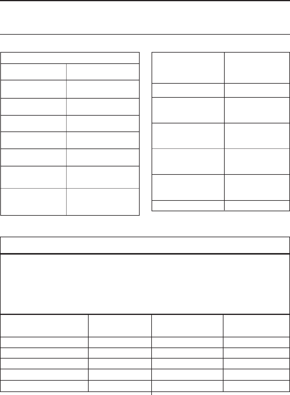
© 2003 Maytag Corporation
16010154 SECTION 6. SPECIFICATIONS 6-16-1
6-16-1
6-1
The laboratory test data in this chart was obtained under the following conditions: (1)(1)
(1)(1)
(1) power source of
115V AC, 60 Hz, (2)(2)
(2)(2)
(2) no door openings, (3)(3)
(3)(3)
(3) no load, (4)(4)
(4)(4)
(4) customer control(s) set at mid-point. The pressures
and wattages shown were taken: (a)(a)
(a)(a)
(a) during a normal running cycle, (b)(b)
(b)(b)
(b) with freezer temperature near 0o
F (refrigerator temperature, if applicable, near +37o F). (c)(c)
(c)(c)
(c) no sooner than 5 minutes after compressor
start-up. In the home, measurements will vary depending upon environmental and usage conditions.
70 70
70 70
70o o
o o
o FF
FF
F 90 90
90 90
90oo
oo
o F F
F F
F 110 110
110 110
110oo
oo
o F F
F F
F
(Ambient)(Ambient)
(Ambient)(Ambient)
(Ambient) (Ambient)(Ambient)
(Ambient)(Ambient)
(Ambient) (Ambient)(Ambient)
(Ambient)(Ambient)
(Ambient)
% Operating Timer% Operating Timer
% Operating Timer% Operating Timer
% Operating Timer 25-35 45-55 70-80
KWH/24 HoursKWH/24 Hours
KWH/24 HoursKWH/24 Hours
KWH/24 Hours 1.10/1.40 1.75/2.40 2.85/3.65
Suction Pressure (psig)Suction Pressure (psig)
Suction Pressure (psig)Suction Pressure (psig)
Suction Pressure (psig) -3" Hg/0 -2" Hg/2 -1" Hg/5
High Side Pressure (psigHigh Side Pressure (psig
High Side Pressure (psigHigh Side Pressure (psig
High Side Pressure (psig) 100/130 150-180 190-210
Running WattsRunning Watts
Running WattsRunning Watts
Running Watts 145-165 150-170 155-185
Temp ControlTemp Control
Temp ControlTemp Control
Temp Control Normal SettingNormal Setting
Normal SettingNormal Setting
Normal Setting
Cut / Out (
± 2
o F)
+34 o F
Cut / In (
± 2
o F)
+6 o F
CondenserCondenser
CondenserCondenser
Condenser Fan Cooled
Capillary TubeCapillary Tube
Capillary TubeCapillary Tube
Capillary Tube
Length
103 inches
Diameter
0.028 inches I.D.
Defrost thermostatDefrost thermostat
Defrost thermostatDefrost thermostat
Defrost thermostat
Cut / Out ( ±3 o F)
+38o F
Cut / In ( ±11 o F)
+15oF
Defrost TimerDefrost Timer
Defrost TimerDefrost Timer
Defrost Timer
Defrost Cycle
8 hrs.
Defrost Time
23 ± 3 Min.
Defrost HeaterDefrost Heater
Defrost HeaterDefrost Heater
Defrost Heater
Ohms
26.5
Watts
500
Defrost Amps. (Max.)Defrost Amps. (Max.)
Defrost Amps. (Max.)Defrost Amps. (Max.)
Defrost Amps. (Max.) 4.3
Power RequirementPower Requirement
Power RequirementPower Requirement
Power Requirement 115 VAC 60 HZ
Operating AmpsOperating Amps
Operating AmpsOperating Amps
Operating Amps
(Max.) (Max.)
(Max.) (Max.)
(Max.) 7.2
Refrigerant ChargeRefrigerant Charge
Refrigerant ChargeRefrigerant Charge
Refrigerant Charge
R134A (oz.) R134A (oz.)
R134A (oz.) R134A (oz.)
R134A (oz.) 4.25 oz
Compressor OilCompressor Oil
Compressor OilCompressor Oil
Compressor Oil
Charge (oz.) Charge (oz.)
Charge (oz.) Charge (oz.)
Charge (oz.) 250cc
CompressorCompressor
CompressorCompressor
Compressor
(BTU/hr.) (BTU/hr.)
(BTU/hr.) (BTU/hr.)
(BTU/hr.) 1007 (Matsushita)
Cabinet LinerCabinet Liner
Cabinet LinerCabinet Liner
Cabinet Liner High Impact
Laminated Polystyrene
Door LinersDoor Liners
Door LinersDoor Liners
Door Liners High Impact
Laminated Polystyrene
Cabinet & DividerCabinet & Divider
Cabinet & DividerCabinet & Divider
Cabinet & Divider
Insulation Insulation
Insulation Insulation
Insulation Foam
PERFORMANCE TEST DATAPERFORMANCE TEST DATA
PERFORMANCE TEST DATAPERFORMANCE TEST DATA
PERFORMANCE TEST DATA
21' Dispenser/Non Dispenser21' Dispenser/Non Dispenser
21' Dispenser/Non Dispenser21' Dispenser/Non Dispenser
21' Dispenser/Non Dispenser
Founatin Heater
Ohms 4810
Watts
2.75
SECTION 6. SPECIFICATIONSSECTION 6. SPECIFICATIONS
SECTION 6. SPECIFICATIONSSECTION 6. SPECIFICATIONS
SECTION 6. SPECIFICATIONS
© 2003 Maytag Corporation
16010154 SECTION 6. SPECIFICATIONS 6-26-2
6-26-2
6-2
Temp ControlTemp Control
Temp ControlTemp Control
Temp Control Normal SettingNormal Setting
Normal SettingNormal Setting
Normal Setting
Cut / Out (
±
2 o F)
+37o F
Cut / In (
±
2o F)
+9 o F
CondenserCondenser
CondenserCondenser
Condenser Fan Cooled
Capillary TubeCapillary Tube
Capillary TubeCapillary Tube
Capillary Tube
Length
103 inches
Diameter
0.028inches I.D.
Defrost thermostatDefrost thermostat
Defrost thermostatDefrost thermostat
Defrost thermostat
Cut / Out (±3 o F)
+43 o F
Cut / In (±11 o F)
+15 o F
Defrost TimerDefrost Timer
Defrost TimerDefrost Timer
Defrost Timer
Defrost Cycle
8 hrs.
Defrost Time
23 ± 3 Min.
Defrost HeaterDefrost Heater
Defrost HeaterDefrost Heater
Defrost Heater
Ohms
24.0
Watts
550
Defrost Amps. (Max.)Defrost Amps. (Max.)
Defrost Amps. (Max.)Defrost Amps. (Max.)
Defrost Amps. (Max.) 4.8
Power Requirement Power Requirement
Power Requirement Power Requirement
Power Requirement 115 VAC 60 HZ
Operating Amps Operating Amps
Operating Amps Operating Amps
Operating Amps
(Max.) (Max.)
(Max.) (Max.)
(Max.) 7.2
Refrigerant Charge Refrigerant Charge
Refrigerant Charge Refrigerant Charge
Refrigerant Charge
R134A (oz.) R134A (oz.)
R134A (oz.) R134A (oz.)
R134A (oz.) 4.50 oz
Compressor OilCompressor Oil
Compressor OilCompressor Oil
Compressor Oil
Charge (oz.)Charge (oz.)
Charge (oz.)Charge (oz.)
Charge (oz.) 250cc
CompressorCompressor
CompressorCompressor
Compressor
(BTU/hr.) (BTU/hr.)
(BTU/hr.) (BTU/hr.)
(BTU/hr.) 1007 (Matsushita)
Cabinet LinerCabinet Liner
Cabinet LinerCabinet Liner
Cabinet Liner High Impact
Laminated Polystyrene
Door Liners Door Liners
Door Liners Door Liners
Door Liners High Impact
Laminated Polystyrene
Cabinet & DividerCabinet & Divider
Cabinet & DividerCabinet & Divider
Cabinet & Divider
InsulationInsulation
InsulationInsulation
Insulation Foam
The laboratory test data in this chart was obtained under the following conditions: (1)(1)
(1)(1)
(1) power source of
115V AC, 60 Hz. (2) (2)
(2) (2)
(2) no door openings, (3)(3)
(3)(3)
(3) no load, (4)(4)
(4)(4)
(4) customer control(s) set at mid-point, The pressures
and wattages shown were taken: (a)(a)
(a)(a)
(a) during a normal running cycle, (b)(b)
(b)(b)
(b) with freezer temperature near 0oF
(refrigerator temperature, if applicable, near +37o F), (c)(c)
(c)(c)
(c) no sooner than 5 minutes after compressor start-
up. In the home, measurements will vary depending upon environmental and usage conditions.
70 70
70 70
70oo
oo
o F F
F F
F 9090
9090
90o o
o o
o FF
FF
F110110
110110
110oo
oo
oFF
FF
F
(Ambient)(Ambient)
(Ambient)(Ambient)
(Ambient) (Ambient)(Ambient)
(Ambient)(Ambient)
(Ambient) (Ambient)(Ambient)
(Ambient)(Ambient)
(Ambient)
% Operating Time% Operating Time
% Operating Time% Operating Time
% Operating Time 25 - 35 45 - 55 70 - 80
KWH/24 HoursKWH/24 Hours
KWH/24 HoursKWH/24 Hours
KWH/24 Hours 1.15 / 1.70 2.00 / 2.75 3.30 / 4.20
Suction Pressure (psig)Suction Pressure (psig)
Suction Pressure (psig)Suction Pressure (psig)
Suction Pressure (psig) -3" Hg / 0 -2" Hg / 2 -1" Hg / 5
High Side Pressure (psig)High Side Pressure (psig)
High Side Pressure (psig)High Side Pressure (psig)
High Side Pressure (psig) 100 -130 150 -180 190 / 210
Running WattsRunning Watts
Running WattsRunning Watts
Running Watts 145 -165 150 -170 155 - 185
PERFORMANCE TEST DATAPERFORMANCE TEST DATA
PERFORMANCE TEST DATAPERFORMANCE TEST DATA
PERFORMANCE TEST DATA
23'/25' Dispenser/23' Non Dispenser23'/25' Dispenser/23' Non Dispenser
23'/25' Dispenser/23' Non Dispenser23'/25' Dispenser/23' Non Dispenser
23'/25' Dispenser/23' Non Dispenser
Fountain Heater
Ohms 4810
Watts
2.75
© 2003 Maytag Corporation
16010154 SECTION 6. SPECIFICATIONS 6-36-3
6-36-3
6-3
Power RequirementPower Requirement
Power RequirementPower Requirement
Power Requirement 115 VAC 60 HZ
Operating AmpsOperating Amps
Operating AmpsOperating Amps
Operating Amps
(Max.) (Max.)
(Max.) (Max.)
(Max.) 7.2
Refrigerant ChargeRefrigerant Charge
Refrigerant ChargeRefrigerant Charge
Refrigerant Charge
R134A (oz.) R134A (oz.)
R134A (oz.) R134A (oz.)
R134A (oz.) 4.25
Compressor OilCompressor Oil
Compressor OilCompressor Oil
Compressor Oil
Charge (oz.)Charge (oz.)
Charge (oz.)Charge (oz.)
Charge (oz.) 350 cc
Compressor Compressor
Compressor Compressor
Compressor
(BTU/hr.) (BTU/hr.)
(BTU/hr.) (BTU/hr.)
(BTU/hr.) 950 (Embraco)
Cabinet LinerCabinet Liner
Cabinet LinerCabinet Liner
Cabinet Liner High Impact
Laminated Polystyrene
Door LinersDoor Liners
Door LinersDoor Liners
Door Liners High Impact
Laminated Polystyrene
Cabinet & DividerCabinet & Divider
Cabinet & DividerCabinet & Divider
Cabinet & Divider
Insulation Insulation
Insulation Insulation
Insulation Foam
Temp ControlTemp Control
Temp ControlTemp Control
Temp Control Normal SettingNormal Setting
Normal SettingNormal Setting
Normal Setting
Cut / Out (
±2
F)
-10o F
Cut / In (
±
2 o F) +2
2o F
CondenserCondenser
CondenserCondenser
Condenser Fan Cooled
Capillary TubeCapillary Tube
Capillary TubeCapillary Tube
Capillary Tube
Length
103 inches
Diameter
0.028 inches I.D.
Defrost thermostatDefrost thermostat
Defrost thermostatDefrost thermostat
Defrost thermostat
Cut / Out (± 3o F)
+43o F
Cut / In (± 11o F)
+15 o F
Defrost TimerDefrost Timer
Defrost TimerDefrost Timer
Defrost Timer
Defrost Cycle
8 hrs.
Defrost Time
23± 3 Min.
Defrost HeaterDefrost Heater
Defrost HeaterDefrost Heater
Defrost Heater
Ohms
26.5
Watts
500
Defrost Amps. (Max.)Defrost Amps. (Max.)
Defrost Amps. (Max.)Defrost Amps. (Max.)
Defrost Amps. (Max.) 4.3
The laboratory test data in this chart was obtained under the following conditions: (1)(1)
(1)(1)
(1) power source of
115V AC, 60 Hz. (2) (2)
(2) (2)
(2) no door openings, (3)(3)
(3)(3)
(3) no load, (4)(4)
(4)(4)
(4) customer control(s) set at mid-point, The pres-
sures and wattages shown were taken: (a)(a)
(a)(a)
(a) during a normal running cycle, (b)(b)
(b)(b)
(b) with freezer temperature
near 0o F (refrigerator temperature, if applicable, near +37o F), (c)(c)
(c)(c)
(c) no sooner than 5 minutes after
compressor start-up. In the home, measurements will vary depending upon environmental and usage
conditions.
70 70
70 70
70oo
oo
o F F
F F
F 9090
9090
90o o
o o
o FF
FF
F110110
110110
110oo
oo
oFF
FF
F
(Ambient)(Ambient)
(Ambient)(Ambient)
(Ambient) (Ambient)(Ambient)
(Ambient)(Ambient)
(Ambient) (Ambient)(Ambient)
(Ambient)(Ambient)
(Ambient)
% Operating Time% Operating Time
% Operating Time% Operating Time
% Operating Time 25-35 45-55 70-80
KWH/24 HoursKWH/24 Hours
KWH/24 HoursKWH/24 Hours
KWH/24 Hours 1.10/1.40 1.75/2.50 2.85/3.65
Suction Pressure (psig)Suction Pressure (psig)
Suction Pressure (psig)Suction Pressure (psig)
Suction Pressure (psig) -3" Hg/0 -2" Hg/2 -1" Hg/5
High Side Pressure (psig)High Side Pressure (psig)
High Side Pressure (psig)High Side Pressure (psig)
High Side Pressure (psig) 100/130 150/180 190/210
Running WattsRunning Watts
Running WattsRunning Watts
Running Watts 145-165 150-170 155-185
PERFORMANCE TEST DATAPERFORMANCE TEST DATA
PERFORMANCE TEST DATAPERFORMANCE TEST DATA
PERFORMANCE TEST DATA
21' Non Dispenser (Maytag)21' Non Dispenser (Maytag)
21' Non Dispenser (Maytag)21' Non Dispenser (Maytag)
21' Non Dispenser (Maytag)
o
Fountain Heater
Ohms NA
Watts
NA
© 2003 Maytag Corporation
16010154 SECTION 6. SPECIFICATIONS 6-46-4
6-46-4
6-4
Power RequirementPower Requirement
Power RequirementPower Requirement
Power Requirement 115 VAC 60 HZ
Operating Amps Operating Amps
Operating Amps Operating Amps
Operating Amps
(Max.) (Max.)
(Max.) (Max.)
(Max.) 7.2
Refrigerant ChargeRefrigerant Charge
Refrigerant ChargeRefrigerant Charge
Refrigerant Charge
R134A (oz.) R134A (oz.)
R134A (oz.) R134A (oz.)
R134A (oz.) 4.50
Compressor OilCompressor Oil
Compressor OilCompressor Oil
Compressor Oil
Charge (oz.)Charge (oz.)
Charge (oz.)Charge (oz.)
Charge (oz.) 350cc
CompressorCompressor
CompressorCompressor
Compressor
(BTU/hr.) (BTU/hr.)
(BTU/hr.) (BTU/hr.)
(BTU/hr.) 950 (Embraco)
Cabinet LinerCabinet Liner
Cabinet LinerCabinet Liner
Cabinet Liner High Impact
Laminated Polystyrene
Door LinersDoor Liners
Door LinersDoor Liners
Door Liners High Impact
Laminated Polystyrene
Cabinet & DividerCabinet & Divider
Cabinet & DividerCabinet & Divider
Cabinet & Divider
Insulation Insulation
Insulation Insulation
Insulation Foam
Fountain HeaterFountain Heater
Fountain HeaterFountain Heater
Fountain Heater
Ohms
4810
Watts
2.75
Temp. ControlTemp. Control
Temp. ControlTemp. Control
Temp. Control Normal SettingNormal Setting
Normal SettingNormal Setting
Normal Setting
Cut / Out (
±2
o F)
-10 o F
Cut / In (
±2
o F)
+22 o F
CondenserCondenser
CondenserCondenser
Condenser Fan Cooled
Capillary TubeCapillary Tube
Capillary TubeCapillary Tube
Capillary Tube
Length
103 inches
Diameter
0.028 inches I.D.
Defrost thermostatDefrost thermostat
Defrost thermostatDefrost thermostat
Defrost thermostat
Cut / Out (± 3o F)
+43 o F
Cut / In (± 11o F)
+15 o F
Defrost TimerDefrost Timer
Defrost TimerDefrost Timer
Defrost Timer
Defrost Cycle
8 hrs.
Defrost Time
23 ± 3 Min.
Defrost HeaterDefrost Heater
Defrost HeaterDefrost Heater
Defrost Heater
Ohms
24
Watts
550
Defrost Amps. (Max.)Defrost Amps. (Max.)
Defrost Amps. (Max.)Defrost Amps. (Max.)
Defrost Amps. (Max.) 4.8
The laboratory test data in this chart was obtained under the following conditions: (1)(1)
(1)(1)
(1) power source of
115V AC, 60 Hz. (2) (2)
(2) (2)
(2) no door openings, (3)(3)
(3)(3)
(3) no load, (4)(4)
(4)(4)
(4) customer control(s) set at mid-point, The pres-
sures and wattages shown were taken: (a)(a)
(a)(a)
(a) during a normal running cycle, (b)(b)
(b)(b)
(b) with freezer temperature
near 0o F (refrigerator temperature, if applicable, near +37o F), (c)(c)
(c)(c)
(c) no sooner than 5 minutes after
compressor start-up. In the home, measurements will vary depending upon environmental and usage
conditions.
70 70
70 70
70oo
oo
o F F
F F
F 9090
9090
90o o
o o
o FF
FF
F110110
110110
110oo
oo
oFF
FF
F
(Ambient)(Ambient)
(Ambient)(Ambient)
(Ambient) (Ambient)(Ambient)
(Ambient)(Ambient)
(Ambient) (Ambient)(Ambient)
(Ambient)(Ambient)
(Ambient)
% Operating Time% Operating Time
% Operating Time% Operating Time
% Operating Time 25 - 35 45 - 55 70 - 80
KWH/24 HourKWH/24 Hour
KWH/24 HourKWH/24 Hour
KWH/24 Hour 1.15 / 1.70 2.00 / 2.75 3.04 / 4.20
Suction Pressure (psig)Suction Pressure (psig)
Suction Pressure (psig)Suction Pressure (psig)
Suction Pressure (psig) -3" Hg / 0 -2" Hg / 2 -1" Hg / 5
High Side Pressure (psig)High Side Pressure (psig)
High Side Pressure (psig)High Side Pressure (psig)
High Side Pressure (psig) 100 / 130 150 / 180 190 / 210
Running WattsRunning Watts
Running WattsRunning Watts
Running Watts 145 - 165 150 - 170 155 - 185
PERFORMANCE TEST DATAPERFORMANCE TEST DATA
PERFORMANCE TEST DATAPERFORMANCE TEST DATA
PERFORMANCE TEST DATA
23'/25' Dispenser/Non Dispenser (Maytag)23'/25' Dispenser/Non Dispenser (Maytag)
23'/25' Dispenser/Non Dispenser (Maytag)23'/25' Dispenser/Non Dispenser (Maytag)
23'/25' Dispenser/Non Dispenser (Maytag)
© 2003 Maytag Corporation
16010154 SECTION 6. SPECIFICATIONS 6-56-5
6-56-5
6-5
Power Requirement Power Requirement
Power Requirement Power Requirement
Power Requirement 115 VAC 60 HZ
Operating AmpsOperating Amps
Operating AmpsOperating Amps
Operating Amps
(Max.)(Max.)
(Max.)(Max.)
(Max.) 7.2
Refrigerant ChargeRefrigerant Charge
Refrigerant ChargeRefrigerant Charge
Refrigerant Charge
R134A (oz.) R134A (oz.)
R134A (oz.) R134A (oz.)
R134A (oz.) 4.50
Compressor OilCompressor Oil
Compressor OilCompressor Oil
Compressor Oil
Charge (oz.)Charge (oz.)
Charge (oz.)Charge (oz.)
Charge (oz.) 350 cc
CompressorCompressor
CompressorCompressor
Compressor
(BTU/hr.) (BTU/hr.)
(BTU/hr.) (BTU/hr.)
(BTU/hr.) 950 (Embraco)
Cabinet LinerCabinet Liner
Cabinet LinerCabinet Liner
Cabinet Liner High Impact
Laminated Polystyrene
Door LinersDoor Liners
Door LinersDoor Liners
Door Liners High Impact
Laminated Polystyrene
Cabinet & DividerCabinet & Divider
Cabinet & DividerCabinet & Divider
Cabinet & Divider
InsulationInsulation
InsulationInsulation
Insulation Foam
The laboratory test data in this chart was obtained under the following conditions: (1)(1)
(1)(1)
(1) power source of
115V AC, 60 Hz. (2) (2)
(2) (2)
(2) no door openings, (3)(3)
(3)(3)
(3) no load, (4)(4)
(4)(4)
(4) customer control(s) set at mid-point, The pres-
sures and wattages shown were taken: (a)(a)
(a)(a)
(a) during a normal running cycle, (b)(b)
(b)(b)
(b) with freezer temperature
near 0o F (refrigerator temperature, if applicable, near +37o F), (c)(c)
(c)(c)
(c) no sooner than 5 minutes after
compressor start-up. In the home, measurements will vary depending upon environmental and usage
conditions.
70 70
70 70
70oo
oo
o F F
F F
F 9090
9090
90o o
o o
o FF
FF
F110110
110110
110oo
oo
oFF
FF
F
(Ambient)(Ambient)
(Ambient)(Ambient)
(Ambient) (Ambient)(Ambient)
(Ambient)(Ambient)
(Ambient) (Ambient)(Ambient)
(Ambient)(Ambient)
(Ambient)
% Operating Time% Operating Time
% Operating Time% Operating Time
% Operating Time 25-35 45-55 70-80
KWH/24 HoursKWH/24 Hours
KWH/24 HoursKWH/24 Hours
KWH/24 Hours 1.15/1.70 2.00/2.75 3.40/4.20
Suction Pressure (psig)Suction Pressure (psig)
Suction Pressure (psig)Suction Pressure (psig)
Suction Pressure (psig) -3" Hg/0 -2" Hg/2 -1" Hg/5
High Side Pressure (psig)High Side Pressure (psig)
High Side Pressure (psig)High Side Pressure (psig)
High Side Pressure (psig) 100/130 150/180 190/210
Running WattsRunning Watts
Running WattsRunning Watts
Running Watts 145-165 150-170 155-185
Temp. ControlTemp. Control
Temp. ControlTemp. Control
Temp. Control Normal Setting
Cut / Out (
±2
o F)
-10 o F
Cut / In (
±
2o F)
+22 o F
CondenserCondenser
CondenserCondenser
Condenser Fan Cooled
Capillary TubeCapillary Tube
Capillary TubeCapillary Tube
Capillary Tube
Length
103 inches
Diameter
0.028inches I.D.
Defrost thermostatDefrost thermostat
Defrost thermostatDefrost thermostat
Defrost thermostat
Cut / Out (±3 o F)
+43 o F
Cut / In (±11 o F)
+15 o F
Defrost TimerDefrost Timer
Defrost TimerDefrost Timer
Defrost Timer
CycleCycle
CycleCycle
Cycle Adaptive DefrostAdaptive Defrost
Adaptive DefrostAdaptive Defrost
Adaptive Defrost
Defrost HeaterDefrost Heater
Defrost HeaterDefrost Heater
Defrost Heater
Ohms
24.0
Watts
550
Defrost Amps. (Max.)Defrost Amps. (Max.)
Defrost Amps. (Max.)Defrost Amps. (Max.)
Defrost Amps. (Max.) 5.2
PERFORMANCE TEST DATAPERFORMANCE TEST DATA
PERFORMANCE TEST DATAPERFORMANCE TEST DATA
PERFORMANCE TEST DATA
23'/25' Dispenser/23' Non Dispenser (Maytag Premium)23'/25' Dispenser/23' Non Dispenser (Maytag Premium)
23'/25' Dispenser/23' Non Dispenser (Maytag Premium)23'/25' Dispenser/23' Non Dispenser (Maytag Premium)
23'/25' Dispenser/23' Non Dispenser (Maytag Premium)
Fountain HeaterFountain Heater
Fountain HeaterFountain Heater
Fountain Heater
Ohms
4810
Watts
2.75
© 2003 Maytag Corporation
16010154 SECTION 6. SPECIFICATIONS 6-66-6
6-66-6
6-6

© 2003 Maytag Corporation
16010154 SECTION 7. SCHEMATICS 7-17-1
7-17-1
7-1
SECTION 7. SCHEMATICSSECTION 7. SCHEMATICS
SECTION 7. SCHEMATICSSECTION 7. SCHEMATICS
SECTION 7. SCHEMATICS
DESCRIPTION ID NO.
FACTORY INSTALLED OR PROVISIONAL ICE MAKER MODELS RWD-1
SLIDE SELECTOR FOUNTAIN M ODELS RWD-2
ALTERNATE VERSION OF SLIDE SELECTOR FOUNTAIN MODELS RWD-3
ELECTRONIC FOUNTAIN, DEFROST TIMER
MAYTAG & JENN-AIR MODELS RWD-4
ELECTRONIC FOUNTAIN, ADAPTIVE DEFROST
MAYTAG & JENN-AIR MODELS RWD-5
REFRIGERANT FLOW RD-1
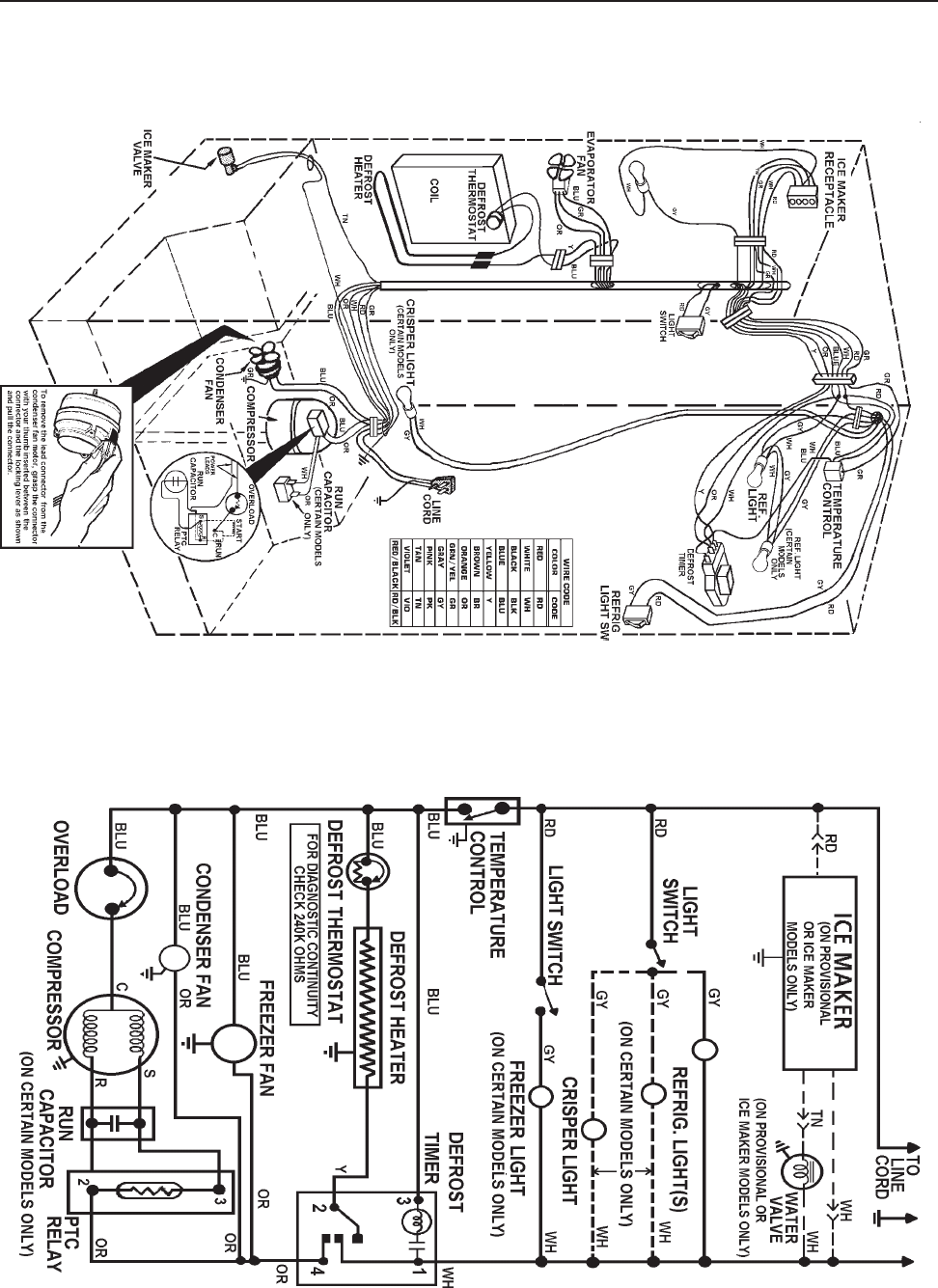
© 2003 Maytag Corporation
16010154 SECTION 7. SCHEMATICS 7-27-2
7-27-2
7-2
PICTORIAL WIRING DIAGRAM
ALLOW 10 PERCENT TOLERANCE ON ALL RESISTANCES SCHEMATIC WIRING DIAGRAM
DISCONNECT THE UNIT FROM THE POWER SOURCEDISCONNECT THE UNIT FROM THE POWER SOURCE
DISCONNECT THE UNIT FROM THE POWER SOURCEDISCONNECT THE UNIT FROM THE POWER SOURCE
DISCONNECT THE UNIT FROM THE POWER SOURCE
SCHEMATIC - RWD1SCHEMATIC - RWD1
SCHEMATIC - RWD1SCHEMATIC - RWD1
SCHEMATIC - RWD1
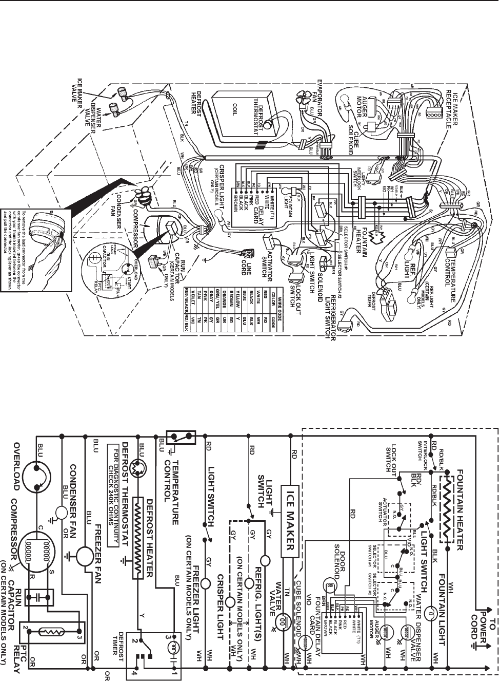
© 2003 Maytag Corporation
16010154 SECTION 7. SCHEMATICS 7-37-3
7-37-3
7-3
SCHEMATIC WIRING DIAGRAM
PICTORIAL WIRING DIAGRAM
ALLOW 10 PERCENT TOLERANCE ON ALL RESISTANCES
DISCONNECT THE UNIT FROM THE POWER SOURCEDISCONNECT THE UNIT FROM THE POWER SOURCE
DISCONNECT THE UNIT FROM THE POWER SOURCEDISCONNECT THE UNIT FROM THE POWER SOURCE
DISCONNECT THE UNIT FROM THE POWER SOURCE
SCHEMATIC - RWD2SCHEMATIC - RWD2
SCHEMATIC - RWD2SCHEMATIC - RWD2
SCHEMATIC - RWD2

© 2003 Maytag Corporation
16010154 SECTION 7. SCHEMATICS 7-47-4
7-47-4
7-4
CRUSHER/CUBE/WATER/
LIGHT
CUBE/WATER/LIGHT/LOCK
CUBE/LIGHT
CUBE
DISCONNECT THE UNITDISCONNECT THE UNIT
DISCONNECT THE UNITDISCONNECT THE UNIT
DISCONNECT THE UNIT
FROM THE POWERFROM THE POWER
FROM THE POWERFROM THE POWER
FROM THE POWER
SOURCESOURCE
SOURCESOURCE
SOURCE
CUBE/WATER/LIGHT
SCHEMATIC - RWD3SCHEMATIC - RWD3
SCHEMATIC - RWD3SCHEMATIC - RWD3
SCHEMATIC - RWD3

© 2003 Maytag Corporation
16010154 SECTION 7. SCHEMATICS 7-57-5
7-57-5
7-5
DISCONNECT THE UNIT FROM THE POWER SOURCEDISCONNECT THE UNIT FROM THE POWER SOURCE
DISCONNECT THE UNIT FROM THE POWER SOURCEDISCONNECT THE UNIT FROM THE POWER SOURCE
DISCONNECT THE UNIT FROM THE POWER SOURCE
PICTORIAL WIRING DIAGRAM
ALLOW 10 PERCENT TOLERANCE ON ALL RESISTANCES SCHEMATIC WIRING DIAGRAM
SCHEMATIC - RWD4SCHEMATIC - RWD4
SCHEMATIC - RWD4SCHEMATIC - RWD4
SCHEMATIC - RWD4
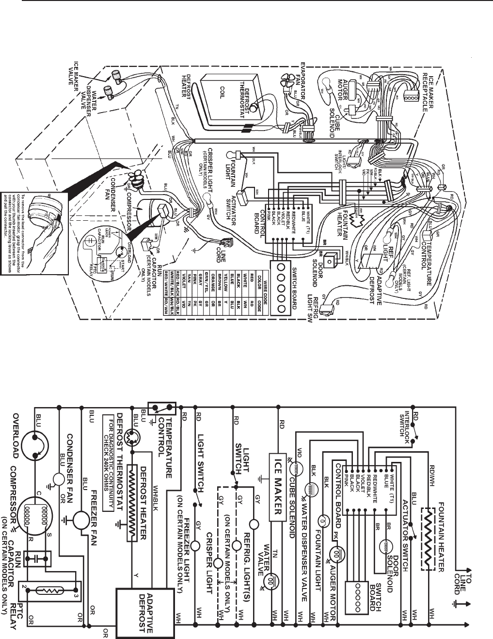
© 2003 Maytag Corporation
16010154 SECTION 7. SCHEMATICS 7-67-6
7-67-6
7-6
PICTORIAL WIRING DIAGRAM
ALLOW 10 PERCENT TOLERANCE ON ALL RESISTANCES SCHEMATIC WIRING DIAGRAM
DISCONNECT THE UNIT FROM THE POWER SOURCEDISCONNECT THE UNIT FROM THE POWER SOURCE
DISCONNECT THE UNIT FROM THE POWER SOURCEDISCONNECT THE UNIT FROM THE POWER SOURCE
DISCONNECT THE UNIT FROM THE POWER SOURCE
SCHEMATIC - RWD5SCHEMATIC - RWD5
SCHEMATIC - RWD5SCHEMATIC - RWD5
SCHEMATIC - RWD5
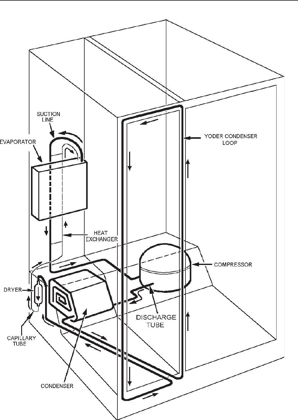
© 2003 Maytag Corporation
16010154 SECTION 7. SCHEMATICS 7-77-7
7-77-7
7-7
REFRIGERANT FLOW - RD1REFRIGERANT FLOW - RD1
REFRIGERANT FLOW - RD1REFRIGERANT FLOW - RD1
REFRIGERANT FLOW - RD1
© 2003 Maytag Corporation
16010154 SECTION 7. SCHEMATICS 7-87-8
7-87-8
7-8
©2003 Maytag Appliances Company 16010154 Rev. 0 A -1
Appendix A

©2003 Maytag Appliances Sales Company
16010154 Introduction i
INTRODUCTION
This refrigeration service supplement provides the information necessary to service Side-by-
Side model refrigerators.
The supplement is printed in loose leaf format. Each part of this supplement is divided into
sections relating to a general group of components and each section is subdivided into
various parts describing a particular component or service procedure.
The subdividing of the subject matter, plus the loose leaf form, will facilitate the updating of
the supplement as new models, and new or revised components of service procedures are
introduced.
Each page of this supplement will be identified in the lower right hand corner. As new or
revised pages are published, it will be easy to keep the supplement up to date.
This service supplement is a valuable service tool and care should be taken to keep it up to
date by prompt and proper filing of subsequent pages as they are issued.
©2003 Maytag Appliances Sales Company
16010154 Introduction ii

© 2003 Maytag Appliances Sales Company
16010154 Contents iii
CONTENTS
SECTION 1. GENERAL INFORMATION............................................................... 1-1
INSTRUCTIONS - ELECTRICAL REQUIREMENTS ................................................. 1-1
IMPORTANT SAFETY PRECAUTIONS............................................................... 1-1
GROUNDING INSTRUCTIONS......................................................................... 1-1
CLIMATE ZONE TECHNOLOGY (CZT) ............................................................... 1-2
CLIMATE ZONE TECHNOLOGY STORAGE DRAWERS (Select Models)...................... 1-4
LIGHT BULB REPLACEMENT .......................................................................... 1-5
Removal of the Drawer Assemblies for Cleaning.............................................. 1-5
AUTOMATIC HUMIDITY CONTROL (Select Models) ............................................. 1-6
WATER FILTER CHANGE REMINDER (Select Models)............................................ 1-6
SECTION 2. COMPONENTS ............................................................................ 2-1
COMPONENT TESTING................................................................................. 2-1
CHECKING THE CZT FAN MOTOR.................................................................... 2-1
REMOVING THE CZT FAN MOTOR................................................................... 2-2
CHECKING THE CZT DAMPER MOTOR/DOOR ASSEMBLY .................................... 2-3
REMOVING THE CZT DAMPER MOTOR/DOOR ASSEMBLY ................................... 2-4
CHECKING AND REPLACING THE THERMISTOR ................................................. 2-5
TESTING AND REPLACING THE DRAWER SWITCH.............................................. 2-6
REPLACING THE INNER ENCLOSURE ASSEMBLY................................................ 2-6
CHECKING AND REPLACING THE AUTO DAMPER BIAS HEATER ............................ 2-6
ICE MAKER WATER VALVE RELAY................................................................... 2-7
ELECTRONIC CONTROL BOARD TROUBLESHOOTING ......................................... 2-8
Some LED’s Will Not Light ......................................................................... 2-8
Fountain Light Will Not Light ...................................................................... 2-8
Will Not Dispense Ice or Water .................................................................... 2-8
CHANGE FILTER LIGHT WILL NOT LIGHT........................................................... 2-8
IN-CABINET FUNCTION TEST (ICFT)................................................................. 2-9
CZT SERVICE ISSUES.................................................................................. 2-11
CZT SERVICE ISSUES Display........................................................................2-12
CZT SERVICE ISSUES Food Preservation .......................................................... 2-13
CZT SERVICE ISSUES Noise.......................................................................... 2-14
CZT SERVICE ISSUES CZT External Condensation/Icing ....................................... 2-14
CZT SERVICE ISSUES Refrigerator Performance ................................................2-15
CZT SERVICE ISSUES Usage Issues.................................................................2-16
SECTION 3. SPECIFICATIONS .................................................................3-1
27’/29’ DISPENSER (CZT/WFR AND NOT CZT)..................................................... 3-1
PERFORMANCE TEST DATA .......................................................................... 3-1
SECTION 4. SCHEMATICS ......................................................................4-1
© 2003 Maytag Appliances Sales Company
16010154 Contents iv
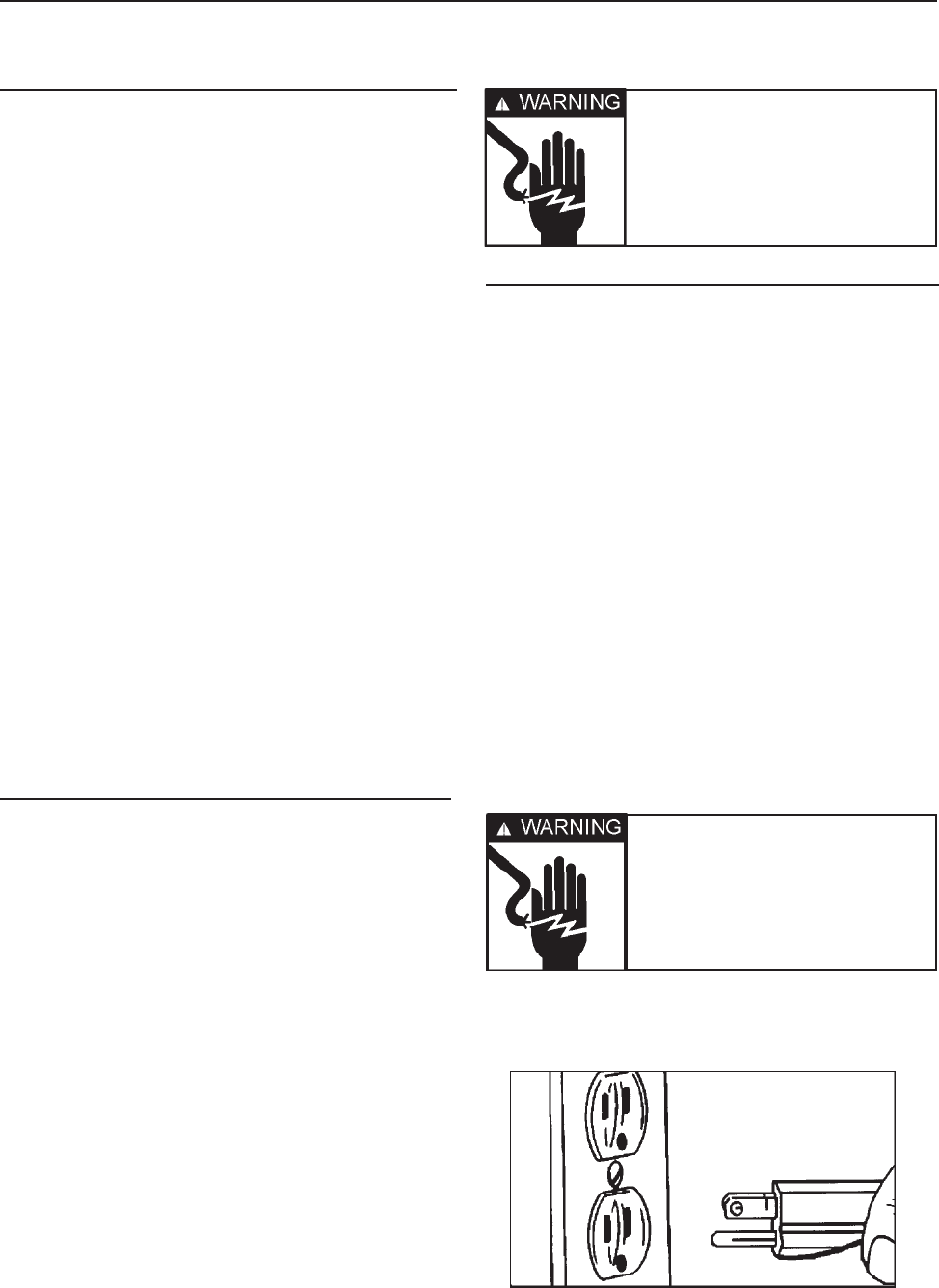
©2003 Maytag Appliances Sales Company
16010154 SECTION 1. GENERAL INFORMATION 1-1
INSTRUCTIONS - ELECTRICAL
REQUIREMENTS
It is the personal responsibility and
obligation of the appliance owner to provide
adequate electrical service for this appliance.
Observe all electrical and local codes and
ordinances.
A 120 volt 60Hz, 15 ampere fused electrical
supply is required. An individual branch (or
separate circuit serving only this appliance)
is recommended.
Do not use an extension cord.
Before plugging in power cord, operating or
testing, follow grounding instructions in
Grounding Section.
Electrical Service
Grounding: 120 VOLTS, 60Hz Only
IMPORTANT SAFETY PRECAUTIONS
WARNING: Personal Injury Hazard - To
prevent unnecessary risk of fire, electrical
shock or personal injury, all wiring and
grounding must be done in accordance with
National Electrical Code and local codes and
ordinances.
GROUNDING INSTRUCTIONS
This appliance is equipped with a power
supply cord having a 3-prong grounding
plug. For your safety, this cord must be
plugged into a mating 3-prong type wall
receptacle which is properly wired,
grounded and polarized.
If a mating wall receptacle is not available,
contact a qualified electrician to have the
wall receptacle replaced. Do not use an AC
adapter plug. If there is any question, local
building officials or electrical utility should
be consulted.
SECTION 1. GENERAL INFORMATION
Warning - Electrical
ground is required on this
appliance!
Warning - Do not under
any circumstance remove
the grounding prong
from the power supply
cord.
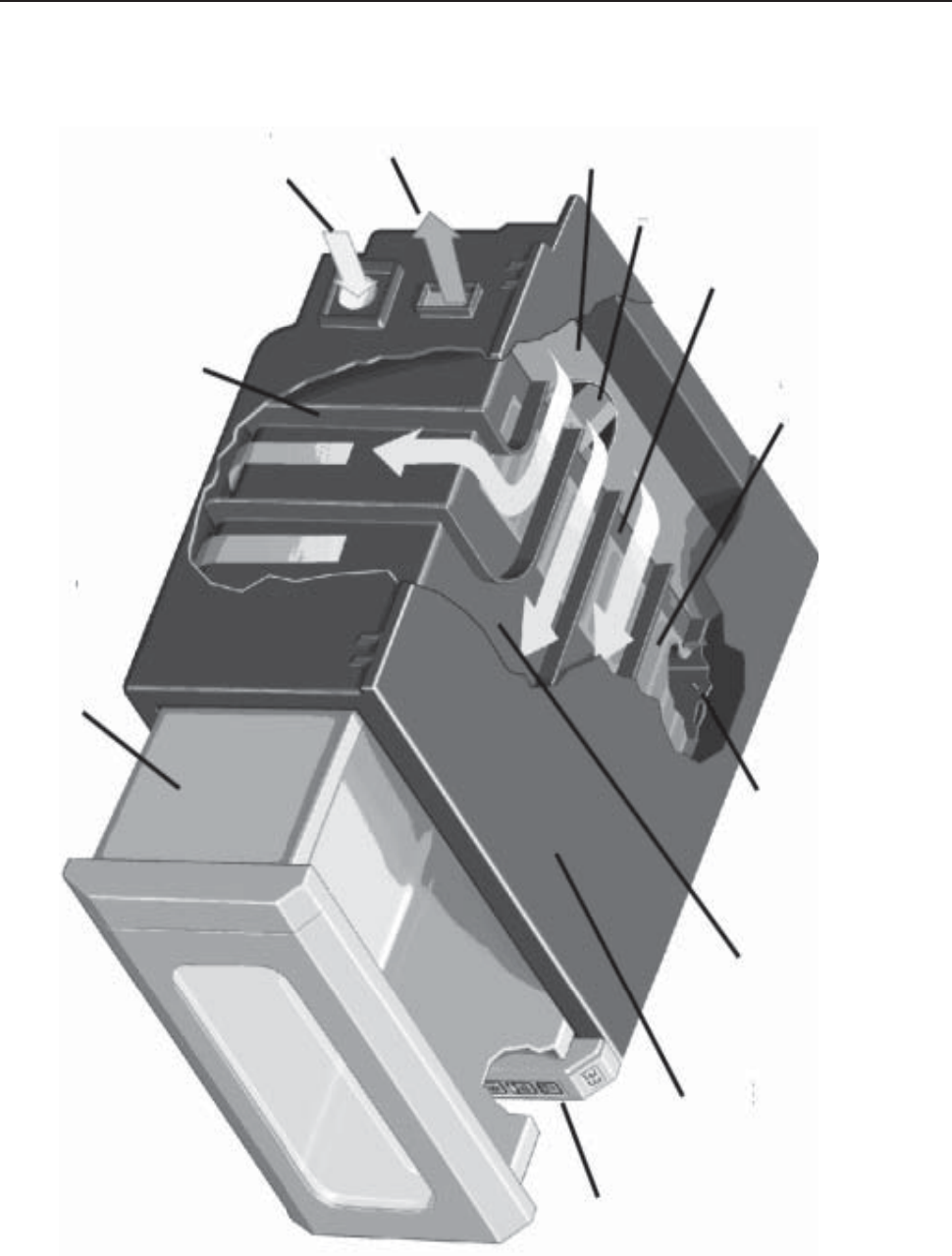
©2003 Maytag Appliances Sales Company
16010154 SECTION 1. GENERAL INFORMATION 1-2
CLIMATE ZONE TECHNOLOGY (CZT)
Shape Memory
Polymer (S.M.P)
Permeable Fabric
Air Flow Passages
Circulation Fan
Guide Vanes
Cold Air
Intake
Warm Air
Exhaust
Thermistor Inner
Enclosure Wall
(Air Jacket) Outer
Enclosure Wall
Electronic
Control
Housing
Bulkhead
Storage Drawer
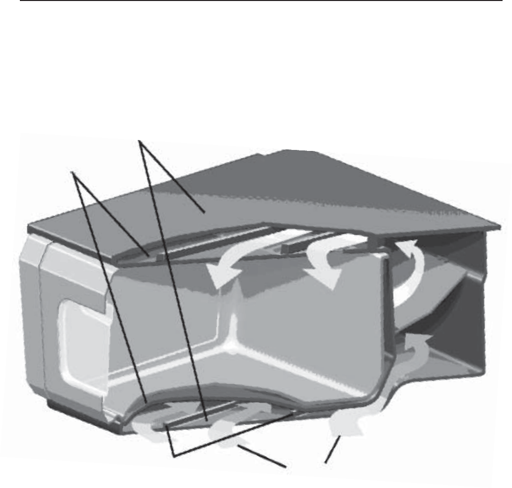
©2003 Maytag Appliances Sales Company
16010154 SECTION 1. GENERAL INFORMATION 1-3
CLIMATE ZONE TECHNOLOGY (CZT)
Outer
Enclosure Walls
Inner
Enclosure Walls
(Air Jacket)
Guide Vanes Air Flow
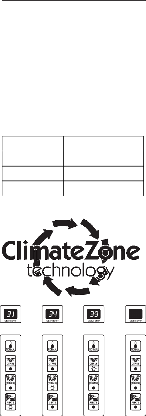
©2003 Maytag Appliances Sales Company
16010154 SECTION 1. GENERAL INFORMATION 1-4
CLIMATE ZONE TECHNOLOGYTM
STORAGE DRAWERS
(Select Models)
Climate Zone TechnologyTM Storage Drawers
prolong the freshness of meats, fruits and
vegetables. The top drawer accommodates
meats, citrus fruits and fresh produce. The
middle drawer holds citrus fruits and fresh
produce. Climate Zone TechnologyTM
drawers are equipped with Automatic
Humidity Control*. The drawers are set to
provide optimal temperatures and a
numerical temperature display for each food
setting according to the chart below.
Climate Zone TechnologyTM can also be
turned off, and the drawers operate as
standard sealed crisper drawers with no
temperature display.
Notes:
• If a Climate Zone TechologyTM drawer is
left open the display will flash. Close the
drawer completely and the display will
return to normal.
• After prolonged drawer openings and /or
loading the drawers, etc. the
temperature readout may rise by a few
degrees. This is normal. The
temperature will recover in a short
period of time.
• Handle fresh meat with care to avoid
cross-contamination. Store meat in
airtight containers and be sure to wipe
up spills of meat juices immediately
using hot, soapy water. Disinfect drawer
with liquid chlorine bleach according to
label directions and rinse with clean
water.
• For enhanced flavor, store hard cheeses
on the Citrus setting.
• Frozen meats will thaw very slowly on
the Meat setting. Most thawing should
be done outside of the drawers, on the
lowest shelf in the refrigerator.
•Under heavy usage conditions during
hot, humid weather, the exterior
surfaces of the Climate Zone
TechnologyTM drawers may fog or sweat.
This is normal. The condensation will
clear once the door is closed for a period
of time.
• Due to the accuracy and the location of
the Climate Zone Technology™
temperature sensor system, drawer
temperatures measured with house hold
refrigerator thermometers may vary
from the drawer temperature display.
This is normal.
Item Storage Temperature
Citrus 39º F
Vegetables 34º F
Meats 31º F

©2003 Maytag Appliances Sales Company
16010154 SECTION 1. GENERAL INFORMATION 1-5
• If Climate Zone Technology™ drawers
are not opened for a period of four
weeks, they will automatically go to the
Normal or “off” state. The display will
turn off.
To remove: Pull the drawer out until it stops.
Tilt the drawer-front up and pull out. To
replace the drawer, align the drawer in the
tracks, lift the drawer-front and slide in.
LIGHT BULB REPLACEMENT
A light bulb is located behind the upper
Climate Zone Technology™ drawer
assembly. The light bulb part number is
61004862 see your Maytag dealer for
replacement or call 1-800-688-8408 to order
direct.
Warning: To prevent electric shock, always
unplug the refrigerator before changing the
light bulb. Wear gloves as protection
against possible broken glass.
To remove the drawer assembly: Unload
and remove shelf located above the Climate
Zone Technology™ drawers. Unload and
remove the drawer. Remove two
combination phillips,1/4” hex head screws
located on the left hand side. Lift the top
drawer assembly upward (approx. 1 inch)
and pull forward (approx. 3-4 inches). The
assembly should rest on its shelf supports.
Replace the bulb: Unscrew bulb and
replace. Caution: Handle the light bulb with
care to prevent breakage. The bulb may be
hot from use.
To replace drawer assembly: Lift the
assembly back into its original position
against the back stop. Make sure the
assembly is pushed firmly to the left of the
refrigerator cavity to align the screw holes.
Replace the two screws. Replace the
drawers into the assemblies and reconnect
the power to the refrigerator.
Removal of the Drawer Assemblies for
Cleaning
Unload and remove the shelf above the
Climate Zone Technology™ drawers. Unload
and remove the drawers. Remove two
combination phillips,1/4” hex head screws
located on the left side.
Lift the top drawer assembly upward
(approx. 1 inch) and pull forward (approx.
3-4 inches). The assembly should rest on its
shelf supports. Disconnect the power cords
to free the assembly, then pull completely
out. Repeat with second drawer assembly.
To replace: Lift the lower assembly back
into its original position leaving enough
space to reach the power cords. Reconnect
the assembly power cords. Push the
assembly in all the way to the back stop.
Make sure the assembly is pushed firmly to
the left of the refrigerator cavity to align
the screw holes. Replace the two screws.
Repeat with top assembly. Replace the
drawers into the assemblies and reconnect
the power source to the refrigerator.
Note: Make sure wire harness is guided
away from light bulb area. A clip is located
on the back of the assembly to secure
harness.
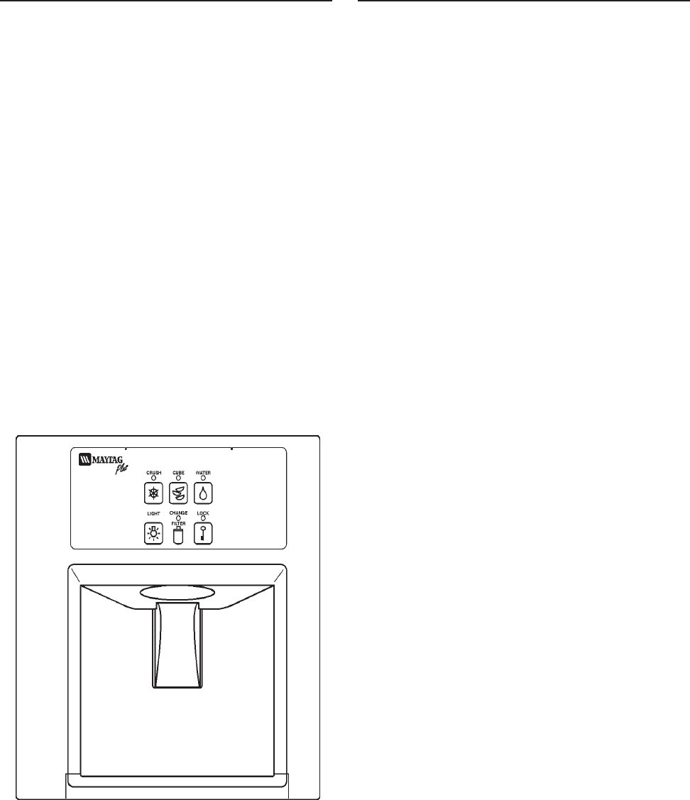
©2003 Maytag Appliances Sales Company
16010154 SECTION 1. GENERAL INFORMATION 1-6
WATER FILTER CHANGE REMINDER
(Select Models)
For some refrigerator models featuring
water filters, the Water Filter Change
Reminder function monitors the life of the
filter and provides a reminder when it is time
for the filter to be changed.
When the system detects either 12 months
of usage, or the filtering of 416 gallons of
water (whichever comes first), the CHANGE
FILTER indicator light will illuminate. This
indicates that the water filter should be
changed and the light reset.
To reset CHANGE FILTER light: Press and
hold the LIGHT and LOCK pads until the
CHANGE FILTER light blinks (approx. 3
seconds). The control is now reset for 12
months or another 416 gallons.
Note: The Water Filter Reminder will
operate if the filter bypass is in place.
AUTOMATIC HUMIDITY CONTROL
(Select Models)
Some crispers are equipped with an
automatic humidity control system,
eliminating the need for manual humidity
slide controls on the drawer. A fabric-like
material* covers small air vents in the
drawer cavity. This material controls the flow
of moist air out of the crisper to provide the
optimum environment for your food. If a
food spill should occur on the air vent or
mesh material, wipe with a clean, damp
cloth.
*Maytag Automatic Humidity Control
system features a unique, patented material
called Shape Memory Polymer (SMP) that
when laminated to fabric becomes DIAPLEX.
DIAPLEX is manufactured by Mitsubishi.
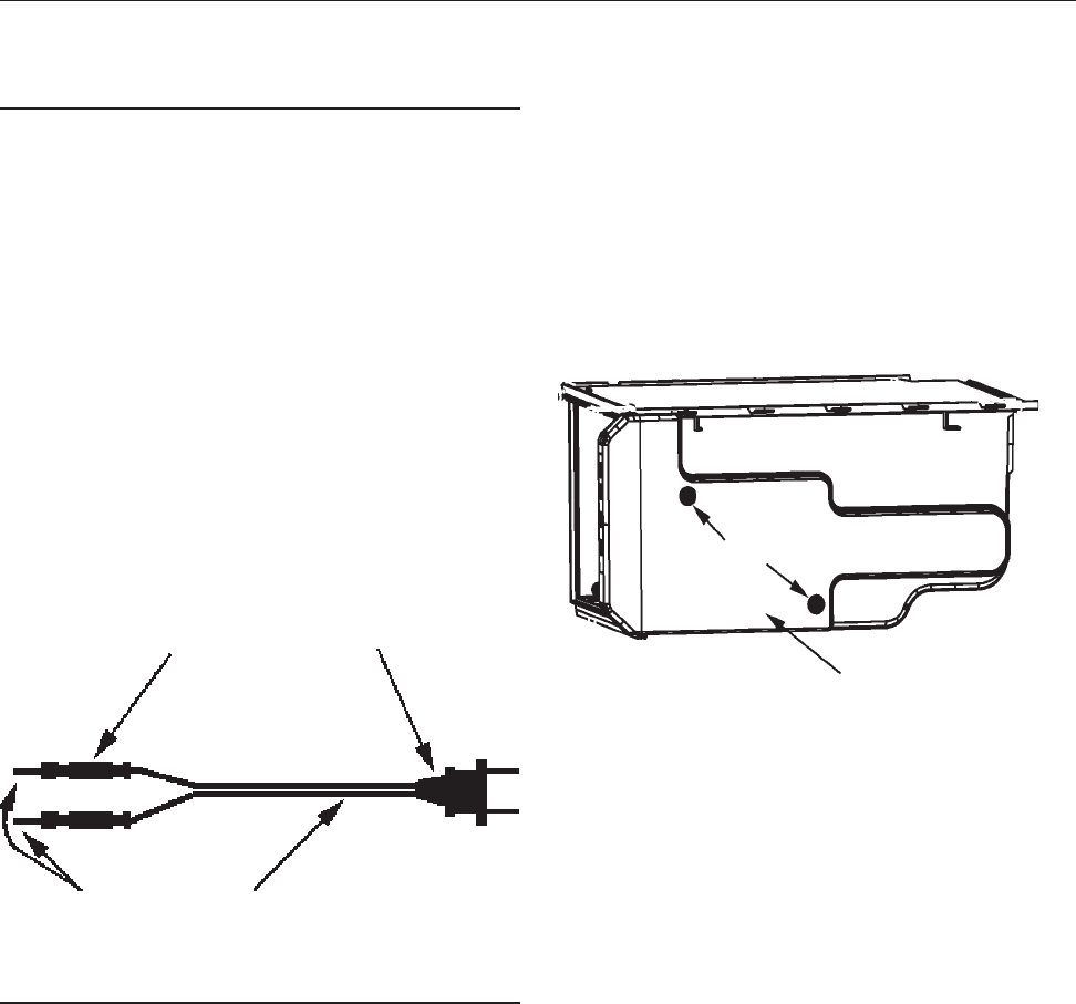
©2000 Maytag Appliances Sales Company
16010154 SECTION 2. COMPONENTS 2-1
CHECKING THE CZT FAN MOTOR
Disconnect the unit from the power source
1. Unload and remove shelf located above
the Climate Zone Technology™ drawers.
2. Unload and remove the CZT drawers.
3. Remove two combination phillips,1/4”
hex head screws located on the left side.
4. Lift the top drawer assembly upward
(approx. 1 inch) and pull forward
(approx. 3-4 inches). The assembly
should rest on its shelf supports.
COMPONENT TESTING
Test Cord
You will need to make up a test cord. Below
is a list parts to make the cord:
1. 115 volt plug.
2. 16 gauge line cord (length three foot)
3. Two crimp splice connectors.
4. Two solid steel 18 gauge pins one inch
long.
Assemble the test cord as shown below.
5. Disconnect the power cords to free the
assembly, then pull completely out.
Repeat with second drawer assembly.
6. Remove two control housing mounting
screws, See Figure 2-2. Remove the
control housing.
7. Disconnect the CZT, PC board connector
from the PC board. See below.
Note: The following test should be made by
a qualifed service Technician.
8. Using the test cord shown in Figure 2-1,
make the following connection to CZT PC
board wire harness connector;
a*. Insert one of the 18 gauge steel
pins into terminal # 1 (white wire).
b*.Insert the other steel pin into termi-
nal # 11 (blue wire green tracer).
* See Figure 2-3 for connector terminal
layout.
9. Make sure every thing is clear. Plug the
test cord into a 115 VAC outlet. The fan
should run. If not, disconnect the test
cord from the AC outlet. Using an
ohmmeter check the wire leads to the fan
motor for continuity. If they check ok,
replace the fan motor.
SECTION 2. COMPONENTS
Insulated
splice
Connector
18 Gauge
Steel Pins Line Cord
115 Volt
Plug
Figure 2-1
Control Housing
Mounting
Screws
Figure 2-2
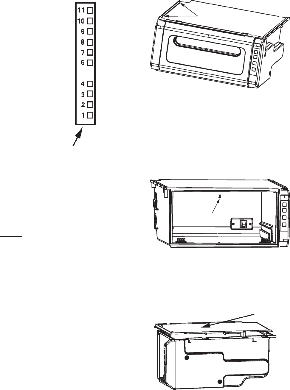
©2000 Maytag Appliances Sales Company
16010154 SECTION 2. COMPONENTS 2-2
REMOVING THE CZT FAN MOTOR
The CZT fan motor circulates the cooled air
around the air jacket. The fan runs
continuously except, during defrost cycle,
crisper drawer open condition or when the
normal (off) button is pushed
Disconnect the refrigerator from the power
source.
Removal of the Drawer Assemblies
1. Unload and remove shelf located above
the Climate Zone Technology™ drawers.
2. Unload and remove the drawer.
3. Remove two combination phillips,1/4”
hex head screws located on the left side.
(See Figure 2-4)
4. Lift the top drawer assembly upward
(approx. 1 inch) and pull forward
(approx. 3-4 inches). The assembly
should rest on its shelf supports.
5. Disconnect the power cords to free the
assembly, then pull completely out.
6. Remove the control housing cover. Then
remove the top cover mounting screw.
(See Figure 2-5)
Repeat steps 2 thru 5 with second
drawer assembly if you need to get to
that fan motor or other componets.
7. Pull the top cover foward and then up to
remove. (See Figure 2-6)
Figure 2-4
1/4” HEX
MOUNTING SCREWS
MOUNTING SCREW
Figure 2-5
TOP COVER
Figure 2-6
FAN
DAMPER OPEN
DAMPER CLOSED
HEATER/ADC
HEATER /COLD CONTROL
LINE (L1)
ADC STATUS
PAN SWITCH
DOOR SWITCH
NEUTRAL
PC WIRE HARNESS
CONNECTOR (END VIEW))
BLU\GRN WIRE
RED\BRN WIRE
RED\GRN WIRE
OR\BLU WIRE
BLUE WIRE
RED WIRE
ORANGE WIRE
BLACK WIRE
WH\RD WIRE
WHITE WIRE
Figure 2-3
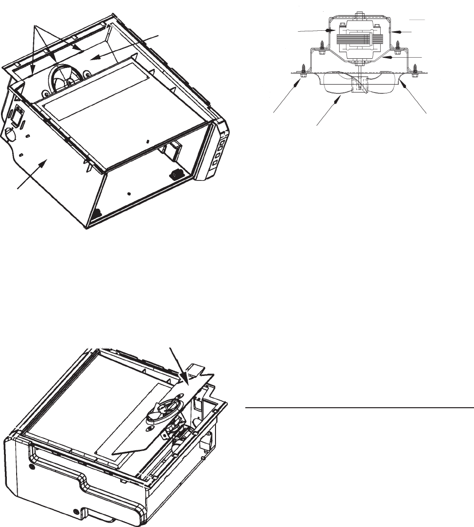
©2000 Maytag Appliances Sales Company
16010154 SECTION 2. COMPONENTS 2-3
8. Release the three locking tabs fan shroud
by pushing back on the outer box
assembly and pulling foward on the fan
shroud. (See Figure 2-7)
9. Carefully remove the fan shroud
assembly. (See Figure 2-8)
10. Disconnect the fan motor leads. The
wires are self-locking and it is important
to squeeze the clip before pulling the
leads off the terminals. (See Figure 2-9)
11. Remove the fan shroud assembly and
place it on a work surface.
12. Remove the screws that secure the
motor bracket assembly to the fan
shroud.
13. Remove the fan blade by pulling it off the
shaft.
14. Remove the screws that secure the rear
bracket to the front bracket. Remove the
motor from the rear mounting bracket.
15. Install the new part and all components
in reverse order of removal.
CHECKING THE CZT DAMPER
MOTOR/DOOR ASSEMBLY
Disconnect the unit from the power source.
1. Perform steps 1 thru 8 in checking CZT
fan motor.
Note: The following test should be made by
a qualifed service Technician.
2. Using the test cord shown in Figure 2-1,
make the following connection to CZT PC
board wire harness connector.
FAN
MOTOR
REAR
MOTOR
BRACKET
MOUNTING
SCREWS FAN BLADE FAN
SCHROUD
Figure 2-9
FAN SHROUD
LOCKING TABS FAN SHROUD
OUTER
BOX
Figure 2-7
FAN SHROUD
ASSEMBLY
Figure 2-8
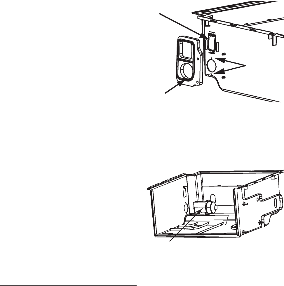
©2000 Maytag Appliances Sales Company
16010154 SECTION 2. COMPONENTS 2-4
3. Remove the CZT damper motor/switch
assembly as shown in Figure 2-11.
4. Remove the wire leads to the CZT
Damper motor and switch assembly.
5. Install the new parts and all components
in reverse order of removal.
3. Note the position of the damper.
4. If the damper door is closed
a*. Insert one of the leads
into terminal #1 (white wire).
b*.Insert the other lead into termi-
nal #10 (Red\Brn).
5. Make sure every thing is clear. Plug the
test cord into a 115 volt ac outlet. The
damper door should open. If not,
disconnect the test cord from the AC
outlet. Using an ohmmeter check the
wire leads to the damper motor for
continuity. If they check ok, replace the
motor/damper door assembly.
6. If the damper door is open
a*. Insert one of the leads into terminal
#1 (white wire).
b*.Insert the other lead into terminal #9
(Red\Grn).
7. Make sure every thing is clear. Plug the
test cord into a 115 volt ac outlet. The
damper door should close. If not,
disconnect the test cord from the AC
outlet.
Using an ohmmeter check the wire leads to
the motor for continuity. If they check ok,
replace the motor/damper door assembly.
REMOVING THE CZT DAMPER MOTOR/
DOOR ASSEMBLY
The CZT damper motor/door assmbly
controls the air flow into the CZT assembly.
Disconnect the unit from the power source.
1. Perform steps 1 thru 10 in replacing CZT
fan motor.
2. Remove the CZT air seal. (See Figure 2-10)
Rotary
Damper
Assembly
Mounting
Screws
Return Air
Damper
CZT Air
Seal Figure 2-10
CZT Damper Door/Motor
and Switch Assemlby
Figure 2-11
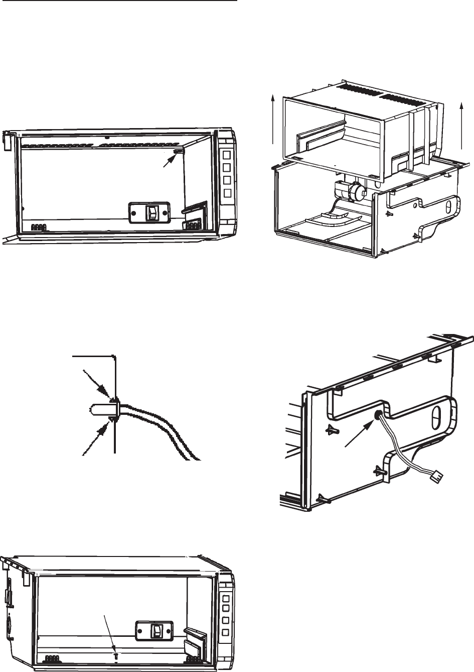
©2000 Maytag Appliances Sales Company
16010154 SECTION 2. COMPONENTS 2-5
CHECKING AND REPLACING
THE THERMISTOR
Disconnect the unit from the power source.
1. Perform steps 1 through 9 of Removing
The CZT Fan Motor.
2. Squeeze the locking tabs on the
thermistor to remove from the inner
enclosure. (See Figure 2-13)
3. Remove the lower inner enclosure
mounting screw shown in Figure 2-14.
4. Disconnect the drawer switch leads.
5. Remove the inner enclosure. (See Figure
2-15)
6. Remove the thermistor grommet from
the outer enclosure. (See Figure 2-16)
7. Place the thermistor in ice-water bath.
8. Connect an ohmmeter to the leads of the
thermistor.
9. At 32º F the resistance of the thermistor
should measure 347K, minimum or 354K,
maximum.
Thermistor
Figure 2-12
Figure 2-13
Tab
Tab
Figure 2-14
Mounting Screw
Figure 2-15
Figure 2-16
Grommet
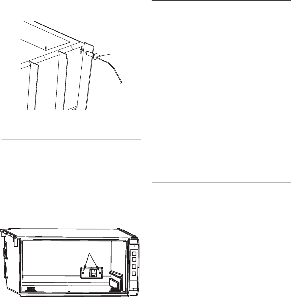
©2000 Maytag Appliances Sales Company
16010154 SECTION 2. COMPONENTS 2-6
10. Reinstall all componets in reverse order
of removal.
11. When placing the thermistor back into
the inner enclosure, make sure it is in its
proper orientation. (See Figure 2-17)
TESTING AND REPLACING
THE DRAWER SWITCH
Disconnect the unit from the power source.
1. Remove the Storage Drawer.
2. Remove the two switch mounting
screws. (See Figure 18)
4. Remove the switch wire leads.
5. Using an ohmmeter check the switch. If
open for continuity, replace the switch.
6. Install new switch in reverse order of
removal.
REPLACING THE INNER
ENCLOSURE ASSEMBLY
If the shape Memory Polymer (SMP)
becomes damaged the inner enclosure
assembly will have to be replaced.
Disconnect the unit from the power source.
1. Perform steps 1 thru 10 of Removing the
CZT Fan motor.
2. Next, perform steps 2 thru 5 of Replacing
the Thermistor.
3. Remove the drawer switch and the
wiring harness.
4. Reinstall all parts in the new inner enclo-
sure in reverse order of removal.
CHECKING AND REPLACING THE AUTO
DAMPER BIAS HEATER
The CZT bias heater is a resistive heater
attached to the auto damper with a metal
spring clip. The main purpose of the heater
is to allow more cold air into the freshfood
compartment when both pans are in the
normal storage (off) mode. This is
accomplished by heating the auto damper
bellows, which results in the damper door
being opened further. The auto damper still
regulates the airflow into the freshfood, but
the control band has now been “biased” or
shifted by the supplemental heater.
Power is supplied to the heater whenever
BOTH crisper fans are off. This occurs under
the following conditions: when BOTH pans
are in the normal storage (off) mode; when
the refrigerator is in defrost (this includes
the drip time); when BOTH pans are open;
and when BOTH of the pan temperatures
are above 60 F.
Flat Side of
Thermistor
Base
Figure 2-17
Switch Mounting Screws
Figure 2-18

©2000 Maytag Appliances Sales Company
16010154 SECTION 2. COMPONENTS 2-7
Disconnect the unit from the power source
1. Open the fresh food door and remove
any items on the top shelf.
2. Remove the light shield cover by pulling
down on the back corners of the cover
and sliding the cover forward.
3. Remove the fascia/radiant shield mount-
ing screws. Remove the control housing
mounting screw at the back, bottom
center of the control housing. Slide the
control housing to the right. Lower the
control housing.
4. Disconnect the control housing electric
quick disconnect.
5. Remove the control housing from the
refrigerator and place on a flat work
surface.
6. Disconnect the auto damper bias heater
wire leads. Using an ohmmeter check the
bias heater, it should be 18K ohms
(±10%).
ICE MAKER WATER VALVE RELAY
The Water Filter Reminder product includes
an external relay to control the ice maker
water valves. This external relay is required
so the electronic control can monitor the
water usage of the ice maker. The water
usage through the dispenser is controlled by
a relay on the electronic control board, which
is also monitored. With the knowledge of the
combined water usage of the ice maker and
the dispenser, the control can determine
when the appropriate amount of water flow
through the water filter has occurred, and
will turn on the change filter light.
Disconnect the unit from the power source.
1. Remove the machine compartment cover.
2. Remove the the TN and WH/BU from the
water valve relay. Continuity check relay
coil using a volt-ohm meter if open
replace the relay.
Auto Damper/Bias Heater
Figure 2-19
Tan
White w/blue
stripe
Mounting
Screw
Mounting
Screw Red
Tan w/white
stripe
Left Rear Cabinet
Support
Figure 2-20
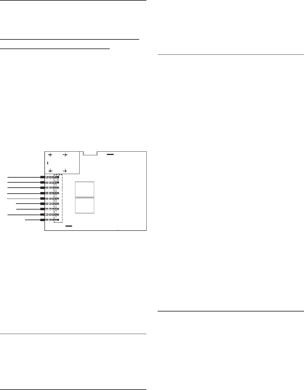
©2000 Maytag Appliances Sales Company
16010154 SECTION 2. COMPONENTS 2-8
ELECTRONIC CONTROL BOARD
TROUBLESHOOTING
The following checks should only be made
by a Qualified Service Technician.
NO LED'S ILLUMINATED ON THE
FOUNTAIN TOUCH PAD
1. Check ribbon cable/wire connection
between the two PC boards
("Mechanically Tight").
2. Checking the AC line in fountain verifies
operation/closure of door interlock
switch.
3. Check fountain heater continuity. Unplug
the unit. Check heater resistance neutral
to heater connection. It should read
approximately 1300 ohms.
4. Replace key pad board.
5. Replace fountain control board.
Some LED’s Will Not Light
1. Replace key pad board.
2. Replace control board.
Fountain Light Will Not Light
1. Check bulb and mechanical connections.
2. Does fountain light illuminate during a
dispense?
Yes: (a) Replace key pad board.
No: (b) Replace control board.
Will Not Dispense Ice Or Water
1. Press lock button 3 times. If another LED
lights, replace LED/Switch PC Board.
2. When actuator pad is pressed, does
fountain light come on?
Note: Make sure fountain light bulb is good!
No: (a) Check actuator switch and
mechanical connections.
(b) Replace control board.
Yes: (a) If nothing works (ice door
solenoid/auger/cube solenoid/
water valve), replace control board.
No: (b) If some functions work, check for
115 VAC at ice door solenoid/
auger/cube solenoid/water valve
terminals during dispense.
(1) If 115 VAC output exists,
replace component.
(2) If 115 VAC output is not
present, replace control board.
CHANGE FILTER LIGHT WILL NOT LIGHT
1. Press and hold lock and light buttons
together for 3 seconds. Indicator should
begin blinking. Release keypads lamp
should go out.
No: (a) Replace key pad board.
(b) Replace the control board.
JF1 BRN
BLU
PK
RD/BLK
TN/WH
BLK
BLK
RD/WH (J1)
VIO
N/C
Figure 2-21

©2000 Maytag Appliances Sales Company
16010154 SECTION 2. COMPONENTS 2-9
IN-CABINET FUNCTION
TEST (ICFT)
• Climate Zone Technology™ Control
board assemblies have a self diagnostic
function called an “In Cabinet Function
Test “(ICFT)”
•Before conducting (ICFT) The
refrigerator control settings and
temperatures should be verified.
•Extreme fresh food control settings (to
warm or to cold) will cause the CZT
assemblies to exceed their limits.
• The CZT is designed to operate within
a range of freezer and fresh food
temperatures. (Freezer range -3 to +3°
F. Fresh food range 35 to 40° F.) If
temperatures exceed these ranges due
to adjustments of the refrigerator
controls, the CZT may no longer
maintain the desired temperature.
This problem is magnified when the
upper/lower CZT settings are meat
keeper/citrus.
•Therefore, it is important to determine
the refrigerator control settings prior
to troubleshooting.
•If the refrigerator controls are not at
(mid/mid), customer education will be
required.
•If the controls are set at (mid/mid)
verify the fresh food and freezer
compartments are within the ranges
given above.

©2000 Maytag Appliances Sales Company
16010154 SECTION 2. COMPONENTS 2-10
IN-CABINET FUNCTION TEST (ICFT)
COMPRESSOR IS RUNNING (NOT IN DEFROST)
FRESH FOOD DOOR IS OPEN
CZT ASSEMBLY HAS POWER AND A SET POINT IS SELECTED, I.E. CITRUS,PRODUCE OR
MEATS.
CZT PAN DRAWER IS CLOSED, I,E, NO FLASHING DISPLAY
ACTION RESULT
1. PUSH PAN NORMAL
BUTTON. WAIT UNTIL ROTARY DAM PER STOPS M OVING AND IS IN
CLOSED POSITION (M AY TAKE UP TO 30 SECONDS).
DISPLAY AND SETPOINT LEDS SHOULD BE OFF.
2. DOOR SWITCH TO DOOR
CLOSED, PUSH PAN NORM AL
AND PRODUCE BUTTON AT
THE SAME TIME.
ROTARY DAM PER NOT M OVING AND FAN OFF. TEST M ODE
ENABLED FOR 4 M INUTES.
3. RELEASE DOOR SWITCH TO
DOOR OPEN. ALL SET POINT LEDS ON. DISPLAY SHOWS 'PA' (PAN
AM BIENT) FOR THREE (3) SECONDS, THEN SHOWS PAN
TEM PERATURE (IF ABOVE 80º, WILL SHOW 80º). VERIFY ALL
LEDS ARE ON.
4. PUSH PAN CITRUS BUTTON. DISPLAY SHOWS 'PA' (PAN AM BINET) FOR THREE (3)
SECONDS, THEN SHOWS PAN TEM PERATURE. VERIFY
DISPLAY IS ON, AND INDICATES TEMPERATURE AS
DESCRIBED IN STEP 3).
5. OPEN PAN. DISPLAY FLASHES (APPROXIM ATELY 1/2 SECOND ON, 1
SECOND OFF). VERIFY FLASHING DISPLAY.
6. CLOSE PAN. VERIFY DISPLAY STOPS FLASHING.
7. PUSH PAN PRODUCE
BUTTON. DAMPER OPENS. FAN OFF. 7-SEGM ENT DISPLAY BEGINS
'WALKING SEGM ENT' SEQUENCE. VERIFY DAM PER OPEN.
VERIFY ALL SEGIMENTS ILLUMINATE NO MORE THAN ONE
ON AT A TIME.
8. PUSH PAN PRODUCE
BUTTON. DAM PER CLOSED. FAN ON. VERIFY ROTARY DAMPER
CLOSED AND FAN ON. NOTE: IF DISPLAY SHOWS E1,
THERE IS AN EEPROM FAILURE.
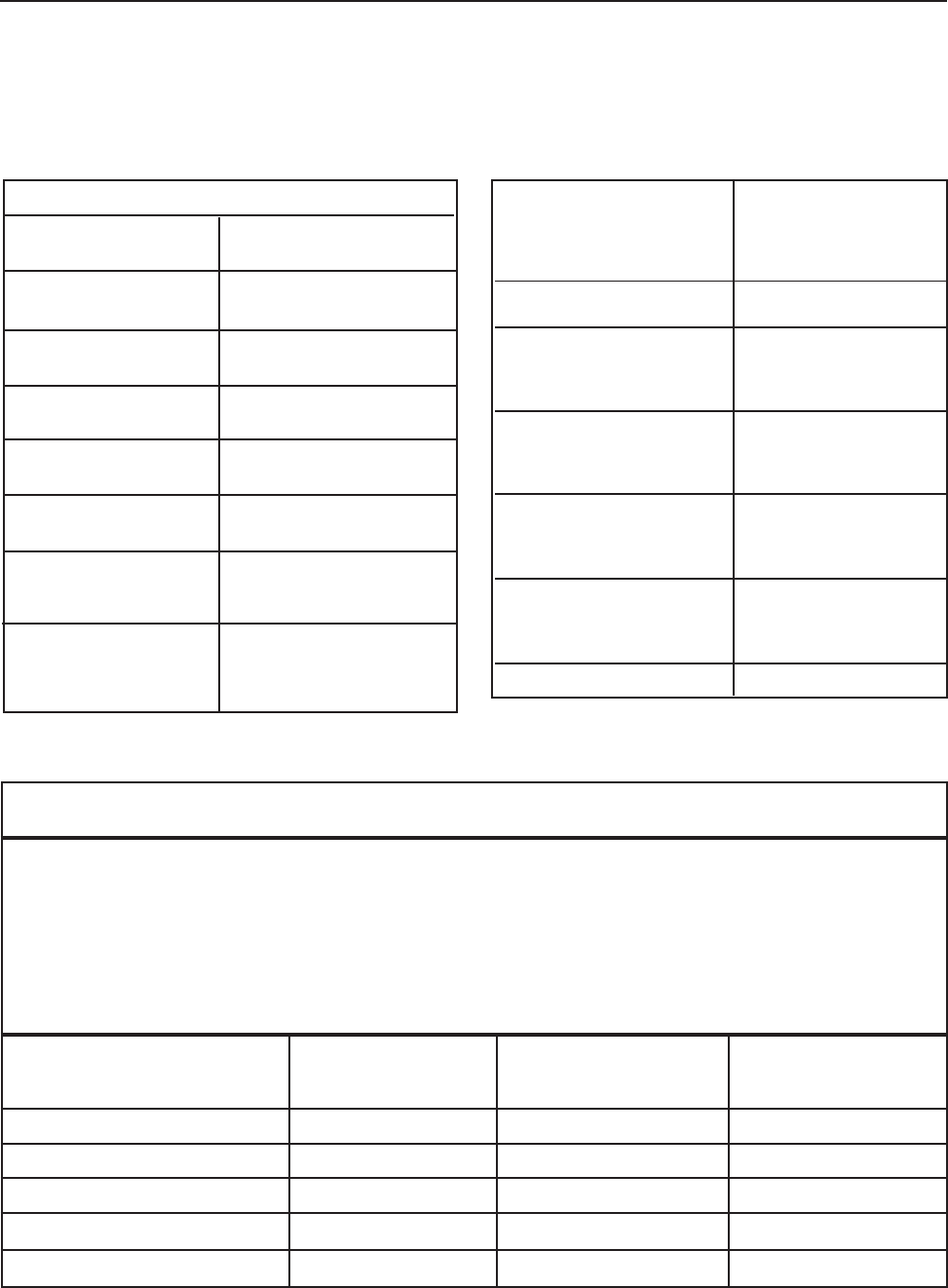
©2003 Maytag Appliances Sales Company
16010154 SECTION 3. SPECIFICATIONS 3-1
70o F 90o F 110o F
(Ambient) (Ambient) (Ambient)
% Operating Timer 34-44 49-62 100
KWH/24 Hours 1.44-1.76 2.12-2.62 3.95-4.25
Suction Pressure (psig) -3" Hg/0 -2" Hg/2 -1" Hg/5
High Side Pressure (psig) 100/130 150-180 190-210
Running Watts 145-180 155-190 165-200
Temp Control Normal Setting
Cut / Out (± 2 o F) -9 o F
Cut / In (± 2 o F) +21 o F
Condenser Fan Cooled
Capillary Tube
Length 103 inches
Diameter 0.028 inches I.D.
Defrost thermostat
Cut / Out ( ±3 o F) +43o F
Cut / In ( ±11 o F) +15oF
Defrost Timer
Defrost Cycle 10 hrs.
Defrost Time 23 ± 3 Min.
Defrost Heater
Ohms 22
Watts 600
Power Requirement 115 VAC 60 HZ
Operating Amps
(Max.) 7.2
Refrigerant Charge
R134A (oz.) 5.75 oz
Compressor Oil
Charge (oz.) 11.8
Compressor
(BTU/hr.) 1020
Cabinet Liner HIPS
Door Liners HIPS
Cabinet & Divider
Insulation Foam
Fountain Heater
Ohms 1300
PERFORMANCE TEST DATA
27’/29 DISPENSER (CZT/WFR AND NON CZT)
SECTION 3. SPECIFICATIONS
The laboratory test data in this chart was obtained under the following conditions: (1) power source of
115V AC, 60 Hz, (2) no door openings, (3) no load, (4) customer control(s) set at mid-point. The pressures
and wattages shown were taken: (a) during a normal running cycle, (b) with freezer temperature near 0o
F (refrigerator temperature, if applicable, near +37o F). (c) no sooner than 5 minutes after compressor
start-up. In the home, measurements will vary depending upon environmental and usage conditions.
©2003 Maytag Appliances Sales Company
16010154 SECTION 3. SPECIFICATIONS 3-2

©2003 Maytag Appliances Sales Company
16010154 SECTION 4. SCHEMATICS 4-1
SECTION 4. SCHEMATICS
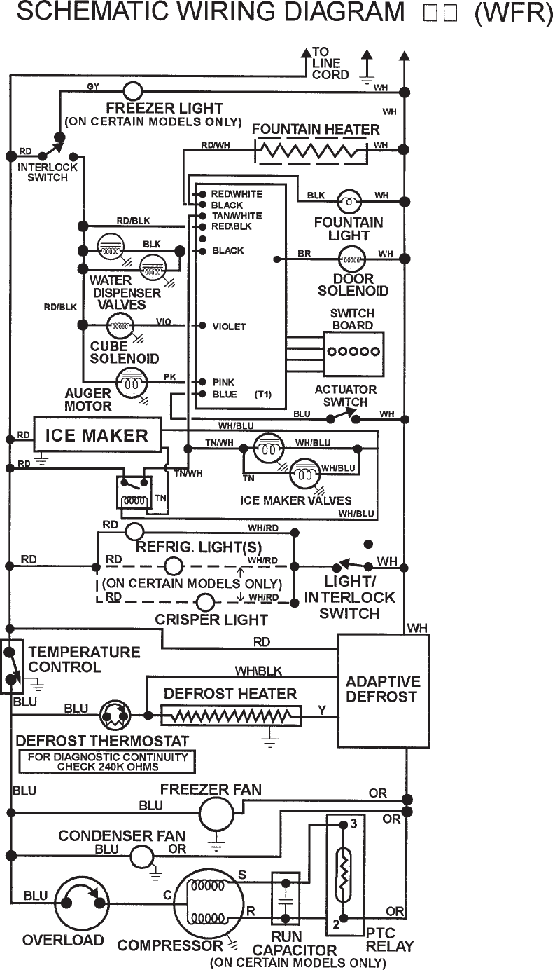
©2003 Maytag Appliances Sales Company
16010154 SECTION 4. SCHEMATICS 4-2

©2003 Maytag Appliances Sales Company
16010154 SECTION 4. SCHEMATICS 4-3

©2003 Maytag Appliances Sales Company
16010154 SECTION 4. SCHEMATICS 4-4
(CZT/WFR)

Maytag Appliances Sales Company
Customer Service
240 Edwards Street, S.E.
Cleveland, Tennessee 37311
