Ts532 Maytag Yoder Loop Heater Kit
2013-04-06
: Pdf Maytag - Yoder Loop Heater Kit Maytag - Yoder Loop Heater Kit Maytag, Magic Chef, Jenn Air
Open the PDF directly: View PDF ![]() .
.
Page Count: 2
4/98
REFRIGERATION
Yoder Loop Heater Repair
TS
Bulletin
532
MODELS: PRODUCT TYPE:
ALL 1997 AND NEWER TOP
MOUNT VERTICAL
EVAPORATOR COIL
CONDITION
Leak in the yoder loop tubing.
CORRECTION
Order part number 12001492. See instructions below.
Admiral
Crosley
Jenn-Air
Magic
Chef
Maytag
Norge
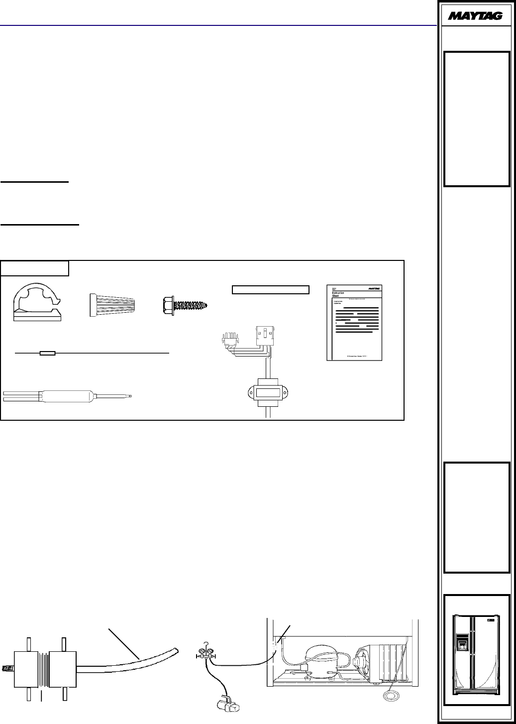
CONTENTS:
(1) 16009142
Instruction Sheet
(1) 55602-34
Plastic Tubing
(2) 61002819
Screws
(1) 13900-1 Dryer
(1) 61003481
Heater Wire
(Yoder)
(2) 27116-5
Wire Nuts
(3) 67619-1
Adhesive Clips
(1) 61003479 (115V)
OR
(1) 61003480 (230V)
Transformer
1. If the leak has been determined to be in the yoder loop tubing, connect tubing as de-
scribed in the service manual, eliminating the yoder loop. Rework the sealed system and
make appropriate refrigerant charge as indicated on the serial plate. Then proceed as
follows:
2. Clean and straighten the yoder loop tubing so it is free of burrs and has the correct I.D.
3. Install a process tube adapter on a 3/16" I.D. plastic sleeve (55602-34), see Figure 1.
Connect the plastic sleeve to one side of the yoder loop.
4. Connect a gauge set and vacuum pump to the process adapter, see Figure 2.
5. Insert the braided end of the electric heater wire (61003481) into the condenser side of
the yoder loop.
Disconnect unit from power supply before servicing.
Plastic Sleeve
Processor Adapter Yoder Loop Heater
Vacuum Pump
Manifold Guage
Processor
Adapter
Figure 1. Figure 2.
6. Start the vacuum pump and place your finger over the end of the yoder tube with the braid inserted.
When a good vacuum is obtained, release your finger from the tube and begin to feed the braid into
the tube, one to two inches at a time until the braid reaches the plastic sleeve. Shut the vacuum
pump off and remove the plastic sleeve.
7. Pull the braid, while pushing an equal amount of the heater into the other end of the yoder tube until
heater wire lead connector reaches the end of the yoder tube.
8. Place the adhesive clips (67619-1) an equal distance across the top of the machine compartment
housing. Lace the yoder heater lead wire through the clips, see Figure 3.
9. Using the bottom ground wire mounting hole on the cabinet panel leg, mount the transformer
61003479 (115V) or 61003480 (230V) using a screw (61002819), (if a ground wire is mounted to the
bottom hole, move the ground wire up to the next hole). Turn the transformer approximately 50
inward (toward the front of the machine compartment). Using the other transformer mounting foot
hole as a guide, drill a 3/32" pilot hole in the cabinet panel leg. Fasten the transformer mounting foot
using a screw (61002819), see Figure 4.
10. Cut off the excess heater wire leaving only enough to wire to the transformer lead. Do not cut the
yoder heater lead wire coming from the condenser side of the cabinet. Wire both heater leads to
transformer using the wire caps (27116-5) supplied with the yoder heater assembly, see Figure 4.
11. Disconnect the compressor quick disconnect plug from the main wire harness and install the trans-
former lead connectors as shown in Figure 4.
12. Install the machine compartment cover and reconnect the power cord to the wall outlet.
(3) Adhesive Clips
Condenser
Transformer
Yoder
Heater
Lead Wire
Cut off excess
heater wire,
leave only
enough to
wire to the
transformer
Cabinet Panel Leg Figure 3.
Compressor
Leads
Bottom Ground
Wire Mounting
Hole
Heater Wires
Main Wire
Harness Leads
from the
Cabinet
Figure 4.
Wire Nuts
