Maytagfridge56326
Maytag Refridgerator - Good Basics - 56326 Maytag Refridgerator - Good Basics - 56326 Maytag Refridgerator - Good Basics - 56326 Maytag, Magic Chef, Jenn Air applianceservicesecretsmembership.com_manuals
2013-04-05
: Pdf Maytagfridge56326 maytagfridge56326 Maytag, Magic Chef, Jenn Air
Open the PDF directly: View PDF ![]() .
.
Page Count: 159 [warning: Documents this large are best viewed by clicking the View PDF Link!]
r-
Side-By-Side
and
ToP
Mount
Refrigerator
Service
Manual
svF-0289
PRINTED
IN
U.S.A.
o Copyright
1989
-- ,-a. l..r 4-- , ,.-.-.-,=--:..
56326 ]
INDEX
4-1
4-4
4-8
4-11
4-15
4-15
4-16
4-17
4-17
4-20
4-25
4-28
4-33
4-34
4-36
SaBIECT
SECTION
1
. INTRODUCTION
SECTION
2 . INSTALLATION
Specifications
Warranty
Installation
Instructions
Operation
SECTION
3. SERVICE
PROCEDURES
General
Checking
Operation
Leak
Testing
Leak
Testing
Yoder
LooP
Checking
Pressures
Evacuating
& Recharging
Sealed
System
SweeP
Charge
SECTION
4 - COMPONENTS
Compressor
Heat
Exchanger
Condenser
Freezer
Evaporator
Electrical
System
Compressor
Overload
Protector
Starting
RelaY
PTC & Run CaPacitor
Temperature
Oontrol
Defrost
Timer
Defrost
Heater
& Thermostat
Condenser
Fan
Freezer
Fan
Divider Channel
Heater
SECTION
5 . CABINET
& RELATED
COMPONENTS
Food
Liner
Compartment
Accessories
(shelves)
PAGE SaBIECT
2-1
2-4
2-5
2-14
3-1
3-5
3-7
3-8
3-10
3-12
3-14
Meat
Keeper 5-3
Freezer
Cold
Control 5-4
Mounting
Hardware 5-6
Drain
Tubes 5-6
Styrofoam
Drip
Tray 5-7
Cabinet
Doors
& Assoc.
Parts 5'9
Paint Touch-up 5-9
Door
Liner 5-9
Door Panel S10
Reversing
Doors $11
Top
Hinge 5-11
Door Closer 5-11
Shelf Guards 5'12
Cabinet
Wheels 5-12
Cabinet
Leveling 5-12
Gasket
Seal 5-13
Door
Switch 5-14
Water Components 5-15
Water
Supply 5-15
Water
Valve 5-15
Water Fill
Tubing 5-15
Water
Reservoir S18
Fountain
Assembly 5-2O
lce & Water
Fountain 5-20
lce & Water
Actuator
Switch 5-21
Dash-Pot 5-22
Switch
Assembly 5-22
lce & Water
Activating
Sw. +23
lce Dispensing
Safety
Door 5-23
Fountain
Heater 5-23
lce Storage
Bin 5-24
Interlock
Switch 5-24
Auger 5-25
PACE
SECTION6.ICEMAKER
lnstallation
Servicing
SECTION
7 . TROUBLESHOOTING
SECTION
8 . SCHEMATICS
sEcTroN
I - SPECIFICATIONS
6-1
6-10
5-1
5-1
MI\YTAG SECTION I
INTRODUCTION
GENERAL
This
manual covers
Maytag Refrigerators
manufactured beginning in 1989. Those
models
covered are 15, 17, 19, 20, 21,22,23 and
24 cubic
foot
Side-By-Side and
Top Mount
ref rigerators.
SAFETY
PRECAUTIONS
This
service information is intended to be used
by a qualified
service technician, who is
familiar with proper and safe
procedures
to be followed when repairing any electrical
appliance.
All fests and repairs should be performed
by a qualified
service technician,
using only Genuine Maytag
parts.
Repairs and servicing
attempted by uninformed
persons
can result in hazards
developing
due to improper assembly
or adjustment. While
performing
such
repairs,
persons
not
having
the
proper
background may
subject
themselves to the risk
of injury
or electrical
shock which can be
serious or even
fatal.
1-1
M/\YTAG SECTION 2
INSTALLATION
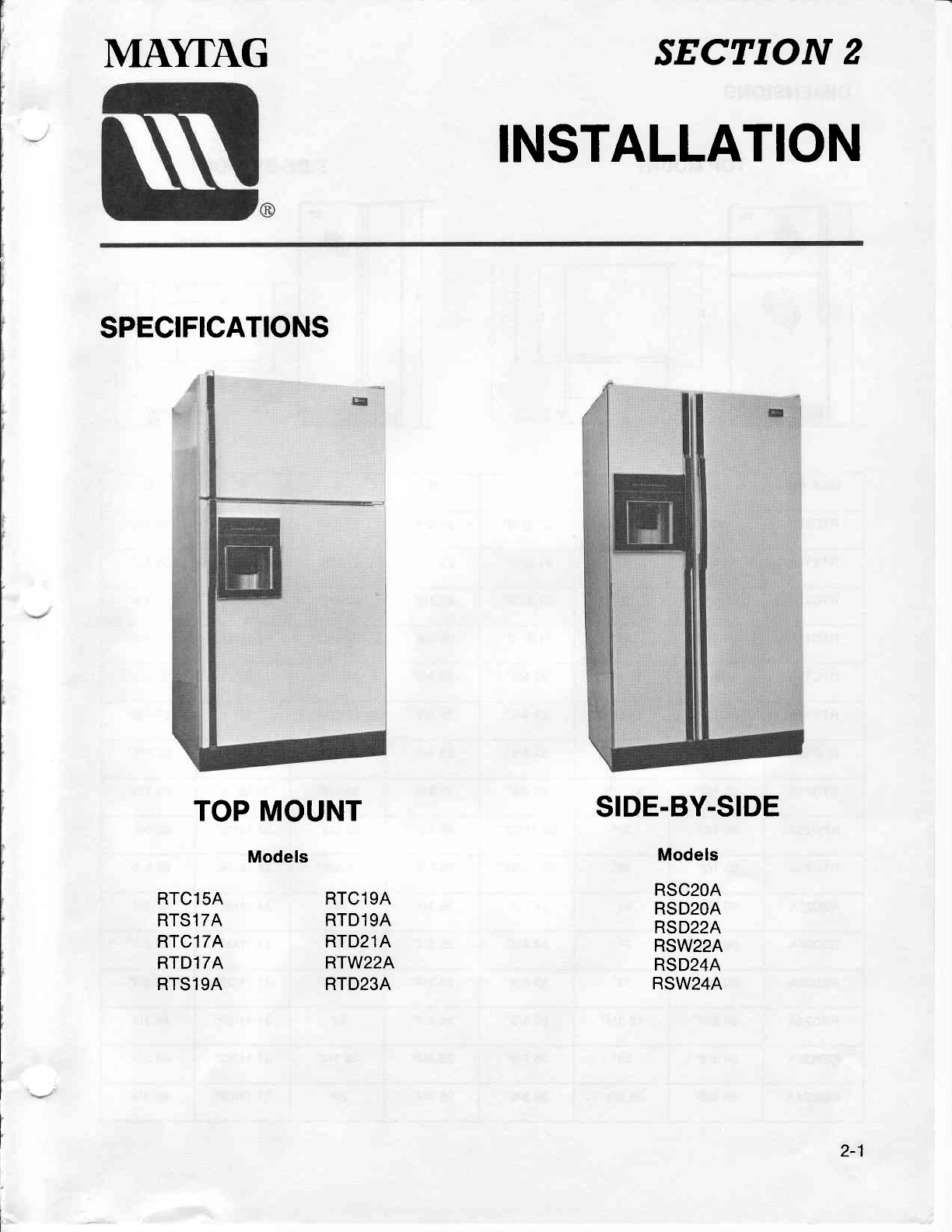
SPECIFICATIONS
TOP
MOUNT
Models
SIDE.BY.SIDE
Models
RSC2OA
RSD2OA
RSD22A
RSW22A
RSD24A
RSW24A
RTC15A
RTS17A
RTC17A
RTD17A
RTS19A
RTC19A
RTD19A
RTD21A
RTW22A
RTD23A
2-1
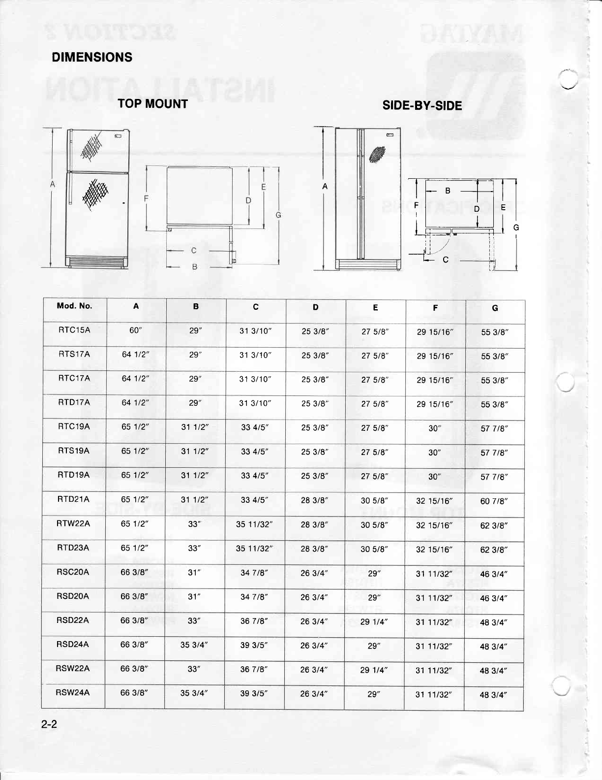
DIMENSIONS
TOP
MOUNT SIDE-BY.SIDE
;i
*"1 L-C
ry
It-B--hrl
ri o
le
I
:l ; lrl
lr trln
I r-----------------r-1 I "
-i:
T
I
I
A
E
ffi
Mod. No. ABcDEFG
RTC15A 60" 29" 31
3t10" 25
3t8" 27 5/8" 29 15t16" 55 3/8"
RTSl 7A 641t2" 29' 31 3/10" 25
3t8" 27 5t8" 29 15/16" 55 3/8"
RTCl7A 641/2" 29" 31
3/10" 25
3t8" 27
5/8" 29
15t16" 55 3/8"
RTD17A 64 1/2" ZJ 31 3/10" 25
3/8' 27 5/8" 29 15/16" 55 3t8"
RTC19A 65112" 31 1t2" 33 4t5" 25
3t8" 27
5t8" 30" 57 7
/8"
RTS19A 651/2' 31
1t2" 33 4t5' 25 3/8' 27
5/8" erl" 57 7 l8'
RTD19A 65 1t2" 31
1/2" 33 4t5" 25 3t8" 27
5/8" 30" 57 7t8"
RTD21A 651t2" 31 1/2" 33 4t5" 28
3t8" 30 5/8" 32
15/16" 60
7 /8"
RTW22A 65 1t2" 33" 3511t32" 28
3t8" 30 5/8" 32
15t16" 62 3t8"
RTD23A 651/2" 33" 3511t32' 28 3t8" 30
5t8" 32
15/16" 62
3t8"
RSC2OA 66 3/8" JI 34 7 t8" 26
3t4" 29" 31
11t32" 46
3t4"
RSD2OA 66 3/8" JI 34 7 /8" 26
3t4" ZJ 31
11t32" 46 3t4"
RSD22A 66 3/8' 33" 36 7 t8" 26
3t4" 29 1/4" 3111t32" 48
3t4"
RSD24A 66
3/8" 35 3t4" 39 3/5" 26
3t4" 29" 31 11t32' 48
3t4"
RSW22A 66
3/8" 33" 36 7 /8" 26
3t4" 29 114" 31 11/32" 48 3t4"
RSW24A 66
3/8" 35 3/4" 39 3/5" 26
3t4" 29" 3111t32" 48
3/4"
2-2
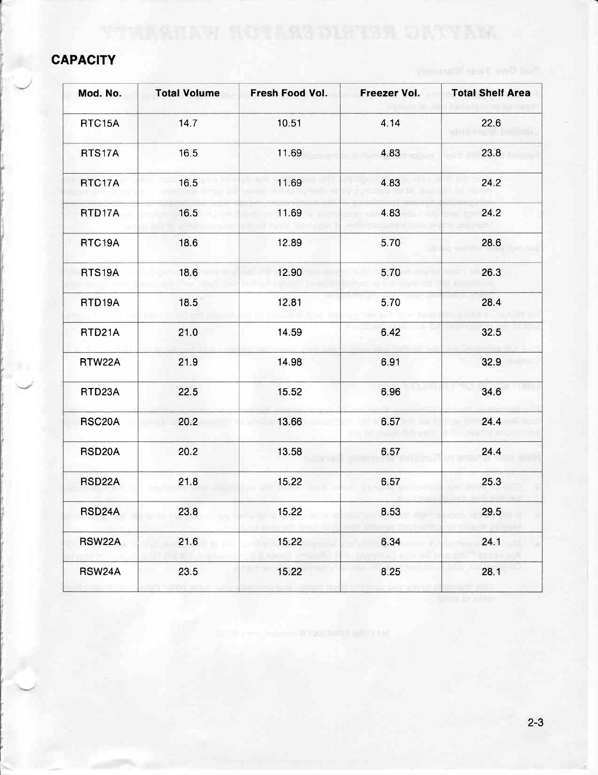
CAPACITY
Mod. No. Total Volume Fresh Food Vol. Freezer Vol. Total
Shelf
Area
RTC15A 14.7 10.51 4.14 22.6
RTS17A 16.5 11.69 4.83 23.8
RTC17A 16.5 11.69 4.83 24.2
RTD17A 16.5 11.69 4.83 24.2
RTC19A 18.6 12.89 5.70 28.6
RTS19A 18.6 12.90 5.70 26.3
RTD19A 18.5 12.81 5.70 28.4
RTD21A 21.0 '14.59 6.42 32.5
RTW22A 21.9 14.98 6.91 32.9
RTD23A 22.5 15.52 6.96 34.6
RSC2OA 20.2 13.66 6.57 24.4
RSD2OA 20.2 13.58 o.c/ 24.4
RSD22A 21.8 15.22 6.57 25.3
RSD24A 23.8 15.22 8.53 29.5
RSW22A 21.6 15.22 6.34 24.1
RSW24A 23.5 15.22 8.25 28.1
2-3
MAYTAG REFRIGERATOR WARRANTY
Full
One Year
Warranty
For
one
(1) year
from the
date of
original retail
purchase,
any
part
which
fails
in normal
home
use will be
repaired
or
replaced
f ree
of charge.
Limited
Warranty
Second
thru Fifth Year
- major refrigeration
components:
After the first
year
and through
the
fifth
year
after the
date
of original
retail
purchase
Maytag will
repair
or replace,
at
its
option, f ree
of
charge to the
owner for
parts
and labor
any
part
of the
sealed
refrigeration
system
(consisting
ol the
compressor,
evaporator,
condenser,
drier
and
connecting
tubing)
and the
cabinet liner
(exclusive
of the
door liner)
which fails
in normal
home
use. Trrp
charges,
travel
and transportation,
if required,
shall
be the responsibility
of the
owner.
Second
year
- other
parts:
Other
parts
which
fail
in normal
home
use
during the
second
year
following
date
of original
retail
purchase
will
be
repaired
or replace
free
of charge
for the
part
itsell,
with
the
owner
paying
all
other
costs,
including
labor
and trip
charges.
lce Maker
-
when
purchased
with
the refrigerator
and installed
by the
dealer the
ice
maker
will
be considered
part
of the
ref rigerator
for
warranty
purposes.
This
full
warranty
and the
limited
warranty
apply
only when
the
appliance
is located
in
the
United
States
or
Canada.
LIMITATION
OF LIABILITY
The
warrantor,
Maytag
Company,
shall not
be liable
for
any incidental
or consequential
damages,
including
food
loss. Some states
do not
allow
the
exclusion
or limitations
of consequential
damages,
so
the
above
limitations
or
exclusion
may
not apply
to
you.
How
and
Where
to Receive
Warranty
Service
Call
or write the
authorized
Maytag
dealer
from
whom
the
appliance
was
purchased
or the
authorized
service
firm
designated
by
it.
lf
the
owner moves from
the
selling
dealer's
servicing
area
after
purchase,
call
or write
any
authorized
Maytag
dealer
or
authorized
service
firm
in
or near the
new
location.
Should
the
owner not
receive
satisfactory
warranty
service from
one
of
the
above, call
or
write
MAyCOR
Appliance
Parts
and
Service
Company,
240
Edwards
Street
S.E.,
Cleveland,
TN
97911,
a division
of Maytag
Corporation,
and
arrangements
for
warranty
service
will
be made.
This
Warranty
gives
you
specific
legal
rights,
and
you
may
also have
other
rights
which
vary from
state to
state.
2-4
MAYTAG
COMPANYO
Newton,
towa
50208
INSTALLATION
INSTRUCTIONS
ELECTRICAL
REQUI REM
ENTS
OBSERVE ALL NATIONAL ELECTRICAL
CODES AND LOCAL CODES
&
ORDINANCES
ELECTRICAL
SERVICE
- 120 VOLTS,
60 Hz
ONLY
A 120 volt,
60 Hz, 15 ampere fused
electrical supply is required.
An
individual
branch
(or
separate
circuit serving only this
appliance
is
recommended.)
DO
NOT USE
EXTENSION
CORD unless it meets
all
requirements
as outlined for
grounding,
polarizing
(3-wire)
and
capacity. Wire
size should be
at
least No. 14.
BEFORE PLUGGING
lN POWER
CORD, OPERATING
OR TESTING,
Follow grounding
instructions
in
Grounding
Section.
GROUNDING
. 120
VOLTS, 60
HZ
IMPORTANT
SAFETY PRECAUTIONS
WARNING
- To
prevent
unnecessary risk of fire, electrical
shock
or personal
injury, all
wiring
and
grounding
must
be done
in accordance
with National
Electrical
Code and local
codes
and ordinances. lt is the personal
responsibility
and obligation
of the appliance
owner to
provide
adequate electrical
service for this
appliance.
ELECTRICAL
GROUTVD 'S REQUIRED
ON THIS
APPLIANCE
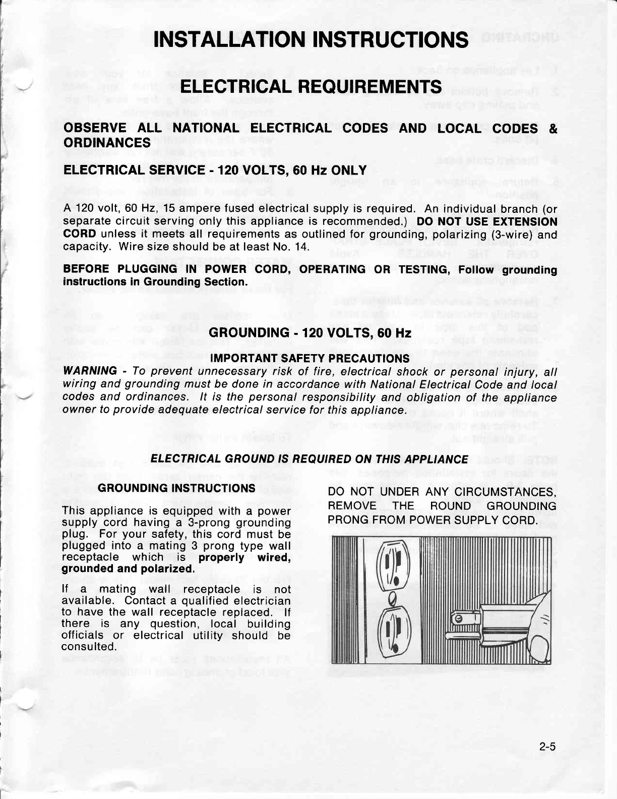
GROUNDING INSTRUCTIONS
This
appliance is
equipped with
a power
supply
cord having
a 3-prong
grounding
plug. For
your
safety, this cord must
be
plugged
into
a mating
3 prong
type wall
receptacle
which is properly wired,
grounded
and
polarized.
lf a mating wall receptacle
is not
available.
Contact
a qualified
electrician
to have the wall receptacle
replaced.
lf
there is any question,
local building
off
icials or electrical
utility should be
consulted.
DO NOT
UNDER ANY
CIRCUMSTANCES,
REMOVE THE ROUND GROUNDING
PRONG FROM
POWER
SUPPLY
CORD.
2-5
UNCRATING
1. Lay
appliance on back.
2. Remove
bottom cap by cutting
band
and
pulling
cap
away.
3. Remove crate base by removing
four
(4)
bolts.
4. Discard crate base.
5. Return appliance to an upright
position
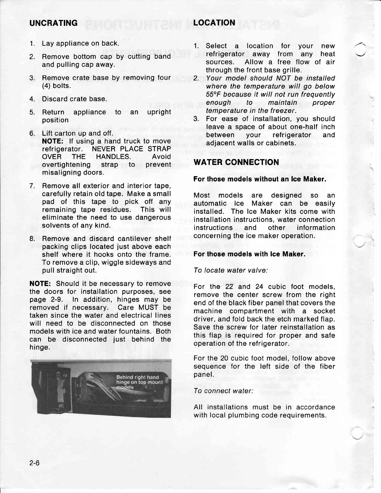
6. Lift carton up and off.
NOTE:
lf using a hand
truck to move
refrigerator. NEVER PLACE STRAP
OVER THE HANDLES. Avoid
overtightening strap to prevent
misaligning doors.
7. Remove
all exterior and
interior tape,
carefully
retain
old
tape. Make a small
pad of this tape to pick off any
remaining tape residues. This will
eliminate
the need to use dangerous
solvents
of
any
kind.
8. Remove and discard cantilever shelf
packing
clips located
just
above each
shelf where
it hooks
onto
the frame.
To remove
a clip,
wiggle
sideways and
pull
straight out.
NOTE: Should it be necessary to remove
the doors
for installation
purposes,
see
page
2-9. ln addition,
hinges may be
removed if necessary. Care MUST be
taken since the water and electrical lines
will need
to be disconnected
on those
models with ice and water fountains. Both
can be disconnected
just behind the
hinge.
LOCATION
1. Select a location for your new
ref rigerator away f rom any heat
sources. Allow a free flow of air
through the front base
grille.
2. Your model
should
NOT
be installed
where the temperature will go below
55"F because
if will not
run frequently
enough to maintain proper
temperature in the freezer.
3. For ease of installation,
you should
leave
a space of about one-half inch
between your ref rigerator and
adjacent walls or cabinets.
WATER
CONNECTION
For those models without an lce Maker.
Most models are designed so an
automatic lce Maker can be easily
installed. The lce Maker kits
come
with
installation instructions. water connection
instructions and other information
concerning the ice maker operation.
For
those models
with lce
Maker.
To
locate water valve:
For the 22 and 24 cubic foot models,
remove
the center screw from the right
end of the
black
fiber
panel
that covers
the
machine compartment with a socket
driver, and fold back the etch marked flap.
Save the screw for later reinstallation
as
this flap
is required for proper
and safe
operation of the refrigerator.
For
the 20 cubic foot model. follow above
sequence for the left side of the fiber
panel.
To connect
water:
All installations
must be in accordance
with local
plumbing
code requirements.
2-6
Copper
tubing
( 114" O.D.)
and saddle
valve can be purchased
f rom local
hardware stores. Sweat or f lare
connection
can be used instead
of the
compression
union,
if desired. 4.
Do
not use
plastic
tubing or
plastic
fittings
because
the connection
between
the
water supply
and the refrigerator
water
valve inlet is under
constant
pressure.
Also,
certain
types of plastic
tubing
may
become brittle with age and crack,
resulting
in water
leakage.
NOTE:
When using
unfiltered
well
water,
it is advisable
to use
a filter in
the water
supply
line.
This
eliminates
all
possibility
of small
particles
from entering
the water
valve.
Find
a 318" to 1" vertical COLD
water
pipe near the ref rigerator. Water
pressure
must be
between
20 and
12Q
P.S.l.
Vertical
pipe
is
preferable,
but
a horizontal
pipe will work. lf a
horizontal
pipe is used,
install the
saddle
valve on the
top
or
the side
of
the
pipe,
not on the bottom.
Install
the saddle
valve according
to
manufacturer's
instructions
included
with the
valve.
Route the copper
tubing
through
the
floor, wall or
sink cabinet
to the saddle
valve location. Form the excess
tubing
into a
large loop.
This allows movement for the
refrigerator
without disconnecting
the
tubing. Other
routing
methods
are
shown
on
page
2-8.
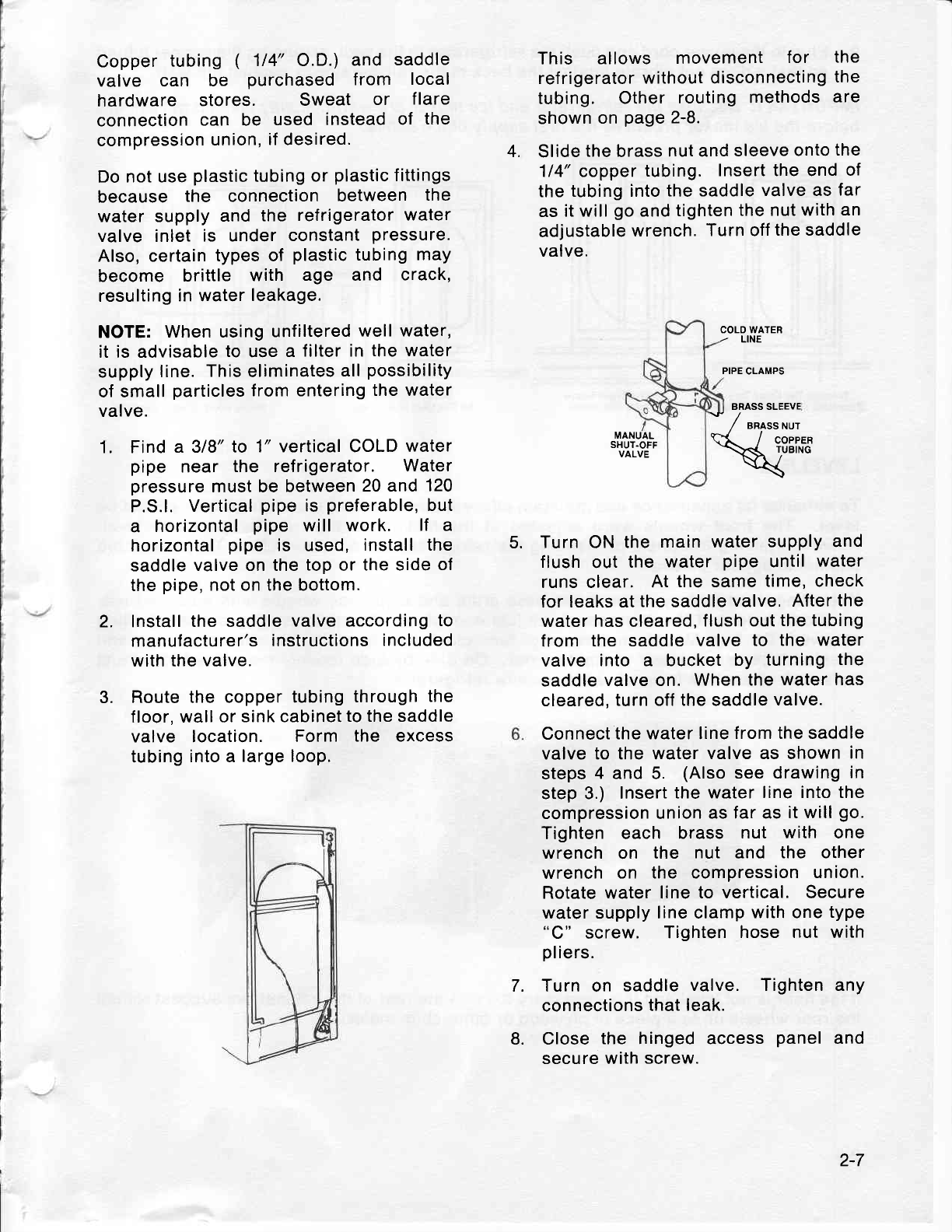
Slide
the
brass
nut and
sleeve
onto
the
114" copper
tubing. Insert the end
of
the
tubing into
the saddle
valve as
far
as it
will
go
and
tighten
the nut with
an
adjustable
wrench.
Turn off
the saddle
valve.
COLD WATER
- LINE
PIPE
CLAMPS
BRASS SLEEVE
1. MANUAL
SHUT.OFF
VALVE
Turn ON
the
main water supply
and
flush
out the water
pipe until
water
runs clear. At
the same
time, check
for leaks at
the
saddle
valve, After
the
water has cleared,
flush
out
the tubing
from the saddle
valve to the water
valve into a bucket
by turning
the
saddle
valve on. When
the
water has
cleared,
turn off the saddle
valve.
Connect
the water line
from the saddle
valve
to the water
valve as shown
in
steps
4 and 5. (Also
see drawing
in
step 3.) Insert
the water
line into the
compression union
as far as
it will
go.
Tighten each brass nut with one
wrench on the nut and the other
wrench
on the compression
union.
Rotate water line
to vertical. Secure
water
supply
line clamp
with one
type
screw. Tighten
hose nut with
pliers.
Turn on saddle
valve. Tighten any
connections
that
leak.
Close
the hinged access
panel
and
secure with screw.
* / "rorrrut
Htt**
5.
2.
3.
7.
8.
2-7
I' Plug
in
the
power
cord
and
push
the
refrigerator
to the
walt,
arranging
the
copper
tubing
so
that it
does
not
vibrate
against
the
back
of the
refrigerator
or
against
the
wall.
IMPORTANT:
Because
the
refrigerator
and ice
maker
are warm.
tt
may
take
up
to
12
hours
before
the
ice maker
produces
the first
suppty
of ice
cubes.
^-
In
The
Crawl
Space
Under
The Hdme Through
The
Wall
To The
Utility
Room
Cold
Water
piDe
lf the
floor
is
not level
and
it
is
necessary
to
raise
the
rear
of the
cabinet,
we
suggest
rolling
the
rear
wheels
on
to
a
piece
of
plywood
or
other
shim
material.
Under
The
Sink
To
The
Cold
Water
pipe
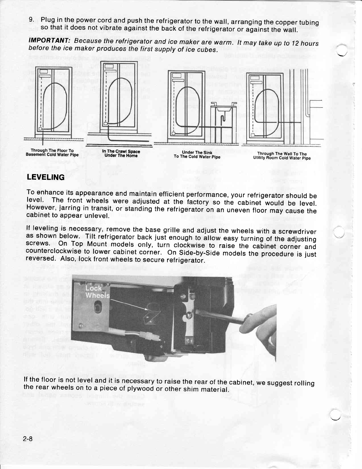
LEVELING
To
enhance
its
appearance
and
maintain
efficient
performance,
your
refrigerator
should
be
level. The
front
wheels
were
adjusted
at the
iactory
so th; cabinet
would
be levet.
Ho.wever,
jarring
in
transit,
or
standing
the
refrigerator
on
an
uneven
floor
may
cause
the
cabinet
to
appear
unlevel.
lf
leveling
is
necessary,
remove
the
base
grille
and
adjust
the
wheels
with
a screwdriver
as
shown
below.
Tilt
refrigerator
back
jusi
enough
to
illow easy
turning
of the
adjusting
screws. On Top Mount
models
only,
turn
clockwise
to raise
the cabinet
corner
and
counterclockwise
to lower
cabinet
corner.
On
Side-by-Side
models
the
procedure
is
just
reversed.
Also,
lock
front
wheels
to
secure
refrigerator.
Through
The Floor
To
Basement
Cold
Water Pipe
2-8
REVERSING
DOORS
Top Mount
Models
Only
Door reversal
is NOT
possible
on those
models that
have a built-in
ice and water
lountain. However, if door removal
becomes
necessary
please see the note
in Step
9.
Unplug Refrigerator. lf unit is in use,
remove food
from fresh
food compartment
and
freezer com
partment.
Removing doors.
NOTE: Taping doors shut prior to
physically
removing them may prevent
unnecessary
damage.
1. Remove hinge cover from top of
treezer door by
removing screw.
2. Remove
three
(3)
screws
from hinge.
&
Lift
hinge
off of cabinet.
Open
freezer
door,
pivot
and
lift door
off of center
hinge
pin.
NOTE: Keep track at all times the
position
of all spacers and
pads
when
removing them from doors.
Remove
center pin using a 5116"
wrench.
Open
refrigerator door and
lift
door off
lower hinge
pin
and
place
to the side
for now.
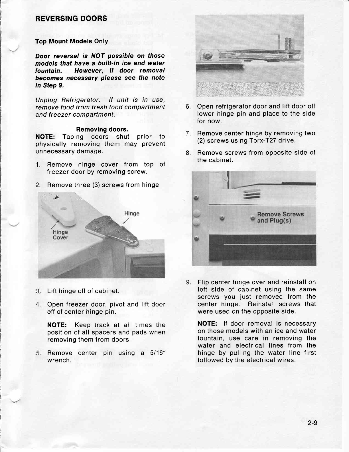
Remove center
hinge by
removing
two
(2)
screws
using Torx-T27 drive.
Remove screws
from opposite side
of
the cabinet.
Flip
center
hinge
over
and reinstall on
left
side
of cabinet using
the same
screws
you just removed from the
center
hinge. Reinstall screws that
were used on
the
opposite
side.
NOTE: lf door
removal is necessary
on those models with an ice and
water
fountain,
use care in removing the
water and electrical lines
from the
hinge by pulling
the water line
first
followed by
the
electrical
wires,
6.
L
7.
9.
4.
2-9
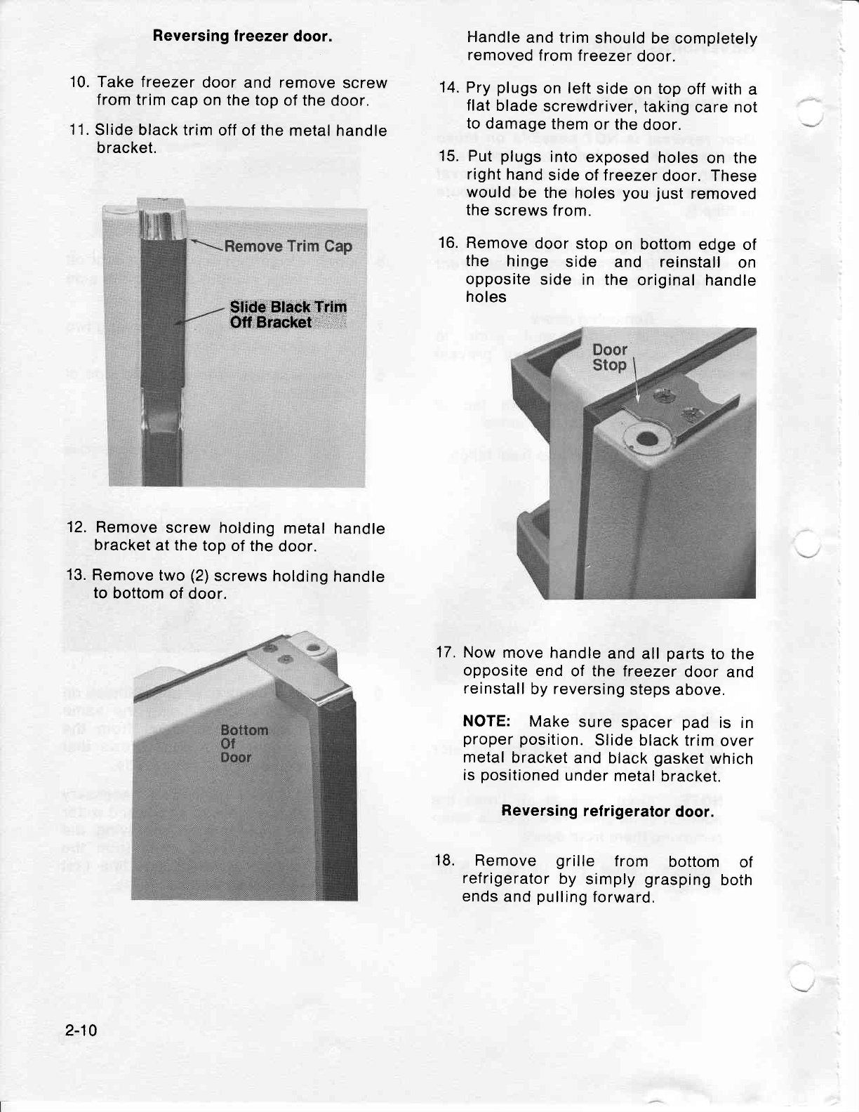
Reversing
lreezer
door.
10. Take freezer
door and remove
screw
from
trim cap
on the top
of the
door.
11.
Slide black trim
off
of
the
metal handle
bracket.
$tide Black
Trim
Off Bracket
12.
Remove
screw
holding
metal handle
bracket
at
the
top
of the
door.
13.
Remove
two
(2)
screws holding
handle
to
bottom
of door.
Handle
and trim
should
be completely
removed
from freezer
door.
Pry
plugs
on left
side
on top
off with
a
flat
blade
screwdriver,
taking
care not
to
damage
them
or the
door.
Put
plugs
into
exposed
holes
on the
right
hand
side of treezer
door. These
would
be the
holes
you
just
removed
the
screws
from.
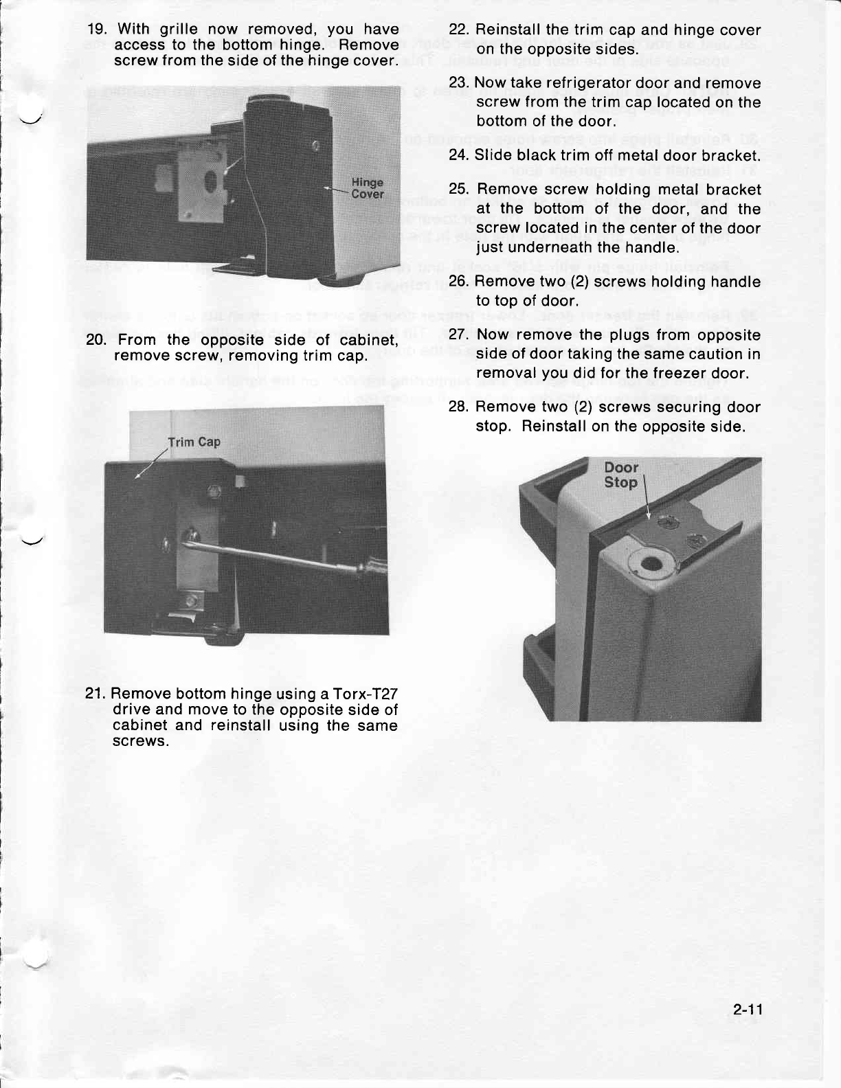
Remove
door
stop
on bottom edge
of
the hinge side and reinstall
on
opposite
side in the
original handle
holes
Now
move
handle
and all
parts
to the
opposite
end
of the freezer
door
and
reinstall
by
reversing
steps
above.
NOTE: Make
sure
spacer
pad is in
proper position.
Slide black
trim
over
metal
bracket
and black
gasket
which
is
positioned
under
metal
bracket.
Reversing
refrigerator
door.
Remove grille f rom bottom of
refrigerator
by simply
grasping
both
ends
and
pulling
forward.
14.
15.
16.
17.
18.
2-10
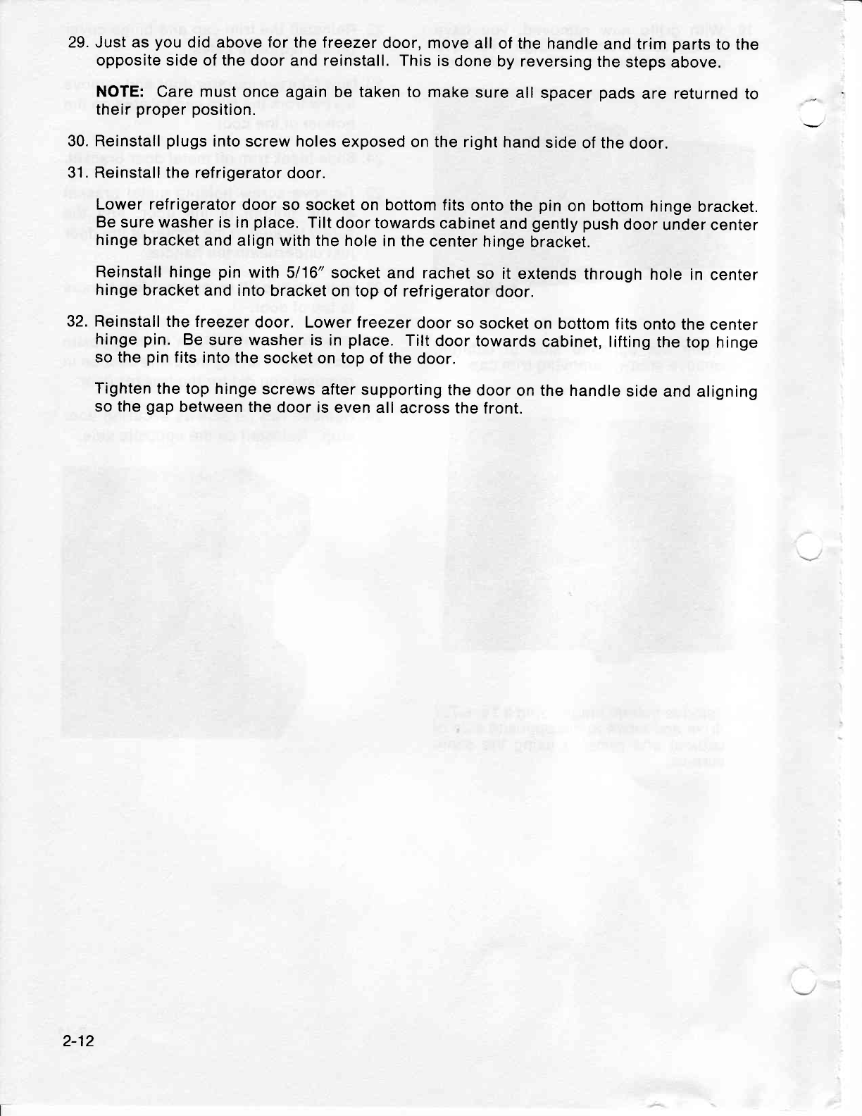
19. With
grille now removed,
you have
access to the bottom
hinge. Remove
screw
from the
side of the hinge cover.
20. From the opposite side of cabinet,
remove
screw, removing trim
cap.
21. Remove
bottom hinge
using aTorx-T?7
drive
and move to the
opposite side of
cabinet and reinstall
using
the
same
screws.
22. Reinstall
the trim
cap and hinge
cover
on the
opposite sides.
23. Now take refrigerator
door and remove
screw from the
trim cap located
on the
bottom
of
the
door,
24. Slide
black trim
off
metal
door
bracket.
25.
Remove
screw holding metal
bracket
at the bottom
of the door, and the
screw located in the
center of the
door
just
underneath the
handle.
26. Remove
two
(2)
screws holding handle
to top
of door.
Now remove the
plugs
from
opposite
side of
door
taking
the
same caution in
removal
you
did for the treezer
door.
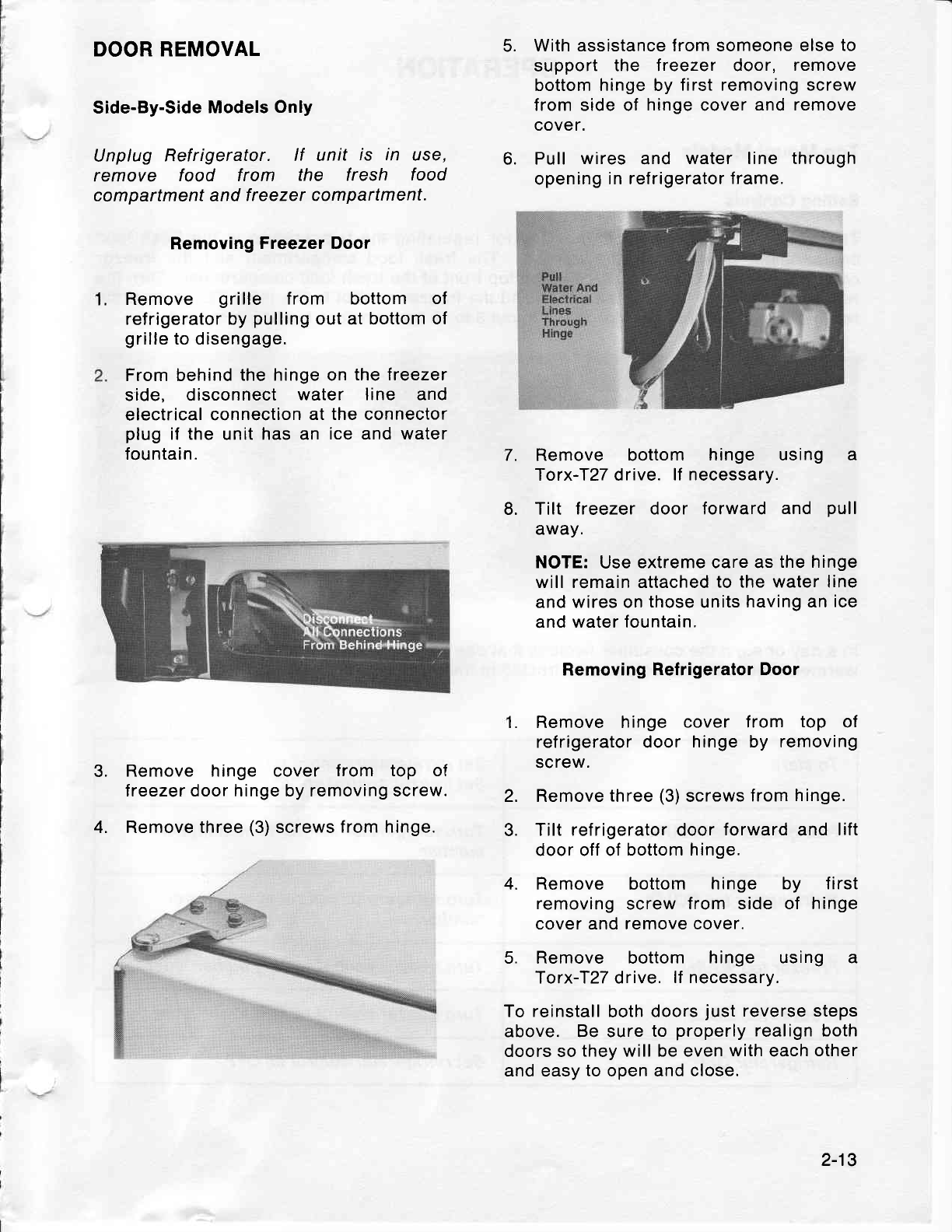
Remove
two
(2)
screws securing
door
stop. Reinstall on the
opposite side.
27.
28.
2-11
29. Just as
you
did above for the
treezer
door, move
all of the
handle
and trim
parts
to the
opposite side of the
door and
reinstall.
This
is
done by reversing
the
steps
above.
NOTE:
Care
must
once
again be
taken
to make
sure
all
spacer
pads
are
returned
to
their
proper position.
30. Reinstall
plugs
into
screw
holes
exposed
on the right
hand
side
of the
door.
31. Reinstall the refrigerator
door.
Lower refrigerator
door
so socket on bottom
fits
onto the
pin
on bottom
hinge
bracket.
Be
sure washer is in
place.
Tilt
door towards
cabinet
and
gently
push
door
under
center
hinge
bracket
and align with the hole
in the
center
hinge
bracket.
Reinstall hinge
pin
with
5116"
socket and rachet
so it extends
through
hole
in
center
hinge
bracket
and into
bracket on top
of refrigerator
door.
32. Reinstall
the freezer
door. Lower treezer
door
so socket
on bottom
f its
onto the center
hinge
pin. Be
sure washer is
in
place.
Tilt
door towards
cabinet, lifting
the
top hinge
so the
pin
fits
into the
socket
on top of the
door.
Tighten
the top hinge
screws
after supporting
the
door
on the handle
side and
aligning
so
the
gap
between the
door is
even
all across the
front.
2-12
1.
DOOR REMOVAL
Side-By-Side
Models
Only
Unplug Refrigerator. lf unit is in use,
remove food from the f resh food
com
partment
and
f reezer compartment.
Removing
Freezer Door
Remove grille from bottom of
refrigerator by
pulling
out at bottom
of
grille
to disengage.
From behind
the hinge on
the treezer
side, disconnect
water line and
electrical
connection
at the connector
plug
if the
unit
has an ice
and
water
fountain.
Remove hinge cover f rom top of
lreezer door hinge by removing screw.
Remove three
(3)
screws
from hinge.
With assistance from someone else
to
support the treezer door, remove
bottom hinge by
first removing screw
from side of hinge
cover
and remove
cover.
Pull wires and water line through
opening
in refrigerator
frame.
7. Remove bottom hinge using a
Torx-I27 drive. lf necessary.
Tilt lreezer door forward and pull
away.
NOTE:
Use
extreme care as
the hinge
will remain attached
to the water line
and wires on
those
units
having an
ice
and water fountain.
Removing Refrigerator
Door
1. Remove hinge cover f rom top of
refrigerator door hinge by removing
screw.
Remove
three
(3)
screws
from
hinge.
Tilt refrigerator door
forward
and
lift
door off of
bottom hinge.
Remove bottom hinge by f irst
removing
screw
from side of hinge
cover and remove cover.
Remove bottom hinge using a
Torx-f27 drive.
lf necessary.
To reinstall
both
doors
just reverse steps
above. Be sure to properly
realign both
doors so
they will be even
with
each
other
and easy
to
open and
close.
6.
4.
5.
8.
3.
4.
2.
3.
2-13
OPERATION
Top Mount Models
Setting Controls
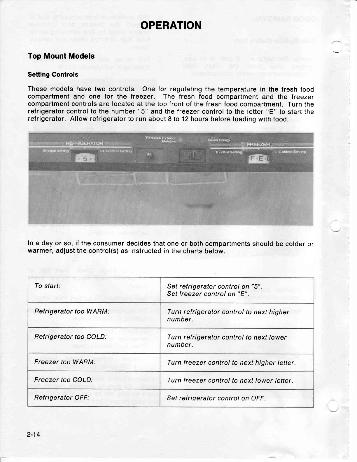
These
models have two
controls. One
for regulating the
temperature in
the fresh
food
compartment and one for the freezer. The fresh food compartment
and the treezer
compartment controls
are
located
at the top front
of the fresh food
compartment.
Turn the
refrigerator control to the number
"5" and
the
freezer control to the
letter
"E"
to start the
refrigerator. Allow refrigerator
to run
about 8 to 12 hours
before loading
with food.
In
a day
or so, if the consumer
decides that
one
or both compartments
should
be colder or
warmer,
adjust the control(s)
as instructed
in the
charts
below.
To start: Set refrigerator
control
on
"5"
Set
freezer
control
on
"E".
Refrigerator
too WARM: Turn
refrigerator
control to next
higher
number.
Refrigerator
too
COLD: Turn
refrigerator
control to
next lower
number.
Freezer
too
WARM: Turn
freezer control
to next higher
letter.
Freezer
too
COLD: Turn
freezer control
to next
lower letter.
Refrigerator OFF: Set ref
rigerator control
on OFF.
2-14
USE OF CONTROLS
f
MPORTANT: Except when
starting, do not
change
either control more
than one number
at
a time. ALLOW 24
HOURS FOR TEMPERATURE
TO
STABILIZE BEFORE RESETNNG.
Changing either control will have
some effect on the temperature
of the other
compartment.
The number
"9"
lreezer control
setting
is recommended
for
short term
use ONLY.
Please note:
The refrigerator may run for several
hours
when first
started
up. This is
normal
and shouldn't
be cause for alarm.
Warm
Cabinet Surfaces
At
times, the front
surfaces of the refrigerator
cabinet
may be warm
to the touch.
This is a
normal function
of the refrigerator,
This feature
prevents
moisture
from
condensing
on
the
outside of the refrigerator
during
humid
weather.
This condition
may
be
noticeable
when
you
first
start the refrigerator,
during
hot weather,
and excessive
or
lenghty
door openings.
Energy
Saver
Control
During
extremely
huinid weather,
moisture
has
a tendency
to collect
on objects that
are
cooler than the
surrounding
air,
just
as droplets
of water accumulate
on
a
glass
containing
an iced drink
during a hot
summer day.
The refrigerator
is
built
to
exacting
standards and,
therefore,
contains
condensate
driers
that
are designed to minimize
any collection
of
moisture
on
the
cabinet
external surface
during
periods
of high
humidity.
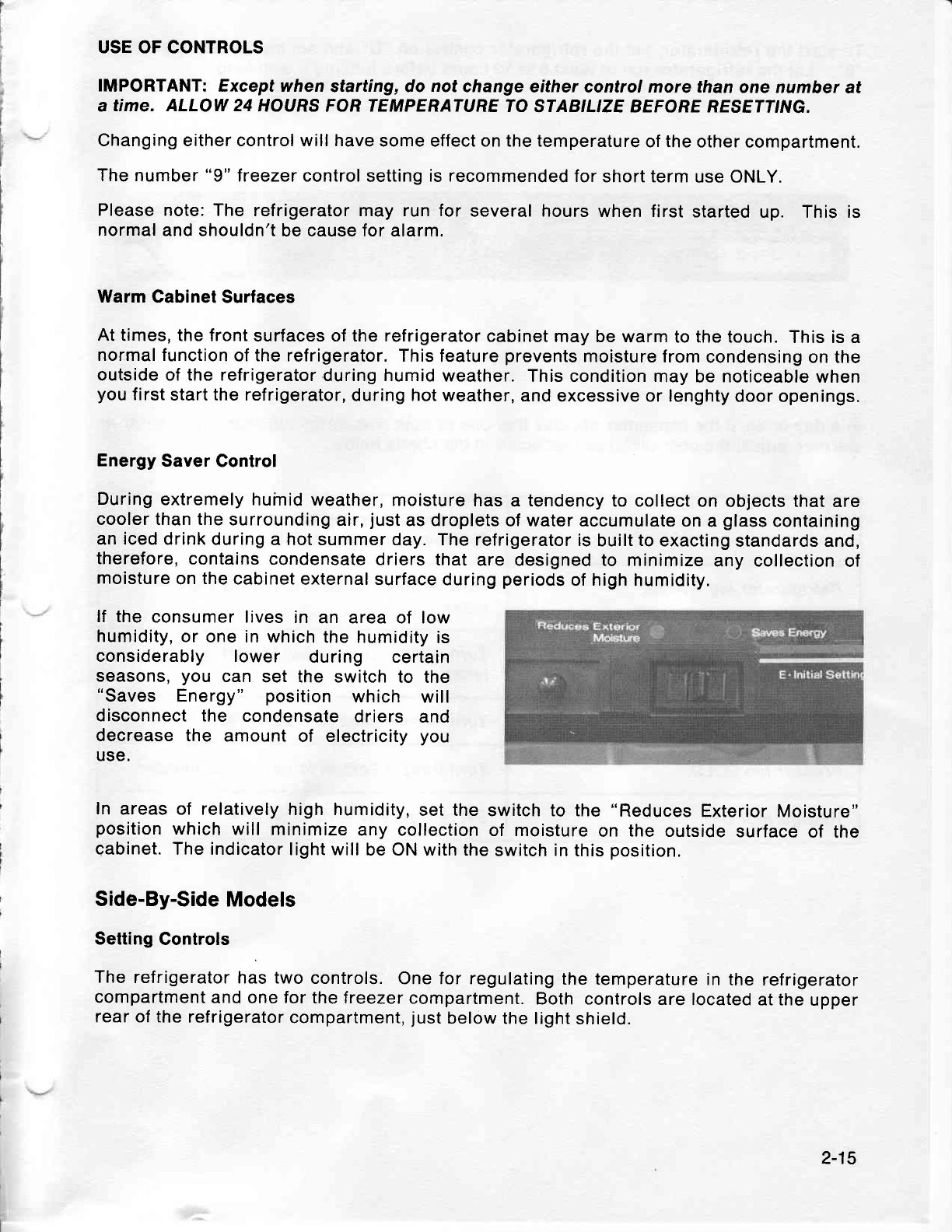
lf the consumer lives
in an area of low
humidity, or
one in which
the humidity
is
considerably lower during certain
seasons,
you can set the switch
to the
"Saves Energy" position
which will
disconnect the condensate
driers and
decrease the amount
of electricity
you
use.
In areas of relatively
high humidity,
set the
switch to the "Reduces
Exterior
Moisture"
position
which
will minimize
any collection
of moisture
on the outside
surface
of the
cabinet.
The indicator
light will
be ON with
the
switch
in
this
position.
Side-By-Side
Models
Setting
Controls
The
refrigerator
has two
controls.
One for regulating
the temperature
in
the refrigerator
compartment
and
one for the freezer
compartment.
Both controls
are located
at the
upper
rear
of
the
refrigerator
compartment,
just
below the light
shield.
2-15
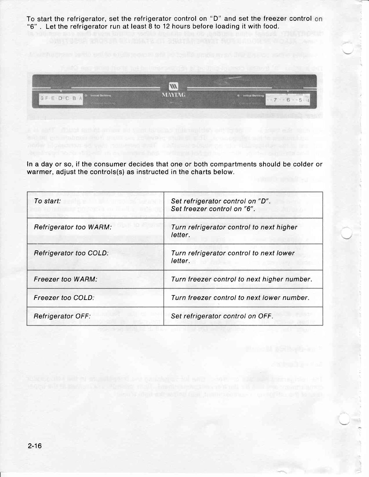
To
start
the refrigerator,
"6"
. Let
the
relfrigerator
set
the refrigerator
run at least 8
to 12 control on
"D"
and
set
the
hours before loading it withfreezer control
food.
ln a day or so, if the consumer
warmer,
adjust
the
controls(s)
decides
that one
or both compartments should be colder
or
as
instructed in
the charts below,
To start: Set refrigerator control
on
"D".
Set f reezer control
on
"6".
Refrigerator too WARM: Turn refrigerator control
to
next higher
letter.
Refrigerator too
COLD: Turn refrigerator control to next lower
letter.
Freezer
too WARM: Turn
freezer
control to
next
higher number.
Freezer too
COLD. Turn freezer control to next lower number.
Refrigerator
OFF: Set refrigerator
control
on OFF.
2-16

USE
OF CONTROLS
IMPORTANT:
Except when
starting, DO NOT
change either
control more than
one letter
or
one number
at a time. Allow 24
hours tor temperature
to stabilize betore resetting.
To turn
off
the
refrigerator,
set the refrigerator
control
on OFF.
Warm
Cabinet Surfaces
At times,
the front
surfaces of the refrigerator
cabinet may
be
warm
to the touch.
This is
a
normal
function
of
the
refrigerator. This
feature
prevents
moisture from
condensing
on the
outside
of
the refrigerator
during
humid
weather.
This condition
may
be
noticeable
when
you
first start the
refrigerator,
during hot weather,
and excessive
or lengthy
door openings.
2-17
-l
MITYTAG SECTION 3
SERVICE
PROCEDURES
GENERAL INFORMATION
TOP MOUNT
MODELS
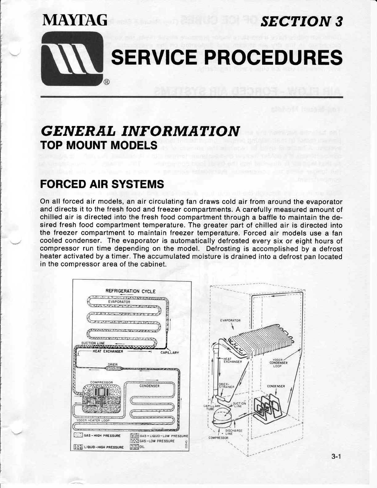
FORCED AIR
SYSTEMS
On all forced air models,
an air circulating fan
draws cold
air
from
around the evaporator
and directs it
to
the fresh food
and treezer
compartments. A
carefully measured amount
of
chilled
air
is
directed into the fresh food
compartment
through a baffle
to
maintain the de-
sired fresh food
compartment temperature.
The
greater
part
of chilled air is directed into
the freezer
compartment to maintain
freezer temperature.
Forced
air models use
a fan
cooled
condenser. The
evaporator
is
automatically
defrosted
every six or eight hours
of
compressor run time
depending
on
the
model. Defrosting
is accomplished by
a defrost
heater
activated by
a
timer.
The
accumulated moisture is
drained into
a defrost
pan
located
in the compressor
area of the
cabinet.
REFRIGERATION
CYCLE
@l
HEATEXCHANGER - --- - cAptLLARy
I ols
-
rrex
pREssuRE
ffi rrouro-xrot
pREssuRE
CONDE NSER
3-1
EVAPORATION OF ICE CUBES (rop
Mount
& side-By-side
Moders)
Since
ice
cubes have a moisture
vapor
pressure
above them,
the vapor
is
constantly
being
picked
up in the
dry air stream
and deposited
on the
evaporator.
This
physical
change
known
as
"sublimation",
is the
changing
of a solid to
a vapor
without
going
through liquid
state. In
a
forced
air treezer
compartment,
this
action will
be readily
noticed
by a customer
who
does
not
use ice cubes
with regularity.
AIR
FLOW. FORCED
AIR
SYSTEMS
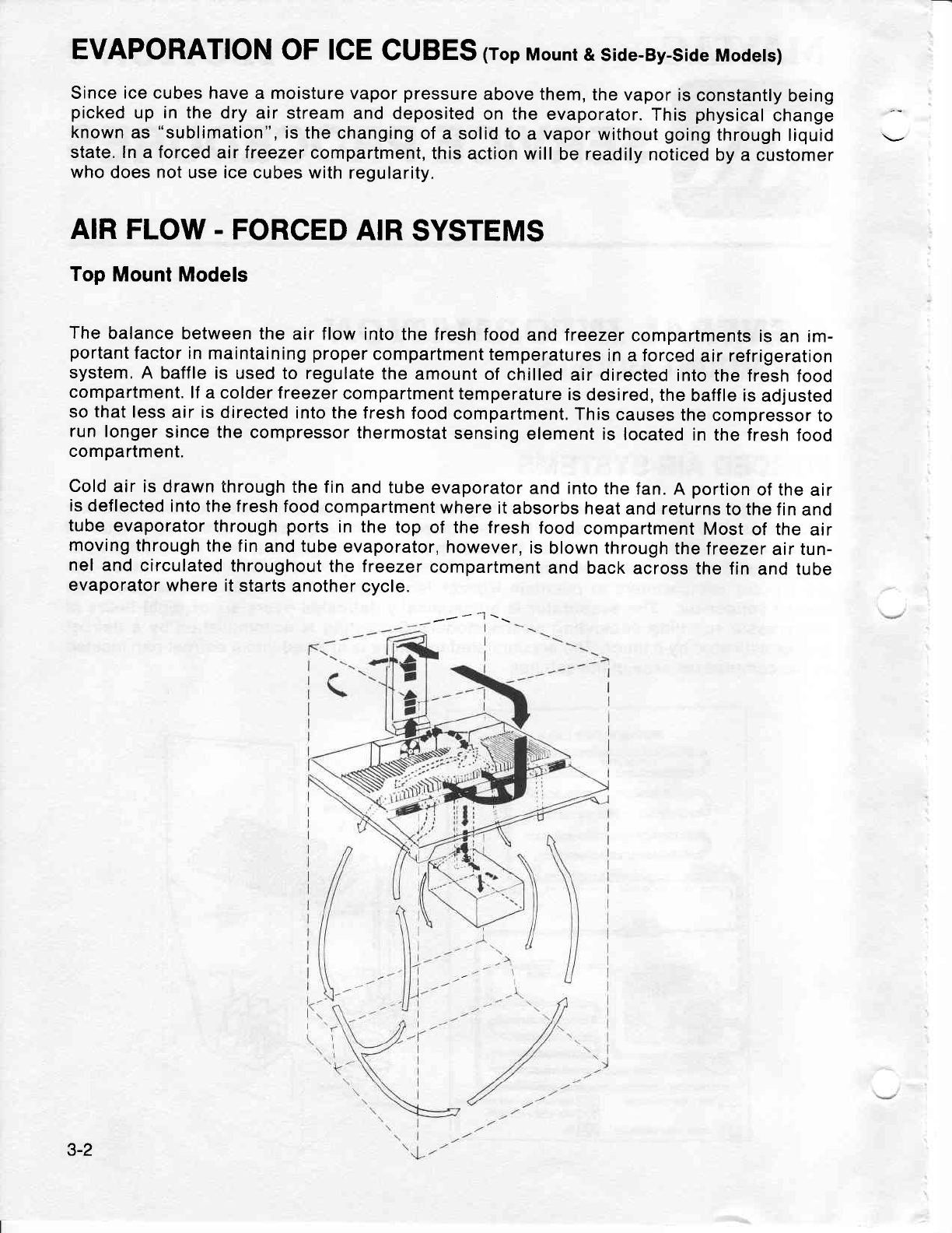
Top
Mount Models
The
balance
between the
air flow
into the fresh
food
and Ireezer
compartments
is
an im-
portant
factor in
maintaining
proper
compartment
temperatures
in
a
forced
air
refrigeration
system.
A baffle is used
to regulate
the
amount of
chilled
air directed
into
the fresh
food
compartment.
lf
a colder treezer
compartment temperature
is
desired,
the
baffle is
adjusted
so that less
air is directed
into the
fresh food
compartment.
This
causes
the
compressor
to
run longer
since the
compressor thermostat
sensing
element is
located
in the fresh
food
compartment.
Cold
air is
drawn through
the fin
and tube
evaporator
and
into
the
fan.
A portion
of the
air
is
deflected
into the f
resh food
compartment
where
it
absorbs heat
and returns
to the
f in
and
tube
evaporator
through
ports
in the
top
of the fresh
food
compartment
Most
of the
air
moving
through the
fin
and tube
evaporator,
however,
is
blown through
the
freezer
air tun-
nel
and
circulated
throughout
the freezer
compartment
and back
across
the fin
and tube
evaporator
where
it starts
another
cycle.
-r' - -l \\
3-2
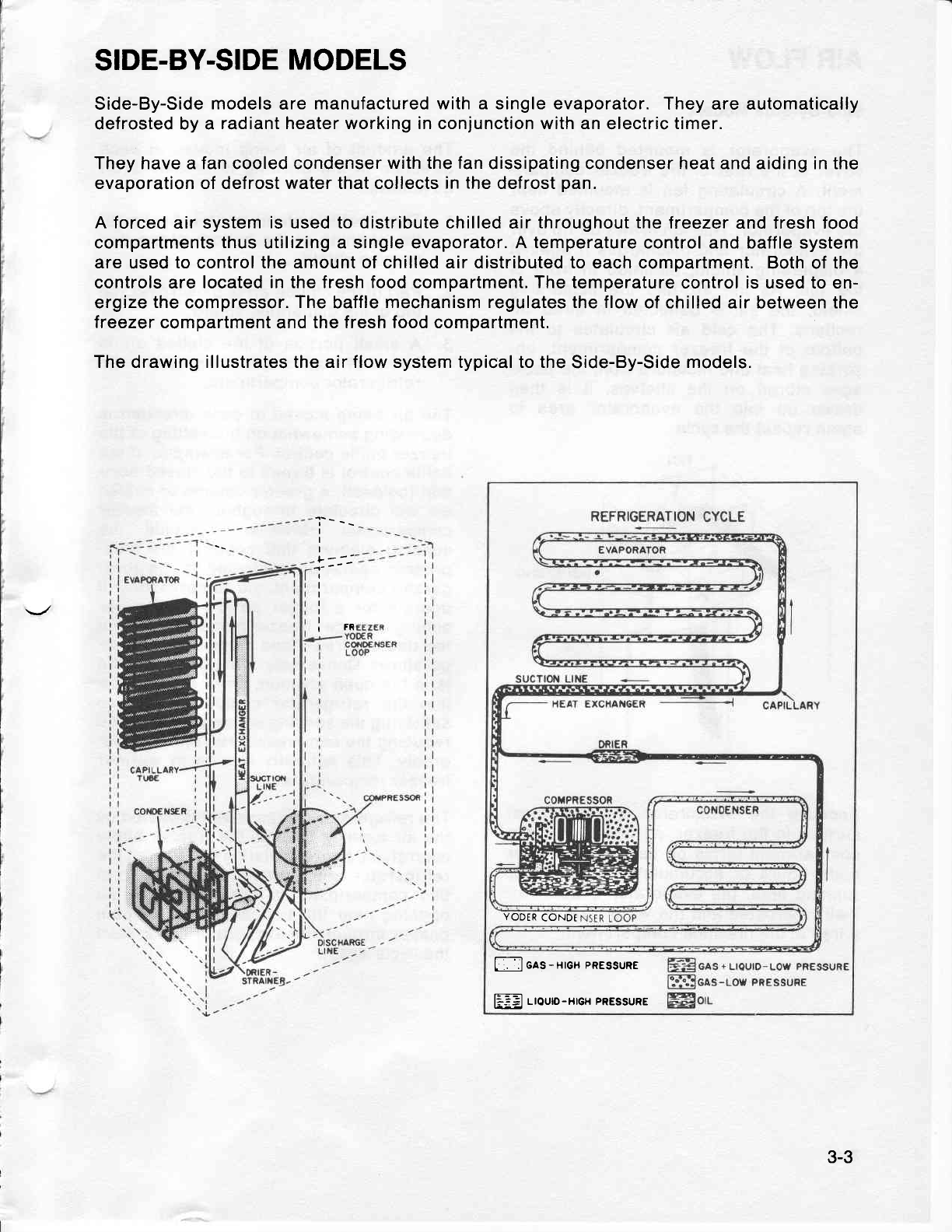
SIDE-BY-SIDE
MODELS
Side-By-Side
models
are
manufactured with a single evaporator.
They are automatically
defrosted by a radiant heater working in conjunction with an
electric
timer.
They have a fan cooled condenser
with the fan
dissipating condenser heat and aiding in the
evaporation of defrost water that collects in
the
defrost
pan.
A forced
air system
is
used
to distribute
chilled air
throughout the
lreezer and fresh food
compartments
thus
utilizing a single evaporator. A
temperature
control and baffle
system
are
used
to
control
the amount of chilled air distributed to
each compartment, Both of the
controls are
located in the fresh food compartment. The temperature
control is used to en-
ergize
the
compressor.
The
baffle
mechanism regulates the flow
of chilled air
between
the
freezer compartment
and
the fresh food compartment.
The drawing illustrates the air flow system typical to the
Side-By-Side
models.
"i----
I
I
L--'
1"-'
I
I
I
I
rFR
L
:. :IGAS-HIGH
PRESSURE
liiEJ L|OUD-H|GH PRESSURE
YODER
CONDT
3-3
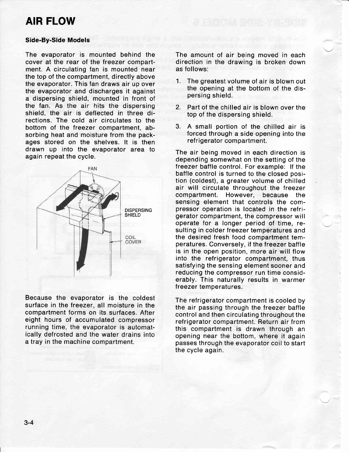
AIR
FLOW
Side-By-Side
Models
The evaporator is mounted behind the
cover at the rear
of the freezer
compart-
ment. A circulating fan is mounted near
the top of the compartment, directly
above
the
evaporator. This fan
draws air up over
the evaporator and discharges it against
a dispersing shield, mounted in front
of
the fan. As the air hits the dispersing
shield, the air is deflected in three
di-
rections. The cold air circulates to the
bottom of the freezer
compartment,
ab-
sorbing heat and moisture from
the
pack-
ages
stored on the shelves. lt is then
drawn up into the evaporator atea to
again
repeat the
cycle,
DISPERSING
SHIELD
Because
the evaporator
is the coldest
surface in the
treezer,
all moisture in the
compartment forms
on its
surfaces.
After
eight hours
of accumulated
compressor
running
time, the
evaporator
is automat-
ically
defrosted
and the water
drains into
a
tray
in the machine
compartment.
The
amount
of air being moved in each
direction
in the drawing is broken
down
as follows:
1. The
greatest
volume
of air is
blown out
the
opening
at the bottom of the
dis-
persing
shielc.
2. Part
of
the
chilled air is
blown over the
top
of
the
dispersing
shield.
3. A small
portion
of the chilled
air is
forced through
a side
opening into the
ref ri
gerator
com
partment.
The
air being moved in
each direction is
depending
somewhat
on the setting of the
treezer
baffle control, For
example: lf the
baffle control is turned
to the
closed
posi-
tion
(coldest),
a greater
volume
of chilled
air will circulate throughout
the treezer
compartment.
However, because the
sensing
element
that
controls the com-
pressor
operation is located
in the refri-
gerator
compartment, the
compressor will
operate for a longer
period
of time, re-
sulting in colder lreezer
temperatures
and
the
desired fresh food
compartment tem-
peratures.
Conversely, if the
treezer
baffle
is
in the
open
position,
more
air will flow
into the refrigerator
compartment,
thus
satisfyinQ the
sensing
element sooner
and
reducing
the compressor
run time consid-
erably.
This naturally
results in warmer
freezer temperatures.
The refrigerator
compartment is
cooled by
the
air
passing
through
the freezer
baffle
control
and then circulating throughout
the
refrigerator
compartment. Return
air from
this compartment
is drawn
through an
opening near
the bottom, where
it again
passes
through the
evaporator coil to
start
the
cycle again.
3-4
I-.l
CHECKING OPERATIOT\f - (A'
Moders)
The following
general information
ex-
plains
several
method for
checking oper-
ation of the refrigeration
system. This
information
applies to all systems
covered
in
this manual.
The
correct operation
of a refrigeration
system is dependent upon the proper
functioning
of each of the
parts
comprising
the system. lf the
system does
not operate
properly
(long
run
periods,
warmer than
normal
temperatures),
the trouble
may be
caused
by one of the following
conditions.
RESTRICTED
CAPILLARY
TUBE
The
opening
of a capillary
tube is about
the
same
diameter as the period
at the
end of this
sentence. This
should indicate
that
it doesn't
take much
to restrict
this
tube. lt should also tell
you
to use care
when any service procedures
involve
moving
or
touching
the
capillary
tube. A
very
slight
kink
can
cause
a complete re-
striction
of
the tube.
Restrictions
of the
capillary tube
may be
caused
by:
(1)
moisture
freeze-up,
(2)
tor-
eign
particles
lodged
in the tube,
or (3)
a
bend
or
kink.
lf the
capillary tube
is restricted,
there
will
be
a noticeable
lack of frost
on
all of the
cooling
surfaces; the
compressor
may
op-
erate for
a short
period
of time
and then
cycle
on the
overload. Because
some mo-
dels can hold the entire
charge in the
condenser,
the compressor
may run con-
tinuously
and
definite
vacuum
will be no-
ticed in the low side. When moisture
freeze-up
causes
a restriction,
it usually
occurs
at the
outlet
end of the
capillary
tube.
Normally,
a frost
build-up
can be
detected in this area, but insulation
wrapped
around the
tubing may
conceal
or limit the
amount
of frost
accumulation.
Expose
the discharge
end of the capillary
and apply heat
at this point.
lf there
is
enough head pressure,
and if the re-
striction
is caused
by moisture
freeze-up,
you
will
be able to
hear a gurgling
noise
as the heat releases the ref
rigerant
through the
tubing.
It is
possible
that this
moisture will
be ab-
sorbed
by the
drier and remedy the
trou-
ble. However, if the
freeze-up recurs,
you
must replace
the drier.
A kink in the capillary
tube will reveal
about the same symptom
as a moisture
freeze-up
except for the
accumulation
of
frost.
Check the
entire length
of
the
capil-
lary
tube and, if possible,
straighten the
kink to relieve the
restrictions.
Check the
unit operation to see if you
have helped
the situation. lf the trouble
persists,
re-
place
the
defective
part.
lf the freeze-up
condition
does not
exist
and
there
is not
a kink,
you
can
assume
that
a foreign
particle
is causing the re-
strictions
--
the
only remedy
in this
case
is
to replace
the restricted
part.
PARTIAL RESTRICTION
IN LOW
SIDE
TUBING
Bent tubing,
foreign
matter,
or moisture in
the
system may
cause
a partial
restriction
in
the low
side tubing. This
is usually
in-
dicated
by frost-free
tubing
between the
restriction
and the
capillary
tube
and by
f rost-covered
tubing between the re-
striction
and the suction line. The re-
striction
acts like
a second
capillary tube,
increasing
the pressure ahead of it
(warming)
and decreasing the pressure
beyond it (cooling).
To confirm
the
exist-
ence
of a restriction
in the low
side tubing,
perform
operational
pressure
checks.
3-5
SLOW LEAK IN SYSTEM
On forced air
models, long run time will
be noticed during the early
stages of a
leak. As the refrigerant
continues
to es-
cape, both compartments
will gradually
warm up and the compressor will run
continuously.
The freezer will probably
warm
up
first.
INCORRECT REFRIGERANT
CHARGE
The
sealed unit
may
have too much refri-
gerant
(overcharged
system) or too little
refrigerant
(undercharged
system). The
following
paragraphs
will inform
you
on
how to recognize
a
system
with these
de-
fects.
An overcharged system may
have a frost
back condition
appearing outside the in-
sulation
sleeve on the
suction line
at
the
cabinet
rear.
When the
compressor
stops,
the frost
melts
and drips on the floor.
A
heat
exchanger
separation will
also cause
this
symptom.
An undercharged
system depending
on
the
degree
of undercharge,
will operate
with temperatures
above normal
and the
compressor
run time
will be increased.
The
greater
the
undercharge,
the higher
the temperature
will
be
and
the longer
the
run
time.
An
undercharged
system must
be
purged,
evacuated,
and recharged
with the
proper
amount
of refrigerant.
Before recharging,
however,
test for
refrigerant leaks.
DEFECTIVE
COMPRESSOR
A compressor which is not
pumping
ade-
quately
will not
cool effectively.
All cool-
ing
surfaces
may be covered
with a thin
film
of
frost,
but the
temperature will
not
descend to the
cut-out temperature
of the
control, even
with continuous
running
of
the
compressor.
Because these
symptoms
are similar to
a
refrigerant leak, it is advisable to thor-
oughly leak
test
at
this
point.
lf no leak
is
indicated,
install
gauges
and check the
operating
pressures.
lf the
high side
pres-
sures are lower
than those
specified,
and
low side
pressures
are higher than
speci-
fied,
suspicions of
an inefficient
compres-
sor will
be confirmed
and the compressor
must be replaced.
PRESSURE
UNLOADING IN
SYSTEM
The
compressor may
stall
and cycle on
the overload
protector
if an attempt is
made
to restart the
unit immediately
after
it has
stopped. This
is
because
the refri-
gerant
pressure
is
high
on the condenser
side and low on the
evaporator
side. When
the
compressor
stops running, the liquid
slowly
passes
through
the capillary tube
and the
pressures
are said to be
"unload-
ing". Pressure
unloading in the system
may
take from
3
to
6 minutes.
PULL
DOWN
OVERLOAD
lf the cabinet
compartments
are warm
when the compressor starts, the "pull
down" may temporarily
overheat the
compressor
and cause
cycling on the ov-
erload
protector.
3-6
LEAK TESTING
The following
general information
ex-
plains
several methods
of checking the
refrigeration
system
for
leaks. This infor-
mation
applies to all systems covered in
this
manual.
lf there
is an undercharge
of refrigerant
and the system has not been recently
opened, there is probably
a leak in the
system. In that
case, it would
be only a
temporary
solution to add ref
rigerant
without
first locating
and repairing
the
leak
since
adding refrigerant
will not
per-
manently
correct the difficulty.
The leak
must
be
located
and repaired
if
possible,
after which
the
entire system must
be
re-
charged
with the
proper
amount of refri-
gerant. Whenever
a new charge of
refrigerant
is
added, it is
necessary
to in-
stall
a
new
drier.
Any
leak, regardless
of its
size, must
be
located
before
you
can
determine the
op-
erative
status
of the
system
components.
Do
not replace
a component
because the
system is short
of refrigerant
unless
a
non-repairable
leak
is found.
lf your
analysis
indicates
a leak, find it
before
opening the
system.
You
are more
likely
to pinpoint
the leak before
dis-
charging
than if the surrounding
air is
contaminated
with ref
rigerant
f rom a
newly
opened
system.
The
presence
of oil
around a tubing
joint
usually indicates
a leak,
but don't let this
be the determining
factor.
Always
check
the area with
a
leak
detector
to make
sure.
To simplify leak
detection, keep
the sys-
tem
pressurized
to
a minimum
of 75 P.S.l.
This is
easily
accomplished
for high
side
testing
by merely running
the
compressor.
To
pressurize
the low
side,
allow the en-
tire
system to warm
up to room temper-
ature.
Often
enough
refrigerant
may have
es-
caped to make it impossible
to raise
the
pressure
enough to leak
test effectively.
In
cases of this nature,
clamp a piercing
valve to the
compressor
process
tube and
add enough refrigerant
to conduct the
test.
Leak
testing with
a Halide
torch is consid-
ered satisfactory in most
cases, but for
more
accurate testing,
we recommend
the
use
of a Dielectric
Differential Leak
De-
tector.
This transistorized
model reduces
the
guesswork
in leak
testing
because it is
more sensitive,
faster responding,
and
capable
of detecting
a leak
even
though
the
surrounding
air is
contaminated.
The
leak
gun provides
an audible indication
of
a refrigerant
leak.
3-7
LEAK
TESTING
YODER
LOOP
The following
general information
ex-
plains
several
methods
used
in leak
test-
ing the
yoder
loop.
The
yoder
loop is
routed
in the front
cabi-
net
flange at
the top and
sides.
The
yoder
condenser
loop warms
the front
of
the ca-
binet
and
thus
reduces
the formation
of
condensation
on the cabinet
front. By
transferring
heat
to the cabinet
front, the
loop helps cool
the condensing
system.
Since
the
yoder
condenser
loop cannot
be
reached
for leak
testing, it
is impossible
to
check
in the normal
manner.
Instead,
it
must be disconnected
from the system
and
checked
separately.
NOTE: BE SURE
A LEAK IS
NOT PRESENT
IN ANY EXTERNAL
TUBING OR
JOINT
BE-
FORE
PERFORMING
THE FOLLOWING
TESTS.
USING
PRESSURE
METHOD
To test for leaks
in the
yoder
loop
tubing,
a pressurized
test using
the following
equipment
is required,
A. An access
fitting.
B. A cylinder
of dry
nitrogen.
C. Pressure
regulator.
D. One
gauge.
E. Line valve
and tubing.
The
access
fitting should
be
prepared
as
follows:
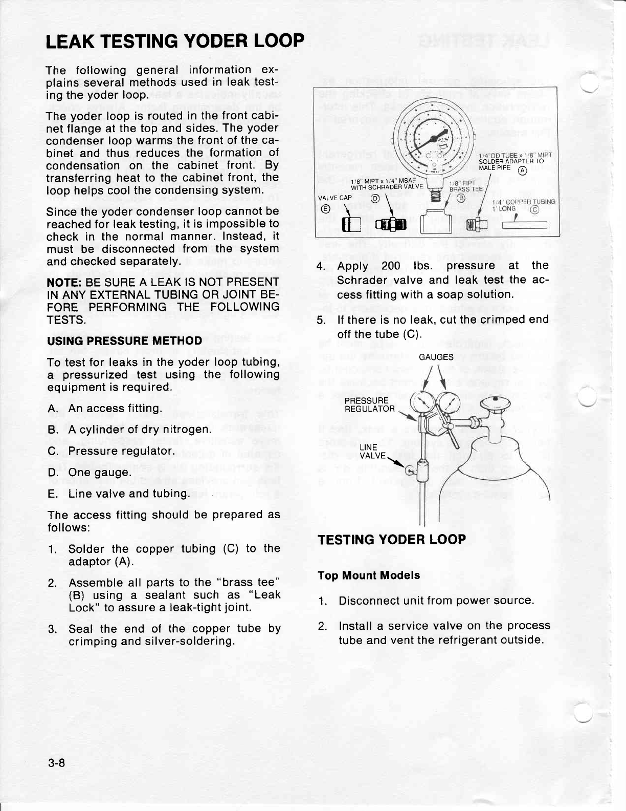
1. Solder
the
copper tubing
(C)
to the
adaptor
(A).
2. Assemble
all
parts
to
the
"brass
tee"
(B) using
a sealant
such
as "Leak
Lock"
to assure a
leak-tight
joint.
3. Seal
the end of the copper
tube bY
crimping
and silver-soldering.
SOLDER
ADAPTER
TO
N,IALE
PIPE @
1
/8" MIPT
x 1/4"
filSAE
WITH SCHFADER
VALVE
VALVECAP @ \
A\\
\y\\
tf trfft
4.
5.
Apply 200 lbs. pressure at the
Schr.ader
valve and leak test
the ac-
cess fitting
with a soap
solution.
lf
there
is no leak,
cut the crimped
end
off
the
tube
(C).
PRESSURE
REGULATOR
LINE
VALVE .\
TESTING
YODER
LOOP
Top Mount Models
1. Disconnect unit
f rom
power
source.
2. Install a service
valve on the
process
tube
and vent
the refrigerant
outside.
GAUGES
3-8
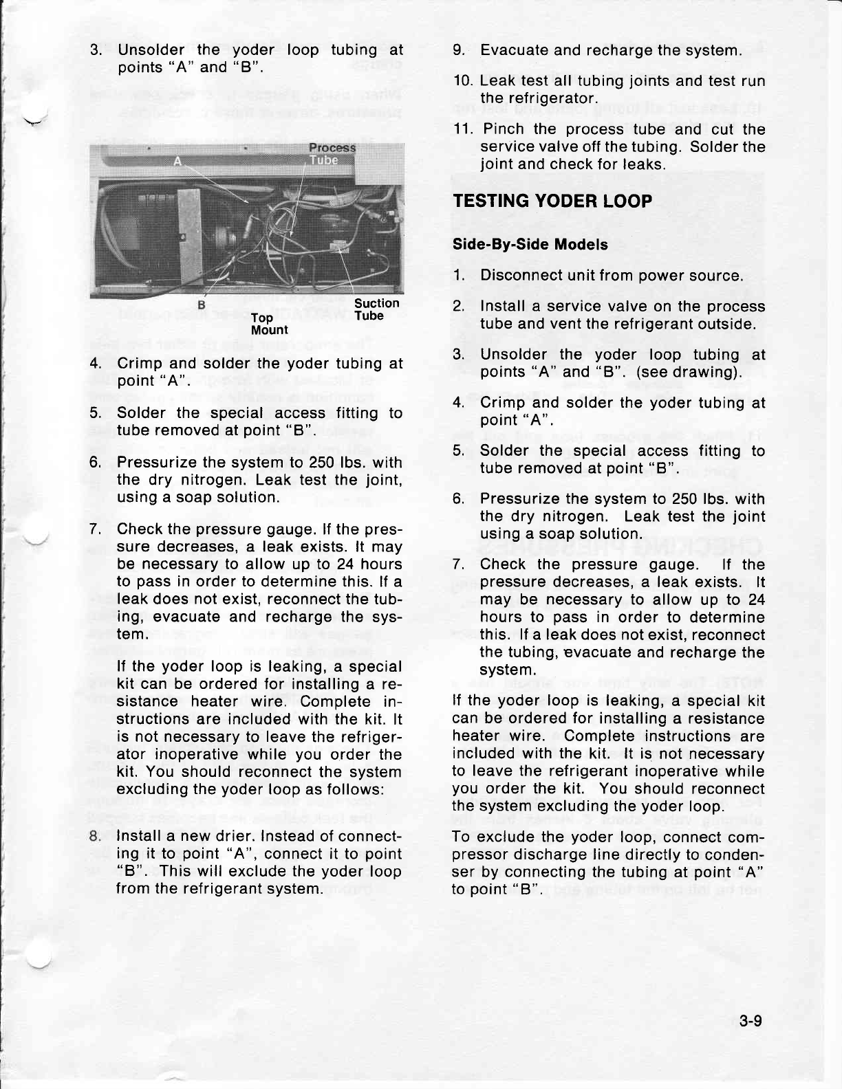
3. Unsolder
the yoder loop tubing
at
points
"A"
and
"8".
Top
Mount
Crimp and solder the
yoder
tubing at
point
"A".
Solder the special access
fitting
to
tube removed
at
point
"8".
Pressurize the
system
to
250 lbs. with
the dry nitrogen. Leak test the
joint,
using a soap solution.
Check the
pressure
gauge.
lf the
pres-
sure decreases,
a leak
exists. lt may
be necessary to
allow up to 24 hours
to
pass
in order to
determine this. lf
a
leak
does
not
exist, reconnect the tub-
ing,
evacuate and recharge
the sys-
tem.
lf the
yoder
loop is
leaking, a special
kit can
be
ordered
for installing
a re-
sistance heater wire. Complete in-
structions are included with the
kit. lt
is not necessary to leave
the refriger-
ator inoperative while
you
order the
kit. You should reconnect
the system
excluding the
yoder
loop as follows:
Install
a
new
drier. lnstead
of connect-
ing it
to
point
"A",
connect it to
point
"B". This will
exclude the
yoder
loop
from the refrigerant
system.
9. Evacuate
and recharge the system.
10.
Leak test
all
tubing
joints
and test run
the refrigerator.
11. Pinch
the process
tube
and cut the
service valve
off
the tubing.
Solder the
joint
and check
for leaks.
TESTING
YODER
LOOP
Side-By-Side Models
1. Disconnect
unit f rom
power
source.
2. Install
a service valve on the
process
tube
and
vent
the refrigerant
outside.
3. Unsolder the yoder loop tubing
at
points
"A"
and
"8". (see
drawing).
4. Crimp and solder the
yoder
tubing
at
point
"A".
5. Solder the special
access
fitting
to
tube
removed at
point
"8".
6. Pressurize the
system to 250 lbs.
with
the
dry nitrogen. Leak test the
joint
using
a
soap
solution.
7. Check the pressure
gauge. lf the
pressure
decreases, a leak exists.
lt
may
be necessary
to allow up to 24
hours
to pass
in order to determine
this.
lf a leak does not
exist, reconnect
the
tubing, evacuate
and recharge the
system.
lf
the
yoder
loop is leaking,
a special
kit
can be ordered for
installing
a resistance
heater wire. Complete instructions
are
included
with the kit. lt is
not necessary
to leave the refrigerant
inoperative
while
you
order the kit. You
should reconnect
the
system
excluding the
yoder
loop.
To
exclude the
yoder
loop,
connect com-
pressor
discharge
line directly to
conden-
ser by connecting the tubing
at
point
"A"
to
point
"8",
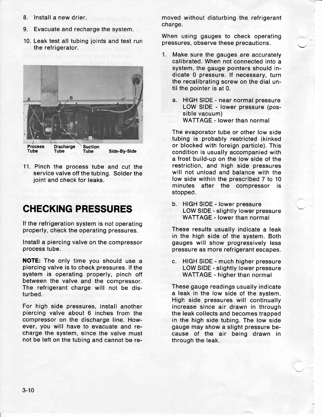
Suction
Tube
4.
5.
6.
7.
3-9
8. lnstall
a new drier.
9. Evacuate
and recharge the
system.
10. Leak test
all
tubing
joints
and test run
the refrigerator.
moved
without disturbing the refrigerant
charge.
When
using
gauges
to check
operating
pressures,
observe these
precautions.
1. Make
sure the
gauges
are
accurately
calibrated.
When not
connected into a
system, the
gauge pointers
should in-
dicate
0 pressure.
lf necessary,
turn
the recalibrating
screw on the
dial un-
til the
pointer
is
at 0.
a. HIGH
SIDE
- near
normal
pressure
LOW
SIDE
- lower
pressure
(pos-
sible vacuum)
WATTAGE
- lower
than normal
The
evaporator
tube
or other low side
tubing
is probably
restricted
(kinked
or blocked with foreign
particle).
This
condition is
usually accompanied
with
a
frost
build-up
on the low
side of the
restriction,
and high
side
pressures
will not unload
and balance with the
low
side within
the
prescribed
7 to 10
minutes after the compressor is
stopped.
b, HIGH SIDE
-
lower
pressure
LOW SIDE
-
slightly lower
pressure
WATTAGE
- lower
than normal
These results
usually
indicate a leak
in the high
side of the
system. Both
gauges
will show
progressively
less
pressure
as more refrigerant
escapes.
c. HIGH
SIDE
-
much higher
pressure
LOW
SIDE
-
slightly lower
pressure
WATTAGE
- higher
than normal
These
gauge
readings
usually
indicate
a leak
in the low
side
of
the
system.
High
side
pressures
will continually
increase
since air drawn in through
the
leak collects
and becomes trapped
in
the high
side tubing. The
low side
gauge
may
show a
slight
pressure
be-
cause of the air being drawn in
through
the leak.
Process
Tube Discharge
Tube Side-By-Side
Suction
Tube
11. Pinch the process
tube and cut the
service valve
off the
tubing.
Solder
the
joint
and check
for leaks.
CHECKING PRESSURES
lf the
refrigeration
system is not
operating
properly,
check the operating
pressures.
Install
a
piercing
valve
on the compressor
process
tube.
NOTE: The only time
you should
use a
piercing
valve
is to
check
pressures.
lf
the
system is operating
properly, pinch
off
between the valve
and
the compressor.
The refrigerant
charge
will not be dis-
turbed.
For high
side
pressures,
install
another
piercing
valve
about 6 inches
from the
compressor
on the
discharge line.
How-
ever,
you will have
to evacuate
and re-
charge the
system,
since the valve
must
not
be left
on the tubing
and cannot
be re-
3-10
d. HIGH SIDE
-
lower
pressure
LOW SIDE
- in vacuum
WATTAGE
- lower than
normal
The system is probably
restricted
at
the
entrance of the
capillary tube. High
side
pressures
will take much longer
than
the
prescribed
7 to
10 minutes to
unload and balance with
the low side
after the compressor is
stopped.
e. HIGH
SIDE
-
higher
pressure
LOW SIDE
-
near normal
pressure
WATTAGE
-
higher than normal
These
findings indicate
air
in the
sys-
tem.
This is usually
the result
of a low
side leak
being repaired
without the
system
being
thoroughly
purged
and
evacuated
before
recharging.
To
confirm the
existence
of air in
the
system, check the temperatures
of the
condenser inlet
hnd outlet. During
normal
operation,
the outlet
should be
from
15 to 20
degrees
colder than the
inlet. lf these
temperatures
do
not
vary
at least 15
degrees, the
presence
of air
is
almost certain.
Simply
purging
the
air
from the
system
is not
practical.
This
may result in
the
system
being
undercharged
due
to
the
loss of ref rigerant.
Purge, replace
drier,
evacuate,
and
recharge
the
sys-
tem.
f. HIGH
SIDE
-
higher
pressure
LOW
SIDE
- higher
pressure
WATTAGE
-
higher than
normal
These
gauge
readings
usually indicate
an overcharge
of refrigerant.
The
ex-
tent
of the
pressure
increase
depends
on the amount
of
overcharge and room
temperature.
A
slight overcharge
may
not
cause trouble
in 70
degree tem-
peratures
whereas
in
90 degree tem-
peratures
a considerable
rise in
pressure
will result.
An overcharge
may also cause the
suction line to be frosted
during the
run cycle.
Evacuate
and recharge
if
the system
is
overcharged.
g. HIGH
SIDE
-
lower than normal
LOW
SIDE
-
higher
than normal
WATTAGE
- lower
than normal
These
results indicate
an inefficient
compressor.
All
cooling surfaces
may
be covered
with
a
thin
film of frost,
but
the temperature
will not descend to
cut
off
temperature
of the control,
even
with
continuous running.
Also the
con-
denser
will be noticeably
cooler to the
touch than
normal.
Once the confir-
mation
of
an
inefficient
compressor is
determined, it
should
be replaced.
3-1
1
EVACUATING
AND RECHARGING
The
following
general
information
applies
to all systems
covered
in
this manual.
EVACUATING
Any
time the sealed
system
is opened
and
the refrigerant
charge
removed,
you
must
install a
new service
drier and
thoroughly
evacuate
before
recharging.
Even
though
a complete
evacuation
takes additional
time,
it will save
time
in the long
run.
1. Open
the compressor
low side
proc-
ess
tube as close
to the
pinched
end
as possible.
This will leave sufficient
room
for pinching
off at the conclu-
sion.
2. Install a service
valve on
the
process
tube.
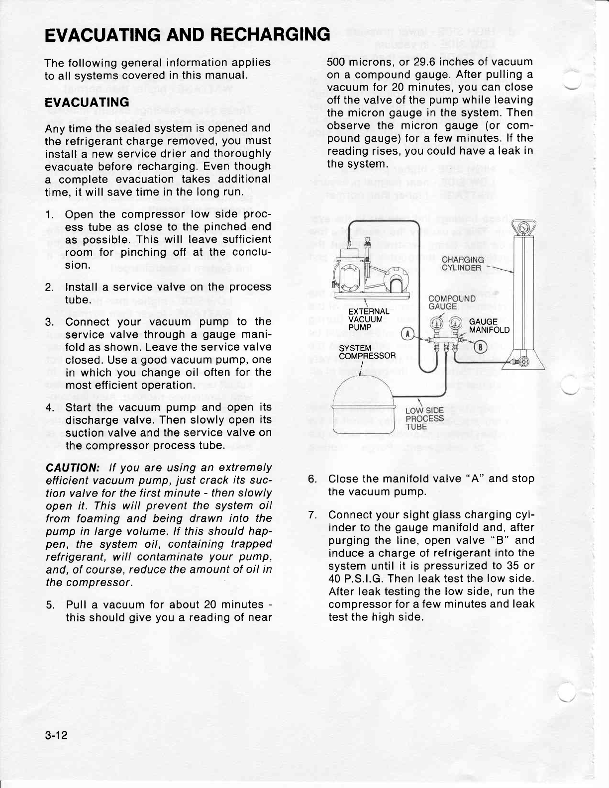
3. Connect
your vacuum
pump
to the
service
valve through a gauge
mani-
fold
as shown.
Leave
the service
valve
closed. Use a
good
vacuum
pump,
one
in which
you
change oil often
for
the
most
eff
icient operation.
4. Start
the vacuum
pump
and open
its
discharge
valve.
Then slowly open
its
suction
valve and the service
valve on
the compressor
process
tube.
CAUTION:
lf you are using an extremely
efficient
vacurlm
pump, just
crack
its suc-
tion valve
for the f irst minute
- then slowly
open it. This
will prevent
the system
oil
from foaming and being drawn into the
pump
in large volume. lf this
should
hap-
pen, the system oil, containing
trapped
refrigerant, will contaminate
your pump,
and, of
course, reduce the amount of
oil
in
the compressor.
5. Pull
a vacuum for about
20 minutes
-
this should
give
you
a
reading of
near
500
microns, or 29.6
inches of vacuum
on
a compound
gauge.
After
pulling
a
vacuum for 20
minutes,
you
can close
off
the valve of the
pump
while leaving
the
micron
gauge
in the system.
Then
observe the micron
gauge
(or com-
pound gauge)
for a few minutes.
lf the
reading rises,
you
could
have a leak
in
the system.
EXTERNAL
VACUUM
PUMP
SYSTEM
COMPRESSOR
GAUGE
MANIFOLD
6.
7.
Close the manifold
valve
"A"
and
stop
the vacuum
pump.
Connect
your
sight
glass
charging
cyl-
inder to the
gauge
manifold and, after
purging
the line, open
valve
"B" and
induce
a
charge of
refrigerant into the
system
until it is
pressurized
to 35 or
40 P,S.l.G.
Then leak test the
low
side.
After leak testing
the low side,
run the
compressor
for a
few minutes and leak
test the
high
side.
3-12
8. Purge the temporary ref rigerant
charge out the low
side.
This
will help
to remove
moisture from
the system.
Keep in mind that the process
of
flushing clean refrigerant
through the
system is equivalent
to 20 or 25 min-
utes of pulling
a vacuum with
a vac-
uum pump of lower capacity than
those specified. Therefore,
you can
induce
another temporary
charge and
purge,
if
you
desire.
9. Repeat the vacuum
pump procedure
for
another 30 minutes
which
should
again
pull
down to about
500 microns
or 29.6 inches
of mercury.
IMPORTANT:
Always
heat
as
much
of the
system
as
you
can while
evacuating,
pref-
erably with
a heat
lamp
- not
a torch. Be
careful with the
lamp, however,
to avoid
damaging
any nearby
plastic parts
or
sys-
tem
parts.
RECHARGING
lt is very essential
that you have the
proper
eguipment
when
charging the
sys-
tem
so
you
can
be accurate to within
1/4
ounce of refrigerant.
Although there
are
several methods
of charging, we recom-
mend the
use
of a sight
glass
charging
cylinder which is accurate
regardless
of
the
ambient
temperature.
We recommend
when
using the
vacuum
pump evacuating
procedure,
that you
charge through
the low
side of the
system,
either through the process
tube or the
suction line. Remember,
however,
that
the ref
rigerant should be introduced
slowly. Because
the refrigerant
will
enter
the
system in a liquid
state,
you
should
never run
the
compressor
while
charging.
Wait
at least
5 minutes
after
the
charge
has entered
before starting the
compres-
sor.
1. Connect the hose
of the
charging
cyl-
inder
to the
system through
a gauge
manifold
as shown in previous
draw-
ing.
Close valve
"A"
on the manifold.
2. Open the
charging cylinder
and
purge
the hose.
As soon as the refrigerant
has
stabilized
in the
charging cylinder,
check the
pressure
reading
of the
cyl-
inder
and rotate
the
sleeve
to
correct
the
setting
for pressure
and the type
of
refrigerant
being
used.
3. Consult
Section
9 for the amount of
charge needed,
then
open valve
"8".
As you
charge
the system,
you may
notice
some bubbles in
the cylinder.
These
can
be eliminated
by closing
your
service valve
and tipping the
cyl-
inder
upside-down
momentarily.
Then
continue
charging
until the correct
charge has
entered the
system.
lf
at
any time
you
are required
to raise
the
internal
pressure
of the
charging cylinder,
or if
your
charging
cylinder
does not have
an
internal
heater,
place
the
cylinder in
a
bucket
of warm
water
(not
over 125o F).
Never
heat
a charging
cylinder
with
a
flame.
Such
action
could
cause hydros-
tatic
pressure
to build up to dangerous
levels
and
possibly
cause the
cylinder
to
rupture
iike
a bomb.
4. When
you
are
sure the
system is
cor-
rectly
charged,
stop the
flow
of refri-
gerant
at
valve
"B".
Then
pinch
off the
low side process
tube, close the
charging
cylinder
valve,
remove
the
service valve,
and
solder
the
process
tube
closed.
3-13
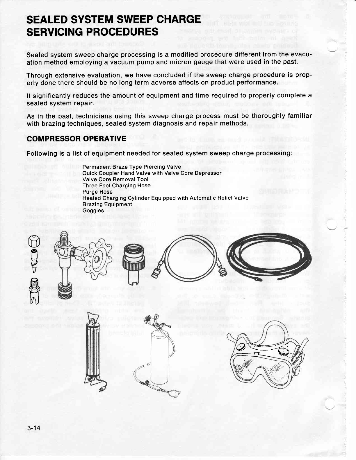
SEALED
SYSTEM
SWEEP
CHARGE
SERVICING
PROCEDURES
Sealed
system
sweep
charge
processing
is a modified
procedure
different
from the evacu-
ation
method
employing a
vacuum
pump
and
micron
gauge
that
were
used
in the
past.
Through extensive
evaluation,
we
have
concluded
if
the
sweep charge
procedure
is
prop-
erly
done
there should be
no long
term
adverse
affects on
product performance.
It
significantly
reduces the
amount
of equipment and
time required
to
properly
complete
a
sealed
system
repair.
As
in the
past,
technicians using this sweep
charge
process
must be
thoroughly
familiar
with
brazing
techniques, sealed system
diagnosis and
repair methods.
COMPRESSOR
OPERATIVE
Following is a list
of equipment
needed for sealed system sweep
charge
processing:
Permanent Braze
Type Piercing Valve
Quick
Coupler
Hand Valve with
Valve
Core Depressor
Valve
Core
Removal Tool
Three Foot Charging
Hose
Purge Hose
Heated
Charging Cylinder
Equipped
with Automatic Relief
Valve
Brazing Equipment
Goggles
ffi
er
u
V
R
n)
'Q':fr-fr
:---Q\ \*1'.
3-14
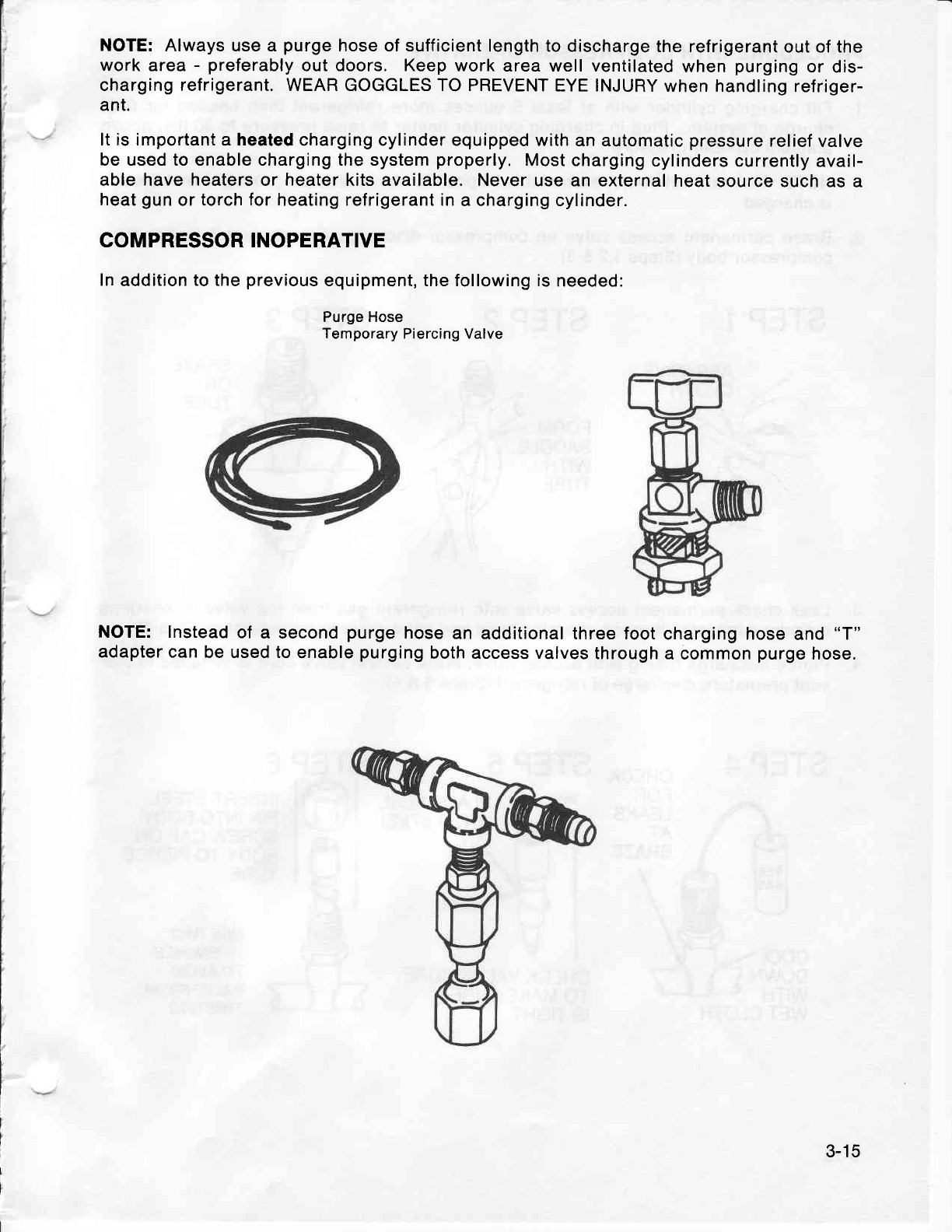
NOTE: Always use a purge
hose
of
sufficient
length to discharge
the refrigerant
out of the
work
area
- preferably
out doors. Keep work
area well ventilated
when
purging
or dis-
charging refrigerant. WEAR GOGGLES TO PREVENT
EYE INJURY
when handling
refriger-
ant.
It is important
a
heated
charging cylinder equipped with
an automatic
pressure
relief
valve
be used to enable charging the
system
properly.
Most charging
cylinders
currently avail-
able have
heaters
or heater
kits available. Never
use an
external heat
source such as
a
heat
gun
or torch for heating refrigerant in
a charging cylinder.
COMPRESSOR INOPERATIVE
In
addition
to the
previous
equipment, the following is
needed:
Purge Hose
Temporary
Piercing Valve
NOTE: Instead
of
a second
purge
hose an additional three foot
charging hose
and
"T"
adapter can
be used to
enable
purging
both access valves
through
a common
purge
hose.
3-15
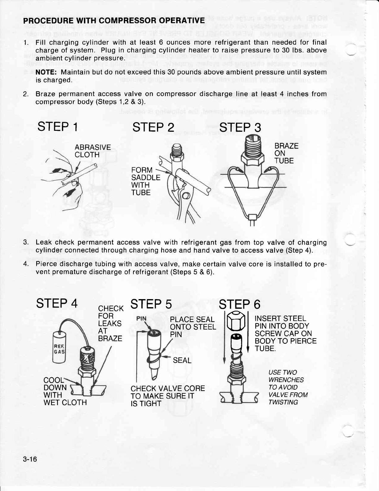
1.
2.
PROCEDURE
WITH COMPRESSOR
OPERATIVT
Fill
charging cylinder
with
at least 6 ounces more refrigerant than needed for final
charge
of system.
Plug in
charging
cylinder heater to raise
pressure
to
30
lbs.
above
ambient
cylinder
pressure.
NOTE:
Maintain but do
not
exceed
this 30
pounds
above ambient
pressure
until system
is charged.
Braze
permanent
access
valve on compressor discharge
line at least 4 inches from
compressor
body
(Steps
1,2
& 3).
STEP
1STEP 2
BRAZE
ON
TUBE
FORM
SADDLE
WITH
TUBE
Leak check
permanent
access valve
with
refrigerant
gas
from top valve
of charging
cylinder connected through
charging hose and hand valve to
access
valve
(Step
4).
Pierce
discharge tubing with access valve, make
certain valve core is installed to
pre-
vent
premature
discharge
of
refrigerant
(Steps
5 & 6).
STEP
4CHECKSTEP 5 S
3.
4.
FOR
LEAKS
AT
BRAZE
PLACE
SEAL
ONTO STEEL
PIN
6
INSERT
STEEL
PIN INTO
BODY
SCREW CAP ON
BODY TO PIERCE
TUBE.
USE TWO
WRENCHES
TO AVOID
VALVE
FROM
TWISTING
TEP
ml
sl
coor
DOWN
WITH
SEAL
CHECK
VALVE CORE
TO MAKE
SURE
IT
IS TIGHT
STEP
3
ABRASIVE
CLOTH
3-16
WET
CLOTH
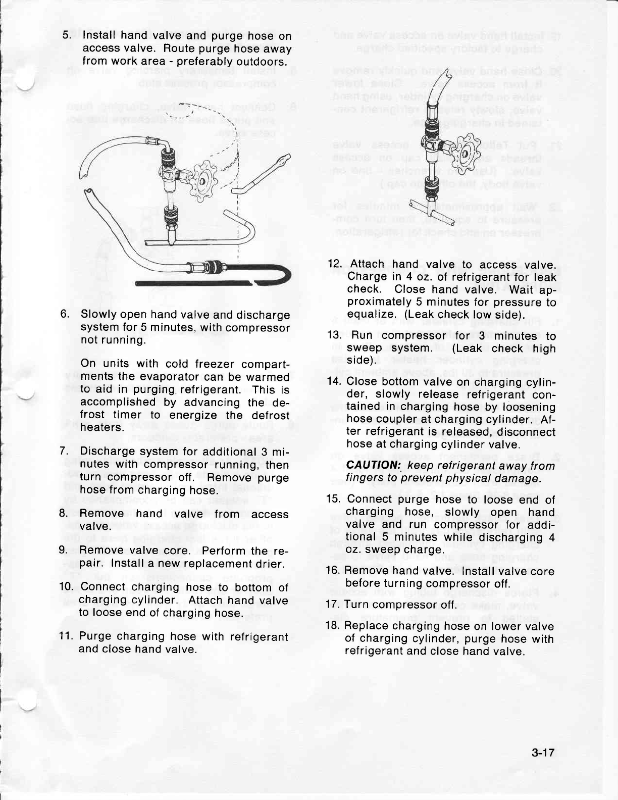
5. Install
hand
valve
and
purge
hose
on
access
valve.
Route
purge
hose
away
from work
area
- preferably
outdoors.
Slowly
open hand
valve
and
discharge
system
for
5 minutes,
with
compressor
not
running.
On units
with cold freezer
compart-
ments
the
evaporator
can be warmed
to
aid in
purging,
refrigerant.
This
is
accomplished
by advancing
the de-
frost timer to energize
the defrost
heaters.
Discharge
system
for
additional
3 mi-
nutes
with
compressor
running,
then
turn
compressor
off. Remove
purge
hose from
charging
hose.
Remove hand valve f rom access
valve.
Remove
valve
core. Perform
the re-
pair.
lnstall
a
new
replacement
drier.
Connect
charging
hose
to bottom
of
charging
cylinder.
Attach
hand
vaive
to loose
end of charging
hose.
Purge
charging
hose with
refrigerant
and
close
hand valve.
12. Attach
hand valve to access
valve.
Charge in
4 oz.
of refrigerant
for leak
check. Close
hand
valve. Wait
ap-
proximately
5 minutes
for
pressure
to
equalize,
(Leak
check low
side).
13. Run compressor
for 3 minutes
to
sweep system. (Leak check high
side).
14.
Close
bottom valve
on charging
cylin-
der, slowly release
refrigerant
con-
tained
in
charging
hose
by loosening
hose
coupler
at charging
cylinder.
Af-
ter
refrigerant
is released,
disconnect
hose
at charging
cylinder
valve.
CAUTION:
keep
refrigerant
away from
fingers
to'
prevent
physical
damage.
15,
Connect
purge
hose to loose
end
of
charging
hose, slowly open hand
valve
and run compressor
for addi-
tional
5 minutes
while
discharging
4
oz. sweep
charge.
16. Remove
hand
valve.
Install
valve
core
before turning
compressor
off.
17.
Turn
compressor
off.
18. Replace
charging
hose
on lower
valve
of charging
cylinder,
purge
hose
with
refrigerant
and
close
hand valve.
6,
7.
8.
9.
10.
11.
3-17
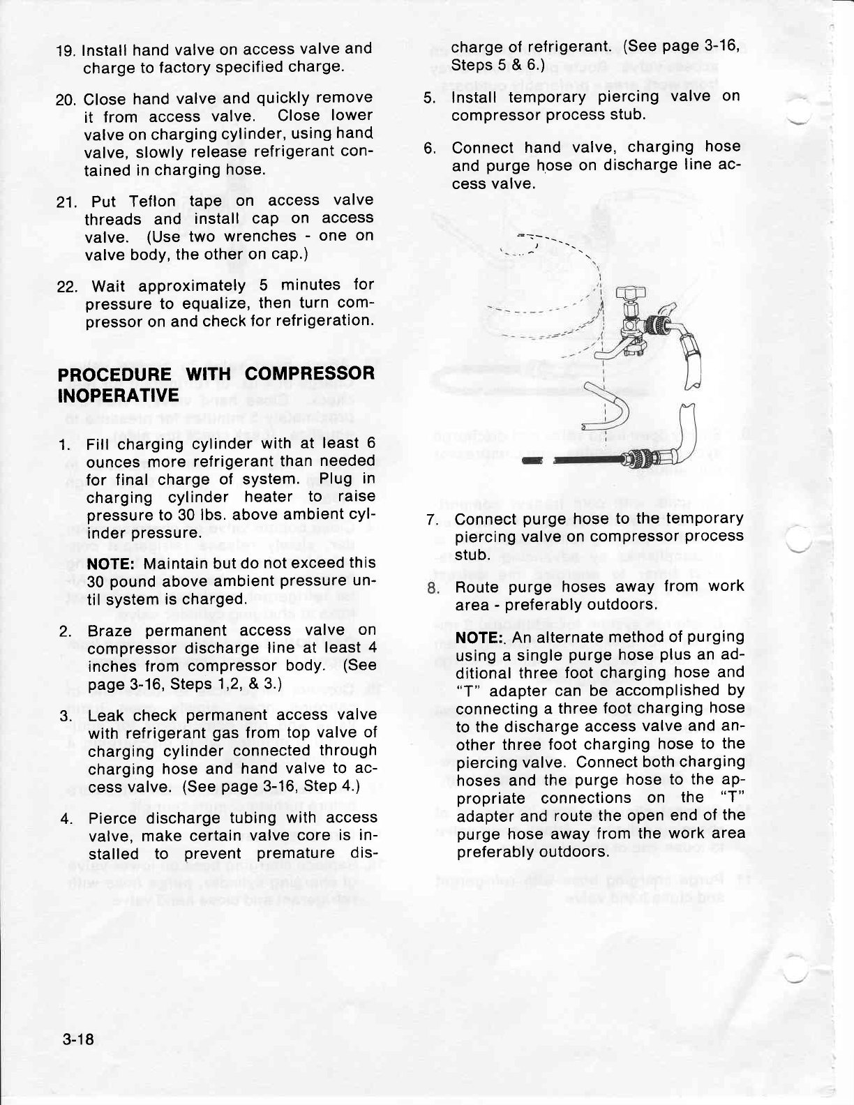
19,
Install
hand
valve
on
access
valve
and
charge
to factory
specified
charge.
20. Close
hand
valve
and
quickly
remove
it from access
valve. Close
lower
valve
on
charging
cylinder,
using
hand
valve,
slowly
release
refrigerant
con-
tained
in charging
hose.
21. Put Tef
lon tape on access valve
threads
and install
caP on access
valve. (Use
two wrenches
- one
on
valve
body,
the
other on
caP.)
22. Wait approximately
5 minutes
for
pressure
to equalize,
then
turn
com-
pressor
on
and
check
for
refrigeration.
PROCEDURE
WITH
COMPRESSOR
INOPERATIVE
Fill
charging
cylinder
with at least
6
ounces
more
refrigerant
than
needed
for final charge
of system. Plug
in
charging cylinder heater to raise
pressure
to 30
lbs. above
ambient
cyl-
inder
pressure.
NOTE:
Maintain
but
do
not exceed
this
30
pound
above
ambient
pressure
un-
til system
is charged.
Braze permanent
access valve on
compressor
discharge
line at least
4
inches
from compressor
body. (See
page
3-16,
Steps
1,2, & 3.)
Leak
check
permanent
access
valve
with
refrigerant
gas
from
top valve of
charging
cylinder
connected
through
charging
hose
and
hand
valve
to ac-
cess
valve.
(See
page
3-16, SteP
4.)
Pierce
discharge
tubing
with access
valve,
make
certain
valve
core
is in-
stalled to prevent premature
dis-
charge
of
refrigerant.
(See
page
3-16,
Steps
5 &
6.)
lnstall
temporary
piercing
valve on
compressor
process
stub.
Connect
hand
valve,
charging
hose
and
purge
hose on
discharge
line
ac-
cess
valve.
Connect
purge
hose
to
the temporary
piercing
valve on
compressor
process
stub.
Route
purge
hoses away
from
work
area
- preferably
outdoors.
NOTE:.
An alternate
method
of
purging
using
a single
purge
hose
plus
an ad-
ditional
three
foot charging
hose and
"T" adapter
can
be accomplished
bY
connecting
a
three
foot charging
hose
to
the discharge
access
valve
and an-
other
three foot
charging
hose
to the
piercing
valve. Connect
both
charging
hoses and
the
purge
hose
to the aP-
propriate
connections
on the "T"
adapter
and
route the open
end
of
the
purge
hose away
from
the
work area
preferably
outdoors.
5.
6.
1.
7.
2.
3.
4.
3-18
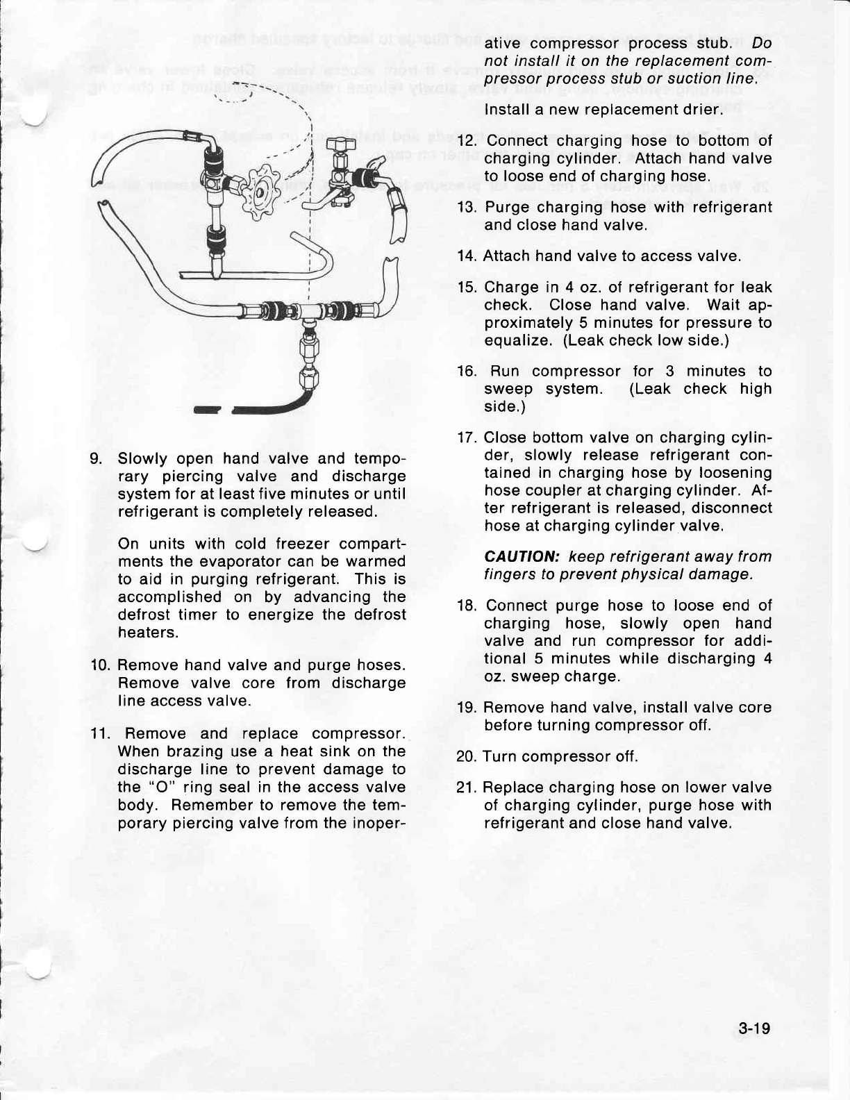
Slowly
open hand
valve
and
tempo-
rary piercing
valve and discharge
system
for
at
least f ive minutes or
until
refrigerant is
completely
released.
On units with cold freezer compart-
ments
the
evaporator can be
warmed
to aid in purging
refrigerant.
This
is
accomplished on by advancing
the
defrost
timer to energize
the defrost
heaters.
Remove hand valve
and
purge
hoses.
Remove valve core from discharge
line access valve.
Remove and replace compressor.
When brazing use a heat
sink on
the
discharge line to prevent
damage to
the
"O" ring seal in the access valve
body. Remember to remove the tem-
porary piercing
valve
from the inoper-
ative
compressor
process
stub. Do
not install it on the replacement com-
pressorprocess
stub or suction line.
Install a new replacement drier.
12. Connect
charging
hose to bottom of
charging cylinder.
Attach hand valve
to loose
end of charging hose,
13. Purge
charging hose
with refrigerant
and close hand valve.
14. Attach hand valve to access valve.
Charge in 4 oz. of
refrigerant for leak
check. Close hand valve. Wait ap-
proximately
5 minutes for
pressure
to
equalize.
(Leak
check
low side.)
Run compressor for 3 minutes to
sweep system. (Leak
check high
side.)
Close bottom
valve
on charging cylin-
der, slowly
release refrigerant con-
tained in
charging
hose by loosening
hose coupler
at charging
cylinder. Af-
ter refrigerant is released, disconnect
hose at charging cylinder valve.
CAUTION: keep refrigerant away
from
fingers to
prevent physical
damage.
Connect
purge
hose to loose end of
charging hose, slowly open hand
valve
and run compressor for addi-
tional 5 minutes while discharging 4
oz. sweep charge.
Remove
hand valve, install valve core
before turning compressor off.
20. Turn
compressor off.
21. Replace charging hose on
lower valve
of charging cylinder,
purge
hose with
refrigerant
and close
hand valve.
15.
16.
17.
9.
18.
10.
11.
19.
3-19
22.
lnstall
hand valve on access
valve and
charge
to factory
specified
charge.
23.
Close
hand
valve and
quickly
remove
it from access valve. Close
lower valve on
charging
cylinder,
using
hand
valve, slowly
release refrigerant contained
in charging
hose.
24.
Put
Teflon
tape on access
valve
threads and install cap on access
valve. (Use
two
wrenches
-
one on
valve body,
the other
on cap.)
25. Wait
approximately
5 minutes
for
pressure
to
equalize,
then
turn compressor
on and
check
for
refrigerant.
f-
3-20
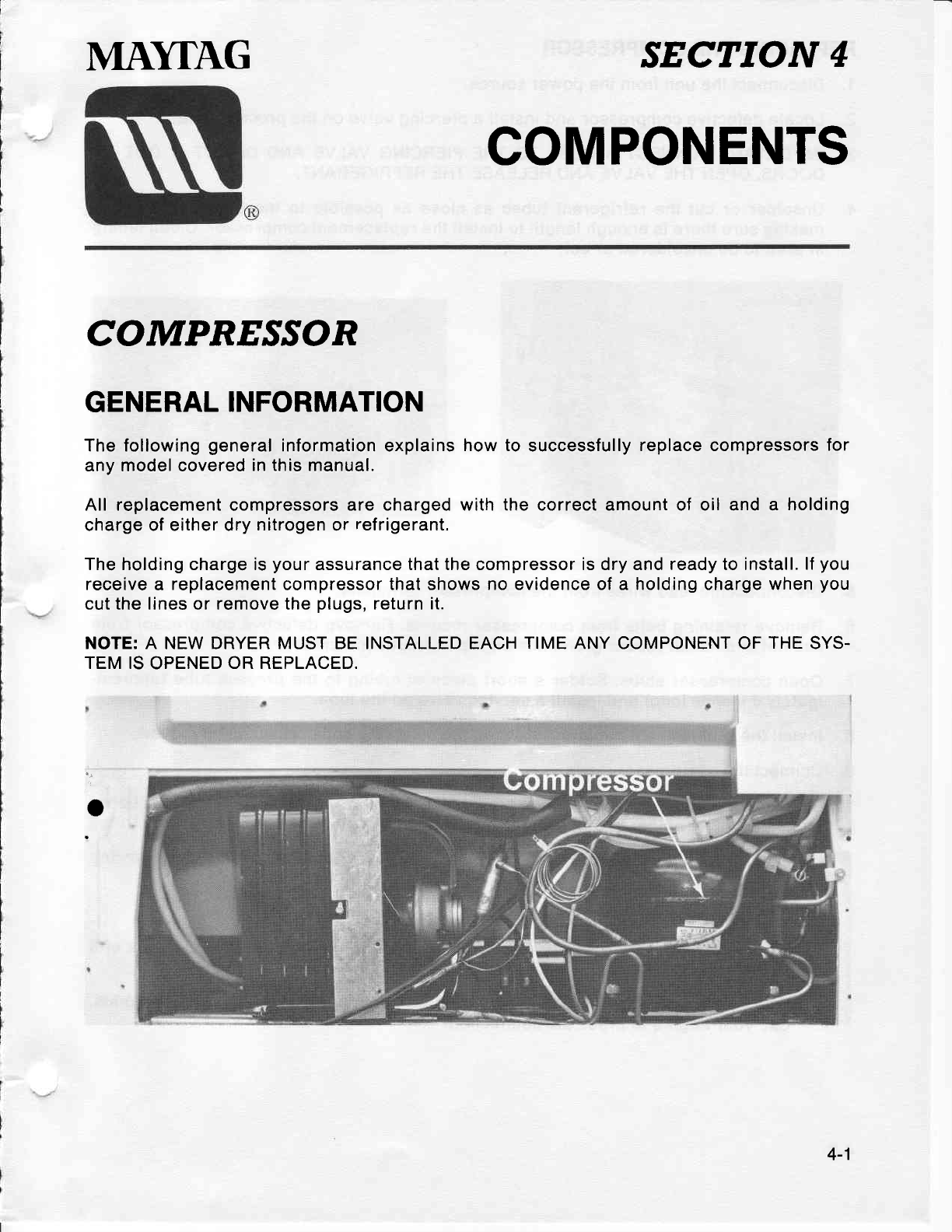
MAYTAG SECTION
4
COMPONENTS
COMPR.ESSON
GENERAL
INFORMATION
The following
general
information explains
how to successfully
replace compressors
for
any model covered
in this manual.
All replacement
compressors
are charged with the correct amount of oil and a holding
charge of either dry
nitrogen
or
refrigerant.
The holding charge is
your
assurance that the compressor is dry and ready to install.
lf
you
receive
a replacement
compressor
that shows no evidence of a holding charge when
you
cut the lines or remove the
plugs,
return it.
NOTE: A NEW DRYER MUST BE INSTALLED EACH TIME ANY COMPONENT OF
THE
SYS-
TEM IS
OPENED
OR REPLACED.
.
4-1
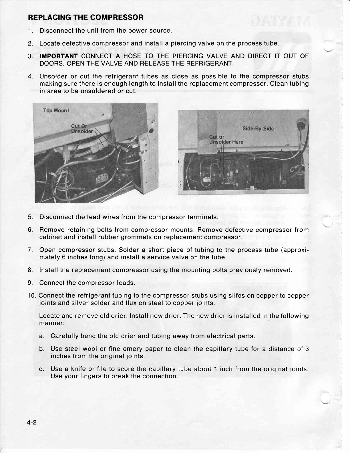
REPLACING THE COMPRESSOR
1. Disconnect the unit
from the
power
source,
2. Locate defective
compressor and install a
piercing
valve on the
process
tube.
3. IMPORTANT
CONNECT A HOSE
TO THE PIERCING VALVE
AND
DIRECT IT
OUT OF
DOORS. OPEN
THE VALVE AND RELEASE THE REFRIGERANT.
4. Unsolder
or cut
the refrigerant
tubes as close as possible
to the compressor stubs
making sure there is enough
length
to install the replacement compressor. Clean tubing
in area
to
be unsoldered or cut.
5. Disconnect
the lead wires from the compressor terminals.
6. Remove retaining
bolts
from
compressor mounts, Remove defective compressor from
cabinet
and
install
rubber
grommets
on
replacement
compressor.
7. Open compressor
stubs.
Solder a short
piece
of
tubing to the
process
tube
(approxi-
mately
6
inches long)
and
install
a service
valve
on the
tube.
8. Install the replacement compressor using the mounting bolts
previously
removed.
9. Connect
the
compressor
leads.
10.
Connect
the refrigerant
tubing
to the
compressor stubs using silfos on copper to copper
joints
and
silver
solder and flux
on steel
to copper
joints.
Locate
and
remove
old drier.
Install new
drier.
The new
drier is installed in the following
manner:
a. Carefully bend
the
old drier and
tubing
away lrom electrical
parts.
b. Use steel
wool
or
fine
emery
paper
to clean the capillary tube for
a distance of 3
inches from the
original
joints.
c. Use a knife
or file to score the capillary tube
about
1
inch
from
the
original
joints.
Use
your
fingers to
break the connection.
4-2
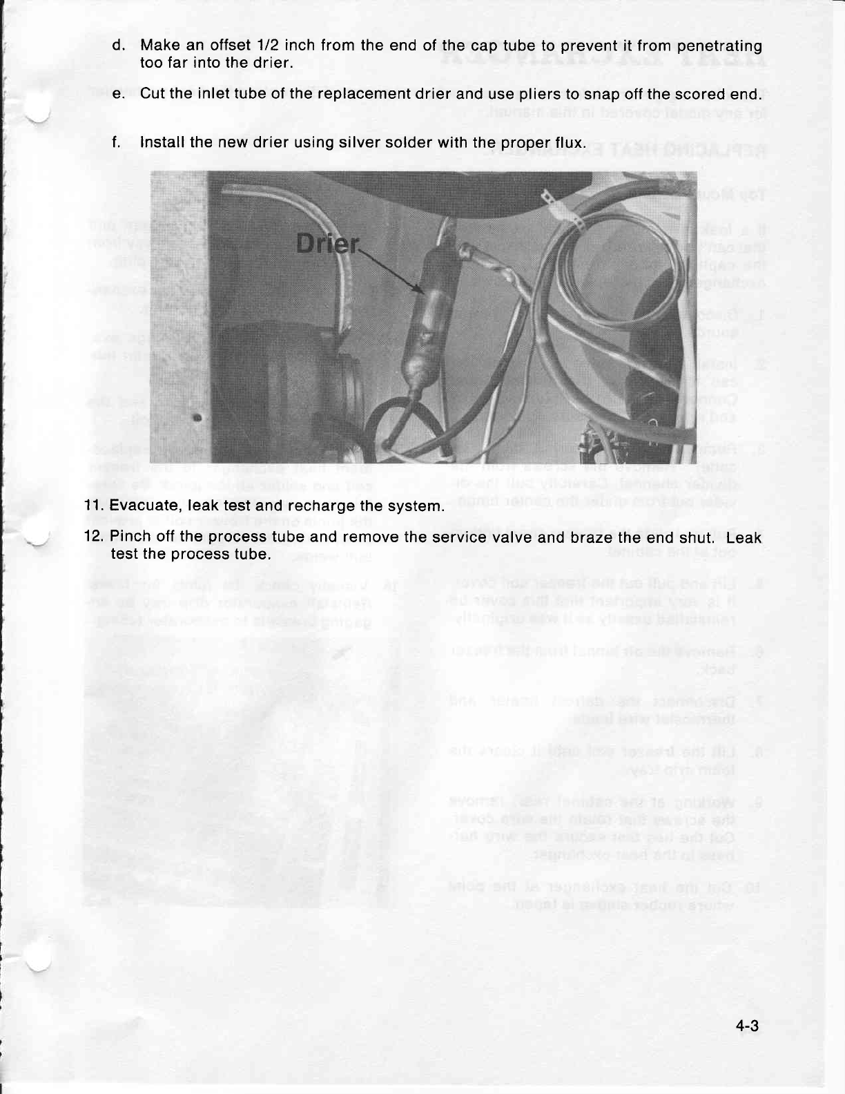
Make
an offset
1/2 inch
from the end
of
the
cap tube to
prevent
it from
penetrating
too far into the
drier.
Cut the inlet tube
of
the replacement
drier
and use
pliers
to
snap off
the
scored end.
lnstall the new
drier using silver solder with
the
proper
flux.
11.
Evacuate, leak test
and recharge the
system.
12. Pinch
off the
process
tube
and
remove
the
service valve
and braze the
end shut. Leak
test the
process
tube.
d.
e.
f.
4-3
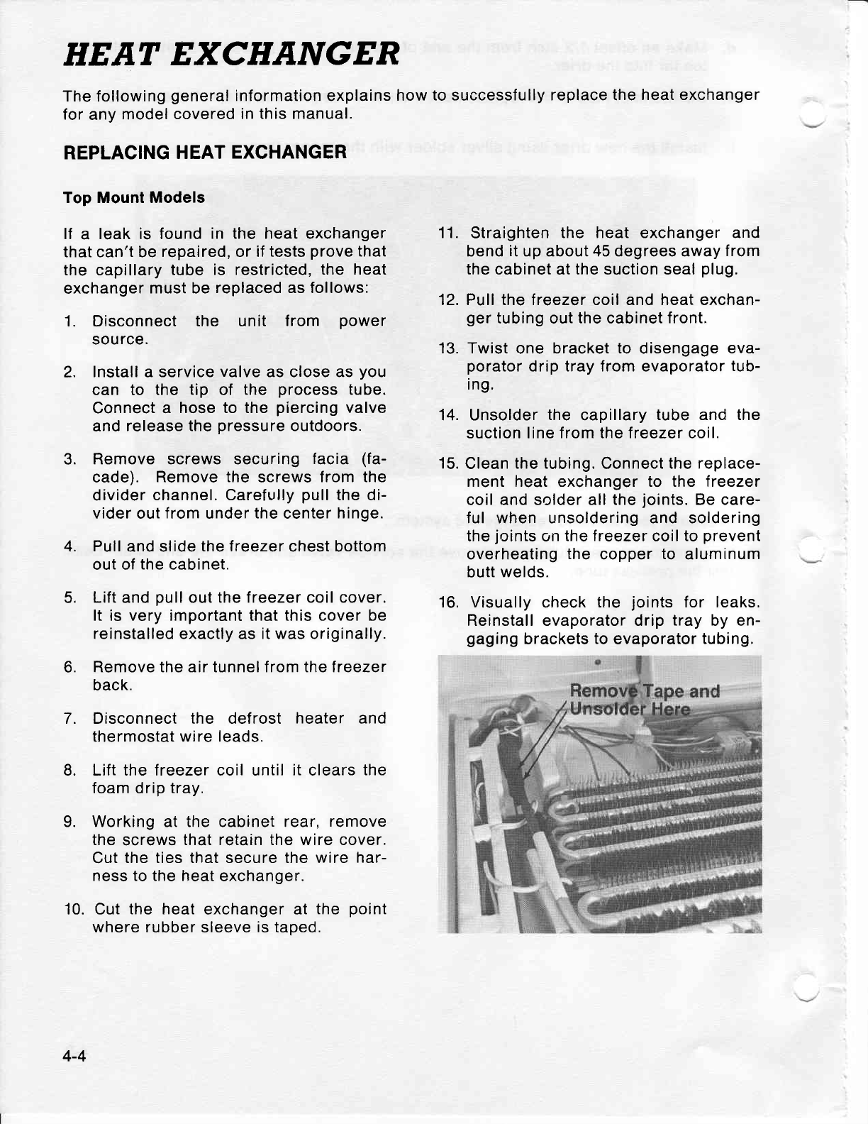
HEAT EXCHANGER
The following
general
information explains
how
to
successfully
replace the
heat exchanger
for
any
model
covered
in this manual.
REPLACING
HEAT
EXCHANGER
Top Mount Models
lf a leak is found
in the heat exchanger
that can't be
repaired, or if tests
prove
that
the capillary
tube is restricted,
the heat
exchanger
must be
replaced as follows:
1. Disconnect
the unit from power
source.
2. Install
a
service
valve
as close as
you
can to the tip of the process
tube.
Connect a hose to the
piercing
valve
and
release the
pressure
outdoors.
3. Remove screws securing
facia (fa-
cade). Remove the
screws
from the
divider
channel. Carefuf ly
pull
the di-
vider out
from
under
the
center
hinge.
4. Pull
and slide
the treezer
chest bottom
out of
the
cabinet.
5. Lift
and
pull
out
the freezer coil cover.
It is very important
that
this cover be
reinstalled exactly as it was originally.
6. Remove the air tunnel from the treezer
back.
7. Disconnect the defrost
heater and
thermostat
wire leads.
8. Lift the treezer coil until
it
clears
the
foam
drip
tray.
9. Working at the cabinet rear,
remove
the
screws
that retain the wire cover.
Cut
the ties that secure the wire
har-
ness to the heat
exchanger.
10. Cut the heat exchanger at the
point
where rubber
sleeve
is taped.
11.
Straighten
the heat exchanger and
bend
it up about 45 degrees away
f rom
the cabinet at
the
suction seal
plug.
12. Pull the freezer coil and heat exchan-
ger
tubing out
the
cabinet
front.
13. Twist
one bracket
to disengage
eva-
porator
drip tray from evaporator
tub-
ing.
14. Unsolder
the
capillary
tube and the
suction line from the freezer coil.
15.
Clean
the tubing.
Connect
the replace-
ment heat exchanger to the treezer
coil and solder
all the
joints.
Be care-
ful when unsoldering and soldering
the
joints
on
the treezer
coil
to
prevent
overheating
the
copper
to aluminum
butt
welds.
16. Visually
check
the joints
for leaks.
Reinstall evaporator drip tray by en-
gaging
brackets
to
evaporator
tubing.
4-4
17. Transfer
the rubber sleeve
to the re-
placement
heat exchanger and tape
both
ends.
18. Insert the
heat
exchanger
into
the tube
entry hole by
working it through
from
the front of the cabinet.
Push
it
all
the
way in until
the treezer coil
lines up
with the
foam drip tray.
19.
Working at the rear of the cabinet,
shape
the
heat
exchanger
as
the
ori-
ginal
was.
20. Clean and connect
the
suction
line
to
the
suction
stub of the compressor.
21. Cut or unsolder
the old drier.
22. Clean
the tube where the original drier
was connected
and install the new
drier.
1. Disconnect
the unit f
rom power
source.
23. Make an offset
1/2" lrom the end of
the
capillary
tube
and
insert into the new
drier.
24.
Solder
all connections.
Application
of
f lux is required
when using silver
solder.
25.
Visually
check all soldered
joints
for
leaks. Clean
the flux from the tubing.
Then
evacuate and
recharge the sys-
tem as instructed under
"Evacuating
and
Recharging."
26. Assemble all the
parts
in the reverse
order of removal.
Test run the refrigerator to make sure
it is
operating
properly.
Pinch the
process
tube and cut off
the
service
valve. Solder the
joint
and
test
for leaks.
This will allow easy
pinch-off
after
re-
charging
the
system.
Connect a hose
to the
service
valve
and slowly
release the pressure,
di-
recting
the
hose
outdoors.
Leave the
valve
open.
Unsolder suction
line from the suction
stub of
the
compressor.
27.
28.
REPLACING HEAT EXCHANGER
Side-By-Side Models
lf
a leak is found
in the heat
exchanger
that
can't be
repaired, or if tests
prove
that the
ca-
pillary
tube is restricted, the heat exchanger
must
be
replaced
as
follows:
5.
6.
2.
3.
4.
Remove the machine
cover.
Remove the tube clamp
exchanger.
lnstalt
a service valve
possible
to the tip of the
compartment
from the heat
as close as
process
tube.
4-5
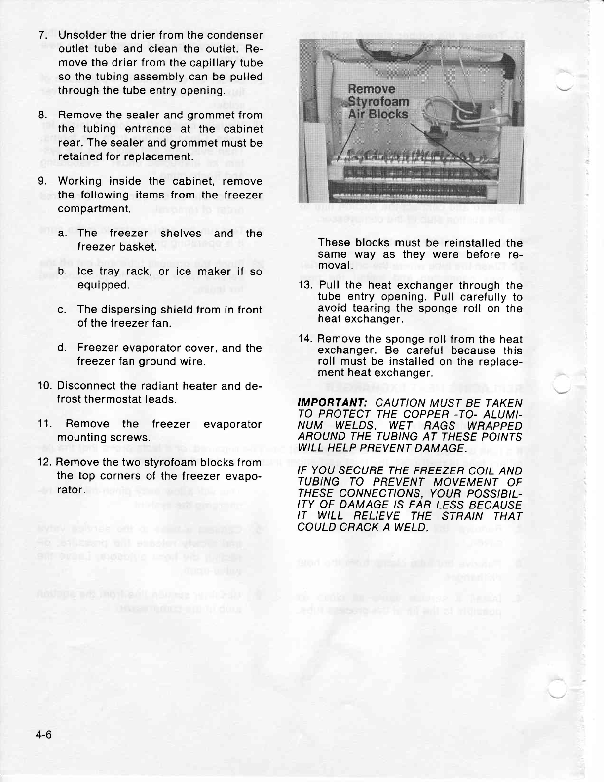
7.
8.
Unsolder the
drier
from the
condenser
outlet
tube
and clean the outlet. Re-
move the drier from the
capillary tube
so the tubing assembly
can be
pulled
through the tube
entry opening.
Remove
the
sealer
and
grommet
from
the tubing
entrance at the cabinet
rear. The sealer
and
grommet
must be
retained for replacement.
9. Working inside
the cabinet, remove
the following
items from the lreezer
compartment.
a. The treezer shelves and the
lreezer
basket.
b. lce tray rack,
or ice maker
if so
equipped.
c. The
dispersing
shield from in front
of the lreezer
tan.
d. Freezer
evaporator
cover, and the
treezer
fan
ground
wire.
10.
Disconnect the radiant
heater
and de-
frost thermostat
leads.
1 1. Remove the lreezer evaporator
mounting
screws.
12.
Remove the two
styrofoam
blocks from
the top
corners
of the treezer
evapo-
rator.
These
blocks
must be reinstalled
the
same way as they were before re-
moval.
13.
Pull the
heat
exchanger through
the
tube
entry
opening. Pull
carefully
to
avoid
tearing the
sponge roll on the
heat
exchanger.
14.
Remove
the
sponge roll from
the heat
exchanger.
Be careful
because this
roll must
be installed
on
the
replace-
ment
heat
exchanger.
IMPORTANT:
CAUTION MUST
BE TAKEN
TO PROTECT
THE
COPPER
-TO-
ALUMI-
NUM WELDS, WET RAGS WRAPPED
AROUND
THE TUBING
AT THESE
POINTS
WILL
HELP PREVENT
DAMAGE.
IF YOU
SECURE THE FREEZER
COIL AND
TUBING
TO PREVENT
MOVEMENT
OF
THESE
CONNECTIONS,
YOUR POSS/B/I-
ITY
OF DAMAGE
IS FAR
IESS BECAUSE
IT WILL RELIEVE
THE STRA/N THAT
COULD
CRACK A WELD.
4-6
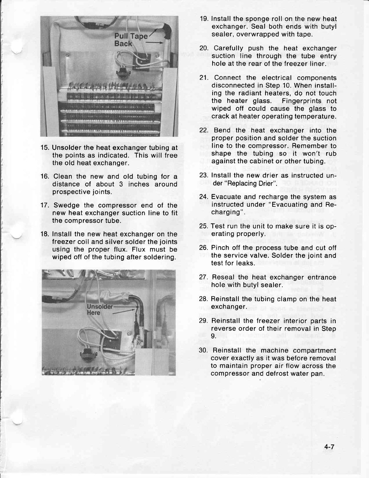
15.
16.
Unsolder
the
heat exchanger tubing
at
the
points
as
indicated. This
will free
the
old heat exchanger.
Clean the new
and old
tubing
for a
distance
of about 3 inches around
prospective
joints.
Swedge the compressor end of the
new heat exchanger
suction line to fit
the
compressor
tube.
Install the new
heat exchanger
on
the
treezer coil
and silver solder the
joints
using the proper
flux.
Flux
must be
wiped off of the tubing
after soldering.
22.
lnstall
the
sponge
roll
on
the
new heat
exchanger.
Seal both ends
with
butyl
sealer, overwrapped
with tape.
Carefully
push
the heat exchanger
suction line through
the tube entry
hole at the rear
ol the treezer liner.
Connect
the electrical components
disconnected
in Step 10. When install-
ing the radiant
heaters,
dq not touch
the heater
glass. Fingerprints
not
wiped
off could
cause the glass
to
crack at heater
operating temperature.
Bend the heat exchanger into the
proper position
and solder
the
suction
line to the
compressor. Remember
to
shape the tubing
so it won't rub
against the
cabinet or other tubing.
Install
the new drier
as instructed un-
der
"Replacing
Drier".
Evacuate
and
recharge
the
system as
instructed
under
"Evacuating
and Re-
charging
".
Test run
the unit to make
sure
it is
op-
erating
properly.
Pinch
off
the
process
tube
and cut off
the
service valve. Solder the
joint
and
test
for leaks.
Reseal
the heat
exchanger entrance
hole with
butyl
sealer.
Reinstall
the tubing
clamp on the heat
exchanger.
29. Reinstall the
lreezer interior
parts
in
reverse
order of their removal
in
Step
9.
30. Reinstall the machine
compartment
cover exactly as it was
before removal
to maintain
proper
air
flow
across the
compressor
and
defrost
water
pan.
19.
20.
21.
27.
28.
24.
23.
25.
26.
17.
18.
4-7
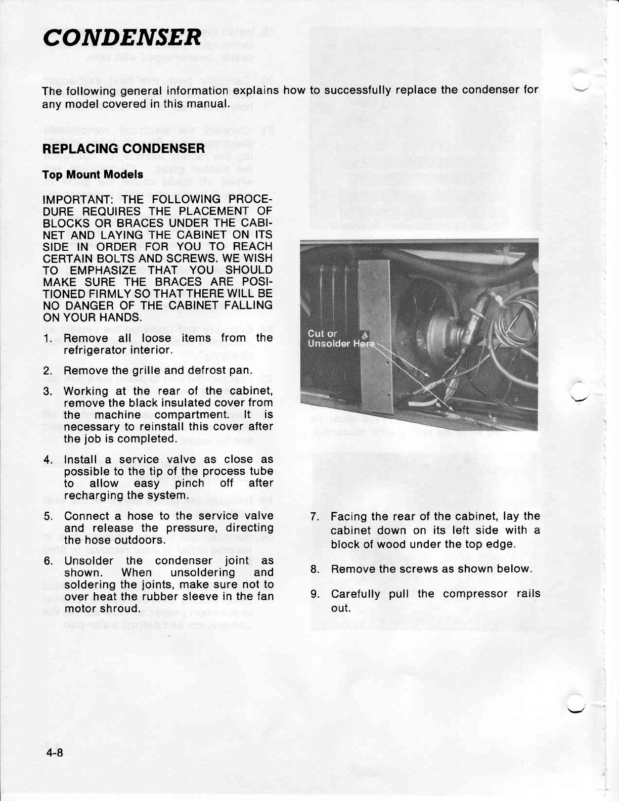
CONDEJVSER
The
following
general
any
model covered
in information
explains
this
manual. how
to
successfully
replace
the condenser
for
REPLACING
CONDENSER
Top
Mount
Models
IMPORTANT:
THE FOLLOWING
PROCE-
DURE
REQUIRES
THE PLACEMENT
OF
BLOCKS
OR BRACES
UNDER
THE CABI.
NET AND
LAYING THE CABINET
ON ITS
SIDE
IN ORDER
FOR
YOU TO REACH
CERTAIN
BOLTS
AND SCREWS.
WE
WISH
TO EMPHASIZE
THAT YOU SHOULD
MAKE SURE
THE BRACES
ARE POSI-
TIONED FIRMLY
SO THAT
THERE WILL
BE
NO DANGER OF
THE CABINET
FALLING
ON YOUR
HANDS.
1. Remove all loose items from the
ref
ri
gerator
i nterior.
2. Remove
the
grille
and defrost
pan.
3. Working
at the rear of the cabinet,
remove the black
insulated cover
from
the machine compartment.
lt is
necessary to reinstall this cover after
the
job
is
completed.
4. lnstall a service
valve as close as
possible
to the
tip
of
the
process
tube
to allow easy pinch off after
recharging
the system.
5. Connect
a hose
to the service
valve
and release
the pressure,
directing
the
hose outdoors.
6, Unsolder the condenser
joint as
shown. When unsoldering and
soldering
the
joints,
make sure
not to
over heat the
rubber sleeve
in the fan
motor shroud.
Facing
the rear of
the
cabinet,
lay the
cabinet down
on its left
side
with a
block of
wood under
the top edge.
Remove the screws
as shown
below.
Carefully
pull the compressor
rails
out.
7,
8.
9.
4-8
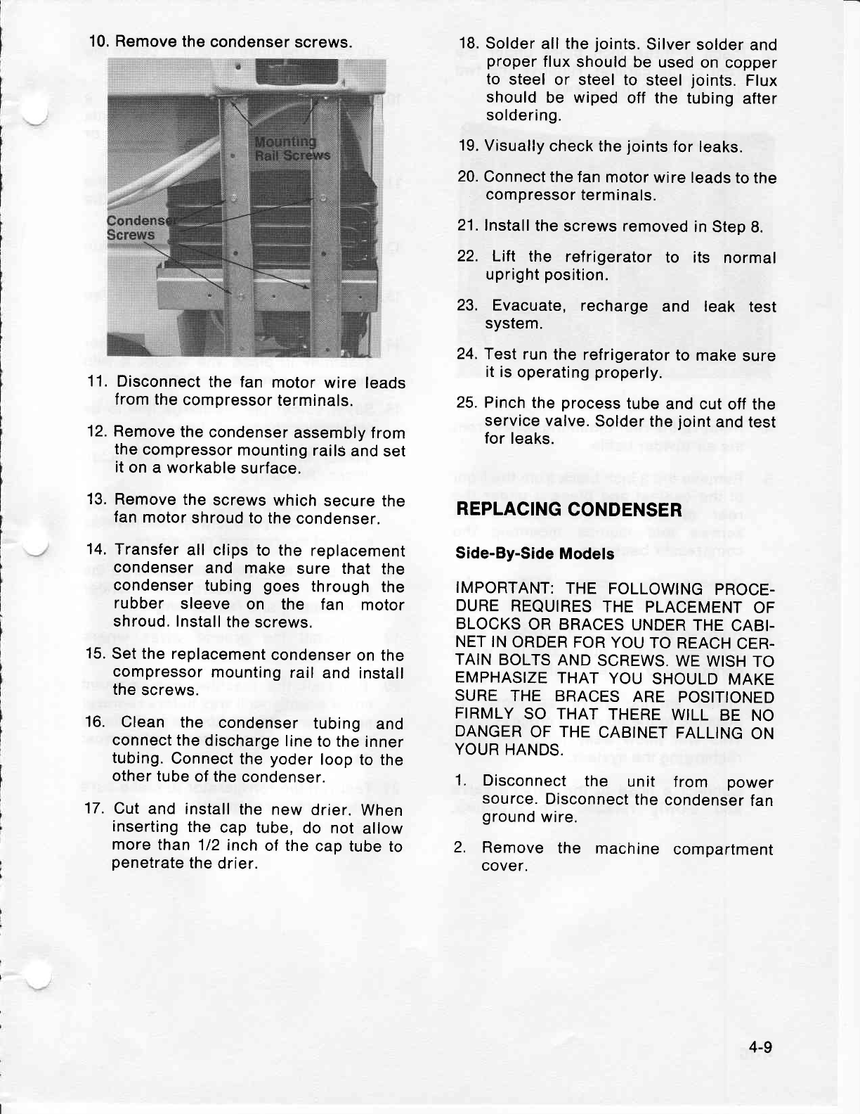
10. Remove the
condenser
screws.
11.
Disconnect
the fan
motor
wire leads
from the
compressor
terminals.
12. Remove
the
condenser
assembly from
the
compressor
mounting
rails
and
set
it
on
a workable
surface.
13.
Remove
the
screws
which
secure
the
fan
motor
shroud to
the
condenser.
14.
Transfer
all clips
to the replacement
condenser
and make sure that the
condenser
tubing
goes
through
the
rubber sleeve on the fan motor
shroud. Install
the
screws.
15.
Set the replacement
condenser
on the
compressor
mounting
rail
and install
the
screws.
16. Clean the condenser
tubing and
connect
the
discharge
line
to
the inner
tubing.
Connect
the
yoder
loop
to the
other
tube
of the
condenser.
17.
Cut
and install
the new
drier.
When
inserting
the
cap tube,
do not
allow
more
than
112 inch
of the
cap tube
to
penetrate
the
drier.
18.
Solder all the
joints.
Silver
solder
and
proper
flux
should
be used
on copper
to steel
or steel to steel
joints.
Flux
should
be wiped
off the tubing
after
soldering.
19.
Visually
check the
joints
for leaks.
20.
Connect
the fan
motor
wire leads
to the
compressor
terminals.
21. Install
the
screws removed
in
Step 8.
22. Lift the refrigerator
to its normal
upright
position.
23. Evacuate,
recharge and leak test
system.
24.
Test run
the
refrigerator
to
make
sure
it is
operating
properly.
25.
Pinch
the
process
tube
and cut
off the
service
valve.
Solder
the
joint
and test
for
leaks.
REPLACING
CONDENSER
Side-By-Side
Models
IMPORTANT:
THE FOLLOWING
PROCE-
DURE
REQUIRES
THE PLACEMENT
OF
BLOCKS
OR BRACES
UNDER
THE
CABI-
NET IN
ORDER FOR
YOU
TO
REACH
CER.
TAIN
BOLTS
AND
SCREWS.
WE
WISH
TO
EMPHASIZE
THAT
YOU
SHOULD
MAKE
SURE
THE BRACES
ARE POSITIONED
FIRMLY
SO THAT
THERE
WILL
BE NO
DANGER
OF
THE
CABINET
FALLING
ON
YOUR
HANDS.
1. Disconnect
the unit f rom power
source.
Disconnect
the
condenser
fan
ground
wire.
2. Remove
the machine
compartment
cover.
4-9
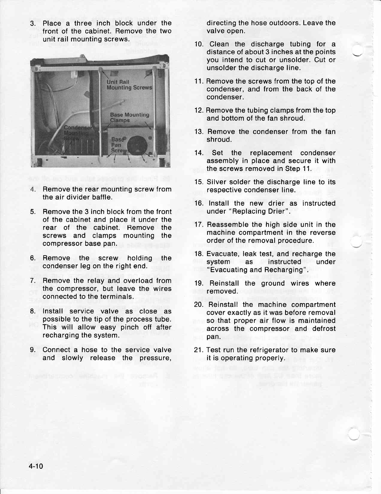
3. Place a three inch block
under
front of the cabinet.
Remove
the
unit
rail mounting screws.
Remove the rear mounting
screw
from
the
air divider baffle.
Remove the
3
inch
block
from the front
of the
cabinet
and
place
it under
the
rear of the cabinet.
Remove the
screws and clamps mounting
the
compressor base
pan.
Remove the screw holding the
condenser
leg
on
the
right end.
Remove the relay
and overload from
the compressor, but leave the wires
connected
to the
terminals.
Install service valve as close as
possible
to
the tip of the
process
tube.
This will allow
easy pinch
off after
recharging the
system.
Connect a hose to the service
valve
and slowly release the pressure,
directing
the hose outdoors.
Leave the
valve open.
10. Clean the discharge
tubing for a
distance
of about
3
inches
at
the
points
you
intend
to cut or unsolder. Cut or
unsolder the discharge line.
11. Remove the
screws
f rom the top of the
condenser. and
from the back of the
condenser.
12. Remove the
tubing clamps
from the top
and bottom of the fan shroud.
13. Remove the
condenser from
the
fan
shroud.
Set the replacement
condenser
assembly in place
and secure
it
with
the
screws
removed in
Step
11.
Silver solder
the
discharge line to its
respective condenser line.
lnstall the new drier as instructed
under
"Replacing
Drier".
Reassemble the high
side unit
in the
machine
compartment
in the reverse
order
of
the removal
procedure.
Evacuate,
leak test, and recharge the
system as instructed under
"Evacuating
and Recharging".
Reinstall the ground wires where
removed.
Reinstall the machine compartment
cover exactly as
it was
before
removal
so that
proper
air flow is maintained
across the compressor
and defrost
pan.
Test run the refrigerator to make sure
it is
operating
properly.
the
two
5.
14.
15.
16,
17.
18.
19.
20.
21.
L
o.
7.
8.
4-10
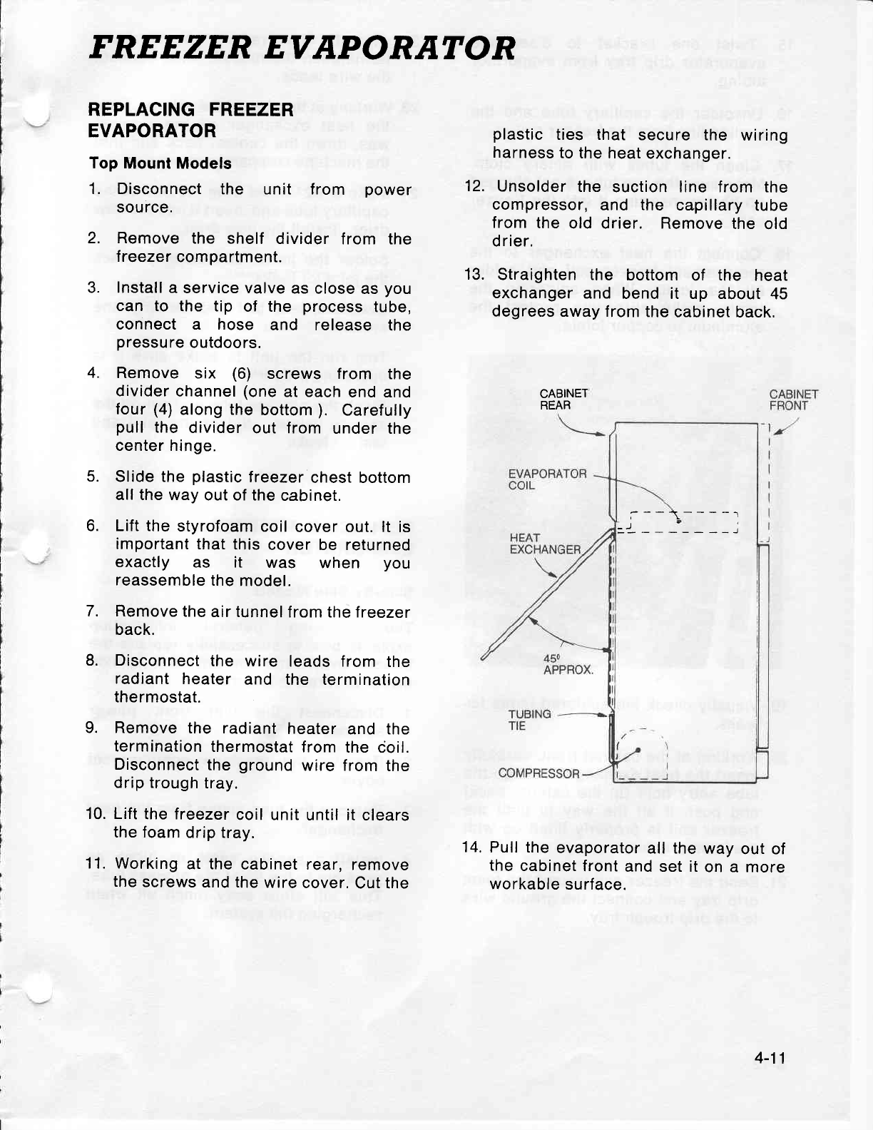
FREEZER EVAPORATOR
REPLACING FREEZER
EVAPORATOR
Top
Mount Models
1. Disconnect
the unit from power
source.
2. Remove
the shelf divider
from the
treezer
compartment.
3. Install
a service valve
as
close as
you
can to the tip of the process
tube,
connect a hose and release the
pressure
outdoors.
Remove
six (6) screws from the
divider
channel
(one
at each
end and
four
(4)
along the
bottom
). Carefully
pull
the divider
out from
under the
center hinge.
Slide the plastic
lreezer
chest bottom
all the way
out of the
cabinet.
Lift the
styrofoam
coil
cover out. lt is
important
that
this
cover be returned
exactly as it was when you
reassemble
the
model.
Remove
the
air tunnel
from the treezer
back.
Disconnect
the wire leads from the
radiant
heater
and the termination
thermostat.
Remove
the radiant
heater
and the
termination
thermostat
from
the coil.
Disconnect
the
ground
wire from
the
drip
trough
tray.
Lift
the lreezer
coil unit
until it clears
the foam
drip tray.
Working
at the
cabinet rear,
remove
the
screws
and the
wire
cover.
Cut the
12.
13.
plastic
ties that secure the wiring
harness
to the heat
exchanger.
Unsolder
the suction line from the
compressor,
and the capillary
tube
from
the old drier. Remove
the old
drier.
Straighten the bottom
of the heat
exchanger
and bend it up about
45
degrees away from
the
cabinet back.
CABINET
REAR
14.
Pull the
evaporator
all the way
out of
the
cabinet
front
and set it
on
a more
workable
surface.
4.
5.
6.
7.
8.
9.
10.
11.
---1-----l
=)---------i
4-11
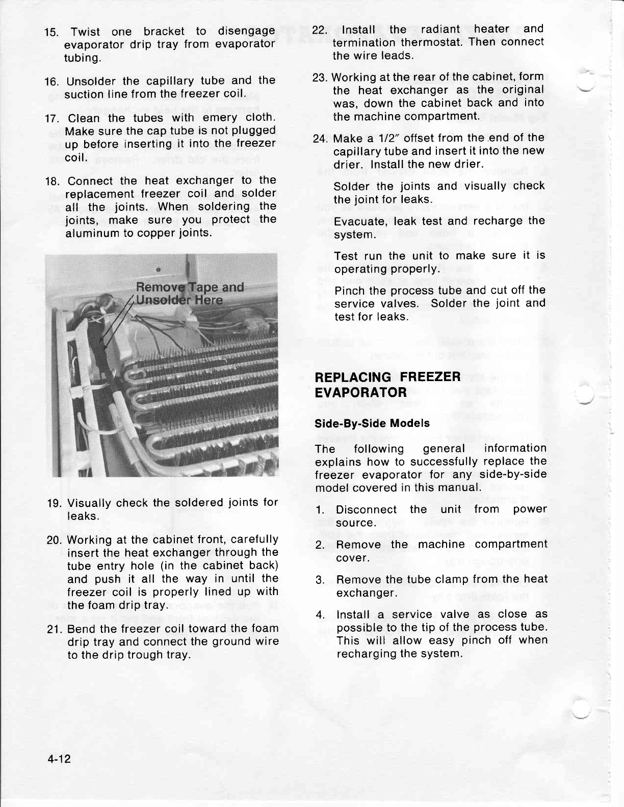
15.
16.
17.
19.
20.
21.
Twist one bracket to disengage
evaporator
drip
tray
from
evaporator
tubing.
Unsolder
the capillary
tube and the
suction
line
from
the
freezer
coil.
Clean
the tubes
with emery cloth.
Make sure
the cap
tube
is
not
plugged
up
before
inserting
it into
the
freezer
coil.
18. Connect
the heat
exchanger
to the
replacement
freezer
coil and solder
all the joints.
When
soldering
the
joints, make sure You Protect
the
aluminum
to copper
joints.
Visually check
the soldered
joints
for
leaks.
Working
at the cabinet
front, carefully
insert
the
heat exchanger
through
the
tube
entry
hole
(in
the cabinet
back)
and
push
it all the way in until
the
treezer coil
is
properly
lined
up
with
the
foam drip
tray.
Bend
the freezer
coil
toward the
foam
drip
tray and connect
the
ground
wire
to the drip
trough
tray.
22. lnstall the radiant heater and
termination
thermostat.
Then connect
the
wire leads.
23, Working
at the
rear of
the cabinet,
form
the heat exchanger
as the original
was,
down
the cabinet
back
and
into
the
machine
compartment.
24,
Make a 112" offset
from the.end
of
the
capillary
tube and
insert
it into
the new
drier.
Install
the
new drier.
Solder
the
joints
and
visually
check
the
joint
for
leaks.
Evacuate,
leak
test and
recharge
the
system.
Test
run the unit
to make
sure it is
operating
properly.
Pinch the
process
tube and
cut off
the
service
valves.
Solder
the
joint
and
test
for leaks.
REPLACING
FREEZER
EVAPORATOR
Side-By-Side
Models
The following general information
explains
how to successfully
replace
the
treezer evaporator
for any side-by-side
model covered
in this
manual.
1. Disconnect
the unit from Power
source.
2. Remove
the machine
comPartment
cover.
3. Remove
the
tube
clamp
from the
heat
exchanger.
4. Install a service
valve as close as
possible
to
the tip of
the
process
tube.
This will allow
easy
pinch
off
when
recharging
the system.
4-12
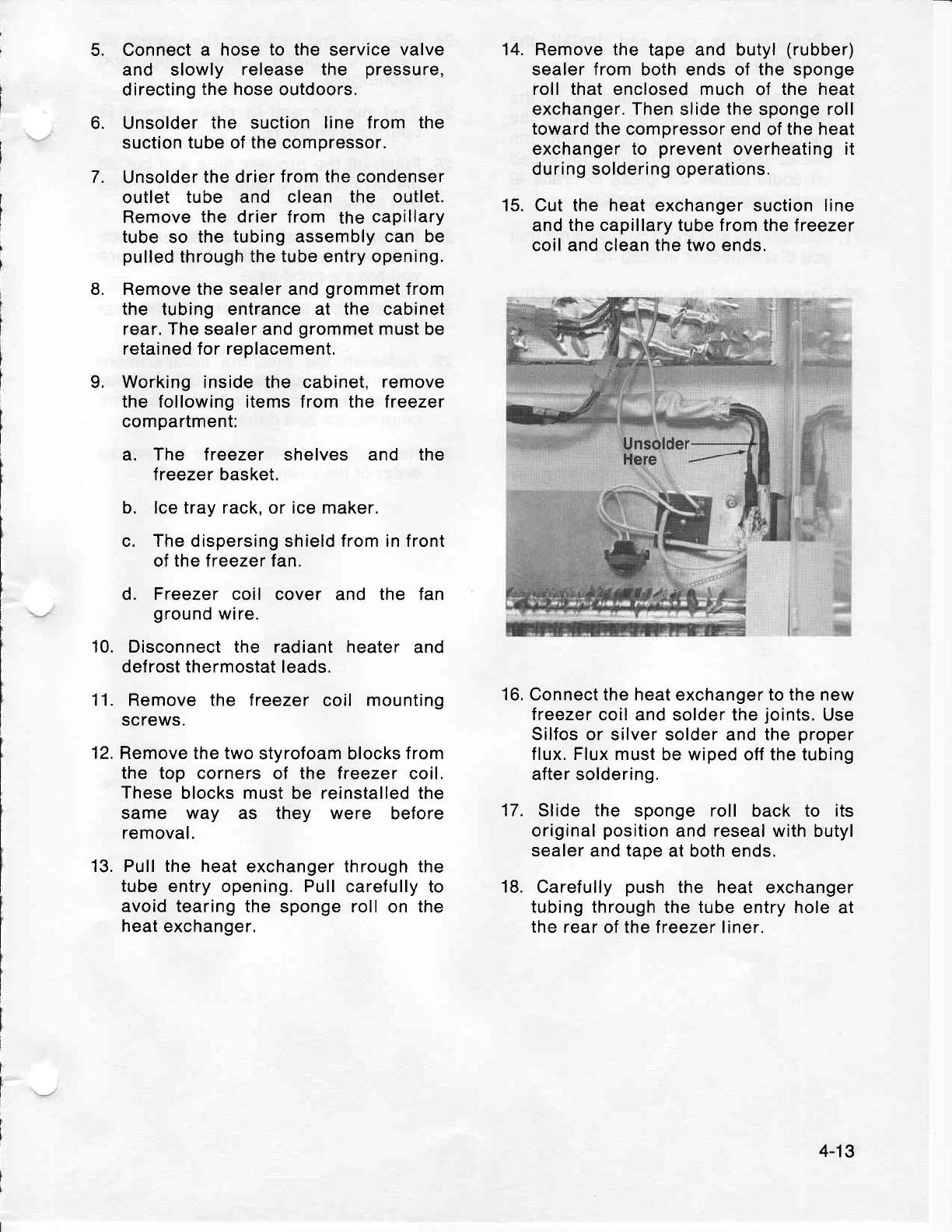
14.
5.
6.
7.
Connect
a hose to the service valve
and slowly release the pressure,
directing
the
hose
outdoors.
Unsolder
the suction line from the
suction
tube
of
the compressor.
Unsolder
the drier
from the
condenser
outlet tube and clean the outlet.
Remove
the drier
from the
capillary
tube
so the
tubing
assembly
can be
pulled
through the
tube
entry opening.
Remove the sealer
and
grommet
from
the tubing entrance at the cabinet
rear. The
sealer and
grommet
must be
retained for replacement,
Working
inside the cabinet,
remove
the following items from the treezer
compartment:
a. The treezer shelves and the
treezer basket.
b. lce tray rack, or ice maker.
c. The dispersing
shield
from in front
of the freezer fan.
d. Freezer coil cover and the fan
ground
wire.
Disconnect the radiant heater and
defrost thermostat
leads.
11. Remove the lreezer
coil mounting
screws.
12,
Remove the two
styrofoam blocks
from
the top corners
of the freezer
coil.
These
blocks must
be reinstalled
the
same way as they were before
removal.
13. Pull the heat
exchanger through the
tube entry opening. Pull
carefully to
avoid
tearing
the sponge roll on the
heat
exchanger.
Remove
the tape and butyl
(rubber)
sealer
from
both ends of the
sponge
roll that
enclosed
much
of the heat
exchanger.
Then
slide
the
sponge roll
toward the
compressor end of the heat
exchanger to prevent
overheating
it
during soldering operations.
Cut the heat
exchanger suction
line
and
the capillary tube from the
freezer
coil and clean the two ends,
16, Connect the heat
exchanger
to the new
treezer
coil and solder the
joints.
Use
Silfos or
silver solder and
the
proper
flux. Flux must
be wiped off the tubing
after soldering.
17. Slide the sponge roll back to its
original
position
and
reseal
with butyl
sealer
and
tape
at both ends,
18.
Carefully
push
the heat
exchanger
tubing through
the tube entry hole
at
the
rear of the lreezer liner.
15.
8.
9.
10.
4-13
19. Position
the coil and install the
mounting
screws.
20. Transfer
the radiant heaters
to the
replacement
coil.
When installing
the
radiant
heaters,
do not touch the
heater
glass. Fingerprints
not
wiped
off could
cause the glass
to crack
at
heater
operati ng tem
peratu
re.
21. Connect
the electrical
components
that
you
disconnected
in
Step 10.
22.
Caretully
bend the lower
portion
of the
heat exchanger
into the machine
compartment
and
resolder
the
suction
line
to the
compressor.
Remember
to
shape the tubing so it won't rub
against
the
cabinet
or other wiring.
23. lnstall
a new
drier
as
instructed
under
"Replacing
Drier".
Then leak
test
all
joints.
24. Evacuate
and recharge
the system
as
instructed
under "Evacuating
and
Rechargi
ng
".
25.
Test run
the unit to make
sure it is
operating
properly.
26. Pinch
off the
process
tube
and cut
off
the
service
valve.
Solder
the
joint
and
test for
leaks.
27.
Reseal
the heat
exchanger
entrance
hole
with butyl
sealer, making
sure
you
have
a
good
seal.
28. Reinstall
the
tubing
clamp
on the heat
exchanger.
29. Reinstall
the machine
compartment
cover
exactly
as
it
was
before removal
to
maintain
proper
air flow across
the
compressor
and defrost
pan.
30. Reinstall
the
freezer
parts
in reverse
order
of their removal
in
Step
9.
4-14
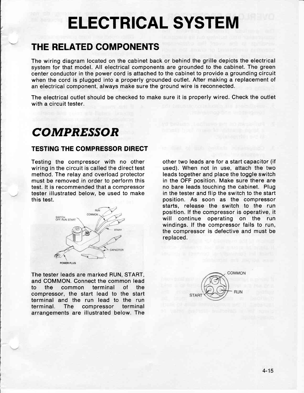
ELECTRICAL
SYSTEM
THE RELATED COMPONENTS
The
wiring
diagram
located on the cabinet back
or behind the
grille
depicts
the electrical
system for that
model. All electrical components
are
grounded
to the cabinet.
The
green
center
conductor
in the
power
cord is attached
to the cabinet
to
provide
a
grounding
circuit
when the
cord
is
plugged
into
a properly grounded
outlet.
After making a replacement
of
an electrical component,
always
make
sure
the
ground
wire is reconnected.
The
electrical
outlet should be checked
to make
sure
it is
properly
wired.
Check
the outlet
with a circuit tester.
COMPR^ESSOR
TESTING THE COMPRESSOR
DIRECT
Testing the compressor with no other
wiring in the circuit is called the direct
test
method. The relay and overload
protector
must
be
removed in order to
perform
this
test. lt is recommended
that
a compressor
tester illustrated below. be used
to make
this test.
The tester leads
are
marked RUN, START,
and COMMON. Connect
the
common
lead
to the common terminal of the
compressor,
the start lead to the start
terminal
and the run lead to the run
terminal. The compressor terminal
arrangements are illustrated below. The
other two
leads
are
for
a start
capacitor
(if
used). When not in use, attach
the two
leads together and
place
the toggle switch
in the OFF
position.
Make
sure
there are
no bare leads touching
the cabinet. Plug
in the
tester
and
flip the
switch
to the start
position.
As soon as the compressor
starts, release the switch to the run
position.
lf the
compressor
is operative,
it
will continue
operating on the run
windings. lf the compressor fails
to run,
the compressor
is defective and must be
replaced.
4-15
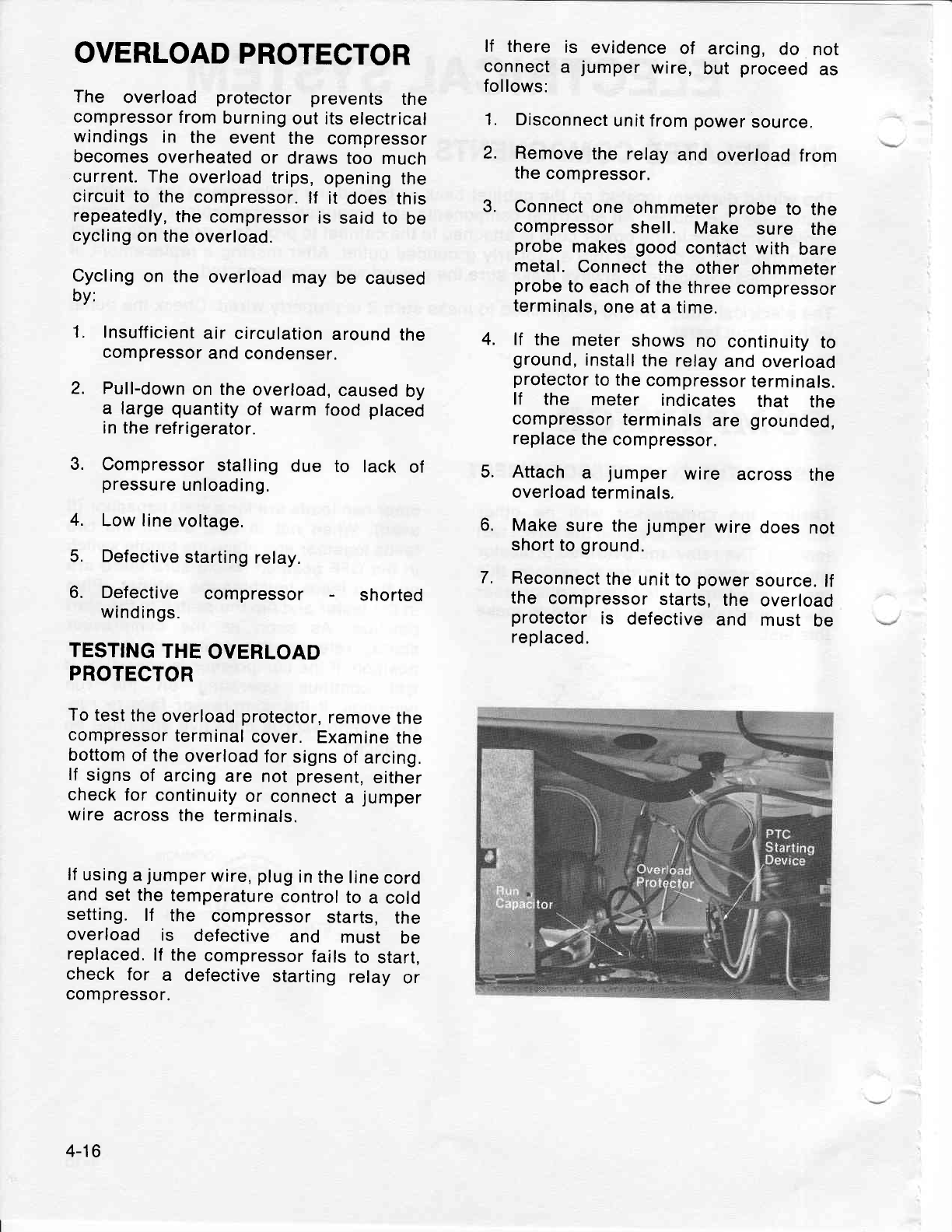
OVERLOAD
PROTECTOR
The overload protector prevents the
compressor
from
burning
out its
electrical
windings
in the event
the compressor
becomes
overheated
or draws
too much
current. The
overload
trips,
opening
the
circuit
to the
compressor.
lf it does this
repeatedly,
the
compressor
is
said to be
cycling
on the
overload.
Cycling
on the
overload
may
be caused
by:
1. Insufficient
air circulation
around
the
compressor
and
condenser.
2. Pull-down
on the
overload,
caused
by
a large
quantity
of
warm
food
placed
in the
refrigerator.
3. Compressor
stalling
due to lack of
pressure
unloading.
4. Low line
voltage.
5. Defective
starting
relay.
6. Defective compressor - shorted
windings.
TESTING
THE
OVERLOAD
PROTECTOR
To
test
the
overload
protector,
remove
the
compressor
terminal
cover.
Examine
the
bottom
of the
overload
for
signs
of arcing,
lf signs
of arcing
are
not
present,
either
check
for
continuity
or
connect
a jumper
wire across
the
terminals.
lf
using
a
jumper
wire,
plug
in
the
line
cord
and
set
the temperature
control
to
a cold
setting.
lf the compressor
starts,
the
overload is defective
and must be
replaced.
lf the
compressor
fails
to start,
check
for a defective
starting
relay
or
compressor.
lf there is evidence
of arcing,
do not
connect
a jumper
wire,
but proceed
as
follows:
1. Disconnect
unit from
power
source.
2. Remove
the
relay
and
overload
from
the
compressor.
3. Connect
one
ohmmeter
probe
to the
compressor
shell. Make sure the
probe
makes
good
contact
with
bare
metal.
Connect
the other
ohmmeter
probe
to
each
of the three
compressor
terminals,
one
at
a
time.
4. lf the meter
shows
no continuity
to
ground,
install
the
relay
and
overload
protector
to the
compressor
terminals.
lf the meter indicates that the
compressor
terminals
are grounded,
replace
the
compressor.
5. Attach a jumper wire across the
overload
terminals,
6. Make
sure
the
jumper
wire
does
not
short
to
ground.
7, Reconnect
the
unit
to
power
source.
lf
the compressor
starts,
the overload
protector
is defective
and must be
replaced.
4-16
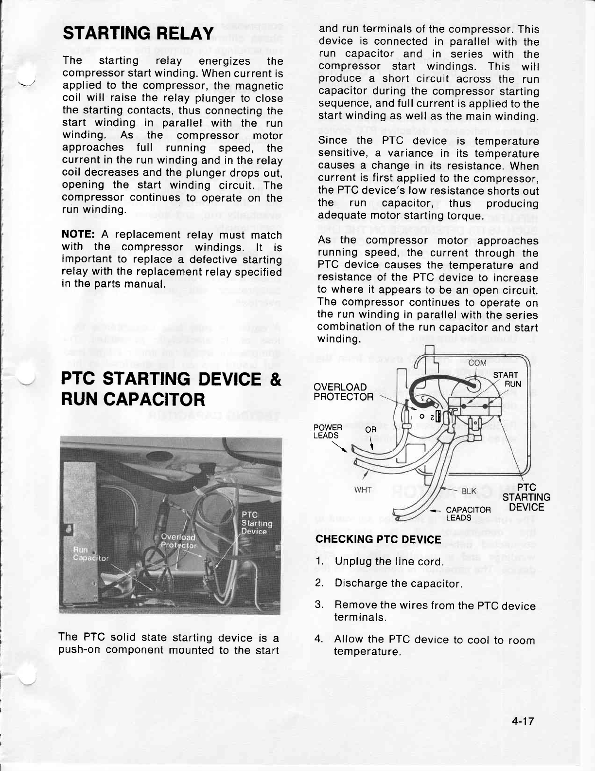
STARTING RELAY
The starting relay energizes the
compressor
start winding.
When current
is
applied to the
compressor,
the magnetic
coil will raise
the relay
plunger
to
close
the
starting contacts,
thus
connecting
the
start
winding in parallel
with the run
winding. As the compressor motor
approaches
f
ull running speed, the
current
in the run
winding
and in the
relay
coil
decreases
and
the
plunger
drops out,
opening the start winding
circuit. The
compressor
continues
to operate
on the
run winding.
NOTE:
A replacement
relay
must
match
with the compressor
windings. lt is
important
to replace
a defective
starting
relay
with the
replacement
relay
specified
in
the
parts
manual.
and run
terminals
of the
compressor.
This
device is connected
in parallel
with
the
run capacitor
and in series with the
compressor
start windings.
This will
produce
a short
circuit
across
the run
capacitor
during
the
compressor
starting
sequence,
and
full
current is
applied to
the
start winding
as
well
as
the
main
winding.
Since the PTC device is temperature
sensitive,
a variance
in its temperature
causes
a change
in its
resistance.
When
current
is first
applied
to the
compressor,
the PTC
device's
low
resistance
shorts
out
the run capacitor, thus producing
adequate
motor
starting torque.
As the compressor
motor approaches
running
speed,
the current
through
the
PTC
device
causes the
temperature
and
resistance
of the PTC
device to increase
to
where
it
appears
to
be an
open circuit.
The
compressor
continues
to operate
on
the run
winding
in
parallel
with the
series
combination
of the
run
capacitor
and
start
winding.
START
PTC
STARTING
DEVICE
&
RUN
CAPACITOR OVERLOAD
PROTECTOR ,_
o
,[n
RUN
PTC
STARTING
DEVICE
OR
\
POWER
LEADS
The
PTC
solid
state
starting
push-on
component
mounted
+ CAPACITOR
LEADS
CHECKING
PTC
DEVICE
1. Unplug
the line
cord.
2. Discharge
the
capacitor.
3. Remove
the
wires
from
the
pTC
device
terminals.
4. Allow
the
PTC
device
to
cool to room
temperature,
device is a
to the start
4-17
5. Remove the PTC device from the
compressor.
6. Using an ohmmeter, check the
resistance
between
the PTC
device
terminals.
The ohmmeter should
register
between
3 and
20 ohms.
An extreme
variance
from
between
3 and
20 ohms
indicates
a defective
PTC d'evice
which
must be
replaced.
NOTE: WE DISCOURAGE
USING A
VOLTMETER TO CHECK THE
PERFORMANCE
OF THE PTC DEVICE
BECAUSE
THE TEST RESULTS
ARE
INFLUENCED
BY SEVERAL
FACTORS,
SUCH
AS
ITS DEPENDENCE
ON
THE LINE
VOLTAGE
TO THE COMPRESSOR,
THE
RESPONSE
CHARACTERISTIC
OF THE
VOLTMETER
AND THE PTC DEVICE
TEMPERATURE
AT THE TIME THE
COMPRESSOR
IS ENERGIZED.
REPLACING
PTC
DEVICE
1. Unplug
the
line cord.
2. Disconnect
the PTC device
from the
compressor
terminals.
3. Remove
the
lead wires
from
the PTC
device
terminals.
4. Replace
the device and
reconnect
the
wires
to the
proper
terminals.
RUN
CAPACITOR
The run capacitor
is mounted adjacent
to
the compressor. lt is electrically
connected
between
the run and start
windings
and in parallel
with
the PTC
device.
The capacitor
is connected
to the
compressor
circuit
to
provide
the required
phase
difference
between
the start and
run
windings
for running
the compressor.
CAPACITOR
FAILURES
Failure
of the capacitor
may
be caused
by
(1)
a short
circuit,
(2)
open
circuit,
(3)
a
capacitor
that is low
in capacitance.
A short circuit will cause the start
windings
to be energized
in the start
mode
all the time.
The compressor
could
start
but the overload protector would
eventually
trip, and
sooner
or later, trip
continuously.
An open circuit
should,
under normal
conditions,
allow
the compressor
to
start.
Under
a heavy
running
load, however,
the
compressor
will usually
trip on the
overload.
A capacitor
may lose capacitance
by a
loss of its electrolytic
properties.
The
compressor
would
run under
a light
load,
but
would trip,on
the overload
in high
ambient
conditions.
TESTING CAPACITOR
CAUTION: DISCHARGE
A CAPACITOR
BEFORE
HANDLING.
SHORT
ACROSS
/TS
TERMINALS,
US/NG
A RES/STOR
WITH A
MINIMUM
RES/STANCE
OF
lOOO OHMS,
We recommend using a caPacitor
analyzer
when
testing.
Preferably
a solid
state
unit
that measures
capacitance
and
power
factor
of any capacitor,
and
has an
automatic
means of discharging
the
capacitor
through
resistance.
4-18
ALTERNATE METHOD
USING OHMMETER
1. Unplug the line
cord.
2. Disconnect
the capacitor lead
wires.
3. Short
across
the
terminals
using a resistor
with
a minimum
resistance
of
1000
ohms to
be
sure
no
charge remains
to damage the
ohmmeter.
4. Set the
ohmmeter
selector
switch
to
the 10,000
ohm scale
(Rx10K).
5. Connect
the ohmmeter
leads to the
capacitor
terminals
and observe the meter
pointer
low
end.
a. lf
the
pointer
deflects
to the low
end and remains
there,
the capacitor
is shorted
and
must
be
replaced.
b. lf
there is no
deflection
of the
pointer,
the
capacitor is
open and must
be replaced.
c. lf the pointer
deflects toward
the
high
end of the
scale
and then slowly returns
toward
the low
end, the
capacitor is
good.
4-19
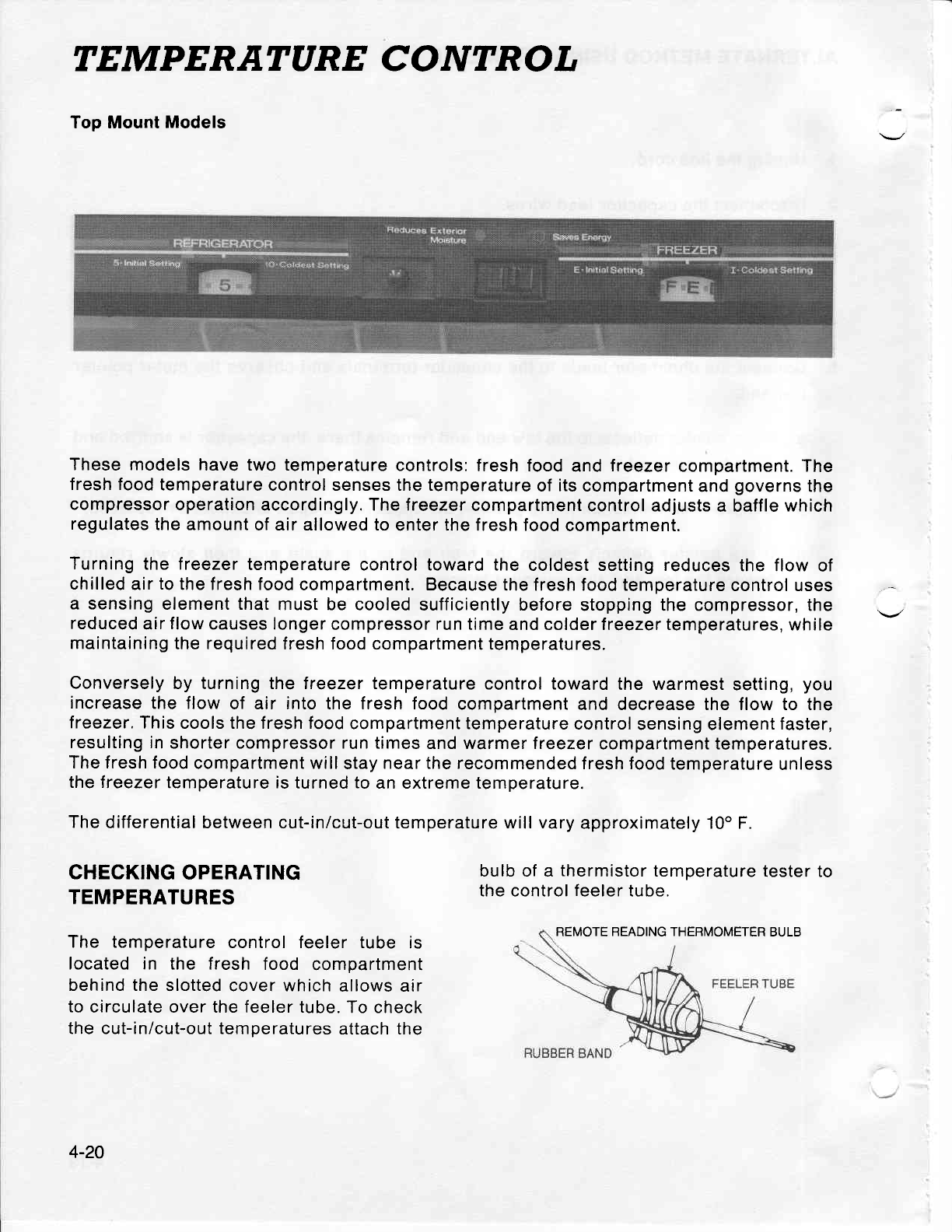
TEMPERATARE CONTROL
Top Mount Models
These models
have two temperature
controls:
fresh food
and
treezer
compartment. The
fresh food
temperature
control senses the temperature
of
its
compartment
and
governs
the
compressor
operation
accordingly. The freezer
compartment
control adjusts
a baffle
which
regulates
the amount
of air allowed to
enter the fresh food
compartment.
Turning
the freezer
temperature
control toward the
coldest setting reduces
the flow
of
chilled
air
to
the fresh food
compartment. Because
the fresh food temperature
control uses
a sensing
element that
must be cooled
sufficiently before
stopping the compressor, the
reduced
air
flow
causes longer
compressor run time
and colder treezer temperatures,
while
maintaining
the required
fresh food compartment
temperatures.
Conversely
by turning the treezer temperature
control toward
the warmest
setting,
you
increase
the flow
of air into the fresh food
compartment
and decrease the flow to the
f reezer. This
cools the f resh food
compartment temperature
control
sensing element
faster,
resulting in
shorter compressor run
times and warmer treezer
compartment temperatures.
The fresh food
compartment will
stay
near the recommended
f resh food
temperature
unless
the freezer
temperature is
turned
to
an extreme temperature.
The
differential
between cut-in/cut-out temperature will vary
approximately 10o F.
CHECKING
OPERATING
TEMPERATURES
The temperature
control feeler tube is
located in the fresh food compartment
behind the
slotted cover which
allows air
to
circulate over the feeler tube.
To check
the cut-in/cut-out temperatures
attach the
bulb of a
thermistor
temperature
tester to
the control
feeler
tube.
REMOTE READING THERMOMETER
BULB
4-20
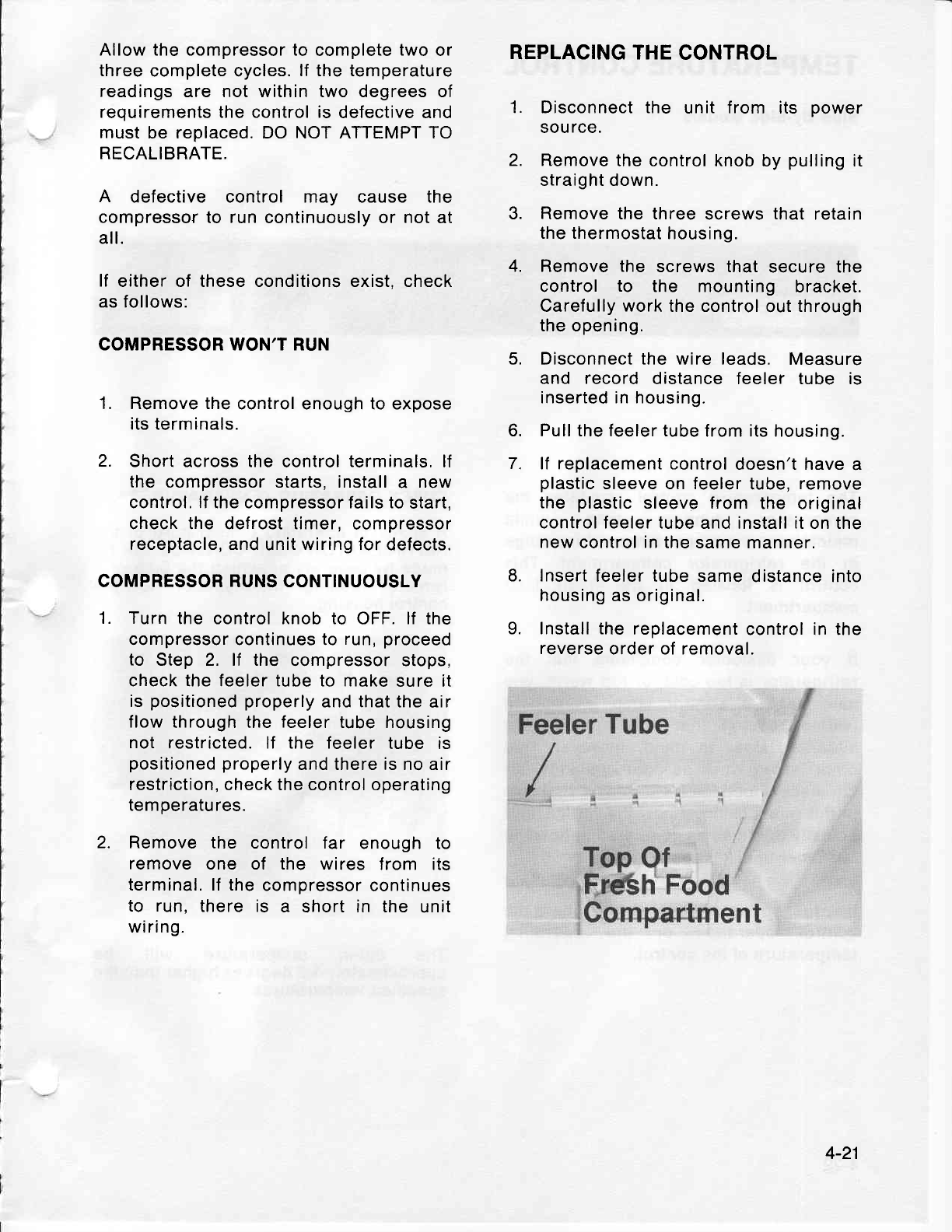
Allow the compressor to
complete
two
or
three
complete cycles.
lf the temperature
readings
are not within two degrees of
requirements the control is
defective and
must
be replaced. DO NOT ATTEMPT TO
RECALlBRATE.
A defective control may cause the
compressor to run
continuously or not
at
all.
lf either of these conditions exist, check
as follows:
COMPRESSOR WON'T RUN
1, Remove the
control enough to expose
its terminals.
2. Short across the
control
terminals,
lf
the compressor starts, install
a new
control, lf the compressor fails to
start,
check the defrost timer,
compressor
receptacle, and
unit
wiring for
defects.
COMPRESSOR RUNS CONTINUOUSLY
Turn
the control knob to OFF.
lf the
compressor continues to
run,
proceed
to Step 2. lf the compressor stops,
check the feeler tube to make
sure it
is
positioned properly
and that the
air
flow
through the
feeler
tube housing
not restricted. lf the feeler
tube is
positioned
properly
and there is no air
restriction,
check the control operating
temperatures.
Remove
the control lar enough to
remove
one of the wires from its
terminal. lf the
compressor
continues
to run,
there is a short
in the unit
wiring.
REPLACING THE
CONTROL
1. Disconnect the unit from its power
sou
rce.
2. Remove
the control knob
by
pulling
it
straight down.
3. Remove the three
screws
that
retain
the thermostat
housing.
4. Remove the screws that
secure the
control to the mounting bracket.
Carefully
work
the control
out
through
the
opening.
5, Disconnect the wire leads,
Measure
and record
distance feeler tube is
inserted in housing.
6. Pull the feeler tube
from its housing.
7. lf replacement control
doesn't have
a
plastic
sleeve on feeler
tube,
remove
the plastic
sleeve from the original
control feeler tube
and install it on the
new
control
in
the same manner.
8. Insert
feeler tube same
distance into
housing
as original.
9. Install the
replacement
control in the
reverse
order of removal.
1.
2.
4-21
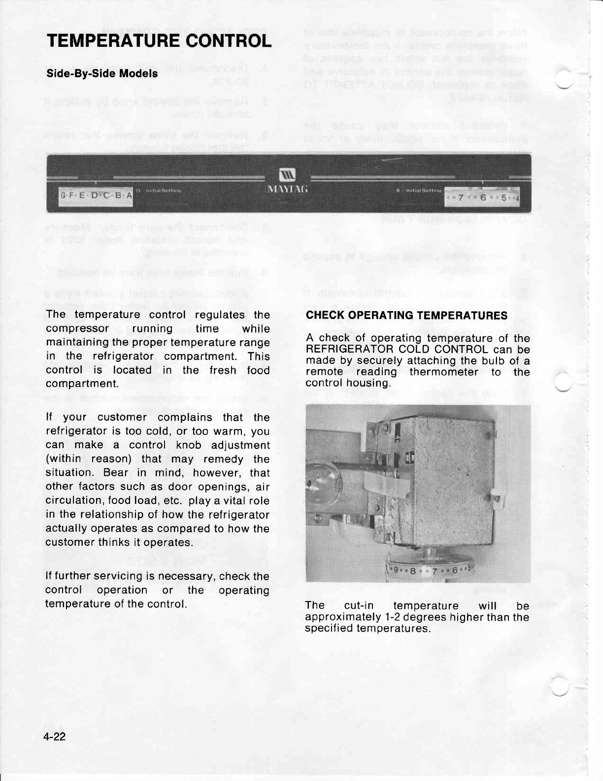
TEMPERATURE
CONTROL
Side-By-Side Models
The temperature
control regulates
the
compressor running time while
maintaining
the
proper
temperature
range
in the ref rigerator
compartment.
This
control is located in the f resh food
compartment.
lf your customer
complains
that the
refrigerator
is too
cold,
or too
warm,
you
can make a control knob adjustment
(within reason)
that may remedy the
situation. Bear in mind,
however, that
other factors
such
as door openings,
air
circulation,
food load,
etc.
play
a vital role
in
the relationship
of how
the refrigerator
actually operates
as compared
to how
the
customer thinks
it operates.
lf
further
servicing is necessary,
check the
control operation or the operating
temperature
of the
control.
CHECK OPERATING
TEMPERATURES
A check of operating temperature
of the
REFRIGERATOR
COLD CONTROL
can
be
made
by
securely
attaching
the bulb
of a
remote reading thermometer
to the
control housing.
The cut-in temperature will be
approximately
1-2
degrees
higher than
the
specif ied
temperatures.
4-22
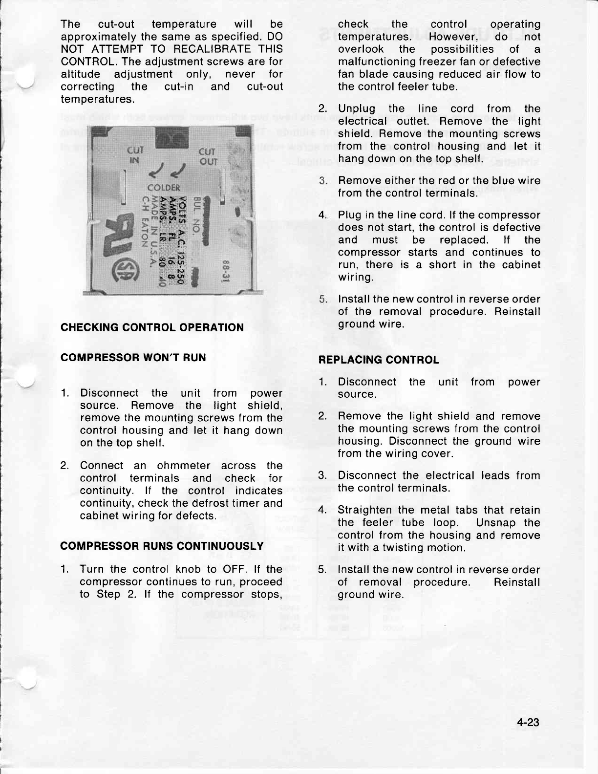
The cut-out temperature will be
approximately the same as specified. DO
NOT ATTEMPT TO RECALIBRATE
THIS
CONTROL. The adjustment screws are
for
altitude adjustment only, never for
correcting the cut-in and cut-out
temperatures.
CHECKING
CONTROL
OPERATION
COMPRESSOR WON'T RUN
1. Disconnect
the unit from power
source. Remove the light shield,
remove the
mounting screws from the
control housing and let it hang
down
on the top
shelf.
2. Connect an ohmmeter
across the
control terminals and check for
continuity.
lf the control indicates
continuity, check the
defrost
timer
and
cabinet
wiring
for defects,
COMPRESSOR RUNS
CONTINUOUSLY
1. Turn the control
knob to OFF.
lf the
compressor continues to run,
proceed
to Step 2. lf the compressor stops,
check the control operating
temperatures. However, do not
overlook the possibilities
of a
malfunctioning
f reezer fan
or defective
fan blade
causing
reduced
air
flow to
the control feeler tube.
Unplug the line cord f rom the
electrical outlet. Remove the light
shield. Remove the mounting
screws
from the control housing
and let it
hang
down on
the top
shelf.
Remove
either the red or the
blue
wire
from the control terminals.
Plug in the line
cord. lf the compressor
does
not
start. the control is defective
and must be replaced. lf the
compressor
starts and continues
to
run, there is a short
in the
cabinet
wiring.
Install
the new control in reverse order
of the removal
procedure,
Reinstall
ground
wire.
REPLACING
CONTROL
1. Disconnect the unit f rom power
source.
2. Remove the light
shield and
remove
the mounting
screws
from the
control
housing. Disconnect the
ground
wire
from
the wiring cover.
3. Disconnect the electrical
leads
from
the control terminals.
4. Straighten the metal tabs that retain
the feeler
tube loop. Unsnap
the
control from the housing
and remove
it with
a
twisting motion,
5. Install
the new control in reverse
order
of removal procedure, Reinstall
ground
wire.
2.
4.
:Y,:::k
33
'9t
ln trt
t...:.t .:.
t-:;t
:f,1 l:
,,
,::'
:..".:''..
:
66
,l ''.:,
| .
r .oe
W
a>
F;1
*}xb .
y'4
| *&.
ne
{&
,,:',*..
4-23
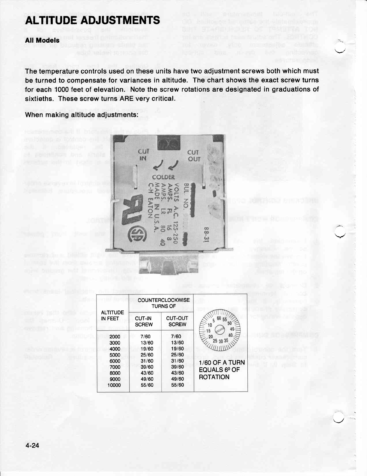
ALTITUDE
ADJUSTMENTS
All Models
The temperature controls used on
these units have two adjustment
screws both which
must
be
turned to
compensate
for variances
in altitude, The chart shows
the exact
screw
turns
for each
1000 feet
of elevation.
Note the screw
rotations are designated in
graduations
of
sixtieths.
These screw turns
ARE very critical.
When
making
altitude
adjustments:
:-
ALTITUDE
IN
FEET
COUNTEBCTOCKWISE
TURNS OF
1/60
OF
A TURN
EQUALS 60 OF
ROTATION
CUT.IN
SCREW CUT.OUT
SCREW
2000
3000
4000
5000
6000
7000
8000
9000
1 0000
7t60
13/60
1 9/60
25/60
31 /60
39/60
43/60
49/60
55/60
7t60
1 3/60
1
9/60
25t60
31
/60
39/60
43t60
49/60
55/60
4-24
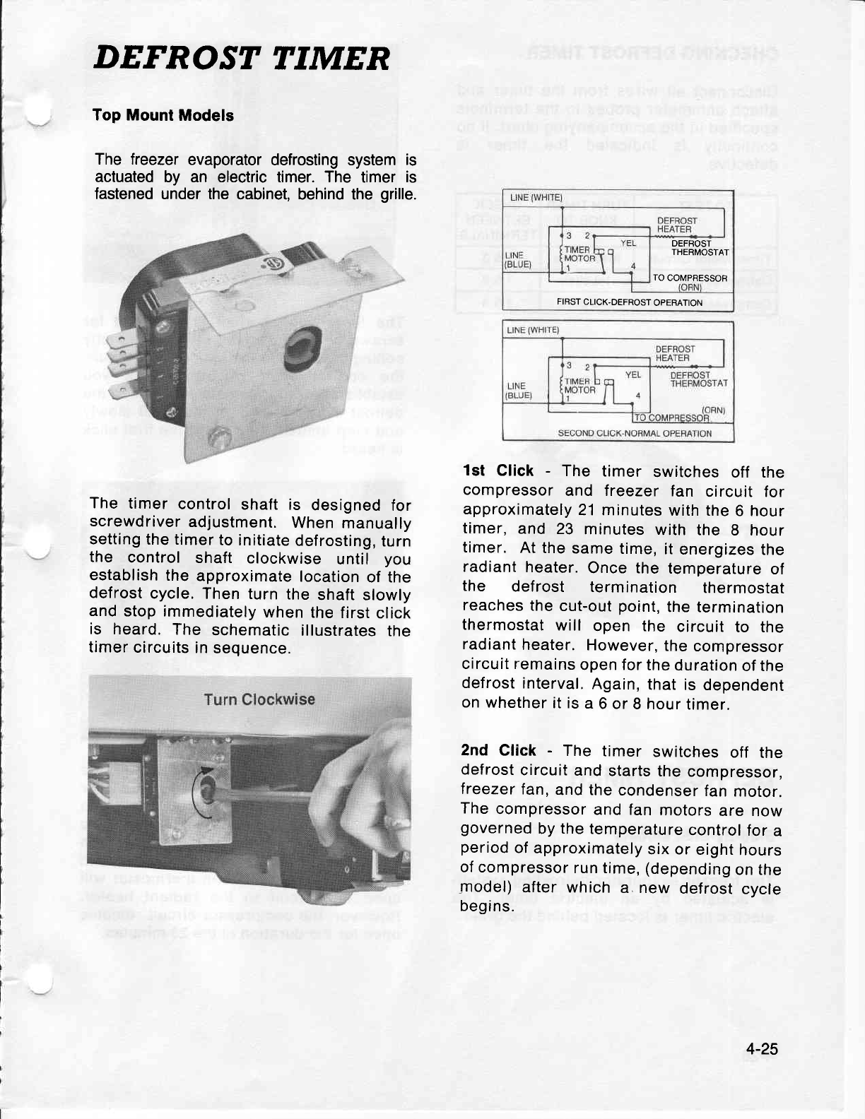
DEFROST TIMER
Top Mount
Models
The freezer
evaporator
defrosting system
is
actuated
by an electric
timer.
The timer
is
fastened
under the
cabinet, behind the
grille.
The timer
control
shaft
is designed
for
screwdriver
adjustment.
When
manually
setting
the timer
to initiate
defrosting,
turn
the control shaft clockwise
until you
establish
the
approximate
location
of the
defrost
cycle.
Then turn
the
shaft
slowly
and
stop immediately
when
the
first
click
is heard.
The schematic
illustrates
the
timer
circuits
in
sequence.
1st Click
- The timer switches
off the
compressor
and treezer
fan circuit for
approximately
21 minutes
with the
6 hour
timer,
and
23 minutes
with the 8 hour
timer.
At the
same
time,
it
energizes
the
radiant
heater.
Once the
temperature
of
the def rost termination thermostat
reaches
the
cut-out
point,
the termination
thermostat
will open the circuit
to the
radiant
heater.
However,
the
compressor
circuit remains
open for
the
duration
of the
defrost
interval,
Again,
that is
dependent
on whether
it is
a
6 or
8 hour
timer,
2nd Click
- The timer switches
off the
defrost
circuit
and
starts
the
compressor,
lreezer
fan,
and the
condenser
fan
motor.
The
compressor
and fan
motors
are
now
governed
by
the
temperature
control
for
a
period
of
approximately
six or
eight
hours
of compressor
run time, (depending
on the
model)
after which
a new defrost
cycle
begins.
DEFROST
THERMOSTAT
TO
COMPRESSOR
FIBST
CLICK.DEFROST
OPERATION
4-25
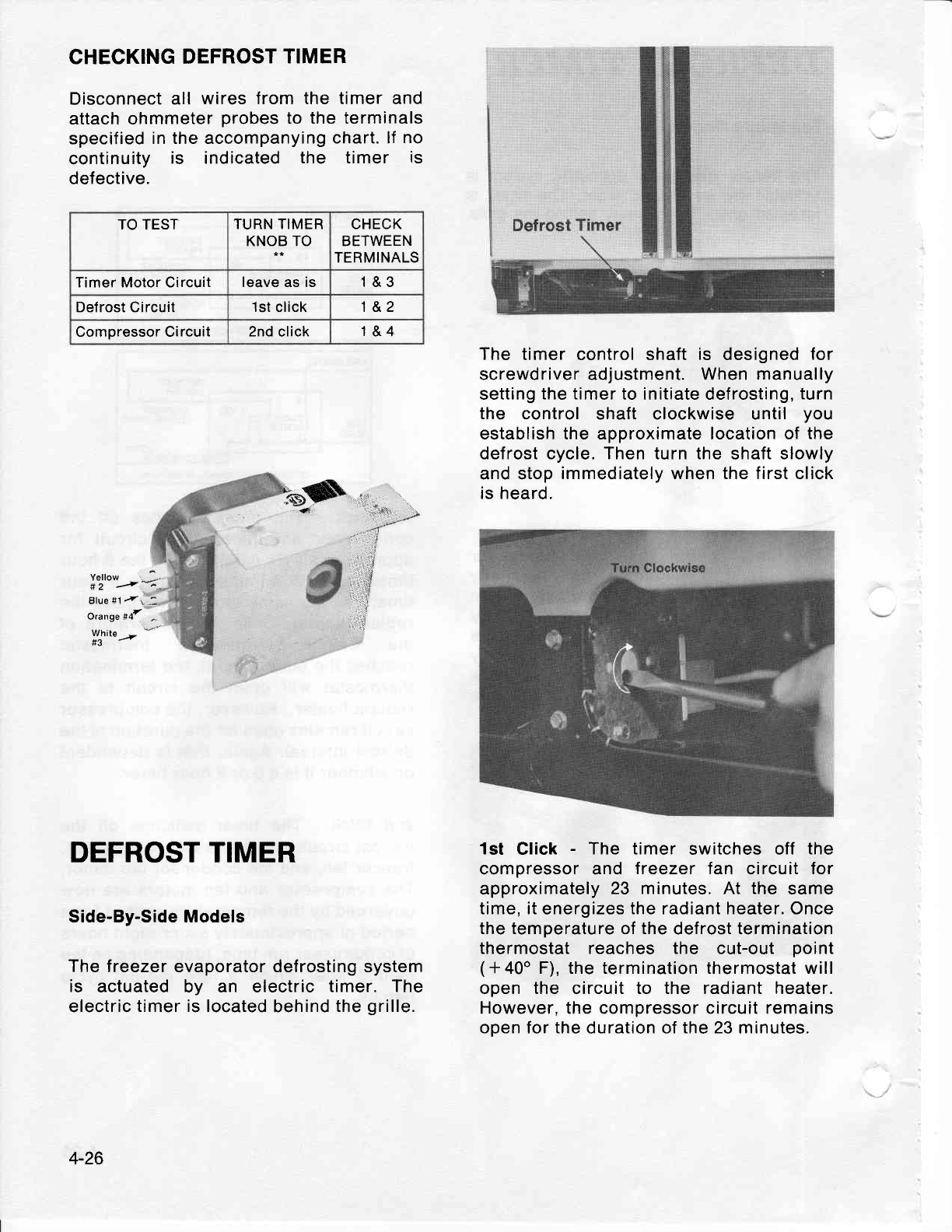
CHECKING
DEFROST
TIMER
Disconnect
all wires from the timer and
attach ohmmeter
probes
to the terminals
specified
in the accompanying
chart. lf
no
continuity
is indicated
the timer is
defective.
qs
l.'
"-
Yellow :
# 2 /* *-,.
Blue #1
-t, :
Qrange #d
WLrite_--'""
TO TEST TURN TIMER
KNOB TO CHECK
BETWEEN
TERMINALS
Timer Motor Circuit leave as is 1&3
Defrost Circuit 1st
click 1&2
Compressor Circuit 2nd
click 1&4
DEFROST TIMER
Side-By-Side Models
The freezer evaporator defrosting system
is actuated by an electric
timer. The
electric
timer is located
behind
the
grille.
The timer
control shaft
is designed
for
screwdriver adjustment. When
manually
setting
the timer
to initiate defrosting,
turn
the control shaft clockwise until you
establish the approximate location of
the
defrost cycle. Then turn the
shaft
slowly
and stop
immediately when the first click
is heard.
1st Click
- The timer switches off the
compressor and freezer fan circuit
for
approximately
23 minutes. At the same
time, it
energizes
the radiant heater. Once
the temperature of the
defrost
termination
thermostat reaches the cut-out point
(+40' F), the termination thermostat
will
open the circuit to the radiant heater.
However, the compressor circuit remains
open for the
duration of
the 23 minutes.
4-26
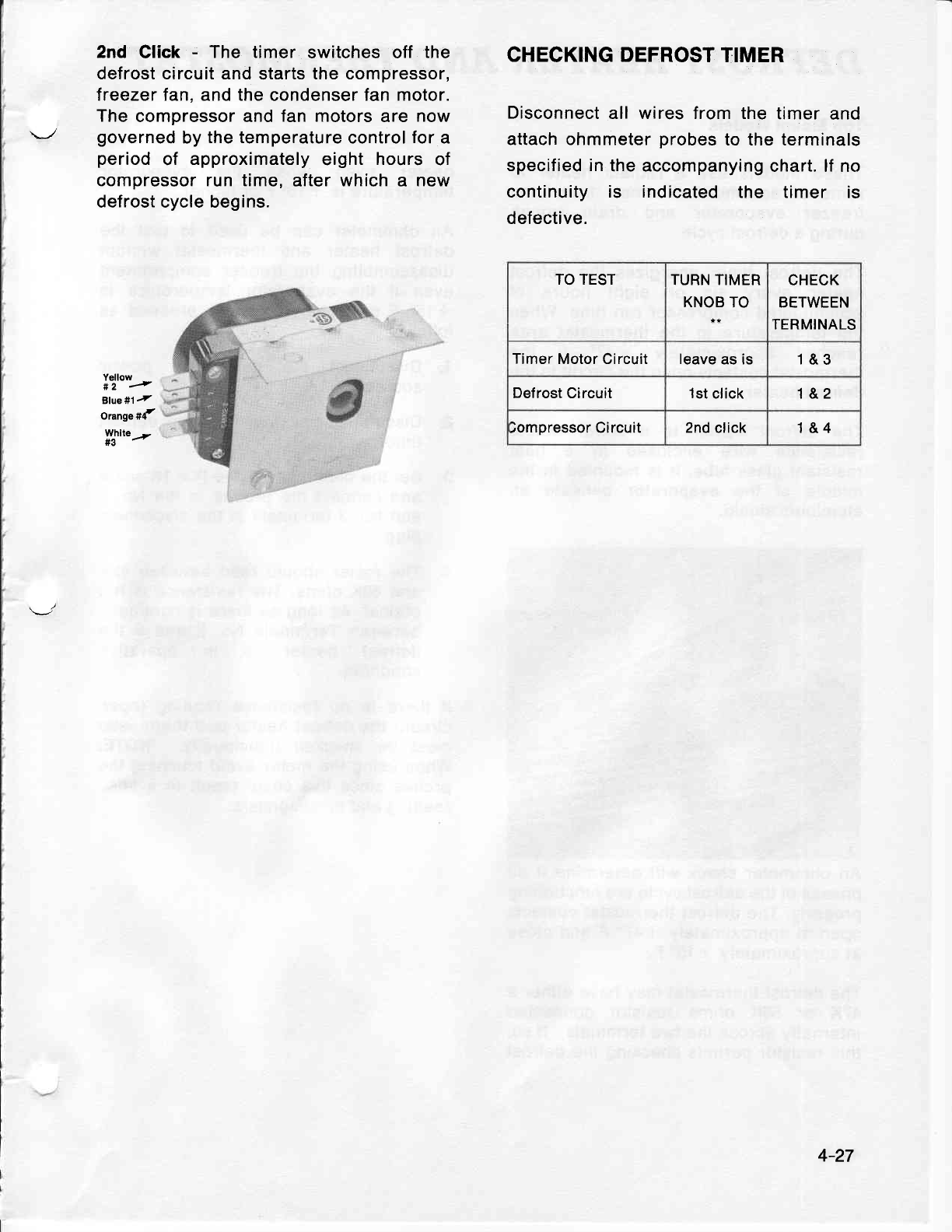
2nd Click - The timer switches off the
defrost circuit and
starts
the compressor,
freezer fan, and the
condenser
fan motor.
The
compressor and
fan motors
are now
governed
by
the temperature
control
for
a
period
of approximately
eight hours
of
compressor run time,
after which a new
defrost cycle begins.
Yellow
*2 I
Blue#1,
orangesf,
Wtlte,r.
CHECK1NG DEFROST
TIMER
Disconnect
all wires from the
timer
and
attach ohmmeter
probes
to the terminals
specified in
the accompanying
chart. lf no
continuity is indicated
the timer is
defective.
TO TEST TURN TIMER
KNOB
TO
CHECK
BETWEEN
TERMINALS
Timer Motor Circuit leave
as is 1&3
Defrost Circuit 1st
click 1&2
)ompressor Circuit 2nd
click 1&4
4-27
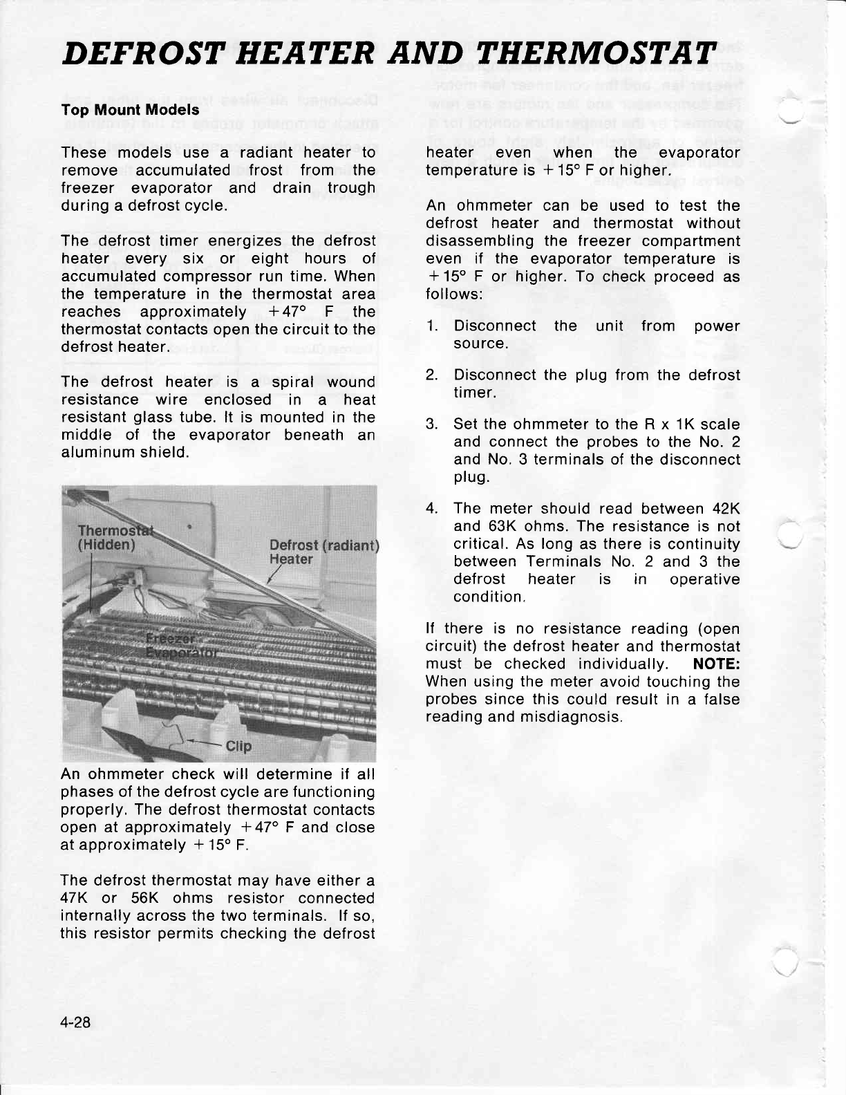
DEFROST HEATER AND THERMOSTAT
Top Mount
Models
These
models
use a radiant heater
to
remove accumulated
f rost f rom the
lreezer evaporator and drain trough
during a defrost cycle.
The defrost timer
energizes
the defrost
heater every six or eight hours of
accumulated
compressor
run
time. When
the temperature in the thermostat
area
reaches approximately
+ 47o F the
thermostat
contacts open
the
circuit to the
defrost heater.
The defrost
heater is a spiral wound
resistance
wire enclosed in a heat
resistant
glass
tube.
lt is mounted in the
middle of the evaporator beneath
an
aluminum
shield.
An
ohmmeter
check will
determine if all
phases
of
the
defrost cycle are
functioning
properly.
The
defrost
thermostat
contacts
open at approximately
+
47" F and
close
at approximately
+
15o F.
The defrost
thermostat
may have either
a
47K or 56K ohms resistor connected
internally across the two terminals. lf
so,
this resistor
permits
checking
the defrost
heater even when the evaporator
temperature is
* 15o F
or
higher.
An ohmmeter can be used to test the
defrost heater and thermostat without
disassembling
the treezer
compartment
even if the evaporator
temperature
is
+
15o F or higher.
To check
proceed
as
follows:
1. Disconnect the unit from oower
source.
2. Disconnect the plug
from the defrost
timer.
3. Set
the
ohmmeter to the R x 1K
scale
and
connect
the
probes
to the No. 2
and No. 3 terminals of the
disconnect
plug.
4. The
meter should read
between
42K
and 63K ohms. The resistance is not
critical. As long
as there is continuity
between Terminals No. 2 and 3 the
def
rost heater is in operative
condition.
lf there
is no resistance reading
(open
circuit)
the
defrost heater
and thermostat
must be checked individually.
NOTE:
When
using
the
meter avoid touching the
probes
since
this
could result in
a false
reading
and misdiagnosis.
4-28
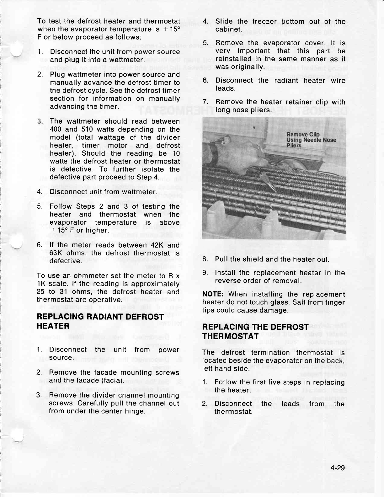
To test the
defrost heater and thermostat
when the
evaporator
temperature
is * 15o
F
or below
proceed
as
follows:
1. Disconnect the
unit
f rom
power
source
and
plug
it into
a wattmeter.
2. Plug wattmeter into
power
source and
manually
advance the defrost timer to
the
defrost cycle. See the defrost timer
section for information
on manually
advancing the timer.
The wattmeter
should
read between
400
and 510
watts
depending
on the
model
(total
wattage
of the divider
heater, timer motor and def
rost
heater).
Should the reading
be '10
watts the
defrost
heater
or thermostat
is defective. To further isolate
the
defective
part
proceed
to
Step
4.
Disconnect
unit from wattmeter.
Follow
Steps 2 and 3 of testing
the
heater and thermostat
when the
evaporator temperature is above
+
15o F
or
higher.
lf the meter reads
between 42K and
63K
ohms.
the defrost thermostat
is
defective.
To
use an ohmmeter
set the meter to R x
1K scale. lf the reading
is
approximately
25 to 31 ohms. the defrost heater
and
thermostat
are
operative.
REPLACING
RADIANT DEFROST
HEATER
Disconnect
the unit f rom power
sou rce.
Remove
the facade mounting
screws
and the facade
(facia).
Remove the
divider channel
mounting
screws.
Carefully
pull
the
channel
out
from
under the
center hinge.
Slide the freezer
bottom out of the
cabinet.
Remove
the evaporator cover. lt is
very important
that this part be
reinstalled
in the same manner
as it
was
originally.
Disconnect
the radiant heater
wire
leads.
Remove the heater
retainer clip with
long nose
pliers.
8. Pull
the shield
and
the
heater
out.
9. Install the replacement
heater in the
reverse
order of removal.
NOTE: When
installing the replacement
heater
do
not
touch
glass.
Salt from finger
tips
could cause
damage.
REPLACING
THE DEFROST
THERMOSTAT
The defrost
termination
thermostat
is
located
beside the
evaporator on the
back,
left hand
side.
1. Follow
the first
five
steps
in
replacing
the heater.
2. Disconnect
the leads f rom the
thermostat.
4.
5.
6.
7.
4.
5.
6.
1.
2.
3.
4-29
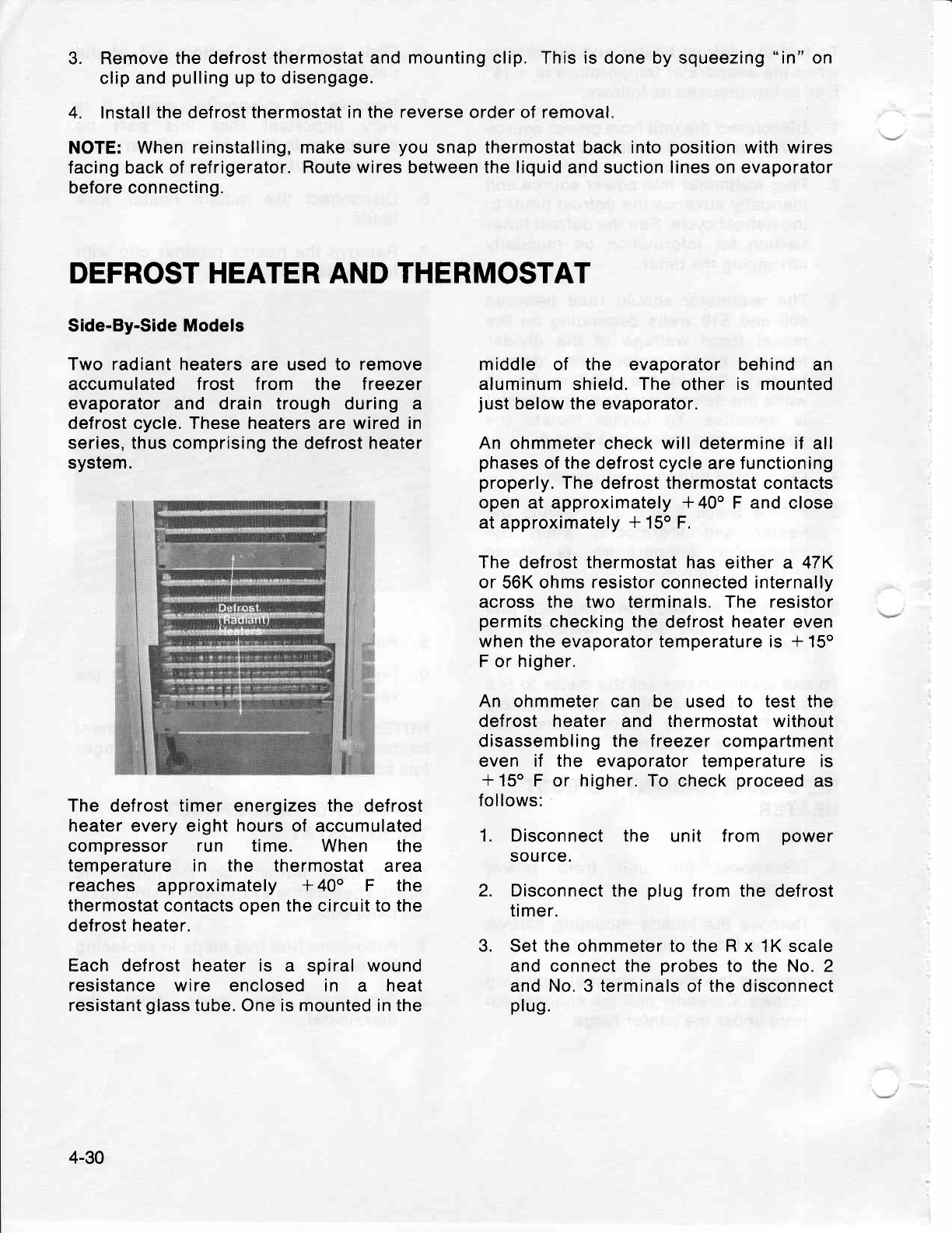
3. Remove
the
defrost
thermostat and
mounting
clip. This is
done by squeezing
"in"
on
clip and
pulling
up to disengage.
4. Install the defrost thermostat
in the reverse order of removal.
NOTE: When
reinstalling, make sure
you
snap thermostat back into
position
with wires
facing
back
of refrigerator.
Route wires between the liquid
and suction
lines
on evaporator
before connecting.
DEFROST HEATER AND
THERMOSTAT
Side-By-Side Models
Two radiant heaters
are used
to remove
accumulated f rost f rom the treezer
evaporator
and drain trough during a
defrost cycle. These heaters
are
wired in
series, thus comprising the
defrost
heater
system.
The defrost
timer
energizes
the defrost
heater every eight hours of accumulated
compressor run time. When the
temperature in the thermostat area
reaches approximately
+
40o F the
thermostat contacts open the circuit to the
defrost heater.
Each defrost heater is a spiral wound
resistance wire enclosed in a heat
resistant
glass
tube.
One
is mounted in the
middle of the evaporator
behind an
aluminum shield. The
other
is mounted
just
below the evaporator.
An ohmmeter check will determine if all
phases
of the defrost cycle are functioning
properly.
The defrost thermostat contacts
open at approximately
* 40" F and close
at approximately
+ 150 F.
The
defrost
thermostat
has either a 47K
or
56K ohms
resistor
connected internally
across
the two terminals. The resistor
permits
checking the
defrost heater even
when the
evaporator
temperature is * 150
F
or
higher.
An ohmmeter can be used
to test the
defrost heater and thermostat without
disassembling the treezer compartment
even if the evaporator temperature is
+15o
F or higher. To
check
proceed
as
follows:
1. Disconnect the unit from power
source.
2. Disconnect
the plug
from the
defrost
timer.
3. Set
the
ohmmeter to
the R
x 1K scale
and connect the probes
to the No. 2
and No.
3
terminals
of
the
disconnect
plug.
4-30
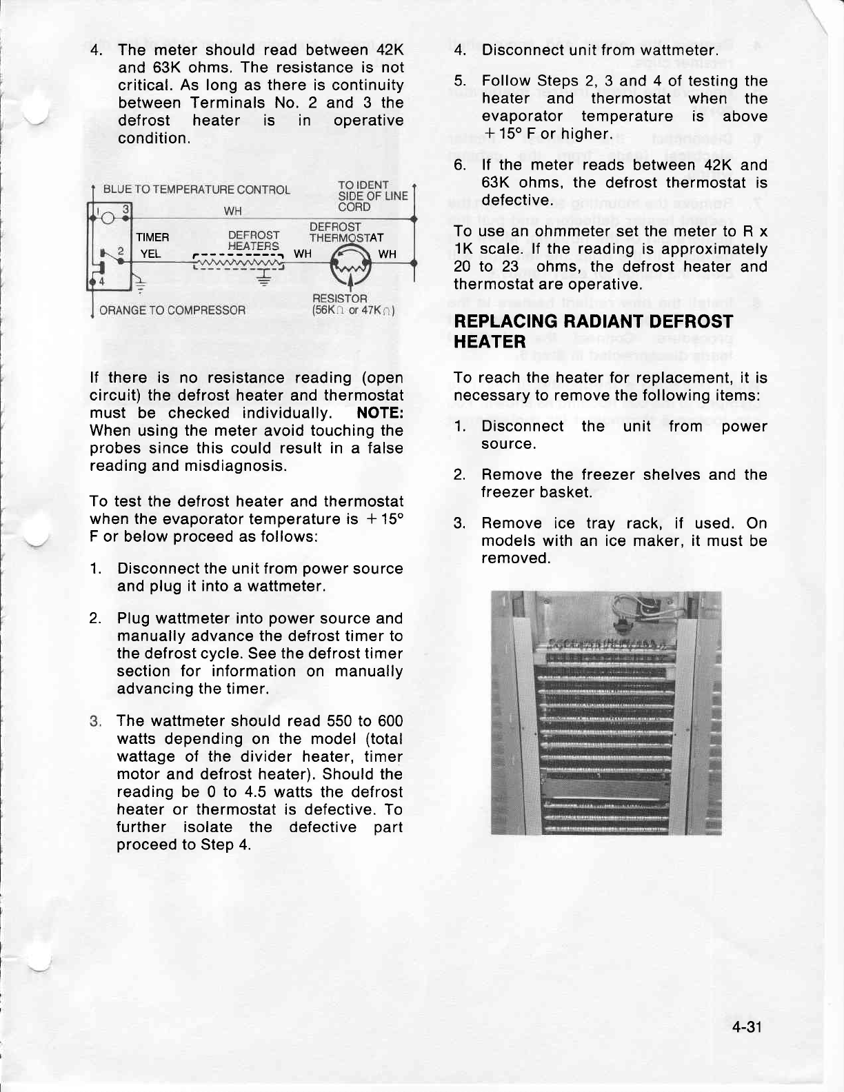
4. The meter should read between 42K
and 63K ohms.
The resistance is not
critical. As long as there is continuity
between
Terminals No. 2 and 3 the
def rost heater is in operative
condition.
lf there
is no resistance reading
(open
circuit) the
defrost heater and
thermostat
must be checked individually. NOTE:
When
using
the meter
avoid
touching the
probes
since this could result in a false
reading
and misdiagnosis.
To test
the defrost heater and thermostat
when
the evaporator temperature is * 15o
F
or below
proceed
as
follows:
1. Disconnect the
unit f
rom
power
source
and
plug
it into
a
wattmeter.
Plug wattmeter into
power
source and
manually advance the defrost timer to
the
defrost cycle. See the def
rost
timer
section for information
on manually
advancing the timer.
The
wattmeter should read 550 to 600
watts
depending on the model
(total
wattage
of the divider heater, timer
motor
and defrost heater). Should the
reading
be 0 to 4.5
watts
the defrost
heater
or thermostat is defective.
To
f urther isolate the defective part
proceed
to Step 4.
Disconnect
unit
from wattmeter.
Follow
Steps 2,
3 and
4 of
testing
the
heater and thermostat when the
evaporator temperature is above
+
150
F or higher.
6. lf the meter reads
between 42K and
63K ohms, the defrost
thermostat
is
defective.
To use an
ohmmeter set
the meter
to R x
1K scale. lf the reading
is approximately
20 to 23 ohms, the defrost
heater
and
thermostat
are operative.
REPLACING RADIANT
DEFROST
HEATER
To reach the
heater for replacement, it is
necessary to remove the following items:
1. Disconnect
the unit from power
source.
2. Remove the
freezer shelves and the
lreezer
basket.
3. Remove ice tray rack, if used. On
models with an ice maker, it must
be
removed.
4.
5.
2.
4-31
TIMER
YEL
AT
,WH
r-----::'---; wH
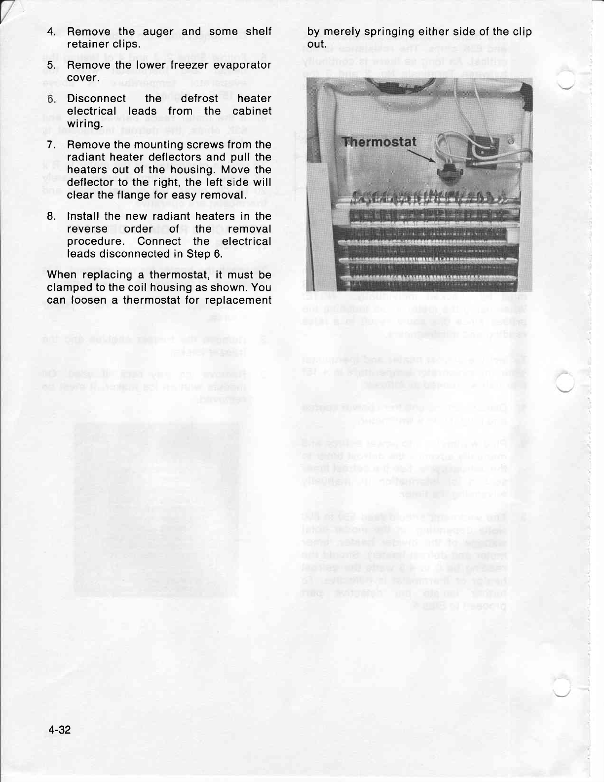
4.
5.
Remove the auger and some shelf
retainer clips.
Remove the lower freezer evaporator
cover.
Disconnect the def rost heater
electrical leads f rom the cabinet
wiring.
Remove the mounting
screws
from the
radiant heater deflectors and
pull
the
heaters
out of
the housing. Move
the
deflector
to the right, the left
side will
clear the flange for easy removal.
lnstall
the new radiant heaters in the
reverse order of the removal
procedure.
Connect the electrical
leads disconnected in
Step 6.
When replacing
a thermostat, it must
be
clamped to the
coil
housing
as shown. You
can
loosen
a thermostat for replacement
by
merely
springing either side of the clip
out.
7.
8.
4-32
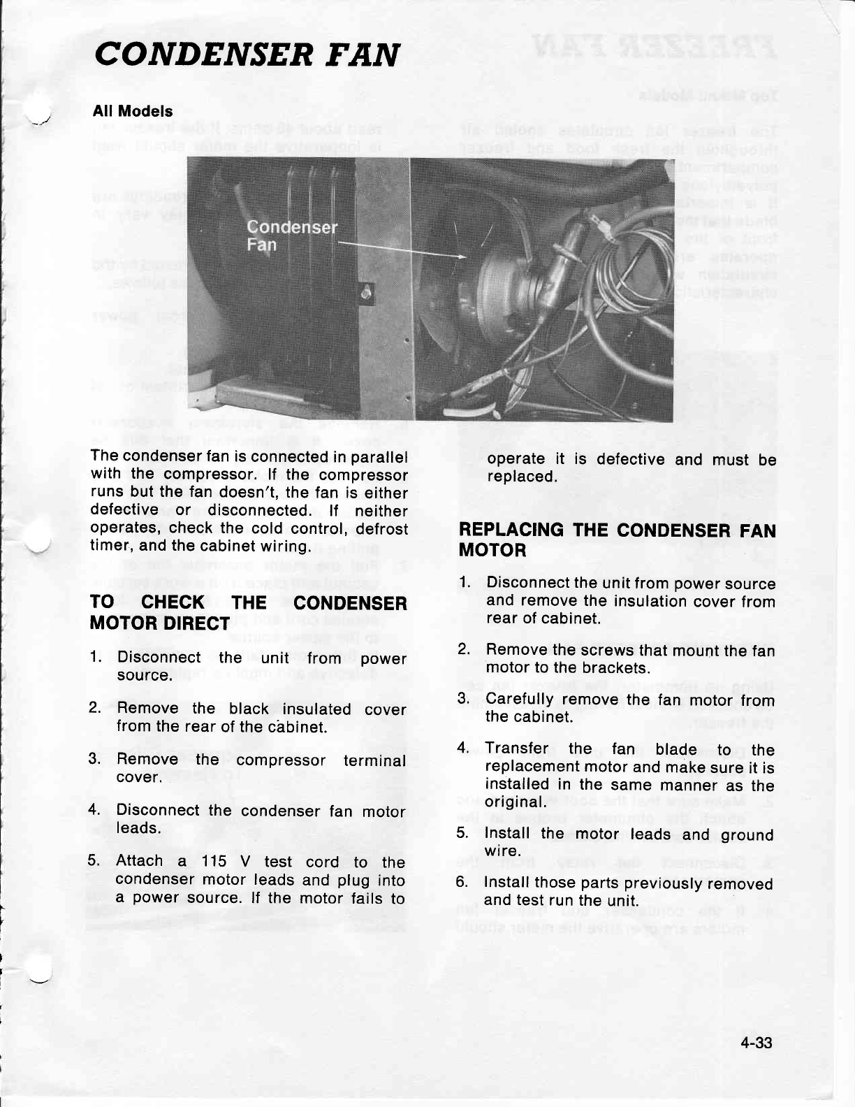
CONDENSER
FAN
All Models
The
condenser
fan
is
connected
in
parallel
with
the compressor.
lf the compressor
runs
but the fan
doesn't,
the
fan is
either
defective
or disconnected.
lf neither
operates,
check
the cold control,
defrost
timer,
and the
cabinet
wiring.
TO CHECK THE CONDENSER
MOTOR
DIRECT
1. Disconnect
the unit from power
source.
2. Remove
the black insulated
cover
from
the rear
of
the
chbinet.
3. Remove the compressor
terminal
cover.
4. Disconnect
the condenser
fan motor
leads.
5. Attach a 115 V test cord to the
condenser
motor
leads
and
plug
into
a power
source.
lf the motor
fails
to
t'
Y
I
t
I*
I
operate
it is defective
and rnust
be
replaced.
REPLACING
THE
CONDENSER
FAN
MOTOR
1. Disconnect
the
unit f rom
power
source
and
remove
the
insulation
cover
from
rear
of
cabinet.
2. Remove
the
screws
that
mount
the fan
motor to
the
brackets.
3. Carefully
remove
the
fan motor
from
the
cabinet.
4. Transfer the fan blade to the
replacement
motor
and
make
sure it is
installed
in the
same
manner
as the
original.
5. Install
the motor leads
and ground
wire.
6. Install
those
parts
previously
removed
and test
run
the
unit.
4-33
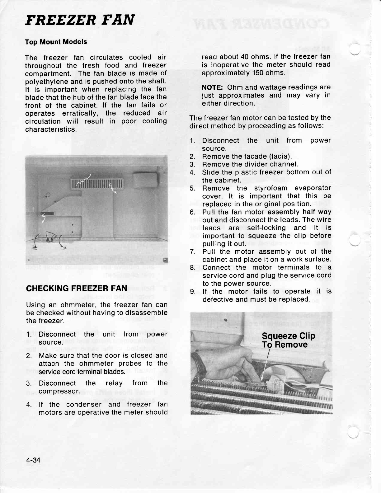
FREEZER FAN
Top Mount
Models
The lreezer fan circulates
cooled air
throughout
the fresh food and freezer
compartment.
The fan blade
is made
of
polyethylene
and
is
pushed
onto
the
shaft.
It is important
when replacing
the fan
blade
that
the hub of
the fan blade
face
the
front of the cabinet.
lf the fan fails or
operates erratically,
the reduced air
circulation
will result
in poor cooling
characteristics.
CHECKING
FREEZER FAN
Using an ohmmeter,
the treezer fan
can
be checked without
having to disassemble
the freezer.
1. Disconnect
the unit from power
sou
rce.
2. Make sure
that the door
is
closed and
attach
the ohmmeter
probes
to the
service cord
terminal blades.
3. Disconnect the relay f rom the
compressor.
4. lf the condenser and treezer fan
motors
are operative
the meter should
read about
40 ohms.
lf the
freezer
tan
is inoperative
the meter
should
read
approximately
150 ohms.
NOTE:
Ohm and
wattage
readings
are
just approximates
and may vary in
either direction.
The freezer
fan motor can be
tested by
the
direct
method by
proceeding
as
follovvs:
1, Disconnect
the unit from power
source.
2. Remove the
facade
(facia).
3. Remove the divider
channel.
4. Slide
the
plastic
Ireezer bottom
out of
the cabinet.
5. Remove the styrofoam evaporator
cover. lt is important
that this be
replaced
in the
original
position.
6. Pull the fan
motor
assembly
half way
out and disconnect
the leads.
The
wire
leads are self-locking
and it is
important to squeeze
the clip before
pulling
it out.
Pull
the motor assembly
out of the
cabinet
and
place
it on a
work surface.
Connect
the motor terminals
to a
service
cord and
plug
the service
cord
to the
power
source,
lf the motor fails to operate
it is
defective and
must be
replaced.
7.
8.
9,
Squeeze
Clip
To
Remove
4-34
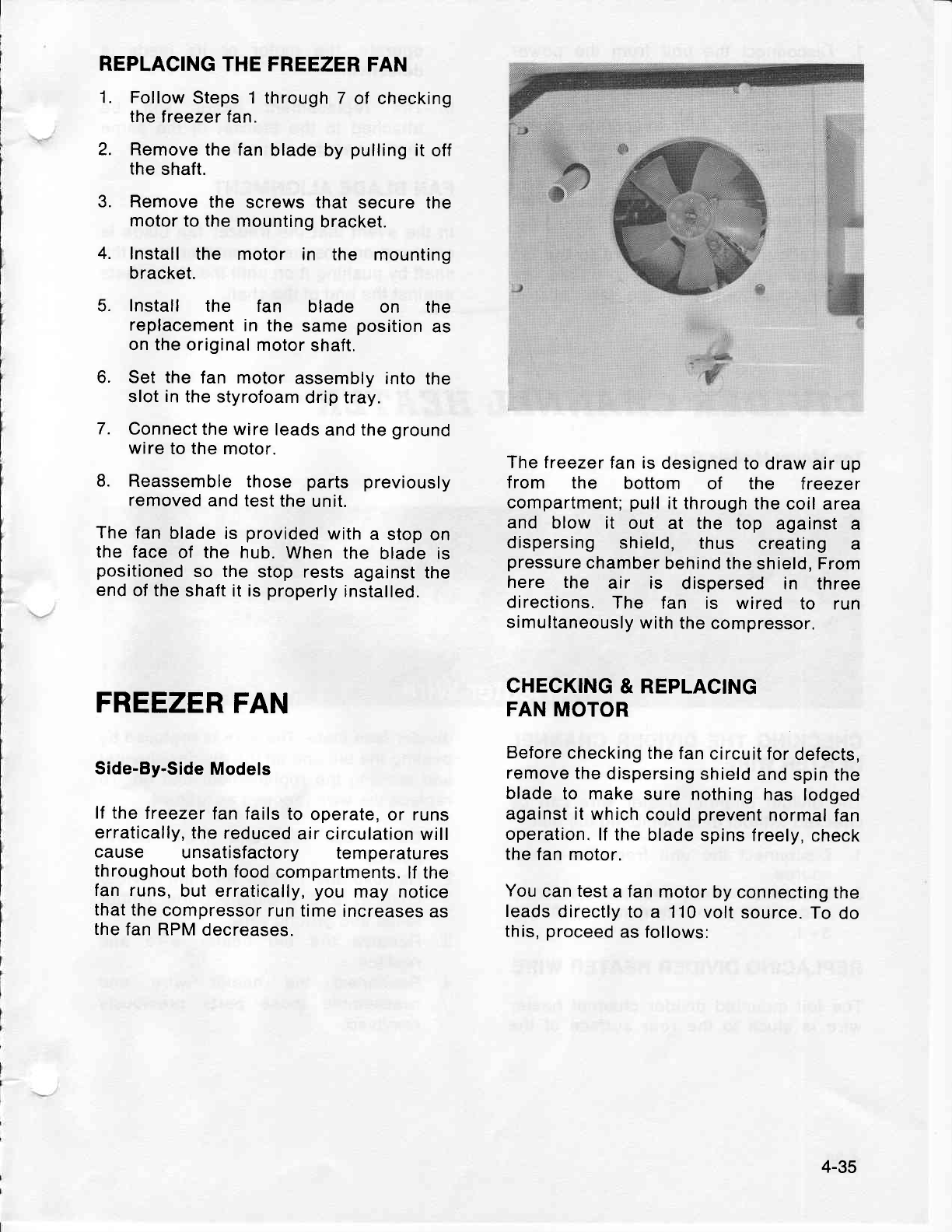
REPLACING
THE FREEZER
FAN
1. Follow
Steps 1
through 7 of checking
the freezer fan.
2. Remove
the fan
blade by
pulling
it off
the
shaft.
3. Remove
the screws that
secure the
motor
to the
mounting
bracket.
4. Install
the motor in the mounting
bracket.
5. Install the fan blade on the
replacement
in the
same
position
as
on the original
motor
shaft.
6. Set the
fan motor
assembly into
the
slot
in
the styrofoam
drip tray.
7. Connect the
wire leads
and the
ground
wire
to the
motor.
8. Reassemble
those parts previously
removed
and
test the
unit.
The fan
blade
is provided
with
a stop on
the face
of the hub.
When
the blade is
positioned
so the
stop
rests
against the
end
of the
shaft it is
properly
installed.
FREEZER
FAN
Side-By-Side
Models
lf the
treezer
fan fails
to
operate,
or runs
erratically, the
reduced
air circulation
will
cause unsatisfactory temperatures
throughout
both food
compartments.
lf the
fan runs,
but erratically,
you may
notice
that
the
compressor
run time
increases
as
the
fan RPM
decreases.
The freezer
fan is
designed
to draw
air up
f rom the bottom of the treezer
compartment;
pull
it through
the
coil area
and blow it out at the top against
a
dispersing
shield, thus creating a
pressure
chamber
behind the
shield, From
here the air is dispersed in three
directions.
The fan is wired to run
simultaneously
with
the
compressor.
CHECKING
& REPLACING
FAN
MOTOR
Before
checking
the fan
circuit for
defects,
remove
the
dispersing
shield and
spin the
blade to make
sure nothing
has lodged
against
it which
could
prevent
normal
fan
operation.
lf the
blade
spins freely,
check
the
fan motor.
You
can
test
a
fan
motor
by
connecting
the
leads
directly
to
a 110 volt
source.
To
do
this,
proceed
as follows:
4-35
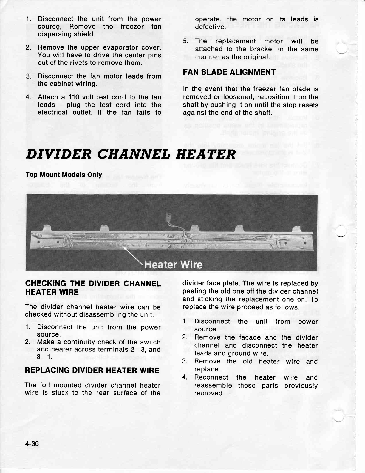
1.
2.
Disconnect
the unit
from the power
source. Remove the freezer fan
dispersing
shield.
Remove the upper evaporator cover.
You
will have to drive the
center
pins
out of the rivets to remove them.
Disconnect
the fan motor leads from
the
cabinet
wiring.
4. Attach
a 110
volt test cord to the fan
leads - plug the test cord into the
electrical
outlet. lf the fan fails to
operate, the motor or its leads is
defective.
5. The replacement motor will be
attached to the bracket
in the same
manner
as the original.
FAN
BLADE ALIGNMENT
ln the
event
that the treezer fan blade is
removed
or loosened, reposition
it
on the
shaft
by
pushing
it
on until the
stop resets
against the end of the
shaft.
DTVIDER CHANNEL HEATER
Top Mount Models
Only
CHECKING
THE
DIVIDER
CHANNEL
HEATER
WIRE
The
divider channel
heater
wire can be
checked
without
disassembling the
unit.
1. Disconnect
the unit from the power
source.
2. Make a continuity
check
of the switch
and heater
across terminals
2
-
3.
and
3
-
1.
REPLACING
DIVIDER
HEATER WIRE
The
foil mounted
divider
channel heater
wire is stuck to the rear surface of the
divider face
plate.
The
wire is replaced
by
peeling
the
old
one off the
divider channel
and
sticking the
replacement
one on. To
replace
the wire
proceed
as follows.
1. Disconnect
the unit from power
source.
2. Remove
the facade
and the divider
channel
and disconnect the heater
leads
and
ground
wire.
3. Remove
the old heater wire and
replace.
4. Reconnect
the heater wire and
reassemble
those parts previously
removed.
4-36
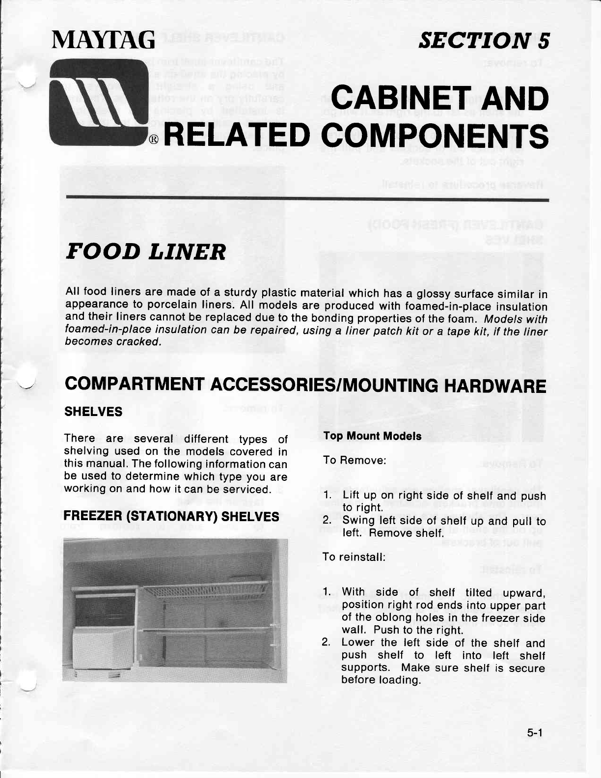
MI\YTAG SECTION
5
CABINET
AND
@RELATED
COMPONENTS
FOOD LINER
All food
liners
are made
of a sturdy
plastic
material
which
has
a glossy
surface
similar
in
appearance
to porcelain
liners.
All models
are
produced
with foamed-in-place
insulation
and
their f
iners
cannot
be replaced
due to
the
bonding
properties
of the foam.
Models
with
foamed-in-place
insulation
can
be repaired,
using
a iner patch
kit or a tape
kit, if the
Iiner
becomes
cracked.
COMPARTMENT
ACCESSORIES/MOUNTING
HARDWARE
SHELVES
There are several different types of
shelving
used
on the
models
covered
in
this
manual.
The following
information
can
be
used to
determine
which
type
you
are
working
on
and how
it
can be
serviced.
FREEZER
(STATTONARY)
SHELVES
Top
Mount
Models
To
Remove:
1. Lift
up on right
side
of shelf
and
push
to right.
2. Swing
left
side
of shelf
up
and
pull
to
left.
Remove
shelf.
To
reinstall:
With side of shelf tilted upward,
position
right
rod
ends
into
upper
part
of the
oblong
holes
in
the freezer
side
wall. Push
to
the right.
Lower
the left
side
of the shelf
and
push shelf to left into left shelf
supports.
Make
sure
shelf is secure
before
loading.
1.
2.
5-1
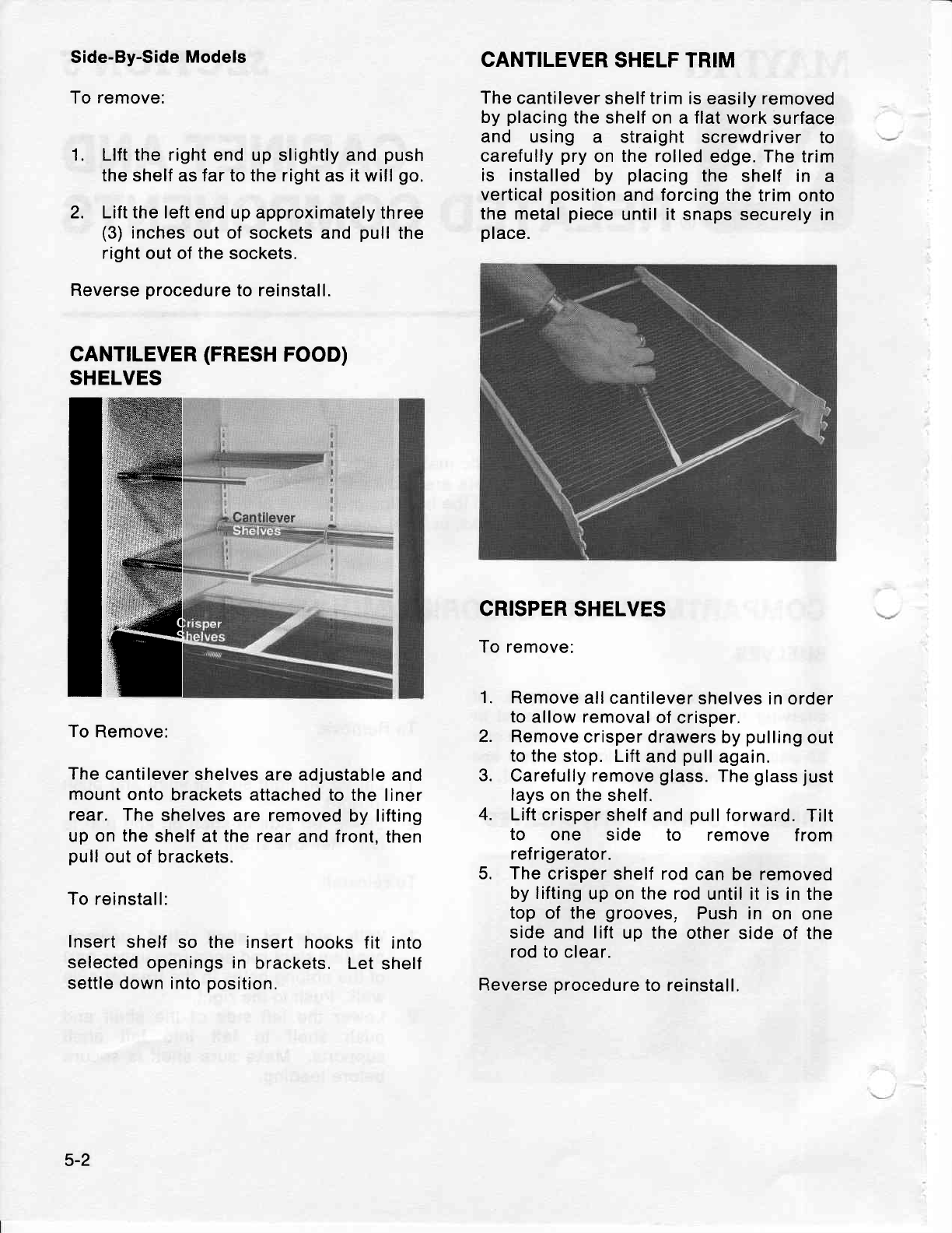
CANTILEVE
SHELVES
I'
lff
Side-By-Side
Models
To
remove:
1. Llft the right
end up slightly and
push
the
shelf as
far to the right
as
it
will
go.
2. Lift the left
end up approximately three
(3)
inches
out of sockets and
pull
the
right
out of
the
sockets.
Reverse
procedure
to reinstall.
R
(FRESH
FOOD)
To
Remove:
The
cantilever
shelves are
adjustable and
mount
onto
brackets
attached to the liner
rear. The
shelves are removed
by lifting
up on
the
shelf
at
the
rear
and
front,
then
pull
out of
brackets.
To reinstall:
Insert
shelf so the insert
hooks
fit into
selected
openings in brackets.
Let
shelf
settle down into
position.
CANTILEVER
SHELF TRIM
The
cantilever
shelf
trim
is easily removed
by
placing
the shelf
on a
flat
work
surface
and using a straight screwdriver to
carefully
pry
on the
rolled
edge. The trim
is installed
by placing
the shelf in a
vertical
position
and forcing the
trim onto
the metal
piece
until it
snaps securely
in
place.
CRISPER SHELVES
To remove:
1. Remove
all cantilever
shelves
in order
to
allow removal
of crisper,
2. Remove
crisper
drawers by
pulling
out
to the
stop. Lift
and
pull
again.
3. Carefully remove
glass.
The
glass
just
lays
on the
shelf.
4. Lift crisper
shelf
and
pull
forward.
Tilt
to one side to remove f rom
ref rigerator.
5. The
crisper shelf rod
can
be
removed
by lifting
up on the rod
until it is in the
top
of the
grooves. Push in on one
side and lift
up the other
side of the
rod to clear.
Reverse
procedure
to
reinstall.
5-2
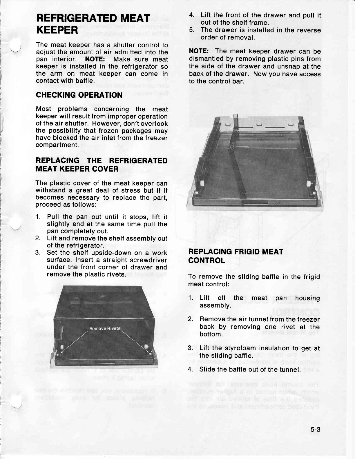
REFRIGERATED
MEAT
KEEPER
The
meat
keeper has a shutter control to
adjust the
amount of air
admitted into the
pan interior. NOTE: Make sure meat
keeper
is installed in the refrigerator
so
the arm on meat keeper
can come in
contact with
baffle.
CHECKING
OPERATION
Most problems concerning the meat
keeper
will result from
improper
operation
of the
air shutter. However,
don't
overlook
the possibility
that frozen
packages
may
have
blocked the
air
inlet
from the freezer
compartment.
REPLACING
THE REFRIGERATED
MEAT
KEEPER
COVER
The
plastic
cover
of
the
meat keeper
can
withstand
a great
deal of stress but if it
becomes
necessary
to replace the part,
proceed
as
follows:
Pull
the pan
out until it stops, lift it
slightly
and at the same time
pull
the
pan
completely
out.
Lift and remove
the
shelf assembly
out
of the
refrigerator.
Set
the
shelf
upside-down
on a work
surface.
Insert
a straight screwdriver
under
the front
corner of
drawer and
remove
the
plastic
rivets.
4. Lift the front
of the
drawer and
pull
it
out of the
shelf frame.
5. The drawer
is installed
in the reverse
order of removal.
NOTE: The meat keeper
drawer can be
dismantled
by
removing
plastic pins
from
the
side of
the
drawer
and unsnap
at the
back of the
drawer. Now
you
have access
to the
control
bar.
REPLACING
FRIGID
MEAT
CONTROL
To remove
the
sliding baffle
in the frigid
meat control:
1. Lift off the meat pan housing
assembly.
2. Remove
the air tunnel
from the freezer
back by removing
one rivet at the
bottom.
3, Lift the
styrofoam
insulation to get
at
the sliding
baffle.
4. Slide the baffle
out of the tunnel.
1.
2.
3.
5-3
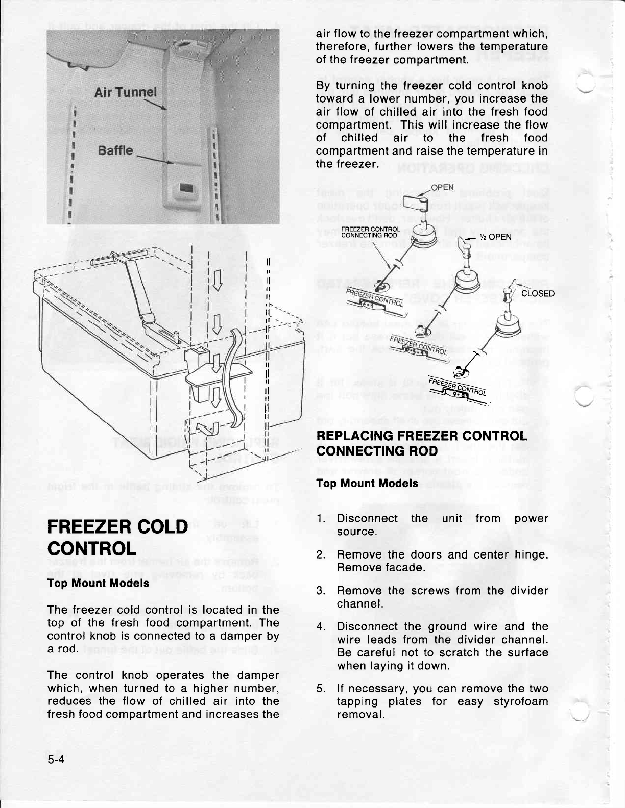
air
flow
to the treezer compartment which,
therefore,
further lowers the
temperature
of the freezer
compartment.
By turning
the freezer cold control knob
toward
a lower number,
you
increase the
air
flow
of chilled air into the fresh
food
compartment. This will increase the flow
of chilled air to the f resh food
compartment
and
raise the temperature in
the freezer.
FREEZER
CONTROL
CONNECTING ROD .- 7z OPEN
CLOSED
tl
ll
tl
tl
tl
I
l.
tt.
rl
tr
tl
tl
ll
il
rl
tl
ll
ll
g
FREEZER
COLD
CONTROL
Top Mount Models
The freezer cold control is located in the
top of the fresh food compartment.
The
control
knob is
connected to a damper by
a rod.
The control knob operates the damper
which, when turned to a higher number,
reduces the flow
of chilled air into the
fresh food
compartment and increases the
5-4
1.
2.
3.
4.
REPLACING
FREEZER CONTROL
CONNECTING ROD
Top Mount Models
Disconnect the unit lrom power
source.
Remove the doors and center
hinge.
Remove facade.
Remove the screws from the divider
channel.
Disconnect
the ground
wire and
the
wire leads from the divider channel.
Be careful not to scratch
the surface
when laying it down.
lf necessary,
you
can
remove the two
tapping plates for easy styrofoam
removal.
5.
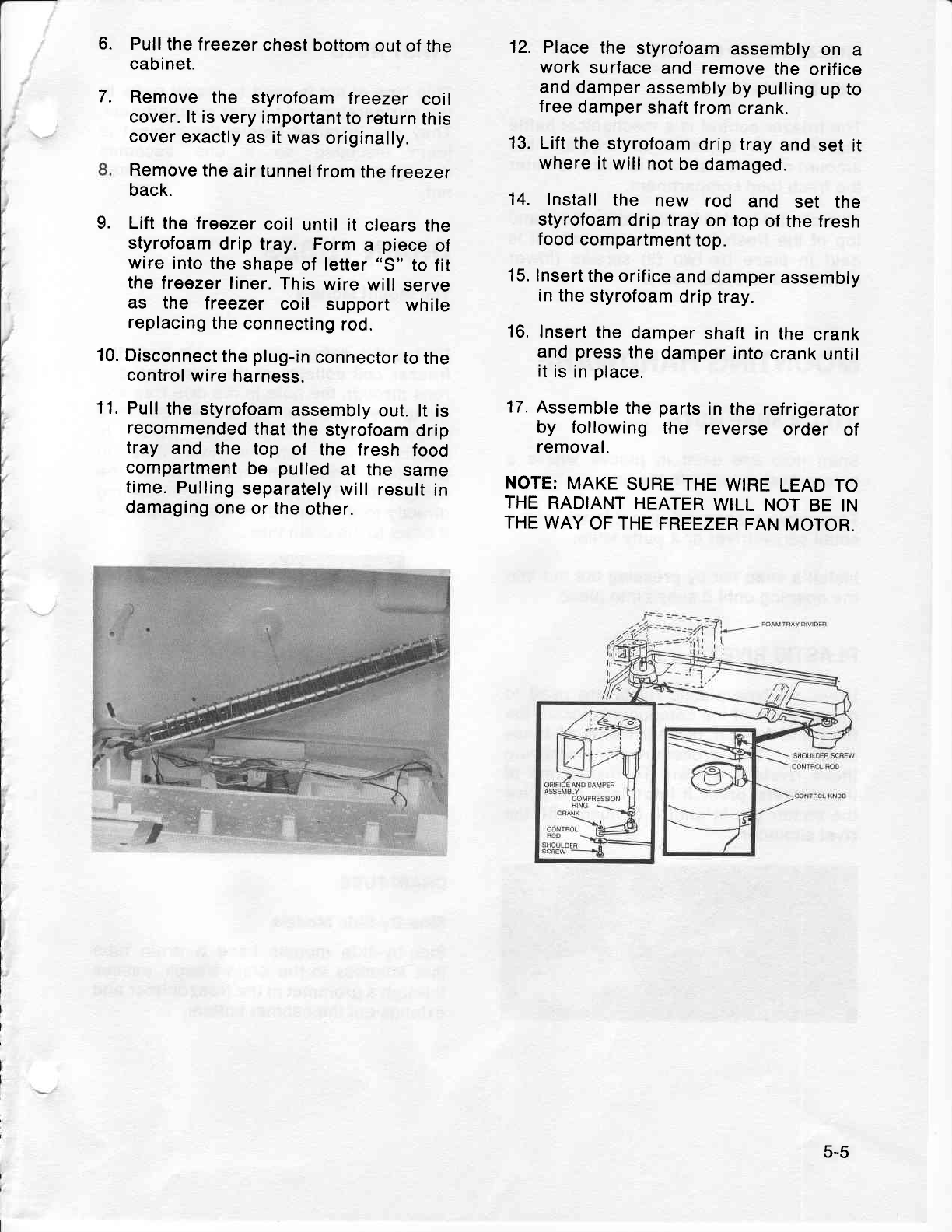
6.
7.
Pull
the lreezer
chest
bottom
out
of the
cabinet.
Remove
the styrofoam
lreezer coil
cover.
lt is very
important
to return
this
cover
exactly
as it
was
originally.
Remove
the
air
tunnel
from
the treezer
back.
Lift
the
freezer
coil
until it clears
the
styrofoam
drip tray. Form
a piece
of
wire
into the
shape
of letter
"S" to
fit
the
freezer
liner.
This
wire
will
serve
as the treezer coil support while
replacing
the
connecting
rod.
10.
Disconnect
the
plug-in
connector
to the
control
wire
harness.
11.
Pull
the
styrofoam
assembly
out.
lt is
recommended
that the
styrofoam
drip
tray and the top of the fresh food
compartment
be pulled
at the same
time.
Pulling
separately
will
result
in
damaging
one or
the
other.
12. Place
the styrofoam
assembly
on a
work surface
and remove
the orifice
and
damper
assembly
by
pulling
up to
free
damper
shaft
from
crank.
13.
Lift the
styrofoam
drip tray
and
set it
where it
will
not
be damaged.
14. Install
the new rod and set the
styrofoam
drip
tray
on top
of the
fresh
food
compartment
top.
15. lnsert
the
orifice
and
damper
assembly
in the
styrofoam
drip tray.
16.
Insert
the
damper
shaft in the
crank
and
press
the
damper
into
crank
until
it
is
in
place.
17.
Assemble
the
parts
in
the
refrigerator
by following the reverse order of
removal.
NOTE:
MAKE
SURE
THE
WIRE
LEAD
TO
THE
RADIANT
HEATER
WILL
NOT
BE
IN
THE
WAY
OF THE
FREEZER
FAN
MOTOR.
9.
5-5
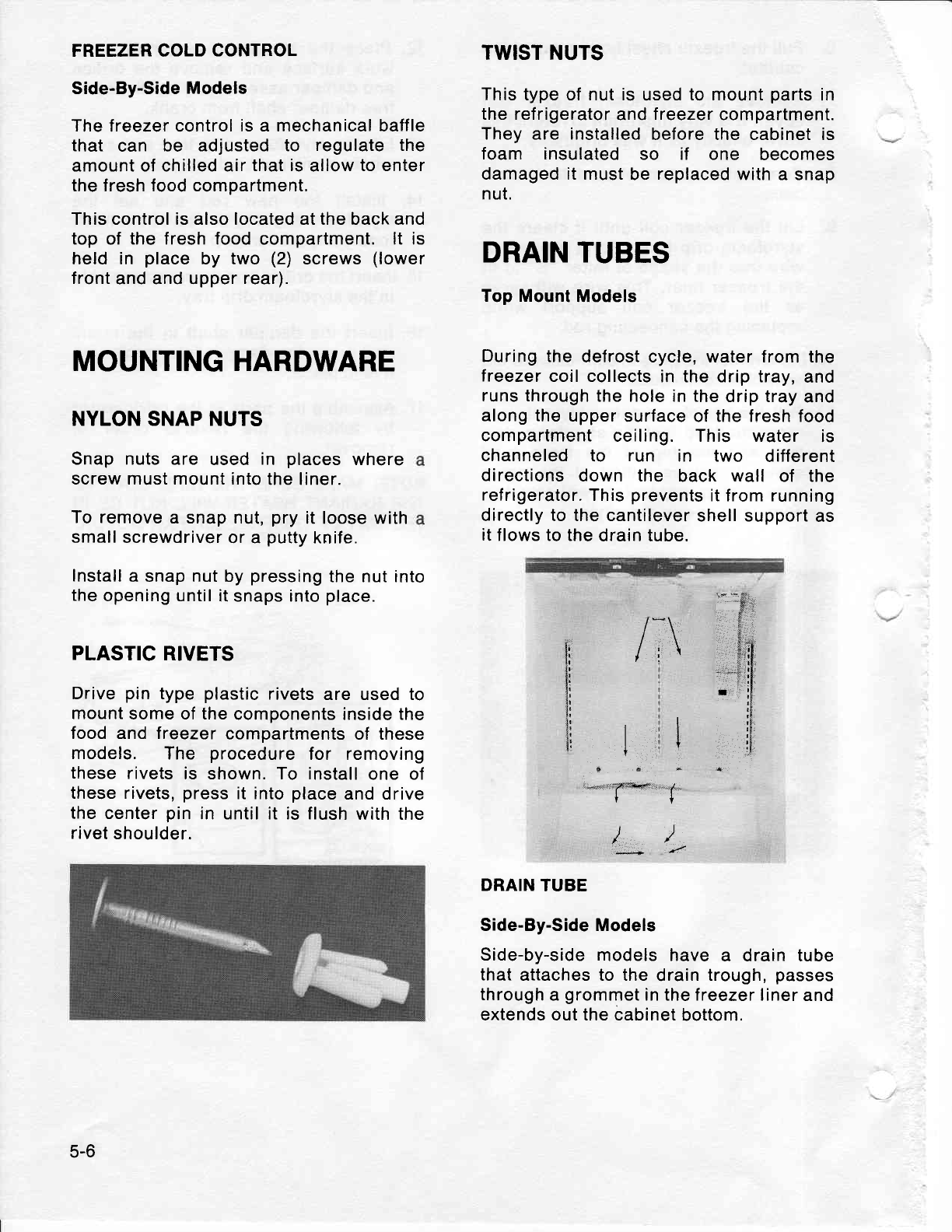
FREEZER COLD
CONTROL
Side-By-Side Models
The
freezer control
is a mechanical baffle
that can be adjusted to regulate the
amount of chilled air
that is
allow
to enter
the fresh food compartment.
This control is also located at the back and
top
of the fresh food
compartment.
lt is
held in place
by two (2)
screws
(lower
front
and and upper
rear).
MOUNTING HARDWARE
NYLON SNAP NUTS
Snap nuts are used
in places
where
screw must mount into
the liner.
To remove
a snap
nut,
pry
it loose
with
small screwdriver
or a
putty
knife.
Install
a snap nut by
pressing
the nut into
the
opening until
it snaps into
place.
PLASTIC
RIVETS
Drive
pin
type
plastic
rivets
are used to
mount
some of the
components inside the
food and treezer
compartments of these
models. The procedure
for removing
these
rivets
is shown. To install
one of
these rivets,
press
it into
place
and drive
the center
pin
in until it is flush
with the
rivet
shoulder.
TWIST NUTS
This type of nut is
used
to mount
parts
in
the refrigerator
and
treezer
compartment.
They are installed
before the cabinet is
foam insulated
so if one becomes
damaged it must
be
replaced
with a snap
nut.
DRAIN TUBES
Top Mount
Models
During the
defrost cycle, water from the
treezer
coil collects
in the drip tray,
and
runs through
the hole in the
drip tray
and
along
the
upper
surface of the fresh food
compartment
ceiling. This water is
channeled to run in two different
directions
down the back wall of the
refrigerator.
This
prevents
it from running
directly to the cantilever
shell support
as
it
flows to the
drain tube.
i':
ll
il
l!
li
{i
:l;
tl
tr
t,
/:\
*$
,$
i$,
I
i
(
/* /
DRAIN
TUBE
Side-By-Side Models
Side-by-side
models have
a drain tube
that
attaches to the
drain
trough,
passes
through
a
grommet
in the lreezer liner
and
extends out the cabinet
bottom.
5-6
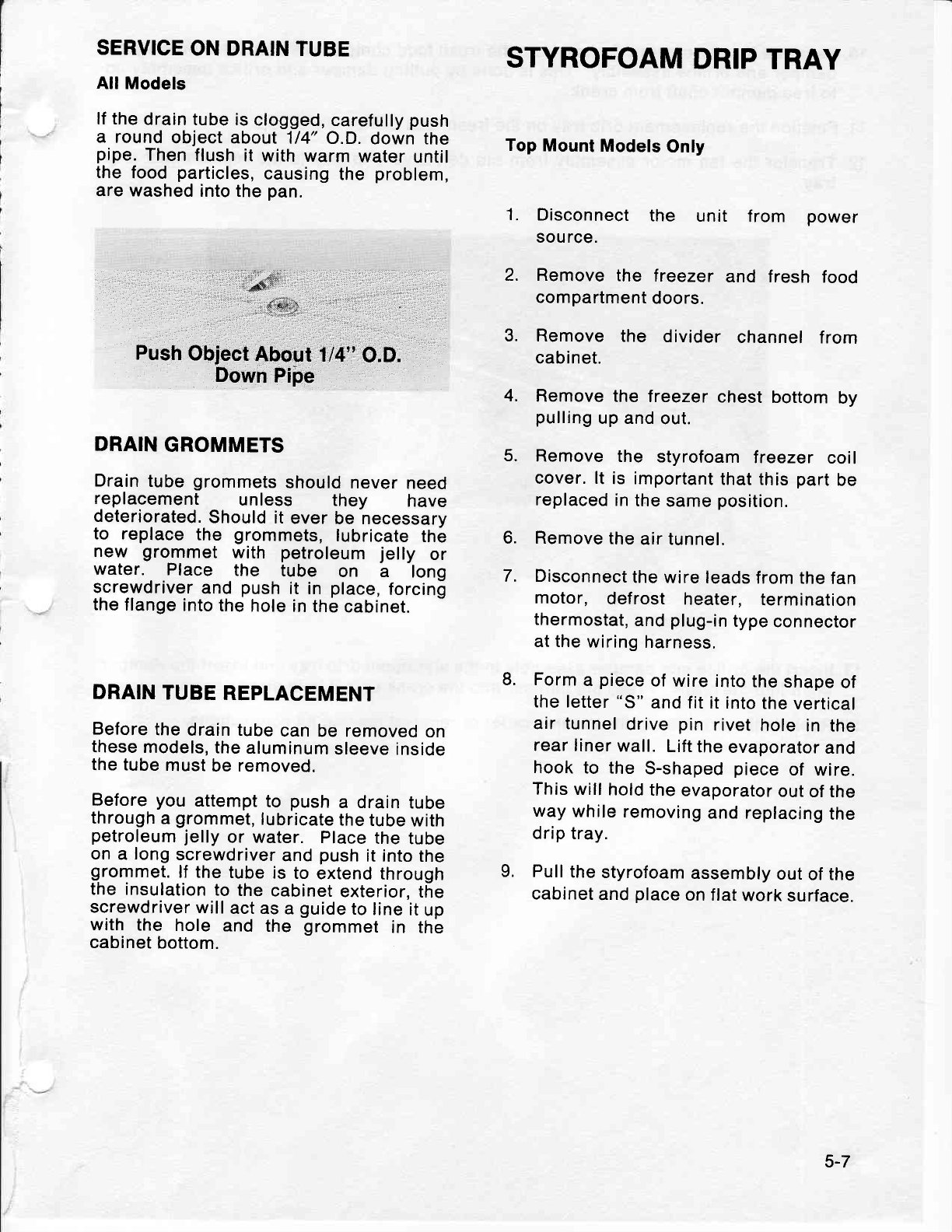
SERVICE
ON DRAIN
TUBE
All Models
lf the
drain
tube is
clogged,
carefully
push
a round
object about
114"
O.D.
down the
pipe.
Then
flush
it with
warm
water
until
the
food
particles,
causing
the problem,
are washed
into the
pan.
STYROFOAM
DRIP
TRAY
Top
Mount
Models
Only
1. Disconnect
the unit f rom power
source.
2. Remove
the freezer
and fresh food
compartment
doors.
3. Remove
the divider channel
from
cabinet.
4. Remove
the freezer
chest
bottom
by
pulling
up and
out.
5. Remove
the styrofoam
treezer coil
cover. lt is important
that this
part
be
replaced
in
the
same
position.
6. Remove
the
air tunnel.
7. Disconnect
the
wire leads
from
the fan
motor, def rost heater, termination
thermostat,
and
plug-in
type
connector
at the
wiring
harness.
Form
a piece
of
wire into
the
shape
of
the letter
"S"
and
fit it into
the
vertical
air tunnel
drive
pin
rivet
hole
in the
rear
liner
wall.
Lift
the
evaporator
and
hook
to the S-shaped
piece
of wire.
This
will
hold
the
evaporator
out
of the
way
while
removing
and replacing
the
drip tray.
Pull
the
styrofoam
assembly
out
of the
cabinet
and
place
on flat
work
surface.
''N-*-
= *,*,U
Push
Object
About
114"
O.;.
Down
Pipe
DRAIN
GROMMETS
Drain
tube
grommets
should
never
need
replacement unless they have
deteriorated.
Should
it
ever
be necessary
to replace
the grommets,
lubricate
the
new grommet
with petroleum
jelly or
water. Place the tube on a long
scre-wdriver
and
push
it in place,
forcing
the
flange
into
the
hole in
the
cabinet.
DRAIN
TUBE
REPLACEMENT
Before
the
drain tube
can
be removed
on
these
models,
the
aluminum
sleeve inside
the tube
must
be removed.
Before
you attempt
to push
a drain
tube
through
a
grommet,
lubricate
the
tube
with
petroleum
jelly
or water. Place
the
tube
on
a long
screwdriver
and
push
it into
the
grommet.
lJ the
tube
is
to
extend
through
the insulation
to
the
cabinet
exterior,
the
screwdriver
will
act
as a
guide
to
line
it
up
with the hole and the grommet
in the
cabinet
bottom.
8.
L
5-7
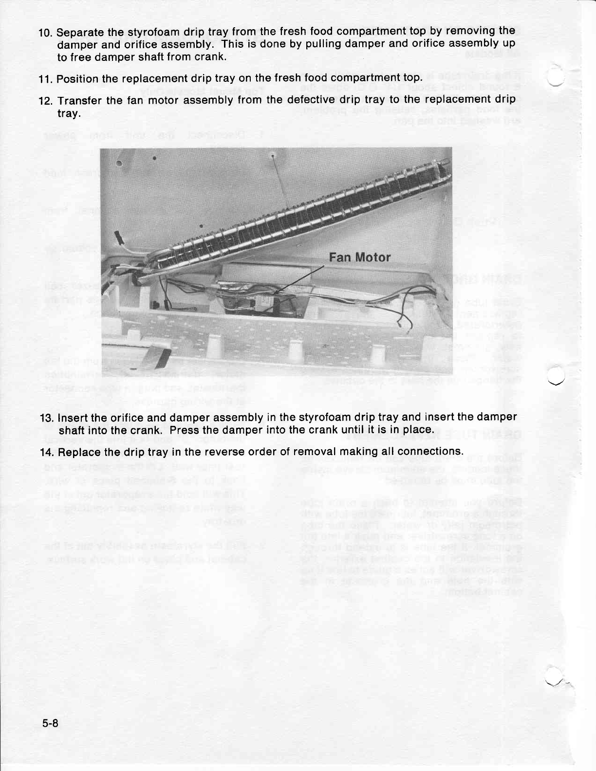
10.Separate
the styrofoam
drip
tray
from the
fresh food
compartment
top by
removing
the
damper
and orifice
assembly.
This
is
done
by
pulling
damper
and orifice
assembly
up
to free
damper shaft
from crank.
Position
the replacement
drip
tray on
the fresh
food compartment
top.
Transfer
the fan motor assembly
from the defective
drip
tray to the replacement
drip
tray.
lnsert the orifice and
damper assembly
in the styrofoam drip
tray and
insert
the
damper
shaft
into the crank.
Press the damper
into
the crank until
it is in
place.
Replace
the
drip
tray
in the reverse
order of
removal making all connections.
11.
12.
13.
14.
5-8
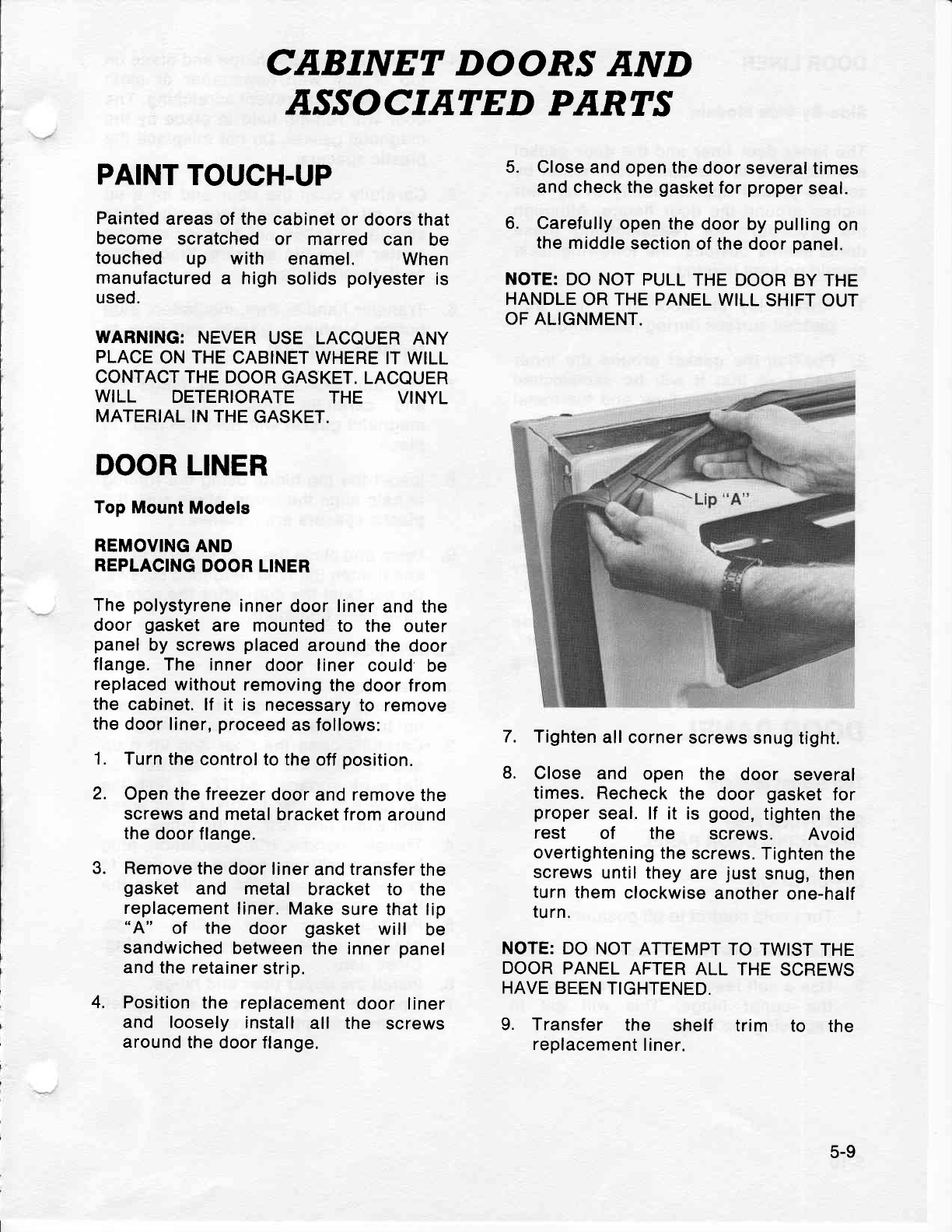
CABINET DOOR^S
AND
ASSOCIATED PARTS
PAINT
TOUCH.UP
Painted
areas of the
cabinet
or doors that
become scratched
or marred can be
touched up with enamel. When
manufactured
a high
solids
polyester
is
used.
WARNING:
NEVER
USE LACOUER
ANY
PLACE
ON THE CABINET
WHERE
IT WILL
CONTACT THE
DOOR
GASKET. LACQUER
WILL DETERIORATE THE VINYL
MATERIAL
IN THE
GASKET.
DOOR LINER
Top Mount
Models
REMOVING
AND
REPLACING
DOOR
LINER
The
polystyrene
inner
door liner
and the
door gasket
are mounted
to the outer
panel
by screws
placed
around the door
flange.
The inner
door liner
could be
replaced
without
removing
the
door from
the cabinet.
lf it is necessary
to remove
the
door liner,
proceed
as follows:
1. Turn
the
control to the
off
position.
2. Open the freezer
door
and remove
the
screws
and metal
bracket from
around
the
door flange,
Remove
the door
liner
and
transfer
the
gasket and metal bracket to the
replaeement
liner.
Make
sure that lip
"A" of the door gasket will be
sandwiched
between
the inner
panel
and the retainer
strip.
Position
the replacement
door liner
and loosely install
all the screws
around
the
door flange.
5. Close and
open the
door several
times
and check the
gasket
for
proper
seal.
6. Carefully
open the
door
by
pulling
on
the
middle
section
of the
door
panel.
NOTE: DO NOT
PULL
THE DOOR
BY THE
HANDLE
OR THE PANEL
WILL
SHIFT OUT
OF ALIGNMENT.
Tighten
all corner
screws
snug tight.
Close and open the door several
times.
Recheck
the door gasket
for
proper
seal. lf it is good,
tighten
the
rest of the screws. Avoid
overtightening
the
screws.
Tighten
the
screws
until they
are
just
snug, then
turn them
clockwise
another
one-half
turn.
NOTE:
DO
NOT ATTEMPT
TO
TWIST
THE
DOOR
PANEL
AFTER
ALL
THE
SCREWS
HAVE BEEN
TIGHTENED.
9. Transfer the shelf trim to the
replacement
liner.
7.
L
3.
4.
5-9
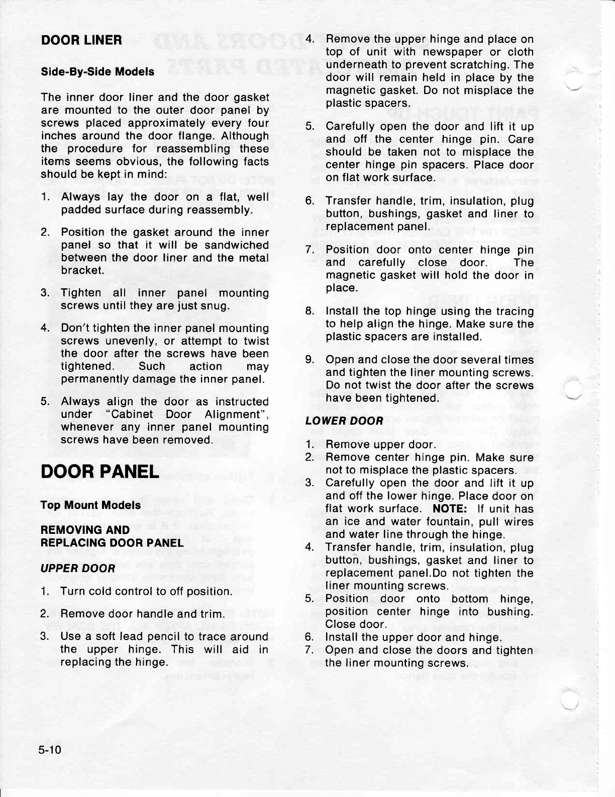
DOOR
LINER
Side-By-Side
Models
The inner door liner and the
door
gasket
are mounted to the
outer door
panel
by
screws
placed
approximately every four
inches
around
the
door
flange.
Although
the procedure
for reassembling these
items
seems obvious, the following facts
should be
kept in
mind:
1. Always lay the door on a flat, well
padded
surface
during reassembly.
2. Position the
gasket
around the inner
panel
so that it will be sandwiched
between the
door
liner
and the metal
bracket.
3. Tighten
all inner panel mounting
screws until they
are
just
snug.
4. Don't
tighten the inner
panel
mounting
screws unevenly,
or attempt to twist
the door after
the screws have
been
tightened. Such action may
permanently
damage the inner
panel.
5. Always
align the door as instructed
under "Cabinet
Door Alignment",
whenever
any inner
panel
mounting
screws have
been
removed.
DOOR PANEL
Top Mount Models
REMOVING
AND
REPLACING
DOOR PANEL
UPPER
DOOR
1. Turn
cold control to
off
position.
2. Remove
door handle
and trim.
3. Use a soft lead
pencil
to trace
around
the upper hinge.
This will aid in
replacing the hinge.
4. Remove
the upper hinge and
place
on
top of unit
with newspaper
or cloth
underneath
to
prevent
scratching. The
door will remain held in place
by the
magnetic
aasket.
Do not misplace
the
plastic
spacers.
5. Carefully open the
door and lift it up
and off the center hinge
pin. Care
should be taken not to misplace the
center hinge
pin
spacers. Place door
on flat work
surface.
6. Transfer handle,
trim, insulation,
plug
button,
bushings,
gasket
and
liner
to
replacement
panel.
7. Position
door onto center
hinge
pin
and caref
ully close door. The
magnetic
gasket
will
hold the door in
place.
8. Install
the top hinge
using the tracing
to help
align the hinge. Make
sure the
plastic
spacers are installed.
L Open and
close
the
door
several
times
and
tighten
the liner
mounting screws.
Do not twist
the door
after
the
screws
have
been tightened.
LOWER DOOR
Remove
upper
door.
Remove
center hinge
pin.
Make
sure
not to misplace
the
plastic
spacers.
Carefully open the
door and lift it up
and off the lower
hinge. Place
door on
flat work surface.
NOTE: lf unit has
an ice
and
water
fountain,
pull
wires
and
water
line through
the hinge.
Transfer
handle,
trim, insulation,
plug
button, bushings,
gasket
and
liner
to
replacement
panel.Do
not tighten
the
liner mounting
screws.
Position
door onto bottom hinge,
position
center hinge
into bushing.
Close door.
Install the
upper door
and
hinge.
Open
and close the
doors and tighten
the liner
mounting
screws.
1.
2.
3.
4.
5.
o.
7.
5-10
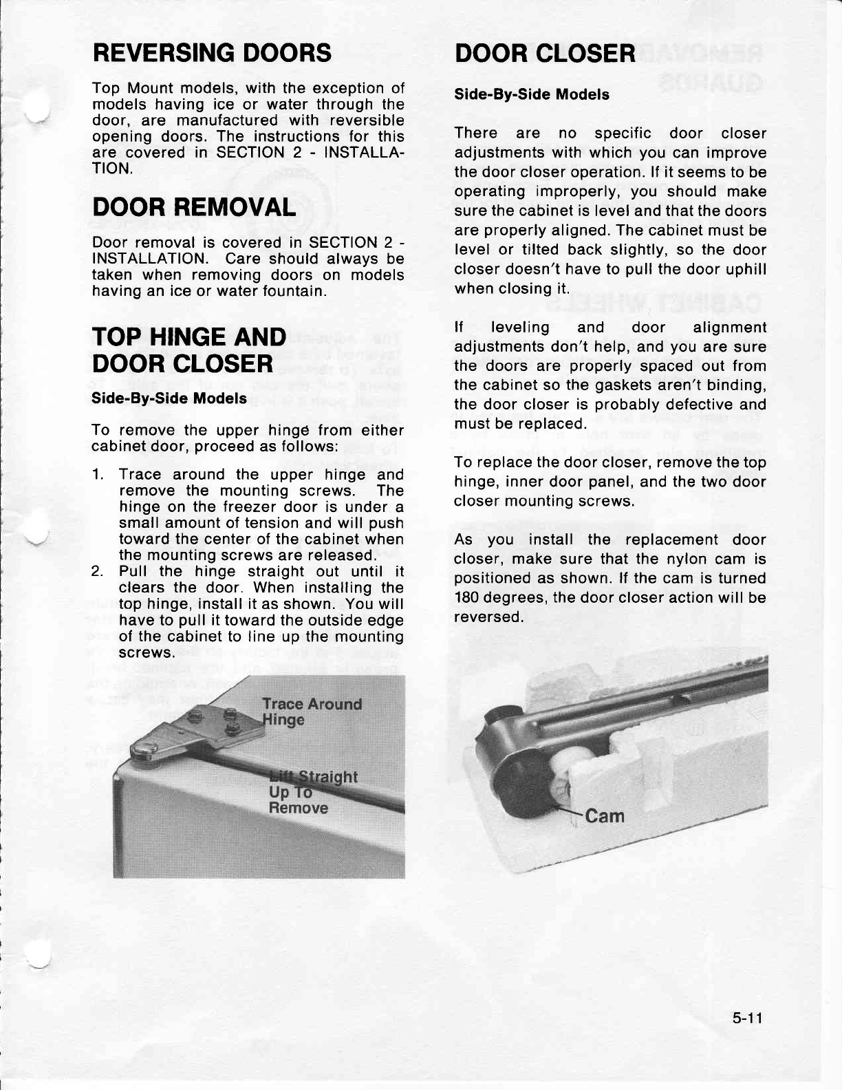
REVERSING DOORS
Top
Mount models, with the exception of
models
having
ice
or water through the
door, are manufactured with reversible
opening
doors.
The instructions for this
are covered
in SECTION
2 - INSTALLA-
TION.
DOOR
REMOVAL
Door
removal is covered in SECTION
2 -
INSTALLATION.
Care should
always
be
taken when removing
doors on models
having
an
ice
or
water fountain.
TOP HINGE
AND
DOOR
CLOSER
Side-By-Side Models
To remove the upper
hingd from
either
cabinet
door,
proceed
as follows:
1. Trace
around the upper hinge
and
remove
the mounting
screws. The
hinge
on the lreezer door is under a
small
amount of
tension
and will
push
toward
the center of the cabinet when
the mounting
screws are released,
2. Pull the hinge straight
out until it
clears the door.
When installing
the
top
hinge,
install
it as shown. You will
have
to
pull
it
toward the
outside edge
of
the
cabinet to line up the mounting
screws.
DOOR
CLOSER
Side-By-Side Models
There are no specif ic door closer
adjustments with which
you
can improve
the door
closer operation.
lf
it seems to
be
operating
improperly,
you should make
sure
the
cabinet
is
level and that the
doors
are
properly
aligned. The
cabinet must be
level
or tilted back
slightly, so the
door
closer doesn't have to
pull
the
door uphill
when
closing it,
lf leveling and door alignment
adjustments
don't
help,
and
you
are sure
the doors
are properly
spaced out from
the
cabinet so
the
gaskets
aren't
binding,
the door closer is
probably
defective and
must
be
replaced.
To replace the
door closer,
remove
the top
hinge, inner
door
panel,
and the two door
closer mounting screws.
As you install the replacement
door
closer, make
sure
that the nylon
cam is
positioned
as shown.
lf the
cam is turned
180
degrees,
the
door closer action will
be
reversed.
5-11
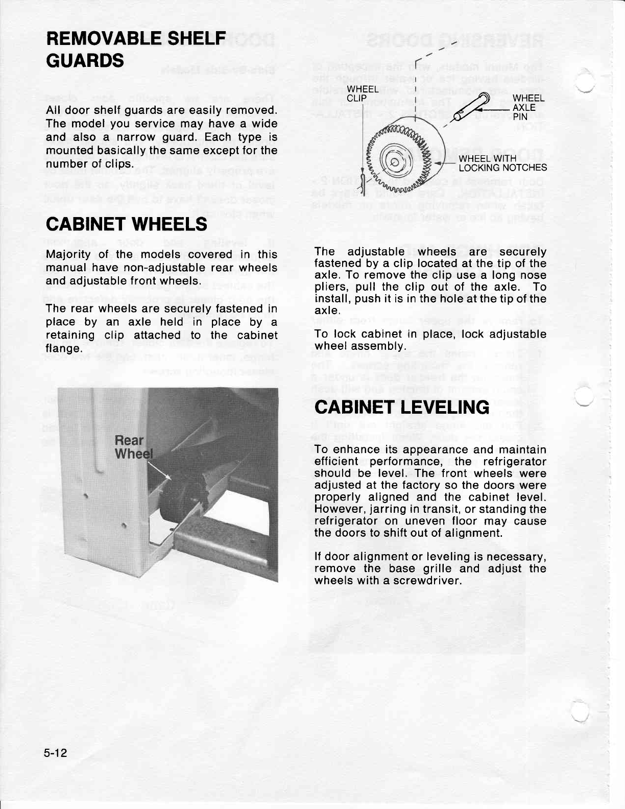
REMOVABLE
SHELF
GUARDS
All
door
shelf
guards
are
easily
removed.
The model
you
service may have a wide
and also a narrow
guard.
Each type is
mounted basically the same except for the
number
of clips.
CABINET
WHEELS
Majority
of the models covered in this
manual have non-adjustable
rear wheels
and adjustable front wheels.
The rear wheels
are securely fastened in
place by an axle held in place by a
retaining
clip attached
to the cabinet
f lange.
WHEEL
CLIP e-[fi'?"
WHEEL
WITH
LOCKING
NOTCHES
The adjustable wheels are securely
fastened
by a clip located
at
the tip
of
the
axle. To remove the
clip use a long nose
pliers, pull
the clip
out of
the
axle. To
install,
push
it is in the hole
at the tip of the
axle.
To lock cabinet in place,
lock adjustable
wheel
assembly.
CABINET LEVELING
To
enhance its appearance
and
maintain
eff icient performance,
the ref rigerator
should be level.
The front wheels
were
adjusted at the factory
so
the
doors were
properly
aligned and the cabinet level.
However,
jarring
in transit,
or standing the
refrigerator
on uneven
floor
may cause
the
doors
to
shift out of
alignment.
lf
door alignment
or
leveling
is necessary,
remove
the base
grille and adjust
the
wheels with a
screwdriver,
5-12
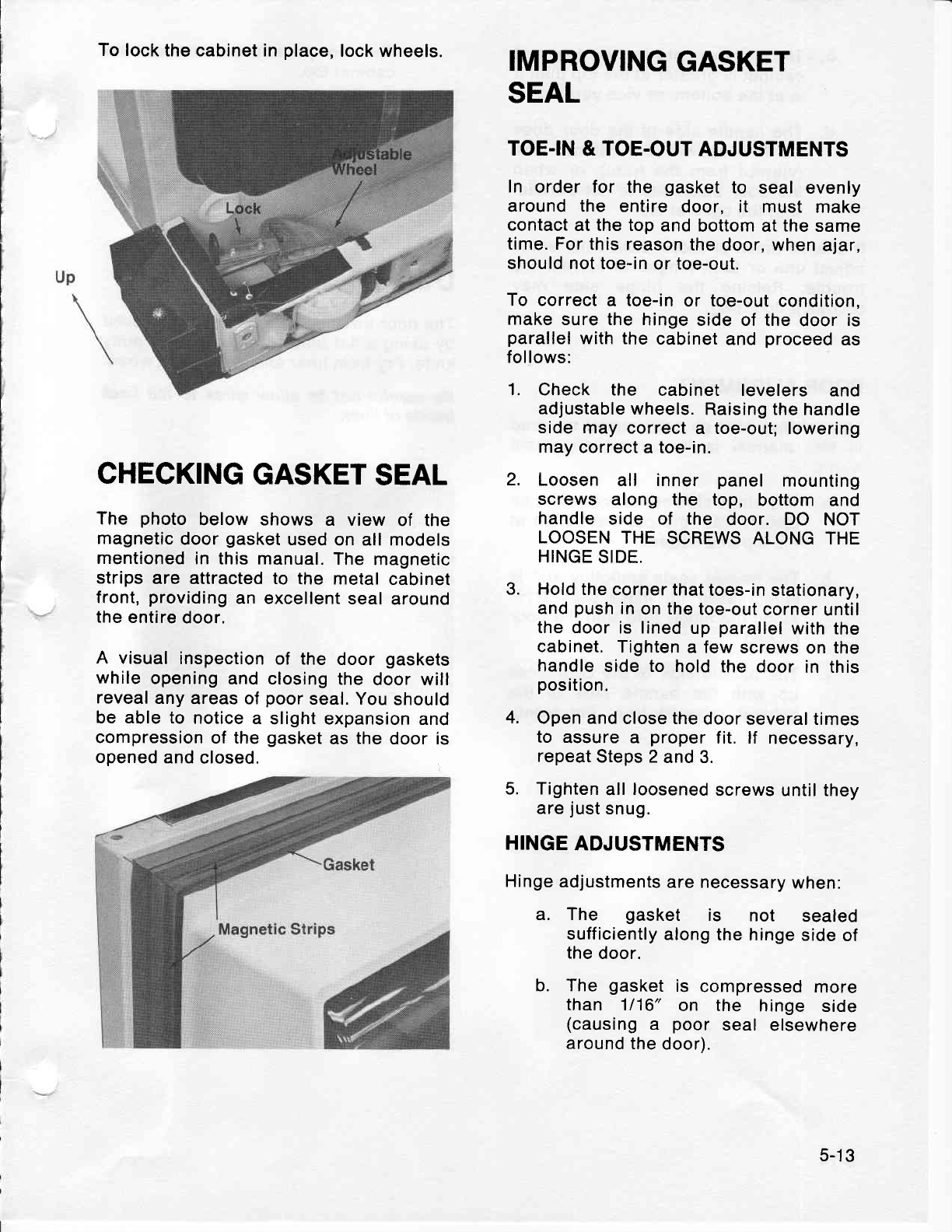
To lock
the cabinet in
place,
lock wheels. IMPROVING
GASKET
CHECKING
GASKET
SEAL
The photo below shows a view of the
magnetic
door
gasket
used
on all models
mentioned
in this manual.
The
magnetic
strips
are attracted to the metal
cabinet
front,
providing
an excellent
seal
around
the
entire
door.
A visual
inspection
of the door
gaskets
while
opening
and closing
the
door will
reveal
any
areas of
poor
seal. You
should
be able
to notice
a slight expansion
and
compression
of the
gasket
as
the
door is
opened
and closed.
SEAL
TOE.IN
&
TOE.OUT
ADJUSTMENTS
In order for the gasket
to seal evenly
around the entire
door, it must make
contact
at the top
and
bottom at the same
time. For
this reason
the
door, when
ajar,
should not toe-in
or toe-out.
To correct a toe-in
or toe-out
condition,
make
sure the
hinge
side of the
door
is
parallel
with the
cabinet
and
proceed
as
follows:
1. Check the cabinet levelers and
adjustable wheels.
Raising the
handle
side
may correct
a toe-out; lowering
may
correct
a
toe-in.
2. Loosen
all inner panel mounting
screws along the top, bottom
and
handle
side of the door. DO NOT
LOOSEN
THE
SCREWS ALONG
THE
HINGE
SIDE.
3. Hold
the
corner that
toes-in
stationary,
and
push
in
on
the
toe-out
corner
until
the door
is lined
up
parallel
with the
cabinet.
Tighten
a few
screws
on
the
handle
side to hold the door
in this
position.
4. Open and
close the
door
several times
to assure a proper
fit. lf necessary,
repeat
Steps 2
and 3.
5. Tighten
all
loosened
screws
until they
are
just
snug.
HINGE
ADJUSTMENTS
Hinge
adjustments
are necessary
when:
a. The gasket is not sealed
sufficiently
along
the hinge
side
of
the
door.
b. The gasket
is compressed
more
than 1116"
on the hinge side
(causing
a poor seal elsewhere
around
the
door).
5-1
3
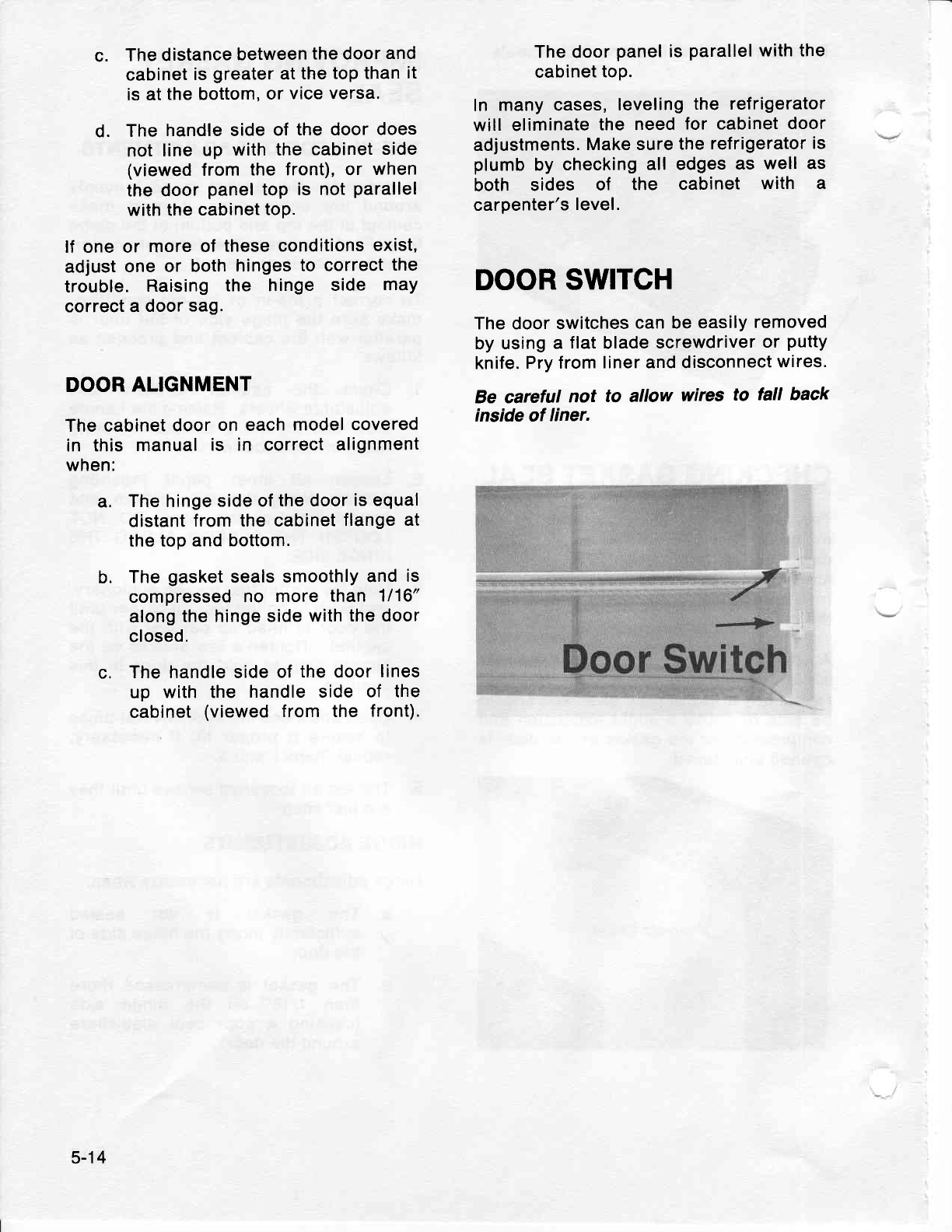
c. The distance
between
the door
and
cabinet
is
greater
at
the
top than
it
is at
the bottom,
or
vice versa.
d. The
handle side
of
the door
does
not
line up with the
cabinet
side
(viewed
from the front), or when
the door
panel
toP
is not
Parallel
with the
cabinet
toP.
lf one or more
of these conditions
exist,
adjust
one or both
hinges
to correct
the
trouble. Raising
the hinge side may
correct a
door
sag.
DOOR
ALIGNMENT
The cabinet
door
on each
model
covered
in this manual
is in correct
alignment
when:
a. The hinge
side of
the door
is equal
distant
from the cabinet
flange
at
the top and
bottom.
b. The
gasket
seals
smoothly
and
is
compressed
no more
than 1116"
along
the hinge side
with
the door
closed.
c. The handle side
of
the
door
lines
up with the handle side of the
cabinet
(viewed
from the front).
The door
panel
is
parallel
with the
cabinet
top.
In many cases,
leveling
the refrigerator
will eliminate
the need
for cabinet
door
adjustments.
Make sure
the
refrigerator
is
plumb
by checking
all edges
as well as
both sides of the cabinet with a
carpenter's
level.
DOOR
SWITCH
The door switches
can be easily
removed
by
using
a flat
blade
screwdriver
or putty
knife.
Pry from
liner and disconnect
wires.
Be carefut not to allow wires to tall back
inside of liner.
5-14
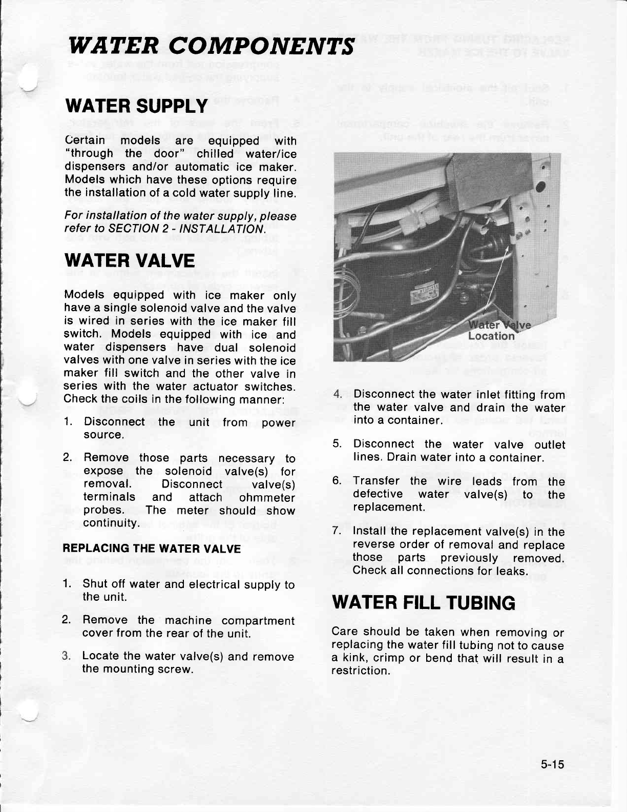
WATER COMPONENTS
WATER
SUPPLY
Certain models are equipped with
"through the door" chilled water/ice
dispensers
and/or
automatic ice maker.
Models
which
have these
options require
the installation
of
a cold water
supply line.
For installation
of
the
water
supply,
please
refer
to SECTION 2
- INSTALLATION.
WATER
VALVE
Models
equipped
with ice maker only
have
a
single solenoid
valve
and the valve
is wired in series
with
the ice
maker
fill
switch,
Models
equipped
with ice and
water dispensers
have dual solenoid
valves
with
one valve
in
series with
the ice
maker fill switch
and the other
valve
in
series
with the
water
actuator
switches.
Check
the
coils in
the
following
manner:
1. Disconnect
the unit from power
source.
2. Remove those parts necessary
to
expose the solenoid valve(s) for
removal. Disconnect valve(s)
terminals and attach ohmmeter
probes. The meter should show
continuity.
REPLACING
THE WATER
VALVE
1. Shut
off water
and electrical
supply to
the
unit.
Remove
the machine
compartment
cover from
the rear
of the unit.
Locate
the
water
valve(s)
and remove
the
mounting
screw.
5.
Disconnect
the
water inlet
fitting
from
the water
valve
and drain
the water
into
a container.
Disconnect
the water valve outlet
lines.
Drain
water
into
a container.
6. Transfer
the wire leads from the
defective water valve(s) to the
replacement.
7. Install
the replacement
valve(s)
in
the
reverse
order
of removal
and replace
those parts previously removed.
Check
all
connections
for
leaks.
WATER
FILL
TUBING
Care
should
be taken
when
removing
or
replacing
the
water fill
tubing
not
to
cause
a kink,
crimp
or
bend that
will result
in
a
restriction.
2.
5-1
5
REPLACING
TUBING
FROM THE WATER
VALVE
TO THE ICE
MAKER
1. Shut
off the electrical supply
to the
unit.
2. Remove
the machine
compartment
cover
from
the rear
of
the unit.
3. Remove
the water valve mounting
screw and disconnect the ice maker
supply
tubing from the water
valve.
Drain the
water into
a container.
4. Remove the wire cover from the
cabinet back.
5. Remove the tubing clamps
from the
cabinet back.
6. Remove
the
clamp
which fastens the
supply tubing to the fill grommet
supplying the ice maker.
7. lnstall the replacement
tubing
in the
reverse
order of removal
and check
all connections
for
leaks.
NOTE: When installing the
supply
tubing
care
should be
taken not to crimp, kink or
bend the tubing so that a restriction
is
formed.
REPLACING TUBING
FROM
WATER
VALVE
TO WATER
RESERVOIR
1. Shut off the electrical supply
to the
unit.
2. Remove the machine compartment
cover from the rear of the unit.
3. Remove
the water valve mounting
screw and disconnect the
compression nut from the water valve
supplying the
chilled
water fountain.
4. Remove the
crisper shelf.
5. From the back of the refrigerator,
disconnect the compression nut from
the
bottom
reservoir
connection.
Drain
the water
into a container.
6. Pull the comoression nut off of the
supply
tubing
and pull the supply
tubing f
rom the back of the unit
through the bottom. (To pull new
tubing,
tie
to the old and
pull
with old
tubing.)
7. Install the replacement tubing in the
reverse order of removal.
8. Turn on the electrical and water
supply and activate the chilled water
dispenser. Draw six or seven
glasses
of water to remove
any trapped air in
the
system. Check all
fittings for leaks.
REPLACING THE TUBING FROM THE
RESERVOIR
TO
THE FOUNTAIN
The
supply
tubing from
the
reservoir to the
fountain is
composed of
two
sections and
extends
from:
1. Reservoir to a connection
at the
bottom of
the
cabinet behind
the right
side
of
the
grille.
2. Then, from the connection behing the
grille
to the fountain.
5-16
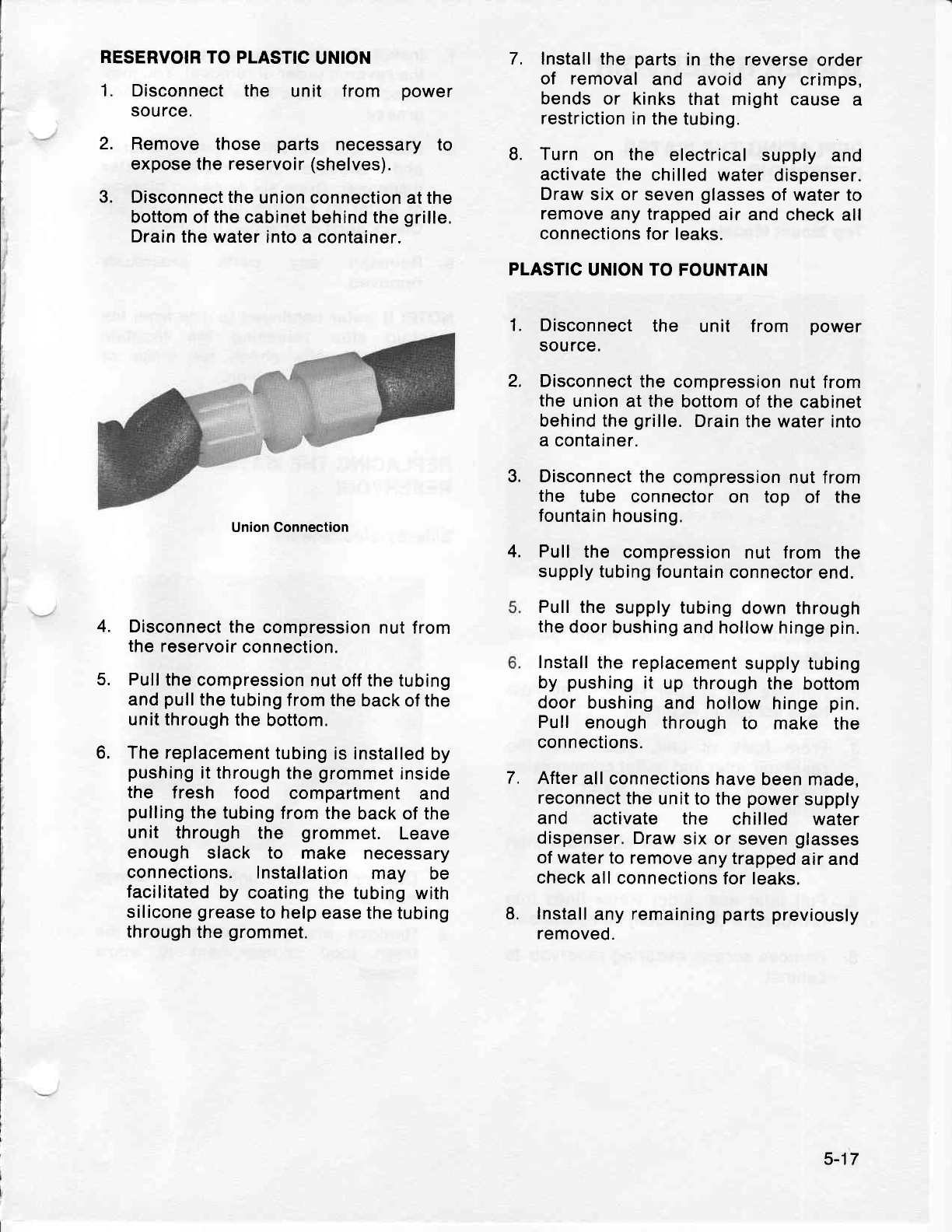
RESERVOIR
TO PLASTIC
UNION
1. Disconnect the unit from power
source.
2. Remove those parts necessary to
expose the reservoir
(shelves).
3. Disconnect the
union connection
at the
bottom
of
the cabinet
behind the
grille.
Drain
the water
into a container.
Union Connection
Disconnect
the
compression
nut from
the reservoir
connection.
Pull
the
compression
nut off the
tubing
and
pull
the tubing from
the
back of the
unit through
the
bottom.
The replacement
tubing
is installed
by
pushing
it through
the
grommet
inside
the fresh food compartment
and
pulling
the tubing
from the
back of the
unit through the grommet. Leave
enough slack to make necessary
connections.
Installation
may be
facilitated
by coating the
tubing with
silicone
grease
to help
ease the tubing
through
the
grommet.
7. Install
the
parts
in the reverse
order
of removal
and avoid any crimps,
bends or kinks
that might
cause
a
restriction
in
the tubing.
L Turn on the electrical supply and
activate
the chilled water
dispenser.
Draw
six or seven
glasses
of water to
remove
any trapped
air
and check
all
connections
for
leaks.
PLASTIC
UNION TO
FOUNTAIN
Disconnect
the unit f rom power
source.
Disconnect
the
compression
nut from
the
union
at
the
bottom of the
cabinet
behind the
grille.
Drain
the water
into
a
container.
Disconnect
the
compression nut
from
the tube connector
on top of the
fountain
housing.
Pull the compression
nut from the
supply tubing
fountain
connector
end.
Pull the
supply
tubing
down through
the
door
bushing
and hollow hinge
pin.
Install
the replacement
supply
tubing
by pushing
it up through
the bottom
door
bushing
and hollow
hinge
pin.
Pull enough
through
to make the
connections.
After
all connections
have
been
made,
reconnect
the
unit to the
power
supply
and activate the chilled water
dispenser.
Draw
six
or seven
glasses
of water
to remove
any
trapped
air
and
check
all connections
for leaks.
lnstall
any
remaining
parts
previously
removed.
1.
2,
3.
4.
4.
5.
6,
7.
L
5-17
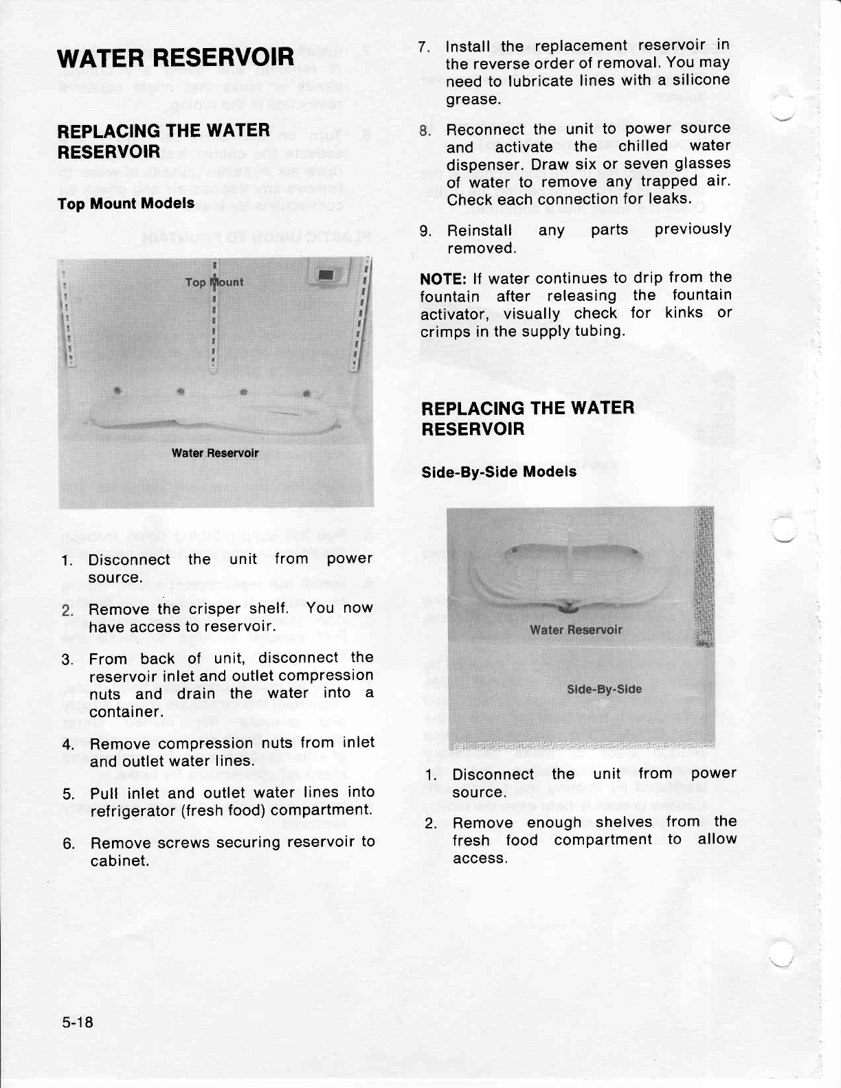
Water Reservoir
Disconnect
the unit f rom Power
source.
Remove
the crisper
shelf. You
now
have
access
to reservoir.
From back of unit, disconnect
the
reservoir
inlet
and
outlet
compression
nuts and drain the water into a
container.
Remove
compression
nuts
from
inlet
and outlet
water
lines.
Pull
inlet
and
outlet
water
lines
into
refrigerator
(fresh
food) compartment.
Remove
screws
securing
reservoir
to
cabinet.
Install
the replacement
reservoir
in
the reverse
order
of
removal.
You may
need
to lubricate
lines
with
a silicone
grease.
Reconnect
the unit
to Power
source
and activate the chilled water
dispenser.
Draw
six
or
seven
glasses
of water
to remove
anY
traPPed
air'
Check
each
connection
for
leaks.
L Reinstall any Parts PreviouslY
removed.
NOTE:
lf water
continues
to drip
from
the
fountain after releasing
the fountain
activator,
visually
check for kinks or
crimps
in
the supply
tubing.
REPLACING
THE
WATER
RESERVOIR
Side-By'Side
Models
lrll'::,l:rl:rilri::;irtll:l.:':,:llr'::,:rrr,,rr
li. :1"". . . '.i -.. : r' r'j;rr:
Disconnect
the unit f rom Power
source.
Remove
enough shelves
f rom the
f resh food compartment
to allow
access.
7.
WATER
RESERVOIR
REPLACING
THE
WATER
RESERVOIR
Top Mount
Models
f$i
f
$lii
$r
1.
1.
2.
5.
6.
3.
4.
5-18
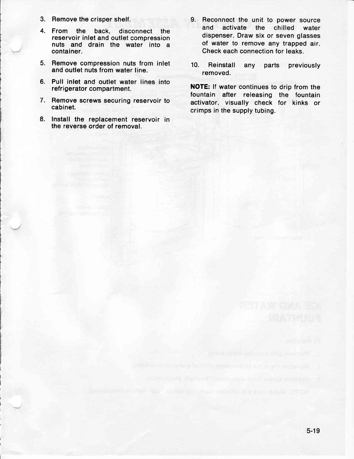
3.
4.
Remove
the crisper
shelf.
From the back, disconnect the
reservoir
inlet and
outlet
compression
nuts and drain the water into a
container.
Remove
compression nuts
from inlet
and
outlet
nuts
from water
line.
Pull
inlet
and outlet water lines
into
ref ri
gerator
compartment.
Remove
screws securing reservoir
to
cabinet.
Install
the replacement
reservoir
in
the reverse
order of removal.
9. Reconnect
the unit to power
source
and activate the chilled water
dispenser. Draw
six or seven
glasses
of water to remove
any trapped
air.
Check
each connection for
leaks.
10. Reinstall any
removed. parts previously
NOTE:
lf water
continues to drip from the
fountain after releasing the fountain
activator, visually
check for kinks or
crimps in
the supply tubing.
5.
6.
7.
8.
5-19
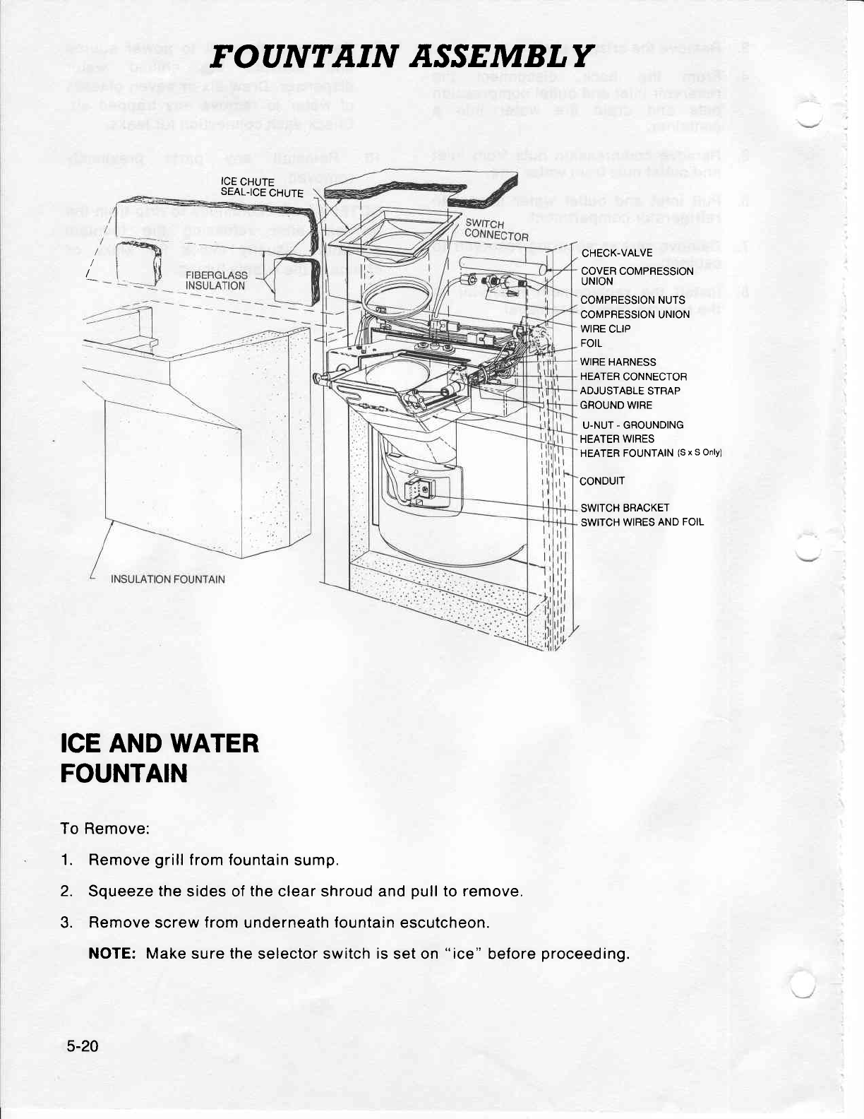
FOANTAIN ASSEMBLY
ICE
CHUTE
SEAL.ICE
CHUTE
CHECK-VALVE
COVER COMPRESSION
UNION
COMPBESSION
NUTS
COMPRESSION UNION
WIRE
CLIP
FOIL
WIRE
HARNESS
HEATER
CONNECTOR
ADJUSTABLE
STRAP
GROUND WIRE
U-NUT
-
GROUNDING
HEATER
WIRES
HEATER
FOUNTAIN
(S
x s only)
CONDUIT
SWITCH
BRACKET
SWITCH
WIRES
AND FOIL
ICE AND WATER
FOUNTAIN
To Remove:
1. Remove
grill
f rom fountain
sump.
2. Squeeze
the
sides of
the
clear shroud and
pull
to
remove.
3. Remove
screw
from
underneath
fountain
escutcheon.
NOTE: Make sure the
selector switch
is
set on "ice" before
proceeding.
5-20
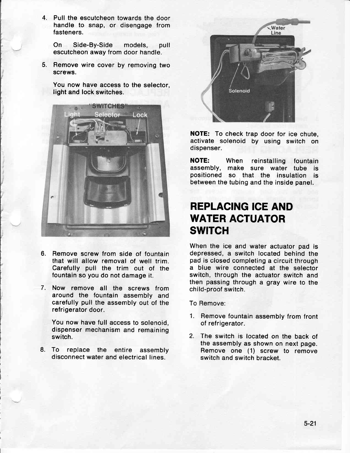
4.
5.
6.
7.
Pull the escutcheon
towards
the door
handle to snap,
or disengage
from
fasteners.
On Side-By-Side models, pull
escutcheon away from
door handle.
Remove wire cover by removing
two
screws.
You now have
access to the selector,
light
and lock
switches.
Remove
screw from
side
of fountain
that
will allow removal
of well
trim.
Carefully
pull the trim out of the
fountain
so
you
do not damage
it.
Now remove all the screws from
around the fountain
assembly
and
carefully
pull
the
assembly
out of the
refrigerator
door.
You now
have full
access to
solenoid,
dispenser
mechanism
and remaining
switch.
To replace the entire assembly
disconnect
water
and electrical
lines.
NOTE:
To
check trap
door for ice
chute,
activate
solenoid
by using switch on
dispenser.
NOTE: When reinstalling
fountain
assembly,
make sure water tube is
positioned
so that the insulation
is
between the
tubing
and the inside
panel.
REPLACING
ICE AND
WATER
ACTUATOR
swrTcH
When
the ice and water
actuator
pad is
depressed,
a switch located
behind
the
pad
is closed
completing
a
circuit through
a blue wire connected
at the selector
switch,
through the actuator switch
and
then
passing
through
a gray
wire
to the
child-proof
switch.
To Remove:
1. Remove
fountain
assembly from
front
of refrigerator.
2. The switch
is located
on the back
of
the
assembly
as shown
on next
page.
Remove
one (1) screw to remove
switch
and
switch
bracket.
8.
5-21
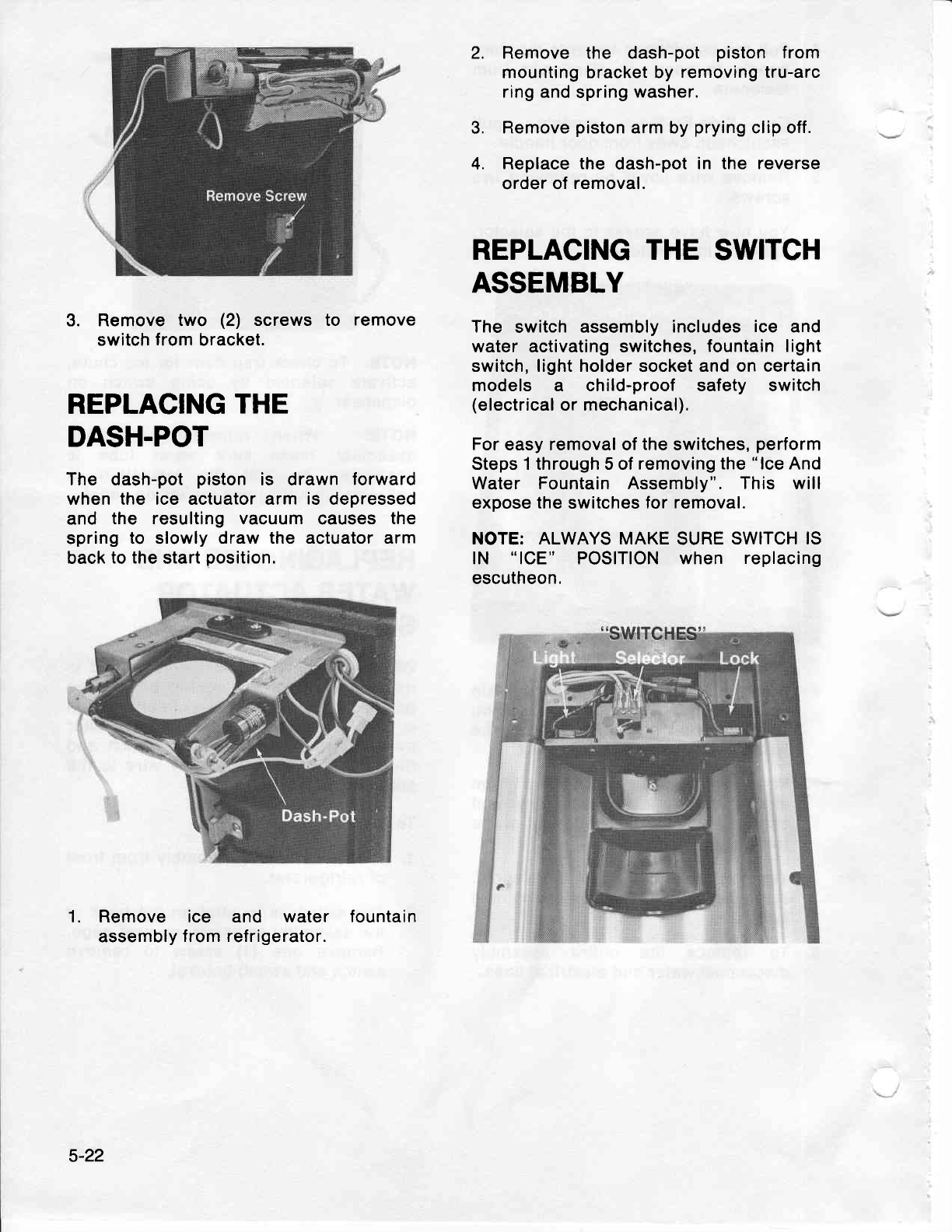
2.
3. Remove
two (2) screws to remove
switch
from
bracket.
REPLACING
THE
DASH-POT
The dash-pot
piston is drawn forward
when the ice actuator arm is depressed
and the resulting vacuum
causes
the
spring
to slowly
draw the actuator arm
back
to the
start
position.
1. Remove ice
assembly
from and water fountain
ref rigerator.
3.
4.
Remove the dash-pot piston from
mounting bracket by
removing tru-arc
ring
and spring
washer.
Remove
piston
arm by
prying
clip off.
Replace the dash-pot
in the reverse
order of
removal.
REPLACING THE SWITCH
ASSEMBLY
The switch assembly
includes
ice and
water activating switches,
fountain light
switch, light holder socket and on certain
models a child-proof safety switch
(electrical
or mechanical).
For
easy removal of
the
switches,
perform
Steps 1 through 5 of removing
the
"lce
And
Water Fountain Assembly". This will
expose
the
switches
for removal.
NOTE: ALWAYS MAKE
SURE
SWITCH IS
lN "lCE" POSITION when replacing
escutheon.
5-22
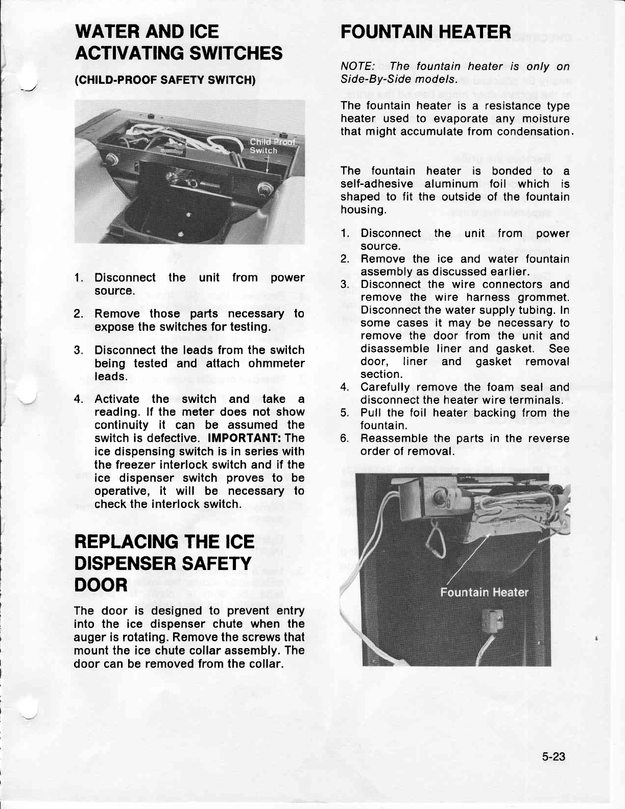
WATER AND
ICE
ACTIVATING
SWITCHES
(GH|LD-PROOF
SAFETY SWTTCH)
Disconnect the unit from power
source.
Remove those parts necessary to
expose
the switches for testing.
Disconnect the leads from
the switch
being tested and attach ohmmeter
leads.
Activate the switch and take a
reading. lf the meter does not show
continuity it can be assumed the
switch is defective. IMPORTANT: The
ice dispensing
switch is
in
series
with
the freezer interlock
switch and
if the
ice dispenser switch proves to be
operative, it will be necessary to
check the
interlock
switch.
FOUNTAIN
HEATER
NOTE: The fountain heater is only on
Slde-By-Side
models.
The fountain heater
is a nesistance type
heater
used
to evaporate any moisture
that might
accumulate from condensation.
The fountain heater is bonded to a
self-adhesive aluminum foil which is
shaped to fit the outside of the fountain
housing.
1. Disconnect the unit from power
source.
2. Remove the ice and water fountain
assembly as discussed earlier.
3. Disconnect
the wire connectors
and
remove the wire harness
grommet,
Disconnect
the water supply tubing. In
some cases it may be necessary to
remove the door
from the unit and
disassemble liner and gasket. See
door, liner and gasket removal
section.
4. Carefully
remove
the foam
seal and
disconnect the heater wire terminals.
5. Pull the foil heater
backing from the
fountain.
6. Reassemble the parts
in the reverse
order of removal.
1.
2.
3.
4.
REPLACING
THE ICE
DISPENSER
SAFETY
DOOR
The door. is designed to prevent
entry
into the ice dispenser chute when the
auger
is rotating. Remove the screws that
mount the ice chute collar assembly. The
door can be removed from the collar.
5-23
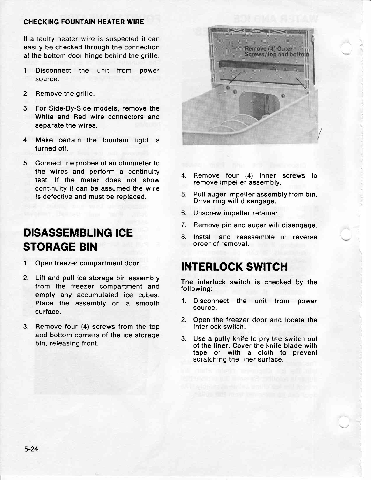
CHECKING
FOUNTAIN HEATER WIRE
lf a faulty
heater wire is suspected it can
easily be checked
through
the connection
at
the
bottom
door hinge
behind the
grille.
1. Disconnect the unit f rom power
source.
2. Remove the
grille.
3. For
Side-By-Side models, remove the
White and Red wire connectors and
separate
the wires.
Make certain the fountain light is
turned
off.
Connect the
probes
of an ohmmeter
to
the wires and perform
a continuity
test. lf the meter does not show
continuity
it
can be assumed the wire
is
defective and must
be
replaced.
Remove four (4) inner screws to
remove
impeller assembly.
Pull
auger impeller
assembly
from
bin.
Drive ring will
disengage,
Unscrew impeller retainer.
Remove
pin
and auger will disengage.
Install
and reassemble in reverse
order
of
removal.
4.
5.
4.
1.
2. INTERLOCK
SWITCH
The interlock
switch
following:
1. Disconnect the
source.
2. Open the freezer
door and locate the
interlock
switch.
3. Use
a putty
knife
to pry
the switch
out
of the liner.
Cover
the knife
blade with
tape or with a cloth to prevent
scratching
the liner
surface.
is checked by the
unit f rom power
3.
DISASSEMBLING ICE
6.
7.
8.
STORAGE BIN
Open
treezer
compartment door.
Lift
and
pull
ice
storage bin assembly
from the freezer compartment and
empty any accumulated ice cubes.
Place the assembly on a smooth
surface.
Remove four
(4)
screws from the top
and
bottom
corners
of
the
ice storage
bin, releasing front.
5-24
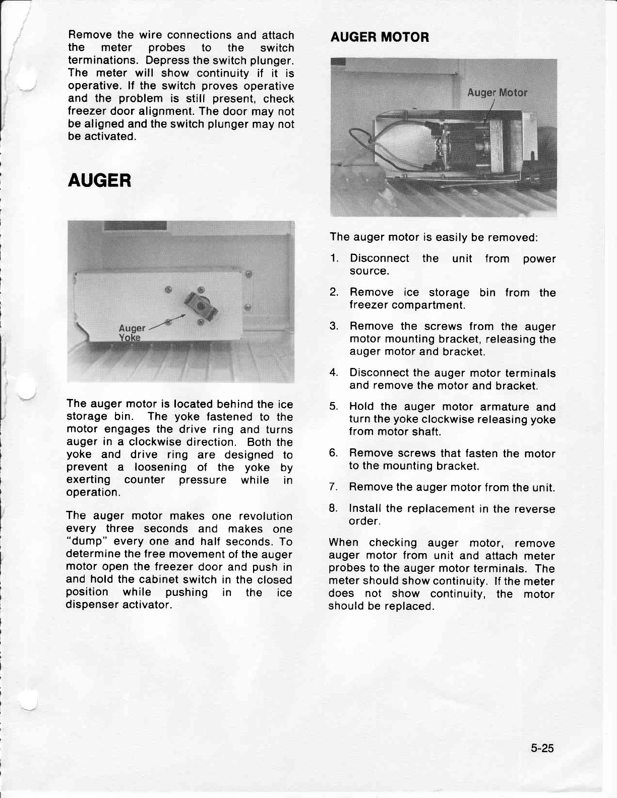
Remove
the wire
connections
and attach
the meter probes to the switch
terminations.
Depress the
switch
plunger.
The meter will show continuity
if it is
operative.
lf the switch
proves
operative
and the problem
is still present,
check
treezer
door alignment.
The door
may not
be
aligned and the
switch
plunger
may
not
be
activated.
AUGER
The
auger
motor is located
behind the ice
storage
bin. The yoke fastened
to the
motor
engages the
drive ring
and turns
auger in
a clockwise
direction. Both
the
yoke and drive ring are designed to
prevent
a loosening
of the yoke by
exerting counter pressure while in
operation.
The auger motor
makes
one revolution
every three seconds and makes one
"dump"
every
one and half
seconds. To
determine
the free
movement
of the
auger
motor
open the
treezer
door
and
push
in
and hold
the
cabinet
switch in the
closed
position while pushing in the ice
dispenser
activator.
AUGER MOTOR
The
auger motor is
easily be removed:
1. Disconnect
the unit from power
source.
2. Remove
ice storage
bin from the
treezer
compartment.
3, Remove
the screws from
the auger
motor
mounting
bracket, releasing
the
auger motor
and
bracket.
4. Disconnect
the
auger
motor terminals
and remove
the motor
and
bracket.
5. Hold the auger motor
armature
and
turn
the
yoke
clockwise releasing
yoke
from
motor
shaft.
6. Remove
screws that fasten
the
motor
to the mounting
bracket.
7. Remove
the
auger motor
from
the unit.
8. Install
the replacement
in the reverse
order.
When checking
auger motor, remove
auger motor
from
unit and
attach
meter
probes
to the
auger motor
terminals.
The
meter
should
show continuity.
lf the
meter
does not show continuity,
the motor
should
be
replaced.
5-25
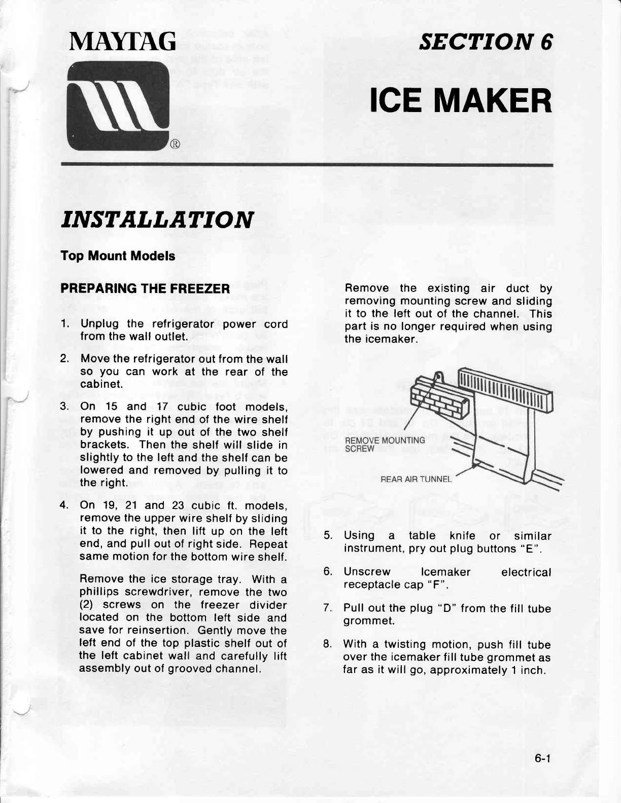
MI\YTAG SECTION 6
ICE
MAKER
INSTALLATION
Top Mount Models
PREPARING
THE
FREEZER
1, Unplug the refrigerator
power cord
from
the wall
outlet.
2. Move
the refrigerator
out from
the wall
so you can work at the rear of the
cabinet.
3. On 15 and 17 cubic foot models,
remove
the right
end
of
the
wire shelf
by pushing
it up out of the two shelf
brackets. Then
the
shelf will slide in
slightly to the left
and
the
shelf
can be
lowered
and removed
by pulling
it to
the right.
4. On 19, 21 and 23 cubic ft. models,
remove
the
upper
wire
shelf by sliding
it to the right,
then lift up on the left
end,
and
pull
out
of
right
side. Repeat
same motion
for the
bottom
wire
shelf.
Remove
the ice storage
tray. With a
phillips
screwdriver,
remove
the two
(2) screws on the treezer divider
located on the bottom left side and
save
for reinsertion.
Gently move
the
left
end
of the top plastic
shelf out
of
the left
cabinet wall and carefully lift
assembly
out of
grooved
channel.
5.
6.
7.
8.
Remove the existing
air duct by
removing
mounting
screw
and sliding
it to the left
out
of
the
channel. This
part
is no
longer required
when
using
the icemaker.
Using a table knife or similar
instrument,
pry
out
plug
buttons
"E".
Unscrew lcemaker electrical
receptacle
cap
"F".
Pull
out the
plug
"D"
from the
fill tube
grommet.
With
a twisting
motion,
push
fill
tube
over the icemaker
fill tube
grommet
as
far
as it will
go,
approximately
1 inch.
6-1
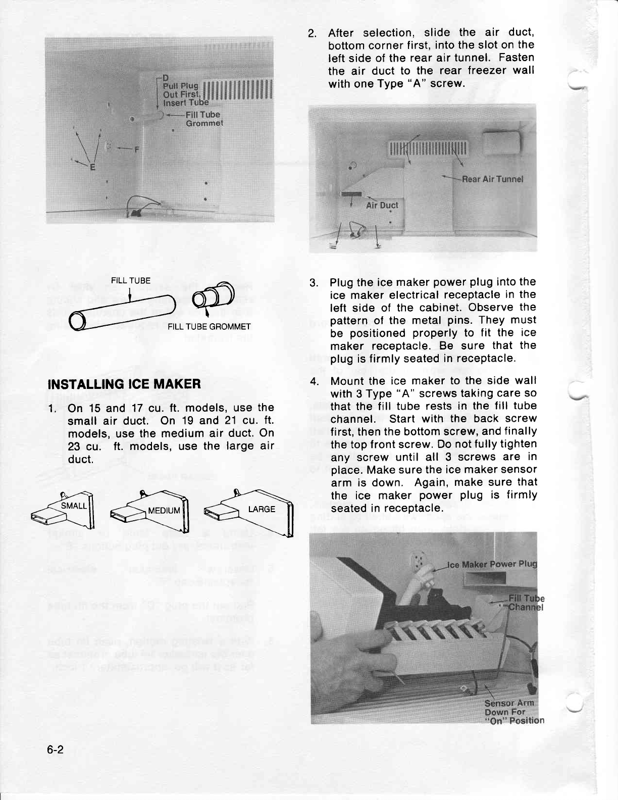
FILL TUBE
_--17@
A--- FILLTuBEGRoMMET
INSTALLING
ICE MAKER
1. On 15 and
17
cu.
ft.
models, use
the
small
air duct. On 19
and
21 cu.
ft.
models, use
the medium
air
duct.
On
23 cu. ft. models, use
the
large air
duct.
2. After selection,
slide the air duct,
bottom
corner
first,
into the slot
on
the
left side
of the
rear air
tunnel.
Fasten
the air duct
to the rear freezer
wall
with one
Type
"A"
screw.
Plug the
ice
maker
power
plug
into
the
ice maker
electrical
receptacle
in the
left side
of the
cabinet.
Observe
the
pattern
of the
metal
pins.
They
must
be positioned properly
to fit the ice
maker
receptacle.
Be sure
that the
plug
is
firmly seated
in receptacle.
Mount
the
ice
maker to
the side
wall
with 3
Type
"A"
screws
taking
care so
that
the fill
tube rests
in the
lill tube
channel. Start
with
the back
screw
first,
then
the bottom screw,
and
finally
the top
front screw.
Do
not fully
tighten
any screw
until all 3 screws
are in
place.
Make
sure the
ice maker
sensor
arm
is down, Again,
make sure
that
the ice maker
power plug is firmlY
seated
in receptacle.
3.
4.
4@q
6-2
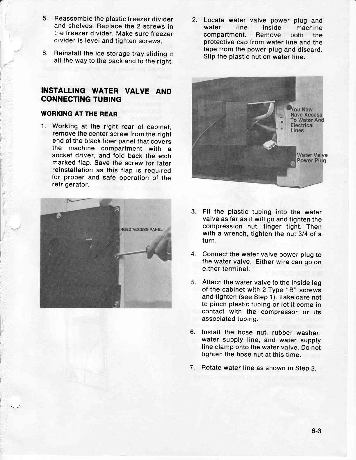
5.
6.
Reassemble
the
plastic
treezer
ctivider
and
shelves.
Replace
the
2 screws
in
the
freezer
divider.
Make
sure freezer
divider
is level
and
tighten
screws.
Reinstall
the ice
storage
tray
sliding
it
all the
way
to the
back
and to the
right.
INSTALLING
WATER VALVE AND
CONNECTING
TUBING
WORKING
AT THE
REAR
1. Working
at the right
rear
of cabinet,
remove
the
center
screw
from
the right
end
of the
black
f iber
panel
that
covers
the machine
compartment
with a
socket
driver,
and fold back
the etch
marked
flap.
Save
the
screw
for later
reinstallation
as this
flap
is required
for proper
and safe
operation
of the
refrigerator.
2. Locate water valve power plug and
water line inside machine
compartment. Remove both the
protective
cap from water line
and the
tape
from
the
power
plug
and discard.
Slip the
plastic
nut
on water
line.
Fit
the plastic
tubing
into
the water
valve
as far
as it will
go
and tighten
the
compression
nut,
finger
tight.
Then
with
a wrench,
tighten
the
nut
3/4 of
a
tu rn.
Connect
the
water
valve
power
plug
to
the
water
valve.
Either
wire
can
go
on
either
terminal.
Attach
the water
valve
to
the inside
leg
of the
cabinet
with
2 Type
"B"
screws
and
tighten
(see
Step 1). Take
care not
to
pinch
plastic
tubing
or let
it come
in
contact
with the compressor
or its
associated
tubing.
Install
the hose
nut,
rubber
washer,
water
supply
line,
and water
supply
line
clamp
onto
the
water
valve.
Do
not
tighten
the
hose
nut
at this
time.
Rotate
water
line
as shown
in
Step
2.
3.
4.
6.
7.
6-3
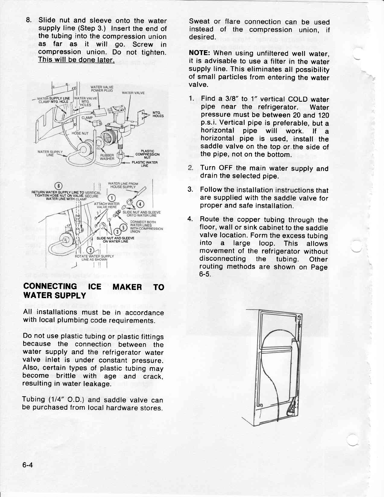
8. Slide nut
and
sleeve
onto
the water
supply line
(Step
3.) Insert
the
end of
the tubing
into
the
compression
union
as far as it will go. Screw in
compression
union.
Do not tighten.
This
will
be done
later.
MTG.
HOLES
PLASTIC
COMPRESSION
NUT
PLASTIC
WATER
LINE
RETURN
WATER
SUPPLY LINE
TO
TIGHTEN HOSE
NUT
ON VALVE,
Sweat
or flare connection
can be used
instead
of the compression
union, if
desired.
NOTE:
When
using
unfiltered
well
water,
it is
advisable
to
use
a filter
in
the water
supply
line.
This
eliminates
all
possibility
of
small
particles
from
entering
the
water
valve.
Find
a 3/8" lo 1"
vertical
COLD
water
pipe near the refrigerator. Water
pressure
must
be between
20
and 1ZO
p.s.i.
Vertical
pipe
is
preferable,
but
a
horizontal pipe will work. lf a
horizontal pipe is used,
install
the
saddle
valve
on
the top
or,the
side
of
the
pipe,
not
on
the
bottom.
Turn
OFF
the
main
water
supply
and
drain
the
selected
pipe.
Follow
the
installation
instructions
that
are
supplied
with the
saddle
valve
for
proper
and
safe installation.
Route
the
copper
tubing
through
the
floor,
wall
or
sink
cabinet to
the
saddle
valve
location.
Form
the
excess
tubing
into a large loop. This allows
movement
of the
refrigerator
without
disconnecting
the tubing. Other
routing
methods
are
shown
on page
6-5,
1.
WATER
LINE WITH
3.
4.
SLIOE
NUT AND SLEEVE
ON WATER LINE
CONNECTING
ICE MAKER TO
WATER
SUPPLY
All installations
must
be in accordance
with
local
plumbing
code
requirements.
Do not
use
plastic
tubing
or
plastic
fittings
because
the connection
between
the
water
supply
and the refrigerator
water
valve
inlet is under
constant
pressure.
Also,
certain
types
of plastic
tubing
may
become brittle with age and crack,
resulting
in
water
leakage.
Tubing
(1/4"
O.D.)
and
saddle
valve
can
be
purchased
from
local
hardware
stores.
SUPPLY LINE
MTG. HOLE
6-4
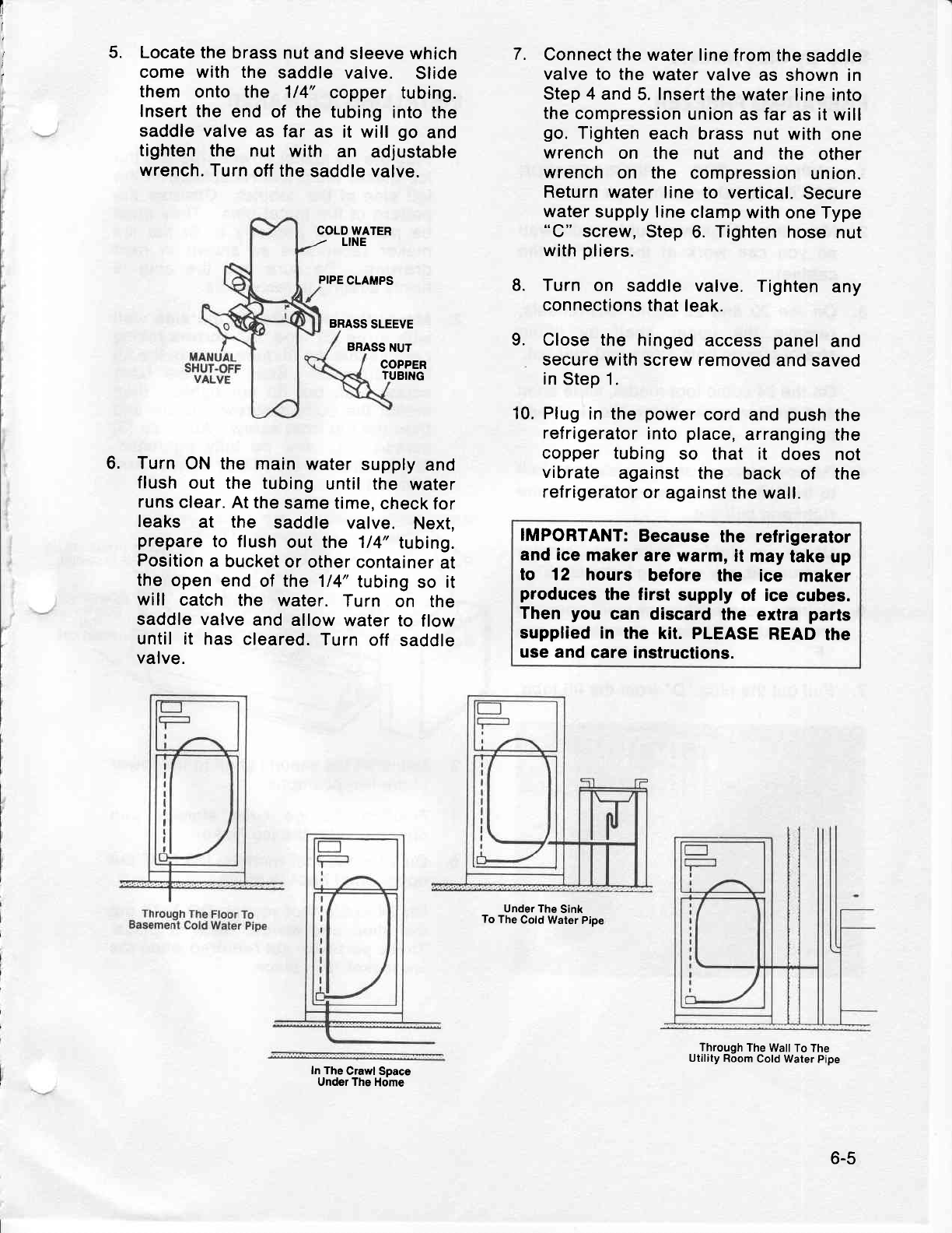
I
t
,, 7.
5. Locate the brass
nut and
sleeve which
come with the saddle
valve. Slide
them onto the 114"
copper tubing.
Insert the
end of the
tubing
into the
saddle valve
as far as it will
go and
tighten the nut with an adjustable
wrench.
Turn
otf the
saddle valve.
PIPE
CLAMPS
BRASS
SLEEVE
BBASS
NUT
COPPER
TUBING
Turn
ON the main
water
supply
and
flush
out the tubing
until the water
runs
clear. At
the
same
time,
check for
leaks at the saddle valve. Next,
prepare
to flush
out the 1/4"
tubing.
Position
a bucket
or
other container
at
the open
end
of the 1/4"
tubing
so it
will catch the water.
Turn on the
saddle valve
and allow
water to
flow
until it has cleared.
Turn
off saddle
valve.
In The Crawl Space
Under The
Home
Connect the
water line
from the
saddle
valve to the
water
valve
as shown in
Step 4
and 5. Insert the
water
line into
the compression
union
as
far
as
it
will
go.
Tighten
each
brass nut with
one
wrench
on the nut and the other
wrench
on the compression
union.
Return
water line to vertical.
Secure
water
supply line
clamp
with one
Type
"C" screw,
Step
6. Tighten
hose
nut
with
pliers.
Turn on saddle valve.
Tighten
any
connections
that
leak.
Close the hinged
access
panel
and
secure with
screw removed
and
saved
in
Step 1.
Plug
in the
power
cord
and
push
the
refrigerator
into
place,
arranging
the
copper tubing
so that it does not
vibrate against the back of the
refrigerator
or
against the wall.
IMPORTANT:
Because
the relrigerator
and ice
maker
are
warm, it
may
take up
to 12 hours belore the ice maker
produces
the first supply
of ice cubes.
Then you can discard
the extra parts
supplied in the kit. PLEASE
READ
the
use and
care instructions.
COLD
WATER
/ LINE
8.
9.
10.
6.
Under
The
Sink
To The
Cold Water
Pipe
Through
The
Wall To The
Utility
Room
Cold Water
Pipe
6-5
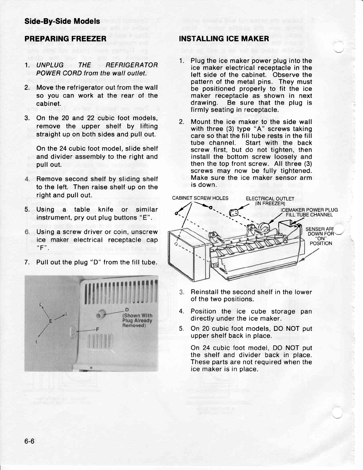
1.
2.
3.
Side-By-Side Models
PREPARING FREEZER
UNPLUG THE REFRIGERATOR
POWER CORD
from
the wall outlet.
Move the
refrigerator
out from
the wall
so you can work at the rear of the
cabinet.
On the 20 and 22 cubic
foot models,
remove the upper shelf by lifting
straight up on both sides and
pull
out.
On the 24 cubic foot model,
slide shelf
and divider assembly to the right and
pull
out.
Remove second shelf
by sliding shelf
to
the
left.
Then raise
shelf up on the
right and
pull
out.
Using a table knife or similar
instrument,
pry
out
plug
buttons
"E".
Using a screw driver or coin, unscrew
ice maker
electrical receptacle cap
7. Pull
out
the
plug
"D"
f rom the f ill
tube.
INSTALLING
ICE
MAKER
1. Plug the ice maker
power plug
into the
ice maker
electrical
receptacle in
the
left
side of the cabinet. Observe the
pattern
of the metal
pins. They must
be positioned
properly
to fit the ice
maker receptacle
as shown in next
drawing. Be sure that the plug is
firmly
seating in
receptacle.
2. Mount
the ice maker to the side wall
with three
(3)
type
"A" screws taking
care so that the fill tube
rests
in the fill
tube channel. Start
with the back
screw
first,
but do not tighten, then
install the bottom screw loosely and
then the top front
screw. All
three
(3)
screws
may now be fully
tightened.
Make
sure the ice maker sensor arm
is down.
CABINET
SCREW HOLES ELECTRICAL
OUTLET
Reinstall
the second
shelf
in the lower
of the two
positions.
Position the ice cube storage pan
directly under the ice maker.
On
20
cubic
foot
models, DO NOT
put
upper shelf
back
in
place.
On 24 cubic
foot
model, DO NOT
put
the shelf and divider back in place.
These
parts
are not required when the
ice maker is in
place.
5.
SENSER
ARI
DOWN
FOR'-
"oN"
POSITION
4.
5.
6-6
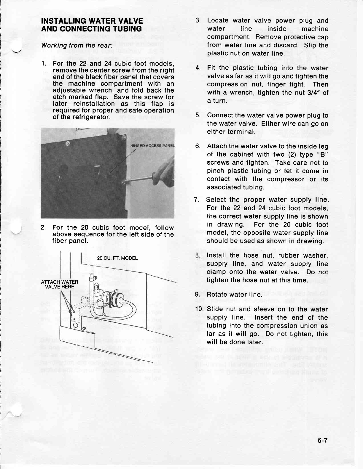
INSTALLING
WATER VALVE
AND CONNECTING TUBING
Working from the
rear:
1. For the 22 and 24 cubic foot models,
remove the center
screw from the right
end
of
the black fiber
panel
that covers
the machine compartment with an
adjustable
wrench,
and
fold
back
the
etch marked
flap. Save
the
screw
for
later reinstallation
as this f lap is
required for
proper
and safe operation
of the refrigerator.
2. For
the 20 cubic
foot model,
follow
above
sequence for the
left side
of the
fiber
panel.
20
CU.
FT. MODEL
ATTACH
WATER
VALVE HERE
Locate
water valve power plug and
water line inside machine
compartment.
Remove
protective
cap
from water
line
and discard.
Slip the
plastic
nut
on
water
line.
Fit the plastic
tubing into
the water
valve
as
far
as it will
go
and tighten the
compression
nut, finger tight. Then
with a wrench,
tighten the nut
314"
ot
a turn.
Connect the
water valve
power
plug
to
the water valve.
Either wire
can
go
on
either terminal.
Attach
the water valve
to the inside leg
of the
cabinet with two (2)
type
"B"
screws
and tighten. Take
care not to
pinch
plastic
tubing
or let it
come
in
contact with the compressor
or its
associated tubing.
Select the proper
water
supply line.
For the 22 and 24 cubic foot models,
the
correct water
supply line is shown
in drawing. For the 20 cubic toot
model,
the
opposite water supply
line
should be used
as shown in drawing,
Install the hose nut, rubber
washer,
supply
line, and water
supply line
clamp
onto the water
valve. Do not
tighten the hose
nut
at
this
time.
Rotate water line.
Slide nut
and sleeve
on to the
water
supply line. Insert the end of the
tubing
into the
compression
union
as
far
as it will
go. Do not tighten,
this
will
be done
later.
3.
4.
5.
6.
7.
9.
10.
6-7
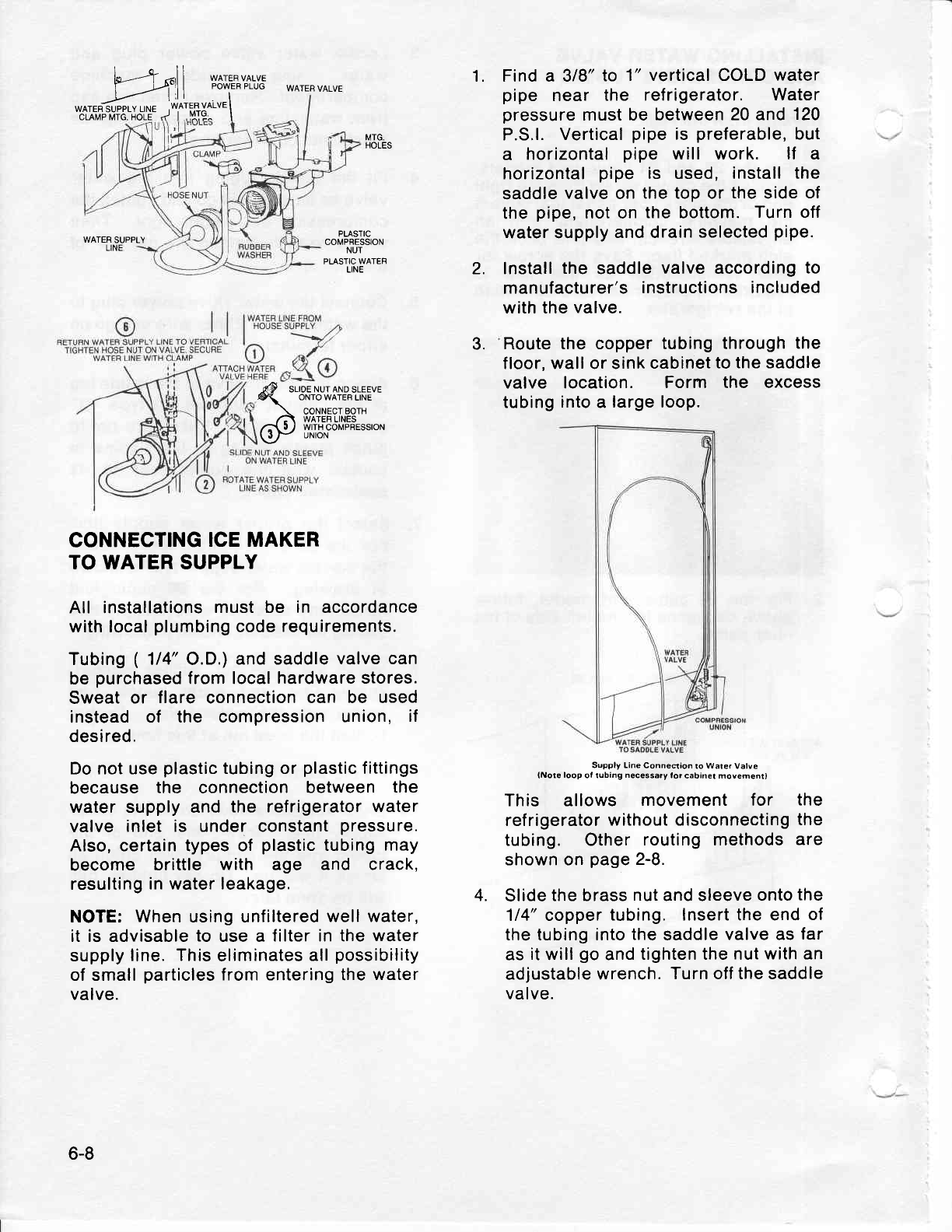
ir-'--t -l ] *ATERVALVE
J--.-_pl"l I PowER PLUG
w^m;-rslruu.Ji^l'fi
il*'\
CONNECTING
ICE MAKER
TO WATER SUPPLY
All installations
must be in accordance
with local
plumbing
code requirements.
Tubing
( 114" O.D.)
and saddle
valve can
be
purchased
from local
hardware stores.
Sweat
or flare connection
can be used
instead
of the compression
union, if
desired.
Do not use
plastic
tubing or
plastic
fittings
because the connection
between the
water supply and the refrigerator
water
valve
inlet is under constant
pressure.
Also, certain types of plastic
tubing
may
become brittle with age and crack,
resulting
in
water
leakage,
NOTE: When using unfiltered
well water,
it is advisable
to use a filter in the
water
supply
line. This
eliminates
all
possibility
of small
particles
from entering the
water
valve.
Find a 318"
to 1" vertical COLD
water
pipe near the ref rigerator. Water
pressure
must be between
20 and
120
P.S.l.
Vertical
pipe
is
preferable,
but
a horizontal
pipe will work. lf a
horizontal
pipe is used,
install the
saddle
valve
on
the top or
the
side
of
the
pipe,
not on
the
bottom.
Turn
off
water supply
and drain
selected
pipe.
lnstall
the
saddle
valve
according
to
manufacturer's
instructions included
with the
valve.
Route
the copper
tubing through
the
floor, wall or sink
cabinet
to the saddle
valve location. Form the excess
tubing
into
a
large loop.
tNororoopotrubinr"*""":;"t:;:I:.:,";;"u"'*:""r,
This allows movement for the
refrigerator
without disconnecting
the
tubing. Other routing methods
are
shown on page
2-8.
Slide
the brass
nut
and sleeve
onto
the
114" copper
tubing. lnsert the end
of
the tubing into
the
saddle
valve as
far
as
it
will
go
and
tighten the nut
with an
adjustable
wrench.
Turn off the saddle
valve.
1.
WATER
VALVE
MTG.
HOLES
WATER
SUPPLY
LINE
PLASTIC
COMPRESSION
NUT
PLASTIC
WATEF
LINE
14P
- srroe
ruur
nruo
sleeve
\ oNrowArERL|NE
\ CONNECT BOTH
/:\ WATEF LrNEs
@U Yl'15"t*PBEssroN
2.
3.
4.
6-8
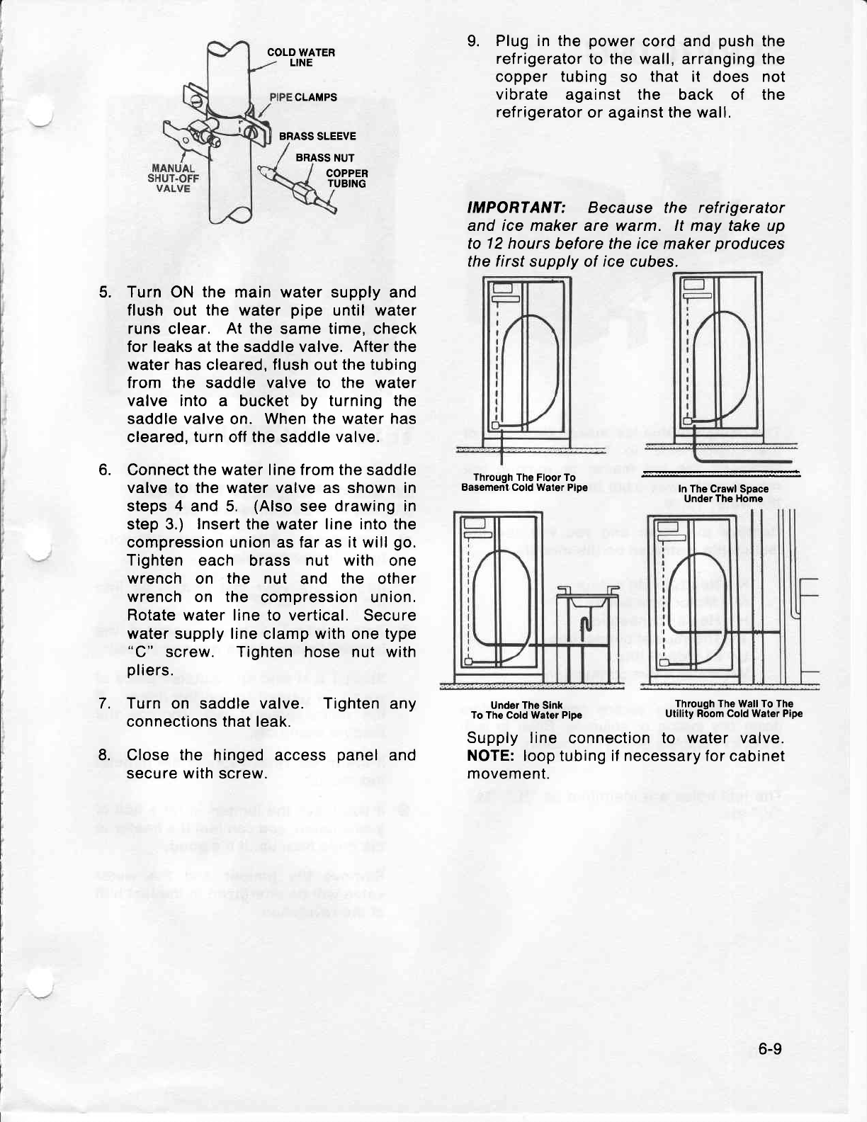
COLD WATER
LINE
BRASS
SLEEVE
BRASS
NUT
COPPER
TUBING
Turn ON
the main water supply and
flush
out
the water
pipe
until
water
runs clear. At the same time, check
for leaks at the saddle valve. After the
water
has
cleared, flush out
the tubing
from the saddle valve to the water
valve into a bucket by turning the
saddle valve
on. When the water has
cleared,
turn
off the saddle valve.
Connect
the water line from the
saddle
valve to the water valve as shown in
steps
4 and 5. (Also
see drawing in
step 3.) Insert the water line into the
compression union
as
far as it will
go.
Tighten
each brass nut with one
wrench
on the nut and the other
wrench on the compression union.
Rotate water line to vertical. Secure
water supply line
clamp
with
one type
"C" screw. Tighten hose nut with
pliers.
Turn
on saddle
valve. Tighten
any
connections that leak.
Close the hinged
access
panel
and
secure with screw.
9. Plug in the power
cord and push
the
refrigerator
to the wall, arranging the
copper tubing so that it does not
vibrate against the back of the
refrigerator
or against the wall.
IMPORTANT: Because the refrigerator
and ice maker are warm. lt may take
up
to 12 hours
before the ice maker
produces
the f irst supply
of
ice
cubes.
CLAMPS
5.
6.
Under The Sink
To The Cold Water Pipe
In
The Crawl Space
Under The Home
Through The Wall To The
Utility Room Cold Water Pipe
7.
8. Supply line connection to water valve.
NOTE:
loop tubing if necessary for cabinet
movement.
Through
The Floor To
Basement. Cold Waler
Pipe
6-9
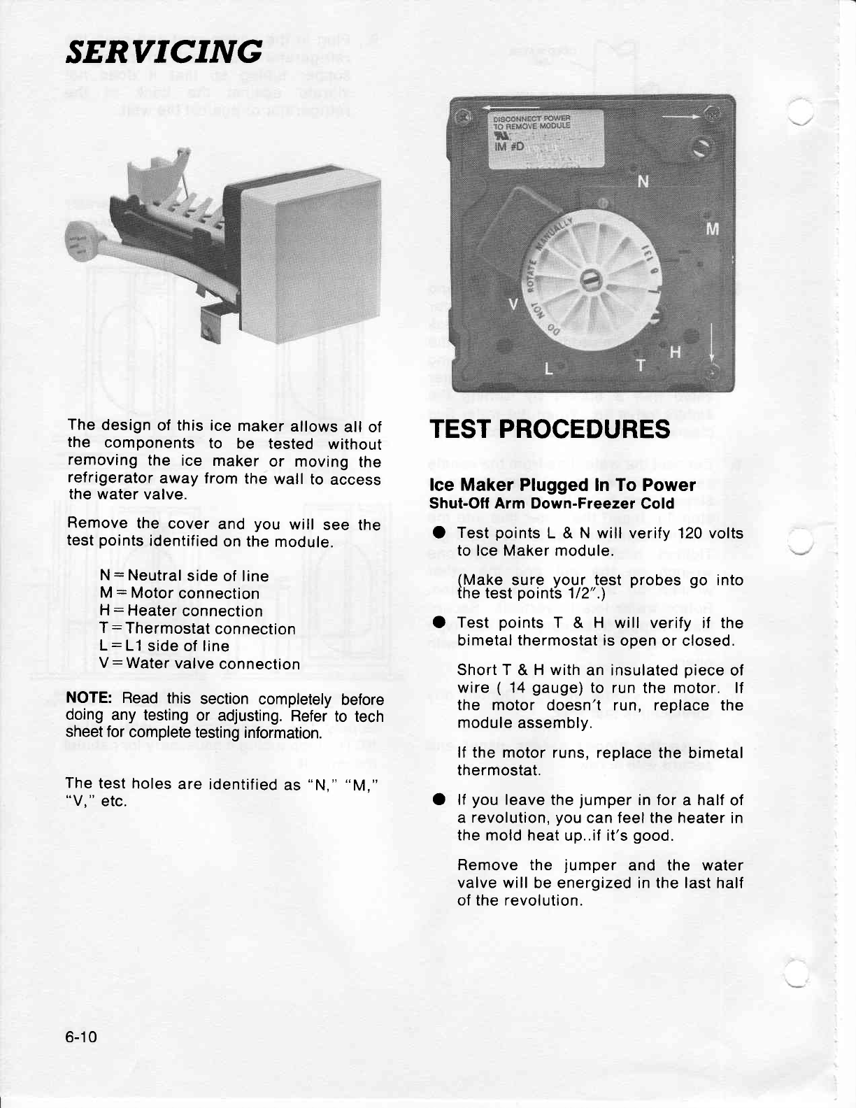
.'ERVICING
The
design
of this ice
maker
allows
all of
the components to be tested without
removing
the ice maker or moving the
refrigerator
away from the wall to access
the water
valve.
Remove
the cover and you will see the
test
points
identified
on the
module.
N: Neutral
side
of line
M: Motor
connection
H: Heater
connection
T
: Thermostat
connection
L: L1
side
of
line
V: Water
valve
connection
NOTE: Read this section
completely
before
doing any testing
or adjusting.
Refer
to tech
sheet for
complete
testing
information.
The
test
holes
are identified
as
"N," "M,"
"V,"
etc.
TEST PROCEDURES
lce Maker
Plugged ln To Power
Shut-Off Arm Down-Freezer
Cold
O Test
points
L & N will verify 120 volts
to lce Maker module.
(Make
sure vour test orobes oo into
the
test
point's
112".)
O Test points
T & H will verify if the
bimetal
thermostat is
open
or closed.
Short
T & H with
an insulated
piece
of
wire ( 14
gauge)
to run
the motor. lf
the motor doesn't run, replace the
module
assembly.
lf the motor runs, replace
the bimetal
thermostat.
O lf
you leave
the
jumper
in for
a half
of
a revolution,
you
can feel the heater
in
the mold heat
up..if it's
good.
Remove the jumper and the water
valve will be energized in the last
half
of the revolution.
6-10
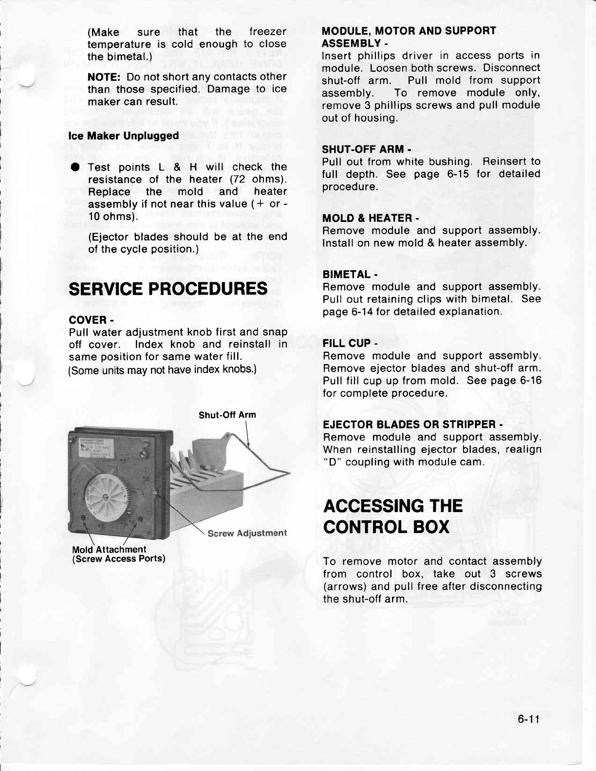
(Make sure that the treezer
temperature
is cold enough
to close
the
bimetal.)
NOTE:
Do not short
any contacts
other
than those
specified.
Damage
to ice
maker can
result.
lce
Maker
Unplugged
O Test points
L & H will check
the
resistance
of the heater
(72 ohms).
Replace the mold and heater
assembly
if not near
this value
(* or
-
10
ohms).
(Ejector
blades should be
at the end
of the cycle
position.)
SERVICE
PROCEDURES
covER
-
Pull water adjustment
knob first and snap
off cover. Index knob and reinstall
in
same
position
for same
water fill.
(Some
units
may
not
have
index
knobs')
Mold
Attachment
(Screw
Access
Ports)
MODULE, MOTOR
AND SUPPORT
ASSEMBLY
-
Insert
phillips
driver in access
ports
in
module. Loosen both
screws.
Disconnect
shut-off
arm. Pull mold from support
assembly. To remove module only,
remove 3
phillips
screws
and
pull
module
out of
housing,
SHUT.OFF
ARM
-
Pull out
from white bushing.
Reinsert
to
full depth. See page 6-15 for detailed
procedure.
MOLD & HEATER
-
Remove
module and support
assembly.
Install on
new mold & heater assembly.
BIMETAL.
Remove
module and support
assembly.
Pull out
retaining clips
with bimetal. See
page
6-14
for detailed explanation.
FILL CUP
-
Remove module and support
assembly,
Remove
ejector
blades and
shut-off arm.
Pull fill
cup up
from mold. See
page
6-16
for
complete
procedure.
EJECTOR
BLADES OR STRIPPER.
Remove module and support assembly.
When reinstalling ejector blades,
realign
"D"
coupling
with module cam.
ACCESSING
THE
CONTROL
BOX
To remove motor and contact assembly
f rom control box, take out 3 screws
(arrows)
and
pull
free after disconnecting
the
shut-off
arm.
Shut-Off
Arm
6-1 1
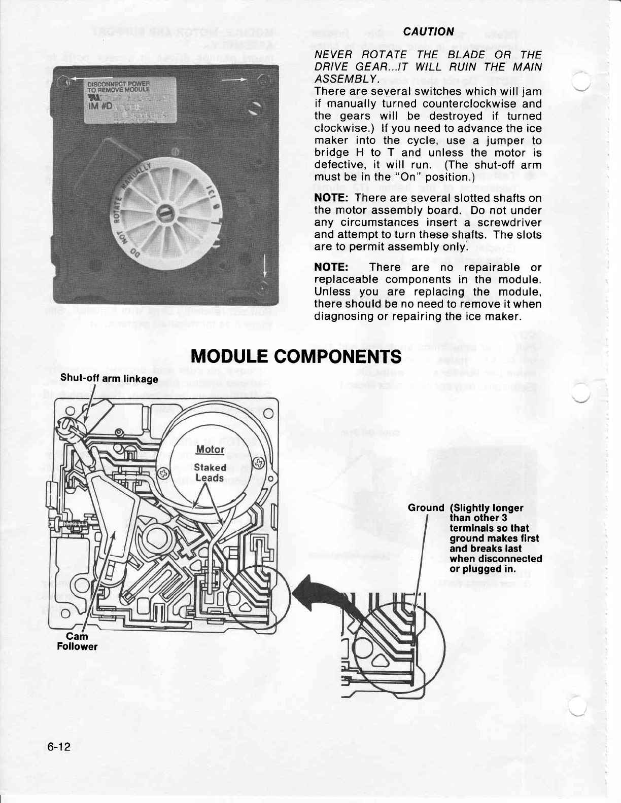
CAUTION
NEVER ROTATE
THE BLADE
OR THE
DRIVE
GEAR...IT WILL RUIN
THE MAIN
ASSEMBLY.
There
are several
switches which will
jam
if manually turned
counterclockwise
and
the gears will be destroyed if turned
clockwise.) lf
you
need to
advance
the ice
maker
into the cycle,
use a jumper
to
bridge H to T and unless the motor is
defective, it will run. (The
shut-off arm
must
be
in the
"On"
position.)
NOTE: There
are
several slotted shafts on
the
motor
assembly
board. Do not under
any circumstances insert
a screwdriver
and attempt to turn these
shafts. The
slots
are
to
permit
assembly
only.
NOTE: There are no repairable
or
replaceable
components in the module.
Unless
you are replacing
the module,
there
should
be
no need
to remove it when
diagnosing
or repairing the ice
maker.
MODULE
COMPONENTS
Shut-off
arm
linkage
Cam
Follower
Ground(Slightly
longer
than
other 3
terminals
so that
ground
makes first
and breaks
last
when
disconnected
or
plugged
in.
6-12
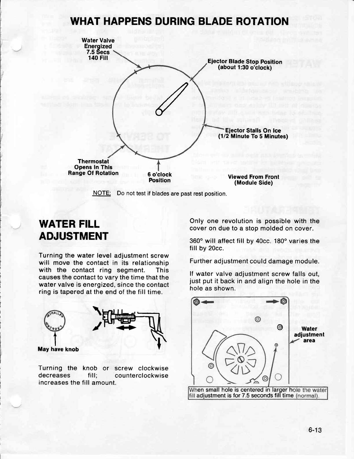
WHAT HAPPENS DURING
BLADE ROTATION
Water
Valve
Energized
7.5
Secs
140
Fiil Ejector
Blade
Stop
position
(about
1:30
o'clock)
Ejector
Stalls
On
lce
(1/2
Minute
To
5 Minutes)
Thermostal
Opens
In
This
Range
Of Rotalion 6 o'clock
Position
NOTE: Do not
test
if blades
are
past
rest
position.
Viewed From
Front
(Module
Side)
Only one revolution is possible
with the
cover on
due
to
a stop molded
on
cover.
360o will
affect
fill
by 40cc. 180o varies the
fill by Z0cc.
Further
adjustment
could damage module.
lf
water valve
adjustment
screw
falls
out,
just
put
it back in
and align the hole in
the
hole
as shown.
@Water
adjustment
area
knob
l
I
haveMay
/
WATER
FILL
ADJUSTMENT
Turning
the water level
adjustment
screw
will move the
contact in its relationship
with the contact
ring segment. This
causes the
contact to vary the time that
the
water valve is
energized, since the
contact
ring is
tapered
at
the
end of the fill time.
Turning the knob or screw clockwise
decreases f ill: counterclockwise
increases
the fill
amount. ren
small
hole is
centered
in larger hr
adiustment is for 7.5 seconds
fill
time
6-13
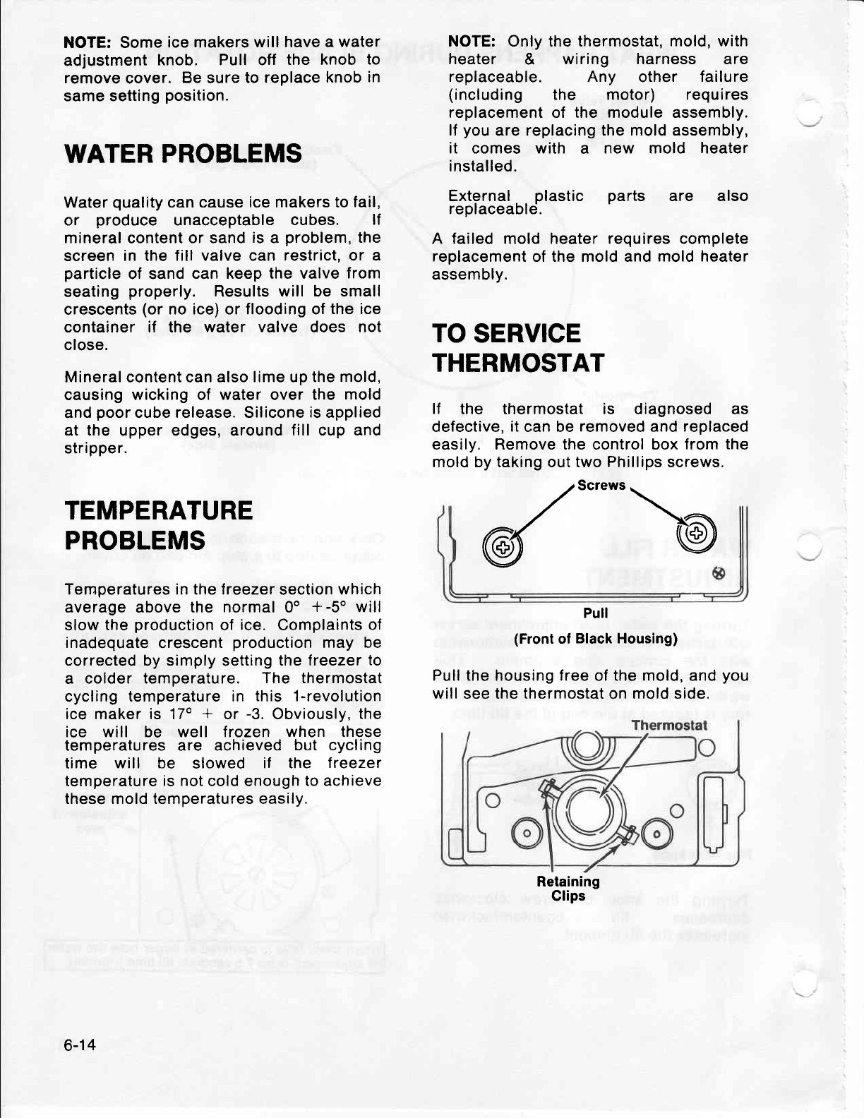
NOTE: Some
ice makers
will have a
water
adjustment
knob. Pull off the knob to
remove
cover.
Be sure
to replace
knob
in
same setting
position.
WATER
PROBLEMS
Water
quality
can cause
ice makers to fail,
or produce unacceptable
cubes. lf
mineral
content
or sand
is
a problem,
the
screen in the
fill valve can restrict, or a
particle
of sand
can keep the valve
from
seating
properly. Results
will be small
crescents
(or
no ice) or flooding of
the ice
container if the water valve does not
close.
Mineral content
can
also lime up the
mold,
causing
wicking
of water over the mold
and
poor
cube release. Silicone
is
applied
at the upper edges, around
fill cup and
stripper.
TEMPERATURE
PROBLEMS
Temperatures in the freezer
section
which
average
above
the normal 0o *-5o will
slow the
production
of
ice. Complaints
of
inadequate
crescent
production
may be
corrected by simply setting
the freezer
to
a colder temperature.
The thermostat
cycling
temperature in this 1-revolution
ice maker is 17o
+ or
-3.
Obviously,
the
ice will be well f rozen when these
temperatures are achieved but cycling
time will be slowed if the freezer
temperature
is not
cold enough
to achieve
these mold temperatures easily.
NOTE: Only the thermostat,
mold, with
heater & wiring harness are
replaceable. Any other failure
(including the motor) requires
replacement of the module assembly.
lf
you
are
replacing the mold assembly,
it comes with a new mold heater
installed.
External
. . plastic parts are
replaceabld.
A failed mold heater requires complete
replacement
of the mold and
mold heater
assembly.
TO
SERVICE
THERMOSTAT
lf the thermostat is diagnosed as
defective,
it
can be removed
and replaced
easily, Remove the control box
from the
mold by taking out two Phillips screws.
{screwsb
Pull
(Front
ol Black Housing)
Pull the
housing
free
of the
mold,
and
you
will
see the
thermostat
on mold side.
also
Retaining
Glips
6-14
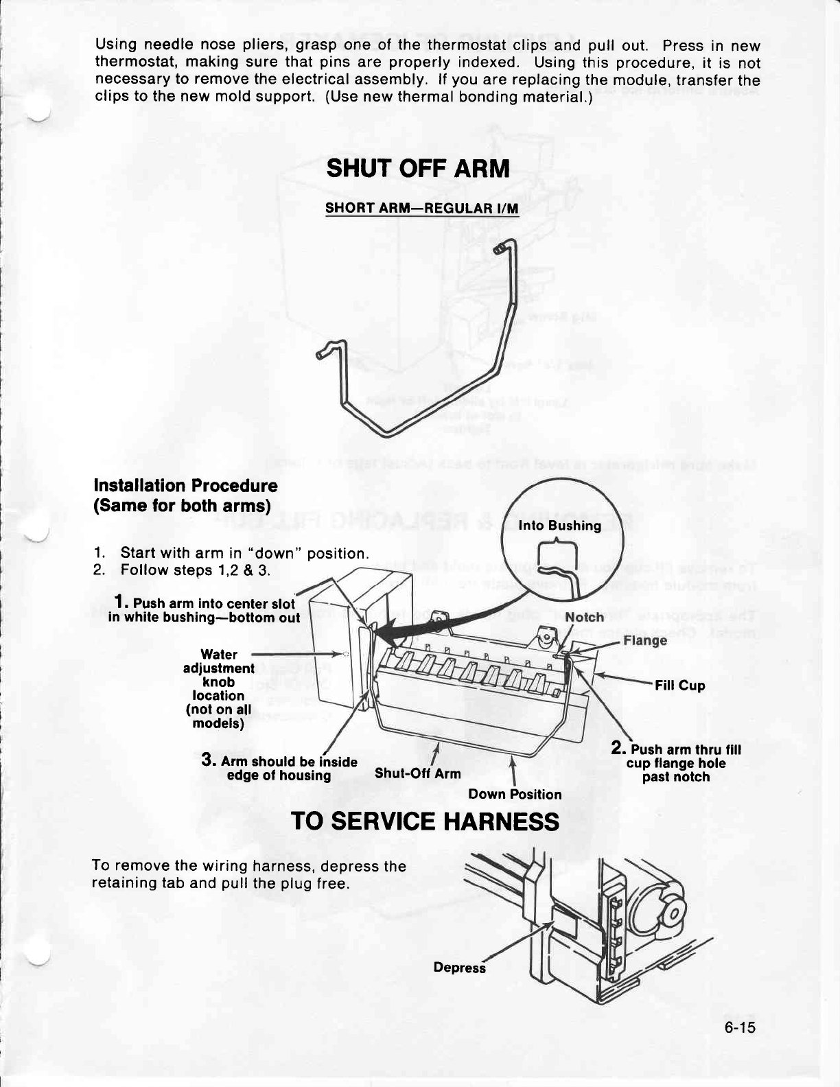
Using
needle nose
pliers,
grasp
one of the thermostat
clips
and
pull
out. Press in
new
thermostat,
making
sure that
pins
are
properly
indexed.
Using this
procedure,
it is not
necessary
to
remove
the electrical
assembly. lf
you
are
replacing
the module,
transfer
the
clips to
the new mold
support.
(Use
new thermal
bonding material.)
SHUT OFF ARM
SHORT ARM_REGULAR
I/M
Installation
Procedure
(Same
lor both arms)
Start
with arm in
Follow
steps
1,2
"down"
position.
1.
2. &3.
1. Pustr
arm
inlo
center slot
in
white bushing-bottom
out
Water
adjustment
knob
localion
(not
on
all
models)
3. lrm should
be i'nside
edge
ol housing Shut-Ofl
Arm
FillCup
2. -Pustr
arm thru fill
cup flange
hole
past nolch
To
remove the
wiring
retaining
tab
and
pull
TO
SERVICE
HARNESS
harness,
depress the
the
plug
free.
Inlo
Bushing
Down Position
Depres5
6-15
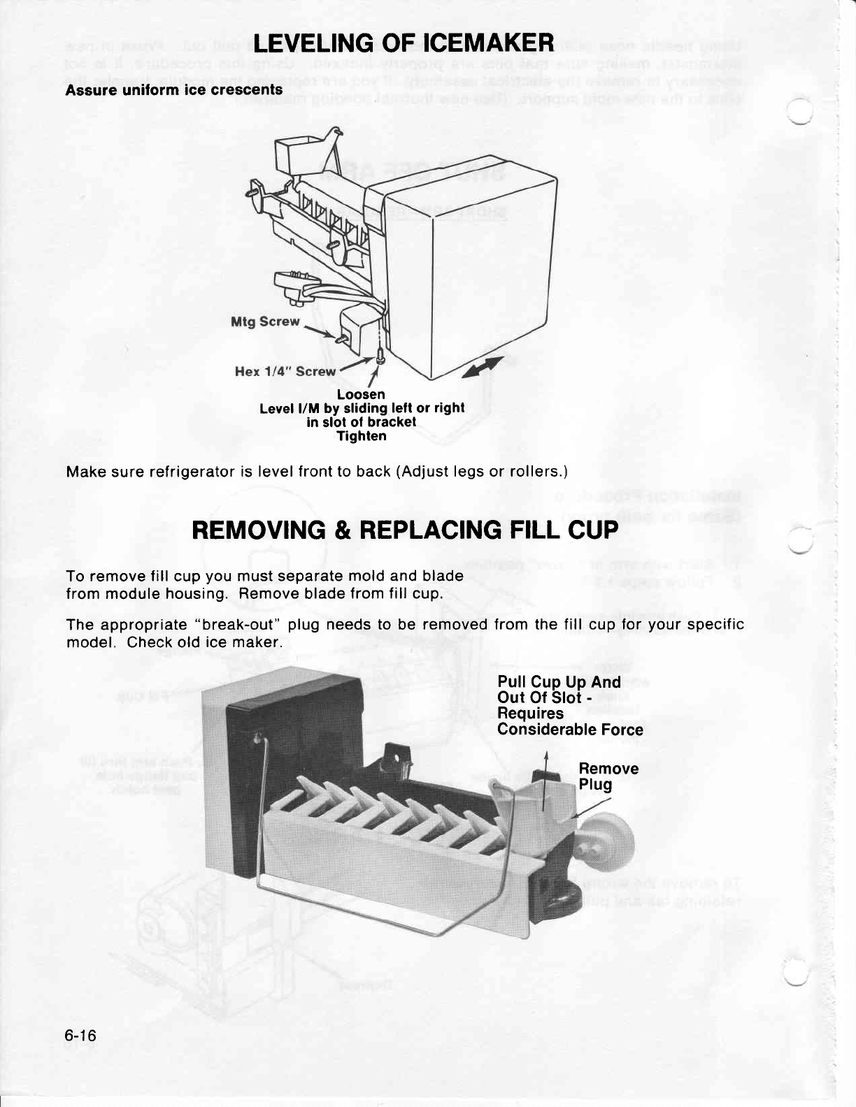
LEVELING OF
ICEMAKER
Assure uniform
ice crescents
Level
l/M by sliding
lell or right
in slot ol bracket
Tighten
Make sure
refrigerator
is level front to back
(Adjust
legs or rollers.)
REMOVING
& REPLACING
FILL
CUP
To remove
fill
cup
you
must separate
mold
and blade
from module housing.
Remove
blade
from fill cup.
The appropriate
"break-out"
plug
needs to
be
removed from the fill cup
for
your
specific
model. Check old
ice maker.
Pull
Cup Up And
Out
Of Slot
-
Requires
Considerable
Force
Remove
Plug
Loosen
6-1
6
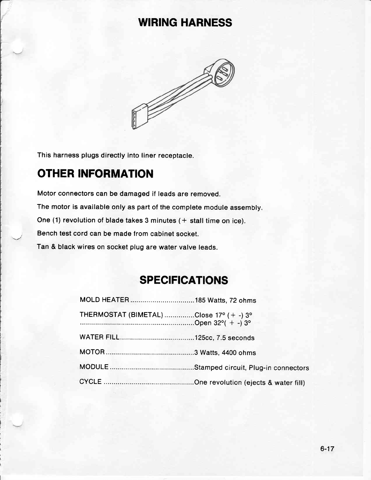
WIRING
HARNESS
This
harness
plugs
directly into liner
receptacle.
OTHER INFORMATION
Motor
connectors
can be
damaged if leads
are removed.
The
motor is
available
only as
part
of the
complete
module
assembly.
One
(1)
revolution
of
blade takes 3 minutes
(* stall time
on ice).
Bench
test
cord
can be made lrom
cabinet
socket.
Tan
& black wires
on socket
plug
are
water valve
leads.
SPECIFICATIONS
MOLD HEATER 185
Watts. 72
ohms
l::Y:"ll
l:i":llfl
::
::::: :::3i".:,"#.'i
-i
$
WATER
F|LL...,.... 125cc.
7.5
seconds
MOTOR ............3
Watts. 4400
ohms
MODULE ..........Stamped
circuit,
Plug-in
connectors
CYCLE .............One
revolution
(ejects
& water fill)
6-17
MAYTAG SECTION 7
TROUBLE
SHOOTING
TOP MOANT
AND
SIDE.BY.SIDE
MODEI'S
7'-1
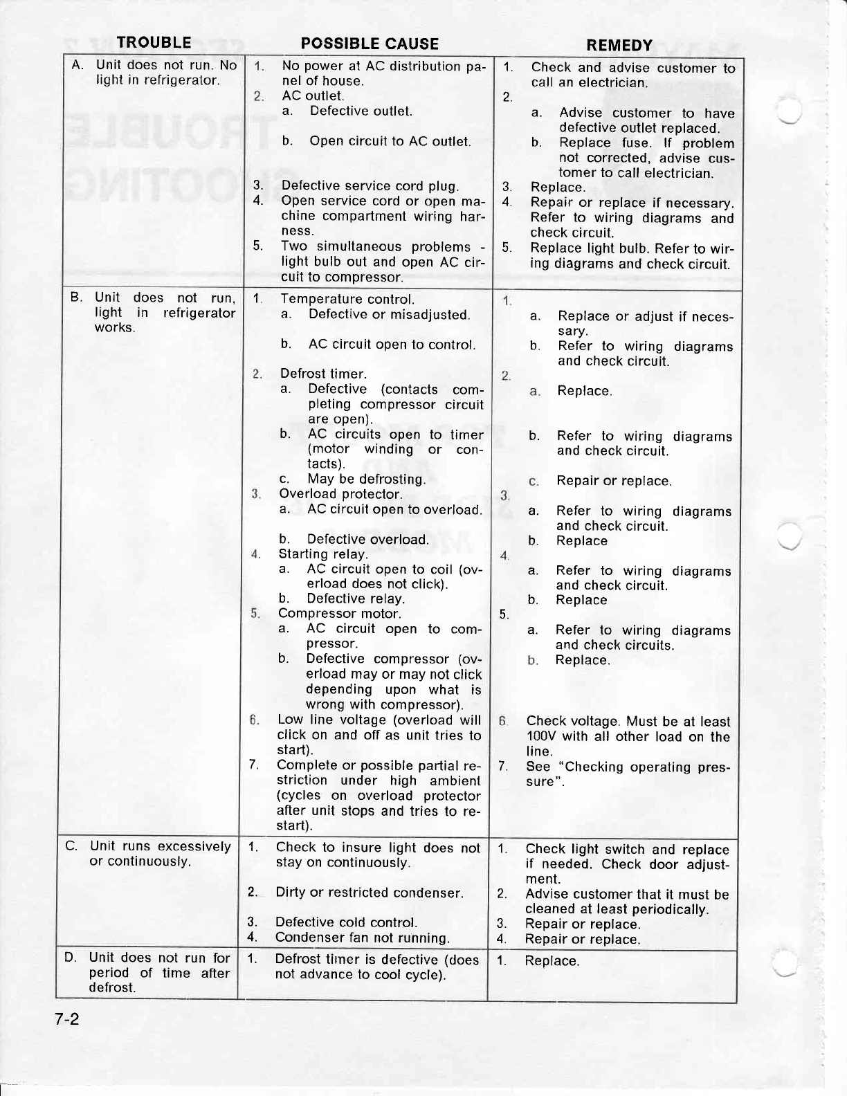
TROUBLE POSSIBLE
CAUSE REMEDY
A. Unit does
not run.
No
light in
refrigeralor. power
at AC
distribution
pa-
of house.
outlet.
Defective
outlet.
b. Open circuit
to AC outlet.
3. Defective
service
cord
plug.
4. Open service
cord
or open
ma-
chine
compartment
wiring
har-
NESS.
5. Two simultaneous
problems
-
light
bulb
out and
open
AC cir-
cuit
to compressor.
No
nel
AC
a.
1. Check
and advise
customer
to
call an
electrician.
2. a. Advise customer
to have
defective
outlet
replaced.
b. Replace
fuse. lf problem
not corrected.
advise cus-
tomer
to call electrician.
3. Replace.
4. Repair
or replace
if necessary.
Refer
to wiring diagrams
and
check
circuit.
5. Replace
light
bulb. Refer
to wir-
ing diagrams
and check
circuit.
Unit does not run,
light in refrigerator
works.
B. Temperature
control.
a. Defective
or misadjusted.
b. AC
circuit
open to control.
Defrost
timer.
a. Defective (contacts com-
pleting
compressor
circuit
are open).
b. AC circuits
open to timer
(motor winding or con-
tacts).
c. May
be defrosting.
Overload
proteclor.
a. AC circuit
open
to overload.
b. Defective
overload.
Stading
relay.
a. AC circuit
open
to coil
(ov-
erload
does
not click).
b. Defective
relay.
Compressor
motor.
a. AC circuit open to com-
pressor.
b. Defective
compressor
(ov-
erload
may or may
not
click
depending
upon what is
wrong with
compressor).
Low
line voltage
(overload
will
click on and off
as unit tries
to
stad).
Complete
or possible parlial
re-
striction
under high ambient
(cycles on overload protector
after unit
stops
and tries
to re-
stad).
a
t.
7.
b.
Replace
or adjust
if neces-
sary.
Refer
to wiring diagrams
and check
circuit.
Replace.
Refer to wiring diagrams
and
check circuit.
Repair
or replace.
Refer
to wiring diagrams
and
check
circuit.
Replace
Refer
to wiring diagrams
and check
circuit.
Replace
Refer
to wiring diagrams
and check
circuits.
Replace.
5.
Check voltage.
Must be
at least
100V
with
all other
load
on the
line.
See "Checking
operating
pres-
sure
".
a.
b.
a.
b.
a.
b.
a.
7
C. Unit
runs
excessively
or continuously. 1. Check
to insure
light
does
not
stay
on continuously.
2. Dirty or restricted
condenser.
3. Defective
cold control.
4. Condenser
fan
not running.
1. Check
light
switch
and replace
if needed.
Check
door adjust-
ment.
2. Advise customer
that
it must
be
cleaned
at
least
periodically.
3. Repair
or replace.
4. Repair
or replace.
D. Unit
does
not run
for
period
of time after
defrost.
1. Defrost
tirner is defective
(does
not advance
to
cool
cycle). 1. Replace.
7-2
t=
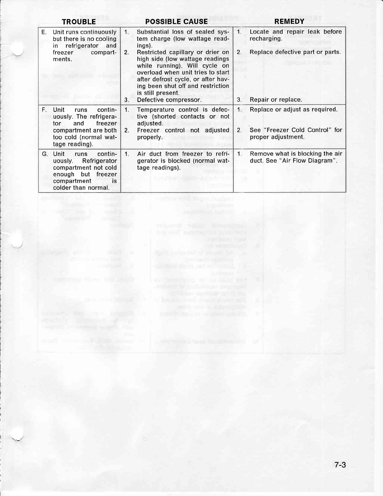
TROUBLE POSSIBLE CAUSE REMEDY
E. Unit runs
continuously
but there is no cooling
in refrigerator and
freezer compad-
ments.
1. Substantial
loss of sealed
sys-
tem charge
(low
wattage read-
i ngs).
2. Restricted
capillary or drier on
high
side
(low
wattage readings
while running). Will cycle
on
overload when unit
tries to start
after
defrost cycle, or after hav-
ing been
shut off and restriction
is still
present.
3. Defective compressor.
1. Locate and repair leak before
recharg i ng.
2. Replace defective
pad
or parts.
3. Repair or replace.
F. Unit runs contin-
uously. The refrigera-
tor and freezer
compartment are both
too cold
(normal
wat-
tage reading).
1. Temperature control
is defec-
tive (shorted contacts or not
adjusted.
Freezer control not adjusted
properly.
2.
1. Replace
or adjust as required.
2. See
"Freezer
Cold
Control" for
proper
adjustment.
G. Unit runs contin-
uously. Refrigerator
compaftment not cold
enough but freezer
compartment is
colder than normal.
1. Air duct from freezer to refri-
gerator
is blocked
(normal
wat-
tage readings).
1. Remove what is blocking
the air
duct. See
"Air
Flow Diagram".
7-3
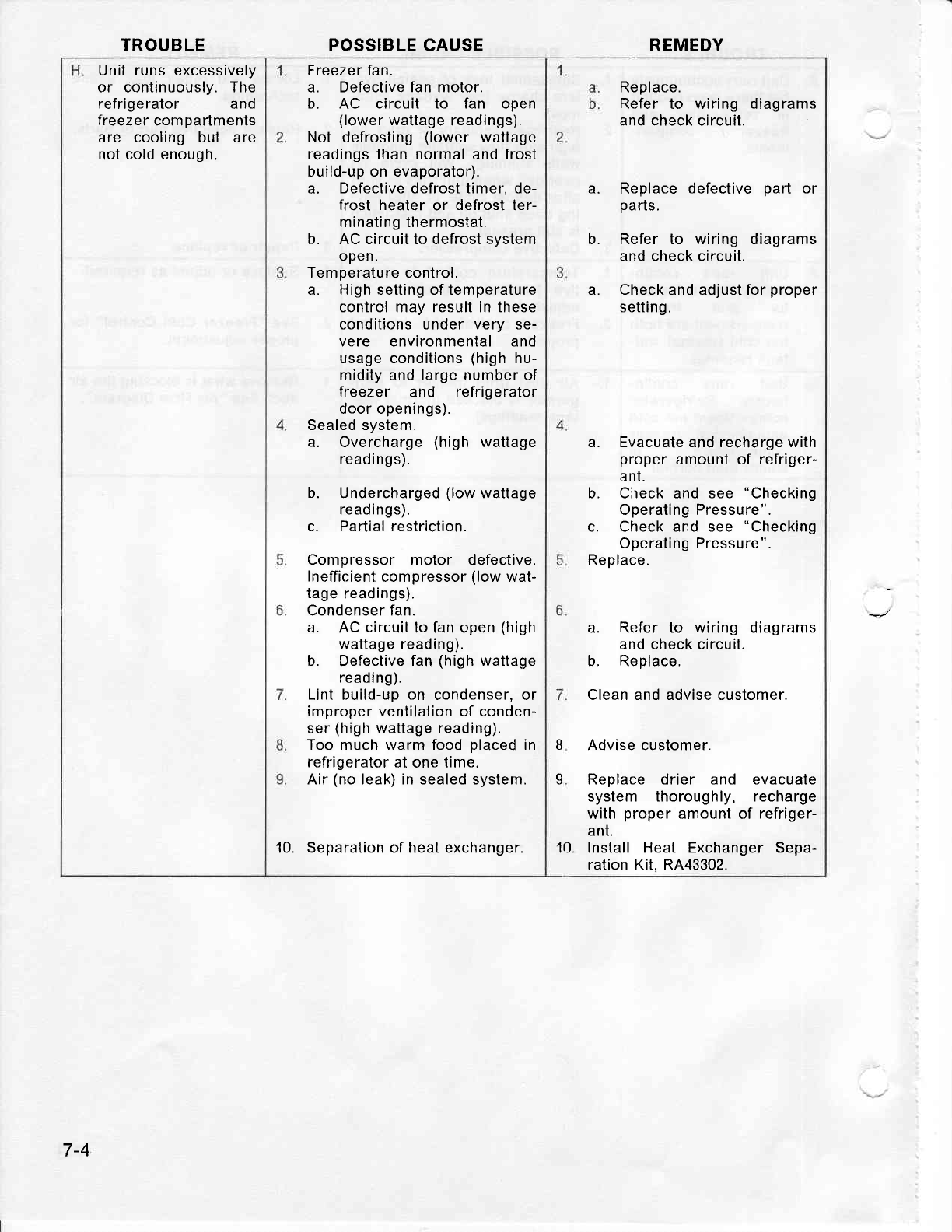
Unit
runs
excessively
or continuously. The
refrigerator and
freezer compartments
are cooling but are
not
cold enough.
Freezer
fan.
a. Defective fan motor.
b. AC circuit to fan open
(lower
wattage
readings).
Not defrosting
(lower wattage
readings than normal and frost
build-up on evaporator).
a. Defective
defrost timer, de-
frost heater
or defrost
ter-
minating thermostat.
b. AC circuit to defrost svstem
open.
Temperature control.
a. High setting of temperature
control may result in these
conditions under very se-
vere environmental and
usage conditions
(high
hu-
midity and large number of
freezer and refrigerator
door openings).
Sealed system.
a. Overcharge
(high wattage
readings).
b. Undercharged
(low
wattage
readings).
c. Partialrestriction.
Compressor motor defective.
Inefficient
compressor
(low
wat-
tage
readings).
Condenser fan.
a. AC
circuit
to fan open
(high
wattage reading).
b. Defective
fan
(high
wattage
reading).
Lint build-up
on condenser, or
improper ventilation of conden-
ser
(high
wattage reading).
Too much warm food
placed
in
refrigerator
at one time.
Air
(no
leak) in sealed system.
10. Separation of heat exchanger.
TROUBLE POSSIBLE CAUSE REMEDY
Replace.
Refer
to wiring diagrams
and check circuit.
b.
Replace defective
part or
pads.
Refer to wiring diagrams
and check circuit.
Check and adjust for
proper
setting.
a. Evacuate and recharge with
proper
amount of refriger-
ant.
b. Cireck and see "Checking
Operating Pressure".
c. Check and see "Checking
Operating Pressure".
Replace.
a. Refer to wiring diagrams
and check circuit.
b. Replace.
Clean and advise customer.
Advise customer.
Replace drier and evacuate
system thoroughly, recharge
with
proper
amount of refriger-
ant.
Install Heat Exchanger Sepa-
ration
Kit, RA43302.
a.
a.
I
a
10.
7-4
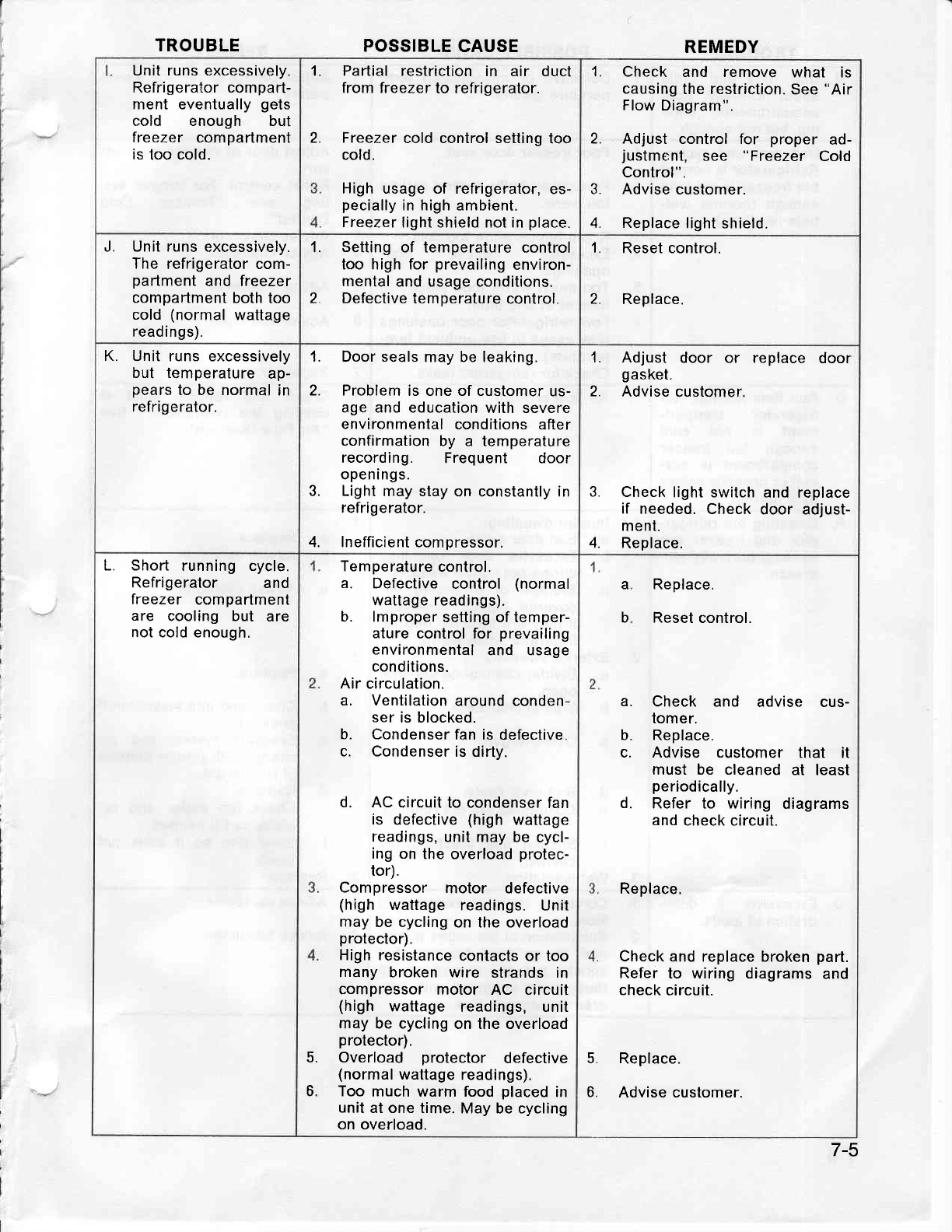
TROUBLE POSSIBLE
CAUSE REMEDY
Unit
runs
excessively.
Refrigerator compart-
ment eventually
gets
cold enough but
freezer compartment
is
too
cold.
'1. Padial restriction
in air duct
from freezer
to refrigerator.
2. Freezer
cold control setting
too
cold.
High usage of refrigerator,
es-
pecially
in high ambient.
Freezer
light shield not in
place.
1. Check and remove what is
causing
the restriction.
See
"Air
Flow Diagram".
2. Adjust control
for proper ad-
justment, see "Freezer Cold
Control".
3. Advise
customer.
4. Replace
light shield.
J. Unit runs
excessively.
The refrigerator com-
pafiment
and freezer
compadment
both too
cold (normal
wattage
readings).
Setting
of temperature
control
too high for prevailing
environ-
mental
and usage conditions.
Defective tem
perature
control.
1.
2.
1. Reset control.
Replace.2.
K. Unit runs excessively
but temperature
ap-
pears
to be normal
in
refrig erator.
1. Door seals
may be leaking.
2. Problem
is one of customer
us-
age and education
with severe
environmental
conditions
after
confirmation
by a temperature
recording. Frequent door
openings.
3. Light may stay
on constantly in
refrigerator.
4. Inefficient compressor.
1. Adjust door or replace door
gasket.
2. Advise customer.
3. Check
light switch
and replace
if needed. Check
door adjust-
ment.
4. Replace.
t
L. Short running cycle.
Refrigerator and
freezer compadment
are cooling but are
not cold enough.
Temperature
control.
a. Defective
control (normal
wattage readings).
b. lmproper
selting of temper-
ature
control for prevailing
environmental
and usage
conditions.
circulation.
Ventilation
around
conden
ser
is blocked.
Condenser fan
is defective
Condenser
is dirty.
d. AC
circuit to condenser
fan
is defective
(high
wattage
readings,
unit
may be cycl-
ing on
the overload
protec-
tor).
Compressor motor defective
(high wattage
readings. Unit
may
be cycling
on the overload
protector).
High resistance
contacts or too
many broken
wire strands in
compressor
motor AC circuit
(high wattage readings, unit
may be cycling
on the overload
protector).
Overload protector defective
(normal
wattage
readings).
Too
much warm food
placed
in
unit
at one time.
May be cycling
on overload.
Air
a.
b.
c.
5.
6.
Replace.
Reset control.
Check and advise cus-
tomer.
Replace.
Advise customer that it
must be cleaned
at least
periodically.
Refer to wiring diagrams
and
check circuit.
Replace.
Check
and replace broken
part.
Refer
to wiring diagrams
and
check
circuit.
Replace.
Advise customer.
a
b
a.
b.
c.
d.
5.
6.
7-5
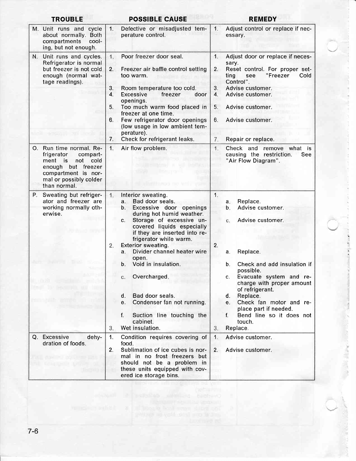
TROUBLE POSSIBLE CAUSE REMEDY
M. Unit runs and cycle
about normally. Both
compadmenls cool-
ing,
but
not enough.
1. Defective or misadjusted
tem-
perature
control. 1. Adjust
control or replace if nec-
essary.
N. Unit runs and cycles.
Refrigerator is normal
but freezer is not cold
enough
(normal
wat-
tage
readings).
Poor freezer
door seal.
2. Freezer
air baffle control setting
too warm.
3. Room temperature too cold.
4. Excessive freezer door
openings.
5. Too much warm food
placed
in
freezer at one time.
6. Few refrigerator door openings
(low
usage in low ambient tem-
pe
ratu
re).
7. Check for refrigerant leaks.
1. Adjust door
or replace if neces-
sary.
2. Reset control. For proper set-
ting see "Freezer Cold
Control".
3. Advise customer.
4. Advise cuslomer.
5. Advise customer.
6. Advise customer.
Repair or replace.
O. Run
time normal.
Re-
frigerator compad-
ment is not cold
enough but freezer
compartment is nor-
mal or
possibly
colder
than normal.
1, Air flow
problem. Check and remove what
causing the restriction.
"Air
Flow Diagram".
IS
See
Sweating but refriger-
ator and freezer are
working normally oth-
erwise.
P. Interior sweating.
a. Bad door seals.
b. Excessive door openings
during hot humid weather.
c. Storage of excessive un-
covered liquids especially
if they are inserted into re-
frigerator while warm.
Exterior sweating,
a. Divider
channel
healer wire
open.
b. Void
in insulation.
Overcharged
d. Bad door seals.
e. Condenser fan not running.
f. Suction line touching the
cabinet.
Wet insulation.
Replace.
Advise
customer.
Advise
customer.
a. Replace.
b. Check and add insulation if
possible.
c. Evacuate
system and re-
charge
with
proper
amount
of refrigerant.
d. Replace.
e. Check fan motor and re-
place part
if
needed.
f. Bend line so it does nol
touch.
Replace"
La
b
2.
a. Excessive dehy-
dration of foods. L Condition requires
covering
of
food.
2. Sublimation
of ice cubes is nor-
mal in no frost freezers but
should not be a problem in
these units equipped with cov-
ered ice storage bins.
1. Advise customer.
2. Advise customer
7-6
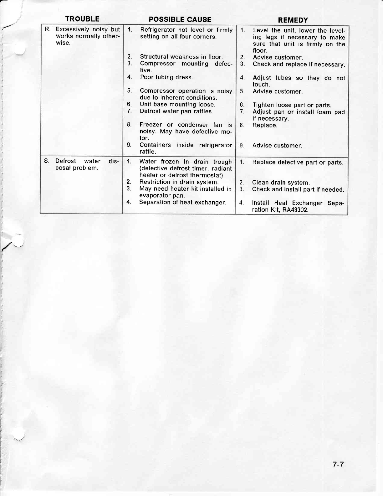
TROUBLE POSSIBLE
CAUSE REMEDY
R. Excessively
noisy
but
works
normally
other-
wise.
1. Refrigerator
not level or firmly
setting on
all four corners.
Structural
weakness
in floor.
Compressor mounling defec-
tive.
Poor
tubing
dress.
Compressor
operation
is noisy
due
to inherent
conditions.
Unit
base
mounting loose.
Defrost
water
pan
raltles.
Freezer
or condenser
fan is
noisy.
May have defective
mo-
tor.
Containers
inside refrigerator
rattle.
2.
3.
4.
5.
6
7
8.
9.
1. Level
the unit,
lower
the level-
ing legs if necessary
to make
sure thal unit is firmly
on the
floor.
2. Advise
customer.
3. Check
and replace
if
necessary.
4. Adjust tubes so they do not
touch.
5. Advise
customel.
6. Tighten
loose
part
or parts.
7. Adjust
pan
or install
foam
pad
if necessary.
8. Replace.
Advise customer
S. Defrost water dis-
posal problem. 1. Water frozen in drain trough
(defective
defrost
timer,
radiant
heater
or defrost
thermostat),
2. Restriction
in
drain system.
3. May
need heater
kit
installed in
evaporator
pan.
4. Separation
of heat
exchanger.
1. Replace
defective
part
or parts.
2. Clean
drain system.
3. Check
and
install
pad
if needed.
4. Install Heat Exchanger
Sepa-
ration
Kit, RA43302.
7-7
M/\YTAG SECTION
8
SCHEMATICS
INDEX
t-
8-1
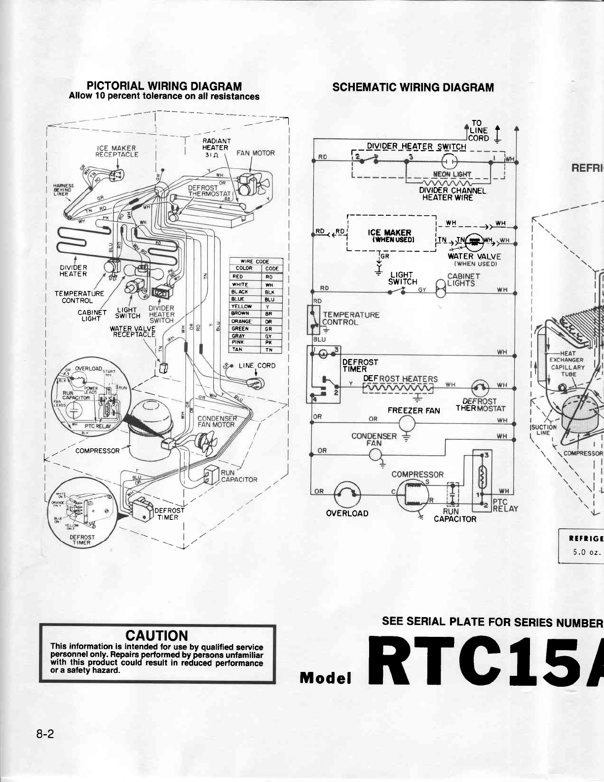
WIRE
CODE
COLOR CODE
R€O RO
WHITE WH
gLACX aLx
BLUE BLU
YELLOW
SROWN BR
ORANGE OR
GREEN GR
GRAY
PI NX PK
TAN TX
PICTORIAL
WIRING
DIAGRAM
Allow
10
percent
tolerance
on all resistances SCHEMATIC WIRING DIAGRAM
RADIANT
HEATER
JRe
t
cono
t
DIVIOE
R
HEATER
TEMPERATURE
CONTROL
CABINET
LIGHT
LIGHT
SWITCH
DIVIDER
HEATER
SWITCH
t----:-
CAPACITOR
SEE
SERIAL
PLATE
FOR
SERIES
NUMBER
WATER VALVE
RECEPTACLE
I LJJ LINE CORD
I
l/
K
/ COMPRESSOR
I
\\|/
\r
DEFROST
TI
MERI
\l/
t/
v
OVERLOAD
CAUTION
This information
is intended
for use bv
qualified
service
personnel
only. Repairs
perlormed
by
fer'sons
unfamiliar
with thjs product,
could result in rdd-uced
performance
or a safety hazard.
DIVIO€R
CHANNEL
HEATER
WIRE
r------------'l
Rp<
.-LD-.] tCf, ilAXER
I lflrlixrrcrn
l_
!! __ _+>_w_[
L-_i:gt'r__io.'#@*s
iGR WATER VALV
Y
= LIGHT
swrTcH
DEFROST
TIMER
OEF
- uEr
FREEZER
FAN THER
t:fltGt
5.0
oz.
8-2
M.de,
RTC!5/
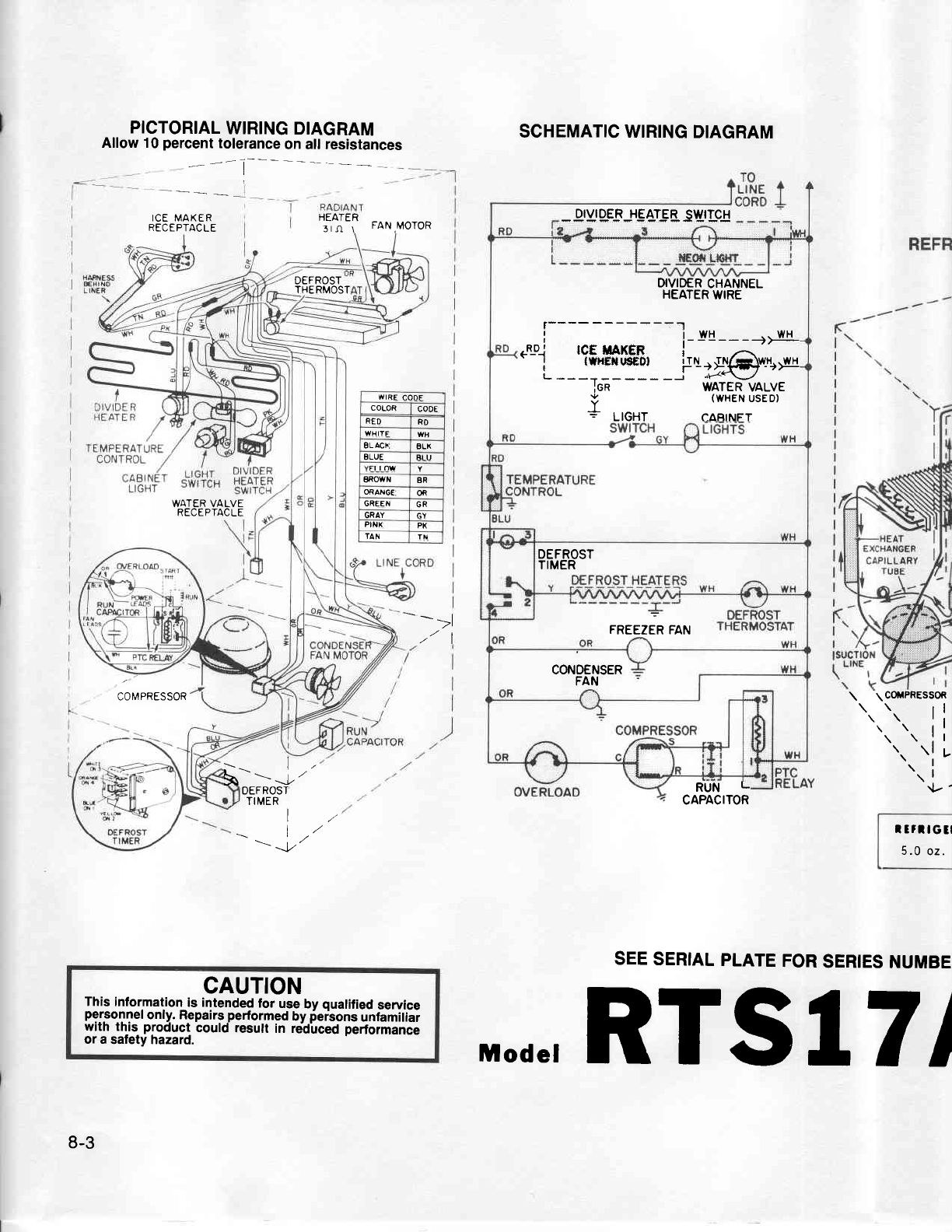
wrRE
cooF
COLOR co0E
RED RO
WHITF WH
ELACI BLX
BLU€ BLU
BROIYN 8R
ORANG€ ofi
GREEN GR
GRAY GY
PIIIX PX
TAN
PICTORIAL
WIRING
DIAGRAM
Allow 10
percent
tolerance
on all resistances SCHEMATIC WIRING
DIAGRAM
* grYr qEs
J*E Ar! B SWrLc!
SEE
SERIAL
PLATE
FOR
SERIES
NUMBE
ICE MAKER
RECEPTACLE
WATER VALVE
RECEPTACLE
STti FAN,MoroR
DEFROST
THERMOST
I
./' I
/l
COMPRESSOR
*-=
J"
OEFROST
TI MER RUN L
CAPACITOR
I
l/
1,/
\t/
-\ l-'
v
CAUTION
This
information
is intended
for
use
by
qualified
service
personnel
only. Repairs
performed
by
fersons
unlamiliar
with this-
product
could result
in njdirced performance
or a
safety hazard.
8-3
DIVID€R
CHANNEL
HEATER
WIRE
r---- - - - - - - - -'1
| | wH .-wH
.Lo_.j tcf, maKER
'-i--i:gY--fo.'#@***
IEn WATER
VALVE
v (WHEN
usED)
= LTGHT caBtNFT
DEFROST
TIMER
FREEZER
FAN
CONOENSER
FAN
l COftlPREsS0R
\
\ rl
t.t. it
\
\:l
t.. tl ,
t.. i
tl-'
Itrltctl
5.0
oz.
,,,.de,
RTSIT/
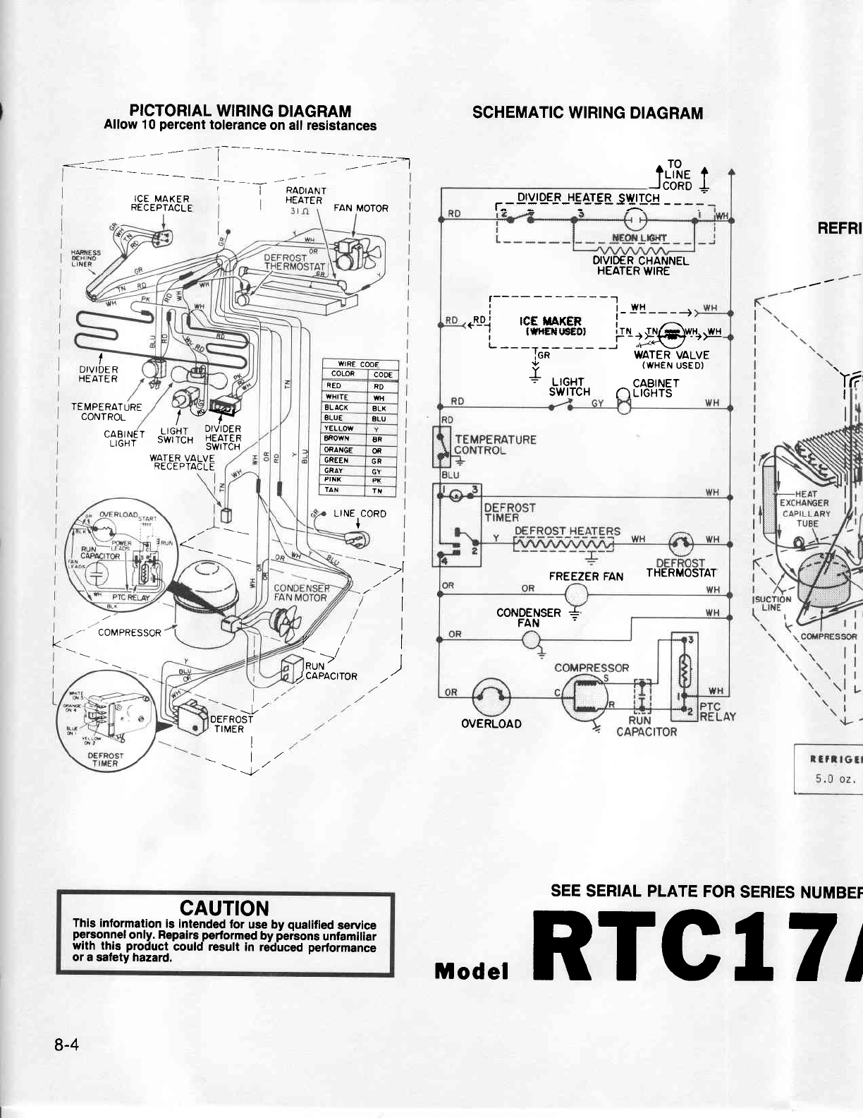
wrRE
COOE
COLOR co0E
REO RO
WHITE WH
ELACX 8LX
gLUE BLU
YELLOIV
BROWN BR
OfiANGE OR
GREEN GR
GRAY GY
PI
NX
TAN TX
PICTORIAL
WIRING
DIAGRAM
Allow
10
percent
tolerance
on all resistances
rl
SCHEMATIC WIRING
DIAGRAM
RADIANT
HEATER
rJRe t
__.tcoao
I
ICE
MAKER
RECEPTACLE
WATER
VALVE
RECEPTACLE
FAN MOTOR DIVIOER HEATER
SIVITCH
r---: - - - :-- - -;:-- - - - :
REFRI
SEE
SERIAL PLATE
FOR
SERIES
NUMBEF
V.
I
v/
;P,
DIVIDE
R
HEATER
TEMPERATURE
CONTROL
CABINET
LIGHT
/ *jl*"
r rnir DIVIDER
sliiiiu !fifIF,T
LINE
CORD
+
->l
,tlI
I
I
I
COMPRESSOR
)caPActroR
t\
/'
DEFROST
TIMERI
t/
\l/'
-\ v
OVERLOAD
CAUTION
This information
is intended
tor use by
qualified
service
personnel
only. Repairs
performed
by
6erbons
unlamiliar
with th-is
product
bould result in re'dirced
pedormance
or a safety hazard.
OIVIDER
CHANNEL
HEATER
WIRE
r------------'l
I l-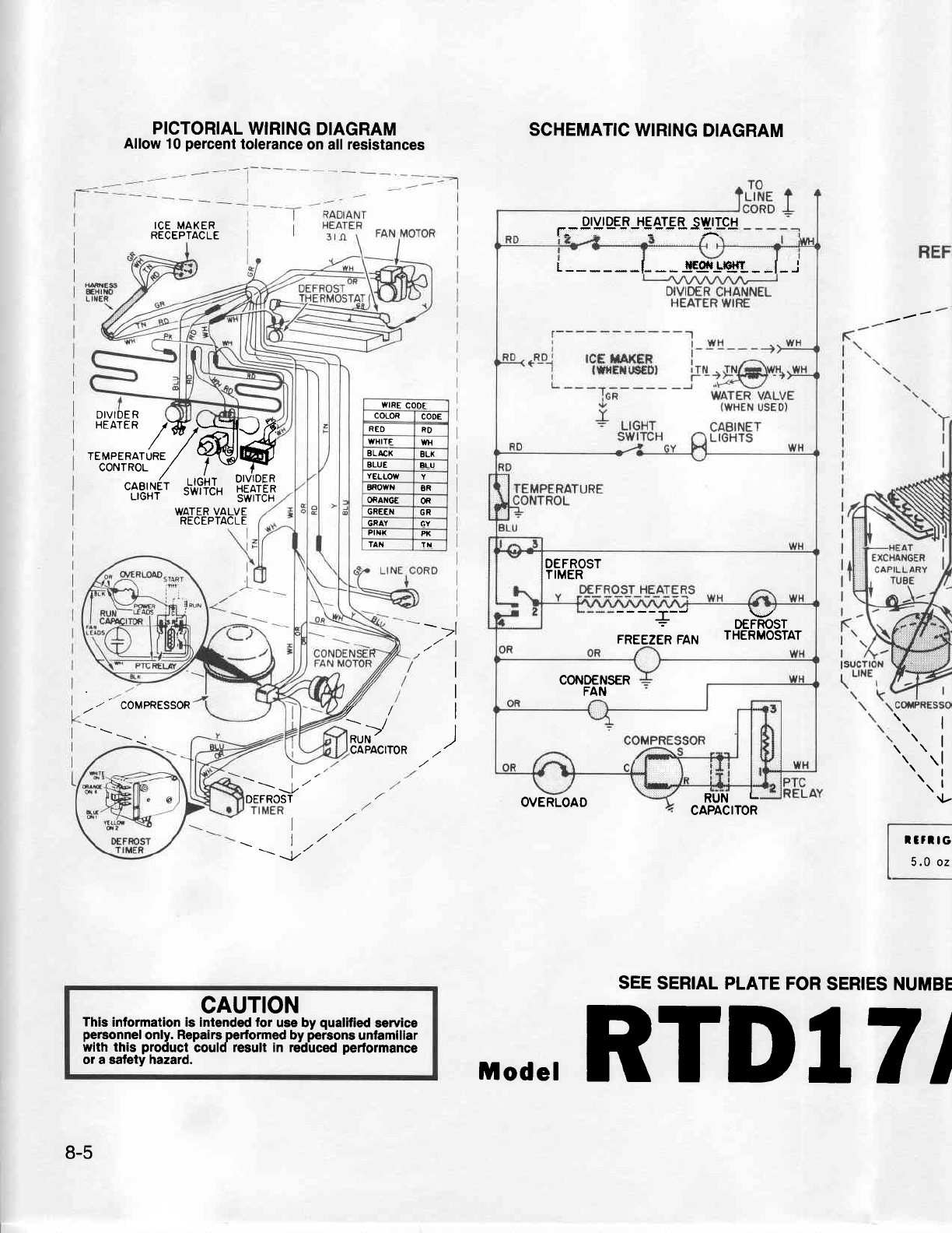
DIVIDE R
PICTORIAL
WIRING
DIAGRAM
Allow 10
percent
tolerance
on all
resistances
ICE MAKER
RECEPTACLE
SCHEMATIC
WIRING
DIAGRAM
DIVIDER HEATER
SIYITCH
r-**:- ;Li--
RUN L
CAPACITOR
SEE
SERIAL PLATE
FOR
SERIES NUMBE
,:;*qmffi^
.flB,#F'
,\i?fJ,
!#iF$
WATER VALVE
RECEPTACLE
I
->l
,,, I
I
I
I
I
COMPRESSOR v/
;,P, .t. I
t.. i
{-
CAPACITOR
I
\1,'
-\l/
v
DEFROST
L
t/
lr/
\t\ l./
v
OVERLOAD
CAUTION
Thls
information is intended for use by qualified
service
personnel
only.
Repairs
performed
by
persons
unlamlliar
with this product could result in reduced
performance
or a safety hazard.
8-5
WIRE
CODE
COLOR co0E
REO RD
WHITF WH
BL
ACX BLX
ELUE BLU
YELLOW
BROWI{ 8R
ORANG€ OR
GRE€N GR
GRAY GY
Ptt|x Pt(
TAN TN
r I llEofi L|e}{T | |
DEFROST
TIMER
----5- oehsr
FREEZER
FAN THERMOSTAT
CONDENSER
FAN
ltrltc
5.0 oz
M.de,
RTDIT/
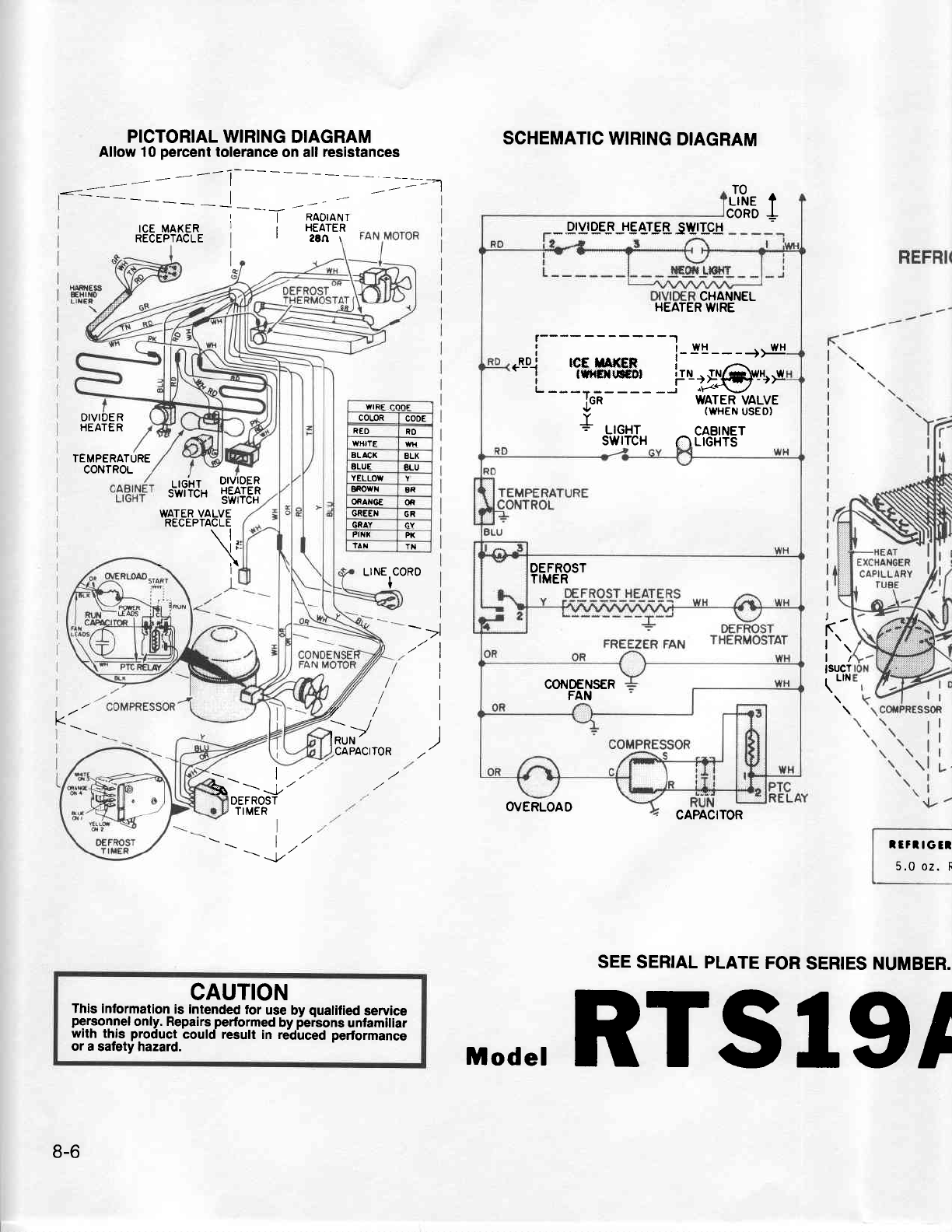
PICTORTAL WIRING
DIAGRAM
Allow 10
percent
tolerance
on all
resistances
1 HEATER
r26Ar
SCHEMATIC
WIRING
DIAGRAM
J'Rr
t
CORD
+
ICE MAKER
RECEPTACLE _,qryr
gEs
JE arg 8. swrlc
H
CAPACITOR
SEE
SERIAL PLATE
FOR
SERIES
NUMBER.
DIVIDE R
HEATER
TEMPERATURE
CONTROL .'-',i,t'iJ"
!'#?:t$
WATER VALVE
RECEPTACLE
\l
\l
\,:
\I F
.\ LINE CORO
I
t
.->l
-tl
I
I
I
,)
lt'.,
l/
lsucT
\ t'n
t/
Kv/
t/
CAPACITOR
t-=
J"
OEFROST
TIMER O/ERLOAO
\1,/
\-\ L'
v
CAUTION
This information
is intended
for use
by qualified
service
personnel
only. Repairs
performed
by
ier-sons
unfamiliar
with thjs product could result in rddlced pertormance
or a
safety hazard.
CHANNEL
HEATER
UIIRE
r---- - - - - - - - -'l
arwH
I i wH ..wH
---
,LD_.l tCE
XAf(ER '
'-i--rW--io:g@u*
L __**
__ ___ _[ -le.V/ -'.
Icn WATER
VALVE
.,l/ (WHEN
USED)
Y '-"-
= LIGHT CABINET
SWITCH nL|GHTS
DEFROST
TIMER
CONOENSER
FAN
WIRE 'ODF
COLOR cooE
REO RO
WHITE WH
ALACK 8LX
ALUE 8LU
YELLOW
EROWN BR
ORANGE oi
GREEN GR
GRAY GY
Frxx PK
TAN Tll
IrrltGtl
5.0
oz. R
8-6
,,.de,
RTSIgI
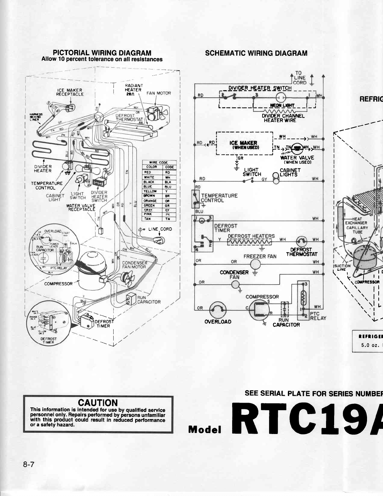
PICTORIAL
WIRING DIAGRAM
Allow 10
percent
tolerance
on all
resistances SCHEMATIC
WIRING DIAGRAM
OIVIOER HEATER
SWITCH
O/ERLOAD
I
ICE MAKER
RECEPTACLE
RADIANT
HEATER
?!Ar
I
IREFRIC
. uRr{Ess
I ExtiD
' LINER
r)
(t----t
''
I
I TEMPERATURE
,/ -
I corvrRol / |
,17
t
DIVIDE R
I HEATER
WATER VALVE
RECEPTACLE
LINE
CORD
t
COMPRESSOR
\ -"'"
r
\k
CAFACITOR
SEE
SERIAL
PLATE
FOR
SERIES
NUMBET
1l
otPRESSOI
1l
t..!
'.. )l
\;
a;
l!
I
I
I
I
I
v'
*-=-1,'
DEFROST
TI MER
L
t/
t/
\\ l,'
v
CAUTION
This information
is intended
for
use by
qualified
service
personnel
only. Repairs
performed
by
perbons
unfamiliar
with thjs product
could result
in redlced performance
or a safety
hazard,
L - - - - - -l- - - jEgl-tr$L - -l - -,i
DIVIDER
CHANNEL
HEATER
WIRE
llwfl
tl
I l^G g^t|iE I
.LD-.I lCf, l|AfGF i ,-r
' I lffiEtrro€Dl FU)IN{g:}w-t!,t
L ---*----- -i "\14\.J
Ien WATER VALVE
9 (WHEN
USEDI
Y
+ trcxr CABINET
SWITCH NLIGHTS
OEFROST
THERMOSTAT
COI,I0ENSER
IVIRE CODE
COLOR coo€
RED RO
WHITE WH
BLACX gLl(
BLUE etu
YELLOW
sowN ER
ORANGE OR
GREEI{ GR
PII{K
rAN TT
r
Irl tG
tl
5.0 oz. I
8-7
D'.de,
RTCIgI
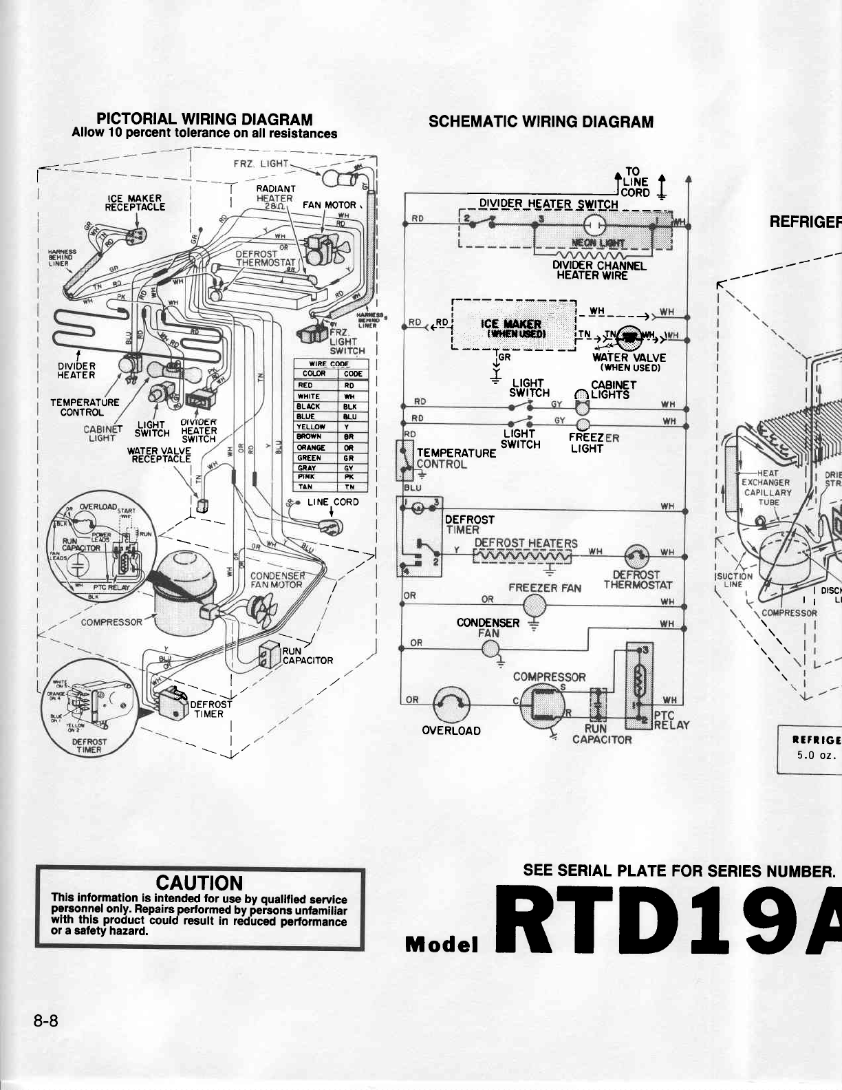
l-
PICTORIAL
WIRING
DIAGRAM
Allow 10
percent
tolerance
on all resistances
I RADIANT
ICE
MAKER
RECEPTACLE FAN
MOTOR.
SCHEMATIC WIRING
DIAGRAM
REFRIGEF
-----
(
I
I
DIVIDER
HEATER
TEMPERATURE
CONTROL ' ,.J,ffJ,
!i#TF$
WATER
VALVE
RECEPTACLE
lL, Lr
NEIC0RD
. .->l
r)
SEE
SERIAL PLATE FOR
SERIES NUMBER.
RUN'
CAPACITOR
d-'-
-f
'
DEFROST
TIMERI
\|,
-- -Jr'
CAUTION
This
information
is intended
for use by quatified
sewice
personnel
only. Repairs
performed
by
ierbons unfamiliar
with th-is.
ploduct could result in reidlced
performance
or a satety
hazard.
WIRE CODE
COLOR cooE
REO RO
WXITE tl{
BLACI( 8LK
ALUE ELU
YELLOW
sowfl OR
Of,AI'Gf, m
GREEII GR
GN Y GY
Flix Pt(
TAN tx
?J,Re t
ffi:"i1-t
DIVIO€R
CHANNEL
HEATER
WIRE
t-------'aTTE:1!
| ,,
' l-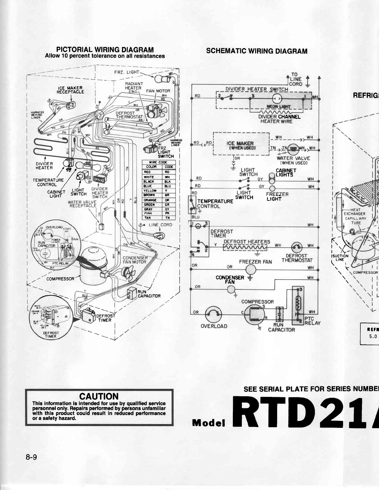
PICTORIAL
WIRING
DIAGRAM
Allow 10
percent
tolerance
on all
resistances
ICE
MAXER
RECEPTACLE
SCHEMATIC
WIRING
DIAGRAM
REFRIGI
SEE SERIAL
PLATE
FOR
SERIES
NUMBEI
LIGHT
swrTcH
I
->l
at 'l
I
I
I
I
/ COMPRESSOR
-^-
(\
| /Y-
lsucn0N
\ .,n.,
\k
t/'
Kv/
R,/
CAPACITOR
L-=
J"
DEFROST
TIMER
lr'
\1,
\ --t' t;
L
':
CAUTION
This information is intended for use by quallfied
service
personnel
only.
Repalrs
performed
by
persons
unlamiliar
with this product
could
result in reduced
performance
ol a safety
hazard.
8-9
CHANNEL
CABINET
LIGHTS
._ __
SWITCH urOxi
TEMPERATURE
cor{PFilsER
+
I
8t"i?EF
/Wh
rEupERntuRe ,/ 5
co'waot / ^l
tl,'u',|r6'
t'J'ffJ'
wtRE coffi
co{oR cooE
REO RD
WHITE WH
BLACX BLX
ELUE BLU
YELLOW
8f,OWN BR
OfiAXGE OR
GREEI{ GR
GRAY GY
fi
lat rx
,,.de,RTD2l/
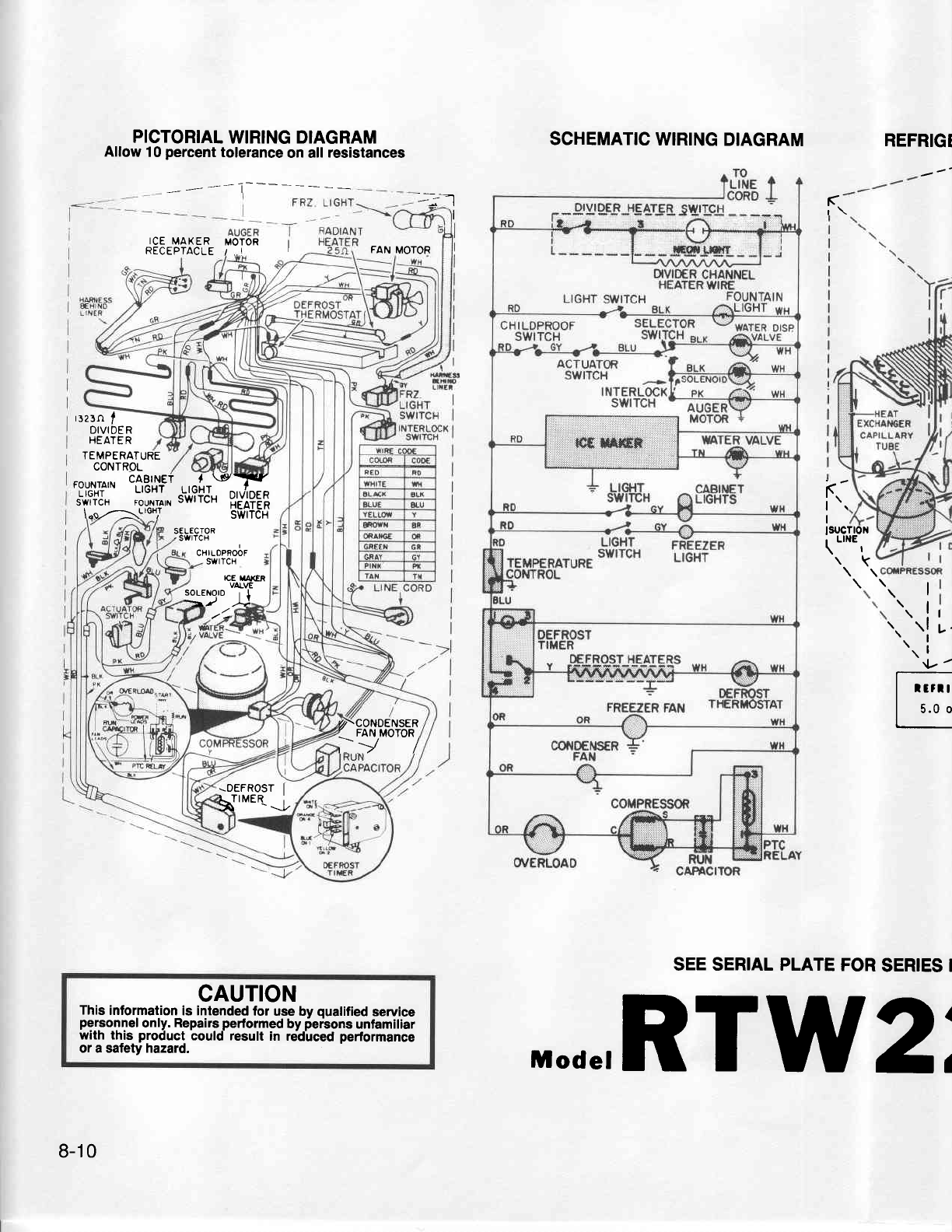
PICTORIAL
WIRING DIAGRAM
Allow
10
percent
tolerance
on all
resistances
ICE
MAKER MOTOR I
REcEpracLE
/._t I
SCHEMATIC
WIRING
DIAGRAM REFRIGI
Ir-
r\
I
FAN MOTOR
Foun'rN
tflBu'$Ft
r,o[r*^X^
r"i,?iJ, ,-"J"yi-
sATiix
D"'JI?EE
\.o-z\LrGH/ SWtic-x
rrzrn
I
DIVIDE R
HEATE
R
TEMPERATURE
CONTROL
CHI LOPROOF
swrTcH
ri
lsucTt0N
\.'".,
\k
SELECTOR
.
swrTcH
ICE I/|AXER
VALVE
soLENOro
t I
->,/ 1l
\. 1
'.'.'.i
L
'tf -
I rlrrlt
I s.o o
SEE SERIAL PLATE
FOR
SERIES I
CAUTION
This
information
is intended
for use bv
qualified
service
personnel
only. Repairs
performed
by
ferbons
unlamiliar
with this product_
could result in rddirced
performance
or a safety hazard.
Z/-CONDENSER
)'9"o*?
-DEFROST
I
HnME(J
8-10
Mode,RTW2"
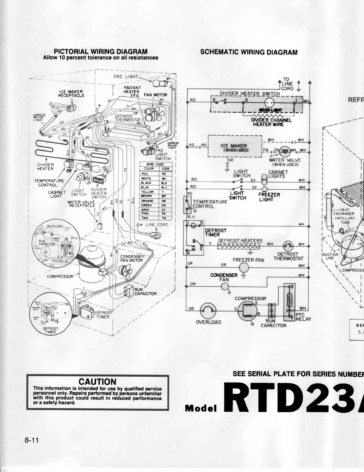
CONDENSEI
FAN MOTOR
WIRE
CODE
COLOR co0E
RLO RO
WHITE WH
8L ACX gLX
ALUE EIU
Y
ELLOW
EROWrl 8R
ORANGE OR
GR€EN GR
GRAY GY
PIH
XPX
TAN Ttl
PICTORIAL
WIRING
DIAGRAM
Allow 10
percent
tolerance
on all resistances SCHEMATIC
WIRING
DIAGRAM
SEE
SERIAL
PLATE
FOR
SERIES
NUMBET
ICE MAKER
RECEPTACLE
I RADIANT
| -54.ttEI FAN
MoroR
t
D
IVIDE
R
HEATE R
/*/
reueeRarune
/
coNTROl- i/
CABINET
LIGHT
WATER
VALVE
RECEPTACLE
\1,
v\
a:
COMPRESSOR v/
T,P'
I
,tl
I
I
I
I
k'
CAPACITOR
CAUTION
This information
is intended
for use by
qualified
service
personnel
only. Repairs
performed
by
persons
unfamiliar
with this product
could result
in retlced performance
or a safety hazard.
L------L-*!q$$m- |
OVIO€R
CHANNEL
HEATER
WIRE
rt'l9iJr tT;t*Ttt
OEFROST
TIMER
CONOENSER
8-11
,,.de,RTD23
I

PICTORIAL
WIRING
DIAGRAM
Allow
10
percent
tolerance
on all resistinces
=:-.-T .-
SCHEMATIC
WIRING
DIAGRAM
OVERLOAD RUN
CAPACITOR
SEE
SERIAL
PLATE
FOR
SERIES
NUMBER.
|.:-
i
rcr
uaxen
I
RECEPTACLE.
I
I
I
I
i
I
I
I
I
I
I x FN€SS
|
6!xrN0
I
LrxEn
FREEZER
LIGHT
I
lct
fr
I
I
I
I
I
I
I
I
I
I
+
I
-r
I
I
I
l/
l'
swrrcx)
NPftEI /
_)i#
coiMlG
YIT*#.'l,wyr
RUN
/CAPACITOR
-\
on
RO
AU
)
I
)
\L/-
I
\1
rl
\,
CAUTION
This information
is Intended
for use
by quallfied
service
pe.rsornel
only. Repairs
performed
by
persons
unfimiliar
wrtn th_ts.
proctuct
could result in redtced performance
or a safety hazard.
r------------1
| | wH ..WH
lr---
EL.L0-.1 tcE
tAxER i ,--r
I l|lerqrrcDltl iTN -TNt-\Wl.l - W
L-
iigT]--io:g@.ur
Ien WATER
VALVE
Y (WHEN
USED}
I
= LtcHT
swrTcH (|)REFR|G.
LTGHTS
DEFROST
TIMER
DEF -- --.:rj- oeffisr
FREEZER
FAN THERMOSTAT
8-12
,|,.de,RSC20
l
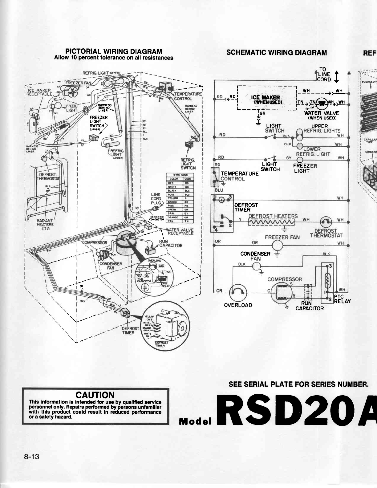
PICTORIAL
WIRING DIAGRAM
Allow 10
percent
tolerance
on all
resistances
t{ iil€ss r
EHtfro
LITER
\
SCHEMATIC
WIRING
DIAGRAM REFI
t
TO
,LINE
CORD
-----^,
FREEZER
LIGHT
.
swrTcH>
":"Y
Gdm
'----1\
l-
:'i n
'..L-----
\l
-rl
_)i
I
)PTC
RELAY
I
I
\l
OVERLOAD RUN
CAPACITOR
SEE SERIAL
PLATE
FOR
SERIES
NUMBER.
CAUTION
Thls
lnformation is intended
for use bv qualified
service
personnel
only.
Repairs
performed
by
iersons unfamiliar
with thls product
could
result
in reduced
perlormance
or a safety
hazard.
r-- --
| | WH ..WH
---
.Lo_.l tcf f,at(ER ,
.i--iW'__io,,g@',u+
IAA WATER
VALVE
WAI LIT YFLV
Y (WHEN
usEo)
I
= LIGHT UPPER
LIGHT rneeZ
__
SwlTcH LtGii
TEMPERATURE
DEFROST
TIMER
CONDENSER
8-13
,,.de,RSD20
A
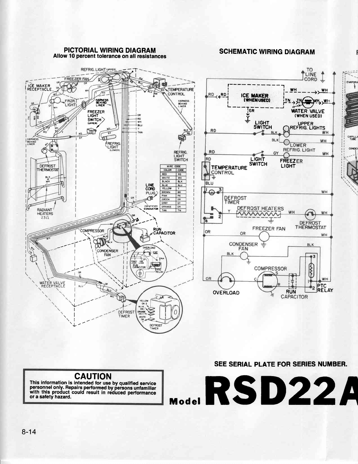
i ICE MAKER
!
RECEPTACLE
FREEZER
L|GHT
-
swrTcH2
,*y
PICTORIAL
WIRING
DIAGRAM
Allow t0 percent
tolerance
on all resistances
=-.7 I
HANrlESS
EH|l{0
SCHEMATIC
WIRING
DIAGRAM
OVERLOAD
PTC
RELAY
SEE
SERIAL
PLATE FOR
SERIES
NUMBER.
LINER
LINE
CORD
\ CONMTq
Y:-"'^,
r>
--l t
t\
I
I
I
l/
\_/-
I
I
\l
\|
\
|
--
aur.r
CAPACITOR
-\
.._ij.f
---
CAUTION
This information
is intended
for
use
by
qualified
service
personnel
only. Repairs
performed
by
ier'sons
unfamiliar
with th-is
product_
could result in reiCirced
performance
or a safety hazard.
r-- --
I r wH ..wH
I
e{_Dj rcf, ilAxEF
.-i--:H'__fo:;$vr*
iGR WATER
VALVE
(WHEN
USED}
Y I
wrrsrt veEv,
F -t=!-olt uPPER
swrTcH 6ner-nrc.
Lionrs
LIGHT FR-EEZ
TEMpERAT,RE
swlrcH lteni
RUN
8-14
,L.de,RSD22A

I
rcE
MAKER I
<'o'Y'-t,
i=.
ice r,raxen
REC
E PTACLE
RADIANT
HEATERS
23n
_ sry_-
-
^:._ 1^ \FRzr-rGHr
FREEZER
REFR|G.
L|GHI
H NE$
EHIiO
L IIEF
.\--6
-1 i^(ttt
-..
PtgToRtAL
WtRtNG
DTAGRAM
Allow
10
percent
tolerance
on
att ieslsiinces SCHEMATIC
WIRING
DIAGRAM REFRIC
SELECTOR
RUN L
CAPACITOR
SEE
SERIAL
PLATE
FOR
SERIES
NUMBE
CHILDPROOF
SWITCH
OVERLOAD
WATEROISP
VE
(LO\fER)
REFRIG.
LIGHT
I
;ATER
WIRE
2940.Cl
FOUNTAIN
LIGHT
'swrTcH
swrTcri
S€LECTOR
swrTcH
SOLENOID
R0
aLr
OR
/:
/l
I
)
k
rotnrFt€D
\ cq&cor
t icinoeisrn i ,
\ ', F!0t
_--ii\l
A!
\\
\\
I
I
1l
:a\ll
-i* -
\-I-l
OEFRO
TIMER
\. I or'!"f
\- Dtscoill{EcT
CAUTION
This
information
is intended
for use
by
qualified
service
pg.r.so.lTel
only. Repairs performed
by
feisons untlmitiai
wrrn
tn-ts.
product
could result
in red-uced performance
or
a safety
hazard,
AQ.T..-uAJoR f e,_* A;- wH
_ __
SWITCH urOxi
TEMP€RATURE
8-15
i,.de,RSW22
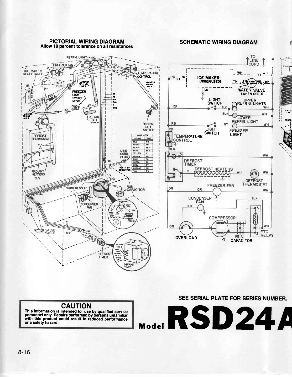
PICTORIAL
WIRING
DIAGRAM
Allow
10
percent
tolerance
on all
resistances
HAF
iEss ,
EH|l{O
LINER
-
SCHEMATIC
WIRING
DIAGRAM
CONTROL
I
I
I
I
I
I
NR€SS
trxtio
Ltlfl
FREEZER
LIGHT
.
swrrcn)
lu"ftel /
ff
RO
lx
lu
| {ARRESS
r
aExrto
I uf,fF
CAHLU
TC
mEl
ffi
trtlrF
\ cilm
--\
l/
\|
v\l z-
rl
\l
\l
\l -'
'l
/
CAUTION
This information
is intended for use by qualified
service
personnel
only.
Repairs
performed
by
perbons
unfamiliar
with this product could result in re-dLced
pedormance
or a safety hazard.
OVERLOAD CAPACITOR
SEE SERIAL
PLATE
FOR
SERIES NUMBER.
.E_D_.I tcE UAKER | "
'ilxHilTdr
_ fo3$@.+xo
- -- *jfi - - - - -'J ilil,.S,-y3r.y,.
Y I
wnEt! ui
* utcxt uppER
SWITCH r.)REFRIG.
LIGHTS
SWITCH l,CXt
RATURE LI
8-1
6
,,.de,RSD24A
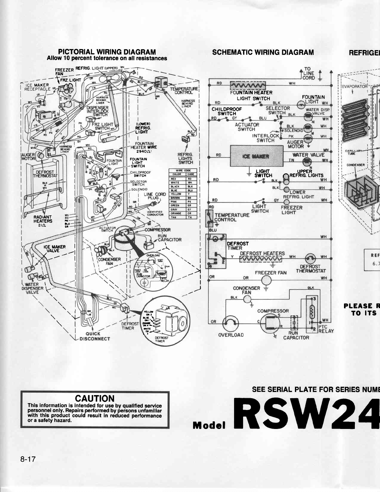
ICE MAKER I
{Y-''t
[!q
OI
rq. \
.Et
frm
l5/
PICTORIAL
WIRING
DIAGRAM
Allow 10
percent
tolerance
on all resistances
6p652gp REFRTG.
F3!-- .-
- - ={tr u,qn
MAKER ]JTA I
SCHEMATIC WIRING DIAGRAM REFRIGEI
PLEASE
R
TO ITS
SEE
SERIAL
PLATE FOR
SERIES NUMT
(LosER)
R€FRIG.
LIGHT
I
WIRE
2940Jr!
FOUNTAIII.I
LIGHT
'swtTcH
swtTcfl
RADIANT
HEATERS
2
rtr 4-
lu
ot.
--\
\i
\l
-/l I
I
_)
k
\tu
\l
CAUTION
This information
is intended
for
use bv
oualified service
personnel
only. Repairs
performed
by
iersons
unfamiliar
with thjs product
could
result
in redirced
performance
or
a
salety
hazard.
UNTAIN
HEATER
LrcHr
s'tvrrcH _FppM3lN
CHILOPROOF
swrTcH
LIGHT UPPER
SWITCH (I]IREFRIG.LIGHTS
DEFROST
8-17
i,.de,RSW24
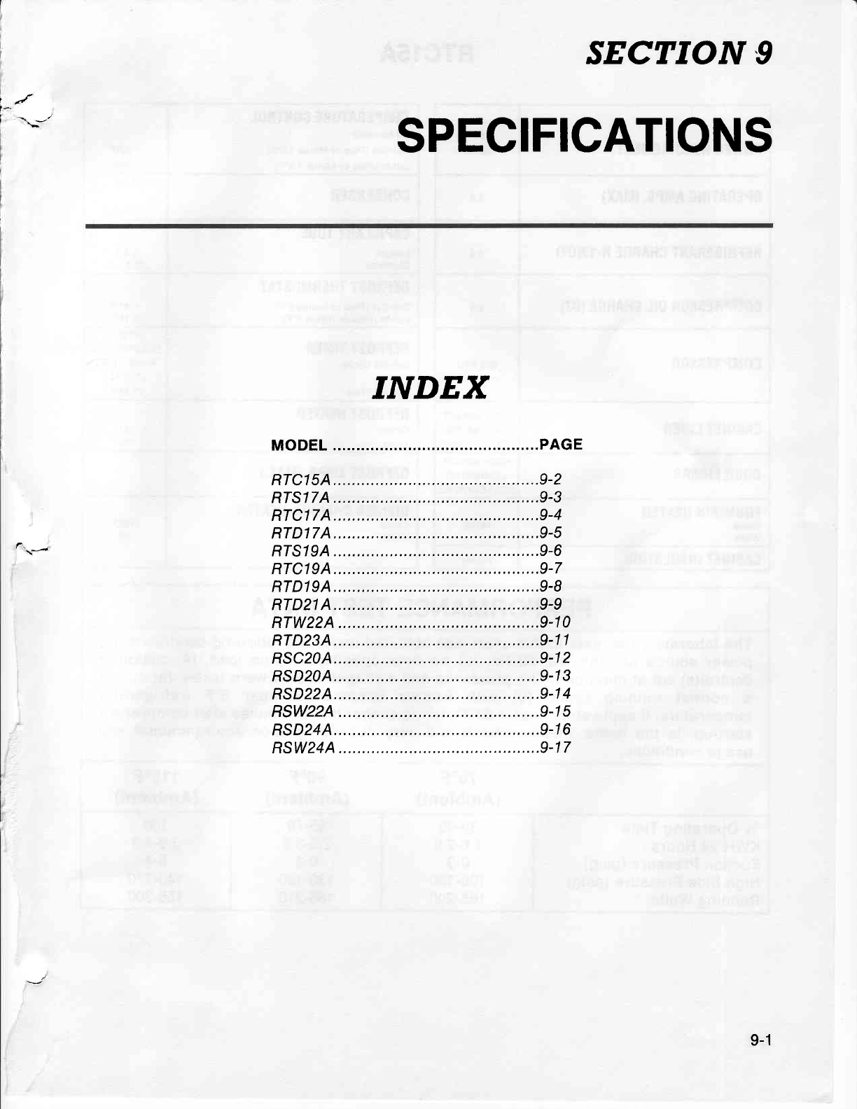
f-.
i --.
-'
SECTION 9
SPECIFICATIONS
INDEX
9-1

RTCl5A
POWER REOUIREMENT 1 1sVAC
do n.
oPERATTNG AMPS.
(MAX) 6.6
REFRTGERANT
CHARGE R-1 2(02) 5.0
G0MPRESS0R 0rL
CHARGE
(02) 8.5
COMPRESSOR 690 BTU
CABINET
LINER HIGH IMPACT
LAMINATED
POLYSTYRENE
OOOR TINERS HIGH IMPACT
LAMINATED
POLYSTYRENE
FOUNTAIN
HEATER
Ohms
Watts NONE
CABINET
INSULATION FOAM
TEMPERATURE
CONTROL
(At
Normal)
Cut-Oul
(Plus
or Minus
1.5'F)
Cut-ln
(Plus
or Minus
1.5oF)
+
23"F
+
330F
CONDENSER FAN
COOLED
CAPILLARY TUBE
Length
Diameter 5.5 ft.
026"
t.D
DEFROST
THERMOSTAT
Cut-Out
(Plus
or
minus
6oF)
Cut-ln
(Plus
or minus
6oF) + 47"F
+
150F
DEFROST TIMER
Defrost Cycle
Defrosl Time
AFTER
COMPRESSOR
RUNS
6
HRS.
(rorAL)
21
MtN.
DEFROST HEATER
Ohms
Watts 31
400
DEFR0ST
AMPS.
(MAX.)
DIVIDER
CHANNEL HEATER
Ohms
Watts 1
323
10
-t/z''
PERFORMANCE
TEST
DATA
The
laboratory test
data in this chart was
obtained under the following
conditions:
(1)
power
source
of 115V AC,60 Hz,
(2)
no
door openings,
(3)
no load,
(4)
customer
control(s)
set at mid-point. The
pressures
and wattages
shown were taken:
(a)
during
a normal running
cycle, (b) with freezer
temperature
near OoF
(refrigerator
temperature,
if applicable, near
+38oF), (c)
no sooner than
5 minutes
after compressor
start-up. In the home,
measurements will vary
depending
upon environmental
and
usage
conditions.
70"F
(Ambient) 90"F
(Ambient) 1100F
(Ambient)
o/o
Operating
Time
KWH/24 Hours
Suction Pressure
(psig)
High Side Pressure
(psig)
Running Watts
30-40
1.6-2.0
0-3
1
00-1 20
1
65-200
55-70
2.5-3.3
0-3
1
30-1
50
165-210
100
3.8-4"9
0-4
140-170
1
55-200
9-2
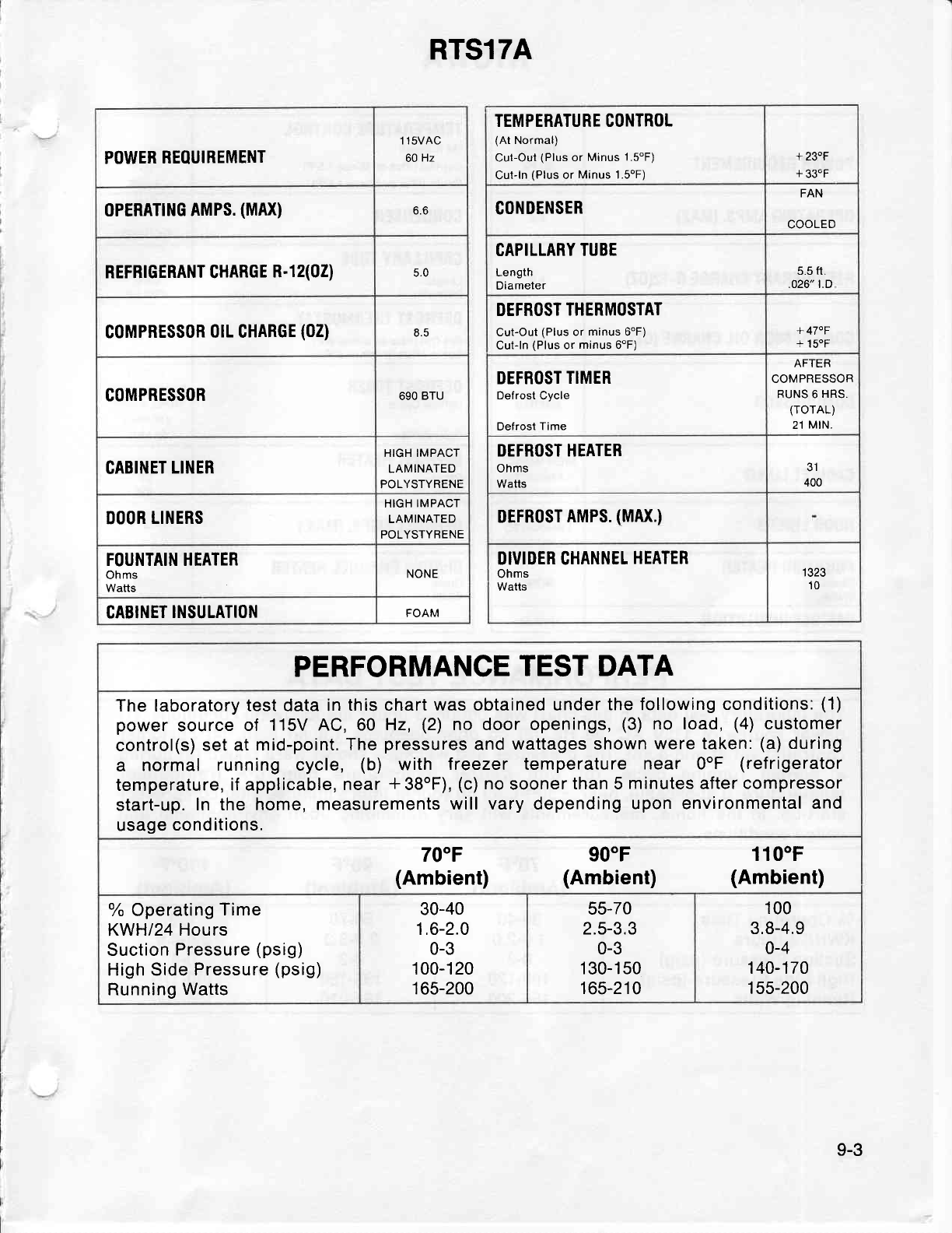
RTS17A
POWER
REOUIREMENT 1 1sVAC
60
Hz
oPERATTNG
AMPS.
(MAX) o.o
REFRTGERANT CHARGE
R-12(02) 5.U
coMPRESSoR
0rL GHARGE
(02) 8.5
COMPRE$SOR 690
BTU
CABINET
LINER HIGH IMPACT
LAMINATED
POLYSTYRENE
DOOR
LINERS HIGH
IMPACT
LAMINATED
POLYSTYRENE
FOUNTAIN HEATER
Ohms
Watts NONE
CABINET
INSULATION FOAM
TEMPERATURE CONTROL
(At
Normal)
Cut-Out
(Plus
or Minus 1.5"F)
Cut-ln
(Plus
or Minus 1.SoF)
+ 230F
+ 330F
CONDENSER FAN
COOLED
CAPILLARY
TUBE
Length
Diameter
5.5
ft.
.026" LD
DEFROST
THERMOSTAT
Cut-Out
(Plus
or
minus
6'F)
Cut-ln
(Plus
or
minus
6"F) + 47"F
+ 150F
DEFROST
TIMER
Defrost Cycle
Defrost
Time
AFTER
COMPRESSOR
FUNS 6
HRS,
(rorAL)
21
MtN.
DEFROST HEATER
Ohms
Watts
31
400
DEFRoST
AMPS.
(MAX.)
DIVIDER CHANNEL
HEATER
Ohms
Watts
'1323
10
PERFORMANCE
TEST DATA
The laboratory
test data in
this chart
was
obtained
under
the following
conditions:
(1)
power
source
of 115V
AC,60 Hz,
(2)
no door openings,
(3)
no load,
(4)
customer
control(s)
set at
mid-point, The
pressures
and
wattages shown
were taken:
(a)
during
a normal running cycle, (b) with treezer temperature
near OoF
(ref
rigerator
temperature,
if applicable,
near
*38oF),
(c)
no
sooner
than 5
minutes
after
compressor
start-up.
In the home,
measurements
will vary depending
upon environmental
and
usage
conditions.
70"F
(Ambient) 90"F
(Ambient) 1100F
(Ambient)
oh
Operating
Time
KWH|?
Hours
Suction
Pressure
(psig)
High Side
Pressure
(psig)
Running Watts
30-40
1.6-2.0
0-3
1 00-1 20
1
65-200
55-70
2.5-3.3
0-3
1
30-1
50
165-210
100
3.8-4.9
o-4
140-170
1 5s-200
9-3
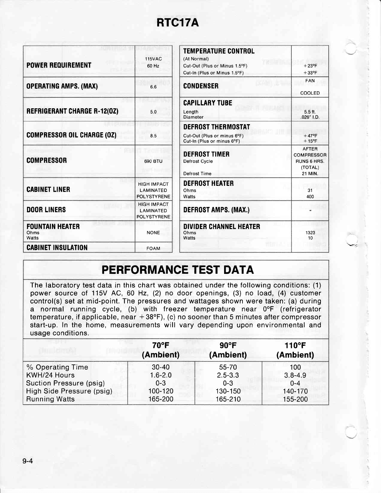
POWER
REOUIREMENT 1 1sVAC
60 Hz
oPERATTNG
AMPS.
(MAX) b.b
REFRTGERANT
CHARGE
R-12(02) qn
G0MPRESS0R
0rL
CHARGE
(02) 8.5
COMPRESSOR 690
BTU
CABINET
LINER HIGH IMPACT
LAMINATED
POLYSTYRENE
DOOR LINERS HIGH IMPACT
LAMINATED
POLYSTYRENE
FOUNTAIN HEATER
Ohms
Watts NONE
CABINET INSULATION FOAM
RTCl7A
TEMPERATURE
CONTROL
(At
Normal)
Cut-Out
(Plus
or
Minus
1.soF)
Cut-ln
(Plus
or
Minus 1.5oF)
+ 230F
+ 330F
GONDENSER FAN
COOLED
CAPILLARY
TUBE
Length
Diameter 5.5 fr.
.026" t.o.
DEFROST THERMOSTAT
Cut-Out
(Plus
or minus 6oF)
Cut-ln
(Plus
or minus 6oF) + 470F
+ 15"F
DEFROST TIMER
Defrost Cycle
Defrost Time
AFTER
COMPRESSOR
RUNS 6 HRS.
(rorAL)
21 MIN,
DEFROST HEATER
Ohms
Watts 31
400
DEFRoST AMPS.
(MAX.)
DIVIDER
CHANNEL HEATER
Ohms
Watts 1 323
10
PERFORMANCE
TEST
DATA
The
laboratory test data in this chart was obtained under
the following
conditions:
(1)
power
source of 115V AC,60 Hz,
(2)
no door
openings,
(3)
no load,
(4)
customer
control(s) set at
mid-point. The
pressures
and wattages shown were taken:
(a)
during
a normal running cycle, (b) with treezer temperature
near 0"F (refrigerator
temperature, if applicable,
near
*38oF),
(c)
no
sooner than 5 minutes after compressor
start-up.
ln the
home,
measurements will vary
depending upon environmental and
usage conditions.
70"F
(Ambient) 900F
(Ambient) 1100F
(Ambient)
% Operating Time
KWH/24 Hours
Suction Pressure
(psig)
High
Side
Pressure
(psig)
Running
Watts
30-40
1.6-2.0
0-3
100-120
1
65-200
55-70
2.5-3.3
0-3
1 30-1 50
165-210
100
3.8-4.9
0-4
140-170
1 55-200
9-4
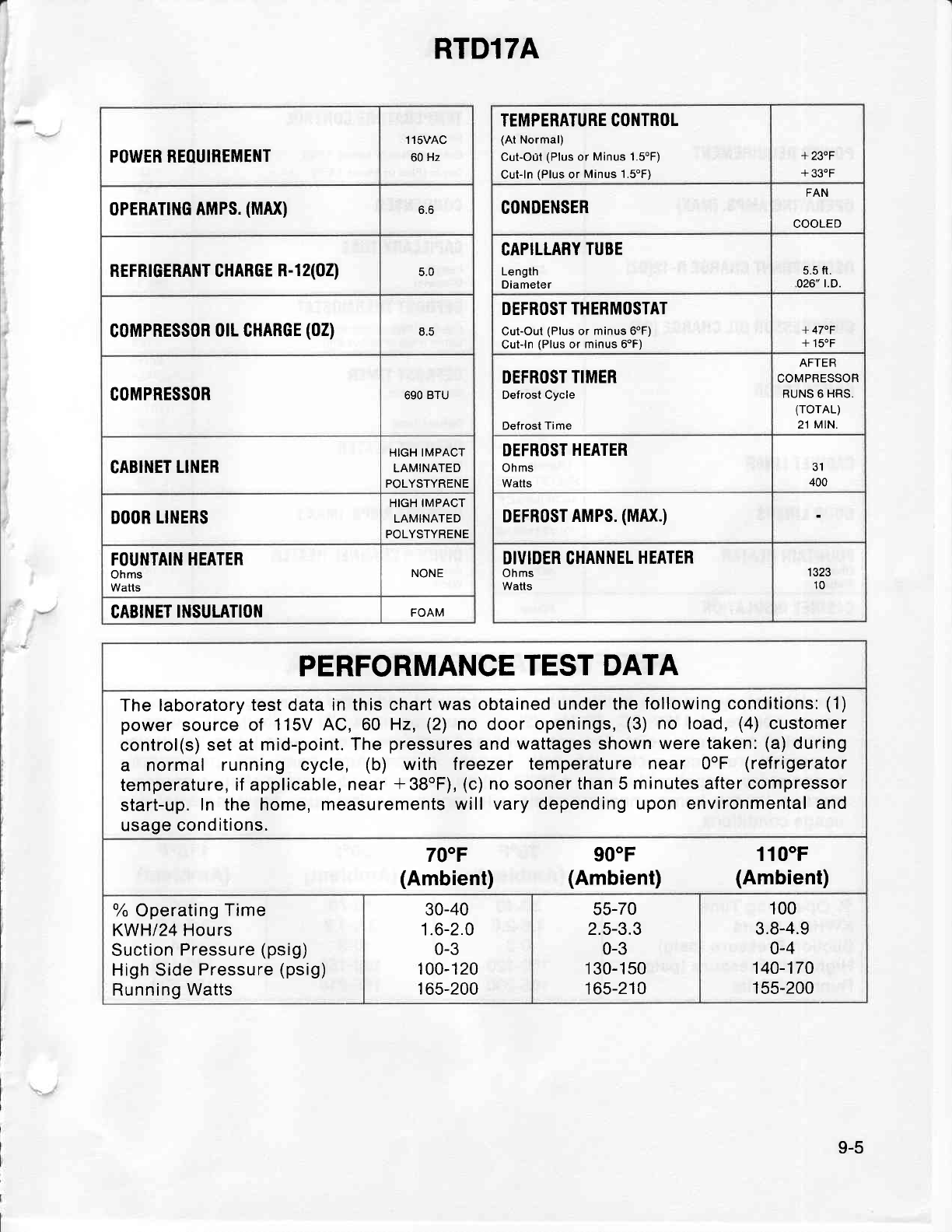
RTDl7A
POWER REOUIREMENT 1 1sVAC
60
Hz
oPERATTNG
AMPS.
(MAX) o.o
REFRTGERANT CHARGE
R-12(02) c.u
G0MPRESS0R
0rL CHARGE
(02) EE
COMPRESSOR 690
BTU
CABINET
LINER HIGH IMPACT
LAMINATED
POLYSTYRENE
DOOR LINERS HIGH IMPACT
LAMINATED
POLYSTYRENE
FOUNTAIN
HEATER
Ohms
Watts NONE
CABINET
INSULATI0I'l FOAM
TEMPERATURE CONTROL
(At
Normal)
Cut-O0t
(Plus
or
Minus 1.5oF)
Cut-ln
(Plus
or
Minus 1.5oF)
+ 230F
+ 33.F
CONDENSER FAN
COOLED
CAPILLARY
TUBE
Length
Diameter 5.5
fr.
026"
t.D.
DEFROST
THERMOSTAT
Cut-Out
(Plus
or
minus 6oF)
Curln
{Plus
or
minus 6oF) + 470F
+ 150F
DEFROST
TIMER
Defrost Cycle
Defrost Time
AFTER
COMPRESSOR
RUNS 6
HRS.
(rorAL)
21
MlN.
DEFROST
HEATER
Ohms
Watls
31
400
DEFRoST
AMPS.
(MAX.)
DIVIDER CHANNEL
HEATER
Ohms
Watts 1323
10
PERFORMANCE
TEST DATA
The laboratory
test data
in this chart
was obtained under
the
following conditions:
(1)
power
source of 115V
AC,60 Hz,
(2)
no door openings,
(3)
no load,
(4)
customer
control(s)
set at mid-point.
The
pressures
and
wattages shown
were taken:
(a)
during
a normal running cycle, (b) with lreezer temperature
near OoF
(ref
rigerator
temperature,
if applicable,
near
*38oF),
(c)
no sooner
than 5
minutes
after
compressor
start-up.
In the home, measurements
will vary depending
upon environmental
and
usage conditions.
700F
(Ambient) 900F
(Ambient) 110"F
(Ambient)
o/o
Operating
Time
KWH|24 Hours
Suction
Pressure
(psig)
High Side
Pressure
(psig)
Running
Watts
30-40
1.6-2.0
0-3
1
00-1
20
1
65-200
55-70
2.5-3.3
0-3
1
30-1
50
165-210
100
3.8-4.9
0-4
140-170
155-200
9-5
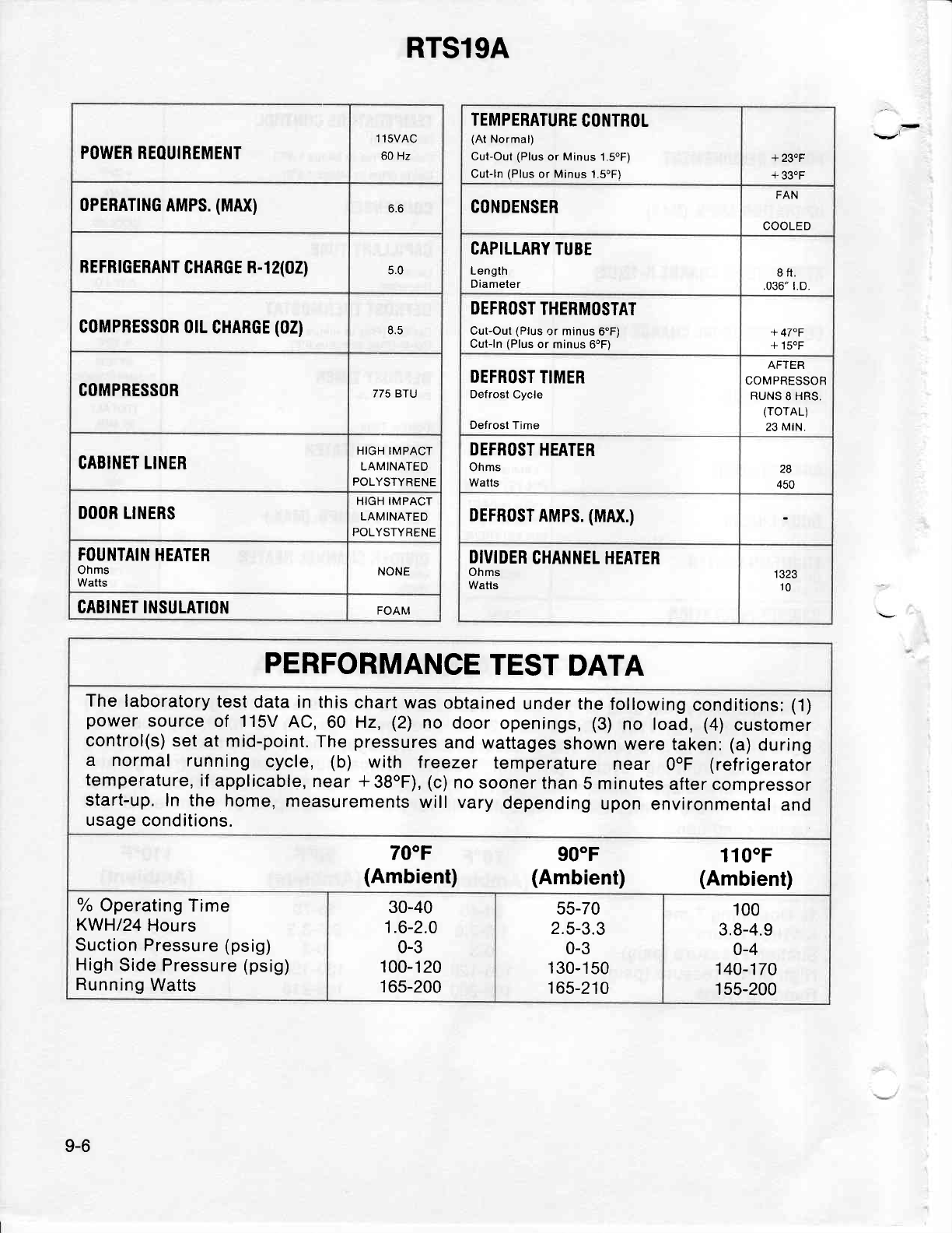
POWER REOUIREMENT 1 1sVAC
60 Hz
0PERATTNG
AMPS.
(MAX) o.o
REFRTGERANT
CHARGE R-1 2(02) 5.0
G0MPRESS0R
otL
CHARGE
(02) 8.5
COMPRESSOR 775 BTU
CABIiIET LINER HIGH IMPACT
LAMINATED
POLYSTYRENE
DOOR
LINERS HIGH IMPACT
LAMINATED
POLYSTYRENE
FOUNTAIN
HEATER
Ohms
Watts NONE
CABINET INSULATION FOAM
RTSl9A
TEMPERATURE
CONTROL
(At
Normal)
Cut-Out
(Plus
or Minus
1.SoF)
Cut-ln
(Plus
or Minus
l.SoF)
+ 230F
+ 33.F
CONDENSER FAN
COOLED
CAPILLARY
TUBE
Length
Diameter 8 ft.
.036" t.D.
DEFROST
THERMOSTAT
Cut-Out
(Plus
or minus
6"F)
Cut-ln
(Plus
or minus
6oF) + 47"F
+
150F
DEFROST
TIMER
Defrost Cycle
Defrost
Time
AIIEh
COMPRESSOR
RUNS
8 HRS,
(rorAL)
23
MrN.
DEFROST
HEATER
Ohms
Watts 28
450
DEFR0ST
AMPS.
(MAX.)
DIVIDER
CHANNEL
HEATER
Ohms
Watls I ozo
10
PERFORMANCE
TEST
DATA
The laboratory
test
data in this
chart was
obtained
under the
following
conditions:
(1)
power
source
of 115v
Ac,60 Hz,
(2)
no
door
openings,
(3)
no load,
(4)
customer
control(s)
set
at mid-point.
The
pressures
and wattages
shown
were
taken:
(a)
during
a normal running
cycle, (b) with freezer
temperature
near OoF
(ref
rigerator
temperature,
if applicable,
near
*38"F),
(c)
no
sooner
than
5 minutes
after compressor
start-up. In
the home,
measurements
will vary
depending
upon
environmental
and
usage
conditions.
700F
(Ambient) 90"F
(Ambient) 1100F
(Ambient)
o/o
Operaling
Time
KWH/24
Hours
Suction Pressure (psig)
High
Side Pressure
(psig)
Running
Watts
30-40
1.6-2.0
0-3
100-120
165-200
55-70
2.5-3.3
0-3
130-150
165-210
100
3.8-4.9
0-4
140-170
1 55-200
9-6
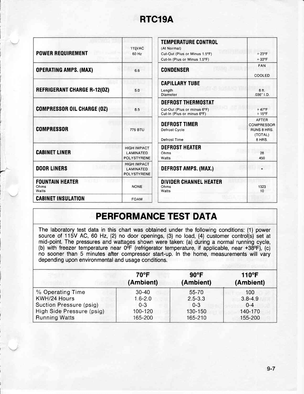
RTC19A
POWER REOUIREMENT 1
IqVAC
60 Hz
oPERATTNG
AMPS.
(MAX) 6.6
REFRTGERANT
GHARGE
R-1 2(02) c.u
coMPBES$oR 0rL CHAnGE
(02) 8.5
COMPRESSOR 775 BrU
CABINET
LINER HIGH IMPACT
LAMINATED
POLYSTYRENE
DOOR LINERS HIGH
IMPACT
LAMINATED
POLYSTYRENE
FOUNTAIN
HEATER
Ohms
Watts NONE
CABINET INSULATION FOAM
TEMPERATURE CONTROL
(At
Normal)
CutQut
(Plus
or
Minus
1.5'F)
Cut-ln
(Plus
or
Minus
1.SoF)
+
23"F
+
33oF
CONDENSER FAN
COOLED
CAPILLARY
TUBE
Length
Diameter 8ft.
.036" r.D.
DEFROST THERMOSTAT
Cut-Out
(Plus
or minus 6"F)
Cut-ln
(Plus
or
minus
6oF) + 47"F
+
150F
DEFROST TIMER
Defrost Cycle
Defrost Time
AFTER
COMPRESSOR
RUNS 8 HRS.
(rorAL)
8 HRS,
DEFROST HEATER
Ohms
Watts
28
450
DEFR0ST AMPS.
(MAX.)
DIVIDER
CHANNEL
HEATER
Ohms
Watts 1
323
10
PERFORMANCE
TEST
DATA
The
laboratory
test data
in
this
chart
was
obtained under the following
conditions:
(1)
power
source of 1 15V
AC,
60 Hz,
(21
no door openings,
(3)
no load,
(4)
customer control(s) set at
mid-point. The
pressures
and
wattages
shown were taken:
(a)
during a normal running
cycle,
(b)
with
lreezer temperature near
00F
(refrigerator
temperature,
if applicable, near
+380F),
{c)
no sooner than 5 minutes
after compressor
start-up.
In the home, measurements
will vary
depending upon environmental
and usage conditions.
70"F
(Ambient) 900F
(Ambient) 110"F
(Ambient)
ok
Operating Time
KWH|24 Hours
Suction Pressure
(psig)
High
Side
Pressure
(psig)
Running Watts
30-40
1.6-2.0
0-3
1 00-1 20
1 65-200
55-70
2.5-3.3
0-3
1 30-1 50
165-210
100
3.8-4.9
o-4
140-174
1
55-200
9-7
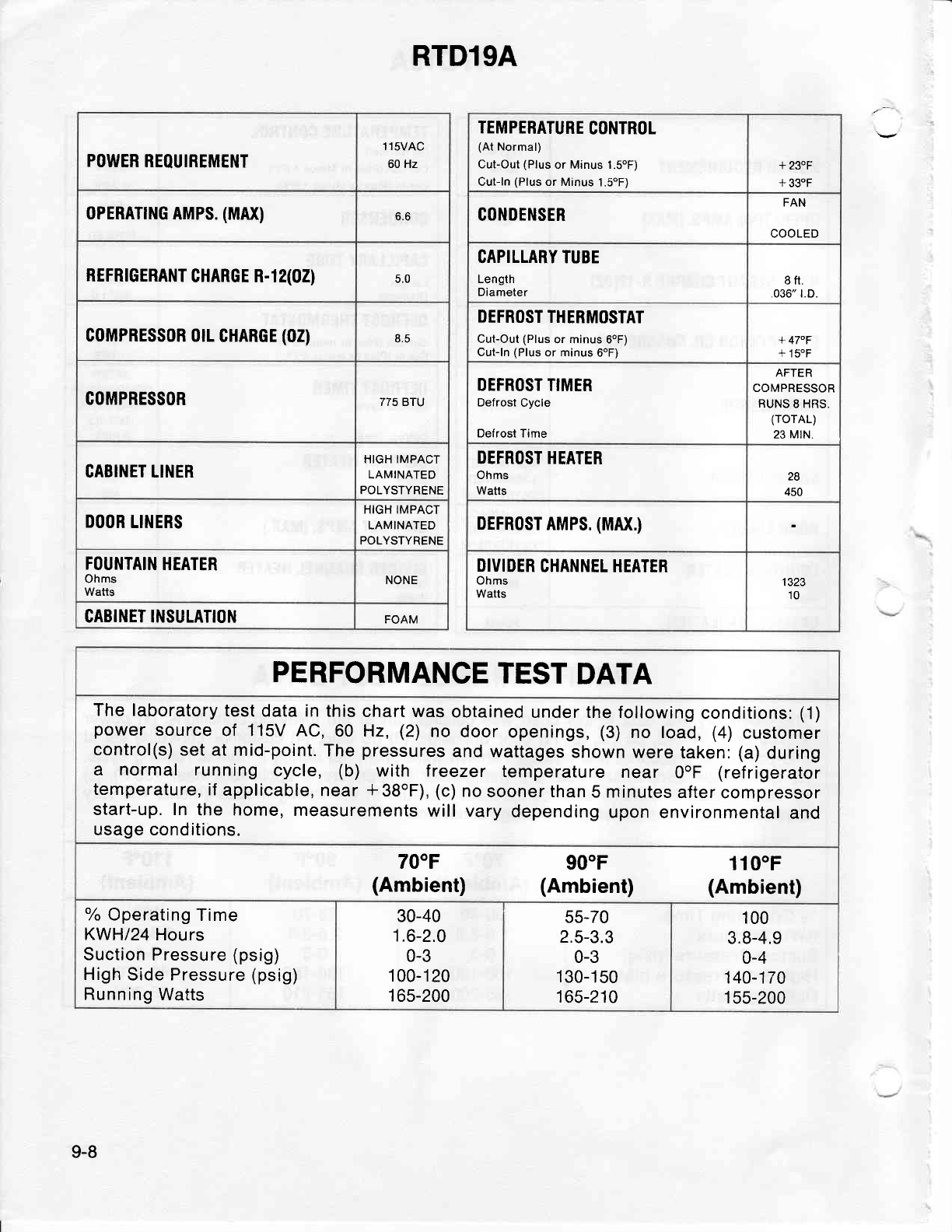
RTDl9A
POWER
REOUIREMENT 1 1sVAC
60 Hz
0PERATIl'lG
AMPS.
(MAx) 6.6
REFRTGERANT
CHARGE R-12(02) c.u
C0MPRESS0R 0tL
CHARGE
(02)
COMPRESSOR //c E tu
CABINET LINER HIGH IMPACT
LAMINATED
POLYSTYRENE
DOOR
LINERS HIGH IMPACT
LAMINATED
POLYSTYRENE
FOUNTAIN
HEATER
Ohms
Watts NONE
CABINET INSULATION FOAM
TEMPERATURE
CONTROL
(At
Normal)
CulOut
(Plus
or Minus 1.SoF)
Cut-ln
(Plus
or Minus
1.SoF)
+230F
+ 330F
CONDENSER FAN
COOLED
CAPILLARY TUBE
Length
Diameter 8fl.
,036" t.D.
DEFROST
THERMOSTAT
Cut-Out
(Plus
or minus 6oF)
Cut- ln
(Plus
or
minus
6oF) + 47"F
+
150F
DEFROST
TIMER
Defrost
Cycle
Defrost Time
ATIEh
COMPRESSOR
RUNS
8 HRS.
(rorAL)
23 MtN.
DEFROST HEATER
Ohms
Watts
'A
450
DEFRoST
AMPS.
(MAX.)
DIVIDER
CHANNEL HEATER
Ohms
Watts I JZJ
10
PERFORMANCE
TEST
DATA
The laboratory
test
data
in
this
chart was
obtained
under the
following
conditions:
(1)
power
source
of 115v AC,60 Hz,
(2)
no
door
openings,
(3)
no load,
(4)
customer
control(s)
set
at mid-point.
The
pressures
and
wattages
shown were
taken:
(a)
during
a normal running
cycle, (b) with treezer
temperature
near OoF
(ref
rigerator
temperature,
if
applicable,
near
*38oF),
(c)
no
sooner than
5 minutes
after
compressor
start-up. In
the home,
measurements
will vary
depending
upon
environmental
and
usage conditions.
700F
(Ambient) 900F
(Ambient) 1100F
(Ambient)
o/o
Operating
Time
KWH|24
Hours
Suction
Pressure
(psig)
High
Side Pressure
(psig)
Running
Watts
30-40
1.6-2.0
0-3
1
00-1 20
1
65-200
55-70
2.5-3.3
0-3
1
30-1
50
165-210
100
3.8-4.9
0-4
140-170
155-200
9-8

RTD21A
POWER REOUIREMENT 1 1sVAC
60 Hz
oPERATTNG AMPS.
(MAX) 6.6
REFRTGERANT
CHARGE
R-1 2(02) 5.0
G0MPRESS0R orL
CHARGE
(02) 8.5
COMPRESSOR 893 BTU
CABINET LINER HIGH IMPACT
LAMINATED
POLYSTYRENE
OOOR
LINERS HIGH IMPACT
LAMINATED
POLYSTYRENE
FOUNTAIN
HEATER
Ohms
Watts NONE
CABINET
INSULATION FOAM
TEMPERATURE
CONTROL
(At
Normal)
CufOut
(Plus
or Minus 1.5oF)
Ctit-ln
(Plus
or Minus 1.50F)
+23"F
+
330F
CONDENSER FAN
COOLED
CAPILLARY TUEE
Length
Diameter I ft.
.036"
t.D.
DEFROST THERMOSTAT
Cut-Out
(Plus
or minus
6oF)
Cut-ln
(Plus
or minus
6oF) + 470F
+ 150F
DEFROST TIMER
Defrost
Cycle
Defrost Time
AFTER
COMPRESSOR
RUNS
8 HRS.
(rorAL)
23
MtN.
DEFROST HEATER
Ohms
Watts 28
450
DEFRoST
AMPS.
(MAX.)
DIVIDER
CHANNEL
HEATER
Ohms
Watts 1323
10
PERFORMANCE
TEST
DATA
The
laboratory test
data in this
chart was
obtained
under the following
conditions:
(1)
power
source
of 115V
AC,60 Hz,
(2)
no
door
openings,
(3)
no load,
(4)
customer
control(s)
set
at
mid-point.
The
pressures
and wattages
shown were
taken:
(a)
during
a normal running
cycle, (b) with treezer temperature
near OoF
(ref
rigerator
temperature,
if
applicable, near
*38"F), (c)
no sooner than
5
minutes
after compressor
start-up. In the
home, measurements
will vary
depending
upon
environmental
and
usage conditions.
70"F
(Ambient) 900F
(Ambient) 1100F
(Ambient)
oh
Operaling Time
KWH|24 Hours
Suction Pressure
(psig)
High
Side
Pressure
(psig)
Running
Watts
30-40
1.6-2.0
0-3
1
00-1 20
1
65-200
55-70
2.5-3.3
0-3
1 30-1
50
165-210
100
3.8-4.9
0-4
140-170
1 55-200
9-9
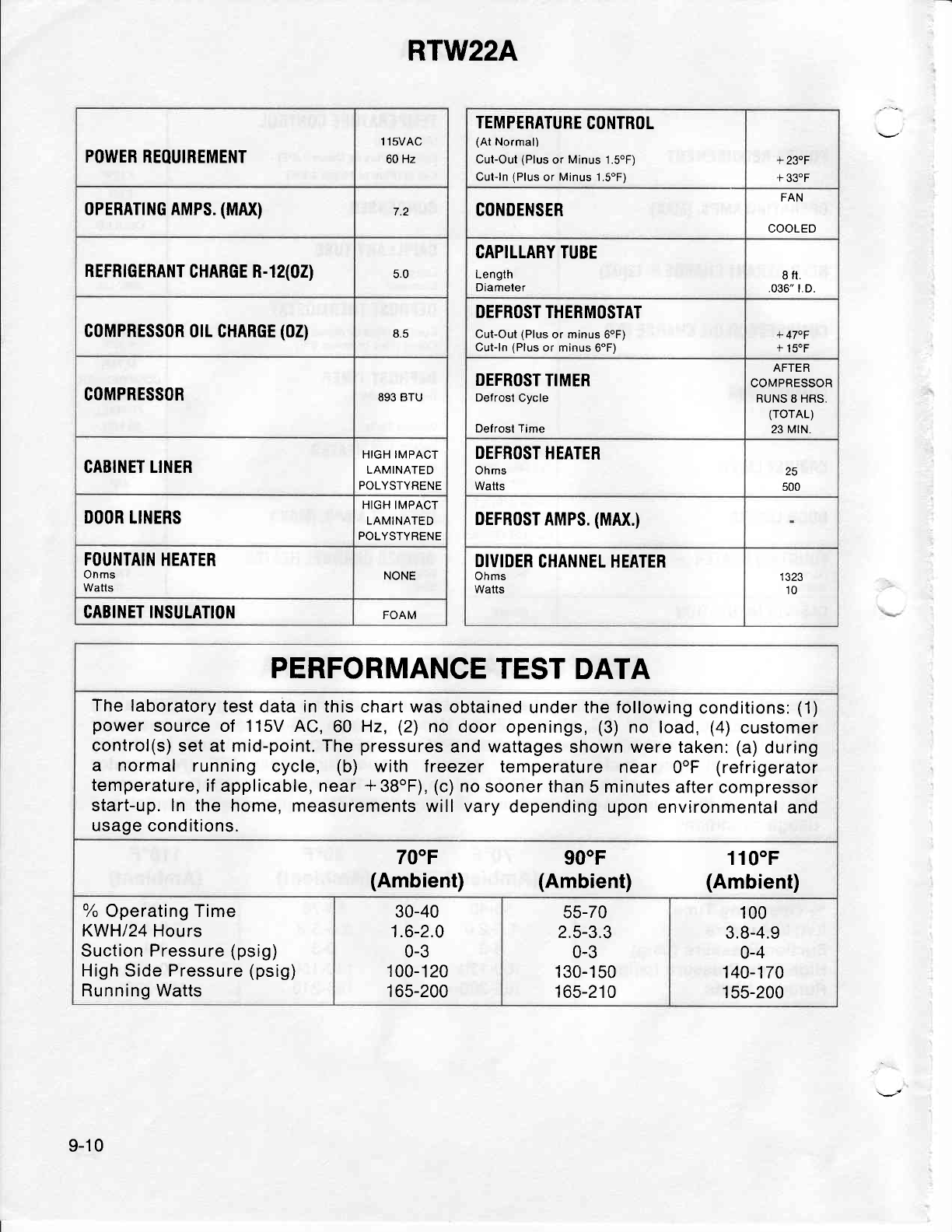
RTW22A
POWER
REOUIREMENT 1 1sVAC
60
Hz
0PERATTNG AMPS.
(MAX) 7.2
REFRTGERANT
CHARGE R-12(02) 5.0
coMPRESSoR
0rL CHARGE
(02) 8.5
COMPRESSOR 893 BTU
CABINET LINER HIGH IMPACT
LAMINATED
POLYSTYRENE
DOOR
LI}IERS HIGH IMPACT
LAMINATED
POLYSTYRENE
FOUNTAIN
HEATER
Onms
Watts NONE
CABINET
INSULATION FOAM
TEMPERATURE
CONTROL
(At
Normal)
Cut-Out
(Plus
or
Minus
1.SoF)
Cut-ln
(Plus
or
Minus
1.SoF)
+ 230F
+
33.F
CONDENSER FAN
COOLED
CAPILLARY
TUBE
Lenglh
Diameler 8
tt.
.036"
t.D.
DEFROST
THERMOSTAT
Cut-Out
(Plus
or minus 6oF)
Culln
(Plus
or minus
6oF) + 470F
+
150F
DEFROST
TIMER
Defrost Cycle
Defrost
Time
AFTER
COMPRESSOR
RUNS
8 HRS.
(rorAL)
23
MtN.
DEFROST
HEATER
Ohms
Watts 25
500
DEFRoST
AMPS.
(MAX.)
DIVIDER
CHANNEL HEATER
Ohms
Watts I JZJ
10
PERFORMANCE
TEST
DATA
The laboratory
test
data in this chart was
obtained
under the following
conditions:
(1)
power
source
of 115V AC,60 Hz,
(2)
no
door openings,
(3)
no load,
(4)
customer
control(s)
set at mid-point. The
pressures
and wattages
shown were taken:
(a)
during
a normal running
cycle, (b) with treezer ternperature
near 0"F (ref
rigerator
temperature,
if
applicable, near
+
38oF),
(c)
no sooner than
5 minutes
after compressor
start-up. ln
the home, measurements
will vary
depending
upon
environmental
and
usage
conditions.
700F
(Ambient) 90"F
(Ambient) 110"F
(Ambient)
oh
Operating Time
KWH/24
Hours
Suction Pressure
(psig)
High Side Pressure
(psig)
Running Watts
30-40
1.6-2.0
0-3
1
00-1 20
1 65-200
55-70
2.5-3.3
0-3
1
30-1 50
165-210
100
3.8-4.9
0-4
140-170
1
55-200
9-1 0

RTD23A
iJ
POWER REOUIREMENT 1 1sVAC
60 Hz
0PERATTNG AMPS.
(MAX) 6.6
REFRTGERANT
CHARGE
R-l 2(02) 5.0
coMPRESS0R 0rL
CHARGE
(02) 8.5
COMPRESSOR 893 BTU
GABINET LINER HIGH IMPACT
LAMINATED
POLYSTYRENE
DOOR
LINERS HIGH IMPACT
LAMINATED
POLYSTYRENE
FOUNTAIN
HEATER
Ohms
Watts NONE
CABINET IIISULATION FOAM
TEMPERATURE
CONTROL
(At
Normal)
CufOut
(Plus
or Minus 1.5"F)
Cut-ln
{Plus
or Minus
1.S"Fi
+
23.F
+
33"F
CONDENSEB FAN
COOLED
CAPILLARY TUBE
Length
Diameter I ft.
036" t.D.
DEFROST THERMOSTAT
CufOut (Plus
or minus 6oF)
Cut-ln
(Plus
or minus
6'F)
+ 470F
+
15.F
DEFROST TIMER
Defrost Cycle
Defrost Time
AFTER
COMPRESSOR
RUNS
8
HRS.
(rorAL)
23
MtN.
DEFROST HEATER
Ohms
Watts
ZJ
500
DEFRoST AMPS.
(MAX.)
DIVIDER
CHANNEL
HEATER
Ohms
Walts 1
323
10
PERFORMANCE
TEST
DATA
The
laboratory test
data in this
chart was obtained
under the following
conditions:
(1)
power
source of 115V AC,60 Hz,
(2)
no door
openings,
(3)
no load,
(4)
customer
control(s)
set at mid-point. The
pressures
and wattages
shown were taken:
(a)
during
a normal running
cycle, (b) with treezer temperature
near OoF
(refrigerator
temperature,
if applicable,
near
*38oF),
(c)
no
sooner than
5
minutes
after
compressor
start-up. In the
home, measurements
will vary
depending
upon
environmental
and
usage conditions.
70"F
(Ambient) 90"F
(Ambient) 1100F
(Ambient)
o/o
Operating Time
KWH|24
Hours
Suction Pressure
(psig)
High
Side
Pressure
(psig)
Running Watts
30-40
1.6-2.0
0-3
1
00-1
20
1
65-200
55-70
2.5-3.3
0-3
1
30-1 50
165-210
100
3.8-4.9
0-4
140-170
1
55-200
9-11
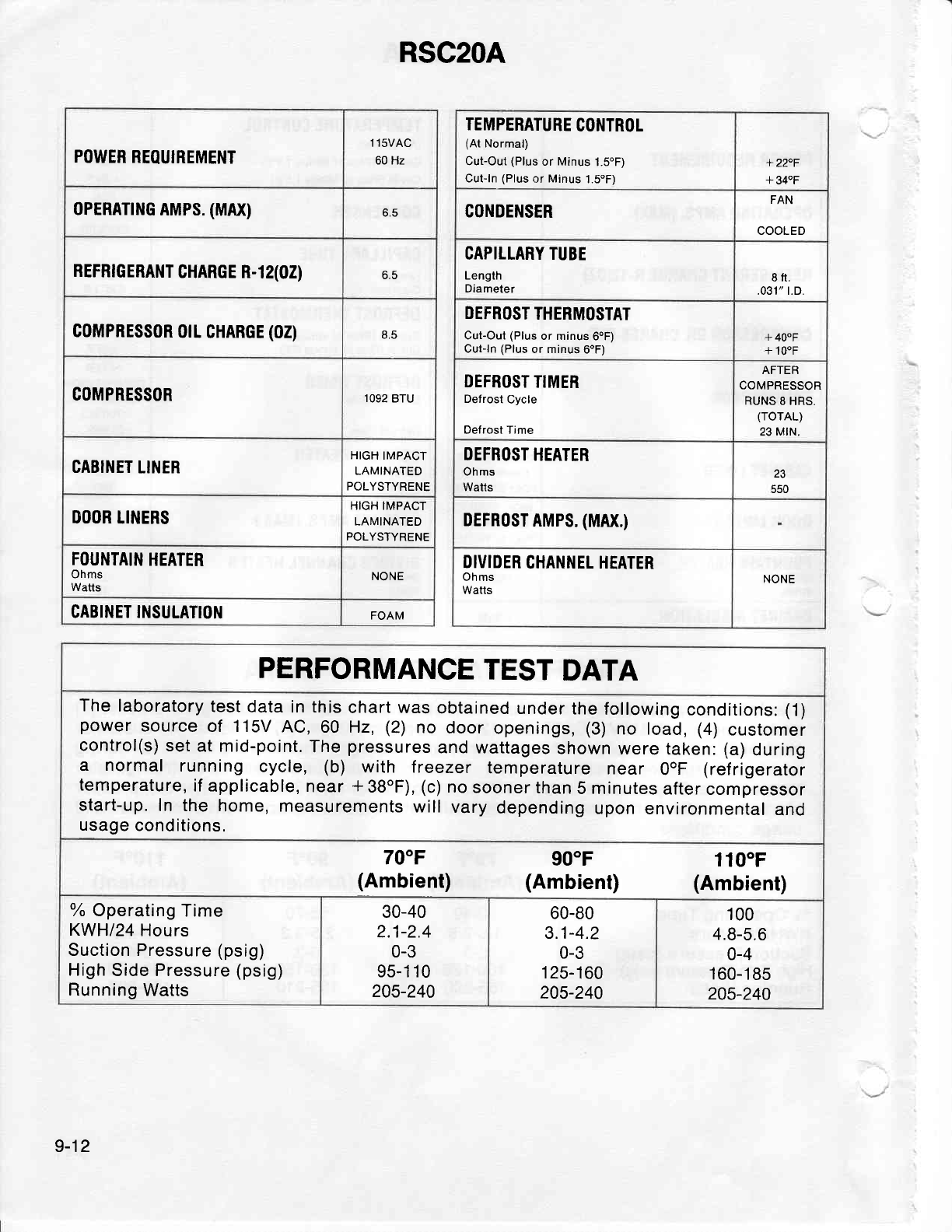
RSC2OA
POWER
REOUIREMENT 1 1sVAC
60 Hz
oPERATTNG
AMPS.
(MAX) 6.5
REFRTGERANT
CHARGE R-1
2(02) o.c
G0MPRESS0R
0tL CHARGE
(02) 8.5
COMPRESSOR 1092
BTU
CABIl.IET
LIIIER HIGH
IMPACT
LAMINATED
POLYSTYRENE
DOOR
TINERS HIGH IMPACT
LAMINATED
POLYSTYRENE
FOUNTAIN
HEATER
Ohms
Watts NONE
CABINET Il,ISULATIO}I FOAM
TEMPERATURE
CONTROL
(At
Normal)
Cut-Out
(Plus
or
Minus
1.5"F)
Cut-ln
(Plus
or Minus
1.5oF)
+22"F
+ 340F
CONDENSER FAN
COOLED
CAPILLARY TUBE
Length
Diameter 8ft.
.031" r.D.
DEFROST
THERMOSTAT
Cut-Out
(Plus
or minus
6oF)
Cut-ln
IPlus
or minus
6oF) +
40"F
+
100F
DEFROST
TIMER
Defrost Cycle
Oefrost Time
AFTER
COMPRESSOR
RUNS
8 HRS,
(rorAL)
23 MtN.
DEFROST
HEATER
Ohms
Watts 1J
550
DEFR0ST
AMPS.
(MAX.)
DIVIDER
CHANNEL HEATER
Ohms
Watts NONE
PERFORMANCE
TEST
DATA
The laboratory
test
data in this
chart was
obtained
under
the
following
conditions:
(1)
power
source
of 115v
AC,60 Hz,
(2)
no
door
openings,
(3)
no load,
(4)
customer
control(s)
set
at mid-point.
The
pressures
and wattages
shown
were taken: (a)
during
a normal running
cycle, (b) with treezer temperature
near OoF
(refrigerator
temperature,
if
applicable,
near
*38oF),
(c)
no
sooner than
5 minutes
after
compressor
start-up.
In the
home, measurements
will
vary
depending
upon
environmental
and
usage
conditions.
70"F
(Ambient) 90"F
(Ambient) 110"F
(Ambient)
o/o
Operating
Time
KWH|24
Hours
Suction Pressure
(psig)
High
Side Pressure
(psig)
Running
Watts
30-40
2.1-2.4
0-3
95-1 1
0
205-240
60-80
3.1-4.2
0-3
1 25-1
60
205-240
100
4.8-5.6
0-4
1
60-1
85
2Q5-240
9-12
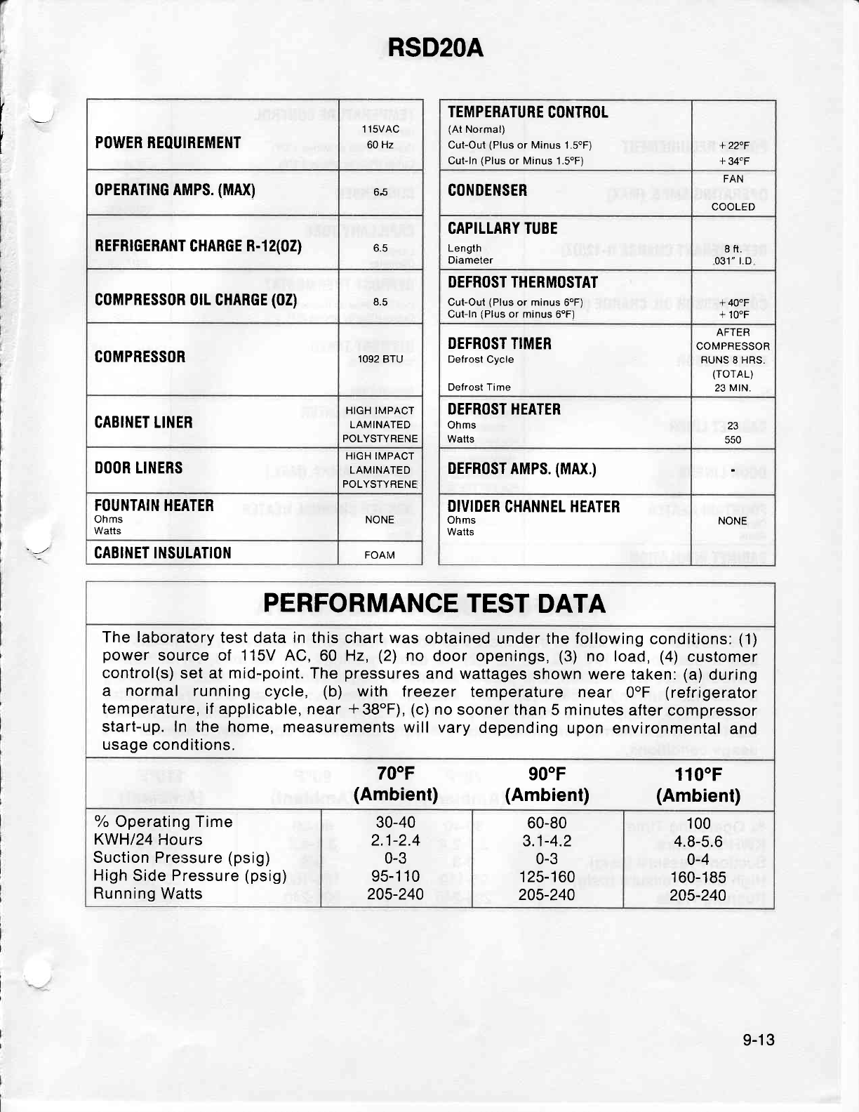
RSD2OA
[- POWEB REOUIREMENT 1 1sVAC
60 Hz
0PERATTNG AMPS.
(MAX)
REFRTGERANT
CHARGE
R-1 2(02) o.c
G0MPRESS0R orl CHARGE
(02)
COMPRESSOR 1092
BTU
CABINET LINER HIGH IMPACT
LAMINATED
POLYSTYRENE
DOOR
LINERS HIGH IMPACT
LAMINATED
POLYSTYRENE
FOUNTAIN
HEATER
Ohms
Watts NONE
CABINET INSULATION FOAM
TEMPERATURE
CONTROL
(At
Normal)
Cut-Out
(Plus
or Minus 1.SoF)
Cut-ln
(Plus
or Minus
1.SoFi
+
22"F
L EAFC
CONOENSER FAN
COOLED
CAPILLARY
TUBE
Length
Diameter 8ft.
031" r.D
DEFROST THERMOSTAT
CutOut (Plus
or minus
6oF)
Cut-ln
(Plus
or minus
6oF) + 400F
+ 100F
DEFROST
TIMER
Defrost Cycle
Defrost Time
AFTER
COMPRESSOR
RUNS
8 HRS.
(TOTAL)
23 MtN.
DEFROST HEATER
Ohms
Watls
.J
550
DEFR0ST
AMPS.
(MAX.)
DIVIDER
CHANNEL
HEATER
Ohms
Watts NONE
PERFORMANCE
TEST
DATA
The laboratory
test
data
in
this
chart
was
obtained
under the
following
conditions:
(1)
power
source
of 115V
4C,60 Hz,
(2)
no
door
openings,
(3)
no load,
(4)
customer
control(s)
set at mid-point.
The
pressures
and wattages
shown
were
taken:
(a)
during
a normal running
cycle, (b) with treezer temperature
near OoF
(refrigerator
temperature,
if
applicable, near
*38oF), (c)
no
sooner than 5 minutes
after compressor
start-up. ln the
home, measurements
will vary
depending
upon
environmental
and
usage
conditions.
70"F
(Ambient) 900F
(Ambient) 1100F
(Ambient)
oh
Operating Time
KWH|24
Hours
Suction Pressure
(psig)
High
Side
Pressure
(psig)
Running
Watts
30-40
2.1-2.4
0-3
95-1
10
205-240
60-80
3.1-4.2
0-3
'125-160
205-240
100
4.8-5.6
0-4
160-185
245-240
9-13
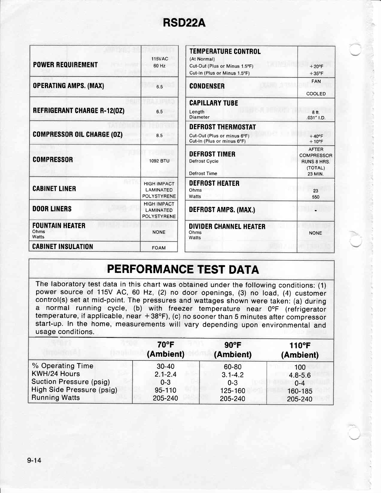
RSD22A
POWER REOUIREMENT 1 1sVAC
60 Hz
0PERATTNG AMPS.
(MAX) 6.5
REFRTGERANT
CHARGE R-1 2(02) 6.5
coMPRESS0R 0rL
CHABGE
(02) qA
COMPRESSOR 1092 BTU
CABINET LINER HIGH IMPACT
LAMINATED
POLYSTYRENE
DOOR
LINERS HIGH IMPACT
LAMINATED
POLYSTYRENE
FOUI,ITAIN
HEATER
Ohms
Watts NONE
GABINET INSULATION FOAM
TEMPERATURE
GONTROL
(At
Normal)
Cut-Out
(Plus
or
Minus
1.5oF)
Cut-ln
(Plus
or Minus 1.SoF)
+ 200F
+ 35.F
GONDENSER FAN
COOLED
CAPILLARY TUBE
Length
Diameter 8ft.
.031"
t"D.
DEFROST
THERMOSTAT
Cul-Out
(Plus
or minus
6oF)
Cut-ln
(Plus
or minus
6oF) + 400F
+ 100F
DEFROST
TIMER
Defrost
Cycle
Defrost Time
AFTER
COMPRESSOR
RUNS
8 HRS.
(rorAL)
23
MtN.
DEFROST
HEATER
Ohms
Watts 23
550
DEFR0ST
AMPS.
(MAX.)
DIVIDER
CHANNEL
HEATER
Ohms
Watts NONE
PERFORMANCE
TEST
DATA
The
laboratory
test
data in this
chart
was
obtained
under
the following
conditions:
(1)
power
source
of 115V
AC,60 Hz,
(2)
no
door
openings,
(3)
no load,
(4)
customer
control(s)
set at mid-point.
The
pressures
and wattages
shown
were
taken:
(a)
during
a normal running
cycle, (b) with f reezer temperature
near OoF
(ref
rigerator
temperature,
if applicable,
near
*38oF),
(c)
no
sooner than
5 minutes
after
compressor
start-up.
In the home,
measurements
will vary
depending
upon environmental
and
usage conditions.
700F
(Ambient) 90"F
(Ambient) 1100F
(Ambient)
% Operating
Time
KWH|?
Hours
Suction Pressure (psig)
High
Side Pressure
(psig)
Running
Watts
30-40
2.1-2.4
0-3
95-1 10
205-240
60-80
3.1-4.2
0-3
1 25-1
60
205-240
100
4.8-5.6
0-4
160-185
205-240
9-14
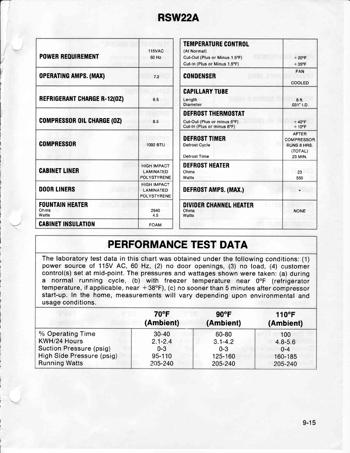
RSW22A
POWER REOUIREMENT 1 15VAC
60 Hz
0PERAT|NG
AMPS.
{MAX) 7.2
REFRTGERANT
CHARGE
R-1 2(02) o.J
G0MPRESS0R 0rL
CHARGE
(02) 8.5
COMPRESSOR 1092 BTU
CABIl'lET
LINER HIGH
TMPACT
LAMINATED
POLYSTYRENE
DOOR LINERS HIGH IMPACT
LAMINATED
POLYSTYRENE
FOUNTAIN
HEATER
Ohms
Watts 2940
4.5
CABINET INSULATION FOAM
TEMPERATURE
COI,ITROL
(At
Normal)
Cut-Out
(Plus
or
Minus 1.5oF)
Cufln
(Plus
or
Minus
1.5oF)
+200F
+ 350F
CONDENSER FAN
COOLED
CAPILLARY TUBE
Length
Diameter 8ft.
031" t.D
DEFROST THERMOSTAT
Cut-Out
(Plus
or
minus
6"F)
Cut-ln
(Plus
or minus
6oF) + 400F
+ 100F
DEFROST TIMER
Defrost
Cycle
Defrost Time
AFTER
COMPRESSOR
RUNS
8 HRS.
(rorAL)
23 MtN.
DEFROST HEATER
Ohms
Watts 23
550
DEFRoST
AMPS.
(MAX.)
DIVIDER
CHAN}IEL HEATER
Ohms
Watts NONE
PERFORMANCE
TEST
DATA
The laboratory
test
data in this chart was
obtained
under the following
conditions:
(1)
power
source of 115V AC,60 Hz,
(2)
no door
openings,
(3)
no load,
(4)
customer
control(s)
set at mid-point. The
pressures
and wattages
shown were
taken:
(a)
during
a normal running
cycle, (b) with treezer temperature
near OoF
(refrigerator
temperature, if
applicable, near
* 38oF),
(c)
no
sooner
than
5
minutes
after
compressor
start-up. In the home,
measurements
will vary
depending
upon
environmental
and
usage conditions.
700F
(Ambient) 90"F
(Ambient) 110"F
(Ambient)
% Operating Time
KWH/24
Hours
Suction Pressure
(psig)
High
Side Pressure
(psig)
Running Watts
30-40
2.1-2.4
0-3
95-1
1
0
205-240
60-80
3.1-4.2
0-3
1 25-1
60
205-240
100
4.8-5.6
0-4
1 60-1
85
205-240
9-15
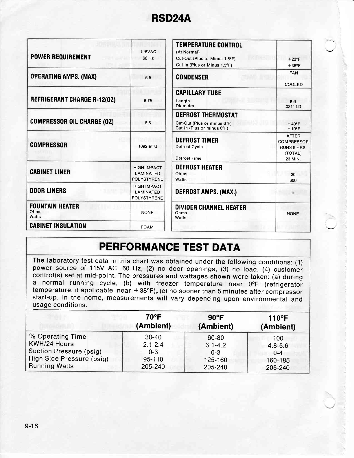
POWER
REOUIREMENT 1 1sVAC
60
Hz
oPERATTNG
AMPS.
(MAX)
REFRTGERANT
CHARGE n-1
2(02) b./J
coMPRESSoR
0tL
CHARGE
(02) 8,5
COMPRESSOR 1092
BTU
GABIIIET LII.IER HIGH IMPACT
LAMINATED
POLYSTYRENE
DOOR LINERS HIGH IMPACT
LAMINATED
POLYSTYRENE
FOUNTAIN
HEATER
Ohms
Watts NONE
CABINET INSULATION FOAM
RSD24A
TEMPERATURE
C01'lTR0L
(At
Normal)
Cut-Out
(Plus
or Minus
1.SoF)
Cut-ln
(Pltrs
or Minus
1.SoF)
+ 230F
+ 360F
CONDENSER FAN
COOLED
CAPILLARY
TUBE
Length
Diameter I fr.
.031" t.D.
DEFROST
THERMOSTAT
Cut-Out
(Plus
or minus
6oF)
Cutln
(Plus
or minus
6oF) +
40"F
+
100F
DEFROST
TIMER
Defrost Cycle
Defrost Time
AFTER
COMPRESSOR
RUNS
8 HRS.
(rorAL)
23
MrN.
DEFROST
HEATER
Ohms
Watts 20
600
DEFRoST
AMPS.
(MAX.)
DIVIDER
CHANNEL
HEATER
Ohms
Watts NONE
PERFORMANCE
TEST
DATA
The
laboratory
test
data
in this
chart was
obtained
under
the following
conditions:
(1)
power
source
of 115V
AC,60 Hz,
(2)
no
door
openings,
(3)
no load,
(4)
customer
control(s)
set
at
mid-point.
The
pressures
and
wattages
shown
were
takeni
(a)
during
a normal running
cycle, (b) with f reezer temperature
near OoF
(ref
rigeratoi
temperature,
if
applicable,
near
*38oF),
(c)
no
sooner
than
5 minutes
after
compressor
start-up. In
the
home,
measurements
will vary
depending
upon
environmental
and
usage
conditions.
700F
(Ambient) 90"F
(Ambient) 1100F
(Ambient)
% Operating
Time
KWH/24
Hours
Suction
Pressure (psig)
High
Side
Pressure
(psig)
Running
Watts
30-40
2.1-2.4
0-3
95-1 10
205-240
60-80
3.1-4.2
0-3
125-160
205-240
100
4.8-5.6
0-4
1
60-1 85
205-240
9-16
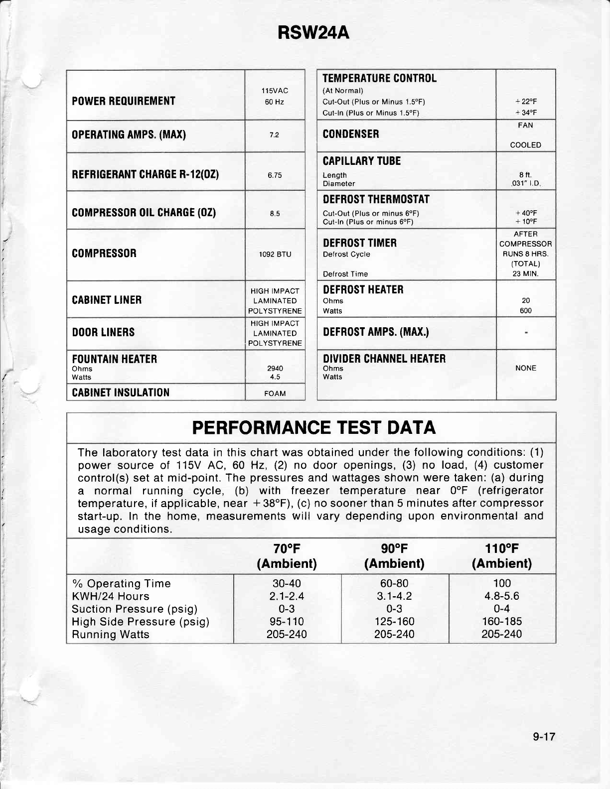
RSW24A
:
j
POWER
REOUIREMENT 1 lsVAC
60 Hz
0PERATTNG
AMPS.
(MAX)
REFBTGERANT CHARGE
R-1 2(02) 6.75
coMPRESSoR
0rL CHARGE
(02) b.J
COMPRESSOR 1092 BTU
CABINET LINER HIGH IMPACT
LAMINATED
POLYSTYRENE
DOOR LINERS HIGH IMPACT
LAMINATED
POLYSTYRENE
FOUNTAIN HEATER
Ohms
Watts 2940
4.5
CABINET
INSULATION FOAM
TEMPERATURE CONTROL
{At
Normal)
CuLOut
(Plus
or Minus 1.5oF)
Cut-ln
(Plus
or
Minus
1.5oF)
+22"F
+
340F
C0l'IDENSER FAN
COOLED
CAPILLARY
TUBE
Length
Diameter 8ft.
031"
l.D
DEFROST THERMOSTAT
Cut-Out
(Plus
or minus 6oF)
Cut-ln
(Plus
or minus 6oF) + 400F
+ 100F
DEFROST
TIMER
Defrost Cycle
Defrost Time
AFTER
COMPRESSOR
RUNS
8
HRS.
(rorAL)
23
MtN.
DEFROST HEATER
Ohms
Watts
20
600
DEFRoST
AMPS.
(MAX.)
DIVIDER
CHANNEL
HEATER
Ohms
Watts NONE
PERFORMANCE
TEST
DATA
The laboratory
test data in this chart
was
obtained under
the following conditions:
(1)
power
source
of 115V AC,60 Hz,
(2)
no door openings,
(3)
no load,
(4)
customer
control(s) set at
mid-point, The
pressures
and
wattages
shown
were taken:
(a)
during
a normal running cycle, (b) with treezer temperature near OoF
(refrigerator
temperature, if applicable, near
*38oF), (c)
no
sooner
than 5 minutes after compressor
start-up. In
the home, measurements will
vary
depending upon
environmental and
usage conditions.
700F
(Ambient) 90"F
(Ambient) 1100F
(Ambient)
% Operating
Time
KWH/24 Hours
Suction
Pressure
(psig)
High Side
Pressure
(psig)
Running Watts
30-40
2.1-2.4
0-3
95-1
10
245-240
60-80
3.1-4.2
0-3
1
25-1 60
205-240
100
4.8-5.6
0-4
1 60-1 85
205-240
9-17
