M/DN® Femoral Retrograde Intramedullary Fixation Surgical Technique Mdn
Mdn-Femoral-Retrograde-Intramedullary-Fixation-Surgical-Technique mdn-femoral-retrograde-intramedullary-fixation-surgical-technique mdn-femoral-retrograde-intramedullary-fixation-surgical-technique 4 2016 pdf 258413772373414384
2016-02-17
: Pdf Mdn-Femoral-Retrograde-Intramedullary-Fixation-Surgical-Technique mdn-femoral-retrograde-intramedullary-fixation-surgical-technique 2 2016 pdf
Open the PDF directly: View PDF ![]() .
.
Page Count: 22
M/DN® Femoral
Retrograde
Intramedullary
Fixation
Surgical Technique

M/DN® Femoral Retrograde Intramedullary Fixation 1
Surgical Techniques
for Fixation of Fractures
with an M/DN Femoral
Retrograde Nail
Table of Contents
Surgical Technique for the M/DN
Femoral Retrograde Nail Fixation 2
Introduction 2
Indications 2
Preoperative Planning 2
Patient Positioning and Radiographic Control 3
Reduction 3
Incision and Exposure 3
Creating the Entry Portal 4
Guide Wire Placement and Reaming 5
Nail Insertion 7
Distal Locking 9
Proximal Locking 12
Technique for Using the Free-Hand Targeting Device 12
End Cap Placement 14
Closure and Postoperative Care 14
Extraction 14
Instrument Case Options 15

M/DN® Femoral Retrograde Intramedullary Fixation
2
Surgical Technique
for the M/DN Femoral
Retrograde Nail Fixation
Introduction
Retrograde femoral nailing is an
alternate technique for the treatment
of femoral fractures utilizing an
intramedullary nail that is similar to but
modified from a standard antegrade
femoral nail. The M/DN® Femoral
Retrograde Nail is designed for distal
fixation and anterior to posterior
proximal fixation. The nail is available
in six diameters ranging from 9mm to
14mm and lengths from 14cm to 48cm
in 2cm increments. The distal end of
the retrograde femoral nail is 12mm in
diameter for nail sizes 9-12mm.
Indications
A. Fractures without
Extensive Comminution
B. Fractures Involving the
Femoral Condyles that Require Open
Knee Access
C. Intertrochanteric Femoral
Shaft Fractures
D. Femoral Shaft Fractures with
Attendant Femoral Neck Fractures
(Nail to be used in conjection with
fixation screws or plates as needed)
E. Ipsilateral Femorotibial Fractures
(“Floating Knee” Fractures)
F. Distal Fractures Involving
Osteoporotic Bone
G. Closed Supracondylar Fractures
H. Nonunions or Pseudoarthroses
I. Malunions
J. Pathological Fractures
K. T-condylar Fractures
L. Severely Comminuted
Supracondylar Fractures with
Articular Involvement
M. Femoral Shaft Fractures
N. Ipsilateral Patellofemoral Fractures
O. Bilateral Femoral Shaft Fractures
Preoperative Planning
Proper preoperative planning is
essential to successful retrograde
nailing of the femur. To determine the
appropriate nail size, an ossimeter,
roentgenogram templates, and an x-ray
film of the unaffected extremity are
necessary for determining canal size
at the isthmus and for measuring
the length of the femur to aid in
determining nail length.
The Nail Length Gauge or Harris/
Galante Bulb-Tip (Sounds), available in
diameters from 10mm to 17mm, can
be used as alternate techniques to
determine nail diameter and length.
X-rays taken at a 36-inch distance
from the x-ray source result in 10-15
percent magnification of bone. The
ossimeter has both an actual size
scale and one that takes into account
this magnification. It should be used
routinely to determine nail diameter
and length.
The proper length of the nail should
extend from 5mm-7mm above the
intercondylar notch, proximal to the
superior border of the lesser trochanter.
The diameter of the femoral nail should
match the isthmus in the lateral x-ray
projection or the canal reamed to
accept the desired nail size.
The surgeon should review the x-ray
to assure that there are no unusual
anatomic variations.
M/DN® Femoral Retrograde Intramedullary Fixation 3
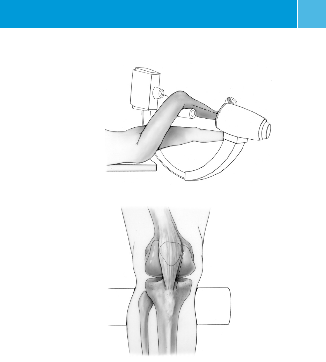
Fig. 1
Patient Positioning and
Radiographic Control
Place the patient in the supine
position (Fig. 1) with the knee flexed
approximately 30 degrees. Prep the hip
to the iliac crest to ensure access to the
lesser trochanter.
The use of image intensification
is required. The image intensifier
should be sterile-draped and may be
positioned from either the contralateral
or ipsilateral side of the operating
table. Positioning from the contralateral
side will facilitate insertion of the
proximal locking screws. This will also
allow the limb to be externally rotated
when obtaining a lateral view of the
proximal femur for estimating the screw
size. Confirm visualization of the hip
as well as the shaft of the femur using
image intensification before prepping
and draping.
Reduction
It is important to reduce the
fracture before beginning the
surgical procedure.
Incision and Exposure
Make a medial parapatellar incision
in line with the femoral shaft (Fig 2).
Dissect the soft tissue medial to the
patellar ligament. It is not necessary
to expose the femoral condyles as
placement of the pin is determined
under C-arm control.
Fig. 2
M/DN® Femoral Retrograde Intramedullary Fixation
4
Insert the 9mm Trochanteric Reamer
over the pin, and ream through the
metaphyseal region (Fig. 4). Be sure
to follow the path of the pin, allowing
the reamer to advance through the
metaphyseal bone without binding on
the pin and pushing it up the femoral
canal. Do not ream into the diaphyseal
area. Stop reaming when reduced
resistance is felt. Remove the reamer
and Steinmann Pin.
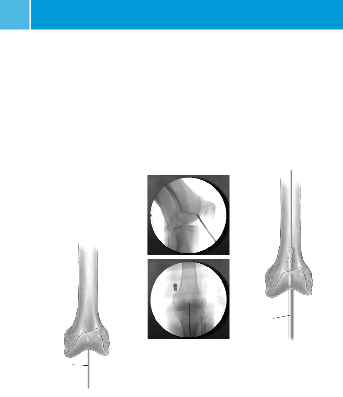
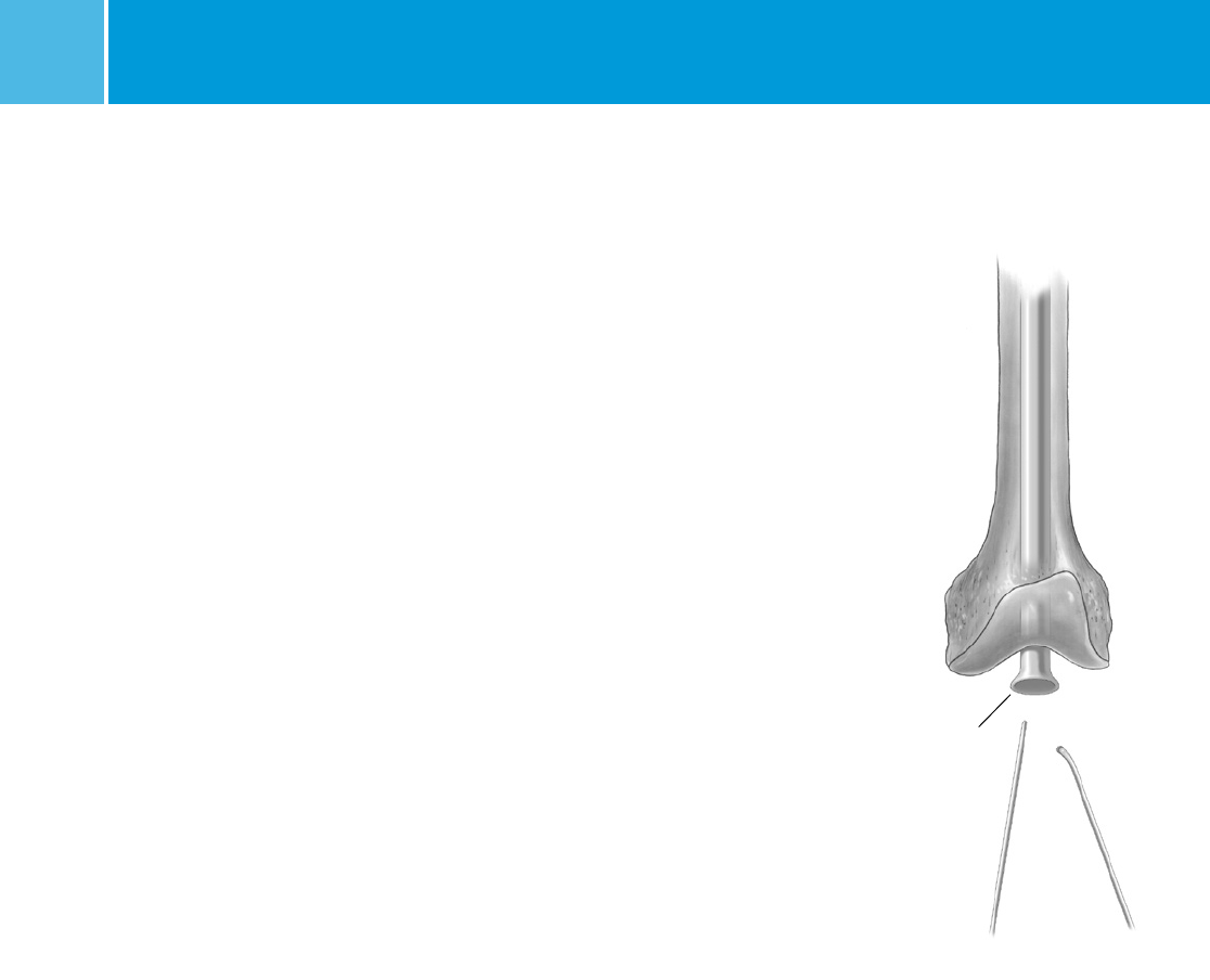
Creating the Entry Portal
Locating the entry portal is extremely
important to avoid anterior placement
of the nail, involvement of the
intercondylar notch, mediolateral mal-
positioning, or posterior positioning
involving the cruciate ligaments.
Place a smooth Steinmann pin
through the fat pad and onto the
femoral condyles (Fig. 3). Guide the
pin to the notch region using gentle
pressure to avoid any extraneous
scoring of the articular cartilage. Take
A/P and lateral views to check the
proper position. The starting point
should be in line with the femoral canal
on the A/P view, and just anterior to
where Blumensaat’s line intersects
the anterior intercondylar notch on the
lateral view.
Trochanteric
Reamer
Fig. 4
Steinmann
Pin
When the proper position is confirmed,
apply firm pressure on the pin so the
tip engages and maintains its position.
Then adjust the angle of the pin so it is
aligned with the femoral canal. Monitor
the pin alignment with both A/P and
lateral C-arm views as the pin is driven
into the bone.
Advance the pin proximally until
reduced resistance is felt as the pin
exits the metaphyseal region. Make a
final check with A/P and lateral views.
Fig. 3
M/DN® Femoral Retrograde Intramedullary Fixation 5
Fig. 6 Fig. 7
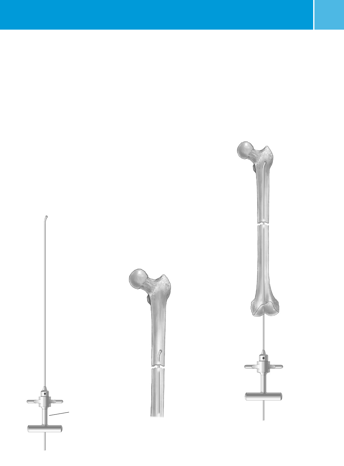
Guide Wire Placement
and Reaming
Conventional Guide Wire/
Exchange Tube Technique
Attach the 3.0mm Ball-Tip Guide
Wire to the Wire-Grip T-Handle and
tighten (Fig. 5). The Ball-Tip Guide Wire
may also be described as a Bulb-Tip
or Bullet-Tip Guide Wire. To aid in
manipulation, bend the wire at a 10˚
angle 5cm from the tip. Insert the
Guide Wire through the entry hole and
manipulate it up the distal femur. At
the fracture site, manipulate the Guide
Wire under C-arm control (Fig. 6). Once
in the proximal canal, pass the wire to
its final position (Fig. 7).
CAUTION: If the guide wire is bent shorter
than 5cm from the end of the wire and/or
more than 10 degrees it may be difficult to
remove from the nail. If the wire becomes
lodged inside the nail, utilize the WIRE
GRIP T-HANDLE and mallet to remove the
guide wire from the nail.
The Reduction Finger can be used to
assist in fracture reduction. To use the
Reduction Finger, advance the Guide Wire
and ream the distal segment. Pass the
Reduction Finger over the Ball-Tip Guide
Wire. Manipulate the fracture externally
while using the Reduction Finger internally
to aid in fracture reduction. Once the
Ball-Tip Guide Wire has passed through
the fracture site, the Ball-Tip Guide Wire is
advanced to epiphyseal scar.
If the Ball-Tip Guide Wire can not advance
through the fracture site,
the ball tip of the Guide Wire should
be bent slightly and then reinserted
to aid in internal reduction.
Determine the proper nail length by
placing a second Guide Wire of equal
length at the intercondylar notch. The
length of the wire that is not overlapping
is the correct nail length. The 50cm Ruler
or ossimeter may be used for an accurate
measurement.
Fig. 5
Ball-Tip
Guide Wire
Wire Grip
T-Handle
M/DN® Femoral Retrograde Intramedullary Fixation
6
Alternatively, the Nail Length Gauge can
be used to measure the appropriate
Nail length through measurement of
one 100cm guide wire. To use, place a
100cm Guide Wire down the medullary
canal. Slide the Nail Length Gauge
over the Guide Wire, ensuring that the
distal portion of the gauge is resting on
the distal femur in order to determine
correct nail length. Nail length is
determined by noting the location of
the remaining Guide Wire and reading
the Nail Length Gauge at that particular
location. If the length indicated is
between two available nail sizes, it
is recommended that the shorter nail
be chosen.
NOTE: Nail Length Gauge can only be
used with 100cm Guide Wire.
Remove the Wire-Grip T-Handle, and
place an intramedullary reamer over
the Guide Wire. The Pressure Sentinel®
Intramedullary Reaming System is a
system of one-piece reamers ranging
in size from 5mm diameter to 27mm
diameter in half millimeter increments.
Each reamer is composed of a fluted
reamer head, a shaft and a quick-
connect drive end. The quick-connect
end can be connected to a manual
or powered driver. The width of the
isthmus of the medullary canal is
determined by preoperative x-ray
examination. The instrument with the
smallest possible diameter is used
for initial reaming into the medullary
canal. Reamers with a diameter of 5mm
to 7.5mm use a 2.4mm Ball-Tip Guide
Wire while reamers with a diameter of
8mm to 27mm use a 3.0mm Ball-Tip
Guide Wire. As reaming continues,
the reamer size should be increased
by 0.5mm or 1.0mm increments
until an opening of the desired size
is obtained.
Fig. 8
Exchange Tube
Note: To avoid reamer lodging during
use, reaming should be immediately
stopped and the reamers retracted
when there is too much resistance.
If the reamer becomes lodged, stop
reaming immediately.
Reverse the direction of rotation of the
handpiece and back the reamer out
of the canal. The reamer can also be
extracted by snapping the T-Handle
Extractor onto the reamer end and then
gently tapping the Extractor with a
small mallet or hammer.
CAUTION: Excessive blows to the
T-Handle Extractor may damage the
reamer or the Extractor.
NOTE: The distal end of the nail is
larger than the shaft diameter on some
sizes. Over ream as appropriate to
create clearance for the nail. 9mm-
11mm nails have a 12mm distal end.
New Guide Wire Technique
Option
If using a Ball-Tip Guide Wire that does
NOT have a gold-coated end OR if using
a nail less than 10mm:
NOTE: If the Guide Wire becomes
lodged within the reamer, use the
Wire-Grip T-Handle to push the Guide
Wire back into the IM canal.
When the reaming is complete and
the final measurements are made,
insert the plastic Exchange Tube
over the Ball-Tip Guide Wire. Remove
the Ball-Tip Guide Wire, and insert a
Smooth Guide Wire (Fig 8).
M/DN® Femoral Retrograde Intramedullary Fixation 7
Retrograde Distal
Targeting Guide
Locking
Bolt
Locking
Knob
Fig. 9
If using a Ball-Tip Guide Wire that DOES
have a gold-coated end and if using a
nail equal to or greater than 10mm:
The Ball-Tip Guide Wire can remain in
place. It is NOT NECESSARY to exchange
the Ball-Tip Guide Wire for a Smooth
Guide Wire.
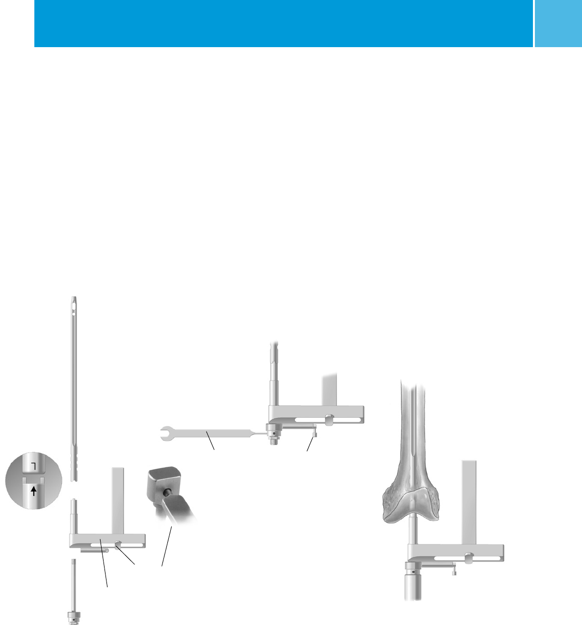
Nail Insertion
Place the selected nail over the Smooth
or Ball-Tip (Gold tipped) Guide Wire and
into the femur. Slide the adjustable arm
of the Retrograde Distal Targeting Guide
approximately to the middle of the
targeting guide base and tighten the
lock knob. Depending on the size of the
patient, it may be necessary to adjust
the position of the arm in or out.
Attach the Retrograde Distal Targeting
Guide to the distal end of the nail
(Fig. 9). Be sure the arrow on the guide
is pointing to the appropriate “Left”
or “Right” indication. Lift and turn the
ratchet lever 90 degrees to open the
ratchet mechanism of the targeting
guide. Insert the Locking Bolt through
the barrel of the guide. Lift and turn the
ratchet lever 90 degrees to close the
ratchet mechanism, and use the Pin
Wrench to tighten the Locking Bolt into
the distal end of the Nail (Fig. 10).
A keyway in the distal end of the nail
will help ensure proper alignment. The
ratchet mechanism will prevent the
Locking Bolt from loosening during
insertion of the nail (Fig. 11).
NOTE: If the ratchet mechanism of
the Retrograde Distal Targeting Guide
does not operate freely, it may be
necessary to disassemble, clean,
and reassemble the mechanism. If
the ratchet mechanism becomes
inoperative, it may be removed. The
assembly will still function; however,
the Locking Bolt may loosen during
the procedure.
Pin Wrench Ratchet
Mechanism
Fig. 10
Fig. 11
M/DN® Femoral Retrograde Intramedullary Fixation
8
Verify proper alignment by inserting
the 5.0mm Femoral Drill Bushing into
the 8.0mm Femoral Screw Bushing.
All retrograde nail sizes use 5.5mm
screws distally (Color Code: Green).
Place the two guide bushings through
one of the inferior holes in the
Retrograde Distal Targeting Guide.
Insert the 5.0mm Femoral drill through
the inner bushing. When the device
is properly aligned, the drill will pass
through the hole of the nail and will
not contact the nail (Fig. 12). After
ensuring proper alignment, remove
the drill and bushings.
Screw the Threaded Driver or
Slaphammer onto the back end of
the Locking Bolt. Begin seating the
Implant/Instrumentation Specifications for Retrograde Nails
Nail Diameter (mm) 910 11 12 13 14
Head Diameter (mm) 12 12 12 12 13 14
Guide Wire, Smooth (mm) 3.0 3.0 3.0 3.0 3.0 3.0
Proximal Screw Size (mm) 4.2
blue
4.2
blue
4.2
blue
5.5
green
5.5
green
5.5
green
Proximal Drill Size (mm) 3.7 3.7 3.7 5.0 5.0 5.0
Proximal Trocar Diameter (mm) 3.7 3.7 3.7 5.0 5.0 5.0
Distal Screw Size (mm) 5.5
green
5.5
green
5.5
green
5.5
green
5.5
green
5.5
green
Distal Drill Size (mm) 5.0 5.0 5.0 5.0 5.0 5.0
Drill Bushing Size (mm) 5.0 5.0 5.0 5.0 5.0 5.0
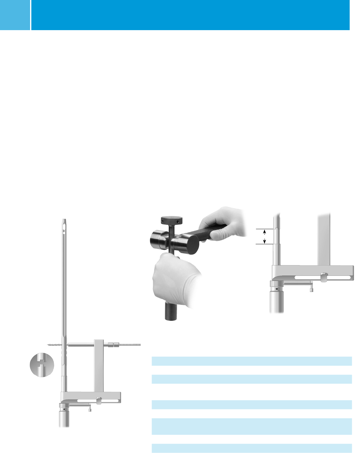
nail using gentle impaction. While
impacting the nail, use the targeting
guide to maintain the proper rotation.
Take great care when crossing the
fracture site. Visualize the fracture in
two planes with image intensification
to assure proper passage of the nail
into the proximal fragment. Reduce
the force of impaction as the distal
end of the nail approaches the
intercondylar notch.
The Slotted Mallet can be used with
the Threaded Driver to make slight
upward adjustments in depth (Fig. 13).
15mm
Fig. 14
If excessive resistance is encountered
during nail driving, remove the nail
and check the size of both the reamer
and nail. Once proper sizing has been
confirmed, the surgeon may choose to
over ream the canal further or select a
smaller size nail.
Continue to seat the nail. The targeting
guide has a shoulder 15mm from the
end of the nail (Fig. 14). Using this
shoulder as a reference, countersink
the nail approximately 5mm-7mm
below the intercondylar notch. When
the nail is fully seated, remove the
Threaded Driver. Then REMOVE THE
GUIDE WIRE.
Fig. 12
Fig. 13
Note: 4.5mm cortical interlocking screws are NOT indicated for use with the MDN system.
M/DN® Femoral Retrograde Intramedullary Fixation 9
T-Handle
Screwdriver
Long Screw
Depth Gauge
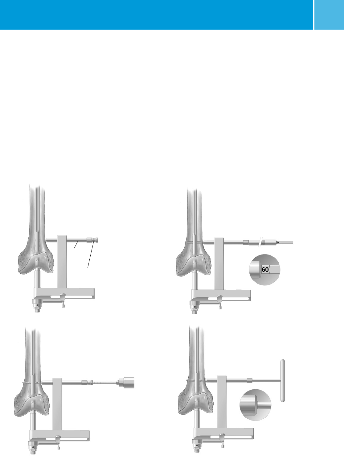
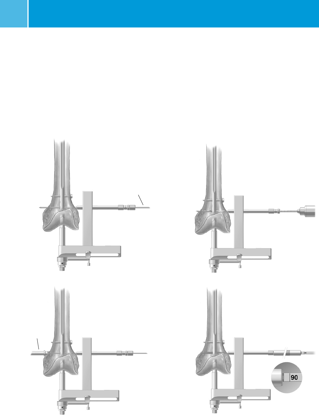
Distal Locking
Slide the arm of the Retrograde Distal
Targeting Guide toward the knee until
it gently contacts the skin, and tighten
the Locking Knob with the Pin Wrench.
Insert the Femoral Screw Bushing
through the Retrograde Distal Targeting
Guide. Make a small incision at the
point where the bushing contacts the
skin. Then insert the 5.0mm Femoral
Drill Bushing (Color Code: Green), into
the Femoral Screw Bushing. Advance
both bushings through the incision
until they contact the bone (Fig. 15).
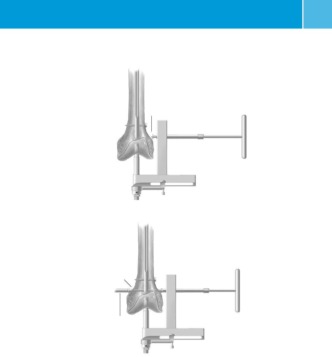
Fig. 17
Fig. 18
Insert the 5.0mm Femoral Drill (Color
Code: Green) and drill until the medial
cortex is penetrated (Fig. 16). Remove
the drill and Femoral Drill Bushing.
Use the Long Screw Depth Gauge to
determine the screw length (Fig. 17).
Select an appropriate length screw to
ensure adequate engagement of the
outer cortex. Then use the T-Handle
Screwdriver to insert the appropriate
size screw to the correct has mark
(Fig. 18). All retrograde nails use
5.5mm screws distally. Repeat the
procedure for the second and third
distal screws.
NOTE: Distal locking screws for all
femoral nails are 5.5mm in diameter
with lengths ranging from 20mm to
100mm in 2.5mm increments. These
are inserted from lateral to medial.
The proximal anterior to posterior
locking screws for the 9mm through
11mm nails are 4.2mm in diameter
with lengths ranging from 20mm to
90mm in 2.5mm increments. For the
12mm through 14mm diameter nails,
the 5.5mm locking screw can be used
at the proximal anterior to posterior
locking screw positions (Available in
2.5mm length increments.
Fig. 16
Fig. 15
Femoral
Screw
Bushing
Femoral
Drill
Bushing
Drill
Note: 4.5mm cortical interlocking screws are NOT indicated for use with the MDN system.
M/DN® Femoral Retrograde Intramedullary Fixation
10
If the bone is osteoporotic, a Cortical
Nut and Washer are available to
prevent the screw(s) from pulling
out of the bone. After inserting the
Femoral Screw Bushing, insert the
3.7mm radiolucent R-T Bushing (blue).
Then insert a 3.2mm Steinmann Pin
into the R-T Bushing. Use the drill to
drive the pin through both cortices
(Fig 19). Palpate the pin on the medial
side of the knee, and make a small skin
incision to expose the tip of the pin.
Insert the Cortical Nut Counterbore
over the pin and bore into the medial
bone (Fig. 20). Remove the Steinmann
Pin, and the Femoral Pin/Drill Bushing.
Then use the drill to drill through both
cortices (Fig. 21). Remove the Femoral
Fig. 21
Fig. 22
Steinmann Pin
Cortical Nut
Counterbore
Fig. 19
Fig. 20
Drill Bushing and use the Long Screw
Depth Gauge to determine the screw
length (Fig. 22). Select an appropriate
length screw to ensure adequate
engagement of the far cortex.
M/DN® Femoral Retrograde Intramedullary Fixation 11
Cortical
Nut
Cortical Nut
Screwdriver
Washer
Fig. 23
Fig. 24
Use the T-Handle Screwdriver to insert
the appropriate size screw through the
targeting guide. Before the screw enters
the wound, insert a washer onto the
screw (Fig. 23). Then begin driving the
screw into the bone and through the
hole in the nail.
As the screw penetrates the opposite
cortex, observe the screw entering
the cortical nut (Fig 24). Use an image
intensifier to verify proper alignment.
Continue to drive the screw until the
Cortical Nut is tight. Be careful not
to overtighten.
Remove the screwdriver and Femoral
Screw Bushing. Take A/P and lateral
C-arm views to check for correct
positioning. Disengage the ratchet
mechanism, then loosen and remove
the Locking Bolt and the Retrograde
Distal Targeting Guide.
To avoid nonunion and leg length
discrepancy, take A/P and lateral C-arm
views to be sure that the fracture is at
the proper length and not distracted. If
there appears to be distraction, lightly
tap the nail in until the cortices are
properly engaged.
M/DN® Femoral Retrograde Intramedullary Fixation
12
Free-Hand
Targeting
Device
Proximal Locking
Technique for Using the
Free-Hand Targeting Device
The proximal locking screws may be
inserted with a freehand technique
using the Free-Hand Targeting Device.
NOTE: 9mm-11mm retrograde nails
use 4.2mm screws proximally which
require 3.7mm Drills or Trocars (Color
Code: Blue). 12mm-14mm retrograde
nails use 5.5mm screws proximally
which require 5.0mm
Drills or Trocars (Color Code: Green).
Insert an appropriate size Trocar into
the Free-Hand Targeting Device and
finger tighten.
NOTE: 14cm - 22cm length nails in
all diameters have one lateral/medial
proximal dynamic slot and one static
locking hole. 24cm - 48cm length nails
in all diameters have one anterior/
posterior dynamic slot and one static
locking hole.
Choose the appropriate locking hole
based on the need for dynamization.
The inferior locking hole on the M/DN
Retrograde Nail is used for static
locking. If static locking is preferred,
but there is a potential need for later
dynamization, insert screws in both
locking holes. The locking screw in the
static hole can then be removed to
achieve later dynamization.
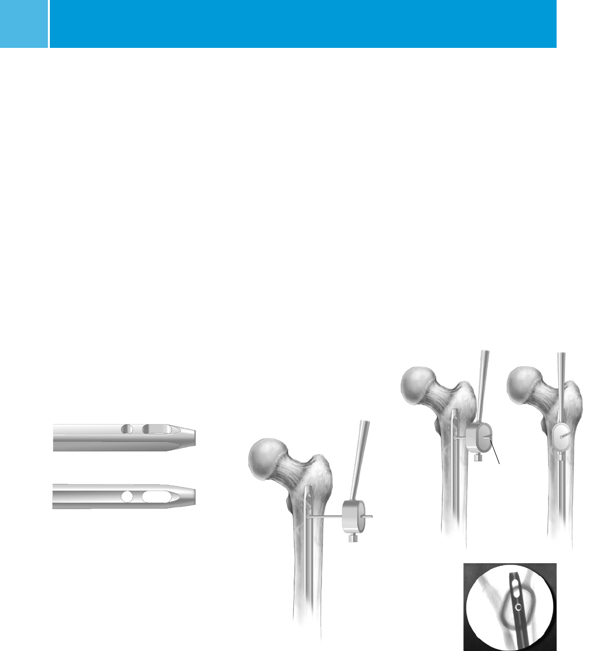
For success with this technique,
proper placement of the A/P x-ray
beam is critical. Position the C-arm so
the locking hole of the nail appears
perfectly round on the monitor or, if
using the dynamic slot, the slot should
reveal its greatest width (Fig. 25).
When this is achieved, make an
anterior stab wound opposite the
appropriate locking hole. Bring the tip
of the Trocar to the bone and center it
over the locking hole using the C-arm
(Fig. 26).
Fig. 26
Incorrect
Correct
Fig. 27
Drive the Trocar into the bone and
across the hole in the nail in line
with the A/P x-ray beam, but do not
penetrate the posterior cortex (Fig. 27).
Remove the Free-Hand Targeting
Device. Verify Trocar placement in both
the A/P and lateral planes. Proximal
Bushings can be used with the Free-
Hand Targeting Device. A separate
radiolucent Bushing Insert is available
to accommodate the bushings. Insert
the 3.7mm or 5.0mm Proximal Bushing
and the 8.0mm Proximal Bushing into
the targeting device, and place it over
the Trocar (see chart on page 6 for
correct size information). Advance the
bushings to the bone and check their
position with the C-arm.
Fig. 25
Note: 4.5mm cortical interlocking screws are NOT indicated for use with the MDN system.
M/DN® Femoral Retrograde Intramedullary Fixation 13
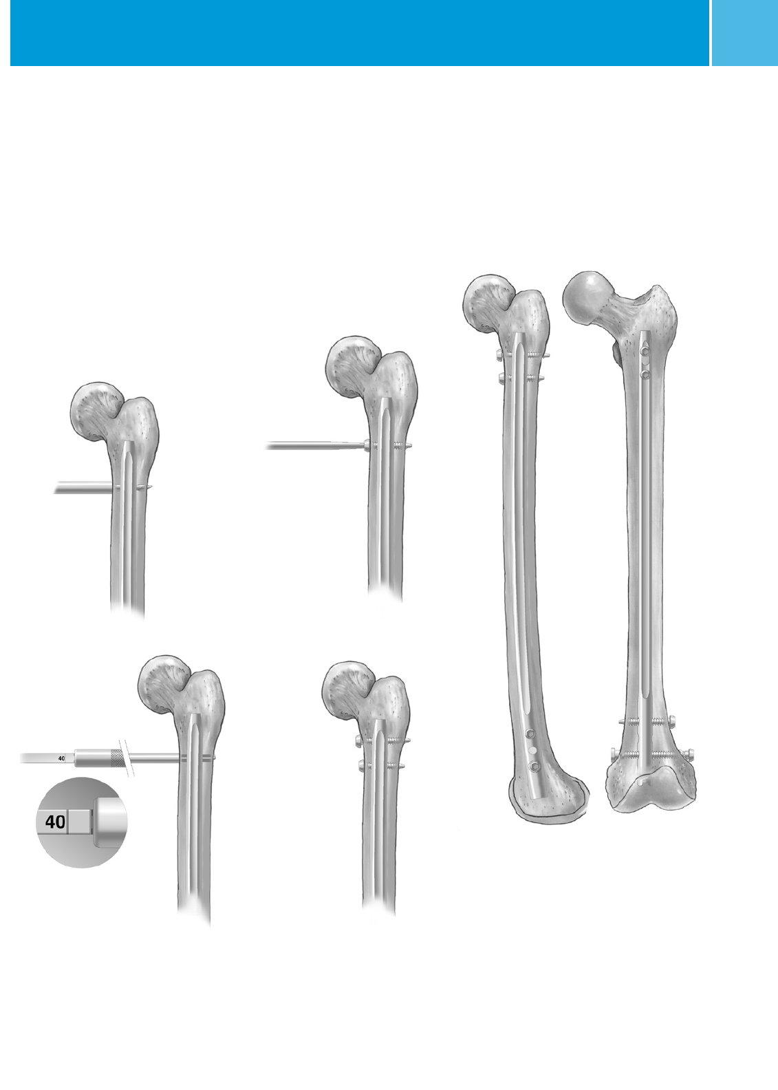
After it has been correctly placed,
remove the Trocar and the 5.0mm
Proximal Bushing. The path of the
Trocar in the bone acts as a pilot hole
for the appropriate size drill. Insert
the Proximal Stop Drill into the 8.0mm
Proximal Bushing. Before drilling
through the anterior cortex, check the
A/P and lateral C-arm image to assure
that the drill is in the hole in the nail.
Then drill both cortices. The step in the
drill will prevent over-drilling (Fig. 28).
Fig. 29
Fig. 28
Fig. 30
Short
Screw
Depth
Gauge
Proximal
Drill
w/Stop
If desired, insert the second screw in
the second locking hole of the nail in
an identical manner (Fig. 31). Check the
position of both screws with the C-arm
in the A/P and lateral planes (Fig. 32).
Fig. 31
Fig. 32
Remove the drill and insert the Short
Screw Depth Gauge (Fig. 29). The
length of the screw is determined by
reading it directly off the depth gauge.
Select an appropriate length screw to
ensure adequate engagement of the
far cortex. Insert the appropriate size
M/DN Screw using the appropriate
screwdriver (Fig. 30).

M/DN® Femoral Retrograde Intramedullary Fixation
14
End Cap Placement
If desired, insert the Retrograde
Femoral Locking Nail Cap in the distal
end of the nail to ensure secure fixation
with the distal oblique screw.
Closure and Postoperative Care
Thoroughly irrigate the knee and
close the distal wound. Apply a soft
compression dressing.
Extraction
Should extraction of the nail become
necessary, attach the Threaded
Extractor to the end of the nail and use
a Slaphammer to extract the nail. If
an End Cap had been used, be sure to
remove before attempting to remove
the nail.
NOTE: The cannulated Locking
Bolt should not be used for nail
removal. Extraction of the nail
should be accomplished by using
the Threaded Extractor.

M/DN® Femoral Retrograde Intramedullary Fixation 15
Instrument Case Options
M/DN Instruments
Option A (Metal Femoral/MIS Femoral/Retrograde)
Set Number 00-2255-000-17 (includes case/tray/lid + instruments)
Case Set Number 00-2237-090-00 (includes trays and lid)
Metal Femoral Guides/Instruments (top tray holds the
following)
Prod. No. Description
00-2255-001-03 Locking Bolt Assembly 2
00-2255-002-10 Fem. Prox. Targeting Guide 1
00-2255-002-11 Fem. Prox. Targeting Guide 1
00-2255-004-32 3.2mm Pin Bushing 2
00-2255-004-50 5.0mm Drill Bushing 2
00-2255-004-80 8.0mm Screw Bushing 2
00-2255-011-00 Recon Screw Counterbore 1
00-2258-067-00 ITST ® Threaded Guide Pin 355mm 3
00-2255-028-00 Pin Wrench 1
00-2255-035-50 5.0mm Femoral Drill, Large 3
MIS Guides (middle tray holds the following; must be used
with above tray)
Prod. No. Description
00-2255-003-03 Perc. Recon Arm Set Screw 2
00-2255-028-00 Pin Wrench 1
00-2255-050-01 Fem. Perc. Targeting Guide 1
00-2255-050-02 Fem. Perc. Targeting Guide 1
00-2255-051-00 Perc. Recon Arm 1
00-2255-053-00 Perc. Cannula 1
00-2255-054-00 Perc. Centering Bushing 1
00-2255-058-00 Per. Locking Bolt 2
Retrograde Femoral Instruments (base of case holds the
following)
Prod. No. Description
00-2241-001-00 Retro. Targ. Guide Assembly (4 pcs.) 1
00-2241-001-01 Adj. Targ. Arm Assembly (5 pcs.) 1
00-2241-006-00 Cortical Nut Screwdriver 1
00-2241-008-37 3.7mm Drill Bushing 2
00-2241-008-50 5.0mm Drill Bushing 2
00-2258-067-00 ITST Threaded Guide Pin 355mm 3
00-2255-001-00 Locking Bolt 2
00-2255-004-80 8.0mm Screw Bushing 2
00-2255-028-00 Pin Wrench 1
00-2255-031-37 3.7mm Drill 1
00-2255-035-50 5.0mm Drill, Large 1
00-2255-059-00 Nail Cap Inserter
(captured screwdriver)
1

M/DN® Femoral Retrograde Intramedullary Fixation
16
M/DN Instruments
Option B (Metal Femoral/Tibial/Humeral/Retrograde)
Set Number 00-2255-000-18 (includes case/tray/lid + instruments)
Case Set Number 00-2237-068-00 (includes trays and lid)
Metal Femoral Guides/Instruments (top tray holds the
following)
Prod. No. Description
00-2255-001-03 Locking Bolt Assembly 2
00-2255-002-10 Fem. Prox. Targeting Guide 1
00-2255-002-11 Fem. Prox. Targeting Guide 1
00-2255-004-32 3.2mm Pin Bushing 2
00-2255-004-50 5.0mm Drill Bushing 2
00-2255-004-80 8.0mm Screw Bushing 2
00-2255-011-00 Recon Screw Counterbore 1
00-2258-067-00 ITST Threaded Guide Pin 355mm 3
00-2255-028-00 Pin Wrench 1
00-2255-035-50 5.0mm Femoral Drill, Large 3
Tibial/Humeral Instruments (middle tray holds the following)
Prod. No. Description
00-2255-001-00 Locking Bolt 2
00-2255-003-00 Tibial Proximal Targeting Guide 1
00-2255-003-01 Tibial Oblique Hole Adapter 1
00-2255-003-03 Set Screw 2
00-2255-004-00 Humeral Proximal Targeting Guide 1
00-2255-004-01 Humeral Oblique Hole Adapter 1
00-2255-036-37 Tib./Hum. 3.7mm Drill Bushing 2
00-2255-036-80 Tib./Hum. 8.0mm Screw Bushing 2
00-2255-028-00 Pin Wrench 1
00-2255-032-37 Tib./Hum. 3.7mm Drill 2
Retrograde Femoral Instruments (base of case holds the
following)
Prod. No. Description
00-2241-001-00 Retro. Targ. Guide Assembly (4 pcs.) 1
00-2241-001-01 Adj. Targ. Arm Assembly (5 pcs.) 1
00-2241-006-00 Cortical Nut Screwdriver 1
00-2241-008-37 3.7mm Drill Bushing 2
00-2241-008-50 5.0mm Drill Bushing 2
00-2258-067-00 ITST Threaded Guide Pin 355mm 3
00-2255-001-00 Locking Bolt 2
00-2255-004-80 8.0mm Screw Bushing 2
00-2255-028-00 Pin Wrench 1
00-2255-031-37 3.7mm Drill 1
00-2255-035-50 5.0mm Drill, Large 1
00-2255-059-00 Nail Cap Inserter
(captured screwdriver)
1

M/DN® Femoral Retrograde Intramedullary Fixation 17
General Instrument Set
Set Number 00-2255-000-16 (includes case/tray/lid + instruments)
Case Set Number 00-2237-095-00 (includes trays and lid)
General Instruments (top tray holds the following)
Prod. No. Description
00-2237-053-00 Wire Grip T-Handle 1
00-2237-061-00 Long T-Handle Cannulated Awl 1
00-2237-066-00 Short T-Handle Cannulated Awl 1
00-2255-016-00 7mm Angled Femoral Awl* 1
00-2255-034-00 Reduction Finger 1
00-2255-052-00 9mm/14mm Perc. Tapered Reamer 1
00-2255-060-00 8mm Trochanteric Reamer 1
00-2258-067-00 ITST Threaded Guide Pin 355mm 3
00-2255-038-00 T-Handle 1
00-4816-060-00 Ball-Spiked Pusher 1
00-4817-011-00 Shoulder Hook 1
General Instruments (middle tray holds the following)
Prod. No. Description
00-2228-097-00 Diameter Gauge 1
00-2237-055-00 Ruler 1
00-2255-057-00 Flexible Reamer Extension 2
00-2305-024-00 Screwdriver, Small Hexhead 1
00-2237-060-00 Slotted Mallet 1
00-2237-062-00 Threaded Driver 1
00-2237-063-00 Screw Depth Gauge, Long 1
00-2255-013-00 Screwdriver 3.5mm Hex, Long 1
00-2255-017-00 Flared Exchange Tube 1
00-2237-064-00 Nail Length Gauge 1
00-2258-057-00 Cannulated Depth Gauge 1
General Instruments (base of case holds the following)
Prod. No. Description
00-2255-009-00 Slaphammer 1
00-2255-028-00 Pin Wrench 1
00-2237-065-00 Threaded Extractor (17cm) 1
00-2237-065-01 Threaded Extractor (32cm) 1
00-2255-012-33 3.2mm Trocar 3
00-2255-012-37 3.7mm Trocar 3
00-2255-012-50 5.0mm Trocar 3
00-2255-033-32 3.2mm Drill 3
00-2255-033-37 3.7mm Drill 3
00-2255-033-50 5.0mm Drill 3
00-2255-018-00 Distal Screw Depth Gauge 1
00-2255-013-01 Distal Screwdriver 3.5mm Hex 1
00-2255-015-03 Wand Handle 1
00-2255-015-01 Wand Insert 1
00-2255-015-02 Wand Set Screw 1
* The 7mm Straight Awl (00-2237-001-07) OR the
7mm Angled Femoral Awl (00-2255-016-00) will
fit in the case. However, when you order the set
number (00-2255-000-16), you will get the Angled Awl.
NOTE: See sales representative for optional instruments.

M/DN® Femoral Retrograde Intramedullary Fixation
18
Pressure Sentinel Intramedullary Reaming System
Order Information
Prod. No. Description
00-2218-000-00 Long Pressure Sentinel Reamers
Tray/Case/Lid
Includes the following instruments & case:
00-2218-008-00 8.0mm Long Flexible PS Reamer
00-2218-008-05 8.5mm Long Flexible PS Reamer
00-2218-009-00 9.0mm Long Flexible PS Reamer
00-2218-009-05 9.5mm Long Flexible PS Reamer
00-2218-010-00 10.0mm Long Flexible PS Reamer
00-2218-010-05 10.5mm Long Flexible PS Reamer
00-2218-011-00 11.0mm Long Flexible PS Reamer
00-2218-011-05 11.5mm Long Flexible PS Reamer
00-2218-012-00 12.0mm Long Flexible PS Reamer
00-2218-012-05 12.5mm Long Flexible PS Reamer
00-2218-013-00 13.0mm Long Flexible PS Reamer
00-2218-013-05 13.5mm Long Flexible PS Reamer
00-2218-014-00 14.0mm Long Flexible PS Reamer
00-2218-014-05 14.5mm Long Flexible PS Reamer
00-2218-015-00 15.0mm Long Flexible PS Reamer
00-2218-015-05 15.5mm Long Flexible PS Reamer
00-2218-016-00 16.0mm Long Flexible PS Reamer
00-2218-016-05 16.5mm Long Flexible PS Reamer
00-2218-017-00 17.0mm Long Flexible PS Reamer
00-2218-017-05 17.5mm Long Flexible PS Reamer
00-2218-018-00 18.0mm Long Flexible PS Reamer
00-2228-030-00 T-Handle Extractor
00-2228-097-00 Diameter Gauge
00-5044-012-00 Adapter 3 Jaw Chuck
00-2228-098-10 Soak Tray
00-2218-025-00 Long Cleaning Brush
00-2218-030-00 Torque Limiter
00-2237-075-00 Long Reamer/Instrument
Case Assembly
00-2237-076-00 Long Reamer/Instrument Case Base
00-2237-077-00 Long Reamer/Instrument Case Lid
00-2237-078-00 Long Reamer/Instrument Top Tray
(8mm-13.5mm)
00-2237-079-00 Long Reamer/Instrument Middle Tray
00-2228-000-00 Pressure Sentinel Reamer Full Set
Includes the following instruments & case:
00-2228-005-00 5.0mm Flexible Reamer
00-2228-005-05 5.5mm Flexible Reamer
00-2228-006-00 6.0mm Flexible Reamer
00-2228-006-05 6.5mm Flexible Reamer
00-2228-007-00 7.0mm Flexible Reamer
00-2228-007-05 7.5mm Flexible Reamer
00-2228-008-00 8.0mm Flexible Reamer
00-2228-008-05 8.5mm Flexible Reamer
00-2228-009-00 9.0mm Flexible Reamer
00-2228-009-05 9.5mm Flexible Reamer
00-2228-010-00 10.0mm Flexible Reamer
00-2228-010-05 10.5mm Flexible Reamer
00-2228-011-00 11.0mm Flexible Reamer
00-2228-011-05 11.5mm Flexible Reamer
00-2228-012-00 12.0mm Flexible Reamer
00-2228-012-05 12.5mm Flexible Reamer
00-2228-013-00 13.0mm Flexible Reamer
00-2228-013-05 13.5mm Flexible Reamer
00-2228-014-00 14.0mm Flexible Reamer
00-2228-014-05 14.5mm Flexible Reamer
00-2228-015-00 15.0mm Flexible Reamer
00-2228-015-05 15.5mm Flexible Reamer
00-2228-016-00 16.0mm Flexible Reamer
00-2228-016-05 16.5mm Flexible Reamer
00-2228-017-00 17.0mm Flexible Reamer
00-2228-017-05 17.5mm Flexible Reamer
00-2228-018-00 18.0mm Flexible Reamer
00-2228-018-05 18.5mm Flexible Reamer
00-2228-019-00 19.0mm Flexible Reamer
00-2228-019-05 19.5mm Flexible Reamer
00-2228-020-00 20.0mm Flexible Reamer
00-2228-020-05 20.5mm Flexible Reamer
00-2228-021-00 21.0mm Flexible Reamer
00-2228-021-05 21.5mm Flexible Reamer
00-2228-022-00 22.0mm Flexible Reamer
00-2228-030-00 T-Handle Extractor
00-2228-097-00 Diameter Gauge
00-2228-098-00 Soak Tray
00-5044-012-00 1/4in. Jacob’s Chuck to Zimmer
Adapter, Qty =2
00-2228-090-00 Sterilization Case

M/DN® Femoral Retrograde Intramedullary Fixation 19
Optional Reamer Sizes
Prod. No. Description
00-2228-022-05 22.5mm Flexible Reamer
00-2228-023-00 23.0mm Flexible Reamer
00-2228-023-05 23.5mm Flexible Reamer
00-2228-024-01 24.0mm Flexible Reamer
00-2228-024-05 24.5mm Flexible Reamer
00-2228-025-01 25.0mm Flexible Reamer
00-2228-025-05 25.5mm Flexible Reamer
00-2228-026-01 26.0mm Flexible Reamer
00-2228-026-05 26.5mm Flexible Reamer
00-2228-027-01 27.0mm Flexible Reamer
Pressure Sentinel Sets
Prod. No. Description
00-2228-000-01 Pressure Sentinel Reamer Trauma Set
Includes the following instruments & case:
5.0mm, 6.0mm, 7.0mm & 8.00mm-17.5mm
Flexible Reamers in .5mm increments (1ea.)
00-2228 -030-00 T-Handle Extractor
00-5044-012-00 1/4in. Jacob’s Chuck to Zimmer
Adapter, Qty=2
00-2228-090-00 Sterilization Case
00-2228-000-02 Pressure Sentinel Reamer Hip Set
Includes the following instruments & case:
8.0mm-18.0mm Flexible reamers in 1mm increments (1ea.)
00-2228-030-00 T-Handle Extractor
00-5044-012-00 1/4in. Jacob’s Chuck to Zimmer
Adapter, Qty=1
00-2228-090-00 Sterilization Case
00-2228-000-03 Pressure Sentinel Reamer Expanded
Hip Set
Includes the following instruments & case:
8.0mm-18.0mm Flexible reamers in .5mm increments (1ea.)
00-2228-030-00 T-Handle Extractor
00-5044-012-00 1/4in. Jacob’s Chuck to Zimmer
Adapter, Qty=1
00-2228-090-00 Sterilization case
00-2228-90-00 Sterilization Case
Includes the following components:
00-2228-091-00 Base
00-2228-092-00 18.0mm to 22.0mm Reamer Tray
00-2228-093-00 12.0mm to 17.5mm Reamer Tray
00-2228-094-00 5.0mm to 11.5mm Reamer Tray
00-2228-096-00 Case Lid
00-9975-011-00 Pressure Sentinel Reamer ZMR® Hip Set
Includes the following components:
8.0mm-27.0mm Flexible reamers in .5mm increments (1ea.)
00-9965-081-10 ZMR Flexible Reamer
Diameter Gauge
00-9975-099-00 Case Lid
00-2228-040-00 ZMR Flexible Reamer Metal Case
* Set includes case and contents without the
00-9975-099-00 Case Lid. The Case Lid must
be ordered separately.
Optional Instruments
Prod. No. Description
00-2255-008-00 Guide Wire 2.4mm, Ball-Tip,
70cm box (required for 5.0mm-7.5mm
Pressure Sentinel Reamers)
47-2255-008-01 Guide Wire 3.0mm, Ball-Tip, 100cm
Sterile/box (required for 8.0mm and larger
Pressure Sentinel Reamers)
00-2255-008-01 Guide Wire 3.0mm, Ball-Tip, 100cm
Non-sterile/box (required for 8.0mm and
larger Pressure Sentinel Reamers)

Contact your Zimmer representative or visit us at www.zimmer.com
97-2252-009-01 Rev. 3 MC 120710 6-1-2015 ©2015 Zimmer, Inc.
The CE mark is valid only if it is also printed on the product label.
DISCLAIMER:
This documentation is intended exclusively for physicians and is not intended for laypersons. Information on
the products and procedures contained in this document is of a general nature and does not represent and does
not constitute medical advice or recommendations. Because this information does not purport to constitute any
diagnostic or therapeutic statement with regard to any individual medical case, each patient must be examined
and advised individually, and this document does not replace the need for such examination and/or advise in
whole or in part.
Please refer to the package inserts for important product information, including, but not limited to, indications,
contraindications, warnings, precautions, and adverse effects.
