MIS Radiolucent Targeting Device NCB Periprosthetic Femur Plate System Surgical Technique 97 2370 101 00 1
Mis-Radiolucent-Targeting-Device-Ncb-Periprosthetic-Femur-Plate-System-Surgical-Technique-1-2 mis-radiolucent-targeting-device-ncb-periprosthetic-femur-plate-system-surgical-technique-1-2 mis-radiolucent-targeting-device-ncb-periprosthetic-femur-plate-system-surgical-technique-1-2 2 2016 pdf 258413772373414384
2016-04-04
: Pdf Mis-Radiolucent-Targeting-Device-Ncb-Periprosthetic-Femur-Plate-System-Surgical-Technique-1 mis-radiolucent-targeting-device-ncb-periprosthetic-femur-plate-system-surgical-technique-1 4 2016 pdf
Open the PDF directly: View PDF ![]() .
.
Page Count: 14
MIS Radiolucent
Targeting Device
NCB® Periprosthetic
Femur Plate System
Surgical Technique

NCB® Periprosthetic MIS Radiolucent Targeting Device 3
Table of Contents
Introduction 4
Proximal NCB Periprosthetic MIS Technique 6
Insertion of the Proximal NCB Plate
6
Distal NCB Periprosthetic MIS Technique 7
Insertion of the Distal NCB Plate 7
Secure the Safety Lock Pin 8
Reduction of the Metaphyseal Bone Fragments 8
Insertion of the NCB Screws in Diaphyseal Bone 9
Creating Compression between the Plate and the Bone 11
4NCB® Periprosthetic MIS Radiolucent Targeting Device
This surgical technique is intended to
be used in conjunction with the NCB
Periprosthetic Femur Plate System Surgical
Technique (06.02013.012).
Introduction
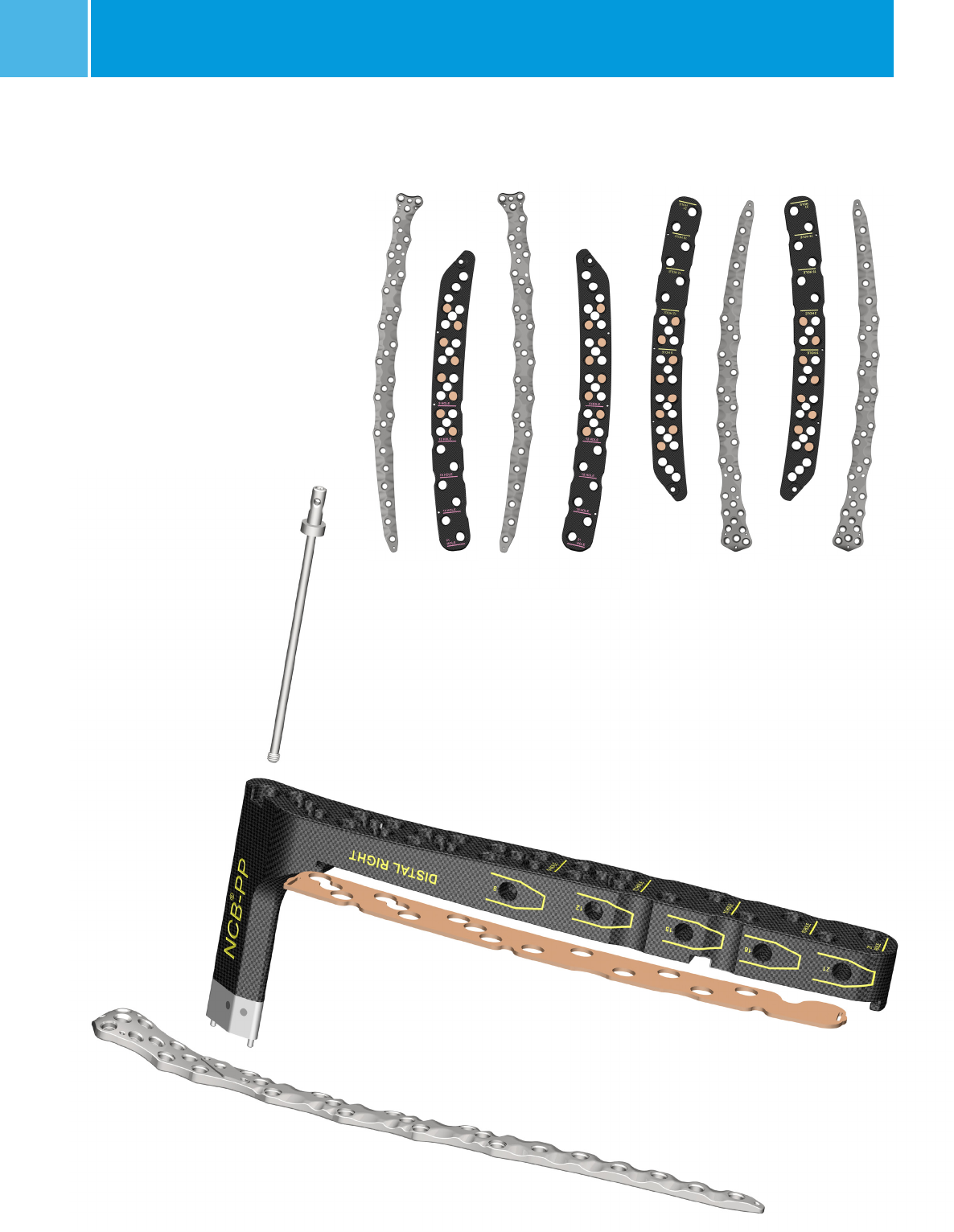
Fully radiolucent Targeting Devices are
available, allowing MIS techniques to be
used for the NCB Periprosthetic Proximal
Femur and NCB Periprosthetic Distal
Femur Plates. The addition of Bottom
Covers provides proper targeting
according to plate size by blocking
holes that do not correspond to
the plate (Fig. 1&2). Each plate
length and type has a unique
Bottom Cover that targets its
hole pattern.
NOTE: Use of the Targeting
Device prevents polyaxial
screw insertion.
Fig. 1
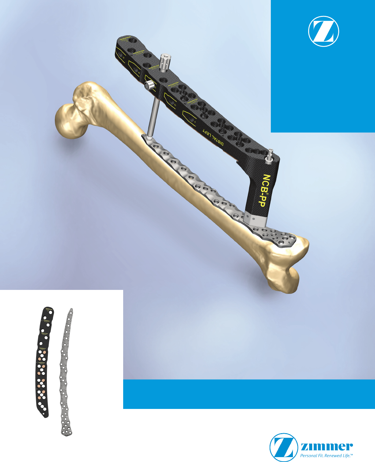
Fig. 2 NCB Periprosthetic Femur Plates and NCB MIS Radiolucent Targeting Device
with Bottom Covers
NCB® Periprosthetic MIS Radiolucent Targeting Device 5
MIS Technique - Targeting
Device Assembly for
Insertion
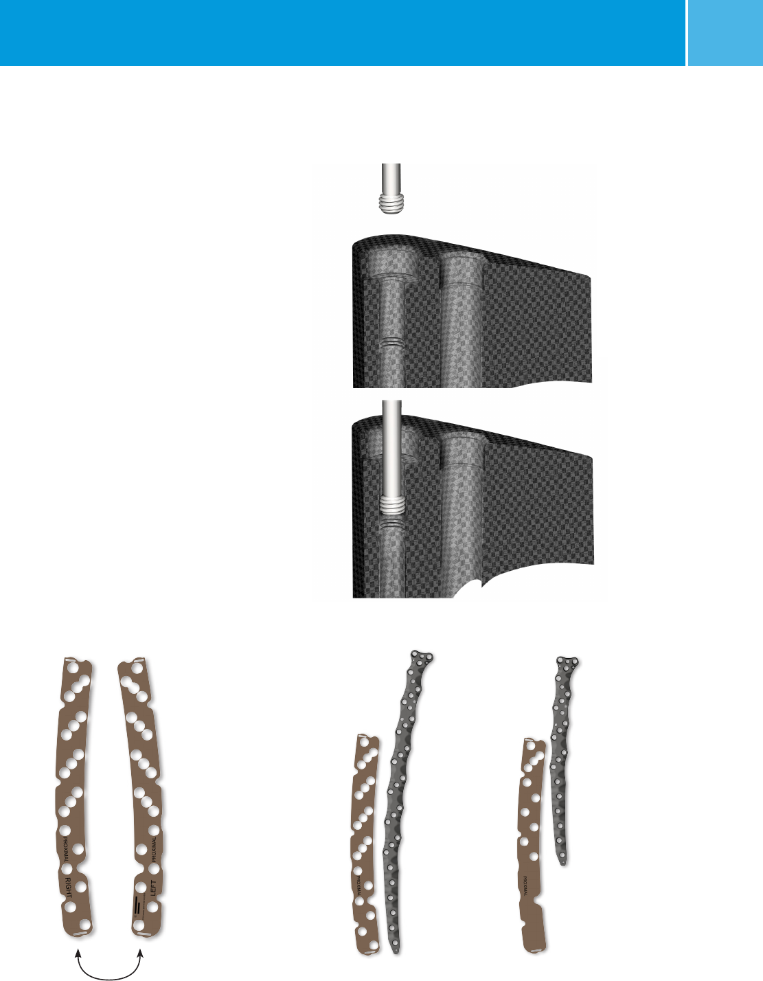
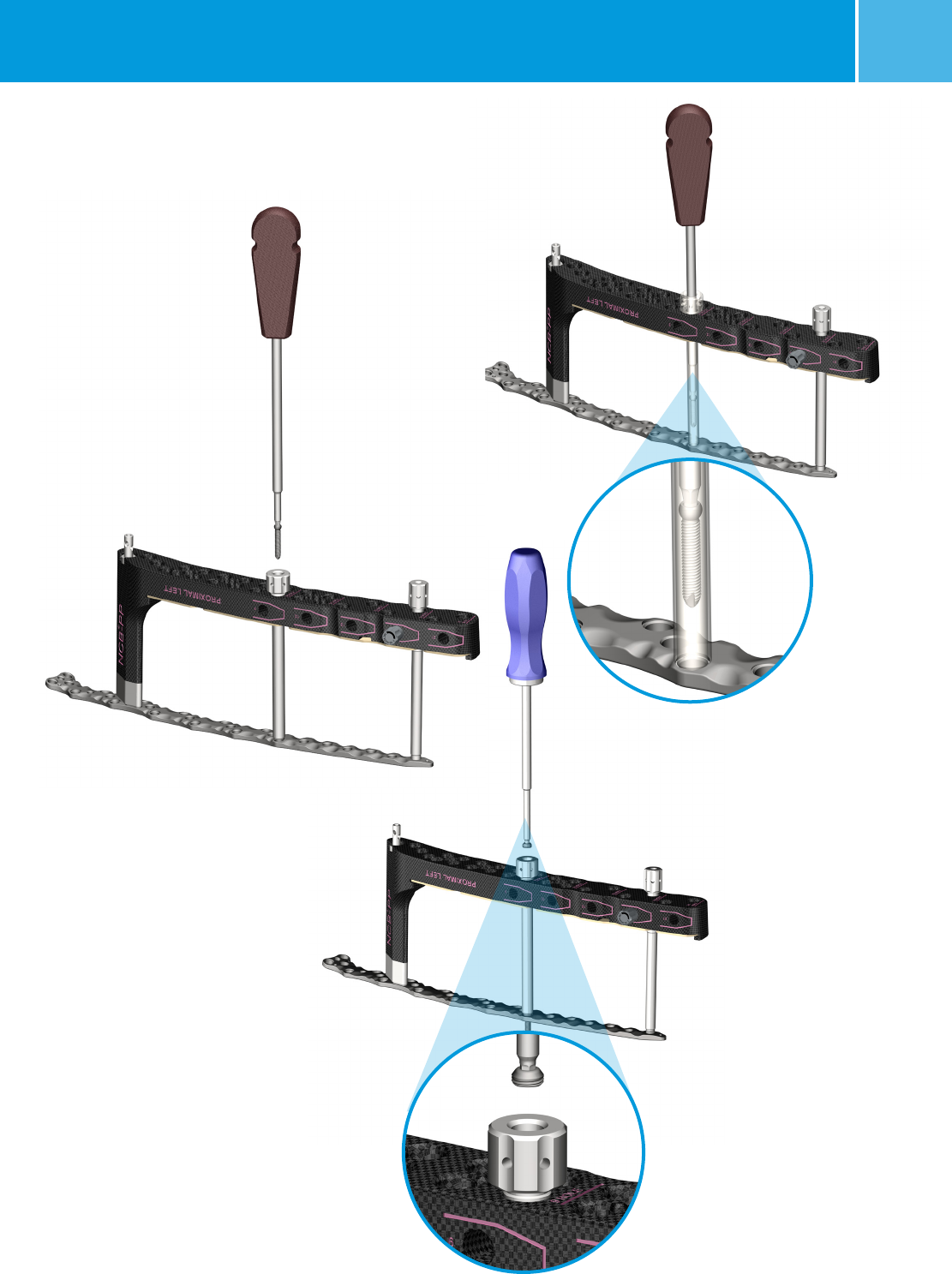
Thread the Connection Bolt (REF
02.00024.380) through the NCB
Periprosthetic Targeting Device (Fig. 3).
Attach the Targeting Device by screwing
the connection bolt into the NCB
Periprosthetic Femur Plate. Attach the
NCB Periprosthetic Targeting Device to
the corresponding NCB Periprosthetic
Plate. (Left Proximal REF 02.00024.371;
Left Distal REF 02.00024.373 ; Right
Proximal REF 02.00024.370; Right
Distal REF 02.00024.372). Screw
the Connection Bolt into the NCB
Periprosthetic Plate and tighten with the
6Nm Torque Limiting Screwdriver (REF
02.00024.021).
Choose the appropriate Bottom Cover
(Proximal REF 02.00024.390-394; Distal
REF 02.00024.395-399) by matching
the plate size with the number of holes
indicated on the Bottom Cover for the
plate (Fig. 4). Snap it into the bottom of
the Targeting Device.
21 hole 12 hole
Proximal
Fig. 4 Each plate length and type uses a unique Bottom Cover to match its
specific hole pattern. For reference, the 21 hole and 12 hole proximal plates
with corresponding bottom covers are shown above.
Right Left
The Bottom Cover is flipped over for
right or left application.
Fig. 3 The Connection Bolt is first threaded into the top of the Targeting Device to
prevent it from falling out.
6NCB® Periprosthetic MIS Radiolucent Targeting Device
Proximal NCB
Periprosthetic MIS
Technique
Make the incision using a lateral
subvastus approach. Alternately,
incorporate the existing incision if
applicable. Avoid excessive stripping of
the soft tissue and keep the periosteum
intact.
Reduce the fracture prior to inserting the
plate. Bone fragments can be secured
with 2.0mm K-wires (REF 290.20.280)
or clamps, such as pointed reduction
forceps. Ensure that preliminary fixation
devices do not interfere with the future
location of the plate and screws,
with the prosthesis or with the NCB
Periprosthetic Targeting Device.
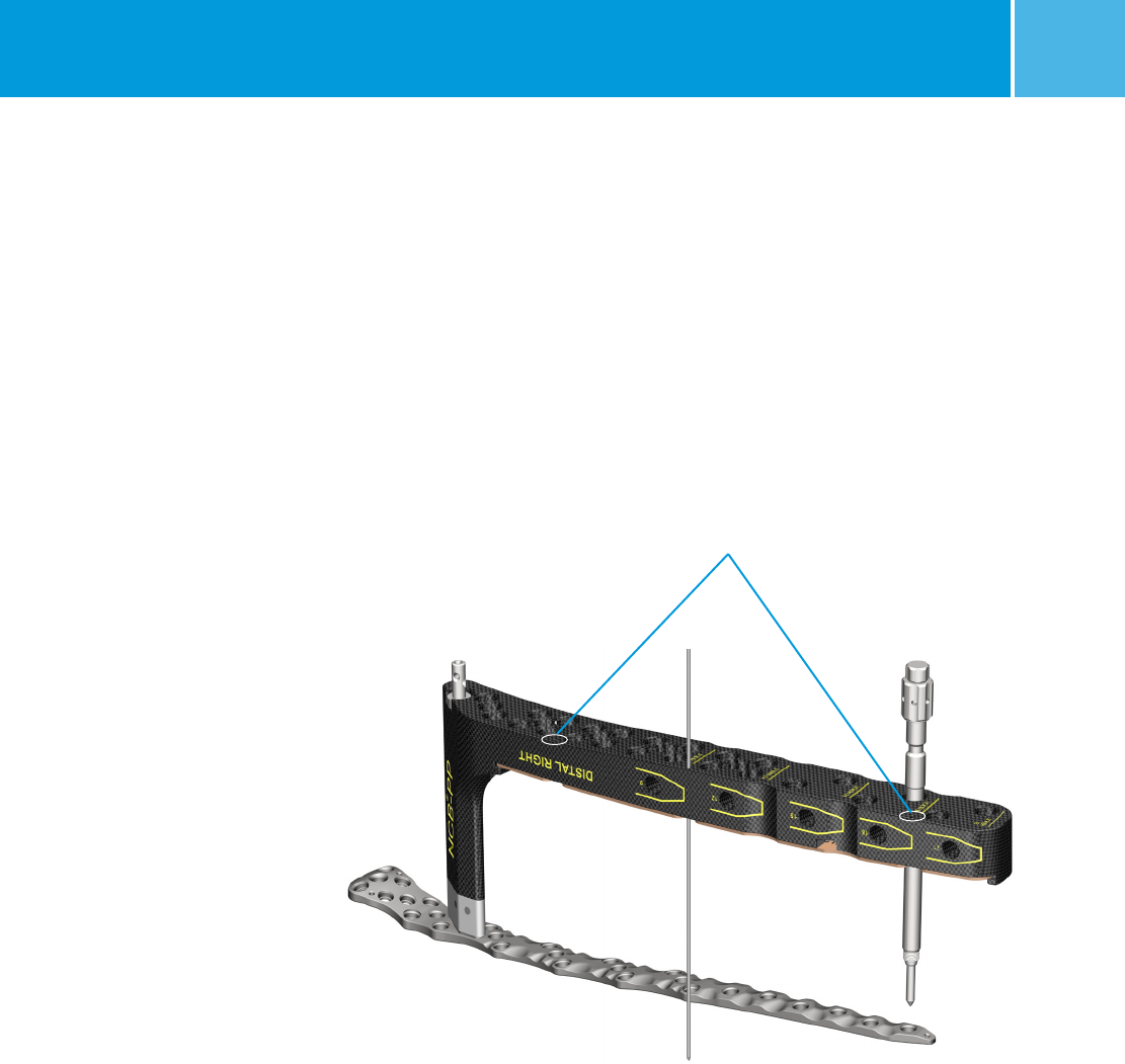
Insertion of the Proximal NCB Plate
1. Insert the plate between the vastus
lateralis muscle and the periosteum.
Place the Proximal Femur Plate just
below the vastus tubercle until you
achieve good contact with the bone.
Keep the distal end of the plate in
close contact with the bone during
insertion. Ensure both proximal and
distal ends of the plate have good
placement on the bone.
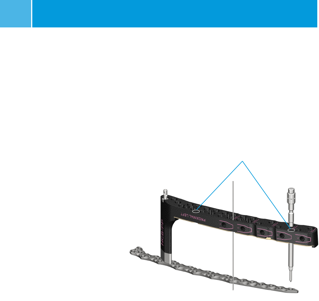
2. Make a stab incision at the most
distal plate hole. Insert the NCB
Trocar (REF 02.00024.062) and
Stabilization Bolt (REF 02.00024.074)
into the NCB Periprosthetic Plate (Fig.
5). Use the three K-wire holes to hold
the targeting device in place, ensuring
that the targeting device does not
sag. Depending on the patient
anatomy, these K-wires may rest on
the anterior aspect of the femur when
the plate is centered on the bone.
NOTE: To place a screw in the distal
end of the plate, exchange out the NCB
Stabilization Bolt with the NCB Trocar,
Drill Guide, and Tissue Protection
Sleeve assembly after all other screws
have been inserted.
Fig. 5
Additional K-wire holes
NCB® Periprosthetic MIS Radiolucent Targeting Device 7
Distal NCB Periprosthetic
MIS Technique
A lateral incision is recommended. The
skin incision should start at Gerdy’s
tubercle and extend proximally. The
muscles are left attached to the fracture
fragments for optimal blood supply. Do
not strip the periosteum.
Reduce the fracture prior to inserting the
plate. Bone fragments can be secured
with 2.0mm K-wires (REF 290.20.280)
or clamps, such as pointed reduction
forceps. Ensure that preliminary fixation
devices do not interfere with the future
location of the plate and screws,
with the prosthesis or with the NCB
Periprosthetic Targeting Device.
Insertion of the Distal NCB Plate
1. Insert the plate between the vastus
lateralis muscle and the periosteum.
Keep the proximal end of the plate in
close contact with the bone during
insertion. Place the distal end of the
plate as distal as possible. Ensure
both proximal and distal ends of the
plate have good placement on the
bone.
2. Make a stab incision at the most
proximal plate hole. Insert the NCB
Trocar (REF 02.00024.062) and
Stabilization Bolt (REF 02.00024.074)
into the NCB Periprosthetic Plate
(Fig. 6). Use the three K-wire holes
to hold the targeting device in place,
ensuring that the targeting device
does not sag. Depending on the
patient anatomy, these K-wires may
rest on the anterior aspect of the
femur when the plate is centered on
the bone.
NOTE: To place a screw in the proximal
end of the plate, exchange out the NCB
Stabilization Bolt with the NCB Trocar,
Drill Guide, and Tissue Protection
Sleeve assembly after all other screws
have been inserted.
Fig. 6
Additional K-wire holes
8NCB® Periprosthetic MIS Radiolucent Targeting Device
Proximal & Distal NCB
Periprosthetic MIS
Technique (cont'd)
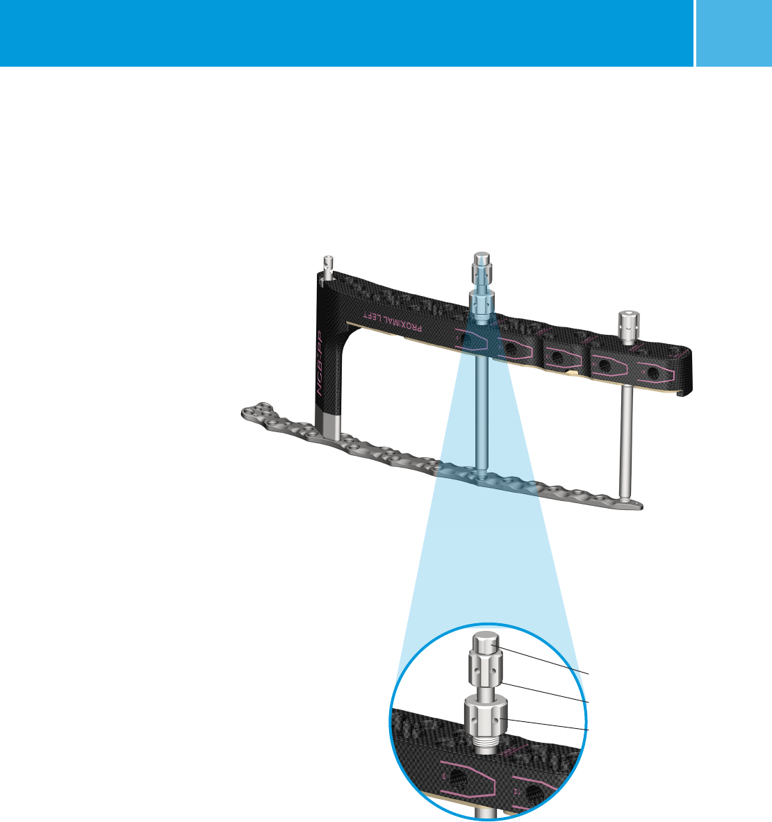
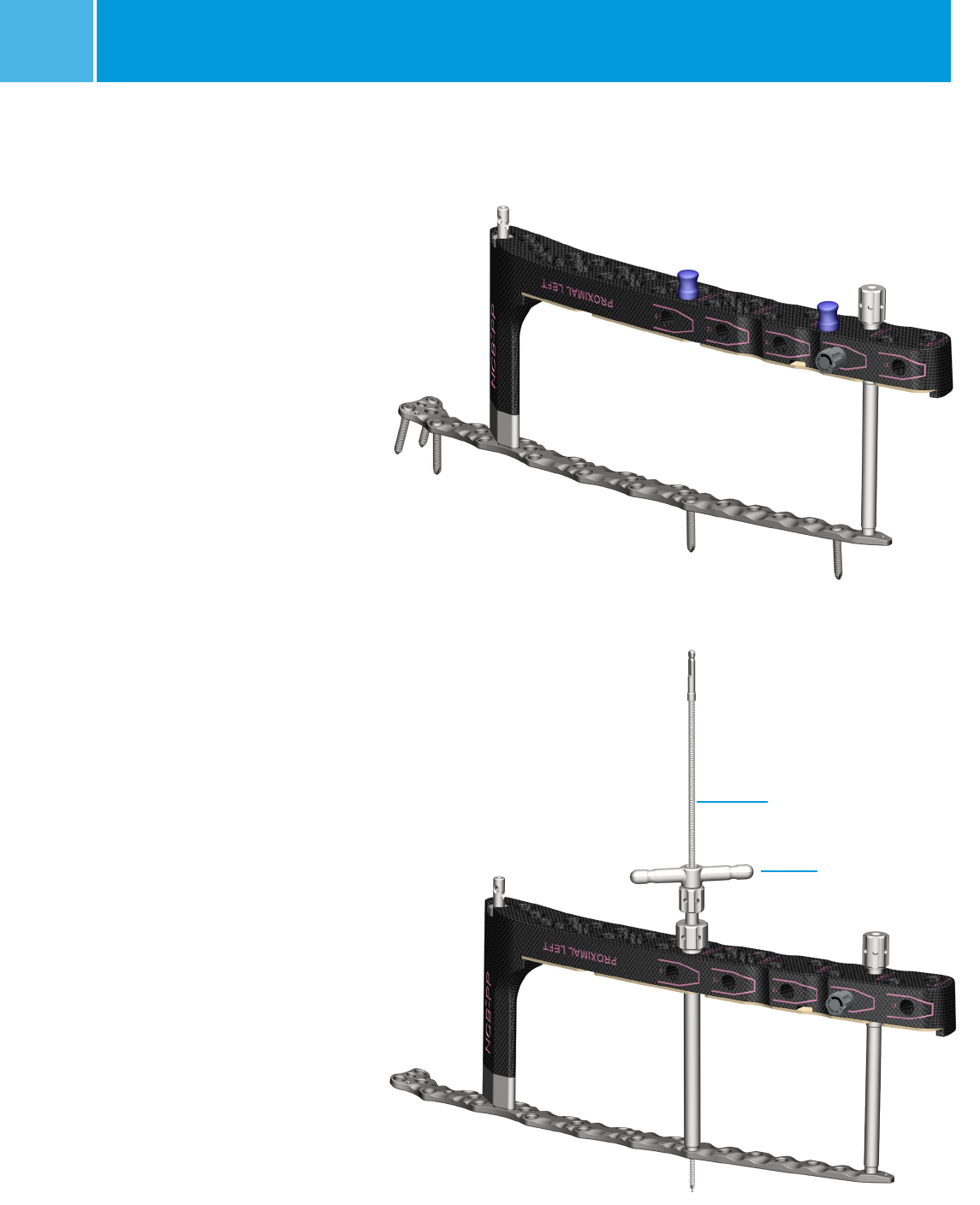
Secure the Safety Lock Pin
Insert the NCB Periprosthetic Safety Lock
Pin (REF 02.00024.382) into the NCB
Periprosthetic Targeting Device from the
anterior side to ensure proper distance
is maintained between the Targeting
Device and the
plate throughout the
procedure (Fig. 7).
To ensure the Pin
is locked in place, adjust the distance
between the end of the Targeting Device
and the end of the plate by gently
pushing on the Targeting Device.
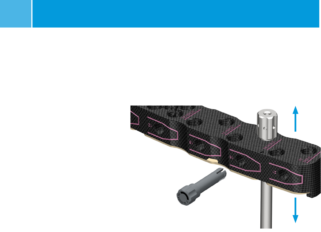
Reduction of the Metaphyseal
Bone Fragments
Insert screws into the metaphyseal area
of the plate using the open technique on
page 20 of the NCB Periprosthetic Femur
Plate System Surgical Technique.
NOTE: 15o angulation may be
restricted when inserting screws in the
metaphyseal region with the Targeting
Device attached to the plate.
NOTE: Some Locking Caps near the
metaphyseal region must be placed
after the Targeting Device has been
removed from the plate.
Fig. 7 Adjust the height of the Targeting Device to allow Safety Lock Pin placement.
NCB® Periprosthetic MIS Radiolucent Targeting Device 9
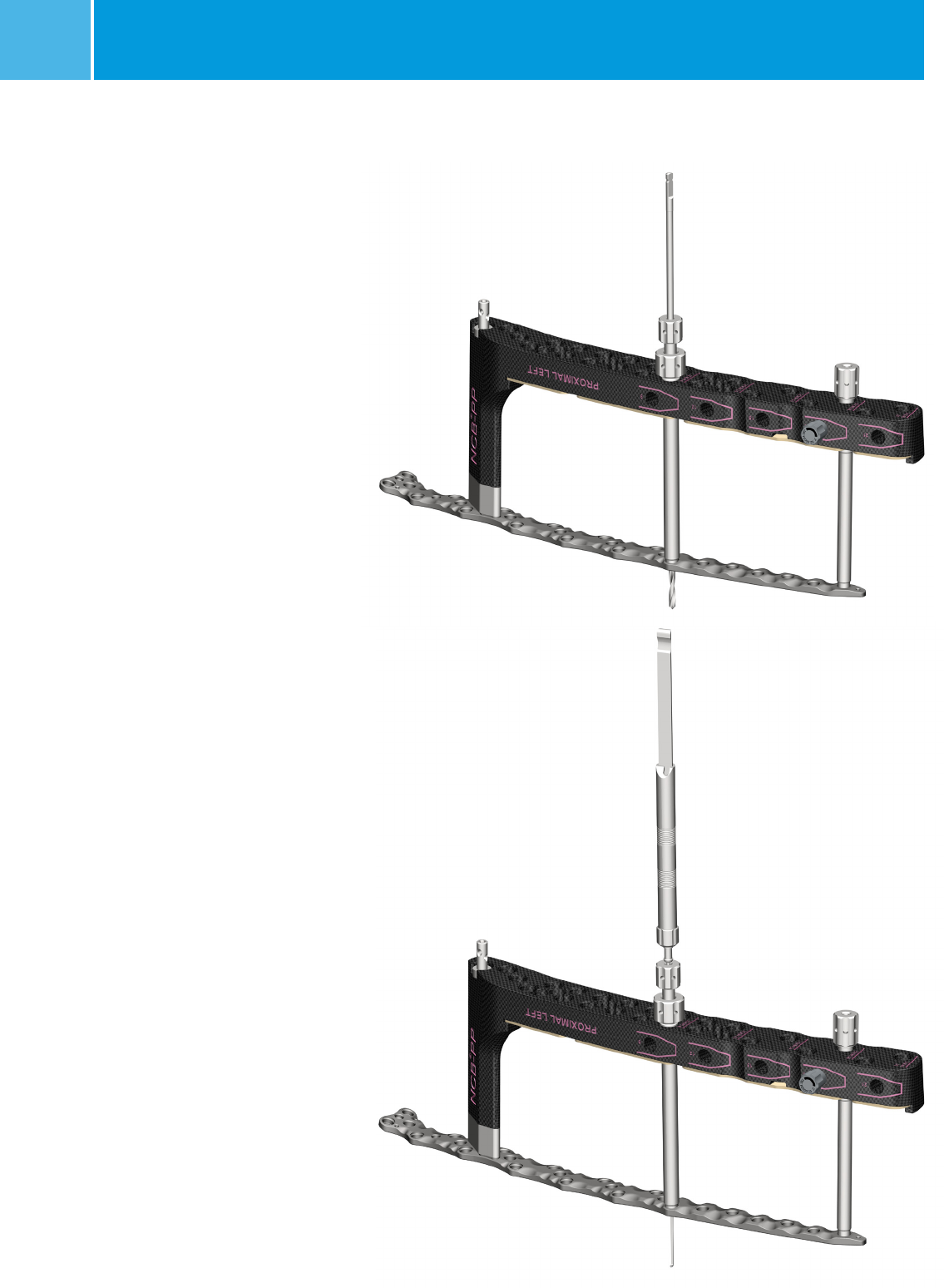
Insertion of the NCB Screws in
Diaphyseal Bone
1. Make a stab incision to access the
plate hole. Insert the NCB Trocar,
Drill Guide, and Tissue Protection
Sleeve assembly (REF 02.00024.060-
062) (Fig. 8).
2. Screw the Tissue Protection Sleeve
into the NCB Periprosthetic Targeting
Device. The Tissue Protection Sleeve
will be in direct contact with the
plate.
3. Screw the Drill Guide into the plate
hole.
4. Remove the Trocar.
Fig. 8
Trocar
Drill Guide
Tissue Protection Sleeve
NCB® Periprosthetic MIS Radiolucent Targeting Device
10
Fig. 9
Fig. 10
5. Insert the correct diameter Drill Bit
for the desired screw. The same
Drill Guide is used for both the 3.3mm
and 4.3mm drill bits. The calibration
lines on the Drill Bit can be used to
determine the screw length (Fig. 9).
Alternatively, determine the screw
length using the NCB Depth Gauge
(REF 02.00024.006) by measuring
through the Drill Guide and Tissue
Protection Sleeve (Fig. 10).
NOTE: Ensure that other existing
medical devices and their fixation and/
or anchorage elements are not affected
or damaged by drill bits, taps, or
screws. Do not hit the prosthesis with
the tip of the drill, tap, or screw.
11
NCB® Periprosthetic MIS Radiolucent Targeting Device
6. Remove the Drill Guide and insert
the appropriate screw using the
NCB Hexagonal Screwdriver
(REF 02.00024.023) (Fig. 11).
NOTE: If the screw is inserted using
power, final tightening should be
done by hand.
7. To lock the screw, insert a Locking
Cap (REF 02.03150.300) and tighten
the Cap with the 6Nm Torque Limiting
Screwdriver (REF 02.00024.021) until
a clicking sound is heard (Fig. 12).
NOTE: The Self-Retaining Screwdriver
(REF 5912) can be used to prevent
screws and Locking Caps from being
lost inside the Tissue Protection Sleeve,
however the NCB hexagonal screwdriver
may be needed to insert the Screw. Final
tightening of the Locking Caps must
always be done using the 6Nm Torque
Limiting Screwdriver.
Fig. 11
Fig. 12
NCB® Periprosthetic MIS Radiolucent Targeting Device
12
(Optional)
Creating Compression between
the Plate and the Bone
1. Screw the Reduction Spin Knob (REF
00-2360-011-03) onto the threads
nearest to the AO adapter on the
Plate Reduction Instrument (REF
00-2360-011-01).
2. Insert the NCB Trocar, Drill Guide, and
Tissue Protection Sleeve Assembly as
described in steps 1-4 from the section
entitled "Insertion of the NCB Screws in
Diaphyseal Bone" on page 9.
3. Drill the Plate Reduction Instrument
into the bone.
4. Turn the Spin Knob against the Drill
Guide until it provides the desired
amount of compression (Fig. 14).
8. Remove the Tissue Protection
Sleeve and place a Screw Marker
(02.00024.077) into the hole in the
NCB Periprosthetic Targeting Device
to indicate which plate holes contain
screws (Fig. 13).
9. Repeat the above steps as needed to
insert additional screws.
Fig. 13
Fig. 14
Plate Reduction Instrument
Reduction Spin Knob

NCB® Periprosthetic MIS Radiolucent Targeting Device 13
Product Information – MIS Guides and Instruments
NCB® Periprosthetic MIS Instruments
REF Description
02.00002.001 Assembly Pin
02.00024.003 NCB-PT Drill Bit 4.3MM QC
02.00024.006 NCB-DF Depth Gauge
02.00024.060 NCB-DF Soft Tissue Protection Sleeve 10.0/8.2MM
02.00024.061 NCB-DF Drill Guide 8.2/4.3MM
02.00024.062 NCB-DF Trocar
02.00024.074 NCB-DF Stabilization Bolt
02.00024.077 NCB-PT Screw Marker
02.00024.370 NCB Periprosthetic Femur targeting device, right proximal
02.00024.371 NCB Periprosthetic Femur targeting device, left proximal
02.00024.372 NCB Periprosthetic Femur targeting device, right distal
02.00024.373 NCB Periprosthetic Femur targeting device, left distal
02.00024.380 NCB Periprosthetic Femur connection bolt for targeting device
02.00024.381 NCB Periprosthetic Femur MIS drill bit Ø 3.3mm, with quick coupling
02.02024.381 NCB Periprosthetic Femur MIS drill bit Ø 3.3mm, with quick coupling (sterile)
02.00024.382 NCB Periprosthetic Femur Safety Lock Pin
02.00024.390 NCB Periprosthetic Proximal Femur targeting device bottom cover for 9 hole plate
02.00024.391 NCB Periprosthetic Proximal Femur targeting device bottom cover for 12 hole plate
02.00024.392 NCB Periprosthetic Proximal Femur targeting device bottom cover for 15 hole plate
02.00024.393 NCB Periprosthetic Proximal Femur targeting device bottom cover for 18 hole plate
02.00024.394 NCB Periprosthetic Proximal Femur targeting device bottom cover for 21 hole plate
02.00024.395 NCB Periprosthetic Distal Femur targeting device bottom cover for 9 hole plate
02.00024.396 NCB Periprosthetic Distal Femur targeting device bottom cover for 12 hole plate
02.00024.397 NCB Periprosthetic Distal Femur targeting device bottom cover for 15 hole plate
02.00024.398 NCB Periprosthetic Distal Femur targeting device bottom cover for 18 hole plate
02.00024.399 NCB Periprosthetic Distal Femur targeting device bottom cover for 21 hole plate
00-2360-011-01 Plate Reduction Instrument
00-2360-011-03 Reduction Spin Knob
5912 Self-Retaining Screwdriver
Graphic Cases for NCB Periprosthetic MIS Instruments
Standard Graphic Cases
REF Description
02.00024.913 NCB Periprosthetic Femur MIS Case Assembly
02.00024.914 NCB Periprosthetic Femur MIS Case Base
02.00024.915 NCB Periprosthetic Femur MIS Case Tray
00-5900-099-00 Generic Lid
97-2370-010-00 7-24-13 Printed in USA ©2013 Zimmer, Inc.
This documentation is intended exclusively for physicians and is not intended for laypersons.
Information on the products and procedures contained in this document is of a general nature
and does not represent and does not constitute medical advice or recommendations. Because
this information does not purport to constitute any diagnostic or therapeutic statement with
regard to any individual medical case, each patient must be examined and advised individually,
and this document does not replace the need for such examination and/or advice in whole or
in part. Please refer to the package inserts for important product information, including, but not
limited to, contraindications, warnings, precautions, and adverse effects.
Contact your Zimmer representative or visit us at www.zimmer.com
The CE mark is valid only if it is also printed on the product label.
