2450 Interactive SourceMeter® Instrument User's Manual Source Meter User
User Manual: Pdf
Open the PDF directly: View PDF ![]() .
.
Page Count: 96
- Model 2450 User's Manual
- Table of Contents
- Safety precautions
- 1 Introduction
- 2 Using the front-panel interface
- 3 Using a remote interface
- 4 Making basic front-panel measurements
- 5 Measuring low-resistance devices
- 6 Leakage current and insulation resistance
- 7 Measuring I-V characteristics of FETs
- 8 Rechargeable battery measurements
- 9 Measuring I-V characteristics of solar cells
- 10 Troubleshooting FAQs
- About this section
- Where can I find updated drivers?
- How do I upgrade the firmware?
- Why can't the Model 2450 read my USB flash drive?
- How do I change the command set?
- Why am I getting a 5074 event code?
- How do I save the present state of the instrument?
- Why did my settings change?
- What are the Quick Setup options?
- 11 Next steps

User’s Manual
2450-900-01 Rev. D / May 2015
*P245090001D*
2450-900-01D
www.keithley.com
Model 2450
Interactive SourceMeter Instrument
A Greater Measure of Confidence
Interactive SourceMeter® Instrument
User's Manual
© 2015, Keithley Instruments
Cleveland, Ohio, U.S.A.
All rights reserved.
Any unauthorized reproduction, photocopy, or use of the information herein, in whole or in part,
without the prior written approval of Keithley Instruments is strictly prohibited.
TSP®, TSP-Link®, and TSP-Net® are trademarks of Keithley Instruments. All Keithley Instruments
product names are trademarks or registered trademarks of Keithley Instruments, Inc. Other brand
names are trademarks or registered trademarks of their respective holders.
Document number: 2450-900-01 Rev. D / May 2015
Model 2450

Safety precautions
The following safety precautions should be observed before using this product and any associated instrumentation. Although
some instruments and accessories would normally be used with nonhazardous voltages, there are situations where hazardous
conditions may be present.
This product is intended for use by qualified personnel who recognize shock hazards and are familiar with the safety precautions
required to avoid possible injury. Read and follow all installation, operation, and maintenance information carefully before using
the product. Refer to the user documentation for complete product specifications.
If the product is used in a manner not specified, the protection provided by the product warranty may be impaired.
The types of product users are:
Responsible body is the individual or group responsible for the use and maintenance of equipment, for ensuring that the
equipment is operated within its specifications and operating limits, and for ensuring that operators are adequately trained.
Operators use the product for its intended function. They must be trained in electrical safety procedures and proper use of the
instrument. They must be protected from electric shock and contact with hazardous live circuits.
Maintenance personnel perform routine procedures on the product to keep it operating properly, for example, setting the line
voltage or replacing consumable materials. Maintenance procedures are described in the user documentation. The procedures
explicitly state if the operator may perform them. Otherwise, they should be performed only by service personnel.
Service personnel are trained to work on live circuits, perform safe installations, and repair products. Only properly trained
service personnel may perform installation and service procedures.
Keithley Instruments products are designed for use with electrical signals that are measurement, control, and data I/O
connections, with low transient overvoltages, and must not be directly connected to mains voltage or to voltage sources with high
transient overvoltages. Measurement Category II (as referenced in IEC 60664) connections require protection for high transient
overvoltages often associated with local AC mains connections. Certain Keithley measuring instruments may be connected to
mains. These instruments will be marked as category II or higher.
Unless explicitly allowed in the specifications, operating manual, and instrument labels, do not connect any instrument to mains.
Exercise extreme caution when a shock hazard is present. Lethal voltage may be present on cable connector jacks or test
fixtures. The American National Standards Institute (ANSI) states that a shock hazard exists when voltage levels greater than
30 V RMS, 42.4 V peak, or 60 VDC are present. A good safety practice is to expect that hazardous voltage is present in any
unknown circuit before measuring.
Operators of this product must be protected from electric shock at all times. The responsible body must ensure that operators
are prevented access and/or insulated from every connection point. In some cases, connections must be exposed to potential
human contact. Product operators in these circumstances must be trained to protect themselves from the risk of electric shock. If
the circuit is capable of operating at or above 1000 V, no conductive part of the circuit may be exposed.
Do not connect switching cards directly to unlimited power circuits. They are intended to be used with impedance-limited
sources. NEVER connect switching cards directly to AC mains. When connecting sources to switching cards, install protective
devices to limit fault current and voltage to the card.
Before operating an instrument, ensure that the line cord is connected to a properly-grounded power receptacle. Inspect the
connecting cables, test leads, and jumpers for possible wear, cracks, or breaks before each use.
When installing equipment where access to the main power cord is restricted, such as rack mounting, a separate main input
power disconnect device must be provided in close proximity to the equipment and within easy reach of the operator.
For maximum safety, do not touch the product, test cables, or any other instruments while power is applied to the circuit under
test. ALWAYS remove power from the entire test system and discharge any capacitors before: connecting or disconnecting
cables or jumpers, installing or removing switching cards, or making internal changes, such as installing or removing jumpers.
Do not touch any object that could provide a current path to the common side of the circuit under test or power line (earth)
ground. Always make measurements with dry hands while standing on a dry, insulated surface capable of withstanding the
voltage being measured.
For safety, instruments and accessories must be used in accordance with the operating instructions. If the instruments or
accessories are used in a manner not specified in the operating instructions, the protection provided by the equipment may be
impaired.
Do not exceed the maximum signal levels of the instruments and accessories, as defined in the specifications and operating
information, and as shown on the instrument or test fixture panels, or switching card.
When fuses are used in a product, replace with the same type and rating for continued protection against fire hazard.
Chassis connections must only be used as shield connections for measuring circuits, NOT as protective earth (safety ground)
connections.
If you are using a test fixture, keep the lid closed while power is applied to the device under test. Safe operation requires the use
of a lid interlock.
If a screw is present, connect it to protective earth (safety ground) using the wire recommended in the user documentation.
The symbol on an instrument means caution, risk of danger. The user must refer to the operating instructions located in the
user documentation in all cases where the symbol is marked on the instrument.
The symbol on an instrument means caution, risk of electric shock. Use standard safety precautions to avoid personal
contact with these voltages.
The symbol on an instrument shows that the surface may be hot. Avoid personal contact to prevent burns.
The symbol indicates a connection terminal to the equipment frame.
If this symbol is on a product, it indicates that mercury is present in the display lamp. Please note that the lamp must be
properly disposed of according to federal, state, and local laws.
The WARNING heading in the user documentation explains dangers that might result in personal injury or death. Always read
the associated information very carefully before performing the indicated procedure.
The CAUTION heading in the user documentation explains hazards that could damage the instrument. Such damage may
invalidate the warranty.
Instrumentation and accessories shall not be connected to humans.
Before performing any maintenance, disconnect the line cord and all test cables.
To maintain protection from electric shock and fire, replacement components in mains circuits — including the power
transformer, test leads, and input jacks — must be purchased from Keithley Instruments. Standard fuses with applicable national
safety approvals may be used if the rating and type are the same. Other components that are not safety-related may be
purchased from other suppliers as long as they are equivalent to the original component (note that selected parts should be
purchased only through Keithley Instruments to maintain accuracy and functionality of the product). If you are unsure about the
applicability of a replacement component, call a Keithley Instruments office for information.
To clean an instrument, use a damp cloth or mild, water-based cleaner. Clean the exterior of the instrument only. Do not apply
cleaner directly to the instrument or allow liquids to enter or spill on the instrument. Products that consist of a circuit board with
no case or chassis (e.g., a data acquisition board for installation into a computer) should never require cleaning if handled
according to instructions. If the board becomes contaminated and operation is affected, the board should be returned to the
factory for proper cleaning/servicing.
Safety precaution revision as of January 2013.

Introduction ............................................................................................................... 1-1
Welcome .............................................................................................................................. 1-1
Introduction to this manual ................................................................................................... 1-1
Extended warranty ............................................................................................................... 1-1
Contact information .............................................................................................................. 1-2
CD-ROM contents ................................................................................................................ 1-2
Organization of manual sections .......................................................................................... 1-2
Applications .......................................................................................................................... 1-3
Using the front-panel interface ................................................................................ 2-1
Power the instrument on or off ............................................................................................. 2-1
Front panel overview ............................................................................................................ 2-2
Turn the Model 2450 output on or off ................................................................................... 2-4
Touchscreen display ............................................................................................................ 2-5
Select items on the touchscreen ............................................................................................... 2-5
Scroll bars ................................................................................................................................. 2-6
Interactive swipe screens .......................................................................................................... 2-6
Menu overview .......................................................................................................................... 2-9
Store measurements on a USB flash drive ........................................................................ 2-10
Saving screen captures to a USB flash drive .................................................................... 2-10
Using a remote interface .......................................................................................... 3-1
Remote communications interfaces ..................................................................................... 3-1
Supported remote interfaces ................................................................................................ 3-1
GPIB communications .......................................................................................................... 3-2
Install the GPIB driver software ................................................................................................. 3-2
Install the GPIB cards in your computer .................................................................................... 3-2
Connect GPIB cables to your instrument .................................................................................. 3-2
Set the GPIB address ............................................................................................................... 3-3
LAN communications ........................................................................................................... 3-4
Set up LAN communications on the instrument ........................................................................ 3-4
Set up LAN communications on the computer .......................................................................... 3-6
USB communications ........................................................................................................... 3-7
Connect a computer to the Model 2450 using USB .................................................................. 3-7
Communicate with the instrument ............................................................................................. 3-8
Using the web interface...................................................................................................... 3-11
Connect to the instrument web interface ................................................................................. 3-11
LAN troubleshooting suggestions ............................................................................................ 3-11
Identify the instrument ............................................................................................................. 3-13
Review events in the event log ................................................................................................ 3-13
Determining the command set you will use ....................................................................... 3-13
Table of Contents

Table of Contents
Model 2450 Interactive SourceMeter® Instrument
User's Manual
Making basic front-panel measurements ................................................................ 4-1
Introduction .......................................................................................................................... 4-1
Equipment required for this application................................................................................ 4-2
Device connections .............................................................................................................. 4-2
Make front-panel measurements ......................................................................................... 4-2
How to make front-panel measurements .................................................................................. 4-3
Measuring low-resistance devices .......................................................................... 5-1
Introduction .......................................................................................................................... 5-1
Equipment required .............................................................................................................. 5-1
Set up remote communications ........................................................................................... 5-1
Device connections .............................................................................................................. 5-2
Low-resistance measurements ............................................................................................ 5-5
Set up the measurement from the front panel ........................................................................... 5-5
View the measurements on the front-panel GRAPH swipe screen ........................................... 5-6
View the buffer statistics on the front panel ............................................................................... 5-6
Set up the low-resistance application using SCPI commands................................................... 5-6
Set up the low-resistance application using TSP commands .................................................... 5-7
Leakage current and insulation resistance ............................................................. 6-1
Introduction .......................................................................................................................... 6-1
Equipment required .............................................................................................................. 6-1
Set up remote communications ........................................................................................... 6-2
Device connections .............................................................................................................. 6-2
Measuring leakage current .................................................................................................. 6-4
Set up the leakage current application using the front panel ..................................................... 6-4
View the measurements on the front-panel graph ..................................................................... 6-5
Set up the leakage current application using SCPI commands ................................................. 6-6
Set up the leakage current application using TSP commands .................................................. 6-6
Measuring insulation resistance ........................................................................................... 6-8
Set up the insulation resistance application using the front panel ............................................. 6-9
Viewing the measurements on the front-panel graph ................................................................ 6-9
Set up the application using SCPI commands ........................................................................ 6-10
Set up the application using TSP commands .......................................................................... 6-10
Measuring I-V characteristics of FETs .................................................................... 7-1
Introduction .......................................................................................................................... 7-1
Equipment required .............................................................................................................. 7-1
Set up remote communications ........................................................................................... 7-2
Set up external hardware triggers ........................................................................................ 7-2
Connections for the SCPI command set ................................................................................... 7-2
Connections for the TSP command set ..................................................................................... 7-3

Model 2450
Interactive SourceMeter® Instrument User's Manual Table
of Contents
Device connections .............................................................................................................. 7-4
Remote control of FET testing using SCPI commands ....................................................... 7-5
Set up the application using SCPI commands with the trigger model ....................................... 7-6
Set up the application using SCPI commands in a linear sweep ............................................... 7-8
Remote control of FET testing using TSP commands ......................................................... 7-9
Set up the application using TSP commands with the trigger model ....................................... 7-10
Set up the application using TSP commands in a linear sweep .............................................. 7-12
Rechargeable battery measurements ...................................................................... 8-1
Introduction .......................................................................................................................... 8-1
Equipment required .............................................................................................................. 8-3
Device connections .............................................................................................................. 8-3
Automated battery charge and discharge cycle testing ....................................................... 8-5
Set up remote communications ................................................................................................. 8-6
Set up the battery application using SCPI commands .............................................................. 8-7
Set up the battery application using TSP commands ................................................................ 8-8
Measuring I-V characteristics of solar cells ............................................................ 9-1
Introduction .......................................................................................................................... 9-1
Equipment required .............................................................................................................. 9-1
Set up remote communications ........................................................................................... 9-2
Device connections .............................................................................................................. 9-2
Solar cell characterization .................................................................................................... 9-4
Set up the solar cell I-V sweep from the front panel .................................................................. 9-5
Set up the solar cell I-V sweep using SCPI commands ............................................................ 9-6
Set up the solar cell I-V sweep using TSP commands .............................................................. 9-7
Troubleshooting FAQs ........................................................................................... 10-1
About this section ............................................................................................................... 10-1
Where can I find updated drivers? ..................................................................................... 10-1
How do I upgrade the firmware? ........................................................................................ 10-2
Why can't the Model 2450 read my USB flash drive?........................................................ 10-2
How do I change the command set? ................................................................................. 10-2
Why am I getting a 5074 event code? ............................................................................... 10-3
How do I save the present state of the instrument? .......................................................... 10-4
Why did my settings change? ............................................................................................ 10-5
What are the Quick Setup options? ................................................................................... 10-5
Next steps ............................................................................................................... 11-1
Additional Model 2450 information ..................................................................................... 11-1

In this section:
Welcome .................................................................................. 1-1
Introduction to this manual ....................................................... 1-1
Extended warranty ................................................................... 1-1
Contact information .................................................................. 1-2
CD-ROM contents .................................................................... 1-2
Organization of manual sections .............................................. 1-2
Applications .............................................................................. 1-3
Welcome
Thank you for choosing a Keithley Instruments product. The Model 2450 Interactive SourceMeter®
instrument is a precise, low-noise instrument that combines a stable DC power supply, true current
source, electronic load, and a high-impedance multimeter. The design of this instrument features
intuitive setup and control, enhanced signal quality and range, and better resistivity and resistance
capabilities than similar products on the market.
With 0.012 percent basic accuracy at 6½-digit resolution, the Model 2450 delivers 59 readings per
second over the IEEE-488 bus. At 4½-digit resolution, it can read up to 3000 readings per second into
its internal buffer.
Introduction to this manual
This manual provides detailed applications to help you achieve success with your Keithley
Instruments Model 2450. In addition, this manual provides information about the basics of the front
panel to familiarize you with the instrument.
This manual presents an overview of each application, followed by instructions to complete the
application using the front panel, SCPI code, TSP code, or Keithley KickStart Startup Software.
More information about the commands that are used in these applications is available. Refer to the
SCPI and TSP command reference sections of the Model 2450 Reference Manual. This manual is on
the Product Information CD-ROM that came with your instrument.
Extended warranty
Additional years of warranty coverage are available on many products. These valuable contracts
protect you from unbudgeted service expenses and provide additional years of protection at a fraction
of the price of a repair. Extended warranties are available on new and existing products. Contact your
local Keithley Instruments office, sales partner, or distributor for details.
Section 1
Introduction

Section
1: Introduction Model 2450 Interactive SourceMeter® Instrument
User's Manual
1-2 2450-900-01 Rev. D/May 2015
Contact information
If you have any questions after you review the information in this documentation, please contact your
local Keithley Instruments office, sales partner, or distributor. You can also call Keithley Instruments
corporate headquarters (toll-free inside the U.S. and Canada only) at 1-800-935-5595, or from
outside the U.S. at +1-440-248-0400. For worldwide contact numbers, visit the Keithley website (see
http://www.keithley.com - http://www.keithley.com).
CD-ROM contents
The following CD-ROM is shipped with each Model 2450 instrument:
• Interactive SourceMeter® SMU Instruments Product Information CD-ROM (Keithley Instruments
part number 24GDI-950-01)
The Model 2450 Interactive SourceMeter SMU Instrument Product Information CD-ROM
contains:
• Quick Start Guide: Provides unpacking instructions, describes basic connections, reviews basic
operation information, and provides a quick test procedure to ensure the instrument is
operational.
• User's Manual: Provides application examples that you can use as a starting point to create your
own applications.
• Reference Manual: Includes advanced operation topics, maintenance information,
troubleshooting procedures, and in-depth descriptions of programming commands.
• KickStart Startup Software Quick Start Guide: Provides instructions for the KickStart Startup
Software, which allows you to quickly make measurements and get results without having to
program test scripts.
• Accessories information: Documentation for accessories that are available for the Model 2450.
For the latest drivers and additional support information, see the Keithley Instruments website
(http://www.keithley.com).
Organization of manual sections
This manual is organized into the following sections:
• Using the front-panel interface (on page 2-1): Describes the basics of using the front-panel
interface.
• Using a remote interface (on page 3-1): Describes the basics of remote communications and
using the instrument web interface.
• Application examples (see below): Provides detailed examples of how to use the Model 2450 in
some typical situations.

Model 2450
Interactive SourceMeter® Instrument User's Manual Section 1:
Introduction
2450-900-01 Rev. D/May 2015 1-3
• Troubleshooting FAQs (on page 10-1): Provides answers to frequently asked questions to help
you troubleshoot common problems encountered with the Model 2450.
• Next steps (on page 11-1): Provides information about additional resources that can help you use
the Model 2450.
The PDF version of this manual contains bookmarks for each section. The manual sections are also
listed in the Table of Contents at the beginning of this manual.
For more information about bookmarks, see Adobe® Acrobat® or Reader® help.
Applications
This manual provides application examples that show you how to perform tests from the front panel
and over a remote interface. These applications are presented after the summary information about
the Model 2450. The applications include:
• Making basic front-panel measurements (on page 4-1): Demonstrates the basic measurement
functionality using a single Model 2450 and a two-terminal device under test (DUT).
• Measuring low-resistance devices (on page 5-1): Demonstrates how to use a Model 2450 to
make low-resistance measurements of a 20 mΩ resistor.
• Leakage current and insulation resistance (on page 6-1): Two examples that demonstrate how to
use the Model 2450 to measure the leakage current of a capacitor and the insulation resistance
between the two conductors of a coaxial cable.
• Measuring I-V characteristics of FETs (on page 7-1): Two examples demonstrate how to use two
Model 2450 instruments to perform a drain family of curves (Vds-Id) on a three-terminal
MOSFET. One example uses the Model 2450 trigger model; the other uses linear sweep
commands to make the measurements.
• Rechargeable battery measurements (on page 8-1): Demonstrates how to use a single Model
2450 to perform automated battery discharge and charge cycle testing.
• Measuring I-V characteristics of solar cells (on page 9-1): Demonstrates using an I-V sweep to
characterize a solar cell using the Model 2450.
In this section:
Power the instrument on or off ................................................. 2-1
Front panel overview ................................................................ 2-2
Turn the Model 2450 output on or off ....................................... 2-4
Touchscreen display................................................................. 2-5
Store measurements on a USB flash drive ............................. 2-10
Saving screen captures to a USB flash drive ......................... 2-10
Power the instrument on or off
Follow the steps below to connect the Model 2450 to line power and turn on the instrument. The
Model 2450 operates from a line voltage of 100 V to 240 V at a frequency of 50 Hz or 60 Hz. It
automatically senses line voltage and frequency. Make sure the operating voltage in your area is
compatible.
You must turn on the Model 2450 and allow it to warm up for at least one hour to achieve rated
accuracies.
Operating the instrument on an incorrect line voltage may cause damage to the instrument, possibly
voiding the warranty.
The power cord supplied with the Model 2450 contains a separate protective earth (safety
ground) wire for use with grounded outlets. When proper connections are made, the
instrument chassis is connected to power-line ground through the ground wire in the power
cord. In addition, a redundant protective earth connection is provided through a screw on
the rear panel. This terminal should be connected to a known protective earth. In the event
of a failure, not using a properly grounded protective earth and grounded outlet may result
in personal injury or death due to electric shock.
Do not replace detachable mains supply cords with inadequately rated cords. Failure to use
properly rated cords may result in personal injury or death due to electric shock.
To connect the power cord:
1. Make sure that the front-panel POWER switch is in the off (O) position.
2. Connect the female end of the supplied power cord to the AC receptacle on the rear panel.
3. Connect the other end of the power cord to a grounded AC outlet.
Section 2
Using the front-panel interface
Section
2: Using the front-panel interface Model 2450 Interactive SourceMeter® Instrument
User's Manual
2-2 2450-900-01 Rev. D/May 2015
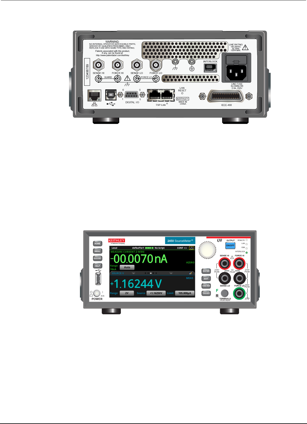
Figure 1: Model 2450 rear panel
To turn a Model 2450 on or off:
1. Before turning the instrument on, disconnect any devices under test (DUTs) from the Model 2450.
2. To turn your instrument on, press the front-panel POWER switch to place it in the on (|) position.
The instrument displays a status bar as it powers on. The Home screen is displayed when power
on is complete.
3. To turn your instrument off, press the front-panel POWER switch to place it in the off (O) position.
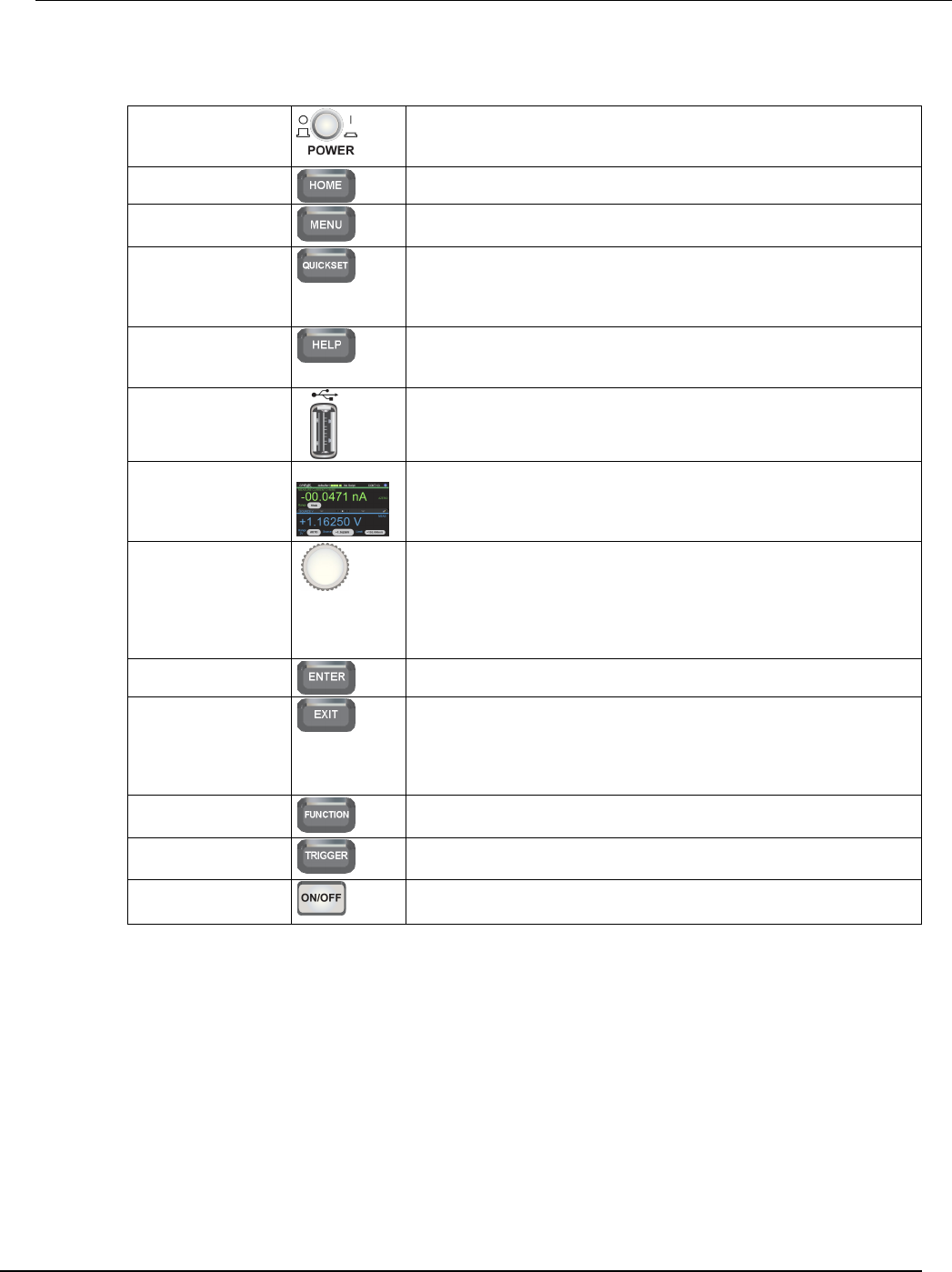
Front panel overview
The front panel of the Model 2450 is shown below. Descriptions of the controls on the front panel
follow the figure.
Figure 2: Model 2450 front panel
Model 2450
Interactive SourceMeter® Instrument User's Manual Section 2: Using the front-panel interface
2450-900-01 Rev. D/May 2015 2-3
POWER switch
Turns the instrument on or off. To turn the instrument on, press the
power switch so that it is in the on position (|). To turn it off, press the
power switch so that it is in the off position (O).
HOME key
Returns the display to the Home screen.
MENU key
Opens the main menu. Press the icons on the main menu to open
source, measure, view, trigger, script, and system screens.
QUICKSET key
Opens a menu of preconfigured setups, including voltmeter,
ammeter, ohmmeter, and power supply. Also allows you to choose
source and measure functions and adjust performance for better
resolution or speed.
HELP key Opens help for the area or item that is selected on the display. If
there is no selection when you press the HELP key, it displays
overview information for the screen you are viewing.
USB port
Saves reading buffer data and screen snapshots to a USB flash
drive. Also stores and retrieves scripts to and from a USB flash drive.
The flash drive must be formatted as a FAT drive.
Touchscreen
The Model 2450 has a high-resolution, five-inch color touchscreen
display. The touchscreen accesses swipe screens and menu options.
You can access additional interactive screens by pressing the
front-panel MENU, QUICKSET, and FUNCTION keys.
Navigation control
Turning the navigation control: Moves the cursor to highlight a list
value or menu item so that you can select it. Turning the control when
the cursor is in a value entry field increases or decreases the value in
the field.
Pressing the navigation control: Selects the highlighted choice or
allows you to edit the selected field.
ENTER key
Selects the highlighted choice or allows you to edit the selected field.
EXIT key
Returns to the previous screen or closes a dialog box. For example,
press the EXIT key when the main menu is displayed to return to the
Home screen. When you are viewing a subscreen (for example, the
Event Log screen), press the EXIT key to return to the main menu
screen.
FUNCTION key
Displays instrument functions. To select a function, touch the function
name on the screen.
TRIGGER key
Accesses trigger-related settings and operations. The action of the
TRIGGER key depends on the instrument state.
OUTPUT ON/OFF
switch
Turns the output source on or off. The key illuminates when the
source output is on.
Section
2: Using the front-panel interface Model 2450 Interactive SourceMeter® Instrument
User's Manual
2-4 2450-900-01 Rev. D/May 2015
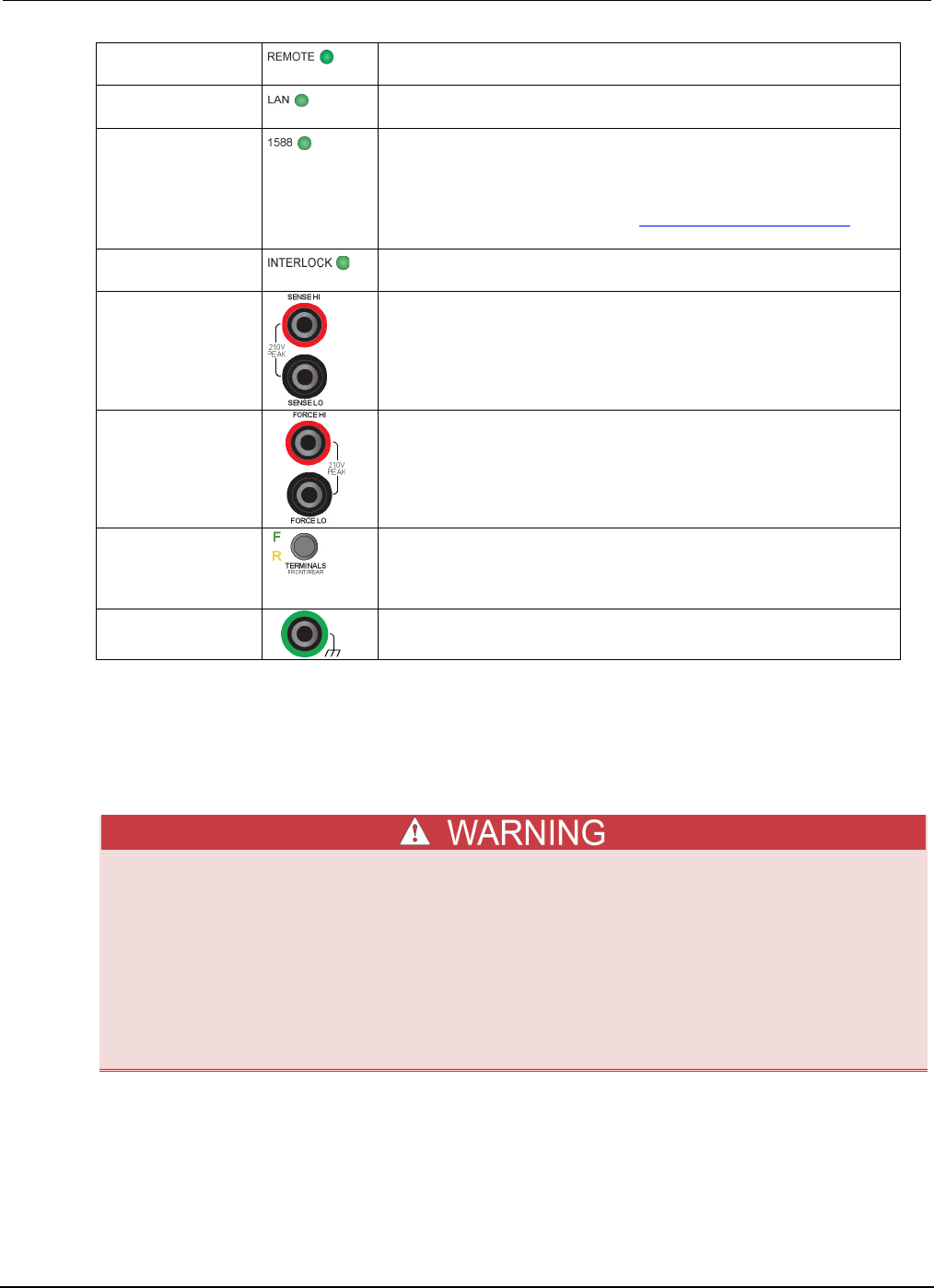
REMOTE LED
indicator
Illuminates when the instrument is controlled through a remote
interface.
LAN LED indicator Illuminates when the instrument is connected to a local area network
(LAN).
1588 LED indicator Illuminates when the instrument is connected to an IEEE-1588
compliant device.
Note that 1588 functionality is not supported at this time. This
functionality will be made available with a firmware update. See the
Model 2450 Release Notes on the Keithley Instruments website
(http://www.keithley.com) for details.
INTERLOCK LED
indicator
Illuminates when the interlock is enabled.
SENSE terminals
Use the SENSE HI and SENSE LO terminal connections to measure
voltage at the device under test (DUT). When you use sense leads,
measurement of the voltage drop across the force leads is
eliminated. This produces more accurate voltage sourcing and
measurement at the DUT.
FORCE terminals
Use FORCE HI and FORCE LO terminal connections to source or
sink voltage or current to or from a device under test (DUT).
FRONT/REAR
TERMINALS switch
Activates the terminals on the front or rear panel. When the
front-panel terminals are active, a green "F" is visible to the left of the
FRONT/REAR switch. When the rear-panel terminals are active, a
yellow "R" is visible to the left of the switch.
Chassis connection
Banana jack connector that provides a chassis connection.
Turn the Model 2450 output on or off
You can turn the Model 2450 output on from the front panel or by sending remote commands.
Turning the Model 2450 output off does not place the instrument in a safe state (an interlock
is provided for this function).
Hazardous voltages may be present on all output and guard terminals. To prevent electrical
shock that could cause injury or death, never make or break connections to the Model 2450
while the instrument is powered on. Turn off the equipment from the front panel or
disconnect the main power cord from the rear of the Model 2450 before handling cables.
Putting the equipment into an output-off state does not guarantee that the outputs are
powered off if a hardware or software fault occurs.
Model 2450
Interactive SourceMeter® Instrument User's Manual Section 2: Using the front-panel interface
2450-900-01 Rev. D/May 2015 2-5
When the source of the instrument is turned off, it may not completely isolate the instrument from the
external circuit. You can use the Output Off setting to place the Model 2450 in a known,
noninteractive state during idle periods, such as when you are changing the device under test. The
output-off states that can be selected for a Model 2450 are normal, high-impedance, zero, or guard.
See "Output-off state" in the Model 2450 Reference Manual for additional details.
Using the front panel:
Press the OUTPUT ON/OFF switch. The instrument is in the output-on state when the switch is
illuminated. The instrument is in the output-off state when the switch is not illuminated.
Using SCPI commands:
To turn the output on, send the command:
:OUTPut:STATe ON
To turn the output off, send the command:
:OUTPut:STATe OFF
Using TSP commands:
To turn the output on, send the command:
smu.source.output = smu.ON
To turn the output off, send the command:
smu.source.output = smu.OFF
Touchscreen display
The touchscreen display gives you quick front-panel access to source and measure settings, system
configuration, instrument and test status, reading buffer information, and other instrument
functionality. The display has multiple swipe screens that you can access by swiping the front panel.
You can access additional interactive screens by pressing the front-panel MENU, QUICKSET, and
FUNCTION keys.
Do not use sharp metal objects, such as tweezers or screwdrivers, or pointed objects, such as pens
or pencils, to touch the touchscreen. It is strongly recommended that you use only fingers to operate
the instrument. Use of clean-room gloves to operate the touchscreen is supported.
Select items on the touchscreen
To select an item on the displayed screen, do one of the following:
• Touch it with your finger
• Turn the navigation control to highlight the item, and then press the navigation control to select it
The following topics describe the Model 2450 touchscreen in more detail.
Section
2: Using the front-panel interface Model 2450 Interactive SourceMeter® Instrument
User's Manual
2-6 2450-900-01 Rev. D/May 2015
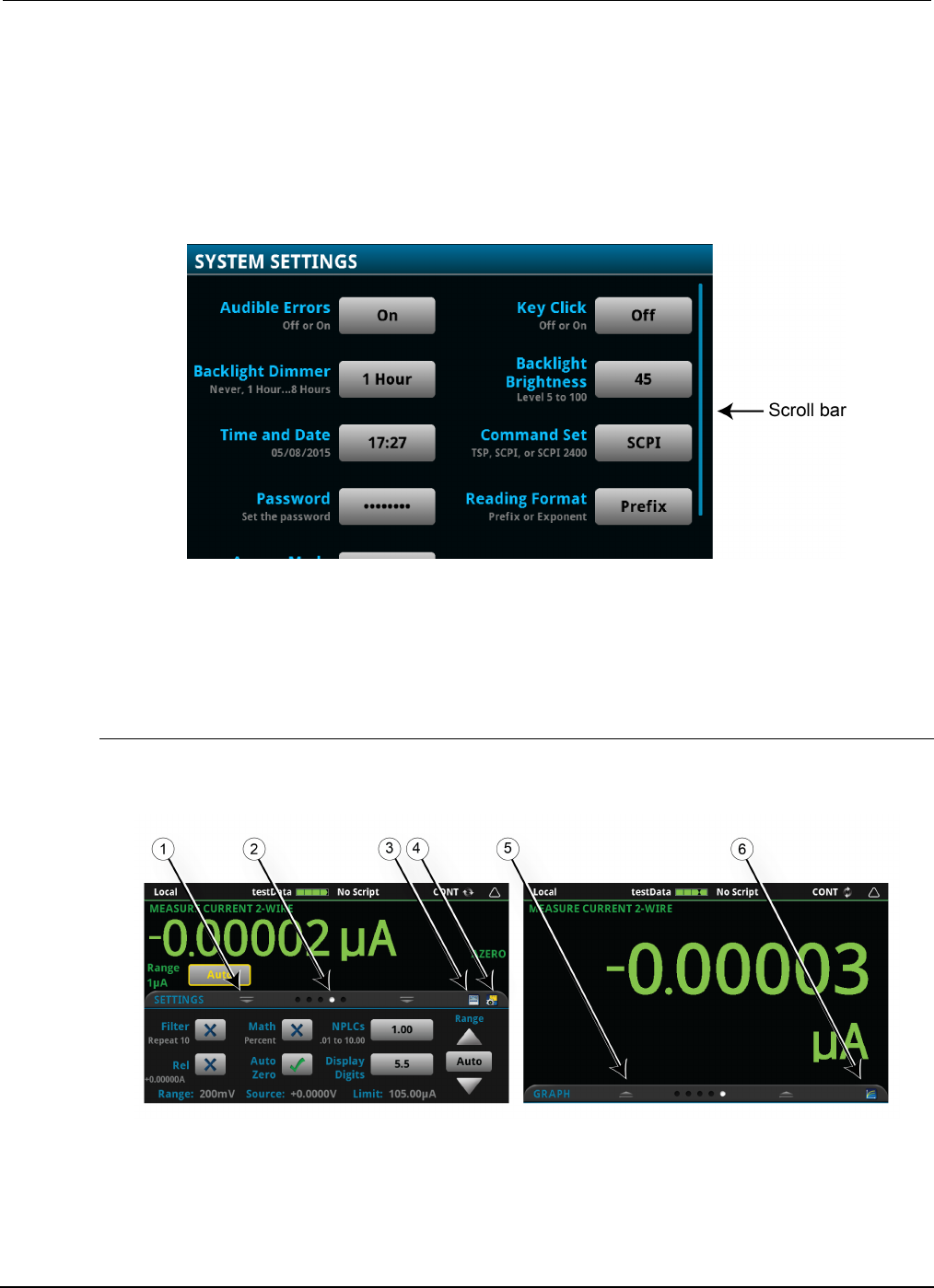
Scroll bars
Some of the interactive screens have additional options that are only visible when you scroll down the
screen. A scroll indicator on the right side of the touchscreen identifies these screens. Swipe the
screen up or down to view the additional options.
The figure below shows a screen with a scroll bar.
Figure 3: Touchscreen scroll indicator
Interactive swipe screens
The Model 2450 touchscreen display has multiple screens that you can access by gently swiping left
or right on the lower half of the display. The options available in the swipe screens are described in
the following topics.
Swipe screen heading bar
The heading bar of the swipe screen contains the following options.
Figure 4: Swipe screens, maximized and minimized
Model 2450
Interactive SourceMeter® Instrument User's Manual Section 2: Using the front-panel interface
2450-900-01 Rev. D/May 2015 2-7
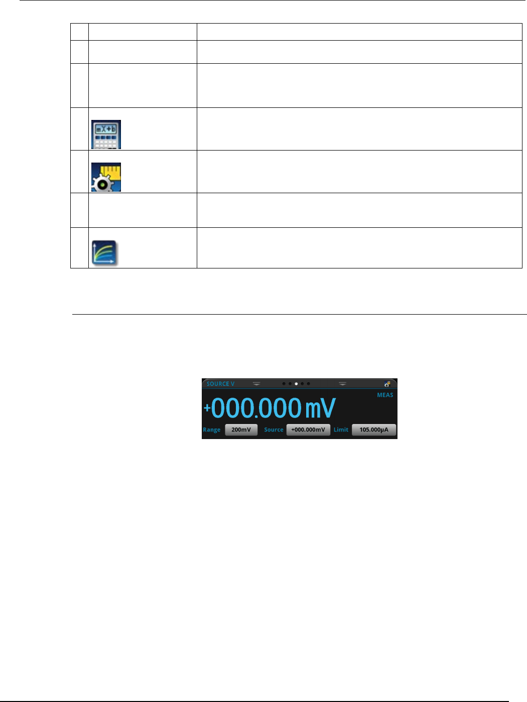
# Screen element Description
1
Minimize indicator
You can swipe down to minimize the swipe screens.
2
Swipe screen indicator
Each circle represents one swipe screen. As you swipe right or left, a different
circle changes color, indicating where you are in the screen sequence. Select a
circle to go to a swipe screen without swiping.
3
Calculations shortcut
Select to open the CALCULATIONS SETTINGS menu.
4
Settings shortcut
Select to open the MEASURE SETTINGS menu for the selected function.
5
Restore indicator
Indicates that you can swipe up to display the swipe screen.
6 Graph shortcut
Select to open the Graph screen.
SOURCE swipe screen
The SOURCE swipe screen shows the present value of the source and the set values for source,
source range, and source limit. You can change the set values from the front panel by selecting the
buttons on this screen.
Figure 5: SOURCE swipe screen
Source function indicators on the right side of the screen signify settings that affect the displayed
source value.
• MEAS: Source readback is on and the value shown is the measured value of the source
• PROG: Source readback is off and the value shown is the programmed source value. If the
output is off, the displayed source value is replaced with Output Off.
The icon on the right side of the swipe screen heading bar is a shortcut to the full SOURCE
SETTINGS menu.
Section
2: Using the front-panel interface Model 2450 Interactive SourceMeter® Instrument
User's Manual
2-8 2450-900-01 Rev. D/May 2015
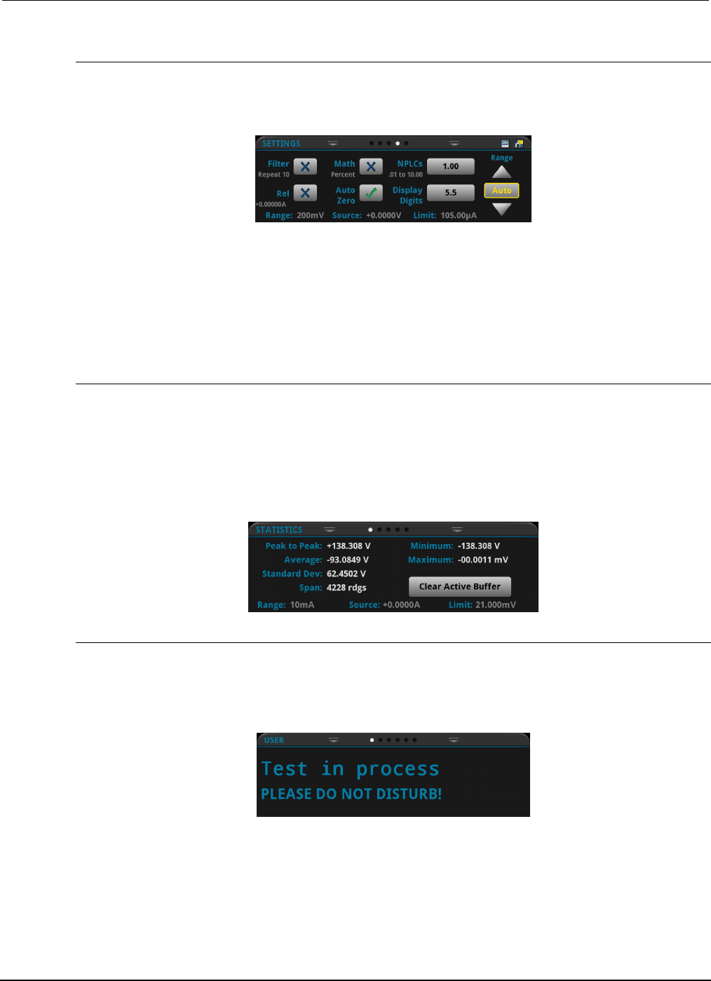
SETTINGS swipe screen
The SETTINGS swipe screen gives you front-panel access to some instrument settings. It shows you
the present settings and allows you to change, enable, or disable them quickly.
Figure 6: SETTINGS swipe screen
To disable or enable a setting, select the box next to the setting so that it shows an X (disabled) or a
check mark (enabled).
The icons on the right side of the swipe screen heading bar are shortcuts to the CALCULATIONS
SETTINGS and MEASURE SETTINGS menus.
For descriptions of the settings, use the navigation control to select the button, then press the HELP
key.
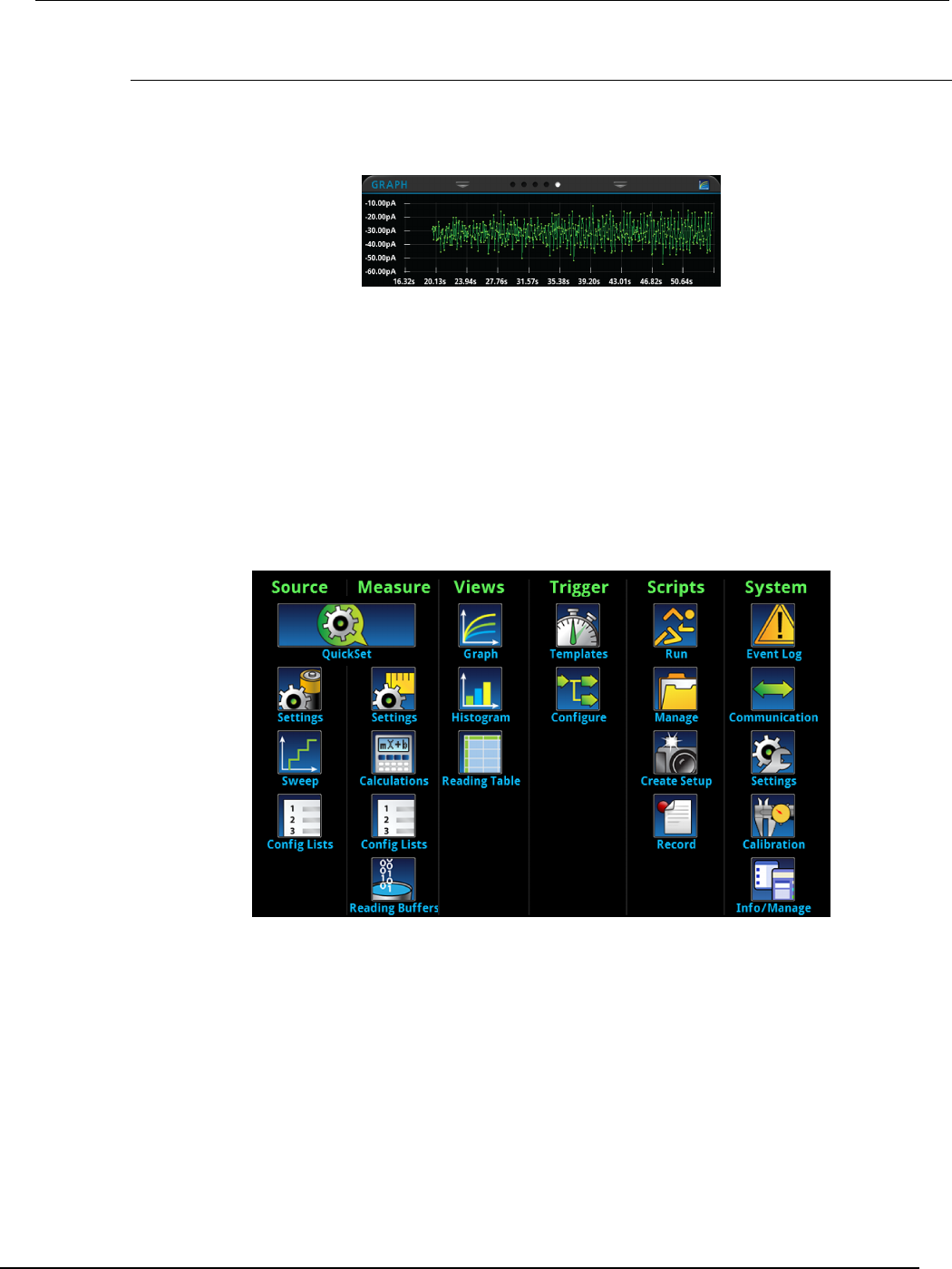
STATISTICS swipe screen
The STATISTICS swipe screen contains information about the readings in the active reading buffer.
When the reading buffer is configured to fill continuously and overwrite older data with new data, the
buffer statistics include the data that was overwritten. To get statistics that do not include data that
has been overwritten, define a large buffer size that will accommodate the number of readings you
will make. You can use the Clear Active Buffer button on this screen to clear the data from the
active reading buffer.
Figure 7: STATISTICS swipe screen
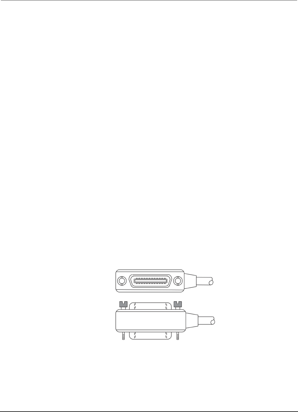
USER swipe screen
You can program custom text that appears on the USER swipe screen. For example, you can
program the Model 2450 to show that a test is in process. For details about using remote commands
to program the display, refer to Customizing a message for the USER swipe screen.
Figure 8: USER swipe screen
Model 2450
Interactive SourceMeter® Instrument User's Manual Section 2: Using the front-panel interface
2450-900-01 Rev. D/May 2015 2-9
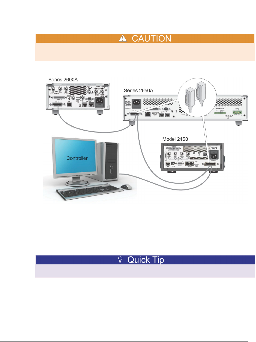
GRAPH swipe screen
The GRAPH swipe screen shows a graphical representation of the readings in the presently selected
reading buffer.
Figure 9: GRAPH swipe screen
To view the graph in the full screen and to access graph settings, select the graph icon on the right
side of the swipe screen header. You can also open the full-function Graph screen by pressing the
MENU key and selecting Graph under Views.
For more information about graphing measurements, see "Graphing" in the Model 2450 Reference
Manual.
Menu overview
To access the main menu, press the MENU key on the Model 2450 front panel. The figure below
shows the organization of the main menu.
Figure 10: Model 2450 main menu
The main menu includes submenus that are labeled in green across the top of the display. Touching
an icon in a submenu opens an interactive screen.

Section
2: Using the front-panel interface Model 2450 Interactive SourceMeter® Instrument
User's Manual
2-10 2450-900-01 Rev. D/May 2015
Store measurements on a USB flash drive
If there is measurement data in the buffer, you can copy it from the Model 2450 to a USB flash drive.
The information is saved in the .csv file format.
To store measurement data:
1. Insert a flash drive into the front-panel USB port.
2. Press the MENU key.
3. In the Measure column, select Reading Buffers.
4. Select the buffer that you want to save.
5. Select Save to USB.
6. Enter a name for the new file.
7. Select the OK button on the displayed keyboard.
8. Select Yes to confirm saving the file.
9. Select OK to close the dialog box.
Saving screen captures to a USB flash drive
You can save the content of the front-panel display to a graphic file. The instrument saves these
graphic files, also known as screen captures, screen grabs, or screen shots, to the USB flash drive in
the .png file format.
To save the screen capture:
1. Insert a USB flash drive in the USB port on the front panel of the instrument.
2. Navigate to the screen you want to capture.
3. Press the HOME and ENTER keys. The instrument displays "Saving screen capture."
4. Release the keys.

In this section:
Remote communications interfaces.......................................... 3-1
Supported remote interfaces .................................................... 3-1
GPIB communications .............................................................. 3-2
LAN communications................................................................ 3-4
USB communications ............................................................... 3-7
Using the web interface .......................................................... 3-11
Determining the command set you will use ............................ 3-13
Remote communications interfaces
You can choose from one of several communication interfaces to send commands to and receive
responses from the Model 2450.
You can control the Model 2450 from only one communications interface at a time. The first interface
on which it receives a message takes control of the instrument. If another interface sends a message,
that interface can take control of the instrument. You may need to enter a password to change the
interface, depending on the access mode.
The Model 2450 automatically detects the type of communications interface (LAN, GPIB, or USB)
when you connect to the respective port on the rear panel of the instrument. In most cases, you do
not need to configure anything on the instrument. In addition, you do not need to reboot if you change
the type of interface that is connected.
Supported remote interfaces
The Model 2450 supports the following remote interfaces:
• GPIB: IEEE-488 instrumentation general purpose interface bus
• Ethernet: Local area network ethernet communications
• USB: Type B USB port
• TSP-Link: A high-speed trigger synchronization and communications bus that test system
builders can use to connect multiple instruments in a master-and-subordinate configuration
For details about TSP-Link, see "TSP-Link System Expansion Interface" in the Model 2450 Reference
Manual.
Section 3
Using a remote interface
Section
3: Using a remote interface Model 2450 Interactive SourceMeter® Instrument
User's Manual
3-2 2450-900-01 Rev. D/May 2015
GPIB communications
The Model 2450 GPIB interface is IEEE Std 488.1 compliant and supports IEEE Std 488.2 common
commands and status model topology.
You can have up to 15 devices connected to a GPIB interface, including the controller. The maximum
cable length is the lesser of either:
• The number of devices multiplied by 2 m (6.5 ft)
• 20 m (65.6 ft)
You may see erratic bus operation if you ignore these limits.
Install the GPIB driver software
Check the documentation for your GPIB controller for information about where to acquire drivers.
Keithley Instruments also recommends that you check the website of the GPIB controller for the latest
version of drivers or software.
It is important that you install the drivers before you connect the hardware. This prevents associating
the incorrect driver to the hardware.
Install the GPIB cards in your computer
Refer to the documentation from the GPIB controller vendor for information about installing the GPIB
controllers.
Connect GPIB cables to your instrument
To connect an instrument to the GPIB interface, use a cable equipped with standard GPIB
connectors, as shown below.
Figure 11: GPIB connector
Model 2450
Interactive SourceMeter® Instrument User's Manual Section 3:
Using a remote interface
2450-900-01 Rev. D/May 2015 3-3
To allow many parallel connections to one instrument, stack the connectors. Each connector has two
screws to ensure that connections remain secure. The figure below shows a typical connection
diagram for a test system with multiple instruments.
To avoid possible mechanical damage, stack no more than three connectors on any one instrument.
To minimize interference caused by electromagnetic radiation, use only shielded GPIB cables.
Contact Keithley Instruments for shielded cables.
Figure 12: IEEE-488 connection example
Set the GPIB address
The default GPIB address is 18. You can set the address to any address from 1 to 30 if it is unique in
the system. This address cannot conflict with an address that is assigned to another instrument or to
the GPIB controller.
GPIB controllers are usually set to 0 or 21. To be safe, do not configure any instrument to have an
address of 21. To change the controller address, see the documentation for the controller.
The instrument saves the address in nonvolatile memory. It does not change when you send a reset
command or when you turn the power off and then on again.

Section
3: Using a remote interface Model 2450 Interactive SourceMeter® Instrument
User's Manual
3-4 2450-900-01 Rev. D/May 2015
To set the GPIB address from the front panel:
1. Press the MENU key.
2. Under System, select Communication. The SYSTEM COMMUNICATIONS window opens.
3. Select the GPIB tab.
4. Next to Address, select the number. The GPIB Address dialog box is displayed.
5. Enter the address.
6. Select OK.
LAN communications
You can communicate with the instrument using a local area network (LAN).
When you connect using a LAN, you can use a web browser to access the internal web page of the
instrument and change some of the instrument settings. For more information, see Using the web
interface (on page 3-11).
The Model 2450 is an LXI version 1.4 Core 2011 compliant instrument that supports TCP/IP and
complies with IEEE Std 802.3 (ethernet LAN). There is one LAN port (located on the rear panel of the
instrument) that supports full connectivity on a 10 Mbps or 100 Mbps network. The Model 2450
automatically detects the speed.
The Model 2450 also supports Multicast DNS (mDNS) and DNS Service Discovery (DNS-SD), which
are useful on a LAN with no central administration.
Contact your network administrator to confirm your specific network requirements before setting up a
LAN connection.
If you have problems setting up the LAN, refer to LAN troubleshooting suggestions (on page 3-11).
Set up LAN communications on the instrument
This section describes how to set up manual or automatic LAN communications on the instrument.
Check communication settings
Before setting up the LAN configuration, you can check the communication settings on the instrument
without making any changes.
To check communication settings on the instrument:
1. Press the MENU key.
2. Under System, select Communication. The SYSTEM COMMUNICATIONS window opens.
3. Select one of the four tabs, GPIB, USB, LAN, or TSP-Link, to see the settings for that interface.
4. Press the EXIT key to leave the SYSTEM COMMUNICATION window without making any
changes.
Model 2450
Interactive SourceMeter® Instrument User's Manual Section 3:
Using a remote interface
2450-900-01 Rev. D/May 2015 3-5
Set up automatic LAN configuration
If you are connecting to a LAN that has a DHCP server or if you have a direct connection between the
instrument and a host computer, you can use automatic IP address selection.
If you select Auto, the instrument attempts to get an IP address from a DHCP server. If this fails, it
reverts to an IP address in the range of 169.254.1.0 through 169.254.254.255.
Both the host computer and the instrument should be set to use automatic LAN configuration.
Though it is possible to have one set to manual configuration, it is more complicated to set up.
To set up automatic IP address selection using the front panel:
1. Press the MENU key.
2. Under System, select Communication.
3. Select the LAN tab.
4. For TCP/IP Mode, select Auto.
5. Select Apply Settings to save your settings.
Set up manual LAN configuration
If necessary, you can set the IP address on the instrument manually.
You can also enable or disable the DNS settings and assign a host name to the DNS server.
Contact your corporate information technology (IT) department to secure a valid IP address for the
instrument when placing the instrument on a corporate network.
The instrument IP address has leading zeros, but the computer IP address cannot.
To set up manual IP address selection on the instrument:
1. Press the MENU key.
2. Under System, select Communication.
3. Select the LAN tab.
4. For TCP/IP Mode, select Manual.
5. For IP Address, enter the LAN IP address. You can touch the number you want to change.
6. For Gateway, enter the gateway address.
7. For Subnet, enter the subnet mask.
8. Select Apply Settings to save your settings.

Section
3: Using a remote interface Model 2450 Interactive SourceMeter® Instrument
User's Manual
3-6 2450-900-01 Rev. D/May 2015
Set up LAN communications on the computer
This section describes how to set up the LAN communications on your computer.
Do not change your IP address without consulting your system administrator. If you enter an
incorrect IP address, it can prevent your computer from connecting to your corporate network or it
may cause interference with another networked computer.
Record all network configurations before modifying any existing network configuration information on
the network interface card. Once the network configuration settings are updated, the previous
information is lost. This may cause a problem reconnecting the host computer to a corporate
network, particularly if DHCP is disabled.
Be sure to return all settings to their original configuration before reconnecting the host computer to a
corporate network. Contact your system administrator for more information.
Wait for the LAN status indicator on the front panel to turn solid green
A solid green LAN status indicator confirms that the instrument was assigned an IP address. Note
that it may take several minutes for the computer and instrument to establish a connection.
Install LXI Discovery Browser software on your computer
You can use the LXI Discovery Browser to identify the IP addresses of LXI-certified instruments.
Once identified, you can double-click the IP address in the LXI Discovery Browser to open the web
interface for the instrument.
The Keithley LXI Discovery Browser is available on the Keithley Instruments website
(http://www.keithley.com).
To locate the Keithley LXI Discovery Browser on the Keithley website:
1. Select the Support tab.
2. In the model number box, type 2450.
3. From the list, select Software and click the search icon. A list of software applications for the
instrument is displayed.
4. See the readme file included with the application for more information.
For more information about the LXI Consortium, see the LXI Consortium website
(http://www.lxistandard.org/).

Model 2450
Interactive SourceMeter® Instrument User's Manual Section 3:
Using a remote interface
2450-900-01 Rev. D/May 2015 3-7
Run the LXI Discovery Browser
To run the LXI Discovery Browser software:
1. From the Microsoft Windows Start menu, select Keithley Instruments.
2. Select LXI Discovery Browser.
3. Click LXI Discovery Browser. The Keithley LXI Discovery Browser window is displayed.
The LXI Discovery Browser displays the instruments that it finds on the network and their
associated IP addresses.
4. Double-click an IP address in the LXI Discovery Browser dialog box. The instrument web page for
that instrument opens.
For information about using the web page, see the "Using the web interface" topic in the Model 2450
Reference Manual.
USB communications
To use the rear-panel USB port, you must have the Virtual Instrument Software Architecture (VISA)
layer on the host computer. See "How to install the Keithley I/O Layer" in the Model 2450 Reference
Manual for more information.
VISA contains a USB-class driver for the USB Test and Measurement Class (USBTMC) protocol that,
once installed, allows the Microsoft® Windows® operating system to recognize the instrument.
When you connect a USB device that implements the USBTMC or USBTMC-USB488 protocol to the
computer, the VISA driver automatically detects the device. Note that the VISA driver only
automatically recognizes USBTMC and USBTMC-USB488 devices. It does not recognize other USB
devices, such as printers, scanners, and storage devices.
In this section, "USB instruments" refers to devices that implement the USBTMC or
USBTMC-USB488 protocol.
Connect a computer to the Model 2450 using USB
To connect the Model 2450 to a computer using a USB connection, use Keithley Instruments
Model USB-B-1, which is shipped with the instrument.
Each Model 2450 needs its own USB cable to be connected to the computer.
To connect an instrument to a computer using USB:
1. Connect the Type A end of the cable to the computer.
2. Connect the Type B end of the cable to the instrument.
3. Turn on the instrument power. When the computer detects the new USB connection, the Found
New Hardware Wizard starts.
4. If the "Can Windows connect to Windows Update to search for software?" dialog box opens, click
No, and then click Next.
5. On the "USB Test and Measurement device" dialog box, click Next, and then click Finish.
Section
3: Using a remote interface Model 2450 Interactive SourceMeter® Instrument
User's Manual
3-8 2450-900-01 Rev. D/May 2015
Communicate with the instrument
For the instrument to communicate with the USB device, you must use NI-VISATM. VISA requires a
resource string in the following format to connect to the correct USB instrument:
USB0::0x05e6::0x2450::[serial number]::INSTR
Where:
• 0x05e6: The Keithley vendor ID
• 0x2450: The instrument model number
• [serial number]: The serial number of the instrument (the serial number is also on the rear
panel)
• INSTR: Use the USBTMC protocol
To determine these parameters, you can run the Keithley Configuration Panel, which automatically
detects all instruments connected to the computer.
If you installed the Keithley I/O Layer, you can access the Keithley Configuration Panel through the
Microsoft® Windows® Start menu.
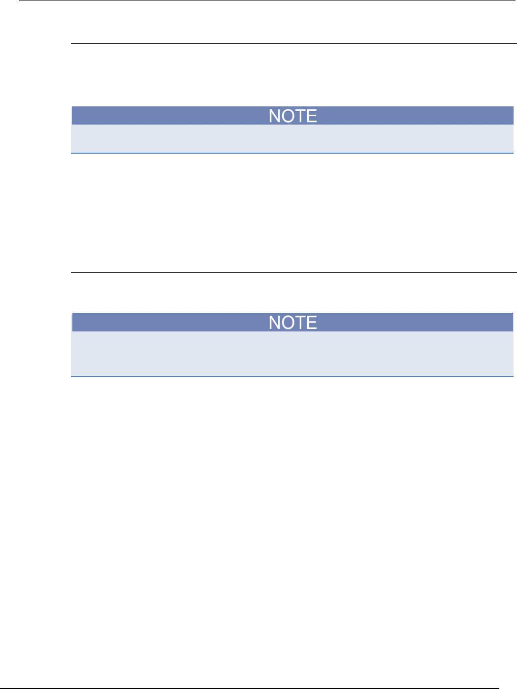
To use the Keithley Configuration Panel to determine the VISA resource string:
1. Click Start > All Programs > Keithley Instruments > Keithley Configuration Panel. The
Select Operation dialog box is displayed.
Figure 13: Select Operation dialog box
2. Select Add.
Mo
del 2450 Interactive SourceMeter® Instrument User's Manual Section 3:
Using a remote interface
2450-900-01 Rev. D/May 2015 3-9
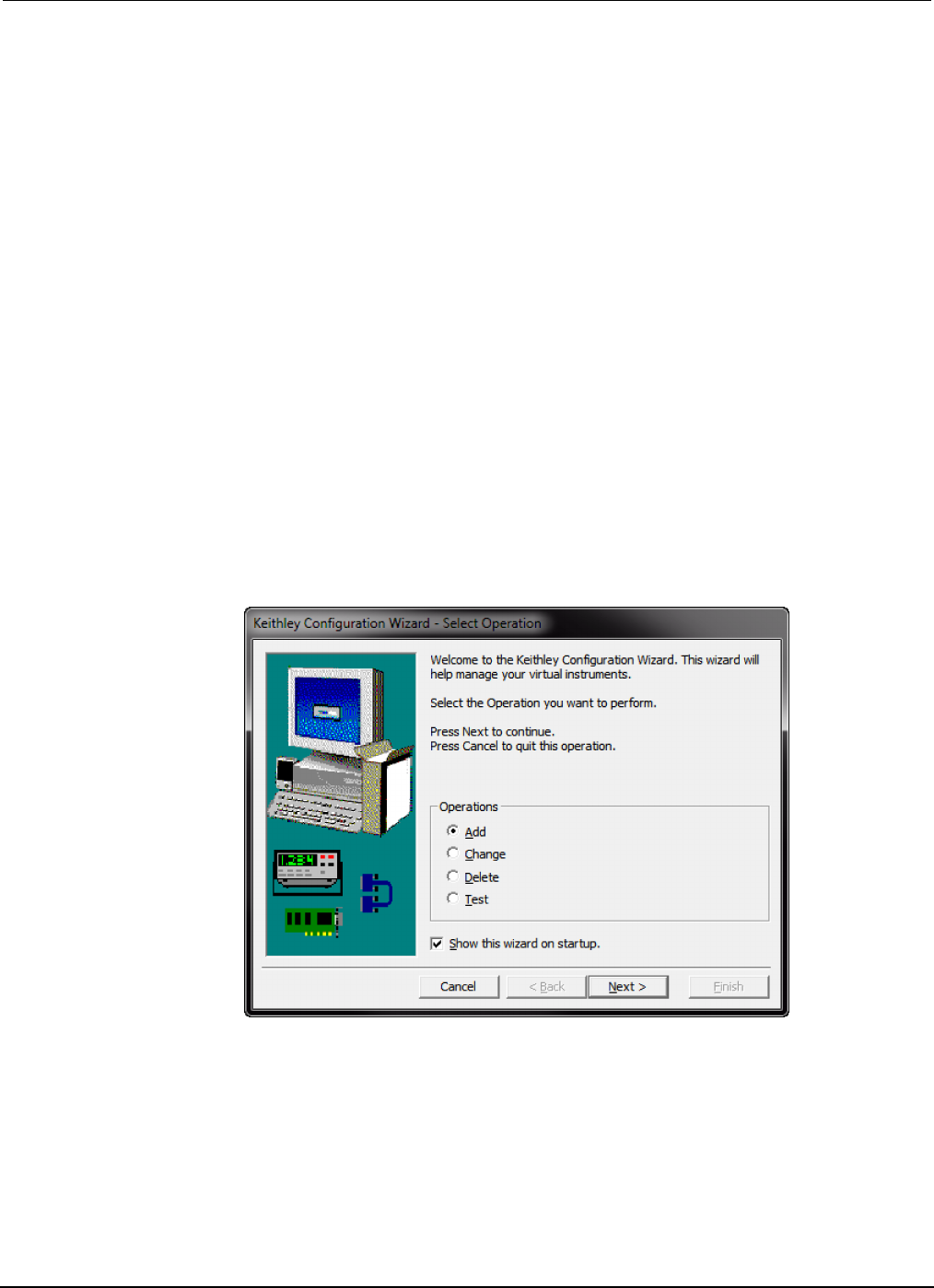
3. Click Next. The Select Communication Bus dialog box is displayed.
Figure 14: Select Communication Bus dialog box
4. Select USB.
5. Click Next. The Select Instrument Driver dialog box is displayed.
Figure 15: Select Instrument Driver dialog box
6. Select Auto-detect Instrument Driver - Model.
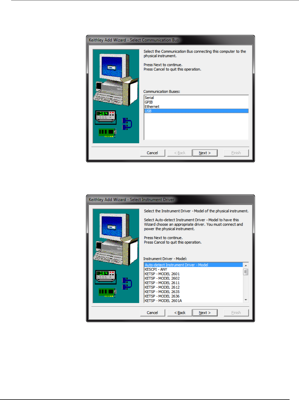
7. Click Next. The Configure USB Instrument dialog box is displayed with the detected instrument
VISA resource string visible.
8. Click Next. The Name Virtual Instrument dialog box is displayed.
Section
3: Using a remote interface Model 2450 Interactive SourceMeter® Instrument
User's Manual
3-10 2450-900-01 Rev. D/May 2015
Figure 16: Name Virtual Instrument dialog box
9. In the Virtual Instrument Name box, enter a name that you want to use to refer to the instrument.
10. Click Finish.
11. Click Cancel to close the Wizard.
12. Save the configuration. From the Keithley Configuration Panel, select File > Save.
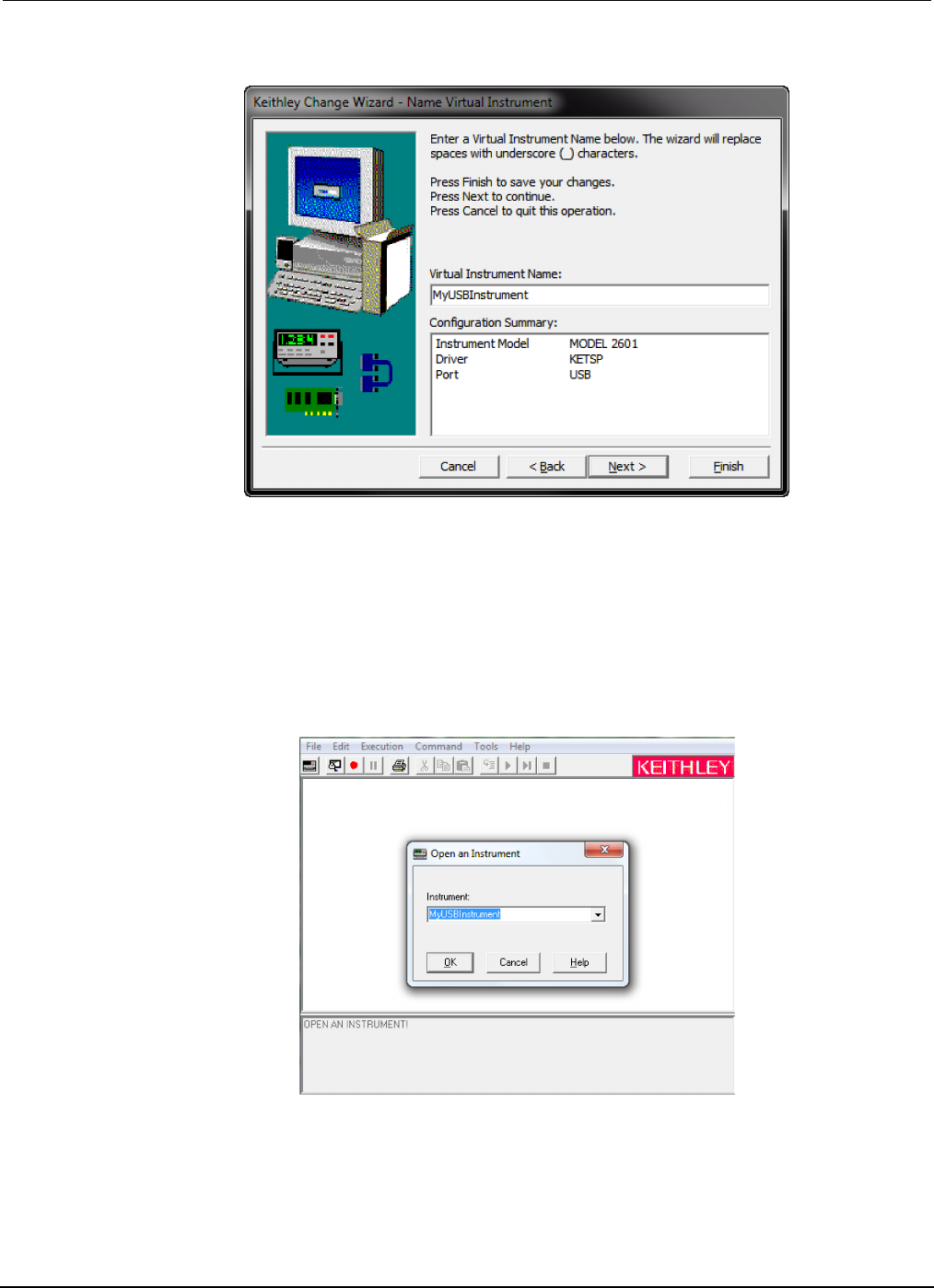
Verify the instrument through the Keithley Communicator:
1. Click Start > All Programs > Keithley Instruments > Keithley Communicator.
2. Select File > Open Instrument to open the instrument you just named.
Figure 17: Keithley Communicator Open an Instrument
3. Click OK.
4. Send a command to the instrument and see if it responds.

Model 2450
Interactive SourceMeter® Instrument User's Manual Section 3:
Using a remote interface
2450-900-01 Rev. D/May 2015 3-11
If you have a full version of NI-VISA on your system, you can run NI-MAX or the VISA Interactive
Control utility. See the National Instruments documentation for information.
If you have the Agilent IO Libraries on your system, you can run Agilent Connection Expert to check
your USB instruments. See the Agilent documentation for information.
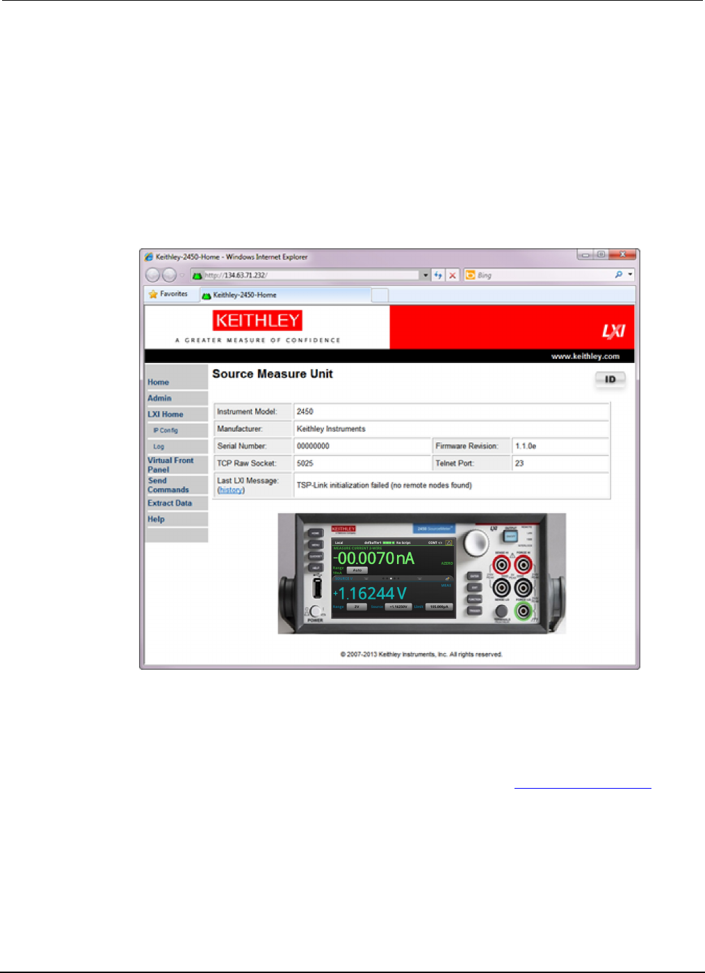
Using the web interface
The Model 2450 web interface allows you to make settings and control your instrument through a web
page. The web page includes:
• Instrument status.
• The instrument model, serial number, firmware revision, and the last LXI message.
• An ID button to help you locate the instrument.
• A virtual front panel and command interface that you can use to control the instrument.
• Download access to a .csv file that contains reading buffer data.
• Administrative options and LXI information.
The instrument web page resides in the firmware of the instrument. Changes you make through the
web interface are immediately made in the instrument.
Connect to the instrument web interface
When the LAN and instrument establish a connection, you can open a web page for the instrument.
To access the web interface:
1. Open a web browser on the host computer.
2. Enter the IP address of the instrument in the address box of the web browser. For example, if the
instrument IP address is 192.168.1.101, enter 192.168.1.101 in the browser address box.
3. Press Enter on the computer keyboard to open the instrument web page.
4. If prompted, enter a user name and password. The default is admin for both.
LAN troubleshooting suggestions
If you are unable to connect to the web interface of the instrument, check the following items:
• The network cable is in the LAN port on the rear panel of the instrument, not one of the
TSP-Link® ports.
• The network cable is in the correct port on the computer. The LAN port of a laptop may be
disabled when the laptop is in a docking station.
• The setup procedure used the configuration information for the correct ethernet card.
• The network card of the computer is enabled.
• The IP address of the instrument is compatible with the IP address on the computer.
• The subnet mask address of the instrument is the same as the subnet mask address of the
computer.
Section
3: Using a remote interface Model 2450 Interactive SourceMeter® Instrument
User's Manual
3-12 2450-900-01 Rev. D/May 2015
You can also try restarting the computer and the instrument. To restart the instrument:
1. Turn the instrument's power off, and then on.
2. Wait at least 60 seconds for the network configuration to be completed.
3. Press the MENU key.
4. Under System, select Communication.
5. Select the LAN tab.
6. Verify the settings.
If the above actions do not correct the problem, contact your system administrator.
Figure 18: Model 2450 web interface Home page
The Home page of the instrument provides information about the instrument. It includes:
• The instrument model number, manufacturer, serial number, and firmware revision number.
• The TCP Raw Socket number and Telnet Port number.
• The last LXI message. The history link opens the LXI Home page.
• The ID button, which allows you to identify the instrument. Refer to Identify the instrument (on
page 3-13).

Model 2450
Interactive SourceMeter® Instrument User's Manual Section 3: Using a remote i
nterface
2450-900-01 Rev. D/May 2015 3-13
Identify the instrument
If you have a bank of instruments, you can click the ID button to determine which one you are
communicating with.
To identify the instrument:
In the middle of the left side of the Home page, click the ID button.
The button turns green and the LAN status indicator on the instrument blinks.
Click the ID button again to return the button to its original color and return the LAN status indicator to
steady on.
Review events in the event log
The event log records all LXI events that the instrument generates and receives. The log includes the
following information:
• The EventID column, which shows the event identifier that generated the event.
• The System Timestamp column, which displays the seconds and nanoseconds when the event
occurred.
• The Data column, which displays the text of the event message.
To clear the event log and update the information on the screen, click the Refresh button.
Determining the command set you will use
You can control the Model 2450 with command sets that are based on the SCPI or Test Script
Processor (TSP®) programming languages. You can change the command set that you use with the
Model 2450. The remote command sets that are available include:
• SCPI: An instrument-specific language built on the SCPI standard.
• TSP: A scripting programming language that contains instrument-specific control commands that
can be executed from a stand-alone instrument. You can use TSP to send individual commands
or use it to combine commands into scripts.
• SCPI 2400: An instrument-specific language that allows you to run code developed for earlier
Series 2400 instruments.
You cannot combine the command sets.
As delivered from Keithley Instruments, the Model 2450 is set to work with the Model 2450 SCPI
command set.
If you choose the SCPI 2400 command set, you will not have access to some of the extended
ranges and other features that are now available using the SCPI command set. In addition, some
Series 2400 code will work differently in the Model 2450 than it did in the earlier instrument. See
"Model 2450 in a Model 2400 application" in the Model 2450 Reference Manual for information about
the differences.

Section
3: Using a remote interface Model 2450 Interactive SourceMeter® Instrument
User's Manual
3-14 2450-900-01 Rev. D/May 2015
Using the front panel:
1. Press the MENU key.
2. Under System, select Settings.
3. Select the button next to Command Set and select the command set.
4. You are prompted to reboot.
To change to the SCPI command set from a remote interface:
Send the command:
*LANG SCPI
Reboot the instrument.
To change to the TSP command set from a remote interface:
Send the command:
*LANG TSP
Reboot the instrument.
To change to the SCPI 2400 command set from a remote interface:
Send the command:
*LANG SCPI2400
Reboot the instrument.
To verify which command set is selected:
Send the command:
*LANG?

In this section:
Introduction .............................................................................. 4-1
Equipment required for this application .................................... 4-2
Device connections .................................................................. 4-2
Make front-panel measurements .............................................. 4-2
Introduction
You can use the Model 2450 to source voltage or current and make measurements from the front
panel.
Make sure you select functions before you make changes to other instrument settings. The options
that you have for settings depend on the functions that are active when you make the changes. If
you make a change that is not compatible with the active functions, you may get unexpected results
or you may receive an event message. Also note that when you select a different function, the
instrument clears the buffer. The applications in this manual illustrate the order in which you should
perform operations for best results.
In this application, you make measurements on a 10 kΩ resistor by sourcing voltage and measuring
current. You can make similar measurements on any two-terminal device under test (DUT) if
appropriate source values are used.
Some of the methods you can use to set up the Model 2450 to make measurements from the front
panel include:
• Use Quicksets. Press the QUICKSET key to open a menu of preconfigured setups, including
voltmeter, ammeter, ohmmeter, and power supply setups. It also allows you to choose test
functions and adjust performance for better resolution or speed.
• Select source and measure functions. Press the FUNCTION key to select from a list of source
and measure functions.
• Use menu options. Press the MENU key to open a menu of options.
After selecting your source and measure functions, select buttons on the Model 2450 Home screen
and Settings swipe screens to change the settings.
You will use a combination of these methods to set up the measurement for this application.
Section 4
Making basic front-panel measurements
Section
4: Making basic front-panel measurements Model 2450 Interactive SourceMeter® Instrument
User's Manual
4-2 2450-900-01 Rev. D/May 2015
Equipment required for this application
Equipment required for this application:
• Model 2450 Interactive SourceMeter® instrument
• Two insulated banana cables; you can use the set that is provided with the Model 2450, the
Keithley Instruments Model 8608 High-Performance Clip Lead Set
• One 10 kΩ resistor to test
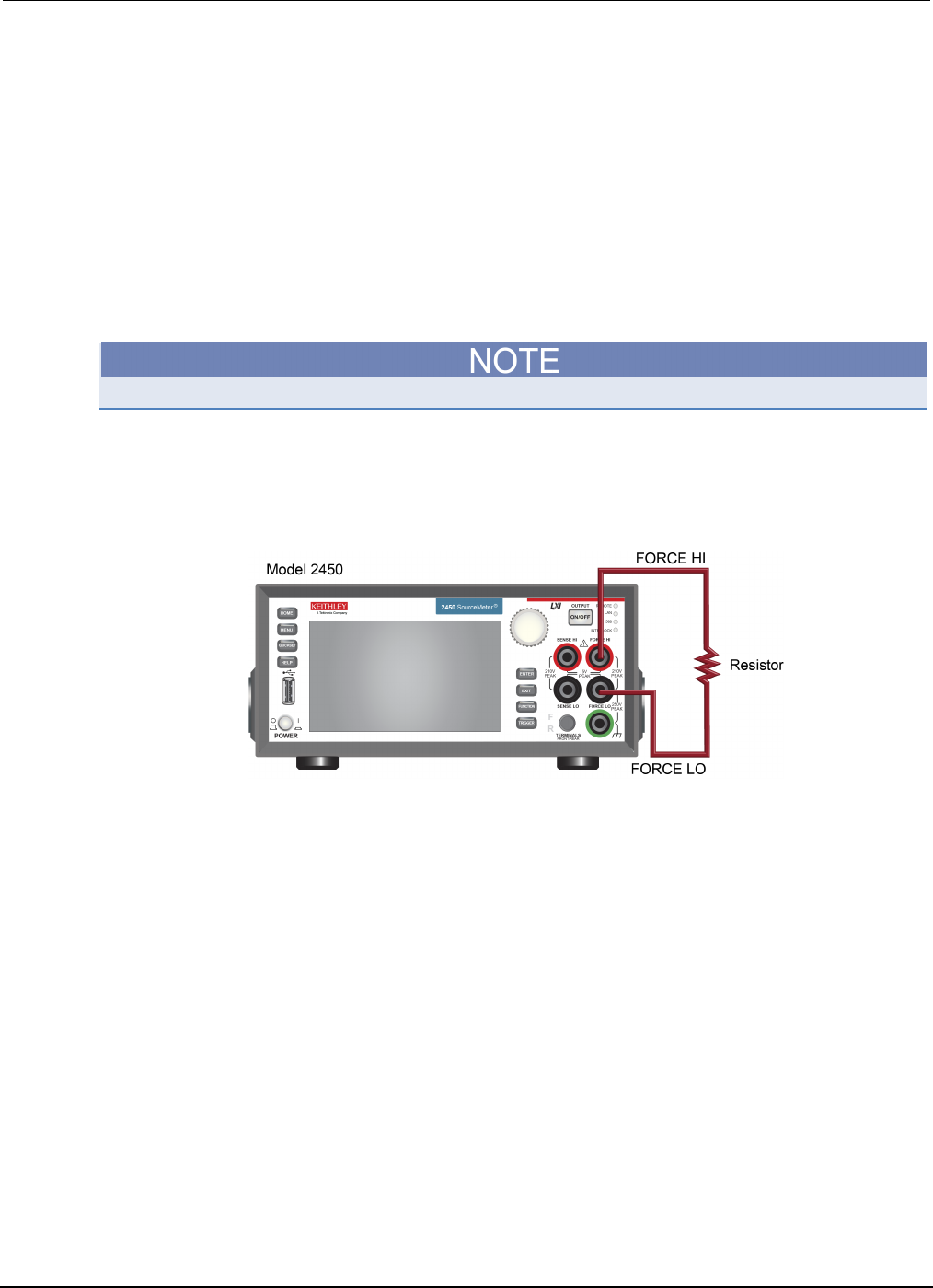
Device connections
Turn the power to the instrument off before attaching connections to the Model 2450.
Connect the Model 2450 to the resistor in a 2-wire (local sense) configuration. In this configuration,
the device is connected between the FORCE HI and FORCE LO terminals.
The physical connections to the front panel are shown in the following figure.
Figure 19: Model 2450 2-wire front-panel connections
Make front-panel measurements
For this application, you will:
• Select the source and measure functions
• Select the source range
• Set the source value
• Set the source limit
• Select the measurement range
• Turn on the source output
• Observe the readings on the display
• Turn off the source output

Model 2450
Interactive SourceMeter® Instrument User's Manual Section 4: Making basic front-
panel measurements
2450-900-01 Rev. D/May 2015 4-3
How to make front-panel measurements
To make a measurement from the front panel:
1. Press the POWER switch on the front panel to turn on the instrument or cycle power if the
instrument is already on.
2. Verify the source and measure function. On the front panel, press the FUNCTION key.
3. Under Source Voltage and Measure, select Current.
4. Select the source range. On the Home screen, under SOURCE V, select the button next to
Range.
5. Select 20 V.
6. Select the source voltage. Under SOURCE V, select the button next to Source.
7. Enter 10 V and select OK.
8. Set the limits for the source. Under SOURCE V, select the button next to Limit.
9. Enter 10 mA and select OK.
10. Select the measurement range. In the MEASURE area of the Home screen, select the button
next to Range.
11. Select Auto.
12. Turn on the output by pressing the OUTPUT ON/OFF switch. The OUTPUT indicator light turns
on.
13. Observe the readings on the display. For the 10 kΩ resistor, typical display values are:
1.00000 mA
+9.99700 V
14. When measurements are complete, turn the output off by pressing the OUTPUT ON/OFF switch.
The OUTPUT indicator light turns off.

In this section:
Introduction ............................................................................... 5-1
Equipment required .................................................................. 5-1
Set up remote communications ................................................ 5-1
Device connections .................................................................. 5-2
Low-resistance measurements ................................................. 5-5
Introduction
This application example demonstrates how to use the Model 2450 to measure a low-resistance
device.
You may need to make low-resistance measurements (<10 Ω) in a number of applications. Typical
applications include continuity testing of cables and connectors, substrate vias, and resistors.
Typically, you make these resistance measurements by forcing a current and measuring the resulting
voltage drop. The Model 2450 automatically calculates the resistance. The measured voltage is
usually in the mV range or less. Built-in features of the Model 2450 optimize low-resistance
measurements, such as remote sensing and offset compensation.
Equipment required
• One Model 2450 Interactive SourceMeter® instrument
• For front-panel connections, use four insulated banana cables such as the Keithley Instruments
Model 8608 High-Performance Clip Lead Set (one set included with the Model 2450; you will
need another set)
• For rear-panel connections, use four triaxial cables
• One low-resistance device to be tested; the application shown here uses a 20 mΩ resistor
Set up remote communications
You can run this application from the front panel or any of the supported communication interfaces for
the instrument (GPIB, USB, or ethernet).
The following figure shows the rear-panel connection locations for the remote communication
interfaces. For additional information about setting up remote communications, see Remote
communications interfaces.
Section 5
Measuring low-resistance devices
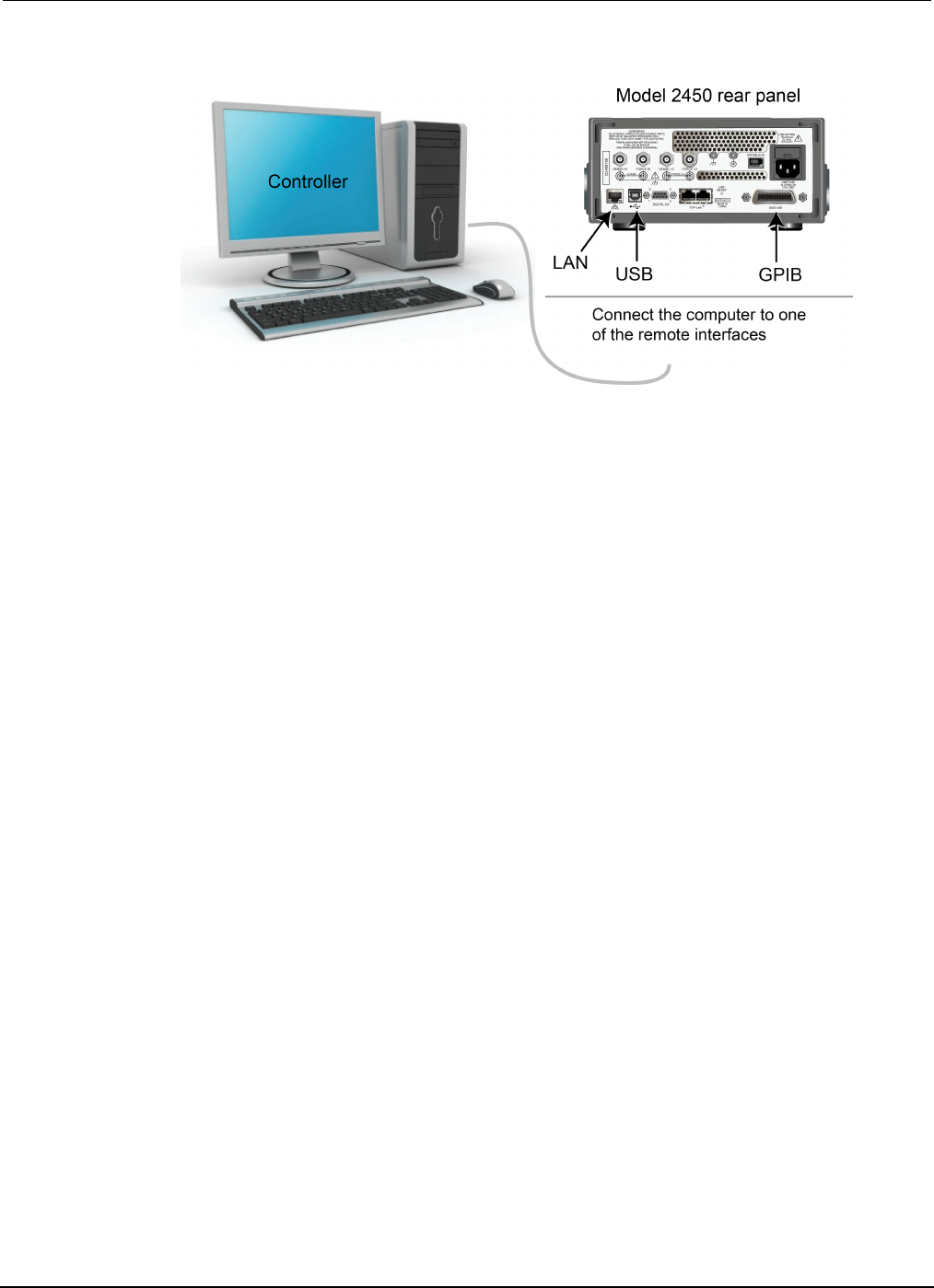
Section
5: Measuring low-resistance devices Model 2450 Interactive SourceMeter® Instrument
User's Manual
5-2 2450-900-01 Rev. D/May 2015
Figure 20: Model 2450 remote interface connections
Device connections
To provide the best measurement accuracy, use the four-wire (Kelvin) measurement method for this
test. This method eliminates the effects of lead resistance on the measurement accuracy. It is the
preferred method when measuring low resistances.
To use the 4-wire connection method:
• Connect one set of test leads to the FORCE LO and FORCE HI terminals; this setup forces a
current through the device under test.
• Connect the other set of test leads to the SENSE HI and SENSE LO terminals, which measure
the voltage drop across the device under test (DUT).
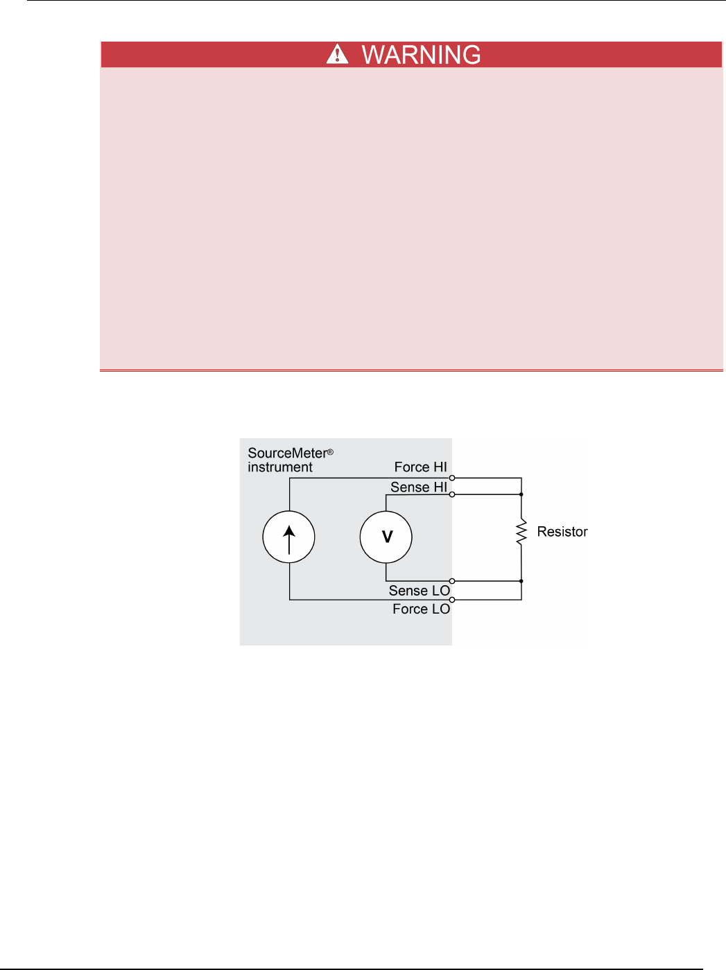
Model 2450
Interactive SourceMeter® Instrument User's Manual Section 5: Measuring low-
resistance devices
2450-900-01 Rev. D/May 2015 5-3
Hazardous voltages may be present on all output and guard terminals. To prevent electrical
shock that could cause injury or death, never make or break connections to the Model 2450
while the output is on.
To prevent electric shock, test connections must be configured such that the user cannot
come in contact with conductors or any device under test (DUT) that is in contact with the
conductors. It is good practice to disconnect DUTs from the instrument before powering the
instrument. Safe installation requires proper shields, barriers, and grounding to prevent
contact with conductors.
There is no internal connection between protective earth (safety ground) and the LO
terminals of the Model 2450. Therefore, hazardous voltages (more than 30 Vrms) can appear
on LO terminals. This can occur when the instrument is operating in any mode. To prevent
hazardous voltage from appearing on the LO terminals, connect the LO terminal to
protective earth if your application allows it. You can connect the LO terminal to the chassis
ground terminal on the front panel or the chassis ground screw terminal on the rear panel.
Note that the front-panel terminals are isolated from the rear-panel terminals. Therefore, if
you are using the front-panel terminals, ground to the front-panel LO terminal. If using the
rear-panel terminals, ground to the rear panel LO terminal.
The following figure shows the schematic for the application.
Figure 21: Sourcing current and measuring resistance using a 4-wire configuration
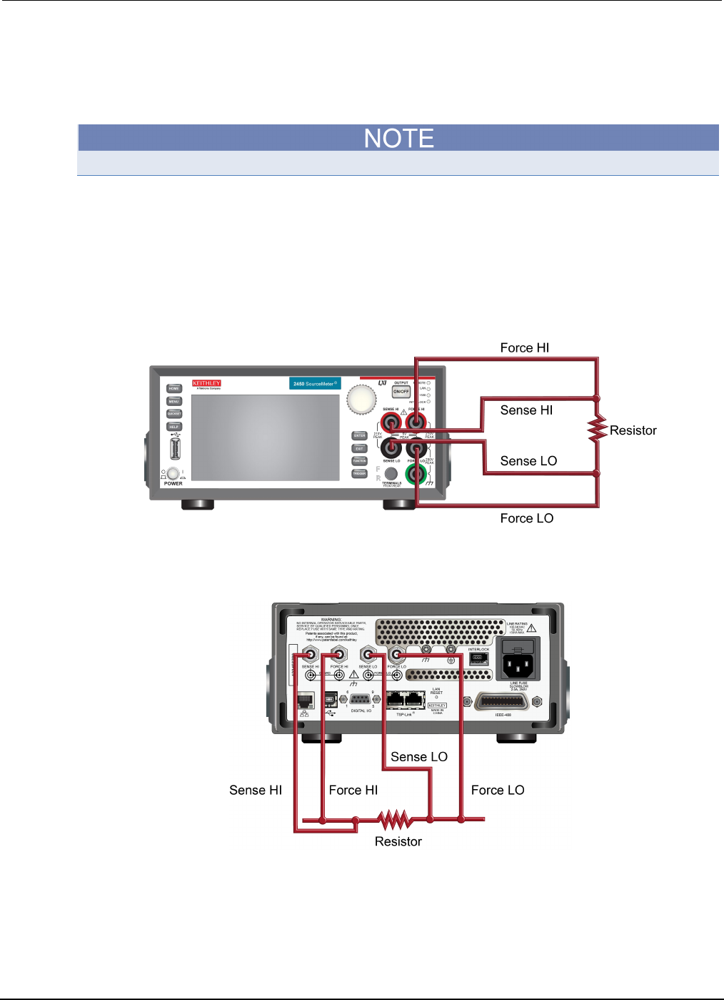
Section
5: Measuring low-resistance devices Model 2450 Interactive SourceMeter® Instrument
User's Manual
5-4 2450-900-01 Rev. D/May 2015
You can use either the front-panel or the rear-panel terminals for this application. The following
figures show the physical connections for the front and rear panels. Note that you must use either the
front-panel terminals or rear-panel terminals — you cannot mix connections.
The rear-panel connections are triaxial. The front-panel connections are safety banana jacks.
Turn the power to the instrument off before attaching connections to the Model 2450.
When you connect the leads to the device under test (DUT), notice that the FORCE LO and SENSE
LO connections are attached to one of the DUT leads. Make the FORCE HI and SENSE HI
connections to the other lead. Connect the sense connections as close to the resistor under test as
possible. This 4-wire measurement eliminates the resistance of the test leads in the measurement.
The figure below shows the front-panel connections. You can make these connections with four
insulated banana cables such as two sets of the Keithley Instruments Model 8608 High-Performance
Clip Lead Set.
Figure 22: Model 2450 front-panel connections for low-resistance measurements
The figure below shows the rear-panel connections. You can make these connections with four
triaxial cables.
Figure 23: Rear-panel connections for low-resistance measurements

Model 2450
Interactive SourceMeter® Instrument User's Manual Section 5: Measuring low-
resistance devices
2450-900-01 Rev. D/May 2015 5-5
Low-resistance measurements
This application demonstrates how to use the Model 2450 to measure a low-resistance device. You
can measure from the front panel or over the remote interface using SCPI code or TSP code.
For this application, you will:
• Reset the instrument.
• Select the source current and measure resistance function.
• Set the current source value.
• Select four-wire (remote sense) mode. This eliminates the effect of lead resistance on
measurement accuracy.
• Enable offset compensation. This reduces offset caused by thermoelectric voltages. For
information about offset compensation, see "What is offset compensation?" in the Model 2450
Reference Manual.
• Turn on the source output and start making measurements.
• Generate readings from the front panel or the remote interface.
• Turn the source output off.
Set up the measurement from the front panel
To set up the application from the front panel:
1. Make connections from the Model 2450 to the device under test, as described in Device
connections (on page 5-2, on page 6-2, on page 9-2).
2. Reset the instrument:
a. Press the MENU key.
b. Under System, select Info/Manage.
c. Select System Reset.
d. Select OK.
3. Press the FUNCTION key.
4. Under Source Current and Measure, select Resistance.
5. Press the HOME key.
6. In the SOURCE I area, select the button next to Source. Select the source value.
7. Press the MENU key. Under Measure, select Settings.
8. Next to Sense, select 4-Wire Sense.
9. Next to Offset Compensation, select On.
10. Press the HOME key.
11. Press the OUTPUT ON/OFF switch to enable the output and start making measurements.
12. Press the OUTPUT ON/OFF switch to disable the output and stop making measurements.
The instrument displays the measurements in the MEASURE VOLTAGE area of the Home screen.
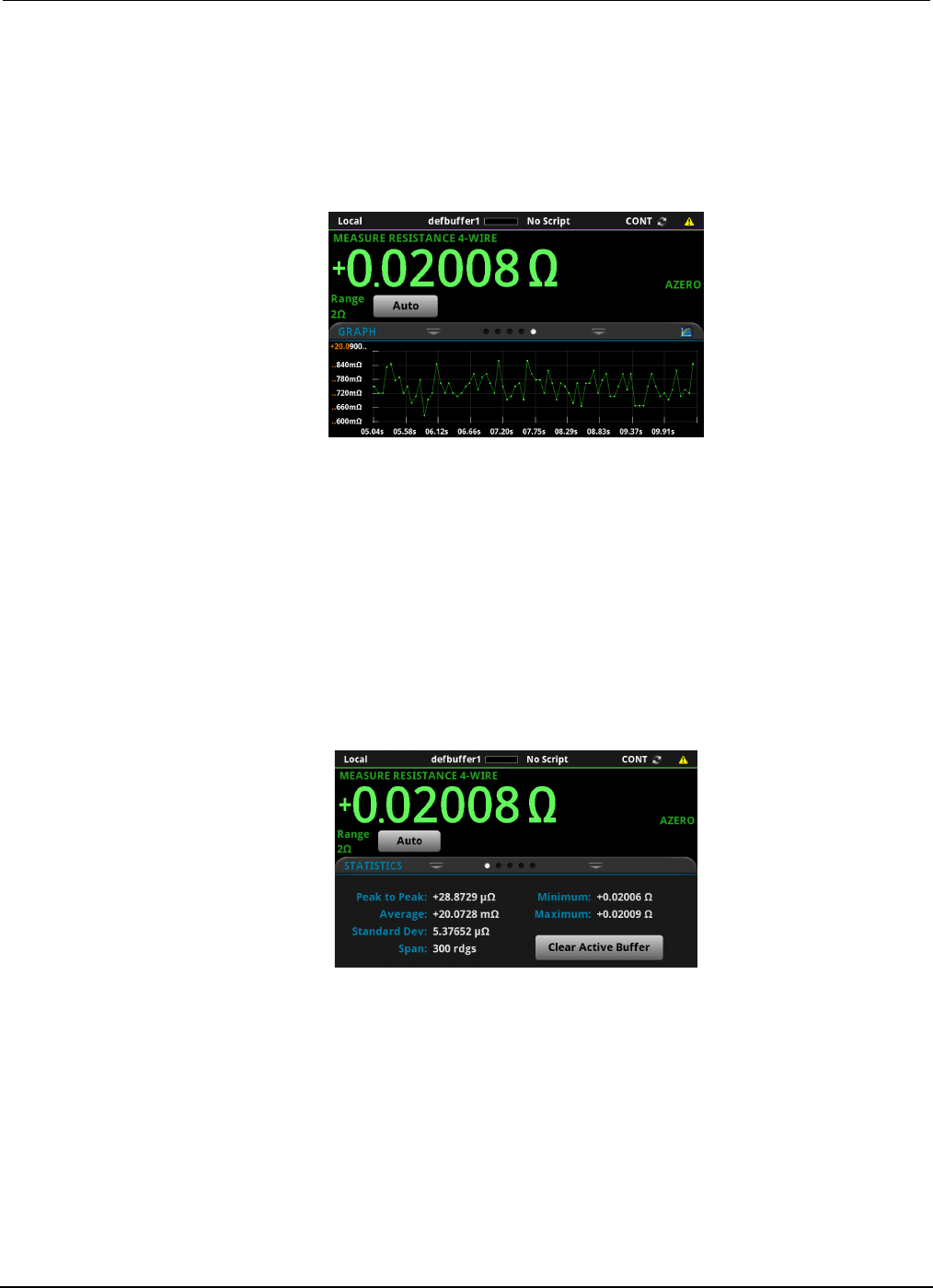
Section
5: Measuring low-resistance devices Model 2450 Interactive SourceMeter® Instrument
User's Manual
5-6 2450-900-01 Rev. D/May 2015
View the measurements on the front-panel GRAPH swipe screen
You can view the resistance measurements as a function of time on the front-panel GRAPH swipe
screen. To access the GRAPH swipe screen, swipe the bottom part of the Home screen to the right.
A graph similar to the one in the figure below is displayed.
Figure 24: GRAPH swipe screen
To see the graph on the full screen, touch the graph icon on the GRAPH swipe bar to open the Graph
screen.
View the buffer statistics on the front panel
You can view the measurement statistics on the Model 2450 front-panel STATISTICS swipe screen,
including:
• Peak-to-peak value
• Minimum, maximum, and average reading values
• Standard deviation
Figure 25: STATISTICS swipe screen
Set up the low-resistance application using SCPI commands
The following sequence of SCPI commands makes 100 low-resistance measurements by sourcing
current and measuring resistance. In this example, the source current magnitude and limit voltage are
set automatically. It uses remote commands to change the front-panel display to show the GRAPH
swipe screen. This allows you to view numeric data at the top of the screen and graphic data at the
bottom of the screen.

Model 2450
Interactive SourceMeter® Instrument User's Manual Section 5: Measuring low-
resistance devices
2450-900-01 Rev. D/May 2015 5-7
You may need to make changes so that this code will run in your programming environment.
Send the following commands for this example application:
Command Description
*RST
TRIG:LOAD "SimpleLoop", 100
SENS:FUNC "RES"
SENS:RES:RANG:AUTO ON
SENS:RES:OCOM ON
SENS:RES:RSEN ON
DISP:SCR SWIPE_GRAPh
OUTP ON
INIT
*WAI
TRAC:DATA? 1, 100, "defbuffer1", READ, REL
OUTP OFF
•
Reset the Model 2450.
• Configure Simple Loop trigger model
template to make 100 readings.
• Set to measure resistance.
• Turn on auto range.
• Enable offset compensation.
• Set to use 4-wire sense mode.
• Show the GRAPH swipe screen.
• Turn on the output.
• Initiate readings.
• Wait until finished.
• Read the resistance and time values from
defbuffer1.
• Turn off the output.
Set up the low-resistance application using TSP commands
The following TSP code is designed to be run from Keithley Instruments Test Script Builder (TSB).
TSB is a software tool that is available from the Keithley Instruments website. You can install and
use TSB to write code and develop scripts for TSP-enabled instruments. Information about how to
use TSB is in the online help for TSB and in the “Introduction to TSP operation” section of the Model
2450 Reference Manual.
To use other programming environments, you may need to make changes to the example TSP code.
By default, the Model 2450 is configured to use the SCPI command set. You must select the TSP
command set before sending TSP commands to the instrument.
To enable TSP commands:
1. Press the MENU key.
2. Under System, select Settings.
3. For Command Set, select TSP.
4. At the prompt to reboot, select Yes.
This sequence of TSP commands makes 100 low-resistance measurements by sourcing current and
measuring resistance. In this example, the source current magnitude and limit voltage are set
automatically. It uses remote commands to change the front-panel display to show the GRAPH swipe
screen. This allows you to view numeric data at the top of the screen and graphic data at the bottom
of the screen. After the code executes, the data is displayed in the Instrument Console of Test Script
Builder.

Section
5: Measuring low-resistance devices Model 2450 Interactive SourceMeter® Instrument
User's Manual
5-8 2450-900-01 Rev. D/May 2015
Send the following commands for this example application:
--Reset the instrument to the default settings
reset()
--Configure the Simple Loop trigger model template to make 100 readings.
trigger.model.load("SimpleLoop", 100)
--Change the view on the front panel to the GRAPH swipe screen.
display.changescreen(display.SCREEN_GRAPH_SWIPE)
--Set to measure resistance, use 4-wire sense,
--and offset compensation.
smu.measure.func = smu.FUNC_RESISTANCE
smu.measure.sense = smu.SENSE_4WIRE
smu.measure.offsetcompensation = smu.ON
--Turn on the output
smu.source.output = smu.ON
--Initiate trigger model and wait until finished.
trigger.model.initiate()
waitcomplete()
--Turn off output
smu.source.output = smu.OFF
--Read the resistance and time values from defbuffer1.
print("Resistance:\tTime:")
for i = 1, 100 do
print(string.format("%f\t%f", defbuffer1[i], defbuffer1.relativetimestamps[i]))
end

In this section:
Introduction .............................................................................. 6-1
Equipment required .................................................................. 6-1
Set up remote communications ................................................ 6-2
Device connections .................................................................. 6-2
Measuring leakage current ....................................................... 6-4
Measuring insulation resistance ............................................... 6-8
Introduction
To measure the leakage current or insulation resistance of a device, you need to apply a fixed voltage
to the device and measure the resulting current. Depending on the device under test, the measured
current is typically very small, usually less than 10 nA.
This application consists of two examples that demonstrate:
• How to use the Model 2450 to perform leakage current measurements on a capacitor
• How to use the Model 2450 to measure insulation resistance between the two conductors of a
coaxial cable
The only difference between these two application examples is that when you measure leakage
current, the results are returned in units of amperes. When you measure insulation resistance, the
results are returned in units of ohms.
The leakage current application applies the voltage for a specified period because the device needs
time to charge. In some cases, the resulting current is measured the entire time the device is biased.
In other cases, only one reading is made at the end of the soak period.
The following topics describe how to do these applications from the front panel. They also show how
to do them using a remote interface with SCPI commands or Test Script Processor (TSP®)
commands.
Equipment required
• One Model 2450 Interactive SourceMeter® instrument
• Two triaxial cables
• One capacitor for the leakage current application
• One coaxial cable or other device for the insulation resistance application
• One ethernet, GPIB, or USB cable for the TSP and SCPI remote command examples
Section 6
Leakage current and insulation resistance
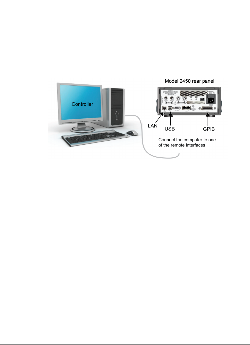
Section
6: Leakage current and insulation resistance Model 2450 Interactive SourceMeter® Instrument
User's Manual
6-2 2450-900-01 Rev. D/May 2015
Set up remote communications
You can run this application from the front panel or any of the supported communication interfaces for
the instrument (GPIB, USB, or ethernet).
The following figure shows the rear-panel connection locations for the remote communication
interfaces. For additional information about setting up remote communications, see Remote
communications interfaces.
Figure 26: Model 2450 remote interface connections
Device connections
Depending on the device under test (DUT), the current measurement is typically very small, usually
<10 nA. Measuring leakage current and insulation resistance involves measuring very small values.
To get more accurate readings, connect the DUT to the Model 2450 rear panel with low-noise triaxial
cables.
Connect the DUT between the FORCE HI and FORCE LO terminals of the Model 2450.
The following figure shows schematic diagrams. One shows measuring the leakage current of a
capacitor. The other shows measuring the insulator resistance between two conductors of a coaxial
cable.
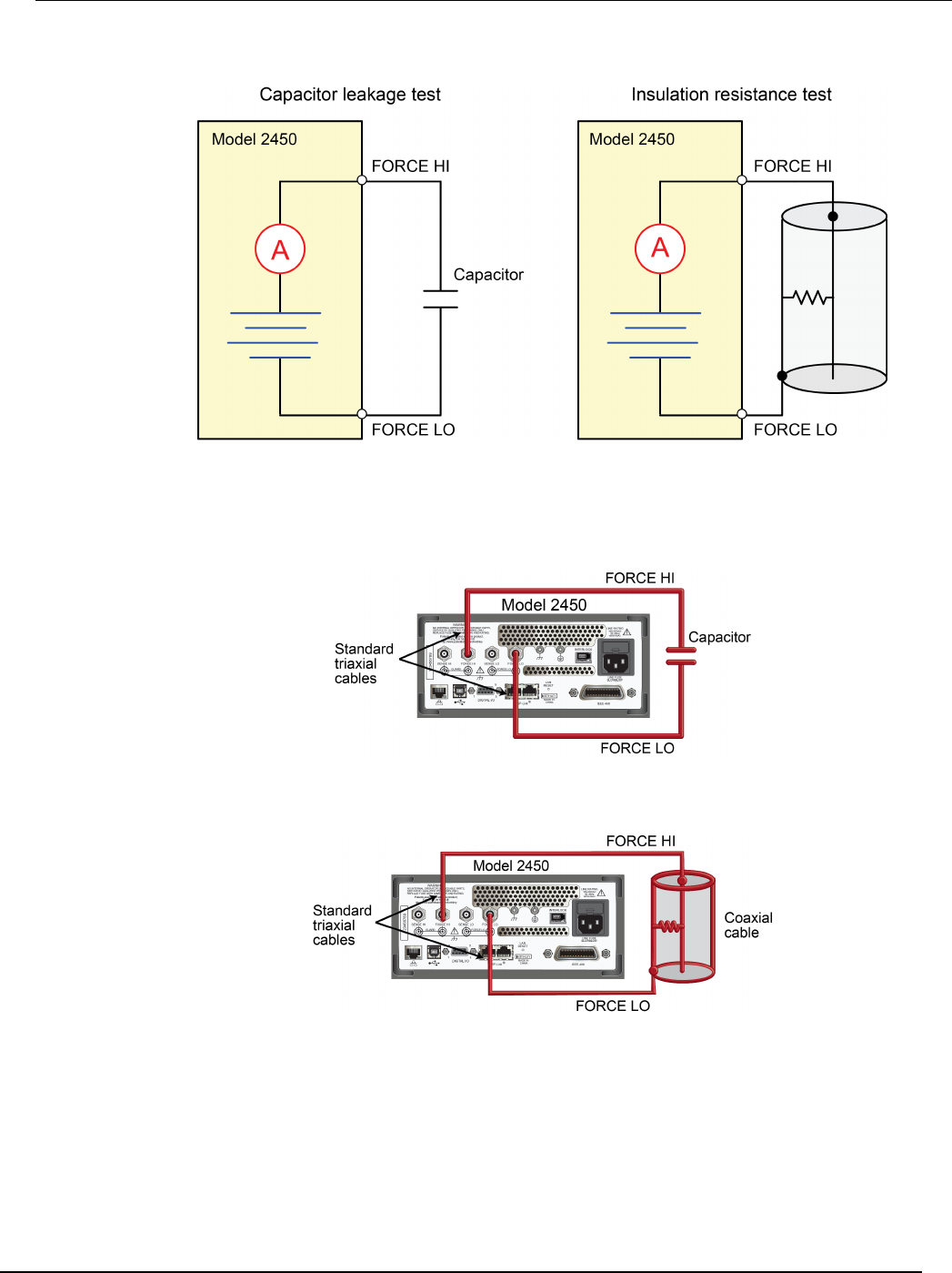
Model 2450
Interactive SourceMeter® Instrument User's Manual Section 6: Leakage current and insulation resista
nce
2450-900-01 Rev. D/May 2015 6-3
Figure 27: Connection schematics for the capacitor leakage and insulation resistance tests
The following figures show the rear-terminal connections to the device under test (DUT) for these
applications. If capacitor leakage measurements are noisy, you may need to use the high
capacitance mode or add a low leakage forward-biased diode in series with the capacitor.
Figure 28: Rear-panel connections for the leakage current test
Figure 29: Rear-panel connections insulation resistance test

Section
6: Leakage current and insulation resistance Model 2450 Interactive SourceMeter® Instrument
User's Manual
6-4 2450-900-01 Rev. D/May 2015
Measuring leakage current
The following application demonstrates how to use the Model 2450 to measure the leakage current of
a 1 nF capacitor by sourcing a voltage and measuring the resulting current using the front panel or
over the remote interface. The remote interface examples show SCPI commands and TSP
commands.
This application sets the Model 2450 to source 20 V and measure the resulting leakage current as a
function of time. The instrument takes current measurements for a specific period.
For this test, you will:
• Reset the instrument
• Set the instrument to read the rear terminals
• Select the source voltage function and measure current function
• Set the magnitude of the voltage source
• Turn on autoranging
• Set the measure delay
• Use the Duration Loop trigger model template to make readings for a specified time period
• Turn on the source output
• Take readings for a specified period of time
• Turn off the source output
When you use the Model 2450 to measure small current values, ensure that the device under test is
electrostatically shielded. If the capacitor rating is greater than 20 nF, enable the high capacitance
mode for best results.
For more information about making optimized capacitor leakage measurements and minimizing
noisy measurements, see the Keithley Instruments Low Level Measurements Handbook, available
on the Keithley Instruments website (http://www.keithley.com).
Set up the leakage current application using the front panel
To set up the application from the front panel:
1. Use the test leads to make the connection from the capacitor to the rear panel of the Model 2450,
as described in Device connections (on page 5-2, on page 6-2, on page 9-2).
2. Reset the Model 2450.
a. Press the MENU key.
b. Under System, select Info/Manage.
c. Select System Reset, and then select OK.
3. Press the TERMINAL FRONT/REAR switch to set the instrument to use the rear-panel terminals
(R is displayed to the left of the switch).
4. Press the HOME key.
5. Press the FUNCTION key.
6. Under Source Voltage and Measure, select Current.
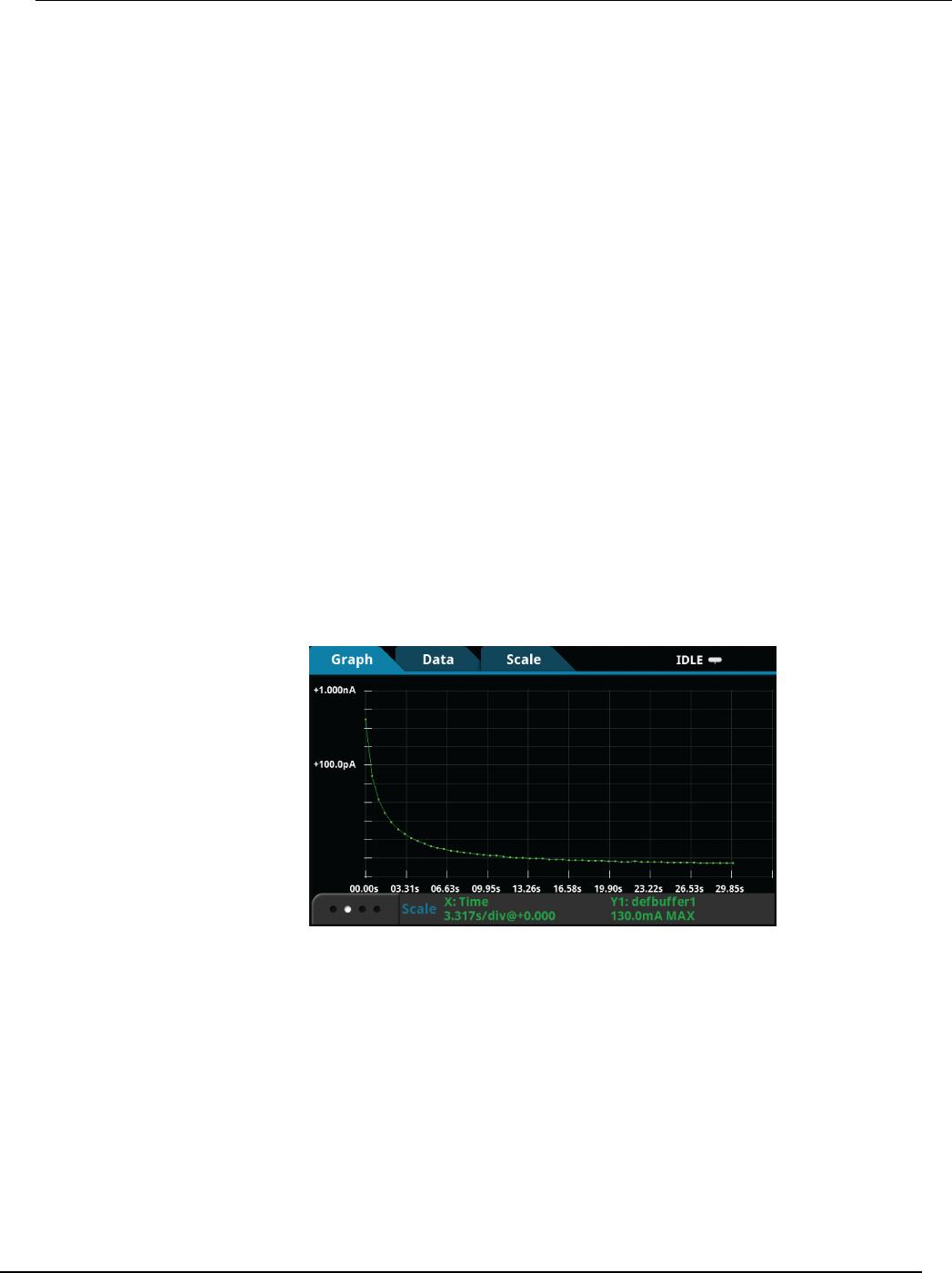
Model 2450
Interactive SourceMeter® Instrument User's Manual Section 6:
Leakage current and insulation resistance
2450-900-01 Rev. D/May 2015 6-5
7. Select the button next to Source (at the bottom of the screen).
8. Enter 20 V and select OK.
9. Press the MENU key.
10. Under Trigger, select Templates.
11. Next to Templates, select DurationLoop.
12. Next to Duration, enter a soak time of 30s and select OK.
13. Next to Delay, enter 0.2s, and select OK.
14. Press the HOME key to return to the Home screen.
15. Press the TRIGGER key to turn on the output and make measurements. The output is turned off
when the measurements are complete.
View the measurements on the front-panel graph
To view the leakage current measurements on the front-panel graph:
1. Press the MENU key.
2. Under Views, select Graph.
3. Select the Scale tab.
4. Under Y-Axis, next to Scale Format, select Log.
5. Under X-Axis, next to Method, select SmartScale.
6. Select the Graph tab to view the graph.
The following figure shows the front-panel graph for this application.
Figure 30: Viewing the leakage current measurement on the front-panel

Section
6: Leakage current and insulation resistance Model 2450 Interactive SourceMeter® Instrument
User's Manual
6-6 2450-900-01 Rev. D/May 2015
Set up the leakage current application using SCPI commands
The following SCPI code performs a capacitor leakage measurement by sourcing 20 V and
measuring the resulting leakage current. The Duration Loop trigger model template applies the
voltage for 60 seconds and makes measurements at 200 ms intervals. After the duration time, the
capacitor is discharged at 0 V and the output is turned off.
Send the following commands for this example application:
Command Description
*RST
:SOUR:FUNC VOLT
:SOUR:VOLT 20
:SOUR:VOLT:ILIMIT 0.01
:SENSE:FUNC "CURR"
:ROUT:TERM REAR
:CURR:RANG:AUTO ON
:SENSE:CURR:NPLC 1
:TRIG:LOAD "DurationLoop", 60, 0.2
:OUTP ON
:INIT
*WAI
:TRAC:ACT? "defbuffer1"
:TRAC:DATA? 1, <n>, "defbuffer1", READ, REL
:SOUR:VOLT 0
:OUTP OFF
• Reset the Model 2450.
• Set to source voltage.
• Set the source voltage to 20 V.
• Set the current limit to 10 mA.
• Set the instrument to measure current.
• Set to use rear-panel terminals.
• Set the current range to autorange.
• Set the number of power line cycles
to 1.
• Load the Duration Loop trigger model
to run for 60 s at 200 ms intervals.
• Turn on the output.
• Trigger the measurement.
• Wait for the measurement to finish.
• <n> is the queried number of readings.
• Query the number of readings in
defbuffer1 and return the readings
and time.
• Discharge the capacitor to 0 V.
•
Turn off the output.
Set up the leakage current application using TSP commands
The following TSP code is designed to be run from Keithley Instruments Test Script Builder (TSB).
TSB is a software tool that is available from the Keithley Instruments website. You can install and
use TSB to write code and develop scripts for TSP-enabled instruments. Information about how to
use TSB is in the online help for TSB and in the “Introduction to TSP operation” section of the Model
2450 Reference Manual.
To use other programming environments, you may need to make changes to the example TSP code.
By default, the Model 2450 is configured to use the SCPI command set. You must select the TSP
command set before sending TSP commands to the instrument.
To enable TSP commands:
1. Press the MENU key.
2. Under System, select Settings.
3. For Command Set, select TSP.
4. At the prompt to reboot, select Yes.

Model 2
450 Interactive SourceMeter® Instrument User's Manual Section 6:
Leakage current and insulation resistance
2450-900-01 Rev. D/May 2015 6-7
The following TSP code performs a capacitor leakage measurement by sourcing 20 V and measuring
the resulting leakage current. The Duration Loop trigger model template applies the voltage for 60
seconds and makes measurements at 200 ms intervals. After the duration time, the capacitor is
discharged at 0 V and the output is turned off.
After the code is executed, the measurement results are displayed in the Instrument Console of Test
Script Builder. From the Instrument Console, you can copy the data into a spreadsheet for graphing.
Send the following commands for this example application:
-- Reset the instrument, which also clears the buffer.
reset()
-- Set up the source function.
smu.source.func = smu.FUNC_DC_VOLTAGE
smu.source.ilimit.level = 10e-3
smu.source.level = 20
-- Set up measure function.
smu.measure.func = smu.FUNC_DC_CURRENT
smu.measure.terminals = smu.TERMINALS_REAR
smu.measure.autorange = smu.ON
smu.measure.nplc = 1
-- Turn on the output and initiate readings.
smu.source.output = smu.ON
trigger.model.load("DurationLoop", 60, 0.2)
trigger.model.initiate()
-- Wait for the trigger model to complete.
waitcomplete()
-- Parse index and data into three columns.
print("Rdg #", "Time (s)", "Current (A)")
for i = 1, defbuffer1.n do
print(i, defbuffer1.relativetimestamps[i], defbuffer1[i])
end
-- Discharge the capacitor to 0 V and turn off the output.
smu.source.level = 0
delay(2)
smu.source.output = smu.OFF
The graph in the following figure shows the results of this application. Notice the exponential current
response of the capacitor as it charges up to 20 V over time.
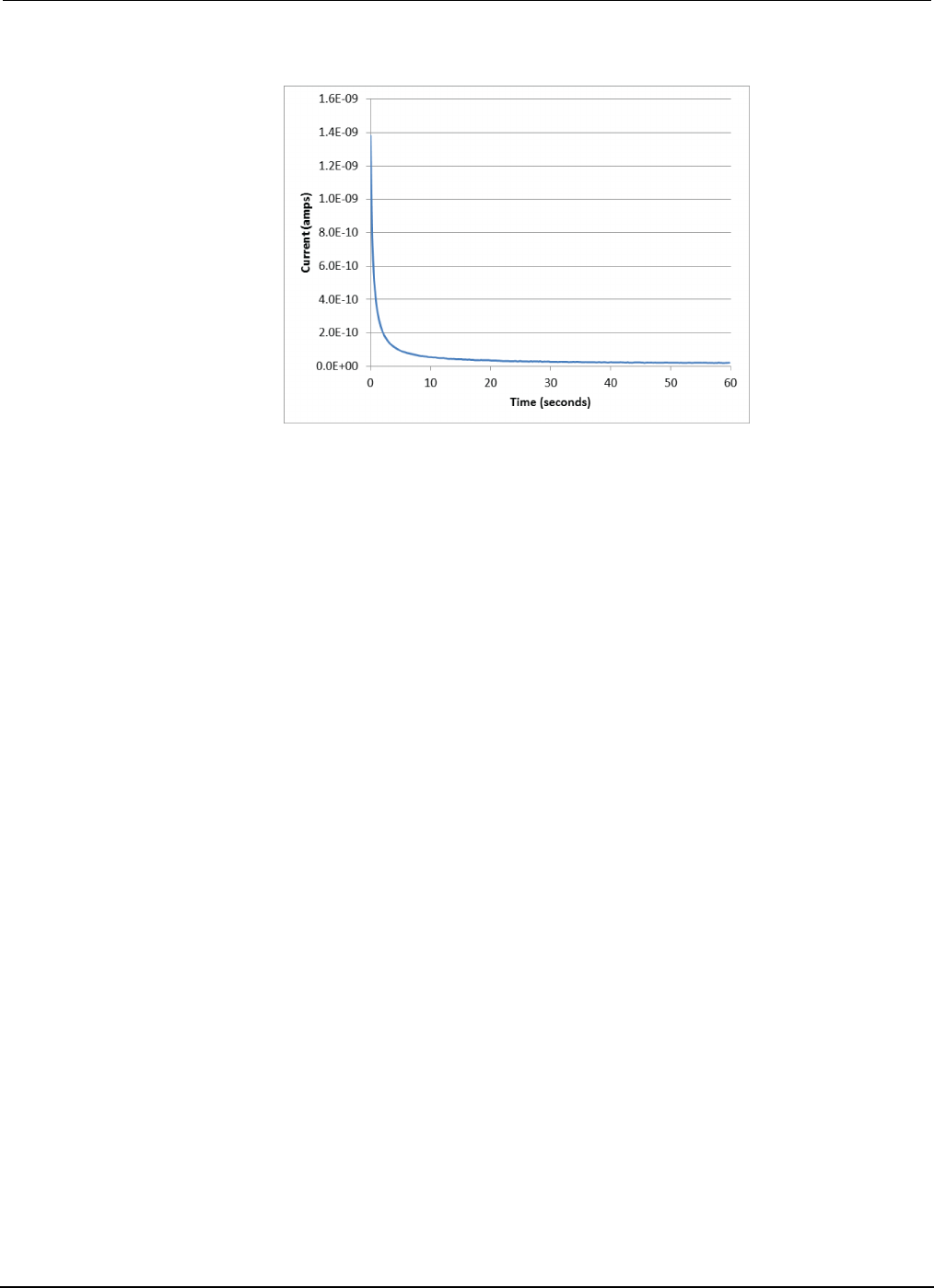
Section
6: Leakage current and insulation resistance Model 2450 Interactive SourceMeter® Instrument
User's Manual
6-8 2450-900-01 Rev. D/May 2015
Figure 31: Leakage current test results
Measuring insulation resistance
The following applications demonstrate how to use the Model 2450 to measure insulator resistance.
The applications shows how to use the front-panel interface, the remote interface using the SCPI
command set, and the remote interface using the Test Script Processor (TSP®) command set.
You make insulation resistance measurements between traces on a printed circuit board and
between conductors in cables and connectors.
This application sets the Model 2450 to source 20 V and makes 10 resistance readings with a 100 ms
interval time. Once the measurements are made, the output is turned off.
For this test, you will:
• Reset the instrument
• Set the instrument to read the rear terminals
• Select the source voltage function and measure resistance function
• Set the magnitude of the voltage source output
• Turn on autoranging
• Use the Simple Loop trigger model template to set the numbers of readings and interval time
• Turn on the source output
• Make readings
• Turn off the source output

Model 2450
Interactive SourceMeter® Instrument User's Manual Section 6:
Leakage current and insulation resistance
2450-900-01 Rev. D/May 2015 6-9
Set up the insulation resistance application using the front panel
To set up the application from the front panel:
1. Connect the device under test (DUT) to the rear panel of the Model 2450, as described in Device
connections (on page 5-2, on page 6-2, on page 9-2).
2. Reset the Model 2450.
a. Press the MENU key.
b. Under System, select Info/Manage.
c. Select System Reset, and then select OK.
3. Press the TERMINAL FRONT/REAR switch to set the instrument to use the rear-panel terminals
(R is displayed to the left of the switch).
4. Press the HOME key.
5. Press the FUNCTION key.
6. Under Source Voltage and Measure, select Resistance.
7. Select the button next to Source (at the bottom of the screen).
8. Enter 20 V (or other applicable test voltage) and select OK.
9. Press the MENU key.
10. Under Trigger, select Templates.
11. Next to Templates, select SimpleLoop.
12. Set Count to 10 and select OK.
13. Set Delay to 0.1 seconds and select OK.
14. Press the HOME key.
15. Press the OUTPUT ON/OFF switch to enable the output.
16. Press the TRIGGER key to begin taking readings. The resistance measurements appear in the
measure area (top half) of the Home screen.
17. Press the OUTPUT ON/OFF switch to turn off the output when you are done making
measurements.
Viewing the measurements on the front-panel graph
To view the insulation resistance measurements on the front-panel graph while the output is on:
1. Press the MENU key.
2. Under Views, select Graph.

Section
6: Leakage current and insulation resistance Model 2450 Interactive SourceMeter® Instrument
User's Manual
6-10 2450-900-01 Rev. D/May 2015
Set up the application using SCPI commands
The following SCPI commands make insulation resistance measurements by sourcing 20 V and
measuring the resistance. The Simple Loop trigger model template is used to make
10 measurements at 100 ms intervals.
Send the following commands for this example application:
Command Description
*RST
ROUT:TERM REAR
SOUR:FUNC VOLT
SOUR:VOLT 20
SOUR:VOLT:ILIM 0.01
SENS:FUNC "CURR"
SENS:CURR:RANG:AUTO ON
SENSE:CURR:UNIT OHM
TRIG:LOAD "SimpleLoop", 10, 0.1
OUTP ON
INIT
*WAI
:TRAC:DATA? 1, 10, "defbuffer1", READ, REL
:OUTP OFF
•
Reset the Model 2450.
• Select the rear-panel terminals for the
measurement.
• Set to source voltage.
• Output 20 V.
• Set a 10 mA source limit.
• Set the instrument to measure current.
• Set the current range to autorange.
• Set the instrument to measure resistance.
• Use the Simple Loop trigger model to make 10
measurements at 100 ms.
• Turn the output on.
• Initiate readings.
• Wait for the measurement to finish.
• Read the resistance and time values from
defbuffer1.
•
Turn the output off.
Set up the application using TSP commands
The following TSP code is designed to be run from Keithley Instruments Test Script Builder (TSB).
TSB is a software tool that is available from the Keithley Instruments website. You can install and
use TSB to write code and develop scripts for TSP-enabled instruments. Information about how to
use TSB is in the online help for TSB and in the “Introduction to TSP operation” section of the Model
2450 Reference Manual.
To use other programming environments, you may need to make changes to the example TSP code.
By default, the Model 2450 is configured to use the SCPI command set. You must select the TSP
command set before sending TSP commands to the instrument.
To enable TSP commands:
1. Press the MENU key.
2. Under System, select Settings.
3. For Command Set, select TSP.
4. At the prompt to reboot, select Yes.

Model 2450
Interactive SourceMeter® Instrument User's Manual Section 6:
Leakage current and insulation resistance
2450-900-01 Rev. D/May 2015 6-11
The following TSP commands make insulation resistance measurements by sourcing 20 V and
measuring the resistance. The Simple Loop trigger model template is used to make
10 measurements at 100 ms intervals. After the code is executed, the measurement results are
displayed in the Instrument Console of Test Script Builder.
Send the following commands for this example application:
--Reset the instrument
reset()
--Set up the measure function
smu.measure.func = smu.FUNC_DC_CURRENT
smu.measure.unit = smu.UNIT_OHM
smu.measure.terminals = smu.TERMINALS_REAR
smu.measure.autorange = smu.ON
smu.measure.nplc = 1
--Set up the source function.
smu.source.func = smu.FUNC_DC_VOLTAGE
smu.source.ilimit.level = 0.1
smu.source.level = 20
--Turn on the source output and take readings.
trigger.model.load("SimpleLoop", 10, 0.1)
smu.source.output = smu.ON
trigger.model.initiate()
--Wait for the measurements to complete.
waitcomplete()
--Parse index and the data into three columns.
for i = 1, defbuffer1.n do
print(i, "\t", defbuffer1[i], "\t", defbuffer1.relativetimestamps[i])
end
--Turn off the output.
smu.source.output = smu.OFF

In this section:
Introduction .............................................................................. 7-1
Equipment required .................................................................. 7-1
Set up remote communications ................................................ 7-2
Set up external hardware triggers ............................................ 7-2
Device connections .................................................................. 7-4
Remote control of FET testing using SCPI commands ............ 7-5
Remote control of FET testing using TSP commands .............. 7-9
Introduction
This example application demonstrates how to use two Model 2450 instruments to perform I-V
characterization of field effect transistors (FETs). The Model 2450 is a good choice for semiconductor
device testing because it can quickly and accurately source and measure both current and voltage.
Determining the I-V parameters of FETs helps you ensure that they function properly in their intended
applications, and that they meet specifications. There are many I-V tests that you can perform with
the Model 2450, including gate leakage, breakdown voltage, threshold voltage, transfer
characteristics, and drain current. The number of Model 2450 instruments required for testing
depends on the number of FET terminals that must be biased and measured.
This application shows you how to perform a drain family of curves (Vds-Id) on a three-terminal
MOSFET. The MOSFET is the most commonly used FET because it is the basis for digital integrated
circuits.
Equipment required
• Two Model 2450s
• Four triaxial cables (Keithley model number 7078-TRX-10)
• A metal-shielded test fixture or probe station with female triaxial connectors
• A triaxial tee connector (Keithley model number 237-TRX-T)
• The cabling for external hardware triggers depends on the command set you are using:
• For SCPI commands, use a DB-9 male-to-male 9-pin cable to connect the digital I/O ports on the back
of the Model 2450 instruments to each other.
• For TSP commands, you need a TSP-Link crossover cable (one Keithley Model CA-180-3A is included
with your Model 2450) to connect the TSP-Link ports on the rear panel of the Model 2450 instruments to
each other.
Section 7
Measuring I-V characteristics of FETs
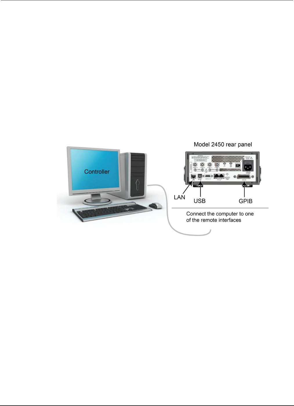
Section
7: Measuring I-V characteristics of FETs Model 2450 Interactive SourceMeter® Instrument
User's Manual
7-2 2450-900-01 Rev. D/May 2015
• Cabling from the computer to the Model 2450 instruments depends on the command set you are
using:
• For the SCPI command example, use two GPIB cables, two USB cables, or two ethernet cables
• For the TSP command example, use one GPIB cable, one USB cable, or one ethernet cable
Instructions for setting up the two Model 2450 instruments for this application are in the following
paragraphs.
Set up remote communications
This application is configured to run remotely. You can run this application from any of the supported
communication interfaces for the instrument (GPIB, USB, or ethernet).
The following figure shows the rear-panel connection locations for the remote communication
interfaces. For additional information about how to set up remote communications, see Remote
communications interfaces.
Figure 32: Model 2450 remote interface connections
Set up external hardware triggers
To enable synchronization between the two Model 2450 instruments for stepping and sweeping
voltages, connect the external triggers of each instrument to the other. The cabling you use depends
on Model 2450 programming command set you choose to control the test.
Connections for the SCPI command set
If you are using the SCPI command set, connect a DB-9 male-to-male cable between the digital I/O
connectors on the back of each of the instruments, as shown in the figure below.
For more detailed information about the digital I/O connector pins, see "Digital I/O" in the Model 2450
Reference Manual.
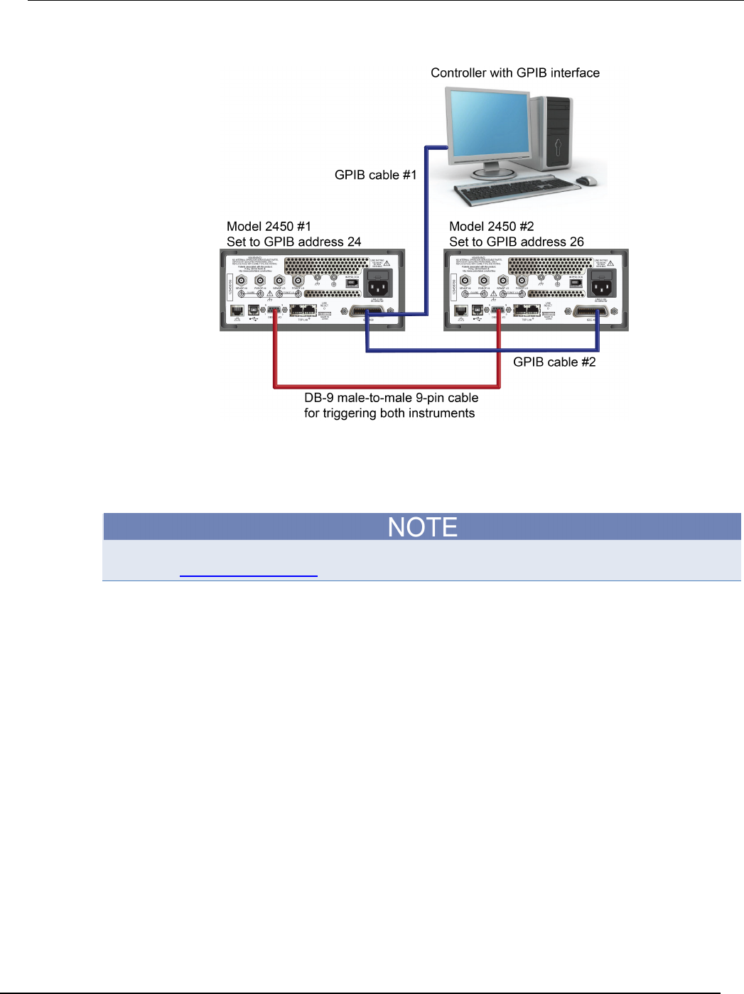
Model 2450
Interactive SourceMeter® Instrument User's Manual Section 7: Measuring I-
V characteristics of FETs
2450-900-01 Rev. D/May 2015 7-3
Figure 33: GPIB and DB-9 cable connections for the SCPI programming example
The figure above also shows the communication cable connections if you are using the GPIB remote
communication interface. GPIB cable #1 connects the GPIB port on the computer (controller) to the
IEEE-488 connector on the rear panel of Model 2450 #1. GPIB cable #2 connects the IEEE-488
connectors of the two Model 2450s.
Each Model 2450 must have a different GPIB address. You can set this up using the front panel. For
details, see Set the GPIB address (on page 3-3).
If you are using USB cables to connect the computer and Model 2450 instruments, each instrument
must be connected to the computer with a separate USB cable.
If you are using ethernet connections to connect the computer and Model 2450 instruments, the
instruments and computer must be connected using an ethernet switch or hub.
Connections for the TSP command set
If you use the Test Script Processor (TSP®) command set for remote programming, use a Model
CA-180-3A crossover cable (one is included with the Model 2450) to connect the TSP-Link ports on
the rear panels of the Model 2450 instruments to each other (see figure below). For more information
about using TSP-Link, see "TSP-Link System Expansion Interface" in the Model 2450 Reference
Manual.
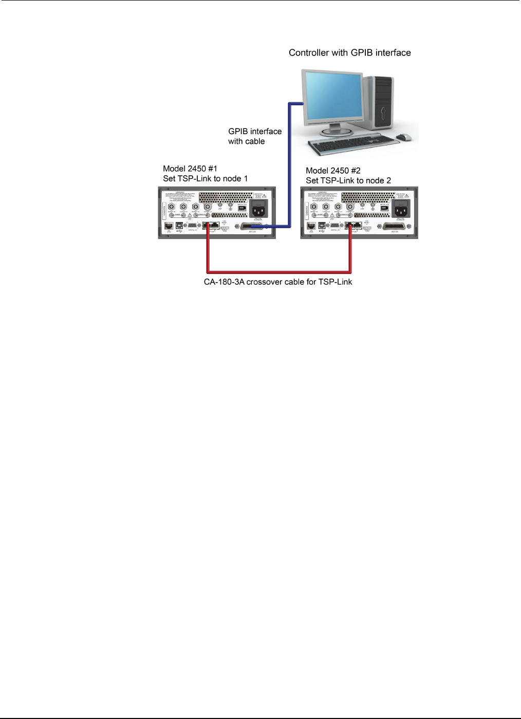
Section
7: Measuring I-V characteristics of FETs Model 2450 Interactive SourceMeter® Instrument
User's Manual
7-4 2450-900-01 Rev. D/May 2015
Figure 34: Connections for the TSP command set
For GPIB communication from the computer to the Model 2450 instruments, you only need one cable
from the GPIB interface to one of the Model 2450 IEEE-488 interfaces (Model 2450 #1 in the figure
above).
Set the TSP-Link node of Model 2450 #1 to node 1 and the TSP-Link node of Model 2450 #2 to
node 2.
To set the Model 2450 TSP-Link nodes from the front panel:
1. Press the MENU key.
2. Under System, select Communication. The SYSTEM COMMUNICATION window opens.
3. On the TSP-Link tab, next to Node, enter the node number of this instrument.
4. Select OK.
5. Select Initialize.
6. Press the HOME key to return to the Home screen.
Repeat these steps for all Model 2450 instruments in your TSP-Link network.
Device connections
To perform a drain family of curves, configure both Model 2450 instruments to source voltage and
measure current.
In this circuit, you connect the Force HI terminal of Model 2450 #2 to the gate of the MOSFET, and
connect the Force HI terminal of Model 2450 #1 to the drain.
You connect the source terminal of the MOSFET to the Force LO terminals of both Model 2450
instruments. You need a third Model 2450 if you want to source and measure from all three terminals.
The following figure shows an I-V test configuration for a MOSFET using two Model 2450
instruments.
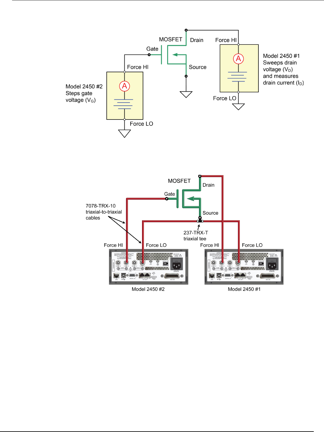
Model 2450
Interactive SourceMeter® Instrument User's Manual Section 7: Measuring I-
V characteristics of FETs
2450-900-01 Rev. D/May 2015 7-5
Figure 35: Three-terminal I-V test configuration for a MOSFET
The following figure shows the connections from the rear-panel terminals of both Model 2450
instruments to the MOSFET.
Figure 36: Two Model 2450s configured to test a three-terminal MOSFET
For this application, connect four triaxial cables (Model 7078-TRX-10) from the Model 2450
rear-panel female triaxial connectors to the MOSFET device. Mount the MOSFET device in a metal-
shielded test fixture with female triaxial connectors. Connect the Force LO terminals of both Model
2450 instruments to the Source terminal of the MOSFET using a triaxial tee connector (Model 237-
TRX-T).
Remote control of FET testing using SCPI commands
The two example sequences of SCPI commands for this application generate a drain family of curves
on a MOSFET using two Model 2450 instruments. One of the examples uses the trigger model to
generate the family of curves. The other example uses a linear sweep. You may need to make
modifications for operation in your programming environment.

Section
7: Measuring I-V characteristics of FETs Model 2450 Interactive SourceMeter® Instrument
User's Manual
7-6 2450-900-01 Rev. D/May 2015
Set up the application using SCPI commands with the trigger model
In this application, the gate voltage steps from 2 V to 5 V in 1 V steps, the drain voltage sweeps from
0 V to 5 V in 51 steps, and the drain current is measured. The current and voltage measurements are
stored in defbuffer1. The Model 2450 trigger model synchronizes the two Model 2450 instruments.
You send commands to either the sweeper on the drain (SMU 1) or the stepper on the gate (SMU 2).
In the table, commands for the sweeper have a light gray background. Commands for the stepper
have a darker gray background. The light-brown shaded code represents pseudocode that will vary
depending on the programming environment you use. Each bulleted item in the Description column
describes a single line of code in the Commands column.
Send the following commands for this example application:
SMU 1,
SMU 2, or
pseudocode
Commands Description
SMU 1
*RST
SENS:FUNC "CURR"
SENS:CURR:RANG:AUTO ON
ROUT:TERM REAR
SOUR:FUNC VOLT
SOUR:VOLT:RANG 20
SOUR:CONF:LIST:CRE "stepVals"
DIG:LINE1:MODE TRIG, OUT
DIG:LINE2:MODE TRIG, IN
TRIG:DIG1:OUT:STIM NOT1
TRIG:DIG2:IN:CLE
TRIG:DIG2:IN:EDGE RIS
• Reset the instrument.
• Set to measure current.
• Set to measure with autorange enabled.
• Set to rear terminals.
• Set to source voltage.
• Set to 20 V source range.
• Create a source configuration list called
stepVals.
• Set digital line 1 to trigger out.
• Set digital line 2 to trigger in.
• Set the stimulus for digital line 1 to the
notify1 event.
• Clear digital line 2.
•
Set to detect rising edge on line 2.
Pseudocode
for i = 2 to 5 do:
•
Set up a for loop from 2 to 5.
SMU 1
SOUR:VOLT i
SOUR:CONF:LIST:STORE "stepVals"
• Set the voltage level to the iteration
number.
• Store the source configuration to
stepVals.
Pseudocode
end for
• End the
for
loop.
SMU 1
TRIG:BLOC:CONF:RECALL 1, "stepVals"
TRIG:BLOC:SOUR:STAT 2, ON
TRIG:BLOC:MEAS 3
TRIG:BLOC:NOT 4, 1
TRIG:BLOC:WAIT 5, DIG2
TRIG:BLOC:CONF:NEXT 6, "stepVals"
TRIG:BLOC:BRAN:COUN 7, 4, 3
TRIG:BLOC:SOUR:STAT 8, OFF
• Create trigger model block 1 to load
stepVals at the first index.
• Create block 2 to turn the output on.
• Create block 3 to make a measurement.
• Create block 4 to generate the notify1
event.
• Create block 5 to wait on digital line 2.
• Create block 6 to load the next index of
stepVals.
• Create block 7 to branch to block 3, 3
times.
• Create block 8 to turn the output off.

Model 2450
Interactive SourceMeter® Instrument User's Manual Section 7: Measuring I-
V characteristics of FETs
2450-900-01 Rev. D/May 2015 7-7
SMU 2
*RST
SENS:FUNC "CURR"
SENS:CURR:RANG:AUTO ON
ROUT:TERM REAR
SOUR:FUNC VOLT
SOUR:VOLT:RANG 20
SOUR:VOLT:ILIM 1
SOUR:CONF:LIST:CRE "sweepVals"
DIG:LINE2:MODE TRIG, OUT
DIG:LINE1:MODE TRIG, IN
TRIG:DIG2:OUT:STIM NOT2
TRIG:DIG1:IN:CLE
TRIG:DIG1:IN:EDGE RIS
• Reset the instrument.
• Set to measure current.
• Set to measure with autorange enabled.
• Set to rear terminals.
• Set to source voltage.
• Set to 20 V source range.
• Set the source limit to 1 A.
• Create the source configuration list
sweepVals.
• Set digital line 2 to trigger out.
• Set digital line 1 to trigger in.
• Set the stimulus for digital line 2 to the
notify2 event.
• Clear digital line 1.
•
Detect for a rising edge on line 1.
Pseudocode
for i = 0, 5, 0.1 do:
• Set up a for loop from 0 to 5 in 0.1
steps (inclusive).
SMU 2
SOUR:VOLT i
SOUR:CONF:LIST:STORE "sweepVals"
• Set the voltage level to the iteration
number.
• Store the source configuration to
sweepVals.
Pseudocode
end for
• End the
for
loop.
SMU 2
TRIG:BLOC:CONF:RECALL 1, "sweepVals"
TRIG:BLOC:SOUR:STAT 2, ON
TRIG:BLOC:WAIT 3, DIG1
TRIG:BLOC:DEL:CONS 4, 0.01
TRIG:BLOC:MEAS 5
TRIG:BLOC:CONF:NEXT 6, "sweepVals"
TRIG:BLOC:BRAN:COUN 7, 51, 4
TRIG:BLOC:NOT 8, 2
TRIG:BLOC:BRAN:COUN 9, 4, 3
TRIG:BLOC:SOUR:STAT 10, OFF
• Create a block to load sweepVals at
the first index.
• Create a block to turn the output on.
• Create a block to wait on digital line 3.
• Create a block to delay for 0.01
seconds.
• Create a block to take a measurement.
• Create a block to load the next index of
sweepVals.
• Create a block to branch to block 4, 50
times.
• Create a block to generate the notify2
event.
• Create a block to branch to block 3 three
times.
• Create a block to turn the output off.
SMU 1
INIT
•
Initiate the trigger model.
SMU 2
INIT
• Initiate the trigger model.
Pseudocode
vds = []
ids = []
for i = 2, 5 do:
• Create an empty array to hold measured
voltage values.
• Create an empty array to hold measured
current values.
• Set up a for loop from 2 to 5 (Including
5).
SMU 2
vds[i-1] = TRAC:DATA? 1 + 51*(i-2),
51*(i-1), "defbuffer1", SOUR
vds[i-1] = TRAC:DATA? 1 + 51*(i-2),
51*(i-1), "defbuffer1", READ
• Save the sourced and measured values
to the arrays vds and ids, respectively.
The readings from each step are saved
at each index in the array.
Pseudocode
end for
• End the
for
loop.
Section
7: Measuring I-V characteristics of FETs Model 2450 Interactive SourceMeter® Instrument User's Man
ual
7-8 2450-900-01 Rev. D/May 2015
Set up the application using SCPI commands in a linear sweep
In this example, the gate voltage steps from 2 V to 6 V in 1 V steps, the drain voltage sweeps from
0 V to 5 V in 51 steps, and the drain current is measured. The application retrieves each of 51
readings and source values from defbuffer1 and saves them in the arrays vds and ids,
respectively.
You send commands to either the sweeper (SMU 1) or the stepper (SMU 2). In the table, the
commands for the sweeper are shown with a light gray background. The commands for the stepper
are shown with a darker gray background. The light-brown shaded code represents pseudocode that
will vary depending on the programming environment you use. Each bulleted item in the Description
column describes a single line of code in the Commands column.
Send the following commands for this application:
SMU 1,
SMU 2, or
pseudocode
Commands Description
SMU 2
*RST
SENS:FUNC "CURR"
SENS:CURR:RANG:AUTO ON
ROUT:TERM REAR
SOUR:FUNC VOLT
SOUR:VOLT:RANG 20
• Reset the instrument.
• Set to measure current.
• Set to measure with autorange enabled.
• Set to use rear terminals.
• Set to source voltage.
• Set to 20 V source range.
SMU 1
*RST
SENS:FUNC "CURR"
SENS:CURR:RANG:AUTO ON
ROUT:TERM REAR
SOUR:FUNC VOLT
SOUR:VOLT:RANG 20
SOUR:VOLT:ILIM 1
SOUR:SWE:VOLT:LIN 0, 5, 51, 0.01
• Reset the instrument.
• Set to measure current.
• Set to measure with autorange enabled.
• Set to use the rear terminals.
• Set to source voltage.
• Set to the 20 V source range.
• Set the source limit to 1 A.
• Set up a linear sweep from 0 V to 5 V in 51
steps, with a delay of 10 ms.
SMU 2
OUTP ON
• Turn on the output.
Pseudocode
vds = []
ids = []
for i = 2, 5 do:
• Create an empty array to hold measured
voltage values.
• Create an empty array to hold measured
current values.
• Set up a for loop from 2 to 5 (inclusive).
SMU 2
SOUR:VOLT i
• Set the source level to the iteration number
of the loop.
Pseudocode
delay(0.5)
•
Delay for 500 ms to allow for settling.
SMU 1
INIT
*OPC?
• Trigger the sweep to start.
• Query for operation complete bit.

Model 2450
Interactive SourceMeter® Instrument User's Manual Section 7: Measuring I-
V characteristics of FETs
2450-900-01 Rev. D/May 2015 7-9
Pseudocode
Read output queue
• Wait for sweep to complete.
SMU 1
vds[i-1]=TRAC:DATA? 1, 51,
"defbuffer1", SOUR
ids[i-1]=TRAC:DATA? 1, 51,
"defbuffer1", READ
• Receive each of 51 readings and source
values from the buffer and save them in
the arrays vds and ids, respectively. The
arrays start at index one. Each point in the
arrays contains a list of values for each
gate voltage.
Pseudocode
end for
• End the for loop.
SMU 2
OUTP OFF
• Turn the output off. NOTE: All of the
source and measure values can be
returned from the arrays vds and ids.
Remote control of FET testing using TSP commands
The two example sequences of Test Script Processor (TSP®) commands for this application generate
a drain family of curves on a MOSFET using two Model 2450 instruments. One of the examples uses
the trigger model to generate the family of curves. The other example uses a linear sweep. You may
need to make modifications for operation in your programming environment.
The following TSP code is designed to be run from Keithley Instruments Test Script Builder (TSB).
TSB is a software tool that is available from the Keithley Instruments website. You can install and
use TSB to write code and develop scripts for TSP-enabled instruments. Information about how to
use TSB is in the online help for TSB and in the “Introduction to TSP operation” section of the Model
2450 Reference Manual.
To use other programming environments, you may need to make changes to the example TSP code.
By default, the Model 2450 is configured to use the SCPI command set. You must select the TSP
command set before sending TSP commands to the instrument.
To enable TSP commands:
1. Press the MENU key.
2. Under System, select Settings.
3. For Command Set, select TSP.
4. At the prompt to reboot, select Yes.

Section
7: Measuring I-V characteristics of FETs Model 2450 Interactive SourceMeter® Instrument
User's Manual
7-10 2450-900-01 Rev. D/May 2015
Set up the application using TSP commands with the trigger model
Send the following commands for this example application:
--Reset the instruments and the TSP-Link connection, and clear the buffers.
tsplink.initialize()
reset()
--If the tsplink state is not online, print an error message and quit
state = tsplink.state
if state ~= "online" then
print("Error:\n-Check that all SMUs have a different node number")
print("-Check that all SMUs are connected correctly\n")
return
end
--######################## Model 2450 #1 (gate) setup ################
steppoints = 4
--Set up the source function.
smu.source.configlist.create("stepVals")
smu.source.func = smu.FUNC_DC_VOLTAGE
smu.source.autorange = smu.ON
--Set up the measure function.
smu.measure.func = smu.FUNC_DC_CURRENT
smu.measure.autorange = smu.ON
smu.measure.terminals = smu.TERMINALS_REAR
--Set up TSP-Link triggering.
tsplink.line[1].reset()
tsplink.line[1].mode = tsplink.MODE_SYNCHRONOUS_MASTER
trigger.tsplinkout[1].stimulus = trigger.EVENT_NOTIFY1
--Populate the stepVals source config list, with source levels 2 V to 5 V
for i = 2, 5 do
smu.source.level = i
smu.source.configlist.store("stepVals")
end
--Set up the trigger model.
trigger.model.setblock(1, trigger.BLOCK_CONFIG_RECALL, "stepVals")
trigger.model.setblock(2, trigger.BLOCK_SOURCE_OUTPUT, smu.ON)
trigger.model.setblock(3, trigger.BLOCK_MEASURE)
trigger.model.setblock(4, trigger.BLOCK_NOTIFY, trigger.EVENT_NOTIFY2)
trigger.model.setblock(5, trigger.BLOCK_WAIT, trigger.EVENT_TSPLINK1)
trigger.model.setblock(6, trigger.BLOCK_CONFIG_NEXT, "stepVals")
trigger.model.setblock(7, trigger.BLOCK_BRANCH_COUNTER, steppoints, 3)
trigger.model.setblock(8, trigger.BLOCK_SOURCE_OUTPUT, smu.OFF)
--########################## Model 2450 #2 (drain) setup ################
sweeppoints = 51
--Set up the source function.
node[2].smu.source.configlist.create("sweepVals")
node[2].smu.source.func = node[2].smu.FUNC_DC_VOLTAGE
node[2].smu.source.autorange = node[2].smu.ON
node[2].smu.source.ilimit.level = 100e-3
--Set up the measure function.
node[2].smu.measure.func = node[2].smu.FUNC_DC_CURRENT
node[2].smu.measure.autorange = node[2].smu.OFF
node[2].smu.measure.terminals = node[2].smu.TERMINALS_REAR
node[2].smu.measure.range = 100e-3
--Set up TSP-Link triggering.
node[2].tsplink.line[1].mode = node[2].tsplink.MODE_SYNCHRONOUS_ACCEPTOR

Model 24
50 Interactive SourceMeter® Instrument User's Manual Section 7: Measuring I-
V characteristics of FETs
2450-900-01 Rev. D/May 2015 7-11
node[2].trigger.tsplinkout[1].stimulus = node[2].trigger.EVENT_NOTIFY1
--Populate the sweepVals source config list, with source levels
--0 V to 5 V in 100 mV steps
for i = 0, 5, 0.1 do
node[2].smu.source.level = i
node[2].smu.source.configlist.store("sweepVals")
end
--Set up the trigger model.
node[2].trigger.model.setblock(1, node[2].trigger.BLOCK_CONFIG_RECALL, "sweepVals")
node[2].trigger.model.setblock(2, node[2].trigger.BLOCK_SOURCE_OUTPUT,
node[2].smu.ON)
node[2].trigger.model.setblock(3, node[2].trigger.BLOCK_WAIT,
node[2].trigger.EVENT_TSPLINK1)
node[2].trigger.model.setblock(4, node[2].trigger.BLOCK_DELAY_CONSTANT, 0.01)
node[2].trigger.model.setblock(5, node[2].trigger.BLOCK_MEASURE)
node[2].trigger.model.setblock(6, node[2].trigger.BLOCK_CONFIG_NEXT, "sweepVals")
node[2].trigger.model.setblock(7, node[2].trigger.BLOCK_BRANCH_COUNTER,
sweeppoints, 4)
node[2].trigger.model.setblock(8, node[2].trigger.BLOCK_NOTIFY,
node[2].trigger.EVENT_NOTIFY1)
node[2].trigger.model.setblock(9, node[2].trigger.BLOCK_BRANCH_COUNTER, steppoints,
3)
node[2].trigger.model.setblock(10, node[2].trigger.BLOCK_SOURCE_OUTPUT,
node[2].smu.OFF)
--Start the trigger model for both SMUs and wait until it is complete
node[2].trigger.model.initiate()
trigger.model.initiate()
waitcomplete()
--Print the formatted readings.
if defbuffer1.n == 0 then
print("\nNo readings in buffer\n")
else
for k = 1, sweeppoints do
print(string.format("%f\t%f\t\t%f\t%f\t\t%f\t%f\t\t%f\t%f",
node[2].defbuffer1.sourcevalues[k], node[2].defbuffer1[k],
node[2].defbuffer1.sourcevalues[k+sweeppoints],
node[2].defbuffer1[k+sweeppoints],
node[2].defbuffer1.sourcevalues[k+sweeppoints*2],
node[2].defbuffer1[k+sweeppoints*2],
node[2].defbuffer1.sourcevalues[k+sweeppoints*3],
node[2].defbuffer1[k+sweeppoints*3]))
end
end

Section
7: Measuring I-V characteristics of FETs Model 2450 Interactive SourceMeter® Instrument
User's Manual
7-12 2450-900-01 Rev. D/May 2015
Set up the application using TSP commands in a linear sweep
In this example, the code steps the gate-source voltage, sweeps the drain-source voltage at each
step, and measures the drain-source current. The parameters for this example are:
• SMU-1 (drain) is the sweeper and master node (set to node 1)
• Starting step voltage: 0 V
• Stopping step voltage: 5 V
• Number of steps: 51
• SMU-2 (gate) is the stepper and subordinate node 2
• Starting step voltage: 2 V
• Stopping step voltage: 5 V
• Number of steps: 4
Send the following commands for this example application:
--Reset the instruments and the TSP-Link connection, and clear the buffers.
tsplink.initialize()
reset()
node[2].reset()
--If the TSP-Link state is not online, print an error message and quit.
state = tsplink.state
if state ~= "online" then
print("Error:\n-Check that all SMUs have a different node number")
print("-Check that all SMUs are connected correctly\n")
return
end
--Set the number of sweep points (also used for printing).
num = 51
--######################## Model 2450 #1 (drain) setup ################
--Set up the source function.
smu.source.func = smu.FUNC_DC_VOLTAGE
smu.source.ilimit.level = 300e-3
smu.source.autorange = smu.ON
--Set up the measure function.
smu.measure.func = smu.FUNC_DC_CURRENT
smu.measure.autorange = smu.ON
smu.measure.terminals = smu.TERMINALS_REAR
--Set up a linear sweep.
smu.source.sweeplinear("MOSFET", 0, 5, num, 0.001)
--########################## Model 2450 #2 (gate) setup ################
--Set up the source function.
node[2].smu.source.func = node[2].smu.FUNC_DC_VOLTAGE
node[2].smu.source.autorange = node[2].smu.ON
node[2].smu.source.ilimit.level = 100e-3
--Set up the measure function.
node[2].smu.measure.func = node[2].smu.FUNC_DC_CURRENT
node[2].smu.measure.autorange = node[2].smu.ON
node[2].smu.measure.terminals = node[2].smu.TERMINALS_REAR

Model 2450
Interactive SourceMeter® Instrument User's Manual Section 7: Measuring I-
V characteristics of FETs
2450-900-01 Rev. D/May 2015 7-13
--Turn the stepper output on.
node[2].smu.source.output = node[2].smu.ON
readings = {}
sourcevalues = {}
iteration = 0
steppoints = 4
--Set the stepper V level, delay, start sweep, and wait to complete.
for i = 2, 5 do
node[2].smu.source.level = i
delay(0.01)
trigger.model.initiate()
waitcomplete()
for j = 1, num do
readings[j+iteration*num] = defbuffer1[j]
sourcevalues[j+iteration*num] = defbuffer1.sourcevalues[j]
end
iteration = iteration+1
end
--Turn the stepper output off.
node[2].smu.source.output = node[2].smu.OFF
--Print the formatted readings.
if defbuffer1.n == 0 then
print("\nNo readings in buffer\n")
else
for k = 1, num do
print(string.format("%f\t%f\t\t%f\t%f\t\t%f\t%f\t\t%f\t%f", sourcevalues[k],
readings[k], sourcevalues[k+num], readings[k+num], sourcevalues[k+num*2],
readings[k+num*2], sourcevalues[k+num*3], readings[k+num*3]))
end
end
The resulting drain current and drain voltage are returned in tabular form in the Instrument Console of
Test Script Builder. You can copy the data into a spreadsheet, such as Microsoft® Excel®, for
graphing and further analysis.
The following figure shows a graph of the family of curves generated in this example.
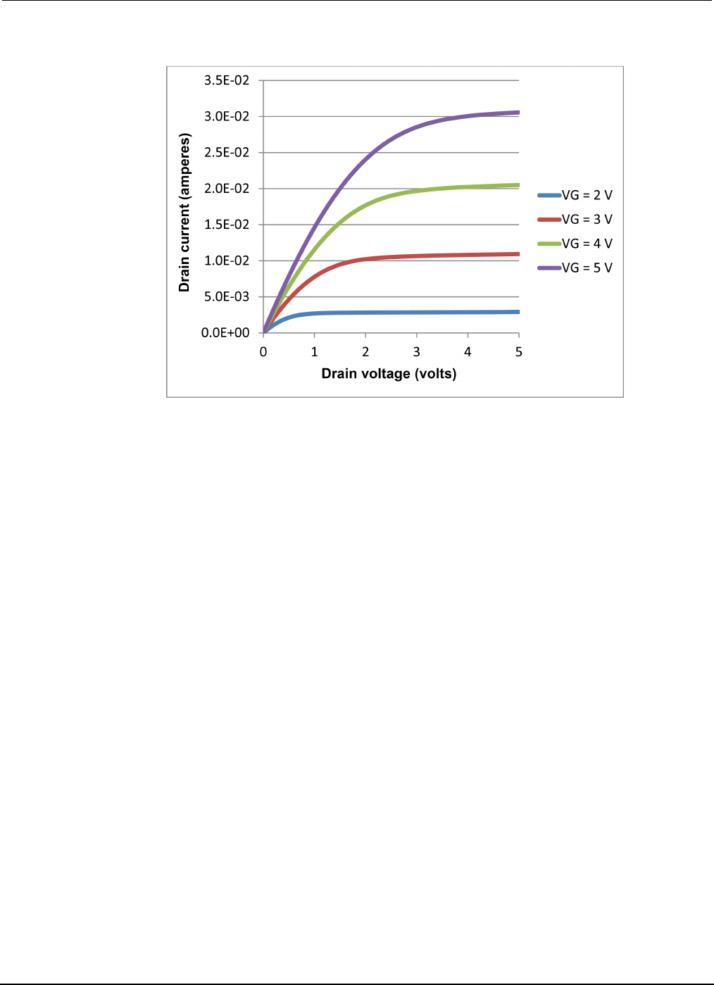
Section
7: Measuring I-V characteristics of FETs Model 2450 Interactive SourceMeter® Instrument
User's Manual
7-14 2450-900-01 Rev. D/May 2015
Figure 37: MOSFET drain family of curves generated with two Model 2450s
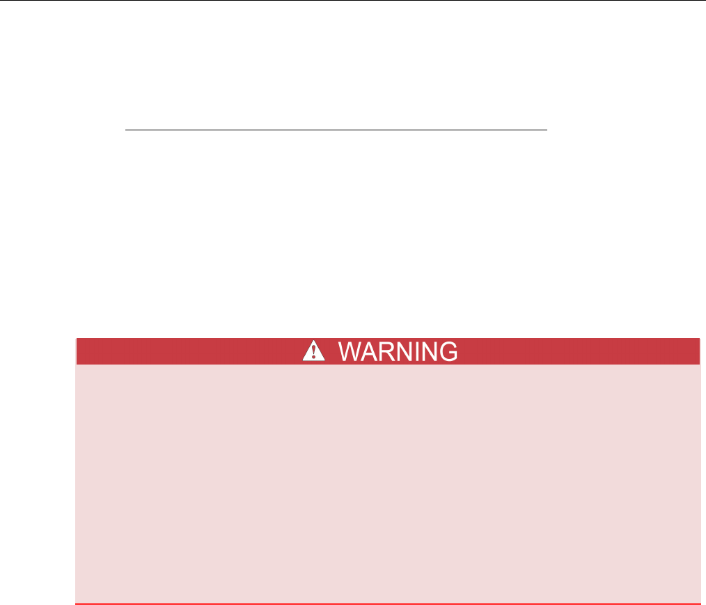
In this section:
Introduction ............................................................................... 8-1
Equipment required .................................................................. 8-3
Device connections .................................................................. 8-3
Automated battery charge and discharge cycle testing ............ 8-5
Introduction
This example application demonstrates how to use a single Model 2450 to perform automated battery
discharge and charge cycle testing.
To prevent personal injury or damage to the Model 2450, do not attempt to charge
nonrechargeable batteries. Some of the batteries that can be charged with a Model 2450
are nickel cadmium (Ni-Cd), nickel metal hydride (Ni-MH), lithium ion (Li-ion), rechargeable
alkaline, and lead acid. If you are working with a battery type that is not listed here, please
contact your local Keithley office, sales partner, or distributor, or call one of our
Applications Engineers to get technical assistance.
Always follow the battery manufacturer's requirements for charging or discharging
batteries using a Model 2450. Failure to properly charge or discharge batteries may cause
them to leak or explode, resulting in personal injury and property damage. Overvoltage and
current protection should be provided in the charge circuit, external to the instrument,
when charging batteries without built-in protection.
Do not charge or discharge batteries that exceed 21 V at 1.05 A or 210 V at 105 mA.
For both the charging and discharging cycles, you configure the Model 2450 to source voltage and
measure current. The following figures show simplified schematics for the charge and discharge
cycles.
Section 8
Rechargeable battery measurements
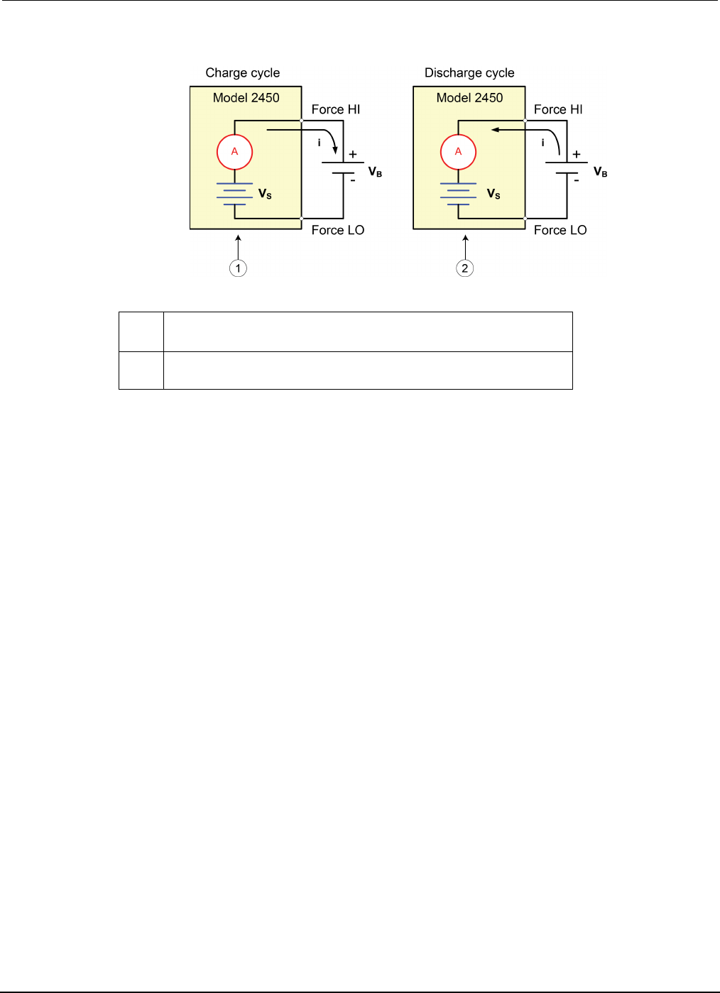
Section
8: Rechargeable battery measurements Model 2450 Interactive SourceMeter® Instrument
User's Manual
8-2 2450-900-01 Rev. D/May 2015
Figure 38: Battery charge-discharge cycle schematics
1 Model 2450 is in source mode (VS > VB). Instrument functions as a
power supply; charge current (i) is positive.
2
Model 2450 is in sink mode (Vs > VB). Instrument functions as an
electronic load; discharge current (i) is negative.
Charging
A battery is usually charged using a constant current. To do this, use a Model 2450 as a voltage
source set to the voltage rating of the battery with the desired charging current set as the current limit.
At the start of the test, the battery voltage is less than the voltage output setting of the Model 2450.
As a result, this voltage difference drives a current that is immediately limited to the user-defined
current limit. When in current limit, the Model 2450 acts as a constant current source until it reaches
the programmed voltage level. As the battery becomes fully charged, the current decreases until it
reaches zero or near zero. To prevent safety hazards or damage to the battery, be careful not to
overcharge the battery.
Discharging
When discharging a battery, the Model 2450 operates as a sink because it is dissipating power rather
than sourcing it. The voltage source of the Model 2450 is set to a lower level than the battery voltage.
The current limit sets the discharge rate. When the output is enabled, the current from the battery
flows into the HI terminal of the Model 2450. As a result, the current readings are negative. The
discharge current should stay constant until the battery voltage decreases to the voltage source
setting of the Model 2450.

Model 2450
Interactive SourceMeter® Instrument User's Manual Section 8:
Rechargeable battery measurements
2450-900-01 Rev. D/May 2015 8-3
If you are using the current source to charge or discharge batteries, the following precautions must
be observed. Failure to observe these precautions could result in instrument damage that is not
covered by the warranty.
Make sure the external voltage never exceeds the voltage limit setting of the current source. This will
cause excessive current to be drawn from the external battery or source.
Be sure to set the output-off state of the current source for high impedance. This setting opens the
output relay when the output is turned off. With the normal output-off state selected, turning the
output off sets the voltage limit to zero. This 0 V source limit condition will cause excessive current to
be drawn from the external battery or source.
Carefully consider and configure the output-off state, source, and limits before connecting the Model
2450 to a device that can deliver energy. Devices that can deliver energy include voltage sources,
batteries, capacitors, and solar cells. Configure instrument settings before making connections to the
device. Failure to consider the output-off state, source, and limits may result in damage to the
instrument or to the device under test (DUT).
When using the current source as a sink, always set the voltage limit and configure overvoltage
protection (OVP) to levels that are higher than the external voltage level. Failure to do so could result
in excessive current flow into the Model 2450 (> 105 mA) and incorrect measurements.
Equipment required
• One Model 2450 High-Current Interactive SourceMeter® instrument
• For front-panel connections, use four insulated banana cables such as the Keithley Instruments
Model 8608 High-Performance Clip Lead Set (one set included with the Model 2450; you will
need another set)
• For rear-panel connections, use four triaxial cables
• One GPIB, USB, or ethernet cable to connect the Model 2450 to a computer
• One rechargeable 2300 mAh AA (1.2 V) battery to test
Device connections
To set up the test, connect the Model 2450 to the battery as shown in the following figure. Make a
4-wire (remote sense) connection from the instrument terminals to the battery to eliminate the effects
of the lead resistance. This allows you to measure the battery voltage as closely as possible to the
terminals of the instrument.
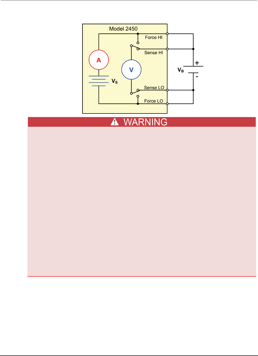
Section
8: Rechargeable battery measurements Model 2450 Interactive SourceMeter® Instrument
User's Manual
8-4 2450-900-01 Rev. D/May 2015
Figure 39: Schematic for the battery charge and discharge cycle test
To prevent electric shock, test connections must be configured such that the user cannot
come in contact with conductors or any device under test (DUT) that is in contact with the
conductors. It is good practice to disconnect DUTs from the instrument before powering the
instrument. Safe installation requires proper shields, barriers, and grounding to prevent
contact with conductors.
There is no internal connection between protective earth (safety ground) and the LO
terminals of the Model 2450. Therefore, hazardous voltages (more than 30 Vrms) can appear
on LO terminals. This can occur when the instrument is operating in any mode. To prevent
hazardous voltage from appearing on the LO terminals, connect the LO terminal to
protective earth if your application allows it. You can connect the LO terminal to the chassis
ground terminal on the front panel or the chassis ground screw terminal on the rear panel.
Note that the front-panel terminals are isolated from the rear-panel terminals. Therefore, if
you are using the front-panel terminals, ground to the front-panel LO terminal. If using the
rear-panel terminals, ground to the rear panel LO terminal.
Be aware that hazardous voltages can appear on the LO terminals even if the terminals are
not presently selected. The TERMINALS FRONT/REAR switch selects the active terminals
for the measurement. It does not disconnect the terminals.
The maximum input voltage between INPUT HI and INPUT LO is 1000 Vpeak. Exceeding this
value may create a shock hazard.
The maximum common-mode voltage (the voltage between INPUT LO and chassis ground) is
500 Vpeak. Exceeding this value may cause a breakdown in insulation that can create a shock
hazard.
You can make test connections to the Model 2450 from the rear or front panel of the instrument.
Connect the Force HI and Sense HI output terminals of the Model 2450 to the positive (+) terminal of
the battery. Connect the Sense LO and Force LO outputs to the negative (−) terminal of the battery.
Make sure that when the output of the Model 2450 is turned off, it is set to the high-impedance
(High-Z) output-off state. When the high-impedance output-off state is selected, the output relay
opens when the output is turned off. This prevents the battery from draining when the output is off.
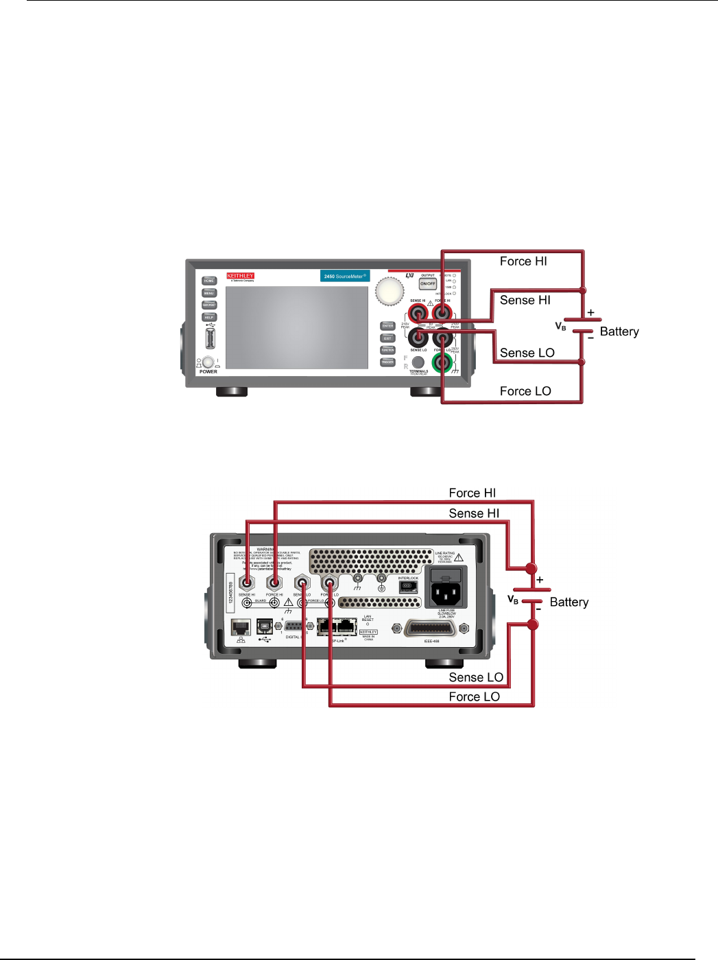
Model 2450
Interactive SourceMeter® Instrument User's Manual Section 8:
Rechargeable battery measurements
2450-900-01 Rev. D/May 2015 8-5
To set the output-off state to high impedance:
1. Press the MENU key.
2. In the Source column, select Settings.
3. Select the button next to Output Off and select High Impedance.
4. Press the HOME key to return to the Home screen.
The figure below shows the front-panel connections. You can make these connections with four
insulated banana cables such as two sets of the Keithley Instruments Model 8608 High-Performance
Clip Lead Set.
Figure 40: Front-panel connections for the battery discharge-charge application
The figure below shows the rear-panel connections. You can make these connections with four
triaxial cables.
Figure 41: Rear-panel connections for the battery discharge-charge application
Automated battery charge and discharge cycle testing
Battery charge and discharge cycles often take several hours, so automating the test is important.
This example demonstrates how to use the Model 2450 to perform an automated battery discharge
test using SCPI commands or TSP commands.
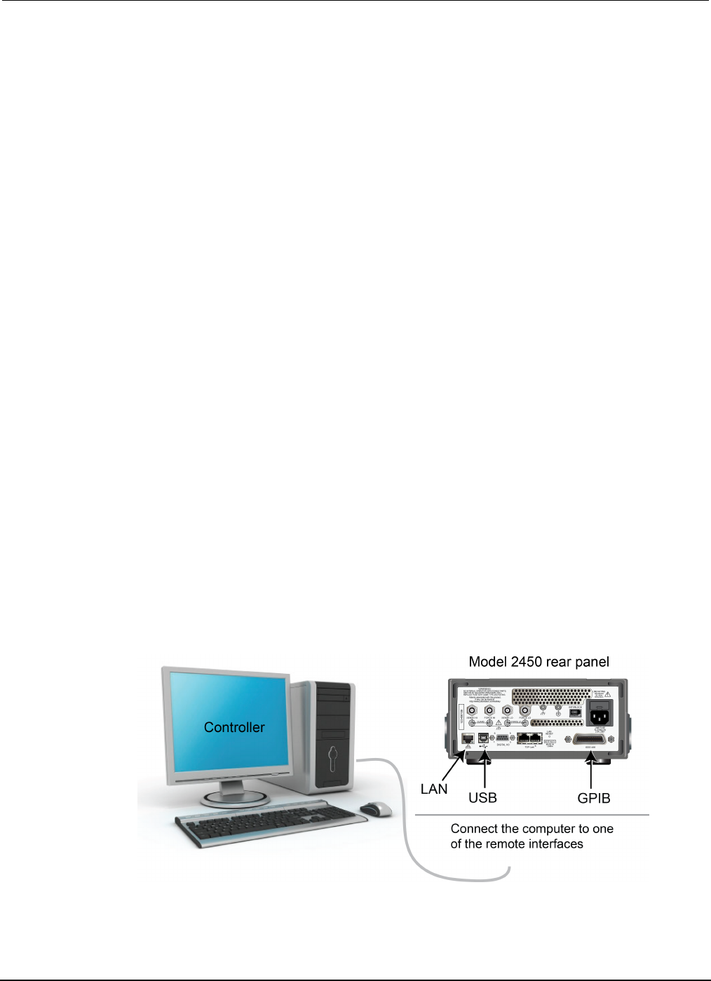
Section
8: Rechargeable battery measurements Model 2450 Interactive SourceMeter® Instrument
User's Manual
8-6 2450-900-01 Rev. D/May 2015
For this application, you will:
• Reset the instrument.
• Set the measurement to a 4-wire configuration.
• Set the instrument to source voltage and measure current.
• Select the high impedance output-off mode, which opens the output relay when the Model 2450
output is turned off. Select this mode before connecting the battery to the output. This prevents
the battery from draining when it is connected to the instrument with the output off.
• Set the current limit to the current level at which the battery is to be charged or discharged. This
is the load current of the test. Even though the Model 2450 is sourcing voltage, it operates in
constant current mode because it is in current limit until it reaches the desired voltage.
• Turn on the source readback to enable the Model 2450 to measure the battery voltage while it
either charges or discharges.
• Read the load current, source readback voltage, and the relative timestamp.
• Monitor the voltage until the battery voltage reaches the desired voltage level and stop the test.
To charge the battery, program the Model 2450 to output a voltage that is equivalent to the voltage
rating of the battery. For example, to charge a 10 V battery, set the Model 2450 to source 10 V. As
the battery fully charges, current decreases until it reaches zero or near zero (battery charged).
To discharge the battery, program the Model 2450 to output a voltage to a lower level than the battery
voltage and set the output-off state to high impedance. In this configuration, the Model 2450 operates
as a sink to discharge the battery. Current from the battery flows into the HI terminal of the Model
2450, which results in negative current measurements. As the battery discharges, the current stays
constant.
Set up remote communications
This application is configured to run remotely. You can run this application from any of the supported
communication interfaces for the instrument (GPIB, USB, or ethernet).
The following figure shows the rear-panel connection locations for the remote communication
interfaces. For additional information about how to set up remote communications, see Remote
communications interfaces.
Figure 42: Model 2450 remote interface connections
Model 2450
Interactive SourceMeter® Instrument User's Manual Section 8:
Rechargeable battery measurements
2450-900-01 Rev. D/May 2015 8-7
Set up the battery application using SCPI commands
The SCPI code in this example sets the Model 2450 to the source voltage function and measure
current function. The voltage source is set to 1 V and the source limit is set to 460 mA. The voltage,
current, and relative timestamp values are returned. Measurements are made until the voltage
reaches the set level.
You may need to change the current and voltage levels so that they are appropriate for the battery
you are testing.
In the following example code, notice that some of the code is labeled as "Pseudocode." The code
you use for the pseudocode lines will vary based on the programming environment you use.
Send the following commands for this example application:
SMU
command or
pseudocode
Commands Description
SMU
command
*RST
OUTP:SMOD HIMP
SENS:RES:RSEN ON
SOUR:FUNC VOLT
SOUR:VOLT 1
SOUR:VOLT:READ:BACK ON
SOUR:VOLT:RANG 2
SOUR:VOLT:ILIM 460e-3
SENS:FUNC "CURR"
SENS:CURR:RANG 1
OUTP ON
• Reset the instrument.
• Turn on high-impedance output mode.
• Set to 4-wire sense mode.
• Set to source voltage.
• Set source level to 1 V.
• Turn on source readback.
• Set source range to 2 V.
• Set the source limit to 460 mA.
• Set to measure current.
• Set current range to 1 A.
• Turn the output on.
Pseudocode
iteration = 1
voltLimit = 1.0
current = []
voltage = []
seconds = []
hours = []
while true do:
• Create a variable called iteration and
initialize to 1.
• Create a variable called voltLimit and
initialize to 1.
• Create an empty array for current
measurements.
• Create an empty array for voltage
measurements.
• Create an empty array for the time values.
• Start a
while
loop.
SMU
command
current[iteration] = READ?
"defbuffer1"
voltage[iteration] = TRAC:DATA?
iteration, iteration,
"defbuffer1", SOUR
seconds[iteration] = TRAC:DATA?
iteration, iteration,
"defbuffer1", REL
• Append the current reading to the array
current.
• Append the voltage reading to the array
voltage.
• Append the time reading to the array
seconds.
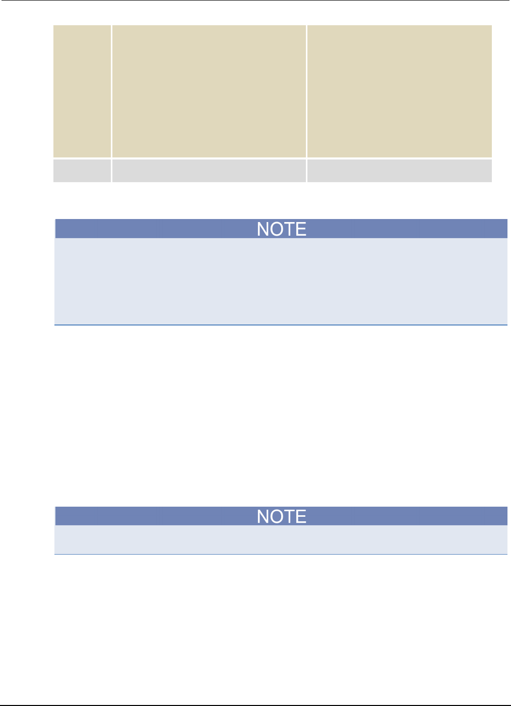
Section
8: Rechargeable battery measurements Model 2450 Interactive SourceMeter® Instrument
User's Manual
8-8 2450-900-01 Rev. D/May 2015
Pseudocode
hours[iteration] =
seconds[iteration]/3600
print(voltage[iteration],
current[iteration],
hours[iteration])
if voltage[iteration] <=
voltLimit then:
break
end if
iteration = iteration + 1
delay(10)
end while
• Calculate the hours taken at each iteration.
• Print the measured values.
• Compare the voltage reading from this
iteration to the voltage limit. If the
measured value is less than or equal to the
limit, break out of the loop.
• End the if statement.
• Increment the iteration count by 1.
• Delay for 10 seconds.
• End the while loop.
SMU
command
OUTP OFF
• Turn the output off.
Set up the battery application using TSP commands
The following TSP code is designed to be run from Keithley Instruments Test Script Builder (TSB).
TSB is a software tool that is available from the Keithley Instruments website. You can install and
use TSB to write code and develop scripts for TSP-enabled instruments. Information about how to
use TSB is in the online help for TSB and in the “Introduction to TSP operation” section of the Model
2450 Reference Manual.
To use other programming environments, you may need to make changes to the example TSP code.
By default, the Model 2450 is configured to use the SCPI command set. You must select the TSP
command set before sending TSP commands to the instrument.
To enable TSP commands:
1. Press the MENU key.
2. Under System, select Settings.
3. For Command Set, select TSP.
4. At the prompt to reboot, select Yes.
The TSP code in this example sets the Model 2450 to the source voltage function and measure
current function. The voltage source is set to 1 V and the source limit is set to 460 mA. The voltage,
current, and relative timestamp values are returned. Measurements are made until the voltage
reaches the set level. During the test, these measurements are shown on the USER swipe screen at
the bottom of the screen (see the figure following the example code).
You may need to change the current and voltage levels so that they are appropriate for the battery
you are testing.

Model 2450
Interactive SourceMeter® Instrument User's Manual Section 8:
Rechargeable battery measurements
2450-900-01 Rev. D/May 2015 8-9
Send the following TSP commands for this example application:
--Reset the instrument, which clears the buffer.
reset()
--Source settings.
smu.source.func = smu.FUNC_DC_VOLTAGE
smu.source.offmode = smu.OFFMODE_HIGHZ
smu.source.level = 1
smu.source.range = 2
smu.source.readback = smu.ON
smu.source.ilimit.level = 460e-3
--Measure settings.
smu.measure.func = smu.FUNC_DC_CURRENT
smu.measure.range = 460e-3
smu.measure.sense = smu.SENSE_4WIRE
--Set the voltage limit at which the battery will stop discharging.
--Set the variable for the number of iterations.
voltLimit = 1.0
iteration = 1
--Turn on the source output.
smu.source.output = smu.ON
--Change the display to the USER swipe screen.
display.changescreen(display.SCREEN_USER_SWIPE)
--Keep taking readings in the while loop until the measured voltage
--is equal to the voltage limit.
while true do
--Take a reading and get the current, voltage, and relative
--timestamp values.
curr = smu.measure.read(defbuffer1)
volt = defbuffer1.sourcevalues[iteration]
time = defbuffer1.relativetimestamps[iteration]
hours = time/3600
--Print the number of completed cycles, the voltage, and the time
--for the iteration. Display information on the front panel.
print("Completed Cycles: ", iteration, "Voltage: ", volt,
"Time:", time)
display.settext(display.TEXT1, string.format("Voltage = %.4fV", volt))
display.settext(display.TEXT2, string.format("Current = %.2fA,"
.."Time = %.2fHrs", curr, hours))
--Increment the number of iterations and wait 10 seconds.
--Compare the measured voltage to the voltage limit.
--Exit the loop if the voltage limit has been reached.
if volt <= voltLimit then
break
end
iteration = iteration + 1
delay(10)
end
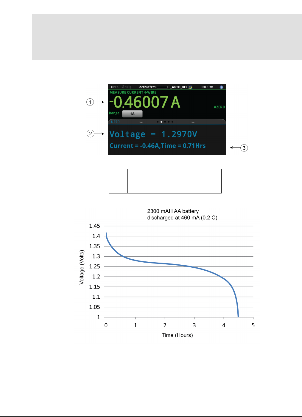
Section
8: Rechargeable battery measurements Model 2450 Interactive SourceMeter® Instrument
User's Manual
8-10 2450-900-01 Rev. D/May 2015
--Turn the output off when the voltage limit is reached.
smu.source.output = smu.OFF
--Print the measured values in a four-column format.
print("\nIteration:\tCurrent:\tVoltage:\tTime:\n")
for i = 1, defbuffer1.n do
print(i, "\t", defbuffer1[i], "\t", defbuffer1.sourcevalues[i],
"\t", defbuffer1.relativetimestamps[i])
endThe following figures show the results of this test application.
Figure 43: Model 2450 USER swipe screen showing test results
1
Measured load current
2
Measured battery voltage
3
Source value and elapsed test time
Figure 44: Results of battery charge and discharge test

In this section:
Introduction ............................................................................... 9-1
Equipment required .................................................................. 9-1
Set up remote communications ................................................ 9-2
Device connections .................................................................. 9-2
Solar cell characterization ........................................................ 9-4
Introduction
This example application demonstrates how to use the Model 2450 Interactive SourceMeter®
instrument to measure the I-V characteristics of a solar cell.
From the I-V characteristics measured by the Model 2450, you can determine important parameters
about the solar cell, including:
• Maximum current (Imax) and voltage (Vmax)
• Maximum power (Pmax)
• Open circuit voltage (Voc)
• Short-circuit current (Isc)
Because the Model 2450 has four-quadrant source capability, it can sink up to 1 A of cell current as a
function of the applied voltage.
Equipment required
• One Model 2450 Interactive SourceMeter® instrument
• For front-panel connections, use four insulated banana cables such as the Keithley Instruments
Model 8608 High-Performance Clip Lead Set (one set included with the Model 2450; you will
need another set)
• For rear-panel connections, use four triaxial cables
• One solar cell
Section 9
Measuring I-V characteristics of solar cells
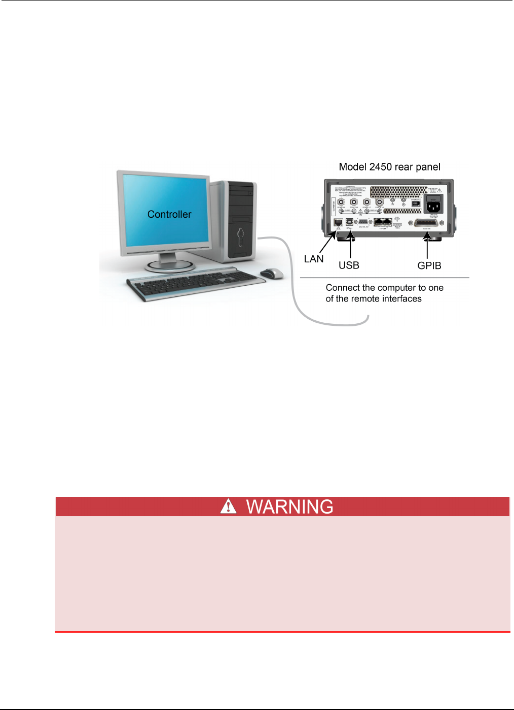
Section
9: Measuring I-V characteristics of solar cells Model 2450 Interactive SourceMeter® Instrument
User's Manual
9-2 2450-900-01 Rev. D/May 2015
Set up remote communications
You can run this application from the front panel or any of the supported communication interfaces for
the instrument (GPIB, USB, or ethernet).
The following figure shows the rear-panel connection locations for the remote communication
interfaces. For additional information about setting up remote communications, see Remote
communications interfaces.
Figure 45: Model 2450 remote interface connections
Device connections
Connect the Model 2450 to the solar cell in a 4-wire configuration to provide the best measurement
accuracy and eliminate the effects of the lead resistance on the measurement.
To use the 4-wire connection method:
• Connect the FORCE LO and SENSE LO leads to the cathode terminal.
• Connect the FORCE HI and SENSE HI leads to the anode terminal.
• Make the connections as close to the solar cell as possible to avoid including the resistance of
the test leads in the measurement.
You can use either the front-panel or the rear-panel terminals for this application.
Hazardous voltages may be present on all output and guard terminals. To prevent electrical
shock that could cause injury or death, never make or break connections to the Model 2450
while the output is on.
To prevent electric shock, test connections must be configured such that the user cannot
come in contact with conductors or any device under test (DUT) that is in contact with the
conductors. It is good practice to disconnect DUTs from the instrument before powering the
instrument. Safe installation requires proper shields, barriers, and grounding to prevent
contact with conductors.
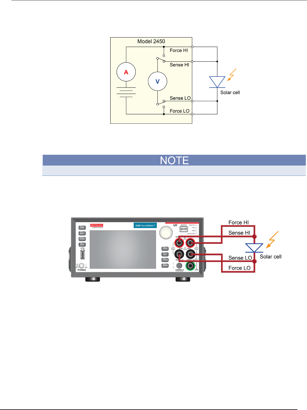
Model 2450
Interactive SourceMeter® Instrument User's Manual Section 9: Measuring I-V characteris
tics of solar cells
2450-900-01 Rev. D/May 2015 9-3
The following figure shows the schematic for the application.
Figure 46: Model 2450 connections to a solar cell
The following figures show the physical connections for the front and rear panels. Note that you must
use either the front-panel terminals or rear-panel terminals — you cannot mix connections.
The rear-panel connections are triaxial. The front-panel connections are safety banana jacks.
Turn the power to the instrument off before attaching connections to the Model 2450.
The figure below shows the front-panel connections. You can make these connections with four
insulated banana cables such as two sets of the Keithley Instruments Model 8608 High-Performance
Clip Lead Set.
Figure 47: Model 2450 4-wire connections to the front panel
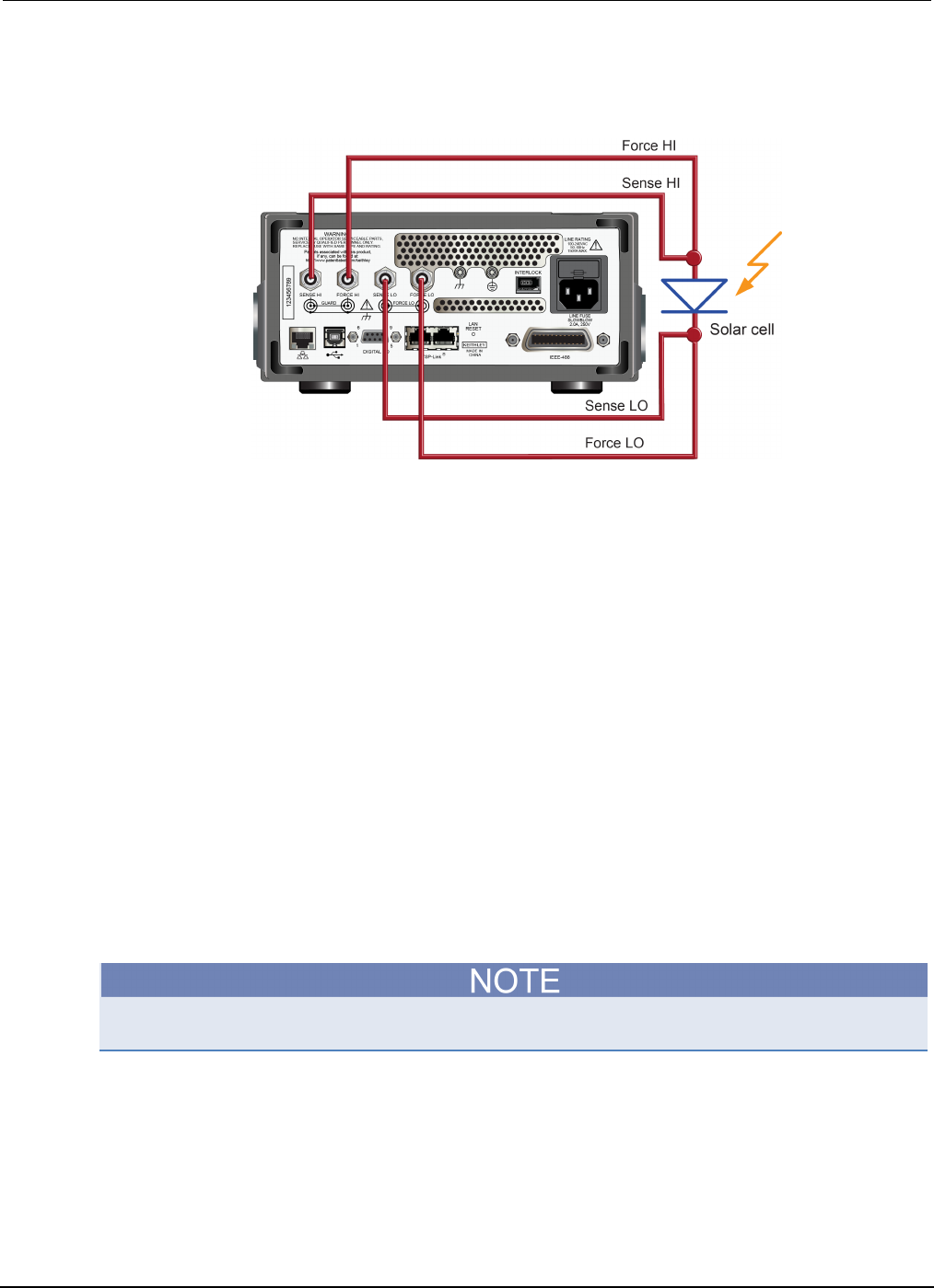
Section
9: Measuring I-V characteristics of solar cells Model 2450 Interactive SourceMeter® Instrument
User's Manual
9-4 2450-900-01 Rev. D/May 2015
The figure below shows the rear-panel connections. You can make these connections with four
triaxial cables.
Figure 48: Model 2450 4-wire connections to the rear panel
Solar cell characterization
This application demonstrates how to use the Model 2450 to characterize a solar cell. The examples
show how to use the front panel, SCPI code over a remote interface, and TSP code over a remote
interface.
For this test, you will:
• Reset the instrument.
• Select the source voltage function and measure current function.
• Set the current limit.
• Select four-wire (remote sense) mode.
• Set up and generate a voltage sweep.
• Initiate the trigger model, which will turn the output on.
• Record the measurements.
• After the voltage sweep is complete, turn off the output.
• Retrieve the measurements.
• View the data on the front-panel graph.
You must control the light source for this application; you will run the test with the light source on and
again with the light source off.

Model 2450
Interactive SourceMeter® Instrument User's Manual Section 9: Measuring I-
V characteristics of solar cells
2450-900-01 Rev. D/May 2015 9-5
Set up the solar cell I-V sweep from the front panel
This is an example of an I-V test that sweeps voltage from 0 V to 0.55 V in 10 mV steps and
measures the resulting current. You can then view the data on the graph screen.
To set up the application from the front panel:
1. Make connections to the instrument and device under test (DUT) as described in Device
connections (on page 5-2, on page 6-2, on page 9-2).
2. Press the POWER switch on the front panel to turn on the instrument.
3. Reset the instrument:
a. Press the MENU key.
b. Under System, select Info/Manage.
c. Select System Reset.
d. Select OK.
4. Press the HOME key.
5. Press the FUNCTION key.
6. Under Source Voltage and Measure, select Current.
7. Press the MENU key.
8. Under Measure, select Settings.
9. Select the button next to Sense and select 4-Wire Sense.
10. Press the MENU key.
11. Under Source, select Sweep.
12. Set the Start level to 0 V and select OK.
13. Set the Stop level to 0.55 V and select OK.
14. Set the Step level to 10 mV and select OK.
15. Swipe the SWEEP SETTINGS screen until you see Source Limit.
16. Select the button next to Source Limit, enter 1 A, and select OK.
17. Select Generate. This sets up a trigger model for the sweep.
18. Press the MENU key.
19. Under Views, select Graph.
20. Press the TRIGGER key to initiate the trigger model. The output turns on and a RUN indicator is
visible at the top of the screen while the sweep is running.
21. Press the trigger key again to repeat the sweep.
The following figure shows an example of solar cell I-V measurements on the front-panel graph. Note
that the current is negative on the graph because the Model 2450 is sinking current.
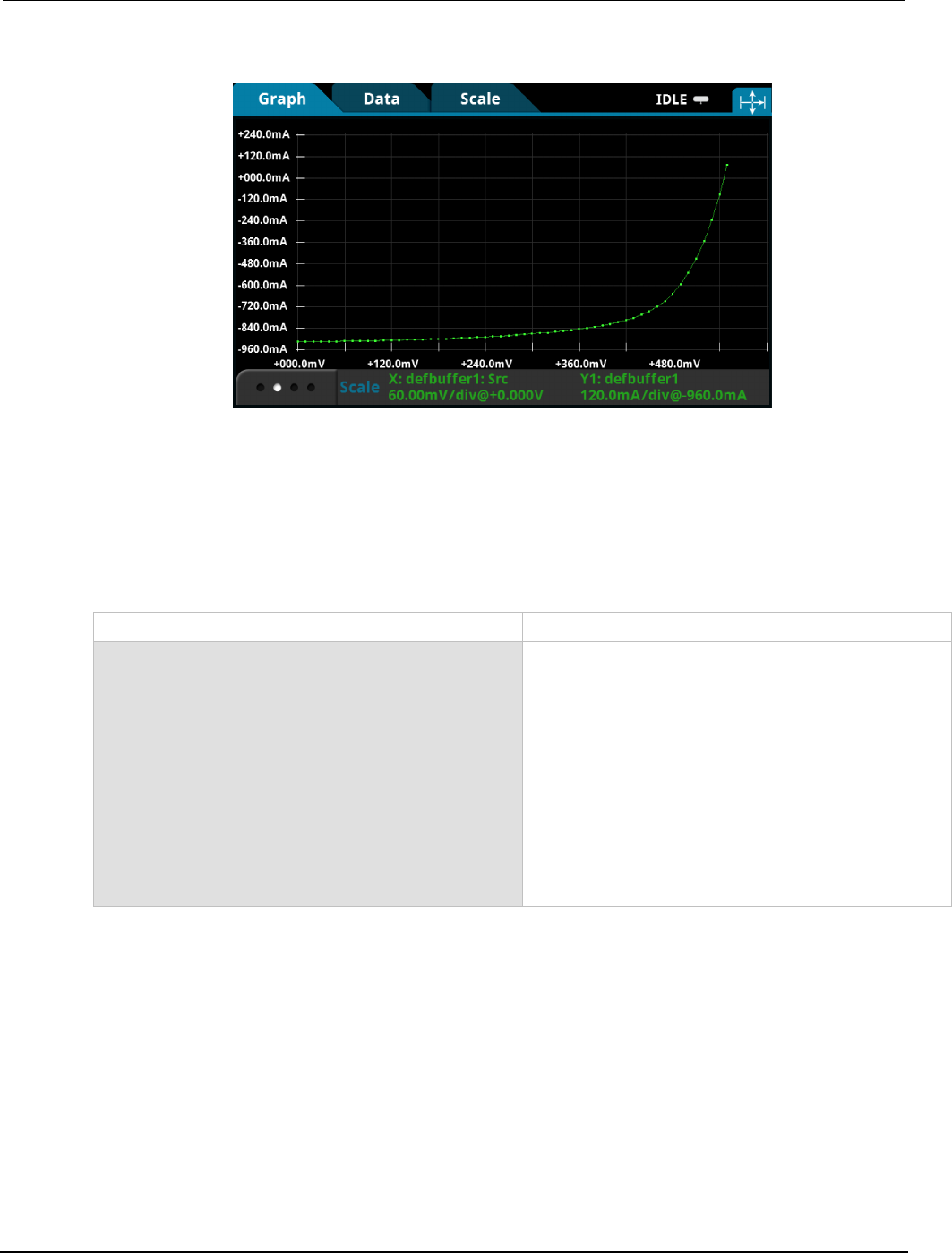
Section
9: Measuring I-V characteristics of solar cells Model 2450 Interactive SourceMeter® Instrument
User's Manual
9-6 2450-900-01 Rev. D/May 2015
Figure 49: Example of solar cell measurements on the front-panel graph
Set up the solar cell I-V sweep using SCPI commands
This example sequence of SCPI commands generates an I-V sweep on a solar cell. You may need to
make changes so that this code will run in your programming environment.
In this example, the voltage is swept from 0 V to 0.55 V in 56 steps. The resulting solar cell current is
measured. The current and voltage measurements are stored in default buffer 1 (defbuffer1).
Send the following commands for this example application:
Command Description
*RST
SENS:FUNC "CURR"
SENS:CURR:RANG:AUTO ON
SENS:CURR:RSEN ON
SOUR:FUNC VOLT
SOUR:VOLT:RANG 2
SOUR:VOLT:ILIM 1
SOUR:SWE:VOLT:LIN 0, 0.55, 56, 0.1
:INIT
*WAI
TRAC:DATA? 1, 56, "defbuffer1", SOUR, READ
• Reset the Model 2450.
• Set to measure current.
• Set to measure with autorange enabled.
• Set to use 4-wire sense mode.
• Set to source voltage.
• Set to the 2 V source range.
• Set the current limit to 1 A.
• Set to sweep voltage from 0 to 0.55 V in 56 steps
with a 0.1 s delay.
• Initiate the sweep.
• Wait until the sweep is finished.
• Read the source and measure values from
defbuffer1
.

Mode
l 2450 Interactive SourceMeter® Instrument User's Manual Section 9: Measuring I-
V characteristics of solar cells
2450-900-01 Rev. D/May 2015 9-7
Set up the solar cell I-V sweep using TSP commands
The following TSP code is designed to be run from Keithley Instruments Test Script Builder (TSB).
TSB is a software tool that is available from the Keithley Instruments website. You can install and
use TSB to write code and develop scripts for TSP-enabled instruments. Information about how to
use TSB is in the online help for TSB and in the “Introduction to TSP operation” section of the Model
2450 Reference Manual.
To use other programming environments, you may need to make changes to the example TSP code.
By default, the Model 2450 is configured to use the SCPI command set. You must select the TSP
command set before sending TSP commands to the instrument.
To enable TSP commands:
1. Press the MENU key.
2. Under System, select Settings.
3. For Command Set, select TSP.
4. At the prompt to reboot, select Yes.
In this application, a linear voltage sweep is configured to output voltage from 0 V to 0.53 V in 56
steps. The instrument measures the resulting current from the solar cell during the sweep.
Send the following commands for this example application:
--Define the number of points in the sweep.
num = 56
--Reset the instrument and clear the buffer.
reset()
--Set the source and measure functions.
smu.measure.func = smu.FUNC_DC_CURRENT
smu.source.func = smu.FUNC_DC_VOLTAGE
--Measurement settings.
smu.measure.terminals = smu.TERMINALS_FRONT
smu.measure.sense = smu.SENSE_4WIRE
smu.measure.autorange = smu.ON
smu.measure.nplc = 1
--Source settings.
smu.source.highc = smu.OFF
smu.source.range = 2
smu.source.readback = smu.ON
smu.source.ilimit.level = 1
smu.source.sweeplinear("SolarCell", 0, 0.53, num, 0.1)
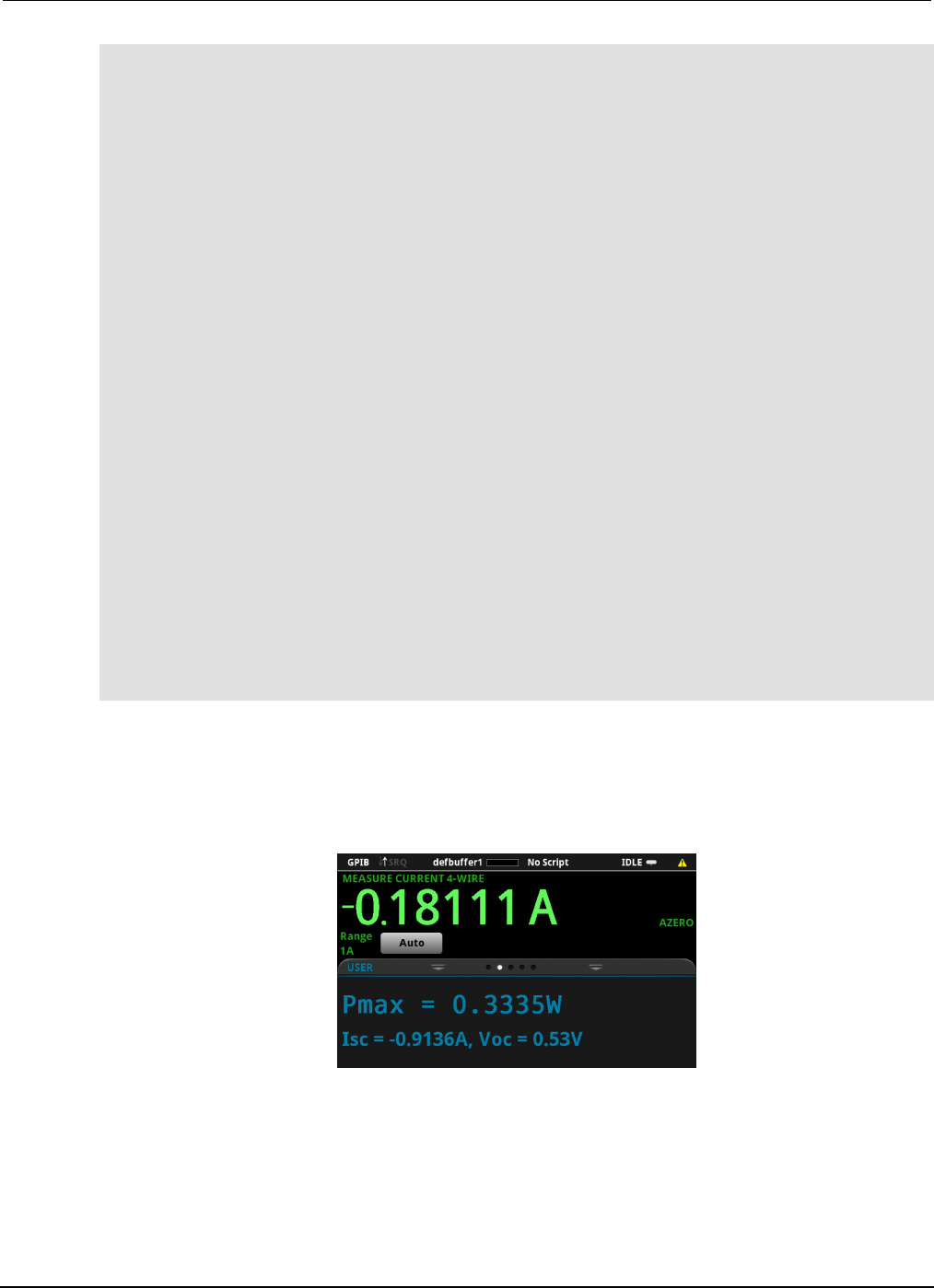
Section
9: Measuring I-V characteristics of solar cells Model 2450 Interactive SourceMeter® Instrument
User's Manual
9-8 2450-900-01 Rev. D/May 2015
--Start the trigger model and wait for it to complete.
trigger.model.initiate()
waitcomplete()
--Define initial values.
voltage = defbuffer1.sourcevalues
current = defbuffer1
isc = current[1]
mincurr = current[1]
imax = current[1]
voc = voltage[1]
vmax = voltage[1]
pmax = voltage[1]*current[1]
--Calculate values.
for i = 1, num do
print(voltage[i],current[i],voltage[i]*current[i])
if (voltage[i]*current[i] < pmax) then
pmax = voltage[i]*current[i]
imax = current[i]
vmax = voltage[i]
end
if math.abs(current[i]) < math.abs(mincurr) then
voc = voltage[i]
end
end
pmax = math.abs(pmax)
imax = math.abs(imax)
print("Pmax = ", pmax, ", Imax = ", imax, ", Vmax = ", vmax, ", Isc = ", isc, ", "
.."Voc = ", voc)
--Display values on the front panel.
display.changescreen(display.SCREEN_USER_SWIPE)
display.settext(display.TEXT1, string.format("Pmax = %.4fW", pmax))
display.settext(display.TEXT2, string.format("Isc = %.4fA, Voc = %.2fV", isc, voc))
In the example above, the instrument is programmed to display custom text on the USER swipe
screen using the display.changescreen and display.settext commands. After the test is
finished, the display will indicate the maximum power (Pmax), the short circuit current (ISC), and the
open circuit voltage (VOC), as shown in the figure below.
Figure 50: Solar cell I-V sweep results on the USER swipe screen
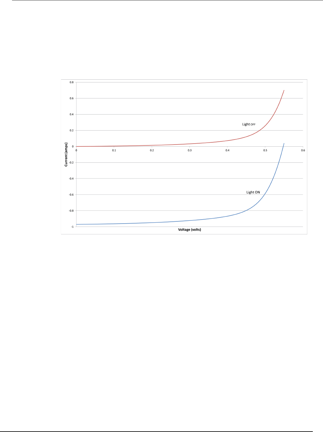
Model 2450
Interactive SourceMeter® Instrument User's Manual Section 9: Measuring I-V characteristics of
solar cells
2450-900-01 Rev. D/May 2015 9-9
After the code is executed, five values are returned in the Instrument Console of Test Script Builder
(TSB), and the measured current, voltage, and calculated power are displayed on the front panel of
the Model 2450. You can copy the data from the TSB Instrument Console into a spreadsheet such as
Microsoft® Excel® for graphing and further analysis. The figure below shows the results of graphing
the data in an Excel spreadsheet. Notice that the test on the solar cell was executed with light (light
ON) and in the dark (light OFF).
Figure 51: Solar cell I-V characteristics generated with and without light

In this section:
About this section ................................................................... 10-1
Where can I find updated drivers? .......................................... 10-1
How do I upgrade the firmware? ............................................ 10-2
Why can't the Model 2450 read my USB flash drive? ............. 10-2
How do I change the command set? ...................................... 10-2
Why am I getting a 5074 event code? .................................... 10-3
How do I save the present state of the instrument? ............... 10-4
Why did my settings change? ................................................. 10-5
What are the Quick Setup options? ........................................ 10-5
About this section
This section is helps you find answers to the most common questions encountered with the Model
2450. For additional FAQs, please see the "Frequently Asked Questions (FAQs)" section of the Model
2450 Reference Manual.
Where can I find updated drivers?
For the latest drivers and additional support information, see the Keithley Instruments support
website.
To see what drivers are available for your instrument:
1. Go to the Keithley Instruments support website (http://www.keithley.com/support).
2. Enter the model number of your instrument.
3. Select Software Driver from the list.
If you use the native LabVIEWTM or IVI driver, you must configure the Model 2450 to use the SCPI
command set. For information on changing the command set, refer to How do I change the
command set? (on page 10-2)
Section 10
Troubleshooting FAQs

Section
10: Troubleshooting FAQs Model 2450 Interactive SourceMeter® Instrument
User's Manual
10-2 2450-900-01 Rev. D/May 2015
How do I upgrade the firmware?
Do not turn off power or remove the USB flash drive until the upgrade process is complete.
You can upgrade or downgrade the firmware from the front panel or from the virtual front panel.
Refer to Using the Model 2450 virtual front panel for information.
From the front panel or virtual front panel:
1. Copy the firmware file (.upg file) to a USB flash drive.
2. Verify that the firmware file is in the root subdirectory of the flash drive and that it is the only
firmware file in that location.
3. Disconnect any input and output terminals that are attached to the instrument.
4. Turn on instrument power.
5. Insert the flash drive into the USB port on the front panel of the instrument.
6. From the instrument front panel, press the MENU key.
7. Under System, select Info/Manage.
8. To upgrade to a newer version of firmware, select Upgrade to New.
9. To return to a previous version of firmware, select Downgrade to Older.
10. If the instrument is controlled remotely, a message is displayed. Select Yes to continue.
11. When the upgrade is complete, reboot the instrument.
A message is displayed while the upgrade is in progress.
Upgrade files are available on the Keithley Instruments website (http://www.keithley.com).
Why can't the Model 2450 read my USB flash drive?
Verify that the flash drive is formatted with the FAT file system. The Model 2450 only supports FAT
drives.
In Microsoft® Windows®, you can check the file system by checking the properties of the USB flash
drive.
How do I change the command set?
You can change the command set that you use with the Model 2450. The remote command sets that
are available include:
• SCPI: An instrument-specific language built on the SCPI standard.
• TSP: A scripting programming language that contains instrument-specific control commands that
can be executed from a stand-alone instrument. You can use TSP to send individual commands
or use it to combine commands into scripts.
• SCPI 2400: An instrument-specific language that allows you to run code developed for earlier
Series 2400 instruments.

Model 2450
Interactive SourceMeter® Instrument User's Manual Section 10:
Troubleshooting FAQs
2450-900-01 Rev. D/May 2015 10-3
You cannot combine the command sets.
As delivered from Keithley Instruments, the Model 2450 is set to work with the Model 2450 SCPI
command set.
If you choose the SCPI 2400 command set, you will not have access to some of the extended
ranges and other features that are now available using the SCPI command set. In addition, some
Series 2400 code will work differently in the Model 2450 than it did in the earlier instrument. In the
Model 2450 Reference Manual, see "Model 2450 in a Model 2400 application" for information about
the differences.
To set the command set from the front panel:
1. Press the MENU key.
2. Under System, select Settings.
3. Select the button next to Command Set.
4. Select the command set.
5. You are prompted to reboot.
To verify which command set is selected from a remote interface:
Send the command:
*LANG?
To change to the SCPI command set from a remote interface:
Send the command:
*LANG SCPI
Reboot the instrument.
To change to the TSP command set from a remote interface:
Send the command:
*LANG TSP
Reboot the instrument.
To change to the SCPI 2400 command set from a remote interface:
Send the command:
*LANG SCPI2400
Reboot the instrument.
Why am I getting a 5074 event code?
The instrument provides an interlock circuit on the rear panel. You must enable this circuit in order for
the instrument to set source voltages greater than ±42 V DC. If you try to assign a high-voltage output
and turn the source on when the interlock is not asserted, you see event code 5074, "Output voltage
limited by interlock."
Section
10: Troubleshooting FAQs Model 2450 Interactive SourceMeter® Instrument User's Manu
al
10-4 2450-900-01 Rev. D/May 2015
The Model 2450 is provided with an interlock circuit that must be positively activated in
order for the high voltage output to be enabled. The interlock helps facilitate safe operation
of the equipment in a test system. Bypassing the interlock could expose the operator to
hazardous voltages that could result in personal injury or death.
If the safety interlock is not asserted and the source is turned on, the following actions occur:
• The nominal output is limited to less than ±42 V.
• The front-panel INTERLOCK indicator is not illuminated.
To recover from this error, properly engage the interlock using a safe test fixture before turning on the
Model 2450 output.
How do I save the present state of the instrument?
You can save the settings in the instrument as a script using the front-panel menus or from a remote
interface. After they are saved, you can recall the script or copy it to a USB flash drive.
From the front panel:
1. Configure the Model 2450 to the settings that you want to save.
2. Press the MENU key.
3. Under Scripts, select Create Setup. The CREATE SETUP window is displayed.
4. Select Create. A keyboard is displayed.
5. Use the keyboard to enter the name of the script.
6. Select the OK button on the displayed keyboard. The script is added to internal memory.
Using SCPI commands:
Configure the instrument to the settings that you want to save. To save the setup, send the
command:
*SAV <n>
Where <n> is an integer from 0 to 4.
In the front-panel script menus, the setups saved with the *SAV command have the name Setup0x,
where x is the value you set for <n>.
Using TSP commands:
Configure the instrument to the settings that you want to save. To save the setup, send the
command:
createconfigscript("setupName")
Where setupName is the name of the setup script that will be created.
Model 2450
Interactive SourceMeter® Instrument User's Manual Section 10:
Troubleshooting FAQs
2450-900-01 Rev. D/May 2015 10-5
Why did my settings change?
Many of the commands in the Model 2450 are saved with the source or measure function that was
active when you set them. For example, assume you have the measure function set to current and
you set a value for display digits. When you change the measure function to voltage, the display digits
value changes to the value that was last set for the voltage measure function. When you return to the
current measure function, the display digits value returns to the value you set previously.
What are the Quick Setup options?
The QUICKSET key opens a screen that provides access to function selection, performance
adjustments, and quick setups.
The Function button on the Quickset menu allows you to select a source or measure function. The
options are the same as those available when you use the front-panel FUNCTION key.
The Performance slider allows you to adjust speed and resolution. As you increase speed, you lower
the amount of resolution. As you increase resolution, you decrease the reading speed. These settings
take effect the next time a measurement is made.
The Performance slider allows you to adjust speed and resolution. As you increase speed, you lower
the amount of resolution. As you increase resolution, you decrease the reading speed. These settings
take effect the next time the output is turned on and measurements are made.
The Quick Setups allow you to set the instrument to operate as a Voltmeter, Ammeter, Ohmmeter, or
Power Supply.
When you select a Quick Setup, the instrument turns the output on. Carefully consider and configure
the appropriate output-off state, source, and limits before connecting the Model 2450 to a device that
can deliver energy, such as other voltage sources, batteries, capacitors, or solar cells. Configure the
settings that are recommended for the instrument before making connections to the device. Failure
to consider the output-off state, source, and limits may result in damage to the instrument or to the
device under test (DUT).

In this section:
Additional Model 2450 information ......................................... 11-1
Additional Model 2450 information
This manual has prepared you to start using your new Model 2450 Interactive SourceMeter®
instrument for your application. For more detailed information, refer to the Keithley Instruments Model
2450 Reference Manual.
For related documentation, software tools, and drivers, see the 24GDI-950-01 Interactive
SourceMeter® Instruments Product Information CD-ROM.
Also see the Keithley Instruments website, www.keithley.com (http://www.keithley.com/support) for
support and additional information about the instrument. From the website, you can access:
• The Knowledge Center, which contains the following handbooks:
• The Low Level Measurements Handbook: Precision DC Current, Voltage, and Resistance
Measurements
• Switching Handbook: A Guide to Signal Switching in Automated Test Systems
• Application notes
• Updated drivers
• Information about related products
Your local Field Applications Engineer can help you with product selection, configuration, and usage.
Check the website for contact information.
Section 11
Next steps

Specifications are subject to change without notice.
All Keithley trademarks and trade names are the property of Keithley Instruments.
All other trademarks and trade names are the property of their respective companies.
Keithley Instruments
Corporate Headquarters • 28775 Aurora Road • Cleveland, Ohio 44139 • 440-248-0400 • Fax: 440-248-6168 • 1-800-935-5595 • www.keithley.com
8/14
A Greater Measure of Confidence
