Moto Zero User Guide 1.2
MotoZero_User_Guide_1.2
MotoZero_User_Guide_1.2
User Manual: Pdf
Open the PDF directly: View PDF ![]() .
.
Page Count: 28

MotoZero
“Mechanics Manual”
Motor Controller Board
User Guide and Information
Product Page: ThePiHut.com/motozero

2
K
Guide Contents
Introduction 3
Design Features 4
Kit Contents 5
Assembly 6
Motor Selection 13
Wiring Up 16
Code and Control 21
GPIO Zero Control 25
GPIO Pins Used 26
FAQs 27

3
K
Introduction
Congratulations on your purchase of the MotoZero motor driver board for the
Raspberry Pi!
The MotoZero is designed to be a simple and easy way to get lots of motors
moving with the Raspberry Pi, allowing anyone to make really cool robots!
The board allows you to control up to 4 motors in both directions, in the
easiest way possible on a Raspberry Pi. It uses simple GPIO on/off commands
to make it the perfect gentle introduction to robotics with the Pi.
Wiring and powering the board is simple too. Simply power your Pi in the usual
way with a 5V power bank or battery box, then add power for the motors to
the MotoZero and connect 4 motors.
This “Mechanics Manual” will take you through each step to get your robot
moving from initial assembly and soldering, motor selection, wiring, power,
code and frequently asked questions.

4
K
Design Features
We’ve tried to make the MotoZero as visually appealing as possible,
inspired by old-school motoring and brands
We’ve sourced great quality terminal blocks with large solid flat-head
screw fixings that won’t round-off like cheaper, smaller alternatives
We’ve broken the motor terminals out to each end of the board where
the motors are more likely to be
We’ve included 2 motor drivers to allow the use of 4 motors
We’ve chosen motor drivers that allow the use of super simple GPIO
programming to make your robot move, and include built in protection
from motor voltage spikes (“flyback”)
The motor drivers can be removed from their sockets and replaced if
accidentally damaged
The board has been kept as symmetrical as possible to ensure your
robot looks great
We’ve used ENIG (gold) plating on the PCB to protect against oxidation
and offer a good soldered contact.
5
K
Kit Contents
Like many Raspberry Pi add-on boards, the MotoZero is sold as a kit which
requires soldering.
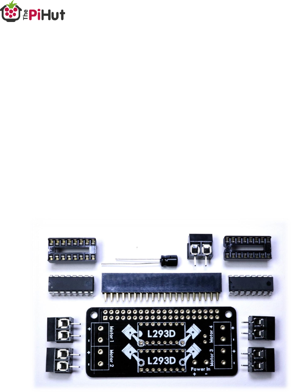
The following parts should be inside your kit bag:
1x MotoZero PCB
1x 40-pin GPIO header
2x 16-way IC Sockets
2x L293D Motor Driver ICs
5x Terminal Blocks
1x Capacitor

6
K
Assembly
Assembling the MotoZero involves soldering the provided components to the
PCB.
Tools Required
Soldering Iron
Solder
Wire/Side cutters
Wire Strippers
Flat-head screwdriver (small)
Protective eyewear
Before You Start
Make sure you have all the parts required
Read all steps through before starting, and take a good look at each image
to confirm component positions before soldering.
ALWAYS wear protective eyewear when soldering!
7
K
Assembly Steps
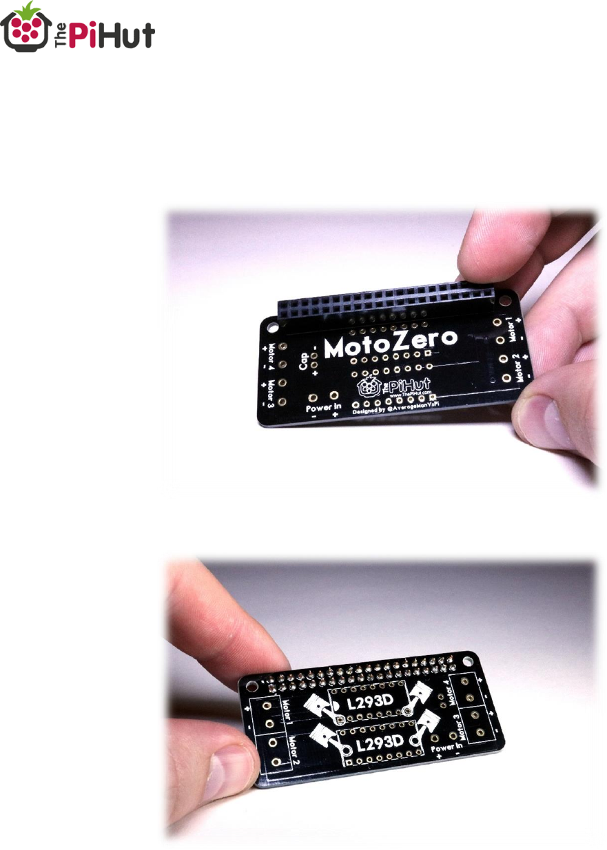
1. First solder the 40-pin GPIO header to the PCB. The plastic end of the
header should be showing on the rear ‘MOTOZERO’ text side of the PCB:
8
K
2. Next solder the two 16-way IC sockets to the PCB, making sure the notch
is pointing to the left of the board.
The plastic end of the sockets should be showing on the front of the board
alongside the piston images.
Note: Soldering next to the 40-pin GPIO header can be tricky, however
we assemble in this order as any accidental spoiling of the 40-pin GPIO
header plastic will not be seen on the underside of the board.
9
K
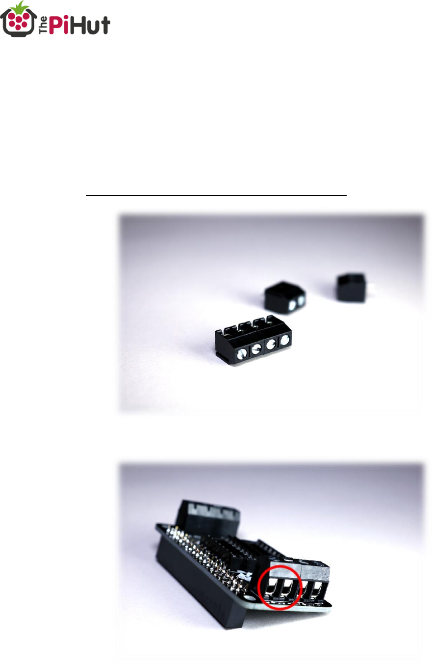
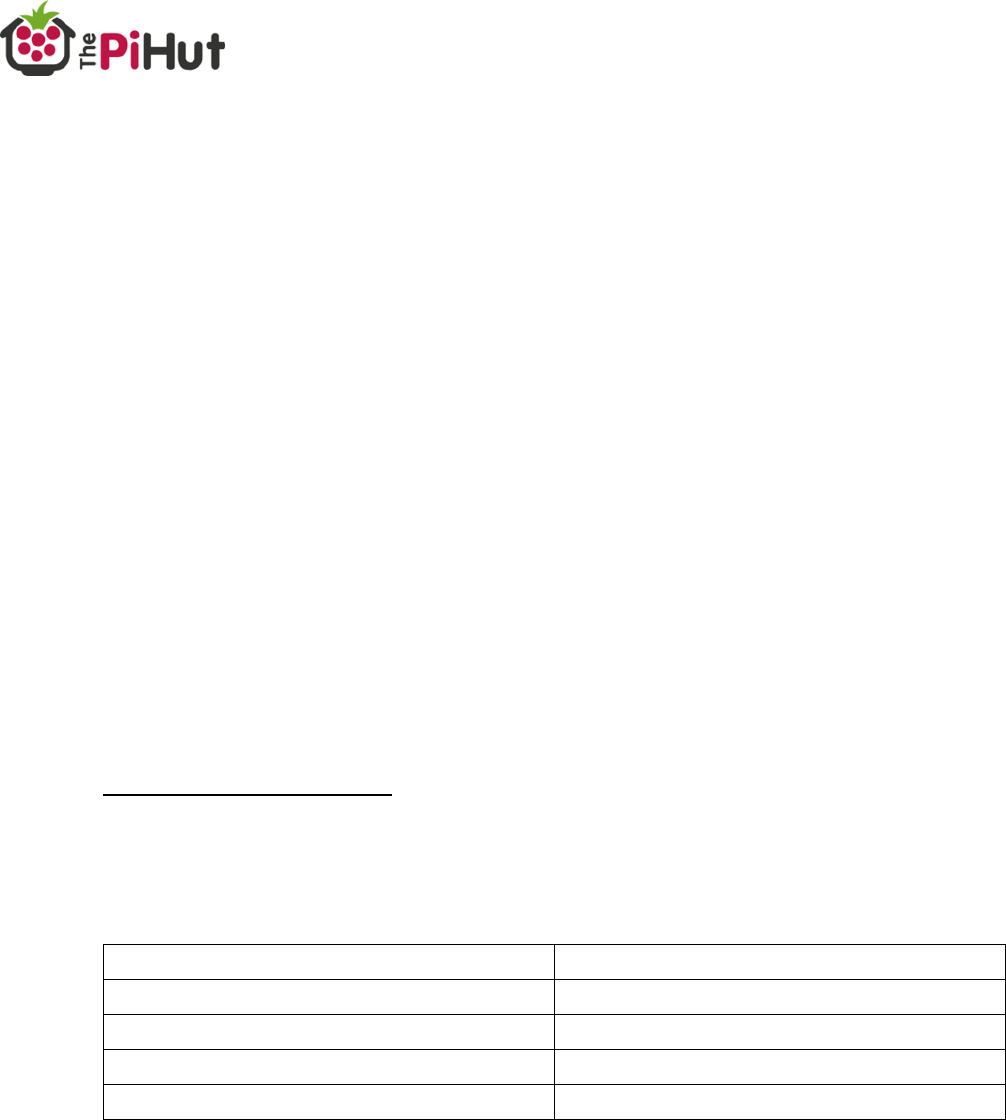
3. Next solder the 4 motor connection terminals. These are the two pairs of
terminals at each end of the PCB, and should be fitted to the top of the
board.
Join the two pairs of terminals together by sliding the edge ridges
together.
Make sure the wire holes are facing outwards, and then solder in place.
10
K
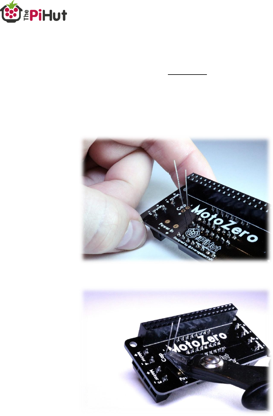
4. Next solder the capacitor to the right of the IC sockets, and snip off the
remaining legs.
IMPORTANT – the capacitor has a set polarity. The longer leg must be
soldered to the ‘+’ pad, and the shorter leg to the ‘-‘ pad.
The capacitor body should be showing to the front of the board.
Tip: You can also check polarity with the white stripe along the body of
the capacitor. This is the ‘-‘ leg.
11
K
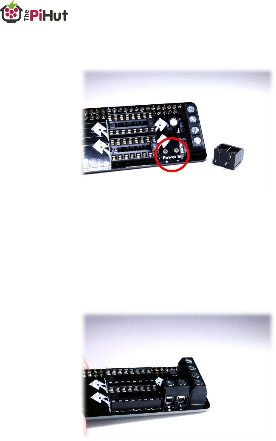
5. You now need to choose how you’re going to connect motor power. The
input power for the motors are the last remaining pads next to the
motor 3 terminal.
A fifth terminal block is provided should you want to use it, or you can
choose to directly solder wires from your chosen power supply.
In this example we will use the terminal block, as this gives you greater
flexibility to change power supplies in the future.
Fit the terminal through the pads so that the main body is on the front
of the board (the same as the motor terminals) with the wire holes
facing the edge of the PCB, then solder.
12
K
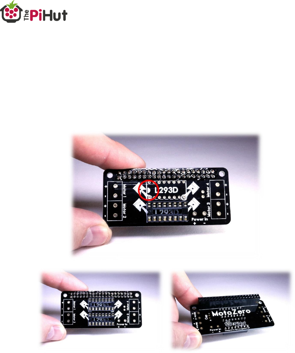
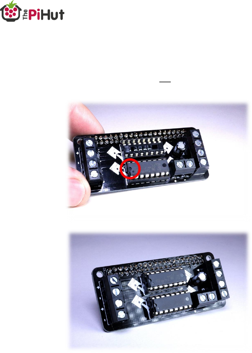
6. Lastly, fit the L293D motor driver ICs into the 2 IC sockets. You may need
to bend the legs of each chip inwards to fit the socket.
IMPORTANT – the notch on the ICs (looks like a ‘D’ at one end of the
chip) should be positioned to the left, next to the Motor 1 and Motor 2
terminals.
Assembly complete!
13
K
Motor Selection
You now have a completed MotoZero ready to control motors – but which
motors can you use with this board?
This is determined by the L293D motor driver ICs used on the MotoZero.
Every motor driver IC has different limits to the motors they can drive. This is
usually related to voltage used and the amount of current the IC can handle.
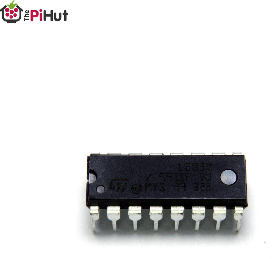
Why We Use The L293D?
The L293D has been out a long time, however it’s still a very popular choice
due to its low cost, simplicity and internal protection. It’s able to be controlled
by basic GPIO commands (including GPIO Zero) which makes it a great choice
for beginner boards like the MotoZero.
The L23D can handle a wide range of voltages, includes over-temperature
protection and comes with integrated clamp/flyback diodes to protect from
sudden voltage spikes (“flyback”) from the motors.
The L293D DIP format, used with an IC socket, allows the user to easily replace
the IC if they accidentally damage it.
14
K
L293D Headline Specifications
Let’s take a look at the key specifications for the L293D:
600mA continuous current per channel (per motor)
1.2A peak output current per channel (per motor)
Supports voltages of 4.5V to 36V
Try to ignore that second 1.2A current figure when choosing motors – you
want to avoid running the chips at peak!
A safe approach is to match your motor’s stall current to no more than the
continuous current figure (600mA), allowing lots of breathing room for the odd
current spike to peak if required (for example, if the motor stalls).
Example Motor Recommendation
With the specifications above in mind, let’s take a look a popular brand of
motors available on the market to give you an idea of what to look for.
Micro Metal Gearmotors
There are lots of examples of these small 6V motors available online, ideal for
making robots. One manufacturer offer these motors in 4 main power
categories:
Category
Stall Current
High-Power Carbon Brushes
1600mA
High-Power
1600mA
Medium-Power
700mA
Low-Power
360mA
By looking at the stall currents of each of these categories, we can see that the
low-power versions will be a good choice for the L293D, with a stall current of
360Ma.
The medium-power motors could also be selected, however as these run
slightly over our target stall current at 700mA, so it would be wise to take
necessary precautions to avoid stalling the motor. Temperature should also be
monitored.

16
K
Wiring Up
With your board soldered and motors ready, it’s time to connect everything to
the MotoZero.
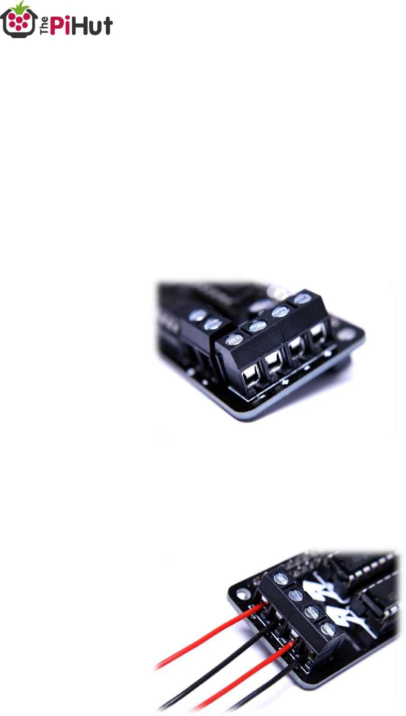
Connect Motors
You can choose to wire 1, 2, 3 or 4 motors to the MotoZero at any one time. It
doesn’t make any difference how many you use, or which terminals you use.
Your motors connect to the 4 terminal blocks at each end of the MotoZero –
each motor terminal has a pair of connections and are labelled ‘Motor 1’,
‘Motor 2’, ‘Motor 3’ and ‘Motor 4’.
Each motor terminal is labelled with ‘+’ and ‘-‘ markings, however it doesn’t
matter which way round you wire the motors to each terminal.
Insert the two wires from each motor in to the ‘+’ and ‘-‘ of each terminal
block.
Use your flat-head screwdriver to secure the wires – just finger tight will do.
17
K
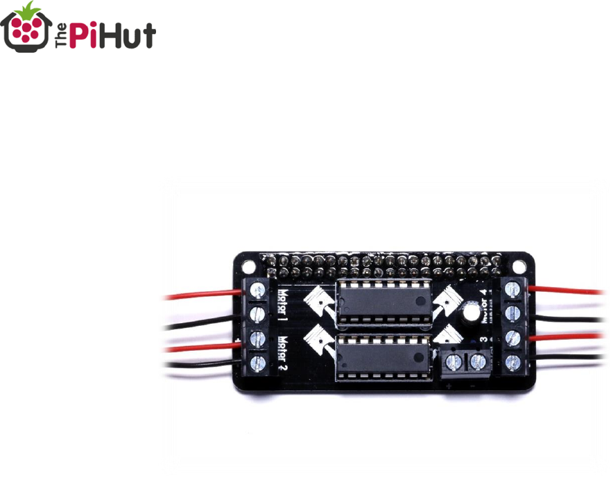
The plastic body of the terminal block may twist slightly, this is normal and can
be pushed back if needed.
If connecting 4 motors, it should look something like this:

18
K
Connect The Motor Power
***** WARNING *****
ENSURE YOUR MOTOR POWER SUPPLY IS WIRED WITH THE CORRECT
POLARITY! ENSURE THE POSITIVE (USUALLY RED) WIRE IS CONNECTED TO THE
‘+’ PAD/TERMINAL HOLE!
Q
Let us stress that again…
MAKE SURE YOU CONNECT YOUR BATTERY THE RIGHT WAY ROUND!
The MotoZero is a simple and affordable motor controller add-on board, and
therefore does not include any protection against incorrect battery polarity.
**********
Motor power I connected to the MotoZero’s ‘Power In’ section. We’re using
the supplied terminal block here:
19
K
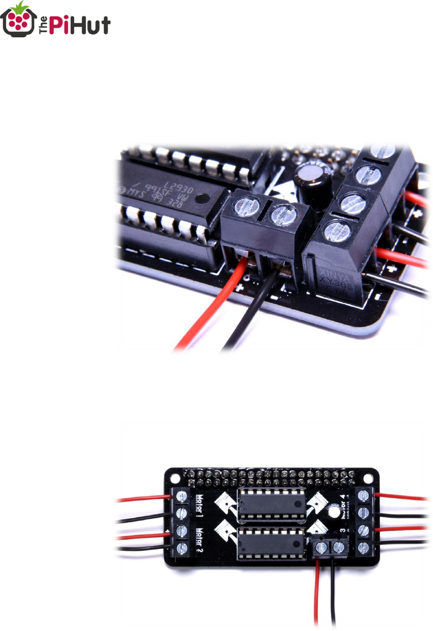
Turn your power supply off (or remove the batteries if it has no on/off switch).
Connect your battery wires to the MotoZero’s ‘power In’ section, ensuring the
positive wire is connected to the ‘+’ terminal and the negative wire connected
to the ‘-‘ terminal.
Your MotoZero should now look something like this:

20
K
Connect The Raspberry Pi Power Source
Your Raspberry Pi should be powered via the usual micro-USB port using either
a wall plugged power supply (for testing at a workstation) or power
bank/battery pack.
Turn the chosen power supply off and connect the cable to the Raspberry Pi.
21
K
Code and Control
Introduction
Controlling motors with the MotoZero is very easy thanks to simple GPIO
‘on/off’ control. If you’ve controlled an LED using the GPIO, you’ll feel right at
home with the MotoZero.
All examples in this document use the GPIO.BCM mode and the standard
Raspbian Jessie image.
Turn on your Pi and motor power sources, then try some of the examples.
GPIO Control Explained
Each motor has 3 GPIO pins associated with it. One pin enables the motor
(think of this as a “master on/off switch”) and the other two pins control the
power to the positive and negative wires of the motor.
To make the motor turn, we need to enable the motor (our “master switch”)
and then send power to one of the motor wires, and GND the other one. This
will make the motor turn in one direction.
To make the motor turn in the other direction, we simply switch the code
around so that we send power and ground to the opposite motor wires.
Let’s show you an example, and then list the GPIOs used in the MotoZero.

22
K
One Motor One Direction Example
Here’s an example of making Motor 1 turn in one direction for 3 seconds. This
example uses the exact same GPIO pins that the MotoZero uses:
Motor 1 is enabled by GPIO 5 (our “Master Switch” or “Enable”)
The Motor 1 ‘+’ motor terminal is linked to GPIO 27
The Motor 1 ‘-‘ motor terminal is linked to GPIO 24
Our setup code imports the ‘GPIO’ and ‘sleep’ modules. It then sets the GPIO
mode to BCM.
We then tell the code which GPIO pins we want to use for what (A and B are
our motor terminal wires. E is for ‘Enable’). Lastly we set up each GPIO pin to
be an output:
1. # Import GPIO
2. import RPi.GPIO as GPIO
3.
4. # Import sleep
5. from time import sleep
6.
7. # Set the GPIO mode
8. GPIO.setmode(GPIO.BCM)
9.
10. # Define GPIO pins
11. Motor1A = 27
12. Motor1B = 24
13. Motor1Enable = 5
14.
15. # Set up defined GPIO pins
16. GPIO.setup(Motor1A,GPIO.OUT)
17. GPIO.setup(Motor1B,GPIO.OUT)
18. GPIO.setup(Motor1Enable,GPIO.OUT)
We then tell the code to turn certain pins on or off to make the motor move:
20. # Turn the motor on
21. GPIO.output(Motor1A,GPIO.HIGH) # GPIO high to send power to the + terminal
22. GPIO.output(Motor1B,GPIO.LOW) # GPIO low to ground the - terminal
23. GPIO.output(Motor1Enable,GPIO.HIGH) # GPIO high to enable this motor
24.
25. # Leave the motor on for 3 seconds
26. sleep(3)
27.
28. # Stop the motor by 'turning off' the enable GPIO pin
29. GPIO.output(Motor1Enable,GPIO.LOW)
30.
31. # Always end this script by cleaning the GPIO
32. GPIO.cleanup()
This will make the motor turn in one direction for 3 seconds then stop.

23
K
One Motor Two Directions Example
Here’s an example of making Motor 1 turn in one direction for 3 seconds, then
turn in the other direction for another 3 seconds.
We’re using the exact same set up as the last example but will add a little more
code to make the motor turn in the other direction.
The setup lines are the same:
1. # Import GPIO
2. import RPi.GPIO as GPIO
3.
4. # Import sleep
5. from time import sleep
6.
7. # Set the GPIO mode
8. GPIO.setmode(GPIO.BCM)
9.
10. # Define GPIO pins
11. Motor1A = 27
12. Motor1B = 24
13. Motor1Enable = 5
14.
15. # Set up defined GPIO pins
16. GPIO.setup(Motor1A,GPIO.OUT)
17. GPIO.setup(Motor1B,GPIO.OUT)
18. GPIO.setup(Motor1Enable,GPIO.OUT)
However, we now add some lines after the ‘sleep’ to the turn the motor in the
opposite direction for 3 seconds as well. To do this, we simply copy the same
lines but swap the Motor1A and Motor1B GPIO directions:
1. # Turn the motor on one way
2. GPIO.output(Motor1A,GPIO.HIGH) # GPIO high to send power to the + terminal
3. GPIO.output(Motor1B,GPIO.LOW) # GPIO low to ground the - terminal
4. GPIO.output(Motor1Enable,GPIO.HIGH) # GPIO high to enable this motor
5.
6. # Leave the motor on for 3 seconds
7. sleep(3)
8.
9. # Turn the motor the other way
10. GPIO.output(Motor1A,GPIO.LOW)
11. GPIO.output(Motor1B,GPIO.HIGH)
12. GPIO.output(Motor1Enable,GPIO.HIGH)
13.
14. # Leave the motor on for 3 seconds
15. sleep(3)
16.
17. # Stop the motors by 'turning off' the enable GPIO pins
18. GPIO.output(Motor1Enable,GPIO.LOW)
19.
20. # Always end this script by cleaning the GPIO
21. GPIO.cleanup()

24
K
Two Motors One Direction Example
Using more motors on the MotoZero is super simple and just a case of
connecting the motors and a bit of ‘copy and paste’.
Let’s go through the differences. You’ll need to define the pins for the second
motor– notice the Motor 2 block added below (we’ve skipped past the import
section this time):
10. # Define GPIO pins
11. Motor1A = 24
12. Motor1B = 27
13. Motor1Enable = 5
14.
15. Motor2A = 6
16. Motor2B = 22
17. Motor2Enable = 17
Then you’ll need to set up the pins as outputs in the same way. We’ve added a
black for motor 2 again:
19. # Set up defined GPIO pins
20. GPIO.setup(Motor1A,GPIO.OUT)
21. GPIO.setup(Motor1B,GPIO.OUT)
22. GPIO.setup(Motor1Enable,GPIO.OUT)
23.
24. GPIO.setup(Motor2A,GPIO.OUT)
25. GPIO.setup(Motor2B,GPIO.OUT)
26. GPIO.setup(Motor2Enable,GPIO.OUT)
Same again when we turn on the motors, we just duplicate for motor 2:
28. # Turn the motor on one way
29. GPIO.output(Motor1A,GPIO.HIGH) # GPIO high to send power to the + terminal
30. GPIO.output(Motor1B,GPIO.LOW) # GPIO low to ground the - terminal
31. GPIO.output(Motor1Enable,GPIO.HIGH) # GPIO high to enable this motor
32.
33. GPIO.output(Motor2A,GPIO.HIGH)
34. GPIO.output(Motor2B,GPIO.LOW)
35. GPIO.output(Motor2Enable,GPIO.HIGH)
When we disable the motors, we add a line to turn off motor 2 as well:
37. # Leave the motors on for 3 seconds
38. sleep(3)
39.
40. # Stop the motors by 'turning off' the enable GPIO pin
41. GPIO.output(Motor1Enable,GPIO.LOW)
42. GPIO.output(Motor2Enable,GPIO.LOW)
43.
44. # Always end this script by cleaning the GPIO
45. GPIO.cleanup()

25
K
GPIO Zero Control
The ‘Motor’ and ‘OutputDevice’ functions within GPIO Zero provide an easy
way to get your robot moving with the MotoZero, and also offers speed
control!
Add this code to the start of your Python file to set up the motor pins:
1. from gpiozero import Motor, OutputDevice
2. from time import sleep
3.
4. motor1 = Motor(24, 27)
5. motor1_enable = OutputDevice(5, initial_value=1)
6. motor2 = Motor(6, 22)
7. motor2_enable = OutputDevice(17, initial_value=1)
8. motor3 = Motor(23, 16)
9. motor3_enable = OutputDevice(12, initial_value=1)
10. motor4 = Motor(13, 18)
11. motor4_enable = OutputDevice(25, initial_value=1)
Then use any of the example commands below to make your robot move.
Tip: Remember to change the code to match the number of your motor, for
example motor1.forward() or motor2.reverse().
1. motor.forward() # full speed forwards
2. motor.forward(0.5) # half speed forwards
3.
4. motor.backward() # full speed backwards
5. motor.backward(0.5) # half speed backwards
6.
7. motor.stop() # stop the motor
8.
9. motor.value = 0.5 # half speed forwards
10. motor.value = -0.5 # half speed backwards
11. motor.value = 0 # stop
12.
13. motor.reverse() # reverse direction at same speed, e.g...
14.
15. motor.forward(0.5) # going forward at half speed
16. motor.reverse() # now going backwards at half speed
It really is that simple!

26
K
GPIO Pins Used
The MotoZero PCB has GPIO pins pre-allocated for the twin L293D motor
drivers.
You’ll need to know which pins are assigned to which motor in order to be able
to drive them properly (as demonstrated in the code examples).
Tip: No SPI, I2C or UART pins have been used, allowing you to use these
connections alongside the MotoZero if desired.
Motor 1
Enable Pin = 5
Positive (+) Terminal = 24
Negative (-) Terminal = 27
Motor 2
Enable Pin = 17
Positive (+) Terminal = 6
Negative (-) Terminal = 22
Motor 3
Enable Pin = 12
Positive (+) Terminal = 23
Negative (-) Terminal = 16
Motor 4
Enable Pin = 25
Positive (+) Terminal = 13
Negative (-) Terminal = 18

27
K
FAQs
Q. Can I use this with any Raspberry Pi?
A. The MotoZero can only be used with 40-pin Raspberry Pis (B+, A+, Pi2, Pi
Zero and the Pi3).
Q. Is this a HAT?
A. No. HATs have a set specification including EEPROM chips and other
standards. We didn’t feel this product needed HAT features, so we prefer to
call it an “add-on board”.
Q. What motors can I use with this board?
A. Check the ‘Motor Selection’ section of this document. In general, aim for
motors from 4.5V to 36V with a stall current not much greater than 600mA.
Q. What voltage battery should I use to power the motors?
A. Your battery voltage should match the voltage rating of your motors, and
be within 4.5V to 36V.
Q. How big should my motor battery be?
A. Anything from AAA size battery packs should give reasonable running time.
AA battery packs are most commonly used – however the voltage rating of
your motors will determine the type and number of batteries to use.
Q. My motor isn’t turning?
A. This could be due to a number of reasons. Is your wiring correct? Are the
ICs the right way around? Is the battery charged and turned on? Does the

28
K
motor work in another terminal? Does another motor work? Is your code
correct?
Q. Why is my motor going the wrong way?
A. There is no right or wrong way with motors. However, if you want your
motor to turn in the opposite direction you can either swap the wires over or
reverse the code.
Q. Why isn’t my wire going in to the terminal block?
A. After some usage, the gripping metal part inside terminal blocks can ‘pull
out’. Turn off and disconnect the MotoZero, unscrew the terminal block
screws, then push a small screwdriver into the terminal block wire hole to
bend the internal metal gripper back into position.
Q. Why are the LM293D ICs getting hot?
A. The ICs will get warm with normal usage, and even warmer depending on
the voltage and current requirements of the motors. Make sure your motors
are within the specification detailed in the ‘Motor Selection’ section, and avoid
stalling.
Q. I made a cool project with the MotoZero, how can I show you?
A. We LOVE seeing MotoZero projects! Share your image with @ThePiHut
and show us what you’ve made.
